application of ribbon burners to the flame treatment of polypropylene films
TRANSCRIPT

ARTICLE IN PRESS
Progress in Energy and Combustion Science 34 (2008) 696– 713
Contents lists available at ScienceDirect
Progress in Energy and Combustion Science
0360-12
doi:10.1
� Corr
E-m
journal homepage: www.elsevier.com/locate/pecs
Application of ribbon burners to the flame treatment of polypropylene films
Colleen Stroud Alexander a,�, Melvyn C. Branch a, Mark Strobel b, Michael Ulsh b, Neal Sullivan c,Trina Vian d
a Department of Mechanical Engineering, University of Colorado, Boulder, CO, USAb Corporate Research Process Laboratory, 3M Company, St. Paul, MN, USAc Division of Engineering, Colorado School of Mines, Golden, CO, USAd Lincoln Laboratory, Massachusetts Institute of Technology, Lexington, MA, USA
a r t i c l e i n f o
Article history:
Received 20 November 2007
Accepted 23 April 2008Available online 20 June 2008
Keywords:
Ribbon burner
Burner design
Flame stability
Flame treatment
Surface modification
Wettability
Whilhelmy plate technique
85/$ - see front matter & 2008 Elsevier Ltd. A
016/j.pecs.2008.04.004
esponding author. Tel.: +1303 275 4267; fax:
ail addresses: [email protected], Co
a b s t r a c t
This article focuses on recent advances in the understanding of industrial gas burners. Ribbon burners
have been chosen as the focus of the review because of the advantages presented by the burner
arrangement and burner performance. The ribbon burner configuration, because of its ability to provide
large flame surface and flame stabilization, has a large range of stability as flow rate, equivalence ratio
and reactant gas composition are varied. Discussed in detail is the application of ribbon burners in the
surface modification, or flame treatment, of polymer films to increase the wettability of a polymer
surface. Optimum treatment requires a spatially homogeneous post-flame reaction zone even with
burners up to 3 m in length. For methane/air flames, the optimum equivalence ratio is near 0.93 where
the active oxidizing-species concentration near the surface is a maximum. Chemical kinetic models of
the impinging flame and surface oxidation chemistry of a polymer film are also discussed. The model
predictions are in good qualitative agreement with the available understanding of the flame variables
affecting surface treatment and the expected oxidized species on the polymer surface.
& 2008 Elsevier Ltd. All rights reserved.
Contents
1. Introduction . . . . . . . . . . . . . . . . . . . . . . . . . . . . . . . . . . . . . . . . . . . . . . . . . . . . . . . . . . . . . . . . . . . . . . . . . . . . . . . . . . . . . . . . . . . . . . . . . . . . . . 697
1.1. Burner applications . . . . . . . . . . . . . . . . . . . . . . . . . . . . . . . . . . . . . . . . . . . . . . . . . . . . . . . . . . . . . . . . . . . . . . . . . . . . . . . . . . . . . . . . . . . 697
1.2. Burner configuration . . . . . . . . . . . . . . . . . . . . . . . . . . . . . . . . . . . . . . . . . . . . . . . . . . . . . . . . . . . . . . . . . . . . . . . . . . . . . . . . . . . . . . . . . . 697
2. Characteristics defining burner stability and flame environment structure . . . . . . . . . . . . . . . . . . . . . . . . . . . . . . . . . . . . . . . . . . . . . . . . . . . . 699
2.1. Burner stability parameters. . . . . . . . . . . . . . . . . . . . . . . . . . . . . . . . . . . . . . . . . . . . . . . . . . . . . . . . . . . . . . . . . . . . . . . . . . . . . . . . . . . . 699
2.2. Variables influencing flame environment structure . . . . . . . . . . . . . . . . . . . . . . . . . . . . . . . . . . . . . . . . . . . . . . . . . . . . . . . . . . . . . . . . . 699
2.2.1. Effect of burner configuration on flame environment . . . . . . . . . . . . . . . . . . . . . . . . . . . . . . . . . . . . . . . . . . . . . . . . . . . . . . . . 700
2.2.2. Parameterized flow regime analysis . . . . . . . . . . . . . . . . . . . . . . . . . . . . . . . . . . . . . . . . . . . . . . . . . . . . . . . . . . . . . . . . . . . . . . 700
2.2.3. Heat and mass transfer non-uniformities . . . . . . . . . . . . . . . . . . . . . . . . . . . . . . . . . . . . . . . . . . . . . . . . . . . . . . . . . . . . . . . . . . 702
3. Flame treatment of polymer films . . . . . . . . . . . . . . . . . . . . . . . . . . . . . . . . . . . . . . . . . . . . . . . . . . . . . . . . . . . . . . . . . . . . . . . . . . . . . . . . . . . . 703
3.1. Overview and discussion of wettability . . . . . . . . . . . . . . . . . . . . . . . . . . . . . . . . . . . . . . . . . . . . . . . . . . . . . . . . . . . . . . . . . . . . . . . . . . . 703
3.2. Flame-treatment parameters . . . . . . . . . . . . . . . . . . . . . . . . . . . . . . . . . . . . . . . . . . . . . . . . . . . . . . . . . . . . . . . . . . . . . . . . . . . . . . . . . . . . 705
3.2.1. Effect of fuel/air equivalence ratio. . . . . . . . . . . . . . . . . . . . . . . . . . . . . . . . . . . . . . . . . . . . . . . . . . . . . . . . . . . . . . . . . . . . . . . . 705
3.2.2. Effect of film positioning within the flame-treatment environment . . . . . . . . . . . . . . . . . . . . . . . . . . . . . . . . . . . . . . . . . . . . . 706
3.2.3. Effect of temperature and flow environments . . . . . . . . . . . . . . . . . . . . . . . . . . . . . . . . . . . . . . . . . . . . . . . . . . . . . . . . . . . . . . 706
4. Roles of flame and surface chemistry in flame treating. . . . . . . . . . . . . . . . . . . . . . . . . . . . . . . . . . . . . . . . . . . . . . . . . . . . . . . . . . . . . . . . . . . . 708
4.1. Flame chemistry. . . . . . . . . . . . . . . . . . . . . . . . . . . . . . . . . . . . . . . . . . . . . . . . . . . . . . . . . . . . . . . . . . . . . . . . . . . . . . . . . . . . . . . . . . . . . . 709
4.2. Surface chemistry . . . . . . . . . . . . . . . . . . . . . . . . . . . . . . . . . . . . . . . . . . . . . . . . . . . . . . . . . . . . . . . . . . . . . . . . . . . . . . . . . . . . . . . . . . . . 709
4.3. Effect of nitrous oxide additive . . . . . . . . . . . . . . . . . . . . . . . . . . . . . . . . . . . . . . . . . . . . . . . . . . . . . . . . . . . . . . . . . . . . . . . . . . . . . . . . . . 711
5. Summary and conclusions. . . . . . . . . . . . . . . . . . . . . . . . . . . . . . . . . . . . . . . . . . . . . . . . . . . . . . . . . . . . . . . . . . . . . . . . . . . . . . . . . . . . . . . . . . . 712
Acknowledgements . . . . . . . . . . . . . . . . . . . . . . . . . . . . . . . . . . . . . . . . . . . . . . . . . . . . . . . . . . . . . . . . . . . . . . . . . . . . . . . . . . . . . . . . . . . . . . . . 712
References . . . . . . . . . . . . . . . . . . . . . . . . . . . . . . . . . . . . . . . . . . . . . . . . . . . . . . . . . . . . . . . . . . . . . . . . . . . . . . . . . . . . . . . . . . . . . . . . . . . . . . . 713
ll rights reserved.
+1303 275 4415.
[email protected] (C.S. Alexander).

ARTICLE IN PRESS
C.S. Alexander et al. / Progress in Energy and Combustion Science 34 (2008) 696–713 697
1. Introduction
The present article focuses on recent advances in the under-standing of industrial gas burners and, by example, the use ofthese burners in a particularly demanding application. There isincreasing need for the design of such burners with greaterefficiency and stability that enable flames with variable chemicalcomposition and reduced air pollutant emissions. The optimiza-tion of the burners for a particular application requires a detailedunderstanding of the flame structure, chemical composition,chemical kinetics, and flame–surface chemical interactions. Theuse of ribbon burners, described below, for the surface treatmentof polymer films is an excellent example of a very demandingindustrial process.
Ribbon burners have been chosen as the focus of the reviewbecause of the advantages presented by the burner arrangementand the recent studies that have clarified burner performance. Gasburners have been described as non-aerated (air mixes with thefuel after the fuel exits the burner port), partially aerated (partialmixing of fuel and air prior to exiting the burner port), or fullyaerated (fuel and air are fully mixed prior to exiting the burnerport) depending on the degree of premixing of fuel and air prior tocombustion [1]. Of these, the most stable and easily controlled isthe fully aerated burner with independent control of fuel andoxidizer flow rates. More specifically, the ribbon burner design,which features a series of premixed conical flamelets, has beenused in a variety of applications. The ribbon burner offers theadvantages of compact design and ease of manufacture making itattractive for such industrial applications as furnaces, bakingovens, plastic and metal forming, and flame treatment of polymerfilms.
Recent advances in the optimization of flame treatment,employing the use of ribbon burners, have resulted from theapplication of modern experimental and analytical techniques,combustion modeling, and an understanding of flame–surfacereaction chemistry to this unique process. This progress is alsoreviewed in this article beginning with a detailed description ofthe flame structure created by a methane/air mixture and the fluidand thermal environment created by the ribbon burner, and thenproceeding to a discussion of the application of burners in theflame-treatment process.
1.1. Burner applications
As described in the previous section, ribbon burners have beenemployed in a variety of industries due to the positive designcharacteristics of these types of burners. In the baking and foodprocessing industries, ribbon burners are used extensively. Manytypes of cereal grain foods and meat food products are baked,cooked, warmed, browned or toasted in ovens or over grills heatedwith ribbon burners. In the paper industry, ribbon-burner-supported flames are impinged on paper roll stock during themanufacturing process to remove (via singeing) small fibersprotruding from the paper surface. Many molded three-dimen-sional plastic parts are surface treated with ribbon burners forimproved wetting or bonding of inks, paints, coatings, and labels.Ribbon burners are chosen in this application because they areeasily adapted to any firing orientation and can be small enoughto mount on robotics or other automated process equipment. Fortwo-dimensional or sheet-stock materials, ribbon burners as wideas 8 m are used in a variety of applications. For metal sheeting,ribbon burners are used to clean, or de-grease, aluminum sheetingprior to coating or other processing. And, as will be discussed indetail in this review, ribbon burners are the optimal solution forthe surface modification, or flame treatment of polymer films.
Of the applications mentioned above, flame treatment is themost demanding due to the requirement for exceptional uni-formity of the flame environment over large physical distancescoupled with the need for exceptional control of the flamechemistry and heat-transfer characteristics. These demandsrequire a precise understanding of the combustion environmentcreated by the burner. The goal of flame treatment is thegeneration of a uniformly modified polymer surface in a high-speed industrial process. Flame treating is accomplished byradicals in the post-flame gases that oxidize the surface of thepolymer film and increase the wettability of the surface withoutcausing thermal damage to the plastic film. The surface oxidationand consequent increased wettability lead to stronger attachmentof adhesives, inks, and other coatings to the surface. The processallows for improved adhesive tape and labeled packagingproducts, as examples.
1.2. Burner configuration
Many parameters must be considered in the design andmanufacture of an effective and efficient burner. A well designedburner will have a high level of stability, reducing the occurrenceof flashback and flame lift, which are two types of instabilities thatoccur due to an imbalance between the fuel/oxidizer mixture flowvelocity and the burn velocity of the combustible mixture. Theparameters that influence burner stability include port size,shape, number, and proximity within an array. In studying thevarious burner types, including punched-metal, slot, and ribbonburners, it has been found that the ribbon burner is the moststable under a wide range of conditions while maintaining higherlevels of heat release [2]. The formation of smaller momentum-controlled flames allows for more flexibility in the directionalmounting of the burner [2]. In addition, the ribbon burnerprovides a large port area in comparison to other burner types,reducing the physical size of the burner for a given poweroutput [1].
Ribbon burners have a variety of sizes ranging from a singlerow of ports to multiple-tiered rows, such as the so-called ‘4-portburner’ illustrated in Fig. 1, with additional burner details shownin Fig. 2. The ribbon is comprised of packed sheets of corrugatedstainless steel, which form rows of nearly elliptical outlets, orports, each having a major diameter of 2.4 mm and a minordiameter of 1.5 mm. The rows are parallel, but offset, so that thecenters of the outlets are staggered, as shown in Fig. 1. In each row,the spacing between the outlets is ca. 2.5 mm center-to-center.With reference to Fig. 1, ports ‘1’ and ‘4’ are denoted as primerports, while the central ports ‘2’ and ‘3’ are considered to be themain ports [3]. Alternately, ports ‘1’ and ‘3’ form the upstream pairof burner outlets while ports ‘2’ and ‘4’ form the downstream pair,with the upstream and downstream directions being definedrelative to the motion of the heated, baked, or treated surface, i.e.,the surface to be treated is exposed to the flame issuing from theupstream pair of ports first. The surface of the ribbon is generallyrecessed 3 mm below the surface of the burner housing. Thedefinition of the axes is depicted in Fig. 2 where the cross-webdirection (x) runs along the length of the burner and the down-web direction (y) is defined as crossing the width of the burner.The burner ports can be straight or angled for ease of burnerassembly, as shown in Fig. 2.
From a fluid dynamics standpoint, a ribbon burner employed inan industrial process may be treated as an array of multiple jets,often impinging on a nearby surface. Consideration should begiven to the multiple jet interaction as well as to the presence andproximity of the impingement surface and any external crossflowgenerated by the movement of the impingement surface. The

ARTICLE IN PRESS
Fig. 1. A photograph coupled with a schematic diagram of the ribbon burner showing port nomenclature. Ports 1 and 4 are primer ports, while ports 2 and 3 are main ports.
Ports 1 and 3 form the upstream pair of burner outlets, while ports 2 and 4 form the downstream pair.
x, cross-web
z
y, down-web
1 cm
2 mm 31cm
0° or 17°slant
Burner Housing
Fig. 2. Side view showing burner housing and top view of ribbon placement along with the orientation of experimental axes. Direction x is cross-web and direction y is
down-web (�y is up-web).
C.S. Alexander et al. / Progress in Energy and Combustion Science 34 (2008) 696–713698

ARTICLE IN PRESS
C.S. Alexander et al. / Progress in Energy and Combustion Science 34 (2008) 696–713 699
multiple jet interactions become complicated with the formationof turbulent eddies that enhance mixing. The overall levels ofmixing and entrainment are greater for a multi-jet array incomparison to that of a single jet, leading to as much as a 3-foldincrease in the total average heat-transfer coefficient [4], thusenhancing burner efficiency and performance.
2. Characteristics defining burner stability and flameenvironment structure
In this section, we begin with a description of the character-istics of the burner design that influence the stability of the flameabove a ribbon burner and go on to describe the structure of theflame cones and subsequent mixing of the combustion products.In most practical applications it is desired to have a burner thatcan operate safely and stably over a wide range of flow rates, withor without a nearby surface that is being exposed to the hightemperature combustion products. Rapid mixing of the combus-tion products is also desirable for insuring the spatial uniformityof treatment of a surface exposed to the combustion products andreactive intermediates. Recent studies, summarized below, haveshed considerable light on the flow field and mixing character-istics of reactants exiting the burner, reacting in the flame, andleaving the reaction zone, providing insight into the behavior ofthe fully aerated ribbon burner under a wide range of operatingconditions.
2.1. Burner stability parameters
Burner flame stability, which was briefly discussed in Section1.2, will now be addressed in more detail, relating flameinstabilities with the specific burner design parameters that helpto promote stable burner performance. In general, burner flamestability, which refers to the relatively stationary upright positionof the flame, can be achieved by promoting wall attachment [2].Wall attachment occurs when the flame adheres to a nearbysurface because of the presence of a boundary layer along thewall. Near the surface of the wall, the flame is stabilized due toheat losses to the wall. The no-slip condition at the surface mustbe satisfied and a velocity gradient (from zero to the free streamvelocity) forms within the layer. When the stream velocitymatches the burning velocity, a stable flame is formed and ableto attach. In contrast, flame lift occurs when the stream velocityexceeds the burning velocity and combustion is delayed untilfurther downstream. This type of instability is undesirablebecause it is an indicator of incomplete combustion and can leadto flame extinction.
Flashback is another type of instability that can develop in apremixed burner if the burning velocity of the flame exceeds thestream velocity flowing out of the port. The flame front thenpropagates inside the burner housing and into the reactantdelivery system, leading to undesirable and potentially dangerousresults. Flashback may occur when burner ports are larger thanthe reactant gas quenching distance. Under these conditions, themaximum port diameter ensuring necessary thermal losses hasbeen exceeded, thus allowing the flame to propagate back into themixing chamber. Appropriately sized port diameters enable aflame exhibiting this form of instability to be quenched due toproper heat loss to the port-forming walls, while a balancebetween the flame-specific burning velocity and the premixedfuel/oxidizer flow velocity is also necessary to ensure properflame attachment and stability.
Jet separation distance, defined as the separation between portopenings in the burner and, therefore, also the separationbetween the flamelets formed, is also crucial in determining
flame stability with a ribbon burner. If the jets are too closetogether, combustion product recirculation near the base of anadjacent flame is restricted. As a result, the local stream velocityfrom the adjacent jets exceeds the burning velocity and flame liftoccurs. If the jets are too far apart, the retention of a stable flameis reduced due to excessive heat loss to the burner surface. Anoptimal flame separation distance for a methane/air mixture wasexperimentally determined by Pearson et al. [2] to be1.25–2.25 mm. Additional studies related to burner configurationand flame stability were performed by Stroud et al. [5] and will bedescribed in detail in the next section.
The addition of oxygen to the reactant gas has been explored inorder to increase the burning velocity of the premixed flamesattached to a ribbon burner. The effect of this oxygen enrichmentis to increase the rate of energy deposition to an adjacent surfaceor to a heated environment. Care must be taken in suchapplications to insure that the ribbon burner ports remain smallerthan the quenching distance of the reactant gas mixture as thequenching distance is dependent on the nature of the fuel beingused. Since oxygen enrichment inevitably leads to smallerquenching distances, a burner that is safe for operation with airas oxidizer may not be safe if the oxygen concentration in thecombustible mixture is increased.
As described in the introductory section of this paper, ribbonburner ports often have an elliptical shape with a majordimension almost twice that of the minor dimension. Berladand Potter [6] developed a correlation to calculate the quenchingdistance for an elliptical cross section tube relative to that for acircular tube. The correlation is described as follows:
d2o ¼ d2
2
2
1þ ðd2=d1Þ2
" #(1)
where the axes of the port are defined as d1 and d2 with d24d1
and do is defined as the quenching diameter of the equivalentcircular port. There are also extensive experimental data onquenching distances for various fuels in air and oxygen enrichedair available in Lewis and von Elbe [7]. The data provided can beused to calculate the effect of oxygen enrichment on quenchingdistance for ribbon burners and to suggest ribbon burner portdiameters for safe operation. The resulting correlation suggeststhat for stoichiometric methane and air (0.21 oxygen molefraction in air) a safe port minor dimension is approximately2.57 mm, while for operation with air enriched to 0.35 oxygenmole fraction, the safe burner port minor dimension is reduced toapproximately 1.04 mm.
Other important concerns in designing stable and safelyoperating ribbon burners are the total number of ribbons andribbon packing. Widening of the ribbon, i.e., increasing the totalnumber of packed corrugated sheets, increases the surface area incontact with the flame. This causes the central portion of theribbon to be further removed from the cooled burner housing. Theconductive and radiant heat-transfer mechanisms are therebydiminished, forcing the burner to absorb more energy, potentiallyleading to failure of the ribbon. Similarly, one must ensure thatthe ribbon is tightly packed in the burner housing to obtainmaximum thermal contact and prevent overheating [2], againhighlighting the fact that both stability and safety must be takeninto consideration with burner design.
2.2. Variables influencing flame environment structure
Similar to the many parameters that influence burner stability,there are many variables that affect the structure of the multipleflame cones being emitted from a ribbon burner as well as thepost-flame environment created. It is important to understand

ARTICLE IN PRESS
C.S. Alexander et al. / Progress in Energy and Combustion Science 34 (2008) 696–713700
how these variables interact in order to better predict how theflame environment is influenced. The variables include burnerconfiguration, flame power (in units of W/cm2, calculated basedon the fuel flowrate, the heating content of the fuel, and the areaof the ribbon face), flame stoichiometry, the presence of animpingement surface, the gap between the burner surface and theimpingement surface, and the relative motion of the impingementsurface.
Building on previous studies [1,2], researchers [5] performedqualitative stability and flow regime analyses relating changes inthe combustion environment to changes in burner configurationas well as the other additional operating parameters describedabove. In addition to the flow regime analyses, a heat-transferanalysis was also performed and will be detailed in the followingparagraphs.
The experimental setup mirrors that used in the process ofindustrial flame treating. The setup consists of a mounted 25 cmdiameter roller (the impingement surface) that is driven by avariable-speed drive train allowing for rotational speeds between0 and 7 Hz, translating to a roller rotational velocity of 0–5.5 m persecond (m/s). The roller is chilled to approximately 400 K toprevent any thermal damage that could occur due to the presenceof the flame and to prevent the buildup of condensation on theroller surface. The burner is oriented beneath the roller, parallel tothe face of the roller. The vertical separation distance or gapbetween the roller and the burner can be varied along with thehorizontal positioning of the burner in relation to the roller.
The stability and flow regime analyses utilized a flowvisualization process called Schlieren imaging. With this techni-que, the flame thermal gradients are made visible due to thedeflection of light resulting from the presence of density gradientswithin the flame. An inline color filter qualitatively indicates thedegree of diffraction that occurs, giving a blue color for smallerthermal gradients, green and yellow for moderate gradients, andorange and red for the largest gradients, providing insightconcerning gradient intensity and location.
2.2.1. Effect of burner configuration on flame environment
The study done by Stroud et al. [5] relates changes in burnerconfiguration to changes in flame stability and the flameenvironment created above the burner for laminar, stoichiometricflame conditions incorporating the influence of crossflow result-ing from impinging surface motion, which is a condition that isoften seen in industry processes. As stated in Section 2.1, theoptimal flame separation distance has been experimentallydetermined to be 1.25–2.25 mm [2] under conditions withoutimpinging surface motion. Based on these results, one wouldexpect that 3 or 4 typical ribbons between each row of portswould be optimal as each ribbon typically has a width of 0.5 mm.
Six burner configurations were considered, including 8-, 4-,and 2-port burner with the row separation distances varying from1.0 to 2.5 mm [5]. The 8-port burner, with a 1.5 or 2.0 mmseparation distance, created a stable flame environment. Incomparison to the 8-port burner, the 4-port burner was moresusceptible to air entrainment at the highest roll rotational speeds(5.50 m/s) due to the reduction in the number of jets providing acumulative resistance to the rotational velocities. The 4-portburner with a 1.0 mm ribbon separation did not present a stableflame even with a stationary roller. Entrainment began at low rollrotational speeds and the flames lost stability as the rotationalspeed of the roll increased. The 2-port burner provided a stableflame when the impingement surface was stationary, but becausethere are no outer flames to shield against the entrained ambientair, the flame was completely extinguished at a high roll rotationalspeed (5.50 m/s). A 4-port burner with a 2.5 mm row separation
showed the same vulnerability to entrainment as the 1.0 mmdesign mentioned above since the flames are too far apart toprovide enough stabilization in the boundary layer formed on theroller at a processing speed of 5.50 m/s.
These results [5] suggest that a burner with a 1.5–2.0 mm(3- or 4-ribbon) row separation distance and at least 4 ports isdesirable to create a stable and uniform environment above theburner that is resistant to entrainment effects introduced due toimpinging surface motion. These results are in agreement withthe optimal flame separation distance previously determined byPearson et al. [2].
2.2.2. Parameterized flow regime analysis
With the optimal row separation distance established, Stroudet al. [5] also performed a parameterized flow regime analysis,where the flame power, burner-to-roll (impinging surface) gap,and roll rotational speed were systematically varied at stoichio-metric conditions for a methane/air flame environment created bya 4-port, 4-ribbon burner. These changes in the thermal flamestructure and post-combustion environment were captured onfilm utilizing the Schlieren imaging technique. The images werevisually compared and categorized as laminar, partially mixed, orhighly mixed based on the level of small-scale fluctuations thatwere present in the flame environment. The effects of airentrainment were also considered in order to determine if thefree jet velocities were influenced by the roll rotational velocity.Figs. 3 and 4 provide examples of the Schlieren images capturedand the details of the experimental conditions and categorizedresults are presented in Table 1, with flame powers.
In Figs. 3 and 4, the roll is moving in a clockwise direction andis seen as the black circular object at the top center of the images.The ribbon burner is the black object at the bottom center of theimages, viewed along its cross-web axis. The colors are anintegration of the flame diffraction effects along the length ofthe burner (cross-web or x direction). Fig. 3 presents Schlierenimages of the flame structure and the post-combustion environ-ment with a large burner-to-impingement surface gap(H450 mm) in which the flame cones generated do not impingeon the roll surface. The left images in Fig. 3 depict a low flamepower condition (309 W/cm2). The flame itself is laminar with alarge region of little or no thermal variation at the center of theflame-treatment region, as indicated by the dark blue colorbetween the burner and the roll surface. The highest thermalgradients are indicated in red and are found at the outer edges ofthe flame zone. The right images in Fig. 3 show a high flame powercondition with high reactant flowrates (1570 W/cm2). The pre-sence of taller, more defined flame cones along with increasedsmall-scale fluctuations are evident and the size of the thermallyuniform core (indicated in dark blue) is reduced, indicating a morehighly mixed flame environment.
Higher-resolution Schlieren images were taken to observe atcloser range the behavior of the flame cones and the generatedpost-combustion environment under the same conditions and areshown in the bottom two images in Fig. 3. As can be seen in bothhigh-resolution images, the flame cones, indicated by the areas ofcone-shaped yellow and red color located near the burner surface,do not appear to be affected by the presence of the impingementsurface. There is a large area of constant high temperaturecentered above the burner, indicated by the black/dark bluesection in the center of the picture in the low flame powerconfiguration. In general, under non-impinging conditions(H450 mm), the low flame powers reflect laminar conditionswith little-to-no mixing aside from the entrainment of air near theimpingement surface at higher rotational speeds (5.50 m/s). Thestability of the flames being emitted from the burner is not

ARTICLE IN PRESS
Fig. 3. Schlieren images of non-impinging conditions (50 mm gap) for a 4-port burner with a clockwise roll rotation of 0.785 m/s: left Images—low flame power (309 W/
cm2) and right Images—high flame power (1570 W/cm2).
Fig. 4. Schlieren images of impinging conditions (7 mm gap) for a 4-port burner with a clockwise roll rotation of 5.50 m/s: left Image—low flame power (309 W/cm2) and
right Image—high flame power (1570 W/cm2).
C.S. Alexander et al. / Progress in Energy and Combustion Science 34 (2008) 696–713 701
affected by surface motion. The high flame power images alsoreflect extremely stable conditions, but with a high level ofmixing. The high-power flames show limited effects due to airentrainment as a result of surface motion.
Fig. 4 captures the conditions within the flame treatment zoneas separation distance H is decreased to 7 mm and the rollrotational speed is increased to 5.50 m/s, which is a relativelyextreme condition for flame treatment. The left image in Fig. 4represents a flame at low flame power (309 W/cm2) impinging onthe roll and the right image shows the environment created withhigh flame powers (1570 W/cm2) at the same gap. At the highflame power, the flame cones are affected by the presence of theimpingement surface. Mixing is increased under these conditionsas the flame cones deform, causing a redirection of the fluid flow.Under these conditions there is little entrainment of ambient airalong the roll surface and the stability of the flame environment isnot affected. In contrast, at the low flame power, the Schlierenimage shows laminar behavior with few small-scale fluctuationsin thermal gradients and minimal mixing. The effects of rollrotation and entrainment are obvious as the flame zone is
influenced by the rotational flow, disturbing the upstreamenvironment where ambient air is introduced into the treatmentzone. Under these conditions the momentum of the jets isovertaken by the influx of entrained air and the environmentabove the burner is perturbed.
For a flame, or reacting jet, the free jet Reynolds number, Red, isdefined as
Red ¼ ud=u (2)
where the characteristic length, d, is the burner port averagediameter (1.38�10�3 m) which is calculated based an averageport open area of 1.5 mm2, u is the unburned gas velocity (seeTable 1), and u is the reactant kinematic viscosity (1.59�10�5 m2/s).In accordance with Shaddix [8], the properties of nitrogen areused for the Reynolds number calculations as they provide areasonable approximation for the properties of methane–airmixtures. All Reynolds numbers were calculated using propertiesdefined at 300 K, assuming that the reactant fuel and air are closeto the ambient temperature as they exit the burner ports.

ARTICLE IN PRESS
Table 1Flow regime analysis results
Flame power (W/cm2) Roller rotational velocity (m/s) Flow velocity (m/s) Free jet Reynolds no. (Red) Gap (mm) Flow regimesa
309 0.785 4.78 415 5–50 L
2.35 5–50 L
3.93 5–50 PM
5.50 5–50 PME
495 0.785 7.65 664 5–50 PM
2.35 5–50 PM
3.93 5–50 PM
5.50 25–50 PM
5.50 5–20 PME
649 0.785 9.36 812 30–50 PM
0.785 5–25 PM to HM
5.50 5–50 PM to HM
923 0.785–5.50 10.9 947 5–50 HM
1237 0.785–5.50 13.9 1210 5–50 HM
1570 0.785–5.50 17.5 1520 5–50 HM
a Flow regimes—laminar (L), partially mixed (PM), partially mixed with entrainment (PME), highly mixed (HM).
C.S. Alexander et al. / Progress in Energy and Combustion Science 34 (2008) 696–713702
The flow regimes established for the environment created bythe array of reacting methane–air jets were similar to thepublished regimes for single non-reacting circular jets which aredefined in the literature as follows [4]:
(1)
Reo300 Dissipated laminar jet (2) 300oReo1000 Fully laminar jet (3) 1000oReo3000 Semi-turbulent jet (4) 3000oRe Fully turbulent jetThe experimental observations of Stroud et al. [5] show that theactual flame environment remains laminar below a free jetReynolds number of 600, starts to transition from laminar topartially mixed at Re4600, and becomes highly mixed aroundRe ¼ 900, in comparison to the expected Re ¼ 3000, which isconsidered to be the fully turbulent condition for a single non-reacting jet. The flame environment created by the array of jets isvery highly mixed, resembling a fully turbulent condition eventhough the Reynolds number is lower than that expected for asingle non-reacting fully turbulent jet. This is due to the effects ofcombustion-induced turbulence and jet interaction, as higherflow velocities are coupled with greater heat transfer andtransport properties due to increased mixing. As suggested byLewis and von Elbe [7], turbulence can be introduced by thechemical kinetics, rapid volume expansion, and general velocityincrease occurring within the flame as a result of combustion.
The roll rotational velocity can also be influential in the level ofthermal gradient fluctuation that is produced, especially withlarger gaps between the burner and impingement surface. Theincreased levels of entrained ambient air can cause a laminarflame environment to appear more partially mixed with increasedsmaller-scale thermal fluctuations as depicted by the top leftimage in Fig. 3. In general, however, roll rotation can only inducesmall changes in the flame environment at low flow velocities andhas little to no influence on the flame environment at high flamepower, high flow-velocity conditions.
2.2.3. Heat and mass transfer non-uniformities
A significant problem in applications involving multipleimpinging jets are the non-uniform heat and mass transfer
profiles that can be generated on the impingement surface. Toprevent non-uniform heat and mass transfer, the jets need to bewell mixed prior to impingement so that a homogenous post-flame environment is produced. For this reason detailed flowvelocity and thermal measurements were made by Stroud et al.[5] in order to characterize the flow above the burner, compli-menting the flow regime analyses work described in the previoussection.
Cold-flow velocity field measurements were made, employinghot-wire anemometry to determine the flow characteristicswithout the influence of combustion. With this diagnostictechnique, fluid velocity is measured by sensing the changes inheat transfer from a small, electrically heated sensor exposed tothe fluid motion. Under conditions in which fluid temperature,composition, and pressure are constant, the dominant mechanismof heat transfer from the wire is through forced convection, whichis directly related to the velocity of the fluid. By measuring thevoltage required to maintain the desired hot-wire temperature,the fluid velocity can be accurately determined.
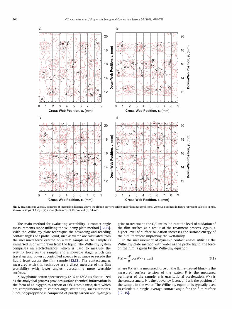
The cold-flow velocity field measured at a position z ¼ 2 mmabove the ribbon burner operating at laminar conditions (equiva-lent to 490 W/cm2 for a reacting flow) is shown in Fig. 5. Underthese conditions the highest reactant flow velocity was found tobe 6.8 m/s. The velocity field is highly non-uniform over the maincombustion zone (10oy, down-webo20 mm). Inter-jet mixingcan be observed in the contour plots of the main combustion zone(10pyp20 mm) shown in Fig. 6. The jets formed above the portopenings are easily identified at the low separation distance ofz ¼ 2 mm, but become increasingly difficult to distinguish as thevertical distance is increased. While velocities are relatively highat z ¼ 10 mm, adjacent jets have combined at this height, reachinga plane of horizontal uniformity [9] relative to the z ¼ 2 and 6conditions and fluctuations in the flow appear random. Atz ¼ 14 mm, in Fig. 6, the flowfield dissipates significantly, andlittle structure can be identified.
Incorporating combustion effects, Fig. 7 presents temperaturedata for highly impinging flame environments for laminar (309 W/cm2) and the highly mixed (923 W/cm2) flow regimes. Theradiation loss corrected thermal characterization of the combus-tion environment was captured utilizing an Omega R-typethermocouple (platinum/platinum-13% rhodium) positioned

ARTICLE IN PRESS
5
10
15
20
25
2
4
6
02
46
8
Air
Velo
city
(m /
sec)
0Down-Web Position (mm)Cross-Web
Position (m
m)
Fig. 5. Reactant gas velocity field above 4-port ribbon burner under laminar conditions at vertical position z ¼ 2 mm.
C.S. Alexander et al. / Progress in Energy and Combustion Science 34 (2008) 696–713 703
above the burner. A traversing system controlled with oneautomated (y direction) and two manual micrometers (x and z
direction) was used for thermocouple positioning. Under thelaminar condition (left), similar to the conditions explored in thecold-flow analysis, the combustion environment temperaturesrange above 2100 K with the difference between the minimumand maximum local temperatures being less than 230 K. Theuniform plane noted with the cold-flow velocity measurements isevident in the thermal measurements as the difference in theaverage temperature in the x or cross-web direction is less than1001 under laminar flow conditions. In contrast, for the highlymixed flow regime, the difference between the minimum andmaximum measured temperatures is �1250 K. This increasedtemperature difference occurs at these high flowrate, highlyimpinging conditions because there is little time for mixing of thepost-combustion gases that would result in a more uniformthermal environment. For both flame environments, highertemperatures are found between the ports [4,9] and the lowesttemperatures are seen above the port openings due to thepresence of unreacted fuel and air.
3. Flame treatment of polymer films
As mentioned in the Introduction to this review, the flametreatment of polymer films presents a challenging operatingenvironment for the design of the burner and placement of thetreatment surface. The process involves exposing the surface of athin polymer film to the reactant species in the mixture down-stream of the flame in order to produce a film surface that has arange of desired properties, without causing thermal degradationof the film. One of the desired properties of the treated film is anincrease in surface wettability so that water-based inks andadhesives will adhere to the surface treated film. For thisapplication, precise control of the flame environment and its
spatial uniformity is essential. In this section of the review, wedescribe the flame-treatment process for increased wettabilityand the flame parameters that need to be optimized to producethe highest degree of wettability. These parameters include thosethat influence burner stability, the combustion flow regimescreated, and the uniformity of the heat and mass transfer thatresults, as discussed in Section 2. The surface chemical reactionsbetween the post-flame reactants and the polymer film have alsobeen studied extensively and will be discussed in the followingsection of the review.
3.1. Overview and discussion of wettability
Corona discharge treatments have long been the dominantmethod of treating polymer films, principally because of concernsabout the safety of open flames in industrial environments andthe observed sensitivity of flame treatments to small changes inprocess conditions. Recently, however, flame treatment hasreceived renewed industrial interest as a technique for modifyingpolymer films. Some of the reasons for this renewed interestinclude: major improvements in the safety, reliability, and ease ofoperation of flame-treating equipment; energy consumption andequipment space requirements comparable to corona treatment;the ability to achieve high levels of surface oxidation of polymersat extremely short processing times (o0.5 s); and no generation oftoxic, corrosive ozone [11].
Untreated, many polymers, in particular polyolefins, arehydrophobic and therefore tend to repel water and water-basedsubstances. The oxidation of the film through flame surfacetreatment increases the surface energy of the film, making thematerial less repellent of water, improving film wettability.Increasing wettability is a necessary component of manymanufacturing processes that require water-based inks andadhesive materials to be applied to the polymer film surface.
ARTICLE IN PRESS
12
14
16
18
20
Dow
n-W
eb P
ositi
on, y
, (m
m)
0Cross-Web Position, x, (mm)
1
11
1
1
1
1
1
1
1
1
1
1
1
1
1
11
1
1
1
1
1
1
1
1
1
1
1
1
1
1
1
2
2
2 1
12
1
2
2
2
2
2
2
2
22
2
322
2
2
2
22
2
3
2
2
3
2
2
3
4
3
2
2
3
3
2
3
4
3
34
4
3
4 3
5
5
5
5
5 5
5
5
5
5
4
5
65
6
5
6
6
12
14
16
18
20
Dow
n-W
eb P
ositi
on, y
, (m
m)
1
1
1
11
1 1 1
11
1
1
1
1
1
1
1
11
1
111
12
2
2
2
2
22
2
2
2
22
2
2
2
2
2
2
2 2
2
2
2
2
22 22
2
2
2 2
2
2
2
3
2
3
3
3
3
3
3
3
3
3
3
3
3
33
3
3
3
3
3
3
333
3
3
333
3
3
3
33 3
3
4
4
44
34
4
4
4
44
4
4
4
4
4
4
12
14
16
18
20
Dow
n-W
eb P
ositi
on, y
, (m
m)
1
1
1
1
1
1
1
11 11
1
1
1
1 1
1
1
1
1
1
1
2
1
2
2
2
2
2
2
2
3
222
2
2
2
2
22
2 3
2
3
3
3
2
3
2
23
3
3
3
3
3
3
3
3
3
3
33
3
3
3
4
3
33
333
3 3
34
3
3
44
43
3
4
4
3
3
3
3
3
3
3
3
34
3
4
44
3
4
44
3
4
5
3
4
44
4
44
4
44
5
444
5
4 5
45
4
5
5
55
55
12
14
16
18
20
Dow
n-W
eb P
ositi
on, y
, (m
m)
11
1
1
1
1
1
1
1
1
1
2
2 2
2
2
2
2
2 2
2
2
2
2
3
2
2
2
2
2
22
2
2
2
3
3
2
2 3
2
3
3
2
3
3
2
3
3
3
3
2
3
23
3
3
3
3
4
4
22
3
3
4
4
2 45
3
4
3
4
34
4
5
5
6
4
4
45
4
4
5
5
5 5
46
5
5
5
5
6
6
6
6
1 2 3 4 5 6 7 8 9
0Cross-Web Position, x, (mm)
1 2 3 4 5 6 7 8 9 0Cross-Web Position, x, (mm)
1 2 3 4 5 6 7 8 9
0Cross-Web Position, x, (mm)
1 2 3 4 5 6 7 8 9
Fig. 6. Reactant gas velocity contours at increasing distance above the ribbon burner surface under laminar conditions. Contour numbers in figure represent velocity in m/s,
shown in steps of 1 m/s. (a) 2 mm, (b) 6 mm, (c) 10 mm and (d) 14 mm.
C.S. Alexander et al. / Progress in Energy and Combustion Science 34 (2008) 696–713704
The main method for evaluating wettability is contact-anglemeasurements made utilizing the Wilhemy plate method [12,13].With the Wilhelmy plate technique, the advancing and recedingcontact angles of a probe liquid, such as water, are calculated fromthe measured force exerted on a film sample as the sample isimmersed in or withdrawn from the liquid. The Wilhelmy systemcomprises an electrobalance, which is used to measure thewetting force on the sample, and a movable stage, which cantravel up and down at controlled speeds to advance or recede theliquid front across the film sample [12,13]. The contact-anglesmeasured with this technique are a direct measure of the filmwettability with lower angles representing more wettablesurfaces.
X-ray photoelectron spectroscopy (XPS or ESCA) is also utilizedas the analytical process provides surface chemical information inthe form of an oxygen-to-carbon or O/C atomic ratio, data whichare complimentary to contact-angle wettability measurements.Since polypropylene is comprised of purely carbon and hydrogen
prior to treatment, the O/C ratios indicate the level of oxidation ofthe film surface as a result of the treatment process. Again, ahigher level of surface oxidation increases the surface energy ofthe film, therefore improving the wettability.
In the measurement of dynamic contact angles utilizing theWilhelmy plate method with water as the probe liquid, the forceon the film is given by the Wilhelmy equation:
FðxÞ ¼gP
gcos yðxÞ þ bx=2 (3.1)
where F(x) is the measured force on the flame-treated film, g is themeasured surface tension of the water, P is the measuredperimeter of the sample, g is gravitational acceleration, y(x) isthe contact angle, b is the buoyancy factor, and x is the position ofthe sample in the water. The Wilhelmy equation is typically usedto calculate a single, average contact angle for the film surface[12–15].

ARTICLE IN PRESS
Fig. 7. False color image of temperature above a 6-port ribbon burner. (Left) Laminar, 7 mm gap, 0.785 m/s roll rotation, 309 W/cm2: (Right) highly mixed, 4 mm gap,
0.785 m/s roll rotation, 923 W/cm2.
C.S. Alexander et al. / Progress in Energy and Combustion Science 34 (2008) 696–713 705
In general, the advancing water contact angle is most sensi-tive to the low-energy, unmodified components of the surfacewhile the receding angle is more sensitive to the high-energy,oxidized groups introduced by the flame treatment [12]. Inaddition, in many industrial coating processes, liquids arephysically forced to wet a film surface; whether or not thecoating continues to uniformly wet the film during the dryingor curing of the coating can depend upon the receding contactangle of the coated liquid on the film substrate. Therefore, tobest characterize the flame-treated polypropylene, both theadvancing and receding contact angles are examined, with thereceding angle being the more important measurement. Lowercontact angles are indicative of higher surface energy, increasedwettability, and better adhesion. Specific examples of theWilhelmy force traces are shown and discussed in detail inSection 3.2 of this paper.
3.2. Flame-treatment parameters
3.2.1. Effect of fuel/air equivalence ratio
As previously mentioned, polyolefin films are often exposedto a flame to improve the wetting and adhesion propertiesof the polymer. Efforts were made by Branch et al. [9] toinvestigate the relationship between the flame conditions duringtreatment and the improvement in the wettability of polypropy-lene film.
Fig. 8 shows a plot of ESCA O/C atomic ratios and the contactangles of water on flame-treated polypropylene as a function of
the equivalence ratio, where the equivalence ratio (j) is defined as
f ¼ðmoles of fuel=moles of oxidizerÞActual
ðmoles of fuel=moles of oxidizerÞStoichiometric(3.2)
at a constant burner-to-film separation of 5 mm. The flame-treated polypropylene samples were analyzed by ESCA andcontact-angle measurements utilizing the Wilhemy plate method[12,13] previously described in Section 3.
Because lower contact angles are indicative of greater wett-ability, the contact-angle axis is plotted from high-to-low values.For comparison, untreated polypropylene has an advancingcontact angle of 1081 and a receding contact angle of 871. As afunction of the equivalence ratio, the contact angles of water onflame-treated polypropylene decrease as j increases, with aminimum in the contact-angle values occurring at an equivalenceratio of about 0.93, as shown in Fig. 8. In general, the studyperformed by Branch et al. [9] indicated that j ¼ 0.93 for amethane/air flame is optimal for all combinations of flame-to-filmdistance, flame power, and film speed. As the flames become fuel-rich, there is a steep increase in the contact angles at equivalenceratios from 0.97 to 1.05. Treatment of polypropylene in a fuel-richflame (j41) yields little improvement in wettability.
The surface chemistry of flame-treated polypropylene closelycorrelates with the wettability of the surface. Fig. 8 also shows theESCA O/C atomic ratio of flame-treated polypropylene as afunction of the equivalence ratio. The amount of surface oxidationgenerated by the flame follows the same trend as the wettability.The maximum O/C ratio of 0.18 is obtained at j ¼ 0.92–0.94.Within this range, the gas-phase concentrations of surface

ARTICLE IN PRESS
0
20
40
60
80
100
1200
Distance from burner face (mm)
Advancing angle
Receding angle
Con
tact
ang
le o
f wat
er (d
egre
es)
2 4 6 8 10 12
Fig. 9. Contact-angle measurements as a function of the position of the polymer
film relative to the flame at the optimum equivalence ratio of 0.93.
0
20
40
60
80
100
1200.68
Equivalence Ratio
Con
tact
ang
e of
wat
er (d
egre
es)
0
0.05
0.1
0.15
0.2
ESC
A O
/C a
tom
ic ra
tio
Receding AngleAdvancing AngleO/C Ratio
0.78 0.88 0.98 1.08
Fig. 8. Plot of the ESCA O/C atomic ratio and the contact angles of water on flame-
treated polypropylene as a function of the equivalence ratio with a constant
burner-to-film separation of 5 mm. Optimum treatment occurs at j ¼ 0.93 where
oxidizing-species concentrations are at a maximum.
C.S. Alexander et al. / Progress in Energy and Combustion Science 34 (2008) 696–713706
oxidizers in the flame are high. This surface oxidation is thereason for the improved wettability and adhesion properties offlame-treated polypropylene. A detailed discussion of the flameand surface chemistry involved in surface treating is presented inSection 4.
3.2.2. Effect of film positioning within the flame-treatment
environment
Researchers [16–18] have reported the need to position thefilm slightly beyond the luminous or visible flame front forimproved polymer film surface treatment results. Branch et al. [9]worked to provide a detailed justification of this claim. Althoughthe optimum equivalence ratio is independent of the position ofthe film relative to the flame, the position of the surface to betreated relative to the flames has a large effect on the level ofwettability achieved with flame treatment for a given flamepower. Fig. 9 shows contact-angle measurements as a function ofthe position of the polymer film relative to the flame at theoptimum equivalence ratio of 0.93 and a flame power of 500 W/cm2. Similar trends are seen at other equivalence ratios. In Fig. 9, aposition of approximately 2 mm represents the location of the tipsof the flamelets. Optimal treating at these laminar treatmentenvironment conditions occurs at distances between the tips ofthe flamelets and the polypropylene film of 0–2 mm. At greaterflame-to-film distances, treatment effectiveness declines gradu-ally, although some improvement in wettability is still noted atdistances of up to 20 mm.
3.2.3. Effect of temperature and flow environments
Non-uniform treatment of the polypropylene film, leading toirregularities in the wettability of the surface of the material canoften occur. Building on the discussion initially presented inSection 2, Strobel et al. [14] provide more insight on the formationof non-uniform temperature and flow environments above theribbon burner by continuing to look at the causes behind the non-uniform surface treatment of polymer films. Depending upon thetreatment conditions, polypropylene (PP) can be exposed to aninhomogeneous environment because of the conical shape of theflames [9,15]. This non-uniform environment can lead to cross-web variations, or ‘lanes’, in the wettability of the film [15]. Thelower-wettability lanes in the PP are not untreated film; they aremerely slightly less wettable than the other portions of the flame-treated PP. However, even this slight variation can have detri-
mental consequences in the subsequent processing of the flame-treated film.
The cross-web lanes have a periodicity that corresponds to thegeometrical spacing of the outlets, or ports, along a single cross-web row of the ribbon burner that is used to support the flame[9,15]. For a typical industrial ribbon burner, the spacing of theports along a single row is ca. 2.5 mm. However, the design of theribbon burner is such that successive rows of ports are staggered,so that there is a port every ca. 1.25 mm in the cross-webdirection. As a result, the film is actually exposed to a flame coneevery 1.25 mm in the cross-web direction as it passes by theburner, but the resulting period of variation in film oxidation is2.5 mm relative to the expected 1.25 mm. This is due to the factthat the upstream pair (Fig. 1) is more effective in oxidizing thesurface of the film in comparison to the downstream pair asdetermined by ‘registering’ the position of the film in relation to agiven burner port by marking the film with a scratch [14]. Thescratch allows specific features in the Wilhelmy force trace to beassociated as a function of position with a given port on the ribbonburner (see Figs. 10 and 11), providing information on the spatialnon-uniformities of the flame-treated PP.
Two types of registration experiments are presented by Strobelet al. [14] comparing the changes in the Wilhelmy force traces as afunction of position when either an upstream or a downstreamprimer port is ‘registered’ as well as plugged. Fig. 10 depicts thetrace when registering and plugging an upstream pair of primerports. Fig. 11 depicts the trace when registering and plugging adownstream set of ports. The location of the scratch or ‘registered’port is indicated in each figure, along with the locations of theplugged port and the force ‘peaks’ (lower contact angles) and‘valleys’ (higher contact angles). Note the extremely regular2.5 mm periodicity in the traces.
When an upstream primer port is used to make the scratch(Fig. 10), the scratch discontinuity in the Wilhelmy trace is alwayslocated in an expected peak position. Thus, the upstream pair ofports is always associated with higher Wilhelmy forces, lowercontact angles, and more effective oxidation of the PP. Theplugged upstream primer port that is separated by 5 mm fromthe scratch also corresponds to a peak position. However, in mostinstances, the ‘plugged-port peak’ is of lower overall force thanthe adjacent peaks. This indicates that each burner port compris-ing the upstream pair contributes to the surface oxidation of thefilm.
When a downstream primer port is used to make the scratch(Fig. 11), the scratch discontinuity is always located in an expected

ARTICLE IN PRESS
20
25
30
35
40
45
5Cross-web Position (mm)
Scratch location
Plugged port
Scratch at locationof peak
Adv
anci
ng W
ilhel
my
Forc
e (m
g)
10 15 20
Fig. 10. Wilhelmy advancing force data for flame-treated PP. To generate this data, a scratch was made in the PP film directly above an upstream primer port while a second
upstream primer port located 5 mm away form the scratch was also plugged with a short length of wire. This figure illustrates that laning, or non-uniform treatment has the
same spacing as the cross-web port spacing.
15
20
25
30
35
40
45
50
5Cross-web Position (mm)
Scratch location is in a valley
Plugged port valley has
less effect when
downstream
Valley
Valley
Peak PeakPeak
Peak
Adv
anci
ng W
ilhel
my
Forc
e (m
g)
10 15 20 25
Fig. 11. Wilhelmy advancing force data for flame-treated PP. To generate this data, a scratch was made directly above a downstream primer port while a second
downstream primer port located 5 mm away from the scratch was also plugged.
C.S. Alexander et al. / Progress in Energy and Combustion Science 34 (2008) 696–713 707
valley position. The downstream pair of ports is thus associatedwith lower Wilhelmy forces, higher contact angles, and lesseffective treatment of the PP film. The presence of the pluggeddownstream primer port that is separated by 5 mm from thescratch is not easily detected in the Wilhelmy traces. There islittle, if any, difference in the forces between the valley formed bythe plugged port and the valleys formed by unplugged down-stream primer ports. This observation implies that the down-stream primer ports have little influence on laning. Theseexperiments [14] show that the upstream pair of burner ports ismore effective in oxidizing the PP surface than the downstreampair of ports providing an explanation for the 2.5 mm spacing ofthe lanes of non-uniform surface treatment.
The difference between the upstream and downstream pairs ofports is best illustrated by determining the average temperatureof the post-combustion gases in the downstream direction as afunction of cross-web position. The term ‘average temperature’means the average of all temperature measurements made alonga downstream line at a particular cross-web position. The averagetemperature correlates to the number of active oxidizing speciesthat the film is exposed to as the film traverses downstreamacross the face of the burner. Average temperature data arepresented in Figs. 12 and 13 for a flame power of 309 W/cm2. Inthese figures, the x-origin is located at the centerline of theupstream pair of ports. Fig. 12 shows the average temperaturesnear the surface of the backing roll, which is the impingement

ARTICLE IN PRESS
C.S. Alexander et al. / Progress in Energy and Combustion Science 34 (2008) 696–713708
surface, as a function of cross-web position along the burner for aburner face-to-backing roll gap of 12 mm. In both of these cases,the backing roll was positioned such that the thermocouple cameas close as physically possible to the surface of the backing roll atan up-web location directly above the centerline of the burner, i.e.,at the bottom-dead-center location of the backing roll above thetwo main ports of the burner.
When the burner is located far from the backing roll, thetemperature field near the backing roll surface is quite uniform.The range in average temperatures across the measured area inFig. 12 is o25 K and the local temperature profile is similar to thatpresented for the laminar environment shown in Fig. 7 (left) withthe average temperatures being slightly lower due to theincreased gap between the burner and backing roll surface.
At the flame conditions used to generate Fig. 12, the array ofconical flames supported on the ribbon burner is far from thebacking roll. The combustion products from each conical flamehave ample time to mix prior to impinging upon the PP surfacethat is held against the backing roll. The relatively homogeneousflame environment at the backing roll under these ‘wide gap’conditions causes relatively uniform treatment of the PP surface.As determined in another study [15], PP film treated at theseconditions had no detectable treatment lanes. A uniform flametemperature field at the backing roll surface translates into auniform surface treatment of the PP. Unfortunately, increasing theburner-to-roll gap to eliminate laning comes at the cost of a
1790
1795
1800
1805
1810
1815
1820
1825
0Cross-web Position (mm)
Ave
rage
Tem
pera
ture
(K)
1 2 3 4 5
Fig. 12. The average flame temperature (in K) experienced by the PP film during
passage through the flame as a function of cross-web position for a 12 mm burner
face-to-backing roll gap. The x-origin represents a line passing through the
upstream pair of ribbon burner ports.
1620164016601680170017201740176017801800
0Cross-web Position (mm)
Ave
rage
Tem
pera
ture
(K)
1 2 3 4 5 6 7 8 9 10
Fig. 13. The average flame temperature (in K) experienced by the PP film during
passage through the flame as a function of cross-web position with a 4 mm burner
face-to-backing roll gap. The x-origin represents a line passing through the up-web
pair of ribbon burner ports. The figure shows that the peaks in the average
temperature in the cross-web direction have the same spacing as the peaks in
surface treatment levels.
reduction in the overall surface treatment of the PP (see Fig. 9, forexample).
As the burner-to-roll gap is decreased at a constant flamepower, the products of combustion have less time to mix prior tocontact with the backing roll so that the flame environment at theroll surface is much less uniform. Fig. 13 shows the averagetemperatures near the surface of the backing roll as a function ofcross-web position above the burner for a burner-to-roll gap ofonly 4 mm. The range in average temperatures across themeasured area increases to approx. 120 K at the 4 mm gap incomparison to the ‘wide gap’ condition and the trends in the localtemperature profile is more similar to the those presented for thehighly mixed environment shown in Fig. 7 (right), as the portlocations, marked by cooler pockets of unreacted fuel and air, aremore clearly defined in comparison to the larger gap condition.The small cross-web variation in treatment that is manifest aslaning is caused by the non-uniform flame environment above theburner itself. Again, it is presumed that the concentration of activespecies is also non-uniform above the burner ports. Thetemperature measurements show a difference between theupstream and downstream pairs of ports. The coolest averagetemperatures are found along the line of the downstream pair ofports which are associated with lower Wilhelmy forces, highercontact angles, and less effective treatment of the PP film. These‘cool-temperature valleys’ in Fig. 13 are spaced 2.5 mm apart.Cooler average temperatures are associated with lower concen-trations of active species and lower levels of surface treatment.Conversely, the higher average temperatures in Fig. 13 correspondto the upstream pair of ports, which are the ports associated withhigher Wilhelmy forces, lower contact angles and more effectivetreatment.
Laning on flame-treated PP is a small, but significant, non-uniformity in the extent of surface oxidation and wettability thatis superimposed upon a much larger average increase in oxidationand wettability. The wettability and temperature data presentedby Strobel et al. [14] show that the PP film that passes above theupstream pair of ribbon–burner ports is exposed to a greateraverage temperature during passage through the flame. Thisgreater average temperature correlates to an exposure to a greaterconcentration of the active species, which cause the surfaceoxidation of the PP.
It is now believed that some level of laning is inevitable inflame treating because all viable commercial flame-treatmentequipment uses an array of conical flames. Conical flames do notquickly coalesce into a uniform flame front, but remain distinctsome distance above the burner surface. While other burnerdesigns that may generate a more uniform flame environmentthan a ribbon burner can be envisioned, such designs are notpractical for industrial flame treatment. A large array of conicalflames is essential to provide the high flame powers typicallyneeded for treatment at industrial film speeds. Whenever an arrayof flames is used, there will be an inherent non-uniformity in theflame environment used to modify the substrate. This non-uniformity will be present for all types of flames and for bothribbon and drilled-port burners. The severity of laning can bereduced, but not completely eliminated.
4. Roles of flame and surface chemistry in flame treating
The previous section of the review has described the flameparameters that must be controlled and optimized to produce apolymer film of the desired level of wettability. The presentsection is a review of the current state of knowledge of thechemical kinetic mechanism of the reactions between flamereactants and the surface layer of polymer molecules. The

ARTICLE IN PRESS
Nozzle:gas phase
reactants atTinlet and
Vinlet
L
Cool
surface
at Twall
r
x
C.S. Alexander et al. / Progress in Energy and Combustion Science 34 (2008) 696–713 709
discussion begins with a consideration of the flow, impingement,and quenching of the combustion products and reactive inter-mediates on the cooled surface of the polymer film. Thediscussion then proceeds to describe a detailed chemical kineticmechanism for the surface reaction. The resulting mechanism isable to qualitatively account for the influence of the major flamevariables on the wettability of the polymer surface. Finally, theaddition of secondary species, specifically nitrous oxide (N2O), tothe primary reactants to alter the thermal and/or chemicalbehavior of the flame is discussed, providing an example of theeffects of flame-chemistry modification.
Fig. 14. Schematic diagram of the impinging flame model. Solution obtained using
the SPIN software from Reaction Design.
4.1. Flame chemistryThe oxidation of the polymer surface as a result of flametreatment occurs through multiple physical processes, includinghomogeneous combustion of the premixed reactants, transport ofthe products of combustion to the polymer surface, and hetero-geneous reaction of flame products with the polymer. While thecombustion of natural gas is often simplified by the globaloxidation reaction:
CH4 þ O2 ! CO2 þ 2H2O
actual combustion chemistry is comprised of hundreds, perhapsthousands, of elementary reaction steps [19]. The short-lived,highly reactive radical species that are present during thesechemical interactions are widely believed to be the chemicalspecies that participate most actively in the polymer oxidationprocess, as compared to the comparatively stable and unreactivefinal products (CO2 and H2O) [10].
These gas-phase chemical and transport processes wereexamined numerically by Sullivan et al. [20] through applicationof the CHEMKIN chemically reacting flow software libraries [21].In this commercially available modeling package, the species,temperature and velocity profiles are calculated for numerouschemically reacting flowfields while accounting for finite-rategas-phase chemical kinetics and multicomponent moleculartransport. For these studies [20], the PREMIX and SPIN applica-tions of the CHEMKIN software library were employed to comparethe structure and chemistry of a freely propagating methane–airflame, where there is no impingement surface, with that of aflame in a stagnation-flow geometry where an impingementsurface is present [22,23]. Under the impinging conditions, theflame is strained causing changes in velocity, temperature, andchemistry when compared with the freely propagating flow. Bycomparing the results of these models, the effects of thestagnation surface on flame structure and homogenous chemistrycan be examined.
The idealized stagnation-flow geometry is shown in Fig. 14;reactive gases exit a nozzle at velocity Vinlet and temperature Tinlet
and impinge upon a surface at temperature Twall positioned at aseparation distance L. This chemically reacting flowfield is solvedusing the SPIN application, while PREMIX is employed to studythe freely propagating flame in which the stagnation surface isabsent. The GRI 3.0 chemical kinetics mechanism for methane–aircombustion is used in both simulations, employing 49 species and277 elementary reactions steps [19].
In Fig. 15a, the temperature and velocity profiles are comparedbetween freely propagating flames and flames that impinge upona cool stagnation surface. In this and the following figures, thegases travel from right-to-left and the stagnation surface is atposition x ¼ 0 mm. In this stable, stoichiometric methane–airflame, the gas velocity reduces from the initial velocity of 100 cm/s before igniting at the flame speed of 40 cm/s at x�5 mm. Thetemperature increases to approximately 2100 K, then decreases
significantly at xo2 mm because of the high heat transfer fromthe hot gases to the cold wall. These gases finally reach the surfaceat zero velocity (stagnation) at temperature Tgas ¼ Tsurface ¼ 400 K.Heat transfer to the wall is observed to affect the bulk of the flameby decreasing the maximum temperature below the adiabaticvalue of 2220 K. High strain is evident as the temperature dropsnearly 1700 K over a quench distance of 2 mm.
The observed impinging flame structure contains interestingprofiles in post-flame gas composition. Molecular oxygen (O2),atomic oxygen (O), atomic hydrogen (H), and hydroxyl radical(OH) are the species normally deemed responsible for theoxidation of the polymer surface [10]. Fig. 15b shows the molefractions of these 4 species in the strained flame across the flamezone to the stagnation surface. In Fig. 15c, the behavior of thesespecies in the quench zone (xo2 mm) is revealed; in addition, themole fractions of hydroperoxy radical (HO2) and hydrogenperoxide (H2O2) are shown.
As shown in Fig. 15b, the lower temperatures encountered atxo2 mm correlate to a decrease in the concentrations of O2, O, H,and OH by up to an order of magnitude at the stagnation surface.The limited availability of atomic oxygen at the surface (3 ppm)implies that the role of O atoms in the modification of the polymerfilm is limited. While O2, H, and OH are also consumed in thequench layer, the concentrations remain relatively high at 1700,215, and 112 ppm, respectively. In comparison to all other species,only the stable products of combustion have higher concentrationthan these 3 polymer-reactive species.
Fig. 15c shows the sharp increase in the species H2O2 and HO2,whose concentrations increase by an order of magnitude in thequench zone to 33 and 14 ppm, respectively, similar to the resultsof Aghalayam and Vlachos [24]. While these species have notpreviously been postulated as significant in the flame treatment ofpolymer films, they have been found to be reactive with polymers[25,26]. Though these concentrations are moderate, they aresignificant, implying that HO2 and H2O2 may play a secondary rolein oxidizing the surface.
4.2. Surface chemistry
Elements of the mechanism for the surface oxidation ofpolypropylene (PP) by flame treatment have been proposed inprevious papers [10,14,15,20,27] and the flame chemistry has beendescribed in detail in the previous section. The definingcharacteristics of the mechanism include the formation ofpolymer radicals by hydrogen abstraction, primarily, under typicalflame-treating conditions, by the hydroxyl radical (OH). Polymerradical formation is suggested as the rate-limiting step since theoxidation reactions involving the alkyl radical are expected to befast and non-rate-determining [28–30]. It is these PP alkyl radicalreactions with H, O, OH, HO2, H2O2, and O2 that lead to the

ARTICLE IN PRESS
0
500
1000
1500
2000
2500
0Distance, x, (mm)
Distance, x, (mm)
Distance, x, (mm)
Tem
pera
ture
, T (
x), (
K)
0
50
100
150
200
250
Vel
ocit
y, u
(x)
, (cm
/s)
T
V
0 < x < 10 mm
0
2
4
6
8
0
Spec
ies
Mol
e F
ract
ion
x 10
-3
0.0
0.5
1.0
1.5
2.0
O2
Mol
e F
ract
ion
x 10
-1
OH
H
O
O2
0 < x < 10 mm
0
1
2
3
4
0
Spec
ies
Mol
e F
ract
ion
x 10
-3
0.00
0.02
0.04
0.06
0.08
0.10
O2
Mol
e F
ract
ion
x 10
-1
OH
H
O
O2H2O2*10-2
0 < x < 2 mm
HO2*10-2
0.5 1 1.5 2
2 4 6 8 10
2 4 6 8 10
Fig. 15. Profiles for the CH4–air flame (a) temperature and velocity; (b) O2, OH, H,
and O across the computational domain; and (c) O2, OH, H, O, HO2, and H2O2 near
the wall. The profiles show recombination of H, O, and OH near the impingement
surface.
C.S. Alexander et al. / Progress in Energy and Combustion Science 34 (2008) 696–713710
oxidation of the surface [10,14,15,20,27]. These studies have alsoshown that there is limited formation of low-molecular-weightoxidized material (LMWOM) on the polymer surface during flametreating [15,31,32]. The formation of LMWOM is associated withreaction of O atoms and O3 molecules [15,31,32], with the alkoxyfunctional group being the main precursor to LMWOM formation.This, coupled with the chemistry effects of flame impingementdiscussed in the previous section, suggests that it is unlikely thatthe alkoxy functional group is a dominant surface oxidized speciesin the flame-treatment process [15,20,31,32].
Dorai and Kushner [33] have reviewed the work of previousinvestigators and suggested a full reaction mechanism for thesurface oxidation of polypropylene through corona treating. It isknown that the mechanisms for corona treatment and flametreatment share many of the same elementary reactions. Model-ing work described by Stroud and Branch [34], utilized the Doraiand Kushner plasma mechanism [33] and added the hydrogen-containing elementary reactions specific to flame treatment toprovide a complete polypropylene surface reaction mechanism.The final reduced mechanism along with the defined reaction ratecoefficients are shown in Table 2, with the functional groupdefinitions shown in Table 3.
It is Reaction 3, OH+PPH)PPd+H2O, and Reaction 5,PPd+O2)PPO2d, that have the greatest effect on the formationof surface oxidizing species within this mechanism, which is inagreement with other researchers [31,32]. Reaction 3, wherehydrogen is abstracted by the OH radical, is considered the rate-limiting step. Reaction 5 is also extremely influential sincemolecular oxygen is at such high concentrations at lean-to-stoichiometric conditions and small changes in the reaction rate
Table 2Surface oxidation reduced reaction mechanism
Reaction type Elementary reactions Reaction rate coefficienta
Initiation (1) O+PPH)PPd+OH 1.00�10�3
(2) H+PPH)PPd+H2 1.00�10�5
(3) OH+PPH)PPd+H2O 0.0025
Propagation (4) PPd+O)PPOd 0.01
(5) PPd+O2)PPO2d 1.00�10�2
(6) PPd+HO2)PPOOH 0.5
(7) PPd+H2O2)PPOH+OH 0.5
(8) PPd+H2O2)PPO2d+H2 0.5
(9) PPO2d+PPH)PPOOH+PPd 3.31�108 cm2/s-mole
(10) PPOd+PPH)PPOH+PPd 4.82�1010 cm2/s-mole
(11) O+PPOH)PPOd+OH 7.50�10�4
(12) OH+PPOH)PPOd+H2O 8.20�10�3
Termination (13) H+PPd)PPH 0.2
(14) OH+PPd)PPOH 0.02
a Sticking coefficient unless otherwise indicated.
Table 3Functional group definition for surface reaction mechanism
Functional group Term definition
PPH CHCH3CH2
PPd CCH3CH2
PPOd or PPO COCH3CH2
PPO2d CO2CH3CH2
PPOOH CO2HCH3CH2
PPOH COHCH3CH2
PPQO COHCH3CH
dPPQO CHCH3CO
PPH(alt) CHCH3
(OH)PPQO CHCH3COOH

ARTICLE IN PRESS
C.S. Alexander et al. / Progress in Energy and Combustion Science 34 (2008) 696–713 711
coefficient result in large changes in the oxidation levels of thepolypropylene surface and in the production of the peroxyfunctional group.
The effects of the reduced and modified mechanism (Table 2)on the functional groups found on the PP surface are given inFig. 16. In comparison to the original plasma-treatment mechan-ism [33], the reduced and modified reaction mechanism pre-sented by Stroud and Branch [34] yields surface speciesfunctionalities that are more consistent with the data availablefrom the most recent studies [31,32]. In comparing Fig. 17, whichdepicts the calculated variation in concentration of hydrogen andseveral oxidizing gas-phase species as the equivalence ratio of theinitial gas mixture is varied, with Fig. 16, one would expect thePPOH concentrations to remain elevated above PPOd mirroringthe gas-phase species counterparts, but this is not the case.Throughout all of the variations in the model, if peroxy (PPO2d)surface radical concentrations are driven to increase at stoichio-metric conditions, then PPOH remains low in comparison toalkoxy (PPOd) surface radical.
Overall, it is the peroxy polymer radical that is the majoroxidized surface species under lean and near-stoichiometricconditions, as shown in Fig. 16. Under stoichiometric conditions,the peroxy, alkoxy, and hydroxyl functional groups contributealmost equally to the oxidation of the surface. Under richconditions when the molecular oxygen concentration decreases,the alcohol group (PPOH) is the leading surface oxidized species.
4.3. Effect of nitrous oxide additive
As noted in Section 3, flame treatment of polymer films istypically implemented using natural gas (which is largelymethane) and air as the reactants. Propane is also commonlyutilized as a fuel. It is well known, however, that the character-istics of premixed flames depend greatly on the reactant species.Thus, the addition of secondary species to the primary reactants toalter the thermal and/or chemical behavior of the flame may beenvisioned. The addition of an oxidizing additive, nitrous oxide(N2O), is reviewed here as an example of the effects of this type offlame-chemistry modification.
One limitation of flame treatment as currently practiced is thatit is only capable of oxidation of polymer surfaces. However, there
0
0.1
0.2
0.3
0.4
0.5
0.6
0.7
0.8
0.9
1
0.7
Mol
e F
ract
ion
0.75 0.8 0.85 0.9
Equivalen
Fig. 16. Functional group production as a function of equivalence ratio—reduced and m
where PPO2, PPO, and PPOH are a maximum.
are many instances in which a different type of chemicalmodification of the surface would be useful. In particular,nitrogen-based surface chemistry is often useful for improvingthe adhesion properties of polymer films [35–38]. Recent work byStrobel and collaborators [39–41] has led to the discovery of anovel flame-treatment process that generates nitrogen-containingpolymer surfaces.
Two sets of experiments were carried out to elucidate theeffects of N2O addition to the standard methane/air flame [41].These experiments were carried out at the same normalized flamepower as previous experiments [9] with standard flames (490 W/cm2), though it should be noted that nitrous oxide-supportedflames would have higher flame temperatures than air-supportedflames because there are fewer molecules (of nitrogen) per moleof reactant that must be heated to the product temperature. Thefirst set of experiments was performed to understand the effectsof a small addition of N2O to a standard methane/air flame at anequivalence ratio of 1.0. Both ESCA atomic ratio and contact-angleanalysis show that there is a marked enhancement of wettabilityby a small addition of N2O. Moreover, the data showed that theaddition of N2O to the methane/air flame not only adds nitrogen-containing species to the surface of the polymer, but alsosignificantly increases the amount of oxygen affixation. It shouldbe noted that previous studies have shown that no nitrogen, at thelevel detected by ESCA, is affixed to the polymer surface duringflame treatment with standard methane/air flames [39].
The second set of experiments was performed to investigatethe effect of equivalence ratio. An addition of N2O totaling 4% ofthe total oxidizing-species reactant flows was selected. Contact-angle measurements showed that (a) the wettability of thepolymer surface improved, relative to treatment with methane/air flames, and (b) the optimal equivalence ratio shifted from ca.0.93 to stoichiometric (j ¼ 1.0). Correspondingly, ESCA datashowed that, while addition of oxygen to the polymer surfacewas a maximum at ca. j ¼ 0.88–0.93, the addition of nitrogen wasa maximum at j ¼ 1.0. It was also discovered that the totalamount of nitrogen affixation did not vary greatly with equiva-lence ratio; however, analysis of the ESCA spectral data indicatedthat the type of nitrogen functionality added to the polymersurface was a strong function of j (Fig. 18). In particular, theresearchers found that, in lean mixtures (jo1.0), there were bothhighly oxygenated and reduced nitrogen species on the surface,
PPH
PP·
PPOH
PPO·
PPO2·
0.95 1 1.05 1.1 1.15
ce Ratio, ϕ
odified mechanism from Table 2. This figure shows the optimum treatment is near

ARTICLE IN PRESS
Sign
al S
tren
gth
Sign
al S
tren
gth
Sign
al S
tren
gth
� = 0.80
� = 0.94
� = 1.00
0
0.001
0.002
0.003
0.004
0.005
0.006
0.007
0.008
0.7
Equivalence Ratio
Mol
e F
ract
ion
0
500
1000
1500
2000
2500
Tem
pera
ture
(K
)
H
O2/10
OH
O*10
Tad
0.8 0.9 1 1.1
Fig. 17. Gas-phase species mole fraction versus equivalence ratio.
C.S. Alexander et al. / Progress in Energy and Combustion Science 34 (2008) 696–713712
whereas as the reactant mixture became more rich, the amount ofoxygen-containing nitrogen species was greatly reduced. Analysisof likely surface reaction paths and known stability of polymersurface functionalities [41] indicated that the main oxygenatedforms of nitrogen on the polymer surface were likely nitrate(R–ONO2) and nitro (R–NO2) groups. The main reduced form ofnitrogen was determined to be oxime (RQNOH) groups, withnitroso (R–NQO) and nitrosoamine (R–HN–NQO) as additionalprimary species. Further reduced species such as hydroxylamine(RQNO–R), amine (R–NH2), and nitrile (RRN) were alsospeculated, resulting from secondary surface reactions.
Sign
al S
tren
gth
398408410 404 402 400
Binding Energy, (eV)
412 406
� = 1.20
Fig. 18. Nitrogen 1s ESCA spectra (at an 181 electron take-off angle with respect to
the surface) of polypropylene treated in flames containing 4% added nitrous oxide
at 4 different flame equivalence ratios (j). The 0.80 equivalence ratio represents
the most fuel-lean flame, while the 1.20 equivalence ratio represents the most
fuel-rich flame. The constituent peaks are labeled as follows: N5—nitrate at
408.1 eV; N4—nitro and nitrite at 406.3 eV; N3—nitrosoamine and nitroso at
402.4 eV; N2—oxime, nitrosoamine, hydroxylamine, and amide at 400.9 eV; and
N1—amine and nitrile at 399.8 eV. The arbitrary y-axis represents the signal
strength.
5. Summary and conclusions
We have presented in this review the results of a series ofstudies investigating the nature of ribbon burners and their use inthe flame-treatment process. These results have shown the powerof conventional combustion research tools to provide insight intoand understanding of the flow and flame chemistry of the burner,contributing to the optimization of a commercial process relyingon flame and surface chemistry. The results can serve as an initialguide to the behavior of an array of flamelets used for flameprocessing or process heating.
The ribbon burner configuration, because of its ability toprovide large flame surface and flame stabilization from theinteraction of reactants and combustion products from adjacentflames, has a large range of stability as flow rate, equivalence ratioand reactant gas composition are varied. The flame structurepasses from laminar flow conditions at low flow rates to atransitional-mixing regime to a more fully mixed regime as theflowrate is increased. This behavior is similar to that of non-reacting, mixing jets.
The flame treatment of polymer films to increase thewettability of a polymer surface has been described as aparticularly challenging application of the ribbon burner. Opti-mum treatment requires a spatially homogeneous post-flamereaction zone even with burners up to 3 m in length. The resultspresented have shown that the conditions for optimum flametreatment correspond to exposure of the polymer film surface to ahigh concentration of surface oxidizing species. For methane/airflames, the optimum equivalence ratio is near 0.93 where theactive oxidizing-species concentration near the surface is amaximum. The optimum separation distance from the flame tothe polymer surface being treated is the separation distance thatagain gives the highest local oxidizing radical concentration.
Chemical kinetic models of the impinging flame and surfaceoxidation chemistry of a polymer film were deduced from the
existing understanding of the gas-phase reactions and thepolymer oxidation chemistry in plasma discharge systems. Thesolution of the reaction mechanisms using software available tothe combustion community produced the first realistic models forthe reaction chemistry. The model predictions are in goodqualitative agreement with the available understanding of theflame variables affecting surface treatment and the expectedoxidized species on the polymer surface. While not definitive, itserves as a basis for further understanding of polymer-flamesurface chemistry.
Acknowledgements
Research sponsored by the 3M Company Corporate ResearchProcess Laboratory, St. Paul, MN, USA

ARTICLE IN PRESS
C.S. Alexander et al. / Progress in Energy and Combustion Science 34 (2008) 696–713 713
References
[1] Jones HRN. Fully aerated burners. In: Spon E, Spon FN, editors. Theapplications of combustion principles to domestic gas burner design. London,New York: British Gas; 1989. p. 76–105.
[2] Pearson E, Saunders T, Hargreaves K. Fully premixed natural gas burners foruse in high thermal efficiency domestic boilers. In: 1983 international gasresearch conference, 1983. p. 683–94.
[3] Sullivan NP, Branch MC, Strobel M, Ulsh M. Transport issues when impinginglaminar premixed flames on a rotating cylinder. Proc Combust Inst2001;28:1405–11.
[4] Viskanta R. Heat transfer to impinging isothermal gas and flame jets. ExpTherm Fluid Sci 1993;6:111–34.
[5] Stroud C, Branch MC, Vian T, Sullivan N, Strobel M, Ulsh M. Characterization ofthe thermal and fluid flow behavior of industrial ribbon burners. In: Fuel2008; 87:2201–2210.
[6] Berlad AL, Potter AE. In: Fifth symposium (international) on combustion,1955. p. 728.
[7] Lewis B, von Elbe G. Combustion, flames and explosions of gases. 3rd ed. NewYork: Academic Press, Inc.; 1987.
[8] Shaddix CR. Correcting thermocouple measurements for radiation loss: acritical review. In: Proceedings of the 33rd national heat transfer conference,1999. p. 1–10.
[9] Branch MC, Sullivan N, Ulsh M, Strobel M. Surface modification ofpolypropylene films by exposure to laminar, premixed methane–air flames.In: 27th symposium (international) on combustion. Pittsburgh, PA: TheCombustion Institute; 1998. p. 2807–13.
[10] Koopman RN, Sparrow EM. Local and average transfer coefficients due to animpinging row of jets. Int J Heat Mass Transfer 1975;19:673–83.
[11] Strobel M, Branch MC, Ulsh M, Kapaun RS, Kirk S, Lyons CS. Flame surfacemodification of polypropylene film. J Adhes Sci Technol 1996;10:515–39.
[12] Morra M, Occhiello E, Garbassi F. Knowledge about polymer surfaces fromcontact-angle measurements. Adv Colloid Interface Sci 1990;9:79–116.
[13] Chan CM. Polymer surface modification and characterization. Cincinnati:Hanser/Gardner; 1994. p. 59–62.
[14] Strobel M, Ulsh M, Stroud C, Branch M. The causes of non-uniform flametreatment of polypropylene film surfaces. J Adhes Sci Technol 2006;20:1493–505.
[15] Park J, Lyons CS, Strobel M, Ulsh M, Kinsinger MI, Prokosch MJ. Characteriza-tion of non-uniform wettability on flame-treated polypropylene-film sur-faces. J Adhes Sci Technol 2003;17:643–53.
[16] Dillard JG, Cromer TF, Burtoff CE, Cosentino AJ, Cline AL, Maclver GM. SurfaceProperties and Adhesion of Flame Treated Sheet Molded Composite (SMC).J Adhes 1988;26:181–98.
[17] Sheng E, Sutherland I, Brewis DM, Heath RJ. Effects of flame treatment onpolypropylene–ethylene copolymer surfaces. Appl Surf Sci 1994;78:249–54;Sheng E, Sutherland I, Brewis DM, Heath RJ. An X-ray photoelectronspectroscopy study of flame treatment of polypropylene. J Mater Chem1994;4:487–90.
[18] Papirer E, Wu DY, Nanse G, Schultz J. Modification of poly(olefin) surfaces byflame treatment. In: Mottola HM, Steinmetz JR, editors. Chemically modifiedsurfaces. Amsterdam: Elsevier; 1992. p. 369–84.
[19] Bowman CT, Hanson RK, Davidson DF, Gardiner Jr WC, Lissianski V, Smith GP,et al. /http://www.me.berkeley.edu/gri_mech/S.
[20] Sullivan N, Branch MC, Strobel M, Park J, Ulsh M, Leys B. The effects of animpingement surface and quenching on the structure of laminar premixedflames. Combust Sci Technol 2000;158:115–34.
[21] Kee RJ, Rupley FM, Miller JA, Coltrin ME, Grcar JF, Meeks E, et al. CHEMKINrelease 4.0.2, Reaction design 2005, San Diego, CA.
[22] Coltrin ME, Kee RJ, Evans GH, Rupley FM, Meeks E. SPIN (version 3.83): aFORTRAN program for modeling one-dimensional rotating-disk/stagnation-flow chemical vapor deposition reactors, Sandia National Laboratories Reportno. SAND91-8003, 1991.
[23] Kee RJ, Rupley FM, Meeks E. CHEMKIN III: a FORTRAN chemical kineticspackage for the analysis of gas-phase chemical and plasma kinetics, SandiaNational Laboratories Report no. SAND96-8216, 1996.
[24] Aghalayam P, Vlachos DG. NOx and fuel emission in combustion of hydrogen/air mixtures near inert surfaces. In: 27th symposium (international) oncombustion. Pittsburgh, PA: The Combustion Institute; 1998. p. 1435–42.
[25] Linden LA, Rabek JF, Kaczmarek H, Kaminska A, Scoponi M. Photooxidativedegradation of polymers by HO and HO2 radicals generated during thephotolysis of H2O2 FeCl3 and Fenton reagents. Coord Chem Rev1993;125:195–218.
[26] Gugumus F. Mechanisms of photooxidation of polyolefins. Die AngewandteMakromolekulare Chemie 1990;176/177:27–42.
[27] Strobel M, Sullivan N, Branch MC, Jones V, Park J, Ulsh M, et al. Gas-phasemodeling of impinging flames used for the flame surface modification ofpolypropylene film. J Adhes Sci Technol 2001;15:1–21.
[28] Decker C, Jenkins AD. Kinetic approach of O2 inhibition in ultraviolet-induced and Liwer-induced polymerizations. Macromolecules 1985;18:1241–4.
[29] Denisov ET. In: Scott G, editor. Mechanisms of polymer degradation andstabilization. London: Elsevier Applied Science; 1990 [chapter 1].
[30] Hollander A, Klemberg-Sapieha JE, Wertheimer MR. Vacuum-ultravioletinduced oxidation of the polymers polyethylene and polypropylene. J PolymSci A: Polym Chem 1995;33:2013–35.
[31] Pachuta SJ, Strobel M. Time-of-flight SIMS analysis of polypropylene filmsmodified by flame treatments using isotopically labeled methane fuel.J Adhes Sci Technol 2007;21:795–818.
[32] Strobel M, Jones V, Lyons CS, Ulsh M, Kushner MJ, Dorai R, et al. A comparisonof corona-treated and flame-treated polypropylene films. Plasmas Polym2003;8:61–95.
[33] Dorai R, Kushner MJ. A model for plasma modification of polypropyleneusing atmosphere pressure discharges. J Phys D: Appl Phys 2003;36:666–85.
[34] Stroud C, Branch MC. Modeling of the surface oxidation of flame treatedpolypropylene film. Combust Sci Technol 2007;179:2091–105.
[35] Grace JM, Chen J, Gerenser LJ, Glocker DA. US Patent nos. 5,425,980; 1995 and5, 582,921, 1996.
[36] Gerenser LJ. An X-ray photoelectron spectroscopy study of chemicalinteractions at silver/plasma-modified polyethylene surfaces: correlationswith adhesion. J Vac Sci Technol A 1988;6:2897–903.
[37] Liston EM, Martinu L, Wertheimer MR. Plasma surface modification ofpolymers for improved adhesion: a critical review. In: Strobel M, Lyons CS,Mittal KL, editors. Plasma surface modification of polymers: relevance toadhesion. Utrecht: VSP; 1994. p. 14–7.
[38] Chan CM. Polymer surface modification and characterization. Cincinnati:Hanser/Gardner; 1994. p. 235–53.
[39] Strobel M, Branch MC, Kapaun RS, Lyons CS. US Patent no. 5,753,754, 1998.[40] Sullivan N, Branch MC, Strobel M, Park J, Ulsh M, Leys B. The effects of an
impingement surface and quenching on the structure of laminar premixedflames. Combust Sci Technol 2000;158:115–34.
[41] Strobel M, Sullivan N, Branch MC, Park J, Ulsh M, Kapaun RS, et al. Surfacemodification of polypropylene film using N2O-containing flames. J Adhes SciTechnol 2000;14:1243–64.