dual fuel gas oil/ gas burners - riello
TRANSCRIPT

20121279 (1) -10/2016
Installation, use and maintenance instructions
Dual fuel gas oil/ gas burners
Progressive two-stage or modulating operation
CODE MODEL TYPE
20070478 - 20070479 RLS 160/EVi MX FS1 781T2
20081713 - 20081714 RLS 200/EVi MX FS1 LS002 T2
GB

Translation of the original instructions

1 20121279GB
Contents
1 Declarations...................................... .......................................................................................................................................... 3
2 Information and general warnings.................. .......................................................................................................................... 42.1 Information about the instruction manual .................................................................................................................... 4
2.1.1 Introduction.................................................................................................................................................................. 42.1.2 General dangers.......................................................................................................................................................... 42.1.3 Other symbols ............................................................................................................................................................. 42.1.4 Delivery of the system and the instruction manual...................................................................................................... 5
2.2 Guarantee and responsibility....................................................................................................................................... 5
3 Safety and prevention.............................. .................................................................................................................................. 63.1 Introduction.................................................................................................................................................................. 63.2 Personnel training ....................................................................................................................................................... 6
4 Technical description of the burner ............... .......................................................................................................................... 74.1 Burner designation ...................................................................................................................................................... 74.2 Models available.......................................................................................................................................................... 74.3 Burner categories - Countries of destination ............................................................................................................... 84.4 Technical data ............................................................................................................................................................. 84.5 Electrical data.............................................................................................................................................................. 84.6 Maximum dimensions.................................................................................................................................................. 94.7 Firing rates ................................................................................................................................................................ 104.8 Test boiler.................................................................................................................................................................. 104.9 Commercial boilers.................................................................................................................................................... 114.10 Burner equipment...................................................................................................................................................... 114.11 Burner description ..................................................................................................................................................... 124.12 Control box for the air/fuel ratio (LMV 26...) .............................................................................................................. 13
4.12.1 Operation sequence of the burner (gas operation) ................................................................................................... 154.12.2 Operation sequence of the burner (light oil operation) .............................................................................................. 164.12.3 List of the phases (gas operation) ............................................................................................................................. 174.12.4 List of the phases (light oil operation)........................................................................................................................ 17
4.13 Operator panel operation .......................................................................................................................................... 174.13.1 Description of the symbols on the display ................................................................................................................. 184.13.2 Description of the buttons.......................................................................................................................................... 18
4.14 Servomotors .............................................................................................................................................................. 19
5 Installation ...................................... .......................................................................................................................................... 205.1 Notes on safety for the installation ............................................................................................................................ 205.2 Handling .................................................................................................................................................................... 205.3 Preliminary checks .................................................................................................................................................... 205.4 Operating position ..................................................................................................................................................... 215.5 Preparing the boiler ................................................................................................................................................... 21
5.5.1 Boring the boiler plate ............................................................................................................................................... 215.5.2 Blast tube length........................................................................................................................................................ 21
5.6 Securing the burner to the boiler ............................................................................................................................... 225.7 Nozzle ....................................................................................................................................................................... 23
5.7.1 Recommended nozzles............................................................................................................................................. 235.7.2 Nozzle installation ..................................................................................................................................................... 235.7.3 Shutter movement ..................................................................................................................................................... 24
5.8 Pressure variator ....................................................................................................................................................... 245.9 Combustion head adjustment.................................................................................................................................... 255.10 Electrodes adjustment............................................................................................................................................... 255.11 Closing the burner ..................................................................................................................................................... 265.12 Light oil supply........................................................................................................................................................... 27
5.12.1 Double-pipe circuit..................................................................................................................................................... 275.12.2 The loop circuit .......................................................................................................................................................... 275.12.3 Hydraulic connections ............................................................................................................................................... 28
5.13 Burner start-up ......................................................................................................................................................... 285.13.1 Pump ......................................................................................................................................................................... 295.13.2 Priming pump ............................................................................................................................................................ 295.13.3 Pump motor rotation.................................................................................................................................................. 29
5.14 Gas feeding ............................................................................................................................................................... 305.14.1 Gas feeding line ........................................................................................................................................................ 305.14.2 Gas pressure............................................................................................................................................................. 31
5.15 Electrical wiring ......................................................................................................................................................... 32

20121279 2 GB
Contents
5.15.1 Supply cables and external connections passage .....................................................................................................325.16 Inverter .......................................................................................................................................................................33
5.16.1 LED status display .....................................................................................................................................................34
6 Start-up, calibration and operation of the burner .. ................................................................................................................356.1 Notes on safety for the first start-up...........................................................................................................................356.2 Adjustments prior to ignition (light oil) ........................................................................................................................35
6.2.1 Nozzle ........................................................................................................................................................................356.2.2 Combustion head.......................................................................................................................................................356.2.3 Pump pressure...........................................................................................................................................................356.2.4 Fan damper................................................................................................................................................................35
6.3 Operations before start-up (gas) ................................................................................................................................356.4 Burner start-up ...........................................................................................................................................................366.5 Change of fuel............................................................................................................................................................366.6 Burner adjustment......................................................................................................................................................37
6.6.1 Gas/air delivery adjustment .......................................................................................................................................376.6.2 Light oil/air delivery adjustment..................................................................................................................................37
6.7 Final calibration of the pressure switches ..................................................................................................................376.7.1 Air pressure switch.....................................................................................................................................................376.7.2 Maximum gas pressure switch...................................................................................................................................386.7.3 Minimum gas pressure switch....................................................................................................................................386.7.4 PVP pressure switch kit .............................................................................................................................................386.7.5 Minimum oil pressure switch......................................................................................................................................386.7.6 Maximum oil pressure switch.....................................................................................................................................38
6.8 Visualisation and programming mode........................................................................................................................396.8.1 Normal mode .............................................................................................................................................................396.8.2 Info mode ...................................................................................................................................................................406.8.3 Service mode .............................................................................................................................................................416.8.4 Parameters Mode ......................................................................................................................................................41
6.9 Parameter modification procedure.............................................................................................................................436.10 Start-up procedure .....................................................................................................................................................456.11 Backup / Restore procedure ......................................................................................................................................47
6.11.1 Backup .......................................................................................................................................................................476.11.2 Restore ......................................................................................................................................................................48
6.12 List of parameters ......................................................................................................................................................496.13 Operation ...................................................................................................................................................................546.14 Ignition failure.............................................................................................................................................................546.15 Burner flame goes out during operation.....................................................................................................................556.16 Stopping of the burner ...............................................................................................................................................556.17 Final checks (with burner operating) ..........................................................................................................................55
7 Maintenance ....................................... .......................................................................................................................................567.1 Notes on safety for the maintenance .........................................................................................................................567.2 Maintenance programme ...........................................................................................................................................56
7.2.1 Maintenance frequency..............................................................................................................................................567.2.2 Checking and cleaning...............................................................................................................................................567.2.3 Checking the air and gas pressure on the combustion head.....................................................................................577.2.4 Measuring the flame signal ........................................................................................................................................587.2.5 Rpm sensor adjustment .............................................................................................................................................587.2.6 Inverter replacement/maintenance ............................................................................................................................58
7.3 Opening the burner ....................................................................................................................................................597.4 Closing the burner......................................................................................................................................................59
8 Faults - Probable causes - Solutions ................ ......................................................................................................................608.1 List of error codes ......................................................................................................................................................60
A Appendix - Accessories ............................ ...............................................................................................................................67
B Appendix - Electrical panel layout................. ..........................................................................................................................68

3 20121279GB
Declarations
1 Declarations
Declaration of Conformity in accordance with ISO / I EC 17050-1
Manufacturer: RIELLO S.p.A.
Address: Via Pilade Riello, 737045 Legnago (VR)
Product: Dual fuel light oil/ gas burners
Model: RLS 160/EVi MX FS1RLS 200/EVi MX FS1
These products are in compliance with the following Technical Standards:
EN 676
EN 267
EN 12100
and according to the European Directives:
GAD 2009/142/EC Gas Devices Directive
MD 2006/42/EC Machine Directive
LVD 2014/35/UE Low Voltage Directive
EMC 2014/30/UE Electromagnetic Compatibility
Such products are marked as follows:
The quality is guaranteed by a quality and manageme nt system certified in accordance with UNI EN ISO 90 01.
Legnago, 01.12.2015 General ManagerRIELLO S.p.A. - Burners Department
Research and Development DirectorRIELLO S.p.A. - Burners Department
Eng. U. Ferretti Eng. F. Comencini
0085- in progress

20121279 4 GB
Information and general warnings
2.1 Information about the instruction manual
2.1.1 IntroductionThe instruction manual supplied with the burner:➤ is an integral and essential part of the product and must not
be separated from it; it must therefore be kept carefully forany necessary consultation and must accompany the burnereven if it is transferred to another owner or user, or toanother system. If the manual is lost or damaged, anothercopy must be requested from the Technical Assistance Ser-vice of the area;
➤ is designed for use by qualified personnel;➤ offers important indications and instructions relating to the
installation safety, start-up, use and maintenance of theburner.
Symbols used in the manual
In some parts of the manual you will see triangular DANGERsigns. Pay great attention to these, as they indicate a situation ofpotential danger.
2.1.2 General dangersThe dangers can be of 3 levels , as indicated below.
2.1.3 Other symbols
Abbreviations used
Ch. ChapterFig. FigurePage PageSec. SectionTab. Table
2 Information and general warnings
DANGER
Maximum danger level!This symbol indicates operations which, if not car-ried out correctly, cause serious injury, death orlong-term health risks.
WARNING
This symbol indicates operations which, if not car-ried out correctly, may cause serious injury, deathor long-term health risks.
CAUTION
This symbol indicates operations which, if not car-ried out correctly, may cause damage to the ma-chine and/or injury to people.
DANGER
DANGER: LIVE COMPONENTS
This symbol indicates operations which, if not car-ried out correctly, lead to electric shocks with le-thal consequences.
DANGER: FLAMMABLE MATERIAL
This symbol indicates the presence of flammablematerials.
DANGER: BURNING
This symbol indicates the risks of burns due tohigh temperatures.
DANGER: CRUSHING OF LIMBS
This symbol indicates the presence of movingparts: danger of crushing of limbs.
WARNING: MOVING PARTS
This symbol indicates that you must keep limbsaway from moving mechanical parts; danger ofcrushing.
DANGER: EXPLOSION
This symbol signals places where an explosive at-mosphere may be present. An explosive atmos-phere is defined as a mixture - under atmosphericconditions - of air and flammable substances inthe form of gases, vapours, mist or dust in which,after ignition has occurred, combustion spreads tothe entire unburned mixture.
PERSONAL PROTECTION EQUIPMENT
These symbols indicate the equipment that mustbe worn and kept by the operator for protectionagainst threats against safety and/or health whileat work.
OBLIGATION TO ASSEMBLE THE COVERAND ALL THE SAFETY AND PROTECTION DE-VICES
This symbol signals the obligation to reassemblethe cover and all the safety and protection devicesof the burner after any maintenance, cleaning orchecking operations.
ENVIRONMENTAL PROTECTION
This symbol gives indications for the use of themachine with respect for the environment.
IMPORTANT INFORMATION
This symbol indicates important information thatyou must bear in mind.
➤ This symbol indicates a list.

5 20121279GB
Information and general warnings
2.1.4 Delivery of the system and the instruction manual
When the system is delivered, it is important that:➤ the instruction manual is delivered to the user by the system
manufacturer, with the recommendation to keep it in theroom where the heat generator is to be installed.
➤ The instruction manual shows:- the serial number of the burner;
- the address and telephone number of the nearest Assis-tance Centre
➤ The system supplier must carefully inform the user about:- the use of the system; - any further tests that may be required before activating the
system; - maintenance, and the need to have the system checked at
least once a year by a representative of the manufactureror another specialised technician.To ensure a periodic check, the manufacturer recom-mends the drawing up of a Maintenance Contract.
2.2 Guarantee and responsibility
The manufacturer guarantees its new products from the date ofinstallation, in accordance with the regulations in force and/or thesales contract. At the moment of the first start-up, check that theburner is integral and complete.
In particular, the rights to the guarantee and the responsibility willno longer be valid, in the event of damage to things or injury topeople, if such damage/injury was due to any of the followingcauses:➤ incorrect installation, start-up, use and maintenance of the
burner;➤ improper, incorrect or unreasonable use of the burner;➤ intervention of unqualified personnel;➤ carrying out of unauthorised modifications on the equipment;➤ use of the burner with safety devices that are faulty, incor-
rectly applied and/or not working;➤ installation of untested supplementary components on the
burner;➤ powering of the burner with unsuitable fuels;➤ faults in the fuel supply system;➤ continuation of use of the burner when a fault has occurred;➤ repairs and/or overhauls incorrectly carried out;➤ modification of the combustion chamber with inserts that
prevent the regular development of the structurally estab-lished flame;
➤ insufficient and inappropriate surveillance and care of thoseburner components most likely to be subject to wear andtear;
➤ use of non-original components, including spare parts, kits,accessories and optional;
➤ force majeure.
The manufacturer furthermore declines any and every re-sponsibility for the failure to observe the content s of thismanual.
.........................................................................................
.........................................................................................
.........................................................................................
.........................................................................................
WARNING
Failure to observe the information given in thismanual, operating negligence, incorrect installa-tion and carrying out of non authorised modifica-tions will result in the annulment by themanufacturer of the guarantee that it supplies withthe burner.

20121279 6 GB
Safety and prevention
3.1 Introduction
The burners have been designed and built in compliance withcurrent regulations and directives, applying the known technicalrules of safety and envisaging all the potential danger situations.
It is necessary, however, to bear in mind that the imprudent andclumsy use of the equipment may lead to situations of death riskfor the user or third parties, as well as the damaging of the burneror other items. Inattention, thoughtlessness and excessive confi-dence often cause accidents; the same applies to tiredness andsleepiness.
It is a good idea to remember the following:➤ The burner must only be used as expressly described. Any
other use should be considered improper and therefore dan-gerous.
In particular:
it can be applied to boilers operating with water, steam, diather-mic oil, and to other uses expressly foreseen by the manufactur-er;
the type and pressure of the fuel, the voltage and frequency of theelectrical power supply, the minimum and maximum deliveries forwhich the burner has been regulated, the pressurisation of thecombustion chamber, the dimensions of the combustion cham-ber and the ambient temperature must all be within the values in-dicated in the instruction manual.➤ Modification of the burner to alter its performance and desti-
nations is not allowed.➤ The burner must be used in exemplary technical safety con-
ditions. Any disturbances that could compromise safety mustbe quickly eliminated.
➤ Opening or tampering with the burner components is notallowed, apart from the parts requiring maintenance.
➤ Only those parts envisaged by the manufacturer can bereplaced.
3.2 Personnel training
The user is the person, body or company that has acquired themachine and intends to use it for the specific purpose. He is re-sponsible for the machine and for the training of the people work-ing around it.
The user:➤ undertakes to entrust the machine exclusively to suitably
trained and qualified personnel;➤ undertakes to inform his personnel in a suitable way about
the application and observance of the safety instructions.With that aim, he undertakes to ensure that everyone knowsthe use and safety instructions for his own duties;
➤ Personnel must observe all the danger and caution indica-tions shown on the machine.
➤ Personnel must not carry out, on their own initiative, opera-tions or interventions that are not within their province.
➤ Personnel must inform their superiors of every problem ordangerous situation that may arise.
➤ The assembly of parts of other makes, or any modifications,can alter the characteristics of the machine and hence com-promise operating safety. The manufacturer thereforedeclines any and every responsibility for any damage thatmay be caused by the use of non-original parts.
In addition:
3 Safety and prevention
WARNING
The manufacturer guarantees safety and properfunctioning only if all burner components are intactand positioned correctly.
➤ must take all the measures necessary to pre-vent unauthorised people gaining access tothe machine;
➤ the user must inform the manufacturer iffaults or malfunctioning of the accident pre-vention systems are noticed, along with anypresumed danger situation;
➤ personnel must always use the personal pro-tective equipment envisaged by legislationand follow the indications given in this man-ual.

7 20121279GB
Technical description of the burner
4.1 Burner designation
4.2 Models available
Tab. A
4 Technical description of the burner
Designation Voltage Start-up Code
RLS 160/EVi MX FS1 TC 3/400/50 Inverter 20070478
RLS 160/EVi MX FS1 TL 3/400/50 Inverter 20070479
RLS 200/EVi MX FS1 TC 3/400/50 Inverter 20081713
RLS 200/EVi MX FS1 TL 3/400/50 Inverter 20081714
Class 2 EN267 - Class 3 EN676
Range: R
Size
Fuel : Natural gas
Light oil
Light oil / Methane
Adjustment :
Flame control system :FS1FS2
Standard (1 stop every 24 h)Continuous operation (1 stop every 72 h)
Electrical supply of the system :3/400/503/230/50
Voltage of auxiliaries :230/50/60110/50/60
R LS 160 EVi TC
Emission : C11 or... Class 1 EN267 - EN676C22 or MZ Class 2 EN267 - EN676
C33 or BLU Class 3 EN267 - EN676
FS1 3/400/50 230/50/60
BASIC DESIGNATION
EXTENDED DESIGNATION
MX
3N / 400V / 50Hz3 / 230V / 50Hz
230V / 50-60Hz110V / 50-60Hz
Heavy oil
E Electronic camSV Electronic cam with variable speed (with Inverter)
P Proportional air/gas valve
BP Two stage (light oil) / Proportional valve (gas)
M Mechanical cam
S
L
LS
N
Head: TC Standard headTL Long head
C23 or MX
C13 Class 1 EN267 - Class 3 EN676
EVi Electronic cam with integrated Inverter

20121279 8 GB
Technical description of the burner
4.3 Burner categories - Countries of destination
Tab. B
4.4 Technical data
Tab. C(1) Reference conditions: Ambient temperature 20°C - Gas temperature 15°C - Barometric pressure 1,013 mbar - Altitude 0 m a.s.l.
(2) Sound pressure measured in manufacturer's combustion laboratory, with burner operating on test boiler and at maximum output. The sound poweris measured with the “Free Field” method, as per EN 15036, and according to an accurate “Accuracy: Category 3” measurement, as described inEN ISO 3746.
4.5 Electrical data
Country of destination Gas categorySE - FI - AT - GR - DK - ES - GB - IT - IE - PT - IS - CH - NO I2H
DE I2ELL
NL I2L
FR I2Er
BE I2E(R)B
LU - PL I2E
Model RLS 160/EVi MX FS1 RLS 200/EVi MX FS1
Power(1)Delivery (1)
min - maxkWkg/h
421/947 - 184535/80 - 155
401/1400 - 232234/118 - 196
Fuels Light oil, max. viscosity at 20 °C: 6 mm2/s (1.5°E - 6 cSt)Natural gas: G20 (methane gas) - G21 - G22 - G23 - G25
Operation - Intermittent (min. 1 stop in 24 hours)- Oil / Gas: Progressive two-stage or modulating by kit (See ACCESSO-
RIES)
Nozzles number 1
Standard applications Boilers: water, steam, diathermic oil
Ambient temperature °C 0 - 40
Combustion air temperature °C max 60
Pump output (at 20 bar)pressure rangefuel temperature
kg/hbar
°C max
3507 - 40150
Noise levels (2) Sound pressureSound power
dB(A)80.591.5
8596
Weight kg 135 140
Modello RLS 160/EVi MX FS1 RLS 200/EVi MX FS1
Main electrical supply 3 ~ 400V - 50Hz +/-10%
Auxiliary circuit electrical supply 1N ~230V - 50Hz
Fan motor rpmV
HzWA
2,80040050
4,5008.7
2910380/415
50550010.5
Pump motor rpmV
HzWA
2790220/380
501100
4.5/2.6
Ignition transformer V1 - V2I1 - I2
230 V - 2 x 5 kV1.9 A - 35 mA
Max. Absorbed electric power main electrical supply- light oil- gas
W66465249
77056638

9 20121279GB
Technical description of the burner
Tab. D
4.6 Maximum dimensions
The maximum dimensions of the burner are given in Fig. 1.
Bear in mind that inspection of the combustion head requires theburner to be opened and the rear part drawn back on the slidebars.
The dimensions of the open burner are indicated by position I.
Tab. E
(*) Blast tube: short-long
Max. Absorbed electric power auxiliary circuit electrical supply- light oil- gas
W500500
500500
Protection level IP 44
Modello RLS 160/EVi MX FS1 RLS 200/EVi MX FS1
O
I
N
G
D
H
E
F 1M
L F
B
A
C
Fig. 1
20101785
mm A B C D E F* F1* G H I* L M N O
RLS 160/EVi 895 415 480 615 880 373-503 272-402 221 445 1440-1575 221 141 262 2”
RLS 200/EVi 935 455 480 615 880 373-503 272-402 221 445 1440-1575 221 141 262 2”

20121279 10 GB
Technical description of the burner
4.7 Firing rates
The maximum output should be chosen within area A)(Fig. 2) ofthe diagram.
The minimum output must not be lower than the minimum limitof the diagram.
4.8 Test boiler
The firing rates were established in special test boilers, accordingto EN 676 regulations.
In Fig. 3 you can see the diameter and length of the test combus-tion chamber.
Example:Output 756 kW (650 Mcal/h): diameter 60cm, length 2m.
WARNING
For model RLS 200/EVi MX
For operation within area B)(Fig. 2) advance theshutter as shown in paragraph “Shutter move-ment ” on page 24.
WARNING
The firing rate was obtained with an ambient tem-perature of 20°C and a barometric pressure of1013 mbar (approx. 0m above sea level), with thecombustion head adjusted as shown on page 25.
Pre
ssur
e in
com
bust
ion
cham
ber
- m
bar
Thermal power Fig. 2
20101957
Fig. 3
Com
bust
ion
cham
ber
leng
th -
m
D715

11 20121279GB
Technical description of the burner
4.9 Commercial boilers
The burner is suitable for operating on both flame inversion boil-ers (*), as well as on boilers with a combustion chamber with run-off from the bottom (three flue passes) on which the best resultsfor low NOx emissions are obtained.
The boiler front door maximum thickness must not exceed 250mm (Fig. 4).
The coupling is ensured when the boiler is EC type-approved; forboilers or ovens with combustion chambers of very different di-mensions compared to those shown in the diagram of (Fig. 3)preliminary checks are recommended.
(*) For flame inversion boilers, a kit is available to reduce the CO,if necessary.
4.10 Burner equipment
1Flange for gas train . . . . . . . . . . . . . . . . . . . . . . . . . . . . . No. 1
Extensions for slide bars (TC version) . . . . . . . . . . . . . . . . No. 2
Extensions for slide bars (TL version) . . . . . . . . . . . . . . . . No. 4
Gasket for flange . . . . . . . . . . . . . . . . . . . . . . . . . . . . . . . . No. 1
M10x35 screws to fix the gas flange . . . . . . . . . . . . . . . . . No. 4
Thermal insulation screen . . . . . . . . . . . . . . . . . . . . . . . . . No. 1
Screws M16x50 to fix the burner flange to the boiler . . . . . No. 4
Flexible hoses . . . . . . . . . . . . . . . . . . . . . . . . . . . . . . . . . . No. 2
Fittings for hoses . . . . . . . . . . . . . . . . . . . . . . . . . . . . . . . . No. 2
Gaskets . . . . . . . . . . . . . . . . . . . . . . . . . . . . . . . . . . . . . . . No. 2
Instruction booklet . . . . . . . . . . . . . . . . . . . . . . . . . . . . . . . No. 1
Spare parts list . . . . . . . . . . . . . . . . . . . . . . . . . . . . . . . . . . No. 1
Fig. 4
250 mm MAX
D1079

20121279 12 GB
Technical description of the burner
4.11 Burner description
1 Combustion head2 Ignition electrodes3 Screw for combustion head adjustment4 Maximum gas pressure switch5 Pipe coupling6 Fuel servomotor7 “K4” relay8 Pump motor starter9 OFF/ON selector (0-1)10 Terminal board for electrical wiring11 Operator panel with LCD display12 Control box for checking flame and air/fuel ratio13 “K3” relay14 Filter to protect against radio disturbance15 Flame inspection window16 Ignition transformer17 Cable grommets for electrical wiring (to be carried out by the
installer)18 Air servomotor19 Air pressure switch 20 Slide bars for opening the burner and inspecting the com-
bustion head21 Gas pressure test point and head fixing screw22 Air pressure test point23 Cell UV24 Air damper25 Fan air inlet26 Screws to secure fan to pipe coupling27 Gas input pipe28 Gas butterfly valve29 Boiler fixing flange30 Flame stability disc
31 Bracket for application of output power regulator RWF50(optional)
32 Return line valve (VR-VR1)33 Pump motor34 Pump35 Safety valve36 Working valve37 Fan motor38 Rpm sensor39 Inverter40 Inverter status led41 Terminal board for RPM sensor and inverter42 “K1” relay43 “K2” relay44 "OIL-EXT-GAS" selector45 Terminals for earthing46 Relay with timer “K0”47 Relay with timer “KG”48 Minimum oil pressure switch49 Maximum oil pressure switch50 Nozzle delivery pressure gauge51 Nozzle return pressure gauge52 Lifting rings
1232152019
9
31
10
11
12
17
25
24
26
29
22
30
15
33
3435
36
41
44
42-43
45
8
32
48
49
51
50
45
17
14
52
18
52
23
28
4
27
38
3739
40
6
16
13
47
46
7
Fig. 5
20124751

13 20121279GB
Technical description of the burner
4.12 Control box for the air/fuel ratio (LMV 26...)
Important notes
The control box is a system to check the burners, based on a mi-croprocessor and equipped with components to adjust and su-pervise medium and large capacity forced draught burners.The control box contains the following components:- burner management system with valve leak detection control
device;- electronic device to check the fuel/air ratio with a maximum
of 2 actuators;- Modbus interface.
➤ All interventions (assembly and installation operations,assistance, etc.) must be carried out by qualified personnel.
➤ Before carrying out any checks on the wiring, fully isolate thesystem from the electric mains (omnipolar separation).Check the system is not powered and cannot be accidentallyreconnected. Failure to do this will lead to the risk of electro-cution.
➤ Protection against electrocution from the control box and allconnected electric components is obtained with the correctassembly.
➤ After every intervention (assembly and installation opera-tions, assistance, etc.), ensure the wiring is in order and thatthe parameters are correctly set, then perform the safetychecks.
➤ Falls and collisions can negatively affect the safety func-tions. In this case, the control box must not be operated,even if it displays no evident damage.
➤ During the programming of the air-fuel ratio control curves,the technician should constantly observe the quality of thecombustion process (for example using a gas analyser) and,in the event of inadequate combustion values or dangerousconditions, should take appropriate action, for example shut-ting down the system manually.
➤ The plugs of the connection cables or other accessories canbe disconnected when the system has been switched off.
➤ The connections to the actuators do not provide a secureseparation from the mains voltage. Before connecting orchanging the actuators the system should be off to avoid anyconditions that could cause the formation of condensation orhumidity. Otherwise, before switching on again, make surethat the entire control box is perfectly dry!
➤ Static charges must be avoided since they can damage thecontrol box’s electronic components when touched.
➤ Static charges must be avoided since they can damage thecontrol box’s electronic components when touched.
WARNING
To avoid accidents, material and/or environmentaldamage, observe the following instructions!
The control box is a safety device! Avoid openingor modifying it, or forcing its operation. RielloS.p.A. cannot assume any responsibility for dam-age resulting from unauthorised interventions!
Risk of explosion!
An incorrect configuration can provoke fuel over-charging, with the consequential risk of explosion!The operators must be aware that the incorrectsetting of the visualisation and operation controlbox, and of the positions of the fuel and/or air ac-tuators, can cause dangerous conditions duringburner operation.
WARNING
For the safety and reliability of the control box,comply with the following instructions:
Fig. 6
S8163

20121279 14 GB
Technical description of the burner
Technical data
Tab. F
Control box Mains voltage AC 230 V -15% / +10%
Mains frequency 50 / 60 Hz ±6%
Power absorption < 30 W
Safety class I, with components in compliance with II and III, ac-cording to DIN EN 60730-1
Load on‘input’ terminals
Fuse on the control box (can be inspected) 6.3 AT
Undervoltage- Safety switch-off from operating position to mains
voltage- Restart when mains voltage picks up
< AC 190 V
> AC 195 V
Cable lengths - Main line AC 230 V- Control load (TL1-TL2)- External reset button (RS)- Load exit (DC 0/2...10V)- Fuel valve - Other lines
Max. 100m (100 pF/m)Max. 20m (100 pF/m)Max 20 m (100 pF/m)Max. 10m (100 pF/m)Max. 3m (100 pF/m)Max. 3m (100 pF/m)
Environmental conditions
Storage- Climatic conditions- Mechanical conditions- Temperature range- Humidity
DIN EN 60721-3-1Class 1K3Class 1M2-20 ... +60 °C< 95% RH
Transport- Climatic conditions- Mechanical conditions- Temperature range- Humidity
DIN EN 60721-3-2Class 2K2Class 2M2-30 ... +60 °C< 95% RH
Operation- Climatic conditions- Mechanical conditions- Temperature range- Humidity
DIN EN 60721-3-3Class 3K3Class 3M3-20 ... +60 °C< 95% RH
WARNING
Condensation, the formation of ice and the entryof water are prohibited!

15 20121279GB
Technical description of the burner
4.12.1 Operation sequence of the burner (gas operation)
t1 TSA1
5) 6)27s 5s
13)30s
0.6s
Pa
P
P
P
P
Phase number
INP
UT
SIG
NA
LS
Thermostat/pressure switch
OU
TP
UT
SIG
NA
LS
Thermostat/pressure switch
Flame sensor
Air pressure switch PA
Min. gas pressure switch
Min. gas pressure switch
Gas pressure switch for PGVP leak detection control
Alternative to the control
safety TS
Fan motor MV
Transformer of
Safety valve VS
Fuel valve V1
Fuel valve V2
Pilot valve VP
Lock-out signal
indicator TL
SE
RV
OM
OT
OR
S
Air
Fue
l
90°Nominal load
Pos. of post-purgingIgnition load
Low flamePos. without load
0°
S8870 Fig. 7
Checking ofsealSwitching off
Operation
Start-up
Timer - Resolution - Ratio
Timer 1 (parameters)
Timer 2 (parameters)
Timer 3 = max. phase time
Input signals
PGmin
PGMin
Max gas pressure switchPGMax
CPI seal
TA ignition
90°Nominal load
Pos. of post-purgingIgnition load
Low flamePos. without load
0°
RAST plug
X3-04 Pin 1/2
PIN number
X5-03 Pin 1/4
X10-05 Pin 2 Pin 3/4X10-06 Pin 1/2
X3-02 Pin 1/2
X5-01 Pin 2/3
X5-01 Pin 2/3
X5-02 Pin 2/3
X9-04 Pin 2/3
X5-02 Pin 2/3
X3-05 Pin 1
X4-02 Pin 2/3
X6-03 Pin 2/3
X8-02 Pin 1/3
X7-01 Pin 2/3
X7-02 Pin 2/3
X3-05 Pin 2
RAST plugPIN number
X54
X53
Signal ON
Signal OFF
Both states are allowed

20121279 16 GB
Technical description of the burner
4.12.2 Operation sequence of the burner (light oil operation)
t1
p
P
P
5 s5 s 30 s
X3-04 Pin 1/2
X5-03 Pin 1/4
X10-05 Pin 2 / Pin 3/4X10-06 Pin 1/2
X3-02 Pin 1/2
X5-01 Pin 2/3
X5-02 Pin 2/3
X5-02 Pin 2/3
X3-05 Pin 1
X4-02 Pin 2/3
X6-03 Pin 2/3
X8-02 Pin 1/3
X7-01 Pin 2/3
X7-02 Pin 2/3
X3-05 Pin 2
X54
X53
Phase number
INP
UT
SIG
NA
LS
Thermostat/pressure switch
OU
TP
UT
SIG
NA
LS
Thermostat/pressure switch
Flame sensor
Air pressure switch PA
Minimum oil pressure switch
Alternative to the control
safety TS
Fan motor MV
Transformer of
Safety valve SVOIL
Fuel valve V1
Lock-out signal
indicator TL
SE
RV
OM
OT
OR
S
Air
Fue
l
90°Nominal load
Pos. of post-purgingIgnition load
Low flamePos. without load
0°
S9230
Fig. 8
Switching offOperation
Start-up
Timer - Resolution - Ratio
Timer 1 (parameters)
Timer 2 (parameters)
Timer 3 = max. phase time
Input signals
POil Min.
Maximum oil pressure switchPOil Max.
CPI seal
TA ignition
90°Nominal load
Pos. of post-purgingIgnition load
Low flamePos. without load
0°
RAST plugPIN number
RAST plugPIN number
Signal ON
Signal OFF
Both states are allowed
Fuel valve V2
Fuel valve V3

17 20121279GB
Technical description of the burner
4.12.3 List of the phases (gas operation)
Tab. G
4.12.4 List of the phases (light oil operation)
Tab. H
4.13 Operator panel operation
The control box LMV 26... is connected directly to the operatorpanel (Fig. 9).
The buttons allow you to programme the operation and diagnos-tics menus.
The burner management system is shown on the LCD display(Fig. 10). To simplify the diagnostics, the display shows the oper-ating status, type of problem, and when the problem arose.
Phase Description
Ph00 Lockout phase
Ph02 Safety phase
Ph10 Closing paused
Ph12 Standby
Ph22 Fan motor(MV) = ON Safety valve (VS) = ON
Ph24 The burner moves to the pre-purging position
Ph30 Pre-purging time
Ph36 The burner moves to the ignition position
Ph38 Ignition phase (TA) = ON
Ph39 Minimum gas pressure switch test (PGmin.)
Ph40 Fuel valve (V) = ON
Ph42 Ignition (TA) = OFF
Ph44 t44 = interval time 1
Ph60 Operation
Ph62 The burner moves to the switching off position
Ph70 t13 = post-combustion time
Ph72 The burner moves to the post-purging position
Ph74 t8 = post-purging time
Ph78 t3 = post-purging time
Ph80 emptying time (valve leak detection)
Ph81 Atmospheric time test (valve leak control)
Ph82 filling time (valve leak detection)
Ph83 pressure test time (valve leak detection)
Ph90 Standby time due to lack of gas
Phase Description
Ph00 Lockout phase
Ph02 Safety phase
Ph10 Closing paused
Ph12 Standby
Ph22 Fan motor(MV) = ON Pump motor (MP) = ON Safety valve (SVOIL) = ONTest maximum oil pressure switch (POilmax)
Ph24 The burner moves to the pre-purging position
Ph30 Pre-purging time
Ph36 The burner moves to the ignition position
Ph38 Ignition phase (TA) = ONTest minimum oil pressure switch (POilmin)
Ph40 Fuel valve (V) = ON
Ph42 Ignition (TA) = OFF
Ph44 t44 = interval time 1
Ph60 Operation
Ph62 The burner moves to the switching off position
Ph70 t13 = post-combustion time
Ph72 The burner moves to the post-purging position
Ph74 t8 = post-purging time
Ph78 t3 = post-purging time
WARNING
➤ Observe the procedures and adjustmentsshown below.
➤ All interventions (assembly and installationoperations, assistance, etc.) must be carriedout by qualified personnel.
➤ If the display and operator panel are dirty,clean them with a dry cloth.
➤ Protect the panel from excessive tempera-tures and liquids.
D9001Fig. 9

20121279 18 GB
Technical description of the burner
4.13.1 Description of the symbols on the display
The brightness of the display can be adjusted from 0 ... 100%with the parameter 126.
4.13.2 Description of the buttons
Tab. I
Lock-out lamp
Flame presence
Valve poweredIgnition transformer
Fan motor powered Pre-heater active
Heat request
Info mode active
Service mode active
Closure of servomotors
Opening of servomotors
Unit of measurement
Lockout
Parameter mode active
only for light oil burners
V h min sD9000
powered
Fig. 10
Button Button Function
Button FTo adjust the fuel servomotor
(keep pressed and adjust the value by pressing or )
Button ATo adjust the air servomotor
(keep pressed and adjust the value by pressing or )
Buttons A and FVSD function
To change the mode setting parameter P
(simultaneously press and plus or
Button Info and Enter
• Enter in Parameters Mode• Reset in the event of a lockout• Access to a lower level of the menu• To navigate in Mode Info or Service and permits:
- the selection of the parameter (flashing symbol)(press for <1 s)- access to a lower level of the menu (press from 1...3 s)- access to a higher level of the menu (press from 3...8 s)- access to another Mode (press for > 8 s)
Button -Lowering the value- Access to a lower point of the modulation curve- Scrolling the parameter list
Button +Increasing the value- Access to a higher point of the modulation curve- Scrolling the parameter list
Buttons - and +
Quit function (ESC)
(press and simultaneously)- Does not confirm the value- Access to a higher level of the menu
F F
A A
VSD
AFF A
/reset
ESC

19 20121279GB
Technical description of the burner
4.14 Servomotors
Introduction
The servomotors are commanded by the control box, which con-stantly checks their position by means of a return signal from theoptic sensor inside the servomotor.
The position (in degrees) of the servomotors can be seen on thedisplay of the operator panel.
See paragraph “List of parameters ” on page 49, parameter 922- index “0” for fuel servomotor, index “1” for air servomotor.
The servomotors are electrically connected to the control box bymeans of RAST 2.5 type connectors.
During the maintenance or replacement of the servom otors,take care not to invert the connectors.
Follow the indications given in the electrical layouts or the silk-screen printing on the control box cover.
Technical data
Tab. J
WARNING
For this reason it is absolutely forbidden to re-move the cover of the servomotors.
Model SQM33.5...
Type of motor Stepping motor
Electrical supply AC/DC 24V
Protection level IP54
Firing rate 0 - 90°
Opening time 0 - 90° Min: 5 sMax: 120s depending on the
type of control box
Torque 3 Nm
Input power 10 W
Rotation Clockwise/anticlockwise (can be selected from the control
box)
D8271Fig. 11

20121279 20 GB
Installation
5.1 Notes on safety for the installation
After carefully cleaning all around the area where the burner willbe installed, and arranging the correct lighting of the environ-ment, proceed with the installation operations.
5.2 Handling
The burner packaging includes a wooden platform, it is thereforepossible to move the burner (still packaged) with a transpallettruck or fork lift truck.
5.3 Preliminary checks
Checking the consignment
Checking the characteristics of the burner
Check the identification label of the burner, showing:➤ the model (A) and type of burner (B);➤ the year of manufacture, in cryptographic form (C);➤ the serial number (D);➤ the data for electrical supply and the protection level (E);➤ the absorbed electrical power (F);➤ the types of gas used and the relative supply pressures (G);➤ the data of the burner's minimum and maximum output pos-
sibilities (H) (see Firing rate)Warning. The output of the burner must be within theboiler's firing rate;
➤ the category of the appliance/countries of destination (I).
5 Installation
DANGER
All the installation, maintenance and disassemblyoperations must be carried out with the electricitysupply disconnected.
WARNING
The installation of the burner must be carried outby qualified personnel, as indicated in this manualand in compliance with the standards and regula-tions of the laws in force.
DANGER
Combustion air inside the boiler must be free fromhazardous mixes (e.g.: chloride, fluoride, halo-gen); if present, it is highly recommended to carryout cleaning and maintenance more frequently.
WARNING
The handling operations for the burner can behighly dangerous if not carried out with the great-est attention: keep any unauthorised people at adistance; check the integrity and suitableness ofthe available means of handling.Check also that the area in which you are workingis empty and that there is an adequate escapearea (i.e. a free, safe area to which you can quick-ly move if the burner should fall).When handling, keep the load at not more than20-25 cm from the ground.
After positioning the burner near the installationpoint, correctly dispose of all residual packaging,separating the various types of material.
CAUTION
Before proceeding with the installation operations,carefully clean all around the area where the burn-er will be installed.
CAUTION
After removing all the packaging, check the integ-rity of the contents. In the event of doubt, do notuse the burner; contact the supplier.
The packaging elements (wooden cage or card-board box, nails, clips, plastic bags, etc.) must notbe abandoned as they are potential sources ofdanger and pollution; they should be collected anddisposed of in the appropriate places.
WARNING
A burner label that has been tampered with, re-moved or is missing, along with anything else thatprevents the definite identification of the burnermakes any installation or maintenance work diffi-cult.
Fig. 12D7738
R.B.L.
GAS-KAASUGAZ-AEPIO
0085
RIELLO S.p.A.I-37045 Legnago (VR)
CE
A B CED F
HGG H
I

21 20121279GB
Installation
5.4 Operating position
5.5 Preparing the boiler
5.5.1 Boring the boiler platePierce the closing plate of the combustion chamber, as in Fig. 14.
The position of the threaded holes can be marked using the ther-mal insulation screen supplied with the burner.
5.5.2 Blast tube lengthThe length of the blast tube must be selected according to the in-dications provided by the manufacturer of the boiler, and in anycase it must be greater than the thickness of the boiler door com-plete with its fettling.
The available lengths L are those indicated in the table below.
Tab. K
For boilers with a front flue gas passes 13) (Fig. 16) or flame in-version chamber, a protection device in refractory material 11)must be inserted between the boiler fettling 12) and the blast tube10).
This protective fettling must not compromise the extraction of theblast tube.
For boilers with a water-cooled frontal, a refractory lining is notnecessary 11)-12) unless expressly requested by the boiler man-ufacturer.
Tab. L
WARNING
➤ The burner is designed to operate only inpositions 1, 2, 3 and 4 (Fig. 13).
➤ Installation 1 is preferable, as it is the onlyone that allows the maintenance operationsas described in this manual.
➤ Installations 2, 3 and 4 permit operation butmake maintenance and inspection of thecombustion head more difficult.
DANGER
➤ Any other position could compromise the cor-rect operation of the appliance.
➤ Installation 5 is prohibited for safety reasons.
Fig. 13
2 3 4 51
D7739
Blast tube (mm) Short Long
RLS 160/EVi MX 373 503
RLS 200/EVi MX 373 503
mm A B C
RLS 160/EVi MX 230 325-368 M 16
RLS 200/EVi MX 230 325-368 M 16
Fig. 14D455

20121279 22 GB
Installation
5.6 Securing the burner to the boiler
Before fixing the burner to the boiler, check from the openingof the blast tube if the electrodes are positioned correctly as inFig. 26.
If in the previous check the position was not correct, remove thescrew 1) (Fig. 15) extract the inner part 2) of the head, and adjustthem.
Separate the combustion head from the rest of the burner,(Fig. 16). To do this, proceed as follows:➤ loosen the 4 screws 3) and remove the hood 1);➤ disconnect the light oil pipes unscrewing the two unions 16);➤ remove screws 2) and lifting rings from the two slide bars 5);➤ disconnect the tie-rod 14) from the sector 15);➤ disconnect the socket from the maximum gas pressure
switch;➤ remove the two screws 4);➤ pull back the burner on the slide bars 5) by about 100 mm;➤ disconnect the cables, then completely unthread the burner
from the slide bars.
Provide an adequate lifting system.
D7951
Fig. 15
9 13
12
11
14
8
13
52
3
16
10
100mm
15
4
3
1
Fig. 16
20102202

23 20121279GB
Installation
5.7 Nozzle
The burner complies with the emission requirements of the EN267 standard. In order to guarantee that emissions do not vary,recommended and/or alternative nozzles specified by Riello inthe Instruction and warning booklet should be used.
5.7.1 Recommended nozzles- Bergonzo type A3 - angle 45° (Fig. 17)- Bergonzo type A4 - angle 45° (Fig. 18)
If you want a delivery somewhere between the two values shownin the diagram (Fig. 17 and Fig. 18), select a nozzle with a higherflow rate.
The reduction in the flow rate is obtained with the pressure vari-ator.
5.7.2 Nozzle installation➤ Remove the screw 1)(Fig. 19) and the internal part 2);➤ remove the nozzle 1)(Fig. 20) using a wheel spanner;➤ install the nozzle 1)(Fig. 20);➤ fix it with the spanner through the central hole of the flame
stability disk or loosen the screws 1)(Fig. 21);➤ remove the disk 2) and replace the nozzle with the spanner 3).
WARNING
It is advisable to replace the nozzle once a yearduring periodical maintenance.
CAUTION
The use of nozzles other than those specified byRiello S.p.A. and inadequate regular maintenancemay result into emission limits non-conforming tothe values set forth by the regulations in force, andin extremely serious cases, into potential hazardsto people and objects.
The manufacturing company shall not be liable forany such damage arising from non-observance ofthe requirements contained in this manual.
Fig. 17
D1982
Fig. 18
D1983
WARNING
➤ Do not use any sealing products such as gas-kets, sealing compound, or tape.
➤ Be careful to avoid damaging the nozzle seal-ing seat.
➤ The nozzle must be screwed into place tightlybut not to the maximum torque value pro-vided by the wrench.
Fig. 19
D3131
Fig. 20D9543
Fig. 21D9544

20121279 24 GB
Installation
5.7.3 Shutter movement For model RLS 200/EVi MX only
Necessary for the operation within area B) of the “Firing rates ”on page 10.➤ Withdraw the inner part of the combustion head as
described in paragraph “Nozzle installation ” on page 23; ➤ unscrew the 4 head centring elements 3) screwed into the
flame funnel 1);
➤ unscrew the 4 screws 2) and remove the flame funnel;➤ move the shutter 4) forward, from position X to position Y,
moving the screws 5);➤ reassemble the flame funnel 1);
5.8 Pressure variator
The value of the pressure on the return line of the nozzle is shownon the pressure gauge 1)(Fig. 23).
The pressure and the flow output of the nozzle are at their maxi-mum when the servomotor is at the maximum position.
For a correct calibration, the eccentric 6) must operate on the en-tire range of travel of the servomotor: a pressure variation mustcorrespond to every variation of the servomotor.
If you want to check the output delivery of the nozzle, open theburner, connect a pipe to the nozzle, simulate the ignition andproceed with the weighing of the fuel at the maximum and mini-mum pressures.
If at the maximum delivery of the nozzle (maximum pressure onthe return line) pressure oscillations can be seen on the pressuregauge 1), slightly reduce the pressure until they disappear.
Key (Fig. 23)1 Nozzle return pressure gauge2 Nozzle delivery pressure gauge3 Minimum oil pressure switch4 Piston stop ring5 Piston calibration nut and lock nut 6 Variable eccentric7 Maximum oil pressure switch8 Eccentric cover 6) and nut 5)9 Cover fixing screw
X Y
4
1
2
3
5
5 5
Fig. 22
20122248
WARNING
Never take the piston of the variator to the end:the stop ring 4) determines the maximum travel.
4 5 6 8
9
12 73
Fig. 23
20122199

25 20121279GB
Installation
5.9 Combustion head adjustment
The adjustment of the combustion head depends only on themaximum output of the burner.
Turn the screw 5)(Fig. 24) until the notch indicated by the dia-gram (Fig. 25) corresponds with the front part of the flange 6).
Example:
Burner maximum output = 1700 kW (RLS 200/EVi)
The diagram (Fig. 25) shows that for this output, the adjust-ment of the combustion head is carried out on the notch 4, asin (Fig. 24).
5.10 Electrodes adjustment
WARNING
To facilitate the adjustment, loosen the screw 1)(Fig. 19 on page 23), adjust, then block.
Fig. 24D1149
Fig. 25
20102207
Burner output
Set
poi
nt
WARNING
Position the electrodes according to the dimen-sions shown in Fig. 26.
2 mm
3 ÷ 5 - 4 mm
8
mm
Fig. 26
D9545

20121279 26 GB
Installation
5.11 Closing the burner
Once the combustion head adjustment is completed:➤ reassemble the burner on the guides 3) at about 100 mm
from the pipe coupling 4) - burner in the position shown inFig. 16;
➤ insert the electrode cables and then slide the burner up tothe pipe coupling;
➤ connect the tie-rod 14) to the sector 15);➤ connect the socket of the maximum gas pressure switch;
➤ replace screws 2) and lifting rings on the two slide bars 3);➤ connect the light oil pipes by screwing the two fittings 16); ➤ fix the burner to the pipe coupling with the screws 4).
WARNING
When fitting the burner on the two slide bars, it isadvisable to gently draw out the high voltage ca-ble and the flame detection probe cable until theyare slightly stretched.
14
4
3
2
16
15
Fig. 2720107998

27 20121279GB
Installation
5.12 Light oil supply
5.12.1 Double-pipe circuitThe burner is equipped with a self-priming pump which is capableof feeding itself within the limits listed in Tab. M.
Tank higher than burner A (Fig. 28)
Distance "P" must not exceed 10 meters in order to avoid strain-ing the pump's seal; distance "V" must not exceed 4 meters in or-der to allow pump self-priming even when the tank is almostempty.
Tank lower than burner B (Fig. 28)
Pump depression values higher than 0.45 bar (35 cm Hg) mustnot be exceeded. Because at higher levels gas is released fromthe fuel, the pump starts making noise and its working life-spandecreases. It is good practice to ensure that the return and suc-tion lines enter the burner from the same height; in this way it willbe less probable that the suction line fails to prime or stops prim-ing.
5.12.2 The loop circuitA loop circuit consists of a loop of piping departing from and re-turning to the tank with an auxiliary pump that circulates the fuelunder pressure. A branch connection from the loop feeds the burner. This circuit is extremely useful whenever the burner pump doesnot succeed in self-priming because the tank distance and/orheight difference are higher than the values listed in Tab. M.
Tab. M
Key (Fig. 28)
H = Pump/Foot valve height differenceL = Piping lengthØ = Inside pipe diameter1 = Burner2 = Pump3 = Filter4 = Manual on/off valve5 = Suction line6 = Foot valve7 = Quick closing manual valve with remote control (Italy only)8 = On/off solenoid valve (Italy only).9 = Return line10 = Check valve (only Italy)
Explosion danger due to fuel leaks in the pres-ence of a flammable source.
Precautions: avoid knocking, attrition, sparks andheat.
Make sure the fuel interception tap is closed be-fore performing any operation on the burner.
WARNING
The fuel supply line must be installed by qualifiedpersonnel, in compliance with current standardsand laws.
+/- H L [m]m Ø 12 mm Ø 14 mm Ø 16 mm
+ 4+ 3+ 2+ 1
+ 0.5
7162534440
1381221069082
150150150150150
0 36 74 137- 0.5- 1- 2- 3- 4
32281910-
6658422610
123109815325
A
B
35
9
1
2
7
10
9 5
7
6
6
8
4
10 c
m
V
P
- H+
H
Fig. 2820058642

20121279 28 GB
Installation
5.12.3 Hydraulic connectionsThe pumps are equipped with a by-pass that connects return linewith suction line.
They are installed on the burner with the by-pass closed by screw6)(Fig. 30).
It is necessary to connect both flexible hoses to the pump (Fig. 29).The pump will break down immediately if it is run with the return lineclosed and the by-pass screw inserted.
Remove the plugs from the suction and return connections of thepump.
5.13 Burner start-up
➤ The working valve closes, the motor starts.➤ The pump 3) (Fig. 30) draws fuel from the tank through the
pipe 1) and pushes it under pressure to the outlet. ➤ The piston 4) rises and the fuel returns to the tank through
the piping 5) - 7). The screw 6) closes the by-pass towardsthe suction line and the solenoid valves 8)-9)-2)-15), de-energised, closing the path towards the nozzle.
➤ The damper and the pressure regulator are set to minimumoutput.
➤ Ignition electrode emits a spark.➤ Solenoid valves 8)-9)-2)-15) open and the fuel passes
through the piping 10) and filter 11) and is then sprayed outthrough the nozzle, igniting when it comes into contact withthe spark. flame at low output level. The remaining fuelpasses through the pipe 12) at the pressure regulated by theregulator 13), then through the pipe 7), returns into the tank.
➤ The starting cycle comes to an end.
Key (Fig. 30)1 Pump suction2 Return valve3 Pump4 Pressure adjuster5 Pressure test point6 Bypass screw7 Pump return line8 Safety valve9 Working valve10 Delivery line11 Nozzle12 Return line13 Pressure adjuster14 Pressure adjustment eccentric15 Maximum oil pressure switchM Pressure gaugeP Maximum oil pressure switchV Vacuometer
WARNING
Follow the instructions below:➤ Tighten the flexible hoses with the supplied
gaskets. ➤ Take care that the hoses are not stretched or
twisted during installation.➤ Place the pipes so that they are not crushed
or are in contact with hot parts of the boilerand so it is possible to open the burner.
➤ Finally, connect the other end of the flexiblehoses to the suction and return pipes.
Fig. 29
D10531
20096849
Fig. 30

29 20121279GB
Installation
5.13.1 Pump
Technical data
Tab. N
1 Suction line G 1/2"2 Return line G 1/2”3 Gauge connection G 1/8”4 Vacuometer connection G 1/8”5 Pressure adjuster6 By-pass screws
5.13.2 Priming pump
In order for self-priming to take place, the screw 3) (Fig. 31) of thepump must be loosened in order to bleed off the air contained inthe suction line.➤ Select the fuel by positioning the selector (Fig. 31) to “OIL”.➤ Start the burner by closing the remote control, with the selec-
tor 9)(Fig. 5 on page 12) in position “1”.➤ The pump can be considered to be primed when the light oil
starts coming out of the screw 3)(Fig. 31). ➤ Stop the burner: position the selector 9)(Fig. 5 on page 12)
in the “OFF” position and tighten the screws 3) of the pump.
The time required for this operation depends upon the diameterand length of the suction tubing.
If the pump fails to prime at the first starting of the burner and theburner locks out, wait approx. 15 seconds, reset the burner, andthen repeat the starting operation as often as required. And soon.
After 5 or 6 starting operations allow 2 or 3 minutes for the trans-former to cool.
Do not illuminate the UV cell or the burner will lock out; the burnershould lock out anyway about 10 seconds after it starts.
5.13.3 Pump motor rotation
SUNTEC TA2 pump
Min. delivery rate at 20 bar pressure 350 kg/h
Delivery pressure range 7 - 40 bar
Max. suction depression 30 cm Hg
Viscosity range 4 - 75 cSt
Max. light oil temperature 150 °C
Max. suction and return pressure 5 bar
Pressure calibration in the factory 20 bar
WARNING
➤ Before starting the burner, make sure that thetank return line is not clogged.
➤ Obstructions in the line could cause the seal-ing organ located on the pump shaft to break.
➤ Make sure that the valves on the suction lineare open and that there is fuel in the tank.
D1979
Fig. 31
WARNING
The above-mentioned operation is possible be-cause the pump is already full of fuel when itleaves the factory. If the pump has been drained,fill it with fuel through the opening on the vacuummeter prior to starting; otherwise, the pump willseize.
Whenever the length of the suction piping ex-ceeds 20-30 meters, the supply line must be filledusing a separate pump.
WARNING
Check that the rotation takes place in an anti-clockwise direction, as shown in Fig. 33.
EXT
OIL GAS
Fig. 3220108975
Fig. 3320124876

20121279 30 GB
Installation
5.14 Gas feeding
5.14.1 Gas feeding lineKey (Fig. 34 - Fig. 35 - Fig. 36 - Fig. 37)1 Gas input pipe2 Manual valve3 Vibration damping joint4 Pressure gauge with push-button cock5 Filter
6A Includes:- filter- safety valve- pressure adjuster- working valve
6C Includes:- safety valve- working valve
6D Includes:- safety valve- working valve
7 Minimum gas pressure switch
8 Leak detection control, provided as an accessory or integrat-ed, based on the gas train code. In compliance with the EN676 standard, gas valve leak detection control devices arecompulsory for burners with maximum outputs over 1,200kW.
9 Gasket, for "flanged" versions only
10 Pressure adjuster
11 Train-Burner adaptor, supplied separately
P2 Upstream pressure of valves/adjuster
P3 Upstream pressure of the filter
L Gas train, supplied separately
L1 The responsibility of the installer
Explosion danger due to fuel leaks in the pres-ence of a flammable source.
Precautions: avoid knocking, attrition, sparks andheat.
Make sure the fuel interception tap is closed be-fore performing any operation on the burner.
WARNING
The fuel supply line must be installed by qualifiedpersonnel, in compliance with current standardsand laws.
Fig. 3420057264
MB
Fig. 3520062223
MBC
Fig. 3620062227
DMV
Fig. 3720062228
CB

31 20121279GB
Installation
5.14.2 Gas pressure Tab. O indicates the pressure drop of the combustion head andthe gas butterfly valve depending on the operating output of theburner.
The values shown the table refer to:- natural gas G 20 NCV 10 kWh/Nm3 (8.6 Mcal/Nm3)- natural gas G 25 NCV 8.6 kWh/Nm3 (7.4 Mcal/Nm3)
Column 1
Combustion head pressure drop.Gas pressure measured at test point 1)(Fig. 38), with:• combustion chamber at 0 mbar;• gas butterfly valve fully opened (90°) as in Fig. 38; • combustion head set as on page 25.
Column 2Pressure loss at gas butterfly valve 2)(Fig. 38) with maximumopening: 90°.
To calculate the approximate output at which the burner oper-ates:- subtract the pressure in combustion chamber from the gas
pressure measured at test point 1) (Fig. 38).- Find, in related to the burner concerned, the pressure value
closest to the result of the subtraction.- Read off the corresponding output on the left.
Example with G 20 natural gas - RLS 160/EVi MX:Maximum output operationGas pressure at test point 1)(Fig. 38) = 13.7 mbarPressure in combustion chamber = 3.0 mbar
13.7 - 3.0 = 10.7 mbar
A pressure of 10.7 mbar, (column 1, corresponds in to an outputof 1697 kW.
This value serves as a rough guide; the effective output must bemeasured at the gas meter.
To calculate the required gas pressure at test point 1) (Fig. 38),set the maximum modulating output required from the burner op-eration:- find the nearest output value in for the burner in question.- read, on the right (column 1), the pressure at the test point 1)
(Fig. 38).- Add this value to the estimated pressure in combustion
chamber.
Example with G 20 natural gas - RLS 160/EVi MX:Operation at maximum modulating outputGas pressure at an output of 1697 kW = 10.7 mbarPressure in combustion chamber = 3.0 mbar
10.7 + 3.0 = 13.7 mbarpressure required at test point 1)(Fig. 38).
Tab. O
Mod
.
kW1 ∆p (mbar) 2 ∆p (mbar)
G20 G25 G20 G25
RLS
160
/EV
i MX
421 2.5 3.5 0.1 0.1
579 2.6 3.6 0.4 0.6
737 3.1 4.3 0.6 0.8
896 3.7 5.2 1 1.4
1054 4.6 6.4 1.4 2.0
1212 5.8 8.1 1.8 2.5
1370 7.2 10.1 2.3 3.2
1529 8.8 12.3 2.8 3.9
1697 10.7 15.0 3.4 4.8
1845 12.8 17.9 4 5.6
RLS
200
/EV
i MX
401 0.4 0.6 0.1 0.1
614 1.2 1.7 0.4 0.6
828 2.1 2.9 0.8 1.1
1041 3.2 4.5 1.3 1.8
1255 4.5 6.3 1.9 2.7
1468 6 8.4 2.6 3.6
1682 7.6 10.6 3.4 4.8
1895 9.4 13.2 4.2 5.9
2109 11.4 16.0 5.2 7.3
2322 13.6 19.0 6.2 8.7
Fig. 38S9159

20121279 32 GB
Installation
5.15 Electrical wiring
Notes on safety for the electrical wiring
Before carrying out any maintenance, cleaning or checking oper-ations:
If the cover is still present, remove it and proceed with the electri-cal wiring according to the wiring diagrams.
Use flexible cables in compliance with the EN 60 335-1 standard.
5.15.1 Supply cables and external connections passage
All the cables to be connected to the burner should be passedthrough cable grommets, as shown in Fig. 39.
Key (Fig. 39)1 Three-phase power supply2 Gas valves3 Consents / Safety4 Single-phase power supply5 External selection of the fuel 6 Remote reset7 Gas valves seal control8 Signal clean contacts output
NOTE:for details of external connections, refer to the wiring diagrams in-cluded in this booklet.
To select the fuel from the outside, a switching system is providedwith a contact capable of opening the TL circuit at every rotationof the selector.
DANGER
➤ The electrical wiring must be carried out with the electrical supply disconnected.➤ Electrical wiring must be made in accordance with the regulations currently in force in the country of destination
and by qualified personnel. Refer to the wiring diagrams.➤ The manufacturer declines all responsibility for modifications or connections different from those shown in the wir-
ing diagrams.➤ Check that the electrical supply of the burner corresponds to that shown on the identification label and in this man-
ual.➤ The burner has been type-approved for intermittent use.
This means they should compulsorily be stopped at least once every 24 hours to enable the control box to per-form checks of its own start-up efficiency. Normally, burner stopping is guaranteed by the boiler's thermostat/pres-sure switch.
➤ If this is not the case, a time switch should be fitted in series to IN to provide for burner stopping at least onceevery 24 hours. Refer to the wiring diagrams.
➤ The electrical safety of the device is obtained only when it is correctly connected to an efficient earthing system,made according to current standards. It is necessary to check this fundamental safety requirement. In the event ofdoubt, have the electrical system checked by qualified personnel. Do not use the gas tubes as an earthing systemfor electrical devices.
➤ The electrical system must be suitable for the maximum power absorption of the device, as indicated on the labeland in the manual, checking in particular that the section of the cables is suitable for that level of power absorp-tion.
➤ For the main power supply of the device from the electricity mains:- do not use adapters, multiple sockets or extensions;- use a multiple pole switch with at least a 3 mm gap between the contacts (overvoltage category III), as envis-
aged by the present safety standards.➤ Do not touch the device with wet or damp body parts and/or in bare feet.➤ Do not pull the electric cables.
DANGER
Turn off the burner's electrical supply using themain system switch.
DANGER
Turn off the fuel interception tap.
DANGER
Avoid condensate, ice and water leaks from form-ing.
After carrying out maintenance, cleaning orchecking operations, reassemble the cover andall the safety and protection devices of the burner.
1
6
7
8
2
5
3
4
Fig. 39
20124757

33 20121279GB
Installation
5.16 Inverter
Important notes
➤ All interventions (assembly and installation operations,assistance, etc.) must be carried out by qualified person-nel.
➤ Before modifying the wiring in the connection area, fully dis-connect the system from the power supply (omnipolar sepa-ration). Check the system is not powered and cannot beaccidentally reconnected. Failure to do this will lead to therisk of electrocution.
➤ Protection against electrocution from the inverter and allconnected electric components is obtained with the correctassembly.
➤ Before any intervention (assembly and installation opera-tions, assistance, etc.), ensure the wiring is in order and thatthe parameters are correctly set, then make the safetychecks.
➤ Falls and collisions can negatively affect the safety func-tions. In this case, the unit must not be started, even if it displaysno evident damage.
➤ Information on the status of the inverter can be obtainedthrough the “LED STATUS DISPLAY” on the basis of the col-our (green or red) and the type (fixed or blinking) seeFig. 41.
WARNING
To avoid accidents, material or environmentaldamage, observe the following instructions!
Avoid opening, modifying or forcing the inverter.
Riello S.p.A. cannot assume any responsibilityfor damage resulting from unauthorised inter-ventions! Operators must be aware of the factthat incorrectly setting the inverter risks causingdangerous conditions while the burner is oper-ating.
WARNING
The burner leaves the factory with the inverter in-stalled and programmed.
WARNING
The inverter leaves the factory with its settings inplace.For the burner to operate correctly, therefore, nochanges to the settings are necessary.
WARNING
To reset a fault (blinking red led) or a state of lock-out (fixed red led), it is necessary to turn off themain power supply to the burner and restart after3 minutes.If the fault or error persists, you should contact thenearest Technical Assistance Centre.
Fig. 40
S9507

20121279 34 GB
Installation
5.16.1 LED status display
The symbols used to indicate the states of the LED have the fol-lowing meaning:
Tab. P
A cable with adapter can be connected for programming / diag-nosis.
To make the connection, unscrew the plug indicated in Fig. 42,and make the connection to the appropriate connector.
LED green “INVERTER OK”
LED red “INVERTER ERROR”
Description
Off Off OFF or initialisation active
Off Inverter ready
Off Inverter ready but not running
Off Inverter running or motor identification phase
Blinking red in all states of green led; this indicates the presence of a faultthat has been found or which has been memorised
The inverter continues to work; to reset the fault, see “Inverter ” on page 33
Off Problem
Off Inverter error, to reset see “Inverter ” on page 33
the LED blinks once about every 3 seconds (slow blinking)
the LED blinks once about every 1.25 sec-onds (double blinking)
the LED blinks every second
the LED is always on Fig. 41S8635
S9512 Fig. 42

35 20121279GB
Start-up, calibration and operation of the burner
6.1 Notes on safety for the first start-up
6.2 Adjustments prior to ignition (light oil)
The optimum calibration of the burner requires an analysis of theflue gases at the boiler outlet and interventions on the followingpoints.
6.2.1 NozzleSee information in paragraph “Nozzle ” on page 23.
6.2.2 Combustion head The adjustment of the combustion head already carried out onpage 25 does not require any modifications unless the burneroutput is changed.
6.2.3 Pump pressure In order to change the pump pressure, use the screw 5) (Fig.31 on page 29).
6.2.4 Fan damperFor the initial ignition, leave the factory setting for the 1st and 2ndstages.
6.3 Operations before start-up (gas)
➤ Ensure that the gas supply company has carried out thesupply line vent operations, eliminating air or inert gasesfrom the piping.
➤ Slowly open the manual valves situated upstream from thegas train.
➤ Adjust the minimum gas pressure switch to the start of thescale.
➤ Adjust the maximum gas pressure switch to the end of thescale.
➤ Adjust the air pressure switch to the start of the scale.➤ Adjust the pressure switch for the valve leak detection con-
trol device (PVP kit), if present, according to the instructionssupplied with the kit itself.
➤ Check the gas supply pressure by connecting a pressuregauge to the pressure test point 1) (Fig. 43) of the minimumgas pressure switch: it must be lower than the maximumallowed pressure of the gas train, as shown on the charac-teristics label.
➤ Bleed the air from the piping of the gas train, connecting aplastic tube to the pressure test point 1) (Fig. 43) of the mini-mum gas pressure switch. Take the vent tube outside the building so you can notice thesmell of gas.
➤ Connect two lamps or testers to the two gas line solenoids tocheck the exact moment in which voltage is supplied. This operation is unnecessary if each of the two solenoidvalves is equipped with a pilot light that signals voltage pass-ing through.
6 Start-up, calibration and operation of the burner
WARNING
The first start-up of the burner must be carried outby qualified personnel, as indicated in this manualand in compliance with the standards and regula-tions of the laws in force. WARNING
Check the correct working of the adjustment, com-mand and safety devices.
WARNING
It is recommended to adjust first the light oil burnerand then the gas burner.
Carry out the fuel change with burner off.
DANGER
Excessive gas pressure can damage the com-ponents of the gas train and lead to a risk ofexplosion.
WARNING
Before starting up the burner, it is good prac-tice to adjust the gas train so that ignitiontakes place in conditions of maximum safety,i.e. with gas delivery at the minimum.
1
Fig. 4320124886

20121279 36 GB
Start-up, calibration and operation of the burner
6.4 Burner start-up
➤ Feed electricity to the burner via the disconnecting switch onthe boiler panel.
➤ Close the thermostats/pressure switches.➤ Put the switch to the “OIL” (Fig. 44) position for light oil
operation and “GAS” for gas operation.
6.5 Change of fuel
There are two change of fuel options: 1 with the “OIL-EXT-GAS ” selector (Fig. 44);2 with a remote selector connected to the main terminal
board.
Positioning the selector to “EXT” activates the remote selectionof the fuel.
In this position, if there is no remote selector, the display showsthe priority fuel, but does not start.
In the passage between the two fuels, the following is displayed: “FUEL CHG” (Fig. 47).
The display shows when operating with:- light oil “OFF GASO” (Fig. 45)- gas “OFF GAS1” (Fig. 46)
DANGER
Make sure that the lights or testers connected tothe solenoids, or the pilot lights on the solenoidsthemselves, indicate that no voltage is present.
If voltage is present, stop the burner immediatelyand check the electrical wiring.
EXT
OIL GAS20108974
Fig. 44
WARNING
The selection of the fuel must take place withthe burner off.
WARNING
The burner is electrically and mechanically de-signed to exclude the operation with light oil andto activate the gas operation.
This modification must be made by qualified Riellopersonnel.
P
hV min s %
Fig. 45
2009
5643
P
hV min s %
Fig. 46
2009
5655
P
hV min s %
Fig. 47
2009
5656

37 20121279GB
Start-up, calibration and operation of the burner
6.6 Burner adjustment
6.6.1 Gas/air delivery adjustment➤ Slightly move towards the maximum flow rate (butterfly valve
fully open);➤ adjust the maximum delivery required with the pressure sta-
biliser;➤ Adjust the fuel parameters with the air servomotor and mem-
orise the maximum combustion value;➤ slowly complete the procedure, synchronising the combus-
tion with the two servomotors and memorising the differentadjustment values.
6.6.2 Light oil/air delivery adjustment➤ Position the selector for selecting the light oil fuel.➤ During the ignition phase, slightly move towards the oil ser-
vomotor, with an approximate adjustment of max. 90°.➤ Adjust the maximum pressure on the return nozzle using the
"nut and blocking nut".➤ Adjust the fuel parameters with the air servomotor and mem-
orise the maximum combustion value.➤ slowly complete the procedure, synchronising the combus-
tion with the two servomotors.➤ Memorise the different adjustment values.
6.7 Final calibration of the pressure switches
6.7.1 Air pressure switch Adjust the air pressure switch after performing all other burneradjustments with the air pressure switch set to the start of thescale (Fig. 48).
With the burner operating at MIN output, insert a combustionanalyser in the stack, slowly close the suction inlet of the fan (forexample, with a piece of cardboard) until the CO value does notexceed 100 ppm.
Slowly turn the appropriate knob clockwise until the burner goesinto lockout.
Read the value indicated by the upward arrow on the graduatedscale (Fig. 49). Turn the knob clockwise again, until the valueshown on the graduated scale corresponds with the arrow point-ing downwards, and so recovering the hysteresis of the pressureswitch (shown by the white mark on a blue background, betweenthe two arrows).
Now check the correct start-up of the burner.
If the burner locks out again, turn the knob anticlockwise a littlebit more.
During these operations it may be useful to measure the air pres-sure with a pressure gauge.
The connection of the pressure gauge is shown in Fig. 49.
The standard configuration is that with the air pressure switchconnected in absolute mode. Note the presence of a “T” connec-tion, not supplied.
In certain applications in strong depression situations, the con-nection of the pressure switch does not allow it to change over.In this case it is necessary to connect the pressure switch in dif-ferential mode, applying a second tube between the air pressureswitch and the fan suction line mouth. In this case also, the pres-sure gauge must be connected in differential mode, as shown inFig. 49.
WARNING
For the start-up procedure and the adjustmentof the parameters, see the specific manual ofthe electronic cam, supplied with the burner.
Fig. 48D3854
_+
_+
Fig. 49
D3951
20124889
Connecting the pressure gauge with the pressure switch in differen-tial mode
Connecting the pressure gauge with the pressure switch in absolute mode

20121279 38 GB
Start-up, calibration and operation of the burner
6.7.2 Maximum gas pressure switchAdjust the maximum gas pressure switch after having performedall the other burner adjustments with the maximum gas pressureswitch set at the end of the scale (Fig. 50).
With the burner operating at maximum output, lower the adjust-ment pressure by slowly turning the relative knob anticlockwiseuntil the burner locks out.
Turn the knob clockwise by 0.2 kPa (2 mbar) and repeat the start-up of the burner.
If the burner locks out again, turn the knob clockwise again by0.1 kPa (1 mbar).
6.7.3 Minimum gas pressure switchAdjust the minimum gas pressure switch after performing all theother burner adjustments with the pressure switch set to the startof the scale (Fig. 51).
With the burner operating at maximum output, increase adjust-ment pressure by slowly turning the relative knob clockwise untilthe burner stops.
Then turn the knob anticlockwise by 0.2 kPa (2 mbar) and repeatburner start-up to ensure it is uniform.
If the burner locks out again, turn the knob anticlockwise again by0.1 kPa (1 mbar).
6.7.4 PVP pressure switch kitAdjust the pressure switch for the leak detection control (PVP kit)(Fig. 52) according to the instructions supplied with the kit.
6.7.5 Minimum oil pressure switchThe minimum oil pressure switch (Fig. 53) is calibrated in the fac-tory at 18 bar. If the oil pressure falls below this value in the de-livery line, the pressure switch stops the burner.
The burner restarts automatically if the pressure goes above 18bar after the burner starts.
6.7.6 Maximum oil pressure switchThe maximum oil pressure switch (Fig. 53) is calibrated in thefactory at 3 bar. If the oil pressure goes above this value in thereturn line, the pressure switch stops the burner.
The burner restarts automatically if the pressure drops below 3bar, after the burner has stopped.
If a loop circuit with pressure “Px" feeds the burner, the pressureswitch has to be adjusted to Px + 3 bar.
For the regulation see Fig. 53.
WARNING
1 kPa = 10 mbar
Fig. 50D3856
Fig. 51D3855
Fig. 52D3855
+ -
+
-
Fig. 5320108033

39 20121279GB
Start-up, calibration and operation of the burner
6.8 Visualisation and programming mode
6.8.1 Normal modeThe Normal mode is the standard operation mode visualised onthe operator panel display. It is the main level of the menu.➤ Visualises the operation conditions and allows you to modify
the operation point of the burner manually.➤ It does not require any use of the keys of the Operator
Panel.➤ It allows access to the other visualisation and programming
modes.
From Normal mode you can access other levels:- Info mode (InFo )- Service mode (SEr)- Parameter mode (PArA )
Some examples in the standard conditions are given below.
6.8.1.1 Burner in stand-by display
The burner is in the heat request waiting mode, or the selector“OFF-ON” (Fig. 5 on page 12) is set to “OFF”.
6.8.1.2 Display during starting / stopping
The display visualises the various phases of the start-up, ignitionand switch-off of the burner.
In the example, the display indicates that the burner is inPhase 30 (see diagram Fig. 54) and there are 12 seconds untilthe next phase.
6.8.1.3 Display of the work position
The burner is working in the requested load position (in the exam-ple alongside, 78.4%).
6.8.1.4 Error state message, display of the errors a nd information
The display visualises alternately the error code (in the examplec: 12 ) and the relative diagnostic (in the example d: 0 ).
The system goes into safety mode and the message shown in thenext figure appears.
The burner goes into lockout.
The display visualises alternately the lockout code (in the exam-ple alongside c: 4 ) and the relative diagnostic (in the exampled: 3 ). The red lockout lamp is on.
The display visualises alternately an error code and a diagnostic,which does not take the system into safety mode.
D90
02
P
hV min s %
D90
03
P
hV min s %
D90
04
P
hV min s %
D90
05
P
hV min s %
D90
06
P
hV min s %
D90
07
P
%sminV h
D90
08
P
hV min s %
D90
09
P
%sminV h
D90
10
P
hV min s %

20121279 40 GB
Start-up, calibration and operation of the burner
6.8.1.5 Reset procedure
The burner is in lockout when the red indicator light on the oper-ator panel is lit up, and the display visualises the lockout code (inthe example alongside c: 4 ) and the relative diagnostics (in theexample d: 3 ) alternately.
To reset, press the “i/reset ” key for 1s: the display will show “RE-SEt”. When the key is released, the lockout signal will disappearand the red indicator light will switch off. The control box is reset.
6.8.1.6 Manual lockout procedure
If necessary, it is possible to manually block the control box and,consequently, the burner, by pressing the key “i/reset ”. simulta-neously with any other key of the operator panel.
6.8.1.7 Manual operation procedure
After the adjustment of the burner and the setting of the points onthe modulation curve, it is possible to manually check the opera-tion of the burner along the entire curve.
Example: the burner is working at the requested load percentage: 20%.
Press the “F” key for 1 second: “LoAd ” is displayed and the loadpercentage flashes.
Releasing the “F” key, the standard visualisation appears, withthe current load percentage flashing: this means that the burneris working in Manual mode (any outside adjustment is excludedand only the safety devices are active).
Keep the “F” key pressed and, with the keys “+” or “–”, increaseor decrease the load percentage.
To exit manual mode, press the keys “+” and “-” (ESC) simulta-neously for 3 seconds: the burner will work in Automatic modeand the output will depend on the thermostat/adjustment pres-sure switch (TR).
6.8.2 Info modeThe Info mode (InFo ) visualises general system information. Toaccess this level you must:➤ press the “i/reset ” key for 1-3 s. ➤ Release the key immediately when the display shows
“InFo ”.
CAUTION
With the selector “OFF-ON” (Fig. 5 on page 12)the burner does not stop immediately, but theswitch-off phase is activated.
D90
07
P
%sminV h
D90
08P
hV min s %
D90
13
P
%sminV h/reset
D90
14
P
hV min s %
D90
15
P
sminV h
D90
16
P
shV min
D90
17
P
sminV h
ESC
/reset
P
%minV h s
D90
19

41 20121279GB
Start-up, calibration and operation of the burner
The list of parameters (in the sequence in which they are dis-played) is shown in Tab. Q.
Tab. Q
6.8.3 Service modeThe Service mode (SEr) visualises the error log and certaintechnical information about the system. To access this level youmust:➤ press the “i/reset” key for more than 3 s. ➤ Release the key immediately when the display shows
“SEr” .
The list of parameters (in the sequence in which they are dis-played) is shown in Tab. R.
Tab. R
6.8.3.1 Operating mode on Info Mode and Service Mode
After access to these levels, the display visualises the number ofthe parameter (flashing) on the left, and the corresponding valueon the right.
If the value is not displayed, press the “i/reset” key for a periodof 1 to 3 seconds.
To return to the Parameter List, press the “i/reset” key for morethan 3 s, or press the keys “+” and “-” (ESC) simultaneously.
To move on to the next parameter, press the key “+” or “i/reset”for less than 1s. At the end of the list, the display visualises“End” .
To move back to the previous parameter, press the key “-” .
To return to the Normal/Standard Visualisation Mode, press the“i/reset” key for more than 3 s, or press the keys “+” and “-”(ESC) simultaneously.
For a moment the display will show “OPErAte” .
6.8.4 Parameters ModeThe Parameters Mode (PArA ) displays and allows you to modi-fy/programme the parameters list on page 49.
The factory-set parameters are not visible.
To access this level, refer to “Access procedure with pass-word” .
6.8.4.1 Access procedure with password
Press the “F” and “A” keys simultaneously for 1s.
For a moment the display will show “CodE“ , and immediately af-ter you will see 7 dashes, the first one flashing.
With the keys “+” and “–” select the first character of the pass-word (letter or number), and confirm by pressing the key “i/re-set” .
No. Parameter
167Volumetric delivery of fuel in the unit of measurementselected
162 Operation time with flame
163 Operation time
164 No. of resettable ignitions
165 No. of ignitions
177Fuel 1: Volumetric output of fuel in the unit of meas-urement selected
172 Fuel 1: Operation time with flame
174 Fuel 1: No. of resettable ignitions
175 Fuel 1: No. of ignitions
166 Total no. of ignitions
113 Identification code of the burner
107 Software version
108 Software variation
102 Control box test date
103 Identification code of the control box
104 Identification number of the group of parameters set
105 Version of the group of parameters
143 Reserved
End
No. Parameter
954 Flame intensity (%)
960 Actual fuel which passes in units of volume / h(m³/h, l/h, ft³/h, gal/h)
121 Manual setting of outputNot defined = automatic operation
922 Position of the servomotors (expressed in de-grees, symbol )0 = fuel1 = air
161 Number of errors
701÷725 Log of the errors: 701-725.01, Code
945 Fuel in use:0 = fuel 0 (oil)1 = fuel 1 (gas)
/reset
D90
20
P
shV min %
D90
21
P
%minh s
D90
25
P
V %minh sD
9026
P
V %sminh
VSD
AF
/reset
D90
27
P
h min s %V

20121279 42 GB
Start-up, calibration and operation of the burner
Once you have confirmed, the sign “–” will appear.
Continue in the same way for the other characters.
After inserting the last character of the password, confirm bypressing the key “i/reset” : if the password inserted is correct youwill see “PArA” for a few seconds, then you can access the var-ious groups of parameters.
With the keys “+” and “–” select the group you require.
If the password inserted is incorrect, the message “Error” willappear for a moment. It is then necessary to repeat the proce-dure.
Once the access procedure has been carried out, the display willshow “PArA” for a few seconds.
Select the desired group of parameters with keys “+” and “-” ,and confirm by pressing the key “i/reset” .
Within the group you have chosen, scroll through the list with thekeys “+” and “-” . At the end of the list, the display shows “End “.
To return to Normal visualisation mode, simultaneously press thekeys “+” and “-” (ESC) twice.
6.8.4.2 Assigning parameter levels
The parameters level is subdivided into groups as shown in Tab. S.
Tab. S
To modify a parameter, refer to paragraph “Parameter modifi-cation procedure” .
This procedure for example illustrates a single fuel (0). The sameprocedure is also valid with reference to Tab. S for fuel (1) also.
WARNING
The password must only be communicated to thequalified personnel or the Technical AssistanceService, and must be kept in a safe place.
/reset
D90
22
P
sh min %V
D90
23
P
V %sminh
D90
24
P
h min s %V
D90
22
P
sh min %V
/reset
ESC
No. Parameter
100: ParA General parametersInformation and identification data of the system.
200: ParA Burner checks (Fuel 0)Type of operation, intervention and safety timesof the various phases.
300: ParA Burner checks (Fuel 1)Type of operation, intervention and safety times ofthe various phases.
400: Set Air/fuel modulation curveSetting of air/fuel adjustment points
500: ParA Positioning of servomotorsChoice of positions of the air/fuel servomotors inthe various phases.
600: ParA ServomotorsSetting and addressing of the servomotors.
700: HISt Log of the errors:Choice of different visualisation modes for the er-rors log.
900: dAtA Process informationVisualisation of information for the remote man-agement of the burner.
WARNING
All the parameters are checked in the factory. Modification/tampering may compromise thegood operation of the burner and cause injury topeople or damage to things. In any case, modifi-cations must be carried out by qualified person-nel.

43 20121279GB
Start-up, calibration and operation of the burner
6.9 Parameter modification procedure
After accessing the level and group of parameters, the displayvisualises the number of the parameter (flashing) on the left, andthe corresponding value on the right.
If the value is not visualised, press the key “i/reset” for 1 - 3seconds.An example of how to modify the parameter relating to pre-purging time (no.225) is given below.Press the key “i/reset” : the value 20 (seconds) will appear.
NOTE:The unit of measurement of the time is not visualised but is un-derstood in seconds.
Press the key “+” and increase the value to 25 seconds (flash-ing). Press the key “i/reset” to confirm and store.
To return to the list of parameters, press the keys “+” and “-”(ESC) simultaneously.
6.9.0.1 Procedure for inserting and adjusting points on the modulation curve
Nine adjustment/calibration points (P1 - P9) can be inserted inthe control box for each servomotor, varying their position by de-grees and, consequently, the quantity of air and fuel introduced.
The ignition point P0 is independent of the minimum modulationvalue. This means that, in the event of difficulty, it is possible toswitch on the burner at a value other than the modulation mini-mum (P1).
To access the Parameter mode (group 400) referring to the Ac-cess procedure with password.
To insert or adjust a point, proceed as follows.
Using the keys “+” and “-” insert/select the curve point you wantand wait for it to flash: this means that the servomotors are nowpositioned on the values shown on the display and which corre-spond to the point previously set.
It is now possible to insert/modify the position by degrees.
For the fuel servomotor, keep the key “F” pressed (the positionin degrees flashes) and press the keys “+” or “-” to increase ordecrease the value.
For the air servomotor, keep the key “A” pressed (the position indegrees flashes) and press the keys “+” or “-” to increase or de-crease the value.
To adjust the speed of the inverter (expressed in % and that is 50Hz = 100 %), keep the buttons “F” and “A” simultaneouslypressed, the percentage position blinks and press buttons “+” or“-” to increase or decrease the value.
Select another point, or exit this area by pressing the keys “+”and “-” (ESC) simultaneously.
D90
28
P
%sminh
/reset
D90
29
h min s %V
P
D90
30
P
V %sh mi /reset
D90
31
P
%sh min
ESC
WARNING
The set value does not require confirmation.
D90
32
P
minh s %V
D90
33
P
s %F
D90
34
P
V minhA
D12
135
h min %
P
V
VSD
AF
ESC

20121279 44 GB
Start-up, calibration and operation of the burner
6.9.0.2 CALC function
The diagram (Fig. 54) shows how the fuel modulation curve ismodified if the values of point “P5” are changed.By keeping the “+” key pressed for more than 3 s, the pointsfrom “P6” to “P8” are recalculated.By keeping the “-” key pressed for more than 3 s, the points from“P4” to “P2” are recalculated.
The diagram of (Fig. 55) shows the fuel modulation curve when,after the modification of point “P5”, the recalculation of all the oth-er points is not carried out.
Fig. 54
P0 P1 P2 P3 P4 P5 P6 P7 P8 P90
10
20
30
40
50
60
70
80
90
100
Ang
le (
degr
ees)
Point of the curve
Originalcurve
Fuel
CALC-
CALC+
D7908
Recalculation
Fig. 55
P0 P1 P2 P3 P4 P5 P6 P7 P8 P90
10
20
30
40
50
60
70
80
90
100
Point of the curve
Ang
le (
degr
ees)
D7909
Fuel

45 20121279GB
Start-up, calibration and operation of the burner
6.10 Start-up procedure
Check that the Operator panel display shows the heat requestand “OFF UP0” for fuel 0" or “OFF UPr1” for fuel 1: this meansit is necessary to set the modulation curve of the burner.
Access the Parameters Level referring to Access procedure withpassword.The display screen displays the parameters group 400.
Confirm with the key “i/reset”
The display shows “run”
Confirm with the key “i/reset”. The burner starts up.
The display shows all the phases and relative times in sequence.The phases are listed in the section List of the phases (gas oper-ation).
Phase 22:
Start of the fan motor.
Pump motor start-up (only for oil operation).
Phase 24:
The burner goes to the pre-purging position, the air servomotoropens the damper at 90°.
Phases 80, 81, 82, 83 (only with gas operation):
These phases relate to the valve seal test.
Phase 30:The count of the pre-purging time pre-set in the factory begins.
Phase 36:
The burner goes to its switch-on position, point “P0” , defined inTab. T on page 46: the display shows a flashing “P0” indication.
If the value proposed is adequate, confirm using the “+” but-ton .
Otherwise, modify the ignition point (see the section Procedurefor inserting and adjusting points on the modulation curve.
Phase 38:
The ignition phase begins and the spark goes off.
Phase 40:
The fuel valves open (the safety time count begins). Using the ap-propriate visor check there is a flame and that the combustion pa-rameters are correct. if necessary, vary the degrees of opening/closing of the air and fuel servomotors.
If the control box goes into lockout, press the keys “+” and “-”(ESC) simultaneously: the display visualises alternately the lock-out code for flame absence c: 4 ) and the relative diagnostic (d: 3 ).
h min s %V
P
h min s %V
P
2009
6077
D90
23
P
V %sminh
/reset
2006
4414
WARNING
The values shown in the figure are purely for indi-cation purposes.
WARNING
When operating with oil, the valves only open withthe consent of the minimum oil pressure switch. Ifnecessary adjust the minimum pressure switch orcheck the fuel flow.
D90
32
P
minh s %V
D90
07D
9008
P
%sminV h
P
hV min s %

20121279 46 GB
Start-up, calibration and operation of the burner
Solve the problem, referring to the paragraph Ignition failure.
To unlock, see Reset procedure. The display shows “OFF UP0”or “OFF UPr1”
Repeat the “Start-up procedure” .
Once the ignition has occurred (point “P0” ), proceed with thecalibration of the modulation curve.
Press the button “+”: the display visualises the indicator “P1”flashing and proposes the same settings as point “P0” .
Press button “+” again: the display shows “CALC ” for a few sec-onds.
The control box will automatically report the same values set inpoints “P0” and “P1” at points “P2” to “P8”.
Press “+” until point “P9” is reached.
Once point“P9” is reached wait for the display to show the flash-ing indicator “P9” proposing the same settings as point “P0”.
Now it is possible to change this value to obtain the maximum op-erating power desired.
If the gas pressure is insufficient, despite opening the gas servo-motor to a maximum of 90°, it is necessary to use the gas valvestabiliser.
After adjusting point “P9” keep the “-” key on the display pressedfor about 5 seconds, “CALC ” appears for a few seconds.
The control box will automatically calculate the points from “P8”to “P2”, distributing them in a straight line. These are theoreticaland must be checked.
Check that the settings of point “P8” are adequate.
If not, modify the point.
Proceed in sequence, with the “-” button, up to point “P1”.
It is possible to modify point “P1” to obtain a minimum modulationpoint different to the ignition point (“P0”).
During the adjustment of each point, work on the air and gas ser-vomotors, without modifying the position of the gas valve stabilis-er.
Halfway through the procedure (i.e. around point P4 or P5), youare advised to measure gas delivery and check that the output isabout 50% of the maximum output.
If this is not the case, work also on the gas valve stabiliser: in thiscase however, it is necessary to revise the calibrations of all thepoints previously set.
Once the calibration of point “P1” is completed, confirm by press-ing the keys “+” and “-” (ESC) simultaneously: parameter “546”will appear.
If you want to make the burner work on the entire modulationcurve, press the “+” and “-” (ESC) keys simultaneously: in thisway, parameter “546” will automatically be assigned the value of100% and parameter “545” will have a value of 20%.
If you want to make the burner work on just a part of the modula-tion curve, modify the parameters “546” and “545” according tothe Parameter modification procedure.
Press the keys “+” and “-” (ESC) simultaneously twice, the dis-play will show the current load position.
Factory settings
Tab. T
WARNING
The values previously inserted remain stored.
WARNING
The purpose of this is to reach point “P9” to regu-late/determine the maximum operation output.
WARNING
Before moving on from one point to the next, waitfor the servomotors to reach the position visual-ised on the display.
D90
41
h min s %V
P
D90
41
h min s %V
P
WARNING
At the end of the "Start-up procedure it is neces-sary to carry out a "Backup" , which is used tomemorise the parameters and the data in the con-trol box within the display RDI21…
This operation allows the parameters and thepoints of the modulation curve to be restored inthe event of problems.
It is advisable to perform a backup every time thata parameter is changed!
For the procedure see “Backup ” on page 47.
Point of the curve Burner
Ligh
t oil P0
air 15°
fuel 17°
P9 air / fuel 90°
Gas
P0air 15°
fuel 20°
P9 air / fuel 90°
D90
14
P
hV min s %
ESC

47 20121279GB
Start-up, calibration and operation of the burner
6.11 Backup / Restore procedure
At the end of the “Start-up procedure ” it is wise to carry out abackup, creating a copy of the data memorised on the LMV 26...,in the RDI 21 display panel.
This will allow the data to be used for programming a newLMV 26... or to return to the memorised settings of the sameLMV 26....
6.11.1 BackupTo perform the backup, proceed as follows:➤ access the Parameters Level referring to Access procedure
with password.
The display screen displays the parameters group 400.
With the key "-" :
Select the parameters group 000:
The 000 parameter blinks, confirm using the "i/reset" key:
The display screen shows parameter 050 blinking:
confirm with the key "i/reset" :
The parameter bAC_UP appears on the display screen:
confirm with the key "i/reset" :
The display screen shows the following value:
Use the button "+" :
The value will be set to 1. Value 1 is flashing:
confirm with the button "i/reset" to activate the backup process.
The value 1 appears on the display screen:
After approx 5 seconds (it depends on the duration of the pro-gramme), the 0 value appears on the display screen, this is to in-dicate that the backup process has been completed correctly.
WARNING
We suggest that this operation be carried out atthe end of any intervention that involves modifica-tions to what has been set on the cam.
This will allow you to carry out a restore in a simplemanner on a new cam supplied as a replacementpart, without having to reprogramme the system.
D90
23
P
V %sminh
D12
140
h min s %
P
/reset
D12
141
h min s %
P
/reset
D12
142
h min s %
P
V
/reset
D12
143
h min s %
P
V
D12
144
h min s
P
V
/reset
D12
145
h min s %
P
V
D12
143
h min s %
P
V

20121279 48 GB
Start-up, calibration and operation of the burner
NOTE:If an error occurs during the backup process, the d isplayscreen shows a negative value. Refer to diagnostic code 137 to determine the cause of theerror (see section List of parameters).
6.11.2 Restore
To perform the restore procedure, proceed as follows:➤ access the Parameters Level referring to Access procedure
with password .
The display screen displays the parameters group 400.
With the key "-" :
Select the parameters group 000:
The 000 parameter blinks, confirm using the "i/reset" key:
The display screen shows parameter 050 blinking:
confirm with the key "i/reset" :
The parameter bAC_UP appears on the display screen:
With the key "+"
select the rEStorE parameter
confirm with the key "i/reset" :
The display shows the following value.
Use the button "+" :
The value will be set to 1. Value 1 is flashing:
confirm with the button "i/reset" to activate the restore process.
The value 1 appears on the display screen:
WARNING
It is advisable to perform a backup every timethat a parameter is changed, after checkingthat the modification carried out is correct.
WARNING
Use this procedure when replacing equipmentwith a parts code. In this way it is possible to havethe default parameters already memorised orthose memorised during the start-up.
This procedure cannot be carried out onequipment coming from other burners.
D90
23
P
V %sminh
D12
140
h min s %
P
/reset
D12
141
h min s %
P
/reset
D12
142
h min s %
P
V
D12
146
h min s %
P
V
/reset
D12
143
h min s %
P
V
D12
144
h min s
P
V
/reset
D12
145
h min s %
P
V

49 20121279GB
Start-up, calibration and operation of the burner
After approx 8 seconds (it depends on the duration of the pro-gramme), the 0 value appears on the display screen, this is to in-dicate that the restore process has been completed correctly.
NOTE:When the restore process is successfully completed, the 0value is shown on the display screen. Err C information: 136 D: 1 (restore process initial ised) isdisplayed for a brief moment.
6.12 List of parameters
D12
143
h min s %
P
VWARNING
At the end of the restore process, it is neces-sary to check the sequence of functions andthe list of parameters.
ParameterNo. of
elements
Unit of measure-
ment
Modifica-tion
Values intervalDegree of precision
Predefined setting
Access modeNo. Description Min. Max.
000 INTERNAL PARAMETERS
050
Start backup/restore process via RDI21... / PC TOOL (set the parameter to 1)Index 0 = create backupIndex 1 = perform restoreNegative values indicate errors
2 - Modification -99 2 1 0; 0 Service mode
055Burner identification number created from the backup on RDI21...
1 - Reading only 0 99999999 1 0 Service mode
056 ASN number created by the backup on RDI21... 8 - Reading only 0 127 1 0 Service mode
057 Software Version created by the backup on RDI21... 1 - Reading only 0x100 0xFFF9 1 0 Service mode
100 GENERAL PARAMETERS
102 Control box identification date 1 - Reading only 0 255 1 Info mode
103 Control box identification number 1 - Reading only 0 65535 1 Info mode
104 Identification number of the group of parameters set 1 - Reading only 0 255 1 30 Info mode
105 Version of the group of parameters set 1 - Reading only 0 0xFFFF 1 V 01.08 Info mode
107 Software version 1 - Reading only 0 0xFFF9 1 V 03.30 Info mode
108 Software variation 1 - Reading only 0 225 1 1 Info mode
111ASN number to verify the ASN number created by the backup on RDI 21…
8 - Reading only 0 127 1 0 Service mode
113 Burner identification 1 - Modification 0 99999999 1 Not definedInfo Mode
with password Service Mode
121Manual setting of outputNot defined = automatic operation
1 %Modification /zero setting
0% 100% 0.1% Not defined Info mode
123
Minimum output step positionIndex 0: BACS outputIndex 1: output of the external load regulator, analogue.Index 2: output of the external load regulator contacts.
3 % Modification 0% 100% 0.1%0% ; 1%;
0%Service mode
124Beginning flame loss test (TÜV test)(define the parameter at 1)(switch of flame loss fuel valves) A negative value indicates an error (see code 150)
1 - Modification -6 1 1 0 Service mode
125Frequency of main power supply0 = 50 Hz1 = 60 Hz
1 - Modification 0 1 1 0 Service Mode
126 Brightness of display 1 % Modification 0% 100% 1% 75% Service Mode
128Fuel meter: Led pulse valence(led pulses / volumetric flow units)
1 - Modification 0 400 0.01 0 Service Mode
130
Eliminate visualisation error chronologyTo eliminate the visualisation, set the parameter to 1, then to 2Answer 0: process successfulAnswer -1: timeout of 1_2 - sequence
1 - Modification -5 2 1 0 Service Mode
133
Default output for TÜV test:Not valid for TÜV test when output is activated 2,000 ..... 10,000 = low flame or first / second / third stage
1 %Modification /zero setting
20% 100% 0.1% Not defined Service Mode
141
Remote management of control box0 = off1 = Modbus2 = reserved
1 - Modification 0 2 1 0 Service Mode

20121279 50 GB
Start-up, calibration and operation of the burner
142
Standby time before a new attempt in event of com-munication faultSet values: 0 = not active1 = .... 7200 s
1 s Modification 0s 7200s 1s 120s Service Mode
143 Reserved 1 - Modification 1 8 1 1 Info Mode
144 Reserved 1 s Modification 10s 60s 1s 30s Service Mode
145Peripheral address for ModbusSet values:1 ... 247
1 - Modification 1 247 1 1 Service Mode
146
Baud Rate for ModbusSet values:0 = 96001 = 19200
1 - Modification 0 1 1 1 Service Mode
147
Parity for Modbus0 = none1 = odd2 = even
1 - Modification 0 2 1 0 Service Mode
148
Selection of the burner operation during the interrup-tion of the switch-over with the system of remote man-agement.Set values:With modulating operation the settings of the valuesare the following:0...19.9 = burner switched off20...100 = 20...100% modulation field of the burner.With stage operation : 0 = burner off P1, P2, P3No setting = no function in the event of communicationinterruption
1 %Modification /zero setting
0% 100% 0.1% Not defined Service Mode
161 Total number of errors 1 - Reading only 0 65535 1 0 Info mode
162 Hours of operation (that can be reset) 1 h Reset 0 h 999999h 1 h 0h Info mode
163 Total hours of power supply to control box 1 h Reading only 0h 999999h 1h 0h Info mode
164 Total number of start-ups (that can be reset) 1 - Reset 0 999999 1 0 Info mode
166 Total number of start-ups 1 - Reading only 0 999999 1 0 Info mode
167Volumetric delivery of fuel in the selected unit of meas-urement (that can be reset)
1m3, l,ft3, gal
Reset 0 99999999 1 0 Info mode
200 BURNER CHECKS (fuel 0)
201
Burner operation mode (fuel supply line, modulating/stage, servomotors, etc.)-- = not defined (eliminate curves)1 = Gmod2 = Gp1 mod3 = Gp2 mod4 = Lo mod5 = Lo 2 stage6 = Lo 3 stage7 = Gmod pneu8 = Gp1 mod pneu9 = Gp2 mod pneu10 = LoGp mod11 = LoGp 2-stage12 = Lo mod 2 fuel valves13 = LoGp mod 2 fuel valves14 = G mod pneu without actuator15 = Gp1 mod pneu without actuator16 = Gp2 mod pneu without actuator17 = Lo 2-stage without actuator18 = Lo 3-stage without actuator19 = G mod only gas actuator20 = Gp1 mod only gas actuator21 = Gp2 mod only gas actuator22 = Lo mod only oil actuator
1 -Modify/set to
zero1 22 1 Not defined Service Mode
208
Stopping of the program0 = deactivated1 = pre-purging (Ph24)2 = Ignition (Ph36)3 = Interval 1 (Ph44)4 = Interval 2 (Ph52)
1 - Modification 0 4 1 0 Service Mode
210Alarm as the pre-purging phase begins;0 = Deactivated;1 = Activated
1 - Modification 0 1 1 0 Service Mode
ParameterNo. of
elements
Unit of measure-
ment
Modifica-tion
Values intervalDegree of precision
Predefined setting
Access modeNo. Description Min. Max.

51 20121279GB
Start-up, calibration and operation of the burner
211 Uphill train fan motor 1 s Modification 2s 60s 0.2s 2s Service Mode
212 Maximum time to reach low flame 1 s Modification 0.2s 10 min 0.2s 45s Service Mode
215
Maximum repeats of safety circuit1 = No repetition2...15 = Number of repetitions16 = Constant repetitions
1 - Modification 1 16 1 16 Service Mode
221Gas: selection of flame sensor0 = QRB.../ QRC1 = ION / QRA
1 - Modification 0 1 1 1 Service Mode
222Gas: Selection of the pre-purging function0 = deactivated1 = activated
1 - Modification 0 1 1 1 Service Mode
223
Maximum repeats of minimum gas pressure switch intervention1 = No repetition2...15 = Number of repetitions16 = Constant repetitions
1 - Modification 1 16 1 16 Service Mode
225 Gas: pre-purging time 1 s Modification 20s 60 min 0.2s 20s Service Mode
226 Gas: pre-ignition time 1 s Modification 0.4 s 60 min 0.2s 2s Service Mode
230 Gas: interval 1 1 s Modification 0.4 s 60s 0.2s 2s Service Mode
232 Gas: interval 2 1 s Modification 0.4 s 60s 0.2s 2s Service Mode
233 Gas: post-combustion time 1 s Modification 0.2s 60s 0.2s 8s Service Mode
234 Gas: Post-purging time (no extraneous light test) 1 s Modification 0.2s 108 min 0.2s 0.2s Service Mode
236
Gas: Minimum gas pressure switch input0 = deactivated1 = minimum gas pressure switch (upstream of the fuel valve 1 (V1))2 = valve control via the minimum pressure switch (between fuel vale 1 (V1) and 2 (V2))
1 - Modification 1 2 1 1 Service Mode
237
Gas: Maximum gas pressure switch / POC Input0 = deactivated1 = Maximum gas pressure switch2 = POC3 = Leak detection control pressure switch
1 - Modification 1 2 1 1 Service Mode
241
Gas: Valve leak detection test0 = test deactivated1 = valve leak detection test at start up2 = valve leak detection test at shutdown3 = valve leak detection test at start-up and at shut-down
1 - Modification 0 3 1 2 Service Mode
248Gas: Post-purging time (t3)(at deactivation of the load (LR)) - ON
1 s Modification 1s 108 min 0.2 s 1s Service Mode
261Oil: selection of flame sensor0 = QRB.../ QRC...1 = ION / QRA...
1 - Modification 0 1 1 0 Service Mode
265 Oil: pre-purging time 1 s Modification 15s 60 min 0.2s 15s Service Mode
266 Oil: pre-ignition time 1 s Modification 0.6s 60 min 0.2s 2s Service Mode
270 Oil: interval 1 1 s Modification 0.4 s 60 min 0.2s 2s Service Mode
272 Oil: interval 2 1 s Modification 0.4 s 60 min 0.2s 2s Service Mode
273 Oil: post-combustion time 1 s Modification 0.2s 60s 0.2s 8s Service Mode
274 Oil: Post-purging time (no extraneous light test) 1 s Modification 0.2s 108 min 0.2s 0.2s Service Mode
276
Oil: Minimum input oil pressure switch0 = deactivated1 = activated from phase 382 = activated from safety time (TSA)
1 - Modification 1 2 1 1 Service Mode
277
Oil: Maximum oil pressure switch / POC Input0 = deactivated1 = Maximum oil pressure switch2 = POC
1 - Modification 1 2 1 1 Service Mode
281Oil: selection transformer ignition phase TA0 = brief pre-ignition (Ph38)1 = long pre-ignition (with fan)(Ph22)
1 - Modification 0 1 1 1 Service Mode
284Oil: Post-purging time (t3)(at deactivation of the load (LR)) - ON
1 s Modification 1s 108 min 0.2 s 1s Service Mode
300 BURNER CHECKS (FUEL 1)
ParameterNo. of
elements
Unit of measure-
ment
Modifica-tion
Values intervalDegree of precision
Predefined setting
Access modeNo. Description Min. Max.

20121279 52 GB
Start-up, calibration and operation of the burner
301
Burner operation mode (fuel supply line, modulating/stage, servomotors, etc.)-- = not defined (eliminate curves)1 = Gmod2 = Gp1 mod3 = Gp2 mod4 = Lo mod5 = Lo 2 stage6 = Lo 3 stage7 = Gmod pneu8 = Gp1 mod pneu9 = Gp2 mod pneu10 = LoGp mod11 = LoGp 2-stage12 = Lo mod 2 fuel valves13 = LoGp mod 2 fuel valves14 = G mod pneu without actuator15 = Gp1 mod pneu without actuator16 = Gp2 mod pneu without actuator17 = Lo 2-stage without actuator18 = Lo 3-stage without actuator19 = G mod only gas actuator20 = Gp1 mod only gas actuator21 = Gp2 mod only gas actuator22 = Lo mod only oil actuator
1 -Modify/set to
zero1 22 1 Not defined Service Mode
321(Fuel 1) Gas: selection of flame sensor0 = QRB.../ QRC1 = ION / QRA
1 - Modification 0 1 1 1 Service Mode
322(Fuel 1) Gas: Selection of the pre-purging function0 = deactivated1 = activated
1 - Modification 0 1 1 1 Service Mode
323
Maximum repeats of minimum gas pressure switch intervention1 = No repetition2...15 = Number of repetitions16 = Constant repetitions
1 - Modification 1 16 1 16 Service Mode
325 (Fuel 1) Gas: pre-purging time 1 s Modification 20s 60 min 0.2s 20s Service Mode
326 (Fuel 1) Gas: Spark pre-ignition time 1 s Modification 0.4 s 60 min 0.2s 2s Service Mode
330 (Fuel 1) Gas: interval 1 1 s Modification 0.4 s 60s 0.2s 2s Service Mode
332 (Fuel 1) Gas: interval 2 1 s Modification 0.4 s 60s 0.2s 2s Service Mode
333 (Fuel 1) Gas: post-combustion time 1 s Modification 0.2s 60s 0.2s 8s Service Mode
334(Fuel 1) Gas: Post-purging time (no extraneous light test)
1 s Modification 0.2s 108 min 0.2s 0.2s Service Mode
336
(Fuel 1) Gas: Minimum gas pressure switch input0 = deactivated1 = minimum gas pressure switch (upstream of the fuel valve 1 (V1))2 = valve control via the minimum pressure switch (between fuel vale 1 (V1) and 2 (V2))
1 - Modification 1 2 1 1 Service Mode
337
(Fuel 1) Gas: Maximum gas pressure switch / POC Input0 = deactivated1 = Maximum gas pressure switch2 = POC3 = Leak detection control pressure switch
1 - Modification 1 2 1 1 Service Mode
341
(Fuel 1) Gas: Valve leak detection test0 = test deactivated1 = valve leak detection test at start up2 = valve leak detection test at shutdown3 = valve leak detection test at start-up and at shut-down
1 - Modification 0 3 1 2 Service Mode
348(Fuel 1) Gas: Post-purging time (t3)(at deactivation of the load (LR)) - ON
1 s Modification 1s 108 min 0.2 s 1s Service Mode
361(Fuel 1) Oil: selection of flame sensor0 = QRB.../ QRC...1 = ION / QRA...
1 - Modification 0 1 1 0 Service Mode
365 (Fuel 1) Oil: pre-purging time 1 s Modification 15s 60 min 0.2s 15s Service Mode
366 (Fuel 1) Oil: Spark pre-ignition time 1 s Modification 0.6s 60 min 0.2s 2s Service Mode
370 (Fuel 1) Oil: interval 1 1 s Modification 0.4 s 60 min 0.2s 2s Service Mode
372 (Fuel 1) Oil: interval 2 1 s Modification 0.4 s 60 min 0.2s 2s Service Mode
373 (Fuel 1) Oil: post-combustion time 1 s Modification 0.2s 60s 0.2s 8s Service Mode
ParameterNo. of
elements
Unit of measure-
ment
Modifica-tion
Values intervalDegree of precision
Predefined setting
Access modeNo. Description Min. Max.

53 20121279GB
Start-up, calibration and operation of the burner
374(Fuel 1) Oil: Post-purging time (no extraneous light test)
1 s Modification 0.2s 108 min 0.2s 0.2s Service Mode
377
(Fuel 1) Oil: Maximum oil pressure switch / POC Input0 = deactivated1 = Maximum oil pressure switch2 = POC
1 - Modification 1 2 1 1 Service Mode
381(Fuel 1) Oil: selection transformer ignition phase TA0 = brief pre-ignition (Ph38)1 = long pre-ignition (with fan)(Ph22)
1 - Modification 0 1 1 1 Service Mode
384(Fuel 1) Oil: Post-purging time (t3)(at deactivation of the load (LR)) - ON
1 s Modification 1s 108 min 0.2 s 1s Service Mode
400 AIR / FUEL MODULATION CURVES
401Checking fuel servomotor(only setting of the curve)
13 (°) Modification 0° 90° 0.1°0°; 0°; 15°; Not defined
Service Mode
402Checking air servomotor(only setting of the curve)
13 (°) Modification 0° 90° 0.1°0°; 90°; 45°; Not defined
Service Mode
500 POSITIONING OF SERVOMOTORS
501
Position of the fuel servomotor in absence of flameIndex 0 = standby positionIndex 1 = pre-purging positionIndex 2 = post-purging position
3 (°) Modification 0° 90° 0.1° 0°; 0°; 15° Service Mode
502
Position of the air servomotor in absence of flameIndex 0 = standby positionIndex 1 = pre-purging positionIndex 2 = post-purging position
3 (°) Modification 0° 90° 0.1° 0°; 90°; 45° Service Mode
545Minimum modulation limitNot defined = 20%
1 %Modification /zero setting
20% 100% 0.1% Not defined Service Mode
546Maximum modulation limitNot defined = 100%
1 %Modification /zero setting
20% 100% 0.1% Not defined Service Mode
600 SERVOMOTORS
606
Tolerance limit for position check (0.1°)Index 0 = fuelIndex 1 = airMore serious position error, where a defect has cer-tainly been detected- > Stop range: (P 606 - 0.6°) a P606
2 (°) Modification 0.5° 4° 0.1° 1.7°; 1.7° Service Mode
645
Analogue exit configuration0 = DC 0...10 V1 = DC 2...10 V2 = DC 0 / 2...10 V
1 - Modification 0 2 1 2 Service Mode
700 LOG OF THE ERRORS
701 Error chronology: 701-725.01.Code 25 - Reading only 0 255 1 0 Info mode
• Error chronology: 701-725.02.Diagnostic code 25 - Reading only 0 255 1 0 Info mode
• Error chronology: 701-725.03.Error class 25 - Reading only 0 6 1 0 Info mode
• Error chronology: 701-725.04.Phase 25 - Reading only 0 255 1 0 Info mode
• Error chronology: 701-725.05.Start-up meter 25 - Reading only 0 99999999 1 0 Info mode
725 Error chronology: 701-725.06.Load 25 % Reading only 0% 100% 0.1% 0% Info mode
900 PROCESS INFORMATION
903Actual outputIndex 0 = fuelIndex 1 = air
2 % Reading only 0% 100% 0.1% 0% Info mode
922Position of the servomotorsIndex 0 = fuelIndex 1 = air
2 (°) Reading only -50° 150° 0.01° 0° Info mode
942
Heat source active1 = output during the definition of the curves2 = manual output3 = BACS output4 = analogue input output5 = output of the external load regulator contacts
1 - Reading only 0 255 1 0 Service mode
ParameterNo. of
elements
Unit of measure-
ment
Modifica-tion
Values intervalDegree of precision
Predefined setting
Access modeNo. Description Min. Max.

20121279 54 GB
Start-up, calibration and operation of the burner
Tab. U
6.13 Operation
Burner without modulating operation kitOnce the start-up cycle is completed, the servomotor commandmoves on to the thermostat/pressure switch TR that controls thepressure or the temperature in the boiler.➤ If the temperature or the pressure is low (so the thermostat/
pressure switch TR is closed), the burner progressivelyincreases the output as far as the MAX value (point “ P9”).
➤ If the temperature or the pressure increases as far as theopening of the thermostat/pressure switch TR, the burnerprogressively reduces the output as far as the MIN value
(point “P1”). The sequence repeats endlessly.➤ The burner stops when the heat request is less than the heat
supplied by the burner at MIN output. ➤ The thermostat/pressure switch TL opens, the control box
carries out the switching off phase. ➤ The air damper closes completely to reduce heat losses to a
minimum.
Burner with modulating operation kitSee manual enclosed with the adjuster kit.
6.14 Ignition failure
If the burner does not switch on, there is a lockout within 3s ofthe electrical supply reaching the gas valve.It may be that the gas does not arrive at the combustion headwithin the safety time of 3s. In this case increase gas ignition delivery.The arrival of gas to the pipe coupling is shown by the pressuregauge in Fig. 57.
947
Result of the sampling of the contact (codified in bits)Bit 0.0 = 1: Minimum pressure switchBit 0.1 = 2: Maximum pressure switchBit 0.2 = 4: Pressure switch control valvesBit 0.3 = 8: Air pressure switchBit 0.4 = 16: Open load checkBit 0.5 = 32: ON load checkBit 0.6 = 64: Closed load checkBit 0.7 = 128: Safety circuit Bit 1.0 = 1: Safety valveBit 1.1 = 2: IgnitionBit 1.2 = 4: Fuel valve 1Bit 1.3 = 8: Fuel valve 2Bit 1.4 = 16: Fuel valve 3/ pilot valveBit 1.5 = 32: Reset
2 - Reading only 0 255 1 0 Info mode
950
Relay request status (coded in bits)Bit 0 = 1: AlarmBit 1 = 2: Safety valve Bit 2 = 4: IgnitionBit 3 = 8: Fuel valve 1Bit 4 = 16: Fuel valve 2Bit 5 = 32: Fuel valve 3/ pilot valve
1 - Reading only 0 255 1 0 Info mode
954 Flame intensity 1 % Reading only 0% 100% 1% 0% Info mode
960 Actual output 1m3/h, l, h, ft3/h, gal/h
Reading only 0 6553.5 0.1 0 Info mode
961 Status of external modules and visualisation 1 - Reading only 0 255 1 0 Info mode
981 Memory error: Code 1 - Reading only 0 255 1 0 Info mode
982 Memory error: diagnostic code 1 - Reading only 0 255 1 0 Info mode
992 Error indicators 10 - Reset 00xFFFFFF
FF1 0 Service mode
ParameterNo. of
elements
Unit of measure-
ment
Modifica-tion
Values intervalDegree of precision
Predefined setting
Access modeNo. Description Min. Max.
WARNING
In the event the burner stops, in order to preventany damage to the installation, do not unblock theburner more than twice in a row.
If the burner locks out for a third time, contact thecustomer service.
DANGER
In the event there are further lockouts or faultswith the burner, the maintenance interventionsmust only be carried out by qualified, authorisedpersonnel, in accordance with the contents of thismanual and in compliance with the standards andregulations of current laws.

55 20121279GB
Start-up, calibration and operation of the burner
6.15 Burner flame goes out during operation
If the flame accidentally goes out during operation, the controlbox carries out a recycle (i.e. it repeats the start-up phase once,and makes a further ignition attempt).
If the flame is still absent, the control box goes into lockout.
6.16 Stopping of the burner
The burner can be stopped by:➤ intervening on the disconnecting switch of the electrical sup-
ply line, located on the boiler panel;➤ position selector “OFF/ON” (Fig. 5 on page 12) to “OFF” (0);➤ removing the transparent protection that covers the Operator
Panel (after loosening the relative screw), and interveningon the Panel itself as explained in the “Manual lockout pro-cedure.
6.17 Final checks (with burner operating)
Tab. V
➤ Open the thermostat/pressure switch TL➤ Open the thermostat/pressure switch TS ➮ The burner must stop
➤ Turn the gas maximum pressure switch knob to the mini-mum end of scale position
➤ Turn the air pressure switch to the maximum end of scaleposition
➤ Turn the oil maximum pressure switch knob to the mini-mum end of scale position
➮ The burner must stop in lockout
➤ Turn off the burner and cut off the power➤ Disconnect the minimum gas pressure switch connector➤ Turn the oil minimum pressure switch knob to the maxi-
mum end of scale position
➮ The burner must not start
➤ Obscure the flame sensor ➮ the burner must stop in lockout due to flame loss
WARNING
Make sure that the mechanical locking systemson the various adjustment devices are fully tight-ened.

20121279 56 GB
Maintenance
7.1 Notes on safety for the maintenance
The periodic maintenance is essential for the good operation,safety, yield and duration of the burner.
It allows you to reduce consumption and polluting emissions andto keep the product in a reliable state over time.
Before carrying out any maintenance, cleaning or checking oper-ations:
7.2 Maintenance programme
7.2.1 Maintenance frequency
7.2.2 Checking and cleaning
CombustionThe optimum calibration of the burner requires an analysis of theflue gases. Significant differences with respect to the previous measure-ments indicate the points where most care should be exercisedduring maintenance.
Combustion headOpen the burner and make sure that all the components of thecombustion head are:- undamaged;- not deformed due to high temperature;- free of ambient dirt or dust;- free of rusted materials;- adequately positioned. Check the gas outlet holes for the ignition phase (in the distribu-tor of the combustion head) are free of impurities or rust.
BurnerClean the outside of the burner.
FanCheck to make sure that no dust has accumulated inside the fanor on its impellers, as this condition will cause a reduction in theair flow rate and provoke polluting combustion.
BoilerClean the boiler as indicated in its accompanying instructions inorder to maintain all the original combustion characteristics in-tact, especially: the flue gas temperature and combustion cham-ber pressure.
Electrical current to UV cell
Clean the glass cover from any dust that may have accumulated. To remove the photocell, pull out outwards; it is only pressed in.Min value for a good work: 70 µA. If the value is lower, it could be due to:- exhausted photocell - low voltage (lower than 187 V) - bad regulation of the burner
In order to measure the current, use a microammeter of 100 µAd.c., connected in series to the photocell, as in the scheme, witha capacitor of 100 µF - 1V d.c. at the same level of the instrument.
7 Maintenance
DANGER
The maintenance interventions and the calibrationof the burner must only be carried out by qualified,authorised personnel, in accordance with the con-tents of this manual and in compliance with thestandards and regulations of current laws.
DANGER
Turn off the burner's electrical supply using themain system switch.
Make sure that both electrical supplies have beendisconnected.
DANGER
Turn off the fuel interception tap.
Wait for the components in contact with heatsources to cool down completely.
The gas combustion system should be checked atleast once a year by a representative of the man-ufacturer or another specialised technician.
The operator must use the required equipmentduring maintenance.
Fig. 56D1143

57 20121279GB
Maintenance
PumpThe depression must be less than 0.45 bar.Unusual noise must not be evident during pump operation.If the pressure is found to be unstable or if the pump runs noisily,the flexible hose must be detached from the line filter and the fuelmust be sucked from a tank located near the burner. This measure permits the cause of the anomaly to be traced toeither the suction piping or the pump.If the problem lies in the suction line, check the filter is clean andthat air is not entering the piping.
FiltersCheck the filtering baskets on line and at nozzle present in thesystem.Clean or replace if necessary. If rust or other impurities are observed inside the pump, use aseparate pump to lift any water and other impurities that mayhave deposited on the bottom of the tank.
NozzlesIt is advisable to replace nozzles once a year during periodicalmaintenance.Do not clean the nozzle openings.
HosesCheck that these are in good conditions.
Fuel tankApproximately every 5 years, suck any water on the bottom of thetank using a separate pump.
Combustion
In case the combustion values found at the beginning of the inter-vention do not respect the standards in force or, in any case, donot correspond to a proper combustion, contact the Technical As-sistance Service in order to carry out the necessary adjustments.
Tab. W
Gas leaksMake sure that there are no gas leaks on the pipe between thegas meter and the burner.
Gas filterChange the gas filter when it is dirty.
CombustionIn case the combustion values found at the beginning of the inter-vention do not respect the standards in force or, in any case, donot correspond to a proper combustion, contact the Technical As-sistance Service in order to carry out the necessary adjustments.
Tab. X
7.2.3 Checking the air and gas pressure on the combustion head
To carry out this operation it is necessary to use a pressure gaugeto measure the air and gas pressure at the combustion head, asshown in Fig. 57.
LIGHT OIL OPERATION
EN 267Air excess
COMax. outputλ ≤1.2
Min. outputλ ≤1.3
Theoretical max CO 20 % O2
CO2 % Calibrationmg/kWh
λ = 1.2 λ = 1.3
15.2 12.6 11.5 ≤ 1000
GAS OPERATION
EN 676Air excess
COMax. outputλ ≤ 1.2
Max. outputλ ≤ 1.3
GASTheoretical max
CO20 % O2
CO2 % Calibrationmg/kWh
λ = 1.2 λ = 1.3
G 20 11.7 9.7 9 ≤ 1000
G 25 11.5 9.5 8.8 ≤ 1000
G 30 14.0 11.6 10.7 ≤ 1000
G 31 13.7 11.4 10.5 ≤ 1000
20124909
Fig. 57
Gas pressure control
Air pressure control
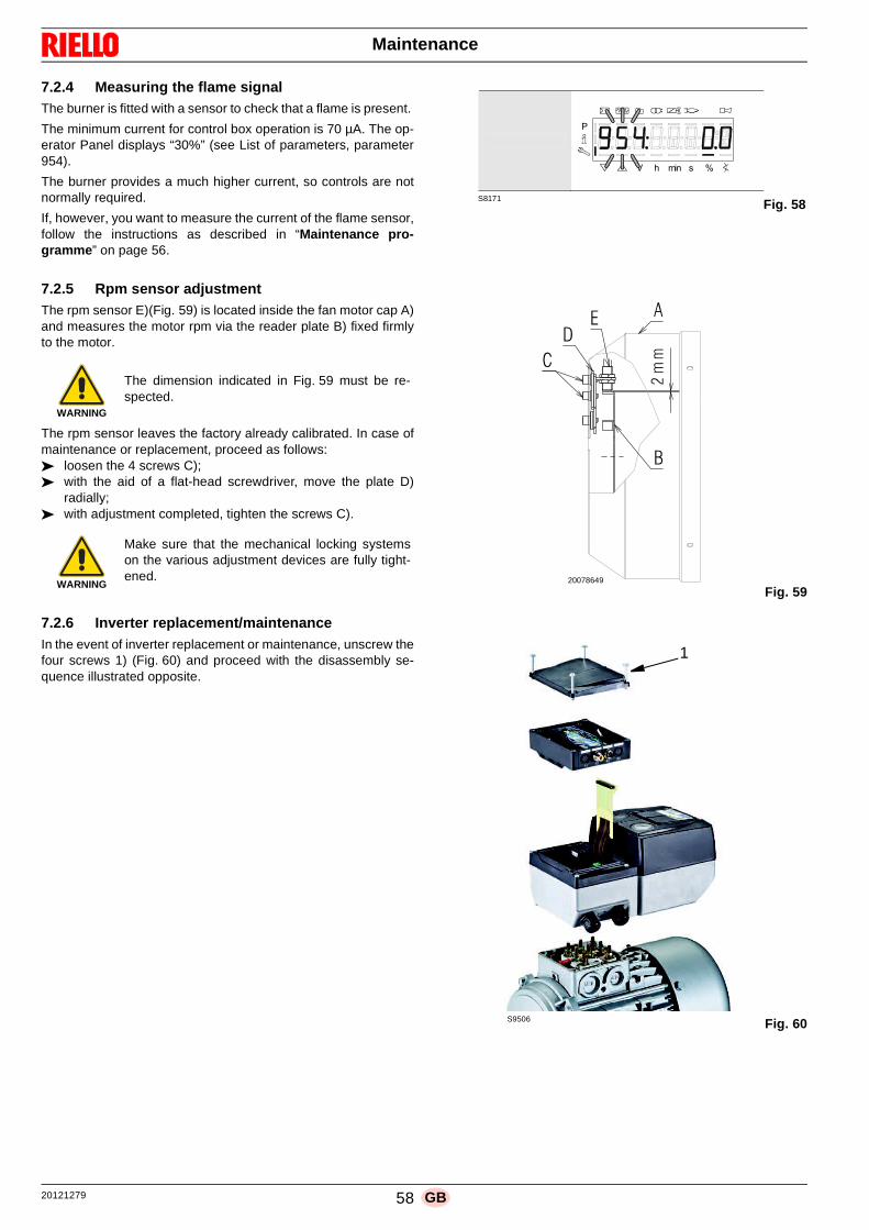
20121279 58 GB
Maintenance
7.2.4 Measuring the flame signalThe burner is fitted with a sensor to check that a flame is present.
The minimum current for control box operation is 70 µA. The op-erator Panel displays “30%” (see List of parameters, parameter954).
The burner provides a much higher current, so controls are notnormally required.
If, however, you want to measure the current of the flame sensor,follow the instructions as described in “Maintenance pro-gramme ” on page 56.
7.2.5 Rpm sensor adjustmentThe rpm sensor E)(Fig. 59) is located inside the fan motor cap A)and measures the motor rpm via the reader plate B) fixed firmlyto the motor.
The rpm sensor leaves the factory already calibrated. In case ofmaintenance or replacement, proceed as follows:➤ loosen the 4 screws C);➤ with the aid of a flat-head screwdriver, move the plate D)
radially;➤ with adjustment completed, tighten the screws C).
7.2.6 Inverter replacement/maintenanceIn the event of inverter replacement or maintenance, unscrew thefour screws 1) (Fig. 60) and proceed with the disassembly se-quence illustrated opposite.
WARNING
The dimension indicated in Fig. 59 must be re-spected.
WARNING
Make sure that the mechanical locking systemson the various adjustment devices are fully tight-ened.
S8171
P
V h min s %
Fig. 58
Fig. 5920078649
Fig. 60S9506
1

59 20121279GB
Maintenance
7.3 Opening the burner
➤ Loosen the 4 screws 1) (Fig. 61) and remove the hood 2).➤ Disconnect the light oil pipes using the fittings 3).➤ Disconnect the tie-rod 4) from the sector 5);➤ Assemble the supplied extensions on the sliding bars 6).➤ Fit the screws 10).➤ Disconnect the socket from the maximum gas pressure
switch.➤ Remove the screws 7) and move the burner backwards by
about 100 mm on the slide bars 6). ➤ Disconnect the probe and electrode leads and then pull the
burner fully back.➤ At this point it is possible to extract the inner part 8) after
having removed the screw 9).
7.4 Closing the burner
➤ Push the burner to approximately 100 mm from the pipecoupling.
➤ Disassemble the two extensions from the slide bars 6).➤ Tighten the screws 10) on the slide bars of the burner.➤ Reconnect the cables and slide in the burner until it comes
to a stop.➤ Connect the socket of the maximum gas pressure switch.➤ Replace the screws 7) and carefully pull the probe and elec-
trode cables outwards until they are slightly taut. ➤ Connect the tie-rod 4) from the sector 5);➤ Connect the light oil pipes using the fittings.
DANGER
Turn off the burner's electrical supply using themain system switch.
Make sure that both electrical supplies have beendisconnected.
DANGER
Turn off the fuel interception tap.
Wait for the components in contact with heatsources to cool down completely.
4
89
7
6
10
2
1
3
5
Fig. 6120108036
After carrying out maintenance, cleaning orchecking operations, reassemble the cover andall the safety and protection devices of the burner.

20121279 60 GB
Faults - Probable causes - Solutions
If faults arise in ignition or operations, the burner performs a"safety stop", which is signalled by the red burner lockout LED.
The display of the operator panel visualises alternately the lock-out code and the relative diagnostic.
To restore start-up conditions, refer to the Reset procedure.
When the burner starts up again, the red LED goes out.
8.1 List of error codes
8 Faults - Probable causes - Solutions
WARNING
In the event the burner stops, in order to preventany damage to the installation, do not unblock theburner more than twice in a row.
If the burner locks out for a third time, contact thecustomer service.
DANGER
In the event there are further lockouts or faultswith the burner, the maintenance interventionsmust only be carried out by qualified, authorisedpersonnel, in accordance with the contents of thismanual and in compliance with the standards andregulations of current laws.
Error code
Diagnostic code Meaning of the LMV 26... system Recommended measures
No Comm No communication between LMV 26... and RDI21…Check the wiring between the control box LMV 26... and display RDI21…
2 # No flame at the end of TSA1
1 No flame at the end of safety time 1 (TSA1)
2 No flame at the end of safety time 2 (TSA2)
4No flame at the end of safety time 1 (TSA1)(software version ≤ V02.00)
3 # Air pressure error
0 Air pressure switch off
1 Air pressure switch on
4 Air pressure on – Lockout alarm at start
20 Air pressure, fuel pressure on - Alarm lock at start
68 Air pressure, POC on – Alarm lockout at start
84 Air pressure, fuel pressure, POC on - Alarm lockout at start
4 # Extraneous light
0 Extraneous light during start-up
1 Extraneous light during switch-off
2 Extraneous light during start-up – Lockout alarm at start
6Extraneous light during start-up, air pressure - Alarm lockout at start
18Extraneous light during start-up, fuel pressure - Alarm lockout at start
24Extraneous light during start-up, air pressure, fuel pressure - Alarm lockout at start
66Extraneous light during start-up, POC – Alarm lockout at start
70Extraneous light during start-up, air pressure, POC - Alarm lockout at start
82Extraneous light during start-up, fuel pressure, POC - Alarm lockout at start
86Extraneous light during start-up, air pressure, fuel pressure, poc - Alarm lockout at start
7 # Loss of flame
0 Loss of flame
3 Flame loss (software version ≤ V02.00)
3…255 Flame loss during TÜV test (flame loss test)The diagnostics covers the period of time from the closure of thefuel valves to the point the flame loss was detected (resolution0.2 s → value 5 = 1 s).
12 # Valve leak detection control
0 V1 leaksLeak testCheck if the valve on the side of the gas has any leaks.Check the wiring and make sure that the circuit is open.

61 20121279GB
Faults - Probable causes - Solutions
1 V2 leaks
Leak testCheck if the valve on the side of the burner has any leaks.Check if the pressure switch for the leak test (PGVP) is closed when gas pressure is not present.Check the wiring and check if there is a short circuit.
2 Valve leak detection test not possibleThe valve leak detection is active, but the minimum gas pressure switch is selected as input for X9-04 (check parameters 238 and 241)
3 Valve leak detection test not possibleThe valve leak detection is active, but no input has been assigned (check parameters 236 and 237)
4 Valve leak detection not possibleValve leak detection is active, but 2 inputs have already been assigned (configure parameter 237 or maximum gas Pressure switch or POC)
5 Valve leak detection not possibleThe valve leak detection is active, but 2 inputs have been assigned (check parameters 236 and 237)
14 # POC
0 POC Open Check if the closure contact of the valve is closed
1 POC Closed Check the wiringCheck if the closure contact of the valve opens when the valve is checked
64 POC Open - Alarm lockout at start Check the wiringCheck if the closure contact of the valve is closed
19 80 Fuel pressure, POC - Alarm lockout at startCheck that the pressure switch is closed when no pressure is present from the fuelCheck that there are no short-circuits
20 # Pmin
0 Minimum gas/oil pressure absent Check that there are no line interruptions
1 Scarcity of gas - Alarm lockout at start Check that there are no line interruptions
21 # Pmax/POC
0Pmax: Max. gas/oil pressure exceededPOC: POC open (software version ≤ V02.00)
Check the wiring.POC: check whether the closure contact of the valve is closed
1 POC closed (software version ≤ V02.00)Check the wiring.Check if the closure contact of the valve opens when the valve is checked
64POC Open - Lockout alarm at the start (software version ≤ V02.00)
Check the wiring.Check if the contact of the valve opens when the valve is checked
22OFF S
# Safety circuit/Burner flange
0 Safety circuit open /Burner flange open
1Safety circuit open /Burner flange open - Alarm lockout at start
3Safety circuit open /Burner flange open, extraneous light - Alarm lockout at start
5Safety circuit open /Burner flange open, extraneous light - Alarm lockout at start
17Safety circuit open /Burner flange open, extraneous light - Alarm lockout at start
19Safety circuit open /Burner flange open, extraneous light - Alarm lockout at start
21Safety circuit open /Burner flange open, extraneous light - Alarm lockout at start
23Safety circuit open /Burner flange open, extraneous light, air pressure, fuel pressure - Alarm lockout at start
65Safety circuit /Burner flange open, POC - Alarm lockout at start
67Safety circuit open /Burner flange open, extraneous light, POC - Alarm lockout at start
69Safety circuit open /Burner flange open, air pressure, POC - Alarm lockout at start
71Safety circuit open /Burner flange open, extraneous light, air pressure, POC - Alarm lockout at start
81Safety circuit open /Burner flange open, fuel pressure, POC - Alarm lockout at start
Error code
Diagnostic code Meaning of the LMV 26... system Recommended measures

20121279 62 GB
Faults - Probable causes - Solutions
83Safety circuit open /Burner flange open, extraneous light, air pressure, POC - Alarm lockout at start
85Safety circuit open /Burner flange, air pressure, fuel pressure, POC - Alarm lockout at start
87Safety circuit open /Burner flange, extraneous light, air pressure, fuel pressure, POC - Alarm lockout at start
50 ÷ 58 # Internal errorCarry out a reset; if the error arises repeatedly, replace the control box
60 0 Internal error: no valid load checking deviceCarry out a reset; if the error arises repeatedly, replace the control box
65 ÷ 67 # Internal errorCarry out a reset; if the error arises repeatedly, replace the control box
70 #Fuel/air checking error: Calculation position in modulation
23 Invalid load No valid load
26 Curve points not defined Adjust the curve points of all the actuators
71 # Special position not defined
0 Standby position Set the standby position of all the servomotors used
1 Pre-purging position Set the pre-purging position of all the servomotors used
2 Post-purging position Set the post-purging position of all the servomotors used
3 Ignition position Set the ignition position of all the servomotors used
72 # Fuel/air internal checking errorCarry out a reset; if the error arises repeatedly, replace the control box
73 #Fuel/air internal checking error: multistep calcula tion position
23 Position calculation, invalid stage load No valid load
26 Position calculation, stage curve points not defined Adjust the curve points of all the servomotors
75 #Fuel/air ratio internal checking error: cyclical da ta check
1 Check synchronisation data, different current load
2 Check synchronisation data, different target load
4 Check synchronisation data, different target positions
16 Check synchronisation data, different positions reached
76 # Fuel/air internal checking errorCarry out a reset; if the error arises repeatedly, replace the control box
85 # Reference error of a servomotor
0 Reference error of the fuel servomotor
The reference of the fuel servomotor was not successful. It was not possible to reach the reference point.1. Check if the servomotors have been inverted.2. Check if the servomotor is blocked or overloaded.
1 Reference error of the air servomotor
The reference of the air servomotor was not successful.It was not possible to reach the reference point.1. Check if the servomotors have been inverted.2. Check if the servomotor is blocked or overloaded.
Bit 7Valence ≥128
Reference error owing to parameter modificationThe parameterisation of an actuator (e.g. the reference position) has been modified. This error will be visualised to start up a new reference.
86 # Fuel servomotor error
0 Position errorIt was not possible to reach the target position within the requested tolerance range.1. Check if the servomotor is blocked or overloaded.
Bit 0Valence 1
Circuit openCircuit open shown on the servomotor connection.1. Check the wiring (the voltage between pin 5 or 6 and 2 of the X54 connector must be > 0.5 V).
Bit 3Valence ≥8
Curve too steep in terms of train ratioThe slope of the curve can correspond to a maximum position modification of 31° between 2 points of the modulation curve.
Bit 4Valence ≥16
Deviation of section compared with the last reference
Overloading of the servomotor or servomotor subjected to mechanical torsion.1. Check if the servomotor is blocked in any point along its range of action.2. Check if the torque is sufficient for the application.
87 # Air servomotor error
Error code
Diagnostic code Meaning of the LMV 26... system Recommended measures

63 20121279GB
Faults - Probable causes - Solutions
0 Position errorIt was not possible to reach the target position within the requested tolerance range.1. Check if the servomotor is blocked or overloaded.
Bit 0Valence 1
Circuit openCircuit open shown on the servomotor connection.1. Check the wiring (the voltage between pin 5 or 6 and 2 of the X54 connector must be > 0.5 V).
Bit 3Valence ≥8
Curve too steep in terms of train ratioThe slope of the curve can correspond to a maximum position modification of 31° between 2 points of the modulation curve.
Bit 4Valence ≥16
Deviation of section compared with the last reference
Overloading of the servomotor or servomotor subjected to mechanical torsion.1. Check if the servomotor is blocked in any point along its range of action.2. Check if the torque is sufficient for the application.
90 - 91 # Burner internal checking error
93 # Flame signal acquisition error
3 Short circuit of the sensorShort circuit in the QRB sensor...1. Check the wiring.2. Flame detector probably faulty.
95 # Relay supervision error
3 Ignition transformers4 Fuel valve 15 Fuel valve 26 Fuel valve 3
External power supply - Contact active Check the wiring
96 # Relay supervision error
3 Ignition transformers4 Fuel valve 15 Fuel valve 26 Fuel valve 3
The relay contacts have joined together
Check the contacts:1. Control box connected to the power supply: the fan output must be without voltage.2. Disconnect the power supply. Disconnect the fan. The resistive connection between the fan output and the neutral wire is not allowed.If one of the 2 tests fails, replace the control box because the contacts are definitively joined together and it is no longer possible to guarantee safety.
97 # Relay supervision error
0The safety relay contacts have joined together or the safety relay has been powered by an external power supply
Check the contacts:1. Control box connected to the power supply: the fan output must be without voltage.2. Disconnect the power supply. Disconnect the fan. The resistive connection between the fan output and the neutral wire is not allowed.If one of the 2 tests fails, replace the control box because the contacts are definitively joined together and it is no longer possible to guarantee safety.
98 # Relay supervision error
2 – Safety valve3 Ignition transformers4 Fuel valve 15 Fuel valve 26 Fuel valve 3
The relay does not start up Carry out a reset; if the error arises repeatedly, replace the unit
99 # Relay internal checking errorCarry out a reset; if the error arises repeatedly, replace the control box
3 Relay internal checking error
Carry out a reset; if the error arises repeatedly, replace the control boxSoftware version V03.10: If error C:99 D:3 occurs during the standardisation of the VSD, temporarily deactivate the Alarm function at the start of the pre-purging phase (parameter 210 = 0) or interrupt the signal controller-ON
100 # Relay internal checking errorCarry out a reset; if the error arises repeatedly, replace the control box
105 # Contact sampling internal error
Error code
Diagnostic code Meaning of the LMV 26... system Recommended measures

20121279 64 GB
Faults - Probable causes - Solutions
0 Min. pressure switch1 Max. pressure switch2 Valve operation test pressure switch3 Air pressure4 Load controller open5 Load controller on/off6 Load controller closed7 Safety loop / burner flange8 Safety valve9 Ignition transformers10 Fuel valve 111 Fuel valve 212 Fuel valve 313 Reset
Blocked upon irregularityCan be caused by capacitive loads or presence of DC voltage on the main power supply of the control box. The diagnostic code indicates the input in which the problem arose
106 ÷ 108 # Contact request internal errorCarry out a reset; if the error arises repeatedly, replace the control box
110 # Voltage monitoring test internal errorCarry out a reset; if the error arises repeatedly, replace the control box
111 0 Low level of power supplyInsufficient mains voltage.Conversion of the diagnostic codeVoltage value (230 V AC : 1.683)
112 0 Reset power supply voltageError code for the carrying out of a reset in the event of power supply restoration (absence of error)
113 # Mains voltage supervision internal errorCarry out a reset; if the error arises repeatedly, replace the control box
115 # Control box meter internal error
116 0Life cycle of the control box in the critical inter val (250,000 Start ups)
The envisaged life cycle of the control box has been exceeded. Replace it.
117 0 Life cycle of the control box exceeded The switch-off threshold has been reached.
120 0 Interruption of fuel limiting meter inputToo many disturbance impulses on the input of the fuel meter.Improve the electromagnetic compatibility.
121 ÷ 124 # EEPROM access internal errorCarry out a reset, repeat and check the last setting of the parameters. Restore the group of parameters: if the error arises repeatedly, replace the control box.
125 # EEPROM reading access internal errorCarry out a reset, repeat and check the last setting of the parameters. If the error arises repeatedly, replace the control box.
126 # EEPROM writing access internal errorCarry out a reset, repeat and check the last setting of the parameters. If the error arises repeatedly, replace the control box.
127 # EEPROM access internal errorCarry out a reset, repeat and check the last setting of the parameters. Restore the group of parameters: if the error arises repeatedly, replace the control box.
128 0EEPROM access internal error - synchronisation during the initialisation
Carry out a reset; If the error arises repeatedly, replace the control box.
129 #EEPROM access internal error – command synchronisation
Carry out a reset, repeat and check the last setting of the parameters. If the error arises repeatedly, replace the control box.
130 # EEPROM access internal error - time-outCarry out a reset, repeat and check the last setting of the parameters. If the error arises repeatedly, replace the control box.
131 # EEPROM access internal error - page interruptedCarry out a reset, repeat and check the last setting of the parameters. If the error arises repeatedly, replace the control box.
132 # EEPROM register initialisation internal errorCarry out a reset; if the error arises repeatedly, replace the control box.
133 ÷ 135 #EEPROM access internal error – request synchronisation
Carry out a reset, repeat and check the last setting of the parameters. If the error arises repeatedly, replace the control box.
136 1 Restoration started The restoration of a backup has been started (no error)
137 # Internal error – backup / restoration
157 (-99)Restoration – OK, but backup < compared with set data of current system
Restoration successful, but the backup data installed are fewer than those currently present in the system.
239 (-17) Backup - logging of the backup on RDI21… failed Perform the reset and repeat backup
240 (-16) Reset - no backup in RDI21… No backup in RDI21…
241 (-15) Reset - Interruptions relating to impracticable ASNThe backup has an impracticable ASN and cannot reset the unit
242 (-14) Backup – the backup carried out is contradictory The backup is irregular and cannot be transferred again
Error code
Diagnostic code Meaning of the LMV 26... system Recommended measures

65 20121279GB
Faults - Probable causes - Solutions
243 (-13)Backup – the data comparison between the internal microprocessors is irregular
Repeat the reset and backup
244 (-12) The backup data are incompatible The backup data are incompatible with the current version of the software; the restoration is not possible
245 (-11) Error in access to the parameter Restore_Complete Repeat the reset and backup
246 (-10) Restoration – time-out during logging in EEPROM Repeat the reset and backup
247 (-9) The data received are contradictory The series of backup data is not valid; restoration is not possible
248 (-8) The restoration cannot currently be carried out Repeat the reset and backup
249 (-7)Restoration – interruption caused by inadequate identification of the burner
The backup has an inadequate identification of the burner and must not be transferred to the control box
250 (-6) Backup – the CRC of a page is not correct The series of backup data is not valid; restoration is not possible
251 (-5) Backup – the identification of the burner is not defined Define the identification of the burner and repeat the backup
252 (-4) After restoration, the pages are still in INTERRUPTION Repeat the reset and backup
253 (-3) The restoration cannot currently be carried out Repeat the reset and backup
254 (-2) Interruption owing to transmission error Repeat the reset and backup
255 (-1) Interruption owing to time-out during the restoration Carry out a reset, check the connections and repeat the backup
146 # Time-out of the system automation interface Refer to the Modbus User Documentation (A7541)
1 Modbus time-out
150 # TÜV test
1 (-1) Invalid phase The TÜV test can only be started in phase 60 (operation)
2 (-2) The TÜV test default output is too lowThe output of the TÜV test must be lower than the minor output limit
3 (-3) The TÜV test default output is too highThe output of the TÜV test must be greater than the upper output limit
4 (-4) Manual interruption No error: Manual interruption of the TÜV test by the user
5 (-5) TÜV test time-out
No flame loss after the fuel valves have been closed1. Check for any extraneous lights2. Check that there are no short-circuits3. Check whether one of the valves is leaking
165 # Internal error
166 0 Watchdog reset internal error
167 # Manual lockout The control box has been manually blocked (no error)
1 Manual lockout from remote reset command
2 Manual lockout from RDI21…
3 Manual lockout from PC interface
8Manual lockout from RDI21…Timeout/interrupted communication
During a regulation of the curve via the operating panel RDI21…the timeout for the operating menu is passed (setting via the 127 parameter), or else the communication between LMV 26... and RDI21... has been interrupted
9Manual lockout from PC interfaceCommunication interrupted
During an adjustment of the curve via the PC interface, the communication between LMV 26... and the operator panel has been interrupted for more than 30 seconds
33Manual lockout after the PC tool has performed a tentative reset
The PC tool has performed a tentative reset, even if the system has worked correctly
168 ÷ 171 # Internal error managementCarry out a reset; if the error arises repeatedly, replace the control box
200 off # System free of errors No error
201 off VA
# Lockout or error at start Lockout or error due to lack of unit parameter settings
Bit 0Valency 1
No valid operation mode
Bit 1Valency 2..3
No fuel train defined
Bit 2Valency 4..7
No curve defined
Bit 3Valency 8..15
Standardisation speed not defined
Bit 4Valency 16..31
Backup / Reset impossible
202 # Selection of internal operation mode Redefine the operation mode (parameter 201)
Error code
Diagnostic code Meaning of the LMV 26... system Recommended measures

20121279 66 GB
Faults - Probable causes - Solutions
Tab. Y
203 # Internal errorRedefine the operation mode (parameter 201)Carry out a reset; if the error arises repeatedly, replace the control box
204 Phase number Program stop The program stop is active (no error)
205 # Internal errorCarry out a reset; if the error arises repeatedly, replace the control box
206 0Combination of control box and operator panel not allowed
207 # Compatibility of control box with operator panel
0 Obsolete version of control box
1 Obsolete version of operator panel
208 - 209 # Internal errorCarry out a reset; if the error arises repeatedly, replace the control box
210 0The selected operating mode is not released for the standard unit
Select an operating mode released for the standard unit
240 # Internal errorCarry out a reset; if the error arises repeatedly, replace the control box
245 # Internal errorCarry out a reset; if the error arises repeatedly, replace the control box
250 # Internal errorCarry out a reset; if the error arises repeatedly, replace the control box
Error code
Diagnostic code Meaning of the LMV 26... system Recommended measures

67 20121279GB
Appendix - Accessories
Output power regulator kit for modulating operation
With the modulating operation, the burner continually adapts thepower to the heat request, ensuring a high level of stability forthe parameter controlled: temperature or pressure.
Two components should be ordered:• the output power regulator to be installed on the burner;• the probe to install on the heat generator.
EMI and ferrite filter kit
Continuous purging kit
Soundproofing box kit
Tubes kit
Software interface kit (ACS410 + OCI410.30) - Servi ce Level
Modbus interface kit
Gas trains in compliance with EN 676
Please refer to manual.
A Appendix - Accessories
Parameter to be checked Probe Output regulator
Adjustment field Type Code Type Code
Temperature - 100...+ 500°C PT 100 3010110RWF50
RWF55
20099869
20099905Pressure0...2.5 bar0...16 bar
Output probe4...20mA
30102133010214
Burner Code
RLS 160-200/EVi MX 20122922
Burner Code
RLS 160-200/EVi MX 3010094
Burner Code
RLS 160-200/EVi MX 3010404
Burner Code
RLS 160/EVi MX 3010249
RLS 200/EVi MX 20035848
Burner Code
RLS 160-200/EVi MX 3010436
Burner Model Code
RLS 160-200/EVi MX OCI412 3010437

20121279 68 GB
Appendix - Electrical panel layout
B Appendix - Electrical panel layout
Index of layouts
2 Indication of references
3 Layout of unifilar output
4 Layout of unifilar output
5 LMV26.... operational layout
6 LMV26.... operational layout
7 LMV26.... operational layout
8 LMV26.... operational layout
9 LMV26.... operational layout
10 Electrical connections set by installer
11 Electrical connections set by installer
12 RWF50... operational layout
1
2
Sheet no.
/1 .A1
Co-ordinates
Indication of references

69 20121279GB
Appendix - Electrical panel layout
!"##$%%&
'()
'*+
',-
'.*+
'/)
',0)
'1)
'1*+
'*2
'3,
4
4
'1*2
'(-
'3-
'1
'15
'6)
(75
'(-
'.5
'1892
',-
'.
'.
)-
5
:;
7<
)-
5
:;
7<
6
=
>
?
@ ,
6
=
>
?
@ ,
!>A@*6%098,8B6C@%?8%+DE@9F6
B6GD0E%D,%098,8B6C%D0E+0E
@89?C6AE83@!%B@8!E093!!>A@*6
!>A@*6%098,8B68C@%?@%+08!!69>@
B)
+@
0)
1)
H==
)I)%J1
2)
)
-5
;
:
':6
=<
K:L=<
M7
M<
M:
M;
K:L=<
)
:
-5
;
B)
%%%%5NN2%:NAO
B)
B-
B
+@
H=>
B-
B-
B
B
+@
P)I:QQR
+@
P)I:QQR
+@
H==
02
1+@
+@
B)
+@
H==
892@CE@C%B@9F@%<5NN%*DE@>
-5D
-5D
39?
60
?
9>
>D*
9D
68
C,C
B-B
02
1
B)%
B-%
B %
+@%
5I:%J1
:I:%J1
5P-I:QQR
-
H==
5
:
L
+@
ST"
;PNL:QQRHST"
ST"
:PNL:QQRHST"
B*2-;LLL
2!?
K:L6)
-5
:)
,UVT$WXVYZ
#Y[$"
-3G
)
-3G
G@
-
G@
539
539
:=9
;
:=9
7;1A
<
K:L=7
))
)-)5
)+.
;1A
N%
=)
M7M<
6)
6-
K<L6;
)5
)-
))
)
K5L6)
9
K5L=)
*
4
%4
4
*
H
'
H
=0%\%=B0%K%=B0@%K%=B@0%K%=B60
=.%\%9@CD%K%=B6>.%K%9D8C%K%!>A16CF
G@%\%386BBD%K%G@BBD1%K%]609@%K%3@B=
39%\%2@C?@%K%3C@@9%K%2@CE%K%3C^9
C?%\%CD!!D%K%C@?%K%CD03@%K%CDE
1A%\%=869>D%K%1A8E@%K%=B69>%K%1@8!!
D3\%6C69>8D%K%DC693@%K%DC693@%K%DC693@
2E\%28DB@EED%K%28DB@E%K%28DB@E%K%28DB@EE
3G\%3C838D%K%3C@G%K%3C8!%K%3C60
+.\%CD!6%K%+89.%K%CD!@%K%CD!6
3?\%DCD%K%3DB?%K%DC%K%3DB?
E/\%E0C>A@!@%K%E0C/0D8!@%K%E0C/0D8!@%K%E0C.8!=B60
!C\%6C3@9ED%K%!8B2@C%K%6C3@9E%K%!8B=@C
39G@\%386BBDK2@C?@%K%G@BBD1K3C@@9%K%]609@K2@CE%K%3@B=K3C09
=9%\%*6CCD9@%K%=CD19%K%*6CCD9%K%=C609
5NN2%%:NAO
1-
0-
2-
0)
2)
1)
D0E
H-5
89
!#$_XWV$
NLLL)N2
D0E
H-5
CB!%);NK@2
2)1)
0)
1-
0-
2-
*2
CB!%-NNK@2
2)1)
0)
1-
0-
2-
5NN%2
5NN%2
=0
=.
=9
89?0>E82@
+CD(8*8EG%!18E>A

20121279 70 GB
Appendix - Electrical panel layout
!"##$%%&
'()
*
+,-
'+!
'./
*
'+0
")
'12
'3
'4/
'5
)/
6
7,
89
)/
6
7,
89
-
5
:
;
< =
-
5
:
;
< =
!:3<>-%?21=10-@<%;1%*A+<2B-
0-CA?+%A=%?21=10-@%A?+*?+
<12;@-3+1D<!%0<1!+?2D!!:3<>-
!:3<>-%?21=10-1@<%;<%*?1!!-2:<
)
E6F59
2
E6F:9
*<
*<
G5:
G5:
02
*<
G5:
)2%%%/6HI%%7H3J
G5:
() (/
2)
0)
20
*<
2
0
+0)
+0/
!6
5
)%
6)%
(7'6)%
(6'7/%
(9' /%
)
E7F:)
2
E7F:)
*<
E7F;)
6)
E,F:)
(7'6)
E,F:)
(6'7/
E7F:)
(9' /
E7F:)
K
5?%L%50?%E%50?<%E%50<?%E%50-?
5M%L%2<@A%E%50-:M%E%2A1@%E%!:34-@B
C<%L%D1-00A%E%C<00A4%E%N-?2<%E%D<05
D2%L%I<@;<%E%D@<<2%E%I<@+%E%D@O2
@;%L%@A!!A%E%@<;%E%@A?D<%E%@A+
43%L%51-2:A%E%431+<%E%50-2:%E%4<1!!
ADL%-@-2:1A%E%A@-2D<%E%A@-2D<%E%A@-2D<
I+L%I1A0<++A%E%I1A0<+%E%I1A0<+%E%I1A0<++
DCL%D@1D1A%E%D@<C%E%D@1!%E%D@-?
*ML%@A!-%E%*12M%E%@A!<%E%@A!-
D;L%A@A%E%DA0;%E%A@%E%DA0;
+.L%+?@:3<!<%E%+?@.?A1!<%E%+?@.?A1!<%E%+?@M1!50-?
!@L%-@D<2+A%E%!10I<@%E%-@D<2+%E%!105<@
D2C<L%D1-00AEI<@;<%E%C<00A4ED@<<2%E%N-?2<EI<@+%E%D<05ED@?2
52%L%>-@@A2<%E%5@A42%E%>-@@A2%E%5@-?2
012<
0A-;

71 20121279GB
Appendix - Electrical panel layout
!"##$%%&
'()*+
'()*(
'()*,
' )*,
' )*-
'.)*+
'+)*,
'()*
'/)*+
)0-
)1'234
)'-
)'234
)53
)234
)1'267849:
)20
)'267849:
)267849:
)56
)'-
)'23;2
)<0
)5,
)5,
)=!
)5-
)5-
)5+
)5+
)53
)56
)>,
)542
)542
-,
(+
?
@/
-,
(+
?
@/
0
A
B
C
D >
0
A
B
C
D >
!BED40%>FGHI6G0JD%J4;,?KKK
J4;,?KKK%62D=0<I6G0J%J0L6F<
AD<=IDA!!BED40%J4;,?KKK
!BED40%>6GB<I6G0J%J4;,?KKK
'/)+,
M+KA/
'() ,
M+KA/
-
M+K0/
G
M+KA/
2D
M+KA/
J4;,?KKK
+
(,
--
,-
,-
,(
-,
(-
,(
-,
(-
,(
-,
M?K0,
M.K0-
M@K0
M(K0
-%
'()+,%
234-
'()+,%
NAA
(
'()+-%
M/KB+
--
-,-+
+,%
-
-, (
NAA
2O
,
-%
G%
'(),(%
(
-,
2P
'(),-%
'()+,%
NAA
,
,( -
NAA
EI3E%6IJ%2=D!!F=D%!1I<BE
2O
(
+(%
-
' )-(% 2D%
2D
' )-,%
' )-,
M@K0-
' )-(
M@K0-
' ),(%
' ),,%
M/KB,
,-
,,,+
2;2
-, (
NAA
23;2
(-
,
2P
'.)+,%
2;2
'+),(%
,(*;% *EQ
R;
2D
'() ,%
'() ,%
0-
0,
M/K0@
-+
-,
--
'() -%
=!-
NAB
'/)+,%
0-
0,
M/K0
-+
-,
--
'/)+-%
=!,
0-
0,
M(KA?
-+
-,
--
'.)+,%
M/KB+
,-
,,,+
'/)+-%
'() -%
-%
M/KB,
(-
(,(+
++%
M(KA-
.
.?
0,
0-
M(KB-
M(KB-
M(KB-
-
(
,
+
?
-
M?KB-
G
M?KB-
2D
M?KB-
AF%S%AJF%M%AJFD%M%AJDF%M%AJ0F
A5%S%GD=6%M%AJ0B5%M%G6I=%M%!BE10=H
LD%S%3I0JJ6%M%LDJJ61%M%T0FGD%M%3DJA
3G%S%;D=CD%M%3=DDG%M%;D=<%M%3=UG
=C%S%=6!!6%M%=DC%M%=6F3D%M%=6<
1E%S%AI0GB6%M%1EI<D%M%AJ0GB%M%1DI!!
63S%0=0GBI6%M%6=0G3D%M%6=0G3D%M%6=0G3D
;<S%;I6JD<<6%M%;I6JD<%M%;I6JD<%M%;I6JD<<
3LS%3=I3I6%M%3=DL%M%3=I!%M%3=0F
25S%=6!0%M%2IG5%M%=6!D%M%=6!0
3CS%6=6%M%36JC%M%6=%M%36JC
<VS%<F=BED!D%M%<F=VF6I!D%M%<F=VF6I!D%M%<F=5I!AJ0F
!=S%0=3DG<6%M%!IJ;D=%M%0=3DG<%M%!IJAD=
3GLDS%3I0JJ6M;D=CD%M%LDJJ61M3=DDG%M%T0FGDM;D=<%M%3DJAM3=FG
AG%S%40==6GD%M%A=61G%M%40==6G%M%A=0FG
261D=%,(*;9W
!0>D<L%J662
AF=GD=
>J0G3D
2
2K4IG%M2;2
=D!D<M>FDJ%!DJDB<K%-
2K40'
=D!D<M
>FDJ%!DJDB<K%,
2D

20121279 72 GB
Appendix - Electrical panel layout
!"##$%%&
'!(
')(
*+',-
*(,',+
*(,',
'*(
'./
0
'1/)
'*(
'234
'*0(
'5(
(6
-7
+
89
(6
-7
+
89
)
5
:
;
< =
)
5
:
;
< =
!:><?)%=3@ABC@)D<%D?46 EEE
D?46 EEE%C0</).BC@)D%D)FC3.
5<./B<5!!:><?)%D?46 EEE
!:><?)%=C@:.BC@)D%D?46 EEE
-(
G7E59
*+'-(
G7E59
(
G+E:9
@
G+E:9
0<
G+E;9
( (H
6 6H
C=='C@
-(%
D?46 EEE
-7
6(
6+
(-
7(
6
G+E)(
I%%%%%'
*+'-7%
*+'--%
*+'-6%
.
I5:
:@C
@:
*+'-(%
.8
.9
.8%
.9%
. %
0#J%KL%MNLL#OHP#Q$N%RHJ#%JKR#JKP#Q$N%H%SHOKQH%(6
=NJ%$"#%MNQQ#M$KNQ%J#R#J%$N%$"#%T"##$%(6
!#%JURUJ#J%HVW%SHO#%(6
=XJ%<L#Y$JNHQTM"LVZ%TK#"#%!#K$#%(6
*(,' 6%
(D
*(,' (%
(D
@(
1(-
1(7
B(
?(
[(I
3(
[I
['
0<
(%
(%
(
'?5
/2=%+,EEE
@(%
6
1(-%
-
1(7%
7
. %
+
.9%
.8%
8
B(%
9
?(%
\
[(I%
(,
3(%
((
[I%
(6
['%
(-
(7
(+
(
G9E)(
@
G8E:(
0<
G8E:(
I'
53%]%5D3%G%5D3<%G%5D<3%G%5D)3
5^%]%@</C%G%5D):^%G%@CB/%G%!:>2)/A
F<%]%[B)DDC%G%F<DDC2%G%_)3@<%G%[<D5
[@%]%4</;<%G%[/<<@%G%4</.%G%[/`@
/;%]%/C!!C%G%/<;%G%/C3[<%G%/C.
2>%]%5B)@:C%G%2>B.<%G%5D)@:%G%2<B!!
C[]%)/)@:BC%G%C/)@[<%G%C/)@[<%G%C/)@[<
4.]%4BCD<..C%G%4BCD<.%G%4BCD<.%G%4BCD<..
[F]%[/B[BC%G%[/<F%G%[/B!%G%[/)3
0^]%/C!)%G%0B@^%G%/C!<%G%/C!)
[;]%C/C%G%[CD;%G%C/%G%[CD;
.1]%.3/:><!<%G%.3/13CB!<%G%.3/13CB!<%G%.3/^B!5D)3
!/]%)/[<@.C%G%!BD4</%G%)/[<@.%G%!BD5</
[@F<]%[B)DDCG4</;<%G%F<DDC2G[/<<@%G%_)3@<G4</.%G%[<D5G[/3@
5@%]%?)//C@<%G%5/C2@%G%?)//C@%G%5/)3@
,(
C@GC==
0C2</
1/)EEEE
[@;
1/5EEEE
BC@
!B[@)D
1/:EEEE
D(
@
(@
^1
(0
^6
^-
(6
(-
((
[I
['
;(
;[
)'
)I

73 20121279GB
Appendix - Electrical panel layout
!"##$%%&
'()*+,-.,/
')*+,-.,/
'*+,-.,/
')0
'1
'*2.,/
')*2.,/
'3+
'(4!+,-
'50
) '60
)7'68
) '68
)9'6:
'4!+,-
'3+
')0
'(4;+,-
'4;+,-
'32
'(4<+,-
'4<+,-
'(4<0+,-
')4<0+,-
08
:=
>9
7
08
:=
>9
7
5
?
@
A
B ;
5
?
@
A
B ;
[email protected]%;DEFG+E5HB%H.489III
H.489III%+*B<5JG+E5H%H51+DJ
?BJ<[email protected]%H.489III
[email protected]%;+E@JG+E5H%H.489III
)>'08
K>I?=
)>'0:
K>I@=
E
K9I@7
*B
K9I@7
8 8: 0
L??
H+(%+GH%*<B!!D<B%!(GJ@C
*M
98%
:
)>'0:%
0
)>'08%
)>'0:%
*B%
*B
*0
*B
0
8:
L?@
08 :
L?@
*M
8:
0*B
L?@
96%
*8
K7I@8
00
080=
*B
E0
9:%
40
9=%
48
H.489III
=0
8:
08
:0
8:
08
:
K>I50
E%
90%
)7'80%
K7I@8
=0
=8==
90%
4+GH
4+GH
E%
90%
) '0:%
K7I@=
=0
=8==
E%
90%
E%
8
L??
90%
0
*B%
*B
E
K7I@0
?D%N%?HD%K%?HDB%K%?HBD%K%?H5D
?3%N%EB<+%K%?H5@3%K%E+G<%K%!@C(5<F
1B%N%2G5HH+%K%1BHH+(%K%O5DEB%K%2BH?
2E%N%4B<AB%K%2<BBE%K%4B<J%K%2<PE
<A%N%<+!!+%K%<BA%K%<+D2B%K%<+J
(C%N%?G5E@+%K%(CGJB%K%?H5E@%K%(BG!!
+2N%5<5E@G+%K%+<5E2B%K%+<5E2B%K%+<5E2B
4JN%4G+HBJJ+%K%4G+HBJ%K%4G+HBJ%K%4G+HBJJ
21N%2<G2G+%K%2<B1%K%2<G!%K%2<5D
*3N%<+!5%K%*GE3%K%<+!B%K%<+!5
2AN%+<+%K%2+HA%K%+<%K%2+HA
JQN%JD<@CB!B%K%JD<QD+G!B%K%JD<QD+G!B%K%JD<3G!?H5D
!<N%5<2BEJ+%K%!GH4B<%K%5<2BEJ%K%!GH?B<
2E1BN%2G5HH+K4B<AB%K%1BHH+(K2<BBE%K%O5DEBK4B<J%K%2BH?K2<DE
?E%N%.5<<+EB%K%?<+(E%K%.5<<+E%K%?<5DE
*B
4!
4<
40
EE
EE
48
4:K4*
!4
40
48
4:K4*
!4

20121279 74 GB
Appendix - Electrical panel layout
!"##$%%&
'()
'()
'*+
'!,
'(-
'(-
'(+
'*+
'(.
'(/
+/
.0
,1
2
+/
.0
,1
2
3
4
5
6
7 8
3
4
5
6
7 8
!597:3%8;<=>)<3?7%?:@/1AAA
?:@/1AAA%)B7C3D>)<3?%?3E);D
47DC>74!!597:3%?:@/1AAA
!597:3%8)<5D>)<3?%?:@/1AAA
+
F1A5
<
F2A5
+%
'!,
/G+%
3+
3/
F2A4.
+0
+/
++
F,A4,
/0
//
/+
F,A3
.0
./
.+
F2A4,
00
0/
0+
/G+%
)>?
.
0
+
/
.
0
8;7?
!7?75D)C
/GG% /GG%
5):
/G/%
-3!
?H%I#J#KLMN#%O#J%PMQRSI$LRLJ#
TH%#UU#$$SH$H%IMJHQ#N$#
PMN%RVSPLH$MV#%IW#N$M
/G/%
3+
3/
F,A4/
+0
+/
++
F,A72
/0
//
/+
.0
./
.+
F2A41
00
0/
0+
F,A42
++
+/+0
8?3:7
3?>-9D
2+/%
+
2+0%
/
F.A4
++
+/+0
@!6
3?3C:F
)@7C?)36
2+1%
.
2+ %
0
F,A41
++
+/+0
4;C<7C
?)5(');D
2/G%
,
2//%
1
4;%X%4?;%F%4?;7%F%4?7;%F%4?3;
4(%X%<7C)%F%4?35(%F%<)>C%F%!59Y3C=
E7%X%->3??)%F%E7??)Y%F%Z3;<7%F%-7?4
-<%X%@7C67%F%-C77<%F%@7CD%F%-C[<
C6%X%C)!!)%F%C76%F%C);-7%F%C)D
Y9%X%4>3<5)%F%Y9>D7%F%4?3<5%F%Y7>!!
)-X%3C3<5>)%F%)C3<-7%F%)C3<-7%F%)C3<-7
@DX%@>)?7DD)%F%@>)?7D%F%@>)?7D%F%@>)?7DD
-EX%-C>->)%F%-C7E%F%-C>!%F%-C3;
B(X%C)!3%F%B><(%F%C)!7%F%C)!3
-6X%)C)%F%-)?6%F%)C%F%-)?6
D\X%D;C597!7%F%D;C\;)>!7%F%D;C\;)>!7%F%D;C(>!4?3;
!CX%3C-7<D)%F%!>?@7C%F%3C-7<D%F%!>?47C
-<E7X%->3??)F@7C67%F%E7??)YF-C77<%F%Z3;<7F@7CD%F%-7?4F-C;<
4<%X%:3CC)<7%F%4C)Y<%F%:3CC)<%F%4C3;<
)>?
)>?%B)!>D>)<
7*D%B)!>D>)<
-3!%B)!>D>)<
7*D
-3!
.%]+^ ]/G+^%0 . 0 . 0
+ / +%]+^ ]/GG^%/ + /
. 0 . 0 .%]+^ ]/G/^%0
)>?
-3!
7*D
8;7?%7*D7C<3?
!7?75D)C
<)
<)
)>?
-3!
G

75 20121279GB
Appendix - Electrical panel layout
!"##$%%&
'!()
*+,
'-.
'*)
/01
/02
/03
/ 4
/.2
/.0
'!(4
5678
'-9
'/:;
'*4
<=+2)4
(<;>6!%!?!@7(
,!290
'A4
+
'>4
'B
)4
12
03
.9
)4
12
03
.9
*
>
=
;
7 5
*
>
=
;
7 5
!=C7(*%56DE+<D*87%8(F43GGG
8(F43GGG%<:7,*@+<D*8%8*?<6@
>7@,+7>!!=C7(*%8(F43GGG
!=C7(*%5<D=@+<D*8%8(F43GGG
B>>
+DH>
+DH*
<6@H>
<6@H*
AD;
6*=H!*
AD
?7
A?
>D
>I
,;
8(F43GGG
03
21
43
)2
0)
41
41
21
2)
1)
44
)4
J0G*)
*+,%*=@6*@<,
5678%*=@6*@<,
(<;>6!%+D@7,5*=7
8<*;%<6@:6@
5678%=<6D@7,%+D:6@
;+!:8*?
)
B>>
+DH>
+DH*
<6@H>
<6@H*
AD;
6*=H!*
AD
?7
A?
>D
>I
,;
2
1
4
)
(KLMN#
B>=
((
>6%O%>86%J%>867%J%>876%J%>8*6
>I%O%D7,<%J%>8*=I%J%D<+,%J%!=C-*,E
?7%O%A+*88<%J%?788<-%J%P*6D7%J%A78>
AD%O%F7,;7%J%A,77D%J%F7,@%J%A,QD
,;%O%,<!!<%J%,7;%J%,<6A7%J%,<@
-C%O%>+*D=<%J%-C+@7%J%>8*D=%J%-7+!!
<AO%*,*D=+<%J%<,*DA7%J%<,*DA7%J%<,*DA7
F@O%F+<87@@<%J%F+<87@%J%F+<87@%J%F+<87@@
A?O%A,+A+<%J%A,7?%J%A,+!%J%A,*6
:IO%,<!*%J%:+DI%J%,<!7%J%,<!*
A;O%<,<%J%A<8;%J%<,%J%A<8;
@RO%@6,=C7!7%J%@6,R6<+!7%J%@6,R6<+!7%J%@6,I+!>8*6
!,O%*,A7D@<%J%!+8F7,%J%*,A7D@%J%!+8>7,
AD?7O%A+*88<JF7,;7%J%?788<-JA,77D%J%P*6D7JF7,@%J%A78>JA,6D
>D%O%(*,,<D7%J%>,<-D%J%(*,,<D%J%>,*6D
;=%0F
AD;
,/;S
@/;S
;=%0F
AD;
,/;)
@/;)
AD;
<6@:6@
+D:6@
+DH>
+DH*
<6@H>
<6@H*
AD;
6*=H!*
+DH>
+DH*
<6@H>
<6@H*
AD;
6*=H!*
;=%SJ4GGG)SF
;=%42F
F!;
7!=
5*
'B
T#U#$
AD;
,/;S
@/;S
6;VUWNXY

20121279 76 GB
Appendix - Electrical panel layout
!
"#$$%&&'
()*
(+
(,
(-
(,.
(/
0102345261&78+
04
)*
+
)9
41"& .!:0;
41"&9!!:0;
-
<
(7=>?@
=6"&;61;0A7;7&106B&C0302358D
(,
(,
)*01&40>830&"0102384
(4"
(,
5DC526384":6D25116450"
9
EF
G.
HI
9
EF
G.
HI
6
<
2
C
0 )
6
<
2
C
0 )
28110=6>0D35&010334525&6&2*46&C011J&5D"361163840
0102345261&28DD02358D"&"03&</&5D"361104
010B3486D"2K1L""0&;8>&5D"3611630*4&6*"M*)LK40D
462284C0>0D3"&N102345-*0&0))023*N&764&1J&5D"3611630*4
E&&&&F!!;&G!KO
1
D
9
E70
1
P9
19
1E
7#
1E
70
70
9
>;
E
F&QQR
9!6
ES&&F!!;&G!KO
T=
U>
(
1QUV
9G&Q
W
E!!Q6
2&9!6
7X
9 E
E
7;7
7;7&
7;7
7;7&
7=;7
E
9
7X
851
28>
=6"
4"
4"9
)16>>0&05D
)16>>0&611*>N0
)16>0&615=K3
)56>>6&6220"6
*"2536&28D36335&7*1535
;8136=0&)400&28D3623&8*3103
"84350&28D3623"&748740"
6*"=6D=&)L4&405DB8D36B30
9
"3Y46<"2K613*D=&C0"&;"C
<1826=0&;"C
;"C&182B&8*3
E <18228&;"C
QUV& !6&62 &9E!;&62
QUV&96&62 G&9E!;&62
F
"3Y46<"2K613*D=&C0"&<40DD04"
<1826=0&<4*10*4
<*4D04&182B&8*3
G <18228&<4*2563840
.
&S
S
<*&Z&<1*&:&<1*0&:&<10*&:&<16*
<B&Z&D048&:&<162B&:&D854&:&"2K+
64M
/0&Z&=56118&:&/0118+
&:&[6*D0&:&=01<
=D&Z&;04C0&:&=400D&:&;043&:&=4LD
4C&Z&48""8&:&40C&:&48*=0&:&483
+K&Z&<56D28&:&+
K530&:&<16D2&:&+
05""
8=Z&646D258&:&846D=0&:&846D=0&:&846D=0
;3Z&;5810338&:&;58103&:&;58103&:&;581033
=/Z&=45=58&:&=40/&:&=45"&:&=46*
7BZ&48"6&:&75DB&:&48"0&:&48"6
=CZ&848&:&=81C&:&84&:&=81C
3-Z&3*42K0"0&:&3*4-*85"0&:&3*4-*85"0&:&3*4B5"<16*
"4Z&64=0D38&:&"51;04&:&64=0D3&:&"51<04
=D/0Z&=56118:;04C0&:&/0118+
:=400D&:&[6*D0:;043&:&=01<:=4*D
<D&Z&>6448D0&:&<48+
D&:&>6448D&:&<46*D
;"
;4
+9
*9
;9
*
;
+
+9
*9
;9
*
;
+
>6,
>5D
F\G&]+
G\G&]+
>6,
>5D
(,7=>?@
9E
70
(,7=;7
A<<
EE
99
)*01&0,304D61
"0102384
D8
D8
851
=6"
!

77 20121279GB
Appendix - Electrical panel layout
!"##$%%&
'
()!
*+%,,-
(./
)01
(23
(45
()6
'
(7
!8591%:4)%;<
=%+>%(%<
4)7?@)%;<
=%+>%(%!15!%;<
=%+>%(%?758%;<
=%+>
"
(2
(2A
'?<
8;%;8B@61)4?5
'
();
();
'
();
'
'
()!
*+%,,-
(./
)01
(23
(45
(7
"
C?5%:4)%;<
=%+>%(%<
4)C7%;<
=%+>%(%1D8C%;<
=%+>%(%E4)%;<
=%+>
(2
(2A
'?<
8;%;8B@61)4?5
/
FA
+0
3G
/
FA
+0
3G
1
H
C
I
8 =
1
H
C
I
8 =
C?668B1E85)4%868));4C4%1%C@;1%I866J%45!)1661)?;8
868C);4C16%C?558C)4?5!%!8)%HK%45!)1668;
868:);?15!C76L!!8%D?E%45!)1661)8@;%1@!9@=L7;85
;1CC?;I8E85)!%M68C);4.@8%8==8C)@M%'1;%6J%45!)1661)8@;
NHC
NHC
5%%%/F>D%%+>7O
6
6
5 5'8
)
NHC
NHC
)/
!F
2 2/
,PQ%>*+1
/F>D%1C
HA
. F
. A
)0
)0
)0
)3
)3
4R%!$PS#
)3
C
5C
5?
44R%!$PS#
)G
)G
)G
H+
NHC
NHC
5%%%/F>D%%+>7O
6
6
5 5'8
)
NHC
)/
!F
2 2/
45%C1!?%I4%1''64C194?58%I86%:4)%;8B?61)?;8%I4%'?)8591%;<
=+>
45%C1!8%?=%;<
=+>%?@)'@)%'?<
8;%;8B@61)?;%1''64C1)4?5
85%C1!%IJ1''64C1)4?5%I@%;8B@61)8@;%I8%'@4!!15C8%;<
=+>
H84%15<
85I@5B%I8!%684!)@5B!;8B68;!%;<
=+>
,PQ%>*+1
/F>D%1C
HA
. F
. A
)0
4TU#VWV#%XP%UYWTP%2A%U#TOP%Z[TT#UUW[TW\
4TU#V$%$"#%YX]S%2A%^W$"[]$%Z[TT#Z$W[TU\
4TU_V#V%XP%`WZ"#%2A%UPTU%Z[TT#QW[TU\
I#T%2A%!$#Za#V%["T#%1TUZ"XbUU#T%U$#Za#T\
)3
)G
H+
cc
H@%d%H6@%e%H6@8%e%H68@%e%H61@
H:%d%58;?%e%H61C:%e%5?4;%e%!C7<
1;9
K8%d%B4166?%e%K866?<
%e%f1@58%e%B86H
B5%d%D8;I8%e%B;885%e%D8;)%e%B;L5
;I%d%;?!!?%e%;8I%e%;?@B8%e%;?)
<7%d%H415C?%e%<
74)8%e%H615C%e%<
84!!
?Bd%1;15C4?%e%?;15B8%e%?;15B8%e%?;15B8
D)d%D4?68))?%e%D4?68)%e%D4?68)%e%D4?68))
BKd%B;4B4?%e%B;8K%e%B;4!%e%B;1@
':d%;?!1%e%'45:%e%;?!8%e%;?!1
BId%?;?%e%B?6I%e%?;%e%B?6I
).d%)@;C78!8%e%)@;.@?4!8%e%)@;.@?4!8%e%)@;:4!H61@
!;d%1;B85)?%e%!46D8;%e%1;B85)%e%!46H8;
B5K8d%B4166?eD8;I8%e%K866?<
eB;885%e%f1@58eD8;)%e%B86HeB;@5
H5%d%E1;;?58%e%H;?<
5%e%E1;;?5%e%H;1@5

20121279 78 GB
Appendix - Electrical panel layout
!
"#$$%&&'
(
)*
)*
)*+
),
"-./01-
)
)*.2
3)*.2
3
4+504678
)*.2
3
*9):;
)*
),5
)*
),+
<4=>875046&06+>5&2
05?&@,-A!:)+BBBBB
)*.2
3
),5-*5
180<7501&14<+-6"75046
),5!
),5;
)*.2
3
),.
+4""0,0805C&43&+.4,-&06+>5
)*
),+
),5D
(
),7
()
),7
()
+4""0,0805C&43&"-5+4065&06+>5&76=&"-5+4065&"?035
)
+4""0,0805C&43&&<4=>875046&06+>5&2
05?&.0-884&+.4,-"
)*
(
),/
()
),/
()
)
!
;D
9A
EF
!
;D
9A
EF
7
,
1
=
- 3
7
,
1
=
- 3
"1?-<7&3>6G04678-&.2
39:BBB
.2
39:BBB&4+-.7504678&87C4>5
,-5.0-,""1?-<7&.2
39:BBB
"1?-<7&346150466-8&.2
39:B
H(
8
)<,
.2
3&9:BBB
4I$JK%LMN&OPQ%KN$
RPJ&%JKMSTUV$J
=1&!D/&W&!9X7
H)
6
!
@ ;
;
@ D
D9
A
7(
E
Y468C&34.&.2
399BBZ
<PTUQK%LMN&PU%IU%
:YDZ)!:X7&&:) :/&=1
0
F
7)
<
[
H (
:
>
.(
H(
!
<4=,>"
Y468C&34.&.2
399BBZ
H)
;
.)
5A&
5F&
5E&
3-
D
D
;
1
8</&!ABBB
9
!
1!
Y468C&34.&.2
399BAZ
+.430,>"&=+
1;
1D
3-
0
Y468C&34.&.2
399BBZ
<
H)
2?
,6
@,-A!:)+BBBBB
H6
:W :/
<
H(
;
>
Y468C&34.&.2
399BBZ
;!
H (
<
0
!;
H (
<
!
H (
+-
!
+-
DBBBB!:X7
+%& ::
2?
2?
.=
.=
(,1
(,1
0
:)!:X7&&D)!:X7&=1
0
!
:YDZ)!:X7&=1
Y468C&34.&.2
399BBZ
<
<
!;
<
>
:) /&&:) :/&=1
H)
H( !!
:Y Z)9/&&:) :/&=1
0
<
!;
(
)
(
(
((
,>&\&,8>&W&,8>-&W&,8->&W&,87>
,]&\&6-.4&W&,871]&W&640.&W&"1?2
7.G
C-&\&H07884&W&C-8842
&W&^7>6-&W&H-8,
H6&\&/-.=-&W&H.--6&W&/-.5&W&H._6
.=&\&.4""4&W&.-=&W&.4>H-&W&.45
2?&\&,07614&W&2
?05-&W&,8761&W&2
-0""
4H\&7.76104&W&4.76H-&W&4.76H-&W&4.76H-
/5\&/048-554&W&/048-5&W&/048-5&W&/048-55
HC\&H.0H04&W&H.-C&W&H.0"&W&H.7>
+]\&.4"7&W&+06]&W&.4"-&W&.4"7
H=\&4.4&W&H48=&W&4.&W&H48=
5@\&5>.1?-"-&W&5>.@>40"-&W&5>.@>40"-&W&5>.]0",87>
".\&7.H-654&W&"08/-.&W&7.H-65&W&"08,-.
H6C-\&H07884W/-.=-&W&C-8842
WH.--6&W&^7>6-W/-.5&W&H-8,WH.>6
,6&\&<7..46-&W&,.42
6&W&<7..46&W&,.7>6
8
6
6
]@
+
]!
];
!
;
H(
H)
=
=H
7)
7(
.`=5`=&(
.`=5`=&)
/+&Y(9&/Z
.`=W5`=)+&Y,Z
.`=W5`=)6&Y7Z
=H6=
5#$JXPVPUIQ$
4U%SLT$&5$XI$JK%UJ$
.$SLS%KMV$&5#$JXPX$%$J
LM&!)aLJ$&VLJVUL%&:) ;9&!
.$SLS%KMV$&5#$JXPX$%$J
LM&;)aLJ$&VLJVUL%
.$SLS%KMV$
+P%$M%LPX$%$J&:) :::&!
+JPb$&aL%#&VUJJ$M%&PU%IU%
=$OLV$&aL%#&VUJJ$M%&PU%IU%
+JPb$&aL%#&OPQ%KN$&PU%IU%
=$OLV$&aL%#&OPQ%KN$&PU%IU%

79 20121279GB
Appendix - Electrical panel layout
Wiring layout key
+BB Burner components
+BC Boiler components
A1 Control box for the air/fuel ratio
A2 Operator panel
B Filter to protect against radio disturbance
B1 Output regulator RWF50
B2 Fuel meter
BA Input in current DC 4...20 mA
BA1 Input in current DC 4...20 mA to modify remote set-point
BP Pressure probe
BP1 Pressure probe
BR Remote setpoint potentiometer
BT1 Thermocouple probe
BT2 Probe Pt100, 2 wires
BT3 Probe Pt100, 3 wires
BT4 Probe Pt100, 3 wires
BTEXT External probe for climatic compensation of the set-point
BV Input in voltage DC 0...10V
BV1 Input in voltage DC 0...10V to modify remote set-point
F2 Pump motor thermal relay
FU1 Three-phase power supply fuses
G2 Rpm sensor
GF Inverter
H Remote lockout signal
h1 Operation hour counter
IN Burner manual stop switch
K1 Relay K1 (clean contacts “FLAME ALIGHT”)
K2 Relay K2 (clean contacts “BURNER LOCK-OUT”)
K3 Relay K3 (clean contacts “VSD ALARM/OVER-LOAD”)
K4 Relay K4 (VSD ON/OFF)
KG Gas operation relay "KG"
KMP Pump motor contact maker
KO relay “KO” light oil operation
MP Pump motor
MV Fan motor
OCI Communication interface for Modbus system
PA Air pressure switch
PE Burner earth
PGM Maximum gas pressure switch
PGMin Minimum gas pressure switch
PGVP Gas pressure switch for valve leak detection control device
POilMin Minimum oil pressure switch
POilMax Maximum oil pressure switch
Q1 Three-phase line disconnecting switch
Q2 Single-phase line disconnecting switch
QRA Flame sensor
RS Remote burner reset button
S1 On/off selector
S5 Fuel selector
SM1 Air servomotor
SM2 Gas servomotor
TA Ignition transformer
TL Limit thermostat/pressure switch
TR Adjustment thermostat/pressure switch
TS Safety thermostat/pressure switch
VFOil Light oil working valve
VROil Light oil adjustment valve
VR1Oil Light oil adjustment valve
VSOil Oil safety valve
X1 Burner terminal strip
X2 Inverter support terminal board and RPM sensor
XP1 Connector for output power regulator kit RWF50
XPD Operator panel connector
XPGM Maximum gas pressure switch connector
XPGMin Minimum gas pressure switch connector
XPGVP Gas pressure switch connector for gas leak control
XPOilMax Maximum oil pressure switch connector
XPoilMin Minimum oil pressure switch connector
Y Gas regulator valve + gas safety valve


Subject to modifications
RIELLO S.p.A.
I-37045 Legnago (VR)
Tel.: +39.0442.630111
http:// www.riello.it
http:// www.riello.com