forced draught gas burners - riello
TRANSCRIPT

Installation, use and maintenance instructions
Forced draught gas burners
Progressive two-stage or modulating operation
CODE MODEL TYPE
3789400 - 3789410 RS 34/E MZ 888 T
3789401 - 3789411 RS 34/E MZ 888 T
3789500 - 3789510 RS 44/E MZ 889 T
3789501 - 3789511 RS 44/E MZ 889 T
3789530 - 3789540 RS 44/E MZ 889 T
3789531 - 3789541 RS 44/E MZ 889 T
GB
20068131 (2) - 09/2016

Translation of the original instructions

Contents
1 Declarations................................................................................................................................................................................ 3
2 Information and general warnings............................................................................................................................................ 52.1 Information about the instruction manual ..................................................................................................................... 5
2.1.1 Introduction .................................................................................................................................................................. 52.1.2 General dangers .......................................................................................................................................................... 52.1.3 Other symbols .............................................................................................................................................................. 52.1.4 Delivery of the system and the instruction manual ...................................................................................................... 6
2.2 Guarantee and responsibility ....................................................................................................................................... 6
3 Safety and prevention................................................................................................................................................................ 73.1 Introduction .................................................................................................................................................................. 7
3.2 Personnel training ........................................................................................................................................................ 7
4 Technical description of the burner ......................................................................................................................................... 84.1 Burner designation ....................................................................................................................................................... 8
4.2 Models available .......................................................................................................................................................... 8
4.3 Burner categories......................................................................................................................................................... 9
4.4 Technical data.............................................................................................................................................................. 9
4.5 Electrical data............................................................................................................................................................... 9
4.6 Maximum dimensions ................................................................................................................................................ 10
4.7 Firing rates ................................................................................................................................................................. 104.7.1 Firing rate on basis of air density ............................................................................................................................... 11
4.8 Test boiler .................................................................................................................................................................. 12
4.9 Burner equipment....................................................................................................................................................... 12
4.10 Burner description ...................................................................................................................................................... 13
4.11 Control box for the air/fuel ratio (REC 27.100A2) ...................................................................................................... 14
4.12 Operation sequence of the burner ............................................................................................................................. 174.12.1 List of phases ............................................................................................................................................................. 18
4.13 Operator panel operation ........................................................................................................................................... 184.13.1 Symbols description on the display............................................................................................................................ 184.13.2 Buttons description..................................................................................................................................................... 19
4.14 Servomotors (SQN13...)............................................................................................................................................. 20
5 Installation ................................................................................................................................................................................ 215.1 Notes on safety for the installation............................................................................................................................. 21
5.2 Handling ..................................................................................................................................................................... 21
5.3 Preliminary checks ..................................................................................................................................................... 21
5.4 Operating position ...................................................................................................................................................... 22
5.5 Preparing the boiler.................................................................................................................................................... 225.5.1 Introduction ................................................................................................................................................................ 225.5.2 Boring the boiler plate ................................................................................................................................................ 225.5.3 Blast tube length ........................................................................................................................................................ 22
5.6 Positioning probe - electrode ..................................................................................................................................... 23
5.7 Securing the burner to the boiler................................................................................................................................ 24
5.8 Combustion head adjustment .................................................................................................................................... 24
5.9 Burner closing ............................................................................................................................................................ 25
5.10 Gas feeding................................................................................................................................................................ 265.10.1 Gas feeding line ......................................................................................................................................................... 265.10.2 Gas train..................................................................................................................................................................... 275.10.3 Gas train installation................................................................................................................................................... 275.10.4 Gas pressure.............................................................................................................................................................. 27
5.11 Electrical wiring .......................................................................................................................................................... 295.11.1 Supply cables and external connections passage ..................................................................................................... 30
5.12 Calibration of the thermal relay (only for RS 44/E MZ three-phase) .......................................................................... 30
6 Start-up, calibration and operation of the burner ................................................................................................................. 316.1 Notes on safety for the first start-up........................................................................................................................... 31
6.2 Adjustments prior to ignition....................................................................................................................................... 31
6.3 Burner start-up ........................................................................................................................................................... 31
6.4 Burner adjustment...................................................................................................................................................... 32
1 20068131GB

Contents
6.4.1 Firing output ................................................................................................................................................................326.4.2 Maximum output .........................................................................................................................................................326.4.3 Minimum output ..........................................................................................................................................................32
6.5 Final calibration of the pressure switches...................................................................................................................336.5.1 Air pressure switch .....................................................................................................................................................336.5.2 Minimum gas pressure switch ....................................................................................................................................336.5.3 PVP pressure switch kit ..............................................................................................................................................33
6.6 Visualisation and programming mode ........................................................................................................................346.6.1 Normal mode ..............................................................................................................................................................346.6.2 Info mode....................................................................................................................................................................356.6.3 Service mode..............................................................................................................................................................366.6.4 Parameter mode .........................................................................................................................................................36
6.7 Parameter modification procedure..............................................................................................................................37
6.8 Start-up procedure ......................................................................................................................................................39
6.9 Backup / Restore procedure .......................................................................................................................................416.9.1 Backup........................................................................................................................................................................416.9.2 Restore .......................................................................................................................................................................426.9.3 Parameter list..............................................................................................................................................................44
6.10 Steady-state operation................................................................................................................................................48
6.11 Ignition failure..............................................................................................................................................................48
6.12 Burner flame goes out during operation .....................................................................................................................48
6.13 Stopping of the burner ................................................................................................................................................48
6.14 Final checks (with burner operating)...........................................................................................................................49
7 Maintenance ..............................................................................................................................................................................507.1 Notes on safety for the maintenance ..........................................................................................................................50
7.2 Maintenance programme............................................................................................................................................507.2.1 Maintenance frequency ..............................................................................................................................................507.2.2 Checking and cleaning ...............................................................................................................................................507.2.3 Measuring the ionisation current.................................................................................................................................517.2.4 Checking the air and gas pressure on the combustion head......................................................................................51
7.3 Opening the burner .....................................................................................................................................................52
7.4 Closing the burner.......................................................................................................................................................52
8 Faults - Probable causes - Solutions ......................................................................................................................................538.1 Error codes list ............................................................................................................................................................53
A Appendix - Accessories ...........................................................................................................................................................60
B Appendix - Electrical panel layout...........................................................................................................................................62
20068131 2 GB

Declarations
1 Declarations
Declaration of conformity in accordance with ISO / IEC 17050-1
Manufacturer: RIELLO S.p.A.
Address: Via Pilade Riello, 737045 Legnago (VR)
Product: Forced draught gas burners
Model:RS 34/E MZRS 44/E MZ
These products are in compliance with the following Technical Standards:
EN 676
EN 12100
and according to the European Directives:
GAD 2009/142/EC Gas Devices Directive
MD 2006/42/EC Machine Directive
LVD 2014/35/UE Low Voltage Directive
EMC 2014/30/UE Electromagnetic Compatibility
Such products are marked as follows:
The quality is guaranteed by a quality and management system certified in accordance with UNI EN ISO 9001.
Declaration of Conformity A.R. 8/1/2004 & 17/7/2009 – Belgium
Manufacturer: RIELLO S.p.A. 37045 Legnago (VR) ItalyTel. ++39.0442630111 www.riello.com
Distributed by: RIELLO NVNinovesteenweg 1989320 ErembodegemTel. (053) 769 030Fax. (053) 789 440e-mail. [email protected]. www.riello.be
It is hereby certified that the apparatuses specified below conform with the model of the type described n the CE conformity decla-ration and they are produced and placed in circulation in conformity with the provisions defined in L.D. dated January 8, 2004 andJuly 17, 2009.
Type of product: Forced draught gas burners
Model: RS 34/E MZRS 44/E MZ
Regulation applied: EN 267 and A.R. dated January 8, 2004 - July 17, 2009
Control body: TÜV Industrie Service GmbHTÜV SÜD GruppeRidlerstrase, 6580339 München DEUTSCHLAND
Measured value: RS 34/E MZCO max: 7 mg/kWhNOx max: 103 mg/kWh
RS 44/E MZCO max: 2 mg/kWhNOx max: 89 mg/kWh
Legnago, 01.12.2015 Executive General ManagerRIELLO S.p.A. - Burner Department
Research & Development DirectorRIELLO S.p.A. - Burner Department
Mr. U. Ferretti Mr. F. Comencini
CE-0085BS0378
3 20068131GB

Declarations
Manufacturer’s Declaration
RIELLO S.p.A. declares that the following products comply with the NOx emission limits specified by German standard “1. BIm-SchV release 26.01.2010”.
Product Type Model Power
Forced draught gas burners 889T RS 44/E MZ 80 - 550 kW
Legnago, 01.12.2015 Executive General ManagerRIELLO S.p.A. - Burner Department
Research & Development DirectorRIELLO S.p.A. - Burner Department
Mr. U. Ferretti Mr. F. Comencini
20068131 4 GB

Information and general warnings
2.1 Information about the instruction manual
2.1.1 Introduction
The instruction manual supplied with the burner: is an integral and essential part of the product and must not
be separated from it; it must therefore be kept carefully forany necessary consultation and must accompany the burnereven if it is transferred to another owner or user, or toanother system. If the manual is lost or damaged, anothercopy must be requested from the Technical Assistance Ser-vice of the area;
is designed for use by qualified personnel; offers important indications and instructions relating to the
installation safety, start-up, use and maintenance of theburner.
Symbols used in the manual
In some parts of the manual you will see triangular DANGERsigns. Pay great attention to these, as they indicate a situation ofpotential danger.
2.1.2 General dangers
The dangers can be of 3 levels, as indicated below.
2.1.3 Other symbols
Abbreviations used
Ch. ChapterFig. FigurePage PageSec. SectionTab. Table
2 Information and general warnings
DANGER
Maximum danger level!This symbol indicates operations which, if not car-ried out correctly, cause serious injury, death orlong-term health risks.
WARNING
This symbol indicates operations which, if not car-ried out correctly, may cause serious injury, deathor long-term health risks.
CAUTION
This symbol indicates operations which, if not car-ried out correctly, may cause damage to the ma-chine and/or injury to people.
DANGER
DANGER: LIVE COMPONENTS
This symbol indicates operations which, if not car-ried out correctly, lead to electric shocks with le-thal consequences.
DANGER: FLAMMABLE MATERIAL
This symbol indicates the presence of flammablematerials.
DANGER: BURNING
This symbol indicates the risks of burns due tohigh temperatures.
DANGER: CRUSHING OF LIMBS
This symbol indicates the presence of movingparts: danger of crushing of limbs.
WARNING: MOVING PARTS
This symbol indicates that you must keep limbsaway from moving mechanical parts; danger ofcrushing.
DANGER: EXPLOSION
This symbol signals places where an explosive at-mosphere may be present. An explosive atmos-phere is defined as a mixture - under atmosphericconditions - of air and flammable substances inthe form of gases, vapours, mist or dust in which,after ignition has occurred, combustion spreads tothe entire unburned mixture.
PERSONAL PROTECTION EQUIPMENT
These symbols indicate the equipment that mustbe worn and kept by the operator for protectionagainst threats against safety and/or health whileat work.
OBLIGATION TO ASSEMBLE THE HOOD ANDALL THE SAFETY AND PROTECTION DEVIC-ES
This symbol signals the obligation to reassemblethe hood and all the safety and protection devicesof the burner after any maintenance, cleaning orchecking operations.
ENVIRONMENTAL PROTECTION
This symbol gives indications for the use of themachine with respect for the environment.
IMPORTANT INFORMATION
This symbol indicates important information thatyou must bear in mind.
This symbol indicates a list.
5 20068131GB

Information and general warnings
2.1.4 Delivery of the system and the instruction manual
When the system is delivered, it is important that: the instruction manual is delivered to the user by the system
manufacturer, with the recommendation to keep it in theroom where the heat generator is to be installed.
The instruction manual shows:– the serial number of the burner;
– the address and telephone number of the nearest Assis-tance Centre.
The system supplier must carefully inform the user about:– the use of the system; – any further tests that may be required before activating the
system; – maintenance, and the need to have the system checked at
least once a year by a representative of the manufactureror another specialised technician.To ensure a periodic check, the manufacturer recom-mends the drawing up of a Maintenance Contract.
2.2 Guarantee and responsibility
The manufacturer guarantees its new products from the installa-tion date, in accordance with the regulations in force and/or thesales contract. At the moment of the first start-up, check that theburner is integral and complete.
In particular, the rights to the guarantee and the responsibility willno longer be valid, in the event of damage to things or injury topeople, if such damage/injury was due to any of the followingcauses: incorrect installation, start-up, use and maintenance of the
burner; improper, incorrect or unreasonable use of the burner; intervention of unqualified personnel; carrying out of unauthorised modifications on the equipment; use of the burner with safety devices that are faulty, incor-
rectly applied and/or not working; installation of untested supplementary components on the
burner; powering of the burner with unsuitable fuels; faults in the fuel supply system; use of the burner even following an error and/or an irregular-
ity; repairs and/or overhauls incorrectly carried out; modification of the combustion chamber with inserts that
prevent the regular development of the structurally estab-lished flame;
insufficient and inappropriate surveillance and care of thoseburner components most likely to be subject to wear andtear;
the use of non-original components, including spare parts,kits, accessories and optional;
force majeure.
The manufacturer furthermore declines any and every re-sponsibility for the failure to observe the contents of thismanual.
.........................................................................................
.........................................................................................
.........................................................................................
.........................................................................................
WARNING
Failure to observe the information given in thismanual, operating negligence, incorrect installa-tion and carrying out of non authorised modifica-tions will result in the annulment by themanufacturer of the guarantee that it supplies withthe burner.
20068131 6 GB
Safety and prevention
3.1 Introduction
The burners have been designed and built in compliance withcurrent regulations and directives, applying the known technicalrules of safety and envisaging all the potential danger situations.
It is necessary, however, to bear in mind that the imprudent andclumsy use of the equipment may lead to situations of death riskfor the user or third parties, as well as the damaging of the burneror other items. Inattention, thoughtlessness and excessive confi-dence often cause accidents; the same applies to tiredness andsleepiness.
It is a good idea to remember the following: The burner must only be used as expressly described. Any
other use should be considered improper and therefore dan-gerous.
In particular:
it can be applied to boilers operating with water, steam, diather-mic oil, and to other users expressly named by the manufacturer;
the type and pressure of the fuel, the voltage and frequency of theelectrical power supply, the minimum and maximum deliveries forwhich the burner has been regulated, the pressurisation of thecombustion chamber, the dimensions of the combustion chamberand the room temperature must all be within the values indicatedin the instruction manual. Modification of the burner to alter its performance and desti-
nations is not allowed. The burner must be used in exemplary technical safety con-
ditions. Any disturbances that could compromise safety mustbe quickly eliminated.
Opening or tampering with the burner components is notallowed, apart from the parts requiring maintenance.
Only those parts envisaged by the manufacturer can bereplaced.
3.2 Personnel training
The user is the person, body or company that has acquired themachine and intends to use it for the specific purpose. He is re-sponsible for the machine and for the training of the people work-ing around it.
The user: undertakes to entrust the machine exclusively to suitably
trained and qualified personnel; undertakes to inform his personnel in a suitable way about
the application and observance of the safety instructions.With that aim, he undertakes to ensure that everyone knowsthe use and safety instructions for his own duties;
Personnel must observe all the danger and caution indica-tions shown on the machine.
Personnel must not carry out, on their own initiative, opera-tions or interventions that are not within their province.
Personnel must inform their superiors of every problem ordangerous situation that may arise.
The assembly of parts of other makes, or any modifications,can alter the characteristics of the machine and hence com-promise operating safety. The manufacturer thereforedeclines any and every responsibility for any damage thatmay be caused by the use of non-original parts.
In addition:
3 Safety and prevention
WARNING
The manufacturer guarantees safety and properfunctioning only if all burner components are intactand positioned correctly.
the user must take all the measures neces-sary to prevent unauthorised people gainingaccess to the machine
the user must inform the manufacturer iffaults or malfunctioning of the accident pre-vention systems are noticed, along with anypresumed danger situation
personnel must always use the personal pro-tective equipment envisaged by legislationand follow the indications given in this man-ual
7 20068131GB

Technical description of the burner
4.1 Burner designation
4.2 Models available
Tab. A
4 Technical description of the burner
R S 34 E TC FS1 3/400/50 230/50/60
BASIC DESIGNATION
EXTENDED DESIGNATION
MZ
Range : R
Size
Fuel : Natural gas
Light oil
Light oil / Natural gas
Adjustment :
Flame control system :FS1
FS2
Standard (1 stop every 24h)
Continuous operation (1 stop every 72h)
Electrical supply of the system :3/400/50
3/230/50
Voltage of auxiliaries :230/50/60
110/50/60
3N / 400V / 50Hz
3 / 230V / 50Hz
230V / 50-60Hz
110V / 50-60Hz
Heavy oil
E Electronic cam
EV Electronic cam and variable speed (with Inverter)
M Mechanical cam
P Proportional air/gas valve
S
L
LS
N
Head : TC Standard headTL Long head
Emission : ...MZ
BLU
MX
Class 1 EN676Class 2 EN676
Class 3 EN676
Class 3 EN676
3/400-230/50 3N / 400V-230V / 50Hz
Designation Voltage Start-up Code
RS 34/E MZ TC 230V - 50/60Hz Direct 3789400 - 3789410
RS 34/E MZ TL 230V - 50/60Hz Direct 3789401 - 3789411
RS 44/E MZ TC 230V - 50/60Hz Direct 3789500 - 3789510
RS 44/E MZ TL 230V - 50/60Hz Direct 3789501 - 3789511
RS 44/E MZ TC 3 ~ 400/230V - 50/60Hz Direct 3789530 - 3789540
RS 44/E MZ TL 3 ~ 400/230V - 50/60Hz Direct 3789531 - 3789541
20068131 8 GB
Technical description of the burner
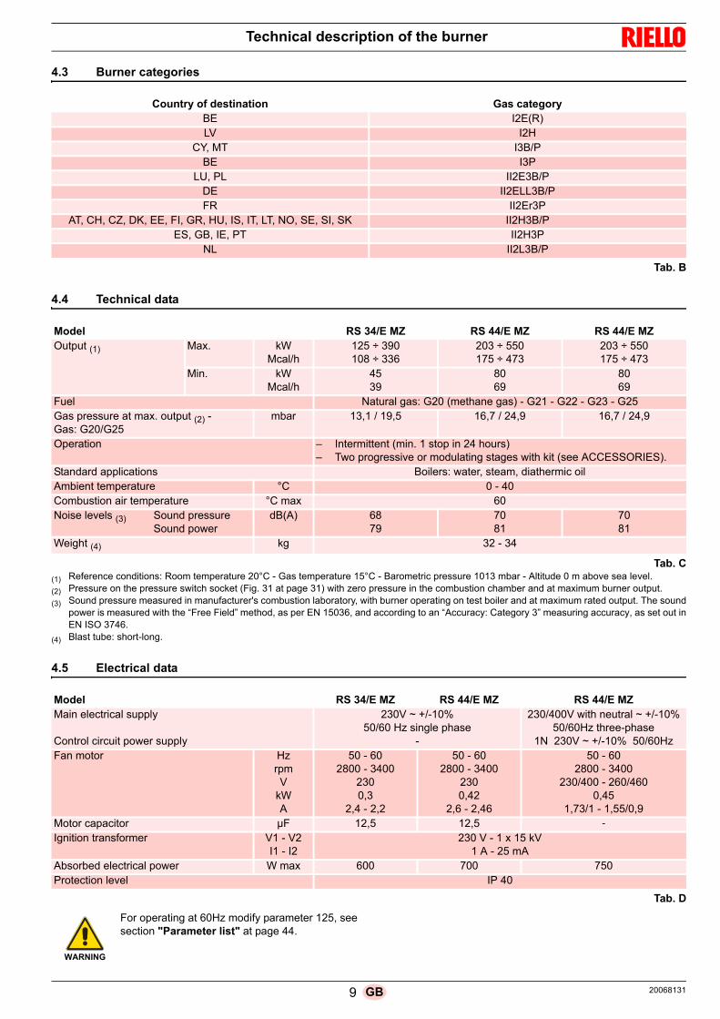
4.3 Burner categories
Tab. B
4.4 Technical data
Tab. C(1) Reference conditions: Room temperature 20°C - Gas temperature 15°C - Barometric pressure 1013 mbar - Altitude 0 m above sea level.
(2) Pressure on the pressure switch socket (Fig. 31 at page 31) with zero pressure in the combustion chamber and at maximum burner output.
(3) Sound pressure measured in manufacturer's combustion laboratory, with burner operating on test boiler and at maximum rated output. The soundpower is measured with the “Free Field” method, as per EN 15036, and according to an “Accuracy: Category 3” measuring accuracy, as set out inEN ISO 3746.
(4) Blast tube: short-long.
4.5 Electrical data
Tab. D
Country of destination Gas categoryBE I2E(R)LV I2H
CY, MT I3B/PBE I3P
LU, PL II2E3B/PDE II2ELL3B/PFR II2Er3P
AT, CH, CZ, DK, EE, FI, GR, HU, IS, IT, LT, NO, SE, SI, SK II2H3B/PES, GB, IE, PT II2H3P
NL II2L3B/P
Model RS 34/E MZ RS 44/E MZ RS 44/E MZOutput (1) Max. kW
Mcal/h125 ÷ 390108 ÷ 336
203 ÷ 550175 ÷ 473
203 ÷ 550175 ÷ 473
Min. kWMcal/h
4539
8069
8069
Fuel Natural gas: G20 (methane gas) - G21 - G22 - G23 - G25Gas pressure at max. output (2) - Gas: G20/G25
mbar 13,1 / 19,5 16,7 / 24,9 16,7 / 24,9
Operation – Intermittent (min. 1 stop in 24 hours)– Two progressive or modulating stages with kit (see ACCESSORIES).
Standard applications Boilers: water, steam, diathermic oilAmbient temperature °C 0 - 40Combustion air temperature °C max 60Noise levels (3) Sound pressure
Sound powerdB(A) 68
797081
7081
Weight (4) kg 32 - 34
Model RS 34/E MZ RS 44/E MZ RS 44/E MZMain electrical supply
Control circuit power supply
230V ~ +/-10% 50/60 Hz single phase
-
230/400V with neutral ~ +/-10%50/60Hz three-phase
1N 230V ~ +/-10% 50/60HzFan motor Hz
rpmV
kWA
50 - 602800 - 3400
2300,3
2,4 - 2,2
50 - 602800 - 3400
2300,42
2,6 - 2,46
50 - 602800 - 3400
230/400 - 260/4600,45
1,73/1 - 1,55/0,9Motor capacitor µF 12,5 12,5 -
Ignition transformer V1 - V2I1 - I2
230 V - 1 x 15 kV1 A - 25 mA
Absorbed electrical power W max 600 700 750Protection level IP 40
WARNING
For operating at 60Hz modify parameter 125, seesection "Parameter list" at page 44.
9 20068131GB

Technical description of the burner
4.6 Maximum dimensions
The dimensions of the burner are shown in Fig. 1.
Bear in mind that inspection of the combustion head requires theburner to be opened and the rear part drawn back on the guides.
The dimensions of the open burner are indicated by position O.
Tab. E(1) Blast tube: short-long
4.7 Firing rates
The maximum output is chosen within area A.
The minimum output must not be lower than the minimum limitof the diagram:RS 34/E MZ = 45 kWRS 44/E MZ = 80 kW
Fig. 1D3831
mm A D E F(1) H I L O N V M
RS 34/E MZ 442 422 508 216-351 140 305 138 780 84 177 1”1/2
RS 44/E MZ 442 422 508 216-351 152 305 138 780 84 177 1”1/2
WARNING
The firing rate (Fig. 2) was obtained considering aroom temperature of 20°C and an atmosphericpressure of 1013 mbar (approx. 0 m above sealevel), with the combustion head adjusted asshown at page 24.
Fig. 2
D9304
Thermal power
Thermal power
Com
bust
ion
cham
ber
pres
sure
- m
bar
Com
bust
ion
cham
ber
pres
sure
- m
bar
RS 44/E MZ
RS 34/E MZ
20068131 10 GB

Technical description of the burner
4.7.1 Firing rate on basis of air density
The firing rate of the burner shown in the manual is valid for aroom temperature of 20°C and an altitude of 0m above sea level(barometric pressure around 1013 mbar).
It may be that a burner has to operate with combustive air at ahigher temperature and/or higher altitudes.
The heating of the air and the increase in altitude produce thesame effect: the expansion of the air volume (i.e. the reduction ofits density).
The delivery of the burner fan remains essentially the same, butthe oxygen per m3 of air, and the thrust (discharge head) of thefan are reduced.
It is therefore important to know if the maximum output requestedfrom the burner at a determinate combustion chamber pressureremains within the firing rate of the burner even with the changedtemperature and altitude conditions.
To check it, proceed as follows:1 find the corrective factor F (relating to the air temperature
and altitude of the system) in the Tab. F.2 Divide the output Q required from the burner by F to obtain
the equivalent output Qe:
3 In the firing rate of the burner, mark the work point identifiedby:Qe = equivalent outputH1 = pressure in combustion chamberpoint A that must remain within the firing rate.
4 Trace a vertical line from point A)(Fig. 3), and find the maxi-mum pressure H2 of the firing rate.
5 Multiply H2 by F to obtain the maximum lowered pressureH3 of the firing rate:
If H3 is greater than H1)(Fig. 3), the burner can produce the de-livery requested.
If H3 is less than H1, it is necessary to reduce the output of theburner. The reduction in output is accompanied by a reduction inthe combustion chamber pressure:Qr = reduced outputH1r = reduced pressure
Example, 5% reduction in output:
Qr = Q x 0,95H1r = H1 x (0,95)2
With the new values - Qr and H1r - repeat steps 2 - 5.
Tab. F
Qe = Q : F (kW)
H3 = H2 x F (mbar)
WARNING
The combustion head should be adjusted in rela-tion to the equivalent output Qe.
H1r = H1 x ( )QrQ
2
Qe kg/h
mbar
Qe kW
mbar
AH1
H2H3
D388
Fig. 3
AltitudeAverage baro-metric pressure
F
Air temperature °C
m a.s.l. mbar 0 5 10 15 20 25 30 40
010020030040050060070080090010001200140016001800200024002800320036004000
10131000989978966955944932921910898878856836815794755714675635616
1.0871.0731.0611.0501.0371.0251.0131.0000.9880.9770.9640.9420.9190.8970.8750.8520.8100.7660.7240.6820.661
1.0681.0541.0421.0311.0181.0070.9950.9820.9710.9590.9460.9250.9020.8810.8590.8370.7960.7530.7110.6690.649
1.0491.0351.0241.0131.0000.9890.9770.9650.9540.9420.9300.9090.8860.8660.8440.8220.7820.7390.6990.6570.638
1.0311.0171.0060.9950.9830.9720.9600.9480.9370.9260.9140.8930.8710.8510.8290.8080.7680.7260.6870.6460.627
1.0131.0000.9890.9780.9660.9550.9440.9320.9210.9100.8980.8780.8560.8360.8150.7940.7550.7140.6750.6350.616
0.9960.9830.9720.9620.9500.9390.9280.9160.9060.8950.8830.8630.8420.8220.8010.7810.7420.7020.6640.6240.606
0.9800.9670.9560.9460.9340.9230.9130.9010.8910.8800.8680.8490.8280.8080.7880.7680.7300.6900.6530.6140.596
0.9480.9360.9260.9160.9040.8940.8840.8720.8620.8520.8410.8220.8010.7830.7630.7430.7070.6680.6320.5940.577
11 20068131GB

Technical description of the burner
4.8 Test boiler
The firing rates were obtained in special test boilers, according toEN 676 regulations.
Fig. 4 indicates the diameter and length of the test combustionchamber.
Example:Output 407 kW (350 Mcal/h) - diameter 50 cm, length 1.5 m.
The coupling is ensured when the boiler is EC type-approved; forboilers or ovens with combustion chambers of very different di-mensions compared to those shown in the diagram of Fig. 4, pre-liminary checks are recommended.
4.9 Burner equipment
The burner is supplied complete with:
Gas train flange . . . . . . . . . . . . . . . . . . . . . . . . . . . . . . . . . No. 1
Gasket for gas train flange . . . . . . . . . . . . . . . . . . . . . . . . . No. 1
Screws M8 x 25 to fix the flange . . . . . . . . . . . . . . . . . . . . No. 4
Screws M8 x 25 to fix the burner flange to the boiler . . . . . No. 4
Thermal insulation screen . . . . . . . . . . . . . . . . . . . . . . . . . No. 1
Plugs for electrical wiring (RS 34-44/E MZ single phase) . No. 3
Plugs for electrical wiring (RS 44/E MZ three-phase) . . . . No. 4
Instruction manual . . . . . . . . . . . . . . . . . . . . . . . . . . . . . . . No. 1
Spare parts list . . . . . . . . . . . . . . . . . . . . . . . . . . . . . . . . . . No. 1
Fig. 4
Com
bust
ion
ch
ambe
rm
D497
20068131 12 GB

Technical description of the burner
4.10 Burner description
1 Combustion head2 Ignition electrode3 Screw for combustion head adjustment4 Pipe coupling5 Gas servomotor6 Plug-socket on ionisation probe cable7 Motor contact maker and thermal relay with reset button8 Operation on/off switch9 Terminal board for electrical wiring10 Operator panel with LCD display11 Control box for checking flame and air/fuel ratio12 Extensions for guides 20) - only for TL versions13 Filter to protect against radio disturbance14 Flame inspection window15 Ignition transformer16 Sockets for electrical wiring17 Air servomotor18 Air pressure switch (differential type)
19 Guides for opening the burner and inspecting the combus-tion head
20 Gas pressure test point and head fixing screw21 Air pressure socket22 Flame sensor probe23 Air damper24 Fan air inlet25 Screws to secure fan to pipe coupling26 Gas input pipe27 Gas regulator28 Boiler fixing flange29 Flame stability disc30 4-pole socket cover (see electrical panel appendix)
12
22
29
3 20 2819
18
8
13
9
10
11
16
17
21
2324
25
12
14
30
26 27
4
5
6
7
15
Fig. 5
20052928
13 20068131GB

Technical description of the burner
4.11 Control box for the air/fuel ratio (REC 27.100A2)
Important notes
All interventions (assembly and installation operations,assistance, etc.) must be carried out by qualified personnel.
Before modifying the wiring in the control box connectionarea, fully disconnect the system from the power supply(omnipolar separation). Check the system is not poweredand cannot be accidentally reconnected. Failure to do thiswill lead to the risk of electrocution.
Protection against electrocution from the control box and allconnected electric components is obtained with correctassembly.
Before any intervention (assembly and installation opera-tions, assistance, etc.), ensure the wiring is in order and thatthe parameters are correctly set, then make the safetychecks.
Falls and collisions can negatively affect the safety func-tions. In this case, the control box must not be operated,even if it displays no evident damage.
During the programming of the control curves of the air-fuelratio, the technician should constantly observe the quality ofthe combustion process (for example, using a gas analyser)and, if the combustion values are too low or if there are dan-gerous conditions, take the appropriate action, for exampleby manually switching off the system.
The plugs of the connection cables or other accessories canbe removed or changed when the system is off.
The connections to the actuators do not provide a safe sepa-ration of the mains voltage. Before connecting or changingthe actuators, the system should be switched off.
To ensure the safety and reliability of the control box, the follow-ing instructions must also be followed:– avoid conditions that can favour the development of conden-
sate and humidity. Otherwise, before switching on again,make sure that the entire control box is perfectly dry!
– Static charges must be avoided since they can damage thecontrol box’s electronic components when touched.
Installation notes Arrange the HV ignition cables separately, as far as possible
from the control box and the other cables. Check the electric wiring inside the boiler complies with the
national and local safety regulations. Phase and neutral should not be exchanged (cause of dan-
gerous malfunctions, loss of protection against electricshocks, etc..).
Make certain that strain relief of the connected cables is incompliance with the relevant standards (e.g. as perEN60730 e EN60 335).
Ensure that spliced wires cannot get into contact with neigh-bouring terminals. Use adequate ferrules.
The mechanical connection between the actuators and theelements for controlling the fuel and air, or other control ele-ments, should be rigid.
When wiring the unit, make sure that AC 230V mains volt-age cables are run strictly separate from extra low-voltagecables to avoid risks of electrical shock hazard.
Mechanical structure
The control box is a system to check the burners, based on a mi-croprocessor and equipped with components to adjust and mon-itor medium and large capacity forced draught burners.
The base control box of the control box incorporates the followingcomponents:– burner adjustment device with system for checking the seal
of the gas valves;– electronic fuel/air ratio monitoring device with a maximum of
2 actuators;– Modbus interface.
WARNING
To avoid accidents, material or environmentaldamage, observe the following instructions!
The control box is a safety device! Avoid openingor modifying it, or forcing its operation. RielloS.p.A. cannot assume any responsibility for dam-age resulting from unauthorised interventions!
Risk of explosion!
An incorrect configuration can provoke fuel over-charging, with the consequential risk of explosion!Operators must be aware that incorrect settingsmade on the display and operating unit and incor-rect settings of the fuel and / or air actuator posi-tions can lead to dangerous burner operatingconditions.
Fig. 6D8266
20068131 14 GB

Technical description of the burner
Electrical connection of flame detector
It is important for signal transmission to be almost totally freeof any disturbances or loss: always separate the detector cables from the other cables:
– line capacitance reduces the magnitude of the flame sig-nal.
– Use a separate cable. Respect the allowed cable lengths. The ionisation probe is not protected against the risk of elec-
trocution; it must be protected against any accidental con-tact.
The grounding of the burner must be in compliance with therules in force; the grounding of the boiler alone is notenough.
Position the ignition electrode and the ionisation probe sothat the ignition spark cannot form an arc on the probe (riskof electric overcharge).
Technical data
Control box Mains voltage AC 230 V -15 % / +10 %
Mains frequency 50 / 60 Hz ±6 %
Power absorption < 30 W (normal)
Safety class I, with components in compliance with II and III, ac-cording to DIN EN 60730-1
Load on ‘input’ terminals
F1 unit fuse (internal) 6,3 AT
Main fuse of perm. network (external) Max. 16 AT
Undervoltage– Safety switch-off from operating position to mains
voltage– Restart when mains voltage picks up
< AC 186 V
> AC 195 V
Input currents and input voltages– UeMax– UeMin– Iemax– IeMin
UN +10%UN -15%1.5 mA peak0.7 mA peak
Voltage detection– On– Off
AC 180...253 V< AC 80 V
Load on ‘output’terminals
Total load on the contacts– Mains voltage– Total unit input current (safety circuit)
- Fan motor contactor- Ignition transformer- Valve
AC 230 V, 50 / 60 HzMax. 5 A
Single contact loadingFan motor contactor– Rated voltage– Nominal current– Power factor
AC 230 V, 50 / 60 Hz2A cos > 0.4
Alarm output– Rated voltage– Nominal current– Power factor
AC 230 V, 50 / 60 Hz1Acos > 0.4
Ignition transformer – Rated voltage– Nominal current– Power factor
AC 230 V, 50 / 60 Hz2A cos > 0.2
Fuel valve – Rated voltage– Nominal current– Power factor
AC 230 V, 50 / 60 Hz2A cos > 0.4
Display operation – Rated voltage– Nominal current– Power factor
AC 230 V, 50 / 60 Hz0,5A cos > 0.4
15 20068131GB

Technical description of the burner
Tab. G
Cable lengths – Main line AC 230 V– Display, BCI
– Load control (LR) X5-03– External reset button– Safety valve (SV)– Load output– Fuel valve – Pilot valve– Ignition transformer– Other lines
Max. 100 m (100 pF / m)For installation under the casing of the burner or in the control panel max. 3 m (100 pF / m)Max. 20 m (100 pF/m)Max 20 m (100 pF/m)Max 20 m (100 pF/m)Max. 10 m (100 pF/m)Max. 3 m (100 pF/m)Max. 3 m (100 pF/m)Max. 3 m (100 pF/m)Max. 3 m (100 pF/m)
Cross-sections of the power supply lines
They should be sized for rated currents as per the pri-mary external fuse and the fuse of the internal unit.– Min. cross-section– Fuses used inside the control box F1
(max. 6.3 AT)0.75 mm²6.3 AT DIN EN 60127 2 / 5
Environmental conditions
Storage– Climatic conditions– Mechanical conditions– Temperature range– Humidity
DIN EN 60721-3-1Class 1K3Class 1M2-20 ... +60 °C< 95% RH
Transport– Climatic conditions– Mechanical conditions– Temperature range– Humidity
DIN EN 60721-3-2Class 2K2Class 2M2-30 ... +60 °C< 95% RH
Operation– Climatic conditions– Mechanical conditions– Temperature range– Humidity
DIN EN 60721-3-3Class 3K3Class 3M3-20 ... +60 °C< 95% RH
WARNING
Condensation, formation of ice and the entranceof water are not permitted!
20068131 16 GB
Technical description of the burner
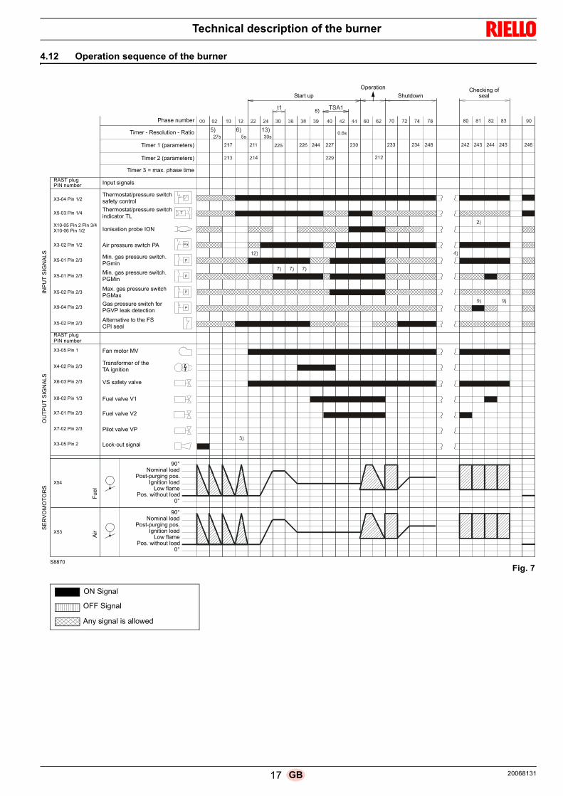
4.12 Operation sequence of the burner
t1 TSA1
5) 6)27s 5s
13)30s
0.6s
Pa
P
P
P
P
Phase number
INP
UT
SIG
NA
LS
Thermostat/pressure switch
OU
TP
UT
SIG
NA
LS
Thermostat/pressure switch
Ionisation probe ION
Air pressure switch PA
Min. gas pressure switch.
Min. gas pressure switch.
Gas pressure switch for PGVP leak detection
Alternative to the FS
safety control
Fan motor MV
Transformer of the
VS safety valve
Fuel valve V1
Fuel valve V2
Pilot valve VP
Lock-out signal
indicator TL
SE
RV
OM
OT
OR
S
Air
Fue
l
90°Nominal load
Post-purging pos.Ignition load
Low flamePos. without load
0°
S8870
Fig. 7
Checking ofsealShutdown
Operation
Start up
Timer - Resolution - Ratio
Timer 1 (parameters)
Timer 2 (parameters)
Timer 3 = max. phase time
Input signals
PGmin
PGMin
Max. gas pressure switchPGMax
CPI seal
TA ignition
90°Nominal load
Post-purging pos.Ignition load
Low flamePos. without load
0°
RAST plug
X3-04 Pin 1/2
PIN number
X5-03 Pin 1/4
X10-05 Pin 2 Pin 3/4X10-06 Pin 1/2
X3-02 Pin 1/2
X5-01 Pin 2/3
X5-01 Pin 2/3
X5-02 Pin 2/3
X9-04 Pin 2/3
X5-02 Pin 2/3
X3-05 Pin 1
X4-02 Pin 2/3
X6-03 Pin 2/3
X8-02 Pin 1/3
X7-01 Pin 2/3
X7-02 Pin 2/3
X3-05 Pin 2
RAST plugPIN number
X54
X53
ON Signal
OFF Signal
Any signal is allowed
17 20068131GB

Technical description of the burner
4.12.1 List of phases
4.13 Operator panel operation
The control box REC 27.100A2 is directly connected to the oper-ator panel (Fig. 8).
The buttons allow you to programme the operation and diagnos-tics menus.
The burner management system is visualised on the LCD display(Fig. 9). To simplify the diagnostics, the display shows the oper-ating status, type of problem, and when the problem arose.
4.13.1 Symbols description on the display
The display brightness can be regulated from 0 ... 100% with pa-rameter 126.
Phase Description
Ph00 Lockout phase
Ph02 Safety phase
Ph10 Closing paused
Ph12 Standby
Ph22 Fan motor (MV) = ON Safety valve (VS) = ON
Ph24 The burner moves to the pre-purging position
Ph30 Pre-purging time
Ph36 The burner moves to the ignition position
Ph38 Ignition phase (TA) = ON
Ph39 Min. gas pressure switch test (PGmin.)
Ph40 Fuel valve (V) = ON
Ph42 Ignition (TA) = OFF
Ph44 t44 = interval time 1
Ph60 Operation
Ph62 The burner moves to the switching off position
Ph70 t13 = post-combustion time
Ph72 The burner moves to the post-purging position
Ph74 t8 = post-purging time
Ph78 t3 = post-purging time
Ph80 Emptying time (valve leak detection)
Ph81 Atmospheric test time (valve leak detection)
Ph82 Filling time (valve leak detection)
Ph83 Pressure test time (valve leak detection)
Ph90 Standby time due to lack of gas
Phase Description
WARNING
Observe the procedures and adjustmentsshown below.
All interventions (assembly and installationoperations, assistance, etc.) must be carriedout by qualified personnel.
If the display and operator panel are dirty,clean them with a dry cloth.
Protect the panel from excessive tempera-tures and liquids.
D9001 Fig. 8
Lock-out lamp
Flame presence
Valve poweredIgnition transformer
Fan motor powered
Pre-heater active
Heat request
Info Mode active
Service Mode active
Closure of servomotors
Opening of servomotors
Measurement unit
Lockout
Parameters Mode active
only for light oil burners
V h min sD9000
powered
Fig. 9
20068131 18 GB

Technical description of the burner
4.13.2 Buttons description
Tab. H
Button Button Function
Button FTo regulate the fuel servomotor
(keep pressed and adjust the value by pressing or )
Button ATo regulate the servomotor air
(keep pressed and adjust the value by pressing or )
Button A and FVSD Function
To modify the parameter for setting the P mode
(simultaneously press and plus or
Button Info and Enter
• Enter in Parameters Mode• Reset in the event of a lockout• Access to a lower level of the menu• To navigate in Service or Info Mode and allows:
– the selection of the parameter (flashing symbol) (press for <1 s)– access to a lower level of the menu (press from 1...3 s)– access to a higher level of the menu (press from 3...8 s)– access to another Mode (press for > 8 s)
Button -
Reduction of the value– Access to a lower point of the modulation curve– Scrolling of the parameter list
Button +
Increase of the value– Access to a higher point of the modulation curve– Scrolling of the parameter list
Buttons - and +
Quit function (ESC)
(press and simultaneously)– Does not confirm the value– Access to a higher level of the menu
F F
A A
VSD
AFF A
������
ESC
19 20068131GB

Technical description of the burner
4.14 Servomotors (SQN13...)
Introduction
The servomotors that equip the burners of the RS range work di-rectly on the air damper and the gas butterfly valve, without me-chanical leverages but via the interposition of an elastic coupling.
They are commanded by the control box, which constantlychecks their position by means of a return signal from the opticsensor inside the servomotor.
Important notes
All interventions (assembly and installation operations,assistance, etc.) must be carried out by qualified personnel.
Before modifying the wiring in the servomotor connectionarea, fully disconnect the burner control device from thepower supply (omnipolar separation)..
To avoid the risk of electrocution, protect the connection ter-minals in a suitable manner and correctly fix the cover.
In the event of assembly, installation, maintenance, etc... it isnecessary to check that the wiring and the parameterisationare in order.
Falls and collisions can negatively affect the safety func-tions. In this case, the unit must not be operated, even if itdisplays no evident damage.
Installation notes Check the relevant national safety standards are respected. The connection between the actuator command shaft and
the control element must be rigid, without any mechanicalplay.
The tightening torque for the fixing screws should be 1.5Nm. It is recommended that this value is not exceeded toprevent damaging the servomotor.
To avoid an excessive load on the bearings due to rigidhubs, the use of compensation clutches without anymechanical play is recommended (e.g. metal bellows-typeclutches).
It is advisable to oversize the drive shaft in relation to therated torque of the actuator.
The static torque is reduced when the electrical supply of theactuator is switched off.
Arrange the H.V. ignition cables separately, as far as possi-ble from the control box and the other cables.
Technical data
Tab. I
WARNING
To avoid accidents, material or environmentaldamage, observe the following instructions!
Avoid opening, modifying or forcing the servo-motor. The servomotor is equipped with a systemof optical feedback.
Power supply AC / DC 24 V ± 20% (load inter-face)
Safety class EN 60730 part 1-14
Power absorption Max. 7.5 W
Angle adjustment, usable range
Max. 90°
Degree of protection IP40
Work of field 0-90°
Opening time 0-90° Min 5 sec.Max 120 sec. depending on thecontrol box type
Direction of rotation Anticlockwise
Torque operating 0.7 Nm
Torque off 0.4 Nm
Cable length 1.2 m
Radial load on the bearing 30 N
Axial load on the bearings Max. 5 N
Weight About 0.3 kg
Connecting cable RAST2.5
Environmental conditions:
OperationClimatic conditionsMechanical conditionsTemperature rangeHumidity
DIN EN 60721-3-3Class 3K3Class 3M3-10 ... +60 °C< 95% RH
WARNING
Condensation, formation of ice and the entranceof water are not permitted!
Fig. 10
D8083
20068131 20 GB

Installation
5.1 Notes on safety for the installation
After carefully cleaning all around the area where the burner willbe installed, and arranging the correct lighting of the environ-ment, proceed with the installation operations.
5.2 Handling
The burner is shipped in cardboard packaging, so it is possible tomove it when it is still packaged with a transpallet or fork lift truck.
5.3 Preliminary checks
Checking the consignment
Checking the characteristics of the burner
Check the identification label of the burner (Fig. 11), showing:A the burner modelB the burner typeC the cryptographic year of manufactureD the serial numberE the data for electrical supply and the protection levelF the electrical power consumptionG the types of gas used and the relative supply pressuresH the data of the burner's minimum and maximum output pos-
sibilities (see Firing rate)Warning. The burner output must be within the boiler's firingrate
I the category of the appliance/countries of destination
5 Installation
DANGER
All the installation, maintenance and disassemblyoperations must be carried out with the electricitysupply disconnected.
WARNING
The installation of the burner must be carried outby qualified personnel, as indicated in this manualand in compliance with the standards and regula-tions of the laws in force.
DANGER
Combustion air inside the boiler must be free fromhazardous mixes (e.g.: chloride, fluoride, halo-gen); if present, it is highly recommended to carryout cleaning and maintenance more frequently.
WARNING
The handling operations for the burner can behighly dangerous if not carried out with the great-est attention: keep any unauthorised people at adistance; check the integrity and suitableness ofthe available means of handling.
Check also that the area in which you are workingis empty and that there is an adequate escapearea (i.e. a free, safe area to which you can quick-ly move if the burner should fall).
When handling, keep the load at not more than20-25 cm from the ground.
After positioning the burner near the installationpoint, correctly dispose of all residual packaging,separating the various types of material.
CAUTION
Before proceeding with the installation operations,carefully clean all around the area where the burn-er will be installed.
CAUTION
After removing all the packaging, check the integ-rity of the contents. In the event of doubt, do notuse the burner; contact the supplier.
The packaging elements (wooden cage or card-board box, nails, clips, plastic bags, etc.) must notbe abandoned as they are potential sources ofdanger and pollution; they should be collected anddisposed of in the appropriate places.
WARNING
A burner label, or any other component, that hasbeen tampered with, removed or is missing, pre-vents the definite identification of the burner andmakes any installation or maintenance work diffi-cult.
Fig. 11
R.B.L.
GAS-KAASUGAZ-AEPIO
0085
RIELLO S.p.A.I-37045 Legnago (VR)
CE
A B CED F
HGG H
I
D7738
21 20068131GB

Installation
5.4 Operating position
5.5 Preparing the boiler
5.5.1 Introduction
The burners are suitable for working on both flame inversion boil-ers (in this case the long head model is recommended) and boil-ers with a combustion chamber with bottom runoff (three flue gascirculations), from which the best results of low NOx emissionsare obtained.
The maximum thickness of the front hatch of the boiler, completewith refractory, must not exceed the dimension indicated inFig. 13.
5.5.2 Boring the boiler plate
Drill holes in the plate shutting off the combustion chamber, asillustrated in Fig. 14. The position of the threaded holes can bemarked using the thermal insulation screen supplied with theburner.
5.5.3 Blast tube length
The length of the blast tube must be selected according to the in-dications provided by the manufacturer of the boiler, and in anycase it must be greater than the thickness of the boiler door com-plete with its refractory.
The lengths L available are:
For boilers with front flue passes 13)(Fig. 17), a protection in re-fractory material 11) must be inserted between the boiler refrac-tory 12) and the blast tube 10).
This protection must not compromise the extraction of the blasttube.
For boilers with a water-cooled frontal, a refractory cover is notnecessary 11)-12)(Fig. 17), unless expressly requested by theboiler manufacturer.
Tab. J
WARNING
The burner is designed to operate only inpositions 1, 2, 3 and 4 (Fig. 12).
Installation 1 is preferable, as it is the onlyone that allows the maintenance operationsas described in this manual.
Installations 2, 3 and 4 permit operation butmake maintenance and inspection of thecombustion head more difficult.
DANGER
Any other position could compromise the cor-rect operation of the appliance.
Installation 5 is prohibited for safety reasons.
2 3 4 51
Fig. 12
D3928
Blast tube Short (mm) Long (mm)
RS 34-44/E MZ 216 351 mm A B C
RS 34/E MZ 160 224 M 8
RS 44/E MZ 160 224 M 8
Fig. 13
200 mm
D1079
Fig. 14D455
20068131 22 GB

Installation
5.6 Positioning probe - electrode
If, in the previous check, the position of the probe or electrodewas not correct, is necessary: remove the screw 1)(Fig. 15) extract the inner part 2)(Fig. 15) of the head, and adjust
them.
WARNING
Before fixing the burner to the boiler, check fromthe opening of the blast tube that the probe andthe electrode are correctly positioned, as inFig. 16.
WARNING
Do not rotate the probe: leave it as in Fig. 16.
If it is located too close to the ignition electrode,the control box amplifier may be damaged.
WARNING
Observe the dimensions shown in Fig. 16.
2
1
Fig. 15D8008
Fig. 16
Probe Electrode
D3844
23 20068131GB

Installation
5.7 Securing the burner to the boiler
Separate the combustion head from the rest of the burner, as inFig. 17; proceed as follows: loosen the screws 3) and remove the cover 1); remove the screws 2) from the two guides 5); disconnect the plug 14), unscrew the grommet 15); remove the screw 4);
pull back the burner on the guides 5) by about 100 mm; disconnect the probe and electrode leads, then unthread the
burner completely from the guides 5). Fix the flange 9) to the boiler plate, interposing the supplied
insulating gasket 8). Use the 4 screws supplied, with a tightening torque of 35 ÷
40 Nm, after protecting their thread with anti-seize products.
5.8 Combustion head adjustment
At this point of the installation, the combustion head is fixed to theboiler as shown in Fig. 15.
It is therefore especially easy to adjust, and this adjustment de-pends only on the maximum output of the burner.
In the diagram (Fig. 18) find the notch at which to adjust the com-bustion head.
Provide an adequate lifting system of the burner.
WARNING
The seal between burner and boiler must be air-tight; after the start-up, check there is no leakageof flue gases into the external environment.
L
245
14
10
8
100 mm9
13
13
1
3
15
11
12
Fig. 17
D8010
Fig. 18
No. notches
Max burner output
D3837
20068131 24 GB

Installation
Air adjustment
Rotate the screw 4)(Fig. 19) until the notch you have found cor-responds with the front surface 5) of the flange.
Example:RS 44/E MZ, burner output = 300 kW. From diagram (Fig. 18) you can see that for this output the airshould be adjusted at notch 3, subtracted from the value of thepressure in the chamber.
Central air adjustment
In case the application needs a particular setup, it is possible tomodify the central air delivery using the ring nut 7)(Fig. 19) up tothe notch indicated in diagram (Fig. 20).
In order to carry out this operation, unscrew the screws8)(Fig. 19) and lift up the ring nut 7).
At the end, tighten the screws 8) again.
NOTE:The adjustments indicated can be modified during the initialstart-up.
5.9 Burner closing
Once the combustion head adjustment is completed: reassemble the burner on the guides 3) at about 100 mm
from the pipe coupling 4) - burner in the position shown inFig. 17;
insert the probe and electrode cables, then slide the burneras far as the pipe coupling - burner in the position shown inFig. 21;
connect the plug of the servomotor 14)(Fig. 17) and tightenthe grommet 15);
refit the screws 2) on the guides 3); fix the burner to the pipe coupling with the screw 1).
WARNING
To facilitate the adjustment, loosen the screw6)(Fig. 19), adjust, then block.
WARNING
If the chamber pressure is equal to 0 mbar, the airadjustment is made referring to the dotted line ofdiagram (Fig. 18).
4
5
6
7
8
Fig. 19D8595
Fig. 20
No. notches
Max burner output
D8577
WARNING
When fitting the burner on the two guides, it is ad-visable to gently draw out the high voltage cableand flame detection probe cable until they areslightly taut.
5
4
1
3
2
Fig. 21D8009
25 20068131GB

Installation
5.10 Gas feeding
5.10.1 Gas feeding line
Key (Fig. 22 - Fig. 23 - Fig. 24 - Fig. 25)1 Gas input pipe2 Manual valve3 Vibration damping joint4 Pressure gauge with pushbutton cock5 Filter
6A Includes:– Filter– working valve– safety valve– pressure adjuster
6C Includes– safety valve– working valve
6D Includes:– safety valve– working valve– pressure adjuster– filter
7 Minimum gas pressure switch8 Leak detection device, supplied as an accessory or incorpo-
rated, based on the gas train code. In compliance with theEN 676 standard, the leak detection control is compulsory forburners with maximum outputs over 1200 kW.
9 Gasket, for “flanged” versions only10 Pressure adjuster11 Train-burner adaptor, supplied separatelyP2 Upstream pressure of valves/adjusterP3 Upstream pressure of the filterL Gas train supplied separatelyL1 The responsibility of the installer
Explosion danger due to fuel leaks in the pres-ence of a flammable source.
Precautions: avoid knocking, attrition, sparks andheat.
Make sure that the fuel interception tap is closedbefore performing any operation on the burner.
WARNING
The fuel supply line must be installed by qualifiedpersonnel, in compliance with current standardsand laws.
Fig. 2220057264
MB
Fig. 2320062223
MBC
Fig. 2420062227
DMV
Fig. 2520062228
CB
20068131 26 GB

Installation
5.10.2 Gas train
Type-approved in accordance with EN 676 and supplied sepa-rately from the burner.
To select the correct model of the gas train, refer to the “burner-gas train combination” manual supplied.
5.10.3 Gas train installation
The gas train can enter the burner from the right or left side, de-pending on which is the most convenient, see Fig. 26.
The gas train must be connected to the gas attachment1)(Fig. 26), with the flange 2), the gasket 3) and the screws 4)supplied with the burner.
See the accompanying instructions for the adjustment of the gastrain.
5.10.4 Gas pressure
Tab. K indicates the pressure drop of the combustion head andthe gas butterfly valve depending on the operating output of theburner.
Tab. K
The values shown in Tab. K refer to: – Natural gas G 20 NCV 9.45 kWh/Sm3 (8.2 Mcal/Sm3)– Natural gas G 25 NCV 8.13 kWh/Sm3 (7.0 Mcal/Sm3)
Column 1
Load loss at combustion head.Gas pressure measured at the test point 1)(Fig. 27), with:• combustion chamber at 0 mbar;• burner working at maximum output;
Column 2Pressure loss at gas butterfly valve 2)(Fig. 27) with maximumopening: 90°.
To know the approximate output at which the burner is operatingat its maximum:– Subtract the combustion chamber pressure from the gas
pressure measured at test point 1)(Fig. 27).– Find, in the Tab. K relating to the burner concerned, column
1, the pressure value closest to the result you want.– Read the corresponding output on the left.
DANGER
Disconnect the electrical power using the mainsystem switch.
Check that there are no gas leaks.
Beware of train movements: danger of crushing oflimbs.
Make sure that the gas train is properly installedby checking for any fuel leaks.
The operator must use appropriate tools for instal-lation.
WARNING
The gas solenoids must be as close as possible tothe burner, to ensure that the gas reaches thecombustion head within the safety time of 3s.
Ensure that the maximum pressure to the burneris within the calibration range of the pressure reg-ulator.
kW1 p (mbar) 2 p (mbar)
G 20 G 25 G 20 G 25
RS
34/
E M
Z
130 1.5 2.2 0.4 0.6
180 3.8 5.7 0.7 1.0
260 7.3 10.9 1.9 2.8
340 10.9 16.3 1.6 2.4
390 13.1 19.5 3.4 5.1
RS
44/
E M
Z
200 3.0 4.5 0.6 0.9
300 6.9 10.3 0.4 0.6
400 10.8 16.1 2.4 3.6
500 14.7 21.9 3.8 5.7
550 16.7 24.9 4.6 6.9
Fig. 26
D3839
27 20068131GB

Installation
Example with natural gas G 20 for RS 44/E MZ:Maximum output operationGas pressure at test point 1)(Fig. 27) = 12.8 mbarPressure in combustion chamber = 2.0 mbar
12.8 - 2.0 = 10.8 mbar
A maximum output of 400 kW shown in Tab. K corresponds to10.8 mbar pressure, column 1.
This value serves as a rough guide; the effective output must bemeasured at the gas meter.
To know the required gas pressure at test point 1)(Fig. 27), setthe maximum output required from the burner operation, then:– find the nearest output value in the Tab. K for the burner in
question.– Read, on the right (column 1) the socket pressure 1)(Fig. 27).– Add this value to the estimated pressure in the combustion
chamber.
Example with natural gas G 20 for RS 44/E MZ:Maximum output required: 400 kWGas pressure at output of 400 kW = 10.8 mbarPressure in combustion chamber = 2.0 mbar
10.8 + 2.0 = 12.8 mbargas pressure at test point 1)(Fig. 27).
2
1
Fig. 27S8738
20068131 28 GB

Installation
5.11 Electrical wiring
Notes on safety for the electrical wiring
Before carrying out any maintenance, cleaning or checking oper-ations:
If the hood is still present, remove it and proceed with the electri-cal wiring according to the wiring diagrams.
Use flexible cables in compliance with the EN 60 335-1 standard.
NOTE
The RS 44/E MZ three-phase model leaves the factory for 400Vpower supplies.
If the power supply is 230V, change the motor connection (fromstar to triangle) and the thermal relay setting
DANGER
The electrical wiring must be carried out with the electrical supply disconnected. Electrical wiring must be made in accordance with the regulations currently in force in the country of destination
and by qualified personnel. Refer to the wiring diagrams. The manufacturer declines all responsibility for modifications or connections different from those shown in the wir-
ing diagrams Check that the electrical supply of the burner corresponds to that shown on the identification label and in this man-
ual. The burner has been type-approved for intermittent use.
This means they should compulsorily be stopped at least once every 24 hours to enable the control box to per-form checks of its own start-up efficiency. Normally, burner stopping is guaranteed by the boiler's thermostat/pres-sure switch. If this is not the case, a time switch should be fitted in series to TL to stop the burner at least onceevery 24 hours. Refer to the wiring diagrams.
The electrical safety of the device is obtained only when it is correctly connected to an efficient earthing system,made according to current standards. It is necessary to check this fundamental safety requirement. In the event ofdoubt, have the electrical system checked by qualified personnel. Do not use the gas tubes as an earthing systemfor electrical devices.
The electrical system must be suitable for the maximum power absorption of the device, as indicated on the labeland in the manual, checking in particular that the section of the cables is suitable for that level of power absorp-tion.
For the main power supply of the device from the electricity mains:- do not use adapters, multiple sockets or extensions;- use a multiple pole switch with at least a 3mm gap between the contacts (overvoltage category III), as envis-
aged by the present safety standards. Do not touch the device with wet or damp body parts and/or in bare feet. Do not pull the electric cables.
DANGER
Disconnect the electrical supply from the burnerby means of the main system switch.
DANGER
Close the fuel interception tap.
DANGER
Avoid condensate, ice and water leaks from form-ing.
WARNING
Modulating operation
If connecting the output power regulator kit RWF,the TR thermostat/pressure switch and the TLthermostat/pressure switch must be removed.
If the 4-pole socket becomes unhooked, apply thesupplied cover, as in Fig. 29.
29 20068131GB

Installation
5.11.1 Supply cables and external connections passage
All cables to connect to the burner are connected to the appropri-ate sockets on the side of the burner (Fig. 28), (use the suppliedplugs for the connections).
The use of the cable grommets can take various forms. By wayof example we indicate the following mode:
RS 34-44/E BLU single phase 1 7 pole socket for single phase power supply, thermostat/
pressure switch TL2 6 pole socket for gas valves, gas pressure switch or the
valve leak detection device3 4 pole socket for thermostat/pressure switch TR (with
removable cover)4 5 pole socket not used5 2 pole socket for maximum gas pressure switch accessory6-6A Prepared for pipe unions (drill if 6A pipe unions are re-
quired)
RS 44/E MZ three-phase1 7 pole socket for single phase power supply, thermostat/
pressure switch TL2 6 pole socket for gas valve, gas pressure switch or the
valve leak detection device3 4 pole socket for thermostat/pressure switch TR (with
removable cover)4 5 pole socket for three-phase power supply5 2 pole socket for maximum gas pressure switch accessory6-6A Prepared for pipe unions (drill if 6A pipe unions are re-
quired)
5.12 Calibration of the thermal relay (only for RS 44/E MZ three-phase)
The thermal relay is used to avoid damage to the motor owing toa strong increase in absorption or the lack of a phase. For thecalibration, refer to the electrical wiring.
If the minimum value of the scale of the thermal relay is greaterthan the rating absorption of the motor, protection is still ensured.This arises when the power supply of the motor is 400 V.
To reset, in the case of an intervention of the thermal relay, pressthe button 1)(Fig. 30).
DANGER
The socket cover 3)(Fig. 29) must only be re-moved when the 4-pole socket is in use.
When the 4-pole socket is not in use the covermust be in place.
The manufacturer furthermore declines any andevery responsibility for the failure to observe thecontents of this manual. After carrying out maintenance, cleaning or
checking operations, reassemble the hood and allthe safety and protection devices of the burner.
6A
54
3
2
1
6
Fig. 2820052930
3
Fig. 2920052852
Fig. 30
2
1
D8267
20068131 30 GB

Start-up, calibration and operation of the burner
6.1 Notes on safety for the first start-up
6.2 Adjustments prior to ignition
The adjustments to be carried out are: ensure that the gas supply company has carried out the sup-
ply line vent operations, eliminating air or inert gases fromthe piping.
Slowly open the manual valves situated upstream of the gastrain.
Adjust the minimum gas pressure switch (Fig. 34 atpage 33) to the start of the scale.
Adjust the air pressure switch (Fig. 33 at page 33) to the startof the scale.
Adjust the pressure switch for the valve leak detection controldevice (PVP kit)(Fig. 35 at page 33), if present, according to theinstructions supplied with the kit itself.
Check the gas supply pressure by connecting a pressuregauge to the pressure test point 1)(Fig. 31) of the minimumgas pressure switch: it must be lower than the maximumallowed pressure of the gas train, as shown on the charac-teristics label.
Bleed the air from the piping of the gas train, connecting aplastic tube to the pressure test point 1)(Fig. 26) of the mini-mum gas pressure switch.Take the vent tube outside the building so you can notice thesmell of gas.
Connect two lamps or testers to the two gas line solenoids tocheck the exact moment at which voltage is supplied.This operation is unnecessary if each of the two solenoids isequipped with an indicator light that signals voltage passingthrough.
6.3 Burner start-up
Feed electricity to the burner via the disconnecting switch on theboiler panel.
Close the thermostats/pressure switches and turn the switch ofFig. 32 to position “1”.
6 Start-up, calibration and operation of the burner
WARNING
The first start-up of the burner must be carried outby qualified personnel, as indicated in this manualand in compliance with the standards and regula-tions of the laws in force. WARNING
Check the correct working of the adjustment, com-mand and safety devices.
An excessive gas pressure can damage the com-ponents of the gas train and lead to a risk of explo-sion.
CAUTION
Before starting up the burner, it is good practice toadjust the gas train so that ignition takes place inconditions of maximum safety, i.e. with gas deliv-ery at the minimum.
Fig. 31
D7999 1
DANGER
Make sure that the lamps or testers connected tothe solenoids, or indicator lights on the solenoidsthemselves, show that no voltage is present.
If voltage is present, stop the burner immediatelyand check the electrical wiring
31 20068131GB
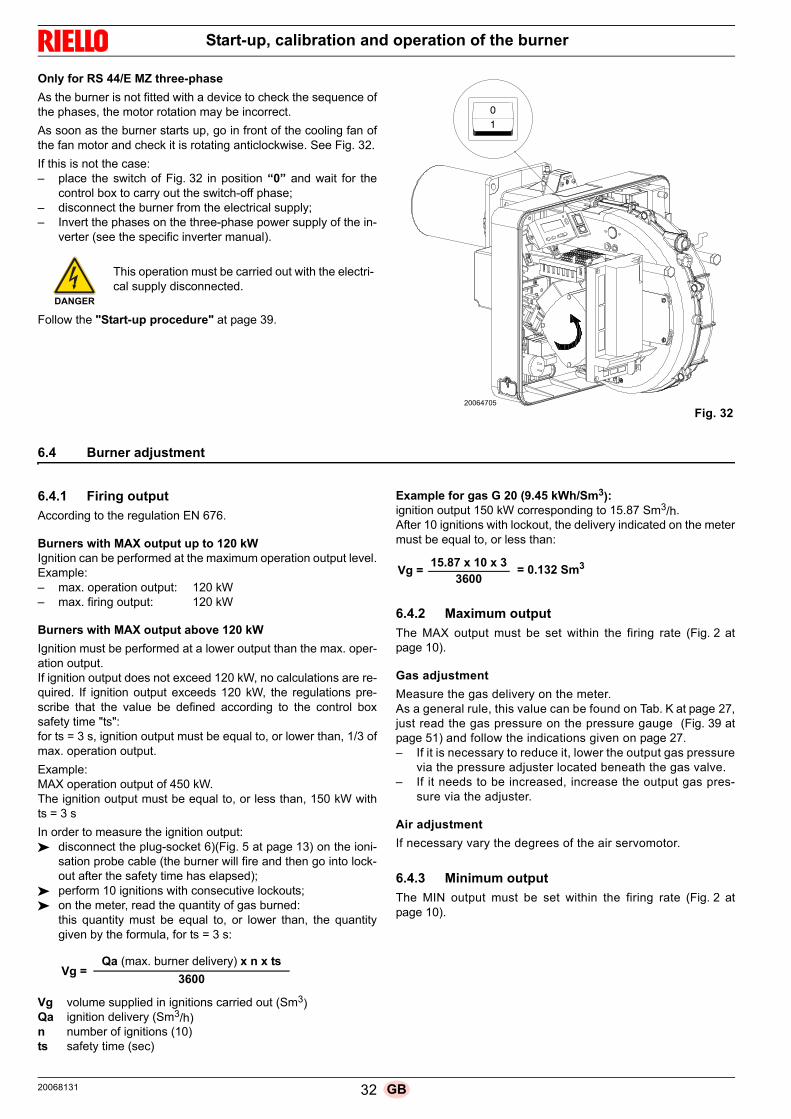
Start-up, calibration and operation of the burner
Only for RS 44/E MZ three-phase
As the burner is not fitted with a device to check the sequence ofthe phases, the motor rotation may be incorrect.
As soon as the burner starts up, go in front of the cooling fan ofthe fan motor and check it is rotating anticlockwise. See Fig. 32.
If this is not the case:– place the switch of Fig. 32 in position “0” and wait for the
control box to carry out the switch-off phase;– disconnect the burner from the electrical supply;– Invert the phases on the three-phase power supply of the in-
verter (see the specific inverter manual).
Follow the "Start-up procedure" at page 39.
6.4 Burner adjustment
6.4.1 Firing output
According to the regulation EN 676.
Burners with MAX output up to 120 kWIgnition can be performed at the maximum operation output level.Example:– max. operation output: 120 kW– max. firing output: 120 kW
Burners with MAX output above 120 kW
Ignition must be performed at a lower output than the max. oper-ation output.If ignition output does not exceed 120 kW, no calculations are re-quired. If ignition output exceeds 120 kW, the regulations pre-scribe that the value be defined according to the control boxsafety time "ts":for ts = 3 s, ignition output must be equal to, or lower than, 1/3 ofmax. operation output.
Example:MAX operation output of 450 kW.The ignition output must be equal to, or less than, 150 kW withts = 3 s
In order to measure the ignition output: disconnect the plug-socket 6)(Fig. 5 at page 13) on the ioni-
sation probe cable (the burner will fire and then go into lock-out after the safety time has elapsed);
perform 10 ignitions with consecutive lockouts; on the meter, read the quantity of gas burned:
this quantity must be equal to, or lower than, the quantitygiven by the formula, for ts = 3 s:
Vg volume supplied in ignitions carried out (Sm3)Qa ignition delivery (Sm3/h)n number of ignitions (10)ts safety time (sec)
Example for gas G 20 (9.45 kWh/Sm3):ignition output 150 kW corresponding to 15.87 Sm3/h.After 10 ignitions with lockout, the delivery indicated on the metermust be equal to, or less than:
6.4.2 Maximum output
The MAX output must be set within the firing rate (Fig. 2 atpage 10).
Gas adjustment
Measure the gas delivery on the meter. As a general rule, this value can be found on Tab. K at page 27,just read the gas pressure on the pressure gauge (Fig. 39 atpage 51) and follow the indications given on page 27.– If it is necessary to reduce it, lower the output gas pressure
via the pressure adjuster located beneath the gas valve.– If it needs to be increased, increase the output gas pres-
sure via the adjuster.
Air adjustment
If necessary vary the degrees of the air servomotor.
6.4.3 Minimum output
The MIN output must be set within the firing rate (Fig. 2 atpage 10).
DANGER
This operation must be carried out with the electri-cal supply disconnected.
Fig. 3220064705
Vg =3600
Qa (max. burner delivery) x n x ts
Vg =3600
15.87 x 10 x 3= 0.132 Sm3
20068131 32 GB

Start-up, calibration and operation of the burner
6.5 Final calibration of the pressure switches
6.5.1 Air pressure switch
Adjust the air pressure switch (Fig. 33) after having performed allother burner adjustments with the air pressure switch set to thestart of the scale.
With the burner working at MIN output, insert a combustionanalyser in the stack, slowly close the suction inlet of the fan (forexample, with a piece of cardboard) until the CO value does notexceed 100 ppm.
Slowly turn the appropriate knob clockwise until the burner goesinto lockout.
Check the indication of the arrow pointing upwards on the gradu-ated scale. Turn the knob clockwise again, until the value shownon the graduated scale corresponds with the arrow pointingdownwards, and so recovering the hysteresis of the pressureswitch (shown by the white mark on a blue background, betweenthe two arrows).
Now check the correct start-up of the burner. If the burner locksout again, turn the knob slightly anticlockwise. During these op-erations it may be useful to measure the air pressure with a pres-sure gauge.
The connection of the pressure gauge is shown in Fig. 33. The standard configuration is that with the air pressure switchconnected in absolute mode. Note the presence of a “T” connec-tion, not supplied.
In certain applications in strong depression situations, the con-nection of the pressure switch does not allow it to change over. Inthis case it is necessary to connect the pressure switch in differ-ential mode, applying a second tube between the air pressureswitch and the fan suction line mouth. In this case also, the pressure gauge must be connected in differ-ential mode, as shown in Fig. 33.
6.5.2 Minimum gas pressure switch
Adjust the minimum gas pressure switch (Fig. 34) after havingperformed all other burner adjustments with the pressure switchset to the start of the scale.
With the burner operating at maximum output, increase adjust-ment pressure by slowly turning the relative knob clockwise untilthe burner locks out.
Then turn the knob anticlockwise by 0,2 kPa (2 mbar) and repeatthe burner start-up to ensure it is regular.
If the burner locks out again, turn the knob anticlockwise again by0,1 kPa (1 mbar).
6.5.3 PVP pressure switch kit
Adjust the pressure switch for the valve leak detection control de-vice (PVP Kit)(Fig. 35), if present, according to the instructionssupplied with the Kit itself.
WARNING
1 kPa = 10 mbar
Fig. 33
Connecting the pressure gauge with the pressure switch in differen-tial mode
D8003
D3951
Connecting the pressure gauge with the pressure switch in abso-lute mode
Fig. 34D3855
Fig. 35D3855
33 20068131GB

Start-up, calibration and operation of the burner
6.6 Visualisation and programming mode
6.6.1 Normal mode
The Normal mode is the standard operation mode visualised onthe operator panel display. It is the main level of the menu. Visualises the operation conditions and allows you to modify
the operation point of the burner manually. It does not require any use of the keys of the operator panel. It allows access to the other visualisation and programming
modes.
From Normal mode you can access other levels:– Info mode (InFo)– Service mode (SEr)– Parameter mode (PArA)
Some examples in the standard conditions are given below.
6.6.1.1 Burner display in stand-by
The burner is in the heat request waiting mode, or the selector “0-1” (Fig. 32 at page 32) is in the “0” position.
6.6.1.2 Display during the start up / stop
The display visualises the various phases of the start-up, ignitionand switch-off of the burner.
In the example, the display indicates that the burner is inPhase 30 (see diagram Fig. 36) and there are 12s to the succes-sive stage.
6.6.1.3 Display of the work position
The burner is working in the requested load position (in the exam-ple alongside, 78.4%).
6.6.1.4 Condition error message, display of the errors and information
The display visualises alternately the error code (in the examplec: 12) and the relative diagnostic (in the example d: 0).
The system goes into safety mode and the message shown in thenext figure appears.
The burner goes into lockout.
The display visualises alternately the lockout code (in the exam-ple alongside c: 4) and the relative diagnostic (in the example d:3). The red lockout lamp is on.
The display visualises alternately an error code and a diagnostic,which does not take the system into safety mode.
D9
00
2
P
hV min s %
D9
00
3
P
hV min s %
D9
00
4
P
hV min s %
D9
00
5
P
hV min s %
D9
00
6
P
hV min s %
D9
00
7
P
%sminV h
D9
00
8
P
hV min s %
D9
00
9
P
%sminV h
D9
01
0
P
hV min s %
20068131 34 GB
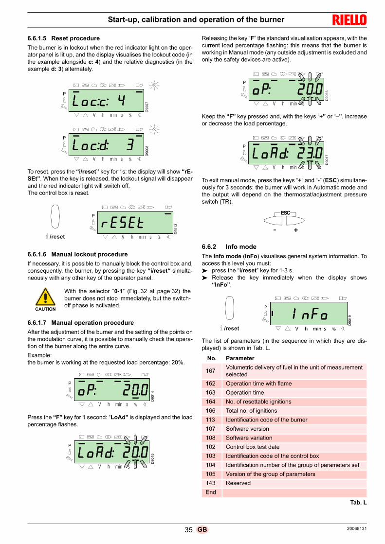
Start-up, calibration and operation of the burner
6.6.1.5 Reset procedure
The burner is in lockout when the red indicator light on the oper-ator panel is lit up, and the display visualises the lockout code (inthe example alongside c: 4) and the relative diagnostics (in theexample d: 3) alternately.
To reset, press the “i/reset” key for 1s: the display will show “rE-SEt”. When the key is released, the lockout signal will disappearand the red indicator light will switch off. The control box is reset.
6.6.1.6 Manual lockout procedure
If necessary, it is possible to manually block the control box and,consequently, the burner, by pressing the key “i/reset“ simulta-neously with any other key of the operator panel.
6.6.1.7 Manual operation procedure
After the adjustment of the burner and the setting of the points onthe modulation curve, it is possible to manually check the opera-tion of the burner along the entire curve.
Example: the burner is working at the requested load percentage: 20%.
Press the “F” key for 1 second: “LoAd” is displayed and the loadpercentage flashes.
Releasing the key “F” the standard visualisation appears, with thecurrent load percentage flashing: this means that the burner isworking in Manual mode (any outside adjustment is excluded andonly the safety devices are active).
Keep the “F” key pressed and, with the keys “+” or “–”, increaseor decrease the load percentage.
To exit manual mode, press the keys “+” and “-” (ESC) simultane-ously for 3 seconds: the burner will work in Automatic mode andthe output will depend on the thermostat/adjustment pressureswitch (TR).
6.6.2 Info mode
The Info mode (InFo) visualises general system information. Toaccess this level you must: press the “i/reset” key for 1-3 s. Release the key immediately when the display shows
“InFo”.
The list of parameters (in the sequence in which they are dis-played) is shown in Tab. L.
Tab. L
CAUTION
With the selector “0-1” (Fig. 32 at page 32) theburner does not stop immediately, but the switch-off phase is activated.
D9
00
7
P
%sminV h
D9
00
8
P
hV min s %
D9
01
3
P
%sminV h������
D9
01
4
P
hV min s %
D9
01
5
P
sminV h
No. Parameter
167Volumetric delivery of fuel in the unit of measurementselected
162 Operation time with flame
163 Operation time
164 No. of resettable ignitions
166 Total no. of ignitions
113 Identification code of the burner
107 Software version
108 Software variation
102 Control box test date
103 Identification code of the control box
104 Identification number of the group of parameters set
105 Version of the group of parameters
143 Reserved
End
D9
016
P
shV min
D9
01
7
P
sminV h
ESC
������
P
%minV h s
D9
01
9
35 20068131GB

Start-up, calibration and operation of the burner
6.6.3 Service mode
The Service mode (SEr) visualises the error log and certaintechnical information about the system. To access this level youmust: press the “i/reset” key for more than 3 s. Release the key immediately when the display shows
“SEr”.
The list of parameters (in the sequence in which they are dis-played) is shown in Tab. M.
Tab. M
6.6.3.1 Operating mode on Info Mode and Service Mode
After access to these levels, the display visualises the number ofthe parameter (flashing) on the left, and the corresponding valueon the right.
If the value is not displayed, press the “i/reset” key for a periodof 1 - 3s.
To return to the Parameter List, press the “i/reset” key for morethan 3s, or press the keys “+” and “-” (ESC) simultaneously.
To move on to the next parameter, press the “+” or “i/reset” keyfor less than 1 s. At the end of the list, the display visualises“End”.
To move back to the previous parameter, press the key “-”.
To return to the Normal/Standard visualisation mode, press the “i/reset” key for more than 3s, or press the keys “+” and “-” (ESC)simultaneously.
For a moment the display will show “OPErAte”.
6.6.4 Parameter mode
The Parameters Mode (PArA) displays, and allows to be mod-ified/programmed, the list of parameters indicated on page 44.
The factory-set parameters are not visible.
To access this level you must follow "Access procedure withpassword".
6.6.4.1 Access procedure with password
Press the “F” and “A” keys simultaneously for 1s.
For a moment the display will show “CodE“, and immediately af-ter you will see 7 dashes, the first one flashing.
With the keys “+” and “–” select the first character of the pass-word (letter or number), and confirm by pressing the key “i/re-set”.
Once you have confirmed, the sign “–” will appear.
Continue in the same way for the other characters.
After inserting the last character of the password, confirm bypressing the key “i/reset”: if the password inserted is correct youwill see “PArA“ for a few seconds, then you can access the var-ious groups of parameters.
With the keys “+” and “–” select the group you require.
If the password inserted is incorrect, the message “Error“ willappear for a moment. It is then necessary to repeat the proce-dure.
No. Parameter
954 Flame intensity (%)
960 Actual fuel which passes in units of volume / h(m³/h, l/h, ft³/h, gal/h)
121 Manual setting of outputNot defined = automatic operation
922 Position of the servomotors (expressed in de-grees, symbol )0 = fuel1 = air
161 Number of errors
701÷725 Log of the errors: 701-725.01, Code
������
D9
02
0
P
shV min %
D9
02
1
P
%minh sD
90
25
P
V %minh s
D9
02
6
P
V %sminh
VSD
AF
������
D9
02
7
P
h min s %V
������
D9
02
2
P
sh min %V
D9
02
3
P
V %sminh
D9
02
4
P
h min s %V
20068131 36 GB

Start-up, calibration and operation of the burner
Once the access procedure has been carried out, the display willshow “PArA” for a few seconds.
Select the group of parameters with keys “+“ and “-“, and con-firm by pressing the “i/reset” key.
Within the group you have chosen, scroll through the list with thekeys “+“ and “-”. At the end of the list, the display visualises“End“.
To return to Normal visualisation mode, simultaneously press thekeys “+” and “-” (ESC) twice.
6.6.4.2 Allocating the levels of the parameters
The parameters' level is subdivided into groups as shown in Tab.N.
Tab. N
To modify a parameter, refer to the "Parameter modificationprocedure".
6.7 Parameter modification procedure
After accessing the level and group of parameters, the displayvisualises the number of the parameter (flashing) on the left, andthe corresponding value on the right.
If the value is not visualised, press the key “i/reset” for 1 - 3s.An example of how to modify the parameter relating to pre-purging time (no.225) is given below.Press the key “i/reset“: the value 20 (seconds) will appear.
NOTE:The unit of measurement of the time is not visualised but is un-derstood in seconds.
Press the key “+“ and increase the value to 25 seconds (flash-ing). Press the key “i/reset“ to confirm and store.
To return to the list of parameters, press the keys “+“ and “-“(ESC) simultaneously.
WARNING
The password must only be communicated to thequalified personnel or the Technical AssistanceService, and must be kept in a safe place.
D9
02
2
P
sh min %V
������
ESC
No. Parameter
100: ParA General parametersInformation and identification data of the system.
200: ParA Checks on the burnerType of operation, intervention and safety timesof the various phases.
400: Set Air/fuel modulation curveSetting of air/fuel adjustment points
500: ParA Positioning of servomotorsChoice of positions of the air/fuel servomotors inthe various phases.
600: ParA ServomotorsSetting and addressing of the servomotors.
700: HISt Log of the errors:Choice of different visualisation modes for the er-rors log.
900: dAtA Process informationVisualisation of information for the remote man-agement of the burner.
WARNING
All the parameters are checked in the factory. Modification/tampering may compromise thegood operation of the burner and cause injury topeople or damage to things. In any case, modifi-cations must be carried out by qualified person-nel.
D9
02
8
P
%sminh
������
D9
02
9
h min s %V
P
D9
03
0
P
V %sh mi ������
D9
03
1
P
%sh min
ESC
37 20068131GB

Start-up, calibration and operation of the burner
6.7.0.1 Procedure for inserting and adjusting points on the modulation curve
Nine adjustment/calibration points (P1 ÷ P9) can be inserted inthe control box for each servomotor, varying their position by de-grees and, consequently, the quantity of air and fuel introduced.
The ignition point P0 is independent of the minimum modulationvalue. This means that, in the event of difficulty, it is possible toswitch on the burner at a value other than the modulation mini-mum (P1).
To access the Parameter mode (group 400) referring to the "Ac-cess procedure with password" at page 36.
To insert or adjust a point, proceed as follows.
Using the keys “+” and “-” insert/select the curve point you wantand wait for it to flash: this means that the servomotors are nowpositioned on the values shown on the display and which corre-spond to the point previously set.
It is now possible to insert/modify the position by degrees.
For the fuel servomotor, keep the key “F” pressed (the positionin degrees flashes) and press the keys “+” or “-” to increase ordecrease the value.
For the air servomotor, keep the key “A” pressed (the position indegrees flashes) and press the keys “+” or “-” to increase or de-crease the value.
To adjust the speed of the inverter (expressed in % and that is 50Hz = 100 %), keep the buttons “F” and “A” simultaneouslypressed, the percentage position blinks and press buttons “+” or“-” to increase or decrease the value.
Select another point, or exit this area by pressing the keys “+”and “-” (ESC) simultaneously.
6.7.0.2 CALC function
The diagram (Fig. 36) shows how the fuel modulation curve ismodified if the values of point “P5” are changed.By keeping the “+” key pressed for more than 3s, the pointsfrom “P6” to “P8” are recalculated.By keeping the “-” key pressed for more than 3s, the points from“P4” to “P2” are recalculated.
The diagram of (Fig. 37) shows the fuel modulation curve when,after the modification of point “P5”, the recalculation of all the oth-er points is not carried out.
WARNING
The set value does not require confirmation.
D9
03
2
P
minh s %V
D9
033
P
s %F
D9
03
4
P
V minhA
D1
213
5
h min %
P
V
VSD
AF
ESC
Fig. 36
P0 P1 P2 P3 P4 P5 P6 P7 P8 P90
10
20
30
40
50
60
70
80
90
100
An
gle
(deg
rees
)
Point of the curve
originalcurve
CALC-
CALC+
D7908
Recalculation
Fuel
Fig. 37
P0 P1 P2 P3 P4 P5 P6 P7 P8 P90
10
20
30
40
50
60
70
80
90
100
Point of the curve
Ang
le (
degr
ees
)
D7909
Fuel
20068131 38 GB

Start-up, calibration and operation of the burner
6.8 Start-up procedure
Check that the operator panel display shows the heat requestand “OFF Upr”: this means it is necessary to set the modulationcurve of the burner.
Access the Parameters Level referring to "Access procedurewith password" at page 36.The display screen displays the parameters group 400.
Confirm with the key “i/reset”
The display visualises “run”
Confirm with the key “i/reset”. The burner starts up.
The display visualises all the phases and relative times in se-quence. The phases are listed in section "List of phases" atpage 18.
Phase 22:
Start of the fan motor.
Phase 24:
The burner goes to the pre-purging position, the air servomotoropens the damper at 90°.
Phases 80, 81, 82, 83:
These phases relate to the valve seal test.
Phase 30:The count of the pre-purging time pre-set in the factory begins.
Phase 36:
The burner goes to its switch-on position, point “P0”, defined inTab. O at page 40: the display shows a flashing “P0” indicator.
If the set value is adequate, confirm using the button “+”.
Otherwise, modify the ignition point, see the section "Procedurefor inserting and adjusting points on the modulation curve"at page 38).
Phase 38:
The ignition phase begins and the spark goes off.
Phase 40:
The gas valves open (the count of the safety time begins). Checkthe presence of the flame from the special inspection window,and that the combustion parameters are correct. if necessary,vary the degrees of opening/closing of the air and fuel servomo-tors.
If the control box goes into lockout, press the keys “+” and “-”(ESC) simultaneously: the display visualises alternately the lock-out code for flame absence c: 4) and the relative diagnostic (d: 3).
Solve the problem, referring to the paragraph "Ignition failure"at page 48.
To unlock, see "Reset procedure" at page 35. The display vis-ualises “OFF Upr”.
Repeat the "Start-up procedure".
Once it has ignited (point “P0”), proceed with the calibration ofthe modulation curve.
Press the button “+”: the display visualises the flashing “P1” indi-cator and proposes the same settings as for point “P0”.
Press the button“+” again: “CALC” appears on the display for afew seconds.
D9
03
5
h min s %V
P
D9
023
P
V %sminh
������
20
06
441
4
WARNING
The values shown in the figure are purely for indi-cation purposes.
WARNING
The values previously inserted remain stored.
D9
03
2
P
minh s %V
D9
007
D9
00
8
P
%sminV h
P
hV min s %D
904
1
h min s %V
P
39 20068131GB

Start-up, calibration and operation of the burner
The control box will automatically report the same values set atthe points “P0” and “P1” to points “P2” to “P8”.
Press the key “+” until point “P9” has been reached.
Once “P9” has been reached wait until the display visualises theflashing indictor “P9” proposing the same settings as point “P0”.
Now it is possible to change this value to attain the desired max-imum operating power.
If the gas pressure is too low, despite opening the gas servomotorto the maximum 90°, it is necessary to use the stabiliser of thegas valve.
After adjusting point “P9 keep the key “+” pressed for about 5 sec-onds, the display shows “CALC” for a few seconds.
The control box will automatically calculate the points from “P8”to “P2”, distributing them in a line. These are theoretical and mustbe checked.
Check that the settings of point “P8” are adequate.
If not, modify the point.
Proceed in sequence, with the button “-” , up to point “P1”.
It is possible to modify point “P1” to obtain a different minimummodulation point to the ignition point (“P0”).
During the adjustment of each point, work on the air and gas ser-vomotors, without modifying the position of the gas valve stabilis-er.
Halfway through the procedure (i.e. around point P4 or P5), youare advised to measure the gas delivery and check that the out-put is about 50% of the maximum output.
If this is not the case, work also on the gas valve stabiliser: in thiscase however, it is necessary to revise the calibrations of all thepoints previously set.
Once the calibration of point “P1” is finished, confirm by simulta-neously pressing keys “+” and “-” (ESC): the parameter “546” ap-pears.
If you want to make the burner work on the entire modulationcurve, press the “+” and “-” (ESC) keys simultaneously: in thisway, parameter “546” will automatically be assigned the value of100% and parameter “545” will have a value of 20%.
If you want to make the burner work on just a part of the modula-tion curve, modify parameters “546” and “545” according to the"Parameter modification procedure" at page 37.
Simultaneously press the keys “+” and “-” (ESC) twice, the dis-play will show the position of the current load.
Factory settings
Tab. O
IMPORTANT
The purpose is to reach the point “P9” to adjust/fixthe maximum operating power.
IMPORTANT
Before moving on from one point to the next, waitfor the servomotors to reach the position visual-ised on the display.
D9
04
1
h min s %V
P
Point of the curveBurner
RS 34/E MZ RS 44/E MZ
P0air 13° 18°
gas 20° 30°
WARNING
At the end of the "Start-up procedure" it is nec-essary to carry out a "Backup", which is used tomemorise the parameters and the data in the con-trol box inside the RDI21 display …
This operation allows the parameters and thepoints of the modulation curve to be restored incase of problems.
It is advisable to perform a backup every time thata parameter is changed!
For the procedure refer to the section "Backup"at page 41.
D9
01
4
P
hV min s %
ESC
20068131 40 GB

Start-up, calibration and operation of the burner
6.9 Backup / Restore procedure
At the end of the "Start-up procedure" it is opportune to make abackup, creating a copy of the data memorised on the REC, inthe display panel RDI 21.
This will allow the data be used to programme a new REC or toreturn to the memorised settings of the same REC.
6.9.1 Backup
To perform the backup, proceed as follows: access the Parameters Level referring to "Access proce-
dure with password" at page 36.
The display screen displays the parameters group 400.
With the key "-":
Select the parameters group 000:
The 000 parameter blinks, confirm using the "i/reset" key:
The display screen shows parameter 050 blinking:
Confirm with the key "i/reset":
The parameter bAC_UP appears on the display screen:
confirm with the key "i/reset":
The display screen shows the following value:
Use the button "+":
The value will be set to 1. Value 1 is flashing:
confirm with the button "i/reset" to activate the backup process.
The value 1 appears on the display screen:
After approx 5 seconds (it depends on the duration of the pro-gramme), the 0 value appears on the display screen, this is to in-dicate that the backup process has been completed correctly.
WARNING
We suggest carrying out this operation at the endof each intervention that modifies what has beenset on the cam.
This will allow a restore to be easily carried out ona new cam supplied as a replacement part, with-out having to reprogramme the system.
D9
02
3
P
V %sminh
D1
21
40
h min s %
P
������
D1
21
41
h min s %
P
������
D1
21
42
h min s %
P
V
������
D1
214
3
h min s %
P
V
D12
14
4
h min s
P
V
������
D12
14
5
h min s %
P
V
D1
214
3
h min s %
P
V
41 20068131GB

Start-up, calibration and operation of the burner
NOTE:If an error occurs during the backup process, the displayscreen shows a negative value. To determine the cause of the error refer to diagnostic code137 (see section "Error codes list" at page 53).
6.9.2 Restore
To perform the restore procedure, proceed as follows: access the Parameters Level referring to "Access proce-
dure with password" at page 36.
The display screen displays the parameters group 400.
With the key "-":
Select the parameters group 000:
The 000 parameter blinks, confirm using the "i/reset" key:
The display screen shows parameter 050 blinking:
Confirm with the key "i/reset":
The parameter bAC_UP appears on the display screen:
With the key "+"
Select therEStorE parameter
Confirm with the key "i/reset":
The display screen shows the following value.
Use the button "+":
The value will be set to 1. Value 1 is flashing:
confirm with the button "i/reset" to activate the restore process.
WARNING
It is advisable to perform a backup every timethat a parameter is changed, after checkingthe modification carried out is correct.
WARNING
Use this procedure when replacing equipmentwith a parts code. In this way it is possible to havethe default parameters already memorised orthose memorised during the start-up.
The procedure cannot be carried out on equip-ment coming from other burners.
D9
02
3
P
V %sminh
D1
21
40
h min s %
P
������
D12
14
1
h min s %
P
������
D1
21
42
h min s %
P
V
D1
21
46
h min s %
P
V
������
D1
21
43
h min s %
P
V
D1
214
4
h min s
P
V
������
20068131 42 GB

Start-up, calibration and operation of the burner
The value 1 appears on the display screen:
After approx 8 seconds (it depends on the duration of the pro-gramme), the 0 value appears on the display screen, this is to in-dicate that the restore process has been completed correctly.
NOTE:When the restore process is successfully completed, the 0value is shown on the display screen. Err C information: 136 D: 1 (restore process initialised) isdisplayed for a brief moment.
IMPORTANT
At the end of the restore process, it is neces-sary to check the sequence of functions andthe list of parameters.
D1
21
45
h min s %
P
V
D1
214
3h min s %
P
V
43 20068131GB

Start-up, calibration and operation of the burner
6.9.3 Parameter list
Parameter No. ele-ments
Unit of measure
Modifica-tion
Value range Degree of accuracy
Defaultsetting
Acces modeNo. Description Min. Max.
000 INTERNAL PARAMETERS
050
Start backup/restore process via RDI21... / PC TOOL (set the parameter to 1)Index 0 = create backupIndex 1 = perform restoreNegative values indicate errors
2 - Modification -99 2 1 0; 0 Service mode
055Burner identification number created from the backup on RDI21...
1 - Reading only 0 99999999 1 0 Service mode
056 ASN number created by the backup on RDI21... 8 - Reading only 0 127 1 0 Service mode
057 Software Version created by the backup on RDI21... 1 - Reading only 0x100 0xFFF9 1 0 Service mode
100 GENERAL PARAMETERS
102 Control box identification date 1 - Reading only 0 255 1 Info mode
103 Control box identification number 1 - Reading only 0 65535 1 Info mode
104 Identification number of the group of parameters set 1 - Reading only 0 255 1 30 Info mode
105 Version of the group of parameters set 1 - Reading only 0 0xFFFF 1 V 01.08 Info mode
107 Software version 1 - Reading only 0 0xFFF9 1 V 03.30 Info mode
108 Software variation 1 - Reading only 0 225 1 1 Info mode
111ASN number to verify the ASN number created by the backup on RDI 21…
8 - Reading only 0 127 1 0 Service mode
113 Burner identification 1 - Modification 0 99999999 1 Not definedInfo Mode with
password Service Mode
121Manual setting of outputNot defined = automatic operation
1 %Modification /zero setting
0% 100% 0.1% Not defined Info mode
123
Minimum output step positionIndex 0: BACS outputIndex 1: output of the external load regulator, analogue.Index 2: output of the external load regulator contacts.
3 % Modification 0% 100% 0.1%0% ; 1%;
0%Service mode
124Beginning flame loss test (TÜV test) (define the parameter at 1) (switch of flame loss fuel valves) A negative value indicates an error (see code 150)
1 - Modification -6 1 1 0 Service mode
125Frequency of main power supply0 = 50 Hz1 = 60 Hz
1 - Modification 0 1 1 0 Service mode
126 Brightness of display 1 % Modification 0% 100% 1% 75% Service mode
128Fuel meter: Led pulse valence(led pulses / volumetric flow units)
1 - Modification 0 400 0.01 0 Service mode
130
Eliminate visualisation error chronologyTo eliminate the visualisation, set the parameter to 1, then to 2Answer 0: process successfulAnswer -1: time-out of 1_2 - sequence
1 - Modification -5 2 1 0 Service mode
133
Default output for TÜV test:TÜV test not valid when output is activated 2,000 ..... 10,000 = low flame or first / second / third stage
1 %Modification /zero setting
20% 100% 0.1% Not defined Service mode
141
Remote management of control box0 = off1 = Modbus2 = reserved
1 - Modification 0 2 1 0 Service mode
142
Standby time before a new attempt in event of com-munication faultValues set: 0 = not active1 = .... 7200 s
1 s Modification 0s 7200s 1s 120s Service mode
143 Reserved 1 - Modification 1 8 1 1 Info mode
144 Reserved 1 s Modification 10s 60s 1s 30s Service mode
145Peripheral address for ModbusValues set:1 ... 247
1 - Modification 1 247 1 1 Service mode
20068131 44 GB

Start-up, calibration and operation of the burner
146
Baud Rate for ModbusValues set:0 = 96001 = 19200
1 - Modification 0 1 1 1 Service mode
147
Parity for Modbus0 = none1 = odd2 = even
1 - Modification 0 2 1 0 Service mode
148
Selection of the burner operation during the interrup-tion of the switch-over with the system of remote man-agement.Values set:With modulating operation the settings of the valuesare the following:0...19.9 = burner switched off20...100 = 20...100% modulation field of the burner.With stage operation: 0 = burner off P1, P2, P3No setting = no function in the event of communicationinterruption
1 %Modification /zero setting
0% 100% 0.1% Not defined Service mode
161 Total number of errors 1 - Reading only 0 65535 1 0 Info mode
162 Hours of operation (that can be reset) 1 h Reset 0h 999999 h 1h 0h Info mode
163 Total hours of power supply to control box 1 h Reading only 0h 999999h 1h 0h Info mode
164 Total number of start-ups (that can be reset) 1 - Reset 0 999999 1 0 Info mode
166 Total number of start-ups 1 - Reading only 0 999999 1 0 Info mode
167Volumetric delivery of fuel in the selected unit of meas-urement (that can be reset)
1m3, l,ft3, gal
Reset 0 99999999 1 0 Info mode
200 CHECKS ON THE BURNER
201
Burner operation mode (fuel supply line, modulating/stage, servomotors, etc.)-- = not defined (eliminate curves)1 = Gmod2 = Gp1 mod3 = Gp2 mod4 = Lo mod5 = Lo 2 stage6 = Lo 3 stage7 = Gmod pneu8 = Gp1 mod pneu9 = Gp2 mod pneu10 = LoGp mod11 = LoGp 2-stage12 = Lo mod 2 fuel valves13 = LoGp mod 2 fuel valves14 = G mod pneu without actuator15 = Gp1 mod pneu without actuator16 = Gp2 mod pneu without actuator17 = Lo 2-stage without actuator18 = Lo 3-stage without actuator19 = G mod only gas actuator20 = Gp1 mod only gas actuator21 = Gp2 mod only gas actuator22 = Lo mod only oil actuator
1 -Modify/set to
zero1 22 1 Not defined Service mode
208
Stopping of the program0 = deactivated1 = pre-purging (Ph24)2 = Ignition (Ph36)3 = Interval 1 (Ph44)4 = Interval 2 (Ph52)
1 - Modification 0 4 1 0 Service mode
210Alarm as the pre-purging phase begins;0 = Deactivated;1 = Activated
1 - Modification 0 1 1 0 Service mode
211 Uphill train fan motor 1 s Modification 2s 60s 0.2s 2s Service mode
212 Maximum time to reach low flame 1 s Modification 0.2s 10 min 0.2s 45s Service mode
215
Maximum repeats of safety circuit1 = No repetition2...15 = Number of repetitions16 = Constant repetitions
1 - Modification 1 16 1 16 Service mode
Parameter No. ele-ments
Unit of measure
Modifica-tion
Value range Degree of accuracy
Defaultsetting
Acces modeNo. Description Min. Max.
45 20068131GB

Start-up, calibration and operation of the burner
221Gas: selection of flame sensor0 = QRB.../ QRC1 = ION / QRA
1 - Modification 0 1 1 1 Service mode
222Gas: Selection of the pre-purging function0 = deactivated1 = activated
1 - Modification 0 1 1 1 Service mode
223
Maximum repeats of minimum gas pressure switch intervention1 = No repetition2...15 = Number of repetitions16 = Constant repetitions
1 - Modification 1 16 1 16 Service mode
225 Gas: pre-purging time 1 s Modification 20s 60 min 0.2s 20s Service mode
226 Gas: pre-ignition time 1 s Modification 0.4 s 60 min 0.2s 2s Service mode
230 Gas: interval 1 1 s Modification 0.4 s 60s 0.2s 2s Service mode
232 Gas: interval 2 1 s Modification 0.4 s 60s 0.2s 2s Service mode
233 Gas: post-combustion time 1 s Modification 0.2s 60s 0.2s 8s Service mode
234 Gas: Post-purging time (no extraneous light test) 1 s Modification 0.2s 108 min 0.2s 0.2s Service mode
236
Gas: Minimum gas pressure switch input0 = deactivated1 = minimum gas pressure switch (upstream of the fuel valve 1 (V1))2 = valve control via the minimum pressure switch (between fuel vale 1 (V1) and 2 (V2))
1 - Modification 1 2 1 1 Service mode
237
Gas: Maximum gas pressure switch / POC Input0 = deactivated1 = Maximum gas pressure switch2 = POC
1 - Modification 1 2 1 1 Service mode
241
Gas: Valve leak detection test0 = test deactivated1 = valve leak detection test at start-up2 = valve leak detection test at shut-down3 = valve leak detection test at start-up and at shut-down
1 - Modification 0 3 1 2 Service mode
248Gas: Post-purging time (t3) (at deactivation of the load (LR)) - ON
1 s Modification 1s 108 min 0.2s 1s Service mode
261Oil: selection of flame sensor0 = QRB.../ QRC...1 = ION / QRA...
1 - Modification 0 1 1 0 Service mode
265 Oil: pre-purging time 1 s Modification 15s 60 min 0.2s 15s Service mode
266 Oil: pre-ignition time 1 s Modification 0.6s 60 min 0.2s 2s Service mode
270 Oil: interval 1 1 s Modification 0.4 s 60 min 0.2s 2s Service mode
272 Oil: interval 2 1 s Modification 0.4 s 60 min 0.2s 2s Service mode
273 Oil: post-combustion time 1 s Modification 0.2s 60s 0.2s 8s Service mode
274 Oil: Post-purging time (no extraneous light test) 1 s Modification 0.2s 108 min 0.2s 0.2s Service mode
276
Oil: Minimum input oil pressure switch0 = deactivated1 = activated from phase 382 = activated from safety time (TSA)
1 - Modification 1 2 1 1 Service mode
277
Oil: Maximum oil pressure switch / POC Input0 = deactivated1 = Maximum oil pressure switch2 = POC
1 - Modification 1 2 1 1 Service mode
281Oil: selection transformer ignition phase TA0 = brief pre-ignition (Ph38)1 = long pre-ignition (with fan) (Ph22)
1 - Modification 0 1 1 1 Service mode
284Oil: Post-purging time (t3) (at deactivation of the load (LR)) - ON
1 s Modification 1s 108 min 0.2s 1s Service mode
400 AIR/FUEL MODULATION CURVES
401Checking fuel servomotor(only setting of the curve)
13 (°) Modification 0° 90° 0.1°0°; 0°; 15°; Not defined
Service mode
402Checking air servomotor(only setting of the curve)
13 (°) Modification 0° 90° 0.1°0°; 90°; 45°; Not defined
Service mode
500 POSITIONING OF SERVOMOTORS
Parameter No. ele-ments
Unit of measure
Modifica-tion
Value range Degree of accuracy
Defaultsetting
Acces modeNo. Description Min. Max.
20068131 46 GB

Start-up, calibration and operation of the burner
501
Position of the fuel servomotor in absence of flameIndex 0 = standby positionIndex 1 = pre-purging positionIndex 2 = post-purging position
3 (°) Modification 0° 90° 0.1° 0°; 0°; 15° Service mode
502
Position of the air servomotor in absence of flameIndex 0 = standby positionIndex 1 = pre-purging positionIndex 2 = post-purging position
3 (°) Modification 0° 90° 0.1° 0°; 90°; 45° Service mode
545Minimum modulation limitNot defined = 20%
1 %Modification /zero setting
20% 100% 0.1% Not defined Service mode
546Maximum modulation limitNot defined = 100%
1 %Modification /zero setting
20% 100% 0.1% Not defined Service mode
600 SERVOMOTORS
606
Tolerance limit for position check (0.1°)Index 0 = fuelIndex 1 = airMore serious position error, where a defect has cer-tainly been detected- > Stop range: (P 606 - 0.6°) a P606
2 (°) Modification 0.5° 4° 0.1° 1.7°; 1.7° Service mode
645
Analogue exit configuration0 = DC 0...10 V1 = DC 2...10 V2 = DC 0 / 2...10 V
1 - Modification 0 2 1 2 Service mode
700 LOG OF THE ERRORS
701 Error chronology: 701-725.01.Code 25 - Reading only 0 255 1 0 Info mode
• Error chronology: 701-725.02.Diagnostic code 25 - Reading only 0 255 1 0 Info mode
• Error chronology: 701-725.03.Error class 25 - Reading only 0 6 1 0 Info mode
• Error chronology: 701-725.04.Phase 25 - Reading only 0 255 1 0 Info mode
• Error chronology: 701-725.05.Start-up meter 25 - Reading only 0 99999999 1 0 Info mode
725 Error chronology: 701-725.06.Load 25 % Reading only 0% 100% 0.1% 0% Info mode
900 PROCESS INFORMATION
903Actual outputIndex 0 = fuelIndex 1 = air
2 % Reading only 0% 100% 0.1% 0% Info mode
922Position of the servomotorsIndex 0 = fuelIndex 1 = air
2 (°) Reading only -50° 150° 0.01° 0° Info mode
942
Heat source active1 = output during the definition of the curves2 = manual output3 = BACS output4 = analogue input output5 = output of the external load regulator contacts
1 - Reading only 0 255 1 0 Service mode
947
Result of the sampling of the contact (codified in bits)Bit 0.0 = 1: Minimum pressure switchBit 0.1 = 2: Maximum pressure switchBit 0.2 = 4: Pressure switch control valvesBit 0.3 = 8: Air pressure switchBit 0.4 = 16: Open load checkBit 0.5 = 32: ON load checkBit 0.6 = 64: Closed load checkBit 0.7 = 128: Safety circuit Bit 1.0 = 1: Safety valveBit 1.1 = 2: IgnitionBit 1.2 = 4: Fuel valve 1Bit 1.3 = 8: Fuel valve 2Bit 1.4 = 16: Fuel valve 3/ pilot valveBit 1.5 = 32: Reset
2 - Reading only 0 255 1 0 Info mode
950
Relay request status (coded in bits)Bit 0 = 1: AlarmBit 1 = 2: Safety valve Bit 2 = 4: IgnitionBit 3 = 8: Fuel valve 1Bit 4 = 16: Fuel valve 2Bit 5 = 32: Fuel valve 3/ pilot valve
1 - Reading only 0 255 1 0 Info mode
954 Flame intensity 1 % Reading only 0% 100% 1% 0% Info mode
Parameter No. ele-ments
Unit of measure
Modifica-tion
Value range Degree of accuracy
Defaultsetting
Acces modeNo. Description Min. Max.
47 20068131GB

Start-up, calibration and operation of the burner
Tab. P
6.10 Steady-state operation
Burner without modulating operation kit
Once the start-up cycle is completed, the servomotor commandmoves on to the thermostat/pressure switch TR that controls thepressure or the temperature in the boiler. If the temperature or the pressure is low (so the thermostat/
pressure switch TR is closed), the burner progressivelyincreases the output as far as the MAX value (point “P9”).
If the temperature or the pressure increases as far as theopening of the thermostat/pressure switch TR, the burnerprogressively reduces the output as far as the MIN value(point “P1”). And so on.
The burner switches off when the request for heat is lowerthan the heat supplied by the burner at MIN output.
The thermostat/pressure switch TL opens and the controlbox carries out the switching off phase.
The damper closes completely to reduce thermal disper-sions to a minimum.
Burner with modulating operation kitSee the manual supplied with the regulator.
6.11 Ignition failure
If the burner does not switch on, there is a lockout within 3s of theelectrical supply reaching the gas valve.
It may be that the gas does not arrive at the combustion headwithin the safety time of 3 s.
In this case, increase gas delivery upon ignition.
The arrival of the gas at the pipe coupling is shown on the pres-sure gauge of Fig. 39 at page 51.
6.12 Burner flame goes out during operation
If the flame accidentally goes out during operation, the controlbox carries out a recycle (i.e. it repeats the start-up phase once,and makes a further ignition attempt).
If the flame is still absent, the control box goes into lockout.
6.13 Stopping of the burner
The burner can be stopped by: intervening on the disconnecting switch of the electrical sup-
ply line, located on the boiler panel; removing the cover and working on the switch “0-1” of
Fig. 32 at page 32; removing the transparent protection that covers the Operator
Panel, after loosening the relative screw, and using thepanel itself according to "Manual lockout procedure" atpage 35.
960 Actual output 1m3/h, l, h, ft3/h, gal/h
Reading only 0 6553.5 0.1 0 Info mode
961 Status of external modules and visualisation 1 - Reading only 0 255 1 0 Info mode
981 Memory error: Code 1 - Reading only 0 255 1 0 Info mode
982 Memory error: diagnostic code 1 - Reading only 0 255 1 0 Info mode
992 Error indicators 10 - Reset 00xFFFFFF
FF1 0 Service mode
Parameter No. ele-ments
Unit of measure
Modifica-tion
Value range Degree of accuracy
Defaultsetting
Acces modeNo. Description Min. Max.
WARNING
In the event of a burner lockout, more than twoconsecutive burner reset operations could causedamage to the installation. On the third lockout,contact the Aftersales Service.
DANGER
If further lockouts or burner faults occur, interven-tions must only be made by qualified, authorisedpersonnel (as indicated in this manual, and incompliance with the laws and regulations current-ly in force).
20068131 48 GB

Start-up, calibration and operation of the burner
6.14 Final checks (with burner operating)
Tab. Q
Open the thermostat/pressure switch TL Open the thermostat/pressure switch TS ✟ The burner must stop
Turn the gas maximum pressure switch knob to the mini-mum end of scale position
Turn the air pressure switch to the maximum end of scaleposition.
✟ The burner must stop in lockout
Switch off the burner and disconnect the voltage. Disconnect the minimum gas pressure switch connector. ✟ The burner must not start
Disconnect the ionisation probe wire ✟ The burner must stop in lockout due to firing failure
WARNING
Make sure that the mechanical locking systemson the various adjustment devices are fully tight-ened.
49 20068131GB

Maintenance
7.1 Notes on safety for the maintenance
The periodic maintenance is essential for the good operation,safety, yield and duration of the burner.
It allows you to reduce consumption and polluting emissions andto keep the product in a reliable state over time.
Before carrying out any maintenance, cleaning or checking oper-ations:
7.2 Maintenance programme
7.2.1 Maintenance frequency
7.2.2 Checking and cleaning
CombustionThe optimum calibration of the burner requires an analysis of theflue gases. Significant differences with respect to the previousmeasurements indicate the points where more care should be ex-ercised during maintenance.
Combustion headOpen the burner and make sure that all the components of thecombustion head are undamaged, not deformed due to hightemperature, free of ambient dirt or dust, free of rusted materialsand adequately positioned.
FanCheck to make sure that no dust has accumulated inside the fanor on its blades, as this condition will cause a reduction in the airflow rate and provoke polluting combustion.
BurnerClean the outside of the burner.
Gas leaksMake sure that there are no gas leaks on the pipes between thegas meter and the burner.
Gas filterReplace the gas filter when it is dirty.
BoilerClean the boiler as indicated in its accompanying instructions inorder to maintain all the original combustion characteristics intact,especially the flue gas temperature and combustion chamberpressure.
CombustionIf the combustion values found at the start of the intervention donot satisfy current standards or anyway indicate a poor state ofcombustion (consult the table below), contact the Technical As-sistance Service for the necessary adjustments.
Tab. R
7 Maintenance
DANGER
The maintenance interventions and the calibrationof the burner must only be carried out by qualified,authorised personnel, in accordance with the con-tents of this manual and in compliance with thestandards and regulations of current laws.
DANGER
Disconnect the electrical supply from the burnerby means of the main system switch.
DANGER
Close the fuel interception tap.
Wait for the components in contact with heatsources to cool down completely.
The gas combustion system should be checked atleast once a year by a representative of the man-ufacturer or another specialised technician.
The operator must use the required equipmentduring maintenance.
EN 676Air excess
COMax. output 1.2
Max. output 1.3
GASTheoretical max. CO2
0 % O2
CO2 % Calibrationmg/kWh
= 1.2 = 1.3
G 20 11.7 9.7 9 1000
G 25 11.5 9.5 8.8 1000
G 30 14.0 11.6 10.7 1000
G 31 13.7 11.4 10.5 1000
20068131 50 GB

Maintenance
7.2.3 Measuring the ionisation current
The burner is fitted with an ionisation system to check that aflame is present.
The minimum current for control box operation is 4 µA. The Op-erator Panel visualises “30%” (see "Parameter list" at page 44,parameter no. 954).
The burner provides a much higher current, so controls are notnormally required.
However, if it is necessary to measure the ionisation current, dis-connect the plug-socket on the ionisation probe cable and inserta direct current microammeter with a base scale of 100 µA - seeFig. 38.
7.2.4 Checking the air and gas pressure on the combustion head
To carry out this operation a pressure gauge must be used tomesure the air and gas pressure at the combustion head, asshown in Fig. 39.
WARNING
Carefully check the polarities!
Fig. 38D8006
D8005
Checkingair pressure
Checkinggas pressure
Fig. 39
51 20068131GB

Maintenance
7.3 Opening the burner
Loosen the screws 1)(Fig. 40)and remove the cover 2). Remove the nuts 2)(Fig. 17 at page 24) fit them on the sup-
plied extensions and screw them on guides 3) (only for TLversions).
Disconnect the plug 14)(Fig. 17 at page 24) and loosen thegrommet 15).
Remove the screw 5)(Fig. 40) and pull back the burner onthe guides 3) by about 100 mm.
Disconnect the cables of the probe and electrode, then pullthe burner back completely.
At this point it is possible to extract the inner part 4) afterhaving removed the screw 6).
7.4 Closing the burner
Push the burner up to approximately 100 mm from the pipecoupling.
Reinsert the cables and slide the burner as far as the stop. Connect the plug of the servomotor 14)(Fig. 17 at page 24)
and tighten the grommet 15). Tighten the screws 5)(Fig. 40) and carefully pull the probe
and electrode cables outwards until they are slightly taut. Remove the two extensions from the guides 3), fix them in
their original positions and replace the nuts 2)(Fig. 17 atpage 24)(only for TL versions).
DANGER
Disconnect the electrical supply from the burnerby means of the main system switch.
DANGER
Close the fuel interception tap.
Wait for the components in contact with heatsources to cool down completely.
Fig. 40D8096
After carrying out maintenance, cleaning orchecking operations, reassemble the hood and allthe safety and protection devices of the burner.
20068131 52 GB

Faults - Probable causes - Solutions
If faults arise in ignition or operations, the burner performs a"safety stop", which is signalled by the red burner lockout LED.
The display of the operator panel visualises alternately the lock-out code and the relative diagnostic.
To restore start-up conditions, refer to the "Reset procedure" atpage 35.
When the burner starts up again, the red LED goes out.
8.1 Error codes list
8 Faults - Probable causes - Solutions
WARNING
In the event of a burner lockout, more than twoconsecutive burner reset operations could causedamage to the installation. On the third lockout,contact the Aftersales Service.
DANGER
If further lockouts or burner faults occur, interven-tions must only be made by qualified, authorisedpersonnel (as indicated in this manual, and incompliance with the laws and regulations current-ly in force).
Error code
Diagnostic code Meaning of the REC 27.100A2 system Recommended measures
No Comm No communication betweenREC 27.100A2 and RDI21…
Check the wiring between the control box REC 27.100A2 and the display RDI21…
2 # No flame at the end of TSA1
1 No flame at the end of safety time 1 (TSA1)
2 No flame at the end of safety time 2 (TSA2)
4No flame at the end of safety time 1 (TSA1)(software version V02.00)
3 # Air pressure error
0 Air pressure switch off
1 Air pressure switch on
4 Air pressure on – Lockout alarm at start
20 Air pressure, fuel pressure on - Alarm lock at start
68 Air pressure, POC on – Alarm lockout at start
84 Air pressure, fuel pressure, POC on - Alarm lockout at start
4 # Extraneous light
0 Extraneous light during start-up
1 Extraneous light during switch-off
2 Extraneous light during start-up – Lockout alarm at start
6Extraneous light during start-up, air pressure - Alarm lockout at start
18Extraneous light during start-up, fuel pressure - Alarm lockout at start
24Extraneous light during start-up, air pressure, fuel pressure - Alarm lockout at start
66Extraneous light during start-up, POC – Alarm lockout at start
70Extraneous light during start-up, air pressure, POC - Alarm lockout at start
82Extraneous light during start-up, fuel pressure, POC - Alarm lockout at start
86Extraneous light during start-up, air pressure, fuel pressure, poc - Alarm lockout at start
7 # Loss of flame
0 Loss of flame
3 Flame loss (software version V02.00)
3…255 Flame loss during TÜV test (flame loss test)The diagnostics covers the period of time from the closure of thefuel valves at the point the flame loss was detected (resolution0.2 s value 5 = 1 s).
12 # Valve leak detection control:
0 V1 leaksLeak testCheck if the valve on the side of the gas has any leaks.Check the wiring and check that the circuit is open.
1 V2 leaks
Leak testCheck if the valve on the side of the burner has any leaks.Check if the pressure switch for the leak test (PGVP) is closed when gas pressure is not present.Check the wiring and check if there is any short-circuit.
53 20068131GB

Faults - Probable causes - Solutions
2 Valve leak detection test not possibleThe valve leak detection is active, but the minimum gas pressure switch is selected as input for X9-04 (check parameters 238 and 241)
3 Valve leak detection test not possibleThe valve leak detection is active, but no input has been assigned (check parameters 236 and 237)
4 Valve leak detection not possibleValve leak detection is active, but 2 inputs have already been assigned (configure parameter 237 or maximum gas Pressure switch or POC)
5 Valve leak detection not possibleThe valve leak detection is active, but 2 inputs have been assigned (check parameters 236 and 237)
14 # POC
0 POC Open Check if the closure contact of the valve is closed
1 POC Closed Check the wiringCheck if the closure contact of the valve opens when the valve is checked
64 POC Open - Alarm lockout at start Check the wiringCheck if the closure contact of the valve is closed
19 80 Fuel pressure, POC - Alarm lockout at startCheck that the pressure switch is closed when no pressure is present from the fuelCheck that there are no short-circuits
20 # Pmin
0 Minimum gas/oil pressure absent Check that there are no line interruptions
1 Scarcity of gas - Alarm lockout at start Check that there are no line interruptions
21 # Pmax/POC
0Pmax: Max. gas/oil pressure exceededPOC: POC open (software version V02.00)
Check the wiring.POC: check if the closure contact of the valve is closed
1 POC closed (software version V02.00)Check the wiring.Check if the closure contact of the valve opens when the valve is checked
64POC Open - Alarm lockout at the start (software version V02.00)
Check the wiring.Check if the contact of the valve opens when the valve is checked
22OFF S
# Safety circuit/Burner flange
0 Safety circuit open /Burner flange open
1Safety circuit open /Burner flange open - Alarm lockout at start
3Safety circuit open /Burner flange open, extraneous light - Alarm lockout at start
5Safety circuit open /Burner flange open, extraneous light - Alarm lockout at start
17Safety circuit open /Burner flange open, extraneous light - Alarm lockout at start
19Safety circuit open /Burner flange open, extraneous light - Alarm lockout at start
21Safety circuit open /Burner flange open, extraneous light - Alarm lockout at start
23Safety circuit open /Burner flange open, extraneous light, air pressure, fuel pressure - Alarm lockout at start
65Safety circuit /Burner flange open, POC - Alarm lockout at start
67Safety circuit open /Burner flange open, extraneous light, POC - Alarm lockout at start
69Safety circuit open /Burner flange open, air pressure, POC - Alarm lockout at start
71Safety circuit open /Burner flange open, extraneous light, air pressure, POC - Alarm lockout at start
81Safety circuit open /Burner flange open, fuel pressure, POC - Alarm lockout at start
83Safety circuit open /Burner flange open, extraneous light, air pressure, POC - Alarm lockout at start
85Safety circuit open /Burner flange, air pressure, fuel pressure, POC - Alarm lockout at start
87Safety circuit open /Burner flange, extraneous light, air pressure, fuel pressure, POC - Alarm lockout at start
Error code
Diagnostic code Meaning of the REC 27.100A2 system Recommended measures
20068131 54 GB

Faults - Probable causes - Solutions
50 ÷ 58 # Internal errorCarry out a reset; if the error arises repeatedly, replace the control box
60 0 Internal error: no valid load checking deviceCarry out a reset; if the error arises repeatedly, replace the control box
65 ÷ 67 # Internal errorCarry out a reset; if the error arises repeatedly, replace the control box
70 #Fuel/air checking error: Calculation position in modulation
23 Invalid load No valid load
26 Curve points not defined Adjust the curve points of all the actuators
71 # Special position not defined
0 Standby position Set the standby position of all the servomotors used
1 Pre-purging position Set the pre-purging position of all the servomotors used
2 Post-purging position Set the post-purging position of all the servomotors used
3 Ignition position Set the ignition position of all the servomotors used
72 # Fuel/air internal checking error:Carry out a reset; if the error arises repeatedly, replace the control box
73 #Fuel/air internal checking error: multistep calculation position
23 Position calculation, invalid stage load No valid load
26 Position calculation, stage curve points not defined Adjust the curve points of all the servomotors
75 #Fuel/air ratio internal checking error: cyclical data check
1 Check synchronisation data, different current load
2 Check synchronisation data, different target load
4 Check synchronisation data, different target positions
16 Check synchronisation data, different positions reached
76 # Fuel/air internal checking error:Carry out a reset; if the error arises repeatedly, replace the control box
85 # Reference error of a servomotor
0 Reference error of the fuel servomotor
The reference of the fuel servomotor was not successful. It was not possible to reach the reference point.1. Check if the servomotors have been inverted.2. Check if the servomotor is blocked or overloaded.
1 Reference error of the air servomotor
The reference of the air servomotor was not successful.It was not possible to reach the reference point.1. Check if the servomotors have been inverted.2. Check if the servomotor is blocked or overloaded.
Bit 7Valence 128
Reference error owing to parameter modificationThe parameterisation of an actuator (e.g. the reference position) has been modified. This error will be visualised to start up a new reference.
86 # Fuel servomotor error
0 Position errorIt was not possible to reach the target position within the requested tolerance range.1. Check if the servomotor is blocked or overloaded.
Bit 0Valence 1
Circuit openCircuit open shown on the servomotor connection.1. Check the wiring (the voltage between pin 5 or 6 and 2 of the X54 connector must be > 0.5 V).
Bit 3Valence 8
Curve too steep in terms of train ratioThe slope of the curve can correspond to a maximum position modification of 31° between 2 points of the modulation curve.
Bit 4Valence 16
Deviation of section compared with the last reference
Overloading of the servomotor or servomotor subjected to mechanical torsion.1. Check if the servomotor is blocked in any point along its range of action.2. Check if the torque is sufficient for the application.
87 # Air servomotor error
0 Position errorIt was not possible to reach the target position within the requested tolerance range.1. Check if the servomotor is blocked or overloaded.
Bit 0Valence 1
Circuit openCircuit open shown on the servomotor connection.1. Check the wiring (the voltage between pin 5 or 6 and 2 of the X54 connector must be > 0.5 V).
Bit 3Valence 8
Curve too steep in terms of train ratioThe slope of the curve can correspond to a maximum position modification of 31° between 2 points of the modulation curve.
Error code
Diagnostic code Meaning of the REC 27.100A2 system Recommended measures
55 20068131GB

Faults - Probable causes - Solutions
Bit 4Valence 16
Deviation of section compared with the last reference
Overloading of the servomotor or servomotor subjected to mechanical torsion.1. Check if the servomotor is blocked in any point along its range of action.2. Check if the torque is sufficient for the application.
90 - 91 # Burner internal checking error
93 # Flame signal acquisition error
3 Short circuit of the sensorShort circuit in the QRB sensor...1. Check the wiring.2. Flame detector probably faulty.
95 # Relay supervision error
3 Ignition transformer4 Fuel valve 15 Fuel valve 26 Fuel valve 3
External power supply - Contact active Check the wiring
96 # Relay supervision error
3 Ignition transformer4 Fuel valve 15 Fuel valve 26 Fuel valve 3
The relay contacts have joined together
Check the contacts:1. Control box connected to the power supply: the fan output must be without voltage.2. Disconnect the power supply. Disconnect the fan. The resistive connection between the fan output and the neutral wire is not allowed.If one of the 2 tests fails, replace the control box because the contacts are definitively joined together and it is no longer possible to guarantee safety.
97 # Relay supervision error
0The safety relay contacts have joined together or the safety relay has been powered by an external power supply
Check the contacts:1. Control box connected to the power supply: the fan output must be without voltage.2. Disconnect the power supply. Disconnect the fan. The resistive connection between the fan output and the neutral wire is not allowed.If one of the 2 tests fails, replace the control box because the contacts are definitively joined together and it is no longer possible to guarantee safety.
98 # Relay supervision error
2 – Safety valve3 Ignition transformer4 Fuel valve 15 Fuel valve 26 Fuel valve 3
The relay does not start up Carry out a reset; if the error arises repeatedly, replace the unit
99 # Relay internal checking errorCarry out a reset; if the error arises repeatedly, replace the control box
3 Relay internal checking error
Carry out a reset; if the error arises repeatedly, replace the control boxSoftware version V03.10: If error C:99 D:3 occurs during the standardisation of the VSD, temporarily deactivate the Alarm function at the start of the pre-purging phase (parameter 210 = 0) or interrupt the signal controller-ON
100 # Relay internal checking errorCarry out a reset; if the error arises repeatedly, replace the control box
105 # Contact sampling internal error
0 Min. pressure switch1 Max. pressure switch2 Valve operation test pressure switch3 Air pressure4 Load controller open5 Load controller on/off6 Load controller closed7 Safety loop / burner flange8 Safety valve9 Ignition transformer10 Fuel valve 111 Fuel valve 212 Fuel valve 313 Reset
Blocked upon irregularityCan be caused by capacitive loads or presence of DC voltage on the main power supply of the control box. The diagnostic code indicates the input in which the problem arose
106 ÷ 108 # Contact request internal errorCarry out a reset; if the error arises repeatedly, replace the control box
110 # Voltage monitoring test internal errorCarry out a reset; if the error arises repeatedly, replace the control box
Error code
Diagnostic code Meaning of the REC 27.100A2 system Recommended measures
20068131 56 GB

Faults - Probable causes - Solutions
111 0 Low level of power supplyInsufficient mains voltage.Conversion of the diagnostic codeVoltage value (230 V AC : 1,683)
112 0 Reset power supply voltageError code for the carrying out of a reset in the event of power supply restoration (absence of error)
113 # Mains voltage supervision internal errorCarry out a reset; if the error arises repeatedly, replace the control box
115 # Control box meter internal error
116 0Life cycle of the control box in the critical interval (250,000 Start ups)
The envisaged life cycle of the control box has been exceeded. Replace it.
117 0 Life cycle of the control box exceeded The switch-off threshold has been reached.
120 0 Interruption of fuel limiting meter inputToo many disturbance impulses on the input of the fuel meter.Improve the electromagnetic compatibility.
121 ÷ 124 # EEPROM access internal errorCarry out a reset, repeat and check the last setting of the parameters. Restore the group of parameters: if the error arises repeatedly, replace the control box.
125 # EEPROM reading access internal errorCarry out a reset, repeat and check the last setting of the parameters. If the error arises repeatedly, replace the control box.
126 # EEPROM writing access internal errorCarry out a reset, repeat and check the last setting of the parameters. If the error arises repeatedly, replace the control box.
127 # EEPROM access internal errorCarry out a reset, repeat and check the last setting of the parameters. Restore the group of parameters: if the error arises repeatedly, replace the control box.
128 0EEPROM access internal error - synchronisation during the initialisation
Perform a reset; if the error arises repeatedly, replace the control box.
129 #EEPROM access internal error – command synchronisation
Carry out a reset, repeat and check the last setting of the parameters. If the error arises repeatedly, replace the control box.
130 # EEPROM access internal error - time-outCarry out a reset, repeat and check the last setting of the parameters. If the error arises repeatedly, replace the control box.
131 # EEPROM access internal error - page interruptedCarry out a reset, repeat and check the last setting of the parameters. If the error arises repeatedly, replace the control box.
132 # EEPROM register initialisation internal errorPerform a reset; if the error arises repeatedly, replace the control box.
133 ÷ 135 #EEPROM access internal error – request synchronisation
Carry out a reset, repeat and check the last setting of the parameters. If the error arises repeatedly, replace the control box.
136 1 Restoration started The restoration of a backup has been started (no error)
137 # Internal error – backup / restoration
157 (-99)Restoration – OK, but backup < compared with set data of current system
Restoration successful, but the backup data installed are fewer than those currently present in the system.
239 (-17) Backup - logging of the backup on RDI21… failed Perform the reset and repeat backup
240 (-16) Reset - no backup in RDI21… No backup in RDI21…
241 (-15) Reset - Interruptions relating to impracticable ASNThe backup has an impracticable ASN and cannot reset the unit
242 (-14) Backup – the backup carried out is contradictory The backup is irregular and cannot be transferred again
243 (-13)Backup – the data comparison between the internal microprocessors is irregular
Repeat the reset and backup
244 (-12) The backup data are incompatible The backup data are incompatible with the current version of the software; the restoration is not possible
245 (-11) Error in access to the parameter Restore_Complete Repeat the reset and backup
246 (-10) Restoration – time-out during logging in EEPROM Repeat the reset and backup
247 (-9) The data received are contradictory The series of backup data is not valid; restoration is not possible
248 (-8) The restoration cannot currently be carried out Repeat the reset and backup
249 (-7)Restoration – interruption caused by inadequate identification of the burner
The backup has an inadequate identification of the burner and must not be transferred to the control box
250 (-6) Backup – the CRC of a page is not correct The series of backup data is not valid; restoration is not possible
251 (-5) Backup – the identification of the burner is not defined Define the identification of the burner and repeat the backup
252 (-4) After restoration, the pages are still in INTERRUPTION Repeat the reset and backup
253 (-3) The restoration cannot currently be carried out Repeat the reset and backup
Error code
Diagnostic code Meaning of the REC 27.100A2 system Recommended measures
57 20068131GB

Faults - Probable causes - Solutions
254 (-2) Interruption owing to transmission error Repeat the reset and backup
255 (-1) Interruption owing to time-out during the restoration Carry out a reset, check the connections and repeat the backup
146 # Time-out of the system automation interface Refer to the Modbus User Documentation (A7541)
1 Modbus time-out
150 # TÜV test
1 (-1) Invalid phase The TÜV test can only be started in phase 60 (operation)
2 (-2) The TÜV test default output is too lowThe output of the TÜV test must be lower than the minor output limit
3 (-3) The TÜV test default output is too highThe output of the TÜV test must be greater than the upper output limit
4 (-4) Manual interruption No error: Manual interruption of the TÜV test by the user
5 (-5) TÜV test time-out
No flame loss after the fuel valves have been closed1. Check for potential extraneous lights2. Check that there are no short-circuits3. Check that one of the valves is leaking
165 # Internal error
166 0 Watchdog reset internal error
167 # Manual lockout The control box has been manually blocked (no error)
1 Manual lockout from remote reset command
2 Manual lockout from RDI21…
3 Manual lockout from PC interface
8Manual lockout from RDI21…Time-out/interrupted communication
During a regulation of the curve via the operating panel RDI21…the time-out for the operating menu is passed (setting via the 127 parameter), or the communication between REC 27.100A2... and RDI21 has been interrupted
9Manual lockout from PC interfaceCommunication interrupted
During an adjustment of the curve via the PC interface, the communication between REC 27.100A2 and the operating panel has been interrupted for more than 30 s
33Manual lockout after the PC tool has performed a tentative reset
The PC tool has performed a tentative reset, even if the system has worked correctly
168 ÷ 171 # Internal error managementCarry out a reset; if the error arises repeatedly, replace the control box
200 off # System free of errors No error
201 off VA
# Lockout or error at start Lockout or error due to lack of unit parameter settings
Bit 0Valency 1
No valid operation mode
Bit 1Valency 2..3
No fuel train defined
Bit 2Valency 4..7
No curve defined
Bit 3Valency 8..15
Standardisation speed not defined
Bit 4Valency 16..31
Backup / Reset impossible
202 # Selection of internal operation mode Redefine the operation mode (parameter 201)
203 # Internal errorRedefine the operation mode (parameter 201)Carry out a reset; if the error arises repeatedly, replace the control box
204 Phase number Program stop The program stop is active (no error)
205 # Internal errorCarry out a reset; if the error arises repeatedly, replace the control box
206 0Combination of control box and operator panel not allowed
207 # Compatibility of control box with operator panel
0 Obsolete version of control box
1 Obsolete version of operator panel
208 - 209 # Internal errorCarry out a reset; if the error arises repeatedly, replace the control box
210 0The selected operating mode is not released for the standard unit
Select an operating mode released for the standard unit
240 # Internal errorCarry out a reset; if the error arises repeatedly, replace the control box
Error code
Diagnostic code Meaning of the REC 27.100A2 system Recommended measures
20068131 58 GB

Faults - Probable causes - Solutions
Tab. S
245 # Internal errorCarry out a reset; if the error arises repeatedly, replace the control box
250 # Internal errorCarry out a reset; if the error arises repeatedly, replace the control box
Error code
Diagnostic code Meaning of the REC 27.100A2 system Recommended measures
59 20068131GB

Appendix - Accessories
Long head kit
Spacer kit
Continuous purging kit
Soundproofing chamber kit
Output power regulator kit for modulating operation
With the modulating operation, the burner continually adapts thepower to the heat request, ensuring a high level of stability for theparameter controlled: temperature or pressure.
Two components should be ordered:– the output power regulator to be installed on the burner; – the probe to be installed on the heat generator.
Connection flange kit
Kit for LPG operation
Town gas kit
A Appendix - Accessories
BurnerStandard head length
(mm)Extended head length
(mm)Code
RS 34/E MZ 216 351 3010428
RS 44/E MZ 216 351 3010429
Burner Thickness (mm) Code
RS 34-34/E MZ 100 3010095
Burner Code
RS 34-34/E MZ 3010449
Burner Type dB(A) Code
RS 34-34/E MZ C1/3 10 3010403
Parameter to be checked Probe Output regulator
Adjustment field Type Code Type Code
Temperature - 100 ÷ 500° C PT 100 3010110
RWF50.2
RWF55.5
20083339
20098541Pressure
0 ÷ 2,5 bar 4 ÷ 20 mA 3010213
0 ÷ 16 bar 4 ÷ 20 mA 3010214
0 ÷ 25 bar 4 ÷ 20 mA 3090873
Burner Code
RS 34-34/E MZ 3010138
Burner Output kW Code
RS 34/E MZ 80/125 - 390 3010423
RS 44/E MZ 120/200 - 530 3010424
Burner Output kW Code
RS 34/E MZ 70/130 - 390 3010502
RS 44/E MZ 120/200 - 550 3010503
20068131 60 GB

Appendix - Accessories
Differential switch kit
Maximum gas pressure switch
Clean contacts kit
Software interface kit (ACS410 + OCI410.30) - Service Level
Modbus interface kit
PVP kit (Pressure Valve Proving)
Gas trains in compliance with EN 676
Please refer to manual.
Burner Code
RS 34-34/E MZ 3010448
Burner Code
RS 34-34/E MZ 3010418
Burner Code
RS 34-34/E MZ 3010419
Burner Code
RS 34-34/E MZ 3010436
Burner Model Code
RS 34-34/E MZ OCI412 3010437
Burner Gas train type Code
RS 34-34/E MZ MB - CB 3010344
61 20068131GB

Appendix - Electrical panel layout
B Appendix - Electrical panel layout
Index of layouts
2 Indication of references
3 REC27... operational layout
4 REC27... operational layout
5 REC27... operational layout
6 Electrical connections set by installer
7 Electrical connections for kit
8 Electrical connections for external RWF... kit
1
2
Sheet no.
/1.A1
Co-ordinates
Indication of references
20068131 62 GB

Appendix - Electrical panel layout
RS
34
/E M
Z
63 20068131GB

Appendix - Electrical panel layout
RS
44/
E M
Z
20068131 64 GB

Appendix - Electrical panel layout
RS
44/
E M
Z -
3P
h
65 20068131GB

Appendix - Electrical panel layout
RS
34-
44/
E M
Z
20068131 66 GB

Appendix - Electrical panel layout
RS
44/
E M
Z -
3P
h
67 20068131GB

Appendix - Electrical panel layout
20068131 68 GB

Appendix - Electrical panel layout
69 20068131GB

Appendix - Electrical panel layout
20068131 70 GB

Appendix - Electrical panel layout
71 20068131GB

Appendix - Electrical panel layout
Wiring layout key
A1 Control box for the air/fuel ratio
A2 Operator panel
B Filter to protect against radio disturbance
+BB Burners components
+BC Boiler components
B1 Output regulator RWF
B2 Fuel meter
BA Input in current DC 4...20 mA
BA1 Input in current DC 4...20 mA to modify remote set-point
BP Pressure probe
BP1 Pressure probe
BR Remote setpoint potentiometer
BT1 Thermocouple probe
BT2 Probe Pt100, 2 wires
BT3 Probe Pt100, 3 wires
BT4 Probe Pt100, 3 wires
BTEXT External probe for climatic compensation of the set-point
BV Input in voltage DC 0...10V
BV1 Input in voltage DC 0...10V to modify remote setpoint
C1 Capacitor
CN1 Ionisation probe connector
F1 Fan motor thermal relay
G1 Load indicator
G2 Communication interface for Modbus system
h1 Hour counter
H Remote lockout signal
ION Ionisation probe
IN Manual burner arrest switch
KM Fan motor contact maker
MV Fan motor
PA Air pressure switch
PE Burner earth
PGM Maximum gas pressure switch
PGMin Minimum gas pressure switch
PGVP Gas pressure switch for valve leak detection control device
Q1 Three-phase disconnecting switch
Q2 Single phase disconnecting switch
RS Remote burner reset button
S1 On/off selector
SM1 Air servomotor
SM2 Gas servomotor
TA Ignition transformer
TL Limit thermostat/pressure switch
TR Adjustment thermostat/pressure switch
TS Safety thermostat/pressure switch
X1 Burner terminal strip
X4 4 pin plug
X5 5 pin plug
X6 6 pin plug
X7 7 pin plug
X9 9 pin plug
XP1 Connector for output power regulator kit RWF
XP4 4 pole socket
XP5 5 pole socket
XP6 6 pole socket
XP7 7 pole socket
XPD Operator panel connector
XP2 Maximum gas pressure switch connector
XPGVP Gas pressure switch connector for valve leak detec-tion control device
XRWF Terminal board for output power regulator RWF
XSM1 Gas servomotor connector
XSM2 Air servomotor connector
XTM Burner shelf
Y Gas adjustment valve + gas safety valve
20068131 72 GB


Subject to modifications
RIELLO S.p.A.
I-37045 Legnago (VR)
Tel.: +39.0442.630111
http:// www.riello.it
http:// www.riello.com