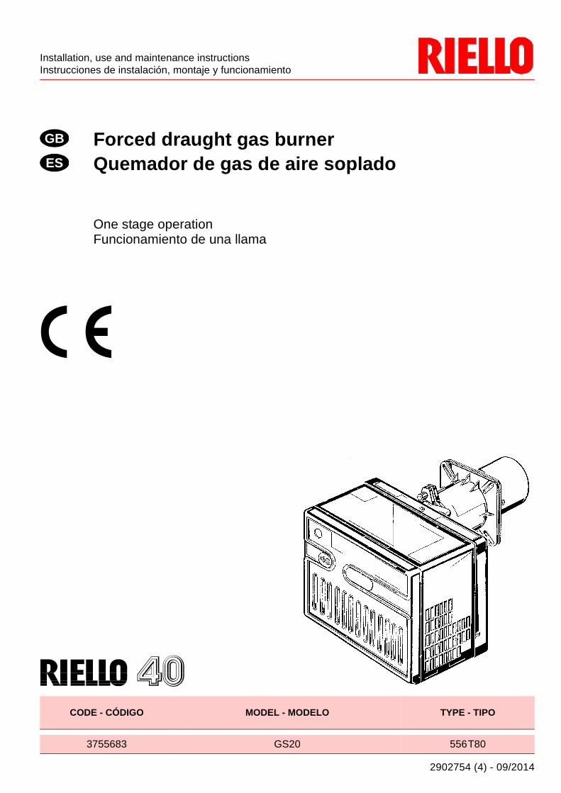
forced draught gas burner quemador de gas de aire soplado
TRANSCRIPT
Installation, use and maintenance instructionsInstrucciones de instalación, montaje y funcionamiento
2902754 (4) - 09/2014
Forced draught gas burnerQuemador de gas de aire soplado
One stage operationFuncionamiento de una llama
CODE - CÓDIGO MODEL - MODELO TYPE - TIPO
3755683 GS20 556T80
GB
ES

2754
1 GB
INDEX
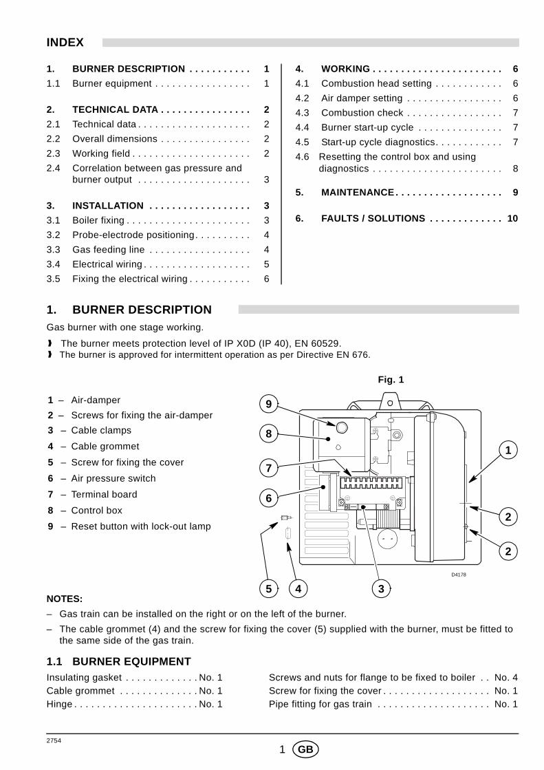
1. BURNER DESCRIPTIONGas burner with one stage working.
1.1 BURNER EQUIPMENTInsulating gasket . . . . . . . . . . . . . No. 1 Screws and nuts for flange to be fixed to boiler . . No. 4Cable grommet . . . . . . . . . . . . . . No. 1 Screw for fixing the cover . . . . . . . . . . . . . . . . . . . No. 1Hinge . . . . . . . . . . . . . . . . . . . . . . No. 1 Pipe fitting for gas train . . . . . . . . . . . . . . . . . . . . No. 1
1. BURNER DESCRIPTION . . . . . . . . . . . 1
1.1 Burner equipment . . . . . . . . . . . . . . . . . 1
2. TECHNICAL DATA . . . . . . . . . . . . . . . . 2
2.1 Technical data . . . . . . . . . . . . . . . . . . . . 2
2.2 Overall dimensions . . . . . . . . . . . . . . . . 2
2.3 Working field . . . . . . . . . . . . . . . . . . . . . 2
2.4 Correlation between gas pressure and burner output . . . . . . . . . . . . . . . . . . . . 3
3. INSTALLATION . . . . . . . . . . . . . . . . . . 3
3.1 Boiler fixing . . . . . . . . . . . . . . . . . . . . . . 3
3.2 Probe-electrode positioning. . . . . . . . . . 4
3.3 Gas feeding line . . . . . . . . . . . . . . . . . . 4
3.4 Electrical wiring . . . . . . . . . . . . . . . . . . . 5
3.5 Fixing the electrical wiring . . . . . . . . . . . 6
4. WORKING . . . . . . . . . . . . . . . . . . . . . . . 6
4.1 Combustion head setting . . . . . . . . . . . . 6
4.2 Air damper setting . . . . . . . . . . . . . . . . . 6
4.3 Combustion check . . . . . . . . . . . . . . . . . 7
4.4 Burner start-up cycle . . . . . . . . . . . . . . . 7
4.5 Start-up cycle diagnostics. . . . . . . . . . . . 7
4.6 Resetting the control box and using diagnostics . . . . . . . . . . . . . . . . . . . . . . . 8
5. MAINTENANCE . . . . . . . . . . . . . . . . . . . 9
6. FAULTS / SOLUTIONS . . . . . . . . . . . . . 10
NOTES:
– Gas train can be installed on the right or on the left of the burner.
– The cable grommet (4) and the screw for fixing the cover (5) supplied with the burner, must be fitted tothe same side of the gas train.
1 – Air-damper
2 – Screws for fixing the air-damper
3 – Cable clamps
4 – Cable grommet
5 – Screw for fixing the cover
6 – Air pressure switch
7 – Terminal board
8 – Control box
9 – Reset button with lock-out lamp
Fig. 1
2
1
2
D4178
5 4 3
9
8
7
6
❱ The burner meets protection level of IP X0D (IP 40), EN 60529.❱ The burner is approved for intermittent operation as per Directive EN 676.
2754
2 GB
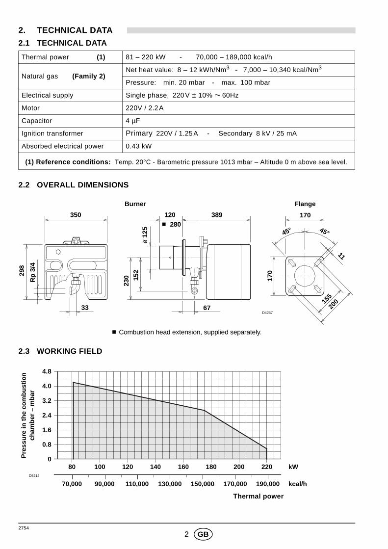
2. TECHNICAL DATA
2.1 TECHNICAL DATA
2.2 OVERALL DIMENSIONS
2.3 WORKING FIELD
Thermal power (1) 81 – 220 kW - 70,000 – 189,000 kcal/h
Natural gas (Family 2)Net heat value: 8 – 12 kWh/Nm3 - 7,000 – 10,340 kcal/Nm3
Pressure: min. 20 mbar - max. 100 mbar
Electrical supply Single phase, 220V ± 10% ~ 60Hz
Motor 220V / 2.2A
Capacitor 4 µF
Ignition transformer Primary 220V / 1.25A - Secondary 8 kV / 25 mA
Absorbed electrical power 0.43 kW
(1) Reference conditions: Temp. 20°C - Barometric pressure 1013 mbar – Altitude 0 m above sea level.
FlangeBurner
350 120 389 170
155
33 67
45°45°
ø 1
25
298
11
170
Rp
3/4
230 15
2
■ 280
D425720
0
■ Combustion head extension, supplied separately.
D5212
0
Thermal power
0.8
1.6
2.4
3.2
4.0
4.8
70,000 90,000 110,000 130,000 kcal/h
80 120100 140 160 kW180
170,000
200 220
150,000 190,000
Pre
ssur
e in
the
com
bust
ion
cham
ber
– m
bar
2754
3 GB
2.4 CORRELATION BETWEEN GAS PRESSURE AND BURNER OUTP UTTo obtain the maximum output, a gas head pressure of 6.9 mbar is measured with the combustion chamber at0 mbar using gas G20 with a net heat value of 10 kWh/Nm3 (8,570 kcal/Nm3).
3. INSTALLATIONTHE BURNER MUST BE INSTALLED IN CONFORMITY WITH LEG ISLATION AND LOCAL STANDARDS.
3.1 BOILER FIXING
3
D5213
4
5
6
7
8
Thermal power
70,000 90,000 110,000 130,000 kcal/h
80 120100 140 160 kW180
170,000
200 220
150,000 190,000
Gas
pre
ssur
e in
the
com
bust
ion
head
– m
bar
Boiler door must have a max. thickness of 100 mm ,refractory lining included.
If thickness is greater (max. 260 mm) , a combustionhead extension must be fitted, which is suppliedseparately.
IMPORTANT ■ Separate the combustion-head assemblyfrom the burner body by removing nut (1) andremoving group (A).
■ Fix the head assembly group (B) to the boiler(2) insert the supplied insulating gasket (3).
HINGE
S7393
ASSEMBLY1 3 2
A B
D5097
2754
4 GB
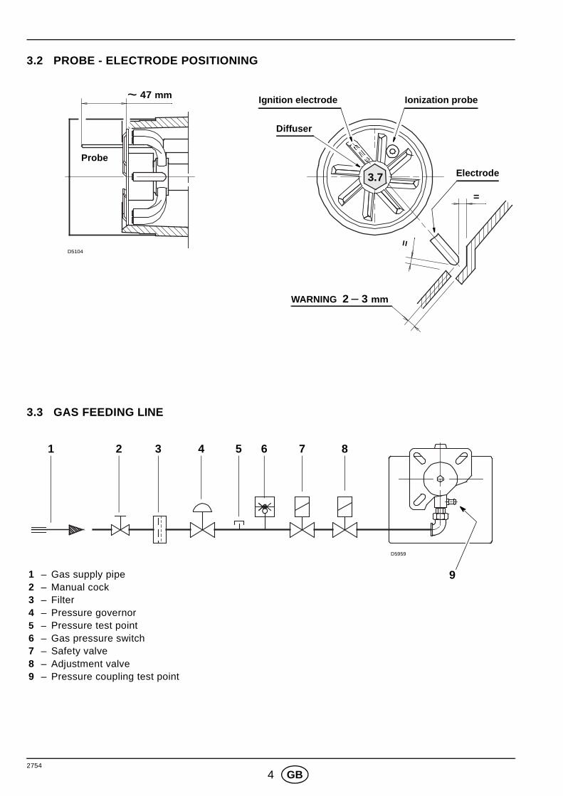
3.2 PROBE - ELECTRODE POSITIONING
3.3 GAS FEEDING LINE
D5104
Ignition electrode
WARNING 2 – 3 mm
Ionization probe
Probe
Electrode3.7
~ 47 mm
Diffuser
=
=
1 – Gas supply pipe2 – Manual cock3 – Filter4 – Pressure governor5 – Pressure test point6 – Gas pressure switch7 – Safety valve8 – Adjustment valve9 – Pressure coupling test point
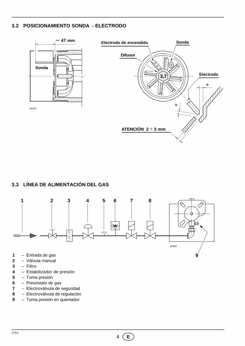
1
D5959
6432
9
5 7 8
2754
5 GB
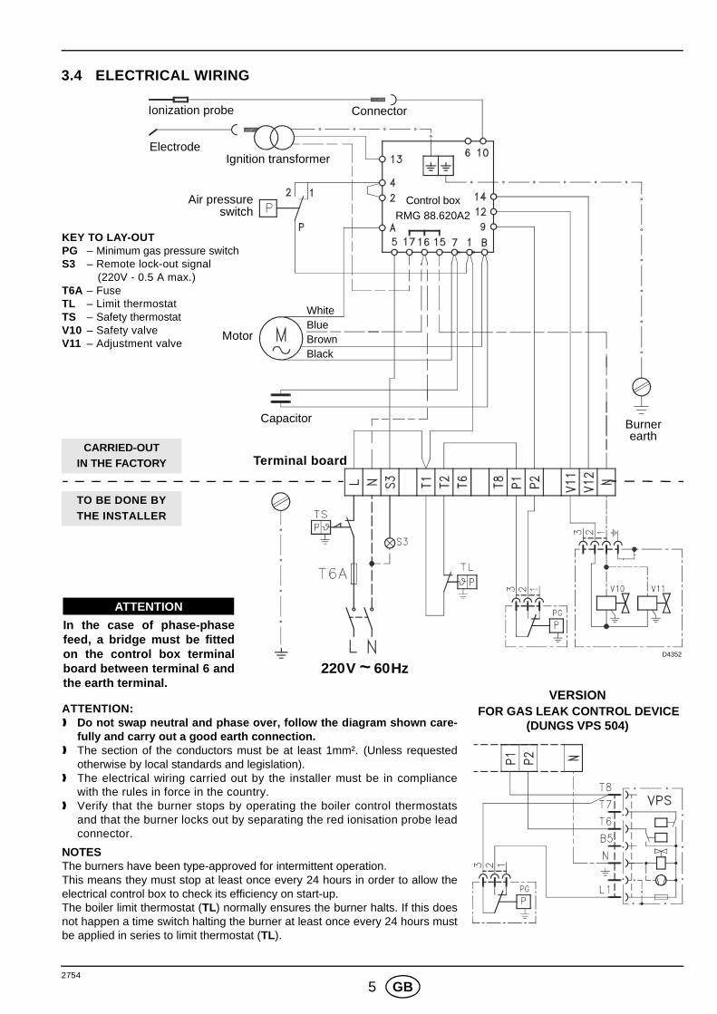
3.4 ELECTRICAL WIRING
KEY TO LAY-OUTPG – Minimum gas pressure switchS3 – Remote lock-out signal
(220V - 0.5 A max.)T6A – FuseTL – Limit thermostatTS – Safety thermostatV10 – Safety valveV11 – Adjustment valve
Ionization probe
Ignition transformerElectrode
Motor
Capacitor Burner
220V ~ 60Hz
Terminal board
Air pressure
WhiteBlueBrown
VERSION FOR GAS LEAK CONTROL DEVICE
(DUNGS VPS 504)
Control boxRMG 88.620A2
D4352
Connector
earth
Black
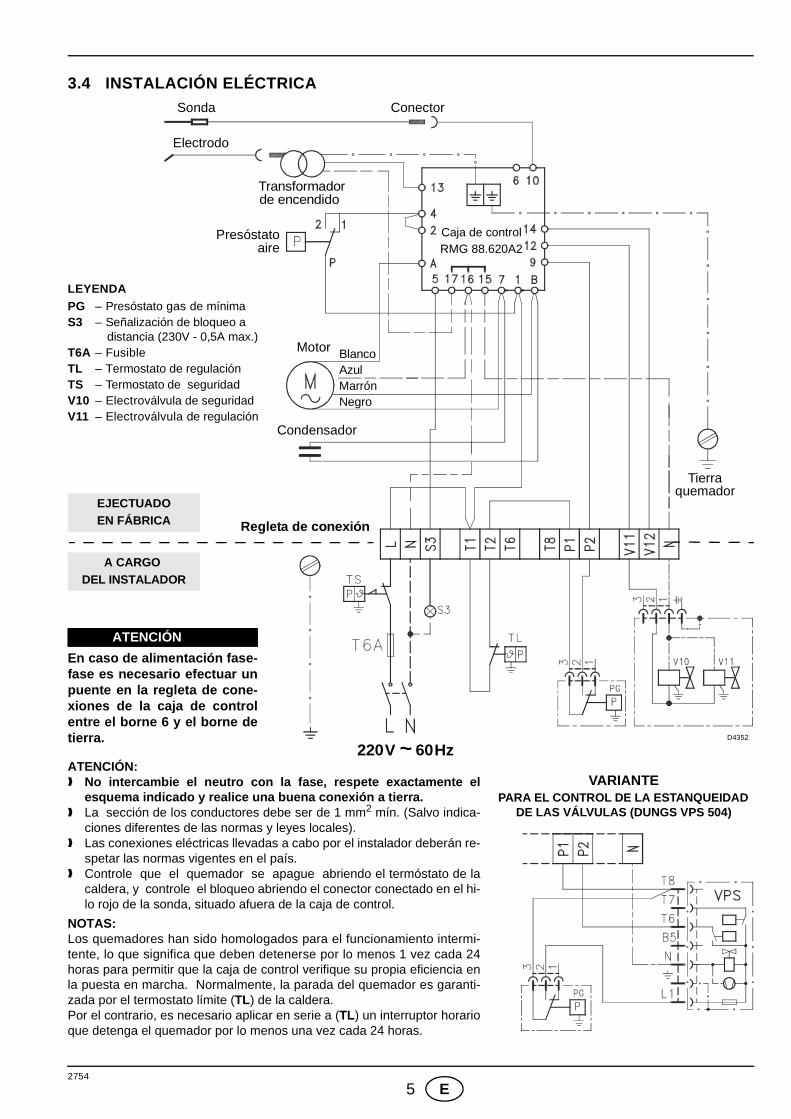
In the case of phase-phasefeed, a bridge must be fittedon the control box terminalboard between terminal 6 andthe earth terminal.
ATTENTION
switch
ATTENTION: ❱ Do not swap neutral and phase over, follow the diagr am shown care-
fully and carry out a good earth connection.❱ The section of the conductors must be at least 1mm². (Unless requested
otherwise by local standards and legislation).❱ The electrical wiring carried out by the installer must be in compliance
with the rules in force in the country.❱ Verify that the burner stops by operating the boiler control thermostats
and that the burner locks out by separating the red ionisation probe leadconnector.
NOTESThe burners have been type-approved for intermittent operation. This means they must stop at least once every 24 hours in order to allow theelectrical control box to check its efficiency on start-up. The boiler limit thermostat (TL) normally ensures the burner halts. If this doesnot happen a time switch halting the burner at least once every 24 hours mustbe applied in series to limit thermostat (TL).
TO BE DONE BYTHE INSTALLER
CARRIED-OUTIN THE FACTORY
2754
6 GB
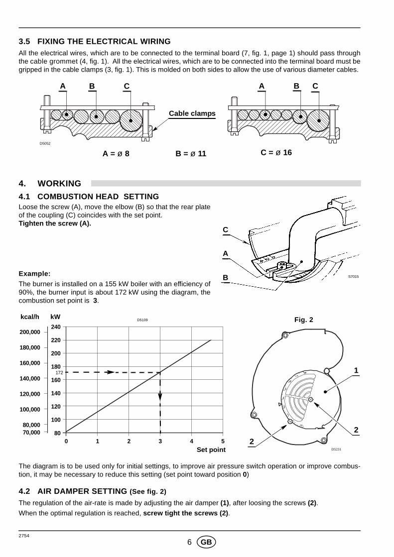
3.5 FIXING THE ELECTRICAL WIRINGAll the electrical wires, which are to be connected to the terminal board (7, fig. 1, page 1) should pass throughthe cable grommet (4, fig. 1). All the electrical wires, which are to be connected into the terminal board must begripped in the cable clamps (3, fig. 1). This is molded on both sides to allow the use of various diameter cables.
4. WORKING
4.1 COMBUSTION HEAD SETTING Loose the screw (A), move the elbow (B) so that the rear plateof the coupling (C) coincides with the set point. Tighten the screw (A).
Example:The burner is installed on a 155 kW boiler with an efficiency of90%, the burner input is about 172 kW using the diagram, thecombustion set point is 3.
The diagram is to be used only for initial settings, to improve air pressure switch operation or improve combus-tion, it may be necessary to reduce this setting (set point toward position 0)
4.2 AIR DAMPER SETTING (See fig. 2)
The regulation of the air-rate is made by adjusting the air damper (1), after loosing the screws (2). When the optimal regulation is reached, screw tight the screws (2) .
Cable clamps
A CB A CB
A = ø 8 B = ø 11 C = ø 16D5052
S7015
C
A
B
1
D5231
2
2
Fig. 2kcal/h kW
Set point0 21 3 4
240
140
120
100
80
160
200,000
140,000
120,000
100,000
70,000
D5109
5
180
200
220
80,000
160,000
180,000
172
2754
7 GB
4.3 COMBUSTION CHECKCO2
It is advisable to not exceed 10% of CO2 (natural gas), in order to avoid the risk that small changes of theadjustments due, for instance, at draught variation, may cause combustion with insufficient air and consequentlyformation of CO.
CO - Not exceeding 100 mg/kWh (93 ppm).
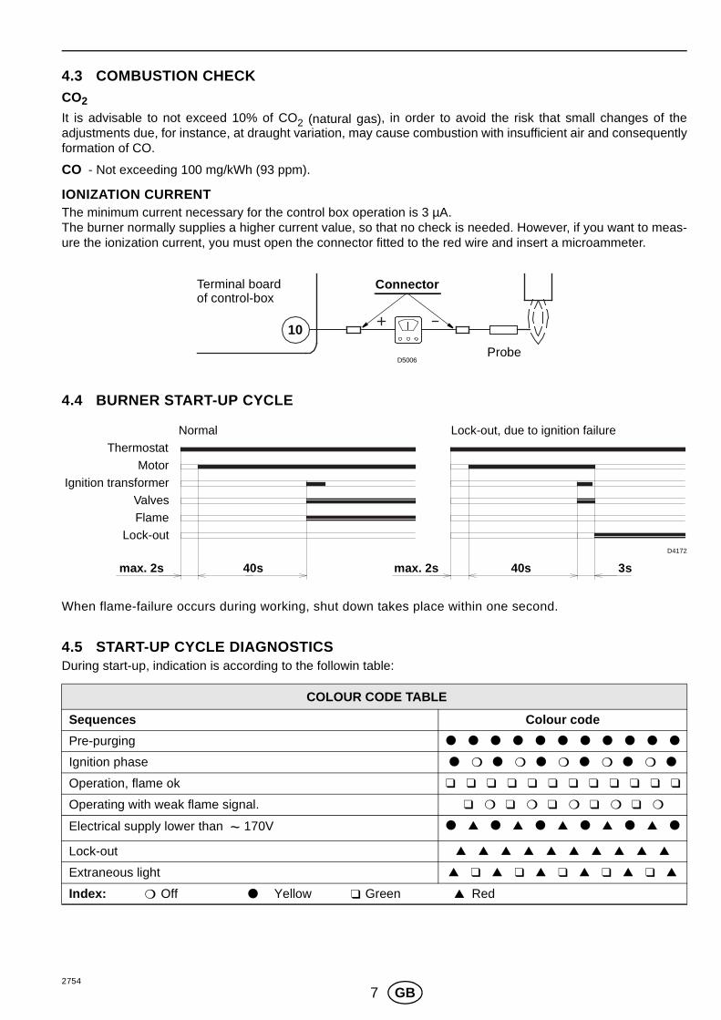
IONIZATION CURRENT The minimum current necessary for the control box operation is 3 µA. The burner normally supplies a higher current value, so that no check is needed. However, if you want to meas-ure the ionization current, you must open the connector fitted to the red wire and insert a microammeter.
4.4 BURNER START-UP CYCLE
When flame-failure occurs during working, shut down takes place within one second.
4.5 START-UP CYCLE DIAGNOSTICSDuring start-up, indication is according to the followin table:
COLOUR CODE TABLE
Sequences Colour code
Pre-purging ● ● ● ● ● ● ● ● ● ● ●
Ignition phase ● ❍ ● ❍ ● ❍ ● ❍ ● ❍ ●
Operation, flame ok ❑ ❑ ❑ ❑ ❑ ❑ ❑ ❑ ❑ ❑ ❑ ❑
Operating with weak flame signal. ❑ ❍ ❑ ❍ ❑ ❍ ❑ ❍ ❑ ❍
Electrical supply lower than ~ 170V ● ▲ ● ▲ ● ▲ ● ▲ ● ▲ ●
Lock-out ▲ ▲ ▲ ▲ ▲ ▲ ▲ ▲ ▲ ▲
Extraneous light ▲ ❑ ▲ ❑ ▲ ❑ ▲ ❑ ▲ ❑ ▲
Index: ❍ Off ● Yellow ❑ Green ▲ Red
Probe
ConnectorTerminal boardof control-box
D5006
10
3s40s40smax. 2s max. 2s
D4172
Lock-out, due to ignition failureNormal
Thermostat
Motor
Ignition transformer
Valves
Flame
Lock-out
2754
8 GB
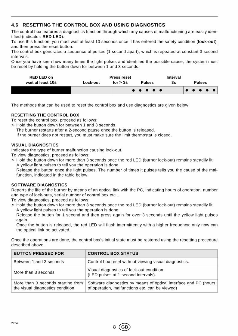
4.6 RESETTING THE CONTROL BOX AND USING DIAGNOSTICSThe control box features a diagnostics function through which any causes of malfunctioning are easily iden-tified (indicator: RED LED).To use this function, you must wait at least 10 seconds once it has entered the safety condition (lock-out ),and then press the reset button. The control box generates a sequence of pulses (1 second apart), which is repeated at constant 3-secondintervals. Once you have seen how many times the light pulses and identified the possible cause, the system mustbe reset by holding the button down for between 1 and 3 seconds.
The methods that can be used to reset the control box and use diagnostics are given below.
RESETTING THE CONTROL BOX To reset the control box, proceed as follows:➣ Hold the button down for between 1 and 3 seconds.
The burner restarts after a 2-second pause once the button is released.If the burner does not restart, you must make sure the limit thermostat is closed.
VISUAL DIAGNOSTICS Indicates the type of burner malfunction causing lock-out.To view diagnostics, proceed as follows:➣ Hold the button down for more than 3 seconds once the red LED (burner lock-out) remains steadily lit.
A yellow light pulses to tell you the operation is done.Release the button once the light pulses. The number of times it pulses tells you the cause of the mal-function, indicated in the table below.
SOFTWARE DIAGNOSTICSReports the life of the burner by means of an optical link with the PC, indicating hours of operation, numberand type of lock-outs, serial number of control box etc ...To view diagnostics, proceed as follows:➣ Hold the button down for more than 3 seconds once the red LED (burner lock-out) remains steadily lit.
A yellow light pulses to tell you the operation is done. Release the button for 1 second and then press again for over 3 seconds until the yellow light pulsesagain.Once the button is released, the red LED will flash intermittently with a higher frequency: only now canthe optical link be activated.
Once the operations are done, the control box’s initial state must be restored using the resetting proceduredescribed above.
BUTTON PRESSED FOR CONTROL BOX STATUS
Between 1 and 3 seconds Control box reset without viewing visual diagnostics.
More than 3 secondsVisual diagnostics of lock-out condition:(LED pulses at 1-second intervals).
More than 3 seconds starting fromthe visual diagnostics condition
Software diagnostics by means of optical interface and PC (hoursof operation, malfunctions etc. can be viewed)
� � � � � � � � � �
Press resetfor > 3s 3sPulses Pulses
RED LED onwait at least 10s
IntervalLock-out
2754
9 GB
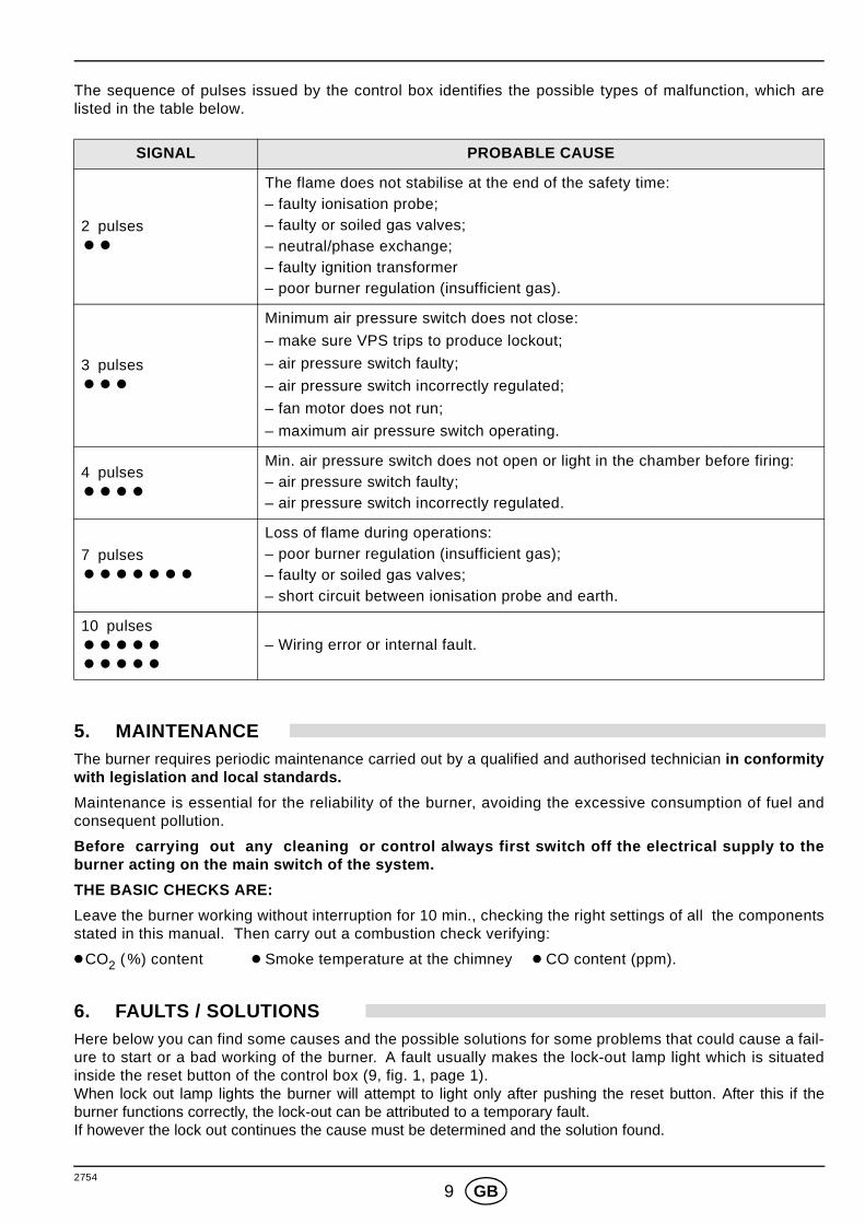
The sequence of pulses issued by the control box identifies the possible types of malfunction, which arelisted in the table below.
5. MAINTENANCEThe burner requires periodic maintenance carried out by a qualified and authorised technician in conformitywith legislation and local standards.
Maintenance is essential for the reliability of the burner, avoiding the excessive consumption of fuel andconsequent pollution.
Before carrying out any cleaning or control al ways first switch off the electrical supply to theburner acting on the main switch of the system.
THE BASIC CHECKS ARE:
Leave the burner working without interruption for 10 min., checking the right settings of all the componentsstated in this manual. Then carry out a combustion check verifying:
● CO2 (%) content ● Smoke temperature at the chimney ● CO content (ppm).
6. FAULTS / SOLUTIONSHere below you can find some causes and the possible solutions for some problems that could cause a fail-ure to start or a bad working of the burner. A fault usually makes the lock-out lamp light which is situatedinside the reset button of the control box (9, fig. 1, page 1). When lock out lamp lights the burner will attempt to light only after pushing the reset button. After this if theburner functions correctly, the lock-out can be attributed to a temporary fault.If however the lock out continues the cause must be determined and the solution found.
SIGNAL PROBABLE CAUSE
2 pulses��
The flame does not stabilise at the end of the safety time:– faulty ionisation probe;– faulty or soiled gas valves;– neutral/phase exchange;– faulty ignition transformer– poor burner regulation (insufficient gas).
3 pulses���
Minimum air pressure switch does not close:
– make sure VPS trips to produce lockout;
– air pressure switch faulty;
– air pressure switch incorrectly regulated;
– fan motor does not run;
– maximum air pressure switch operating.
4 pulses����
Min. air pressure switch does not open or light in the chamber before firing:– air pressure switch faulty;– air pressure switch incorrectly regulated.
7 pulses�������
Loss of flame during operations:– poor burner regulation (insufficient gas);– faulty or soiled gas valves;– short circuit between ionisation probe and earth.
10 pulses�����
�����
– Wiring error or internal fault.
2754
10 GB
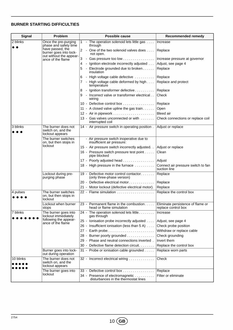
BURNER STARTING DIFFICULTIES
Signal Problem Possible cause Recommended remedy
2 blinks Once the pre-purging phase and safety time have passed, the burner goes into lock-out without the appear-ance of the flame
1 - The operation solenoid lets little gas . . . . through
Increase
2 - One of the two solenoid valves does . . . . not open.
Replace
3 - Gas pressure too low . . . . . . . . . . . . . . . . Increase pressure at governor4 - Ignition electrode incorrectly adjusted . . . Adjust, see page 45 - Electrode grounded due to broken . . . . . .
insulationReplace
6 - High voltage cable defective . . . . . . . . . . Replace7 - High voltage cable deformed by high . . . .
temperatureReplace and protect
8 - Ignition transformer defective . . . . . . . . . . Replace9 - Incorrect valve or transformer electrical . .
wiringCheck
10 - Defective control box . . . . . . . . . . . . . . . . Replace11 - A closed valve upline the gas train. . . . . . Open12 - Air in pipework . . . . . . . . . . . . . . . . . . . . . Bleed air13 - Gas valves unconnected or with . . . . . . .
interrupted coilCheck connections or replace coil
3 blinks The burner does not switch on, and the lockout appears
14 - Air pressure switch in operating position . Adjust or replace
The burner switches on, but then stops in lockout
- Air pressure switch inoperative due to insufficient air pressure:
15 - Air pressure switch incorrectly adjusted. . Adjust or replace16 - Pressure switch pressure test point . . . . .
pipe blockedClean
17 - Poorly adjusted head . . . . . . . . . . . . . . . . Adjust18 - High pressure in the furnace . . . . . . . . . . Connect air pressure switch to fan
suction lineLockout during pre-purging phase
19 - Defective motor control contactor. . . . . . . (only three-phase version)
Replace
20 - Defective electrical motor . . . . . . . . . . . . . Replace21 - Motor lockout (defective electrical motor). Replace
4 pulses The burner switches on, but then stops in lockout
22 - Flame simulation . . . . . . . . . . . . . . . . . . . Replace the control box
Lockout when burner stops
23 - Permanent flame in the combustion. . . . . head or flame simulation
Eliminate persistence of flame or replace control box
7 blinks The burner goes into lockout immediately following the appear-ance of the flame
24 - The operation solenoid lets little. . . . . . . . gas through
Increase
25 - Ionisation probe incorrectly adjusted . . . . Adjust, see page 426 - Insufficient ionisation (less than 5 A) . . . . Check probe position27 - Earth probe. . . . . . . . . . . . . . . . . . . . . . . . Withdraw or replace cable28 - Burner poorly grounded . . . . . . . . . . . . . . Check grounding29 - Phase and neutral connections inverted . Invert them30 - Defective flame detection circuit. . . . . . . . Replace the control box
Burner goes into lock-out during operation
31 - Probe or ionisation cable grounded . . . . . Replace worn parts
10 blinks The burner does not switch on, and the lockout appears
32 - Incorrect electrical wiring . . . . . . . . . . . . . Check
The burner goes into lockout
33 - Defective control box . . . . . . . . . . . . . . . . Replace34 - Presence of electromagnetic . . . . . . . . . .
disturbances in the thermostat linesFilter or eliminate
2754
11 GB
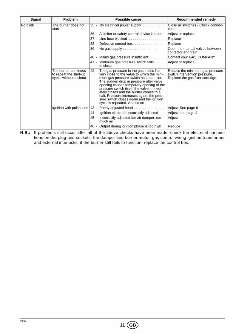
N.B.: If problems still occur after all of the above checks have been made, check the electrical connec-tions on the plug and sockets, the damper and burner motor, gas control wiring ignition transformerand external interlocks, if the burner still fails to function, replace the control box.
No blink The burner does not start
35 - No electrical power supply . . . . . . . . . . . . Close all switches - Check connec-tions
36 - A limiter or safety control device is open. . Adjust or replace37 - Line fuse blocked . . . . . . . . . . . . . . . . . . . Replace38 - Defective control box. . . . . . . . . . . . . . . . . Replace39 - No gas supply . . . . . . . . . . . . . . . . . . . . . . Open the manual valves between
contactor and train40 - Mains gas pressure insufficient . . . . . . . . . Contact your GAS COMPANY41 - Minimum gas pressure switch fails . . . . . .
to closeAdjust or replace
The burner continues to repeat the start-up cycle, without lockout
42 - The gas pressure in the gas mains lies very close to the value to which the mini-mum gas pressure switch has been set. The sudden drop in pressure after valve opening causes temporary opening of the pressure switch itself, the valve immedi-ately closes and the burner comes to a halt. Pressure increases again, the pres-sure switch closes again and the ignition cycle is repeated. And so on
Reduce the minimum gas pressure switch intervention pressure. Replace the gas filter cartridge.
Ignition with pulsations 43 - Poorly adjusted head . . . . . . . . . . . . . . . . Adjust. See page 644 - Ignition electrode incorrectly adjusted. . . . Adjust, see page 445 - Incorrectly adjusted fan air damper: too
much airAdjust
46 - Output during ignition phase is too high . . Reduce
Signal Problem Possible cause Recommended remedy
2754
12 GB
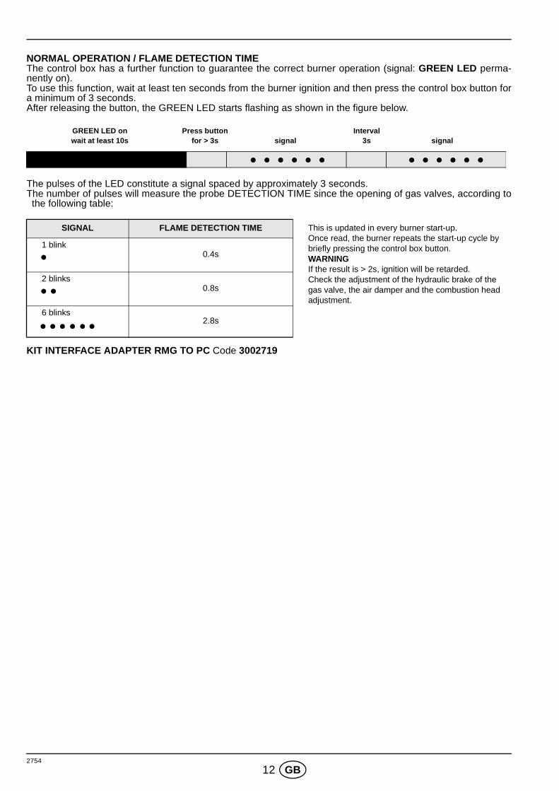
NORMAL OPERATION / FLAME DETECTION TIMEThe control box has a further function to guarantee the correct burner operation (signal: GREEN LED perma-nently on).To use this function, wait at least ten seconds from the burner ignition and then press the control box button fora minimum of 3 seconds.After releasing the button, the GREEN LED starts flashing as shown in the figure below.
The pulses of the LED constitute a signal spaced by approximately 3 seconds.The number of pulses will measure the probe DETECTION TIME since the opening of gas valves, according tothe following table:
KIT INTERFACE ADAPTER RMG TO PC Code 3002719
SIGNAL FLAME DETECTION TIME This is updated in every burner start-up.Once read, the burner repeats the start-up cycle by briefly pressing the control box button.WARNINGIf the result is > 2s, ignition will be retarded.Check the adjustment of the hydraulic brake of the gas valve, the air damper and the combustion head adjustment.
1 blink0.4s
2 blinks0.8s
6 blinks2.8s
GREEN LED onwait at least 10s
Press buttonfor > 3s signal signal
Interval3s
2754
1 E
INDICE
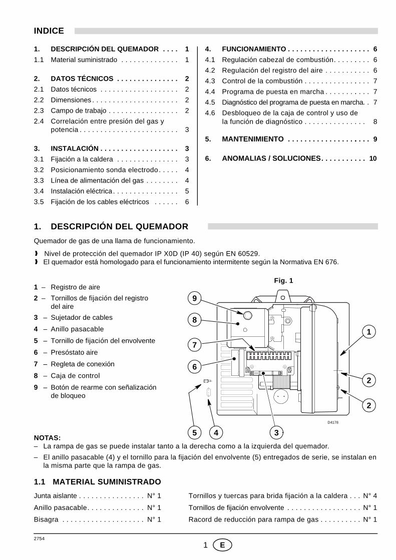
1. DESCRIPCIÓN DEL QUEMADOR
Quemador de gas de una llama de funcionamiento.
1.1 MATERIAL SUMINISTRADO
Junta aislante . . . . . . . . . . . . . . . . N° 1 Tornillos y tuercas para brida fijación a la caldera . . . N° 4
Anillo pasacable. . . . . . . . . . . . . . N° 1 Tornillos de fijación envolvente . . . . . . . . . . . . . . . . . . N° 1
Bisagra . . . . . . . . . . . . . . . . . . . . N° 1 Racord de reducción para rampa de gas . . . . . . . . . . N° 1
1. DESCRIPCIÓN DEL QUEMADOR . . . . 1
1.1 Material suministrado . . . . . . . . . . . . . . 1
2. DATOS TÉCNICOS . . . . . . . . . . . . . . . 2
2.1 Datos técnicos . . . . . . . . . . . . . . . . . . . 2
2.2 Dimensiones . . . . . . . . . . . . . . . . . . . . . 2
2.3 Campo de trabajo . . . . . . . . . . . . . . . . . 2
2.4 Correlación entre presión del gas y potencia . . . . . . . . . . . . . . . . . . . . . . . . 3
3. INSTALACIÓN . . . . . . . . . . . . . . . . . . . 3
3.1 Fijación a la caldera . . . . . . . . . . . . . . . 3
3.2 Posicionamiento sonda electrodo . . . . . 4
3.3 Línea de alimentación del gas . . . . . . . . 4
3.4 Instalación eléctrica. . . . . . . . . . . . . . . . 5
3.5 Fijación de los cables eléctricos . . . . . . 6
4. FUNCIONAMIENTO . . . . . . . . . . . . . . . . . . . . 6
4.1 Regulación cabezal de combustión. . . . . .. . . . 6
4.2 Regulación del registro del aire . . . . . . . .. . . . 6
4.3 Control de la combustión . . . . . . . . . . . . .. . . . 7
4.4 Programa de puesta en marcha . . . . . . . .. . . . 7
4.5 Diagnóstico del programa de puesta en marcha . . 7
4.6 Desbloqueo de la caja de control y uso de la función de diagnóstico . . . . . . . . . . . . . . . 8
5. MANTENIMIENTO . . . . . . . . . . . . . . . . .. . . . 9
6. ANOMALIAS / SOLUCIONES . . . . . . . . . . . 10
1 – Registro de aire
2 – Tornillos de fijación del registro del aire
3 – Sujetador de cables
4 – Anillo pasacable
5 – Tornillo de fijación del envolvente
6 – Presóstato aire
7 – Regleta de conexión
8 – Caja de control
9 – Botón de rearme con señalización de bloqueo
NOTAS:– La rampa de gas se puede instalar tanto a la derecha como a la izquierda del quemador.
– El anillo pasacable (4) y el tornillo para la fijación del envolvente (5) entregados de serie, se instalan enla misma parte que la rampa de gas.
Fig. 1
2
1
2
D4178
5 4 3
9
8
7
6
❱ Nivel de protección del quemador IP X0D (IP 40) según EN 60529.❱ El quemador está homologado para el funcionamiento intermitente según la Normativa EN 676.
2754
2 E
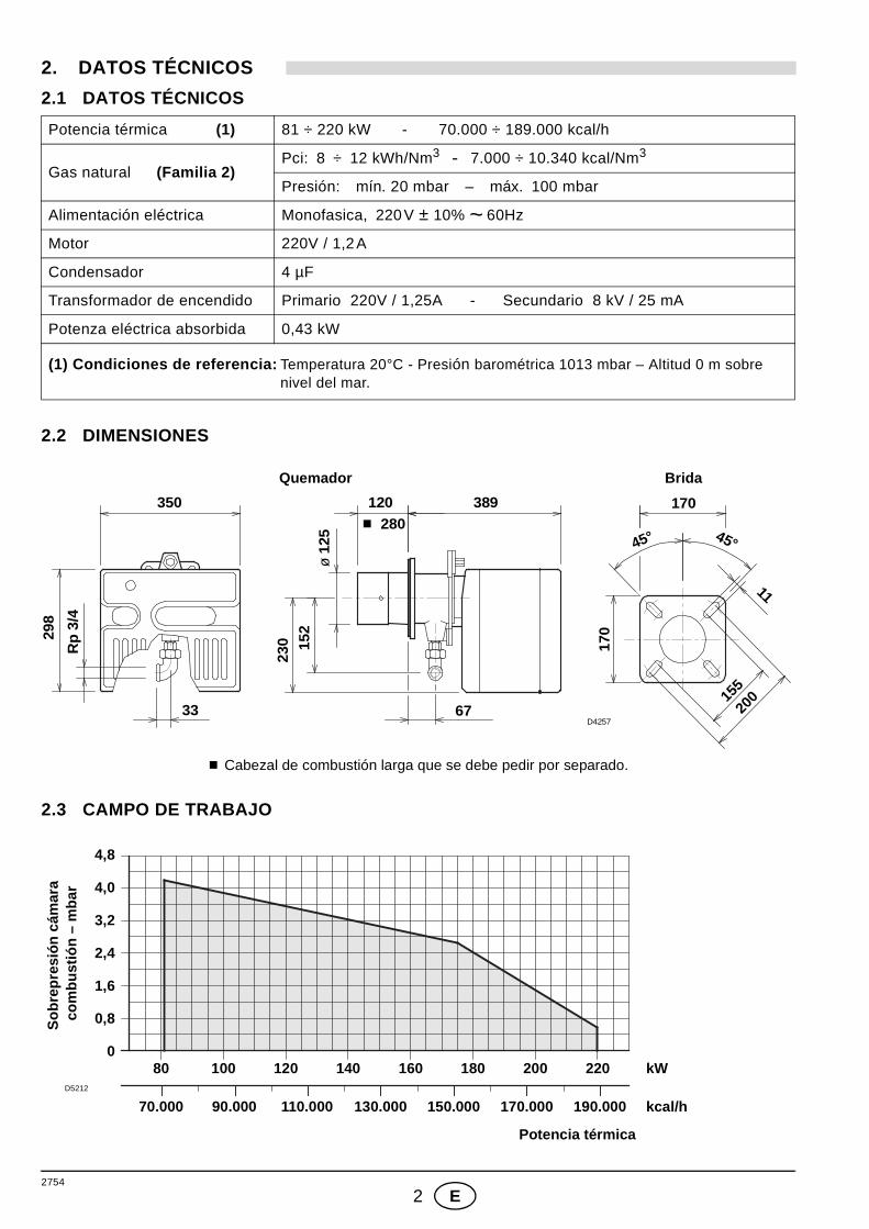
2. DATOS TÉCNICOS
2.1 DATOS TÉCNICOS
2.2 DIMENSIONES
2.3 CAMPO DE TRABAJO
Potencia térmica (1) 81 ÷ 220 kW - 70.000 ÷ 189.000 kcal/h
Gas natural (Familia 2)Pci: 8 ÷ 12 kWh/Nm3 - 7.000 ÷ 10.340 kcal/Nm3
Presión: mín. 20 mbar – máx. 100 mbar
Alimentación eléctrica Monofasica, 220V ± 10% ~ 60Hz
Motor 220V / 1,2A
Condensador 4 µF
Transformador de encendido Primario 220V / 1,25A - Secundario 8 kV / 25 mA
Potenza eléctrica absorbida 0,43 kW
(1) Condiciones de referencia: Temperatura 20°C - Presión barométrica 1013 mbar – Altitud 0 m sobre nivel del mar.
BridaQuemador
350 120 389 170
155
33 67
45°45°
ø 1
25
298
1117
0
Rp
3/4
230 15
2
■ 280
D425720
0
■ Cabezal de combustión larga que se debe pedir por separado.
D5212
0
Potencia térmica
0,8
1,6
2,4
3,2
4,0
4,8
70.000 90.000 110.000 130.000 kcal/h
80 120100 140 160 kW180
170.000
200 220
150.000 190.000
Sob
repr
esió
n cá
mar
a co
mbu
stió
n –
mba
r
2754
3 E
2.4 CORRELACIÓN ENTRE PRESIÓN DEL GAS Y POTENCIA
Para obtener la potencia máxima se requieren 6,9 mbar medidos en el manguito con cámara de combus-tión a 0 mbar y gas G20 - Pci = 10 kWh/Nm3 (8.570 kcal/Nm3).
3. INSTALACIÓN
EL QUEMADOR SE DEBE INSTALAR DE CONFORMIDAD CON LAS LEYES Y NORMATIVAS LOCALES.
3.1 FIJACIÓN A LA CALDERA
3
D5213
4
5
6
7
8
Potencia térmica
70.000 90.000 110.000 130.000 kcal/h
80 120100 140 160 kW180
170.000
200 220
150.000 190.000
Pre
sión
del
gas
al c
abez
alde
com
bust
ión
- m
bar
La puerta de la caldera debe tener un grosor máximode 100 mm incluido el revestimiento refractario.
En el caso en que el grosor fuera mayor (máx.260 mm) es necesario utilizar una extensión para latobera, que se debe pedir por separado.
ATENCIÓN ■ Separe el cabezal de combustión del resto delquemador quitando la tuerca (1) y extraiga elgrupo (A).
■ Fije el grupo (B) a la placa (2) de la caldera,interponiendo la junta aislante (3) suministradade serie.
MONTAJE DE
S7393
LA BISAGRA1 3 2
A B
D5097
2754
4 E
3.2 POSICIONAMIENTO SONDA - ELECTRODO
3.3 LÍNEA DE ALIMENTACIÓN DEL GAS
D5104
Electrodo de encendido
ATENCIÓN 2 ÷ 3 mm
Sonda
Sonda
Electrodo3,7
~ 47 mm
Difusor
=
=
1 – Entrada de gas2 – Válvula manual3 – Filtro4 – Estabilizador de presión5 – Toma presión6 – Presóstato de gas7 – Electroválvula de seguridad8 – Electroválvula de regulación9 – Toma presión en quemador
1
D5959
6432
9
5 7 8
2754
5 E
3.4 INSTALACIÓN ELÉCTRICA Sonda
Transformador
Electrodo
Motor
Condensador
Tierra
220V ~ 60Hz
Regleta de conexión
Presóstato
BlancoAzulMarrón
VARIANTEPARA EL CONTROL DE LA ESTANQUEIDAD
DE LAS VÁLVULAS (DUNGS VPS 504)
Caja de controlRMG 88.620A2
D4352
Conector
quemador
Negro
de encendido
ATENCIÓN:❱ No intercambie el neutro con la fase, respete exacta mente el
esquema indicado y realice una buena conexión a tie rra.❱ La sección de los conductores debe ser de 1 mm2 mín. (Salvo indica-
ciones diferentes de las normas y leyes locales).❱ Las conexiones eléctricas llevadas a cabo por el instalador deberán re-
spetar las normas vigentes en el país.❱ Controle que el quemador se apague abriendo el termóstato de la
caldera, y controle el bloqueo abriendo el conector conectado en el hi-lo rojo de la sonda, situado afuera de la caja de control.
NOTAS:Los quemadores han sido homologados para el funcionamiento intermi-tente, lo que significa que deben detenerse por lo menos 1 vez cada 24horas para permitir que la caja de control verifique su propia eficiencia enla puesta en marcha. Normalmente, la parada del quemador es garanti-zada por el termostato límite (TL) de la caldera.Por el contrario, es necesario aplicar en serie a (TL) un interruptor horarioque detenga el quemador por lo menos una vez cada 24 horas.
LEYENDAPG – Presóstato gas de mínimaS3 – Señalización de bloqueo a
distancia (230V - 0,5A max.)T6A – FusibleTL – Termostato de regulaciónTS – Termostato de seguridadV10 – Electroválvula de seguridadV11 – Electroválvula de regulación
En caso de alimentación fase-fase es necesario efectuar unpuente en la regleta de cone-xiones de la caja de controlentre el borne 6 y el borne detierra.
ATENCIÓN
aire
A CARGO DEL INSTALADOR
EJECTUADOEN FÁBRICA
2754
6 E
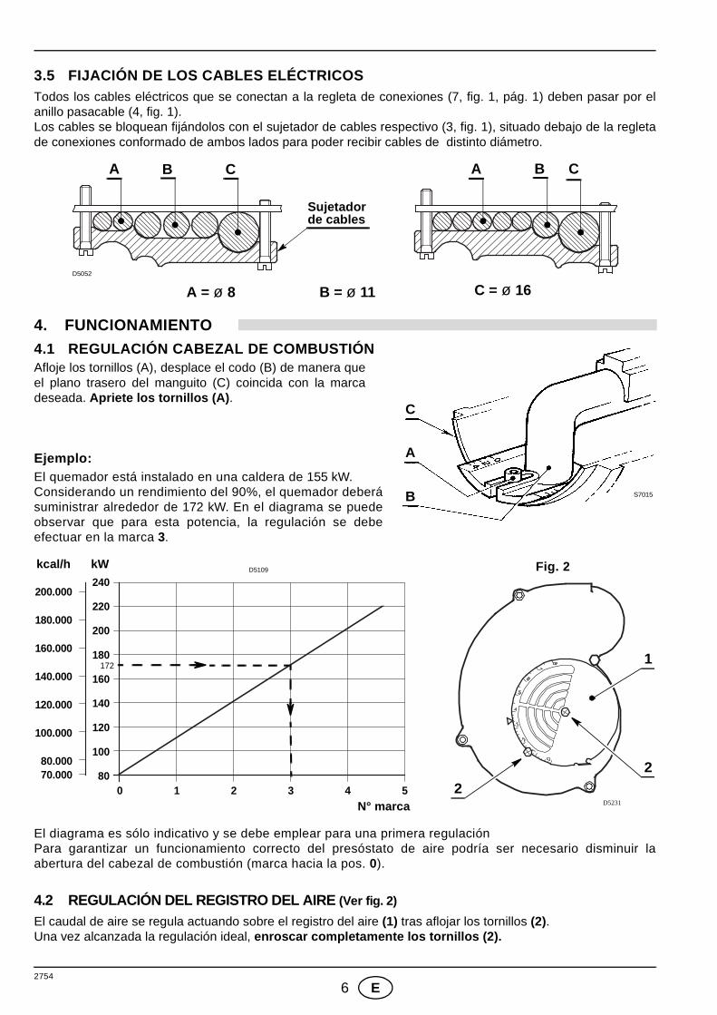
3.5 FIJACIÓN DE LOS CABLES ELÉCTRICOSTodos los cables eléctricos que se conectan a la regleta de conexiones (7, fig. 1, pág. 1) deben pasar por elanillo pasacable (4, fig. 1). Los cables se bloquean fijándolos con el sujetador de cables respectivo (3, fig. 1), situado debajo de la regletade conexiones conformado de ambos lados para poder recibir cables de distinto diámetro.
4. FUNCIONAMIENTO
4.1 REGULACIÓN CABEZAL DE COMBUSTIÓN Afloje los tornillos (A), desplace el codo (B) de manera queel plano trasero del manguito (C) coincida con la marcadeseada. Apriete los tornillos (A) .
Ejemplo:El quemador está instalado en una caldera de 155 kW.Considerando un rendimiento del 90%, el quemador deberásuministrar alrededor de 172 kW. En el diagrama se puedeobservar que para esta potencia, la regulación se debeefectuar en la marca 3.
El diagrama es sólo indicativo y se debe emplear para una primera regulaciónPara garantizar un funcionamiento correcto del presóstato de aire podría ser necesario disminuir laabertura del cabezal de combustión (marca hacia la pos. 0).
4.2 REGULACIÓN DEL REGISTRO DEL AIRE (Ver fig. 2)
El caudal de aire se regula actuando sobre el registro del aire (1) tras aflojar los tornillos (2).Una vez alcanzada la regulación ideal, enroscar completamente los tornillos (2).
A CB A CB
A = ø 8 B = ø 11 C = ø 16D5052
Sujetador de cables
S7015
C
A
B
1
D5231
2
2
Fig. 2kcal/h kW
N° marca0 21 3 4
240
140
120
100
80
160
200.000
140.000
120.000
100.000
70.000
D5109
5
180
200
220
80.000
160.000
180.000
172
2754
7 E
4.3 CONTROL DE LA COMBUSTIÓN
CO2
Se aconseja no pasar del 10% de CO2 (gas natural) para evitar el riesgo de que un ligero desarreglo (ejemplo:variación de tiro) provoque una combustión con defecto de aire y, por consiguiente, formación de CO.
CO - No debe pasar de 100 mg/kWh (93 ppm).
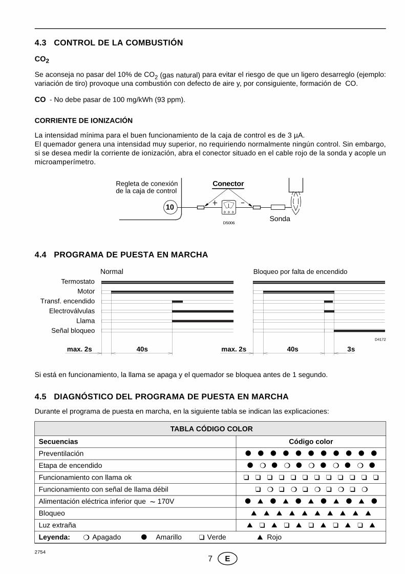
CORRIENTE DE IONIZACIÓN
La intensidad mínima para el buen funcionamiento de la caja de control es de 3 µA.El quemador genera una intensidad muy superior, no requiriendo normalmente ningún control. Sin embargo,si se desea medir la corriente de ionización, abra el conector situado en el cable rojo de la sonda y acople unmicroamperímetro.
4.4 PROGRAMA DE PUESTA EN MARCHA
Si está en funcionamiento, la llama se apaga y el quemador se bloquea antes de 1 segundo.
4.5 DIAGNÓSTICO DEL PROGRAMA DE PUESTA EN MARCHA
Durante el programa de puesta en marcha, en la siguiente tabla se indican las explicaciones:
TABLA CÓDIGO COLOR
Secuencias Código color
Preventilación ● ● ● ● ● ● ● ● ● ● ●
Etapa de encendido ● ❍ ● ❍ ● ❍ ● ❍ ● ❍ ●
Funcionamiento con llama ok ❑ ❑ ❑ ❑ ❑ ❑ ❑ ❑ ❑ ❑ ❑ ❑
Funcionamiento con señal de llama débil ❑ ❍ ❑ ❍ ❑ ❍ ❑ ❍ ❑ ❍
Alimentación eléctrica inferior que ~ 170V ● ▲ ● ▲ ● ▲ ● ▲ ● ▲ ●
Bloqueo ▲ ▲ ▲ ▲ ▲ ▲ ▲ ▲ ▲ ▲
Luz extraña ▲ ❑ ▲ ❑ ▲ ❑ ▲ ❑ ▲ ❑ ▲
Leyenda: ❍ Apagado ● Amarillo ❑ Verde ▲ Rojo
Sonda
ConectorRegleta de conexiónde la caja de control
D5006
10
3s40s40smax. 2s max. 2s
D4172
Bloqueo por falta de encendido NormalTermostato
Motor
Transf. encendido
Electroválvulas
Llama
Señal bloqueo
2754
8 E
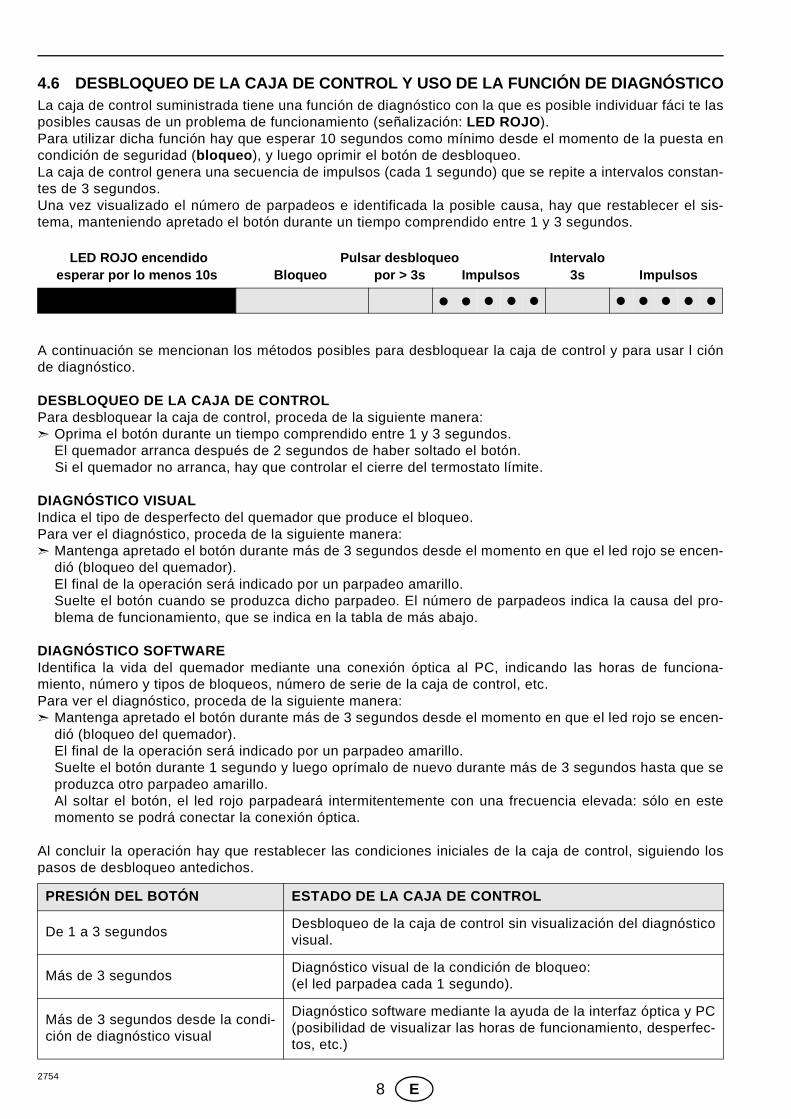
4.6 DESBLOQUEO DE LA CAJA DE CONTROL Y USO DE LA FUN CIÓN DE DIAGNÓSTICOLa caja de control suministrada tiene una función de diagnóstico con la que es posible individuar fáci te lasposibles causas de un problema de funcionamiento (señalización: LED ROJO ).Para utilizar dicha función hay que esperar 10 segundos como mínimo desde el momento de la puesta encondición de seguridad (bloqueo ), y luego oprimir el botón de desbloqueo. La caja de control genera una secuencia de impulsos (cada 1 segundo) que se repite a intervalos constan-tes de 3 segundos. Una vez visualizado el número de parpadeos e identificada la posible causa, hay que restablecer el sis-tema, manteniendo apretado el botón durante un tiempo comprendido entre 1 y 3 segundos.
A continuación se mencionan los métodos posibles para desbloquear la caja de control y para usar l ciónde diagnóstico.
DESBLOQUEO DE LA CAJA DE CONTROL Para desbloquear la caja de control, proceda de la siguiente manera:➣ Oprima el botón durante un tiempo comprendido entre 1 y 3 segundos.
El quemador arranca después de 2 segundos de haber soltado el botón.Si el quemador no arranca, hay que controlar el cierre del termostato límite.
DIAGNÓSTICO VISUAL Indica el tipo de desperfecto del quemador que produce el bloqueo.Para ver el diagnóstico, proceda de la siguiente manera:➣ Mantenga apretado el botón durante más de 3 segundos desde el momento en que el led rojo se encen-
dió (bloqueo del quemador).El final de la operación será indicado por un parpadeo amarillo.Suelte el botón cuando se produzca dicho parpadeo. El número de parpadeos indica la causa del pro-blema de funcionamiento, que se indica en la tabla de más abajo.
DIAGNÓSTICO SOFTWAREIdentifica la vida del quemador mediante una conexión óptica al PC, indicando las horas de funciona-miento, número y tipos de bloqueos, número de serie de la caja de control, etc.Para ver el diagnóstico, proceda de la siguiente manera:➣ Mantenga apretado el botón durante más de 3 segundos desde el momento en que el led rojo se encen-
dió (bloqueo del quemador). El final de la operación será indicado por un parpadeo amarillo. Suelte el botón durante 1 segundo y luego oprímalo de nuevo durante más de 3 segundos hasta que seproduzca otro parpadeo amarillo.Al soltar el botón, el led rojo parpadeará intermitentemente con una frecuencia elevada: sólo en estemomento se podrá conectar la conexión óptica.
Al concluir la operación hay que restablecer las condiciones iniciales de la caja de control, siguiendo lospasos de desbloqueo antedichos.
PRESIÓN DEL BOTÓN ESTADO DE LA CAJA DE CONTROL
De 1 a 3 segundosDesbloqueo de la caja de control sin visualización del diagnósticovisual.
Más de 3 segundosDiagnóstico visual de la condición de bloqueo:(el led parpadea cada 1 segundo).
Más de 3 segundos desde la condi-ción de diagnóstico visual
Diagnóstico software mediante la ayuda de la interfaz óptica y PC(posibilidad de visualizar las horas de funcionamiento, desperfec-tos, etc.)
� � � � � � � � � �
Pulsar desbloqueopor > 3s 3sImpulsos Impulsos
LED ROJO encendidoesperar por lo menos 10s
IntervaloBloqueo
2754
9 E
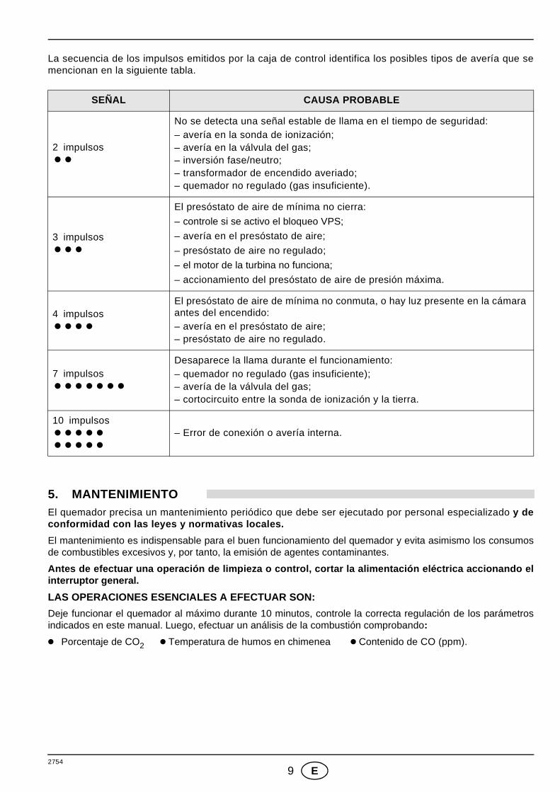
La secuencia de los impulsos emitidos por la caja de control identifica los posibles tipos de avería que semencionan en la siguiente tabla.
5. MANTENIMIENTOEl quemador precisa un mantenimiento periódico que debe ser ejecutado por personal especializado y deconformidad con las leyes y normativas locales.
El mantenimiento es indispensable para el buen funcionamiento del quemador y evita asimismo los consumosde combustibles excesivos y, por tanto, la emisión de agentes contaminantes.
Antes de efectuar una operación de limpieza o contr ol, cortar la alimentación eléctrica accionando elinterruptor general.
LAS OPERACIONES ESENCIALES A EFECTUAR SON:
Deje funcionar el quemador al máximo durante 10 minutos, controle la correcta regulación de los parámetrosindicados en este manual. Luego, efectuar un análisis de la combustión comprobando:
● Porcentaje de CO2 ● Temperatura de humos en chimenea ● Contenido de CO (ppm).
SEÑAL CAUSA PROBABLE
2 impulsos��
No se detecta una señal estable de llama en el tiempo de seguridad:– avería en la sonda de ionización;– avería en la válvula del gas;– inversión fase/neutro;– transformador de encendido averiado;– quemador no regulado (gas insuficiente).
3 impulsos���
El presóstato de aire de mínima no cierra:
– controle si se activo el bloqueo VPS;
– avería en el presóstato de aire;
– presóstato de aire no regulado;
– el motor de la turbina no funciona;
– accionamiento del presóstato de aire de presión máxima.
4 impulsos����
El presóstato de aire de mínima no conmuta, o hay luz presente en la cámara antes del encendido:– avería en el presóstato de aire;– presóstato de aire no regulado.
7 impulsos�������
Desaparece la llama durante el funcionamiento:– quemador no regulado (gas insuficiente);– avería de la válvula del gas;– cortocircuito entre la sonda de ionización y la tierra.
10 impulsos�����
�����
– Error de conexión o avería interna.
2754
10 E
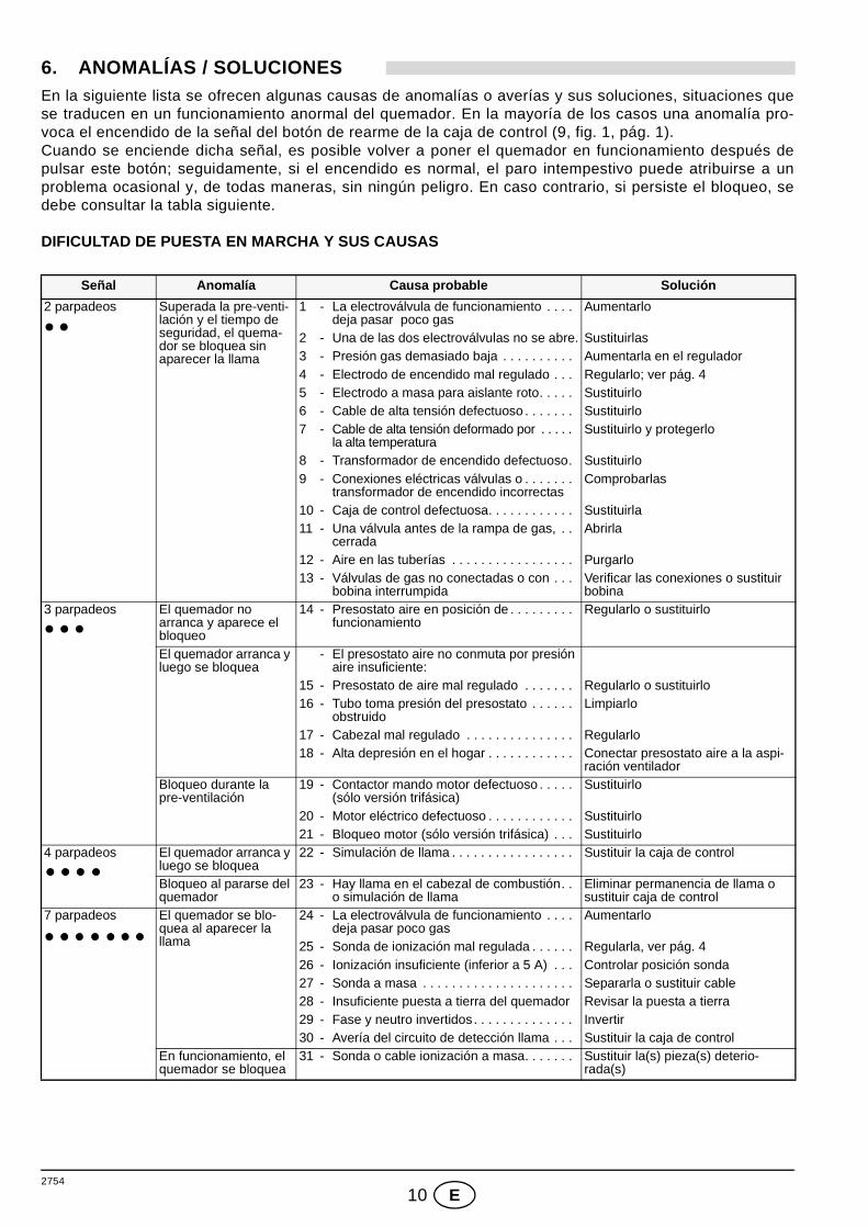
6. ANOMALÍAS / SOLUCIONESEn la siguiente lista se ofrecen algunas causas de anomalías o averías y sus soluciones, situaciones quese traducen en un funcionamiento anormal del quemador. En la mayoría de los casos una anomalía pro-voca el encendido de la señal del botón de rearme de la caja de control (9, fig. 1, pág. 1). Cuando se enciende dicha señal, es posible volver a poner el quemador en funcionamiento después depulsar este botón; seguidamente, si el encendido es normal, el paro intempestivo puede atribuirse a unproblema ocasional y, de todas maneras, sin ningún peligro. En caso contrario, si persiste el bloqueo, sedebe consultar la tabla siguiente.
DIFICULTAD DE PUESTA EN MARCHA Y SUS CAUSAS
Señal Anomalía Causa probable Solución
2 parpadeos Superada la pre-venti-lación y el tiempo de seguridad, el quema-dor se bloquea sin aparecer la llama
1 - La electroválvula de funcionamiento . . . . deja pasar poco gas
Aumentarlo
2 - Una de las dos electroválvulas no se abre. Sustituirlas3 - Presión gas demasiado baja . . . . . . . . . . Aumentarla en el regulador4 - Electrodo de encendido mal regulado . . . Regularlo; ver pág. 45 - Electrodo a masa para aislante roto. . . . . Sustituirlo6 - Cable de alta tensión defectuoso . . . . . . . Sustituirlo7 - Cable de alta tensión deformado por . . . . .
la alta temperaturaSustituirlo y protegerlo
8 - Transformador de encendido defectuoso. Sustituirlo9 - Conexiones eléctricas válvulas o . . . . . . .
transformador de encendido incorrectasComprobarlas
10 - Caja de control defectuosa. . . . . . . . . . . . Sustituirla11 - Una válvula antes de la rampa de gas, . .
cerradaAbrirla
12 - Aire en las tuberías . . . . . . . . . . . . . . . . . Purgarlo13 - Válvulas de gas no conectadas o con . . .
bobina interrumpidaVerificar las conexiones o sustituir bobina
3 parpadeos El quemador no arranca y aparece el bloqueo
14 - Presostato aire en posición de . . . . . . . . . funcionamiento
Regularlo o sustituirlo
El quemador arranca y luego se bloquea
- El presostato aire no conmuta por presión aire insuficiente:
15 - Presostato de aire mal regulado . . . . . . . Regularlo o sustituirlo16 - Tubo toma presión del presostato . . . . . .
obstruidoLimpiarlo
17 - Cabezal mal regulado . . . . . . . . . . . . . . . Regularlo18 - Alta depresión en el hogar . . . . . . . . . . . . Conectar presostato aire a la aspi-
ración ventiladorBloqueo durante la pre-ventilación
19 - Contactor mando motor defectuoso . . . . . (sólo versión trifásica)
Sustituirlo
20 - Motor eléctrico defectuoso . . . . . . . . . . . . Sustituirlo21 - Bloqueo motor (sólo versión trifásica) . . . Sustituirlo
4 parpadeos El quemador arranca y luego se bloquea
22 - Simulación de llama . . . . . . . . . . . . . . . . . Sustituir la caja de control
Bloqueo al pararse del quemador
23 - Hay llama en el cabezal de combustión. . o simulación de llama
Eliminar permanencia de llama o sustituir caja de control
7 parpadeos El quemador se blo-quea al aparecer la llama
24 - La electroválvula de funcionamiento . . . . deja pasar poco gas
Aumentarlo
25 - Sonda de ionización mal regulada . . . . . . Regularla, ver pág. 426 - Ionización insuficiente (inferior a 5 A) . . . Controlar posición sonda27 - Sonda a masa . . . . . . . . . . . . . . . . . . . . . Separarla o sustituir cable28 - Insuficiente puesta a tierra del quemador Revisar la puesta a tierra29 - Fase y neutro invertidos. . . . . . . . . . . . . . Invertir30 - Avería del circuito de detección llama . . . Sustituir la caja de control
En funcionamiento, el quemador se bloquea
31 - Sonda o cable ionización a masa. . . . . . . Sustituir la(s) pieza(s) deterio-rada(s)
2754
11 E
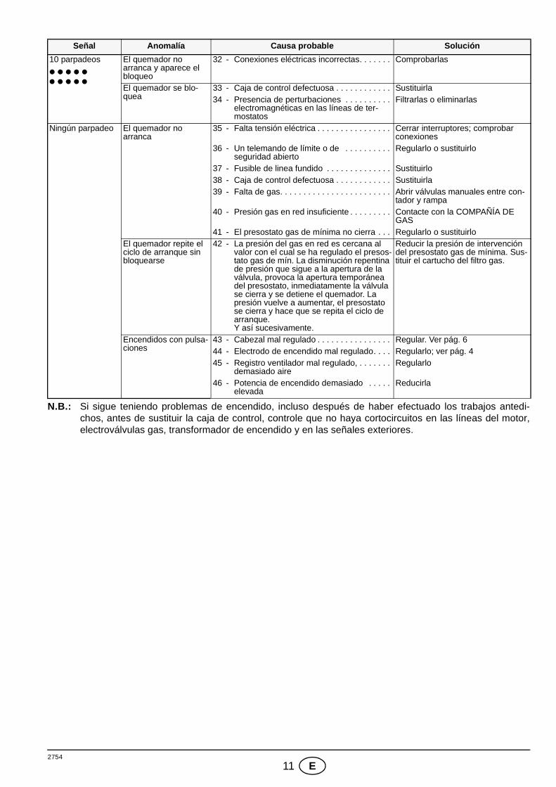
N.B.: Si sigue teniendo problemas de encendido, incluso después de haber efectuado los trabajos antedi-chos, antes de sustituir la caja de control, controle que no haya cortocircuitos en las líneas del motor,electroválvulas gas, transformador de encendido y en las señales exteriores.
10 parpadeos El quemador no arranca y aparece el bloqueo
32 - Conexiones eléctricas incorrectas. . . . . . . Comprobarlas
El quemador se blo-quea
33 - Caja de control defectuosa . . . . . . . . . . . . Sustituirla34 - Presencia de perturbaciones . . . . . . . . . .
electromagnéticas en las líneas de ter-mostatos
Filtrarlas o eliminarlas
Ningún parpadeo El quemador no arranca
35 - Falta tensión eléctrica . . . . . . . . . . . . . . . . Cerrar interruptores; comprobar conexiones
36 - Un telemando de límite o de . . . . . . . . . .seguridad abierto
Regularlo o sustituirlo
37 - Fusible de linea fundido . . . . . . . . . . . . . . Sustituirlo38 - Caja de control defectuosa . . . . . . . . . . . . Sustituirla39 - Falta de gas. . . . . . . . . . . . . . . . . . . . . . . . Abrir válvulas manuales entre con-
tador y rampa40 - Presión gas en red insuficiente . . . . . . . . . Contacte con la COMPAÑÍA DE
GAS41 - El presostato gas de mínima no cierra . . . Regularlo o sustituirlo
El quemador repite el ciclo de arranque sin bloquearse
42 - La presión del gas en red es cercana al valor con el cual se ha regulado el presos-tato gas de mín. La disminución repentina de presión que sigue a la apertura de la válvula, provoca la apertura temporánea del presostato, inmediatamente la válvula se cierra y se detiene el quemador. La presión vuelve a aumentar, el presostato se cierra y hace que se repita el ciclo de arranque. Y así sucesivamente.
Reducir la presión de intervención del presostato gas de mínima. Sus-tituir el cartucho del filtro gas.
Encendidos con pulsa-ciones
43 - Cabezal mal regulado . . . . . . . . . . . . . . . . Regular. Ver pág. 644 - Electrodo de encendido mal regulado. . . . Regularlo; ver pág. 445 - Registro ventilador mal regulado, . . . . . . .
demasiado aireRegularlo
46 - Potencia de encendido demasiado . . . . .elevada
Reducirla
Señal Anomalía Causa probable Solución
2754
12 E
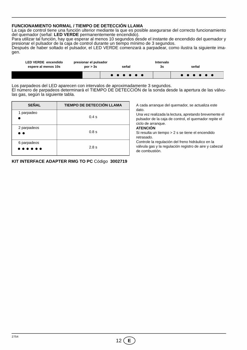
FUNCIONAMIENTO NORMAL / TIEMPO DE DETECCIÓN LLAMALa caja de control tiene una función ulterior mediante la que es posible asegurarse del correcto funcionamientodel quemador (señal: LED VERDE permanentemente encendido).Para utilizar tal función, hay que esperar al menos 10 segundos desde el instante de encendido del quemador ypresionar el pulsador de la caja de control durante un tiempo mínimo de 3 segundos.Después de haber soltado el pulsador, el LED VERDE comenzará a parpadear, como ilustra la siguiente ima-gen.
Los parpadeos del LED aparecen con intervalos de aproximadamente 3 segundos.El número de parpadeos determinará el TIEMPO DE DETECCIÓN de la sonda desde la apertura de las válvu-las gas, según la siguiente tabla.
KIT INTERFACE ADAPTER RMG TO PC Código 3002719
SEÑAL TIEMPO DE DETECCIÓN LLAMA A cada arranque del quemador, se actualiza este dato.Una vez realizada la lectura, apretando brevemente el pulsador de la caja de control, el quemador repite el ciclo de arranque.ATENCIÓNSi resulta un tiempo > 2 s se tiene el encendido retrasado.Controle la regulación del freno hidráulico en la válvula gas y la regulación registro de aire y cabezal de combustión.
1 parpadeo0.4 s
2 parpadeos0.8 s
6 parpadeos2.8 s
LED VERDE encendidoespere al menos 10s
presionar el pulsadorpor > 3s señal señal
Intervalo3s


Subject to modifications - Con la posibilidad de modificación
RIELLO S.p.A.
I-37045 Legnago (VR)
Tel.: +39.0442.630111
http:// www.riello.it
http:// www.riello.com