c21500d-manual-867.pdf - nu-way burner
TRANSCRIPT
Prin
ted
in G
erm
any
/ M-M
T-B
OS
• E
diti
on11
.99
• #
231
763
1 … 112
Read the operating andmounting instructions be-
fore commissioning.
Only specialised personnelmay perform work on the
automatic burner control system.
Never perform any workwhen the control system is
live. This also applies if low-volt-age components such as servo-motors, display or communica-tion components are replaced orinstalled.
In case of fuse failure,check the safety function
of the automatic burner controlsystem. Otherwise contact weldcaused by short-circuit may oc-cur.
Only specialised personnelmay set operating param-
eters.
Only use the communica-tion connection together
with components expressly ap-proved for this purpose.
Perform the connection re-lated to the correct phase
and the protective conductor con-nection according to the terminaldiagram and check it before com-missioning.
Warranty for the controlsystem expires on im-
proper handling of the electronicsystem or due to incorrect stor-age.
The data contained in theseinstructions specify the au-
tomatic burner control system.They do not imply any character-istics.
If you do not follow theseinstructions, danger to life
to the equipment may occur.
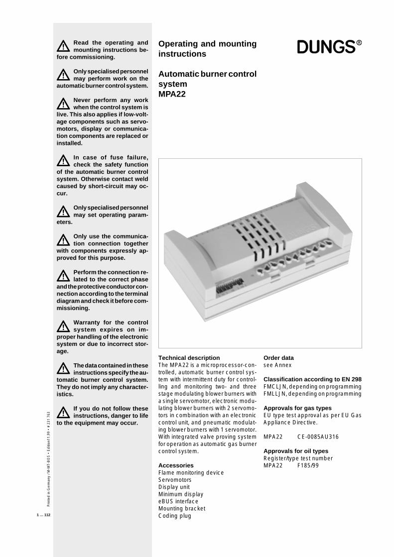
Technical descriptionThe MPA22 is a microprocessor-con-trolled, automatic burner control sys-tem with intermittent duty for control-ling and monitoring two- and threestage modulating blower burners witha single servomotor, electronic modu-lating blower burners with 2 servomo-tors in combination with an electroniccontrol unit, and pneumatic modulat-ing blower burners with 1 servomotor.With integrated valve proving systemfor operation as automatic gas burnercontrol system.
AccessoriesFlame monitoring deviceServomotorsDisplay unitMinimum displayeBUS interfaceMounting bracketCoding plug
Operating and mountinginstructions
Automatic burner controlsystemMPA22
Order datasee Annex
Classification according to EN 298FMCLJN, depending on programmingFMLLJN, depending on programming
Approvals for gas typesEU type test approval as per EU GasAppliance Directive.
MPA22 CE-0085AU316
Approvals for oil typesRegister/type test numberMPA22 F185/99
Prin
ted
in G
erm
any
/ M-M
T-B
OS
• E
diti
on 1
1.99
• #
231
763
2 … 112
Contents
Operating modes ....................................................................................................................................................... 10Operating modeGas firing, electronic modulation ..........................................................................................................................11-12Terminal diagram - Gas firing, electronic modulation ................................................................................................ 13Terminal diagram - Gas firing, pneumatic modulation ..........................................................................................14-15Terminal diagram - Gas firing, pneumatic modulation ............................................................................................... 16Operating mode - Oil firing, three stage ...............................................................................................................17-18Terminal diagram - Operating mode - Oil firing, three stage ..................................................................................... 19Integrated valve proving system, electronic modulation ........................................................................................... 20Time diagram - Operating mode - Gas firing, electronic modulation ...................................................................21-22Time diagram - Operating mode - Gas firing, pneumatic modulation ..................................................................23-24Time diagram - Oil firing, three stage ...................................................................................................................25-26Explanation display .................................................................................................................................................... 27Display functions........................................................................................................................................................ 28Relationships between the individual display modes ...........................................................................................29-30Display during standby .............................................................................................................................................. 31Display when a password is entered in parameterisation or setup mode ................................................................. 32Display when the basic configuration is entered ..................................................................................................33-34Commissioning, setup mode ..................................................................................................................................... 35CommissioningMain parameters ........................................................................................................................................................ 36Setup mode - Gas firing, electronic modulation ...................................................................................................37-50Setup mode - Gas firing, pneumatic modulation ..................................................................................................51-55Setup mode - Oil firing, three stage ......................................................................................................................56-63Display in operating modeGas firing, electronic modulation and Gas firing, pneumatic modulation ............................................................64-69Display in operating mode „Oil firing, three stage“ ..............................................................................................70-75Display in information modeGas firing, electronic modulation; Gas firing, pneumatic modulation and Oil firing, three stage .............................. 76Display in information modeGas firing, electronic modulation; Gas firing, pneumatic modulation and Oil firing, three stage .............................. 77Display in information modeGas firing, electronic modulation; Gas firing, pneumatic modulation and Oil firing, three stage .............................. 78Display in information modeGas firing, electronic modulation; Gas firing, pneumatic modulation and Oil firing, three stage .............................. 79Display in service modeGas firing, electronic modulation ..........................................................................................................................82-89Display in service modeGas firing, pneumatic modulation .........................................................................................................................90-98Display in parameterisation modeGas firing, electronic modulation; Gas firing, pneumatic modulation and Oil firing, three stage .............................. 99Display in parameterisation modeGas firing, electronic modulation; Gas firing, pneumatic modulation and Oil firing, three stage ............................ 100Display in parameterisation modeGas firing, electronic modulation; Gas firing, pneumatic modulation and Oil firing, three stage .....................101-106Error indicationGas firing, electronic modulation; Gas firing, pneumatic modulation and Oil firing, three stage .....................107-108System error messages ....................................................................................................................................109-111
Prin
ted
in G
erm
any
/ M-M
T-B
OS
• E
diti
on11
.99
• #
231
763
3 … 112
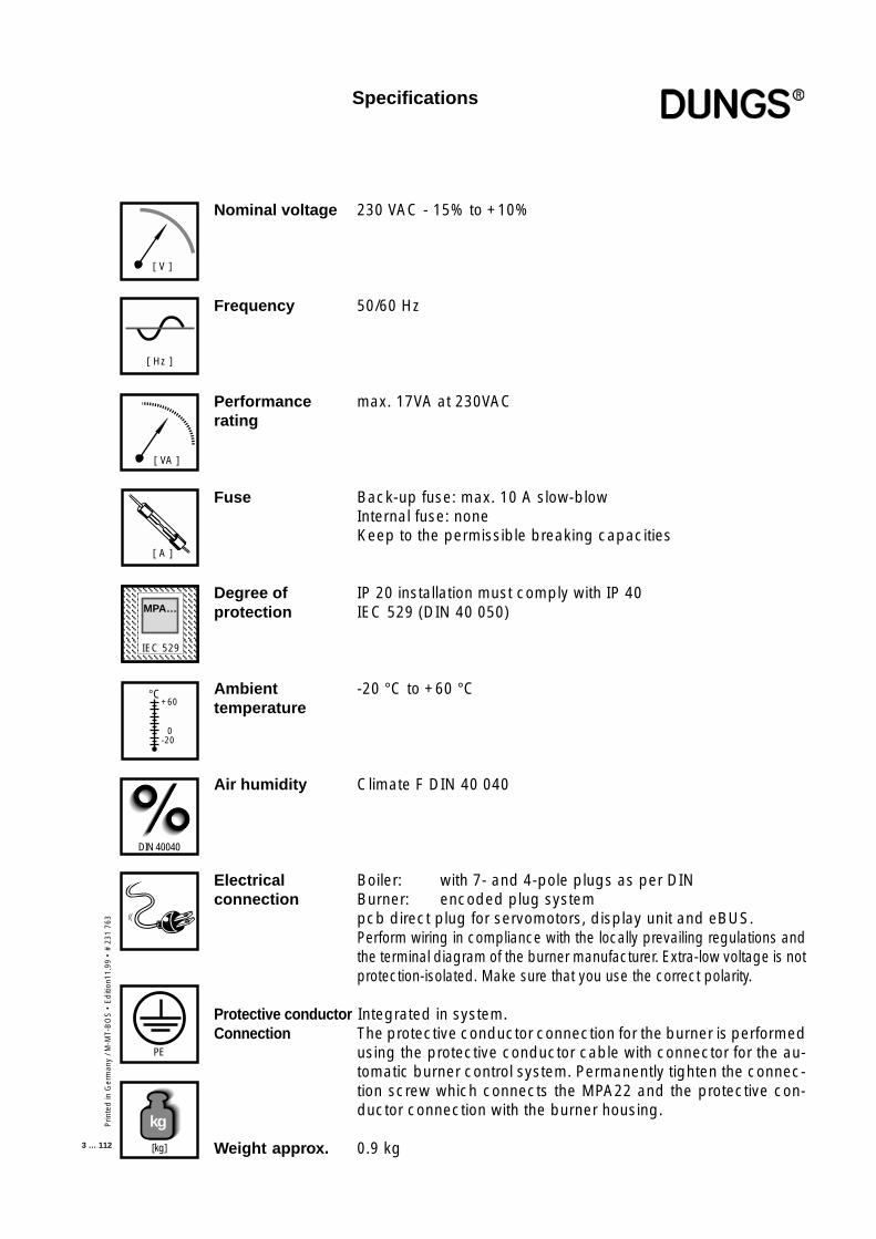
Nominal voltage 230 VAC - 15% to +10%
Frequency 50/60 Hz
Performance max. 17VA at 230VACrating
Fuse Back-up fuse: max. 10 A slow-blowInternal fuse: noneKeep to the permissible breaking capacities
Degree of IP 20 installation must comply with IP 40protection IEC 529 (DIN 40 050)
Ambient -20 °C to +60 °Ctemperature
Air humidity Climate F DIN 40 040
Electrical Boiler: with 7- and 4-pole plugs as per DINconnection Burner: encoded plug system
pcb direct plug for servomotors, display unit and eBUS.Perform wiring in compliance with the locally prevailing regulations andthe terminal diagram of the burner manufacturer. Extra-low voltage is notprotection-isolated. Make sure that you use the correct polarity.
Protective conductor Integrated in system.Connection The protective conductor connection for the burner is performed
using the protective conductor cable with connector for the au-tomatic burner control system. Permanently tighten the connec-tion screw which connects the MPA22 and the protective con-ductor connection with the burner housing.
Weight approx. 0.9 kg
[ Hz ]
[ V ]
[ A ]
IEC 529IEC 529
MPA…
°C
0
+60
-20
DIN 40040
PE
[kg]
kg
Specifications
[ VA ]
Prin
ted
in G
erm
any
/ M-M
T-B
OS
• E
diti
on 1
1.99
• #
231
763
4 … 112
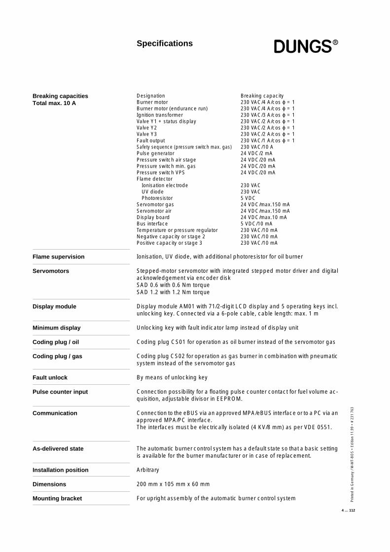
Breaking capacitiesTotal max. 10 A
Designation Breaking capacityBurner motor 230 VAC/4 A/cos ϕ = 1Burner motor (endurance run) 230 VAC/4 A/cos ϕ = 1Ignition transformer 230 VAC/3 A/cos ϕ = 1Valve Y1 + status display 230 VAC/2 A/cos ϕ = 1Valve Y2 230 VAC/2 A/cos ϕ = 1Valve Y3 230 VAC/2 A/cos ϕ = 1Fault output 230 VAC/1 A/cos ϕ = 1Safety sequence (pressure switch max. gas) 230 VAC/10 APulse generator 24 VDC/2 mAPressure switch air stage 24 VDC/20 mAPressure switch min. gas 24 VDC/20 mAPressure switch VPS 24 VDC/20 mAFlame detector
Ionisation electrode 230 VACUV diode 230 VACPhotoresistor 5 VDC
Servomotor gas 24 VDC/max.150 mAServomotor air 24 VDC/max.150 mADisplay board 24 VDC/max.10 mABus interface 5 VDC/10 mATemperature or pressure regulator 230 VAC/10 mANegative capacity or stage 2 230 VAC/10 mAPositive capacity or stage 3 230 VAC/10 mA
Specifications
Flame supervision
Servomotors
Display module
Minimum display
Coding plug / oil
Coding plug / gas
Fault unlock
Pulse counter input
Communication
As-delivered state
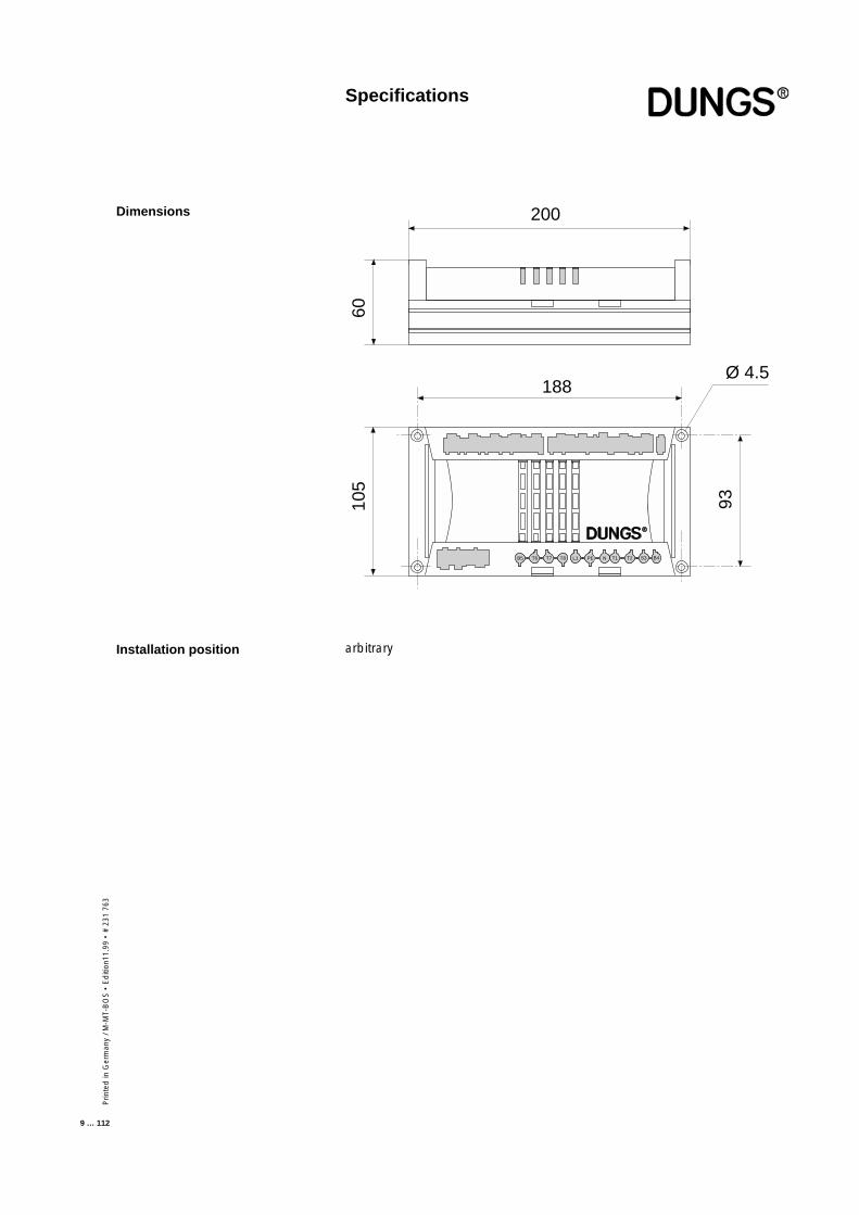
Installation position
Dimensions
Mounting bracket
Ionisation, UV diode, with additional photoresistor for oil burner
Stepped-motor servomotor with integrated stepped motor driver and digitalacknowledgement via encoder diskSAD 0.6 with 0.6 Nm torqueSAD 1.2 with 1.2 Nm torque
Display module AM01 with 71/2-digit LCD display and 5 operating keys incl.unlocking key. Connected via a 6-pole cable, cable length: max. 1 m
Unlocking key with fault indicator lamp instead of display unit
Coding plug CS01 for operation as oil burner instead of the servomotor gas
Coding plug CS02 for operation as gas burner in combination with pneumaticsystem instead of the servomotor gas
By means of unlocking key
Connection possibility for a floating pulse counter contact for fuel volume ac-quisition, adjustable divisor in EEPROM.
Connection to the eBUS via an approved MPA/eBUS interface or to a PC via anapproved MPA/PC interface.The interfaces must be electrically isolated (4 KV/8 mm) as per VDE 0551.
The automatic burner control system has a default state so that a basic settingis available for the burner manufacturer or in case of replacement.
Arbitrary
200 mm x 105 mm x 60 mm
For upright assembly of the automatic burner control system
Prin
ted
in G
erm
any
/ M-M
T-B
OS
• E
diti
on11
.99
• #
231
763
5 … 112
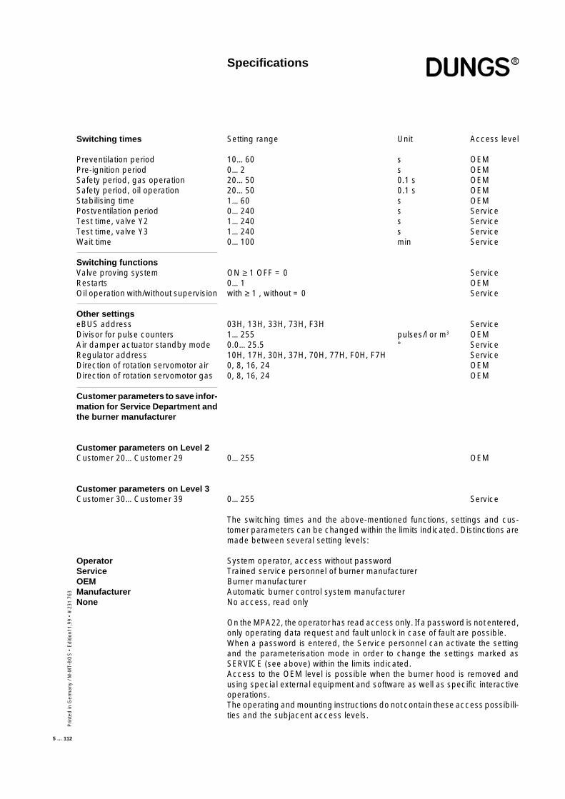
Switching times
Preventilation periodPre-ignition periodSafety period, gas operationSafety period, oil operationStabilising timePostventilation periodTest time, valve Y2Test time, valve Y3Wait time
Switching functionsValve proving systemRestartsOil operation with/without supervision
Other settingseBUS addressDivisor for pulse countersAir damper actuator standby modeRegulator addressDirection of rotation servomotor airDirection of rotation servomotor gas
Customer parameters to save infor-mation for Service Department andthe burner manufacturer
Customer parameters on Level 2Customer 20…Customer 29
Customer parameters on Level 3Customer 30…Customer 39
OperatorServiceOEMManufacturerNone
Setting range Unit Access level
10…60 s OEM0…2 s OEM20…50 0.1 s OEM20…50 0.1 s OEM1…60 s OEM0…240 s Service1…240 s Service1…240 s Service0…100 min Service
ON ≥ 1 OFF = 0 Service0…1 OEMwith ≥ 1 , without = 0 Service
03H, 13H, 33H, 73H, F3H Service1…255 pulses/l or m3 OEM0.0…25.5 ° Service10H, 17H, 30H, 37H, 70H, 77H, F0H, F7H Service0, 8, 16, 24 OEM0, 8, 16, 24 OEM
0…255 OEM
0…255 Service
The switching times and the above-mentioned functions, settings and cus-tomer parameters can be changed within the limits indicated. Distinctions aremade between several setting levels:
System operator, access without passwordTrained service personnel of burner manufacturerBurner manufacturerAutomatic burner control system manufacturerNo access, read only
On the MPA22, the operator has read access only. If a password is not entered,only operating data request and fault unlock in case of fault are possible.When a password is entered, the Service personnel can activate the settingand the parameterisation mode in order to change the settings marked asSERVICE (see above) within the limits indicated.Access to the OEM level is possible when the burner hood is removed andusing special external equipment and software as well as specific interactiveoperations.The operating and mounting instructions do not contain these access possibili-ties and the subjacent access levels.
Specifications
Prin
ted
in G
erm
any
/ M-M
T-B
OS
• E
diti
on 1
1.99
• #
231
763
6 … 112
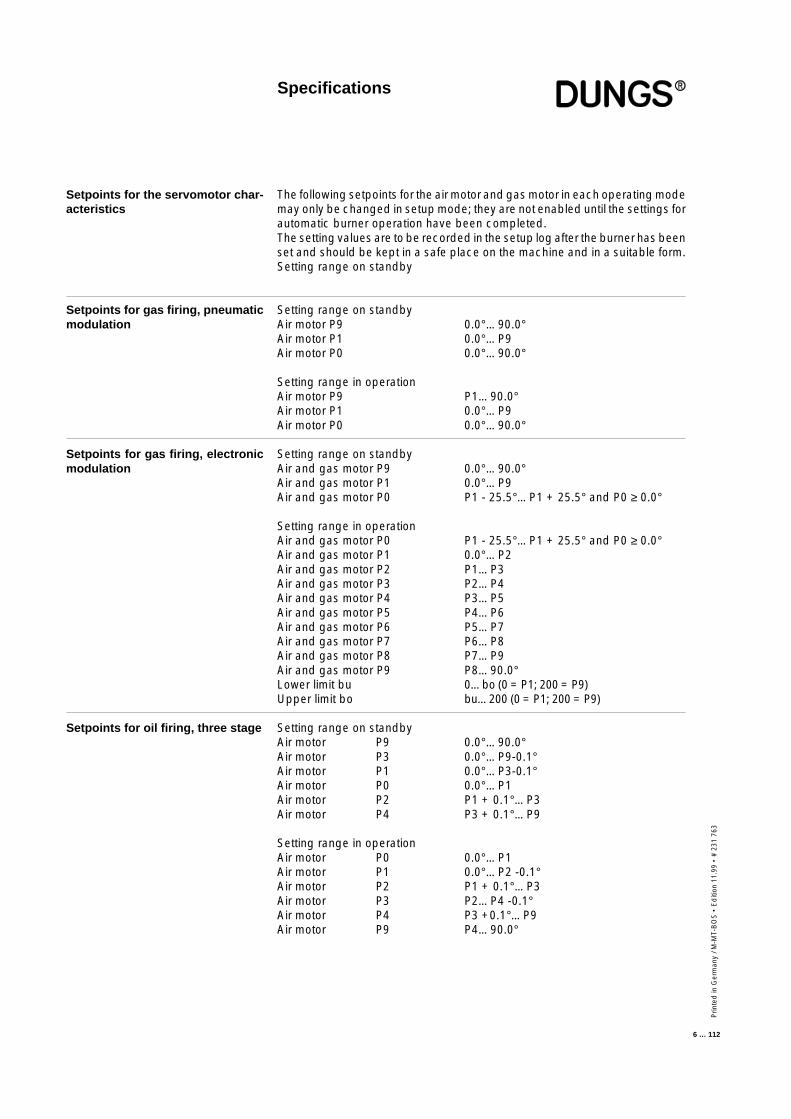
Setpoints for the servomotor char-acteristics
Setpoints for gas firing, pneumaticmodulation
Setpoints for gas firing, electronicmodulation
Setpoints for oil firing, three stage
The following setpoints for the air motor and gas motor in each operating modemay only be changed in setup mode; they are not enabled until the settings forautomatic burner operation have been completed.The setting values are to be recorded in the setup log after the burner has beenset and should be kept in a safe place on the machine and in a suitable form.Setting range on standby
Setting range on standbyAir motor P9 0.0°…90.0°Air motor P1 0.0°…P9Air motor P0 0.0°…90.0°
Setting range in operationAir motor P9 P1…90.0°Air motor P1 0.0°…P9Air motor P0 0.0°…90.0°
Setting range on standbyAir and gas motor P9 0.0°…90.0°Air and gas motor P1 0.0°…P9Air and gas motor P0 P1 - 25.5°…P1 + 25.5° and P0 ≥ 0.0°
Setting range in operationAir and gas motor P0 P1 - 25.5°…P1 + 25.5° and P0 ≥ 0.0°Air and gas motor P1 0.0°…P2Air and gas motor P2 P1…P3Air and gas motor P3 P2…P4Air and gas motor P4 P3…P5Air and gas motor P5 P4…P6Air and gas motor P6 P5…P7Air and gas motor P7 P6…P8Air and gas motor P8 P7…P9Air and gas motor P9 P8…90.0°Lower limit bu 0…bo (0 = P1; 200 = P9)Upper limit bo bu…200 (0 = P1; 200 = P9)
Setting range on standbyAir motor P9 0.0°…90.0°Air motor P3 0.0°…P9-0.1°Air motor P1 0.0°…P3-0.1°Air motor P0 0.0°…P1Air motor P2 P1 + 0.1°…P3Air motor P4 P3 + 0.1°…P9
Setting range in operationAir motor P0 0.0°…P1Air motor P1 0.0°…P2 -0.1°Air motor P2 P1 + 0.1°…P3Air motor P3 P2…P4 -0.1°Air motor P4 P3 +0.1°…P9Air motor P9 P4…90.0°
Specifications
Prin
ted
in G
erm
any
/ M-M
T-B
OS
• E
diti
on11
.99
• #
231
763
7 … 112
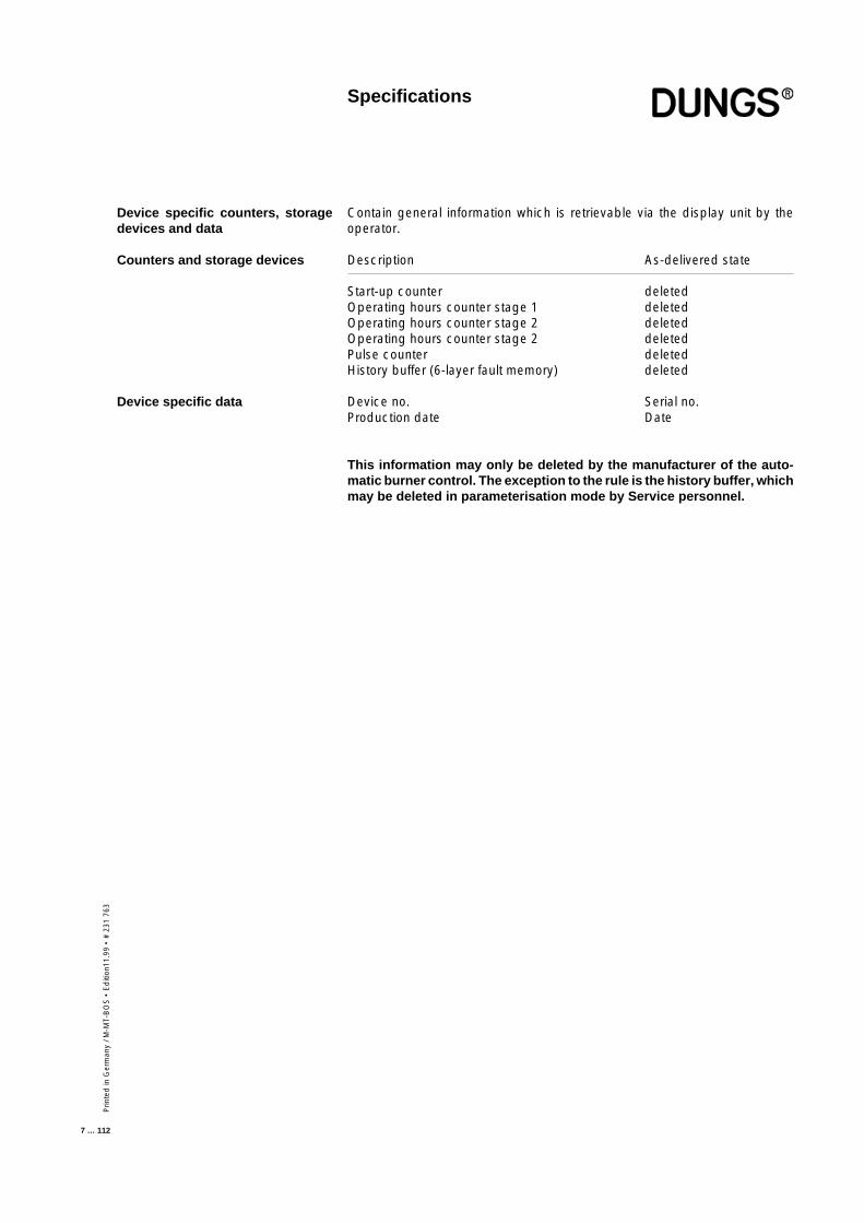
Contain general information which is retrievable via the display unit by theoperator.
Description As-delivered state
Start-up counter deletedOperating hours counter stage 1 deletedOperating hours counter stage 2 deletedOperating hours counter stage 2 deletedPulse counter deletedHistory buffer (6-layer fault memory) deleted
Device no. Serial no.Production date Date
This information may only be deleted by the manufacturer of the auto-matic burner control. The exception to the rule is the history buffer, whichmay be deleted in parameterisation mode by Service personnel.
Device specific counters, storagedevices and data
Counters and storage devices
Device specific data
Specifications
Prin
ted
in G
erm
any
/ M-M
T-B
OS
• E
diti
on 1
1.99
• #
231
763
8 … 112
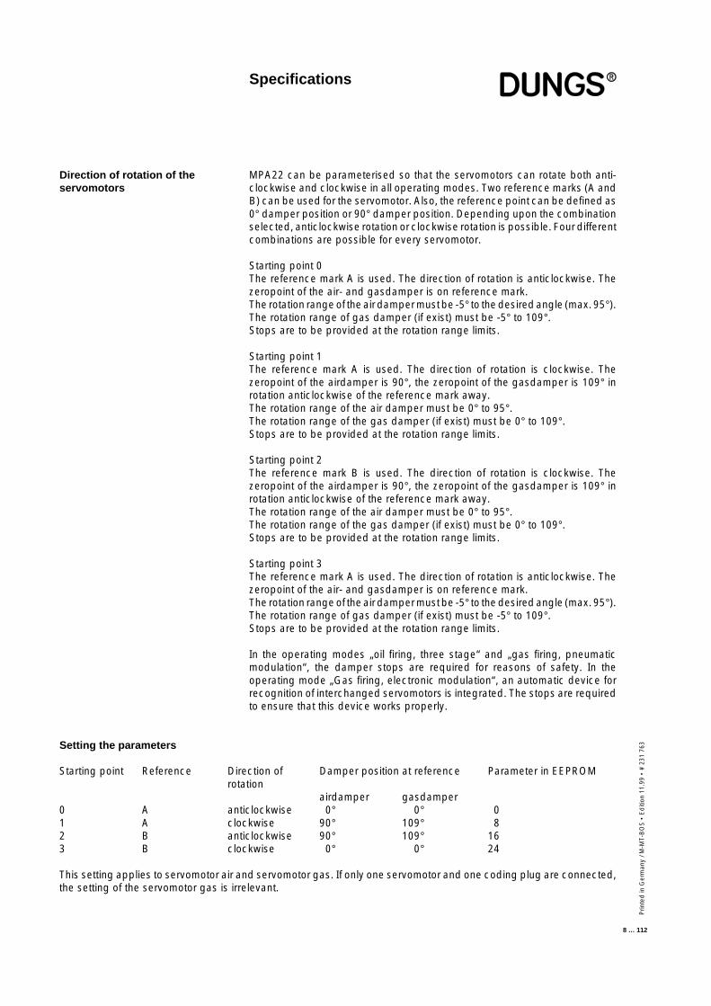
MPA22 can be parameterised so that the servomotors can rotate both anti-clockwise and clockwise in all operating modes. Two reference marks (A andB) can be used for the servomotor. Also, the reference point can be defined as0° damper position or 90° damper position. Depending upon the combinationselected, anticlockwise rotation or clockwise rotation is possible. Four differentcombinations are possible for every servomotor.
Starting point 0The reference mark A is used. The direction of rotation is anticlockwise. Thezeropoint of the air- and gasdamper is on reference mark.The rotation range of the air damper must be -5° to the desired angle (max. 95°).The rotation range of gas damper (if exist) must be -5° to 109°.Stops are to be provided at the rotation range limits.
Starting point 1The reference mark A is used. The direction of rotation is clockwise. Thezeropoint of the airdamper is 90°, the zeropoint of the gasdamper is 109° inrotation anticlockwise of the reference mark away.The rotation range of the air damper must be 0° to 95°.The rotation range of the gas damper (if exist) must be 0° to 109°.Stops are to be provided at the rotation range limits.
Starting point 2The reference mark B is used. The direction of rotation is clockwise. Thezeropoint of the airdamper is 90°, the zeropoint of the gasdamper is 109° inrotation anticlockwise of the reference mark away.The rotation range of the air damper must be 0° to 95°.The rotation range of the gas damper (if exist) must be 0° to 109°.Stops are to be provided at the rotation range limits.
Starting point 3The reference mark A is used. The direction of rotation is anticlockwise. Thezeropoint of the air- and gasdamper is on reference mark.The rotation range of the air damper must be -5° to the desired angle (max. 95°).The rotation range of gas damper (if exist) must be -5° to 109°.Stops are to be provided at the rotation range limits.
In the operating modes „oil firing, three stage“ and „gas firing, pneumaticmodulation“, the damper stops are required for reasons of safety. In theoperating mode „Gas firing, electronic modulation“, an automatic device forrecognition of interchanged servomotors is integrated. The stops are requiredto ensure that this device works properly.
Direction of rotation of theservomotors
Specifications
Setting the parameters
Starting point Reference Direction of Damper position at reference Parameter in EEPROMrotation
airdamper gasdamper0 A anticlockwise 0° 0° 01 A clockwise 90° 109° 82 B anticlockwise 90° 109° 163 B clockwise 0° 0° 24
This setting applies to servomotor air and servomotor gas. If only one servomotor and one coding plug are connected,the setting of the servomotor gas is irrelevant.
Prin
ted
in G
erm
any
/ M-M
T-B
OS
• E
diti
on11
.99
• #
231
763
9 … 112
Specifications
Dimensions
Installation position
200
188
6010
5
93
Ø 4.5
B4S3T2NL1 PET8T7T6B5 T1 T2S3 B4
arbitrary

Prin
ted
in G
erm
any
/ M-M
T-B
OS
• E
diti
on 1
1.99
• #
231
763
10 … 112
123456789012345678901234567890121234567890123456789012345678901234567890123456789012345678901212345678901234567890123456789012345678901234567890123456789012123456789012345678901234567890123456789012345678901234567890121234567890123456789012345678901234567890123456789012345678901212345678901234567890123456789012345678901234567890123456789012123456789012345678901234567890123456789012345678901234567890121234567890123456789012345678901234567890123456789012345678901212345678901234567890123456789012345678901234567890123456789012123456789012345678901234567890123456789012345678901234567890121234567890123456789012345678901234567890123456789012345678901212345678901234567890123456789012345678901234567890123456789012123456789012345678901234567890123456789012345678901234567890121234567890123456789012345678901234567890123456789012345678901212345678901234567890123456789012345678901234567890123456789012123456789012345678901234567890123456789012345678901234567890121234567890123456789012345678901234567890123456789012345678901212345678901234567890123456789012345678901234567890123456789012123456789012345678901234567890123456789012345678901234567890121234567890123456789012345678901234567890123456789012345678901212345678901234567890123456789012345678901234567890123456789012123456789012345678901234567890123456789012345678901234567890121234567890123456789012345678901234567890123456789012345678901212345678901234567890123456789012345678901234567890123456789012123456789012345678901234567890123456789012345678901234567890121234567890123456789012345678901234567890123456789012345678901212345678901234567890123456789012345678901234567890123456789012123456789012345678901234567890123456789012345678901234567890121234567890123456789012345678901234567890123456789012345678901212345678901234567890123456789012345678901234567890123456789012123456789012345678901234567890123456789012345678901234567890121234567890123456789012345678901234567890123456789012345678901212345678901234567890123456789012345678901234567890123456789012123456789012345678901234567890123456789012345678901234567890121234567890123456789012345678901234567890123456789012345678901212345678901234567890123456789012345678901234567890123456789012123456789012345678901234567890123456789012345678901234567890121234567890123456789012345678901234567890123456789012345678901212345678901234567890123456789012345678901234567890123456789012123456789012345678901234567890123456789012345678901234567890121234567890123456789012345678901234567890123456789012345678901212345678901234567890123456789012345678901234567890123456789012123456789012345678901234567890123456789012345678901234567890121234567890123456789012345678901234567890123456789012345678901212345678901234567890123456789012345678901234567890123456789012123456789012345678901234567890123456789012345678901234567890121234567890123456789012345678901234567890123456789012345678901212345678901234567890123456789012345678901234567890123456789012123456789012345678901234567890123456789012345678901234567890121234567890123456789012345678901234567890123456789012345678901212345678901234567890123456789012345678901234567890123456789012123456789012345678901234567890123456789012345678901234567890121234567890123456789012345678901234567890123456789012345678901212345678901234567890123456789012345678901234567890123456789012123456789012345678901234567890123456789012345678901234567890121234567890123456789012345678901234567890123456789012345678901212345678901234567890123456789012345678901234567890123456789012123456789012345678901234567890123456789012345678901234567890121234567890123456789012345678901234567890123456789012345678901212345678901234567890123456789012345678901234567890123456789012123456789012345678901234567890123456789012345678901234567890121234567890123456789012345678901234567890123456789012345678901212345678901234567890123456789012345678901234567890123456789012123456789012345678901234567890123456789012345678901234567890121234567890123456789012345678901234567890123456789012345678901212345678901234567890123456789012345678901234567890123456789012123456789012345678901234567890123456789012345678901234567890121234567890123456789012345678901234567890123456789012345678901212345678901234567890123456789012345678901234567890123456789012123456789012345678901234567890123456789012345678901234567890121234567890123456789012345678901234567890123456789012345678901212345678901234567890123456789012345678901234567890123456789012123456789012345678901234567890123456789012345678901234567890121234567890123456789012345678901234567890123456789012345678901212345678901234567890123456789012345678901234567890123456789012123456789012345678901234567890123456789012345678901234567890121234567890123456789012345678901234567890123456789012345678901212345678901234567890123456789012345678901234567890123456789012123456789012345678901234567890123456789012345678901234567890121234567890123456789012345678901234567890123456789012345678901212345678901234567890123456789012345678901234567890123456789012123456789012345678901234567890123456789012345678901234567890121234567890123456789012345678901234567890123456789012345678901212345678901234567890123456789012345678901234567890123456789012123456789012345678901234567890
Prin
ted
in G
erm
any
/ M-M
T-B
OS
• E
diti
on11
.99
• #
231
763
11 … 112
Operating modes
■ Operating modes of MPA22
■ Setting the operating mode
Gas modulating mode (electronic) with stepped motor to control the air andgas volume.
Gas modulating mode (pneumatic) with servomotor air damper control
Oil firing, three stage with oil preheater and servomotor air damper control
The operating mode is set at the servomotor gas connection by means of thecoding plug and is checked and identified when the automatic burner controlis put into operation.
Prin
ted
in G
erm
any
/ M-M
T-B
OS
• E
diti
on 1
1.99
• #
231
763
12 … 112
Servomotor air plugged inServomotor gas plugged in
The internal self-tests are performed when the regulator issues a heatingrequest. First, the servomotor air locates its reference point, then the servomo-tor gas.The servomotor air then moves to pre-ventilation position P9.The idle position of the air pressure switch is checked and the flame monitoringdevice is checked for flame simulation. If these checks are successful, theblower is energised.When the air pressure switch is closed, the preset pre-purge period elapsesand the remaining pre-purge period is displayed. Pre-purging is monitored bythe air pressure switch.During the pre-purge period, the servomotor gas runs to position 109° to checkwhether the servomotors for gas and air have been interchanged.After the servomotor has reached the 109° position it returns to ignition point P0during the pre-purge period.If a valve test has still not been performed after a power failure or fault shut-down and the valve proving function has been selected, a valve test and restartare performed once the pre-purge period has expired.
Otherwise, external valve Y1 (liquid gas) of the servomotor air opens and theservomotor air moves to ignition point P0 after the pre-purge period hasexpired. After the servomotor air has reached ignition point P0, the ignition isturned on for the preset pre-purge period (with pre-ignition period = 2 s).Valve Y2 is opened one second before the startup safety period commences(the ignition is also turned on if pre-ignition period = 1s). The gas pressureswitch GW_min must indicate the presence of gas pressure within this periodof time. Otherwise, a safety shut-down will be triggered and the gas fail-safeprogram executed.If gas pressure is present after 1 second, the ignition is turned on (if pre-ignitionperiod = 0) and valve Y3 is opened.The ignition cuts out at the end of the safety period and, provided that a flameis present, the two servomotors remain in the ignition position for the presetstabilising time. After the stabilising time has expired, the servomotors alter-nately move to position P1 in stepping mode. When the servomotors reachposition P1, the automatic burner control is in the service position.
If the “Lower limit” bu > 0, the automatic burner control operates according tothe characteristic curve defined by points P1 to P9, consecutively activating theservomotors until it reaches the predefined minimum capacity point in theclosed-loop control mode.The MPA22 is now in closed-loop control mode, i.e. it accepts the controlsignals applied to the inputs capacity + and capacity - and thus regulates thecapacity over the predefined characteristic curve in the range between bu andbo.If the MPA22 has already been in service for 24 hours, a controlled shut-downis executed automatically.If the heating request is cancelled, a controlled shut-down takes place. If thevalve proving system is not activated, valves Y2 and Y3 and the external valveY1 close and the blower runs on for the preset postventilation period.If the valve proving system is activated, a leakage check is performed on gasvalves Y2 and Y3. The post-ventilation period elapses in parallel with theleakage check.
When the blower is switched off, the servomotor air runs to the set standbyposition and then the servomotor gas runs to position 0°.A restart lock-out period (if set) now elapses (the time is indicated on thedisplay), or the automatic burner control enters standby mode (readout ondisplay = OFF).
Operating modeGas firing, electronicmodulation
■ ConfigurationGas firing, electronic modulation
■ Functional sequenceGas firing, electronic modulation
Prin
ted
in G
erm
any
/ M-M
T-B
OS
• E
diti
on11
.99
• #
231
763
13 … 112
Operating modeGas firing, electronicmodulation
If no flame is present after the startup safety period has elapsed, a safety shut-down takes place and the system executes a restart (if permitted). A faultlockout is triggered otherwise.If the presence of a flame is not indicated after a restart attempt, a fault shut-down takes place and the burner enters the non-variable fault state.If flame failure occurs when the burner is in operation, the burner is restarted(if permitted). Otherwise, a fault shut-down takes place and the burner entersthe non-variable fault state.In the event of a fault shut-down, all valves are closed and the blower andignition are turned off.If the presence of a flame is signalled before the gas is enabled, the automaticburner control enters the non-variable fault state.If a malfunction occurs during the start-up phase or operating phase, a safetyshut-down is activated. Depending upon the nature of the fault, the burnereither enters the non-variable fault state or the start-up attempt is repeated.After 5 failed attempts, the automatic burner control enters the non-variablefault state.The type of fault or disturbance is displayed.
The gas pressure switch GW_min is fitted in between gas valves Y2 and Y3.At burner start-up, valve Y2 is activated 1 second before the startup safetyperiod commences and also 1 s before valve Y3 is opened.If a pressure sufficient to actuate gas pressure switch GW_min does not buildup inside the space between valve Y2 and valve Y3, burner start-up isinterrupted. The valves are closed and the blower is switched off. Theautomatic burner control waits for 2 minutes before repeating the start-upattempt.If there is a still a shortage of gas after this 2-minute wait, the start-up attemptis repeated a third time after waiting another 2 minutes.After the third failed start-up attempt, the burner waits for an hour beforeattempting another restart.This function makes possible leakage checks and gas pressure monitoringwith only one pressure switch. It does not give rise to a fault lockout in the eventof a gas shortage and reduces the frequency of start-up attempts if a gasshortage exists over a lengthy period of time.The gas pressure switch must be set to at least the flow pressure necessary inbetween the two valves at full load.Examples of a display during the wait period: 18 1-23 (= 1 minute 23 sremaining waiting time)The waiting time can only be reset by disconnecting the voltage supply to thedevice (turn main switch OFF or disconnect the 7-pole connector).
■ Response to faultsGas firing, electronic modulation
■ Gas pressure switchingGas fail-safe program for gasburners with electronic modula-tion
Prin
ted
in G
erm
any
/ M-M
T-B
OS
• E
diti
on 1
1.99
• #
231
763
14 … 112
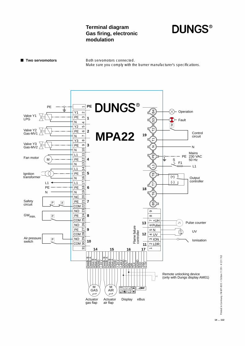
Terminal diagramGas firing, electronicmodulation
■ Two servomotors Both servomotors connected.Make sure you comply with the burner manufacturer’s specifications.
L1PEN
MPA22B
4S
3T
2N
L1P
ET
8T
7T
6B
5T
1
Fee
db. B
Fee
db. A
Driv
e B
Driv
e A
DG
ND
+ 2
4 V
Fee
db. B
Fee
db. A
Driv
e B
Driv
e A
DG
ND
+ 2
4 V
ϑ
M
MGAS
M AIR
P
PE
1
2
3
4
5
6
7
8
9
10
14 15 16 1711
12
13
18
19
12Y1
N
34
5Y2
PE
67
89
PENY3PE
10N
11L1PEN
1213
14L1PE 15
N 1617L1
PE 18
N 1920NC
PE 21
COM 2223NO
PECOM
2425
26
PE 27
NO
COMNOCOM
2829
3031
9
+UH
87
65
43
21
PulseNUVIONLDR
+ 2
4 V
DG
ND
DO
UT
DIN
DIR
CLK
DG
ND
RX
DT
XD
G 5
V
Mains230 VAC50 Hz
Valve Y1LPG
Ignitiontransformer
Fan motor
Operation
Fault
L1
PE
N
PE
Safetycircuit
Valve Y2Gas-MV1
Valve Y3Gas-MV2
Pulse counter
UV
Ionisation
F1S
DisplayActuatorgas flap
eBusActuatorair flap
Fla
me
failu
reco
ntro
ller
(-)
(+) Outputcontroller
Controlcircuit
Air pressureswitch
GWmin.
Remote unlocking device(only with Dungs display AM01)
+
–
1 2
P S i G L/A
hl,m3
P
P
ϑ
Prin
ted
in G
erm
any
/ M-M
T-B
OS
• E
diti
on11
.99
• #
231
763
15 … 112
Servomotor air plugged in.Coding plug gas plugged in instead of servomotor.
The internal self-tests are performed when the regulator issues a heatingrequest.The servomotor air locates its reference point and then the servomotor airmoves to pre-purge position P9.The idle position of the air pressure switch is checked and the flame monitoringdevice is checked for flame simulation. If these checks are passed, the bloweris energised.When the air pressure switch is closed, the preset pre-purge period elapsesand the remaining pre-purge period is displayed. Pre-purging is monitored byLGW.If a valve test has still not been performed after a power failure or fault shut-down and the valve proving function is selected, a valve test and restart areperformed after the pre-purge period has expired.
Otherwise, the external valve Y1 (liquid gas) opens and the servomotor airmoves to ignition point P0 after the pre-purge period has expired. After theservomotor air has reached the ignition point P0, the ignition is turned on for thepreset pre-purge period (with pre-ignition period = 2 s).Valve Y2 is opened one second before the startup safety period commences(the ignition is also turned on if pre-ignition period = 1s). The gas pressureswitch GW_min must indicate the presence of gas pressure within this periodof time. Otherwise, a safety shut-down will be triggered and the gas fail-safeprogram executed.If gas pressure is present after 1 second, the ignition is turned on (if pre-ignitionperiod = 0) and valve Y3 is opened. The ignition is turned off at the end of thesafety period and, provided that a flame is present, the servomotor remains inthe ignition position for the preset stabilising time. After the stabilising time hasexpired, the servomotor runs to position P1 and dwells there for 8 s.The automatic burner control is now in the service position.If the MPA22 has already been in service for 24 hours, a controlled shut-downis executed automatically.If the heating request is cancelled, a controlled shut-down takes place. If theleakage check is not activated, valves Y2, Y3 and the external valve close andthe blower runs on for the preset postventilation period. If the leakage checkfunction is activated, a leakage check is performed on gas valves Y2 and Y3by means of GW_VPS which is fitted in between valves Y2 and Y3. Thepostventilation period elapses in parallel with the leakage check. After theblower has been switched off, the servomotor air moves to the preset standbyposition. A restart lockout time (the time is displayed) now elapses (if set) or theautomatic burner control enters standby mode (readout on display = OFF).
If no flame is present after the startup safety period has elapsed, a safety shut-down takes place and executes a RESTART (if permitted). A fault lockout istriggered otherwise.If the presence of a flame is not indicated after a restart attempt, a fault shut-down takes place and the burner enters the non-variable fault state.If flame failure occurs while the burner is operating, the burner is restarted (ifset in the EEPROM). Otherwise, a fault shut-down takes place and the burnerenters the non-variable fault state.In the event of a fault shut-down, all valves are closed and the blower andignition are turned off.If the presence of a flame is signalled before the gas is enabled, the automaticburner control enters the non-variable fault state.If a malfunction occurs during the start-up phase or operating phase, a safetyshut-down will be triggered. Depending upon the nature of the fault, the burnereither enters the non-variable fault state or the start-up attempt is repeated.After 5 failed attempts, the automatic burner control enters the non-variable
Operating modeGas firing, pneumaticmodulation
■ ConfigurationGas firing, pneumatic modulation
■ Functional sequenceGas firing, pneumatic modulation
■ Response to faultsGas firing, pneumatic modulation
Prin
ted
in G
erm
any
/ M-M
T-B
OS
• E
diti
on 1
1.99
• #
231
763
16 … 112
Gas pressure switch GW_min is fitted upstream of the two gas valves of theRatio control.If a pressure sufficient to actuate gas pressure switch GW_min does not buildup one second before the startup safety period commences, burner start-upis interrupted. The valves are closed and the blower is switched off. Theautomatic burner control waits for 2 minutes before repeating the start-upattempt.If there is a still a shortage of gas after this 2-minute wait, the start-up attemptis repeated a third time after waiting another 2 minutes.After the third failed start-up attempt, the burner waits for an hour beforeattempting another restart.This function does not give rise to a fault lockout in the event of a gas shortageand reduces the frequency of start-up attempts if a gas shortage exists over alengthy period of time.
Examples of a display during the wait period: 18 1-23 (= 1 minute 23 sremaining waiting time)
The waiting time can only be reset by disconnecting the voltage supply to thedevice (turn main switch OFF or disconnect the 7-pole connector).
■ Gas pressure switchingGas fail-safe program for gasburners with pneumatic modula-tion
Operating modeGas firing, pneumaticmodulation
Prin
ted
in G
erm
any
/ M-M
T-B
OS
• E
diti
on11
.99
• #
231
763
17 … 112
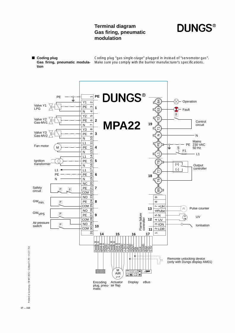
Terminal diagramGas firing, pneumaticmodulation
■ Coding plugGas firing, pneumatic modula-tion
Coding plug “gas single-stage” plugged in instead of “servomotor gas”.Make sure you comply with the burner manufacturer’s specifications.
L1PEN
MPA22
B4
S3
T2
NL1
PE
T8
T7
T6
B5
T1
Fee
db. B
Fee
db. A
Driv
e B
Driv
e A
DG
ND
+ 2
4 V
Fee
db. B
Fee
db. A
Driv
e B
Driv
e A
DG
ND
+ 2
4 V
M
ϑP
M AIR
ϑ
PE
1
2
3
4
5
6
7
8
9
10
14 15 16 1711
12
13
18
19
12Y1
N
34
5Y2
PE
67
89
PENY3PE
10N
11L1PEN
1213
14L1PE 15
N 1617L1
PE 18
N 1920NC
PE 21
COM 2223NO
PECOM
2425
26
PE 27
NO
COMNOCOM
2829
3031
9
+UH
87
65
43
21
PulseNUVIONLDR
+ 2
4 V
DG
ND
DO
UT
DIN
DIR
CLK
DG
ND
RX
DT
XD
G 5
V
Mains230 VAC50 Hz
Valve Y1LPG
Ignitiontransformer
Fan motor
Operation
Fault
L1
PE
N
PE
Valve Y2Gas-MV1
Valve Y3Gas-MV2
Pulse counter
UV
Ionisation
F1S
DisplayEncodingplug, pneu-matic
Actuatorair flap
Fla
me
failu
reco
ntro
ller
(-)
(+) Outputcontroller
Controlcircuit
eBus
Safetycircuit
Air pressureswitch
GWmin.
GWVPS
Remonte unlocking device(only with Dungs display AM01)
P
P
P
+
–
1 2
P S i G L/A
hl,m3
Prin
ted
in G
erm
any
/ M-M
T-B
OS
• E
diti
on 1
1.99
• #
231
763
18 … 112
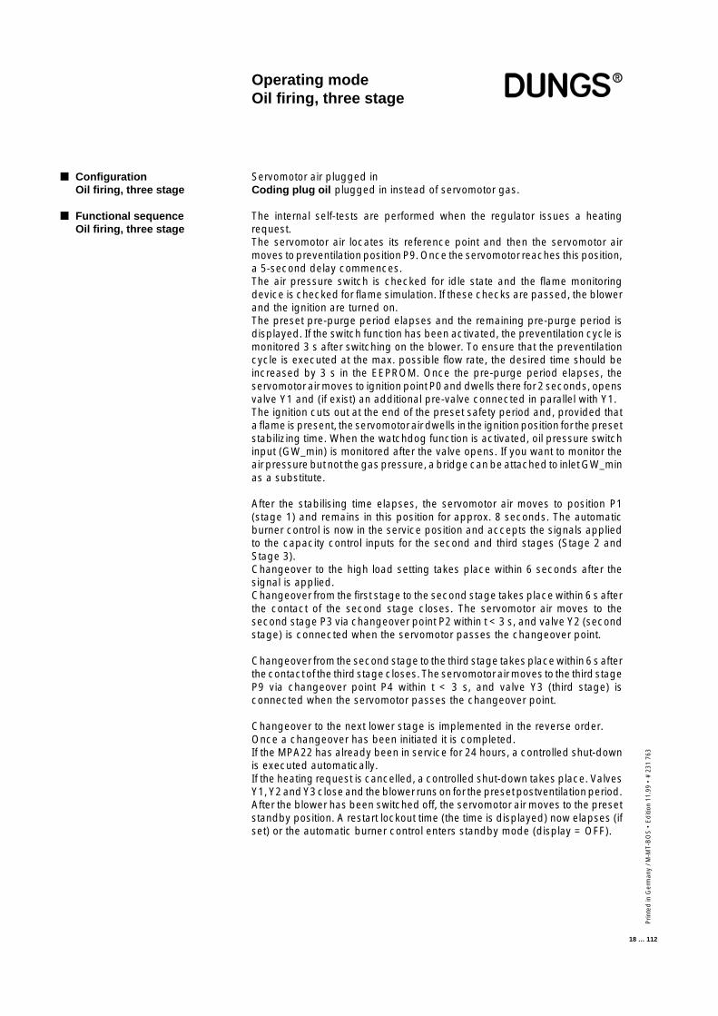
Operating modeOil firing, three stage
Servomotor air plugged inCoding plug oil plugged in instead of servomotor gas.
The internal self-tests are performed when the regulator issues a heatingrequest.The servomotor air locates its reference point and then the servomotor airmoves to preventilation position P9. Once the servomotor reaches this position,a 5-second delay commences.The air pressure switch is checked for idle state and the flame monitoringdevice is checked for flame simulation. If these checks are passed, the blowerand the ignition are turned on.The preset pre-purge period elapses and the remaining pre-purge period isdisplayed. If the switch function has been activated, the preventilation cycle ismonitored 3 s after switching on the blower. To ensure that the preventilationcycle is executed at the max. possible flow rate, the desired time should beincreased by 3 s in the EEPROM. Once the pre-purge period elapses, theservomotor air moves to ignition point P0 and dwells there for 2 seconds, opensvalve Y1 and (if exist) an additional pre-valve connected in parallel with Y1.The ignition cuts out at the end of the preset safety period and, provided thata flame is present, the servomotor air dwells in the ignition position for the presetstabilizing time. When the watchdog function is activated, oil pressure switchinput (GW_min) is monitored after the valve opens. If you want to monitor theair pressure but not the gas pressure, a bridge can be attached to inlet GW_minas a substitute.
After the stabilising time elapses, the servomotor air moves to position P1(stage 1) and remains in this position for approx. 8 seconds. The automaticburner control is now in the service position and accepts the signals appliedto the capacity control inputs for the second and third stages (Stage 2 andStage 3).Changeover to the high load setting takes place within 6 seconds after thesignal is applied.Changeover from the first stage to the second stage takes place within 6 s afterthe contact of the second stage closes. The servomotor air moves to thesecond stage P3 via changeover point P2 within t < 3 s, and valve Y2 (secondstage) is connected when the servomotor passes the changeover point.
Changeover from the second stage to the third stage takes place within 6 s afterthe contact of the third stage closes. The servomotor air moves to the third stageP9 via changeover point P4 within t < 3 s, and valve Y3 (third stage) isconnected when the servomotor passes the changeover point.
Changeover to the next lower stage is implemented in the reverse order.Once a changeover has been initiated it is completed.If the MPA22 has already been in service for 24 hours, a controlled shut-downis executed automatically.If the heating request is cancelled, a controlled shut-down takes place. ValvesY1, Y2 and Y3 close and the blower runs on for the preset postventilation period.After the blower has been switched off, the servomotor air moves to the presetstandby position. A restart lockout time (the time is displayed) now elapses (ifset) or the automatic burner control enters standby mode (display = OFF).
■ ConfigurationOil firing, three stage
■ Functional sequenceOil firing, three stage
Prin
ted
in G
erm
any
/ M-M
T-B
OS
• E
diti
on11
.99
• #
231
763
19 … 112
Operating modeOil firing, three stage
If no flame is present after the startup safety period has elapsed, the burnerenters the non-variable fault state.If flame failure occurs while the burner is operating, a fault shut-down takesplace and the system executes a restart. If the presence of a flame is notsignalled, the system enters the non-variable fault state.In the event of a fault shut-down, all valves are closed and the blower andignition are turned off.If the presence of a flame is signalled before the gas is enabled, the automaticburner control enters the non-variable fault state.The type of fault or disturbance is displayed.If air pressure switch failure is detected during the startup period, provided thewatchdog function is activated, a safety shut-down takes place and 5 restartattempts are performed; if this occurs when the burner is operating, theautomatic burner control enters the non-variable fault state.If the oil pressure drops, the automatic burner control enters the non-variablefault state.
■ Response to faultsOil firing, three stage
Prin
ted
in G
erm
any
/ M-M
T-B
OS
• E
diti
on 1
1.99
• #
231
763
20 … 112
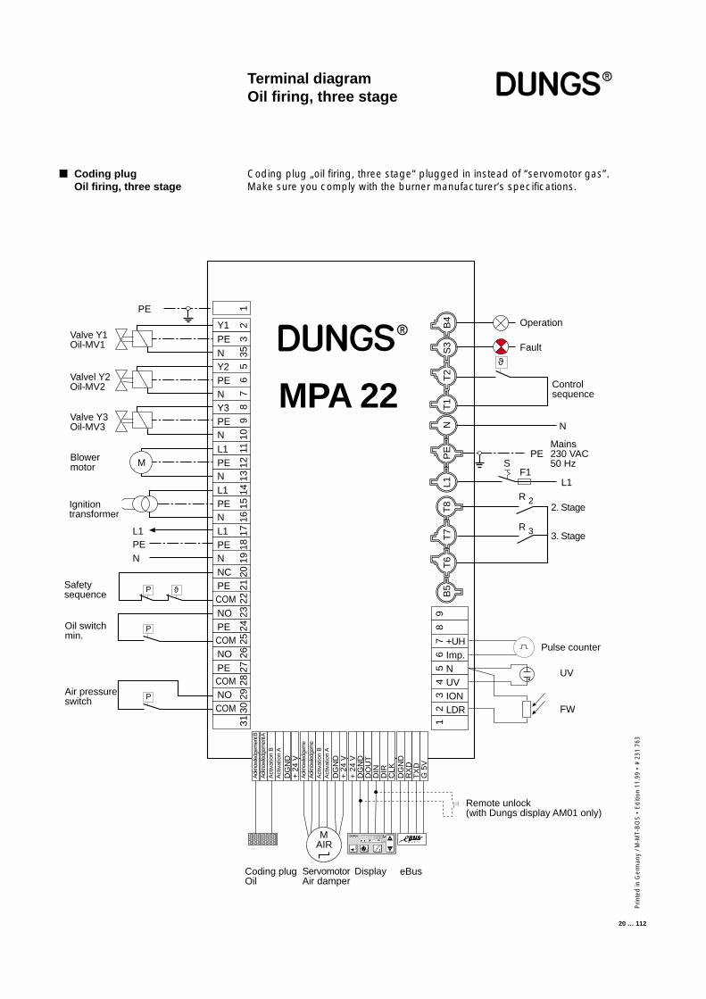
Terminal diagramOil firing, three stage
■ Coding plugOil firing, three stage
Coding plug „oil firing, three stage“ plugged in instead of “servomotor gas”.Make sure you comply with the burner manufacturer’s specifications.
L1PEN
MPA 22B
4S
3T
2N
L1P
ET
8T
7T
6B
5T
1
Ack
now
ledg
emen
t BA
ckno
wle
dgem
ent A
Act
ivat
ion
BA
ctiv
atio
n A
DG
ND
+ 2
4 V
Ack
now
ledg
eme
Ack
now
ledg
eme
Act
ivat
ion
BA
ctiv
atio
n A
DG
ND
+ 2
4 V
M
ϑP
ϑ
M AIR
12Y1
N
335
5Y2
PE
67
89
PENY3PE
10N
11L1PEN
1213
14L1PE 15
N 1617L1
PE 18
N 1920NC
PE 21
COM 2223NO
PECOM
2425
26
PE 27
NO
COMNOCOM
2829
3031
9
+UH
87
65
43
21
Imp.NUVIONLDR
+ 2
4 V
DG
ND
DO
UT
DIN
DIR
CLK
DG
ND
RX
DT
XD
G 5
V
Mains230 VAC50 Hz
Valve Y1Oil-MV1
Ignitiontransformer
Blowermotor
Operation
Fault
L1
PE
N
PE
Valvel Y2Oil-MV2
Valve Y3Oil-MV3
R 2
R 3
Pulse counter
UV
FW
Remote unlock(with Dungs display AM01 only)
F1S
DisplayServomotorAir damper
Coding plugOil
3. Stage
2. Stage
Controlsequence
eBus
Safetysequence
Air pressureswitch
Oil switchmin.
+
–
1 2
P S i G L/A
hl,m3
P
P
Prin
ted
in G
erm
any
/ M-M
T-B
OS
• E
diti
on11
.99
• #
231
763
21 … 112
The valve proving function can be enabled or disabled in parameterisationmode.After a power failure or a fault unlock, the gas valves are always subjected toa leakage check before the burner is started. Otherwise, a leakage check isalways performed after a controlled shut-down of the burner.
Only a gas pressure switch is used to check the gas valves for leaks andmonitor the minimum gas pressure. The gas pressure switch must be con-nected in the circuit between valve Y2 and valve Y3. A leakage check can thusbe performed without the need for additional devices.
A separate gas pressure switch (GW_VPS) is required to test the gas valves forleaks. The gas pressure switch must be connected in the circuit between valveY2 and valve Y3.
After a controlled shut-down, valve Y3 is closed after a 2-second delay. Theexternal valve remains open. The test section is thus rendered pressureless.The gas pressure switch must have switched off (open). Test period V1 for thefirst valve (Y2) on the gas side now commences.During the test period, a pressure sufficient to activate the gas pressure switchmust not build up inside the test section, otherwise a fault shut-down will takeplace and the fault code for “valve 1 leaky” displayed.At the end of test period V1, valve Y2 is opened for 1 s. The gas pressure switchmust switch over within this period of time and indicate the presence of gaspressure, otherwise all valves are closed and the gas fail-safe program isexecuted.Once the period of time has elapsed, valve Y2 and the external pilot valve areclosed.During the test period for valve Y3, a pressure drop below the operating pointof the preset minimum gas pressure must not occur, otherwise a fault shut-down will take place and the fault code for “valve 2 leaky” displayed.
- The volume of gas trapped in between valve Y2 and valve Y3- The preset pressure switching points- The gas mains pressure applied- The permissible leakage rate
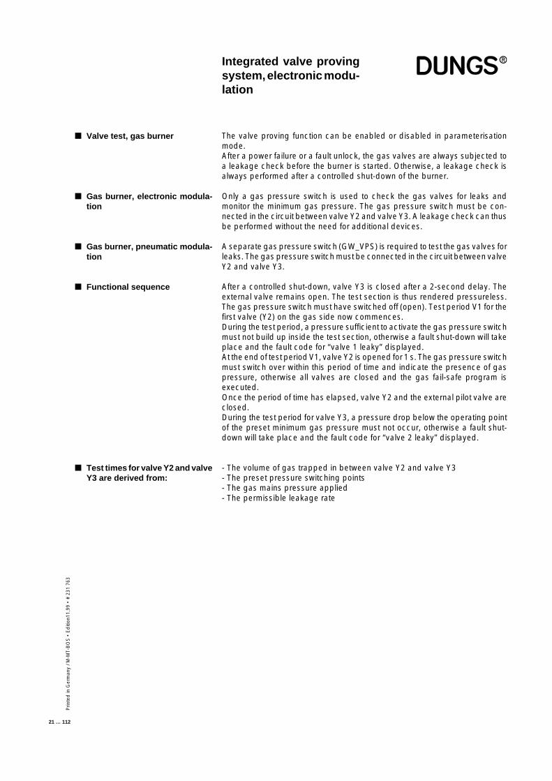
Integrated valve provingsystem, electronic modu-lation
■ Valve test, gas burner
■ Gas burner, electronic modula-tion
■ Gas burner, pneumatic modula-tion
■ Functional sequence
■ Test times for valve Y2 and valveY3 are derived from:
Prin
ted
in G
erm
any
/ M-M
T-B
OS
• E
diti
on 1
1.99
• #
231
763
22 … 112
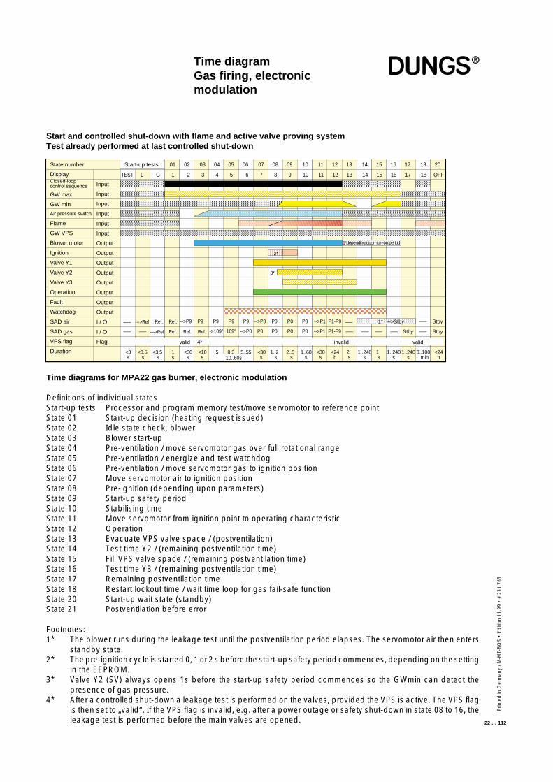
Time diagramGas firing, electronicmodulation
Time diagrams for MPA22 gas burner, electronic modulation
Definitions of individual statesStart-up tests Processor and program memory test/move servomotor to reference pointState 01 Start-up decision (heating request issued)State 02 Idle state check, blowerState 03 Blower start-upState 04 Pre-ventilation / move servomotor gas over full rotational rangeState 05 Pre-ventilation / energize and test watchdogState 06 Pre-ventilation / move servomotor gas to ignition positionState 07 Move servomotor air to ignition positionState 08 Pre-ignition (depending upon parameters)State 09 Start-up safety periodState 10 Stabilising timeState 11 Move servomotor from ignition point to operating characteristicState 12 OperationState 13 Evacuate VPS valve space / (postventilation)State 14 Test time Y2 / (remaining postventilation time)State 15 Fill VPS valve space / (remaining postventilation time)State 16 Test time Y3 / (remaining postventilation time)State 17 Remaining postventilation timeState 18 Restart lockout time / wait time loop for gas fail-safe functionState 20 Start-up wait state (standby)State 21 Postventilation before error
Footnotes:1* The blower runs during the leakage test until the postventilation period elapses. The servomotor air then enters
standby state.2* The pre-ignition cycle is started 0, 1 or 2 s before the start-up safety period commences, depending on the setting
in the EEPROM.3* Valve Y2 (SV) always opens 1s before the start-up safety period commences so the GWmin can detect the
presence of gas pressure.4* After a controlled shut-down a leakage test is performed on the valves, provided the VPS is active. The VPS flag
is then set to „valid“. If the VPS flag is invalid, e.g. after a power outage or safety shut-down in state 08 to 16, theleakage test is performed before the main valves are opened.
Start and controlled shut-down with flame and active valve proving systemTest already performed at last controlled shut-down
Start-up tests 01 02 03 04 05 06 07 08 09 10 11 12 13 14 15 16 17 18 20State number
DisplayClosed-loopcontrol sequence
GW max
GW min
Air pressure switch
Flame
GW VPS
Blower motor
Ignition
Valve Y1
Valve Y2
Valve Y3
Operation
Fault
Watchdog
SAD air
SAD gas
VPS flag
Duration
Input
Input
Input
Input
Input
Input
Output
Output
Output
Output
Output
Output
Output
Output
I / O
I / O
Flag
TEST L G 1 2 3 4 5 6 7 8 9 10 11 12 13 14 15 16 17 18 OFF
<3 s
--->Ref Ref. P9P9-->P9 P9 P9 -->P0 P0 P0 P0 -->P1–––
––– ––– --->Ref Ref. Ref. Ref.
Ref. P1-P9 –––
->109° 109° P0-->P0 P0 P0 P0 -->P1 P1-P9 ––– ––– ––– ––– Stby ––– Stby
1* -->Stby Stby–––
1*depending upon run-on period
2*
3*
<3,5 s
<3,5 s
1 s
<30 s
<10 s
5 0,3 5..55 <30 s
1..2 s
2..5 s
1..60 s
<30 s
<24 h
2 s
1..240 s
1 s
0..100 min 10..60s
1..240 s
1..240 s
<24 h
valid 4* invalid valid
Prin
ted
in G
erm
any
/ M-M
T-B
OS
• E
diti
on11
.99
• #
231
763
23 … 112
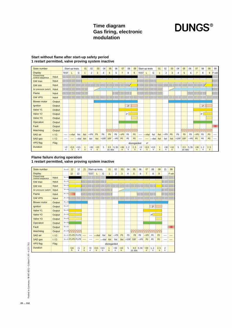
Time diagramGas firing, electronicmodulation
Start-up tests 01 02 03 04 05 06 07 08 09 Start-up tests 01 02 03 04 05 06 07 08 09 99State number
DisplayClosed-loopcontrol sequence
GW max
GW min
Air pressure switch
Flame
GW VPS
Blower motor
Ignition
Valve Y1
Valve Y2
Valve Y3
Operation
Fault
Watchdog
SAD air
SAD gas
VPS flag
Duration
Input
Input
Input
Input
Input
Input
Output
Output
Output
Output
Output
Output
Output
Output
I / O
I / O
Flag
TEST L G 1 2 3 4 5 6 7 8 9 TEST L G 1 2 3 4 5 6 7 8 9 F xxh
<3 s
--->Ref Ref. P9P9-->P9 P9 P9 -->P0 P0 P0–––
––– ––– --->Ref Ref. Ref. Ref.
Ref.
->109° 109° P0-->P0 P0 P0
2*
3*
<3,5 s
<3,5 s
1 s
<30 s
<10 s
5 0,3 5..55 <30 s
1..2 s
2..5 s 10..60s
disregarded 4*
2*
3*
<3 s
--->Ref Ref. P9P9-->P9 P9 P9 -->P0 P0 P0–––
––– ––– --->Ref Ref. Ref. Ref.
Ref.
->109° 109° P0-->P0 P0 P0
<3,5 s
<3,5 s
1 s
<30 s
<10 s
5 0,3 5..55 <30 s
1..2 s
2..5 s 10..60s
–––
–––
>---> 12 12 21 Start-up tests 01 02 03 04 05 06 07 08 09 21 99State number
DisplayClosed-loopcontrol sequence
GW max
GW min
Air pressure switch
Flame
GW VPS
Blower motor
Ignition
Valve Y1
Valve Y2
Valve Y3
Operation
Fault
Watchdog
SAD air
SAD gas
VPS flag
Duration
Input
Input
Input
Input
Input
Input
Output
Output
Output
Output
Output
Output
Output
Output
I / O
I / O
Flag
12 12 TEST L G 1 2 3 4 5 6 7 8 9 F xxh
>--->
>--->
>--->
>--->
>--->
>--->
>--->
>--->
>--->
>--->
>--->
>--->
>--->
>--->
>--->
>--->
<3 s
--->Ref Ref. P9P9-->P9 P9 P9 -->P0 P0 P0
--->Ref Ref. Ref. Ref.
Ref.P1-P9
->109° 109° -->P0 P0 P0 P0 –––
–––
2*
3*
<3,5 s
<3,5 s
1 s
<30 s
<10 s
5 0,3 5..55 <30 s
1..2 s
2..5 s
<24 h
2 s 10..60s
disregarded
–––
–––P1-P9 ––– –––
P1-P9 P1-P9 ––– ––– –––
2 s
<1 s
Start without flame after start-up safety period1 restart permitted, valve proving system inactive
Flame failure during operation1 restart permitted, valve proving system inactive
Prin
ted
in G
erm
any
/ M-M
T-B
OS
• E
diti
on 1
1.99
• #
231
763
24 … 112
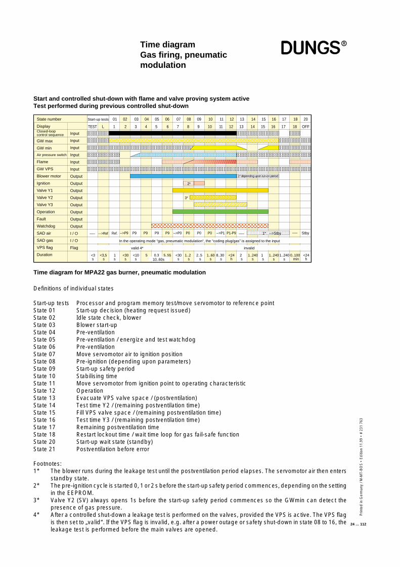
Time diagramGas firing, pneumaticmodulation
Time diagram for MPA22 gas burner, pneumatic modulation
Definitions of individual states
Start-up tests Processor and program memory test/move servomotor to reference pointState 01 Start-up decision (heating request issued)State 02 Idle state check, blowerState 03 Blower start-upState 04 Pre-ventilationState 05 Pre-ventilation / energize and test watchdogState 06 Pre-ventilationState 07 Move servomotor air to ignition positionState 08 Pre-ignition (depending upon parameters)State 09 Start-up safety periodState 10 Stabilising timeState 11 Move servomotor from ignition point to operating characteristicState 12 OperationState 13 Evacuate VPS valve space / (postventilation)State 14 Test time Y2 / (remaining postventilation time)State 15 Fill VPS valve space / (remaining postventilation time)State 16 Test time Y3 / (remaining postventilation time)State 17 Remaining postventilation timeState 18 Restart lockout time / wait time loop for gas fail-safe functionState 20 Start-up wait state (standby)State 21 Postventilation before error
Footnotes:1* The blower runs during the leakage test until the postventilation period elapses. The servomotor air then enters
standby state.2* The pre-ignition cycle is started 0, 1 or 2 s before the start-up safety period commences, depending on the setting
in the EEPROM.3* Valve Y2 (SV) always opens 1s before the start-up safety period commences so the GWmin can detect the
presence of gas pressure.4* After a controlled shut-down a leakage test is performed on the valves, provided the VPS is active. The VPS flag
is then set to „valid“. If the VPS flag is invalid, e.g. after a power outage or safety shut-down in state 08 to 16, theleakage test is performed before the main valves are opened.
Start-up tests 01 02 03 04 05 06 07 08 09 10 11 12 13 14 15 16 17 18 20State number
DisplayClosed-loopcontrol sequence
GW max
GW min
Air pressure switch
Flame
GW VPS
Blower motor
Ignition
Valve Y1
Valve Y2
Valve Y3
Operation
Fault
Watchdog
SAD air
SAD gas
VPS flag
Duration
Input
Input
Input
Input
Input
Input
Output
Output
Output
Output
Output
Output
Output
Output
I / O
I / O
Flag
TEST L 1 2 3 4 5 6 7 8 9 10 11 12 13 14 15 16 17 18 OFF
<3 s
--->Ref P9P9-->P9 P9 P9 -->P0 P0 P0 P0 -->P1––– Ref. P1-P9 ––– 1* -->Stby Stby–––
1* depending upon run-on period
2*
3*
<3,5 s
1 s
<30 s
<10 s
5 0,3 5..55 <30 s
1..2 s
2..5 s
1..60 s
8..30 s
<24 h
2 s
1..240 s
1 s
0..100 min 10..60s
1..240 s
1..240 s
<24 h
valid 4* invalid
In the operating mode “gas, pneumatic modulation“, the “coding plug/gas” is assigned to the input
Start and controlled shut-down with flame and valve proving system activeTest performed during previous controlled shut-down
Prin
ted
in G
erm
any
/ M-M
T-B
OS
• E
diti
on11
.99
• #
231
763
25 … 112
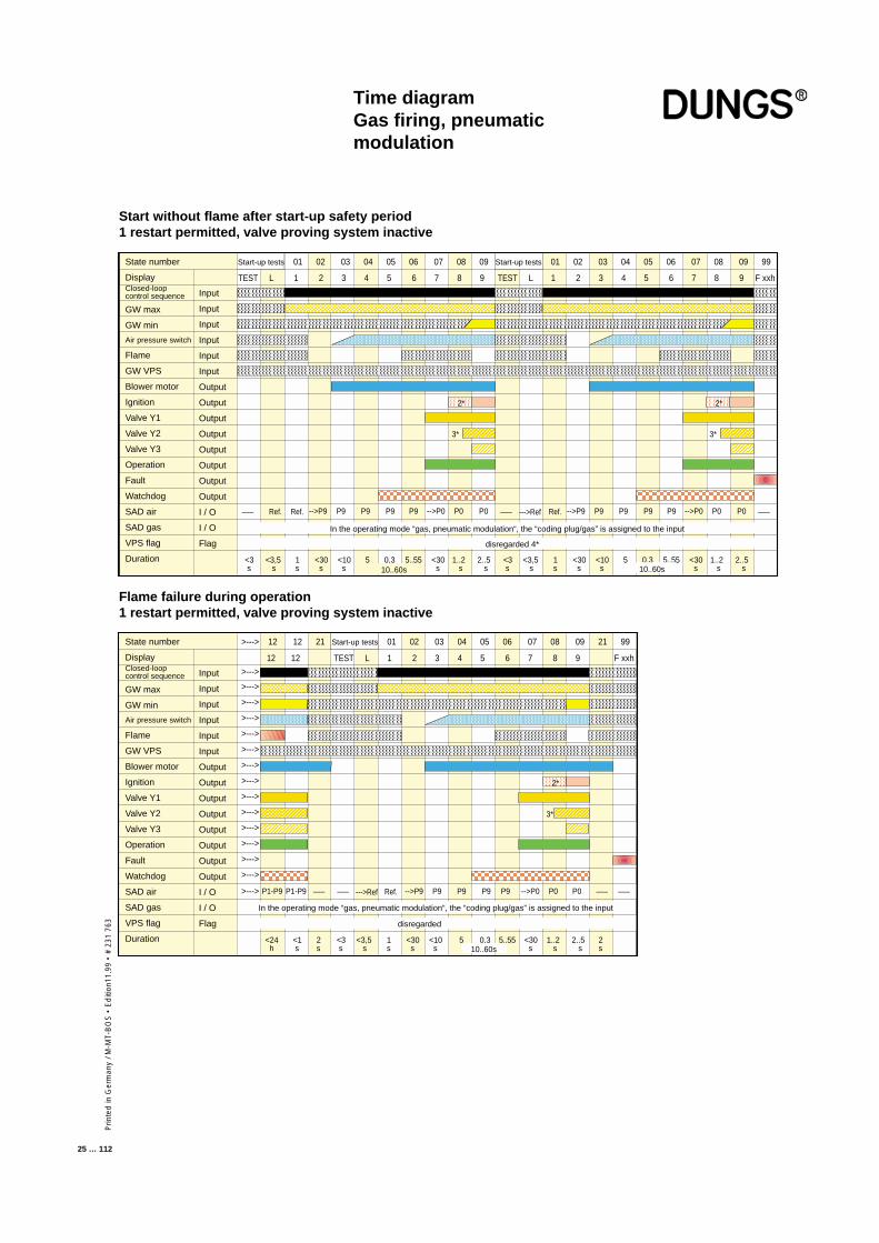
Time diagramGas firing, pneumaticmodulation
Start-up tests 01 02 03 04 05 06 07 08 09 Start-up tests 01 02 03 04 05 06 07 08 09 99State number
DisplayClosed-loopcontrol sequence
GW max
GW min
Air pressure switch
Flame
GW VPS
Blower motor
Ignition
Valve Y1
Valve Y2
Valve Y3
Operation
Fault
Watchdog
SAD air
SAD gas
VPS flag
Duration
Input
Input
Input
Input
Input
Input
Output
Output
Output
Output
Output
Output
Output
Output
I / O
I / O
Flag
TEST L 1 2 3 4 5 6 7 8 9 TEST L 1 2 3 4 5 6 7 8 9 F xxh
<3 s
Ref. P9P9-->P9 P9 P9 -->P0 P0 P0––– Ref.
2*
3*
<3,5 s
1 s
<30 s
<10 s
5 0,3 5..55 <30 s
1..2 s
2..5 s 10..60s
disregarded 4*
2*
3*
<3 s
--->Ref P9P9-->P9 P9 P9 -->P0 P0 P0––– Ref.
<3,5 s
1 s
<30 s
<10 s
5 0,3 5..55 <30 s
1..2 s
2..5 s 10..60s
–––
In the operating mode “gas, pneumatic modulation“, the “coding plug/gas” is assigned to the input
>---> 12 12 21 Start-up tests 01 02 03 04 05 06 07 08 09 21 99State number
DisplayClosed-loopcontrol sequence
GW max
GW min
Air pressure switch
Flame
GW VPS
Blower motor
Ignition
Valve Y1
Valve Y2
Valve Y3
Operation
Fault
Watchdog
SAD air
SAD gas
VPS flag
Duration
Input
Input
Input
Input
Input
Input
Output
Output
Output
Output
Output
Output
Output
Output
I / O
I / O
Flag
12 12 TEST L 1 2 3 4 5 6 7 8 9 F xxh
>--->
>--->
>--->
>--->
>--->
>--->
>--->
>--->
>--->
>--->
>--->
>--->
>--->
>--->
>--->
<3 s
--->Ref P9P9-->P9 P9 P9 -->P0 P0 P0 Ref.P1-P9 –––
2*
3*
<3,5 s
1 s
<30 s
<10 s
5 0,3 5..55 <30 s
1..2 s
2..5 s
<24 h
2 s 10..60s
disregarded
–––P1-P9 ––– –––
2 s
<1 s
In the operating mode “gas, pneumatic modulation“, the “coding plug/gas” is assigned to the input
Start without flame after start-up safety period1 restart permitted, valve proving system inactive
Flame failure during operation1 restart permitted, valve proving system inactive
Prin
ted
in G
erm
any
/ M-M
T-B
OS
• E
diti
on 1
1.99
• #
231
763
26 … 112
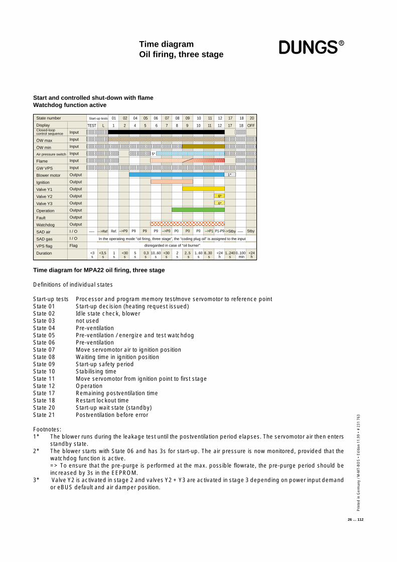
Time diagramOil firing, three stage
Time diagram for MPA22 oil firing, three stage
Definitions of individual states
Start-up tests Processor and program memory test/move servomotor to reference pointState 01 Start-up decision (heating request issued)State 02 Idle state check, blowerState 03 not usedState 04 Pre-ventilationState 05 Pre-ventilation / energize and test watchdogState 06 Pre-ventilationState 07 Move servomotor air to ignition positionState 08 Waiting time in ignition positionState 09 Start-up safety periodState 10 Stabilising timeState 11 Move servomotor from ignition point to first stageState 12 OperationState 17 Remaining postventilation timeState 18 Restart lockout timeState 20 Start-up wait state (standby)State 21 Postventilation before error
Footnotes:1* The blower runs during the leakage test until the postventilation period elapses. The servomotor air then enters
standby state.2* The blower starts with State 06 and has 3s for start-up. The air pressure is now monitored, provided that the
watchdog function is active.=> To ensure that the pre-purge is performed at the max. possible flowrate, the pre-purge period should beincreased by 3s in the EEPROM.
3* Valve Y2 is activated in stage 2 and valves Y2 + Y3 are activated in stage 3 depending on power input demandor eBUS default and air damper position.
Start-up tests 01 02 04 05 06 07 08 09 10 11 12 17 18 20State number
DisplayClosed-loopcontrol sequence
ÖW max
ÖW min
Air pressure switch
Flame
GW VPS
Blower motor
Ignition
Valve Y1
Valve Y2
Valve Y3
Operation
Fault
Watchdog
SAD air
SAD gas
VPS flag
Duration
Input
Input
Input
Input
Input
Input
Output
Output
Output
Output
Output
Output
Output
Output
I / O
I / O
Flag
TEST L 1 2 4 5 6 7 8 9 10 11 12 17 18 OFF
<3 s
--->Ref P9P9-->P9 P9 -->P0 P0 P0 P0 -->P1––– Ref. P1-P9 –––->Stby Stby
1*
6*
<3,5 s
1 s
<30 s
5 s
0,3 s
10..60 s
<30 s
2 s
2..5 s
1..60 s
8..30 s
<24 h
1..240 s
0..100 min
<24 h
disregarded in case of “oil burner”
In the operating mode “oil firing, three stage”, the “coding plug oil” is assigned to the input
6*
5*
Start and controlled shut-down with flameWatchdog function active
Prin
ted
in G
erm
any
/ M-M
T-B
OS
• E
diti
on11
.99
• #
231
763
27 … 112
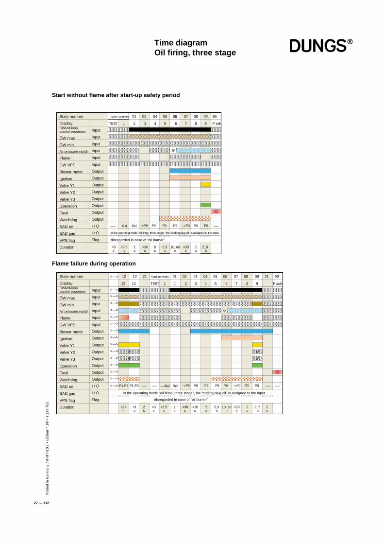
Time diagramOil firing, three stage
Start without flame after start-up safety period
Start-up tests 01 02 04 05 06 07 08 09 99State number
DisplayClosed-loopcontrol sequence
ÖW max
ÖW min
Air pressure switch
Flame
GW VPS
Blower motor
Ignition
Valve Y1
Valve Y2
Valve Y3
Operation
Fault
Watchdog
SAD air
SAD gas
VPS flag
Duration
Input
Input
Input
Input
Input
Input
Output
Output
Output
Output
Output
Output
Output
Output
I / O
I / O
Flag
TEST L 1 2 4 5 6 7 8 9 F xxh
<3 s
Ref. P9P9-->P9 P9 -->P0 P0 P0––– Ref.
5*
<3,5 s
1 s
<30 s
5 s
<30 s
2 s
2..5 s
0,3 s
–––
10..60 s
disregarded in case of “oil burner”
In the operating mode “oil firing, three stage”, the “coding plug oil” is assigned to the input
>---> 12 12 21 Start-up tests 01 02 03 04 05 06 07 08 09 21 99State number
DisplayClosed-loopcontrol sequence
ÖW max
ÖW min
Air pressure switch
Flame
GW VPS
Blower motor
Ignition
Valve Y1
Valve Y2
Valve Y3
Operation
Fault
Watchdog
SAD air
SAD gas
VPS flag
Duration
Input
Input
Input
Input
Input
Input
Output
Output
Output
Output
Output
Output
Output
Output
I / O
I / O
Flag
12 12 TEST L 1 2 3 4 5 6 7 8 9 F xxh
>--->
>--->
>--->
>--->
>--->
>--->
>--->
>--->
>--->
>--->
>--->
>--->
>--->
>--->
>--->
<3 s
--->Ref P9P9-->P9 P9 P9 -->P0 P0 P0 Ref.P1-P9 –––
6*
6*
<3,5 s
1 s
<30 s
<10 s
5 s
0,3 s
<30 s
2 s
2..5 s
<24 h
2 s
10..60 s
–––P1-P9 ––– –––
2 s
<1 s
disregarded in case of “oil burner”
In the operating mode “oil firing, three stage”, the “coding plug oil” is assigned to the input
5*
6*
6*
Flame failure during operation
Prin
ted
in G
erm
any
/ M-M
T-B
OS
• E
diti
on 1
1.99
• #
231
763
28 … 112
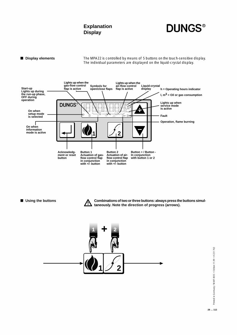
The MPA22 is controlled by means of 5 buttons on the touch-sensitive display.The individual parameters are displayed on the liquid-crystal display.
Combinations of two or three buttons: always press the buttons simul-taneously. Note the direction of progress (arrows).
ExplanationDisplay
■ Display elements
■ Using the buttons
1 2
1 2+
+
–
1 2
P S i G L/A
hl,m3
Acknowledg-ment or resetbutton
Button 1Actuation of gas-flow control flapin conjunctionwith +/- button
Button 2Actuation of air-flow control flapin conjunctionwith +/- button
Button + / Button -In conjunctionwith button 1 or 2
On whensetup modeis selected
Start-upLights up duringthe run-up phase,OFF duringoperation
Lights up when thegas-flow controlflap is active
On wheninformationmode is active
Lights up when theair-flow controlflap is active h = Operating hours indicator
l, m3 = Oil or gas consumption
Operation, flame burning
Fault
Lights up whenservice modeis active
Liquid-crystaldisplay
Symbols foropen/close flaps
Prin
ted
in G
erm
any
/ M-M
T-B
OS
• E
diti
on11
.99
• #
231
763
29 … 112
Display functions
Gas, electronic modulationGas, pneumatic modulationOil, three stage
Operating modeInformation modeService mode
Parameterisation mode is password-protected.
System error messagesError messages
■ Setup mode
■ Display functions
■ Parameterisation mode
■ Error indication
Prin
ted
in G
erm
any
/ M-M
T-B
OS
• E
diti
on 1
1.99
• #
231
763
30 … 112
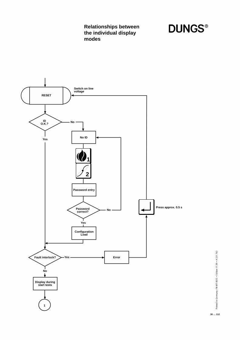
Relationships betweenthe individual displaymodes
RESET
IDO.K.?
No ID
Password entry
Passwordcorrect?
No
Yes
No
Yes
Fault interlock?
No
Yes
Display duringstart tests
1
Error
Press approx. 0.5 s
Switch on linevoltage
ConfigurationLoad
1
2
Prin
ted
in G
erm
any
/ M-M
T-B
OS
• E
diti
on11
.99
• #
231
763
31 … 112
+ –
+
+ –
MPA
fu
llyp
aram
eter
ized
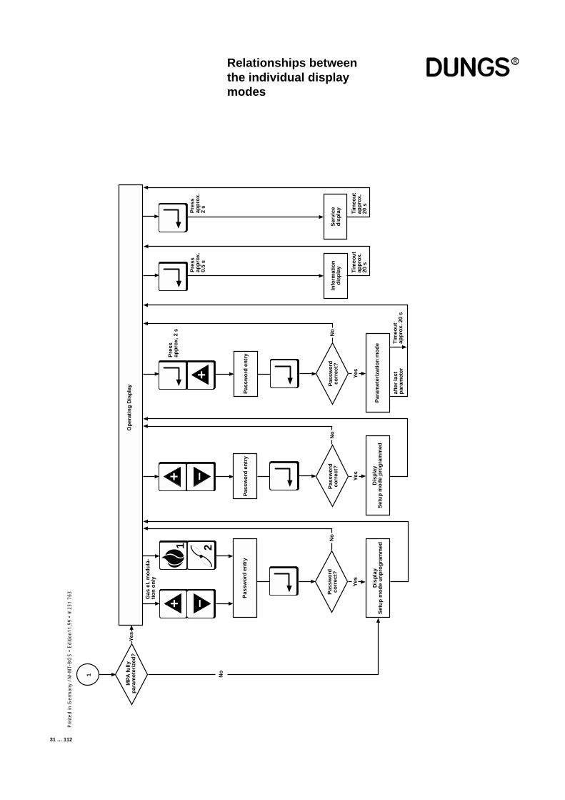
?O
per
atin
g D
isp
lay
Gas
el.
mo
du
la-
tio
n o
nly
Pas
swo
rd e
ntr
y
Pas
swo
rdco
rrec
t?
Dis
pla
yS
etu
p m
od
e u
np
rog
ram
med
Pas
swo
rd e
ntr
y
Pas
swo
rdco
rrec
t?
Dis
pla
yS
etu
p m
od
e p
rog
ram
med
Pas
swo
rd e
ntr
y
Pas
swo
rdco
rrec
t?N
o
Pre
ssap
pro
x. 2
s
Par
amet
eriz
atio
n m
od
e
afte
r la
stp
aram
eter
Tim
eou
tap
pro
x. 2
0 s
Info
rmat
ion
dis
pla
y
Tim
eou
tap
pro
x.20
s
Pre
ssap
pro
x.0.
5 s
Ser
vice
dis
pla
y
Tim
eou
tap
pro
x.20
s
Pre
ssap
pro
x.2
s
Yes
Yes
Yes
No
No
1 2
Yes
No1
Relationships betweenthe individual displaymodes
Prin
ted
in G
erm
any
/ M-M
T-B
OS
• E
diti
on 1
1.99
• #
231
763
32 … 112
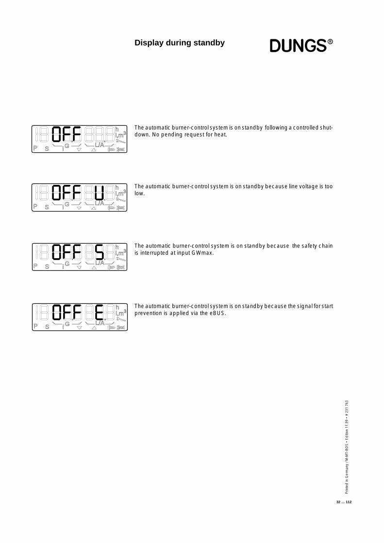
Display during standby
The automatic burner-control system is on standby following a controlled shut-down. No pending request for heat.
iP S G L/A
hl,m3
iP S G L/A
hl,m3
iP S G L/A
hl,m3
iP S G L/A
hl,m3
The automatic burner-control system is on standby because line voltage is toolow.
The automatic burner-control system is on standby because the safety chainis interrupted at input GWmax.
The automatic burner-control system is on standby because the signal for startprevention is applied via the eBUS.
Prin
ted
in G
erm
any
/ M-M
T-B
OS
• E
diti
on11
.99
• #
231
763
33 … 112
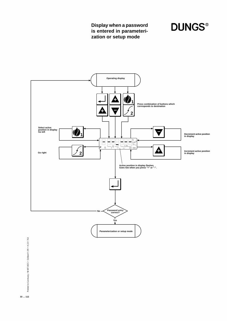
Display when a passwordis entered in parameteri-zation or setup mode
+
Active position in display flashes.Goes low when you press "+" or "-".
iP S G L/A
hl,m3
–
+2
Select activeposition in displayGo left
1
+
–
2
1
Operating display
Password entrycorrect?
Yes
Parameterization or setup mode
Go right
No
Decrement active positionin display
Increment active positionin display
Press combination of buttons whichcorresponds to destination
Prin
ted
in G
erm
any
/ M-M
T-B
OS
• E
diti
on 1
1.99
• #
231
763
34 … 112
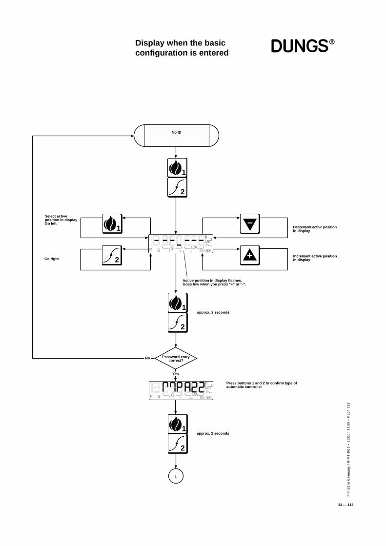
Display when the basicconfiguration is entered
Active position in display flashes.Goes low when you press "+" or "-".
Select activeposition in displayGo left
Yes
Go right
No
Decrement active positionin display
Increment active positionin display
approx. 2 seconds
iP S G L/A
hl,m3
approx. 2 seconds
Press buttons 1 and 2 to confirm type ofautomatic controller
+2
1
2
1
No ID
Password entrycorrect?
2
1
iP S G L/A
hl,m3
2
1
1
–
Prin
ted
in G
erm
any
/ M-M
T-B
OS
• E
diti
on11
.99
• #
231
763
35 … 112
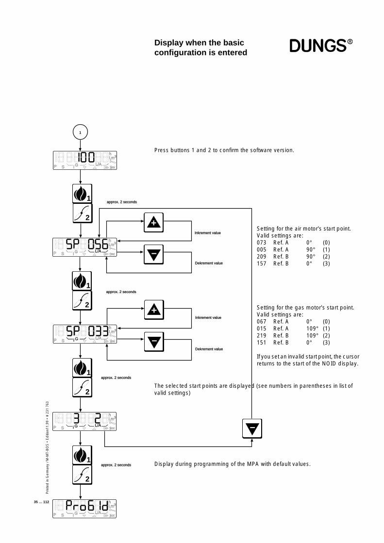
Display when the basicconfiguration is entered
Press buttons 1 and 2 to confirm the software version.
Setting for the air motor's start point.Valid settings are:073 Ref. A 0° (0)005 Ref. A 90° (1)209 Ref. B 90° (2)157 Ref. B 0° (3)
Setting for the gas motor's start point.Valid settings are:067 Ref. A 0° (0)015 Ref. A 109° (1)219 Ref. B 109° (2)151 Ref. B 0° (3)
If you set an invalid start point, the cursorreturns to the start of the NOID display.
The selected start points are displayed (see numbers in parentheses in list ofvalid settings)
Display during programming of the MPA with default values.
1
2
1
iP S G L/A
hl,m3
2
1
2
1
2
1
approx. 2 seconds
approx. 2 seconds
approx. 2 seconds
approx. 2 seconds
iP S G L/A
hl,m3
iP S G L/A
hl,m3
iP S G L/A
hl,m3
iP S G L/A
hl,m3
–
–
+Inkrement value
Dekrement value
–
+
Dekrement value
Inkrement value
Prin
ted
in G
erm
any
/ M-M
T-B
OS
• E
diti
on 1
1.99
• #
231
763
36 … 112
When operating voltage is applied, the MPA22 automatic burner-controlsystem performs a startup test and then displays "OFFUPr".This means that no setup procedure has been completed as yet.
The MPA22 automatic burner-control system has separate setup proceduresfor each operating mode and characteristic-map memories which are backedup separately for each operating mode.
A "P" is displayed while setup is in progress. This mode has a 30-minute timeout;the timer is reset each time you press a button on the touch-sensitive display.If the timeout expires a safety shutdown is triggered and the "OFFUPr" messagereappears in the automatic burner-control system's display.The purpose of this timeout is to prevent incomplete setup causing the burnerto remain on for a prolonged period of time.
All safety functions are activated during the setup procedure, just as in normaloperation. The only difference is that the servomotors can be brought to thelimits specified in the setup mode. As in normal operation, flame failure, air-pressure monitor failure or a fault in servomotor drive and feedback, or other,similar faults result in a fault-triggered or safety shutdown.
Setup has to be repeated if a fault-triggered, safety or controlled shutdown occursduring the setup procedure. The values entered beforehand are retained, oncondition that they pass the plausibility check which takes place on startup.
You must enter a password before you can set the parameters of the MPA22automatic burner-control system.
Consult the operating instructions for the burner connected to theMPA22 for detailed settings.
The first step is always to set the automatic burner-control system to setupmode: Simultaneously press buttons "1" and "2".
A prompt asking you to enter the password appears on the display:
CommissioningSetup mode
■ Prior to commissioning, makesure that all connections arecorrect.
■ Check the following safety func-tions for commissioning:
■ Shutdown of the controllers,monitors and limiters (as in-stalled)
■ switching points of gas-pressureswitch
■ Flame monitor■ Set times and operating modes
It is important to step the auto-matic burner-control system
at least once through the entiresetup procedure for the appropriateoperating mode. Only then is theautomatic burner-control systemprogrammed for automatic opera-tion in this mode.
■ Setup instructions, setup proce-dures
■ In setup mode
Setup mode: oil, three-stage
Setup mode: gas, pneumatic modulation
Setup mode: gas, electronic modulation
If the mode displayed does not match the burner, check the wiring,the terminals of the servo drives and the coding plugs.
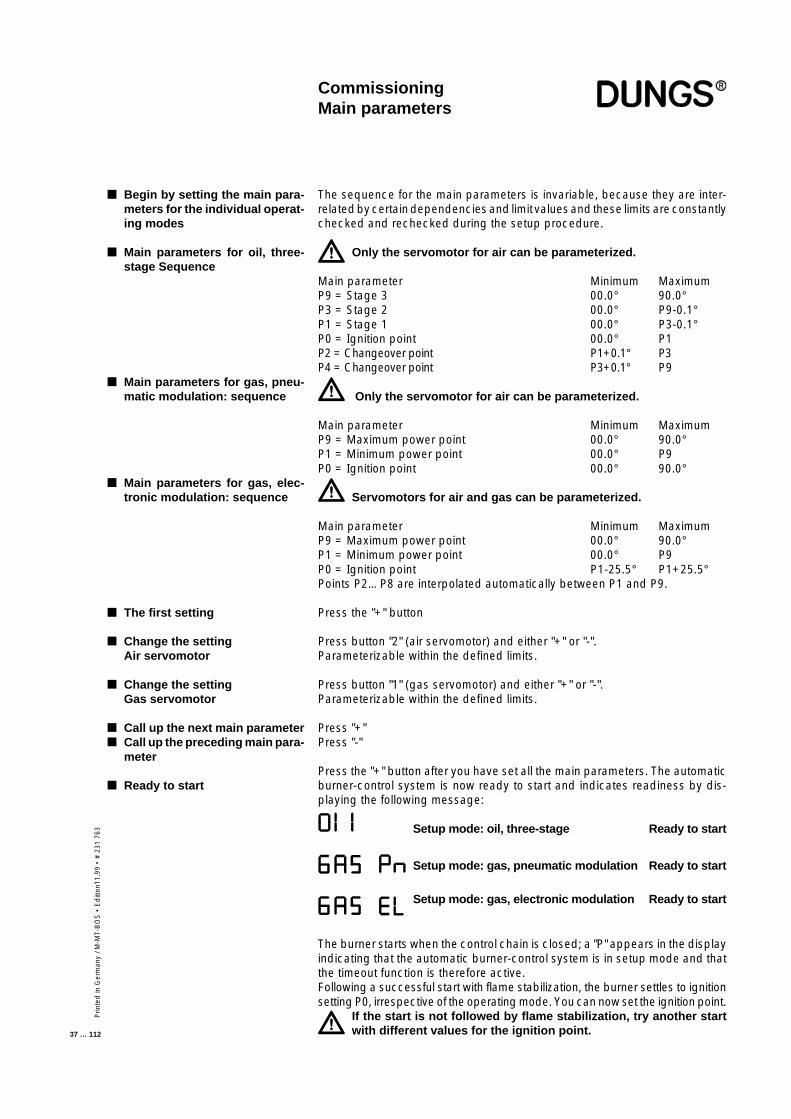
Prin
ted
in G
erm
any
/ M-M
T-B
OS
• E
diti
on11
.99
• #
231
763
37 … 112
The sequence for the main parameters is invariable, because they are inter-related by certain dependencies and limit values and these limits are constantlychecked and rechecked during the setup procedure.
Only the servomotor for air can be parameterized.
Main parameter Minimum MaximumP9 = Stage 3 00.0° 90.0°P3 = Stage 2 00.0° P9-0.1°P1 = Stage 1 00.0° P3-0.1°P0 = Ignition point 00.0° P1P2 = Changeover point P1+0.1° P3P4 = Changeover point P3+0.1° P9
Only the servomotor for air can be parameterized.
Main parameter Minimum MaximumP9 = Maximum power point 00.0° 90.0°P1 = Minimum power point 00.0° P9P0 = Ignition point 00.0° 90.0°
Servomotors for air and gas can be parameterized.
Main parameter Minimum MaximumP9 = Maximum power point 00.0° 90.0°P1 = Minimum power point 00.0° P9P0 = Ignition point P1-25.5° P1+25.5°Points P2…P8 are interpolated automatically between P1 and P9.
Press the "+" button
Press button "2" (air servomotor) and either "+" or "-".Parameterizable within the defined limits.
Press button "1" (gas servomotor) and either "+" or "-".Parameterizable within the defined limits.
Press "+"Press "-"
Press the "+" button after you have set all the main parameters. The automaticburner-control system is now ready to start and indicates readiness by dis-playing the following message:
Setup mode: oil, three-stage Ready to start
Setup mode: gas, pneumatic modulation Ready to start
Setup mode: gas, electronic modulation Ready to start
The burner starts when the control chain is closed; a "P" appears in the displayindicating that the automatic burner-control system is in setup mode and thatthe timeout function is therefore active.Following a successful start with flame stabilization, the burner settles to ignitionsetting P0, irrespective of the operating mode. You can now set the ignition point.
If the start is not followed by flame stabilization, try another startwith different values for the ignition point.
■ Begin by setting the main para-meters for the individual operat-ing modes
■ Main parameters for oil, three-stage Sequence
■ Main parameters for gas, pneu-matic modulation: sequence
■ Main parameters for gas, elec-tronic modulation: sequence
■ The first setting
■ Change the settingAir servomotor
■ Change the settingGas servomotor
■ Call up the next main parameter■ Call up the preceding main para-
meter
■ Ready to start
CommissioningMain parameters

Prin
ted
in G
erm
any
/ M-M
T-B
OS
• E
diti
on 1
1.99
• #
231
763
38 … 112
Setup modeGas firing, electronicmodulation
The controller automatically goes to standby status if the automatic burner-control system has not been programmed. In the unprogrammed state, theautomatic burner-control system remains on standby. Unprogrammed meansthat the characteristic has not been fully programmed.Once a valid characteristic has been programmed and the automatic burner-control system detects the presence of the corresponding components whenit starts up, the burner starts as soon as the control chain and GWmax areclosed.
If you want to correct a characteristic or ignition point P0 without recalculatingall other points as well, you can access setup mode by simultaneously pressingthe "+" and "-" buttons.
Simultaneously press the "1" and "2" buttons if you want to enter the full setupmode. The "P" symbol always appears in the display to indicate that setupmode is activated. If you do not press a button in setup mode before thetimeout expires, setup mode is exited automatically and a RESTART isperformed.
■ The burner must be in standbystatus, otherwise you cannotaccess the setup mode
■ Changing a characteristic de-fined beforehand
■ Accessing setup mode
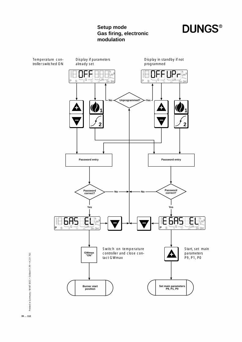
Prin
ted
in G
erm
any
/ M-M
T-B
OS
• E
diti
on11
.99
• #
231
763
39 … 112
+
–
– –
+
P S G L/A
hl,m3
P S i G L/A
hl,m3
i
P S G L/A
hl,m3
i P S G L/A
hl,m3
i
1
2
Unprogrammed?No Yes
1
2
Password entry Password entry
Passwordcorrect?
Passwordcorrect?No
Yes Yes
+
–
GWmax"ON"
Burner startposition
Set main parametersP9, P1, P0
No
Setup modeGas firing, electronicmodulation
Display if parametersalready set
Display in standby if notprogrammed
Switch on temperaturecontroller and close con-tact GWmax
Start, set mainparametersP9, P1, P0
Temperature con-troller switched ON
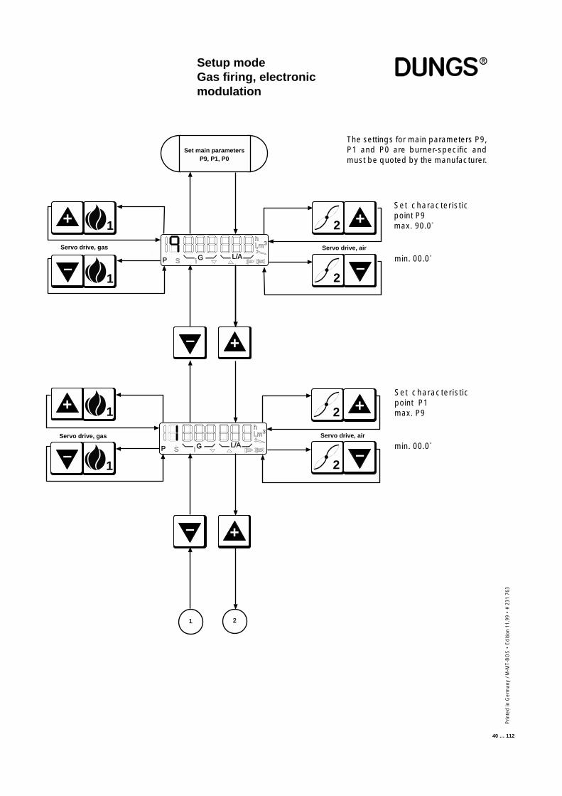
Prin
ted
in G
erm
any
/ M-M
T-B
OS
• E
diti
on 1
1.99
• #
231
763
40 … 112
P S G L/A
hl,m3
i
Set main parametersP9, P1, P0
–
+
–
+
21
iP S G L/A
hl,m3
Servo drive, airServo drive, gas
1+
1
–
Servo drive, gas
1+
1
–
Servo drive, air
2 +
2
–
2 +
2
–
Setup modeGas firing, electronicmodulation
The settings for main parameters P9,P1 and P0 are burner-specific andmust be quoted by the manufacturer.
min. 00.0°
Set characteristicpoint P9max. 90.0°
Set characteristicpoint P1max. P9
min. 00.0°
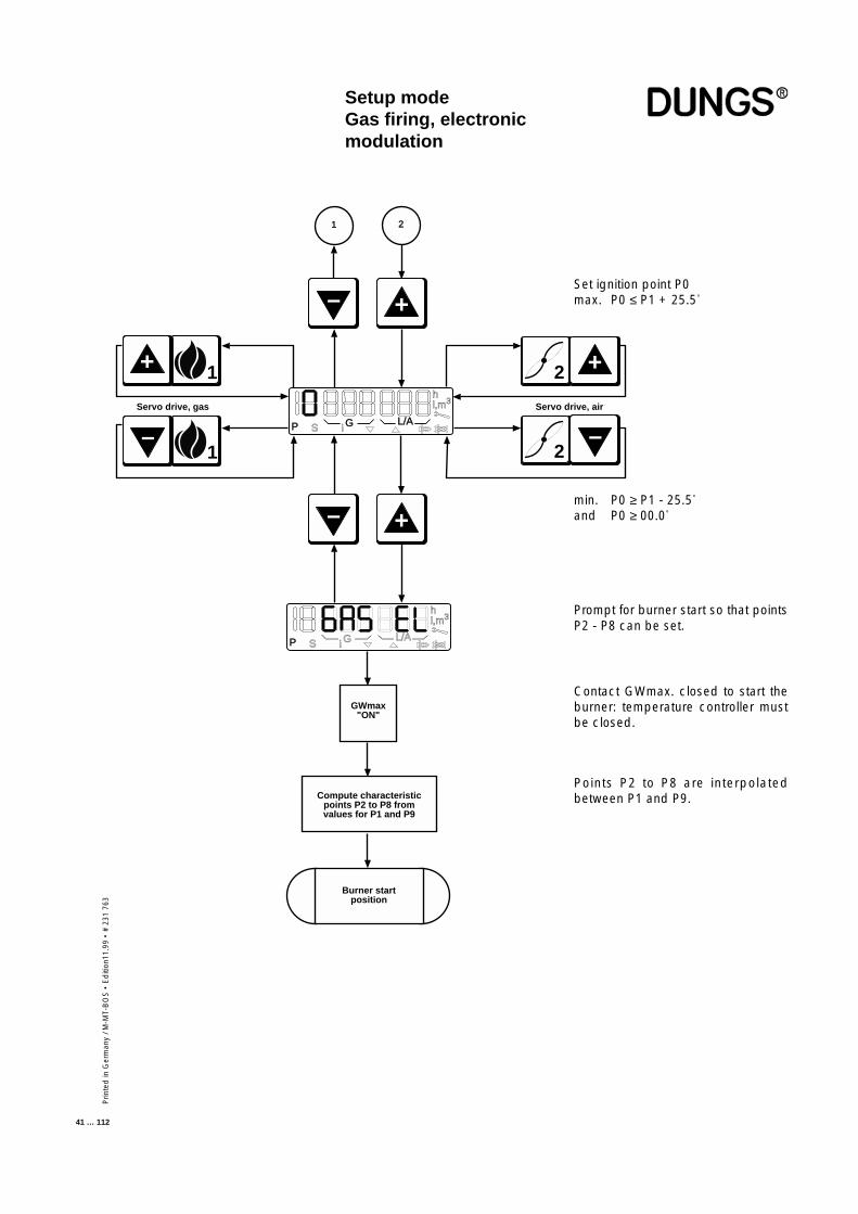
Prin
ted
in G
erm
any
/ M-M
T-B
OS
• E
diti
on11
.99
• #
231
763
41 … 112
Servo drive, air
iP S G L/A
hl,m3
–
+
P S G L/A
hl,m3
i
–
+
Servo drive, gas
Burner startposition
1+
1
–
2
–
2 +
21
GWmax"ON"
Compute characteristicpoints P2 to P8 fromvalues for P1 and P9
Setup modeGas firing, electronicmodulation
Set ignition point P0max. P0 ≤ P1 + 25.5°
Prompt for burner start so that pointsP2 - P8 can be set.
Contact GWmax. closed to start theburner: temperature controller mustbe closed.
Points P2 to P8 are interpolatedbetween P1 and P9.
min. P0 ≥ P1 - 25.5°
and P0 ≥ 00.0°
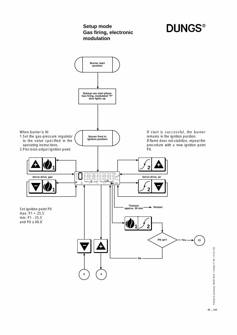
Prin
ted
in G
erm
any
/ M-M
T-B
OS
• E
diti
on 1
1.99
• #
231
763
42 … 112
+
Burner startposition
Burner fired inignition position
Timeoutapprox. 30 min Restart
Servo drive, gas
1+
1
–
Servo drive, air
P S G L/A
hl,m3
i
2 +
2
–
3
Startup see start phaseGas firing, modulated "P"
also lights up
–
4
1 2
P9 set? Yes 21
No
Setup modeGas firing, electronicmodulation
If start is successful, the burnerremains in the ignition position.If flame does not stabilize, repeat theprocedure with a new ignition pointP0.
When burner is lit:1.Set the gas-pressure regulator
to the value specified in theoperating instructions.
2.Precision-adjust ignition point.
Set ignition point P0max. P1 + 25.5°
min. P1 - 25.5°
and P0 ≥ 00.0°
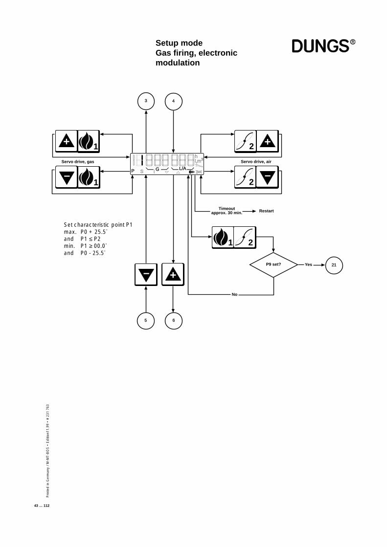
Prin
ted
in G
erm
any
/ M-M
T-B
OS
• E
diti
on11
.99
• #
231
763
43 … 112
+
Timeoutapprox. 30 min. Restart
Servo drive, gas
1+
1
–
Servo drive, air
P S G L/A
hl,m3
i
2 +
2
–
–
1 2
P9 set? Yes 21
No
3 4
5 6
Setup modeGas firing, electronicmodulation
Set characteristic point P1max. P0 + 25.5°
and P1 ≤ P2min. P1 ≥ 00.0°
and P0 - 25.5°

Prin
ted
in G
erm
any
/ M-M
T-B
OS
• E
diti
on 1
1.99
• #
231
763
44 … 112
+
Timeoutapprox. 30 min. Restart
Servo drive, gas
1+
1
–
Servo drive, air
P S G L/A
hl,m3
i
2 +
2
–
–
1 2
P9 set? Yes 21
No
7 8
5 6
Setup modeGas firing, electronicmodulation
Set characteristic point P2max. P1 + 25.5°
and P2 ≤ P3min. P1
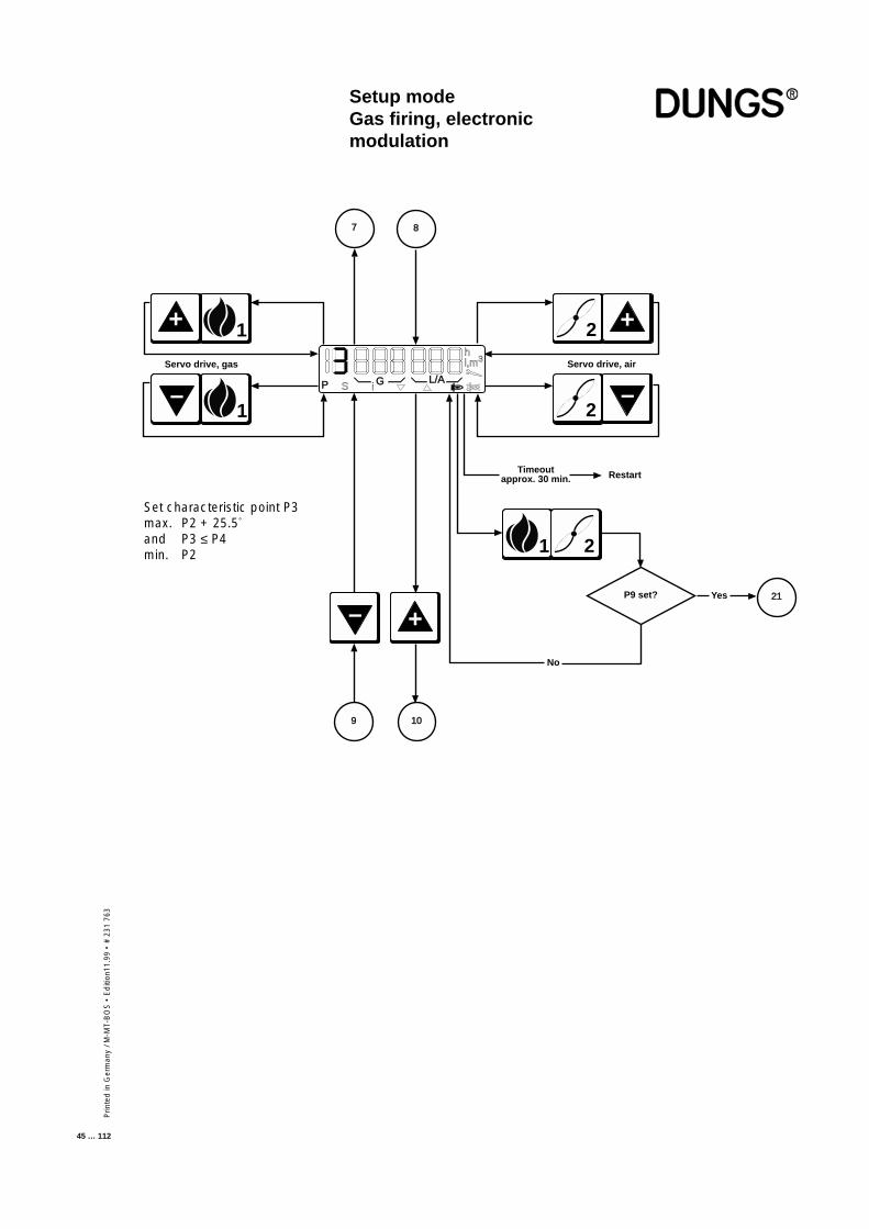
Prin
ted
in G
erm
any
/ M-M
T-B
OS
• E
diti
on11
.99
• #
231
763
45 … 112
+
Timeoutapprox. 30 min. Restart
Servo drive, gas
1+
1
–
Servo drive, air
P S G L/A
hl,m3
i
2 +
2
–
–
1 2
P9 set? Yes 21
No
9 10
7 8
Setup modeGas firing, electronicmodulation
Set characteristic point P3max. P2 + 25.5°
and P3 ≤ P4min. P2

Prin
ted
in G
erm
any
/ M-M
T-B
OS
• E
diti
on 1
1.99
• #
231
763
46 … 112
+
Timeoutapprox. 30 min. Restart
Servo drive, gas
1+
1
–
Servo drive, air
P S G L/A
hl,m3
i
2 +
2
–
–
1 2
P9 set? Yes 21
No
11 12
9 10
Setup modeGas firing, electronicmodulation
Set characteristic point P4max. P3 + 25.5°
and P4 ≤ P5min. P3
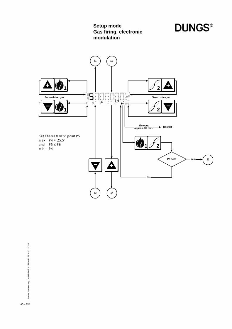
Prin
ted
in G
erm
any
/ M-M
T-B
OS
• E
diti
on11
.99
• #
231
763
47 … 112
+
Timeoutapprox. 30 min. Restart
Servo drive, gas
1+
1
–
Servo drive, air
P S G L/A
hl,m3
i
2 +
2
–
–
1 2
P9 set? Yes 21
No
13 14
11 12
Setup modeGas firing, electronicmodulation
Set characteristic point P5max. P4 + 25.5°
and P5 ≤ P6min. P4

Prin
ted
in G
erm
any
/ M-M
T-B
OS
• E
diti
on 1
1.99
• #
231
763
48 … 112
+
Timeoutapprox. 30 min. Restart
Servo drive, gas
1+
1
–
Servo drive, air
P S G L/A
hl,m3
i
2 +
2
–
–
1 2
P9 set? Yes 21
No
15 16
13 14
Setup modeGas firing, electronicmodulation
Set characteristic point P6max. P5 + 25.5°
and P6 ≤ P7min. P5

Prin
ted
in G
erm
any
/ M-M
T-B
OS
• E
diti
on11
.99
• #
231
763
49 … 112
+
Timeoutapprox. 30 min. Restart
Servo drive, gas
1+
1
–
Servo drive, air
P S G L/A
hl,m3
i
2 +
2
–
–
1 2
P9 set? Yes 21
No
17 18
15 16
Setup modeGas firing, electronicmodulation
Set characteristic point P7max. P6 + 25.5°
and P7 ≤ P8min. P6
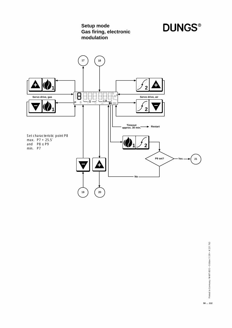
Prin
ted
in G
erm
any
/ M-M
T-B
OS
• E
diti
on 1
1.99
• #
231
763
50 … 112
+
Timeoutapprox. 30 min. Restart
Servo drive, gas
1+
1
–
Servo drive, air
P S G L/A
hl,m3
i
2 +
2
–
–
1 2
P9 set? Yes 21
No
19 20
17 18
Setup modeGas firing, electronicmodulation
Set characteristic point P8max. P7 + 25.5°
and P8 ≤ P9min. P7
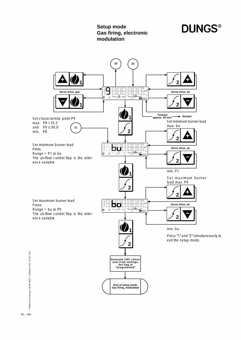
Prin
ted
in G
erm
any
/ M-M
T-B
OS
• E
diti
on11
.99
• #
231
763
51 … 112
Setup modeGas firing, electronicmodulation
Timeoutapprox. 30 min. Restart
Servo drive, gas
1+
1
–
Servo drive, air
2 +
2
–
2019
1
2
P S G L/A
hl,m3
i
P S G L/A
hl,m3
i
1
2
P S G L/A
hl,m3
i
1
2
End of setup modeGas firing, modulated
Generate CRC check-sum from settings.
Set flag to"programmed"
21
2
–
Servo drive, air
2 +
2
–
Servo drive, air
2 +
Set characteristic point P9max. P8 +25.5°
and P9 ≤ 90.0°
min. P8
Set minimum burner loadPmin.Range = P1 to boThe air-flow control flap is the refer-ence variable
Set maximum burner loadPmax.Range = bu to P9The air-flow control flap is the refer-ence variable
Set minimum burner loadmax. bo
min. P1
Set maximum burnerload max. P9
min. bu
Press "1" and "2" simultaneously toexit the setup mode.
Prin
ted
in G
erm
any
/ M-M
T-B
OS
• E
diti
on 1
1.99
• #
231
763
52 … 112
The controller automatically goes to standby status if the automatic burner-control system has not been programmed. In the unprogrammed state, theautomatic burner-control system remains on standby. Unprogrammed meansthat the working point has not been fully programmed.Once valid working points have been programmed and the automatic burner-control system detects the presence of the corresponding components whenit starts up, the burner starts as soon as the control chain and GWmax areclosed.
If progamming has been completed and you want to correct points such asthe ignition load P0, low load P1 or high load P9 in operation, press the "+"and "-" buttons simultaneously to access setup mode.
Simultaneously press the "1" and "2" buttons if you want to enter the full setupmode. The "P" symbol always appears in the display to indicate that setupmode is activated. If you do not press a button in setup mode before thetimeout expires, setup mode is exited automatically and a RESTART isperformed.
Setup modeGas firing, pneumaticmodulation
■ The burner must be in standbystatus, otherwise you cannotaccess the setup mode
■ Changing points defined before-hand
■ Accessing setup mode
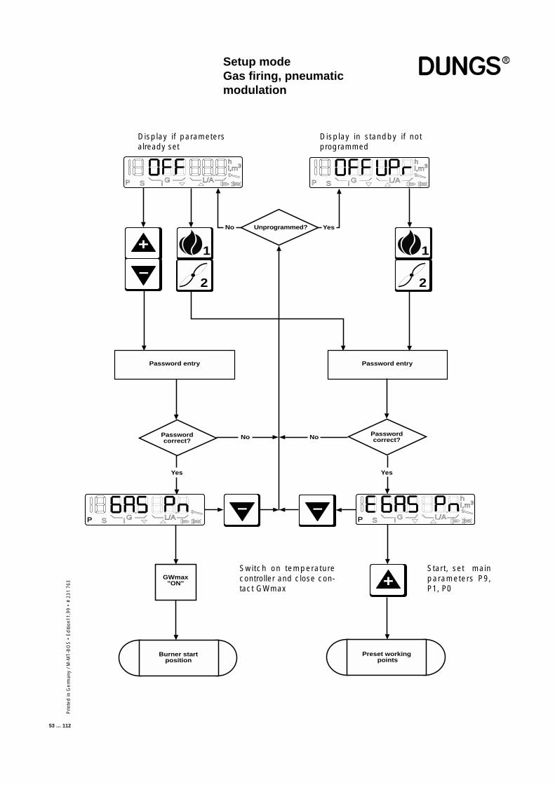
Prin
ted
in G
erm
any
/ M-M
T-B
OS
• E
diti
on11
.99
• #
231
763
53 … 112
– –
+
P S G L/A
hl,m3
P S i G L/A
hl,m3
i
hl,m3
1
2
Unprogrammed?No Yes
1
2
Password entry Password entry
Passwordcorrect?
Passwordcorrect?No
Yes Yes
+
–
GWmax"ON"
No
P S G L/Ai P S G L/A
hl,m3
i
Burner startposition
Preset working points
Setup modeGas firing, pneumaticmodulation
Display if parametersalready set
Display in standby if notprogrammed
Switch on temperaturecontroller and close con-tact GWmax
Start, set mainparameters P9,P1, P0
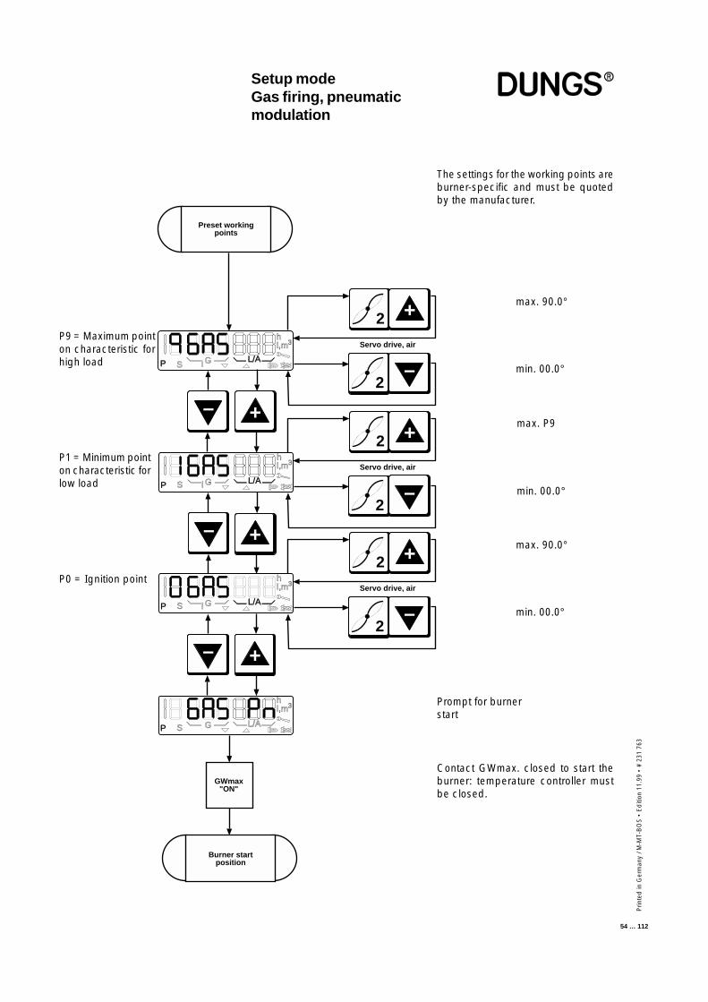
Prin
ted
in G
erm
any
/ M-M
T-B
OS
• E
diti
on 1
1.99
• #
231
763
54 … 112
Setup modeGas firing, pneumaticmodulation
The settings for the working points areburner-specific and must be quotedby the manufacturer.
max. 90.0°
min. 00.0°
max. P9
min. 00.0°
Prompt for burnerstart
Contact GWmax. closed to start theburner: temperature controller mustbe closed.
P9 = Maximum pointon characteristic forhigh load
P1 = Minimum pointon characteristic forlow load
–
–
+
+
–
+
Burner startposition
GWmax"ON"
P S i G L/A
hl,m3
Preset workingpoints
P S G L/A
hl,m3
i
P S i G L/A
hl,m3
P S G L/A
hl,m3
Servo drive, air
2 +
2
–
Servo drive, air
2 +
2–
Servo drive, air
2 +
2
–
max. 90.0°
min. 00.0°
P0 = Ignition point
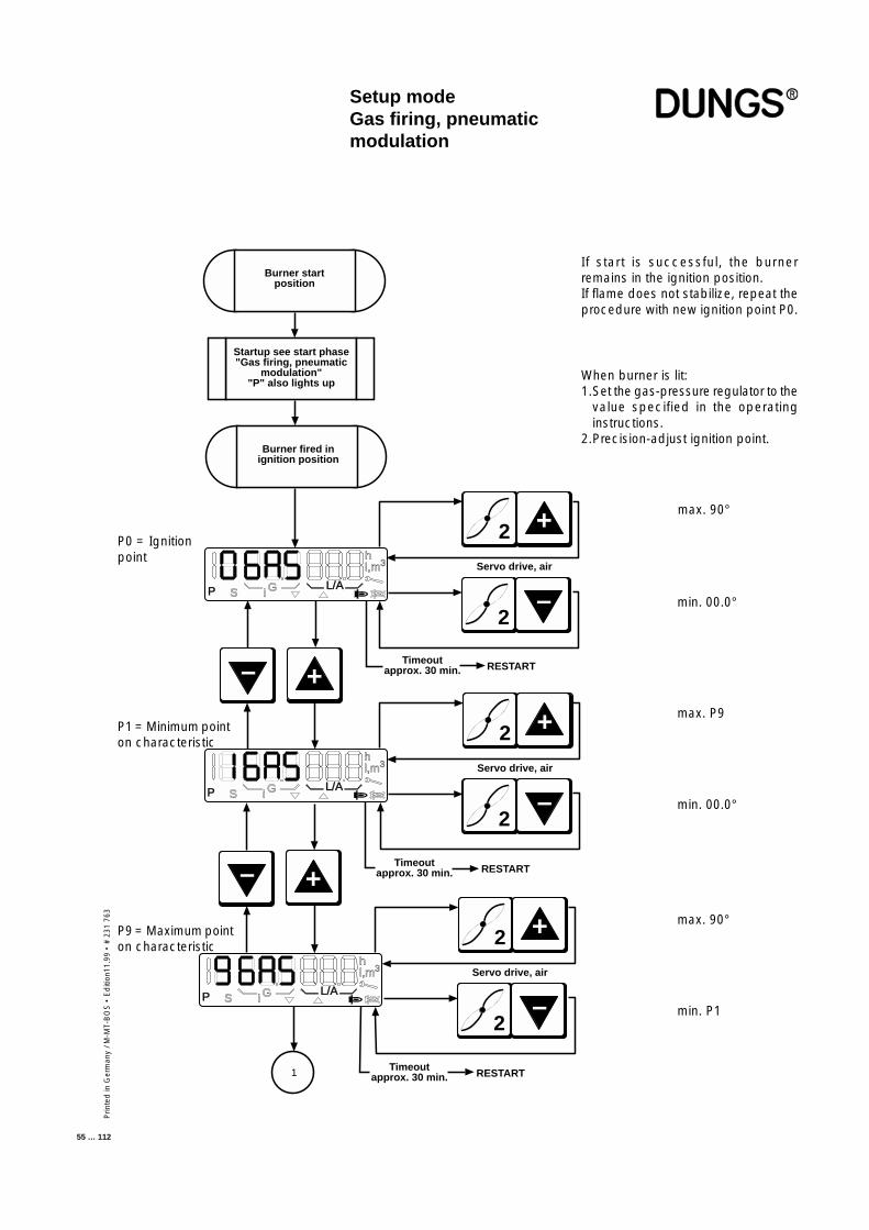
Prin
ted
in G
erm
any
/ M-M
T-B
OS
• E
diti
on11
.99
• #
231
763
55 … 112
If start is successful, the burnerremains in the ignition position.If flame does not stabilize, repeat theprocedure with new ignition point P0.
When burner is lit:1.Set the gas-pressure regulator to the
value specified in the operatinginstructions.
2.Precision-adjust ignition point.
max. 90°
min. 00.0°
max. P9
min. 00.0°
P0 = Ignitionpoint
P1 = Minimum pointon characteristic
–
+
–
+
Burner startposition
Startup see start phase"Gas firing, pneumatic
modulation""P" also lights up
Burner fired inignition position
RESTARTTimeoutapprox. 30 min.
P S i GL/A
hl,m3 Servo drive, air
2 +
2–
1
P S i GL/A
hl,m3
Timeoutapprox. 30 min. RESTART
Servo drive, air
2 +
2
–
P S i GL/A
hl,m3
Timeoutapprox. 30 min. RESTART
Servo drive, air
2 +
2
–
max. 90°
min. P1
P9 = Maximum pointon characteristic
Setup modeGas firing, pneumaticmodulation
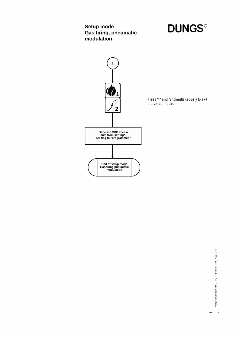
Prin
ted
in G
erm
any
/ M-M
T-B
OS
• E
diti
on 1
1.99
• #
231
763
56 … 112
Press "1" and "2" simultaneously to exitthe setup mode.
1
Generate CRC check-sum from settings.
Set flag to "programmed"
End of setup modeGas firing pneumatic
modulation
1
2
Setup modeGas firing, pneumaticmodulation
Prin
ted
in G
erm
any
/ M-M
T-B
OS
• E
diti
on11
.99
• #
231
763
57 … 112
The controller automatically goes to standby status if the automatic burner-control system has not been programmed. In the unprogrammed state, theautomatic burner-control system remains on standby. Unprogrammed meansthat the working point has not been fully programmed.Once valid working points have been programmed and the automatic burner-control system detects the presence of the corresponding components whenit starts up, the burner starts as soon as the control chain and GWmax areclosed.
If progamming has been completed and you want to correct points such asthe the first stage P1, the second stage P3, the third stage P9 or the changeoverpoints P2 and P4 in operation, press the "+" and "-" buttons simultaneously toaccess setup mode.
Simultaneously press the "1" and "2" buttons if you want to enter the full setupmode. The "P" symbol always appears in the display to indicate that setupmode is activated. If you do not press a button in setup mode before thetimeout expires, setup mode is exited automatically and a RESTART isperformed.
Setup modeOil firing, three stage
■ The burner must be in standbystatus, otherwise you cannotaccess the setup mode
■ Changing points defined before-hand
■ Accessing setup mode
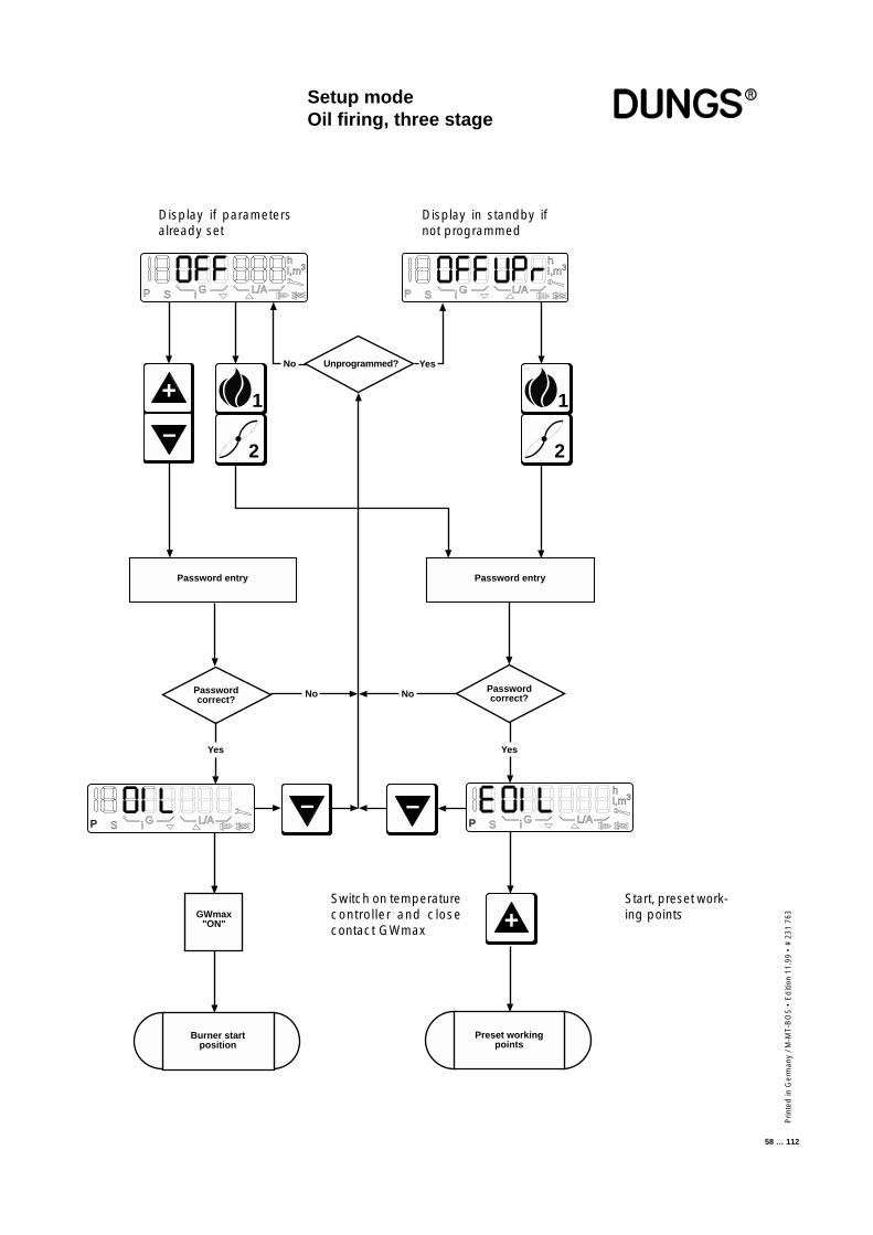
Prin
ted
in G
erm
any
/ M-M
T-B
OS
• E
diti
on 1
1.99
• #
231
763
58 … 112
P S G L/A
hl,m3
P S i G L/A
hl,m3
i
1
2
Unprogrammed?No Yes
1
2
Password entry Password entry
Passwordcorrect?
Passwordcorrect?No
Yes Yes
+
–
GWmax"ON"
No
Burner startposition
Preset workingpoints
hl,m3
P S G L/Ai P S G L/A
hl,m3
i
– –
+
Setup modeOil firing, three stage
Start, preset work-ing points
Switch on temperaturecontroller and closecontact GWmax
Display if parametersalready set
Display in standby ifnot programmed
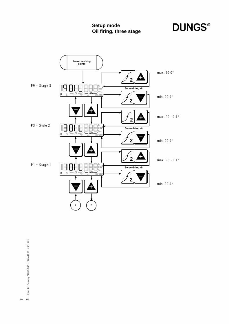
Prin
ted
in G
erm
any
/ M-M
T-B
OS
• E
diti
on11
.99
• #
231
763
59 … 112
P9 = Stage 3
P3 = Stufe 2
P1 = Stage 1
max. 90.0°
min. 00.0°
max. P9 - 0.1°
min. 00.0°
max. P3 - 0.1°
Setup modeOil firing, three stage
Servo drive, air
2 +
2
–
1 2
Preset workingpoints
P S i GL/A
hl,m3
Servo drive, air
2 +
2
–
Servo drive, air
2 +
2
–
P S i G L/A
hl,m3
P S G L/A
hl,m3
i
–
–
+
+
–
+
min. 00.0°
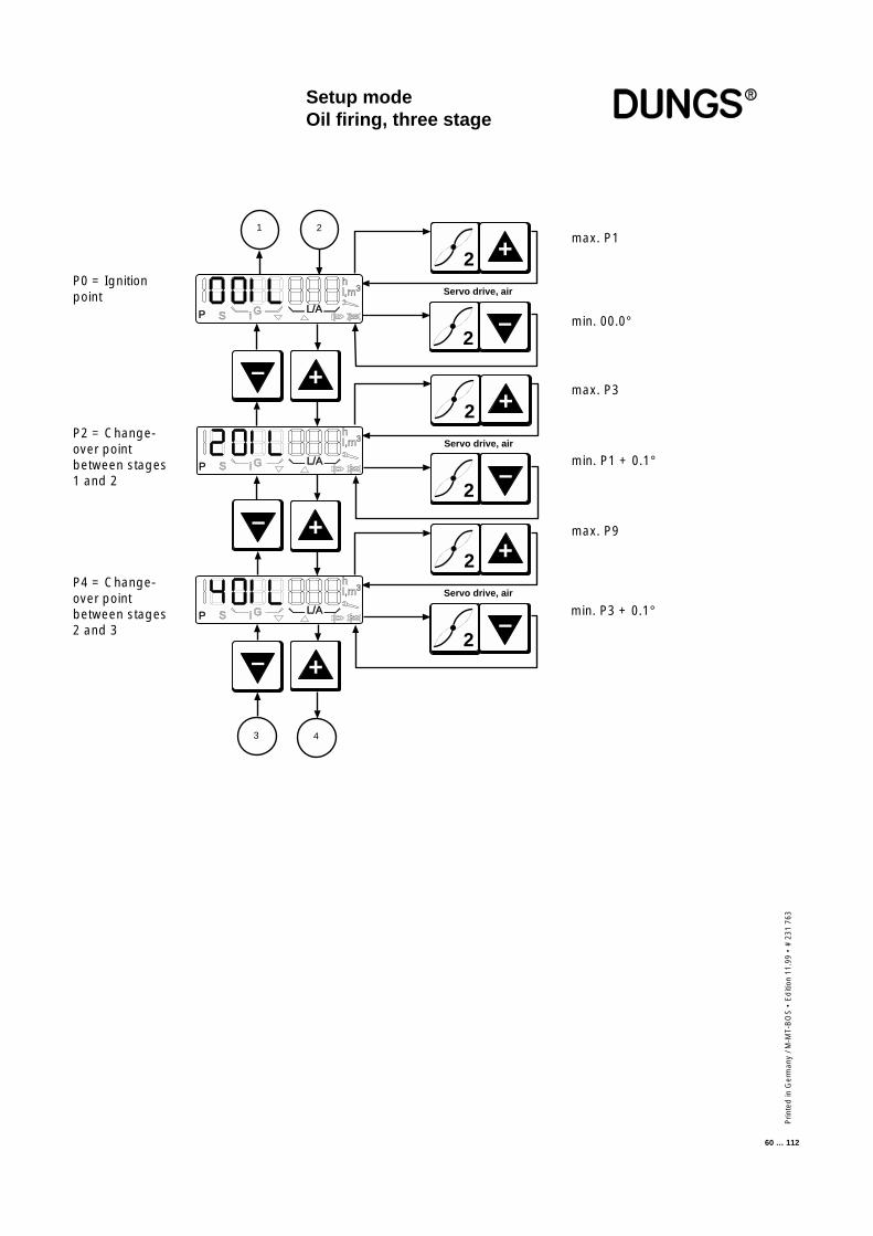
Prin
ted
in G
erm
any
/ M-M
T-B
OS
• E
diti
on 1
1.99
• #
231
763
60 … 112
–
–
+
+
–
+
Servo drive, air
2 +
2
–P S i GL/A
hl,m3
Servo drive, air
2 +
2
–
Servo drive, air
2 +
2
–
P S i G L/A
hl,m3
P S G L/A
hl,m3
i
1 2
3 4
max. P1
min. 00.0°
max. P3
min. P1 + 0.1°
min. P3 + 0.1°
max. P9
P0 = Ignitionpoint
P2 = Change-over pointbetween stages1 and 2
P4 = Change-over pointbetween stages2 and 3
Setup modeOil firing, three stage
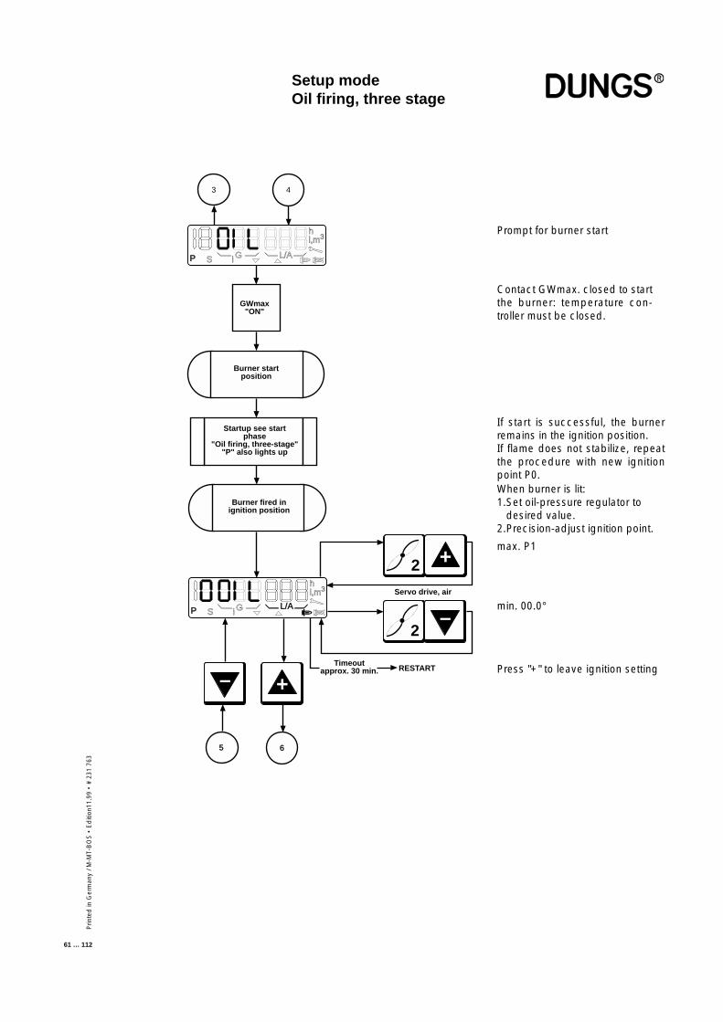
Prin
ted
in G
erm
any
/ M-M
T-B
OS
• E
diti
on11
.99
• #
231
763
61 … 112
Prompt for burner start
Contact GWmax. closed to startthe burner: temperature con-troller must be closed.
If start is successful, the burnerremains in the ignition position.If flame does not stabilize, repeatthe procedure with new ignitionpoint P0.When burner is lit:1.Set oil-pressure regulator to
desired value.2.Precision-adjust ignition point.
max. P1
min. 00.0°
Press "+" to leave ignition setting–
+
3
GWmax"ON"
Burner startposition
Startup see startphase
"Oil firing, three-stage""P" also lights up
Burner fired inignition position
RESTARTTimeout
approx. 30 min.
4
P S i G L/A
hl,m3
P S i GL/A
hl,m3
5 6
Servo drive, air
2 +
2
–
Setup modeOil firing, three stage
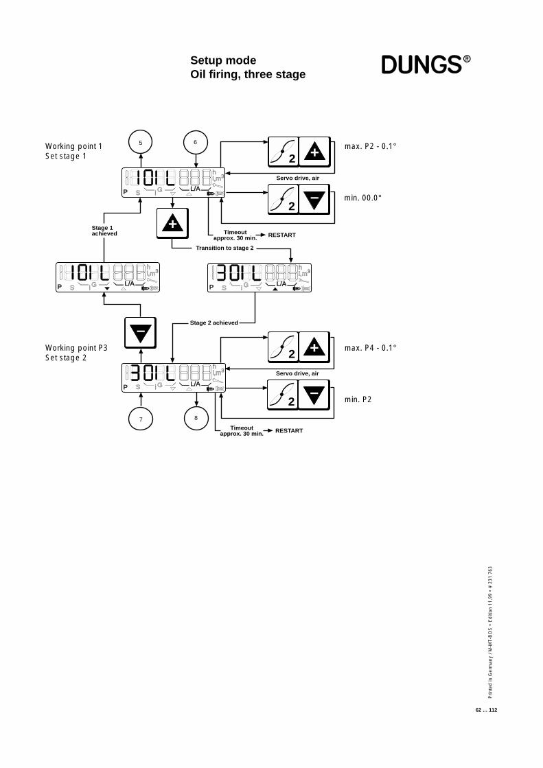
Prin
ted
in G
erm
any
/ M-M
T-B
OS
• E
diti
on 1
1.99
• #
231
763
62 … 112
+
–
Transition to stage 2
Stage 1achieved
Stage 2 achieved
Timeoutapprox. 30 min. RESTART
P S G L/A
hl,m3
i
P S G L/A
hl,m3
i
P S G L/A
hl,m3
i
P S G L/A
hl,m3
i
5 6
7 8
Servo drive, air
2 +
2
–
Servo drive, air
2 +
2
–
Timeoutapprox. 30 min. RESTART
max. P2 - 0.1°
min. 00.0°
Working point 1Set stage 1
Working point P3Set stage 2
max. P4 - 0.1°
min. P2
Setup modeOil firing, three stage
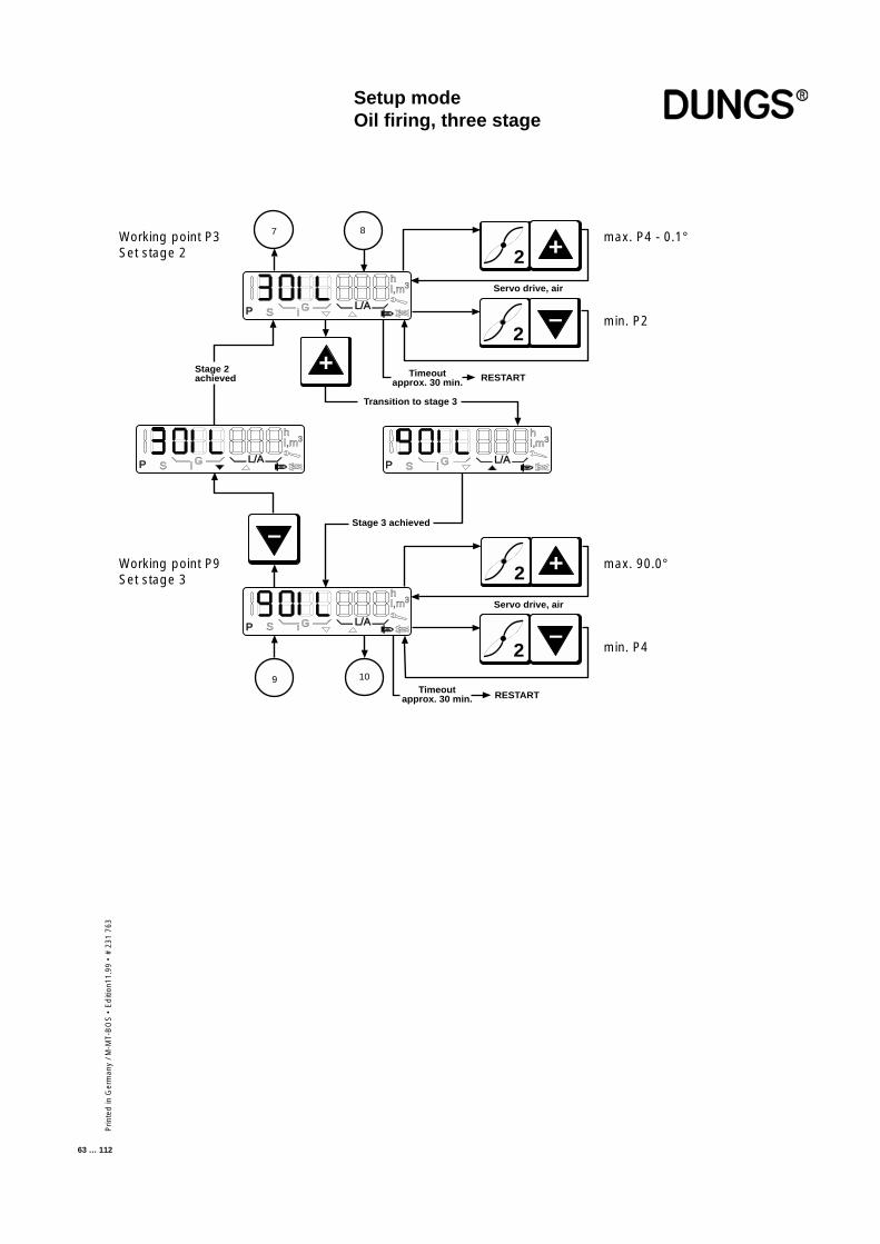
Prin
ted
in G
erm
any
/ M-M
T-B
OS
• E
diti
on11
.99
• #
231
763
63 … 112
+
–
Transition to stage 3
Stage 2achieved
Stage 3 achieved
Timeoutapprox. 30 min. RESTART
Timeoutapprox. 30 min. RESTART
P S G L/A
hl,m3
i
P S G L/A
hl,m3
i
P S G L/A
hl,m3
i
P S G L/A
hl,m3
i
7 8
109
Servo drive, air
2 +
2
–
Servo drive, air
2 +
2
–
max. P4 - 0.1°
min. P2
Working point P3Set stage 2
Working point P9Set stage 3
max. 90.0°
min. P4
Setup modeOil firing, three stage
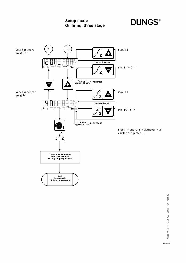
Prin
ted
in G
erm
any
/ M-M
T-B
OS
• E
diti
on 1
1.99
• #
231
763
64 … 112
Setup modeOil firing, three stage
+
– Timeoutapprox. 30 min. RESTART
9 10
P S G L/A
hl,m3
i
1
2
P S G L/A
hl,m3
i
Timeoutapprox. 30 min. RESTART
EndSetup mode
Oil firing, three-stage
Servo drive, air
2 +
2
–
Servo drive, air
2 +
2
–
Generate CRC check-sum from settings.
Set flag to "programmed"
max. P3
min. P1 + 0.1°
Set changeoverpoint P2
Set changeoverpoint P4
max. P9
min. P3 +0.1°
Press "1" and "2" simultaneously toexit the setup mode.

Prin
ted
in G
erm
any
/ M-M
T-B
OS
• E
diti
on11
.99
• #
231
763
65 … 112
Display in operating modeGas firing, electronicmodulationGas firing, pneumaticmodulationDisplay in operating mode, gas firing with electronic modulation and gas firingwith pneumatic modulation.If setup mode is activated, the "P" symbol also appears in the start phase.
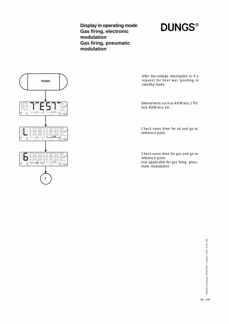
Prin
ted
in G
erm
any
/ M-M
T-B
OS
• E
diti
on 1
1.99
• #
231
763
66 … 112
After line-voltage interruption or if arequest for heat was pending instandby mode.
Internal tests such as ROM test, CPUtest, RAM test, etc.
Check servo drive for air and go toreference point.
Check servo drive for gas and go toreference point.(not applicable for gas firing, pneu-matic modulation)
P S i G L/A
hl,m3
P S i G L/A
hl,m3
P S i G L/A
hl,m3
1
Restart
Display in operating modeGas firing, electronicmodulationGas firing, pneumaticmodulation
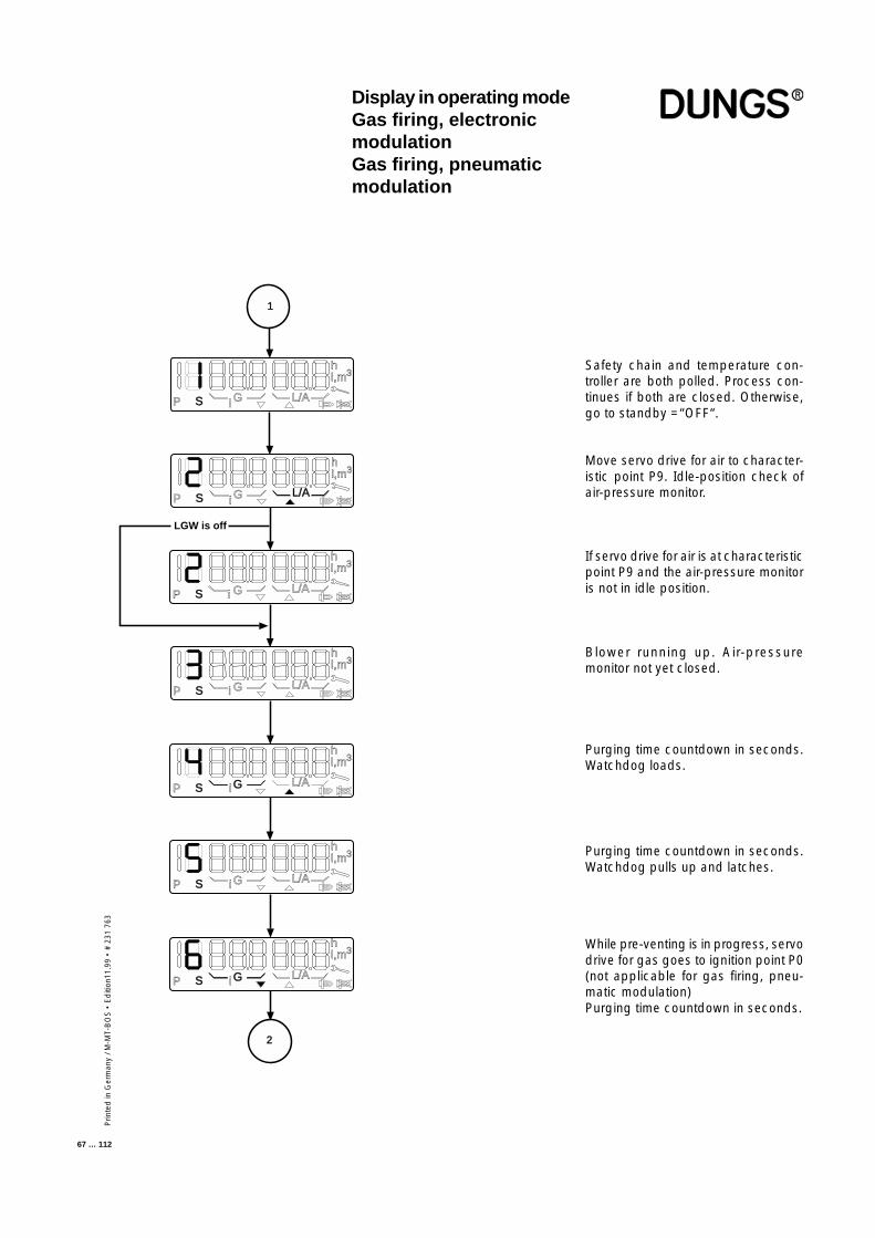
Prin
ted
in G
erm
any
/ M-M
T-B
OS
• E
diti
on11
.99
• #
231
763
67 … 112
Safety chain and temperature con-troller are both polled. Process con-tinues if both are closed. Otherwise,go to standby =“OFF“.
Move servo drive for air to character-istic point P9. Idle-position check ofair-pressure monitor.
If servo drive for air is at characteristicpoint P9 and the air-pressure monitoris not in idle position.
Blower running up. Air-pressuremonitor not yet closed.
Purging time countdown in seconds.Watchdog loads.
While pre-venting is in progress, servodrive for gas goes to ignition point P0(not applicable for gas firing, pneu-matic modulation)Purging time countdown in seconds.
Display in operating modeGas firing, electronicmodulationGas firing, pneumaticmodulation
Purging time countdown in seconds.Watchdog pulls up and latches.
P S G L/A
hl,m3
P S G L/A
hl,m3
i
i
P S G L/A
hl,m3
i
P S G L/A
hl,m3
i
P S G L/A
hl,m3
i
iP S G L/A
hl,m3
1
LGW is off
P S G L/A
hl,m3
i
2
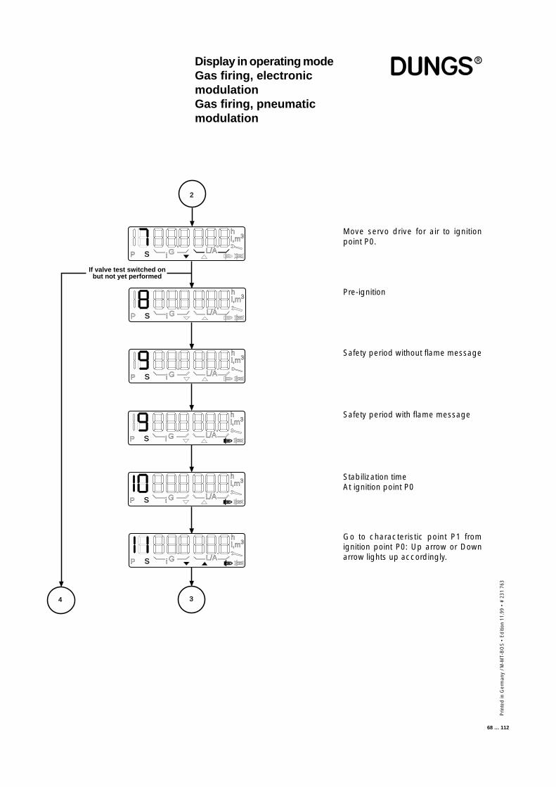
Prin
ted
in G
erm
any
/ M-M
T-B
OS
• E
diti
on 1
1.99
• #
231
763
68 … 112
Move servo drive for air to ignitionpoint P0.
Pre-ignition
Safety period without flame message
Safety period with flame message
Stabilization timeAt ignition point P0
Go to characteristic point P1 fromignition point P0: Up arrow or Downarrow lights up accordingly.
Display in operating modeGas firing, electronicmodulationGas firing, pneumaticmodulation
P S G L/A
hl,m3
If valve test switched onbut not yet performed
P S i GL/A
hl,m3
P S i G L/A
hl,m3
i
P S i G L/A
hl,m3
P S i G L/A
hl,m3
P S i G L/A
hl,m3
2
34
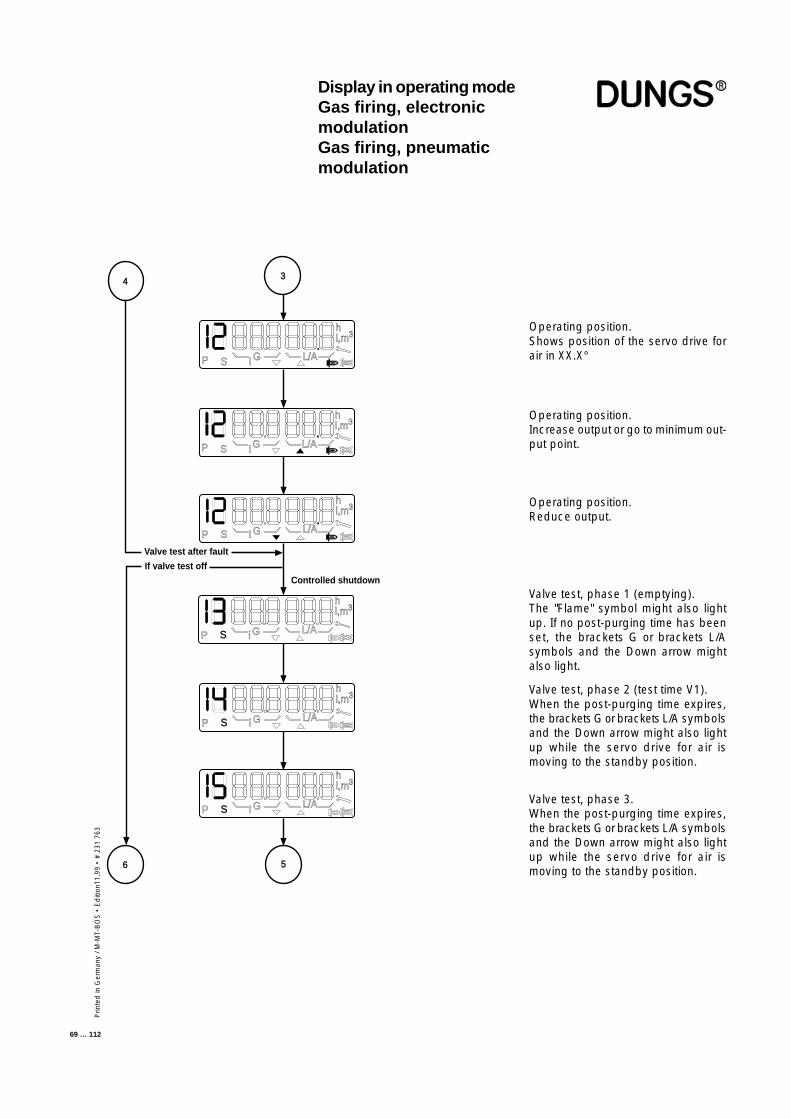
Prin
ted
in G
erm
any
/ M-M
T-B
OS
• E
diti
on11
.99
• #
231
763
69 … 112
Operating position.Shows position of the servo drive forair in XX.X°
Operating position.Increase output or go to minimum out-put point.
Operating position.Reduce output.
Valve test, phase 1 (emptying).The "Flame" symbol might also lightup. If no post-purging time has beenset, the brackets G or brackets L/Asymbols and the Down arrow mightalso light.
Valve test, phase 2 (test time V1).When the post-purging time expires,the brackets G or brackets L/A symbolsand the Down arrow might also lightup while the servo drive for air ismoving to the standby position.
Valve test, phase 3.When the post-purging time expires,the brackets G or brackets L/A symbolsand the Down arrow might also lightup while the servo drive for air ismoving to the standby position.
P S G L/A
hl,m3
Valve test after fault
If valve test off
P S i G L/A
hl,m3
i
P S i G L/A
hl,m3
P S i G L/A
hl,m3
P S i G L/A
hl,m3
P S i G L/A
hl,m3
Controlled shutdown
4 3
6 5
Display in operating modeGas firing, electronicmodulationGas firing, pneumaticmodulation
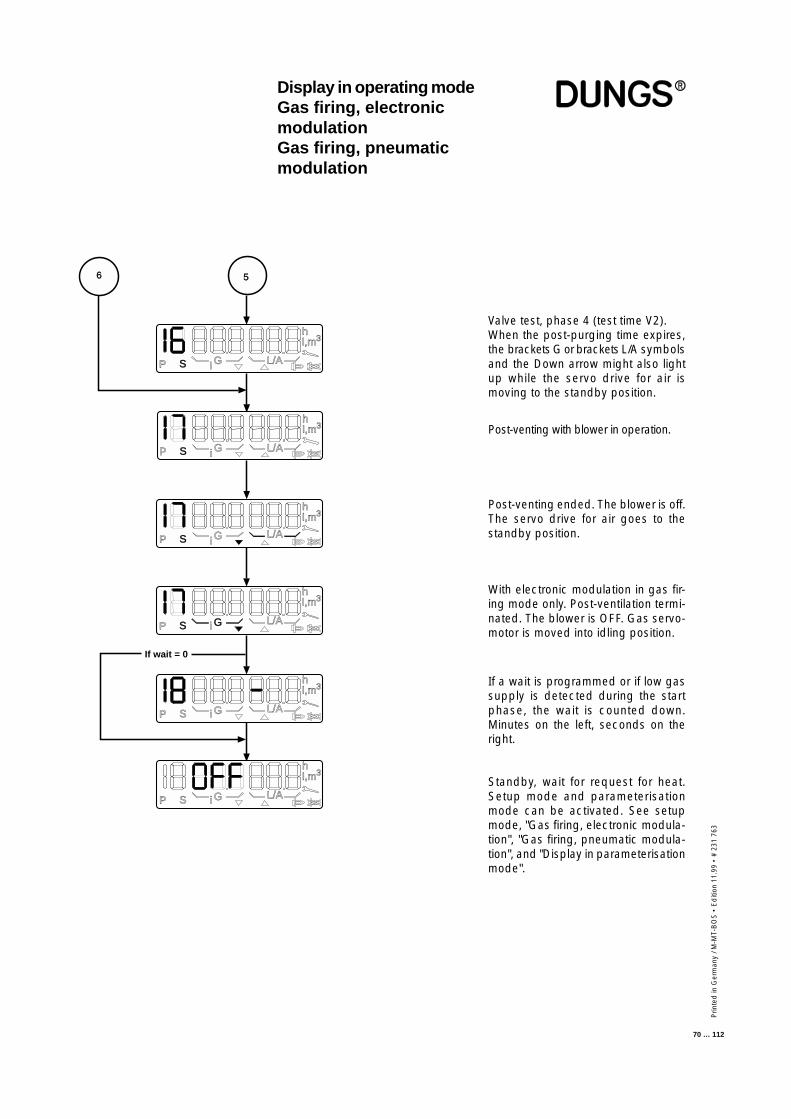
Prin
ted
in G
erm
any
/ M-M
T-B
OS
• E
diti
on 1
1.99
• #
231
763
70 … 112
Valve test, phase 4 (test time V2).When the post-purging time expires,the brackets G or brackets L/A symbolsand the Down arrow might also lightup while the servo drive for air ismoving to the standby position.
Post-venting with blower in operation.
Post-venting ended. The blower is off.The servo drive for air goes to thestandby position.
With electronic modulation in gas fir-ing mode only. Post-ventilation termi-nated. The blower is OFF. Gas servo-motor is moved into idling position.
If a wait is programmed or if low gassupply is detected during the startphase, the wait is counted down.Minutes on the left, seconds on theright.
Standby, wait for request for heat.Setup mode and parameterisationmode can be activated. See setupmode, "Gas firing, electronic modula-tion", "Gas firing, pneumatic modula-tion", and "Display in parameterisationmode".
P S i G L/A
hl,m3
P S i G L/A
hl,m3
P S i G L/A
hl,m3
P S i G L/A
hl,m3
P S i G L/A
hl,m3
If wait = 0
6 5
P S i GL/A
hl,m3
Display in operating modeGas firing, electronicmodulationGas firing, pneumaticmodulation

Prin
ted
in G
erm
any
/ M-M
T-B
OS
• E
diti
on11
.99
• #
231
763
71 … 112
Display in operating modeOil firing, three stage
Display in operating mode, oil firing, three stage.If setup mode is activated, the "P" symbol also appears in the start phase.
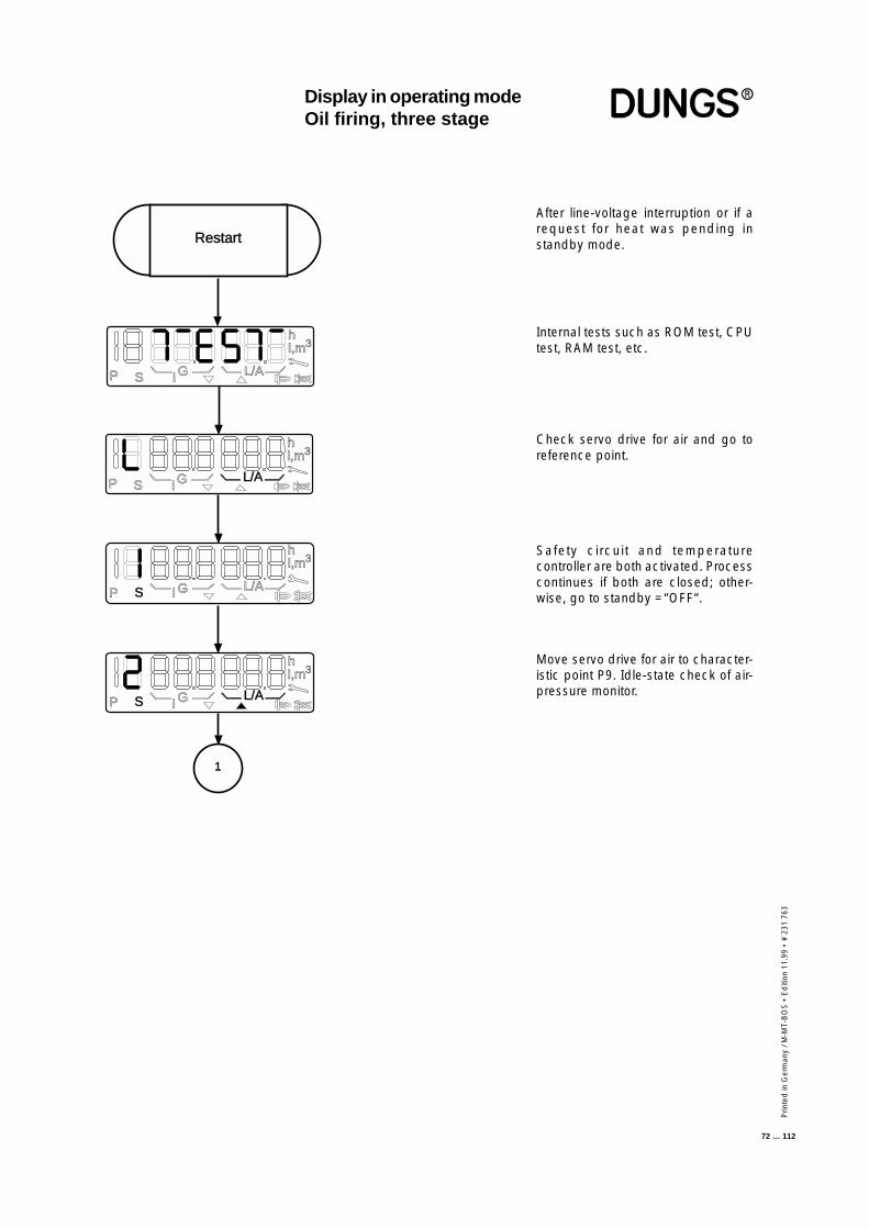
Prin
ted
in G
erm
any
/ M-M
T-B
OS
• E
diti
on 1
1.99
• #
231
763
72 … 112
Internal tests such as ROM test, CPUtest, RAM test, etc.
Check servo drive for air and go toreference point.
Safety circuit and temperaturecontroller are both activated. Processcontinues if both are closed; other-wise, go to standby =“OFF“.
After line-voltage interruption or if arequest for heat was pending instandby mode.
Move servo drive for air to character-istic point P9. Idle-state check of air-pressure monitor.
Restart
P S i G L/A
hl,m3
P S i GL/A
hl,m3
P S i G L/A
hl,m3
P S i GL/A
hl,m3
1
Display in operating modeOil firing, three stage
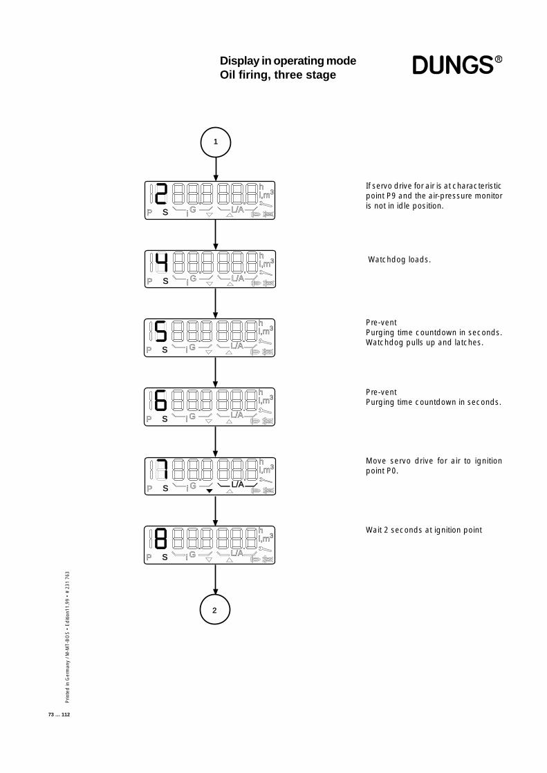
Prin
ted
in G
erm
any
/ M-M
T-B
OS
• E
diti
on11
.99
• #
231
763
73 … 112
If servo drive for air is at characteristicpoint P9 and the air-pressure monitoris not in idle position.
Watchdog loads.
Move servo drive for air to ignitionpoint P0.
Wait 2 seconds at ignition point
Display in operating modeOil firing, three stage
P S i G L/A
hl,m3
P S i G L/A
hl,m3
1
P S i G L/A
hl,m3
P S i G L/A
hl,m3
P S i G L/A
hl,m3
P S i G L/A
hl,m3
2
Pre-ventPurging time countdown in seconds.Watchdog pulls up and latches.
Pre-ventPurging time countdown in seconds.
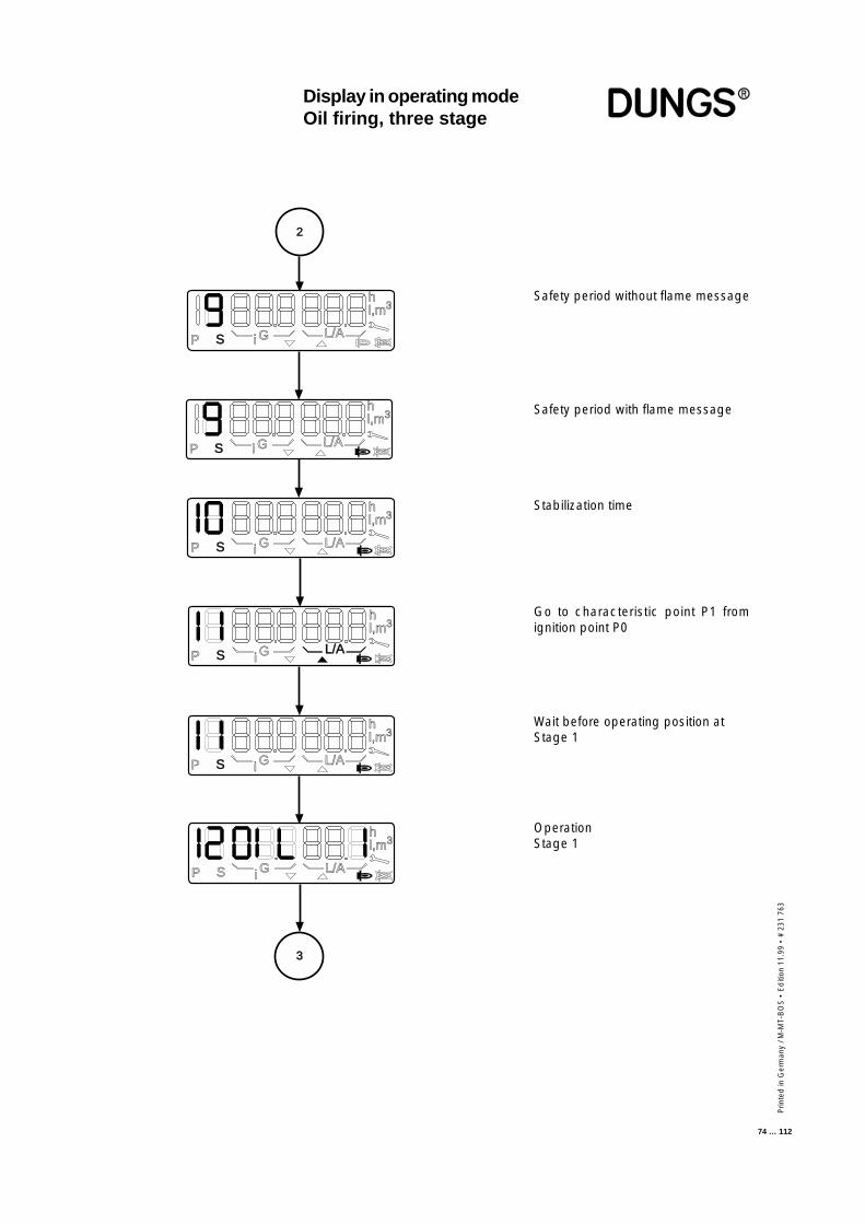
Prin
ted
in G
erm
any
/ M-M
T-B
OS
• E
diti
on 1
1.99
• #
231
763
74 … 112
Stabilization time
Go to characteristic point P1 fromignition point P0
Wait before operating position atStage 1
OperationStage 1
2
P S i G L/A
hl,m3
P S i G L/A
hl,m3
P S i G L/A
hl,m3
P S i GL/A
hl,m3
P S i G L/A
hl,m3
P S i G L/A
hl,m3
3
Display in operating modeOil firing, three stage
Safety period without flame message
Safety period with flame message
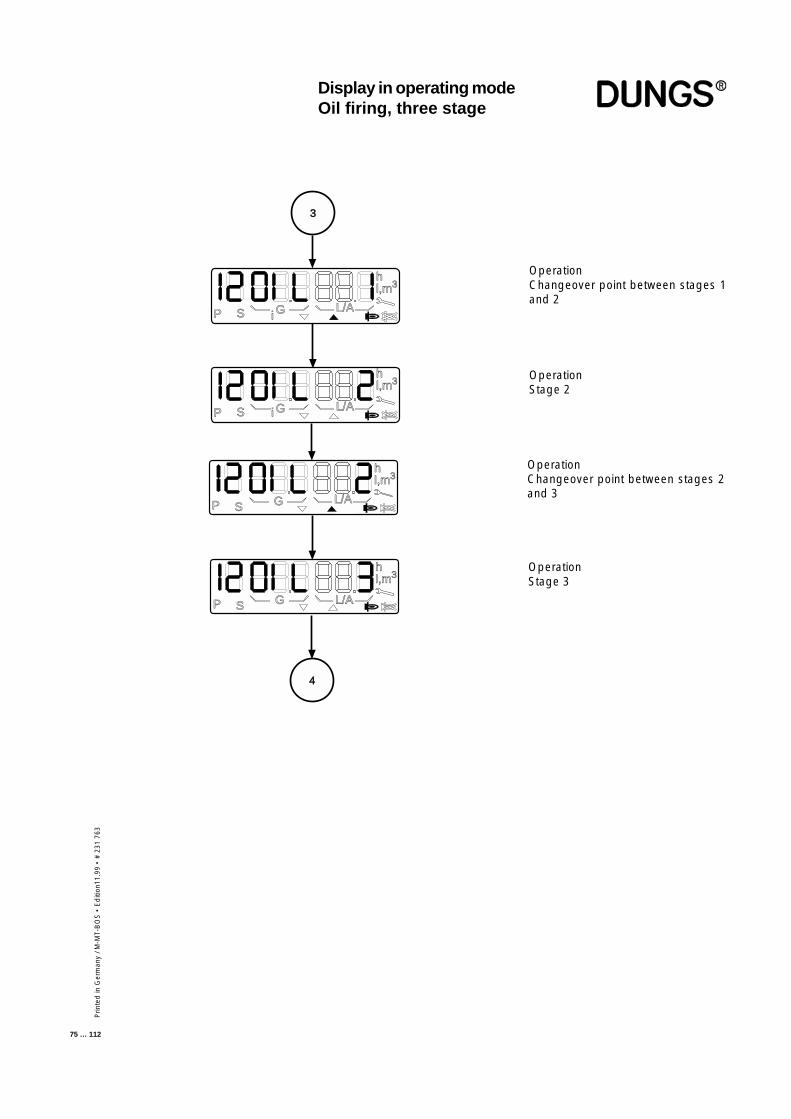
Prin
ted
in G
erm
any
/ M-M
T-B
OS
• E
diti
on11
.99
• #
231
763
75 … 112
Display in operating modeOil firing, three stage
i
P S i GL/A
hl,m3
P S i G L/A
hl,m3
P S G L/A
hl,m3
P S G L/A
hl,m3
3
4
OperationChangeover point between stages 1and 2
OperationStage 2
OperationChangeover point between stages 2and 3
OperationStage 3
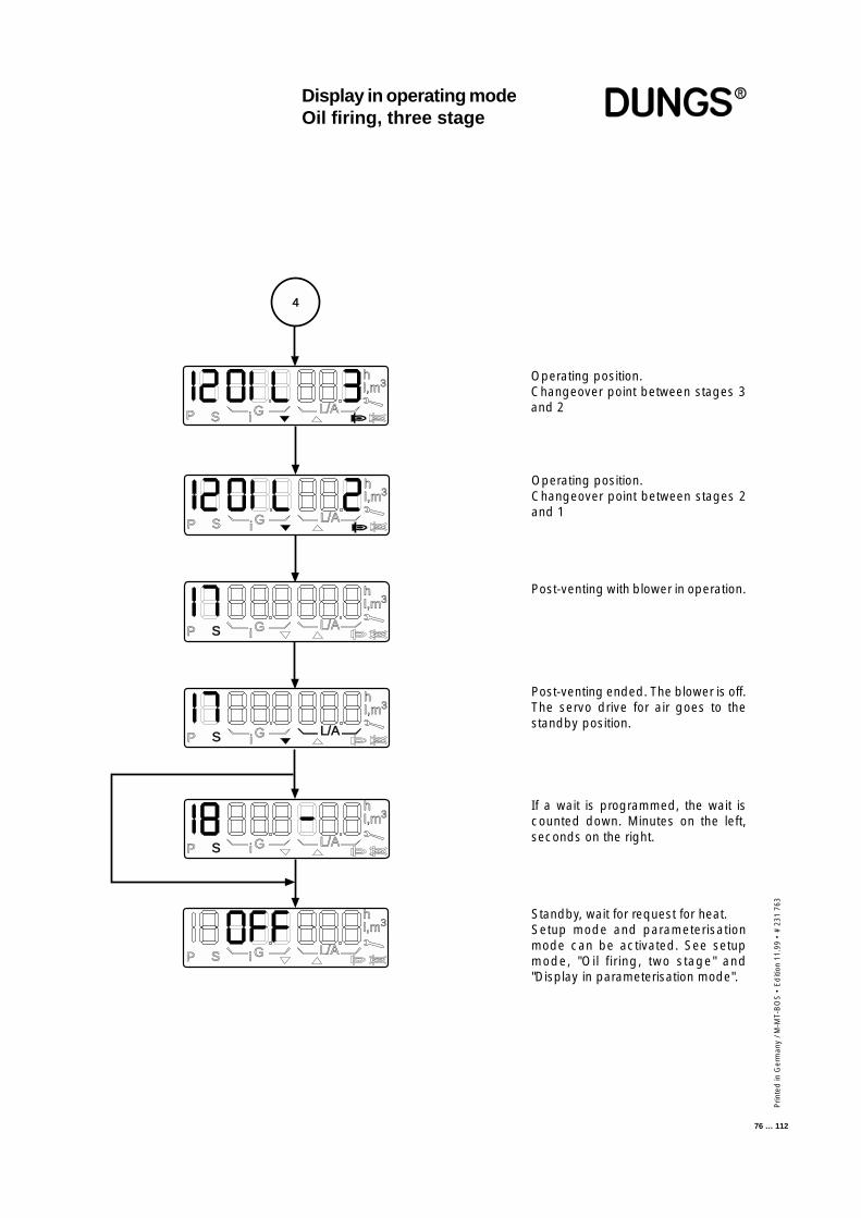
Prin
ted
in G
erm
any
/ M-M
T-B
OS
• E
diti
on 1
1.99
• #
231
763
76 … 112
Operating position.Changeover point between stages 3and 2
Post-venting with blower in operation.
Post-venting ended. The blower is off.The servo drive for air goes to thestandby position.
If a wait is programmed, the wait iscounted down. Minutes on the left,seconds on the right.
Standby, wait for request for heat.Setup mode and parameterisationmode can be activated. See setupmode, "Oil firing, two stage" and"Display in parameterisation mode".
Display in operating modeOil firing, three stage
P S i GL/A
hl,m3
P S i GL/A
hl,m3
P S i GL/A
hl,m3
4
hl,m3
P S i G L/A
hl,m3
P S i G L/A
P S i GL/A
hl,m3
Operating position.Changeover point between stages 2and 1
Prin
ted
in G
erm
any
/ M-M
T-B
OS
• E
diti
on11
.99
• #
231
763
77 … 112
Display in informationmodeGas firing, electronicmodulationGas firing, pneumaticmodulationOil firing, three stage
The information-mode display can be accessed only from the operating-modedisplay. It can be called up irrespective of burner status and provides infor-mation on:
Current counts for
• Fuel quantities• Operating hours• Starts
Information about:
• Software status• Date of production• Machine serial number
This display mode is exited after a 20-second timeout or if the readout isscrolled past the last item.
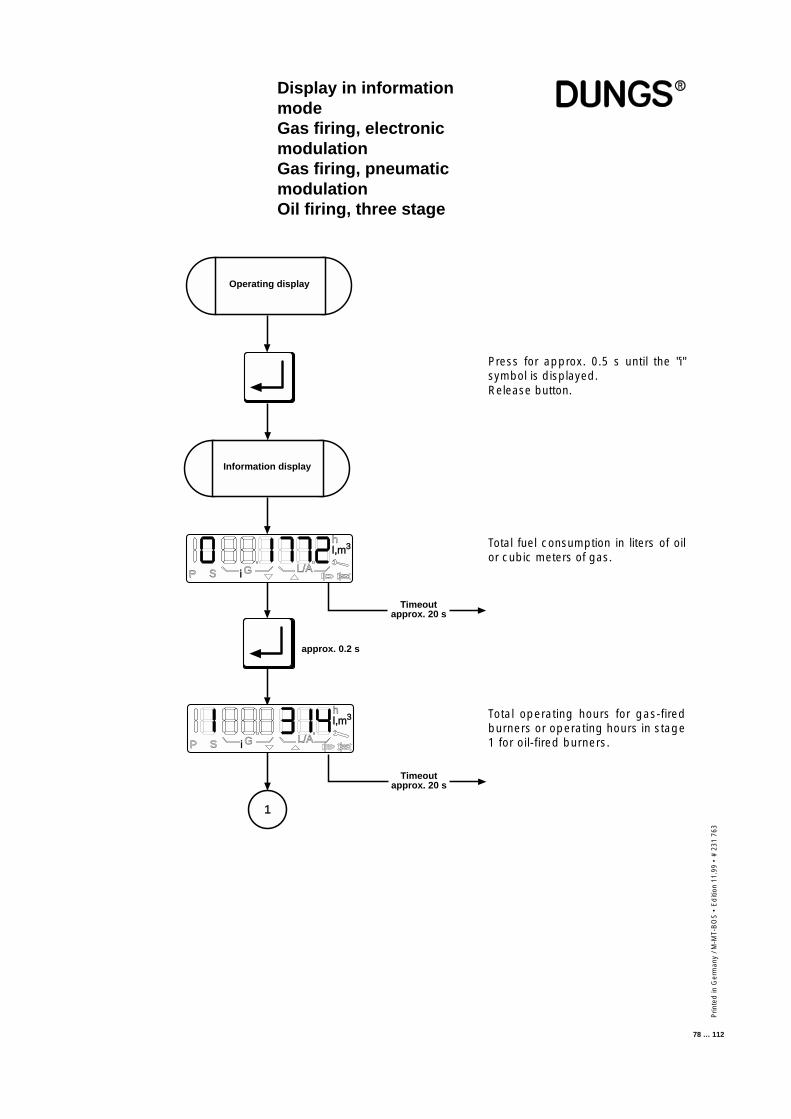
Prin
ted
in G
erm
any
/ M-M
T-B
OS
• E
diti
on 1
1.99
• #
231
763
78 … 112
Display in informationmodeGas firing, electronicmodulationGas firing, pneumaticmodulationOil firing, three stage
Press for approx. 0.5 s until the "i"symbol is displayed.Release button.
Total fuel consumption in liters of oilor cubic meters of gas.
Total operating hours for gas-firedburners or operating hours in stage1 for oil-fired burners.
1
approx. 0.2 s
P S G L/A
hl,m3
i
Information display
Operating display
P S G L/A
hl,m3
i
Timeoutapprox. 20 s
Timeoutapprox. 20 s
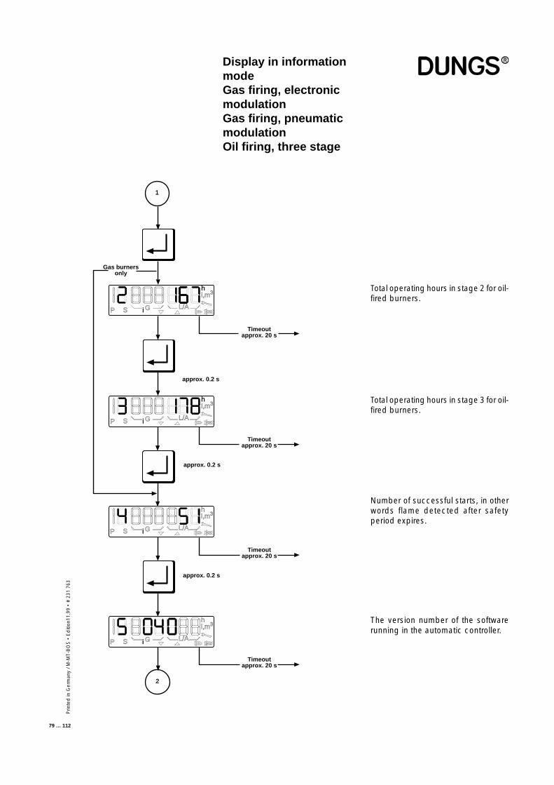
Prin
ted
in G
erm
any
/ M-M
T-B
OS
• E
diti
on11
.99
• #
231
763
79 … 112
Display in informationmodeGas firing, electronicmodulationGas firing, pneumaticmodulationOil firing, three stage
Number of successful starts, in otherwords flame detected after safetyperiod expires.
The version number of the softwarerunning in the automatic controller.
1
approx. 0.2 s
P S G L/A
hl,m3
i
P S i G L/A
hl,m3
2
P S i G L/A
hl,m3
P S i G L/A
hl,m3
Gas burnersonly
Timeoutapprox. 20 s
Timeoutapprox. 20 s
Timeoutapprox. 20 s
Timeoutapprox. 20 s
approx. 0.2 s
approx. 0.2 s
Total operating hours in stage 2 for oil-fired burners.
Total operating hours in stage 3 for oil-fired burners.
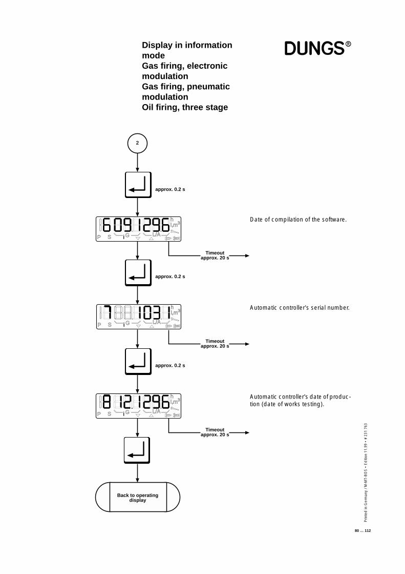
Prin
ted
in G
erm
any
/ M-M
T-B
OS
• E
diti
on 1
1.99
• #
231
763
80 … 112
Automatic controller's serial number.
Automatic controller's date of produc-tion (date of works testing).
Display in informationmodeGas firing, electronicmodulationGas firing, pneumaticmodulationOil firing, three stage
Timeoutapprox. 20 s
approx. 0.2 s
Timeoutapprox. 20 s
approx. 0.2 s
approx. 0.2 s
Timeoutapprox. 20 s
2
P S i G L/A
hl,m3
P S G L/A
hl,m3
i
P S G L/A
hl,m3
i
Back to operatingdisplay
Date of compilation of the software.
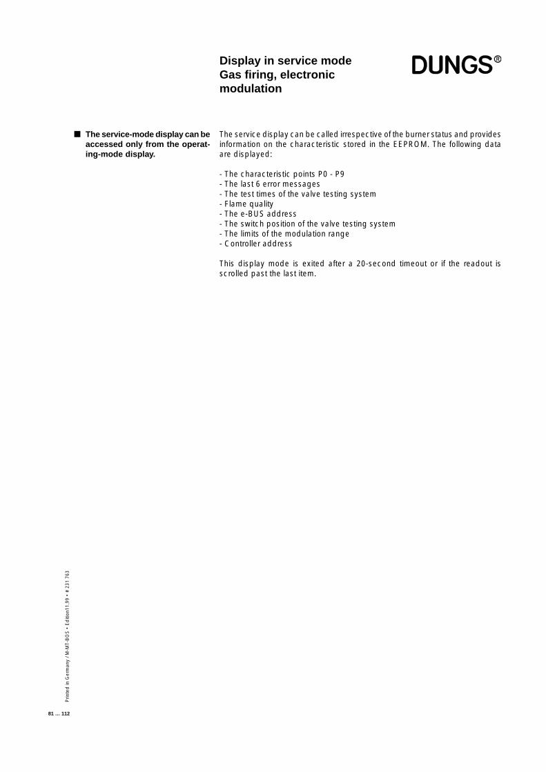
Prin
ted
in G
erm
any
/ M-M
T-B
OS
• E
diti
on11
.99
• #
231
763
81 … 112
Display in service modeGas firing, electronicmodulation
The service display can be called irrespective of the burner status and providesinformation on the characteristic stored in the EEPROM. The following dataare displayed:
- The characteristic points P0 - P9- The last 6 error messages- The test times of the valve testing system- Flame quality- The e-BUS address- The switch position of the valve testing system- The limits of the modulation range- Controller address
This display mode is exited after a 20-second timeout or if the readout isscrolled past the last item.
■ The service-mode display can beaccessed only from the operat-ing-mode display.
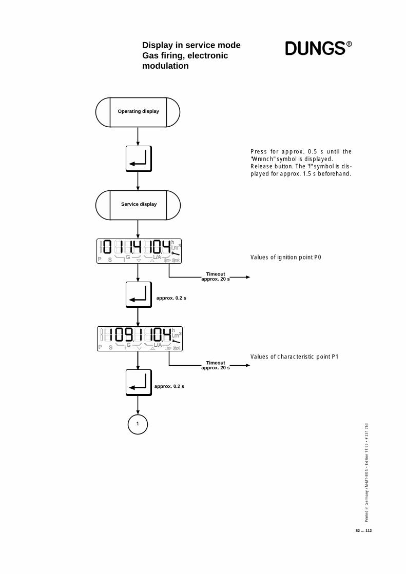
Prin
ted
in G
erm
any
/ M-M
T-B
OS
• E
diti
on 1
1.99
• #
231
763
82 … 112
Display in service modeGas firing, electronicmodulation
Press for approx. 0.5 s until the"Wrench" symbol is displayed.Release button. The "i" symbol is dis-played for approx. 1.5 s beforehand.
Values of ignition point P0
Values of characteristic point P1
N
approx. 0.2 s
approx. 0.2 s
Timeoutapprox. 20 s
Timeoutapprox. 20 s
1
P S i G L/A
hl,m3
P S i G L/A
hl,m3
Service display
Operating display
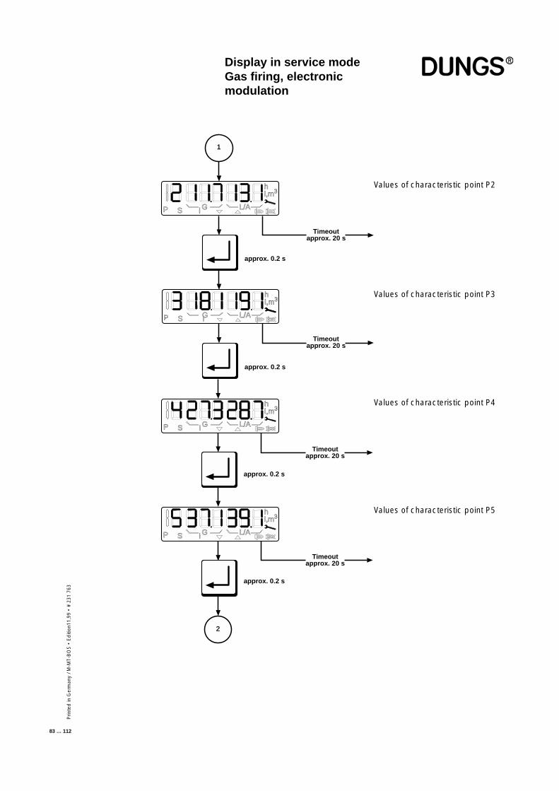
Prin
ted
in G
erm
any
/ M-M
T-B
OS
• E
diti
on11
.99
• #
231
763
83 … 112
Display in service modeGas firing, electronicmodulation
Values of characteristic point P2
Values of characteristic point P3
approx. 0.2 s
Timeoutapprox. 20 s
approx. 0.2 s
Timeoutapprox. 20 s
1
P S i G L/A
hl,m3
i
Timeoutapprox. 20 s
approx. 0.2 s
Timeoutapprox. 20 s
approx. 0.2 s
2
P S i G L/A
hl,m3
P S i G L/A
hl,m3
P S G L/A
hl,m3
Values of characteristic point P4
Values of characteristic point P5
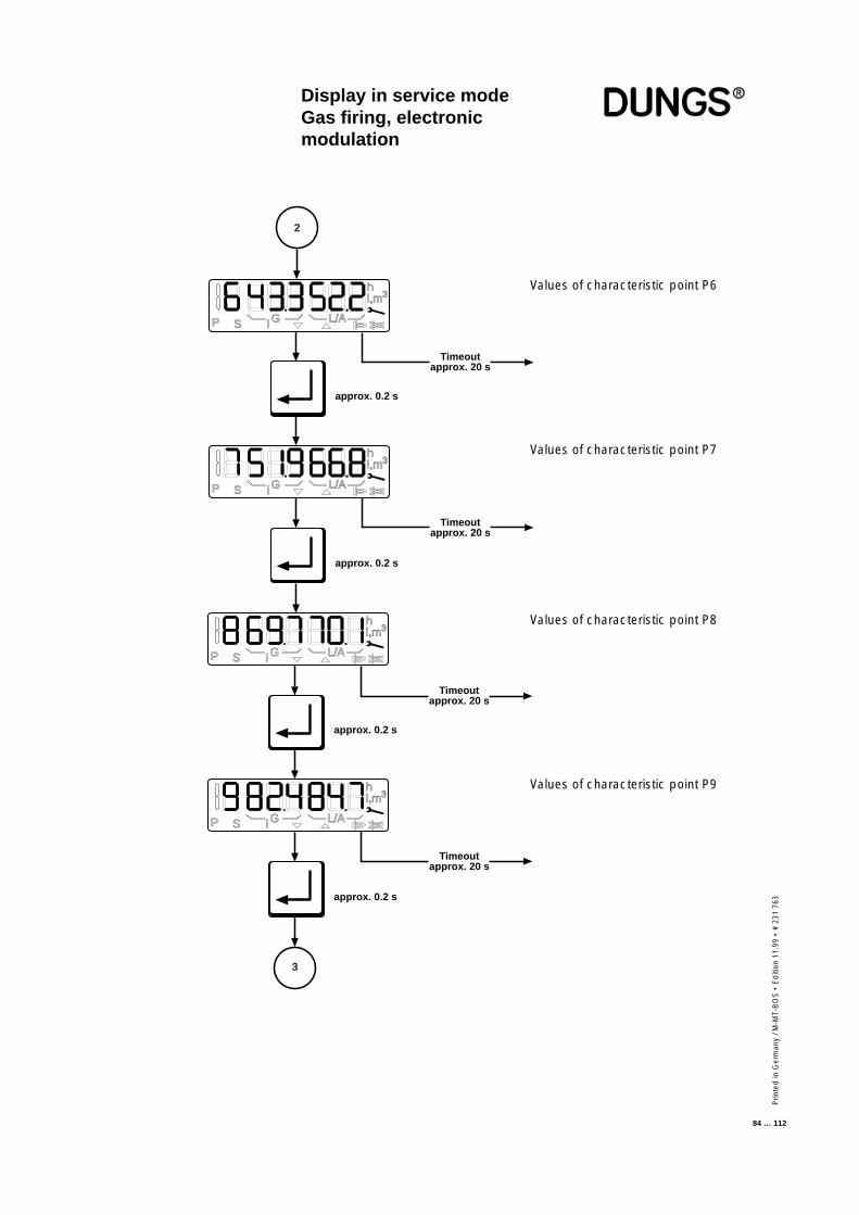
Prin
ted
in G
erm
any
/ M-M
T-B
OS
• E
diti
on 1
1.99
• #
231
763
84 … 112
Values of characteristic point P8
Values of characteristic point P9
Display in service modeGas firing, electronicmodulation
Values of characteristic point P6
Values of characteristic point P7
Timeoutapprox. 20 s
approx. 0.2 s
Timeoutapprox. 20 s
approx. 0.2 s
P S i G L/A
hl,m3
P S i G L/A
hl,m3
Timeoutapprox. 20 s
approx. 0.2 s
Timeoutapprox. 20 s
approx. 0.2 s
3
P S i G L/A
hl,m3
P S i G L/A
hl,m3
2
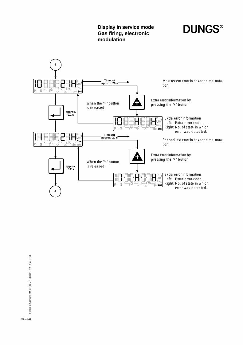
Prin
ted
in G
erm
any
/ M-M
T-B
OS
• E
diti
on11
.99
• #
231
763
85 … 112
Display in service modeGas firing, electronicmodulation
3
approx.0.2 s
+
P S G L/A
hl,m3
i
P S G L/A
hl,m3
i
P S G L/A
hl,m3
i
4
Timeoutapprox. 20 s
Timeoutapprox. 20 s
P S i G L/A
hl,m3
approx.0.2 s
+ Extra error information bypressing the "+" button
Extra error informationLeft: Extra error codeRight: No. of state in which
error was detected.
When the "+" buttonis released
Most recent error in hexadecimal nota-tion.
When the "+" buttonis released
Extra error informationLeft: Extra error codeRight: No. of state in which
error was detected.
Extra error information bypressing the "+" button
Second last error in hexadecimal nota-tion.
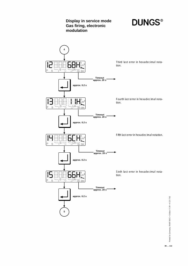
Prin
ted
in G
erm
any
/ M-M
T-B
OS
• E
diti
on 1
1.99
• #
231
763
86 … 112
Fifth last error in hexadecimal notation.
Sixth last error in hexadecimal nota-tion.
i
G
approx. 0.2 s
approx. 0.2 s
Timeoutapprox. 20 s
5
i
iP S L/A
hl,m3
4
P S G L/A
hl,m3
P S G L/A
hl,m3
i
i
i
P S G L/A
hl,m3
i
Timeoutapprox. 20 s
Timeoutapprox. 20 s
Timeoutapprox. 20 s
approx. 0.2 s
approx. 0.2 s
Third last error in hexadecimal nota-tion.
Fourth last error in hexadecimal nota-tion.
Display in service modeGas firing, electronicmodulation
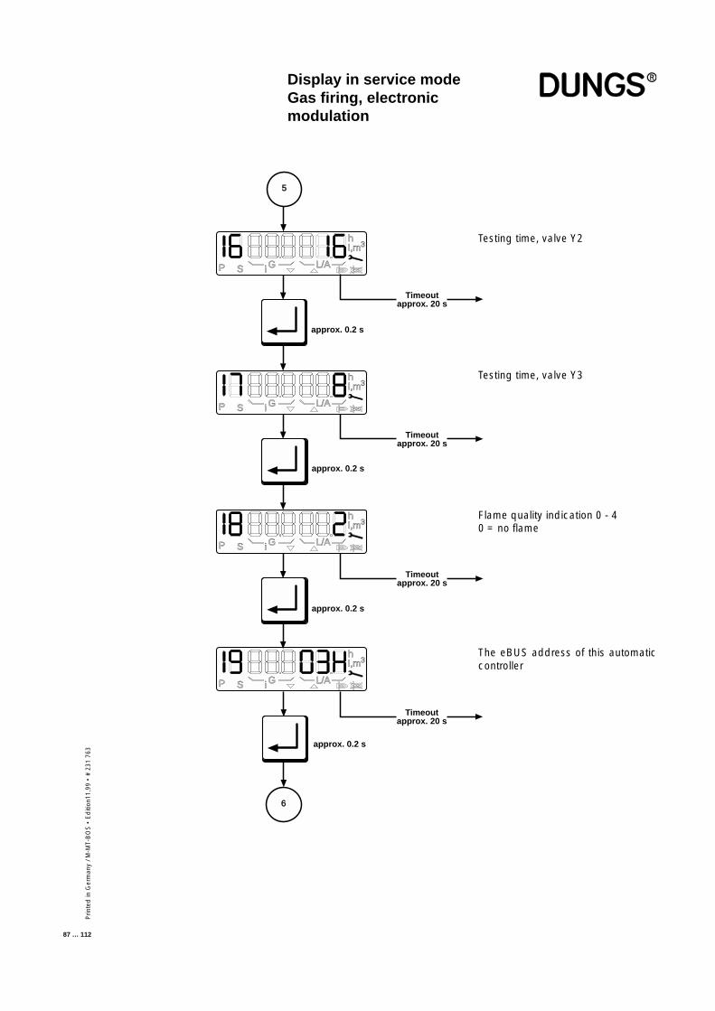
Prin
ted
in G
erm
any
/ M-M
T-B
OS
• E
diti
on11
.99
• #
231
763
87 … 112
Testing time, valve Y2
Flame quality indication 0 - 40 = no flame
The eBUS address of this automaticcontroller
Testing time, valve Y3
6
Timeoutapprox. 20 s
Timeoutapprox. 20 s
approx. 0.2 s
approx. 0.2 s
P S i G L/A
hl,m3
P S i G L/A
hl,m3
5
approx. 0.2 s
P S i G L/A
hl,m3
P S i G L/A
hl,m3
Timeoutapprox. 20 s
Timeoutapprox. 20 s
approx. 0.2 s
Display in service modeGas firing, electronicmodulation
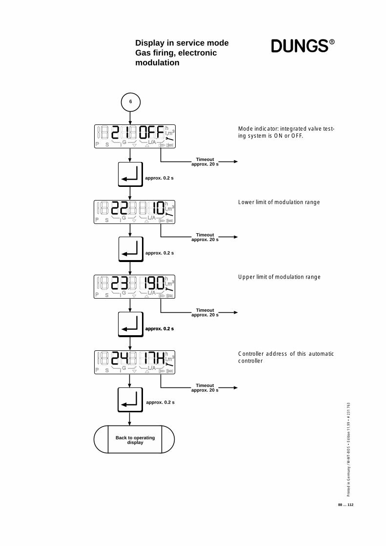
Prin
ted
in G
erm
any
/ M-M
T-B
OS
• E
diti
on 1
1.99
• #
231
763
88 … 112
Mode indicator: integrated valve test-ing system is ON or OFF.
Lower limit of modulation range
Upper limit of modulation range
Timeoutapprox. 20 s
Timeoutapprox. 20 s
approx. 0.2 s
approx. 0.2 s
P S i G L/A
hl,m3
6
approx. 0.2 s
P S i G L/A
hl,m3
P S i G L/A
hl,m3
P S i G L/A
hl,m3
NBack to operating
display
Timeoutapprox. 20 s
Timeoutapprox. 20 s
approx. 0.2 s
approx. 0.2 s
Controller address of this automaticcontroller
Display in service modeGas firing, electronicmodulation
Prin
ted
in G
erm
any
/ M-M
T-B
OS
• E
diti
on11
.99
• #
231
763
89 … 112
Display in service modeGas firing, pneumaticmodulation
The service display can be called irrespective of the burner status and providesinformation on the characteristic stored in the EEPROM.The following data are displayed:
- The characteristic points P0, P1 and P9- The last 6 error messages- The test times of the valve testing system- Flame quality- The e-BUS address- The switch position of the valve testing system- Controller address
This display mode is exited after a 20-second timeout or if the readout isscrolled past the last item.
■ The service-mode display can beaccessed only from the operat-ing-mode display.
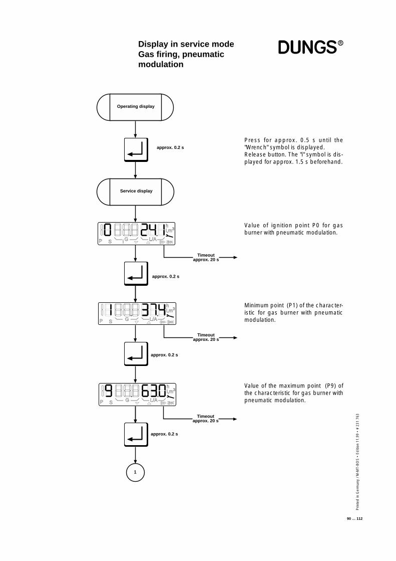
Prin
ted
in G
erm
any
/ M-M
T-B
OS
• E
diti
on 1
1.99
• #
231
763
90 … 112
Display in service modeGas firing, pneumaticmodulation
Press for approx. 0.5 s until the"Wrench" symbol is displayed.Release button. The "i" symbol is dis-played for approx. 1.5 s beforehand.
Value of ignition point P0 for gasburner with pneumatic modulation.
Minimum point (P1) of the character-istic for gas burner with pneumaticmodulation.
P S G L/A
hl,m3
N
approx. 0.2 s
approx. 0.2 s
Timeoutapprox. 20 s
i
Service display
Operating display
P S i G L/A
hl,m3
P S G L/A
hl,m3
1
approx. 0.2 s
Timeoutapprox. 20 s
Timeoutapprox. 20 s
approx. 0.2 s
Value of the maximum point (P9) ofthe characteristic for gas burner withpneumatic modulation.
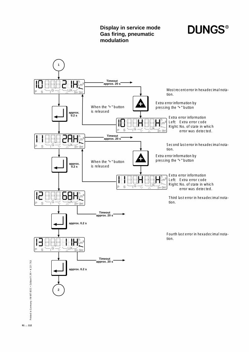
Prin
ted
in G
erm
any
/ M-M
T-B
OS
• E
diti
on11
.99
• #
231
763
91 … 112
Display in service modeGas firing, pneumaticmodulation
Most recent error in hexadecimal nota-tion.
Second last error in hexadecimal nota-tion.
Third last error in hexadecimal nota-tion.
Fourth last error in hexadecimal nota-tion.
Extra error informationLeft: Extra error codeRight: No. of state in which
error was detected.
When the "+" buttonis released
When the "+" buttonis released
Extra error information bypressing the "+" button
Extra error information bypressing the "+" button
Extra error informationLeft: Extra error codeRight: No. of state in which
error was detected.
approx.0.2 s
P S i G L/A
hl,m3
1
P S G L/A
hl,m3
i
approx.0.2 s
P S i G L/A
hl,m3
+
G L/A
hl,m3
i
Timeoutapprox. 20 s
Timeoutapprox. 20 s
P S
Timeoutapprox. 20 s
approx. 0.2 s
Timeoutapprox. 20 s
approx. 0.2 s
2
P S i G L/A
hl,m3
P S i G L/A
hl,m3
+
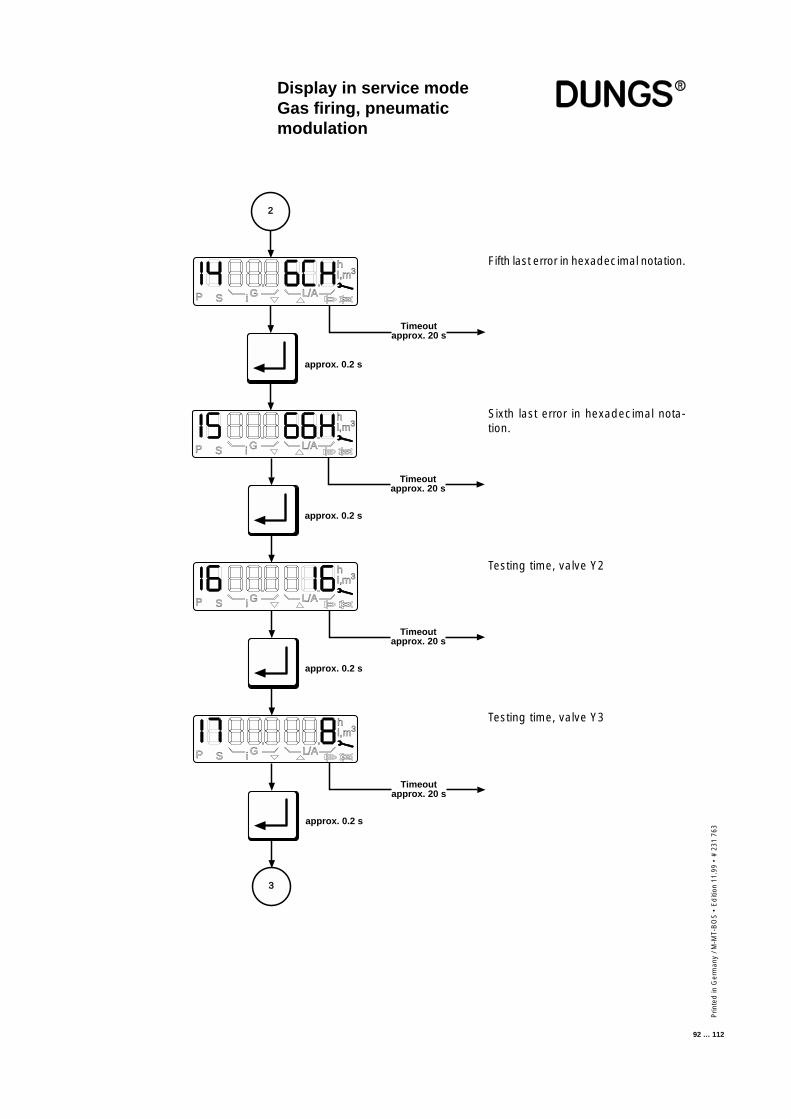
Prin
ted
in G
erm
any
/ M-M
T-B
OS
• E
diti
on 1
1.99
• #
231
763
92 … 112
Display in service modeGas firing, pneumaticmodulation
Fifth last error in hexadecimal notation.
Sixth last error in hexadecimal nota-tion.
Testing time, valve Y2
Testing time, valve Y3
approx. 0.2 s
Timeoutapprox. 20 s
P S i G L/A
hl,m3
2
approx. 0.2 s
Timeoutapprox. 20 s
iP S G L/A
hl,m3
approx. 0.2 s
Timeoutapprox. 20 s
iP S G L/A
hl,m3
approx. 0.2 s
Timeoutapprox. 20 s
iP S G L/A
hl,m3
3
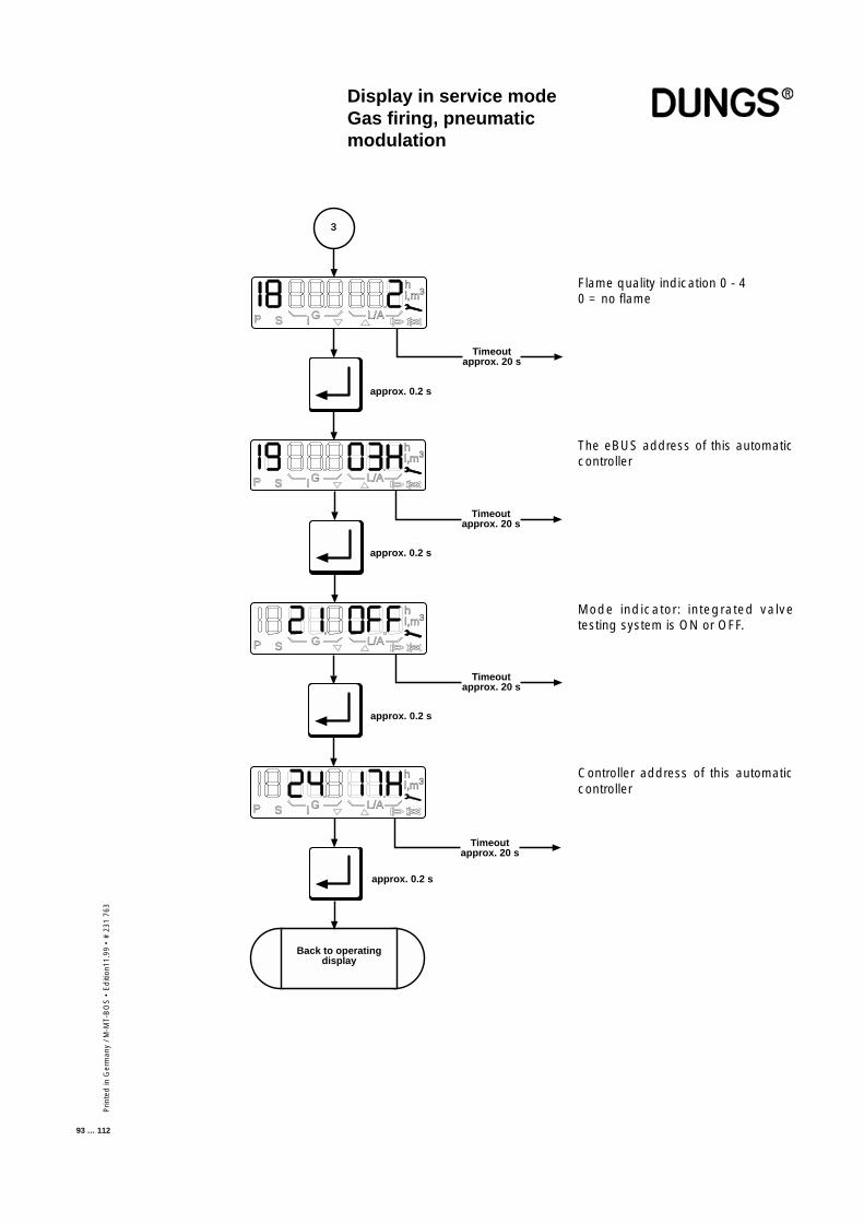
Prin
ted
in G
erm
any
/ M-M
T-B
OS
• E
diti
on11
.99
• #
231
763
93 … 112
Display in service modeGas firing, pneumaticmodulation
Flame quality indication 0 - 40 = no flame
The eBUS address of this automaticcontroller
approx. 0.2 s
Timeoutapprox. 20 s
3
approx. 0.2 s
Timeoutapprox. 20 s
approx. 0.2 s
Timeoutapprox. 20 s
i
P S i G L/A
hl,m3
iP S G L/A
hl,m3
Back to operatingdisplay
P S G L/A
hl,m3
P S i G L/A
hl,m3
Timeoutapprox. 20 s
approx. 0.2 s
Mode indicator: integrated valvetesting system is ON or OFF.
Controller address of this automaticcontroller
Prin
ted
in G
erm
any
/ M-M
T-B
OS
• E
diti
on 1
1.99
• #
231
763
94 … 112
Display in service modeOil firing, three stage
The service display can be called irrespective of the burner status and providesinformation on the characteristic stored in the EEPROM.The following data are displayed:
- The characteristic points P0, P1, P3 and P9- The changeover points P2, P4- The last 6 error messages- Flame quality- The e-BUS address- The switch position of the monitor function- Controller address
This display mode is exited after a 20-second timeout or if the readout isscrolled past the last item.
■ The service-mode display can beaccessed only from the operat-ing-mode display.
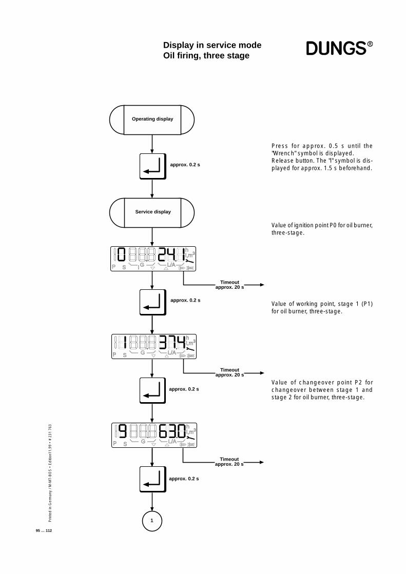
Prin
ted
in G
erm
any
/ M-M
T-B
OS
• E
diti
on11
.99
• #
231
763
95 … 112
Display in service modeOil firing, three stage
Value of ignition point P0 for oil burner,three-stage.
Value of working point, stage 1 (P1)for oil burner, three-stage.
Value of changeover point P2 forchangeover between stage 1 andstage 2 for oil burner, three-stage.
Press for approx. 0.5 s until the"Wrench" symbol is displayed.Release button. The "i" symbol is dis-played for approx. 1.5 s beforehand.
P S G L/A
hl,m3
N
approx. 0.2 s
approx. 0.2 s
Timeoutapprox. 20 s
i
Service display
Operating display
P S i G L/A
hl,m3
P S G L/A
hl,m3
1
approx. 0.2 s
Timeoutapprox. 20 s
Timeoutapprox. 20 s
approx. 0.2 s
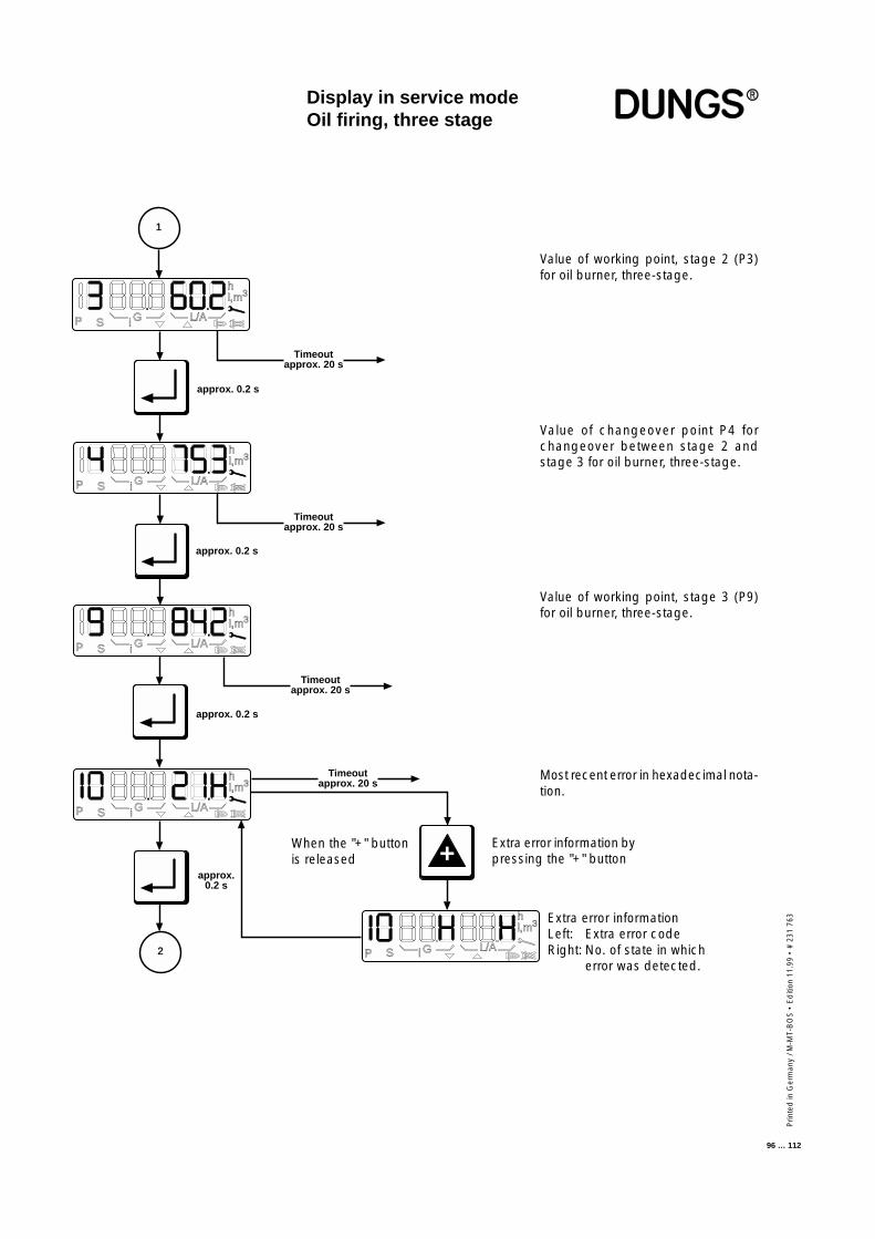
Prin
ted
in G
erm
any
/ M-M
T-B
OS
• E
diti
on 1
1.99
• #
231
763
96 … 112
Display in service modeOil firing, three stage
Value of working point, stage 2 (P3)for oil burner, three-stage.
Value of changeover point P4 forchangeover between stage 2 andstage 3 for oil burner, three-stage.
approx. 0.2 s
Timeoutapprox. 20 s
approx. 0.2 s
Timeoutapprox. 20 s
P S i G L/A
hl,m3
P S i G L/A
hl,m3
Timeoutapprox. 20 s
approx. 0.2 s
P S i G L/A
hl,m3
1
2
approx.0.2 s
P S i G L/A
hl,m3
+
P S G L/A
hl,m3
i
Timeoutapprox. 20 s
Value of working point, stage 3 (P9)for oil burner, three-stage.
Most recent error in hexadecimal nota-tion.
Extra error informationLeft: Extra error codeRight: No. of state in which
error was detected.
When the "+" buttonis released
Extra error information bypressing the "+" button
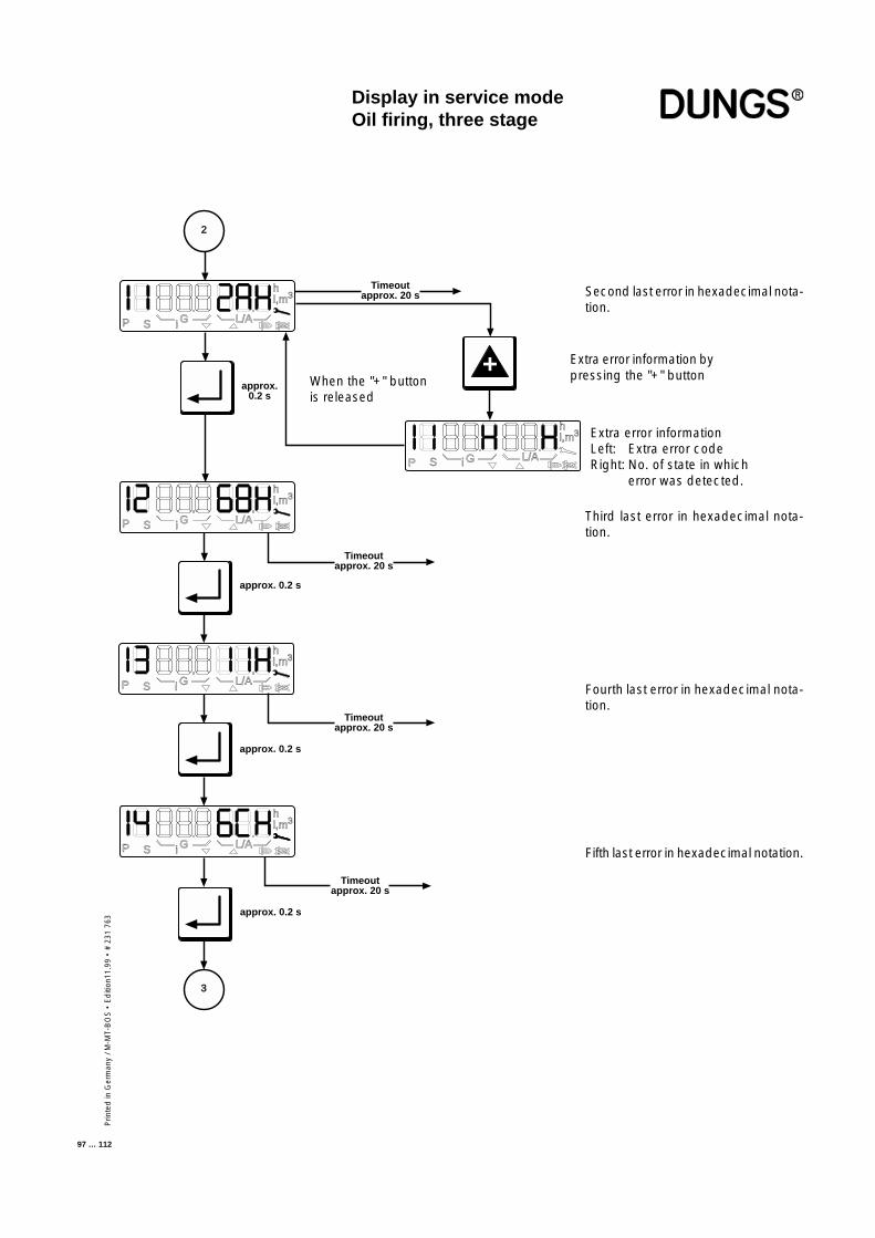
Prin
ted
in G
erm
any
/ M-M
T-B
OS
• E
diti
on11
.99
• #
231
763
97 … 112
Display in service modeOil firing, three stage
Second last error in hexadecimal nota-tion.
Third last error in hexadecimal nota-tion.
Fourth last error in hexadecimal nota-tion.
Fifth last error in hexadecimal notation.
Extra error informationLeft: Extra error codeRight: No. of state in which
error was detected.
When the "+" buttonis released
Extra error information bypressing the "+" button
approx.0.2 s
P S i G L/A
hl,m3
+
P S G L/A
hl,m3
i
Timeoutapprox. 20 s
2
3
Timeoutapprox. 20 s
approx. 0.2 s
Timeoutapprox. 20 s
approx. 0.2 s
P S i G L/A
hl,m3
P S i G L/A
hl,m3
approx. 0.2 s
Timeoutapprox. 20 s
P S i G L/A
hl,m3
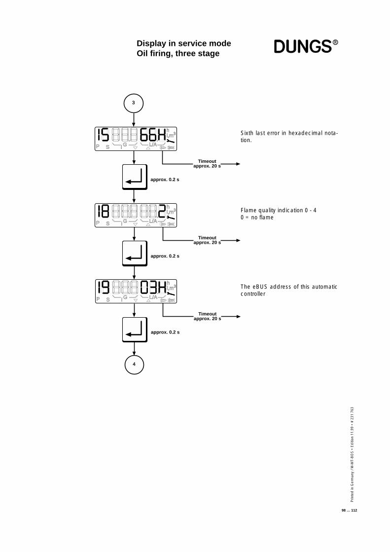
Prin
ted
in G
erm
any
/ M-M
T-B
OS
• E
diti
on 1
1.99
• #
231
763
98 … 112
Display in service modeOil firing, three stage
Sixth last error in hexadecimal nota-tion.
The eBUS address of this automaticcontroller
approx. 0.2 s
Timeoutapprox. 20 s
iP S G L/A
hl,m3
approx. 0.2 s
Timeoutapprox. 20 s
iP S G L/A
hl,m3
approx. 0.2 s
Timeoutapprox. 20 s
iP S G L/A
hl,m3
4
3
Flame quality indication 0 - 40 = no flame
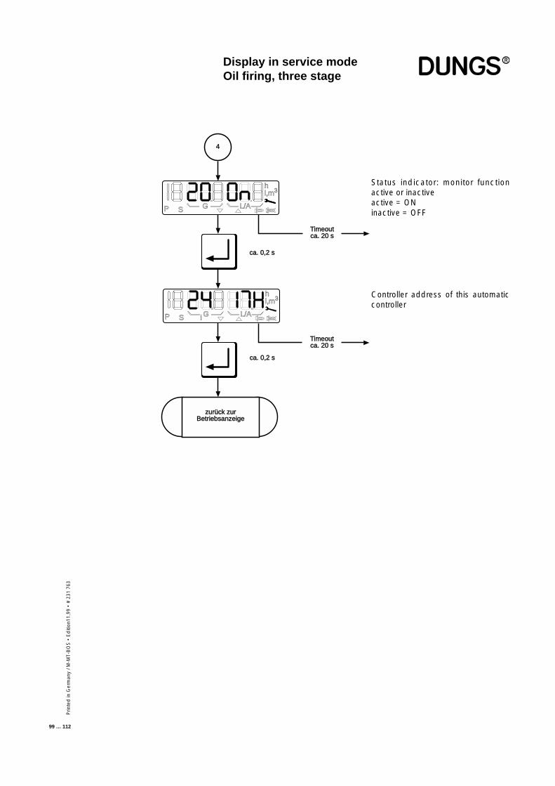
Prin
ted
in G
erm
any
/ M-M
T-B
OS
• E
diti
on11
.99
• #
231
763
99 … 112
Status indicator: monitor functionactive or inactiveactive = ONinactive = OFF
Display in service modeOil firing, three stage
ca. 0,2 s
Timeoutca. 20 s
i
zurück zurzurück zurBetriebsanzeige
P S G L/A
hl,m3
ca. 0,2 s
P S i G L/A
hl,m3
Timeoutca. 20 s
4
Controller address of this automaticcontroller
Prin
ted
in G
erm
any
/ M-M
T-B
OS
• E
diti
on 1
1.99
• #
231
763
100 … 112
Parameterisation mode can be accessed only from the operating-mode displaywhen the controller is on standby ("OFF"). Parameterisation mode is used toview important operating parameters and adjust the settings by means of thebuttons on the touch-sensitive display.
Paramterization mode defines access priority in such a way that all service-level parameters can be configured with MPA Vision.
This display mode is exited after a 20-second timeout or if the readout isscrolled past the last display image.
Display in parameteriza-tion modeGas firing, electronicmodulationGas firing, pneumaticmodulationOil firing, three stage
■ The parameterisation-mode dis-play can be accessed only fromthe operating-mode display instandby status.
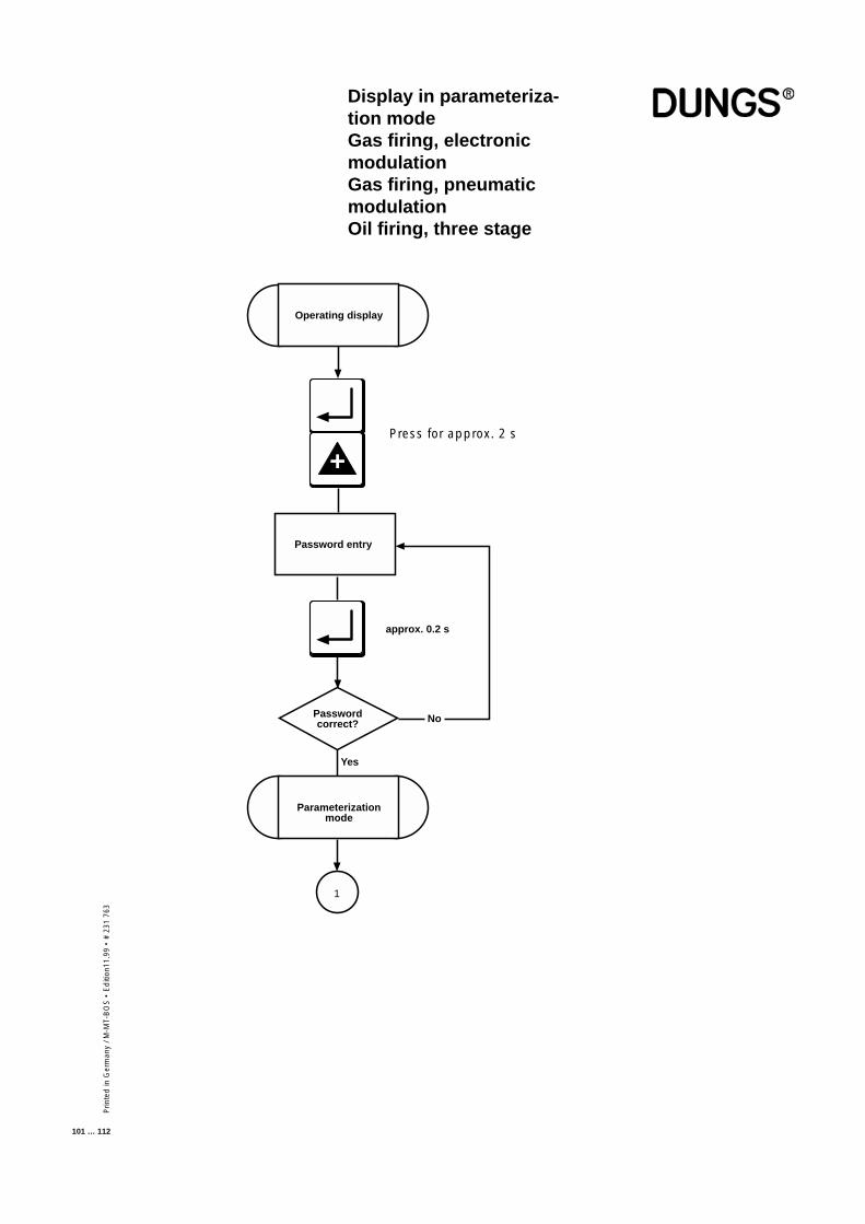
Prin
ted
in G
erm
any
/ M-M
T-B
OS
• E
diti
on11
.99
• #
231
763
101 … 112
Display in parameteriza-tion modeGas firing, electronicmodulationGas firing, pneumaticmodulationOil firing, three stage
+
1
Passwordcorrect?
Password entry
No
Yes
Operating display
Parameterizationmode
approx. 0.2 s
Press for approx. 2 s
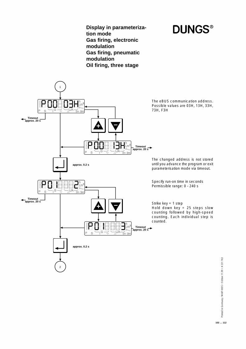
Prin
ted
in G
erm
any
/ M-M
T-B
OS
• E
diti
on 1
1.99
• #
231
763
102 … 112
The changed address is not storeduntil you advance the program or exitparameterisation mode via timeout.
Specify run-on time in secondsPermissible range: 0 - 240 s
The eBUS communication address.Possible values are 03H, 13H, 33H,73H, F3H
Display in parameteriza-tion modeGas firing, electronicmodulationGas firing, pneumaticmodulationOil firing, three stage
Timeoutapprox. 20 s
Timeoutapprox. 20 s
Timeoutapprox. 20 s
+
Timeoutapprox. 20 s
P S i G L/A
hl,m3
P S i G L/A
hl,m3
P S i G L/A
hl,m3
P S i G L/A
hl,m3
approx. 0.2 s
approx. 0.2 s
1
–
+
–
2
Strike key = 1 stepHold down key = 25 steps slowcounting followed by high-speedcounting. Each individual step iscounted.
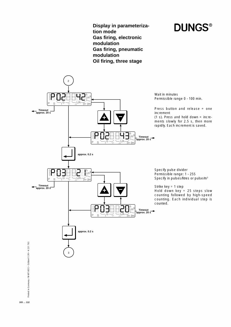
Prin
ted
in G
erm
any
/ M-M
T-B
OS
• E
diti
on11
.99
• #
231
763
103 … 112
Wait in minutesPermissible range 0 - 100 min.
Press button and release = oneincrement(1 s). Press and hold down = incre-ments slowly for 2.5 s, then morerapidly. Each increment is saved.
Display in parameteriza-tion modeGas firing, electronicmodulationGas firing, pneumaticmodulationOil firing, three stage
Specify pulse dividerPermissible range: 1 - 255Specify in pulses/litres or pulse/m3
Strike key = 1 stepHold down key = 25 steps slowcounting followed by high-speedcounting. Each individual step iscounted.
P S i G L/A
hl,m3
Timeoutapprox. 20 s
Timeoutapprox. 20 s
P S i G L/A
hl,m3
approx. 0.2 s
2
+
–
P S i G L/A
hl,m3
Timeoutapprox. 20 s
P S i G L/A
hl,m3
Timeoutapprox. 20 s
+
–
approx. 0.2 s
3
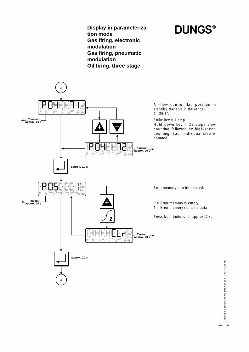
Prin
ted
in G
erm
any
/ M-M
T-B
OS
• E
diti
on 1
1.99
• #
231
763
104 … 112
P S i G L/A
hl,m3
Timeoutapprox. 20 s
Timeoutapprox. 20 s
P S i G L/A
hl,m3
approx. 0.2 s
3
+
–
P S i G L/A
hl,m3
Timeoutapprox. 20 s +
2
P S i G L/A
hl,m3
Timeoutapprox. 20 s
approx. 0.2 s
4
Display in parameteriza-tion modeGas firing, electronicmodulationGas firing, pneumaticmodulationOil firing, three stage
Air-flow control flap position instandby. Variable in the range0 - 25.5°.
Strike key = 1 stepHold down key = 25 steps slowcounting followed by high-speedcounting. Each individual step iscounted.
Error memory can be cleared.
0 = Error memory is empty1 = Error memory contains data
Press both buttons for approx. 2 s.
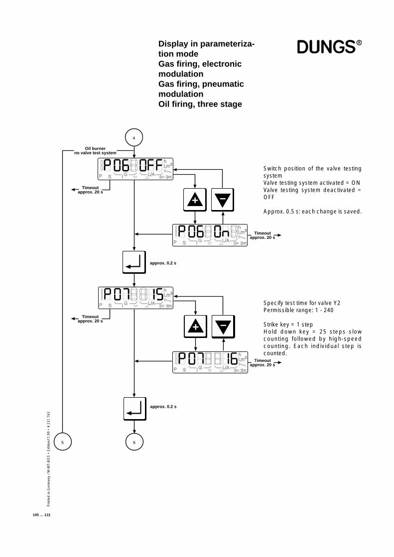
Prin
ted
in G
erm
any
/ M-M
T-B
OS
• E
diti
on11
.99
• #
231
763
105 … 112
P S i G L/A
hl,m3
Timeoutapprox. 20 s
Timeoutapprox. 20 s
P S i G L/A
hl,m3
approx. 0.2 s
4
+
–
P S i G L/A
hl,m3
Timeoutapprox. 20 s
approx. 0.2 s
65
Oil burnerno valve test system
+
–
P S i G L/A
hl,m3
Timeoutapprox. 20 s
Switch position of the valve testingsystemValve testing system activated = ONValve testing system deactivated =OFF
Approx. 0.5 s: each change is saved.
Specify test time for valve Y2Permissible range: 1 - 240
Strike key = 1 stepHold down key = 25 steps slowcounting followed by high-speedcounting. Each individual step iscounted.
Display in parameteriza-tion modeGas firing, electronicmodulationGas firing, pneumaticmodulationOil firing, three stage
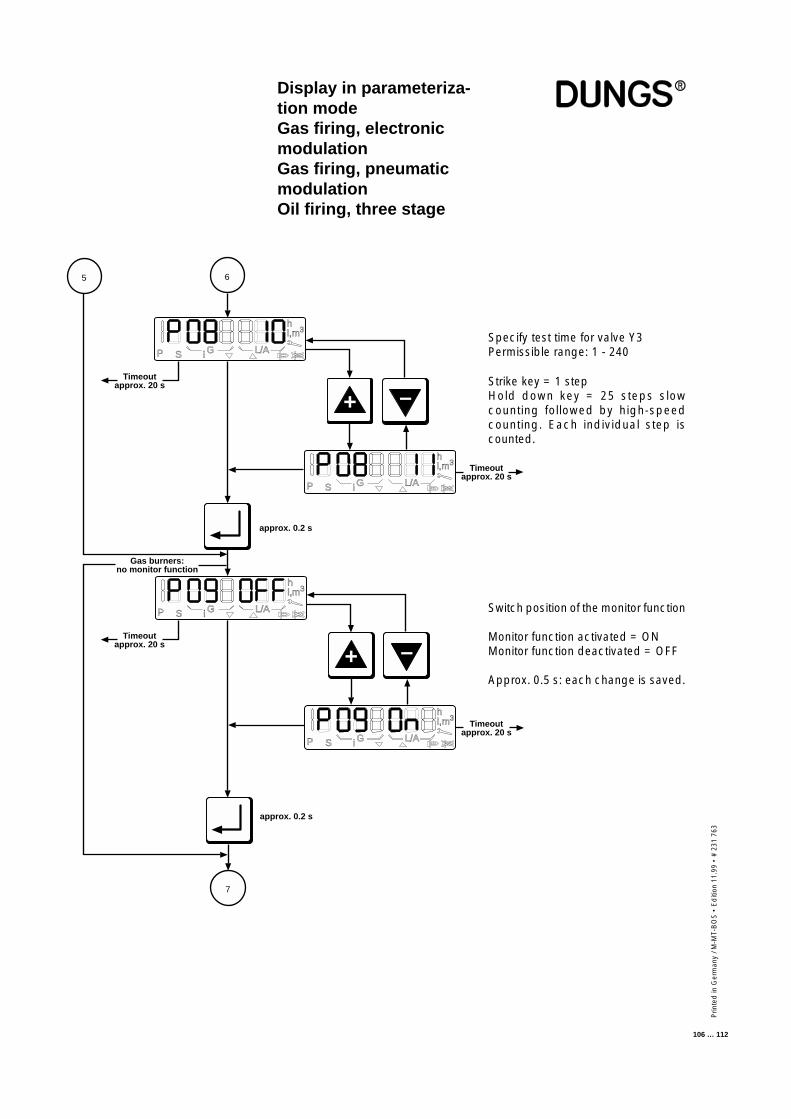
Prin
ted
in G
erm
any
/ M-M
T-B
OS
• E
diti
on 1
1.99
• #
231
763
106 … 112
P S i G L/A
hl,m3
Timeoutapprox. 20 s
Timeoutapprox. 20 s
P S i G L/A
hl,m3
approx. 0.2 s
6
+
–
P S i G L/A
hl,m3
Timeoutapprox. 20 s
approx. 0.2 s
Gas burners:no monitor function
+
–
P S i G L/A
hl,m3
Timeoutapprox. 20 s
5
7
Specify test time for valve Y3Permissible range: 1 - 240
Strike key = 1 stepHold down key = 25 steps slowcounting followed by high-speedcounting. Each individual step iscounted.
Switch position of the monitor function
Monitor function activated = ONMonitor function deactivated = OFF
Approx. 0.5 s: each change is saved.
Display in parameteriza-tion modeGas firing, electronicmodulationGas firing, pneumaticmodulationOil firing, three stage
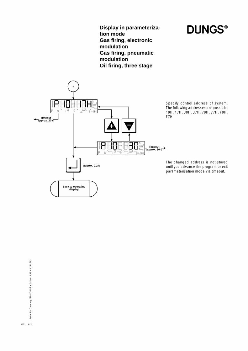
Prin
ted
in G
erm
any
/ M-M
T-B
OS
• E
diti
on11
.99
• #
231
763
107 … 112
Display in parameteriza-tion modeGas firing, electronicmodulationGas firing, pneumaticmodulationOil firing, three stage
Specify control address of system.The following addresses are possible:10H, 17H, 30H, 37H, 70H, 77H, F0H,F7H
The changed address is not storeduntil you advance the program or exitparameterisation mode via timeout.
P S i G L/A
hl,m3
Timeoutapprox. 20 s
Timeoutapprox. 20 s
P S i G L/A
hl,m3
approx. 0.2 s
7
+
–
Back to operatingdisplay
Prin
ted
in G
erm
any
/ M-M
T-B
OS
• E
diti
on 1
1.99
• #
231
763
108 … 112
Error indicationGas firing, electronicmodulationGas firing, pneumaticmodulationOil firing, three stage
Error mode overwrites all other display modes.Error mode is not active unless a error is detected.
The following appears on the display:
• An "F" on the left• The "Flame with strike-through" symbol• The error code in hexadecimal notation; occupies the three places on the
right.• The error code flashes
The error codes are listed complete with their individual meanings in the ErrorCodes list below.
Press the "+" button to call up an extra error code which provides more detailedinformation on the error, along with details of the program state in which theerror occurred. The extra error code does not flash on the display.
You must press the "Acknowledgment" or "Reset" button to reset.
■ Error mode
■ Error indication
■ Error code
■ Extra error code
■ Reset
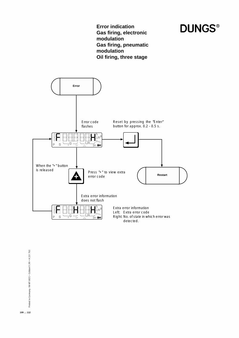
Prin
ted
in G
erm
any
/ M-M
T-B
OS
• E
diti
on11
.99
• #
231
763
109 … 112
+
P S G L/A
hl,m3
i
Error
Restart
P S G L/A
hl,m3
i
Error indicationGas firing, electronicmodulationGas firing, pneumaticmodulationOil firing, three stage
Error codeflashes
Reset by pressing the "Enter"button for approx. 0.2 - 0.5 s.
When the "+" buttonis released Press "+" to view extra
error code
Extra error informationLeft: Extra error codeRight: No. of state in which error was
detected.
Extra error informationdoes not flash
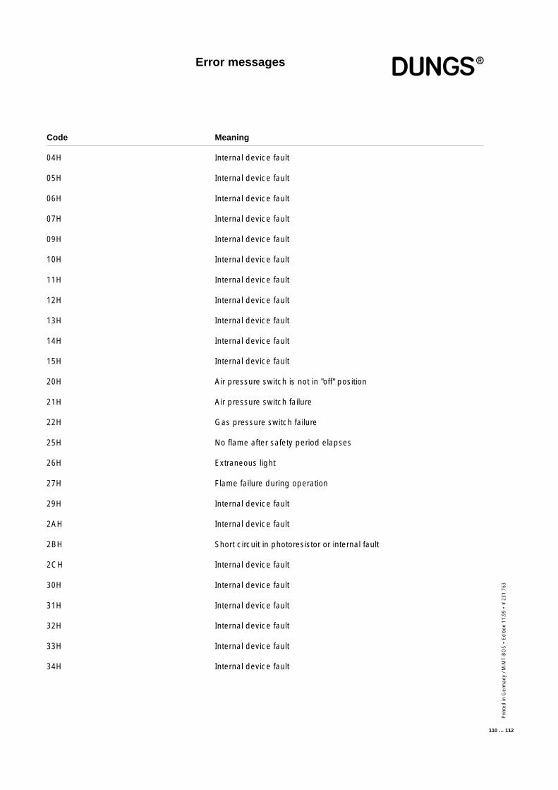
Prin
ted
in G
erm
any
/ M-M
T-B
OS
• E
diti
on 1
1.99
• #
231
763
110 … 112
Code Meaning
04H Internal device fault
05H Internal device fault
06H Internal device fault
07H Internal device fault
09H Internal device fault
10H Internal device fault
11H Internal device fault
12H Internal device fault
13H Internal device fault
14H Internal device fault
15H Internal device fault
20H Air pressure switch is not in "off" position
21H Air pressure switch failure
22H Gas pressure switch failure
25H No flame after safety period elapses
26H Extraneous light
27H Flame failure during operation
29H Internal device fault
2AH Internal device fault
2BH Short circuit in photoresistor or internal fault
2CH Internal device fault
30H Internal device fault
31H Internal device fault
32H Internal device fault
33H Internal device fault
34H Internal device fault
Error messages
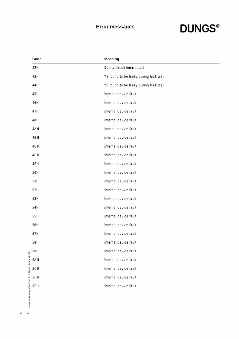
Prin
ted
in G
erm
any
/ M-M
T-B
OS
• E
diti
on11
.99
• #
231
763
111 … 112
Code Meaning
42H Safety circuit interrupted
43H Y2 found to be leaky during leak test
44H Y3 found to be leaky during leak test
45H Internal device fault
46H Internal device fault
47H Internal device fault
48H Internal device fault
4AH Internal device fault
4BH Internal device fault
4CH Internal device fault
4DH Internal device fault
4EH Internal device fault
50H Internal device fault
51H Internal device fault
52H Internal device fault
53H Internal device fault
54H Internal device fault
55H Internal device fault
56H Internal device fault
57H Internal device fault
58H Internal device fault
59H Internal device fault
5AH Internal device fault
5CH Internal device fault
5DH Internal device fault
5EH Internal device fault
Error messages
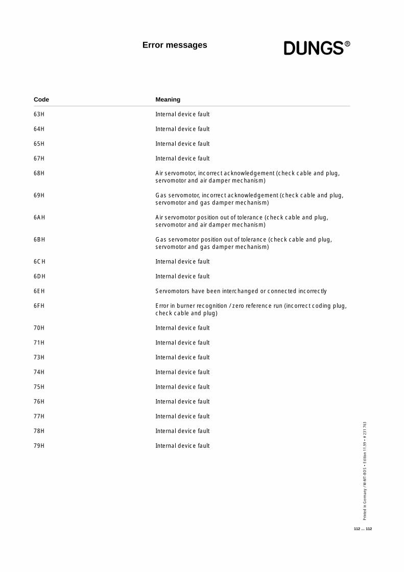
Prin
ted
in G
erm
any
/ M-M
T-B
OS
• E
diti
on 1
1.99
• #
231
763
112 … 112
Code Meaning
63H Internal device fault
64H Internal device fault
65H Internal device fault
67H Internal device fault
68H Air servomotor, incorrect acknowledgement (check cable and plug,servomotor and air damper mechanism)
69H Gas servomotor, incorrect acknowledgement (check cable and plug,servomotor and gas damper mechanism)
6AH Air servomotor position out of tolerance (check cable and plug,servomotor and air damper mechanism)
6BH Gas servomotor position out of tolerance (check cable and plug,servomotor and gas damper mechanism)
6CH Internal device fault
6DH Internal device fault
6EH Servomotors have been interchanged or connected incorrectly
6FH Error in burner recognition / zero reference run (incorrect coding plug,check cable and plug)
70H Internal device fault
71H Internal device fault
73H Internal device fault
74H Internal device fault
75H Internal device fault
76H Internal device fault
77H Internal device fault
78H Internal device fault
79H Internal device fault
Error messages