control of combustion in a thermally stabilized burner
TRANSCRIPT

127
Control of combustion in a thermally stabilized burnerS Chaudhuri1, A Mukhopadhyay2, M S Biswas3, B M Cetegen1, and S Basu4∗1Department of Mechanical Engineering, University of Connecticut, Connecticut, USA2Department of Mechanical Engineering, Jadavpur University, India3NTPC, India4Department of Mechanical, Materials and Aerospace Engineering, University of Central Florida, Orlando, Florida, USA
The manuscript was received on 24 July 2008 and was accepted after revision for publication on 20 November 2008.
DOI: 10.1243/09576509JPE680
Abstract: A model has been developed with the assumption of a plug flow reactor that simu-lates heat transfer originating from the combustion of premixed reactants within a refractorytube. The work depicted in this article successfully implemented a transient one-dimensionalcoupled model of a plug flow reactor, which finds practical applications in a batch-type heattreatment furnace. All modes of heat transfer, namely conduction, convection, and radiation,were included in the model with single-step global chemistry for combustion of both methaneand propane. Effects of variations of parameters such as inlet gas temperature, mass flux, andinlet fuel mass fraction on the gas and tube wall temperature profiles were studied to understandthe shift in flame position along the tube length. It is established that the inlet gas temperature orthe preheating level is one of the major governing parameters that determines the position of theflame in the tube. Similarly, reduction in mass flowrate shifted the flame location significantlyupstream of the tube. It was also observed that the flame temperature exhibits a monotonic decaywith depletion in mass flowrate. Results also show that for fixed inlet gas temperature and massflowrate, the flame location shifts upstream for an increase in inlet fuel mass fraction. Thermallystabilized sustained combustion mode with optimum inlet gas preheating requirement was anal-ysed as a function of mixture stoichiometry and mass flux. Open-loop and closed-loop controlschemes were effectively implemented to establish the thermally stabilized scheme of heatingand desired flame position within the tube. For open-loop control, with reduction in the massflowrate (= 0.01 kg/s), an inlet gas temperature as low as 650 K can be maintained for sustainingcombustion inside the tube.
The joint variation of these inlet parameters has been well predicted by a correlation developedfor a particular aspect ratio for high Reynolds number flows. The problem of absence of combus-tion and its solution towards stable flame position for tubes having smaller ratio of cross-sectionalarea to surface area have been addressed, which leads to the study for low Reynolds number flows.In the small Reynolds number flow cases, a thermally stabilized scheme has been successfullyimplemented that eliminates the necessity of preheating the gas prior to its combustion insidethe tube.
Keywords: thermally stabilized burner, transient analysis, open- and closed-loop control, flamestabilization
1 INTRODUCTION
Combustion in burners with refractory walls hasbeen extensively studied in recent times. In these
∗Corresponding author: Department of Mechanical, Materials
and Aerospace Engineering, University of Central Florida, 4000
Central Florida Boulevard, Orlando, Florida 32816, USA. email:
combustors, the heat conducted from the flamethrough the ceramic wall preheats the reacting mix-ture, which causes the local flame temperature toexceed the adiabatic flame temperature. Such a super-adiabatic combustion is particularly suited for fuelswith relatively lower heating values [1]. Since the flamein such combustors is stabilized by a thermal feedbackmechanism, such burners have been termed ‘ther-mally stabilized burners’ (TSBs) [2]. Interest in TSBshas been revived due to its valuable use in developing
JPE680 © IMechE 2009 Proc. IMechE Vol. 223 Part A: J. Power and Energy

128 S Chaudhuri, A Mukhopadhyay, M S Biswas, B M Cetegen, and S Basu
microscale burners. For developing such burners, heatrecirculation through the wall to preheat the mixtureplays a major role [3, 4]. Microscale burners are findingapplications in thermophotovoltaic and thermoelec-tric [5, 6] devices. Heat conduction through the com-bustor wall also plays an important role in enhancingthe performance of radiant tube burners [7, 8].
Kansuntisukmongkol et al. [2] developed a modelfor thermally stabilized combustion in a refractorytube. They identified the existence of multiple steadystates (upstream and downstream positions) for thesame inlet conditions depending on the initial tem-perature profile of the wall. They also investigatedthe dynamics of transition among different steady-state flame positions. However, their study mainlyfocused on the dynamics of the gaseous phase. Kan-suntisukmongkol et al. [9] carried out experimentsin a configuration similar to that of Chen et al. [10]and similarly obtained multiple flame positions intheir experiment. Kansuntisukmongkol and Ozoe [11]observed that with decreasing wall conductivity, bothupstream and downstream flames shifted towards thecentre. The increase in tube diameter causes boththe flames to move towards the inlet. On the otherhand, an increase in tube length causes the positionof the upstream flame to remain unchanged, while thedownstream flame shifts towards the exit.
Norton and Vlachos [3, 12] numerically investi-gated the combustion characteristics of a microscaleburner burning methane and propane, respectively.They observed that there exists an optimum value ofthermal conductivity of the wall for thermal stabiliza-tion of flames, guided by the conflicting conditionsof increased heat loss and increased preheating ofreactants with increasing wall conductivity. They alsoidentified a narrow range of mixture velocities at whichflames can be stabilized within the channel. Nortonand Vlachos [3, 12] investigated the parametric influ-ence of burner geometry and wall properties on theposition of flame stabilization.
Leach et al. [4] and Leach and Cadou [13] usedone-dimensional models to investigate the role ofthermal feedback through combustor walls on theperformance of microcombustors. They observedthat the thermal feedback has a more pronouncedeffect on the flame stabilization for narrow chan-nels. They also observed that as the burner widthapproaches the flame thickness, flames can be stabi-lized within the burner for an increasingly large rangeof flowrates.
Yang et al. [14, 15] investigated the applicationof microscale burners in microthermophotovoltaicdevices wherein the combustor acted as the heatsource and an emitting material with desired char-acteristics was placed around the combustor wall foremission.
In all these applications, the temperature pro-file of the combustor wall strongly influences the
performance and the wall temperature again dependson the flame position. It was thus emphasized thatcontrolling the position of the flame stabilized in aheat-circulating burner is important.
Most of the works in the literature discussed theeffect of design parameters such as burner dimen-sions [1] and shape [16] on the flame position. How-ever, such passive design techniques cannot respondto either changes in load conditions or slow changes insystem parameters. On the other hand, active controlhas the capability of making ‘run-time’ modificationsto the system parameters to respond to changes in loadconditions or aging.
The present work is focused on the refractory tube ofa batch-type, heat treatment furnace inside of whichcombustion of premixed methane–air mixture takesplace. The combustion of these premixed gases liber-ates energy, which gets transmitted to the tube wallsand subsequently to the load outside through a com-bination of convection, radiation, and conduction.The entire timescale of combustion and the associ-ated heat transfer phenomenon can be subdividedinto initial transient condition and subsequent steadystates of the reacting gas and tube wall. The objectiveof the present work is to predict the different ther-mal states of the gas and wall in both the transientand steady-state conditions. This is done by mathe-matical modelling of the combustion and heat andmass transfer phenomena. A detailed knowledge ofthe relationship between the mode of variation of thethermal states of the gas and wall with different inputparameters will eventually lead to the development ofa successful control scheme. Accordingly, one objec-tive of the present work is to develop strategies foropen-loop and closed-loop control of flame positionin a TSB and to implement such control on a com-putational model by suitably varying several inputparameters. Previous works in this field, especially byTiwari et al. [8] and Chen and Churchill [10], consid-ered combustion in refractory tubes with preferenceto certain phenomena, which indeed have their ownimportance and do provide valuable insights. Tiwariet al. [8] considered steady-state conditions and Chenand Churchill [10] assumed an adiabatic tube. How-ever, both the assumptions are limiting in nature anddo not capture all the physical events. The presentwork is addressed to encompass most of such phys-ical events under the common umbrella of a singlestudy.
1.1 Computational model
The computational domain consists of a refractorytube surrounded by a typical load as shown in Fig. 1.Preheated gas enters the tube and undergoes com-bustion, releasing heat that is transferred to the wallthrough convection and radiation. In some cases,
Proc. IMechE Vol. 223 Part A: J. Power and Energy JPE680 © IMechE 2009
Control of combustion in a thermally stabilized burner 129
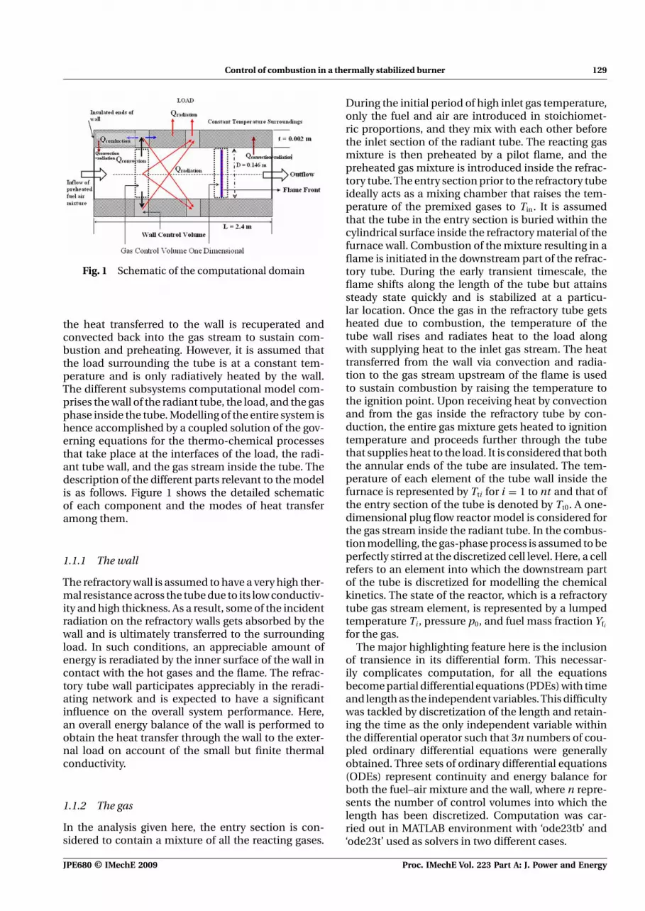
Fig. 1 Schematic of the computational domain
the heat transferred to the wall is recuperated andconvected back into the gas stream to sustain com-bustion and preheating. However, it is assumed thatthe load surrounding the tube is at a constant tem-perature and is only radiatively heated by the wall.The different subsystems computational model com-prises the wall of the radiant tube, the load, and the gasphase inside the tube. Modelling of the entire system ishence accomplished by a coupled solution of the gov-erning equations for the thermo-chemical processesthat take place at the interfaces of the load, the radi-ant tube wall, and the gas stream inside the tube. Thedescription of the different parts relevant to the modelis as follows. Figure 1 shows the detailed schematicof each component and the modes of heat transferamong them.
1.1.1 The wall
The refractory wall is assumed to have a very high ther-mal resistance across the tube due to its low conductiv-ity and high thickness. As a result, some of the incidentradiation on the refractory walls gets absorbed by thewall and is ultimately transferred to the surroundingload. In such conditions, an appreciable amount ofenergy is reradiated by the inner surface of the wall incontact with the hot gases and the flame. The refrac-tory tube wall participates appreciably in the reradi-ating network and is expected to have a significantinfluence on the overall system performance. Here,an overall energy balance of the wall is performed toobtain the heat transfer through the wall to the exter-nal load on account of the small but finite thermalconductivity.
1.1.2 The gas
In the analysis given here, the entry section is con-sidered to contain a mixture of all the reacting gases.
During the initial period of high inlet gas temperature,only the fuel and air are introduced in stoichiomet-ric proportions, and they mix with each other beforethe inlet section of the radiant tube. The reacting gasmixture is then preheated by a pilot flame, and thepreheated gas mixture is introduced inside the refrac-tory tube. The entry section prior to the refractory tubeideally acts as a mixing chamber that raises the tem-perature of the premixed gases to Tin. It is assumedthat the tube in the entry section is buried within thecylindrical surface inside the refractory material of thefurnace wall. Combustion of the mixture resulting in aflame is initiated in the downstream part of the refrac-tory tube. During the early transient timescale, theflame shifts along the length of the tube but attainssteady state quickly and is stabilized at a particu-lar location. Once the gas in the refractory tube getsheated due to combustion, the temperature of thetube wall rises and radiates heat to the load alongwith supplying heat to the inlet gas stream. The heattransferred from the wall via convection and radia-tion to the gas stream upstream of the flame is usedto sustain combustion by raising the temperature tothe ignition point. Upon receiving heat by convectionand from the gas inside the refractory tube by con-duction, the entire gas mixture gets heated to ignitiontemperature and proceeds further through the tubethat supplies heat to the load. It is considered that boththe annular ends of the tube are insulated. The tem-perature of each element of the tube wall inside thefurnace is represented by Tti for i = 1 to nt and that ofthe entry section of the tube is denoted by Tt0. A one-dimensional plug flow reactor model is considered forthe gas stream inside the radiant tube. In the combus-tion modelling, the gas-phase process is assumed to beperfectly stirred at the discretized cell level. Here, a cellrefers to an element into which the downstream partof the tube is discretized for modelling the chemicalkinetics. The state of the reactor, which is a refractorytube gas stream element, is represented by a lumpedtemperature Ti, pressure p0, and fuel mass fraction Yfi
for the gas.The major highlighting feature here is the inclusion
of transience in its differential form. This necessar-ily complicates computation, for all the equationsbecome partial differential equations (PDEs) with timeand length as the independent variables.This difficultywas tackled by discretization of the length and retain-ing the time as the only independent variable withinthe differential operator such that 3n numbers of cou-pled ordinary differential equations were generallyobtained. Three sets of ordinary differential equations(ODEs) represent continuity and energy balance forboth the fuel–air mixture and the wall, where n repre-sents the number of control volumes into which thelength has been discretized. Computation was car-ried out in MATLAB environment with ‘ode23tb’ and‘ode23t’ used as solvers in two different cases.
JPE680 © IMechE 2009 Proc. IMechE Vol. 223 Part A: J. Power and Energy

130 S Chaudhuri, A Mukhopadhyay, M S Biswas, B M Cetegen, and S Basu
2 GOVERNING EQUATIONS
The assumptions were noted as follows.
1. For a particular control volume it is assumed thatevery property is uniform within the cell, i.e. withineach control volume the mixture is perfectly stirred.Justification of this assumption will depend on thefineness of the grid into which the length has beendivided for discretization.
2. It is assumed that the thermophysical propertiesare steady and uniform and independent of speciesconcentration and their values equal to that of airat a mean temperature of 1000 K.
3. The single-step chemistry model is used.4. The burner tube is a hollow cylinder with constant
inner and outer diameters along its entire axiallength.
2.1 Mass balance for the fuel
Discretizing the length of the tube into a finite numberof control volumes, the continuity equation for eachreacting species becomes
∗m yfi−1 = ∗
m yfi + ddt
(ρ�Vyfi ) + w̄f�V · Wf (1)
In equation (1), for methane combustion, a single-step chemistry model is adopted, which assumescombustion under isobaric conditions (Table 1)
w̄f = Af ·(
FYX · T0
Tfi
· 122.4
)m+n
· (Wo · rst)(−m)
· (Wf )(−n) · (yfi )
m+n · exp(
−Tact
Tfi
)(2)
where rst is the mass-based stoichiometric fuel–airratio, Tact is the activation temperature, and Af isthe pre-exponential factor. Exponents m and n havenumerical values of −0.3 and 1.3, respectively. Thevariable FYX in equation (2) is defined as
FYX =∑
j njWj∑j nj
j = O, F, CO2, N2, H2O (3)
where nj is the number of moles of species j and Wj
are the corresponding molecular weight.Equation (2) is valid for mild combustion
of methane. To calculate the parameters usedin equation (2), the stochiometric combustionequation is
CH4 + 2(3.76N2 + O2) −→ CO2 + 2H2O + 7.52N2
Table 1 Data used for modelling combustion in thebatch-type furnace (methane–air combustion inlarge aspect ratio tubes)
ρ = 0.384 kg/m3 Density of the fuel–air mixture
Wf = 16 kg/mole Molecular weight of methane
Wo = 32 kg/mole Molecular weight of oxygen
�hr = 50 016 × 103 J/kg Heat of combustion
Cp = 1150 J/kg K Specific heat of the gas–air mixture
Pr = 0.726 Prandtl number
μ = 424.4 × 10⁻⁷ Coefficient of viscosity
σ = 5.67 × 10⁻⁸ Stefan-Boltzmann constant(W/m2 K4)
m = −0.3
n = 1.3
rst = 0.25 Stoichiometric fuel–air ratio formethane
Kg = 66.7 × 10⁻³ W/mK Thermal conductivity of the gas
Af = 8.3 × 10⁵ Premultiplier for methane–aircombustion kinetics
Fyx = 27.33
Ac = 0.016 74 m2 Cross-sectional area
At = 0.000 929 911 m2 Cross-sectional area of the tube
L = 2.4 m Length of the tube
T0 = 273 K
Tload = 700 K Temperature of the load
Cpt = 700 J/kg K Specific heat of tube material
Kt = 5.0W/mK Thermal conductivity of the tubematerial
ρt = 7854 kg/m3 Density of the tube wall material
dt = 0.15 m Diameter of the tube
tt = 002 m Wall thickness of the tube
�A = 0.004 587 Area of the tube
ε = 0.6 Absorptivity of the tube
Corresponding variable values used in the equationsare calculated using the following definitions
rst = nf Wf
noWo= 0.25
r|CO2 = nf Wf
nCO2 WCO2
= 1.161.44
= 411
r|H2O = nf Wf
nH2OWH2O
1.162.18
= 0.44
r|N2 = nf Wf
nN2 WN= 1.16
nn.28= 1
12
•mair = 4 · •
mo = 16 · •mf
As there is no recirculation, the net mass flowrate isthe sum of the mass flowrates of fuel and air
•m = •
mair + •mf = 17
•mf
Using the net mass flowrate, FYX is calculated as
FYX = 1.16 + 2.32 + 6.86 · 28 + 2.18 + 1.441 + 2 + 6.86 + 2 + 1
= 27.38
Proc. IMechE Vol. 223 Part A: J. Power and Energy JPE680 © IMechE 2009
Control of combustion in a thermally stabilized burner 131
For propane combustion equation (2) is replaced by
w̄f = Afρ2g XC3H8
1.5X 0.5O2
e(−E/RTg) (4)
For propane combustion, the global chemistrymodel of Chen and Churchill [10] is adopted. Cal-culations similar to those for methane combustionwere carried out to determine numerical values ofequation (4). Table 2 shows the relevant values usedfor propane combustion.
2.2 Energy balance applied on the gas stream
The discretized energy equation for the ith controlvolume becomes
•mCpgTfi−1 − •
mCpgTfi + �hr•
mconsumed − •Qconvection
− •Qradiation = ρCpg�V
dTfi
dt(5)
For•
mconvection, the Dittus–Boelter correlation is used.It is further assumed that the flow can be approx-imated by fully developed (both hydrodynamicallyand thermally) turbulent flow in a smooth circular
tube [17]. Hence, the Nusselt number (for•
Qconvection)in equation (5) is given by
NuD = 0.023 · Re0.8Prn′
where n′ = 0.4 for heating (the wall temperature ishigher than the gas temperature) and 0.3 for cooling(gas temperature is higher). Substituting the expres-sion for Reynolds number in Nusselt number oneobtains
NuD = 0.023
[ •m
π(dt − 2tt)μ
]0.8
Prn′
Convective heat transfer hence can be expressed as
•Qconvection = NuD · Kg
(dt − 2tt)· [π(dt − 2tt)�x](Tfi − Tti )
(6)
However, for the analysis of the small aspect ratioheat transfer problem, the flow is laminar and theDittus–Boelter correlation cannot be used. Therefore,in order to validate the model with the experimen-tal data of Chen and Churchill [10], the correlationproposed by Churchill and Ozoe [18] is adopted asfollows
•Qconvection = 5.784
[1 +
(Gz
82.5
)9/8]4/9
Kg
dt(Tfi − Tti )
(6a)
where Gz is the Graetz number.
Table 2 Propane–air combustion in the reduced-scalemodel of an adiabatic refractory tube
ρ = 0.348 kg/m3 Density of the fuel–air mixtureWf = 44 kg/mole Molecular weight of propaneWo = 32 kg/mole Molecular weight of oxygen�hr = 46357 × 103 J/kg Heat of combustionCp = 1150 J/kg K Specific heat of the gas–air mixturePr = 0.726 Prandtl numberμ = 424.4 × 10⁻⁷ Coefficient of viscosityσ = 5.67 × 10⁻⁸ Stefan-Boltzmann constant
(W/m2 K4)m = 0.1n = 1.65rst = 0.275 Stoichiometric fuel–air ratio for
propaneKg = 66.7 × 10⁻³ W/mK Thermal conductivity of the gasAf = 4.773 × 10⁸ Premultiplier for propane–air
combustion kineticsFyx = 29.39L = 0.254 m Length of the tubeT0 = 273 KTload = 700 K Temperature of the loadCpt = 700 J/kg K Specific heat of tube materialKt = 4.37W/mK Thermal conductivity of the tube
materialρt = 7854 kg/m3 Density of the tube wall materialdt = 0.9525 × 10⁻² m Diameter of the tubett = 0.238 125 × 10−2 m Wall thickness of the tubeε = 0.6 Absorptivity of the tube
•Qradiation is calculated using an optically thin model
for the gas (i.e. the gaseous fuel–air mixture only emitsbut does not absorb any radiation) such that
•Qradiation = 1
π
∫4π
KpσT 4t dω (7)
where Kp is the Planck mean absorption coefficientof the gas mixture, which has been assumed to beisotropic with a value of Kp = 2.0 corresponding to thecombustion products at 1500 K. Numerical integration
of•
Qradiation yields
•Qradiation
=⎧⎨⎩Kpσ
π
nt∑j=0
(T 4fi
− T 4tj)�ωij + Kpσ
π
×[(T 4
fi− T 4
in)πr2
R
r2i−in
+ (T 4fi
− T 4last)
πr2R
r2i−last
] ⎫⎬⎭ �V
(8)
where rR is the inner radius of the radiant tube =((dt − 2tt)/2), ri−in and ri−last are the distances of theinlet and outlet tube sections from the ith sectionand �ωij is the solid angle of the jth wall elementwith respect to ith gas control volume. The above-mentioned radiation model is similar both in the casesof methane and propane combustions.
JPE680 © IMechE 2009 Proc. IMechE Vol. 223 Part A: J. Power and Energy

132 S Chaudhuri, A Mukhopadhyay, M S Biswas, B M Cetegen, and S Basu
2.3 Energy balance applied to the wall element
The discretized energy equation for the ith wall ele-ment is given by
− KtAt
(Tti − Tti−1
�x
)−
[−KtAt
(Tti+1 − Tti
�x
)]
+ •Qin, convection + •
Qin, radiation − •Qout, radiation
− εσ (πdt�x)(T 4ti
− T 4load) = ρt�VtCt
dTti
dt(9)
where At is the area through which conduction is tak-ing place (i.e. = π/4 · [d2
t − (dt − 2t 2t )]) and �Vt is the
volume of the ith wall element = At�x.•
Qin, convection is
given by equations (6) or 6(a).•
Qout, radiation is given by
•Qout, radiation = επ(dt − 2tt)�xσT 4
ti(10)
•Qin, radiation is the sum of radiation from the gas ele-ments as well as from the other wall elements, and isgiven by
•Qin, radiation =
⎛⎝σF (l − z)T 4
last + σF (z)T 4in
+∫ l
0B(ξ)|K (z − ξ)|dξ + Kpσ
π
nt∑j=1
× (T 4fj
− T 4ti)�ωij · �Vfj
⎞⎠ · π(dt − 2tt)�x
(11)
where B(z) is the radiosity of the tube wall elementand it is related to the irradiation H (z) in the following
manner
B(z) = (1 − ε)H (z) + εσT 4t (12)
In equation (11), F (z) is the view factor between thetube end and a wall element situated at a distancez. F (z) is the view factor between two wall elementssituated z distance apart. According to Usiskin andSiegel [19], the view factor F (z) can be closely approx-imated by 0.5exp(z) and the view factor F (z) can beapproximated by exp(−2/z).
3 VALIDATION
The model is validated by simulating the experi-mental results given in Chen and Churchill [10] asshown in Fig. 2. From the diagram it is seen that thewall temperature profile obtained agrees very closelywith the experimental points as given in Chen andChurchill [10]. However, in the current analysis, steadystate is not attained at the time instant the validationis carried out.
4 RESULTS AND DISCUSSIONS
The main objective of the present work is the transientmodelling of the heat treatment furnace. The numer-ical analysis provides results of both the transientand steady-state conditions. This comprises fuel massfraction, gas temperature, and wall temperature pro-files with various boundary conditions. The differentgas and wall temperature profiles obtained and theirnature due to the variation of different parameterssome of which are initial and boundary conditions(e.g. the inlet fuel mass fraction and the inlet gas
Fig. 2 Validation of the computation with experimental results from Chen and Churchill [10] forwall temperature profile
Proc. IMechE Vol. 223 Part A: J. Power and Energy JPE680 © IMechE 2009

Control of combustion in a thermally stabilized burner 133
temperature), while some are constants for a partic-ular run (e.g. mass flowrate of the air fuel mixture),give some concrete idea of the major influencing fac-tors at different stages of the heat transfer process. Thework can be divided into two parts. In the first part, thefuel is methane in the full-scale model of a heat treat-ment furnace. In the second part the fuel is propanewith the reduced scale model of an adiabatic refractorytube. For all the presented results, radiation is consid-ered the only mode of heat transfer between the walland load, which is kept at 700 K. The flame in the tubeis assumed to be located at the position of maximumgas temperature.
4.1 Effect of independent variation of inlet gastemperature, mass flowrate, and inlet fuelmass fraction for methane combustion
Figure 3 shows the steady-state temperature profilesof both the gas and wall under variation of the inletgas temperature from 1300 to 1100 K. It is seen that theflame shifts away from the inlet as the inlet gas temper-ature is decreased from 1300 to 1100 K for a constantmass flowrate of 0.0289 kg/s and fuel mass fraction of0.05. This can be attributed to the precombustion reac-tions that require a longer length scale to complete,for a lower inlet gas temperature. The higher the inletgas temperature the easier the gas ignited. The flamelocation changes by over 0.3 m for a 200 K decreasein inlet gas temperature. However, it should be notedthat the flame temperature (maximum gas tempera-ture) remains almost the same independent of all inletgas temperatures. The wall temperature also exhibitsa temperature peak near the flame location due to thecombined convection and radiation from the gas. It isthus clearly established that the inlet gas temperature
or the preheating level is one of the major governingparameters that determines the position of the flamein the tube.
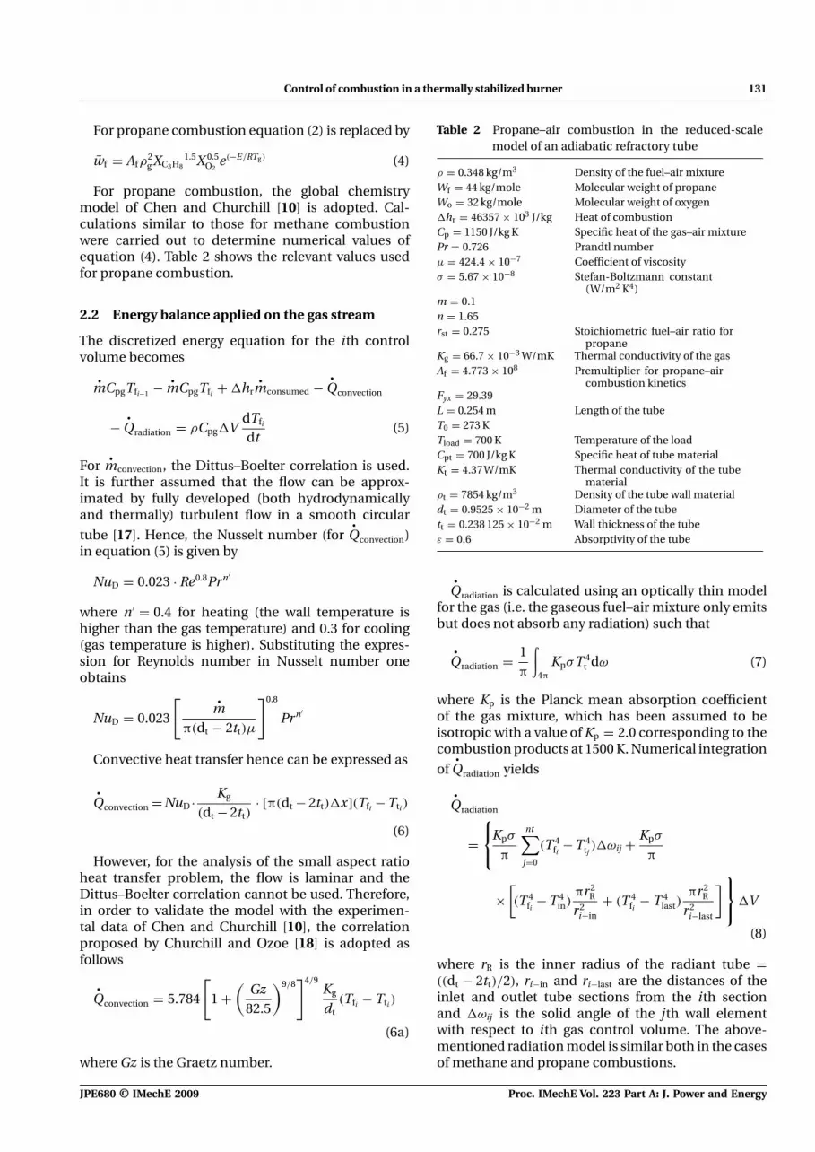
It is found that the mass flowrate is another param-eter governing the position of the flame. Figure 4illustrates that with reduction in the mass flowratefrom 0.038 to 0.0175 kg/s, the flame location is shiftedby almost 0.2 m upstream of the tube. For all the resultsshown in Fig. 4, the mass fraction of the fuel is heldat 0.05, while the inlet gas temperature was fixed at1250 K. This is because reduction in the mass flowrateonly implies reduction in flow velocity. As the veloc-ity of the flow is reduced, the precombustion reactionsget sufficient time to complete before the gas movesfurther downstream, allowing the flame to stabilize atan upstream location. It is to be noted that the flametemperature exhibits a monotonic decay with deple-tion in mass flowrate from 3000 to 2600 K. A similarcharacteristic is noted for the peak wall temperature,which decreases with decrease in mass flux. However,it is observed that the wall temperature in the preflamezone in steady state is higher for the more upstreamflame. This can be attributed to the larger fractions ofenergy that the wall receives by radiation from a nearbyflame in comparison to that of a far off flame. However,in the reverse case, as the mass flowrate is increased,the flame does not continue to shift downstream unin-terruptedly even at a very high value of mass flowrate(
•m = 0.05 kg/s), and after a small shift the gas gets
ignited because of its high inlet temperature and largefuel mass.
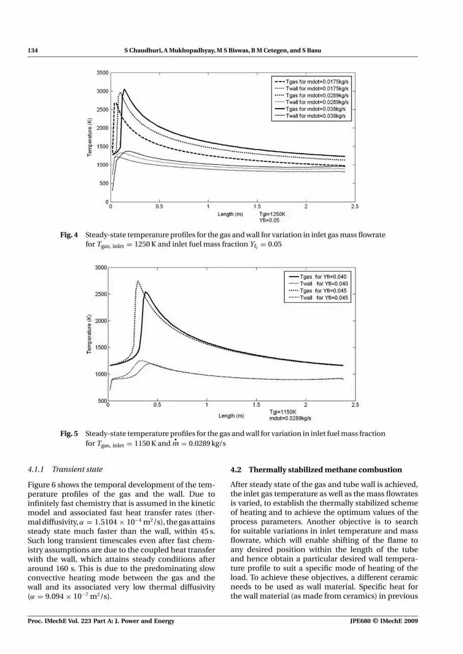
Figure 5 shows that for fixed inlet gas temperatureand mass flowrate the flame location shifts upstreamfor an increase in inlet fuel mass fraction. This isexpected from the increase in heat release as themixture ratio approaches stoichiometric value.
Fig. 3 Steady-state temperature profiles for the gas and wall for variation in inlet gas temperaturefor
•m = 0.0289 kg/s and inlet fuel mass fraction Yfi = 0.05
JPE680 © IMechE 2009 Proc. IMechE Vol. 223 Part A: J. Power and Energy
134 S Chaudhuri, A Mukhopadhyay, M S Biswas, B M Cetegen, and S Basu
Fig. 4 Steady-state temperature profiles for the gas and wall for variation in inlet gas mass flowratefor Tgas, inlet = 1250 K and inlet fuel mass fraction Yfi = 0.05
Fig. 5 Steady-state temperature profiles for the gas and wall for variation in inlet fuel mass fractionfor Tgas, inlet = 1150 K and
•m = 0.0289 kg/s
4.1.1 Transient state
Figure 6 shows the temporal development of the tem-perature profiles of the gas and the wall. Due toinfinitely fast chemistry that is assumed in the kineticmodel and associated fast heat transfer rates (ther-mal diffusivity, α = 1.5104 × 10⁻⁴ m2/s), the gas attainssteady state much faster than the wall, within 45 s.Such long transient timescales even after fast chem-istry assumptions are due to the coupled heat transferwith the wall, which attains steady conditions afteraround 160 s. This is due to the predominating slowconvective heating mode between the gas and thewall and its associated very low thermal diffusivity(α = 9.094 × 10⁻⁷ m2/s).
4.2 Thermally stabilized methane combustion
After steady state of the gas and tube wall is achieved,the inlet gas temperature as well as the mass flowratesis varied, to establish the thermally stabilized schemeof heating and to achieve the optimum values of theprocess parameters. Another objective is to searchfor suitable variations in inlet temperature and massflowrate, which will enable shifting of the flame toany desired position within the length of the tubeand hence obtain a particular desired wall tempera-ture profile to suit a specific mode of heating of theload. To achieve these objectives, a different ceramicneeds to be used as wall material. Specific heat forthe wall material (as made from ceramics) in previous
Proc. IMechE Vol. 223 Part A: J. Power and Energy JPE680 © IMechE 2009

Control of combustion in a thermally stabilized burner 135
Fig. 6 Transient temperature profiles for gas and wall leading to the attainment of steady thermalstate for
•m = 0.0289 kg/s, Tgas, inlet = 1250 K, and inlet fuel mass fraction Yfi = 0.05
cases has been considered to be 434 J/kg K [8], but inthis case, since the main objective is attainment of thethermally stabilized scheme, wall material is chosensuch that the specific heat is 700 J/kg K. An open-loopcontrol is implemented using the following strategy.At 600 s, inlet gas temperature and mass flowrate arereduced to optimum values (for a stable flame) of850 K and 0.01 kg/s, respectively. Figure 7(a) showsthe flame and wall temperature profiles immediatelybefore and after 600 s. It is observed that the flameimmediately responds to the change in inlet tempera-ture and mass flowrate that is exhibited by a reductionin peak gas temperature. Following the reduction ininlet gas temperature and mass flowrate, steady stateis attained, which is represented by the profiles shownin Fig. 7(a) at t = 36 000 s. It is interesting to note thatthe flame temperature decreases substantially withreduced mass flux and inlet temperature but the flamelocation remains almost the same. It is also found fromFig. 7(a) that in the preflame zone, the wall tempera-ture is greater than the gas temperature. Hence, unlikein the previous analysis presented, heating of the gasby the wall is observed. This indicates that althoughthe preheating of the inlet gas still provides a part ofthe activation energy needed for combustion, the tubewall emerges as a major contributor. It is further seenas indicated in Fig. 7(b) that with reduction in the massflowrate (= 0.01 kg/s), an inlet gas temperature as lowas 650 K can be maintained for sustaining combustioninside the tube. Preheating requirement of the inlet gasthrough a pilot flame hence becomes less significant,which is particularly desired in the present analysis.This thermally stabilized scheme implies that the con-vective heat transfer from the hot gas to the wall is
conducted upstream, increasing the wall temperaturesubstantially near the inlet. The heated wall through acombined process of convection and radiation heatsup the colder inlet gas to the activation temperaturefor ignition. The scheme increases waste heat recu-peration from the flame and uses a part of it to preheatthe gas and sustain the combustion process. The wallalso heats the load through radiation outside the tubefurnace. The flame is also found to exist at a very shortdistance downstream of the inlet after the reductionin preheating and mass flux. This is because decreasein the inlet gas temperature means the flame shiftsdownstream, but decrease in the mass flowrate impliesa shift in the upstream direction. These counteract-ing phenomena led to results that show that in certainoptimized situations, the flame position is more or lessfixed at a small distance from the inlet under differentinput conditions.
To study the flame shift as a function of massflowrate for a low inlet gas temperature the followingmethod is adopted. The flame was allowed to attain asteady-state configuration for an inlet gas temperatureand fuel mass fraction of 800 K and 0.05, respectively.At t = 1400 s, the mass flowrate is increased instanta-neously to a value of 0.018 kg/s. Figure 8 shows thatfor a mass flowrate of 0.018 kg/s, the flame slowly trav-els a long distance downstream to finally stabilize at adistance of 2.3 m from the inlet. A more gradual flameshift is possible by changing mass flowrates throughseveral smaller steps. It is also observed that the flameposition becomes very sensitive to mass flow and avariation of mass flowrate from 0.01 to 0.02 kg/s shiftsthe flame more than 80 per cent of the tube length,from near inlet to near outlet positions. Thus, with
JPE680 © IMechE 2009 Proc. IMechE Vol. 223 Part A: J. Power and Energy

136 S Chaudhuri, A Mukhopadhyay, M S Biswas, B M Cetegen, and S Basu
Fig. 7 Transient and steady-state temperature profilesof the gas and wall for reduction in (a) gas tem-perature from 1200 to 850 K and
•m from 0.028 to
0.01 kg/s, and (b) gas temperature from 1200 to650 K and
•m from 0.028 to 0.01 kg/s
efficient control of mass flowrate, wall temperatureprofiles can be controlled according to the differentheating modes required in the plant.
4.3 Experimental correlation for flame position inmethane combustion
It is evident from the previous sections that the flameposition is sensitive to inlet gas temperature, mass flux,and fuel mass fraction. Hence, it is apparent that anempirical correlation that predicts the flame positionas a function of the above parameters will be useful forprediction purposes. For generalization purposes, allthe parameters are cast in their corresponding non-dimensional form. This is done by normalizing theinlet gas temperature with the autoignition tempera-ture Tautoignition of the corresponding fuel, transforming
Fig. 8 Thermal stabilization after flame shift by reduc-tion in the gas mass flowrates after initial steadystate is attained
the mass flowrate to Reynolds number Re and theinlet fuel mass fraction to the equivalence ratio Φ,respectively. The length scale x is normalized by thetotal length of the tube. These parameters are givenby Xf ∗ = x/L, T∗ = Tinlet/Tautoignition, Re = ρVdt/μ, andΦ = equivalence ratio.
In each simulation, one of the parameters was variedretaining the other two constants and finally they werecombined to obtain the normalized flame position asa function of the combined normalized parameters.On the basis of these normalizations, the correlationshown in Fig. 9 is obtained. The correlation shows thatthe flame location is a strong function of equivalenceratio, inlet gas temperature, and flow Reynolds num-ber. It is seen that for a change in T∗ from 1.6 to 1.35,the normalized flame position shifts by almost 14 percent downstream for constant Φ and Re. Similarly, amaximum variation of 6.5 per cent is detected in theflame position for a Reynolds number change of 2500for constant Φ and T∗.
4.3.1 Closed-loop control for methane combustion
Once open-loop control was successful by the ther-mally stabilized scheme, closed-loop control on thebasis of feedback from flame position (hypothesized tobe the same location as the position of the maximumgas temperature) was implemented by the following
Proc. IMechE Vol. 223 Part A: J. Power and Energy JPE680 © IMechE 2009

Control of combustion in a thermally stabilized burner 137
Fig. 9 Empirical correlation of flame position as a func-tion of mass flux, equivalence ratio, and massflowrate
algorithm. For time t < 600 s, the gas was preheatedup to a temperature of 1150 K as in the previous cases.After 600 s, the preheating was lowered so that the gasinlet temperature Tgas = 800 K; the mass flowrate wasalso lowered to 0.01 kg/s to create a low-velocity flowfield so as to sustain combustion. Finally, for timesgreater than 1400 s, if the flame position sensed wasgreater than 0.5 m from the inlet, gas mass flowratewas adjusted according to the following equation:
•m = ( fp − 0.5)x(−0.0175) + 0.0185 (13)
For flame positions less than 0.5 m, the massflowrate was kept constant at 0.0185 kg/s. As shownin Fig. 10, by this algorithm the flame position couldbe controlled within a very small positional windowinside the tube. This also allowed for obtaining a pre-determined wall temperature profile that would allow
desired local heat fluxes for its application in the heattreatment furnace.
4.3.2 Limitations with smaller diameter tubes withthe same aspect ratio
It was found that for a 20 per cent reduction in thetube diameter with a constant aspect ratio, the nor-malized flame position shifts downstream by 100 percent. This can be attributed to the simple scaling argu-ment that the ratio of heat released to heat convectionscales as the tube diameter D (if one looks only at thegeometry). Hence, with a smaller D, the mixture needsrelatively more energy to ignite as convection losesdominate because of increased surface area to vol-ume ratio. Hence, the normalized flame position Xf ∗increases with decrease in D and it is expected that forsome cut-off value, the gas would leave the tube with-out getting ignited. It is found that for a 90 per centreduction in both D and L, no combustion is found tooccur even though the aspect ratio is kept constant.
4.4 Combustion under reduced scale usingpropane
This problem was solved for a burner with diam-eter reduced by 90 per cent and length modifiedso as to keep the aspect ratio constant (also otherparameters of the burner remained the same as theburner discussed in the previous cases) by shift-ing to lower Reynolds number flows and to a fuelwith lower autoignition temperature such as propane.Lower Reynolds number flows have got an advan-tage, which is increased residence time for the flowso that the ratio of the chemical reaction timescaleto the residence time of the gas (tchem/tres) or the
Fig. 10 Feedback control to stabilize flame at a desired location in the tube on the basis of flameposition
JPE680 © IMechE 2009 Proc. IMechE Vol. 223 Part A: J. Power and Energy

138 S Chaudhuri, A Mukhopadhyay, M S Biswas, B M Cetegen, and S Basu
Damkohler number is < 1. Proceeding with laminarflow assumption and propane as the fuel, the follow-ing results are obtained (as shown in Figs 11 and 12).Figures 11 and 12 show the temperature profiles forlower Re flows (Re = 1426) obtained with different setsof initial conditions. Figure 11 shows the transient tem-perature profiles leading up to steady state for an inletgas temperature of 1200 K. In Fig. 12, the profiles wereobtained with preheated walls and cold inlet gas. Thisshows that after combustion is initiated, heat trans-ferred into the wall is conducted upstream and againconvected into the relatively cold gas near the inlet thatenables ignition and sustaining the flame even withoutpreheating the gas above its autoignition temperatureas was exhibited in all the previous cases.
Fig. 11 Development of temperature profiles (fromtransient to steady state) for the gas and wallfor laminar flow at different instants of time
Fig. 12 Development of temperature profiles for the gasand wall for laminar flow at different instantsof time for thermally stabilized scheme by pre-heated wall
5 CONCLUSION
The work depicted in this article successfully imple-mented a transient one-dimensional coupled model ofa plug flow reactor, which finds practical applicationsin a batch-type heat treatment furnace. All modes ofheat transfer including conduction, convection, andradiation were included in the model with single-stepglobal chemistry for combustion of both methane andpropane. Effects of variations of parameters such asinlet gas temperature, mass flux, and inlet fuel massfraction on the gas and tube wall temperature profileswere studied to understand the shift in flame positionalong the tube length. Thermally stabilized sustainedcombustion mode with optimum inlet gas preheat-ing requirement was analysed as a function of mixturestoichiometry and mass flux. Open-loop and closed-loop control schemes were effectively implemented toestablish the thermally stabilized scheme of heatingand desired flame position within the tube.
REFERENCES
1 Shinoda, M., Maihara, R., Kobayashi, N., Arai, N.,and Churchill, S. W. The characteristics of a heat-recirculating ceramic burner. J. Chem. Eng., 1998, 71,207–212.
2 Kansuntisukmongkol, R., Miyaki, H., Ozoe, H., andChurchill, S. W. Development of a computationalscheme for transient combustion inside a refractorytube. Combust. Flame, 1997, 108, 158–172.
3 Norton, D. G. and Vlachos, D. G. Combustion character-istics and flame stability at the microscale: a CFD studyof premixed methane/air mixtures. J. Chem. Eng., 2003,58, 4871–4882.
4 Leach, T. T., Cadou, C. P., and Jackson, G. S. Effectof structural conduction and heat loss on combustionin micro-channels. Combust. Theory Model., 2006, 10,85–103.
5 Yang, W. M., Chou, S. K., Shu, C., Xue, H., Li, Z. W., Li,D. T., and Pan, J. F. Microscale combustion researchfor application to micro thermophotovoltaic systems.Energy Convers. Manage., 2003, 44, 2635–2644.
6 Weinberg, F. Optimising heat recirculating combustionsystems for thermoelectric converters. Combust. Flame,2004, 138, 401–403.
7 Ramamurthy, H., Ramadhyani, S., and Viskanta R.Development of fuel burn-up and wall heat transfer cor-relations for flows in radiant tubes. Numer. Heat Transf.A, 1997, 31, 563–584.
8 Tiwari, M. K., Mukhopadhyay, A., and Sanyal, D. Processmodeling for control of a batch heat treatment fur-nace with low NOx radiant tube burner. Energy Convers.Manage., 2005, 46, 2093–2113.
9 Kansuntisukmongkol, R., Ozoe, H., and Churchill, S. W.Experiments of a premixed flame inside a refractory tube.J. Chem. Eng., 1998, 71, 213–220.
10 Chen, J. L. P. and Churchill, S. W. Stabilization offlames in refractory tubes. Combust. Flame, 1972, 18,37–42.
Proc. IMechE Vol. 223 Part A: J. Power and Energy JPE680 © IMechE 2009

Control of combustion in a thermally stabilized burner 139
11 Kansuntisukmongkol, R. and Ozoe, H. Influence of ther-mal conductivity and aspect ratio on stable combustioninside a refractory tube. Energy Convers. Manage., 1997,38, 1051–1059.
12 Norton, D. G. and Vlachos, A. CFD study of propane/airmicroflame stability. Combust. Flame, 2004, 138,97–107.
13 Leach, T. T. and Cadou, C. The role of structuralheat exchange and heat loss in the design of efficientsilicon micro-combustors. Proc. Combust. Inst., 2005, 30,2437–2444.
14 Yang, W. M., Chou, S. K., Shu, C., Li, Z. W., and Xue, H.Combustion in micro-cylindrical combustors with andwithout a backward facing step. Appl. Therm. Eng., 2002,22, 1777–1787.
15 Yang, W. M., Chou, S. K., Shu, C., Li, Z. W., and Xue, H.Research on micro-thermophotovoltaic power genera-tors. Sol. Energy Mater. Sol. Cells, 2003, 80, 95–104.
16 Richecoeur, F. and Kyritsis, D. Experimental study offlame stabilization in low Reynolds and Dean numberflows in curved mesoscale ducts. Proc. Combust. Inst.,2005, 30, 2419–2427.
17 Incropera, F. P. and DeWitt, D. P. Fundamentals of heatand mass transfer, 5th edition, 2002 (John Wiley andSons, USA).
18 Churchill, S. W. and Ozoe, H. Correlations for lami-nar forced convection in flow over an isothermal flatplate and in developing and fully developed flow in anisothermal tube. Trans. ASME J. Heat Transf., 1973, 95,416–419.
19 Usiskin, C. M. and Siegel, R. Thermal radiation from acylindrical enclosure with specified wall heat flux. Trans.ASME J. Heat Transf., 1960, 82(4), 369–374.
APPENDIX
Notation
Af pre-exponential factorCpg specific heat of the gas–air mixture
Ct specific heat of the tube materialdt diameter of the tubefp flame positionGz Graetz numberKg thermal conductivity of the gas–air mixtureKt thermal conductivity of the tube materialKp Planck mean absorption coefficient
•m mass flowratenf molar concentration coefficientnj number of moles of j speciesnt number of control volumesNuD Nusselt numberPr Prandtl numberr|CO2 ratio of mass fraction of fuel and CO2
rst stoichiometric fuel–air ratiot timett thickness of the tube materialTact activation temperature for the fuel–air
ratioTg gas temperatureTload load temperatureTt tube wall temperaturew̄f molar species destruction rateWf molecular weight of the fuelWo molecular weight of oxygenXC3H8 molar fraction of propaneXO2 molar fraction of oxygenyf fuel mass fraction
�hr specific enthalpy released by thecombustion process
�v elemental gas stream elementμ dynamic viscosity coefficientρg density of the gas–air mixtureρt density of the tube materialσ Stefan Boltzmann constantω solid angle
JPE680 © IMechE 2009 Proc. IMechE Vol. 223 Part A: J. Power and Energy