the structure of triple flames stabilized on a slot burner
TRANSCRIPT
The Structure of Triple Flames Stabilized on a Slot Burner
RICCARDO AZZONI, STEFANO RATTI, SURESH K. AGGARWAL, andISHWAR K. PURI*
Department of Mechanical Engineering (M/C 251), University of Illinois at Chicago, 842 W. Taylor St.,Rm. 2039, Chicago, IL 60607-7022
A triple flame is a partially premixed flame that contains two premixed reaction zones (one fuel-lean and theother rich) that form exterior wings and a nonpremixed reaction zone that is established in between these wings.The three reaction zones merge at a “triple point.” Triple flames may play an important role in the stabilizationand liftoff of laminar nonpremixed flames. They are also of fundamental importance in the reignition ofturbulent mixtures. Despite their importance, many aspects of triple flames have not been adequatelyinvestigated and are, consequently, not clearly understood. Herein, laminar triple flames stabilized on aWolfhard-Parker slot burner are investigated. The flow consists of a rich mixture of methane and air emergingfrom the inner slot and a lean mixture from two symmetric outer slots. In this configuration the three reactionzones that characterize a triple flame can be clearly distinguished. The loci of the “triple points” form a “tripleline” in this planar configuration. The velocity field is characterized using laser Doppler velocimetry, and thetemperature distribution using laser interferometric holography. In addition, C*2-chemiluminescence images ofthe three reaction zones are obtained. A detailed numerical model is employed to completely characterize theflame. It is based on a 24-species and 81-reaction mechanism. The numerical results are validated throughcomparisons with the experimental measurements. Our results focus on the detailed structure, the interactionbetween the three reaction zones, the dependence of the flame structure on the initial velocities and mixtureequivalence ratios, and the dominant chemical pathways. The lean premixed reaction zone (external wing)exhibits different features from the rich premixed reaction zone. In particular, it is characterized by strong HO2
formation and consumption reactions, and by relatively weak methane consumption reactions. Radical activityis higher in the nonpremixed reaction zone than in the other reaction zones. Overall, radicals from thenonpremixed reaction zone are transported to both the rich and lean premixed reaction zones where they attackthe reactants. Simplifying the chemical mechanism by removing the C2-containing species produces significantdifferences in the predicted results only for the inner rich premixed reaction zone. © 1999 by The CombustionInstitute
INTRODUCTION
A triple flame is a partially premixed flameconsisting of two premixed reaction zones (onefuel-rich and the other fuel-lean) and a nonpre-mixed reaction zone. The two premixed reac-tion zones form exterior “wings” of the flame.The nonpremixed reaction zone, that is estab-lished in the region where excess fuel andoxidizer from the respective rich and lean pre-mixed reaction zones mix in stoichiometric pro-portion, is enclosed in between these two wings.All three reaction zones (that are often referredto as flames) merge at a “triple point.” The lociof the “triple points” form a “triple line” in aplanar configuration.
The behavior of triple flames is of fundamen-tal importance for several reasons. First, tripleflames may play an important role in the stabi-lization of laminar nonpremixed flames [1].
While premixed flames propagate because theflame provides heat to the unburned mixture,nonpremixed flames do not possess such a sim-ple stabilization mechanism. The stabilization ofnonpremixed flames can occur by two means:(1) near a splitter plate where the plate wakeprovides very low strain rates and where heatconduction to the plate becomes important; or(2) when the flames are lifted downstream inthe form of a triple flame in which the propa-gating premixed reaction zones anchor the non-premixed reaction zone [2]. Secondly, tripleflames play an important role during reignitionin turbulent flows when, after a local extinctiondue to excessive strain, the turbulence intensitydecreases so that reignition can occur [3].
Triple flames were first reported by Phillipswho investigated their propagation in a meth-ane mixing layer in a horizontal configuration[4]. He was particularly interested in determin-ing the flame speed and volume in the context ofthe explosive conditions that occur at the roof of*Corresponding author. E-mail: [email protected].
COMBUSTION AND FLAME 119:23–40 (1999)© 1999 by The Combustion Institute 0010-2180/99/$–see front matterPublished by Elsevier Science Inc. PII S0010-2180(99)00047-4
coal mine roadways. Thereafter, Dold per-formed a theoretical investigation that con-cluded that the triple flame propagation speedin the presence of a slowly varying mixturefraction gradient strongly depends upon thetransverse mixture fraction gradient [5]. Hedetermined that the flame speed increases asthe mixture fraction gradient decreases, and it isbounded by the maximum adiabatic laminarflame speed of the system. The shape of tripleflames was predicted to depend on the mixturefraction gradient, and theory found that flamesbend at steeper gradients. In a subsequentstudy, Dold and Hartley relaxed the constraintof a slowly varying mixture fraction gradient andit was shown that the flame speed remainspositive for all mixture fraction gradients thatproduce a reaction zone which is at least asthick as the preheat zone [6]. For very steepgradients negative flame speeds were predicted,which implied that triple flames could be estab-lished following the extinction of a diffusiveinterface [7].
Ruetsch et al. [1] theoretically investigatedthe effects of heat release and mixture fractiongradient on the flame speed. They concludedthat heat release increases the flame speed, asdoes a decrease in the mixture fraction gradient,in accord with the results presented by Dold [5].They found flame speeds to be higher than thecorresponding planar premixed flame speedthat was in disagreement with Dold, but inagreement with the experimental results of Phil-lips [4]. Ruetsch et al. suggested the followingmechanism to explain their observations: Theheat release causes the velocity component per-pendicular to the flame to increase. As a conse-quence, the streamlines bend toward the cen-terline as they cross the flame. This results in adivergence of the velocity field ahead of theflame so that the velocity reaches a minimum atthe triple point. They predicted that the mini-mum velocity, where the flame stabilizes, isclose to the laminar flame speed (SL), but theoverall flame speed of the triple flame, whichmust be considered further upstream, is largerthan SL.
Kioni et al. [3] have reported on an experi-mental investigation of a lifted triple flamestabilized in a coflowing stream. They observedthat the width of the premixed wings increases
as the mixture fraction gradient decreases. Inaddition, the velocity profile at the leading edgeof a triple flame was examined as a function ofthe transverse mixture fraction gradient. Atrend opposite to that predicted by Dold wasobserved [5], since the velocity increased withthe mixture fraction gradient and was wellabove the adiabatic laminar flame speed of thecorresponding stoichiometric premixed fuel–airmixture. However, Phillips [4] found the varia-tion of the flame speed with the mixture fractiongradient to be consistent with the prediction byDold [5]. Phillips suggested that the flame speedis higher for low mixture fraction gradients,because the flame is flatter and the preheatingof the unburned mixture is more efficient underthese conditions. However, the absolute flamespeeds were higher than the adiabatic flamespeed of the corresponding stoichiometric pre-mixed flame. Kioni et al. [3] obtained a similarresult by defining the flame speed as the meanflow velocity at the location of the flame.
Muniz and Mungal [8] experimentally inves-tigated the velocity profile at the base of a liftedjet flame and found it to be similar to theprediction of Ruetsch et al. [1]. In particular,they observed that the flame stabilizes itself inthe region where the velocity is close to thepremixed laminar flame speed. Schefer andGoix [9] extended the work of Muniz andMungal regarding the applicability of laminartriple flame concepts to the stabilization oflifted turbulent jet-flames, and concluded thatthis is not straightforward, since turbulencecauses distortions in the velocity field. Munizand Mungal found that the instantaneous veloc-ity at the stabilization point varied between SL
to 3SL, while Schefer and Goix found that theaverage velocity at the instantaneous flame baseincreased from 0.2SL–1.2SL with increasingReynolds number.
Aggarwal and Puri have reported on a nu-merical investigation of triple flame structure inaxisymmeteric inverse lifted partially premixedflames [10]. They determined the existence of aspatially thin rich premixed flame (RPF), twospatially broad nonpremixed flames (NF) ateither wing of the RPF, and a lean premixedflame (LPF) stabilized by heat and mass trans-port towards the oxidizer-rich center. Theirinvestigation illustrated how triple flames can be
24 R. AZZONI ET AL.
established in relatively complex configurations.Echekki and Chen [11] conducted direct numer-ical simulations of methanol–air triple flamesand concluded that the triple region is stronglyinfluenced by the reaction zone curvature andby the differential diffusion of molecular hydro-gen. Both the curvature and diffusion effectsaugment radical production that, consequently,enhances the flame propagation speed. Echekkiand Chen found that the flame structure couldbe characterized in terms of a mixture fractionparameter. A similar approach has been sug-gested by Aggarwal and Puri [10].
A divergence in the velocity field is caused bythe combination of two factors: The heat re-lease at the flame location, and the curvature ofthe flame front. However, both of these factorscan be present in configurations other thanthose involving triple flames. Domingo and Ver-visch [12] suggested that the front of the flamecan propagate because of the interaction ofmultiple rich and lean layers (in accord with theconclusions of Aggarwal and Puri [10]). A fun-damental understanding of this interaction is,therefore, required. Transport effects have alsobeen investigated by Buckmaster and Matalon[13]. Despite the various questions, many as-pects of triple flames have not been adequatelyinvestigated and are, consequently, not clearlyunderstood.
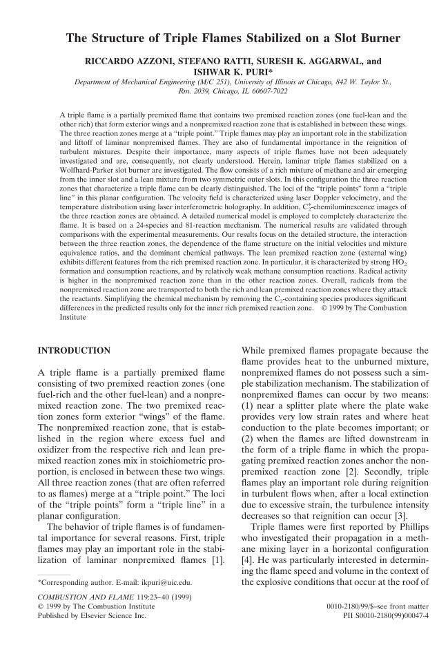
In this study, laminar triple flames stabilizedon a Wolfhard-Parker slot burner have beeninvestigated by using detailed measurementsand numerical simulations. As illustrated in Fig.1, the flow consists of a rich mixture emergingfrom an inner slot and a lean mixture intro-duced from two symmetric outer slots. In thisplanar configuration the three reaction zonesthat characterize a triple flame are clearly dis-tinguished. The measurements include those ofthe velocity field using laser Doppler velocim-etry, the reaction zone location by detectingC*2-chemiluminescence, and the temperature dis-tribution using laser interferometric holography.In addition, a detailed numerical model is em-ployed to characterize the flame structure. It isbased on C2-chemistry and involves a mechanismcontaining 24 species and 81 reactions. A simpli-fied and reduced form of this chemistry wasemployed by Plessing et al. [14] who determinedthat the triple flame structure depends on heat
transport between the multiple reaction zones,and on the heat loss from the curved reactionzone fronts in the vicinity of the triple point.
The numerical and chemical models are val-idated through comparisons with experimentalmeasurements for a representative flame. Thediscussion focuses on the detailed structure ofthis triple flame, the interactions between thethree reaction zones, and the dependence of theflame structure on the initial velocity and mix-ture ratio.
EXPERIMENTAL PROCEDURE
Atmospheric methane–air flames were estab-lished using a Wolfhard-Parker slot burner. Aschematic diagram of the burner is contained inFig. 1. The flows were straightened and laminar-ized in the inner and outer burner slots usingceramic inserts. The rectangular burner geometryprovided symmetrical two-dimensional flames.
Fig. 1. A schematic diagram of the Wolfhard-Parker slotburner. The burner dimensions are in units of mm.
25STABILIZED TRIPLE FLAMES
Velocity Measurements
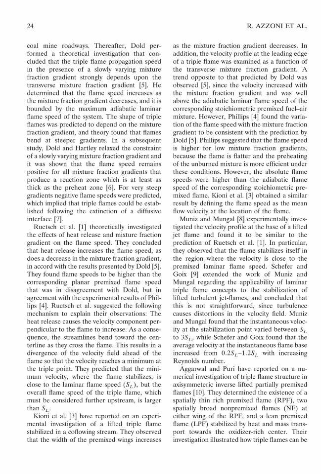
A laser Doppler velocimeter (DANTEC 5500Awith an Ar-ion laser) was used to make thevelocity measurements. The flow was seededwith TiO2 particles. A traverse controller wasused to make the point measurements in aspecified domain. Despite the insertion of ce-ramic flow straighteners in the burner slots (cf.Fig. 1), cold flow measurements showed theformation of wall jets in each of the three slots.The flow retained its two-dimensional charac-teristics, but a higher gas velocity was measuredadjacent to the walls than at planes removedfrom it. A typical velocity profile and the asso-ciated bulk-averaged velocity is presented inFig. 2. This profile was used as a boundarycondition for the simulations. Although themeasured rms velocities were, in general, small,their values were used as a criterion to evaluatethe measurement accuracy for axial velocitiesgreater than 0.2 m s21. When the local meanaxial velocity was greater than 0.2 m s21, veloc-ity measurements with rms values greater than5% of the mean were assumed to be contami-nated with noise, and, therefore, discarded.
C*2 Chemiluminescent Emission
The excited C*2 free radical species is consideredto be a good indicator of the reaction zone [15],and its light intensity varies linearly with thevolumetric heat release [16, 17]. The C*2-chemi-luminescence images were obtained fromflames using a 513 3 480 pixel intensified andgated solid state camera (ITT F4577). A narrow
wavelength interference filter (470 6 10 nm)was employed to detect the emission occurringat 473 nm due to the (1, 0) C2 Swan band [18].A background image was subtracted from theraw images to correct for noise. The chemilu-minescence images are directly proportional tothe C*2 formation rate and, therefore, serve as aqualitative rate measure of the flame chemistry[19].
Temperature Measurements
A nonintrusive diagnostic tool is required tomeasure the temperature in triple flames, sincethe spatially broadened reaction zones produceunquantifiable errors due to conduction effectswhen thermocouples are used. We have deter-mined that laser holographic interferometry is asuitable tool to measure the temperature oftwo-dimensional partially premixed flames [20].The use of holographic interferometry to obtainrefractive index and temperature measurementsin flames has been described in detail in theliterature [21–23].
A double-exposure laser image holographictechnique is used for measuring the tempera-ture field. A typical off-axis holography systemis used. The beam from a 17 mW He-Ne laser isdivided by a beam splitter into an object and areference beam. The object beam passesthrough the flame in a direction parallel to thehorizontal (z-) axis. The wave front experiencesa two-dimensional refractive index distributionin the other two directions. A holographic platesensitive to red light is used to record therefractive index distribution. The temperaturecan be related to the refractive index throughthe relation T 5 (n0 2 1) T0/(n0 2 (Nl)/L 21), where N denotes the fringe number (in-ferred from the hologram image), n0 representsthe reference refractive index at the referencetemperature T0, l the wavelength, and L thebeam path-integration length (related to theburner dimension in the cross-stream direc-tion).
NUMERICAL MODEL
The numerical model solves the time-depen-dent governing equations for a two-dimensional
Fig. 2. The velocity profile at the inlet boundary. The walljet and bulk-averaged profiles correspond to the samevolumetric flow rate.
26 R. AZZONI ET AL.
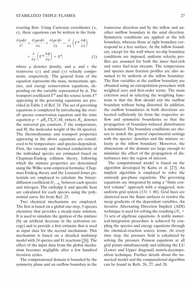
reacting flow. Using Cartesian coordinates ( x,y), these equations can be written in the form
~rf!
†1
~ruf!
x1
~rvf!
y5
x SGff
xD1
y SGff
yD 1 Sf, (1)
where r denotes density, and u and v thetransverse ( x) and axial ( y) velocity compo-nents, respectively. The general form of theequation represents the mass, momentum, spe-cies, and energy conservation equations, de-pending on the variable represented by f. Thetransport coefficient Gf and the source terms Sf
appearing in the governing equations are pro-vided in Table 1 of Ref. 24. The set of governingequations is completed by introducing the over-all species conservation equation and the stateequation p 5 rRuTSiYi/Mi (where Ru denotesthe universal gas constant, T the temperature,and Mi the molecular weight of the ith species).The thermodynamic and transport propertiesappearing in the above equations are consid-ered to be temperature- and species-dependent.First, the viscosity and thermal conductivity ofthe individual species are estimated based onChapman-Enskog collision theory, followingwhich the mixture properties are determinedusing the Wilke semi-empirical formulae. Chap-man-Enskog theory and the Lennard-Jones po-tentials are employed to calculate the binary-diffusion coefficient Di2N2
between each speciesand nitrogen. The enthalpy h and specific heatare calculated for each species using the poly-nomial curve fits from Ref. 25.
Two chemical mechanisms are employed.The first is based on a global one-step, 5-specieschemistry that provides a steady-state solution.It is used to simulate the ignition of the mixture(by an artificial decrease in the activation en-ergy) and to provide a first estimate that is usedas input data for the second mechanism. Thismechanism is based on a detailed multistepmodel with 24 species and 81 reactions [26]. Theeffect of the input data from the global mecha-nism becomes negligible after a few hundrediteration cycles.
The computational domain is bounded by thesymmetry plane and an outflow boundary in the
transverse direction and by the inflow and an-other outflow boundary in the axial direction.Symmetric conditions are applied at the leftboundary, whereas those at right boundary cor-respond to a free surface. At the inflow bound-ary, except for the wall where no-slip boundaryconditions are imposed, uniform velocity pro-files are assumed for both the inner fuel-richand outer fuel-lean streams. The temperatureand species mass fraction profiles are also as-sumed to be uniform at the inflow boundary.The flow variables at the outflow boundary areobtained using an extrapolation procedure withweighted zero and first-order terms. The maincriterion used in selecting the weighting func-tions is that the flow should exit the outflowboundary without being distorted. In addition,the outflow boundaries in both directions arelocated sufficiently far from the respective in-flow and symmetric boundaries so that thepropagation of boundary-induced disturbancesis minimized. The boundary conditions are cho-sen to match the general experimental settingswith the species’ densities and the mixture ve-locity at the inflow boundary. Moreover, thedimensions of the domain are large enough tominimize the effect of the propagation of dis-turbances into the region of interest.
The computational model is based on thealgorithm developed by Katta et al. [27]. Animplicit algorithm is employed to solve theunsteady gas-phase equations. The governingequations are integrated by using a “finite con-trol volume” approach with a staggered, non-uniform grid system (131 3 88). Grid lines areclustered near the flame surfaces to resolve thesteep gradients of the dependent variables. Aniterative Alternating Direction Implicit (ADI)technique is used for solving the resulting (Ns 13) sets of algebraic equations. A stable numer-ical-integration procedure is achieved by cou-pling the species and energy equations throughthe chemical-reaction source terms. At everytime step, the pressure field is calculated bysolving the pressure Poisson equations at allgrid points simultaneously and utilizing the LU(Lower and Upper diagonal) matrix-decompo-sition technique. Further details about the nu-merical model and the computational algorithmcan be found in Refs. 26, 27, and 28.
27STABILIZED TRIPLE FLAMES
RESULTS AND DISCUSSION
General Features of Triple Flames
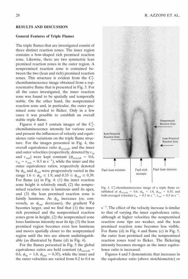
The triple flames that are investigated consist ofthree distinct reaction zones. The inner regioncontains a bow-shaped rich premixed reactionzone. Likewise, there are two symmetric leanpremixed reaction zones in the outer region. Anonpremixed reaction zone is contained be-tween the two (lean and rich) premixed reactionzones. This structure is evident from the C*2-chemiluminescence image obtained from a rep-resentative flame that is presented in Fig. 3. Forall the cases investigated, the inner reactionzone was found to be spatially and temporallystable. On the other hand, the nonpremixedreaction zone and, in particular, the outer pre-mixed zone tended to flicker. Only in a fewcases it was possible to establish an overallstable triple flame.
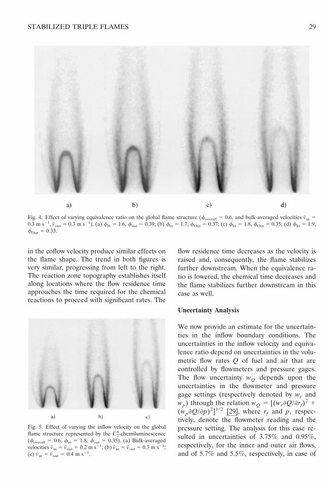
Figures 4 and 5 contain images of the C*2-chemiluminescence intensity for various casesand present the influences of velocity and equiv-alence ratio variations on the triple flame struc-ture. For the images presented in Fig. 4, theoverall equivalence ratio foverall, and the innerand outer velocities (respectively, denoted by vinand vout) were kept constant (foverall 5 0.6,vin 5 vout 5 0.3 m s21), while the inner and theouter equivalence ratios, respectively denotedby fin and fout were progressively varied in therange 1.6 # fin # 1.9, and 0.33 # fout # 0.39.For flame (a) in Fig. 4: (1) the inner reactionzone height is relatively small, (2) the nonpre-mixed reaction zone is luminous until its apex,and (3) the lean premixed reaction zone isfaintly luminous. As fin increases (or, con-versely, as fout decreases), the gradient ¹W fbecomes larger, and we find that (1) the innerrich premixed and the nonpremixed reactionzones grow in height, (2) the nonpremixed zoneloses luminous intensity near its tip, (3) the leanpremixed region becomes even less luminousand moves spatially closer to the nonpremixedregion until the two are almost undistinguish-able (as illustrated by flame (d) in Fig. 4).
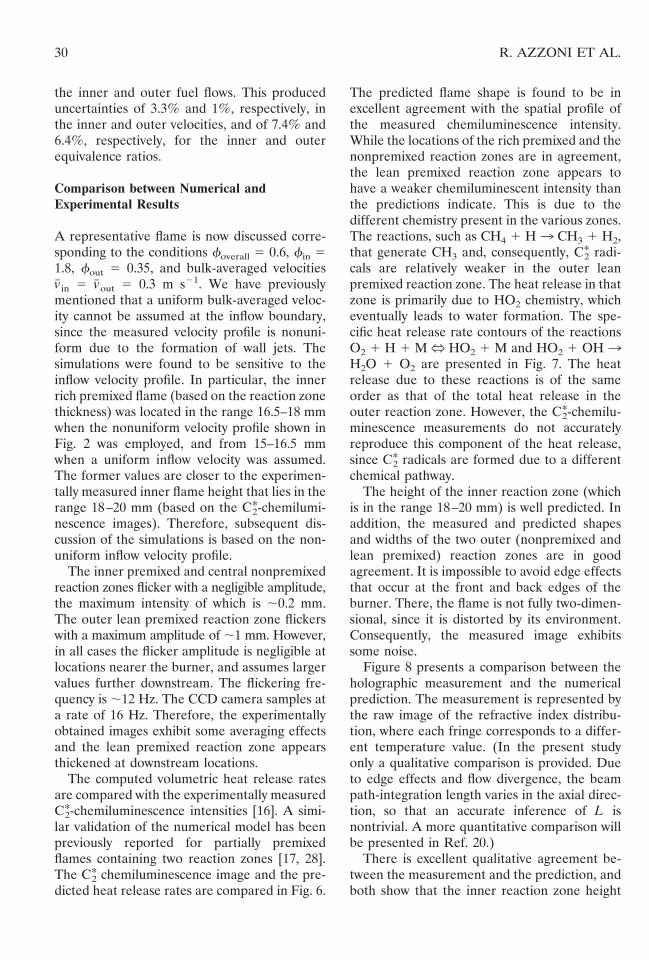
For the flames presented in Fig. 5 the globalequivalence ratios are held constant (foverall 50.6, fin 5 1.8, fout 5 0.35), while the inner andthe outer velocities are varied from 0.2 to 0.4 m
s21. The effect of the velocity increase is similarto that of varying the inner equivalence ratio,although at higher velocities the nonpremixedreaction zone tips are weaker, and the leanpremixed reaction zone becomes less visible.For flame (d) in Fig. 4 and flame (c) in Fig. 5,the outer lean premixed and the nonpremixedreaction zones tend to flicker. The flickeringintensity becomes stronger as the inner equiva-lence ratio is increased.
Figures 4 and 5 demonstrate that increases inthe equivalence ratio (above stoichiometric) or
Fig. 3. C*2-chemiluminescence image of a triple flame es-tablished at foverall 5 0.6, fin 5 1.8, fout 5 0.35, andbulk-averaged velocities v# in 5 0.3 m s21, v#out 5 0.3 m s21.
28 R. AZZONI ET AL.
in the coflow velocity produce similar effects onthe flame shape. The trend in both figures isvery similar, progressing from left to the right.The reaction zone topography establishes itselfalong locations where the flow residence timeapproaches the time required for the chemicalreactions to proceed with significant rates. The
flow residence time decreases as the velocity israised and, consequently, the flame stabilizesfurther downstream. When the equivalence ra-tio is lowered, the chemical time decreases andthe flame stabilizes further downstream in thiscase as well.
Uncertainty Analysis
We now provide an estimate for the uncertain-ties in the inflow boundary conditions. Theuncertainties in the inflow velocity and equiva-lence ratio depend on uncertainties in the volu-metric flow rates Q of fuel and air that arecontrolled by flowmeters and pressure gages.The flow uncertainty wQ depends upon theuncertainties in the flowmeter and pressuregage settings (respectively denoted by wr andwp) through the relation wQ 5 [(wrQ/rf)
2 1(wpQ/p)2]1/ 2 [29], where rf and p, respec-tively, denote the flowmeter reading and thepressure setting. The analysis for this case re-sulted in uncertainties of 3.75% and 0.95%,respectively, for the inner and outer air flows,and of 5.7% and 5.5%, respectively, in case of
Fig. 4. Effect of varying equivalence ratio on the global flame structure (foverall 5 0.6, and bulk-averaged velocities v# in 50.3 m s21, v#out 5 0.3 m s21). (a) fin 5 1.6, fout 5 0.39; (b) fin 5 1.7, fOut 5 0.37; (c) fIn 5 1.8, fOut 5 0.35; (d) fIn 5 1.9,fOut 5 0.33.
Fig. 5. Effect of varying the inflow velocity on the globalflame structure represented by the C*2-chemiluminescence(foverall 5 0.6, fin 5 1.8, fout 5 0.35). (a) Bulk-averagedvelocities v# in 5 v#out 5 0.2 m s21; (b) v# in 5 v#out 5 0.3 m s21;(c) v# in 5 v#out 5 0.4 m s21.
29STABILIZED TRIPLE FLAMES
the inner and outer fuel flows. This produceduncertainties of 3.3% and 1%, respectively, inthe inner and outer velocities, and of 7.4% and6.4%, respectively, for the inner and outerequivalence ratios.
Comparison between Numerical andExperimental Results
A representative flame is now discussed corre-sponding to the conditions foverall 5 0.6, fin 51.8, fout 5 0.35, and bulk-averaged velocitiesv# in 5 v#out 5 0.3 m s21. We have previouslymentioned that a uniform bulk-averaged veloc-ity cannot be assumed at the inflow boundary,since the measured velocity profile is nonuni-form due to the formation of wall jets. Thesimulations were found to be sensitive to theinflow velocity profile. In particular, the innerrich premixed flame (based on the reaction zonethickness) was located in the range 16.5–18 mmwhen the nonuniform velocity profile shown inFig. 2 was employed, and from 15–16.5 mmwhen a uniform inflow velocity was assumed.The former values are closer to the experimen-tally measured inner flame height that lies in therange 18–20 mm (based on the C*2-chemilumi-nescence images). Therefore, subsequent dis-cussion of the simulations is based on the non-uniform inflow velocity profile.
The inner premixed and central nonpremixedreaction zones flicker with a negligible amplitude,the maximum intensity of which is ;0.2 mm.The outer lean premixed reaction zone flickerswith a maximum amplitude of ;1 mm. However,in all cases the flicker amplitude is negligible atlocations nearer the burner, and assumes largervalues further downstream. The flickering fre-quency is ;12 Hz. The CCD camera samples ata rate of 16 Hz. Therefore, the experimentallyobtained images exhibit some averaging effectsand the lean premixed reaction zone appearsthickened at downstream locations.
The computed volumetric heat release ratesare compared with the experimentally measuredC*2-chemiluminescence intensities [16]. A simi-lar validation of the numerical model has beenpreviously reported for partially premixedflames containing two reaction zones [17, 28].The C*2 chemiluminescence image and the pre-dicted heat release rates are compared in Fig. 6.
The predicted flame shape is found to be inexcellent agreement with the spatial profile ofthe measured chemiluminescence intensity.While the locations of the rich premixed and thenonpremixed reaction zones are in agreement,the lean premixed reaction zone appears tohave a weaker chemiluminescent intensity thanthe predictions indicate. This is due to thedifferent chemistry present in the various zones.The reactions, such as CH4 1 H 3 CH3 1 H2,that generate CH3 and, consequently, C*2 radi-cals are relatively weaker in the outer leanpremixed reaction zone. The heat release in thatzone is primarily due to HO2 chemistry, whicheventually leads to water formation. The spe-cific heat release rate contours of the reactionsO2 1 H 1 M N HO2 1 M and HO2 1 OH 3H2O 1 O2 are presented in Fig. 7. The heatrelease due to these reactions is of the sameorder as that of the total heat release in theouter reaction zone. However, the C*2-chemilu-minescence measurements do not accuratelyreproduce this component of the heat release,since C*2 radicals are formed due to a differentchemical pathway.
The height of the inner reaction zone (whichis in the range 18–20 mm) is well predicted. Inaddition, the measured and predicted shapesand widths of the two outer (nonpremixed andlean premixed) reaction zones are in goodagreement. It is impossible to avoid edge effectsthat occur at the front and back edges of theburner. There, the flame is not fully two-dimen-sional, since it is distorted by its environment.Consequently, the measured image exhibitssome noise.
Figure 8 presents a comparison between theholographic measurement and the numericalprediction. The measurement is represented bythe raw image of the refractive index distribu-tion, where each fringe corresponds to a differ-ent temperature value. (In the present studyonly a qualitative comparison is provided. Dueto edge effects and flow divergence, the beampath-integration length varies in the axial direc-tion, so that an accurate inference of L isnontrivial. A more quantitative comparison willbe presented in Ref. 20.)
There is excellent qualitative agreement be-tween the measurement and the prediction, andboth show that the inner reaction zone height
30 R. AZZONI ET AL.
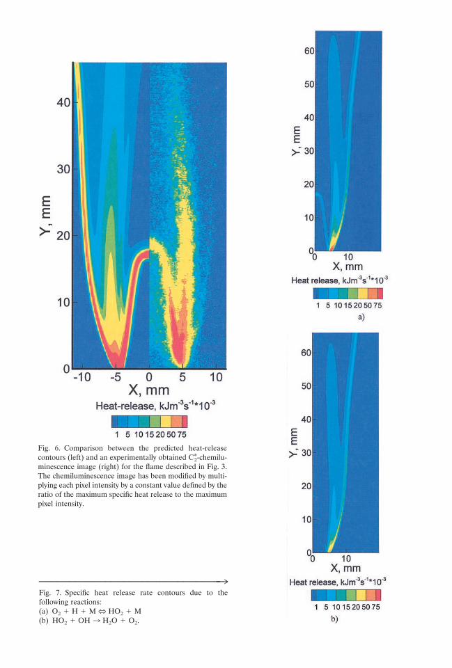
Fig. 6. Comparison between the predicted heat-releasecontours (left) and an experimentally obtained C*2-chemilu-minescence image (right) for the flame described in Fig. 3.The chemiluminescence image has been modified by multi-plying each pixel intensity by a constant value defined by theratio of the maximum specific heat release to the maximumpixel intensity.
™™™™™™™™™™™™™™™™™™™™™™™™™™™™™™3Fig. 7. Specific heat release rate contours due to thefollowing reactions:(a) O2 1 H 1 M N HO2 1 M(b) HO2 1 OH 3 H2O 1 O2.
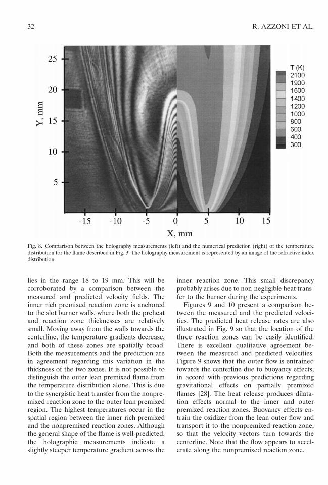
lies in the range 18 to 19 mm. This will becorroborated by a comparison between themeasured and predicted velocity fields. Theinner rich premixed reaction zone is anchoredto the slot burner walls, where both the preheatand reaction zone thicknesses are relativelysmall. Moving away from the walls towards thecenterline, the temperature gradients decrease,and both of these zones are spatially broad.Both the measurements and the prediction arein agreement regarding this variation in thethickness of the two zones. It is not possible todistinguish the outer lean premixed flame fromthe temperature distribution alone. This is dueto the synergistic heat transfer from the nonpre-mixed reaction zone to the outer lean premixedregion. The highest temperatures occur in thespatial region between the inner rich premixedand the nonpremixed reaction zones. Althoughthe general shape of the flame is well-predicted,the holographic measurements indicate aslightly steeper temperature gradient across the
inner reaction zone. This small discrepancyprobably arises due to non-negligible heat trans-fer to the burner during the experiments.
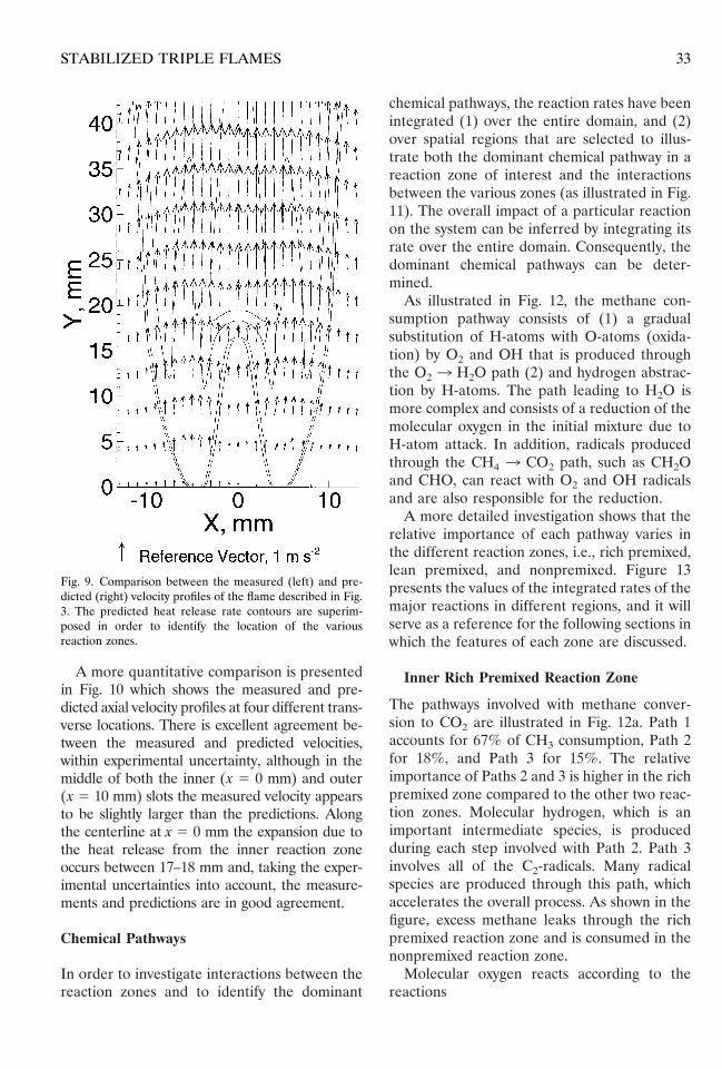
Figures 9 and 10 present a comparison be-tween the measured and the predicted veloci-ties. The predicted heat release rates are alsoillustrated in Fig. 9 so that the location of thethree reaction zones can be easily identified.There is excellent qualitative agreement be-tween the measured and predicted velocities.Figure 9 shows that the outer flow is entrainedtowards the centerline due to buoyancy effects,in accord with previous predictions regardinggravitational effects on partially premixedflames [28]. The heat release produces dilata-tion effects normal to the inner and outerpremixed reaction zones. Buoyancy effects en-train the oxidizer from the lean outer flow andtransport it to the nonpremixed reaction zone,so that the velocity vectors turn towards thecenterline. Note that the flow appears to accel-erate along the nonpremixed reaction zone.
Fig. 8. Comparison between the holography measurements (left) and the numerical prediction (right) of the temperaturedistribution for the flame described in Fig. 3. The holography measurement is represented by an image of the refractive indexdistribution.
32 R. AZZONI ET AL.
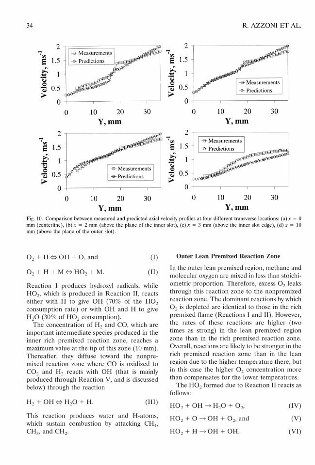
A more quantitative comparison is presentedin Fig. 10 which shows the measured and pre-dicted axial velocity profiles at four different trans-verse locations. There is excellent agreement be-tween the measured and predicted velocities,within experimental uncertainty, although in themiddle of both the inner (x 5 0 mm) and outer(x 5 10 mm) slots the measured velocity appearsto be slightly larger than the predictions. Alongthe centerline at x 5 0 mm the expansion due tothe heat release from the inner reaction zoneoccurs between 17–18 mm and, taking the exper-imental uncertainties into account, the measure-ments and predictions are in good agreement.
Chemical Pathways
In order to investigate interactions between thereaction zones and to identify the dominant
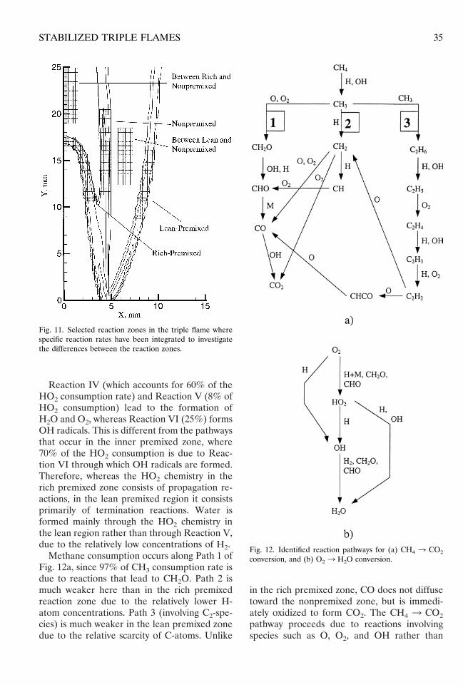
chemical pathways, the reaction rates have beenintegrated (1) over the entire domain, and (2)over spatial regions that are selected to illus-trate both the dominant chemical pathway in areaction zone of interest and the interactionsbetween the various zones (as illustrated in Fig.11). The overall impact of a particular reactionon the system can be inferred by integrating itsrate over the entire domain. Consequently, thedominant chemical pathways can be deter-mined.
As illustrated in Fig. 12, the methane con-sumption pathway consists of (1) a gradualsubstitution of H-atoms with O-atoms (oxida-tion) by O2 and OH that is produced throughthe O2 3 H2O path (2) and hydrogen abstrac-tion by H-atoms. The path leading to H2O ismore complex and consists of a reduction of themolecular oxygen in the initial mixture due toH-atom attack. In addition, radicals producedthrough the CH4 3 CO2 path, such as CH2Oand CHO, can react with O2 and OH radicalsand are also responsible for the reduction.
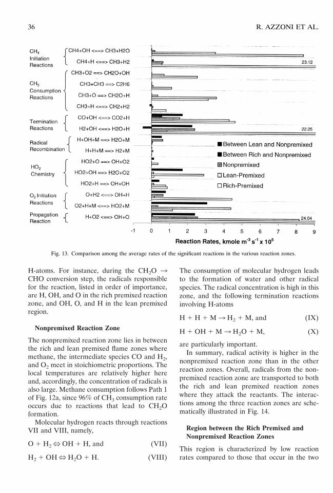
A more detailed investigation shows that therelative importance of each pathway varies inthe different reaction zones, i.e., rich premixed,lean premixed, and nonpremixed. Figure 13presents the values of the integrated rates of themajor reactions in different regions, and it willserve as a reference for the following sections inwhich the features of each zone are discussed.
Inner Rich Premixed Reaction Zone
The pathways involved with methane conver-sion to CO2 are illustrated in Fig. 12a. Path 1accounts for 67% of CH3 consumption, Path 2for 18%, and Path 3 for 15%. The relativeimportance of Paths 2 and 3 is higher in the richpremixed zone compared to the other two reac-tion zones. Molecular hydrogen, which is animportant intermediate species, is producedduring each step involved with Path 2. Path 3involves all of the C2-radicals. Many radicalspecies are produced through this path, whichaccelerates the overall process. As shown in thefigure, excess methane leaks through the richpremixed reaction zone and is consumed in thenonpremixed reaction zone.
Molecular oxygen reacts according to thereactions
Fig. 9. Comparison between the measured (left) and pre-dicted (right) velocity profiles of the flame described in Fig.3. The predicted heat release rate contours are superim-posed in order to identify the location of the variousreaction zones.
33STABILIZED TRIPLE FLAMES
O2 1 HN OH 1 O, and (I)
O2 1 H 1 MN HO2 1 M. (II)
Reaction I produces hydroxyl radicals, whileHO2, which is produced in Reaction II, reactseither with H to give OH (70% of the HO2consumption rate) or with OH and H to giveH2O (30% of HO2 consumption).
The concentration of H2 and CO, which areimportant intermediate species produced in theinner rich premixed reaction zone, reaches amaximum value at the tip of this zone (10 mm).Thereafter, they diffuse toward the nonpre-mixed reaction zone where CO is oxidized toCO2 and H2 reacts with OH (that is mainlyproduced through Reaction V, and is discussedbelow) through the reaction
H2 1 OHN H2O 1 H. (III)
This reaction produces water and H-atoms,which sustain combustion by attacking CH4,CH3, and CH2.
Outer Lean Premixed Reaction Zone
In the outer lean premixed region, methane andmolecular oxygen are mixed in less than stoichi-ometric proportion. Therefore, excess O2 leaksthrough this reaction zone to the nonpremixedreaction zone. The dominant reactions by whichO2 is depleted are identical to those in the richpremixed flame (Reactions I and II). However,the rates of these reactions are higher (twotimes as strong) in the lean premixed regionzone than in the rich premixed reaction zone.Overall, reactions are likely to be stronger in therich premixed reaction zone than in the leanregion due to the higher temperature there, butin this case the higher O2 concentration morethan compensates for the lower temperatures.
The HO2 formed due to Reaction II reacts asfollows:
HO2 1 OH3 H2O 1 O2, (IV)
HO2 1 O3 OH 1 O2, and (V)
HO2 1 H3 OH 1 OH. (VI)
Fig. 10. Comparison between measured and predicted axial velocity profiles at four different transverse locations: (a) x 5 0mm (centerline), (b) x 5 2 mm (above the plane of the inner slot), (c) x 5 3 mm (above the inner slot edge), (d) x 5 10mm (above the plane of the outer slot).
34 R. AZZONI ET AL.
Reaction IV (which accounts for 60% of theHO2 consumption rate) and Reaction V (8% ofHO2 consumption) lead to the formation ofH2O and O2, whereas Reaction VI (25%) formsOH radicals. This is different from the pathwaysthat occur in the inner premixed zone, where70% of the HO2 consumption is due to Reac-tion VI through which OH radicals are formed.Therefore, whereas the HO2 chemistry in therich premixed zone consists of propagation re-actions, in the lean premixed region it consistsprimarily of termination reactions. Water isformed mainly through the HO2 chemistry inthe lean region rather than through Reaction V,due to the relatively low concentrations of H2.
Methane consumption occurs along Path 1 ofFig. 12a, since 97% of CH3 consumption rate isdue to reactions that lead to CH2O. Path 2 ismuch weaker here than in the rich premixedreaction zone due to the relatively lower H-atom concentrations. Path 3 (involving C2-spe-cies) is much weaker in the lean premixed zonedue to the relative scarcity of C-atoms. Unlike
in the rich premixed zone, CO does not diffusetoward the nonpremixed zone, but is immedi-ately oxidized to form CO2. The CH4 3 CO2pathway proceeds due to reactions involvingspecies such as O, O2, and OH rather than
Fig. 11. Selected reaction zones in the triple flame wherespecific reaction rates have been integrated to investigatethe differences between the reaction zones.
Fig. 12. Identified reaction pathways for (a) CH4 3 CO2
conversion, and (b) O2 3 H2O conversion.
35STABILIZED TRIPLE FLAMES
H-atoms. For instance, during the CH2O 3CHO conversion step, the radicals responsiblefor the reaction, listed in order of importance,are H, OH, and O in the rich premixed reactionzone, and OH, O, and H in the lean premixedregion.
Nonpremixed Reaction Zone
The nonpremixed reaction zone lies in betweenthe rich and lean premixed flame zones wheremethane, the intermediate species CO and H2,and O2 meet in stoichiometric proportions. Thelocal temperatures are relatively higher hereand, accordingly, the concentration of radicals isalso large. Methane consumption follows Path 1of Fig. 12a, since 96% of CH3 consumption rateoccurs due to reactions that lead to CH2Oformation.
Molecular hydrogen reacts through reactionsVII and VIII, namely,
O 1 H2N OH 1 H, and (VII)
H2 1 OHN H2O 1 H. (VIII)
The consumption of molecular hydrogen leadsto the formation of water and other radicalspecies. The radical concentration is high in thiszone, and the following termination reactionsinvolving H-atoms
H 1 H 1 M3 H2 1 M, and (IX)
H 1 OH 1 M3 H2O 1 M, (X)
are particularly important.In summary, radical activity is higher in the
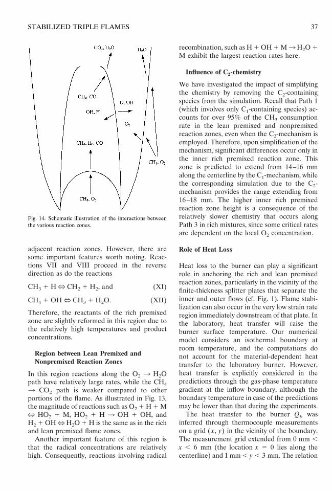
nonpremixed reaction zone than in the otherreaction zones. Overall, radicals from the non-premixed reaction zone are transported to boththe rich and lean premixed reaction zoneswhere they attack the reactants. The interac-tions among the three reaction zones are sche-matically illustrated in Fig. 14.
Region between the Rich Premixed andNonpremixed Reaction Zones
This region is characterized by low reactionrates compared to those that occur in the two
Fig. 13. Comparison among the average rates of the significant reactions in the various reaction zones.
36 R. AZZONI ET AL.
adjacent reaction zones. However, there aresome important features worth noting. Reac-tions VII and VIII proceed in the reversedirection as do the reactions
CH3 1 HN CH2 1 H2, and (XI)
CH4 1 OHN CH3 1 H2O. (XII)
Therefore, the reactants of the rich premixedzone are slightly reformed in this region due tothe relatively high temperatures and productconcentrations.
Region between Lean Premixed andNonpremixed Reaction Zones
In this region reactions along the O2 3 H2Opath have relatively large rates, while the CH43 CO2 path is weaker compared to otherportions of the flame. As illustrated in Fig. 13,the magnitude of reactions such as O2 1 H 1 MN HO2 1 M, HO2 1 H 3 OH 1 OH, andH2 1 OHNH2O 1 H is the same as in the richand lean premixed flame zones.
Another important feature of this region isthat the radical concentrations are relativelyhigh. Consequently, reactions involving radical
recombination, such as H 1 OH 1 M3H2O 1M exhibit the largest reaction rates here.
Influence of C2-chemistry
We have investigated the impact of simplifyingthe chemistry by removing the C2-containingspecies from the simulation. Recall that Path 1(which involves only C1-containing species) ac-counts for over 95% of the CH3 consumptionrate in the lean premixed and nonpremixedreaction zones, even when the C2-mechanism isemployed. Therefore, upon simplification of themechanism, significant differences occur only inthe inner rich premixed reaction zone. Thiszone is predicted to extend from 14–16 mmalong the centerline by the C1-mechanism, whilethe corresponding simulation due to the C2-mechanism provides the range extending from16–18 mm. The higher inner rich premixedreaction zone height is a consequence of therelatively slower chemistry that occurs alongPath 3 in rich mixtures, since some critical ratesare dependent on the local O2 concentration.
Role of Heat Loss
Heat loss to the burner can play a significantrole in anchoring the rich and lean premixedreaction zones, particularly in the vicinity of thefinite-thickness splitter plates that separate theinner and outer flows (cf. Fig. 1). Flame stabi-lization can also occur in the very low strain rateregion immediately downstream of that plate. Inthe laboratory, heat transfer will raise theburner surface temperature. Our numericalmodel considers an isothermal boundary atroom temperature, and the computations donot account for the material-dependent heattransfer to the laboratory burner. However,heat transfer is explicitly considered in thepredictions through the gas-phase temperaturegradient at the inflow boundary, although theboundary temperature in case of the predictionsmay be lower than that during the experiments.
The heat transfer to the burner Qb wasinferred through thermocouple measurementson a grid ( x, y) in the vicinity of the boundary.The measurement grid extended from 0 mm ,x , 6 mm (the location x 5 0 lies along thecenterline) and 1 mm , y , 3 mm. The relation
Fig. 14. Schematic illustration of the interactions betweenthe various reaction zones.
37STABILIZED TRIPLE FLAMES
Qb 5 L*S 2 k~T# !~DT/Dy! Dx, (2)
was used to calculate Qb, where the summationoccurs over the entire transverse burner lengthL*, k(T# ) denotes the grid-averaged thermalconductivity assuming the mixture to have theproperties identical to molecular nitrogen, T# themean temperature at two adjacent axial mea-surement locations, and Dx and Dy (both equalto 0.25 mm) represent the local transverse andaxial displacements along the measurementgrid. The thermocouple temperatures on they 5 1 mm plane lie in the range 440–875 K, andfrom 500–950 K on the y 5 1.25 mm plane.Radiation corrections are expected to be insig-nificant for these temperature values. The ther-mocouple measurements are not entirely accu-rate, since the thermocouple is inserted througha nonuniform temperature field [20]. (We have,therefore, used the qualitative holographic mea-surements for purpose of comparison in Fig. 8.)
This value of the heat transfer was comparedto the maximum possible heat release based onthe fuel flowrate and its lower heating value.The total heat release for this flame is 1154 W,and the heat transfer to the ( x, y 5 1 mm)plane is 5.9 W. Therefore, we infer that the heattransfer to the burner is '0.5% of the maximumpossible heat release. This ratio is insignificant,even if the combustion efficiency were to fall.
A similar calculation was conducted for thenumerical results, although in this case the localconductivity was based on the mixture proper-ties. The heat transfer to the boundary wascompared with two values, one based on theheating value of the fuel, and the other on thelocal heat release rate integrated over the entirecomputational domain. (The integrated value islower than that based on the fuel heat release by12%, primarily because not all of the interme-diate species are transformed into CO2 andH2O.) The corresponding ratios of heat transferto the boundary are 0.72% and 0.8%. The lowerboundary temperature in case of the computa-tions results in slightly steeper temperature gradi-ents and, consequently, leads to larger gas-phaseheat transfer as compared to the experiment.
The heat transfer to the burner or boundaryis a negligible proportion of the total heatrelease in both the computations and the exper-iments. Furthermore, in both cases the heat
transfer to the boundary is of similar magnitude,even though the burner properties are not ex-plicitly modeled. Therefore, we conclude thatthe presence of the splitter plate in the labora-tory burner does not cause a significant anchor-ing effect due to a flame heat loss mechanism.
Lifted Flames
We were able to obtain lifted flames in thelaboratory, but chose to consider one estab-lished closer to the burner surface for severalreasons. The lifted laboratory flames were nottwo-dimensional. The wall jets (that we haveaddressed above) caused the flames to have abow shape in the cross-stream direction, therebylifting them higher along the burner sides. Acomparison with the numerical simulation re-quires that the laboratory flame be quasi two-dimensional. In addition, an important objec-tive was to investigate the effects of varyingparameters, such as fin, fout, vin, and vout. Theflame discussed herein is both more stable andsteady over a wide range of conditions, whichalso precluded an investigation of lifted flames.Unsteady flickering flames are the focus ofanother investigation in our laboratories [30].
CONCLUSION
An atmospheric laminar methane–air triple flamethat is stabilized on a Wolfhard-Parker slotburner has been investigated. A rich mixture isintroduced from the inner slot, while a coflow-ing lean mixture is introduced from the twosymmetric outer slots. The three reaction zonesthat characterize the triple flame have beenclearly distinguished. Velocity measurementswere made using laser Doppler velocimetry,temperature measurements using laser inter-ferometric holography, and C*2-chemilumines-cence images that depict the reaction zones andthe heat release were obtained. A comprehen-sive numerical simulation of the flame wasperformed based on a detailed chemical mech-anism involving 24 species and 81 reactions.
The quantitative spatial comparison betweenspatial locations of the C*2-chemiluminescenceand the predicted specific heat release rate isexcellent. Likewise, the measured and predicted
38 R. AZZONI ET AL.
spatial locations of the three (i.e., triple) reac-tion zones are virtually identical. In comparisonto the other reaction zones the C*2-chemilumi-nescence images do not convey the magnitudeof the heat release rate in the lean premixed andnonpremixed reaction zones due to the fact thathighly exothermic reactions involving the HO2chemistry dominate this zone (rather than theC2-chemistry from which C*2 radicals areformed). The comparison between the mea-sured and the predicted velocities is also excel-lent, which is indicative of the accuracy of thenumerical model. There is also excellent quali-tative agreement regarding the temperature dis-tribution between holography measurementsand numerical predictions, and both sets ofresults indicate that the inner reaction zoneheight for a representative flame extends from18–19 mm.
The effects of the mixture velocity and equiv-alence ratios on the global triple flame structurehave been characterized. As the equivalenceratio in the fuel-rich stream increases or that inthe fuel lean stream decreases, the heights ofboth the inner premixed and the nonpremixedreaction zones increase. In addition, the non-premixed reaction zone becomes less luminousnear its apex and moves closer to the outer leanpremixed reaction zone until the two becomeindistinguishable from each other. A similareffect is observed when the mixture velocities inthe two streams are increased. For all the casesinvestigated, the inner rich premixed zone isfound to be stable, whereas both the nonpre-mixed and the outer lean premixed zones tendto flicker. Only in a few cases is it possible toestablish an overall stable triple flame.
The triple flame structure and the interac-tions between the three reaction zones havebeen investigated in detail. Methane oxidationto CO2 and the reduction of molecular oxygento H2O follow different pathways in the threereaction zones. The intermediate species COand H2 are produced in the inner rich premixedreaction zone. The nonpremixed reaction zoneprovides radical species that oxidize CO and H2to CO2 and H2O. Methane consumption isweaker in the outer lean premixed reactionzone, and the concentration of intermediatespecies, such as CO and H2, is very small there.Simplifying the chemical mechanism by remov-
ing the C2-containing species produces signifi-cant differences in the predicted results only forthe inner rich premixed reaction zone.
The heat transfer to the burner or boundarywas found to be a negligible proportion of thetotal heat release in both the computations andthe experiments. Therefore, the presence of thesplitter plate in the laboratory burner does notappear to cause a significant anchoring effectdue to a flame heat loss mechanism.
This research was supported by the NationalScience Foundation Combustion and Plasma Sys-tems Program through Grant No. CTS-9707000for which Dr. Farley Fisher is the Program Direc-tor. Simulations were performed on SGI worksta-tions at the NCSA at Urbana. Many fruitfuldiscussions with Dr. V. R. Katta of ISSI are greatlyappreciated. We are grateful to Mr. X. Xiao formaking the holography measurement, and to Mr.Z. Shu for implementing the numerical code onNCSA workstations.
REFERENCES
1. Ruetsch, G. R., Vervisch, L., and Linan, A., Phys.Fluids 7:1447 (1995).
2. Chung, S. H., and Lee, B. J., Combust. Flame 86:62(1991).
3. Kioni, P. N., Rogg, B., Bray, K. N. C., and Linan, A.,Combust. Flame 95:276 (1993).
4. Phillips, H., Tenth Symposium (International) on Com-bustion, Cambridge, 1965, p. 1277.
5. Dold, J. W., Combust. Flame 76:71 (1989).6. Hartley, L. J., and Dold, J. W., Combust. Sci. Technol.
80:23 (1991).7. Dold, J. W., in Flame Structure, Nauka Publisher,
Novosibirsk, 1991.8. Muniz, L., and Mungal, M. G., Combust. Flame 111:16
(1997).9. Schefer, R. W., and Goix, P. J., Combust. Flame
112:559 (1998).10. Aggarwal, S. K., and Puri, I. K., AIAA J. 36:1190
(1998).11. Echekki, T., and Chen, J. H., Combust. Flame 114:231
(1998).12. Domingo, P., and Vervisch, L., Twenty-Sixth Sympo-
sium (International) on Combustion, The CombustionInstitute, Pittsburgh, 1996, p. 233.
13. Buckmaster, J., and Matalon, M., Twenty-Second Sym-posium (International) on Combustion, The Combus-tion Institute, Pittsburgh, 1988, p. 1527.
14. Plessing, T., Terhoeven, P., Peters, N., and Mansour,M. S., Combust. Flame 115:335 (1998).
15. Brandon, Y., and Samaniego, J.-M., Combust. Sci.Technol. 84:81–89 (1992).
39STABILIZED TRIPLE FLAMES
16. McManus, K., Yip, B., and Candel, S., Exptl. ThermalFluid Sci. 10:486–502 (1995).
17. Shu, Z., Krass, B. J., Choi, C. W., Aggarwal, S. K.,Katta, V. R., and Puri, I. K., Twenty-Seventh Sympo-sium (International) on Combustion, The CombustionInstitute, Pittsburgh, 1998, p. 625.
18. Pearse, R. W. B., and Gaydon, A. G., The Identificationof Molecular Spectra, 4th ed., Chapman and Hall, NewYork, 1976, p. 83.
19. Najm, H. N., Paul, P. H., Mueller, C. J., and Wyckoff,P. S., Combust. Flame 113:312–332 (1998).
20. Xiao, X., Choi, C. W., and Puri, I. K., Paper No. 137,1999 Joint Meeting of the U.S. Sections of The Com-bustion Institute, Washington, DC, March 15–17,1999.
21. Vest, C. M., Holographic Interferometry, Wiley, 1979.22. Montgomery, G. P., and Reuss, D. L., Appl. Optics
21:1373 (1982).23. Hertz, H. M., Optics Communications 1:131 (1985).24. Shu, Z., Aggarwal, S. K., Katta, V. R., and Puri, I. K.,
Combust. Flame 111:276 (1997).25. Kee, R. J., Miller, J. A., and Warnatz, J. (1983). A
Fortran Program Package for the Evaluation of Gas-Phase Viscosities, Conductivities, and Diffusion Coeffi-cients, Sandia National Laboratories Rept. SAND83-8209.
26. Peters, N., in Reduced Kinetic Mechanisms for Applica-tions in Combustion Systems, Lecture Notes in Physics,Vol. m15, (N. Peters and B. Rogg, Eds.), Springer-Verlag, 1993, pp. 3–14.
27. Katta, V. R., Goss, L. P., and Roquemore, W. M.,Combust. Flame 96:60 (1994).
28. Shu, Z., Choi, C. W., Aggarwal, S. K., Katta, V. R., andPuri, I. K., Combust. Flame 118:91–107 (1999).
29. Holman, J. P., Experimental Methods in MechanicalEngineering, 6th ed., McGraw-Hill, New York, 1994, p.49.
30. Azzoni, R., Aggarwal, S. K., and Puri, I. K., Paper No.167, 1999 Joint Meeting of the U.S. Sections of TheCombustion Institute, Washington, DC, March 15–17,1999.
Received 7 December 1998; revised 9 March 1999; accepted29 March 1999
40 R. AZZONI ET AL.