18th ifrf, germany, experimental investigation of oxy fuel combustion of cng flames stabilized over...
TRANSCRIPT
INTERNATIONAL FLAME RESEARCH FOUNDATION
1
18th
IFRF Members’ Conference – Flexible and clean fuel conversion to industry
Freising, Germany, 1, 2, 3 June 2015 – Paper n. 25
EXPERIMENTAL INVESTIGATION OF OXY-FUEL COMBUSTION OF CNG
FLAMES STABILIZED OVER A PERFORATED-PLATE BURNER
S. Samir Rashwan1, [email protected], A. H. Ibrahim
T. Wazier Abou-Arab3, [email protected]
CAIRO UNIVERSITY, Egypt
ABSTRACT
Carbon dioxide emissions are considered one of the most important factors that cause global warming.
For this reason, it is suggested to burn fuels using an oxidizer mixture consisting of oxygen and carbon
dioxide rather than the conventional burning in air. This combustion technique ensures that the resulting
products consist mainly of carbon dioxide and water vapor which facilitates capturing and sequestration
of the carbon dioxide gas and thus eliminates its release into the atmosphere. One of the main challenges
that faces this technique is the need to ensure the flame stability in a wide range of operating conditions
because of the adverse effects of adding carbon dioxide to the oxidizer mixture on chemical kinetics. This
study experimentally examines some of the conditions that must be met to ensure stable flame operation
when burning compressed natural gas in a controlled mixture of oxygen and carbon dioxide stabilized
over a perforated-plate burner at different equivalence ratios and at different oxygen fractions. Two sets
of experiments are carried-out in this study. In the first set, the study identifies the range of equivalence
ratios at constant oxygen fractions necessary for stable flame operation. In the second set, the study
identifies the range of oxygen fraction at constant equivalence ratios necessary for stable flame operation.
The study also documents the visual flame length and color and identifies the extinction mechanism
outside the flammability limits for both sets. The first set of experiments reveals that, in the range of
Reynolds number considered and at an oxygen fraction of 36%, stable flame operation is observed with
flammability limits that are approximately 80% of the corresponding air-fuel combustion under the same
Reynolds number. This ratio decreases as the oxygen fraction decreases. The visual flame length is longer
than that of air-fuel combustion by approximately 15%. Extinction occurs by blow-off outside the upper
and lower flammability limits. The second set of experiments reveals that for the burner and the range of
Reynolds numbers considered, operation below an oxygen fraction of 29% is not possible at all
equivalence ratios considered (namely 0.7, 0.85, 1 and 1.15) while the upper flammability limit is a
function of the equivalence ratio. Extinction occurs by blow-off below the lower flammability limit, and
by flash-back above the upper flammability limit.
Keywords: Oxy-fuel combustion, CNG/O2/CO2 combustion, flammability limit, extinction mechanism,
visual flame appearance and perforated-plate burner.
1. INTRODUCTION:
The average temperature of the Earth’s surface has increased by about 0.8 °C over the past 100 years,
with about 0.6 °C occurring just over the past three decades1. Scientists are 95-100% certain that this
increase in temperature is primarily caused by increasing concentrations of greenhouse gases produced by
anthropogenic activities such as the burning of fossil fuels and deforestation1.
Carbon dioxide (CO2) is the primary greenhouse gas emitted through human activities. In 2011,
CO2 accounted for about 84% of all U.S. greenhouse gas emissions from anthropogenic activities2.
The continued increase in the atmospheric concentration of carbon dioxide due to anthropogenic
emissions is predicted to lead to significant changes in global climate. For example, evaporation will
increase as the climate warms, which will increase average global precipitation. Soil moisture is likely to
decline in many regions, and intense rainstorms are likely to become more frequent. Worldwide effects of
global warming have been discussed3,4. Some of the impacts on Egypt in particular are reported in 5
,6.
The dramatic effects of global warming on the entire planet have caused many scientists to think of
methods to limit the release of greenhouse gases, with CO2 at the heart of them. Oxy-fuel combustion is
one of the viable methods to facilitate CO2 capturing for sequestration.

INTERNATIONAL FLAME RESEARCH FOUNDATION
2
18th
IFRF Members’ Conference – Flexible and clean fuel conversion to industry
Freising, Germany, 1, 2, 3 June 2015 – Paper n. 25
In this combustion technology, N2 is removed from air using an air separation unit. The remaining gases
which are mainly O2 and some impurities such as argon are used as oxidizers. This makes the flue gases
consist mainly of CO2 and H2O. In order to prevent excessively high temperatures if the fuel is burnt in
O2 alone, some of the CO2 form the flue gases is recirculated and mixed with the oxidizers. Then, H2O is
condensed from the flue gas allowing capture and possible reuse of the condensation heat. This
technology makes the flue gases consist primarily of CO2 and thus facilitates its capture and sequestration,
which in turn eliminates the release of CO2 into the atmosphere. This technology also reduces the flue gas
volume and mass significantly, with corresponding benefits in reduced heat losses and reduced size of
flue gas treatment equipment. The reduction in flue gas volume increases the concentration of pollutants,
making separation easier. Additionally, because N2 from air is eliminated from the reactants, thermal NOx
emissions are eliminated.
The oxy-fuel combustion concept can be described as combustion using substitute air in which N2 is
replaced with CO2. However, the combustion characteristics and radiative heat transfer in oxy-fuel
combustion differ from those of air-fuel combustion due to significant differences in the physical
properties of CO2 and N2. The replacement of N2 by CO2 in the oxidizer mixture impacts the flame in four
issues: changes in mixture density, volumetric heat capacity and adiabatic flame temperature, transport
properties (thermal conductivity, mass diffusivity, and dynamic viscosity), chemical kinetic rates and
radiative heat transfer7.
CO2 has higher density than N2, which affects gas volume, flame shape and pressure drop: the density of
air is 0.43 kg/m3 at 800 K while the densities of CO2/O2 mixture are 0.62, 0.61, 0.60 at oxygen fractions
of 29%, 32%, 36%, respectively. The higher density of CO2 also leads to higher volumetric heat capacity
of CO2/O2 mixtures with respect to air: at 800 K, the volumetric heat capacity of air is 480 J/m3K while
those of CO2/O2 mixtures at oxygen fractions of 29%, 32%, 36% are 480, 705, 700 and 690 J/m3K
respectively. The high volumetric heat capacity of CO2/O2 mixtures with respect to air directly reduces
the temperature level and causes less flame speeds and lower flame stability.
In addition to the changes in densities and in volumetric heat capacities, flame speed also is affected by
gas transport properties. Table 1 shows the thermal conductivity and the dynamic viscosity of N2 and CO2
gases at different temperatures as well as the mass diffusivity of O2 in both N2 and CO2.
N2 CO2
T (C) 25 500 1000 25 500 1000
K(W/mK) 25.5 52.9 74.2 16.9 53.1 81.9
*105 (Pa.S) 1.77 3.42 4.61 1.5 3.3 4.7
D*105 (m
2/s) 2.04 10.3 23.7 1.5 8.1 18.8
Table1: Gas transport properties for N2 and CO2 at 1 Atm7
The table shows that while the thermal conductivity and the viscosity of CO2 are very close to those of
N2, the mass diffusivity of oxygen in CO2 is approximately 20% lower than in N2.
Other factors causing lower flame speeds in CO2-diluted flames with respect to N2-diluted flames include
that CO2 causes adverse kinetic interactions by competing with other reactions requiring the H radical and
that the CO2 in the reacting gases leads to additional preheating, through radiative absorption of heat
emitted from product gases, thus decreasing the flame speed.
In conclusion, the laminar burning velocity is significantly lower for oxy-fuel combustion compared to
air-fuel combustion because of the adverse effects of adding CO2 to the oxidizer mixture. These adverse
effects cause lower flame speed, weaker and longer flames88
INTERNATIONAL FLAME RESEARCH FOUNDATION
3
18th
IFRF Members’ Conference – Flexible and clean fuel conversion to industry
Freising, Germany, 1, 2, 3 June 2015 – Paper n. 25
Consequently, combustion in CO2-diluted systems at the same equivalence ratio as N2-diluted systems
requires oxygen levels higher than 21% in order to achieve comparable flame temperatures necessary to
sustain flame operation7. For example, Ditaranto and Hals9 found that as far as stability is concerned,
oxy-fuel combustion requires at least 30% oxygen to perform in a manner comparable to air-fuel
combustion.
The extinction mechanisms under premixed conditions were studied by Alberto et al.7 They studied
blow-off measurements for both oxy-fuel combustion (CH4/O2/CO2) and air-fuel combustion (CH4/air)
using a premixed swirl combustor. They showed that operating the CO2 diluted system significantly
contracts the operability boundaries, due to the slower kinetics of this system relative to burning in air.
The effects of oxygen fraction on oxy-fuel operation were described by Kutne et al.10. They described
experiments on partially-premixed swirl-stabilized oxy-fuel flames carried-out in a gas turbine model
combustor at atmospheric pressure. Their results showed a strong effect of the oxygen fraction on the
combustion behavior in contrast to the equivalence ratio which has a relatively smaller effect. Operation
with oxygen fractions smaller than 22% was not possible even at stoichiometric conditions. They reported
that as the oxygen fraction increases, the flame can be operated stably for much leaner conditions.
Hu et al.11 studied the effects of equivalence ratios (0.8-1.2) and oxygen concentrations (25%-35%) and
dilutions (N2, CO2) on the laminar flame speeds of CH4/O2/CO2 mixtures in atmospheric conditions. They
reported that the laminar flame speeds of the premixed oxy-methane mixture reach a maximum at the
stoichiometric ratio of 1 while it decreases gradually on either side. The laminar flame speeds increased
with the increase of the oxygen fraction with a quadratic function relationship between the flame
velocities and the O2 concentration. Compared with N2, the high concentration of CO2 decreased the flame
speeds and the measured flame speed using CO2 as a diluent was about one-fifth of that using N2 as a
diluent.
Islam et al. 12-13 studied the effect of blockage ratio on the stability of CNG/CO2/O2 mixture and
compared the results with baseline CNG/air as well as with enriched air.
As CH4/O2/CO2 flames are known to be characterized by slower chemical kinetics than methane-air
flames and as such flame stability is more problematic, this work experimentally investigates the
flammability limits over the range of equivalence ratios (0.23-1.9) and oxygen fractions (29%-36%) and
flow Reynolds number (1100-2000). The results are compared with baseline CNG/air flames. The work
also studies the visual flame length and appearance.
In this work, the oxidizer-to-fuel ratio is defined as the ratio of the mass flow rate of the oxidizer (O2/CO2
mixture in oxy-fuel combustion or air in air-fuel combustion) to the mass flow rate of the fuel. The
equivalence ratio, , is defined as the ratio of the stoichiometric oxidizer-to-fuel ratio to the used oxidizer-
to-fuel ratio. The oxygen fraction is defined as the volumetric ratio of O2 in the O2/CO2 mixture. The
degree of premixing is indicated through the L/D ratio, stating the ratio between the duct length measured
from the point of introducing the combustible mixture to the burner and the duct diameter. The flow
Reynolds number is estimated based on the mass flow rate of the combustible mixture, the combustible
mixture kinematic viscosity and the equivalent diameter of the burner holes.
Two sets of experiments are carried-out in this study. The first set of experiments identifies the range of
equivalence ratios for stable flame operation under constant oxygen fraction conditions. In this set,
several oxygen fractions are considered, namely 29%, 32% and 36%.The second set of experiments
identifies the range of oxygen fraction at constant equivalence ratios (namely, 0.71, 0.85, 1.0 and 1.15)
for stable flame operation. The visual flame length and the extinction mechanisms are observed for both
sets.

INTERNATIONAL FLAME RESEARCH FOUNDATION
4
18th
IFRF Members’ Conference – Flexible and clean fuel conversion to industry
Freising, Germany, 1, 2, 3 June 2015 – Paper n. 25
2. EXPERIMENTAL SETUP AND PROCEDURE:
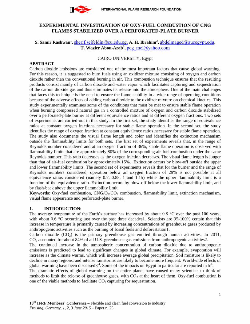
The flow diagram of the experimental oxy-fuel combustion experiments is shown on the left part of figure
1. The diagram describes the air, O2, CO2, CNG lines, the oxidizer mixer, the burner, the confinement and
the exhaust section. Each gas line contains a control valve to control the gas flow rate, a rotameter to
measure the volumetric flow rate, a thermocouple and a pressure gage to measure the gas temperature and
pressure, respectively.
Air is supplied from a reciprocating compressor with a 0.5 m3 storage tank and then is fed to the oxidizer
mixer. Oxygen (99.5% purity) is supplied from two oxygen bottles (120 bar) and then is fed to the oxidizer
mixer. Carbon dioxide (99.5% purity) is supplied from a bottle (70 bar) and then is fed to the oxidizer
mixer.
The oxidizer mixer is designed to achieve complete mixing between the O2 and CO2 gases before their
introduction to the burner. Both gases enter a 1.25 cm diameter, 3.85 m pipe length (L/d = 308). The pipe
exit is fed to the burner. A perforated plate burner (3 mm thick, 30-mm outer diameter, with 22 holes 4-
mm each and made of steel) is used in this work and its schematic is shown on the right part of figure 1.
Multi recirculation zones occur downstream of every hole, providing a region in which the transfer of
mass and energy from the burnt gases to the un-burnt ones is improved and thus enhancing the flame
stability. This type of burner is preferred over a large size single-hole burner since it provides better flame
stability14.
The O2/CO2 mixture is introduced normal to the CNG fuel at a distance of L/D =7 before the ignition
point, making the resulting flames neither purely diffusion nor fully premixed, and hence are considered
partially premixed. Six flame arrestors are used along the path of the combustible mixture to avoid
explosion of the partially-premixed combustible mixture in case of flash back.
A confinement (steel cylinder with 0.5 m length and 15 cm diameter) is used to ensure confined flame
operation. The confinement ratio, (D Confinement/D Burner)2 is 25 indicating that wall effects are
insignificants15. The confinement is followed by an exhaust section (1 m long and 15 cm in diameter) to
prevent air leakage into the system. The exhaust section ends with a cone (20 cm and 40-mm exit diameter)
to eliminate air entrainment into the combustion zone.
A rectangular sight glass (50 mm x 500 mm, mounted on the outer surface of the confinement and sealed
to prevent leakage) is used to allow optical access for capturing digital images of the flames. The visual
flame appearance under different conditions is documented using a digital camera (Canon EOS D1100, 14
Mega pixel resolution, 1/8-s exposure time)
In all experiments, the system is purged first by air flow, and then the oxidizer mixture is introduced
followed by the fuel. A pilot flame is used to provide a source of ignition.
INTERNATIONAL FLAME RESEARCH FOUNDATION
5
18th
IFRF Members’ Conference – Flexible and clean fuel conversion to industry
Freising, Germany, 1, 2, 3 June 2015 – Paper n. 25
Figure 1: Experimental setup of air-fuel and oxy-fuel combustion experiments (left) and Schematic
of the burner setup (right)
3. RESULTS AND DISCUSSION
The results are presented in two separate sets. The first set presents results at constant oxygen fraction and
variable equivalence ratio. The second set presents results at constant equivalence ratio and different
oxygen fractions. The results are presented in terms of upper and lower flammability limits and visual
flame lengths. The flame appearances (inner and outer cones) are documented. The extinction
mechanisms are identified.
The Reynolds number is in the range of 1000-1900 and 1160-1900 for the first and second sets,
respectively. The burner heat capacity (based on a calorific value of 42 MJ/m3)
is in the range 0.3 - 3 kW
and 1.4 to 2.8 kW for the first and second sets, respectively
3.1. Results at constant oxygen fraction and variable equivalence ratio:
In this set, three oxygen fractions are used, namely 29%, 32% and 36%. Flammability limits are identified
by fixing the oxidizer mass flow rate and equivalence ratio at some stable value, then the fuel mass flow
rate is slowly turned down at constant oxygen fraction until the lower flammability limit. Then, the fuel
flow rate is slowly increased at constant oxygen fraction until the upper flammability limit. As such,
extinction is obtained by changing flame temperature and equivalence ratio at a nearly constant nozzle
exit velocity and constant oxygen fraction. Figure 2 shows the flammability limits for this set of
experiments, including comparison with baseline air-fuel combustion.

INTERNATIONAL FLAME RESEARCH FOUNDATION
6
18th
IFRF Members’ Conference – Flexible and clean fuel conversion to industry
Freising, Germany, 1, 2, 3 June 2015 – Paper n. 25
Figure 2: Flammability limits in oxy-fuel combustion and comparison with air-fuel combustion
The results show that air-fuel combustion enjoys larger stability limits under all oxygen fractions
considered. However, using an O2/CO2 mixture with an oxygen fraction of 36% achieves about 79% -
82% of that of air-fuel combustion in the range of Reynolds number considered. Burners specially
designed for enhanced stability may improve this ratio.
Extinction on both sides occur by blow-off, indicating that the flame speed at equivalence ratios beyond
the flammability limits is less than the velocity of the combustible mixture, causing the flame to blow off.
The visual flame length is obtained by digital photography allowing studying its dependence on
equivalence ratios at different oxygen fractions under oxy-fuel and air-fuel conditions. The results show
that the visual flame length generally decreases as the equivalence ratio decreases (owing to less fuel
input) in all cases with flames burnt in O2/CO2 mixtures being longer than almost all those burned in air at
all oxygen fractions considered, due to the slower chemical kinetics when CO2 is added. Under oxy-
combustion conditions, the visual flame length generally decreases as the oxygen fraction increases, due
to enhanced chemical kinetics at higher oxygen fractions.
There are several conical premixed flames formed as inner cones downstream of the perforated-plate
holes and are surrounded by an outer cone. This work presents the visual appearance of both the inner and
outer cones.
The outer and inner cones of the different flames observed are shown in figures 3 and 4, respectively. The
digital images show that the flame length is almost the same between equivalence ratios 1.2 to 0.9, and
then decreases until an equivalence ratio of 0.4 before extinction mechanism occurs.
0.0
0.5
1.0
1.5
2.0
2.5
1,000 1,200 1,400 1,600 1,800 2,000
Equ
ival
ence
Rat
io
Reynolds Number
Air
36%
32%
29%
36 %
32 %
29 %
Air

INTERNATIONAL FLAME RESEARCH FOUNDATION
7
18th
IFRF Members’ Conference – Flexible and clean fuel conversion to industry
Freising, Germany, 1, 2, 3 June 2015 – Paper n. 25
Figure 3: Visual flame length at constant oxygen fractions and comparison with air-fuel
combustion
The flame at a higher equivalence ratio consists of large outer and inner cones, while decreasing
the fuel flow rate the inner cones length begins to decrease gradually and the outer cone disappears
gradually then the flame becomes weak and blow off occurs. This is because of insufficient fuel and
because of the burning velocity is lower than the flow velocity.
Figure 4: Visual flame appearance (outer-cone) in the range of equivalence ratios of 1.2 to 0.5. The
oxygen fraction is 36%
0
5
10
15
20
25
0.4 0.5 0.6 0.7 0.8 0.9 1 1.1 1.2
Flam
e Le
ngt
h c
m
Equivalence Ratio
OF=29% OF=32% OF=36% Air
3 cm

INTERNATIONAL FLAME RESEARCH FOUNDATION
8
18th
IFRF Members’ Conference – Flexible and clean fuel conversion to industry
Freising, Germany, 1, 2, 3 June 2015 – Paper n. 25
Figure 5: Visual flame appearance (inner cones) in the range of equivalence ratios of 1.2 to 0.5.
The oxygen fraction is 36% and the Reynolds number is 1500
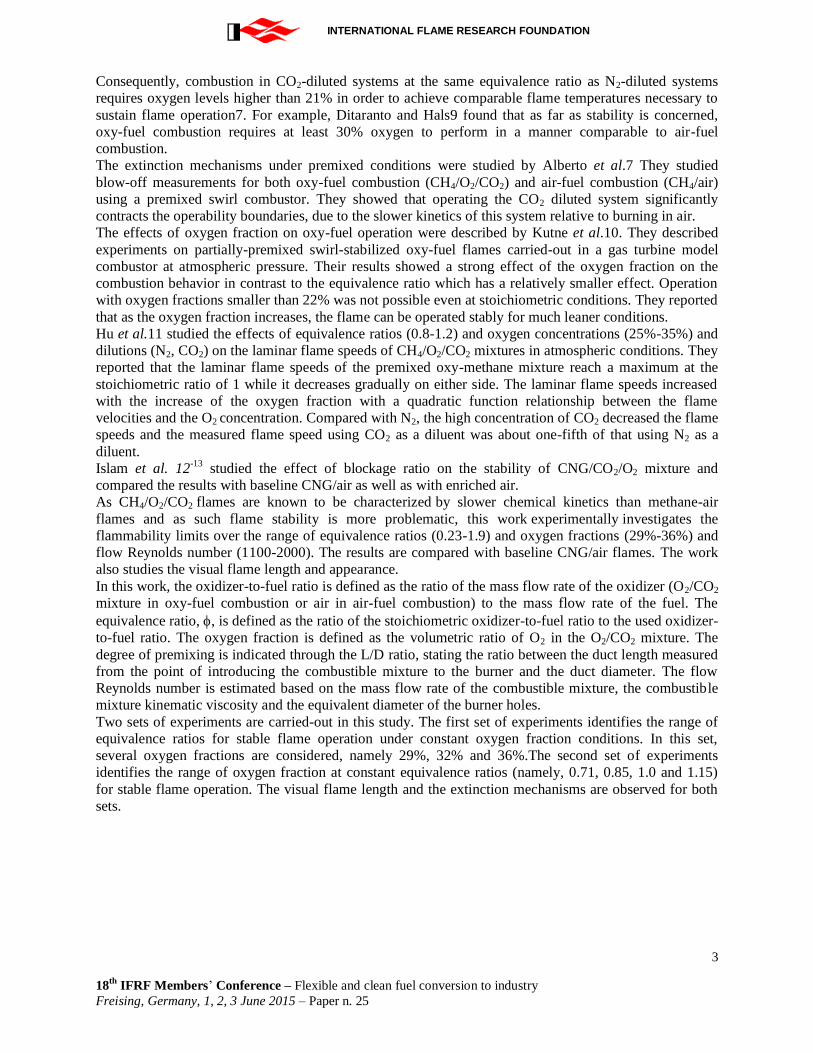
3.2. Results at constant equivalence ratio and variable oxygen fraction
In this set, the flammability limits are obtained by fixing the oxidizer flow rate and the equivalence ratio
at some stable value. Then, the oxygen fraction is slowly turned down while the CO2 fraction is slowly
increased at a constant equivalence ratio until the lower flammability limit. The upper flammability limit
is determined similarly. This ensures that extinction is obtained by changing flame temperature and
oxygen fraction at a nearly constant nozzle exit velocity and constant equivalence ratio.
Extinction beyond the upper flammability limits occurs by flash back indicating that the flame speed at
large oxygen fractions become higher than the velocity of the combustible mixture, causing flash back.
The oxygen fraction corresponding to the upper flammability limit depends on the equivalence ratio. The
lower flammability limits occurs by blow-off indicating that the flame speed at oxygen fractions
below28%, at all equivalence ratios considered (0.7 – 1.15), is less than the velocity of the combustible
mixture, causing the flame to blow off.
INTERNATIONAL FLAME RESEARCH FOUNDATION
9
18th
IFRF Members’ Conference – Flexible and clean fuel conversion to industry
Freising, Germany, 1, 2, 3 June 2015 – Paper n. 25
Figure 6: Flammability limits in oxy-fuel combustion at constant equivalence ratios
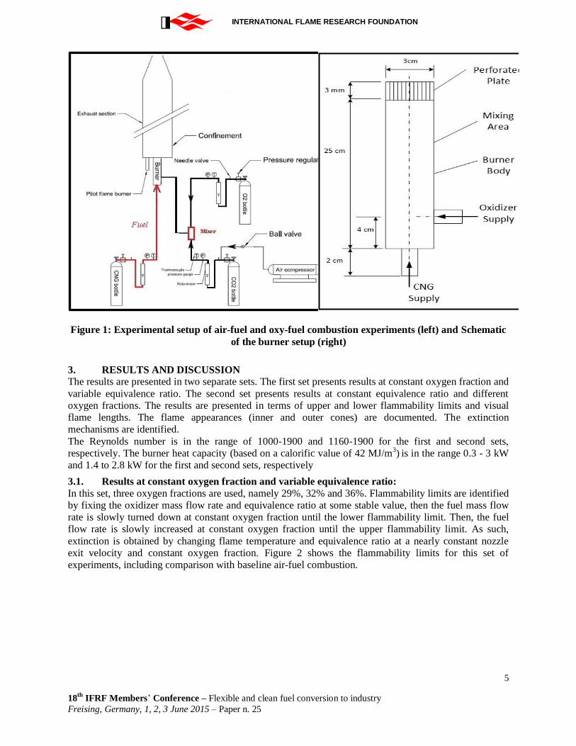
Figure 7: Visual flame length at constant equivalence ratio (0.85)
The outer and inner cones of the different flames observed in this set are shown in figures 7 and
8, respectively. The digital images show that the flame length is almost the same at the same
oxidizer mass flow rates, equivalence ratio and different oxygen fractions, its observed that
increasing the oxygen fraction the inner cones decreases its length and the outer cones becomes
thinner and brighter.
25%
30%
35%
40%
45%
50%
55%
1,000 1,200 1,400 1,600 1,800 2,000
Oxy
gen
Fra
ctio
n O
F%
Reynolds Number Re
Ø = 1.15
Ø = 0.70
Ø = 1
Ø = 0.85
Ø = 0.7-1.15
10
14
18
22
25 30 35 40 45
Flam
e le
ngt
h
Oxygen Fraction

INTERNATIONAL FLAME RESEARCH FOUNDATION
10
18th
IFRF Members’ Conference – Flexible and clean fuel conversion to industry
Freising, Germany, 1, 2, 3 June 2015 – Paper n. 25
It is also observed that the flammability limits increase as the oxidizer mass flow rate increases, the flame
length slightly decreases and the flame color changes from bluish to white as the oxygen fraction
increases.
Figure 8: Visual flame appearance (outer-cone) for oxygen fractions of 29% and 36% and
comparison with air. The equivalence ratio is one and the Reynolds number is 1500
Figure 9: Visual flame appearance (inner-cone) for oxygen fractions of 29% and 36% and
comparison with air. The equivalence ratio is one and the Reynolds number is 1500
In conclusion, as the restrictions on the release of CO2 and other greenhouse gases into the
atmosphere tightens, the need for carbon capture and sequestration increases. The current work
INTERNATIONAL FLAME RESEARCH FOUNDATION
11
18th
IFRF Members’ Conference – Flexible and clean fuel conversion to industry
Freising, Germany, 1, 2, 3 June 2015 – Paper n. 25
presents data on the flame stability and visual flame length and appearance under different oxy-
fuel combustion conditions.
REFERENCES
1. BASC, DELS. Textbook of America's Climate Choices, The National Academies press,
Washington, DC , 2010.
2. Lashof D. A.; Ahuja D. R. Nature.1990, 344, 529-531.
3. Root T. L.; Price J. T.; Hall K. R.; Schneider S. H.; Rosenzweigk C.; Pounds J. A.
Nature. 2003, 421, 57-60.
4. Alaa E. E.; Zaki M. M. Procedia Environmental Sciences. 2011, 4, 251-259.
5. Domroes M.; El-Tantawi A., Int. J. of Climatology. 2005, 25, 51-63.
6. El-Raey M.; Frihy O.; Nasr S. M.; Dewidar K. H. Environmental Monitoring and
Assesment. 1997, 56, 113-128.
7. Amato A.; Robert H.; Noble D. R.; Scarbourough D.; D’carlo P. A.; Seitzman J. M.;
Lieuwen T.C. Proc. of ASME Turbo Expo. 2010, 1-11
8. Philip S. A. M.Sc.Thesis, Mechanical Engineering, Massachusetts Institute of
Technology, 2011.
9. Ditaranto M.; Hals J. Combustion and Flame, 2006, 146, 493-512.
10. Kutne P.; Kapadia B. K.; Meier W.; Aigner M. Proceedings of the Combustion Institute,
2011, 33, 3383–3390
11. Hu X.; Yu Q. B.; Qin Q.; Wang Z. X. Journal of Northeastern University 2013, 34,
1593-1596.
12. Ramadan I. A.; Abou-Arab T.W.; Ibrahim A. H. 7th
Mediterranean Combustion
Symposium, 2011, 11-15.
13. Ramadan I. A. M.Sc. Thesis, Mechanical Engineering, Cairo University, 2011.
14. Jatoliya A.; Pandian B. and Raghavan V. Int. J. of Integrated Engineering, 2012, 4, 1-5.
15. Cai J.; Fu Y.; El-Kady A.; Jeng S.; Mongia H. 41st Aerospace Sciences Meeting and
Exhibit, 2003, 6-9.