4-burner gas grill - david r darrow
TRANSCRIPT
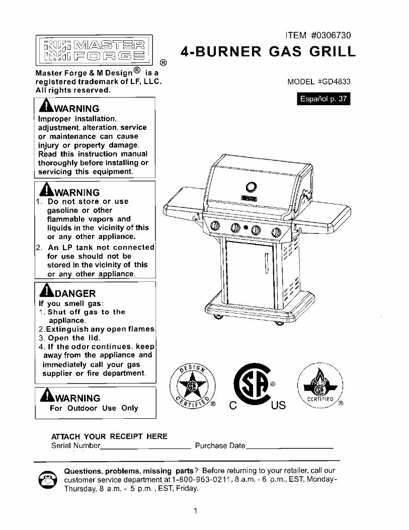
® Master Forge & M Design® is a registered trademark of LF, LLC. All rights reserved.
WARNING Improper installation, adjustment, alteration, service or maintenance can cause in)ury or property damage. Read this instruction manual thoroughly before·· installing or servicing this equipment.
WARNING 1. Do not store or use
gasoline or other flammable vapors and liquids in the vicinity of this or any other appliance.
2. An LP tank not connected for use should not be stored in the vicinity of this or an other a Hance.
AoANGER If you smell gas: 1. Shut off gas to the
appliance. 2.Extinguish any open flames 3. Open the lid. 4. If the odor continues, keep
away from the appliance and immediately call your gas supplie~ or fire department.
WARNING For Outdoor Use Only
ATTACH YOUR RECEIPT HERE
ITEM #0306730
4-BURNER GAS GRILL
MODEL ~GD4833
Espanol p.37
0 --
-----
C
Serial Number. _________ _ Purchase Date· ________ _
Questions, problems, missing parts? Before returning to your retailer, call our customer service department at 1-800-963-0211, 8 a.m. - 6 p.m., EST, MondayThursday, 8 a.m. - 5 p.m., EST, Friday.
1

TABLE OF CONTENTS
Safety Information·-·· ....
Package Contents
Hardware Contents
Preparation ........... .
Assembly Instructions
Installation Instructions
Operating Instructions
Care and Maintenance
Troubleshooting ......
~~~ .. ..
Exploded View ...
.................................................. 3
················ 5
7
.7
........ 8
................... 19
........... 23
··········27
32
34
Replacement Parts List ........ --. -. -............................ ---. -. -..
· 35
. .. 36
2
A SAFETY INFORMATION
Please read and understand this entire manual before attempting to assemble, operate or install the product. If you have any questions regarding the product, please call customer service at 1-800-963-0211, 8 a.m-6 p.m., EST, MondayThursday, 8 a.m.-5 p.m., EST, Friday.
• The installation of this appliance must conform with local codes or, in the absence of local
codes, with the National Fuel Gas Code, ANSI Z 221.3INFPA 54.
• This grill is intended for use outdoors and should not be used in a building, garage or any
other enclosed or covered area.
• This outdoor grill is not intended for installation in or on recreation vehicles and.I or boats.
• A minimum clearance of 36 inches from combustible constructions to the sides of the grill
and 36 inches from the back of the grill to combustible constructions must be maintained.
This outdoor cooking gas appliance must not be placed under overhead combustible
construction.
• The use of an electrical source requires that when installed, the grill must be electrically
grounded in accordance with local codes or, in the absence of local codes, with
ANSl/NFPA 70, or the Canadian Electrical Code, CSAC22.1. Keep electrical supply cords
and the fuel supply hose away from heated surfaces.
• Inspect the hoses before each use for excessive abrasion or wear, or cuts that may affect
safe operation of the grill. lf there is evidence of excessive abrasion or wear, or the hose is
cut, it must be replaced prior to the grill being put into operation. The replacement hose
assembly must be those specified by the manufacturer.
• Keep your grill in an area clear and free from combustible materials, gasoline and other
flammable vapors and liquids.
• DO NOT obstruct the flow of combustion and ventilation air to this appliance.
• Keep the ventilation openings of the tankenclosure free and clear of debris.
• Check all gas connections for leaks with a soapy water solution and brush. Never use an
open flame to check for leaks.
• Never use charcoal in the grill.
• Never use the grill in windy areas.
l
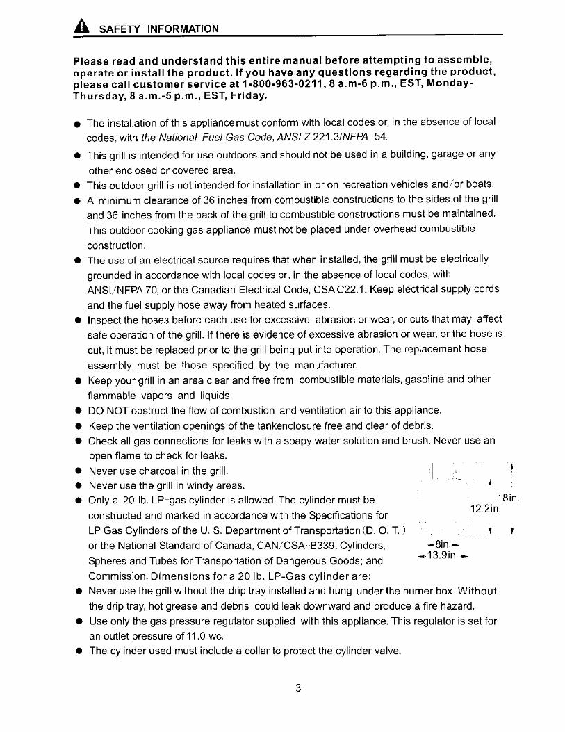
• Only a 20 lb. LP-gas cylinder is allowed. The cylinder must be
constructed and marked in accordance with the Specifications for
18in. 12.2in.
LP Gas Cylinders of the U.S. Department of Transportation (D. 0. T.)
or the National Standard of Canada. CAN/CSA B339. Cylinders.
Spheres and Tubes for Transportation of Dangerous Goods; and
Commission. Dimensions for a 20 lb. LP-Gas cylinder are:
' ! -8in.-
-13.9in. -
• Never use the grill without the drip tray installed and hung under the burner box. Without
the drip tray, hot grease and debris could leak downward and produce a fire hazard.
• Use only the gas pressure regulator supplied with this appliance. This regulator is set for
an outlet pressure of 11.0 we.
• The cylinder used must include a collar to protect the cylinder valve.
3
A SAFETY INFORMATION
• Do not store a spare LP-gas cylinder under or near this appliance.
• Never fill the cylinder beyond 80 percent full.
• Properly route regulator and hose to connect with tank as per the regulator assembly
instructions detailed on page 17 and 18.
• DANGER: If the information in above is not followed exactly, a fire causing death or serious
injury may occur.
• The outdoor cooking gas appliance must be isolated from the gas supply piping system by
closing its individual manual shutoff valve during any pressure testing of the gas supply
system at test pressures equal to or less than 1/2 PSI (3.5 KPa).
• CALIFORNIA PROPOSITION 65 WARNING: The burning of gas cooking fuel generates
some byproducts which are on the list of substances known by the State of California to
cause cancer, reproductive harm, or other birth defects. To reduce exposure to these
substances, always operate this unit according to the use and care manual, ensuring you
provide good ventilation when cooking with gas.
IMPORTANT: We urge you to read this manual carefully and follow the
recommendations enclosed. This will ensure you receive the most enjoyable and
trouble-free operation of your new gas grill. We also advise you retain this manual for
future reference.
WARNING: Your grill has been designed to operate using only the gas specified by the
manufacturer on the rating plate. Do not attempt to operate your grill with other gases.
Failure to follow this warning could lead to a fire hazard and bodily harm and will void
your warranty.
WARNING: Make certain your LP (propane) tank is filled by a reputable propane dealer. An incorrectly filled or overfilled LP tank can be dangerous. An overfilled tank
combined with the warming of the LP tank (a hot summer day, tank left in the sun, etc.)
can cause LP gas to be released by the pressure relief valve on the tank since the
temperature increase causes the propane to expand. LP gas released from the tank is flammable and can be explosive. Refer to your Owner's Manual for more information
concerning filling your LP tank.
4
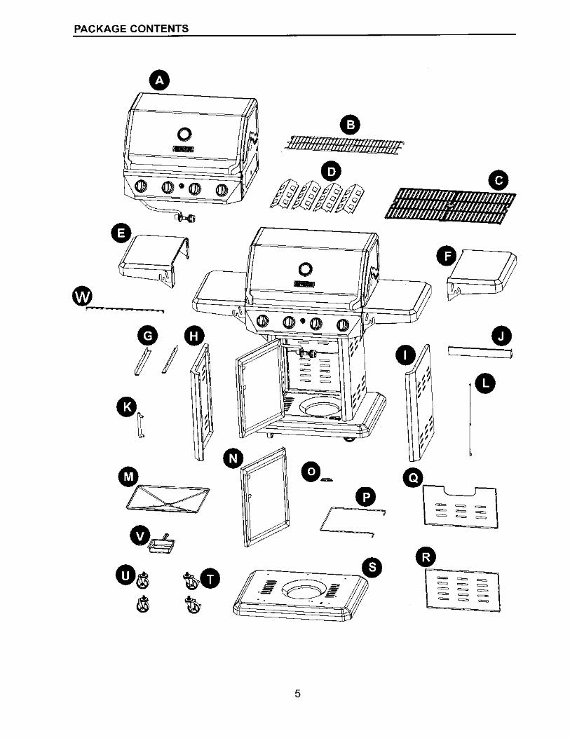
PACKAGE CONTENTS
0
0 -
11 0 '
I ' ' I ' \r \i, •t I
I ' ' I
~ •s ., ~-,
~
0 asmmmmmmmr·
0 -0 ,,
0 /I
I I I
d d I
I 1/
1/ I
I d 1/
I
G)_ e 0
I 7
.,
G
0
0
•
~ ~ ~
~ ~ ~
~ ~ ~
G ~ ~ ~ ~ ~ ~ ~ ~ ~
~ ~ ~ ~ ~ ~
5
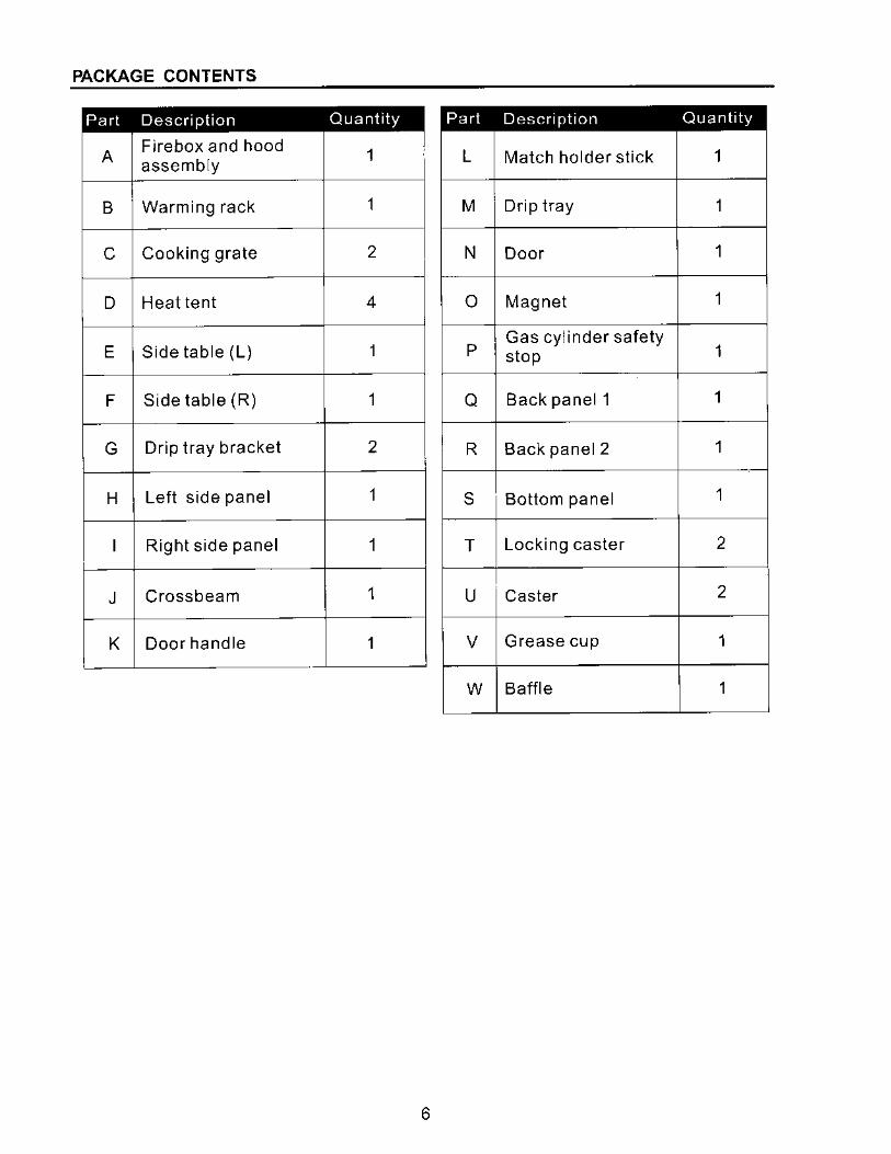
PACKAGE CONTENTS
Part Description Quantity
A Firebox and hood
1 assembly L Match holder stick 1
B Warming rack 1 M Drip tray 1
C Cooking grate 2 N Door 1
D Heat tent 4 0 Magnet 1
E Side table (L) 1 p Gas cylinder safety
1 stop
F Side table (R) 1 Q Back panel 1 1
G Drip tray bracket 2 R Back panel 2 1
H Left side panel 1 s Bottom panel 1
Right side panel 1 T Locking caster 2
J Crossbeam 1 u Caster 2
K Door handle 1 V Grease cup 1
w Baffle 1
6
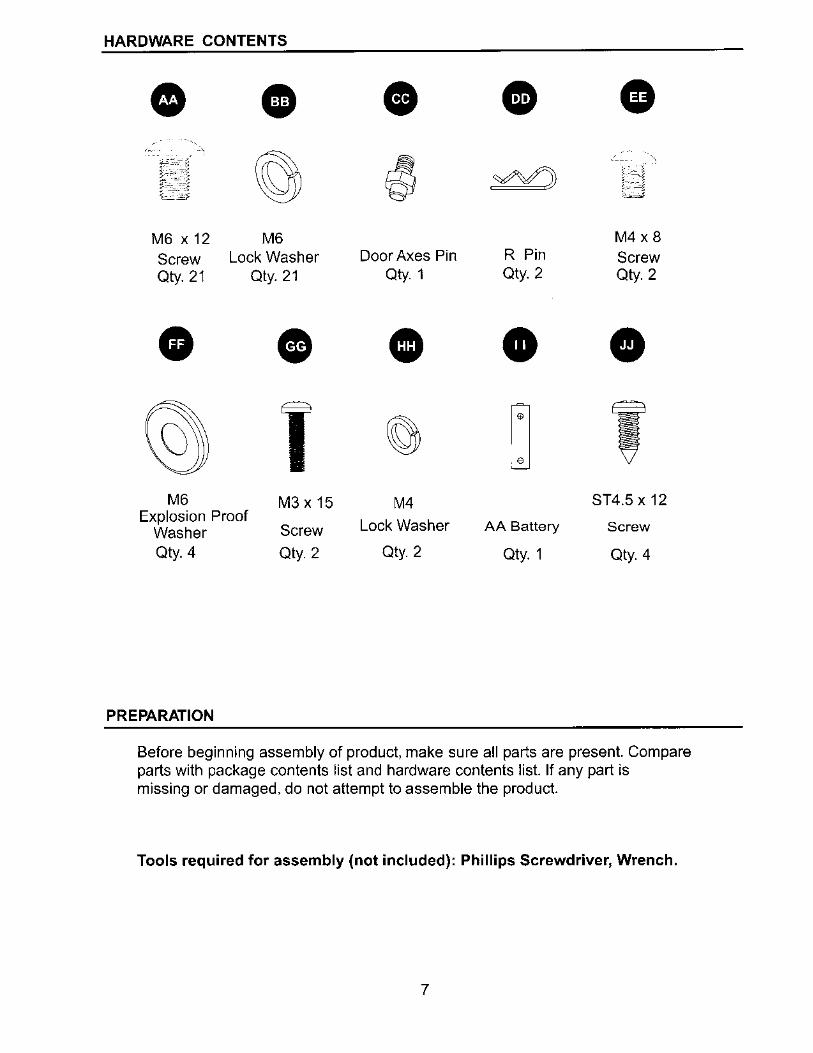
HARDWARE CONTENTS
• • . • • • f-"";,.-~
~ .YVJ ;- -- " ts-~c:;i ,---,_, ,_, __ , t~iJ \:__j
M6 X 12 M6 M4 x8
Screw Lock Washer Door Axes Pin R Pin Screw Qty. 21 Qty. 21 Qty. 1 Qty. 2 Qty. 2
• • (§}
' ~ ' M6 M3 X 15 M4 ST4.5 x 12 Explosion Proof
Screw Lock Washer AA Battery Screw Washer Qty. 4 Qty. 2 Qty. 2 Qty. 1 Qty. 4
PREPARATION
Before beginning assembly of product, make sure all parts are present. Compare parts with package contents list and hardware contents list. If any part is missing or damaged, do not attempt to assemble the product.
Tools required for assembly (not included): Phillips Screwdriver, Wrench.
7
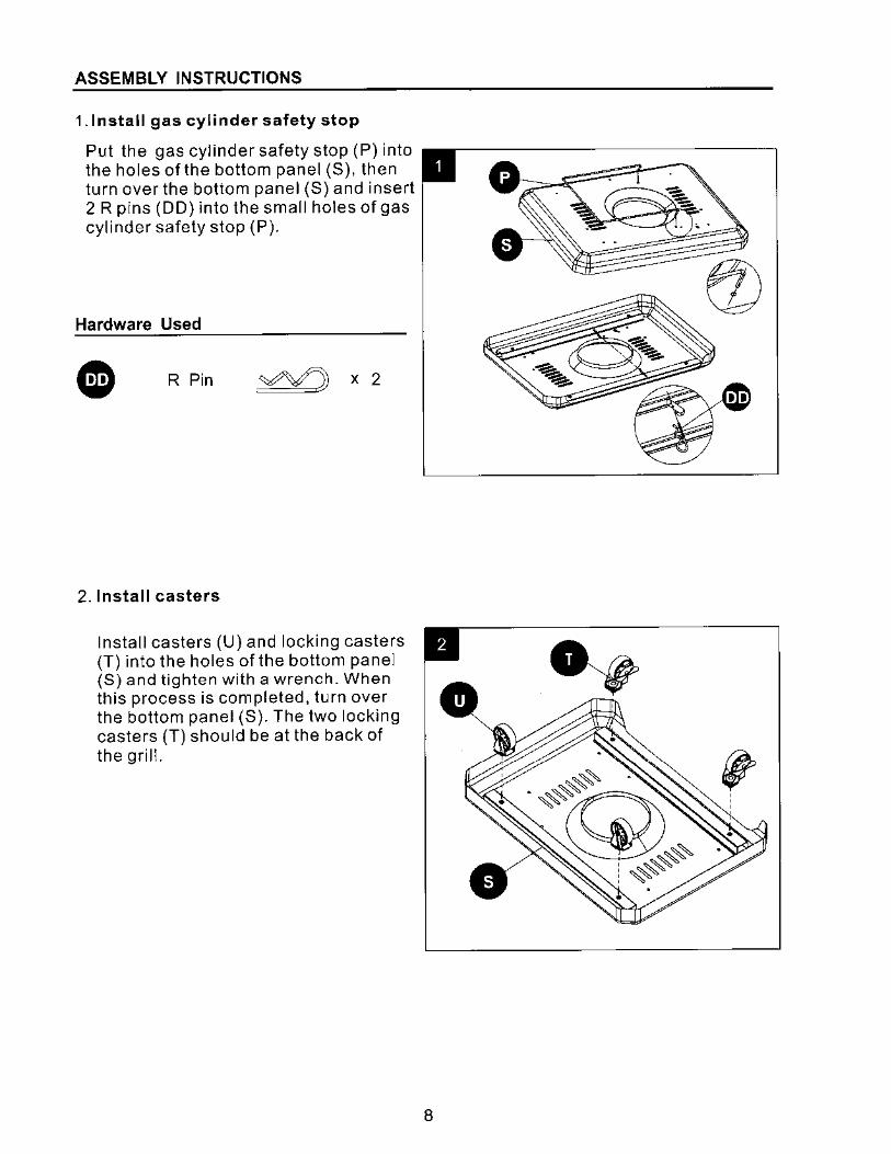
ASSEMBLY INSTRUCTIONS
1. Install gas cylinder safety stop
Put the gas cylinder safety stop (P) into the holes of the bottom panel (S), then turn over the bottom panel (S) and insert 2 R pins (DD) into the small holes of gas cylinder safety stop (P).
Hardware Used
R Pin yY) X 2
2. Install casters
Install casters (U) and locking casters (T) into the holes of the bottom panel (S) and tighten with a wrench. When this process is completed, turn over the bottom panel (S). The two locking casters (T) should be at the back of the grill.
8
ASSEMBLY INSTRUCTIONS
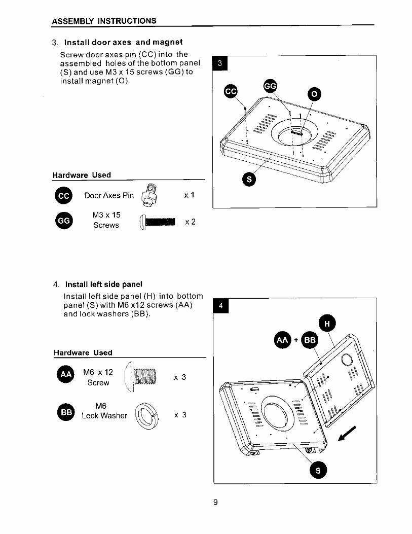
3. Install door axes and magnet
Screw door axes pin (CC) into the assembled holes of the bottom panel (S) and use M3 x 15 screws (GG) to install magnet (0).
Hardware Used
• Door Axes Pin
' X 1
• M3 x 15 (])ma Screws x2
4. Install left side panel
Install left side panel (H) into bottom panel (S) with M6 x12 screws (AA) and lock washers (BB).
Hardware Used
• A w
M6 X 12 Screw
M6 Lock Washer
X 3
X 3
0
9
ASSEMBLY INSTRUCTIONS
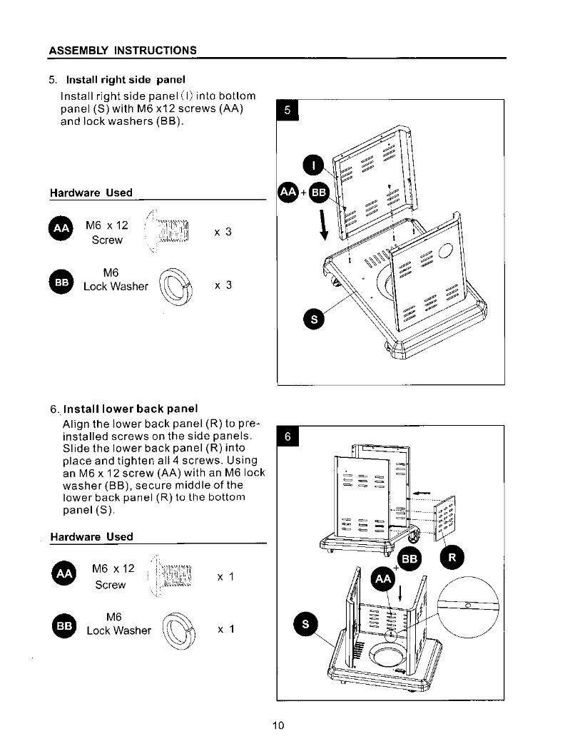
5. Install right side panel
Install right side panel (I) into bottom panel (S) with M6 x12 screws (AA) and lock washers (BB).
Hardware Used
• A w
M6 X 12 Screw
M6 ~ Lock Washer y
6. Install lower back panel
X 3
X 3
Align the lower back panel (R) to preinstalled screws on the side panels. Slide the lower back panel (R) into place and tighten all 4 screws. Using an M6 x 12 screw (AA) with an M6 lock washer (BB), secure middle of the lower back panel (R) tu the bottom panel (S).
Hardware Used
• A w
M6 X 12
Screw -:!'-~1~:m-~,\1: _.,l~,,J;1J:i,:,,
M6 " Lock Washer y
X 1
X 1
fl I ~i
-
10
ASSEMBLY INSTRUCTIONS
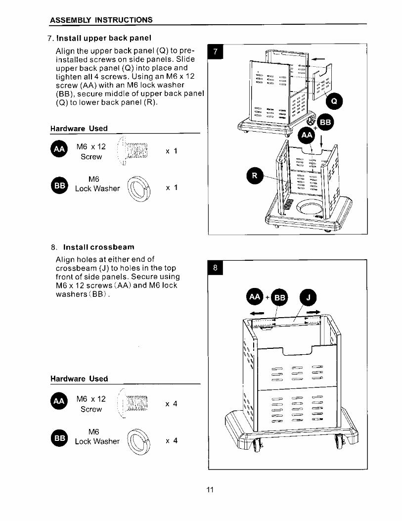
7. Install upper back panel
Align the upper back panel (Q) to preinstalled screws on side panels. Slide upper back panel (Q) into place and tighten all 4 screws. Using an M6 x 12 screw (AA) with an M6 lock washer (BB). secure middle of upper back panel (Q) to lower back panel (R).
Hardware Used
• A w
M6 X 12 Screw
' . : >itt'i'.t·'·i'1'
:'l"i"''l·'' ,,.(,-:\
1{,;tl,'J ·U
M6 ~ Lock Washer Y
8. Install crossbeam
X 1
X 1
Align holes at either end of crossbeam (J) to holes in the top front of side panels. Secure using M6 x 12 screws (AA) and M6 lock washers (BB).
Hardware Used
• A w
M6 X 12 Screw
M6 ~ Lock Washer y
X 4
X 4
11
•· -' :, I 1---,
-
~
~ ~ ~
11r-""-""-i 1
-\ \\, '-----'
\\ \
\ \\ \ \\
\\ \
= = =
= = = = =
= = = = = =
= = = = = = = = = ~
\
ASSEMBLY INSTRUCTIONS
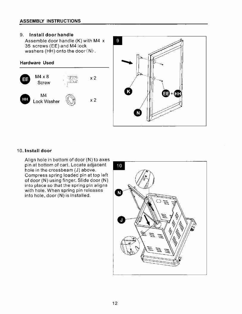
9. Install door handle Assemble door handle (K) with M4 x 35 screws (EE) and M4 lock washers (HH) onto the door (N).
Hardware Used
• M4x 8 ··-Tl"'TO x2 :, Ii: Screw ;.I.L-t-.i,
CD M4 g Lock Washer x2
1 a. Install door
Align hole in bottom of door (N) to axes pin at bottom of cart. Locate adjacent hole in the crossbeam (J) above. Compress spring loaded pin at top left of door (N) using finger. Slide door (N) into place so that the spring pin aligns with hole. When spring pin releases into hole, door (N) is installed.
12
·-. I~ -
I~+ I
ASSEMBLY INSTRUCTIONS
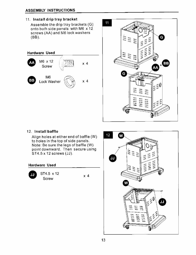
11. Install drip tray bracket Assemble the drip tray brackets (G) onto both side panels with M6 x 12 screws (AA) and M6 lock washers (BB).
Hardware Used
• A w
M6 X 12 Screw
M6 Lock Washer
12. Install baffle
X 4
X 4
Align holes at either end of baffle (W) to holes in the top of side panels. Note: Be sure the legs of baffle (W) point downward. Then secure using ST4.5 x 12 screws (JJ).
Hardware Used
• ST4.5 x 12 Screw
X 4
~ :; (1) = - ~~ = - = ~
= - = = = = = = = = = = - - = - - = =
• 13
ASSEMBLY INSTRUCTIONS
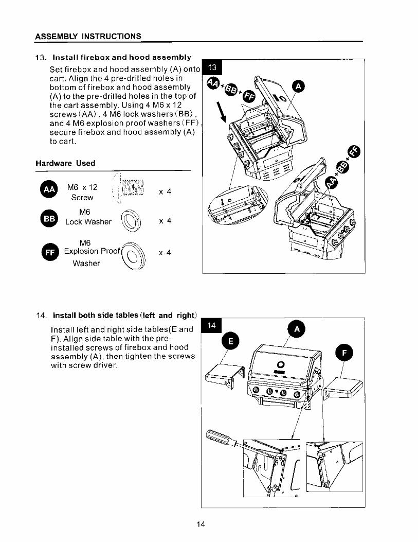
13. Install firebox and hood assembly
Set firebox and hood assembly (A) onto cart. Align the 4 pre-drilled holes in bottom of firebox and hood assembly (A) to the pre-drilled holes in the top of the cart assembly. Using 4 M6 x 12 screws (AA), 4 M6 lock washers (BB), and 4 M6 explosion proof washers (FF) secure firebox and hood assembly (A) to cart.
Hardware Used
• M6 X 12 Screw
!r,1·'Y'"1''·~ d, 1,.1,1 II,'
, • I.I.,] I,, ·:1 X 4 ' ' ,,, "'
' : ,,,i,"-lvc.Y>
• M6 g Lock Washer X 4 -
• M6 @y Explosion Proof CJ X 4 Washer
14. Install both side tables (left and right)
Install left and right side tables(E and F). Align side table with the preinstalled screws of firebox and hood assembly (A), then tighten the screws with screw driver.
14
0
0 -
• •
ASSEMBLY INSTRUCTIONS
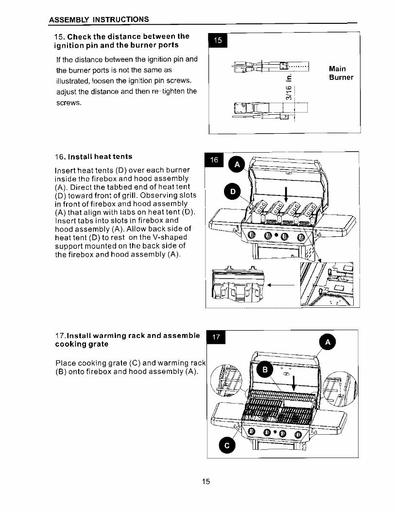
15. Check the distance between the ignition pin and the burner ports
If the distance between the ignition pin and the burner ports is not the same as illustrated, loosen the ignition pin screws,
adjust the distance and then re-tighten the
screws.
EB;i1; g .... 1
;'; I
l"'.:IJ!LJd:M I
Main Burner
16. Install heat tents
Insert heat tents (D) over each burner inside the firebox and hood assembly (A). Direct the tabbed end of heat tent (D) toward front of grill. Observing slots in front of firebox and hood assembly (A) that align with tabs on heat tent (D). Insert tabs into slots in firebox and hood assembly (A). Allow back side of heat tent (D) to rest on the V-shaped support mounted on the back side of the firebox and hood assembly (A).
• ••• .-----:~----;;:::=---------
1
17.lnstall warming rack and assemble cooking grate
Place cooking grate (C) and warming rack (B) onto firebox and hood assembly (A).
15
ASSEMBLY INSTRUCTIONS
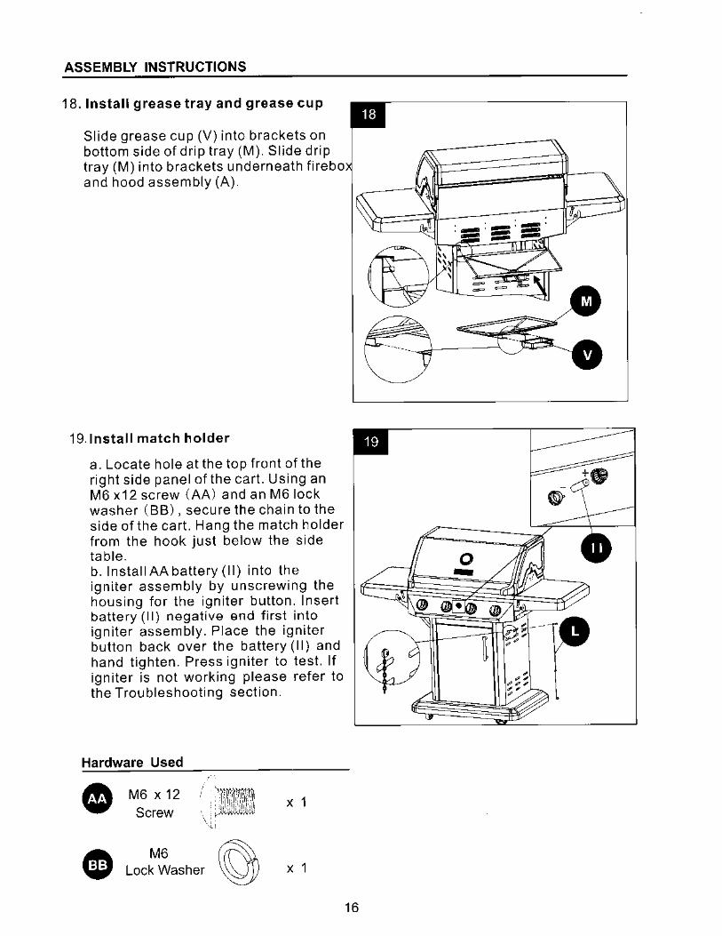
18. Install grease tray and grease cup
Slide grease cup (V) into brackets on bottom side of drip tray (M). Slide drip tray (M) into brackets underneath firebo and hood assembly (A).
19.lnstall match holder
a. Locate hole at the top front of the right side panel of the cart. Using an M6 x12 screw (AA) and an M6 lock washer (BB). secure the chain to the side of the cart. Hang the match holder from the hook just below the side table. b. Install AA battery (II) into the igniter assembly by unscrewing the housing for the igniter button. Insert battery (II) negative end first into igniter assembly. Place the igniter button back over the battery (II) and hand tighten. Press igniter to test. If igniter is not working please refer to the Troubleshooting section.
Hardware Used
• A w
M6 x 12 Screw
M6 ~ Lock Washer y
X 1
X 1
-
~
0 -
16
ASSEMBLY INSTRUCTIONS
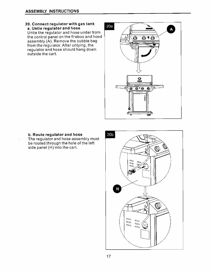
20. Connect regulator with gas tank a. Untie regulator and hose Untie the regulator and hose under from the control panel on the firebox and hood assembly (A). Remove the bubble bag from the regulator. After untying, the regulator and hose should hang down outside the cart.
b. Route regulator and hose The regulator and hose assembly must be routed through the hole of the left side panel (H) into the cart.
0 -
Cl
0 17
ASSEMBLY INSTRUCTIONS
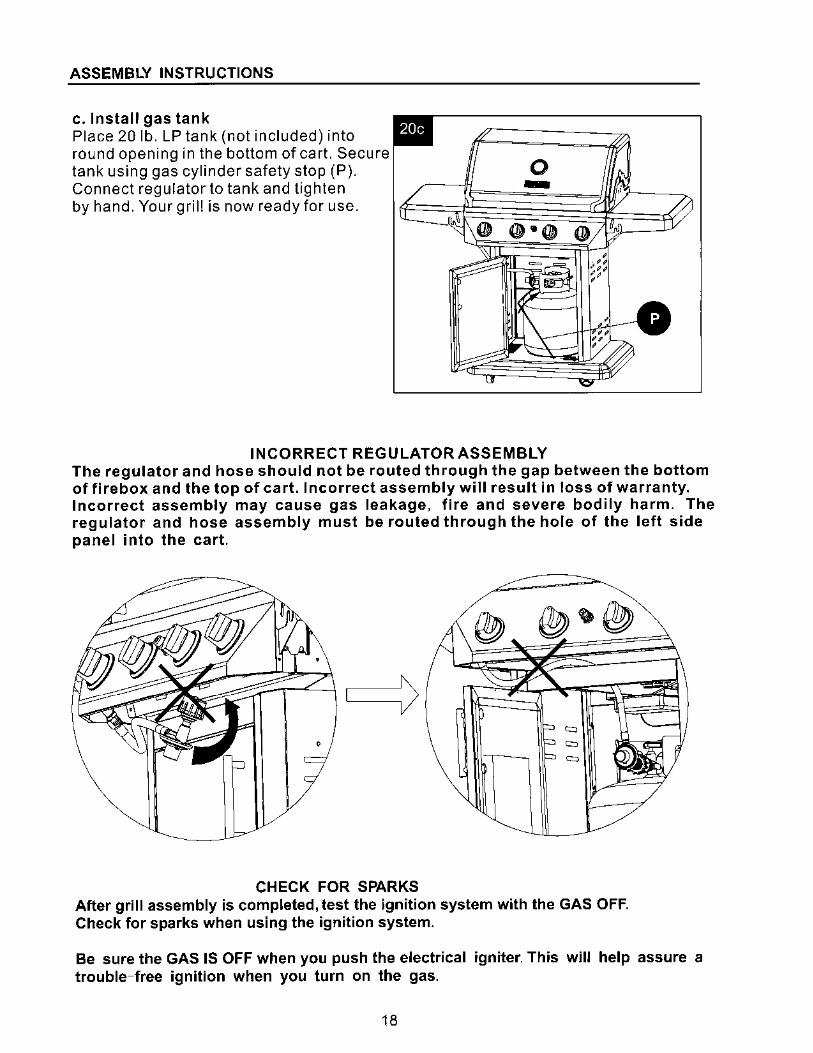
c. Install gas tank Place 20 lb. LP tank (not included) into round opening in the bottom of cart. Secure tank using gas cylinder safety stop (P). Connect regulator to tank and tighten by hand. Your grill is now ready for use.
0 -
INCORRECT REGULATOR ASSEMBLY The regulator and hose should not be routed through the gap between the bottom of firebox and the top of cart. Incorrect assembly will result in loss of warranty. Incorrect assembly may cause gas leakage, fire and severe bodily harm. The regulator and hose assembly must be routed through the hole of the left side panel into the cart.
CHECK FOR SPARKS After grill assembly is completed, test the ignition system with the GAS OFF. Check for sparks when using the ignition system.
Be sure the GAS IS OFF when you push the electrical igniter. This will help assure a trouble-free ignition when you turn on the gas.
18
INSTALLATION INSTRUCTIONS
For Portable LP-Gas Connection
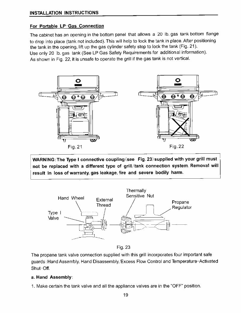
The cabinet has an opening in the bottom panel that allows a 20 lb. gas tank bottom flange
to drop into place (tank not included). This will help to lock the tank in place. After positioning the tank in the opening. lift up the gas cylinder safety stop to lock the tank (Fig. 21 ). Use only 20 lb. gas tank (See LP Gas Safety Requirements for additional information).
As shown in Fig. 22, it is unsafe to operate the grill if the gas tank is not vertical.
0 0 - -. ,e e•e El);
.
-/
' ~
,_, ~ -
1J = Fig. 21 Fig.22
WARNING:The Type I connective coupling(see Fig. 23)supplied with your grill must
not be replaced with a different type of grill/tank connection system. Removal will
result in loss of warranty, gas leakage, fire and severe bodily harm.
Thermally Sensitive Nut
Hand Wheel External /
\
Thread Propane
(
. _j- -I._ ./ Regulator
lfv: I -----------~ : - _/
~~I~ --------'O~>c:~:=:jj ~ c-=i' ~ ---- l_
-·-·
Fig. 23
The propane tank valve connection supplied with this grill incorporates four important safe
guards: Hand Assembly, Hand Disassembly, Excess Flow Control and Temperature-Activated
Shut-Off.
a. Hand Assembly:
1. Make certain the tank valve and all the appliance valves are in the "OFF" position.
19
INSTALLATION INSTRUCTIONS
2. When connecting the regulator/burner valve assembly to the tank valve, turn the large
plastic nut clockwise until it stops.
3. Gas will not flow unless the plastic nut is completely connected.
4. HAND TIGHTEN ONLY.
b. Hand Disassembly:
1. Make certain the tank valve and all the appliance valves are in the "OFF" position.
2. Turn the large plastic nut counter-clockwise until it is disassembled.
3. HAND LOOSEN ONLY.
c. Excess Flow Control
The propane regulator assembly incorporates an excess flow device designed to supply the
grill with sufficient gas flow under normal conditions yet control excess gas flow.
Rapid changes in pressure can trigger the excess flow device providing a low flame and low
temperature. If the tank valve is turned open to allow gas flow while a burner valve is open,
the surge of pressure will cause the device to activate. The device will remain closed until the
pressure is equalized. This should occur within 5 seconds. To ensure this does not cause difficulty in lighting the grill, follow these instructions:
1. Make sure all burner valves are "OFF".
2. Open the tank valve and wait 5 seconds.
d. Temperature-Activated Shut-Off
The large plastic nut on the regulator assembly is designed in coordination with a check valve
in the tank valve to shut off the flow of gas when exposed to temperatures between
240-300° F. In the event of a fire or hose break, one of the safeguards will function to control
or stop the flow of gas from the propane tank. Never attempt to use damaged equipment.
IMPORTANT: Before the use of a fresh tank of gas, please check leakage around the connections according to section "Checking Gas Leaks" on page 25 and make sure
there is no leakage or vapor accumulation in the cabinet. Make sure all openings
around side walls are not blocked.
IMPORTANT: Place dust cap on cylinder valve outlet whenever the cylinder is not in
: use. Only install the type of dust cap on the cylinder valve outlet that is provided with
I the cylinder valve. Other types of caps or plugs may result in leakage of propane.
Gas Requirements
The grill is set and tested at the factory for use with LP-Gas only.
20
INSTALLATION INSTRUCTIONS
LP Gas The regulator supplied is set for 11 in. water column (WC)and is for use with LP gas only.
The factory-supplied regulator and hose must be used with a 20 lb. LP gas tank.
LP GAS System
Contact your gas supplier for a special regulator for bulk gas that fuels other
appliances
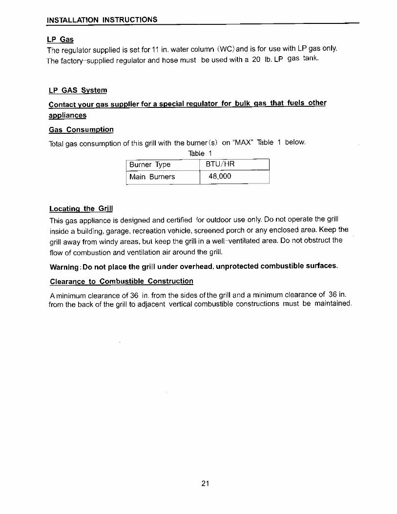
Gas Consumption
Total gas consumption of this grill with the burner(s) on "MAX" Table 1 below.
Table 1
Burner Type BTU/HR
Main Burners 48,000
Locating the Grill
This gas appliance is designed and certified for outdoor use only. Do not operate the grill
inside a building, garage, recreation vehicle, screened porch or any enclosed area. Keep the
grill away from windy areas, but keep the grill in a well--ventilated area. Do not obstruct the
flow of combustion and ventilation air around the grill.
Warning: Do not place the grill under overhead, unprotected combustible surfaces.
Clearance to Combustible Construction
A minimum clearance of 36 in. from the sides of the grill and a minimum clearance of 36 in. from the back of the grill to adjacent vertical combustible constructions must be maintained.
21
INSTALLATION INSTRUCTIONS
However, the manufacturer strongly suggests a 6 ft. clearance of the grill to combustible
constructions.
Clearance to Noncombustible Construction
A minimum clearance of 36 in. from the back of the grill above the cooking surface to
noncombustible constructions is required to allow the grill hood to open completely. A
minimum of 36 in. clearance to the sides of the grill above the cooking surface to
noncombustible constructions is recommended. The grill can be installed directly next to
noncombustible construction below the cooking surface. 11
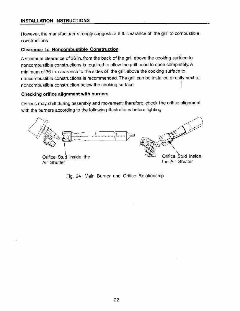
Checking orifice alignment with burners
Orifices may shift during assembly and movement; therefore, check the orifice alignment
with the burners according to the following illustrations before lighting.
Orifice Stud inside the Air Shutter
.. L .......... EV" . ..
Orifice tud inside the Air Shutter
Fig. 24 Main Burner and Orifice Relationship
22
OPERATING INSTRUCTIONS
Grill Lighting Instructions ----------------------------,
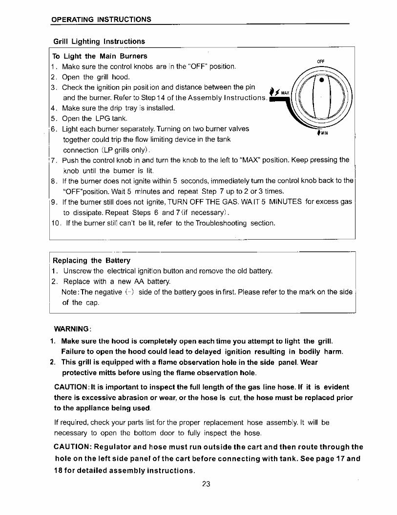
To Light the Main Burners
1. Make sure the control knobs are in the "OFF" position.
2. Open the grill hood. 3. Check the ignition pin position and distance between the pin
and the burner. Refer to Step 14 of the Assembly Instructions.
4. Make sure the drip tray ls installed.
5. Open the LPG tank.
6. Light each burner separately. Turning on two burner valves
together could trip the flow limiting device in the tank
connection (LP grills only).
OFF
7. Push the control knob in and turn the knob to the left to "MAX" position. Keep pressing the
knob until the burner is lit.
8. If the burner does not ignite within 5 seconds, immediately turn the control knob back to the
"OFF"position. Wait 5 minutes and repeat Step 7 up to 2 or 3 times.
9. If the burner still does not ignite, TURN OFF THE GAS. WA IT 5 MINUTES for excess gas
to dissipate. Repeat Steps 6 and 7 (if necessary).
10. If the burner still can't be lit, refer to the Troubleshooting section.
I Replacing the B;;;.-;;- I 1. Unscrew the electrical ignition button and remove the old battery.
2. Replace with a new AA battery.
Note: The negative (-) side of the battery goes in first. Please refer to the mark on the side ,
of the cap.
WARNING:
1. Make sure the hood is completely open each time you attempt to light the grill. Failure to open the hood could lead to delayed ignition resulting in bodily harm.
2. This grill is equipped with a flame observation hole in the side panel. Wear
protective mitts before using the flame observation hole.
CAUTION: It is important to inspect the full length of the gas line hose. If it is evident
there is excessive abrasion or wear, or the hose is cut, the hose must be replaced prior to the appliance being used.
If required, check your parts list for the proper replacement hose assembly. It will be
necessary to open the bottom door to fully inspect the hose.
CAUTION: Regulator and hose must run outside the cart and then route through the
hole on the left side panel of the cart before connecting with tank. See page 17 and
18 for detailed assembly instructions.
23
OPERATING INSTRUCTIONS
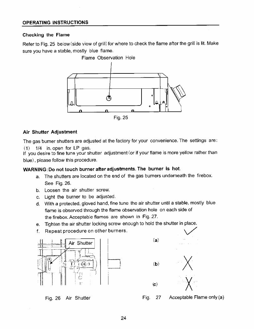
Checking the Flame
Refer to Fig. 25 below (side view of grill) for where to check the flame after the grill is lit. Make
sure you have a stable, mostly blue flame.
Flame Observation Hole
0
0 0
Fig. 25
Air Shutter Adjustment
The gas burner shutters are adjusted at the factory for your convenience. The settings are:
( 1) 114 in. open for LP gas. If you desire to fine tune your shutter adjustment (or if your flame is more yellow rather than
blue), please follow this procedure.
WARNING: Do not touch burner after adjustments. The burner is hot. a. The shutters are located on the end of the gas burners underneath the firebox.
See Fig. 26.
b. Loosen the air shutter screw. c. Light the burner to be adjusted. d. With a protected, gloved hand, fine tune the air shutter until a stable, mostly blue
flame is observed through the flame observation hole on each side of
the firebox. Acceptable flames are shown in Fig. 27.
e. lighten the air shutter locking screw enough to hold the shutter in place.
f. Repeat procedure on other burners. V
Fig. 26 Air Shutter
I
!
h , r
Fig.
24
(a)
(b)
(c)
27
X X
Acceptable Flame only (a)
OPERATING INSTRUCTIONS
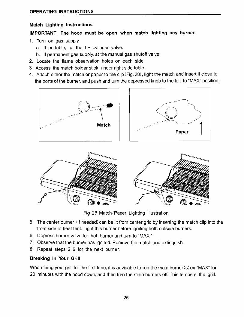
Match Lighting Instructions
IMPORTANT The hood must be open when match lighting any burner.
1. Turn on gas supply
a. If portable, at the LP cylinder valve.
b. If permanent gas supply, at the manual gas shutoff valve.
2. Locate the flame observation holes on each side.
3. Access the match holder stick under right side table. 4. Attach either the match or paper to the clip (Fig. 28), light the rnatch and insert it close to
the ports of the burner, and push and turn the depressed knob to the left to "MAX" position.
,;c=::~
( )) -:\~~-"
_.,_.,,-;_.;--
Match
Fig. 28 Match;Paper Lighting Illustration
Paper
5. The center burner (if needed) can be lit from center grid by inserting the match clip into the
front side of heat tent. Light this burner before igniting both outside burners.
6. Depress burner valve for that burner and turn to "MAX."
7. Observe that the burner has ignited. Remove the match and extinguish.
8. Repeat steps 2-6 for the next burner.
Breaking in Your Grill
When firing your grill for the first time, it is advisable to run the main burner (s) on "MAX" for
20 minutes with the hood down, and then turn the main burners off. This tempers the grill.
25
OPERATING INSTRUCTIONS
Preheating Grill
It is extremely important that your grill be up to temperature before you begin using it. After
lighting, close the hood and preheat the grill on "MAX" for 15 minutes. This preheating will
ensure that the cooking grate is hot enough for proper grilling.
CAUTION: Do not cover the cooking grate during the preheating period.
WARNING: Never leave a grill unattended to guard against possible grease fires
getting out of control. Grease fires can be severe and cause grill damage, property
damage and bodily harm.
Open or Closed Hood for Grilling
Cooking with the lid open or closed is a matter of personal preference. Cooking with the lid
closed is recommended if you enjoy cooking at maximum "searing" temperatures. This
method will also produce more "flare up," speed the cooking procedure and will give you a
more robust, smoky, outdoor flavor. If you prefer cooking slower with less flare up, we suggest
the lid-open method.
We recommend always cooking with the lid CLOSED if you are in a windy area or colder
climate. Your grill has been designed and constructed to give you maximum flexibility
and cooking performance. Be creative. Try different cooking methods on your grill to
determine which suits your needs best. There is no right or wrong way to cook, just different
cooking styles. Get creative and enjoy!
Checking Gas Leaks
Before operating your grill, after refueling, check carefully to be certain that all connections
are tight and there are no gas leaks.
1. Make 2· 3 ounces of leak solution by mixing liquid dishwashing soap with water.
2. Make certain all control knobs are in the "OFF" position.
3. Brush small amounts of the leak solution on all the fittings and turn the gas on.
4. If bubbles appear, there is a leak. Proceed to step 5.
5. Turn the gas off and tighten all connections.
6. Go back to step 1 to retest the fittings.
7. If bubbles continue to appear, turn the gas off. Contact customer service.
WARNING: Never use a match or open flame for leak detection. Use of an open flame
could result in a fire, explosion and bodily harm.
IMPORTANT: When connecting or replacing any gas pipe or fittings, all joints must be
sealed with approved leak-proof sealing compound or plumber's tape.
26
CARE AND MAINTENANCE
WARNING: Please remember this is an outdoor gas grill. Many areas of the grill
generate extreme heat We have taken every precaution to protect you from the contact
areas. However, it is impossible to isolate all high-temperature areas. Therefore, use
good judgment and a certain degree of caution when grilling on this product. We
suggest a covered, protected hand during operation of grill. Do not move your grill
when it is in operation or hot to the touch. Wait until your unit is turned off and
properly cooled down before moving it. Failure to follow this warning could result in
personal injury.
Post Heating
To keep the grates free of charred food remains, run the grill on "MAX" for 15 minutes after
cooking is complete and food has been removed.
CAUTION: Do not cover the grill during the post heating period.
After post heating your grill, turn the control knobs to the "OFF" position.
Propane Tank Shut-Off
After the firebox cool down, the propane tank valve should also be closed. If you do not
want to wait for the firebox to cool, use a covered hand to turn off the propane tank valve.
WARNING: Do not attempt to turn off the LP tank valve without first covering your hand
with a protective mitt or allowing the grill to cool down. Failure to follow this warning
could result in a severe burn.
LP Gas Safety Requirement
For LP gas grills, the LP gas supply tank to be used must be Constructed and marked in
accordance with the Specifications for LP Gas Tanks of the US. Department of
Transportation (DOT) or the National Standard of Canada, CAN/CSA-B339 Cylinders,
Spheres and Tubes for Transportation of Dangerous Goods; and Commission, as applicable;
and Provided with a listed Overfill Prevention Device (OPD).
The tank should be 12 inches in diameter and 18-1/2 inches tall and be equipped with a
Type-I fitting.
The tank supply system must be arranged for vapor withdrawal.
The tank used must include a collar to protect the cylinder valve.
Do not operate the gas grill indoors or in any enclosed area. If the gas grill is not in use, the
gas must be turned off at the supply tank. If the grill is to be stored indoors, disconnect the
gas supply tank and store the tank in an upright position in a cool, well-ventilated outdoor
location away from your grill or any other heat source.
When checking for gas leaks, do not use an open flame. Use a soapy water solution and
apply it to the pipe joints and fittings with a brush and check for bubbles. Check flexible hoses
for cuts and wear that may affect the safe operation of the grill. Only the factory supplied hose
and regulator must be used. Use only replacement regulator and hose assemblies specified
by manufacturer.
27
CARE AND MAINTENANCE
LP tank should be securely locked by the gas cylinder safety stop at all times. An unlocked
tank may fall or tilt which can cause injury or property damage. It is recommended to lock the
tank all the time.
Refer to Fig. 21 and Fig. 22. After positioning the tank in the opening, lift up the gas cylinder
safety stop to lock the tank. Use only 20 lb. gas tank (see LP Gas Safety Requirements for
Additional Information).
Handling the Liquid Propane Tank Safely
Remember to handle your portable liquid propane tank carefully when you take it to your
dealer for a refill. Avoid dropping it or bumping it against sharp objects. Liquid propane tanks
are sturdily constructed, but a series of hard jolts could damage the container.
When transporting the tank to your local propane gas dealer, make sure the valve is closed
tightly and the protective cover is in place. Position the tank securely in an upright positlon so
it will not roll around your vehicle.
If you plan to make stops for shopping or errands, have your liquid propane tank filled at the
last stop before going home. Again, make certain the refilled tank is secure and in an upright
position. When you return home, remove the refilled tank from your vehicle. Never leave a
portable liquid propane tank inside a vehicle that may become overheated by the sun.
Your local liquid propane gas dealer will gladly offer you additional safety tips.
Storing the Liquid Propane Tank Safely
Whether you are between cross-country treks in your recreational vehicle or looking for a
place to keep the liquid propane tank to provide fuel for your outdoor grill, keep in mind some
basic safety ru!es about storing portable liquid propane tanks:
Do not store the tanks (whether full or empty) inside your home, the living area of an R. V., a
garage, basement or workshop. It is unlikely that liquid propane will leak from the tanks. lf it
should leak, the fuel could be exposed to sparks from automobiles, power tools or other
appliances. When storing or transporting your LP tank, it must remain in an upright position.
Never lay your LP tank down on its side whether it is full or empty. Never store a spare tank
under or near your grill.
CAUTION: Never transport or move your grill or grill tank without first closing the
manual valve on your liquid propane gas tank.
The best place to store a liquid propane tank is in a shady or protected spot outdoors, behind
your home or garage, or on a screened porch but where it is out of reach of children. Liquid
propane will not evaporate. It is in a strong, closed container. lt will not lose any of its
clean--burning heat content, even if left outside year-round.
28
CARE AND MAINTENANCE
WARNING: When not connected to your grill, the LP gas tank must be stored in an
upright position in a cool, shady, well-ventilated, outdoor location away from your grill
or any other heat source. Failure to follow this warning could lead to tank valve
damage, fire hazard and personal injury.
Refilling a Propane Tank
It is extremely important that your LP tank be filled properly when you take it to be refilled. Be
sure to use a reputable LP dealer and observe how the tank is filled and at what capacity. An
overfilled LP tank can be dangerous.
The proper way to fill a tank is by weight. The empty tank should be placed on a scale. The
scale weights should be readjusted to a weight that would allow up to 80% of the total weight.
The filling operation must end once the tank is filled to 80% of its total capacity. If the tank is
not completely empty, the scale readjustment must be changed to consider the propane (LP)
already in the tank.
WARNING: An LP (propane)tank is overfilled if it contains more than 80% of its total
capacity of propane (LP).
An incorrectly filled or an overfilled LP(propane)tank can be dangerous. If a tank is overfilled
and the weather causes the warming of the LP tank, (a hot day, tank left in sun or stored
indoors) internal pressure is created due to expansion of the propane which in turn may
cause the LP gas to be released through the pressure relief valve on the tank. The pressure
relief valve is a safety device required on 20 lb. propane tanks by the Department of
Transportation or the National Standard of Canada, CAN/CSA-B339 Cylinders, Spheres and
Tubes for Transportation of Dangerous Goods; and Commission, as applicable, to prevent a
catastrophic tank failure due to excessive pressure. LP gas released from the tank is
flammable and can be explosive.
IMPORTANT: When connecting or replacing gas pipe or fittings, all joints must be
sealed with approved leak-proof sealing compound or plumber's tape. After making
connections, check all joints for leaks using a soapy water solution and a brush.
WARNING: Never use an open flame to test for gas leaks. Use of an open flame could
result in a fire, explosion and bodily harm.
Stainless Steel
The control panel and door of the gas grill is made of stainless steel. Stainless steel is
non-rusting in certain conditions: therefore, a cover and stainless steel cleaner should be used
when the grill is not ln use.
Wipe with stainless steel cleaner on all non-cooking surfaces once a month.
Never clean the stainless steel when it is hot.
After initial grilling, certain areas of the grill (i. e the vents, hood and firebox) may discolor.
This is a normal discoloration caused by the intense heat from the burners.
29
CARE AND MAINTENANCE
Specks of grease can gather on the surface of the stainless steel and get baked-on. These
can usually be removed with warm soapy water or a stainless steel cleaner. As a last resort a
mild abrasive pad could be used with a stainless cleaner. Use light pressure on the pad and
always scrub in the direction of the grain. There are many outstanding products that will help
clean and protect on all non-cooking surfaces.
Do not use steel wool to clean the grill.
Do not use abrasive cleaners on the polished surface. Use caution when cleaning. Metal
polish or a mild chrome cleaner can be used to bring back luster and highlights. Naval jelly
can be used to remove rust stains that occur from outside sources. Follow the naval jelly
instructions carefully.
To touch up minor scratches in the stainless steel, sand the affected surface lightly with 160
dry grit emery sand paper in the direction of the grain.
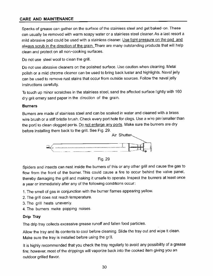
Burners
Burners are made of stainless steel and can be soaked in water and cleaned with a brass
wire brush or a stiff bristle brush. Check every port hole for clogs. Use a wire pin (smaller than
the port)to clean clogged ports. Do not enlarge any ports. Make sure the burners are dry
before installing them back to the grill. See Fig. 29. Air Shutte
~------------- ~~-----~-"' .. ~ ........................... ,., ........ , .......... ; .. ' -- ---- -- ---
Fig. 29
Spiders and insects can nest inside the burners of this or any other grill and cause the gas to
flow from the front of the burner. This could cause a fire to occur behind the valve panel,
thereby damaging the grill and making it unsafe to operate. Inspect the burners at least once
a year or immediately after any of the following conditions occur:
1. The smell of gas in conjunction with the burner flames appearing yellow.
2. The grill does not reach temperature.
3. The grill heats unevenly.
4. The burners make popping noises.
Drip Tray
The drip tray collects excessive grease runoff and fallen food particles.
Allow the tray and its contents to cool before cleaning. Slide the tray out and wipe it clean.
Make sure the tray is installed before using the grill.
It is highly recommended that you check the tray regularly to avoid any possibility of a grease
fire; however, most of the drippings will vaporize back into the cooked item giving you an
outdoor grilled flavor.
30
CARE AND MAINTENANCE
Helpful Care and Maintenance Hints
Before grilling, pre- heat grill for 15 minutes on "MAX" with hood down. To avoid uncontrolled
flare- ups or grease fires, grill meats with hood open. Close hood if meats are thick or weather
is cold, or if you are using a rotisserie or indirect cooking.
Always protect your hand with a pot mitten or cooking glove when coming into contact with a
hot surface.
Hood up when grilling meats, especially chicken. Hood down when indirect or rotisserie
cooking.
NEVER leave your grill unattended while cooking.
After use, close hood, turn burners to "MAX" for 15 min. for self-cleaning, grease burn off.
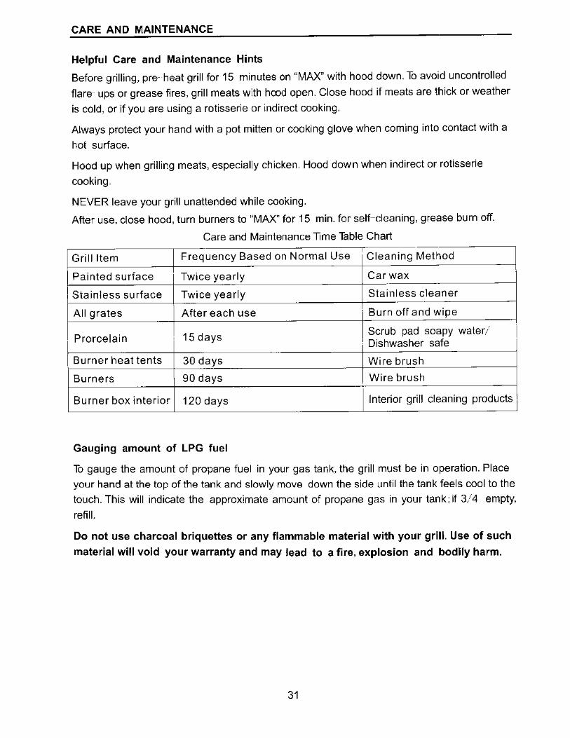
Care and Maintenance Time Table Chart
Grill Item Frequency Based on Normal Use Cleaning Method
Painted surface Twice yearly Car wax
Stainless surface Twice yearly Stainless cleaner
All grates After each use Burn off and wipe
Prorcelain 15 days Scrub pad soapy water; Dishwasher safe
Burner heat tents 30 days Wire brush
Burners 90 days Wire brush
Burner box interior 120 days Interior grill cleaning products
Gauging amount of LPG fuel
To gauge the amount of propane fuel in your gas tank, the grill must be in operation. Place your hand at the top of the tank and slowly move down the side until the tank feels cool to the
touch. This will indicate the approximate amount of propane gas in your tank; if 3/4 empty,
refill.
Do not use charcoal briquettes or any flammable material with your grill. Use of such
material will void your warranty and may lead to a fire, explosion and bodily harm.
31
I
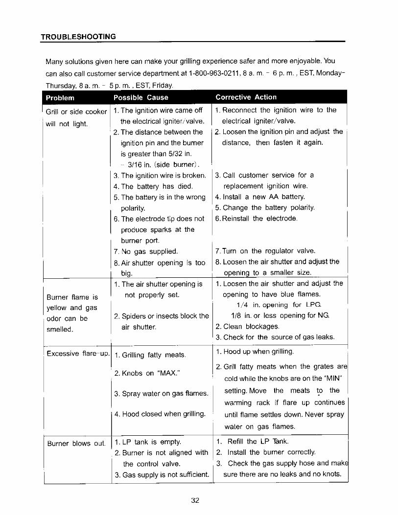
TROUBLESHOOTING
Many solutions given here can make your grilling experience safer and more enjoyable. You
can also call customer service department at 1-800-963-0211, 8 a. m. - 6 p. m. , EST, Monday
Thursday, 8 a, m. - 5 p. m. , EST, Friday.
will not light.
Burner flame is
yellow and gas
odor can be
smelled.
the electrical igniter,1valve. electrical igniter/valve.
' 2. The distance between the 2. Loosen the ignition pin and adjust the
ignition pin and the burner
is greater than 5/32 in.
-- 3/16 in. (side burner).
3. The ignition wire is broken.
4. The battery has died.
5. The battery is in the wrong
polarity.
6. The electrode tip does not
produce sparks at the
burner port.
7. No gas supplied.
distance, then fasten it again.
3. Call customer service for a
replacement ignition wire.
4. Install a new AA battery.
5. Change the battery polarity.
6. Reinstall the electrode.
7. Turn on the regulator valve.
8. Air shutter opening is too 8. Loosen the air shutter and adjust the
big. opening to a smaller size.
1. The air shutter opening is
not properly set.
2. Spiders or insects block the
air shutter.
1. Loosen the air shutter and adjust the
opening to have blue flames.
1 /4 in. opening for LPG
1/8 in. or less opening fo;;JNG
2. Clean blockages.
3. Check for the source of ga~ leaks.
Excessive flare-up. 1. Grilling fatty meats. 1. Hood up when grilling.
Burner blows out.
2. Knobs on "MAX."
3. Spray water on gas flames.
4. Hood closed when grilling.
1. LP tank is empty.
2. Burner is not aligned with
the control valve.
3. Gas supply is not sufficient.
32
2. Grill fatty meats when the grates are
cold while the knobs are on the "MIN"
setting. Move the meats ~o the
warming rack if flare up continues
until flame settles down. Never spray
water on gas flames.
1. Refill the LP Tank.
1 2. Install the burner correctly.
3. Check the gas supply hose and mak
sure there are no leaks and no knots.
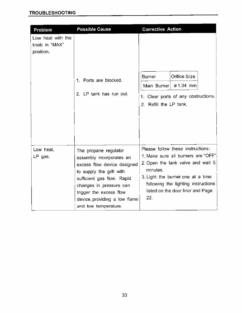
TROUBLESHOOTING
Problem Possible Cause Corrective Action
Low heat with the 1
knob in "MAX"
position.
Low heat,
LP gas.
1. Ports are blocked.
2. LP tank has run out.
The propane regulator
assembly incorporates an
excess flow device designed
to supply the grill with
sufficient gas flow. Rapid
' changes in pressure can
trigger the excess flow
device, providing a low flame
I and low temperature.
33
Burner Orifice Size
Main Burner: 0 1.04 mm '
1. Clear ports of any obstructions.
2. Refill the LP tank.
Please follow these instructions:
1. Make sure all burners are "OFF"
2. Open the tank valve and wait 51 minutes.
3. Light the burner one at a time
following the lighting instructions
listed on the door liner and Page
22.
WARRANTY
Proof of purchase is required to access this warranty program, which is in effect from the
date of purchase. Customers will be subject to parts, shipping, and handling fees if unable to
provide proof of the purchase or after the warranty has expired.
If you have any questions or problems, you can call our customer service department at
1-800-963-0211, 8 a. m. - 6 p. m., EST, Monday-Thursay, 8a. m. - 5 p. m., EST, Friday.
Limited Warranty
5-Year Warranty on stainless steel burners.
1-Year Warranty on all parts affecting the operation of the gas grill due to damage.
Warranty Provisions:
This warranty is non-transferable and does not cover failures due to misuse or improper
installation or maintenance.
This warranty is for replacement of defective parts only. We are not responsible for incidental
or consequential damages or labor costs.
This warranty does not cover corrosion or discoloration after the grill is used, or lack of
maintenance, hostile environment, accidents, alterations, abuse or neglect.
This warranty does not cover damage caused by heat, abrasive and chemical cleaners, or
any damage to other components used in the installation or operation of the gas grill.
Some states do not allow the limitation or exclusion of incidental or consequential
damages, so the above limitations or exclusions may not apply to you. This warranty
gives you specific legal rights, and you may also have other rights that vary from state
to state.
34
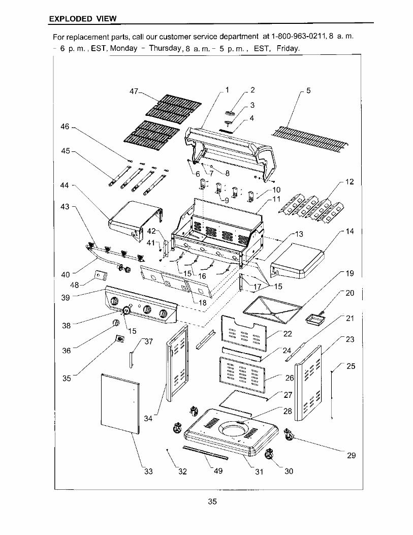
VIEW . artment at 1-8 EXPLODED stomer service dep EST, Friday.
arts call our cu m - 5 p. m. , For replacement p , - Thursday, 8 a. . EST, Monday - 6 p. m.,
0-963-0211, 8 a. m.
46
45
44 -
43
47
-
33
19
23
25
\~ 32
35
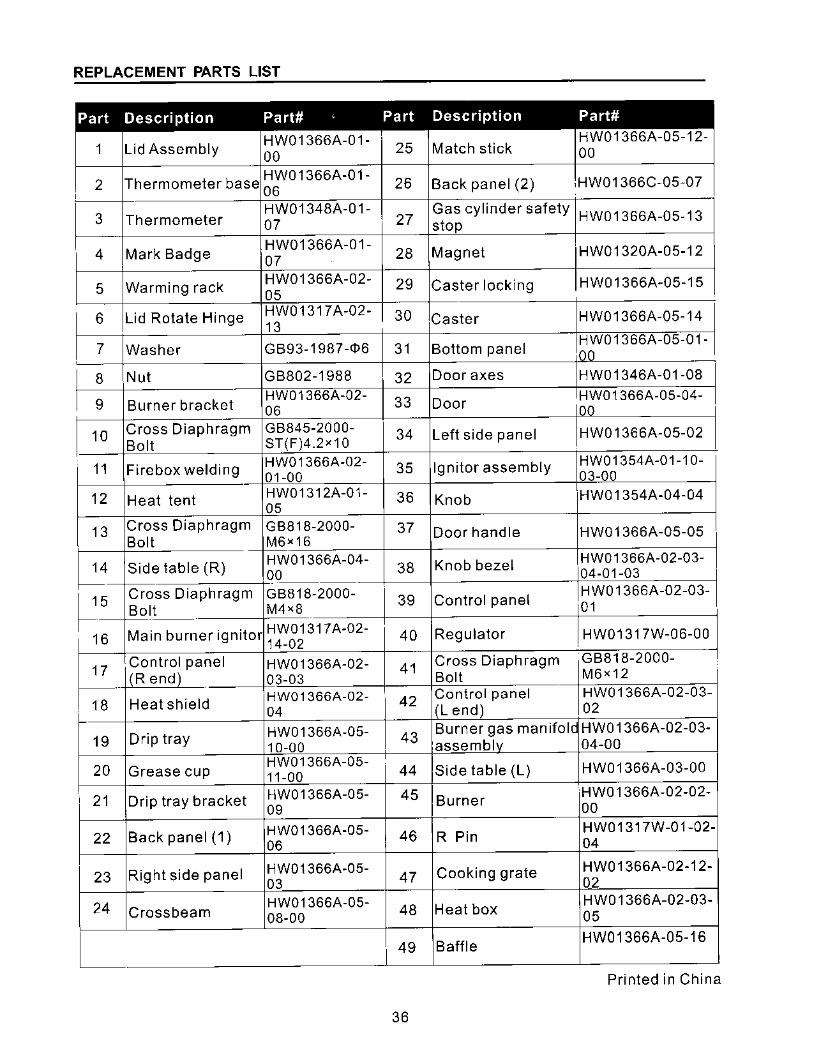
REPLACEMENT PARTS LIST
Part Description Part# ' Part Description Part#
1 Lid Assembly HW01366A-01- 25 Match stick
HW01366A-05-12-
00 00
2 Thermometer base HW0 1366A-0 1-
26 Back panel (2) ,HW01366C-05-07 '
06
3 Thermometer HW01348A-01- Gas cylinder safety HW01366A-05-13 07 27 stop
4 Mark Badge HW01366A-01-
28 Magnet HW01320A-05-12 07
5 Warming rack HW01366A-02- 29 Caster locking HW01366A-05-15 05
6 Lid Rotate Hinge HW01317A-02-13
30 Caster HW01366A-05-14
7 Washer GB93-1987-<!>6 31 Bottom panel HW01366A-05-01-00
8 Nut GB802-1988 32 Door axes HW01346A-01-08
9 Burner bracket HW01366A-02-
33 Door HW0 1366A-05-04-
06 00
10 Cross Diaphragm GB845-2000- 34 Left side panel HW01366A-05-02 Bolt ST(F)4.2x10
11 Firebox welding HW01366A-02- 35 Igniter assembly HW01354A-01-10-01-00 03-00
12 Heat tent HW01312A-01- 36 Knob HW0 1354A-04-04 05
13 Cross Diaphragm GB818-2000- 37 Door handle HW01366A-05-05 Bolt M6><16
14 Side table (R) HW01366A-04-
38 Knob bezel HW01366A-02-03-
00 04-01-03
~5
Cross Diaphragm GB818-2000- 39 Control panel HW01366A-02-03-
Bolt M4x8 01
Main burner igniter HW01317A-02- Regulator 16 14-02 40 HW01317W-06-00
17 Control panel HW0 1366A-02- 41
Cross Diaphragm GB818-2000-
(Rend) 03-03 Bolt M6><12 ~--
18 Heat shield HW01366A-02- 42
Control panel HW0 1 366A-02-03-04 (Lend) 02
19 Drip tray HW01366A-05- 43 Burner gas manifold HW01366A-02-03-
10-00 assemb[,, 04-00
20 Grease cup HW01366A-05-
44 Side table (L) HW0 1366A-03-00 11-00
21 Drip tray bracket HW01366A-05- 45 Burner HW01366A-02-02-
09 00
22 Back panel (1) HW01366A-05- 46 R Pin HW01317W-01-02-
06 04
23 Right side panel HW01366A-05-47 Cooking grate HW01366A-02-12-
03 02
24 Crossbeam HW01366A-05-
48 Heat box HW01366A-02-03-
08-00 05
49 Baffle HW01366A-05-16
Printed in China
36