modelling vibro-acoustic coupling in flexible micro-perforated
TRANSCRIPT
Contents lists available at ScienceDirect
Applied Acoustics
journal homepage: www.elsevier .com/locate /apacoust
Modelling vibro-acoustic coupling in flexible micro-perforated plates bya patch-impedance approach
.
⇑ Corresponding author.E-mail address: [email protected] (M.A. Temiz).
This is a pre-print version.Published in Applied Acoustics (2017), Vol. 125, pp. 80-90. DOI: 10.1016/j.apacoust.2017.04.012
Muttalip As�kın Temiz a,⇑, Jonathan Tournadre b, Ines Lopez Arteaga a,c, Avraham Hirschberg d
a Eindhoven University of Technology, Department of Mechanical Engineering, The NetherlandsbKU Leuven, Department of Mechanical Engineering, Celestijnenlaan 300, B. 3001 Leuven, BelgiumcKTH Royal Institute of Technology, Department of Aeronautical and Vehicle Engineering, Stockholm, Swedend Eindhoven University of Technology, Department of Applied Physics, The Netherlands
Pa r t i c l e i n f o
Article history:Received 3 November 2016Received in revised form 27 February 2017Accepted 13 April 2017Available online 25 April 2017
2010 MSC:70-8074F10
Keywords:Flexible micro-perforated platesVibro-acoustic couplingAcoustic transfer impedanceAbsorption coefficientFinite element method
reprinta b s t r a c t
This study proposes a Finite Element (FE)-based efficient numerical model of the vibro-acoustic couplingin flexible micro-perforated plates (f-MPPs) where each perforation is described as an imposed impe-dance boundary condition (uniform impedance patch) on the plate. This approach opens the possibilityof predicting the influence of perforation distribution on the acoustic performance of f-MPP. Micro per-forated plates have been a topic of interest as a promising sound absorber in a wide range of applications,from room acoustics to combustion systems. One great advantage of these plates is that it gives thedesigner the freedom of choice on material in production. Depending on the material and the dimensions,the acoustical modes of the medium can couple with the structural modes of the plate. This couplingchanges the number of absorption peaks, frequency and amplitude of the Helmholtz resonance of the sys-tem, therefore the coupling becomes an extra parameter in the design process. Current analytical modelssuperpose the mechanical impedance of the plate with the acoustic impedance of the perforations tocompute this coupling. This approach works fairly well for plates with uniform perforation distribution.This study proposes a numerical method which assumes perforations as discrete impedance patches onthe flexible plate so that they can be considered separately. The method couples the solution of theHelmholtz equation in air with shell plate theory to model the vibro-acoustic effects and the impedancepatches are represented as imposed transfer impedance boundary conditions. The assessment of themethod is performed in terms of comparing the calculated absorption coefficient values from the simu-lations of several test cases, fundamental theories and measurement results from the literature. The sim-ulation results agree both with these theoretical limits and measurement results. The use of the methodis illustrated by considering an example of the influence of modification of the spatial distribution of per-forations on the sound absorption of a membrane.
1. Introduction
Micro-perforated plates (MPPs) have been designated as highpotential sound absorbers by Maa [1] for various applicationsincluding the ones with severe environments. Before the study ofMaa [1], they were used only as protective layer for classical soundabsorbers. MPPs are plates with small perforations whose diameteris in the order of 10�1 mmwith low porosity values, i.e. / ¼ Oð1%Þ.When backed by a cavity, they provide broadband acousticdissipation.
The present study is limited to the amplitude range for whichthe behaviour can be described by a linear model. This excludesdamping due to vortex shedding. The linear sound absorptionmechanism in MPPs is based on the conversion of the kineticenergy of the fluid particles into heat energy due to the viscousresistance in the perforations. As the viscous resistance increaseswith the relative velocity between the plate and the fluid, thekinetic energy loss of the particles and the corresponding soundabsorption is larger when the excitation frequency approaches tothe Helmholtz resonance frequency of the back cavity. For a rigidMPP, the relative particle velocity of the air is the same for eachperforation at all frequencies when excited by a planar acousticwave. On the other hand, when the plate is flexible, at certain fre-quencies the plate vibrates with the mode shape depending on its
Prep
geometry, excitation frequency, boundary conditions and material.Due to this mode shape, even under acoustic plane wave excita-tion, the relative air particle velocity with respect to the platedepends on the position of the perforation within the plate. There-fore, the perforation position is potentially a design parameter inflexible micro-perforated plates (f-MPPs).
Sound absorption by flexible plates is a known phenomenon inroom acoustics. One of the first analytical models for a flexibleplate, which does not have perforations but backed by an air cavity,is provided by Cremer and Müller [2]. In this model, they couplethe bending waves of the flexible plate with the acoustic wavesof the air cavity. An important contribution to this model is madeby Basten et al. [3]. They consider an enclosed air cavity betweentwo flexible plates and the distance between these plates are small.Basten et al. [3] analytically show that, such a small gap betweenthe flexible plates causes the visco-thermal effects to become dom-inant in the cavity.
On the MPP side, the first scientists to observe that plate vibra-tions affect the absorption mechanism are Lee and Swenson [4]. Intheir experiments, they report an additional absorption peak whichcannot be modelled by the rigid MPP theory. The first analyticalmodel including the flexible effects in MPPs is given by Lee et al.[5]. Inspired by their work, Toyoda et al. [6] propose a similarapproach for modelling of f-MPPs having circular geometry. BothLee et al. [5] and Toyoda et al. [6] calculate the structural impe-dance of the flexible plate using modal analysis and combine itwith the acoustic transfer impedance defined by Maa [1]. In bothof these studies, the mathematical models are verified by experi-ments. Bravo et al. [7,8] consider a case where the back cavity wallsare flexible and provide a theoretical model where the absorptionmechanism is governed by the relative velocity between the airparticles and the flexible plate. They verify this model by experi-ments. Li et al. [9] propose a sophisticated model to account forthe non-zero velocity boundary condition at the inner walls ofthe perforations. This boundary condition redefines the classicalacoustic transfer impedance expression by Maa [1].
Besides the analytical and empirical approaches described sofar, some numerical models employing finite element method(FEM) have been proposed. Hou and Bolton [10] model the plateas a porous material and they include the vibrations effectsthrough the elastic frame model. They focus on the effect of plateprofile (such as bent and curved plates) on the absorption coeffi-cient. Wang and Huang [11] investigate the effect of complexback-cavity shapes in acoustic response of f-MPPs. They couplethe structural vibrations of the plate with the acoustics of the per-forations and the back cavity. In their model, air particle velocity inthe perforations are averaged over the flexible plate. Okuzono andSakagami [12] propose a numerical model to analyse the soundfield in room acoustics which is computationally low-cost. How-ever, they assume the plate as an additional mass vibrating in frontof the back cavity thus it does not consider the structural platemodes. Moreover, as previous studies, they average the acoustictransfer impedance of the perforations over the plate. On the otherhand, Carbajo et al. [13] consider each perforation separately intheir FE model. They represent the entire acoustic domain (includ-ing the perforations) with linearized Navier-Stokes equations to beable to capture the visco-thermal effects. They study the interac-tion between the perforations. Even though they do not take plateflexibility into account, they report that their model is computa-tionally demanding.
The FE model proposed in the current study makes it possible tomodel (i) the vibro-acoustic coupling in f-MPPs, (ii) viscous lossesin the small perforations, and (iii) the effect of perforation distribu-tion. This is achieved by coupling the Helmholtz equation [14] andKirchhoff’s thin plate equation [15] in the numerical domain, whileeach perforation is represented by transfer impedance boundary
rint
patches on the flexible plate separately. The boundary conditionfor these patches take the viscous losses into account. Consideringthis feature, the model presented in this study is more efficientthan the ones using linearized Navier-Stokes equations [13] to cap-ture the viscous effects of the micro-perforations.
To validate the theory, a cylindrical impedance tube is modellednumerically and the acoustic properties of the f-MPP with a backcavity is assessed in terms of absorption coefficient, aA. The modeloutputs are compared with fundamental plate and acoustic theo-ries and experiments reported in the literature. The use of themethod is illustrated by considering an example of the influenceof modification of the spatial distribution of perforations on thesound absorption of a thin plate.
2. Theoretical background
The numerical domain of the impedance tube configuration ispresented schematically in Fig. 1.
The numerical model is composed of two domains: a structuraldomain (shell) and an acoustic domain. This section provides thegoverning equations used for modelling these domains.
2.1. Structural domain
The equation of motion of the thin, homogeneous flexible plateshown in Fig. 1 is given by Kirchhoff [15] as
Dpr2r2wðrÞ � qptpx2wðrÞ ¼ bP ; ð1Þ
wherer2 is the Laplacian operator, wðx; yÞ is the plate displacementin the z-direction, qp is the plate density (mass per unit of surface),
tp is the plate thickness; bP is the external pressure difference actingon the plate; Dp ¼ Eð1þ jgÞt3p=½12ð1� m2Þ� is the flexural rigidity of
the plate where j is the imaginary number (j2 ¼ �1), E is the Young’smodulus, g is the loss factor and m is the Poisson ratio of the platematerial. As the typical porosity of an f-MPP is in the order of10�2 [16], the effect of perforations on the structural properties ofthe flexible plate is ignored for the modelling.
2.2. Acoustic domain
Domains r and s in Fig. 1 are acoustic domains and they areassumed to be excited by harmonic plane waves. Furthermore,thermo-viscous losses at the sound-hard boundaries are negligiblein theses acoustic domains. Under these assumptions, the spatialpressure distribution in frequency domain is given by Helmholtzequation [14]
x2pnðzÞ þ c20r2pnðzÞ ¼ 0; ð2Þwhere x ¼ 2pf is the radial frequency, c0 is the speed of sound inair and pn is the acoustic pressure in frequency domain for acousticmedium n; i.e. n ¼ 1 for the impedance tube and n ¼ 2 for the backcavity domains, respectively (see Fig. 1).
The two acoustical domains in Fig. 1 are connected throughmicro-perforations which can be considered as independent uni-form impedance patches on the flexible plate. These patches aredefined as imposed transfer impedance boundaries in the numeri-cal model and the mathematical expression for each patch is givenby Temiz et al. [16] as
Zt ¼ p1 � p2
up
¼ jxtpq0 1� 2Sh
ffiffiffiffiffiffi�j
p J1ðShffiffiffiffiffiffi�j
pÞ
J0ðShffiffiffiffiffiffi�j
pÞ
" #�1
þ 2asRs þ jdsxq0dp
2; ð3Þ
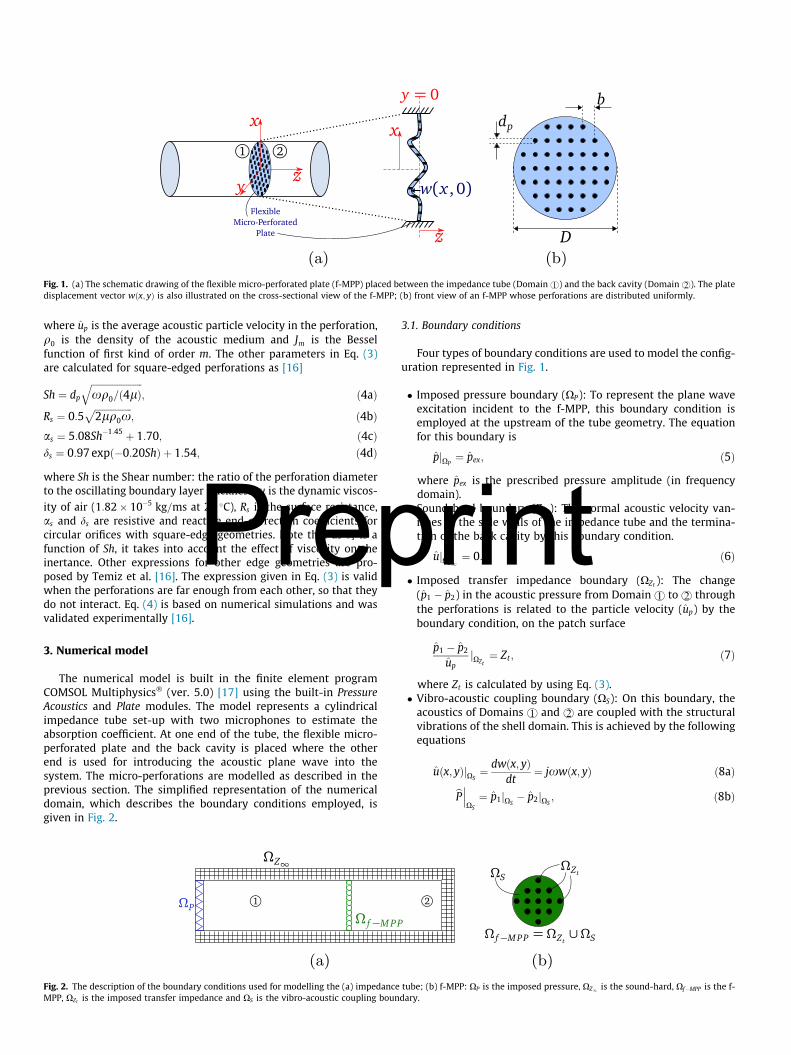
(a) (b)Fig. 1. (a) The schematic drawing of the flexible micro-perforated plate (f-MPP) placed between the impedance tube (Domain r) and the back cavity (Domain s). The platedisplacement vector wðx; yÞ is also illustrated on the cross-sectional view of the f-MPP; (b) front view of an f-MPP whose perforations are distributed uniformly.
Prep
where up is the average acoustic particle velocity in the perforation,q0 is the density of the acoustic medium and Jm is the Besselfunction of first kind of order m. The other parameters in Eq. (3)are calculated for square-edged perforations as [16]
Sh ¼ dp
ffiffiffiffiffiffiffiffiffiffiffiffiffiffiffiffiffiffiffiffiffiffixq0=ð4lÞ
q; ð4aÞ
Rs ¼ 0:5ffiffiffiffiffiffiffiffiffiffiffiffiffiffiffiffi2lq0x
p; ð4bÞ
as ¼ 5:08Sh�1:45 þ 1:70; ð4cÞds ¼ 0:97 expð�0:20ShÞ þ 1:54; ð4dÞwhere Sh is the Shear number: the ratio of the perforation diameterto the oscillating boundary layer thickness, l is the dynamic viscos-ity of air (1:82� 10�5 kg=ms at 20 �C), Rs is the surface resistance,as and ds are resistive and reactive end-correction coefficients forcircular orifices with square-edge geometries. Note that as ds is afunction of Sh, it takes into account the effect of viscosity on theinertance. Other expressions for other edge geometries are pro-posed by Temiz et al. [16]. The expression given in Eq. (3) is validwhen the perforations are far enough from each other, so that theydo not interact. Eq. (4) is based on numerical simulations and wasvalidated experimentally [16].
3. Numerical model
The numerical model is built in the finite element programCOMSOL Multiphysics� (ver. 5.0) [17] using the built-in PressureAcoustics and Plate modules. The model represents a cylindricalimpedance tube set-up with two microphones to estimate theabsorption coefficient. At one end of the tube, the flexible micro-perforated plate and the back cavity is placed where the otherend is used for introducing the acoustic plane wave into thesystem. The micro-perforations are modelled as described in theprevious section. The simplified representation of the numericaldomain, which describes the boundary conditions employed, isgiven in Fig. 2.
(a)Fig. 2. The description of the boundary conditions used for modelling the (a) impedanceMPP, XZt is the imposed transfer impedance and XS is the vibro-acoustic coupling boun
3.1. Boundary conditions
Four types of boundary conditions are used to model the config-uration represented in Fig. 1.
� Imposed pressure boundary (XP): To represent the plane waveexcitation incident to the f-MPP, this boundary condition isemployed at the upstream of the tube geometry. The equationfor this boundary is
pjXP¼ pex; ð5Þ
where pex is the prescribed pressure amplitude (in frequencydomain).
� Sound-hard boundary (Z1): The normal acoustic velocity van-ishes at the side walls of the impedance tube and the termina-tion of the back cavity by this boundary condition.
rintujXZ1¼ 0: ð6Þ� Imposed transfer impedance boundary (XZt ): The change(p1 � p2) in the acoustic pressure from Domain r to s throughthe perforations is related to the particle velocity (up) by theboundary condition, on the patch surface
p1 � p2
upjXZt
¼ Zt ; ð7Þ
where Zt is calculated by using Eq. (3).� Vibro-acoustic coupling boundary (XS): On this boundary, theacoustics of Domains r and s are coupled with the structuralvibrations of the shell domain. This is achieved by the followingequations
tube; (bdary.
uðx; yÞjXS¼ dwðx; yÞ
dt¼ jxwðx; yÞ ð8aÞ
bP���XS
¼ p1jXS� p2jXS
; ð8bÞ
(b)) f-MPP: XP is the imposed pressure, XZ1 is the sound-hard, Xf�MPP is the f-
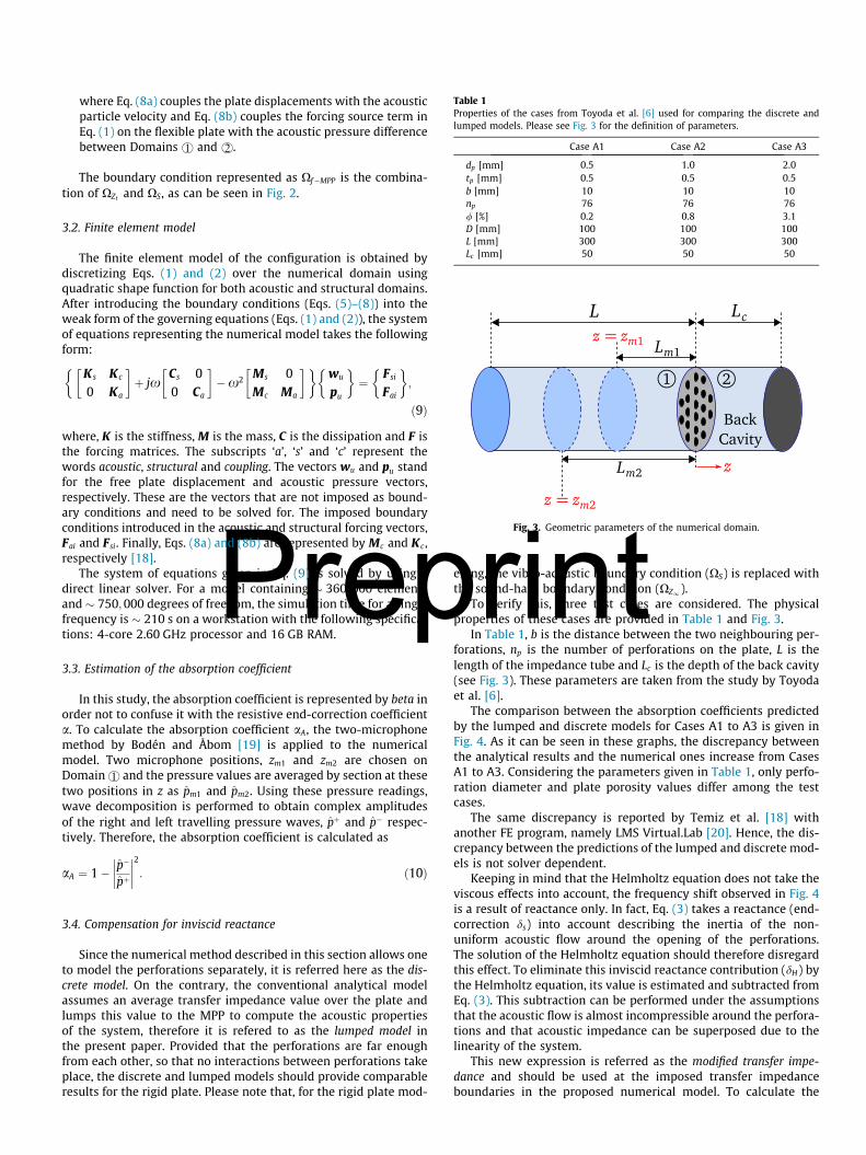
Table 1Properties of the cases from Toyoda et al. [6] used for comparing the discrete andlumped models. Please see Fig. 3 for the definition of parameters.
Case A1 Case A2 Case A3
dp [mm] 0.5 1.0 2.0tp [mm] 0.5 0.5 0.5b [mm] 10 10 10np 76 76 76/ [%] 0.2 0.8 3.1D [mm] 100 100 100L [mm] 300 300 300Lc [mm] 50 50 50
Fig. 3. Geometric parameters of the numerical domain.
Prep
where Eq. (8a) couples the plate displacements with the acousticparticle velocity and Eq. (8b) couples the forcing source term inEq. (1) on the flexible plate with the acoustic pressure differencebetween Domains r and s.
The boundary condition represented as Xf�MPP is the combina-tion of XZt and XS, as can be seen in Fig. 2.
3.2. Finite element model
The finite element model of the configuration is obtained bydiscretizing Eqs. (1) and (2) over the numerical domain usingquadratic shape function for both acoustic and structural domains.After introducing the boundary conditions (Eqs. (5)–(8)) into theweak form of the governing equations (Eqs. (1) and (2)), the systemof equations representing the numerical model takes the followingform:
K s Kc
0 Ka
� �þ jx
Cs 00 Ca
� ��x2 Ms 0
Mc Ma
� �� �wu
pu
� �¼ Fsi
Fai
� �;
ð9Þwhere, K is the stiffness, M is the mass, C is the dissipation and F isthe forcing matrices. The subscripts ‘a’, ‘s’ and ‘c’ represent thewords acoustic, structural and coupling. The vectors wu and pu standfor the free plate displacement and acoustic pressure vectors,respectively. These are the vectors that are not imposed as bound-ary conditions and need to be solved for. The imposed boundaryconditions introduced in the acoustic and structural forcing vectors,Fai and Fsi. Finally, Eqs. (8a) and (8b) are represented by Mc and Kc ,respectively [18].
The system of equations given in Eq. (9) is solved by using adirect linear solver. For a model containing � 360;000 elementsand � 750;000 degrees of freedom, the simulation time for a singlefrequency is � 210 s on a workstation with the following specifica-tions: 4-core 2.60 GHz processor and 16 GB RAM.
3.3. Estimation of the absorption coefficient
In this study, the absorption coefficient is represented by beta inorder not to confuse it with the resistive end-correction coefficienta. To calculate the absorption coefficient aA, the two-microphonemethod by Bodén and Åbom [19] is applied to the numericalmodel. Two microphone positions, zm1 and zm2 are chosen onDomainr and the pressure values are averaged by section at thesetwo positions in z as pm1 and pm2. Using these pressure readings,wave decomposition is performed to obtain complex amplitudesof the right and left travelling pressure waves, pþ and p� respec-tively. Therefore, the absorption coefficient is calculated as
aA ¼ 1� p�
pþ
���� ����2: ð10Þ
3.4. Compensation for inviscid reactance
Since the numerical method described in this section allows oneto model the perforations separately, it is referred here as the dis-crete model. On the contrary, the conventional analytical modelassumes an average transfer impedance value over the plate andlumps this value to the MPP to compute the acoustic propertiesof the system, therefore it is refered to as the lumped model inthe present paper. Provided that the perforations are far enoughfrom each other, so that no interactions between perforations takeplace, the discrete and lumped models should provide comparableresults for the rigid plate. Please note that, for the rigid plate mod-
rintelling, the vibro-acoustic boundary condition (XS) is replaced withthe sound-hard boundary condition (XZ1 ).
To verify this, three test cases are considered. The physicalproperties of these cases are provided in Table 1 and Fig. 3.
In Table 1, b is the distance between the two neighbouring per-forations, np is the number of perforations on the plate, L is thelength of the impedance tube and Lc is the depth of the back cavity(see Fig. 3). These parameters are taken from the study by Toyodaet al. [6].
The comparison between the absorption coefficients predictedby the lumped and discrete models for Cases A1 to A3 is given inFig. 4. As it can be seen in these graphs, the discrepancy betweenthe analytical results and the numerical ones increase from CasesA1 to A3. Considering the parameters given in Table 1, only perfo-ration diameter and plate porosity values differ among the testcases.
The same discrepancy is reported by Temiz et al. [18] withanother FE program, namely LMS Virtual.Lab [20]. Hence, the dis-crepancy between the predictions of the lumped and discrete mod-els is not solver dependent.
Keeping in mind that the Helmholtz equation does not take theviscous effects into account, the frequency shift observed in Fig. 4is a result of reactance only. In fact, Eq. (3) takes a reactance (end-correction ds) into account describing the inertia of the non-uniform acoustic flow around the opening of the perforations.The solution of the Helmholtz equation should therefore disregardthis effect. To eliminate this inviscid reactance contribution (dH) bythe Helmholtz equation, its value is estimated and subtracted fromEq. (3). This subtraction can be performed under the assumptionsthat the acoustic flow is almost incompressible around the perfora-tions and that acoustic impedance can be superposed due to thelinearity of the system.
This new expression is referred as the modified transfer impe-dance and should be used at the imposed transfer impedanceboundaries in the proposed numerical model. To calculate the
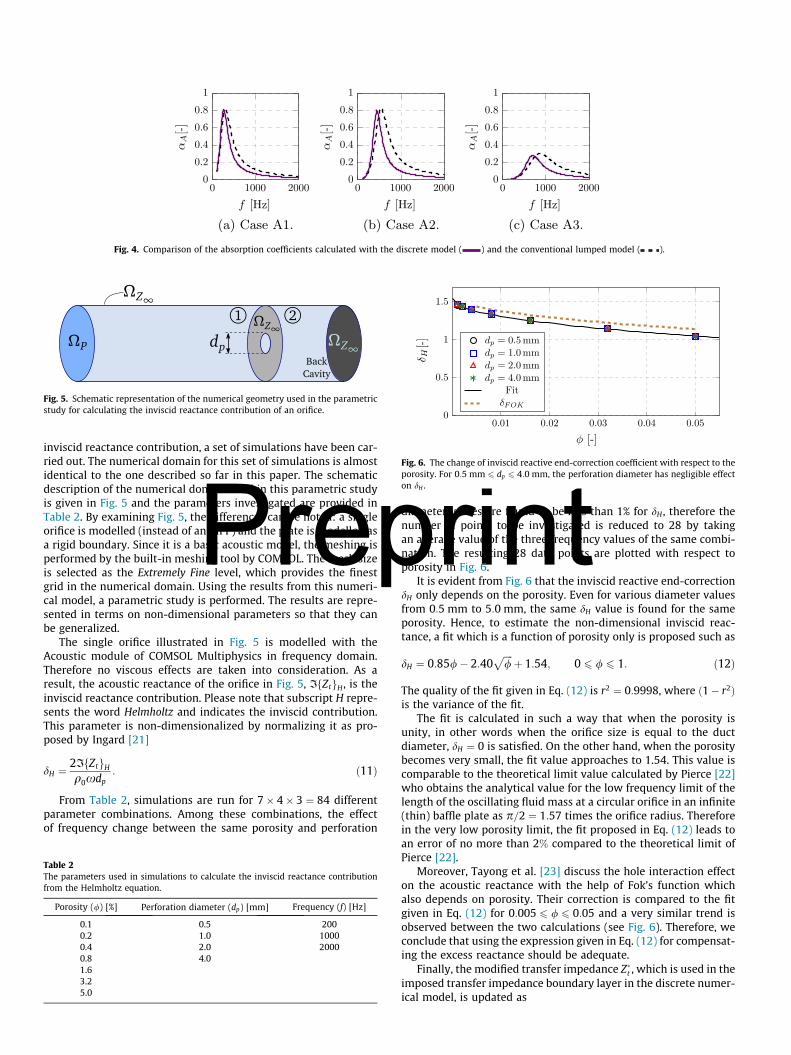
Fig. 4. Comparison of the absorption coefficients calculated with the discrete model ( ) and the conventional lumped model ( ).
Fig. 5. Schematic representation of the numerical geometry used in the parametricstudy for calculating the inviscid reactance contribution of an orifice.
Fig. 6. The change of inviscid reactive end-correction coefficient with respect to theporosity. For 0:5 mm 6 dp 6 4:0 mm, the perforation diameter has negligible effecton dH .
Prepinviscid reactance contribution, a set of simulations have been car-ried out. The numerical domain for this set of simulations is almostidentical to the one described so far in this paper. The schematicdescription of the numerical domain used in this parametric studyis given in Fig. 5 and the parameters investigated are provided inTable 2. By examining Fig. 5, the differences can be noted: a singleorifice is modelled (instead of an MPP) and the plate is modelled asa rigid boundary. Since it is a basic acoustic model, the meshing isperformed by the built-in meshing tool by COMSOL. The mesh sizeis selected as the Extremely Fine level, which provides the finestgrid in the numerical domain. Using the results from this numeri-cal model, a parametric study is performed. The results are repre-sented in terms on non-dimensional parameters so that they canbe generalized.
The single orifice illustrated in Fig. 5 is modelled with theAcoustic module of COMSOL Multiphysics in frequency domain.Therefore no viscous effects are taken into consideration. As aresult, the acoustic reactance of the orifice in Fig. 5, IfZtgH , is theinviscid reactance contribution. Please note that subscript H repre-sents the word Helmholtz and indicates the inviscid contribution.This parameter is non-dimensionalized by normalizing it as pro-posed by Ingard [21]
dH ¼ 2IfZtgHq0xdp
: ð11Þ
From Table 2, simulations are run for 7� 4� 3 ¼ 84 differentparameter combinations. Among these combinations, the effectof frequency change between the same porosity and perforation
Table 2The parameters used in simulations to calculate the inviscid reactance contributionfrom the Helmholtz equation.
Porosity (/) [%] Perforation diameter (dp) [mm] Frequency (f) [Hz]
0.1 0.5 2000.2 1.0 10000.4 2.0 20000.8 4.01.63.25.0
rintdiameter values are found to be less than 1% for dH , therefore thenumber of points to be investigated is reduced to 28 by takingan average value of the three frequency values of the same combi-nation. The resulting 28 data points are plotted with respect toporosity in Fig. 6.
It is evident from Fig. 6 that the inviscid reactive end-correctiondH only depends on the porosity. Even for various diameter valuesfrom 0:5 mm to 5:0 mm, the same dH value is found for the sameporosity. Hence, to estimate the non-dimensional inviscid reac-tance, a fit which is a function of porosity only is proposed such as
dH ¼ 0:85/� 2:40ffiffiffiffi/
pþ 1:54; 0 6 / 6 1: ð12Þ
The quality of the fit given in Eq. (12) is r2 ¼ 0:9998, where ð1� r2Þis the variance of the fit.
The fit is calculated in such a way that when the porosity isunity, in other words when the orifice size is equal to the ductdiameter, dH ¼ 0 is satisfied. On the other hand, when the porositybecomes very small, the fit value approaches to 1.54. This value iscomparable to the theoretical limit value calculated by Pierce [22]who obtains the analytical value for the low frequency limit of thelength of the oscillating fluid mass at a circular orifice in an infinite(thin) baffle plate as p=2 ¼ 1:57 times the orifice radius. Thereforein the very low porosity limit, the fit proposed in Eq. (12) leads toan error of no more than 2% compared to the theoretical limit ofPierce [22].
Moreover, Tayong et al. [23] discuss the hole interaction effecton the acoustic reactance with the help of Fok’s function whichalso depends on porosity. Their correction is compared to the fitgiven in Eq. (12) for 0:005 6 / 6 0:05 and a very similar trend isobserved between the two calculations (see Fig. 6). Therefore, weconclude that using the expression given in Eq. (12) for compensat-ing the excess reactance should be adequate.
Finally, the modified transfer impedance Z�t , which is used in the
imposed transfer impedance boundary layer in the discrete numer-ical model, is updated as
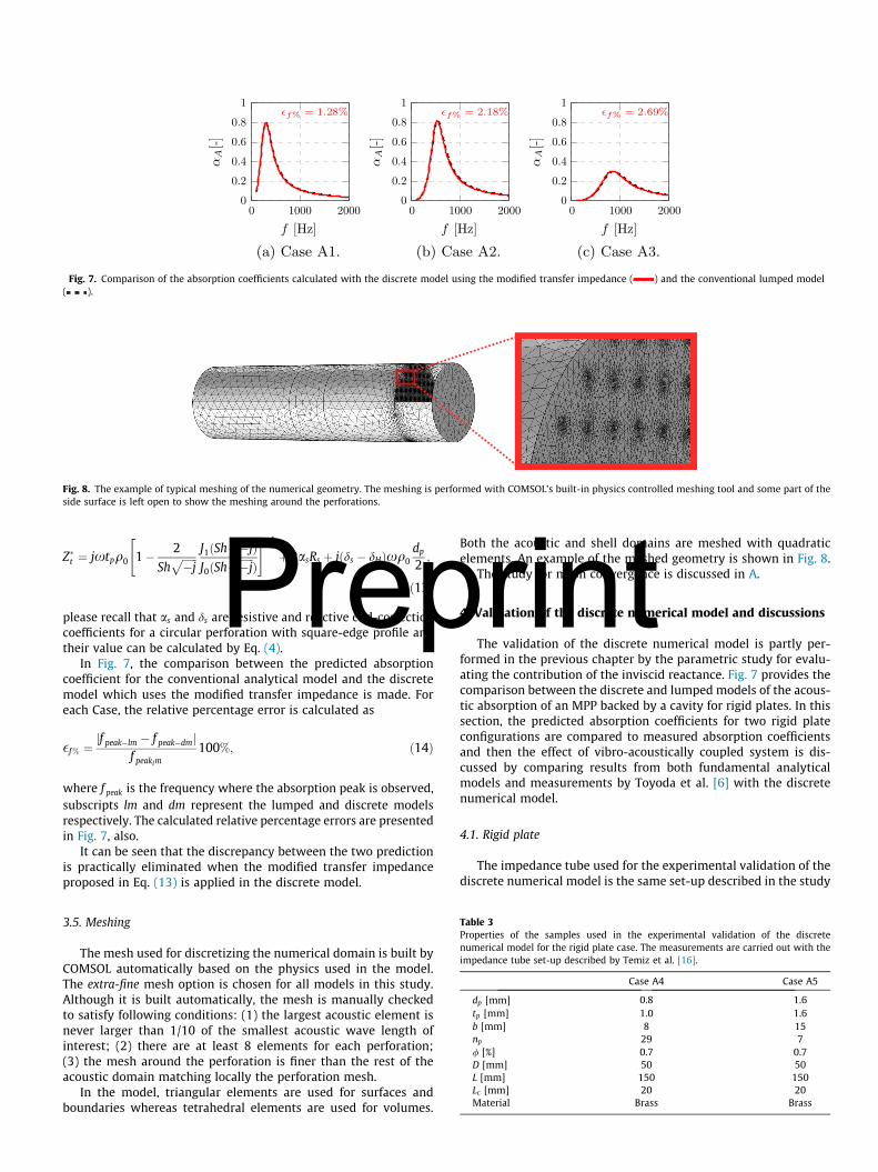
Fig. 7. Comparison of the absorption coefficients calculated with the discrete model using the modified transfer impedance ( ) and the conventional lumped model( ).
Fig. 8. The example of typical meshing of the numerical geometry. The meshing is performed with COMSOL’s built-in physics controlled meshing tool and some part of theside surface is left open to show the meshing around the perforations.
PrepZ�t ¼ jxtpq0 1� 2
Shffiffiffiffiffiffi�j
p J1ðShffiffiffiffiffiffi�j
pÞ
J0ðShffiffiffiffiffiffi�j
pÞ
" #�1
þ 2asRs þ jðds � dHÞxq0dp
2;
ð13Þ
please recall that as and ds are resistive and reactive end-correctioncoefficients for a circular perforation with square-edge profile andtheir value can be calculated by Eq. (4).
In Fig. 7, the comparison between the predicted absorptioncoefficient for the conventional analytical model and the discretemodel which uses the modified transfer impedance is made. Foreach Case, the relative percentage error is calculated as
�f% ¼ jf peak�lm � f peak�dmjf peaklm
100%; ð14Þ
where f peak is the frequency where the absorption peak is observed,subscripts lm and dm represent the lumped and discrete modelsrespectively. The calculated relative percentage errors are presentedin Fig. 7, also.
It can be seen that the discrepancy between the two predictionis practically eliminated when the modified transfer impedanceproposed in Eq. (13) is applied in the discrete model.
Table 3Properties of the samples used in the experimental validation of the discretenumerical model for the rigid plate case. The measurements are carried out with theimpedance tube set-up described by Temiz et al. [16].
Case A4 Case A5
dp [mm] 0.8 1.6tp [mm] 1.0 1.6b [mm] 8 15np 29 7/ [%] 0.7 0.7D [mm] 50 50L [mm] 150 150Lc [mm] 20 20Material Brass Brass
3.5. Meshing
The mesh used for discretizing the numerical domain is built byCOMSOL automatically based on the physics used in the model.The extra-fine mesh option is chosen for all models in this study.Although it is built automatically, the mesh is manually checkedto satisfy following conditions: (1) the largest acoustic element isnever larger than 1/10 of the smallest acoustic wave length ofinterest; (2) there are at least 8 elements for each perforation;(3) the mesh around the perforation is finer than the rest of theacoustic domain matching locally the perforation mesh.
In the model, triangular elements are used for surfaces andboundaries whereas tetrahedral elements are used for volumes.
Both the acoustic and shell domains are meshed with quadraticelements. An example of the meshed geometry is shown in Fig. 8.
The study for mesh convergence is discussed in A.
rint4. Validation of the discrete numerical model and discussionsThe validation of the discrete numerical model is partly per-formed in the previous chapter by the parametric study for evalu-ating the contribution of the inviscid reactance. Fig. 7 provides thecomparison between the discrete and lumped models of the acous-tic absorption of an MPP backed by a cavity for rigid plates. In thissection, the predicted absorption coefficients for two rigid plateconfigurations are compared to measured absorption coefficientsand then the effect of vibro-acoustically coupled system is dis-cussed by comparing results from both fundamental analyticalmodels and measurements by Toyoda et al. [6] with the discretenumerical model.
4.1. Rigid plate
The impedance tube used for the experimental validation of thediscrete numerical model is the same set-up described in the study
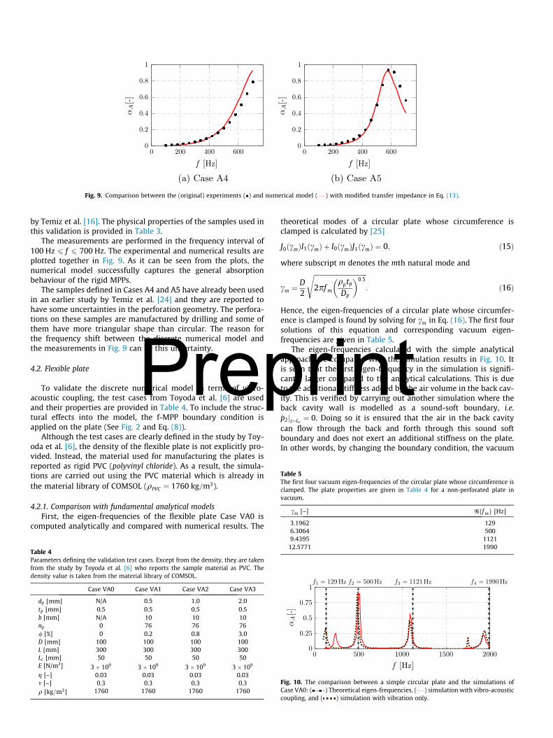
Fig. 9. Comparison between the (original) experiments (�) and numerical model ( ) with modified transfer impedance in Eq. (13).
Table 5The first four vacuum eigen-frequencies of the circular plate whose circumference isclamped. The plate properties are given in Table 4 for a non-perforated plate invacuum.
cm [–] Rff mg [Hz]
3.1962 1296.3064 500
Prep
by Temiz et al. [16]. The physical properties of the samples used inthis validation is provided in Table 3.
The measurements are performed in the frequency interval of100 Hz 6 f 6 700 Hz. The experimental and numerical results areplotted together in Fig. 9. As it can be seen from the plots, thenumerical model successfully captures the general absorptionbehaviour of the rigid MPPs.
The samples defined in Cases A4 and A5 have already been usedin an earlier study by Temiz et al. [24] and they are reported tohave some uncertainties in the perforation geometry. The perfora-tions on these samples are manufactured by drilling and some ofthem have more triangular shape than circular. The reason forthe frequency shift between the discrete numerical model andthe measurements in Fig. 9 can be this uncertainty.
4.2. Flexible plate
To validate the discrete numerical model in terms of vibro-acoustic coupling, the test cases from Toyoda et al. [6] are usedand their properties are provided in Table 4. To include the struc-tural effects into the model, the f-MPP boundary condition isapplied on the plate (See Fig. 2 and Eq. (8)).
Although the test cases are clearly defined in the study by Toy-oda et al. [6], the density of the flexible plate is not explicitly pro-vided. Instead, the material used for manufacturing the plates isreported as rigid PVC (polyvinyl chloride). As a result, the simula-tions are carried out using the PVC material which is already inthe material library of COMSOL (qPVC ¼ 1760 kg=m3).
4.2.1. Comparison with fundamental analytical modelsFirst, the eigen-frequencies of the flexible plate Case VA0 is
computed analytically and compared with numerical results. The
Table 4Parameters defining the validation test cases. Except from the density, they are takenfrom the study by Toyoda et al. [6] who reports the sample material as PVC. Thedensity value is taken from the material library of COMSOL.
Case VA0 Case VA1 Case VA2 Case VA3
dp [mm] N/A 0.5 1.0 2.0tp [mm] 0.5 0.5 0.5 0.5b [mm] N/A 10 10 10np 0 76 76 76/ [%] 0 0.2 0.8 3.0D [mm] 100 100 100 100L [mm] 300 300 300 300Lc [mm] 50 50 50 50E [N/m2] 3� 109 3� 109 3� 109 3� 109
g [–] 0.03 0.03 0.03 0.03m [–] 0.3 0.3 0.3 0.3q [kg=m3] 1760 1760 1760 1760
rint
theoretical modes of a circular plate whose circumference isclamped is calculated by [25]
J0ðcmÞI1ðcmÞ þ I0ðcmÞJ1ðcmÞ ¼ 0; ð15Þwhere subscript m denotes the mth natural mode and
cm ¼ D2
ffiffiffiffiffiffiffiffiffiffiffiffiffiffiffiffiffiffiffiffiffiffiffiffiffiffiffiffiffiffiffiffiffi2pf m
qptpDp
� 0:5s
: ð16Þ
Hence, the eigen-frequencies of a circular plate whose circumfer-ence is clamped is found by solving for cm in Eq. (16). The first foursolutions of this equation and corresponding vacuum eigen-frequencies are given in Table 5.
The eigen-frequencies calculated with the simple analyticalapproach are compared with the simulation results in Fig. 10. Itis seen that the first eigen-frequency in the simulation is signifi-cantly larger compared to the analytical calculations. This is dueto the additional stiffness added by the air volume in the back cav-ity. This is verified by carrying out another simulation where theback cavity wall is modelled as a sound-soft boundary, i.e.p2jz¼Lc ¼ 0. Doing so it is ensured that the air in the back cavitycan flow through the back and forth through this sound softboundary and does not exert an additional stiffness on the plate.In other words, by changing the boundary condition, the vacuum
9.4395 112112.5771 1990
Fig. 10. The comparison between a simple circular plate and the simulations ofCase VA0: ( ) Theoretical eigen-frequencies, ( ) simulation with vibro-acousticcoupling, and ( ) simulation with vibration only.
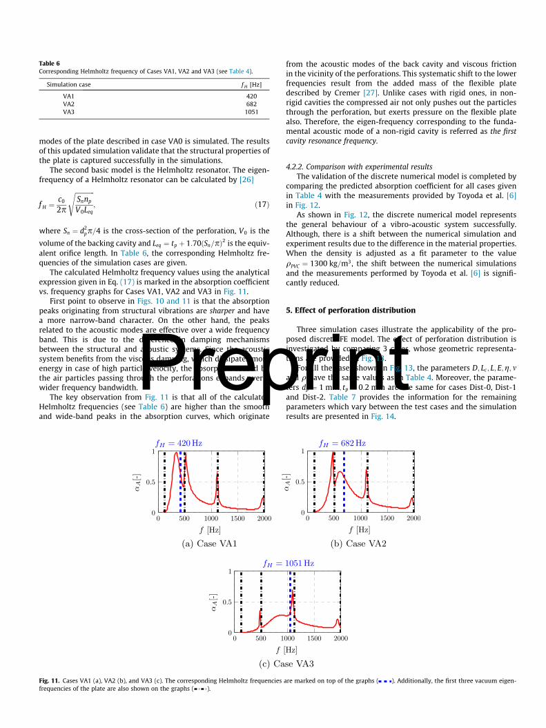
Table 6Corresponding Helmholtz frequency of Cases VA1, VA2 and VA3 (see Table 4).
Simulation case f H [Hz]
VA1 420VA2 682VA3 1051
Prep
modes of the plate described in case VA0 is simulated. The resultsof this updated simulation validate that the structural properties ofthe plate is captured successfully in the simulations.
The second basic model is the Helmholtz resonator. The eigen-frequency of a Helmholtz resonator can be calculated by [26]
f H ¼ c02p
ffiffiffiffiffiffiffiffiffiffiffiffiSnnp
V0Leq
s; ð17Þ
where Sn ¼ d2pp=4 is the cross-section of the perforation, V0 is the
volume of the backing cavity and Leq ¼ tp þ 1:70ðSn=pÞ2 is the equiv-alent orifice length. In Table 6, the corresponding Helmholtz fre-quencies of the simulation cases are given.
The calculated Helmholtz frequency values using the analyticalexpression given in Eq. (17) is marked in the absorption coefficientvs. frequency graphs for Cases VA1, VA2 and VA3 in Fig. 11.
First point to observe in Figs. 10 and 11 is that the absorptionpeaks originating from structural vibrations are sharper and havea more narrow-band character. On the other hand, the peaksrelated to the acoustic modes are effective over a wide frequencyband. This is due to the difference in damping mechanismsbetween the structural and acoustic systems. Since the acousticsystem benefits from the viscous damping, which dissipates moreenergy in case of high particle velocity, the absorption caused bythe air particles passing through the perforations expands over awider frequency bandwidth.
The key observation from Fig. 11 is that all of the calculatedHelmholtz frequencies (see Table 6) are higher than the smoothand wide-band peaks in the absorption curves, which originate
Fig. 11. Cases VA1 (a), VA2 (b), and VA3 (c). The corresponding Helmholtz frequenciesfrequencies of the plate are also shown on the graphs ( ).
from the acoustic modes of the back cavity and viscous frictionin the vicinity of the perforations. This systematic shift to the lowerfrequencies result from the added mass of the flexible platedescribed by Cremer [27]. Unlike cases with rigid ones, in non-rigid cavities the compressed air not only pushes out the particlesthrough the perforation, but exerts pressure on the flexible platealso. Therefore, the eigen-frequency corresponding to the funda-mental acoustic mode of a non-rigid cavity is referred as the firstcavity resonance frequency.
4.2.2. Comparison with experimental resultsThe validation of the discrete numerical model is completed by
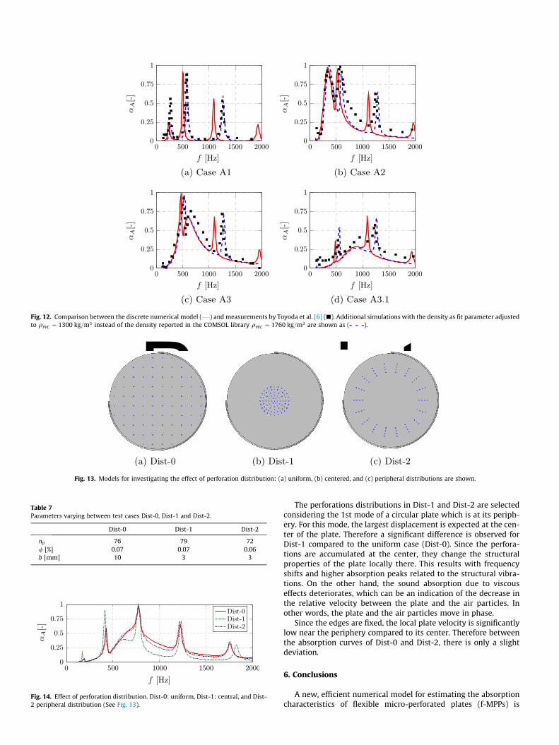
comparing the predicted absorption coefficient for all cases givenin Table 4 with the measurements provided by Toyoda et al. [6]in Fig. 12.
As shown in Fig. 12, the discrete numerical model representsthe general behaviour of a vibro-acoustic system successfully.Although, there is a shift between the numerical simulation andexperiment results due to the difference in the material properties.When the density is adjusted as a fit parameter to the valueqPVC ¼ 1300 kg=m3, the shift between the numerical simulationsand the measurements performed by Toyoda et al. [6] is signifi-cantly reduced.
rint5. Effect of perforation distribution
Three simulation cases illustrate the applicability of the pro-posed discrete FE model. The effect of perforation distribution isinvestigated by comparing 3 cases, whose geometric representa-tions are provided in Fig. 13.
For all the cases shown in Fig. 13, the parameters D; Lc; L; E;g; mand q have the same values as in Table 4. Moreover, the parame-ters dp ¼ 1 mm; tp ¼ 0:2 mm are the same for cases Dist-0, Dist-1and Dist-2. Table 7 provides the information for the remainingparameters which vary between the test cases and the simulationresults are presented in Fig. 14.
are marked on top of the graphs ( ). Additionally, the first three vacuum eigen-
PreprintFig. 12. Comparison between the discrete numerical model ( ) and measurements by Toyoda et al. [6] (j). Additional simulations with the density as fit parameter adjustedto qPVC ¼ 1300 kg=m3 instead of the density reported in the COMSOL library qPVC ¼ 1760 kg=m3 are shown as ( ).
(a) Dist-0 (b) Dist-1 (c) Dist-2
Fig. 13. Models for investigating the effect of perforation distribution: (a) uniform, (b) centered, and (c) peripheral distributions are shown.
Table 7Parameters varying between test cases Dist-0, Dist-1 and Dist-2.
Dist-0 Dist-1 Dist-2
np 76 79 72/ [%] 0.07 0.07 0.06b [mm] 10 3 3
Fig. 14. Effect of perforation distribution. Dist-0: uniform, Dist-1: central, and Dist-2 peripheral distribution (See Fig. 13).
The perforations distributions in Dist-1 and Dist-2 are selectedconsidering the 1st mode of a circular plate which is at its periph-ery. For this mode, the largest displacement is expected at the cen-ter of the plate. Therefore a significant difference is observed forDist-1 compared to the uniform case (Dist-0). Since the perfora-tions are accumulated at the center, they change the structuralproperties of the plate locally there. This results with frequencyshifts and higher absorption peaks related to the structural vibra-tions. On the other hand, the sound absorption due to viscouseffects deteriorates, which can be an indication of the decrease inthe relative velocity between the plate and the air particles. Inother words, the plate and the air particles move in phase.
Since the edges are fixed, the local plate velocity is significantlylow near the periphery compared to its center. Therefore betweenthe absorption curves of Dist-0 and Dist-2, there is only a slightdeviation.
6. Conclusions
A new, efficient numerical model for estimating the absorptioncharacteristics of flexible micro-perforated plates (f-MPPs) is
presented. The model couples the linear acoustics with the shellplate theory. Specifically, the flexible plate is assumed as a shelldomain and the micro-perforations are defined separately asimposed transfer impedance boundaries on this domain. The calcu-lation of the transfer impedance value of a single perforation is per-formed by relations provided by Temiz et al. [16].
Since each perforation is represented separately, the proposedmodel is referred to as the discrete numerical model. During themodel building it is observed that the Helmholtz solver takes thearea changes into account, hence inserting additional reactanceto the modelled system. This additional reactance is calculatedfor several porosity values and a correction to the transfer impe-dance expression proposed as a part of the numerical model.
The validation of the discrete numerical model is performed bycomparing it to the experiment results. The experiment resultsfrom Toyoda et al. [6] is used for the validating the vibro-acoustic coupling of the discrete numerical model. Good agree-ment is achieved between the experimental and numerical results.
The proposed method enables one to treat perforation positionas an additional variable. As a result, the effect of non-uniform per-foration distribution can be investigated for design purposes.Moreover, even though only circular f-MPPs are studied in thispaper, it is possible to use the same model for all types of plategeometries. The model has been used here with impedance of per-forations with square edges. The effect of modified edge geometrycan be taken into account as proposed by Temiz et al. [16].
The use of the proposed model has been illustrated by an exam-ple in a study of the effect of a non-uniform perforation distribu-tion on f-MPPs on the sound absorption. It is observed that the
Prep(a) Mesh-1
Fig. 15. The element size comparison for two meshes built to represent
(a) Mesh-1
Fig. 16. A slice of the numerical domain in yz-plane to show the gradual increase of threpresent the element size and the dimensions provided in the scale are in [m].
perforation distribution can have a significant effect on the viscousdamping mechanism.
Acknowledgements
The presented work is part of the Marie Curie Initial TrainingNetwork Thermoacoustic and Aeroacoustic Nonlinearities in Greencombustors with Orifice structures (TANGO). We gratefullyacknowledge the financial support from the European Commissionunder call FP7-PEOPLE-ITN-2012. Thanks to Paula Martínez-Lerafor valuable discussions in the process of building the numericalmodel.
Appendix A. Mesh convergence
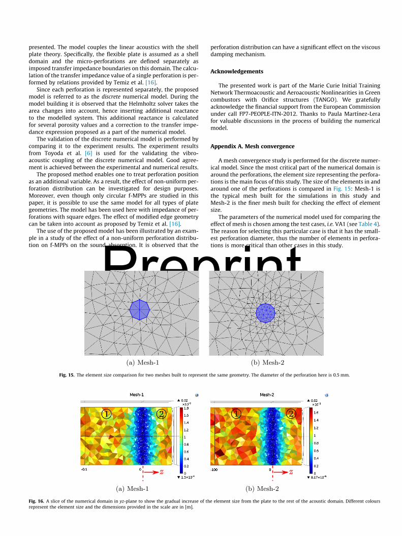
A mesh convergence study is performed for the discrete numer-ical model. Since the most critical part of the numerical domain isaround the perforations, the element size representing the perfora-tions is the main focus of this study. The size of the elements in andaround one of the perforations is compared in Fig. 15: Mesh-1 isthe typical mesh built for the simulations in this study andMesh-2 is the finer mesh built for checking the effect of elementsize.
The parameters of the numerical model used for comparing theeffect of mesh is chosen among the test cases, i.e. VA1 (see Table 4).The reason for selecting this particular case is that it has the small-est perforation diameter, thus the number of elements in perfora-tions is more critical than other cases in this study.
rint(b) Mesh-2
the same geometry. The diameter of the perforation here is 0.5 mm.
(b) Mesh-2
e element size from the plate to the rest of the acoustic domain. Different colours
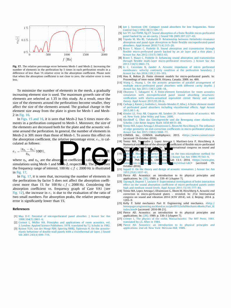
Fig. 17. The relative percentage error between Mesh-1 and Mesh-2. Increasing thenumber of elements in the perforation by 5 times in each perforation results in adifference of less than 1% relative error in the absorption coefficient. Please notethat when the absorption coefficient is not close to zero, the relative error is evenless.
Prep
To minimize the number of elements in the mesh, a graduallyincreasing element size is used. The maximum growth rate of theelements are selected as 1.35 in this study. As a result, once thesize of the elements around the perforations become smaller, theyaffect the size of the elements around. The gradual change in theelement size away from the plate is given for Mesh-1 and Mesh-2 in Fig. 16.
In Figs. 15 and 16, it is seen that Mesh-2 has 5 times more ele-ments in a perforation compared to Mesh-1. Moreover, the size ofthe elements are decreased both for the plate and the acoustic vol-ume around the perforation. In general, the number of elements inMesh-2 is 30% more than those of Mesh-1. To assess this effect onthe absorption coefficient, the relative percentage error, �%, is cal-culated as follows:
�% ¼ jaA2 � aA1 jaA2
100%; ð18Þ
where aA1 and aA2 are the absorption coefficients calculated in thesimulations using Mesh-1 and Mesh-2, respectively. The graph overthe frequency range of interest, 100 Hz 6 f 6 2000 Hz is illustratedin Fig. 17.
In Fig. 17, it is seen that, increasing the number of elements inthe perforations by factor 5 does not affect the absorption coeffi-cient more than 1% for 100 Hz 6 f 6 2000 Hz. Considering theabsorption coefficient vs. frequency graph of Case VA1 (seeFig. 12), the increase in �% is due to the evaluation of the ratio oftwo small numbers. For absorption peaks, the relative percentageerror is significantly lower than 1%.
References
[1] Maa D-Y. Potential of microperforated panel absorber. J Acoust Soc Am1998;104(5):2861–6.
[2] Cremer L, Müller HA. Principles and applications of room acoustics, vol.2. London: Applied Science Publishers; 1978. translated by T.J. Schultz in 1982.
[3] Basten TGH, van der Hoogt PJM, Spiering RMEJ, Tijdeman H. On the acousto-elastic behaviour of double-wall panels with a viscothermal air layer. J SoundVib 2001;243(4):699–719.
rint
[4] Lee J, Swenson GW. Compact sound absorbers for low frequencies. NoiseControl Eng J 1992;38(3):109–17.
[5] Lee YY, Lee EWM, Ng CF. Sound absorption of a finite flexible micro-perforatedpanel backed by an air-cavity. J Sound Vib 2005;287:227–43.
[6] Toyoda M, Mu RL, Takahashi D. Relationship between Helmholtz-resonanceabsorption and panel-type absorption in finite flexible microperforated-panelabsorbers. Appl Acoust 2010;71(4):315–20.
[7] Bravo T, Mauri C, Pinhéde D. Sound absorption and transmission throughflexible micro-perforated panels backed by an air layer and a thin plate. JAcoust Soc Am 2012;131(5):3853–63.
[8] Bravo T, Mauri C, Pinhéde D. Enhancing sound absorption and transmissionthrough flexible multi-layer micro-perforated structures. J Acoust Soc Am2013;134(5):3663–73.
[9] Li C, Cazzolato B, Zander A. Acoustic impedance of micro perforatedmembranes: velocity continuity condition at the perforation boundary. JAcoust Soc Am 2016;139(1):93–103.
[10] Hou K, Bolton JS. Finite element models for micro-perforated panels. In:Proceedings of inter-noise 2009, Ottawa, Canada; 2009. no. 499.
[11] Wang C, Huang L. On the acoustic properties of parallel arrangement ofmultiple micro-perforated panel absorbers with different cavity depths. JAcoust Soc Am 2011;130(1):208–18.
[12] Okuzono T, Sakagami K. A finite-element formulation for room acousticssimulation with microperforated panel sound absorbing structures:verification with electro-acoustical equivalent circuit theory and wavetheory. Appl Acoust 2015;95:20–6.
[13] Carbajo J, Ramis J, Godinho L, Amado-Mendes P, Alba J. A finite element modelof perforated panel absorbers including viscothermal effects. Appl Acoust2015;90:1–8.
[14] Kinsler LE, Frey AR, Coppens AB, Sanders JV. Fundementals of acoustics. 4thed. New York: John Wiley and Sons; 2000.
[15] Kirchhoff G. Über das Gleichgewicht und die Bewegung einer elastischenScheibe. J die Reine Angew Math 1850;40:51–88.
[16] Temiz MA, Lopez Arteaga I, Efraimsson G, ÅbomM, Hirschberg A. The influenceof edge geometry on end-correction coefficients in micro-perforated plates. JAcoust Soc Am 2015;138(6):3668–77.
[17] COMSOL Inc., COMSOL multiphysics; 2015. <https://www.comsol.com>[accessed 19-October-2016].
[18] Temiz MA, Tournadre J, Lopez Arteaga I, Martìnez-Lera P, Hirschberg A.Numerical estimation of the absorption coefficient of flexible micro-perforatedplates in an impedance tube. In: 23rd International congress on sound andvibration (ICSV 2016), Athens; 2016.
[19] Bodén H, Åbom M. Influence of errors on the two-microphone method formeasuring acoustic properties in ducts. J Acoust Soc Am 1986;79:541–9.
[20] Siemens PML Software, LMS Virtual.Lab 13.1; 2014. <https://www.plm.automation.siemens.com/en_us/products/lms/virtual-lab/> [accessed 19-October-2016].
[21] Ingard U. On the theory and design of acoustic resonators. J Acoust Soc Am1953;25(6):1037–61.
[22] Pierce AD. Acoustics: an introduction to its physical principles andapplications. In: [28]; 1989. p. 339–41 [chapter 7].
[23] Tayong R, Dupont T, Leclaire P. Experimental investigation of holes interactioneffect on the sound absorption coefficient of micro-perforated panels underhigh and medium sound levels. Appl Acoust 2011;72(10):777–84.
[24] Temiz MA, Lopez Arteaga I, Efraimsson G, Åbom M, Hirschberg A. Acoustic endcorrection in micro-perforated plates – revisited. In: 21st Internationalcongress on sound and vibration 2014 (ICSV 2014), vol. 2, Beijing; 2014. p.1203–9.
[25] Kelly P. Solid mechanics Part II: Engineering solid mechanics. <http://homepages.engineering.auckland.ac.nz/pkel015/SolidMechanicsBooks/Part_II/index.html> [accessed: 2016-08-21].
[26] Pierce AD. Acoustics: an introduction to its physical principles andapplications. In: [28]; 1989. p. 330–3 [chapter 7].
[27] Cremer L. The physics of the violin. Massachusetts: The MIT Press; 1981.translated by J.S. Allen in 1984.
[28] Pierce AD. Acoustics: an introduction to its physical principles andapplications. 2nd ed. New York: McGraw-Hill; 1989.