acoustic energy harvesting
TRANSCRIPT
Acoustic Energy Harvesting
Rohan Kikani, AashisThayalli, Ravindra Bhat
Member,IEEE Member,IEEE Member,IETE
NMIMS, Mukesh Patel School of Technology Management and Engineering,Shirpur
[email protected], [email protected], [email protected]
Abstract
In this paper an effort to generate powerusing the sound energy is presented. In thisexperimentation is carried out upon twosources through which energy can begenerated on an experimental basis. In thiselectromagnetic induction concept is usedfor getting expected performance togenerate voltage up to 280mV. As worktargets the harvesting of energy throughsound at an experimental basis, outputsuch as mentioned above is primarilyaccepted.
1. INTRODUCTION
Energy harvesting through soundis one of the most interestingand new topics of discussion inthis modern world. The world hasmany different sources togenerate energy but still it isinsufficient to power itcompletely. Also variousdifferent types of pollution isgrasping this world. Hence,noise being one of the biggest
reasons of pollution can be usedas a source to generateenergy[15]. This might solve theworld’s ever rising energycrisis. [3][4].Energy harvestingmaterials and systems haveemerged as a prominent researcharea and continue to grow atrapid pace. There are numerousenergy harvesting methods usedAmbient-radiation sources [8][16], Biomechanical harvesting[9], Photovoltaic harvesting[10], Electrostatic (capacitive)energy harvesting [11], Magnetostatic energy harvesting [11].Since, there have been nosignificant researches done onthe harvesting of energy throughsound; availability of noisemaking it pollution has been agreat plague in the world welive in. This is what derivedconducted research on this verynew subject.
Two experiments are conducted toget best solution through whichsignificant amount of energythrough sound could be generate.
2. ELECTROMAGNETIC INDUCTION
2.1. Working PrincipleElectromagnetic Induction is theproduction of an electriccurrent across a conductormoving through a magnetic field.It underlies the operation ofgenerators, transformers,induction motors, electricmotors, synchronous motors, andsolenoids. Michael Faradayformulated that electromotiveforce (EMF) produced around aclosed path is proportional tothe rate of change of themagnetic flux through anysurface bounded by that path. Inpractice, this means that anelectric current will be inducedin any closed circuit when themagnetic flux through a surfacebounded by the conductorchanges. This applies whetherthe field itself changes instrength or the conductor ismoved through it.[2][7]
In mathematical form, Faraday'slaw states that
ε=−dφBdt
(1)
Where,‘ε’ is the electromotive force;‘ΦB’ is the magnetic flux.For coil of wire, composed of Nloops with the same area, theequation becomes
ε=−NdφB
dt (2)
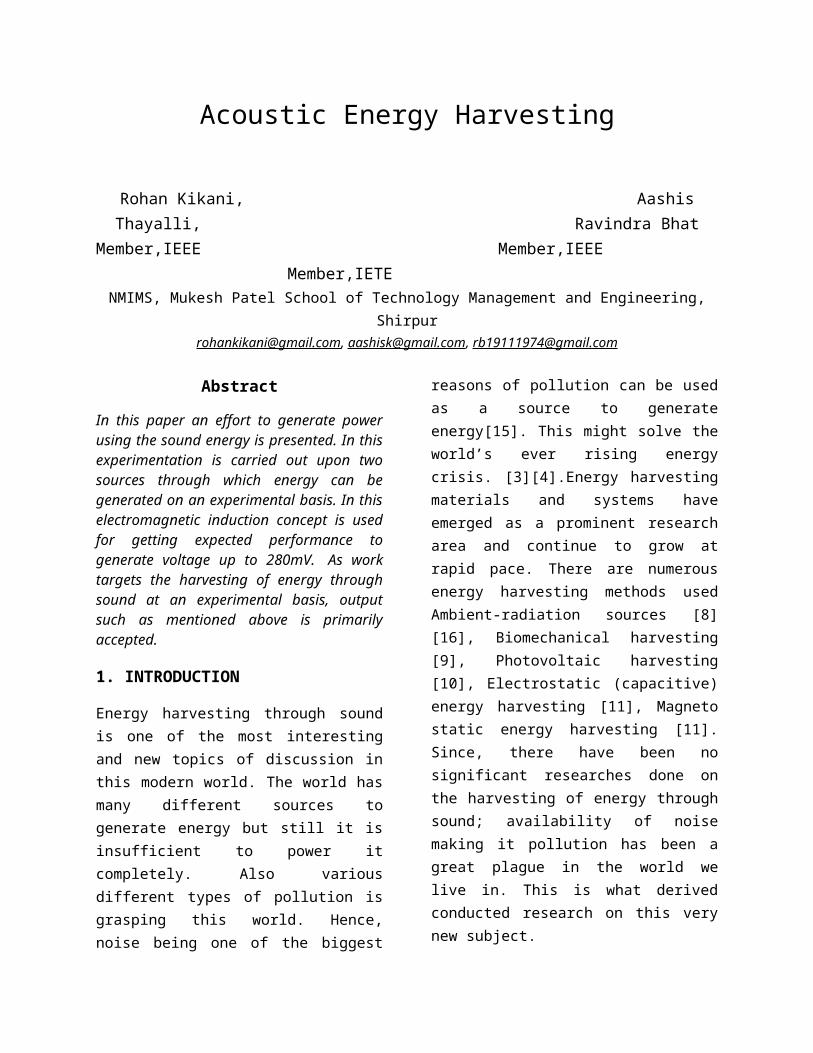
A corollary of Faraday's Law,together with Ampere’s law andOhm's law is Lenz's law: The EMFinduced in an electric circuitalways acts in such a directionthat the current it drivesaround the circuit opposes thechange in magnetic flux whichproduces the EMF. Dynamictransducer filament depends onthe principle that moving a wirewithin a magnetic fieldgenerates a current in the wire.In the case of moving-coildynamic transducer, the wire isa coil of very fine diameterwire, situated within a magneticfield and attached to adiaphragm in contact with theair. [3][4].As the pressure varies, thediaphragm moves in response tothe changing force applied bythe moving air. The coilproduces a small voltage as itmoves in the fixed magneticfield.[14] This voltage is fed,usually through a transformer,
to an external amplifieroptimized for low inputimpedance and high gain. Whileconceptually simple, theimplementation of the dynamictransducer is not sostraightforward. The mass of acoil of wire is not negligible,so the construction of theelement requires special care tomake sure the element can moveeasily enough to allow the smallair pressure variations toproduce a measurable voltage atall audible frequencies.[12]There are also acousticalconsiderations necessary toproduce a consistent outputlevel for sounds originatingfrom different directions and ofdifferent frequencies. This often leads to complicatedacoustical labyrinths built intothe housing of the transducer inorder to control the frequencyresponse and directionalsensitivity. They can toleratevery high sound pressures andare also extremely durable andreliable, so are ideal for usein harsh environmentalconditions.[6][9] In dynamictransducer the speed of thediaphragm movement causes thesignal, not the currentdeflection.
Figure 1 Operating principle [6]
3. EXPERIMENTAL SETUP
3.1 Block Diagram
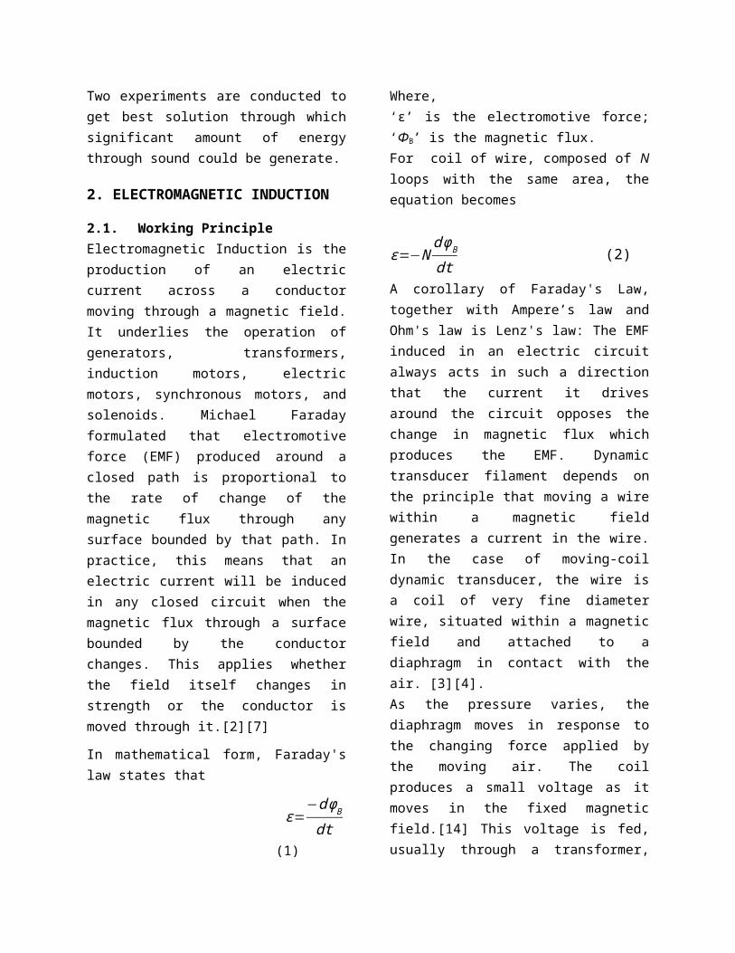
Figure 2 Operational block DiagramThe block diagram consists offour important modules which hasits own important functions. Butfuture research may give rise tothe elimination of one or moremodules. These modules werederived through carefulexperimentation and finallymade.
3.2 Preliminary DesignThree EMI transducers made weremounted in between two thick
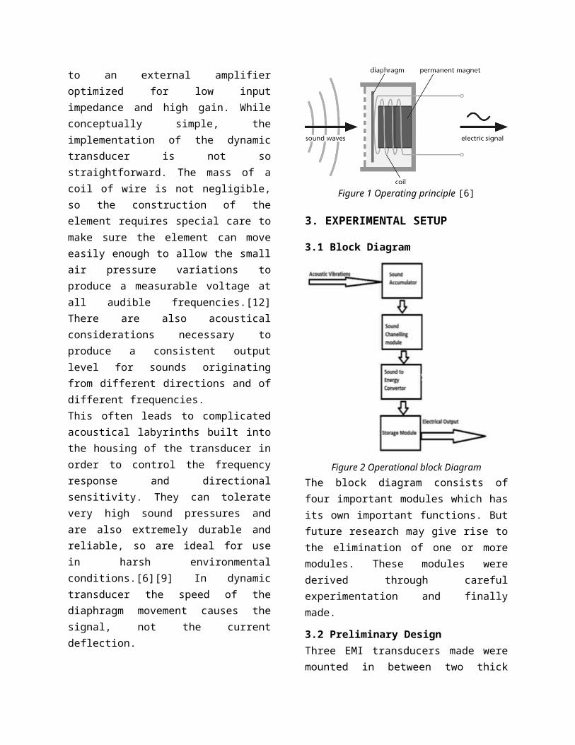
rectangular PVC switch boardplates screwed together. Thisassembly was connected to oneend of a moderately long PVCpipe and the other end was leftopen.
Figure 3 Setup front view showing PVC pipeposition
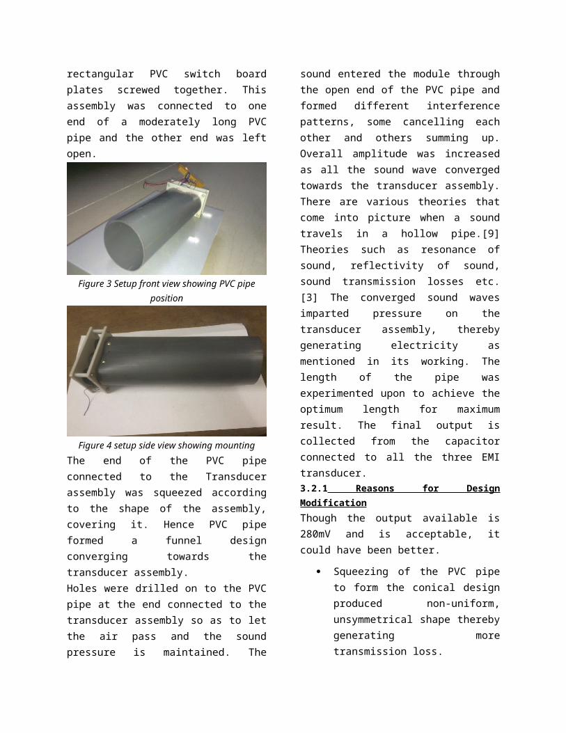
Figure 4 setup side view showing mountingThe end of the PVC pipeconnected to the Transducerassembly was squeezed accordingto the shape of the assembly,covering it. Hence PVC pipeformed a funnel designconverging towards thetransducer assembly. Holes were drilled on to the PVCpipe at the end connected to thetransducer assembly so as to letthe air pass and the soundpressure is maintained. The
sound entered the module throughthe open end of the PVC pipe andformed different interferencepatterns, some cancelling eachother and others summing up.Overall amplitude was increasedas all the sound wave convergedtowards the transducer assembly.There are various theories thatcome into picture when a soundtravels in a hollow pipe.[9]Theories such as resonance ofsound, reflectivity of sound,sound transmission losses etc.[3] The converged sound wavesimparted pressure on thetransducer assembly, therebygenerating electricity asmentioned in its working. Thelength of the pipe wasexperimented upon to achieve theoptimum length for maximumresult. The final output iscollected from the capacitorconnected to all the three EMItransducer.3.2.1 Reasons for DesignModificationThough the output available is280mV and is acceptable, itcould have been better.
Squeezing of the PVC pipeto form the conical designproduced non-uniform,unsymmetrical shape therebygenerating moretransmission loss.
Perfect circular conicalstructure with perfectcylindrical pipe would haveprovided optimal results.
In order that thetransducers are in theaffective area, theassembly had to be changed.
PVC pipe absorbedconsiderable amount ofsound pressure.
Hence to achieve optimal resultshighly sound reflective materiallike aluminum was to be used.
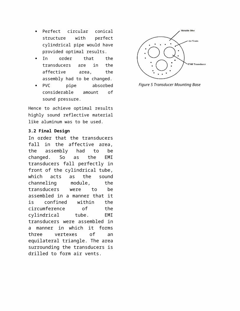
3.2 Final DesignIn order that the transducersfall in the affective area,the assembly had to bechanged. So as the EMItransducers fall perfectly infront of the cylindrical tube,which acts as the soundchanneling module, thetransducers were to beassembled in a manner that itis confined within thecircumference of thecylindrical tube. EMItransducers were assembled ina manner in which it formsthree vertexes of anequilateral triangle. The areasurrounding the transducers isdrilled to form air vents.
Figure 5 Transducer Mounting Base
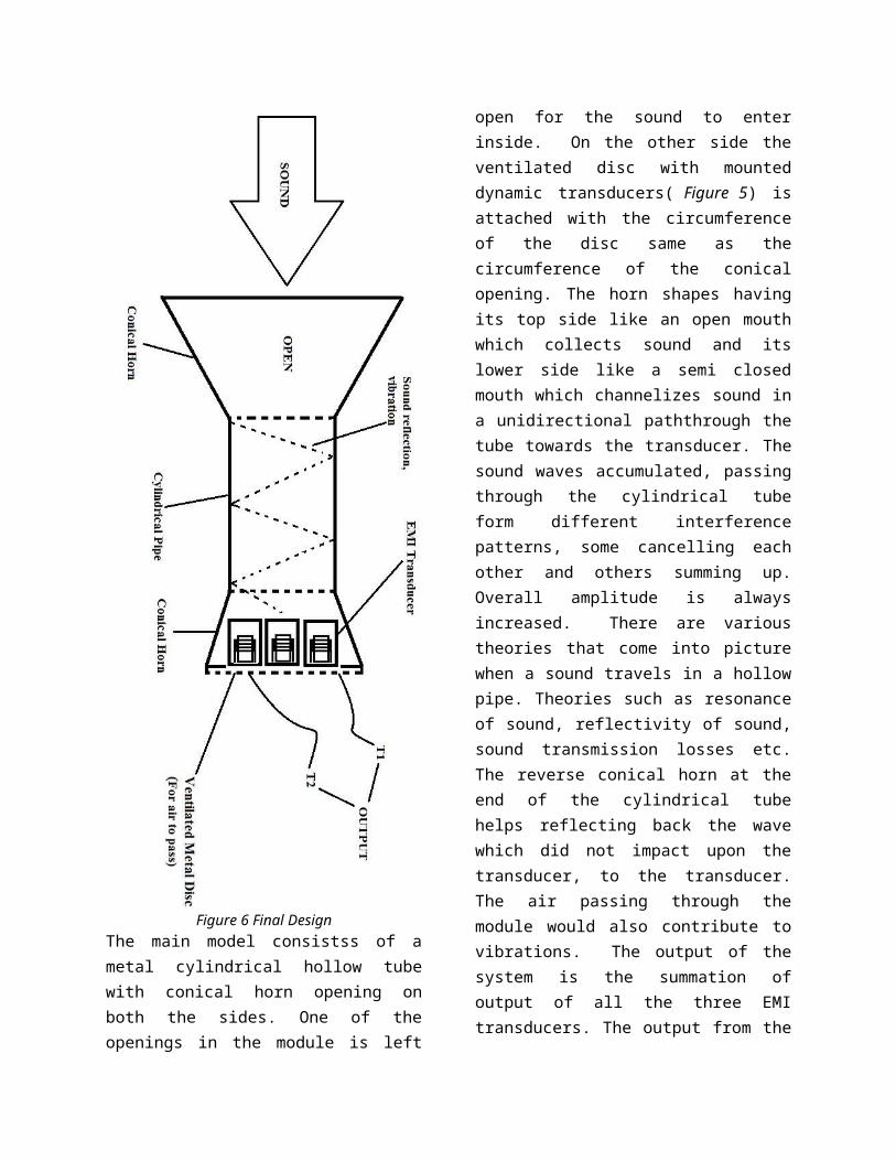
Figure 6 Final DesignThe main model consistss of ametal cylindrical hollow tubewith conical horn opening onboth the sides. One of theopenings in the module is left
open for the sound to enterinside. On the other side theventilated disc with mounteddynamic transducers( Figure 5) isattached with the circumferenceof the disc same as thecircumference of the conicalopening. The horn shapes havingits top side like an open mouthwhich collects sound and itslower side like a semi closedmouth which channelizes sound ina unidirectional paththrough thetube towards the transducer. Thesound waves accumulated, passingthrough the cylindrical tubeform different interferencepatterns, some cancelling eachother and others summing up.Overall amplitude is alwaysincreased. There are varioustheories that come into picturewhen a sound travels in a hollowpipe. Theories such as resonanceof sound, reflectivity of sound,sound transmission losses etc.The reverse conical horn at theend of the cylindrical tubehelps reflecting back the wavewhich did not impact upon thetransducer, to the transducer.The air passing through themodule would also contribute tovibrations. The output of thesystem is the summation ofoutput of all the three EMItransducers. The output from the
transducer can be calculatedfrom the terminals T1 and T2.3.2.1 Final Design circuit diagram
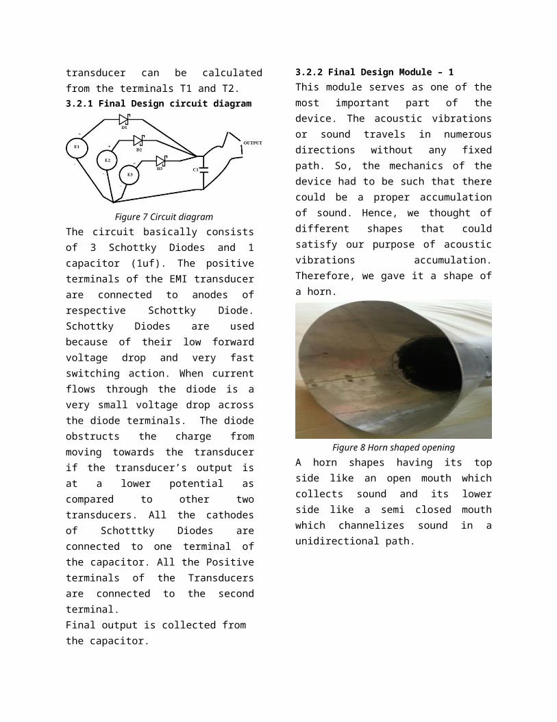
Figure 7 Circuit diagramThe circuit basically consistsof 3 Schottky Diodes and 1capacitor (1uf). The positiveterminals of the EMI transducerare connected to anodes ofrespective Schottky Diode.Schottky Diodes are usedbecause of their low forwardvoltage drop and very fastswitching action. When currentflows through the diode is avery small voltage drop acrossthe diode terminals. The diodeobstructs the charge frommoving towards the transducerif the transducer’s output isat a lower potential ascompared to other twotransducers. All the cathodesof Schotttky Diodes areconnected to one terminal ofthe capacitor. All the Positiveterminals of the Transducersare connected to the secondterminal.Final output is collected from the capacitor.
3.2.2 Final Design Module – 1 This module serves as one of themost important part of thedevice. The acoustic vibrationsor sound travels in numerousdirections without any fixedpath. So, the mechanics of thedevice had to be such that therecould be a proper accumulationof sound. Hence, we thought ofdifferent shapes that couldsatisfy our purpose of acousticvibrations accumulation.Therefore, we gave it a shape ofa horn.
Figure 8 Horn shaped openingA horn shapes having its topside like an open mouth whichcollects sound and its lowerside like a semi closed mouthwhich channelizes sound in aunidirectional path.
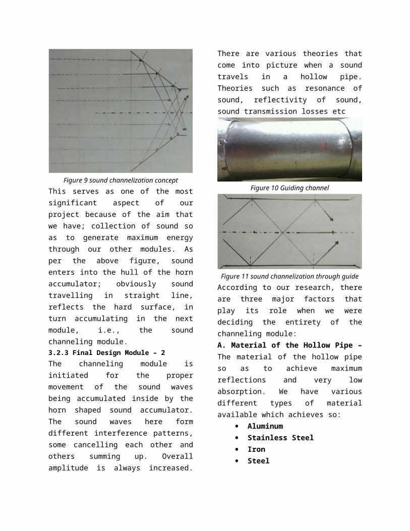
Figure 9 sound channelization conceptThis serves as one of the mostsignificant aspect of ourproject because of the aim thatwe have; collection of sound soas to generate maximum energythrough our other modules. Asper the above figure, soundenters into the hull of the hornaccumulator; obviously soundtravelling in straight line,reflects the hard surface, inturn accumulating in the nextmodule, i.e., the soundchanneling module.3.2.3 Final Design Module – 2The channeling module isinitiated for the propermovement of the sound wavesbeing accumulated inside by thehorn shaped sound accumulator.The sound waves here formdifferent interference patterns,some cancelling each other andothers summing up. Overallamplitude is always increased.
There are various theories thatcome into picture when a soundtravels in a hollow pipe.Theories such as resonance ofsound, reflectivity of sound,sound transmission losses etc
Figure 10 Guiding channel
Figure 11 sound channelization through guide According to our research, thereare three major factors thatplay its role when we weredeciding the entirety of thechanneling module:A. Material of the Hollow Pipe –The material of the hollow pipeso as to achieve maximumreflections and very lowabsorption. We have variousdifferent types of materialavailable which achieves so:
Aluminum Stainless Steel Iron Steel
According to the feasibility ofthe entire structure and itscost effectiveness, we chose touse aluminum. Aluminum is cheap,easily available and also doesnot portray magnetic properties.Steel and iron are eliminatedbecause we cannot use a materialwhich shows magnetic propertiesfor obvious reasons. Stainlesssteel is a costly material;hence we do not use it.B. Shape of the Hollow Pipe –The shape of the hollow pipe weselected is cylindrical so as toachieve maximum output. Sincesound is going to travel in ahollow medium, we expect it toundergo a lot of reflections;producing a lot of interferencepatterns. Hence, the cylindricalpipe was an apt solution. C. Length of the CylindricalPipe– We had to select thelength of the pipe to be apt soas to achieve maximum output.Maximum output means minimumtransmission losses, minimuminterference and maximum soundvibration transfer.D. Thickness of the Pipe –Thepipe had to as thin as possibleto as to achieve properchannelization. We made the pipeas thin as possible and nothampering the shape.3.2.4 Final Design Module – 3
This is the most importantaspect of our entire researchmodule. This is the part whichcontains our sound energy toelectrical energy convertor. Asthe sound vibrations enters intoour system, accumulated throughthe Sound Accumulator, passesthrough the Sound channelingmodule, and finally falls ontoour Electromagnetic InducingTransducer (EMI Transducer).This module was what hadspecially constructed so as toachieve smart conversion of thesame, acquiring lesser space andproducing maximum output. Ourdevice is made up of a magnetwrapped around by a coil whichis connected to a diaphragm.This diaphragm vibrates when thesound vibrations are struck onthe surface in turn vibratingthe coil. As the coil vibratesunder a constant magnetic field,current is induced in the coil.This coil is in turn connectedto the wires which provides withthe output. The output is afluctuating current; voltagebeing alternating in nature.Hence a capacitor is connectedto the output providing with anon-fluctuating constantalternating voltage. Thisvoltage is summed up with thevoltage outputs of the other two
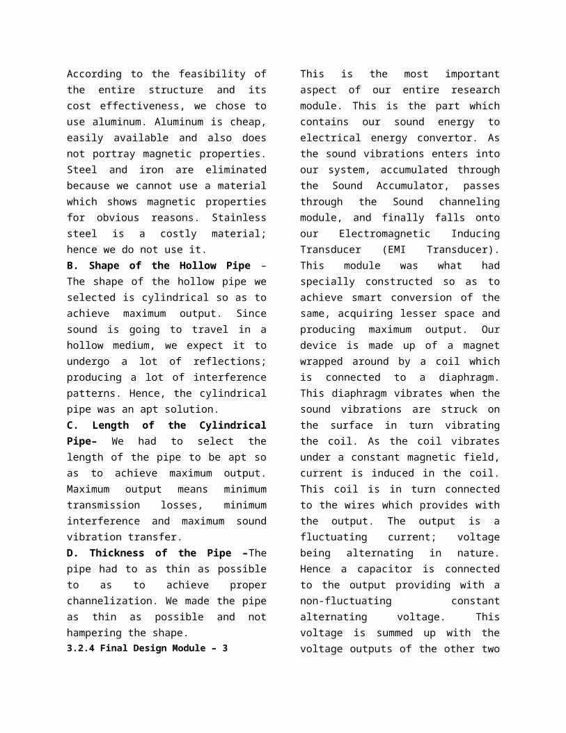
similar devices; as we have usedonly three of those due to costeffectiveness, and the output isgiven to the capacitor. Thiscapacitor can be either used toprovide the power directly orcan be used to store the powerin a battery.
Figure 11 Electromagnetic transducerMechanism
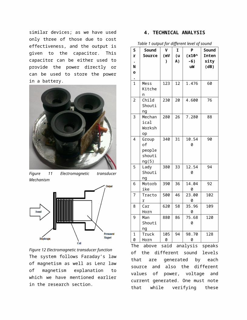
Figure 12 Electromagnetic transducer functionThe system follows Faraday’s lawof magnetism as well as Lenz lawof magnetism explanation towhich we have mentioned earlierin the research section.
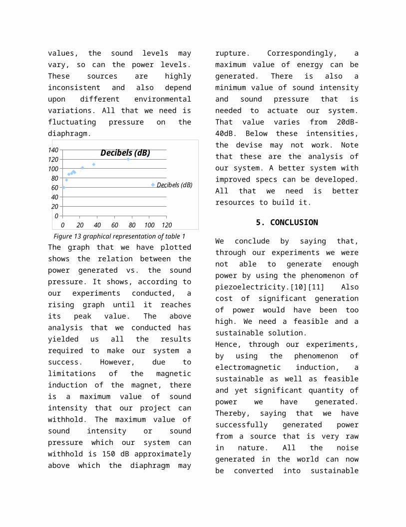
4. TECHNICAL ANALYSIS
Table 1 output for different level of soundSr.No.
SoundSource
V(mV)
I(uA)
P(x10^-6)uW
SoundIntensity(dB)
1 Mess Kitchen
123 12 1.476 60
2 Child Shouting
230 20 4.600 76
3 Mechanical Workshop
280 26 7.280 88
4 Group of peopleshouting(5)
340 31 10.540
90
5 Lady Shouting
380 33 12.540
94
6 Motorbike
390 36 14.040
92
7 Tractor
500 46 23.000
102
8 Car Horn
620 58 35.960
109
9 Man Shouting
880 86 75.680
120
10
Truck Horn
1050
94 98.700
128
The above said analysis speaksof the different sound levelsthat are generated by eachsource and also the differentvalues of power, voltage andcurrent generated. One must notethat while verifying these
values, the sound levels mayvary, so can the power levels.These sources are highlyinconsistent and also dependupon different environmentalvariations. All that we need isfluctuating pressure on thediaphragm.
0 20 40 60 80 100 1200
20406080
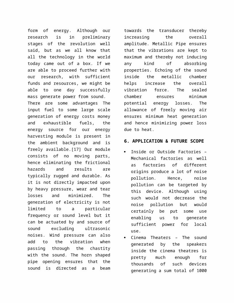
100120140 Decibels (dB)
Decibels (dB)
Figure 13 graphical representation of table 1The graph that we have plottedshows the relation between thepower generated vs. the soundpressure. It shows, according toour experiments conducted, arising graph until it reachesits peak value. The aboveanalysis that we conducted hasyielded us all the resultsrequired to make our system asuccess. However, due tolimitations of the magneticinduction of the magnet, thereis a maximum value of soundintensity that our project canwithhold. The maximum value ofsound intensity or soundpressure which our system canwithhold is 150 dB approximatelyabove which the diaphragm may
rupture. Correspondingly, amaximum value of energy can begenerated. There is also aminimum value of sound intensityand sound pressure that isneeded to actuate our system.That value varies from 20dB-40dB. Below these intensities,the devise may not work. Notethat these are the analysis ofour system. A better system withimproved specs can be developed.All that we need is betterresources to build it.
5. CONCLUSION
We conclude by saying that,through our experiments we werenot able to generate enoughpower by using the phenomenon ofpiezoelectricity.[10][11] Alsocost of significant generationof power would have been toohigh. We need a feasible and asustainable solution. Hence, through our experiments,by using the phenomenon ofelectromagnetic induction, asustainable as well as feasibleand yet significant quantity ofpower we have generated.Thereby, saying that we havesuccessfully generated powerfrom a source that is very rawin nature. All the noisegenerated in the world can nowbe converted into sustainable
form of energy. Although ourresearch is in preliminarystages of the revolution wellsaid, but as we all know thatall the technology in the worldtoday came out of a box. If weare able to proceed further withour research, with sufficientfunds and resources, we might beable to one day successfullymass generate power from sound.There are some advantages Theinput fuel to some large scalegeneration of energy costs moneyand exhaustible fuels, theenergy source for our energyharvesting module is present inthe ambient background and isfreely available.[17] Our moduleconsists of no moving parts,hence eliminating the frictionalhazards and results aretypically rugged and durable. Asit is not directly impacted uponby heavy pressure, wear and tearlosses and minimized. Thegeneration of electricity is notlimited to a particularfrequency or sound level but itcan be actuated by and source ofsound excluding ultrasonicnoises. Wind pressure can alsoadd to the vibration whenpassing through the chastitywith the sound. The horn shapedpipe opening ensures that thesound is directed as a beam
towards the transducer therebyincreasing the overallamplitude. Metallic Pipe ensuresthat the vibrations are kept tomaximum and thereby not inducingany kind of absorbingproperties. Echoing of the soundinside the metallic chamberhelps increase the overallvibration force. The sealedchamber ensures minimumpotential energy losses. Theallowance of freely moving airensures minimum heat generationand hence minimizing power lossdue to heat.
6. APPLICATION & FUTURE SCOPE
Inside or Outside Factories –Mechanical factories as wellas factories of differentorigins produce a lot of noisepollution. Hence, noisepollution can be targeted bythis device. Although usingsuch would not decrease thenoise pollution but wouldcertainly be put some useenabling us to generatesufficient power for localuse.
Cinema Theaters – The soundgenerated by the speakersinside the cinema theatres ispretty much enough forthousands of such devicesgenerating a sum total of 1000
volts of voltage. This muchvoltage can be easily used upby the theatres itself. Thus,terming this special theatreas the self-sustained theatre.
Discotheque – Similar to theconcept of the theatre,thousands of these devicesactuated by the loud music inthe discotheques would easilyhelp in self-sustenance.
Airports – Airports cangenerate a lot of powerthrough these devices as theairports create lots of noise.Such a device can act as afailsafe power generator whenthe major power supply fails.
Bus Depots– The bus depots canbe fitted with such devices,therefore enabling it togenerate a lot of power..
Railway stations - Railwaystations can be fitted withsuch devices which will inturn power the railway stationitself. Such a device can actas a failsafe power generatorwhen the major power supplyfails.
Roads(e.g. On Trafficsignals)–Roads have been aconstant area of noisepollution, Hence such a devicecan very well generate a lotof power from it
Supermarkets – Areas such assupermarkets can act as amajor supply of power if fedsuch a device to the noisegenerated.
In our world where energy is acrisis, our ever demanding needfor sustainable and clean energyresource is nothing but a dream.In our attempt to curb thisdream, to support technology andcreating a better life, we havedevised this module. Mobilephones, palmtops, tablets,pallets would not require anycharging as there would be afeature, then known as Talk andCharge. Talking on the phonewould not drain the battery,instead would initiate charge upof the battery. Laptops, havingsuch a module would help thecommon user decrease the batterydrain anywhere in the world. Beit in a car, on the streets,malls, offices, supermarkets,etc. Our Smart Homes would beever smart as there will beminimum power consumption fromthe government. Our SmartOffices can then be a 24 hourfunctional enterprise wherepeople will enjoy working inshifts. Everyone will haveelectricity at their disposalcurbing the needs of all andensuring smart development of
all humans. Earth will be acleaner and quieter place tolive making all its inhabitantshappy.
7. REFERENCES
[1] Energy HarvestingTechnologies By ShashankPriya & Dan Inmam
[2] "Applications ofelectromagneticinduction". BostonUniversity. 1999-22-07.
[3] S M Dhir (2007). "§6 Otherposive results andcriticism". Hans ChristianØrsted and the romantic legacy inscience: ideas, disciplines,practices. Springer. ISBN 978-1-4020-2987-5.
[4] "Magnets". Think Quest.Retrieved 2009-11-06.
[5] "Joseph Henry". NotableNames Database. Retrieved2009-11-06.
[6] Brauer, John R.(2006). Magnetic actuators andsensors. John Wiley andSons. p. 20. ISBN 0-4Hh71-73169-2
[7] Phillips, James R (2000-08-10). "PiezoelectricTechnology: APrimer".eeProductCenter.TechInsights
[8] Holst Centre Human++Program
[9] Pickin’ up good vibrationsto produce greenelectricity
[10] Piezoelectric EnergyHarvesting Research at NTU
[11] Some Energy HarvestingResearch @NUS
[12] Noise in Physical SystemsLaboratory
[13] EnHANTs project at ColumbiaUniversity
[14] "Architectures forVibration-Driven MicropowerGenerators, P. D.Mitcheson, T. C. Green, E.M. Yeatman, A. S. Holmes"
[15] Energy Harvester ProducesPower from LocalEnvironment, EliminatingBatteries in WirelessSensors
[16] Inventor Joe Tate's AmbientPower Module converts radiofrequencies to usableelectrical power (albeitonly milliwatts) sufficientto operate clocks, smokealarms, Ni-Cd batterychargers, &c.
[17] Electronic Device Which isPowered By Actuation OfManual Inputs, US Patentno. 5,838,138