imaging of diluted turbulent ethylene flames stabilized on a jet in hot coflow (jhc) burner
TRANSCRIPT
Combustion and Flame 152 (2008) 100–113www.elsevier.com/locate/combustflame
Imaging of diluted turbulent ethylene flamesstabilized on a Jet in Hot Coflow (JHC) burner
Paul R. Medwell ∗, Peter A.M. Kalt, Bassam B. Dally
School of Mechanical Engineering, The University of Adelaide, South Australia 5005, Australia
Received 15 January 2007; received in revised form 10 August 2007; accepted 15 September 2007
Abstract
The spatial distributions of the hydroxyl radical (OH), formaldehyde (H2CO), and temperature imaged by laserdiagnostic techniques are presented using a Jet in Hot Coflow (JHC) burner. The measurements are of turbulentnonpremixed ethylene jet flames, either undiluted or diluted with hydrogen (H2), air or nitrogen (N2). The fuel jetissues into a hot and highly diluted coflow at two O2 levels and a fixed temperature of 1100 K. These conditionsemulate those of moderate or intense low oxygen dilution (MILD) combustion. Ethylene is an important speciesin the oxidation of higher-order hydrocarbon fuels and in the formation of soot. Under the influence of the hot anddiluted coflow, soot is seen to be suppressed. At downstream locations, surrounding air is entrained which resultsin increases in reaction rates and a spatial mismatch between the OH and H2CO surfaces. In a very low O2 coflow,a faint outline of the reaction zone is seen to extend to the jet exit plane, whereas at a higher coflow O2 level, theflames visually appear lifted. In the flames that appear lifted, a continuous OH surface is identified that extends tothe jet exit. At the “lift-off” height a transition from weak to strong OH is observed, analogous to a lifted flame.H2CO is also seen upstream of the transition point, providing further evidence of the occurrence of preignitionreactions in the apparent lifted region of these flames. The unique characteristics of these particular cases has ledto the term transitional flame.© 2007 The Combustion Institute. Published by Elsevier Inc. All rights reserved.
Keywords: JHC burner; MILD; Ethylene; OH; Formaldehyde; Rayleigh
1. Introduction
Heat and exhaust gas recirculation in combustorsis an innovative approach to creating a distributedreaction zone, reducing pollutant emissions, and in-creasing the net radiation flux and with it thermalefficiency. It is now well established that a mixture of
* Corresponding author. Fax: +61 8 8303 4367.E-mail address: [email protected]
(P.R. Medwell).
0010-2180/$ – see front matter © 2007 The Combustion Institute.doi:10.1016/j.combustflame.2007.09.003
reactants diluted with combustion products, at a tem-perature above autoignition, can achieve the desiredoutcome of reduced pollutant emissions and enhancedthermal efficiency. The application of these principlesto practical systems has taken different routes anddifferent names used to describe the process. Somerelied on a descriptive form of the resulting combus-tion process, i.e., flameless oxidation [1], and othersdescribed the features of the reactant streams, i.e.,high temperature air combustion. The term used inthis paper is moderate or intense low oxygen dilution(MILD) combustion [2].
Published by Elsevier Inc. All rights reserved.
P.R. Medwell et al. / Combustion and Flame 152 (2008) 100–113 101
The MILD combustion technology has been suc-cessfully applied in several industries [3] and has thepotential for introduction into numerous other appli-cations [2]. To date, however, implementation hasbeen impeded by a lack of fundamental understand-ing of the establishment and detailed structure of thiscombustion regime. Few fundamental studies havebeen performed to look at the detailed structure of thisregime (e.g., [2,4–6]).
Dally et al. [4,7] reported on the structure of hy-drocarbon nonpremixed laminar and turbulent flamesstabilized on a jet in a heated and diluted coflow.They used single-point Raman–Rayleigh–LIF diag-nostic techniques to simultaneously measure temper-ature and major and minor species at different loca-tions in these flames. They found that major changesin the flame structure occur when the oxygen con-centration is reduced and that, at higher jet Reynoldsnumber and low oxygen concentration, oxygen leak-age from the surroundings may cause local extinctionof the flame. Medwell et al. [6] continued this workby simultaneous imaging of OH, H2CO, and temper-ature in the same burner, finding evidence of partialpremixing in these flames, and localized extinction inthe presence of surrounding air.
The current project aims to examine the structureof the reaction zone of a jet in a heated and dilutedcoflow using planar laser imaging techniques. Tem-perature, the hydroxyl radical, and formaldehyde aremeasured instantaneously and simultaneously at dif-ferent parts of the flames. The hydroxyl radical (OH)is used as a flame marker, while the formaldehyde(H2CO) intermediate species is predominant at lowtemperatures typical of those found in MILD combus-tion. The product of [OH] and [H2CO] has also beensuggested as an indicator of the formyl (HCO) radical,which is closely related to the heat release rate [8].
In this paper we report on the combination of thethree scalars in turbulent nonpremixed diluted eth-ylene (C2H4) flames stabilized on a jet issuing intoa heated and diluted coflow. The Jet in Hot Coflow(JHC) burner emulates MILD combustion under con-trolled conditions. Comparisons are made betweendifferent fuel compositions (ethylene undiluted, ordiluted with hydrogen, air, or nitrogen) at a fixedjet Reynolds number and two coflow oxygen levels.Measurements are taken at two downstream locations.The burner used in this work facilitates the additionalstudy of the effects of the entrainment of surroundingair on the flame structure at downstream locations.
Previous experiments have concentrated on meth-ane fuel [4–7] due to its relatively simple chemistry.To bridge the gap to practical fuels, there is a need toinvestigate more complex hydrocarbons. Ethylene isan important intermediate in the oxidation of higher-order hydrocarbons, making it suitable to examine the
effects of such fuels [9]. It is also an important speciesin the production of precursors leading to soot forma-tion [10]. Mixing ethylene with inert gases as well asair and hydrogen has been done in the past to reducesoot. The addition of hydrogen has practical implica-tions for the potential use of hydrogen as a supple-mental fuel additive. Air and nitrogen dilution enablethe comparison of kinetic effects of partial premixingwith inert dilution. To the authors’ knowledge, theseeffects of dilution of the primary fuel (i.e. ethylene)by other gases have not previously been investigatedin a hot and diluted coflow. As MILD combustion re-lies on effective mixing with inert gases and oxygen,understanding the effect of each diluent in isolationserves to advance our understanding of this fuel.
2. Experimental
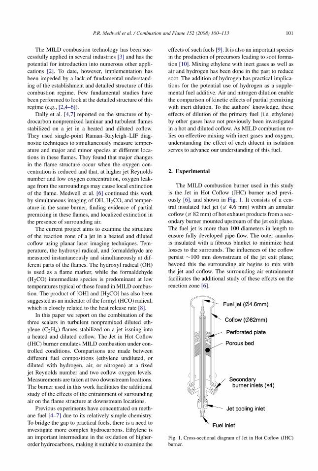
The MILD combustion burner used in this studyis the Jet in Hot Coflow (JHC) burner used previ-ously [6], and shown in Fig. 1. It consists of a cen-tral insulated fuel jet (� 4.6 mm) within an annularcoflow (� 82 mm) of hot exhaust products from a sec-ondary burner mounted upstream of the jet exit plane.The fuel jet is more than 100 diameters in length toensure fully developed pipe flow. The outer annulusis insulated with a fibrous blanket to minimize heatlosses to the surrounds. The influences of the coflowpersist ∼100 mm downstream of the jet exit plane;beyond this the surrounding air begins to mix withthe jet and coflow. The surrounding air entrainmentfacilitates the additional study of these effects on thereaction zone [6].
Fig. 1. Cross-sectional diagram of Jet in Hot Coflow (JHC)burner.
102 P.R. Medwell et al. / Combustion and Flame 152 (2008) 100–113
Table 1Fuel jet dilution ratios of ethylene (C2H4) and stoichiometric mixture fraction (for both coflow compositions)
Fuel composition Volumetric ratio fstoich Ujet [m/s] Rejet [–]
3% O2 9% O2
C2H4 – 0.010 0.029 17.5 10,000C2H4/H2 1:1 0.009 0.027 30.6 10,000C2H4/air 1:3 0.050 0.135 27.3 10,000C2H4/N2 1:3 0.039 0.108 27.3 10,000
Note. For Rejet = 10,000 the bulk jet exit velocity (Ujet) is also shown.
The O2 level of the coflow is controlled by theconstant-flowrate secondary porous burner. The ratioof the coflow air/nitrogen was varied to give excessO2 levels of 3 or 9% (volumetric), while the coflowtemperature and exit velocity were kept constant at1100 K and 2.3 m/s. Based on the annulus diameter,the coflow Reynolds number is ∼1400.
The fuel used in the jet is ethylene (>99% C2H4),either undiluted, or diluted with hydrogen (H2), air,or nitrogen (N2). Table 1 shows the compositions andvolumetric ratios of the jet flow. Addition of H2 at thismixing ratio (1:1) has often been used in hydrocarbonflames to reduce soot interference [11] and is consis-tent with previous measurements in this burner [4,6].Similarly, air dilution (at 1:3 fuel/air) also cleansflames from soot [9], while not significantly alteringthe flame structure [12]. Nitrogen added in the sameratio subsequently allows the effects of inert dilutionto be considered independently. Any differences be-tween the air- and nitrogen-diluted cases are directlyattributable to the kinetic effects of O2 in the fuelstream. Also shown in Table 1 is the stoichiometricmixture fraction for both coflow O2 levels and themean jet exit velocity for a jet Reynolds number of10,000, based on jet inner diameter.
Laser-induced fluorescence (LIF) is used to im-age OH and H2CO, and temperature is inferred fromRayleigh scattering measurements. Each species isprobed with a separate laser system. Excitation ofOH is at 283.222 nm (A–X(1,0)Q1(7)), and H2COat 340.836 nm (A–X(21
0410)pQ21(5)). The two LIF
laser beams were produced from the frequency-doubled output of dye lasers (Nd:YAG pumped at532 nm). The output power of the dye lasers was∼2 mJ/pulse for OH and ∼10 mJ/pulse for H2CO,with measured linewidths of 0.5 and 0.26 cm−1
for OH and H2CO, respectively. The source for theRayleigh scatter was an ∼160 mJ/pulse 532-nmbeam from a Nd:YAG laser. A detailed descriptionof the LIF excitation schemes has previously beenpresented [6].
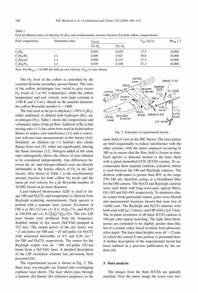
The experimental layout is shown in Fig. 2. Thethree laser wavelengths are formed into overlappingcoplanar laser sheets. The laser sheets pass througha laminar slot burner (for reference purposes) in the
Fig. 2. Schematic of experimental layout.
same field of view as the JHC burner. The laser pulsesare fired sequentially to reduce interference with theother systems, with the entire sequence occurring in300 ns to ensure that the flow field is frozen in time.Each species is detected normal to the laser sheetwith a gated intensified CCD (ICCD) camera. To ac-commodate three separate cameras, a dichroic mirroris used between the OH and Rayleigh cameras. Thedichroic reflectance is greater than 80% in the range270–340 nm, therefore acting as a broadband filterfor the OH camera. The H2CO and Rayleigh cameraswere each fitted with long-wave-pass optical filters,GG-385 and GG-495, respectively. To minimize elas-tic scatter from particulate matter, gases were filteredand measurement locations chosen that were free ofvisible soot. The Rayleigh and H2CO cameras wereboth used with f#1.2 lenses, and OH with a f#4.5 lens.The in-plane resolution of all three ICCD cameras is160 µm, after spatial matching. The light sheet thick-nesses are estimated to be slightly greater than this,but of a similar order, based on burns from photosen-sitive paper. The laser sheet heights were all ∼12 mm,of which the central 8-mm portion is presented here.A further description of the experimental layout hasbeen outlined in a previous publication by the au-thors [6].
3. Data analysis
The images from the three ICCDs are spatiallymatched. Over the entire image the worst case mis-
P.R. Medwell et al. / Combustion and Flame 152 (2008) 100–113 103
match is never more than 2 pixels (320 µm), and aftercropping the matching process gives subpixel accu-racy. Each image is corrected for dark-charge, back-ground, and detector attenuation. All images are cor-rected for laser power and profile variations shot-to-shot based on the signal from the laminar slot burner.Based on the measurements from a flat-flame burner,the laser power shot-to-shot corrections result in inter-shot variations of �5% for the OH and temperature.H2CO shot-to-shot variations could not be accuratelydetermined, but are expected to be of a similar order tothe others. Approximately 400 images were recordedat each flame location and condition.
The temperature and composition change quiteconsiderably both throughout the measurement vol-ume and with different flame conditions. To accountfor these effects, consideration is given to the ground-state Boltzmann population distribution and colli-sional quenching effects. The specific correction pro-cedures for the data is described in depth in a previouspublication by the authors [6]. One minor alterationover the previously reported Rayleigh-to-temperatureconversion was required, as some of the flames in thepresent work appear lifted, so that H2CO is now in-cluded to assist in the determination of the jet/coflowboundary.
The signal-to-noise (SNR) of the instantaneouscorrected images is typically better than 40:1 for OH,10:1 for Rayleigh, and 5:1 for H2CO, although thisvalue increases dramatically for H2CO depending onthe fuel composition.
Although Stokes-shifted Raman scatter fromC2H4 coincides with the OH-LIF detection wave-length, because the LIF signal is much stronger, thisdoes not pose a major problem, and is only barelynoticeable for the undiluted C2H4 flame.
It is noted that the H2CO signal suffers only mi-nor encroachment of vibrational Stokes-shifted Ra-man scatter from H2 passing the detection filter. Thisinterference is restricted to radial locations close tothe centerline and has little effect near the flame lo-cation. Interference from polycyclic aromatic hydro-carbons (PAH) can present a problem in H2CO-LIFmeasurements. The selected excitation scheme hasbeen reported as having lower broadband interfer-ence than other H2CO schemes [13]. To confirm thatPAH interference does not affect the findings, excita-tion wavelength scanning (in conjunction with a cali-brated wavemeter) confirmed the locations of spectralpeaks corresponding to H2CO. Furthermore, for dif-ferent flame conditions, the trends in H2CO-LIF agreewith trends predicted by laminar flame calculationsand not with the trends of increased soot formation.While these observations do not provide categoricalevidence, we are confident that PAH interference withthe H2CO-LIF signal does not significantly affect the
results. Despite these issues, the H2CO-LIF is suffi-cient to obtain reasonable understanding of the para-meters that control its concentration and spatial distri-bution.
The images appearing in this paper have not beenenhanced by image smoothing, to reduce interpixelnoise.
4. Results
4.1. Visual observations
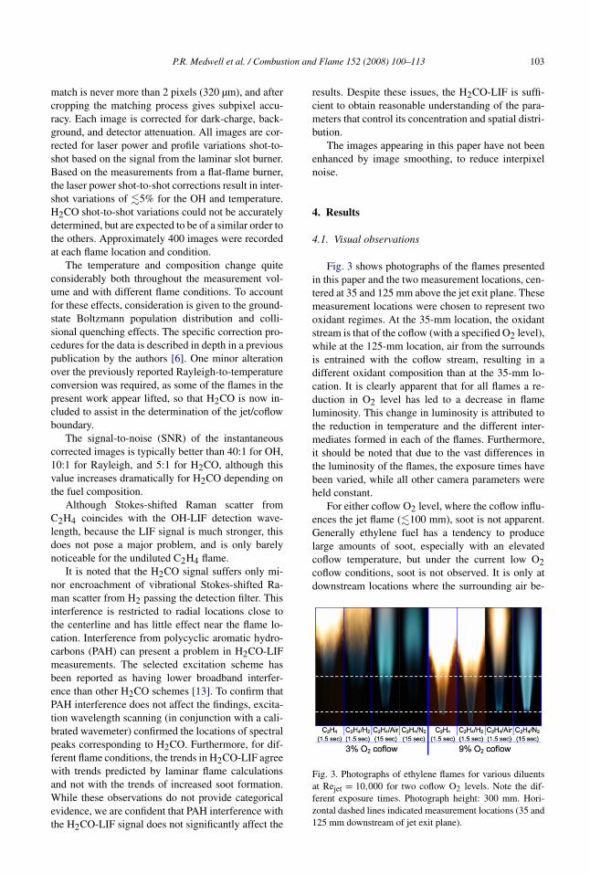
Fig. 3 shows photographs of the flames presentedin this paper and the two measurement locations, cen-tered at 35 and 125 mm above the jet exit plane. Thesemeasurement locations were chosen to represent twooxidant regimes. At the 35-mm location, the oxidantstream is that of the coflow (with a specified O2 level),while at the 125-mm location, air from the surroundsis entrained with the coflow stream, resulting in adifferent oxidant composition than at the 35-mm lo-cation. It is clearly apparent that for all flames a re-duction in O2 level has led to a decrease in flameluminosity. This change in luminosity is attributed tothe reduction in temperature and the different inter-mediates formed in each of the flames. Furthermore,it should be noted that due to the vast differences inthe luminosity of the flames, the exposure times havebeen varied, while all other camera parameters wereheld constant.
For either coflow O2 level, where the coflow influ-ences the jet flame (�100 mm), soot is not apparent.Generally ethylene fuel has a tendency to producelarge amounts of soot, especially with an elevatedcoflow temperature, but under the current low O2coflow conditions, soot is not observed. It is only atdownstream locations where the surrounding air be-
Fig. 3. Photographs of ethylene flames for various diluentsat Rejet = 10,000 for two coflow O2 levels. Note the dif-ferent exposure times. Photograph height: 300 mm. Hori-zontal dashed lines indicated measurement locations (35 and125 mm downstream of jet exit plane).
104 P.R. Medwell et al. / Combustion and Flame 152 (2008) 100–113
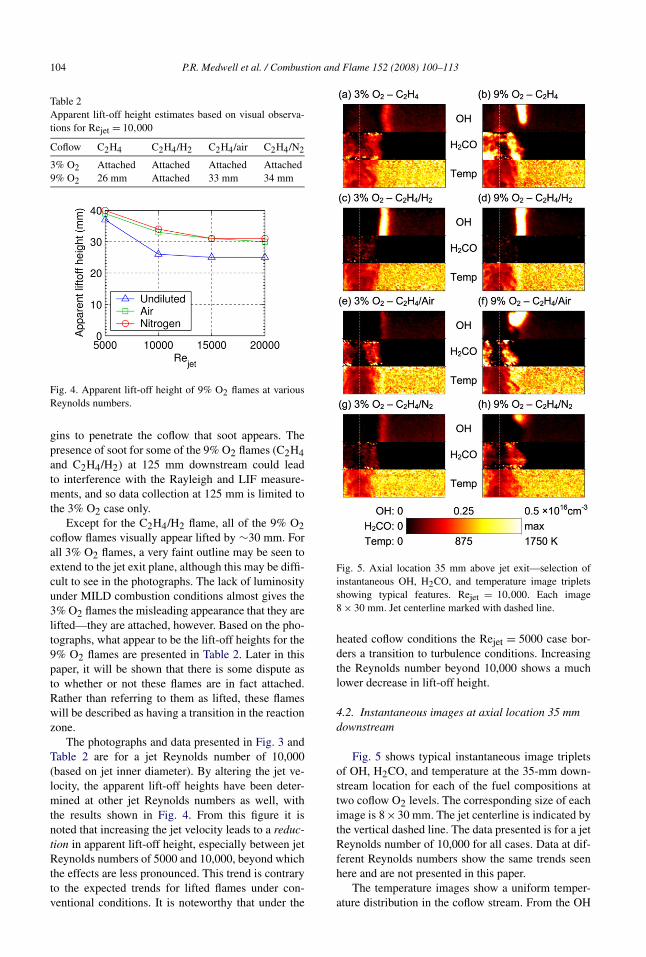
Table 2Apparent lift-off height estimates based on visual observa-tions for Rejet = 10,000
Coflow C2H4 C2H4/H2 C2H4/air C2H4/N2
3% O2 Attached Attached Attached Attached9% O2 26 mm Attached 33 mm 34 mm
Fig. 4. Apparent lift-off height of 9% O2 flames at variousReynolds numbers.
gins to penetrate the coflow that soot appears. Thepresence of soot for some of the 9% O2 flames (C2H4and C2H4/H2) at 125 mm downstream could leadto interference with the Rayleigh and LIF measure-ments, and so data collection at 125 mm is limited tothe 3% O2 case only.
Except for the C2H4/H2 flame, all of the 9% O2coflow flames visually appear lifted by ∼30 mm. Forall 3% O2 flames, a very faint outline may be seen toextend to the jet exit plane, although this may be diffi-cult to see in the photographs. The lack of luminosityunder MILD combustion conditions almost gives the3% O2 flames the misleading appearance that they arelifted—they are attached, however. Based on the pho-tographs, what appear to be the lift-off heights for the9% O2 flames are presented in Table 2. Later in thispaper, it will be shown that there is some dispute asto whether or not these flames are in fact attached.Rather than referring to them as lifted, these flameswill be described as having a transition in the reactionzone.
The photographs and data presented in Fig. 3 andTable 2 are for a jet Reynolds number of 10,000(based on jet inner diameter). By altering the jet ve-locity, the apparent lift-off heights have been deter-mined at other jet Reynolds numbers as well, withthe results shown in Fig. 4. From this figure it isnoted that increasing the jet velocity leads to a reduc-tion in apparent lift-off height, especially between jetReynolds numbers of 5000 and 10,000, beyond whichthe effects are less pronounced. This trend is contraryto the expected trends for lifted flames under con-ventional conditions. It is noteworthy that under the
Fig. 5. Axial location 35 mm above jet exit—selection ofinstantaneous OH, H2CO, and temperature image tripletsshowing typical features. Rejet = 10,000. Each image8 × 30 mm. Jet centerline marked with dashed line.
heated coflow conditions the Rejet = 5000 case bor-ders a transition to turbulence conditions. Increasingthe Reynolds number beyond 10,000 shows a muchlower decrease in lift-off height.
4.2. Instantaneous images at axial location 35 mmdownstream
Fig. 5 shows typical instantaneous image tripletsof OH, H2CO, and temperature at the 35-mm down-stream location for each of the fuel compositions attwo coflow O2 levels. The corresponding size of eachimage is 8×30 mm. The jet centerline is indicated bythe vertical dashed line. The data presented is for a jetReynolds number of 10,000 for all cases. Data at dif-ferent Reynolds numbers show the same trends seenhere and are not presented in this paper.
The temperature images show a uniform temper-ature distribution in the coflow stream. From the OH
P.R. Medwell et al. / Combustion and Flame 152 (2008) 100–113 105
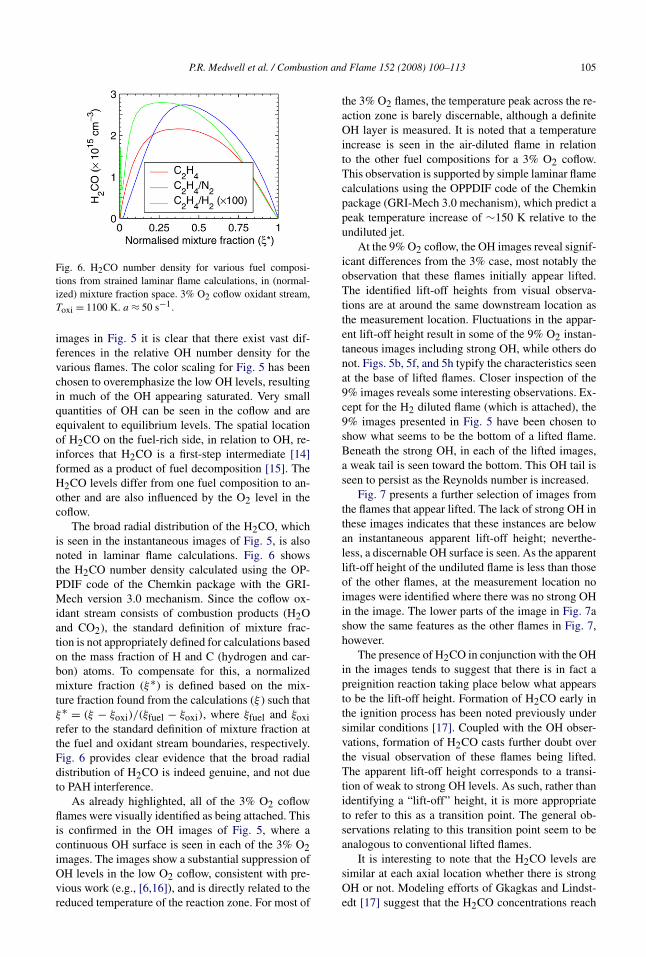
Fig. 6. H2CO number density for various fuel composi-tions from strained laminar flame calculations, in (normal-ized) mixture fraction space. 3% O2 coflow oxidant stream,Toxi = 1100 K. a ≈ 50 s−1.
images in Fig. 5 it is clear that there exist vast dif-ferences in the relative OH number density for thevarious flames. The color scaling for Fig. 5 has beenchosen to overemphasize the low OH levels, resultingin much of the OH appearing saturated. Very smallquantities of OH can be seen in the coflow and areequivalent to equilibrium levels. The spatial locationof H2CO on the fuel-rich side, in relation to OH, re-inforces that H2CO is a first-step intermediate [14]formed as a product of fuel decomposition [15]. TheH2CO levels differ from one fuel composition to an-other and are also influenced by the O2 level in thecoflow.
The broad radial distribution of the H2CO, whichis seen in the instantaneous images of Fig. 5, is alsonoted in laminar flame calculations. Fig. 6 showsthe H2CO number density calculated using the OP-PDIF code of the Chemkin package with the GRI-Mech version 3.0 mechanism. Since the coflow ox-idant stream consists of combustion products (H2Oand CO2), the standard definition of mixture frac-tion is not appropriately defined for calculations basedon the mass fraction of H and C (hydrogen and car-bon) atoms. To compensate for this, a normalizedmixture fraction (ξ∗) is defined based on the mix-ture fraction found from the calculations (ξ ) such thatξ∗ = (ξ − ξoxi)/(ξfuel − ξoxi), where ξfuel and ξoxirefer to the standard definition of mixture fraction atthe fuel and oxidant stream boundaries, respectively.Fig. 6 provides clear evidence that the broad radialdistribution of H2CO is indeed genuine, and not dueto PAH interference.
As already highlighted, all of the 3% O2 coflowflames were visually identified as being attached. Thisis confirmed in the OH images of Fig. 5, where acontinuous OH surface is seen in each of the 3% O2images. The images show a substantial suppression ofOH levels in the low O2 coflow, consistent with pre-vious work (e.g., [6,16]), and is directly related to thereduced temperature of the reaction zone. For most of
the 3% O2 flames, the temperature peak across the re-action zone is barely discernable, although a definiteOH layer is measured. It is noted that a temperatureincrease is seen in the air-diluted flame in relationto the other fuel compositions for a 3% O2 coflow.This observation is supported by simple laminar flamecalculations using the OPPDIF code of the Chemkinpackage (GRI-Mech 3.0 mechanism), which predict apeak temperature increase of ∼150 K relative to theundiluted jet.
At the 9% O2 coflow, the OH images reveal signif-icant differences from the 3% case, most notably theobservation that these flames initially appear lifted.The identified lift-off heights from visual observa-tions are at around the same downstream location asthe measurement location. Fluctuations in the appar-ent lift-off height result in some of the 9% O2 instan-taneous images including strong OH, while others donot. Figs. 5b, 5f, and 5h typify the characteristics seenat the base of lifted flames. Closer inspection of the9% images reveals some interesting observations. Ex-cept for the H2 diluted flame (which is attached), the9% images presented in Fig. 5 have been chosen toshow what seems to be the bottom of a lifted flame.Beneath the strong OH, in each of the lifted images,a weak tail is seen toward the bottom. This OH tail isseen to persist as the Reynolds number is increased.
Fig. 7 presents a further selection of images fromthe flames that appear lifted. The lack of strong OH inthese images indicates that these instances are belowan instantaneous apparent lift-off height; neverthe-less, a discernable OH surface is seen. As the apparentlift-off height of the undiluted flame is less than thoseof the other flames, at the measurement location noimages were identified where there was no strong OHin the image. The lower parts of the image in Fig. 7ashow the same features as the other flames in Fig. 7,however.
The presence of H2CO in conjunction with the OHin the images tends to suggest that there is in fact apreignition reaction taking place below what appearsto be the lift-off height. Formation of H2CO early inthe ignition process has been noted previously undersimilar conditions [17]. Coupled with the OH obser-vations, formation of H2CO casts further doubt overthe visual observation of these flames being lifted.The apparent lift-off height corresponds to a transi-tion of weak to strong OH levels. As such, rather thanidentifying a “lift-off” height, it is more appropriateto refer to this as a transition point. The general ob-servations relating to this transition point seem to beanalogous to conventional lifted flames.
It is interesting to note that the H2CO levels aresimilar at each axial location whether there is strongOH or not. Modeling efforts of Gkagkas and Lindst-edt [17] suggest that the H2CO concentrations reach
106 P.R. Medwell et al. / Combustion and Flame 152 (2008) 100–113
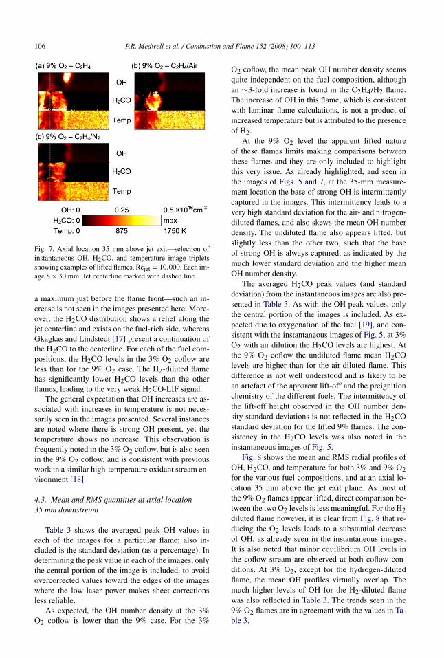
Fig. 7. Axial location 35 mm above jet exit—selection ofinstantaneous OH, H2CO, and temperature image tripletsshowing examples of lifted flames. Rejet = 10,000. Each im-age 8 × 30 mm. Jet centerline marked with dashed line.
a maximum just before the flame front—such an in-crease is not seen in the images presented here. More-over, the H2CO distribution shows a relief along thejet centerline and exists on the fuel-rich side, whereasGkagkas and Lindstedt [17] present a continuation ofthe H2CO to the centerline. For each of the fuel com-positions, the H2CO levels in the 3% O2 coflow areless than for the 9% O2 case. The H2-diluted flamehas significantly lower H2CO levels than the otherflames, leading to the very weak H2CO-LIF signal.
The general expectation that OH increases are as-sociated with increases in temperature is not neces-sarily seen in the images presented. Several instancesare noted where there is strong OH present, yet thetemperature shows no increase. This observation isfrequently noted in the 3% O2 coflow, but is also seenin the 9% O2 coflow, and is consistent with previouswork in a similar high-temperature oxidant stream en-vironment [18].
4.3. Mean and RMS quantities at axial location35 mm downstream
Table 3 shows the averaged peak OH values ineach of the images for a particular flame; also in-cluded is the standard deviation (as a percentage). Indetermining the peak value in each of the images, onlythe central portion of the image is included, to avoidovercorrected values toward the edges of the imageswhere the low laser power makes sheet correctionsless reliable.
As expected, the OH number density at the 3%O2 coflow is lower than the 9% case. For the 3%
O2 coflow, the mean peak OH number density seemsquite independent on the fuel composition, althoughan ∼3-fold increase is found in the C2H4/H2 flame.The increase of OH in this flame, which is consistentwith laminar flame calculations, is not a product ofincreased temperature but is attributed to the presenceof H2.
At the 9% O2 level the apparent lifted natureof these flames limits making comparisons betweenthese flames and they are only included to highlightthis very issue. As already highlighted, and seen inthe images of Figs. 5 and 7, at the 35-mm measure-ment location the base of strong OH is intermittentlycaptured in the images. This intermittency leads to avery high standard deviation for the air- and nitrogen-diluted flames, and also skews the mean OH numberdensity. The undiluted flame also appears lifted, butslightly less than the other two, such that the baseof strong OH is always captured, as indicated by themuch lower standard deviation and the higher meanOH number density.
The averaged H2CO peak values (and standarddeviation) from the instantaneous images are also pre-sented in Table 3. As with the OH peak values, onlythe central portion of the images is included. As ex-pected due to oxygenation of the fuel [19], and con-sistent with the instantaneous images of Fig. 5, at 3%O2 with air dilution the H2CO levels are highest. Atthe 9% O2 coflow the undiluted flame mean H2COlevels are higher than for the air-diluted flame. Thisdifference is not well understood and is likely to bean artefact of the apparent lift-off and the preignitionchemistry of the different fuels. The intermittency ofthe lift-off height observed in the OH number den-sity standard deviations is not reflected in the H2COstandard deviation for the lifted 9% flames. The con-sistency in the H2CO levels was also noted in theinstantaneous images of Fig. 5.
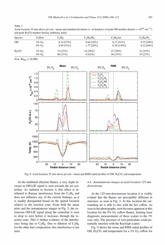
Fig. 8 shows the mean and RMS radial profiles ofOH, H2CO, and temperature for both 3% and 9% O2for the various fuel compositions, and at an axial lo-cation 35 mm above the jet exit plane. As most ofthe 9% O2 flames appear lifted, direct comparison be-tween the two O2 levels is less meaningful. For the H2diluted flame however, it is clear from Fig. 8 that re-ducing the O2 levels leads to a substantial decreaseof OH, as already seen in the instantaneous images.It is also noted that minor equilibrium OH levels inthe coflow stream are observed at both coflow con-ditions. At 3% O2, except for the hydrogen-dilutedflame, the mean OH profiles virtually overlap. Themuch higher levels of OH for the H2-diluted flamewas also reflected in Table 3. The trends seen in the9% O2 flames are in agreement with the values in Ta-ble 3.
P.R. Medwell et al. / Combustion and Flame 152 (2008) 100–113 107
Table 3Axial location 35 mm above jet exit—mean and standard deviation (σ , in brackets) of peak OH number density (×1016 cm−3)and peak H2CO number density (arbitrary units)
Species Coflow C2H4 C2H4/H2 C2H4/air C2H4/N2
OH 3% O2 0.14 [27%] 0.64 [10%] 0.17 [41%] 0.15 [30%]9% O2 0.95 [31%] 1.77 [29%] 0.39 [139%] 0.12 [94%]
H2CO 3% O2 33 [23%] 14 [28%] 47 [29%] 21 [24%]9% O2 86 [31%] 9 [42%] 56 [35%] 35 [23%]
Note. Rejet = 10,000.
Fig. 8. Axial location 35 mm above jet exit—mean and RMS radial profiles of OH, H2CO, and temperature.
In the undiluted ethylene flames, a very slight in-crease in OH-LIF signal is seen towards the jet cen-terline. As outlined in Section 3, this effect is at-tributed to Raman interference from the C2H4 anddoes not influence any of the current findings, as itis readily disregarded based on the spatial locationrelative to the reaction zone. From both the meanplots and the instantaneous images in Fig. 5, the ex-traneous OH-LIF signal along the centerline is seento drop to zero before it increases through the re-action zone. This is further evidence of the interfer-ence being due to C2H4. Due to dilution of C2H4for the other fuel composition, this interference is notseen.
4.4. Instantaneous images at axial location 125 mmdownstream
At the 125-mm-downstream location it is visiblyevident that the flames are perceptibly different instructure, as seen in Fig. 3. At this location the sur-rounding air is able to mix with the hot coflow. Asseen in the photographs, soot becomes apparent at thislocation for the 9% O2 coflow flames, limiting laserdiagnostic measurements of these scalars to the 3%case only. The presence of soot particulate could po-tentially interfere with the Rayleigh scatter.
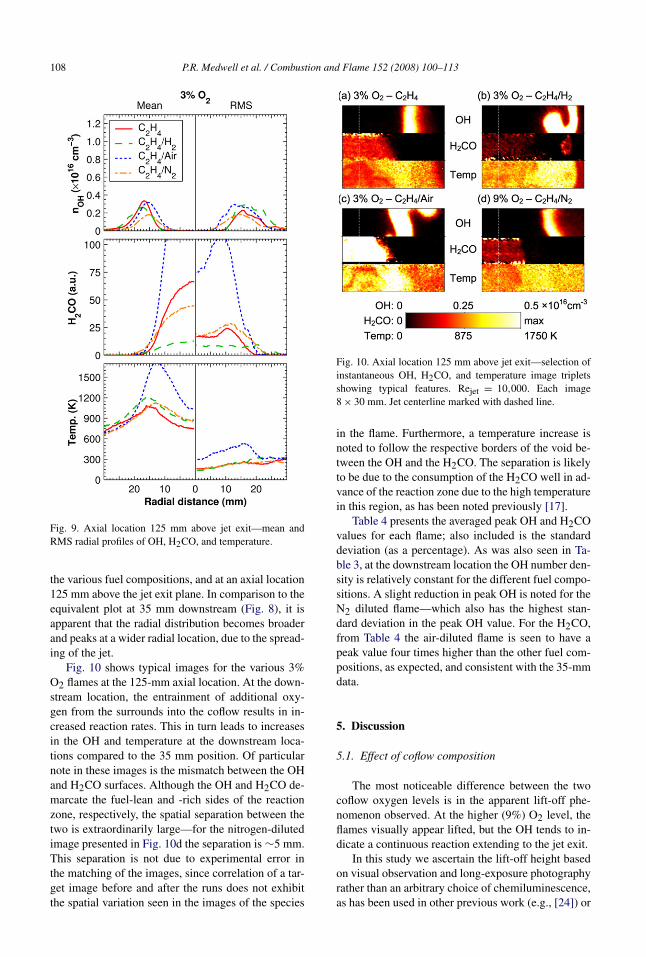
Fig. 9 shows the mean and RMS radial profiles ofOH, H2CO, and temperature for a 3% O2 coflow for
108 P.R. Medwell et al. / Combustion and Flame 152 (2008) 100–113
Fig. 9. Axial location 125 mm above jet exit—mean andRMS radial profiles of OH, H2CO, and temperature.
the various fuel compositions, and at an axial location125 mm above the jet exit plane. In comparison to theequivalent plot at 35 mm downstream (Fig. 8), it isapparent that the radial distribution becomes broaderand peaks at a wider radial location, due to the spread-ing of the jet.
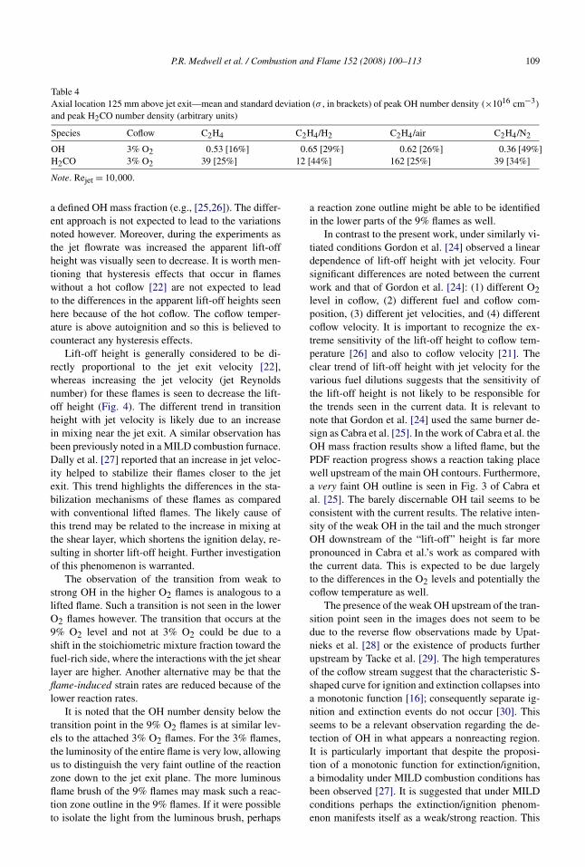
Fig. 10 shows typical images for the various 3%O2 flames at the 125-mm axial location. At the down-stream location, the entrainment of additional oxy-gen from the surrounds into the coflow results in in-creased reaction rates. This in turn leads to increasesin the OH and temperature at the downstream loca-tions compared to the 35 mm position. Of particularnote in these images is the mismatch between the OHand H2CO surfaces. Although the OH and H2CO de-marcate the fuel-lean and -rich sides of the reactionzone, respectively, the spatial separation between thetwo is extraordinarily large—for the nitrogen-dilutedimage presented in Fig. 10d the separation is ∼5 mm.This separation is not due to experimental error inthe matching of the images, since correlation of a tar-get image before and after the runs does not exhibitthe spatial variation seen in the images of the species
Fig. 10. Axial location 125 mm above jet exit—selection ofinstantaneous OH, H2CO, and temperature image tripletsshowing typical features. Rejet = 10,000. Each image8 × 30 mm. Jet centerline marked with dashed line.
in the flame. Furthermore, a temperature increase isnoted to follow the respective borders of the void be-tween the OH and the H2CO. The separation is likelyto be due to the consumption of the H2CO well in ad-vance of the reaction zone due to the high temperaturein this region, as has been noted previously [17].
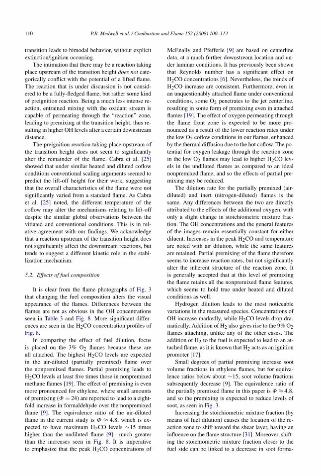
Table 4 presents the averaged peak OH and H2COvalues for each flame; also included is the standarddeviation (as a percentage). As was also seen in Ta-ble 3, at the downstream location the OH number den-sity is relatively constant for the different fuel compo-sitions. A slight reduction in peak OH is noted for theN2 diluted flame—which also has the highest stan-dard deviation in the peak OH value. For the H2CO,from Table 4 the air-diluted flame is seen to have apeak value four times higher than the other fuel com-positions, as expected, and consistent with the 35-mmdata.
5. Discussion
5.1. Effect of coflow composition
The most noticeable difference between the twocoflow oxygen levels is in the apparent lift-off phe-nomenon observed. At the higher (9%) O2 level, theflames visually appear lifted, but the OH tends to in-dicate a continuous reaction extending to the jet exit.
In this study we ascertain the lift-off height basedon visual observation and long-exposure photographyrather than an arbitrary choice of chemiluminescence,as has been used in other previous work (e.g., [24]) or
P.R. Medwell et al. / Combustion and Flame 152 (2008) 100–113 109
Table 4Axial location 125 mm above jet exit—mean and standard deviation (σ , in brackets) of peak OH number density (×1016 cm−3)
and peak H2CO number density (arbitrary units)
Species Coflow C2H4 C2H4/H2 C2H4/air C2H4/N2
OH 3% O2 0.53 [16%] 0.65 [29%] 0.62 [26%] 0.36 [49%]H2CO 3% O2 39 [25%] 12 [44%] 162 [25%] 39 [34%]Note. Rejet = 10,000.
a defined OH mass fraction (e.g., [25,26]). The differ-ent approach is not expected to lead to the variationsnoted however. Moreover, during the experiments asthe jet flowrate was increased the apparent lift-offheight was visually seen to decrease. It is worth men-tioning that hysteresis effects that occur in flameswithout a hot coflow [22] are not expected to leadto the differences in the apparent lift-off heights seenhere because of the hot coflow. The coflow temper-ature is above autoignition and so this is believed tocounteract any hysteresis effects.
Lift-off height is generally considered to be di-rectly proportional to the jet exit velocity [22],whereas increasing the jet velocity (jet Reynoldsnumber) for these flames is seen to decrease the lift-off height (Fig. 4). The different trend in transitionheight with jet velocity is likely due to an increasein mixing near the jet exit. A similar observation hasbeen previously noted in a MILD combustion furnace.Dally et al. [27] reported that an increase in jet veloc-ity helped to stabilize their flames closer to the jetexit. This trend highlights the differences in the sta-bilization mechanisms of these flames as comparedwith conventional lifted flames. The likely cause ofthis trend may be related to the increase in mixing atthe shear layer, which shortens the ignition delay, re-sulting in shorter lift-off height. Further investigationof this phenomenon is warranted.
The observation of the transition from weak tostrong OH in the higher O2 flames is analogous to alifted flame. Such a transition is not seen in the lowerO2 flames however. The transition that occurs at the9% O2 level and not at 3% O2 could be due to ashift in the stoichiometric mixture fraction toward thefuel-rich side, where the interactions with the jet shearlayer are higher. Another alternative may be that theflame-induced strain rates are reduced because of thelower reaction rates.
It is noted that the OH number density below thetransition point in the 9% O2 flames is at similar lev-els to the attached 3% O2 flames. For the 3% flames,the luminosity of the entire flame is very low, allowingus to distinguish the very faint outline of the reactionzone down to the jet exit plane. The more luminousflame brush of the 9% flames may mask such a reac-tion zone outline in the 9% flames. If it were possibleto isolate the light from the luminous brush, perhaps
a reaction zone outline might be able to be identifiedin the lower parts of the 9% flames as well.
In contrast to the present work, under similarly vi-tiated conditions Gordon et al. [24] observed a lineardependence of lift-off height with jet velocity. Foursignificant differences are noted between the currentwork and that of Gordon et al. [24]: (1) different O2level in coflow, (2) different fuel and coflow com-position, (3) different jet velocities, and (4) differentcoflow velocity. It is important to recognize the ex-treme sensitivity of the lift-off height to coflow tem-perature [26] and also to coflow velocity [21]. Theclear trend of lift-off height with jet velocity for thevarious fuel dilutions suggests that the sensitivity ofthe lift-off height is not likely to be responsible forthe trends seen in the current data. It is relevant tonote that Gordon et al. [24] used the same burner de-sign as Cabra et al. [25]. In the work of Cabra et al. theOH mass fraction results show a lifted flame, but thePDF reaction progress shows a reaction taking placewell upstream of the main OH contours. Furthermore,a very faint OH outline is seen in Fig. 3 of Cabra etal. [25]. The barely discernable OH tail seems to beconsistent with the current results. The relative inten-sity of the weak OH in the tail and the much strongerOH downstream of the “lift-off” height is far morepronounced in Cabra et al.’s work as compared withthe current data. This is expected to be due largelyto the differences in the O2 levels and potentially thecoflow temperature as well.
The presence of the weak OH upstream of the tran-sition point seen in the images does not seem to bedue to the reverse flow observations made by Upat-nieks et al. [28] or the existence of products furtherupstream by Tacke et al. [29]. The high temperaturesof the coflow stream suggest that the characteristic S-shaped curve for ignition and extinction collapses intoa monotonic function [16]; consequently separate ig-nition and extinction events do not occur [30]. Thisseems to be a relevant observation regarding the de-tection of OH in what appears a nonreacting region.It is particularly important that despite the proposi-tion of a monotonic function for extinction/ignition,a bimodality under MILD combustion conditions hasbeen observed [27]. It is suggested that under MILDconditions perhaps the extinction/ignition phenom-enon manifests itself as a weak/strong reaction. This
110 P.R. Medwell et al. / Combustion and Flame 152 (2008) 100–113
transition leads to bimodal behavior, without explicitextinction/ignition occurring.
The intimation that there may be a reaction takingplace upstream of the transition height does not cate-gorically conflict with the potential of a lifted flame.The reaction that is under discussion is not consid-ered to be a fully-fledged flame, but rather some kindof preignition reaction. Being a much less intense re-action, entrained mixing with the oxidant stream iscapable of permeating through the “reaction” zone,leading to premixing at the transition height, thus re-sulting in higher OH levels after a certain downstreamdistance.
The preignition reaction taking place upstream ofthe transition height does not seem to significantlyalter the remainder of the flame. Cabra et al. [25]showed that under similar heated and diluted coflowconditions conventional scaling arguments seemed topredict the lift-off height for their work, suggestingthat the overall characteristics of the flame were notsignificantly varied from a standard flame. As Cabraet al. [25] noted, the different temperature of thecoflow may alter the mechanisms relating to lift-offdespite the similar global observations between thevitiated and conventional conditions. This is in rel-ative agreement with our findings. We acknowledgethat a reaction upstream of the transition height doesnot significantly affect the downstream reactions, buttends to suggest a different kinetic role in the stabi-lization mechanism.
5.2. Effects of fuel composition
It is clear from the flame photographs of Fig. 3that changing the fuel composition alters the visualappearance of the flames. Differences between theflames are not as obvious in the OH concentrationsseen in Table 3 and Fig. 8. More significant differ-ences are seen in the H2CO concentration profiles ofFig. 8.
In comparing the effect of fuel dilution, focusis placed on the 3% O2 flames because these areall attached. The highest H2CO levels are expectedin the air-diluted (partially premixed) flame overthe nonpremixed flames. Partial premixing leads toH2CO levels at least five times those in nonpremixedmethane flames [19]. The effect of premixing is evenmore pronounced for ethylene, where small amountsof premixing (Φ = 24) are reported to lead to a eight-fold increase in formaldehyde over the nonpremixedflame [9]. The equivalence ratio of the air-dilutedflame in the current study is Φ ≈ 4.8, which is ex-pected to have maximum H2CO levels ∼15 timeshigher than the undiluted flame [9]—much greaterthan the increases seen in Fig. 8. It is imperativeto emphasize that the peak H2CO concentrations of
McEnally and Pfefferle [9] are based on centerlinedata, at a much further downstream location and un-der laminar conditions. It has previously been shownthat Reynolds number has a significant effect onH2CO concentrations [6]. Nevertheless, the trends ofH2CO increase are consistent. Furthermore, even inan unquestionably attached flame under conventionalconditions, some O2 penetrates to the jet centerline,resulting in some form of premixing even in attachedflames [19]. The effect of oxygen permeating throughthe flame front zone is expected to be more pro-nounced as a result of the lower reaction rates underthe low O2 coflow conditions in our flames, enhancedby the thermal diffusion due to the hot coflow. The po-tential for oxygen leakage through the reaction zonein the low O2 flames may lead to higher H2CO lev-els in the undiluted flames as compared to an idealnonpremixed flame, and so the effects of partial pre-mixing may be reduced.
The dilution rate for the partially premixed (air-diluted) and inert (nitrogen-diluted) flames is thesame. Any differences between the two are directlyattributed to the effects of the additional oxygen, withonly a slight change in stoichiometric mixture frac-tion. The OH concentrations and the general featuresof the images remain essentially constant for eitherdiluent. Increases in the peak H2CO and temperatureare noted with air dilution, while the same featuresare retained. Partial premixing of the flame thereforeseems to increase reaction rates, but not significantlyalter the inherent structure of the reaction zone. Itis generally accepted that at this level of premixingthe flame retains all the nonpremixed flame features,which seems to hold true under heated and dilutedconditions as well.
Hydrogen dilution leads to the most noticeablevariations in the measured species. Concentrations ofOH increase markedly, while H2CO levels drop dra-matically. Addition of H2 also gives rise to the 9% O2flames attaching, unlike any of the other cases. Theaddition of H2 to the fuel is expected to lead to an at-tached flame, as it is known that H2 acts as an ignitionpromoter [17].
Small degrees of partial premixing increase sootvolume fractions in ethylene flames, but for equiva-lence ratios below about ∼15, soot volume fractionssubsequently decrease [9]. The equivalence ratio ofthe partially premixed flame in this paper is Φ ≈ 4.8,and so the premixing is expected to reduce levels ofsoot, as seen in Fig. 3.
Increasing the stoichiometric mixture fraction (bymeans of fuel dilution) causes the location of the re-action zone to shift toward the shear layer, having aninfluence on the flame structure [31]. Moreover, shift-ing the stoichiometric mixture fraction closer to thefuel side can be linked to a decrease in soot forma-

P.R. Medwell et al. / Combustion and Flame 152 (2008) 100–113 111
tion [32]. The stoichiometric mixture fraction of the9% flames is greater than that of the 3% flames, sug-gesting that if the stoichiometry shift were the onlydifference between the two O2 cases, the 9% flameswould exhibit less soot—which does not appear tobe the case. This suggests that the soot suppressionby means of reducing the O2 level is related to thechemical effects of the hot coflow and not the shift instoichiometry.
The effects of the hot and diluted coflow on thelevels of soot seem to extend beyond the regionwhere the oxidant composition is controlled by thecoflow. As a generalization, soot does not appear un-til ∼200 mm downstream of the jet exit. The coflow isknown to persist only approximately 100 mm down-stream [6], and so, it seems that the initial conditionshave a significant effect on the intermediates that areformed, which in turn alter the downstream behaviorof the flames.
5.3. General observations
A triple flame consists of lean and rich premixedflames surrounding a diffusion flame. Joedicke etal. [20] have presented images of lifted methane andmethane/nitrogen flames, suggesting evidence of atriple flame, structure. Their flames consisted of asimple fuel jet issuing into a nominal coflow. Theheated coflow used in our work seems to providean environment fundamentally different from that ofJoedicke et al. [20]. Comparison of our imaging tothat of Joedicke et al. [20] reveals significant dif-ferences in the distribution of OH and H2CO. Thedifferences are particularly evident in the H2CO im-ages. Without a heated coflow, the H2CO only ap-pears around the base of the lifted flame [20], whereaswith a heated coflow, the H2CO is seen to exist wellbelow the lift-off height (Fig. 7).
Imaging of OH alone is insufficient to identify atriple flame structure [21], but coupled with H2CO,it may be possible to infer a triple flame. In a tripleflame the H2CO should “wrap around” the OH,thereby creating two H2CO peaks, demarcating thefuel-lean and -rich branches. In general, our imagesdo not show evidence of a triple flame structure exist-ing in our flames. A few images show some signs oftwo H2CO branches (Fig. 11), but no H2CO is presentat what would be deemed the triple point. The causeof the H2CO distribution seems far more likely to bevortical structures than a triple flame.
While we have no evidence of triple flames, and asignificantly different H2CO distribution, we cannotcategorically confirm or deny the existence of a tripleflame. The turbulent nature of our flames may lead toa compression of the triple flame, such that its pres-ence would be masked [22]. As reported by Joedicke
Fig. 11. Axial location 35 mm above jet exit—further se-lection of instantaneous OH, H2CO, and temperature imagetriplets. Rejet = 10,000. Each image 8 × 30 mm. Jet center-line marked with dashed line.
et al. [20], and noted by Im and Chen [23], as turbu-lence levels increase, the interaction of vortices witha triple flame cause the branches of a triple flame tocollapse into an edge flame.
6. Conclusion
Simultaneous imaging measurements of the hy-droxyl radical (OH), formaldehyde (H2CO), and tem-perature of turbulent nonpremixed diluted ethyleneflames in the Jet in Hot Coflow (JHC) burner havebeen presented. The heated and highly diluted coflowconditions (either 3 or 9% O2, constant temperatureof 1100 K) provided by this burner emulate those ofMILD combustion. Results have been presented attwo coflow O2 levels for a fixed jet Reynolds num-ber of 10,000 and diluents of either hydrogen (H2),air, or nitrogen (N2).
Soot production of the notoriously sooty ethylenefuel is shown to be suppressed under the influenceof the hot and diluted coflow. For either coflow O2level, where the coflow influences the jet flame, sootis not apparent. Even at downstream locations, wherethe surrounding air begins to penetrate the coflow, theeffects of the hot and diluted coflow on the levels ofsoot seem to persist. It is only well beyond the extentof the coflow that soot is noticed. It appears that theinitial conditions have a significant role in the forma-tion of the precursors to soot, which in turn alter thedownstream behavior of the flames.
At the downstream measurement location, the en-trainment of additional oxygen from the surrounds
112 P.R. Medwell et al. / Combustion and Flame 152 (2008) 100–113
into the coflow results in increased reaction rates. Thisin turn leads to increases in the OH and temperatureat the downstream locations compared to closer to thejet exit plane. Of particular note in the downstreammeasurements is a spatial mismatch between the OHand H2CO surfaces. The separation is likely to be dueto the consumption of the H2CO well in advance ofthe reaction zone due to the high temperature in thisregion.
In the 3% O2 coflow case, a faint outline is visu-ally seen to extend to the jet exit plane, whereas thehigher 9% O2 flames visually appear lifted. The ap-parent lift-off height decreases with an increase in jetvelocity, contrary to conventional trends. In the flamesthat appear lifted, a continuous OH surface can beidentified that extends to the jet exit. Nevertheless, atthe “lift-off” height, a transition from weak to strongOH is observed, analogous to lifted flames. H2CO isalso seen upstream of the transition point. Althoughnot a fully reacting flame, the presence of these inter-mediates indicates the occurrence of preignition reac-tions upstream of the transition point of these flames.
The detection of flame species upstream of thetransition height does not necessarily imply that theflames are or are not lifted. The reactions that occurin the “lifted” region are believed to be associatedwith preignition reactions rather than a fully devel-oped flame front. There may be some dispute overthe terminology of this phenomenon. Given that con-ventionally lifted flames do not exhibit preignitionreactions in the same way, it does not seem justifi-able to also refer to these flames as lifted. Describingthese flames as having a transition in reaction zonestructure seems a more accurate depiction. The mea-surements suggest that jet velocity plays an importantrole in promoting mixing to aid in the stabilization ofthese flames. It is clearly apparent that MILD com-bustion conditions provide a fundamentally differentmechanism for flame stabilization.
Acknowledgments
The authors thank Dr. Zeyad Alwahabi for his as-sistance with this project. The financial support of theUniversity of Adelaide and the Australian ResearchCouncil is gratefully acknowledged.
References
[1] J.A. Wünning, J.G. Wünning, Prog. Energy Combust.Sci. 23 (1997) 81–94.
[2] A. Cavaliere, M. de Joannon, Prog. Energy Combust.Sci. 30 (2004) 329–366.
[3] J.G. Wünning, FLOX®—Flameless Combustion, in:Thermprocess Symposium, WS WärmeprozesstechnikGmbH, 2003.
[4] B.B. Dally, A.N. Karpetis, R.S. Barlow, Proc. Com-bust. Inst. 29 (2002) 1147–1154.
[5] C. Ahn, F. Akamatsu, M. Katsuki, A. Kitajima, in: TheFourth Asia-Pacific Conference on Combustion, 2003,pp. 40–43.
[6] P.R. Medwell, P.A.M. Kalt, B.B. Dally, Combust.Flame 148 (2007) 48–61.
[7] B.B. Dally, A.N. Karpetis, R.S. Barlow, Structure of jetlaminar nonpremixed flames under diluted hot coflowconditions, presented at the 2002 Australian Sym-posium on Combustion and The Seventh AustralianFlame Days, Adelaide, Australia, 2002.
[8] H.N. Najm, P.H. Paul, C.J. Mueller, P.S. Wyckoff,Combust. Flame 113 (1998) 312–332.
[9] C.S. McEnally, L.D. Pfefferle, Combust. Flame 121(2000) 575–592.
[10] C.J. Sun, C.J. Sung, H. Wang, C.K. Law, Combust.Flame 107 (1996) 321–335.
[11] H. Guo, F. Liu, G.J. Smallwood, Ö.L. Gülder, Combust.Flame 145 (2006) 324–338.
[12] S.H. Stårner, R.W. Bilger, R.W. Dibble, R.S. Barlow,Combust. Sci. Technol. 72 (1990) 255–269.
[13] P.H. Paul, H.N. Najm, Proc. Combust. Inst. 27 (1998)43–50.
[14] R. Bombach, B. Käppeli, Appl. Phys. B 68 (1999) 251–255.
[15] K. Kohse-Höinghaus, J.B. Jeffries, Applied Combus-tion Diagnostics, Taylor & Francis, 2002.
[16] T. Plessing, N. Peters, J.G. Wünning, Proc. Combust.Inst. 27 (1998) 3197–3204.
[17] K. Gkagkas, R.P. Lindstedt, Proc. Combust. Inst. 31(2007) 1559–1566.
[18] R.L. Gordon, M.J. Dunn, A.R. Masri, R.W. Bilger, in:Fourth Australian Conference on Laser Diagnostics inFluid Mechanics and Combustion, The University ofAdelaide, Australia, 2005, pp. 45–48.
[19] C.S. McEnally, L.D. Pfefferle, Combust. Flame 118(1999) 619–632.
[20] A. Joedicke, N. Peters, M. Mansour, Proc. Combust.Inst. 30 (2005) 901–909.
[21] T. Plessing, P. Terhoeven, N. Peters, M.S. Mansour,Combust. Flame 115 (1998) 335–353.
[22] M.S. Mansour, Combust. Flame 133 (2003) 263–274.[23] H.G. Im, J.H. Chen, Combust. Flame 119 (1999) 436–
454.[24] R.L. Gordon, S.H. Stårner, A.R. Masri, R.W. Bil-
ger, in: 5th Asia-Pacific Conference on Combustion,The University of Adelaide, Australia, 2005, pp. 333–336.
[25] R. Cabra, T. Myhrvold, J.Y. Chen, R.W. Dibble, A.N.Karpetis, R.S. Barlow, Proc. Combust. Inst. 29 (2002)1881–1888.
[26] R.R. Cao, S.B. Pope, A.R. Masri, Combust. Flame 142(2005) 438–453.
[27] B.B. Dally, E. Riesmeier, N. Peters, Combust.Flame 137 (2004) 418–431.
[28] A. Upatnieks, J.F. Driscoll, S.L. Ceccio, Proc. Com-bust. Inst. 29 (2002) 1897–1903.

P.R. Medwell et al. / Combustion and Flame 152 (2008) 100–113 113
[29] M.M. Tacke, D. Geyer, E.P. Hassel, J. Janicka, Proc.Combust. Inst. 27 (1998) 1157–1165.
[30] I.B. Özdemir, N. Peters, Exp. Fluids 30 (2001)683–695.
[31] J.B. Kelman, A.R. Masri, Appl. Opt. 36 (15) (1997)3506–3514.
[32] J. Du, R.L. Axelbaum, Combust. Flame 100 (1995)367–375.