characterization of a gas burner to simulate a propellant flame and evaluate aluminum particle...
TRANSCRIPT

Combustion and Flame 153 (2008) 58–70www.elsevier.com/locate/combustflame
Characterization of a gas burner to simulate a propellantflame and evaluate aluminum particle combustion
Matt Jackson a, Michelle L. Pantoya b,∗, Walt Gill c
a Engineering Department, West Texas A&M University, Canyon, TX 79016, USAb Mechanical Engineering Department, Texas Tech University, Lubbock, TX 79409, USA
c Sandia National Laboratories, Albuquerque, NM 87185, USA
Received 19 February 2007; received in revised form 10 November 2007; accepted 15 November 2007
Available online 4 March 2008
Abstract
This study details the characterization and implementation of a burner designed to simulate solid propellantfires. The burner was designed with the ability to introduce particles (particularly aluminum) into a gas flame.The aluminized flame conditions produced by this burner are characterized based on temperature and heat fluxmeasurements. Using these results, flame conditions are quantified in comparison to other well-characterizedreactions including hydrocarbon and propellant fires. The aluminized flame is also used to measure the burningrate of the particles. This work describes the application of this burner for re-creating small-scale propellant flameconditions and as a test platform for experiments that contribute to the development of a particle combustionmodel, particularly in propellant fires.© 2008 The Combustion Institute. Published by Elsevier Inc. All rights reserved.
Keywords: Aluminum particle combustion; Hydrocarbon combustion; Diffusion flame burner; Propellant simulation burner
1. Introduction
Aluminized solid rocket propellants are widelyused in a variety of civilian and military applications.The heat release associated with the aluminum com-bustion provides a key increase in the specific impulsefor these motors, and much effort has gone into under-standing the influence of aluminum burning rate onproper rocket motor design. One aspect of propellantcombustion that is still not widely understood is analuminized propellant flame burning in an off-designconfiguration such as that which would occur in an
* Corresponding author. Fax: +1 806 742 3540.E-mail address: [email protected]
(M.L. Pantoya).
0010-2180/$ – see front matter © 2008 The Combustion Institute.doi:10.1016/j.combustflame.2007.11.014
accident scenario. Transporting and handling solidpropellants introduces an unusual hazard in these sit-uations, because propellant fires are not susceptible tooxygen starvation and exhibit much higher tempera-tures than typical hydrocarbon fuel fires, the highertemperatures being associated with the aluminum ox-idation. Understanding how an object, such as a haz-ardous materials container or munitions, will be af-fected when exposed to an accidental propellant fire isa multiphysics problem involving coupled flow, com-bustion, and heat/mass transfer phenomena. Methodsthat address this problem are based on propellant nu-merical simulation models [1–5] and actual propellantexperiments [6–8]. In the experimental work, it is ev-ident that a gas-fueled, propellant-simulating burnerwould greatly aid the analysis of propellant burn dy-
Published by Elsevier Inc. All rights reserved.

M. Jackson et al. / Combustion and Flame 153 (2008) 58–70 59
Nomenclature
A area (m2)Bi Biot numberBo,q transfer numbercp specific heat (J/kg K)D diameter (m)F force (N)Fo Fourier numberg gravitational acceleration (9.81 m/s2)h heat transfer coefficient (W/m2 K)hb burnout height (m)hfg heat of vaporization (J/kg)hsf heat of fusion (J/kg)k thermal conductivity (W/m K)Lc critical length (m)m mass (kg)Nu Nusselt numberPr Prandtl numberqi-l droplet heating (J/kg)r radius (m)Re Reynolds number
SD standard deviationt time (s)T temperature (K)Tp,flame particle flame temperature (K)U uncertaintyV velocity (m/s)α thermal diffusivity (m2/s)�hc heat of combustion (J/kg)μ viscosity (kg/s m)ν kinematic viscosity (m2/s)ρ density (kg/m3)
Subscripts
avg averageb boilingf fluidg gasi initials surface∞ free-stream conditions
namics and serve as a source of data acquisition, mea-surement, and testing in support of the developmentof a propellant fire model. For example, this burnercould be used as a test platform for heat transfer stud-ies with objects engulfed in a fire while allowing theexperimenter to vary both flow and combustion para-meters at will. Several factors dictate a need for such aburner, including limited availability and cost of somepropellants, unpredictable nature of propellant com-bustion in off-design configurations, and complexityof propellant experimental burns. In general, a con-trolled propellant-simulating burner would be a safer,less expensive, and more versatile testing platformthan using actual propellants.
2. Evaluation of propellant fire simulator
2.1. Burner design
There are a variety of different gas burner designsin use today in technical settings, but none are in-tended to specifically simulate propellant fires. Someare capable of separately feeding fuel and oxidizergas to the burner surface, and others are utilized forparticle combustion studies, but none combine bothof these features with multiple particle feed portsand the ability to repeatedly withstand the intenseheat (>3000 K) and corrosion associated with moltenAl/Al2O3. The motivation behind the design was todevelop a gas-fueled burner that simulates a pro-pellant flame by recreating temperatures, flow rates,
products, and Al particle combustion. NASA’s Com-puter Program for Calculation of Complex ChemicalEquilibrium Compositions and Applications (CEA)[9,10] is a chemical equilibrium code capable of cal-culating reaction compositions and thermodynamicproperties, assuming chemical equilibrium exists forthe input conditions. This program is used to deter-mine the gas reactants needed to re-create the productgases and temperatures that simulate the propellantflame. Initially, the CEA program is used to character-ize the propellant reaction without aluminum interac-tion, which yields the theoretical adiabatic flame tem-perature and product gas composition. Table 1 showsproduct gas mole fractions and flame temperatures re-sulting from this calculation for a representative pro-pellant, denoted here as Propellant A. The appropriategas reactant composition is then calculated so that thereaction yields the same flame temperature and prod-uct composition as the propellant reaction. These gascompositions can then be supplied to the burner tosimulate the adiabatic flame temperature of the pro-pellant flame. The flow velocities are determined bythe propellant burn rates. As seen in Table 1, thisanalysis shows that theoretical reactant gas compo-sitions can approximately simulate product gases andtemperatures from propellant fires.
The burner is designed to feed both fuel and oxi-dizer gases to the burner surface by an alternating gridof tubes from separate chambers (Figs. 1A and 1B).In addition, there are three tubes running to the sur-face that feed Al particles via N2 carrier gas, as shown

60 M. Jackson et al. / Combustion and Flame 153 (2008) 58–70
Table 1CEA calculated gas reactant compositions (mole fraction) tosimulate a propellant flame
Propellant A Sim A Sim B
Reactants (wt%)CH4 6.92 10.34O2 38.46 42.00N2 28.46 30.17CO 6.15 4.31CO2 11.54 5.17C2H2 7.69 6.90H2 0.77
ProductsCO 25.68 25.63 25.31CO2 9.46 10.12 8.76CL 0.18H 2.85 2.73 3.23HCL 0.85H2 9.16 9.04 9.77H2O 23.81 25.11 24.06NO 0.31 0.31 0.34N2 24.70 23.99 25.21O 0.42 0.41 0.49OH 2.15 2.19 2.37O2 0.43 0.46 0.48
Temperature (K) 2841 2831 2868
in Fig. 1B. The final propellant-simulating burner de-sign includes four layers, as shown in Fig. 1A. Thetop layer is water-cooled and protects the gas cham-bers from high temperatures. The bottom layer is theinlet for the three Al particle feed tubes. The middletwo layers are the gas-supplied chambers with feedtubes on the top of the chamber running to the surface.The rectangular burn surface consists of a 7 × 15 gridof 0.3175-cm outer diameter tubes. The tube layout issuch that they alternate their chamber feed source, andthe overall feed is symmetric. Each chamber has fourouter feed tubes, such that a total of eight gases canbe delivered to the burner surface. To clamp the cool-ing plate to the rest of the burner, 15.24 × 10.16 ×1.27-cm steel plates are located on the top and bot-tom of the burner and bolted together. The top platehas a grid of holes that match the cooling plate, and itprotects the cooling layer from molten Al/Al2O3 de-position. A high-temperature rubber/paper gasket isused above and below the cooling plate to ensure anairtight seal.
The Al particles are fed via nitrogen carrier gasthrough three tubes, independent of the fuel/oxidizergases, as shown in Fig. 1B. The particle feed isaccomplished using a powder hopper designed foruse with thermal spray systems. The hopper is aHA5000F-SA manufactured by Hardface Alloys andallows independent control of the particle and carriergas feed rates. Calibration of the particle feed rate is
(A)
(B)
Fig. 1. (A) Cutaway drawing of propellant-simulatingburner. (B) Arrangement of reactant ports on the burner sur-face.
accomplished by controlling the hopper RPM and us-ing automotive fuel filters to measure the total particlefeed for a given time. The Al particle feed rate canrange from approximately 4 to 10 g/min using thishopper configuration. Burning under ambient condi-tions, the mass flux of aluminum for aluminum-basedpropellants of interest is approximately 6 g/min [11].A feed rate of 5.6 g/min for 60-µm-diameter Al par-ticles in a nitrogen carrier gas flow of 12.8 standardliters per minute (SLPM) is used for these tests un-less stated otherwise. Reactant flow rates during theexperiments are 4, 2, 12, and 2 SLPM for methane,acetylene, oxygen, and nitrogen, respectively. The re-actant nitrogen flow is split nominally 50/50 betweenthe fuel and oxidizer streams. Based on the volumet-ric feed rates and the burner surface geometry, theflow velocity of the carrier gas from the particle tubescan be as much as 25 times higher than the flow ve-locity of the reactant gases, and promotes mixing ofthe particles. Though the particle distribution is notperfectly homogeneous, particularly near the surface,within one to two flame diameters above the surface(depending on input parameters) the flame deviatesfrom three distinct columns of particles and mixes
M. Jackson et al. / Combustion and Flame 153 (2008) 58–70 61
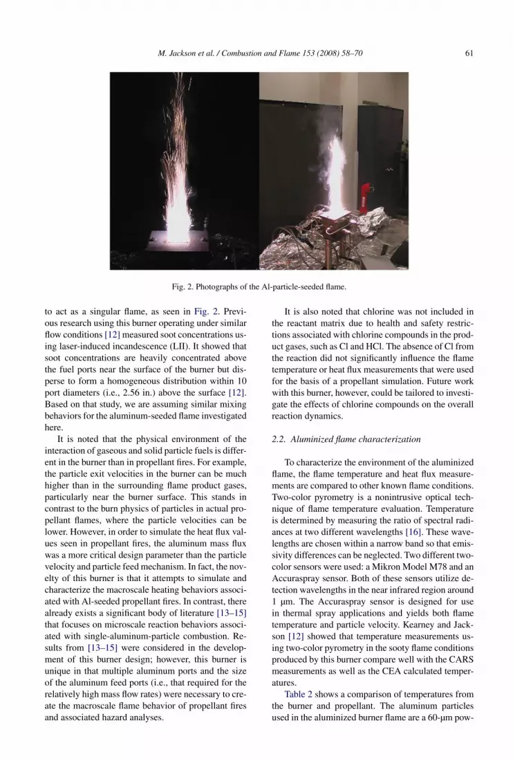
Fig. 2. Photographs of the Al-particle-seeded flame.
to act as a singular flame, as seen in Fig. 2. Previ-ous research using this burner operating under similarflow conditions [12] measured soot concentrations us-ing laser-induced incandescence (LII). It showed thatsoot concentrations are heavily concentrated abovethe fuel ports near the surface of the burner but dis-perse to form a homogeneous distribution within 10port diameters (i.e., 2.56 in.) above the surface [12].Based on that study, we are assuming similar mixingbehaviors for the aluminum-seeded flame investigatedhere.
It is noted that the physical environment of theinteraction of gaseous and solid particle fuels is differ-ent in the burner than in propellant fires. For example,the particle exit velocities in the burner can be muchhigher than in the surrounding flame product gases,particularly near the burner surface. This stands incontrast to the burn physics of particles in actual pro-pellant flames, where the particle velocities can belower. However, in order to simulate the heat flux val-ues seen in propellant fires, the aluminum mass fluxwas a more critical design parameter than the particlevelocity and particle feed mechanism. In fact, the nov-elty of this burner is that it attempts to simulate andcharacterize the macroscale heating behaviors associ-ated with Al-seeded propellant fires. In contrast, therealready exists a significant body of literature [13–15]that focuses on microscale reaction behaviors associ-ated with single-aluminum-particle combustion. Re-sults from [13–15] were considered in the develop-ment of this burner design; however, this burner isunique in that multiple aluminum ports and the sizeof the aluminum feed ports (i.e., that required for therelatively high mass flow rates) were necessary to cre-ate the macroscale flame behavior of propellant firesand associated hazard analyses.
It is also noted that chlorine was not included inthe reactant matrix due to health and safety restric-tions associated with chlorine compounds in the prod-uct gases, such as Cl and HCl. The absence of Cl fromthe reaction did not significantly influence the flametemperature or heat flux measurements that were usedfor the basis of a propellant simulation. Future workwith this burner, however, could be tailored to investi-gate the effects of chlorine compounds on the overallreaction dynamics.
2.2. Aluminized flame characterization
To characterize the environment of the aluminizedflame, the flame temperature and heat flux measure-ments are compared to other known flame conditions.Two-color pyrometry is a nonintrusive optical tech-nique of flame temperature evaluation. Temperatureis determined by measuring the ratio of spectral radi-ances at two different wavelengths [16]. These wave-lengths are chosen within a narrow band so that emis-sivity differences can be neglected. Two different two-color sensors were used: a Mikron Model M78 and anAccuraspray sensor. Both of these sensors utilize de-tection wavelengths in the near infrared region around1 µm. The Accuraspray sensor is designed for usein thermal spray applications and yields both flametemperature and particle velocity. Kearney and Jack-son [12] showed that temperature measurements us-ing two-color pyrometry in the sooty flame conditionsproduced by this burner compare well with the CARSmeasurements as well as the CEA calculated temper-atures.
Table 2 shows a comparison of temperatures fromthe burner and propellant. The aluminum particlesused in the aluminized burner flame are a 60-µm pow-

62 M. Jackson et al. / Combustion and Flame 153 (2008) 58–70
Table 2Flame temperature comparison (K)
Pyrometer Accuraspray CEA
Burner with Al 2705 2765 3500Propellant A 2733 3240
der manufactured by Valimet as H-60 [17]. There isgood agreement between the two diagnostics in thesame flame, and there is only a 1% difference be-tween the burner temperature and the propellant tem-perature. The Accuraspray sensor is not used on thepropellant fire because of the hazardous nature of thefire. It is expected that the actual flame temperaturewould be much lower than adiabatic in this flame dueto the high luminosity and, hence, significant radia-tion losses. An oxyacetylene flame is white-hot, andadding aluminum particles renders the fire unsafe forprolonged exposure (>1 s) to the human eye. The py-rometer indicates approximately a 750-K departurefrom adiabatic for the Al seeded flame. The CEA-calculated adiabatic temperature for the gas reactantmixture without aluminum is 3120 K. This impliesthat adding the Al particles increases the flame tem-perature 380 K from adiabatic. However, the actualincrease is most likely less, due to the increased lu-minosity introduced by the aluminum. The pyrometerdoes not register a temperature in the nonaluminizedflame due to the lack of radiating constituents in theproducts. The CEA calculated adiabatic temperatureof the propellant flame is 3240 K, which indicates adeparture from adiabatic of approximately 500 K dueto heat loss. The higher surface-area-to-volume ratio,coupled with the lack of thermal insulation, facilitatesmore radiative heat loss from the burner.
Calorimeters are often used to measure heat fluxin a flame. The calorimeters used in these tests aretermed “button” calorimeters. They are composed ofstainless steel and consist of a center button 1.27 cmin diameter and an outer ring 3.81 cm in diameter,with a thickness of 1.27 cm [18]. A thin layer of in-sulation between the button and the ring reduces theradial heat transfer. Type-K sheathed thermocouplesare located at one-third thickness increments withinthe button. Temperature data at the two thermocouplelocations are used to calculate the surface heat fluxusing the inverse heat transfer code, IHCP1D [19].A cross section sketch of the calorimeter configura-tion and a photo of the hardware are shown in Fig. 3.
Fig. 4 shows a representative temperature historyrecorded by the thermocouples in the calorimeter andFig. 5 shows the calculated heat flux correspond-ing to these temperatures. These measurements weremade in an Al-seeded flame with an Al feed rateof 5.6 g/min and a nitrogen carrier gas flow rate of12 SLPM. The maximum heat flux is reached shortly
after the calorimeter is inserted into the flame andgradually dissipates afterward. This decrease in therecorded heat flux is due to aluminum deposition onthe lower surface of the sensor head. As the aluminumlayer thickens, it effectively insulates the calorimeterfrom the flame.
Heat fluxes obtained from various flames areshown in Table 3. Four different burner flame con-ditions were examined and varied as a function of Alparticle feed rate and N2 carrier gas flow rate. Burnerflame #2 registers almost a 100% increase in the heatflux over the nonaluminized flame conditions. The ef-fect of increased carrier gas flow for a constant Alfeed rate is seen in a comparison of flames 1 and 2.The carrier gas is inert and serves to thermally andchemically isolate the particles from the flame. Toohigh a carrier gas flow inhibits heat transfer to theparticles and hinders particle interaction within theoxidizer gases. To begin to burn or react, the parti-cles must be heated and interact with oxidizer gases.These results indicate that an aluminized burner flameis more than capable of reaching the high heat fluxlevels seen in actual propellant flames and thereforeof acting as a feasible test platform for experimentallystudying flow, combustion, and heat/mass transferphenomena in propellant fire plumes.
3. Evaluation of aluminum combustion
With evidence that the conditions in the burner areboth chemically and thermally similar to those in analuminized propellant flame, a numerical study wasundertaken of the aluminum combustion processes.The burner is ideal for this type of study in that flowparameters can be controlled. In what follows, an alu-minum combustion model is developed with the aimof defining and prioritizing the combustion controlparameters. In addition, this model will be used toapproximate the burning rate of particles in flame con-ditions present in the burner. Data from a series ofexperiments using the burner are presented and com-pared with both the model results and experimentalresults of others.
3.1. Aluminum particle combustion model
One of the most complex aspects of understand-ing propellant combustion is describing the burnphysics of the aluminum particles. The highest tem-peratures in the flame are associated with localizedparticle combustion, and a significant amount of theheat release to objects in a flame is due to parti-cle deposition. The oxidation of the aluminum par-ticles tends to occur over much longer time scales

M. Jackson et al. / Combustion and Flame 153 (2008) 58–70 63
Fig. 3. Schematic and photo of the calorimeter.
than the conversion of the primary propellant (oxi-dizer/binder/fuel/plasticizer), during which time theparticles are convected away from the burning sur-face. When burning at elevated pressures, as rocketmotors are designed to operate, the propellant burnsrapidly and aluminum particles are likely convectedaway from the surface as they are exposed. Whenburning under ambient conditions, as in an acci-dent scenario, the aluminum particles tend to stayon the surface of the propellant for a period of timewithout burning. These particles cluster together toform larger agglomerates and are then lofted into theplume, where burning takes place [20]. As a result, awide range of particle sizes must be considered in theeffort to simulate a propellant fire for accident sce-nario evaluation.
The Al particle oxidation process in a propellantflame has been described by the melting of the Al2O3outer layer and the formation of a localized “cap” on
the particle surface [21–23]. The exposed liquid Althen evaporates and oxidizes in a gaseous cloud sur-rounding the particle, and the Al2O3 formed can thendiffuse outward or inward to join the cap. The mi-croscale burn dynamics is generally too intricate tobe included in a computational model for a large scalepropellant flame; therefore a better understanding ofthe macroscale aluminum burn dynamics and effectsis desired for incorporation into a model.
In this study, a mathematical description of Al par-ticle burn dynamics is developed from fundamentalprinciples of heat transfer and combustion and per-mits a simplified understanding of Al particle com-bustion in an environment representative of a burningpropellant. The model evaluates Al particle tempera-ture and particle size histories from insertion into theflame through burnout. The mathematical descriptioninvolves two models; the first describes particle heat-ing to boiling, and the second describes evaporation

64 M. Jackson et al. / Combustion and Flame 153 (2008) 58–70
Fig. 4. Temperature history of two thermocouples (TC1 and TC2) in a button calorimeter.
Fig. 5. Heat flux calculated from button calorimeter in a flame with Al feed rate of 5.6 g/min and N2 carrier gas flow rate of12 SLPM.
and combustion. This model is developed for the pur-pose of identifying burner operating conditions andevaluating the aluminum particle burn rates sampledfrom an aluminized flame.
In the first model, a single Al particle is heatedfrom ambient conditions to the boiling point. A mod-ified lump capacitance approach is used that incorpo-rates phase changes. Aluminum particle temperaturehistories are determined as a function of particle sizeand burner flame temperature.
For Al spheres at an initial uniform tempera-ture, with convective heat transfer, and Fo > 0.2, thelumped capacitance method can be approximated bythe equation [24](
T − Tflame
Ti − Tflame
)= C1e−ζ 2
1 Fo 1
ζ1r∗ sin(ζ1r∗),
(1)r∗ = r(t)
ri(= 1 for sphere outer surface),
where C1 and ζ1 are coefficients.

M. Jackson et al. / Combustion and Flame 153 (2008) 58–70 65
Table 3Heat flux from various flame conditions
Burner flame # Propellant A
1 2 3 4
Al feed rate (g/min) 5.6 5.6 3.4 0Carrier gas flow (SLPM) 12.8 3.2 3.2 3.2Maximum heat flux (kW/m2) 560 667 562 343 490
Fig. 6. Temperature history for a 60-µm Al particle subjected to flame temperatures ranging from 2650 to 2850 K in incrementsof 50 K.
Using Eq. (1) and allowing all thermophysicalproperties to be a function of temperature will yieldthe transient thermal behavior of Al particles in boththe solid and liquid state when exposed to a speci-fied flame temperature. However, these data must bebridged by the phase transition region (heat of fusionhsf).
To find the time for the phase transition betweenthese two states, an energy balance is performed, re-lating the heat gained at the surface to the changein internal energy. For strictly phase change this be-comes
(2)hAs(Tflame − Tmelt)t = mhsf,
where t is the total time for phase transition to occur.Figs. 6 and 7 show the influence of both burner
flame temperature and particle size on particle heatingtime to Tb.
For analysis of the particle interaction in theburner flame after reaching the boiling temperature,a droplet evaporation and combustion model is used.
For the purposes of this model, the ignition tempera-ture is assumed to be the melting point of aluminum.Some studies have indicated that this assumption maynot be accurate for all cases [5,25,26], but the validityof this assumption will be discussed with the results.This model is applied for the same particle sizes andburner flame temperatures as used in the lumped ca-pacitance model and yields localized Al particle flametemperatures as a function of time as well as time toparticle burnout.
To find the localized particle flame temperatures,the following equation is used [27]:
(3)Tp,flame = qi-l + hfg
cpg(1 + ν)(νBo,q − 1) + Ts,
where
(4)Bo,q = �hc/ν + cp Al(T∞ − Ts)
qi-l + hfg
and
(5)qi-l = cpl(Ts − Ti).

66 M. Jackson et al. / Combustion and Flame 153 (2008) 58–70
Fig. 7. Particle temperature as a function of time for various Al particle diameters in a 2750-K flame.
The following equation is used to find the time tocomplete particle oxidation [28]:
(6)Dni = Kt,
where
(7)K = 8kg
ρlcpgln(1 + Bo,q).
For spherically symmetric droplet combustion withonly conduction heat transfer, the value of n is 2.However, some experimental data have suggested val-ues varying between 1.2 and 2.5 [29], depending onenvironmental conditions. Variations in n can comefrom asymmetry associated with particle motion orwith the oxide cap, and can also come from radiativetransfer or long droplet-heating transients. All datapresented here are evaluated for n = 2 unless statedotherwise. The times to complete particle oxidationfor varying particle sizes and burner temperatures areshown in Table 4.
3.2. Experimental results
The flame is a mixture of O2, N2, CH4, and C2H2with flow rates of 12, 2, 4, and 2 SLPM, respec-tively. The theoretical adiabatic flame temperature is3500 K. Using two-color pyrometry, the measuredflame temperature is 2700 K. It should be noted thatthis is the flame temperature prior to introduction ofthe N2 carrier gas and Al. The aluminum particlesare sampled from the flame using a 5.08-cm square
Table 4Particle burn times (ms) for varying burner flame tempera-tures and particle sizes
Particlediameter(µm)
Burner flame temperature (K)
2650 2700 2750 2800 2850
30 1.844 1.832 1.820 1.808 1.79560 7.378 7.328 7.279 7.230 7.18190 16.60 16.49 16.38 16.27 16.16
120 29.51 29.31 29.12 28.92 28.73
copper coupon and analyzed for Al and Al2O3 con-tent using differential scanning calorimetry (DSC).These thermal analyses were performed using a NET-ZSCH (Selb/Bavaria, Germany) STA 409 PC/4/HLuxx Simultaneous TG-DSC/DTA with a tempera-ture range from 25 to 1100 ◦C. The calorimetry fur-nace was evacuated to 1.6 × 10⁻⁴ mbar and thenbackfilled with oxygen. Heating rates of 20 ◦C/minwere used. A sensitivity calibration was done usinga least-squares curve fit to an eight-degree polyno-mial from DSC data of a sapphire sample with aknown specific heat. A temperature calibration wasdone based on the melt onset temperature of puremetal samples of indium, tin, zinc, aluminum, andgold with an applicable temperature range from 156to 1064 ◦C. A baseline correction was also applied toeach scan, based on the thermal response of an emptycrucible. The DSC heats a 10-mg sample in an oxygenenvironment at a heating rate of 20 K/min to pro-

M. Jackson et al. / Combustion and Flame 153 (2008) 58–70 67
Fig. 8. Heat flow in mW/mg for the 60-µm Al particles sampled 22.8 cm above the burner surface.
Table 5Results of DSC and TGA analysis
Sample #
1 2 3 4 5 6
Height (cm) 7.62 15.24 22.86 30.48 38.1 45.72Endotherm area (J/g) −145.2 −128.9 −86.63 −46.54 −50.4 −31.1Mass% of unreacted Al 36.41035 32.32296 21.72334 11.67037 12.6383 7.798636% of reaction 48.03265 52.56367 65.60025 80.02233 78.53284 86.22012
mote oxidation of any remaining unreacted aluminumand monitors heat flow as a function of temperature.Aluminum content in the sample is determined bymeasuring the melting endotherm associated with un-reacted Al from the sample. A representative plot isshown in Fig. 8.
Table 5 presents the results of this analysis for60-µm particles, 12.8 SLPM N2 carrier gas flow, and5.5 g/min particle feed rates. These data indicate theexpected trends for the Al oxidation reaction as afunction of height in the flame zone and are furtherillustrated in Fig. 9.
3.3. Comparison of experimental results to model
The results of the experimental analysis of particlecombustion are compared to the 1-D particle combus-tion model. An Accuraspray particle sensor is used tomeasure the particle velocity in the flame. The parti-cle velocity used in conjunction with the percentageof reacted aluminum from the DSC analysis yieldthe time to complete oxidation of aluminum. The ex-perimentally observed time to complete oxidation isapproximately 49 ms, while the theoretically calcu-lated value using the D2 law (Eq. (6)) is 17 ms. Thereare many experimental factors that could cause longerburn times. For example, the model assumes that par-
ticles are burning in air, while the particles are actu-ally well mixed with the acetylene gas mixture. Theselonger burn times are similar to previous results fromstudies of aluminum particle combustion in oxygen-deficient environments [21,30–32]. This suggests thatthe hydrocarbon gas influences the combustion so thatthe majority of the aluminum oxidation reaction oc-curs in a low oxygen environment.
The experimentally determined particle burn timesare shown in Fig. 10, along with results from the1-D model and a compilation of experimental dataoriginally presented by Beckstead [29]. It should benoted that the compilation of experimental data pre-sented in Fig. 10 is from a number of sources withvarying flame conditions, using an assortment of ex-perimental techniques that are a testament to the dif-ficulty of performing these experiments. Though thedata are somewhat scattered, the burn times calcu-lated in the model using n = 2 in the burning ratelaw (Eq. (6)) align very closely to the trendline ofthe experimentally determined burn times. This in-dicates that although there are several simplifyingassumptions made regarding aspects of the particlecombustion, this model gives valid approximationsfor particle burn times under a variety of condi-tions.

68 M. Jackson et al. / Combustion and Flame 153 (2008) 58–70
Fig. 9. Percentage of Al reacted vs height.
Fig. 10. Al particle burn time as a function of particle diameter.
4. Conclusions
This work details the design and development ofa new and unique propellant-simulating burner. Sev-eral diagnostic measurements were used to character-ize the burner flame, including (1) two-color pyrom-etry (for measuring temperature); (2) calorimetry (formeasuring heat flux); (3) an Accuraspray particle sen-sor (for measuring temperature and particle velocity);
and (4) a differential scanning calorimeter (DSC) (formeasuring heat flow and aluminum composition).
Results showed that flame temperatures on theorder of 2700 K can be created and compare wellwith temperature measurements from solid propel-lant fires. The heat fluxes observed in propellants aretypically on the order of hundreds of kW/m2, muchhigher than typical hydrocarbon fires. Calorimeter re-sults indicated that the aluminized flame produced

M. Jackson et al. / Combustion and Flame 153 (2008) 58–70 69
heat fluxes up to 670 kW/m2. These measurementsconfirm that this burner design simulates temperatureand heat flux conditions representative of a typicalpropellant fire burning under accident scenario con-ditions (i.e., ambient pressure).
The burner was also used to evaluate aluminumparticle combustion. Thermal analysis of particlessampled within an aluminized flame revealed alu-minum content as a function of height in the flame.The measured burnout height for a feed rate of5.5 g/min of 60-µm particles with a 12.8 SLPM N2carrier gas flow in a 2750-K flame was approximately22 cm, which yielded a total burn time of 49 ms.Using these data in conjunction with a 1-D particlecombustion model implied a value of n = 1.8 in theDn law. This result is similar to those found in theliterature for Al particle combustion under oxygen-deficient conditions. These results give confidence inboth the experimental and analytical methods thatthese techniques can be used to build a matrix ofinformation to support the development of a three-dimensional, macroscale particle combustion model.
The result of the entirety of this work is a well-characterized burner capable of producing an alu-minized flame that simulates the environment seen insmall-scale propellant fires. The wide variety of ex-perimental data collected under a range of flame con-ditions serve to further understanding and character-ize the burner flame. Most importantly, the burner wasproven capable of reproducing the high heat fluxesseen in propellant flames and of providing a test plat-form for evaluation of aluminum particle combustiondynamics under propellant conditions.
Acknowledgments
The authors gratefully acknowledge helpful dis-cussions with Dr. Sean Kearney, Dr. John Hewson,and Dr. William Erikson from Sandia National Lab-oratory. Special thanks to Garima Chauhan at TexasTech University, who performed the DSC experi-ments. M. Pantoya and M. Jackson are thankful forthe support provided by Dr. Louis Gritzo, Dr. TomBlanchat, and the Fire Science and Technology Di-vision. Sandia is a multiprogram operated by San-dia Corporation, a Lockheed Martin Company, forthe United States Department of Energy’s NationalNuclear Security Administration under Contract DE-AC04-94AL85000.
References
[1] J.S. Sabnis, J. Propuls. Power 19 (1) (2003) 48–55.[2] X. Wang, T.L. Jackson, L. Massa, Combust. Theory
Modelling 8 (2) (2004) 227–254.
[3] T.L. Jackson, J. Buckmaster, AIAA J. 40 (6) (2002)1122–1130.
[4] S.P. Domino, C.D. Moen, G.J. Wagner, G.H. Evans,W.B. Tauber, Sandia Report SAND2003-3424P, SandiaNational Laboratories, Albuquerque, NM, 2003.
[5] P. George, P.E. DesJardin, in: Proceedings of the 2003ASME Summer Heat Transfer Conference, vol. 2,2003, pp. 161–168.
[6] K.K. Kuo, J.P. Gore, M. Summerfield, Prog. Astronaut.Aeronaut. 90 (1984) 599–659.
[7] M.J. Chiaverini, K.K. Kuo, A. Peretz, G.C. Harting,J. Propuls. Power 17 (1) (2001) 99–110.
[8] A. Dokhan, E.W. Price, R.K. Sigman, J.M. Seitz-man, in: 37th AIAA/ASME/SAE/ASEE Joint Propul-sion Conference, Salt Lake City, UT, July 8–11, 2001,Paper AIAA-2001-3581.
[9] S. Gordon, B.J. McBride, Computer Program for Cal-culation of Complex Chemical Equilibrium Composi-tions and Applications, NASA Reference Publication1311, 1994.
[10] B.J. McBride, S. Gordon, Computer Program for Cal-culation of Complex Chemical Equilibrium Composi-tions and Applications II. User’s Manual and ProgramDescription, NASA RP-1311, 1996.
[11] W. Gill, private communication, Sandia National Lab-oratories, 2006.
[12] S. Kearney, M. Jackson, in: Proceedings of 44th AIAAAerospace Sciences Meeting and Exhibit, Reno, NV,9–12 January 2006.
[13] A. Macek, Proc. Combust. Inst. 11 (1966) 203–217.[14] R. Friedman, A. Macek, Combust. Flame 6 (1962) 9–
19.[15] R. Friedman, A. Macek, Proc. Combust. Inst. 9 (1963)
703–709.[16] H. Kostkowski, G. Burns, in: E. Eckert, R. Goldstein
(Eds.), Measurement Techniques in Heat Transfer, Ad-visory Group for Aerospace Research and Develop-ment of NATO, Technivision Services, London, 1970.
[17] http://www.valimet.com/documents/aluminum.htm.[18] W. Erikson, W. Gill, in: JANNAF 40th CS, Charleston,
SC, June 2005.[19] J.V. Beck, User’s Manual for IHCP1D: Program for
Calculating Surface Flux from Transient TemperaturesInside Solids, Beck Engineering Consultants, Co., Oke-mos, MI, 1999.
[20] E.W. Price, in: K.K. Kuo, M. Summerfield (Eds.), Fun-damentals of Solid Propellant Combustion, in: AIAAProgress in Astronautics and Aeronautics, vol. 90,1983, pp. 479–513.
[21] E.L. Dreizin, Combust. Flame 105 (1996) 541–556.[22] E.L. Dreizin, Combust. Flame 117 (1999) 841–850.[23] J.C. Melcher, R.L. Burton, H. Krier, in: Solid Propel-
lant Chemistry, Combustion, and Motor Interior Ballis-tics, in: AIAA Progress in Astronautics and Aeronau-tics, vol. 185, 2000.
[24] F.P. Incropera, D.P. Dewitt, Fundamentals of Massand Heat Transfer, John Wiley & Sons, New York,2002.
[25] A.G. Merzhanov, Yu.M. Grigorjev, Yu.A. Galchenko,Combust. Flame 29 (1977) 1–14.
[26] V.I. Rozenband, Combust. Flame 137 (2004) 366–375.

70 M. Jackson et al. / Combustion and Flame 153 (2008) 58–70
[27] K.K. Kuo, Principles of Combustion, John Wiley &Sons, New York, 1986.
[28] S.R. Turns, An Introduction to Combustion, McGraw–Hill, New York, 2000.
[29] M.W. Beckstead, B.R. Newbold, C. Waroquet, in: 37thJANNAF Combustion Meeting, vol. 1, 2000, CPIA No.689, p. 492.
[30] R.P. Wilson, F.A. Williams, Proc. Combust. Inst. 13(1971) 833–845.
[31] J.L. Prentice, in: AIAA 12th Aerospace Sciences Meet-ing, AIAA Paper No. 74-146; see also NWC TP 5569,1974.
[32] A.A. Zenin, G. Kusnezov, V. Kolesnikov, AIAA-2000-0849, 2000.