r ' - solid propellant ignition and other unsteady
TRANSCRIPT
I r '
r SOLID PROPELLANT IGNITION AND OTHER UNSTEADY0 COMBUSTION PHENOMENA INDUCED BY RADIATION
0 TECHNICAL REPORT
L. DELUCA, T. J. OHLEMILLER, L. H. CAVENYAND M. SUMMERFIELD
-I!
NOVEMBER 1976
• • U. S. ARMY RESEARCH OFFICEGRANTS DA-ARO-D-31-124-71-G51
- DA-ARO-D-31-124-71-G184DA-ARO-D-31-124-71-G109
DAHCO4-74-G-0125DAHCO4-75-G-0124DAAG29-76-G-0270
DEPARTMENT OF AEROSPACE AND MECHANICAL SCIENCES
PRINCETON UNIVERSITYPRINCETON, NEW JERSEY D D C
APPROVED FOR PUBLIC RELEASE: APR 3 i00DISTRIBUTION UNLIMITED. -J-.-. Jul
* 14
I•
THE FINDINGS IN THIS REPORT ARE NOT TO BECONSTRUED AS AN OFFICIAL DEPARTMENT OF THEARMY POSITION, UNLESS SO DESIGNATED BYOTHER AUTHORIZED DOCUMENTS.
".1
.4
d- •
-1
SECURITY CLASSIF.CATION OF THIS PAGE (Ien DataREPO T D CUM NTATON GE __._ • -'• REA; TRUCTIOL45REOTDCMNAINAE BEFORE COMPLETING FORM
R. REPORT NUMBER 2. GOVT ACCESSION NO. 3. REC;PIENT*S CATALOG NUMBER
AMS Report No. 1192-T --
•OLID ROPELLAN.GNITION AND OTHER I Technical r 'JJSTEADY COMBUSTION 910ENOMENA -INDUCED V,t-- DIA--ON. r. 6 PERFORMING ORG. REPORT NUMBER
,BY /DAI O - -- • .. '6 '•'
"L./DeLuca, T. J./Ohlemiller, L.cH./Cavenyce AREAW7OR18K
Resarc Tranl Par,2.C0.70926
9. PERFORMING ORGANIZATION NAME ANC ADDRESS dO 10. PROGRAM ELEMSNT. PRO ECT. TASK
Princeton University"Princeton, N.J. 08540-
II. .OFFICE E SAAE AND ADGREASS 1
U.S Army esearch office -o7Post Office Box 12211 11. NUMBER OFP"AGESResearch Triangle Park, N.C. -27709 7 64
-F4-. MON ITORONB -AGENCY NAME & ADDRESS(t: different f,--, Co,,trolling Oace) 15. SECU-RITY CLASS. (oft this ,,*P,•,t)
Unclassified
-IS& FE-CLASSIFICATION/ • GRADING
SCHEDULE
16. DISTRIBUTION STATEMENT (of this Report)
Approved for public release; distribution unlimited.
17. DISTRIBUTION STATEMENT (of the abstract entered In Block 20, if different from Report)
NA V
W1. SUPPLEMENTARY NOTES
The findings in this report are not to be construed as an official
Department of the Army position, unless so designated by other
authorized documents.
19. KEY WOROS (Continue on roverso aide if naces a• .d Identify by b ,ock nthr)Solid Propellant Ignition Arc Image Furnace HeatingSiRadiative Ignition Nonsteady Combustion
Double Base Propellants Linear Stability AnalysisComposite Propellants Nonlinear Stability Analysis
CO2 Laser HeatingABSTRACT (Continue on reverse aide if necessary and identify" by block numbefr)
Experimental and analytical investigations were conducted to
understand the ignition and nonsteady burning processes that occur
at and near the propellant surface, to determine the connection
between the ignitability of a propellant and its other nonsteady
combustion characteristics, to quantify the peculiarities of radia-
tive ignition, and to develop a means of ranking propellant ignit-
ability. As a result of these investigations, radiative ignition
processes have been explained for a wide variety of propellant and
DD Fop 1473 EOI'iON OF INOV S IS OBSOLETE UNCLASSIFIED
SECURITY CLASSIFICATION OF THIS PAGE (WNhen Data Ent, d
2-
UNCLASSIFIED "SECURITY CLASSIFICATION OF THIS PAGE(IWhrmm Data &r.t.ed)-I
-10. Abstract - continued
"test conditions. The stability properties of heterogeneous com-bustion waves were considered for linear and nonlinear situations.Nonlinear (,large disturbances) sclid propellant stability boundarie-can be immediately defined from the knowledge of the associatedrestoring function. The restoring fu ,tion is a property strictlydependent on the nature of the solid propellant.
,1 I
UNCLASSIFIED "SECURITY C:'LASSIFICATION OF" THIS PAGE~nen Date Fnte.d)
.-- 2
I •.
ACKNOWLEDGMENTS
This study was conducted under the sponsorship of the U.S.Army Research Office under Grants DA-ARO-D-31-124-71-G51, DA-ARO-D-31-124-71-G184, DA-ARO-D-31-124-73-GI09, DAHCO4-74-G-0124,DAHCO4-75-G-0125, and DAAG29-76-G-0270. Dr. James J. Murray, U.S.Army Research Office and Drs. Ingo W. May and Kevin J. White ofthe Ballistic Research Laboratories, Aberdeen Proving Ground, MD,were the technical monitors. Their technical contributionsmaterially aided the research.
The authors thank Professors William A. Sirignano, Sau HaiLam, and Irvin Glassman, of Princeton University for their con-structive review of this research.
The performance of the experimental work was accomplishedwith the capable and careful assistance of the staff of theResearch Group. In particular, the author is very grateful toMessrs. E. Roy Crosby, Chris R. Felsheim, James H. Semler, andSamuel 0. Morris.
Warm thanks are extended to Mrs. Anne M. Chase and MissBridget A. Maisto for their patient and skillful typing ofthis report.
The first author wishes to express his gratitude to ProfessorCorrado Casci of Centro Nazionale di Propulsione of Politecnicodi Milano for encouragement and for providing funds for the useof the computer facilities at Politecnico di Milano.
This report is also the Ph.D. Thesis of Luigi DeLuca andcarries number 1192-T in the records of the Department of Aero-space and Mechanical Sciences.
"Z z
S3....r...... .
" : I•.,.a•.[[ :L•
F ABSTRACTIgnition and transient combustion characteristics of several
ammonium perchlorate composite propellants and several nitrocellu-lose double-base propellants were classified by their responsesto strong radiant heating (5 to 100 cal/cm2 -s) from laser and arcsources. The minimum exposure time to the external radiant fluxrequired for ignition was measured in the pressure range from 5to 21 atm using either nitrogen or air as the pressurizing gas.The experimental portion of this investigation shows that radia-tive sources are not suitable for rating solid rocket propellantignitability due to the interfering effects of solid propellantoptical transparency, slow chemical kinetics in the cool gasphase near the surface, combustion dynamics during the radiationtermination interval, and nonuniform spatial distribution ofimpinging radiation. In particular, the results obtained showthat addition of carbon powder mcy strongly decrease the requiredexposure time for ignition both for composite and double-basepropellants (e.g., by a factor of 30 when 1% carbon is added toa double-base propellant tested in the arc image apparatus at21 atm). Non-self-sustaining reactions are observed for thedouble-base propellants both in the arc image and laser ignitionapparatus. Extinction of well-developed flames is observed fornoncatalyzed double-base propellants following fast removal(e.g., 0.Oul s at 5 - 21 atm) of the impinging radiant flux inthe laser ignition apparatus.
These effects, unwanted in a routine test device, however,make radiative ignition tools particularly suitable for under-standing the basic phenomena connected with unsteady heterogeneousflames. This is shown in the theoretical developments of thisthesis. Analytical and numerical studies prompted by the varietyof phenomena found in the experimental investigation have generatednew knowledge of heterogeneous flame behavior. The theory devel-oped to elucidate these phenomena assumes a quasi-steady gasphase; it employs properly posed flame models of the heat feedbackfor the specific propellant type being analyzed. With it, stabil-ity properties of heterogeneous combustion waves have been studiedboth for linear (small disturbance) and nonlinear (large dis-turbance) situations.
The linearized approach is considered first. The work byMihlfeith on pressure and radiation driven frequency responsefunction (acoustic admittance) has been reviewed. Improvementsin the consistency of the data (the integral energy balance hasto be satisfied) and in the choice Qf the gas phase model (adiffusion fla-ne for composite propellants) have been made. Whena diffusion flanr.c is adopted, the nondimensional admittancefunction foi opaque propellants is shown to be the same for vari-able presrurt! or radiation driven mechanisms. This confirmsthe validia of the suggestion made by Mihlfeith of t-esting thestability of a propellant by its response to a radiative stimulus.
-iv-
However, linearized theories are intrinsically of limited valuein large burning rate excursions (e.g., extinction).
The nonlinear governing set of equations is based on a para-bolic partial differential equation describing the heat conductionin the condensed phase of the burning propellant. In order toascertain general properties of this set of equations, an approxi-mate formulation of the problem in terms of an ordinary differ-ential equation has been derived by means of an integral method.IThis permits a detailed nonlinear stability analysis of solidpropellant burning. Use is made of a flame model developed byMerkle-Turk-Summerfield (MTS) primarily for analysis of compositepropelldnt unsteady burning behavior. In this model, the gasphase flame is controlled by a proper combination of mass diffu-sion and chemical kinetics. An algebraic function is derivedthat contains the basic properties (equilibrium and stability)of the burning solid propellant; this is called restoringfunction. It does not depend on time but only on the nature ofthe particular solid propellant. It is noted that the alterna-tive approach of Zeldovich, requiring steady-state experiments,is useful in establishing intrinsic stability boundaries butcannot be extended to obtain dynamic stability boundaries. Byanalysis of the restoring function, it is found that, in the lowburninr. rate region (e.g., less than 0.1 cm/s at 30 atm), bothstatic e.nd dynamic stability boundaries can be determined in aburning rate vs heat feedback plot. The former is defined as theline of separation between a region where stable steady statesolutions are allowed and a region where only unstable steadystate solutions are found; the latter is defined as that ultimateburning condition beyond which (dynamic) extinction necessarilyfollows. The restoring function shows that static and dynamicstability boundaries may be determined also in the high burningrate region (e.g., above 2 cm/s at 30 atm). This (upper) dynamicstability boundary is defined as that ultimate burning conditionbeyond which vigorous acceleration of the heterogeneous combustionwave occurs (the burning rate may increase by orders of magnitude),possibly followed by dynamic extinction. The restoring functionalso shows that between the two (lower and upper) static stabil-ity boundaries, the stable steady solution is either stationary(for sufficiently low values of the surface heat release, e.g.,150 cal/g at 30 atm) or of a self-sustained oscillating nature(for larger values of the surface heat release, e.g., 200 cal/gat 30 atm). A simple procedure for predicting the existence ofself-sustained oscillations, based on the shape of the restoringfunction, is suggested.
The variety of phenomena discovered in the nonlinear stabil-ity analysis is shown to be not necessarily related to heat lossesfrom the solid propellants. Stability boundaries hold true forboth pressure and radiation timewise changes. The effects ofseveral parameters on the stability properties (restoring function)
-v_
of burning solid propellants are classified; for example, it isshown that large pressure, residual radiant flux intensity andlow surface energy release favor stability.
Numerical results, obtained by integration of the originalgoverning partial differential equation and based on the MTSflame model, show very gocd agreement (generally 5 - 10% withregard to extinction condition) with the nonlinear stability
analysis predictions. Computer-simulated tests yield dynamicextinction due to fast deradiation as well as the widely knowndynamic extinction due to fast depressurization. The opti.caltransparency of the propellant to radiation is shown to have astabilizing effect on fast transients via radiant flux penetra-tion. The importance of radiation scattering in the condensedphase is discussed and an approximate way of accounting for itis shown. For fast pressurizations, stationary equilibrium orself-sustained oscillations are observed, consistent with thetheory. Dynamic extinction following fast pressurization isalso observed when the surface heat release is very large (e.g.,230 cal/g at 30 atm).
In conclusion, nonlinear (large disturbances) solid propel-lant burning stability boundaries can be immediately definedfrom the knowledge of the associated restoring function. Therestoring function is a property strictly dependent on thenature of the solid propellant.
[
t7-
-vi-
TABLE OF CONTENTS
Page
Title PageAcknowledgments iiAbstract iiiTable of Contents viNomenclature ix
List of Tables xv
List of Figures xvii
CHAPTER 1 OBJECTIVES, BACKGROUND AND PLAN OF PRESENTATION 1
1.1 Motivations of Radiative Ignition Research 11.2 Background on Solid Propellant Ignition 31.3 Historical Background on Solid Propellant
Radiative Ignition 51.4 Subjects Treated 81.5 Objectives and Plan of Presentation 9
CHAPTER 2 CRITICAL REVIEW OF RADIATIVE IGNITION EXPERIMENTAL 11WORK
2.1 Experimental Results at Low Radiant Flux 112 Experimental Results in the Arc Image Ignition
Apparatus 132.3 Experimental Results in the Laser Ignition
Apparatus 172.4 Summary of the Results Obtained from Radiative
Ignition Experiments 18
CHAPTER 3 EXPERIMENTAL APPARATUS AND PROCEDURE 20
3.1 Description of Experimental Apparatus 203.2 Description of Experimental Procedure 21
CHAPTER 4 EXPERIMENTAL RADIATIVE IGNITION RESULTS 23
4.1 Comparisons Between Propellant Classes 234.2 Effect of Catalyst Addition in Double-Base
Propellants 264.3 Effect of Carbon Powder Addition 284.4 Dynamic Extinction 294.5 Effect of Atmosphere in Chamber 314.6 Effect of Radiation Source 324.7 Pre-Ignition Events and Qualitative Observations
in the Laser Ignition Apparatus 34
CHAPTER 5 DISCUSSION OF EXPERIMENTAL RESULTS 37
5.1 Phenomenological Description of Radi ant IgnitionTransients 37
5.2 A Generalized Radiant Ignition Map 38
-vii-
CHAPTER 6 THEORETICAL BACKGROUND ON UNSTEADY COMBUSTIONOF SOLID PROPELLANTS 42
6.1 The Quasi-Steady State Gas Phase Assumption 426.2 The MTS Flame Model 436.3 Matching of the Deflagration Wave at the Inter-
face of the Condensed and Gas Phases 456.4 Further Relationships Required by the Presence
of an External Radiant Flux 476.5 Formulation of the General Quasi-Steady Transient
Proble,' 496.6 An Alternative Approach for the Gas Phase: TheSMechanistic Approach of Ya. B. Zeldovich 53
CHAPTER 7 LINEARIZED BURNING STABILITY ANALYSIS 55
7.1 Background and Nomenclature 557.2 Response Function of a Burning Propellant Surface 57
CHAPTER 8 NONLINEAR BURNING STABILITY ANALYSIS 70
8.1 Current Status of the Theory of Nonlinear DynamicStability of Solid Propellant Combustion 70
8.2 Nonlinear Static Stability Analysis 728.3 Nonlinear Dynamic Stability Analysis (Dynamic
Extinction) 858.4 The Question of the Critical Conditions for
Dynamic Extinction 928.5 Lower and Upper Dynamic Stability Analysis 938.6 Self-Sustained Oscillations of Burning Solid
Propellants 958.7 Further Considerations Regarding the Dynamic
Burning Regime 968.8 Summary and Conclusions 98
CHAPTER 9 NUMERICAL RESULTS 101
9.1 Numerical Schemes 1019.2 Organization of the Numerical Program 1039.3 Checks on the Numerical Approach 1059.4 Numerical Results from Quasi-Steady Fast Transients 1059.5 Check of the Dynamic Stability Analysis by
Computer-Simulated Tests 110
CHAPTER 10 CONCLUSIONS 113
10.1 Major Observations and Results 11310.2 Conclusions 11610.3 Suggestions for Future Work 119
-viii-
References 121Tables 136Figures 149
APPENDIX A THE INFLUENCE OF RADIATION ON THE STEADYCONDENSED PHASE THERMAL PROFILE AND THE QUASI-STEADY GAS PHASE ASSUMPTION 210
A.1 Qualitative Picture 210A.2 Stationary Thermal Profiles in Presence
of Radiation 211A.3 The Quasi-Steady State Gas Phase
Assumption 213
APPENDIX B RADIATION SCATTERING: EFFECT OF DISTRIBUTIONFUNCTION IN THE CONDENSED PHASE 217
B.1 Description of the Physical Problem 217B.2 Approximate Solutions of the Radiative
Transfer Equation 223B.2.1 Diffuse Irradiation in an
Arc Image Furnace 223B.2.2 Collimated Irradiation with
a- Laser 227B.3 Experimental Determination of Optical
Properties 228References 232Nomenclature 232aList of Figures in Appendix B 233Figures 234
_ J
- ix-
NOMENCLATURE
a = constant in ballistic mass burning rate law (see p.66)also: volume absorption coefficient, cm- 1
A = constant defined in Eq. 7.2.24
AM = constant used in MTS flame model (see Eq. 6.2.2)
b = constant used in KTSS surface pyrolysis law(see Eq. 6.3.5)
B = pre-exponential factor (see Eq. 7.2.16)
BM = constant used in MTS flame model (see Eq. 6.2.3)
B = depressurization rate coefficient (see Eq. 8.3.13)p
B = deradiation rate coefficient (see Eq. 8.3.14)r
C = specific heat, cal/g-K
C 1... 5 = constants defined in Eq. 7.2.26
E = activation energy, cal/mole
F = nondimensional radiant flux intensity
H = nondimensional surface heat release
2I = radiant flux intensity, cal/cm -s
Io = radiant flux intensity impinging at the propellantsurface, cal/cm2 -s
X = nondimensional layer thicknessI 2_m = mass flow rate, g/cm -s
n = exponent in ballistic mass burning rate law (see p. 66)
ns = pressure coefficient in surface pyrolysis law(see Eq. 7.2.20)
Nt = transparency factor (see Eq. 6.3.6)
P = pressure, atm
PP = nondimensional pressure
S= energy flux intensity, cal/cm 2-s
qf = dimensional heat feedback from the gas phase, cal/cm2 -s
g = nondimensional heat feedback from the gas phase
S* 4
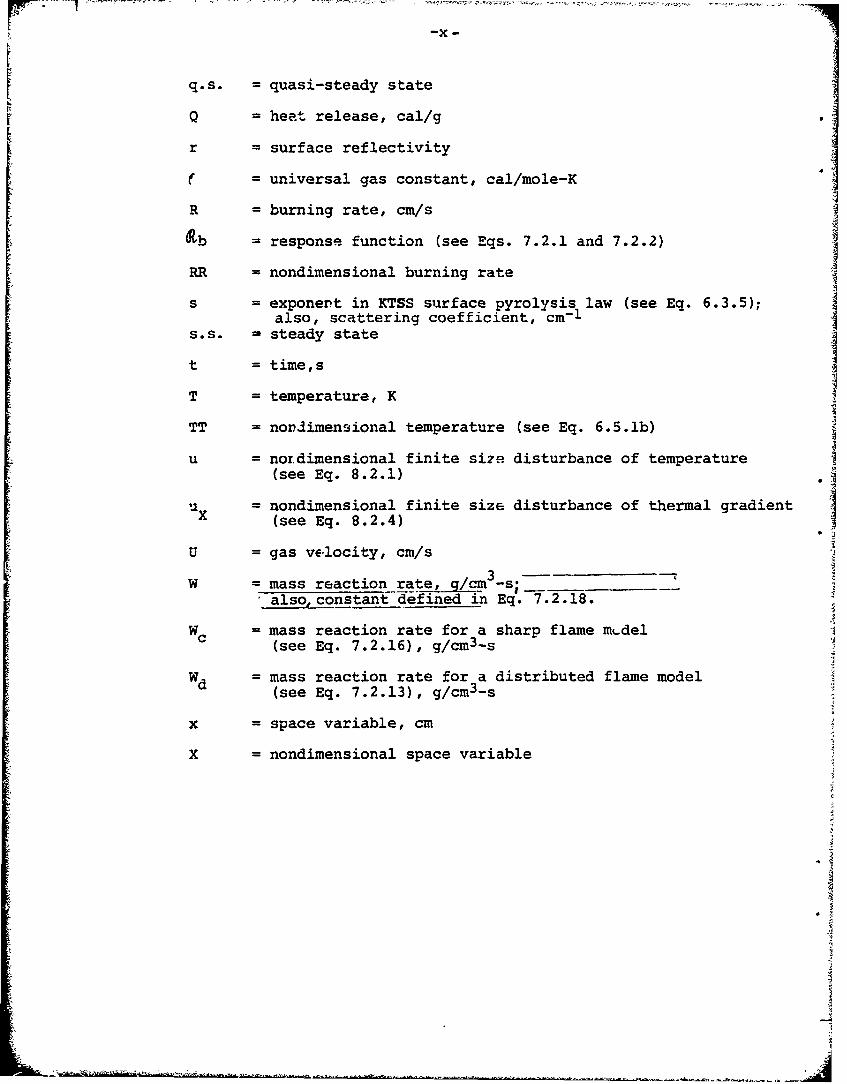
_-x-
rrq.s. = quasi-steady state
Q = heat release, cal/g
r = surface reflectivity
( = universal gas constant, cal/mole-K
R = burning rate, cm/s
dtb = response function (see Eqs. 7.2.1 and 7.2.2)
RR = nondimensional burning rate
s = exponent in KTSS surface pyrolysis law (see Eq. 6.3.5);also, scattering coefficient, cm-I
s.s. = steady state
t = time,s
T = temperature, K
TT = nonlimensional temperature (see Eq. 6.5.1b)
u = nordimensional finite sire disturbance of temperature(see Eq. 8.2.1)
= nondimensional finite size disturbance of thermal gradientUX (see Eq. 8.2.4)
U = gas velocity, cm/s
W = mass reaction rate,_/_c3 -s-also.constant defined in Eq. 7.2.18.
Wc = mass reaction rate for a sharp flame mt-del(see Eq. 7.2.16), g/cm3 -s
Wd = mass reaction rate for a distributed flame model
(see Eq. 7.2.13), g/cm3 -s
x = space variable, cm
X = nondimensional space variable
)
-xi -
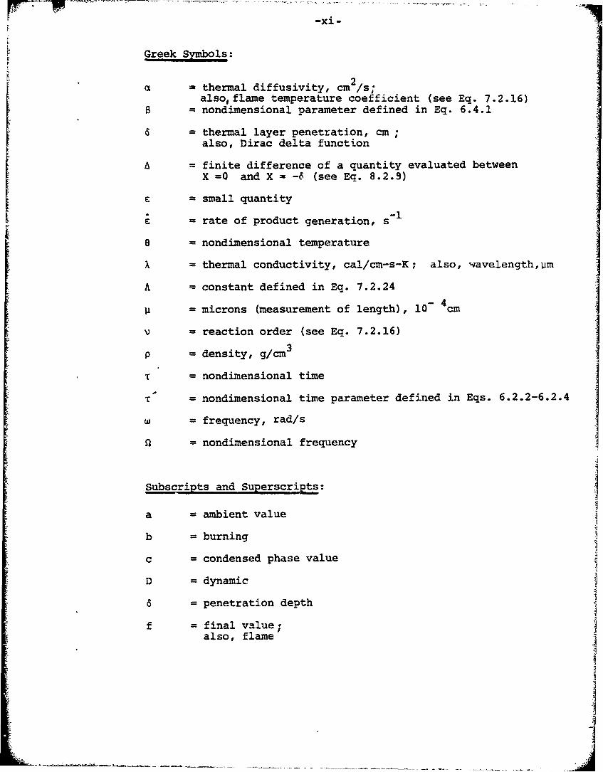
Greek Symbols:
a - thermal diffusivity, cm 2/s;also, flame temperature coefficient (see Eq. 7.2.16)
B = nondimensional parameter defined in Eq. 6.4.1
6 = thermal layer penetration, cm;also, Dirac delta function
A = finite difference of a quantity evaluated betweenX =0 and X = -6 (see Eq. 8.2.9)
6 = small quantity
= rate of product generation, s-i
e = nondimensional temperature
x = thermal conductivity, cal/cm-s-K; also, wavelength, Um
A = constant defined in Eq. 7.2.24
U = microns (measurement of length), 10 4 cm
v = reaction order (see Eq. 7.2.16)
P = density, g/cm 3
T = nondimensional time
T = nondimensional time parameter defined in Eqs. 6.2.2-6.2.4
W = frequency, rad/s
al = nondimensional frequency
Subscripts and Superscripts:
a = ambient value
b = burning
c = condensed phase value
D = dynamic
a = penetration depth
f = final value;also, flame
-xii-
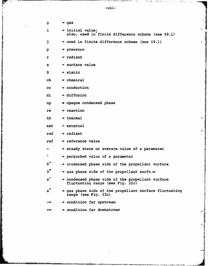
g = gas
i = initial value-also, used in'finite difference scheme (see §9.1)
j = used in finite difference scheme (see §9.1)
p = pressure
r = radiant
s = surface value
S = static
ch = chemical
co = conduction
di = diffusion
op - opaque condensed phase
re = reaction
th = thermal
ext = external
tad = radiant
ref = reference value
- = steady state or averarye value of a parameter
= perturbed value of a parameter
0 = condensed phase side of the propellant surface
+o = gas phase side of the propellant surfaa.e
s = condensed phase side of the propellant surfacefluctuating range (see Fig. 22c)
+ gas phase side of the propellant surface fluctuatingrange (see Fig. 22c)
-= = condition far upstream
= condition far downstream
-4
-xiii-
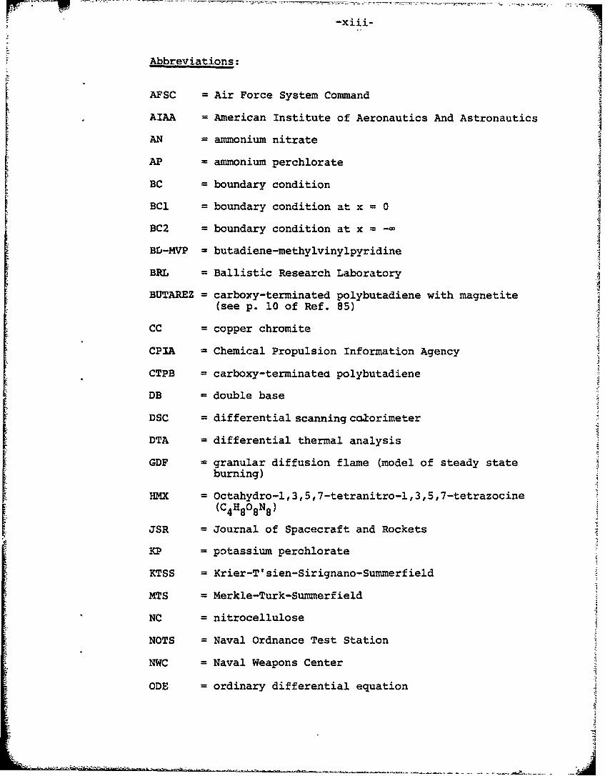
Abbreviations:
AFSC = Air Force System Command A
AIAA = American Institute of Aeronautics And Astronautics
AN = ammonium nitrate
AP = ammonium perchlorateBC = boundary condition
BC1 = boundary condition at x = 0
BC2 = boundary condition at x = -BD-MVP = butadiene-methylvinylpyridine
BRL = Ballistic Research Laboratory
BUTAREZ = carboxy-terminated polybutadiene with magnetite(see p. 10 of Ref. 85)
CC = copper chromite
CPIA = Chemical Propulsion Information Agency
CTPB = carboxy-terminatect polybutadiene
DB =double base
DSC = differential scanning ca3torimeter
DTA = differential thermal analysis
GDF = granular diffusion flame (model of steady stateburning)
HMX = Octahydro-l,3,5,7-tetranitro-l,3,5,7-tetrazocine(C4 H8 08 N8 )
JSR = Journal of Spacecraft and Rockets
KP = potassium perchlorate
KTSS = Krier-T'sien-Sirignano-Summerfield
MTS = Merkle-Turk-Summerfield
NC = nitrocellulose
NOTS = Naval Ordnance Test Station
NWC = Naval Weapons Center
ODE = ordinary differential equation
-xiv-
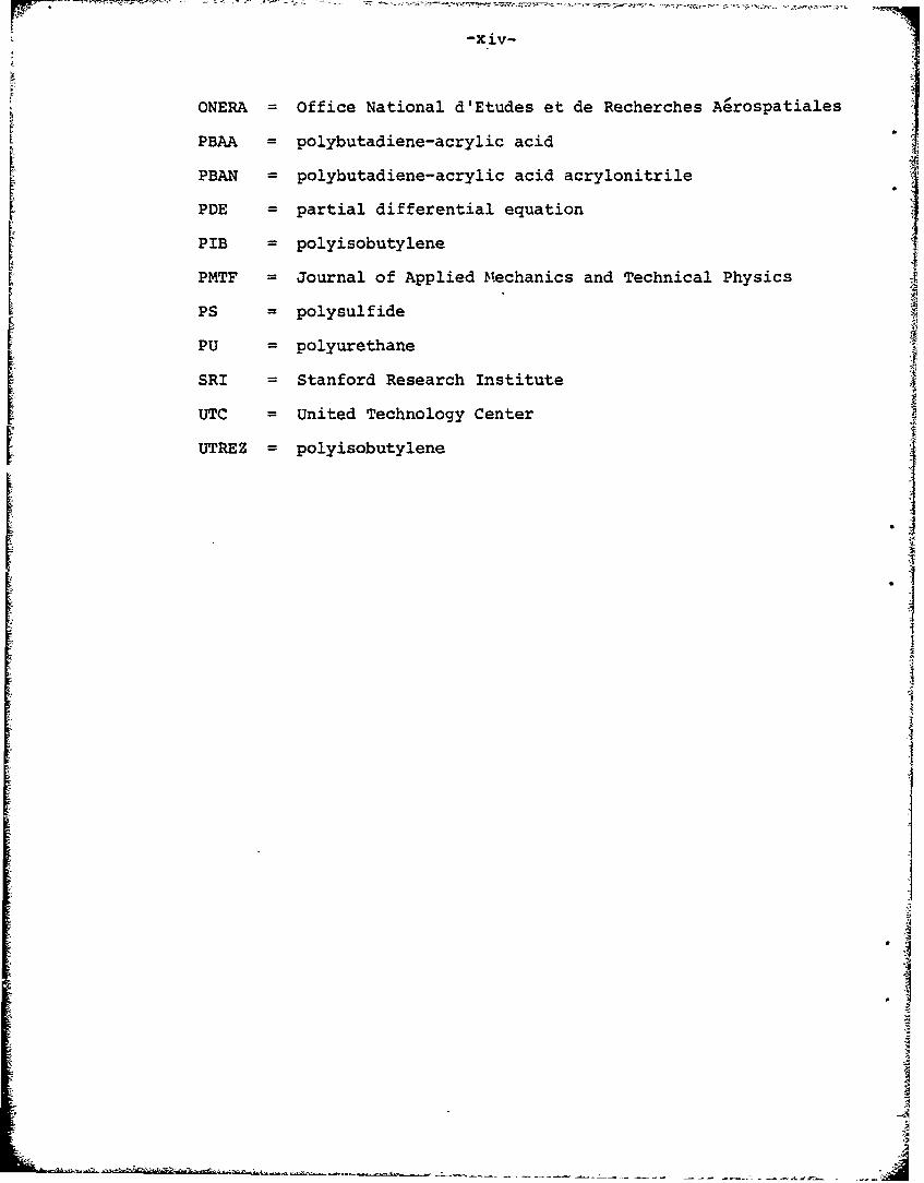
ONERA = Office National d'Etudes et de Recherches Aerospatiales
PBAA = polybutadiene-acrylic acid
PBAN = polybutadiene-acrylic acid acrylonitrile
PDE = partial differential equation
PIB = polyisobutylene
PMTF = Journal of Applied Mechanics and Technical Physics APS = polysulfide f
PU = polyurethane
SRI = Stanford Research Institute
UTC = United Technology Center
UTREZ = polyisobutylene j
4
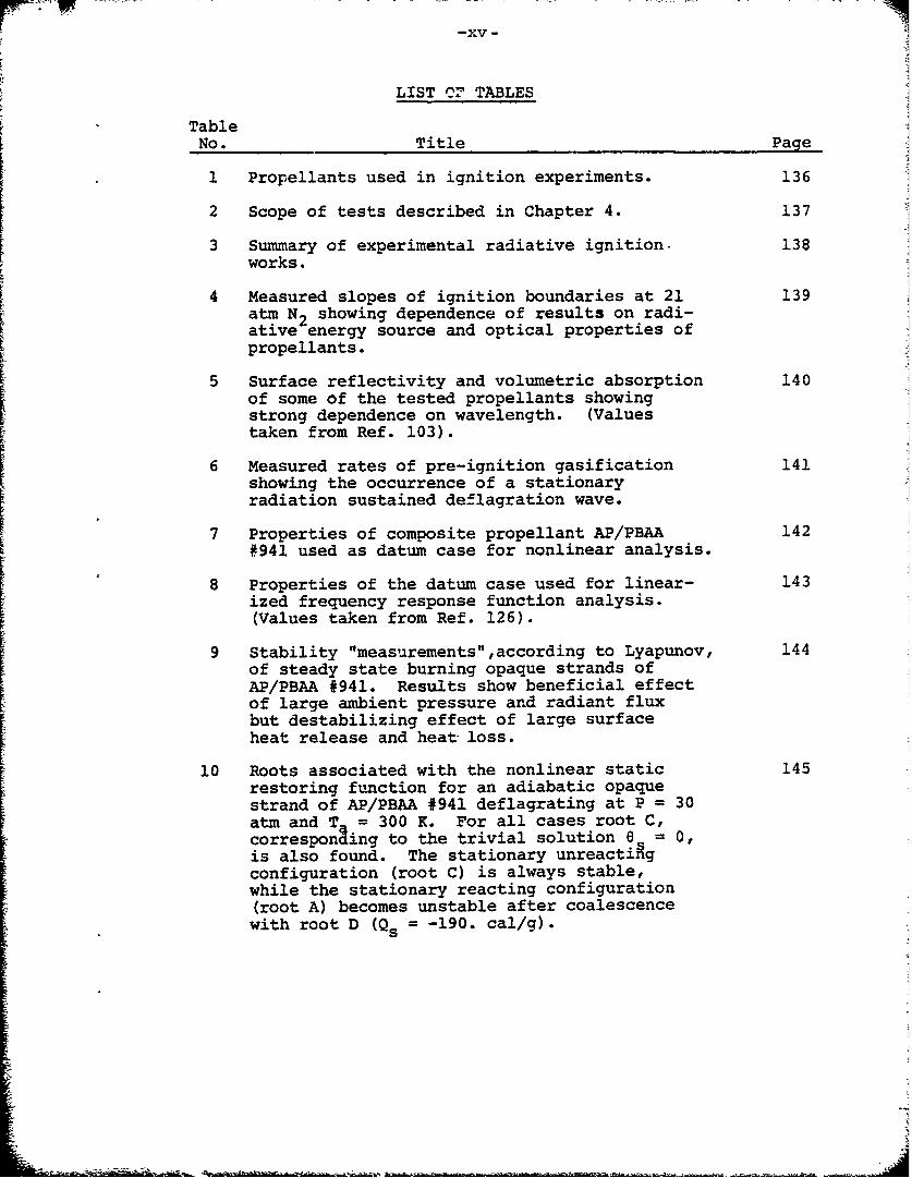
LIST O' TABLES
TableNo. Title Page
1 Propellants used in ignition experiments. 136
2 Scope of tests described in Chapter 4. 137
3 Summary of experimental radiative ignition. 138works.
4 Measured slopes of ignition boundaries at 21 139atm N2 showing dependence of results on radi-ative energy source and optical properties ofpropellants.
5 Surface reflectivity and volumetric absorption 140of some of the tested propellants showingstrong dependence on wavelength. (Valuestaken from Ref. 103).
6 Measured rates of pre-ignition gasification 141showing the occurrence of a stationaryradiation sustained deflagration wave.
7 Properties of composite propellant AP/PBAA 142#941 used as datum case for nonlinear analysis.
8 Properties of the datum case used for linear- 143ized frequency response function analysis.(Values taken from Ref. 126).
9 Stability "measurements",according to Lyapunov, 144of steady state burning opaque strands ofAP/PBAA #941. Results show beneficial effectof large ambient pressure and radiant fluxbut destabilizing effect of large surfaceheat release and heat loss.
10 Roots associated with the nonlinear static 145restoring function for an adiabatic opaquestrand of AP/PBAA #941 deflagrating at P = 30atm and T = 300 K. For all cases root C,corresponding to the trivial solution 6 = 0,is also found. The stationary unreacti~gconfiguration (root C) is always stable,while the stationary reacting configuration(root A) becomes unstable after coalescencewith root D (Qs = -190. cal/g).
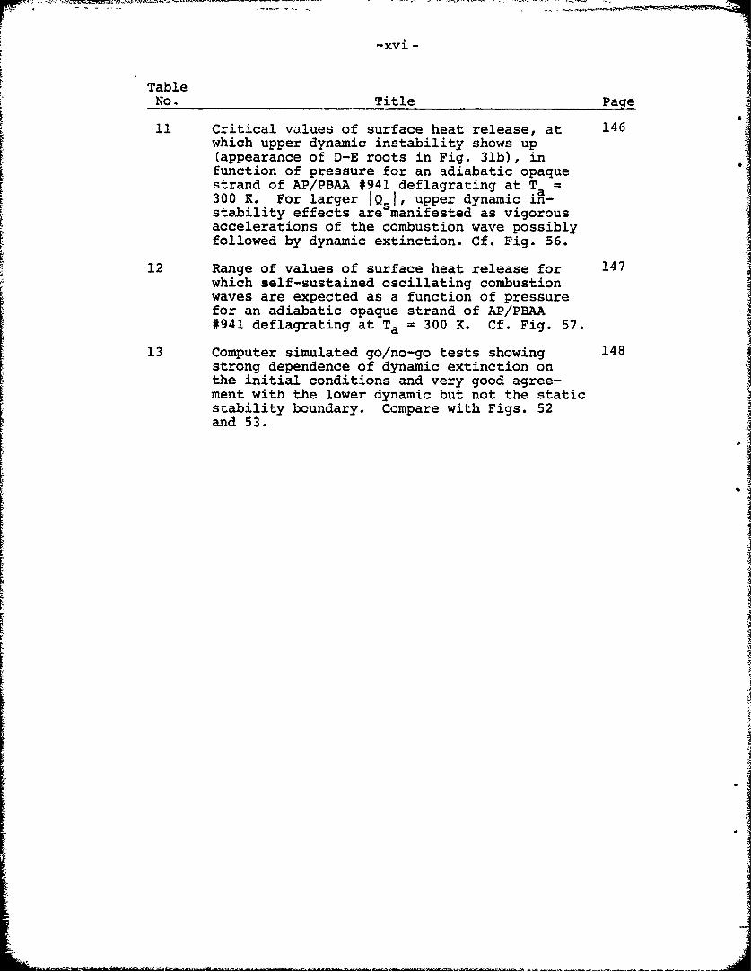
-xvi-
TableNo. Title Page
11 Critical values of surface heat release, at 146which upper dynamic instability shows up(appearance of D-E roots in Fig. 31b), infunction of pressure for an adiabatic opaquestrand of AP/PBAA #941 deflagrating at T =300 K. For larger 1Q.1, upper dynamic in-stability effects are manifested as vigorousaccelerations of the combustion wave possiblyfollowed by dynamic extinction. Cf. Fig. 56.
12 Range of values of surface heat release for 147which self-sustained oscillating combustionwaves are expected as a function of pressurefor an adiabatic opaque strand of AP/PBAA#941 deflagrating at Ta = 300 K. Cf. Fig. 57.
13 Computer simulated go/no-go tests showing 148strong dependence of dynamic extinction onthe initial conditions and very good agree-ment with the lower dynamic but not the staticstability boundary. Compare with Figs. 52and 53.
-x vi-
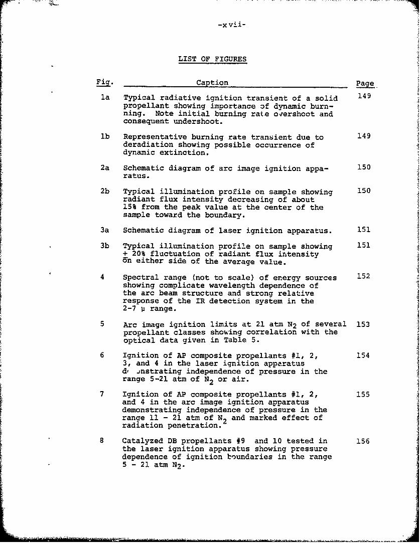
LIST OF FIGURES
Fig. Caption Page
la Typical radiative ignition transient of a solid 149propellant showing importance of dynamic burn-ning. Note initial burning rate oqershoot andconsequent undershoot.
lb Representative burning rate transient due to 149deradiation showing possible occurrence ofdynamic extinction.
2a Schematic diagram of arc image ignition appa- 150ratus.
2b Typical illumination profile on sample showing 150radiant flux intensity decreasing of about15% from the peak value at the center of thesample toward the boundary.
3a Schematic diagram of laser ignition apparatus. 151
3b Typical illumination profile on sample showing 151+ 20% fluctuation of radiant flux intensity-n either side of the average value.
4 Spectral range (not to scale) of energy sources 152showing complicate wavelength dependence ofthe arc beam structure and strong relativeresponse of the IR detection system in the2-7 U range.
5 Arc image ignition limits at 21 atm N2 of several 153propellant classes showing correlation with theoptical data given in Table 5.
6 Ignition of AP composite propellants #1, 2, 1543, and 4 in the laser ignition apparatusd, mnstrating independence of pressure in therange 5-21 atm of N2 or air.
2I7 Ignition of AP composite propellants #1, 2, 155
and 4 in the arc image ignition apparatusdemonstrating independence of pressure in therange 11 - 21 atm of N2 and marked effect of
radiation penetration.
8 Catalyzed DB propellants #9 and 10 tested in 156the laser ignition apparatus showing pressuredependence of ignition boundaries in the range5 -21 atm N2 .
V%-X viii-
Fig. Caption Lae
9 Dynamic extinction of noncatalyzed DB propel- 157lants #5 and #6 tested in the laser ignitionapparatus. (No such boundaries noted in arcimage tests.)
10 Arc image ignition data for HMX composite 158propellants #11, 12, and 13 in nitrogen andin air showing resistance to ignition.
11 High speed shadowgraph movie illustrating 159flame development of an AP composite propel-lant and closely coupledflame.
12 High speed shadowgraph movie illustrating 160flame development of a noncatalyzed DB pro-pellant and large stand-off distance of theluminous zone.
13 High speed shadowgraph movie showing carbon- 161aceous-appearing layer formation on the sur-face of a catalyzed DB propellant.
14 Testing of catalyzed DB propellant #10 in 162the arc image and laser ignition apparatusshowing similarity of the two ignition mapsand that pressure dependence is characteristicof the propellant not the ignition apparatus.
15 Addition of carbon reducing dynamic extinction 163
domain of noncatalyzed DB propellants #7 and#8.
16 Arc image ignition data showing decrease of 164ignition delay with increase of carbon contentand absence of dynamic extinction for non-catalyzed DB propellants #6, 7, and 8.(Contrast with Figs. 8 and 14).
17 Noncatalyzed DB propellants #6, 7, and 8, 165and catalyzed DB propellant #10, ignited inair, showing elimination of pressure depen-dence in the range 5 - 21 atm when air isthe ambient gas.
18 Pressure dependence of strong IR signal for 166noncatalyzed DB propellant #6. (Weak signalis independent of pressure and ambient at-mosphere.)
-x ix'
Fig. Caption Page
F16719 Spreading of gasification process over thesurface of a catalyzed DB propellant subjectedto laser heating showing presence of hot spots.Compare with Figs. 13 and 21.
20 Pre-ignition ablation of a catalyzed DB pro- 168pellant subjected to laser radiation showingoccurrence of stationary gasification processprior to the self-sustained flame. See alsoTable 6.
21 Generalized ignition map showing event limits 169or signals that occur during radiant heatingof solid propellants.
22a Schematic diagram of the physical problem. 170
22b Schematic diagram of energy balance at the 170surface.
22c Schematic diagram of Culick's nomenclature 170for the acoustic admittance function deter-mination.
23a Energy balance in differential form at the 171interior of a slab subjected to conductiveand radiative heating.
23b Steady state thermal profile in a slab sub- 171jected to conductive and radiative heating.
24 Determination of gas phase constants required 172in the MTS flame model.
25 Quasi-steady burning rate vs heat feedback 173plot according to MTS flame model.
26 Construction of the quasi-steady thermal 174gradient at the condensed/surface boundaryaccording to Ya. B. Zeldovich.
27 Response function of a propellant strongly 175affected by the assumed flame model.
28 Response function of a propellant strongly 176affected by the pressure dependence of sur-face pyrolysis law and by energy release ingas phase (sharp flame model).
-XX -
Fig. Caption Page
29 Response function of a propellant showing that 177
the pressure and radiation driven frequencybehavior of an opaque propellant is the samefor a distributed flame model.
30 Destabilizing effect of large surface energy 178release (distributed flame model).
31a Qualitative sketch of the nonlinear static re- 179storing function, for different pressurevalues, illustrating the existence of threeequilibrium configurations: A and B. (forthe reacting mode), C (for thi unrea6tingmode). Roots Bi are statically unstable.
31b Qualitative sketch of the nonlinear static 180restoring function, for increasing surfaceheat re~ease values, illustrating the appear-ance of a second pair of roots, D and E, forthe reacting mode (upper dynamic instability).
32 Influence of pressure on nonlinear static 181restoring function for Q = -158.2 cal/gshowing upper dynamic instability at P =10 atm.
33 Stabilizing effect of residual radiant flux 182intensity on lower dynamic stability boundary.
34a Destabilizing effect of large surface energy 183release on upper dynamic stability boundary.
34b Coalescence of A-D roots at Q = -190. cal/g; 184the steady reacting mode is sfationary forIQI < 190. cal/g and self-sustained oscilla-t1ig forlQ I > 190. cal/g. See Eig. 57.
S
is Negligible influence of ambient temperature on 185nonlinear static restoring function (for theindicated range of values).
36 Construction of the static stability line and 186its meaning.
37a Representative time histories of burning rate 1877during deradiation showing possible occurrence
of dynamic extinction.
37b Corresponding trajectories in burning rate 187vs heat feedback plane.
37c Nomenclature used for deradiation transients. 187
37d Nature of nonautonomous function considered 187in this study.
-xxi-
Fig. Caption. Page
38 The range of possible unstable equilibrium 188points in dynamic burning regime is limitedby the no-return point M (the unstable rootassociated to the static restoring function for
39 Lower dynamic stability boundary on a burning 189rate vs heat feedback plane showing a sensibleincrease of burning region as compared withstatic burning regime.
40 Numerical molecules used in the computer 190solution.
41 Flow chart of the numerical program. 191-193
42 Destabilizing effect of large initial radiant 194flux intensity on dynamic burning rate. (cf.Fig. 46).
43 Occurence of dynamic extinction following 195fast deradiation.
44 Sensitivity of the burning propellant to the 196initial conditions in the region near thelower dynamic stability.
45 Occurrence of damped oscillations in the dy- 197namic burning rate following fast deradiation.(cf. Fig. 47).
46 Destabilizing effect of large depressuriza- 198tion rate on dynamic burning rate. (cf. Fig.42).
47 Occurrence of damped oscillations in the dynamic 199burning rate following fast depressurization.(cf. Fig. 45).
48 Trajectories in the burning rate vs heat 200feedback (or MTS) plane showing that deradia-tion and depressurization transients followdifferent paths.
49 Radiation penetration making more difficult 201dynamic extinction-due to fast deradiation.
50 Radiation penetration decreasing the intensity 202of the undershoot following fast deradiation.
-~ - -
-xxii-
Fig. Caption Page
51 Radiation penetration favoring damped oscilla- 203tions of the dynamic burning rate followingfast deradiation.
52 Go/no-go computer simulated deradiation tests 204in the MTS plane showing very good agreementwith the predicted lower dynamic stabilityboundary.
53 Go/no-go computer simulated deradiation tests 205in the MTS plane showing that radiation pene-tration does not affect the lower dynamic stab-ility boundary. See also Table 13 and Fig. 52.
54 Go/no-go computer simulated depressurization 206tests showing very good agreement with thepredicted lower dynamic stability boundary.See also Table 13.
55 Computer simulated pressurization tests showing 207no upper dynamic instability for IQsI < 170cal/g. Ccf. Tables 10 and 11.)
56 Computer simulated pressurization tests showing 206upper dynamic instability for IQsI > 170 cal/g.(df. Tables l0 and 11.)
57 Computer simulated pressurization tests showing 209self-sustained surface temperature oscillations.
(cf. Tables 10 and 12).
r
- -j
S-1- -1-
CHAPTER 1
OBJECTIVES, BACKGROUND AND PLAN OF PRESENTATION
This chapter describes the purpose of the study and its con-nection with other studies performed at Princeton University and,more generally, with the broad field of solid propellant ignitionand combustion. An introductory background to the problems inves-tigated is offered both from a technical and historical point ofview. Finally, the overall plan of presentation is given. Notethat phenomena associated with solid propellant burning will bedenoted throughout this study as heterogeneous combustion, sincethey usually involve the presence of condensed and gas phases.
1.1 Motivations of Radiative Ignition Research
This study concentrates on the ignition and nonsteady burn-ing of solid rocket propellants. A successful ignition processis a necessary condition for a solid rocket propellant powereddevice to achieve the objectives of its mission. Unfortunately,even today the initiation of the deflagration wave and the subse-quent transients are among the less understood and less predictablecombustion phenomena. Solid propellant rocket motor ignitiontransients include a number of processes occurring in successionor simultaneously in a combustion chamber due to the action ofsome igniter: in particular, the induction interval required forthe appearance of a first flame somewhere along a grain, the flamespreading over the entire surface of the grain, and the chamber fill-ing with gaseous products. However, the ignition transient cannotbe considered complete at this point since pressure overshootsfollowing chamber filling can imperil the motor casing, sometimescausing rupture. Furthermore, a number of severe requirements onreproducibility, short ignition delays, capability of ignition invarious unfavorable conditions (e.g., low temperature and vacuum),etc., are usually rade for solid propellant powered devices. Toascertain the basic factors in the above p~ocesses and to avoidexpensive and time consuming large scale tests, broadly-based igni-tion and nonsteady combustion research has evolved.
The ultimate goal of solid propellant ignition research isto predict with confidence the ignition responses of solid propel-lants under any set of operating conditions. From this point ofview, the (propellant/combustion chamber) system should be consid-ered.- 3 However, this study emphasizes the propellant and doesnot consider the fluid'dynamic interactions between the propellantand chamber. This means that the flame spreading and chamberfilling phenomena are neglected and concentration is placed onthe first ignition event and on nonsteady burning.
In practice, the ignition of solid propellants is frequentlydue to the action of a pyrotechnic igniter emitting hot combustionproducts both solid and gaseous. The ignition response of the
-2-
propellant depends on the rate of energy transfer from the pyro-technic igniter combustion products *o the mass of the initiallycool solid propellant. These responses are complicated to deter-mine, since the heat transfer occurs by simultaneous convectionfrom the flowing hot gas, conduction from impinging incandescentparticles, and by radiation both from gas and particles. Otherheat sources, such as atom recombination and condensation ofsaturated vapors, are also present. Since each of the abovemodes of energy transfer is complicated greatly by the actualgeometrical and physical configuration of the propellant and ofthe igniter combustion products, it is often advisable to restrictexperimental or theoretical analysis to just one mode of energytransfer. Sources of radiant energy allow both a wide range ofexcursion and an accurate control of the intensity of the heatinput and of the exposure time of the propellant under examination.Accordingly, this study is concerned with the ignition and non-steady burning of solid propellant by purely radiative heat trans-fer.
A typical radiative ignition transient is shown in Fig. la.The history of the burning rate illustrates the abrupt passagefrom an initially negligible gasification rate to a vigorous burn-ing regime. It is apparent from Fig. la that the steady state(s.s.) burning rate value may be strongly exceeded (overshoot)during the ignition transient by the instantaneous burning ratepeak; on the other hand, dynamic effects associated with thisovershoot may involve the instantaneous burning rate followingthe peak value falling well below (undershoot) the s.s. value.Usually, the entire transient converges toward the s.s. burning
rate after some oscillations with a period of the order of magni-tude of the solid phase thermal layer characteristic time (see§9.4). A second and distinct phenomenon which will also be dealtwith in this thesis is illustrated in Fig. lb. It is shown thatthe abrupt (in a sense to be specified in §A.3) passage from aninitial to a final burning configuration corresponding to differ-ent values of radiant flux (occurring, for example, at the end ofthe ignition event), may involve a precipitous undershoot leadingto extinction depending on how fast the change of radiant flux isaccomplished. This phenomenon is referred to as dynamic extinc-tion (see §2.3) and may be associated with either an initiallyunperturbed s.s. burning regime (Fig. lb) or a not yet completedignition transient (Fig. la). Accordingly, a radiative ignitiontransient in its most general form includes the presence of phe-nomena (for example, the possibility of extinction of the samplejust ignited following the cut off of the radiant source) notfound in other ignition transients. Changes in any of the severalparameters related either to the radiant source (level of theradiant flux, time for cutting off the radiant source, etc.) orto the propellant sample (addition of chemical additives, trans-parency of the propellant, etc.) affect the entire transient.
-3-
A radiant ignition transient contains a wide variety of com-bustion phenomena: an induction interval, starting of surfaceregression, faJ'.t acceleration of the burning rate, overdrivendeflagration wave, undershoot of burning rate following radiantsource cut off, extinction or recovery, and oscillations. Thisstudy is concerned with all these aspects (for details see §1.4)of unsteady combustion phenomena induced by radiation. In partic-ular, detailed analysis is offered of the stability conditionsfor burning propellant subjected to variable pressure and/orradiant flux level.
1.2 Background on Solid Propellant Ignition
Comprehensive reviews of this subject have been offered byunummerfield 4 ir: 1963, Price 5 in 2.966, Ba:rere 6 in 1969, and Mer-
Lhanov 7 in 1971. In this section, the Lasic concepts are present-ed; a detailed review of radiant ignition research is made in thenext chapter. The most recent comprehensive review on radiativeignition is contained in the work by Ohlemiller and Summerfield. 8
The first quantitative ignition theory for a reactable sub-stance was written by Frank-Kamenetski 9 - 1 0 in his classical workon combustion in 1939. Although it later evolved in two differentforms, his model can be considered the beginning of a long lineof ignition research, known as thermal ignition theory, mainlydeveloped in the Soviet Union (see Refs. 11-18, for example) inits various aspects. Thir theory has been adapted in several waysby many investigators. The basic hypothesis is that ignitionoccurs once a purel. thermal condition has been satisfied. Frank-
Kamenetski considered ignition to have occurred when the rate ofheat production by chemical reaction exceeds the rate of heat loss
to the surroundings, so that a very rapid reaction would be sub-sequently triggered. This idea was also used later for propel-lants by Hicks19- 2 0 and Bradley 2 l among others. Another ignitioncriterion is the achievement of a critical temperature at the pro-pellant surface. This was used by Altman and Grant. 2 of par-ticular interest to us (see §6.6) is the approach by Zeldovich,later followed by other Soviet investigators, prominent among themnition requires triggering chemical activity in both the gas and
solid phases and the formation of a thermal layer in the condensedphase thick enough to sustain the deflagration wave. However, inthe spirit of the thermal theory, Zeldovich 2 3 argues that thecritical step is the heating of this inert layer. Other criteriaof Ehis nature are possible. Parallel to this, similar criteriamay be adopted for experimental work. Commonly accepted (andoften erroneous) are the first flame appearance or the achievementof a critical surface temperature.
In the search for more complete models, the ignition processhas been considered to result from a critical chemical reactionwhose occurrence provides the chemical activity and the thermal
- .- -. -----T-- - - - - - - - - -- ----- 2 I
-4-
energy required for starting the deflagration wave in the propel-lant. The complications inherent in any chemical kinetics aresuch that, as yet, only single one-step reactions are considered.Much controversy exists as to where to assign this single, con-trolling reaction. Thus,depending on the beliefs of the individ-ual investigator, the ignition process is seen as being triggeredby a single one-step reaction in the condensed phase, in the gasphase, or at the solid/gas interface.
Solid phase ignition theory assumes the triggering reactionoccurs in the condensed phase. Since the ignition criteria arenecessarily the same as in the thermal theory, the distinction isby no means sharp. Work along this line has been done by Baerand Ryan, 2 6 Price, 2 7 , 2 8 Rosser, 2 9 Gray and Harper, 3 0 3 2 and someSoviet investigators. 3 3 -3 5 A fundamental shortcoming of thermalPnd solid phase theories is an inherent inability to predict thepressure dependence of the ignition process seen in experimentalresults. An approximate way to include these effects is indicatedby Baer and Ryan..36 They assume that the energy input cannot belarger than the final steady-state heat feedback which, in turn,depends on the pressure. Similar considerations were introducedby Von Elbe 3 7 and Pantoflicek. 3 8
Gas phiase ignition theory assumes the triggering reactionoccurs in tie gas phase between decomposition products of thefuel and oxidizer. This line of research 3 9 - 4 3 is due mainlyto Summerfield and was prompted by the necessity of explainingthe observed effects of pressure and oxygen presence onignition delay. Contrary to most solid phase ignition theories,the gas phase theory predicts a continuous path from the initial-ly cool propellant to the final steady state combustion configur-ation.
Heterogeneous ignition theory assumes the triggering reactionoccurs between the strongly oxidizing gas products of a crystal-line oxidizer (e.g., ammonium perchlorate) decomposition and thefuel surface. This line of research4 4 - 5 0 is due mainly toAnderson.
Because of the necessarily oversimplified assumptions in allthe above models and of the many interacting processes, it has notbeen possible to achieve a single theory for ignition of all pro-pellants in all situations. Indeed, a single theory is not neces-sary; as in other fields of research, a good understanding of afew representative cases which include the important processesmay suffice for the clarification of many other cases. Accord-ingly, in the experimental part of this study, we have sought pro-pellant formulations and test conditions that emphasize particularignition events.
For the sake of completeness and to avoid confusion, noticethat the above solid, gas, and heterogeneous phase ignition theo-ries are all specific models in tihe area of the heterogeneous
-5-
combustion phenomena associated with solid propellants. A similarexpression, "initiation of fast reactions in solids", denotes thatwide branch of applied science which studies the ignition processesin the solid state. An excellent account of this subject is givenin the books by Bowden and Yoffe 5 1- 5 2 and by Johansson and Persson 5 3
It is shown there that the triggering mechanism may be heat, shock,light, ionizing radiation and some not yet understood internal pro-cess confined to the explosive crystal. It is of interest that thedevelopment of fast reactions in a solid, initiated by one or moreof the above mechanisms, occurs in "hot spots" (definite regionsof decomposition of the solid compound) which then develop intoa deflagration or detonation. In this *qport the concepts cfthermal explosion, photochemical effects, -nd initiation by hotspots will be occasionally borrowed.
Likewise notice that the expression "gas phase ignitiontheory" also denotes that specialized branch of homogeneous com-bustion which studies the initiation of reactions in a gas mix-ture. Excellent accounts of this subject are iven in theclassical books by Jost,54 Lewis and Von Elbe,55 Gaydon and Wolf-hard, 5 6 and.Williams. 5 7 However, no confusion should arise withthe Summerfield gas phase ignition model proposed for the initia-tion of combustion reactions in a solid propellant (e.g., Ref. 39);the terminology is similar but the physical situations are dis-tinctly different.
1.3 Historical Background of Solid Propellant Radiative Ignition
The well defined and easily controlled heat outputs obtain-able from radiative energy sources have made the use of such de-vices quite popular both ir. rating solid propellant ignitabilityand in investigating the basic laws of heterogeneous combustion.However, this particular experimental tool has several inherentdifficulties which initially were unsuspected; these difficultieswill be discussed later. Now, a brief historical survey of thesubject is given.
Possibly the first experimental data on radiative ignitionwere obtained by focusing sunlight on a propellant surface. Thiswas done by Anderson and Shooka0 in 1949. Basic shortcomings ofthis type of experiment are the nonreproducibility of the radiativesource conditions and the scattering of the data due to propellantsmoking. About this same time, 1950, the theoretical analysis byAvery 5 9 dealing with the effect of radiation penetration on theburning rate of a tubular grain of JPT propellant was published.Avery demonstrated that in-depth absorption of radiation couldlead to subsurface reactions (referred to as "wormholing"). Animprovement over the original sunlight furnace for radiativeignition experiments was made by Baer, Ryan and co-workers. 3 6 , 6 0-62During a research program started in 1957 at the University ofUtah, they systematically tested ammonium perchlorate (AP) andammonium nitrate (AN) based composite propellants in a black bodytype of radiator obtained by electrical heating of a metallic core.
-6-
Also, they performed experiments at pressures other than oneatmosphere and were the first to recognize that radiative, con-vective, or conductive ignition tests give, in general, differentresults. The details of this and of all the various other exper-imental works concerning radiative ignition are summarized inChapter 2.
A decisive impro'..ment in the experimental technique is dueto Beyer and Fishman 6-J of SRI. They adapted an arc image furnaceto radiative ignition tests and,in 1960, published results on AP-based composite propellants. This was the first of a large numberof papers entirely dedicated to radiative ignition research con-ductea using an arc image ignition apparatus.
In particular, attention is called to the work by Price, 2 7 2 8
who first recognized the existence of steady gasification processesat the surface of the strand prior to ignition. Price also testeddouble-base (DB) propellants and examined the effect of modifierson the ignition delay of AP propellants. Later he offered areview5 on the entire subject of propellant ignition.
From the beginning it was clear that some unique factorswere involved in the radiative ignition experiments. For example,the presence of a cold environmental gas is not found in anactual rocket motor ignition. Likewise, several factors due tothe physics of the radiation are not found in the usual convec-tive or conductive ignition experiments. To elucidate the uniqueconsequences of this experimental technique and also to resolvesome controversies concerning the experiwýn l procedures, around-robin study was initiated in 1964. Due to severaldifficulties, a brochure was not published until 1973. Theimportant points are that:
(1) the arc image has certain advantages: supply of energyin a form independent of the test sample's environment;environment can be controlled over a wide range ofpressure; evolved gas may be analyzed; energy flux iseasily controlled and reproducible over a wide range;sample may be continuously observed by means of atransparent cell; and limitations (radiation penetrationand cold, chemically-inert atmosphere are not typicalof rocket motor ignition).
(2) the report suggests suitable factors in apparatus design(maximum transmission of energy, accuracy of positioningof test sample, ease of flushing out combustion products,etc.), experimental procedure (ignition criterion, timedelay measurement, calibration of focal volume, etc.)and data reduction (statistical treatment for eachignition criterion).
- --- --.. ---- -~ -- - - - -
-7-
(3) the difficulty in relating arc image ignition test datato ignition in solid propellant powe-ed devices (radia-tion absorption, heterogeneo", optical properties andeffect of cold atmospherel is discussed.
Even though no standard test procedures are recommended, thisbrochure helps to systemize radiant ignition experimentation.
A number of papers were published dealing more with specificeffects of the radiation/propellant interaction than with furnish-ing further ignition data. Bastress 6 6 - 6 7 made progress in thisdirection. Measurements of cut propellant reflectivities in thearc image wavelength range indicated that at least the AP compositepropellant surface is, to a good approximation, a diffuse reflector.Ignition delay results were shown to be independent of the wave-length. Additional values for propellant reflectivity were givenby Sutton and Wellings, 6 8 who also discuss the use of opacifiersat the surface of the strand to concentrate in a thin layer theabsorption ?f radiation. Absorption in depth was also considersdat SRI. 2 9 ,69 Further comments were given by Fleming and Derr. 7 uUnfortunately, radiation scattering has been generally neglectedand, therefore, the results are strongly suspect. For example,the data collected at SRI were obtained from experiments per-formed on pressed samples so that the unusually large values ofabsorption coefficient measured are very likely due to scattering.Other peculiar effects, such as bubbling of the binder or quickervaporization of the binder as compared with AP, have also beenobserved71- 7 2 in radiative ignition tests. For a critical reviewof these and other unique factors, the reader is referred toOhlemiller and Summerfield (see pp. 6-10 of Ref. 8a).
Other papers 7 3 - 7 5 distilled unifying concepts from the largeamount of experimental data which were being collected. Ander-son 7 3 at UTC offered an interpretation of the data in terms ofhis heterogeneous phase ignition theory. Baer and Ryan 3 6 gavean approximate model for the ignition response of a solid pro-pellant in the framework of solid phase theory. A comprehensivecritical analysis of the arc image as a radiative source forignition tests was offered by Summerfield and Ohlemiller 7 5 in1968.
In an effort to overcome the difficulties inherent in theuse of the arc image, a laser ignition apparatus was developedat Princeton University. The laser radiation, being collimatedand monochromatic, allows a much simpler interpretation of theresults. The first results obtained in the laser ignition appa-ratus were for tests of polymeric materials in an oxidizingatmosphere. Reference 8 also contains a complete description ofthe experimental apparatus used in this study. Several effectspeculiar to ignition experiments performed with the laser sourcewere investigated at Princeton in a series of works 7 6 - 7 9 and arepartly discussed in this report.
I
______---8- -
Further papers concerning wholly or partly radiative ignitionresearch, both from experimental and theoretical points of view,are given in Refs. 80-89. The relevant details of the experi-mental works are discussed and summarized in Chapter 2.
1.4 Subjects Treated
Ignition characteristics of several classes of solid propel-lants ignited by radiative heating differ markedly depending notonly on the differences in their chemical reactions but also onthe radiative ignition device. This study summarizes the ignitionLasponses of several propellants and offers interpretations ofcertain radiative ignition characteristics and the effects ofvarious propellant additives on the ignition events. As newpropellants and new propellant ingredients arise, their ignitioncharacteristics are of interest. Although the ignition dataare useful in themselves, the main purpose of our radiativeignition experiments was to elucidate the mechanism of ignitionand combustion in terms of the gas phase, surface, and condensedphase processes and not to provide a direct means of ratingpropellant ignitability for particular applications. Indeed, weshow that relating radiative ignition data to the convective andconductive conditions prevalent in most applications is question-able because of: (1) distorting effects of solid propellanttransparency and reflectivity, (2) slow chemical kinetics inthe cool gases near the surface, (3) combustion dynamics duringthe stop-radiation interval, and (4) spatial distribution ofimpinging radiation.
This work goes beyond a previous analysis75 of radiativeignition (which covered in-depth radiation penetration and coolgas phase considerations) since the effects of spatial and timedistributions of radiation and radiation sources are treated aswell. Also, our recent theory7 7 of extinguishment following rapidderadiation (i.e., removal of the radiant flux from the propellantsurface) is applied to propellants in this work by relating theflame dynamics following deradiation to the global combustioncharacteristics.
In previous studies, ignition maps with complex boundarieshave stimulated discussion and analyses of the underlying combus-tion mechanisms. For example, Price and co-workers 2 8 developed
ignition maps which showed interactions between condensed phasereactions, gas phase reactions, free convection, and dilution ofthe flame zone by chamber gases. Also, Lenchitz and co-workers 8 7
discovered several difficult to explain ignition trends duringtheir examination of thin nitrocellulose films. In the spiritof this work, complex interactions of the ignition trends azcwelcomed because they are often useful in deducing informati.,nabout the ignition and transient burning processes.
-9-
Particular attention has been given to the phenomena ofdynamic extinction, since it encompasses several problems ofheterogeneous flame theory. As such, the dynamic extinctionmight provide an easy and meaningful way of testing the stabilityproperties of a propellant when subjected to disturbances. Thisidea has already been suggested by Mihlfeith and is more fullydiscussed in this report. To show peculiarities of radiative-controlled c.ombustion versus pressure-controlled combustion,computer simnulated tests were performed. This required thenumerical integration of a parabolic partial differential equa-tion (PDE). In the computer simulated tests it was noted that,in a transient, the propellant is able to burn even beyond thestatic stability line as defined by Zeldovich or by other intrin-sic stability analyses. This fact generated further interestin the dynamics of heterogeneous flames. It is shown that theuse of a static stability boundary is not only wrong in principlebut also might give a bad approximation of the actual dynamicstability boundary. A method is offered for evaluating separatelyboth the static and the dynamic stability boundaries in conditionsof nonlinear behavior. The quasi-steady assumption has beenrequired for all analytical and numerical treatments. The gran-ular diffusion flame (GDF) theory, in its quasi-steady versionknown as (MTS) Merkle-Turk-Summerfield flame model, 9 0 has beenadopted as a gas phase model and has been extended to the dera-diation situation. Theoretical results, both analytical andnumerical, are given mostly for the specific case of an AP-basedcomposite propellant. The MTS flame model can, however, bespecialized to DB propellants, as shown by Merkle (see Ref. 90b).
A critical review of the quasi-steady assumption has beenoffered by Krier and Summerfield. 9 1 A critical analysis of de-radiation tests will be offered in Chapter 2 of this work. Thereader is assumed to be familiar with the Zeldovich analysis ofunsteady heterogeneous flames as presented in Ref. 92. Suchfamiliarity will aid in appreciating the utility of gas phaseF models when dealing with complex aspects of unsteady combustion.
All of the above theoretical results have been found withinthe context of the simplifying assumptions that the distributionof radiant flux in the condensed phase can be described by Beer'slaw. This is generally untrue, as already mentioned. Therefore,a background in radiation scattering is offered in Appendix Bof this work. It will be shown how to account for this effectin the mathematical model and some results will be given.
1.5 Objectives and Plan of Presentation
In the experimental part of this study a general character-ization of the radiative ignition process will be sought. Thefollowing are specific objectives:
-10-
1. characterization of solid propellant radiative ignitiontrends through systematic experimental testing (seeTable 1 and 2) in various operating conditions;
2. characterization of radiative energy source through acomparison of arc image versus laser (see §3.1 and 4.6);
3. ascertaining the relevance of radiative ignition researchto actual rocket motor configuration;
4. deduction of a generalized radiative ignition mapaccounting for the wide variety of phenomena experi-mentally observed (see §5.2).
In the theoretical part of this study a deeper understandingof dynamic burning will be sought. The following are specificobjectives:
1. definition of a nonlinear static stability boundary(see §8.2);
2. definition of a nonlinear dynamic stability boundary(see §8.3);
3. comparison of dynamic extinction due to depressuriza-tion with dynamic extinction due to deradiation;
4. review of previous works on radiation driven responsefunction as a tool for studying linearized instabilityof solid propellant combustion (see Chapter 7).
The overall plan of presentation is the following. Acritical review of radiative ignition experimental work (Chapter2) introduces the reader to the experimental part of this inves-tigation (apparatus is described in Chapter 3, results are givenin Chapter 4, and discussions are offered in Chapter 5). A back-ground on unsteady combustion of solid propellants (Chapter 6)introduces the reader to the theoretical part of this investigation.The linearized approach is discussed in Chapter 7 andthe nonlinearapproach is presented in Chapter 8. Results by numerical integra-tion of the governing equations are shown in Chapter 9. A sum-mary of major observations, conclusions and suggestions forfuture work are given in Chapter 10. Finally, some problemsassociated with radiation interaction with the condensed phaseare discussed in Appendices A and B. The propellants used inexperimental tests are listed in Table 1. The experiments per-formed are summarized in Table 2. Some details of the experimentsin the radiative ignition area performed by previous investigators,including some Soviet, are discussed in the next chapter and aresummarized in Table 3.
-11-
CHAPTER 2
CRITICAL REVIEW OF RADIATIVE IGNITION EXPERIMENTAL WORK
This chapter is a review of the results obtained in experi-mental investigations specifically dedicated to radiative igni-tion. An historical background on the overall question of radi-ative ignition research has been given in §1.3. The experimentaldetails of the papers mentioned in this chapter are summarizedin Table 3.
In §2.1 the results obtained testing solid propellant atlow (up to about 15 cal/cm2 -sec) radiant flux are discussed.The results obtained with a strong (up to about 150 cal/cm2 -sec)radiant flux are discussed in §2.2 (arc image furnace) and in§2.3 (laser furnace). Finally, some comments about the organ-ization of Table 3 are given in §2.4.
2.1 Experimental Results at Low Radiant Flux
This section discusses results obtained using several typesof radiation heat sources. They have in common only the factthat the level of the incident radiant fluxes is less than about15 cal/cm2 -sec. This is an arbitrary but useful distinction.Indeed, virtually all of the experimental investigating performedprior to the advent of arc image and laser ignition apparatusfall in this category of "low radiant flux" tests. Researchersresorted to many of the possible means to obtain radiative energysources, but several of these early works are simply out of datein view of the current level of sophistication.
58The experiments by Anderson and Shook already mentionedin §1.3 have only historical interest. The use of sunlight istoo uncontrollable for scientific purposes. Some experimentsby Altman and Nichols (p. 2 of Ref. 80), although rough, firsttested whether in the wavelength range from 0.18 to 0.58 u (UV toorange light) the radiation effect is purely thermal. This waschecked by testing disks of ammonium nitrate (AN) based compositepropellants in a 50 lb thrust motor started by gasless igniterscontaining metallic constituents. The considerable radiationemission of the igniting mixture in the UV was suspected as apossible source of photo-chemical activation, but no evidencecould be found in support of this hypothesis.
The first radiative furnace purposely designed for testingsolid propellant ignition trends is the black-body type of radia-tor developed by Baer and Ryan of the University of Utah andused extensively both in this country 2 6 , 6 0 -62,84 and the SovietUnion. 9 3 - 9 5 Although much less flexible than the arc image andthe laser apparatus, this electrical furnace was used withexcellent results by Baer and Ryan in particular.
-12-
The first systematic analysis of solid propellant radiativeignition was started at the University of Utah in 1957 as a partof a broader program on combustion transients of solid rocketpropellants. Results, partially published in Refs. 60-61, aresummarized in Ref. 62. The radiative source was a black bodytype of radiator energized by electrically heating the furnacecore. The level of the radiant flux could be changed by varyingthe current to the heating element. Four composite propellantswere tested: three containing AP with different polymeric bindersand one containing AN. Pressure (0.2 - 11 atm), type of pressur-izing gas (air, nitrogen, or oxygen), and initial sample tempera-ture (-60 to +60 C) were the basic variables whose effects werechecked. These and other experimental details are summarized inTable 3. This type of experiment is relatively unsophisticatedcompared to succeeding works. For example, the radiant fluxintensity was evaluated by means of the Stefan-Boltzmann lawonce the furnace temperature had been measured with a thermo-couple; the optical properties were only roughly approximated.The low intensity of the radiant flux (< 15 cal/cmZ-sec) result-ed in relatively long exposure times, i~e., several seconds arerequired for ignition. Subsequently, pressure effects on ignitionwere observed only in few tests at sub-atmospheric pressure. Theignition criterion was the appearance of first light emission asdetected by a photocell. This method often led to erroneousinterpretation of ignition results (see §2.2). Probably thiserror did not occur because low radiant flux intensities producednon-pressure-sensitive ignitions. The conclusions reached byBaer and Ryan are therefore in agreement with succeeding works.Within the experimental range of their investigations, theyestablished that:
1. change of binder has no noticeable affect on APpropellant radiative ignition;
2. the nature of the pressurizing gas has no affect onAP propellant radiative ignition (this is true onlyas far as the flame appearance is concerned);
3. pressure dependence is observed only at sub-atmosphericpressure;
4. ignition temperature does not depend on the initialtemperature of the strand;
5. AN propellants are more difficult to ignite than APpropellants.
This early work, although relatively unrefined, is basicallycorrect. It is noteworthy that so many correct predictionscould be reached in such a simple experimental apparatus.
I
-13-
In a 1965 paper, Baer and Ryan26 presented a more completeaccount of their work. The beneficial effects of carbon blackand burning rate catalyst addition to the tested propellants wasexperimentally verified. However, no major experimental resultwas given besides those listed above. The authors themselvesrecognized
"Although the high pressure, high convective heatflux data of Baer, Ryan and Salt (Ref. 61] are reason-ably consistent with the results of the low flux igni-tion tests, most data obtained by use of the highradiant fluxes of arc image furnaces [Ref. 63a]show 3ignificant differences, particularly withr•rspect to the effect of pressure. Thus, thesimple model for low flux ignition probably repre-sents a special case of the general ignition pro-cesses." (p. 888 of Ref. 26)
The question of the convective vs radiative ignition results willbe dealt with in more detail in Chapter 5.
The few results concerning radiative ignition reported bySoviet investigators 9 3 "9 5 have been obtained in somewhat similarfurnaces. The black body type of radiative source was a graphiteplate electrically heated. The purpose of the experiment was notto rate propellant ignitability but rather to check the modelbased on a solid phase thermal theory proposed by Koval'skii 3 3
for solid propellant ignition. The testing was restricted toDB propellants and only a limited amount of data was generated.Some of the available experimental details are summarized inTable 3 (entries 1 - 6).
This area of experimental research at low radiant fluxesshows valid propellant ignition trends. However, there areseveral limitations on these experiments and their results. Thelevel of the energy flux (< 15 cal/cm2 -sec) is not comparable tothat observed in actual igniters (usually greater than 50 cal/cm4-sec). Moreover, the experimental apparatus does not allowrefined tests useful for basic understanding of heterogeneousflame processes (see Chapter 5). Finally, most of the experi-mental parameters are poorly known and controlled.
2.2 Experimental Results in the Arc Image Ignition Apparatus
The first experimental data with "high" radiation fluxes(order of 100 cal/cm2 -sec) were obtained by Beyer and Fishman(see Ref. 63a) at SRI by using a carbon arc image ignition appa-ratus. Two composite propellants, respectively containing APand AN as oxidizer, were tested up to 75 cal/cm2 -sec in the range0.006 - 35 atm of a controlled 0 2 /N 2 mixture. The time delayto first light emission was measured by a photocell, but theignition was considered to occur on a go/no-go basis (see below
. . . . . . .
LI
-14-
for discussion of the go/no-go criterion). An inconvenience ofthis SRI experimental study is the time dependence of the radiantpulse, which is approximately one-half a sine wave; this impliesnonuniform intensity in time of the radiant flux and, therefore,lessened the possibility of dynamic extinction. The facts as-certained in the above study are:
I 1. a distinction was made between a self-sustained and aradiation-sustained flame (boundary at 0.06 atm N2for AP/PS type of propellant);
2. a pressure dependence for the self-sustained flame wasobserved (starting at about 5 atm N2 for AP/PS type"of propellant);
3. a requirement of a minimum amount of energy for self-sustained flame was found (1 cal/cm2 for AP/PS typeof propellant at 1 atm N2 );
4. a solid phase ignition mechanism is the controllingfactor at high pressure (above 5 atm N2 for AP/PStype of propellant);
5. ignition energy decreases with increase of initialtemperature of the propellant;
6. there is an ignition-accelerating effect of the 02presence since it decreases ignition energy at atmo-spheric pressure;
7. delay times between the end of the exposure pulse andignition from 50 to 100 msec and surface temperaturesat ignition of 200 - 250 C were measured at atmosphericpressure for AP/PS type of propellant. (This relativelylow value of the ignition surface temperature mightdepend on the measurement technique.)
Further work at SRI is summarized in Ref. 63b. Among the improve-ments realized in the experimental procedure, a trapezoidalradiant pulse was used instead of the original sinusoidal pulse.A large amount of data was provided, but only a few new conclu-sions were reached:
1. the minimum pressure for self-sustained flame dependson the nature of the binder;
2. domains (large pressure and/or low radiant flux inten-sity) which appear to be controlled by a solid phaseignition mechanism are described by a qtraight line ofslope -2 in an (log Io) vs (log t) plot, except whentransparency effects are appreciable.
-L ~"-- ~ -=---"-a-'
-15-
For other details see Table 3. The main theme of this SRI re-port consisted of attempts to relate ignitability to steady-state burning rate of propellants and has not been proved cor-rect.
27Price, et al, in 1963, tested a JPN type of DB propellant
in a carbon arc image furnace in the range of pressures fromabout 1 to 15 atm. The ambient gases were N2, He, or air.The ignition criterion was the go/no-go method. For furtherexperimental details consult Table 3. Among other things, Pricerecorded the weight loss of a series of samples exposed for vary-ing lengths of time to the arc image radiation. On the basis ofthe results obtained, he first gave evidence of the:
1. existence of steady gasification processes sustained byradiation at the surface of the strand prior to ignition;
2. existence of different regimes of ignition according tothe level of the incident radiant flux;
3. dependence of the gas phase regime (in which energyliberated in the gas phase is necessary to sustainedcombustion) on the nature and state of the environmentalatmosphere.
In a subsequent paper, Price, et a1 2 8 confirmed the abovefindings concerning DB propellants and, moreover, presentedfurther experimental results concerning AP-based composite pro-pellants. Evidence was given for the following:
1. at low heating rates the solid phase decomposition ofAP is the limiting mechanism for ignition;
2. lowering the ambient pressure (e.g., toward 1 atm) orincreasing the radiant flux (e.g., above 40 cal/cm2 -sec) shifts the ignition process from the condensedphase toward a gas phase reaction controlled regime;
3. carbon powder or catalyst addition may strongly decreasethe minimum amount of energy required for ignition;
4. a fine particle size of AP crystals reduces the minimumamount of energy required for ignition, if no additiveis present.
For further experimental details consult Table 3.
The arc-image results discussed above lead to an excellentbody of data, and virtually no new experimental findings of majorsignificance were reported after these works in the area ofsolid propellant ignition by arc image radiation.
-16-
Price'28 also clearly discussed the question as to theexperimental definition of ignition.
"A series of samples is tested as near to the ig-nition time as possible, and the exposure timeleading to a 50-50 probability of ignition isdetermined. This go/no-go criterion for igni-tion does not depend on detection of self-luminosity of the test sample nor on assumptionsregarding the relevance of self-luminosity toa state of ignitedness." (p. 8 of Ref. 27)
Although subsequently proposed as a standard method (see Ref.64a) for determining ignition, the go/no-go criterion has notalways been adopted and this is the reason for a great deal ofconfusion in the field. Indeed, even at sub-atmospheric pressure
"Results of those facilities using light detectionmethods agreed among themselves and showed no
pressure effects, while go/no-go test resultsagreed relatively well but did demonstrate con-siderable influence of pressure." (p. 16 of Ref. 74)
The reason for this will be clear after reading Chapters 5 and6. For the time being, the suggestion of Price that ignition hasto be experimentally detected through a go/no-go criterion isaccepted.
Extensive experimental investigations were performwd atSRI, 7 4 , 8 5 at UTC, 7 1 - 7 3 , 7 9 at NWC, 8 at A. D. Little, 6 6',6 andat BRL. 8 7 The details of these experiments are summarized inTable 3 (entries 7-23). Consistent trends can be found fromthis literature:
1. a solid phase mechanism dominates when the pressureis large and/or the radiant flux low;
2. a gas phase mechanism dominates when the pressure islow and/or the radiant flux large;
3. the gas phase regime is affected by the nature, thepressure, and the fluid dynamics of the ambient gas;
4. addition of opacifiers at the propellant surface iseffective in decreasing the minimum energy requiredfor sustained ignition;
5. DB and AP based composite propellants show similarbehavior but for different values of pressure andradiant flux;
-17-
6. the first appearance of luminosity is independent ofpressure and does not imply that sustained ignitionwill follow;
7. steady radiation-induced gasification occurs in theregion of nonsustained ignition.
It will be shown in this study (see Chapter 4) that similart.:ends are observed when propellants are tested in the lasericnition apparatus. In addition, laser ignition tests can pro-duL- the dynamic extinction phenomenon observed for noncatalyzedDB tvsted in an inert ambient atmosphere.
Notice, finally, that today the arc image ignition apparatusis by far the most widely used radiative source not only inresearch programs but also for practical applications. Indeed,
"A common use of the arc image furnace is to determinethe ignition energy requirements of a propellant orpellet sample (usually 3/8 inch diameter) under con-ditions of various heat flux levels, pressure, environ-mental gases, propellant surface conditions, aging,and initial temperature." (p. 12 of Ref. 96)
Moreoever, use has been made of
"An arc ignition system to provide multipleignition of solid propellant grains." (p. 1 of Ref. 97)
in an actual rocket regime.
However, it has already been mentioned (see §1.4) thatrating of propellant ignitability by radiative energy devicesis questionable. On the other hand, radiative ignition toolsare particularly apt for obtaining a deeper understanding of thebasic phenomena connected with unsteady heterogeneous flames.From this point of view, the laser ignition apparatus offerssubstantial improvements (the improvements are indicated in§3.1) with respect to other radiative sources. In conclusion,it is felt that the use of the arc image device should be restrict-ed in the future to those practical situations where a simplepanchromatic and non-collimated but relatively controllableand powerful energy source can be tolerated.
2.3 Experimental Results in the Laser Ignition Apparatus
Most of the laser ignition work has been performed at Prince-ton University. Kondrikov (see Ref. 76a), in 1970, proved that acatalyzed DB propellant (N5 composition) tested in an inert atmo-sphere shows the same qualitative ignition characteristics in thearc image and laser ignition apparatus. Ohlemiller (see Ref. 76b)proved that this is not so for a non-catalyzed DB propellant (NG
-18-
composition). The dynamic extinction phenomenon found in thelatter case, although initially surprising, has been confirmedby a large body of experimental evidence 7 7-79 and has been theo-retically explained in the framework of the Zeldovich theory. 7 7
Some details of the experimental work completed to date in thelaser ignition apparatus are summarized in Table 3 (entries.24-27).
However, the results mentioned above are limited to a fewrepresentative propellants and operating conditions. This studyis directed at solving specific problems associated with theradiative ignition experiments performed in the laser apparatusby offering a systematic analysis of ignition trends of several
classes of solid propellants. One of the main questions whichstill needs to be answered is the following: how do the resultsobtained in the laser ignition apparatus compare to those obtain-ed in the arc ignition apparatus? This question is fully treatedin Chapter 4. Moreover, new experimental facts (see §4.4) con-cerning dynamic extinction and its theoretical interpretation(see Chapters 8 and 9) in terms of the MTS flame model are given.Likewise, the unique aspects connected with the use of the laseras a radiative energy source are treated in §4.7. Some detailsof the experimental work done in this investigation are summar-ized in Table 3. Further details are given in Tables 1, 2, 4,and 5.
2.4 Summary of the Results Obtained from Radiative IgnitionExperiments
Some of the details of the experimental works previouslymentioned and of other papers directly or partly connected withradiative ignition experiments are summarized in Table 3. Thepapers have been listed in order of time of publication for eachcategory: low radiant flux (entries 1 - 6), arc image (entries7 - 23), and laser source (entries 24 - 27). The nature of theradiation source and its power output characteristics have beenindicated. The criterion adopted for deciding about the occur-rence of ignition is given, since different results are expectedfrom different criteria. The type of history of the radiativeenergy stimulus and/or the type of shutters are listed, sincethey are important in data comparisons and in the occurrence ornon-occurrence of dynamic extinction. The nature of the propel-lants tested, the operating pressure, and the nature of the ambi-ent atmosphere are the basic factors affecting the ignitionexperiments. It is considered useful to know which parametershave been varied during each experimental investigation. Finally,a concise summary of the main experimental results is given andthe purpose of the research is specified.
The above information was not always explicitly stated inthe original papers. Therefore, sometimes it is either missingin the table or has been inferred from other sources. Except
-19- 1the work by Ohlemiller and Summerfield 8 in 1969, reporting for thefirst time a systematic analysis of ignition trends (of polymericfuels in oxidizing atmosphere) as observed in the laser-ignitionapparatus, only papers dealing with solid propellants have beenlisted.
III1
1
2 I
'4
-20-
CHAPTER 3
EXPERIMENTAL APPARATUS AND PROCEDURE
In this chapter, the experimental apparatus used in thepresent investigation is only briefl described, since it wasfully discussed in previous reports.° Likewise, the experimentalprocedure is only briefly described. Tables are given of theexperiments performed and of the solid propellants tested.
3.1 Description of Experimental Apparatus
The two radiative sources used in the study are an arc imagefurnace and a C02 laser. Similar arc image ignition apparatushave been described in detail in Refs. 63, 73, and 83, for example.Its schematic diagram is depicted in Fig. 2a. A xenon lamp pro-vides the arc whose image is focused at the surface of the pro-pellant sample. The average intensity of the radiant flux on thetarget is not larger than 120 cal/cm2-sec and is controlled in adiscontinuous manner by inserting attenuation screens (stainlesssteel mesh) into the optical path. A typical illumination profilealong a diameter of the sample is also depicted in Fig. 2b. Itshows a decrease of abouu 15% of radiant flux intensity from thepeak value at the periphery of the sample. For data concerningthe spatial structure of the arc beam, see Ref. 98. The holderof the sample is designed so that no side exposure to radiationis allowed. The fast action shutters are the same shutters asthose used in the laser ignition apparatus.
The laser ignition apparatus has been described in detailin Ref. 8. Its schematic diagram is depicted in Fig. 3a. TheCO2 laser tube provides a continuous emission at 10.6p with amaximum average radiant flux intensity on the propellant sampleof 100 cal/cmi-sec. Continuous control of the radiant fluxintensity is obtained by varying the regulated discharge currentthrough the plasma tube. The spatial nonuniformity of the radiantbeam depends on the oscillating modes of the laser opticalcavity and on the subsequent optical system. Intensity fluctua-tions of 20% on either side of the average value have beendetected at the target surface. However, the spacing and sharp-ness of the beam nonuniformities (see Fig. 3b) are so small thatconductive processes in the sample solid phase are expected toappreciably smooth the peaks of radiant flux in a fraction ofthe typical ignition delay time. For details concerning thespatial structure of the laser beam, see p. 41 of Ref. 8a andalso §4.7 of this work. In any event, it is worthwhile to notethat to obtain the maximum power output the laser must be runin a multi-mode configuration yielding a nonuniform flux distri-bution; the subsequent optical system improves this somewhat.This also is shown in Fig. 3b. The spot size at the propellantsurface is about 2.5 x 2.5 mm and (usually) no side exposure tothe perpenticularly impinging radiation is possible because thesides of the sample are nearly parallel to the laser beam.
-21-
The laser is, generally speaking, far superior to the arc asa radiative source for ignition tests. The laser beam is spectral-ly monochromatic and geometrically collimated; its intensity canbe controlled with continuity. In principle, any power outputrequested for combustion experiments may be provided and, moreover,one has the choice of t-he most convenient wavelength (by changingthe laser source). Again, the reader may consult the work byOhlemiller (see Ref. 8a) for full discussions on this matter. Thebasic difference in the spectral emissions between the xenon arclamp (polychromatic) and the CO2 laser (monochromatic) is shown inFig. 4.
In most experiments to be discussed, both in the laser andarc image ignition apparatus, a standard sample geometry was used.This was a cylinder approximately 2.6 mm in diameter and 10 nm long.The reason behind this choice is explained on p. 34 of Ref. 8a;the reader might wish to consult Ref. 99, also. (Some tests wereconducted with larger diamter samples to investigate flame spread-ing away from the heated region.) The sample surface was complete-ly illuminated by the arc image radiant beam but not totallycovered by the laser radiant beam. The duration and rate of ter-mination of the radiant pulse are controlled by two high speed,iris-type shutters, which operate within less than 1 msec. Thespeed of the shutter system is known to be a very important param-eter from previous studies of the Princeton group. 7 7
3.2 Description of Experimental Procedure
It follows from discussions of previous chapters (§2.2) andfrom literature review that the appropriate experimental methodfor rating the ignitability of propellants is the go/no-go typeof test rather than the detection of a flame during the continuousradiation type of test, since the appearance of the incipient flame(as indicated by IR, photo detectors, or high-speed movies) isoften only a step in the overall ignition transient. The point-by-point nature of the go/no-go data are illustrated on Fig. 5and figures in subsequent chapters. A statistical treatment wasnot applied to the data. Uncertainties concerning a boundarywere reduced by conducting additional tests in the vicinity ofthe boundary. A typical boundary is defined with some tens oftests; double or triple additional tests might be required fordefining boundaries with complex shapes. The results are plottedas the log of radiative heating time vs log of intensity of theincident radiant flux (i.e., intensity before beam is attenuatedby scattering and absorption in a smoke layer, reflection fromsurface, etc.). To permit direct comparisons, all of the resultsare plotted on the same grid.
Most of the propellants considered were tested in both ofthe ignition apparatus at 5, 11, and 21 atm (either air or N2 )and at radiant flux intensities up to 100 cal/cm2 -sec. The re-sponse of the propellant to the radiant pulse is observed both in
-22-
terms of a global result of ignition/no ignition and in terms ofdetailed processes of gasification, incipient flame, and well-developed flame. For selected tests, high-speed (1000 framessec) shadowgraph and color movies aere used to record the igni-tion sequence.
The surfaces of the propellants were freshly cut with arazor blade a few minutes before the test. The solid propellantsfor which ignition maps were obtained are listed in Table 1. Theyinclude both nitrate ester and AP-based composite propellants.(For a detailed description of propellants #5 through #10, seeRef. 100). Propellants #9 and #10 are referred to as catalyzedDB propellants since they contain lead and copper salts that pro-duce increased burning rates.100 A summary of the experimentaltests performed is given in Table 2.
A complete interpretation of the ignition trends requiresdetailed studies of the radiation properties of each propellant.In general, all of the propellants are relatively opaque to the10.64 radiation from the laser. The fraction of the polychromaticarc image radiation that is transmitted below the propellant sur-face is very dependent on composition and particulate additivessuch as carbon and metal fuel. An extensive study (see §4.1.1)of the radiation properties of the propellants listed in Table 1is being completed and some of the results are shown in Table 4.
Overall IR emissions from the propellant surface region wereobserved during continuous irradiation ignition experimentscarried out in the laser apparatus for the same experimentalparameters as used for the go/no-go type of experiments. For eachtest, two times were noted during the ignition transient: (1)the time at which the IR detector senses a first faint emissionof radiation (somewhere near the surface), and (2) the time atwhich a given (specified below) level of IR emission is reacheddue to strong surface gasification and combustion reactions. TheIR detector is a resistive type of photoconductor made of gold-doped germanium as the semi-conducting material. The IR detectoris positioned so that it detects radiation from the surfaceregion through an optical path consisting of two IRTRAN 2 windowsand a front surface aluminum-coated mirror. As shown in Fig. 4,the spectral range of the overall IR detector system encompassesthe range of wavelengths emitted by the surface, even at relative-ly low temperatures, but it responds very weakly to the 10.6pemission of the laser. In order to evaluate the rapidity and theintensity of the flame development during the ignition transient,a reference level of IR emission producing a response of 20 mVfrom the IR detector was arbitrarily chosen. This value is usual-ly achieved by all of the propellants tested during the presentinvestigation. It corresponds to an early stage of the flamedevelopment for the AP-based composite propellants, but to a latestage for the noncatalyzed DB propellants; the catalyzed DB pro-pellants range in the middle.
A • .• I
-23-
CHAPTER 4
EXPERIMENTAL RESUL'TS
Results concerning ignition of a number of solid propellantstested both in the arc image ignition apparatus and in the laserignition apparatus are presented. For a general discussion ofthese results read Chapter 5. An "ignition map" is introducedthere accounting for all experimental observations made in thischapter.
4.1 Comparisons Between Propellant Classes
Since the objective of this section is to present data froma wide variety of propellants and test conditions, the detailedcomparisons require that the reader make repeated references tothe figures. Some of the observations are repeated in the nextsections for the sake of clarity.
4.1.1 Relative Ignitability in the Arc Image Ignition Apparatus
A comparison of the relative ignitability (under arcimage heating) of the several propellant classes is given in Fig.5. Under the 21 atm N2 criditions shown in Fig. 5, the ignitionlimits are straight lines over the indicated range of heat fluxes.At lower pressures (e.g., 5 atm), the limit lines are not straightand a direct comparison of the propellants would be more difficult.The results in Fig. 5 show that the HMX/PU propellants are themost resistant to ignition. The next most resistant propellantsare the AP composite propellants. The opacified NC double-basepropellants (i.e., propellants containing particulate carbon) areclearly the easiest to ignite. These trends are consistent withthe burning surface temperatures of the three propellant types(i.e., 260 to 340 C for NC, 1 0 0 700 to 800 (ý for AP composite,I01and 1050 C for HMX composite1 02 ) and with th ir optical properties(surface reflectivity and volumetric absorption) as measured in Ref.103. The ignition trends could not be correlated with the tempera-ture of runaway exothermic reactions as measured in slow decom-position experiments, such as DTA and DSC. Data from such experi-ments are apparently not indicative of the high-temperature decom-position processes that occur at the propellant surface duringrapid ignition; the slow heating rate in the DTA and DSC is notcomparable to the fast energy input due to the radiative sourceduring an ignition transient. Such differences in heating ratecan shift the relative orders of'the exothermic reactions.
A list of the high pressure (> 21 atm of N2 ) ignition bound-ary sloFes obtained in the laser a~d in the arc image ignitionapparatus is given in Table 4.
-24-
4.1.2 AP Composite Propellants
In order to deduce information concerning the combustionprocesses of the propellant classes, several ignition experimentswere performed under various testing conditions. The resultsconcerning AP-based composite propellants are shown in Fig. 6(laser heating) and in Fig. 7 (arc image heating). In the laserignition apparatus (Fig. 6) no pressure dependence is discerniblein the range from 5 to 21 atm of N2 or air. Moreoever, with thelaser, neither the addition of 1% carbon (propellant #2) northe simultaneous change of AP particle granularity and mixtureratio (propellant #3) appreciably affect the ignitability of theAP composite propellants. Likewise, the very fuel-rich propellant#4 has ignition times comparable to the conventional AP compositepropellant #1, #2 and #3 when tested in the laser ignition appa-ratus in the range from 5 to 21 atm of N2 or air. The value ofthe slope (-2) indicates that penetration of radiation bblow thesurface is negligible. Thus, in the tested conditions, boron
appears to act as an inert opacifier with no major effect on theignition behavior of the propellant. In the arc image ignitionapparatus (Fig. 7), in the range 5 to 21 atm of N2, no pressuredependence is discernible, but the influence of carbon additionin reducing the minimum exposure time to radiation required forobtaining a self-sustaining flame is marked in the whole rangeof radiant flux intensity. Again the slope -2 of the ignitionboundary for propellant #4 in the range from 11 to 21 atm of N2indicates that boron acts as an efficient inert opacifier. Fromall this it is inferred that in the range of investigation, APcomposite propellant ignition with the arc is essentially con-trolled by radiation penetration below the propellant surface.However, it is expected (and it has been confirmed by someexperiments at 1.3 and 2 atm of N2 in the laser ignition appa-ratus for propellants #1 and #4) that lowering the pressure ofN2 in the combustion chamber will make the ignition data pres-sure dependent.
4.1.3 DB Catalyzed Propellants
The results concerning catalyzed DB propellants #9 and#10, both tested in the laser ignition apparatus, are shown inFig. 8. For both propellants, the pressure dependence of theignition data in the range 5 to 21 atm of N2 is increased whenthe pressure is lowered (toward 5 atm) and/or when the radiantflux intensity is increased (toward 100 cal/cm2 -sec). Theslightly different slope of the high pressure boundary may dependon the radiation penetration below the propellant surface.Later, other results will prove that this type of behavior doesnot depend on the specific ignition apparatus used for theexperiments. More detailed comments about the effect of catalystare given in §4.2.
\J
-25-
4.1.4 Noncatalyzed DB Propellants
The results concerning noncatalyzed D5 propellants #5and #6 tested in the laser ignition apparatus are shown in Fig. 9.For both propellants at 21 atm of N2, ignition data show nopressure dependence but the different slope of the two straightlines (-2 for propellant #5 and -1.54 for propellant #6) againindicates the influence of the radiation penetration below thepropellant surface. However, differently from all other casesexamined so far, the flame that developes fully and persists aslong as the radiation continues (overdriving the burning rate)is extinguished by rapid removal of the laser radiant beam (de-radiation time was approximately 0.001 sec for the experimentsof Fig. 9). This new phenomenon is denoted as "dynamic extinction"and has been dealt with in detail in previous works. 7 7 - 7 8 Here,the following facts are recalled:
1. evidence has been offered of the existence of a self-sustaining flame in the ignition corridor limited bythe ignition boundary on one hand and by the dynamicextinction boundary on the other hand (see Fig. 9).
2. the dynamic extinction boundary shifts toward the right,i.e., the width of the ignition corridor increases ifthe pressure of N2 in the combustion chamber is increased.
3. increasing the deradiation time, i.e., the actuationtime of the closing shutter, makes the dynamic extinctionboundary shift toward the right until it eventually dis-appears.
Further boundaries shown in Fig. 9 and attributed to 3-D effectswill be discussed later. The results concerning noncatalyzed DBpropellant #6 tested in the arc image ignition apparatus in therange 5 to 21 atm of N2 are shown in a subsequent figure. Now,dynamic extinction is no longer observed and, again, no ignitionis found at 5 atm of N2. More detailed comments are given in§4.2.
4.1.5 HMX Propellants
The results obtained from tests on HMX/PU propellants(which are known to be resistant to ignition) in the arc imageignition apparatus are shown in Fig. 10. In an N2 atmosphere,propellants f11 and #13 at 5 and 11 atm could not be ignited usingexposure times up to 500 msec; even at 21 atm relatively longexposure times are required to achieve ignition. Ignition ofpropellant #12 which contaias 10% oxamide (a burning rate suppres-sant which decomposes endolthermically on the surface) was verydifficult. For example, at 50 cal/cm2 -sec of radiant flux andat 21 atm of N2, exposure times on the order of several secondswere required. The ignitability of HMX composite propellants
-26-
in air was explored only for propellant #12. The propellantignited easily in air but a pressure-dependent behavior wasobserved. When propellants #11, 12, and 13 were tested in thelaser apparatus there was a marked decrease in the ianition time;this is probably a result of the 10.6p radiation from the laserbeing absorbed at the surface, whereas the 0.5 to 1.5p radiationfrom the arc image may be partially attenuated by reflectionfrom the surface as well as transmitted below the propellantsurface.
4.1.6 Visual Inspection of Flame Structure
The differences in the flame structure of the severalpropellant classes wererevealed by high-speed shadowgraph movies(16 mm, 1000 frames/sec) taken during propellant ignition by thelaser. For AP-based propellants (Fig. 11), the movies show thatfirst appearance of the incipient flame corresponds to the cross-ing of the go/no-go ignition boundary and that soon afterward, athin flame develops, strongly coupled to the surface. As clearlyshown in Fig. 11, the incipient flame appears initially at dis-crete points on the surface without the gasification periodobserved during the ignition of DB propellant (see Fig. 13).Movies of noncatalyzed DB propellants ignited at 21 atm show thatthe visible flame develops well away from the surface (see Fig.12). Catalyzed DB propellants ignited at 21 atm manifest a morecompact type of flame that is more closely coupled to the surface.This might assure a more energetic heat feedback from the gasphase and also a more stable adjustment to the new equilibriumconditions after the removal of the laser beam.
A characteristic carbonaceous-appearing layer (Fig. 13) isobserved when catalyzed DB propellants are ignited at low pres-sure (O 4 atm). This is never observed for AP composite or non-catalyzed DB propellants; also, this is less pronounced whencatalyzed DB propellants are ignited at high pressure (21 atm).Formation, growth, and shedding of carbonaceous-appearing filamentson the surface occurring prior to the time of self-sustainingcombustion suggest some solid phase activity promoted by thecatalysts.
4.2 Effect of Catalyst Addition in Double-Base Propellants
Experiments planned with the specific goal of ascertainingthe effect of the addition of catalysts on the ignition propertiesof double-base propellants were performed both in the laser andin the arc image ignition apparatus. The results concerning cata-lyzed DB propellants are shown in Fig. 8 and in Fig. 14, and a com-parison should be made with the results concerning noncatalyzedDB propellants shown in Figs. 9, 15 and 16. The pressure depend-ence of the ignition boundaries for catalyzed DB propellants #9and #10 in the range 5 to 21 atm of N2 is observed both in the arcand laser ignition apparatus. The qualitative aspects of thispressure dependence (more pronounced at pressure of 5 atm of N2
-27-
and for radiant flux intensity of 100 cal/cm2 -sec) have alreadybeen mentioned in the previous section and are common to otherpropellants according to a well-established body of literature(Refs. 27 and 28, for example). Experimental evidence (moviesand light detectors) proves that the region between the straightline and the curved ignition boundary is characterized by thepresence of a non-self-sustaining flame. This is indicated inFig. 8. The extra exposure times required at 11 atm, for example,compared to 21 atm for a fixed value of radiant flux intensityis necessary for establishing the proper thermal layer thicknessbelow the propellant surface. Further comments on this pointwill be offered in the next chapter. Now, it is stressed thatnoncatalyzed DB propellants differ from this behavior in severalrespects:
1. no pressure dependence of ignition boundaries is observedin experiments performed in N2 atmosphere in the laserignition apparatus (when ignition is achieved).
2. ignition is not realized at 5 atm of N2 for noncatalyzedDB propellant #6 tested both in the laser and arc imageignition apparatus. This indicates that lowering pres-sure toward 5 atm of N2 makes ignition more and moredifficult to realize.
3. a self-sustaining flame, even though well established,may be dynamically extinguished in the laser ignitionapparatus in N2 atmosphere.
4. a phenomenon indicated as "3-D reignition" directlyconnected with the dynamic extinction is observed inthe laser ignition apparatus in N2 atmosphere. Thiswill be treated later.
5. pressure dependence, no dynamic extinction, no 3-Dreignition, and no ignition in 5 atm of N2 characterizeignition results in the arc image ignition apparatus(Fig. 16).
In summary, the presence of catalysts avoids the dynamicextinction and the consequent 3-D reignition observed in N2 atmo-sphere for noncatalyzed DB propellants tested in the laser appa-ratus and, moreover, allows ignition also at 5 atm of N2, whichis not possible for noncatalyzed DB propellants. The presr :eof catalysts is therefore highly beneficial from the poir' f viewof a successful radiative ignition. Finally, a direct conmparisonbetween the DB propellants containing the same 0.2 percent ofcarbon addition, of which one is catalyzed (#10) while the otheris not (#7) is shown in Fig. 5. The direct comparison is limitedto heating at 21 atm of N2 in the arc image ignition apparatus(the behavior at 11 atm of N2 is shown respectively in Figs. 15and 16).
1[ :1
~-. ~- - -
-28-
The large difference in the ignition boundaries at 21 atm of:42 for propellants #7 and #10 on Fig. 5 suggests that under arcimage heating the burning rate catalysts promote surface reac-tions at lower temperatures and/or that the finely divided PbSaand CuSa particles act as opacifiers to concentrate the arc imageradiation at the propellant surface. Evidence for the formeraction is lacking. Indeed, under laser radiation at 21 atm ofN2, the ignition boundary for propellant #7 (Fig. 15) and propel-lant #10 (Fig. 14) almost coincide, which indicates that thecatalysts do not accelerate (by simple heating) the surface decom-position processes. Thus, the opacifying action (with respect tothe arc image radiation) of the finely divided PbSa and CuSaas the explanation of the differences in the ignition boundariesof propellants #7 and #10 (Fig. 5) appears to be reasonable. Onthe other hand, several hypotheses ranging from pure thermaleffects to chemical and/or photochemical mechanisms (Refs. 100,104 and 105, for example) have been made in order to rationalizethe influence of lead and copper salts on the steady burning ofDB propellants. In ignition experiments the explanations arefurther complicated because of the nonsteadiness of the phenomenonand the interfering presence of radiation. Since this study isdedicated to general radiative ignition trends and not to thedefinition of specific mechanisms, the probler of the catalystaction has not been further investigated.
4.3 Effect of Carbon Powder Addition
The importance of the optical properties of the propellantsto be tested in radiative ignition apparatus is obvious. Experi-ments planned with the specific goal of evaluating quantitativelythe effect-of carbon powder addition to the basic propellants wereperformed both in the laser and arc image ignition apparatus. Theresults obtained testing two AP-based composite propellants (pro-pellanit #1 containing no carbon and propellant #2 containing 1%of cai-bon powder) in the laser and arc image ignition apparatusare pi:esented in Figs. 5 and 6. The data were collected in therange 5 to 21 atm of N2 and were already introduced in 94.1.Briefly recall that no effect was found when experiments wereperformed in the laser ignition apparatus, while a drastic changewas found when experiments were performed in the arc imageignit-ion apparatus.
The effect of carbon powder addition to noncatalyzed DB pro-pellants was evaluated by testing three propellants (#6 containingno carbon, #7 containing 0.2% of carbon powder and #8 containing1% of carbon powder) both in the laser and arc image ignitionapparatus. The results obtained in the range 5 to 21 atm of N2are pýesented in Fig. 15. In general, an increase in carbonpowder addition produces a progressive reduction of the minimumexposure time to radiation required for obtaining a self-sustain-ing flame over the whole range of radiant flux intensity. Anexception to this, however, is the behavior of propellant #8 at
-29-
11 atm of N2 for large values of radiant flux intensity. Note,also, that ignition at 5 atm of N2 is never achieved in the inves-tigated range of experimental parameters. The results obtainedin the laser ignition apparatus will be discussed in §4.4 since bthey deal with the problem of dynamic extinction. For the timebeing; just note that no effect on the ignition boundary at 21atm of N2 is observed. This is similar to what has been observedin Figs. 5 and 6 for AP-based composite propellants.
Corresponding data concerning catalyzed DB propellants werenot collected, since the presence of catalysts could interferewith the addition of carbon powder. Other data collected usingair instead of N2 as the pressurizing gas, are presented in Fig.17 and will be discussed in §4.5.
Although it is not possible to offer conclusive evidence,from all indications the carbon powder seems to act like a veryefficient opacifier. This beneficial effect is missing in thelaser ignition apparatus since at 10.6p all propellants arealready dark.
4.4 Dynamic Extinction
The nature of this phenomenon, its interpretation, and somenumerical results in the framework of the Zeldovich zrproachfor q.s. transients have been the object of a previous paper 7 7 bythe Princeton group. Some brief recapitulation was made in§4.1.4. The purpose of this section is to obtain a more completeunderstanding of the phenomenon by the analysis of new experi-mental facts. In particular, it is of relevance to know why sucha remarkable behavior was never observed before.
Several directions were investigated. First of all, thedata presented in Fig. 9 and in Fig. 15 show that dynamic extinc-tion is observable for the general class of noncatalyzed DB pro-pellants tested in the laser ignition apparatus in an N2 atmo-sphere. Indeed, propellants #5, #6, #7, and #8 all show dynamicextinction boundaries when the laser beam is quickly removed(deradiation time 0.001 sec) at 21 atm of N2. However, the datapresented in Fig. 16 show that propellants #6, #7, and #8 arenot subject to dynamic extinction when tested in the same operat-ing conditions in the arc image ignition apparatus. (Propellent#5 was not tested in the arc image ignition apparatus.) Likewise,the data presented in Fig. 17 show that propellants #6, #7, and#8, even in the laser ignition apparatus, are not subjected todynamic extinction when tested in air. (Again, propellant #5was not tested.) Furthermore, direct comparison between the non-catalyzed DB propellant #7 (Fig. 15) and the catalyzed DB propel-lant #2 (Fig. 14), containing the same 0.2% of carbon powder andboth tested at 21 atm of N2 in the laser ignition apparatus, con-firms that the presence of catalysts precludes the occurrence ofdynamic extinction. Also, from the results presented in Fig. 9
-30-
and in Fig. 15, it is inferred that carbon powder reduces theregion of dynamic extinction of noncatalyzed DB propellants testedat 21 atm of N2 in the laser ignition apparatus, but only if theaddition is appreciable (1%). A negligible difference is foundbetween the boundaries concerning propellant #6 (Fig. 9) contain-ing no carbon powder and the boundaries concerning propellant #7(Fig. 15) containing 0.2% of carbon powder.
For all of the situations showing the occurrence of dynamicextinction (Figs. 9 and 15), another boundary line consistentlyappears associated with the dynamic extinction boundary. Thisnew line separated a region of no ignition (due to dynamic ex-tinction) from a region in which ignition is again achieved. Thisreignition boundary is attributed to 3-D effects due to the spread-ing of the flame along the lateral surface of the strand. Whenthe laser beam is shut off, no matter how fast, the dynamiceffects are restricted to that portion of the burning propellantdirectly exposed to radiation. Consequently, the unperturbeddeflagration wave surrounding the target area, in 3-D space, canreignite the entire surface. For this reason, the boundary islabelled as "3-D reignition" in the f£±cres. Obviously, the 3-Dreignition boundary is usually observed at relatively large heat-ing times (about 0.1 sec) during which the radiat. *n overdrivenflame has time to spread beyond the directly irradiated spot.It follows that any mechanism accelerating the flame propagationwill result in a reduction of the dynamic extinction region. Thismight be the role of the carbon powder in the case of the resultsconcerning propellant #8, shown in Fig. 15.
It was not possible to obtain a self-sustaining flame at5 atm of N2 for any of the noncatalyzed DB propellants #5, #6, #7,and #8 tested in the laser ignition apparatus (Figs. 9 and 15).Likewise, it was not possible to obtain a self-sustaining flameat 5 atm of N2 for the noncatalyzed DB propellants #6, #7, and#8 tested in the arc image ignition apparatus. Propellant #5was not tested in the arc image ignition apparatus. Fiom this,it is inferred that the non-achievement of a successful ignitionat this relatively low pressure (5 atm) of N2 is due to "static"reasons, i.e., the heat feedback from the gas phase to the condensedphase is not sufficient to sustain the flame. At 11 atm of N2,the noncatalyzed DB propellants #6, #7, and #8 tested in the arcimage ignition apparatus (Fig. 16) were all ignited. (Again,propellant #5 was not tested in the arc image ignition apparatus.)However, at 11 atm of N2 in the laser ignition aýparatus, a suc-cessful ignition was obtained for propellant #57 but not forpropellants #6 and #7. For propellant #8 (Fig. 15) self-sustain-ing flame at 11 atm of N2 was possible only above a boundarywhich was interpreted as a 3-D reignition limit. From this andfrom the fact that at 11 atm of N2 the ignition corridor of pro-pellant #577 appears clearly shrunken, it is inferred that theoccasional non-achievement of a successful ignition at this inter-mediate pressure (11 atm) of N2 in the laser ignition apparatusis due to "dynamic" reasons. In other words, the burning propellant
-31-
may not be able to stand the disturbance connected with the rapidremoval of the laser beam (although it is statically stable) and,consequently, the ignition corridor is completely wiped out.
In summary, the data presented show that dynamic extinctionand consequent 3-D reignition are only associated with the broadclass of noncatalyzed DB propellants tested in the laser ignitionapparatus in N2 atmosphere. This is the reason why such remarkablebehavior was never observed before in the vast body of experimentalstudies concerned with radiative ignition with sources other thanthe laser tube. Obviously, there is nothing magic about noncata-lyzed DB propellants and it is expected that dynamic extinctionand subsequent 3-D reignition will occur for any other propellanttested in the appropriate range of experimental parameters. Thispoint will be better understood after reading Chapters5 and 8.The question as to the unique effect of the laser radiativesource is dealt with in §4.6.
4.5 Effect of Atmosphere in Chamber
Most of the results presented so far concern experimentsperformed in an N2 atmosphere. Experiments planned with thespecific goal of ascertaining the effect of the nature of thepressurizing gas on the ignition boundaries were performed in thelaser ignition apparatus. The results concerning catalyzed andnoncatalyzed DB propellants tested in the range of 5 to 21 atm ofair are shown in Fig. 17. Within the range of parameters inves-tigated, replacing N2 with air in the combustion chamber givesthe following effects:
1. pressure dependence of the ignition boundaries foundfor catalyzed DB propellants disappears;
2. dynamic extinction and associated 3-D reignition foundfor noncatalyzed DB propellants disappear;
3. ignition is achieved in the whole tested pressure range(5 to 21 atm) also for noncatalyzed DB propellants;
4. negligible dependence of the ignition boundaries on thechemical composition of the tested DB propellants isobserved.
As already shown in Fig. 6, experiments performed with AP-based propellants in the laser ignition apparatus in the range5 to 21 atm of air confirm the validity of the boundaries foundfor tests in N2 (Fig. 6).
The results concerning IR signal detection from noncatalyzedDB propellant #6 tested in the laser ignition apparatus in therange of 5 to 21 atm of air and 11 to 21 atm of N2 are presentedin Fig. 18. Direct comparison of the data obtained in air andin N2 show that:
•[I
-32-
1. the beginning of the IR emission from somewhere nearthe surface region is independent both of the nature ofthe pressurizing gas and on the pressure level;
2. the time required for obtaining an arbitrary but fixedintensity level of IR emission during the flame develop-ment sustained by laser radiation from the burning pro-pellant increases if N2 is used as the pressurizing gasinstead of air or if the pressure is lowered.
The corresponding results concerning IR signal detection fromcatalyzed DB propellants were celiected but are not presentedhere because of the lack of reasonable reproducibility of the data,mainly in the results associated with flame development history.This is due to scattering from the radiation background associatedwith the hot, carbonaceous-appearing residue that forms and shedsoff the propellant surface. However, a negligible differencewas found for the line associated with the beginning of IRemission from somewhere near the surface when compared to thecorresponding (dashed) line for noncatalyzed DB propellant #6shown in Fig. 18. This fact is in agreement with the previouslymentioned negligible dependence of the ignition boundaries on thechemical composition when the DB propellants are tested in air(in the laser ignition apparatus).
In summary, the use of air instead of N2 as the pressurizinggas avoids the dynamic extinction and the consequent 3-D reigni-tion observed in N2 atmosphere for noncatalyzed DB propellantstested in the laser ignition apparatus and makes successful radi-ative ignition generally easier to achieve. This is also con-firmed by the results concerning HŽIX propellants presented inFig. 10 and previously mentioned. From the IR signal detectiondata it is inferred that the beneficial effect of air (in thesense just specified) occurs during the flame development historyrather than at the beginning of some not well-defined chemicalactivity in the region near the propellant surface. As to theimplications of this fact, read Chapter 5. Simple visual inspec-tion suggests that the presence of atmospheric oxygen creates avigorous secondary diffusion flame surrounding and overlappingthe primary (and possibly) weak self-flame of the propellant.The total flame is therefore sufficiently energetic to assure asuccessful ignition whenever the runaway exothermic processes atthe propellant surface are triggered. Accordingly, self-sustain-ing ignition in these conditions is predictable by a simplethermal theory.
4.6 Effect of Radiation Source
The fundamental reasons beyond the choice of the laser tuberather than the arc image as a radiative source were brieflylisted in Chapter 3. Obviously, it was considered of relevanceto evaluate qualitatively and quantitatively what differencesthe use of the two radiative sources could imply in obtaining
-33-
data. Most of these differences have already been mentioned inthe previous sections and they are only summarized here. From adirect comparison of the results obtained testing given propel-lants in the same operating conditions both in the laser and inthe arc image ignition apparatus, the following facts emerge:
1. AP-based composite propellants (Figs. 5 and 6) showsimilar behavior in the laser and arc image ignitionapparatus in that no pressure dependence is found, butthe radiative heating of the solid phase is markedlydifferent due to the different reflection at the surfaceand absorption possibly associated with scattering indepth of the radiant energy. Note that the ignitionboundaries are all essentially parallel, except for thevery fuel-rich composition.
2. Catalyzed DB propellants (Fig. 14) show totally similar
behavior in the laser and arc image ignition apparatus.The data suggest that the 10.6 pradiation from the lasersource is more efficiently concentrated at the propel-lant surface.
3. Noncatalyzed DB propellants show totally different be-havior in the laser (Figs. 9 and 15) and arc image(Fig. 16) ignition apparatus. Dynamic extinction andassociated 3-D reignition typical of laser heatingare not found for arc image heating, while pressuredependence typical of arc image heating is not foundfor laser heating.
The quantitative differences between arc and laser observedfor AP-based composite propellants and catalyzed DB propellantsare attributed exclusively to the dependence of the optical prop-erties of the propellants • the radiation wavelength. Indeed,no evidence has been found so far of photochemical effects ineither radiant sources. More detailed comments on these pointsare given in §4.7 and in Appendix B.
The qualitative differences observed for noncatalyzed DBpropellants require more sophisticated explanations. Since allof the operating conditions (including the shutters) were thesame in the experiments performed in the laser and in the arcimage ignition apparatus, the difference lies in the radiantbeam itself. The possibility that some dependence of the dynamicextinction on the radiation wavelength may occur is discussedin §9.4.3. Now, attention is confined to the spatial structureof the radiant beam. The qualitative difference between thespatial structure at the edge of the laser beam and of the arcbeam as seen at the target surface are obvious if one comparesthe schematics of Figs. 2b and 3b. From this comparison, it isccncluded that the dynamic extinction boundary is not observed inarc image tests for any of the noncatalyzed DB propellants, since
-34-
the weaker heat flux surrounding the target spot provides aregion where the flame is less sensitive to the disruption inthe energy balance necessary for deradiation extinction (and thedisruption is less). It should be recognized, however, that thissmoothing effect at the edge of the illuminated spot might alsobe due, to a minor extent, to the different configuration of thesample in the holder in the two ignition apparatus (see Chapter 3).
Further comments on the spatial structure of the radiantbeam are given in the next section.
4.7 Pre-ignition Events and Qualitative Observations in theLaser Ignition Apparatus.
A considerable advantage of the CO2 laser (IR light) as a radi-ative source is the possibility of examining the flame developmenton the surface of the propellant being ignited without interfer-ence from the external radiative source. This fact has been ex-ploited to obtain qualitative and quantitative information aboutthe events preceding the fast runaway processes during an ignitiontransient. The information collected also clarified some unique-nesses connected with the laser heating.
Although the laser beant is sharply focused, the spatialstructure of the beam (Fig. 3b) implies a nonuniform successionof events on a microscopic scale over the irradiated spot. Thisis illustrated in the four microphotographs (about 50X magnifica-tion) presented in Fig. 19. The pictures have been taken of aseries of samples of catalyzed DB propellant #10, each subjectedto laser radiation for a different time at the fixed conditionsof 37 cal/cm2 -sec of radiant flux intensity and 11 atm of N2.The width of the area in the picture (2 mm) is slightly lessthan the irradiated footprint (2.5 mm). The succession of thepictures in time shows abrupt evidence of gasification (Pictureb) at the core and at the outer region of the beam footprint onthe sample surface and successive spreading of the gasificationfrom these regions (Picture c). High-speed movies (e.g., seeFigs. 11 to 13) and simple visual inspection of the irradiatedsample relics confirm that bubbling, chemical activity, and flameappearance first occur at those small regions ("hot spots")within the illuminated footprint where the radiant flux is moreintense.
Comparison between data from IR signal detection and high-speed movies show that the beginning of IR emission correspondsto the first appearance of the flame. For example, for the se-quence represented in Fig. 11, the first (localized) appearanceof flame for AP composite propellant #1 is observed at 0.057 secwhile IR signal detection for the same operating conditions showsthe beginning of IR emission at 0.055 sec. On the other hand,data collected from go/no-go experiments in the laser ignitionapparatus for propellant #1 (Fig. 6) show that for these same
-35-L
operating conditions, the corresponding point on the ignitionboundary very closely corresponds to the flame appearance as seeneither by high-speed movies or by IR signal detection. Compari-son of the results obtained testing noncatalyzed DB propellant #6in the laser ignition apparatus also shows that the ignitionboundary in air (Fig. 17) and at 21 atm of N2 (Fig. 9) veryclosely correspond to the beginning of IR emission (dashed linein Fig. 18) from somewhere near the surface region. The sameconnection has been found for the catalyzed DB propellant #10between the beginning of IR emission and the ignition boundaryin air (Fig. 17) and at 21 atm of N2 (Fig. 8) in the laserignition apparatus.
The typical pressure dependence of catalyzed DB propellantignition boundaries was exploited for a more detailed investiga-tion of the events preceding the achievement of the self-sustain-ing flame. The microphotographic technique mentioned above wasused in order to follow the gasification evolution in time ofpropellant #9. The results obtained at 5 and 11 atm of N2 andwith a radiant flux intensity of 37 cal/cm2 -sec are presented inFig. 20. The collection of data in the region where gasifica-tion starts (hot spots) was particularly difficult due to thespatial nonuniformity of the laser beam. The following factsemerge from the analysis of the data:
1. a stationary gasification process sustained by theradiant beam occurs in the region of non-self-sustain-ing flame. Similar data by Price 2 7 using an arc imageignition apparatus demonstrate that this behavior doesnot depend on the radiative source.
2. the gasification rate is well above the s.s. burningrate of the propellant measured in a strand burnerwithout radiation assistance, 1 0 0 but is close to thes.s. burning rate of the propellant measured in the arcimage apparatus under the same radiant flux intensity.I 0 5
3. the occurrence of an overdriven q.s. deflagration waveimplies a dynamic burning response will occur when thelaser beam is removed.
4. the period of time between the beginning of gasificationand the achievement of a self-sustaining flame is usedfor building up the appropriate thermal wave in thecondensed phase. However, at the present state of knowl-edge, this is nothing more than a speculation requiringthe further assumption of a surface temperature fixed bythe boiling temperature of the liquefied propellantmixture. Other interpretations might very well becorrect.
-36-
Similar results can be obtained for noncatalyzed DB propellants.The results concerning propellant #6 tested in the laser ignitionapparatus at 11 atm of N2 with a radiant flux intensity of 37cal/cm2 -sec shows scattering of the data for large exposure times,likely due to the 3-D spreading of the radiation-sustained flame.The comments made above for propellant #9 still hold, except thatnow a self-sustaining flame is never achieved due to dynamic ex-tinction. The results obtained from the gasification experimentsare summarized in Table 6.
In summary, in the laser ignition apparatus, the ignitionboundary in air (5 to 21 atm) or at large pressure (21 atm) ofN2 for all propellants tested in this study corresponds to thebeginning of some observable chemical activity (IR emission,gasification, flame appearance, etc.). These processes aretriggered at hot spots within the illuminated area mainly due tothe spatial nonuniformity of the laser beam. A steady state gas-ification exists until either the laser beam is shut off or aself-sustaining flame occurs. It is inferred that, under appro-priate experimental conditions, this behavior may be observedfor all propellants subjected to radiative heating.
* Ii.!I
L~. - ~ - -. -
-37-
CHUAPTER 5
DISCUSSION OF EXPERIMENTAL RESULTS
A phenomenological description of the ignition processes asobserved in the laser ignition apparatus is given. The diffi-culty of acquiring a detailed knowledge of processes in allcases is illustrated. As a conclusion to the experimental part ofthis work, a generalized ignition map is offered by which most ofthe phenomena usually occurring in an ignition transient are putin a rational framework. A list of major experimental observa-tions is given in §10.1.
5.1 Phenomenological Description of Radiant Ignition Transients
Some of the basic processes can be distinguished in the com-plex interplay of physical and chemical phenomena occurring dur-ing ignition. The initially cold propellant sample is heated indepth by the radiant beam (and possibly a thin surface layer isheated by exothermic decomposition reactions occurring near thesurface region) until a runaway process leads to an incipient gasphase flame; this early flame may be localized at hot spots onthe propellant surface. At this point (i.e., incipient flameappearance) energy feedback from the gas phase augments theenergy input into the condensed phase supplied by the extirnalignition source. Depending on the spatial structure of theradiant beam and on the nature of the propellant, more hot spotsare generated from which other flamelets develop, spread, andevenutally merge into one large flame covering the entire surface.The unsteady deflagration wave so established accelerates thegasification process at (and possibly below) the surface which,in turn, increases the gas phase energy release Eventually asteady state, radiation-assisted burning is achieved.
The competition at the solid/gas interface (or, more general-ly, at the interface of the reacting/inert regions of the solidphase) between the energy required to sustain the deflagrationwave in the solid phase and the energy input provided by thegas phase heat feedback is the mechanism which controls theestablishment of a self-sustaining process. This criticalenergy balance depends on the pressure level, the nature of thepropellant, the radiant flux intensity, the rate of terminationof the external energy source, and the nature of the pressuriz-ing gas. If the propellant is able to quickly provide a vigorousenergy feedback to the surface, ignition will be assured by themere appearance of the incipient flame which is a solid phasecontrolled process. This is the case when air or nitrogen athigh pressure (> 21 atm) are used as the pressurizing gas. Con-versely, failurg to establish a self-sustaining burning processmay be due to either a weak and slow-to-be-built-up energy feed-back from the gas phase or to dynamic instability of the propel-lant. Obviously, in both cases smoothing down the radiant flux
L9
-38-
intensity cut off (i.e., low radiant flux intensity, long deradi-ation time, etc.) and/or in-reasing gas phase energy feedbackwill make the self-sustainn.fnt easier.
The results obtained in this experimental investigation aretherefore interpreted in the following way. In the case of APcomposite propellants, a vigorous heat feedback is quickly sup-plied to the surface due to the strong coupling of a thin flameto the solid phase. In the case of a noncatalyzed DB propellant,a weakly coupled flame requires a relatively large value of pres-sure to achieve self-sustained burning. Moreover, such propel-lants are particularly sensitive to dynamic extinction. Platon-izing catalysts make the energy feedback to DB propellants morevigorous; consequently, the pressure dependence of the self-sustainment condition is reduced while the dynamic extinguishmentfollowing deradiation totally disappears.
As already mentioned, AP composite propellants are expectedto have the same type of pressure dependence as exhibited by DBpropellants at pressures of the order of 1 atm. Conversely,catalyzed and noncatalyzed DB propellants do not show any pres-sure dependence when the pressure is increased, e.g., to 31 atm.Likewise, tests conducted in air minimize pressure dependenceagain due to the vigorous gas phase kinetics of the secondarydiffusion flame.
5.2 A Generalized Radiant Ignition Map
The ignition process has been seen in the previous sectionto be the synthesis of many physical and chemical sub-processesacting in series and parallel. It starts with the initial appli-cation of a stimulus and ends with appearance of vigorous self-sustaining reactions. As a propellant is heated to (and possiblypast) the conditions for self-sustaining ignition, well charac-terized successive events occur when various limits are passed.The vertical line in Fig. 21 shows shows a traverse of eventlimits (or signals) on an ignition map. The traverse is at afixed value of pressure and radiant flux intensity. The eventstraversed on the ignition map are categorized in terms of limitsthat signal the onset of the following actions:
L the surface is heated to the point that it is beingla gasified and a carbonaceous layer may form on thesurface, but vigorous exothermic reactions are notoccurring.
L gas phase and/or surface reactions begin to accel-erate rapidly (as indicated by the appearance of a
detectable IR emission from the surface region ofthe sample).
S• ... '-•,,• • • • I •k :• . • ... .. .• • .... . ... . .... .. .... .. . ... ,• I
-39-
LIc "incipient flame" appears (the definition in time ofthis event depends on the specific detection method,i.e., high-speed movies or a prescribed level of IRemission, etc.).
Lld self-sustaining ignition.
L 2 rapid deradiation (of some propellants) betweenlimits L2 and L3 results in dynamic extinguishment.
L3 sustained combustion following deradiation (assuredby flame spreading away from the target area ofradiant heating).
Limits Lid, L2 , and L must be established by go/no-go testing.2 3
The limits Lld, L2 , and L3 are well-defined limits whosepositions (and even existence) are strongly dependent on propellanttype and test conditions (i.e., pressure, atmosphere, deradiationtime, spatial distribution of radiant beam, etc.). Furthermore,as indicated in Fig. 21, the limits Lla, Llb, Llc, and Lidmay not be detectable as four individual limits since two ormore of the limits may occur nearly simultaneously, depending onpressure, heat flux, and atmosphere. When all four limits occurnearly simultaneously, the limits will be referred to simply as
the Ll limit.
In terms of limits shown in Fig. 21, there are two essentialconditions for ignition. The first is the development of theinitial exothermic reactions (i.e., limits Lla, Llb, and Llc)partially within the propellant surface reaction layer andpartially in the adjacent gas phase boundary layer. Correspond-ing quantitative theories, which have evolved to treat this con-dition, were mentioned in §1.2 and §1.3. The second conditionis focused on the final stage of the surface reactions and flamedevelopment and emphasizes the requirements for flame retentionafter the heat source is removed, i.e., limit Lld. This secondcondition is called a late-stage condition in contrast to thefirst condition which is called early-stage. In the late-stage,attention is focused on matching of the heat feedback from aquasi-steady (fully developed) flame to the heating rate requiredto prepare the condensed phase for burning. As already mentioned,there are many instances in which the appearance of visible flamedoes not insure self-sustaining combustion.
Previous experimental and theoretical work described theconditions under which a nitrocellulose double-base (DB) pro-pellant can be brought successfully to ignition in terms of thelate-stage definition (self-sustaining combustion following de-radiation), but, if the heating time is increased beyond L2,the propellant will fail to retain the flame following rapid de-radiation and the propellant stops burning. The upper limit,L3, above which dynamic extinction does not occur, corresponds
-40-
to the time required for flame t: spread o-,er the irradiated
surface beyond the target area of direct exposure. Since thelong exposure times cause the one-dimensionality of the ignitionprocess to break down, as already mentioned, the subsequent dis-appearance of dynamic extinction is referred to on the ignitionmaps as "3-D reignition".
Measurement of the time to a prescribed level of IR emissionfrom the propellant surface region reveals that the appearance of the(incipient) flame corresponds to be a well-defined boundary, Llc.Significantly, the beginning (Llb) of the rapidly acceleratingIR signal from the propellant surface region is independent ofpressure and 02 concentration, but whether and how rapidlystrong surface region reactions occur depend on both. Therefore,the appearance of initial surface reaction (Llb limit) is con-trolled by condensed phase and surface processes and can be de-scribed by simple thermal theory. However, as previously pointedout, neither the appearance of an incipient flame (Llc limit) norcondensed phase thermal theories (Lla or Llb limits) are ingeneral adequate for declaring that sustained ignition (crossingof Lld limit) will occur. In particular situations (e.g.,high pressure and low heat flux), the condensed phase thermalprofile is well established and the propellant is able to providevigorous energy feedback to the surface and rapid flame develop-ment occurs; the requirements for a self-sustaining flame areimmediately satisifed as soon as the Lla limit is reached andgasification begins. In this case, no late-stage theory is needed.
In many situations, the "early stage" and the "late stage"events cannot be neatly separated. Thus, the challenge existsto find a rational line of analysis to join these two events.Indeed, theories of the early stage must depend on knowledge ofthe heat-up process in the solid that leads to surface activity.On the other hand, theories of the late stage depend on knowingthe chemical kinetics or the equivalent thermal feedback func-tions of fully developed flames. Fortunately, fully developedflame feedback data can be approximated from steady-state experi-ments with little knowledge of the chemical rates. In view ofthe success of the Zeldovich approach 7 7 in predicting ignitiontransients, the theoretical problems dealt with next in this workare focused on the general problem of q.s. heterogeneous flamesin the presence of radiation rather than on the specific questionof radiative ignition.
As a summary, three types of radiative ignition maps, whichreoccur on the log-log plots of time-to-ignition versus incident-heat-flux for tests conducted in N2 at pressures between 5 and21 atm, can be categorized by propellant class:
1. AP composite propellants (see Figs. 5 and 6) are char-acterized by a single L1 limit between nonignitionand sustained ignition regions, i.e., the Lla, Llb,
-41-
LIc, and Lld limits merge into one. The boundary isa straight line whose location and slope are independentof pressure, but depend to some extent on radiationpenetration below the surface. (Below 5 atm, pressuredependence becomes pronounced, particularly in the highintensity range.) See Refs. 28, 63 and 73, for example.
2. Catalyzed DB propellants (see Figs. 8 and 14) are char-acterized by the existence of clearly defined Lla andLld limits. As pressure increases, the Lld limitbecomes a single straight line and the non-self-sustain-ing flame region between the Lla and Lld limitsdecreases until it is eliminated.
3. Noncatalyzed propellants tested in the laser ignitionapparatus (Figs. 9 and 15) have a single Lld limitbetween nonignition and sustained ignition regions.Moreover, noncatalyzed DB propellants can be extinguishedby rapid removal of the laser radiant beam. (Definedby the L2 limit.)
-42-
CHAPTER 6
THEORETICAL BACKGROUND ON UNSTEADY COMBUSTION
OF SOLID PROPELLANTS
This chapter provides the basis for understanding the ana-lytical and numerical developments of the next three chapters.As such, it is essentially tutorial in nature. The contributionmade here is limited to specific questions concerning the presenceof radiation. The problem of radiation-assisted burning has beenalready treated by several investigators both in this countrP9,105-110and in the Soviet Union. 3 3 , 1 1 1- 1 1 3 In this chapter a detailedformulation of the general quasi-steady transient problem in termsof a flame model is given. Also, a qualitative comparison withZeldovich's approach is offered. For further information on thequasi-steady assumption, the reader is referred to Appendix A.
6.1 The Quasi-Steady State Gas Phase Assumption
The physical system of Fig. 22a representing a strand ofsolid propellant subjected to a radiant flux impinging withinstantaneous intensity (1 - r)-Io(t) at its surface, burningwith instantaneous rate R(t) in a closed vessel at instantane-ous pressure P(t) and ambient temperature Ta(t) is considered.The overall problem of transient solid propellant combustionconsists of determining quantitatively the parameters of thedeflagration wave and, in particular, to predict the evolutionof burning rate in time.
In general, this is a formidable problem and a solution canbe found only within the framework of convenient approximations.A very constructive approach is based on the quasi-steady stateassumpeion for the gas phase. This implies that the gas phaseis in equilibrium not only with the external parameters (e.g.,pressure) but also with the instantaneous conditions existing inthe condensed phase (e.g., burning rate). The meaning of thisassumption is discussed in Appendix A and is based on the factthat the ratio of the characteristic times in gas and solid phases
g = 0(0.01)Tc
In this section recall that the requirements expressed aboveare frequently satisfied and, therefore, the quasi-steady stateapproximation is often used. It is worthwhile to remark thatthis separation into steady and unsteady portions of the deflagra-tion wave is made simultaneously with the separation of thecondensed phase in reacting and inert portions. From a mathe-matical point of view, the overall unsteady nonlinear problem issplit into an unsteady nonlinear part (inert condensed phase) anda steady nonlinear part (reacting gas phase). This distinction isthe essence of the quasi-steady assumption.
S~j

-43-
The description of the quasi-steady gas phase may be madeeither analytically by means of a flame model or mechanisticallyby means of the Zeldovich approach. In either case, the quasi-steady gas phase behavior is uniquely defined by two parameters(e.g., burning rate and pressure), whereas one parameter isenough to define the steady-state gas phase behavior. In thisstudy, the flame model approach will be implemented accordingto the scheme illustrated in the next sections.
Finally, it is stressed that the possible presence of anexternal radiant beam (see Fig. 23) does not jeopardize thevalidity of the quasi-steady gas phase a&3umption to the extentthat no interaction occurs between the radiant beam and the gasphase (this hypothesis is discussed in §A.3).
6.2 The MTS Flame ModelThe model known as the MTS flame model is the most general
workable approach for dealing with the quasi-steady (q.s.) gasphase behavior. This approach will be used for most of ourproblems, but only qualitative comments will be offered here.
Refs. 101, 114, and 115 treating the GDF theory from which the
MTS flame model has evolved.
Any pattern of chemical reactions, no matter how complicated,involves the two physically distinct phenomena of mass diffusionand chemical kinetics. It is known from homogeneous combustiontheory that quite often diffusion processes dominate the kineticprocesses in the sense that
di/tch >> 1
or, conversely, the opposite extreme may be true. These twolimiting configurations are respectively known as diffusion andpremixed flames. For heterogeneous combustion, in particular ofsolid propellants, there are instances in which the gas phaseportions of the deflagration wave may be treated according toone of the above limiting configurations. But, in principle,especially for transients connected to large excursions of thecontrolling parameters, the gas phase treatment of a heterogene-ous combustion wave has to account for both processes. This wasoriginally done by Summerfield in his GDF theory for the APsteady-flame model. Later, an extension was made for the AP q.s.flame model accounting for variable flame and surface temperatures.Although derived for the specific case of the AP class of pro-pellants, the formulation of the MTS flame model is quite generaland may be adapted to other cases. The most important parametercharacterizing the gas phase during a q.s. transient is the heatfeedback to the burning surface. Obviously, any flame model isable to define all the details of the q.s. deflagration wave in
t I
-44-
the gas phase, but for determining the burning rate evolutionin time of a solid propellant, it is sufficient to obtain fromthe flame model only the heat feedback law. Then, the generalproblem of unsteady combustion of a solid propellant is reducedto analyzing the unsteady thermal profile of the condensedphase when it is subjected to time-varying boundary conditions.
According to the MTS flame model, the nondimensional heatfeedback is
V Tch re / di e- e(6.2.1) T g =s Q*RRe - e + -2.-
Yr /re
where rch is a nondimensional kinetic time parameter;iis a nondimensional diffusion time parameter;
Tre is a nondimensional reaction time parameter;
Q Q Qf/Qref is the heat release in the gas phase.
Following the MTS flame model development, we put
Ef
(6.2.2) /T;7= AM TTf e2CTf, refc P
where a second order gas phase reaction has been postulated tooccur wholly at the highest temperature TTf (p. 29 of Ref. 101)and
(TTf )5/6
(6.2.3 B (T BM)(6/ di EM (TTs) 7/8 (PP) 1/3
where the diffusional mixing rate of fuel pockets with the sur-rounding atmosphere of oxygen-rich gases is assumed to depend onthe surface temperature TTs (p. 31 of Ref. 101).
The two constants AM and BM are determined for each specificpropellant by "the best fit of the steady state burning ratetheory to the measured burning rate data" (p. 38 of Ref. 90b).An application is shown in Fig. 24 for an AP propellant whoseproperties are listed in Table 7. It is further assumed (e.g.,see p. 33 of Ref. 90b) that the overall solid propellant reactiontime parameter can be expressed as the following simple combinationof the two above limiting cases:
(6.2.4) T~ "r 7 + T
.re /T , ,
-45-
This relation has been shown to represent the pressure dependenceof the burning rajlquite accurately for a wide range of compositesolid propellants and also to describe the depressurizationextinction correctly for both composite and double-base solidpropellants. 9 0
Notice that the Krier-T'ien-Sirignano-Summerfield (KTSS)heat feedback law, derived for a diffusionally controlled APflame, is a particular case of Eq. (6.2.1) when
(6.2.5) ' ic
-RR2 Tere
(6.2.6) e << 1
2 5/3(M (7Mf const
d= ( 2 / 3 77T/(di P( (TT S) (PP)
That is, when the diffusion time parameter is much larger thanthe kinetic time parameter (Eq. 6.2.5), the product RR2 -Tr'e islarge enough to satisfy the condition of Eq. (6.2.6), and thediffusion time parameter is temperature independent. Extensiveexperimental investigation1 0 1 shows that for AP propellant flamesthe diffusional mixing is, indeed, sensibly slower than thechemical kinetics as long as the pressure is larger tln 1 atm.It is also expected 9 0b that flame temperature undershoots duringdecelerated transients slow down the chemical kinetics much moreeffectively than the diffusional mixing (compare Eq. 6.2.2 vsEq. 6.2.3). The constraint of Eq. (6.2.6) is not acceptable inextinction transients, 9 0 since under this circumstance RR ÷ 0while Tee remains finite and, therefore,
-RR2.e ree 1. 0
In summary, at low pressure and/or low burning rate, AP flameis kinetically controlled and therefore cannot be described bythe KTSS model. Furthermore, Merkle 90 observes that the KTSSmodel can never predict extinction because the heat feedbacklaw is found to be inversely proportional to the burning rate.However, stationary or small perturbation solutions (see Chapter7) of the MTS and KTSS flame models are similar at high pressure,since in these instances only small changes in temperature andburning rate are considered.
6.3 Matching of the Deflagration Wave at the Interface ofthe Conaensed and Gas Phases
The two portions of the generally unsteady deflagration wavein the condensed and gas phase have to match at the interface interms of temperature, energy, and mass.
-46-
With the hypothesis of an infinitesimally thin planar burningsurface, the temperature matching condition at the surface forgenerally unsteady conditions is, in dimensional terms
(6.3.1) T(x+0-) = T(x -0+) T
With the hypotheses of 1-D laminar flow and thermally perfectfluid in the gas phase, the continuity equation for generally un-steady conditions in dimensional terms, is
(6.3.2) am +
wi.th the assumption of q.s. gas phase, the time derivatives aresmall and can be neglected as compared to other terms in the gasphase equations. Therefore, the mass matching condition indimensional terms is
(6.3.3) R(t) = U(t)Pc
from which the gas velocity U(t) is always in phase with the IIburning rate.
As to the pyrolysis law, the following Arrhenius-type expres-sion is usually assumed also for an unsteady state in dimensionalterms
P-T T(t)(6.3.4) R(t) = As e T
The true R(Ts) relationship is still unknown, even for steadystates. However, experimental results (e.g., Figs. 41 and 51 ofRef. 100 and Fig. 24 of Ref. 101), although scattered, suggestthat large changes of the burning rate are required 4.n order toaffect appreciably the surface temperature.
This evidence and the fact that the solid phase decompositionis very likely a one-way (far from equilibrium) process supportthe use of an Arrhenius expression. However, since this isnothing more than a phenomenological relationship expressing astrong dependence of the burning rate on the surface temperature,the alternative KTSS formulationI 1 5 will often be used, indimensional terms
(6.3.5) R(t) = b(T - Ta)s
This is more easily handled than the previous Eq. (6.3.4) inanalytical developments. Notice that all the constants such as
.1
- -~.~-~ - -
-47-
As, ES, b, s, etc., are essentially empirical factors andusually are determined by the best fitting of experimental q.s.data of R vs Ts. For example, see Table 7 for the propellantAP/PBAA #941.
The energy matching condition is somewhat more delicate todeal with under general conditions. With reference to the schemat-ic drawing of Fig. 22b, in dimensional terms:
(6.3.6) qC f s- + (1 - Nt)(1 - r)q r
where q,cal/cm -sec generally stands for energy flux;is conventionally supposed positive if endothermic;
N = 0 for opaque condensed phase; and
N+ = 1 for transparent condensed phase.
The last point deserves some comment. The hypothesis of acollapsed reacting layer might imply in some cases that a certainthickness of condensed phase is shrunken to an infinitesimallysmall value. For consistency, then, the (external) radiant fluxshould be separated in a portion deposited directly at the surface(as if the propellant were opaque) and in a (remaining) portiondistributed volumetrically in the condensed phase according tothe proper extinction coefficient. The factor Nt, therefore,should be set equal to the fraction of radiant flux absorbed inthe reacting layer when it is thought of as extended. But a newdifficulty arises: the extent and the very existence of a con-densed phase reacting layer is an extremely controversial question.On the other hand, for the large class of AP propellants, it iscurrently accepted that the surface reactions account for areacting layer in the gas phase (premixed NH3 + HC104 flame)whose structure is important only at P = O(I) at:'. For details,consult pp. 49-53 of Ref. 90b. Since the mathematical develop-ments of this work concern composite AP propellants at P =0(10) atm, Nt is taken here either as 0 or 1, although this isnot a necessity.
Finally, notice that Eq. (6.3.6) is valid both for steadyand unsteady states. In the latter case, the unsteady thermalprofile in the condensed phase is related to the quasi-steadythermal profile in the gas phase: mathematically, this hybridsituation reflects the physical "contradiction" of two systems con-nected at the burning surface and of which only one is varyingexplicitly its configuration in time.
6.4 Further Relationships Required by the Presence of anExternal Radiant Flux
IThe s.s. burning rate of a propellant is assumed to be exper-
imentally known. Indeed, it is a current practice to use a strandburner for constructing the plot of R vs P, often at different
I
-48-
ambient temperature. Unfortunately, such data are not currentlyavailable as functions of the external radiant flux intensity,too. Some experiments were performed by OhlemillerlO5 with anarc image furnace apparatus for platonized and unplatonized DBpropellants. Two conclusions were reached: (1) the s.s. burningrate dependence on the external radiant flux intensity R vs 10at a given pressure P = 13.6 atm is linear up to a value ofabout 30 cal/cm2 -sec and then is less pronounced; (2) no non-thermal wavelength dependence is noticeable in the range of 0.3tol.5 V. We can account for Ohlemiller's results by a phenomeno-
logical expression in nondimensional terms of the type:
(6.4.1) RR(PP,F) = RR(PP,F=0) - [1 + B(PP,F) - (1 - r) - F]
where the positive coefficient S(PP,F) has been determined foreach deradiation transient.
A similar problem arises for the flame temperature. Bythermochemical computation, the s.s. Tf(P) may be evaluatedwith good accuracy, together with final (equilibrium) productsof decomposition. For the propellant AP/PBAA #941, Tf hasbeen found 9 0b to have a slight dependence on the pressure. Inthis work the following relationship has been used for P < 100 atm
(6.4.2) Tf(P) = Tf,ref - (PPref )
where Tf ref Tf(Prf) = 2430 K and Pref = 68 atm.
When an external radiant flux impinges on the surface ofthe condensed phase, without interacting with the gas phase, anenergy balance over the whole combustion wave gives, in nondi-mensional terms:
RR - 6s + RR • (Cg/Cc) • f + RR H = RR• Q (l-r) *F
from which one obtains
(6.4.3) 6f(PPF) = 8f(PPF=O) + (1- C c/Cg)[s (PP,F) -
cg s
0 (PP,F=O)] + (1 - Cg F
where Of(PP,F=0) is furnished by thermochemical computation(e.g., Eq. 6.4.2). It should be noticed that only when Cc/Cg = 1the above relationship may be simplified to
F(6.4.4) 6f(PPF) = Of(PP,F=O) + (1- r)R(PP,F)
-49-
In deriving the balance of Eq. (6.4.3), two more assumptionswere tacitly made. The first is
C(6.4.5) Q = Q(PP) = H + 0 (PP) + [if(PP) - 6 (PP)]
S~c
in which the heat release in the gas phase is considered to beuniquely defined by the pressure. This implies that the gasenergetic parameter is independent not only of the radiant fluxintensity (no photochemical effects) but also of the instantaneousvalue of burning rate (no dynamic effects). The dependence onthe pressure is again found through an energy balance in thegas phase.
The second assumption is:
(6.4.6) H = constant
by which the heat release at the surface is considered strictlydependent on the original condensed phase composition only. Thishypothesis has been used in Eqs. (6.4.3) and (6.4.5).
6.5 Formulation of the General Quasi-Steady Transient Problem
We conclude the previous discussions by the following summary.Except where explicitly excluded, the following set of assumptionsis valid throughout this development:
a. Condensed Phase
1. 1-D, semi-infinite slab.
2. Uniform and isotropic composition.
3. Constant properties.
4. Energy exchange through the burning surface only.
5. Chemically inert.
6. No radiation scattering.
7. No photochemical effects.
b. Interface
1. Infinitesimally thin plane surface.
2. Arrhenius or KTSS pyrolysis law.
3. Constant properties.
r• -50-
c. Gas Phase
1. Quasi-steady MTS flame model.
2. No interaction with external radiation.
3. l-D,laminar,nonviscous flow and thermally perfect
fluid (from which P(x) = constant follows).
4. Constant properties.
d. Entire Strand
1. Adiabatic and (at cold boundary) in thermalequilibrium with ambient.
2. Subjected to no external forces.
3. No emission of radiation.
Except where explicitly excluded, the following set ofreference parameters is used for nondimensionalizing (withspecific reference to AP/PBAA #941):
Pref 68 atm,
= R(Pr) cm/sec,ref (Pref)T T(PrA Ks,ref s ref.
Xref ac/Rref cm
t ~cc/R? sectref =c/ ref sci
QC(T ~ Tef cal/grQref c C(s,ref - ref)alg
I p CR (T Tclc eref c c ref s,ref - ef) cal/cm2-sec
from which one gets:
PP = P/Pref nondimensional pressure
RR = R/Rref nondimensional burning rateX = X/Xf nondimensional distance
T = t/tref nondimensional time
H = Q ref nondimensional surface heatrelease
Q = Qf/Q nondimensional gas heat~f0ref release
F = I0/If nondimensional radiant fluxintensity
-.-- -- ~-----~---~-~-~--- i
:" -51-
Notice that for the temperature, both of the following definitionsare used according to need.
(6.5.1a) T - TT = T nondimensional temperatures,ref ref
(e.g.,) es (Ts - T a)/(T sref- Tref)nondimensional surfacetemperature8f = (Tf - Ta)/(Ts,ref - Tref)nondimensional flame
temperature
(6.5.1b) TT = T/Trf nondimensional temperature
(e.g.,) TTs Ts/Ts ref nondimensional surfacetemperature
TTf = Tf/Tfr nondimensional flametemperature
The choice of the particular definition depends on the specificphysical phenomenon considered.
The general nondimensional q.s. transient formulation in-cludes the unsteady condensed phase problem, the q.s. gas phaseproblem, relationships accounting for the surface mass produc-tion (gasification) and for changes in time of the controllingparameters, and, finally, several auxiliary conditions requiredif a radiative flux is present.
0_ Do 1 - r X/zrad II PDEe+RR - = 2 - Fa e X(O,-c)aX rad T>0
8(X,T=O) = given IC(6.5.2)
@ (X+-c,-) = 0 BC2
d_8 =gI8 -H- RR + (i- Nt)(I- r) •F BCI
c,s c g,s
(6.5.3a) RR = e *Tsrf
(6.5.3b) RR = 8ss
-52-
2.
F T~ -R2.. e-RR2T'R T. e re+ d re
Eff f 1 _ 1(6.5.5) h= TAM e fref[ r
(6.5.6) v / i= BM (TTs)S/8(P)/
(6.5.7) = +
(6.5.8) f-e 5 +Q +
17C~~ g RsT
(6.5.9) PP = PP(-r) C gs
(6.5.10) F = F(r)
(6.5.11) 0a = ea (T)
(6.5.12) RR(PP,F) =RR(PP,F=0) • [1 + 8(PP,F) • (1 - r) • F]
(6.5.13) Of(PP,F) = ef(PPF=o) + (1I- r)-F/RR(PP,F)
(6.5.14) Q(PP,F) = Q(PP)
The further relationship of Eq. (6.5.8) is derived from theintegral energy balance in the gas phase and is used for deter-mining the q.s. flame temperature required for the evaluation ofthe chemical time parameter (Eq. 6.5.5) and the diffusion timeparameter (Eq. 6.5.6) in the heat feedback law (Eq. 6.5.4).Obviously, the computation requires, in general, an iterative loopin the flame temperature as far as the condensed phase is concerned.As an illustration, the q.s. heat feedback of the propellantAP/PBAA #941 is shown graphically in Fig. 25 and has been obtainedby solving Eqs. (6.5.3a)and (6.5.4 - 6.5.8). It should be noticedtihat the heat feedback is not directly affected by the radiant .flux intensity.
-53-
Equation (6.5.2) for the unsteady thermal profile in thecondensed phase is a strongly nonlinear sccond order partialdifferential equation of parabolic type. There is today norigorous analytical method of dealing with such a problem.Numerical methods have, therefore, been implemented; this istreated in Chapter 9.
However, before solving the general problem, several otherquestions, solvable by or requiring analytical methods, aretreated in Chapters 7 and 8. The theoretical background for anyfuture development has been presented in detail in this chapter;later there will be only brief reminders.
6.6 An Alternative Approach for the Gas Phase: The MechanisticApproach or Ya. B. Zeldovich
The general q.s. transient behavior of a solid propellantmay be analyzed by two basic types of approaches as to describingthe gas phase. The line of attack described in the previoussections, consisting of a detailed flame model, is able to definethe structure of the deflagration wave in the gas phase and inparticular provides, from a rational basis, the q.s. heat feed-
back function, qf, on the gas side of the burning surface.An alternative approach has been proposed by Ya. B. Zeldovich 2 3 , 1 1 6
and extensively used in the Soviet literaturell 7 -120 and recentlyin the U.S.,too. 9 2 , 1 2 1 , 1 2 2 The method bypasses any detailed knowl-edge of the gas phase and through two Sets of experimental s.s.data, R = R(P,Ta) and Ts = Ts(P,R), is able to construct theq.s. heat feedback function, qc, directly on the condensedside of the burning surface. The method is developed in Fig. 26;for details consult Ref. 92. The heat feedback plot of Fig. 25explains graphically how this is possible. In a q.s. transient,e.g., a decrease of radiant flux at P = P*, the heat feedbackdepends only on two variables, e.g.,
if = if(P*,R)
where R(t) is changing in time. But the plot of Fig. 25 showsthat the same functional dependence at P = P* may be obtainedin a s.s. method by allowing a proper variation in time ofTa (t) .
For solving the general q.s. problem of §6.5, the flamemodel type of approach furnishes analytically the BCl for theunsteady thermal profile in the condensed phase, whereas themechanistic type of approach furnishes the BC1 experimentally.Consequently, following the mechanistic approach, Eqs. (6.5.4) -(6.5.8) are eliminated and BC2 for Eq. (6.5.2) is replaced by atabulated experimental function. All assumptions about the gasphase are removed. The q.s. assumption has to be extended tothe burning surface, though. This is a delicate point, since an
-54-
infinitesimally thin surface in principle has no inertia.Actually, Zeldovich and his co-workers consider the burning sur-face as a collapsed reacting layer whose structure they neglect,but not the proper characteristic time.
As to the features of this method, the advantage of elim-inating the need of a detailed flame model is obvious, but thedifficulties of obtaining reliable s.s. R = R(P,Ta) andTs = Ts(P,R) data over a sufficiently wide range of Ta (evenat negative absolute temperature) should not be overlooked. How-ever, two observations from Ref. 92 are in order. First, inthe absence of surface temperature data, "a partial Zeldovichmethod can be devised that relies on an estimated pyrolysislaw" (p. 258 rf Ref. 92). This is also justified from the factthat Ts(P,R) has little influence on the q.s. heat feedback law.Second, the affective range of Ta (even equ2valent negativeabsolute temperature) over which s.s. R(P,Ta) iata can beobtained is largely extended by the use of a heat sink for lowtemperatures and by a radiant flux for high temperatures. Thelogical equivalence of the flame model type of approach (inparticular, the MTS flame model) and mechanistic type of approach•s shown in Ref. 92. However, until the present work only themechanistic method, with the notable exception of Ref. 123, wascapable (see Ref. 92, for example) of predicting dynamic extinc-tion by means of a stability analysis, in principle, limited toa linearized criterion for small pressure fluctuations. Mostof the stability analyses carried out in the framework of flamemodels are addressed to determining the frequency response func-tion (see Refs. 115, 124-126, for example). Complete detailsconcerning these questions are presented in Chapter 7.
-55-
CHAPTER 7
LINEARIZED BURNING STABILITY ANALYSIS
In this and the following chapter, we will discuss the con-ditions of stability of a strand of propellant burning in differ-ent situations from various points of view. Although some ofthe methods introduced later can also be used to evaluate q.s.transients, our main interest is to discuss qualitative consider-ations and quantitative criteria about the stability of a burningpropellant.
7.1 Background and Nomenclature
The physical system dealt with is represented in its mostgeneral form in the schematic drawing of Fig. 22a. The pressureof the vessel, the radiant flux impinging on the surface of thestrand (originating exclusively from some external energy source),the ambient temperature measured at the cold boundary of the pro-pellant sample which is supposed to be infinitely long, and anyother parameter which can be controlled in a known way from theoutside of the vessel are designated as controlling parameters.A change of one or more of these controlling parameters willaffect, in some way, the state of the physical system and, con-sequently, they are also called external perturbations.
On the other hand, all those "small" (in a sense to bespecified) irregularities and imperfections always present in thereal world but which are nevertheless neglected in the idealizedpicture of Fig. 22a are designated as intrinsic perturLationsources. For example, nonuniform composition of the propellantimpurities variously scattered in the condensed phase, compli-cated geometry of the burning surface, etc., all contribute tohopefully small but persistent differences of the actual phenom-ena from those described by the mathematical models developedin the previous chapter.
Whether the perturbation sources are external or intrinsic,the prior, supposedly unperturbed s.s. profile of temperature inthe combustion wave will be modified to some new perturbedunsteady profile. Let us define the disturbance temperatureprofile as the profile of the point-by-point difference betweenthe perturbed profile and the original, unperturbed profile.The general problem of stability may be stated as follows: givena stationary state of the physical system, the system is forcedto a close but non-stationary state and it is asked whether thesystem, after a long period of time, will go back to its initialstate or will move away from it. In the specific physical con-figuration considered in this study, it is asked whether the
disturbance temperature profile will die out in time or not.Mathematically, the problem is an initial value problem and isusually described by a parabolic type of partial differentialequation.
-56-
It is of concern to make a conventional distinction betweenstatic and dynamic stability. The stabiality of a system whereintrinsic perturbation sources exclusively are considered to beacting is called static. Conversely, the stability of a systemin which the external controlling parameters are changing in timeis called dynamic. It will be shown that in the latter case, therate of change in time of the pressure, for example, is of funda-mental importance and this explains the expression "dynamicstability".
In this and the following chapter, the ultimate objectiveis to establish boundaries separating regions of stability fromthose of instability on some convenient graphical plot. It willbe shown that static and dynamic stability boundaries are com-
pletely different in nature.
Since the mathematical problem is formidable, no general
method has been found so far for solving the stability problemin its various aspects. Historically, a large amount of workhas been devoted to stability problems in fluid dynamics. Astandard treatment in this and related fields is the linearizedapproach, which is based on two essential assumptions: distur-bance quantities infinitesimally small and a mathematical model(differential equations, boundary conditions, and any other re-lationship) containing only disturbance quantities of firstorder. Under these hypotheses, and others which will be specifiedin the next section,the problem reduces to an eigenvalue formu-lation whose mathematical theory is very well developed. Besidesthis standard approach, several other approximate and often ad hocmethods have been set up in various fields of applied sciences.The reason for such a confusing state of affairs is essentiallyone: the behavior of most physical systems is described by non-linear equations and nowadays, not only a mathematical theoryencompassing all types of nonlinearities, but even analyticalmethods capable of dealing with specific types of nonlinearities,are not yet available.
The question, then, arises of how good are the results ob-tained from the linearized theory. The assumption of infinites-imally small disturbances is a first serious drawback. FollowingRef. 127 we can _ffirm: "infinitesimal disturbances are certainlyunavoidable, but not all unavoidable disturbances may be con-sidered infinitesimal. . . . Instability to finite size pertur-bations . . . may be considered one of the most typical phenomenaassociated with nonlinear stability problems." The assumption oflinearity is also a serious drawback. Should any disturbancequantity grow in time much above the level which was set as smallat the beginning, the linearity assumption fails. In this event,the validity of the approach is still valid but only for somelimited period of time starting from the initial instant in whichby hypothesis the disturbance quantities are all infinitesimallysmall. On the other hand, at least for intrinsic perturbation
-57-
sources, a general stability criterion has to consider arbitrary
perturbations (infinitesimally small) and also the possibilityof a succession in arbitrary order of arbitrary perturbations.In this respect, a linearized theory profits from the superposi-tion principle by which "it makes no difference how many timesand in what order of succession different perturbations havebeen introduced. 1 2 7 In conclusion, "the linearized analysismay be considered as the first step in any stability theory;moreover, it is a natural starting point for the description anddefinition of nonlinear problems.12
In §7.2 a linearized analysis is offered of the stabilityof a strand of propellant burning at constant pressure (or radiantflux intensity) subjected to small externally controlled sinu-soidal perturbations of radiant flux intensity (or pressure).Following the trend of the current literature, the behavior ofthe propellant in these specific configurations will be character-ized by the fluctuations of the mass burning rate consequent tothe fluctuations of the controlling parameters. The analyticalrelationship describing this coupling is called a response func-tion or, more exactly, frequency response function, since interestis particularly in the dependence of the fluctuating mass burningrate on the frequency of the sinusoidally fluctuating controlling
parameters.
In §8.2 a nonlinear static stability analysis by means of anapproximate ad hoc approach is offered. Basically, the initialvalue problem will be transformed from a PDE into an ODE formu-lation to which the Lyapunov first criterion of stability will beapplied. This will allow a definition of static stabilityboundary to be made.
In §8.3 the linearized analysis of sinusoidally fluctuatingcontrolling parameters of §7.2 is generalized to a nonlinearanalysis of finite size disturbanrzs consequent to timewisemonotonic changes of the controlling parameters. Following againthe method of reducing the problem to an ODE, the analysis willbe made in very general conditions. A dynamic stability boundarywill be defined for some specific but relevant cases.
7.2 Response Function of a Burning Propellant Surface
Within the framework of a linearized analysis, the frequencyresponse of a propellant will be considered. M1e forcing term isa sinusoidal fluctuation with frequency w either of pressure orradiant flux intensity. In the past decade large efforts havebeen made both theoreticallyl, 5 1 24- 1 2 6 1 2 8, 1 4 and experimen-tally14 4 -146 in studying the solid propellant combustion instabil-ity by means of a response function describing the mass burningrate fluctuations subsequent to pressure fluctuations. The diffi-culties in obtaining such a function (see the excellent reviewby Price1 4 4 in 1967) on a purely theoretical ground led Mihlfeith1 2 6
-58-
in 1972 to suggest that the pressure-driven response function couldbe determined experimentally from a radiation-driven responsefunction. The purpose of this section is to offer a criticalreview of the work by Mihlfeith and, therefore, the novelty hereis limited to some hopefully constructive comments. For a goodbackground on this material, the interested reader might wish toconsult the works by Culick,1 3 7 by Mihlfeith, 1 2 •; and by T'ien. 1 3 9In order to make easier the comparison of the results, Mihlfeith'snomenclature will be used as much as possible.
The mass burning rate response function C'b is defined, inthe case of pressure driven oscillations, as
(7.2.1) &b,p ZEE
This is, in general, a complex quantity. The real part of theresponse function gives that portion of the mass burning ratewhich fluctuates in phase with the pressure and therefore allowsenergy to be exchanged betwe-n the pressure waves in the gasphase and the burning surface. A positive real part of theresponse function implies an amplification of the pressure waves.It follows that the response function can be seen as an indexwhich measures the tendency of the combustion processes to drivewaves and, ultimately, to trigger instability.
The coupling of the combustion processes to the fluid dynamicfield in the region of the burring surface is sensitive to fluctu-ations not only of pressure but also of the gas velocity componentparallel to the burning surface. However, except a recent workby Lengelle, 1 4 0 most of the theoretical investigations are con-cerned only with the pressure coupling. Also, a complete studyof stability, even if linearized, should take into account allthe possible mechanisms of energy losses and gains associatedwith the presence of a combustion chamber. In this work, novelocity coupling is considezed and no refei nce is made to thecombustion chamber (see §1.1). Following Mihlfeith's suggestion,a radiation-driven response function for the mass burning rateis defined as
(7.2.2) bI =b,I
This is a straightforward generalization of the previous pressure-driven response function and all the comments previously madestill hold true.
With this in mind, let us consider the situation representedin Fig. 22c. We wish to predict the fluctuation of burning rate,
or any related parameters, subsequent to an externally controlledcluctuation of the forcing term (pressure or radiant flux intensity).
I
-59-
The following assumptions are made:
1. Gas phase is q.s. (with all the related assumptionsof §6.5).
2. Solid phase temperature can be expressed asT(x,t) = 'T(x) + T'(xei~
where T(x) is the unperturbed q.s. profile and T (x) isa small disturbance profile to be determined. Following Culick'ssuggestion for the reference system, the condensed phase ctranslates toward right with speed W and, therefore, thesurface position fluctuates between two unknown locations(x = s- and x = s+) across the equilibrium location x = 0.A brief summary of how to obtain the response function will begiven.
As a first step, the fluctuating thermal gradient on thecondensed phase side will be evaluated.
The condensed phase thermal profile is fully described by
,aT aT a2TS+ Ra = 2C + N a( 1 - 0eax PDEax~2 tP--cl-r D
(7.2.3)= T(x-),T) Ta BC2
T(x = 0,) = T BCU
For small amplitude fluctuations, assumption 2 of a separateddependence of temperature on space and time variables holds.The problem of Eq. (7.2.3) is then split into two parts:
the steady portion- 2-
(~ ~d T a 1 - axd2+ Nt pc r) ODEdx'--
(7.2.4) (X----,t) = Ta BC2
Y(X =O0,T) =T BCls
admitting the solution
(7.2.5) = T + [T- Tae c +i- r)INt[ Rx/•c ax+
a ae
-60-
and the nonsteady portion
T 2 T it ax-= x - r)I0e e
(7.2.6) T"(x---,i) 0T'(x = 0,T) =T
s
admitting the solution
(7.2.7)(1-/ r)I Nx x
T'(x) =T'e + r... ec p Cc (c a--X-iw/a) K ,e
where T0o is the contribution to the disturbancesurface temperature due to conduction.
The complex characteristic root associated with Eq. (7.2.6)
is X = 11+ AV+i• / 2. The fluctuating portion of the
thermal gradient is q' c x-- " Since the surface is itselffluctuating around the mean position x = 0, a Taylor expansionis useful.
fdT =.dT + x 2d +
cs- dtdx js- ctdJ 0 - scd-J d 0ICulick137 shows how to derive from this the following
(7.2.8) cC sc sT J.+ s""S c X a
The next step is to determine the gas phase counterpart of thefluctuating thermal gradimnt.
Since in this study the specific interest in the gas phaseis the heat feedback law rather than the temperature profile,twolines of attack are possible. The first consists of writing anenergy balance across the boundaries indicated in Fig. 22c; thesecond consists of integrating once the temperature distributionin differential form and it therefore requices a detailed flame
model. The energy balance for the q.s. gas phase gives
(7.2.9) qf m[Qf - Cg(Tf - T)]STs)]
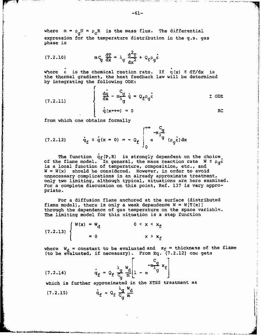
-61-
where m = U= p R is the mass flux. The differential
expression for the temperature distribution in the q.s. gasphase is
dT d2T(7.2.10) mCg = = + QfPg
where e is the chemical reation rate. If q(x) E dT/dx isthe thermal gradient, the heat feedback law will be determinedby integrating the following ODE:
Sddx Im•q QODE(7.2.11) g
(x.+ )= 0 BC
from which one obtains formally
(7.2.12) qf q(x = 0) = - Qf J e (pgý)dxJ0
The function qf(P,R) is strongly dependent on the choiceof the flame model. In general, the mass reaction rate W =- pgeis a local function of temperature, composition, etc., andW = W(x) should be considered. However, in order to avoidunnecessary complications in an already approximate treatment,only two limiting, although typical, situations are here examined.For a complete discussion on this point, Ref. 137 is very appro-priate.
For a diffusion flame anchored at the surface (distributedflame model), there is only a weak dependence W = W[T(x)]through the dependence of gas temperature on the space variable.The limiting model for this situation is a step function
W(x) = Wd 0 < x < xf
(7.2.13)S= 0 x > Xf
where Wd = constant to be evaluated and xf = thickness of the flame(to be evaluated, if necessary). From Eq. (7.2.12) one gets
-m---x
which is further approximated in the KTSS treatment as(7.2.15) qf = Qf X -
gwc iit
--------------------Q Xg
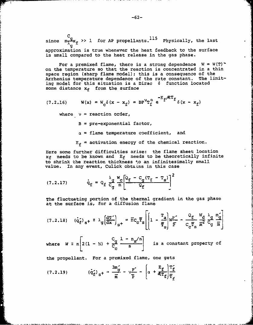
-62-
Ikq
C 115since m)%Xf >> 1 for AP propellants. Physically, the last
gapproximation is true whenever the heat feedback to the surfaceis small compared to the heat release in the gas phase.
For a premixed flame, there is a strong dependence W = W(T)-on the temperature so that the reaction is concentrated in a thinspace region (sharp flame model); this is a consequence of theArrhenius temperature dependence of the rate constant. The limit-ing model for this situation is a Dirac 6 function locatedsome distance xf from the surface
V L-Ef /RTf(7.2.16) W(x) = Wc(X - xf) = BPVT e 6(X - Xf)
where v = reaction order,
B = pre-exponential factor,
a = flame temperature coefficient, and
E = activation energy of the chemical reaction.fIHere some further difficulties arise: the flame sheet locationxf needs to be known and Ef needs to be theoretically infiniteto shrink the reaction thickness to an infinitesimally smallvalue. In any event, Culick obtaLns in this case
X W c[Qf - C 9(Tf - T S)(7.2.17) qf =Qf _%-
The fluctuating portion of the thermal gradient in the gas phaseat the surface is, for a diffusion flame
g~d- 1 Ta . Q f "d m'(7.2.18) (q)s A= -gc d - = s-_ dgg~ ~ x csyls i?- CgJ
where W- n[2(il-) + is a constant property ofc J
the propellant. For a premixed flame, one~ gets
3m'(7.2.19) (if S+ -fT
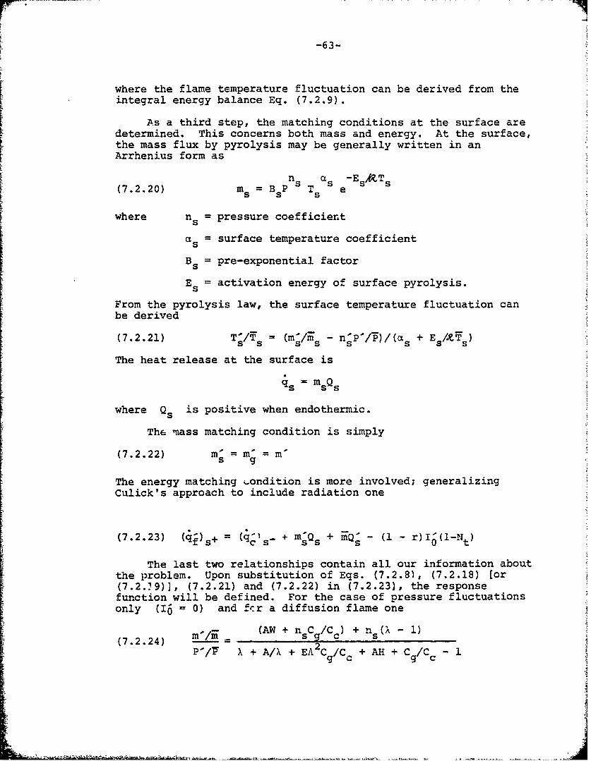
-63-
where the flame temperature fluctuation can be derived from theintegral energy balance Eq. (7.2.9).
As a third step, the matching conditions at the surface aredetermined. This concerns both mass and energy. At the surface,the mass flux by pyrolysis may be generally written in anArrhenius form as
n as '-Es &T s(7.2.20) ms =BsP Ts e
where ns = pressure coefficient
as = surface temperature coefficient
Bs = pre-exponential factor
Es= activation energy of surface pyrolysis.
From the pyrolysis law, the surface temperature fluctuation canbe derived
(7.2.21) TV/T = (m/rs - nP/)/(as + E /xsT
The heat release at the surface is
s s
where Q is positive when endothermic.
The mass matching condition is simply
(7.2.22) m5 = m = m
The energy matching ý.ondition is more involved; generalizingCulick's approach to include radiation one
(7.2.23) (q+)s+ = (q-)s_ + mQ + Q - (1 - r)(1-Nf (I-Nt)
The last two relationships contain all our information aboutthe problem. Upon substitution of Eqs. (7.2.8), (7.2.18) [or(7.2.29)], (7.2.21) and (7.2.22) in (7.2.23), the responsefunction will be defined. For the case of pressure fluctuationsonly (I6 = 0) and frr a diffusion flame one
((AW + nC/C ) + n (X - 1)sq c A2P-/TI X +A/X + EA C/C + AH +C/C -gc gc
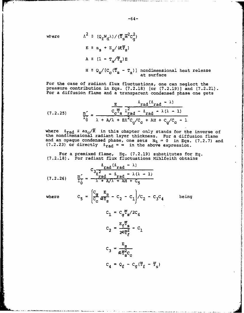
-64-
wl-ere A2 (QfWdX)/(s 2 C2 )
E a •s + E s/(fs)
A H (1 - T a/s)E
H Q s/[C c(s - T a) nondimensional heat releaseat surface
For the case of radiant flux fluctuations, one can neglect thepressure contribution in Eqs. (7.2.18) [or (7.2.19)] and (7.2.21).For a diffusion flame and a transparent condensed phase one gets
E £rad (z rad -X)
C~ T 2 -zX((7.2.25) m- c s rad rad06 X + A/X + EAC9c/Cc + AH + C/C -/c
where trad = aac/R in this chapter only stands for the inverse ofthe nondimensional radiant layer thickness. For a diffusion flameand an opaque condensed phase, one sets Nt = 0 in Eqs. (7.2.7) and(7.2.23) or directly £rad in the above expression.
For a premixed flame, Eq. (7.2.19) substitutes for Eq.(7.2.18). For radiant flux fluctuations Mihlfeith obtains
C rad (rad R,
(7.2.26) m = rad £rad"( 6 IA X + A/X + AH + C5
whee C =[C~eT- C2 - ClJ/C 2 - C3C4 being
C1 = CTs/2C4
EfEsC -1
Es
C4 = Qf - Cg(f -1
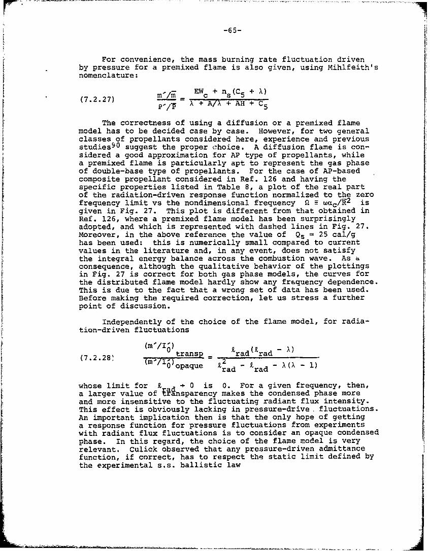
-65-
For convenience, the mass burning rate fluctuation drivenby pressure for a premixed flame is also given, using Mihlfeith'snomenclature:
(7.2.27) mm = EWc + ns(C5 + X)
p X/* + A/X + AH + C5
The correctness of using a diffusion or a premixed flamemodel has to be decided case by case. However, for two generalclasses of propellants considered here, experience and previousstudies 9 0 suggest the proper choice. A diffusion flame is con-sidered a good approximation for AP type of propellants, whilea premixed flame is particularly apt to represent the gas phaseof double-base type of propellants. For the case of AP-basedcomposite propellant considered in Ref. 126 and having thespecific properties listed in Table 8, a plot of the real partof the radiation-driven response function normalized to the zerofrequency limit vs the nondimensional frequency 0 £L wc/K2 isgiven in Fig. 27. This plot is different from that obtained inRef. 126, where a premixed flame model has been surprisinglyadopted, and which is represented with dashed lines in Fig. 27.Moreover, in the above reference the value of Qs = 25 cal/ghas been used: this is numerically small compared to currentvalues in the literature and, in any event, does not satisfythe integral energy balance across the combustion wave. As aconsequence, although the qualitative behavior of the plottingsin Fig. 27 is correct for both gas phase models, the curves forthe distributed flame model hardly show any frequency dependence.This is due to the fact that a wrong set of data has been used.Before making the required correction, let us stress a furtherpoint of discussion.
Independently of the choice of the flame model, for radia-tion-driven fluctuations
(m'/I1) -
transp rad rad(7.2.28, ( 1/i)oae £2 -£ -••-i_0 opaque I rad rad -(A-1)
whose limit for Z 0 is 0. For a given frequency, then,a larger value of Rnsparency makes the condensed phase moreand more insensitive to the fluctuating radiant flux intensity.This effect is obviously lacking in pressure-drive, fluctuations.An important implication then is that the only hope of gettinga response function for pressure fluctuations from experimentswith radiant flux fluctuations is to consider an opaque condensedphase. In this regard, the choice of the flame model is veryrelevant. Culick observed that any pressure-driven admittancefunction, if correct, has to respect the static limit defined bythe experimental s.s. ballistic law
-66-
m = apnfrom which m2/ n for w = 0. It is therefore required that
P-/l7
(7.2.29) li0 Ab,p M
both for the diffusion (Eq. 7.2.24) and the premixed (Eq. 7.2.27)flame model. It is easily verified that the constraint of Eq.(7.2.29) is always satisfied for a diffusion flame model, whereasfor a premixed flame model this is true only for a specific valueof the pressure exponent ns appearing in the surface pyrolysislaw (Eq. 7.2.20). For some typical cases it has been foundthat ns = 2 is required for a pressure-driven admittance func-tion with a premixed flame model to verify the static limit. Thisstrong dependence of the surface pyrolysis law on the pressuremight be suspect if one considers that most models of hetero-geneous flames work successfully with the simple assumption ofns = 0.
The experimental determination of the pressure-driven re-sponse function through radiation-driven tests is possible for allpropellants whose gas phase can be modeled by a diffusion flameand for which ns = 0. (This is a common assumption in theliterature.) From Eq. (7.2.24) and Eq. (7.2.25), it is thenimmediately possible to find for an opaque condensed phase that
(7.2.30) (/Pl) (/V) AW
0m / op) E/(C cs)op c
from which one gets:
Qb,P(W) (m'/P')/((/f/) c s AW
() (mI)o(mI 0 ) E (i-0)
Since lim m'/P" = AW nNIT CX + A/X + EA Cg/Cc + AH + Cl/Cc - 1)
(im WI ) opE/( IC c~sand li0.0 =Ccs(O (N/o0 ) [X + A/X + EAC/Cc + AH + Cge/CC (R/)
one gets
(.3)b,p (M)/Zb,p (W=0)(7.2.31) .... - 1
eb, lop )/Zb, Top"W=
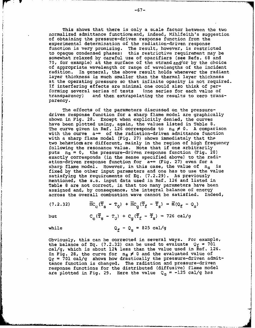
r -67-
This shows that there is only a scale factor between the twonormalized admittance functiorsand, indeed, Mihlfeith's suggestionof obtaining the pressure-driven response function from theexperimental determination of the radiation-driven responsefunction is very promising. The result, however, is restrictedto opaque condensed phases: this restrictive requirement may besomewhat relaxed by careful use of opacifiers (see Refs. 68 and70, for example) at the surface of the strand and'or by the choiceof appropriate wavelength or range of wavelengths of the incidentradition. In general, the above result holds whenever the radiant
layer thickness is much smaller than the thermal layer thicknessat the operating pressure so that infinite opacity is not required.If interfering effects are minimal one could also think of per-forming several series of tests (one series for each value oftransparency) and then extrapolating the results to zero trans-parency.
The effects of the parameters discussed on the pressure-driven response function for a sharp flame model are graphicallyshown in Fig. 28. Except when explicitly denied, the curveshave been plotted using, again, the values listed in Table 8.The curve given in Ref. 126 corresponds to ns 3 0. A comparisonwith the curve a- of the radiation-driven admittance functionwith a sharp flame model (Fig. 27) shows immediately that thetwo behavionsare different, mainly in the region of high frequencyfollowing the resonance value. Note that if one arbitrarily
puts ns = 0, the pressure-driven response function (Fig. 28)exactly corresponds (in the sense specified above) to the radi-ation-driven response function for a-- (Fig. 27) even for asharp flame model. However, in this case, the value of ns isfixed by the other input parameters and one has to use the valuesatisfying the requirements of Eq. (7.2.29). As previouslymentioned, the s.s. input data used in Ref. 126 and listed inTable 8 are not correct, in that too many parameters have beenassigned and, by consequence, the integral balance of energyacross the overall combustion wave cannot be satisfied. Indeed,
(7.2.32) mCc - T() + m-Cg(f - Ts) = E(Qf - Qs)
but C (T - T + Cg(Tf - Y 726 cal/g
while Qf - Qs = 825 cal/g
Obviously, this can be corrected in several ways. For example,the balance of Eq. (7.2.32) can be used to evaluate Qf = 701cal/g, which is about 12% less than the value used in Ref. 126.In Fig. 28, the curve for ns # 0 and the evaluated value ofQf = 701 cal/g shows how drastically the pressure-driven admit-tance function is changed. The radiation and pressure-drivenresponse functions for the distributed (diffusive) flame modelare plotted in Fig. 29. Here the value Qs = -125 cal/g has
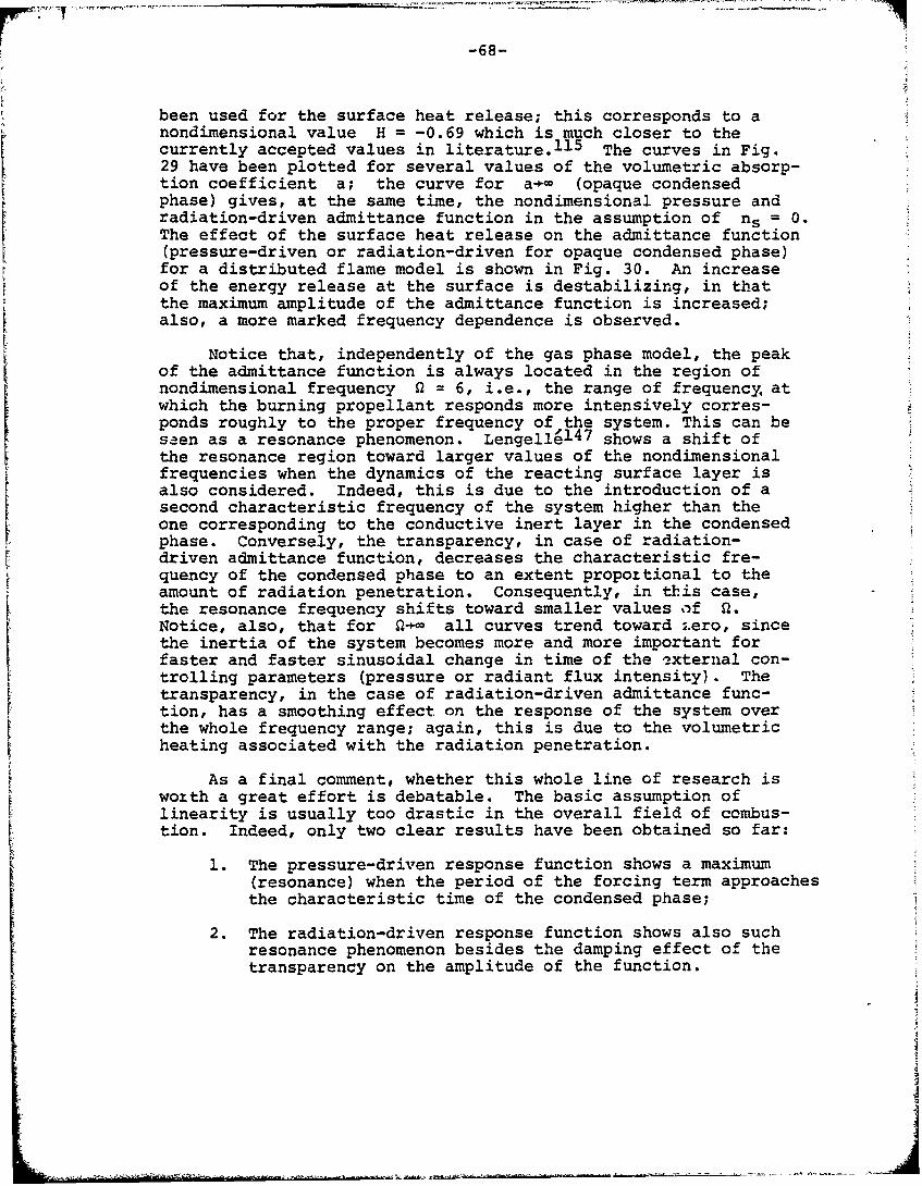
-68-
been used for the surface heat release; this corresponds to anondimensional value H = -0.69 which is much closer to thecurrently accepted values in literature. 1 1 5 The curves in Fig.29 have been plotted for several values of the volumetric absorp-tion coefficient a; the curve for a-)- (opaque condensedphase) gives, at the same time, the nondimensional pressure andradiation-driven admittance function in the assumption of ns = 0.The effect of the surface heat release on the admittance function(pressure-driven or radiation-driven for opaque condensed phase)for a distributed flame model is shown in Fig. 30. An increaseof the energy release at the surface is destabilizing, in thatthe maximum amplitude of the admittance function is increased;also, a more marked frequency dependence is observed.
Notice that, independently of the gas phase model, the peakof the admittance function is always located in the region ofnondimensional frequency 0 = 6, i.e., the range of frequency. atwhich the burning propellant responds more intensively corres-ponds roughly to the proper frequency of the system. This can beseen as a resonance phenomenon. Lengelle 1 4 7 shows a shift of
the resonance region toward larger values of the nondimensionalfrequencies when the dynamics of the reacting surface layer isalso considered. Indeed, this is due to the introduction of asecond characteristic frequency of the system higher than theone corresponding to the conductive inert layer in the condensedphase. Conversely, the transparency, in case of radiation-driven admittance function, decreases the characteristic fre-quency of the condensed phase to an extent propottional to theamount of radiation penetration. Consequently, in this case,the resonance frequency shifts toward smaller values of a.Notice, also, that for 2 all curves trend toward ;.ero, sincethe inertia of the system becomes more and more important forfaster and faster sinusoidal change in time of the external con-trolling parameters (pressure or radiant flux intensity). Thetransparency, in the case of radiation-driven admittance func-tion, has a smoothing effect on the response of the system overthe whole frequency range; again, this is due to the volumetricheating associated with the radiation penetration.
As a final comment, whether this whole line of research iswoxth a great effort is debatable. The basic assumption oflinearity is usually too drastic in the overall field of combus-tion. Indeed, only two clear results have been obtained so far:
1. The pressure-driven response function shows a maximum(resonance) when the period of the forcing term approachesthe characteristic time of the condensed phase;
2. The radiation-driven response function shows also suchresonance phenomenon besides the damping effect of thetransparency on the amplitude of the function.
SJU
-69-
Both results are predictable a priori on simple physical grounds.To extract less immediate results is a cumbersome task and,moreover, is strongly limited by the requirement of linearity.
139The excellent work by T'ien, however, has to be noted.T'ien was able to define a boundary for all possible staticsolutions and also to determine a more restrictive "dynamic"limit by means of a small perturbation analysis with a combustionmodel including heat loss by radiation from the burning surface.The response function concept was used by T'ien for predictingthe (linearized) stability boundaries rather than for ratingthe instability trends of solid propellants. In conclusion,the idea of predicting the pressure-driven behavior by means ofradiation-driven tests is appealing, but one must first ask howmuch practical value the pressure-driven response function has.
I
-70-
CHAPTER 8
NONLINEAR BURNING STABILITY ANALYSIS
No general method exists for studying the stability proper-ties of a strongly nonlinear partial differential equation (PDE)subjected to finite disturbances. On tUhe other hand, rigorousmethods of investigation have been established by Lyapunov forthe case of ordinary differential equations (ODE). In thischapter, therefore, we are going to re-formulate our problem interms of an ODE. This will be accomplished by means of an approx-imate approach known as an "integral method". The problem willbe then analyzed in this new formulation from the point of viewof intrinsic or static stability. The results of this analysiswill prove to be of basic importance in the theory of dynamicburning for the case when the external parameters change mono-tonically in time. It will ze found that, in principle, burningsolid propellants are subjected to static and dynamic instabili-ties in both low (fractions of cm/s) and high (some cm/s) rangesof burning rate. A method of determining the static and dynamicstability boundaries will be described and their dependence onseveral parameters will be discussed. Finally, a method ofspecifying the range of parameters for which self-sustainedoscillations are the only allowed stationary reacting solutions(limit cycle phenomena) will be described.
8.1 Current Status of the Theory of Nonlinear DynamicStability of Solid Propellant Combustion
The question of the dynamic extinction by depressurizationand, in general, of the burning stability has been well debatedin the technical literature,148-156 but few works have beenreally constructive. The erroneous application of the quasi-steady gas phase assumption, 9 1 the strong limitations due to theuse of linearized theories, and the empirical nature of severalof the proposed criteria1 4 9 ,1 5 0 are the most serious drawbacksin this area. For a critical review, the interested readermight wish to consult the work by Merkle. 9a A paper by T'ien1 2 3
is the only one aimed directly at establishing an extinctioncriterion for fast depressurization. Merkle did not formulateany criterion; indeed, in his work in order "to facilitate theactual detection of extinction by the computer, an 'extinction'temperature (analogous to an ignition temperature) of 600 K[6s = 0.43] was specified" (p. 64 of Ref. 90b), below which allchemical reactions were considered unimportant. Likewise, nocriterion has been formulated so far for the case of dynamicextinction by fast deradiation reported by the Princeton group(see §4.4 of this work and Ref. 77).
T'ien123 argues that heat losses are the mechanism forboth static and dynamic extinctions of solid propellants;this view is not fully ihared in this instance (see §8.8).
-71-
In any event, T'ien concludes that for depressurization transients,if the instantaneous burning rate drops below the unstableburning rate solution at the final pressure, extinction willoccur. T'ien1 3 9 derives his quantitative criterion from anotherstudy by him of flammability limits of premixed flames under theinfluence of environmental disturbances. A somewhat similarresult will be obtained here by following a completely differentapproach.
The line of research evolved within the franmework of themechanistic (Zeldovich) approach has been unable to reach trulymeaningful conclusions so far about the dynamic stability bound-ary. Istratov, et a1 1 5 7 in 1964 used an integral method in orderto determine an approximate solution to the unsteady nonlinearenergy equation in the condensed phase of a propellant burningwith constant surface temperature. Extinction was assumed tooccur when the surface thermal gradient on the condensed sideexceeded a critical value corresponding to the static stabilityline. This is a serious mistake, since nothing can really besaid a priori about the possibility of a dynamic burning regimein a range of burning rate that is statically unstable. Herea similar mathematical formulation has been used. but completelydifferent results have been found. Novozhilov,I18 in 1967,improved the previous model by considering a variable surfacetemperature and recognizing that dynamic burning is allowedalso in the range of parameters where statically stable solutionsare not found. Extinction is then assumed to occur when theburning rate at the final pressure drops below a limitingvalue '-stablished experimentally in nonstationary burning con-ditions. This criterion heavily relies on very delicate experi-mental results and, moreover, fails to ass~in any premonitorysignal, if any, about the approaching of t),% limit.
This question of a possible early warning of ext..,ctionduring a depressurization transient evaluated via the9 eldovichmethod was examined in a paper by the Princeton group in1972. The possibility was checked that the crossing of thestatic stability boundary is sufficient to subsequently producedynamic extinction. No clear answer to this question was given.The position taken here is that the static stability boundary hasonly secondary relevance in a dynamic situation. Indeed,according to the same Princeton reference, "the dynamic con-ditions of extinguishment tend to shift the stability line"(p. 257 of Ref. 92). More extensive work 1 2 1 in this area alsofailed to reach any significant conclusion. In any event,Novozhilov, in 1973, observes that this "question requirescertain information about the propertiZ of the system outsidethe area of smooth burning. Such information cannot be obtainedfrom experiments on steady state combustion. For the calculationof unsteady conditions in the unstable region it is necessaryto draw on certain schemes of combustion, which make it possibleto predict the properties of propellants beyond the (static]
If
-72-
stability limit." (p. 216 of Ref. 158). In other words, theauthor admits the failure of the mechanistic approach in thisrespect and recognizes that burning in the statically unstableregion can be treated only with a flame model. However, the needfor more advanced treatments in the framework of flame modelsis advocated in Ref. 159.
In this work, quantitative criteria for dynamic extinctionare defined by means of the MTS flame model. An integral ap-proach is used in order to apply known mathematical methods tothe resulting approximate ODE formulation. The integral approachhas been aplied to several burning problems by Soviet investi-gators. 2 4 , 1 7, 1 6 0 , 1 6 1 Somewhat simpler use has been made alsoat Princeton. 3 , 1 6 2 Within the framework of this approximation,the static stability analysis associated with intrinsic randomdisturbances is given in §8.2, while the dynamic stability analy-sis associated with finite size disturbances following a mono-tonic decay of externally controlled parameters is given in §8.3.A restrictive comment about quantitative criteria for dynamicextinction is made in §8.4. A general discussion (§8.5) on thepossible equilibrium configurations of heterogeneous combustionwaves, unreacting or steady reacting or self-sustained oscillat-ing, and more specific considerations (§8.6) on limit cyclephenomena related to burning solid propellants are offered inthe next two sections. Further comaents on the dynamic burningregime in §8.7 and a summary of the findings in §8.8 concludethe chapter. The reader should note that the dynamic stabilityanalysis heavily relies on the static stability analysis.
8.2 Nonlinear Static Stability Analysis
In this section the integral approach used for reducing thePDE problem to an approximate ODE problem is briefly described.Comments on the validity of the approach are given where appro-priate. The reader should pay more attention to the physicalinterpretation of the results than to the mathematical formulation.This section gives the basis for understanding the subsequentdevelopments.
Basically, the mathematical method is the one set up for thefirst time by Von Karman and Polhausen in the study of boundarylayers and later generalized by Goodman, among others, to alarge number of thermal problems. The method can be extendedto any other problem described by nonlinear PDE of parabolictype. In the present case, the approach consists of defining aparameter 6(T), called the penetration distance of the thermalwave in the condensed phase, "such that for fxJ > S(T) the[propellant] slab, for all practical purposes, is at an equil-ibrium temperature and there is no heat transferred beyond thispoint" (p. 53 of Ref. 163). The evolution in time of the thermalprofile in the condensed phase is obtained by following the timehistory of the penetration distance propagatina into an intially
-73-
uniform temperature field. Within this penetration layer, pro-gressing in time, the qualitative space distribution of tempera-ture is assiued known a priori; but note that, in so doing, theintegral balance of thermal energy in the condensed phase ispreserved. In other words, the limitation imposed by making thetransformation from PDE to ODE formulation is an approximatesolution of the local space distribution of temperature; thisis not such a serious drawback because the interest is in thetime evolution of the surface temperature. In any event, severalinvestigations found an error of only some percents for variouscases in which both the exact and the integral solutions wereevaluated. For example, see Fig. 5 on p. 89 of Ref. 163 showingthe temperature time history at the surface of a semi-infiniteslab with triangular surface heat flux.
In order to get a deeper understanding of questions relatedto the integral method as applied to thermal problems, theinterested reader might wish to consult the excellent review byGoodman 1 6 3 and the references given theie. Reading of Refs.164 and 165 might help the reader to put the method in the rightperspective. In any event, before getting involved in mathe-matical details, the reader should be warned about the limits ofthe integral method. it is obvious that any solution obtained bythe integral method contains, hopefully, small but irrevocableerrors in the final numerical results. The question of howto improve the accuracy then arises. It has been argued that"there is no a priori guarantee that increasing the order ofthe polynomial (used to represent the space distribution of theunsteady temperature profile] will improve the accuracy. Althoughthe accuracy is frequently improved with this technique, it canbe demonstrated, nonetheless, that there are cases for which itactually worsens" (p. 96 of Ref. 163). In this same referenceit is suggested that the method of weighted residuals provides avery efficient method for improving the accuracy of the resultsobtained by using the integral method. As a hint for futurework, the method of weighted residuals is now briefly described.Suppose an approximate solution en(X,t) of a given nonlinearoperator L [e.g., the condensed phase energy equation ofEq. (6.5.2)] is somehow known. The solution 6n is such thatall boundary conditions are satisfied and n unknown parametersare contained. For an exact solution 0(X,T) one would find
L(e) = 0
For the approximate solution en(X,T), instead, one finds
L(en) =n
where cn is a residual. A solution en which makes Enconveniently small in some sense is sought. In order to do this,we set equal to zero the average (over all space) of product of
i
-74-
the residual en by a weighting function wj
wjL(e n)dX =0 j = ,2,...,n.X
The solution has to satisfy the above equation. Since the solu-tion On contains n unknown parameters Cnj, n differentweighting functions are required to defining ;n. The weightingfunctions w- may be the independent variables x), for example,or the depenaent variable OR or any other reasonable function.
For the remainder of this work, a simple integral methodwill be implemented. This can be considered a special case ofthe method of weighted residuals when just one parameter (thepenetration distance 6) and one weighting function (wl = 1)are considered. Under these circumstances, the above equationreduces to the he&t balance integral (see below). The solutionwill be assumed to be a cubic prcfile (see Eq. 8.2.5) in space.Since, as stated above, the integral method assumes a uniforminitial distribution of temperature, a new nondimensional vari-able is defined:
(8.2.1) u(X,T) B (X) - e(XT)
where Ti(X) is the initial s.s. distribution of temperatureand 0(X,T) is the temperature distribution following someperturbation. The new variable u(X,T) may therefore be con-veniently interpreted as the finite temperature disturbancepropagating inside the condensed phase and superimposed on theinitial temperature distribution after the action of perturbation.At the initial instant T = 0, by definition O(X,T) = Wi(X)and u(X,r) = 0. Suppose now that, in the following instant, aperturbation starts acting on the system and makes u(X,T) # 0:the goal of the analysis is to determine the ultimate effect ofsuch a temperature disturbance after waiting a period of timesufficiently long for the perturbation to disappear. In con-trast with the previous linearized analysis, no assumption ismade as to the size of the temperature disturbance.
The analysis will be restricted to the case of an opaquepropellant (in the sense discussed in §A.2). The basic set ofnondimensional equations for an opaque propellant burning atconstant (initial) pressure PPi, while subjected to a radiantflux of constant (initial) intensity Fi is:
-75-
+ RR, a2 e
e (X , ) 0I 0(iRR H + (1- r) Fi
C, S g'
where RR(T) is the burning rate defined by the Arrhenius or
KTSS or any appropriate pyrolysis law and (Xc/Xg.)(9)6/Wsis the nondimensional heat feedback law defined by the S (or
any appropriate) flame model. In terms of the disturbance tem-
perature u(X,x), the set of equations is:
aU dW.i a2 d 2 ri II PDE3x- = - = X--(
dX > 0
u = 0) = 0 IC
(8.2.2) u(x÷ -e,T) = 0 BC2
Ar ~X rdTv.. j rau isg,s •=x•- g,s + RR•H+
-el - (l-r) .F 1 BCU
1 -1-ts~e (Ti us(,TT ref + T ref
where RR(t) = e s~rf iTref
or RR(U) = - us(T)l
and (Xg/xc)(au/ax) gs is defined, e.g., by the MTS flame model.
-76-
Notice that at T = 0, the surface energy balance is
-~ - (1 - r) • F. = -RiR. " H
(8.2.3) (-1wjc, s Fc . Hg,
s,ref refT~ Ts,ref T Ts,refwhere •. e Arrhenius
pyrolysis
or RR =s KTSSoI Ss pyrolysis
Therefore, BCE of Eq. (8.2.2) can be written as
(8.2.4) (U) - -.2)X C's Cs g,s 2 4
In what follows, the integral method will be applied withoutfurther explanations other than what has been said at the begin-ning of this fgtion; for a~plications similar to the one madehere, see Kuo or Peretz. We first assume a cubic dependenceof the disturbance temperature on the space variable:
(8.2.5) u(X,T) K0 (T) + KX(T)-(X) + K2 (T)-(X) + K3 (T)'(X)
Comments about the implications of this particular thermal pro-file are given below. The above four coefficients Ki(T) areto be determined from the boundary conditions which express nodisturbance (up to the second derivative) at the cold end of thepenetration depth and the energy balance at the hot boundary ofthe penetration depth. With our formulation this implies:
au1. -ý-x = 0,T) = (Ux)c,s
2. u(X = X6 1 T) = 0
(8.2.6)3. u(x = X 6 ,T) = 0
2u4. =(X X,) = 0
ax
k>•¸ - -. -' -.. . - -.. ,. . . - ' " • • • •• . ,• • -,. ; • • • _
-77-
where x -6 is the penetration distance to be obtained below.After aliebraic manipulations, one obtains for the unknown pro-file! of the disturbance temperature
u(xT) (ux)s 'S
For X = 0 we get at the surface
u(X = 0,T) - us (u)V~ t*%S 3
from which we can express the unknown penetration depth as
3u(8.2.7) 6(T) =
The disturbance temperature profile is then given by:
(8.2.8) u(X,T) = us 1 + T3
where us(T) is the unknown surface temperature disturbance tobe determined. It is obvious from the above relationship thatthe time history of t!e disturbance temperature is restrictedto disturbance thermal profiles monotonically decaying in space.Indeed, there is no way for a cubic profile to accommodate aninflection point. This difficulty may be overcome by "allowinga new penetration depth to begin propagating at each maximum orminimum" (p. 96 of Ref. 163) of the heat input into the con-densed phase. However, this procedure will not prove necessaryhere, since testing both the static and dynamic stability doesnot require a detailed knowledge of the structure of the thermalprofile.
As a second step, a space integration is performed overX from 0 to (-6) of the PDE:
x6.=Usa_.+2 d2 _j6 au X a dX 3Xa ax d2 J
{-(Rc
101
-78-
where I AW.)~4(X =0) -. (X =-6)
(8.2.9)
tdX de-- - ..(X = 0) - - (X = -6)
Upon substituting the approximate profile found above, one obtains
3 d [ _ s _RR .A(yi) + t•' (X)'-s +(8.2.10) - ;r a= R+[
Since (ux)cs = f(us(T);PP,F) one can write for the burningrate relaxation (at constant pressure and radiant flux)
d(Ux) , dus cXs
(8.2.11) a'S s
(U CSIPP,F =const
which can be evaluated once a flame model (in this case, the MTSone) has been established. After manipulations, the followingODE for the time dependent surface temperature disturbance isobtained
(ux) RRU-(u + A - RR-A(fi)dus 2 c,'s ,. u1
1--
(8.2.12) 2 c, PPau 'c's PP,
U(T = 0) 0
which is approximately equivalent to the initial PDE + boundaryconditions formulation. Notice that in the above equation Ti(X)is known (see Eq. A.2.5), that only the surface temperatureappears, and that the denvminator (evaluated according to theMTS flame model) is found to be always positive in the range of/alues of interest.
The above nonlinear ODE in us(T) also describes the re-sponse of the system when a finite departure (frcom the stationaryvalue) of the surface temperature us(i=O) # 0 occurs forintrinsic reasons, ir a propellant initially burning steadily ata given ambient temperature, pressure, and external radiant flux
-79-
intensity. If one wishes to know the whole temperature profile,he has only to substitute Us(T) in Eq. (8.2.8), evaluate 6(T)from Eq. (8.2.7) with the help of Eq. (8.2.4), and then use the us(r)definition (Eq. 8.k2.) in order to determine the resultant tem-perature profile.
Considerations of a general character on the stability ofthe system described by Eq. (8.2.12) can now be made. Accordingto the theory based on the Lyapunov theorems, a given equilibriumconfiguration of the system is asymptotically stable if
u (T) * 0
or for T
M(X,T) ÷- W(X) 3In other words, the system is (asymptotically) stable if thedisturbance disappears at large time and the system returns toits initial configuration. Following Lyapunov (p. 216 of Ref.166), Eq. (8.2.12) can be written as
dusT = - f(uj)
or, considering the US(T) definition (Eq. 8.2.1), as
de(8.2.13) d + = + - 0 )
One can then think of the chemically reacting system comprisedof the burning propellant as analogous to a mass-spring typemechanical system withthe nonlinear characteristic f(Ti~s - es).In what follows, the function f(ji,s - B.) will be called thenonlinear static restoring function.
bfrConsider the qualitative plot of Fig. 31a and Fig. 31bbefore examining the quantitative plots of Figs. 32-35. Quanti-tative plots of the function f(Wi,s - 6s) vs 8. are given inFigs. 32 to 35 for the propellant AP/PBAA #941 having the proper-ties listed in Table 7. They have been obtained by assuming amodified (see below) Arrhenius-type pyrolysis law at the surface andan MTS type of flame model. According to Eq. (8.2.13), all thepoints (algebraic roots) for which f(Fis - 8Q) = 0 definepossible equilibrium configurations for the burning propellant,since they correspond to des/dT = 0. It is seen in Fig. 31athat, in addition to the trivial 8s = C (unburning propellant,root C), two more equilibrium solutions (roots A and B) areallowed, in general, for a given set of parameters. Let us con-sider the equilibrium configuration corresponding to root A.Suppose that, for some unspecified reason, the burning rate RRor the surface temperature 6s increases a finite amount; then
-80-
the burning_propellant is no longer in a stationary configuration,dfs/dT = f(Oi,s - 6s) is negative, and the system reacts bydecreasing its surface temperature. Conversely, if for an un-specified reason, the surface temperature of a propellant burningaccording to the configuration of root A decreases, the systemreacts by increasing its surface temperature. These movements,around point A, are indicated by arrows in Fig. 31a. :t is con-cluded that the equilibrium configuration corresponding to root Ais stable because, when disturbed, the system always moves backtoward A. By the same arguments, it is concluded that the equil-ibrium configuration corresponding to root B is unstable; anydisturbance yields movement away from the point. Therefore, insteady state experiments, only solution A is observed.
If the set of parameters is changed, for example the pres-sure is increased from P to PI, the initial condition of the ODE(see Eq. A.2.5) is changed so that a new pair of roots, A1 andBl, is found in addition to the trivial es = 0 of root C. Again,root Al defines a stable equilibrium configuration, while rootBl defines an unstable equilibrium configuration correspondingto the new set of parameters. Likewise, a new pair of roots,A2 and B2, in addition to the trivial 8 s = 0 of root C, isfound if the pressure is decreased from P to P2. It followsthat the 8s axis in Fig. 31a includes, in addition to the.:rivial solution of nonburning propellant at the root C, asegment of stable solution Ai and a segment of associated un-stable solution Bi (each pair of roots corresponds to a givenset of parameters).
It should be explicitly observed that the trivial 8s = 0
solution may be obtained only if the exponential Arrhenius-typepyrolysis law for mass production at the surface is dropped.For purposes of this study, it is convenient to assume theexponential form as standard pyrolysis law for most of the sur-face temperature range, while the KTSS power form is consideredvalid at low surface temperature values. The two pyrolysis lawsare arbitrarily matched at Os = 0.15. Obviously, the trivialOs = 0 solution implies that no external energy source (e.g.,radiation) is acting on the solid propellant.
The qualitative picture of Fig. 31a illustrates the generalbehavior of the static restoring function when the pressure isvaried parametrically at fixed ambient temperature and surfaceheat release. The behavior of the static restoring function whenthe surface heat release is varied parametrically, at •.ixedambient temperature and pressure, is illustrated by tha qualita-tive picture of Fig. 31b. Of course, all previous considerationshold true. For example, when the surface heat release is lowenough (in a sense which will be better understood below), thesystem described by Eq. (8.2.13) behaves again according to thestatic restoring function represented by curve CBA (Fig. 31b).However, for increasing values of the surface heat release, it
-81-
is found that the static restoring function is represented bycurve CBIAIDIEI. This is rather surprising; in principle, thereare now five equilibrium configurations for this system.
Based on the previous analysis, however, it is immediatelyrecognized that C is the stable equilibriun solution for theunreacting state (trivial solution). But further discussion isrequired to understand the nature of the remaining four roots.This is most easily accomplished by considering the steadý stateenergy balance of the overall combustion wave. For example, thegraphic plot of Fig. 25 suggests that for each set of parametersonly one solution exists for the reacting state. Conventionally,let us call A that particular root of Figs. 31a and 31b corres-ponding to the energy balance solution of Fig. 25. It followsthat root El, although stable according to Lyapunov, is eliminatedas being a reacting equilibrium solution. The remaining rootsB-1 and Dl are, then, both unstable equilibrium solutior for thereacting state.
For further increase of the surface heat release, it isobserved that A- and D-type roots respectively increase (movingto right) and decrease (moving to left) in the plot of Fig. 31b,until coalescence and then crossing over occur with exchange ofstability character. This important point will be discussed indetail later (see §8.5). For further increasing of the surfaceheat release, B- and D-type roots disappear after coalescence,while both A2 and E2 roots, for different reasons, are eliminatedas being stable reacting solutions (curve CA2E 2 in Fig. 31b).Under these circumstances, it follows that the only allowedsolution is the trivial unreacting configuration representedby root C. Any attempt to produce a stationary combustion wavewith a static restoring function of type CA2 E2 will inevitablyresult in extinction. This type of extinction, however, cannotbe qualified as "dynamic" (see §8.3 and §8.5).
The implications of the different shapes of the staticrestoring functions will be discussed throughout this chapter.Now, a most important feature common to all static restoringfunctions is emphasized. The specific surface temperaturevalue, e0, at which the pair of solutions AS stable andBS unstable coalesces, at a given pressure (Fig. 31a) and fora given set of parameters,
S 0 es1 1 5
defines the branching or metastable point at that pressure (andfor that set of parameters). Corresponding to this special valueof the surface temperature a change of the character of stabil-ity occurs at the given pressure, in that for es < A• allthe equilibrium solutions at that pressure are statically unstable(roots Bi) while for 6s > 6s all the equilibrium solutions at
-82-
that pressure are statically stable (roots Ai). Therefor_, thebranching point at g given pressure isolates the critical staticstability value, es, of the surface temperature at that pres-sure. Constriction of the static stability boundary on the MTSplane RR vs q , in a range of pressure, consists of connectingthe critical satic stability points defined for each pressureof interest in the wanted range. This implies the search of thebranching point at any fixed pressure. A method of implementing
i the search is discussed below.
The above stability arguments can be put on a quantitativebasis by means of the "first" Lyapunov criterion. According tothis, the solution of the nonlinear autonomous ODE of Eq. (8.2.13)
is stable in the neighborhood of a point 8* if
df " iss < 0
at the point of interest G*. The physical meaning of thiscriterion has been explained above. In keeping with the spiritof this physical interpretation, the strength of the stabilityof the solution at a point 8* may be measured by the magnitudeof the derivative df/d0s evaluated at 8s = 8%. How this valueis affected by typical parameters is discussed below. In theexceptional case of a branching, or metastable, point in which
the unstable and the stable solutions coalesce, the above firstcriterion is not valid. In the present situation, however, itis enouq to say that the point eS is stable from one side(8s >8eS + e) while it is unstable on the other side (8s <
-c), so that, overall, the point 8s is said to be unstable.It should be clear that the first Lyapunov criterion (used formeasuring the strength of the stability) is essentially alinearization criterion of the originally nonlinear ODE. However,it is plausible that both roots C and A are stable to finite dis-turbances of an unknown size, also. The extent of the stabilityregion around the stable roots could be estimated by theLyapunov "direct" method; but this is not one of the purposesof this analysis. Physically, it is expected that the range ofstability of C root (always stable) is limited upward by B whilethe range of stability of A root (if stable) is limited down-ward by B. But dynamic effects may increase the range of stabilityof C root against the range of stability of A root.
The effect of the ambient pressure on the static restoringfunction f(ris - 6s) plotted vs the nondimensional surfacetemperature 8s is illustrated in Fig. 32 for the indicated setof parameters. An increase of pressure implies an increase ofthe stable equilibrium surface temperature, but a less pro-nounced increase of the unstable equilibrium surface temperature.The strength of the stability is enhanced by an increase of
-83-
pressure; numerical values are listed in Table 9. Curves are ofthe type CBA (see Fig. 31a), except at P = 10 atm; this willbe discussed in detail in §8.5. Similar comments hold true asto the effect of an external radiant flux on the restoringfunction (Fig. 33). It is important, however, to note that anincrease of the external radiant flux decreases the unstableequilibrium surface temperature and above a certain value ofradiant flux intensity (e.g., 40 cal/cm2 -s for the set of param-eters in Fig. 33) no more unstable solutions are found. Thisimplies that, in principle (see §8.3), at each pressure a minimumvalue of external radiant flux intensity exists above which thedynamic boundary can no longer be defined. The effects of surfaceheat release (Figs. 34a and 34b) are more involved and will bediscussed in detail in §8.5 and §8.6. Note, however, that forincreasing values of the surface heat release, the behavior ofthe static restoring function shifts from a CBA-type (see Fig.31a) curve for Qs = 150 and -158.2 cal/g, to CBADE (see Fig.31b) for Qs = -170 and -180 cal/g, and to CBDAE for Qs =-200 cal/g with A-D roots coalescence occurring at Qs = -190cal/g. This implies that at 30 atm, the system will show dynamicstability effects not only in the low range of surface tempera-
ture (root B in Fig. 31a) but also in the large range (root Din Fig. 31b). The effects of ambient temperature (Fig. 35) areof little interest in the range investigated. Values of thestability strength in various conditions are summarized inTable 9.
The attention of the reader has already been called to thefact that the most important piece of information in this non-linear static stability analysis is the value of the surfacetemperature corresponding to the branching point at any givenpressure. A general method (based on nonadiabaticity of thepropellant) for solving this problem is mentioned in §8.8.However, for the specific case of a solid composite propellantin the range 2 - 40 atm, the search for the branching point maybe performed immediately, although not rigorously, based onobservation of the physical processes. Consider the qualitativepicture superimposed in Fig. 36 on a standard MTS flame modelplot. Recall that burning rate and surface temperature are uni-vocally related by an appropriate pyrolysis law. Therefore, it isirrevelant to define the branching point in terms of burningrate or surface temperature. Now, as schematically indicated inFig. 36, the branching point is determined at each pressure bythe geometrical condition of vertical tangent, i.e., infiniteslope or maximum heat feedback. Indeed, for es > eg. a changeof burning rate or surface terperature produces opposing effectson the thermal gradients at the surface from the condensed andthe gas phase sides; for example, the former increases but thelatter decreases when the burning rate is disturbed upward.This competition is the stabilizing mechanism. For es < 6Sa change of burning rate affects, in the same direction, boththermal gradients; this is destabilizing. Just at the point with
I
-84-
vertical tangent, the two unstable and stable static rootsAs = Bs coalesce and an exchange of the stability character ofthe solutions occurs; therefore, we may identify this point asthe wanted branching or metastable point O6. For 6s = 6S thebehavior of the system depends on the direction of the perturba-
tion. Now, in order to construct a static stability boundaryin the plane RR vs4q, it is enough to connect the branchingpoints GS assogiated with each pressure. This boundaryseparates the region where static solutions are allowed from theregion where no static solution can be found.
The following observations are of concern at this point.This analysis giies more general and more reliable resultsthan the previous linearized analysis (Chapter 7). There aretwo reasons for this: (1) we dropped the strongly restrictiveassumptions of linearized equations and infinitesimal disturbances,and (2) we adopted a more general flame model. In principal,this type of analysis ma'; be applied to any heterogeneous defla-gration wave, provided a proper flame model is furnished. Forthe specific system (a composite solid propellant) presentlydealt with, a reasonably ,complete picture of the static stabilityproperties was obtained with little effort as compared to othertypes of stability analysis.
In conclusion, let us summarize the findings of this section.Within the accuracy of an unsophisticated integral method approach,it has been shown that for a fixed set of parameters (if the sur-face heat release is low enough):
1. two equilibrium solutions exist for the surface tempera-ture of a burning propellant, in addition to the tivialOs = 0 corresponding to a nonreacting configuration.
2. of the two equilibrium states, one is stable (df/d0s <0), while the other is unstable (df/des > 0).
3. the exceptional case of a branching (or metastable)point, in which the stable and the unstable solutionscoalesce, corresponds to the nonlinear static boundarypoint.
4. the branching point may be determined by the intuitiveapproach illustratpd in Fig. 36.
Within the accuracy of the integral method approach, ithas also been shown that increasing the surface heat release(for an otherwise fixed set of parameters) the following factsare observed:
5. a new pair of roots, Dl unstable and El stable, appearin the high burning rate region (see Fig. 31b).
-85-
6. roots A and D approach until coalescence (with stabilitycharacter exchange) occurs. The steady state reactingsolution (root A), stable before coalescence, is unstableafter.
7. roots B and D approach until they merge and disappear,so that only C, A2, and E2 roots are left (see Fig.31b).
For all cases, the steady state energy balance is verifiedonly at roots C (unreacting mode) and A (reacting mode). There-fore, these are, in general, the only allowed stationarysolutions and can be observed either experimentally or theoreti-cally as long as they are stable. But increasing surfaceheat release displaces the reacting parameters toward fasterregimes with loss of stability of root A: this also, then,becomes unobservable.
With this background, one is now ready to approach the moredifficult but fruitful area of nonlinear dynamic burning.
8.3 Nonlinear Dynamic Stability A.nalysis (Dynamic Extinction)
In the next four sections (§8.3 - 8.6) we examine the generalproblem of the behavior of a propellant initially burning stead-ily under a given set of external parameters, then subjected toarbitrary but known changes in time of radiant flux intensityand/or pressure. In this section, inquiry iz made, in particular,about the possibility of dynamic extinction of the propellanteven though it may be capable of statically stable burning forthe given final set of external parameters. It is expected thatthis will be a function of the rate of decrease of the externalparameters from the initial set of values. Specific referenceto this question will be made, but the overall line of attackis of a general nature.
Two broad hypotheses are made as to the burning propellant:quasi-steady behavior of the gas phase (with all the relatedassumptions of §6.5) and, in order to apply the integral methodwithout excessiv3 difficulties, optical opacity of the condensedphase. This second hypothesis is relevant in the case of radiant Iflux change, but it is not expected to affect the conclusionsin a significant way, as will be liscussed at the end of thissection.
The approach followed in the previous section will now begeneralized: let u(X,T) again be the disturbance temperaturein the sense already specified. The basic set of equations iseasily derived from §8.2.
I •
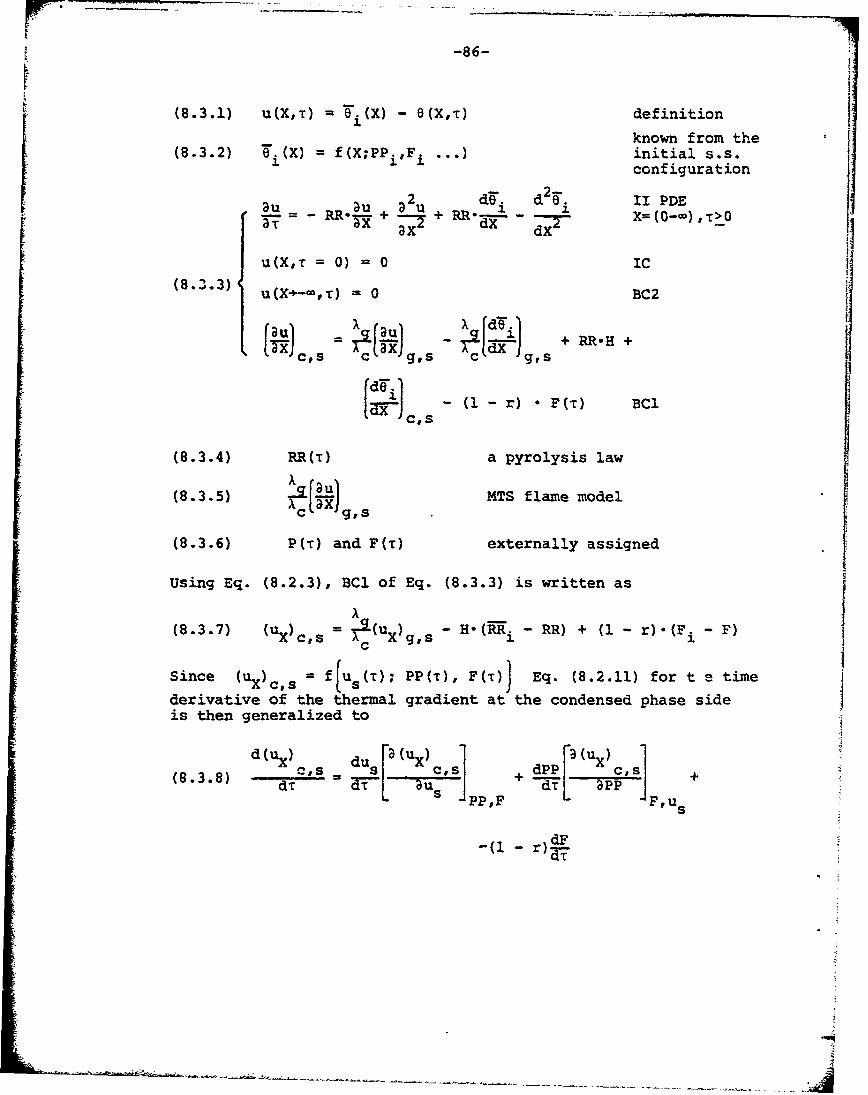
r-86-
(8.3.1) u(X,t) - (X) - 8(X,t) definition
known from the(8.3.2) T.(X) = f(X;PPi,Fi ... ) initial s.s.
configuration
BU Du a2u d i d2 . II PDERR*_+ = + RR* dx = X=(O-a),-r>O
u(X,T = 0) 0 IC(8.3.3) u(X+-),T) 0 BC2
11 )c, gi +RReH +
C's
(8.3.4) RR(It) a pyrolysis law
(8.3.5) 14TS flame model
(8.3.6) P(t) and F('r) externally assigned
Using Eq. (8.2.3), BCI of Eq. (8.3.3) is written as
(8.3.7) (ux) = XI(Ux)gs - H.(MRi - RR) + (1 - r)°(Fi - F)c
Since (us) c = f u 5 (T); PP('), F(T) Eq. (8.2.11) for t a time
derivative of the thermal gradient at the condensed phase sideis then generalized to
d(ux d (u xdP
(8.3.8) dT T- + dT+-PP,F F,us
-(1- dFr)-
U-T
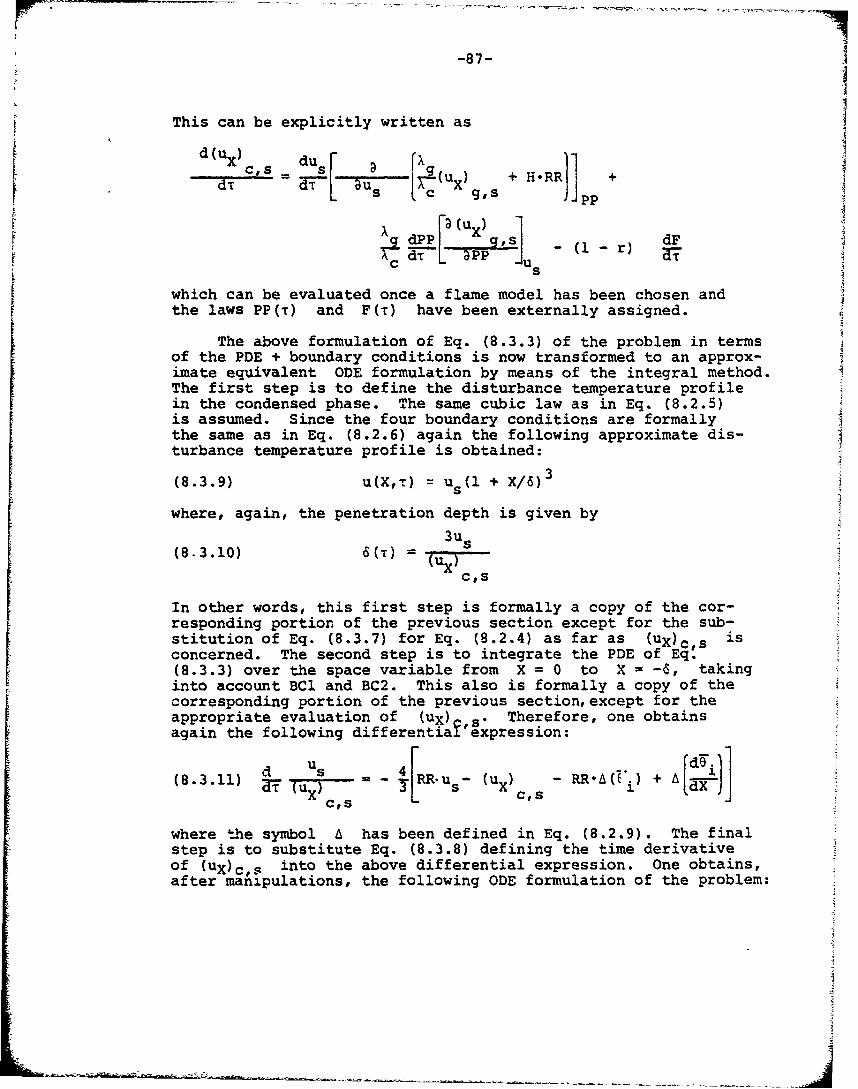
-87-
This can be explicitly written as
F duCd S= _i / (uX) + H.RR +g, s 1PP
a (UX~,
Ps - (il-r)s
which can be evaluated once a flame model has been chosen andthe laws PP(T) and F(r) have been externally assigned.
The above formulation of Eq. (8.3.3) of the problem in termsof the PDE + boundary conditions is now transformed to an approx-imate equivalent ODE formulation by means of the integral method.The first step is to define the disturbance temperature profilein the condensed phase. The same cubic law as in Eq. (8.2.5)is assumed. Since the four boundary conditions are formallythe same as in Eq. (8.2.6) again the following approximate dis-turbance temperature profile is obtained:
(8.3.9) u(XT) = U (l + X16)
where, again, the penetration depth is given by3us
(8.3.10) 6(T) = (u 5
C's
In other words, this first step is formally a copy of the cor-responding portion of the previous section except for the sub-stitution of Eq. (8.3.7) for Eq. (8.2.4) as far as (uX)c s isconcerned. The second step is to integrate the PDE of Eq:(8.3.3) over the space variable from X = 0 to X = -6, takinginto account BCE and BC2. This also is formally a copy of thecorresponding portion of the previous section, except for theappropriate evaluation of (ux) s" Therefore, one obtainsagain the following differentiai expression:
(8.3.11) T - us (U -'(ýi + ACS
where the symbol A has been defined in Eq. (8.2.9). The finalstep is to substitute Eq. (8.3.8) defining the time derivativeof (uX)c,s into the above differential expression. One obtains,after manipulations, the following ODE formulation of the problem:
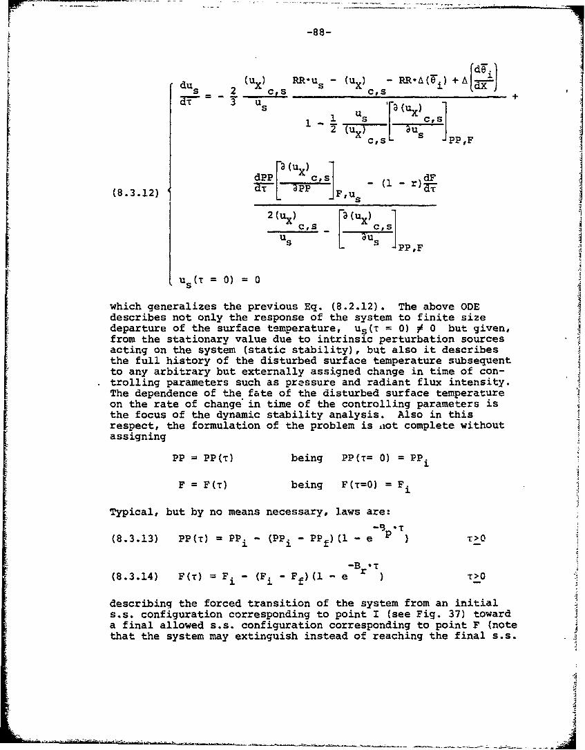
-88-
du5 lx RR~u5 (u (X) - RR-A (Ti)+A~d-J
•aT-=- • Us1 Us [alux)cs
(8.3.12)Fu
c1PP,F
Us(T = 0) = 0
which generalizes the previous Eq. (8.2.12). The above ODE
describes not only the response of the system to finite sizedeparture of the surface temperature, u0(t = 0) ) 0 but given,
from the stationary value due to intrinsic perturbation sourcesacting on the system (static stability), but also it describesthe full history of the disturbed surface temperature subsequentto any arbitrary but externally assigned change in time of con-trolling parameters such as pressure and radiant flux intensity.The dependence of the fate of the disturbed surface temperatureon the rate of change' in time of the controlling parameters isthe focus of the dynamic stability analysis. Also in thisrespect, the formulation of the problem is ixot complete withoutassigning
PP = PP(T) being PP(T= 0) = PP.
F = F(T) being F(T=0) = F i
Typical, but by no means necessary, laws are:
(8.3.13) PP(t) PP. - (PP. - PP)(1 - e >02. f
-Br T(8.3.14) F(T) Fi - (Fi -Ff)( e T>O
describing the forced transition of the system from an initials.s. configuration corresponding to point I (see Fig. 37) towarda final allowed s.s. configuration corresponding to point F (notethat the system may extinguish instead of reaching the final s.s.
_J
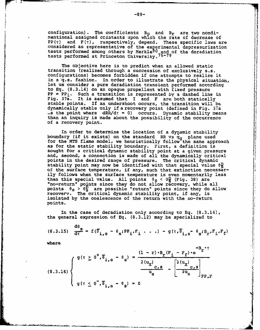
-89-S~I
configuration). The coefficients Bp and Br are two nondi-mentional assigned ccnatants upon which the rate of decrease ofPP(T) and F(T), respectively, depend. These specific laws areconsidered as representative of the experimental depressurizationtests performed among others by Merkle90 and of the deradiationtests performed at Princeton University. 7 6 - 7 9 f
The objective here is to predict when an allowed statictransition (realized through a succession of exclusively s.s.configurations) becomes forbidden if one attempts to realize itin a'q.s. fashion. In order to illustrate the physical situation,let us consider a pure deradiation transient performed accordingto Eq. (8.3.14) on an opaque propellant with fixed pressurePP = PPi. Such a transition is represented by a dashed line inFig. 37a. It is assumed that I and F are both staticallystable points. If an undershoot occurs, the transition will bedynamically stable only ifa recovery point (defined in Fig. 37a_s the point where dRR/dT = 0) occurs. Dynamic stability meansthan an inquiry is made about the possibility of the occurrenceof a recovery point.
In order to determine the location of a dynamic stabilityboundary (if it exists) on the standard RR vs qg plane usedfor the MTS flame model, we heuristically follow the same approachas for the static stability boundary. First, a definition issought for a critical dynamic stability point at a given pressureand, second, a connection is made of all the dynamically criticalpoints in the desired range of pressure. The critical dynamicstability point may now be identified with that special value ORof the surface temperature, if any, such that extinction necessar-ily follows when the surface temperature is even momentarily lessthan this special value. All points Os < OR (Fig. 38) are"no-return" points since they do not allow recovery, while all"Points Os > oD are possible "return" points since they do allowry irecovery. The critical dynamic stability point, if any, isisolated by the coalescence of the return with the no-returnpoints.
In the case of deradiation only according to Eq. (8.3.14),the general expression of Eq. (8.3.12) may be specialized to
(8.3.15) fds a " . - g(T,. 6 s;B- i
where-Br TUi r)- (Fi - f).e
g(T > 0 = -r "Br(F
c,s c-s](8.3.16) u a -PP,F
g(T-< 0 s - u)) 0i's 5
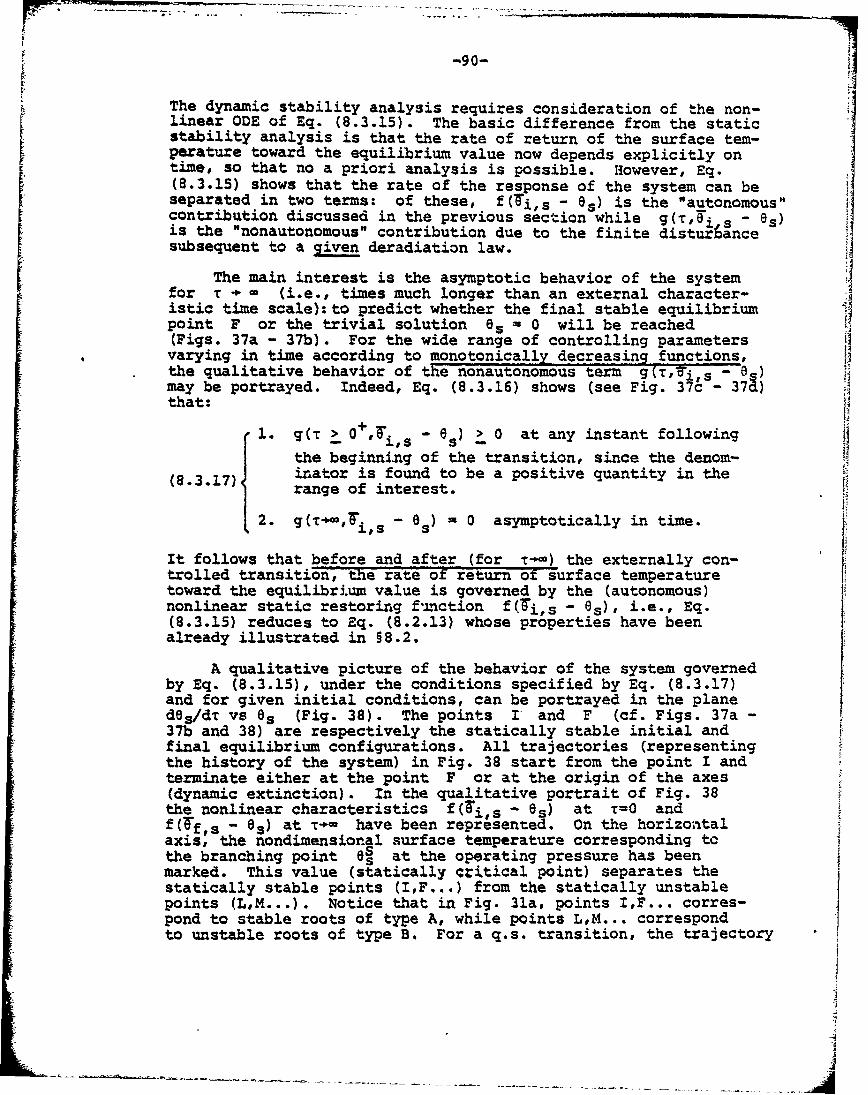
F-90-
The dynamic stability analysis requires consideration of the non-linear ODE of Eq. (8.3.15). The basic difference from the staticstability analysis is that the rate of return of the surface tem-perature toward the equilibrium value now depends explicitly ontime, so that no a priori analysis is possible. However, Eq.(8.3.15) shows that the rate of the response of the system can beseparated in two terms: of these, f(Ti,s - 8s) is the "autonomous"contribution discussed in the previous section while g(T,is - es)is the "nonautonomous" contribution due to the finite disturbancesubsequent to a given deradiation law.
The main interest is the asymptotic behavior of the systemfor r T (i.e., times much longer than an external character- Jistic time scale): to predict whether the final stable equilibriumpoint F or the trivial solution es = 0 will be reached(Figs. 37a - 37b). For the wide range of controlling parametersvarying in time according to monotonically decreasing functions,the qualitative behavior of the nonautonomous term g(r,'i8s - 8s)may be portrayed. Indeed, Eq. (8.3.16) shows (see Fig. 37C - 3 7a)that:
1. qI T!.gr0"",. -8 > 0 at any instant following
the beginning of the transition, since the demom-3nator is found to be a positive quantity in therange of interest.
2. g0r.,airs - 8s) 0 asymptotically in time.
It follows that before and after (for T-1) the externally con-trolled transition, the rate of return of surface temperaturetoward the equilibrium value is governed by the (autonomous)nonlinear static restoring f-mnction f(Ti,s - 8s), i.e., Eq.(8.3.15) reduces to Eq. (8.2.13) whose properties have beenalready illustrated in §8.2.
A qualitative picture of the behavior of the system governedby Eq. (8.3.15), under the conditions specified by Eq. (8.3.17)and for given initial conditions, can be portrayed in the planedes/dT vs 6s (Fig. 38). The points I' and F (cf. Figs. 37a-37b and 38) are respectively the statically stable initial andfinal equilibrium configurations. All trajectories (representingthe history of the system) in Fig. 38 start from the point I andterminate either at the point F or at the origin of the axes(dynamic extinction). In the qualitative portrait of Fig. 38the nonlinear characteristics f(i,-- - es) at T-0 andSf(Tf s - B.) at T-- have been represented. On the horizontalaxis, the nondimensional surface temperature corresponding tothe branching point 8• at the operating pressure has beenmarked. This value (statically qritical point) separates thestatically stable points (IF...) from the statically unstablepoints (L,M...). Notice that in Fig. 31a, points I,F... corres-pond to stable roots of type A, while points L,M... correspondto unstable roots of type B. For a q.s. transition, the trajectory
tI
-91-
starting from point I progresses into the negative half-planedes/dT < 0, since the term g(r,eis - es) initially dominatesthe term f(Ti, - 6.) in the ODE of Eq. (8.3.15). But taesketch of Fig. 17d shows that %(Tr,eis - 8e) decreases monoton-ically toward zero. When g(T,6i• - 8o) gecomes negligiblecompared to t(Oi,s - 8e), the latter term might drive thetrajectory toward the final point F.
The rate of return of the surface temperature toward equilibri-um for rT- is controlled only by the autonomous term. This meansthat, in the disturbance history, it is the intrinsic stabilityof the final state that tends to govern the behavior of the system.Therefore, at a given value of pressure, the critical "no-return"point is defined by the statically unstable root 8s (point M)associated with the final statically stable root Tf-s (point F)through the function f(-f,s es) it will Le noticedthat the whole segment between iss and eD is staticallyunstable but allows a dynamic burning regime. The unstable root8D in Fig. 38 represents a limiting condition which is a uniqueproperty of the system at the operating (final) pressure. Thisanalysis can be repeated for different values of pressure, sothat a dynamic stability boundary may be constructed as shown inFig. 39.for standard ambient temperature (300 K) and no residualradiant flux.
Note that in the general ODE formulation of Eq..(8.3.12)the influence of time-varying external parameters is felt onlythrough their time derivatives. This implies that, if no changeof pressure and/or radiant flux occurs, the system is only sub-jected to random intrinsic fluctuations and the results from thestatic stability analysis apply. It is also implied that, inthe case that g(T,Ti,s - 8s) << f(is - 8s) in Eq. (8.3.12),the dynamic stability boundary is a no-return boundary for anyT (even finite) and for any external law (even non monotonicor increasing). Note at last that, for clarity sake (cf.§8.5), the dynamic stability boundary just determined will becalled, for the remainder of this work, lower dynamic stabilityboundary.
The unstable z.ot es in Fig. 38 represents a limiting con-dition which is a unique property of the propellant at the operat-ing pressure (for a given set of parameters it depends only onthe properties of the intended final state.) It follows thatthe line connecting all the points OD is the lower dynamicstability boundary not only for deradiation transients, mono-tonically decaying toward zero, but also for depressurizationtransients monotonically decaying. Moreover, the unstable root8OD is determined for r-, that is, when the radiant flux is nolonger acting and, therefore, whether the propellant is or isnot transparent is irrelevant. Then, for deradiation transientsmonotonically decaying toward zero, the transparency of the con-densed phase has no influence on the dynamic stability. Noproblem arises if one wishes to consider the effect of other
-92-
parameters, for example the ambient temperature, on the lowerdynamic stability boundaryt it is enough to determine thestatically unstable root (B-type in Fig. 31a) for each ambienttemperature of interest (e;g., see Fig. 35).
In conclusion, the following facts emerge frcm the dynamicstability analysis of adiabatic solid propellants, in the low(fractions of cm/s) burning rate regime, for a given monotoniclaw of timewise change of the controlling parameters:
1. extinction may occur even though the final point ofthe transition is statically stable,
2. the lower dynamic stability boundary is the locus ofthe statically unstable roots associated with the finalstatically stable root through the static restoringfunction f(Wf,s - 6s), and
3. a dynamic stability analysis requires a flame modelapproach (see §8.1).
8.4 The Question of the Critical Conditions for Dynamic Extinction
In the previous section the existence of a lower dynamicstability boundary different from the static stability boundaryhas been shown. It has been said that crossing of this boundaryis enough to assure dynamic extinction for the wide range of con-trolling parameters varying in time according to monotonically
decreasing functions. A major problem in the theory of hetero-geneous flame dynamics is the prediction of the maximum rate ofchange of a controlling parameter allowed without sufferingdynamic extinction. It should be clear that no general answercan be given to this question, not even for the class of mono-tonically decreasing functions, since, in general, the fulldynamic history of the system has to be considered. The bestone can hope to do is to assign a criterion for a specific typeof monotonically decreasing law, for example the exponentiallaw of Eq. (8.3.14) for a deradiation transient. In this case,the trajectories of Fig. 38 show that a critical valueIdOs/dTl* exists such that for Id~s/dTl<IdOs/dTl* a recoverypoint subsequently occurs, whereas for ldes/dT[>jd6s/dTl* norecovery point is possible. Likewise, one could have an evenearlier warning about the occurrence of dynamic extinction byconsidering a critical value jd 20s/dT2 1* associated with thepaths leaving point I. However, no great importance is Lttachedto this idea of obtaining an "early warning" being this strictlydependent on the specific external law being considered.
All criteria assigning critical conditions for predictingextinction are necessarily approximate, often to an unknownextent. Indeed, the lower dynamic stability boundary is uniquelydefined as a property of the system and does not depend on the
J
-93-
specific decay law externally assigned as long as this law ismonotonic. Conversely, any prediction is necessarily associatedto a specific monotonic decay law. Furthermore, it will beshown in §8.5 that dynamic extinction may occur in other,unexpected circumstances. Therefore, approximate criteria arenot only of very limited use but might also be badly mistaken.
8.5 Lower and Upper Dynamic Stability Analysis
So far, only dynamic effects associated with a B-type root(see Figs. 31a and 31b) have been discussed. In fact, similardynamic effects are also associated with a D-type root (seeFig. 31b). The former is called lowe: dynamic stability and thelatter is called upper dynamic stability. Although the last hasbeen essentially neglected in the literature, both types ofinstabilities are very important in practice. Lower dynamicstability relates to extinction. Upper dynamic stability relatesto vigorous accelerations of the combustion wave and, therefore,pressure build-up due to large mass production; eventuallymechanical failure of the enclosing vessel or dynamic extinctionmight follow.
With reference to Fig. 34a, it is seen that a burning rateincrease, occuring for Qs = 158.2 cal/g (no D-type root), isimmediately and effectively balanced by the strong stabilitycharacter associated with the reacting equilibrium configurationof root A (see Table 9). Obviously, this is true only up to afinite size of the initial disturbance. With reference to Fig.34b, it can be seen that for Qs = -170 cal/g the static restoringfunction features two dynamically unstable roots, B (es = 0.68)and D (6s = 1.15), sitting at the sides of the stable steadystate configuration A (es = 0.95). Under these circumstances,if the surface temperature during a transient goes past B or D,the combustion wave will accelerate respectively toward Cs(8 = 0; lower dynamic instability) or E (Os = 1.29; upper dynam-
ic instability). In the case of lower dynamic instability, thefate of the combustion wave is extinction; this has been studiedin detail in §8.3. In the case of upper dynamic instability,the fate of the combustion wave is more involved. As soon asroot D is passed, a vigorous acceleration occurs. The increaseof burning rate may be of orders of magnitude. Root E, althoughstrongly stable, is not allowed as stationary solution. There-fore, after reaching E the wave is violently recalled toward astable steady state configuration. Depending on the dynamicsof the whole process, this can be either the reacting mode A orthe unreacting mode C (dynamic extinction due to overstability).In other words, a dynamic extinction may be the unexpected resultof a "too fast" pressurization (for example) transient.
Even more striking is the behavior of the system for Qs =200 cal/g (Fig. 34b). In this case, the static restoring functionfeatures two stable roots, D (8s = 0.93) and E (es 1.61),
-94-
neither of which is allowed as a stationary solution, sitting atthe sides of the unstable stationary solution A (es = 0.99).Under these circumstances, even in a static environment, theburning propellant is not capable of finding an equilibriumreacting configuration and bounces back and forth around A underthe competing influences of D and E. It is confirmed (see §9.5)by numerical integration that, after a transient, the combustionwave undergoes sharp self-sustained oscillations around A withpeaks near D and E. This suggests, under the specified conditions,the existence of a limit cycle. If so, being a limit cycle anoverall property of the governing differential equation, oncetriggered this oscillatory behavior would not depend on the initialconditions of the system (see §8.6). With this notable difference,i.e., self-sustained oscillations substituting for the stationarysolution as a regime reacting state, all previous considerationson transients are valid. If the surface temperature momentarilygoes past B (Os = 0.72), the combustion wave will irresistiblyaccelerate toward C (dynamic extinction). This may happen if wetry to slow down the combustion wave (e.g., by depressurization)and also if, in trying to accelerate the combustion wave (e.g.,by pressurization), the system goes too much past E during theinitial transient. Therefore, dependin~g on the dynamics of thewhole process, the final result of a transient toward a statecontrolled by a static restoring function of the type CBDAEis either a self-sustained oscillating combustion wave or dynamicextinction.
For Qs = -230 cal/g (for clarity not represented in Fig.34b), the static restoring function is found to be of the typeCAE. As noted in §8.2, under these circumstances the onlypossible solution, even in a static environment, is the trivialunreacting state. Since there is no n!ternative solution, thisshould be considered a static extinction. In other words,too much surface energy release excludes any reacting solutionin the high burning rate regime just as well as too low gas phaseenergy release (or sufficiently large heat losses) excludes anyreacting solution in the low burning rate regime.
The values of the nondimensional surface temperature,associated with the various types of roots discussed, are listedin Table 10 in function of the nondimensional surface heatrelease at P = 30 atm. At this pressure, upper dynamic stability(i.e., existence of a D-type root) shows up for jQsl> 170 cal/g.For decreasing pressure, the minimum value of !QsI aT whichupper dynamic instability shows up also decreases (Table 11).In particular, at P = 10 atm there is upper dynamic instabilityalready at Q0 = -158.2 cal/g. This implies that in the !MTS plot
of Fig. 39, the region of dynamic stability is not only boundeddownward by a lower dynamic limit (see §8.3) but also upward byan upper dynamic limit (not drawn) which, for the specific set ofparameters of Fig. 39, would lie somewhere in the upper leftcorner of the plot.
-95-
8.6 Self-Sustained Oscillations of Burning Solid Propellants
In this section more results concerning the self-sustainedoscillations of heterogeneous combustion waves mentioned in§8.5 are given. First, a simple procedure for detecting theexistence of a limit cycle should be straightforward from theprevious discussion. The simultaneous-presence of two ingred-ients in the static restoring function is required: (1) A rootunstable, and (2) D and E roots stable. The critical conditionfor satisfying the first requirement is the coalescence wf A-Droots (cf. Fig. 34b); the second condition is satisfied as longas coalescence of B-D roots has not yet occurred (cf. Fig. 34n).Therefore, in ordertD detect the existence of a limit cycle ata given pressure, it is enough to plot the values of the relevantroots in function of the surface heat release at the givenpressure. For example, in the case considered in Table 10(adiabatic opaque AP/PBAA #941 burning at P = 30 atm and Ta -
300 K), the existence of a limit cycle is expected betweenQs = 190 cal/g (A-D coalescence) and Qs \, -225 cal/g (B-Dcoalescence). Similar plots can be made Zor any other set ofoperating conditions. The results found in the range 10 - 30atm are summarized in Table 12. It is seen that the minimumvalue of surface heat release, at which self-sustained oscilla-tions are expected, increases with pressure; the range of surfaceheat release, at which self-sustained oscillations are expectedat a given pressure, seems also to increase with pressure.
A physical explanation of the above results might be thefollowing. Any self-sustained reactive system is capable ofexothermic reactions. These partly occur in the gas phase (Qf)and partly in the condensed phase (Qs). The total energy releaseQf(P) + Qs is determined by the energy balance on the overallsteadily burning propellant at the given set of operating con-ditions. Moreover, for a fixed set of operating conditions(pressu;e, radiant flux, and ambient temperature), qs increaseswhile qf decreases for increasing burning rate. For lowvalues of Qs, an increase of burning rate and thereby of4s E PcRQs is counterbalanced through a simultaneous decreaseof 4f % 1/R and increase of the heat flux qc ^ RTs absorbedinto the condensed phase. However, for large values of. Qs,an increase of burninj rate might be destabilizing if qsincreases more than (qc - gf). This implies an acceleration ofthe combustion wave, that is the appearance of a D-type rootin the nonlinear static restoring function (see Fig. 31b).On the other hand, for the same set of operating conditions, alarge increase of burning rate (up to two orders of magnitude,as shown in §9.5) is strongly stabilizing. Indeed, under thesecircumstances, the increase of qc is much larger than theincrease of (4c + qf) due to the Arrhenius-type dependence ofthe surface temperature on the burning rate. This correspondsto the appearance of an E-typa root in the nonlinear staticrestoring function (see Fig. 31b). Therefore, at each pressure
\I
-96-
(see Table 10) a critical (A-D coalescence) value of surfaceheat release exists above which the energy coupling betweencondensed and gas phases becomes locally unstable, i.e., a burningrate disturbance due to the change of heat flux absorbed intothe condensed phase is counterbalanced only'!.n the large" (through alimit cycle process) by an appropriate change of heat feedbackfrom the flame and the surface reacting layer. Furthermore,at each prassure (see Table 10) a cecond larger critical (B-Dcoalescence) value of surface heat release exists above whichthe energy coupling between condensed and gas phases becomestotally unstable (except at the trivial root C), due to theexcessively large thermal gradients occurring in the condensedphase near the burning surface.
As to the pressure effect, recall that increasing pi:ssureimplies increasing Qf, which subsequently requires a largervalue of Qs for destabilizing the combustion wave. Therefore,larger pressures require larger values of Qs for triggeringboth the upper instability (see Table 11) and the self-sustainedoscillation mechanism (see Table 12).
The reader has probably already realized that an estimateof the amplitude of the limit cycle oscillations can be immediate-ly derived by a plot of the appropriate static restoring function(e.g., Fig. 34b or Table 10). Indeed, the extent of the oscilla-tions are basically limited by roots D (minimum value) and E(maximum value). Instead, the frequency of the oscillationsdepend on the thermal wave relaxation in the condensed phase.Comments on these points are given in §9.5.
In conclusion, it is emphasized that this remarkable mech-anism of self-sustained oscillations, once triggered, is absolute-ly independent of the previous history of the system. Althoughdetection of the existence of a limit cycle and prediction of itsbasic properties are made, much work remains to be done, inparticular as to the excitation of the oscillations.
8.7 Further Considerations Regarding the Dynamic Burning Regime
The plot of the static or autonomous nonlinear restoring func-tion f(Tf s - 8s) in Fig. 38 shows that the trajectories, inthe case of both static and dynamic extinction, approach thetrivial stable solution es = RR = 0 asymptotically and tend tocoalesce more and more near the final point 0. Indeed, in theregion es < OD below the dynamic limit, the initial informationis being lost and it becomes very difficult to distinguishtrajectories which had different previous dynamic histories.All this is obvious from the physical point of view.
Notice that, within the accuracy of the method, the transientpaths leading to extinction may be fully evaluated by means ofthe integral approach. Notice also that, differently from allprevious works, the existence of a boundary in the present theory
-97-
implies that the crossing of the critical line may occur at anystage of the transition, not only at the final conditions. Forvery fast transients this crucial condition may occur at thebeginning of the dynamic burning history (in a sense this couldbe considered as a warning signal).
As to the other stable solution es = ef,s (the intended endpoint of the transient), the prediction of the behavior of thetrajectories, in approaching it, is much more involved. First,the final portion of the path may be evaluated only by numericalintegration or by an integral approach considering multiplepenetration depths in order to account for the inflection pointin the thermal profiles. Therefore, in this section, it isnecessary to resort to qualitative comments. The magnified viewof the restoring function f(Wf,s - 6s) in the region surround-ing the final point F in Fig. 38 suggests that either an asymptoticor a damped oscillatory behavior may be expected. Intuitively,one expects that the damped oscillatory type of approach towardthe final equilibrium is favored when a strong restoring force has
been acting on the system, so that an excessive momentum hasbuilt up. In the actual burning propellant, this implies thatan excessive (compared to the final equilibrium state) thickneGSof the thermal layer in the condensed phase is still present inthe system. This persistent memory arises with either a trans-parent propellan+ subjected to fast q.s. deradiation or withany propellant that has experienced a deep undershoot in burningrate during a fast q.s. transient near the dynamic limit. Inany event, the excess of energy, stored either in the radiantlayer at the beginning of the transition or momentarily
in the thermal layer in the dynamic burning regime, has to bedissipated. The damped oscillations around the point F in Fig.38 provide this dissipating mechanism. Since the phenomenon iscontrolled by the inertia of the condensed phase, the period ofthese oscillations is expected to be of the order of the relaxationtime of the condensed phase thermal wave.
The nonlinear nature of the restoring function opposingthe excursion of the propellant during a given transient isfeatured by the occurrence of a sharp maximum (see Figs. 32-35)near the static limit e8. If, in a dynamic burning regime, thesurface temperature falls below this value (8s < 8e), theresistance of the propellant to extinction quickly decreasesalthough dynamic stability is still assured. This region,therefore, is expected to be particularly sensitive to any changeof initial conditions. Experimental tests in this marginal zoneof dynamic stability would have to be very accurate; it is verylikely that inevitable data scattering could mask this extensionof the stability zone. Computer simulated runs might alsorequire a precision of initial data larger than in any realsituation, as is indeed shown in the results to be discussed in§9.3.
-98-
A check on the validity and on the accuracy of the analysisoffered can be made only by computer simulation using the fullunsteady equation and by experimental tests. Computec riins wereperformed with this specific goal and the results are reportedin Chapter 9. It should be emphasized that the computer checkswere made by solving numerically the PDE formulation of the generalq.s. transient problem, whereas the stability boundaries havebeen found by analytical means from considerations of the approx-imately equivalent ODE formulation. As to experimental tests,I any q.s. transient induced by a monotonic change in time of anyof the controlling parameters is adequate for checking thevalidity of the proposed method. Simple go/no-go results aresufficient to locate, at least approximately, the lower (forexample) dynamic stability line as a border between a region ofburning continuing after the transition and a region of extinc-tion induced by the transition. Typical experiments of thisnature are the depressurization tests of Ref. 90 and the deradia-tion tests of Refs. 76 - 79, for example. A method of performingmore meaningful experimental tests is suggested in §10.3.
8.8 Summary and Conclusions
In this chapter the problem of the q.s. burning of a solidpropellant in its more general form has been dealt with. Inorder to retain the nonlinearity of the problem, an approximateformulation in terms of an ODE has been written. This has beendone by means of a rather simple integral approach limited, forsake of simplicity, to situations in which no inflection pointin the history of the condensed phase thermal profiles wouldoccur. Nevertheless, it has been shown that the important facts(see below) of heterogeneous combustion may be ascertained. Thetwo fundamental regimes of the static (intrinsic random pertur-bations) and of the dynamic (finite size disturbances followingexternally assigned change of the controlling parameters)stability of heterogeneous flames have been examined.
The following facts emerge from the nonlinear static stabil-ity analysis. For a given set of parameters:
1. a stable stationary nonreacting equilibrium configuration(trivial solution) is always found;
2. a stable, stationary or sel.-sustained oscillating,reacting equilibrium configuration may be found;
3. with reference to Fig. 31b, the static stabilityboundary is the locus of the branching points (A-B rootscoalescence) in the RR, qg plane;
4. self-sustained oscillations are found between A-D rootscoalescence and B-D roots coalescence;
*1
-99-
5. after B-D roots coalescence, no stable reacting equi-librium solution is found.
6. The effect of the relevant parameters can be easilyevaluated (see Figs. 32-35).
The following facts emerge from nonlinear dynamic stabilityanalysis. For a given monotonic law of timewise decrease of thecontrolling parameters:
1. extinction may occur even though the final point ofthe transition is statically stable;
2. the lower dynamic stability boundary is the locus ofthe statically unstable roots (B-type) associatedwith the final statically stable root through the staticrestoring function (see Fig. 31a);
3. upper dynamic stability is related to D and E roots
(see Fig. 31b) and may cause vigorous acceleration ofthe combustion wave with final failure of the vesselor dynamic extinction.
It is important to recall that the use of a flame modelis essential in these theoretical developments (see §8.1).It is also stressed that, although heat loss from the system isan impyrtant aspect of the problem as rightly pointed out byT'ien, the basic reason for the dynamic extinction is thethermal inertia of the condensed phase which is a most importantheat sink. Indeed, in this work nonadiabaticity is not con-sidered an essential ingredient of stability theories (cf.§8.1), since the sheer existence of unstable solutions is notnecessarily related to nonadiabatic propellants (see Figs. 32-35for example). However, in qualitative agreement with this work,T'ien found that the critical condition for dynamic extinctionby depressurization is fixed by the (statically) unstable rootat the final pressure. On the other hand, the present work isof a more general nature since it allows the prediction of dynamicextinction under various conditions, the definition of bothstatic and dynamic stability boundaries, and the possibility ofascertaining self-sustained oscillations of burning propellants.In any event, it seems suitable to incorporate the heat lossmechanisms considered by T'ien into the present model in orderto obtain more accurate results. Indeed, this analysis has beenrestricted since the beginning to adiabatic propellants only forsimplicity and no major problem arises if one wishes to considerthe more realistic model of a nonadiabatic propellant. Prelim-inary work in this direction shows that all boundaries are shiftedso as to make burning more difficult, until combustion is nolonger allowed even in static conditions (pressure deflagrationlimit). In particular, it is found that for a given pressure,increasing the heat loss from the propellant, a limiting reacting
-100-
solution is determined for the surface temperature or burningrate. This limit exactly coincides with the critical staticpoint as defined in §8.2. Nonadiabaticity allows, then, analternative and physically more sound approach to the deter-mination of the static stability boundary.
It ii also important to point out explicitly that, in order
to obtain meaningful results, a better model of the condensedphase at low burning rates is required. Indeed, the criticalvalues of surface temperature corresponding to the static anddynamic boundaries fall in a range of values so lcw that physico-vhemical properties different from those used in the usual rangeof burning rates may be found. The proper pieces of information,provided at least by an intelligent experimentation if nottheoretically, should be taken into account when consideringvery special phenomena such as the disappearance of the dynamiclimit shown in Fig. 33.
Notice that numerical values have been given only for aparticular composite propellant (AP/PBAA #941). This was donesimply because the properties of that particular propellant anda good flame model were readily available. It is felt, however,that all analyses were conducted from a broad point of view, andin no way were they dependent on the particular type of propel-lant chosen as the datum case. Therefore, the conceptual resultsare expected to hold, although in different ranges of therelevant parameters, for any kind of solid propellant.
It has already been mentioned that the above theory may bechecked by numerical integration (see Chapter 9) or by experi-ments (see suggestions in §10.3). Finally, it is recalled(see §8.2) that the accuracy of the theoretical predictionsmight be sensibly improved by the use of more sophisticatedmethods (for example, method of weighted residuals) for con-structing the nonlinear static restoring function frcm the originalpartial differential equation.
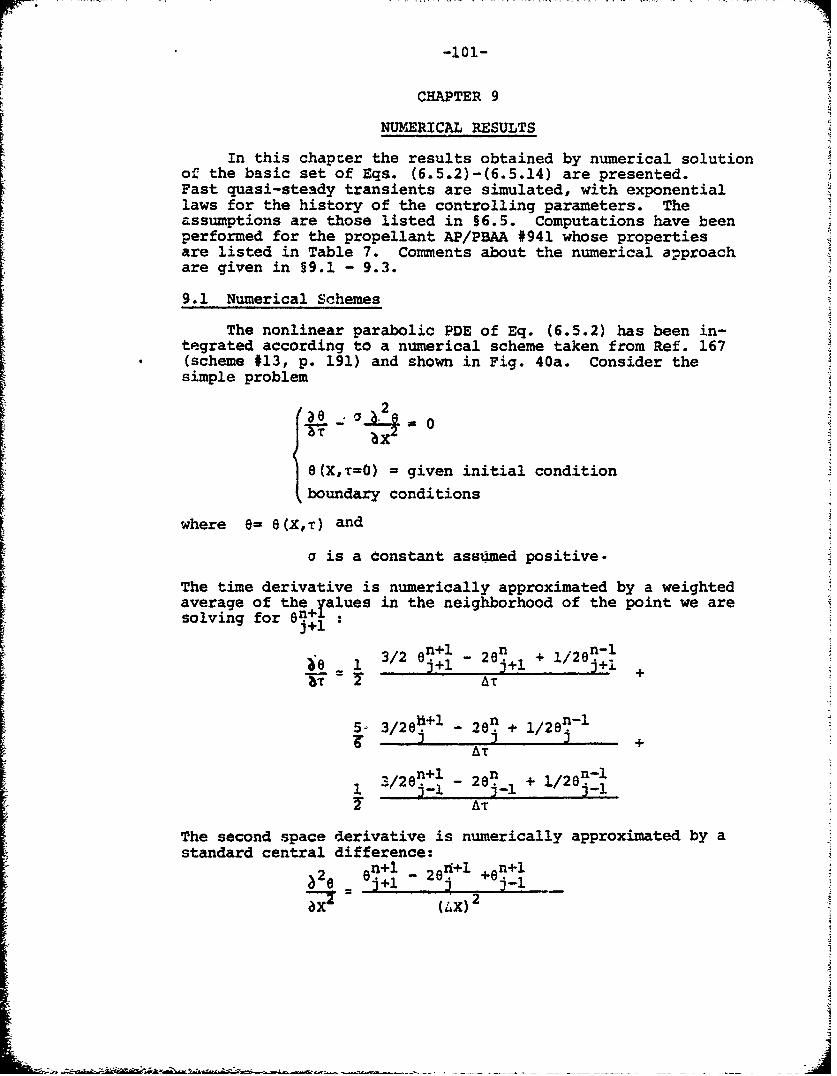
-101-
CHAPTER 9
NUMERICAL RESULTS
In this chapcer the results obtained by numerical solutionof the basic set of Eqs. (6.5.2)-(6.5.14) are presented.Fast quasi-steady transients are simulated, with exponentiallaws for the history of the controlling parameters. Theassumptions are those listed in §6.5. Computations have beenperformed for the propellant AP/PBAA #941 whose propertiesare listed in Table 7. Comments about the numerical a-proachare given in §9.1 - 9.3.
9.1 Numerical Schemes
The nonlinear parabolic PDE of Eq. (6.5.2) has been in-tegrated according to a numerical scheme taken from Ref. 167(scheme #13, p. 191) and shown in Fig. 40a. Consider thesimple problem
2
e(X,T=O) = given initial condition
boundary conditions
where e- 8(X,T) and
a is a Constant assomed positive.
The time derivative is numerically approximated by a weightedaverage of the Values in the neighborhood of the point we aresolving for n+1
•8 1 / 0~j+l -2ni+ l2nlj+i.
3++
A'rS2n~l n 2n-l1 - 3- -1 j-l + +/ j_1T AT
The second space derivative is numerically approximated by astandard central difference:sn+1 _ 8+1 en+l
:-e ei 20 +ej-
a =-lax)-
-102-
This scheme is particularly convenient for rapidly varyingfunctions and is known to be always stable. An estimate ofthe truncation error is given in Fig. 40a.
However, our problem includes other lower order terms,such as the first space derivative in the convective term,which can jeopardize the utility of the above numerical scheme.It is shown in Ref. 167 (p. 195) that stability is unaffectedby the presence of lower order terms with constant coefficients.In our case, the strong nonlinear dependence of the convectiveterm not only affects the choice of the time step size butalso might influence the stability of the overall approach.Unfortunately, no general safe method exists for dealing witha complicated problem such as the one in Eqs. (6.5.2) - (6.5.14)and the obvious method of using the above numerical schemewith sufficiently small (to be defined) discretization stepshas been adopted.
Both the boundary conditions of Eq. (6.5.2) have a directinfluence on the space net dimension, but their requirementsare in opposing directions: BC2 requires an extended spacenet which goes deep inside the solid phase, while BCl requiresa fine space net. In order to avoid unnecessary expenditureof computer core and time, the temperature at the coldboundary is considered to be approximately zero when it is ofseveral orders of magnitude less than the surface temperature.Computer runs performed for different sets of input data in-dicate that cold boundary temperatures 8(X--o,T)= 0(10-5)or less have no appreciable influence on the structure of thethermal profile near the surface of the condensed phase.For each run the total number ,JF,of space integration steps
is then chosen by requiring that e(X+-'=,T) = 0(10-6) atleast.
The numerical treatment of BCI of Eq. (6.5.2) has provedto be most delicate. This is obvious if one considers that thecoupling of the gas with the solid phase is expressed preciselythrough the energy balance of BCE. An error is introducedwhenever the temperature gradient at the surface is evaluatedusing a too large space step. Physically, this is due to thefact that volumetric terms (radiation penetration, convectiveand unsteady effects) become important compared to the surfaceterms (collapsed reacting layer, condensed and gas phase sidethermal gradients) and cannot be neglected in the energy balanceacross the finite thickness AX required by the numerical
approach. For each run the space mesh size AX is then chosenby requiring that across AX
temperature change due to volumetric termsBCl er temperature change due to surface terms «1
-103-
The above check is made at each time integration step. Com-puter runs performed for different sets of input data indicatethat a. BC1 error up to a few percent, at most, has no appreci-able influence on the overall numerical solution.
The numerical molecule shown in Fig. 40a is associatedwith a single mesh of dimensions AX-AT and implies the solutions -of J3 simultaneous algebraic equations on 3 time levels. Theparameter J3 is an integer assigning the total number of nodesin the space net. As mentioned above, J? and AX are fixedby a convenient compromise between cost and accuracy of thenumerical results in the spacewise dimension. The time stepsize A-r is chosen by requiring that the change in time ofthe surface temperature be limited to a few percent, at most,at each integration step. Typical values used for the timeand space step sizes are given in §9.2.
The algebraic system derived from the discretization ofthe PDE is then cast in a very special form called a tridiagonalmatrix. An efficient method of solution suitable for auto-matic computation is indicated in Ref. 167 (p. 199). Itshould be noticed that an initialization procedure is required,since the scheme of Fig. 40a implies the knowledge of thetwo previous time vectors 8n-'(x) anden(X)when solving for thecurrent 8n+l(X). This is accomplished by using a simple Crank-
-Nichb•sn--sciik- (shown in Fig. _40b) - for the first few timeintegration steps. This classical Crank-Nicholson scheme usestwo time levels and is always initiable, since in our transientsthe first vector in time is just the solution of the s.s. thermalprofile.
Both the schemes shown in Fig. 40 are implicit and uncon-ditionally stable (when applied to the simple diffusion problemdiscussed at the beginning of this section). However, scheme(a) is superior to scheme (b) in that, containing more *memory-of the past", it better represents rapidly varying functions.Moreover, the trincation error for scheme (a) is of order (AX) 4
rather than (4X44 as it is for scheme (b).
9.2 Organization of the Numerical Program
A flow chart of the overall program is shown in Fig. 41.The program allows the user to perform 4 different types ofcalculations: steady state or quasi-steady state transientsdue to external radiant flux and/or ambient pressure changingin time according to any arbitrary but fixed law. The type ofcalculation is optional, but has to be specified at the be-ginning by the user by assigning a certain code value to theparameter IOP (see Fig. 41).
As a first step, the s.s. configuration corresponding tothe arbitrary but fixed initial condition is evaluated. This isdone numerically by the subroutine RTMT (taken from an IBM sclenti1icpackage) solving the nonlinear,4lgebraic energy conservationequation by a bisection method1L",*. The transient is, then,
-104-
evaluated by implementing the numerical scheme of Fig. 40b(for the first time integration step at least)and Fig. 40a(for all successive time integration steps).
As already mentioned in §6.5, the coupling of the condensedphase energy equation to the surface pyrolysis law through theconvective term of Eq.(6.5.2)requires an iterative procedurefor the surface temperature e . Moreover, the coupling of thecondensed phase energy equation to the gas phase heat feedbacklaw through BC2 of Eq.(6.5.2),requires another iterative pro-cedure for the flame temperature 8 The flow chart given inFig. 41 shows that the 9 loop is Lnternal to the 0s loop,so that the overall approach consists in evaluating 8 (subroutineMEAP74) for an assumed value of 8 and then in checking .This is done with a simple trial Ind error procedure forthe first few integration steps. Successively, for computationalefficiency, a less primitive predictor-corrector tye of approachis implemented through a parabolic extrapolation. This isaccomplished separately for both loops and for each of thema convergence test is applied at every integration step accor-ding to the following definition:
l jcorrected value - predicted valueloop error E corrected value
For most runs an error of less than 1% has been specified.The numerical evaluation of the transient proceeds until neg-ligible values of burning rate (extinction) or negligibleoscillations of burning rate around the final intended s.s.value are observed.
Typical values used for the time and space step sizes are:
AT = 0.01 and AX = 0.01
The reasons behind this choice were given in §9.1. Suchvalues are by no means mandatory and have been adapted to spec-ific situations with the overall goal of the best compromise
of cost vs accuracy. A minimum number of about one hundredsteps in time is usually performed. Since the surface temp-erature gradient in most of the cases dealt with decreases intime, a variable time step size is used during the same compu-ter run. Usually a transient starts with an (initial) AT = 0.01and then proceeds with larger value up to AT = 0.10. A minimumnumber of about one thousand steps in space is usually adopted.However, particular situations (e.g., self-sustained oscillationsof burning rate or oscillatory change in time of externalradiant flux intensity impinging on a sensibly transparentpropellant) may require mucb more tedious computations.
The program has been written in the FORTRAN IV languageand has been run both on IBM 360/91 and UNIVAC 1108 computers.A typical run resulting ±ndynamic extinction requires a core
tI
-105-
of about 250 K and 30 seconds of machine time with an H levelcompiler in the IBM system.
9.3 Checks on the Numerical Approach
A series of checks were made, and some were incorporatedpermanently in the program, in order to make sure that theoverall numerical approach was performing as intended. Actually,
the difficulties inherent in the numerical solutions of Eqs.(6.5.2 - 6.5.14)deserve a full study by themselves; therefore,only semi-empirical tests are reported.
The first obvious check is to compare the results obtainedin this study with those found in previous investigations.In this respect the work by Merkle 0 has been found parti-cularly useful as to the depressurization tests. Likewise,very helpful is the comparison of the steady state solutionsfound numerically with the corresponding analytical solutions.These checks were used to localize all possible trivial errorsupstream of the overall numerical approach.
The appropriate choice of the time and space size wasverified according to the standard procedure of varying thetime and space mesh size in a programmed manner,while keepingthe input data fixed. For the values of AT and AX given in19.2 no appreciable difference in the results could be de-tected by halving or doubling the mesh size.
The stability of the overall numerical approach was checkedby letting the computer run free on hiypothetical transientswith no change in time of the controlling parameters. Oscilla-tions of negligibly small amplitude around the intital s.s.configuration (known to be physically stablej were observed.
All these checks, although successful, not only are notconclusive but also are, in principle, restricted to thosespecific situations invhich they were performed. It was feltconvenient to have some form of internal check in the programitself, so that each run could at least be considered self-consistent. Therefore, at each integration step, not onlythe cold boundary temperature and the BCU error (discussed in§9.1), but also the integral balances of energy in the solidphase and across the whole deflagration wave are checked.SAgain, these also are not conclusive tests but must rather beviewed as effective warning signals whenever the integral balanceis not satisfied at any stage of the transient.
9.4 Numerical Results from Quasi-Steady Fast Transients
In this section the results obtained by computer simulatedexperiments of quasi-steady (in the sense explained in §6.1)transients driven by fast change in time of ambient pressureor external radiant flux are described.
-106-
9.4'.1 Backgrouhd and" Qkalitative Considerat~ions
The general set of assumptions underlying the resultspresented in this and following sections has been summarizedin §6.5. It should be recalled that because of the q.s.assumption, all of the results of this work are not valid ifthe characteristic time in a gas phase is not small comparedwith the characteristic time associated with the external change.in particular, this implies that stepwise change of the control-ling parameters should not be considered. Notice that the non-dimensional temperature defined according to(Eq. 6.5.1a)hasbeen used. Likewise, the surface pyrolysis law defined accord-ing to the mixed Arrhenius -KTSS type law discussed in §8.2has been used.
The results have been obtained by numerical solution of thebasic set of Eqs. (6.5.2) - (6.3.14) following the approachdescribed in 99.1 - 9.3. Due to their relevance to practicalsituations, only results concerning fast change of ambientpressure or external radiant flux following the exponential.laws of Eqs. (8.3.13)and(8.3.14)are reported. Most of theresults are presented in terms of surface temperature esevolution during the time T(8s vs T plane) measured fromthe instant T=0 in which the assigned change of some controllingparameter is started. As previously done, the computing hasbeen specialized to the case of an AP based composite propellant(AP/PBAA #941) whose properties have been already listed inTable 7. However, no specific importance is attached to thisand the results are expected to show general trends.
in the plane 8s VS T the general behavior of a propellantsubjected to a fast (exponential) decrease of pressure or ex-ternal radiant flux intensity is similar. This is evident ifone compares, for example, Figs. 42-44 with Fig. 45. in botXcases the undershoot of burning rate or surface temperature, isfollowed by asymptotic or damped oscillatory recovery towardthe final s.s. value.
"As previously mentioned, extinction will occur wheneverthe trajectory goes past the no-return point in the RR or 0svs A, plane. There is no way , in general, to predict whetherthis~will happen for a given set of initial conditions. Dueto the complex nature of the problem, all criteria predictingextinction or recovery without fully solving the proper set ofequations are necessarily approximate to an unknown extent and,therefore, should be considered with caution. This is an intrin-sic difficulty with any nonlinear system. On the other hand,physical intuition allows only a very qualitative statement:the more "intense" the disturbance due to the controlling par-ameter change is, the more likely it is that extinction willoccur. Within the framework of the q.s. assumption, the intensityof the disturbance is somehow measured by the adjustments re-quired in the condensed phase thermal profile. This impliesthat extinction is favored by an external change which is fast
-107-
compared to the characteristic time in the condensed phase orby a large gap between the initial and final s.s. values andso on. Another intrinsic property with any nonlinear systemis that a very small change of initial conditions may yielda completely different response of the system to the givendisturbance. This strong dependence of the fate of the transienton the initial conditions is shown, for example, in Fig. 44:here a recovery process changes into a dynamic extinction whenthe initial radiant flux intensity suffers an extremely smallincrease of about 0.01% from 10,i = 156.85 cal/cm2 -sec toIo'i = 156.87 cal/cm2 -sec. The point we wish to make is that,in general, numerical integration is the only "exact" methodavailable for studying all of the intriguing aspects of anonlinear system.
9.4.2 Comparison Between Deradiation and DepressurizationRuns
In Fig. 42 the surface temperature (or, with a nonlinearchange of scale, the burning rate) evolution in time is shownfor a deradiation transient from an initial value Io •(parametrically changed), of the external radiant flux intensityto a final value Io f = 0, according to the exponential lawof Eq. (8.3.14)with Ar = 10. The point at T = 0 gives the s.s.value corresponding to I 0 i, while the dashed line indicatesthe final s.s. value corresponding to 1 o0f = 0. The runs inFig. 42 have been performed for an opaquS propellant burningat a pressure P = 30 atm. Several values of Io have beentested: for Io,i increasing, the initial s.s. value of surfacetemperature increases too while the undershoot becomes greater.However, the qualitative aspect of the.:system response is thesame: an asymptotic recovery follows the end of the deradiation.It will be noticed that the duration of the undershoot isapproximately 2 units of nondimensional time, that is, it isof the order of the characteristic time (indicated as T =2.13in the figures) associated with the condensed phase conauctivethermal wave at the operating pressure.
In Fig. 43 the evolution of the surface temperature forstill larger values of I i is shown. It is seen that theundershoot region becomes'wider and wider until recovery nolonger occurs and the surface temperature decreases monotoni-cally down to zero (ambient temperature in dimensional terms).This phenomenon is called dynamic extinction, since we know thata static solution actually exists. This fact confirms thedynamic nature of the extinctions observed in ignition experi-ments for fast actuation of the shutters. It will be noticedthat the change of the system response occurs abruptly forIo,i = 157 cal/cm2 -sec. As already mentioned, if one takesa closer look at the transition from recovery to extinction(see Fig. 44) the effect of the nonlinearity of the system willbe fully evident. The propellant tested is able to go througha prolonged undershoot period at Io 0 = 156.85 cal/cm2 -sec,but will extinguish for 10,i = 156.7 cal/cm2 -sec. Notice thatthere is practically no di ference between the two curves forabout 50% of the transient. Comparison of Figs. 42,43 and 44
-108-A
also makes it evident that the recovery is more abrupt whenthe undershoot is more pronounced.. This& was indeed expectedafter the qualitative comments about the nature of the restoringfunction made in §8.7. Further discussions on Fig. 44 aregiven in §9.5.
In Fig. 45 the evolution of the surface temperature forderadiation runs at the pressure P - 10 atm is shown. Thesame comments previously made hold true, except that therecovery process is now oscillatory in nature. In agreement withthe qualitative expectations from §8.7, the oscillations aredamped and have a period of the order of relaxation time of theconductive thermal wave in the condensed phase.
A similar behavior may be observed for depressurizationruns. In Fig. 46, for example, exponential' depressurizationsfrom the 1Hini.,apressure Pi = 30 atm to the final pressurePf = 10 atm are shown. For increasing values of the coeffi-cient Bp from 0.15 to 1.0, the undershoot is more and morepronoun ed and consequently the oscillatory nature of therecovery process more and more evident. The damping shrinksthe amplitude of the waves to a few percent of the final s.s.value within two or three oscillations (having a period of theorder of magnitude of the relaxation time in the condensedphase at the final pressure). Further increasing of the initialrate of depressurization up to Bn - 10 makes the recoveryprocess more abrupt. This is shown in Fig. 47.
In a RR vs 4 plane the trajectory of a deradiationtransient (being Isobaric) is drastically different from thetrajectory of a depressurization transient. This is illustratedin Fig. 48. The deradiation path depicted corresponds to anexponential decrease of radiant flux intensity from 1o'156 cal/cm2 -sec to Io f = 0 with Br = 10 at the pressureP = 30 atm. The rela ed surface temperature evolution intime is shown in Fig. 43. Notice that the recovery point occurswell below the static stability line. The two depressurizationpaths depicted correspond to an exponential decrease of ambientpressure from Pi = 30 atm to Pi = 2 atm with B = 0.10 (re-covery) and BD = 0.15 (extinction). A comparison with Fig. 47shows that, by lowering the final pressure to Pf = 2 atm,dynamic extinction occurs for Bp = 0.15(Fig. 48), whereas for Pf = 10 atm (all the other parametersbeing kept constant) extinction is avoided even for B p 10(Fig. 47).
9.4.3 Effect of Radiation Penetration
The effect of radiation penetration inside the condensedphase is shown in Fig. 49. Here a simple Beer's law ha__been used for the distribution of tfheradiant flux intensityin the interior of the slab. This can be a gross mistake forsituations in which scattering of radiation may occur. Howto cope with this difficulty is discussed in Appendix B.
~i
-109-
In any event, the volumetric heating of the condensed phaseimplies a less steep temperature gradient at the surface andtherefore has a smoothing effect on the dynamics of the system.Two limiting cases are evident: when the absorption coefficienta ÷ - or, more generally, whenever Xth/rd >> 1 (see App. A.2)the results found for opaque samples shoul be valid; conversely,for a - 0 the sample is totally transparent and thereforetotally insensitive to deradiation disturbances. This isverified in Fig. 49, in which the minimum initial radiant fluxintensity Io i for obtaining dynamic extinction is plottedvs the absorption coefficient a. The horizontal asymptoticcorresponds to the critical value of 1o i as already determinedin Fig. 45. All the other values have Leen determined bygo/no-go tests at the computer. For a = 200 am-1 the criticalvalue of Io i is much above 200 cal/cm2 -sec and further computersimulated testing has been considered unrealistic. The plothas been made for a given set of values (indicated in figure)of the operating conditions. An increase of pressure or a de-crease of deradiation rate would make the burning region wider.
It will be noticed that the tran3parency of the condensedphase strongly affects the results for a less than approxi-mately 700 cm- 1 . In particular , for a = 250 cm- 1 (whichis approximately expected to be the value of the absorptioncoefficient for AP propellants at 1i.6• u a value of lo i(of the order of several 100 cal/cm. -sec)
much above the experimental range investigated in this reportis required for causing dynamic extinction at P = 10 atm.Although the plot is not intended'.to represent any specificactual situation, there is an indication that in order to ver-ify experimentally the occurrence of dynamic extinctiýon forAP propellants the proper attention should be given also tothe optical properties of the sample. On the other hand, itis known (see Table 5, for example) that AP propellants ex-hibit considerably lower absorption coefficient in the arcimage wavelength. This might be another reason why AP propellantdynamic extinction has not been reported even in those lab-oratories where large power output arc image furnaces withfast shutters are currently operated.
Specific histories of the surface temperature during aderadiation transient are shown in Figs. 50 and 51 for theindicated sets of operating conditions. The smoothing effectof the transparency on the undershoot is self-evident for theabsorption coefficient decreasing to 500 cm- 1 . For evenlower values of the absorption coefficient (Fig. 51), the un-dershoot is less and less pronounced but a stronger oscill-atory behavior is observed. Again, the oscillations are dampedand have a period of the order of the relaxation time (Tp)of the conductive thermal wave in the condensed phase at theambient pressure. Notice, however, that in general at thebeginning of the deradiation transient the characteristic timeTp is reduced (as compared to the final value taken when theexternal radiant flux no longer acting) to the extent in which theburning rate is increased by the presence of radiation.
-110-
Further comments about the effects of transparency ondynamic burning are given in the next section.
9.5 Check of the Dynamic Stability Aalysis by ComputerSimulated Yests.
The basic conclusion of the nonlinear stability analysispresented in Ch. 8 is the existence of two welt distinguishedlines as static and lower dynamic stability boundaries in theE. vs 4-plane. The meaning of these boundaries has been ex-plained:in detail in §8.2 and §8.3. We wish now to check the
-validity of these developments by running computer simulatedtests.
Focusing again our attention to Fig. 44 (already intro-duced in §9.4.2), we can tentatively infer from the nature ofthe depicted trajectories that. a no-return point, if it exists,is located at about Os S 0.67 at the operating pressure ofP - 30 atm. This is in very good agreement with the predictionof 69 m 0.66 of Fig. 32 (see the unstable root at P - 30 atm).Moreover, it was shown in Fig. 48 that the recovery point fora fast deradiation from Ioi = 156 cal/cm2-sec occurs wellbelow the static boundary point OS = 0.81 at the operatingpressure of P - 30 atm. This confirms that static boundarieshave no direct pertinence to dynamic burning regimes.
In order to get more substantial evidence for the validityof the ideas underlying the dynamic stability analysis, otherruns have been made with the specific purpose of defining theno-return point, if it exists, for different situations by ago/no-4*procedure at the computer. The results are summarizedin Fig. 52. At lO, 20 and 30 atm the no-return point forexponential deradiation is just above the lower dynamic stab-ility boundary as determined in Ch. 8 and much below the staticstability boundary. The strong dependence of the results onthe initial conditions may be appreciated by considering thefigures reported in Table 13 for the "bracketing* values ofinitial radiant flux intensities 1o i. defining the no-returnpoint in terms of surface temperature 8s. The above resultshave been interpreted as suggesting the existence of a lowerdynamic boundary line in the sense specified in 18.3.
... furt che the-- no-return point has also been deter-mined at P - 10 atm for several values of the absorptioncoefficient a. For reasons of economy the go/no-go procedurehas not been pushed too far and the results summarized in Fig.53 have been judged to be satisfactory. Again the bracketingvalues of 1o 1 and the observed limiting values of Ss arereported in lable 13. The comparison with the predicted "limiting values of 6s (see Fig. 32) is excellent.
The generality of the approach suggested in Ch. 8 has beentested by considering a deradiation transient with a variablecoefficient Br in Eq. (8.3.14). It was found that increasingor decreasingf the rate of the exponential decay at any inomentof the transition would result in dynamic extinction.
A
only if the lower dynamic stability boundary is crossed.Incidentally, it was observed that changes in the decay rateare most effective in affecting the overall fate of the dynamichistory if realized in the early poriton of the transition.
Similar considerations can be made for monotonic, typicallyexponential, go/no-go depressurization tests. See, for example,Fig. 54 and the last two lines of Table 13. Again, a very goodagreement is found between the observed and the predictedlimiting values of 0s.
It should be clearly understood that the above result ofdetecting recovery points down to 8s = 0.6 is important onlyto the extent to which it illustrates the validity of the analy-tical developments of this report. Indeed, it is very question-able whether chemical processes are still active at such lowsurface temperatures. Moreover, heat loss mechanisms arevery likely not negligible in that surface temperature range.All this implies that more sophisticated flame models haveto be considered, if one wishes accurate results in the mar-ginal domains of burning.
The point we wish to make here is that the numericalintegration of the basic set of equations in terms of the PDEsuggests the existence of a no-return point for fast transientsand defines its value by a trial and error procedure. Thevalues obtained in several different configurations are inexcellent agreement with the predictions made from an analysisof the approximate ODE describing the system. This also confirmsthat the static stability boundary, as determined for examplein the Zeldovich approach, has no relevance in dynamic dis-turbances of finite size.
Results concerning the upper dynamic stability limits areillustrated in Figs. 55-57. Runs with exponential increaseof pressure from Pi = 10 atm to Pf = 30 atm are plotted forseveral values of the surface heat release Qs (cf. Table 10).For Q$ sufficiently low (Fig. 55), one observes a smoothtransition from the initial to the final steady state equili-brium configuration (see, for example, Qs = -150 cal/g). Forlarger values of Qs, a vigorous acceleration of the waveoccurs (Fig. 56). Following this, the heterogeneous deflagrationwave will relax toward a regime solution (Fig. 57). This isthe stable steady state reacting configuration for Qs less thanthe A-D roots coalescence value (for example, Qs = -180 cal/g),self-sustained oscillations for Qs larger than the A-D rootscoalescence value (for example, Qs = -200 cal/g), and thestable steady state unreacting configuration for Q. largerthan the B-D roots coalescence value (for example, Q. = -230cal/g, not drawn) or whenever the dynamics of the transientare too fast (for example, Qs = -210 cal/g) compared to thepropellant response capability.
I
-112-
Self-sustained oacillations have been observed in severaldifferent situations. The nature of oscillations dependsonly on the static restoring function associated to the finalburning conditions. For example, the same regime oscillationshave been found with B = 1.0 and Bp = 200 for the pressuri-zation transient shown in Fig. 57. Notice that the peaksof the oscillations, e 1.65 maximum and 8 0.83 minimum,are comparable respectively with the value o? the E root (es= 1.61) and D root (8s - 0.94) listed in Table 10 for Q= -200cal/g. Moreover, the period of the oscillations is abbut1.5 nondimensional units of time, which is of the order of therelaxation time of the conductive thermal wave in thecondensed phase.
Upper instability phenomena of one-dimensional AP de-flagrations were discussed by Strablel§9 in 1971. However,only very recently 170 numerical results showing self-sustainedoscillations of solid propellants were reported. Experimen-tally, oscillatory behavior in a pressurization test was ob-served in Ref. 171, but. burning rate oscillations there wereattributed to the experimental apparatus.
Iii
[
2I
-113-
CHAPTER 10
CONCLUSIONS
Before unifying in §10.2 the conclusions from the broadvariety of findings and concepts which have been presented, aschematic list of major observations and results is 4ivenin §10.1. Suggestions for future work, both theoretical andexperimental, are offered in §10.3.
10.1 Major Observations and Results
In the experimental portion (Chapters 3 to 5) of this inves-tigation, the following points have been made within the limitsof the experimental range investigated:
1. AP composite propellants at low pressure (e.g., 5 atm)ignite as soon as a critical surface temperature isreached (Figs. 6 and 7).
2. The flame structure (Fig. 11) of the AP propellants(i.e., a thin flame strongly coupled to the burningsurface) provides a strong energy feedback to the pro-pellant surface (compare with #7 below).
3. The effect of large metal content in AP propellantsgreatly reduces radiation penetration below the surface(Table 4).
4. Noncatalyzed DB propellants exhibit dynamic extinctionwhen exposed to rapid deradiation in the laser ignitionapparatus (Figs. 9 and 15).
5. Noncatalyzed DB propellants are difficult to ignite atlow pressure (e.g., 5 atm).
6. Catalyzed DB propellants do not exhibit dynamic extinctionand are ignitable also at low pressure (e.g., 5 atm).
7. The flame structure of the noncatalyzed DB propellants(i.e., a thick gas phase weakly coupled to the burningsurface) provides a relatively weak energy feedback tothe propellant surface when compared to the energyfeedback from AP propellants (Fig. 12).
8. A characteristic carbonaceous-appearing layer (Fig. 13)is observed at the surface of catalyzed DB propellantsburning at low pressure (e.g., 4 atm).
9. The difficulty in igniting HMX propellants with the arcimage furnace is possibly due to the high surface reflec-tivity and endothermic surface decomposition processes.
-114-
10. The effect of carbon addition to AP or DB propellantsis essentially physical, i.e., concentrates radiationat the surface.
11. The presence of 02 (Fig. 17) in the environmental gas:
- eliminates the dynamic extinction of noncatalyzed DBpropellants.
- eliminates the pressure dependence of ignition ofcatalyzed DB propellants in the low pressure domain(e.g., 5 to 10 atm).
- does not affect the high pressure (e.g., > 21 atm)ignition boundary of the propellants tested in N2 .
12. The appearance of the flame (experimentally) and thesimple thermal theory (theoretically) are acceptableignition criteria within the limits of this experimental 14
investigation:
- in presence of oxygen: for any experimental condi-tion and for any of the tested propellants.
- for AP composite propellants: for any experimental
condition.
- for catalyzed DB propellants in inert gas: only athigh pressure (e.g., 21 atm) and low radiant flux(e.g., 10 cal/cm2 -s).
- for noncatalyzed DB propellants in inert gas: for
no experimental condition.
13. A steady pre-ignition gasification has been observedfor both noncatalyzed and catalyzed DB propellants(§4.7, Fig. 20 and Table 6).
14. The same qualitative behavior is found when propellantsare tested in the laser and arc image ignition apparatus,except the dynamic extinction phenomenon (§4.6).
15. The large differential within the illumination profile(Fig. 2) and, possibly, a considerable radiation pene-tration (§9.4) prevent dynamic extinction using the arcimage apparatus.
16. Long exposure times destroy the dynamic extinction dueto 3D re-ignition effects and flame spreading beyondimpingement area (§4.4).
-115-
17. Laser ignition tests are more easily interpretable thanarc image ignition tests, in that only one wavelengthis involved.
18. The structure of the laser beam implies a nonuniformsuccession of events on a microscopic scale over theirradiated spot (§4.7).-
A unifying interpretation of the above facts has been made bymeans of the generalized radiative ignition map shown in Fig. 21.Overall conclusions are offered in the next section.
As to the analytical developments (Chapters 6 to 8), ithas been shown that:
1. Mihlfeith's analysis of radiation-driven responsefunction can be improved (§7.2) by a better choiceof the flame model (Fig. 27) and by assigning a con-sistent set of input data.
2. a large surface energy release is destabilizing inthe framework of a linearized theory (Fig. 30).
3. A nonlinear (lower) static stability boundary has beendefined in the low (fractions of cm/s) burning rateregion (§8.2).
4. a nonlinear lower dynamic stability boundary has beendefined in the low (fractions of cm/s) burning rateregion (§8.3).
5. nonlin-ear static and dynamic stability boundaries maybe defined also in the large (several cm/s) burningrate region (§8.5).
6. dynamic extinction may occur both for too fast deceler-ation (e.g., by depressurization) and acceleration (e.g.,by pressurization) of the heterogeneous combustionwave (Figs. 54 and 56).
7. for a range of parameters, self-sustained oscillationsof the burning rate are the only allowed regimesolution (§8.6).
8. a large surface energy release is destabilizing alsoin the framework of nonlinear theory (Figs. 34a and34b).
9. stability properties of burning solid propellants arecontained in the algebraic nonlinear static restoringfunction, which is strictly dependent on the nature ofthe solid propellant (Figs. 31 to 35).
-116-
A more detailed summary of the findings from the nonlinear
stability analysis has already been given in §8.8. Overallconclusions are offered in the next section.
In the last portion of this investigation (Chapter 9)numerical results have been collected which indicate that:
1. depressurization and deradiation transients are similarin a burning rate vs time plane, in that dynamic extinc-tion or asymptotic recovery or damped oscillation mayfollow the transient (cf. Figs. 42-45 with Figs. 46-47).
2. depressurization and deradiation trajectories are differ-ent in a burning rate or surface temperature vs heatfeedback plane (Fig. 48).
3. optical transparency of the propellants moderates thedynamic burning effects (Figs. 49-51).
4. computer simulated tests confirm the validity of thenonlinear stability analysis (Figs. 52-57 and Table 13).
10.2 Conclusions
The first part of this research consists of a systematicexperimental investigation of several classes of solid rocketpropellants. The ignition trends of different propellant typeshave been rationalized in terms of basic differences in thestructure of the deflagration wave in the solid and gas phases.For example, double-base propellants, in which a large portionof the heat feedback is from the surface reactions, show ignitioncharacteristics with more pronounced dependence on pressure anddynamic burning conditions than ammonium perchlorate-based com-posite propellants, in which lesser portion of the heat feedbackis from the surface reactions.
In agreement with other studies, the data clearly isolatethe domains (high pressure, low radiant flux intensity, presenceof oxygen, etc.) where simple thermal ignition theories apply andthose domains (low pressure, high radiant flux intensity, inertpressurizing gas) where ignition theories taking into accountthe interaction of the incipient gas phase flame with the solidphase are required.
With respect to the measurement technique, it has been foundthat the use of a laser ignition apparatus is an improvement overthe previous radiant ignition furnaces in that dependence of theresults on wavelength and angular distribution of the impingingradiant flux is eliminated. It has been shown that the basicphenomena are the same in the arc image and laser ignitionapparatus but differing quantitative results may be found due tothe differing physical configurations. A major source of the
S-
-117-
quantitative difference is the wavelength dependence of theradiation penetration. An exception to the general agreementof ignition behavior is found with the simultaneous occurrenceof fast actuation of shutters and a uniform illumination profile.Under these circumstances, dynamic extinction of noncatalyzedDB propellants is observed in the laser ignition apparatus.
This study offers evidence that radiative ignition testsare a powerful diagnostic technique for the understanding ofheterogeneous flames but are not suitable for propellantignitability rating. Reasons for this are: (1) difficult-to-interpret effects of the solid propellant optical trans-parency, (2) the slow chemical kinetics in the cool gas phasenear the surface (already stressed in previous studies), (3)the problems posed by the dynamic response of the propellant,and (4) the spatial distribution of the impinging radiation(these are studied in detail here for the first time).
The dynamic extinction phenomenon prompted a theoreticalstudy of the solid propellant burning stability. This was per-formed both for linear (small disturbances) and nonlinear (largedisturbances) situations. First, a review has been made of thestudy of Mihlfeith dealing with a linearized frequency responseanalysis of both pressure- and radiation-induced disturbances.After correcting Mihlfeith's work, the normalized nondimensionaladmittance function for opaque propellants is shown to be thesame for variable pressure or radiation intensity driven mechanismsfor the wide class of AP-based composite propellants. This con-firms the validity of Mihlfeith's suggestion of testing thestability of a propellant by its response to a radiative stimulus.For example, the admittance function shows the destabilizingeffect of a large amount of energy release at the surface of aburning propellant. The potential of this approach, however,is limited by the assumption of small disturbances.
A nonlinear stability analysis of solid propellant burningwas carried out. This required an integral method in reducingthe partial differential equation for the condensed phase heatconduction to an approximate ordinary differential equation.It is shown that, within the limits of this approximation, analgebraic function can be defined that contains all basic proper-ties of equilibrium and stability of burning solid propellants.This is called nonlinear static restoring function; it does notdepend on time, but strictly on the nature of the solid propellant.Analysis of the restoring function reveals that two well-definedburning regimes exist, each limited by a stability boundary: thestatic regime, which can be observed experimentally and thereforecan be studied also in the framework of Zeldovich approach; andthe dynamic regime, which cannot be observed experimentally in astationary mode and (in principle) can only be studied in theframework of a flame model. The fundamental importance of thisdistinction is stressed by the fact that under dynamic conditionsthe propellant may pass through a region which is staticallyunstable.
-118- ---- ~-
The static stability boundary (defined as the line of separa-tion between a region where stable steady-state solutions areallowed and a region where only unstable or no steady solutionsare found) has been determined theoretically in the burningrate vs heat feedback plane in the framework of the MTS flamemodel. This static stability boundary corresponds to the intrin-sic stability boundaries found by other investigators with linear-ized analyses. Moreover, in this work, for the first time, alower dynamic stability boundary has been defined that is applic-able under broad conditions. The lower dynamic stability bound-ary is defined as that ultimate burning condition beyond whichextinction necessarily follows during a burning transient.
Analysis of the dependence of the restoring function on thesurface heat release reveals other, unexpected phenomena. Forincreasing values of the surface heat release at constant pres-sure, it is found that static and dynamic instabilities mayappear both in the low and in the high burning rate regions.Upper dynamic instability implies vigorous oscillations of thecombustion wave, possibly followed by dynamic extinction. Upperstatic instability implies that the stationary reacting equilib-rium solution is no longer allowed. Under these circumstances,it is found that either self-sustained oscillations or the non-burning state are the only stable solutions, depending on thesurface heat release value. A technique to determine these upperboundaries and the domains of self-sustained oscillations isdemonstrated. Estimates of the oscillation amplitude andfrequency are also made on a very simple basis.
An entirely new spectrum of phenomena arises in this exam-ination of heterogeneous flame dynamics. It is shown, for example,that no dynamic limit exists if a minimum value (depending on theambient pressure) of residual radiant flux impinges on the burn-ing propellant following a fast quasi-steady transient. It isshown that a large ratio of gas/surface heat release is stronglystabilizing. It is shown that stability properties are notnecessarily related to heat losses from propellants. It isshown that dynamic extinction may occur due to fast decelerationof the combustion wave (e.g., by depressurization) as well asdue to fast acceleration (e.g., by pressurization), if an exces-sively large burning rate overshoot is attained.
Numerical results based on the Merkle-Turk-Summerfield (MTS)flame model show that transients following both fast depressur-ization or fast deradiation are zimilar in that dynamic extinction,exponential recovery, and damped oscillations may occur in bothcases. The thermal wave relaxation time in the condensed phaseis the controlling time parameter for the dynamic response ofthe system. However, as expected from previous studies, theoptical transparency of the solid phase decreases the sensitivityof the propellant to dynamic disturbances of burning when radiation
-119-
is the forcing function. Likewise, scattering of the radiation(considered here for the first time) at the interior of the solidphase also has a damping effect (see Appendix B).
The validity of the approximate analytical approach has been
verified by computer-simulated transients. Excellent agreementhas been found between the analytical predictions and the numeri-cal results obtained by integration of the governing partialdifferential equation. In particular, the lower dynamic stabil-ity boundary has been verified by go/no-go deradiation and de-pressurization runs under several different operating conditions;the existence of an upper instability region has been verifiedby pressurization runs; self-sustained oscillations have beenfound in the expected range of parameters.
Numerical values are given only for a particular ammoniumperchlorate composite propellant. Nevertheless, it is expectedthat the conceptual findingsof the theoretical part of this-workmay be extended not only to other types of solid rocket propel-lants, but more generally to deflagration waves associated withany condensed reactive substance, provided a proper flame modelis employed.
Finally, notice that the transformation from a partial intoan ordinary nonlinear differential equation has been performedby a standard, but approximate, integral method. This can bestrongly improved by a more sophisticated approach, for example,the weighted residuals method. Nevertheless, it is again expectedthat the conceptual findings will not be affected although theaccuracy of the predictions should be further improved.
10.3 Suggestions for Future Work
Several questions are still open as to the use of radiantenergy sources in heterogeneous combustion problems. First, adetailed knowledge of the optical properties of the propellantsis still lacking; progress in this direction is being made(see Ref. 103). The interaction of the impinging radiant beamwith the gas phase plume extending above the propellant surfacealso needs to be investigated; this could affect, in particular,the occurrence of dynamic extinction following fast deradiation.Experimental results in this area have been given by Mihlfeith(Section F.1 of Ref. 126b), but as yet no data for the laserignition apparatus used here are available.
With specific reference to the radiative ignition experi-ments performed in this investigation, the occurrence of dynamicextinction for AP composite and DB catalyzed propellants has yetto be proved. The effects of catalyst addition to DB propellantsand, partially, of carbon powder addition still are largelyunexplored. The presence of a stationary gasification processprior to ignition also needs to be put in some comprehensivecontext.
-120-
A major experimental objective would be to define the dynamicstability line. As already mentioned in §8.7, go/no-go testingby fast depressurization or deradiation is sufficient to locatethe lower dynamic stability boundary in the same way as done bycomputer-simulated tests (see Fig. 41, for example). In order toperform more meaningful experiments, it is suggested as futurework to run deradiation tests in a stepwise fashion from aninitial radiant flux intensity Ioi to a residual or finalradiant flux intensity Io,f To the extent in which the con-densed phase reacting layer is negligible as compared to theradiantly heated layer (§A.2), the final radiant flux intensityIo,,f may be converted to an equivalent ambient temperature(Fig. 25). In this case, the meaning of Zeldovich's stabilityboundary (expressed in terms of ambient temperature) and theexistence of the lower dynamic stability boundary as definedin §8.3 may be tested simultaneously, Indeed, for a given o,f?Io,i could be increased until a recovery point occuns in thestatically unstable region; according to Zeldovich this alwaysimplies dynamic extinction, whereas according to the theorydeveloped in this study, dynamic extinction occurs only whenthe limiting no-return point is passed. This check can be donefor different sets of values of Io i and 1 o,f. It is alsoexpected from the analysis presenteA in Chapter 8 that above acertain minimum value (depending on the ambient pressure) ofIo,f the dynamically stable burning region is extended (seeFig. 33); on the contrary, the Zeldovich criterion is unable topredict any change in the stability properties of the system.This procedure can be repeated for different pressures. Thedegree of freedom associated with a variable Io f is then usedboth for testing the reproducibility of the resulting stabilityboundary (whatever it is, if it exists) and for discriminatingbetween the predictions of the Zeldovich approach from those ofthe approach proposed in this work.
It is suggested to perform the above experimental check inthe laser apparatus by testing opaque propellants in a inert gasatmosphere. Attention should be paid to the fact that a steadydeflagration wave has to be established before starting thederadiation.
As to the theoretical aspects, some improvements on the model(see §6.5) used throughout this investigation are in order. Fol-lowing T'ien's 1 2 3 suggestion, heat loss mechanisms should be ac-counted for in order to obtain more accurate results. Likewise,it is believed that the inertia of the condensed phase reactinglayer might be very important in the marginal region of dynamicburning stability. The necessity of an optical model explicitlyaccounting for possible radiation scattering in condensed phasehas been often mentioned; a background in this area is offered inAppendix B. However, it has already been mentioned that a basicimprovement of the theoretical model will be the use of moresophisticated methods (e.g., weighted residual method) for ob-taining the nonlinear static restoring function.
-121-
REFERENCES
1. Most, W. J. and Summerfield M., "Starting Thrust Transientsof Solid Rocket Engines", AMS Report No. 873, July 1969,Princeton University, Princeton, N.J.
2. Larue, P. and Nadaud, L., "Processus d'Allumage desPropergols Solides," ONERA T.P. No. 1182, 1972. Seealso: Rech. A~r.,No. 6,1972, pp. 297-311.
3. Peretz, A., Caveny, L.H., Kuo, K. K. and Summerfield, M.,"The Starting Transient of Solid Propellant Rocket MotorsWith High Internal Gas Velocities", AMS Report No. 1100,
April 1973, Princeton University, Princeton, N.J.
4. Summerfield, M., Shinnar, R., Hermance, C.E., and Wenograd,J., "A Critical Review of Recent Research on the Mechanismof Ignition of Solid Propellants," Aeronautical EngineeringLaboratory Report No. 661, AF-AFOSR- 92-63, August 1963,Princeton University, Princeton, N.J.
5. Price, E. W., Bradley, H.H.,Jr., Dehority, G. L., andIbiricu, X. M., "Theory of Ignition of Solid Propellants",AIAA Journal, Vol. 4, No. 7, July 1966, pp. 1153-1181.
6. Barrore, M., "Solid Propellant Ignition: General Consider-
ations" Rech. AMr., No. 123,1968, pp. 15-28.
7. Merzhanov, A. G. and Averson, A. E., "The Present Stateof the Thermal Ignition Theory: An Invited Review,"Combustion and Flame, Vol. 16, No. 1, February 1971, pp. 89-124.
8a. Ohlemiller, T. J. and Summerfield, M., "Radiative Ignitionof Polymeric Fuels in an Oxidizing Gas", AMS Report No. 876,AFOSR Contract AF-69-1651, August 1969, Princeton University,Princeton, N.J.
8b. Ohlemiller, T. J. and Sunmerfield, M., "Radiative Ignitionof Polymeric Materials in Oxygen/Nitrogen Mixtures", Thir-teenth Symposium (International) on Combustion, TheCombustion Institute, 1971, pp. 1087-1094.
9. Frank-Kamenetskiy, D. A., "Distribution of Temperaturesin a Reaction Vessel and the Steady State Theory of ThermalExplosion," J. Phys. Chem., Vol. 13, No. 6, 1939.
10. Frank-Kamenetskiy, D. A., "A Nonsteady Theory of ThermalExplosion", J. Phys. Chem., Vol. 20, No. 2, 1946.
11. Barzykin, V. V., Gontkovskaya, V. T., Merzhanov, A.G. and Khudyayev, "A Theory of Thermal Explosion in UnsteadyState", PMTF. Translation AFSC #FTD-MT-64-319, pp. 196-209.
ý-122-
12 Merzhanov, A. G. and Strunina, A. G., "Laws of ThermalExplosion with Constant Heating Rate", Combustion, Ex-2losion, and Shock Waves, Vol. 1, No. 1 , 1965, pp.59-69.
13. Strunina, A. G., Gontkovskaya, V. T., and Merzhanov, A.G.,"Laws of Thermal Explosion. III. Temperature Field andTransition from Autoignition to Ignition", Combustion,Explosion, and Shock Waves, Vol. 1, No. 3, 1965, pp. 36-40.
14. Vilyunov, V. N., "On the Thermal Theory of Ignition",Combustion, Explosion, and Shock Waves, Vol. 2, No. 2,1966, pp. 77-82.
15. Rozenband, V. I., Barzykin, V. U., and Merzhanov, A. G.,"Ignition of Condensed Substances by Convective Heat Fluxesof Medium Intensity under Dynamic Conditions", Combustion,Explosion, and Shock Waves, Vol. 4, No.,2, 1968, pp. 171-175.
16. Lisitskii, V. I. and Pribytkova, K. V., "Ignition ofCondensed Substances in the Presence of a Phase Transitionin the Heated Layer", Combustion, Explosion, and ShockWaves, Vol. 4, No. 4, 1968, pp. 501-512.
17. Averson, A. E. and Rozenbad, V. I., "Approximate Methodsof Calculating Critical Ignition Conditions," Combustion,Explosion, and Shock Waves, Vol. 4, No. 4, 1966, pp.519-525.
18. Zelikman, E. G., "Degenerate Thermal Explosion Regimesof Autocatalytic Reactions", Combustion, Explosion, andShock Waves, Vol. 4, No. 4, 1968, pp. 563-567.
19. Frazer, J. H. and Hick.s:, B. L., "Thermal Theory ofIgnition of Solid Propellants", J. Phys. Coll. Chem.,Vol. 54, No. 6, 1950, pp. 872-876.
20. Hicks, B. L., "Theory of Ignition Considered as a ThermalReaction", J. Chem. Phys., Vol. 22, No.3, 1954, pp. 414-429.
21a. Bradley, H. H., Jr., "Theory of Ignition of a Reactive Solidby Constant Energy Flux", NWC TP 4618,November 1968, NavalWeapons Center, China Lake, Calif.
21b. Bradley, H. H., Jr., "Theory of Ignition of a ReactiveSolid by Constant Energy Flux", Combustion Science andTechnology, Vol., 2,.No. 1, August 1970, pp. 11-20.
22. Altman, D. and Grant, A. F., Jr., "Thermal Theory ofSolid Propellant Ignition by Hot Wires", Fourth Symposium(International) on Combustion, 1953, pp. --161.
23. Zeldovich, Ya. B., "On the Theory of Combustion of Powderand Explosives", Zh. Eksperim i Teor. Fiz., Vol. 12,NO.II-12.1942, pp. 498-524.
-123-
24. Librovich, V. B., "Ignition of Powders and Explosives",PMTF, No. 6, November-December 1963, pp. 74-80.
25. Vilyunov, V. N., and Sidonskii, 0. B., "Ignition of Con-densed Systems by Radiant Eneray", Combustion, Explosion,and Shock Waves, Vol. 1, No. 4, 1965, pp. 39-43.
26. Baer, A. D., and Ryan, N. W., "Ignition of CompositePropellants By Low Radiant Fluxes", AIAA Journal, Vol. 3,No. 5, May 1965, pp. 884-889.
27. Price, E. W., Bradley, l.H.,.Jz~, and Fleming, R. 0.,Jr.,"Ignition of Solid Propellants", Western States Section ofthe Combustion Institute, WSS/CI Paper 63-6, April 1963.
28. Price, E. W., Bradley, R. H.;.Jr., Hightower, J. D., andFleming, R;- 0.Jr.,: "Ignition of Solid Propellants", AIAAPreprint #64-120, January 1964.
29. Rosser, W. A., Fishman, N., and Wise, H., "Ignition ofSimulated Propellants Based on Amonium Perchlorate", AIAAJournal, Vol. 4, No. 9, September 1966, pp. 1615-162Y.
30. Gray, P. and Harper, M. J., "The Thermal Theory of InductionPeriods and Ignition Delays", Seventh Symposium (Inter-national) on Combustion, Butterworths Publ., 1959, pp.425-430.
31. Gray P. and Harper, M.J., "Thermal Explosions. Part I.Induction Periods and Temperature Changes Before Spontane-ous Ignition", Trans. Far. Soc., Vol. 55, Part 4, April1959, pp. 581-59W.
32. Gray, P. and Harper, M. J., "Contribution of Self-Heatingto the Reactivity of Solids", Fourth International Symposiumon the Reactivity of Solids, edited by J. H. DeBoer,Elsevier Publ., 1961.
33. Koval'skii, A. A., Khlevnoi, S. S., and Mikheev, V. F.,"The Ignition of Ballistite Powders", Combustion, Ex~lo-
sion, and Shock Waves, Vol. 3, No. 4, 1967, pp. 527-541.
34. Averson, A. E., Barzynin, V. V., and Merzhanov, A. G.,"Dynamic Ignition Regimes", Combustion, Explosion, and
Shock Waves, Vol. 4, No. 1, 1968, pp. 20-32.
35. Zarko, V. E. and Khlevnoi, S. S., "'Hot Wire Ignition ofBallistite Propellants", Combustion, Explosion, andShock Waves, Vol. 4, No. 2, 1968 pp. 158-170.
36a. Baer, A. D. and Ryan, N. W., "Ignition and Combustionof Solid Propellants", Final Report AFOSR 68-1858,September 1967, Utah University.
36b. Baer, A. D., and Ryan, N. W., "An Approximate but CompleteModel for the Ignition Response of Solid Propellants*,AIAA Journal, Vol. 6, No. 5, May 1968, pp. 872-877.
-124-
37. Von Elbe, G., "Theory o)f Solid Propellant Ignition andResponse to Pressure &ransients", Bulletin of the 18thInteragendy Solid Propulsion Meeting, CPIA No. 18, Vol.III, June 1963, pp. 95-127.
38. Pantoflicek, J., and Lebr, F., "Ignition of Propellants",Combustion and Flame, Vol. 11, No. 6, December 1967, pp.464-470.
39. McAlevy, R. F. III, Cowan, P. L., and Summerfield, M.,
"The Mechanism of Ignition of Composite Solid Propellantsby Hot Gases", ARS Progress in Astronautics and Rocketry:Solid Propellant Rocket Research, Vol. 1, edited by M.Summerfield, Academic Press, New York, 1960, pp. 623-652.
40. Kling, R., Maman, A., and Brulard, J., "La Cinftiquede l'Allumage des Poudres Composites sous, l'Influencede Flux de Chaleur El~ve's", Rech. Adr., No. 103, 1964,pp. 3-10.
41. Hermance, C. E., Shinnar, R., and Summerfield, M.,"Ignition of an Evaporating Fuel in a Hot Oxidizing GasIncluding the Effect of Heat Feedback," Astronautica Acta,Vol. 12, No. 2, 1966, pp. 95-112.
42. Hermance, C. E. and Kumar, R. K., "Gas Phase IgnitionTheory for Homogeneous Propellants under Shock Tube Con-ditions", AIAA Journal, Vol. 8, No. 9, September 1970,pp. 1551-1558.
43. Kashiwagi, T., MacDonald, B. W., Isoda, H., and Summerfield,M., "Ignition of a Solid Polymeric Fuel in a Hot OxidizingGas Stream", Thirteenth Symposium (International) onCombustion, The Combustion Institute, 1971, pp. 1073-1085.
44. Anderson. R., Brown, R. S. and Shannon . J., "IgnitionTheory of Solid Propellants", AIAA Pr- ! it No. 64-156,Solid Propellant Rocket Conference, i -ry 1964.
45. Brown, R. S., Wirrick, T .K., and Anderson, R., "Theory ofIgnition and Ignition Propagation of Solid Propellants ina Flow Environment", AIAA Preprint 64-157, January 1964.
46. Williams, F. A., "Theory of Propellant Ignition by Hetero-geneous Reaction", AIAA Journal, Vol. 4, No. 8, August1966, pp. 1354-1357.
47. Waldman, C. H. and Summerfield, M., "Theory of PropellantIgnition by Heterogeneous Reaction", AIAA Journal, Vol.7, No. 7. pp. 1359-1361, July 1969.
48. Bradley, H. H., Jr., "Heterogeneous Ignition Theory",NWC TP 4864, February 1970, Naval Weapons Center, China
Lake-, Calif.
' 1i
-125-
49. Bradley, H. H., Jr. and Williams, F. A., "Theory ofRadiant and Hypergolic Ignition of Solid Propellants",Combustion Science and Technology, Vol. 2, No. 1, August1970, pp. 41-52.
50. Waldman, C. H., "Theory of Heterogeneous Ignition",Combustion, Science and Technology, Vol. 2, No. 2-3,November 1970, pp. 81-93.
51. Bowden, F. P. and Yoffe, A. D., Initiation and Growthof Explosions in Liquids and Solids, Cambridge at theUniversity Press, 1952.
52. Bowden, F. P. and Yoffe, A. D., Fast Reactions in Solids,Butterworths Scientific Pulications, London, 1958.
53. Johansson, C. H. and Persson, P. A., Detonics of HighExplosives, Academic Press, London, 1970.
54. Jost, W., Explosion and Combustion Processes in Gases.McGraw Hill Book Co., Inc., New York 1946, translatedby H. 0. Croft.
55. Lewis, B. and Von Elbe, G., Combustion, Flames and Explo-sions of Gases, Academic Press, New York, III Edition, 1970.
56. Gaydon, A. G. and Wolfhard, H. G., Flames, Their Structure,Radiation and Temperature, Chapman and Hall itd., LoidonIII Edition, 1971.
57. Williams, F. A., Combustion Theory, Addison -Wesley Co.,Mass., 1965.
58. Anderson, L. 0. and Shook, G. B., "Experimental Study ofFactors Affecting the Mechanics of Ignition", Bulletin ofthe Fifth Mtg of the Army-Navy Solid Propellant Group,SPIA, 1949, Applied Physics Laboratory, J. Hopkins University,Silver Spring, Md.
59. Avery, W. H., "Radiation Effects in Propellant Burning",J. Phys. Chem., Vol. 54. No. 6, June 1950, pp. 917-928.
60. Baer, A. D., "Ignition of Composite Rocket Propellants".Ph. D. Thesis, University of Utah, 1959.
61. Baer, A. D., Ryan, N. W. and Salt, D. L., "Ignition ofComposite Propellants", Report AFOSR TN59-516, March1959, University pf Utah.
62. Mitchell, R. C., f.eller, J. A., Baer, A. D. and Ryan,N. W., "Ignition and Combustion of Solid Propellants",Final Technical Report AFOSR 2225, September 1961,University of Utah.
I
r -126-
63a. Beyer, R. B., and Fishman, N., "Solid Propellant IgnitionStudies with High Flux Radiant Energy as a Thermal Source",ARS Progress in Astronautics and Rocketry: Solid Propell-ant Rocket Research, Vol. 1, edited by M. SummerfiefJ7Academic Press, New York, 1960, pp. 673-692.
63b. Beyer, R. B., Ferguson, F. A., and Fishman, N., "ArcImage Furnace Ignition Studies", Final Report No. PRU-3614,June 1961, Hercules Powder Co. , Stanford ResearchInstitute.
64a. Hightower, J. D., NOTS letter to participants, Inter-laboratory Solid Propellant Ignition Exchange Program,October 1964.
64b. Hightower, J. D., NOTS Memorandum, "Comparative Calibrationof Calorimeters", April 1965.
65. Arc Image Ignition Brochure, CPIA Publication 238, June1973.
66. Bastress, E. K., Allan, D. S., and Richardson D. L.,"Solid Propellant Ignition Studies", Technical Documen-tary Report No. RPL-TDR-64-65, Contract AF04(611)-9065,October 1964.
67. Bastress, E. K., "Test Methods For Solid PropellantRocketIgniter Development", Proceedings of the 2ndICPRG Combustion Conference, 1966, pp. 551-561.
68. Sutton, D., and Wellings, P. C., "The Ignition of SolidPropellants by Radiant Energy", Report #RDE-TR-66/4,April 1966, Rocket Propulsion Establishment, Essex,England.
69. Evans, M. W., Beyer, R. B., and McCulley, L. "Initiationof Deflagration Waves at Surfaces of Ammonium Perchlorate-Copper Chromite-Carbon Pellets", J. Chem Phys., Vol. 40,May 1964, pp. 2431-2438.
70. Fleming, R. W. and Derr, R. L., "The Use of NonreactiveCoatings in Solid Propellant Arc-Image Ignition Studies",Proceedings of the Seventh JANNAF Combustion Meeting,CPIA Publication 204, Vol. 1, Feb. 1971, pp. 379-389.
71. Shannon, L. J., "Composite Solid Propellant IgnitionMechanism", Technical Report # UTC 2138-ASRl, May 1966,United Technology Center, Sunnyvale, Calif.
72a. Shannon, L. J., "Composite Solid Propellant IgnitionMechanisms", Final Report AFOSR 67-1765, September 1967,United Technology Center, Sunnyvale, Calif.
72b. Shannon, L. J., and Deverall, L. I., "Composite SolidPropellant Ignition Characteristics", Bulletin of theFourth ICRPG Combustion Conference, Vol. 1, October 1967,p. 409, Stanford Research Institute, Menlo Park, Calif.
-127-
73. Beyer, R. B., Anderson, R., McLaren, R. D., and Corcoran,W. J., "Ignition of Solid Propellant Motors Under Vacuum",Final Report UTC 2079-FR, April 1965, United TechnologyCenter, Sunnyvale, Calif.
74. Fishman, N., "Solid Propellant Ignition Studies",Report #AFRPL-TR-65-213, November 1965, StanfordResearch Institute, Menlo Park, Calif.
75. Summerfield, M., and Ohlemiller, T. J., "A CriticalAnalysis of Arc Image Ignition of Solid Propellants",AIAA Journal, Vol. 6, No. 5, May 1968, pp. 878-886.
76a. Kondrikov, B. N., Ohlemiller, T. J. and Summerfield, M.,"Kinetics and Gasification of a DB Propellant Induced byCO2 Laser Radiation", presentation at the ThirteenthSymposium (International) on Combustion, Utah,A-Part, 1970.
76b. Kondrikov, B. N., Ohlemiller, T. J., Caveny, L. H. andSummerfield, M., "Ignition Criteria and Self-Heating ofPropellants Subjected to Radiative Heating", presentationat the Eastern Section of Combustion Institute, Ga.,November 1970.
77. Ohlemiller, T. J., Caveny, L. H., DeLuca, L. and Summer-field, M., "Dynamic Effects on Ignitability Limits of SolidPropellants Subjected to Radiative Heatinj", FourteenthSymposium (International) on Combustion, 1973, pp. 1297-1307.
78. Summerfield, M., Caveny, L. H., and DeLuca, L.,"Radiative Ignition Characteristics of Several PropellantClasses", presented at the Second Review of AMC-FundamentalsOf Ignition Task, Aberdeen, Md., November 1972.
79a. DeLuca, L., Ohlemiller, T. J., Caveny, L. H. and Summer-field, M., "Radiative Ignition of Double Base Propellants:I. Some Formulation Effects", AIAA Journal, Vol. 14,No. 7, July 1976, pp. 940-946.
79b. DeLuca, L., Ohlemiller, T. J., Caveny. L. H. a: . SummerfieldM., "Radiative Ignition of Double Base Propellants: II.Pre-Ignition Events and Source Effects", AIAA Journal,Vol. 14, No. 8., August 1976, pp. 1111 -1117.
80. Altman, D. and Nichols, P. L.,Jr., "Ignition of SolidPropellants," Report No. 20-85, September 1954,Jet Propulsion Laboratory, Calif. Inst. of Tech.
81. Hottel, H. C. and Williams, C. C. III, "Transient Heat FlowIn Organic Materials Exposed to High Intensity ThermalRadiation," Industrial and Engineering Chemistry, Vol. 47,No. 6, June 1955, pp. 1136-1143.
-128-
82. Roth, J. F., and Wachtell, G. P., "Heat Transfer and ChemicalKinetics in the Ignition of Solid Propellants", Industrialand Engineering Chemistry Fundamentals, Vol. 1, No. 1,February 1962, pp. 62-67.
83. Hightower, J. D., "An Investigation of the Effect ofEnvironmental Gases and Pressure on the Ignition of SolidRocket Propellants", Technical Report #NWC-TP-4431, October1967, Naval Weapons Center, China Lake, Calif.
84. Baer, A. D., and Ryan, N. W., "Ignition and Combustion ofSolid Propellants", Final Report AFOSR TR-69-0349, September1968, University of Utah.
85. Inami, S. H., McCulley, L., and Wise, H., "IgnitionResponse of Solid Propellants to Radiation and Conduction",Report Contract NONR-3415(00), October 1968, StanfordResearch Institute.
86. Atallah, S., Allan, D. S., Comstock, D. F., Jr. andBakerjian, B. H., "The Ignition of Solid Propellants byRadiative, Convective and Chemical Heating", Final ReportNovember 1969, A.D. Little Inc.
87. Lenchitz, C., Hayes, E., Velicky, R. W., and SilvestroG., "The Ignition Characteristics of Nitrocellulose",First Review of AMC-Fundamentals of Ignition Task-BRL,1971, Aberdeen Proving Ground, Md.
88. Evans, M. W., Moore, D. B. and McCarty R. C., "Error Analysisof Data From Arc Image Furnace Ignition Experiments",AIAA Paper No. 66-669.
89. Shannon, L. T., "Composite Solid Propellant IgnitionMechanisms", UTC, Final Report AFOSR 69-1250 TR, April1969.
90a. Merkle, C. L., Turk, S. L., and Summerfield, M.,"Extinguishment of Solid Propellants by Depressurization:Effects of Propellant Parameters", AIAA Paper No. 69-176,1969.
90b. Merkle, C. L., Turk,S. L. and Summerfield M., "Extinguish-ment of Solid Propellants by Rapid Depressurization",AMS Report No. 880, July 1969, Princeton University,Princeton, N.J.
91. Summerfield, M., and Krier, H., "Errors in Non Steady Com-bustion Theory in the Past Decade (A Review)", AIAAPaper No. 69-178, 1969.
92. Summerfield, M., Caveny, L. H., Battista, R. A., Kubota,N., Gostintsev, Yu. A., and Isoda, H., "Theory of DynamicExtinguishment of Solid Propellant with Special Referenceto Non-steady Heat Feedback Law", JSR, Vol. 8, No. 3,March 1971, pp. 251-258.
I
-129-
93. Mikheev, V. F., Koval'skii, S. S., and Khlevnoi, S. S.,"Ignition of a Ballistite Propellant by Light Radiation",Combustion, Explosion, and Shock Waves, Vol. 4, No. 1,1968, pp. 3-9.
94. Khlevnoi, S. S., and Kalmykova, A. P., "Ignition of Nitro-glycerine Powder by Light Radiation in a Cold Stream ofGas", Combustion, Explosion, and Shock Waves, Vol. 4, No.1, 1968, pp. 122-124.
95. Khlevnoi, S. S., and Mikheev, V. F., "Effect of InitialTemperature and Transparency of Nitroglycerine Powderon its Ignition by a Light Pulse", Combustion, Explosionand Shock Waves, Vol. 4, No. 4, 1968, pp. 579-583.
96. Webb, G. E., Stokes, B. B. and Graves, A. E., "Developmentof a Standard Comparison Test Procedure for Initiators",Report No. U-65-23A, May 1965,Thiokol Chemical Corp.
97. Dinsdale, V. T., "Study of Arc Ignition Techniques forSolid Rocket Propellants", Report No. RPT-TDR-64-116, August1964, Thiokol Chemical Corp.
98. Beyer, R. B., McCulley, L., and Evans, R. W., "Measurementof Energy Flux Density Distribution in the Focus of anArc Image Furnace", Applied Optics, Vol. 3, 1964,pp. 131-135.
99. Thomas, P. H., "Some Conduction Problems in HeatingSmall Areas on Large Solids", Quart. Journal of Mech.and Appl. Math, Vol. 10, 1957, pp. 482-493.
100. Kubota, N., Ohlemiller, T. u., Caveny, L. H. and Summerfield,M., "The Mechanism of Super-rate Burning of CatalyzedDouble Base Propellants", AMS Report No. 1087, March 1973,(AD 763 786), Princeton University, Princeton, N.J.
101. Steinz, J. A., Stang, P. L. and Summerfield, M.,"TheBurning Mechanism of Ammonium Perchlorate Based CompositePropellants", AMS Report No. 830, February 1969, (AD 688944), Princeton University, Princeton, N.J.
102 Derr, R. L., Beckstead, M. W. and Cohen, N. S., "CombustionTailoring Criteria for Solid Propellant", Lockheed PropulsionCompany Report No. 235-F, Technical Report AFRPL-TR-69-190,May 1969.
103. Caveny, L. H., Sunimerfield, M. and May, I. W., "PropellantOptical Properties and Transient Burning Characteristicsas Modified by Particulate Carbon", Abstract of papersubmitted to the AIAA 13th Aerospace Sciences Meeting,January 1975, Pasadena, Calif.
-130
104. Camp, A. T., et al, "A Decade of Progress in the Under-standing of Certain Ballistic Properties in Double BasePropellants", Navord Rept. 5824, 1958.
105. Ohlemiller, T. J. and Summerfield, M., "Radiation AugmentedBurning of a Solid Propellant", AMS Report No. 799, July1967, Princeton University, Princeton, N.J.
106. Thompson, C. L., Jr. and Suh, N. P., "The Interaction ofThermal Radiation and M-2 Double-Base Solid Propellant",Combustion Science and Technology, Vol. 2, No. 2-3,November 1970, pp.
107. Horton, M. D. and Youngberg, L. Z., "Effect of RadiantEnergy on the Burning Rate of a Composite Solid Propellant",AIAA Journal, Vol. 8, No. 10, October 1970, pp.1738-1741.
108. Coates, R. L. and Kwak S., "Effect of External Radiation onthe Burning Rates of Solid Propellants", JSR, Vol. 9, No.10, October 1972, pp. 742-745.
109. Linan A. and Williams, F. A., "Radiant Ignition of aReactive Solid with In-Depth Absorption", Combustion andFlame, Vol. 18, No. 1, February 1972, pp. 85-97.
110. Caveny, L. H., Ohlemiller, T. J. and Summerfield, M.,"Influence of Thermal Radiation on Solid PropellantBurning Rate", AIAA Journal, Vol. 13, No. 2, February1975, pp. 202-205.
111. Ko.tev, E. V. and Khlevnoi, S. S., "Influence of Light onthe Rate of Burning of Nitroglycerine Powder", PMTF,No. 2, March-April 1963. Translation AFSC #FTD-MT-64-87, February 1966, pp. 294-300.
112. Konev, E. B., "Influence of Light Radiation on theBurning Rate of N-Powder", Combustion, Explosion, andShock Waves, Vol. 1, No. 2, 7965, pp. 76-82.
113. Konev, E. V. and Khlevnoi, S. S., "Burning of a Powderin the Presence of Luminous Radiation", Combustion,Explosion, and Shock Waves, Vol. 2, No. 4, 1966, pp. 33-41.
114. Summerfield, M., Sutherland, G. S., Webb, 44. J., Taback,H. J., and Hall, U. P., "Burning Mechanism of AmmoniumPerchlorate Propellants", ARS Progress in Astronauticsand Rocketry: Solid Propellant Rocket Research,Vol. 1, edited by M. Sunmerfield, Academic Press, NewYork, 1960, pp. 141-182.
-131-
115. Krier, H., T'ien, J. S., Sirignano, W. A., and Summerfield,M., "Nonsteady Burning Phenomena of Solid Propellants:Theory and Experiments", AIAA Journal, Vol. 6, No. 2,February 1968, pp. 278-285.
116. Zeldovich, Ya. B., "The Burning Velocity of Powder UnderVariable Pressure", PMTF, No. 3, January-February 1964,pp. 126-130. Transla-tln AFSC #FTD-MT-64-319, pp. 210-
232.
117. Gostintsev, Ya. A. and Margolin, A. D., "On Nonstation-ary Burning of Powder", PMTF, No. 5, 1964.
118. Novozhilov, B. V., "Nonstationary Burning of PowdersHaving a Variable Surface Temperature", PMTF,No. 1, pp. 54-63, January-February 1967. TranslationAFSC #FTD-MT-24-376-68.
119. Novozhilov, B. V., "Theory of Non Stationary Combustionof Homogeneous Propellants", Combustion, Explosion andShock Waves, Vol. 4, No. 4, 1968, pp. 482-493.
120. Librovich, V. B., "Theory of Propellant Combsution: AReview of Russian Works", Manuscript based on the lecturespresented at Princeton University, Revised draft May 1970.
121. Battista, R. A., Caveny, L. H. and Summerfield, M.,"Nonsteady Combustion of Solid Propellants", AMS Report#1049, October 1972, Princeton University, Princeton, N.J.
122. Turk, S. L., Battista, R. A., Kuo, K. K., Caveny, L. H.and Summerfield, M., "Dynamic Responses of Solid RocketsDuring Rapid Pressure Change",JSR, Vol. 10, No. 2,February 1973, pp. 137-142.
123. T'ien, J. S., "A Theoretical Criterion for Dynamic Extinc-tion of Solid Propellants by Fast Depressurization",Combustion Science and Technology, Vol. 9, No. 1-2, March-April 1974, pp. 37-39.
124. Denison, M. P., and Baum E., "A Simplified Model of UnstableBurning in Solid Propellants", ARS Journal, Vol. 31, 1961,pp. 1112-1122.
125. Sehgal, R., "Low Pressure Combustion and Ignition ofSolid Rocket Propellants", Astronautica Acta, Vol. 13,1967, pp. 167-181.
126a. Mihlfeith, C. M., Baer, A. D. and Ryan, N.W., "TheResponse of a Burning Solid Propellant Surface to ThermalRadiation", AIAA Journal, Vol. 10, No. 10, October 1972,pp. 1280-1285.
-132-
126b. Mihefeith, C. M. "Some Experiments in the Effect of ThermalRadiation on Composite Rocket Propellants", Ph.D. Thesis,University of Utah, June 1971.
127. Eckhaus, W., "Studies in Nonlinear Stability Theory",Springer Tracts in Natural Phylosophy, No. 6, Springer,N.Y., 1965.
128. Hart, R. W. and McClure, F. T., "Combustion Instability:Acoustic Interaction with a Burning Propellant Surface",J. Chem. Phys., Vol. 30, No. 6, June 1.959, pp. 1501-
129. Bird, J. F., Hart, R. W. and McClure F. T., "Effect ofSolid Propellant Compressibility on Combustion Instability",J. Chem. Phys. Vol. 32, No. 5, May 1960, pp. 1423-1429.
130. Hart, R. W. and Cantrell, R. H., "Amplification andAttenuation of Sound by Burning Propellants", A7AA Journal,Vol. l, No. 2, 1963, pp. 98-404.
131. Williams, F. A., "Response of a Burning Solid to Small-Amplitude Pressure Oscillations", Journal Appl. Phys., Vol.33, No. 11, November 1962, pp. 3l53--3166.
132. Ryan, N. W., Coates R. L. and Baer, A. D., "Participationof the Solid Phase in the Oscillatory Burning of Solid.Rocket Propellants", Fourteenth Symposium (International)on Combustion, 1963, pp. 328-334.
133. Friedly, J. C. and Petersen, E. E., "Influence of Com-bustion Parameters on Instability in Solid Pr:pellantMotors: Part I. Development of Model and Linear Analysis",AIAA Journal, Vol. 4, No. 9, September 1966, pp. 1604-1610.
134. Marxman, G. A. and Wooldridge, C. E., "Effect of SurfaceReactions on the Solid Propellant Response Function",AIAA Journal, Vol. 6, No. 3, March 1968, pp. 471-478.
135. Culick, F. E. C., "Calculation of the Admittance Functionfor a Burning Surface", Astronautica Acta, Vol. 13, 1962,pp. 221-237.
136. Culick, F. E. C., "A Review of Calculations for UnsteadyBurning of a Solid Propellant," AIAA Journal, Vol. 6,No. 12, December 1968, pp. 224M1-75.
137. Culick, F. E. C., "Some Problems in the Unsteady Burningof Solid Propellants," NWC TP 4668 February 1969,Naval Weapons Center, China Lake, Calif.
138. Barr~re, M., and Nadaud, L., "Prevision des Domaines deFonctionnement Instable d'un Propulseur a PropergolSolide", ONERA T.P. No. 1016, 1971.
-133-
139. T'ien, J. S., "The Effects of Perturbations on theFlammability Limits", Combustion Science and Technology,Vol. 7, No. 4, June 1973,pp. 185-188.
140. Lengelle, G., "A Model Describing the Velocity Responseof Composite Propellants", ONERA T.P. 1285, 1973. Seealso: AIAA Paper No. 73-1224.
141. Novikov, S. S., and Riazantzev, Y. S., "Acoustic Admittanceof the Burning Surface of the Condensed System", PMTF,No. 6, 1961.
142. Novikov, S.S-., and Riazantzev, Y. S., "On the AcousticAdmittance of the Burning Surface of the Condensed Systems",PMTF, No. 6, 1964.
143. Novikov, S. S., and Riazantzev, Y. S.., "On the Interactionof Acoustic Waves and the Burning Surface of the CondensedSystems", PMTF, No. 2, 1966.
144. Price, E. W., "Status of Solid Rocket Combustion In-stability Research", NOTS, China Lake,,Calif., February1967.
145. Beckstead, M. W. and Culick, F. 8. C., "A Comparisonof Analysis and Experiment for Solid Propellant Combust4.onInstability", NWC, May 1968, China Lake, Calif.
146a. Brown, R. S., Muzzy, R. J. and Steinle, M. E., "Researchon Combustion of Solid Propellants", UTC, Final ReportNo. 2136FR, September 1968.
146b. Brown, R. S., Muzzy, R. J. and Steinle, M. E., "SurfaceReaction Effects on the Acoustic Response of CompositeSolid Propellants", AIAA Journal, Vol. 6, No. 3, March1968, pp. 479-488.
147. Lengelle, G., Kuentzmann, P;, and Rendolet, C., "Responseof A solid Propellant to Pressure Oscillations", ONERAT. P. 1410, 1974.
148. Friedley, J. C. and Petersen E. E., "Influence of CombustionParameters on Instability in Solid Propellant Motors:Part II. Nonlinear Analysis", AIAA Journal, Vol. 11,No. 4, April 1966, pp. 1932-1937.
149. Horton, M. D., Bruno, P. S. aad Graesser, E. C., "De-pressurization Induced Extinction of Burning SolidPropellant", AIAA Journal 1 Vol. 6, No. 2, February 1968,pp. 292-297.
-134-
150. Von Elbe, G. and McHale, E. T., "Extinguishment ofSolid Propellants by Rapid Depressurization", AIAA Journal,Vol. 6, No. 7, July 1968, pp. 1417-1419.
151. Marxman, G. A. and Wooldridge, C. E., "Nonlinear SolidPropellant Burning Rate Behavior During Abrupt PressureExcursion", AIAA Paper, No. 68-172, 1969.
152. Brown, R. S. and Muzzy, R. J., "Linear and NonlinearPressure Coupled Combustion Instability of Solid Propellants",AIAA Journal, Vol. 8, No. 8, August 1970, pp. 1492-1500.
153. Coates, R. L. and Horton, M. D., "Predicted Effects ofMotor Parameters on Solid Propellant Extinguishment",JSR, Vol. 7, No. 12, December 1970, pp. 1468-1470.
154. Park, C. P., Ryan, N. W. and Baer, A. A., "Extinguishmentof Composite Propellants at Low Pressures", AIAA PreprintNo. 73-175.
155. Istratov, A. G. and Librovich, V. B., "Burning Stabilityof Powder", PMTF. Translation AFSC #FTD-MT-65-161.
156. Barrbre, M., "Response A un Regime Transitoire de laSurface de Combustion d'un Propergol Solide HMterogene",ONERA T. P. No. 748, 1969.
157. Istratov, A. G., Librovich, V. B. and Novozhilov, B. V.,"An Approximate Method in the Theory of Unsteady BurningVelocity of Powder", PMTF, No. 3, 1964. TranslationAFSC #FTD-MT-64-319, pp. 233-242.
158. Novozhilov, B. V., Nonstationary Combustion of SolidRocket Fuels, 1973. Translation FTD-MT24-317-74.
159. Boggs, T. L. and Beckstead, N. W., "Failure of ExistingTheories to Correlate Experimental Nonacoustic CombustionInstability Data", AIAA Journal, Vol. 8, No. 4, April1970, pp. 626-631.
160. Gostintsev, Ya. A. and Margolin, A. D., "NonstationaryCombustion of a Powder Under the Action of a PressurePulse", Combustion, Explosion, and Shock Waves, Vol. 1,No. 2, March-April 1965, pp. 69-75.
161. Rozenbad, V. I., Averson, A. E., Barzykin, V. V., andMerzhanov, A. G., "Some Characteristics of DynamicIgnition Regimes", Combustion, Explosion and Shock Waves,Vol. 4, No. 4, 1968, pp. 494-500.
162. Kuo, K. K., "Theory of Flame Front Propagation in PorousPropellant Charges under Confinement", Ph.D. Thesis,August1971, AMS Department, Princeton University, Princeton, N.J.
IiIL
-135- -
163. Goodman, T. R., "Application of Integral Methods to Tran-sient Nonlinear Heat Transfer", Advances in Heat Transfer,Vol. 1, 1964, Academic Press, New York, pp. 51-122.
164. Anisimov, S. I. and Perel'man, "On One Nonlinear Problemof Thermal Conduction", PMTF, No. 5, 1903. TranslationAFSC #FTD-MT-64-61, pp. =Z228.
165. Gostintsev, Ya. A., "Method of Reduction to OrdinaryDifferential Equations in Problems of the NonstationaryBurning of Solid Propellants", Combustion, Explosion,and Shock Waves, Vol. 3, No. 3, 1967, pp. 355-361.
166. Andronov, A. A., Vitt, A. A. and Khaikin, S. E., Theoyof Oscillators, English edition by Pergamon Press7Jtd.London; U.S.A. edition distributed by Addison-Wesley,Mass., 1966.
167. Richtmyer, R. D. and Morton, K. W., Difference Methods forInitial-value Problems, Interscience Publishers, New York,1967.
168. Salvadori, M. G. and Baron, M. L., Numerical Methods inEngineering, Prentice Hall, Inc., Englewood Cliffs, N.J.,1.961.
169. Strahle, W. C., "One-Dimensional Stability of APDeflagrations", AIAA Journal, Vol. 9, No. 4, April1971, pp. 565-569.
170. Barrows, A. W., Kooker, D. E., and Nelson, W.,"Solid Propellant Unsteady Combustion", Second InternationalSymposium on Dynamics of Chemical Reactions, Universityof Padova, December 15-17, 1975.
171. Brulard, J., Kuentzmann, P., and Kiing, R., "R~ponsed'un Propergol Solide A un Echelon de Pression",Rech. Aer., No. 169, 1975, pp. 267-277.
Fr
If
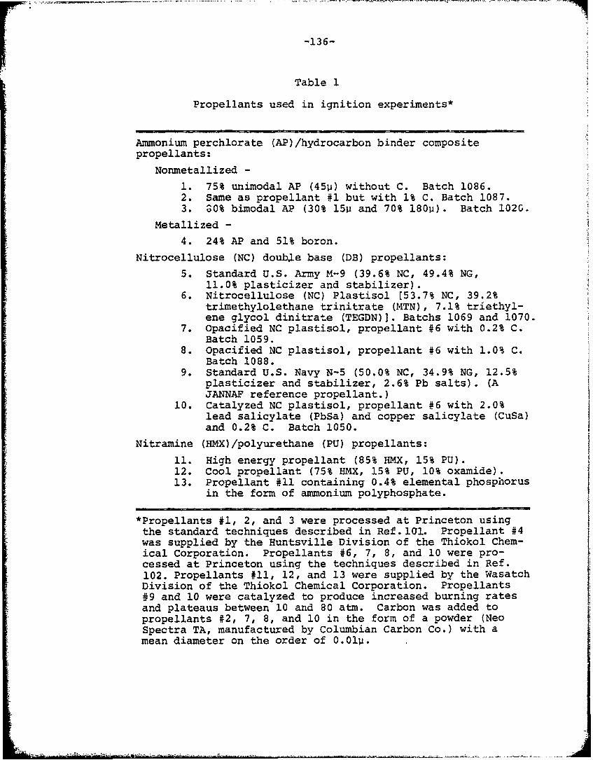
-136-
Table 1
Propellants used in ignition experiments*
Ammonium perchlorate (AP)/hydrocarbon binder compositepropellants:
Nonmetallized -
1. 75% unimodal AP (45p) without C. Batch 1086.2. Same as propellant #1 but with 1% C. Batch 1087.3. ^0% bimodal AP (30% 15 and 70% 180p). Batch 102G.
Metallized -
4. 24% AP and 51% boron.
Nitrocellulose (NC) double base (DB) propellants:
5. Standard U.S. Army M-9 (39.6% NC, 49.4% NG,11.0% plasticizer and stabilizer).
6. Nitrocellulose (NC) Plastisol [53.7% NC, 39.2%trimethylolethane trinitrate (MTN), 7.1% triethyl-ene glycol dinitrate (TEGDN)]. Batchs 1069 and 1070.
7. Opacified NC plastisol, propellant #6 with 0.2% C.Batch 1059.
8. Opacified NC plastisol, propellant #6 with 1.0% C.Batch 1088.
9. Standard U.S. Navy N-5 (50.0% NC, 34.9% NG, 12.5%plasticizer and stabilizer, 2.6% Pb salts). (AJANNAF reference propellant.)
10. Catalyzed NC plastisol, propellant #6 with 2.0%lead salicylate (PbSa) and copper salicylate (CuSa)and 0.2% C. Batch 1050.
Nitramine (HMX)/polyurethane (PU) propellants:
11. High energy propellant (85% HMX, 15% PU).12. Cool propellant (75% HMX, 15% PU, 10% oxamide).13. Propellant #11 containing 0.4% elemental phosphorus
in the form of ammonium polyphosphate.
*Propellants #1, 2, and 3 were processed at Princeton usingthe standard techniques described in Ref.l0l. Propellant #4was supplied by the Huntsville Division of the Thiokol Chem-ical Corporation. Propellants #6, 7, 8, and 10 were pro-cessed at Princeton using the techniques described in Ref.102. Propellants #11, 12, and 13 were supplied by the WasatchDivision of the Thiokol Chemical Corporation. Propellants#9 and 10 were catalyzed to produce increased burning ratesand plateaus between 10 and 80 atm. Carbon was added topropellants #2, 7, 8, and 10 in the form of a powder (NeoSpectra TA, manufactured by Columbian Carbon Co.) with amean diameter on the order of 0.01p.
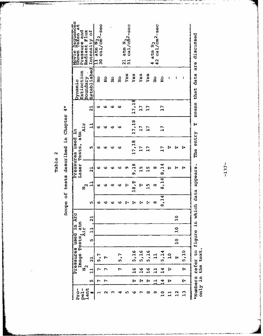
U)4
09 0 0 01
bW 0 > Ei 'Nr: E UGili) 4J Z 0 'NC) U
CJ2E-$.4 J-4 IN IN zN11
d00)*H0BU 00
124HHl (a r. (d
> Vo4 r00 .0 k( - - -
zrn i a000 00 00 H I- m d-q Q
En4 C) D) ( as
M4. - 4J 4U
H4 x 00 sJss
4.) co
m m 1-4r-4 H H-
-I 0- >1
0 10 M Ln w w w w r-r-N N E-4 E- E-4
.0 H'H*-4 004
0 $4 $4i-H ) ul w.QU) W4 4) r4 % D % D M r- - 4 U
E i n V0DE - -
m4 ( (3 co
iW N A r-4 v toD E-4 ft E-4 L.4co I4) ) H o r4 0
044 4-I
~~~~- H H H 4
00
HH MH H $444.
-H N rE4-H E- E4 4fV__
H) 4J (n 0 A N C H N$00wr-
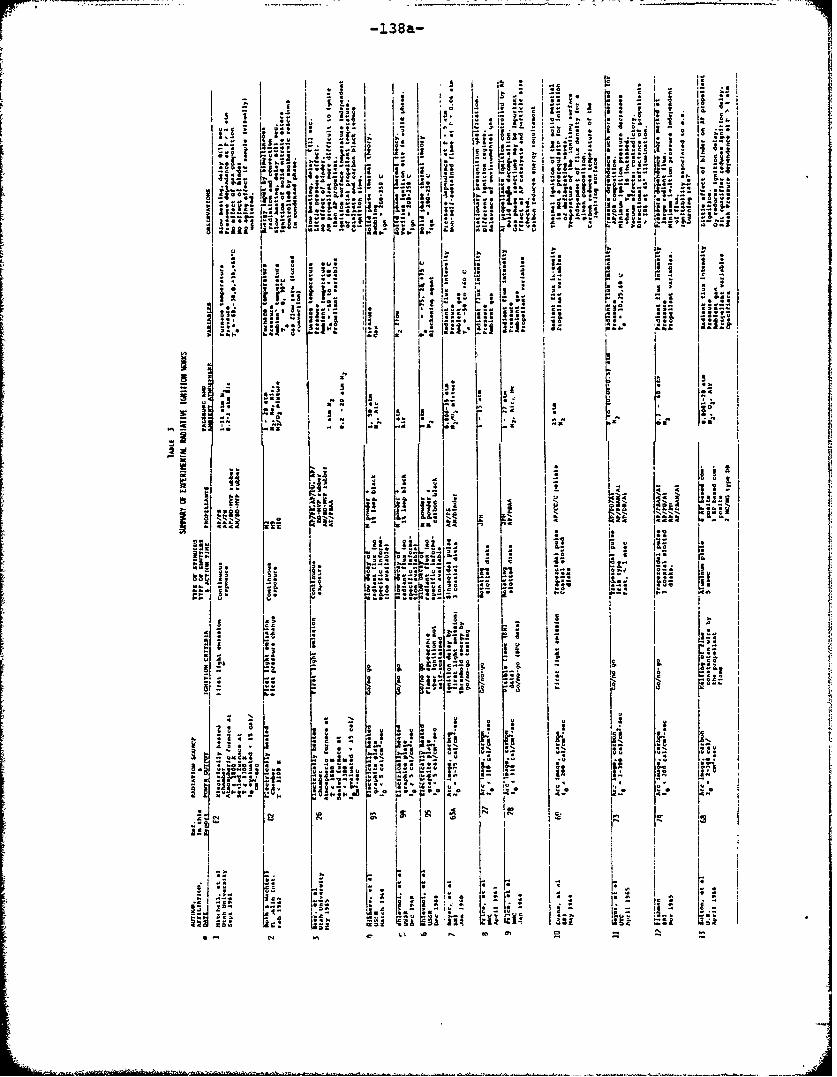
138a-
I A~h
r IZ -
-I i1
.
Ai -. -.
- I: .. l I~-
D.* ri;a
ul u'
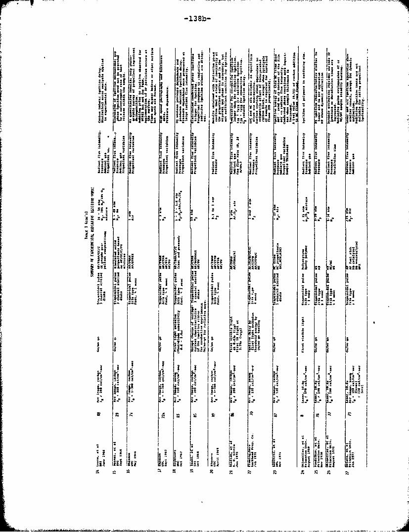
-138b-
" ii = , -, !i A. "" " I."i . a
- :" '"° 31
',, *:'-!*. I *'t = '.=--- * r . ,,,,++. .
": F- 2 "" US": .i.I+:+ V i!
Ni 2 1 i
* *,,, ; - C I
4 1 S
,~ J. It -2+
IMI
%%N L S% % N . .
. i S .C -• "
ii ii -- l --+'-+ z -
8 *!1t• . ". C Lt
"Z .*
C.. 'C +' C' " C•
VI I u
"7 t
L~i.L I. I [6+ 1i * l ,. . **: I-
++ . '.'l l," ""2 Iq" I+++ N.
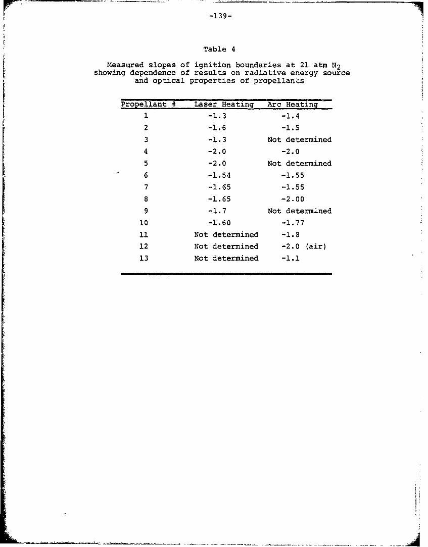
-139-
Table 4
Measured slopes of ignition boundaries at 21 atm N2showing dependence of results on radiative energy sourceand optical properties of propellants
Propellant # Laser Heating Arc Heating
1 -1.3 -1.42 -1.6 -.
3 -1.3 Not determined4 -2.0 -2.0
5 -2.0 Not determined
6 -1.54 -1.557 -1.65 -1.55
8 -1.65 -2-00
9 -1.7 Not determined
10 -1.60 -1.77
11 Not determined -1.8
12 Not determined -2.0 (air)
13 Not determined -1.1
It
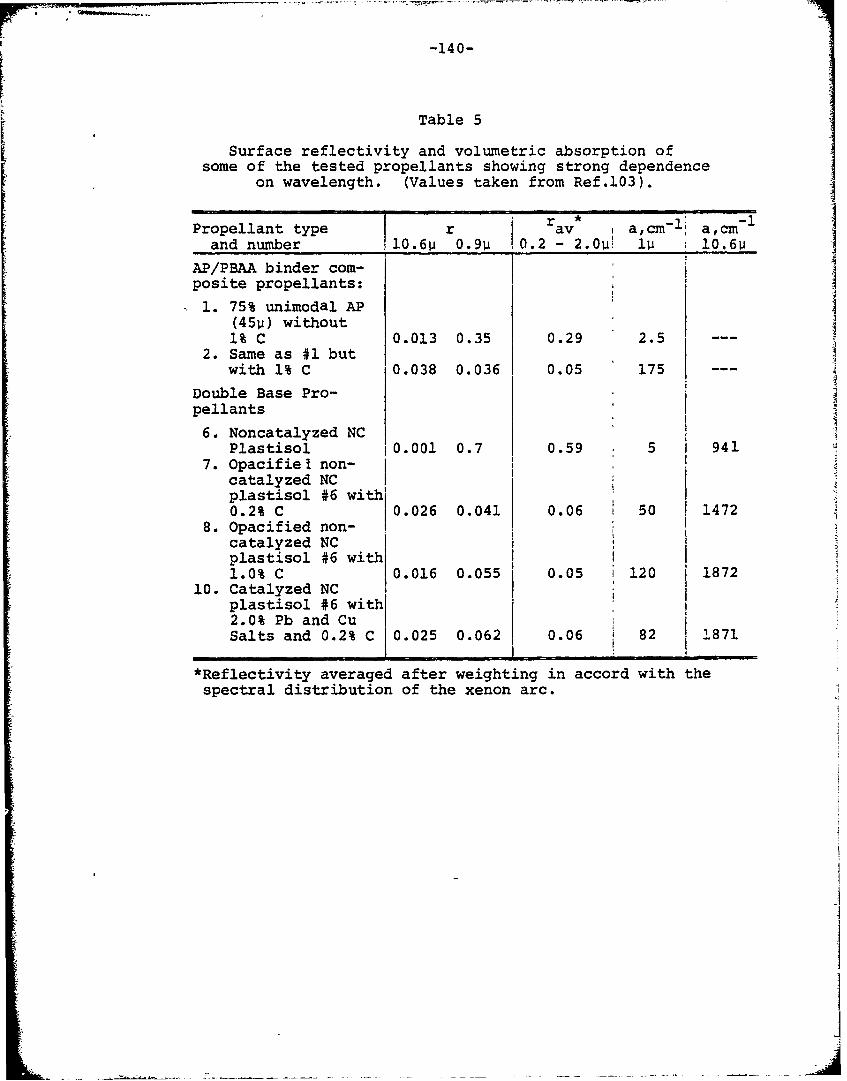
-140-
Table 5
Surface reflectivity and volumetric absorption ofsome of the tested propellants showing strong dependence
on wavelength. (Values taken from Ref.103).
Propellant type r av a,cm- 1 a,cm-and number 10.6p 0.9u 0.2 - 2.0u! u : 06
AP/PBAA binder com-
posite propellants:
1. 75% unimodal AP(450) without1% C 0.013 0.35 0.29 2.5
2. Same as #1 butwith 1% C 0.038 0.036 0.05 175
Double Base Pro-pellants
6. Noncatalyzed NCPlastisol 10.001 0.7 0.59 5 1 941
7. Opacifiel non-catalyzed NCplastisol #6 with10.2% C 0.026 0.041 0.06 50 1472
8. Opacified non-Icatalyzed NC Iplastisol #6 with1.0% C 0.016 0.055 0.05 120 1872
10. Catalyzed NCplastisol #6 with2.0% Pb and Cu 1 0Salts and 0.2% C 0.025 0.062 0.06 82 1871
*Reflectivity averaged after weighting in accord with thespectral distribution of the xenon arc.
i1
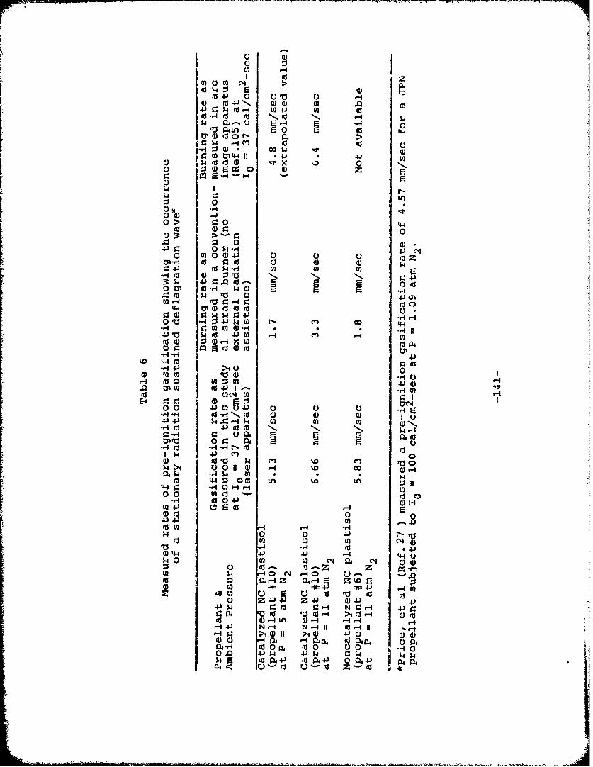
0 41Ul
0) o 4 N 004J C 0 $4 0Srl ( J U
,c 40 0 N0 As 4
01 0
r. U00Q 0l4 1 -4 1U
4(d( w x
0
0 L0
U20 0) 4
0 >4- 0 0 04As 4) .0 0001
40 0 (DN. N0 ow -r 40 ra 4) o1M
0 1 $4 -4 W'n0n
3: k -P 0 ud l (0dO~- wp ( r )-
00 (0,40 V W00r- m4
Ea4 ( 40 Hr
4J rO $4 CO V 4VM1 0-. a)Z rZ
CO 0 r= HOW06 44.H 12.H
CO 0
cc~ VOH to 5 ] H
>i011 Zi0 4)0 0)1E00 4)M040) 0 Q 0 ~ L.rq rj I ( -4 I--, co4) 104.)~E 4.% $4A j- U ) ( 1-
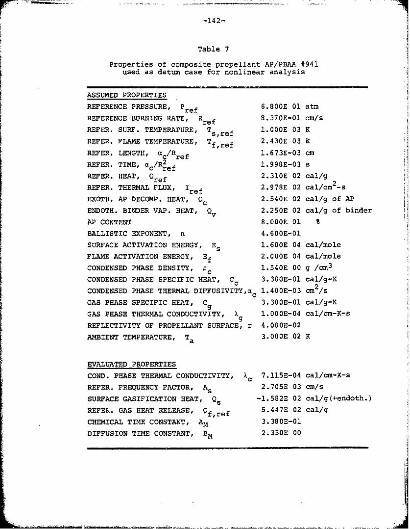
-142-
Table 7
Properties of composite propellant AP/PBAA #941used as datum case for nonlinear analysis
ASSUMED PROPERTIES
REFERENCE PRESSURE, Pref 6.800E 01 atm
REFERENCE BURNING RATE, Rref 8.370E-01 cm/s
REFER. SURF. TEMPERATURE, Ts,ref 1.OOOE 03 K
REFER. FLAME TEMPERATURE, T 2.430E 03 KREFER. LENGTH, 1/R.673E-03 m
c/Rref 163-3cREFER. TIME, /R2ef 1.998E-03 s
REFER. HEAT, Qref 2.310E 02 cal/g2
REFER. THERMAL FLUX, Iref 2.978E 02 cal/cm -s
EXOTH. AP DECOMP. HEAT, Qc 2.540E 02 cal/g of AP
ENDOTH. BINDER VAP. HEAT, Q 2.250E 02 cal/g of binder
AP CONTENT 8.OOOE 01 %
BALLISTIC EXPONENT, n 4.600E-01
SURFACE ACTIVATION ENERGY, Es 1.600E 04 cal/mole
FLAME ACTIVATION ENERGY, E 2.OOOE 04 cal/mole
CONDENSED PHASE DENSITY, p 1.540E 00 g /cm 3c
r CONDENSED PHASE SPECIFIC HEAT, Cc 3.300E-01 cal/g-K
CONDENSED PHASE THERMAL DIFFUSIVITYac 1.400E-03 cm2 /s
GAS PHASE SPECIFIC HEAT, Cg 3.300E-01 cal/g-K
GAS PHASE THERMAL CONDUCTIVITY, X 1.OOOE-04 cal/cm-K-sg
REFLECTIVITY OF PROPELLANT SURFACE, r 4.OOOE-02AMBIENT TEMPERATURE, Ta 3.000E 02 K
EVALUATED PROPERTIES
COND. PHASE THERMAL CONDUCTIVITY, Xc 7.115E-04 cal/cm-K-s
REFER. FREQUENCY FACTOR, As 2.705E 03 cm/s
SURFACE GASIFICATION HEAT, Qs -1.582E 02 cal/g(+endoth.)
REFER. GAS HEAT RELEASE, 0f,ref 5.447E 02 cal/g
CHEMICAL TIME CONSTANT, AM 3.380E-01
DIFFUSION TIME CONSTANT, BM 2.350E 00
M[
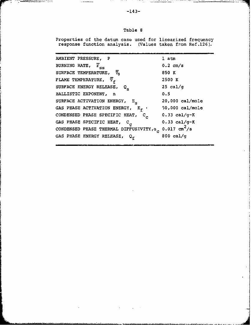
-143-
Table 8
Properties of the datum case used for linearized frequencyresponse function analysis. (Values taken from Ref.126).
AMBIENT PRESSURE, P 1 atm
BURNING RATE, r 0.2 cm/s
SURFACE TEMPERATURE, Ts 850 K
FLAME TEMPERATURE, Tf 2500 K
SURFACE ENERGY RELEASE, 25 cal/g
BALLISTIC EXPONENT, n 0.5
SURFACE ACTIVATION ENERGY, Es 20,000 cal/mole
GAS PHASE ACTIVATION ENERGY, Ef ' 50,000 cal/mole
CONDENSED PHASE SPECIFIC HEAT, Cc 0.33 cal/g-K
GAS PHASE SPECIFIC HEAT, C 0.33 cal/g-Kg
CONDENSED PHASE THERMAL DIFFUSIVITY,ac 0.017 cm2 /s
GAS PHASE ENERGY RELEASE, Qf 800 cal/gf
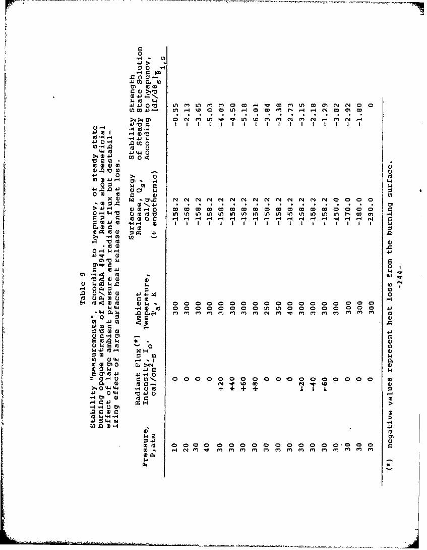
V -
4 - la.~0 : -.
41 M o (n
440
41 ra~ c I I I I I I I I I I I I
.0 Up
0n 0 U
4J 0OW0 $4 m)
-0 W EE g: 0
20% M : = N, 4> r-4 -4 0 0; 0 ; c ; c 0 In ; 0 ; ; 0 ý c ý 0
4j0 t -4 0) $
>1 -v~4 0) t
to4- Xw L0 4 04 -4 'IU-4J
*-4l r) 0
V (1) w r-
.0 ()e 1W 4J W
0V 000000000r.0(a FUI
rn 0 0 0
41 4ITc...
'tdn'...dfr.kA
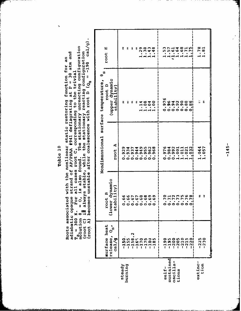
H V.c 1. . I o I 0 . . -f .
w 1 mI c
tW -1 44 M I w
""4 It-1 0I41 9-:N0 :; :% 0
-r p4J W4a0 02 I
41 44) 441'' )~1 Iz in0(d >I-4(23 (( 4$ 0 r-
r. 0 0 4)0(d I ON atcO C CA00cI
~4 ,41 W ad4
$4 4J02C;.-IC'4r't Lf0 O 06I0,
4J4.L I4 r-> 4
44 0 0 00 I4
-ri 4j 0uon4nz
OW1 ccino-r~ to~~o~INto. w.I.,4-r4- 41 4144 %~~4 C
4j~t -W II 0%0 a
.0 o- Ný ' - () 4 0200 0 24 0 1 C ;4
LE2r 04~e w (2)40 It r_
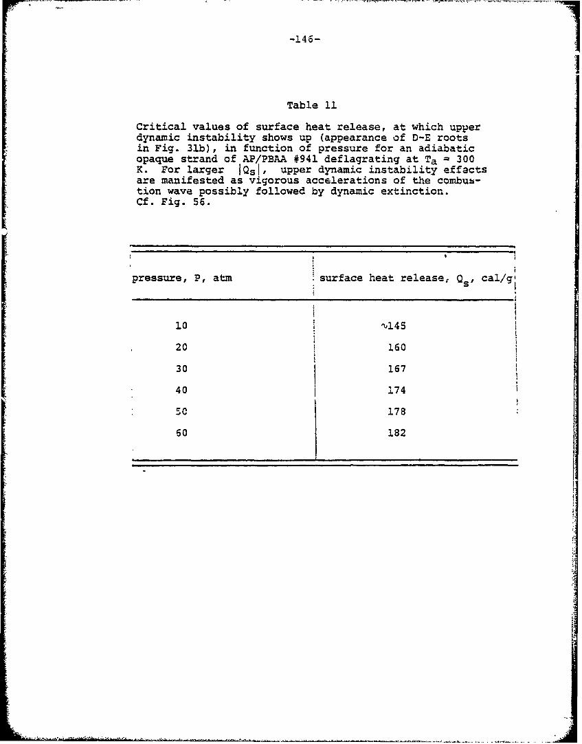
-146-
Table 11
Critical values of surface heat release, at which upperdynamic instability shows up (appearance of D-E rootsin Fig. 31b), in function of pressure for an adiabaticopaque strand of AP/PBAA #941 deflagrating at Ta - 300K. For larger IQsI, upper dynamic instability effactsare manifested as vigorous accelerations of the combus-tion wave possibly followed by dynamic extinction.Cf. Fig. 56.
pressure, P, atm surface heat release, Qs' cal/ge
10 "145
20 160
30 167
40 174
50SC 178 :
60 182
________________,_______i____________JI
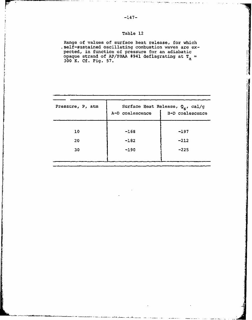
-147-
F Table 12
Range of values of surface heat release, for whichSself-sustained oscillating combustion waves are ex-pected, in function of pressure for an adiabaticr opaque strand of AP/PBAA #941 deflagrating at Ta300 K. Cf. Fig. 57. a
Pressure, P, atm Surface Heat Release, Qs' cal/g
A-D coalescence B-D coalescence
10 -168 -197
20 -182 -212
30 -190 -225
I
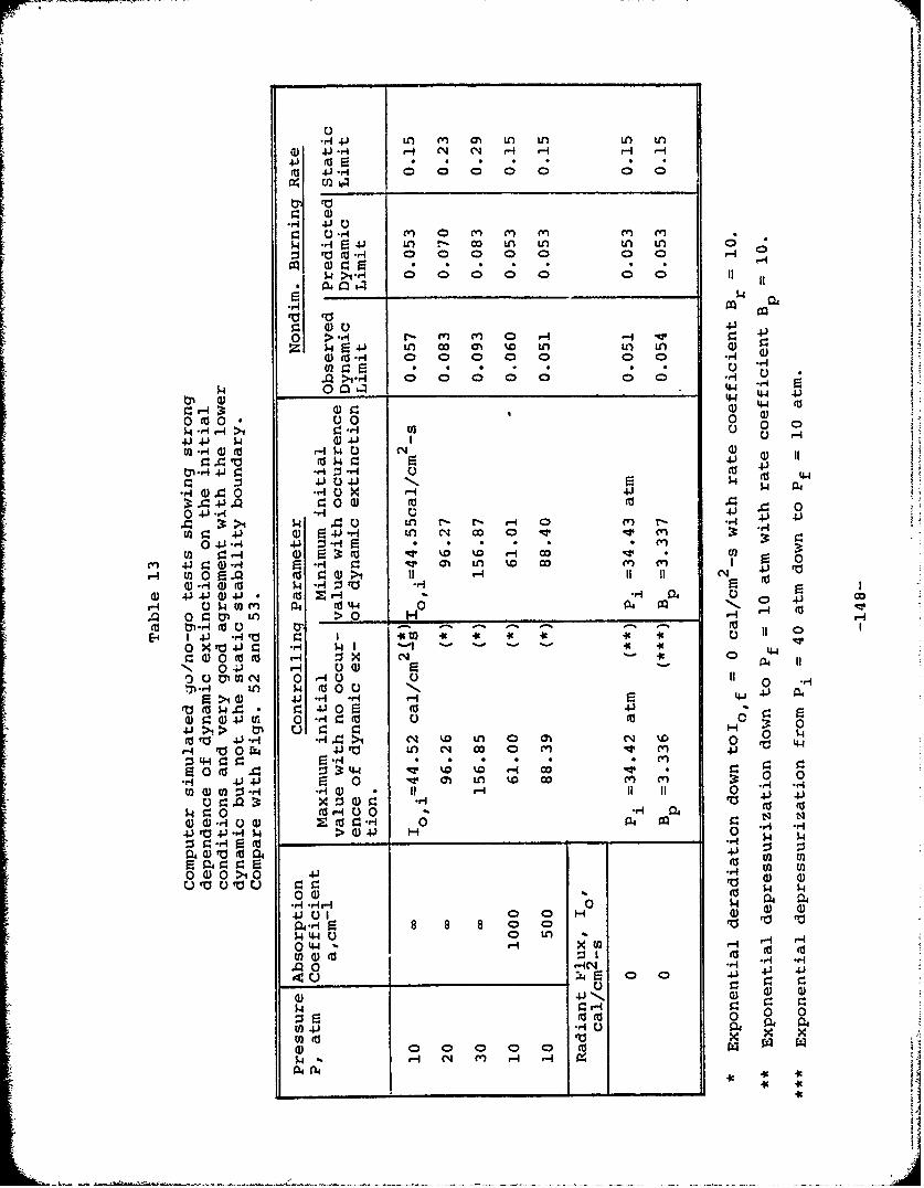
j.*q VA LO rn aU n) Ln
4J U~f c LA UO LA LA
000 0 0 0 0C
0z 0 41
0 > 11 0 H4 IV
Z~ V )c a Dt U) LO0ar4 0 0 0 0 0 0 0D ri
.L>*'4 0 0 0 00;
0 '' 144
0o(dO0 0 0 05.edH -4>1 ~ -4 02 0 0
N) 4.44J U4J 5.
.00 40 X 0- 4I0iji *r. 0Q
r~W .)0 LA r- r. r-4 o en*-r 4-J V.
4Q) 4J r42 *n *V *o a *q -
a) -J0 r4 .,q 4Wi ON LO %0 co m
W. fu4~ 1-4 5 7CD 4J 4J 4)4J -~ (d-HE 0 42c
(n~~1- en a O 40N
C: 00 0O LA ~ 0 x H -'U~C0 -P 0 a) R ~
m w 2N 0 HOi 0 -4rq~a- LO k4 (d000 Nl.ýR >i d).~ Vl HH 2 4-1 4j 0
(d' $4 4 *d-> CIJ 4J 0 Fi 4-
9: 4) 0 41r LA r 0 mr rI:j
40 1 .i >1- N %D n 0*%C % -"V4 r4.4 2 0 OL i LA c o 0 m 0" 0V
*3 44-) r.4. .4r:: 0 (v Z : 3:44 qr %0 %D a- 0; 14
S4~. (OOO 0 (0-r0rq ) 1-9 1- J 4
r. 0 04 (d5- 02 e 9: -1 0 *0 14
4J >i 4.) 4--4 -M $4> )4
fo- .dH 00.0 0) 0 H4 0 01a 0)
8 01.44.4 0 L
-tq rnr4 a) (0 (4(J .g-4a W T
44 0 t n0 44s, x En0
04 r-INE~r 0 0 4041 4
024. *'40 C
0 00o 0 0 a
W4 4' X X
$4~~~4 -1 c K4 -
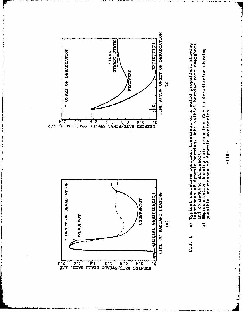
_ _ _0__ _0
Z E-4 H~ inO ~
H inQ to 4)
H E-4 > V
E- 0
> $.4 41
ou 0. Z0 0 .v. 0 Ol ' Ur
~z 0Z to0/~ '3Ix..sax DI0
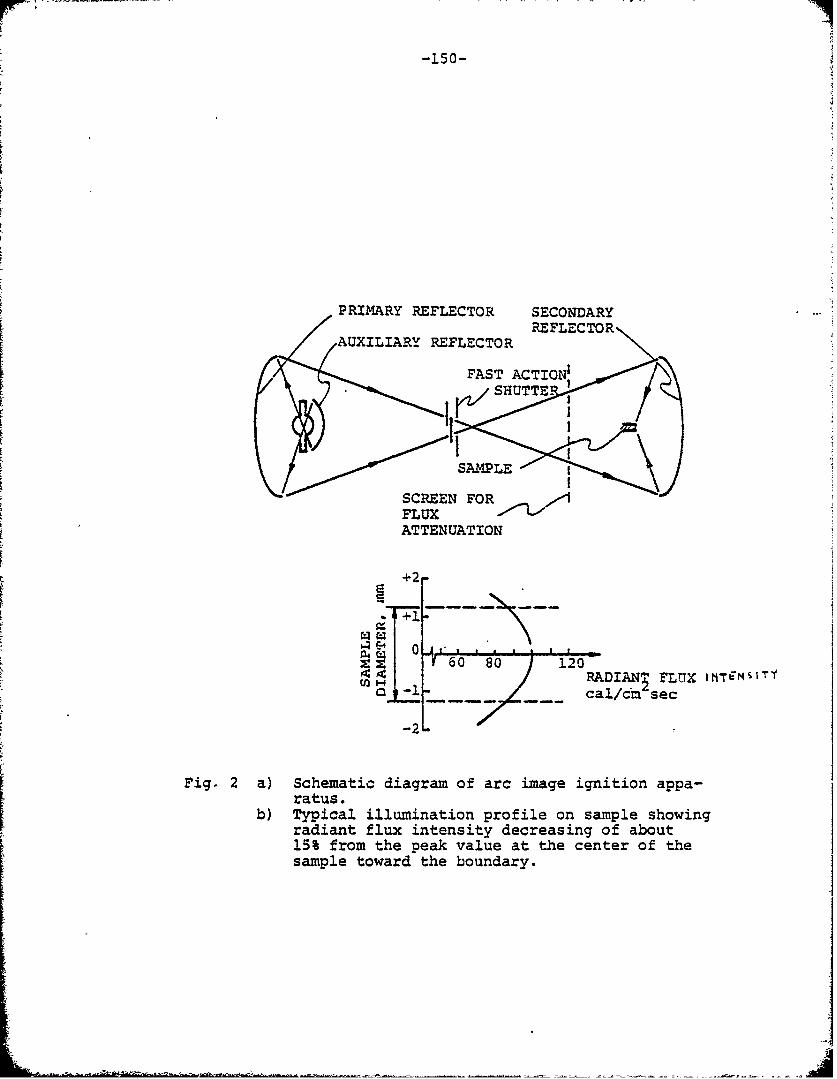
-150-
PRIMARY REFLECTOR SECONDARY
AUXILIARY REFLECTOR REFLECTORPFAST CI
ACIO
ATTENUATION
2----
E ( ' . .,60 80 ! 120-
FLUX~FLX M~I~
- -- .cal/cm sec
-2L
Fig. 2 a) Schematic diagram of arc image ignition appa-ratus.
b) Typical illumination profile on sample showingradiant flux intensity decreasing of about15% from the peak value at the center of thesample toward the boundary.
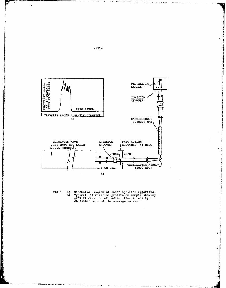
-is'-
[Eý SAMPLE0
4ýCAME IGNITION
- ZERO LEVELTRAVERSE 0Zt A SAPE k=
(b) KALEIDOSCOPE I(3x3x270 MM))
CONTINOUS WAVE ASBESTOS FAST ACTION1 00 WATT CO. LASER SHUTTER /SHUTTER; (eel MSE.C}10.6 MICRC]
(a)
FIG.3 a) Schematic diagram of laser ignition apparatus.b) Typical illumination profile on sample showing
+20% fluctuation of radiant flux intensityBn either side of the average value.
.4
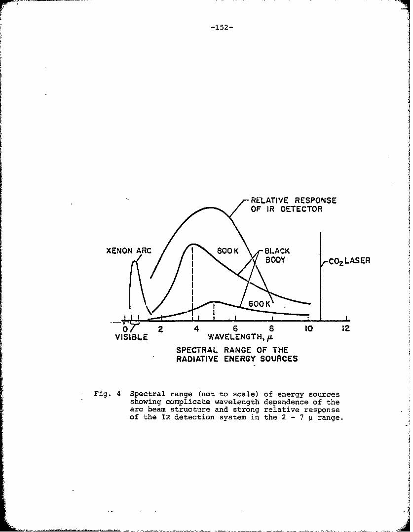
-152-
RELATIVE RESPONSE
OF IR DETECTOR
XENON 800 K BLACKBODY rCOZLASER
600K
o P. 4 6 8 t0 12
VISIBLE WAVELENGTH./L
SPECTRAL RANGE OF THERADIATIVE ENERGY SOURCES
Fig. 4 Spectral range (not to scale) of energy sourcesshowing complicate wavelength dependence of thearc beam structure and strong relative responseof the IR detection system in the 2 - 7 p range.
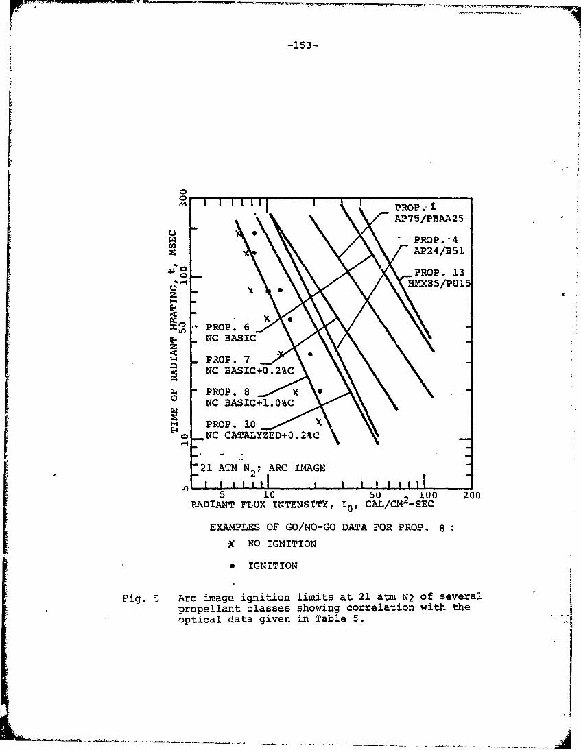
-153-
PROP. -AP75/PBAA25
4" o _PROP. 1
2 HMX85/PUl5zE-4
" PROP. 8
E4NC BASIC0.%
0 NC BASIC+J..0%C
'-~ PROP. 10Eo _NC CATALYZED+0.2%CI21 ATM N2 ; ARC IMAGE
OFI I I I i ----I5 10 50 1 100 200
RADIANT FLUX INTENSITY, I0, CAL/CM- SEC
EXAMPLES OF GO/NO-GO DATA FOR PROP. 8
X NO IGNITION
* IGNITION
Fig. 5 Arc image ignition limits at 21 atm N2 of severalpropellant classes showing correlation with theoptical data given in Table 5. --
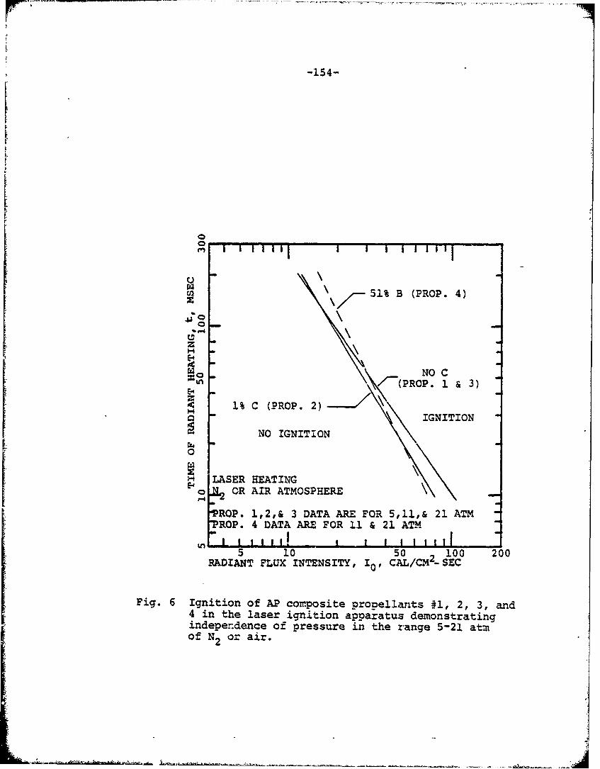
-154-
c-i
S51% B (PROP. 4)z
H
=n-/-(PROP. 1 & 3)
1% C (PROP. 2)- IGNITION
NO IGNITION
0
SLASER HEATINGE OR AIR ATMOSPHERE"P4
"PROP. 1,2,& 3 DATA ARE FOR 5,11,& 21 ATMTROP. 4 DATA ARE FOR 11 & 21 ATMt i
5 10 so 100 200RADIANT FLUX INTENSITY, I0, CAL/C0M- SEC
Fig. 6 Ignition of AP composite propellants #1, 2, 3, and4 in the laser ignition apparatus demonstratingindependence of pressure in the range 5-21 atmof N2 or air.
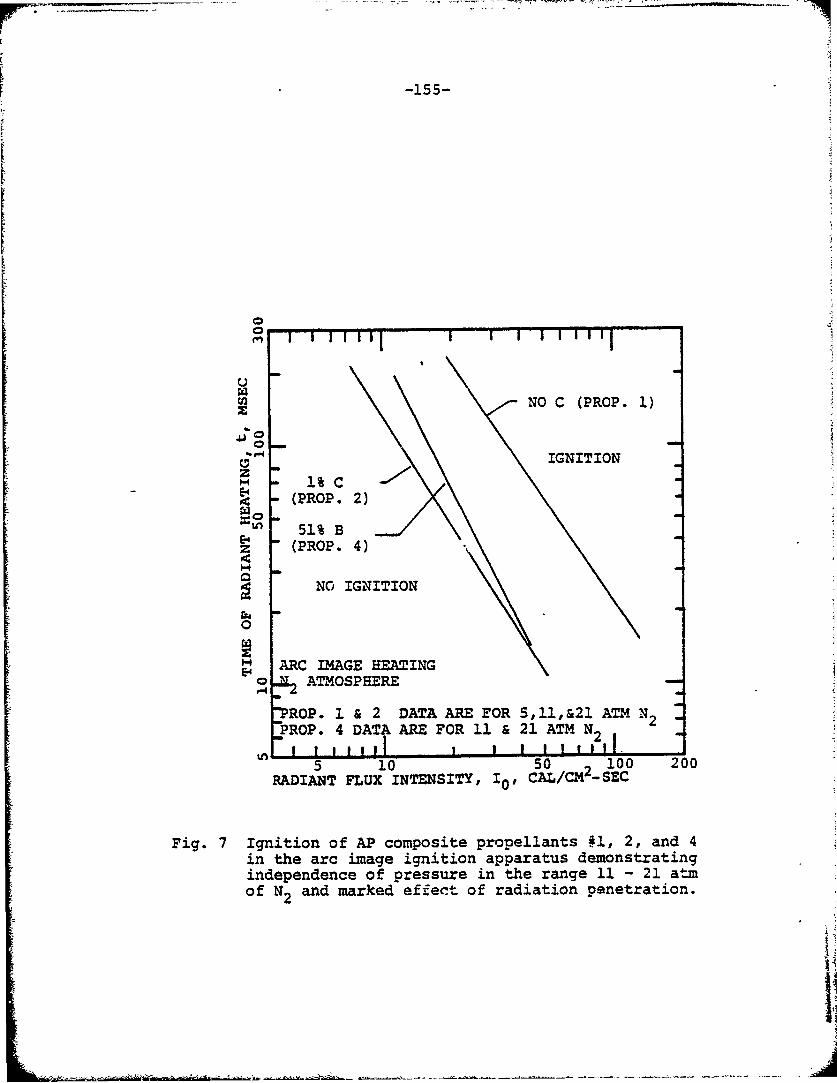
-155-
0
S' ' ''"1 ' ' ' ' ''"1C-"
NO C (PROP. 1)
IGNITIONH 1%C
(PROP. 2)
"51% Bz (PROP. 4)
NO IGNITION
0
E ARC IMAGE HEATINGo ATMOSPHERE
"PROP. 1 & 2 DATA ARE EOR 5,11,&21 ATM NPROP. 4 DATA ARE FOR 11 & 21 ATM N2 2
5 10 50 2 100 200RADIANT FLUX INTENSITYs, 10, AL/CM -_SEC
Fig. 7 Ignition of AP composite propellants #1, 2, and 4in the arc image ignition apparatus demonstratingindependence of pressure in the range 11 - 21 atmof N2 and marked effect of radiation penetration.
I
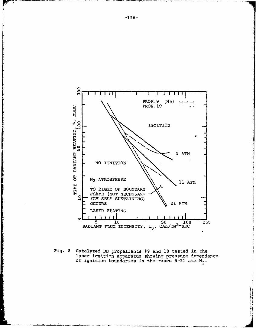
1 -156-
S I i II j I| I | I Ilij
PROP. 9 (N5) -U -PROP. 10W\
" o° )•IGNITIO'X
Z
I NO IGNITION N%
0 N2 ATMOSPHERE 11 ATM
H TO RIGHT OF BOUNDARYSE-4 FLAME (NOT NECESSAR-
ILY SELF SUSTAINING)OCCURS 21 AT_
"LASER HEATINGSjI 111 1 I11
5 10 50 7 100 200RADIANT FLUX INTENSITY, 10, CAL/CM--SEC
Fig. 8 Catalyzed DB propellants #9 and 10 tested in thelaser ignition apparatus showing pressure dependenceof ignition boundaries in the range 5-21 atm N2 .
•J'
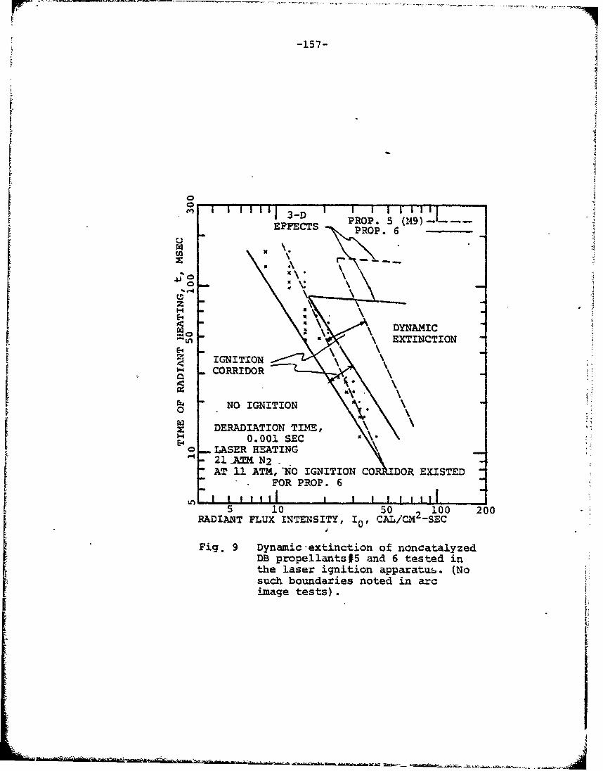
-157-
EFET I3PROP. 5 (,49)-...
SEFFECTS • PROP. 6
•=o DYNAMIC""In \ EXTINCTION
E-4IGNITION
S. CORRIDOR
NO IGNITION0
z DERADIATION TIME,I 0.001 SEC0 LASER HEATING
I- 21 -A~N2AT 11 ATM,,(NO IGNITION CO DOR EXISTED
"r FOR PROP. 6
5 10 50 2100 200
RADIANT FLUX INTENSITY, IC, CAL/CAM4-SECIJFig. 9 Dynamic extinction of noncatalyzed
DB propellants#5 and 6 tested inthe laser ignition apparatus. (Nosuch boundaries noted in arcimage tests).
II
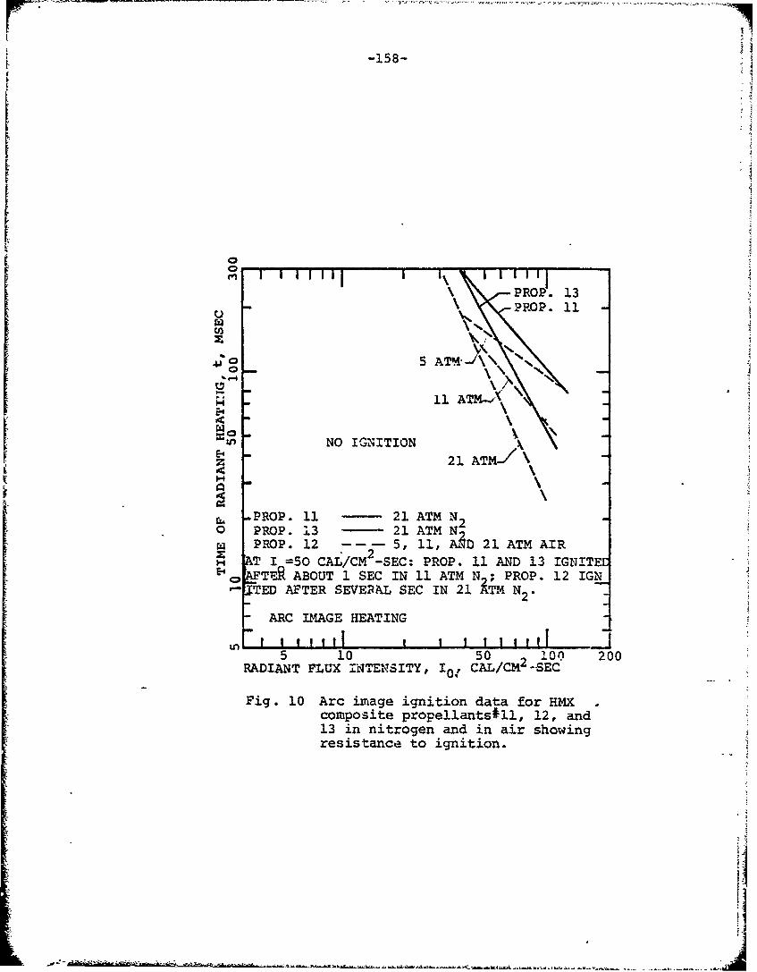
-158-
Fo
PROP•. 13
o .PROP. 11
$o S~ AT04-i\
H ~11 ATM-2. X
Ezn NO IGNITION21 ATM-./ \
HJ
S-PROP. 11 21 ATM N 2O PROP. 13 - 21 ATM NSPROP. 12 5, 11, A;D 21 ATM AIR
2A T I =50 CAL/CM -SEC: PROP. 11 AND 13 IGNITEE
SAFTE ABOUT 1 SEC IN 11 ATM N ; PROP. 12 IGN
TED AFTER SEVE&AL SEC IN 21 iTM N2 .
ARC IMAGE HEATING
5 10 50 100 200RADIANT FLUX INTENSITY, I0, CAL/CM -SEC
Fig. 10 Arc iv-age ignition data for HMXcomposite propellantsJl., 12, and13 in nitrogen and in air showingresistance to ignition.
ii
I
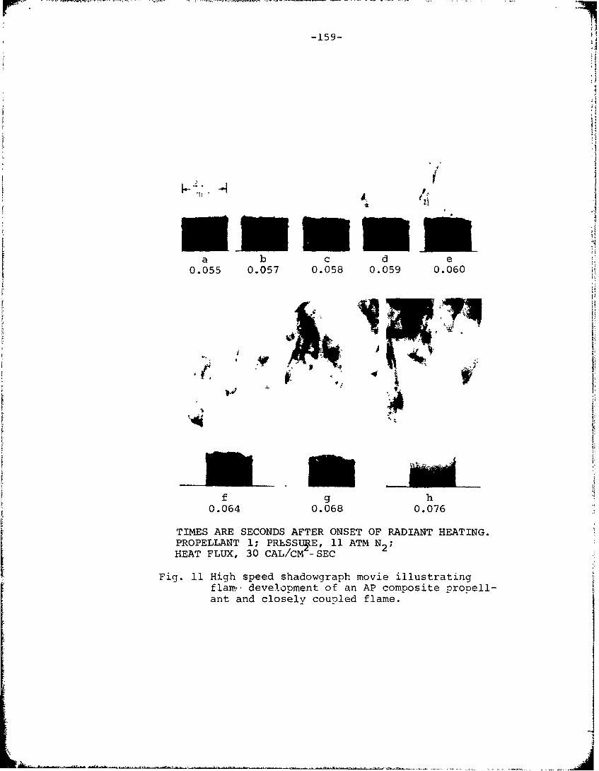
-159- -
a b c d e0.055 0.057 0.058 0.059 0.060
f g h0.064 0.068 0.076
TIMES ARE SECONDS AFTER ONSET OF RADIANT HEATING.PROPELLANT 1; PRLSSUtE, 11 ATM N2 ;
HEAT FLUX, 30 CAL/CM -SEC
Fig. 11 High speed shadowgraph movie illustratingflam, development of an AP composite propell-ant and closely coupled flame.
:. •.• . ... • • • •2"
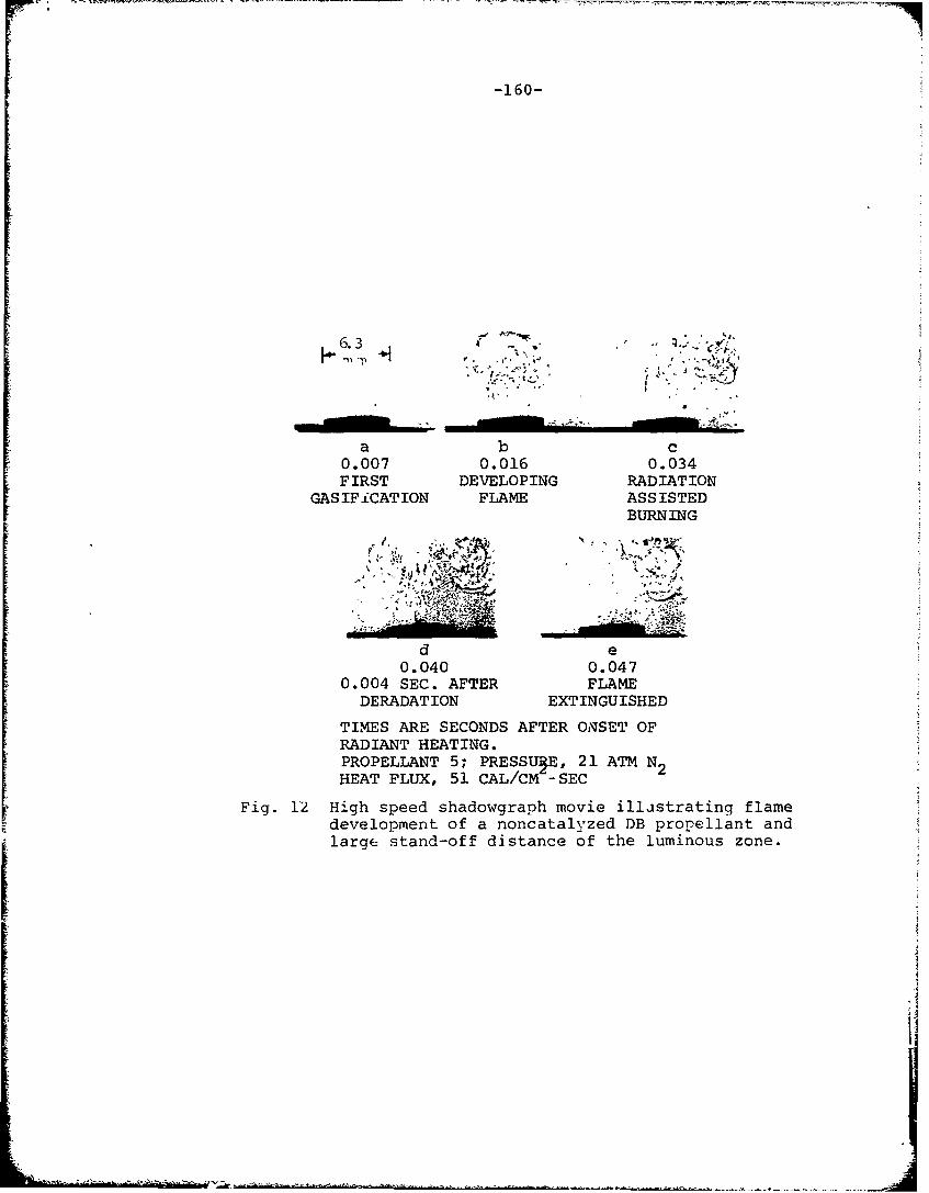
-160-
a b c0.007 0.016 0.034FIRST DEVELOPING RADIATION
GASIFiCATION FLAME ASSISTEDBURNING
---, - ....
d e0.040 0.047
0.004 SEC. AFTER FLAMEDERADAT ION EXTINGUISHED
TIMES ARE SECONDS AFTER ONSET OFRADIANT HEATING.PROPELLANT 5; PRESSUPE, 21 ATM N2HEAT FLUX, 51 CAL/CM -SEC
Fig. 12 High speed shadowgraph movie illstrating flamedevelopment of a noncatalyzed DB propellant andlarge stand-off distance of the luminous zone.
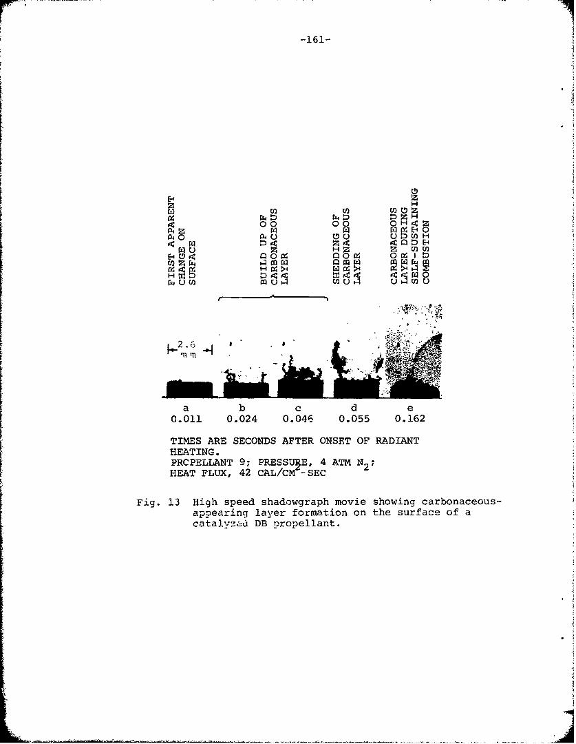
-161-
PZzH
00 00 0H z
a~40U 0 () 1) HH Z U)
W 0
a b c d e0.011 0.024 0. 046 0.055 0.162
TIMES ARE SECONDS AFTER ONSET OF RADIANTHEATING.PRCPELLANT 9; PRESSU, 4 ATM N2 ,HEAT FLUX, 42 CAL/CM - SEC
Fig. 13 High speed shadowgraph movie showing carbonaceous-appearing layer formation on the surface of acatalyzrad DB propellant.
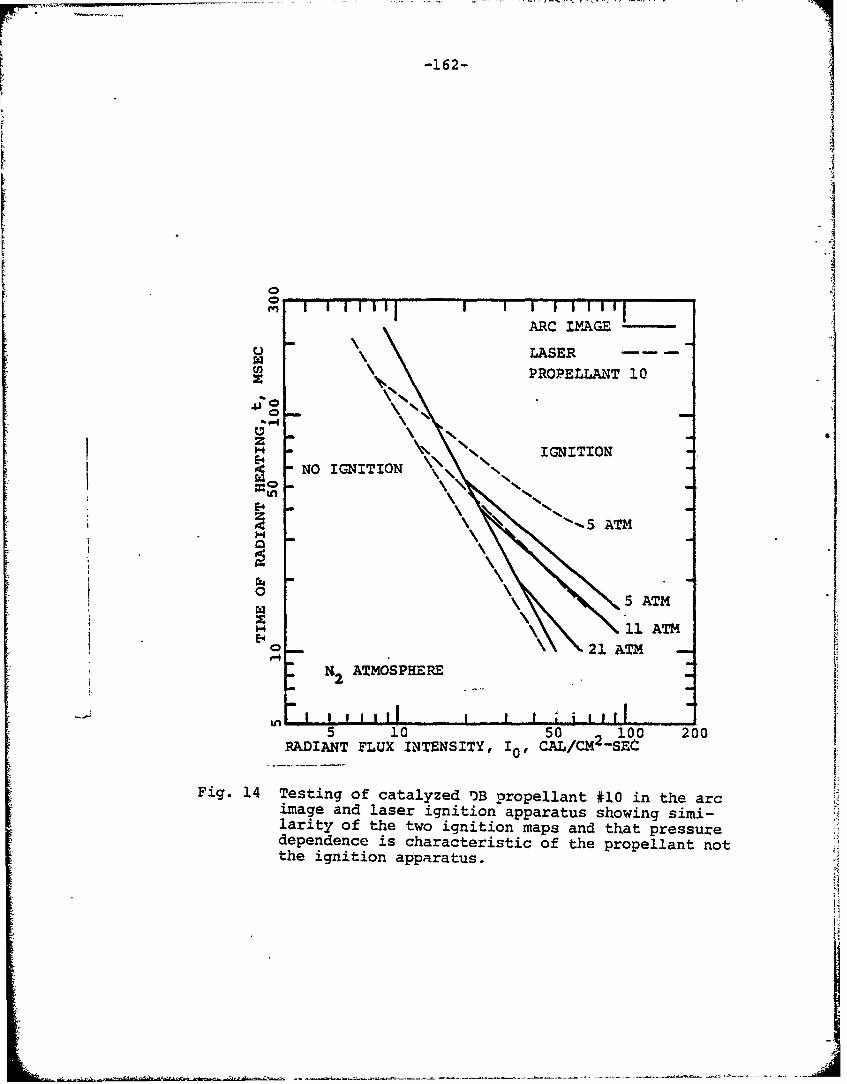
-162-
(.v,
C.)W LASER
PROPELLANT 10
P-4
Zaz- \\ IGNITION
-NO IGNITION T
S~o
""n
5 ATM
H ~11ATME -4
N ATMOSPHEREL 2E -
I 11\1 PRI ELAI itI0
5 10 50 100 200RADIANT FLUX INTENSITY, 10, CAL/CM2 -SEC~
Fig. 14 Testing of catalyzed ')B propellant #10 in the arcimage and laser ignition apparatus showing simi-larity of the two ignition maps and that pressuredependence is characteristic of the propellant notthe ignition apparatus.
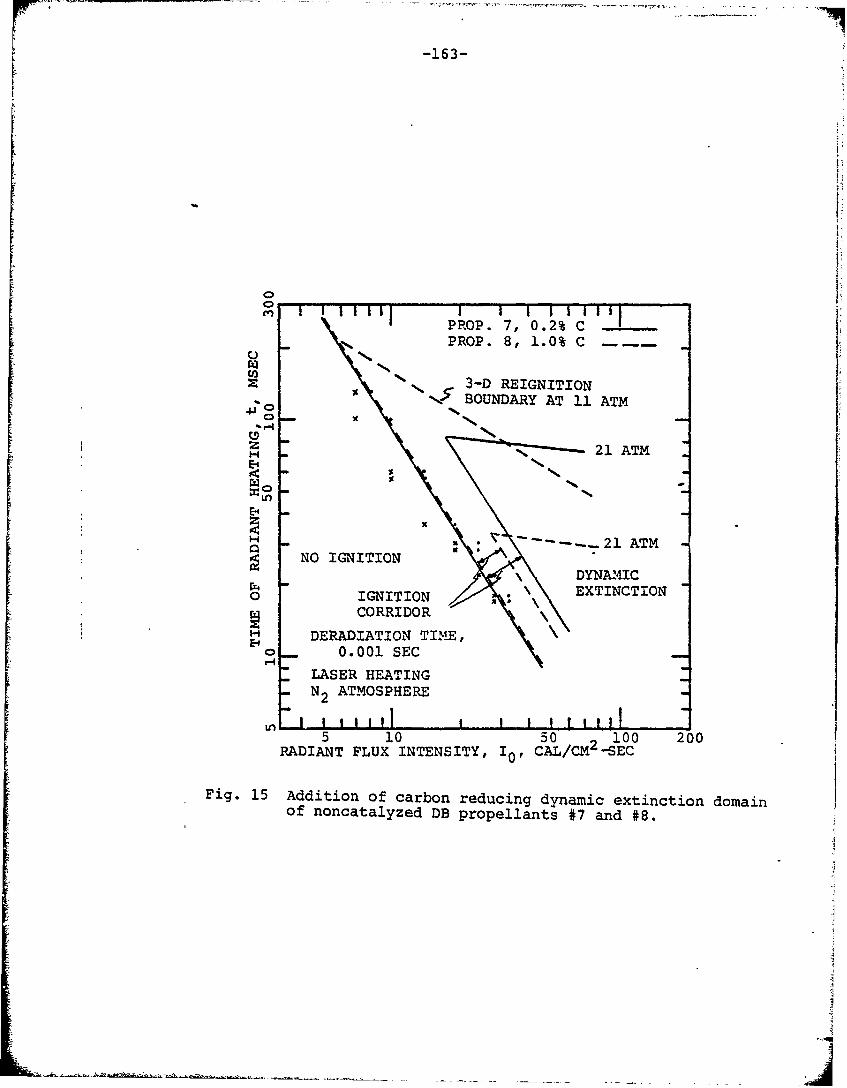
-163-
PROP. 7, 0.2% C
PROP. 8, 1.0% CU,z 3-D REIGNITIONN ' BOUNDARY AT 11 ATM
o -S 21 ATM
H -N T.E21 ATM
S- EXTINCTION0 IGNITION
H DERADIATION TIMiE,E-0 _ 0. 001 SEC
" LASER HEATINGS-N2 ATMOSPHERE-
Ur -I I I1 I I L 15 10 50 100 200
RADIANT FLUX INTENSITY, I0, CAL/CM2 -SEC
Fig. 15 Addition of carbon reducing dynamic extinction domainof noncatalyzed DB propellants #7 and #8.
ii
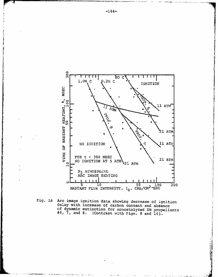
-164-
k C1 0 0/ 0 MSE .2 c
IGNITIONI00
00
3c
- 0%C 0..os 2%
r 1 4 A I E E N
z
RADIAN FLU INES0Y R0 4CA/CM00-SC
a - 21AAT
NOC IMGE ITAO N G
H ORDIM FLU INESIY 100 MSECM-S
Fig. 16 Arc image ignition data showing decrease of ignitiondelay with increase of carbon content and absenceof dynamic extinction for noncatalyzed DB propellants#6, 7, and 8. (Contrast- with Figs. 8 and 14)•.
•, .. ....-.•.• • ,NO .I..NITIO.. ... AT....ATM-
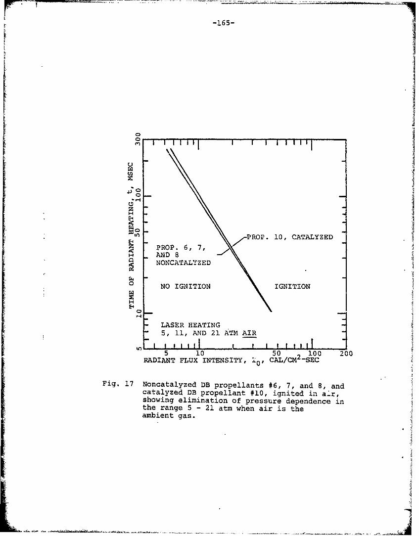
-165-
SP1ROP. 10, CATALYZEDE-4
PROP. 6, R,H AND 8
NONCATALYZED
0
SNO IGNITION • IGNITION
- LASER HEATING"- 5, il, AND 21 ATM AIR
1111 I tlil5 10 50 2100 200RADIANT FLUX INTENSITY, 10,' CAL/CM -SEC
Fig. 17 Noncatalyzed DB propellants #6, 7, and 8, andcatalyzed DB propellant #10, ignited in a-r,showing elimination of pressure dependence inthe range 5 - 21 atm when air is the Jambient gas.
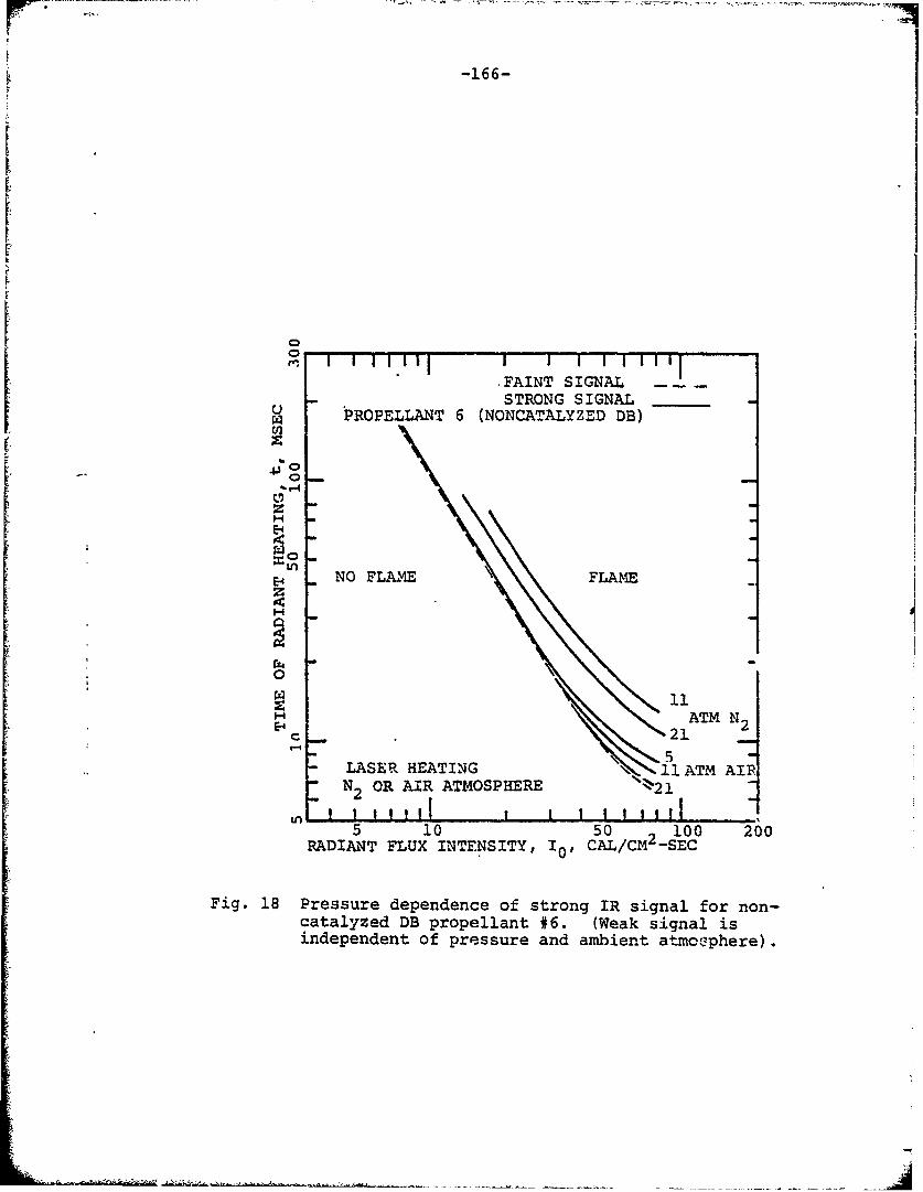
-166-
[
I
0
-FAINT SIGNALSTRONG SIGNAL .
PROPELLANT 6 (NONCATALYZED DB)
4J 00
n NO FLAME FLAM%1EZ
* 0
ATM N2
" ~5- LASER HEATING 1 1l ATM AIR- N2 OR AIR ATMOSPHERE --21
It, ! ! 1 1 1 ! | I I I I! ,i l"5 10 5o0C 100 200
RADIANT FLUX INTENSITY, 10, CAL/CM--SEC
Fig. 18 Pressure dependence of strong IR signal for non-catalyzed DB propellant #6. (Weak signal isindependent of pressure and ambient atmoephere).
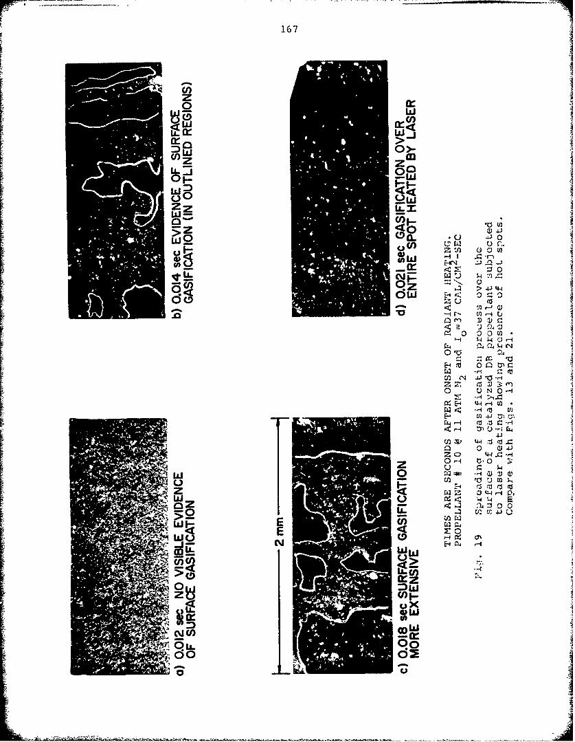
167 A0 I
WW
U) z)
0 LJ
5Z
0W
00
3r <n -ir- 0
0 0 0 fl
04
E4~ 4010 ~ Ji04
cc
W UNi o U)
EE
0 I1
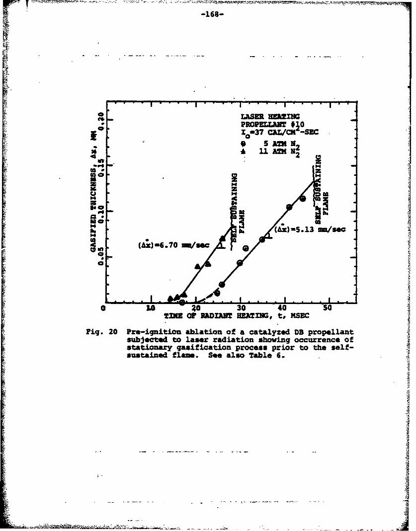
. . ......."""' "I....1....I... v.I""
UP POELLAW#110 -337 CLCM -SEC
4P
14
(Cx)l=6.70 mi/sea
,-OP4o 20 20 30 40 so
Tfl Or MRDIAVl EA2=tI, t, 14SEC
Fig. 20 Pre-ignition ablation of a catalyzed DB propellant2subjected to laser radiation shoving occurrence ofstationary gasification process prior to the self-sustained flame. See also Table 6.
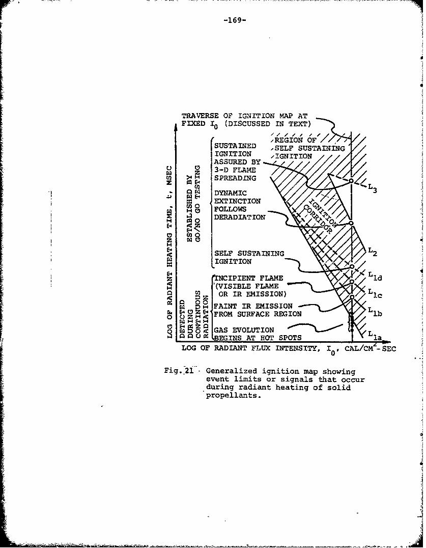
-169-
TRAVERSE OF IGNITION MAP ATFIXED I0 (DISCUSSED IN TEXT)
,REGION OF'/SUSTAINED SELF SUSTAININGIGNITION I.IGNITIONASSURED BY X
' ~ 3-D FLAME>1 H SPREADIG
W r DYNAMIC
O EXTINCTIONC -0-FOLLOWS0
DERADIATION
E-4 4.Z
SELF SUSTAINING 2
" INCIPIENT FLAME Lld
S(VISIBLE FLAME Ln a D OR IR EMISSION) 1c
0FAINT IR EMISSIONO • oz , FROM SURFACE REGION lb
EO4 GAS EVOLUTION 9C LSL•BEGINS AT HOT SPOTS l
LOG OF RADIANT FLUX INTENSITY, I0 CA LCýS-EC0Fig.-2i-'- Generalized ignition map showing
event limits or signals that occurduring radiant heating of solidpropellan-ts.
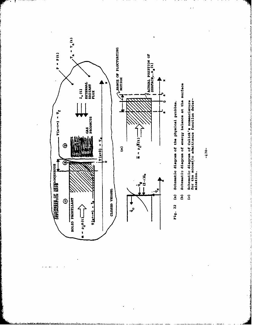
lidi
14 .4 e
0 u
m 0 04
be
'4 I
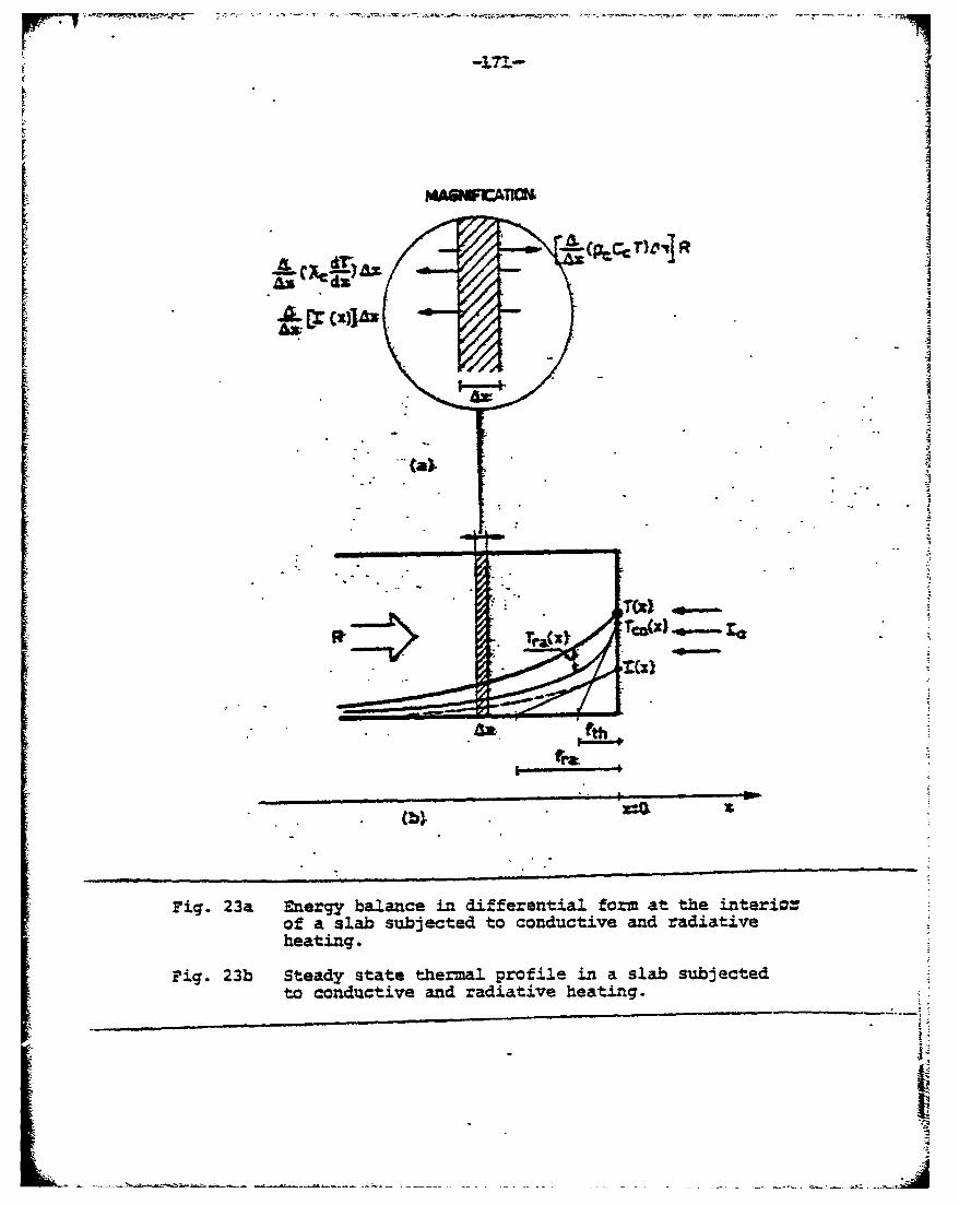
MAGWFCATKU
-(p,,T)&v] R
Tr&Cxl TCMWb-Xl
Wt. t
Fig. 23a Energy balance in differential form at the interic.rof a. slab subjected to conductive and radiativeheating.
Fig. 23b Steady state thermal profile in a slab subjectedto conductive and radiative heating.
oo I
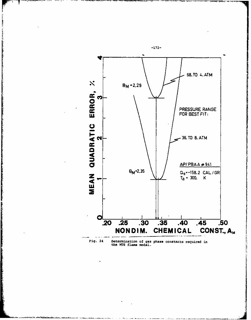
-172-
68.TO I..ATM
cc PRESSURE RANGEIi, I FOR BEST FIT:
2,I36.TM 8. ATM
D2 \ / AP/PBAA #941
BOAS O~--158.2 CALIGRZ Ta 300. K
'U
I
.20 .25 .30 .35 .40 .45 .50NONDIM. CHEMICAL COHST.,A, m
Fig. 24 Det:ermiati£on of g~as phase constant:s required in ;•tche -"4TS f1L~me model. i
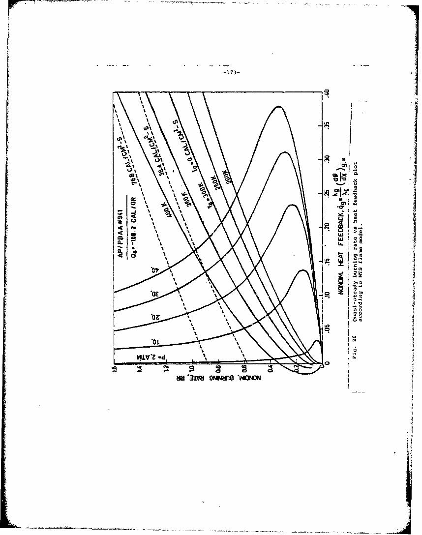
0.0
-44
'or%1IL
ICII2(4 L.
C31 'a.' 4*0) t4.
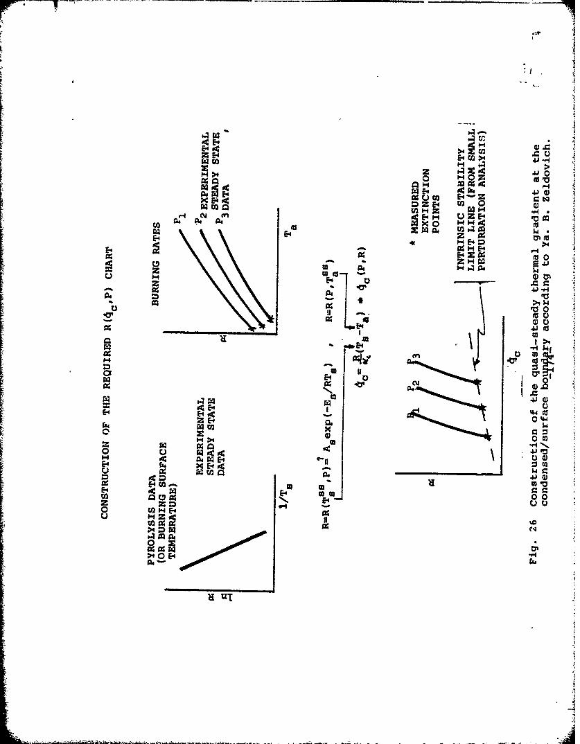
Al U_ >i ~
x oc 1%U cc O2 rr tP44~ al1 =zE-0o
2U Z
x 00W0 E-4 o 0E- zc
U TU
rz E-.- % 02
04,, - I.4
a00
lx 1f
E-4 raII
z (D 00m
0.
E4 a4
Eli
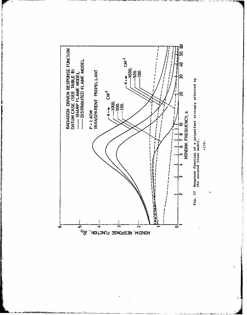
_- 0 . -j i
(nIMiiiUJ 8$. I
ai zo d I I,- C
(nloJ 000:LJ D
Z~o <Z <000
OUXW < $ICXW -)>
z A.
<NI3r cm~S~ ~OO
< < LII
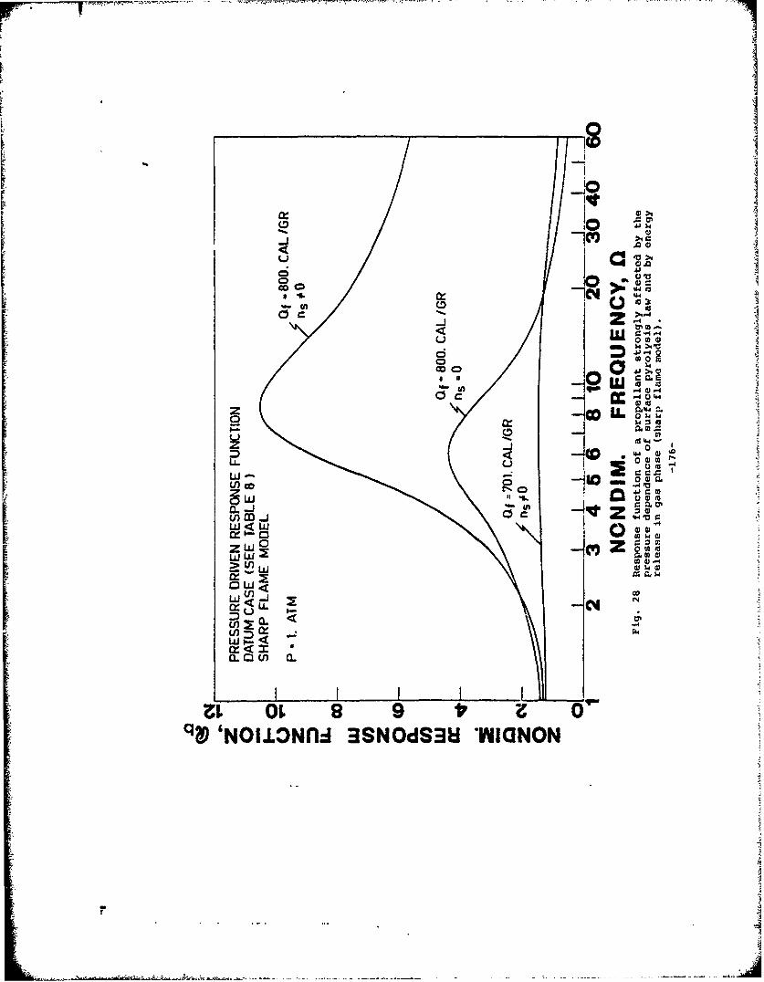
JOO
CD
t'"
z 4
w0-I4
(IILL I I-
q W 'NIJZNl rS-Si ~U
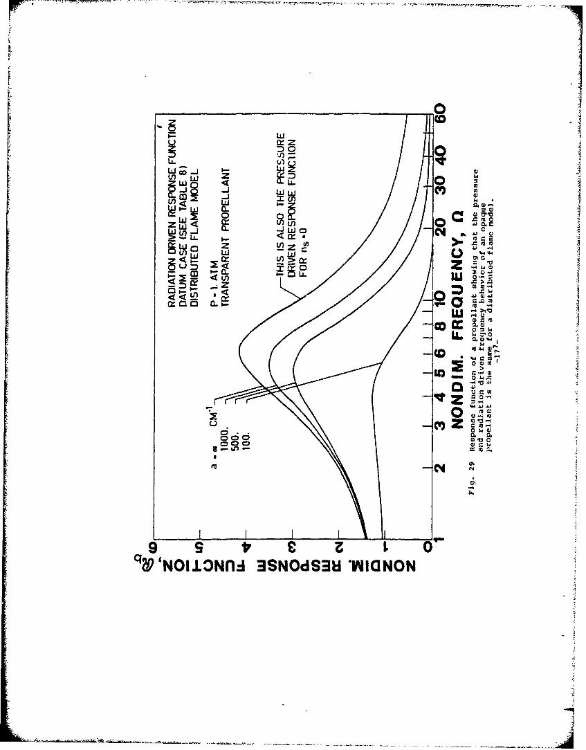
I-L
=) 0u(0
ww
£fw a.Z u
w C3 zV
U)0 ww~I.- cr
L) :) m,.-SO
O9 LL o t~u 0NIL~l S~S1YI~O
< =) z M90 -
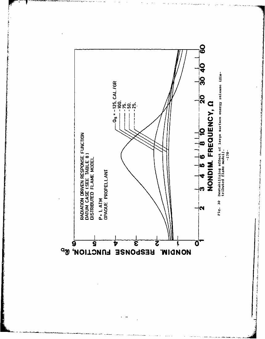
10
0 c0
0 cnw
LA.D
(1) ~O~ -j0 ,r-
W. .- Cil %
-w 0W -4
w~ a.Z 4 1-- X
ou=) W
00
9 SE 0"" NOIJ.ONflI 3SN~dS3U YWIIUNON
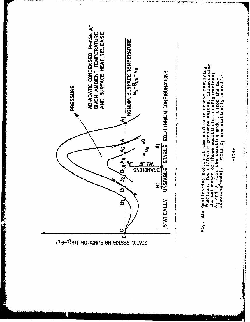
LaiWr
Z) LU I,.-
ZW<.
W Wi
411~~00 41)1O VLLI I.&JO:3 4
S2( 4 2 wZ 4J A 0_ r Cf.J .4
cr Li. M '
w0 C34 4W>
0L a-4 0 C.) 0
< 4) 0-10
I- 4)"q 0 41
m= o"M-%4J C-.
M 00-i4 $4
a) 44 4) 4) 4)0 $40
44 $4) 1" r I
.1V4_ __ __ _ _ __ 41c ina
M0o0-(SS~~ 4 0 1 Jflf~JfW" XN10"8 LL1
9 W (a
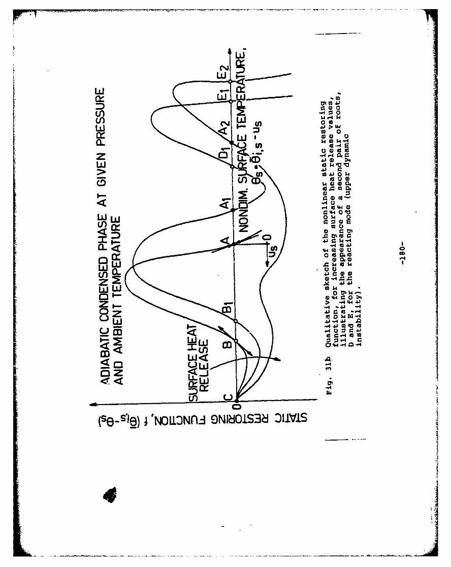
w -
VW "4. 0.0
Ex.W. 14)0 a.9ul U-4 E
to4.) 0 $
z r.4.40 V~
W W0U) Cc 0
0 itOdgC3 4 cog
.'-4
) 00
4) 4J4r. 0>
S-A4 -. 4) -'4
0 :; =
r. r'4 00
W<4~.~----~-u-~ w -~-~an..ati
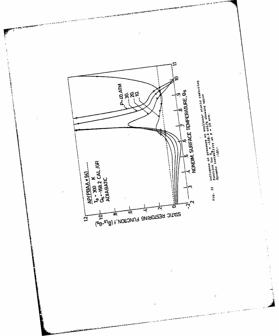
C52CDV
4t r
00
00
Is
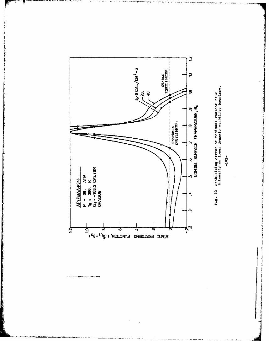
I 0)4
-4i
I U4 0
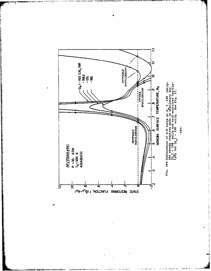
-~~t ---. 3VI
IXIm to to
w IA
c. I a.
0 Ii(se.'IQ ~ NOI.~NA 9N~OLS~ ~1V0
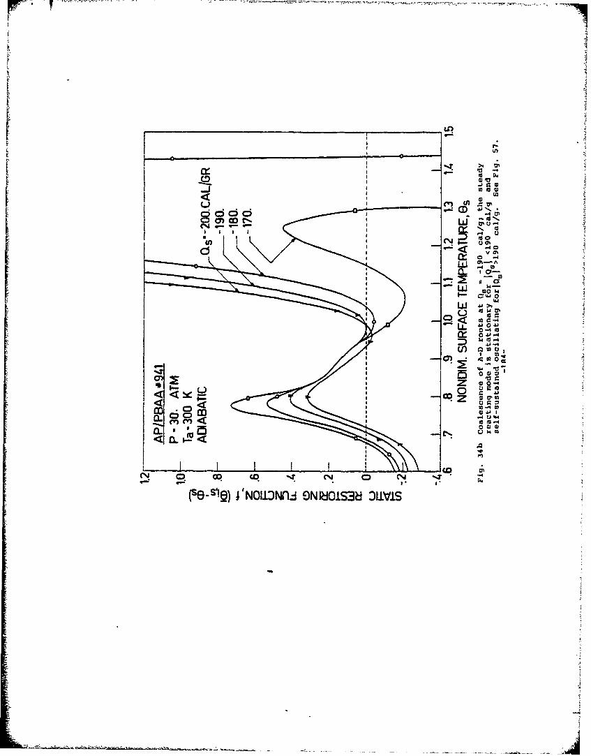
U-)
CID"
(M Go 0ý d j3
(SCV)4N~Jr N~OS~JLI
V - - -
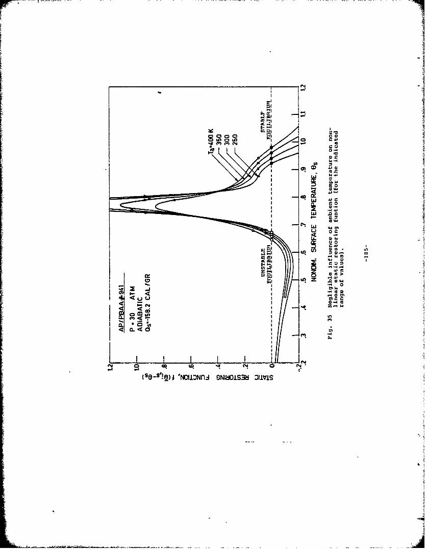
0-.4
10J.
0.44
410
cs~~4r- 0
0.4 .0
b4 "I -= N.
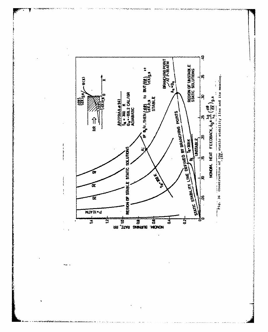
- ~r".2-~ - VS~'Vz
ww
2 I;
40 RaiI-c
UZ 4
K 2r
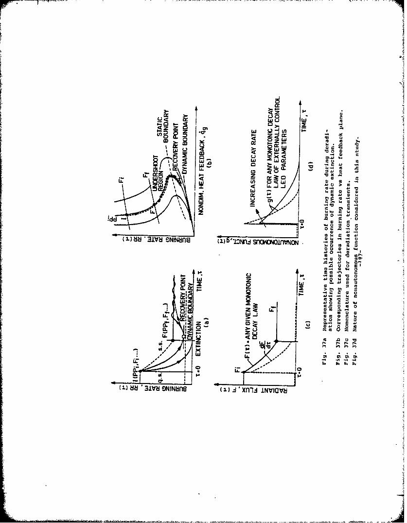
L)
w S
0: .(0 0401
w w
WE z<w - "4 C~
Z <00 Ai wb.- a--7
4% r. 040
00 01 14".
LL 14 4 140. cZ4 0 -. 4
*~ Z... 0" 00 - A. --4 4*0
S0 a 0)
ai 0&~. -.414
** u, .0o
I -,
3IV~NN4fl (1)4n 0NVA.)
z w a .; m
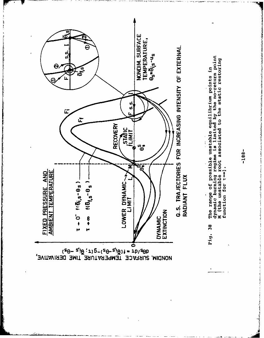
-
UI
w (h1Ua. --- 0.- KW
W 0P4 0)-- - - - - -- -
U) 0
I~~U _ J) '4J
0 0 0~4'1
wo
3AU.~~~~~AI~~~3Or 41dl3f13V313~l 1OO
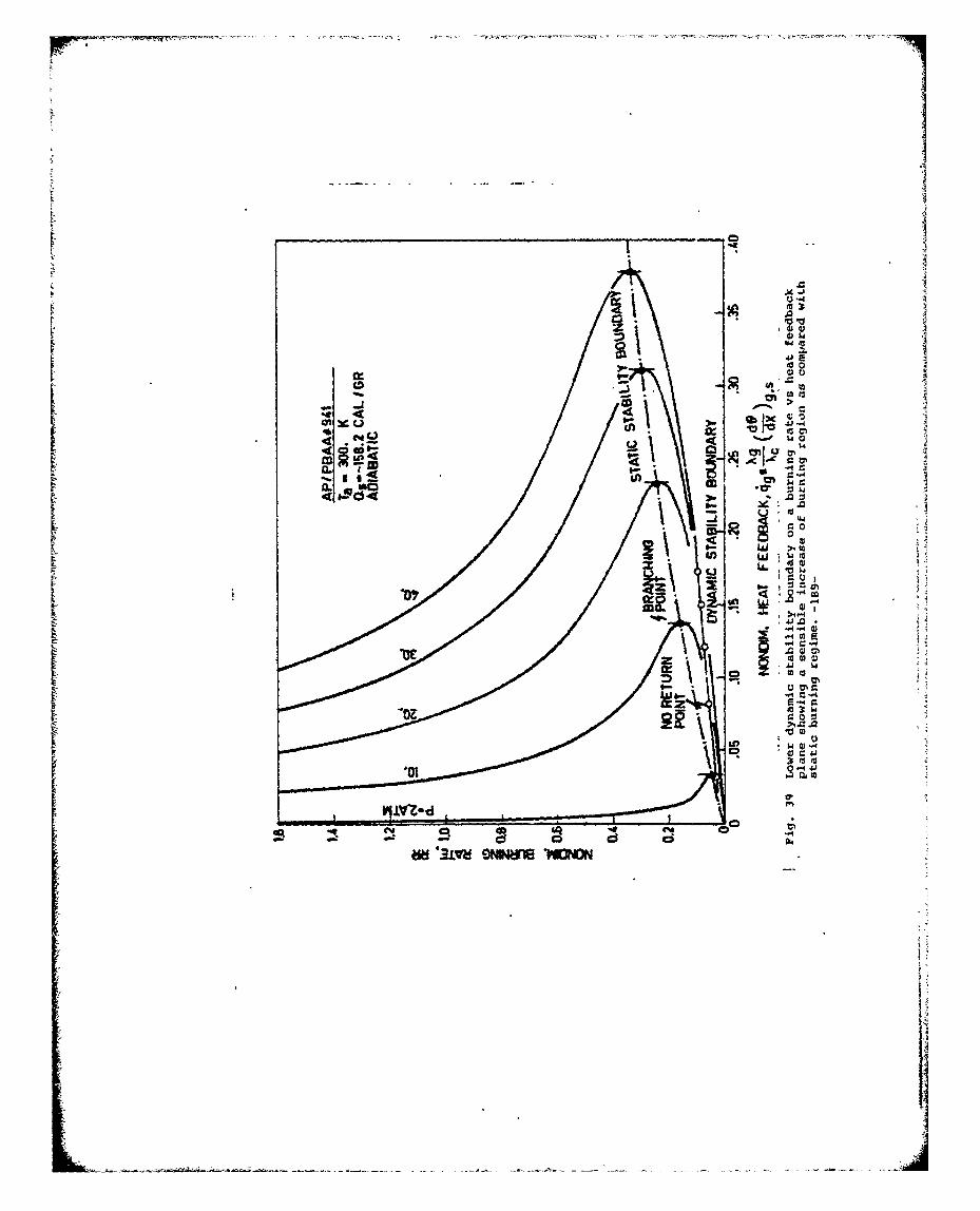
F41 -.4
01
... )
C:
too
Jw 11
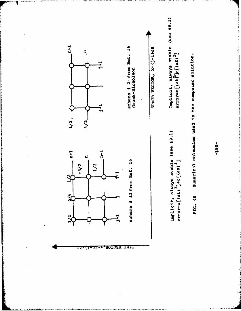
- a 0
r - e -4 4
4I4 o-
*1.
V441 - 4 1
p.r' $4 4
1-r4
r- r4
ob r4
P4 v-4+'
N P, *-I Pl
-4 -P4s
+ 'v--4 9 fa
4J. .4+
L..J
9-'4
r4 0*P4 M.
N-' ra
k L MIX
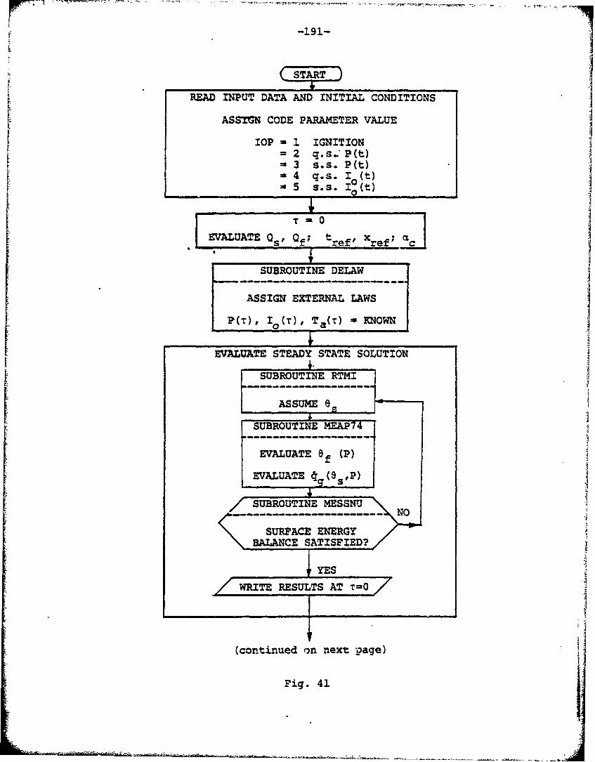
-191-
ISTART
READ INPUT DATA AND INITIAL CONDITIONS .
ASSTGN CODE PARAMETER VALUE
IOP 3, IGNITION2 q.s. P(t)
S3 s.s. P(t)=4 q.s. I 0t)= 5 s.s. I0(t)I 0I
EVALUATE Qs Qf; tref' X
SUBROUTINE DELAW
ASSIGN EXTERNAL LAWS
P(r), I0 (r), Ta(T) - KNOWN
EVALUATE STEADY STATE SOLUTION
SUBROUTINE RTMI
ASSUMESUBROUTINE MEAP74
EVALUATE a (P)
EVALUATE 0 (9sP)
/--SUBROUTINE MESSNU
SYES ...
W ERESULTS AT, 0
(continued on next page) i
Fig. 41
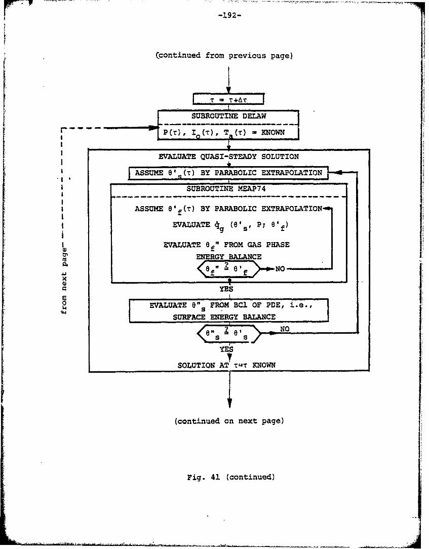
-192-
F
(continued from previous page)
III EVALUAT ( () T KOf
EVALUATE QUASI-STEADY SOLUTION
ASSUME ENERGY PRBALAICEXRPLTO.I
"I SURFUCE ES
ASSUME 0' ( E) BY PARABOLIC EXTRAPOLATIONG LfEVALUATE AT 'sP; 8'O )
SEVALUATE 6 f FROM GAS PHASE• ENERGY BALANCE
S•f" e' NO
Fi.41(otiud
a YE0 EAUT8" FROM BCI OF PDE' i'e.#,
44 SURFACE ENERGY BALANCE
<E !, es 11YES
SOLUTION AT TuT KNOWN
(continued on next page)
Fig. 41 (continued)
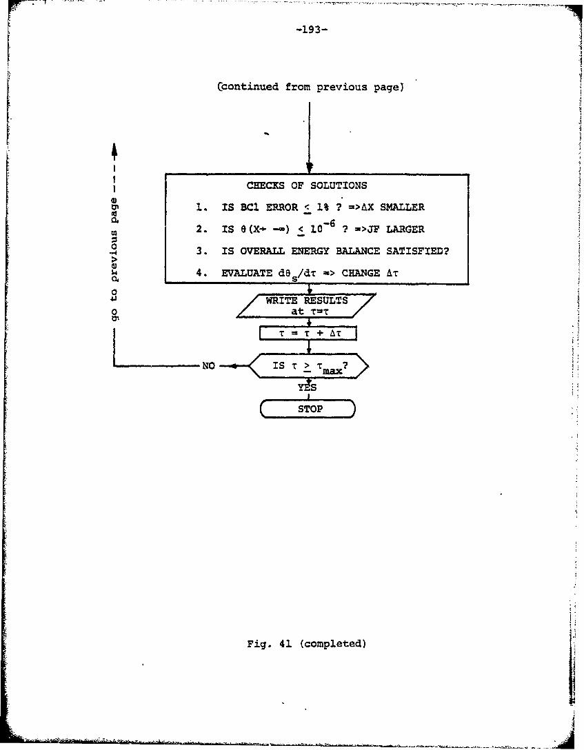
-193-
(continued from previous page)
ICHECKS OF SOLUTIONS
i. IS BCI ERROR < 1% ? =>AX SMALLER
S10-6
-2. IS 0 (X- -•) < 1 =>JF LARGER
-o 3. IS OVERALL ENERGY BALANCE SATISFIED?
$ 4. EVALUATE d@ s/dT_ -> CHANGE AT
-W WITE RESULTS0 at T-T /
( STOP ,
Fig. 41 (completed) "i
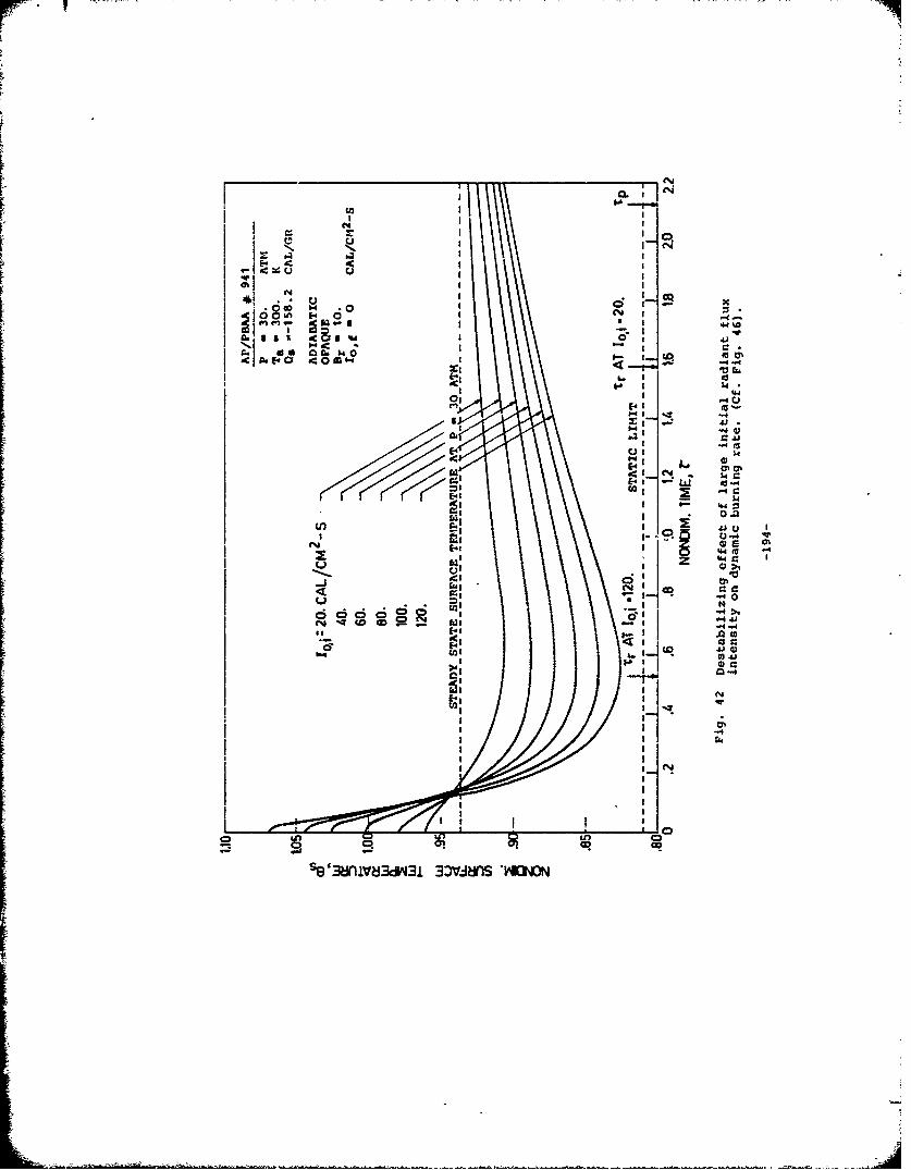
CI
4WN
0m d cm
c .FtC $00" .
ACA
eN'C ai w
0q 0
-J E-444
U 1-4.
LO C3cq CRse38iV3d3 0.-.- dI 'Y*M-m
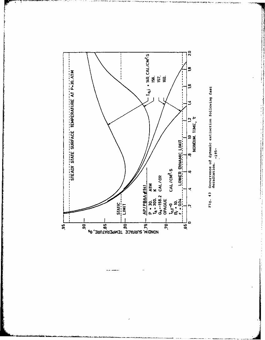
L) d
W 0
Il A
, w
I6 w CS O
I'W 1
050 0
9) CD
C O 0 & 0
C O .
se f8niv~dw~ 3o-imn *VICjI
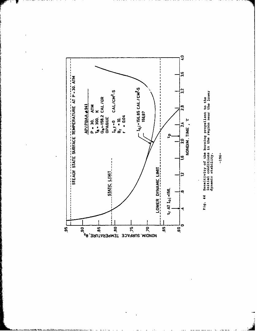
FF
F ________________________________________________
_ _ _ _ _ _ _ _ _ _ _ _ _ _ _ 0
W to
L r. 00
00<- M
:10*IW a)- 4 .4C.
4Cuu in(_j0
w4 41OZ 00.a
:j- I
U 83nV8d3 3avjn -NIN
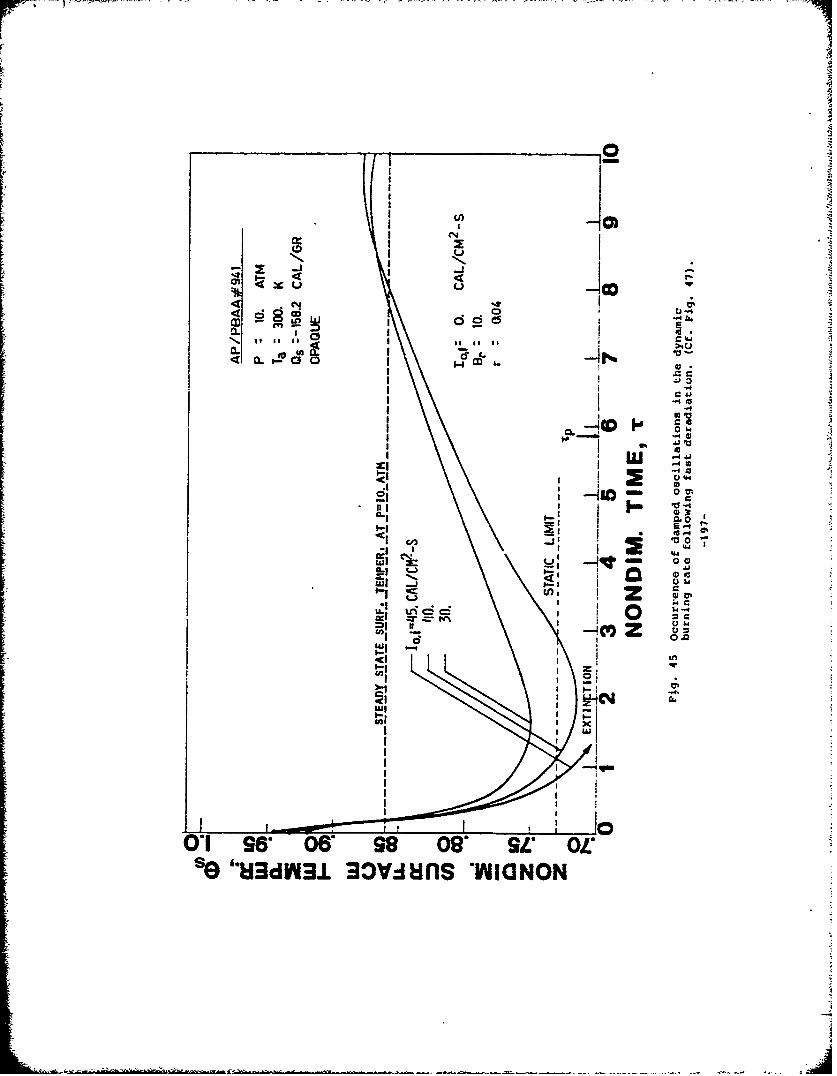
r~
41C0CL GI
< II0
CI
4l 0 0
*%.i CS eI I--r Z ,-
aL Z SIIII
C44
0*1 a6 06 980"3EO
I*~d3 j~ tin MIGNO
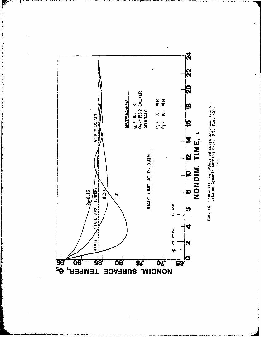
F'4
IC+4
CCM
I',u
ci~
Lp on~
tin- ~ 3- .J
a.' - 0~t -
15 I to* Z MI-Iu
.00
uj:1
I- II
CL
961 0* sea 08' se OLC 990So @eH3dfl3j 3ov~iuns OWIaNON
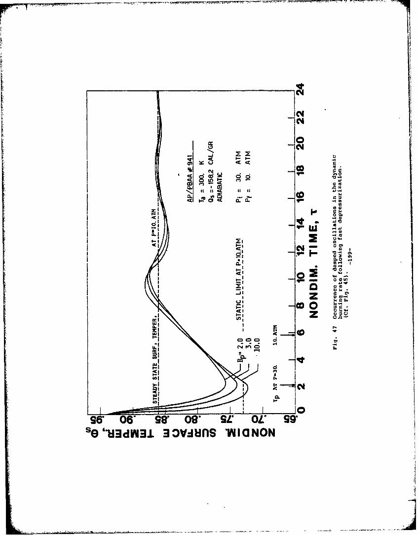
C4I
1 4I0I7 cm
~otn.f to,
~~~- e-e jw0
a-i a)3a 2-0
02 C4
1.4 2C_
z ..
-Ir~ 1 - - W~
IL~( C)J#Ce)'-4 tA
,x..-
CLI
967 OT 980 09* SE OV 97s e.U~dnl3l 3ov~ifls %maINON
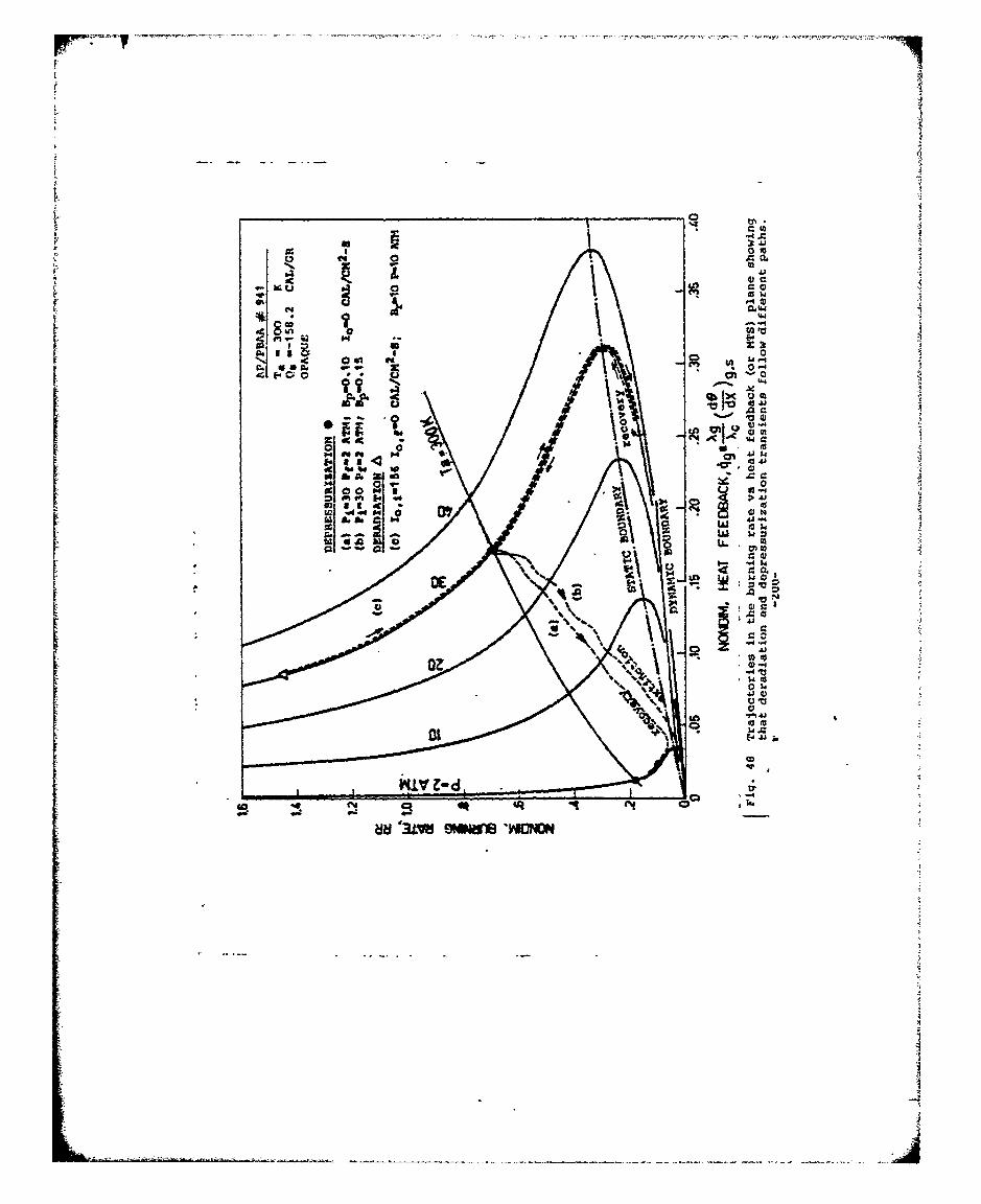
0 t
Aa,
co - i I
0
a 4)
00
on 0gal t 1. M
10 4 a ^UI
M~~ ra0
% J0
*% 410
a..
~~E4
_ _ __ -CD w
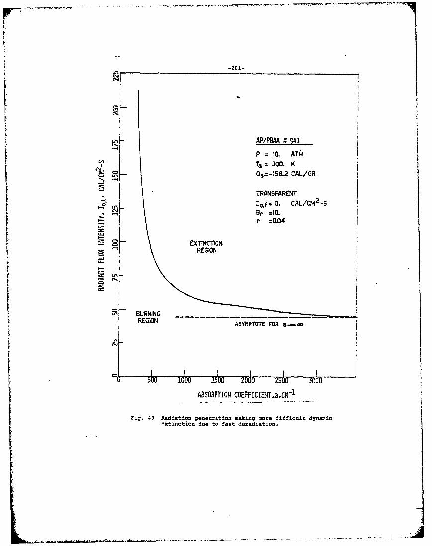
-201-
Cuq
C4
tt
P:=1O. ATM
, Ta = 300. K
TRANSPARENT.I • 0•o CAL/CM2-S
Sr =eQ04
EXTINCTION
REIOF -
--n- BURNINGi
REGION ASYMPTOTE FOR a-
U,
i ABSORPTION COEFFICIECN,aC-1
Fig. 49 Radiation penetration making more difficult dynamic
extinction due to fast deradiation.Ij
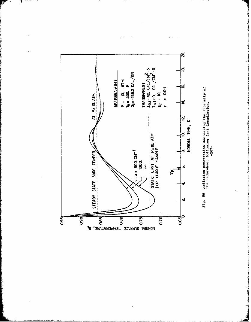
a-,
too
lo t I !4j
-4.U
L&0 0 0
~I Eu W 4
In 0
mn 1n0I 0 (D
W U. 0 00
IAJ t;Lm in 0 L
~-c-- I j
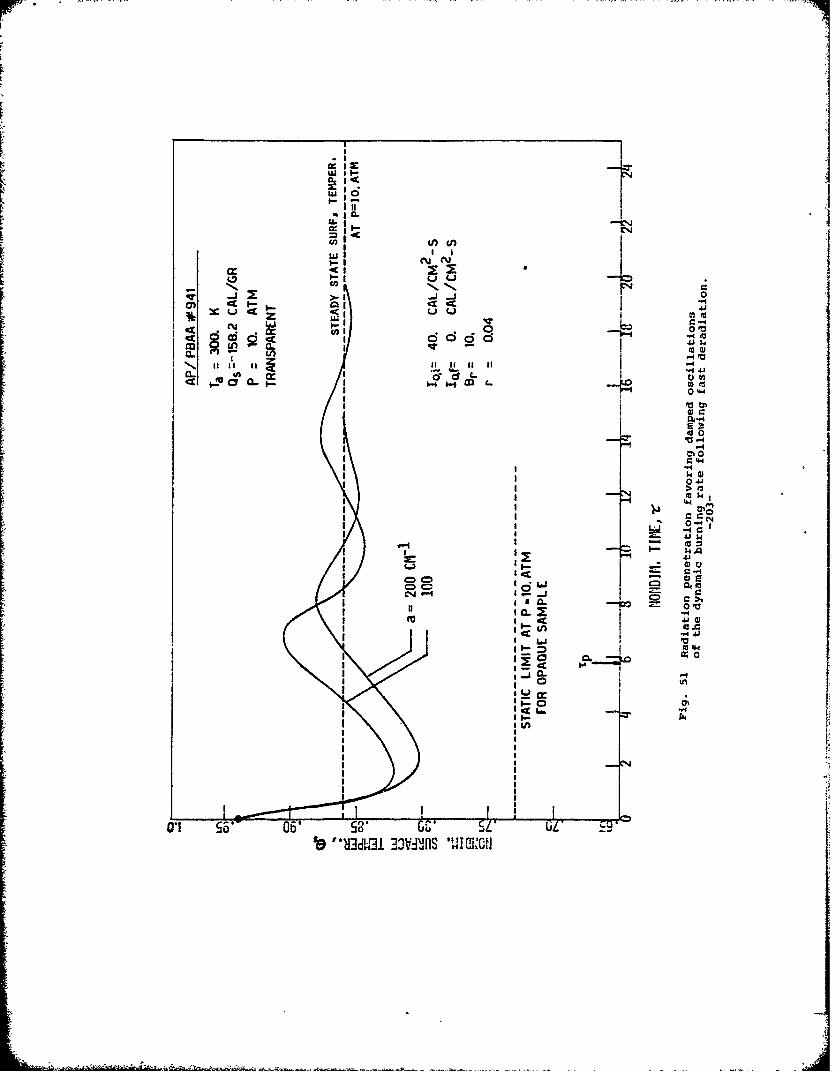
u s I~P I~ g I--' ~>r
wMII
(flu
CON III a< ~0- 7J
CL via iI II a ICE CL M
0 mm
0"0Im 0
0'..qI4 C:I
C-4-
I0 I
a194
G'- SL' UL
19 "'al-M 33VTJO dila.l
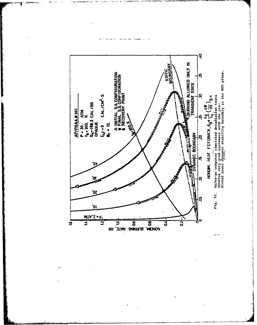
00Mgt-
w w
In ZILZ om- m foz- z4jA
Ujai'll.w I 0 0.L
c /
QI.- ci
ii ..IJW.0
= 4)
v 0 I'm
EN
8~> 0at~ 9IN~16NONO
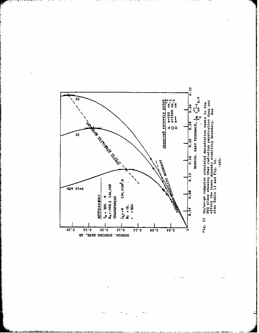
0 D
UCJL %ný
0 am a .0>
44a00 C; d
oz 0 ul oz> 41 r
4Jm
ý4
to t
NZ OT- W 0N10 0IQfn
J co 0 t u 0 0
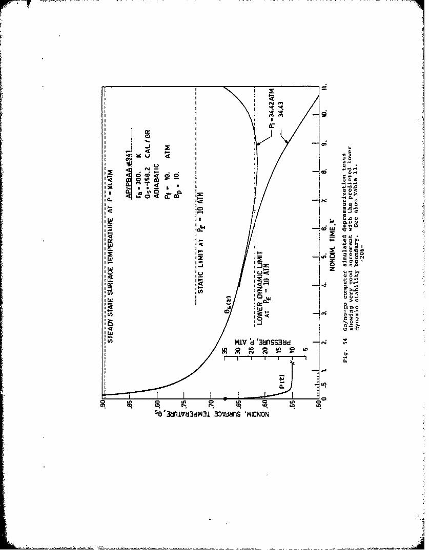
I * 0-
C f"I I 4*.4ýT, 41 .4.-.
Iw 0
DA 4
.0
4)
0 ~0 -,4
II 020.0
I Im
C"In C4- - --
gn Lo Lo &aiWIJIj
ICJ*IV3dG 33VWS*ICO
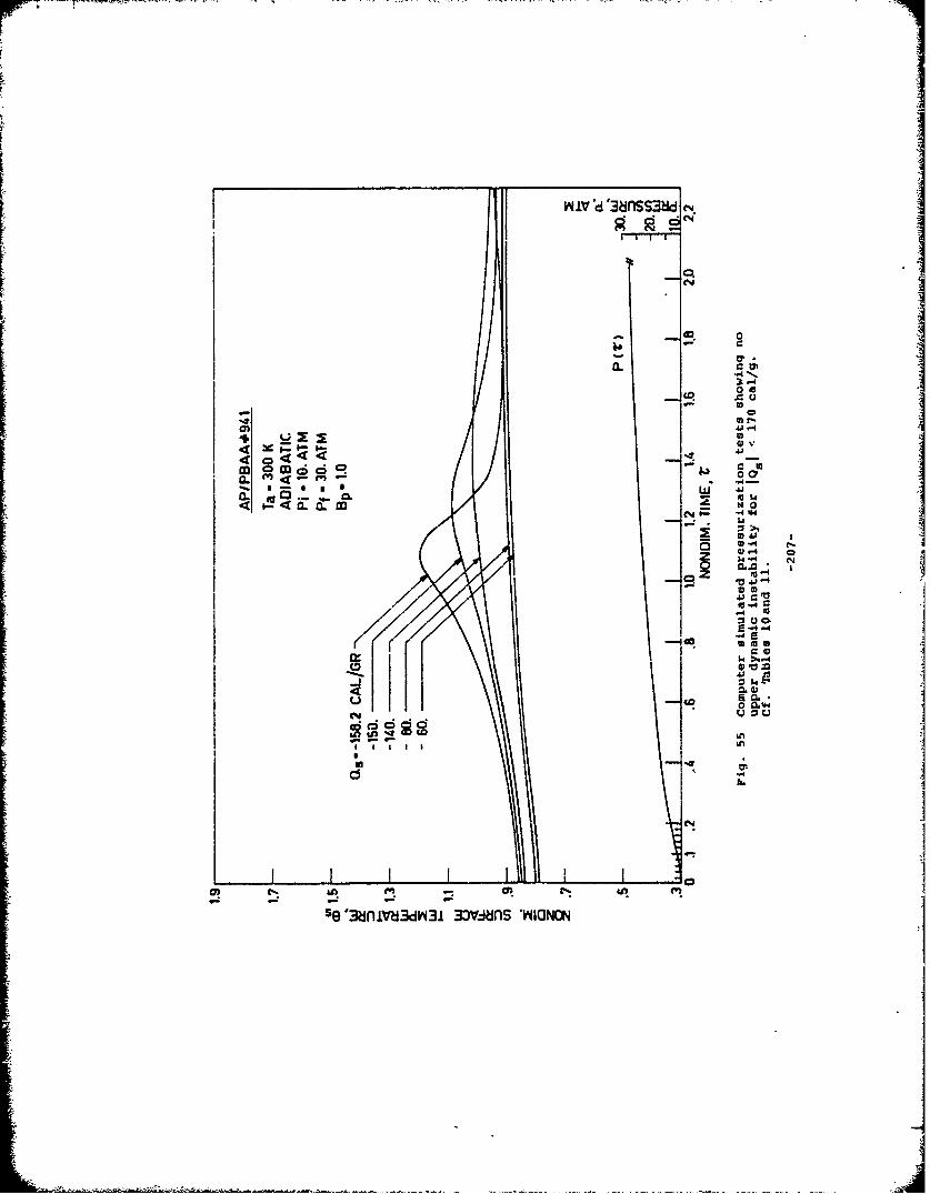
04
m CD 6 d00a. <
- C
-* 01-
44 v
in
C5E
o Wq
se'3ni~bdY4z 3ov-in wao
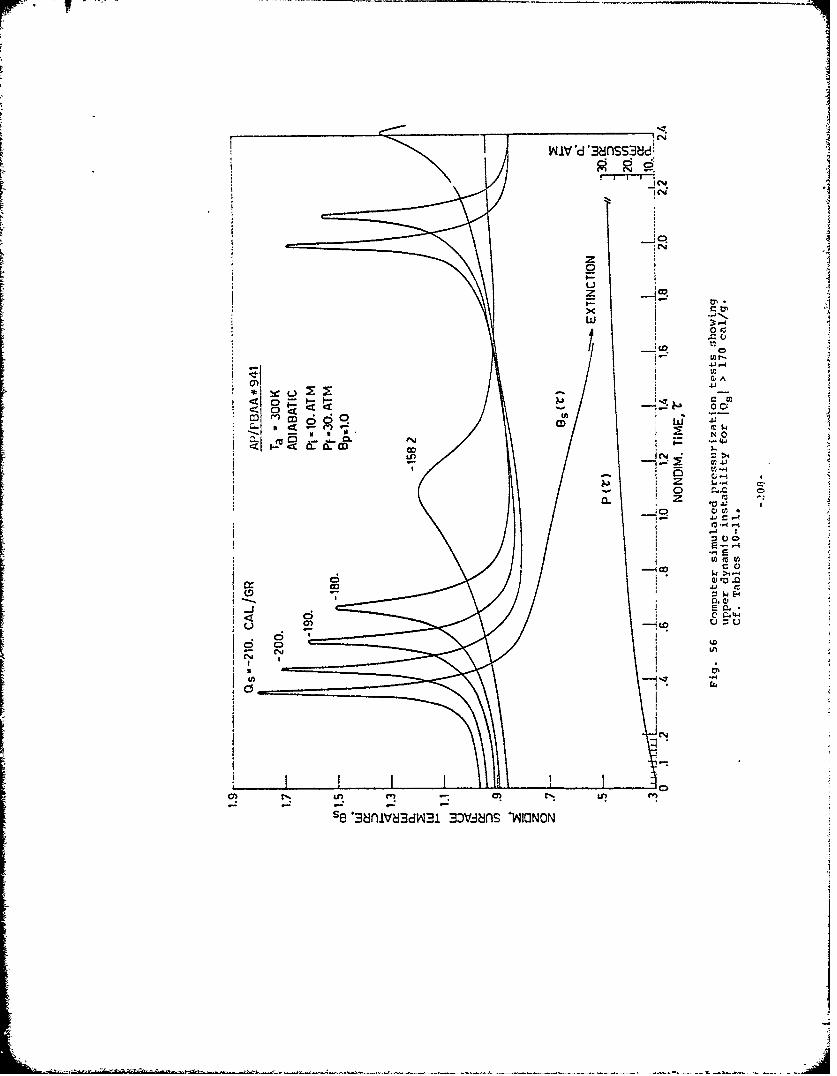
WIVd'3&-tSS3?Jdý
InI
0'*
- Z -C
L L
ri .$4- '1
to
11 0
C0 C 444.3 u4.
L)J
C; tLo
C5 E4~
se~~~~I '3nV3Itl 0Jn OO
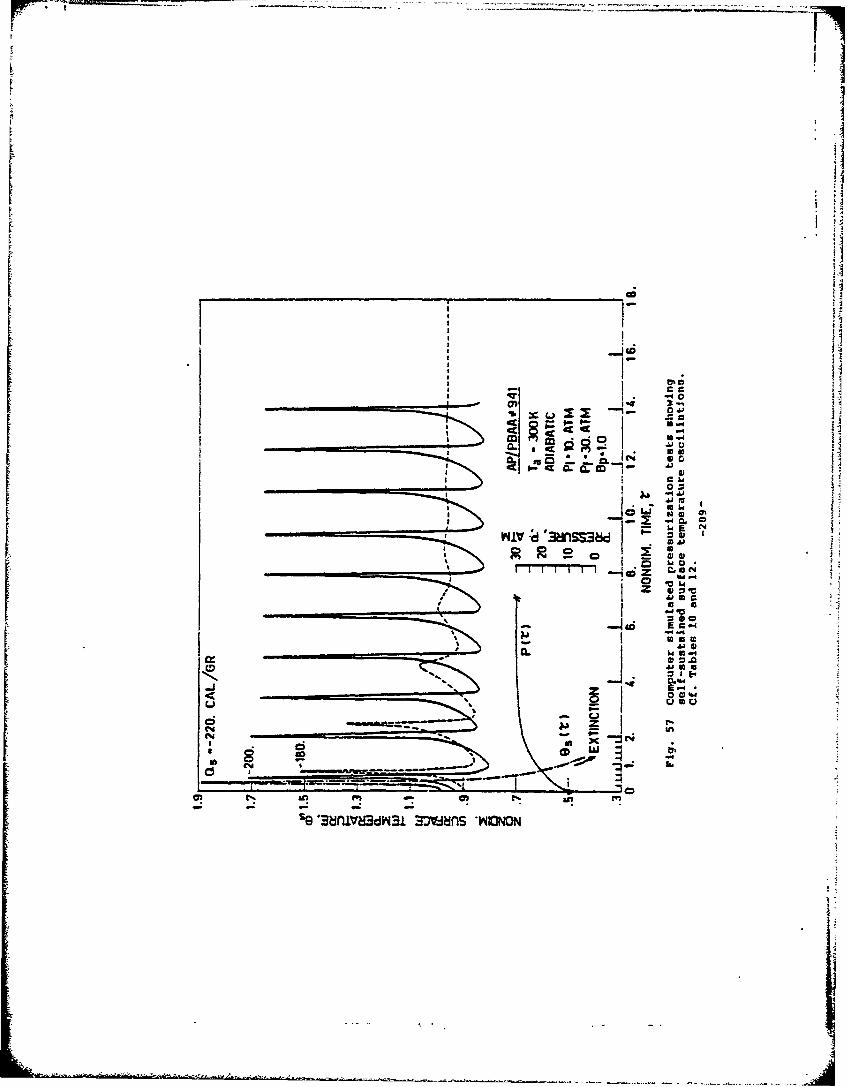
w Cj
911
ICY!rn-I
le '3nV1]3 m-ms-oo
-210-
APPENDIX A
THE INFLUENCE OF RADIATION ON THE STEADY CONDENSEDPHASE THERMAL PROFILE AND THE QUASI-STEADY STATE GAS PHASE ASSUMPTION
In this appendix, first, a qualitative picture of the generalproblem of unsteady solid propellant combustion is given. Next, theeffect of an external radiant flux on the stationary thermal profilesin the condensed phase is shown. Finally, the difficulties of deal-ing with unsteady processes are illustrated and the quasi-steady stategas phase assumption is introduced.
This appendix is meant to help the reader in understanding thetheoretical developments of the thesis presented in Chapters 6-9.This appendix makes use of the main thesis nomenclature.
A.1 Oualitative Picture
With reference to Fig. 22a, let us consider the hetero-geneous deflagration wave consuming a solid propellant subjectedto a radiant flux impinging with intensity (l-r):I at itssurface. For the sake of simplicity, let us examine for thetime being a steady state situation.
In general, a deflagration wave consists of a thermalwave and a simultaneous succession of a large number of endothermic orexot.1ermic chemical reactions, which start somewhere in thesubsurface region of the condensed phase and then proceed in thegas phase. Unfortunately, very little is known about the kineticsand the energetics of these reactions and, moreover, even ifone knew all the details of the above processes, his taskwould be too cumbersome. Consequently, certain drastic butfruitful approximations are made. The first is the inertsolid assumption, consisting in collapsing all reactionsin the condensed phase and in concentrating at the surfacetheir energy effects. Likewise, very little is known aboutthe phase transformations occurring at the interface (condensed/gas). Again we admit our ignorance by makLng the approximationof a plane infinitesimally thin burning surface neatly se-parating the inert condensed phase from the reacting gas phase;the energy effects of the phase transformation are concentratedhere. We emphasize that this is a pure abstraction, but auseful one, yielding useful predictions about real propellants.
Usually just one (essentially phenomenological) parameterQ energy release at the surface in cal/g, is defined encom-passing the energy effects due both to the distributed volume-tric reaction collapsed to the surface and to the phase trans-formations. The qualitative picture we have so far of thedeflagration wave consuming a solid propellant consists ofa layer with no reactions (pure thermal layer) in the con-densed phase and of a layer with reactions and mass diffusionin the gas phase. In order to proceed further, we need to putour discussion on a quantitative basis.
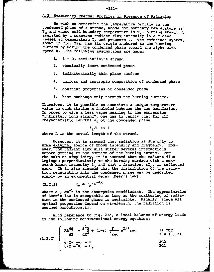
-211-
A.2 Stationary Thermal Profiles in Presence of Radiation
We wish to determine the temperature profile in thecondensed phase of a strand, whose hot boundary temperature isT. and whose cold boundary temperature is T , burning steadily,assisted by a constant radiant flux intensiAy in a closedvessel at temperature T. and pressure P. The reference system,shown in Fig. 22a, has its origin anchored to the burningsurface by moving the condensed phase toward the right withspeed R. The following assumptions are made:
1. 1 - D, semi-infinite strand
2. chemically inert condensed phase
3. infinitesimally thin plane surface
4. uniform and isotropic composition of condensed phase
5. constant properties of condensed phase
6. heat exchange only through the burning surface.
Therefore, it is possible to associate a unique temperaturevalue to each station x included between the two boundaries.In order to give a less vague meaning to the expression"infinitely long strand", one has to verify that for allcharacteristic lengths 6i of the condensed phase
i/L «< 1
where L is the actual length of the strand.
Moreover, it is assumed that radiation is due only tosome external source of known intensity and frequency. How-ever, the riant flux will suffer several interactionsbefore getting to the surface of the burning strand. Forthe sake of simplicity, it is assumed that the radiant fluximpinges perpendicularly to the burning surface with a con-stant known intensity I• and that a fraction, rI , is reflectedback. It is also assumed that the distribution 8f the radia-tion penetrating into the condensed phase may be describedsimply by an exponential decay (Beer's law):
Gk 2.1 e,+ax(A.2.1) I O
where a , cm-I is the absorption coefficient. The approximationof Beer's law is acceptable as long as the scattering of radia-tion in the condensed phase is negligible. Finally, since alloptical properties depend on wavelength, the radiation isassumed monochromatic.
With reference to Fig. 23a, a local balance of energy leadsto the following nondimensional energy equation:
~ dO d 2 F eX/1,I D-X-r • + (l-r) rad ODE"dX dX rad X = (0,-•)
(A.2.2) 0G(x. _-• = 0 BC2e(x =-o) = E) BCI
sI
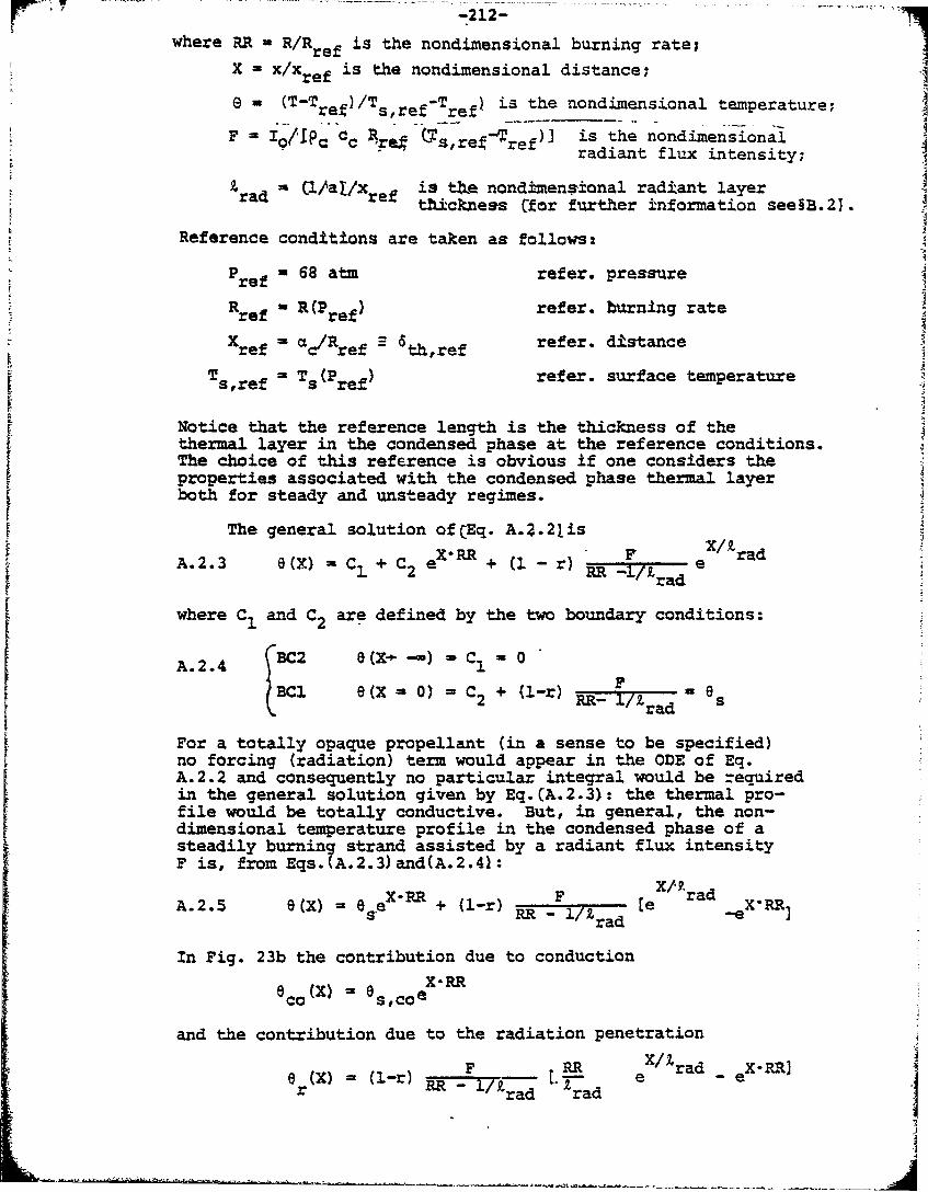
, °-212-
where RR R/Rref is the nondimensional burning rate;
X = X/Xref is the nondimensional distance;
S(T-Tref/Ts,ref ref is the nondimensional temperature;
F IorP•c Cc Arg •Tsrre ref)J is the nondimensionalradiant flux intensity;
za (1/a /x is tbe nondimensional radiant layerthickness Cfor further information see§B.21.
Reference conditions are taken as follows:
Pref 68 atm refer. pressureRrefRref R (Pref) refer. burning rate
X =cRrefer. distanceref "c•Rref -th,ref
T = T (Pe) refer. surface temperatures,ref S ref
Notice that the reference length is the thickness of thethermal layer in the condensed phase at the reference conditions.The choice of this reference is obvious if one considers theproperties associated with the condensed phase thermal layerboth for steady and unsteady regimes.
The general solution of(Eq. A.2.21isXRR + l rad
A.2.3 6(X) C1 + C2 er) RR -i/ e
where C1 and C2 are defined by the two boundary conditions:
A.2.4 (BC2 8(X-.)- C1 0SF
BC e(X = 0) = C2 + (l-r) eRR- 7Z/. sa
For a totally opaque propellant (in a sense to be specified)no forcing (radiation) term would appear in the ODE of Eq.A.2.2 and consequently no particular integral would be requiredin the general solution given by Eq.(A.2.3): the thermal pro-file would be totally conductive. But, in general, the non-dimensional temperature profile in the condensed phase of asteadily burning strand assisted by a radiant flux intensityF is, from Eqs.(A.2.3)and(A.2.4):
F-R eX19.radA.2.5 S(x) = ese8 + (l-r) RRF /rad e -e XRR
In Fig. 23b the contribution due to conduction
6 (X)8 X-RRecoX = es,coe
and the contribution due to the radiation penetration
0 W RR eX/Irad e X-R](X) = (1-r) F- rad erad
-213-
Are shown graphically. The radiatiVe thermal profile startswith zero slope, since tbe absorption of r~diation is avolumetric process,. The effect of the radiation penetrationis to make the overall thermal profile less steep.
It is worthwhile to remark that the conductive thermallayer thickness:
Xth cL/R
th,ref
depends also on the operating pressure through the burningrate, while the radiant absorption layer thickness
Cl/a)rad th,ref
depends exclusively on the natute of the propellant. Noticethat if k£th/£rad " 1 the energy transfer by conductiondominates over the energy transfer by radiation; physicallythis corresponds to the limiting case of an opaque condensedphase. All this implies that, if a large pressure excursionoccurs, the propellant response may be altered by the presenceof radiation since it alters the thermal layer thickness inthe condensed phase.
A.3 The Quasi-Steady State Gas Phase Assumption
The prediction of the burning rate evolution in time forarbitrary but independently assigned laws P(t) and/or I (t)and for a given set of initial values implies that the gurfacetemperature (related to the burning rate through some lawto be defined) is unknown. Therefore, the condensed phasethermal profile can no longer be determined in a straight-forward way, as it was for the stationary case in the previoussection. Indeed, the coupling between the condensed and thegas phases through the burning surface needs to be consideredexplicitly.
For a stationary configuration, the deflagration wavein the (chemically inert) condensed phase is defined by thethermal and radiant layer thicknesses. Since the gas phaseis the site of a complicated pattern of chemical reactionswith the appropriate diffusive and kinetic processes, werecognize that the analysis of a deflagration wave with thesegas phase contrib tions in principle requires the knowledge ofthe thicknesses not only of the proper thermal and radiant layersbut also of some diffusive, kinetic and reacting layers (tobe defined). This is already a big problem, since very littleis known about the details of the gas phase phenomena.In order to simplify our physical model, hopefully withoutloosing the essential features of the overall system, thefollowing assumptions are made for the gas Phase:
-214-
1. emission of radiation is neglected;
2. any interaction with the external radi'ant fluxis neglected;
3. Kinetic processes are approximated by a one step(typically second orderY reaction.
Even with this simple model, we would still not know the finalgas temperature. In order to make life simpler, we use thefurther (unnecessary) assumption of no energy losses from thegas phase; in this event, the final gas temperatureis given for a stationary process by:
Tf - Tef6 (x- = eff .Ts,ref-ref
where e is the nondimensional adiabatic flame temperature.This hypothesis is justified by the fact that it has littleimpact on a model where several more serious approximationshave been made.
Despite these assumptions, for a nonsteady case the problemof fully defining *he deflagration wave is still very difficult.The shape of the thermal profile is a priori unpredictablesince it depends on the full previous time history and on thearbitrary but given laws P(t) and/or I (t). It is obviousthat the concept of a simple fixed thermal layer loosesall its meaning. For the condensed phase, at least, we mayovercome this difficulty by solving the full unsteady thermalproblem. Unfortunately, this implies we must face thedifficulties of a strongly nonlinear initial value problemexpressed by a parabolic PDE. Things are much worse in thegas phase: not only does the concept of characteristic layersloose its validity, but we do not knc, how to deal properlywith unsteady reacting processes including their diffusiveand kinetic aspects.
At this point we invoke a powerful approximation: thequasi-steadiness assumption. This consists in consideringthe fully unsteady condensed phase portion of the deflagrationwave coupled to a steady gas phase portion of the deflagrationwave through the burning surface. In doing so, the gas phaseis assumed to adjust itself instant by instant and infinitelyfast to the conditions existing in the condensed phase (say,burning rate) and to the conditions imposed by the externalparameters (say, pressure).
This assumption may be justified by consideration of thevarious characteristic times. Let the characteristic timefor the conductive thermal processes in the condensed phasebe in dimensional terms
- -. ~ . ~ = . - _ - . ~ - ~ - - -- ~ -"- - ---- - - -
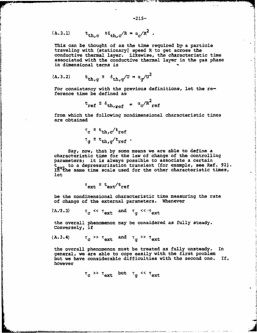
-215-
k2 (A.3.1) t /Rt c t hc c
This can bh thought of as, the time required by a particletraveling with (stationaryl speed R to get across theconductive thermal layer. Liltevise, the chAracteristic timeassociated with the conductive thermal layer in the gas phasein dimensional terms is
(A.3.2) 2tha U-ath2
For consistency with the previous definitions, let the re-ference time be defined as
tref - th,ref = ac/R ref
from which the following nondimensional characteristic times
are obtained
tc tthc/tref
Tgg -tth,g/tref
Say, now, that by some means we are able to define acharacteristic time for the law of change of the controllingparameters; it is always possible to associate a certaint to a depressurization transient (for example, see Ref. 921.IAXthe same time scale used for the other characteristic times,let
ext text/tref
be the nondimensional characteristic time measuring the rateof change of the external parameters. Whenever
(A.13.3) T << T and r :Text
the overall phenomenon may be considered as fully steady.Conversely, if
(A.3.4) Tc >> Text and >> Text
the overall phenomenon must be treated as fully unsteady. Ingeneral, we are able to cope easily with the first problembut we have considerable difficulties with the second one. If,however
Tc >> Text but Tg << Textc xt9 x
-216-
then we have An intemediate oase in hip t4 gA% phae qay.be thought of As be~n9 in eV-ibri• •iU t the egternalparameter% (sar, pressurej while still nothing can .be saidabout the condensed phase (except that, in general, It is notin equilibriuml and about the coupling to the gas phase.
At this point, a fundamental and simple result from thephysics of heterogeneous combustion is of great help. Letus compare the two characteristic thermal times in condensedand gas phases; for sake of clarity in dimensional termsone gets
t a 2thg Rtth,c ac U2
Mass continuity in a steady state requires
pcR P gUc g
from which
(A.3.5) ~ i t~ Cth,c thc c g c
depending only on p~hysical properties of the__ ropellant. Forusual cases na _ood estimate is
(A.3.6) -•=0(0. 01)T
.c
This implies that whenever
T << Text ,even though T.>> Text
the gas phase is not only in equilibrium with the externalparameters (say, pressure) but also with the instantaneousconditions existing in the condensed phase (say, burning rate).
In conclusion, the quasi-steady gas phase assumptionholds true (for the kinds of heterogeneous flames consideredin this work) if Eq. A.3.7 is satisfied. This implies thatall time derivatives in the gas phase equations are small andcan be dropped out; all PDE's are then reduced to ODE's.Therefore, the gas phase equations are immediately integrable(e.g. see Eq. 6.5.4 for the energy equation). However, theresulting quasi-steady integral relations are different fromthe corresponding steady state relations due to the unsteadinessof the boundary conditions at the condensed/gas interface.For a through discussion of this final point, the reader isreferred to Refs. 90 and 115.
A1
- -217-
APPNDIX B
RADIATION, T" - V Q DIZSTRTBUTION'FU1CTZON IW. TIM CONDENSE PHASE
A more general treatment of the fate of the externalradiant flux impinging on the surface of a burning propellantis offered in this appendix. The assumption of no radiationscattering in the condensed phase is relaxed, while all ofthe other assumptions listed in 96.5 are retained. Thisimportant aspect of the physics of the radiation has oftenbeen neglected in the literature of heterogeneous flames.This neglect may affect both the validity of the experimentalmeasurements of absorption coefficients and the qualitativebehavior of a burning propellant assisted by radiation, mainlywith regard to dynamic effects.
The excellent treatment by. Kot~ler B.1,B.2and discussion by Ohlemiller B and 5 are followed here.Further comments on the effects of radiation on burning pro-pellants can be found in Refs. 126 and B.3. The law found forthe distribution of radiation in an absorbing and scatt;-ingmedium can then be incorporated in the system of equationslisted in §6.5. (This law contains certain phenomenologicalconstants which in general must be measured experimentally;a possible procedure is discussed.) Such a more generalmodel can be numerically integrated following the discussionsof Chapter 9.
For the sake of clarity, dimensional quantities are usedin this appendix. The passage to nondimensional variables isthen performed according to the rules indicated in §6.5.
B.1 Description of the Physical Problem
Let us consider a slab of heterogeneous material (Fig.B.la) consisting of a large number of particles embedded in ahomogeneous matrix (absorbing-scattering medium). Let the slabfor the time being have a finite thickness t and be illuminatedat one side by a radiant beam of intensity I0. The beamemerging from the other end at x = t will be less intensealso due to the fact that some light is scattered to the sideby the particles and thus removed from the direct beam. InFig. B.la a portrait of the complicated 3-D radiation intensitydistribution in the absorbing-scattering medium is given:at any station x, the radiation intensity (flux/unit solid angle)depends not only on the depth of the station from the surfacex = 0, but also on the specific direction considered.
We wish, in this section, to describe the above distri-bution of radiation intensity. This is, in general, a -
formidable problem and a certain number of assumptions are tobe made. In order to exclude a wavelength dependence, let usconsider for the time being a beam of monochromatic radiation.It is also assumed for the time being that the matrix of themedium has the same refractive index as the external ambient
S- u
*c 4 -----.r•~,-,.- ~ :- --
-218-I
medium. When this assumption of 4 neutral medium is notsatisfied, reflection at the surface and refraction at theboundary (scattering/ambient medial should he accounted for.Finally, the impinging radiation is assumed unpolarized and theelectromagnetic wave is assumed plane.
A fundamental parameter is the nondimensional ratio d/X,where d is some typical average size of the particles embeddedin the matrix of the scattering medium and A is the wave-
length of the impinging radiation. Whenever
d/X << 1
the absorption effects are largely dominant over the scatteringeffects and the extinction of the impinging beam is practicallydue only to absorption. In this case the fate of the beam iscorrectly described by Beer's law and the results found inChapter 9 do not need to be modified. Conversely, if
d/X >> 1
the scattering effects are substantial and the extinction ofthe impinging beam may be due in large part to scattering.In this case Beer's law is no longer valid and the resultsfound in Chapter 9 are inaccurate. Finally if
d/X = 1
both absorption and scattering effects are important and theextinction of the impinging beam is due to both mechanisms.In this general physical configuration, Beer's law is notsufficient for describing the fate of the radiation at theinterior of the condensed phase of the burning propellant andmore sophisticated theories are to be implemented. Qualitatively,one would expect the results found in Chapter 9 to be stillvalid but with a dependence on the impinging external radiantflux less pronounced to the extent in which the extinction ofthe oeam is due to scattering.
By scattering is meant the combined effect of reflection,refraction and diffraction on a radiant flux interacting witha particle. Only when d/X >> 1 can the fate of the nonabsorbedportion of a plane electromagnetic wave interactina with aparticle be described using the classical concepts of thegeometrical optics (reflection and refraction). For d/X Nlis no longer possible to separate the contributions to theradiant flux intensity due to reflection, refraction, and dif-fraction. A drastic difference exists depending onwhether the beam is impinging on isolated particles or on acluster of particles of different size. For the former casethe well established treatments by Rayleigh (d/X << 1, scatteringonly) and Mie (d/WX arbitrary, scattering and absorption)apply. These theories may be extended to an assembly of par-ticles having the same diameter subjected to illumination
j
by a monochromatic plane wave, and separated from each otherby a distance large enough. to avoid a succession of scatteringevents from the same beam pencil. This situation is definedas single scattering in a monodisperse assembly of particles.In the more general configuration of a cluster made ofclosely packed particles of various shapes and sizes, multiplescattering in a polydisperse assembly has to be considered.This is a very difficult task and no rigourous, theory is avail-able so far. Several phenomenological treatments have beenproposed and they commonly resort to some statistical averagevalues for the geometrical factors concerning, the particlesdispersed in the absorbing-scattering medium. This smoothsdown the dependence of the results on the shape and size of theindividual particles. The behavior of the absorbing-scatteringmedium is globally characterized by two constants, experiment-ally determined, defining the absorption and scattering propertiesof the medium under examination. These are known as "two con-stant theories".
With reference to Fig. B.ib, let us fix a polar systemof coordinates and let us consider only axial-symmetric casesby putting 3/a - 0 for all the relevant functions which willbe met. An external radiant beam impinging with intensity 10at the boundary of the slab and traveling inside the medium issubjected to negative contributions (decrease of intensity)due to absorption and out scattering and positive contributions(increase of intensity) due to emission and in scattering.As usual, any emission of radiation which is not of thermalnature is neglected in this work. We define the volumeabsorption coefficient a, cm- 1 so that the radiant flux intensityemitted within a solid angle dw from a point source and lostby absorption along an arbitrary path of length dt is
diabs = aIdf.
Likewise, we define the volume scattering coefficient s, cm-iso that the radiant flux intensity emitted within a solidangle dw from point source and lost by scattering out along anarbitrary path of length dl is
di sca. out = -s I d9
Obviously, the (total) volume extinction coefficient k, cm 1 isdefined so that the radiant flux intensity emitted within asolid angle dw from a point source suffers a total loss alongan arbitrary path of length dZ given by
dloss= - k I dl
being
k a + s
-220-
Due to Kirchoff'a jay, the gadiant flux intensity emittedwithin A solid angle dw from A point source d:stributed alongan arbitrarr path length dA is
dlem E a Xb dl
where Ib is the intensity of the black body radiation definedby Planck's law.r\
With reference to Fig. B.lb,it can be shownB4 -B6that the gain in intensity of the radiant flux along anarbitrary path dl by scattering from all other bundles dw'into the bundle dw can be expressed as
dlsca in sdl I(x, rt d&
where the phase function P(n,n*) gives the fraction of radiationincident from direction n' that is scattered into direction n.In all scattering processes it is assumed that no frequencychange occurs in the re-emission of radiation. It follows thatthe radiative transfer equation which is an energy conservationstatement on the differential element can be written as:
@.l.l) (a+s) + a b + Ifxp) dv"
where I(x,ji) is the radiant intensity at depth x in direction
Sto the inward normal of the boundary surface;
V Bcosn
a is the volumetric absorption coefficient;
s is the volumetric scattering coefficient;
The solution of the above integro-differential equation forthe general case of multiple scattering in a polydisperse clusterof particles is difficult to obtain. Even for those particularconfigurations for which rigorous solutions have been found,the use of the proper approximate solutions is preferable
Let us turn now to the specific case of a burning propellant.Due to the distribution and moderate level of temperature inthe condensed phase, the emission of thermal radiation albis assumed to be negligibLe compared to the external radiantflux. As due to the .nat,.re of the propellant, two typicalsituations may occur. IZ the composition is homogeneous on amolecular scale (e.g., son., DB propellants), the scattering
-22l-
effects are neglig±ble. In thi case the medium can be thoughtof as a pu~re ahsor4ing one and the radiat#ye transfer equationreduces to Beer ýw law for the limitinng vaue. of s'.Q..Whenever this occurs,), the :results a, presented in Chapter 9 arevalid. On the other hand, if the composition of the strand isnot homogeneous on a molecular scale Ce.g., a composite APpropellant), the full Eq. (B.1.1)needs to be considered and amodel for the optical heterogeneity of thx absorbing-scatteringmedium is required. Following Ohlemiller75 , a conventionalcomposite propellant may be- thought of as, consisting of twophases: a first phase (2S% by" weight of the propellant[consisting of a polymeric fuel binder with additives and alum.",inum powder suspended in it and a second phase (75% by weightof the propellant) consisting of a controlled distributionof AP particles. Usuallyadditives and aluminum powder havea mean size of less than 0ui, whereas AP particles may rangefrom 1. to 100u with a large fraction of particles of the orderof 100. in size. Therefore the fuel phase fills the intersticesaround the randomly distributed but rather closely packedAP particles.
;n the arc. iMaqe Aparatu* moat Qf t~e radiAtion isabsorbed by the polymeric fuel and then the heat is tranmitted--by conduction to the adjacent AV particleo, which are qu.eitetransparent to the arc image radiation CQ.3 to 1.54.. Con-versely, in the laser ignition apparatus the radiation CIQ.6 p)is absorbed both by the polymeric fuel and the AP particles.Note that Eq. B.1.1 has been derived on the assumption of acollection of absorbing and scattering particles distributedin a neutral medium. Obviously, this is not the case for thefuel phase since the medium absorbs as well as the particles.We can account for this fact by considering some mean absorptioncoefficient, a, depending on the composition of the fuel phaseand a surface refctivity coefficient, r. Due to the differentrefractive index of the polymeric fuel and AP pa_-ticles, thereflectivity coefficient may vary on the surface of the pro-pellant. Likewise, as mentioned, the absorption coefficientof the polymeric fuel and AP particles may sensibly differ fromthe average value. All this implies complicated 3-D inter-actions between the local deposition of radiation in depth andthe heating of the propellant by conduction. The picture ismade even more difficult by the chaotic change of direction ofthe light rays(*scattering"1 in the propellant. It is stressedthat the wavelength dependenceof the relevant optical propertiesaccentuates these manifestations of heterogeneity in the arcimage apparatus. Notice also that, in the case of arc imageradiation, the polychromatic nature of the radiant beam shouldbe accounted for. This is not a conceptual difficulty oncewe are able to deal with monochromatic radiation.
>1
-222-
Subsequently, once the problem of the radiation distributionhas been solved (see §B.2), the problem (possibly 3-D) of theheating of the propellant must be dealt with. This also is,in general, a very difficult matter and in this eport wewill just summarize the discussion by Ohlemiller8 and75) in §B.2. As to the radiation scattering question, evenconsidering all the assumtions and simplifications so farmentioned, the problem is still very difficult to solve. Inorder to avoid too cumbersome and unrewarding a task (recall theapproximations listed in §6.5 for the heterogeneous deflagra-tion wave in a solid propellant), we accept the further assump-tion of isotropic scattering. This amounts to putting for thephase function
P(•U•)= 1
Then the radiative transfer equation in dimensional terms inan absorbing and scattering medium may be written as
(.i.2) dI _ (a+s)I + s3
where J(x, Q is the source function at depth x in directionSto the inward normal of the boundary surface and representsthe contribution to radiation in direction p by scatteringfrom all other directions. it can be written as
The radiative transfer equation will be used in the form of Eq.
(B.l.2)throughout the remainder of the text. To assist thereader, the assumptions implicit in Eq. (B.l.2)are summarizedas follows:
1. monochromatic radiation;
2. plane wave;
3. unpolarized radiation;
4. polydisperse cluster of particles;
5. multiple scattering;
6. isotropic scattering;
7. nonemitting scattering medium;
8. no frequency change in re-emission of radiation;
9. axial symmetric processes (no edge effects).
ii
S--223-
B.2 Approximate Solutions of the Radiative Transfer Equation
Within the framework of the assumptions listed in theprevious section, Eq.(B.l.2)can be solved for two differentconfigurations corresponding rather closely to the experi-mental set up of the arc image and of the laser tube. Obviously,the beam from the arc image can be treated as diffuse poly-chromatic radiation while the beam from the laser tube can betreated as collimated monochromatic radiation. Both cases,at this point easily solvable in principle, are still difficultin actual practice: the arc configuration requires an ex-tension to polychiomatic radiation and the laser configurationrequires a proper treatment of the collimated nature of thebeam.
B.2.1 Diffuse Irradiation in an Arc Image Furnace
We start by considering the case of monochromatic uniformlydiffuse radiation (see Fig. B.2). In this case, a first ap-proximation solution of Eq.(B.l.2)is obtained by the assumptionof no angular dependence of the radiant flux intensity in eachof two hemispheres. The original beam I(x,p) is splitconceptually into two parts; one I+(x) travels in the forwarddirection and the second I-(x) travels in the backward direction.Both radiant fluxes are considered independent of angular
distribution within their respective hemispheres, which isnearly correct as long as I(x, u') has a weak depen'ence on
Sin Eq .4 B .l .3).The following expressions are obtained (p .14 of Ref. B.2):
SI () T(x,U > 0) = 0 . e-rX 0 0 r2r-t_ 2
(B. 2 . 1 e 0Roo e - Roo
1 IR~e 2rt] 2 I°R. •Se-rx +rxI-(x) ( IX,1< 0) e|"r e r ' . e
[e - R01 RDwhere t is the thickness of the sample subjected to radiative
heating:
=- 2 Va s, cm+ is a constant
R,= (2a + s - r)/s is a constant
It will be noticed that the original integro-differentialequation of radiative transfer is reduced in this simple caseto a pair of ODE's. The above solution is called the Schuster-Kubelka or Schuster-Schwartzchild first approximation solution.
ILjI
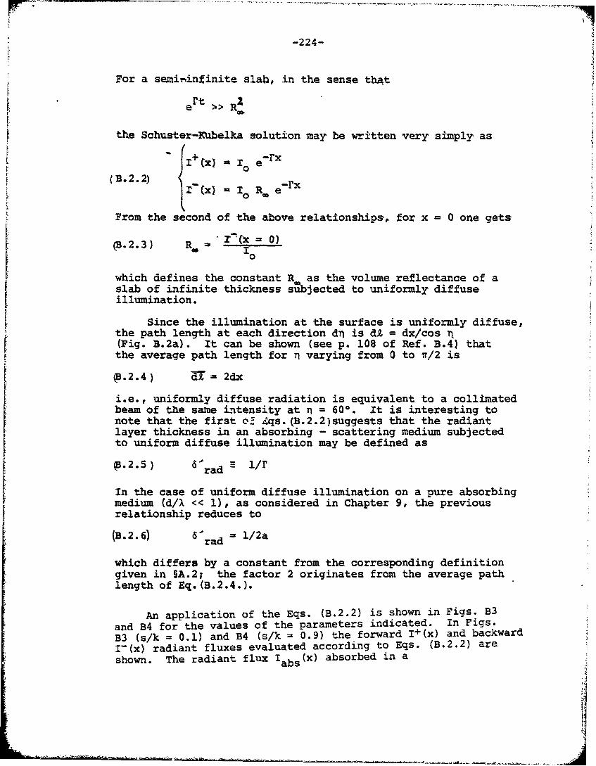
-224-
For a semiiinfinite slab, in the sense tbAt
Pt 2e >> R;
the Schuster-Kubelka solution may be written very simply as
1:12 - :: ;rrxf0
(B. 2.2) +
( "x) 10 Ro e-r
From the second of the above relationships, for x = 0 one gets
S= O)c.B.2.3) R =, ,
which defines the constant R as the volume reflectance of a
slab of infinite thickness subjected to uniformly diffuseillumination.
Since the illumination at the surface is uniformly diffuse,the path length at each direction dn is di = dx/cos n(Fig. B.2a). It can be shown (see p. 108 of Ref. B.4) thatthe average path length for n varying from 0 to v/2 is
(B.2.4) T = 2dx
i.e., uniformly diffuse radiation is equivalent to a collimated
beam of the same intensity at n = 600. It is interesting tonote that the first o._ Zqs. (B.2.2)suggests that the radiantlayer thickness in an absorbing - scattering medium subjectedto uniform diffuse illumination may be defined as
p.2.5) 6 'rad
In the case of uniform diffuse illumination on a pure absorbingmedium (d/X << 1), as considered in Chapter 9, the previousrelationship reduces to
(B. 2.6) 1rad = i/2a
which differs by a constant from the corresponding definitiongiven in §A.2; the factor 2 originates from the average pathlength of Eq. (B.2.4.).
An application of the Eqs. (B.2.2) is shown in Figs. B3and B4 for the values of the parameters indicated. In Figs.B3 (s/k = 0.1) and B4 (s/k = 0.9) the forward I+(x) and backwardI-(x) radiant fluxes evaluated according to Eqs. (B.2.2) are
shown. The radiant flux Iabs(X) absorbed in a
•. bs
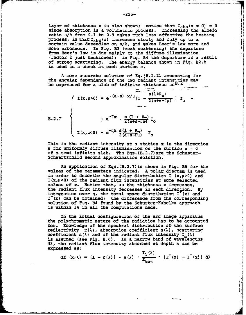
-225-
F layer of thickness x is also shown; notice that labs(x 0) 0since absorption is a volumetric process. Increasing the albedoratio s/k from 0.1 to 0.9 makes much less effective the heatingprocess, in that:Iabs (x) increases slowly and only up to acertain value depending on s/k, and makes Beer's law more andmore erroneous. In Fig. B3 (weak scattering) the departurefrom Beer's law is due mainly to the diffuse illumination(factor 2 just mentioned); in Fig. B4 the departure is a resultof strong scattering. The energy balance shown in Fig. B2.bis used as a check at each station x.
A more a'curate solution of Eq. (B.1.21. accounting forthe angular dependence of the two radiant intensites maybe expressed for a slab of infinite thickness asa
Z(x,u>0) e- (a+s) x/U - +(a+R ]2(a+s-ru) 0
B.2.7 + e-rx . s (1 + Re)Z (a+s-Fw7.1
(x,w) - e-rx S(U + L.)2 (a+s-ru) 110
This is the radiant intensity at a station x in the directionu for uniformly diffuse illumination on the surface x = 0of a semi infinite slab. The Eqs. (B.2.7)are the Schuster-Schwartzchild second approximation solution.
An application of Eqs.(B.2.7)is shown in Fig.. B5 for thevalues of the parameters indicated. A polar diagram is usedin order to describe the angular distribution I (x,p>0) andI(x,v<d) of the radiant flux intensities at some selectedvalues of x. Notice that, as the thickness x increases,the radiant flux intensity decreases in each direction. Byintegration over n, the total space distribution I (x) andI'(x) can be obtained; the difference from the correspondingsolution of Fig. B4 found by the Schuster-Kubelka approachis within 3% in all the computations made.
In the actual configuration of the arc image apparatusthe polychromatic nature of the radiation has to be accountedfor. Knowledge of the spectral distribution of the surfacereflectivity r(X), absorption coefficient a(X), scatteringcoefficient s(M) and of the radiant flux intensity I (X)is assumed (see Fig. B.6). In a narrow band of wavelengthsdX, the radiant flux intensity absorbed at depth x can beexpressed as:
dl (x;X) = 11- r( )M I a(X) M [I+(x) + I-(x)] dAtot
4i
I •
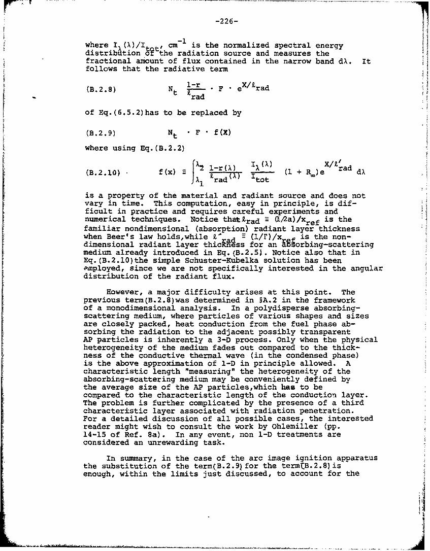
-226-
where I (A)/1 cm is the normalized spectral energydistribution ot the radiation source and measures thefractional amount of flux contained in the narrow band dA. Itfollows that the radiative term
(B.2.8) Nt l-_r F eX/tradrad
of Eq.(6.5.2)has to be replaced by
(B.2.9) Nt F f(X)
where using Eq.(B.2.2)
Sf~x • I l-r•) I(1)X/Y' -
(B.2.10) (i + RJ)e rad dX• 1o)) radX') tot
is a property of the material and radiant source and does notvary in time. This computation, easy in principle, is dif-ficult in practice and requires careful experiments andnumerical techniques. Notice thattrad (!-2a)/xref is thefamiliar nondimensional (absorption) radiant layer thicknesswhen Beer's law holds,while ad (1/r)/x is the non-dimensional radiant layer thicness for an 981orbing-scatteringmedium already introduced in Eq.(B.2.51. Notice also that inEq.(B.2.10)the simple Schuster-Kubelka solution has beenemployed, since we are not specifically interested in the angulardistribution of the radiant flux.
However, a major difficulty arises at this point. The
previous term(B.2.8)was determined in §A.2 in the frameworkof a monodimensional analysis. In a polydisperse absorbing-scattering medium, where particles of various shapes and sizesare closely packed, heat conduction from the fuel phase ab-sorbing the radiation to the adjacent possibly transparentAP particles is inherently a 3-D process. Only when the physicalheterogeneity of the medium fades out compared to the thick-ness of the conductive thermal wave (in the condensed phase)is the above approximation of 1-D in principle allowed. Acharacteristic length "measuring" the heterogeneity of theabsorbing-scattering medium may be conveniently defined bythe average size of the AP particles,which has to becompared to the characteristic length of the conduction layer.The problem is further complicated by the presence of a thirdcharacter±stic layer associated with radiation penetration.For a detailed discussion of all possible cases, the interestedreader might wish to consult the work by Ohlemiller (pp.14-15 of Ref. 8a). In any event, non 1-D treatments areconsidered an unrewarding task.
In summary, in the case of the arc image ignition apparatusthe substitution of the term(B.2.9) for the termtB.2.8)isenough, within the limits just discussed, to account for the
I
-. i
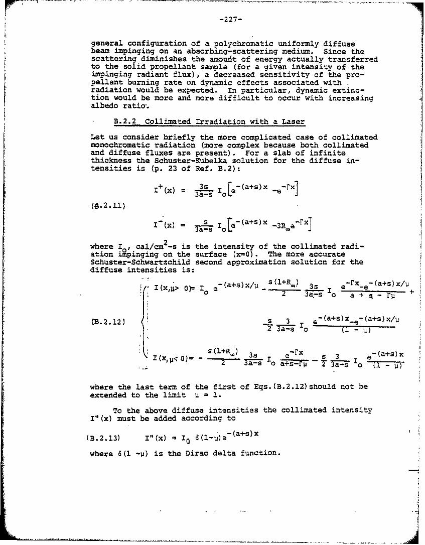
-227-
general configuration of a polychromatic uniformly diffusebeam impinging on an absorbing-scattering medium. Since thescattering diminishes the amouxit of energy actually transferredto the solid propellant sample (for a given intensity of theimpinging radiant flux), a decreased sensitivity of the pro-pellant burning rate on dynamic effects associated withradiation would be expected. In particular, dynamic extinc-tion would be more and more difficult to occur with increasingalbedo ratio.
B.2.2 Collimated Irradiation with a Laser
Let us consider briefly the more complicated case of collimatedmonochromatic radiation (more complex because both collimatedand diffuse fluxes are present). For a slab of infinitethickness the Schuster-Kubelka solution for the diffuse in-tensities is (p. 23 of Ref. B.2):
+ 3s [e-(a+s)x -r
(.2.11)
-(x) = a s Iole'(a+s)x -3R e-rxJ
2_where Io, cal/cm -s is the intensity of the collimated radi-ation impinging on the surface (xz0). The more accurateSchuster-Schwartzchild second approximation solution for thediffuse intensities is:
- x" > )= 0 e (a+s)x/U S (l+R00 ) r3s e -rx -(a+s)x/
0" 0 + - 0
wB.2.12) o . o n -e-(a+s)x/u
I (x) 3s ebad ac-(a+s)x(X =a- la+_s-'rV T Js "Io U-
where the last term of the first of Eqs. (B.2.12)should not beextended to the limit u i
To the above diffuse intensities the collimated intensityVW(x must be added according to
(B.2.13) I"(x) = 1 0 a (1-1)e
where 6(l -j) is the Dirac delta function.
• 4•
F -228-
In this case, the difficulty arises mainly from the factthat the more complex Schuster-Schwartzchild solution hasto be considered, since the radiant flux has to adjust itselffrom an initially collimated configuration to a final uniformlydiffuse configuration. This implies that the dependence of theangular distribution of the radiant flux on the station xcan no longer be neglected. It follows that Eqs.(B.2.12)have to be integrated over U = cosn in order for one to evaluatethe amount of radiation falling on a given station x. Theradiant intensity obtained by adding the collimated intensitygiven by Eq.(B.2.13)can then be directly substituted inEq.(6.5.2)with the same qualitative effects as discussed atthe end of the previous section.
In summary, for the laser ignition apparatus the approximateevaluation of F and Z r quantities in the term(B.2.8)isenough to account for r e general configuration of a monochro-matic collimated beam impinging on an absorbing-scatteringmedium. Notice that in this case we do not worry about 3-Dconductive processes, since (at least at 10.64) the absorptivityof AP is comparable to that of the polymeric binders (about250 cm-1 ). This can be considered as another advantage of thelaser with respect to the arc image source.
B.3 Experimental Determination of Optical Properties
Consider a slab of propellant of finite thicknessbounded by two parallel and optically plane surfaces andsubjected to uniformly diffuse radiation of monochromaticnature (Fig. B.7). In generallthe refractive index of thematrix of the heterogeneous propellant is different from therefractive index of the ambient medium, usually air. There-fore, measurements of the optical propp:ties of such a slab ofheterogenous propellant performed in an integrating photo-meter furnish only total (surface + volume) values of thereflectance and transmittance. (Note: an integrating photo-meter is necessary to capture all reflected and transmittedlight). Instead we are interested in evaluating the threephenomenological constants required for any multiplescatter theory, i.e., the volumetric absorption and scatteringcoefficients, and the internal surface reflectance (see Fig.B.7). This can be done by extending to the case of uniformlydiffuse illumination the solution given by Stokes (p. 484of Ref. Bl) for collimated incidence. It is assumed that theillumination is uniformly diffuse inside the plate also.For remarks concerning this assumption see Kottler (p. 485of Ref. B.1) and Kortum (p. 127 of Ref. B.4).
With reference to Fig. B.7 and to the related list ofsymbols, the Stokes theory shows that the total reflectanceand transmittance can be expressed as:
2(B.3.1) R = r + t' Ti [Rv(1 - r'Rv) + r"T ]/Dt e e 1 v 1 v
-229-
(.3.2) T M tAt.ATv/Dt e
where D (1 -rýR ' (1 - rý•AR ,T2
Notice that the following parameters
(B.3.3i Rt' Tt" re', r'
are measurable,whereas the following parameters
(B.3.4) Rv, T , rj .rý
cannot be directly measured. Therefore, we have so far fourunknowns in Eq. (B.3.41with two algebraic equations Eqs:!B-C3.1 andB.3.2). In order to solve the problem we need two morerelationships. The first just assumes that the front ahdrear surfaces are optically identical, so that
(.35 = r- ri diffuse internal surface reflectivity
r) re: re diffuse external surface reflectivity
The second relationship is obtained from a further measurementperformed in some specific condition so that one of the para-meters is known. For example, it has been suggested to measurethe reflectance RP of the sample with its rear surfaceblackened. In this configuration, the surface reflectivityat the rear surface r"= 0 in Eq. (B.3.1). Thereforethe completeproblem is solved by asing the following set of algebraicequations:
Rt = re + teti (Rv(1 - r.R) + riT 2 ]/D
(B, 3.6 Tt = teti TyD
Rbt = re + tet. Rv0. - r.Rvt e v
where D E (1 r~iy- r T
S-230-
The unknowns are Rv,Tv and ri while the parameters Rt, T ,SRrj, re are measured. Kottler (p. 486 of Ref. B.4), among
other comments, suggests avoiding measurements on overlythick samples, i.e., those with negligible transmittance, inorder to get reliable results.
!oeIn actual practice most of the spectrophotometers usea collimated incidence beam. The above results need, there-fore, to be extended to the configaration of collimated incidentradiation. This implies that the total transmittance Ttconsists now of a specular portion emerging from the rearsurface and of the diffuse portion already considered. More-over, the external diffuse surface reflectivity re has to bereplaced by the specular surface reflectivity rs. Any otherdifferences in the parameters may be neglected. However,in order to verify the assumption of diffuse light at theinterior of the slab, only plates with no emerging speculartransmittance from the rear surface will be considered.This requires either a plate of sufficient thickness or a concen-tration of scattering particles large enough to avoid theconfusing presence of two specular fluxes in the interior of theslab. With these provisions, the volume absorption coefficienta and the volume backward scattering coefficient sb may beevaluated once the algebraic system of Eqs. (B.3.6)has been solved. In the framework of the Schuster theory,one gets
(2 2Jv v (abB.3.7log[(l - RRv)/Tv a - 2asb t
where R = a + sb -
is the volume reflectance for uniformly diffuse illuminationwhen the thickness t ÷ =; it has been defined already bythe relationship(B.2.31, Some algebraic manipulations showthat the two definitions are equivalent if we put
s = 2 sb
Indeed the (total) volume scattering coefficient s can bethought of as the sum of the volume backward scatteringcoefficient s and of he volume forward scattering coeffi-cient sf, so Phat in general
s =sf + sb5 f 5 b
For very small particles, one has
s -sf b
-231-
and therefore
s 2sb
A final comment concerns the experimental measurement ofthe external surface reflectivity. This can be performed ina spectrophotometer equipped with an integrating sphere andwith some minor adjustments both diffuse and specularreflectivity can be evaluated. A detailed discussion onthe related problems is contained in Ref. B.4. I
'I
I
-232-
REFERENCES IN APPENDIX B
B.1 Kottler, F., "Turbid Media with Plane Parallel Surfaces,"Journal of the Optical Society of America, Vol. 50, May1960, pp. 483-490.
B.2 Kottler, F., "The Elements of Radiative Transfer," Pro ressin Optics, Vol. III, John Wiley & Sons, Inc., New Yrk, 964.
B.3 Boehringer, J.C. and Spindler, R.J., "Radiant Heating ofSemitransparent Materials", AIAA Journal, Vol. 1, No. 1,1963, pp. 84-88.
B.4 Kortum, G., Reflectance Spectroscopy: Principles, Methods,Applications, Springer-Verlag, New York 1969.
B.5 Van deHulst, J., Light Scattering !a Small Particles,John Wiley & Sons, Inc., New York, 1957.
B.6 Hottel, H. C. and Sarofim, A. F., Radiative Transfer,McGraw Hill Publishing Co., New York, 1967.
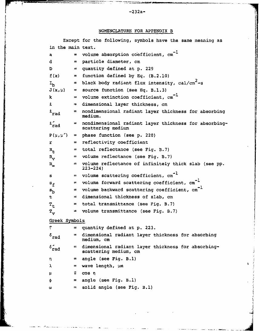
-232a-
NOMENCLATURE FOR APPENDIX B
Except for the following, symbols have the same meaning as
in the main text.
a = volume absorption coefficient, cm 1
d = particle diameter, cmD = quantity defined at p. 229
f(x) = function defined by Eq. (B.2.10)
Sblack body radiant flux intensity, cal/cm2-s
J(xU) = source function (see Eq. B.1.3)
k = volume extinction coefficient, cm
= dimensional layer thickness, cmrad nondimensional radiant layer thickness for absorbingrad medium.
rad = nondimensional radiant layer thickness for absorbing-scattering medium
P(UuA) = phase function (see p. 220)
r = reflectivity coefficient
Rt = total reflectance (see Fig. B.7)
Rv = volume reflectance (see Fig. B.7)
R. = volume reflectance of infinitely thick slab (see pp.223-224)
S= volume scattering coefficient, cm-Isf = volume forward scattering coefficient, cm-I
sb = volume backward scattering coefficient, cm-1
t = dimensional thickness of slab, cm
Tt = total transmittance (see Fig. B.7)
Tv = volume transmittance (see Fig. B.7)
Greek Symbols
r = quantity defined at p. 223.
a rad = dimensional radiant layer thickness for absorbingmedium, cm
S•ad= dimensional radiant layer thickness for absorbing-scattering medium, cm
= angle (see Fig. B.1)
X = wave length, Um
Ii cosn
S= angle (see Fig. B.1)
W solid angle (see Fig. B.1)
-232b-
Abbreviations
abs = absorbed
em = emitted
sca = scattered
°r•% : ••,,_• ... . • ,.. . . .. . .. . . ... ... .. . ; .I•
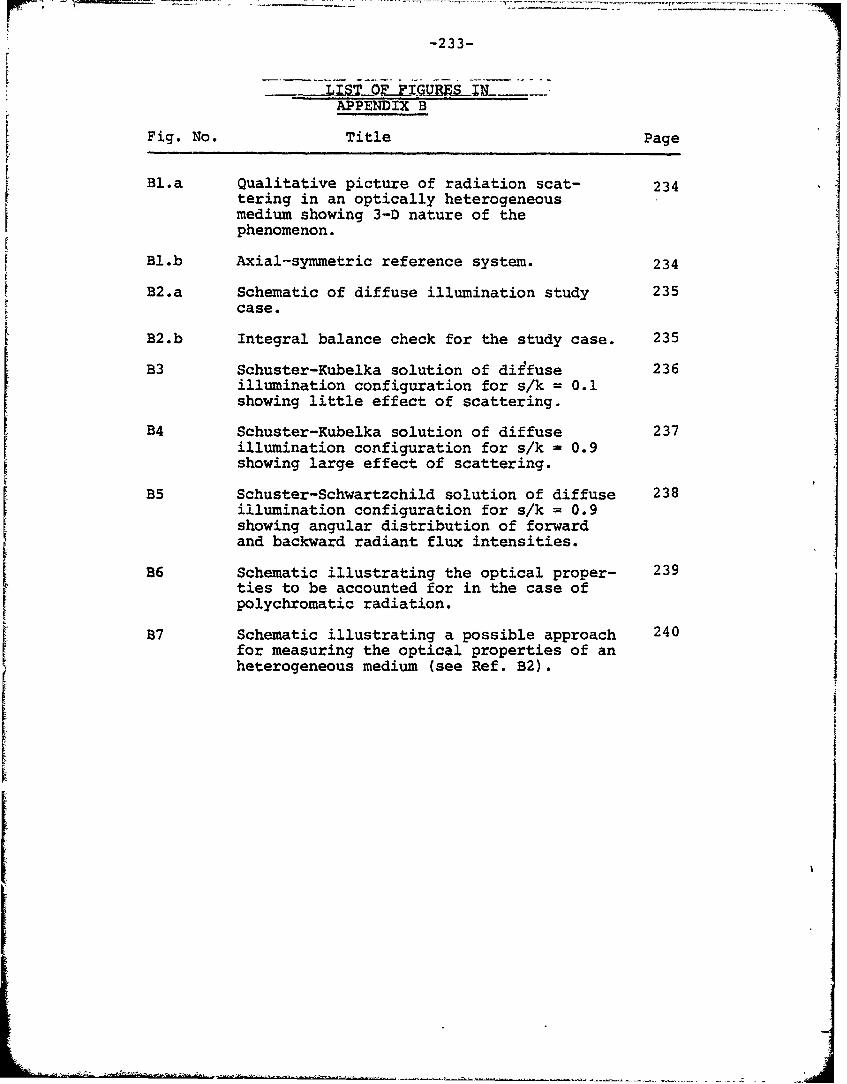
-233-
APPENDIX B
Fig. No. Title Page
Bl.a Qualitative picture of radiation scat- 234tering in an optically heterogeneousmedium showing 3-D nature of thephenomenon.
Bl.b Axial-symmetric reference system. 234
B2.a Schematic of diffuse illumination study 235case.
B2.b Integral balance check for the study case. 235
B3 Schuster-Kubelka solution of diffuse 236illumination configuration for s/k = 0.1showing little effect of scattering.
B4 Schuster-Kubelka solution of diffuse 237illumination configuration for s/k - 0.9showing large effect of scattering.
B5 Schuster-Schwartzchild solution of diffuse 238illumination configuration for s/k = 0.9showing angular distribution of forwardand backward radiant flux intensities.
B6 Schematic illustrating the optical proper- 239ties to be accounted for in the case ofpolychromatic radiation.
B7 Schematic illustrating a possible approach 240for measuring the optical properties of anheterogeneous medium (see Ref. B2).
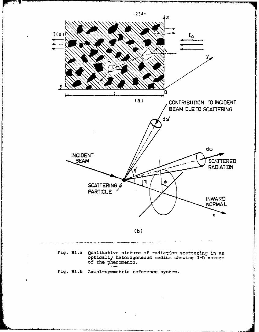
' ~-234-|
Azl
,I(x) "-10l
x . t
(a) CONTRIBUTION TO INCIDENTBEAM OUETO SCATTERING
dw'
dw
BEAM SCATTEREDRADIATION
SCATTERING • '
INWARD/• NORMAL
(b)
Fig. Bl.a Qualitative picture of radiation scattering in anoptically heterogeneous medium showing 3-D natureof the phenomenon.
Fig. Bl.b Axial-symmetric reference system.
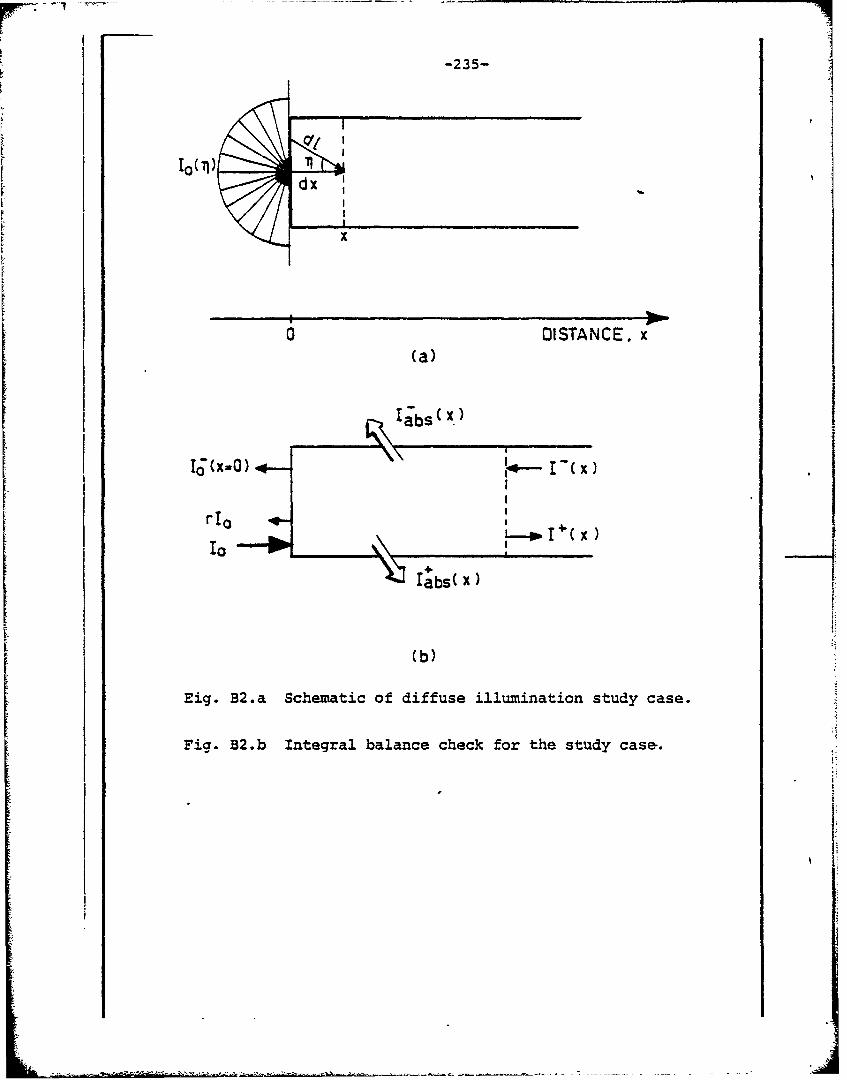
-235-
10(jtO(1dx
Fx
0 QISTANCE. x(a)
r0
a*bs( x)
(b)
Eig. B2.a Schematic of diffuse illumination study case.
Fig. B2.b Integral balance check for the study case.
.j ,
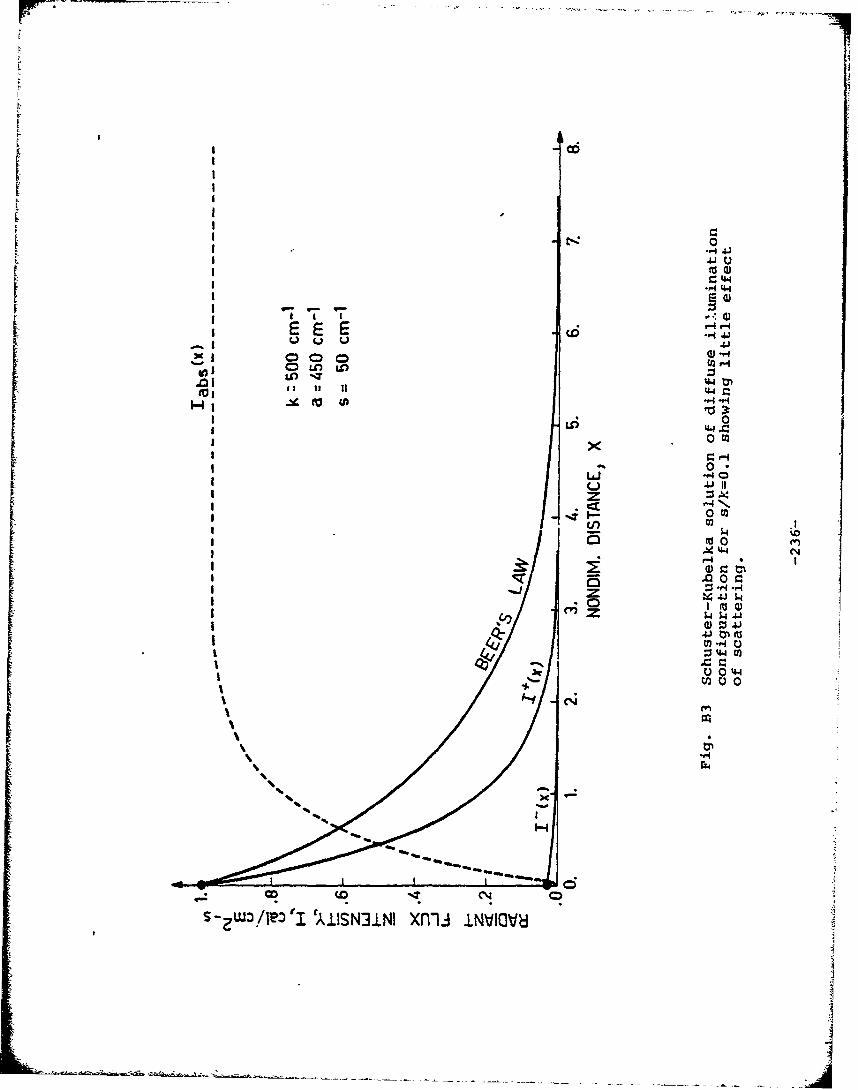
-H 44
E EEE
41:4
.p00
A A
I Wr-4 N,
I ~4.4 0
zz
'-4
U0
rT4
1-41S~ ---.-. ~~ -~--~- -- -~------------
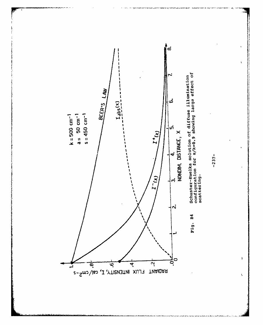
IC 0
tot to
0 0
0i C) Ui1
04
0 C
I 00
0 0to u
%. %.i-%
%~
OR.
S-ZW3/1':) " 'AISN3LNI nij NVI
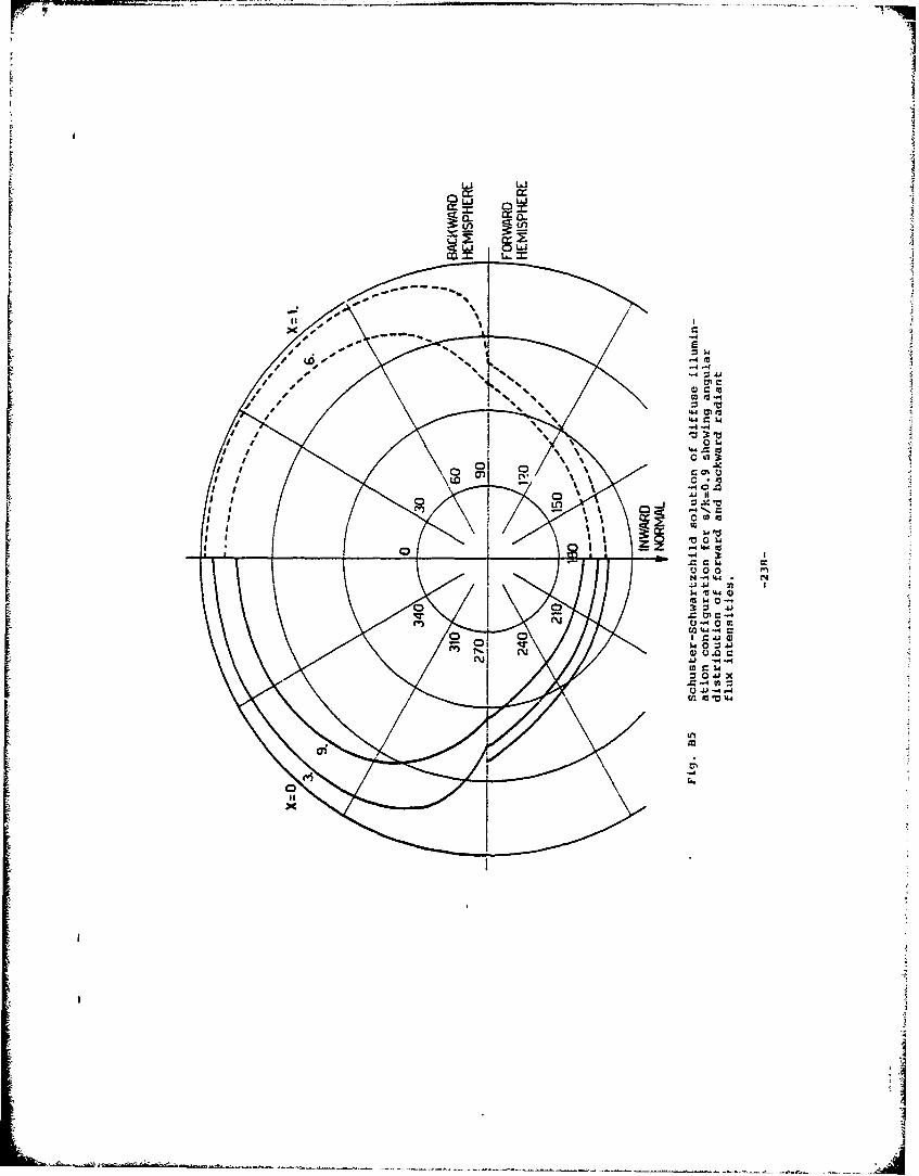
IJ
J. oom 4
%I 0LId
a)~ % 0
ko 0 J to
C)C~
.04 .u-d .-
S20 3 :1 A
U.C 7 1
0-4 0 r
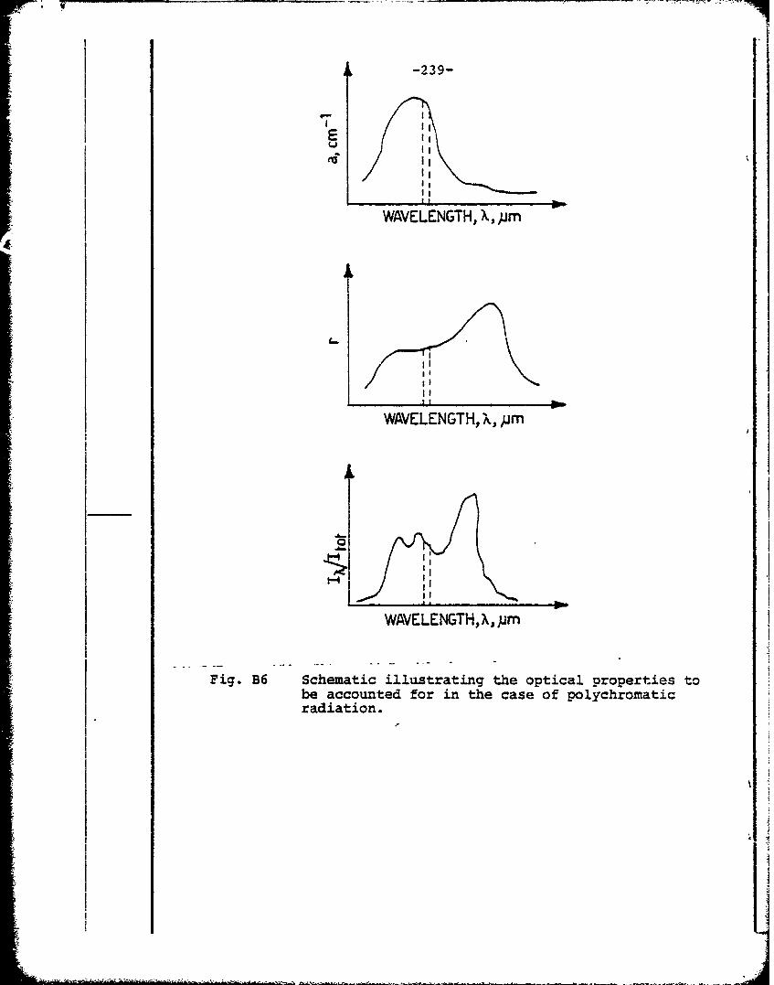
-239-
E
WAVELENGTH, X,pm
I 0I .1I
I~I:
WAVELENGTH, X, jm
Fig. B6 Schematic illustrating the optical properties tobe accounted for in the case of polychromaticradiation.
I 4
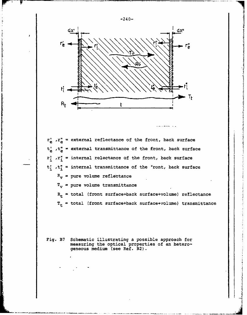
-240-
cix' Id~x"
II
e L#
Rt 4i~-
t re external reflectance of the front, back surface
t' ,te = external transmittance of the front, back surfacee e
r!r = internal relectance of the front, back surface
t! ,t! internal transmittance of the cront, back surface
Rv= pure volume reflectance
v= pure volume transmittance
Rt = total (front surface+back surface+volume) reflectance
Tt = total (front surface+back surface+volume) transmittance
Fig. B7 Schematic illustrating a possible approach formeasuring the optical properties of an hetero-geneous medium (see Ref. B2).