combustion and heat transfer in model two-dimensional porous burners
TRANSCRIPT

Combustion and Heat Transfer in Model Two-DimensionalPorous Burners
C. L. HACKERT,† J. L. ELLZEY, AND O. A. EZEKOYE*Department of Mechanical Engineering and Applied Research Laboratories, University of Texas at Austin,
Austin, TX 78712, USA
A two-dimensional model of two simple porous burner geometries is developed to analyze the influence ofmultidimensionality on flames within pore scale structures. The first geometry simulates a honeycomb burner,in which a ceramic is penetrated by many small, straight, nonconnecting passages. The second geometry consistsof many small parallel plates aligned with the flow direction. The Monte Carlo method is employed to calculatethe viewfactors for radiation heat exchange in the second geometry. This model compares well with experimentson burning rates, operating ranges, and radiation output. Heat losses from the burner are found to reduce theburning rate. The flame is shown to be highly two-dimensional, and limitations of one-dimensional models arediscussed. The effects of the material properties on the peak burning rate in these model porous media areexamined. Variations in the flame on length scales smaller than the pore size are also present and are discussedand quantified. © 1998 by The Combustion Institute
NOMENCLATURE
A channel cross sectional area, m2
a constant in heat capacity expressionB constant in heat capacity expressionc solid heat capacity, J/kg/Kcp gas heat capacity at constant pressure,
J/kg/Kd porous medium square unit cell side
length, mD mass diffusivity, m2/secE chemical reaction activation energy, J/
molF surface to burner end viewfactorh gas specific enthalpy, J/kghc heat of combustion, J/kg fuelJ radiosity, W/m2
k thermal conductivity, W/m/KK surface to surface viewfactorm mass flux, kg/m2/secP pressure, Paq0 conduction/convection heat flux to
surface, W/m2
q- volumetric heat flux to solid, averagedover pore, W/m3
R ideal gas constant, 8.314 J/mol/Ks stoichiometric fuel/oxygen ratio
t time, secT temperature, Ku axial gas velocity, m/secU burning rate or volume flux, m/secvW gas velocity, m/secx axial distancey transverse distanceyf fuel mass fractionyN nitrogen mass fractionyo oxygen mass fractionyp combustion products mass fraction
Greek
a thermal diffusivity, m2/sece surface emissivityf equivalence ratiom absolute viscosity, kg/m/secr density, kg/m3
v reaction rate, kg fuel/m3/sec
Subscripts
avg mass flux averagei, j vector or matrix component` ambient conditions
INTRODUCTION
Early theoretical work on premixed flamesshowed that the lean flammability limit could beextended and the burning rates increased if heat
*Corresponding author. Address: O. A. Ezekoye, AssistantProfessor, Department of Mechanical Engineering, Univer-sity of Texas at Austin, ETC 7.130, Austin, TX 78712.†Current address: Southwest Research Institute, P. O.Drawer 28510, San Antonio, TX 78228-0510.
COMBUSTION AND FLAME 116:177–191 (1999)© 1998 by The Combustion Institute 0010-2180/99/$19.00Published by Elsevier Science Inc. PII S0010-2180(98)00052-2
could be recirculated from the hot products tothe incoming reactants [1]. Takeno et al. [2] andTakeno and Sato [3] showed theoretically thatconduction through a porous solid inserted intoa premixed flame provided this means of heatrecirculation. Echigo et al. [4] showed experi-mentally and analytically that radiation fromscreens in a heated flow recirculated heat fromthe downstream to the upstream regions.
There has been substantial research in thearea of porous media combustion, and a goodreview of the subject is given by Howell et al.[5]. One of the first experimental studies of alaminar porous burner was conducted by Kotaniand Takeno [6], who used a ceramic tube bun-dle as the porous material and routed theexhaust gases back around the burner circum-ference to provide preheating of the inlet mix-ture and to minimize heat losses from thereaction zone. They were able to extend thelean limit of their methane flame to 0.32 andnoted reduced CO and NOx compared to a freeflame. Burning rates significantly higher thanthe free flame were also found. Turbulent re-fractory tube burners using a similar, but larger,geometry were investigated over several yearsby Churchill and coworkers [7–11].
Further experiments on a methane flamewithin a sponge-like reticulated ceramic wereconducted by Sathe et al. [12] and Hsu et al. [13]without the use of external exhaust gas recircu-lation, although the burners were generally wellinsulated. Heat recirculation in these burnerswas provided by conductive or radiative ex-change between the postflame and preflameregions. The results of these experiments aregenerally similar to those of Kotani and Takenowith respect to reduced lean limit, increasedburning rate, and lowered pollutant emissions,although the magnitude of the difference issomewhat reduced. By removing the exhaustgas recirculation, however, radiation from theburner surface may be captured for industrialuse. Experiments have shown that this type ofporous burner can convert a significant percent-age of the chemical heat release into down-stream thermal radiation [14].
A simple geometry in which the coupledeffects of conduction and radiation modify theflame burning properties was examined by Minand Shin [15]. They performed an experimental
study on an uninsulated honeycomb burner, inwhich the propane flame is confined within aceramic penetrated by many small, straight,nonconnecting passages. They investigated thelimits of stability of these flames in terms of flowrates and equivalence ratios, and noted theexistence of two fundamentally different flameshapes. They label these flame shapes as Type Iand Type II. The Type I flame is largely flatacross the burner, i.e., the flame is at roughlythe same distance from the inlet in every flowelement. The Type II flame occurs for lowerflowrates and leaner flames than the Type Iflame. It is more curved in shape, with the flameat the downstream end near the burner edgeand fairly flat in the upstream half near theburner center.
In addition to the practical applications, theseburners provide an interesting area of study bycombining complex multimode heat transferand chemistry with a laminar flow field. Inprinciple, then, these burners can be modeledwithout recourse to ad hoc turbulence models.Many investigators have in fact been very suc-cessful in predicting burning rates, extendedflammability limits, and superadiabatic opera-tion with one-dimensional laminar flow models[2, 3, 16–18]. One-dimensional representationsof porous media flows, however, require modelsfor the gas to solid convective heat transfer andthe solid phase radiative heat transfer. Whilemeasurements of some of these properties havebeen made [19–21], the values recorded aregenerally either fairly uncertain or taken atReynolds numbers or temperatures far from therange encountered in burner applications. Inaddition to the uncertain volume averagedproperties used for the radiation, one-dimen-sional radiation models must break down atlength scales smaller than the pore size becausethey treat the porous matrix as a continuouslyparticipating medium rather than as consistingof individual solid surfaces. Also important onpore scales is a related difficulty associated withflame curvature. It is difficult to imagine thatthe flame is flat and uniform on a pore scale.
A remedy to these problems, of course, is touse multidimensional modeling. This is themethod employed by Sahraoui and Kaviany[22], who compared two-dimensional simula-tions of combustion in porous media with vari-
178 C. L. HACKERT ET AL.
ous one-dimensional formulations. Because ofcomputational limitations and the large numberof simulations performed, they did not includeeither multistep chemistry or radiation heattransport. Research by Hsu and Matthews [23]has shown that including detailed chemistry canbe important for near stoichiometric and richflames, but is less important in modeling verylean flames. Radiation heat transport, however,is known to be critical in establishing the char-acter of porous burner flames. Although similareffects can be achieved using a high solid con-ductivity, in some geometries it is primarily theradiation heat transport which provides most ofthe preheating of the unburned mixture. Thework presented in this paper extends that ofSahraoui and Kaviany by including surface-to-surface radiation.
In this study, we simulate two different po-rous geometries. The first is a honeycomb po-rous media consisting of parallel nonconnectingpassages similar to the experimental work ofMin and Shin [15]. For this geometry, solidconduction and radiation from the tube wallsheat the solid upstream of the flame. In thesecond geometry, the walls are parallel butbroken such that there is no longer a continuoussolid path. The importance of solid conductionis minimized and surface-to-surface radiation isthe only means of transferring heat upstream.These results are compared to experimentalmeasurements from burners with reticulatedporous ceramics.
NUMERICAL TECHNIQUE
Geometry and Computational Domain
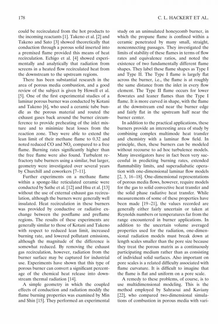
The geometry for the honeycomb burner isshown in Fig. 1. The dimensions and propertiesare those from the burner of Min and Shin [15].The channel width is 1.1 mm and the wallthickness is 0.17 mm resulting in a porosity of75%. The total length is 20 mm. The solidemissivity is 0.4 and the solid conductivity is 2.2W/m/K. The computational domain is shownwith dotted lines. It extends 5 mm upstream and5 mm downstream of the porous solid.
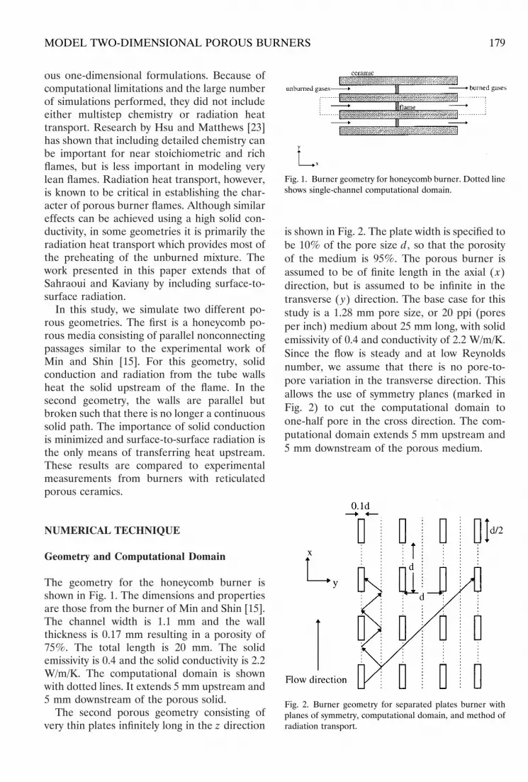
The second porous geometry consisting ofvery thin plates infinitely long in the z direction
is shown in Fig. 2. The plate width is specified tobe 10% of the pore size d, so that the porosityof the medium is 95%. The porous burner isassumed to be of finite length in the axial ( x)direction, but is assumed to be infinite in thetransverse ( y) direction. The base case for thisstudy is a 1.28 mm pore size, or 20 ppi (poresper inch) medium about 25 mm long, with solidemissivity of 0.4 and conductivity of 2.2 W/m/K.Since the flow is steady and at low Reynoldsnumber, we assume that there is no pore-to-pore variation in the transverse direction. Thisallows the use of symmetry planes (marked inFig. 2) to cut the computational domain toone-half pore in the cross direction. The com-putational domain extends 5 mm upstream and5 mm downstream of the porous medium.
Fig. 1. Burner geometry for honeycomb burner. Dotted lineshows single-channel computational domain.
Fig. 2. Burner geometry for separated plates burner withplanes of symmetry, computational domain, and method ofradiation transport.
179MODEL TWO-DIMENSIONAL POROUS BURNERS

Governing Equations
In this problem, we solve conservation equa-tions for mass, momentum, gas phase energy,solid phase energy, and species. We neglectbody forces, the Soret and Dufour effects, andgas radiation. This last assumption is justified bya mean beam length analysis [24] which showsthat for radiant length scales on the order of amillimeter the gas radiation is under 1% of theradiation from adjacent solid surfaces. Theequations are thenContinuity:
r
t1 ¹W z ~rvW! 5 0, (1)
Momentum:
t~rvi! 1 ¹W z ~rvWvi! 5 ¹W z ~m¹W vi! 2
P xi
(2)
Gas phase energy:
t~rh! 1 ¹W z ~rvWh! 5 ¹W z S k
cp¹W hD 1 hcv (3)
Solid phase energy:
t~rcT! 5 ¹W z ~k¹W T! (4)
Fuel diffusion:
t~ryf! 1 ¹W z ~rvWyf! 5 ¹W z ~rD¹W yf! 2 v (5)
Oxygen diffusion:
t~ryo! 1 ¹W z ~rvWyo! 5 ¹W z ~rD¹W yo! 2 sv (6)
Product diffusion:
t~ryp! 1 ¹W z ~rvWyp! 5 ¹W z ~rD¹W yp! 1 ~s 1 1!v
(7)
A single-step global reaction mechanism forthe complete combustion of fuel is used. Fol-lowing the form outlined by Westbrook andDryer [25], the reaction rate is given by
v 5 8.45 3 1011~ yfr!1.8~ yor!e2E/RT (8)
for methane combustion; and
v 5 3.90 3 1010~ yfr!1.3~ yor!0.9e2E/RT (9)
for propane combustion. Here v is kg/m3 of fuelconsumed per second, E is the activation energyfor both reactions (125.6 kJ/mol), R is the idealgas constant, and T is the local gas temperaturein Kelvin. The mechanisms were validatedagainst experimental data of Yamaoka andTsuji [26] and Yu et al. [27] for equivalenceratios between .55 and 1.0. The measured flamespeeds of Yu et al. are approximately 10%higher than those of Yamaoka and Tsuji formethane. Our model predicts flame speedswhich are between the two measured valuesexcept at an equivalence ratio of 0.9 where itpredicts a flame speed approximately 2% lowerthan that measured by Yamaoka and Tsuji. Forpropane, our model predicts flame speeds whichare within 2% of the values of Yamaoka andTsuji except at equivalence ratios near 1.0where the variation is 7%.
The density is obtained directly from the idealgas law using the pressure, the temperature, andthe mixture composition. Other fluid propertiesare modeled on the known temperature-depen-dent values for air [28]. Good agreement withthe viscosity of air is found by setting m 53.371 3 1027 T0.7, where T is in Kelvin and mis in kg/m/sec. Similarly, the thermal diffusion isassumed to be given by ra 5 k/cp 5 4.816 31027 T0.7, where units are as above. Thiscorresponds to a fixed Prandtl number of 0.7.The Lewis numbers for all species are assumedto be unity at all temperatures, and so rDfollows the same temperature dependence asra. The heat capacity of the mixture is modeledby cp 5 a exp(BT). In this expression, a 5947 1 0.12f J/kg/K for methane and a 5947 1 0.095f for propane fuels, and B 51.83 3 1024 K21. In the limit of f 5 0 thisexpression does very well in matching theknown values of cp for air. For other values of f,this expression follows the adiabatic flame tem-peratures for the two fuels.
Boundary and Interface Conditions
At the inlet to the computational domain whichis 5 mm upstream of the burner inlet, thevelocity, temperature (300K), and mass fraction(based on equivalence ratio) of the incoming
180 C. L. HACKERT ET AL.
gas flow are specified. At the downstream endof the computational domain the gradients ofvelocity, temperature, and mass fraction arezero. At the transverse or radial boundary, thereis no heat loss except when otherwise specified.
Several interface conditions are applied at thegas–solid interface within the computationaldomain. The first is a no-slip condition, suchthat gas velocities are zero at the solid surface.Secondly, the solid is treated as being imperme-able to species and noncatalytic. This impliesthat the normal gradient of species concentra-tion at the solid surface is zero. Finally, theenergy interface condition includes the effectsof gas-to-solid heat conduction and the effectsof solid-to-solid radiation. This is expressed as
ksolid
TnU
solid5 kgas
TnU
gas
1e
1 2 e~ J 2 sTsolid
4 ! (10)
where n is a direction normal to and out of thesurface. The-two dimensional model formula-tion allows the elimination of the arbitrarygas-to-solid heat transfer coefficient that mustbe used in one-dimensional models. The solidsurfaces are considered to be gray and diffuseand the surface radiosities J are solved as amatrix equation,
Ji 5 esTi4 1 ~1 2 e!@Kij Jj 1 FisT`
4 #. (11)
In the honeycomb geometry, analytic expres-sions for the viewfactors K and F are available[24]. We solve for the radiation in the separatedplates geometry using the symmetry planesshown in Fig. 2. Since the geometry is fairlycomplicated, the viewfactors for the thermalradiation exchange are calculated using aMonte Carlo method [24]. In this method, alarge number of rays are emitted from each ofthe discretized solid surfaces in random direc-tions and are tracked until they reach anothersurface. When a statistically significant numberof rays have been emitted, the impacts arecounted and the viewfactors relating the sur-faces calculated. As shown in Fig. 2, a rayemitted from a surface is reflected across thesymmetry planes until it strikes a solid object orleaves the burner. This is equivalent to the ray
traveling straight until it strikes a surface withidentical properties several pores to one side.Every ray emitted under this method is trackeduntil impacts a surface (considering the burnerexit and inlet as surfaces). Since all rays areaccounted for, and the viewfactor is the fractionof rays impacting on a given surface, the sum ofall viewfactors for a given surface is one. Theradiation boundary condition enforced in Eq. 11is that the burner surfaces exchange radiationwith a large, cold (300 K) environment at boththe upstream and downstream ends.
Solution Technique
The base code solves Eqs. 1–7 using an alter-nating direction implicit (ADI) finite volumeformulation, and the pseudotransient methodfor steady problems [29]. The pressure field issolved using the SIMPLE method [30].
The surface radiation equations (11) aresolved on the same grid as the other equations.Once the viewfactors are calculated, the radia-tion equation is with a discretization equal tothe grid size. This yields 300 to 600 radiatingsurfaces in the burner model, depending ongeometry and pore size.
Typical grid spacing is 30–40 mm in theburner region, with slightly larger finite volumesupstream and downstream of the burner. Atypical computational domain would then beapproximately 800 by 30 grid points. This grid-ding system was proven to be sufficient bytesting several grid sizes. The reduction in errorwith smaller grids is shown to be of order Dx1.9,consistent with the order Dx2 method used. Achange in grid size from 20 mm to 40 mmresulted in less than a 0.01% change in burningrate.
HONEYCOMB BURNER
Comparison to Experiments
While the experiments of Min and Shin [15]were performed using square channels, thisobviously cannot be done for two-dimensionalcomputations. Instead, two types of geometrywill be used: the cylindrical tube and the parallelplanes. The tube is a good choice for modeling
181MODEL TWO-DIMENSIONAL POROUS BURNERS

a single square element. A square channel ofside length d has the same hydraulic diameter asa tube of diameter d. Also, considering a singleflow channel only, the porosity of a square cellwith a given wall thickness is the same as theporosity of a cylindrical channel with the samewall thickness. In the parallel plates case, thehydraulic diameter is twice the plate separationdistance, and the porosity for a given wallthickness and hydraulic diameter is within a fewpercent of the square channel case. Reynoldsnumbers are uniformly low. The highest Reyn-olds number (based on hydraulic diameter) is113 for any result presented below, and a typicalReynolds number is 47. Modeling a tube ele-ment as a parallel plate channel of the samehydraulic diameter introduces little additionalerror. The burning rates for the two cases lievery close to each other for all flame locations.We present our results in terms of the burningrate (cm/sec), which is the volume flux of mix-ture (m3/sec/m2 5 m/sec) supplied to the burn-er; and the radiant fraction, which is the fractionof energy released by the combustion reactionthat is radiated out of the burner through eitherthe upstream or downstream end. We refer tothe radiant fraction at the downstream end asthe radiant output and the radiant fraction atthe upstream end as the radiant loss.
The calculated temperature distribution istwo-dimensional, and a condition where theflow rate is set at twice the laminar flame speedand f 5 0.55 is shown in Fig. 3. Note that inspite of the small length scale, the temperaturefield is significantly curved. This prediction is
quite different from predictions from one-di-mensional models which volume average thesolid and gas in any given cell. It possiblehowever to compare our calculations with bothone-dimensional simulations and experimentswhich are based upon average conditions bydefining a mass averaged temperature.
The computational gas temperatures (Fig. 3)may be presented as a mass averaged gas tem-perature at a particular x location
Tavg 51
mA E ruT dA (12)
where A is the cross sectional area and u is thenormal velocity. This is, of course, less than thepeak gas temperature for any axial location.Although Min and Shin made experimental gastemperature measurements using thermocou-ples which in theory should represent a pointmeasurement more than the mass averagedvalue, there are several points which make anexact comparison difficult. The location of thebead is not exactly stated, and the thermocouplesupport and bead sizes may be intrusive. Ther-mocouple bead sizes were 25 mm for the gastemperature measurements and 0.1 mm for thesolid temperature measurements [15]. In addi-tion, each thermocouple was supported by a0.5-mm ceramic tube. For comparison, recallthat the channel size is 1.1 mm. Because ofthese complications the simplest assumption isto compare our average temperatures with theirexperimentally measured values.
In Fig. 4 we compare the computed averagegas and solid temperatures to those measuredby Min and Shin. In the experiments, a series ofwalls were removed from the square channels toallow for easier placement of thermocouples.The resulting passage was a parallel planeschannel surrounded by square channels. Aspreviously noted, it is impossible to exactlysimulate the actual three-dimensional experi-ment with a two-dimensional model. As anapproximation, the computational model usedis that of a single cylindrical channel with radi-ally insulated walls.
The agreement between prediction and ex-periment is good for temperatures downstreamof the flame, but there is a discrepancy in thepeak gas temperature. There are several possi-
Fig. 3. Calculated two-dimensional isotherms for f 5 0.55,flowrate of twice the laminar flame speed.
182 C. L. HACKERT ET AL.

ble causes for this, including the modified ex-perimental geometry and the lack of detailedchemistry in the present calculations. Further-more, recall that the computed gas temperatureis an average of the true, two-dimensional tem-perature distribution previously shown in Fig. 3.The peak computed gas temperature in Fig. 3 ishigher than that shown in Fig. 4. Anothercontributing factor to the discrepancy is that inthe experiment some of the upstream radiationfrom the burner (more than 40 kW/m2) iscaptured by the inlet plenum and preheats theinflowing gases. If half of this heat flux istransferred to the inflowing gases, these gaseswould have a temperature of about 375 Kinstead of 300 K. Raising the inlet temperaturedoes decrease the discrepancy but it also causesan increase in the burning rate to a level farabove that observed in the experiment. This islikely due to the use of single step chemistry.The model does, however, predict a burningrate within 5% of the experimental value for thesame flame location.
The peak computed gas temperature for thiscase is about 1580 K, less than the adiabaticflame temperature. The experimental resultsshow superadiabatic operation; that is, the peakgas temperature is above the nominal adiabaticflame temperature (;1610 K) at this equiva-lence ratio. Superadiabatic operation is pre-dicted by the numerical model, however, forflames located further downstream from the
burner inlet, with predicted temperatures ex-ceeding 1800 K for some cases.
In Fig. 5, we compare the range of flowratesthat produce stable flames in radially insulatedelements to the experimentally measured valuesfor the Type I flame of Min and Shin [15]. Thelower computed limit for the radially insulatedcase compares well with the Type I experiments,supporting Min and Shin’s contention that theType II shaped flame occupies a regime domi-nated by radial heat losses. The computed up-per limit of operation is significantly above theexperimental value. This increase is attributedto the complete absence of radial heat losses inthese computations, which provides a moreadiabatic burner than is physically realizable.Min and Shin found the best agreement be-tween their one-dimensional simulations andexperiments when they included an arbitraryheat loss factor to model radial losses. Thecomputed lower edge of the stability diagram issomewhat poorly defined because of the highgradient of burning rate as a function of flamelocation near the inlet region. The upper limitof the burning rate can be found much morereadily, because it does not change much withflame location. Nevertheless, there is goodagreement for the lower limit from f 5 0.52 tof 5 0.7. At the lower equivalence ratios, radialheat losses again become significant and thecomputed values fall below the experiment. Inthe experiments of Min and Shin, the burnerlean limit was found to be f 5 0.49. In thepresent computations, the lean limit for gener-ating stable flames was found to be f 5 0.425.
Fig. 4. Comparison of spatially averaged calculated temper-atures for radially insulated element to experiment, f 50.55, flowrate is about twice the laminar flame speed.
Fig. 5. Range of stable operation of honeycomb burner as afunction of equivalence ratio.
183MODEL TWO-DIMENSIONAL POROUS BURNERS
Burning Rate and Radiant Fractions
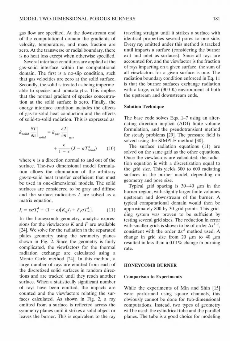
In Fig. 6, we present the burning rate, radiantloss fraction, and radiant output fraction for a f5 0.6 flame as a function of flame location. Thecorresponding firing rates at this equivalenceratio are 428 kW/m2 for the lower burning rateof 21 cm/sec, and 1350 kW/m2 for the maximumburning rate of 66.1 cm/sec. The burning rate isdefined as the average velocity of the coldunburned gases just ahead of the porous me-dium inlet. Thus, the average velocity of un-burned gases in the porous medium is higher bya factor of one over the porosity. The flamelocation is defined as the leading edge of the1000 K isotherm. The radiant output is thefraction of chemical energy released in theburner which is emitted as radiation from thedownstream end of the burner. Similarly, theradiant loss is the fraction of chemical energyradiated from the upstream end of the burner.
For this flame, the burning rates for flamesstabilized near the inlet of the burner are sig-nificantly lower than those for flames stabilizedfurther inside. Flames in regions where thegradient of burning rate with respect to locationis negative are not stable. If a flame in thisregion is perturbed downstream, its burningrate decreases and the flame then continues topropagate further downstream. Conversely, ifthe flame is perturbed upstream in this regionthen its burning rate increases and it continuesto propagate in that direction. The burning rate
dependence on flame location is primarily afunction of radiant losses. Upstream radiantheat losses can be quite high depending on theflame location. The walls upstream of the flameare cooled convectively by the unburned mix-ture, and so most upstream radiation exiting theburner is direct or reflected from the postflameregion. Flames very near the inlet have up-stream radiant loss fractions of almost 0.20, butthis rapidly drops to less than 0.005 as the flameis moved downstream.
Radiant output decreases slightly as the flamemoves downstream, and then increases again asthe burning rate decreases. The actual radiantpower output increases slowly but continuouslyas the flame moves downstream, but in calcu-lating the fraction this increase is offset by theincrease in burning rate. Radiant output contin-ues to increase in this region until it becomes solarge that a flame cannot be supported.
Radiant output for flames in the stable regionlie in the narrow range from 0.15 to 0.17,compared with measured output of 0.15 to 0.25reported for reticulated ceramics [17], andabout 0.20 reported for sooting diffusion flames[31]. The one-dimensional model of Sathe et al.[32] also reports peak radiant efficiencies ofabout 15%.
Wall Thermal Properties
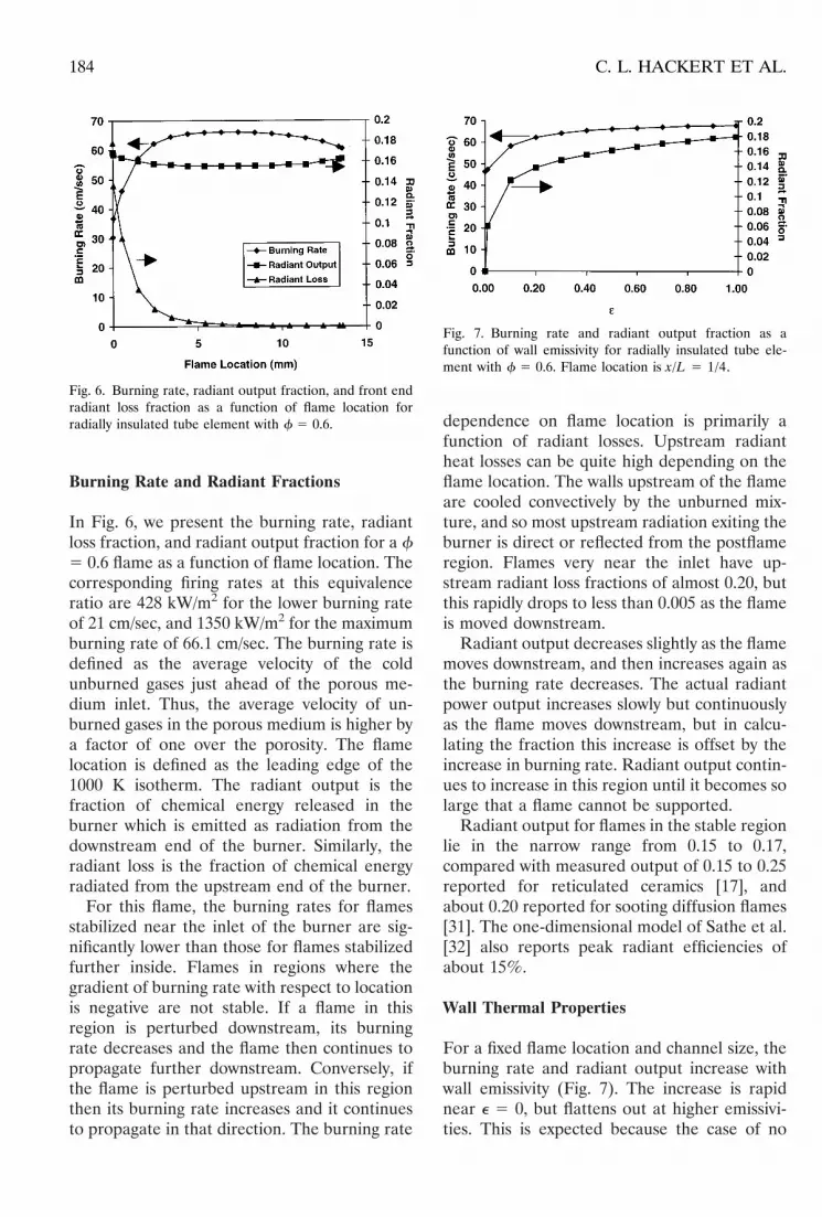
For a fixed flame location and channel size, theburning rate and radiant output increase withwall emissivity (Fig. 7). The increase is rapidnear e 5 0, but flattens out at higher emissivi-ties. This is expected because the case of no
Fig. 6. Burning rate, radiant output fraction, and front endradiant loss fraction as a function of flame location forradially insulated tube element with f 5 0.6.
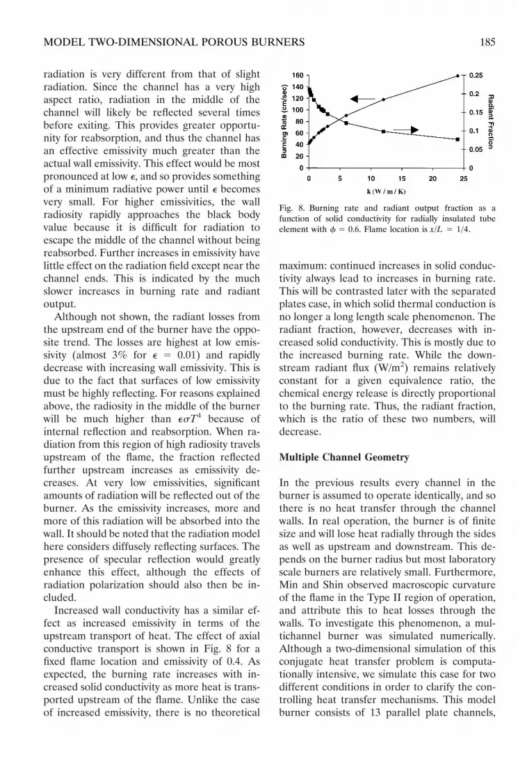
Fig. 7. Burning rate and radiant output fraction as afunction of wall emissivity for radially insulated tube ele-ment with f 5 0.6. Flame location is x/L 5 1/4.
184 C. L. HACKERT ET AL.
radiation is very different from that of slightradiation. Since the channel has a very highaspect ratio, radiation in the middle of thechannel will likely be reflected several timesbefore exiting. This provides greater opportu-nity for reabsorption, and thus the channel hasan effective emissivity much greater than theactual wall emissivity. This effect would be mostpronounced at low e, and so provides somethingof a minimum radiative power until e becomesvery small. For higher emissivities, the wallradiosity rapidly approaches the black bodyvalue because it is difficult for radiation toescape the middle of the channel without beingreabsorbed. Further increases in emissivity havelittle effect on the radiation field except near thechannel ends. This is indicated by the muchslower increases in burning rate and radiantoutput.
Although not shown, the radiant losses fromthe upstream end of the burner have the oppo-site trend. The losses are highest at low emis-sivity (almost 3% for e 5 0.01) and rapidlydecrease with increasing wall emissivity. This isdue to the fact that surfaces of low emissivitymust be highly reflecting. For reasons explainedabove, the radiosity in the middle of the burnerwill be much higher than esT4 because ofinternal reflection and reabsorption. When ra-diation from this region of high radiosity travelsupstream of the flame, the fraction reflectedfurther upstream increases as emissivity de-creases. At very low emissivities, significantamounts of radiation will be reflected out of theburner. As the emissivity increases, more andmore of this radiation will be absorbed into thewall. It should be noted that the radiation modelhere considers diffusely reflecting surfaces. Thepresence of specular reflection would greatlyenhance this effect, although the effects ofradiation polarization should also then be in-cluded.
Increased wall conductivity has a similar ef-fect as increased emissivity in terms of theupstream transport of heat. The effect of axialconductive transport is shown in Fig. 8 for afixed flame location and emissivity of 0.4. Asexpected, the burning rate increases with in-creased solid conductivity as more heat is trans-ported upstream of the flame. Unlike the caseof increased emissivity, there is no theoretical
maximum: continued increases in solid conduc-tivity always lead to increases in burning rate.This will be contrasted later with the separatedplates case, in which solid thermal conduction isno longer a long length scale phenomenon. Theradiant fraction, however, decreases with in-creased solid conductivity. This is mostly due tothe increased burning rate. While the down-stream radiant flux (W/m2) remains relativelyconstant for a given equivalence ratio, thechemical energy release is directly proportionalto the burning rate. Thus, the radiant fraction,which is the ratio of these two numbers, willdecrease.
Multiple Channel Geometry
In the previous results every channel in theburner is assumed to operate identically, and sothere is no heat transfer through the channelwalls. In real operation, the burner is of finitesize and will lose heat radially through the sidesas well as upstream and downstream. This de-pends on the burner radius but most laboratoryscale burners are relatively small. Furthermore,Min and Shin observed macroscopic curvatureof the flame in the Type II region of operation,and attribute this to heat losses through thewalls. To investigate this phenomenon, a mul-tichannel burner was simulated numerically.Although a two-dimensional simulation of thisconjugate heat transfer problem is computa-tionally intensive, we simulate this case for twodifferent conditions in order to clarify the con-trolling heat transfer mechanisms. This modelburner consists of 13 parallel plate channels,
Fig. 8. Burning rate and radiant output fraction as afunction of solid conductivity for radially insulated tubeelement with f 5 0.6. Flame location is x/L 5 1/4.
185MODEL TWO-DIMENSIONAL POROUS BURNERS
with plate separations of 0.55 mm. This yieldsthe same hydraulic diameter per channel as theexperiments. The wall thickness is 0.17 mm, andall properties are as previously stated. The outerwall is assumed to radiate to a large ambientenvironment of 300 K, and is also assumed to besubject to a convection coefficient of 20W/m2/K. This model burner has a total trans-verse width of less than 10 mm, so it cannot besaid that this is a realistic model for a normalsized burner. Nevertheless, the effects of trans-verse heat loss through multiple channels is avaluable observation and may perhaps be ex-trapolated to larger sizes.
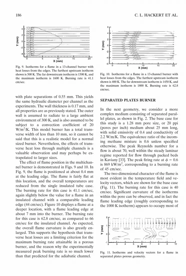
The effect of flame position in the multichan-nel burner is demonstrated in Figs. 9 and 10. InFig. 9, the flame is positioned at about 0.4 mmat the leading edge. The flame is fairly flat atthis location, and the overall temperatures arereduced from the single insulated tube case.The burning rate for this case is 41.1 cm/sec,again slightly below the value for a flame in aninsulated channel with a comparable leadingedge (44 cm/sec). Figure 10 displays a flame at adeeper location, with a flame leading edge atabout 7 mm into the burner. The burning ratefor this case is 62.8 cm/sec, as compared to 66cm/sec for the insulated channel. As expected,the overall flame curvature is also greatly en-larged. This supports the hypothesis that trans-verse heat losses are a limiting criterion for themaximum burning rate attainable in a porousburner, and the reason why the experimentallymeasured peak burning rate is so much lowerthan that predicted for the adiabatic channel.
SEPARATED PLATES BURNER
In the next geometry, we consider a morecomplex medium consisting of separated paral-lel plates, as shown in Fig. 2. The base case forthis study is a 1.28 mm pore size, or 20 ppi(pores per inch) medium about 25 mm long,with solid emissivity of 0.4 and conductivity of2.2 W/m/K. The equivalence ratio of the incom-ing methane mixture is 0.6 unless specifiedotherwise. The peak Reynolds number for aflow is about 70, well within the steady laminarregime reported for flow through packed bedsin Kaviany [33]. The peak firing rate at f 5 0.6is 869 kW/m2, corresponding to a burning rateof 45 cm/sec.
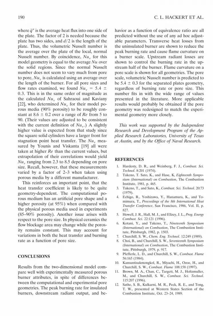
The two-dimensional character of the flame ismost evident in the temperature field and ve-locity vectors, which are shown for the base case(Fig. 11). The burning rate for this case is 40cm/sec. Significant curvature of the isothermswithin the pore can be observed, and in fact theflame leading edge (roughly corresponding tothe 1000 K isotherm) appears to occupy most of
Fig. 9. Isotherms for a flame in a 13-channel burner withheat losses from the edges. The furthest upstream isothermshown is 500 K. The far downstream isotherm is 1500 K, andthe maximum isotherm is 1600 K. Burning rate is 41.1cm/sec.
Fig. 10. Isotherms for a flame in a 13-channel burner withheat losses from the edges. The furthest upstream isothermshown is 400 K. The far downstream isotherm is 1450 K, andthe maximum isotherm is 1800 K. Burning rate is 62.8cm/sec.
Fig. 11. Isotherms and velocity vectors for a flame inseparated plates porous geometry.
186 C. L. HACKERT ET AL.

a pore. The flame ignites from the high temper-ature solid surface, and the rapid expansion ofthe hot gases helps to move the flame away fromthe solid and out to the channel centerline.
The transversely averaged (one-dimensional)temperature profiles corresponding to the flameof Fig. 11 are shown in Fig. 12. Because the solidis broken, solid phase temperatures do not existfor some axial locations. The gas temperatureplotted is a mass average gas temperature,defined at each axial location as in Eq. 12, sothat areas of high mass flux are weighted morestrongly. The effect of preheating is clear in thisfigure. Significant heat release occurs at a down-stream distance of approximately 7 mm whichincreases the gas temperature to its maximumvalue. For locations upstream of the heat re-lease zone the solid temperature is greater thanthe gas temperature. The solid plates in thisregion have been heated due to radiative ex-change with the solid downstream of the flame.Heat transfer from the solid to the gas increasesthe gas temperature from its inlet value of 298 Kto ;1200 K at 0.007 m. The adiabatic flametemperature for complete combustion for thisequivalence ratio is 1684 K. The mass averagegas temperature peaks at 1752 K, and the actualpeak gas temperature (Fig. 11) is higher still(1770 K). Downstream of the reaction zone, thetemperatures of the solid and gas decrease.
Burning Rates and Radiant Fractions
The burning rate and radiant fractions from theupstream and downstream ends of the burner as
a function of flame location are shown in Fig.13. The radiant output fraction is approximatelyconstant at 0.22. The radiant loss fraction de-creases approximately exponentially with thedepth of the flame into the burner. For thisreason, the burning rate is significantly lowerednear the upstream end. At about two porelengths (;2 mm) from the upstream end, theradiant loss is 45%, so it is not surprising that nosteady flame could be sustained numericallyfurther upstream. We have assumed that eachend of the burner radiates to a cold (300 K)black environment. For the upstream end, thismay be an unrealistic boundary condition in anexperiment. The high upstream radiant lossestend to rapidly heat the upstream plenum unlesssome cooling method is employed. Higher tem-peratures just upstream of the burner will re-duce the radiant losses and increase the burningrate at the upstream end closer to the peakvalue.
Once the radiant losses approach zero, theburning rate does not change. The fact thatradiant losses approach zero implies that theupstream radiation from the postflame solid isalmost completely absorbed by the preflamesolid, which then gives up this heat to theunburned gases. This obviously provides themaximum possible preheating, and so shouldyield the maximum possible burning rate. Thepeak burning rate in this model burner is 44cm/sec. For comparison, the adiabatic flamespeed at this equivalence ratio is 11.1 cm/sec.The positive effects of decreasing the radiantlosses and increasing the burning rate continues
Fig. 12. Average gas and solid temperatures for flame inFig. 11.
Fig. 13. Burning rate, downstream radiant output, andupstream radiant loss as a function of flame location in thebase case burner.
187MODEL TWO-DIMENSIONAL POROUS BURNERS

until the flame is located at about the halfwaypoint in the burner; at this point the burningrate begins to drop from its peak value. Beyonda given depth into the medium, there is aninsufficient length of the postflame zone toallow the maximum possible convective heattransfer rates from the solid to the gas.
In all of the results, the radiant output frac-tion is relatively constant near a value of 0.22,regardless of flame position, pore size, orburner material properties. The computed val-ues are consistent with the values measured in alonger 10 ppi burner by Khanna et al. [34] inboth magnitude and trend. The slight decreasein radiant output fraction with increasing burn-ing rate is because the outlet temperature,raised to the fourth power, does not increase asmuch as the heat release. Even though theradiant output power (in W/m2) has increased,the radiant output fraction has decreasedslightly. The physical pore geometry of thecomputational porous media is very differentthan the physical geometry of the experimentalmedium. That the results are so similar seem toimply that the exact pore geometry may not playa large role in the radiant output. Nevertheless,it seems likely that improving the models de-scription of the multidimensional geometrywould result in a better match with experiment.
The peak burning rate as a function of equiv-alence ratio is shown in Fig. 14. This gives anidea of the operating range of the burner. Thecomputed values compare well with the experi-
ments of Hsu et al. [13]. Comparison is alsomade with the one-dimensional model of Hsu etal. [13], and some improvement may be seen.The one-dimensional model shows a concave-downward behavior with equivalence ratio,while the experiments and present model showa concave upward behavior. The radiant outputfraction gradually but continuously decreaseswith increasing burning rate, as shown aboveand in the experiments of Khanna et al. [34].Experiments at equivalence ratios above 0.7were not performed because the high resultingtemperatures strongly degrade the ceramicused. Computations for equivalence ratiosabove 0.7 are not shown because the high flowrates and high temperatures degrade the accu-racy of the model. Detailed chemistry and tur-bulence models (or at least transient calcula-tions for the higher Re flows) will be needed toaccurately model flames at higher equivalenceratios.
Pore Length Scale Variations
The lack of smoothness in the curves plotted inFig. 13 is due to local pore scale variations in thesteady burning rate and radiation field. Thesevariations are plotted in Fig. 15 for a pore nearthe center of the burner (where the overallburning rate does not change much with flameposition). The region occupied by the solid isindicated on the graph. The flame locationindicated in the figure is here defined as theleading edge of the 1000 K isotherm, whichroughly corresponds to the beginning of the
Fig. 14. Variation of peak burning rate and radiant outputwith equivalence ratio, with experimental data and modelresults of Hsu et al. (1993).
Fig. 15. Pore level variations in burning rate and radiationfor separated plates porous geometry. Shaded area showslocation of solid in burner pore.
188 C. L. HACKERT ET AL.

reaction zone. The nominally stable flame loca-tions are those where the burning rate slopedU/dx is positive. This is consistent with thecomputational results reported by Sahraoui andKaviany [22], in that a flame alongside of, or justin front of, a solid region is unstable. Thenatural flame position in porous media withseparated solid surfaces is just downstream of asolid region. Note also that examination of thepore level variations in radiant fraction shows adifference of up to 0.01 in the radiant outputfraction depending on the local flame locationin the pore.
Gas–Solid Heat Transfer
One of the most severe limitations of the one-dimensional approach is the necessity for amodel for the gas-to-solid heat transfer. Multi-dimensional simulations not only do away withthe need for such a model, but also allow thecalculation of what the heat transfer coefficientor pore scale Nusselt number should be. Actu-ally, there are two Nusselt numbers which maybe calculated. We can define the conventionalNusselt number
Nu 5 q0d/DT/k, (13)
where q0 is the local heat flux to the solid plate,d is the pore size, DT is the difference betweenthe local mass average gas temperature (Eq. 12)and the local solid temperature, and k is the gasconductivity at the mass average gas tempera-ture. This is plotted as a function of x for the 20ppi case for flames near the middle of theburner (Fig. 16). Of course, q0 is zero for thosex locations for which no solid exists. Nu istechnically undefined there, since there is nosolid at these locations; the Nu is plotted aszero, however, since there is no heat transfer.For each plate the heat transfer is higher nearthe leading and trailing edges because of thedeveloping boundary layer. Somewhat contraryto expectation, the calculated Nu does notchange much either with pore size (calculationswere made for 5 pore sizes) or from pore topore downstream. By implication, the calcu-lated Nu value does not change much withReynolds number, as Re is a function of boththe pore size and temperature-dependent gas
viscosity. This is, however, a very complicatedsituation with both the gas conductivity andviscosity changing with temperature in two di-mensions, and strong radiative coupling to thesolid.
The exception to the uniformity of the Nupattern occurs near the flame front, wherecalculated Nu are seen to become negative. Thereason for this odd behavior can be seen byexamining Fig. 11 and recalling the definition inuse. Because of viscous effects the maximumvelocities occur along the centerline of eachpore. The mass average gas temperature used inthe calculation of Nu is thus heavily weightedtoward the gas temperature at the pore center-line. Since the flame front is convex, the center-line temperature at the leading flame front issignificantly cooler than that of the combustingmixture near the wall. The hot burned gasesdrive heat into the wall, raising the wall temper-ature significantly. For a small range of spatiallocations then, there is heat transfer into thewall but the wall temperature is higher than themass average gas temperature for these axiallocations. This results in the “negative” Nusseltnumber. Of course, a negative Nusselt numberis neither useful nor physically meaningful, butit does demonstrate the failure near the flamefront of the single gas temperature model withconstant Nusselt number.
A volumetric Nusselt number and heat trans-fer coefficient can also be determined by aver-aging over pores,
Nuv 5q-d2
DTk5
2q# 0~d/ 2!
d2d2
DTk5
q# 0dDTk
, (14)
Fig. 16. Computed local Nusselt numbers for flame near thecenter of 1.28 mm pore size (20 ppi) porous burner.
189MODEL TWO-DIMENSIONAL POROUS BURNERS
where q# 0 is the average heat flux into one side ofthe plate. The factor of 2 is needed because theplate has two sides, and d/ 2 is the length of theplate. Thus, the volumetric Nusselt number isthe average over the plate of the local, normalNusselt number. By coincidence, Nuv for thismodel geometry is equal to the average Nu overthe solid regions. Since the normal Nusseltnumber does not seem to vary much from poreto pore, Nuv is calculated using an average overthe length of the burner. For all pore sizes andflow rates examined, we found Nuv 5 5.4 60.3. This is in the same order of magnitude asthe calculated Nuv of Sahraoui and Kaviany[22], who determined Nuv for their model po-rous media (90% porosity) to be roughly con-stant at 8.6 6 0.2 over a range of Re from 5 to90. (Their values are adjusted to be consistentwith the current definition of Nuv.) A slightlyhigher value is expected from that study sincethe square solid cylinders have a larger front forstagnation point heat transfer. The Nuv mea-sured by Younis and Viskanta [19] all weretaken at higher Re than the current values, butextrapolation of their correlations would yieldNuv ranging from 2.3 to 8.5 depending on poresize. Recall, however, that these measurementsvaried by a factor of 2–3 when taken usingporous media by a different manufacturer.
This reinforces an important point, that theheat transfer coefficient is likely to be quitegeometry-dependent. The computational po-rous medium has an artificial pore shape and ahigher porosity (at 95%) when compared withthe physical porous media used in experiments(85–90% porosity). Another issue arises withrespect to the pore size. In physical ceramics theflow blockage area may change while the poros-ity remains constant. This may account forvariations in both the heat transfer and burningrate as a function of pore size.
CONCLUSIONS
Results from the two-dimensional model com-pare well with experimentally measured porousburner attributes, in spite of differences be-tween the computational and experimental poregeometries. The peak burning rate for insulatedburners, downstream radiant output, and be-
havior as a function of equivalence ratio are allpredicted without the use of any ad hoc adjust-able parameters. Transverse heat losses fromthe uninsulated burner are shown to reduce thepeak burning rate and cause flame curvature ona burner scale. Upstream radiant losses areshown to control the burning rate in the up-stream half of the burner. Flame curvature on apore scale is shown for all geometries. The porescale, volumetric Nusselt number is predicted tobe 5.4 6 0.3 for the separated plates geometry,regardless of burning rate or pore size. Thisnumber fits in with the wide range of valuespresented in the literature. More applicableresults would probably be obtained if the poregeometry was redesigned to match the experi-mental geometry more closely.
This work was supported by the IndependentResearch and Development Program of the Ap-plied Research Laboratories, University of Texasat Austin, and by the Office of Naval Research.
REFERENCES
1. Hardesty, D. R., and Weinberg, F. J., Combust. Sci.Technol. 8:201 (1974).
2. Takeno, T. Sato, K., and Hase, K, Eighteenth Sympo-sium (International) on Combustion, The CombustionInstitute, 1981, p. 465.
3. Takeno, T., and Sato, K., Combust. Sci. Technol. 20:73(1979).
4. Echigo, R., Yoshizawa, Y., Hanamura, K., and To-mimura, T., Proceedings of the 8th International HeatTransfer Conference, San Francisco, 1986, Vol. II, p.827.
5. Howell, J. R., Hall, M. J., and Ellzey, J. L., Prog. EnergyCombust. Sci. 22:121 (1996).
6. Kotani, Y., and Takeno, T., Nineteenth Symposium(International) on Combustion, The Combustion Insti-tute, Pittsburgh, 1982, p. 1503.
7. Churchill, S. W., Chem. Eng. Technol. 12:249 (1989).8. Choi, B., and Churchill, S. W., Seventeenth Symposium
(International) on Combustion, The Combustion Insti-tute, Pittsburgh, 1979, p. 917.
9. Pfefferle, L. D., and Churchill, S. W., Combust. Flame56:165 (1984).
10. Kansuntisukmongkol, R., Miyachi, H., Ozoe, H., andChurchill, S. W., Combust. Flame 108:158 (1997).
11. Brown, M. A., Chan, C., Targett, M. J., Holtzmuller,M., and Churchill, S. W., Combust. Sci. Technol.115:207 (1996).
12. Sathe, S. B., Kulkarni, M. R., Peck, R. E., and Tong,T. W., presented at Western States Section of theCombustion Institute, Oct. 23–24, 1989.
190 C. L. HACKERT ET AL.

13. Hsu, P.-F., Evans, W. D., and Howell, J. R., Combust.Sci. Technol. 90:149 (1993).
14. Ellzey, J. L., and Goel, R., Combust. Sci. Technol.107:81 (1995).
15. Min, D. K., and Shin, H. D., Int. J. Heat Mass Trans.34:341 (1991).
16. Yoshizawa, Y., Sasaki, K., and Echigo, R., Int. J. HeatMass Trans. 31:311 (1988).
17. Sathe, S. B., Kulkarni, M. R., Peck, R. E., and Tong,T. W., Twenty-Third Symposium (International) onCombustion, The Combustion Institute, Pittsburgh,1990, pp. 1011–1018.
18. Tong, T. W., and Sathe, S. B. (1988). ASME HTD04:147.
19. Younis, L. B., and Viskanta, R., Int. J. Heat MassTransfer 36:1425 (1993).
20. Hsu, P.-F., and Howell, J. R., Exp. Heat Transfer 5:293(1992).
21. Hendricks, T. J. (1993). Ph.D. dissertation, Universityof Texas at Austin.
22. Sahraoui, M., and Kaviany, M., Int. J. Heat MassTransfer 37:2817 (1994).
23. Hsu, P.-F., and Matthews, R. D., Combust. Flame93:457 (1993).
24. Siegel, R., and Howell, J. R., Thermal Radiation HeatTransfer, 3rd ed., Hemisphere, Washington, 1992.
25. Westbrook, C. K., and Dryer, F. L., Combust. Sci.Technol. 27:31 (1981).
26. Yamaoka, I., and Tsuji, H., (1984) Twentieth Sympo-sium (International) on Combustion, The CombustionInstitute, Pittsburgh, 1984, p. 1883.
27. Yu, G., Law, C. K., and Wu, C. K., Combust. Flame63:339 (1986).
28. Incropera, F. P., and DeWitt, D. P., Fundamentals ofHeat and Mass Transfer, 3rd ed., John Wiley, NewYork, 1990.
29. Fletcher, C. A. J., Computational Techniques for FluidDynamics 1: Fundamental and General Techniques,Springer-Verlag, Berlin, 1991.
30. Patankar, S. V., Numerical Heat Transfer and FluidFlow, Hemisphere, New York, 1980.
31. Markstein, G. H., and DeRis, J., Twenty-Third Sympo-sium (International) on Combustion, The CombustionInstitute, Pittsburgh, 1990, p. 1685.
32. Sathe, S. B., Peck, R. E., and Tong, T. W., Int. J. HeatMass Transfer 33:1331 (1990).
33. Kaviany, M., Principles of Heat Transfer in PorousMedia, Springer-Verlag, New York, 1991.
34. Khanna, V., Goel, R., and Ellzey, J. L., Combust. Sci.Technol. 99:133 (1994).
Received 27 March 1997; accepted 1 April 1998
191MODEL TWO-DIMENSIONAL POROUS BURNERS