elemental sulfur combustion in a chemical-looping combustion process
TRANSCRIPT

Elemental sulfur combustion in a Chemical-Looping Combustion process
Luis F. DE DIEGOa, Francisco GARCÍA-LABIANO
a, Arturo CABELLO
a, Pilar GAYÁN
a, Alberto
ABADa, Juan ADÁNEZ
a, Gerald SPRACHMANN
b
a Instituto de Carboquímica (ICB-CSIC), Miguel Luesma Castán 4, 50018-Zaragoza, Spain
b Shell Global Solutions International BV. Amsterdam, The Netherlands
P. Gayan, 34976733977, [email protected]
Abstract
The combustion of solid elemental sulfur to SO2 has been performed in a continuous Chemical Looping Combustion (CLC) unit (500 Wth) using a Fe-based material as oxygen carrier. The selection
of this material, Fe20-Al, prepared by impregnation on alumina was based on the excellent results obtained during previous tests on sour gas and acid gas combustion. The feeding of sulfur was carried out by liquefying it at temperatures up to 440 ºC and using an inert carrier gas to carry the gaseous
sulfur corresponding to the vapour pressure of the sulfur at the reactor temperature. The Fe20-Al oxygen carrier was adequate for the sulfur combustion considering that the material maintained a high reactivity during the process and no iron sulfides nor aglomeration were detected. In addition, all the sulfur fed into the CLC system was burnt to SO2 in the fuel reactor, with negligible amounts of SO2 detected in the air reactor. High SO2 concentrations, up to 18 vol.%, together with high combustion efficiencies were reached during operation in the CLC unit. Considering the results herein obtained nearly pure SO2 streams could be expected in an industrial unit with pure sulfur feeding. Keywords: Chemical Looping Combustion, oxygen carrier, elemental sulfur, sulfuric acid.
1. Introduction
Sulfuric acid is one of the largest-volume industrial chemicals produced in the world. The major end-use market for sulfuric acid is the production of phosphate fertilizer materials, accounting for just over 58% of total world consumption in 2014. Other uses include the manufacture of chemicals, processing metals, serves as the electrolyte in the lead-acid storage battery commonly used in motor vehicles, and it is used in petroleum refining to wash impurities out of gasoline and other refinery products. A typical sulfuric acid plant consists of the following main steps: SO2 production, conversion of SO2 into SO3, and absorption of SO3 into 98% sulfuric acid (the dissolved SO3 reacts with the 2 wt.% water forming H2SO4). Elemental sulfur, sulfide ores, spent acid, gases containing H2S, etc. can be used as raw materials in the production of SO2 [1]. Refineries produce high amounts of elemental sulfur from desulfurization of natural gas or crude oil, and at the same time, they use sulfuric acid in their processes. The possibility to integrate in a refinery a sulfuric acid production unit using the elemental sulfur produced inside could be of great interest. Usually, the combustion of sulfur is carried out in one-stage or two-stage sulfur combustion chambers at 900-1050 ºC and it is followed by a process gas cooler. The SO2 content of the combustion gases is generally up to 11 vol.% as a consequence of the N2 present in the air used as oxidizer. It must be considered however that the SO2 concentration obtained in the combustion unit determines the total volume of gases handled in the subsequent processes. Sizes of the plant units such as SO2/SO3

converter, heat exchangers, and absorption towers depend on the gas volume handled. Therefore, the production of concentrated SO2 streams could be advantageous. In this sense, there is a new combustion technology able to obtain pure streams of the combustion products using air as oxidizing in the global process. Chemical Looping Combustion (CLC) is based on the transfer of the oxygen from air to the fuel by using a solid oxygen carrier that circulates between two interconnected fluidized-bed reactors: the fuel reactor (FR) and the air reactor (AR) [2]. As the air does not get mixed with the fuel, a N2-free stream is obtained at the fuel reactor outlet. The key issue in the system performance is the oxygen carrier material. Although the presence of sulfur in the fuel is normally detrimental for most of the oxygen carriers, excellent results were obtained during sour and acid gas combustion when using a Fe-based oxygen carrier in a continuous 500 W th CLC unit [3-5]. Based on those results, the energy exploitation of elemental sulfur by means of a CLC system to obtain a flue gas of pure SO2 ready for application was analyzed in this work.The objective was to demonstrate the feasibility to burn elemental sulfur in a Chemical-Looping Combustion process.
2. Materials. Oxygen carrier.
An oxygen carrier based on iron was used for the combustion tests. The oxygen carrier was
designated as Fe20-Al. For the preparation, commercial γ-Al2O3 (Puralox NWa-155, Sasol Germany
GmbH) particles of 100-300 m, with 1.3 g/cm3 density and 55.4 % porosity, were used as support. A
modification of the incipient impregnation method was carried out by using a hot iron nitrate solution in order to increase the solubility of the nitrate. The oxygen carrier was prepared by impregnating the support heated at 80 ºC in a planetary mixer with a saturated iron nitrate solution [Fe(NO3)3•9H2O] at 50-80 ºC (3.8 M). The volume of solution added corresponded to the total pore volume of the support particles. This solution was slowly added to the alumina particles with thorough stirring at hot temperature (353 K). Two successive impregnation steps were applied to obtain the desired active phase loading (20 wt.%). The material resulting from the first impregnation was calcined at 550 ºC in air atmosphere for 30 min to decompose the impregnated metal nitrate into the metal oxide. Finally, after the second impregnation, the oxygen carrier was sintered in a furnace at 950 ºC for 1 h. Table 1 shows the main characteristics and the photography of the fresh material. The oxygen transport capacity, ROC, was defined as the mass fraction of oxygen that can be used in the oxygen transfer process, and it was calculated as ROC = (mo-mr)/mo, where mo and mr are the masses of the oxidized and reduced forms of the metal oxide, respectively. The surface area of the oxygen carrier particles was determined by the Brunauer–Emmett–Teller (BET) method in a Micromeritics ASAP-2020. Particle porosity was measured by Hg intrusion in a Quantachrome PoreMaster 33. The force needed to fracture a particle was determined using a Shimpo FGN-5 crushing strength apparatus. The identification of crystalline chemical species was carried out by powder X-ray diffraction (XRD) patterns acquired in an X-ray diffractometer Bruker AXS D8ADVANCE using Ni-filtered Cu K a radiation equipped with a graphite monochromator.
Table 1. Properties of the fresh Fe20-Al oxygen carrier. Particle size (mm) 0.1 – 0-3
Oxygen transport capacity, ROC (%) 2.0 BET specific surface area (m
2/g) 39.1
Porosity (%) 50.5 Skeletal density (kg/m
3) 3950
Crushing strength (N) 1.5 XRD phases Fe2O3, -Al2O3

3. Experimental
3.1. Elemental sulfur feeding system
Two types of elemental sulfur were used for the tests: sulfur tablets with a purity of 94.4 wt.% and sulfur powder with a 100 wt.% purity. Figure 1 shows the photographs of the sulfur materials used in this work.
Figure 1. Photographs of the elemental sulfur (tablets and powder) used in the combustion tests. Although sulfur feeding is solved at industrial scale, the constant feeding of elemental sulfur in a small unit is not easy. The use of solid particles obtained from pelletizing, milling, and sieving at the desired particle size was discarded considering that the CLC unit used in this work was not adapted for solids feeding. The pumping of liquid sulfur, as in the industrial units, was also discarded by the small amounts needed in the CLC plant. Therefore, it was decided to feed it in gas phase by using an inert gas flowing through liquid sulfur at a controlled temperature. Figure 2 shows the vapour pressure of elemental sulfur as a function of temperature. Solid sulfur is liquefied at 115.4 ºC and the vapour pressure increases up to 1 atm at 444.6 ºC.
Figure 2. Vapor pressure of elemental sulfur as a function of temperature. Data from ref. [6]. Figure 3 shows a scheme and a photograph of the feeding system designed for sulfur feeding. Solid sulfur was loaded in a reservoir and introduced in a reactor (10 cm I.D) which it was located inside a furnace. The temperature of the sulfur reservoir was measured with a thermocouple and controlled through the furnace temperature. A flow of inert gas was passed through the reactor to carry the gaseous sulfur in the environment corresponding to the vapour pressure of the sulfur at the reactor temperature. The gaseous sulfur and the inert gas were flowed into the fuel reactor through a heated
Liquid phase
115.4 ºC

tube (>200 ºC) that avoided sulfur condensation. A second line connected to the stack was also built for safety reasons. If the main line going to the FR was blocked, the pressure in the system would increase and the safety valve would be open to vent the gas.
Figure 3. Scheme and photography of the system designed for elemental sulfur feeding.
3.2. Chemical-Looping Combustion unit
A schematic diagram of the ICB-CSIC-g1 facility (500 Wth) used for the experimental tests is shown in Figure 4. This facility was composed of two interconnected fluidized bed reactors, a riser for solid transport, a solid valve to control the solids fed to the FR, a loop seal and a cyclone. This design allowed the variation and control of the solid circulation flow rate between the two reactors. The FR (1) and the AR (3) were two bubbling fluidized-beds (0.05 m i.d.) with a bed height of 0.1 m. The AR was followed by a riser (4) of 0.02 m i.d. and 1 m height. This unit has been used for the combustion of different sulfur-containing fuels including sour gas and acid gas with high H2S contents. A further description of this CLC prototype is presented elsewhere [4, 5]. This unit was therefore adapted for a safe operation when using high H2S/SO2 concentrations. Figure 4 shows the CLC unit including the feeding system for the elemental sulfur. N2 and CO2 could be used as inert gas. The usual procedure for the tests was to bypass the sulfur system feeding during heating until stable operation in the unit was reached. After that, the gas flowing to the FR was passed through the sulfur evaporator reactor and both gases (inert gas + gaseous sulfur) were fed at the bottom of the FR. These gases passed through the distributor plate, which was built on kanthal APM, which was resistant to sulfur compounds. An increase in the evaporator temperature also produced an increase in the amount of sulfur fed into the FR. Two scrubbers containing a saturated solution of sodium carbonate were located downstream the FR and AR to keep the emissions below the Health, Safety and the Environment (HSE) limits. Furthermore, a special installation for gas leakage detection was included in the CLC unit. The security system was composed by three gas detectors, a control unit and two electronic valves. Two gas detectors (one for H2S and another one for SO2) were located inside the cupboard covering the CLC plant, and an additional H2S gas detector was installed outside near the plant. The gas detectors were configured for 5 vppm alarm. All the detectors were connected to the control unit. If a gas leakage was detected, several alarms were switched on and the control unit relays acted on the electronic valves. Some specific analyzers for sulfur compounds were located at the outlet streams of the AR and FR. Two non-dispersive infrared (NDIR) analyzers (Siemens Ultramat U22) were used to measure the SO2 concentrations at the FR and AR gas outlet streams.
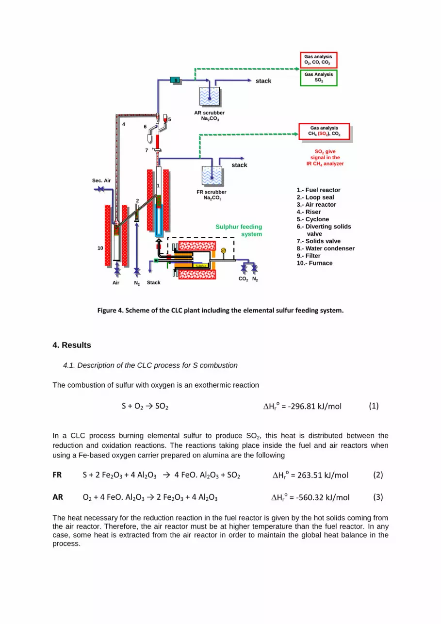
Figure 4. Scheme of the CLC plant including the elemental sulfur feeding system.
4. Results
4.1. Description of the CLC process for S combustion
The combustion of sulfur with oxygen is an exothermic reaction
S + O2 → SO2 Hro = -296.81 kJ/mol (1)
In a CLC process burning elemental sulfur to produce SO2, this heat is distributed between the
reduction and oxidation reactions. The reactions taking place inside the fuel and air reactors when
using a Fe-based oxygen carrier prepared on alumina are the following
FR S + 2 Fe2O3 + 4 Al2O3 → 4 FeO. Al2O3 + SO2 Hro = 263.51 kJ/mol (2)
AR O2 + 4 FeO. Al2O3 → 2 Fe2O3 + 4 Al2O3 Hr
o = -560.32 kJ/mol (3)
The heat necessary for the reduction reaction in the fuel reactor is given by the hot solids coming from the air reactor. Therefore, the air reactor must be at higher temperature than the fuel reactor. In any case, some heat is extracted from the air reactor in order to maintain the global heat balance in the process.
N2AirCO2 N2
Sec. Air
Gas analysis
O2, CO, CO2
Gas analysis
CH4 (SO2), CO2
stack
1
2
4
10
3
9
7
5
6
1.- Fuel reactor
2.- Loop seal
3.- Air reactor
4.- Riser
5.- Cyclone
6.- Diverting solids
valve
7.- Solids valve
8.- Water condenser
9.- Filter
10.- Furnace
Gas Analysis
SO2
AR scrubberNa2CO3
FR scrubberNa2CO3
stack
SO2 give
signal in the
IR CH4 analyzer
P
Sulphur
Sulphur feeding
system
Stack

4.2. Description of the CLC tests
Three tests were carried out at the ICB-CSIC-g1 facility (500 W th) for burning elemental sulfur. Table 2 shows the main operating conditions used in the tests. It should be noted that there was no experience with the use of solid sulfur in a CLC process prior to these tests.
In a CLC process it is important to know the oxygen carrier to fuel ratio () used during the tests, which was defined as,
2 3Fe O
S
F
2 F
(4)
where FFe2O3 is the molar flow rate of Fe2O3 and FS is the inlet molar flow rate of elemental S in the FR. This parameter is defined as the ratio between the oxygen supplied by the oxygen carrier and the
oxygen needed to stoichiometrically react with the sulfur flow. A value of = 1 corresponds to the stoichiometric relation between Fe2O3 and S in reaction 2. In this reaction, iron aluminate (FeO•Al2O3) is the Fe-reduced compound allowing complete combustion of the gaseous fuel to SO2. In this sense, when hematite, Fe2O3, is supported over alumina particles, the oxygen transport capacity of the oxygen carrier is increased by three times in comparison with the transformation from hematite to magnetite (Fe2O3 – Fe3O4). The first trial was carried out with the sulfur tablets. A load of 120 g of sulfur was located inside the reactor. The reactor temperature was initially fixed at 280 ºC, with a inert flow through the reactor of 168 lN/h. To avoid excessive oxygen to fuel ratio in the fuel reactor, a solids circulation rate of 4 kg/h was maintained. The temperature in the sulfur evaporator was later increased, up to reach 440 ºC. SO2 concentrations up to 5 vol.% were detected in the IR analyzer. However, a liquid phase was detected in the teflon line connected to the analyzer as well as in the filter located before it. In addition, the amount of oxygen used for oxygen carrier regeneration was very small and therefore small variations in the O2 concentration in the AR were detected. This fact prevented the possibility to check the oxygen mass balance used for S combustion in the FR (reaction 2) with the oxygen consumption in the AR (reaction 3). According to the results obtained in Test 1, it was decided to use a high purity sulfur powder, to increase the solids circulation rate, and to improve the gas analysis system. To avoid the condensation problems in the sampling lines to the analyzer, two impingers at -10 ºC were located downstream the FR. A white mist was observed during the experimentation in the impingers and also in the condenser fridge previous to the analyzer. However, the sulfur there recovered was negligible. The use of the high purity sulfur and the use of the impingers greatily improved the experimental system for SO2 detection in Tests 2 and 3. Test 2 corresponds to sulfur combustion using N2 as carrier and fluidizing gas. In addition, to analyze the effect of the atmosphere, the N2 was replaced by CO2 in Test 3. No effect of the carrier gas was observed during these tests. As an example, Figure 5 shows the gas outlet streams corresponding to the FR and AR in Test 3 with CO2. In this test, the temperature of the sulfur reactor reservoir was high from the begining, reaching 440 ºC in 1 hour. In all these tests, it was difficult to quantify the instantaneous sulfur feeding rate into the reactor. Assuming a constant feeding rate, an average value
of 0.56 g S/min was calculated. Considering a solids circulating rate of 14 kg/h, the average values calculated during Test 3 was about 10.
Table 2. Operating conditions of the CLC tests.
Test T FR Type of sulfur
Load Carrier gas
OC circulation rates, fs
°C g kg/h --
1 900 Tablets 120 N2 4 --
2 900 Powder 140 N2 14 >10
3 900 Powder 140 CO2 14 >10
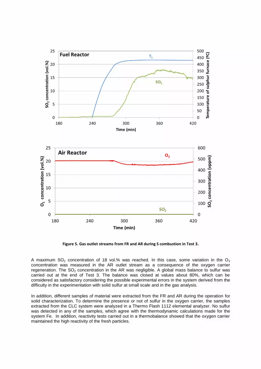
Figure 5. Gas outlet streams from FR and AR during S combustion in Test 3.
A maximum SO2 concentration of 18 vol.% was reached. In this case, some variation in the O2 concentration was measured in the AR outlet stream as a consequence of the oxygen carrier regeneration. The SO2 concentration in the AR was negligible. A global mass balance to sulfur was carried out at the end of Test 3. The balance was closed at values about 80%, which can be considered as satisfactory considering the possible experimental errors in the system derived from the difficulty in the experimentation with solid sulfur at small scale and in the gas analysis.
In addition, different samples of material were extracted from the FR and AR during the operation for solid characterization. To determine the presence or not of sulfur in the oxygen carrier, the samples extracted from the CLC system were analyzed in a Thermo Flash 1112 elemental analyzer. No sulfur was detected in any of the samples, which agree with the thermodynamic calculations made for the system Fe. In addition, reactivity tests carried out in a thermobalance showed that the oxygen carrier maintained the high reactivity of the fresh particles.

5. Conclusions
From the tests carried out at at the ICB-CSIC-g1 facility (500 W th) during continuous operation using
elemental sulfur as fuel and the Fe20-Al material as oxygen carrier, the following conclusions were achieved:
- The Fe-based material, Fe20-AL, is adequate for the combustion of elemental sulfur. Stable operation at high temperature was performed. Neither iron sulfides nor agglomeration were detected. - High SO2 concentrations, up to 18 vol.%, have been reached during continuous operation in the CLC unit. Nearly pure SO2 streams could be expected in an industrial unit with pure sulfur feeding. - All the sulfur fed into the CLC system was burnt to SO2 in the FR. Negligible amounts of SO2 were detected in the AR. Considering the results obtained in the plant, high combustion efficiencies (near 100 %) are previsible.
Acknowledgements This work has been financed by Shell Global Solutions International B.V. within the frame of the agreement PT22648 signed between Shell Global Solutions International B.V. and Instituto de Carboquímica – Consejo Superior de Investigaciones Científicas (ICB –CSIC).
References
[1] N.G. Ashar and K.R. Golwalkar, A Practical Guide to the Manufacture of Sulfuric Acid, 9 Oleums, and Sulfonating Agents. DOI 10.1007/978-3-319-02042-6_2, © Springer International Publishing Switzerland 2013.
[2] J. Adánez, A. Abad, F. García-Labiano, P. Gayán, L.F. de Diego. Progress in chemical-looping combustion and reforming technologies. Progress in Energy and Combustion Science 38 (2012) 215-282.
[3] A. Cabello, C. Dueso, F. García-Labiano, P. Gayán, A. Abad, L. F. de Diego, J. Adánez. Performance of a highly reactive impregnated Fe2O3/Al2O3 oxygen carrier with CH4 and H2S in a 500 Wth CLC unit. Fuel 121 (2014) 117-125
[4] L. F. de Diego, F. García-Labiano, P. Gayán, A. Abad, A. Cabello, J. Adánez, G. Sprachmann. Performance of Cu- and Fe-based oxygen carrier in a 500 Wth CLC unit for sour gas combustion with high H2S content. Int. J. Greenhouse Gas Control 28 (2014) 168-179.
[5] F. García-Labiano, L. F. de Diego, P. Gayán, A. Abad, A. Cabello, J. Adánez, G. Sprachmann, Energy exploitation of acid gas with high H2S content by means of a chemical looping combustion system. Applied Energy 136 (2014) 242-249.
[6] B. Meyer. Elemental Sulfur. Chemical Reviews 3 (1976) 367-388.