on the evaluation of synthetic and natural ilmenite using syngas as fuel in chemical-looping...
TRANSCRIPT
Os
MTa
b
1
CmcrbmiHtccw
0d
chemical engineering research and design 8 8 ( 2 0 1 0 ) 1505–1514
Contents lists available at ScienceDirect
Chemical Engineering Research and Design
journa l homepage: www.e lsev ier .com/ locate /cherd
n the evaluation of synthetic and natural ilmenite usingyngas as fuel in chemical-looping combustion (CLC)
uhammad Mufti Azisa,∗, Erik Jerndala, Henrik Leiona,obias Mattissonb, Anders Lyngfeltb
Department of Chemical and Biological Engineering, Chalmers University of Technology, Kemigården 4, S-41296 Göteborg, SwedenDepartment of Energy and Environment, Chalmers University of Technology, S-412 96 Göteborg, Sweden
a b s t r a c t
Chemical-looping combustion (CLC) is a combustion technique where the CO2 produced is inherently separated from
the rest of the flue gases with a considerably low energy penalty. For this reason, CLC has emerged as one of the more
attractive options to capture CO2 from fossil fuel combustion. When applying CLC with solid fuels, the use of a low
cost oxygen carrier is highly important, and one such low cost oxygen carrier is the mineral ilmenite. The current
work investigates the reactivity of several ilmenites, some which are synthetically produced by freeze granulation
and two natural minerals, one Norwegian ilmenite and one South African ilmenite.
A laboratory fluidized bed reactor made of quartz was used to simulate a two reactor CLC system by alternating
the reduction and oxidation phase. The fuel was syngas containing 50% CO and 50% H2. A mixture of 6 g of ilmenite
with 9 g inert quartz of diameter 125–180 �m was exposed to a flow of 900 mLn/min syngas in the reduction phase.
During the oxidation phase, a 900 mLn/min flow of 10% O2 diluted in N2 was used.
The experimental results showed that all ilmenites give higher conversion of H2 than of CO. Generally, synthetic
ilmenites have better CO and H2 conversion than natural ilmenites and synthetic ilmenites prepared with an excess
of Fe generally showed higher total conversion of CO than synthetic ilmenites with an excess of Ti. Most synthetic
ilmenites and the Norwegian ilmenite showed good fluidization properties during the experiments. However, for two
of the synthetically produced materials, and for the South African ilmenite, particle agglomerations were visible at
the end of the experiment.
© 2010 The Institution of Chemical Engineers. Published by Elsevier B.V. All rights reserved.
Keywords: Chemical-looping combustion; Synthetic ilmenite; Natural ilmenite; Syngas
. Introduction
hemical-looping combustion (CLC) emerges as a promisingethod to achieve CO2 neutral combustion. The CLC system
onsists of two interconnected fluidized bed reactors, an aireactor and a fuel reactor. In a CLC system, a fuel is convertedy extracting oxygen from an oxygen carrier which is com-only a metal oxide. The fuel is fed into the fuel reactor, where
t reacts with the oxygen carrier to produce mainly CO2 and
2O. The reduced oxygen carrier is subsequently transportedo the air reactor, where it is recovered in terms of oxygenontent by oxidation with air. By this concept the CO2 from
ombustion is inherently separated from the other flue gasesithout any direct loss of efficiency. The term looping in CLC∗ Corresponding author. Tel.: +46 31 7723039; fax: +46 31 7723035.E-mail address: [email protected] (M.M. Azis).Received 28 May 2009; Received in revised form 10 March 2010; Accep
263-8762/$ – see front matter © 2010 The Institution of Chemical Engioi:10.1016/j.cherd.2010.03.006
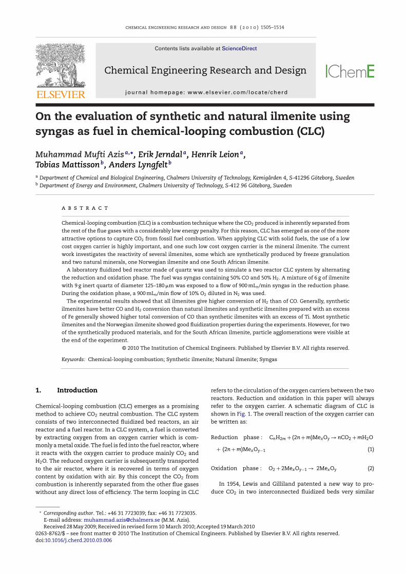
refers to the circulation of the oxygen carriers between the tworeactors. Reduction and oxidation in this paper will alwaysrefer to the oxygen carrier. A schematic diagram of CLC isshown in Fig. 1. The overall reaction of the oxygen carrier canbe written as:
Reduction phase : CnH2m + (2n + m)MexOy → nCO2 + mH2O
+ (2n + m)MexOy−1 (1)
Oxidation phase : O2 + 2MexOy−1 → 2MexOy (2)
ted 19 March 2010
In 1954, Lewis and Gilliland patented a new way to pro-duce CO2 in two interconnected fluidized beds very similar
neers. Published by Elsevier B.V. All rights reserved.
1506 chemical engineering research and d
Fig. 1 – Schematic picture of the CLC-process. Twointerconnected fluidized bed reactors, an air and a fuel
formed by gradually increasing the length of the reduction
reactor, with circulating oxygen carrying particles.
to CLC (Lewis and Gilliland, 1954). However, there were onlya few publications about CLC before Ishida reintroduced it inthe middle of the 1980s (Ishida et al., 1987). In the late 1990s,Lyngfelt and co-workers started CLC research at Chalmers Uni-versity of Technology, Sweden and successfully ran a 10 kWCLC prototype in 2003 (Lyngfelt and Leckner, 1999; Lyngfelt andThunman, 2005).
Selection of appropriate oxygen carriers is one of the mostcritical steps in CLC. Metal oxides based on iron, manganese,copper, cobalt and nickel or even mixed-oxide oxygen car-riers with various support materials have been investigated(Hossain and de Lasa, 2008; Lyngfelt et al., 2008). Further-more, thermodynamic restrictions of several oxygen carriershave been investigated by Jerndal et al. (2006). Comprehensivescreenings of oxygen carrier materials are provided by Adanezet al. (2004) and Johansson (2007).
In 2002 CLC was essentially a paper concept, but today thetechnology has been tested in operation during thousands ofhours in units in the size range 300 W to 120 kW (Abad et al.,2006; Lyngfelt et al., 2008; Kolbitsch et al., 2010). The durabilityof the oxygen carriers has been investigated by Linderholmet al. (2009) and de Diego et al. (2007) for 1016 h and 200 h ofoperation respectively, in different 10 kW CLC units. Further-more, comprehensive reviews of recent status of CLC are givenby Lyngfelt et al. (2008) and Hossain and de Lasa (2008). It isworth noting that the majority of the publications mentioneddeal with gaseous fuels (natural gas, methane and syngas) asthe primary fuel.
Attempts have been made to adapt CLC to solid fuels sincethey are more abundant and less expensive than gaseousfuels. Initial work with solid fuel including TGA experimentshas been done by Cao et al. (Cao and Pan, 2006; Cao et al.,2006) and Pan et al. (2004). Moreover, Leion et al. (2007, 2008a,b,2009a), Gao et al. (2008), Dennis et al. (2006) and Scott et al.(2006) have demonstrated the use of solid fuels in fluidizedlab scale reactors. Work on a 10 kW pilot scale applicationwith solid fuel, has been published by Berguerand and Lyngfelt(2008a,b). Also, a novel combustion technique for solid fuels,chemical-looping with oxygen uncoupling (CLOU), has been
presented by Mattisson et al. (2009). Here, the oxygen carrierreleases gas phase oxygen in the fuel reactor.esign 8 8 ( 2 0 1 0 ) 1505–1514
When a solid fuel (denoted by C) is converted with steamas a gasification agent, it will follow two reactions steps aswritten:
C + H2O → CO + H2 (3)
The gasification gas, a mixture of CO and H2, will furtherreact with the oxygen carrier:
MexOy + H2 → MexOy−1 + H2O (4)
MexOy + CO → MexOy−1 + CO2 (5)
It is also possible that the shift reaction occurs in the gasphase:
CO + H2O ↔ CO2 + H2 (6)
Therefore, the reactivity of the oxygen carrier towardssyngas (mixture of CO and H2) is important for a solid fuelapplication (Leion et al., 2008a) and there are a number of pub-lications with syngas in CLC (Copeland et al., 2002; Jin andIshida, 2004; Johansson et al., 2006a; Mattisson et al., 2006;Abad et al., 2007; Siriwardane et al., 2007; Dueso et al., 2009;Leion et al., 2008a; Song et al., 2008; Tian et al., 2008). It is alsopossible to use CO2 as gasifying gas instead of steam. However,the relative gasification rate with steam is much faster thanwith CO2 which makes gasification with CO2 less favorable(Shadle et al., 2002).
The lifetime of the oxygen carrier is expected to be shorterin solid fuel applications, as compared to gas applications. Thereason for this is possible deactivation by the ash or loss ofmaterials in the separation of ash and oxygen carrier. Hence, itis of importance to find suitable low cost oxygen carrier whenutilizing solid fuels. There are only a few publications concern-ing low cost oxygen carrier in CLC, for instance Leion et al.(2008a,b, 2009a,b) and Mattisson et al. (2001). The most recentwork by Rubel et al. (2009) suggested that iron based oxygencarriers are the top candidate for CLC with solid fuel. Besidesiron based oxygen carrier, work on copper based oxygen car-rier is also promising and has been investigated by Chuang etal. (2007), Cao et al. (2006). Furthermore, Mattisson et al. (2009)and Leion et al. (2008c) have presented the potential use ofcopper based oxygen carriers for CLOU.
Ilmenite (an iron titanium mineral) has emerged as a veryattractive oxygen carrier candidate for solid fuel application(Leion et al., 2008a, 2009b). Berguerand and Lyngfelt (2008a,b)have demonstrated the use of ilmenite in a 10 kW solid fuelcombustor and Pröll et al. (2009) have used ilmenite in a 120 kWdual circulation fluidized bed combustor.
The aim of this paper is to enhance the understanding ofusing ilmenite as oxygen carrier in CLC with solid fuel, bothsynthetically produced ilmenites and in the form of a naturalmineral. The testing of both synthetic ilmenite and naturalilmenite with syngas was investigated in a laboratory setup.Nine synthetic ilmenites were tested with different ratiosbetween Fe and Ti. Besides the synthetic ilmenites, two nat-ural ilmenites, i.e. a Norwegian ilmenite and a South Africanilmenite, were also investigated. Further, a synthetically pro-duced reference sample containing pure hematite (Fe2O3) wasincluded in the investigation. The testing with syngas was per-
time to ensure that the particles had reached their maximumdegree of conversion. The analysis of the characteristics of the
chemical engineering research and design 8 8 ( 2 0 1 0 ) 1505–1514 1507
ut o
psu
2
2
Tqiatttqhoatm
qttf
n5
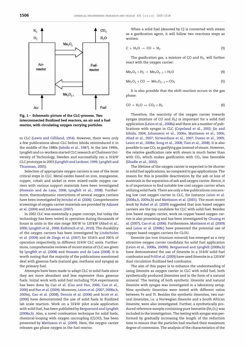
Fig. 2 – Schematic layo
articles was performed using X-ray diffractometry (XRD) andcanning electron microscopy (SEM) by comparing fresh andsed particles.
. Experimental
.1. Laboratory setup
he experiments were performed in a fluidized bed reactor ofuartz. The total length of the reactor was 870 mm with an
nner diameter of 22 mm. The oxygen carriers were placed onporous quartz Plate 370 mm from the bottom of the reac-
or. Two thermocouple probes were placed about 5 mm underhe porous quartz plate and 10 mm above it to measure theemperature of the system. The temperature above the porousuartz plate, here referred to as the bed temperature, waseld constant at 950 ◦C when no reaction occurred. It wasbserved that during oxidation and reduction the bed temper-ture increased approximately 18 ◦C and 8 ◦C respectively dueo the exothermic reactions. The accuracy of the temperature
easurement is ±5 ◦C.A sample of 6 g of ilmenite was mixed with 9 g of inert
uartz, both with a diameter of 125–180 �m. The sample washen placed on the porous plate and heated in an inert phaseo the reaction temperature, i.e. 950 ◦C. The bed height of theresh material was about 25 mm.
The sample was then alternately exposed to 10% O2 initrogen during the oxidation phase and syngas, containing0% CO and 50% H2, during the reduction phase. Pure nitrogen
Table 1 – Composition of fresh synthetically produced materials
Fe:Ti ratio (% molar based) Ave
Sample 1-1 50:50Sample 1-2 52.4:47.6Sample 1-3 47.6:52.4Sample 2-1 45:55Sample 2-2 55:45Sample 2-3 40:60Sample 2-4 60:40Sample 2-5 25:75Sample 2-6 75:25Sample 2-7 100:0
The particles were produced by freeze-granulation and the sintering temp
f the laboratory setup.
was introduced for 180 s between each reduction and oxi-dation phase to enable the reactor to behave as either fuelor air reactor. A complete cycle comprised oxidation-inert-reduction and inert periods, respectively.
The reaction during the oxidation phase is always exother-mic. This means there will be a temperature rise. To limitthis temperature rise and avoid excessive temperatures in thereactor, 10% O2 in N2 was used instead of pure air as an oxidiz-ing agent. In addition, 10% of O2 in N2 gave reasonable shorttime to fully oxidize the oxygen carrier.
The outlet gas from the reactor was transported to anelectric cooler where the water was condensed before enter-ing a gas analyzer (Rosemount NGA-2000). The gas analyzermeasured the concentrations of CO2, CO, CH4, H2 and O2 inaddition to the gas flow. The analyzer was calibrated with allgases used in the experiment with known gas concentrationsprior to the experiments. The analyzer has a compensation forthe cross-sensitivity of H2 for the other gases. This compen-sation was found to work very well, i.e. no significant effect ofother gases was seen on the H2 concentration.
The experiments were conducted in a gas flow900 mLn/min (normalized to 1 bar and 0 ◦C) for all phasesin one cycle. This flow corresponds to 8.5–11.3umf for theoxidation period and to 5.9–7.9umf for the reduction period,where umf is the minimum fluidization velocity, i.e. the gasvelocity at which the oxygen carriers would start to fluidizetheoretically (Kunii and Levenspiel, 1991). Pressure drop
measurements were conducted by measuring the pressuredifference between the inlet and the outlet of the reactorusing high frequency measurements which provided infor-.
rage crushing strength (N) Phases indicated by XRD
2.67 Fe2TiO5, TiO2
2.80 Fe2TiO5, TiO2
2.80 Fe2TiO5, TiO2
2.46 Fe2TiO5, TiO2
1.95 Fe2TiO5, TiO2
2.27 Fe2TiO5, TiO2
1.70 Fe2TiO5, TiO2
3.50 Fe2TiO5, TiO2
1.47 Fe2TiO5, Fe2O3
1.62 Fe2O3
erature was 1100 ◦C.
and design 8 8 ( 2 0 1 0 ) 1505–1514
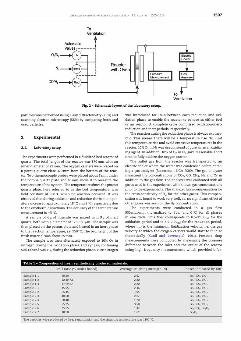
Fig. 3 – SEM images of fresh synthetic ilmenite 1-1
1508 chemical engineering research
mation whether the bed was fluidized or not (Cho et al., 2006).Fig. 2 shows a schematic diagram of the laboratory setup.
2.2. Oxygen carrier used
In nature, ilmenite is the most abundant of all titanium min-erals and is extracted all over the world e.g. in Australia andSouth Africa. When it is used as an oxygen carrier, the mostreduced form of ilmenite is FeTiO3 and its oxidized form isFe2TiO5 (pseudobrookite) + TiO2 (rutile) (Leion et al., 2008a).Hence, the molar based Fe:Ti ratio for ilmenite is close to 50:50.In this paper when ilmenite is mentioned it refers to the oxy-gen carrier itself.
The details of the synthetic ilmenites used in this paperare shown in Table 1. It is worth noting that these syntheticparticles were produced from mixing of fine and pure Fe2O3
and TiO2 powders. During the sintering process these mix-tures formed pseudobrookite, Fe2TiO5. All of these syntheticilmenites were produced by freeze granulation with a sinter-ing temperature of 1100 ◦C. For further details about the freezegranulation method, see Johansson et al. (2006b).
XRD analysis was used to identify the phases contained inthe fresh particles. As seen in Table 1, all materials containedonly Fe2TiO5 and TiO2 except sample 2-6 and 2-7 where Fe2O3
was detected. This finding was expected since these materi-als were prepared with a large excess of Fe2O3 (sample 2-6) orcontained pure Fe2O3 (sample 2-7). Fig. 3 shows a SEM imageof fresh synthetic ilmenite, sample 1-1 in Table 1. The rest ofthe fresh synthetic ilmenites displayed a similar appearanceas presented in Fig. 3. The crushing strength of the syntheti-cally produced materials, presented in Table 1, showed thatthe strength of the particles generally decreased when theFe:Ti ratio increased.
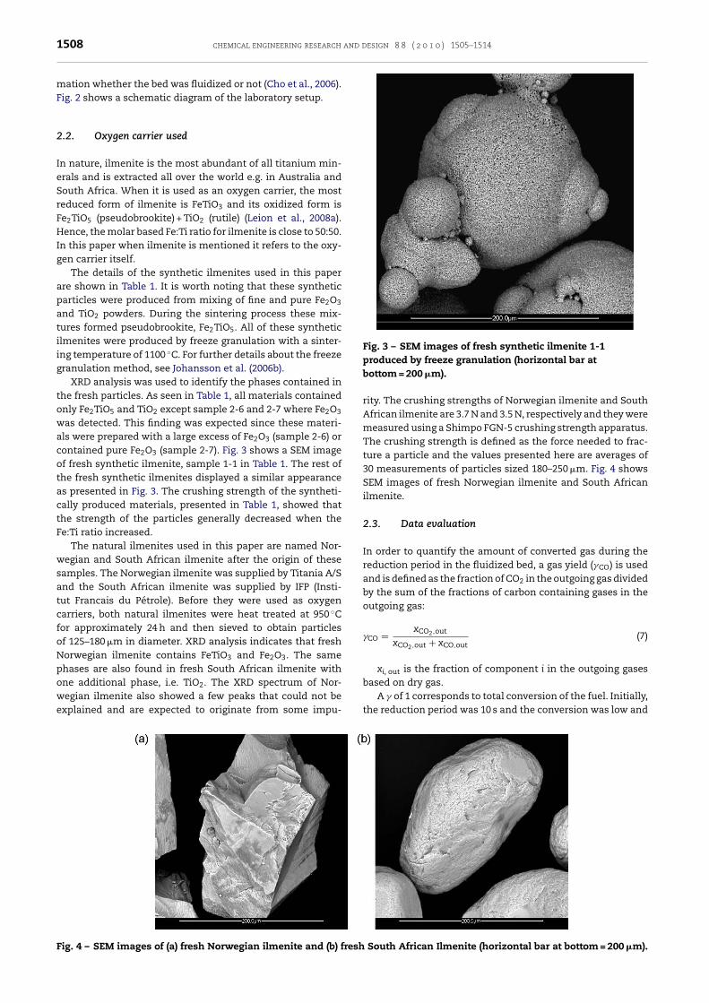
The natural ilmenites used in this paper are named Nor-wegian and South African ilmenite after the origin of thesesamples. The Norwegian ilmenite was supplied by Titania A/Sand the South African ilmenite was supplied by IFP (Insti-tut Francais du Pétrole). Before they were used as oxygencarriers, both natural ilmenites were heat treated at 950 ◦Cfor approximately 24 h and then sieved to obtain particlesof 125–180 �m in diameter. XRD analysis indicates that freshNorwegian ilmenite contains FeTiO3 and Fe2O3. The samephases are also found in fresh South African ilmenite with
one additional phase, i.e. TiO2. The XRD spectrum of Nor-wegian ilmenite also showed a few peaks that could not beexplained and are expected to originate from some impu-Fig. 4 – SEM images of (a) fresh Norwegian ilmenite and (b) fresh
produced by freeze granulation (horizontal bar atbottom = 200 �m).
rity. The crushing strengths of Norwegian ilmenite and SouthAfrican ilmenite are 3.7 N and 3.5 N, respectively and they weremeasured using a Shimpo FGN-5 crushing strength apparatus.The crushing strength is defined as the force needed to frac-ture a particle and the values presented here are averages of30 measurements of particles sized 180–250 �m. Fig. 4 showsSEM images of fresh Norwegian ilmenite and South Africanilmenite.
2.3. Data evaluation
In order to quantify the amount of converted gas during thereduction period in the fluidized bed, a gas yield (�CO) is usedand is defined as the fraction of CO2 in the outgoing gas dividedby the sum of the fractions of carbon containing gases in theoutgoing gas:
�CO = xCO2,out
xCO2,out + xCO,out(7)
xi, out is the fraction of component i in the outgoing gases
based on dry gas.A � of 1 corresponds to total conversion of the fuel. Initially,the reduction period was 10 s and the conversion was low and
South African Ilmenite (horizontal bar at bottom = 200 �m).
chemical engineering research and design 8 8 ( 2 0 1 0 ) 1505–1514 1509
F eriodn
gr23ts
n
n
isi
n
ff
�
otE
�
ω
omrads
ω
t
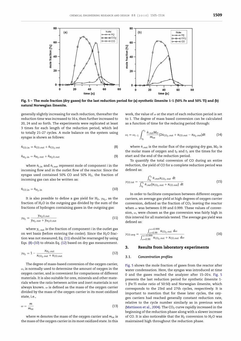
ig. 5 – The mole fraction (dry gases) for the last reduction patural Norwegian ilmenite.
enerally slightly increasing for each reduction; thereafter theeduction time was increased to 16 s, then further increased to0, 24 and so forth. The experiments were replicated at leasttimes for each length of the reduction period, which led
o totally 21–27 cycles. A mole balance on the system usingyngas is shown as follows:
˙ CO,in = nCO,out + nCO2,out (8)
˙ H2,in = nH2,out + nH2O,out (9)
where ni,in and ni,out represent mole of component i in thencoming flow and in the outlet flow of the reactor. Since theyngas used contained 50% CO and 50% H2, the fraction ofncoming gas can also be written as:
˙ CO,in = nH2,in (10)
It is also possible to define a gas yield for H2, �H2 , as theraction of H2O in the outgoing gas divided by the sum of theractions of hydrogen containing gases in the outgoing gas:
H2 = yH2O,out
yH2,out + yH2O,out(11)
where yi, out is the fraction of component i in the outlet gasn wet basis (before entering the cooler). Since the H2O frac-ion was not measured; Eq. (11) should be rearranged by usingqs. (8)–(10) to obtain Eq. (12) based on dry gas measurement.
H2 = 1 − xH2,out
xCO2,out + xCO,out(12)
The degree of mass-based conversion of the oxygen carrier,, is normally used to determine the amount of oxygen in thexygen carrier, and is convenient for comparisons of differentaterials. It is also suitable for ores, minerals and other mate-
ials where the ratio between active and inert materials is notlways known. ω is defined as the mass of the oxygen carrierivided by the mass of the oxygen carrier in its most oxidizedtate, i.e.,
= m
mox(13)
where m denotes the mass of the oxygen carrier and mox ishe mass of the oxygen carrier in its most oxidized state. In this
for (a) synthetic ilmenite 1-1 (50% Fe and 50% Ti) and (b)
work, the value of ω at the start of each reduction period is setto 1. The degree of mass based conversion can be calculatedas a function of time for the reducing period through:
ωi = ωi−1
∫ t1
t0
n,outMO
mox(2xCO2,out + xCO,out − xH2,out)dt (14)
where n,out is the molar flux of the outgoing dry gas, MO isthe molar mass of oxygen and t0 and t1 are the times for thestart and the end of the reduction period.
To quantify the total conversion of CO during an entirereduction, the yield of CO for a complete reduction period wasdefined as:
�CO,tot =∫ t1
t0n,outxCO2,out dt∫ t1
t0n,out(xCO2,out + xCO,out) dt
(15)
In order to facilitate comparison between different oxygencarriers, an average gas yield at high degrees of oxygen carrierconversion, defined as the fraction of CO2 leaving the reactorwhen ω was between 0.99 and 0.999. These values of conver-sion, ω, were chosen as the gas conversion was fairly high inthis interval for all materials tested. The average gas yield wasdefined as:
�CO,avg =∫ ω=0.999
ω=0.99xCO2,out dω∫ ω=0.999
ω=0.99xCO2,out + xCO,out dω
(16)
3. Results from laboratory experiments
3.1. Concentration profiles
Fig. 5 shows the mole fraction of gases from the reactor afterwater condensation. Here, the syngas was introduced at time0 and the gases reached the analyzer after 15–20 s. Fig. 5presents the last reduction period for synthetic ilmenite 1-1 (Fe:Ti molar ratio of 50:50) and Norwegian ilmenite, whichcorresponds to the 23rd and 27th cycles, respectively. It isimportant to mention that for these later cycles, the oxy-gen carriers had reached generally constant reduction rate,relative to the cycle number similarly as in previous work(Mattisson et al., 2004). The CO2 curve rapidly increased in the
beginning of the reduction phase along with a slower increaseof CO. It is also noticeable that the H2 conversion to H2O wasmaintained high throughout the reduction phase.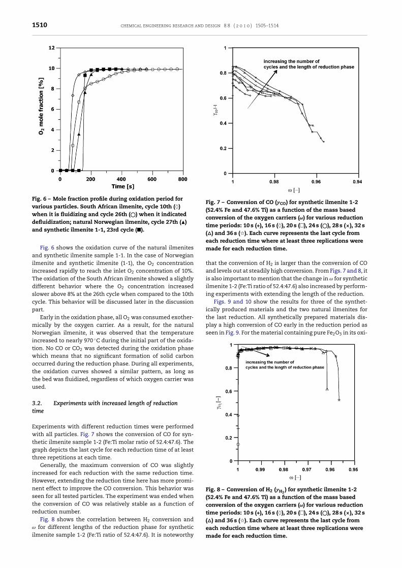
1510 chemical engineering research and design 8 8 ( 2 0 1 0 ) 1505–1514
Fig. 6 – Mole fraction profile during oxidation period forvarious particles. South African ilmenite, cycle 10th (♦)when it is fluidizing and cycle 26th (©) when it indicateddefluidization; natural Norwegian ilmenite, cycle 27th (�)
Fig. 7 – Conversion of CO (�CO) for synthetic ilmenite 1-2(52.4% Fe and 47.6% Ti) as a function of the mass basedconversion of the oxygen carriers (ω) for various reductiontime periods: 10 s (+), 16 s (♦), 20 s (�), 24 s (©), 28 s (×), 32 s(�) and 36 s (�). Each curve represents the last cycle from
play a high conversion of CO early in the reduction period asseen in Fig. 9. For the material containing pure Fe2O3 in its oxi-
Fig. 8 – Conversion of H2 (�H2) for synthetic ilmenite 1-2
(52.4% Fe and 47.6% Ti) as a function of the mass basedconversion of the oxygen carriers (ω) for various reductiontime periods: 10 s (+), 16 s (♦), 20 s (�), 24 s (©), 28 s (×), 32 s
and synthetic ilmenite 1-1, 23rd cycle (�).
Fig. 6 shows the oxidation curve of the natural ilmenitesand synthetic ilmenite sample 1-1. In the case of Norwegianilmenite and synthetic ilmenite (1-1), the O2 concentrationincreased rapidly to reach the inlet O2 concentration of 10%.The oxidation of the South African ilmenite showed a slightlydifferent behavior where the O2 concentration increasedslower above 8% at the 26th cycle when compared to the 10thcycle. This behavior will be discussed later in the discussionpart.
Early in the oxidation phase, all O2 was consumed exother-mically by the oxygen carrier. As a result, for the naturalNorwegian ilmenite, it was observed that the temperatureincreased to nearly 970 ◦C during the initial part of the oxida-tion. No CO or CO2 was detected during the oxidation phasewhich means that no significant formation of solid carbonoccurred during the reduction phase. During all experiments,the oxidation curves showed a similar pattern, as long asthe bed was fluidized, regardless of which oxygen carrier wasused.
3.2. Experiments with increased length of reductiontime
Experiments with different reduction times were performedwith all particles. Fig. 7 shows the conversion of CO for syn-thetic ilmenite sample 1-2 (Fe:Ti molar ratio of 52.4:47.6). Thegraph depicts the last cycle for each reduction time of at leastthree repetitions at each time.
Generally, the maximum conversion of CO was slightlyincreased for each reduction with the same reduction time.However, extending the reduction time here has more promi-nent effect to improve the CO conversion. This behavior wasseen for all tested particles. The experiment was ended whenthe conversion of CO was relatively stable as a function ofreduction number.
Fig. 8 shows the correlation between H conversion and
2ω for different lengths of the reduction phase for syntheticilmenite sample 1-2 (Fe:Ti ratio of 52.4:47.6). It is noteworthy
each reduction time where at least three replications weremade for each reduction time.
that the conversion of H2 is larger than the conversion of COand levels out at steadily high conversion. From Figs. 7 and 8, itis also important to mention that the change in ω for syntheticilmenite 1-2 (Fe:Ti ratio of 52.4:47.6) also increased by perform-ing experiments with extending the length of the reduction.
Figs. 9 and 10 show the results for three of the synthet-ically produced materials and the two natural ilmenites forthe last reduction. All synthetically prepared materials dis-
(�) and 36 s (�). Each curve represents the last cycle fromeach reduction time where at least three replications weremade for each reduction time.
chemical engineering research and design 8 8 ( 2 0 1 0 ) 1505–1514 1511
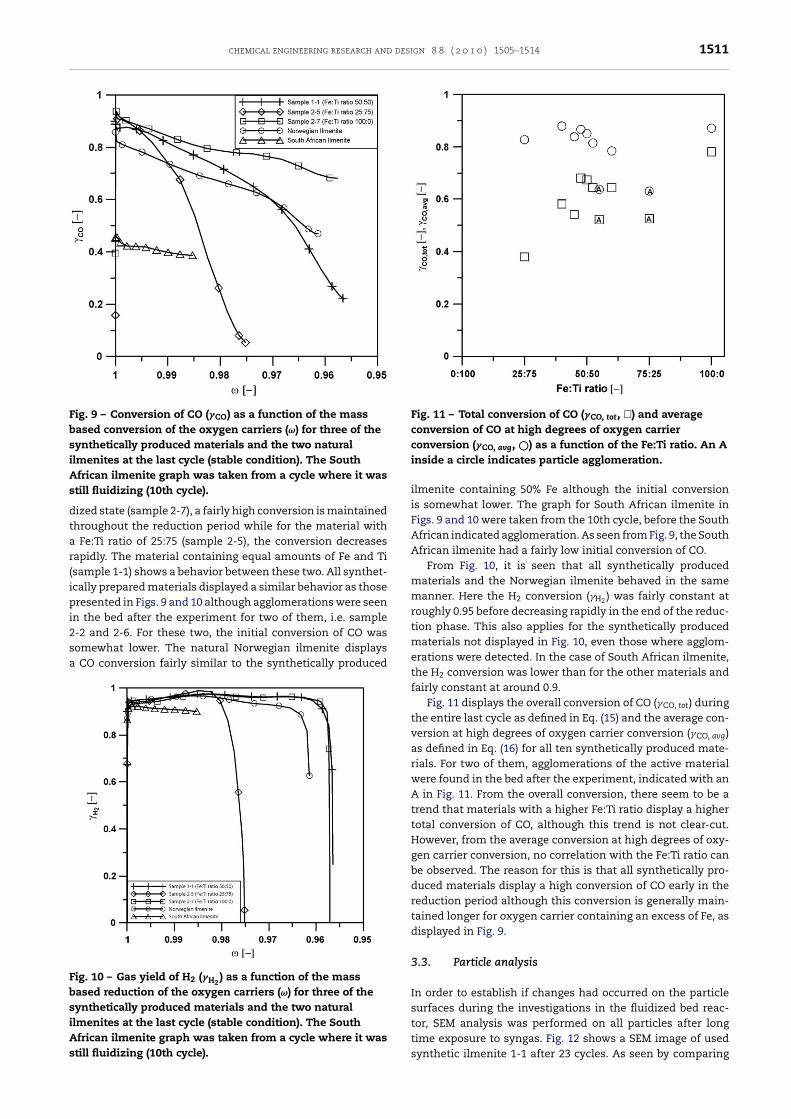
Fig. 9 – Conversion of CO (�CO) as a function of the massbased conversion of the oxygen carriers (ω) for three of thesynthetically produced materials and the two naturalilmenites at the last cycle (stable condition). The SouthAs
dtar(ipi2sa
FbsiAs
Fig. 11 – Total conversion of CO (�CO, tot, �) and averageconversion of CO at high degrees of oxygen carrier
frican ilmenite graph was taken from a cycle where it wastill fluidizing (10th cycle).
ized state (sample 2-7), a fairly high conversion is maintainedhroughout the reduction period while for the material with
Fe:Ti ratio of 25:75 (sample 2-5), the conversion decreasesapidly. The material containing equal amounts of Fe and Tisample 1-1) shows a behavior between these two. All synthet-cally prepared materials displayed a similar behavior as thoseresented in Figs. 9 and 10 although agglomerations were seen
n the bed after the experiment for two of them, i.e. sample
-2 and 2-6. For these two, the initial conversion of CO wasomewhat lower. The natural Norwegian ilmenite displaysCO conversion fairly similar to the synthetically producedig. 10 – Gas yield of H2 (�H2) as a function of the mass
ased reduction of the oxygen carriers (ω) for three of theynthetically produced materials and the two naturallmenites at the last cycle (stable condition). The Southfrican ilmenite graph was taken from a cycle where it wastill fluidizing (10th cycle).
conversion (�CO, avg, ©) as a function of the Fe:Ti ratio. An Ainside a circle indicates particle agglomeration.
ilmenite containing 50% Fe although the initial conversionis somewhat lower. The graph for South African ilmenite inFigs. 9 and 10 were taken from the 10th cycle, before the SouthAfrican indicated agglomeration. As seen from Fig. 9, the SouthAfrican ilmenite had a fairly low initial conversion of CO.
From Fig. 10, it is seen that all synthetically producedmaterials and the Norwegian ilmenite behaved in the samemanner. Here the H2 conversion (�H2 ) was fairly constant atroughly 0.95 before decreasing rapidly in the end of the reduc-tion phase. This also applies for the synthetically producedmaterials not displayed in Fig. 10, even those where agglom-erations were detected. In the case of South African ilmenite,the H2 conversion was lower than for the other materials andfairly constant at around 0.9.
Fig. 11 displays the overall conversion of CO (�CO, tot) duringthe entire last cycle as defined in Eq. (15) and the average con-version at high degrees of oxygen carrier conversion (�CO, avg)as defined in Eq. (16) for all ten synthetically produced mate-rials. For two of them, agglomerations of the active materialwere found in the bed after the experiment, indicated with anA in Fig. 11. From the overall conversion, there seem to be atrend that materials with a higher Fe:Ti ratio display a highertotal conversion of CO, although this trend is not clear-cut.However, from the average conversion at high degrees of oxy-gen carrier conversion, no correlation with the Fe:Ti ratio canbe observed. The reason for this is that all synthetically pro-duced materials display a high conversion of CO early in thereduction period although this conversion is generally main-tained longer for oxygen carrier containing an excess of Fe, asdisplayed in Fig. 9.
3.3. Particle analysis
In order to establish if changes had occurred on the particlesurfaces during the investigations in the fluidized bed reac-
tor, SEM analysis was performed on all particles after longtime exposure to syngas. Fig. 12 shows a SEM image of usedsynthetic ilmenite 1-1 after 23 cycles. As seen by comparing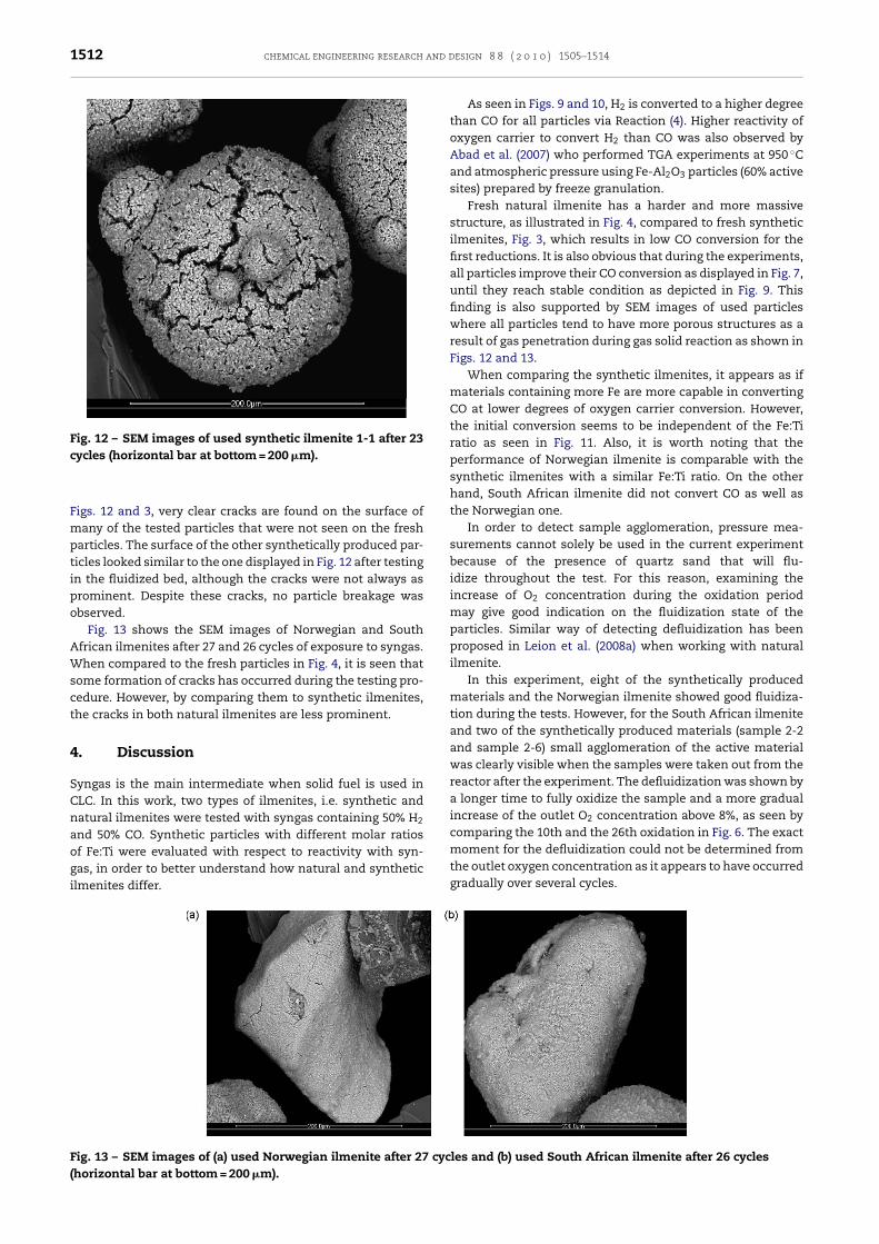
1512 chemical engineering research and d
Fig. 12 – SEM images of used synthetic ilmenite 1-1 after 23cycles (horizontal bar at bottom = 200 �m).
moment for the defluidization could not be determined fromthe outlet oxygen concentration as it appears to have occurred
Figs. 12 and 3, very clear cracks are found on the surface ofmany of the tested particles that were not seen on the freshparticles. The surface of the other synthetically produced par-ticles looked similar to the one displayed in Fig. 12 after testingin the fluidized bed, although the cracks were not always asprominent. Despite these cracks, no particle breakage wasobserved.
Fig. 13 shows the SEM images of Norwegian and SouthAfrican ilmenites after 27 and 26 cycles of exposure to syngas.When compared to the fresh particles in Fig. 4, it is seen thatsome formation of cracks has occurred during the testing pro-cedure. However, by comparing them to synthetic ilmenites,the cracks in both natural ilmenites are less prominent.
4. Discussion
Syngas is the main intermediate when solid fuel is used inCLC. In this work, two types of ilmenites, i.e. synthetic andnatural ilmenites were tested with syngas containing 50% H2
and 50% CO. Synthetic particles with different molar ratiosof Fe:Ti were evaluated with respect to reactivity with syn-gas, in order to better understand how natural and synthetic
ilmenites differ.Fig. 13 – SEM images of (a) used Norwegian ilmenite after 27 cyc(horizontal bar at bottom = 200 �m).
esign 8 8 ( 2 0 1 0 ) 1505–1514
As seen in Figs. 9 and 10, H2 is converted to a higher degreethan CO for all particles via Reaction (4). Higher reactivity ofoxygen carrier to convert H2 than CO was also observed byAbad et al. (2007) who performed TGA experiments at 950 ◦Cand atmospheric pressure using Fe-Al2O3 particles (60% activesites) prepared by freeze granulation.
Fresh natural ilmenite has a harder and more massivestructure, as illustrated in Fig. 4, compared to fresh syntheticilmenites, Fig. 3, which results in low CO conversion for thefirst reductions. It is also obvious that during the experiments,all particles improve their CO conversion as displayed in Fig. 7,until they reach stable condition as depicted in Fig. 9. Thisfinding is also supported by SEM images of used particleswhere all particles tend to have more porous structures as aresult of gas penetration during gas solid reaction as shown inFigs. 12 and 13.
When comparing the synthetic ilmenites, it appears as ifmaterials containing more Fe are more capable in convertingCO at lower degrees of oxygen carrier conversion. However,the initial conversion seems to be independent of the Fe:Tiratio as seen in Fig. 11. Also, it is worth noting that theperformance of Norwegian ilmenite is comparable with thesynthetic ilmenites with a similar Fe:Ti ratio. On the otherhand, South African ilmenite did not convert CO as well asthe Norwegian one.
In order to detect sample agglomeration, pressure mea-surements cannot solely be used in the current experimentbecause of the presence of quartz sand that will flu-idize throughout the test. For this reason, examining theincrease of O2 concentration during the oxidation periodmay give good indication on the fluidization state of theparticles. Similar way of detecting defluidization has beenproposed in Leion et al. (2008a) when working with naturalilmenite.
In this experiment, eight of the synthetically producedmaterials and the Norwegian ilmenite showed good fluidiza-tion during the tests. However, for the South African ilmeniteand two of the synthetically produced materials (sample 2-2and sample 2-6) small agglomeration of the active materialwas clearly visible when the samples were taken out from thereactor after the experiment. The defluidization was shown bya longer time to fully oxidize the sample and a more gradualincrease of the outlet O2 concentration above 8%, as seen bycomparing the 10th and the 26th oxidation in Fig. 6. The exact
gradually over several cycles.
les and (b) used South African ilmenite after 26 cycles
desi
iauf
5
Tirb
•
•
•
A
TDCCww
R
A
A
A
B
B
C
C
C
chemical engineering research and
Even though it was not the best oxygen carrier, Norwegianlmenite showed sufficiently good performance compared toll synthetically produced materials. This fact motivates these of Norwegian ilmenite for further work in CLC with solid
uel application.
. Conclusions
wo natural ilmenites namely Norwegian and South Africanlmenite were compared to ten synthetically produced mate-ials with different Fe:Ti molar ratios. Several conclusions cane drawn from the current investigation:
All oxygen carriers showed higher conversion of H2 than ofCO.When increasing the Fe:Ti ratio in the syntheticallyproduced materials, the total conversion of CO was gen-erally increased although the initial conversion was fairlyunchanged. The conversion towards H2 was about thesame for all materials, regardless of Fe:Ti ratio. The parti-cle strength was generally decreased when the Fe:Ti ratiowas increased.South African ilmenite showed a tendency to agglomerateand had poorer conversion of CO when compared to Nor-wegian ilmenite. The conversion of CO for the Norwegianilmenite was almost as good as for the synthetic ilmenites.
cknowledgment
his work was funded by Statens Energymyndighet (STEM)nr 2006-04665 Projekt nr 21670-2 and the Research Fund foroal and Steel in the project: Emission Free Chemical Loopingoal Combustion Process (ECLAIR). The Norwegian ilmeniteas provided by Titania A/S and the South African ilmeniteas supplied by IFP (Institut Francais du Pétrole).
eferences
bad, A., Garcia-Labiano, F., de Diego, L.F., Gayan, P. and Adanez,J., 2007, Reduction kinetics of Cu- Ni-, and Fe-based oxygencarriers using syngas (CO + H2) for chemical-loopingcombustion. Energy & Fuels, 21(4): 1843–1853.
bad, A., Mattisson, T., Lyngfelt, A. and Rydén, M., 2006,Chemical-looping combustion in a 300 W continuouslyoperating reactor system using a manganese-based oxygencarrier. Fuel, 85(9): 1174–1185.
danez, J., de Diego, L.F., Garcia-Labiano, F., Gayan, P., Abad, A.and Palacios, J.M., 2004, Selection of Oxygen carriers forchemical-looping combustion. Energy & Fuels, 18(2): 371–377.
erguerand, N. and Lyngfelt, A., 2008, Design and operation of a10 kWth chemical-looping combustor for solid fuels—testingwith South African coal. Fuel, 87: 2713–2726.
erguerand, N. and Lyngfelt, A., 2008, The use of petroleum cokeas fuel in a 10 kWth chemical-looping combustor.International Journal of Greenhouse Gas Control, 2(2): 169–179.
ao, Y., Casenas, B. and Pan, W.-P., 2006, Investigation of chemicallooping combustion by solid fuels. 2. Redox reaction kineticsand product characterization with coal, biomass, and solidwaste as solid fuels and CuO as an oxygen carrier. Energy &Fuels, 20(5): 1845–1854.
ao, Y. and Pan, W.-P., 2006, Investigation of chemical loopingcombustion by solid fuels. 1. Process analysis. Energy & Fuels,20(5): 1836–1844.
ho, P., Mattisson, T. and Lyngfelt, A., 2006, Defluidizationconditions for fluidized-bed of iron, nickel, and manganese
oxide-containing oxygen-carriers for chemical-loopingcombustion. Industrial and Engineering Chemistry Research,45(3): 968–977.gn 8 8 ( 2 0 1 0 ) 1505–1514 1513
Chuang, S.Y., Dennis, J.S., Hayhurst, A.N. and Scott, S.A., 2007,Development and performance of Cu-based oxygen carriersfor chemical looping combustion. Combustion and Flame,154(1–2): p.109–121.
Copeland, J.R., Alptekin, G., Cesaria, M. and Gershkovich, Y., 2002,Sorbent energy transfer system (SETS) for CO2 separation withhigh efficiency, In Proceedings of the International TechnicalConference on Coal Utilization & Fuel Systems 27th, vol. 2 , pp.719–729.
de Diego, L.F., Garcia-Labiano, F., Gayan, P., Celaya, J., Palacios, J.M.and Adanez, J., 2007, Operation of a 10kWth chemical-loopingcombustor during 200 h with a CuO–Al2O3 oxygen carrier.Fuel, 86(7–8): 1036–1045.
Dennis, J.S., Scott, S.A. and Hayhurst, A.N., 2006, In situgasification of coal using steam with chemical looping: atechnique for isolating CO2 from burning a solid fuel. Journalof the Energy Institute, 79(3): 187–190.
Dueso, C., Garcia-Labiano, F., Adanez, J., de Diego, L.F., Gayan, P.and Abad, A., 2009, Syngas combustion in a chemical-loopingcombustion system using an impregnated Ni-based oxygencarrier. Fuel, 88(12): 2357–2364.
Gao, Z., Shen, L., Xiao, J., Qing, C. and Song, Q., 2008, Use of coalas fuel for chemical-looping combustion with Ni-basedoxygen carrier. Industrial & Engineering Chemistry Research,47(23): 9279–9287.
Hossain, M.M. and de Lasa, H.I., 2008, Chemical-loopingcombustion (CLC) for inherent CO2 separations—a review.Chemical Engineering Science, 63: 4433–4451.
Ishida, M., Zheng, D. and Akehata, T., 1987, Evaluation of achemical-looping-combustion power-generation system bygraphic exergy analysis. Energy (Oxford, United Kingdom),12(2): 147–154.
Jerndal, E., Mattisson, T. and Lyngfelt, A., 2006, Thermal analysisof chemical-looping combustion. Chemical EngineeringResearch and Design A, 84(9): 795–806.
Jin, H. and Ishida, M., 2004, A new type of coal gas fueledchemical-looping combustion. Fuel, 83(17–18):2411–2417.
Johansson, M., Screening of oxygen-carrier particles based oniron-, manganese-, copper- and nickel oxides for use inchemical-looping technologies, PhD thesis in Dept. ofChemical and Biological Engineering, EnvironmentalInorganic Chemistry. 2007, Göteborg, Sweden: ChalmersUniversity of Technology.
Johansson, M., Mattisson, T. and Lyngfelt, A., 2006, Comparison ofoxygen carriers for chemical-looping combustion. ThermalScience, 10(3): 93–107.
Johansson, E., Mattisson, T., Lyngfelt, A. and Thunman, H., 2006,Combustion of syngas and natural gas in a 300 Wchemical-looping combustor. Chemical Engineering Researchand Design, 84(A9): 819–827.
Kolbitsch, P., Pröll, T., Bolhàr-Nordenkampf, J. and Hofbauer, H.,2010, Operating experience with chemical looping combustionin a 120 kW dual circulating fluidized bed (DCFB) unit.International Journal of Greenhouse Gas Control, 4(2): 180–185.
Kunii, D. and Levenspiel, O., (1991). Fluidization Engineering.(Butterworth-Heinman).
Leion, H., Lyngfelt, A., Johansson, M., Jerndal, E. and Mattisson, T.,2008a, The use of ilmenite as an oxygen carrier inchemical-looping combustion. Chemical EngineeringResearch and Design, 86: 1017–1026.
Leion, H., Mattisson, T. and Lyngfelt, A., 2007, The use ofpetroleum coke as fuel in chemical-looping combustion. Fuel,86(12–13): 1947–1958.
Leion, H., Mattisson, T. and Lyngfelt, A., 2008b, Solid fuels inchemical-looping combustion. International Journal ofGreenhouse Gas Control, 2(2): 180–193.
Leion, H., Mattisson, T. and Lyngfelt, A., 2008c, Combustion ofGerman lignite using chemical-looping with oxygen
uncoupling (CLOU), In Proceeding of the 33rd InternationalTechnical Conference on Coal Utilization & Fuel SystemsClearwater, Florida, USA,
and d
1514 chemical engineering researchLeion, H., Jerndal, E., Steenari, B.-M., Hermansson, S., Israelsson,M., Jansson, E., Johnsson, M., Thunberg, R., Vadenbo, A.,Mattisson, T. and Lyngfelt, A., 2009a, Solid fuels inchemical-looping combustion using oxide scale andunprocessed iron ore as oxygen carriers. Fuel, 88(10):1945–1954.
Leion, H., Mattisson, T. and Lyngfelt, A., 2009b, Use of ores andindustrial products as oxygen carriers in chemical-loopingcombustion. Energy and Fuels, 23(4): 2307–2315.
Lewis, W.K. and Gilliland, E.R., 1954. Production of pure carbondioxide. US Patent No.: 2665972, USA.
Linderholm, C., Mattisson, T. and Lyngfelt, A., 2009, Long-termintegrity testing of spray-dried particles in a 10-kWchemical-looping combustor using natural gas as fuel. Fuel,88(11): 2083–2096.
Lyngfelt, A., Johansson, M. and Mattisson, T., 2008,Chemical-looping combustion-status of development, In 9thInternational Conference on Circulating Fluidized Beds (CFB-9)Hamburg, Germany, May 13–16,
Lyngfelt, A. and Leckner, B., 1999, Technologies for CO2
separation, In Minisymposium on Carbon Dioxide Capture andStorage Chalmers University of Technology and GöteborgUniversity, Göteborg, October 22, , pp. 25–35.
Lyngfelt, A. and Thunman, H., (2005). Construction and 100 h ofoperational experience of a 10-kW chemical-looping combustor (pp.625–645). Carbon Dioxide Capture for Storage in Deep GeologicFormations—Results from the CO2 Capture Project
Mattisson, T., Johansson, M. and Lyngfelt, A., 2004, MulticycleReduction and Oxidation of Different Types of Iron OxideParticles-Application to Chemical-Looping Combustion.Energy & Fuels, 18(3): 628–637.
Mattisson, T., Johansson, M. and Lyngfelt, A., 2006, CO2 capturefrom coal combustion using chemical-loopingcombustion—reactivity investigation of Fe, Ni and Mn based
oxygen carriers using syngas, In Proceeding of 31st InternationalTechnical Conference on Coal Utilization & Fuel SystemsClearwater, USA,esign 8 8 ( 2 0 1 0 ) 1505–1514
Mattisson, T., Lyngfelt, A. and Cho, P., 2001, The use of iron oxideas an oxygen carrier in chemical-looping combustion ofmethane with inherent separation of CO2. Fuel, 80(13):1953–1962.
Mattisson, T., Lyngfelt, A. and Leion, H., 2009, Chemical-loopingwith oxygen uncoupling for combustion of solid fuels.International Journal of Greenhouse Gas Control, 3(1): 11–19.
Pan, W.P., Cao, Y., Liu, K.L., Wu, W.Y. and Riley, J.T., 2004,Application of a circulating fluidized-bed process for thechemical looping combustion of solid fuels. Abstracts ofPapers of the American Chemical Society, 228: U676–U1676.
Pröll, T., Mattisson, T., Mayer, K., Bolhàr-Nordenkampf, J.,Kolbitsch, P., Lyngfelt, A. and Hofbauer, H., 2009, Naturalminerals as oxygen carriers for chemical looping combustionin a dual circulating fluidized bed system. Energy Procedia,1(1): 27–34.
Rubel, A., Liua, K., Neatherya, J. and Taulbeea, D., 2009, Oxygencarriers for chemical looping combustion of solid fuels. Fuel,88(5): 876–884.
Scott, S.A., Dennis, J.S., Hayhurst, A.N. and Brown, T., 2006, In situgasification of a solid fuel and CO2 separation using chemicallooping. AIChE Journal, 52(9): 3325–3328.
Shadle, J., Berry, D.A. and Syamlal, M., (2002). Coal ConversionProcesses, Gasification in Kirk-Othmer Encyclopedia of ChemicalTechnology (6th ed.).
Siriwardane, R., Poston, J., Chaudhari, K., Zinn, A., Simonyi, T. andRobinson, C., 2007, Chemical-looping combustion ofsimulated synthesis gas using nickel oxide oxygen carriersupported on bentonite. Energy & Fuels, 21(3): 1582–1591.
Song, Q., Xiao, R., Deng, Z., Zheng, W., Shen, L. and Xiao, J., 2008,Multicycle study on chemical-looping combustion ofsimulated coal gas with a CaSO4 oxygen carrier in a fluidizedbed reactor. Energy and Fuels, 22(6): 3661–3672.
Tian, H., Chaudhari, K., Simonyi, T., Poston, J., Liu, T., Sanders, T.,
Veser, G. and Siriwardane, R., 2008, Chemical-loopingcombustion of coal-derived synthesis gas over copper oxideoxygen carriers. Energy and Fuels, 22(6): 3744–3755.