conventional exergetic and exergoeconomic analyses of a power plant with chemical looping combustion...
TRANSCRIPT
*This paper is an updated version of a paper published in the ECOS’09 proceedings. It is printed here with permission of the authors and organizers. **Corresponding Author Vol. 13 (No. 3) / 77
Int. J. of Thermodynamics Vol. 13 (No. 3), pp. 77-86, 2010 ISSN 1301-9724 www.icatweb.org/ijot
Conventional Exergetic and Exergoeconomic Analyses of a Power Plant with Chemical Looping Combustion for CO2 Capture*
Fontina Petrakopoulou**1, George Tsatsaronis2, Tatiana Morosuk3
1,2 Institute for Energy Engineering, Technische Universität Berlin, Germany
3 Institute of Marine Propulsion Plants Operation, Maritime Academy of Szczecin, Poland E-mails: 1 [email protected], 2 [email protected], 3 [email protected]
Abstract Exergy-based methods can be used as a tool for examining, comparing and assessing thermodynamic systems. In this paper, an exergoeconomic analysis is used to evaluate a power plant with chemical looping combustion (CLC) for CO2 capture. This oxy-fuel plant is compared, from an exergetic and an economic perspective, to a conventional, reference power plant without CO2 capture. The exergetic analysis shows decreased exergy destruction in the CLC reactors, compared to the exergy destruction in the conventional combustion chamber of the reference case; thus, the irreversibilities caused by combustion in the CLC are reduced. However, due to the addition of the CO2 compression unit, the overall exergetic efficiency of the plant with CLC is lower than that of the reference plant by approximately 5 percentage points. The economic analysis confirms a significant increase in the investment cost of the CO2 capture plant, due to the addition of the units for CO2 compression and CLC. Thus, the cost of electricity is 24% higher for this plant in comparison to that of the reference case. Nevertheless, when compared to the reference plant with CO2 capture with monoethanolamine, the plant with CLC was found to be a more economical option. Since CO2 abatement must be realized in the future, given expected environmental or tax measures, CLC provides relatively low cost carbon dioxide capture and it, therefore, appears to be a promising option for reducing greenhouse gases emitted by power plants using fossil fuels. Keywords: CO2 capture, chemical looping combustion, exergetic analysis, exergoeconomic analysis.
1. Introduction
The mitigation of environmental pollution through CO2 capture in power stations is an area that drew intense attention from a large group of scientists a little more than two decades ago (Herzog, 2001). Although several possible methods for capturing CO2 have been developed in such a short time (Kakaras et al., 2005), few appear promising with respect to efficiency and cost.
In this paper, a combined cycle power plant that performs CO2 capture using chemical looping combustion (CLC), is compared to a 411 MW power plant without CO2 capture (reference plant). Previous studies (Hossain and de Lasa, 2008; Rubin and Rao, 2002) show that CLC has the potential to become an efficient and relatively economical technology for capturing produced CO2 from power plants. The idea was first introduced in 1954 as a way to produce pure CO2 from fossil fuels, using two interconnected fluidized-bed reactors (Lewis and Gilliland, 1954). In 1968, it was proposed by Knoche and Richter as an option for reducing irreversibilities in combustion processes (Knoche and Richter, 1968, 1983) and, in the 1990s, it was recognized as a way to capture CO2 emitted through fossil fuel use to reduce the climate impact (Ishida and Jin, 1994). CLC has been identified as having inherent advantages for carbon dioxide separation with relatively low thermodynamic inefficiencies (Lewis and Gilliland, 1954; Brandvoll and Bolland, 2004).
To evaluate the operation and feasibility of CLC technology for CO2 capture, exergy-based methods were applied in this study. The advantages of an exergetic analysis over a conventional energy analysis are well
established (Bejan et al., 1996; Moran and Shapiro, 2000; Tsatsaronis and Cziesla, 2004-2007). Moreover, an economic analysis has been conducted to analyze the total cost of construction, operation and maintenance associated with the power plant.
The exergoeconomic analysis, an appropriate combination of an exergetic analysis with an economic analysis (Tsatsaronis et al., 1991; Bejan et al., 1996; Tsatsaronis, 1999; Tsatsaronis and Cziesla, 2002), can be considered as an exergy-aided cost reduction approach. In the exergoeconomic analysis, the principle of exergy costing is used to assign monetary costs to all energy streams, as well as to the exergy destruction incurred within each component of a plant. Important information about the trade-offs between exergy destruction and the investment cost of components can then be used for iterative design improvements of the plant.
The purpose of this paper is to present and evaluate the results of a detailed exergoeconomic analysis of a plant capturing CO2 with CLC, as compared to the performance of a conventional plant, referred to as the reference plant.
This paper is part of a study analyzing different concepts of CO2 capture from energy conversion systems exclusively generating electricity (Petrakopoulou et al., 2009a – 2009d, 2010). 2. Methodology 2.1 Exergetic analysis
The exergetic analysis is conducted with a system of balance equations, stated at the component-level, and a general equation for the overall system. The exergy of the
78 / Vol. 13 (No. 3) Int. Centre for Applied Thermodynamics (ICAT)
product can be defined as the exergy of the desired output resulting from the operation of a component, while the exergy of the fuel is the expense in exergetic resources for the generation of this desired output. The exergy destruction within a component is then calculated as the difference between the exergy of the fuel and the exergy of the product ( , , ,D k F k P kE E E= − ).
In dissipative components, such as condensers, intercoolers and throttling valves, exergy is destroyed without any useful product in the component itself; thus, no exergetic purpose for these components can be defined (Bejan et al., 1996; Lazzaretto and Tsatsaronis, 2006). The essential role of these components is to serve other components, or the overall system.
For the component-level analysis, all streams exiting a component are considered either as part of the product, or they are used in the definition of the component’s fuel. Thereafter, exergy loss ( ,L totE ) is defined only for the overall system.
The exergetic efficiencies of the kth component and of the overall system consisting of NC-components are defined by Eqs. (1a) and (1b), respectively:
, ,
, ,
1P k D kk
F k F k
E EE E
ε = = − (1a)
, ,, 1
, ,
1
NC
D k L totP tot k
totF tot F tot
E EEE E
ε =
+= = −
∑ (1b)
Here the system’s exergy of the product ( ,P totE ) is the net power produced, whereas the system’s exergy of the fuel ( ,F totE ) is the sum of the fuel and the air exergy provided to the plant. General guidelines for the definition of exergetic efficiencies have been proposed by Lazzaretto and Tsatsaronis (2006).
A useful variable of the exergetic analysis is the exergy destruction ratio defined by Eq. (2):
,,
,
D kD k
F tot
Ey
E= (2)
This ratio is a measure of the contribution of the exergy
destruction within each component to the reduction of the overall exergetic efficiency.
With the aid of an exergetic analysis, the main sources of irreversibilities within a plant are identified and are then linked to costs in the exergoeconomic evaluation. 2.2 Economic Analysis
For the economic analysis, the total revenue requirement (TRR) method has been implemented (Bejan et al., 1996). The first step of the analysis is to calculate the fixed capital investment (FCI) of the plant (Tsatsaronis and Winhold, 1984; Tsatsaronis et al., 1990; U.S. Department of Energy, 2000; Gas Turbine World Handbook, 2006). Costs are then escalated to the reference year 2008 using the chemical engineering plant cost index (CEPCI) as published in Chemical Engineering Magazine.
The next step that allows the implementation of the TRR method is to meet assumptions concerning market conditions, plant operation and plant construction. To
estimate the total capital investment (TCI) of a project, the total expenses of the construction and the overall operation of the plant must be assessed. The economic life of the plant is assumed to be 20 years, while its life for tax purposes is 15 years. The date of commercial operation of the plant is set to 01.01.2012 with a two year period of design and construction preceding. The average capacity factor of the plant is assumed to be 85%, resulting in an annual operation of 7446 hours. The total capital requirement (TCR) of the plant comes from equity and debt financing with a 10% average annual rate of the cost of money. Lastly, all costs, except that of the fuel, increase annually with an inflation rate of 3%; the cost of natural gas is assumed to be 7€ per GJ of lower heating value (LHV: 50.015 MJ/kg) and its average annual increase amounts to 4%.
With these assumptions the levelized TRR is calculated for a levelization period of 10 years. After completion of the economic analysis, the exergy costing procedure and an exergoeconomic evaluation follow. 2.3 Exergoeconomic Analysis
In an exergoeconomic analysis a specific cost c is assigned to each exergy stream of the plant. The specific cost of stream i, ic , multiplied by the exergy of the same
stream, iE , calculated in the preceding exergetic analysis,
provides the cost rate iC , associated with the ith exergy stream:
i i iC c E= (3)
The cost balance for the kth component is
, ,1 1
0j mi n
i k j k ki j
C C Z==
= =
− + =∑ ∑ (4)
where,
,1
i n
i ki
C=
=∑ is the sum of the cost rates associated with the n
steams entering component k,
,1
j m
j kj
C=
=∑ is the sum of the cost rates associated with the m
streams leaving component k , and kZ is the cost rate associated with the investment cost and
the operating and maintenance costs of component k. kZ is known from the preceding economic analysis.
An important variable of the exergoeconomic evaluation is the relative cost difference. For a given component k, the difference between the specific cost of the product, ,P kc ,
and the specific cost of the fuel, ,F kc , depends on the cost
of exergy destruction, ,D kC , and the investment-based cost
kZ . The relative cost difference, kr is defined by
, ,
,
P k F kk
F k
c cr
c⎛ ⎞−
= ⎜ ⎟⎜ ⎟⎝ ⎠
(5)
The contribution of the capital cost to the total sum of
costs associated with capital investment and exergy
Int. J. of Thermodynamics (IJoT) Vol. 13 (No. 3) / 79
destruction is expressed by the exergoeconomic factor kf that is defined by Eq. (6):
k,Dk
kk CZ
Zf+
= (6)
The relationship between the monetary impact of each
component’s exergy destruction and investment is then examined. If necessary, design changes to improve the cost effectiveness of the plant are proposed. The objective is to reduce the cost associated with a unit of the product of the overall plant. 3. The plants 3.1 The reference plant
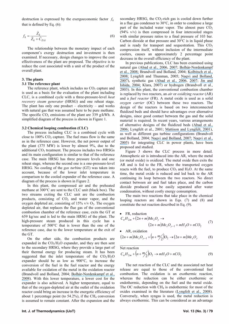
The reference plant, which includes no CO2 capture and is used as a basis for the evaluation of the plant including CLC, is a combined cycle with a three-pressure-level heat recovery steam generator (HRSG) and one reheat stage. The plant has only one product – electricity – and works with natural gas that was assumed here to be pure methane. The specific CO2 emissions of the plant are 339 g/kWh. A simplified diagram of the process is shown in Figure 1. 3.2 Chemical looping combustion (CLC)
The process including CLC is a combined cycle with close to 100% CO2 capture. The fuel mass flow is the same as in the reference case. However, the net power output of the plant (375 MW) is lower by almost 9%, due to the additional CO2 treatment. The process includes two HRSGs and its main configuration is similar to that of the reference case. The main HRSG has three pressure levels and one reheat stage, whereas the second one is a one-pressure-level HRSG. No cooling of the gas turbine (GT) was taken into account, because of the lower inlet temperature in comparison to the cooled expander of the reference case. A diagram of the process is shown in Figure 2.
In this plant, the compressed air and the preheated methane at 300°C are sent to the CLC unit (black box). The two streams exiting the CLC unit are the combustion products, consisting of CO2 and water vapor, and the oxygen depleted air, consisting of 15% v/v O2. The oxygen depleted air, that replaces the flue gas of the conventional combustion chamber of the reference case, exits the GT at 659 kg/sec and is led to the main HRSG of the plant. The high-pressure steam produced in this cycle has a temperature of 500°C that is lower than the one of the reference case, due to the lower temperature at the exit of the GT.
On the other side, the combustion products are expanded in the CO2/H2O expander, and they are then sent to the secondary HRSG, where they provide a large part of their thermal energy for producing steam. It has been suggested that the inlet temperature of the CO2/H2O expander should be as low as 900°C, to increase the conversion of the fuel in the fuel reactor and the energy available for oxidation of the metal in the oxidation reactor (Brandvoll and Bolland, 2004; Bolhàr-Nordenkampf et al., 2008). With this lower temperature, a lower cost for the expander is also achieved. A higher temperature, equal to that of the oxygen-depleted air at the outlet of the oxidation reactor could bring an increase in the energetic efficiency of about 1 percentage point (to 54.2%), if the CH4 conversion is assumed to remain constant. After the expansion and the
secondary HRSG, the CO2-rich gas is cooled down further in a flue gas condenser to 30°C, in order to condense a large part of the included water vapor. The almost pure CO2 (94% v/v) is then compressed in four intercooled stages with similar pressure ratios to a final pressure of 103 bar. Carbon dioxide at that pressure and 30°C is in liquid phase and is ready for transport and sequestration. This CO2 compression itself, without inclusion of the intermediate coolers, causes an approximately 2 percentage point decrease in the overall efficiency of the plant.
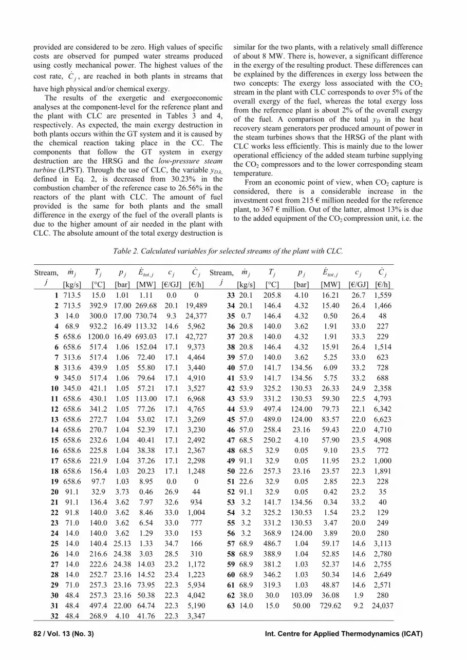
In previous publications, CLC has been examined using natural gas (Abad et al., 2006, 2007; Bolhàr-Nordenkampf et al., 2008; Brandvoll and Bolland, 2004; Kolbitsch et al., 2008; Lyngfelt and Thunman, 2005; Naqvi and Bolland, 2007), synthetic gas (Abad et al., 2006, 2007; Jin and Ishida, 2004; Klara, 2007) or hydrogen (Brandvoll et al., 2003). In this plant, the conventional combustion chamber is replaced by two reactors, an air or oxidizing reactor (AR) and a fuel reactor (FR). A metal oxide is used as a solid oxygen carrier (OC) between these two reactors. The design of the reactors is based on two interconnected fluidized beds and should have advantages over alternative designs, since good contact between the gas and the solid material is required. In recent years, various arrangements of alternative designs of the fluidized beds (Abad et al., 2006; Lyngfelt et al., 2001; Mattison and Lyngfelt, 2001), as well as different gas turbine configurations (Brandvoll and Bolland, 2004; Naqvi and Bolland, 2007; Naqvi et al., 2005) for integrating CLC in power plants, have been proposed and studied.
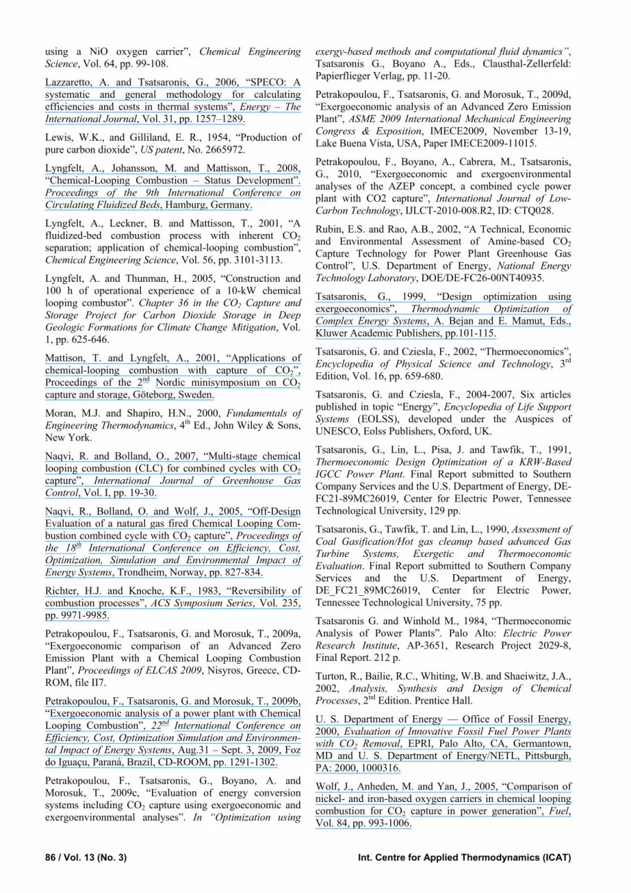
Figure 3 shows the CLC process in more detail. Atmospheric air is introduced into the AR, where the metal (or metal oxide) is oxidized. The metal oxide then exits the AR and is fed to the FR, where the transported oxygen reacts with the fuel, to produce CO2 and H2O. At the same time, the metal oxide is reduced and led back to the AR continuing its loop between the two reactors. No direct contact between air and fuel takes place, and the carbon dioxide produced can be easily separated after water condensation, without costly energy consumption.
The main two reactions that take place in the chemical looping reactors are shown in Eqs. (7) and (8) and constitute the net reaction described in Eq. (9).
• FR, reduction
( )( ) 221
2
2
2
nCOOmHOMemn
OMemnHC
yx
yxmn
+++
→++
− (7)
• AR, oxidation ( ) ( ) ( ) yxyx OMemnOmnOMemn +→+++ − 222 21 (8)
______________________________________________ Net reaction
( ) 2222 2 nCOOmHOmnHC mn +→++ (9)
The net reaction of the CLC and the associated net heat
release are equal to those of the conventional fuel combustion. The oxidation is an exothermic reaction, whereas the reduction can be either exothermic or endothermic, depending on the fuel and the metal oxide. The OC reduction with CH4 is endothermic for most of the oxides examined in the literature (Lyngfelt et al., 2008). Conversely, when syngas is used, the metal reduction is always exothermic. This can be considered as an advantage

80 / Vol. 13 (No. 3) Int. Centre for Applied Thermodynamics (ICAT)
GG
M
M
M
M
M
Chimney
HP HRSG
IP HRSG LP HRSG
Gas Turbine
Condenser CT
De-aerator
RH
Steam Turbine
Pump
Condensate pump
Feedwater pumps
1
2 5
6 97
8 10
11
12
13
14 15 16 17 18 19
202122
233940
41
42
24
25
2627
28
2930
31
32
33
34
35
3637
38
43
44
45
4649
50HPSH
HPEVAP
HPECON
IPECO NIPEVAP LPEVAP Water PHIPSH LPSH
GT
IPST LPS THPS T
HPPIPP
LPP
Compressor
34
Mixer 1
Mixer 2
CC
4847
NG
: Air : Flue gas
: Water/ Steam : Shaft
NG: Natural Gas
HP: High PressureIP: Intermediate Pressure
LP: Low Pressure
GT: Gas TurbineCC: Combustion Chamber
ST: Steam TurbineSH: SuperheaterEVAP: EvaporatorECON:Economizer
P:PumpPH: Preheater
CT: Cooling Tower
Mixer 3
Figure 1. Structure of the Reference Plant.
GG
M
M
M
M
MG
Chimney
Chemical Looping
Combustion
HP HRSG
IP HRSG LP HRSG
Gas Turbine
CO2/H2OExpander
Condenser CoolingTower
De-aerator
RH
NG PH
Secondary HRSG (II)
Steam Turbine
ST for CO2 compressor supply
H2O extraction and CO2 compression with intercooling
Pump
Condensate pump
Feedwater pumps
1
2
3 4
5
6 97
8 10
11
12
13
14 15 16 17 18 19
202122
233940
4142
24
25
2627
28
29
30
31
32
33
34
35
3637
38
43 44
4546
47
4849
50
51
51
52
53
5455
56
57
58 59 60 61 62
65 66
68
67
6364
HPSH
HPECON
IPECONIPEVAP LPEVAP Water PHIPSH LPSH
Compressor G T
SH II EVAP II ECON II
IPS T LPSTHPST
HPPIPP
LPP
NG
Reactors
Mixer 1
Mixer 2
Mixer 3
Mixer 5
Mixer 4
: Air : Flue gas
: Water/ Steam : CO2/H2O stream
: Shaft
NG: Natural GasHP: High Pressure
IP: Intermediate PressureLP: Low PressureGT: Gas Turbine
ST: Steam TurbineSH: SuperheaterEVAP: EvaporatorECON:Economizer
PH: PreheaterP: Pump
HPEVAP
Figure 2. Structure of the plant with Chemical Looping Combustion.
CO 2 + H 2O
Air reactor,
AR
Fuelreactor,
FR
Oxygen depleted air(15% v/v O
Air
Me x + O y
Me x + O y-1
CH4
CO 2 + H 2O
Air reactor,
AR
Fuelreactor,
FR
2 )
Me x + O y
Me x + O y-1
2 3
45
CO 2 + H 2O
Air reactor,
AR
Fuelreactor,
FR
Oxygen depleted air(15% v/v O
Air
Me x + O y
Me x + O y-1
CH4
CO 2 + H 2O
Air reactor,
AR
Fuelreactor,
FR
2 )
Me x + O y
Me x + O y-1
2 3
45
Figure 3. Configuration of Chemical Looping Combustion (the numbering of the streams agrees with Figure 2).

Int. J. of Thermodynamics (IJoT) Vol. 13 (No. 3) / 81
of coal-gas use, since the coal-gas reaction is driven with stronger intensity due to its exothermic character. A part of the produced thermal energy during the oxidation is used in the reduction, if the latter is endothermic.
Many different metals have been suggested for oxygen carriers, mainly based on nickel, Ni (Brandvoll and et., 2003; Jin and Ishida, 2004; Lyngfelt and Thunman, 2005; Johansson et al., 2006; Bolhàr-Nordenkampf et al., 2008; Kolbitsch et al., 2008), iron, Fe (Johansson et al., 2006; Abad et al., 2007; Klara, 2007) and manganese, Mn (Abad et al., 2006; Johansson et al., 2006). Important factors are the reduction and oxidation rate, the chemical and mechanical stability, as well as the price and the environmental characteristics of the oxidizer. Generally Ni and its corresponding oxides show higher oxidation and reduction rates compared to Fe and Mn, as well as greater durability after many repeated cycles. More specifically, experiments with natural gas have shown that Ni reactivity is considerably higher than that of Fe-based oxygen carriers (Johansson et al., 2006). A detailed status of development with respect to oxygen carrier alternatives is presented in Lyngfelt et al. (2008).
In this paper, the CLC reactors are simulated as a black box. In the fuel reactor, 98% of the methane provided is assumed to react with oxygen transferred from the AR. The remaining non-reacting 2% of the fuel is not recycled back to the fuel reactor, but is regarded as a loss. The air ratio - the ratio between the oxygen included in the air and the oxygen needed for stoichiometric combustion - is set to 2.9. This ratio is set to achieve outlet temperatures of the air and the fuel reactors of 1200°C and 930°C, respectively (Lewis and Gilliland, 1954; Abad et al., 2007; Naqvi and Bolland, 2007). In this work, a Ni-based oxygen carrier is
considered, in order to achieve close to 100% CH4 conversion to CO2.
For the calculation of the reactors costs, data from the publications of Klara (2007), Wolf et al. (2005), as well as Lyngfeld and Thunman (2005) were used. In Wolf et al. (2005), an 800 MWth CLC is studied. Residence times in the fuel and air reactor with a Ni-based oxygen carrier were estimated at 60 and 4.8 sec, respectively. In this paper, these residence times were adjusted to the 700 MWth used and considered to be 53 and 4.2 sec, respectively. The volumetric flow rate of the gases was calculated using the simulation software EbsilonProfessional 6.0 and the respective volumes of the air and the fuel reactors assumed here were then estimated to be 718 m3 and 834 m3, respectively. With a reference unit cost 16.12 million euro for a volume of 180 m3 in the year 2000 and an exponent of 0.6 (Turton et al., 2002; Klara, 2007), the equipment costs of the AR and the FR were found to be 37.0 and 40.5 million euro, respectively. The installation together with the metal oxide costs were considered to be 20% of the delivered equipment cost. The total FCI of the CLC unit was then found to be 128 million with adjustment to the year 2008, using the CEPSI index. The cost of the metal oxide was not calculated in detail, because of high uncertainty (Lyngfelt and Thunman, 2005). However, even at the highest suggested prices and quantities it could be considered as negligible in comparison to the total cost of the unit.
4. Results and Discussion
Tables 1 and 2 show important variables for selected streams of the reference plant and the plant with CLC, respectively. In both cases, the cost of air and water
Table 1. Calculated variables for selected streams of the reference case without CO2 capture.
Stream, j
jm [kg/s]
jT [°C]
jp [bar]
j,totE [MW]
jc [€/GJ]
jС [€/h]
Stream, j
jm [kg/s]
jT [°C]
jp [bar]
j,totE [MW]
jc [€/GJ]
jС [€/h]
1 614.5 15.0 1.01 0.96 0.0 0 25 7.2 140.5 25.13 0.68 33.8 83 2 614.5 392.9 17.00 232.25 19.0 15,860 26 7.2 216.6 24.38 1.56 27.2 153 3 14.0 15.0 50.00 729.62 9.2 24,037 27 7.2 222.6 24.38 7.23 21.8 568 5 628.5 1264.0 16.49 741.01 15.3 40,824 28 7.2 237.9 23.16 7.35 22.0 583 6 628.5 580.6 1.06 189.87 15.3 10,460 29 94.6 32.9 0.05 0.44 21.2 33 7 268.5 580.6 1.06 81.11 15.3 4,469 30 72.4 305.1 23.16 79.53 20.3 5,8148 268.5 447.6 1.05 54.64 15.3 3,010 31 72.4 560.6 22.00 103.42 20.0 7,4599 360.0 580.6 1.06 108.75 15.3 5,991 32 72.4 317.2 4.10 66.03 20.0 4,762
10 360.0 449.3 1.05 73.68 15.3 4,059 33 22.1 214.1 4.10 18.01 25.0 1,62311 628.5 448.6 1.05 128.33 15.3 7,070 34 22.1 146.4 4.32 16.96 24.8 1,51412 628.5 341.2 1.04 84.69 15.3 4,666 35 0.8 146.4 4.32 0.63 24.8 56 13 628.5 257.9 1.04 55.77 15.3 3,073 36 23.0 140.0 3.62 2.12 30.7 234 14 628.5 257.3 1.04 55.59 15.3 3,063 37 23.0 140.0 4.32 2.12 31.1 237 15 628.5 237.6 1.04 49.49 15.3 2,727 38 23.0 146.4 4.32 17.60 24.8 1,57016 628.5 234.1 1.04 48.43 15.3 2,668 39 65.2 140.0 3.62 6.01 30.7 665 17 628.5 229.3 1.04 47.01 15.3 2,590 40 65.2 141.8 134.56 6.96 31.4 788 18 628.5 156.4 1.03 27.98 15.3 1,542 41 65.2 325.2 130.53 31.88 22.6 2,59619 628.5 95.3 1.03 16.49 0.0 0 42 65.2 331.2 130.53 71.79 20.5 5,30220 94.6 32.9 3.73 0.47 25.6 44 43 65.2 560.6 124.00 103.51 20.1 7,48921 94.6 135.6 3.62 8.18 30.2 889 44 65.2 313.2 23.16 72.22 20.1 5,22622 95.4 140.0 3.62 8.79 30.7 973 45 94.6 293.0 4.10 83.86 21.2 6,38623 72.4 140.0 3.62 6.67 30.7 739 46 94.6 32.9 0.05 12.87 21.2 980 24 7.2 140.0 3.62 0.67 30.7 74
82 / Vol. 13 (No. 3) Int. Centre for Applied Thermodynamics (ICAT)
provided are considered to be zero. High values of specific costs are observed for pumped water streams produced using costly mechanical power. The highest values of the cost rate, jC , are reached in both plants in streams that have high physical and/or chemical exergy.
The results of the exergetic and exergoeconomic analyses at the component-level for the reference plant and the plant with CLC are presented in Tables 3 and 4, respectively. As expected, the main exergy destruction in both plants occurs within the GT system and it is caused by the chemical reaction taking place in the CC. The components that follow the GT system in exergy destruction are the HRSG and the low-pressure steam turbine (LPST). Through the use of CLC, the variable yD,k, defined in Eq. 2, is decreased from 30.23% in the combustion chamber of the reference case to 26.56% in the reactors of the plant with CLC. The amount of fuel provided is the same for both plants and the small difference in the exergy of the fuel of the overall plants is due to the higher amount of air needed in the plant with CLC. The absolute amount of the total exergy destruction is
similar for the two plants, with a relatively small difference of about 8 MW. There is, however, a significant difference in the exergy of the resulting product. These differences can be explained by the differences in exergy loss between the two concepts: The exergy loss associated with the CO2 stream in the plant with CLC corresponds to over 5% of the overall exergy of the fuel, whereas the total exergy loss from the reference plant is about 2% of the overall exergy of the fuel. A comparison of the total yD in the heat recovery steam generators per produced amount of power in the steam turbines shows that the HRSG of the plant with CLC works less efficiently. This is mainly due to the lower operational efficiency of the added steam turbine supplying the CO2 compressors and to the lower corresponding steam temperature.
From an economic point of view, when CO2 capture is considered, there is a considerable increase in the investment cost from 215 € million needed for the reference plant, to 367 € million. Out of the latter, almost 13% is due to the added equipment of the CO2 compression unit, i.e. the
Table 2. Calculated variables for selected streams of the plant with CLC.
Stream,
j jm
[kg/s] jT
[°C] jp
[bar] j,totE
[MW] jc
[€/GJ] jС
[€/h] Stream,
j jm
[kg/s]jT
[°C] jp
[bar] j,totE
[MW] jc
[€/GJ] jС
[€/h]1 713.5 15.0 1.01 1.11 0.0 0 33 20.1 205.8 4.10 16.21 26.7 1,5592 713.5 392.9 17.00 269.68 20.1 19,489 34 20.1 146.4 4.32 15.40 26.4 1,4663 14.0 300.0 17.00 730.74 9.3 24,377 35 0.7 146.4 4.32 0.50 26.4 48 4 68.9 932.2 16.49 113.32 14.6 5,962 36 20.8 140.0 3.62 1.91 33.0 227 5 658.6 1200.0 16.49 693.03 17.1 42,727 37 20.8 140.0 4.32 1.91 33.3 229 6 658.6 517.4 1.06 152.04 17.1 9,373 38 20.8 146.4 4.32 15.91 26.4 1,5147 313.6 517.4 1.06 72.40 17.1 4,464 39 57.0 140.0 3.62 5.25 33.0 623 8 313.6 439.9 1.05 55.80 17.1 3,440 40 57.0 141.7 134.56 6.09 33.2 728 9 345.0 517.4 1.06 79.64 17.1 4,910 41 53.9 141.7 134.56 5.75 33.2 688
10 345.0 421.1 1.05 57.21 17.1 3,527 42 53.9 325.2 130.53 26.33 24.9 2,35811 658.6 430.1 1.05 113.00 17.1 6,968 43 53.9 331.2 130.53 59.30 22.5 4,79312 658.6 341.2 1.05 77.26 17.1 4,765 44 53.9 497.4 124.00 79.73 22.1 6,34213 658.6 272.7 1.04 53.02 17.1 3,269 45 57.0 489.0 124.00 83.57 22.0 6,62314 658.6 270.7 1.04 52.39 17.1 3,230 46 57.0 258.4 23.16 59.43 22.0 4,71015 658.6 232.6 1.04 40.41 17.1 2,492 47 68.5 250.2 4.10 57.90 23.5 4,90816 658.6 225.8 1.04 38.38 17.1 2,367 48 68.5 32.9 0.05 9.10 23.5 772 17 658.6 221.9 1.04 37.26 17.1 2,298 49 91.1 32.9 0.05 11.95 23.2 1,00018 658.6 156.4 1.03 20.23 17.1 1,248 50 22.6 257.3 23.16 23.57 22.3 1,89119 658.6 97.7 1.03 8.95 0.0 0 51 22.6 32.9 0.05 2.85 22.3 228 20 91.1 32.9 3.73 0.46 26.9 44 52 91.1 32.9 0.05 0.42 23.2 35 21 91.1 136.4 3.62 7.97 32.6 934 53 3.2 141.7 134.56 0.34 33.2 40 22 91.8 140.0 3.62 8.46 33.0 1,004 54 3.2 325.2 130.53 1.54 23.2 129 23 71.0 140.0 3.62 6.54 33.0 777 55 3.2 331.2 130.53 3.47 20.0 249 24 14.0 140.0 3.62 1.29 33.0 153 56 3.2 368.9 124.00 3.89 20.0 280 25 14.0 140.4 25.13 1.33 34.7 166 57 68.9 486.7 1.04 59.17 14.6 3,11326 14.0 216.6 24.38 3.03 28.5 310 58 68.9 388.9 1.04 52.85 14.6 2,78027 14.0 222.6 24.38 14.03 23.2 1,172 59 68.9 381.2 1.03 52.37 14.6 2,75528 14.0 252.7 23.16 14.52 23.4 1,223 60 68.9 346.2 1.03 50.34 14.6 2,64929 71.0 257.3 23.16 73.95 22.3 5,934 61 68.9 319.3 1.03 48.87 14.6 2,57130 48.4 257.3 23.16 50.38 22.3 4,042 62 38.0 30.0 103.09 36.08 1.9 280 31 48.4 497.4 22.00 64.74 22.3 5,190 63 14.0 15.0 50.00 729.62 9.2 24,03732 48.4 268.9 4.10 41.76 22.3 3,347

Int. J. of Thermodynamics (IJoT) Vol. 13 (No. 3) / 83
intercooled CO2 compression unit and the steam turbine used to support it with power. Moreover, almost 35% of the total fixed capital investment of the plant is due to the reactors of the chemical looping unit. Comparing the total FCI per produced kW of the two plants, a large difference is observed. The resulting investment costs for the reference plant and the case with CLC are 522 €/kW and 980 €/kW, respectively.
The specific cost of the product for the reference case is found to be 20.5 €/GJ, while that of the plant with CLC is 25.5 €/GJ. The resulting levelized costs of electricity for the reference plant and the plant with CLC are 73.9 and 91.7 €/MWh, respectively; thus, CO2 capture causes an increase in the cost of electricity (COE) of about 24%.
In order to examine the uncertainties related to the reactors’ costs, a sensitivity analysis was conducted. In this analysis the cost of the reactors was varied from -50% to +100% of the base cost calculated. The results show that with a 50% lower cost, the levelized cost of electricity produced in the plant is 87.2 €/MWh, representing a small decrease of 5% in comparison to the base case cost estimation of the plant with CLC and furthermore an 18% increase in comparison to the reference case with no CO2 capture. On the other hand, a 100% underestimation in the price of the reactors, could result in an increase of the cost of electricity by about 10%, with respect to the base-price (100.5 €/MWh).
The cost of the CO2 avoided can be calculated with Eq. (10) (Rubin and Rao, 2002):
( ) ( )
( ) ( )2 2
€ / € /
/ /
−
−capture reference
CO COreference capture
kWh kWh
t kWh t kWh (10)
Here, the levelized cost of CO2 avoided in the plant with CLC was found to be 53.1 €/t. However, to examine whether CLC is a viable solution for CO2 capture from an economic viewpoint, this cost is compared to the cost associated with the simplest alternative method: Chemical absorption with monoethanolamine (MEA). The plant with post-combustion capture has the same configuration as the reference plant. The changes needed to incorporate post-combustion capture are: (1) the addition of the absorption unit at the outlet of the exhaust gases, (2) steam extraction from the steam turbine (ST) of the plant to produce the required thermal energy for complete regeneration of the chemical solvent, and (3) power generation in the ST used to drive the CO2 compressors. The last two points result in a significant decrease in the power output and, consequently, in the efficiency of the overall system. No solvent losses are taken into account in the simulation. Therefore, the lean sorbent CO2 loading (mol CO2/mol MEA) is set to zero, resulting in a relatively high solvent regeneration requirement. Computational calculations are based on Rubin and Rao (2002). Assuming a 10% increase in the capital cost of the plant working with chemical absorption, with respect to the reference plant, the COE of the MEA
Table 3. Results of the exergetic and exergoeconomic analyses at the component-level for the reference case.
Component, k k,FE [MW]
k,PE [MW]
k,DE [MW]
kε [%]
ky [%]
k,Fc [€/GJ]
k,Pc [€/GJ]
k,DC [€/h]
kZ [€/h]
kf [%]
kr [%]
Compressor 242.68 231.30 11.38 95.3 1.56 16.67 19.05 682.8 1297.0 65.5 14.3 CC 729.62 508.76 220.87 69.7 30.23 9.15 13.63 7276.3 926.5 11.3 48.9 GT 551.15 530.67 20.47 96.3 2.80 15.30 16.67 1127.9 1482.3 56.8 8.9 Reheater 26.47 23.89 2.58 90.3 0.35 15.30 19.13 141.9 105.4 42.6 25.0 HPSH 35.07 31.72 3.35 90.5 0.46 15.30 19.16 184.5 149.5 44.8 25.2 HPEVAP 43.64 39.91 3.73 91.5 0.51 15.30 18.83 205.3 183.6 47.2 23.1 HPECON 28.92 24.91 4.00 86.2 0.55 15.30 20.16 220.5 88.6 28.7 31.8 IPSH 0.18 0.12 0.06 69.0 0.01 15.30 34.61 3.1 3.8 55.2 126.1 IPEVAP 6.10 5.67 0.43 92.9 0.06 15.30 20.32 23.8 65.0 73.2 32.8 IPECON 1.06 0.87 0.19 82.5 0.03 15.30 22.06 10.2 5.2 33.5 44.2 LPSH 1.43 1.04 0.38 73.3 0.05 15.30 28.97 21.0 18.3 46.6 89.3 LPEVAP 19.03 15.48 3.55 81.4 0.49 15.30 23.93 195.4 172.8 46.9 56.4 LPECON 11.49 7.71 3.78 67.1 0.52 15.30 30.48 208.5 92.7 30.8 99.2 HPST 31.29 29.18 2.11 93.2 0.29 20.10 23.77 152.9 165.6 52.0 18.3 IPST 37.39 35.21 2.18 94.2 0.30 20.03 24.19 157.4 299.7 65.6 20.7 LPST 70.99 61.35 9.64 86.4 1.32 21.15 29.01 734.3 696.3 48.7 37.2 Condensate Pump 0.04 0.04 0.01 78.8 0.00 19.64 80.52 0.7 6.7 91.0 310.0 HP Pump 1.12 0.96 0.17 85.3 0.02 19.64 35.63 11.7 38.2 76.6 81.4 IP Pump 0.03 0.02 0.01 65.3 0.00 19.64 140.35 0.7 7.3 91.0 614.6 LP Pump 0.00 0.00 0.00 67.2 0.00 19.64 384.64 0.1 2.4 97.3 1858.4 De-aerator 0.56 0.53 0.03 95.4 0.00 24.79 40.05 2.3 26.1 92.0 61.6 Mixer 1 1.81 1.63 0.18 90.1 0.02 20.03 22.49 12.9 0.0 − 12.2 Mixer 2 0.63 0.58 0.04 92.9 0.01 20.10 24.35 3.2 0.0 − 21.2 Mixer 3 0.18 0.18 0.00 99.9 0.00 15.30 15.32 0.0 0.0 − 0.1 Condenser 12.43 − 7.53 − 1.70 21.15 − 946.4 85.7 8.3 − Total (EL=14 MW) 730.58 411.40 305.15 56.3 41.77 9.15 20.53 10053.1 6459.9 39.1 124.4

84 / Vol. 13 (No. 3) Int. Centre for Applied Thermodynamics (ICAT)
Table 4. Results of the exergetic and exergoeconomic analyses at the component-level for the plant with CLC.
Component, k k,FE [MW]
k,PE [MW]
k,DE [MW]
kε [%]
ky [%]
k,Fc [€/GJ]
k,Pc [€/GJ]
k,DC [€/h]
kZ [€/h]
kf [%]
kr [%]
Compressor 281.78 268.57 13.21 95.3 1.81 18.32 20.16 871.4 903.7 50.9 10.0 Reactors 694.73 500.67 194.06 72.1 26.56 9.06 15.25 6,332.4 4,823.1 43.2 68.3 GT 540.99 521.34 19.65 96.4 2.69 17.13 18.32 1,211.7 1,032.8 46.0 7.0 CO2/H2O Expander 54.16 51.35 2.81 94.8 0.38 14.61 16.51 147.6 202.2 57.8 12.9 NG PH 6.32 1.12 5.20 17.7 0.71 14.61 84.49 273.8 7.4 2.6 478.1Reheater 16.60 14.36 2.24 86.5 0.31 17.13 22.20 138.2 52.3 27.4 29.6 HPSH 22.43 20.43 1.99 91.1 0.27 17.13 21.06 123.0 102.5 45.5 23.0 HPEVAP 35.74 32.97 2.77 92.2 0.38 17.13 20.52 170.8 142.6 45.5 19.8 HPECON 24.25 20.58 3.67 84.9 0.50 17.13 22.54 226.1 57.5 20.3 31.6 IPSH 0.63 0.49 0.14 78.1 0.02 17.13 28.74 8.5 7.6 47.2 67.8 IPEVAP 11.97 11.00 0.97 91.9 0.13 17.13 21.77 60.0 92.5 60.7 27.1 IPECON 2.03 1.70 0.33 83.6 0.05 17.13 23.65 20.5 8.7 29.8 38.1 LPSH 1.12 0.81 0.32 71.9 0.04 17.13 31.82 19.4 13.1 40.3 85.8 LPEVAP 17.03 13.99 3.03 82.2 0.42 17.13 25.51 187.1 137.9 42.4 48.9 LPECON 11.28 7.52 3.76 66.6 0.51 17.13 32.90 232.0 74.0 24.2 92.1 SH II 0.48 0.42 0.05 88.6 0.01 14.61 20.04 2.9 3.7 56.2 37.1 EVAP II 2.03 1.93 0.10 95.2 0.01 14.61 17.36 5.1 10.8 67.7 18.8 ECON II 1.47 1.20 0.27 81.8 0.04 14.61 20.42 14.1 2.6 15.4 39.7 HPST 24.14 22.41 1.73 92.8 0.24 22.01 25.59 137.0 95.9 41.2 16.2 IPST 22.98 21.57 1.41 93.9 0.19 22.27 26.08 112.8 138.4 55.1 17.1 LPST 48.80 42.17 6.63 86.4 0.91 23.55 31.02 561.8 360.8 39.1 31.8 ST for CO2 supply 20.73 15.66 5.06 75.6 0.69 22.29 34.96 406.3 146.0 26.4 56.9 Condensate Pump 0.04 0.03 0.01 78.6 0.00 20.37 72.99 0.7 5.4 89.0 258.3HP Pump 0.98 0.84 0.14 85.3 0.02 20.37 34.75 10.6 28.0 72.6 70.6 IP Pump 0.05 0.04 0.02 70.1 0.00 20.37 95.73 1.1 8.2 87.9 369.9LP Pump 0.00 0.00 0.00 66.5 0.00 20.37 348.84 0.1 1.9 96.8 1612.4CO2 Compressor 1 3.85 3.24 0.61 84.1 0.08 34.96 182.09 76.9 294.1 79.3 420.8CO2 Compressor 2 3.96 3.32 0.64 83.8 0.09 34.96 73.28 81.0 302.4 78.9 109.6CO2 Compressor 3 3.91 3.27 0.64 83.5 0.09 34.96 75.71 81.0 298.4 78.7 116.6CO2 Compressor 4 3.93 3.26 0.67 83.0 0.09 34.96 76.53 84.0 299.8 78.1 118.9De-aerator 0.44 0.42 0.02 95.6 0.00 26.45 41.59 1.8 20.7 91.8 57.3 Mixer 1 0.85 0.79 0.06 92.5 0.01 22.27 24.80 5.1 0.0 0.0 11.4 Mixer 2 0.08 0.08 0.00 99.4 0.00 22.01 22.22 0.0 0.0 0.0 0.9 Mixer 3 1.99 1.97 0.02 99.1 0.00 17.13 17.37 1.1 0.0 0.0 1.4 Mixer 4 0.77 0.73 0.05 93.9 0.01 22.10 24.10 3.7 0.0 0.0 9.1 Mixer 5 0.12 0.12 0.00 100.0 0.00 23.55 23.55 0.0 0.0 0.0 0.0 Flue gas condenser 22.36 - 18.65 - 2.55 14.70 - 1,183.0 70.6 5.6 - Cooler 1 0.77 - 0.62 - 0.08 33.04 - 91.8 8.7 8.7 - Cooler 2 0.91 - 0.74 - 0.10 37.19 - 122.0 8.7 6.6 - Cooler 3 0.85 - 0.70 - 0.10 40.80 - 124.4 7.9 5.9 - Cooler 4 0.86 - 0.71 - 0.10 43.94 - 136.7 10.2 6.9 - Condenser 11.52 - 6.99 - 0.96 23.25 - 964.5 66.2 6.4 - Total (EL=43 MW) 730.73 374.82 312.89 51.29 42.82 9.15 25.46 10,308.1 10,422.8 50.3 178.2 plant increases by about 30%. The cost of the avoided CO2 in the case with MEA would then be 78.3 €/t, a price 47% higher, than that of the plant with CLC. The difference in cost is caused by the high energy consumption during regeneration and the lower CO2 capture percentage (85%) assumed for the plant with MEA. 5. Conclusions
In this paper, a three-pressure-level combined cycle plant using chemical looping combustion for approximately
100% CO2 capture, has been compared to a simple combined cycle plant without CO2 capture and briefly to a plant with CO2 capture through chemical absorption using monoethanolamine.
An exergetic analysis showed lower irreversibilities for the chemical looping reactors in comparison to the conventional combustion chamber of the reference case. Moreover, the process resulted in a decrease of the exergetic efficiency by about 5 percentage points with respect to the case without CO2 capture; yet it achieves an

Int. J. of Thermodynamics (IJoT) Vol. 13 (No. 3) / 85
exergetic efficiency of 51%, almost 6 percentage points higher than that of the conventional approach – chemical absorption with monoethanolamine. Nevertheless, the investment cost of such a technology is high and the operation of such a plant results in a significant increase in the cost of electricity.
Chemical looping combustion with interconnected beds is a promising technology with simultaneous inherent capture of the produced carbon dioxide. Issues that need further consideration are the scaling-up of pilot units and an examination of the impact of high temperatures on materials and engineering components that would result in more reliable and safer operation. Given that a price must be paid to implement CO2 capture from fossil fuel power plants, CLC seems to be a relatively economical alternative, in comparison to other proposed approaches, such as chemical absorption. Acknowledgements
This research was funded by the European Commission’s Marie Curie 6th Framework Programme, and was a part of the Research Training Network, INSPIRE. Nomenclature c cost per unit of exergy (€/GJ) C cost rate associated with an exergy stream (€/h) E exergy rate (MW) f exergoeconomic factor (%) m mass flow rate (kg/s) p pressure (bar) r relative cost difference (%) T temperature (°C) y exergy destruction ratio (%) Z cost rate associated with capital investment (€/h) Greek symbols ε exergetic efficiency (%) Subscripts D destruction (exergy) F fuel (exergy) i, j entering and exiting exergy streams k component L loss (exergy) P product (exergy) Abbreviations AR Air Reactor CC Combustion Chamber CEPCI Chemical Engineering Plant Cost Index CLC Chemical Looping Combustion COE Cost of electricity FCI Fixed Capital Investment FR Fuel Reactor GT Gas Turbine HP,IP,LP High-pressure, Intermediate-pressure, Low-
pressure HRSG Heat Recovery Steam Generator MEA Monoethanolamine OC Oxygen Carrier ST Steam turbine TRR Total Revenue Requirement
References Abad, A., Mattisson, T., Lyngfelt, A. and Johansson, M., 2007, “The use of iron oxide as oxygen carrier in a chemical-looping reactor”, Fuel, Vol. 86, pp. 1021–1035.
Abad, A., Mattisson, T., Lyngfelt, A. and Rydén, M., 2006, “Chemical-looping combustion in a 300 W continuously operating reactor system using a manganese-based oxygen carrier”, Fuel, Vol. 85, pp. 1174–1185.
Bejan, A., Tsatsaronis, G. and Moran, M., 1996, Thermal design and optimization, John Wiley and Sons, New York.
Bolhàr-Nordenkampf, J., Pröll, T. Kolbitsch, P. and Hofbauer, H., 2008, ‘Performance of a NiO-based oxygen carrier for Chemical Looping Combustion and reforming in a 120kW unit”. Proceedings of the 9th International Confe-rence on Greenhouse Gas Technologies, Washington, US.
Brandvoll, Ø. and Bolland, O., 2004, “Inherent CO2 Capture Using Chemical Looping Combustion in a Natural Gas Fired Power Cycle”, ASME Journal of Engineering for Gas Turbines and Power, Vol. 126, pp. 316-321.
Brandvoll, Ø., Kolbeinsen, L., Olsen, N. and Bolland, O., 2003, “Chemical Looping Combustion – Reduction of nickel oxide/nickel aluminate with hydrogen”, Proceedings of the Sixth Italian Conference on Chemical and Process Engineering, Pisa, Italy, Chemical Engineering Transactions, Vol. 3, pp. 105-110.
Gas Turbine World Handbook, 2006, Peguot Publishing.
Herzog, H. 2001, “What Future for Carbon Capture and Sequestration?”, Environmental Science and Technology, Vol. 35, pp. 148 A–153 A.
Hossain, M.M. and de Lasa, H.I., 2008, “Chemical-looping combustion (CLC) for inherent CO2 separation – a review”, Chemical Engineering Science, Vol. 63, pp. 4433-4451.
Ishida, M. and Jin, H., 1994, “A novel combustor based on chemical-looping reactions and its reaction kinetics”, Journal of Chemical Engineering of Japan, Vol.27, pp. 296-301.
Jin, H. and Ishida, M., 2004, “A new type of coal gas fueled chemical-looping combustion”, Fuel, Vol. 83, pp. 2411-2417.
Johansson, M., Mattisson, T. and Lyngfelt, A., 2006, “Comparison of oxygen carriers for Chemical-Looping Combustion”, Thermal Science, Vol. 10, pp. 93-107.
Kakaras, E., Doukelis, A., Giannakopoulos, D. and Koumanakos, A., 2005, “Emission reduction technologies for the fossil fuel fuelled electricity generation sector”, Proceedings of the Scientific conference HELECO.
Klara, J.M., 2007, “Chemical-Looping Process in a Coal-to-Liquids”, Independent Assessment of the potential of the OSU Chemical Looping Concept, U.S. Department of Energy, National Energy Technology Laboratory, DOE/NETL-2008/1307.
Knoche, K.F. and Richter, H., 1968, “Verbesserung der Reversibilität von Verbrennungs-Prozessen”, Brennstoff-Wärme- Kraft, Vol. 5, pp. 205-210.
Kolbitsch, P., Pröll, T. and Hofbauer H., 2008, “Modeling of a 120kW chemical looping combustion reactor system
86 / Vol. 13 (No. 3) Int. Centre for Applied Thermodynamics (ICAT)
using a NiO oxygen carrier”, Chemical Engineering Science, Vol. 64, pp. 99-108.
Lazzaretto, A. and Tsatsaronis, G., 2006, “SPECO: A systematic and general methodology for calculating efficiencies and costs in thermal systems”, Energy – The International Journal, Vol. 31, pp. 1257–1289.
Lewis, W.K., and Gilliland, E. R., 1954, “Production of pure carbon dioxide”, US patent, No. 2665972.
Lyngfelt, A., Johansson, M. and Mattisson, T., 2008, “Chemical-Looping Combustion – Status Development”. Proceedings of the 9th International Conference on Circulating Fluidized Beds, Hamburg, Germany.
Lyngfelt, A., Leckner, B. and Mattisson, T., 2001, “A fluidized-bed combustion process with inherent CO2 separation; application of chemical-looping combustion”, Chemical Engineering Science, Vol. 56, pp. 3101-3113.
Lyngfelt, A. and Thunman, H., 2005, “Construction and 100 h of operational experience of a 10-kW chemical looping combustor”. Chapter 36 in the CO2 Capture and Storage Project for Carbon Dioxide Storage in Deep Geologic Formations for Climate Change Mitigation, Vol. 1, pp. 625-646.
Mattison, T. and Lyngfelt, A., 2001, “Applications of chemical-looping combustion with capture of CO2”, Proceedings of the 2nd Nordic minisymposium on CO2 capture and storage, Göteborg, Sweden.
Moran, M.J. and Shapiro, H.N., 2000, Fundamentals of Engineering Thermodynamics, 4th Ed., John Wiley & Sons, New York.
Naqvi, R. and Bolland, O., 2007, “Multi-stage chemical looping combustion (CLC) for combined cycles with CO2 capture”, International Journal of Greenhouse Gas Control, Vol. I, pp. 19-30.
Naqvi, R., Bolland, O. and Wolf, J., 2005, “Off-Design Evaluation of a natural gas fired Chemical Looping Com-bustion combined cycle with CO2 capture”, Proceedings of the 18th International Conference on Efficiency, Cost, Optimization, Simulation and Environmental Impact of Energy Systems, Trondheim, Norway, pp. 827-834.
Richter, H.J. and Knoche, K.F., 1983, “Reversibility of combustion processes”, ACS Symposium Series, Vol. 235, pp. 9971-9985.
Petrakopoulou, F., Tsatsaronis, G. and Morosuk, T., 2009a, “Exergoeconomic comparison of an Advanced Zero Emission Plant with a Chemical Looping Combustion Plant”, Proceedings of ELCAS 2009, Nisyros, Greece, CD-ROM, file II7.
Petrakopoulou, F., Tsatsaronis, G. and Morosuk, T., 2009b, “Exergoeconomic analysis of a power plant with Chemical Looping Combustion”, 22nd International Conference on Efficiency, Cost, Optimization Simulation and Environmen-tal Impact of Energy Systems, Aug.31 – Sept. 3, 2009, Foz do Iguaçu, Paraná, Brazil, CD-ROOM, pp. 1291-1302.
Petrakopoulou, F., Tsatsaronis, G., Boyano, A. and Morosuk, T., 2009c, “Evaluation of energy conversion systems including CO2 capture using exergoeconomic and exergoenvironmental analyses”. In “Optimization using
exergy-based methods and computational fluid dynamics”, Tsatsaronis G., Boyano A., Eds., Clausthal-Zellerfeld: Papierflieger Verlag, pp. 11-20.
Petrakopoulou, F., Tsatsaronis, G. and Morosuk, T., 2009d, “Exergoeconomic analysis of an Advanced Zero Emission Plant”, ASME 2009 International Mechanical Engineering Congress & Exposition, IMECE2009, November 13-19, Lake Buena Vista, USA, Paper IMECE2009-11015.
Petrakopoulou, F., Boyano, A., Cabrera, M., Tsatsaronis, G., 2010, “Exergoeconomic and exergoenvironmental analyses of the AZEP concept, a combined cycle power plant with CO2 capture”, International Journal of Low-Carbon Technology, IJLCT-2010-008.R2, ID: CTQ028.
Rubin, E.S. and Rao, A.B., 2002, “A Technical, Economic and Environmental Assessment of Amine-based CO2 Capture Technology for Power Plant Greenhouse Gas Control”, U.S. Department of Energy, National Energy Technology Laboratory, DOE/DE-FC26-00NT40935.
Tsatsaronis, G., 1999, “Design optimization using exergoeconomics”, Thermodynamic Optimization of Complex Energy Systems, A. Bejan and E. Mamut, Eds., Kluwer Academic Publishers, pp.101-115.
Tsatsaronis, G. and Cziesla, F., 2002, “Thermoeconomics”, Encyclopedia of Physical Science and Technology, 3rd Edition, Vol. 16, pp. 659-680.
Tsatsaronis, G. and Cziesla, F., 2004-2007, Six articles published in topic “Energy”, Encyclopedia of Life Support Systems (EOLSS), developed under the Auspices of UNESCO, Eolss Publishers, Oxford, UK.
Tsatsaronis, G., Lin, L., Pisa, J. and Tawfik, T., 1991, Thermoeconomic Design Optimization of a KRW-Based IGCC Power Plant. Final Report submitted to Southern Company Services and the U.S. Department of Energy, DE-FC21-89MC26019, Center for Electric Power, Tennessee Technological University, 129 pp.
Tsatsaronis, G., Tawfik, T. and Lin, L., 1990, Assessment of Coal Gasification/Hot gas cleanup based advanced Gas Turbine Systems, Exergetic and Thermoeconomic Evaluation. Final Report submitted to Southern Company Services and the U.S. Department of Energy, DE_FC21_89MC26019, Center for Electric Power, Tennessee Technological University, 75 pp.
Tsatsaronis G. and Winhold M., 1984, “Thermoeconomic Analysis of Power Plants”. Palo Alto: Electric Power Research Institute, AP-3651, Research Project 2029-8, Final Report. 212 p.
Turton, R., Bailie, R.C., Whiting, W.B. and Shaeiwitz, J.A., 2002, Analysis, Synthesis and Design of Chemical Processes, 2nd Edition. Prentice Hall.
U. S. Department of Energy — Office of Fossil Energy, 2000, Evaluation of Innovative Fossil Fuel Power Plants with CO2 Removal, EPRI, Palo Alto, CA, Germantown, MD and U. S. Department of Energy/NETL, Pittsburgh, PA: 2000, 1000316.
Wolf, J., Anheden, M. and Yan, J., 2005, “Comparison of nickel- and iron-based oxygen carriers in chemical looping combustion for CO2 capture in power generation”, Fuel, Vol. 84, pp. 993-1006.