self-recuperative burners high speed free flame - esa pyronics
TRANSCRIPT
Burners
Self-recuperative burners
high speed free flameREKO-SIK-FF (E3901F rev. 05 - 04/08/2015)
REKO-SIK-FF - E3901F rev. 05 - 04/08/15
www.esapyronics.com 2
GENERAL WARNINGS:
¾¾ All installation, maintenance, ignition and setting mustbe performed by qualified staff, respecting the norms
present at the time and place of the installation.
¾¾ To avoid damage to people and things, it is essentialto observe all the points indicated in this handbook. The
reported indications do not exonerate the Client/User
from observing general or specific laws concerning acci-
dents and environmental safeguarding.
¾¾ The operator must wear proper DPI clothing (shoes,helmets...) and respect the general safety, prevention
and precaution norms.
¾¾ To avoid the risks of burns or high voltage electrocu-tion, the operator must avoid all contact with the burner
and its control devices during the ignition phase and
while it is running at high temperatures.
¾¾ All ordinary and extraordinary maintenance must beperformed when the system is stopped.
¾¾ To assure correct and safe use of the combustionplant, it is of extreme importance that the contents of this
document be brought to the attention of and be meticu-
lously observed by all personnel in charge of controlling
and working the devices.
¾¾ The functioning of a combustion plant can be dange-rous and cause injuries to persons or damage to equip-
ment. Every burner must be provided with certified com-
bustion safety and supervision devices.
¾¾ The burner must be installed correctly to prevent anytype of accidental/undesired heat transmission from the
flame to the operator or the equipment.
¾¾ The performances indicated in this technical docu-ment regarding the range of products are a result of
experimental tests carried out at ESA-PYRONICS. The
tests have been performed using ignition systems, flame
detectors and supervisors developed by ESA-PYRO-
NICS. The respect of the above mentioned functioning
conditions cannot be guaranteed if equipment, which is
not present in the ESA-PYRONICS catalogue, is used.
CONTACTS / SERVICE:
To dispose of the product, abide by the local legislations
regarding it.
DISPOSAL:
Headquarters:
Esa S.p.A.
Via Enrico Fermi 40
24035 Curno (BG) - Italy
Tel +39.035.6227411
Fax +39.035.6227499
International Sales:
Pyronics International s.a.
Zoning Industriel, 4ème rue
B-6040 Jumet - Belgium
Tel +32.71.256970
Fax +32.71.256979
www.esapyronics.com
GENERAL NOTES:
¾¾ In accordance to the internal policy of constant quali-ty improvement, ESA-PYRONICS reserves the right tomodify the technical characteristics of the present docu-ment at any time and without warning.
¾¾ It is possible to download technical sheets whichhave been updated to the latest revision from the www.esapyronics.com website.
¾¾ The REKO-SIK-FF products have been designed,manufactured and tested according to the most correctconstruction practices and following the applicablerequirements described in UNI EN 746-2-2010“Industrial heating process equipment - Part 2: Safetyrequirements for combustion and for the handling andprocessing of fuels’. We emphasize that the burnersdescribed in this data sheet are provided as indepen-dent units and are excluded from the scope of theMachine Directive 2006/42/EC not having any mobileitems that are not exclusively manual.
¾¾ Certified in conformity with the UNI EN ISO 9001Norm by DNV GL.
CERTIFICATIONS:
The products conform to the requests for the Euroasia market
(Russia, Belarus and Kazakhstan).
REKO-SIK-FF - E3901F rev. 05 - 04/08/15
www.esapyronics.com 3
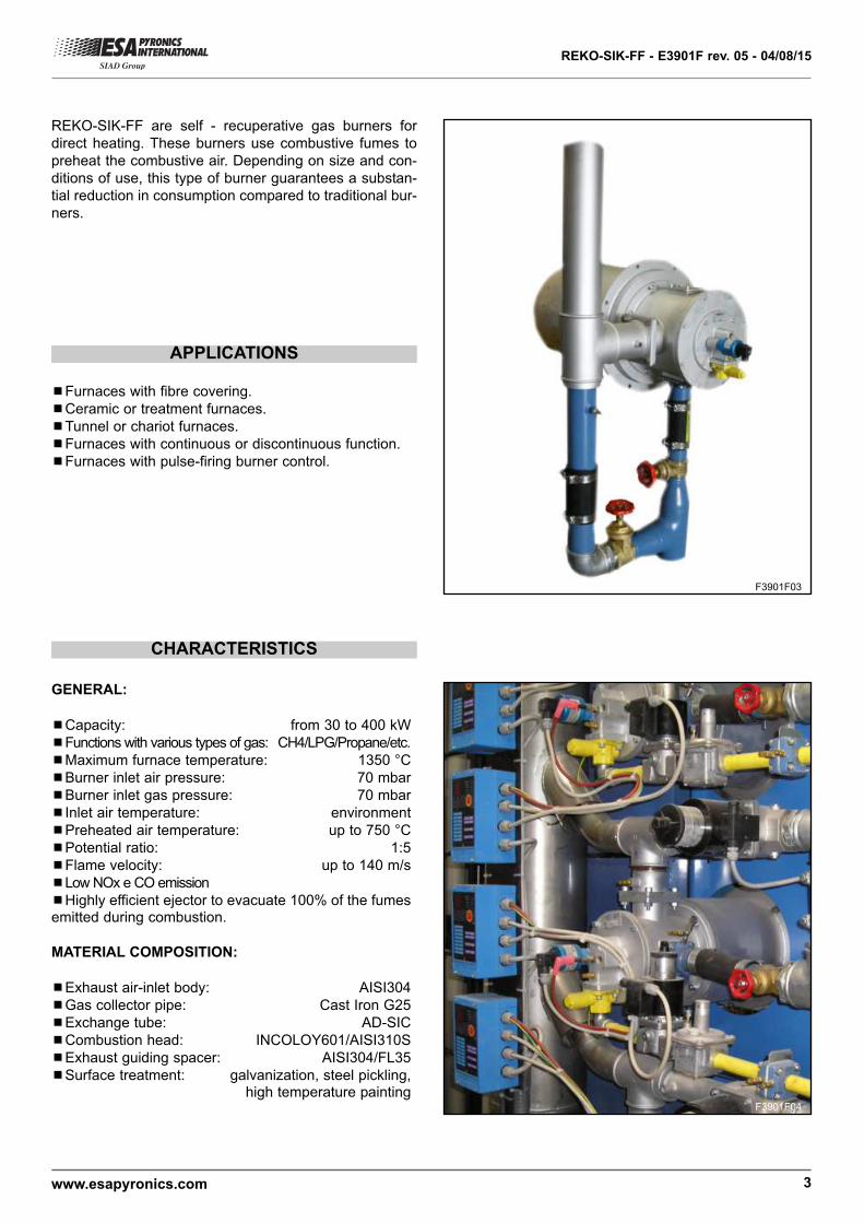
APPLICATIONS
REKO-SIK-FF are self - recuperative gas burners for
direct heating. These burners use combustive fumes to
preheat the combustive air. Depending on size and con-
ditions of use, this type of burner guarantees a substan-
tial reduction in consumption compared to traditional bur-
ners.
¾¾Furnaces with fibre covering.
¾¾Ceramic or treatment furnaces.
¾¾Tunnel or chariot furnaces.
¾¾Furnaces with continuous or discontinuous function.
¾¾Furnaces with pulse-firing burner control.
CHARACTERISTICS
GENERAL:
¾¾Capacity: from 30 to 400 kW
¾¾Functions with various types of gas: CH4/LPG/Propane/etc.
¾¾Maximum furnace temperature: 1350 °C
¾¾Burner inlet air pressure: 70 mbar
¾¾Burner inlet gas pressure: 70 mbar
¾¾Inlet air temperature: environment
¾¾Preheated air temperature: up to 750 °C
¾¾Potential ratio: 1:5
¾¾Flame velocity: up to 140 m/s
¾¾Low NOx e CO emission
¾¾Highly efficient ejector to evacuate 100% of the fumesemitted during combustion.
MATERIAL COMPOSITION:
¾¾Exhaust air-inlet body: AISI304
¾¾Gas collector pipe: Cast Iron G25
¾¾Exchange tube: AD-SIC
¾¾Combustion head: INCOLOY601/AISI310S
¾¾Exhaust guiding spacer: AISI304/FL35
¾¾Surface treatment: galvanization, steel pickling,high temperature painting
F3901F03
F3901F04
REKO-SIK-FF - E3901F rev. 05 - 04/08/15
www.esapyronics.com 4
CAPACITY AND FLAME LENGTH PARAMETERS
DESCRIPTION
The REKO-SIK-FF ignition takes place through a high
tension discharge, which is carried out by a WAND elec-
trode. The flame is detected via a uv-scanner (not inclu-
ded).
The REKO-SIK-FF burners use the temperature exhaust
fumes to preheat the combustive air, thus saving more
FLUE GAS RECIRCULATION
COMBUSTION
AIR INLET
EJECTOR AIR INLET
FLUE GAS OUTLET
GAS INLET
FLUE GAS
PREHEATED
AIR
COMBUSTION
GAS
T AIR
UP TO
750°C
The choice of materials has been made according to the
burners’ performance. Furthermore, the stainless steel
exhaust-air inlet body, assures a high resistance to heat
and oxidation. The heat exchanger element is made of
silicon carbide and its special conformation allows the
D3901F01
The adoption of flame controls is highly recommended in
all systems operating at temperatures below 750°C (UNI
EN746-2 Norm).
energy and reducing atmospheric pollution.
optimization of heat transfer from the combustion pro-
ducts to the combustive air. This choice allows the burner
to be used with maximum chamber temperature of up to
1300°C under direct heating conditions.
ModelCapacity
kW
Flamelengthmm
Nozzle velocity outputIgnition Detection
a 0m a 0,5m a 1m a 1,5m a 2m a 2,5m a 3m
REKO-1-SIK-FF 30 200 ÷ 300 140 116 64 44 35 27 21 WAND-EN UV-2
REKO-2-SIK-FF 60 300 ÷ 400 140 118 66 48 37 29 23 WAND-EN UV-2
REKO-3-SIK-FF 100 400 ÷ 500 140 120 67 49 39 31 24 WAND-EN UV-2
REKO-4-SIK-FF 170 600 ÷ 800 120 66 35 24 18 15 12 WAND-EN UV-2
REKO-5-SIK-FF 240 800 ÷ 1000 120 68 36 25 20 18 15 WAND-EN UV-2
REKO-6-SIK-FF 400 1200 ÷ 1500 120 69 37 28 22 20 18 WAND-EN UV-2
REKO-SIK-FF - E3901F rev. 05 - 04/08/15
www.esapyronics.com 5
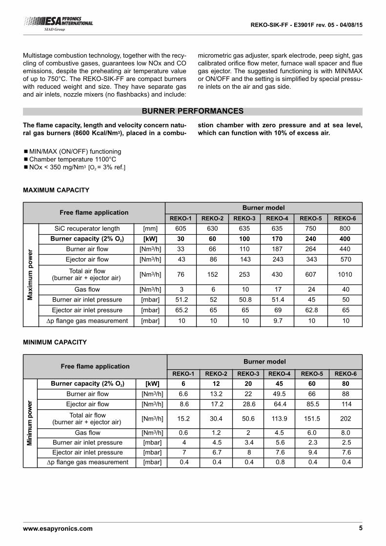
Free flame applicationBurner model
REKO-1 REKO-2 REKO-3 REKO-4 REKO-5 REKO-6
Burner capacity (2% O2) [kW] 6 12 20 45 60 80
Burner air flow [Nm3/h] 6.6 13.2 22 49.5 66 88
Ejector air flow [Nm3/h] 8.6 17.2 28.6 64.4 85.5 114
Total air flow(burner air + ejector air)
[Nm3/h] 15.2 30.4 50.6 113.9 151.5 202
Gas flow [Nm3/h] 0.6 1.2 2 4.5 6.0 8.0
Burner air inlet pressure [mbar] 4 4.5 3.4 5.6 2.3 2.5
Ejector air inlet pressure [mbar] 7 6.7 8 7.6 9.4 7.6
∆p flange gas measurement [mbar] 0.4 0.4 0.4 0.8 0.4 0.4
Minimum power
Free flame applicationBurner model
REKO-1 REKO-2 REKO-3 REKO-4 REKO-5 REKO-6
SiC recuperator length [mm] 605 630 635 635 750 800
Burner capacity (2% O2) [kW] 30 60 100 170 240 400
Burner air flow [Nm3/h] 33 66 110 187 264 440
Ejector air flow [Nm3/h] 43 86 143 243 343 570
Total air flow(burner air + ejector air)
[Nm3/h] 76 152 253 430 607 1010
Gas flow [Nm3/h] 3 6 10 17 24 40
Burner air inlet pressure [mbar] 51.2 52 50.8 51.4 45 50
Ejector air inlet pressure [mbar] 65.2 65 65 69 62.8 65
∆p flange gas measurement [mbar] 10 10 10 9.7 10 10
Maximum power
BURNER PERFORMANCES
¾¾MIN/MAX (ON/OFF) functioning
¾¾Chamber temperature 1100°C
¾¾NOx < 350 mg/Nm3 [O2 = 3% ref.]
MAXIMUM CAPACITY
MINIMUM CAPACITY
Multistage combustion technology, together with the recy-
cling of combustive gases, guarantees low NOx and CO
emissions, despite the preheating air temperature value
of up to 750°C. The REKO-SIK-FF are compact burners
with reduced weight and size. They have separate gas
and air inlets, nozzle mixers (no flashbacks) and include:
The flame capacity, length and velocity concern natu-
ral gas burners (8600 Kcal/Nm3), placed in a combu-
micrometric gas adjuster, spark electrode, peep sight, gas
calibrated orifice flow meter, furnace wall spacer and flue
gas ejector. The suggested functioning is with MIN/MAX
or ON/OFF and the setting is simplified by special pressu-
re inlets on the air and gas side.
stion chamber with zero pressure and at sea level,
which can function with 10% of excess air.
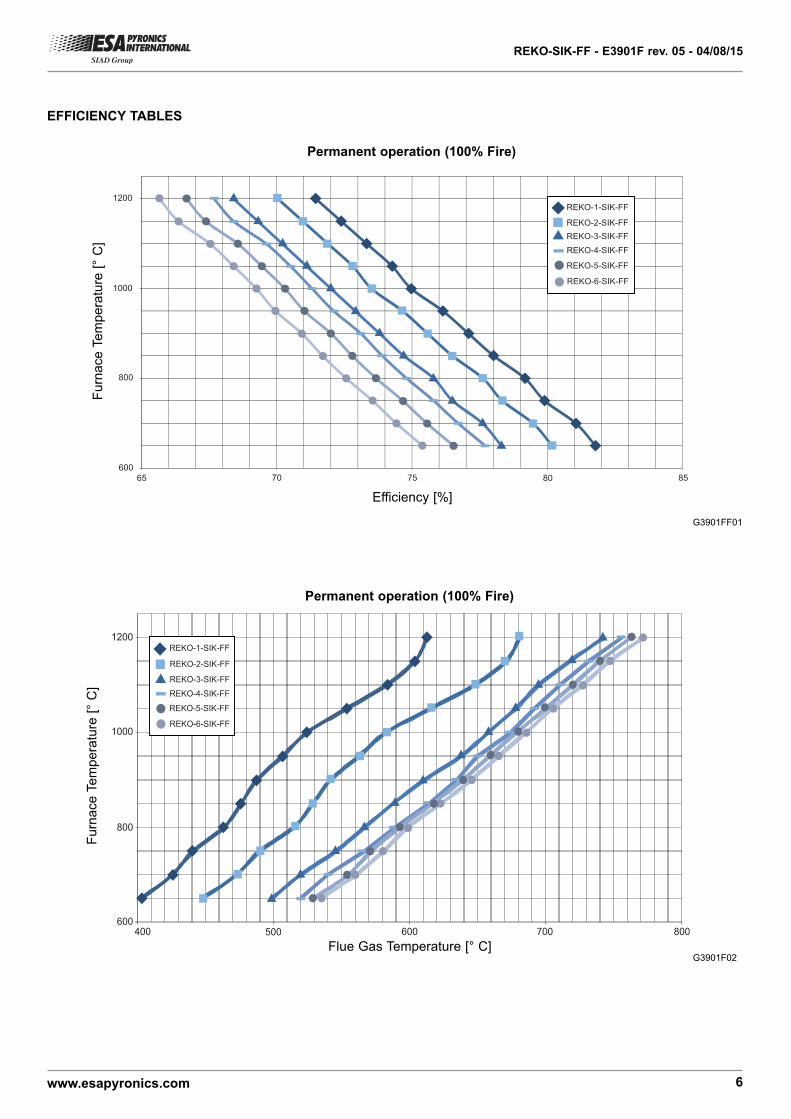
1200REKO-1-SIK-FF
REKO-2-SIK-FF
REKO-3-SIK-FF
REKO-4-SIK-FF
REKO-5-SIK-FF
REKO-6-SIK-FF1000
800
600400 500 600 700 800
REKO-SIK-FF - E3901F rev. 05 - 04/08/15
www.esapyronics.com 6
G3901F02Flue Gas Temperature [° C]
Furn
ace T
em
pera
ture
[°
C]
REKO-1-SIK-FF
REKO-2-SIK-FF
REKO-3-SIK-FF
REKO-4-SIK-FF
REKO-5-SIK-FF
REKO-6-SIK-FF
1200
1000
800
600
65 70 75 80 85
G3901FF01
Efficiency [%]
Furn
ace T
em
pera
ture
[°
C]
EFFICIENCY TABLES
Permanent operation (100% Fire)
Permanent operation (100% Fire)
REKO-SIK-FF - E3901F rev. 05 - 04/08/15
www.esapyronics.com 7
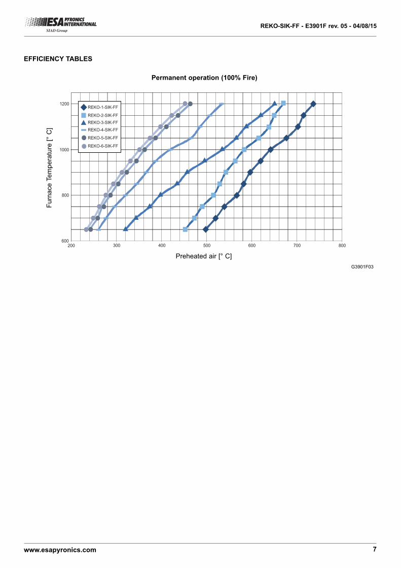
REKO-1-SIK-FF
REKO-2-SIK-FF
REKO-3-SIK-FF
REKO-4-SIK-FF
REKO-5-SIK-FF
REKO-6-SIK-FF
1200
1000
800
600200 300 400 500 600 700 800
G3901F03
Preheated air [° C]
Furn
ace T
em
pera
ture
[°
C]
EFFICIENCY TABLES
Permanent operation (100% Fire)
REKO-SIK-FF - E3901F rev. 05 - 04/08/15
www.esapyronics.com 8
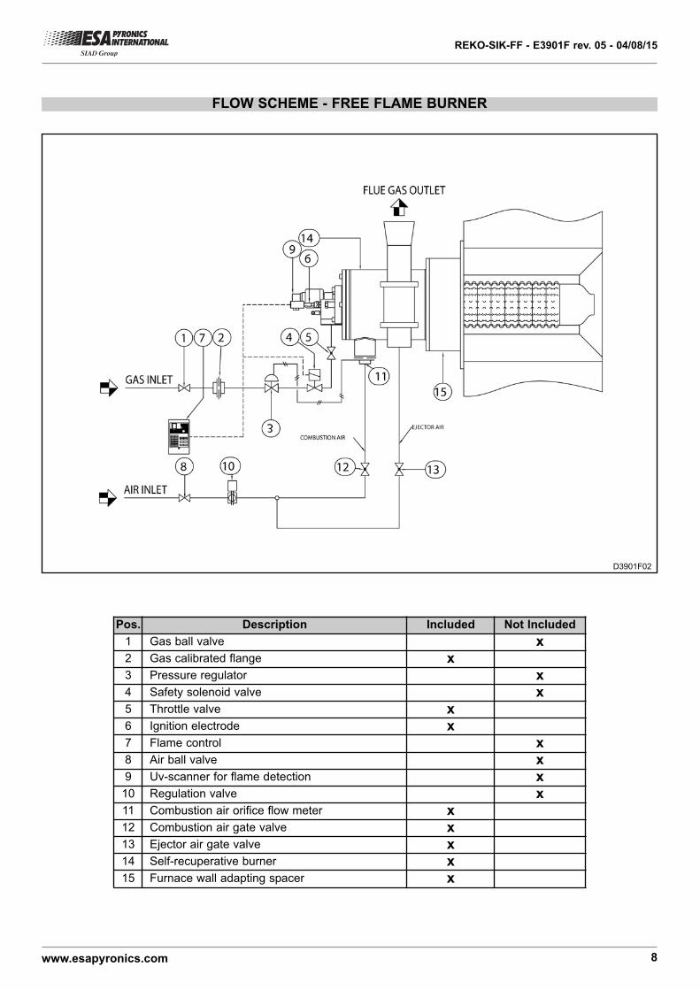
FLOW SCHEME - FREE FLAME BURNER
Pos. Description Included Not Included
1 Gas ball valve x2 Gas calibrated flange x3 Pressure regulator x4 Safety solenoid valve x5 Throttle valve x6 Ignition electrode x7 Flame control x8 Air ball valve x9 Uv-scanner for flame detection x
10 Regulation valve x11 Combustion air orifice flow meter x12 Combustion air gate valve x13 Ejector air gate valve x14 Self-recuperative burner x15 Furnace wall adapting spacer x
D3901F02
REKO-SIK-FF - E3901F rev. 05 - 04/08/15
www.esapyronics.com 9
WARNINGS
¾¾ The REKO-SIK-FF burner series is intended for fixedinstallations. If mobile installations are needed (bell fur-
naces, etc...) it is necessary to preventively take into
consideration the possibility of damage to hoses in sili-
con carbide, which is determined by the movement of
the actual furnace.
¾¾ The burner must always be turned on at minimumpower, then modulating towards the maximum, facilita-
ting ignition and reducing exit overpressure.
¾¾ The passing from minimum power to maximum powermust always be done gradually and not instantaneously.
To do this, the use of two-phase MRBV air regulation val-
ves is suggested.
¾¾ For all applications at low temperature (up to 750°C),burner ignition and the control of solenoid gas valves
must be accomplished using a certified burner control
device.
¾¾ To avoid possible damage to the burners, make surethat the blower does not send them hot or foul air (from
combustion products, oils, solvents or other). To avoid
this from occurring, install the blower or the air suction
duct outside the establishment and far from the exhaust
pipes.
¾¾ Check that the power lines are properly connectedafter the installation. Check the correct air and gas pres-
sures (pag. 5).
¾¾ The burner can only work within the indicated powerranges. The functioning with less or more power can
compromise the correct functioning and life span of the
actual burner. In this case the general warrantee condi-
tions will not be applicable anymore and ESA-PYRO-
NICS will not be held responsible for any damage cau-
sed to persons or things.
¾¾ If there is trouble with other devices during the burnerstart up phase, use the connector with anti disturbance
filter for the high-tension (HT) cable connection of the
ignition electrode.
¾¾ Avoid burner ignition close to each other so as not toheat the ignition command system devices (solenoid val-
ves and transformers). Prewash time lapse + first safety
time lapse + min. of 5 sec. = time lapse between one
ignition and another. (however, do not attempt more than
2 ignitions during a 30sec. time lapse).
¾¾ Make sure the power supply is TURNED OFF whenintervening on the burner and its devices. In case of bur-
ner malfunctioning, follow the indications in the
‘Maintenance’ chapter of the present manual or contact
ESA-PYRONICS assistance.
¾¾ Any modification or repair done by third parties cancompromise the application safety and automatically
cause the general warrantee conditions to expire.
REKO-SIK-FF - E3901F rev. 05 - 04/08/15
www.esapyronics.com 10
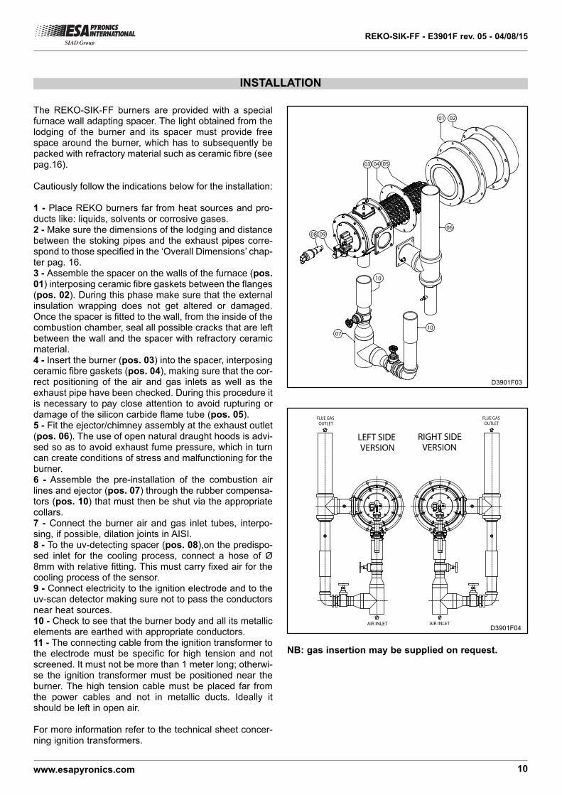
INSTALLATION
The REKO-SIK-FF burners are provided with a specialfurnace wall adapting spacer. The light obtained from thelodging of the burner and its spacer must provide freespace around the burner, which has to subsequently bepacked with refractory material such as ceramic fibre (seepag.16).
Cautiously follow the indications below for the installation:
1 - Place REKO burners far from heat sources and pro-ducts like: liquids, solvents or corrosive gases.2 - Make sure the dimensions of the lodging and distancebetween the stoking pipes and the exhaust pipes corre-spond to those specified in the ‘Overall Dimensions’ chap-ter pag. 16.3 - Assemble the spacer on the walls of the furnace (pos.01) interposing ceramic fibre gaskets between the flanges(pos. 02). During this phase make sure that the externalinsulation wrapping does not get altered or damaged.Once the spacer is fitted to the wall, from the inside of thecombustion chamber, seal all possible cracks that are leftbetween the wall and the spacer with refractory ceramicmaterial.4 - Insert the burner (pos. 03) into the spacer, interposingceramic fibre gaskets (pos. 04), making sure that the cor-rect positioning of the air and gas inlets as well as theexhaust pipe have been checked. During this procedure itis necessary to pay close attention to avoid rupturing ordamage of the silicon carbide flame tube (pos. 05).5 - Fit the ejector/chimney assembly at the exhaust outlet(pos. 06). The use of open natural draught hoods is advi-sed so as to avoid exhaust fume pressure, which in turncan create conditions of stress and malfunctioning for theburner.6 - Assemble the pre-installation of the combustion airlines and ejector (pos. 07) through the rubber compensa-tors (pos. 10) that must then be shut via the appropriatecollars.7 - Connect the burner air and gas inlet tubes, interpo-sing, if possible, dilation joints in AISI.8 - To the uv-detecting spacer (pos. 08),on the predispo-sed inlet for the cooling process, connect a hose of Ø8mm with relative fitting. This must carry fixed air for thecooling process of the sensor.9 - Connect electricity to the ignition electrode and to theuv-scan detector making sure not to pass the conductorsnear heat sources.10 - Check to see that the burner body and all its metallicelements are earthed with appropriate conductors.11 - The connecting cable from the ignition transformer tothe electrode must be specific for high tension and notscreened. It must not be more than 1 meter long; otherwi-se the ignition transformer must be positioned near theburner. The high tension cable must be placed far fromthe power cables and not in metallic ducts. Ideally itshould be left in open air.
For more information refer to the technical sheet concer-ning ignition transformers.
10
05
06
07
10
0908
03 04
0201
D3901F03
LEFT SIDEVERSION
RIGHT SIDEVERSION
AIR INLET
FLUE GASOUTLET
FLUE GASOUTLET
AIR INLETD3901F04
NB: gas insertion may be supplied on request.
REKO-SIK-FF - E3901F rev. 05 - 04/08/15
www.esapyronics.com 11
START UP AND SETTING
The procedures indicated in the following chapter must
be carried out by expert technicians. The non-observan-
ce of the instructions given can provoke dangerous con-
ditions.
1 - Check that the combustion air pressure exiting the blo-
wer and the combustive fuel pressure are both within the
allowed range.
2 - Adjust the working pressure and the safety device
pressure of the combustion plant, whether there is one
per burner or one for the whole plant i.e. gas pressure
reduction gear, block valve, relief valve, pressure swit-
ches etc. Simulate the intervention of all the safety devi-
ces including the intervention of the safety over tempera-
ture, checking that the fuel safety block devices act pro-
perly.
3 - Place the air regulation valve in the maximum opening
position and adjust the burner and ejector inlet air pressu-
re, via the gate valve. This must be done referring to the
values indicated in the ‘Burner Performances’ chapter for
the maximum power pag.05.
4 - Place the air regulation valve in the minimum opening
position and adjust its opening to obtain (in burner and
ejector inlet) the relative minimum power pressure.
5 -Activate the burner control device and attempt the igni-
tion until the burner switches on. While attempting to igni-
te the burner, act on the gas adjustment valve and, star-
ting from the totally closed position, open it gradually until
the burner ignites.
6 - Fully open the air regulation valve and adjust, via the
gas adjustment valve, the maximum fuel capacity, chec-
king the differential pressure created on the calibrated
gas flange.
7 - Double check that, at minimum and maximum power,
the burner and ejector inlet pressures correspond to the
values in the in the ‘Burner Performances’ chapter. These
values may be different depending on whether the burner
is on or off.
8 - If necessary, with all burners turned onto the same
power, analyze the combustion products in the chamber
(where possible) or exiting each burner (on the exhaust
muff).
9 - Repeatedly attempt ignition at minimum burner power,
with maximum amplitude, to check the ignition reliability
and flame stability during the adjustment.
RE
KO
-1-S
IK
RE
KO
-2-S
IK
RE
KO
-3-S
IK
RE
KO
-4-S
IK
RE
KO
-5-S
IK
RE
KO
-6-S
IK
10
110 100 10000
100
10001
REKO-SIK-FF - E3901F rev. 05 - 04/08/15
www.esapyronics.com 12
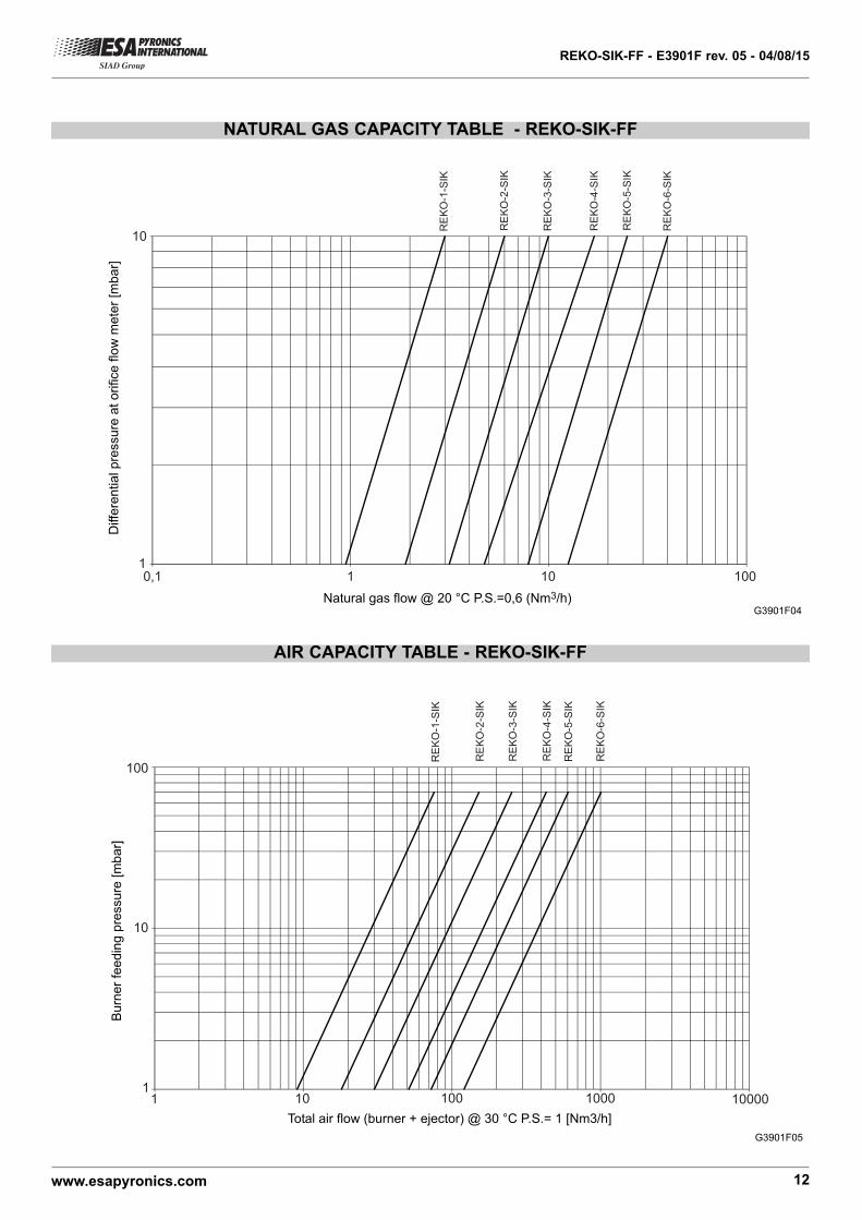
AIR CAPACITY TABLE - REKO-SIK-FF
G3901F05
Total air flow (burner + ejector) @ 30 °C P.S.= 1 [Nm3/h]
Burn
er
feedin
g p
ressure
[m
ba
r]NATURAL GAS CAPACITY TABLE - REKO-SIK-FF
RE
KO
-1-S
IK
RE
KO
-2-S
IK
RE
KO
-3-S
IK
RE
KO
-4-S
IK
RE
KO
-5-S
IK
RE
KO
-6-S
IK
10
10,1 1 10 100
G3901F04Natural gas flow @ 20 °C P.S.=0,6 (Nm3/h)
Diffe
rential p
ressu
re a
t o
rifice
flo
w m
ete
r [m
ba
r]
REKO-SIK-FF - E3901F rev. 05 - 04/08/15
www.esapyronics.com 13
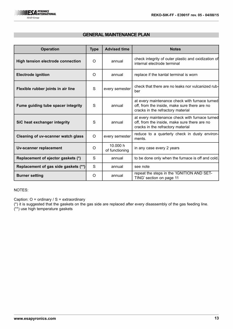
GENERAL MAINTENANCE PLAN
Operation Type Advised time Notes
High tension electrode connection O annualcheck integrity of outer plastic and oxidization of
internal electrode terminal
Electrode ignition O annual replace if the kantal terminal is worn
Flexible rubber joints in air line S every semestercheck that there are no leaks nor vulcanized rub-
ber
Fume guiding tube spacer integrity S annual
at every maintenance check with furnace turned
off, from the inside, make sure there are no
cracks in the refractory material
SiC heat exchanger integrity S annual
at every maintenance check with furnace turned
off, from the inside, make sure there are no
cracks in the refractory material
Cleaning of uv-scanner watch glass O every semesterreduce to a quarterly check in dusty environ-
ments.
Uv-scanner replacement O10.000 h
of functioningin any case every 2 years
Replacement of ejector gaskets (*) S annual to be done only when the furnace is off and cold.
Replacement of gas side gaskets (**) S annual see note
Burner setting O annualrepeat the steps in the ‘IGNITION AND SET-
TING’ section on page 11
NOTES:
Caption: O = ordinary / S = extraordinary
(*) it is suggested that the gaskets on the gas side are replaced after every disassembly of the gas feeding line.
(**) use high temperature gaskets
1 2
3 4 5
6 7
REKO-SIK-FF - E3901F rev. 05 - 04/08/15
www.esapyronics.com 14
G3901F05
ORDINARY MAINTENANCE
For correct dismantling and better maintenance of the
REKO-SIK-FF burners, meticulously follow the instruc-
tions below with the plant turned off.
CLEANING OF UV-SCANNER WATCH GLASS
1 - Check that the burner control device is not connected.2 - Disconnect power supply to the uv-scanner (pos. 01)and the cooling line (where present pos. 07).3 - Unscrew the aluminium pipe fitting (pos. 06) at thebase of the gas collector, removing the uv-scanner with itsspacer.
4 - Unscrew the aluminium fitting from the insulation teflonconnector (pos. 03) and remove the quartz watch glass(pos. 05).5 - Clean the quartz watch glass with a damp cloth and proceed to reassemble everything making sure that boththe glass as well as the gaskets are put back in the cor-rect positions (pos. 04) between the aluminium teflon spa-cer, before tightening.6 - Restore the cooling hoses and power connection.7 - Check the correct flame detection of the uv-scanner.
01
02
05 03 0406
REKO-SIK-FF - E3901F rev. 05 - 04/08/15
www.esapyronics.com 15
For correct dismantling and better maintenance of the
REKO-SIK -FF burner, meticulously follow the instruc-
tions below with the plant turned off.
BURNER SHUTDOWN
In shutdown conditions of the burner refer to the bur-
ner control device indications and to the relative
manual to identify the cause. The main cases are indi-
cated here below:
¾¾Illegal flame detection: the shutdown is due to an ille-
gal flame detection during the phases prior to ignition or
after the turning off. The causes are within the detection
system (broken or faulty sensor or presence of humidi-
ty), or in the gas draw from the electric safety valve,
which allows the burner to remain turned on.
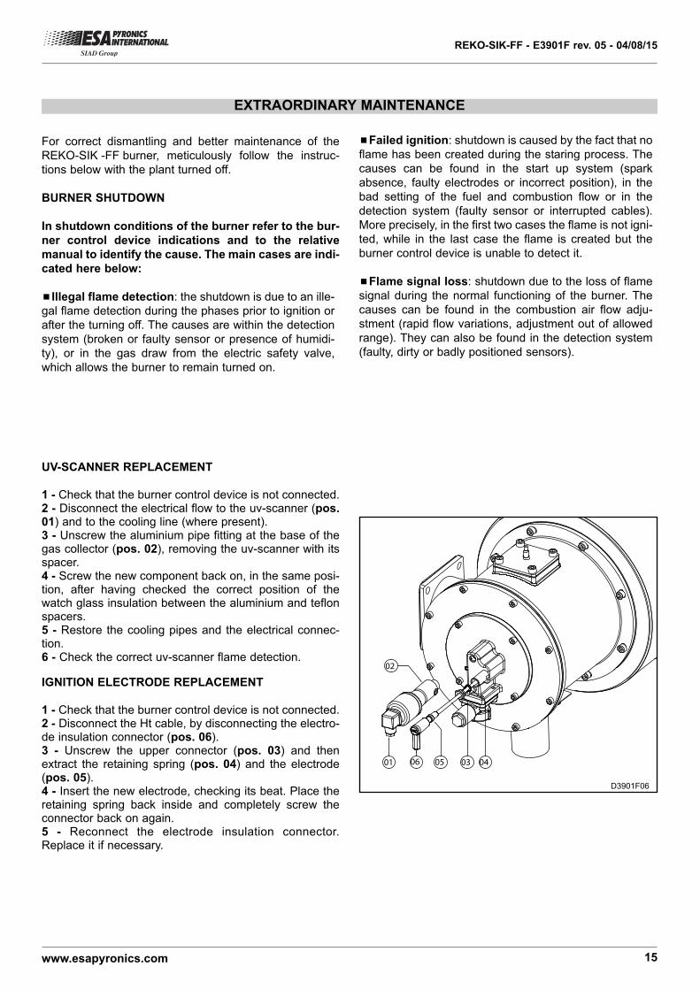
EXTRAORDINARY MAINTENANCE
D3901F06
UV-SCANNER REPLACEMENT
1 - Check that the burner control device is not connected.2 - Disconnect the electrical flow to the uv-scanner (pos.01) and to the cooling line (where present).3 - Unscrew the aluminium pipe fitting at the base of thegas collector (pos. 02), removing the uv-scanner with itsspacer.4 - Screw the new component back on, in the same posi-tion, after having checked the correct position of thewatch glass insulation between the aluminium and teflonspacers.5 - Restore the cooling pipes and the electrical connec-tion.6 - Check the correct uv-scanner flame detection.
IGNITION ELECTRODE REPLACEMENT
1 - Check that the burner control device is not connected.2 - Disconnect the Ht cable, by disconnecting the electro-de insulation connector (pos. 06).3 - Unscrew the upper connector (pos. 03) and thenextract the retaining spring (pos. 04) and the electrode(pos. 05).4 - Insert the new electrode, checking its beat. Place theretaining spring back inside and completely screw theconnector back on again.5 - Reconnect the electrode insulation connector.Replace it if necessary.
¾¾Failed ignition: shutdown is caused by the fact that no
flame has been created during the staring process. The
causes can be found in the start up system (spark
absence, faulty electrodes or incorrect position), in the
bad setting of the fuel and combustion flow or in the
detection system (faulty sensor or interrupted cables).
More precisely, in the first two cases the flame is not igni-
ted, while in the last case the flame is created but the
burner control device is unable to detect it.
¾¾Flame signal loss: shutdown due to the loss of flame
signal during the normal functioning of the burner. The
causes can be found in the combustion air flow adju-
stment (rapid flow variations, adjustment out of allowed
range). They can also be found in the detection system
(faulty, dirty or badly positioned sensors).
REKO-SIK-FF - E3901F rev. 05 - 04/08/15
www.esapyronics.com 16
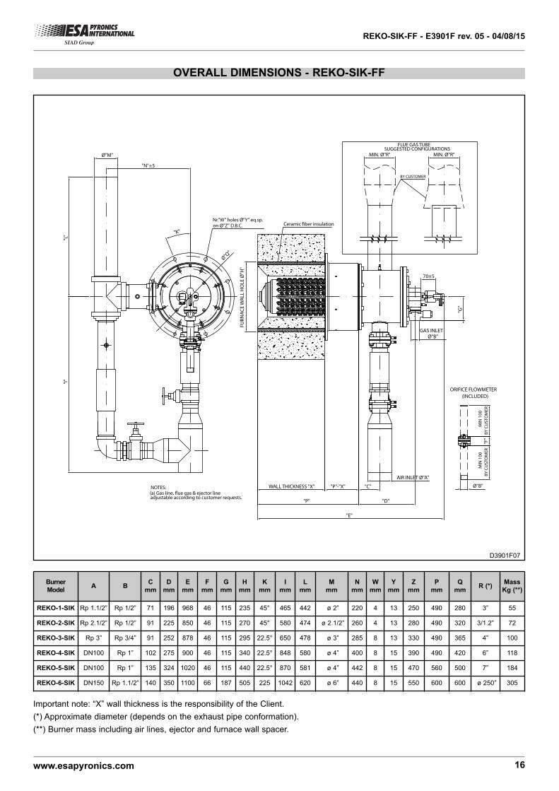
OVERALL DIMENSIONS - REKO-SIK-FF
NOTES:(a) Gas line, !ue gas & ejector lineadjustable according to customer requests.
70±5
"E"
Ceramic $ber insulationØ
"Q"
"G"
AIR INLET Ø"A"
"D"
"C"WALL THICKNESS "X" "P"-"X"
"P"
FU
RN
AC
E W
AL
L H
OL
E Ø
"H"
Nr."W" holes Ø"Y" eq.sp.on Ø"Z" D.B.C.
"K"
"I"
"L"
"N"±5
Ø"M"
BY CUSTOMER
FLUE GAS TUBESUGGESTED CONFIGURATIONS
MIN. Ø"R"MIN. Ø"R"
GAS INLETØ"B"
MIN
10
0
BY
CU
ST
OM
ER
MIN
10
0
BY
CU
ST
OM
ER
"F"
ORIFICE FLOWMETER
(INCLUDED)
Ø"B"
Burner
ModelA B
C
mm
D
mm
E
mm
F
mm
G
mm
H
mm
K
mm
I
mm
L
mm
M
mm
N
mm
W
mm
Y
mm
Z
mm
P
mm
Q
mmR (*)
Mass
Kg (**)
REKO-1-SIK Rp 1.1/2” Rp 1/2” 71 196 968 46 115 235 45° 465 442 ø 2” 220 4 13 250 490 280 3” 55
REKO-2-SIK Rp 2.1/2” Rp 1/2” 91 225 850 46 115 270 45° 580 474 ø 2.1/2” 260 4 13 280 490 320 3/1.2” 72
REKO-3-SIK Rp 3” Rp 3/4” 91 252 878 46 115 295 22.5° 650 478 ø 3” 285 8 13 330 490 365 4” 100
REKO-4-SIK DN100 Rp 1” 102 275 900 46 115 340 22.5° 848 580 ø 4” 400 8 15 390 490 420 6” 118
REKO-5-SIK DN100 Rp 1” 135 324 1020 46 115 440 22.5° 870 581 ø 4” 442 8 15 470 560 500 7” 184
REKO-6-SIK DN150 Rp 1.1/2” 140 350 1100 66 187 505 225 1042 620 ø 6” 440 8 15 550 600 600 ø 250” 305
Important note: “X” wall thickness is the responsibility of the Client.
(*) Approximate diameter (depends on the exhaust pipe conformation).
(**) Burner mass including air lines, ejector and furnace wall spacer.
D3901F07
REKO-SIK-FF - E3901F rev. 05 - 04/08/15
www.esapyronics.com 17
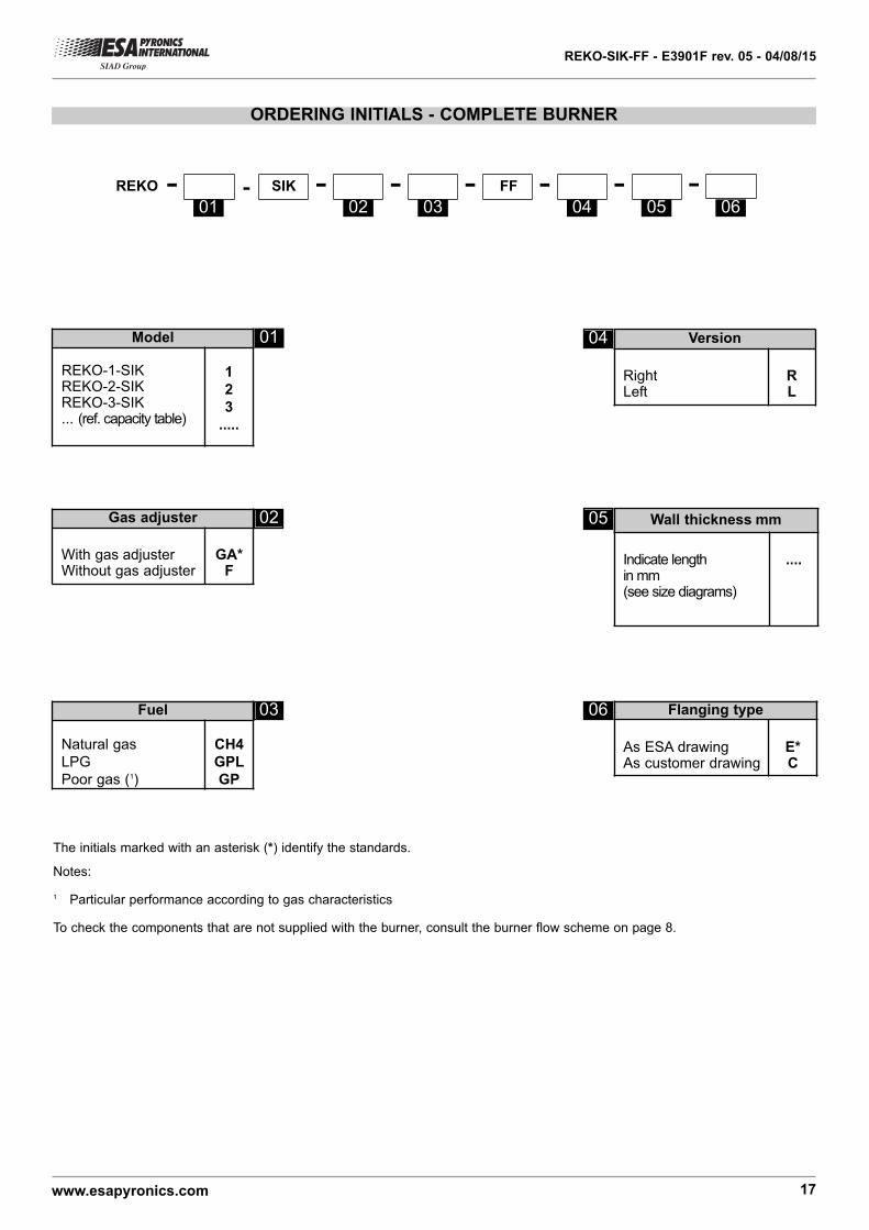
ORDERING INITIALS - COMPLETE BURNER
SIK FF- ---REKO- -- -
The initials marked with an asterisk (*) identify the standards.
Notes:
1 Particular performance according to gas characteristics
To check the components that are not supplied with the burner, consult the burner flow scheme on page 8.
Model
REKO-1-SIKREKO-2-SIKREKO-3-SIK... (ref. capacity table)
1
2
3
.....
Fuel
Natural gas
LPG
Poor gas (1)
CH4
GPL
GP
Gas adjuster
With gas adjusterWithout gas adjuster
GA*F
Version
RightLeft
RL
Flanging type
As ESA drawingAs customer drawing
E*C
Wall thickness mm
Indicate lengthin mm(see size diagrams)
....
01
01 02 03 04 05 06
02
03 06
04
05