eclipse thermjet self-recuperative burners
TRANSCRIPT

Eclipse ThermJetSelf-Recuperative Burners
Models TJSR0020 - TJSR0100
208 Design Guide2/4/2013
Version 5

2
CopyrightCopyright 2010 by Eclipse, Inc. All rights reservedworldwide. This publication is protected by federalregulation and shall not be copied, distributed,transmitted, transcribed or translated into any human orcomputer language, in any form or by any means, to anythird parties, without the express written consent ofEclipse, Inc.
Disclaimer NoticeIn accordance with the manufacturer’s policy of continualproduct improvement, the product presented in thisbrochure is subject to change without notice or obligation.
The material in this manual is believed adequate for theintended use of the product. If the product is used forpurposes other than those specified herein, confirmationof validity and suitability must be obtained. Eclipsewarrants that the product itself does not infringe upon anyUnited States patents. No further warranty is expressed orimplied.
Liability & WarrantyWe have made every effort to make this manual asaccurate and complete as possible. Should you find errorsor omissions, please bring them to our attention so that wemay correct them. In this way we hope to improve ourproduct documentation for the benefit of our customers.Please send your corrections and comments to ourMarketing Communications Manager.
It must be understood that Eclipse’s liability for its product,whether due to breach of warranty, negligence, strictliability, or otherwise is limited to the furnishing ofreplacement parts. Eclipse will not be liable for any otherinjury, loss, damage or expenses, whether direct or
consequential, including but not limited to loss of use,income, or damage to material arising in connection withthe sale, installation, use of, inability to use or the repair orreplacement of Eclipse’s products.
Any operation expressly prohibited in this manual, anyadjustment, or any assembly procedures notrecommended or authorized in these instructions shallvoid the warranty.
Document ConventionsThere are several special symbols in this document. Youmust know their meaning and importance.
The explanation of these symbols follows below. Pleaseread it thoroughly.
How To Get HelpIf you need help, contact your local Eclipse representative.You can also contact Eclipse at:
1665 Elmwood Rd.Rockford, Illinois 61103 U.S.A.Phone: 815-877-3031Fax: 815-877-3336http://www.eclipsenet.com
Please have the information on the product label availablewhen contacting the factory so we may better serve you.
Product NameItem #S/NDD MMM YYYY
www.eclipsenet.com
This is the safety alert symbol. It is used to alert you to potential personalinjurt hazards. Obey all safety messages that follow this symbol to avoidpossible injury or death.
Indicates a hazardous situation which, if not avoided, will result in deathor serious injury.
Indicates a hazardous situation which, if not avoided, could result indeath or serious injury.
Indicates a hazardous situation which, if not avoided, could result inminor or moderate injury.
Is used to address practices not related to personal injury.
Indicates an important part of text. Read thoroughly.NOTENOTICE
CAUTION
WARNING

3Eclipse ThermJet Self-Recuperative, V5, Design Guide 208, 2/4/2013
1 Introduction............................................................................................................................ 4Product Description .............................................................................................................. 4Audience .............................................................................................................................. 4Purpose................................................................................................................................ 4ThermJet Self-Recuperative Documents ............................................................................. 4Related Documents.............................................................................................................. 4
2 Safety...................................................................................................................................... 5Safety Warnings ................................................................................................................... 5Capabilities........................................................................................................................... 5Operator Training ................................................................................................................. 5Replacement Parts............................................................................................................... 5
3 System Design....................................................................................................................... 6Design .................................................................................................................................. 6Step 1: Burner Model Selection............................................................................................ 6Step 2: Control Methodology................................................................................................ 6Step 3: Ignition System ........................................................................................................ 9Step 4: Flame Monitoring Control System............................................................................ 9Step 5: Combustion Air System ........................................................................................... 9Step 6: Main Gas Shut-Off Valve Train ................................................................................ 10
Appendix ................................................................................................................................... iConversion Factors .............................................................................................................. iKey to System Schematics................................................................................................... ii
Table of Contents

4 Eclipse ThermJet Self-Recuperative, V5, Design Guide 208, 2/4/2013
Product DescriptionThe ThermJet Self-Recuperative burner is a nozzle mixburner that is designed to fire an intense stream of hotgases through a combustor. It includes an integralrecuperator and integral eductor to draw exhaust gasesthrough the burner and preheat combustion air. The airrequirements for both the eductor and the burner are metby a single air connection.
The high velocity of the gases improves temperatureuniformity, product quality and system efficiency.
Figure 1.1. Eclipse ThermJetSelf-Recuperative Burner
AudienceThis manual has been written for personnel alreadyfamiliar with all aspects of a nozzle mixing burner and itsadd-on components, also known as “the burner system”.
These aspects are:
• Installation• Use• Maintenance• Safety
The audience is expected to be qualified and haveexperience with this type of equipment and its workingenvironment.
PurposeThe purpose of this manual is to make sure that you carryout the installation of a safe, effective, and trouble-freesystem.
ThermJet Self-Recuperative DocumentsDesign Guide No. 208
• This documentDatasheet No. 208-1 through 208-4
• Available for individual ThermJet Self-Recuperative models
• Required to complete design and selectionInstallation Guide No. 208
• Used with Datasheet to complete installationWorksheet No. 208
• Required to provide application information to Eclipse Engineering
Spare Parts List Series No. 208• Recommended replacement part information
Related Documents• EFE 825 (Combustion Engineering Guide)• Eclipse Bulletins and Info Guides: 610, 710, 720,
730, 742, 744, 760, 930
1Introduction

5
SafetyImportant notices which help provide safe burneroperation will be found in this section. To avoid personalinjury and damage to the property or facility, the followingwarnings must be observed. All involved personnel shouldread this entire manual carefully before attempting to startor operate this system. If any part of the information in thismanual is not understood, contact Eclipse beforecontinuing.
Safety Warnings
■ The burners, described herein, are designed to mixfuel with air and burn the resulting mixture. All fuelburning devices are capable of producing fires andexplosions if improperly applied, installed,adjusted, controlled or maintained.
■ Do not bypass any safety feature; fire or explosioncould result.
■ Never try to light a burner if it shows signs ofdamage or malfunction.
■ The burner and duct sections are likely to haveHOT surfaces. Always wear the appropriateprotective equipment when approaching theburner.
■ Eclipse products are designed to minimize the useof materials that contain crystalline silica.Examples of these chemicals are: respirablecrystalline silica from bricks, cement or othermasonry products and respirable refractoryceramic fibers from insulating blankets, boards, orgaskets. Despite these efforts, dust created bysanding, sawing, grinding, cutting and otherconstruction activities could release crystallinesilica. Crystalline silica is known to cause cancer,and health risks from the exposure to thesechemicals vary depending on the frequency andlength of exposure to these chemicals. To reducethe risk, limit exposure to these chemicals, work ina well-ventilated area and wear approved personalprotective safety equipment for these chemicals.
■ This manual provides information regarding theuse of these burners for their specific designpurpose. Do not deviate from any instructions orapplication limits described herein without writtenapproval from Eclipse.
CapabilitiesOnly qualified personnel, with sufficient mechanicalaptitude and experience with combustion equipment,should adjust, maintain or troubleshoot any mechanical orelectrical part of this system.
Operator TrainingThe best safety precaution is an alert and trainedoperator. Train new operators thoroughly and have themdemonstrate an adequate understanding of theequipment and its operation. A regular retraining scheduleshould be administered to ensure operators maintain ahigh degree of proficiency.
Replacement PartsOrder replacement parts from Eclipse only. All Eclipseapproved valves or switches should carry UL, FM, CSA,CGA and/or CE approval where applicable.
DANGER
WARNING
NOTICE
2
6 Eclipse ThermJet Self-Recuperative, V5, Design Guide 208, 2/4/2013
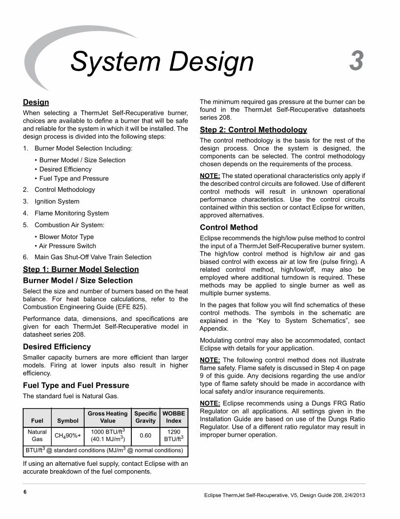
DesignWhen selecting a ThermJet Self-Recuperative burner,choices are available to define a burner that will be safeand reliable for the system in which it will be installed. Thedesign process is divided into the following steps:
1. Burner Model Selection Including:
• Burner Model / Size Selection• Desired Efficiency• Fuel Type and Pressure
2. Control Methodology
3. Ignition System
4. Flame Monitoring System
5. Combustion Air System:
• Blower Motor Type• Air Pressure Switch
6. Main Gas Shut-Off Valve Train Selection
Step 1: Burner Model SelectionBurner Model / Size SelectionSelect the size and number of burners based on the heatbalance. For heat balance calculations, refer to theCombustion Engineering Guide (EFE 825).
Performance data, dimensions, and specifications aregiven for each ThermJet Self-Recuperative model indatasheet series 208.
Desired EfficiencySmaller capacity burners are more efficient than largermodels. Firing at lower inputs also result in higherefficiency.
Fuel Type and Fuel PressureThe standard fuel is Natural Gas.
If using an alternative fuel supply, contact Eclipse with anaccurate breakdown of the fuel components.
The minimum required gas pressure at the burner can befound in the ThermJet Self-Recuperative datasheetsseries 208.
Step 2: Control MethodologyThe control methodology is the basis for the rest of thedesign process. Once the system is designed, thecomponents can be selected. The control methodologychosen depends on the requirements of the process.
NOTE: The stated operational characteristics only apply ifthe described control circuits are followed. Use of differentcontrol methods will result in unknown operationalperformance characteristics. Use the control circuitscontained within this section or contact Eclipse for written,approved alternatives.
Control MethodEclipse recommends the high/low pulse method to controlthe input of a ThermJet Self-Recuperative burner system.The high/low control method is high/low air and gasbiased control with excess air at low fire (pulse firing). Arelated control method, high/low/off, may also beemployed where additional turndown is required. Thesemethods may be applied to single burner as well asmultiple burner systems.
In the pages that follow you will find schematics of thesecontrol methods. The symbols in the schematic areexplained in the “Key to System Schematics”, seeAppendix.
Modulating control may also be accommodated, contactEclipse with details for your application.
NOTE: The following control method does not illustrateflame safety. Flame safety is discussed in Step 4 on page9 of this guide. Any decisions regarding the use and/ortype of flame safety should be made in accordance withlocal safety and/or insurance requirements.
NOTE: Eclipse recommends using a Dungs FRG RatioRegulator on all applications. All settings given in theInstallation Guide are based on use of the Dungs RatioRegulator. Use of a different ratio regulator may result inimproper burner operation.
Fuel SymbolGross Heating
ValueSpecific Gravity
WOBBE Index
Natural Gas CH490%+ 1000 BTU/ft3
(40.1 MJ/m3) 0.60 1290 BTU/ft3
BTU/ft3 @ standard conditions (MJ/m3 @ normal conditions)
3System Design

7Eclipse ThermJet Self-Recuperative, V5, Design Guide 208, 2/4/2013
High/Low ControlThe firing rate is adjusted at two positions, the high andlow fire set points. The burner remains on during the fullprocess cycle. When the system is set to high/low control:
1. Manual butterfly valve sets high fire air flow rate.
2. Solenoid valve opens for high fire air flow and closesfor low fire air flow.
3. Manual butterfly valve sets low fire bypass air flow.
4. Manual butterfly valve balances the air flow for burner(multiple burner installation).
5. Ratio regulator adjusts gas flow as loading linepressure changes due to air pressure changes.
6. Manual butterfly valve sets high fire gas flow.
Figure 3.1 High/Low Control
High/Low Control(single burner)
High/Low Control(multiple burners, shut-off by zone)
Main GasShut-Off
Valve Train
Main GasShut-Off
Valve Train
Main GasShut-Off
Valve Train
��
��
�
��
��
�
�
�
�
�
� �
�
To IndividualBurner Piping
High/Low Control(multiple burners, shut-off by burner)
To OtherZones
To OtherZones
To OtherZones
To OtherZones

8 Eclipse ThermJet Self-Recuperative, V5, Design Guide 208, 2/4/2013
High/Low/Off ControlThe firing rate is set to two positions, the high and low fireset points, or the burner is shut off. The off state is usedwhen the low fire rate causes the process temperature tocontinue to rise. The setup is the same as high/lowcontrol, but the solenoid is used not only as a flame safetymechanism, but also for temperature control. When thesystem is set to high/low/off control:
1. Manual butterfly valve sets high fire air flow rate.
2. Solenoid valve opens for high fire air flow and closesfor low fire air flow.
3. Manual butterfly valve sets low fire bypass air flow.
4. Manual butterfly valve balances the air flow for burner(multiple burner installations).
5. Ratio regulator adjusts gas flow as loading linepressure changes due to air pressure changes.
6. Solenoid valve closes if low fire temperature is toohigh.
7. Manual butterfly valve sets high fire gas flow.
Figure 3.2 High/Low/Off Control
High/Low/Off Control(single burner)
High/Low/Off Control(multiple burners, shut-off by zone)
High/Low/Off Control(Multiple burners, shut-off by burner)
Main GasShut-Off
Valve Train
Main GasShut-Off
Valve Train
Main GasShut-Off
Valve Train
To IndividualBurner Piping
���
��
� �
�� �
��
�
�
�� �
� �
��
To OtherZones
To OtherZones
To OtherZones
To OtherZones

9Eclipse ThermJet Self-Recuperative, V5, Design Guide 208, 2/4/2013
Step 3: Ignition SystemIgnition TransformerFor the ignition system, use a transformer with:
• 6000 VAC transformer• full-wave spark• one transformer per burner
DO NOT USE the following:
• 10000 VAC transformer• twin outlet transformer• distributor type transformer• half-wave transformer
Eclipse recommends a low fire start be used. However,ThermJet Self-Recuperative burners are capable of directspark ignition anywhere within the operating range. Seethe Installation Guide for detailed start information.
NOTE: You must follow the control circuits described inthe previous section, “Control Methodology”, to obtainreliable ignition.
Local safety and insurance require limits on the maximumtrail for ignition time. These time limits vary from countryto country.
The time it takes for a burner to ignite depends on:
• the distance between the gas shut-off valve and the burner
• the air/gas ratio• the gas flow at start conditions
It is possible to have the low fire too low to ignite within thetrail for ignition period. Under these circumstances youmust consider the following options:
• start at higher input levels• resize and/or relocate the gas controls• use bypass start gas
Step 4: Flame Monitoring Control SystemThe flame monitoring control system consists of two maincomponents:
• flame sensor• flame monitoring control
Flame SensorUV Scanners can be used on ThermJet Self-Recuperativeburners.
The UV scanner must be compatible to the flamemonitoring control that is used. Refer to the manual ofyour selected control for proper selection of the scanner.
Flame Monitoring ControlThe flame monitoring control processes the signal fromthe flame sensor and controls the start-up and shut-downsequences.
Eclipse recommends the following flame monitoringcontrols:
• Trilogy series T400 (Instruction Manual 830)• Veri-Flame series 5600 (Instruction Manual 818)• Bi-Flame series 6500 (Instruction Manual 826)• Multi-Flame series 6000 (Instruction Manual 820)
If other controls are considered, contact Eclipse todetermine how burner performance may be affected.Flame monitoring controls that have lower sensitivityflame detecting circuits may limit burner turndown andchange the requirements for ignition.
Flame monitoring controls that stop the spark as soon asa signal is detected may prevent establishment of flame,particularly when using UV scanners. The flamemonitoring control must maintain the spark for a fixed timeinterval that is long enough for ignition.
Step 5: Combustion Air SystemBlower Motor TypeEffects of Atmospheric Conditions
The blower data is based on the International StandardAtmosphere (ISA) at Mean Sea Level (MSL), whichmeans that it is valid for:
• sea level• 29.92" Hg (1013 mbar)• 70°F (21°C)
The makeup of the air is different above sea level or in ahot environment. The density of the air decreases, and asa result, the outlet pressure and the flow of the blowerdecrease. An accurate description of these effects is in theEclipse Combustion Engineering Guide (EFE 825). Theguide contains tables to calculate the effect of pressure,altitude and temperature on air.
Blower
The rating of the blower must match the systemrequirements. You can find all the blower data in Bulletin/Info Guide 610.
1. Calculate the Outlet Pressure
When calculating the required outlet pressure of theblower, the total of these pressures must be calculated.
• the static air pressure required at the burner• the total pressure drop in the piping• the total of the pressure drops across the valves• a minimum safety margin of 10%

10 Eclipse ThermJet Self-Recuperative, V5, Design Guide 208, 2/4/2013
2. Calculate the Blower Air Volume
The volume of air required will be dictated by themaximum output required from the burner. This will bethe total of the air required for combustion plus the airrequired for the eductor. The totals required areshown on the appropriate datasheet. Multiply thisvolume by the number of burners and this is the totalvolume needed.
NOTE: A minimum of 10% safety margin should be addedto the blower capacity.
ExhaustThe eductor provided with the TJSR is capable of pullingall the exhaust gas through the burner and when set upcorrectly will give approximately neutral pressure in thefurnace chamber. Using this method it is not possible touse furnace pressure control.
An alternative method, where more precise furnacepressure control is required, is to pull only 90% of theexhaust gases through the burner. The remaining 10% ofexhaust gas would exit through an auxiliary flue withfurnace pressure control.
The furnace pressure should not be too high; a positivepressure will force a disproportionate amount of exhaustgases through burners that are in the off or low fire mode.
Exhaust ducting should not be connected directly to theeductor outlet. It’s recommended that the exhaust duct orcowl be at least 2" larger in diameter than the eductoroutlet. There should be at least a 2" vertical air gap.
Air Pressure SwitchThe air pressure switch gives a signal to the monitoringsystem when there is not enough air pressure from theblower.
You can find more information on pressure switches inBlower Bulletin 610.
■ Eclipse supports NFPA regulations, which requirethe use of an air pressure switch in conjunctionwith other safety components, as a minimumstandard for main gas safety shutoff systems.
Step 6: Main Gas Shut-Off Valve TrainConsult EclipseEclipse can help you design and obtain a main gas shut-off valve train that complies with the current safetystandards.
The shut-off valve train must comply with all the localsafety standards set by the authorities that havejurisdiction.
For details, please contact your local Eclipserepresentative or Eclipse.
NOTE: Eclipse supports NFPA regulations (two shut-offvalves) as a minimum standard for main gas safety shut-off systems.
WARNING

i
Conversion Factors
Metric to English
Metric to Metric
English to Metric
From To Multiply Byactual cubic meter/h (am³/h) actual cubic foot/h (acfh) 35.31normal cubic meter/h (Nm³/h) standard cubic foot /h (scfh) 38.04
degrees Celsius (°C) degrees Fahrenheit (°F) (°C x 9/5) + 32kilogram (kg) pound (lb) 2.205kilowatt (kW) Btu/h 3415
meter (m) foot (ft) 3.281millibar (mbar) inches water column ("w.c.) 0.402millibar (mbar) pounds/sq in (psi) 14.5 x 10⁻³
millimeter (mm) inch (in) 3.94 x 10⁻²
MJ/Nm³ Btu/ft³ (standard) 26.86
From To Multiply BykiloPascals (kPa) millibar (mbar) 10
meter (m) millimeter (mm) 1000millibar (mbar) kiloPascals (kPa) 0.1millimeter (mm) meter (m) 0.001
From To Multiply By
actual cubic foot/h (acfh) actual cubic meter/h (am³/h) 2.832 x 10⁻²
standard cubic foot /h (scfh) normal cubic meter/h (Nm³/h) 2.629 x 10⁻²
degrees Fahrenheit (°F) degrees Celsius (°C) (°F - 32) x 5/9pound (lb) kilogram (kg) 0.454
Btu/h kilowatt (kW) 0.293 x 10⁻³
foot (ft) meter (m) 0.3048inches water column ("w.c.) millibar (mbar) 2.489
pounds/sq in (psi) millibar (mbar) 68.95inch (in) millimeter (mm) 25.4
Btu/ft³ (standard) MJ/Nm³ 37.2 x 10⁻³
Appendix

ii
Symbol Appearance Name Remarks Bulletin/Info Guide
Gas Cock Gas cocks are used to manually shut off the gas supply. 710
Ratio Regulator
A ratio regulator is used to control the air/gas ratio. The ratio regulator is a sealed unit that adjusts the gas pressure in ratio with the air presssure. To do this, it measures the air pressure with a pressure sensing line, the impulse line. This impulse line is connected between the top of the ratio regulator and the burner body.
742
Main Gas Shut-Off Valve Train
Eclipse strongly endorses NFPA as a minimum. 790/791
Pilot Gas Valve Train Eclipse strongly endorses NFPA as a minimum. 790/791
Automatic Shut-OffValve
Shut-off valves are used to automatically shut off the gas supply on a gas system or a burner.
760
Orifice Meter Orifice meters are used to measure flow. 930
Combustion Air Blower The combustion air blower provides the combustion air to the burner(s). 610
Main GasShut-Off
ValveTrain
Pilot GasShut-Off
Valve Train
System Schematics

iii
Hermetic Booster Booster is used to increase gas pressure. 620
Automatic Butterfly Valve Automatic butterfly valves are typically used to set the output of the system. 720
Manual Butterfly Valve Manual butterfly valve are used to balance the air or gas flow at each burner. 720
Adjustable Limiting Orifice
Adjustable limiting orifices are used for fine adjustment of gas flow. 728/730
Pressure Switch
A switch activated by rise or fall in pressure. A manual reset version requires pushing a button to transfer the contacts when the pressure set point is satisfied.
840
Pressure Gauge A device to indicate pressure. 940
Check ValveA check valve permits flow only in one direction and is used to prevent back flow of gas.
780
Strainer A strainer traps sediment to prevent blockage of sensitive components downstream.
Flexible Connector Flexible connectors isolate components from vibration, mechanical, and thermal stresses.
Heat Exchanger Heat exchangers transfer heat from one medium to another. 500
Pressure Taps Pressure taps measure static pressure.
Symbol Appearance Name Remarks Bulletin/Info Guide

iv
Notes

iii
Notes

Design Guide 208, 2/4/2013