eclipse-it 2013: proceedings of viii workshop of the italian eclipse community: crema, september...
TRANSCRIPT
Eclipse-IT 2013VIII Workshop of the Italian Eclipse Community
Crema, September 19-20 2013
Elvinia Riccobene (ed.)

Elvinia Riccobene (ed.)
Eclipse-IT 2013 VIII Italian Workshop on Eclipse Technologies
Crema, September 19-20, 2013
Università degli Studi di Milano
Eclipse Italian Community
http://eclipse.dis.unina.it/
Conference web site:
http://2013.eclipse-it.org/
September 2013
ISBN: 978-88-904388-4-4

ii
Preface
This volume contains the extended abstracts of the contributions presented at
EclipseIT 2013, the 8th workshop of the Italian Eclipse Community, hosted by the
Computer Science Department of the University of Milan (Crema Campus) on
September 19-20, 2013.
Previous editions took place is Rome (2006), Naples (2007), Bari (2008),
Bergamo (2009), Savona (2010), Milan (2011), and Pozzuoli (2012).
Although Eclipse was initially designed as an integrated development
environment (IDE) for object-oriented application development, today it represents
an open development platform comprised of extensible frameworks, tools and
runtimes for building, deploying and managing software.
Around Eclipse, an international live community continuously works on
improving the framework and on promoting the use of Eclipse. That happens also in
Italy. This workshop is, indeed, the eighth yearly meeting of the Italian Eclipse
Community which includes universities, public institutions and industries,
researchers and practitioners, students and professionals, all joined by the interest in
experimenting, extending, and supporting the Eclipse platform.
The special topic of this edition is the Software cooperative development for
mobile applications. Two tutorials are offered on this theme: (1) Sviluppo di
applicazioni enterprise per il mobile con IBM Jazz, Eclipse e Worklight by
Ferdinando Gorga from IBM, and (2) Uso di Eclipse per lo sviluppo cooperativo del
software, by Paolo Maresca of the University of Naple, Federico II.
We received six contributions from universities, five from industries, some in
collaboration with the academy, and six projects were submitted by students who
participate to the selection of the best student project awarded by Seen Solution.
The conference program included also Ralph Muller, Director Eco Systems
Europe of the Eclipse Foundation, as keynote speaker. He talks about new and
existing things at Eclipse. This year, a live streaming of the workshop is available to

iii
give the opportunity to a large number of students and professionals to follow the
event at a distance.
A further novelty of the current edition is a panel on the theme Professional
skills of ICT professions in Italy on the basis of the European eCompetence
Framework (e-CF), organized by Domenico Squillace, IBM Italy.
This year, the conference received the patronage of ANORC, the official
Italian digital storage responsible association.
Many people contributed to the organization and realization of this workshop. I
would like to thank all the participants who contributed to the success of a new
edition of EclipseIT. I thank the members of the Program Committee for their
evaluable suggestions and the entire Eclipse Italian Community chaired by Paolo
Maresca who gave a special contribution for supporting this workshop. I thank
Domenico Squillace, who makes possible the realization of a panel on a theme that is
extremely important today both for the industry and for the academy. I am grateful
for their invaluable work to Paolo Arcaini who chaired the student track, Davide
Rebeccani for the technical support, and Claudia Piana for her administrative help. I
am thankful to the sponsors of this event, IBM Italy with Carla Milani, the
Department of Computer Science of the University of Milan, the Eclipse Foundation,
and Seen Solution. Finally, a special immeasurable thank to Angelo Gargantini who
helped me in organizing this year workshop and preparing this volume.
Crema, September 2013
Elvinia Riccobene

iv
Conference Chair
Elvinia Riccobene, Università degli Studi di Milano, Italy
Industry track Chair
Domenico Squillace, IBM, Italy
Program Committee
Francesca Arcelli, Università di Milano Bicocca, Italy
Mauro Coccoli, Università di Genova, Italy
Andrea De Lucia, Università di Salerno, Italy
Giovanni Denaro, Università di Milano Bicocca, Italy
Giacomo Franco, IBM, Italy
Angelo Gargantini, Università di Bergamo, Italy
Ferdinando Gorga, IBM, Italy
Paolo Maresca, Università di Napoli Federico II, Italy
Antonio Natali, Università di Bologna, Italy
Patrizia Scandurra, Università di Bergamo, Italy
Lidia Stanganelli, Università di Napoli, Italy
Gianni Vercelli, Università di Genova, Italy
Student track Chair
Paolo Arcaini, CNR IDPA Dalmine, Italy
Technical support
Davide Rebeccani. Università degli Studi di Milano, Italy

v
Sponsors
Università degli Studi di Milano
IBM
Seen Solution
Patronage
ANORC

vi
Sommario
Research track
Lorenzo Bettini, Vincenzo Caselli, Francesco Guidieri
Parsley for your EMF Applications ................................................................................. 1
Marco Anisetti, Claudio A. Ardagna, Ernesto Damiani, Federico Giuba
A Java-Based Certification Framework for Service Composition ................................... 3
Gabriele Bavota, Andrea De Lucia, Andrian Marcus, Rocco Oliveto, Fabio Palomba,
Michele Tufano
ARIES: An Eclipse plug-in to Support Extract Class Refactoring .................................. 6
Steven Capelli, Andrea Ghetti, Davide Mora, Simone Mutti
An Eclipse framework to ease notification among MyUniBG apps ................................ 8
Andrea Dal Passo, Eros Pedrini
Eclipse in a Modern Mobile Development Toolchain ................................................... 13
Rosario Madaudo, Patrizia Scandurra
Native versus Cross-platform frameworks for mobile application development .......... 15
Paolo Maresca, Angela Guercio, Lidia Stanganelli
Misura della cooperazione per lo sviluppo su piattaforma eclipse: lo studio del caso
di collaborazione fra le università Federico II e Ohio state University at Stark ......... 19
Antonio Natali, Sam Golovchenko
Custom environments for event-driven I/O ................................................................... 22
Student track
Claudio A. Ardagna, Ernesto Damiani, Kouessi A.R. Sagbo
STS2Java: An Eclipse Plugin for Early Assessment of Service Performance Based on
Simulation ...................................................................................................................... 24
Mario Bolignano
"Il tesoro di Crema": a QR Code Web Treasure Hunt powered by Eclipse ................. 26
Antonio Esposito
Knowledge Hound: Progetto di un social network orientato allo scambio della
conoscenza ..................................................................................................................... 28
vii
Mauro Fustinoni
Utilizzo di GWT per la Generazione di un Editor di Metadati di Mappe di Suscettività
......................................................................................................................................... 30
Gianluca Vaccaro
Plaze .............................................................................................................................. 32
Paolo Vavassori, Paolo Arcaini, Angelo Gargantini
NuSeen: an eclipse-based environment for the NuSMV model checker ......................... 34

1
Parsley for your EMF Applications(Extended Abstract)
Lorenzo BettiniDipartimento di Informatica,
Università di Torino, [email protected]
Vincenzo CaselliRCP Vision
Francesco GuidieriRCP Vision
EMF, together with JFace, databinding and persistence imple-
mentations, simplifies the development of complex software appli-
cations with its modeling mechanisms. However, setting up and
assembling all these technologies still requires both deep knowl-
edge of most internal details and a considerable amount of time;
the development of applications based on EMF could be made sim-
pler, with more code reuse, and without having to deal with too
many internal details.
In this talk we present EMF Parsley, a framework that has been
recently approved as an Eclipse project. It is based on the previous
experimental framework EMF Components [4].
EMF Parsley provides a framework to easily develop UI com-
ponents based on EMF models. The framework hides most of the
complexity of internal details: creating a JFace viewer and connect-
ing it to an EMF resource, usually requires a few lines of code. The
main design principle underlying this framework is to split respon-
sibilities into small classes (adhering to the Single Responsibility
Principle [9]); thus, customizing a single aspect of the components
requires to specialize only the class that deals with that specific as-
pect, not the whole component. This should maximize code reuse
and promote a programming style where the classes implemented
by the programmer are usually very small and deal with not too
many aspects.
The framework also comes with some UI components that can
be used out-of-the-box (including trees, tables and forms, and view
and editor parts). Programmers can rely on these components and
customize them, or use them as a reference implementation to build
their own components based on our framework.
To customize existing components we rely on Dependency Injec-
tion [7], in particular using Google Guice. The configuration and
setup of Guice modules uses the same mechanism of Xtext (i.e.,
binding an implementation class only requires to write a specific
"bind" method in the main Guice module class). The initial setup
of a project which uses EMF Parsley is done via a project wizard,
so that the programmer does not have to deal with these details.
Specification of custom behaviors (e.g., label providers, content
providers, context menus, etc.) is based on the types of elements
of the EMF model, but without requiring long cascades of Java
“instanceof” and casts: we provide a polymorphic method dispatch
mechanism (borrowed from Xtext) that allows to write cleaner and
declarative code.
We also provide a DSL (implemented in Xtext [3, 5]) for making
the use of our framework easier: customizations can be specified in
a compact form in a single file. The DSL compiler will automat-
ically generate all the Java classes and the corresponding Guice
module bindings. The DSL provides a fully feature Eclipse edi-
tor and, by relying on Xbase [6], it provides a Java-like language
completely integrated with Java and Eclipse JDT.
Setting up views (like in Figure 1) only requires a few lines of
Java code. Using the DSL (like in Figure 2) the customization of
the components is really quick (the corresponding Java code will
be automatically generated by the DSL compiler).
Concerning the persistence aspect, the framework can handle a
generic EMF persistence implementation, like XMI or Teneo, just
providing the EMF Resource’s URIs. It also includes a bundle for
handling CDO resources, which takes care of CDO sessions and
transactions transparently.
All sources are covered by tests, both unit tests (with JUnit) and
functional tests (with SWTBot). Tests are already integrated in the
Continuous Integration system implemented with Jenkins.
Also the building and update site architecture is already setup
and implemented with Buckminster [8]. This building tool is heav-
ily used throughout the whole development cycle, starting from the
workspace and platformmaterialization up to headless building and
continuous integration.
In addition to be used to render RCP UI, the framework is out-
of-the-box ready to be used for RAP development (Remote Appli-
cation Platform [2]). By using single sourcing techniques, it is easy
to develop an RCP application with EMF Parsley and to automati-
cally have a web version (based on RAP) of the same application.
EMF Parsley can also be used with the new Eclipse e4 platform.
The framework that is closer to our proposal is EMF Client Plat-
form [1]. However, while the latter aims at providing a quick way
of obtaining a full application based on EMF, EMF Parsley aims
at providing single smaller and reusable components. Moreover,
our components are not customized via extension points, but using
injection with plain Java and with a DSL.
The framework presented here is available at
http://www.eclipse.org/emf-parsley.
1. REFERENCES[1] EMF Client Platform. http://www.eclipse.org/emfclient.
[2] RAP, Remote Application Platform. http://eclipse.org/rap.
[3] Xtext. http://www.eclipse.org/Xtext.
[4] L. Bettini. EMF Components - Filling the Gap between Models and UI. In
ICSOFT 2012 - Proceedings of the 7th International Conference on Software
Paradigm Trends, pages 34–43. SciTePress, 2012.
[5] L. Bettini. Implementing Domain-Specific Languages with Xtext and Xtend.
Packt Publishing, 2013.
[6] S. Efftinge, M. Eysholdt, J. Köhnlein, S. Zarnekow, R. von Massow,
W. Hasselbring, and M. Hanus. Xbase: Implementing Domain-Specific
Languages for Java. In GPCE, pages 112–121. ACM, 2012.
[7] M. Fowler. Inversion of Control Containers and the Dependency Injection
pattern. http://www.martinfowler.com/articles/injection.html, Jan.2004.
[8] H. Lindberg and T. Hallgren. Eclipse Buckminster, The Definitive Guide. 2009.
[9] R. Martin. Agile Software Development: Principles, Patterns, and Practices.
Prentice Hall, 2003.

2
Figure 1: A Mail RCP Example implemented with EMF Parsley.
Figure 2: Using the EMF Parsley DSL for customizations.

3
A Java-Based Certi cation Framework forService Compositions
Marco Anisetti, Claudio A. Ardagna,Ernesto Damiani
Dipartimento di InformaticaUniversità degli Studi di Milano
Crema (CR), 26013, [email protected]
Federico Giuba
Università degli Studi di MilanoCrema (CR), 26013, Italy
ABSTRACT
The evaluation of security properties of web services is a keyproblem, especially when business processes are dynamical-ly built by composing atomic services provided by di erentsuppliers at runtime. In this paper we present a Java-basedframework for the security certi cation of BPEL-based com-positions of web services. The framework is grounded on thetest-based service certi cation scheme proposed in the con-text of the ASSERT4SOA Project (http://www.assert4soa.eu/) and permits to virtually certify a BPEL-based compo-site service for a set of security properties, starting fromcerti cates awarded to the component services.
1. INTRODUCTION
The success of web services is deeply changing the design,development, and distribution of software. Today, businessprocesses are often implemented through a dynamic com-position of web services available over the Internet. In acontext where web services are continuously (re-)designedand released, an accurate and robust evaluation of compo-site service security becomes a fundamental challenge. Theuse of assurance solutions based on certi cation to evaluatesoftware security has recently received considerable atten-tion [4], but most of the available solutions have not conside-red the certi cation of composite services or are not suitablefor dynamic run-time compositions.Recently, Anisetti et al. [1] have proposed a test-based
security certi cation scheme for BPEL-based composite ser-vices, where the basic idea is to produce a virtual securitycerti cate for compositions on the basis of the certi cates ofcomponent services. Here, the term “virtual” refers to thefact that the test evidence in the certi cate proving a givensecurity property for the composition is inferred by the cer-ti cation authority, with no real testing activities. In thispaper we describe a Java-based framework (developed usingEclipse IDE) implementing the approach in [1] and presenta preliminary performance analysis.
2. BPEL SECURITY CERTIFICATION FRA-
MEWORK
Our certi cation approach models a BPEL process as aBPEL graph in which each web service invocation is repre-sented as a vertex. Service invocations are connected to-gether following di erent compositional pattern: sequence,alternative, or parallel. An annotated BPEL graph extends
a BPEL graph with a labeling function, which annotatesevery vertex representing an invoke operation with functio-nal and security requirements. Given an annotated BPELgraph, a BPEL instance graph is de ned, where every ver-tex representing an invoke operation is instantiated with areal service such that the following conditions hold: i) theservice satis es the functional requirements and ii) its certi-cate satis es security requirements in the annotations. Our
BPEL security certi cation framework receives as input anannotated BPEL graph and a set of candidate services withthe corresponding security certi cates (following the certi-cation scheme described in [1]), selects the best subset of
services satisfying the BPEL security annotations (BPELinstance graph), and generates the virtual security certi ca-te for the BPEL instance graph as output. Figure 2 showsan architectural overview of the BPEL security certi cationframework.
Figure 1: Architectural overview of the BPEL
security certi cation framework
The BPEL instance graph is generated adopting a four-step selection process as follows: i) UDDI Search, for eachinvoke operation in the annotated BPEL graph the frameworkperforms an UDDI inquiry obtaining a set of candidate ser-vices that satisfy functional requirements; ii) Security Requi-rements Matching Process, the security certi cates of everycandidate service selected at step i) are matched with se-curity requirements de ned in the annotated BPEL graph;iii) Comparison Process, candidates returned at step ii) areranked on the basis of their security properties; iv) BPELinstantiation, the rst candidate service in the ranked list ofstep iii) is associated to the BPEL instance graph invocationas a partner link. As soon as the BPEL instance graph isgenerated, a Virtual Certi cation Process is triggered. Thisprocess evaluates i) the security certi cates of the candidateservices belonging to the BPEL instance graph and ii) thecompositional pattern de ned by the BPEL graph. It thengenerates the virtual certi cate for the BPEL instance. Inthe following we describe our components in detail.

4
Figure 2: An example of matching
2.1 UDDI ComponentFor each invoke in the annotated BPEL, a set of services
compatible with the functional annotations are selected. Inparticular, this selection is implemented via inquiring a UD-DI registry (method findCandidates() of class BpelGraph).Our framework integrates the Apache jUDDI-client [3], ba-sed on UDDI v3 API, that allows to connect to every UDDIv3 compliant registry. The functional service search is per-formed using tModels [5] in the UDDI structure. Searchingfor services compatible with a speci c tModel, we obtaina set of endpoints identifying partner link candidates thatsatisfy functional requirements.
2.2 Matching Process ComponentIt receives as input, from the UDDI Component, a set
of web services compatible with the functional requiremen-ts expressed for each invocation in the annotated BPEL.This component implements the matching algorithm (me-thod matchCandidates()) described in [2] allowing to select,between the functional compatible services, those candidateservices that satisfy the security requirements expressed inthe annotated BPEL. Figure 2.2 shows an example of mat-ching process between information stored in a certi cate andthe requirements expressed in the annotation.
2.3 Comparison Process ComponentIt receives as input, from the Matching Process Compo-
nent, a set of functional and security compatible candidateservices for every BPEL invocation. This component im-plements the comparison algorithm described in [2], rankingcandidate services based on their security certi cates. Thiscomponent exposes method compareCandidates() that re-ceives as input a set of partner link candidates and sortsthem out on the basis of their certi cates, according to the“property rst” approach described in [2].
2.4 Virtual Certi cation ComponentIt receives as input a BPEL instance graph and produces
as output a virtual certi cate for it. To this aim, it ite-ratively composes pairs of (virtual) certi cates Ci and Cj ,according to their compositional pattern, to generate a vir-tual certi cate for the composition. The process is repeateduntil the BPEL instance graph is reduced to a graph ha-ving a single vertex v with virtual certi cate Cij . Giventwo certi cates Ci and Cj , a virtual certi cate Cij is gene-rated including a security property, a model of the service,and the evidence supporting the security property. At the
Figure 3: An example of service composition. First,the details about the BPEL graph are shown; then,service certi cates to be composed are listed; nally,the virtual certi cate is presented
Table 1: Performance analysis.Number of candidate Ad-hoc rules Executionservices per invoke times (s)
10 20 1.28s50 20 1.90s200 20 3.78s10 100 5.55s50 100 6.05s200 100 7.76s
current stage our framework supports a virtual certi catecomposition process working at security property level on-ly.1 In particular, a virtual property can be generated eitherby applying a set of ad-hoc rules de ned by experts, whichspeci es if and how a virtual security property can be ge-nerated from the composition of two di erent security pro-perties, or with a default rule, which considers relationshipsamong properties de ned in a property hierarchy. Figure 2.4shows a composition of a pair of certi cates in parallel.
3. PERFORMANCE ANALYSISPerformance analysis has been executed on a workstation
equipped with Intel Core i5-2500K 3.30GHz, 8 GB of RAM,128 GB of SSD, running Windows 7 64-bit and Java 1.7.0-21,and has considered a BPEL process with 6 invoke elements.
Table 1 shows a detailed performance evaluation by in-creasing the number of candidate services per invoke andthe number of ad-hoc rules to be evaluated for the genera-tion of the virtual security property. Our results show thatthe time needed for a runtime generation of a virtual cer-ti cate is reasonable and is 7.76s in the worst-case scenariowith 100 ad-hoc rules and 200 candidate services for eachinvocation.
1We leave the support for virtual models and evidence toour future work.

5
4. CONCLUSIONS
We presented a Java-based framework (developed usingEclipse IDE) for the security certi cation of BPEL-basedcompositions. The proposed framework generates a virtualtest-based certi cate for a composite service, which consistsof a virtual security property, starting from the certi catesof the component services. Our future work will considerthe implementation of an extended framework providing asolution for the generation of complete virtual certi cates.
5. REFERENCES
[1] M. Anisetti, C. A. Ardagna, E. Damiani, andJ. Maggesi. Security certi cation-aware service
discovery and selection. In Proc. of ICWS 2013, 2013.
[2] M. Anisetti, C. A. Ardagna, E. Damiani, andF. Saonara. A test-based security certi cation schemefor web services. ACM Trans. Web, 7(2):5:1–5:41, May2013.
[3] APACHE. juddi apache project - o cial site.http://juddi.apache.org/.
[4] E. Damiani, C. Ardagna, and N. E. Ioini. Open source
systems security certi cation. Springer, New York, NY,USA, 2009.
[5] OASIS. Uddi version 3.0.2.https://www.oasis-open.org/committees/uddi-spec/doc/spec/v3/uddi-v3.0.2-20041019.htm.

6
ARIES: An Eclipse plug-in to SupportExtract Class Refactoring
Gabriele BavotaUniversity of Sannio
Andrea De LuciaUniversity of Salerno
Andrian MarcusWayne State University
Rocco OlivetoUniversity of Molise
Fabio PalombaUniversity of Salerno
Michele TufanoUniversity of Salerno
ABSTRACT
During Object-Oriented development, developers try to de-fine classes having (i) strongly related responsibilities, i.e.,high cohesion, and (ii) limited number of dependencies withother classes, i.e., low coupling [1]. Unfortunately, due tostrict deadlines, programmers do not always have sufficienttime to make sure that the resulting source code conformsto such a development laws [8].
In particular, during software evolution the internal struc-ture of the system undergoes continuous modifications thatmakes the source code more complex and drifts away fromits original design. Classes grow rapidly because program-mers often add a responsibility to a class thinking that itis not required to include it in a separate class. However,when the added responsibility grows and breeds, the classbecomes too complex and its quality deteriorates [8]. A classhaving more than one responsibility has generally low cohe-sion and high coupling. Several empirical studies providedevidence that high levels of coupling and lack of cohesionare generally associated with lower productivity, greater re-work, and more significant design efforts for developers [6],[10], [11], [12], [13]. In addition, classes with lower cohesionand/or higher coupling have been shown to correlate withhigher defect rates [9], [14], [15].
Classes with unrelated methods often need to be restruc-tured by distributing some of their responsibilities to newclasses, thus reducing their complexity and improving theircohesion. The research domain that addresses this problemis referred to as refactoring [8]. In particular, Extract ClassRefactoring allows to split classes with many responsibilitiesinto different classes. Moreover, it is a widely used techniqueto address the Blob antipattern [8], namely a large and com-plex class, with generally low cohesion, that centralize thebehavior of a portion of a system and only use other classesas data holders. It is worth noting that performing ExtractClass Refactoring operations manually might be very diffi-cult, due to the high complexity of some Blobs. For thisreason, several approaches and tools have been proposedto support this kind of refactoring. Bavota et. al [2] pro-posed an approach based on graph theory that is able to splita class with low cohesion into two classes having a highercohesion, using a MaxFlow-MinCut algorithm. An impor-tant limitation of this approach is that often classes need tobe split in more than two classes. Such a problem can bemitigated using partitioning or hierarchical clustering algo-rithms. However, such algorithms suffer of important lim-
itations as well. The former requires as input the numberof clusters, i.e., the number of classes to be extracted, whilethe latter requires the definition of a threshold to cut thedendogram. Unfortunately, no heuristics have been derivedto suggest good default values for all these parameters. In-deed, in the tool JDeodorant [7], which uses a hierarchicalclustering algorithm to support Extract Class Refactoring,the authors tried to mitigate such an issue by proposing dif-ferent refactoring opportunities that can be obtained usingvarious thresholds to cut the dendogram. However, suchan approach requires an additional effort by the softwareengineer who has to analyze different solutions in order toidentify the one that provides the most adequate division ofresponsibilities.We tried to mitigated such deficiencies by defining an
approach able to suggest a suitable decomposition of theoriginal class by also identifying the appropriate number ofclasses to extract [3, 4]. Given a class to be refactored, theapproach calculates a measure of cohesion between all thepossible pairs of methods in the class. Such a measure cap-tures relationships between methods that impact class cohe-sion (e.g., attribute references, method calls, and semanticcontent). Then, a weighted graph is built where each noderepresents a method and the weight of an edge that connectstwo nodes is given by the cohesion of the two methods. Thehigher the cohesion between two methods the higher the like-lihood that the methods should be in the same class. Thus,a cohesion threshold is applied to cut all the edges havingcohesion lower than the threshold in order to reduce spuri-ous relationships between methods. The approach defineschains of strongly related methods exploiting the transitiveclosure of the filtered graph. The extracted chains are thenrefined by merging trivial chains (i.e., chains with few meth-ods) with non trivial chains. Exploiting the extracted chainsof methods it is possible to create new classes - one for eachchain - having higher cohesion than the original class.In this paper, we present the implementation of the pro-
posed Extract Class Refactoring method in ARIES (Au-tomated Refactoring In EclipSe) [5], a plug-in to supportrefactoring operations in Eclipse. ARIES provides supportfor Extract Class Refactoring through a three steps wizard.In the first step, shown in figure 1, the tool supports the
software engineer in the identification of candidate Blobsthrough the computing of three quality metrics, namelyLCOM5 [6], C3 [9] and MPC [16]. Thus, ARIES does notcompute an overall quality of the classes, but it considers

7
Threshold
Metrics' values
Threshold Candidate Blobs
Figure 1: ARIES: Identification of candidate Blobs.
only cohesion and coupling as the main indicators of classquality in this context. Hence, Blobs are usually outliers orclasses having a quality much lower than the average qualityof the system under analysis [9]. The identification of Blobsin ARIES is based on such a conjecture. In the second step ofthe wizard, the software engineer has the possibility to fur-ther analyze a candidate Blob and get insights on the differ-ent responsibilities implemented by analyzing its topic map,represented as the five most frequent terms in a class (theterms present in the highest number of methods). For thisreason, the topic map is represented by a pentagon whereeach vertex represents one of the main topics. Once a classthat needs to be refactored is identified, the software engi-neer activates the last step of the wizard (shown in figure 2)to obtain a possible restructuring of the class under analysis.ARIES reports for each class that should be extracted fromthe Blob the following information: (i) its topic map; (ii)the set of methods composing it; and (ii) a text field wherethe developer can assign a name to the class. The tool alsoallows the developer to customize the proposed refactoringmoving the methods between the extracted classes.
In addition, ARIES offers the software engineer on-demandanalysis of the quality improvement obtained by refactoringthe Blob, by comparing various measures of the new classeswith the measures of the Blob. When the developer endsthe analysis, the extraction process begins. ARIES will gen-erate the new classes making sure that the changes madeby the refactoring do not introduce any syntactic error. Avideo of the tool is available on Youtube1.
REFERENCES
[1] W. Stevens, G. Myers, and L. Constantine. Structureddesign. IBM Systems Journal, vol. 13, no. 2, pp. 115139,1974.
[2] G. Bavota, A. De Lucia, and R. Oliveto. Identifyingextract class refactoring opportunities using structural andsemantic cohesion measures. JSS, 84:397–414, 2011.
[3] G. Bavota, A. D. Lucia, A. Marcus, and R. Oliveto. Atwo-step technique for extract class refactoring. ASE, 151–154, 2010.
[4] G. Bavota, A. D. Lucia, A. Marcus, and R. Oliveto. Au-tomating Extract Class Refactoring: an Improved Methodand its Evaluation. Empirical Software Engineering (EMSE)(2013) To appear.
1http://www.youtube.com/watch?v=csfNhgJlhH8
First class
extracted
Topic map original class Parameters' sliders
Second class
extracted
Figure 2: ARIES: Extract Class refactoring.
[5] G. Bavota, A. D. Lucia, A. Marcus, R. Oliveto andF. Palomba. Supporting Extract Class Refactoring in Eclipse:The ARIES Project. ICSE, 1419–1422, 2012.
[6] S. R. Chidamber and C. F. Kemerer. A metrics suite forobject oriented design. IEEE TSE, 20(6):476–493, 1994.
[7] M. Fokaefs, N. Tsantalis, E. Stroulia, A. Chatzigeorgiou.JDeodorant: identification and application of extract classrefactorings. ICSE, 1037–1039, 2011.
[8] M. Fowler. Refactoring: improving the design of existing
code. Addison-Wesley, 1999.
[9] A. Marcus, D. Poshyvanyk, and R. Ferenc. Using theconceptual cohesion of classes for fault prediction in object-oriented systems. IEEE TSE, 34(2):287–300, 2008.
[10] V. R. Basili, L. Briand, and W. L. Melo. A validation ofobject-oriented design metrics as quality indicators. IEEE
TSE, vol. 22, no. 10, pp. 751–761, 1995
[11] A. B. Binkley and S. R. Schach. Validation of the cou-pling dependency metric as a predictor of run-time failuresand maintenance measures. ICSE, 452–455, 1998
[12] L. C. Briand, J. Wust, and H. Lounis. Using couplingmeasurement for impact analysis in object-oriented systems.ICSM, 475–482, 1999
[13] L. C. Briand, J. Wust, S. V. Ikonomovski, and H. Lou-nis. Investigating quality factors in object-oriented designs:an industrial case study. ICSE, 345–354, 1999
[14] T. Gyimothy, R. Ferenc, and I. Siket. Empirical valida-tion of object-oriented metrics on open source software forfault prediction. IEEE TSE, vol. 31, no. 10, pp. 897910,2005
[15] Y. Liu, D. Poshyvanyk, R. Ferenc, T. Gyimothy, andN. Chrisochoides. Modelling class cohesion as mixtures oflatent topics. ICSM, 233–242
[16] W. Li and S. Henry. Maintenance metrics for objectoriented paradigm. Software Metrics Symposium, 52–60

8
An Eclipse framework to ease notification amongMyUniBG app∗
Steven CapelliUniversità degli Studi di
BergamoDIIMM
Dalmine, [email protected]
Andrea GhettiUniversità degli Studi di
BergamoDIIMM
Dalmine, [email protected]
Davide MoraUniversità degli Studi di
BergamoDIIMM
Dalmine, [email protected]
Simone MuttiUniversità degli Studi di
BergamoDIIMM
Dalmine, [email protected]
ABSTRACT
The widespread diffusion of Android OS has led to a rapidexplosion of the Google Play store (previously Android Mar-ket). As of 2011, the Play store includes more applicationsthan the Apple App Store. It is natural to compare thisgrowth to what happened years ago in the area of the WorldWide Web, although in the second case, the need was to al-low users to interact and collaborate in a more easy way(e.g., social network), while now the need is to try to usethe same device everywhere (e.g., office, home) and for ev-erything (e.g., work, free time). This reflects the rising con-cept of “Bring Your Own Device” (BYOD). In this vision,University of Bergamo decided to develop its own Androidapplication (named MyUniBG) in order to provide to theirstudents and staff members advanced features (e.g., informa-tion about lessons hours and course details). In this paper,we want to highlight how, thanks to the support provided byEclipse framework, we can make a step toward the “BYODvision”.
The aim of the tool is to ease the notification (e.g., varia-tions in lessons hours) using Google Cloud Messaging for An-droid, a service that allows you to send data from your serverto your users’ Android-powered device, and also to receivemessages from devices on the same connection. The tool,implemented as an Eclipse RAP plug-in, will provide twomain functionalities: (a) “push” information to the commu-nity of devices (communication server-client), and (b) “pop”notifications from a device and share this information withothers. In this scenario, MyUniBG app will be extended inorder to be the front-end for the new features.
Keywords
RAP, Android app, Google Cloud Messaging
1. INTRODUCTION
∗This work was partially supported by the EC within the7FP, under grant agreement 257129 “PoSecCo”, by the Ital-ian Ministry of Research within the PRIN projects “PEP-PER 2008”, “GATECOM” and “GenData 2020”.
The widespread diffusion of Android OS has led to a rapidexplosion of the Google Play store (previously Android Mar-ket). As of 2011, the Play store includes more applica-tions than the Apple App Store. At press time Androidhas reached in Europe around the 70% of the market shareof smartphones [4]. It is natural to compare this growthto what happened years ago in the area of the World WideWeb, although in the second case, the need was to allowusers to interact and collaborate in a more easy way (e.g.,social network), while now the need is to try to use thesame device everywhere (e.g., office, home) and for every-thing (e.g., work, free time). This reflects the rising con-cept of “Bring Your Own Device” (BYOD). In this vision,University of Bergamo decided to develop its own Androidapplication (named MyUniBG) in order to provide to theirstudents and staff members advanced features (e.g., informa-tion about lessons hours and course details). The previousversion of MyUniBG offers some minor functionalities: dailyschedule and timetables, staff list with contacts, shortcutsto the main website (www.unibg.it) and access to universityemail @studenti.unibg.it .Before our tool, each variations or information regarding
students could be viewed only thought the website in a non-user-friendly way: students should visit everyday that pagein order to know if a lesson has been suspended or delayed.As we have written above the Android diffusion permits totake advantage of this scenario allowing the developers tocreate a synergy between services provided by University,students own devices and Eclipse framework. This situationalso enforces the BYOD concept: each student, with his owndevice, could benefit of all this services without buying orusing other tools.The aim of the tool is to ease the notification (e.g., vari-
ations in lessons hours and notifications of various informa-tion) to the end users besides the functionalities already pro-vided by the app. This was made possible using Eclipse RAPand Google Cloud Messaging for Android, a communicationprotocol offered by the official Android APIs that allowsyou to send data from your server to your users’ Android-powered device, and also to receive messages from deviceson the same connection.

9
The tool provides two main functionalities (a) “push” in-formation to the community of devices (communication server-client), and (b) “pop” notifications from a device and sharethis information with others. The server application hasbeen built upon Eclipse Remote Application Platform (RAP)and manages the exchanged data between server-devices anddevice-server. The client device receives a small amount ofdata and shows the user the info transmitted.
The paper is organized as follows. Section 2 presents themain features provided by the Eclipse RAP application. Sec-tion 3 briefly illustrates the Google Cloud Messaging proto-col. Section 4 and 5 discuss, respectively the design princi-ples followed in the design of the Server and Client parties.Finally, Section 6 draws some concluding remarks.
2. ECLIPSE RAP SERVER APPLICATION
Remote Application Platform [8] (RAP, formerly Rich AjaxPlatform) Project is an open-source software project underthe Eclipse Technology Project which aims to enable soft-ware developers to build Ajax-enabled rich Internet applica-tions by using the Eclipse development model, plugins anda Java-only application programming interface (API). Thegoal of RAP is to move RCP applications with minimal ef-fort into a web browser. Thus, they can be used from every-where over the web without the need of a local installation.A standard web browser is sufficient. RAP is very similarto Eclipse RCP, but instead of being executed on a desktopcomputer, RAP applications run on a server and standardbrowsers are used on the client side to display the GUI. Onecentral part of RAP is AJAX (Asynchronous JavaScript andXML). A browser can communicate with a server via AJAXrequests. This allows changing small parts of a web pagewithout the need to reload it completely. With this ability,it is possible to build complete applications that seem to beexecuted within a browser. To be precise, this means thatthe major part of the application runs on the web server.The data structures are stored, accessed and modified onthe server. Furthermore, the server controls the logic of theuser interface on the client. The client has the look and feelof an application, but it displays only the GUI and it rendersthe data it receives from the server.
Figure 1: Remote Application Platform
According to the common problems that occur in a bigstructure, there are more than a few people that should beable to modify or update the daily schedule for lessons, e.g.administrative employees, professors or ushers. Each oneshould be able to do this task and a web interface looks likethe better approach to this situation. RAP is ideal for thisscenario, as the RAP project enables developers to build
rich, AJAX-enabled web applications by using the Eclipsedevelopment model, plug-ins with the well known Eclipseworkbench extension points, Jface, and a widget toolkit withSWT API. Developers of a web application implement theGUI with the Java interface of the SWT (Standard Wid-get Toolkit) as they would do for an Eclipse application.In RAP the implementation of SWT is replaced by RWT,which uses Qooxdoo for the client-side GUI presentation.Qooxdoo [7] is an Open Source project that aims at creat-ing application-like GUIs in web browsers with the help ofJavaScript and Ajax [5, 6]. The backend, i.e. the access tothe data structures in Java, does not have to be changed atall. Java objects do not have to be translated into streamsof Ajax requests. RAP takes advantage of the Java devel-opment tools and the plug-in development tools providedby Eclipse. The applications are entirely developed in Javaas bundles (plug-ins). The services, from development tolaunching, debugging and exporting to standard .war files,work out of the Eclipse IDE (a Web archive (WAR) file is apackaged web application). RAP enables application devel-opers familiar with RCP to create web application using theRCP programming model. They do not need to be expertsabout JavaScript and server-side scripting languages.However, there is one important difference between RCP
and RAP applications. In most cases an RCP applicationperforms operations on its own data set. For instance, auser opens his own files with exclusive write access. In aRAP application a user normally does not have a private,exclusive data set. With a web application, users do usuallyaccess the same database. This is not a problem, as long asall users have only read access. Special care has to be takenif the users are allowed to modify their common data. Forinstance, it might be required to update the data represen-tation in the web application of all users that are logged in,when one user changes something.The main advantages of RAP in the previously described
scenario are:
• The implementation looks like a real application thatruns in a browser. It does not have to be installed.This is particularly interesting for the casual user;
• It is platform independent;
• There are benefits for collaborative work, as severalusers can share the same data, which is located on theserver;
• The same Java code base is shared for RCP and RAPapplications and the development is completely in Java.This is a significant benefit for the developers and thecode quality of the application.
Common disadvantages of web based solutions must be con-sidered:
• Nearly every event in the GUI triggers an Ajax call tothe server, e.g., opening a (contextual) menu. Depend-ing on the speed of the network and the responsivenessof the server, the workflow can be slowed down con-siderably. This might affect the user motivation;
• Working without an internet connection is impossible;
• Slow client machines can suffer performance issues.

10
3. GOOGLE CLOUD MESSAGING
Google Cloud Messaging for Android [2] (GCM) is a freeservice by Google that helps developers sending data fromservers to their Android applications on Android devices,and upstreaming messages from the user’s device back tothe cloud. This message could be an acknowledgment, anupdate or anything that fits up to 4kb of payload data. TheGCM service handles all aspects of queuing of messages anddelivering to the target Android application running on thetarget device [3].
Figure 2: Relationship between server, app and
GCM
GCM has these main features:
• It allows RAP application to send messages to MyU-niBG app;
• Using the GCM Connection Server, the server can re-ceive upstream messages from the user’s device;
• MyUniBG app doesn’t need to be running to receivemessages. The system will wake up the applicationvia Intent broadcast when the message arrives, as longas the application is set up with the proper broadcastreceiver and permissions. This behavior contributes toa better smartphone power management;
• It has no hidden cost outside the data connection forboth sides.
As stated by Figure 2 there is a connection cloud betweenserver and app: the server sends a message to the cloud,which forwards it to the target devices. Each devices hasits own ID: on the first run of the app, the device registershimself to the Google connection cloud and to the server,notifying in this way that it wants to receive messages. Theserver then stores this ID: when needed, it sends to the cloudthe message targeting only specifics IDs. If a user doesn’twant to receive any more further messages he simply needsto unregister only from the cloud: he won’t receive anythingtill he register again.
4. SERVER ARCHITECTURE
The core of the architecture, showed in Figure 2, is rep-resented by the server (i.e., the RAP application). As de-scribed before, it provides the functionalities to (a) registerdevices and (b) receive and send notification. The motiva-tion underlying the implementation of the RAP applicationis that Eclipse is the most used open source developmentframework, offering a high degree of flexibility and support-ing the extention of its functionality through the implemen-tation of plug-ins. Moreover, Eclipse can provide a commonrepository model as well a common plugin interface to facil-itate the integration between this and other plugins, whichwill be used to manage other common functionalities (e.g.,save file). Finally, the Eclipse platform encourages the reuseof the functions of other plug-ins and modules of the Eclipseframework, speeding up and improving the quality of thedevelopment process. Hence, the RAP application is com-posed by the following components (see Figure 3):
• User login provides to different users to logon in theapplication. The login grants to the user the capabilityto enable a role (e.g., staff, administrator) in order tocustomize the application based on the user;
• Backend implements the logic of the RAP application,it permits to save the registration ID into the SQLitedatabase, to receive and to send messages, it providesthe set of statistics about the messages received andsent;
• Web interface implements the GUI;
• GCM subscriber delivers functionalities to authenti-cate the RAP application to the GCM and communi-cate with it.
Application Server
Web Interface
SQlite
database
Google Cloud Messaging subscriber
GCM Cloud Connection Server Authentication
Google Cloud Messaging
MessageUser Login
Figure 3: Application Server Architecture
All of these components permit the RAP application tosend and receive notifications from MyUniBG app. Basi-cally, the app registers the device ID to the GCM and tothe RAP application, specifying which news should be awareof. The RAP application stores this data in the SQLitedatabase, then when the timetable needs to be updated, theperson in charge sends, through the application frontend, theupdate, choosing the target of the notification (e.g., lessonof chemistry). The RAP application dispatches to the GCMonly to the interested ID and the message to share and fi-nally the app receives the message (silently and without anyuser update action) and notifies to the user that somethinghas changed in the timetable. If needed a student could re-ply to the application providing further information aboutthe variation (e.g., “Professor is in a traffic jam”).
11
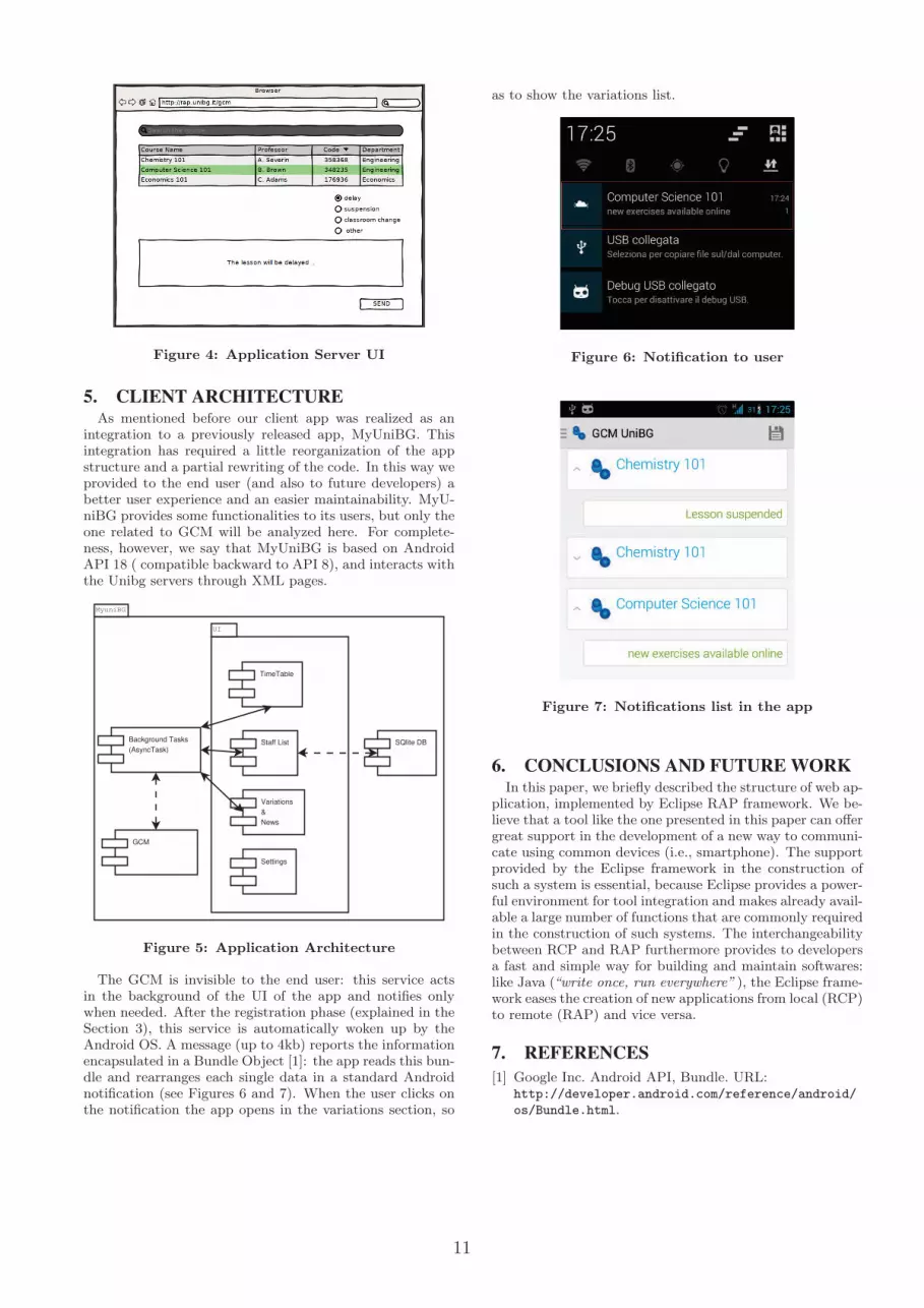
Figure 4: Application Server UI
5. CLIENT ARCHITECTURE
As mentioned before our client app was realized as anintegration to a previously released app, MyUniBG. Thisintegration has required a little reorganization of the appstructure and a partial rewriting of the code. In this way weprovided to the end user (and also to future developers) abetter user experience and an easier maintainability. MyU-niBG provides some functionalities to its users, but only theone related to GCM will be analyzed here. For complete-ness, however, we say that MyUniBG is based on AndroidAPI 18 ( compatible backward to API 8), and interacts withthe Unibg servers through XML pages.
MyuniBG
GCM
SQlite DB
UI
TimeTable
Staff List
Variations
&
News
Settings
Background Tasks
(AsyncTask)
Figure 5: Application Architecture
The GCM is invisible to the end user: this service actsin the background of the UI of the app and notifies onlywhen needed. After the registration phase (explained in theSection 3), this service is automatically woken up by theAndroid OS. A message (up to 4kb) reports the informationencapsulated in a Bundle Object [1]: the app reads this bun-dle and rearranges each single data in a standard Androidnotification (see Figures 6 and 7). When the user clicks onthe notification the app opens in the variations section, so
as to show the variations list.
Figure 6: Notification to user
Figure 7: Notifications list in the app
6. CONCLUSIONS AND FUTURE WORK
In this paper, we briefly described the structure of web ap-plication, implemented by Eclipse RAP framework. We be-lieve that a tool like the one presented in this paper can offergreat support in the development of a new way to communi-cate using common devices (i.e., smartphone). The supportprovided by the Eclipse framework in the construction ofsuch a system is essential, because Eclipse provides a power-ful environment for tool integration and makes already avail-able a large number of functions that are commonly requiredin the construction of such systems. The interchangeabilitybetween RCP and RAP furthermore provides to developersa fast and simple way for building and maintain softwares:like Java (“write once, run everywhere” ), the Eclipse frame-work eases the creation of new applications from local (RCP)to remote (RAP) and vice versa.
7. REFERENCES
[1] Google Inc. Android API, Bundle. URL:http://developer.android.com/reference/android/
os/Bundle.html.
12
[2] Google Inc. Google Cloud Messaging. URL:http://developer.android.com/google/gcm.
[3] Jarle Hansen, T-M Gronli, and Gheorghita Ghinea.Cloud to device push messaging on android: a casestudy. In Advanced Information Networking andApplications Workshops (WAINA), 2012 26thInternational Conference on, pages 1298–1303. IEEE,2012.
[4] Kantar Worldpanel ComTech. Smartphone OS SalesShare, 2013. URL: http://www.kantarworldpanel.com/Global/News/Record-share-for-Windows-phone.
[5] George Lawton. New ways to build rich internetapplications. Computer, 41(8):10–12, 2008.
[6] Linda Dailey Paulson. Building rich web applicationswith ajax. Computer, 38(10):14–17, 2005.
[7] Qooxdoo. A universal javascript framework. URL:http://qooxdoo.org.
[8] The Eclipse Foundation. Remote ApplicationFramework, 2013. URL: http://eclipse.org/rap/.

13
Eclipse in a Modern Mobile Development Toolchain
Andrea Dal PassoLumata ItalyMilano, Italy
Eros PedriniLumata ItalyMilano, Italy
ABSTRACT
Eclipse is the basic Java development tool we use in Lumata.It’s a quite versatile Integrate Development Editor (IDE)that can be extended via plug-ins to satisfy virtually everyspecific need. Currently we use it in conjunction with thefollowing state-of-art development tools: Maven (for projectmanagement), FindBugs (for code analysis), Spring Tool
Suite (to work with Spring Framework), Jenkins (for con-tinuous integration), SonarQube (for code analysis), Artifac-tory (for component/library management), Git (for sourcemanagement) and Jira (for Agile project management). Inthis paper we describe our complete toolchain and howEclipse has been integrated within it.
Keywords
Case studies, Continuous integration, Eclipse, IDE
1. INTRODUCTIONLumata was founded in November 2011 with the goal to
provide Operators, Brands, and Advertisers with the toolsthey need to manage their brand’s interaction with con-sumers over mobile: what we call Mobile Relationship Man-
agement. Lumata is a carve-out from Business to Business
assets of Buongiorno, the leader in Business to Consumer
entertainment on mobile, and is backed by Francisco Part-
ners, a leading technology focused private equity firm. Thedeal created a global business with more than 450 employeesin 18 markets. Lumata offices are located in London (UK),Milano (Italy), Grenoble (France), Madrid (Spain), Moscow(Russia), and Noida (India).Some of our featured clients are: TIM (Italian mobile
operator), Nestle (multinational food and beverage com-pany), Beeline (brand by OJSC VimpelCom, the second-largest telecommunications operator in Russia), and BMW
(German automobile, motorcycle and engine manufacturingcompany). For each of these client, a specific solution hasbeen designed: ranging from engaging mobile game applica-tions (e.g., for BMW), to complex loyalty campaigns (e.g.,Recharge Win reward TIM program). To manage all thesedifferent kinds of applications and to improve the quality ofour products and the efficiency during the development, wespent a lot of resources to design a toolchain of applicationsand the flows among them.In this paper, we will show how Eclipse is one of the build-
ing blocks of our development toolchain and how it interactswith the other component. First, we will describe the maincomponents of our toolchain (Section 2). We will then il-
lustrate where Eclipse is used and the plug-ins we adopted(Section 3). Finally we will describe some of the pitfalls youcan face (Section 4).
2. THE TOOLS WE USEThe first step in our development process involves the
technical specifications: without considering the specificmethodology used (i.e., traditional waterfall or Agile basedon Sprints) the technical specifications have to be insertedinto Jira1 as issues that will be assigned to developers. Jirais developed by Atlassian, and even if it is mainly an is-sue tracking product, it is often used as project manage-ment tool. In this step the product owners (i.e., who havethe knowledge about the final products goals), the techni-cal team leader, and the quality assurance manager work alltogethers to write down the technical specifications.The second step, when needed, is the project/s setup and
it consists in preparing one or more Maven configurationfiles. Apache Maven is a build automation tool based on theconcept of a project object model (POM ). Maven managesthe build, reporting and documentation of a project usingan XML configuration file called pom files. To build a Mav-
enized project, Maven relies on public online library reposi-tories. Considering that we need to support also dependencyamong our own libraries, we have a private repository basedon Artifactory. Artifactory provides out-of-the-box all thatis needed to set up and run a robust secured repository. Ev-ery project has to be deployed into Artifactory: in fact wecombine Maven and Artifactory to deploy our projects intodifferent environments2: quality assurance (QA), staging,and production.The source code of every project is stored in a Git repos-
itory. Git is a distributed version control and source code
management (SCM ) system. We choose Git as principalsource code version system because it permits to manage insimple way also very complex development dependencies. Infact one of the most important Git feature is the simplicityto branch a project and then merging it back3.Our continuous integration system periodically builds all
the projects and, in case something goes wrong, immedi-ately alerts the development team in charge. A build canbe considered faulty mainly for two reasons: (i) one or morefile that don’t compile have been pushed on Git, or (ii) some
1The name Jira is a truncation of Gojira, the Japanese namefor Godzilla.2An environment is a complex system composed of a virtualor physical machine and its operative system.3One of the Git mantra used is branch early, branch often.

14
test don’t pass. For the continuous integration support, werely on Jenkins: which is an open source tool written inJava.
Every time Jenkins builds a project, the project is an-alyzed by SonarQube (formerly Sonar). Sonar is an openplatform managing code quality. As such, it covers the 7axes of code quality: architecture and design, duplication,unit tests, complexity, potential bugs, coding rules, and com-ments. The Sonar reports are very important during thecode review phase.
The last step of our toolchain is QA check. If the QA step(or the code review phase) found bugs or potential issues,they are prioritized and inserted into Jira. In this way thedevelopment flow can proceed considering also these issues.
3. ANDROID, JAVA, AND PLUG-INSIn this section we describe our mobile and enterprise de-
velopment environments, mainly focusing on the most im-portant plug-ins.
3.1 AndroidFor Android development we tested different solutions.
We started working with Motorola Design Studio, a cus-tomized version of Eclipse configured with Android in mind.When this solution become deprecated, we moved to the of-ficial Eclipse ADT [3] plug-in. The transition from MotorolaDesign Studio to Eclipse ADT was very smooth and we wereable to use all the knowledge we acquired without problems.
3.2 JavaOur most recent enterprise (J2EE) projects are developed
with Java 7 : for this reason we use at least Eclipse Indigo(version 3.7.1): which is the first version of Eclipse that fullsupports Java 7 features. To simplify their development,we use the Spring framework, as it provides a comprehen-sive programming and configuration model for modern Java-based enterprise applications.
3.3 Eclipse Plug-insThe plug-ins we currently use with Eclipse are illustrated
in the following.
Android Development Tools (ADT): it is a plug-in forEclipse, designed to give a powerful, integrated environmentin which to build Android applications. The main advantageof this solution is that it give the possibility to use the sameIDE for both enterprise and mobile development.
Maven: to integrate Eclipse with Maven, we use the m2ec
project [2]. In fact it provides a first-class Apache Mavensupport in Eclipse, making it easier to edit, for example,Maven’s pom.xml or run a build from the IDE.
Spring Tool Suite [4] (STS): working with Spring, the STSplug-in is a valuable resource. In fact it provides thebest Eclipse-powered development environment for buildingSpring-powered enterprise applications. It supports the lastSpring features and also it expands Eclipse with advancedcode completion, content-assist, validation, and so on.
EGit [1]: even if usually it is better to use Git manuallyfrom the command line, EGit is a valid alternative. EGitis an Eclipse Team Provider for Git version control system.This plug-in supports all the main functionality of Git (i.e.,commit, fetch, push, branch, and merge) in an integratedenvironment.
Jira: Atlassian provides a connector for Eclipse based on thepopular task-focused Mylyn interface. It is used to receivenotifications of changes of Jira issues, and also to create,update, comment and manage them.
FindBugs [6]: it permits to analyze Java code to find poten-tial bugs. It is based on the concept of bug patterns (i.e., acode idiom that is often an error).
EclEmma [5]: it is a free Java code coverage tool for Eclipse.It brings code coverage analysis directly into Eclipse work-bench without the need to change the code.It’s important to highlight that the last two tools are used
by Sonar to perform the same analysis for its reports.
4. WHEN THE TOOL IS NOT SUFFICIENTEven if the Eclipse plug-ins described in Section 3.3 can
help a company to create a good development flow, thereare some intrinsic problems that you have to warned about.The first issue you may face is related to Git. Even if it’s
a powerful tool and is quite simple to use in general, it candrive you crazy if all the team doesn’t agree on the sourcecode versioning and branching policies. Another problemis related to its configuration: all the team must share thesame Git configuration, otherwise you may have false con-flicts signaled during the source code merging phases.Maven usually doesn’t create any issue, but you can face
someone within m2ec plug-in. Such as the following two.
• You cannot use the m2ec plug-in if your Maven projectrely on automatic code generation during the projectcreation. Usually m2ec generates the code correctly,but it’s not able to associate the generated code asdependency into the Eclipse project.
• By default the m2ec plug-in enables the automaticworkspace projects resolution; this means that if oneproject depends on another project opened in yourworkspace, m2ec uses this for dependency resolution.This is useful during the development, but it can createproblems when you push your changes on the remoterepository. If you forgot to push both the projects youwill break the continuous integration process.
5. CONCLUSIONSIn this paper, we described the tools we use in Lumata
and their interaction with Eclipse. We focused mainly onsome of the most important Eclipse plug-ins that can sim-plify developers lives. We then depicted some of the mostcommon issues that a developer may face.
6. REFERENCES[1] Eclipse Foundation. Egit.
http://www.eclipse.org/egit/, 2013.
[2] Eclipse Foundation. Maven integration (m2e).http://eclipse.org/m2e/, 2013.
[3] Google Inc. Adt plugin. http://developer.android.com/tools/sdk/eclipse-adt.html, 2013.
[4] GoPivotal Inc. Spring tool suite.http://www.springsource.org/sts, 2013.
[5] Mountainminds GmbH. Java code coverage for eclipse.http://www.eclemma.org/, 2013.
[6] University of Maryland. Findbugs - find bugs in javaprograms. http://findbugs.sourceforge.net/, 2013.
15
Native versus Cross-platform frameworks for mobileapplication development
Rosario MadaudoMOVIA SpA, Milano, [email protected]
Patrizia ScandurraUniversità degli Studi di Bergamo, Dipartimento
di Ingegneria, Dalmine (BG), Italy
ABSTRACT
Mobile application development is vibrant and reach of op-portunities. However, new development questions arise, in-cluding what devices to target and which development frame-works to use for creating simple and reliable applications.
Based on our recent experience on developing for mobile de-vices, in this paper we compare the two main approaches fordeveloping mobile applications (or simply apps), namely i)by using native APIs of the target platform and ii) by adopt-ing cross-platform environments (mostly WEB-based). Inparticular, we examine the role of Eclipse in both approachesand present our position on combining preciseness and effi-ciency of native APIs with the flexibility and automation ofthe Web-based frameworks to achieve significant boosts inboth productivity and quality in mobile application devel-opment.
1. INTRODUCTION
In recent years, our increasing dependence on mobile ap-plications running on a wide spectrum of new devices, fromsmartphones to tablets, are rapidly posing new developmentchallenges [1]. With mobile and the proliferation of operat-ing systems – the so called “platforms” (including Android,Apple iOS, Microsoft Windows Mobile and Microsoft Phone7, RIM BlackBerry, etc.) – even experienced developers areleft feeling like beginners [2]. All of the tools, processes, andtechniques they have acquired to build, debug, test, and de-ploy software are suddenly powerless against mobile.
In particular, recently there has been a proliferation of de-velopment environments specific to the mobile world. De-velopers can choose from either native development tools foreach of the major mobile devices and platforms and cross-
platform environments (like PhoneGap [5] and Appcelera-tor Titanium [6]) to create an application that run, at leastin principle, across multiple mobile devices and platforms.So new development questions arise for creating simple andreliable applications, including what devices to target andwhich development frameworks to use.
Based on our recent experience on developing for Blackberryand Android mobile devices, in this position paper we tryto provide an answer to two fundamental questions. Whatkinds of mobile development environments are available, andwhat are their advantages and disadvantages? Specifically,we compare the two main approaches for developing mobileapplications, namely i) by using native APIs and toolkits for
the target platform and ii) by adopting cross-platform envi-ronments, mostly WEB-based. We present our position oncombining preciseness and efficiency of native tools with theflexibility and automation of the cross-platform frameworksto achieve significant boosts in both productivity and qual-ity in mobile application development. Finally, we examinethe role of Eclipse in both approaches.
2. DEVELOPMENT TOOLS FOR MOBILE
APPLICATIONS
Tools vendors have created multiple development environ-ments, but they fall in two main categories: native toolsand cross-platform tools.
Native tools. They are designed to create applications thatrun on specific platforms. For example, in the case of An-droid, this normally means Java and the Android SDK (soft-ware development kit). In the case of Apple iOS, develop-ment is based on the Objective-C programming languageand a toolset for designing and distributing applications in-clude the Xcode IDE for UIs, performance analysis tools,and iOS Simulator. Though based in the past on Java,Blackberry provides for the recent BlackBerry 10 operatingsystem an C/C++ app framework and a plug-in Eclipse.Similarly for other platforms.
Cross-platform tools. They provide developers the flexi-bility to create an application that run across multiple mo-bile devices according to the ideal principle “write-once-run-everywhere”. Examples of cross-platform frameworks thatwe experienced with are Appcelerator’s Titanium and Phone-Gap. They are designed to limit the development work andcosts to create applications for iOS, Android, BlackBerry,Windows Phone and beyond. An entire sub-industry of de-velopment tools and languages exist to develop and deploya mobile application to multiple platforms.
Basically, most of the existing mobile cross-platform envi-ronments are toward open-source world and Web-orientedby incorporating three key technologies: HTML5, CascadingStyle Sheets (CSS), and JavaScript. However, they adoptdifferent development approaches. There are web apps thatrun inside of a browser (either standalone or embedded into acontainer to more closely mimic a native application). Thisapproach is adopted, for example, by PhoneGap. Phone-
16
Gap uses HTML5 inside of a WebView1 on the device. Itessentially creates a mobile web app that sits inside a na-tive application wrapper. The web code is packaged with alibrary that bridges web code to native functionality.
There are also approaches that include their own runtime,like Adobe Air [7]. And there are tools, such as Titaniumand Corona SDK[8], that allow you to write the code inan abstracted scripting language, and then generate na-tive code at compile time. Titanium, for example, com-piles the JavaScript code into a native binary-convertingthe JavaScript into native classes and object files (whereasPhoneGap simply renders a WebView with the code beinginterpreted inside). Though, it is close to pure native map-ping, there is still an interpreter running in interpreted modeto allow, for example, dynamic code.
As cross-platform tools, there also exist Mobile Enterprise
Application Platforms (MEAP) (including Antenna Soft-ware Inc. and Kony Solutions Inc.) [3] that have morefull-fledged development environments, with a wider varietyof traditional tools such as graphical user interfaces, versioncontrol, and workflow. They tend to have more integrationtools and gateways to third-party services (such as Facebookand Twitter), as well as better technical support capabilities.In addition, they focus on the enterprise segment and striveto incorporate stronger security capabilities, taking into ac-count that the applications will be used to access back-endcorporate information.
2.1 Cross-platform vs. native app developmentBoth development approaches has advantages and draw-backs. Table 1 summarizes our comparison of the two ap-proaches according to the following criteria (a subset hasbeen taken and revised from [4]).
UI User Experience. Native apps provide a more fluidand responsive interface than cross-platform solutions, es-pecially for animations and gestures. This is because whencoding with the indented programming language of the plat-form you have access to the full device APIs. Though cross-platform solutions offer native APIs to use, it always refersto a limited subset of the device-specific features and oftenyou have to wait until they are released in order to use them.
Performance. One key advantage of using native devel-opment tools is that applications run more smoothly onwhichever mobile devices use that operating system. In-stead, the cross-compilation process can sometimes be slowerthan using native tools for an app. This difference can beeasily noted during graphical rendering and animations.
Device-specific features. In addition, native tools let de-velopers take full advantages of platform functionality. Onthe contrary, a cross-platform application serves everyone,but has more limited functionality.
1A browser screen within the native application that thenrenders the HTML5/CSS/JavaScript page.
For example, with cross-platform apps, high-end graphicsand 3D support is often limited. There are some cross-platform solutions (like Titanium) that compile code intothe native language, but none of them compile it to com-pletely native.
Distribution via app-store. There may be stringent re-quirements for admission into public app stores. Apple Inc.,for instance, requires that developers submit iPhone mobiledigital device applications for testing within Apple to facil-itate such compatibility.
In this sense, apps developed using native tools are in gen-eral more welcome in app store than cross apps because it isassumed that native apps have been developed by program-mers with expertises of the target platform.
Multiple platforms deployment costs. With native, whendevelopers want to target multiple platforms, they have toadopt application architecture best practices and use of acommon data model to optimize the development effort acrossmultiple platforms. Native requires developers with (not socommon) skills for the target platforms.
With cross apps, development costs are reduced. This isperhaps the biggest advantage because a cross-compilationschema allows companies or brands to get an app onto otherplatforms without having to invest in a team or developerspecific to that ecosystem.
Developers support. Developers we work with often saythat they like to work in native code because it is easierto get help. They can go online to forums and quickly getanswers since many people started writing native code for amuch longer time than cross-platform code (a more recenttechnique).
Security. Cross-platform apps present more security risksthan native apps. The reason is that they inherit the samerisks of HTML5. For example, to name a few, applicationsource code is freely available on the mobile device, datacached on the device (within the browser) not properly se-cured and encrypted, URL security vulnerabilities. On thecontrary, operating systems like iOS and Android offer built-in security services like data encryption. Attack techniquessuch as cookie manipulation and SQL injection to gathersensitive data from back end servers and from the mobiledevice itself are not possible in a (well-built) native app.
Timely access to new OS innovations. A cross-platformframework may not support every feature of an operatingsystem or device. Any new added feature of the operatingsystem is not immediately available on the cross-platformframework you are using. You need to wait it is updated tosupport those new features.

17
Table 1: Cross-platform vs. native development
Native Cross-platform
UI User Experience high lowPerformance high lowDevice-specific features high lowDistribution via app-store high lowMultiple platforms deployment costs high lowDevelopers support high lowSecurity high lowTimely access to new OS innovations high lowCode reusability low highDesign challenges low highAvailability of programming expertise low high
Code reusability. Cross app code is considered reusable.Rather than having to write a specific action or a sequenceof actions for each target platform, a cross developer canjust write the code once and then reuse it on other plat-forms or in other projects. This is not always true. Oftensome cross-platform frameworks often use their own subsetsof JavaScript, which means that if you want to switch to an-other platform, that code you wrote before is likely not goingto be reusable without refactoring or substantial changes.
Design challenges. In native development, design is sim-plified by the support and services provided by the operatingsystem. The operating system can, for example, notify ap-plications about events such as message arrival and powerlevels. In a cross-platform environment, developers will needto add such features explicitly.
Moreover, with cross-platform frameworks, developers mustdesign how each feature they need has to be implementedon each target platform. For instance, designing an app forthe iPhone is different than designing one for Android; theUI and user experience conventions are different, and touchpoints and menus work in different ways. Personally, wethink a good cross-platform application looks at home onwhatever platform it is used on. A bad cross-platform triesto look identical everywhere.
Availability of programming expertise. It is widely ac-knowledged that there are more Web developers than nativedevelopers. Since most cross-platform frameworks are basedon HTML5 CSS3, they are easy for web developers to jumpin and use alongside the calls to more native functions. Onthe other hand, due to the low availability, native developerskills usually cost more.
3. ECLIPSE FOR MOBILE APPLICATION
DEVELOPMENT
Some tools, native or cross-platform, offer easy access toplugins and modules that can easily plug into other servicesor tools including Eclipse. For example, both Titanium andPhoneGap are released as Eclipse-based environments. Pro-viding compatibility with common integrated developmentenvironments (IDEs) like Eclipse is to be considered a fun-damental feature that enable developers to leverage existing
tools and expertise.
The real challenge is to find the next generation of devel-opment tools and development processes that make mobileapplication development as productive and manageable asdesktop and web development have been for so long. Toachieve these productivity goal, there are five aspects [2] re-quiring for better mobile development tools and for whichthe Eclipse-based ecosystem may help:
Building. Many platforms means many different“build” re-quirements for writing and compiling an app for iOS, An-droid, Windows Phone, BlackBerry etc. The building phaserequires at the moment the use of different IDEs, SDKs, andoperating systems. Also cross-platform apps, which leverageexisting Web skills to reach multiple platforms, require lotsof complex and messy configurations for each target OS.
New and improved tools to help mobile developers abstractplatform differences and manage the building phase in lesstime are necessary.
Debugging. Mobile app debugging is based on mobile op-erating system emulators that implies software being writ-ten on a PC, run on a device, and then debugged from thePC. This is quite sufficient. Tools that makes mobile appspainless to debug on mobile devices are necessary.
Testing. Once an app is built, it needs automated tests toensure it works properly before updates are shipped to appstores and users. For conventional applications this is a rel-atively straightforward task and a great variety of testingautomation tools and techniques exist. This not the samefor mobile apps due to the wide variability of today’s mo-bile devices. Mobile app testing needs to happen not onlyon many different operating systems, but on many differentphysical devices.
Recently, tools and“cloud device labs” for testing are emerg-ing, but much more is still needed to make it productiveto record, playback, and manage tests across devices. Forexample, when using BlackBerry WebWorks and Phone-Gap APIs, a sophisticated emulator called Ripple is avail-
18
able as multi-platform mobile environment emulator that iscustom-tailored to mobile HTML5 application developmentand testing. The Ripple emulator is an extension of theGoogle Chrome browser that allows you to quickly see howyour application looks and functions on multiple mobile de-vices and platforms in a browser-like environment. You canuse the Ripple emulator to perform JavaScript debugging,HTML DOM inspection, automated testing, and multipledevice and screen resolution emulation in real-time withoutredeploying the application or restarting the emulator.
Deploying. Deploying mobile apps on app stores requiresmany manual steps. The problem is even more challengingif the destination is not a public app store but a privategroup of users. These last must find their own path to em-ployee devices. Tools that help and automate the deliveringof multi-platform deployment mobile apps are required.
Monitoring and Optimizing. Unlike websites that live onservers or desktop applications that live on relatively sta-tionary PCs, mobile apps get around and once deployed,they are out of your control and destined to be abandoned.
To understand what your app is doing and why, tools thathelp developers to monitor it in-place to final users are nec-essary. In particular, developers need to monitor usage andperformance, watching for common user problems and thosecharacteristics to fine-tune accurately and productively afterinitial use. A nice tool toward this direction is, for exam-ple, the plug-in for Google Analytics provided by PhoneGapthat allow to get reports about the usage and navigation ofan app.
4. CONCLUDING REMARKS
The application development approach developers have tochoose really depends on the application requirements itself.Will it be browser-based, with little or no data saved onthe mobile device? Does it require capabilities native tothe operating system? Does it require security features orsupport capabilities?
However, by the comparison we provided in this paper, wecan also conclude that both approaches have advantages anddisadvantages shortly summarized in Table 1. According tothe chosen criteria, we can conclude that native and cross-platform development approaches are complementary. Webelieve these two approaches can be combined showing howthe advantages of one can be exploited to cover or weakenthe disadvantages of the other. In order to combine in atight way preciseness and efficiency of native apps with flex-ibility and automation of cross-platform apps, conventionalsoftware architectural design patterns may be adopted andrevised to adopt an hybrid development approach. For ex-ample, by using the layer pattern, one can provide a reachUI natively and a functionality core by a cross-platform.The decision to use in a layer one or the other relies on howdeeply developers want to link the application with the un-derlying operating system, as capabilities in one operatingsystem may not be available in another.
Moreover, developers have to guarantee all those desired
software qualities (reliability, efficiency, maintainability, etc.)also for mobile apps. To this purpose, the integration of mo-bile development tools with existing or new Eclipse-basedtools for building, debugging, testing, deployment and opti-mizing is fundamental.
5. REFERENCES[1] Jeff McWherter, Scott Gowell. Professional Mobile
Application Development. John Wiley & Sons, Inc.2012.
[2] Todd Anglin. The 5 hottest areas for mobiledevelopment tools. Guest Post at Telerik, a developerservices company, June 7, 2013.
[3] Srinivas Ramadath, Maurice Collins. MobileApplication Development: Challenges and BestPractices. Accenture white paper, 2012.
[4] Native vs. HTML5 Mobile App Development: Whichoption is best? Appcelerator white paper, 2012.
[5] PhoneGap framework http://phonegap.com/
[6] Titanium Mobile Development Environmenthttp://www.appcelerator.com/platform/titanium-platform/
[7] Adobe AIR and Adobe Flash Player Technologieshttp://labs.adobe.com/technologies/flashruntimes/
[8] Corona frameworkhttp://www.coronalabs.com/products/corona-sdk/
19
Misura della cooperazione per lo sviluppo su piattaforma Eclipse: lo studio del caso di
collaborazione fra le università Federico II e Ohio State University at Stark
Paolo Maresca
Dipartimento di Ingegneria Elettrica e Tecnologie dell'Informazione (DIETI)
Università di Napoli, “Federico II” +0397683168
Angela Guercio Department of Computer Science
Kent State Univ. at Stark, Canton, OH [email protected]
Lidia Stanganelli Dipartimento di Ingegneria Elettrica e Tecnologie dell'Informazione (DIETI)
Università di Napoli, “Federico II” [email protected]
SOMMARIO Le comunità di pratica costituiscono una portante dell'innovazione di prodotto e di processo, in un contesto di depressione economica esse possono trasformarsi in leva per lo sviluppo di idee per piccole e medie imprese. Esse costituiscono un valore per la nostra società. Questo lavoro ha lo scopo di fornire un contributo teso ad incrementare tale valore attraverso lo studio di un modello di misura, basato su GQM, della cooperazione fra studenti appartenenti a corsi di università diverse (Università di Napoli Federico II e Kent State University at Stark su due corsi di computer science: Programmazione I e Computer science II Data structures and abstractions) che fornisca un piano di misura per verificare l'avvicinamento di comunità di pratica apparentemente distanti fra loro. Il modello promuove il trasferimento di conoscenza fra i membri delle comunità di pratica aperte (OCoP) che è amplificato quando vengono adoperati strumenti di cooperazione innovativa come Eclipse e Jazz.
Categories and Subject Descriptors K.3.1 [Computers and education]: Computer uses in education –collaborative learning, distance learning.
General Terms Measurement, Experimentation.
Keywords Collaboration, e-learning, learning models, community of practice, cooperation.
1. INTRODUZIONE Generalmente una Community of practice (CoP) ha una sua mission (es. FERRARI), tende a delimitare i propri confini attraverso degli elementi che la caratterizzano (campo di conoscenza, risultati raggiunti, uomini rappresentativi, argomenti di ricerca in cui è forte, etc) scambiando conoscenza quasi esclusivamente con persone della stessa CoP divenendo di fatto
una comunità chiusa con una rete di innovazione chiusa (closed innovation framework).
Di rado le comunità si aprono, ma quando lo fanno, hanno una visione aperta dell’innovazione (open innovation network): le idee cominciano a circolare e producono altre idee in un circolo virtuoso di innovazione aperta.
È evidente, posto che si abbia l'interesse a che due o più CoP cooperino, esse abbiano un alto potenziale di scambio di conoscenza ma è molto difficile che siano in grado di attivare questo flusso di conoscenza da sole. Metaforicamente è come l'acqua, che scorrendo, trova la via a minor resistenza per far fluire la conoscenza fra due CoPs. Il problema è che non riusciamo a misurare oggettivamente il grado con il quale queste si avvicinano o si allontanano. Lo possiamo solo verificare a posteriore osservando i risultati della loro cooperazione. Questa incapacità ci costringe spesso a vedere la morte di comunità promettenti senza riuscire a fare nulla o meglio senza avere la possibilità di intervenire per rivitalizzarle e allungarle il tempo di vita.
Da più parti ormai si osserva come le comunità di pratica aperte (Ocop) hanno un modo spontaneo di cooperare attraverso strumenti di social networking. Basta guardare ai grandi passi in avanti effettuati in molteplici settori dello sviluppo del software open source nel quale lo sviluppo è diventato cooperativo ed in settori della formazione universitaria di alto livello dove l'apprendimento è diventato cooperativo riuscendo a rimuovere quegli ostacoli alla cooperazione che nascono dalla insana competizione individuale.
Molti aspetti dei modi con i quali le comunità di pratica si avvicinano, si allontanano, producono, nascono e muoiono non sono ancora stati ben compresi. Riteniamo che molto è dovuto sia alla complessità che alla dinamicità con la quale una comunità si muove. Tale dinamicità richiede che un insieme di individui sia: raggiungibile, osservabile e controllabile. Insomma che la comunità sia misurabile in maniera oggettiva anche attraverso gli asset (manufatti) che gli individui producono e che le sue misure siano espresse attraverso numeri o attributi riconosciuti essere oggettivi. In particolare il lavoro proverà a disegnare attorno ad
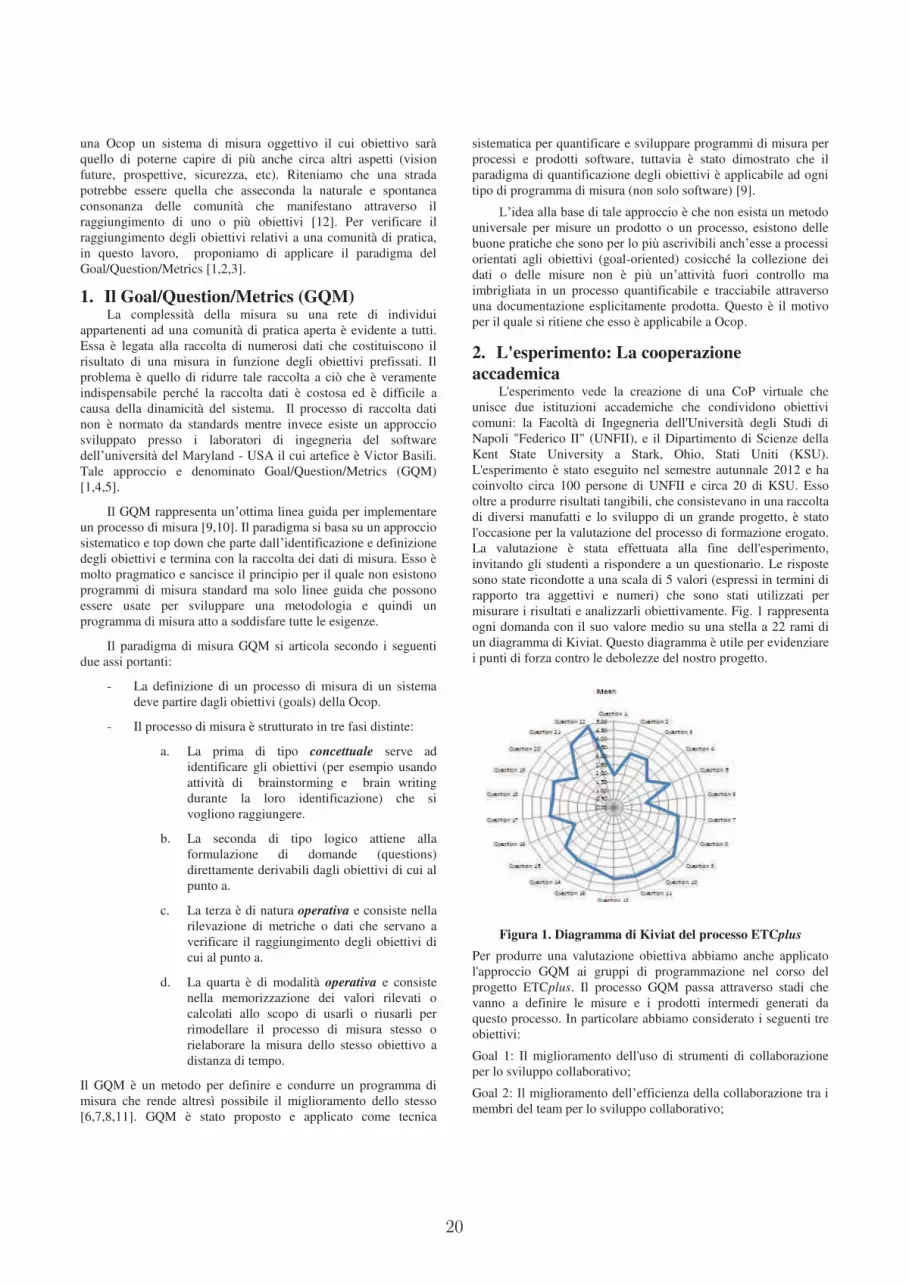
20
una Ocop un sistema di misura oggettivo il cui obiettivo sarà
quello di poterne capire di più anche circa altri aspetti (vision
future, prospettive, sicurezza, etc). Riteniamo che una strada
potrebbe essere quella che asseconda la naturale e spontanea
consonanza delle comunità che manifestano attraverso il
raggiungimento di uno o più obiettivi [12]. Per verificare il
raggiungimento degli obiettivi relativi a una comunità di pratica,
in questo lavoro, proponiamo di applicare il paradigma del
Goal/Question/Metrics [1,2,3].
1. Il Goal/Question/Metrics (GQM) La complessità della misura su una rete di individui
appartenenti ad una comunità di pratica aperta è evidente a tutti.
Essa è legata alla raccolta di numerosi dati che costituiscono il
risultato di una misura in funzione degli obiettivi prefissati. Il
problema è quello di ridurre tale raccolta a ciò che è veramente
indispensabile perché la raccolta dati è costosa ed è difficile a
causa della dinamicità del sistema. Il processo di raccolta dati
non è normato da standards mentre invece esiste un approccio
sviluppato presso i laboratori di ingegneria del software
dell’università del Maryland - USA il cui artefice è Victor Basili.
Tale approccio e denominato Goal/Question/Metrics (GQM)
[1,4,5].
Il GQM rappresenta un’ottima linea guida per implementare
un processo di misura [9,10]. Il paradigma si basa su un approccio
sistematico e top down che parte dall’identificazione e definizione
degli obiettivi e termina con la raccolta dei dati di misura. Esso è
molto pragmatico e sancisce il principio per il quale non esistono
programmi di misura standard ma solo linee guida che possono
essere usate per sviluppare una metodologia e quindi un
programma di misura atto a soddisfare tutte le esigenze.
Il paradigma di misura GQM si articola secondo i seguenti
due assi portanti:
- La definizione di un processo di misura di un sistema
deve partire dagli obiettivi (goals) della Ocop.
- Il processo di misura è strutturato in tre fasi distinte:
a. La prima di tipo concettuale serve ad
identificare gli obiettivi (per esempio usando
attività di brainstorming e brain writing
durante la loro identificazione) che si
vogliono raggiungere.
b. La seconda di tipo logico attiene alla
formulazione di domande (questions)
direttamente derivabili dagli obiettivi di cui al
punto a.
c. La terza è di natura operativa e consiste nella
rilevazione di metriche o dati che servano a
verificare il raggiungimento degli obiettivi di
cui al punto a.
d. La quarta è di modalità operativa e consiste
nella memorizzazione dei valori rilevati o
calcolati allo scopo di usarli o riusarli per
rimodellare il processo di misura stesso o
rielaborare la misura dello stesso obiettivo a
distanza di tempo.
Il GQM è un metodo per definire e condurre un programma di
misura che rende altresì possibile il miglioramento dello stesso
[6,7,8,11]. GQM è stato proposto e applicato come tecnica
sistematica per quantificare e sviluppare programmi di misura per
processi e prodotti software, tuttavia è stato dimostrato che il
paradigma di quantificazione degli obiettivi è applicabile ad ogni
tipo di programma di misura (non solo software) [9].
L’idea alla base di tale approccio è che non esista un metodo
universale per misure un prodotto o un processo, esistono delle
buone pratiche che sono per lo più ascrivibili anch’esse a processi
orientati agli obiettivi (goal-oriented) cosicché la collezione dei
dati o delle misure non è più un’attività fuori controllo ma
imbrigliata in un processo quantificabile e tracciabile attraverso
una documentazione esplicitamente prodotta. Questo è il motivo
per il quale si ritiene che esso è applicabile a Ocop.
2. L'esperimento: La cooperazione
accademica L'esperimento vede la creazione di una CoP virtuale che
unisce due istituzioni accademiche che condividono obiettivi
comuni: la Facoltà di Ingegneria dell'Università degli Studi di
Napoli "Federico II" (UNFII), e il Dipartimento di Scienze della
Kent State University a Stark, Ohio, Stati Uniti (KSU).
L'esperimento è stato eseguito nel semestre autunnale 2012 e ha
coinvolto circa 100 persone di UNFII e circa 20 di KSU. Esso
oltre a produrre risultati tangibili, che consistevano in una raccolta
di diversi manufatti e lo sviluppo di un grande progetto, è stato
l'occasione per la valutazione del processo di formazione erogato.
La valutazione è stata effettuata alla fine dell'esperimento,
invitando gli studenti a rispondere a un questionario. Le risposte
sono state ricondotte a una scala di 5 valori (espressi in termini di
rapporto tra aggettivi e numeri) che sono stati utilizzati per
misurare i risultati e analizzarli obiettivamente. Fig. 1 rappresenta
ogni domanda con il suo valore medio su una stella a 22 rami di
un diagramma di Kiviat. Questo diagramma è utile per evidenziare
i punti di forza contro le debolezze del nostro progetto.
Figura 1. Diagramma di Kiviat del processo ETCplus
Per produrre una valutazione obiettiva abbiamo anche applicato
l'approccio GQM ai gruppi di programmazione nel corso del
progetto ETCplus. Il processo GQM passa attraverso stadi che
vanno a definire le misure e i prodotti intermedi generati da
questo processo. In particolare abbiamo considerato i seguenti tre
obiettivi:
Goal 1: Il miglioramento dell'uso di strumenti di collaborazione
per lo sviluppo collaborativo;
Goal 2: Il miglioramento dell’efficienza della collaborazione tra i
membri del team per lo sviluppo collaborativo;

21
Goal 3: Il miglioramento dell'efficienza dello sviluppo nel
contesto di sviluppo collaborativo.
La tabella 1 riassume i risultati delle analisi eseguite attraverso
GQM nel progetto ETCplus. Per semplicità la tabella mostra il
valore rilevato, il valore atteso, e la percentuale di corrispondenza
conseguita per ciascun obiettivo. La percentuale di
corrispondenza indica un valore sufficiente/buono ma non è molto
alta per ciascun obiettivo. Il valore più basso si raggiunge con il
goal 2. Ciò significa che la collaborazione raggiunta dagli studenti
nell'ambito del progetto ETCplus è sufficiente, ma deve essere
migliorata. Un risultato leggermente migliore si ottiene nel
raggiungere il goal 3. Ciò significa che, anche qui, vi è spazio per
miglioramenti nello sviluppo di codice, così come nella
produzione di codice in termini di completamento del lavoro degli
elementi assegnati. Un migliore risultato invece è raggiunto
nell'uso degli strumenti di collaborazione (goal 1). In questo caso,
la mancanza di esperienza nell’uso di questi strumenti è in parte
stata compensata dal buon lavoro dei coordinatori, che hanno
fornito agli studenti una grande quantità di materiale di supporto
di alta qualità.
Tabella 1. GQM applicato a ETCplus
Goals Detected
Value
Expected
Value
Percentage of
correspondence
Goal 1 68 93 73.1
Goal 2 52 84 61.9
Goal 3 59 87 67.8
Il goal 2 rappresenta il collante naturale tra il questionario erogato
e il GQM. Anche se nel questionario le metriche per la misura
della collaborazione non sono state prodotte, abbiamo
empiricamente osservato che il sistema (cioè la CoP), lasciato
libero di evolversi, ha raggiunto un equilibrio durante la
collaborazione e ha prodotto risultati, come qualsiasi sistema
vitale [13, 12, 14]. Il GQM invece ha generato un sistema ibrido
che mescola una collaborazione guidata con la spontaneità della
comunicazione. Sicché abbiamo ritenuto che il GQM fosse non
solo il modo per superare la soggettività del questionario ma
servisse a migliorare il processo di collaborazione in ETCplus.
ETCplus mostra miglioramenti rispetto a ETC e rileviamo spazio
per ulteriori miglioramenti, quando guardiamo i risultati della
Tabella 1 relativamente al goal 2. Gli autori ritengono che si
debba lavorare sulla consonanza dei mini-sistemi vitali formati dai
gruppi per aumentare la collaborazione [12]. Si consideri che al
progetto hanno partecipato studenti di lingue e università diverse
che sono stati letteralmente “scagliati” in compiti comuni e ci
aspettavamo "risonanti" senza precedente coordinamento.
Tuttavia la risonanza è il risultato di un processo di
collaborazione che si è evoluto. La risonanza è simile a un gruppo
di musicisti, individualmente molto bravi, ma che hanno bisogno
di prove prima di raggiungere un livello di collaborazione
(risonanza) tale da permettere loro di produrre una grande
prestazione. La stessa cosa accadrà per gli studenti. Noi crediamo
che sia importante che i partecipanti si conoscano l'un l'altro
(anche se virtualmente) prima di lavorare insieme.
3. RINGRAZIAMENTI I nostri ringraziamenti vanno a IBM Rational a IBM
academic initiative per il supporto al progetto ETC e ETCplus.
4. BIBLIOGRAFIA [1] Victor R. Basili Software modelling and measurement: The
Goal/Question/Metric paradigm. Technical Report CS-TR-
2956, Departement of Computer Science of Maryland
September 1992.
[2] Victor R. Basili, Models and Metrics for Software
Management and Engineering, IEEE Computer Society
Press, IEEE Catalog No. EHO-167-7, (343 pp), 1980.
[3] Yasuhiro Mashiko, Victor R. Basili, Using the GQM
Paradigm to Investigate Influential Factors for Software
Process Improvement, The Journal of Systems and Software,
Volume 36, Number 1, pp 17-32, January 1997.
[4] Victor R. Basili, Quantitative Evaluation of Software
Methodology (invited paper), National Communications
Forum '86 Chicago, IL, September 29, 1986.
[5] Victor R. Basili, Applying the Goal/Question/Metric
Paradigm in the Experience Factory, 10th Annual CSR
(Centre for Software Reliability) Workshop, Application of
Software Metrics and Quality Assurance in Industry,
Amsterdam, Holand, 29th September - 1st October, 1993.
[6] IEEE ISO/IEC WD 9126-4, Information Technology -
Software Product Quality - Part 4 Quality in use metrics,
1999
[7] IEEE ISO/FCD 9126-1.2 Information Technology –
Software Product Quality - Part 1:Quality model, 1998
[8] IEEE WD 9126-3 Information Technology – Software
Quality Characteristics and Metrics – Part 3 : Internal
Metrics, 1997.
[9] A. Fuggetta, L. Lavazza, S. Morasca, S. Cinti, G. Oldano e
E. Orazi.
Applying GQM in an industrial software factory. ACM
Transactions on Software Engineering and Methodology,
Ottobre 1998.
[10] Fadini B., Maresca P., Russo S., (2002), Un approccio alla
valutazione di piattaforme per l’e-learning basate su
standard di qualità ISO, in E-Learning metodi, strumenti ed
esperienze a confronto, Didamatica 2002 - Informatica per la
Didattica – a cura di A. Andronico, A. Chianese, B. Fadini,
pp. 107-132, Napoli, 14-15 Febbraio 2002, Liguori Editore.
[11] B.Fadini, P.Maresca, P.Prinetto, G.Santiano Validation
criteria for a GQM plan for e-learning platforms
evaluation, 2005 Si-El
[12] AA.VV., Contributions to theoretical and practical
advances in management. A Viable Systems Approach (vSa),
International Printing Srl Editore, Avellino, 2011.
[13] Ashby, W. R., An introduction to cybernetics. Chapman and
Hall, London, 1956.
[14] G. Franco, P. Maresca, G. Nota, M. Saviano, Knowledge
sharing and cooperation between communities of practices:
a possible scenario ?, in Proceedings of the VI Workshop of
the Eclipse Italian Community (Eclipse-IT 11) , Milano, IT,
September 22 - 23, 2011, pp.164-178, Editors: Francesca
Arcelli, Leonardo Mariani e Domenico Squillace ISBN:
9788890438820.
22
Custom environments for event-driven I/O
Antonio NataliDISI
Alma Mater Studiorum - University of Bologna
Sam GolovchenkoCIRI-ICT
Alma Mater Studiorum - University of Bologna
1. EXTENDED ABSTRACT
In the era of the Internet of things (IOT), devices like sen-sors, actuators etc. generate and require data that mustbe aggregated and combined with information from virtualworlds, such as business databases and Web-based applica-tions. The real world becomes usually accessible throughsmall low-cost computers (e.g. Raspberry Pi, Beagleboneblack , etc.) and smart, mobile devices (e.g. Android-baseddevices) able to interact with other computers via the net-work. IOT applications require the design and developmentof distributed and heterogeneous software systems and callsfor new programming concepts and for new scalable, stan-dardised infrastructures. In fact, when an application hasto manage large amounts of I/O, the only way of keepingthe application responsive and allowing it to scale, is usingnon-blocking I/O. Moreover, if asynchronous I/O is achievedvia multi-threaded applications, efficiency problems arise,caused by unnecessary thread-switches or related to networksocket optimization (the C10k problem [3]).
The current solution is to design applications accordingto an event-driven programming style, which is based onan inversion of control, since the control flow is driven bythe events and no more by the user-defined program. Call-backs (i.e. object methods or lexical closures that have beenregistered for events) are used to obtain the results fromasynchronous computations. The main design principle isto avoid as much as possible the usage of threads by adopt-ing the reactor design pattern, and the main rules are: i)don’t stop the reactor and ii) make the callback code aslightweight as possible.However, in callback-based applications, numerous iso-
lated code fragments can be manipulating the same data andcoordinating the callbacks (e.g. when multiple event han-dling is required or when event depends on one another) canbecome a daunting task, a problem today known as the Call-back Hell. A clear introduction to the complexity that arisesfrom event-driven programming both in sequential and con-current environments can be found in [4]. The referenceapplication here is a set of loosely coupled entities (calledplans, so to abstract from programs, processes, etc.) that in-teract cooperatively without knowing very much about eachother through the publish-subscribe pattern based on listen-ers. The problem is the plan interference that arises when”independent plan interact in surprising ways, creating newcases that are difficult to identify, prevent or test”[4].The Callback Hell problem has promoted the development
of dedicated language abstractions to take care of event han-dling and state changes. Moreover, the reactive program-
ming paradigm (for a survey see [1]) has been recently pro-posed to tackle issues posed by event-driven applications byproviding abstractions to express programs as reactions toevents and having the language automatically manage theflow of time and data dependencies .The problem is that most of the available libraries and lan-
guages for event-driven or reactive programming are relatedto functional languages and to JavaScript, the most domi-nant language in the Web. Moreover, standardised infras-tructures do not fully exist today. As a consequence, soft-ware designers must develop event-driven applications usingdifferent languages/libraries in different environments. Forexample they could use Node.js (based on the Google’s V8JavaScript Engine) together with Flapjax (for reactive ab-stractions), or Tornado (the Python’s answer to Node.js) orScala.React, an extension of Scala that provides reactive pro-gramming abstractions in place of the observer pattern. TheVert.x system [7] 1 is a polyglot application platform forthe JVM that provides an asynchronous programming modelfor writing scalable non-blocking applications whose compo-nents can be written in JavaScript, Ruby, Groovy, Java orPython. For example, a event-driven HTTP Server written inVert.x is:
HTTP Server in Vert.x (Java version)public class Server extends Verticle {public void start() {vertx.createHttpServer().requestHandler(new Handler<HttpServerRequest>(){public void handle(HttpServerRequest req) {String file=req.path().equals("/")?"index.html":req.path();req.response().sendFile("webroot/" + file);}}).listen(8080); }}
Thus, a Java component in Vert.x reproduces a Node.js
style of programming, by using objects as callbacks.In this scenario, our intent is not to reproduce already
available programming styles or define a completely new lan-guage like [6], but to provide an open and extendible pro-gramming environment for the design and implementation(actually in Java, but not limited to Java) on small compu-tational devices of event-driven, platform-independent appli-cations. We start from the idea that events should be explic-itly declared and explicitly managed in order to highlight theapplication architecture in terms of event-interacting com-ponents2. To this end, we provide:
1. An infrastructure (written in Java and named RTEM:Runtime Task/Event Manager) that supports a ”classi-
1Vert.x moved to Eclipse Foundation in August 2013.2Each event ha a message content of type String in orderto increase the interoperability with non-Java applications.

23
cal” event-driven model by executing a event-loop thatmanages two types of computational objects: Even-tHandlers (similar to callbacks) and Tasks (similarto plans). Both EventHandlers and Tasks can raiseevents and react to events. To overcome the Callbackproblem, an EventHandler is conceived as a terminat-ing computation modelled as a state machine in whichactions and state transitions are performed as conven-tional procedure calls. A Task is defined and imple-mented as a finite state machine in which state transi-tions returns the control to the RTEM.
2. An extension of the basic infrastructure in which theevents are stored within the RTEM so that they can belogically consumed by tasks even if they are not ex-plicitly registered for the events when they are raised.This is a quite relevant (and perhaps questionable) ex-tension to the basic event-programming model, sinceit introduces the possibility of time-uncoupled interac-tion. But, from our point of view, this model is just oneof the ways of conceiving the communications amongthe components of distributed and heterogeneous soft-ware applications, and could include the event-drivenprogramming model in the context of the general con-text introduced in [5].
3. A custom language called ECSL (Event Contact SpecificationLanguage), defined and implemented with the Xtext [2]technology. This language allows an application de-signer to specify in a declarative way the events andthe application architecture along three main dimen-sions: structure, interaction and component behavior.Thus, a ECSL specification is a model (instance of acustom meta-model) in which the behavior of compo-nents is expressed in terms of state-machines.
4. A custom Eclipse IDE (called Event-ide), that auto-matically generates the software layer that couples theapplication logic with the underlying RTEM platform.
The current version provides basic mechanisms that allowus to avoid the usage of thread and the Callback Hell withreference to classical problems., like recursive event-drivencomputations (e.g. the evaluation of Fibonacci’s numbers),event-driven HTTP/TCP servers, event-driven components withboth a proactive (e.g. counting) and reactive (e.g. react toa stop event) behavior (the problem addressed in [6]), orapplications that require plan coordination in the sense in-troduced in [4]. For example, the ECSL specification of theHTTP server is:
ECSL specification for a HTTP server systemEventSystem httpServerExternalIO -basic
/* - Declaration of the components - */EventHandler connectionHandler ;Task server -nostart ;
/* - Declaration of the events - */Event connection ;Event startServer ;Event endRW ;
/* - Declaration of the external components - */External ReaderWriter raising endRW ;External ServersocketExternal raising connection ;
/* - Declaration of the event-based interactions - */handlerHandle: connectionHandler handle connection ;handlerRaise: connectionHandler raise startServer ;serverHandle: server handle endRW ;
/* - Declaration of the behavior of the components - */BehaviorOf server{ ... }BehaviorOf connectionHandler{ ... } //creates/starts a server
This ECSL model can be informally represented in graph-ical form as follows
The impact of the custom meta-model on problem analysisand design is the main issue here, once the RTEM has provedto be sufficiently efficient (benchmarks are in progress).A library that implements the RTEM and the a couple of
Eclipse plugins that implement the Event-ide for ECSL areour current tangible final products 3. But thanks to Eclipseand to the model-driven software development methodologysupported by Xtext, this project is intended to be just thefirst element of a possible family of custom environmentsable to express and support more evolute forms of reactiveprogramming mechanisms like component dependencies (soto automatically avoid the glitch problem described in [1])or advanced reactive constructs (e.g. event-stream mergingprovided by Flapajax) that at the moment must be explic-itly handled at application level. The main issue here is thecooperative work between application designers and systemdesigners (technology experts) in the stream of [5] in orderto reuse the same logical (meta)models on different com-putational platforms, by progressively evolving from single-processor, single-node systems to multi-processor, multi-nodeenvironments.
2. REFERENCES
[1] E. Bainomugisha, A. Carreton, T. Cutsem,S. Mostinckx, and D. Meuter. A Survey on Reactiveprogramming. ACM, 2012.
[2] L. Bettini. Implementing Domain-Specific Languageswith Xtext and Xtend. Packt Publishing, August 21,2013.
[3] D. Kegel. The c10k problem.http://www.kegel.com/c10k.html.
[4] S. J. Miller M.S, Tribble E.D. Concurrency AmongStrangers: Programming in E as Plan Coordination.Springer Verlag, 2005.
[5] A. Natali. Model-driven communications andcollaborative software development. Proceedings of the6th Workshop of the Italian Eclipse Community, pages4–15, 2011.
[6] A. Ricci and A. Santi. Programming abstractions forintegrating autonomous and reactive behaviors: anagent-oriented approach. In Proceedings of AGERE!’12, pages 83–94, New York, NY, USA, 2012. ACM.
[7] S. Scarduzio. Instant Vert.x. Packt Publishing, August2013.
3See the site https://137.204.107.21/contact.

24
STS2Java: An Eclipse Plugin for Early Assessment ofService Performance Based on Simulation
Claudio A. Ardagna
Dipartimento di InformaticaUniversita degli Studi di Milano
Crema (CR), 26013, [email protected]
Ernesto Damiani
Dipartimento di InformaticaUniversita degli Studi di Milano
Crema (CR), 26013, [email protected]
Kouessi A.R. Sagbo
Dipartimento di InformaticaUniversita degli Studi di Milano
Crema (CR), 26013, [email protected]
ABSTRACT
Since the emergence of the model-driven development para-digm, there has been a significant effort towards the integra-tion of solutions for the assessment of software performancein the early phases of the software development process.Along this line, we have proposed a framework based on sim-ulation that estimates the performance of web services mod-eled as Symbolic Transition Systems (STSs). Our frameworkuses the STS-based model of the service under evaluation toautomatically produce a simulation script for performanceestimation. In this paper, we present STS2Java, an imple-mentation of the framework as a plugin for Eclipse IDE,which produces Java-based simulation scripts.
Keywords
Eclipse plugin, Performance, Simulation, Web services
1. INTRODUCTIONThe evaluation of software performance is a complex and
time-honored problem, which has been exacerbated by thesuccess of the Service-Oriented Architecture (SOA) paradigmand web services [2, 4]. Today, in fact, there is the need ofevaluating the performance of highly dynamic and evolvingservices at design time, by integrating a performance anal-ysis step into the development cycle. To this aim, in [1], wepresented a model-based approach that relies on a SymbolicTransition System (STS)-based representation of servicesto evaluate their performance. In particular, we proposeda framework that extends the standard STS definition [3]with transition probabilities and delay distributions, anduses the extended STS-based models to generate simulationscripts for service performance estimation. In this paper, wepresent an implementation of our solution as a plugin, calledSTS2Java, within the Eclipse IDE (www.eclipse.org). Ourplugin supports developers and expert users in the genera-tion of ready-to-use Java-based simulation scripts, startingfrom an XML-based encoding of the STS-based model of theservices. Simulation scripts are then used for an early assess-ment of service performance, and to negotiate and evaluateSLAs on service performance.
2. OUR FRAMEWORKOur framework proposed in [1] evaluates the performance
of a web service by measuring some performance indicatorslike service time and response time. Figure 1 shows a sim-plified version of this framework. Basically, the model of the
service is first built from the service interface and code. Themodel is then given as input to our framework that producesa simulation model by adding transition probabilities anddelay (waiting time) distributions to transitions represent-ing internal service operation tasks. The transition proba-bilities model the normal execution flow of the service. A de-lay distribution represents the distribution of times neededto complete the task represented by a state transition, andcan be adjusted on the basis of coarse-grained informationretrieved by testing on the total execution time of serviceoperations. The simulation model is then encoded in XMLand used to generate a simulation script that is executed tomeasure the performance indicators of the service, when theservice code is not available. The outputs produced by theexecution allow to estimate the behavior of the service.
Figure 1: Our simplified framework for simulation
script generation
3. SIMULATION PLUGIN: STS2JAVA
This section presents plugin STS2Java for simulation scriptgeneration and some experimental results of its execution.
3.1 OverviewThe Eclipse plugin STS2Java (available at http://sesar.
dti.unimi.it/sts2java/) helps developers and expert usersin assessing the behavior of a service at design time, viasimulation. It is compatible with Eclipse 3.4 and JavaSE-1.6, and implements two main components: i) a parser thatchecks the validity of the XML encoding of the STS-basedsimulation model; ii) a generator that generates a Java-based simulation script. The execution of the generatedscript provides an estimation of the performance of the ser-vice under evaluation. This performance can be comparedwith results retrieved by testing the real service, to evaluatethe quality of our simulation approach.
3.2 Execution flowAfter STS2Java has been installed following a traditional
Eclipse installation procedure, entry “STS2Java” is added to

25
Figure 2: Interface for STS-based simulation model
selection
Figure 3: Interface for simulation script generation
the Eclipse main menu. Upon starting STS2Java by click-ing on the new entry in the menu, the interface in Figure 2is shown to the user. The user can then choose the STS-based model for simulation representing the service to beevaluated, and click on button “Next” to reach the interfacefor simulation script generation (Figure 3). At this point,the user clicks on button “Generate script” to generate thesimulation script and on button “Save” to save it for execu-tion. Figure 3 shows a fragment of a simulation script (i.e.,Method EvaluateServiceTime) that has been generatedby our plugin. We note that the generated script is inte-grated within Java class STS2Java and can be executedwithin Eclipse IDE to show the service performance and itstrend of execution times.
3.3 Experimental resultsWe show the outputs of our plugin by using the refer-
ence scenario described in [1], which considers a financialservice implementing a reverse ATM. In particular, usingSTS2Java, we generate a simulation script to evaluate theperformance of operation CreditAdd that allows authenti-cated users to deposit funds on their bank account.
Figure 4 shows the Java-based simulation script gener-ated by our plugin on the basis of the simulation modelin [1]. Method EvaluateServiceTime first starts a clock(line 2) and calls, for each activity in the execution flow ofoperation CreditAdd, an instruction Delay. This instructioni) randomly selects a waiting time (ms) using the probabil-ity distribution given as input, and ii) implements a Javathread that sleeps for the generated waiting time. We notethat a switch case statement is generated to model possiblealternatives in the execution flow (lines 10–19). Instructions
1 public long EvaluateServiceTime ( ) {2 long beginT = System . cur rentTimeMi l l i s ( ) ;3 D i s t r i bu t i on event = new GenerateRandomEvent ( ) ;45 // t rans i t i on (5 ,5a)6 Delay ( Uniform (0 ,4 ) ) ;7 // t rans i t i on (5a ,5 b )8 Delay ( Uniform (1 ,4 ) ) ;9 Double pevent = event . nextRandom ( ) ;
10 switch ( pevent ) {11 // t rans i t i on (5b ,5 c ) and (5c ,5)12 case pevent <= 0 . 1 :13 Delay ( Uniform (1 ,1 ) ) ;14 Delay ( Uniform (1 ,1 ) ) ;15 // t rans i t i on (5b ,5 d) and (5d ,5)16 case pevent > 0 . 1 :17 Delay ( Uniform (4 ,7 ) ) ;18 Delay ( Uniform (2 ,9 ) ) ;19 }2021 return System . cur rentTimeMi l l i s ( ) − beginT ;22 }
Figure 4: Java-based simulation script
5
10
15
20
25
0 20 40 60 80 100 120 140
Tim
e (
ms)!!!
Request ID!!!
CreditAdd
Figure 5: An example of simulated execution times
in lines 3 and 9 permit to generate a random number that isused to select a given alternative (lines 12 and 16) followingthe transition probabilities defined in the simulation model.At the end of the simulation, the clock is stopped and theexecution time computed (line 21).Figure 5 shows an example of performance evaluation given
by the execution of the simulation script.
4. CONCLUSIONSWe presented STS2Java, an Eclipse plugin that allows de-
velopers and expert users to simulate the behavior of a ser-vice from its STS-based model. Using this plugin, the perfor-mance analysis step can be integrated into the developmentcycle of software/services and allows an early assessment oftheir performance. Our future work will provide an inte-grated environment, supporting the automatic execution ofthe simulation scripts, with an interface showing the trendof the execution times and performance for the simulatedservices.
5. REFERENCES[1] C.A. Ardagna, E. Damiani, and K.A.R. Sagbo. Early
assessment of service performance based on simulation.In Proc. of SCC 2013, Santa Clara, CA, USA, June2013.
[2] L. Cheung, L. Golubchik, and F. Shai. A study of webservices performance prediction: A client’s perspective.In Proc. of MASCOTS 2011, Singapore, July 2011.
[3] L. Frantzen, J. Tretmans, and T. Willemse. Testgeneration based on symbolic specifications. In Proc. ofFATES 2004, Linz, Austria, September 2004.
[4] D. C. Petriu. Software model-based performanceanalysis. John Wiley & Sons, 2010.
26
�Il tesoro di Crema�: a QR Code Web Treasure Hunt powered by Eclipse
Mario Bolignano Università degli Studi di Milano Computer Science Department
Crema, Italy
ABSTRACT
The application described in this work is the first public
implementation of our framework that aims to create, organize
and manage web-based �Treasure Hunt� games using QR Codes.
The use of an IDE as Eclipse for Java EE Developers has played a
strategically role firstly to simplify the setup and development of a
framework for web applications and then to instantiate from it the
specific case of study.
The proposed application takes part to the �Una App per
Crema� contest organized by �Associazione Cremasca Studi
Universitari�. The case of study demo is available at
http://crema.mbns.it
Keywords
Web Application, Framework, QR code, Treasure Hunt, Tourism.
1. INTRODUCTION Nowadays, mobile communication makes use of phones that
vary in features and specifications: while low-end ones that just
support basic telephony still exist, most of mobile handsets
currently sold are so called "smartphones" [2], devices with an
advanced operating system and hardware, supporting a wide range
of software applications. As a result of technological improvement
in cellular networks as well, internet connection is also made
available to mobile phones, and smartphones are naturally the
main recipients of this technological advantage.
One of the more common features made available on almost
every smartphone is the geographical localization of the phone
itself and therefore of its owner. This is made possible,
alternatively, thanks to a GPS antenna embedded in the handset if
existing, or other means, such as GSM network cell localization,
detectable WiFi access points available in the area and so on.
Based on this feature, a lot of applications make use of the
detected user coordinates to "check in" her/him at nearby
locations (often commercial venues or touristic attractions) in
order to allow her/him to meet friends, exchange reviews, collect
some kind of credits and other purposes.
This schema, anyway, doesn't reflect the fact that just being
"near" a place doesn't mean having really "discovered" it, and
since the developed framework aims to create and to properly
manage a Treasure Hunt, another mean of "check-in" is required
to fully guarantee that the goal has been reached, especially if the
place is intended to be hidden or disguised.
Making use of another feature that is almost essential for a
smartphone, i.e. the camera, the idea underlying the proposed
framework is to make use of QR codes: they would be placed
nearby the intended locations and carry the information that allow
the user to properly check in that specific place, if and when some
preset conditions occur (for example: user enrollment to the hunt,
user proximity to the location, proper order in the path�).
The framework has been designed to support a generic concept
of treasure hunt as a game, but the discovery process can also
drive a website created to support local tourism or business.
The presented case of study based on this framework has been
implemented as a technological aid to tourism for the city of
Crema, Italy. In the following sections we will describe the case
of study architecture and the essential role of Eclipse in tailoring
the final application.
2. CASE OF STUDY The proposed application aims to promote and enrich the
tourists� experience in the city of Crema, providing visitors with
an innovative and captivating way to discover the territory, i.e. a
�treasure hunt�.
The innovative aspect is guaranteed by the use of the QR Code
technology, commonly known as "matrix barcode� or �two-
dimensional barcode". A barcode is an optically machine-readable
label that is attached to an item and that records information
related to that item. A QR code consists of black modules (square
dots) arranged in a square grid on a white background intended to
be translated and interpreted through, for example, a smartphone
camera [1].
The underlying idea is that the different Points Of Interest
(POIs) in the city of Crema can be organized in several thematic
paths, i.e. cultural, touristic, gastronomic etc., so that the POIs can
be viewed as individual stages of a specific treasure hunt game.
A QR Code will be physically located nearby the referring POI.
By scanning the code with a smartphone or a tablet connected to
the internet, the user will access the web application that shows
information about the current POI.
Unlike a traditional treasure hunt game, in order for the user to
find the next stage, the application does not provide a clue to
solve: it could be boring or impossible to solve for a tourist; the
directions to reach the next stage (POI) in the specific thematic
path are showed instead. Moreover, the directions can be designed
and presented so to induce users to follow the most befitting
route, not just the shorter one, in order to enrich the experience of
the territory discovery.
The application tracks the user movements so that he/she can
display the already reached POIs on a map; this kind of
visualization helps them to better recognize the reached places
and the followed route and eventually plan future trips.
The application also provides the management tools to create
and organize the treasure hunt games via an �admin� panel. The
game promoters can define different POIs, providing images and
information; they can create and organize distinct thematic paths,
associate POIs to them, and finally generate the QR Codes to print
and physically place nearby the POIs.
A working prototype of the application is currently available at
http://crema.mbns.it. Access to the site is subject to enrollment via
the specific form; an Italian mobile phone number enabled to the
SMS service is required. Some demonstrative thematic paths and
their QR codes are available at: http://mbns.it/democrema.

27
3. WEB ARCHITECTURE The application architecture relies on a three-tier architecture,
composed by a data storage at the back end, a business logic layer,
and a visualization layer at the front end, respecting the Model-
View-Controller design pattern. To achieve modularization,
communication among or intra modules is carried out through
standard open protocols for exchanging data formats like XML,
JDBC etc.
3.1 Data Storage Layer/Model This component is responsible for storing the application data,
making them persistent and retrieving them on request. It relies on
the PostgreSQL DBMS. This layer communicates with the upper
one by means of JDBC protocol, feeding the Java Beans classes
representing the database entities in the Business Logic layer.
3.2 Business Logic Layer/Controller This component is composed by a set of Java Servlets that carry
out user requests generated in the view component:
· LoginServlet: it manages user registration and sessions;
· GameServlet: it manages the treasure hunt game actions,
checks the validity of the parsed QR code and manages the
user statistics.
· AdminServlet: it manages the creation and editing of POIs,
thematic paths and QR Code generation by an admin user.
3.3 Visualization Layer/View The main goal of this layer is to present the game information to
the users and to notify the underlying layers about queries and
requests issued by them.
The layer comprises a set of dynamically generated JSP pages.
The main pages are:
· Scopri.jsp: this page displays information about the scanned
QR Code POI. It also provides, to authenticated users only,
information about the path directions to the next POI.
· Esplora.jsp: this page welcomes an authenticated user not
yet registered to a thematic path, listing the available ones.
Access to a path happens by finding any QR code belonging
to it, since paths are designed to be circular, with no preset
starting point.
· Admin.jsp: this page allows creation of POIs and thematic
paths and management of existing ones.
If at any moment the requested page is not consistent with the
user status (e.g. enrollment status, active path, query parameters) a
redirection mechanism takes care of providing the more suitable
page for the current status, showing error messages when needed.
4. ECLIPSE IDE The use of an IDE as Eclipse, and its extension for Java EE web
developers, played a strategically role in the development both of
the game framework and of the specific web application for
Crema treasure hunt. In the following sections we will describe
the specific features that turned out to be essential for a faster and
simpler engineering of the presented work.
4.1 Web Environment Building a web application means dealing with a set of
technologies and tools that must be set up for their cooperation
through scripts, xml configuration files etc. These are error prone
operations for a developer and the use of an IDE automatizing
such operations reduces errors and programming time.
The Eclipse Java EE extension for web developers allows
creating a Dynamic Web Project that takes care of the
configuration aspect between the various required tool (e.g. a
servlet server like Apache Tomcat) for example by automating the
registration of a servlet upon creation into the web.xml
configuration file or offering the stubs for the more commons web
related methods, or making it possible with a few mouse clicks to
export the whole project as a single file to be transferred and
deployed on the production server.
4.2 User-friendly Code Editor The described architecture is easily organized and managed
thanks to Eclipse natural support for the MVC pattern, which
allows developer to easily create servlets, beans and JSP/HTML
pages, to edit or replace them individually while still retaining an
overall solidity by means of powerful features of code refactoring.
In fact, the Eclipse built-in code editor significantly improves
the coding experience not only offering basic features like syntax
highlighting for several languages (mainly useful for a web
project which concurrently includes Java, JSP, HTML, CSS and
Javascript code) or automatic code indentation, but including
more advanced functions for code refactoring (e.g. auto updating
references) which in our case greatly simplified the creation of the
case of study application from the treasure hunt game generic
framework, specifically allowing a clean transition from a naming
convention to another and simplifying the code recycling for the
newly added or improved code sections.
4.3 Built-in Debugger �Everyone knows that debugging is twice as hard as writing a
program in the first place. So if you�re as clever as you can be
when you write it, how will you ever debug it?� [3].
Debugging clearly covers a remarkable role in the software
development timeline, and the Eclipse web tools greatly empower
developers by offering them the opportunity to even debug the
web queries that occur during the application execution, allowing
the step by step analysis not only of the code itself but of the web
environment overall, accurately reproducing the final product
behavior so to significantly shorten the time needed for the debug.
5. CONCLUSION In this work a framework to create treasure hunt web games
based on QR Codes has been introduced and a specific case of
study with touristic purposes has been detailed.
The dual innovating features of the web application lie not only
on the use of the ever more widespread QR Codes but also in the
unusual perspective of visiting a city as if it was a treasure to
discover, without knowing in advance the places and the paths
that will be met during the trip.
Eclipse Java EE extension for web developers proved to be a
simple yet powerful environment to easily design, develop and
maintain both the general framework and the case of study app.
6. REFERENCES [1] Denso ADC. 2011. QR Code Essential. Retrieved Sep 1st,
2013 from: http://www.nacs.org/LinkClick.aspx?fileticket=D
1FpVAvvJuo%3D&tabid=1426&mid=4802
[2] Gartner. 2013. Gartner Says Smartphone Sales Grew 46.5
Percent in Second Quarter of 2013 and Exceeded Feature
Phone Sales for First Time. Retrieved September 1st, 2013
from: http://www.gartner.com/newsroom/id/2573415
[3] Kernighan, Brian Wilson. 1978. "The Elements of
Programming Style", 2nd edition, chapter 2

28
Knowledge Hound: Progetto di un social network
orientato allo scambio della conoscenza
Antonio Esposito Università degli studi di Napoli Federico II
Via Alcide.De Gasperi, 151 80021 Afragola NA +39 3343372919
ABSTRACT
In questo documento si intende affrontare il problema della
condivisione della conoscenza e della cooperazione tra gli utenti
mediante strumenti telematici e porre l’attenzione sull’ostacolo
rappresentato dalla frammentazione delle informazioni e dalla
dispersione degli utenti su un numero eccessivo di piattaforme
indipendenti.
Si intende infine proporre il progetto di una piattaforma in grado
di soddisfare al suo interno tutte le esigenze degli utenti che
desiderano usufruire di un ambiente integrato per la
collaborazione e la condivisione della conoscenza, allo scopo di
illustrare quali sono le funzionalità che un ambiente di questo tipo
dovrebbe offrire e quali sono le altre caratteristiche che dovrebbe
possedere.
Categories and Subject Descriptors
K.3.1 [Computers and education]: Computer uses in education –
collaborative learning, distance learning.
Keywords
Collaboration, e-learning, learning models, community of
practice, cooperation
1. INTRODUZIONE La costante evoluzione della tecnologia ed in particolare dei
mezzi di telecomunicazione ha drasticamente modificato il nostro
approccio alla conoscenza. In ambito accademico ed aziendale si
riscontra la crescente tendenza ad affidarsi a motori di ricerca,
social network e più in generale a strumenti online per accedere
quasi istantaneamente a vaste quantità di informazioni nonché allo
scopo di produrre conoscenza in maniera collaborativa.
1.1 Problematica Il principale ostacolo alla diffusione della conoscenza attraverso
questi metodi, tuttavia, risiede proprio nell'estrema dispersione, e
spesso nell'esclusività, delle piattaforme utilizzate: seguendo le
rotte implicitamente definite dagli strumenti indipendenti messi a
disposizione da atenei ed aziende, vengono di fatto a crearsi
comunità isolate. In una situazione del genere la conoscenza tende
a formare dei punti di accumulazione ed il suo trasporto da un
punto all'altro non può avvenire senza fatica. In quest'ottica
assume particolare interesse lo sviluppo di una piattaforma
specific-purpose che riunisca in un unico ambiente tutte le
funzioni necessarie alla gestione della conoscenza.
1.2 Obiettivi Tramite il confronto con strumenti già esistenti ed attraverso
l'osservazione di comunità attive, si è cercato di individuare quali
sono le principali esigenze degli utenti. Si è rilevato che ciò che
essi desiderano è disporre di un ambiente in cui possano
agevolmente condividere conoscenze e documenti d'interesse
comune, mettere in mostra il proprio know-how, reperire
informazioni e stringere contatti di collaborazione con altri utenti,
tutto ciò in tempo reale e nella maniera più semplice possibile.
Tenendo presenti questi requisiti, si è scelto di sviluppare la
piattaforma in oggetto nella forma di una applicazione per
cellulari che realizza nella pratica un social network
completamente orientato alla gestione ed alla condivisione della
conoscenza, ovvero dotato di tutte e sole le funzionalità
specificamente necessarie per soddisfare le esigenze osservate e
privo di ulteriori features general-purpose che avrebbero il solo
effetto di complicare e vincolare le attività degli utenti.
2. CARATTERISTICHE Tutte le funzionalità della piattaforma progettata ruotano attorno
ad una manciata di entità chiave che, opportunamente gestite e
messe in collegamento, perseguono gli scopi precedentemente
illustrati.
2.1 Comunità Si tratta di gruppi, generalmente aperti e comunque sempre
visibili, in cui utenti appartenenti alla stessa istituzione, coinvolti
in uno stesso progetto o semplicemente interessati allo stesso
argomento possono aggregarsi, condividere conoscenza sotto
forma di Oggetti e dichiarare di aver acquisito competenze
mediante un sistema di Skill. Sono dotate di sistemi interni e
personalizzabili di credenziali che, oltre a suddividere le
responsabilità di amministrazione, hanno anche lo scopo di
qualificare il ruolo e le attività dei suoi utenti.
2.2 Skill Ciascuna Comunità crea un proprio sistema di Skill, legate ai suoi
campi di interesse, che gli utenti possono acquisire dichiarando
all’interno della piattaforma il possesso di uno specifico bagaglio
di conoscenze e competenze.
29
2.3 Oggetti Gli utenti possono inserire all'interno di una Comunità uno o più
Oggetti, (materiale didattico, modelli, esercitazioni, file di
progetto e così via) che possono essere scaricati, valutati e
commentati dagli altri utenti.
2.4 News Allo scopo di tenere costantemente aggiornati gli utenti
sull’evoluzione delle Comunità di cui fa parte, ogni evento che
avviene all’interno di una Comunità viene associato ad uno
specifico tipo di News, ovvero una notifica che descrive l’evento.
Gli utenti iscritti alle Comunità hanno la facoltà di scegliere a
quali eventi sono interessati e quindi di ricevere in tempo reale
una notifica della loro occorrenza.
3. CONCLUSIONI Il progetto presentato non ha certo la pretesa di costituire un
nuovo standard per la condivisione della conoscenza mediante
strumenti telematici; intende semplicemente dimostrare l'utilità di
poter disporre di un'unica piattaforma che abbia la capacità di
riunire in sé differenti realtà interessate alla gestione della
conoscenza e che una piattaforma di questo genere, per poter
risultare efficace, ha la necessità di essere quanto più semplice ed
aperta possibile, facilmente accessibile, e di non essere inquinata
con funzionalità aggiuntive che si discostano, anche
minimamente, dal suo scopo principale.
4. ACKNOWLEDGEMENTS Desidero ringraziare il prof. ing. Paolo Maresca dell’Università
degli studi di Napoli Federico II per l’opportunità di presentare
questo progetto, per il costante supporto ed i preziosi consigli
dispensati nel corso del lavoro.

30
Utilizzo di GWT per la Generazione di un Editor
di Metadati di Mappe di Suscettività
Mauro Fustinoni Università degli Studi di Bergamo
Facoltà di Ingegneria
ABSTRACTLo scopo di questo articolo è quello di fornire una presentazione
generale delle caratteristiche di GWT e del corrispondente plugin
realizzato per Eclipse. Vengono inoltre descritti i possibili
vantaggi derivanti dall’utilizzo di tale strumento, riportando, a
titolo di esempio, le caratteristiche dell’applicazione realizzata per
la piattaforma INSPIRE.
Viene infine presentato brevemente il progetto SISTEMATI
con riferimento all’utilizzo di tale strumento, nella costruzione di
un’applicazione web basata sulla piattaforma INSPIRE.
General TermsDocumentation, Design, Theory
KeywordsApplicazioni web, georeferenziazione, GWT
1. INTRODUZIONE Google Web Toolkit (GWT) è un toolkit di sviluppo per la
costruzione e l’ottimizzazione di applicazioni internet complesse
[1]. GWT è stato sviluppato da Google è viene attualmente
utilizzato da parecchi prodotti e servizi offerti dall’azienda stessa,
tra cui Google AdWorks e Google Blogger, per citarne alcuni. Il
toolkit è distribuito open-source, completamente gratuito, ed è
ampiamente utilizzato nell’ambito della programmazione di
applicazioni web per le sue particolari caratteristiche, che lo
rendono uno strumento semplice e molto efficace.
2. GOOGLE WEB TOOLKIT
2.1 Le Principali Caratteristiche La peculiarità che rende GWT uno strumento di grande
successo è il fatto che permette di costruire applicazioni AJAX,
anche molto complesse, in linguaggio Java e, successivamente,
compilare il codice sorgente in JavaScript altamente ottimizzato
per essere compatibile con sostanzialmente la totalità dei browser
web diffusi sul mercato. Quindi, non solo permette di
programmare facilmente le funzionalità richieste dall’applicazione
in un linguaggio tra i più diffusi e usati dalla comunità degli
sviluppatori, ma fornisce anche una certa sicurezza sulla
successiva portabilità dell’applicazione stessa tra i vari browser
esistenti (compresi browser forniti su dispositivi mobile come
iPhone e Android), permettendo quindi agli sviluppatori di
concentrare i propri sforzi sull’implementazione delle funzionalità
desiderate, piuttosto che su questioni legate alla compatibilità
degli script generati.
L’SDK di GWT mette a disposizione del programmatore un set
di Java API e widget, che forniscono una buona base di partenza
per l’implementazione di gran parte delle funzionalità che si
potrebbero voler inserire nella propria applicazione. Tuttavia, non
si è limitati all’utilizzo degli stessi; infatti, GWT è in grado di
accettare e supportare qualsiasi funzione che può essere
normalmente realizzata con JavaScript o DOM. Inoltre, fornisce
la possibilità di gestire anche codice JavaScript scritto “a mano”,
quindi non generato dal compilatore, includendolo nella
distribuzione finale dell’applicazione in modo integrato con le
altre funzioni derivanti dai sorgenti in Java.
GWT permette anche di suddividere il codice sorgente in due
parti, rispettivamente per il client e per il server, di modo da poter
realizzare architetture software più complete. Le due parti sono
scritte entrambe in Java, ma al momento della compilazione, solo
la parte di sorgenti riferita al client viene compilata in JavaScript,
per permetterne l’esecuzione nell’ambiente del browser. Il codice
sorgente riferito al server viene invece compilato normalmente ed
eseguito dalla JVM direttamente sul server. Di fatto, GWT
consente di realizzare le due parti con un unico linguaggio
eliminando la difficoltà di dover lavorare con linguaggi diversi.
2.2 GWT Plugin per Eclipse Insieme all’SDK per lo sviluppo, Google distribuisce
liberamente anche un plugin per Eclipse, che viene costantemente
aggiornato per essere supportato anche dalle più recenti versioni
dell’IDE.
Oltre al compilatore GWT, il plugin integra con l’IDE un
ambiente di sviluppo che permette di eseguire e testare
direttamente il codice scritto senza la necessità di doverlo
compilare immediatamente e senza quindi dover montare
l’applicazione compilata su un server web. In sostanza permette
quindi di avviare il software su un server virtuale e di visualizzare
il front-end dell’applicazione direttamente sul proprio browser,
dando la possibilità di effettuare il debug come se si trattasse di un
normale applicazione desktop. Questa caratteristica è di indubbia
utilità in fase di implementazione, permettendo allo sviluppatore
di verificare in pochi passi gli effetti delle proprie modifiche al
codice sorgente.
2.3 Ottimizzazione del Codice GWT fornisce anche alcuni tool per l’ottimizzazione del
codice generato, in fase di compilazione, che permettono, per
esempio, di eliminare parti di codice non utilizzato o comunque,
in generale, di snellire il codice sorgente, col fine di ottenere
versione finale dell’applicazione più leggera ed efficiente.
Inoltre il compilatore è in grado di dividere in più segmenti
JavaScript l’applicazione compilata, separando “moduli” della
stessa che sono atti a funzionalità indipendenti e che possono
quindi essere trattati separatamente. Questo permette di caricare
l’applicazione nel browser in modo incrementale, migliorando
notevolmente le prestazioni di start-up per applicazioni di grosse
dimensioni.
31
3. LA PIATTAFORMA INSPIRE Un valido esempio di applicazione web realizzata con
l’utilizzo di GWT è costituito dalla piattaforma INSPIRE per la
generazione strutture di metadati, secondo lo standard approvato
dalla commissione europea. L’applicazione è operativa e
raggiungibile all’url http://inspire-geoportal.ec.europa.eu/editor/.
Sostanzialmente, l’applicazione fornisce all’utente
un’interfaccia web composta da diversi moduli che permettono
l’inserimento di metadati e la successiva costruzione di un file
XML per salvarli e renderli utilizzabili per molteplici applicazioni
pratiche. I valori inseriti nei campi della GUI producono
l’aggiornamento real-time, in modo asincrono, di una struttura
XML appositamente formulata e volta a contenere tutte le
informazioni fornite dai vari form. L’applicazione permette quindi
la generazione ed il download del file XML associato alla
struttura, che risulta quindi direttamente a disposizione
dell’utente.
Queste funzioni sono eseguite da comandi Javascript che sono
stati appunto generati da codice sorgente scritto in Java, tramite il
compilatore di GWT. Il risultato è un’applicazione piuttosto
fluida, nonostante le dimensione non siano molto ridotte.
4. IL PROGETTO SISTEMATI SISTEMATI è un progetto, in fase di sviluppo, che si propone
di raccogliere e sfruttare informazioni riguardanti rischi di
calamità (come gli incendi) e dati storici delle stesse, per poter
ottenere dei miglioramenti, in termini di efficacia degli interventi,
in caso di emergenza.
4.1 Necessità di Georeferenziazione Una parte di questo progetto consiste quindi nell’avere la
possibilità di tradurre enormi quantità di dati, associati alle mappe
di rischio per le varie possibili calamità, in dati più sintetici che
possano quindi essere più facilmente manipolati, consultati ed
interrogati, dando accesso ad importanti informazioni per la
previsione dell’evoluzione di particolari eventi che comportano
rischi ambientali e alle persone [2].
Ne consegue, tuttavia, che a questi dati “riassuntivi” deve
rimanere associata un’informazione relativa alla posizione
geografica e al momento temporale a cui i dati stessi fanno
riferimento; ossia, è necessario georeferenziarli, integrandoli con
metadati che aiutino a catalogarli e organizzarli.
Il codice sorgente della piattaforma INSPIRE, preceden-
temente descritta, è open-source e liberamente distribuito.
L’applicazione è strutturata in maniera tale da permetterne
l’estensione; ossia, è progettata per essere utilizzata come base di
partenza per la costruzione di una nuova applicazione che possa
permettere l’aggiunta di dati arbitrari alla struttura base XML con
cui sono organizzati e salvati i metadati.
La scelta di produrre un’evoluzione di tale software è quindi
favorita dalla presenza di funzioni per la gestione e la
formulazione di strutture XML, già adattate allo standard vigente,
per l’associazione di metadati ai dati arbitrari, come quelli relativi
alle mappe di suscettibilità ai vari scenari di rischio.
4.2 Estensione delle Piattaforma INSPIRE L’utilizzo di GWT per la costruzione della piattaforma
INSPIRE ha sicuramente facilitato l’estensione della stessa,
permettendo di potersi concentrare sull’implementazione delle
nuove caratteristiche, sfruttando il riuso di widget e funzioni già
implementati per l’applicazione originale; inoltre, GWT ha
permesso di programmare direttamente in Java per la
realizzazione delle nuove funzionalità sia lato client che lato
server, eliminando la difficoltà di dover lavorare con due
linguaggi diversi.
Per quanto riguarda, nello specifico, l’interfaccia grafica, è
stata necessaria la creazione di una nuova tab, che potesse
contenere tutti i form relativi ai dati sui rischi di calamità; tuttavia,
grazie all’utilizzo di GWT, non si è dovuto creare “da zero” ogni
elemento della schermata aggiuntiva, ma si è potuto riutilizzare
parte dei widget già costruiti per l’applicazione base. La gestione
dei nuovi elementi inseriti è stata quindi demandata alla
infrastruttura software già esistente ed, eventualmente, modificata
dove se ne è presentata la necessità.
La piattaforma INSPIRE, pur avendo un buon livello di
complessità, non offre comunque un’interfaccia molto dinamica
che permetta, per esempio, l’auto-completamento di alcuni campi.
Si è quindi dovuto implementare ex novo ogni funzione che
richiedesse un aggiornamento più dinamico dei form
dell’interfaccia o che permettesse una più semplice
customizzazione delle liste di parametri selezionabili all’interno
dei vari moduli. L’aggiunta di queste funzionalità è permessa
dall’utilizzo delle API di GWT, che forniscono supporto per
l’implementazione dei normali comandi eseguibili in JavaScript.
Per accogliere i dati relativi ai parametri delle mappe di
rischio, si è successivamente esteso lo schema base XML dei
metadati, aggiungendo campi volti a contenere i nuovi valori
inseriti. Per sfruttare a pieno la funzione, già fornita da INSPIRE,
che consente l’aggiornamento automatico della struttura XML, si
è poi reso necessario esplicitare l’associazione di ogni nuovo
campo della struttura dei metadati ad un campo dell’interfaccia
estesa, eventualmente nascondendo visivamente alcuni di essi,
ove si volesse renderli non editabili.
L’inserimento automatico, nella struttura dati XML, dei dati
relativi agli scenari di calamità, estrapolandoli direttamente dalle
mappe di rischio, ha richiesto invece alcune modifiche più
complesse. Si è dovuto infatti demandare questa funzione ad una
servlet, risiedente per l’appunto sul server, che, in risposta
all’upload dei dati relativi ad un mappa, restituisce i dati trattati e
formattati per poter essere integrati con i metadati provenienti dai
vari moduli dell’applicazione. Innescando inoltre un nuovo
aggiornamento dinamico dell’interfaccia.
5. CONCLUSIONI GWT è sicuramente un strumento molto utile e relativamente
di facile utilizzo nell’ambito della produzione di applicazioni
web. Si è inoltre potuto constatare che la piattaforma INSPIRE,
basata su questo toolkit, ha fornito una buona base di partenza per
l’implementazione delle funzionalità richieste nell’ambito del
progetto SISTEMATI.
6. RINGRAZIAMENTI Si ringraziano Gloria Bordogna e Paolo Arcaini del CNR-
IDPA, per il supporto e le informazioni riguardanti il progetto
SISTEMATI.
7. REFERENCES [1] GWT-Project website: http://www.gwtproject.org/
[2] P. Arcaini, G. Bordogna, and S. Sterlacchini. Wildfire
Susceptibility Maps Flexible Querying and Answering. In
Proceedings of the 10th International Conference on
Flexible Query Answering Systems (FQAS
2013), Granada, Spain, September 18-20, 2013 (to appear)
32
Plaze
Gianluca VaccaroUniversità degli Studi di Napoli Federico II
Plaze e un social network ma con qualcosa in piu!Il mondo dei social network sino ad ora si e limitato a
renderci tutti parte di una realta meramente virtuale.In questi anni i social network hanno avuto un boom di
crescita molto elevato, il loro scopo e quello di avvicinare lepersone, il paradosso pero e che ci sono persone con migliaiadi amici virtuali sparsi per il mondo ma senza amici nellavita reale, che passano le giornate incatenati davanti al pro-prio pc/smartphone nell’illusione di vivere.
Plaze da un lato accomuna tutte le caratteristiche dei so-cial network, dall’altro li rende piu social, evitando l’allonta-namento dal mondo reale. L’utente in qualsiasi momentopotra “connettersi” con le persone vicine a lui (ragazze com-prese!) vincendo cosı la timidezza dell’approccio diretto e,dopo aver scambiato due parole virtuali, continuare il dis-corso fisicamente grazie alla vicinanza. Inoltre, una voltastretta l’amicizia su plaze, l’utente sara in grado in ogni mo-mento di conoscere la posizione dei suoi amici, quando questisono on line.
Partendo da una piazza, luogo di aggregazione sociale pereccellenza, i nostri utenti potranno visualizzare le personeche ivi si trovano e a quel punto chattare insieme, condi-videre attraverso i loro profili le foto ed i ricordi di quelposto, venirsi incontro e stringere amicizie virtualmente masoprattutto anche fisicamente.
Attraverso l’applicazione, qualsiasi luogo della citta potraavere un suo profilo! Arrivati, per esempio in una piazza,ma anche in una strada, potremo visualizzare le persone e lefoto di quel posto e inoltre informarci sulle offerte commer-ciali e di divertimento che i commercianti potranno inseriresull’app.
La ricerca, oltre al livello locale, puo estendersi anche allivello mondiale: potendo l’utente visualizzare tutte le per-sone che si trovano in un determinato luogo del mondo (entroun raggio di 500 mt. dallo stesso), inserendo il nome dellacitta e della via.
In questo modo l’utente partendo da un semplice indirizzopuo farsi un’idea concreta del posto ricercato conoscendo:
• la tipologia di persone che lo frequentato (tramite fotoe commenti);
• l’utente puo capire se c’e vita notturna;
• se il posto e frequentato o affollato;
• se e caro o economico e altro ancora, per decidere seandarci;
• rintracciare facilmente una persona (e scoprire cosa fae con chi sta);
In tal modo l’utente non si sentira mai solo potendo, anchedurante l’attesa dei mezzi pubblici, chattare con chiunque glista intorno e stringere nuove amicizie non piu solo virtuali.Gli amici di Plaze si suddividono in due schermate:
• una che mostra all’utente gli amici che si trovano nellesue vicinanze
• un’altra che invece comprende tutti i suoi amici nelmondo con l’indicazione del luogo nel quale si trovanoin quel momento (se sono on line, o lo sono stati neidieci minuti precedenti).
Inoltre l’utente di Plaze puo anche vedere tutte le foto con-divise dagli altri sia intorno a lui, sia nei posti da lui ricercatie dare un giudizio positivo o negativo su di esse.Le foto col maggior numero di voti positivi saranno in-
serite nei “Best”, suddivisi in sezioni con le migliori fotodella citta (visibili componendo il nome della citta scelta)e le migliori foto del mondo.L’utente di Plaze ha poi la possibilita di impostare due
diversi tipi di privacy:
1. permettere la visualizzazione delle sue foto solo ai suoiamici oppure a tutti gli utenti.
2. decidere se accettare messaggi da tutti gli utenti op-pure solo dai suoi amici.
Inoltre Plaze e il primo social network che si preoccupa an-che dell’istruzione universitaria potendo l’utente impostareanche le informazioni inerenti l’universita che frequenta e gliesami che ha sostenuto di modo che se un utente ha difficoltacon un esame puo ricercare le persone del suo stesso ateneoe corso di studi che lo hanno gia sostenuto per chiedere unamano.I giudizi sulle foto, l’invio e l’accettazione delle richieste
di amicizia sono notificate sul cellulare(nel caso di cellularespento o internet disattivato la notifica arriva appena il cel-lulare torna reperibile).Plaze e un applicazione android sviluppata con eclipse
ADT un IDE utilissimo che oltre a facilitare la scritturadi codice con suggerimenti e auto completamenti, permetteanche una semplice ed intuitiva costruzione di layout grafici,grazie alla quale sono riuscito a studiare la grafica di androidsemplicemente usandola.La chat e le notifiche si basano su Google Cloud Messaging
permettendo cosı la ricezione di dati anche se l’applicazionenon e in funzione.Come database e stato usato PostgresSQL con l’estensione
postGIS per calcolare la distanza tra coordinate. Plaze e
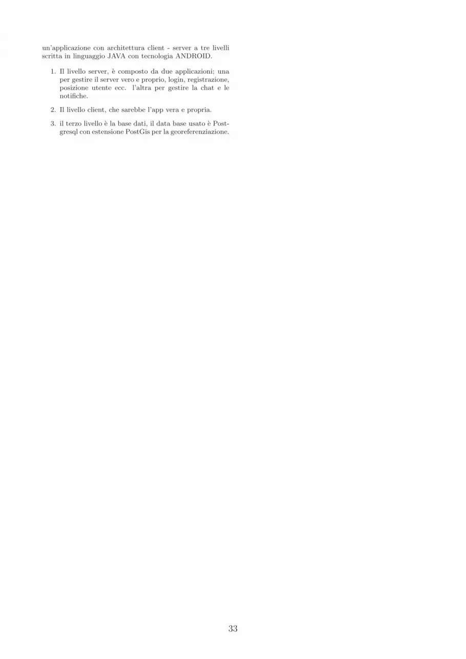
33
un’applicazione con architettura client - server a tre livelli
scritta in linguaggio JAVA con tecnologia ANDROID.
1. Il livello server, e composto da due applicazioni; una
per gestire il server vero e proprio, login, registrazione,
posizione utente ecc. l’altra per gestire la chat e le
notifiche.
2. Il livello client, che sarebbe l’app vera e propria.
3. il terzo livello e la base dati, il data base usato e Post-
gresql con estensione PostGis per la georeferenziazione.

34
NuSeen: an eclipse-based environmentfor the NuSMV model checker
Paolo ArcainiCNR – IDPA
Angelo GargantiniUniversity of Bergamo
Paolo VavassoriUniversity of Bergamo
1. INTRODUCTIONNuSMV [5] is a symbolic model checker originated from
the reengineering, reimplementation and extension of CMUSMV, the original BDD-based model checker developed atCMU by McMillan [4]. The NuSMV project aims at thedevelopment of a state-of-the-art symbolic model checker,designed to be applicable in technology transfer projects: itis a well structured, open, flexible and documented platformfor model checking, and is robust and close to industrialsystems standards [3].
NuSMV has a rich and powerful language that can be usedto describe complex systems, which contain the specificationof the system behavior as Finite State Machines and its ex-pected requirements (often given by temporal formula).
It can also be used as a model checker, both as a BDD-based symbolic model checker, and as a Bounded modelchecker. It has around 50 options when it is called in abatch mode. It is widely used as back end for the verifica-tion of properties of systems given by means of other formalnotations (as for the Abstract State Machines in [1]).
In [2], we have developed a model advisor for NuSMVmodels. The model advisor performs automatic review ofNuSMV models, with the aim of determining if a model isof sufficient quality, where quality is measured as the absenceof certain faults. Vulnerabilities and defects a developer canintroduce during the modeling activity using NuSMV areexpressed as the violation of formal meta-properties. Thesemeta-properties are then mapped to temporal logic formu-las, and the NuSMV model-checker itself is used as the en-gine of our model advisor to notify meta-properties viola-tions, so revealing the absence of some quality attributes ofthe specification.
2. NUSEEN: A NUSMV ECLIPSE-BASED
ENVIRONMENTNuSeen is an eclipse-based environment for NuSMV, with
the aim of helping NuSMV users. It mainly focuses in easingthe use of the NuSMV tool by means of graphical elementslike buttons, menu, text highlighting, and so on. It features:
• A language defined by a grammar (concrete syntax)and provided with metamodel (abstract syntax)
• An editor that can be used to write NuSMV modelsand provides an useful feedback like syntax highlight-ing, autocompletion, and outline.
• A way to execute the NuSMV model checker insideeclipse.
• An integrated version of the model advisor which canbe executed in eclipse.
2.1 Language and editorNuSeen introduces the definition of the language and of
the editor for NuSMV by Xtext [6]. Xtext is a frameworkfor development of programming languages and domain spe-cific languages. It covers all aspects of a complete languageinfrastructure, from parsers, over linker, compiler or inter-preter to fully-blown top-notch Eclipse IDE integration. Itcomes with good defaults for all these aspects and at thesame time every single aspect can be tailored to your needs.We have defined a grammar for the NuSMV notation in theXtext format. From that, we automatically obtain:
1. a meta-model for the language in the form of an EMF(eclipse metamodeling framework) model in the ecoreformat. It represents the abstract syntax of our lan-guage in terms of classes and relations. From the meta-model, we automatically obtain the Java APIs that areable to manage (query, create, and modify) NuSMVmodels and parts of them. This allows the integrationof NuSMV with other Java-based tools.
2. an editor with syntax coloring based on the lexicalstructure, content assist that proposes valid code com-pletions at any place in the document, helping userswith the syntactical details of the language, validationand quick fixes, linking errors, the outline view, findreferences, etc.
The editor can be easily extended in order to support extrasemantics validation rules, particular rules for indentationand outlining, and other ad hoc editing rules.
2.2 NuSMV executorNuSeen allows the user to run NuSMV from within eclipse.
We exploit the launching framework in Eclipse. We haveperformed the following steps:
1. The first step consists in declaring a config type forNuSMV models, by extending the non-ui extensionpoint launchConfigurationTypes in the (non-ui) pack-age org.eclipse.debug.core.
2. The extension is implemented in a class that actuallyexecutes NuSMV with the model chosen by the user.
3. We then prepare the launch configuration dialog (oftencalled LCD) by defining an extension for the extension
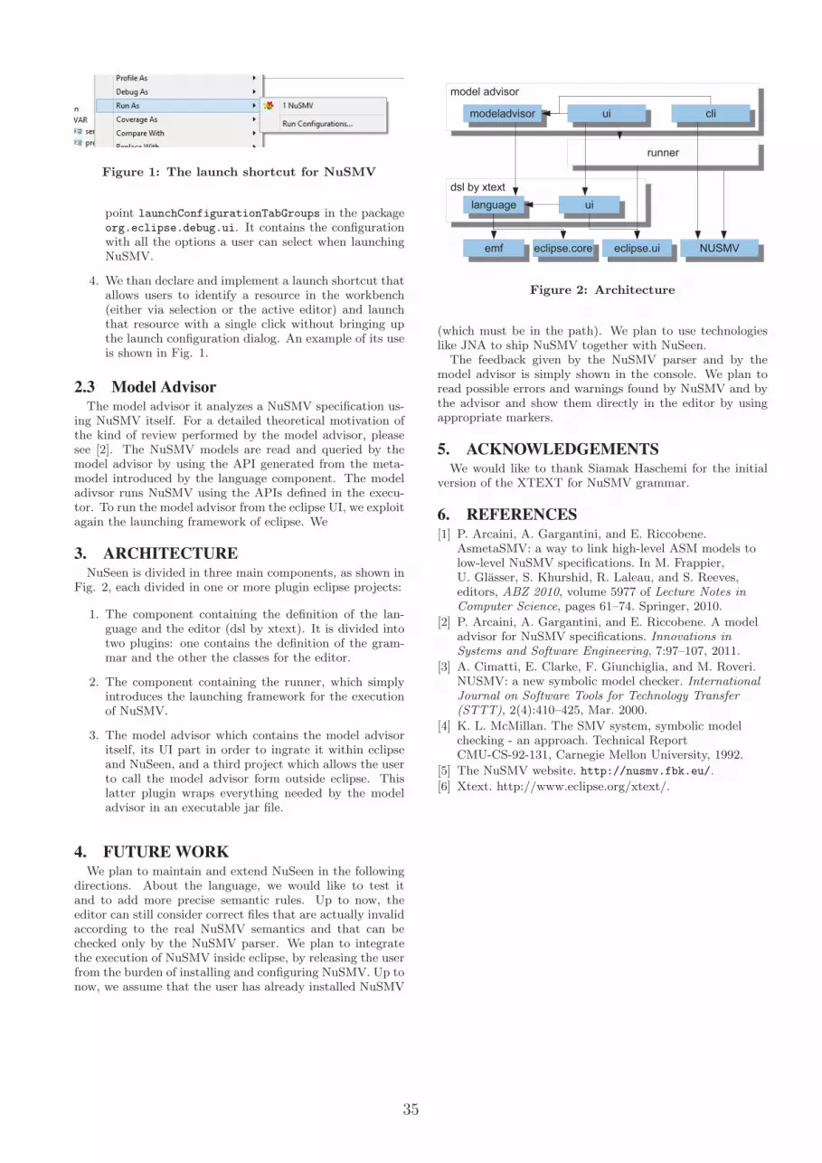
35
Figure 1: The launch shortcut for NuSMV
point launchConfigurationTabGroups in the packageorg.eclipse.debug.ui. It contains the configurationwith all the options a user can select when launchingNuSMV.
4. We than declare and implement a launch shortcut thatallows users to identify a resource in the workbench(either via selection or the active editor) and launchthat resource with a single click without bringing upthe launch configuration dialog. An example of its useis shown in Fig. 1.
2.3 Model Advisor
The model advisor it analyzes a NuSMV specification us-ing NuSMV itself. For a detailed theoretical motivation ofthe kind of review performed by the model advisor, pleasesee [2]. The NuSMV models are read and queried by themodel advisor by using the API generated from the meta-model introduced by the language component. The modeladivsor runs NuSMV using the APIs defined in the execu-tor. To run the model advisor from the eclipse UI, we exploitagain the launching framework of eclipse. We
3. ARCHITECTURE
NuSeen is divided in three main components, as shown inFig. 2, each divided in one or more plugin eclipse projects:
1. The component containing the definition of the lan-guage and the editor (dsl by xtext). It is divided intotwo plugins: one contains the definition of the gram-mar and the other the classes for the editor.
2. The component containing the runner, which simplyintroduces the launching framework for the executionof NuSMV.
3. The model advisor which contains the model advisoritself, its UI part in order to ingrate it within eclipseand NuSeen, and a third project which allows the userto call the model advisor form outside eclipse. Thislatter plugin wraps everything needed by the modeladvisor in an executable jar file.
4. FUTURE WORK
We plan to maintain and extend NuSeen in the followingdirections. About the language, we would like to test itand to add more precise semantic rules. Up to now, theeditor can still consider correct files that are actually invalidaccording to the real NuSMV semantics and that can bechecked only by the NuSMV parser. We plan to integratethe execution of NuSMV inside eclipse, by releasing the userfrom the burden of installing and configuring NuSMV. Up tonow, we assume that the user has already installed NuSMV
����������
������ ������
��������������������
� ����� ����
������������������������
������������������������
���� ������� ���
����������������������
����
������
Figure 2: Architecture
(which must be in the path). We plan to use technologieslike JNA to ship NuSMV together with NuSeen.The feedback given by the NuSMV parser and by the
model advisor is simply shown in the console. We plan toread possible errors and warnings found by NuSMV and bythe advisor and show them directly in the editor by usingappropriate markers.
5. ACKNOWLEDGEMENTS
We would like to thank Siamak Haschemi for the initialversion of the XTEXT for NuSMV grammar.
6. REFERENCES
[1] P. Arcaini, A. Gargantini, and E. Riccobene.AsmetaSMV: a way to link high-level ASM models tolow-level NuSMV specifications. In M. Frappier,U. Glasser, S. Khurshid, R. Laleau, and S. Reeves,editors, ABZ 2010, volume 5977 of Lecture Notes inComputer Science, pages 61–74. Springer, 2010.
[2] P. Arcaini, A. Gargantini, and E. Riccobene. A modeladvisor for NuSMV specifications. Innovations inSystems and Software Engineering, 7:97–107, 2011.
[3] A. Cimatti, E. Clarke, F. Giunchiglia, and M. Roveri.NUSMV: a new symbolic model checker. InternationalJournal on Software Tools for Technology Transfer(STTT), 2(4):410–425, Mar. 2000.
[4] K. L. McMillan. The SMV system, symbolic modelchecking - an approach. Technical ReportCMU-CS-92-131, Carnegie Mellon University, 1992.
[5] The NuSMV website. http://nusmv.fbk.eu/.
[6] Xtext. http://www.eclipse.org/xtext/.