trends in modeling of porous media combustion
TRANSCRIPT

This article appeared in a journal published by Elsevier. The attachedcopy is furnished to the author for internal non-commercial researchand education use, including for instruction at the authors institution
and sharing with colleagues.
Other uses, including reproduction and distribution, or selling orlicensing copies, or posting to personal, institutional or third party
websites are prohibited.
In most cases authors are permitted to post their version of thearticle (e.g. in Word or Tex form) to their personal website orinstitutional repository. Authors requiring further information
regarding Elsevier’s archiving and manuscript policies areencouraged to visit:
http://www.elsevier.com/copyright
Author's personal copy
Trends in modeling of porous media combustion
M. Abdul Mujeebu a,*, M. Zulkifly Abdullah a, A.A. Mohamad b, M.Z. Abu Bakar c
a Porous Media Combustion Laboratory, School of Mechanical Engineering, Universiti Sains Malaysia, Engineering Campus, 14300 Nibong Tebal, Penang, MalaysiabCollege of Engineering, Alfaisal University, Riyadh 11533, P.O. Box 50927, Saudi Arabiac School of Chemical Engineering, Universiti Sains Malaysia, Engineering Campus, 14300 Nibong Tebal, Penang, Malaysia
a r t i c l e i n f o
Article history:Received 14 September 2009Accepted 11 February 2010Available online 23 March 2010
Keywords:Porous media combustionExcess enthalpyNumerical modelingReaction kineticsLocal thermal equilibriumFiltration combustionRadiant burners
a b s t r a c t
Porous media combustion (PMC) has interesting advantages compared with free flame combustion dueto higher burning rates, increased power dynamic range, extension of the lean flammability limits, andlow emissions of pollutants. Extensive experimental and numerical works were carried out and are stillunderway, to explore the feasibility of this interesting technology for practical applications. For thispurpose, numerical modeling plays a crucial role in the design and development of promising PMCsystems. This article provides an exhaustive review of the fundamental aspects and emerging trends innumerical modeling of gas combustion in porous media. The modeling works published to date arereviewed, classified according to their objectives and presented with general conclusions. Numericalmodeling of liquid fuel combustion in porous media is excluded.
� 2010 Elsevier Ltd. All rights reserved.
Contents
1. Introduction . . . . . . . . . . . . . . . . . . . . . . . . . . . . . . . . . . . . . . . . . . . . . . . . . . . . . . . . . . . . . . . . . . . . . . . . . . . . . . . . . . . . . . . . . . . . . . . . . . . . . . . . . . . . . . . . . . . . . . 6282. The art of PMC modeling . . . . . . . . . . . . . . . . . . . . . . . . . . . . . . . . . . . . . . . . . . . . . . . . . . . . . . . . . . . . . . . . . . . . . . . . . . . . . . . . . . . . . . . . . . . . . . . . . . . . . . . . . . 628
2.1. Governing equations . . . . . . . . . . . . . . . . . . . . . . . . . . . . . . . . . . . . . . . . . . . . . . . . . . . . . . . . . . . . . . . . . . . . . . . . . . . . . . . . . . . . . . . . . . . . . . . . . . . . . . . . . . 6282.2. Boundary conditions . . . . . . . . . . . . . . . . . . . . . . . . . . . . . . . . . . . . . . . . . . . . . . . . . . . . . . . . . . . . . . . . . . . . . . . . . . . . . . . . . . . . . . . . . . . . . . . . . . . . . . . . 6292.3. Radiation modeling . . . . . . . . . . . . . . . . . . . . . . . . . . . . . . . . . . . . . . . . . . . . . . . . . . . . . . . . . . . . . . . . . . . . . . . . . . . . . . . . . . . . . . . . . . . . . . . . . . . . . . . . . 6292.4. Combustion modeling . . . . . . . . . . . . . . . . . . . . . . . . . . . . . . . . . . . . . . . . . . . . . . . . . . . . . . . . . . . . . . . . . . . . . . . . . . . . . . . . . . . . . . . . . . . . . . . . . . . . . . . . 630
3. History of PMC modeling . . . . . . . . . . . . . . . . . . . . . . . . . . . . . . . . . . . . . . . . . . . . . . . . . . . . . . . . . . . . . . . . . . . . . . . . . . . . . . . . . . . . . . . . . . . . . . . . . . . . . . . . . . 6304. Further advances in modeling . . . . . . . . . . . . . . . . . . . . . . . . . . . . . . . . . . . . . . . . . . . . . . . . . . . . . . . . . . . . . . . . . . . . . . . . . . . . . . . . . . . . . . . . . . . . . . . . . . . . . . .6315. Multidimensional modeling . . . . . . . . . . . . . . . . . . . . . . . . . . . . . . . . . . . . . . . . . . . . . . . . . . . . . . . . . . . . . . . . . . . . . . . . . . . . . . . . . . . . . . . . . . . . . . . . . . . . . . . . .637
5.1. Need for multidimensional modeling . . . . . . . . . . . . . . . . . . . . . . . . . . . . . . . . . . . . . . . . . . . . . . . . . . . . . . . . . . . . . . . . . . . . . . . . . . . . . . . . . . . . . . . . . . . 6375.2. 2D models . . . . . . . . . . . . . . . . . . . . . . . . . . . . . . . . . . . . . . . . . . . . . . . . . . . . . . . . . . . . . . . . . . . . . . . . . . . . . . . . . . . . . . . . . . . . . . . . . . . . . . . . . . . . . . . . . . 6375.3. 2D-modeling of non-premixed filtration combustion . . . . . . . . . . . . . . . . . . . . . . . . . . . . . . . . . . . . . . . . . . . . . . . . . . . . . . . . . . . . . . . . . . . . . . . . . . . . 6395.4. PMC modeling applied to IC engines . . . . . . . . . . . . . . . . . . . . . . . . . . . . . . . . . . . . . . . . . . . . . . . . . . . . . . . . . . . . . . . . . . . . . . . . . . . . . . . . . . . . . . . . . . . 6405.5. 3D models . . . . . . . . . . . . . . . . . . . . . . . . . . . . . . . . . . . . . . . . . . . . . . . . . . . . . . . . . . . . . . . . . . . . . . . . . . . . . . . . . . . . . . . . . . . . . . . . . . . . . . . . . . . . . . . . . 641
6. Modeling of cylindrical (radial flow)and spherical burner geometries . . . . . . . . . . . . . . . . . . . . . . . . . . . . . . . . . . . . . . . . . . . . . . . . . . . . . . . . . . . . . . . . . . . . .6417. Modeling of PMC with liquid fuel . . . . . . . . . . . . . . . . . . . . . . . . . . . . . . . . . . . . . . . . . . . . . . . . . . . . . . . . . . . . . . . . . . . . . . . . . . . . . . . . . . . . . . . . . . . . . . . . . . . . 6448. Non-conventional modeling techniques . . . . . . . . . . . . . . . . . . . . . . . . . . . . . . . . . . . . . . . . . . . . . . . . . . . . . . . . . . . . . . . . . . . . . . . . . . . . . . . . . . . . . . . . . . . . . . 644
8.1. Flamelet-generated manifolds method . . . . . . . . . . . . . . . . . . . . . . . . . . . . . . . . . . . . . . . . . . . . . . . . . . . . . . . . . . . . . . . . . . . . . . . . . . . . . . . . . . . . . . . . . 6448.2. Lattice Boltzmann method . . . . . . . . . . . . . . . . . . . . . . . . . . . . . . . . . . . . . . . . . . . . . . . . . . . . . . . . . . . . . . . . . . . . . . . . . . . . . . . . . . . . . . . . . . . . . . . . . . . . 6458.3. Mesh-based microstructure representation algorithm (MBMRA) . . . . . . . . . . . . . . . . . . . . . . . . . . . . . . . . . . . . . . . . . . . . . . . . . . . . . . . . . . . . . . . . . . . 645
9. Concluding remarks . . . . . . . . . . . . . . . . . . . . . . . . . . . . . . . . . . . . . . . . . . . . . . . . . . . . . . . . . . . . . . . . . . . . . . . . . . . . . . . . . . . . . . . . . . . . . . . . . . . . . . . . . . . . . . . .647Acknowledgements . . . . . . . . . . . . . . . . . . . . . . . . . . . . . . . . . . . . . . . . . . . . . . . . . . . . . . . . . . . . . . . . . . . . . . . . . . . . . . . . . . . . . . . . . . . . . . . . . . . . . . . . . . . . . . . . 647References . . . . . . . . . . . . . . . . . . . . . . . . . . . . . . . . . . . . . . . . . . . . . . . . . . . . . . . . . . . . . . . . . . . . . . . . . . . . . . . . . . . . . . . . . . . . . . . . . . . . . . . . . . . . . . . . . . . . . . . . 647
* Corresponding author. Tel.: þ6045996310.E-mail address: [email protected] (M.A. Mujeebu).
Contents lists available at ScienceDirect
Progress in Energy and Combustion Science
journal homepage: www.elsevier .com/locate/pecs
0360-1285/$ e see front matter � 2010 Elsevier Ltd. All rights reserved.doi:10.1016/j.pecs.2010.02.002
Progress in Energy and Combustion Science 36 (2010) 627e650

Author's personal copy
1. Introduction
Porous media combustion (PMC), offers high power density,high power dynamic range and very low NO and CO emissions,owing to the high levels of heat capacity, conductivity andemissivity of the solid matrix, compared to a gas. Heat feed-backfrom the high temperature reaction (post-flame) zone, by radia-tion and conduction through solid medium serves to heat theporous solid in the preheat (pre-flame) zone, which, in turn,convectively preheats the incoming reactants. This regenerativeinternal heat feedback mechanism results in several interestingcharacteristics relative to a free-burning flame, namely higherburning velocities, extension of the lean flammability limit, lowemission of pollutants and the ability to burn fuels with a lowenergy content. Many researchers published excellent reviews onthis interesting topic [1e8]. Our recent reviews [9,10], givecomprehensive and updated information on PMC and its wide-spread applications. However, an exclusive review on modeling isstill lacking.
Development of advanced combustion systems to meet globalenergy efficiency and emission standards requires mathematicalmodeling of the systems. In the recent past, models with varyingdegrees of sophistication have been developed and applied to theproblem of predicting flame speeds, emission, temperature andconcentration profiles, and radiative efficiency of combustionwithin porous media (PM). The current study includes a thoroughreview on PMCmodeling, from its history to the current stage. Afterdescribing the basic modeling aspects the documented works arecategorized according to their methodologies and presented inchronological order. While describing the previous works, focus isgiven only to highlighting the modeling techniques and thatinformation which indicates the strength of each technique inhandling the problem under study. In this article we deal with thecombustion of gaseous fuel; the readers are encouraged to consultour recent review [11] for more details on modeling of liquid fuelcombustion in PM.
2. The art of PMC modeling
PMC is complex in the sense that it requires coupled solutionof heat transfer and chemical kinetics. Furthermore, as the PMC ischaracterized by the presence of both solid and fluid (gas orliquid) media, governing equations must be developed for boththe phases. Fig. 1 illustrates the basic heat transfer mechanisms ina PM burner.
The basic equations governing the combustion of gaseousfuels in PM and the resulting heat transfer modes are energy,continuity, momentum and species conservation equations. Inaddition, the mathematical models of chemical reaction kineticsand radiation effects of solid and gas phases are also included. Asfar as the energy equation is concerned, the earlier trend was toassume a local thermal equilibrium between the solid and gasphases so that only one equation was enough to represent theenergy balance during the process (volume-averaged or singlemedium or one-temperature model). This assumption was latershown to be inaccurate for PMC modeling [4,12]. However, sincethe work of Chen et al. [13], use of separate energy equations forsolid and gaseous phases (two-medium or two-temperaturemodel) has generally been followed. The effects of conductionand radiation, as well as convection of solid with the gas, areincorporated in the solid phase equation. Conduction, chemicalenergy release due to combustion and convection with the solidphase are included in the gas phase equation. Terms for Dufoureffect (the occurrence of a heat flux due to chemical potential
gradient), and Soret effect (mass diffusion due to temperaturegradients) which are often neglected, may also be incorporated.In order to provide a basic understanding of PMC modelingapproach, the model proposed by Mohamad [5] for a simpleburner geometry (axial flow burner) as shown in Fig. 2, is pre-sented as follows:
Somegeneral assumptions1. The thermo-physical properties of the air (density, thermal
conductivity and specific heat) are assumed to be functions ofthe temperature and species concentration.
2. The pressure drop through the porous burner is not high andits effect on the thermo-physical properties can be neglected.
3. The properties of the solid phase are constant.4. There is thermal non-equilibrium between the gas and the
solid phase.5. The air and fuel are completely premixed at a given temper-
ature and equivalence ratio.6. The solid phase is gray, and emits, scatters, and absorbs
radiant energy, and the gas phase is transparent.7. Flow is incompressible and one-dimensional so that the
momentum equation need not be solved explicitly.
2.1. Governing equations
The energy equation for the gas phase [5]:
v
vt
�4rgCpgTg
�þ v
vx
�4rgCpgnTg
�¼ v
vx
�4kg
vTgvx
�� ð1� fÞhv
�Tg � Ts
�þ 4DHcSfg ð1Þ
where 4, r,Cp, T, v, k, hv, ΔHc and Sfg are the porosity, density, specificheat, temperature, velocity, thermal conductivity, volumetric heattransfer coefficient, enthalpy of combustion and rate of fuelconsumption per unit volume, respectively. Subscripts g and s referto gaseous and solid phases, respectively.
The energy equation for the solid phase [5]:
v
vtðrsCsTsÞ ¼ v
vx
�ksvTsvx
�� hv
�Ts � Tg
��V$F (2)
The term V$F represents the radiative transport equation and isgiven by:
V$F ¼ �ð1� uÞðG� 4 EbÞ (3)
where u is the single scattering albedo and the irradiance G isgoverned by
V2G ¼ h2ðG� 4 EbÞ (4)
and
h2 ¼ 3b2ð1� uÞð1� guÞ (5)
where Eb is the Planck black body emitted flux, sT4, F is the radiativeflux, F ¼ Fxiþ fyj, b is the extinction coefficient, and g is anasymmetry factor.
The conservation equation for the mass fraction of the fuel isgiven as follows [5]:
v
vt
�rgmE
�þ v
vx
�rgnmf
�¼ v
vx
�DABrg
vmfvx
�� Sfg (6)
M.A. Mujeebu et al. / Progress in Energy and Combustion Science 36 (2010) 627e650628

Author's personal copy
where mf is the fuel mass fraction and DAB is the diffusioncoefficient.
A single-step Arrhenius type chemical kinetic equation as givenbelow is normally adopted in modeling the combustion [5]:
Sfg ¼ f r2gmfmO2exp
�E
RTg
�(7)
where f, mO2, E and R refer to pre-exponential factor, oxygen massfraction, activation energy and gas constant, respectively.
2.2. Boundary conditions
The following boundary conditions are adopted for the gas, solidand species [5]:
Gas:
Tgj ¼ Tin at x ¼ 0;
vTgvx
��� ¼ 0 at x ¼ L;(8)
Solid:
Species:
mf ¼ mf ;in at x ¼ 0;
vmfvx
¼ 0 at x ¼ L:(10)
The control volume approach, or the finite-difference method,can be used to solve the governing equations. The solution isadvanced in time by using a fully implicit technique and this wasnecessary due to the stiffness of the governing matrix of theproblem. Also, it is necessary to use an adaptive grid, or a very finegrid, to ensure the accuracy of the solution [5].
The above model is one-dimensional (1D) and time-dependent,with single step reaction kinetics and is presented as an example.However, depending on the nature of the problem under consider-ation, different researchers have adopted different types of modelssuch as two- dimensional (2D) & three - dimensional (3D) models,and cylindrical & spherical systems of modeling. Non-conventionaltechniques such as flamelet-generated manifolds (FGM) method,Lattice Boltzmann method (LBM) and mesh-based microstructurerepresentation algorithm (MBMRA) are also reported. We willdescribe all of these models in the following sections.
2.3. Radiation modeling
The radiation problem has been handled by a variety of fashions.Ratzel [14] introduced the P3 approximation for radiationmodeling.Lawson and Norbury [15] had used the Rosseland approximation inwhich the radiation is modeled as a diffusive process. Studies ofthermal radiation had also been reported by Tong and Sathe [16]and Andersen [17]. However, the model predictions were notcomparable with the experimental data. Further, results indicatedthat the correct radiation mode of heat transfer is an importantfactor. More realistic models were reported by Chen et al. [18],Yoshizawa et al. [19] and Sathe et al. [20,21]. Detailed radiationmodels by considering emission, absorption and scattering, were
Fig. 1. Schematic of a typical two-layer premixed PM burner, showing the major heat transfer modes and directions.
Fig. 2. Physical model for axial flow PMB[5].
hinhTg;in � Tsjx¼0
iþ s˛in
hT4in;amb � T4
s jx¼0
i¼ �ks
vTsvx
jx¼0
at x ¼ 0;houthTout;amb � Tsjx¼L
iþ s˛out
hT4out;amb � T4
s jx¼L
i¼ �ks
vTsvx
jx¼L
at x ¼ L (9)
M.A. Mujeebu et al. / Progress in Energy and Combustion Science 36 (2010) 627e650 629

Author's personal copy
also reported [22e26]. Hayashi [27] provided an outline of theprevious works on radiation modeling from 1991 to 2003. Subse-quent developments will be discussed in the ensuing sections.
2.4. Combustion modeling
The chemical reaction may be modeled by considering eithera single step or multi step reaction kinetics. In either case, theresulting reaction may be extremely stiff owing to the temperaturedependence of the chemical reactions, and the solution fortemperature, flame speed and species distributionwithin the PM isdifficult. Moreover convergence to accurate solution is a difficulttask, and this situation necessitates the development of modifiedcodes. The standard techniques such as PREMIX Code which issuccessfully used for premixed combustion analysis for openflames often fail and must be modified when applied to PMC [1].Even though considering single step reaction kinetics is sufficientfor normal PMC modeling problems, the detailed reaction kineticsmust be incorporated in order to obtain realistic predictions ofpollutants formation. The general purpose chemical kineticprogram package, CHEMKIN, introduced by Kee et al. [28] and theGRI-Mech (versions 1.2, 2.11 and 3) series of detailed chemicalreaction mechanism for natural gas combustion, introduced by theUniversity of California at Berkeley, USA (http://www.me.berkeley.edu/grimech/) are some of the detailed reaction mechanismsreported.
3. History of PMC modeling
For convenience, the modeling trends up to 1997 are includedin this section which mainly describes 1D models. However,please note that the works mentioned in Section 2 under radia-tion modeling and those cited in Section 5 are also part of thehistory.
As far as the authors are aware, Takeno, Echigo and their co-workers [29e31,19] are the pioneers in PMC modeling. A modelwas proposed by Takeno and Sato [29] to study the effects of massflow rate and heat transfer coefficient on flame characteristics inexcess enthalpy flames and suggested inserting a porous, highlyconductive solid into the flame to conduct heat from the solid to thereactants. They described excess enthalpy as a measure of theexcess amount of enthalpy stored in the flame zone. They foundthat increasing the mass flow rate above the laminar burning rateincreased the heat release rate and the reaction zone became moreconcentrated. This model was modified by Takeno et al. [30], whoinvestigated the effects of finite solid length. They identifieda critical mass flow rate above which the flame was not self-sustaining. Beyond the critical flow rate, the flame blew off. Thecritical flow rate was dependent upon the type of combustionsystem; particularly the length of the solid and the heat losses inthe system. Takeno and Murayama [31] computationally studiedthe effect of increasing the length of the reaction zone by insertinga high-conductivity porous solid at a constant temperature into theflame. Echigo [32] investigated the ability of converting some of theenthalpy of a non-reacting hot gas for radiative transfer from a PMthrough which the gas was flowing. Subsequently, Echigo andco-workers [19,33,34] provided a rigorous model for multi-modeheat transfer, Arrhenius-type one-step reaction kinetics and exactsolution for radiative transfer in the absorbing/emitting medium. Itwas assumed that the burner could be divided into three regions;an upstream region where no reactions occur, so that the gas/solidtemperature were constant; a combustion zone, where the one-step combustion reaction goes to completion; and an exit zone,where the gases leaving the combustion zone again undergo no
further reaction. Based on these assumptions, temperature profilesin the gas were predicted.
Chen et al. [18] applied the energy and species equations tomodel PM burners. A multi-step mechanism for methanecombustion was used in the model, based on the reaction set fromthe code CHEMKIN by Kee et al. [28] which includes 17 species and55 reactions. Parametric variations of the thermal conductivity ofthe solid, volumetric heat transfer coefficient and radiative prop-erties were carried out to determine their effect on flame speed andtemperature profiles. Complete solution of the radiative transferequation was used, but scattering was neglected. A very high localheat transfer coefficient was assumed that the solid and gastemperatures were locally equal, consequently only one energyequation needed to be solved. However, this assumption wasremoved in their subsequent study [13] in which the morecomplete multi-step reaction kinetics were substituted for theone-step mechanism. Consequently, the super-adiabatic flametemperatures predicted by others were disappeared. Moreover, themulti-step reactions spreaded out the combustion energy releaseover a broader flame front rather than over the narrow flame fronttypical of one-step reaction mechanisms.
The importance of radiation on velocity and flame structure inPMC was studied by Yoshizawa et al. [19] by means of an analyticalmodel. Their model burner was divided into three sections andcombustion occurredwithin themiddle section. Physical propertieswere assumed to be constant and combustion was modeled bya one-step reaction. Solid and gas phase conduction, solid radiation,and convection between the solid and gas effects were included.They concluded that radiation is more important than solidconduction in excess enthalpy burning.
Hsu et al. [35] and Hsu and Matthews [36] extended the modelof Chen et al. [13] to include the Zeldovich mechanism (3 reactionsand two additional species) for NO chemistry, and experimentalvalues for thermal conductivity and radiative extinction coefficient.In addition, a two-region burner with a small-pore size upstreamsection and large-pore downstream section was modeled. Theycompared the modeling results with the experimental data by Hsuand Howell [37] who investigated two-region porous mediaburners made of partially stabilized zirconia of various pores size.The model was accurate in predicting the maximum flame speedssustainable within the burner (blow-off limit); the minimumequivalence ratio for sustainable combustion; the trends of flamespeed with pore diameter and equivalence ratio and the measuredemissions of CO, CO2 and NO.
Sathe el al. [20,38] carried out a similar numerical modelingeffort, using single-step chemistry but including the effort ofisotropic scattering. They observed that the flame could bestabilized at the exit or entrance to the burner, but that bestradiant output could be obtained if the flame were located nearthe burner centre. Good agreement between wall-temperatureprofile predictions and measurements were observed fora particular set of parameters used in the model. They alsopresented a conduction, convection, radiation, and combustionmodel [21,39] to study the premixed flame stabilization inporous radiant burners. The influence of the flame location, theradiative properties of the porous material, the solid thermalconductivity, and stoichiometry on the flame speed and stabilitywere determined. The PM was allowed to emit, absorb, andscatter radiant energy. Non-local thermal equilibrium betweenthe solid and gas was accounted for by introducing separateenergy equations for the two phases. Heat release was describedby a single-step, global reaction. It was observed that flamepropagation near the edge of the porous layer was controlledmostly by solid-phase conduction; whereas, in the interior bothsolid conduction and radiation heal transfer were important. The
M.A. Mujeebu et al. / Progress in Energy and Combustion Science 36 (2010) 627e650630

Author's personal copy
radiative characteristics of the porous matrix such as the opticaldepth and scattering albedo were also shown to have a consid-erable effect on flame stability. It was also revealed that formaximizing the radiant output the optical depth should beabout ten and the flame should be stabilized near the center ofthe PM.
A model was proposed by McIntosh and Prothero [40] for thesurface- stabilized combustion of a premixed gas mixture near thedownstream surface of a porous solid. Using large-activation-energy asymptotic methods an analytical solution was derivedfor the gas and solid temperature profiles within the burner. Themodel predicted operational features of practical surfacecombustion burners such as radiant efficiency, flame lift-off andflashback limits, and thermal range of surface combustionoperation. Singh el al. [41] modeled burner behavior using sepa-rate solid and gas energy equations, and used the two-fluxapproximation for the radiative transfer. They assumed that allchemical heat release occurred within a defined small region, sono chemical kinetics was used in the solution. They examined theeffect of forward radiative scattering and found it to be small. Asimplified model was presented by Nakamura et al. [42] to studythe mechanism of methaneeair combustion on the surface ofa porous ceramic plate. The effects of such parameters as thicknessof porous ceramic plates, equivalence ratio of mixed gas and heatload on the combustion characteristics were examined. Super-adiabatic combustion with reciprocating flow in a PM was inves-tigated by Hanamura et al. [43] through an unsteady and two-temperature model. The working gas was assumed non-radiating, the PM was able to emit and absorb thermal radiationin local thermodynamic equilibrium, the Lewis number was unity,and the physical properties were constant. Modeling of porousradiant burners with large extinction coefficients was presentedby Escobedo and Viljoen [44] who performed a comparative studyof numerical and analytical results and shown that the analyticalmethod captured all the features of the system and could be usedfor quantitative applications.
Rabinovich et al. [45] proposed an unsteady state model of gascombustion in a PM, treated as a discrete structure. Each element ofthis regular periodic structure consisted of the three elements:a solid particle, a gas flow zone, and a gas stagnation zone, as shownin Fig. 3. Separate energy equations were developed for theseelements. It was assumed that combustion occurred in the flowzones; the solid particles and stagnation zones were chemically
inert. Further, the main heat and mass transfer processes occurredalong the direction of gas flow and combustion front propagation.Numerical simulation of the opposing waves of premixedmethane-air combustion in the discrete-modeled PM revealed the pulsatingnature of the process. The maximal temperature and burning ratein the combustion front as well as the velocity of its propagationwere low in the regions of the gas flow zone, which were adjacentto the particles, and increased in the neighborhood of the stagna-tion zone.
Lee et al. [46] had experimentally and numerically investigatedthe combustion of premixed propane-air mixture inside a honey-comb ceramic. They used 1D flame structure model and a one-stepreaction mechanism. The model of Sathe et al. [21] was utilized byKulkarni and Peck [47] with improvements to boundary conditionsand modifications to include multistep combustion and non-homogeneous material properties. They studied the heating effec-tiveness of a composite porous radiant burner (PRB) and provedthat the radiative output of a PRB could be improved by optimizingthe burner properties upstream and downstream of the flame.Rumminger et al. [48] developed a one-dimensional steady statemodel in which they predicted flame location and flame structurein a two-layer PM burner.
4. Further advances in modeling
Byrne and Norbury [49] introduced a model to examine theeffect of solid conversion on the downstream temperature fortravelling combustion waves in porous media. Bouma [50]studied flame stabilization in methane- air combustion onceramic foam surface burners using simple analytical andstationary models for the flame. As an excellent breakthrough inPMC modeling, Zhou and Pereira [51] had introduced a modelwhich could take care of fluid flow, combustion and heat transferin porous media. They modeled 1D combustion and heat transferof methane/air fuel in a two-region burner with a small-pore sizeupstream section and large-pore downstream section. Theyconsidered a detailed reaction mechanism describing formationand destruction of nitrogen oxides, which included 27 speciesand 73 reactions. So the study of pollutants (CO and NO) and theeffect of radical generation in the preheating zone were possible.The separated energy equations for gas and solid matrix withconductive and radiative heat transfer were modeled by couplinggas and solid through convective heat transfer. They investigatedthe effect of excess air ratio, thermal power, solid conductivityand radiative heat transfer to the temperature profiles and theemission of CO and NO. The details of the model are presentedhere, for the benefit of the readers.
Fig. 4 shows the schematic of the physical model which con-sisted of two porous ceramic cylinders stacked together and insu-lated around the circumference. The upstream and downstreamceramic cylinders were referred to as preheating region (PR) andthe stable burning region (SBR), respectively. The porous ceramicwas a reticulated matrix that consisted of alumina oxide (Al2O3).Pore densities of 10 pores per inch (PPI) were used for the SBR andthe PR had 66 PPI. The length of PR was 5 cm, and the SBR was10 cm.
The main assumptions were, adiabatic burner walls, one e
dimensional flame structure and heat transfer mechanisms, negli-gible catalytic effects of the high temperature solid, Dufour effect,bulk viscosity and body forces, isobaric flow and non-radiatingmixture. Accordingly, the 1D laminar flame code PREMIX code[28] was modified for the solution purpose. This code allowed forthe use of multi-step detailed chemical kinetics [52], accounted forthe Soret effect, and used the TRANFIT subroutine [53] for accuratedetermination of the transport properties of the gas. This code was
Fig. 3. The porous medium model with discrete periodic structure proposed byRabinovich et al. [45].
M.A. Mujeebu et al. / Progress in Energy and Combustion Science 36 (2010) 627e650 631

Author's personal copy
modified to solve a separate energy equation for the solid matrixwith radiative and conductive heat transport through the solidmatrix and convective heat transfer between the solid and the gas.
Amodified skeletalmechanism [54] driven from the full reactionmechanism [55] for methane oxidation was used to simulate thechemical reactions in porous media. The full mechanism contained48 species and 225 elementary reactions. However, when thismechanism was used in the calculation of combustion in porousmedia, the convergence to an accurate solution was uncertain anddifficult because the resulting equation set was extremely stiff.Hence they considered a skeletal mechanism which included themost important reactions, consisted of 27 species and 73 reactions.
Continuity equation [51]
dðruÞdx
¼ 0 (11)
Species conservation equation [51]
rAudYkdx
þ ddx
ðrAYkVkÞ � A _ukWk ¼ 0; k ¼ 1;2;.;K (12)
where _uk is the production rate of the k-th species. The i-thchemical reaction is of the general form
Xkk¼1
n0 kixk4Xkk¼1
n00 kixk
_uk ¼Xli¼1
�ðnÞ00ki � n0ki��
kfiYkk¼1
½xk�n0�kri
Ykk¼1
½xk�n00�
kfi ¼ AiTbiexp
�� EiRcT
�(13)
where kf i is the forward rate constant for reaction i and kri is thereverse rate constant.
Convection was included by solving separate energy equationsfor the solid and the gas and coupling them through a convectiveheat transfer coefficient. The energy equation for the gas did notinclude radiation terms and the energy equation for the solid didnot include energy liberation (reaction) terms.
Gas phase energy equation [51]
ruAdTdx
� 1Cp
ddx
�lA
dTdx
�þ ACp
Xkk¼1
rYkVkCpkdTdx
þ ACp
_ukhkWk
þ ACp
hvðT � TsÞ ¼ 0 ð14Þ
Solid phase energy equation [51]
ddx
�lsA
dTsdx
�� ddx
ðAqrÞ þ AhvðT � TsÞ ¼ 0 (15)
where ls is the effective solid thermal conductivity qr is the radi-ative heat flux term, hv is the volumetric convection heat transfer
between the solid and the gas. An empirical correlation [56] of thedata in terms of the Nusselt number, Nu ¼ hvd2=lg was taken.
Nu ¼ 0:8191� 7:33
�dL
�Re0:36½1þ15:5ðdLÞ� (16)
where d is the actual pore diameter and L is the thickness of thespecimen in the flow direction. The Reynolds number was definedby Re¼ rUd/m, where U is the superficial or face velocity. Theradiative flux term qr was calculated by the 1D Discrete-Ordinatesmethod. The extinction coefficient b was calculated by the corre-lation presented by Hsu and Howell [37].
b ¼ 3dð1� fÞ (17)
where f is the porosity of the sample. The scattering albedo wasassumed to be 0.8.
The equation of state
r ¼ WPRcT
(18)
Boundary conditions
At the inlet : T ¼ Tin;Y ¼ Yk;in
At the exit :dTdx
¼ 0;dYkdx
¼ 0
The boundary conditions of the solid temperature at the inletand exit were written in the corresponding finite difference formsof Eq. (15).
The above model was successfully validated by using theexperimental data of Pickenacker et al. [57] who constructeda 10 kW PM burner with integrated heat exchanger. Figs. 5 and 6show the comparison of calculated temperature profiles withexperimental data, for power 5 kw and excess air ratio 1.6 and 1.5,respectively. The calculated NO concentration was higher and COconcentration was lower than the measurements. This might bedue to the difference of temperature profiles and the skeletalreaction mechanism. However, the general agreement betweensolution and experiment was within the acceptable limit.
The strength of the above model was tested further [58] withfour combustion models: full mechanism (FM, 49 species and 227elemental reactions), skeletal mechanism (SM, 26 species and 77elemental reactions), 4-step reduced mechanism (4RM, 9 species)and 1-step global mechanism (1GM). The effects of thesemodels ontemperature, species, burning speeds and pollutant emissions wereexamined and compared with experimental data. It was concludedthat the limitation of 1-step global mechanism that it could not beused to predict the pollutant emissions, could be partially elimi-nated by the proposed 4-step reducedmechanism. This 4RMmodelcompared very satisfactorily with the full mechanism in thesimulation of combustion in porous media. It was claimed that the4RM model could improve the stability of the calculation processand could be used with reduced computational resources and cost.
Fig. 4. The physical model used by Zhou and Pereira [51].
M.A. Mujeebu et al. / Progress in Energy and Combustion Science 36 (2010) 627e650632

Author's personal copy
The interesting results and conclusions of this study are not pre-sented in this article due to page limitation.
The stabilization of a lean premixed methaneeair flame in theradiant mode in a ceramic foam surface burner was simulated byBouma and De Goey [59], taking into account the heat transferbetween the gas and the burner and the radiative properties ofthe ceramic material. The combustion was modeled with theskeletal mechanism and the nitrogen chemistry using an accuratepost-processing technique based on the reaction mechanism ofGlarborg et al. [54]. The numerical results were validated withexperiments. It was shown that modeling of the gas radiation isessential for an accurate prediction of CO in the postflame zone.It was also shown that prompt NO, as well as the thermal NO,mechanisms were important for an accurate prediction of thetotal NO emission for combustion in the radiant mode. Thestationary 1D mass balance equations for N - 1 of the N speciesare [59]:
fvrguvYivx
� v
vx
�fvrgDim
vYivx
�¼ fv _ri with i ˛½1;N � 1� (19)
wherefv is the volumetric porosity of the PM, Yi is themass fractionof the ith species,Dim is the diffusion coefficient and r is the density.
Gas phase energy equation [59]
fvrguCpvTgvx
� v
vx
�fvlg
vTgvx
�¼aS
�Ts�Tg
��fn
XNi¼1
hi _riþfv
�XNi¼1
rgCpiDimvYivx
vTgvx
�vqrad;gvx
ð20Þ
Heat transfer between gas and solidmatrix was described by theterm aSðTs�TgÞ with a the heat transfer coefficient and S thespecific internal surface of the PM. The third term on the right wasfor the enthalpy transport due to diffusion of species. The energyflux due to radiation of the product species CO2 and H2O waswritten in differential form:
vqrad;gvx
¼ 2Kps�2T4g � eT4s;x¼0 � T4w
�(21)
Energy equation for the solid phase [59]
� v
vx
�ð1� fvÞls
vTsvx
�¼ �aS
�Ts � Tg
�� vqradvx
(22)
Jugjai and Somjetlertcharoen [60] proposed a two temperaturemodel with one-step chemistry, to study the combustion andmultimode heat transfer in a PM, with and without a cyclic flowreversal. Foutko et al. [61] simulated the experiments of Zhdanoket al. [62]. Radiation was included through an effective solidconductivity, gas-phase transport was neglected and the oxidationof methane was approximated using a single reaction.
Later on, the models of Hanamura et al. [43] and Foutko et al.[61] were modified by Henneke and Ellzey [63] using 1D approachwith detailed chemistry. The initial simulations included solidconduction, radiation (P3 approximation), inter-phase heatexchange, and gas-phase transport including dispersion effects.They investigated the importance of each of these processes to thewave speed. The effect of heat losses on combustion wave propa-gation was clarified by the numerical results. As the above modelcould excellently represent the low-velocity filtration combustion,many researchers have adopted the same in the subsequent works.The computational domain used in this study is shown in Fig. 7.
The conservation equations for mass, gas energy, solid energy,and gas species used by Henneke and Ellzey [63] are:
v�rge�
vtþv�rgeu
�vx
¼ 0 (23)
Fig. 5. Comparison of calculated temperature profiles with measurement for excess airratio 1.6, power 5 kW [51].
Fig. 6. Comparison of calculated temperature profiles with measurement for excess airratio 1.5; power 5 kW [51]. Fig. 7. The computational domain used by Henneke and Ellzey [63].
M.A. Mujeebu et al. / Progress in Energy and Combustion Science 36 (2010) 627e650 633

Author's personal copy
rgCgevTgvt
þ rgCgeuvTgvx
þXi
rgeYiViCgivTgvx
þ eXi
_uihiWi
¼ ev
vx
��kg þ rgCgD
dk�vTgvx
�� hv
�Tg � Ts
�(24)
rsCsð1� eÞvTsvt
¼ ksð1� eÞv2Tsvx2
þ hv�Tg � Ts
�� dqr
dx(25)
rgevYivt
rgeuvYivx
þ v
vxðreYiViÞ � e _uiWi ¼ 0 (26)
Gas densities were computed from the ideal gas equation ofstate for a multi-component mixture:
P ¼ rgRTgW
(27)
The mixture velocities included with the dispersion effect wasgiven by:
VYi ¼ ��DYimþ DYðk mÞ[d
�1=XYi
�vXYi
�vx (28)
Dim was computed using the binary diffusion coefficients, Dij by
Dim ¼ 1� YiPNjsi
Xj
Dij
(29)
As an efficient mechanism to reproduce the combustion wavephenomena under very lean conditions of methane combustion,they used the GRI 1.2 chemical kinetic mechanism [64] whichcontained 32 species and 177 reactions. The radiation wasmodeled using the P3 approximation [14] with scattering.Computations were performed with a time step of 0.5 s (due to thestiffness of the gas-phase equations) so as to treat the radiationproblem explicitly.
Boundary and initial conditions [63]
For the radiative transfer equation, Marshak's boundaryconditions were implemented assuming black boundaries. Initialconditions were obtained from the experimental data of Zhdanoket al. [62]. The solid temperature was initialized to the experi-mentally measured temperature profiles. The gas within thepacked bed was initially at the inlet temperature, but withina very short time, the gas was heated to nearly the solidtemperature and ignited. These rapid transients occurred withinthe first several milliseconds, and nearly steady wave propagationwas observed thereafter. The gas-phase thermochemical andtransport properties were taken from the Chemkin [28] andTranfit [52] packages. The volumetric heat transfer coefficient Nuvwas computed by:
Nuv¼ Asf$dNu, where Asf is the specific surface area which isP/d for spheres in simple packing and Nu was given by:
Nu ¼ 2þ 1:1Re0:6Pr1=2
The dispersion coefficient was correlated by:
Ddk
ag¼ 0:5 Pe
For species diffusion, the following analogous formulawas used.
DmkdDim
¼ 0:5 Pem
The computed wave speeds were compared to the experimentaland theoretical data of Zhdanok et al. [62] assuming no heat lossesto the surroundings, and found in good match as shown in Fig. 8.The parameter DTsi was the gas temperature rise from theunburned condition to the point where the gas temperature firstexceeded the solid temperature. The parameter DTad was theadiabatic temperature rise for constant pressure combustioncomputed using an initial temperature of 1200 K, which was theobserved ignition temperature.
A time-dependent one-temperature model was used byAldushin et al. [65] to study the energy accumulation in super-adiabatic filtration combustion waves. Viskanta and Gore [66]performed a numerical study for a two-section PM burner withcordierite with 26 pores per centimeter (ppcm) in the upstreamsection and cordierite LS-2 (4 ppcm) in the downstream section.They showed that a larger heat transfer coefficient resulted ina higher peak solid temperature, which promoted higher radiativeflux from the high temperature zone, but did not significantly affectthe maximum gas temperature. In addition, increasing theconductivity in the downstream section resulted in a decrease insolid temperature.
A 1D, steady state and coupled chemistry-radiation modelnamed as ‘ChemRad’ for predicting combustion and heat transfercharacteristics in a single and multi-layered porous media wasproposed by Christo [67]. The model incorporated detailed gas andsurface chemical kinetics mechanisms and used a two-flux radia-tion approximation in the energy equation. A stoichiometricpropane/air mixture burning in a thin wire-mesh burner(INCONEL601) has been modeled using the GRI-Mech 1.2 mecha-nism for chemical kinetics. Subsequently [68], this model wasapplied to study the thermal radiation from the same wire-meshporous burner. Bubnovich et al. [69] analyzed premixed flame ina PM by means of a rigorous treatment of the reaction zone ina one-temperature approximation.
The modeling technique similar to that of Zhou and Pereira[51] was used by Tseng [70] investigated the effects of hydrogenaddition on premixed combustion of methane in PM burners.However, GRI-Mech 2.11[71], which is an optimized detailed
x¼ 0 x¼ L
Tg¼ TgovTgvx
¼ 0
vTsvx
¼ 0vTsvx
¼ 0
Yi¼ YiovYivx
¼ 0
Fig. 8. Comparison of simulation data of Henneke and Ellzey [63] to the theory andexperiment of Zhdanok et al. [62].
M.A. Mujeebu et al. / Progress in Energy and Combustion Science 36 (2010) 627e650634

Author's personal copy
chemical reaction mechanism capable of the best representationof natural gas fames and ignition, was used for combustionmodeling.
Diamantis et al. [72] developed a model that was capable ofrepresenting both surface and submerged (matrix-stabilized)combustion modes. The model was steady, 1D, and included theeffects of solid and gas conduction, convection between the solidand the gas, radiation, species diffusion, and full chemistry usingGRI 2.11. A time dependent model with the assumption of localequilibrium between the phases was proposed by Akkutlu andYortsos [73] who investigated the dynamics of in-situ combustionfronts. Other assumptions were: heat transfer by radiation, energysource terms due to pressure increase, and work from surface andbody forces were all negligible; the ideal gas law was the equationof state for the gas phase; thermodynamic and transport properties,such as conductivity, diffusivity, heat capacity of the solid, heat ofreaction, etc., all remained constant.
As an extension to the work of Bouma [50], Lammers andDe Goey [74] presented a detailed numerical analysis of the flash-back phenomenon, based on the detailed interaction of the flamewith the foam using complex chemistry and internal radiation.The model was basically similar to that of Henneke and Ellzey[63]. It was shown that the enhanced flame propagation at deepstabilization plays a dominant role in the flame flashbackmechanism.
Contarin et al. [75] studied a reciprocal flow burner (RFB) withembedded heat exchangers. In this system the combustion ofmethane and air mixture was stabilized in a transient porousmedia combustor by periodical switching the direction of theflow. Two heat exchangers were placed in the terminal sections ofthe porous matrix, constraining the reaction in the central insu-lated zone as shown in Fig. 9. They applied a 1D transient twophase model with one-step kinetics to test a new concept of heatextraction strategy. The model was basically similar to the oneused by Hanamura et al. [43].
The model of Henneke and Ellzey [63] was used by Barra et al.[76] to the study the effects of material properties on flame stabi-lization in a porous burner, and by Barra and Ellzey [77] to quantifythe heat recirculation porous burners and analyze the dominantheat transfer processes responsible for heat recirculation. A model
for the combustion of methane-air mixtures in the presence ofa catalyst in a packed-bed reactor was developed by Younis andWierzba [78]. The model accounted for both gas-phase (homoge-neous) and catalytic surface (heterogeneous) reactions, and thereactions were modeled using single-step kinetics. Smucker andEllzey [79] had used a transient model with full chemistry, to studya two-section porous burner operated on propane/air andmethane/air mixtures. The model was satisfactorily validated byexperimental results.
As part of continued effort on reciprocating- flow combustionin porous media Hanamura et al. [80] used their previous model[43] to study the feasibility of electrical power generation usingPMC. The schematic of the combustion system for electricityproduction is shown in Fig. 10. The system consisted of a ceramicporous catalyst and two thermoelectric porous elements. Thethermoelectric porous elements each consisted of a catalytichoneycomb core and U-shaped semiconductors; a large numberof slim U-shaped pen semiconductors made of FeSi was insertedinto two adjacent pores in the honeycomb core. All the U-shapedelements were electrically connected at the low-temperatureside. A low-calorific gas was introduced into the PM, where theflow direction changed at a regular interval of time thc.To makea reciprocating flow, two solenoid valves were connected to theinlet pipes and two others were connected to the outlet pipes.When valves 1 and 4 are closed and valves 2 and 3 are opened,the gas flows from left to right, and vice versa. Combustionoccurred mainly in the central porous catalyst. A steep temper-ature gradient was established in the thermoelectric porouselement. In this system, the thermal energy transferred byconduction in the element was recovered through heat transferbetween the low-calorific gas and the thermoelectric porouselement. The 1D model for this interesting system is shown inFig. 11.
The geometrical and the optical lengths of the PM were,respectively, 2xe and 2 se. The PM was assumed homogeneous inthe entire region. In the PM region of x�e< x< xe, and in thegas-phase regions of x-oe< x< x-e and xe< x< xoe, the workinggas flows uniformly with velocity u. The gas entrance temper-ature T0 at x¼ x-oe (or x¼ xoe) is 300 K. The combustion reactionwas described by an irreversible first order isomerization (i.e.
Fig. 9. Schematic of the RFB [75].
M.A. Mujeebu et al. / Progress in Energy and Combustion Science 36 (2010) 627e650 635

Author's personal copy
reactant/ product). The PM was catalytic in the entire region,in which the catalytic effect was taken into account by usinga small activation energy compared with that for combustion inan inert PM. Both ends of the PM were exposed to blacksurfaces maintained at T0 that provided incident radiances Io andIe. The working gas was assumed non-radiating, the PM wasable to emit and absorb thermal radiation in local thermody-namic equilibrium, the Lewis number was unity, and the phys-ical properties were constant. Accordingly the energy equationsfor gas and solid phases and the conservation equation forproduct species were formulated, similar to those of Hanamuraet al. [43].
The electric power (We) was evaluated from the maximumtemperature gradient in the PM, its effective thermal conduc-tivity (ls) and the conversion efficiency of the element hele asfollows:
We ¼ hele
���lsvTsvx
���max
(30)
The total thermal efficiency ht was calculated by:
ht ¼ We
rguho(31)
The product rguh0 represented the input energy by combustionand h0¼ Cp (Tth� T0), where Tth was the theoretical flametemperature.
The model of Henneke and Ellzey [63] was later used byDhamrat and Ellzey [81] for conversion of methane to hydrogen ina PM reactor. As continuation to the previous study [69], Bubnovichet al. [82] focused on combustion waves during the filtration oflean methaneeair mixtures in inert porous media using onetemperature approximation in a semi-infinite canal. Single stepglobal reaction kinetics and first order Arrhenius equation wereused. For species diffusivity, the molecular Lewis number wasunity. Physical properties of both the phases were constant.However, their model has been modified recently [83] to incor-porate local non-equilibrium between phases. Da Mota andSchecter [84] used a model for the lateral propagation ofa combustion front through a PM with two parallel layers havingdifferent properties. The reaction involved oxygen and a solid fuel.In each layer, the model consisted of a nonlinear reac-tionediffusioneconvection system, derived from balance equa-tions and Darcy's law. Under an incompressibility assumption, theyobtained a simple model whose variables were temperature andunburned fuel concentration in each layer. The model includedheat transfer between the layers.
A model with two temperature approximation and assumptionssimilar to those of Viskanta and Gore [66] was used by Gauthieret al. [85] to study the effect of solid matrix properties on theperformance of an open NiCrAl foam burner. A reduced mechanismconsidering 6 species, CH4, O2, CO, CO2, H2O and N2 was used forcombustion modeling. An important feature of this model was thatthe position of the combustion front was not fixed but was a resultof the calculations. A laminar combustion model was proposed byZhao et al. [86] who simulated premixed combustion of CH4/airmixture in a PM, with multi-step reaction kinetics.
Based on the models of Zhou and Pereira [51] and Diamantiset al. [72], Mendes et al. [87] recently studied the stability ofultra-lean H2/CO mixtures in a PM burner. A two-step mecha-nism was employed to perform a linear stability analysis. Theseresults were used to investigate the stability of the steadysolutions as a function of burning velocity and flame location.Hossainpour and Haddadi [88] compared three combustionmodels: GRI 3.0, GRI 1.2, skeletal mechanism, and concludedthat skeletal mechanism had a good agreement with GRI 3.0 andhad less cost. A FLUENT-based analysis has been reported by Shiet al. [89] who simulated the experimental model of Zhdanoket al. [62] to study the combustion wave characteristics of leanpremixtures. The modeling approach was basically similar tothat of Henneke and Ellzey [63], but single-step reaction kineticswas used for combustion modeling. To allow the gas and solidphases to have their own temperatures, user-defined functions(UDF) and scalars (UDS) were implemented and incorporatedinto the commercial CFD code FLUENT6.1. The most recentworks include, the modeling of RSCP (reciprocating super-adiabatic combustion of premixed gases in inert porous media)by Shi et al. [90], the unsteady two temperature model withsingle step chemistry, of Akbari et al. [91] who analyzed laminarpremixed flame propagation of methane/air mixture, the simu-lation of turbulent combustion by De Lemos [92] who used
Fig. 10. Schematic of thermoelectric power generation using super-adiabaticcombustion in porous medium [80].
Fig. 11. The analytical model for reciprocating combustion in PM for power generation[80].
M.A. Mujeebu et al. / Progress in Energy and Combustion Science 36 (2010) 627e650636

Author's personal copy
a model that explicitly considered the intra-pore levels ofturbulent kinetic energy, the simulations performed by Xie et al.[93], Toledo et al. [94] and Al-Hamamre et al. [95] with detailedchemical kinetics, for hydrogen production from hydrocarbonfuels, and the modeling of filtration combustion reported byLaevsky and Yausheva [96].
5. Multidimensional modeling
5.1. Need for multidimensional modeling
Generally all 1D models assume 1D flow conditions and noradial heat losses. These two assumptionsmay become inaccurate ifthe porous media combustor is a commercial burner prototypewith a complex geometry. In such a situation 1D relations will nolonger be valid and multidimensional models are imperative. It is,therefore, necessary to be able to predict 2D combustion andemissions in complex geometrical burner configurations to help inthe design of commercial inert porous burners [97].
1D representations of porous media flows, however, requiremodels for the gas to solid convective heat transfer and the solidphase radiative heat transfer. While measurements of some ofthese properties have been made, the values recorded are generallyeither fairly uncertain or taken at Reynolds numbers or tempera-tures far from the range encountered in burner applications. Inaddition to the uncertain volume averaged [27] properties used forthe radiation, 1D radiation models must break down at lengthscales smaller than the pore size because they treat the porousmatrix as a continuously participating medium rather than asconsisting of individual solid surfaces. Also important on porescales is a related difficulty associated with flame curvature. It isdifficult to imagine that the flame is flat and uniform on a porescale. A remedy to these problems, of course, is to use multidi-mensional modeling [98].
Two types of two-dimensional effects were reported in theliterature [99]. The first one is the non-uniform radial temper-ature distribution due to the high wall heat losses in combustorsof small diameters. Calculations from 2D models performed fora PM burner with a rectangular cross-section geometry hadbeen found to be in good agreement with experimental results[98, 100].The second effect is the theoretical prediction of two-dimensional hydrodynamic instability leading to the inclinationof the combustion wave experimentally noticed in combustors oflarge diameters [101], which is an obstacle to use porous mediaburners in industry. Dobrego et al. [102] studied theoretically,numerically and experimentally the combustion wave inclinationinstability. They found that inclination amplitude growthvelocity on the linear stage is a function of combustion wavevelocity, the combustor diameter and of the diameter of theporous media particles. Mohamad et al. [25,103] and Sahraouiand Kaviany [104] are the founding contributors in multidi-mensional modeling of PMC.
5.2. 2D models
Mohamad et al. [25,103] modeled a PM burner with embeddedcoolant tubes. The 2D continuity, momentum, energy and fuel massfraction equations were solved and the combustion was describedas a one-step reaction. Sahraoui and Kaviany [104] examined theflame structure and speed in adiabatic, premixed methane-aircombustion in porous media. In their 2D model a comparisonwas made between the local thermal equilibrium and non-equilibrium approaches. The results showed that the flame struc-ture, thickness, speed, and excess temperature (i.e. local gastemperature in excess of the adiabatic temperature) were fairly
well predicted by the two-medium model (the single-mediumtreatment was unable to predict the local excess temperature).The volume-averaged treatments were unable to predict the pore-level, local high temperature region in the gas phase and the pore-level variation in the flame speed with respect to the flame locationin the pore. Other shortcomings of the volume-averaged treat-ments were also revealed through a parametric examinationinvolving the pore-geometry variables, solid to gas conductivityratio, equivalence ratio, porosity, and flame location within thepore. Raymond and Volpert [105] had formulated a 2D model todescribe the combustion of porous condensed materials in whicha reactant melts and spreads through the voids of a porous solid. Inthe limit of large activation energy, they analytically found a 1Dbasic state consisted of a uniformly propagating wavewith a planarreaction front a planar melting front. Their model was the 2Dextension of the model presented by Aldushin et al. [106] Fu et al.[107] developed an axisymmetric 2D model that accounted for thetransport of mass, momentum, heat and species in axial and radialdirections in a PM unit cell. The unit cell was modeled as a cylin-drical tube where combustion took place. The combustion wasdescribed by a one-step global reaction.
A model of two simple porous burner geometries was devel-oped by Hackert et al. [98], to analyze the influence of multidi-mensionality on flames within pore scale structures. The firstgeometry simulated a honeycomb burner in which a ceramic waspenetrated by many small, straight, non-connecting passages. Thesecond geometry consisted of many small parallel plates alignedwith the flow direction. The Monte Carlo method was employed tocalculate the view-factors for radiation heat exchange in the secondgeometry. This model compared well with experiments on burningrates, operating ranges, and radiation output. Heat losses from theburner were found to reduce the burning rate. The flame wasshown to be highly two-dimensional, and limitations of 1D modelswere discussed. The effects of the material properties on the peakburning rate were examined.
A numerical method for the calculation of premixed methanecombustion and heat transfer in porous burners with built-in heatexchangers was presented by Malico and Pereira [108]. The flow,temperature, and major species concentration fields were calcu-lated by solving the mass, momentum, gas, and solid energy andspecies conservation equations. Non-equilibrium between the gasand solid phases was considered by using separate energy equa-tions for the gas and the solid and by coupling them througha convective heat transfer coefficient. The PMwas assumed to emit,absorb, and isotropically scatter radiation. Centerline gas and solidtemperatures were compared with available experimental dataobtained for two different burner configurations. The predictionswere found in good agreement with the experimental data. In theirextended research [97] temperature profiles and pollutantsformation were predicted. The Navier-Stokes, the energy and thechemical species transport equations were solved and a multistepkinetics mechanism (77 reactions and 26 species) was employed.Thermal non-equilibrium was accounted for and the discreteordinates method, for the case of isotropic scattering, was used.Centerline temperature predictions were in good agreement withthe experimental results. Predicted CO and NO emissions werecompared to experimental results for a 5 kW thermal power andseveral excess air ratios. Subsequently, they [109] performed a 2Dnumerical study on using the 56 approximation for solving theradiative transfer equation. They concluded that temperaturedistribution is strongly dependent on radiative properties espe-cially scattering phase function, and in the absence of radiation, theresults were not in good agreement with the experimental data.
Brenner et al. [100] presented a 2D numerical model for a PMburner with rectangular cross-section geometry. The equations for
M.A. Mujeebu et al. / Progress in Energy and Combustion Science 36 (2010) 627e650 637
Author's personal copy
laminar, non-isothermal, non-dissipative, steady flow of a chemi-cally reactingmixture of Newtonian, perfect gases were considered.A numerical code utilizing a pseudo-homogeneous heat transferand flowmodel for the porous material, wherein the solid and fluidphases are treated as an artificial unique phase, was applied. Itconsidered conservation equations for 20 species, two momentumequations, and one energy equation. The finite volume code,‘Fastest-2D’was used for the solution of equations. Their predictionof CO emission was in good agreement with the experimentalobservations. Wawrzenik et al. [110] employed the same code fortheir model which was developed for calculating the heat balanceof the PM reactor for Cl2/H2 systemwith the inert components H2Oand HCl, respectively. A five-step mechanismwas implemented forthe HCl reaction.
Talukdar et al. [111] presented the heat transfer analysis of a 2Drectangular porous radiant burner. Combustion in the PM wasmodeled as a spatially dependent heat generation zone. The gasand the solid phases were considered in non-local thermal equi-librium, and separate energy equations were used for the twophases. The solid phase was assumed to be absorbing, emitting andscattering, while the gas phase was considered transparent toradiation. The radiative part of the energy equation was solvedusing the collapsed dimension method. The alternating directionimplicit scheme was used to solve the transient 2D energyequations. Effects of various parameters on the performance of theburner were studied.
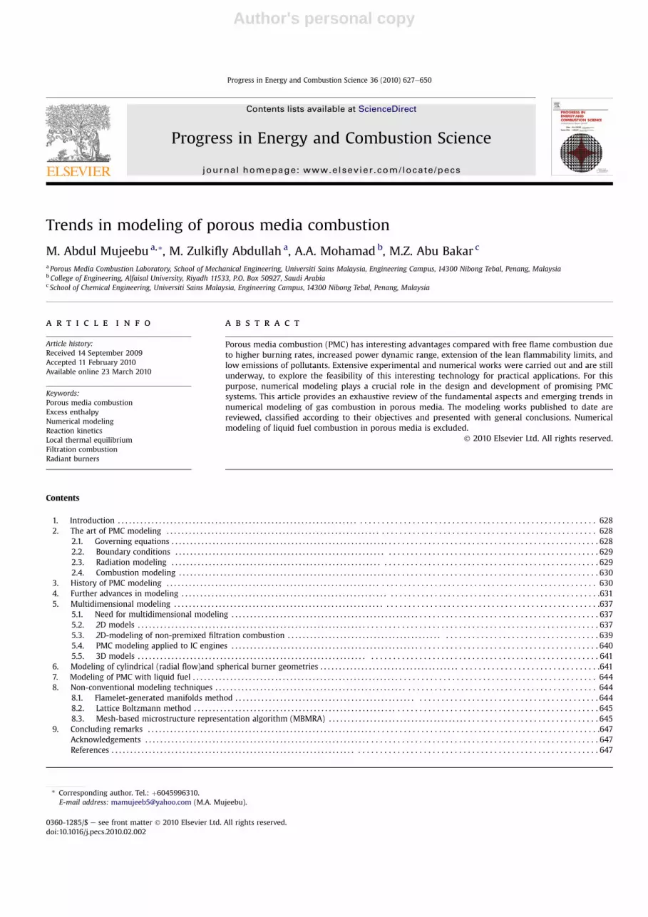
The Fastest-2D was also used by Nemoda et al. [112] for calcu-lations of non-isothermal laminar steady-state flow, with chemicalreactions in gas flow as well as within porous media with appro-priate corrections in the momentum equations for the porousregion. A heterogeneous model was considered for the heattransfer within the porous matrix. The solid and gas phases weretreated separately, but coupled via convective heat transfer term.For modeling laminar combustion of methane, the GRI-Mech 1.2mechanism [113] with 26 species and 164 reactions was used. Theproposed model was applied for both submerged and surfaceburners whose physical models are shown in Fig. 12.
In their [112] numerical method, each governing equation couldbe reduced to the general elliptical transport equation form:
v�rUjf
�vxj
� v
vxj
Gf
vf
vxj
!¼ Sf (32)
where f is the general transported variable, Gf is the correspondingeffective diffusion coefficient and Sf are the sources and sinks of f.The terms on the left side of Eq. (32) correspond to the convective
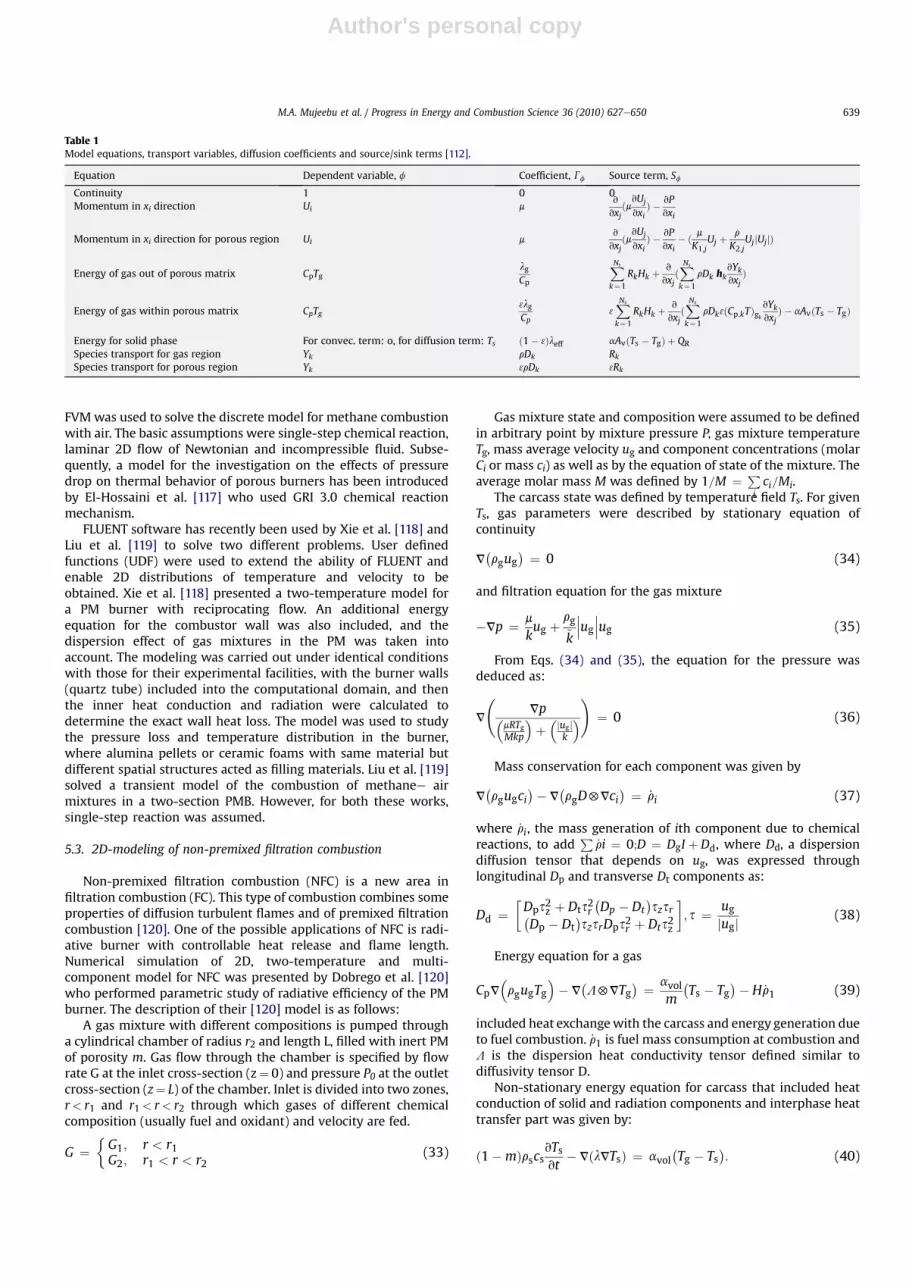
and diffusion processes, respectively, and the term on the right siderepresents source/sink in the transport equation of the variable f.All model equations defined by Eq. (32) are summarized in Table 1.The solution domain was discretized by a structured, non-orthogonal blocked grid. The pressure and velocity were coupledby SIMPLE algorithm and the semi-implicit procedure was used tosolve the algebraic equations.
A 2D rectangular porous burner was investigated by Mishraet al. [114]. Methaneeair combustion with detailed chemicalkinetics was used to model the combustion part. 164 chemicalreactions with 20 species were considered. Separate energy equa-tions for gas and solid phases were solved. The radiative part of theenergy equation was modeled using the collapsed dimensionmethod. The effects of the parameters such as power density,equivalence ratio, extinction coefficient and volumetric heattransfer coefficient on temperature and concentration profiles werestudied.
A 2D steady, laminar flow model was used by Tseng andTsai[115]. A single-step reaction of methane is used for the chemicalkinetic model and thermal radiation transport of the porous mediawas also included. The radiative transport equation was solved byusing the discrete ordinate method. To simplify the problem, theymade the following assumptions. (1) Flow is steady and laminar. (2)Gas radiation is negligible because it is much smaller than solidradiation. (3) The inert PM is homogeneous and emits, absorbs, andscatters radiation. (4) The Dufour effect and the gravity effect arenegligible.
A numerical code has been developed by Bidi et al. [116] toevaluate the effects of different parameters of combustion inporous media. The NaviereStokes, the solid and gas energy andthe chemical species transport equations were solved usinga multi-step reduced kinetic mechanism. The discrete ordinatesmethod was used to solve the radiative transfer equation anda finite volume method (FVM) based on SIMPLE method wasapplied to discretize the conservation equations. The differentburner regions consisting of a preheat zone (low porosity matrix),a combustion zone (high porosity matrix) and a heat exchangerzone were studied and the temperature field and species massfractions obtained numerically were compared with availableexperimental data. It was found that use of multi-step chemistryleads to more accurate results for temperature field and speciesmass fractions.
A 2D, two temperature mathematical model, based on fluidmechanics, energy and chemical species governing equations hasbeen used by Moraga et al. [99] who studied the convective heattransfer within a cylindrical inert porous media combustor. The
Fig. 12. The physical models used by Nemoda et al. [112]: Case 1 e PM burner with submerged combustion, Case 2 e surface combustion burner.
M.A. Mujeebu et al. / Progress in Energy and Combustion Science 36 (2010) 627e650638
Author's personal copy
FVMwas used to solve the discrete model for methane combustionwith air. The basic assumptions were single-step chemical reaction,laminar 2D flow of Newtonian and incompressible fluid. Subse-quently, a model for the investigation on the effects of pressuredrop on thermal behavior of porous burners has been introducedby El-Hossaini et al. [117] who used GRI 3.0 chemical reactionmechanism.
FLUENT software has recently been used by Xie et al. [118] andLiu et al. [119] to solve two different problems. User definedfunctions (UDF) were used to extend the ability of FLUENT andenable 2D distributions of temperature and velocity to beobtained. Xie et al. [118] presented a two-temperature model fora PM burner with reciprocating flow. An additional energyequation for the combustor wall was also included, and thedispersion effect of gas mixtures in the PM was taken intoaccount. The modeling was carried out under identical conditionswith those for their experimental facilities, with the burner walls(quartz tube) included into the computational domain, and thenthe inner heat conduction and radiation were calculated todetermine the exact wall heat loss. The model was used to studythe pressure loss and temperature distribution in the burner,where alumina pellets or ceramic foams with same material butdifferent spatial structures acted as filling materials. Liu et al. [119]solved a transient model of the combustion of methanee airmixtures in a two-section PMB. However, for both these works,single-step reaction was assumed.
5.3. 2D-modeling of non-premixed filtration combustion
Non-premixed filtration combustion (NFC) is a new area infiltration combustion (FC). This type of combustion combines someproperties of diffusion turbulent flames and of premixed filtrationcombustion [120]. One of the possible applications of NFC is radi-ative burner with controllable heat release and flame length.Numerical simulation of 2D, two-temperature and multi-component model for NFC was presented by Dobrego et al. [120]who performed parametric study of radiative efficiency of the PMburner. The description of their [120] model is as follows:
A gas mixture with different compositions is pumped througha cylindrical chamber of radius r2 and length L, filled with inert PMof porosity m. Gas flow through the chamber is specified by flowrate G at the inlet cross-section (z¼ 0) and pressure P0 at the outletcross-section (z¼ L) of the chamber. Inlet is divided into two zones,r< r1 and r1< r< r2 through which gases of different chemicalcomposition (usually fuel and oxidant) and velocity are fed.
G ¼�G1; r < r1G2; r1 < r < r2
(33)
Gas mixture state and composition were assumed to be definedin arbitrary point by mixture pressure P, gas mixture temperatureTg, mass average velocity ug and component concentrations (molarCi or mass ci) as well as by the equation of state of the mixture. Theaverage molar mass M was defined by 1=M ¼ P
ici=Mi.
The carcass state was defined by temperature field Ts. For givenTs, gas parameters were described by stationary equation ofcontinuity
V�rgug
� ¼ 0 (34)
and filtration equation for the gas mixture
�Vp ¼ m
kug þ
rg~k
���ug���ug (35)
From Eqs. (34) and (35), the equation for the pressure wasdeduced as:
V
Vp�
mRTgMkp
�þ�jugj
k
�!
¼ 0 (36)
Mass conservation for each component was given by
V�rgugci
�� V�rgD5Vci
� ¼ _ri (37)
where _ri, the mass generation of ith component due to chemicalreactions, to add
Pi_ri ¼ 0;D ¼ DgI þ Dd, where Dd, a dispersion
diffusion tensor that depends on ug, was expressed throughlongitudinal Dp and transverse Dt components as:
Dd ¼Dps2z þ Dts2r
�Dp � Dt
�szsr�
Dp � Dt�szsrDps2r þ Dts2z
; s ¼ ug
jugj (38)
Energy equation for a gas
CpV�rgugTg
�� V
�L5VTg
� ¼ avolm
�Ts � Tg
�� H _r1 (39)
included heat exchangewith the carcass and energy generation dueto fuel combustion. _r1 is fuel mass consumption at combustion andL is the dispersion heat conductivity tensor defined similar todiffusivity tensor D.
Non-stationary energy equation for carcass that included heatconduction of solid and radiation components and interphase heattransfer part was given by:
ð1�mÞrscsvTsvt
� VðlVTsÞ ¼ avol�Tg � Ts
�: (40)
Table 1Model equations, transport variables, diffusion coefficients and source/sink terms [112].
Equation Dependent variable, f Coefficient, Gf Source term, Sf
Continuity 1 0 0Momentum in xi direction Ui m
v
vxjðmvUj
vxiÞ � vP
vxi
Momentum in xi direction for porous region Ui mv
vxjðmvUj
vxiÞ � vP
vxi� ð m
K1;jUj þ
r
K2;jUjjUjjÞ
Energy of gas out of porous matrix CpTglgCp
XNs
k¼ 1
RkHk þv
vxjðXNs
k¼1
rDk hkvYkvxj
Þ
Energy of gas within porous matrix CpTg3lgCp
3XNs
k¼1
RkHk þv
vxjðXNs
k¼1
rDk3ðCp;kTÞgk
vYkvxj
Þ � aAvðTs � TgÞ
Energy for solid phase For convec. term: o, for diffusion term: Ts ð1� 3Þleff aAvðTs � TgÞ þ QRSpecies transport for gas region Yk rDk RkSpecies transport for porous region Yk 3rDk 3Rk
M.A. Mujeebu et al. / Progress in Energy and Combustion Science 36 (2010) 627e650 639

Author's personal copy
where l, the effective heat conductivity in the carcass was given by:
l ¼ ls þ 163
�0:666m1�m
þ 0:5�d03intsT
as (41)
Boundary conditions [120]
Tgðz ¼ 0Þ ¼ T0
Gas heat exchange with walls was negelected, therefore, on theside surface and at the chamber's outlet cross-section,
ðn$VÞTg ¼ 0
Black body irradiation at inlet, outlet cross-section and burnersides were assumed as:
�lvTsvz
¼ 3exts�T4s � T40
�; z ¼ 0;
�lvTsvz
¼ 3exts�T4s � T4ext
�; z ¼ L;
�lvTsvz
¼ 3exts�T4s � T4ext
�; r ¼ r2:
The following conditions for pressure were considered:Side surface non-permeability
vpvr
¼ 0; r ¼ r2
Normal outlet pressure
p ¼ p0; z ¼ L
The boundary condition for pressure at inlet cross-section(z¼ 0) was obtained by using pressure and flow rates G1, G2compliance condition
vpvz
¼�g1 for r < r1g2 for r1 < r < r2
where
g1
Z r1
0
rdr�mRTgMkp
�þ�jugj
~k
� ¼ �r01G1pm
; r < r1;
g2
Z r1
0
rdr�mRTgMkp
�þ�jugj
~k
� ¼ �r02G2pm
; r1 < r < r2;
Wall non-permeability was applied for the gas components,Eq. (37)
ðn$VÞci ¼�0 for r ¼ r2;0 for z ¼ L
Initial composition of gases was specified at the outlet cross-section as:
ciðz ¼ 0Þ ¼�ci1; r ¼ r1;ci2; r1 < r < r2:
To prevent uncontrollable diffusion and energy flow through theinlet cross-section, it was assumed that:
Dðz ¼ 0Þ ¼ 0; Lðz ¼ 0Þ ¼ 0:
For solution technique and results readers are advised to referDobregoetal. [120]. Lateron[121], thismodelwasutilized tostudythecharacteristics of a new regeneratorerecuperator scheme of filtrationcombustion VOC (volatile organic compounds) oxidizing reactor.
5.4. PMC modeling applied to IC engines
As detailed in our previous article [10], excellent experimentaland numerical works have been reported, on the implementation ofPMC in internal combustion (IC) engines. Themost recent modelingworks are briefed here. The combustion and working processes ofa specific PM engine were simulated by Liu et al. [122] using a two-zonemodel considering the influences of themass distribution, heattransfer from the cylinder wall, mass exchange between zones andthe heat transfer in PM. In the proposed model the combustionchamber was divided into two zones (Fig. 13) with differenttemperatures and mass compositions according to the structure ofthe PM engine: the PM chamber zone (zone one) and cylinder zone(zone two). During the combustion process the volume of PM zonekeeps constant while the volume of cylinder zone varies with time(crank angle). The thermodynamic properties and mass composi-tionwere spatially uniform in each zone. Moreover, mass exchangebetween two zones occurred to maintain the in-cylinder pressureuniform. Combustion was described using a skeletal chemicalkineticsmechanism for iso-octane oxidation consistingof 38 speciesand 69 reactions. For each species, the rate of production wascalculated and the differential equations of species mass fraction
Fig. 13. The definition of two zones in different engines; (Left) in permanent contact PM engine, and (Right) in periodic contact PM engine [122].
M.A. Mujeebu et al. / Progress in Energy and Combustion Science 36 (2010) 627e650640

Author's personal copy
were solved using the chemical kinetics package CHEMKIN III toobtain the changes in mixture composition in each zone.
Zhao and Xie [123,124] simulated the working process of a PMengine, characterized as periodic contact type and fuelled withmethane, by using an improved version of KIVA-3V which is a CFDcode for the simulation of IC engines. The KIVA-3Vwas validated bysimulating the experiment made by Zhdanok et al. [62] on thesuperadiabatic combustion of CH4eair mixtures under filtration ina packed bed. Computational results were in good agreement withexperimental data for the speed of the combustion wave. KIVA-3Vwas linked to Chemkin 3.0, such that the gas transport phenom-enon was based on KIVA-3V, while the thermal properties andchemical reactions were based on Chemkin 3.0. They used the GRI1.2 chemical kinetic mechanism for combustion modeling.
This study was extended by Dong et al. [125] to understand theeffects of a PM heat regenerator inserted into the combustionchamber on the turbulent flow characteristics and fuel-air mixtureformation. The cylindrical chamber had a constant volume, inwhich a disk-shaped PM insert was fixed. A simplifiedmodel for therandom structure of the PM was presented, in which the PM wasrepresented by an assembly of a great number of randomlydistributed solid units. To simulate flows in the PM a microscopicapproach was employed, in which computations were performedon a pore-scale mesh and based on the standard k-e turbulencemodel. A spray model, in which the effects of drop breakup, colli-sion and coalescence were taken into account, was introduced todescribe spray/wall interactions.
5.5. 3D models
As an excellent breakthrough in PMCmodeling, Hayashi and co-workers [27,126,127] had introduced the 3Dmodeling of a two-layerburner. The first layer was a perforated plate made of an insulatingmaterial (Al2O3) with the purpose of avoiding flash-back, while thesecond layer, a thinplatemadeof SiC foamtoact as the reaction layer.They claimed that the proposed 3Dmodel could facilitate a detailedstudy of the flowat the interface of the two solid layers, which is notpossible bymeans of one- or two-dimensionalmodels, owing to thecomplexflowstructure originated by the 3D jets fromtheperforatedplate into the SiC foam. 3D, steady, laminar and Newtonian flow ininert porous media was considered. Since local thermal non-equilibrium was assumed, energy balances for both the fluid andthe solid phases were performed. Catalytic effects of the high
temperature solids were assumed negligible, and the gas mixturewas considered non-radiating. The model comprised of balances ofmass, momentum and energy for both the solid and the fluid phase,along with the transport equations for the chemical species. Radia-tion heat transfer within the PM was accounted for and detailedchemical kinetic models for the combustion of methane andheptane were considered.
The physical model used is shown schematically in Fig. 14.Premixed fuel and air enters the burner through the perforatedplate and reaction takes place inside the foam. The flame front isanchored inside the SiC porousmatrix, near the interface of the twolayers.
In order to perform three-dimensional simulations of combus-tion inside the burner at reasonable computational costs, a repre-sentative unit cell corresponding to a 1/2463 fraction of the totalvolume of the two-layer chamber has been considered, as is sche-matically shown in Fig. 14. The SiC foam was treated as a singlecontinuum with volume-averaged properties, while direct simu-lation of the fluid paths was applied for the calculation of the flowin the perforated plate. In this layer, a geometrical simplificationwas made and the cylindrical holes were approximated by squareholes of the same cross-sectional area. Another interesting work on3D modeling is of Yamamotoa et al. [128, 129] who employed theLattice Boltzmannmethod (described in Section 8.2) for simulation.Recently a FLUENT based steady state simulation of non-premixedcombustion of LPG has been performed by Muhad et al. [130,131]who developed a novel burner in which porous packed bed ofalumina balls was arranged downstream of a conventional burner.
6. Modeling of cylindrical (radial flow)and spherical burnergeometries
In the cylindrical and spherical burners, the air flows radiallythrough an annular porous matrix as shown schematically inFig. 15. Themain feature of these geometries is that the surface areaincreases as the radius increases. Such a geometrical propertyprovides a wide flame stability range compared with the axialburner. Since the flame stabilizes in a regionwhere the flame speedis equal to the flow speed, the velocity distribution through theporous layer is related to the flame stability and to the rate of powermodulation. The velocity profile in the porous layer could be easilycalculated from the continuity equation. For constant density fluidflow, the velocity distribution through the cylindrical and spherical
Fig. 14. Schematic diagram of the combustion chamber and of the representative unit volume [27,126].
M.A. Mujeebu et al. / Progress in Energy and Combustion Science 36 (2010) 627e650 641

Author's personal copy
porous layer is inversely proportional to the radius (r). While for theaxial flow burner (flat burner) the flow velocity is constant alongthe porous layer. Accordingly the cylindrical and spherical burnersoffer a wide range of flame stability and rate of power modulationthan does the axial flow burner. Hence, it is expected that thesegeometries will offer a much wider range of flame stability limitand power modulation than do the free flame and axial porousburners [5].
A basic frame-work for the mathematical modeling of cylin-drical and spherical coordinate systems, as proposed by Mohamad[5] is given as follows:
The energy equation for the gas phase [5]:
v
vt�4rgCpgTg
�þ 1rn
v
vr�4rgCpgr
nyTg�
¼ 1rn
v
vr
�4kgrn
vTgvr
�� ð1� qÞhv
�Tg � Ts
�þ 4DHcSfg (42)
The energy equation for the solid phase [5]:
v
vtðrsCsTsÞ þ
1rn
v
vr
�rnks
vTsvr
�hv �
�Ts � Tg
�� V$F (43)
V$F is already defined in Eq. (3)The conservation equation for the mass fraction of the fuel [5]:
v
vt�rgmf
�þ 1rn
v
vr�rgr
nymf� ¼ 1
rnv
vr
�rnDABrg
vmf
vr
�� Sfg (44)
The notations are the same as those defined for Eqs. (1)e(7). Thevalue of n is set to 1 and 2 for cylindrical and spherical coordinatesystems, respectively. The boundary conditions are similar to thosegiven in Eqs. (8)e(10).
According to the knowledge of the authors, Zhdanok and co-workers [132,133] were the first to perform the modeling of PMCin cylindrical and spherical geometries. Fig. 16 shows the schematicof the physical model used by Zhdanok et al. [132] who studied thefiltration combustion front localization inside a cylindrical PMburner (PMB). They claimed that cylindrical axis-symmetricalconfiguration provided natural stabilization of combustion front
inside the carcass due to filtration speed decrease with the radiusgrowth. The flame localization inside the PMB was one of theimportant issues as the parameters such as maximum temperatureinside the PM, the design of PMB and the combustion front stabilitystrongly depend on the same. They analyzed this issue by using one-temperature analytical model and performing 1D two-temperaturenumerical simulation of combustion front localization.
In their extended work [133], the influence of partial trans-parency of PM on radiative efficiency, maximum solid phasetemperature and combustion localization radius of cylindrical andspherical PMB was investigated. They considered a 1D cylindricalsystem as shown in Fig. 17. It was assumed that the gas phase wasoptically transparent and isobaric, and overall heat release wasdescribed by Arrhenius Brutto reaction.
The mathematical model consisted of energy balance equationsfor solid and gas phases and mass balance equation for limitingcomponent. Diffusion and thermal conductivity were neglected incomparisonwith conduction in the gas phase. Mohamad [5] provedthat the cylindrical burner is superior to the flat burner as far as thethermal performance and the NOx formation are concerned. The 2D
Fig. 15. Schematic of cylindrical (radial flow) (a) and spherical (b) geometries [5].
Fig. 16. The physical model of cylindrical PMB [132].
M.A. Mujeebu et al. / Progress in Energy and Combustion Science 36 (2010) 627e650642

Author's personal copy
model of Tseng andTsai [115] and thework on NFC by Dobrego et al.[120,121] are also examples of cylindrical system of modeling.
As extension to the previous study [120], Gnesdilov et al. [134]presented a model for porous media VOC oxidizing reactor, con-sisting of coaxial tubes system with counter-flow heat exchangeand embedded electric heater as shown schematically in Fig. 18.The volume averaged approximation was used for the simulation.The set of equations included continuity and filtration equations forgas, mass conservation equation for chemical components, thermalconductivity equations for gas and solid phases, and ideal gas state
equation. Gas dispersion conductivity and diffusivity and radiationconductivity were taken into consideration. Similar modelingtechnique was applied in their subsequent study [135] inwhich theinfluence of incoming gas flux, adiabatic temperature of gascombustion, reaction rate constant, diameter of porous bodyparticles, reactor size and heat losses on maximal temperature ofreactor, recuperation efficiency, combustion front position of theVOC reactor were investigated. The ‘2DBurner’ software packagewas used in their simulations.
To study the convective heat transfer within a cylindrical inertporous media combustor, recently Moraga et al. [99] presenteda 2D, two temperature model. Their physical model was an axis-symmetric cylindrical quartz tube of 0.52 m in length and0.076 m in diameter filled with alumina spheres as shown in Fig.19.
Methane and air mixture entered the combustor at ambienttemperature with uniform velocity. To start the combustiona temperature profile of one step type, with a maximum temper-ature of 1150 K and a thickness of 4 cm was assumed to simulatethe ignition by means of an external energy source. In thecombustion zone, the products: CO2, H2O, O2 and N2 weregenerated. Air, gas and products were assumed to behave as idealgases and hence density was calculated in terms of temperaturefrom the ideal gas state equation. The pressure drop of the flowthrough the channel was neglected. The mathematical model wasbuilt on the basis of the following assumptions: A single-stepchemical reaction, laminar 2D flow of Newtonian and incom-pressible fluid. The FVM along with the SIMPLE algorithmwas usedto solve the discrete model for methane combustionwith air. A fifthpower law was used to calculate the convective terms while thediffusion terms were determined by linear interpolation functionsfor the dependent variables between the nodes.
The latest works include those of Farzaneh et al.[136] whoperformed FVM based 2D simulation on a PM burner, Moraga et al.[137] who presented a similar simulation technique on a double-tube heat exchanger that used the combustion gases from natural
Fig. 17. 1D cylindrical system of the axially symmetric PMB [133]. Carcass temperatureprofile is shown by solid line, products and irradiation by arrows.
Fig. 18. Scheme of the VOC reactor and heating elements configuration [134]. (1)Incoming gases, (2) flue gases, (3) reactors body, (4) porous media, (5) central tube,(6)e(8) electric heater; (6) axial position, (7) ring shape element, (8) ring shapeelement for UDG-2 reactor simulation. t1et5: positions of thermocouples.
Fig. 19. Physical model of the cylindrical porous medium burner used in the work ofMoraga et al. [99].
M.A. Mujeebu et al. / Progress in Energy and Combustion Science 36 (2010) 627e650 643

Author's personal copy
gas in a PM located in a cylindrical tube to warm up air flowingthrough a cylindrical annular space, and Chumakov and Knyazeva[138] who studied the regimes of gas combustion in a porous bodyof a cylindrical heat generator. Another interesting study wasreported by Keshtkar et al. [139] who simulated a porous radiant airheater (PRAH) that operated on the basis of an effective energyconversion method between flowing gas enthalpy and thermalradiation. In this system, four porous layers consisting of porousradiant burner (PRB), high-temperature (HT) section, first heatrecovery section, and second heat recovery section were consid-ered, as illustrated in Fig. 20. These layers were separated from eachother by three quartz glass walls. The PRB generates a large amountof thermal radiative energy, which was converted into gas enthalpyin heat recovery layers. In the HT section, the gas enthalpy of thePRB exhaust was converted into thermal radiation. At each layer,the gas and solid phases were considered in non-local thermalequilibrium and combustion in the PRB was modeled by consid-ering a non-uniform heat generation zone. The homogeneousporous media, in addition to its convective heat exchange with thegas, might absorb, emit, and scatter thermal radiation. In order todetermine the thermal characteristics of the proposed PRAH, a 2Dmodel was used to solve the governing equations for PM and gasflow and the discrete ordinates method was used to obtain thedistribution of radiative heat flux in the PM.
7. Modeling of PMC with liquid fuel
When using a liquid fuel, the interaction between the fuel sprayand a PM is very crucial for homogenization of the fuele air mixturein the PM. Unfortunately, the complicated process and patterns offuel spray impingement on the PM, as well as the spray spreading init, could not be observed and measured with a conventionalexperimental facility because the complex PM matrix does notallow optical access into it. However, numerical simulationprovides an alternative, and in fact, simulation is the only way toperform the analysis at present [140].Though the basic modelingapproach is similar to the PMC with gaseous fuel, the numericalmodeling of liquid fuel combustion in PM needs some additionalparameters to be incorporated. As far as the authors are aware,Martynenko et al. [141] were the first to introduce a model forliquid fuel. The PM under studywas of high porosity with uniformlydistributed spheres and with uniform distribution of cavities withequal mean pore size in the PM. Later on, Park and Kaviany [142],Sankara et al. [143], Periasamy et al. [144], Zhao and Xie [140], Kayal
and Chakravarty [145-147], and Sadasivuni and Agrawal [148] havepresented excellent models. Interested readers may consult ourreview [11] to have detailed information on this topic.
8. Non-conventional modeling techniques
8.1. Flamelet-generated manifolds method
As an efficient technique to reduce the computational cost,recently, van Oijen et al. [149] introduced the flamelet-generatedmanifolds (FGM) method which is a combination of twoapproaches to simplify flame calculations, i.e. a flamelet anda manifold approach. The FGM method, shares the idea withflamelet approaches that a multi-dimensional flame may beconsidered as an ensemble of 1D flames. The implementation,however, is typical for manifold methods: a low-dimensionalmanifold in composition space is constructed, and the thermo-chemical variables are stored in a database which can be used insubsequent flame simulations. In the FGM method a manifold isconstructed using 1D flamelets, and the dimension of the manifoldcan be increased to satisfy a desired accuracy. Since the major partsof convection and diffusion processes are present in 1D flamelets,the FGM is more accurate in the ‘colder’ zones of premixed flamesthan methods based on local chemical equilibria. Therefore, lesscontrolling variables are sufficient to represent the combustionprocess [149]. Through the test results of one and two-dimensionalpremixed methane/air flames the authors proved that detailedcomputations were reproduced very well with a FGM consisting ofonly one progress variable apart from the enthalpy to account forenergy losses.
Subsequently, they [150] applied the FGMmethod for modelinga ceramic foam surface burner in a radiating furnace. The profiles oftemperature and species concentration for methane combustionwere obtained numerically (using FGM method) as well as byexperiment. Further, the FGM results were compared with thoseobtained through a time-dependent 1D simulation with detailedreaction kinetics (16 species and 25 reactions), under identicalconditions. They claimed that the computation time of flamesimulations could be reduced by at least a factor of 20 through FGMtechnique compared to the 1D detailed simulation. An even higherefficiency (with a factor of 40) could be reached if an explicit solverwas used for the reduced computations. For more complex reactionmechanisms the speed up would be even larger. It was concludedthat this method could be used to perform accurate and efficient
Fig. 20. The physical model of the PRAH simulated by Keshtkar et al. [139].
M.A. Mujeebu et al. / Progress in Energy and Combustion Science 36 (2010) 627e650644

Author's personal copy
simulations of premixed laminar flames in complex burnersystems. For more details of this interesting technique the readersare encouraged to consult the referred literature.
The FGM simulation model was consistent with the experi-mental set-up shown in Fig. 21. The temperature and speciesconcentration profiles at the centre-line of the burner, obtained byFGM and 1D detailed simulation techniques are compared in Fig. 22which shows their close agreement. The radial temperature profilesof FGM and experiment are compared in Fig. 23 which furtherillustrates the strength of FGM.
8.2. Lattice Boltzmann method
The introduction of Lattice Boltzmann method (LBM) to PMCmodeling was reported by Yamamotoa et al. [128,129]. The mainadvantages of LBM were claimed to be the simplicity of the algo-rithm and the flexibility for complex geometries. The motivationwas to perform efficient simulations for the design and develop-ment of diesel particulate filter (DPF) which has been introduced toreduce the particulate matters in the after-treatment of exhaust gasin diesel engines. According to the authors, the so called “filterregeneration process” inside the DPF along with its geometriccomplexity was challenging to deal with, by conventional modelingtechniques. The fundamental idea of the LBM is to constructsimplified kinetic models that incorporate the essential physics ofmicroscopic or mesoscopic processes so that the macroscopicaveraged properties obey the desired macroscopic equations suchas the NeS equation. The kinetic equation provides many of theadvantages of molecular dynamics, including clear physicalpictures, easy implementation of boundary conditions, and fullyparallel algorithms. The LBM helps to meet these requirements ina straightforward manner [128].
They [128,129] performed 3-D simulations of flow andcombustion on the real geometry as shown in Fig. 24, of porousNieCr metal which is the core part of DPF. To examine thecombustion field in detail, they obtained the profiles at the cross-section. Fig. 25 shows the distributions of velocity in the x-direc-tion, temperature and mass fraction of oxygen in xey and yezplanes of the porous wall. The positions to obtain these cross-sections are shown by dotted line in Fig. 25A. It is clear that thevelocity was accelerated in the region of narrow paths. The
temperature was increased by soot combustion near the wallsurface, and the local temperature was different due to the inho-mogeneous porous structure. This local information was indis-pensable to improve the thermal duration of DPF. Thus it wasdemonstrated that the combustion was well simulated in porousmedia using LBM. It has also been proved that combustion withdetailed chemistry could be effectively simulated by this technique.
8.3. Mesh-based microstructure representation algorithm(MBMRA)
In conventional CFD approach, a prescribed physical domain ofPM with existing fluid-solid interface is mapped onto a computa-tional domain, which is then geometrically discretized by meshgeneration. Recently, Liou and Greber [151] pointed out that, thiswould become a formidable task if hundreds or thousands of poresof irregular shapeswere tobemapped. Toovercome thishurdle, theyintroduced the so-called MBMRAwhich is summarized as follows.
Fig. 21. Cross-section of the experimental setup used by van Oijen et al. [150].
Fig. 22. Profiles of temperature and species concentration (YO) along the center-axis[150]. Symbols and lines are used to represent FGM and 1D detailed results,respectively.
Fig. 23. Radial profiles of the temperature at 2.5 and 8 cm from the burner surface[150]. Symbols and lines represent measurements and simulations, respectively.
M.A. Mujeebu et al. / Progress in Energy and Combustion Science 36 (2010) 627e650 645

Author's personal copy
First, the outline of the computational domain is selected torepresent the physical domain of interest. Next, the computationaldomain is discretized with a fine enough mesh, which is generallyan easy task since there are no convoluted interfaces to conform to.Then mesh locations are chosen as seed locations of solid material;these locations are chosen randomly, but with prescribed rules. Thesolid regions are then allowed to grow, again randomly but inaccordance with prescribed rules. The rules are established so thatthe eventual statistical properties of the porous region matchclosely the geometric properties (such as the porosity and the poresize) of the physical PM that it is sought to simulate. The solid andfluid-filled pore regions are then assigned the thermodynamic andtransport properties of the corresponding physical materials. Asa natural byproduct of this process, the interface between solid andpore regions always lies at the boundary between mesh cells. Thusit results in a complete conforming (body-fitted) at the solid andfluid interfaces. Another advantage over the conventional approachis that fluid and solid matrix interaction (e.g. surface reaction) canbe accommodated easily since the mesh for the solid matrix is alsoavailable [151].
Fig. 24. The porous NieCr metal structure used in the LBM analysis of Yamamotoet al. [128].
Fig. 25. Profiles of combustion field in porous media, in xey and yez planes obtained through LBM simulation of Yamamoto et al. [128].
M.A. Mujeebu et al. / Progress in Energy and Combustion Science 36 (2010) 627e650646

Author's personal copy
Improvement to MBMRA was later suggested [152], by incor-porating a mesh adaptation scheme. The local refinement of meshin the surroundings of a solid structure in the PM offers an efficientgrid distribution and a cost-effective use of computing time. Thedegree of refinement is based on the minimum distance from solidcells, and the refinement is typically done by connecting midpointsof cell edges (thus, a triangle is divided into 4 sub-elements in 2D).A smoothing mechanism is added to blend fine meshes into coarseones smoothly. The refinement is completed by a bisectionrefinement (dividing into 2 sub-elements) to eliminate hangingnodes. The refined 2D unstructured triangular mesh MBMRA isillustrated in Fig. 26. The shaded area in (a) is a sample solid whichis composed of three triangular cells. After the refining processesdescribed above, new meshes were produced as shown in (b), andtheir corresponding connectivity were rebuilt. Also, the samplesolid has increased its mesh from three triangular cells to 26elements which allows a more effective conjugate heat transfersimulation. The strength of MBRA to study complex PMC systemshas also been demonstrated by typical case studies [152].
9. Concluding remarks
The basic modeling approach and a comprehensive review ofinvestigations on PMC modeling have been presented; yet we areunable to claim its perfectness. Many excellent works might havebeen left without citation due to the lack of accessibility to thosedocuments. The proper grouping of the previous numerical inves-tigations was a tedious job; so in the present organization of thearticle, the chronological order of development and the order ofdimensions and geometrical complexity were taken care. Ingeneral, it has been observed that different researchers haveadopted different kinds of models to solve their problems. Thechoice of a particular model was always dependent on the natureand objectives of the problems under study. For most of the casesa 1Dmodel with single-step reaction kinetics could yield the resultswith reasonable accuracy. In fact, the realistic prediction of
pollutants formation necessitated detailed reaction kinetics to beincorporated in the model. However, the assumption of localthermal equilibrium between the phases has always been foundinaccurate. The introduction of multidimensional modeling wasa remarkable improvement, as it could resolve the issues associatedwith 1D models in handling complex PMC problems. In terms ofreducing the computational cost without sacrificing the accuracy,FGM method would be a promising option. The LBM techniqueindeed has opened the doors for the modeling of highly complexPMC systems. It is worth noting that, after the introduction of FGMand LBM to PMCmodeling, no further works have been reported tillthe year 2009; same is the case for MBMRA, 3D modeling andspherical burner geometry. Use of FLUENT software has recentlyattracted few researchers, but 3D simulation, inclusion of detailedreaction chemistry are still lacking. Further works may also be doneusing ‘2DBurner’ software package for filtration combustion. Thus,there is a wide scope for future works, especially on 3D modeling,cylindrical (radial flow) and spherical geometries, and on exploringthe non-conventional modeling techniques. At this juncture, theneed for the development of a user-friendly software package tohandle PMC problems of any nature is quite obvious. The authorshope that this article would definitely guide the new researchers indeciding the direction of further investigation.
Acknowledgements
The authors would like to thank the Ministry of Technology andInnovation, Malaysia and Universiti Sains Malaysia for the financialsupport for the ongoing research on PMC technology.
References
[1] Howell JR, Hall MJ, Ellzey JL. Combustion of hydrocarbon fuels within porousinert media. Prog Energy Combust Sci 1996;22(2):121e45.
[2] Trimis D, Durst F. Combustion in a porous medium e advances and appli-cations. Combust Sci Technol 1996;121(1e6):153e68.
[3] Mößbauer S, Pickenäcker O, Pickenäcker K, Trimis D. Application of theporous burner technology in energy and heat engineering. In: Fifth inter-national conference on technologies and combustion for a clean environ-ment (clean air V), Libson (Portugal), 12e15 July 1999, vol. 1; 1999. Lecture20.2, pp.519e523.
[4] Oliveria AAM, Kaviani M. nonequilibrium in the transport of heat and reac-tants during combustion in porous media. Prog Energy Combust Sci2001;27:523e45.
[5] Mohamad AA. Combustion in porous media: fundamentals and applications.Transport phenomena in porous media III; 2005, pp. 287e304.
[6] Kamal MM, Mohamad AA. Combustion in porous media, a review. J PowerEnergy 2006;220(5):487e508.
[7] Pantangi VK, Mishra SC. Combustion of gaseous hydrocarbon fuels withinporous media e a review, Advances in Energy Research (AER e 2006),pp. 455e461.
[8] Wood S, Harris AT. Porous burners for lean-burn applications. Prog EnergyCombust Sci 2008;34:667e84.
[9] Mujeebu MA, Abdullah MZ, Abu Bakar MZ, Mohamad AA, Muhad RMN,Khalil M. Combustion in porous media and its applications e a comprehen-sive survey. J Environ Manage 2009;90:2287e312.
[10] Mujeebu MA, Abdullah MZ, Abu Bakar MZ, Mohamad AA, Khalil M. Appli-cations of porous media combustion technology e a review. Appl Energy2009;86(9):1365e75.
[11] Mujeebu MA, Abdullah MZ, Abu Bakar MZ, Mohamad AA, Khalil M. A reviewof investigations on liquid fuel combustion in porous inert media. ProgEnergy Combust Sci 2009;35:216e30.
[12] Kaviany M. Principles of heat transfer in porous media. 2nd ed. New York:Springer-Verlag; 1995.
[13] Chen YK, Hsu PF, Lim IG, Lu ZH, Matthews RD, Howell JR, et al. Experimentaland theoretical investigation of combustion within porous inert media. In:The 22nd international symposium on combustion. The Combustion Insti-tute; 1988. Poster paper 22e207.
[14] Ratzel III AC, Howell JR. Two-dimensional radiation in absorbing-emittingmedia using the P-N approximation. J Heat Trans, Trans ASME1983;105:333e40.
[15] Lawson DA, Norbury J. Porous medium combustion. In: Lewis RW,editor. Numerical methods in heat transfer, vol. III. New York: Wiley;1985. p. 173e93.
Fig. 26. (a) Original MBMRA mesh distribution around a sample solid; (b) Refinedmesh distribution of the same solid sample [152].
M.A. Mujeebu et al. / Progress in Energy and Combustion Science 36 (2010) 627e650 647

Author's personal copy
[16] Tong TW, Sathe SB. Heat transfer characteristics of porous radiant burners.ASME HTD 1988;104:147e55.
[17] Andersen F. A low NOx, low temperature oxygen-fuel burner. In:Lukasiewicz MA, editor. Industrial combustion technologies. AmericanSociety for Metals; 1989. p. 329e34.
[18] Chen YK, Matthews RD, Howell JR. The effect of radiation on the structure ofa premixed flame within a highly porous inert medium, in radiation, phasechange heat transfer and thermal systems. In: ASME Publication HTD, vol. 81;Dec 13e18, 1987. 35e42.
[19] Yoshizawa Y, Sasaki K, Echigo R. Analytical study of structure of radiationcontrolled flame. Int J Heat Mass Transfer 1988;31(2):311e9.
[20] Sathe SB, Peck RE, Rong TW. A numerical analysis of combustion and heattransfer in porous radiant burners. In: Shah RK, editor. Heat transferphenomena in radiation. Combustion and fires. ASME HTD, vol. 107; 1989. p.461e8.
[21] Sathe SB, Peck RE, Tong TW. A numerical analysis of heat transfer andcombustion in porous radiant burners. Int. J. Heat Mass Transfer 1990;33(6):1331e8.
[22] Mohamad AA, Viskanta R. Combined convectioneradiation heat transfer ina surface combustor-process heater. In: Boehm RF, El-Sayed YM, editors.Simulation of thermal energy systems. ASME-HTD, vol. 124. New York:ASME; 1989. p. 1e8.
[23] Tien CL, Drolen BL. Thermal radiation in particulate media with dependentand independent scattering. In: Chawla TC, editor. Annual review ofnumerical fluid mechanics and heat transfer. Washington, DC: Hemisphere;1987. p. 1e32.
[24] Singh BP, Kaviany M. Radiation in porous media. In: Hartnett JP, Irvine TF,editors. Advances in heat transfer, vol. 23. New York: Academic Press; 1993.p. 369e464.
[25] Mohamad AA, Ramadhyani S, Viskanta R. Modelling of combustion and heattransfer in a packed bed with embedded coolant tubes. Int J Heat MassTransfer 1994;37:1181e97.
[26] Christo FC. A parametric analysis of a coupled chemistryeradiation model inporous media, May. 2000, DSTO Aeronautical and Maritime Research Labo-ratory, PO Box 4331, Melbourne Victoria 3001, Australia.
[27] Hayashi TC. Multidimensional modeling and calculation of combustion inporous media, PhD. thesis, 2005, Universidade Técnica De Lisboa, InstitutoSuperior Técnico, Portugal.
[28] Kee RJ, Miller JA, Jefferson TH. CHEMKIN: a general purpose problem inde-pendent, transportable, FORTRAN, chemical kinetic program package. SandiaNational Laboratory; 1980. Report, SAND80-8003.
[29] Takeno T, Sato K. An excess enthalpy flame theory. Combust Sci Technol1979;20(1e2):73e84.
[30] Takeno T, Sato K, Hase K. A theoretical study on an excess enthalpy flame.Proc Combust Inst 1981;18:465e72.
[31] Takeno T, Murayama M. In: Bowen JR, Manson N, Oppenheim AK,Soloukhin RI, editors. Dynamics of reactive systems part I: flames andconfigurations. AIAA ProgAstronaut Aeronaut 1986;105:246e62.
[32] Echigo R. Effective energy conversion method between gas enthalpy andthermal radiation and application to industrial furnaces. In: Proceedings ofseventh International Heat Transfer Conference, Munich, vol. YI; 1982. p. 361.
[33] Echigo R, Yoshizawa Y, Hanamura K, Tomimura T. Analytical and experi-mental studies on radiative propagation in porous media with internal heatgeneration. In: Proceedings of eighth International Heat Transfer Conferenceand San Francisco CA, vol. ll; 1986. 827e832.
[34] Echigo R. Radiation enhanced/controlled phenomena of heat and masstransfer in porous media. In: Lloyd JR, Kurosaki Y, editors. Proceedings of thethird ASME/JSME joint thermal engineering conference, 6. New York: ISME;1991. p. 361e6.
[35] Hsu PF, Evans WD, Howell JR. Experimental and numerical study of premixedcombustion within nonhomogeneous porous ceramics. Combust Sci Technol1993;90:149e72.
[36] Hsu PF,Matthews RD. The necessity of using detailed chemical kinetics inmodelfor premixed combustion in porous media. Combust Flame 1993;93:457e66.
[37] Hsu PF, Howell JR. Measurements of thermal conductivity and opticalproperties of porous partially stabilized zirconia. Exp Heat Trans1993;5:293e313.
[38] Sathe SB, Kulkarni MR, Peck RE, Tong TW. An experimental and theoreticalstudy of porous radiant burner performance. In: Twenty-third symposium(international) on combustion. Pittsburgh, PA: The Combustion Institute;1990. p. 1011e8.
[39] Sathe SB, Peck RE, Tong TW. Flame stabilization and multimode heat transferin inert porous media: a numerical study. Combust Sci Technol 1990;70(4):93e109.
[40] McIntosh AC, Prothero A. A model of large heat transfer surface combustionwith radiant heat emission. Combust Flame 1991;83(1e2):111e26.
[41] Singh S, Ziolkowski M, Sultzbaugh J, Viskanta R. Mathematical model ofa ceramic burner radiant heater. In: Ruiz R, editor. Fossil fuel combustion.ASME PD, vol. 33; 1991.
[42] Nakamura Y, Itaya Y, Miyoshi K, Hasatani M. Mechanism of methaneeaircombustion on the surface of a porous ceramic plate. J Chem Eng Jpn 1993;26(2):205e11.
[43] Hanamura K, Echigo R, Zhdanok SA. Superadiabatic combustion in a porousmedium. Int J Heat Mass Trans 1993;36:3201e9.
[44] Escobedo F, Viljoen HJ. Modeling of porous radiant burners with largeextinction coefficients. Canad J Chem Eng 1994;72:805e14.
[45] Rabinovich OS, Fefelov AV, Pavlyukevich NV. Modeling of premixed gascombustion in porous media composed of coarse-sized particles: 1-Ddescription with discrete solid phase. In: Proceedings of the twenty-sixthsymposium (international) on combustion. The Combustion Institute; 1996.p. 3383e9.
[46] Lee YI, Shin HD, Baek SW. Experimental and numerical study on the laminarpremixed flame stabilized inside a honeycomb ceramic. Combust Sci Technol1996;112:75e93.
[47] Kulkarni MR, Peck RE. Analysis of a bilayered porous radiant burner. NumerHeat TransA Appl: Int J Comput Methodol 1996;30(3):219e32.
[48] Rumminger MD, Dibble RW, Heberle NH, Crosley DR. Gas temperaturesabove a porous radiant burner. In: Twenty-sixth symposium (international)on combustion. Pittsburgh: The Combustion Institute; 1996. p. 1755.
[49] Byrne H, Norbury J. The effect of solid conversion on travelling combustionwaves in porous media. J Eng Mathem 1997;32:321e42.
[50] Bouma PH, Methane-air combustion on a ceramic foam surface burners.Ph.D. dissertation 1997, Eindhoven University of Technology.
[51] Zhou XY, Pereira JCF. Numerical study of combustion and pollutant formationin inert non-homogeneous porous media. Combust Sci Technol 1997;130:335e64.
[52] Kee RJ, Dixon-Lewis G, Warnatz J, Coltrin ME, Miler JA. A Fortrancomputer code package for the evaluation of gas phase multicomponenttransport properties. Sandia National Laboratory; 1996. Report SAND86-8246.
[53] Kee RJ, Grcar JF, Smooke MD, Miller JA. A Fortran program for modeling studylaminar one-dimensional premixed flames. Albuquerque: Sandia NationalLaboratory; 1996. Report, SAND85-8240.
[54] Glarborg P, Nils LL, Stale B, Magnussen BF, Kilpinen P, Hupa M. A reducedmechanism for nitrogen chemistry in methane combustion. In: Twenty-fourth symposium (international) on combustion. The Combustion Institute;1992. p. 889e98.
[55] Miller JA, Bowman CT. Mechanism and modeling of nitrogen chemistry incombustion. Prog Energy Combust Sci 1989;15(40):287e338.
[56] Younis LB, Viskanta R. Experimental determination of the volumetric heattransfer coefficient between stream of air and ceramic foam. Int J Heat MassTransfer 1993;36(6):1425e34.
[57] Pickenacker K, Trimis D, Durst F. First periodic report of compact porousmedium burner and heat exchanger for household applications, contract No.JOE3- CT95-0019, 1996.
[58] Zhou XY, Pereira JCF. Comparison of four combustion models for simulatingthe premixed combustion in inert porous media. Fire Mater 1998;22(5):187e97.
[59] Bouma PH, De Goey LPH. Premixed combustion on ceramic foam burners.Combust Flame 1999;119:133e43.
[60] Jugjai S, Somjetlertcharoen A. Multimode heat transfer in cyclic flow reversalcombustion in a porous medium. Int J Energy Res 1999;23:183e206.
[61] Foutko SI, Shabunya SI, Zhdanok SA. Superadiabatic combustion wave ina diluted methaneeair mixture under filtration in a packed bed. In:Proceedings of the twenty-sixth symposium (international) on combustion.The Combustion Institute; 1996. p. 3377e82.
[62] Zhdanok S, Kennedy LA, Koester G. Superadiabatic combustion of methaneair mixtures under filtration in a packed bed. Combust Flame 1995;100(1e2):221e31.
[63] Henneke MR, Ellzey JL. Modeling of filtration combustion in a packed bed.Combust Flame 1999;117:832e40.
[64] Frenklach M, Wang H, Yu C-L, Goldenberg M, Bowman CT, Hanson RK, et al.Technical Report No. GRI/95008, 1995, Gas Research Institute.
[65] Aldushin AP, Rumanov IE, Matkowsky BJ. Maximal energy accumulation ina superadiabatic filtration combustion wave. Combust Flame1999;118:76e90.
[66] Viskanta R, Gore JP. Overview of cellular ceramics based porous radiantburners for supporting combustion. Environ Combust Technol 2000;1:167e203.
[67] Christo FC. A parametric analysis of a coupled chemistryeradiation model inporous media. PO Box 4331, Melbourne Victoria 3001, Australia: DSTOAeronautical and Maritime Research Laboratory; October 2000.
[68] Christo FC, Krishnamurthy LV. An experimental and numerical study ofinfrared (IR) emission from a porous radiant burner. PO Box 4331, MelbourneVictoria 3001, Australia: DSTO Aeronautical and Maritime Research Labora-tory; May 2001.
[69] Bubnovich V, Vergara J, Rosas C. Theoretical analysis of combustion waves ina methaneeair mixture under filtration in a packed bed, in: Proceedings of IVinternational school e seminar “modern problems of combustion and itsapplication”, Minsk, Belarus; 2001, pp. 158e162.
[70] Tseng C-J. Effects of hydrogen addition on methane combustion in a porousmedium burner. Int J Hydrogen Energy 2002;27:699e707.
[71] Bowman CT, Hanson RK, Davidson DF, Gardiner Jr WC, Lissianski V, Smith GP,et al, http://www.me.berkeley.edu/grimech/. URL:.
[72] Diamantis DJ, Mastorakos E, Goussis DA. Simulations of premixed combus-tion in porous media. Combust Theory Model 2002;6(3):383e411.
[73] Akkutlu IY, Yortsos YC. The dynamics of in-situ combustion fronts in porousmedia. Combust Flame 2003;134:229e47.
M.A. Mujeebu et al. / Progress in Energy and Combustion Science 36 (2010) 627e650648

Author's personal copy
[74] Lammers FA, De Goey LPH. A numerical study of flash back of laminar pre-mixed flames in ceramic-foam surface burners. Combust Flame2003;133:47e61.
[75] Contarin F, Saveliev AV, Fridman AA, Kennedy LA. A reciprocal flow filtrationcombustor with embedded heat exchangers: numerical study. Int J HeatMass Trans 2003;46(6):949e61.
[76] Barra AJ, Diepvens G, Ellzey JL, Henneke MR. Numerical study of the effects ofmaterial properties on flame stabilization in a porous burner. Combust Flame2003;134:369e79.
[77] Barra AJ, Ellzey JL. Heat recirculation and heat transfer in porous burners.Combust Flame 2004;137:230e41.
[78] Younis LB, Wierzba I. A numerical investigation of catalytic oxidation of verylean methane-air mixtures within a packed-bed reactor. J Porous Media2004;7(2):21e8.
[79] Smucker MT, Ellzey JL. Computational and experimental study of a two-section porous burner. Combust Sci Technol 2004;176(8):1171e89.
[80] Hanamura K, Kumano T, Iida L. Electric power generation by super-adiabatic combustion in thermoelectric porous element. Energy2005;30:347e57.
[81] Dhamrat RS, Ellzey JL. Numerical and experimental study of the conversionof methane to hydrogen in a porous media reactor. Combust Flame2006;144:698e709.
[82] Bubnovich VI, Zhdanok SA, Dobrego KV. Analytical study of the combustionwaves propagation under filtration of methaneeair mixture in a packed bed.Int J Heat Mass Trans 2006;49:2578e86.
[83] Bubnovich V, Toledo M. Analytical modeling of filtration combustion in inertporous media. Appl Therm Eng 2007;27(7):1144e9.
[84] Da Mota JC, Schecter S. Combustion fronts in a porous medium with twolayers. J Dynam Different Equat 2006;18(3):615e64.
[85] Gauthier S, Lebas E, Baillis D. One layer porous radiant burners: experimentaland numerical study. Eurotherm Seminar No. 81, Reactive heat transfer inporous media. Ecole des Mines d'Albi, France, June 4e6, 2007.
[86] Zhao P, Chen Y, Liu M, Ding M, Zhang G. Numerical simulation of laminarpremixed combustion in a porous burner. Front Energy Power Eng China2007;1(2):233e8.
[87] Mendes MAA, Pereira JMC, Pereira JCF. On the stability of ultra-lean H2/COcombustion in inert porous burners. Int J Hydrogen Energy 2008;33(13):3416e25.
[88] Hossainpour S, Haddadi B. Numerical study of the effects of porous burnerparameters on combustion and pollutants formation. In: Proceedings of theWorld Congress on Engineering 2008, vol. II. London, U.K: WCE, ISBN 978-988-17012-3-7; July 2e4, 2008.
[89] Shi JR, Xie MZ, Liu H, Li G, Zhou L. Numerical simulation and theoreticalanalysis of premixed low-velocity filtration combustion. Int J Heat MassTrans 2008;51(7-8):1818e29.
[90] Shi J-R, Xie M-Z, Li G, Liu H, Liu J-T, Li H- T. Approximate solutions of leanpremixed combustion in porous media with reciprocating flow. Int J HeatMass Trans 2009;52:702e8.
[91] Akbari MH, Riahi P, Roohi R. Lean flammability limits for stable performancewith a porous burner. Appl Energy 2009;86:2635e43.
[92] De Lemos MJS. Numerical simulation of turbulent combustion in porousmaterials. Int Commun Heat Mass Trans 2009;36:996e1001.
[93] Xie M, Dong M, Lu N, Shi J. Numerical simulation of methaneeair filtrationcombustion in porous media for hydrogen production. Heat Transfer e AsianRes 2009;38(8):536e47.
[94] Toledo M, Bubnovich V, Saveliev A, Kennedy L. Hydrogen production inultrarich combustion of hydrocarbon fuels in porous media. Int J HydrogenEnergy 1818;2009:34e1827.
[95] Al-Hamamre Z, Voß S, Trimis D. Hydrogen production by thermal partialoxidation of hydrocarbon fuels in porous media based reformer. Int JHydrogen Energy 2009;34:827e32.
[96] Laevsky YM, Yausheva LV. Simulation of filtrational gas combustion processesin nonhomogeneous porous media. Numer Anal Appli 2009;2(2):140e53.
[97] Malico L, Zhou XY, Pereira JCF. Two-dimensional numerical study ofcombustion and pollutants formation in porous burners. Combust Sci Tech-nol 2000;152:57e79.
[98] Hackert CL, Ellzey JL, Ezekoye OA. Combustion and heat transfer model intwo dimensional porous burners. Combust Flame 1999;116:177e91.
[99] Moraga NO, Rosas CE, Bubnovich VI, Solari NA. On predicting two-dimensional heat transfer in a cylindrical porous media combustor. Int JHeat Mass Trans 2008;51(1e2):302e11.
[100] Brenner G, Pickenacker K, Pickenacker O, Trimis D, Wawrzinek K,Weber T. Numerical and experimental investigation of matrix-stabilizedmethane/air combustion in porous inert media. Combust Flame 2000;123:201e13.
[101] Minaev SS, Potytnyakov SI, Babkin VA. Combustion wave instability in thefiltration combustion of gases. Combust Explos Shock Waves 1994;30(3):306e10.
[102] Dobrego KV, Kozlov IM, Bubnovich VI, Rosas CE. Dynamics of filtrationcombustion front perturbation in the tubular porous media burner. Int J HeatMass Trans 2003;46:3279e89.
[103] Mohamad AA, Viskanta R, Ramadhyani S. Numerical predictions ofcombustion and heat transfer in a packed bed with embedded coolant tubes.Combust Sci Technol 1994;96:381e407.
[104] Sahraoui M, Kaviany M. Direct simulation versus volume averaged treatmentof adiabatic, premixed flame in porous medium. Int J Heat Mass Trans1994;37(18):2817e34.
[105] Raymond CS, Volpert VA. Stability of uniformly propagating SHS waves inporous solids with melting and flow of reactants. Chem Eng Sci 1996;51(19):4443e62.
[106] Aldushin AP, Matkowsky BJ, Shkadinsky KG, Shkadinshaya GV, Volpert VA.Combustion of porous samples with melting and flow of reactants. CombustSci Technol 1994;99:313e43.
[107] Fu X, Mskanta R, Gore JP. Combustion and heat transfer interaction in a pore-scale refractory tube burner. J Thermophys Heat Transfer 1998;12:164e71.
[108] Malico I, Pereira JCF. Numerical predictions of porous burners with integratedheat exchanger for household applications. J Porous Media 1999;2(2):153e62.
[109] Malico I, Pereira JCF. Numerical study on the influence of radiative propertiesin porous media combustion. ASME J Heat Transfer 2001;123:951e7.
[110] Wawrzenik K, Kesting A, Kunzel J, Pickenäcker K, Pickenäcker O, Trimis D,et al. Experimental and numerical study of applicability of porous combus-tors for HCL synthesis. Catal Today 2001;69:393e7.
[111] Talukdar P, Mishra SC, Trimis D, Durst F. Heat transfer characteristics ofa porous radiant burner under the influence of a 2-D radiation field.J Quantitat Spectros Radiat Transfer 2004;84:527e37.
[112] Nemoda S, Trimis D, Zivkovi�c G. Numerical simulation of porous burners andhole plate surface burners. Therm Sci 2004;8(1):3e17.
[113] Kazakov A, Frenklach M. Reduced reaction sets based on GRI-Mech 1.2. USA:University of California at Berkeley; 1994.
[114] Mishra SC, Steven M, Nemoda S, Talukdar P, Trimis D, Durst F. Heat transferanalysis of a two-dimensional rectangular porous radiant burner. Int Com-mun Heat Mass Transfer 2006;33(4):467e74.
[115] Tseng C-J, Tsai H- Y. Simulation of thermally-enhanced combustion ina porous medium burner. Heat Transfer Asian Res 2006;35(1):75e88.
[116] Bidi M, Avval S, Nobari H, A two-dimensional numerical study of combustionin porous media. Eurotherm Seminar No. 81on Reactive Transfer in PorousMedia, Ecole des Mines d'Albi, France June 4e6, 2007.
[117] El-Hossaini MK, Maerefat M, Mazaheri K. Numerical investigation on theeffects of pressure drop on thermal behavior of porous burners. ASME J HeatTransfer 2008;130:032601.1e032601.5.
[118] Xie M-Z, Shi J-R, Deng Y-B, Liu H, Zhou L, Xu Y- N. Experimental andnumerical investigation on performance of a porous medium burner withreciprocating flow. Fuel 2009;88(1):206e13.
[119] Liu H, Dong S, Li B-W, Chen H-G. Parametric investigations of premixedmethaneeair combustion in two-section porous media by numerical simu-lation, Fuel, in press http://dx.doi.org/10.1016/j.fuel.2009.06.001.
[120] Dobrego KV, Kozlov IM, Zhdanok SA, Bubnovich VI, Gnesdilov NN. Modelingof diffusion filtration combustion radiative burner. Int J Heat Mass Trans2001;44(17):3265e72.
[121] Dobrego KV, Gnezdilov NN, Kozlov IM, Bubnovich VI, Gonzalez HA. Numer-ical investigation of the new regeneratorerecuperator scheme of VOCoxidizer. Int J Heat Mass Trans 2005;48(23e24):4695e703.
[122] Liu H, Xie M, Wu D. Simulation of a porous medium (PM) engine using a two-zone combustion model. Appl Therm Eng 2009;29:3189e97.
[123] Zhao Z-G, Xie M- Z. Numerical study of the working mechanisms andinfluential factors affecting a compression ignition engine with a closedporous medium chamber. Proc IMechE Part D: J Automob Eng2008;222:1011e9.
[124] Zhao Z-G, Xie M- Z. Numerical study on the compression ignition of a porousmedium engine. Sci China Ser E Technol Sci 2008;51(3):277e87.
[125] Dong M, Xie M-Z, Li S- F. Numerical study on turbulent two-phase flow inporous medium combustion chamber. Sci China Ser E Technol Sci 2009;52(6):1511e20.
[126] Hayashi TC, Malico I, Pereira JCF. Three-dimensional modeling of a two-layerporous burner for household applications. Comput Struct 2004;82:1543e50.
[127] Hayashi TC, Malico I, Pereira JCF. Comparison of single-step and multi-stepmodels for the three-dimensional study of a two-layer porous burner. In:International conference on applications of porous media. Portugal:University of Evora; 2004. p. 369e75.
[128] Yamamoto K, Takada N, Misawa M. Combustion simulation with LatticeBoltzmann method in a three-dimensional porous structure. Proc CombustInst 2005;30:1509e15.
[129] Yamamoto K, Takada N. LB simulation on soot combustion in porous media.Phys A 2006;362:111e7.
[130] Muhad, RMN. Development and analysis of porous medium gas combustor,MSc.thesis, 2008, School of Mechanical Engineering, Universiti SainsMalaysia.
[131] Muhad RMN, Abdullah MZ, Mohamad AA, Mujeebu MA, Abu Bakar MZ,Zakaria R. 3-D numerical modeling and experimental investigation ofpartial-premix type porous medium burner using LPG fuel. J Porous Media2010;13(9).
[132] Zhdanok SA, Dobrego KV, Futko SI. Flame localization inside axis-symmetriccylindrical and spherical porous media burners. Int J Heat Mass Trans1998;41:3647e55.
[133] Zhdanok SA, Dobrego KV, Futko SI. Effect of porous media transparency onspherical and cylindrical filtration combustion heaters performance. Int JHeat Mass Trans 2000;43(18):3469e80.
M.A. Mujeebu et al. / Progress in Energy and Combustion Science 36 (2010) 627e650 649

Author's personal copy
[134] Gnesdilov NN, Dobrego KV, Kozlov IM, Shmelev ES. Numerical study andoptimization of the porous media VOC oxidizer with electric heatingelements. Int J Heat Mass Trans 2006;49:5062e9.
[135] Gnesdilov NN, Dobrego KV, Kozlov IM. Parametric study of recuperative VOCoxidation reactor with porous media. Int J Heat Mass Trans 2007;50:2787e94.
[136] Farzaneh M, Ebrahimi R, Shams M, Shafiey M. Numerical simulation ofthermal performance of a porous burner. Chem Eng Process2009;48:623e32.
[137] Moraga NO, Rosas CE, Bubnovich VI, Tobar JR. Unsteady fluid mechanics andheat transfer study in a double-tube airecombustor heat exchanger withporous medium. Int J Heat Mass Trans 2009;52:3353e63.
[138] Chumakov YA, Knyazeva AG. Regimes of gas combustion in a porous body ofa cylindrical heat generator. Combust Explos Shock Waves 2009;45(1):14e24.
[139] Keshtkar MM, Nassab SAG, Nasr MRJ. Heat transfer characteristics ofa cylindrical porous radiant air heater under the influence of a two-dimensional axisymmetric radiative field. Proc IMechE A J Power Energy2009;223:913e23.
[140] Zhao Z, Xie M. Numerical simulation about interaction between pressureswirl spray and hot porous medium. Energy Convers Manage 2008;49:1047e55.
[141] Martynenko VV, Echigo R, Yoshida H. Mathematical model of self-sustainingcombustion in inert porous medium with phase change under complex heattransfer. Int J Heat Mass Trans 1998;41:117e26.
[142] Park CW, Kaviany M. Evaporationecombustion affected by in-cylinder,reciprocating porous regenerator. ASME J Heat Transfer 2002;124:184e94.
[143] Sankara C, Periasamy C, Gollahalli S. Spray impingement and evaporationthrough porous media. GT2004-53391, ASME Turbo Expo; 2004.
[144] Periasamy C, Chinthamony SKS, Gollahalli SR. Numerical modeling of evap-oration process in porous media for gas turbine applications. In: 42nd AIAAAerospace Sciences Meeting and Exhibit 5e8 January 2004. Reno, Nevada:AIAA; 2004. p. 139.
[145] Kayal TK, Chakravarty M. Combustion of liquid fuel inside inert porousmedia: an analytical approach. Int J HeatMass Transfer 2005;48:331e9.
[146] Kayal TK, Chakravarty M. Modeling of trickle flow liquid fuel combustion ininert porous medium. Int J Heat Mass Trans 2006;49:975e83.
[147] Kayal TK, Chakravarty M. Modeling of a conceptual self-sustained liquid fuelvaporizationecombustion system with radiative output using inert porousmedia. Int J Heat Mass Trans 2007;50:1715e22.
[148] Sadasivuni V, Agrawal AK. A novel meso-scale combustion system for oper-ation with liquid fuels. Proc Combust Inst 2009;32(2):155e3162.
[149] van Oijen JA, Lammers FA, de Goey LPH. Modeling of premixed laminar flamesusing flamelet-generated manifolds. Combust Sci Technol 2000;161:113e37.
[150] van Oijen JA, Lammers FA, de Goey LPH. Modeling of complex premixedburner systems by using flamelet-generated manifolds. Combust Flame2001;127:2124e34.
[151] Liou M-F, Greber I. Mesh-based microstructure representation algorithm forsimulating pore-scale transport phenomena in porous media. In: Computa-tional fluid dynamics. Berlin Heidelberg: Springer; 2006. p. 601e6. ISBN978-3-540-92778-5 (Print) 978-3-540-92779-2 (Online), Part 7.
[152] Liou M-F, Kim H. Pore scale simulation of combustion in porous media. In:Computational fluid dynamics. Berlin Heidelberg: Springer; 2008. p. 363e74.Part 19, ISBN:978-3-642-01272-3 (Print), 978-3-642-01273-0 (Online).
M.A. Mujeebu et al. / Progress in Energy and Combustion Science 36 (2010) 627e650650