characterization of the thermal and fluid flow behavior of industrial ribbon burners
TRANSCRIPT

Available online at www.sciencedirect.com
www.fuelfirst.com
Fuel 87 (2008) 2201–2210
Characterization of the thermal and fluid flow behaviorof industrial ribbon burners
Colleen Stroud a,*, Melvyn C. Branch a, Trina Vian b, Neal Sullivan c,Mark Strobel d, Michael Ulsh d
a Center for Combustion and Environmental Research, Department of Mechanical Engineering, University of Colorado, Boulder, CO 80309-0427, USAb Lincoln Laboratory, Massachusetts Institute of Technology, Lexington, MA 02420, USA
c Division of Engineering, Colorado School of Mines, Golden, CO 80401, USAd Corporate Research Process Laboratory, 3M Company, 3M Center, Building 208-1, St. Paul, MN 55144, USA
Received 2 March 2007; received in revised form 13 September 2007; accepted 23 October 2007Available online 26 November 2007
Abstract
This study focuses on the key parameters that enhance the stability of ribbon burners used in various industrial processes, character-izing the flame environment and flow regimes that the burner creates under changing operating conditions. The research includes theexploration of ribbon-pack configurations in order to define the effects of separation distance and port arrangement on flame stabilityand thermal and fluid flow. Flow visualization studies reveal that burners having a 1.5–2.0 mm division between rows appear to be themost stable. More than four rows of ports in the ribbon-pack are required to resist entrainment of ambient air as a result of impingingsurface motion. The flame environment created by the ribbon burner experiences higher levels of mixing, at a lower Reynolds number incomparison to a single non-reacting jet due to combustion-induced turbulence and jet interaction. Under these high flow velocity con-ditions there is little entrainment of ambient air along the impingement surface and a very stable flame environment is created.� 2007 Elsevier Ltd. All rights reserved.
Keywords: Ribbon burner; Burner design; Flame stability; Turbulence
1. Introduction
1.1. Overview of practical burner design
This paper focuses on defining the key parameters thatenhance the stability of ribbon burners used in heating,baking, flame treatment and other industrial processes,characterizing the flame environment and flow regimes thatthe burner creates under different operating conditions.Ribbon burners have been chosen as the focus of thisresearch because they demonstrate exceptional stabilityover a large range of operating conditions, allowing themto be employed in a wide range of applications. The
0016-2361/$ - see front matter � 2007 Elsevier Ltd. All rights reserved.
doi:10.1016/j.fuel.2007.10.027
* Corresponding author. Tel.: +1 303 275 4267; fax: +1 303 275 4415.E-mail address: [email protected] (C. Stroud).
research includes the exploration of ribbon-pack configura-tions in order to define the effects of separation distanceand port arrangement on flame stability and thermal andfluid flow, qualitatively and quantitatively categorizingthe environment created.
Many parameters must be considered in the design andmanufacture of an effective and efficient burner. A welldesigned burner will have a high level of stability, reducingthe occurrence of flashback and flame lift. The designparameters that influence burner stability include port size,shape, number, and port proximity within an array, amongothers. In studying the various burner types, including thepunched-metal, slot, drilled-port, and ribbon burners, ithas been found that the ribbon burner is the most stableunder a wide range of conditions while maintaining higherlevels of heat release [1]. Designed as a fully premixedburner, the formation of smaller momentum-controlled

2202 C. Stroud et al. / Fuel 87 (2008) 2201–2210
(versus buoyancy-controlled) flames allows for more flexi-bility in the directional mounting of the burner [1]. In addi-tion, the ribbon burner provides a large port area incomparison to other burner types, reducing the physicalsize of the burner needed for a given power output [2].
The typical ribbon burner is formed by packing corru-gated strips of metal into a casing to form rows of ellipticalports as shown in Fig. 1. From a fluid dynamics stand-point, a ribbon burner employed in an industrial processmay be treated as an array of multiple jets, sometimesimpinging on a nearby surface (i.e., flame treatment). Con-sideration should be given to the multiple jet interaction aswell as to the presence and proximity of the impingementsurface and the external crossflow generated by the move-ment of that surface. The multiple jet interactions becomemore complicated and cause turbulent eddies to formwhich enhance mixing. The overall levels of mixing andentrainment are greater for a multi-jet array in comparisonto that of a single jet, leading to as much as a threefoldincrease in the total average heat transfer coefficient [3].In practical applications where multi-jet arrays areemployed, the uniformity of the heat flux distributionbecomes a concern and an understanding of the factorsthat influence this distribution is important.
1.2. Burner stability
Burner flame stability, which refers to the relatively sta-tionary upright position of the flame, can be achieved bypromoting wall attachment and/or flame retention [1,2].Wall attachment occurs when the flame adheres to a nearbysurface because of the presence of a boundary layer alongthe wall. Near the surface of the wall, the flame is stabilizeddue to heat losses to the wall. The no-slip condition at thesurface must be satisfied and a velocity gradient formswithin the layer. Within the boundary layer, the gas veloc-ity varies from zero to the free stream velocity. At somepoint this stream velocity matches the burning velocity,allowing a stable flame to attach, promoting flame reten-tion. In contrast, flame lift occurs when the stream velocityexceeds the burning velocity and combustion is delayeduntil further downstream. This type of instability is unde-
B4P, 2/4/4/4/2
Fig. 1. Top view of a typical ribbon burner configuration with staggeredopenings for conical flame attachment. Burner designation: B – Brasshousing, 4P – 4 full ports, 2/4/4/4/2 – number of ribbons between each fullport.
sirable since it is an indicator of incomplete combustionand can lead to flame extinction.
Flashback is another type of instability that can developin a premixed burner if the burning velocity of the flameexceeds the stream velocity flowing out of the port. Theflame front then propagates inside the burner housingand into the reactant delivery system, leading to undesir-able and potentially dangerous results. Flashback mayoccur when burner ports are larger than the reactant gasquenching distance thus allowing the flame to propagateback into the mixing chamber. With appropriately sizedport diameters, the flame is quenched due to excessive heatloss to the port-forming walls.
Jet separation distance is crucial in determining stabilitywith a ribbon burner. If the jets are too close together, theflames restrict regional combustion product recirculationnear the flame base. The local stream velocity from theadjacent jets exceeds the burning velocity and flame liftoccurs. If the jets are too far apart, flame stability is com-promised due to reduced jet interactions and increased heatloss to the burner surface [1]. An optimal flame separationdistance was experimentally determined by Pearson et al.[1] to be 1.25–2.25 mm. Other important concerns indesigning stable ribbon burners are the total number of rib-bons, ribbon pitch, and port depth. As the total number ofribbons is increased, the burner surface temperatureincreases. Widening of the burner increases the surface areain contact with the flame and the central portion of the bur-ner becomes farther removed from the cooled burner hous-ing. As a result, the conductive and radiant heat transfermechanisms allowing for effective heat dissipation arediminished, thereby increasing the heat transfer from theflame to the burner. One must also ensure that the ribbonsare tightly packed to obtain maximum thermal contact toprevent overheating [1].
2. Experimental apparatus and procedure
2.1. Burner configuration
All burners used during this study were stainless steelribbon-pack burners housed in brass chambers. Thelengths of the brass burner plenums were 10 or 31 cm witha maximum diameter of 4.4 cm. The widths of the burnerslots for the 10 and 31 cm length plenums were 1 and2 cm, respectively. The stainless steel ribbons were corru-gated with a peak-to-peak spacing of 2 mm and were0.5 mm wide. Each ribbon was 10 or 31 cm in length,depending on plenum length, and 1 cm in height. The cor-rugations were slanted at a 17� angle from vertical asshown in Fig. 2. The slant of the burner ports allows forease of burner assembly. To create a ribbon-pack, ribbonswere aligned in phase to create a spacer or were weldedtogether out of phase to produce full ports.
Ribbon-pack configurations were varied in the burnersto explore the effects of separation distance and portarrangement on the flame treatment process. A standard
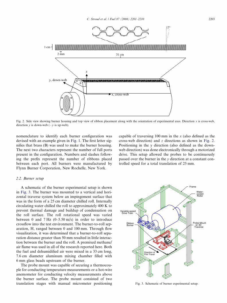
Fig. 2. Side view showing burner housing and top view of ribbon placement along with the orientation of experimental axes. Direction x is cross-web,direction y is down-web (�y is up-web).
C. Stroud et al. / Fuel 87 (2008) 2201–2210 2203
nomenclature to identify each burner configuration wasdevised with an example given in Fig. 1. The first letter sig-nifies that brass (B) was used to make the burner housing.The next two characters represent the number of full portspresent in the configuration. Numbers and slashes follow-ing the prefix represent the number of ribbons placedbetween each port. All burners were manufactured byFlynn Burner Corporation, New Rochelle, New York.
Frame
Water-cooledRoller
Variable-speedDrive Train
RibbonBurner
Probe Mountw/ 3D
Traverse
Direction ofFilm Travel
Fig. 3. Schematic of burner experimental setup.
2.2. Burner setup
A schematic of the burner experimental setup is shownin Fig. 3. The burner was mounted to a vertical and hori-zontal traverse system below an impingement surface thatwas in the form of a 25 cm diameter chilled roll. Internallycirculating water chilled the roll to approximately 400 K toprevent thermal damage and buildup of condensation onthe roll surface. The roll rotational speed was variedbetween 0 and 7 Hz (0–5.50 m/s) in order to introducecrossflow into the test environment. The burner-to-roll sep-aration, H, ranged between 0 and 100 mm. Through flowvisualization, it was determined that a burner-to-roll sepa-ration distance greater than 50 mm resulted in little interac-tion between the burner and the roll. A premixed methane/air flame was used in all of the research reported here. Boththe fuel and dehumidified air were mixed in a 33 cm long,7.6 cm diameter aluminum mixing chamber filled with6 mm glass beads upstream of the burner.
The probe mount was capable of securing a thermocou-ple for conducting temperature measurements or a hot-wireanemometer for conducting velocity measurements abovethe burner surface. The probe mount consisted of twotranslation stages with manual micrometer positioning
capable of traversing 100 mm in the x (also defined as thecross-web direction) and z directions as shown in Fig. 2.Positioning in the y direction (also defined as the down-web direction) was done electronically through a motorizeddrive. This setup allowed the probes to be continuouslypassed over the burner in the y direction at a constant con-trolled speed for a total translation of 25 mm.

2204 C. Stroud et al. / Fuel 87 (2008) 2201–2210
2.3. Flow visualization
The flow visualization experiments were achievedthrough schlieren imaging [4]. With this technique, theflame thermal gradients are made visible due to the deflec-tion of light resulting from the presence of density gradi-ents within the flame. For ideal gases, the densitygradients are equal in magnitude to the thermal gradientsunder constant-pressure flame conditions. The setup uti-lized a Z-configuration [4] where the light generated by axenon arc lamp is passed through a separate lens and spa-tial filter in order to generate a point source of light. Thispoint source was then directed onto a spherical mirror thatproduced a collimated beam of light equal in size to thediameter of the mirror (30.5 cm). This collimated beamwas then passed through the test section, in this case theburner and flame environment above the burner, and ontoa second mirror of the same size, called the schlieren head.The schlieren head was positioned to focus the beam oflight through a 5 cm diameter colored bulls-eye schlierenstop and onto a camera lens. The color filter qualitativelyindicates the degree of diffraction that occurs, giving a bluecolor for smaller thermal gradients, green and yellow formoderate gradients, and orange and red for the largest gra-dients, providing insight concerning gradient intensity andlocation. The color black in the images indicates anabsence of light due to blockage by an object such as theburner or roll or the frame capturing an area outside thecollimated beam.
A Nikon FM-2n camera was used with various lensesand film speeds to obtain all flow visualization images.For all far-field images, a Sun Zoom Telephoto Lens witha focal range of 85–210 mm was used with ISO 200 speed35 mm color film. The lens setting was 210 mm (f/4.8), witha camera shutter speed of 1/1000 s, which creates a time-averaged image as the thermal gradients fluctuate at a fas-ter rate than the time that the camera shutter is open (1/1000 s). A Tamron Zoom Lens coupled with a TC300 2Xteleconverter was used in order to capture the high resolu-tion images (maximum focal length of 600 mm) on 800speed film (f/4.8), with a camera shutter speed of 1/1000 s.
2.4. Temperature measurements
An Omega R-type thermocouple (platinum/platinum-13% rhodium) was used to measure the flame temperatures.The thermocouple wire (diameter = 0.08 mm) wasmounted within a 1.6 mm diameter ceramic sheath. Thethermocouple wire junction was coated with Aremco (Val-ley Cottage, NY) Ceramabond 569 alumina ceramic adhe-sive to protect the thermocouple junction from corrosion.The maximum bead diameter after coating was 0.59 mm,which allowed for the appropriate response time and spa-tial resolution to obtain the time-averaged trends in thetemperature data.
In order to obtain the true local gas temperature in theflame, the measured temperatures must be corrected for
radiation losses that occur at the thermocouple junction.Conductive and catalytic losses can also occur, but properprecautions were taken to avoid these types of losses. Theceramic coating prevents catalytic activity while conductivelosses are minimal if the thermocouple wire length-to-diameter ratio is >200, which was the case for all of ourmeasurements [5]. The radiation correction to the thermo-couple data was performed according to the methoddescribed by Shaddix [6], utilizing the Nusselt numberexpression proposed by Collis and Williams for flow overa cylinder [7]. As the temperature in the flame environmentincreases, larger correction factors are also required, rang-ing from 1 K for a measured thermocouple junction tem-perature of 500–280 K for a measured thermocouplejunction temperature of 2200 K. All temperature measure-ments presented in this paper were corrected for radiationlosses.
2.5. Hot-wire anemometry
The flowfield generated by the multiple jets of the rib-bon burner were measured using hot-wire anemometry.With this diagnostic technique, fluid velocity is measuredby sensing the changes in heat transfer from a small,electrically heated sensor exposed to the fluid motion.Under conditions in which fluid temperature, composi-tion, and pressure are constant, the dominant mechanismof heat transfer from the wire is through forced convec-tion, which is directly related to the velocity of the fluid.By measuring the voltage required to maintain thedesired hot-wire temperature, the fluid velocity can beaccurately determined. For further detail, the reader isdirected to Goldstein [8]. Hot-wire materials are notdesigned to withstand combustion environments so thatmeasurements must be made under cold-flow conditions.Even though these conditions differ from those with com-bustion present, the data provides valuable detailsdescribing the environment created.
In these studies, a TSI tungsten hot-wire anemometer(model number 1212-T1.5) with a wire diameter of approx-imately 0.0038 mm (0.0001500) and a sensing area length ofapproximately 1.27 mm (0.05000) was employed. The sensorwas connected to a TSI 1010 Heat Flux System. The volt-age output of the hot-wire circuitry was calibrated againsta known velocity through use of an Armfield C2 SubsonicWind Tunnel at velocities ranging from 0.3 m/s to 14.5 m/s. The sample rate was 1000 Hz, the sample period was10 s, and a low-pass filter of 10 kHz was employed to pre-vent aliasing of the data.
Velocity measurements were taken to observe the veloc-ity field above the burner under non-impinging conditions(H > 50 mm). The velocity field at a vertical position zabove the burner was measured by traversing the hot-wireanemometer across the burner using a motorized drive.Measurements were taken at vertical distances above theburner from z = 2 mm to z = 15 mm in steps of Dz =1.0 mm.
C. Stroud et al. / Fuel 87 (2008) 2201–2210 2205
3. Results and discussion
3.1. Burner configuration study
Color schlieren flow visualization was used to investi-gate various ribbon burner designs (31 cm plenum length).Changes in burner configuration were related to changes inflame stability and the flame environment created abovethe burner. As stated in Section 1.2, the optimal flame sep-aration distance has been experimentally determined to be1.25–2.25 mm [1]. Since each ribbon has a width of 0.5 mm,one would expect that three or four ribbons between eachrow of ports would be optimal. An 8-port burner, B8P,4/3/3/3/3/3/3/3/4, having a 1.5 mm row separation dis-tance was studied first. The burner created a very stableflame structure, showing minimal effects as a result ofincreased roll rotational speed, indicating that the rota-tional velocities were small in comparison to the jet veloc-ities. The burner creates a stable flame environment, butreaches acoustical resonance under some operating condi-tions. The sound emitted, described as ‘‘howling’’, reachesnearly 120 dB and is a result of environmental acousticinstabilities.
Two burners, C4P, 2/4/4/4/2 and C8P, 2/4/4/4/4/4/4/4/2, both with a 2.0 mm row separation were also examined.The 2.0 mm 8-port configuration is resistant to entrainmentintrusion, similar to the 1.5 mm 8-port burner, creating avery stable flame environment. The 4-port burner is moresusceptible to air entrainment at the highest roll rotationalspeeds (5.50 m/s) due to the reduction in the number of jetsthat would provide a cumulative resistance to the rota-tional velocities.
Row separations between 1.0 mm and 2.5 mm were alsoinvestigated in order to test the row separation parameter,using B4P, 4/2/2/2/2 (1.0 mm row separation) and B2P,6/2/6 (2.5 mm row separation) type burners. The 4-port,small port separation burner does not present a stableflame even with a stationary roller. Entrainment begins atlow roll rotational speeds and the flames lose stability asthe rotational speed of the roll is increased. The 2-port bur-ner provides a stable flame when the impingement surfaceis stationary, but because there are no outer flames toshield against the entrained ambient air, the flame is com-pletely extinguished at a roll rotational speed of 5.50 m/s.A 4-port burner, B4P, 5/5/5/5/5, with a 2.5 mm row sepa-ration shows the same vulnerability to entrainment as the1.0 mm design mentioned above since the flames are toofar apart to provide enough stabilization in the boundarylayer formed on the roller. The results above suggest thata burner with a 1.5–2.0 mm (three or four ribbon) divisionand at least four ports is desirable to create a stable anduniform environment above the burner.
3.2. Burner performance and flow regime analysis
Aside from the burner port configuration discussedabove, other variables that affect the flame structure
include the reactant flow velocity or flame power, the gapbetween the burner surface and the impingement surface,and the relative motion of the impingement surface, in thiscase the roll rotational speed. Flame power, in units of W/cm2, is calculated based on the fuel flowrate and the heat-ing capacity of methane per cm2 of ribbon surface area.The flame powers were varied from a minimum of309 W/cm2 (‘‘low’’ flame power, 4.78 m/s cold-flow area-averaged velocity) to a maximum of approximately1790 W/cm2 (‘‘high’’ flame power, 17.5 m/s cold-flowarea-averaged velocity). The flame equivalence ratio wasset to one (stoichiometric conditions). The gap (H) betweenthe burner casing (3 mm above the ribbon-pack surface)and roll varied from a minimum of 5 mm to a maximumof 50 mm. Finally, the roll rotational speed ranged from1 Hz to 7 Hz (0.785–5.50 m/s). All experiments discussedin this section were performed with a 10 cm burner havinga configuration of B4P, 3/4/4/4/3.
Fig. 4 presents schlieren images of the flame environ-ment created with a large burner-to-impingement surfacegap (H > 50 mm) in which the flame cones generated donot impinge on the roll surface. In Figs. 4 and 5, the rollis moving in a clockwise direction and is seen as the blackcircular object in the center of the image. The ribbon bur-ner is the black object at the bottom of each image, viewedalong its cross-web axis. The colors are an integration ofthe flame diffraction effects along the length of the burner(x direction). The left images (Top- far-field, Bottom – highresolution) in Fig. 4 depict a low flame power condition inwhich the reactant volumetric flow rate is 105 lpm (4.78 m/s, 309 W/cm2). The flame itself is laminar with a largeregion of little to no thermal variation at the center ofthe flame treatment region, as indicated by the dark bluecolor between the burner and the roll surface. The highestthermal gradients are indicated in red and are found at theouter edges of the flame zone. The right images (Top- far-field, Bottom – high resolution) in Fig. 4 show a high flamepower condition with high reactant flow rates (350 lpm,15.9 m/s, 1570 W/cm2). The presence of taller, moredefined flame cones along with increased small-scale fluctu-ations are evident and the size of the thermally uniformcore (indicated in dark blue) is reduced, indicating the pres-ence of a more highly mixed flame environment.
The higher-resolution schlieren images were taken toobserve at close range the behavior of the flame conesunder the same conditions. As can be seen in both high res-olution images (bottom photos – Fig. 4), the flame cones,indicated by the areas of cone-shaped yellow and red colorlocated near the burner surface, do not appear to beaffected by the presence of the impingement surface. Thereis a large area of constant high temperature centered abovethe burner, indicated by the black/dark blue section in thecenter of the picture in the low flame power configuration.In general, under non-impinging conditions (H > 50 mm),the low flame powers reflect laminar conditions with littleto no turbulence or mixing aside from the entrainment ofair near the impingement surface at higher rotational

Fig. 4. Schlieren images of non-impinging conditions (50 mm gap) for a B4P, 3/4/4/4/3 burner with a clockwise roll rotation of 0.785 m/s; top left image –far-field, low flame power (105 lpm, 4.78 m/s, 309 W/cm2); bottom left image – high resolution, low flame power; top right image –far-field, high flamepower (350 lpm, 15.9 m/s, 1570 W/cm2); bottom right image –high resolution, high flame power.
Fig. 5. Schlieren images of impinging conditions (10 mm gap) for a B4P, 3/4/4/4/3 burner with a clockwise roll rotation of 5.50 m/s; left image - low flamepower (105 lpm, 4.78 m/s, 309 W/cm2); right image - high flame power (350 lpm, 15.9 m/s, 1570 W/cm2).
2206 C. Stroud et al. / Fuel 87 (2008) 2201–2210
speeds (5.50 m/s). The stability of the flames being emittedfrom the burner is not affected by surface motion. The highflame power images also reflect extremely stable conditions,but with a high level of mixing. The high-power flamesshow limited effects due to air entrainment as a result ofsurface motion.
Fig. 5 captures the conditions within the flame treatmentzone as separation distance, H, is decreased to 10 mm andthe roll rotational speed is increased to 5.50 m/s. The leftimage in Fig. 5 represents a flame at low flame power(105 lpm, 4.78 m/s, 309 W/cm2) impinging on the roll andthe right image shows the environment created with a high
flame power (350 lpm, 15.9 m/s, 1570 W/cm2) at the samegap. At the high flame power, the flame cones are affectedby the presence of the impingement surface. Mixing isincreased under these conditions as the flame cones deform,causing a redirection of the fluid flow. Under these condi-tions there is little entrainment of ambient air along the rollsurface and the stability of the flame environment is notaffected. In contrast, at the low flame power, the schlierenimage shows laminar behavior with few small-scale fluctu-ations in thermal gradients and minimal mixing. The effectsof roll rotation and entrainment are obvious as the flamezone is influenced by the rotational flow, perturbing the

C. Stroud et al. / Fuel 87 (2008) 2201–2210 2207
upstream environment where ambient air is introduced.Under these conditions the rotational velocity of theimpingement surface exceeds the jet velocities and the envi-ronment above the burner is therefore affected.
Building on the flow visualization analysis described inthe preceding paragraphs, a qualitative flow regime analy-sis was performed using the data gathered with the schlie-ren images as the flame power, burner-to-roll gap, androll rotational speed were systematically varied. The imageswere visually compared and categorized as laminar,partially mixed, or highly mixed based on the level ofsmall-scale fluctuations that were present in the flame envi-ronment. The effects of entrainment were also considered inorder to determine if the free jet velocities were influencedby the roll rotational velocity. The categorized results arepresented in Table 1. For a flame, or reacting jet, the freejet Reynolds number, Red, is defined as:
Red ¼ ud=m ð3:1Þ
where the characteristic length, d, is the burner port diam-eter (1.38 · 10�3 m), u is the unburned gas velocity (see Ta-ble 1), and t is the reactant kinematic viscosity(1.59 · 10�5 m2/s). In accordance with Shaddix [6], theproperties of nitrogen are used for the Reynolds numbercalculations as they provide a reasonable approximationfor the properties of methane–air mixtures. All Reynoldsnumbers were calculated using properties defined at300 K, assuming that the reactant fuel and air are closeto ambient temperatures as they exit the burner ports.The fuel and air volumetric flow rate was divided by the
Table 1Flow regime analysis results
Reactant flow (lpm) Roller rotational velocity (m/s) Flow velocity (m
105 0.785 4.780.7852.352.353.933.935.505.50
160 0.785 7.650.7850.7852.353.935.505.50
206 0.785 9.360.7850.7855.505.505.50
240 0.785 to 5.50 10.9305 0.785 to 5.50 13.9
* Observed flow regimes – laminar (L), laminar with entrainment (LE), part(HM).
open area of the burner ports (0.000366 m2) in order to ob-tain the reactant flow velocity.
The resulting flow regimes established through flowvisualization analysis of the environment created by thearray of reacting methane–air jets were similar to the pub-lished regimes for single non-reacting circular jets whichare defined as follows [3]:
(1) Re < 300 dissipated laminar jet(2) 300 < Re < 1000 fully laminar jet(3) 1000 < Re < 3000 semi-turbulent jet(4) 3000 < Re fully turbulent jet
Observations show that the flame environment remainslaminar below a jet Reynolds number of 600 (calculatedat the burner port outlet), then starts to transition fromlaminar to partially mixed at Re > 600, and becomes highlymixed around Re = 900, in comparison to Re = 3000 for afully turbulent single non-reacting jet. The environmentbecomes very highly mixed at a lower Reynolds numberin comparison to a single non-reacting jet because of theeffects of combustion-induced turbulence and jet interac-tion, as higher flow velocities are coupled with greater heattransfer and transport properties due to increased mixing.As suggested by Lewis and von Elbe [9], turbulence canbe introduced by the chemical kinetics and rapid volumeexpansion occurring within the flame. Their results shownearly an order of magnitude increase in the turbulenceintensity of the post-flame gases for a methane–air flameand an even greater increase for an acetylene–air flame,in comparison to that of the respective approach flows.
/s) Free jet Reynolds number (Red) Gap (mm) Flow regimes*
415 10–50 L5–7 L25–50 L5–20 L25–50 PM5–20 PM20–50 PME5–15 PME
664 25–50 PM15–20 PM5–10 PM5–50 PM5–50 PM25–50 PM5–20 PME
812 40–50 ST30–35 ST5–25 PM to HM45–50 PM to HM25–40 PM to HM5–20 PM to HM
947 5–50 HM1210 5–50 HM
ially mixed (PM), partially mixed with entrainment (PME), highly mixed
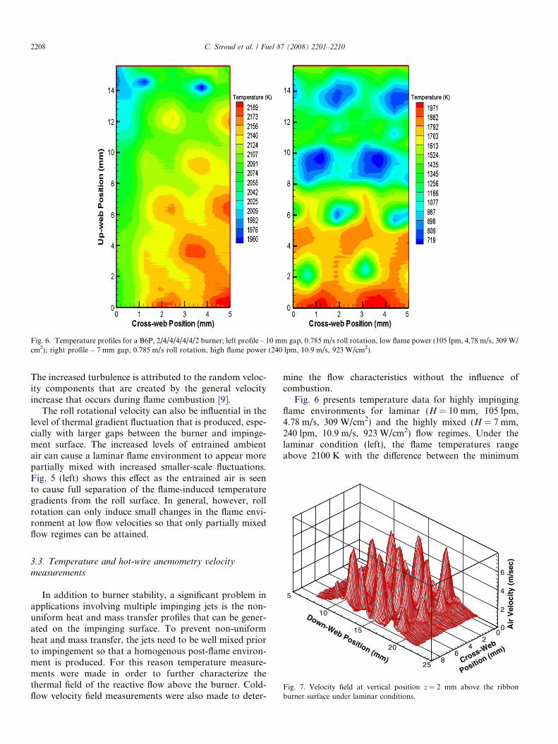
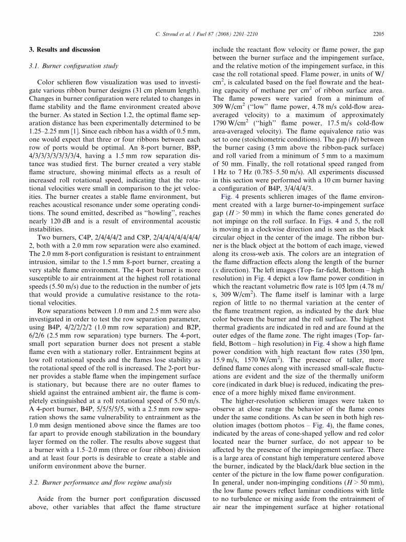
Fig. 6. Temperature profiles for a B6P, 2/4/4/4/4/4/2 burner; left profile – 10 mm gap, 0.785 m/s roll rotation, low flame power (105 lpm, 4.78 m/s, 309 W/cm2); right profile – 7 mm gap, 0.785 m/s roll rotation, high flame power (240 lpm, 10.9 m/s, 923 W/cm2).
2208 C. Stroud et al. / Fuel 87 (2008) 2201–2210
The increased turbulence is attributed to the random veloc-ity components that are created by the general velocityincrease that occurs during flame combustion [9].
The roll rotational velocity can also be influential in thelevel of thermal gradient fluctuation that is produced, espe-cially with larger gaps between the burner and impinge-ment surface. The increased levels of entrained ambientair can cause a laminar flame environment to appear morepartially mixed with increased smaller-scale fluctuations.Fig. 5 (left) shows this effect as the entrained air is seento cause full separation of the flame-induced temperaturegradients from the roll surface. In general, however, rollrotation can only induce small changes in the flame envi-ronment at low flow velocities so that only partially mixedflow regimes can be attained.
5
10
15
20
25
2
4
6
02
46
8
Down-Web Position (mm)
Air
Vel
oci
ty (
m/s
ec)
Cross-Web
Position (m
m)
0
Fig. 7. Velocity field at vertical position z = 2 mm above the ribbonburner surface under laminar conditions.
3.3. Temperature and hot-wire anemometry velocity
measurements
In addition to burner stability, a significant problem inapplications involving multiple impinging jets is the non-uniform heat and mass transfer profiles that can be gener-ated on the impinging surface. To prevent non-uniformheat and mass transfer, the jets need to be well mixed priorto impingement so that a homogenous post-flame environ-ment is produced. For this reason temperature measure-ments were made in order to further characterize thethermal field of the reactive flow above the burner. Cold-flow velocity field measurements were also made to deter-
mine the flow characteristics without the influence ofcombustion.
Fig. 6 presents temperature data for highly impingingflame environments for laminar (H = 10 mm, 105 lpm,4.78 m/s, 309 W/cm2) and the highly mixed (H = 7 mm,240 lpm, 10.9 m/s, 923 W/cm2) flow regimes. Under thelaminar condition (left), the flame temperatures rangeabove 2100 K with the difference between the minimum

C. Stroud et al. / Fuel 87 (2008) 2201–2210 2209
and maximum local temperatures being less than 230 K. Incontrast, for the high flow velocity, highly mixed flowregime, the difference between the minimum and maximummeasured temperatures is �1250 K. For both flame envi-ronments, higher temperatures are found between the ports[3,10] and the lowest temperatures are seen above the portopenings due to the presence of unreacted fuel and air.
The cold-flow velocity field measured at a position z = 2mm above the ribbon burner operating at laminar flameenvironment conditions (equivalent to 580 W/cm2 for areacting flow) is shown in Fig. 7. Under these conditions
12
14
16
18
20
0 1 2 3 4 5 6 7 8 9
1
11
1
1
1
1
1
1
1
1
1
1
1
1
1
1
1
1
1
1
1
1
1
1
1
1
1
1
1
1
1
1
2
2
21
12
1
2
2
2
2
2
2
2
22
2
32
2
2
2
2
2
2
2
3
2
2
3
2
2
3
4
3
2
2
3
3
2
3
4
3
34
4
3
4 3
5
5
5
5
5 5
5
5
5
5
4
5
6
5
6
5
6
6
(a) 2 mm
12
14
16
18
20
0 1 2 3 4 5 6 7 8 9
Cross-Web Position, x, (mm)
Cross-Web Position, x, (mm)
1
1
1
1
1
1
1
11 11
1
1
1
1 1
1
1
1
1
1
1
2
1
2
2
2
2
2
2
2
3
222
2
2
2
2
2
2
2
3
2
3
3
3
2
3
2
2
3
3
3
3
3
3
3
3
3
3
3
3
3
3
3
3
4
3
33
333
3
3
34
3
3
44
4
3
3
4
4
3
3
3
3
3
3
3
3
34
3
4
44
3
4
44
3
4
5
3
4
44
4
44
4
44
5
444
5
4 5
45
4
5
5
55
55
Do
wn
-Web
Po
siti
on
, y, (
mm
)D
ow
n-W
eb P
osi
tio
n, y
, (m
m)
(c) 10 mm
Fig. 8. Velocity contours at increasing distance above t
the highest reactant flow velocity was found to be 6.8 m/s.The velocity field is highly non-uniform over the main com-bustion zone (10 < y, down-web < 20 mm). Inter-jet mixingcan be observed in the contour plots of the main combus-tion zone (10 6 y 6 20 mm) shown in Fig. 8. The jets areeasily identified at the low separation distance of 2 mm,but become increasingly difficult to distinguish as the verti-cal distance is increased. While velocities are relatively highat z = 10 mm, adjacent jets have combined at this height,reaching a plane of horizontal uniformity [11] and fluctua-tions in the flow appear random. This uniform plane is also
12
14
16
18
20
0 1 2 3 4 5 6 7 8 9
1
1
1
11
1 1 1
11
1
1
1
1
1
1
1
11
1
111
12
2
2
2
2
2
2
2
2
2
22
2
2
2
2
2
2
2 2
2
2
2
2
22 2
2
2
2
2 2
2
2
2
3
2
3
3
3
3
3
3
3
3
3
3
3
3
33
3
3
3
3
3
3
333
3
3
3
33
3
3
3
3
3 3
3
4
4
44
34
4
4
4
44
4
4
4
4
4
4
Cross-Web Position, x, (mm)
Cross-Web Position, x, (mm)
12
14
16
18
20
Do
wn
-Web
Po
siti
on
, y, (
mm
)D
ow
n-W
eb P
osi
tio
n, y
, (m
m)
0 1 2 3 4 5 6 7 8 9
11
1
1
1
1
1
1
1
1
1
2
2 2
2
2
2
2
2 2
2
2
2
2
3
2
2
2
2
2
2
2
2
2
2
3
3
2
2
3
2
3
3
2
3
3
2
3
3
3
3
2
3
23
3
3
3
3
4
4
22
3
3
4
4
245
3
4
3
4
34
4
5
5
6
4
4
45
4
4
5
5
5
5
46
5
5
5
5
6
6
6
6
(b) 6 mm
(d) 14 mm
he ribbon burner surface under laminar conditions.

2210 C. Stroud et al. / Fuel 87 (2008) 2201–2210
evident in Fig. 6 as the difference in the average temperaturein the x or cross-web direction is less than 100� under lam-inar flow conditions. At z = 14 mm, in Fig. 8, the flowfielddissipates significantly, and little structure can be identified.
A reasonable assumption might be that a laminar envi-ronment would be the flow regime of choice for mostindustrial processes because of the high temperatures andrelative uniformity of the temperature field [11], but dueto reduced resistance to entrainment, a laminar environ-ment may not always be desirable. Required reductionsin impingement surface motion to attenuate entrainmenteffects may result in unsatisfactory processing speeds andefficiencies. In addition to this, the combustion productflowrates are significantly less, allowing time for radicalrecombination, leading to insufficient treatment levels insuch processes as the surface treatment of polymer filmswhere the surface is oxidized due to exposure to post com-bustion gases [11–14].
4. Conclusions
This study focused on the key parameters that enhancethe stability of ribbon burners used in flame treatmentand other industrial processes and characterized the flameenvironment and flow regimes that the burner createsunder varying operating conditions. Burner configurationdirectly influences the stability of a ribbon burner. Adetailed color schlieren study revealed that burners havinga 1.5–2.0 mm division between rows appeared to be themost stable and that more than four rows of ports in theribbon-pack are required to resist entrainment of ambientair as a result of impinging surface motion.
The flame environment created by the array of jets of theribbon burner becomes more highly mixed at a lower Rey-nolds number in comparison to a single non-reacting jetbecause of the effects of combustion-induced turbulenceand jet interaction. Higher flow velocities are coupled withgreater heat transfer and transport properties due toincreased mixing. Under these conditions there is littleentrainment of ambient air along the impingement surfaceand a very stable flame environment is created. More uni-form temperature and velocity profiles are seen with lami-
nar flame environment conditions but resistance toentrainment is reduced.
Acknowledgement
Research sponsored by 3M Company Corporate Re-search Process Laboratory, St. Paul, Minnesota.
References
[1] Pearson E, Saunders T, Hargreaves K. Fully premixed natural gasburners for use in high thermal efficiency domestic boilers. 1983International gas research conference. 1983:683–694.
[2] Jones HRN. Fully aerated burners. In: Spon E, Spon FN, editors.The applications of combustion principles to domestic gas burnerdesign. London and New York: British Gas; 1989. p. 76–105.
[3] Viskanta R. Heat transfer to impinging isothermal gas and flame jets.Exp Therm Fluid Sci 1993;6:111–34.
[4] Settles GS. Schlieren and Shadowgraph techniques. 1st ed. Ber-lin: Springer; 2001.
[5] Heitor MV, Moreira ALN. Thermocouples and sample probes forcombustion studies. Prog Energ Combust Sci 1993;19:259–78.
[6] Shaddix CR. Correcting thermocouple measurements for radiationloss: a critical review. In: Proceedings of the 33rd national heattransfer conference, August 1999. Albuquerque, New Mexico.
[7] Collis DC, Williams MJ. Two-dimensional convection from heatedwires at low Reynolds numbers. J Fluid Mech 1959;6:357–84.
[8] Goldstein RJ. Fluid mechanics measurements. 2nd ed. Washington,DC: Taylor and Francis; 1996.
[9] Lewis B, von Elbe G. Combustion, flames and explosions of gases.3rd ed. New York: Academic Press; 1987.
[10] Koopman RN, Sparrow EM. Local and average transfer coefficientsdue to an impinging row of jets. Int J Heat Mass Trans1975;19:673–83.
[11] Branch MC, Sullivan N, Ulsh M, Strobel M. Surface modification ofpolypropylene films by exposure to laminar, premixed methane–airflames. 27th symposium (international) on combustion. PittsburghPA: The Combustion Institute; 1998. p. 2807–13.
[12] Sullivan N, Branch MC, Strobel M, Park J, Ulsh M, Leys B. Theeffects of an impingement surface and quenching on the structure oflaminar premixed flames. Combust Sci Technol 2000;158:115–34.
[13] Park J, Lyons CS, Strobel M, Ulsh M, Kinsinger MI, Prokosch MJ.Characterization of non-uniform wettability on flame-treated poly-propylene-film surfaces. J Adhes Sci Technol 2003;17:643–53.
[14] Strobel M, Ulsh M, Stroud C, Branch M. The Causes of non-uniformflame treatment of polypropylene film surfaces. J Adhes Sci Technol2006;20:1493–505.