fluid kinematics
TRANSCRIPT
Fluids have a tendency to move or flow even if there exists a very small shear stress.
The study of velocity and acceleration of a flowing fluid and the description and visualization of the fluid motion are dealt with fluid kinematics.
Two Methods: 1.Eulerian Method:
concerned with field of flow. The properties (pressure, velocity, density etc.) are expressed as function of space and time. F = f(x, y, z, t)
2.Lagrangian Method: follows an individual particle( or given mass) flowing through the flow field and thus determines the fluid properties of individual particles or masses as a function of time like p(t), v(t) etc.
A fluid consists of large number of particles, therefore it is convenient to use the Eulerian method for describing the fluid motion.
SYSTEM : It refers to a fixed, identifiable quantity of mass in space: Three types of system: open system, closed system, isolated system.
SURROUNDING: All other matter around the system is called surrounding
BOUNDARY: The system boundaries forming a closed surface separates the system from surrounding.
The system boundary may be fixed or movable but there is no mass transfer occurs across the system boundaries.
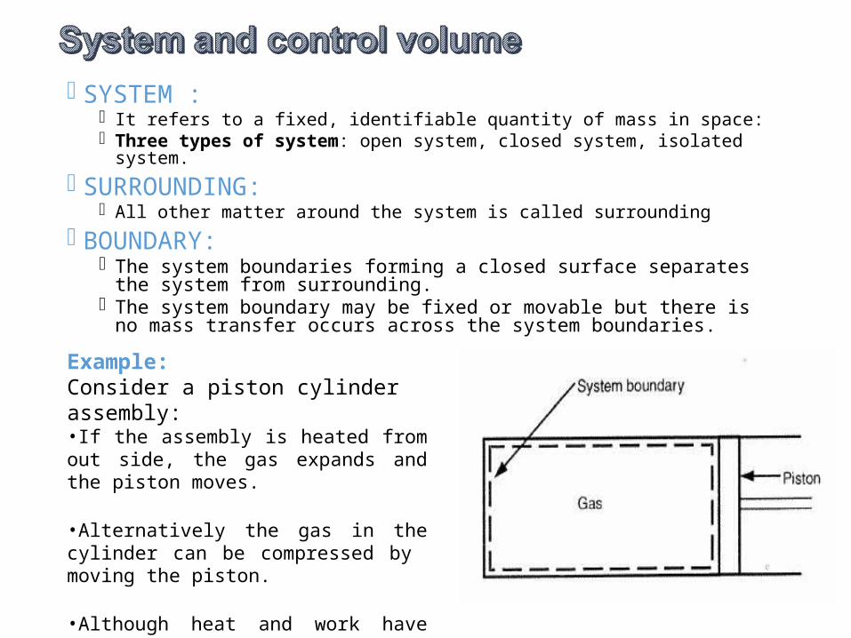
Example:Consider a piston cylinder assembly:•If the assembly is heated from out side, the gas expands and the piston moves.
•Alternatively the gas in the cylinder can be compressed by moving the piston.
•Although heat and work have transferred through the boundary but there is no mass transfer across the boundary.
In case of fluid flow in pipes, channels, nozzles etc. it is difficult to focus attention on fixed identifiable quantity of mass.
It is convenient to focus attention on a volume, in a flow field, through which the fluid flows. This volume is called control volume.
Control volume: May be defined as an arbitrary volume in a flow field through which the fluid flows
The geometric boundary of the control volume is called control surface, that may be real or imaginary or may beat rest or in motion.Example:
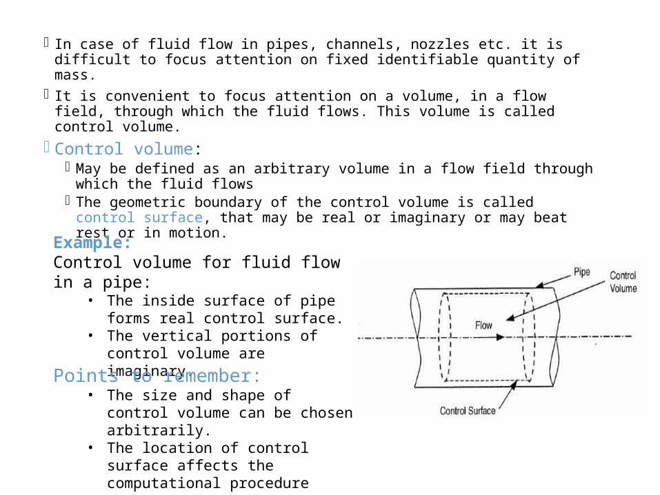
Control volume for fluid flow in a pipe:
• The inside surface of pipe forms real control surface.
• The vertical portions of control volume are imaginary. Points to remember:
• The size and shape of control volume can be chosen arbitrarily.
• The location of control surface affects the computational procedure
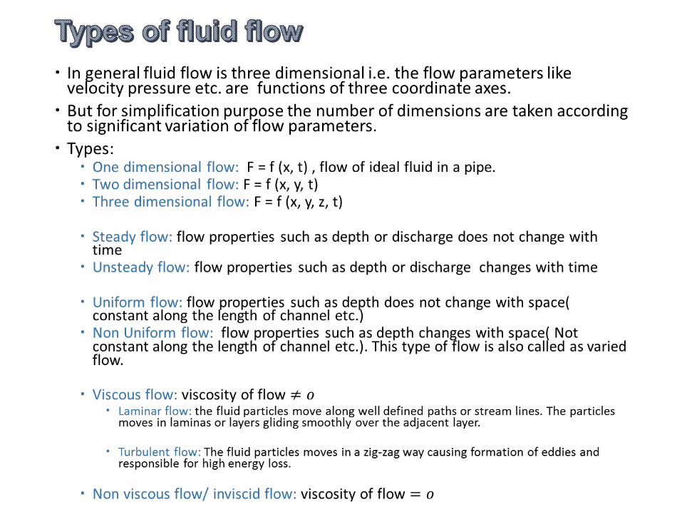
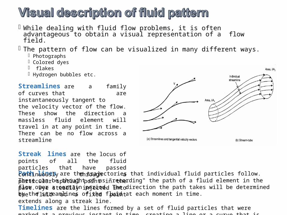
While dealing with fluid flow problems, it is often advantageous to obtain a visual representation of a flow field.
The pattern of flow can be visualized in many different ways. Photographs Colored dyes flakes Hydrogen bubbles etc.
Path lines are the trajectories that individual fluid particles follow. These can be thought of as "recording" the path of a fluid element in the flow over a certain period. The direction the path takes will be determined by the streamlines of the fluid at each moment in time.
Timelines are the lines formed by a set of fluid particles that were marked at a previous instant in time, creating a line or a curve that is displaced in time as the particles move.
Streamlines are a family of curves that are instantaneously tangent to the velocity vector of the flow. These show the direction a massless fluid element will travel in at any point in time.There can be no flow across a streamline
Streak lines are the locus of points of all the fluid particles that have passed continuously through a particular spatial point in the past. Dye steadily injected into the fluid at a fixed point extends along a streak line.
Stream tube: A typical set of neighboring streamlines that forms a passage through which the fluid flows is called stream tube.
No flow is possible across a stream tube except through its ends.
The stream tube need not be a solid and are fluid surface.
Stream filament: It is a stream tube with its cross section sufficiently small so that variation of velocity over it may be considered negligible.
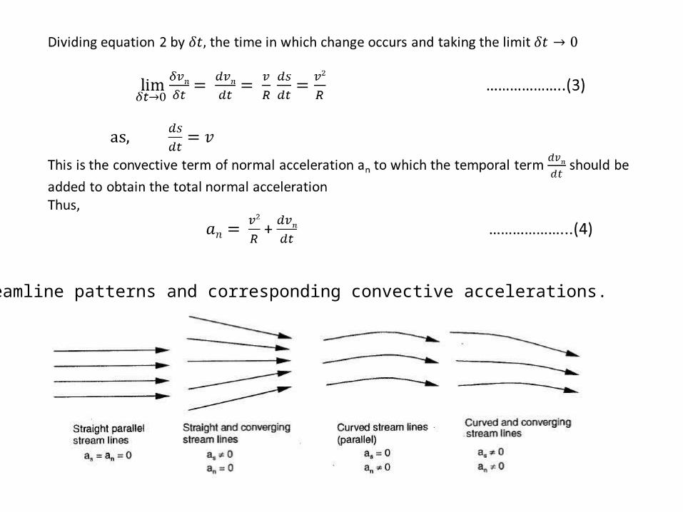
Streamline patterns and corresponding convective accelerations.
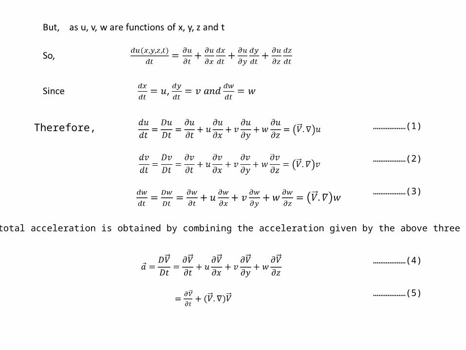
Therefore, ………………(1)
………………(2)
………………(3)
So, the total acceleration is obtained by combining the acceleration given by the above three equations
………………(4)
………………(5)
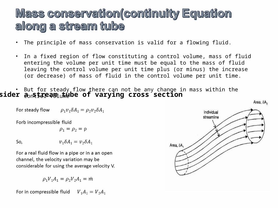
• The principle of mass conservation is valid for a flowing fluid.
• In a fixed region of flow constituting a control volume, mass of fluid entering the volume per unit time must be equal to the mass of fluid leaving the control volume per unit time plus (or minus) the increase (or decrease) of mass of fluid in the control volume per unit time.
• But for steady flow there can not be any change in mass within the control volumeConsider a stream tube of varying cross section
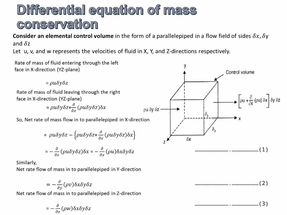
………………………….……………………(1)
………………………….……………………(2)
………………………….……………………(3)
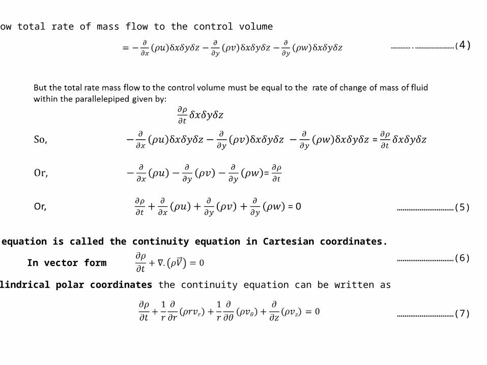
Now total rate of mass flow to the control volume………….……………………(4)
…………………………(5)
This equation is called the continuity equation in Cartesian coordinates.
In vector form …………………………(6)
In cylindrical polar coordinates the continuity equation can be written as
…………………………(7)
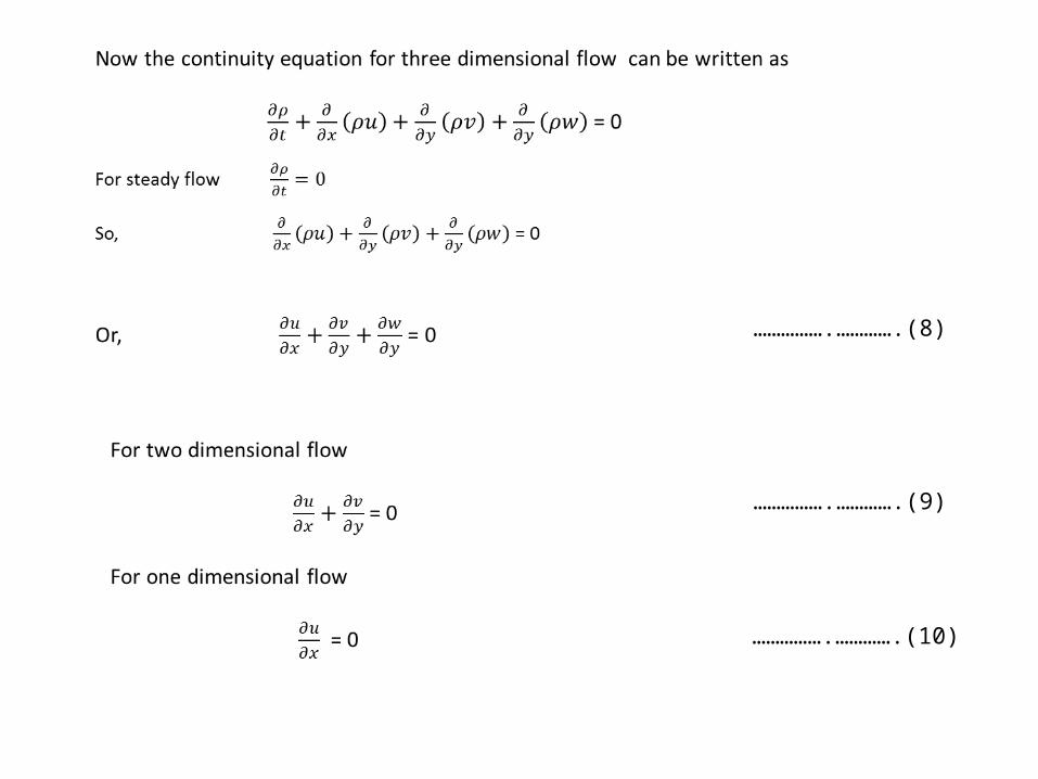
…………….………….(8)
…………….………….(9)
…………….………….(10)
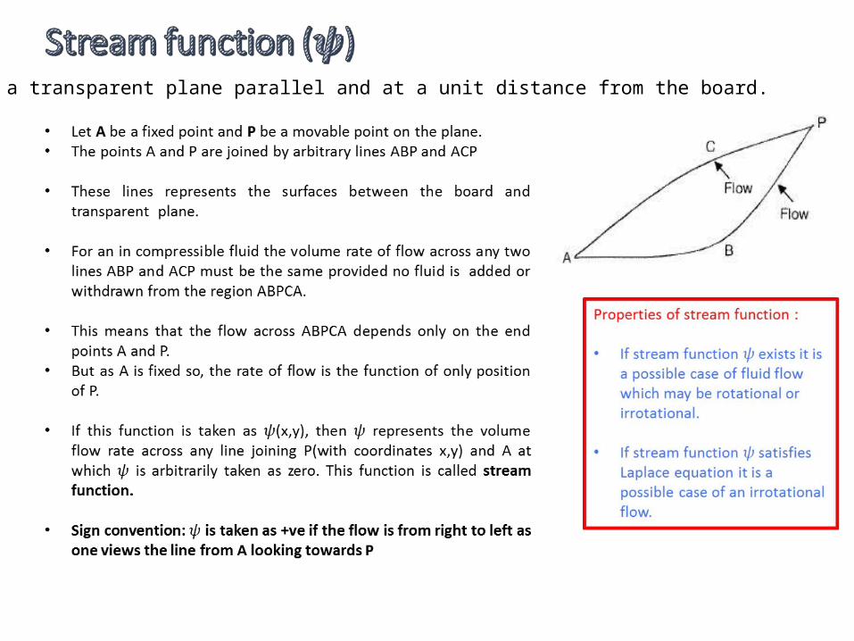
Consider a transparent plane parallel and at a unit distance from the board.
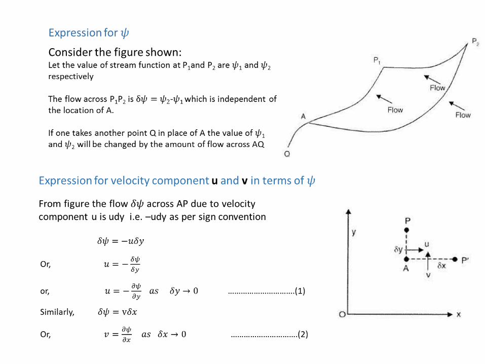

The partial derivative of the stream function with respect to any direction gives the velocity component at 90o anticlockwise to that direction.The stream function is only defined for two dimensional in compressible flow, for which the continuity equation can be written as
Putting the values of u and v from equation 1 and 2, we will get
This shows that the stream function always satisfies the continuity equation.
In polar coordinates
…………….(3)
…………….(4)
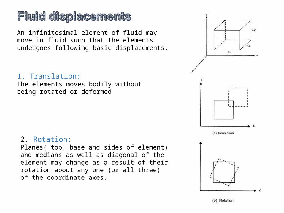
An infinitesimal element of fluid may move in fluid such that the elements undergoes following basic displacements.
1. Translation: The elements moves bodily without being rotated or deformed
2. Rotation: Planes( top, base and sides of element) and medians as well as diagonal of the element may change as a result of their rotation about any one (or all three) of the coordinate axes.
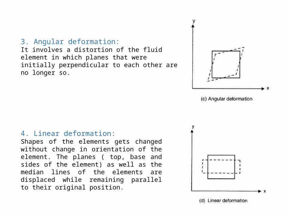
4. Linear deformation: Shapes of the elements gets changed without change in orientation of the element. The planes ( top, base and sides of the element) as well as the median lines of the elements are displaced while remaining parallel to their original position.
3. Angular deformation:It involves a distortion of the fluid element in which planes that were initially perpendicular to each other are no longer so.

• Counter clock wise rotation is considered to be positive.
• If the fluid particles in a flow region have rotation about any axis the flow is called rotational flow or vortex flow.
• If the fluid particles in a flow region do not have rotation about any axis the flow is called irrotational flow
………………………(A)
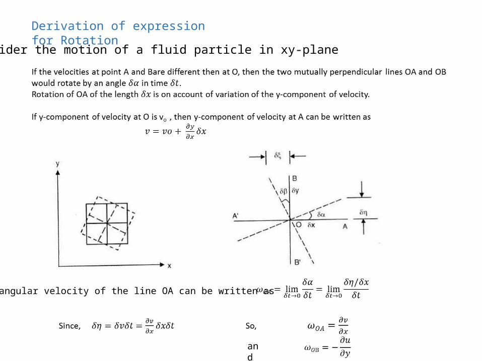
Consider the motion of a fluid particle in xy-planeDerivation of expression for Rotation
The angular velocity of the line OA can be written as
and
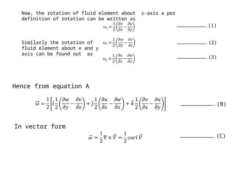
Now, the rotation of fluid element about z-axis a per definition of rotation can be written as
Similarly the rotation of fluid element about x and y axis can be found out as
………………………….(1)
………………………….(2)
………………………….(3)
Hence from equation A
………………………….(B)
In vector form………………………….(C)
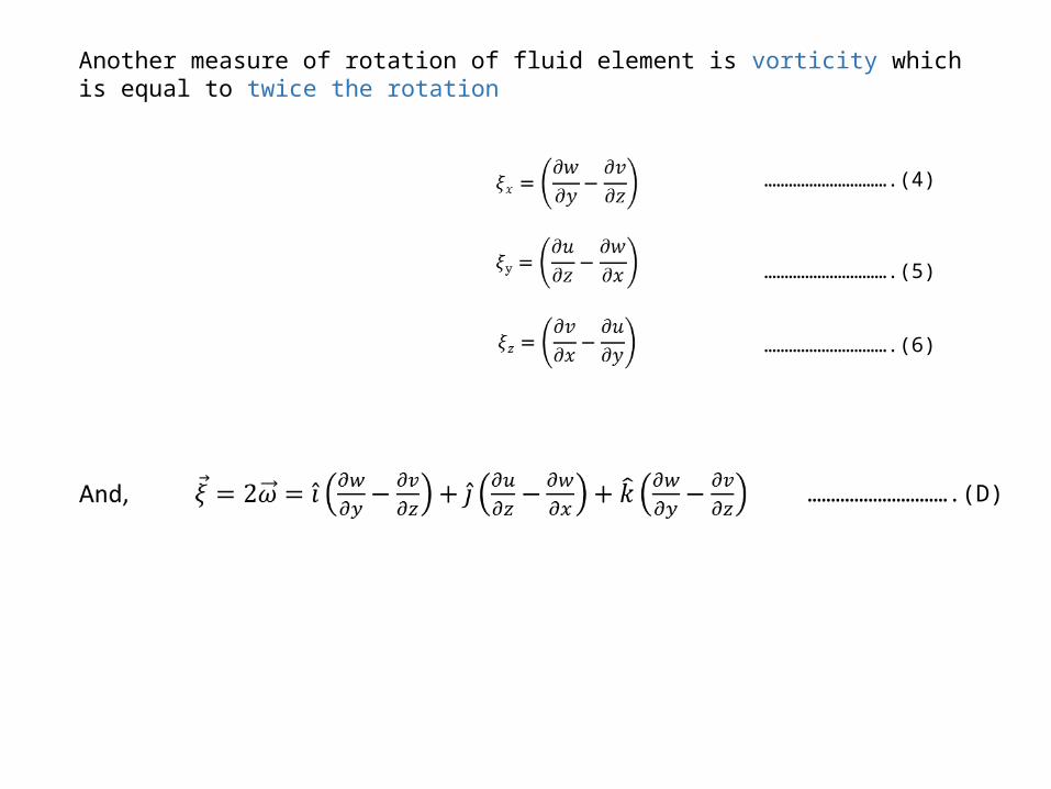
Another measure of rotation of fluid element is vorticity which is equal to twice the rotation
………………………….(4)
………………………….(5)
………………………….(6)
………………………….(D)
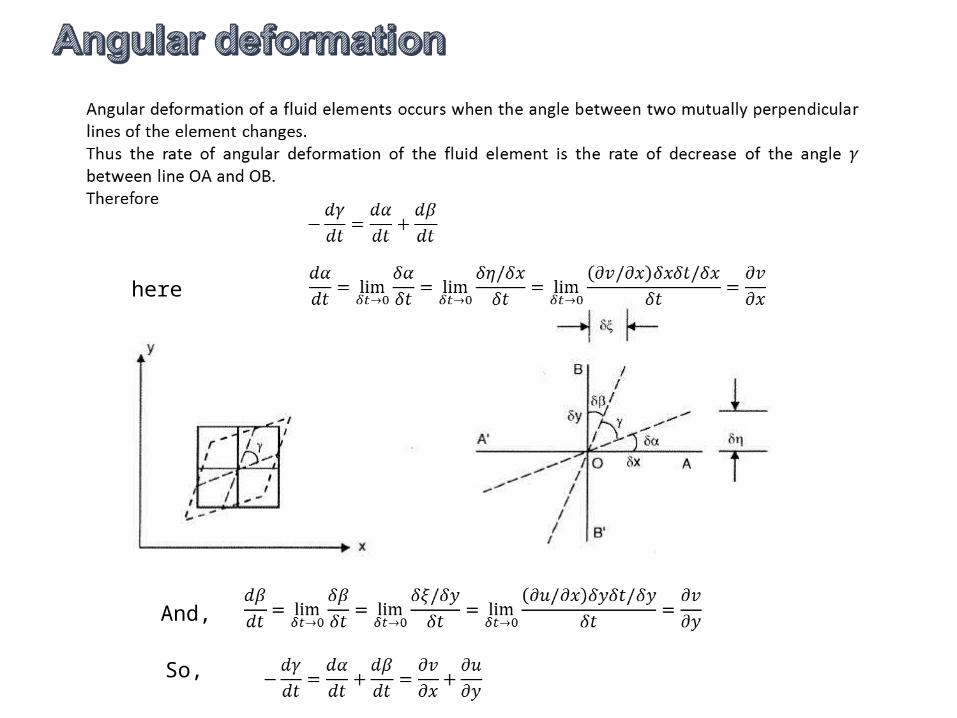
here
And,
So,
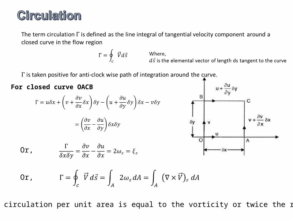
For closed curve OACB
Or,
Or,
This means circulation per unit area is equal to the vorticity or twice the rotation
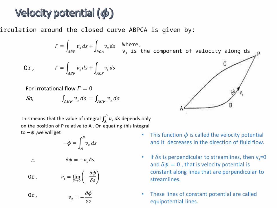
The circulation around the closed curve ABPCA is given by:
Or,
Where,vs is the component of velocity along ds
Or,
Or,
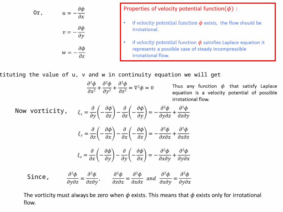
Or,
Substituting the value of u, v and w in continuity equation we will get
Now vorticity,
Since,
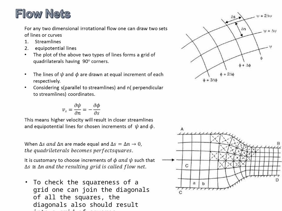
• To check the squareness of a grid one can join the diagonals of all the squares, the diagonals also should result into a grid of squares
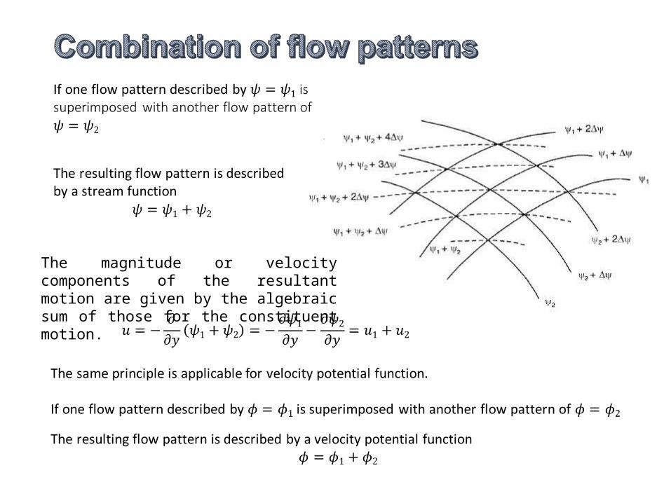
The magnitude or velocity components of the resultant motion are given by the algebraic sum of those for the constituent motion.
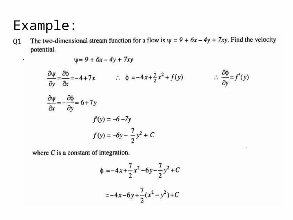
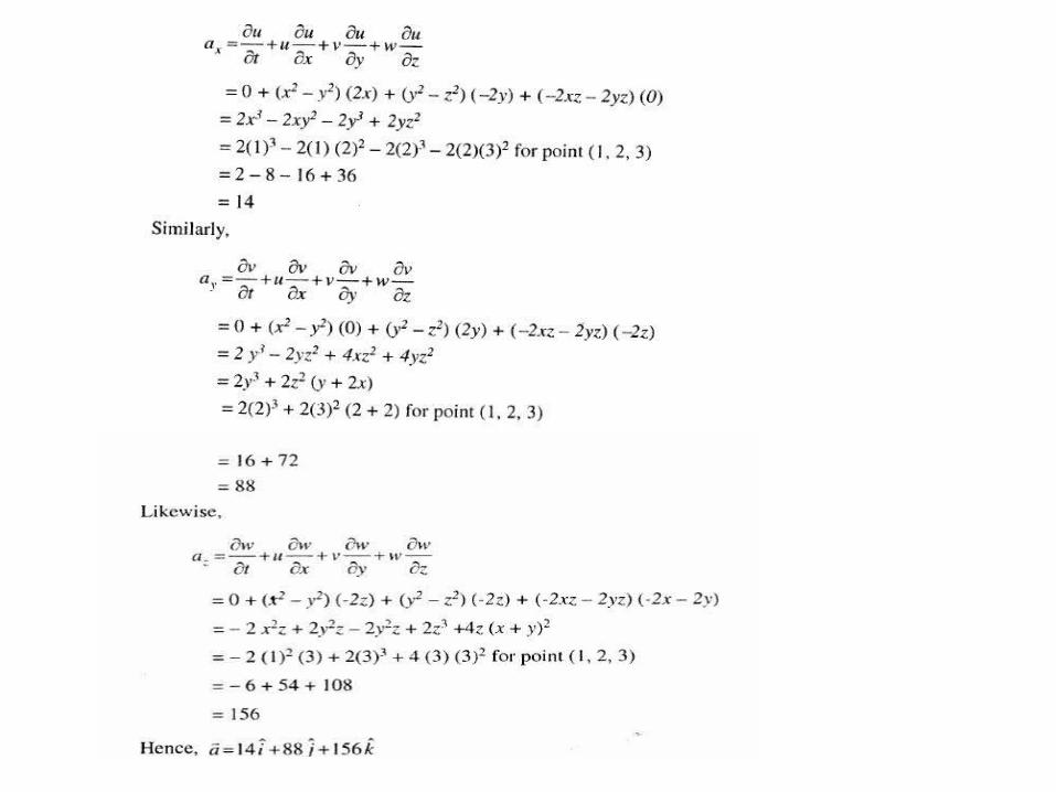
Example:Q1
Tutorial Question
Reference: Fluid Flow in pipes and channels by GL ASAWA