polypropylene manufacturing
TRANSCRIPT
1SUMITOMO KAGAKU 2009-II
Introduction
Polypropylene (PP) has the physical characteristics
of a low specific gravity, rigidity, heat resistance and
superior workability. In addition, since it is compara-
tively low in cost, it is used in a variety of applications,
such as films, industrial components for automobiles,
furniture, etc., and miscellaneous goods. It has been
more than 50 years since 1954, when G. Natta et al. of
Italy were successful in synthesizing high molecular
weight, highly crystalline PP,1) and the total worldwide
demand for PP has currently reached an amount of
approximately 47 million tons (prediction for 2008).
However, replacement of other materials and resins is
progressing even more, and moving forward, the fore-
cast is for the highest growth rate among general pur-
pose resins at an average of about 6% per year.2)
This flourishing of the PP market has been support-
ed by the large improvements and simplification in the
manufacturing process that had been accomplished
with the leaps in catalyst performance. Furthermore, in
addition to the characteristics of PP itself described
above, the fact that there have been large improve-
ments in the transparency and impact resistance at low
temperatures through copolymerization with ethylene
and other alpha olefins has probably been an important
factor. With the increase in the level of requirements
for quality in recent years, a variety of ideas and con-
trivances have been integrated into the manufacturing
process for PP. In this paper, we will give a summary of
the changes and the current state of the PP manufac-
turing process based on information in the important
patents and literature along with technologies devel-
oped by Sumitomo Chemical.
Changes in the PP Manufacturing Process
The PP manufacturing process is mainly made up of a
raw material refining process, polymerization process,
aftertreatment process and granulation process. The raw
material refining process is the furthest upstream
process and is a process for eliminating minute amounts
of impurities that affect the process, such as water, oxy-
gen, carbon monoxide, carbon dioxide, carbonyl sulfide
and the like, from the propylene and other monomers as
well as the solvents and other raw materials and auxil-
iary materials used. Moreover, this process may be set
up at a raw material manufacturing plant positioned
upstream of the PP manufacturing plant, but in either
case, it is a fundamentally necessary process for stabi-
lization of the overall process. The polymerization
process is a process for polymerization that brings the
propylene and, if necessary, ethylene and other
monomers into contact with a catalyst having polymer-
Review on Development ofPolypropylene ManufacturingProcess
Sumitomo Chemical Co., Ltd.
Process & Production Technology Center
Hideki SATO
Hiroyuki OGAWA
Polypropylene (PP) is a typical commodity plastic and has been widely used in many application fieldsincluding packaging films, industrial components and miscellaneous goods, due to its excellence in propertiessuch as stiffness, heat resistance and processability in addition to light weight material density and also arelatively low price. The continued demands from the market for higher performances have stimulated,particularly in recent time, the improvement of PP manufacturing processes with newly created ideas. Thisreview describes, mainly based on the information published in literature and patents, an outline of thedevelopment history of PP manufacturing processes and an introduction to recent progress, including our owntechnologies.
This paper is translated from R&D Report, “SUMITOMO KAGAKU”, vol. 2009-II.

2SUMITOMO KAGAKU 2009-II
Review on Development of Polypropylene Manufacturing Process
ization activity. Most of the main industrial catalysts are
in a granular shape. The main catalysts are mostly in the
form of secondary or tertiary particles of several tens of
µm that are aggregations of primary molecules having
diameters of several hundred angstroms. The polymer-
ization reaction occurs at the active points of the catalyst
particles, and the PP that is formed precipitates out, and
the catalyst splits into primary particles. However, there
are few deviations in the shape of the catalyst, and this
forms PP particles that resemble the original aggregated
catalyst shape.3) The aftertreatment process is a process
for eliminating catalyst residue, the solvent and atactic
polymers (AP: noncrystalline polymers where the
methyl groups of propylene units are arranged irregular-
ly on the chain), which are components that are unnec-
essary, from the PP particles obtained in the
polymerization process. Of these, the operation for elimi-
nating the catalyst is known as deashing.
In addition, when a solvent is used in the polymeriza-
tion process, a process for recovering and purifying it
is included. The granulation process is the furthest
downstream process, and it is a process for melting
and kneading additives and fillers into the PP particles
that have undergone the after-processing and forming
pellets.
In recent years, there are cases where large diameter
PP particles are shipped directly without granulation
through improvements in the catalyst performance,
methods of stabilizer distribution, etc. However, this is
limited to a few examples still, and it has not come to
the point of completely eliminating the granulation
process.4) Moreover, storage, packaging and shipping,
etc., are indispensable further downstream in commer-
cial plants, but since they are not unique to PP manu-
facturing processes, we will not touch on them in this
paper.
Of these processes, there have been particularly
large improvements in simplifications for the
aftertreatment process, such that they can be cited as
a representative example of advances in chemical man-
ufacturing processes. The PP manufacturing process
can be divided into three generations, the first genera-
tion (deashing and AP removal), second-generation
(non-deashing or non-solvent) and third-generation
(non-deashing and non-AP removal) according to these
advances in technology. In addition, classification can
be done according to the polymerization method into
solvent processes, bulk polymerization processes and
vapor phase polymerization processes. Fig. 1 shows
the changes in the PP manufacturing processes
arranged according to the processes required for the
representative polymerization process for each genera-
tion. Moreover, the furthest upstream raw material
refining process and the downstream granulation
process, which are fundamentally required in all of
these processes, are omitted in Fig. 1.
We will give a summary of these changes in PP man-
ufacturing processes, using representative polymeriza-
tion processes that Sumitomo Chemical has developed
for each generation.
1. Solvent polymerization process
Since the PP particles are dispersed in the form of a
slurry in the solvent with the solvent polymerization
process, this is also called the slurry polymerization
process, and it was a representative manufacturing
process that was the main current in the first genera-
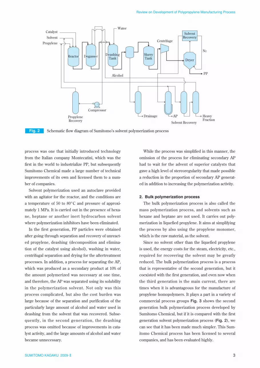
tion. Fig. 2 shows the first-generation solvent polymer-
ization process developed by Sumitomo Chemical.5)
The Sumitomo Chemical solvent polymerization
Fig. 1 Polypropylene manufacturing process
1st GenerationSolvent polymerization process
2nd Generationa) Solvent polymerization process (Non-deashing)
3rd GenerationVaper phase polymerization process (Non-deashing, Non-AP)
Drying PPDegassing Deashing
Monomer Recovery
Solvent Recovery
b) Bulk polymerization process (Non-solvent)
AP, Ash
AP
AP, Ash
Polymerization
Drying PPDegassing
Monomer Recovery
Solvent Recovery
Polymerization
PPExtraction
Monomer Recovery
Polymerization
PPPolymerization
3SUMITOMO KAGAKU 2009-II
Review on Development of Polypropylene Manufacturing Process
process was one that initially introduced technology
from the Italian company Montecatini, which was the
first in the world to industrialize PP, but subsequently
Sumitomo Chemical made a large number of technical
improvements of its own and licensed them to a num-
ber of companies.
Solvent polymerization used an autoclave provided
with an agitator for the reactor, and the conditions are
a temperature of 50 to 80°C and pressure of approxi-
mately 1 MPa. It is carried out in the presence of hexa-
ne, heptane or another inert hydrocarbon solvent
where polymerization inhibitors have been eliminated.
In the first generation, PP particles were obtained
after going through separation and recovery of unreact-
ed propylene, deashing (decomposition and elimina-
tion of the catalyst using alcohol), washing in water,
centrifugal separation and drying for the aftertreatment
processes. In addition, a process for separating the AP,
which was produced as a secondary product at 10% of
the amount polymerized was necessary at one time,
and therefore, the AP was separated using its solubility
in the polymerization solvent. Not only was this
process complicated, but also the cost burden was
large because of the separation and purification of the
particularly large amount of alcohol and water used in
deashing from the solvent that was recovered. Subse-
quently, in the second generation, the deashing
process was omitted because of improvements in cata-
lyst activity, and the large amounts of alcohol and water
became unnecessary.
While the process was simplified in this manner, the
omission of the process for eliminating secondary AP
had to wait for the advent of superior catalysts that
gave a high level of stereoregularity that made possible
a reduction in the proportion of secondary AP generat-
ed in addition to increasing the polymerization activity.
2. Bulk polymerization process
The bulk polymerization process is also called the
mass polymerization process, and solvents such as
hexane and heptane are not used. It carries out poly-
merization in liquefied propylene. It aims at simplifying
the process by also using the propylene monomer,
which is the raw material, as the solvent.
Since no solvent other than the liquefied propylene
is used, the energy costs for the steam, electricity, etc.,
required for recovering the solvent may be greatly
reduced. The bulk polymerization process is a process
that is representative of the second generation, but it
coexisted with the first generation, and even now when
the third generation is the main current, there are
times when it is advantageous for the manufacture of
propylene homopolymers. It plays a part in a variety of
commercial process groups Fig. 3 shows the second
generation bulk polymerization process developed by
Sumitomo Chemical, but if it is compared with the first
generation solvent polymerization process (Fig. 2), we
can see that it has been made much simpler. This Sum-
itomo Chemical process has been licensed to several
companies, and has been evaluated highly.
Fig. 2 Schematic flow diagram of Sumitomo’s solvent polymerization process
Compressor
Drainage AP HeavyFraction
Solvent Recovery
Alcohol
Reactor DeashingTank Dryer
SolventRecovery
PP
N2
Degasser
Centrifuge
Water
SlurryTank
Solvent
Catalyst
Propylene
PropyleneRecovery

4SUMITOMO KAGAKU 2009-II
Review on Development of Polypropylene Manufacturing Process
It is characterized by the use of a continuous extrac-
tion tower that was developed by Sumitomo Chemical
and has a special internal structure.5) Furthermore, in
addition to using a high performance catalyst that Sum-
itomo Chemical developed itself, we were successful in
being the first in the world to greatly simplify deashing
and the secondary AP elimination process by providing
a countercurrent washing system that uses refined liq-
uefied propylene.
The typical operating conditions for the bulk polymer-
ization process are a temperature of 50 to 80°C and a
pressure that is roughly the vapor pressure of propy-
lene. It changes according to the temperature, but is in a
range of 2 to 4 MPa. Since liquefied propylene, which is
a monomer, is used for the solvent, the polymerization
reaction is rapid, and the retention time is shortened.
Since the volumetric efficiency is greatly improved, the
reactor size for obtaining the same production capacity
can be smaller than it was conventionally. However,
even though there is high productivity, the heat elimina-
tion surface area is insufficient for removing the poly-
merization heat if the size of the device is reduced.
Therefore, in the case of a stirred tank reactor, a special
external heat exchanger that implements measures for
preventing adherence of the polymer is used. On the
other hand, loop reactors where the surface area for
heat elimination can be increased relative to the reac-
tion volume have become practical.
The bulk polymerization process is a process with
many advantages like these, but it is not suitable for the
manufacture of the polymers known as impact copoly-
mers. Impact copolymers are a mixture of a propylene
homopolymer component with a comparatively low mol-
ecular weight and a rubber component, which is an eth-
ylene-propylene copolymer with a comparatively high
molecular weight. This has improved impact strength at
low temperatures while at the same time maintaining
the rigidity, which is one of the superior original charac-
teristics of PP, as much as possible. It is mainly used in
injection molding applications starting with automobile
components. Industrially, it is obtained by polymeriz-
ing the latter following the polymerization of the for-
mer, and during continuous production, individual
reactors are required for polymerization of each of the
components. To polymerize the rubber component, the
reaction composition must have a high ethylene con-
centration, but if ethylene is dissolved in the liquefied
propylene to the point of obtaining the required ethyl-
ene concentration with bulk polymerization, the overall
reaction pressure increases, so there have been almost
no practical implementations. In addition, since the
rubber component is dissolved in the liquefied propy-
lene, there is a problem with the limitations for poly-
merization of the rubber component.
3. Vapor phase polymerization process
The vapor phase polymerization process falls under
the category of bulk (mass) polymerization processes
carried out only with monomers in the broad sense, but
since polymerization is carried out in propylene gas
rather than in liquefied propylene, it is handled as a
process different from conventional bulk polymerization.
It is positioned as a third-generation process, but the his-
tory is longer than expected, and the technology already
existed when first generation processes were the main
current. The vapor phase polymerization at that time
was inferior in terms of quality because there was no
process for separating the very many AP secondary
products, and products were limited to special applica-
tions. However, with the subsequent complete elimina-
tion of deashing and AP removal operations because of
the rapid improvement in catalyst performance, further
simplifications were achieved in the process, and it
achieved a position as the third generation process capa-
ble of manufacturing high performance products with
diverse levels of quality. Fig. 4 shows the initial third-
generation vapor phase polymerization process devel-
oped by Sumitomo Chemical for manufacturing impact
copolymers.6) Manufacturing impact copolymers
requires at least two reactors, and a supply line for ethyl-
ene, which is a comonomer, is installed for the second
stage reactor so that the rubber component can be poly-
merized. Moreover, manufacturing is fundamentally
possible with one reactor for polymers other than impact
Fig. 3 Schematic flow diagram of Sumitomo’s bulk polymerization process
AP PPPowder
Catalyst
Recycle Monomer
Propylene
HeavyFraction
Polymerization APSeparation
PowderSeparation
Extraction MonomerPurification
Compressor

5SUMITOMO KAGAKU 2009-II
Review on Development of Polypropylene Manufacturing Process
narrow retention time distribution.
In the following, we will focus on the vapor phase
polymerization process and review the patent and refer-
ence literature as well as the technology developed in
recent years, inclusive of technology developed by
Sumitomo Chemical, while focusing on the differences
in reactor types and configurations aimed at improving
the uniformity of polymer granular structures accord-
ing to required performance.
1. Improvement in uniformity in particles using
circulation type reactors
Improvement on the uniformity in the polymer parti-
cles produced is mainly aimed at controlling molecular
weight distribution in many ways. In other words, since
the physical characteristics such as the impact strength
of molded products can be improved, a high molecular
weight for the PP is desirable, but on the other hand,
processing is difficult. Therefore, it is necessary to
include a suitable amount of low molecular weight
components for such improvements, and as a result,
PP with a broad molecular weight distribution is desir-
able. This concept itself is not original, but to obtain PP
with a broad molecular weight distribution, the molecu-
lar weight has been varied during a series of reactions
in batch polymerization in the conventional process.
Alternatively, a continuous polymerization method
where multiple complete mixing reactors are set up
with conditions that give different molecular weights
are simply connected has been used. However, since
the productivity of batch polymerization is very inferi-
or, its use is limited to special applications, and it has
not been widely disseminated. Since there is also a
retention time distribution in the polymer particles pro-
duced with continuous polymerization, the molecular
weight distribution varies with each particle. In addi-
tion, it is difficult to avoid uneven distribution of com-
ponents with different molecular weights within single
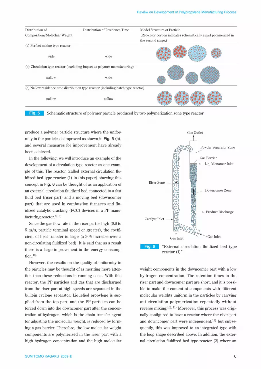
particles. Fig. 5 shows conceptual diagrams of the poly-
mer particle structures produced in these processes.
As is shown in Fig. 5 (a), the uneven distribution of the
various components in the polymer particles produced
is an important problem where defects (causing reduc-
tions in strength and problems with appearance) from
poor melting and mixing called fisheyes arise in the
forming process particularly when there is a large dif-
ference in the molecular weight between high molecu-
lar weight components and the low molecular weight
components. To solve this problem, it is desirable to
copolymers. The typical operating conditions are a tem-
perature of 50 to 80°C and a pressure in the range of 1 to
2 MPa. Various types of reactors, such as stirred tanks
and fluidized beds, have been developed by various com-
panies, but while there are small differences in construc-
tion costs and variable costs, these are not determiners
of the differences in the final product costs. The compe-
tition between makers can be said to be mainly in the
area of product quality.7) Along with the further improve-
ments to the process, Sumitomo Chemical has made
great strides on the quality front by commercializing a
variety of polymer designs based on our own high per-
formance catalyst technology.
Current Status of PP Manufacturing Processes
With the increase in the level of performance
required for PP quality in recent years, a variety of
ideas and contrivances have been integrated into the
manufacturing process for PP. If we take a bird’s eye
view of the trends in process development that focus
on these improvements in quality, all of them are point-
ing in one direction. In other words, while the configu-
ration and conditions of the of the polymerization
reaction are varied to diversify the molecular weight
distribution and compositional distribution, attempts
are being made to hold heterogeneousness of the poly-
mer particle structure produced that tends to occur
with this to a minimum.
There are roughly two directions for the specific
methods. One is improvement of uniformity of the poly-
mer particles produced using a circulation type reactor,
and the other is improvement in the uniformity among
polymer particles produced by using a reactor with a
Fig. 4 Schematic flow diagram of Sumitomo’s vaper phase polymerization process
Catalyst
Recycle Monomer
PP PowderPropylene
Ethylene
Powder SeparationPolymerization
6SUMITOMO KAGAKU 2009-II
Review on Development of Polypropylene Manufacturing Process
produce a polymer particle structure where the unifor-
mity in the particles is improved as shown in Fig. 5 (b),
and several measures for improvement have already
been achieved.
In the following, we will introduce an example of the
development of a circulation type reactor as one exam-
ple of this. The reactor (called external circulation flu-
idized bed type reactor (1) in this paper) showing this
concept in Fig. 6 can be thought of as an application of
an external circulation fluidized bed connected to a fast
fluid bed (riser part) and a moving bed (downcomer
part) that are used in combustion furnaces and flu-
idized catalytic cracking (FCC) devices in a PP manu-
facturing reactor.8), 9)
Since the gas flow rate in the riser part is high (0.8 to
5 m/s, particle terminal speed or greater), the coeffi-
cient of heat transfer is large (a 30% increase over a
non-circulating fluidized bed). It is said that as a result
there is a large improvement in the energy consump-
tion.10)
However, the results on the quality of uniformity in
the particles may be thought of as meriting more atten-
tion than these reductions in running costs. With this
reactor, the PP particles and gas that are discharged
from the riser part at high speeds are separated in the
built-in cyclone separator. Liquefied propylene is sup-
plied from the top part, and the PP particles can be
forced down into the downcomer part after the concen-
tration of hydrogen, which is the chain transfer agent
for adjusting the molecular weight, is reduced by form-
ing a gas barrier. Therefore, the low molecular weight
components are polymerized in the riser part with a
high hydrogen concentration and the high molecular
weight components in the downcomer part with a low
hydrogen concentration. The retention times in the
riser part and downcomer part are short, and it is possi-
ble to make the content of components with different
molecular weights uniform in the particles by carrying
out circulation polymerization repeatedly without
reverse mixing.10), 11) Moreover, this process was origi-
nally configured to have a reactor where the riser part
and downcomer part were independent,12) but subse-
quently, this was improved to an integrated type with
the loop shape described above. In addition, the exter-
nal circulation fluidized bed type reactor (2) where an
Fig. 5 Schematic structure of polymer particle produced by two polymerization zone type reactor
(a) Perfect mixing type reactor
Distribution of Composition/Molecluar Weight
widewide
(b) Circulation type reactor (excluding impact co-polymer manufacturing)
widenallow
nallownallow
Distribution of Residence Time Model Structure of Particle (Red-color portion indicates schematically a part polymerized in the second stage.)
(c) Nallow residence time distribution type reactor (including batch type reactor)
Fig. 6 “External circulation fluidized bed type reactor (1)”
Gas Inlet
Catalyst Inlet
Product Discharge
Gas Outlet
Gas Inlet
Liq. Monomer Inlet
Powder Separator Zone
Downcomer Zone
Riser Zone
Gas Barrier

7SUMITOMO KAGAKU 2009-II
Review on Development of Polypropylene Manufacturing Process
external circulation function is configured for a conven-
tional fluidized bed reactor as shown conceptually in
Fig. 7 has been proposed.13)
We have discussed examples of applications of exter-
nal circulation fluidized beds above, but several exam-
ples of internal circulation fluidized beds have been
reported.14) For example, as is shown conceptually in
Fig. 8, an internal circulation fluidized bed type reactor
that is given an internal circulation function with a mov-
ing bed provided in a conventional fluidized bed reac-
tor has been proposed.15) The fundamental thinking for
improvements can be assumed to be the same as for
the external circulation fluidized bed described above.
It is possible to control uneven distribution of compo-
nents with different molecular weights in the particles
by supplying liquefied propylene to the uppermost part
of the moving bed, forming a gas barrier and forming
internal circulation. In particular, since it is possible to
freely control the proportion of the retention time for
the moving bed, which polymerizes the high molecular
weight components, and the fluidized bed, which poly-
merizes the low molecular weight components, by
independently controlling the amount of PP particles
discharged by the moving bed, polymer designs with
even more variety than with loop type external circula-
tion reactors become possible.
These circulation type reactors can control the mole-
cular weight distribution variously, but it is also possi-
ble to make various designs for the comonomer
composition distribution by also controlling the
comonomer concentration in each polymerization
stage in the same manner. However, when impact
copolymers are manufactured, the comonomers must
be almost completely separated in the comonomer
polymerization stage, and it is difficult to use a circula-
tion type reactor by itself. Therefore, while improve-
ments in the uneven distribution in the polymer
particles produced are not achieved, the processes that
will be discussed in the following aimed at producing
polymer particle structures with improved uniformity
among the particles like those shown in Fig. 5 (c) are
being developed.
2. Improvements in uniformity among particles
using narrow retention time distribution type
reactors
For improvements in the uniformity among the poly-
mer particles produced, we can expect greatly
improved results in quality when both a propylene
homopolymerization stage where the comonomers are
almost completely separated, mainly as in the impact
copolymers described above, and a polymerization
stage where the composition differs greatly when the
copolymerization stage has a high comonomer concen-
tration are required. In the following, we will explain
the reasons why a narrow retention time distribution
type reactor is necessary, using the manufacture of
impact copolymers as an example.
We have already discussed how continuous polymer-
ization of impact copolymers requires polymerization
of the comparatively low molecular weight propylene
homopolymer component and rubber component,
which is a comparatively high molecular weight ethyl-
ene-propylene copolymer, in separate reactors.
Fig. 7 “External circulation fluidized bed type reactor (2)”
Gas Inlet
Gas Outlet
Catalyst InletProduct Discharge
Liq. Monomer InletGas Barrier
Product Discharge
Gas Inlet
Liq. or Gas Monomer Inlet
Fig. 8 “Internal circulation fluidized bed type reactor”
Gas Inlet
Gas Outlet
CatalystInlet
Product discharge
Liq. Monomer Inlet
Valve
Gas Barrier
8SUMITOMO KAGAKU 2009-II
Review on Development of Polypropylene Manufacturing Process
While ones with different configurations, such as
mixing tank types and fluidized bed types are used for
commercial production processes, the polymer parti-
cles are normally mixed into a state close to complete
mixing in the reactors.16) Therefore, in the two tank
continuous process, which is the most simple for pro-
ducing impact copolymers, the polymers produced in
the end have a low mass ratio for the homopolymer
component and the rubber component because of the
retention time in each of the tanks, so they are mixed
until it is high. If polymer particles with a high rubber
component content are included, it invites dispersion
problems during melting and mixing, and we have
already said that it causes a lowering of quality where
the appearance deteriorates and the impact resistance
is lowered. The process has been improved with the
goal of narrowing the retention time distribution partic-
ularly in the first stage to prevent a lowering of quality
based on this mechanism.
A multi-tank device that increases the number of
continuous reaction devices connected in series has
been used to narrow the retention time distribution for
manufacturing polymers with high quality from the
concept above.
However, at the same time, there is an increasing
demand for lowering costs along with increasing the
PP performance, and there are limitations to the con-
ventional method of just increasing the number of reac-
tors. From this point of view, polymerization processes
that can narrow the retention time distribution for the
polymer particles with a smaller number of reactors are
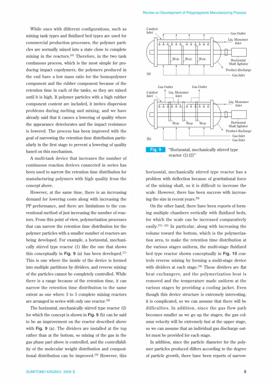
being developed. For example, a horizontal, mechani-
cally stirred type reactor (1) like the one that shows
this conceptually in Fig. 9 (a) has been developed.17)
This is one where the inside of the device is formed
into multiple partitions by dividers, and reverse mixing
of the particles cannot be completely controlled. While
there is a range because of the retention time, it can
narrow the retention time distribution to the same
extent as one where 3 to 5 complete mixing reactors
are arranged in series with only one reactor.18)
The horizontal, mechanically stirred type reactor (2)
for which the concept is shown in Fig. 9 (b) can be said
to be an improvement on the reactor described above
with Fig. 9 (a). The dividers are installed at the top
rather than at the bottom, so mixing of the gas in the
gas phase part above is controlled, and the controllabil-
ity of the molecular weight distribution and composi-
tional distribution can be improved.19) However, this
horizontal, mechanically stirred type reactor has a
problem with deflection because of gravitational force
of the mixing shaft, so it is difficult to increase the
scale. However, there has been success with increas-
ing the size in recent years.20)
On the other hand, there have been reports of form-
ing multiple chambers vertically with fluidized beds,
for which the scale can be increased comparatively
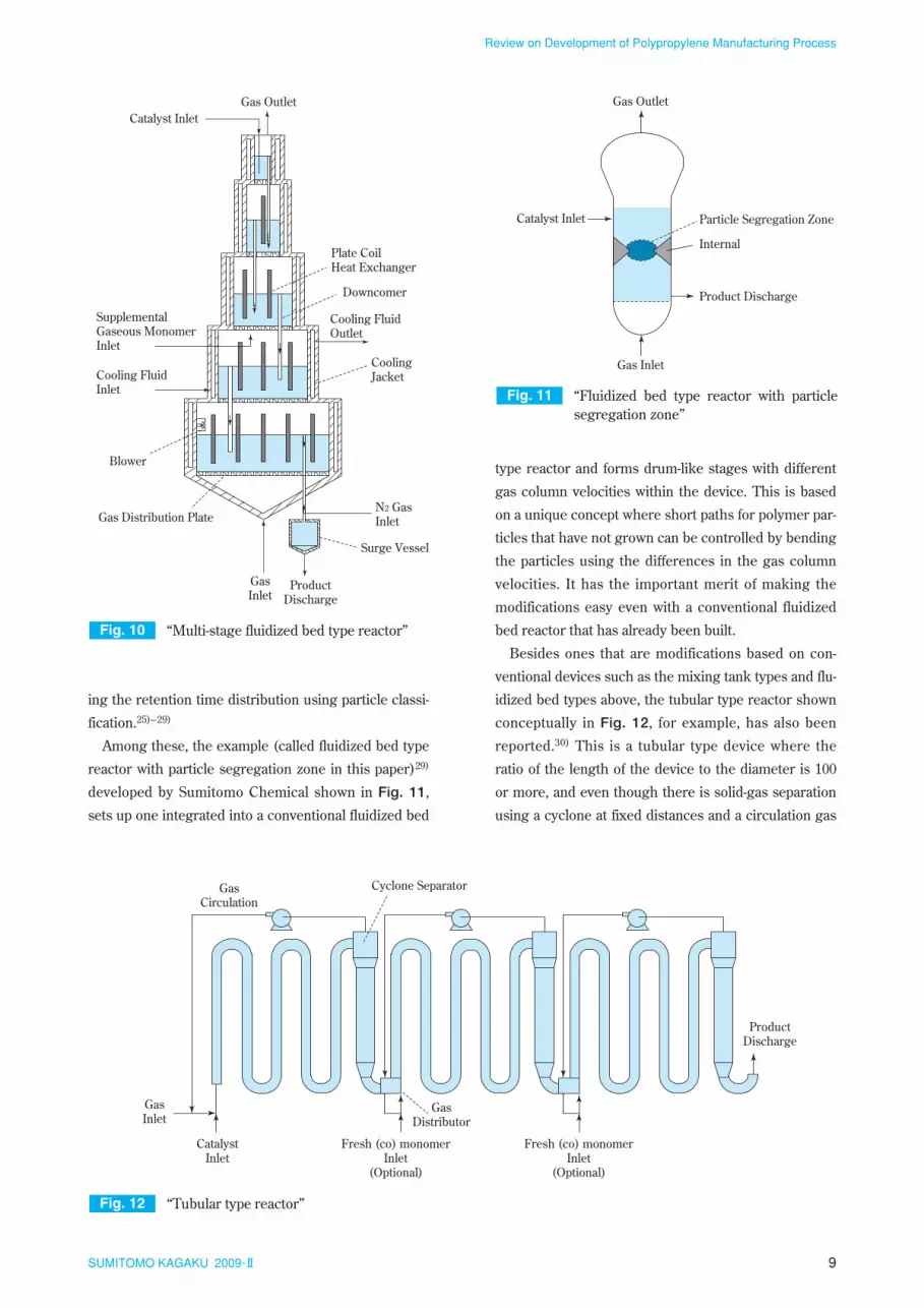
easily.21)– 24) In particular, along with increasing the
volume toward the bottom, which is the polymeriza-
tion area, to make the retention time distribution at
the various stages uniform, the multi-stage fluidized
bed type reactor shown conceptually in Fig. 10 con-
trols reverse mixing by forming a multi-stage device
with dividers at each stage.24) These dividers are flat
heat exchangers, and the polymerization heat is
removed and the temperature made uniform at the
various stages by providing a cooling jacket. Even
though this device structure is extremely interesting,
it is complicated, so we can assume that there will be
difficulties. In addition, since the gas flow path
becomes smaller as we go up the stages, the gas col-
umn velocity will be extremely fast at the upper stage,
so we can assume that an individual gas discharge out-
let must be provided for each stage.
In addition, since the particle diameter for the poly-
mer particles produced differs according to the degree
of particle growth, there have been reports of narrow-
Fig. 9 “Horizontal, mechanically stirred type reactor (1)(2)”
Liq. MonomerInlet
Gas Inlet
Gas OutletCatalystInlet
Product discharge
Horizontal Shaft Agitator
Weir Weir Weir
Liq. MonomerInlet
Gas Inlet
Gas OutletGas Outlet
CatalystInlet
Product discharge
HorizontalShaft Agitator
Weir
(a)
(b)
Weir Weir
Gas Inlet
Liq. MonomerInlet
9SUMITOMO KAGAKU 2009-II
Review on Development of Polypropylene Manufacturing Process
ing the retention time distribution using particle classi-
fication.25)– 29)
Among these, the example (called fluidized bed type
reactor with particle segregation zone in this paper)29)
developed by Sumitomo Chemical shown in Fig. 11,
sets up one integrated into a conventional fluidized bed
type reactor and forms drum-like stages with different
gas column velocities within the device. This is based
on a unique concept where short paths for polymer par-
ticles that have not grown can be controlled by bending
the particles using the differences in the gas column
velocities. It has the important merit of making the
modifications easy even with a conventional fluidized
bed reactor that has already been built.
Besides ones that are modifications based on con-
ventional devices such as the mixing tank types and flu-
idized bed types above, the tubular type reactor shown
conceptually in Fig. 12, for example, has also been
reported.30) This is a tubular type device where the
ratio of the length of the device to the diameter is 100
or more, and even though there is solid-gas separation
using a cyclone at fixed distances and a circulation gas
Fig. 11 “Fluidized bed type reactor with particle segregation zone”
Gas Inlet
Gas Outlet
Catalyst Inlet
Product Discharge
Internal
Particle Segregation Zone
Fig. 12 “Tubular type reactor”
GasInlet
CatalystInlet
GasDistributor
Fresh (co) monomerInlet
(Optional)
Cyclone SeparatorGasCirculation
Fresh (co) monomerInlet
(Optional)
ProductDischarge
Fig. 10 “Multi-stage fluidized bed type reactor”
GasInlet
ProductDischarge
N2 GasInlet
Gas OutletCatalyst Inlet
Downcomer
Cooling FluidInlet
Cooling FluidOutlet
Cooling Jacket
SupplementalGaseous MonomerInlet
Surge Vessel
Plate CoilHeat Exchanger
Gas Distribution Plate
Blower

10SUMITOMO KAGAKU 2009-II
Review on Development of Polypropylene Manufacturing Process
compressor, there is almost no reverse mixing, so the
retention time distribution is extremely narrow. How-
ever, the fact that sufficient retention time cannot be
assured with gas phase polymerization, which typically
requires several hours, because the retention time is
about 15 minutes even with a device length of 200 m is
an important problem.
In addition, for example, we can also mention meth-
ods that use a moving bed type reactor developed by
Sumitomo Chemical.31), 32) This is a process that uses a
non-circulating moving bed type reactor in the second
or later stages after growing polymer particles to an
extent that does not melt and clump because of prob-
lems with heat elimination. With this process configu-
ration, it is thought that most of the retention time
distribution arises in the second or later stages and suf-
ficient retention time can be assured.
Conclusion
In this paper, we have given a review of the changes
and current state of PP manufacturing processes,
including technology developed by Sumitomo Chemi-
cal, based on information in patents and the literature.
We mainly focused on the trends in process develop-
ment aiming at improving quality in particular, but
besides this, a variety of processes, such as many tech-
nical improvements aiming at stable operation and
processes33) making high temperature polymerization
possible by improving the polymer particle and
monomer separation efficiency through operation in
the supercritical range for propylene, have been devel-
oped. Even though a giant market has been formed for
PP already, perfection of the manufacturing processes
for it has not been completed. Further progress is
desirable moving forward along with developing basic
technology starting with catalysts and various types of
peripheral technology to answer the demands from a
market that will not fail.
At Sumitomo Chemical, we are thinking in terms of
further polishing our own technology, which has been
built up to this point and developing processes that pro-
vide products that are attractive to the market.
References
1) G. Natta, P. Pino, P. Corradini, F. Danusso, E. Man-
tica, G. Mazzaniti and G. Moraglio, J. Am. Chem.
Soc., 77, 1708 (1955).
2) “Supply and demand trend of petrochemicals in the
world”, Ministry of Economy, Trade and Industry
of Japan (2008).
3) A. Shiga and T. Sasaki, “SUMITOMO KAGAKU”,
1984-@, 15 (1984).
4) “New Global Warming Prevention on Technology
Program, Development of Energy Conservation
Technology for Manufacturing Plastic Products
through Process Omission (FY2003-FY2004) Final
Report”, New Energy and Industrial Technology
Development Organization (2005).
5) A. Shiga, K. Matsuyama, M. Kakugo, H. Hashimo-
to, “SUMITOMO KAGAKU”, 1980-@, 52 (1980).
6) M. Kakugo, H. Sadatoshi, H. Kora, J. Isohata, H.
Ogawa, “SUMITOMO KAGAKU”, 1986-@, 4 (1986).
7) K. B. Sinclair, Hydrocarbon Processing, July, 81
(1985).
8) Montell, International Patent WO97/04015 (1997).
9) Montell, European Patent 1012195-A (2000).
10) M. Covezzi and G. Mei, Chem. Eng. Sci., 56, 4059
(2001).
11) A. de Vries and N. Izzo-Iammarrone, DECHEMA
Monographs, 137, 43 (2001).
12) Spherliene and Himont, European Patent 574821-
A2 (1993).
13) Basell, International Patent WO2004/033505
(2004).
14) G. Weickert and C. Dittrich, Chemie Ingenieur
Technik, 77 (8), 977 (2005).
15) Universiteit Twente, European Patent 1484343-A1
(2004).
16) J. J. Zacca, J. A. Debling and W. H. Ray, Chem. Eng.
Sci., 51, 4859 (1996).
17) Standard Oil Company, Japanese Patent S59-21321
(1984).
18) C. J. Dittrich and S. M. P. Mutsers, Chem. Eng.
Sci., 62, 5777 (2007).
19) Chisso, Japanese Patent 2504452 (1996).
20) K. Miyazaki, “Chemical Process”, edited by The
Society of Chemical Engineers, Japan, published
by Tokyo Kagaku Dozin Co. Ltd., (1998), p.191.
21) Phillips, U.S. Patent 2936303 (1960).
22) Union Carbide Chem., International Patent
WO98/47611 (1998).
23) Sumitomo Chemical, Japanese Patent 2003-277412
(2003).
24) Phillips, U.S. Patent 5235009 (1993).
25) Chisso, Japanese Patent S55-116716 (1980).
26) Ube Industries, Japanese Patent H 7-286004 (1995).

11SUMITOMO KAGAKU 2009-II
Review on Development of Polypropylene Manufacturing Process
27) Mitsubishi Chemical, Japanese Patent H10-120741
(1998).
28) Mitsubishi Chemical, Japanese Patent H10-120742
(1998).
29) Sumitomo Chemical, Japanese Patent 2006-348275
(2006).
30) Elenac, International Patent WO00/49055 (2000).
31) Sumitomo Chemical, Japanese Patent 2007-84645
(2007).
32) Sumitomo Chemical, Japanese Patent 2007-112976
(2007).
33) Hydrocarbon Processing, March, 136 (1999).
P R O F I L E
Hideki SATO
Sumitomo Chemical Co., Ltd.Process & Production Technology CenterResearch Associate
Hiroyuki OGAWA
Sumitomo Chemical Co., Ltd.Process & Production Technology CenterSenior Research Associate(Present Post: Temporary Researcher)