vialli polypropylene - (ppr) pipes & fittings
TRANSCRIPT
- 1 -
VIALLI POLYPROPYLENE
(PPR) Pipes & Fittings
VIALLI Pipes& fittings one of the European product produced by FV PLAST, we are
Specialized in supplying piping products and fittings for plastic piping system of pressure and
hot water (heating) distribution. Our main products are PPRc, PP-RCT Pipes, PPR Stabi pipes
with aluminum layer & PPR Fiberglass Composite Pipes and Fittings.
Our production and inspection is effected strictly according to Germany and European
Standards. For our PPR system production, we only use the heights-quality materials
HOSTALEN, VESTOLEN and RA130E from BOREALIS- granulates with high molecular weight
and highly heat stabilized: color gray/ green. The material is compliance with the
recommendations of KTW, the German Federal Public Health Department (BGA).
VIALLI pipes and fittings are produced accordance to DIN German Standards and approved
by German Technical & Scientific Association for Gas and Water (DVGW). Certificate
Registration Number (DW 8317CT0418)
Problematic spots like plastic-metal transitions are handles without compromise- we use metal
components manufacture from the highest- quality Natural Brass, Brass Nickel Plated,
Stainless Steel and Bronze all made in Germany,Our production process is fully automated.
And our technologies are improved constantly.
All our product VIALLI PPRc & PP-RCT pipes PN20, VIALLI PPR Stabi pipes with Aluminum
Layer PN25 and VIALLI PPR Fiber Glass Composite Pipes PN25, produced and approved as
per European Water Regulations Advisory Scheme (WRAS)
All our product achieved Hygienic and Quality Test Requirements as DVGW Recommended
- 2 -
SYSTEM CHARACTERISTICS AND BENEFITS
1. Plastic piping for interior hot and cold water distribution systems in buildings, floor
& Central Heating Systems.
2. Meeting all health requirements
3. No corrosion and / or encrustation
4. Exceptionally long service life while preserving high utility value
5. Trouble- Free operations with less noise
6. Less friction losses than with traditional materials
7. Less weight than with traditional materials
8. Quick, easy and clean installation works
9. Resistance in aggressive environments.
ENVIRONMENTAL ASPECTS
Fully recyclable product; neither toxic nor otherwise harmful substance are used in its
manufacture and/ or application.
INTENDED USE
For interior hot and cold water distribution systems in buildings and floor & central
heating systems:
PN 10-cold water distribution and floor heating systems PN 16-Higher Pressure cold water distribution and DHW Systems at lower Pressures PN 20- Hot water distribution systems, Central Heating PN 25- Hot water distribution systems, Central Heating
TECHNICAL SPECIFICATIONS
Material statistical polypropylene copolymer (random copolymer) for injection molding and
extrusion processes with excellent welding ability; nickel plated brass fittings
Manufacturing process pipes are produced by extrusion, while fittings by injection molding
Shapes - pipe lengths 4 Meter
Assembly / Fixing the product range covers all needs for interior water distribution systems
and heating system routes
Transitions for other pipe material implemented by threaded connection (i.e. by combined
couplings) or flange connections.
Coupling standard method is poly fusion welding or by electro fitting
Surface finish elements are in green color without any finish, Separate metal element brass,
alternatively, nickel plated, black identification printing on the surface.
- 3 -
PHYSIC CHEMICAL PROPERTIES
Density 0.9 Kg/m3
Thermal expansion coefficient- for VIALLI PPR pipes 0.15mm/Mk
Thermal conductivity - 0.22 W/Mk, fire rating Class C3
Resistance against Chemicals PPR piping systems are intended mainly for water
distribution (drinking, cold, hot, irrigation, etc.) it is also possible to use the system for other
media, in which in case their concrete use is governed by DIN 8078 Bb-1 possible to consult
the manufacturer.
LABORATORY OPERATION & TEST DEVISSES
1. MFI (Melt Flow Index) Test Device:
before being processed in the
extruder. This device gives us information regarding the flow rate of the material in the unit
temperature and time, this helps us to have information on the possible behavior of the material
in the extruder. The quality Standard for this test is ISO 1133.
2. Precise Balance:
Using this balance, the weight of the material which was passed from MFI device is determined
according to standard ISO 1183 separately in the air and in the liquid whose density is known.
After having these weight figures, the mater
density formula.
3. IZOD-Charpy test Device:
With this device, the amount of the energy absorption and the possible applicable force on the
unit area are determined by using free falling method using materials having different weights.
with sudden impacts. The standards applied for this test are TS 1004, TS 1005, ISO 179 and
ISO 180.
4. Pulling – Pressing Test Device:
(the maximum force strength per unit area) maximum tension. Elongation in percentage,
deformation, elongation at break point, tension at break point etc. of the product. By meansof
these test we can make forecasts on the possible behavior of the material in the working
conditions. In these test ISO R 527 standard is applied.
5. Hallow Die Punch (sampling Device):
This device is used for the preparation of the sample which will be tested in the pulling test
device. The sample is prepared in accordance with Standard No. ISO 527
- 4 -
6. Shore (Hardness Device):
This device is used for the
the simple, if the material is too soft then it will be pressed like paper while if it is to hard then it
will be broken. For this reason, the hardness value of the product must be within the range of
the values mention in the Standard No. DIN 53505.
7. Microtome Device:
This is a device used to cut small pieces which can be monitored under microscope for the
proposed of inspecting the infrastructure of the material.
8. Microscope Image System:
This is a system used for monitoring the fibro structure of the material. The aim of this test is to
image is not in the
liner from then it means that there is a mistake either in the production stage or in the quality of
the raw material itself.
9. Furnace-Deep Freezer:
These devices are used for shock cooling of heating. In certain intervals of time impact test is
applied on the material which is hold in the furnace or deep Freezer and its behavior is
monitored at different test temperatures.
10. Furnace: 3
This device is used in thermal Strength test. The aim of this test is to monitor whether the
length of the material exceed more than 3% when applied to a certain temperature for certain
time. This test is important because at considerably higher temperature the material expands
and elongates but a low temperature it shrinks. But after application of higher or lower
temperature. The material does not return fully to its normal size in the normal temperature.
This character leads to a change from round shape to oval shape in the close pipe system. The
standard applied for this test is TS 5450.
11. Pressure Test:
For the pipes produced according to the standard TS 5439, to monitor the strength of the
pipes to the pressure, a pressure test is applied under 100h (at 20 °C), and 165 and 1000h (at
80 °C). the standards used for this test are ISO 4427 (for PE 100), ISO 4437 (for 80) and TSE
10827.
12. Momentum Strength Test:
In addition to the leak test also strength test is applied with the aim of testing the
harmonically work of the metal fittings with plastic. In order to be able to apply a 95 °C
temperature to the pipe it must resist 10 Bar pressure for short time test.
- 5 -
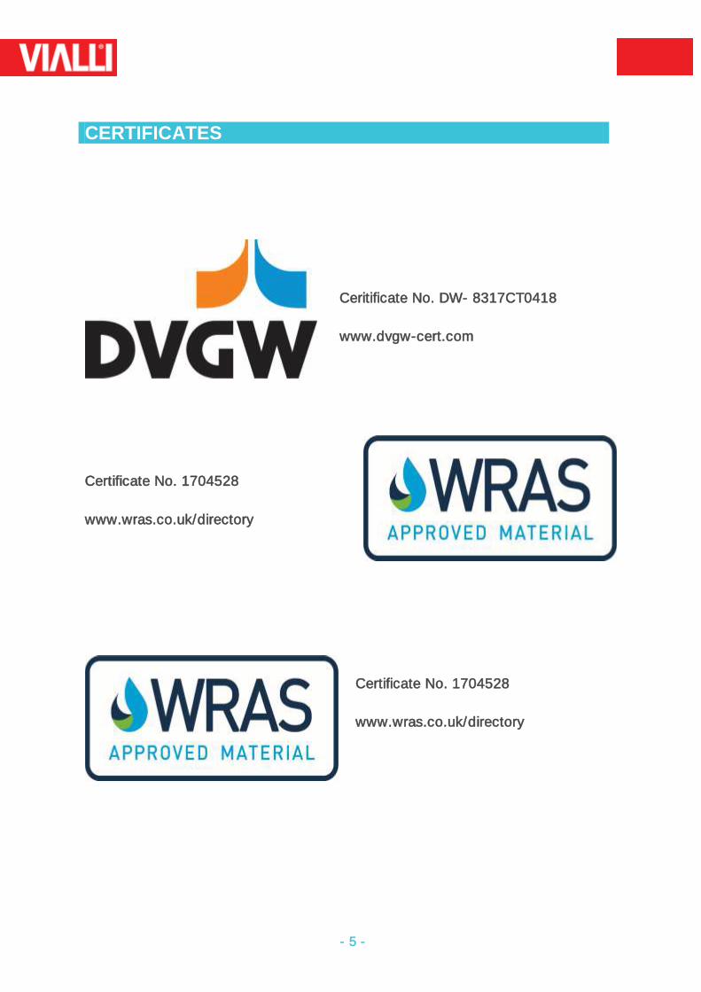
CERTIFICATES
Ceritificate No. DW- 8317CT0418
www.dvgw-cert.com
Certificate No. 1704528
www.wras.co.uk/directory
Certificate No. 1704528
www.wras.co.uk/directory
- 6 -
TECHNICAL SPECIFICATION
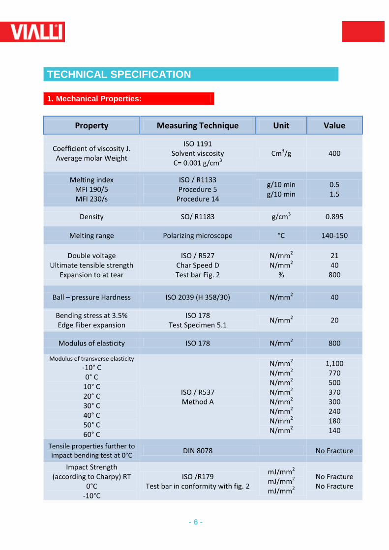
1. Mechanical Properties:
Property Measuring Technique Unit Value
Coefficient of viscosity J. Average molar Weight
ISO 1191 Solvent viscosity C= 0.001 g/cm3
Cm3/g 400
Melting index MFI 190/5 MFI 230/s
ISO / R1133 Procedure 5
Procedure 14
g/10 min g/10 min
0.5 1.5
Density SO/ R1183 g/cm3 0.895
Melting range Polarizing microscope °C 140-150
Double voltage Ultimate tensible strength
Expansion to at tear
ISO / R527 Char Speed D Test bar Fig. 2
N/mm2 N/mm2
%
21 40
800
Ball – pressure Hardness ISO 2039 (H 358/30) N/mm2 40
Bending stress at 3.5% Edge Fiber expansion
ISO 178 Test Specimen 5.1
N/mm2 20
Modulus of elasticity ISO 178 N/mm2 800
Modulus of transverse elasticity
-10° C 0° C
10° C 20° C 30° C 40° C 50° C 60° C
ISO / R537 Method A
N/mm2
N/mm2
N/mm2
N/mm2
N/mm2
N/mm2
N/mm2
N/mm2
1,100 770 500 370 300 240 180 140
Tensile properties further to impact bending test at 0°C
DIN 8078 No Fracture
Impact Strength (according to Charpy) RT
0°C -10°C
ISO /R179 Test bar in conformity with fig. 2
mJ/mm2
mJ/mm2
mJ/mm2
No Fracture No Fracture
- 7 -
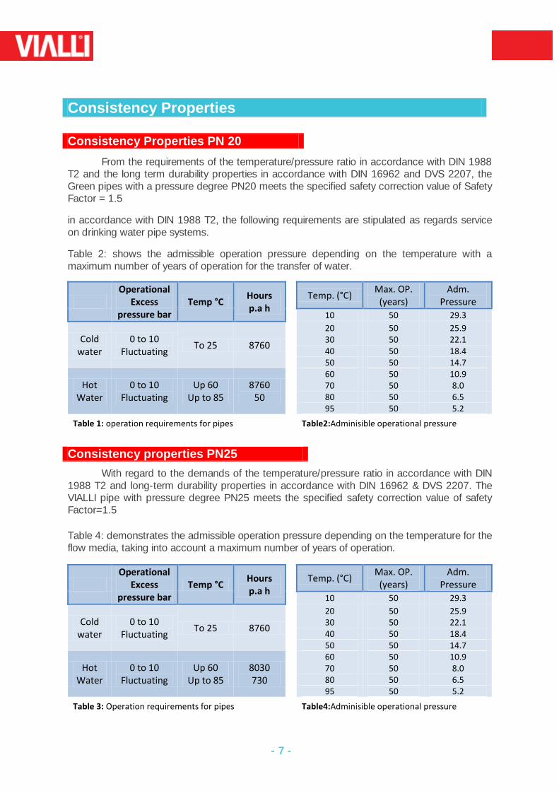
Consistency Properties
Consistency Properties PN 20
From the requirements of the temperature/pressure ratio in accordance with DIN 1988 T2 and the long term durability properties in accordance with DIN 16962 and DVS 2207, the Green pipes with a pressure degree PN20 meets the specified safety correction value of Safety Factor = 1.5
in accordance with DIN 1988 T2, the following requirements are stipulated as regards service on drinking water pipe systems.
Table 2: shows the admissible operation pressure depending on the temperature with a maximum number of years of operation for the transfer of water.
Operational
Excess pressure bar
Temp °C Hours p.a h
Temp. (°C) Max. OP.
(years) Adm.
Pressure
10 50 29.3
Cold water
0 to 10 Fluctuating
To 25 8760
20 50 25.9 30 50 22.1 40 50 18.4 50 50 14.7
Hot Water
0 to 10 Fluctuating
Up 60 Up to 85
8760 50
60 50 10.9 70 50 8.0 80 50 6.5 95 50 5.2
Table 1: operation requirements for pipes Table2:Adminisible operational pressure
Consistency properties PN25
With regard to the demands of the temperature/pressure ratio in accordance with DIN 1988 T2 and long-term durability properties in accordance with DIN 16962 & DVS 2207. The VIALLI pipe with pressure degree PN25 meets the specified safety correction value of safety Factor=1.5
Table 4: demonstrates the admissible operation pressure depending on the temperature for the flow media, taking into account a maximum number of years of operation.
Operational
Excess pressure bar
Temp °C Hours p.a h
Temp. (°C) Max. OP.
(years) Adm.
Pressure
10 50 29.3
Cold water
0 to 10 Fluctuating
To 25 8760
20 50 25.9 30 50 22.1 40 50 18.4 50 50 14.7
Hot Water
0 to 10 Fluctuating
Up 60 Up to 85
8030 730
60 50 10.9 70 50 8.0 80 50 6.5 95 50 5.2
Table 3: Operation requirements for pipes Table4:Adminisible operational pressure
- 8 -
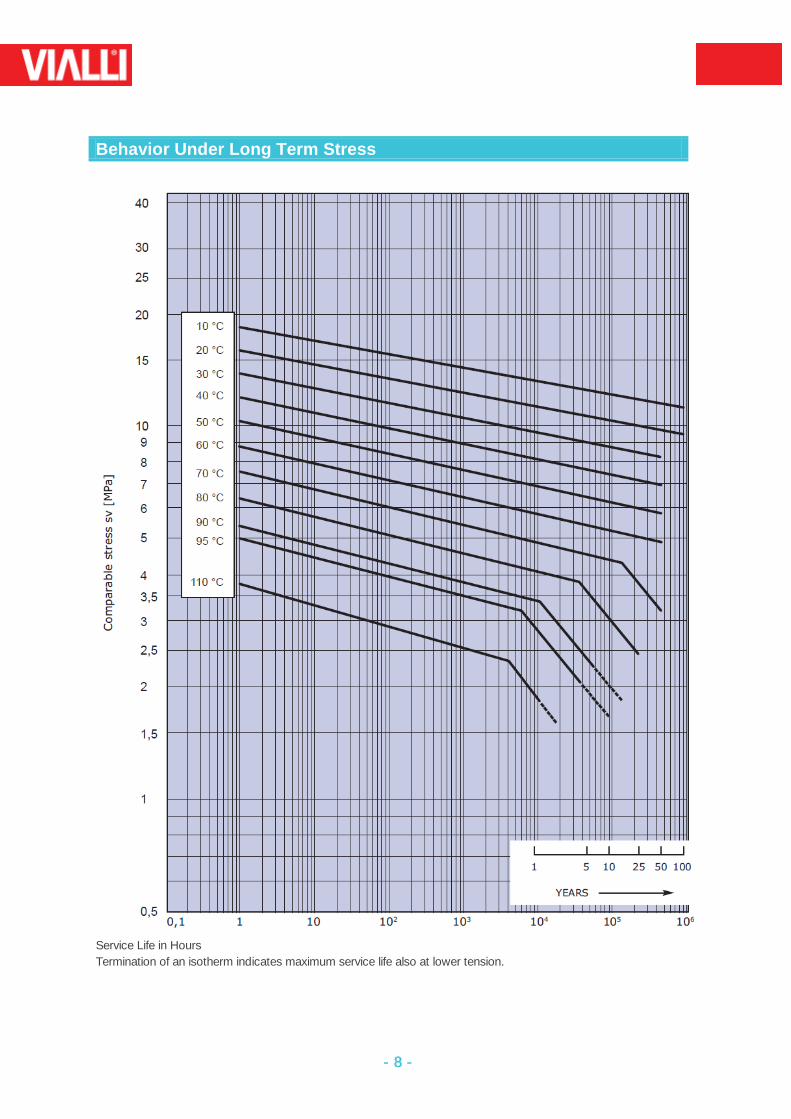
Behavior Under Long Term Stress
Service Life in Hours
Termination of an isotherm indicates maximum service life also at lower tension.
- 9 -
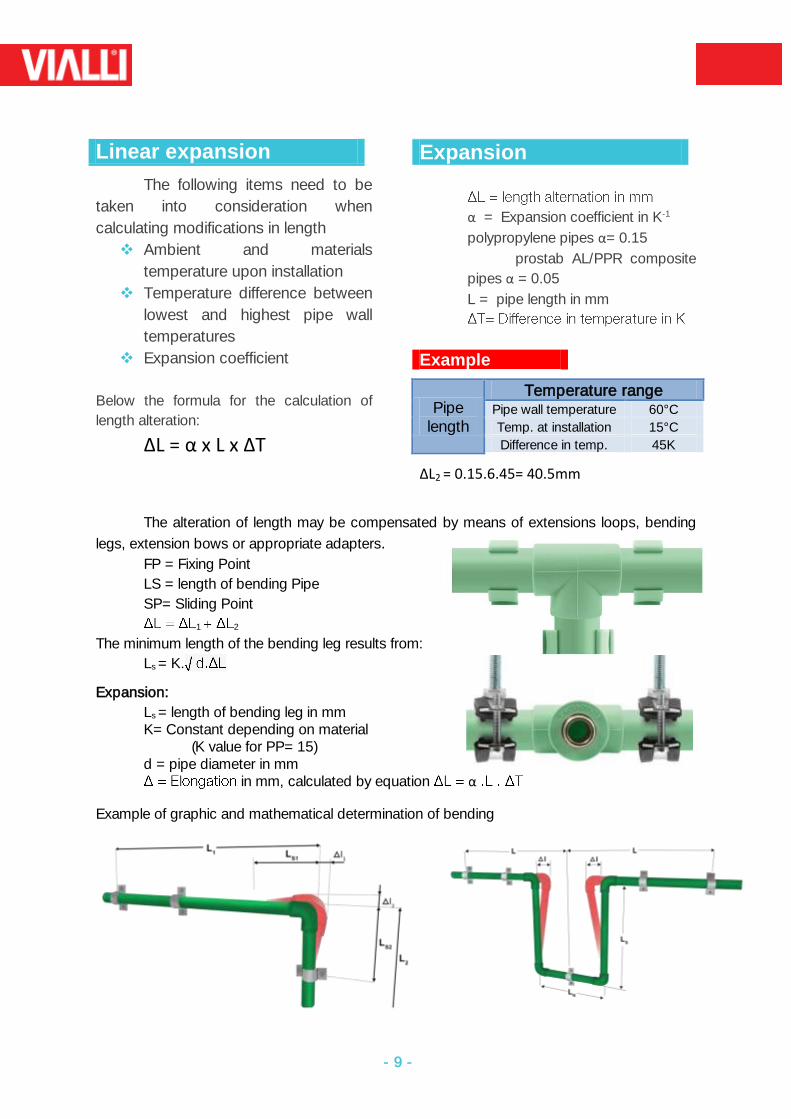
Linear expansion
The following items need to be
taken into consideration when
calculating modifications in length
Ambient and materials
temperature upon installation
Temperature difference between
lowest and highest pipe wall
temperatures
Expansion coefficient
Below the formula for the calculation of
length alteration:
ΔL = α x L x ΔT
Expansion
α = Expansion coefficient in K-1
polypropylene pipes α= 0.15
prostab AL/PPR composite
pipes α = 0.05
L = pipe length in mm
Example
Pipe length
Temperature range Pipe wall temperature 60°C
Temp. at installation 15°C
Difference in temp. 45K
ΔL2 = 0.15.6.45= 40.5mm
The alteration of length may be compensated by means of extensions loops, bending
legs, extension bows or appropriate adapters.
FP = Fixing Point
LS = length of bending Pipe
SP= Sliding Point
1 2
The minimum length of the bending leg results from:
Ls = K.
Expansion:
Ls = length of bending leg in mm K= Constant depending on material (K value for PP= 15) d = pipe diameter in mm
in mm, calculated by equation α
Example of graphic and mathematical determination of bending
- 10 -
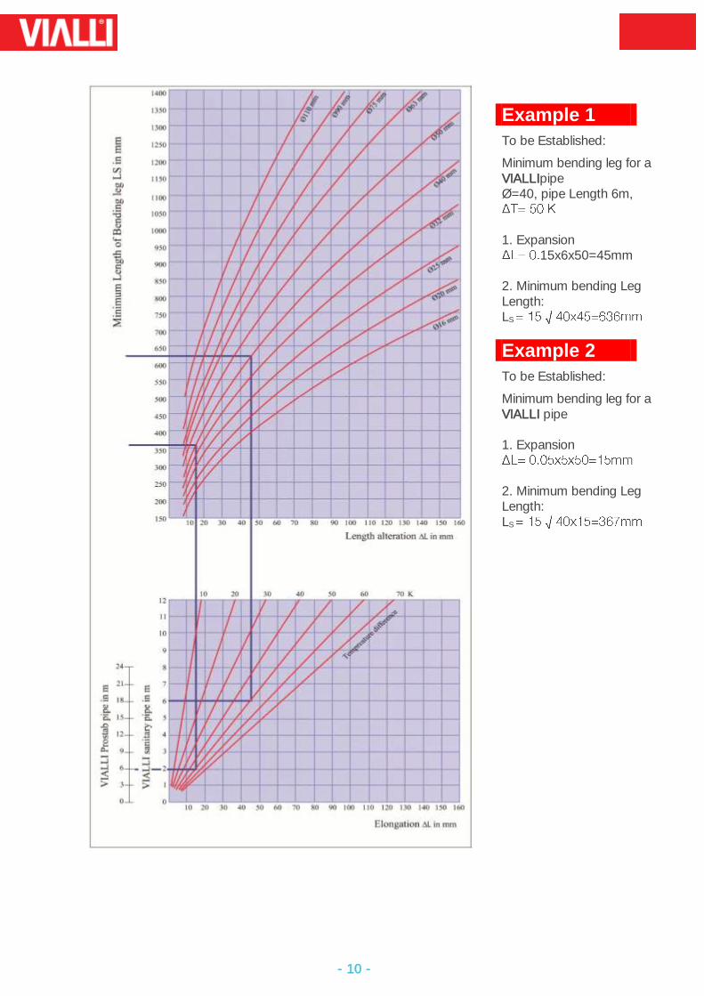
Example 1
To be Established:
Minimum bending leg for a VIALLIpipe Ø=40, pipe Length 6m,
1. Expansion
15x6x50=45mm 2. Minimum bending Leg Length: LS
Example 2
To be Established:
Minimum bending leg for a VIALLI pipe 1. Expansion
2. Minimum bending Leg Length: LS
- 11 -
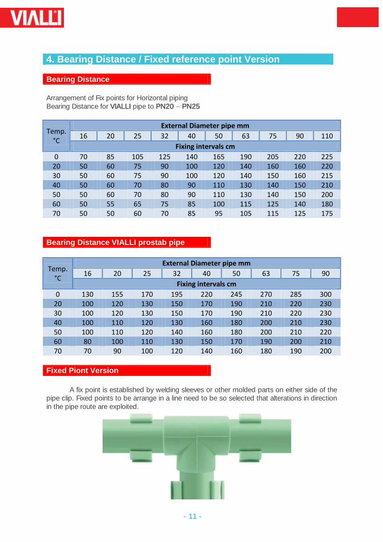
4. Bearing Distance / Fixed reference point Version
Bearing Distance
Arrangement of Fix points for Horizontal piping Bearing Distance for VIALLI pipe to PN20 PN25
Temp. °C
External Diameter pipe mm
16 20 25 32 40 50 63 75 90 110
Fixing intervals cm
0 70 85 105 125 140 165 190 205 220 225 20 50 60 75 90 100 120 140 160 160 220 30 50 60 75 90 100 120 140 150 160 215 40 50 60 70 80 90 110 130 140 150 210 50 50 60 70 80 90 110 130 140 150 200 60 50 55 65 75 85 100 115 125 140 180 70 50 50 60 70 85 95 105 115 125 175
Bearing Distance VIALLI prostab pipe
Temp. °C
External Diameter pipe mm
16 20 25 32 40 50 63 75 90
Fixing intervals cm
0 130 155 170 195 220 245 270 285 300 20 100 120 130 150 170 190 210 220 230 30 100 120 130 150 170 190 210 220 230 40 100 110 120 130 160 180 200 210 230 50 100 110 120 140 160 180 200 210 220 60 80 100 110 130 150 170 190 200 210 70 70 90 100 120 140 160 180 190 200
Fixed Piont Version
A fix point is established by welding sleeves or other molded parts on either side of the
pipe clip. Fixed points to be arrange in a line need to be so selected that alterations in direction in the pipe route are exploited.
- 12 -
Drop in pressure Owing to pipe Friction
Pressure drops owing to pipe friction and calculated flow speed depending on peak
flow for all pipes of the VIALLI installation system
Following charts of pressure drops resulting from pipe friction were established in analogy to
DIN 1988, Section 3
Starting Values:
Reference Temperature 10°C
Reference pressure 10 bar
Absolute roughness of interior pipe wall K = 0.007 mm
Calculation of pipe friction coefficient according to Colebrook White)
Note:
Pressure losses resulting from pipe friction change only insignificantly in the operating
temperature range (up to 60°C) of Domestic Cold & Hot water supply system, therefore it is
customary for the house installation to calculate with an overall supply pipes reference
temperature of 10 °C (DIN 1988, Section 3, Page 10)
The Legal unit used (SI unit) for pressure is the Pa (Pascal) Value, However, DIN standards
refers to bar unit or mbar, respective ly. Should the loss in pressure required in practice be the
Pascal Value, the Following ratio will apply: 1 mbar = 100 Pa.
Intermediate values not indicated in the tables may be interringpolated. It should be noted,
however, that no liner functions serve as basis
Losses in pressure of the Prostab pipes may be seen from the tables of nominal pressure
degree PN20 &PN25 as the inner pipes have the same Dimensions.
- 13 -
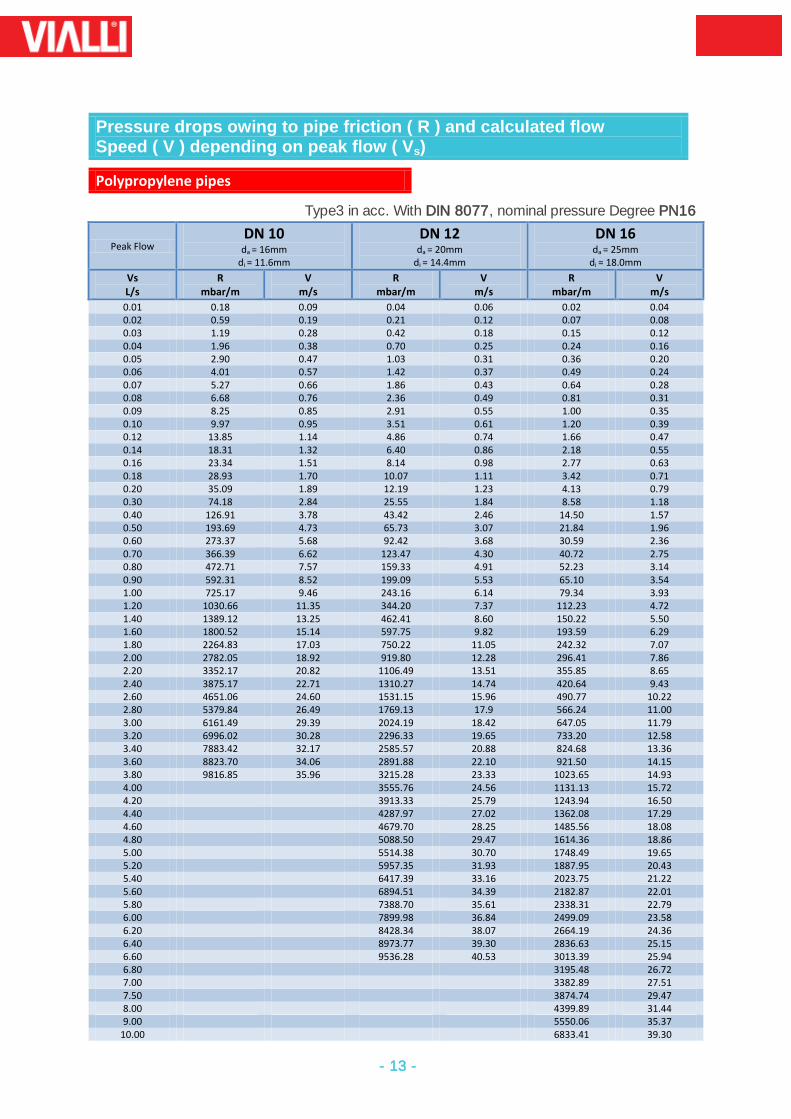
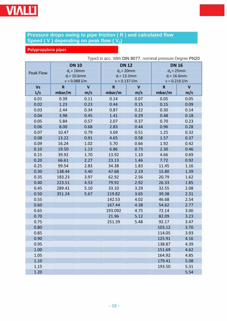
Pressure drops owing to pipe friction ( R ) and calculated flow Speed ( V ) depending on peak flow ( Vs)
Polypropylene pipes
Type3 in acc. With DIN 8077, nominal pressure Degree PN16
Peak Flow DN 10
da = 16mm di = 11.6mm
DN 12 da = 20mm
di = 14.4mm
DN 16 da = 25mm
di = 18.0mm
Vs L/s
R mbar/m
V m/s
R mbar/m
V m/s
R mbar/m
V m/s
0.01 0.18 0.09 0.04 0.06 0.02 0.04 0.02 0.59 0.19 0.21 0.12 0.07 0.08 0.03 1.19 0.28 0.42 0.18 0.15 0.12 0.04 1.96 0.38 0.70 0.25 0.24 0.16 0.05 2.90 0.47 1.03 0.31 0.36 0.20 0.06 4.01 0.57 1.42 0.37 0.49 0.24 0.07 5.27 0.66 1.86 0.43 0.64 0.28 0.08 6.68 0.76 2.36 0.49 0.81 0.31 0.09 8.25 0.85 2.91 0.55 1.00 0.35 0.10 9.97 0.95 3.51 0.61 1.20 0.39 0.12 13.85 1.14 4.86 0.74 1.66 0.47 0.14 18.31 1.32 6.40 0.86 2.18 0.55 0.16 23.34 1.51 8.14 0.98 2.77 0.63 0.18 28.93 1.70 10.07 1.11 3.42 0.71 0.20 35.09 1.89 12.19 1.23 4.13 0.79 0.30 74.18 2.84 25.55 1.84 8.58 1.18 0.40 126.91 3.78 43.42 2.46 14.50 1.57 0.50 193.69 4.73 65.73 3.07 21.84 1.96 0.60 273.37 5.68 92.42 3.68 30.59 2.36 0.70 366.39 6.62 123.47 4.30 40.72 2.75 0.80 472.71 7.57 159.33 4.91 52.23 3.14 0.90 592.31 8.52 199.09 5.53 65.10 3.54 1.00 725.17 9.46 243.16 6.14 79.34 3.93 1.20 1030.66 11.35 344.20 7.37 112.23 4.72 1.40 1389.12 13.25 462.41 8.60 150.22 5.50 1.60 1800.52 15.14 597.75 9.82 193.59 6.29 1.80 2264.83 17.03 750.22 11.05 242.32 7.07 2.00 2782.05 18.92 919.80 12.28 296.41 7.86 2.20 3352.17 20.82 1106.49 13.51 355.85 8.65 2.40 3875.17 22.71 1310.27 14.74 420.64 9.43 2.60 4651.06 24.60 1531.15 15.96 490.77 10.22 2.80 5379.84 26.49 1769.13 17.9 566.24 11.00 3.00 6161.49 29.39 2024.19 18.42 647.05 11.79 3.20 6996.02 30.28 2296.33 19.65 733.20 12.58 3.40 7883.42 32.17 2585.57 20.88 824.68 13.36 3.60 8823.70 34.06 2891.88 22.10 921.50 14.15 3.80 9816.85 35.96 3215.28 23.33 1023.65 14.93 4.00 3555.76 24.56 1131.13 15.72 4.20 3913.33 25.79 1243.94 16.50 4.40 4287.97 27.02 1362.08 17.29 4.60 4679.70 28.25 1485.56 18.08 4.80 5088.50 29.47 1614.36 18.86 5.00 5514.38 30.70 1748.49 19.65 5.20 5957.35 31.93 1887.95 20.43 5.40 6417.39 33.16 2023.75 21.22 5.60 6894.51 34.39 2182.87 22.01 5.80 7388.70 35.61 2338.31 22.79 6.00 7899.98 36.84 2499.09 23.58 6.20 8428.34 38.07 2664.19 24.36 6.40 8973.77 39.30 2836.63 25.15 6.60 9536.28 40.53 3013.39 25.94 6.80 3195.48 26.72 7.00 3382.89 27.51 7.50 3874.74 29.47 8.00 4399.89 31.44 9.00 5550.06 35.37
10.00 6833.41 39.30
- 14 -
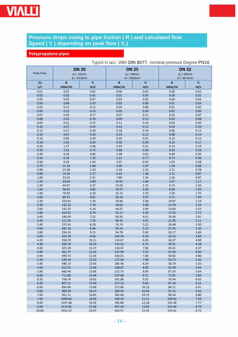
Pressure drops owing to pipe friction ( R ) and calculated flow Speed ( V ) depending on peak flow ( Vs)
Polypropylene pipes
Type3 in acc. With DIN 8077, nominal pressure Degree PN16
Peak Flow DN 20
da = 32mm di = 23.0mm
DN 25 da = 40mm
di = 28.8mm
DN 32 da = 50mm
di = 36.2mm
Vs L/s
R mbar/m
V m/s
R mbar/m
V m/s
R mbar/m
V m/s
0.01 0.01 0.02 0.00 0.02 0.00 0.01 0.02 0.02 0.05 0.01 0.03 0.00 0.02 0.03 0.05 0.07 0.02 0.05 0.00 0.03 0.04 0.08 0.10 0.03 0.06 0.01 0.04 0.05 0.11 0.12 0.04 0.08 0.01 0.05 0.06 0.15 0.14 0.05 0.09 0.02 0.06 0.07 0.20 0.17 0.07 0.11 0.02 0.07 0.08 0.25 0.19 0.09 0.12 0.03 0.08 0.09 0.31 0.22 0.11 0.14 0.04 0.09 0.10 0.37 0.24 0.13 0.15 0.04 0.10 0.12 0.51 0.29 0.18 0.18 0.06 0.12 0.14 0.67 0.34 0.23 0.21 0.08 0.14 0.16 0.85 0.39 0.29 0.25 0.10 0.16 0.18 1.05 0.43 0.36 0.28 0.12 0.17 0.20 1.27 0.48 0.43 0.31 0.14 0.19 0.30 2.61 0.72 0.88 0.46 0.30 0.29 0.40 4.39 0.96 1.48 0.61 0.49 0.39 0.50 6.58 1.20 2.21 0.77 0.73 0.49 0.60 9.18 1.44 3.07 0.92 1.02 0.58 0.70 12.18 1.68 4.06 1.07 1.34 0.68 0.80 15.58 1.93 5.18 1.23 1.71 0.78 0.90 19.36 2.17 6.43 1.38 2.11 0.87 1.00 23.53 2.41 7.80 1.54 2.56 0.97 1.20 33.04 2.89 10.91 1.84 3.57 1.17 1.40 44.07 3.37 14.50 2.15 4.73 1.36 1.60 56.62 3.85 18.57 2.46 6.04 1.55 1.80 70.93 4.33 23.13 2.76 7.50 1.75 2.00 86.53 4.81 28.16 3.07 9.11 1.94 2.20 103.63 5.30 33.66 3.38 10.87 2.14 2.40 122.22 5.78 39.63 3.68 12.78 2.33 2.60 142.32 6.26 46.07 3.99 14.83 2.53 2.80 163.91 6.74 53.17 4.30 17.02 2.72 3.00 186.99 7.22 60.56 4.61 19.36 2.91 3.20 211.56 7.70 68.42 4.91 21.85 3.11 3.40 237.63 8.18 76.74 5.22 24.48 3.30 3.60 265.18 8.66 85.53 5.53 27.25 3.50 3.80 294.23 9.15 94.78 5.83 30.17 3.69 4.00 324.76 9.36 104.50 6.14 33.23 3.89 4.20 356.78 10.11 114.67 6.45 36.57 4.08 4.40 390.29 10.59 125.32 6.75 39.91 4.28 4.60 425.28 11.07 136.42 7.06 43.41 4.47 4.80 461.77 11.55 147.99 7.37 47.04 4.66 5.00 499.73 12.03 160.01 7.68 50.82 4.86 5.20 539.19 12.52 172.50 7.98 54.73 5.05 5.40 580.13 13.00 185.46 8.29 58.79 5.25 5.60 622.55 13.48 198.87 8.60 62.99 5.44 5.80 666.46 13.96 212.75 8.90 67.33 5.64 6.00 711.86 14.44 227.08 9.21 71.81 5.83 6.20 758.74 14.92 241.88 9.52 76.44 6.02 6.40 807.11 15.40 257.14 9.82 81.20 6.22 6.60 856.96 15.89 272.86 10.13 86.11 6.41 6.80 908.29 16.37 289.04 10.44 91.15 6.61 7.00 961.11 16.85 305.68 10.75 96.34 6.80 7.50 1099.66 18.05 349.30 11.51 109.92 7.29 8.00 1247.48 19.26 395.80 12.28 124.38 7.77 9.00 1570.95 21.66 497.44 13.82 155.94 8.74
10.00 1931.52 24.07 610.57 15.35 191.01 9.72
- 15 -
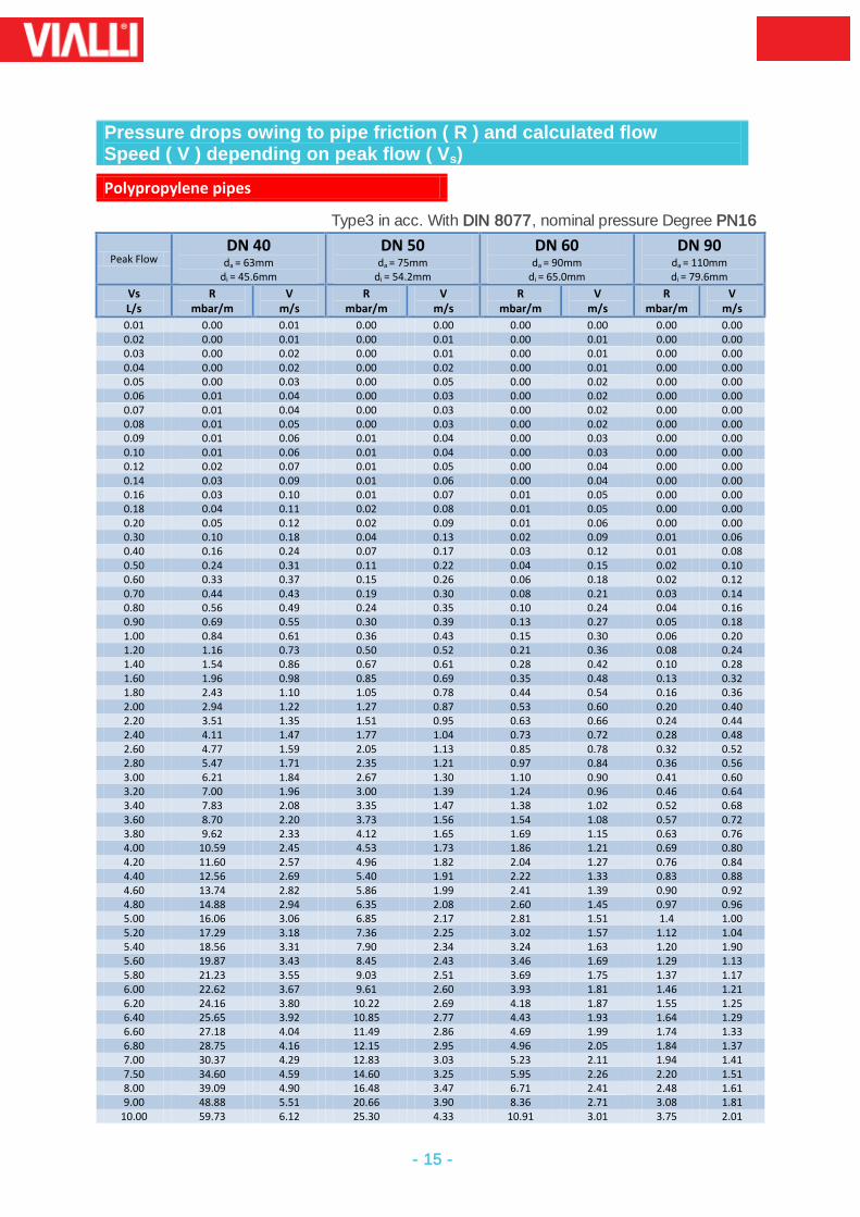
Pressure drops owing to pipe friction ( R ) and calculated flow Speed ( V ) depending on peak flow ( Vs)
Polypropylene pipes
Type3 in acc. With DIN 8077, nominal pressure Degree PN16
Peak Flow DN 40
da = 63mm di = 45.6mm
DN 50 da = 75mm
di = 54.2mm
DN 60 da = 90mm
di = 65.0mm
DN 90 da = 110mm di = 79.6mm
Vs L/s
R mbar/m
V m/s
R mbar/m
V m/s
R mbar/m
V m/s
R mbar/m
V m/s
0.01 0.00 0.01 0.00 0.00 0.00 0.00 0.00 0.00 0.02 0.00 0.01 0.00 0.01 0.00 0.01 0.00 0.00 0.03 0.00 0.02 0.00 0.01 0.00 0.01 0.00 0.00 0.04 0.00 0.02 0.00 0.02 0.00 0.01 0.00 0.00 0.05 0.00 0.03 0.00 0.05 0.00 0.02 0.00 0.00 0.06 0.01 0.04 0.00 0.03 0.00 0.02 0.00 0.00 0.07 0.01 0.04 0.00 0.03 0.00 0.02 0.00 0.00 0.08 0.01 0.05 0.00 0.03 0.00 0.02 0.00 0.00 0.09 0.01 0.06 0.01 0.04 0.00 0.03 0.00 0.00 0.10 0.01 0.06 0.01 0.04 0.00 0.03 0.00 0.00 0.12 0.02 0.07 0.01 0.05 0.00 0.04 0.00 0.00 0.14 0.03 0.09 0.01 0.06 0.00 0.04 0.00 0.00 0.16 0.03 0.10 0.01 0.07 0.01 0.05 0.00 0.00 0.18 0.04 0.11 0.02 0.08 0.01 0.05 0.00 0.00 0.20 0.05 0.12 0.02 0.09 0.01 0.06 0.00 0.00 0.30 0.10 0.18 0.04 0.13 0.02 0.09 0.01 0.06 0.40 0.16 0.24 0.07 0.17 0.03 0.12 0.01 0.08 0.50 0.24 0.31 0.11 0.22 0.04 0.15 0.02 0.10 0.60 0.33 0.37 0.15 0.26 0.06 0.18 0.02 0.12 0.70 0.44 0.43 0.19 0.30 0.08 0.21 0.03 0.14 0.80 0.56 0.49 0.24 0.35 0.10 0.24 0.04 0.16 0.90 0.69 0.55 0.30 0.39 0.13 0.27 0.05 0.18 1.00 0.84 0.61 0.36 0.43 0.15 0.30 0.06 0.20 1.20 1.16 0.73 0.50 0.52 0.21 0.36 0.08 0.24 1.40 1.54 0.86 0.67 0.61 0.28 0.42 0.10 0.28 1.60 1.96 0.98 0.85 0.69 0.35 0.48 0.13 0.32 1.80 2.43 1.10 1.05 0.78 0.44 0.54 0.16 0.36 2.00 2.94 1.22 1.27 0.87 0.53 0.60 0.20 0.40 2.20 3.51 1.35 1.51 0.95 0.63 0.66 0.24 0.44 2.40 4.11 1.47 1.77 1.04 0.73 0.72 0.28 0.48 2.60 4.77 1.59 2.05 1.13 0.85 0.78 0.32 0.52 2.80 5.47 1.71 2.35 1.21 0.97 0.84 0.36 0.56 3.00 6.21 1.84 2.67 1.30 1.10 0.90 0.41 0.60 3.20 7.00 1.96 3.00 1.39 1.24 0.96 0.46 0.64 3.40 7.83 2.08 3.35 1.47 1.38 1.02 0.52 0.68 3.60 8.70 2.20 3.73 1.56 1.54 1.08 0.57 0.72 3.80 9.62 2.33 4.12 1.65 1.69 1.15 0.63 0.76 4.00 10.59 2.45 4.53 1.73 1.86 1.21 0.69 0.80 4.20 11.60 2.57 4.96 1.82 2.04 1.27 0.76 0.84 4.40 12.56 2.69 5.40 1.91 2.22 1.33 0.83 0.88 4.60 13.74 2.82 5.86 1.99 2.41 1.39 0.90 0.92 4.80 14.88 2.94 6.35 2.08 2.60 1.45 0.97 0.96 5.00 16.06 3.06 6.85 2.17 2.81 1.51 1.4 1.00 5.20 17.29 3.18 7.36 2.25 3.02 1.57 1.12 1.04 5.40 18.56 3.31 7.90 2.34 3.24 1.63 1.20 1.90 5.60 19.87 3.43 8.45 2.43 3.46 1.69 1.29 1.13 5.80 21.23 3.55 9.03 2.51 3.69 1.75 1.37 1.17 6.00 22.62 3.67 9.61 2.60 3.93 1.81 1.46 1.21 6.20 24.16 3.80 10.22 2.69 4.18 1.87 1.55 1.25 6.40 25.65 3.92 10.85 2.77 4.43 1.93 1.64 1.29 6.60 27.18 4.04 11.49 2.86 4.69 1.99 1.74 1.33 6.80 28.75 4.16 12.15 2.95 4.96 2.05 1.84 1.37 7.00 30.37 4.29 12.83 3.03 5.23 2.11 1.94 1.41 7.50 34.60 4.59 14.60 3.25 5.95 2.26 2.20 1.51 8.00 39.09 4.90 16.48 3.47 6.71 2.41 2.48 1.61 9.00 48.88 5.51 20.66 3.90 8.36 2.71 3.08 1.81
10.00 59.73 6.12 25.30 4.33 10.91 3.01 3.75 2.01
- 16 -
Pressure drops owing to pipe friction ( R ) and calculated flow Speed ( V ) depending on peak flow ( Vs)
Polypropylene pipes
Type3 in acc. With DIN 8077, nominal pressure Degree PN20
Peak Flow
DN 10 da = 16mm
di = 10.6mm v = 0.088 l/m
DN 12 da = 20mm
di = 13.2mm v = 0.137 l/m
DN 16 da = 25mm
di = 16.6mm v = 0.216 l/m
Vs L/s
R mbar/m
V m/s
R mbar/m
V m/s
R mbar/m
V m/s
0.01 0.39 0.11 0.14 0.07 0.05 0.05 0.02 1.23 0.23 0.44 0.15 0.15 0.09 0.03 2.44 0.34 0.87 0.22 0.30 0.14 0.04 3.98 0.45 1.41 0.29 0.48 0.18 0.05 5.84 0.57 2.07 0.37 0.70 0.23 0.06 8.00 0.68 2.83 0.44 0.96 0.28 0.07 10.47 0.79 3.69 0.51 1.25 0.32 0.08 13.22 0.91 4.65 0.58 1.57 0.37 0.09 16.24 1.02 5.70 0.66 1.92 0.42 0.10 19.50 1.13 6.86 0.73 2.30 0.46 0.15 39.92 1.70 13.92 1.10 4.66 0.69 0.20 66.61 2.27 23.13 1.46 7.72 0.92 0.25 99.54 2.83 34.38 1.83 11.45 1.16 0.30 138.44 3.40 47.68 2.19 15.80 1.39 0.35 183.23 3.97 62.92 2.56 20.79 1.62 0.40 223.51 4.53 79.92 2.92 26.33 1.85 0.45 289.41 5.10 33.10 3.29 32.55 2.08 0.50 351.24 5.67 119.82 3.65 39.38 2.31 0.55 142.53 4.02 46.68 2.54 0.60 167.44 4.38 54.62 2.77 0.65 193.092 4.75 72.14 3.00 0.70 21.96 5.12 82.09 3.23 0.75 251.39 5.48 92.17 3.47 0.80 103.12 3.70 0.85 114.05 3.93 0.90 125.91 4.16 0.95 138.87 4.39 1.00 151.69 4.62 1.05 164.92 4.85 1.10 179.41 5.08 1.15 193.50 5.31 1.20 5.54
- 17 -
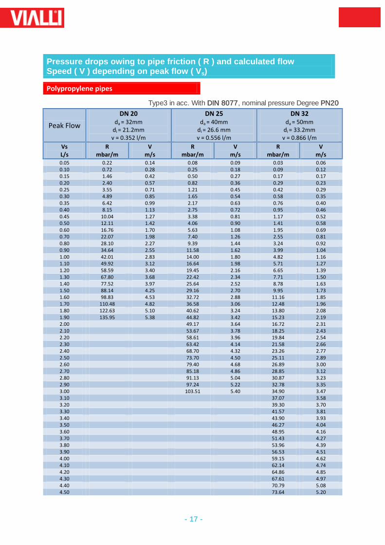
Pressure drops owing to pipe friction ( R ) and calculated flow Speed ( V ) depending on peak flow ( Vs)
Polypropylene pipes
Type3 in acc. With DIN 8077, nominal pressure Degree PN20
Peak Flow
DN 20 da = 32mm
di = 21.2mm v = 0.352 l/m
DN 25 da = 40mm
di = 26.6 mm v = 0.556 l/m
DN 32 da = 50mm
di = 33.2mm v = 0.866 l/m
Vs L/s
R mbar/m
V m/s
R mbar/m
V m/s
R mbar/m
V m/s
0.05 0.22 0.14 0.08 0.09 0.03 0.06 0.10 0.72 0.28 0.25 0.18 0.09 0.12 0.15 1.46 0.42 0.50 0.27 0.17 0.17 0.20 2.40 0.57 0.82 0.36 0.29 0.23 0.25 3.55 0.71 1.21 0.45 0.42 0.29 0.30 4.89 0.85 1.65 0.54 0.58 0.35 0.35 6.42 0.99 2.17 0.63 0.76 0.40 0.40 8.15 1.13 2.75 0.72 0.95 0.46 0.45 10.04 1.27 3.38 0.81 1.17 0.52 0.50 12.11 1.42 4.06 0.90 1.41 0.58 0.60 16.76 1.70 5.63 1.08 1.95 0.69 0.70 22.07 1.98 7.40 1.26 2.55 0.81 0.80 28.10 2.27 9.39 1.44 3.24 0.92 0.90 34.64 2.55 11.58 1.62 3.99 1.04 1.00 42.01 2.83 14.00 1.80 4.82 1.16 1.10 49.92 3.12 16.64 1.98 5.71 1.27 1.20 58.59 3.40 19.45 2.16 6.65 1.39 1.30 67.80 3.68 22.42 2.34 7.71 1.50 1.40 77.52 3.97 25.64 2.52 8.78 1.63 1.50 88.14 4.25 29.16 2.70 9.95 1.73 1.60 98.83 4.53 32.72 2.88 11.16 1.85 1.70 110.48 4.82 36.58 3.06 12.48 1.96 1.80 122.63 5.10 40.62 3.24 13.80 2.08 1.90 135.95 5.38 44.82 3.42 15.23 2.19 2.00 49.17 3.64 16.72 2.31 2.10 53.67 3.78 18.25 2.43 2.20 58.61 3.96 19.84 2.54 2.30 63.42 4.14 21.58 2.66 2.40 68.70 4.32 23.26 2.77 2.50 73.70 4.50 25.11 2.89 2.60 79.40 4.68 26.89 3.00 2.70 85.18 4.86 28.85 3.12 2.80 91.13 5.04 30.87 3.23 2.90 97.24 5.22 32.78 3.35 3.00 103.51 5.40 34.90 3.47 3.10 37.07 3.58 3.20 39.30 3.70 3.30 41.57 3.81 3.40 43.90 3.93 3.50 46.27 4.04 3.60 48.95 4.16 3.70 51.43 4.27 3.80 53.96 4.39 3.90 56.53 4.51 4.00 59.15 4.62 4.10 62.14 4.74 4.20 64.86 4.85 4.30 67.61 4.97 4.40 70.79 5.08 4.50 73.64 5.20
- 18 -
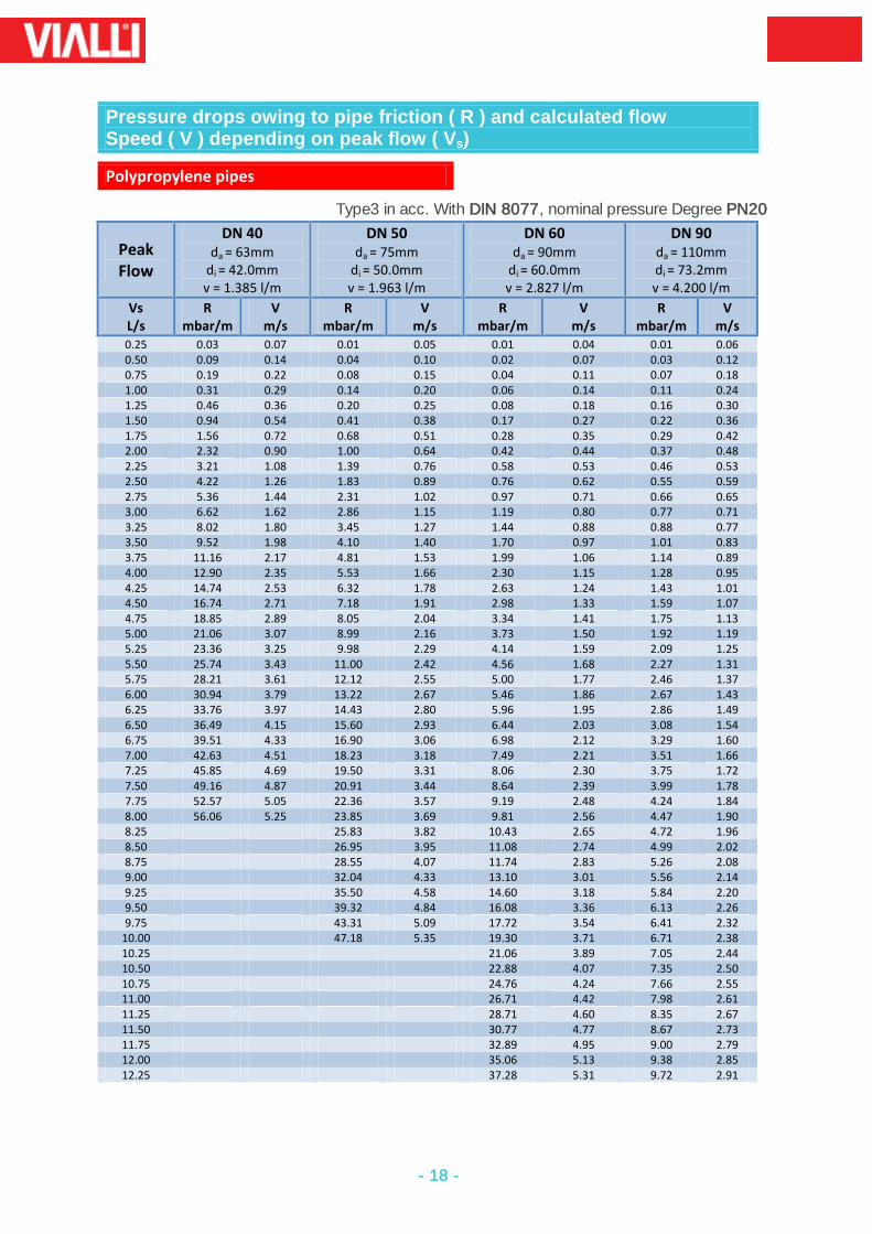
Pressure drops owing to pipe friction ( R ) and calculated flow Speed ( V ) depending on peak flow ( Vs)
Polypropylene pipes
Type3 in acc. With DIN 8077, nominal pressure Degree PN20
Peak Flow
DN 40 da = 63mm
di = 42.0mm v = 1.385 l/m
DN 50 da = 75mm
di = 50.0mm v = 1.963 l/m
DN 60 da = 90mm
di = 60.0mm v = 2.827 l/m
DN 90 da = 110mm di = 73.2mm v = 4.200 l/m
Vs L/s
R mbar/m
V m/s
R mbar/m
V m/s
R mbar/m
V m/s
R mbar/m
V m/s
0.25 0.03 0.07 0.01 0.05 0.01 0.04 0.01 0.06 0.50 0.09 0.14 0.04 0.10 0.02 0.07 0.03 0.12 0.75 0.19 0.22 0.08 0.15 0.04 0.11 0.07 0.18 1.00 0.31 0.29 0.14 0.20 0.06 0.14 0.11 0.24 1.25 0.46 0.36 0.20 0.25 0.08 0.18 0.16 0.30 1.50 0.94 0.54 0.41 0.38 0.17 0.27 0.22 0.36 1.75 1.56 0.72 0.68 0.51 0.28 0.35 0.29 0.42 2.00 2.32 0.90 1.00 0.64 0.42 0.44 0.37 0.48 2.25 3.21 1.08 1.39 0.76 0.58 0.53 0.46 0.53 2.50 4.22 1.26 1.83 0.89 0.76 0.62 0.55 0.59 2.75 5.36 1.44 2.31 1.02 0.97 0.71 0.66 0.65 3.00 6.62 1.62 2.86 1.15 1.19 0.80 0.77 0.71 3.25 8.02 1.80 3.45 1.27 1.44 0.88 0.88 0.77 3.50 9.52 1.98 4.10 1.40 1.70 0.97 1.01 0.83 3.75 11.16 2.17 4.81 1.53 1.99 1.06 1.14 0.89 4.00 12.90 2.35 5.53 1.66 2.30 1.15 1.28 0.95 4.25 14.74 2.53 6.32 1.78 2.63 1.24 1.43 1.01 4.50 16.74 2.71 7.18 1.91 2.98 1.33 1.59 1.07 4.75 18.85 2.89 8.05 2.04 3.34 1.41 1.75 1.13 5.00 21.06 3.07 8.99 2.16 3.73 1.50 1.92 1.19 5.25 23.36 3.25 9.98 2.29 4.14 1.59 2.09 1.25 5.50 25.74 3.43 11.00 2.42 4.56 1.68 2.27 1.31 5.75 28.21 3.61 12.12 2.55 5.00 1.77 2.46 1.37 6.00 30.94 3.79 13.22 2.67 5.46 1.86 2.67 1.43 6.25 33.76 3.97 14.43 2.80 5.96 1.95 2.86 1.49 6.50 36.49 4.15 15.60 2.93 6.44 2.03 3.08 1.54 6.75 39.51 4.33 16.90 3.06 6.98 2.12 3.29 1.60 7.00 42.63 4.51 18.23 3.18 7.49 2.21 3.51 1.66 7.25 45.85 4.69 19.50 3.31 8.06 2.30 3.75 1.72 7.50 49.16 4.87 20.91 3.44 8.64 2.39 3.99 1.78 7.75 52.57 5.05 22.36 3.57 9.19 2.48 4.24 1.84 8.00 56.06 5.25 23.85 3.69 9.81 2.56 4.47 1.90 8.25 25.83 3.82 10.43 2.65 4.72 1.96 8.50 26.95 3.95 11.08 2.74 4.99 2.02 8.75 28.55 4.07 11.74 2.83 5.26 2.08 9.00 32.04 4.33 13.10 3.01 5.56 2.14 9.25 35.50 4.58 14.60 3.18 5.84 2.20 9.50 39.32 4.84 16.08 3.36 6.13 2.26 9.75 43.31 5.09 17.72 3.54 6.41 2.32
10.00 47.18 5.35 19.30 3.71 6.71 2.38 10.25 21.06 3.89 7.05 2.44 10.50 22.88 4.07 7.35 2.50 10.75 24.76 4.24 7.66 2.55 11.00 26.71 4.42 7.98 2.61 11.25 28.71 4.60 8.35 2.67 11.50 30.77 4.77 8.67 2.73 11.75 32.89 4.95 9.00 2.79 12.00 35.06 5.13 9.38 2.85 12.25 37.28 5.31 9.72 2.91
- 19 -
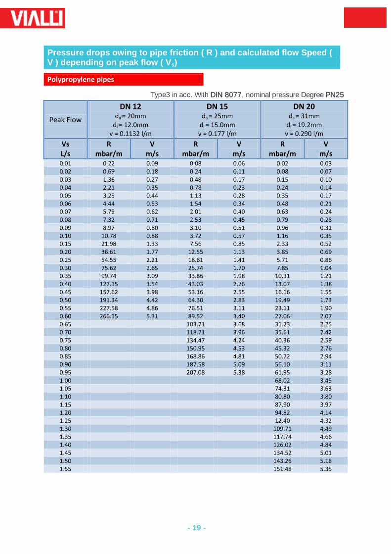
Pressure drops owing to pipe friction ( R ) and calculated flow Speed ( V ) depending on peak flow ( Vs)
Polypropylene pipes
Type3 in acc. With DIN 8077, nominal pressure Degree PN25
Peak Flow
DN 12 da = 20mm
di = 12.0mm v = 0.1132 l/m
DN 15 da = 25mm
di = 15.0mm v = 0.177 l/m
DN 20 da = 31mm
di = 19.2mm v = 0.290 l/m
Vs L/s
R mbar/m
V m/s
R mbar/m
V m/s
R mbar/m
V m/s
0.01 0.22 0.09 0.08 0.06 0.02 0.03 0.02 0.69 0.18 0.24 0.11 0.08 0.07 0.03 1.36 0.27 0.48 0.17 0.15 0.10 0.04 2.21 0.35 0.78 0.23 0.24 0.14 0.05 3.25 0.44 1.13 0.28 0.35 0.17 0.06 4.44 0.53 1.54 0.34 0.48 0.21 0.07 5.79 0.62 2.01 0.40 0.63 0.24 0.08 7.32 0.71 2.53 0.45 0.79 0.28 0.09 8.97 0.80 3.10 0.51 0.96 0.31 0.10 10.78 0.88 3.72 0.57 1.16 0.35 0.15 21.98 1.33 7.56 0.85 2.33 0.52 0.20 36.61 1.77 12.55 1.13 3.85 0.69 0.25 54.55 2.21 18.61 1.41 5.71 0.86 0.30 75.62 2.65 25.74 1.70 7.85 1.04 0.35 99.74 3.09 33.86 1.98 10.31 1.21 0.40 127.15 3.54 43.03 2.26 13.07 1.38 0.45 157.62 3.98 53.16 2.55 16.16 1.55 0.50 191.34 4.42 64.30 2.83 19.49 1.73 0.55 227.58 4.86 76.51 3.11 23.11 1.90 0.60 266.15 5.31 89.52 3.40 27.06 2.07 0.65 103.71 3.68 31.23 2.25 0.70 118.71 3.96 35.61 2.42 0.75 134.47 4.24 40.36 2.59 0.80 150.95 4.53 45.32 2.76 0.85 168.86 4.81 50.72 2.94 0.90 187.58 5.09 56.10 3.11 0.95 207.08 5.38 61.95 3.28 1.00 68.02 3.45 1.05 74.31 3.63 1.10 80.80 3.80 1.15 87.90 3.97 1.20 94.82 4.14 1.25 12.40 4.32 1.30 109.71 4.49 1.35 117.74 4.66 1.40 126.02 4.84 1.45 134.52 5.01 1.50 143.26 5.18 1.55 151.48 5.35
- 20 -
Pressure drops owing to pipe friction ( R ) and calculated flow Speed ( V ) depending on peak flow ( Vs)
Polypropylene pipes
Type3 in acc. With DIN 8077, nominal pressure Degree PN25
Peak Flow
DN 25 da = 40mm
di = 24.0mm v = 0.452 l/m
DN 30 da = 50mm
di = 30.0mm v = 0.707 l/m
Vs L/s
R mbar/m
V m/s
R mbar/m
V m/s
0.05 0.12 0.11 0.04 0.07
0.10 0.40 0.22 0.14 0.14
0.15 0.81 0.33 0.28 0.21
0.20 1.33 0.44 0.46 0.28
0.25 1.97 0.55 0.68 0.35
0.30 2.70 0.66 0.93 0.42
0.35 3.54 0.77 1.22 0.50
0.40 4.49 0.88 1.55 0.57
0.45 5.52 0.99 1.90 0.64
0.50 6.67 1.11 2.28 0.71
0.60 9.20 1.33 3.16 0.85
0.70 12.12 1.55 4.15 0.99
0.80 15.44 1.77 5.27 1.13
0.90 19.04 1.99 6.48 1.27
1.00 23.00 2.21 7.48 1.14
1.10 27.34 2.43 9.28 1.56
1.20 31.95 2.65 10.85 1.70
1.30 36.98 2.87 12.57 1.84
1.40 42.29 3.09 14.32 1.98
1.50 48.09 3.32 16.21 2.12
1.60 53.93 3.54 18.27 2.26
1.70 60.30 3.76 20.34 2.41
1.80 66.94 3.98 22.58 2.55
1.90 73.85 4.20 24.92 2.69
2.00 81.01 4.42 27.35 2.83
2.10 88.87 4.64 29.86 2.97
2.20 96.55 4.86 32.61 3.11
2.30 104.99 5.08 35.28 3.25
2.40 113.73 5.31 38.04 3.40
2.50 41.06 3.54
2.60 44.19 3.68
2.70 47.17 3.82
2.80 50.46 3.96
2.90 53.85 4.10
3.00 57.33 4.24
3.10 60.89 4.39
3.20 64.54 4.53
3.30 68.28 4.67
3.40 72.09 4.81
3.50 75.99 4.95
3.60 80.39 5.09
3.70 84.46 5.23
3.80 88.61 5.38
- 21 -
Pressure drops owing to pipe friction ( R ) and calculated flow Speed ( V ) depending on peak flow ( Vs)
Polypropylene pipes
Type3 in acc. With DIN 8077, nominal pressure Degree PN25
Peak Flow
DN 40 da = 63mm
di = 37.8mm v = 1.122 l/m
DN 45 da = 75mm
di = 45.0mm v = 1.590 l/m
Vs L/s
R mbar/m
V m/s
R mbar/m
V m/s
0.10 0.05 0.09 0.02 0.06
0.20 0.15 0.18 0.07 0.13
0.30 0.31 0.27 0.14 0.19
0.40 0.51 0.36 0.22 0.25
0.50 0.76 0.45 0.33 0.31
0.75 1.55 0.67 0.67 0.47
1.00 2.58 0.89 1.12 0.63
1.25 3.84 1.11 1.66 0.79
1.50 5.32 1.34 2.30 0.94
1.75 7.01 1.56 3.03 1.10
2.00 8.91 1.78 3.85 1.26
2.25 11.06 2.00 4.76 1.41
2.50 13.32 2.23 5.74 1.57
2.75 15.88 2.45 6.81 1.73
3.00 18.62 2.67 7.98 1.89
3.25 21.52 2.90 9.23 2.04
3.50 24.57 3.12 10.54 2.20
3.75 27.91 3.34 11.98 2.36
4.00 31.42 3.56 13.42 2.52
4.25 35.09 3.79 14.99 2.67
4.50 38.92 4.01 16.63 2.83
4.75 43.12 4.23 18.43 2.99
5.00 47.26 4.46 20.20 3.14
5.25 51.81 4.68 22.03 3.30
5.50 56.54 4.90 24.05 3.46
5.75 61.11 5.12 26.14 3.62
6.00 66.16 5.35 28.14 3.77
6.25 30.37 3.93
6.50 32.66 4.09
6.75 35.02 4.24
7.00 37.44 4.40
7.25 39.94 4.56
7.50 42.49 4.72
7.75 45.11 4.87
8.00 48.06 5.03
8.25 50.82 5.19
8.50 53.62 5.34
- 22 -
6. Determination of Total Pressure loss of the installation
The calculation flow rates of the individual take-off points are summed in a direction and
are assigned to the corresponding pipe sections as cumulative flow rates.
The dimensions are calculated from the sum of continuous flow rates and peak rates.
The continuous flow rates is regarded as the quality which emerges when water is
removed for more than 15 minutes, converted to liter per second.
Values for the conversion of cumulative flow rates in to peak flow rates are shown in
diagram.
In association with international pipe diameter. The peak flow rates determine the
pressure gradient due to pipe friction.
The total pressure loss of the pipe (without equipment resistance)is the sum of the
pressure losses due to pipe friction and individual resistance.
The coefficients of resistance of pipeline sections and individual resistance are shown in
table
The total pressure loss of the pipe can be determined with the aid of the relevant
equation:
ΔP = Σ(R x L + Z)
Z = Ϛ. V2 .e
2
Peak Flow
Peak flow Vsdepending on summation flow Σ VR
- 23 -
Resistance Coefficient Values
Resistance Coefficient ValuesϚufor piping junctions
No. Designation Graphic Symbols
Loss coefficients
1 Branching. One sided dividing flow
1.3
2 Branching. One sided merging flow
0.9
3 Branching one-sided passage for dividing flow
0.3
4 Branching one-sided passage for merging flow
0.6
5
Branching one sided counter-current for merging flow
3.0
6
Branching one sided counter-current for dividing flow
1.3
7 Branching, one sided bow shaped dividing flow
0.9
8
Branching one sided bow shaped, merging flow
0.4
9
Branching one sided bow shaped passage for dividing flow
0.3
10
Branching one sided bow shaped passage for merging flow
0.2
11 Branching with 2 exit pipes (casing reservoir)
0.5
12 Branching with 2 entry pipes (casing reservoir)
1.0
13
Bow 90°smooth R=d =2d =4d =6d
=10d Bow 90° rough
R=d =2d =4d =6d
=10d
0.21 0.14 0.09 0.11
0.51 0.30 0.23 0.18 0.20
No. Designation Graphic Symbols
Loss coefficients
14
Elbow joints 90° smooth Elbow joints 90° rough
1.13 1.27
15
Widening steady ß= 10°
=20° =30° =40°
Widening sudden Widening free discharge
0.20 0.45 0.60 0.75
(F1/F2=1)2
1.0
16
Narrowing steady
Reductions 1 dimensions 2 dimensions 3 dimensions 4 dimensions 5 dimensions 6 dimensions
0.40 0.50 0.60 0.70 0.80 0.90
17
Smooth comp tube bend quill comp tube bend corrugated comp tube
0.7 1.4 2
18
Screw-down stop Globe valve DN20 DN25 Slanted set valves DN 20 DN25
8.5 7.0
2.5 2.0
19
Full current valve DN20 DN25
1.5
20
Corner valves DN20 Dn25
2.0
21
Main slide valve DN20 Dn25
0.5
- 24 -
8. QUALITY CONSIDERATIONS
The deciding factor in theVIALLIPPR pipes and fittings manufacturing process is the use of
correct/ pure raw materials.
Pipes and pipe fittings are long consisting with PPR material properties and
characteristics.
Has a direct impact on the welding quality (example: the melting pint of PPR material is
140 °C that of PP-B material is about 160 °C) welding conditions become different so
that the welding quality is easy to grasp. This is due to the fact that two kinds of
crystalline material used in the PP blend mix have varying melting degrees.
The cooling rate is different in the welding process due to the different shrinkage rates
which leads to stress concentration.
When the raw material is mixed with a number of recycling industrial waste plastic
granulates, the pipes and fittings produced could be toxic and thus not suitable for
long-term use to transport drinking water this will serious
Smell and black smoke appears during the welding process
The life span of such pipes and fitting is rather short. Leakage problems will properly
start within first few months of regular function. The repair and replacement coast in
case of occupied residential units will be much higher.
The production machines play also an important role in securing a quality product. Low
quality suppliers tend to use cheap equipment for their manufacturing process. For
example: pipes are produced with an uneven wall thickness all throughout the pipe. This
will have a great impact on a quality of the pipe and it chemical/thermal characteristics.
- 25 -
9. FREQUENTLY ASKED QUESTIONS
Q: Which is the raw material used to produce VIALLI PPR Pipe system?
AN
SWER
PPR pipe systems are produce out of polypropylene random copolymer referred to as type III PPR (commonly known as PPR). This raw material is obtained by cracking petroleum where by propane-monomer polymerizes with polypropylene co monomer to form polypropylene random copolymer. We use only one of the best PPR raw material over the world approved for the production of pipes & fittings accordance to the DIN 8078 & DIN 16962 standards.
Q: How are the pipes and Fittings manufactured using this raw material?
AN
SWER
The PPR-raw material is a thermoplastic resin and is supplied in granules pre-colored. This raw material is transformed in to finished product by a rise in temperature. Which plastizes the material. Allowing the pipe to produce by means of extrusion, and fittings by molding.
Q: What do PPR-c type 1 Type, Type 2 and Type 3 refer to? What are the difference between them?
AN
SWER
Plastic pipes get more resistant as they are developed. The fist produced
have been added into the propylene molecules. This was called Type 2 Polypropylene block copolymer. Later the Type 3 product have been obtained, which has a structure including ethylene molecules regular sequenced among the propylene molecules. Today, because of the features they posses, Type 2 and Type 3 are widely used. Type 2 is used only at cold water networks. It is not resistant to hot fluids. Type 3 could be used at hot water since it is resistant to hot fluids.
Q: Are VIALLI pipes UV resistant?
AN
SWER
VIALLI PPR pipes and fittings are having sufficient UV stability in order to protect from UV. Rays. However it is not advisable to use this pipes & fittings under direct sunlight continuously for outdoor installation of pipelines it is recommended to make an acrylic paint coating on pipes, or protect them from direct sunlight by giving shelter covering or installing in a duct
- 26 -
Q: Is insulation necessary for hot water applications?
AN
SWER
Normally it is not obligatory for the plumbers to make the insulation since the thermal conductivity of PPR piping systems is lower compared to metal piping systems (0.24 W/mK). However, for centralized heating systems. To prevent heat loss and isolate the pipelines. From other utilities, it is advisable to insulate these lines. The required thickness of insulation is quite lower as compared with conventional lines.
Q: How can we connect VIALLI products to other metal systems?
AN
SWER
VIALLI PPR system can be connected to other metal systems easily by a flange or a metal adaptor. (BS 6920)
Q: What is DIN Standards?
AN
SWER
DeutschesInstitutfürNormung (DIN) is Germany institute for Standardization, it is a technical and scientific association recognized by the Germany government as the national standards body representing Germany interests at international and European levels. DIN provides a forum in which representatives from the manufacturing industries, consumer organization, commerce, the trades, service industries, science technical inspectorates, and government may discuss and define their specific standardization requirements and to record the result as German Standards.
Q: What are production standards of VIALLI PPR ?
AN
SWER
Following standards are used for the production of VIALLI pipes and fittings:
Standard Concern Production DIN 8076 Standard for Testing metal threaded joints
DIN 8077 Polypropylene Pipes. Dimensions
DIN 8078 Polypropylene Pipes, General Quality Requirements & Testing
DIN 16962 Pipe joints and elements for Polypropylene Pressure Pipes
DIN 1988 Drinking Water Supply Systems, Materials, Components, Appliances Design and installation
DIN 16928 Pipe joints & Elements for Pipes, Laying-General Directions
DIN 2999 Standard for fittings with threaded metallic insert EN ISO - 15874
Plastic piping system for hot & cold water Installation (PP)
BS 6700 Design, Installation, Testing and Maintenance of Services Supplying Water for Domestic use with in buildings and their Cartilages
DVS 2207 Welding of Thermoplastics
DVS 2208 Welding Machines and Devices for Thermoplastics
- 27 -
Q: What is the service life (life span) of VIALLI PPR piping system for different pressure groups?
AN
SWER
PPRC pipes have a service life of 50 years according to DIN Standards for in house applications. To have detailed information for Different temperatures and pressure rates, please refer product catalogue
Q: Are VIALLI PPR pipes used for drinking water? Are they Hygienic/ Healthy?
AN
SWER
PPRC products can safely be used for Drinking water. VAILLI PPR products have got all international Approvals as well as the approvals of the sales territories
Q: What does PN Stands for and what does it mean to be PN-16 or PN20?
AN
SWER
PN stands for Nominal Pressure, it is numerical designation used for reference purpose related to mechanical characteristics of the component of a piping system. A PN-20 pipe mean the pipe can withstand pressure Up to 20 Bars.
Q: Why is VIALLI fittings categorized under PN-25 Types?
AN
SWER
VIALLI fittings can withstand temperature above 95°C and pressure up to 25 kg/ cm2, (25 Bars) hence categorized under PN-25.
Q: What does PN Stands for and what does it mean to be PN-16 or PN20?
AN
SWER
PN stands for Nominal Pressure, it is numerical designation used for reference purpose related to mechanical characteristics of the component of a piping system. A PN-20 pipe mean the pipe can withstand pressure Up to 20 Bars.
- 28 -
Q: What is the deference between PN16 and PN20 pipes due to the application areas?
AN
SWER
Life Span of PN20 is Longer than PN-16 pipes under the same temperature and pressure conditions. Especially for the exposed installations as the expansion of PN-20 pipes are 1/5 of PN 16 pipes saggaing and snaking problems are avoided.
Q: How is pipe categorized as PN-10, PN-16, PN-20 & PN25 matched with SDR (Standard Dimension Rate) of conventional pipes?
AN
SWER
A PPR Pipes with all thickness of OD/ SDR is matched as the Equivalent PPR Pipe for a SDR Pipe. PN-10 is regarded as equivalent to SDR 11 Because, PN 10 Pipe of 20 mm OD has thickness approx. to 20/11=1.8 PN-10 160 mm has thickness approx. to 160/11=14.55 Likewise SDR 7.4 is matched as PN-16 and SDR 6 as PN-20.
Q: What is the intended use of different classes of Pipes?
AN
SWER
PN 10 Cold water distribution and floor heating systems PN 16 Higher pressure cold water distribution and domestic hot water system at lower Pressures. PN 20 hot water distribution Central PN 25 - Higher pressure Hot water distribution Central and Domestic
Q: What should be done is somebody accidentally drills a hole on the pipe?
AN
SWER
Kit to repair the hole on the pipe. If the damage part of the pipe is not concealed yet (before the pressure test is conducted), the recommended procedure is to cut that part and replace it by a new part through normal welding of a socket.
Q: Should any precaution be taken for the installation at low temperatures?
AN
SWER
At lower temperature of 0°C and below, the flexibility of PPR pipes reduces and impact strength also reduces. This makes pipes more prone to mechanical damages against impact loads. To avoid the damages at low temperature, it is advisable to insulate the pipe lines
- 29 -
Q: Does VIALLI PPR Piping system burn?
AN
SWER
VIALLI pipes and fittings have combustion point 330°C & Burning Point 360°C these conform to B2 (Normally inflammable) class fire requirements of normal combustibility according to DIN 4102. On fire, PPR-c pipes & fittings emits carbon dioxide and water , other than this, carbon monoxide gas, molecular hydrocarbon and oxidation product of these are also emitted in proportion to the availability of oxygen, even if the fire is incomplete, the materials emitted are less poisonous than wood or fire from conventional pipe system in similar condition
Q: How can the PPR pipes & fittings joined together?
AN
SWER
the process of jointing PPR pipes and fittings is very simple & result an inseparable water joints. It is carried out using a simple welding machine that melts the internal surface of the fittings and the external surface of the pipe at 270°C, so that the material of the pipe and the fitting will be melded together. Since the pipes and fittings are produced from the same material, the connection usually comes as homogenous.
Q: Can the pipes alignment be adjusted after the welding process?
AN
SWER
Alignment up to 5 degree relative to the axis of the pipe can be done immediately after jointing.
Q: How is the pipe cutting recommended?
AN
SWER
It is advised to used sharp cutting tools to cut the pipe with no burrs, VIALLI Provide cutting tools of size 20-40, 20-63, 50-110, 160, 200 & 250.
Q: How is the size of pipes and fittings measured?
AN
SWER
Pies size is measured by mm (millimeter) of its outer Dia. PRR fittings are measured by mm (millimeter) of inner dia. and metal threaded fittings treaded side size is measured in inches
- 30 -
Q: Which is the metal used in manufacturing of VIALLI Threaded fittings?
AN
SWER
VAILLI Threaded fittings are manufactured using stainless steel inserts, tin bronze inserts, brass with nickel platted inserts & natural brass inserts and its threading is made as per British Standard Threading.
Q: How can the stressing of pipe be avoided?
AN
SWER
Possible liner thermal expansion/contraction needs to be taken care during designing and installing. Stressing of pipes can be avoided by providing flexible free length and proper supporting.
Q: Why is joining of pipes without using sockets un-recommended?
AN
SWER
this joining results blockage or reduction in inner Dia. At joining point hence its recommended to avoid as it can affect the function of the system.
Q: Is joining of pipes & fittings using the glues recommended?
AN
SWER
guarantee against leakages. Also it intakes the demerits of glue connecting like termite attack and frequent maintenance and thus hygienic and long life of VIALLI PPR Pipe system.
Q: How is pressure testing recommended?
AN
SWER
Before any pipe are filled or cemented in concealed application the pipes are to be hydrostatically tested for any pressure loss or leak. The testing shall be done by loading the line which is closed all end with cap and pipe plug with water and pressure up to 25 bar, for PN-20 and PN-25 pipes and up to 15 bar, pressure for PN-16 pipes at room temperature. The pressure shall be maintained at least for 8 hours to check any pressure drop, the same shall be repeated to confirm the minute chances of any leakage. In the event of any considerable pressure drop the particular area of leakage has to be identified and redone.
- 31 -
10. VIALLI GLASS FIBER REINFORCED PIPE
PRODUCT DESCRIPTION
FR-PPR Glass Fiber reinforced hot and cold water composite Pipe is a three layer co-extrided, Low temperature high-speed production with special merits of PPR pipe it also the following characteristic:
1. Liner expansion coefficient is only formed 20-30% of ordinary, PPR Pipe. 2. Enhances pipe rigid, prevents droop down phenomenon, and also supporting points,
and thus cuts down the total coast installation. 3. Higher pressure resistant level and longer working life under several working
conditions. (95 °C at 10bar for short time test 200 hours) 95 °C at6.5 Bar for Service time 50 years
4. Solves the oxygen permanently of the pipeline, the inner surface not appear. The middle layer of FR-PPR pipe completely prevents oxygen there by inhabits algae growth and maintains fresh pure water.
5. Good resistance to ultraviolet radiation so installation will be without deformation. 6. Low thermal conductivity PPR Aluminum composite pipe coefficient of thermal conductivity is 190w/mk PPR Glass fiber composite pipe coefficient of thermal conductivity is 110w/mk
ideal choice for outdoor construction of solar and heat energy system.
Raw Material and Technical Specifications
Pipe Type: PPR Glass-Fiber Rain Forced
Elongation coefficient: 0.035 mm/mk
Fields of use: Heating, Cooling, internal and external cold and hot domestic water
supply pipes system.
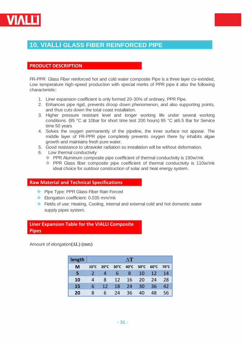
Liner Expansion Table for the VIALLI Composite Pipes
Amount of elongation(∆L) (mm)
length ∆T
M 10°C 20°C 30°C 40°C 50°C 60°C 70°C
5 2 4 6 8 10 12 14 10 4 8 12 16 20 24 28 15 6 12 18 24 30 36 42 20 8 6 24 36 40 48 56
- 32 -
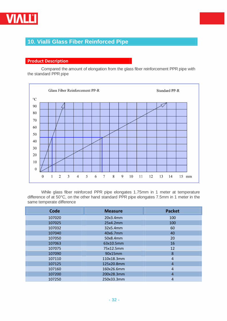
10. Vialli Glass Fiber Reinforced Pipe
Product Description
Compared the amount of elongation from the glass fiber reinforcement PPR pipe with the standard PPR pipe
While glass fiber reinforced PPR pipe elongates 1.75mm in 1 meter at temperature difference of at 50°C, on the other hand standard PPR pipe elongates 7.5mm in 1 meter in the same temperate difference
Code Measure Packet
107020 20x3.4mm 100 107025 25x4.2mm 100 107032 32x5.4mm 60 107040 40x6.7mm 40 107050 50x8.4mm 20 107063 63x10.5mm 16 107075 75x12.5mm 12 107090 90x15mm 8 107110 110x18.3mm 4 107125 125x20.8mm 4 107160 160x26.6mm 4 107200 200x28.3mm 4 107250 250x33.3mm 4
- 33 -
11. Vialli Aluminum Reinforced Pipe
Product Description
VIALLIPN25 (with aluminum Layer) the inside and outside layers are made of PPR.
Tightly bonded with PP-based adhesive to the middle layer of aluminum core, which is well
welded in an overlapping way, such pipe is a kind of perfect combination of metal pipe and
plastic pipe.
Advantages
Greatly reduce liner expansion coefficient, only ¼ of that of PPR, which means the
composite pipes have stable dimensions.
100% Oxygen tightness, suitable for heating system.
Improved resistant to impulse under low temperature, resistant to UV-rays.
Working under Higher temperature and higher pressure for cool and hot water system.
Easily detected when embedded, owing to the metal layer.
Good performance of heat preservation and low heat conduction coefficient of 0.45W/
m.k
Smooth and sanitary, being good selection for drinkable water system.
Advantages
Distribution for cold and hot water.
Pipe for kinds of high temperature and low temperature heating system.
Pipes for heating and cooling settings in solar energy system.
Ductfor drinkable water system.
Industrial transportation for chemical liquids.
Connecting pipe for air conditioners.
Pressure pipe for irrigation system.
- 34 -
12. Fittings insert
Much of the life expectancy of fittings has to do with its resistance to corrosion so we are using several types of Metal Inserts to produce Male & Female VIALLI Fittings as Below
12.1 Stainless Steel Inserts
Vialli Stainless Steel Fittings have low Interior surface friction, remain stable
under extreme temperatures. Vialli Stainless Steel Fittings like the ones link plus installs to be among the most
Durable option available The standard for producing Vialli Stainless Steel PPR Fittings DIN 17440 and
DIN 17441 Life Span for Vialli Stainless Steel PPR fittings under Marin environment 35-50
Years
12.2 Tin Bronze Inserts
The excellent properties of Copper-Tin alloys-Gun Metal- of Vialli Bronze PPR
Fittings All Bronze Inserts with the following Technical Specifications (CuSn5 Zn5Pb5-C),
(CuSn5 Zu5 Pb2-C) Life Span for the Vialli Tin Bronze Fittings under Marin Environment 30-45
years
12.3 Brass with Nickel Platted Inserts
VialliBrassNickel Plated PPR fittings are common used around the world which
refers to good quality and reasonable price. The VialliBrassNickel plated PPR Fittings with the following Technical
Specifications(CuZn39 Pb2) , (CuZn39 Pb3) , (CuZn40 Pb2) The Surface Treatment Nickel Plated as Per DIN 259 and BS 2779 Life Span for Vialli Nickel Plated Fittings 25-35 years
12.4 Natural Brass Insert
Vialli Natural Brass fittings are produced by similar technical specifications of
Brass with Nickel Plated but without making surface treatment. It is less durable option available. Life Span for Vialli Natural Brass PPR Fittings under Marine Environment 15-20
years
- 35 -
13. INSTALLATION RECOMMENDATIONS
Handling the Vialliinstallation system does basically not from the installation scheme for
metallic pipes
Fittings and fixture customary in the trade as well as insulating materials in accordance
with the heating installation prescription may be applied in the traditional manner.
Planning and execution of drinking water systems are carried out in conformity with DIN
Used on mixed systems e.g during repair work is problem free
The exceedingly small number of tools required, simplifies the processing of entire
system.
Owing to the extensive fitting programmed, appropriate molded parts required for each
mode of installations e.g wall installations are available
Coupling with existing Vialli systems can easily be carried out using welding saddles
Installations elements subject to frequent use can be pre-assembled (welded)in the
workshop.
To make sure that our system is installed in a professional manner, the following recommendation should be observed:
Avoid the bubbles inside the piping.
Mount piping upward towards the tapping point.
Install aerators and ventilation device at the upper end of the ascending part of the line,
evacuation at the lower end.
Separate cut-offs should be mounted for ascending phases, apartment piping, pressure
risers, hot water boilers, and garden piping.
For condensations reasons, the hotter water piping should be mounted above the cold
water piping.
Pipe fitting should always be fixe with inserts to avoid sound transmission
Contacts with all structures ought to be avoided for passages through walls and
ceilings to eliminate sound transmission.
Pipe elongation should be taken into account welding at outdoor temperature below
0 C is possible only under specific conditions.
- 36 -
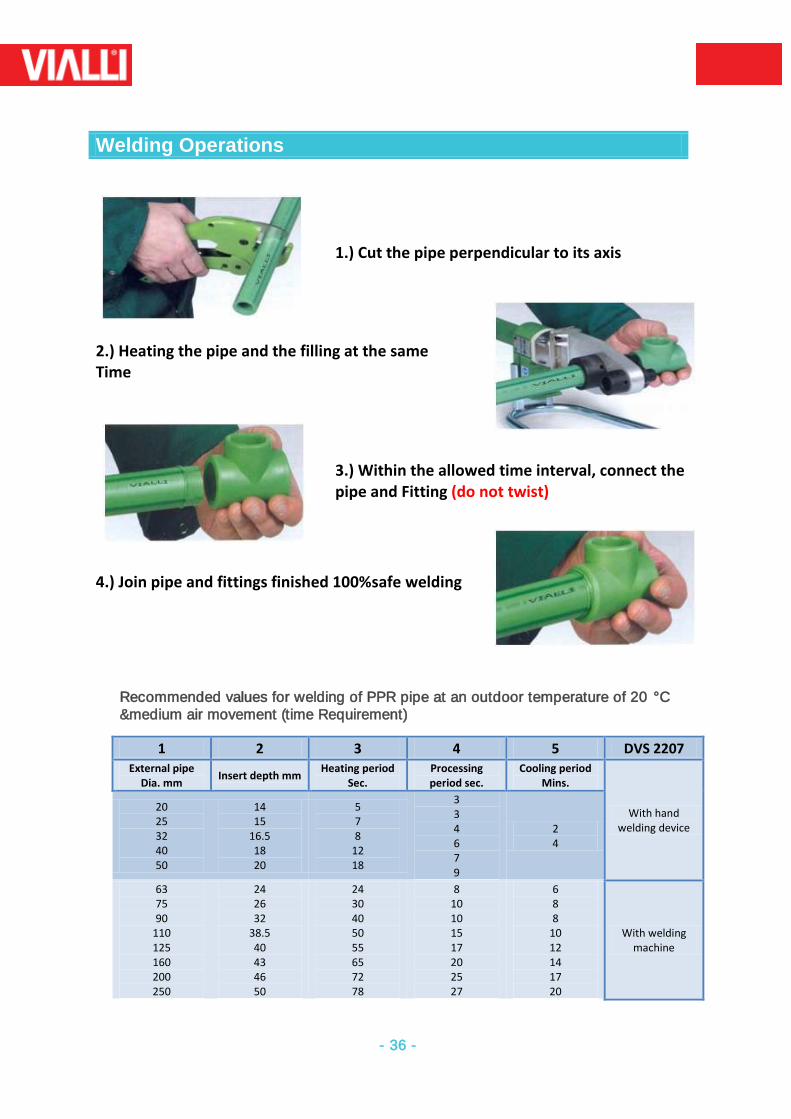
Welding Operations
1.) Cut the pipe perpendicular to its axis
2.) Heating the pipe and the filling at the same Time
3.) Within the allowed time interval, connect the pipe and Fitting (do not twist)
4.) Join pipe and fittings finished 100%safe welding
Recommended values for welding of PPR pipe at an outdoor temperature of 20 °C &medium air movement (time Requirement)
1 2 3 4 5 DVS 2207 External pipe
Dia. mm Insert depth mm
Heating period Sec.
Processing period sec.
Cooling period Mins.
With hand welding device
20 25 32 40 50
14 15
16.5 18 20
5 7 8
12 18
3 3 4 6 7 9
2 4
63 75 90
110 125 160 200 250
24 26 32
38.5 40 43 46 50
24 30 40 50 55 65 72 78
8 10 10 15 17 20 25 27
6 8 8
10 12 14 17 20
With welding machine
- 37 -
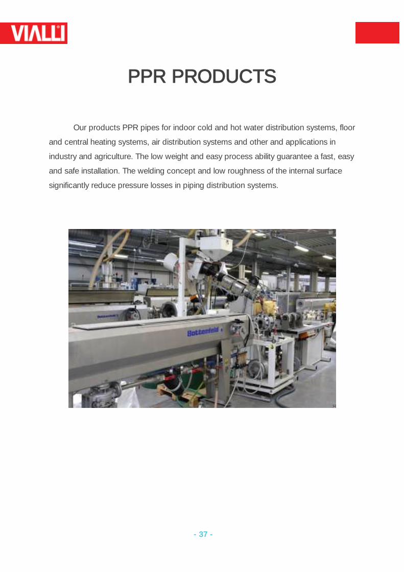
PPR PRODUCTS
Our products PPR pipes for indoor cold and hot water distribution systems, floor
and central heating systems, air distribution systems and other and applications in
industry and agriculture. The low weight and easy process ability guarantee a fast, easy
and safe installation. The welding concept and low roughness of the internal surface
significantly reduce pressure losses in piping distribution systems.
- 38 -
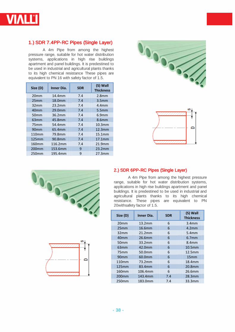
1.) SDR 7.4PP-RC Pipes (Single Layer)
A 4m Pipe from among the highest pressure range, suitable for hot water distribution systems, applications in high rise buildings apartment and panel buildings. It is predestined to be used in industrial and agricultural plants thanks to its high chemical resistance These pipes are equivalent to PN 16 with safety factor of 1.5.
Size (D) Inner Dia. SDR (S) Wall
Thickness
20mm 14.4mm 7.4 2.8mm 25mm 18.0mm 7.4 3.5mm 32mm 23.2mm 7.4 4.4mm 40mm 29.0mm 7.4 5.5mm 50mm 36.2mm 7.4 6.9mm 63mm 45.8mm 7.4 8.6mm 75mm 54.4mm 7.4 10.3mm 90mm 65.4mm 7.4 12.3mm
110mm 79.8mm 7.4 15.1mm 125mm 90.8mm 7.4 17.1mm 160mm 116.2mm 7.4 21.9mm 200mm 153.6mm 9 23.2mm 250mm 195.4mm 9 27.3mm
2.) SDR 6PP-RC Pipes (Single Layer)
A 4m Pipe from among the highest pressure range, suitable for hot water distribution systems, applications in high rise buildings apartment and panel buildings. It is predestined to be used in industrial and agricultural plants thanks to its high chemical resistance. These pipes are equivalent to PN 20withsafety factor of 1.5.
Size (D) Inner Dia. SDR (S) Wall
Thickness
20mm 13.2mm 6 3.4mm 25mm 16.6mm 6 4.2mm 32mm 21.2mm 6 5.4mm 40mm 26.6mm 6 6.7mm 50mm 33.2mm 6 8.4mm 63mm 42.0mm 6 10.5mm 75mm 50.0mm 6 12.5mm 90mm 60.0mm 6 15mm
110mm 73.2mm 6 18.4mm 125mm 83.4mm 6 20.8mm 160mm 106.4mm 6 26.6mm 200mm 143.4mm 7.4 28.3mm 250mm 183.0mm 7.4 33.3mm
- 39 -
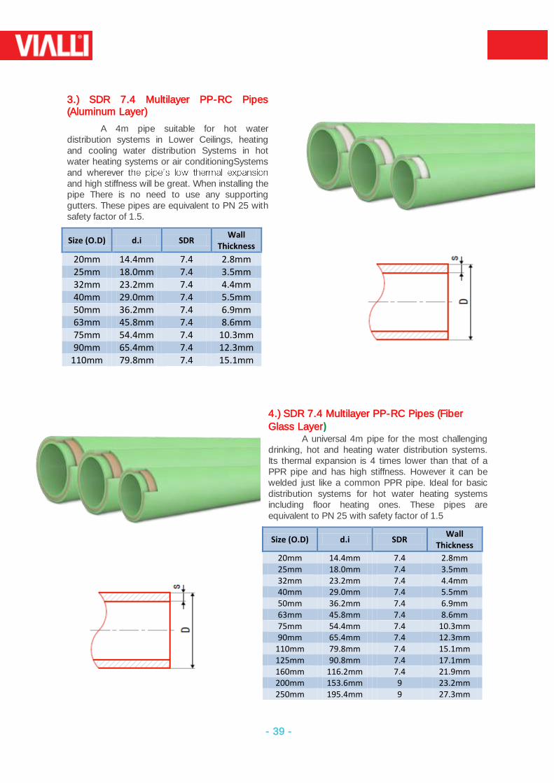
3.) SDR 7.4 Multilayer PP-RC Pipes (Aluminum Layer)
A 4m pipe suitable for hot water distribution systems in Lower Ceilings, heating and cooling water distribution Systems in hot water heating systems or air conditioningSystems and wherever tand high stiffness will be great. When installing the pipe There is no need to use any supporting gutters. These pipes are equivalent to PN 25 with safety factor of 1.5.
Size (O.D) d.i SDR Wall
Thickness
20mm 14.4mm 7.4 2.8mm 25mm 18.0mm 7.4 3.5mm 32mm 23.2mm 7.4 4.4mm 40mm 29.0mm 7.4 5.5mm 50mm 36.2mm 7.4 6.9mm 63mm 45.8mm 7.4 8.6mm 75mm 54.4mm 7.4 10.3mm 90mm 65.4mm 7.4 12.3mm
110mm 79.8mm 7.4 15.1mm
4.) SDR 7.4 Multilayer PP-RC Pipes (Fiber
Glass Layer) A universal 4m pipe for the most challenging
drinking, hot and heating water distribution systems. Its thermal expansion is 4 times lower than that of a PPR pipe and has high stiffness. However it can be welded just like a common PPR pipe. Ideal for basic distribution systems for hot water heating systems including floor heating ones. These pipes are equivalent to PN 25 with safety factor of 1.5
Size (O.D) d.i SDR Wall
Thickness
20mm 14.4mm 7.4 2.8mm 25mm 18.0mm 7.4 3.5mm 32mm 23.2mm 7.4 4.4mm 40mm 29.0mm 7.4 5.5mm 50mm 36.2mm 7.4 6.9mm 63mm 45.8mm 7.4 8.6mm 75mm 54.4mm 7.4 10.3mm 90mm 65.4mm 7.4 12.3mm
110mm 79.8mm 7.4 15.1mm 125mm 90.8mm 7.4 17.1mm 160mm 116.2mm 7.4 21.9mm 200mm 153.6mm 9 23.2mm 250mm 195.4mm 9 27.3mm
- 40 -
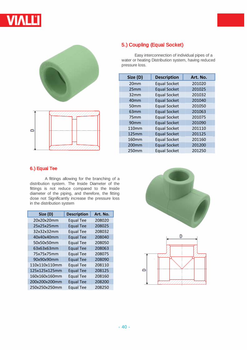
5.) Coupling (Equal Socket)
Easy interconnection of individual pipes of a water or heating Distribution system, having reduced pressure loss.
Size (D) Description Art. No. 20mm Equal Socket 201020 25mm Equal Socket 201025 32mm Equal Socket 201032 40mm Equal Socket 201040 50mm Equal Socket 201050 63mm Equal Socket 201063 75mm Equal Socket 201075 90mm Equal Socket 201090
110mm Equal Socket 201110 125mm Equal Socket 201125 160mm Equal Socket 201160 200mm Equal Socket 201200 250mm Equal Socket 201250
6.) Equal Tee
A fittings allowing for the branching of a distribution system. The Inside Diameter of the fittings is not reduce compared to the Inside diameter of the piping, and therefore, the fitting dose not Significantly increase the pressure loss in the distribution system
Size (D) Description Art. No.
20x20x20mm Equal Tee 208020 25x25x25mm Equal Tee 208025 32x32x32mm Equal Tee 208032 40x40x40mm Equal Tee 208040 50x50x50mm Equal Tee 208050 63x63x63mm Equal Tee 208063 75x75x75mm Equal Tee 208075 90x90x90mm Equal Tee 208090
110x110x110mm Equal Tee 208110 125x125x125mm Equal Tee 208125 160x160x160mm Equal Tee 208160 200x200x200mm Equal Tee 208200 250x250x250mm Equal Tee 208250
- 41 -
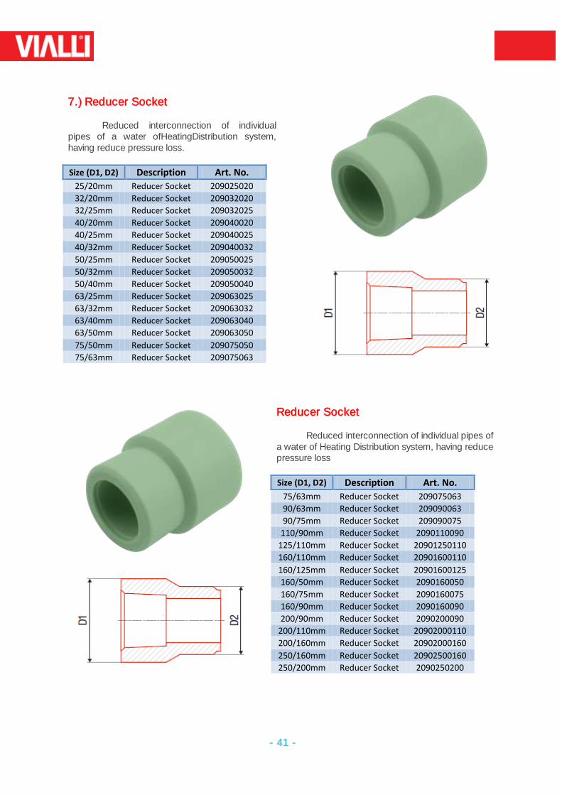
7.) Reducer Socket
Reduced interconnection of individual pipes of a water ofHeatingDistribution system, having reduce pressure loss.
Size (D1, D2) Description Art. No.
25/20mm Reducer Socket 209025020
32/20mm Reducer Socket 209032020
32/25mm Reducer Socket 209032025
40/20mm Reducer Socket 209040020
40/25mm Reducer Socket 209040025
40/32mm Reducer Socket 209040032
50/25mm Reducer Socket 209050025
50/32mm Reducer Socket 209050032
50/40mm Reducer Socket 209050040
63/25mm Reducer Socket 209063025
63/32mm Reducer Socket 209063032
63/40mm Reducer Socket 209063040
63/50mm Reducer Socket 209063050
75/50mm Reducer Socket 209075050
75/63mm Reducer Socket 209075063
Reducer Socket
Reduced interconnection of individual pipes of a water of Heating Distribution system, having reduce pressure loss
Size (D1, D2) Description Art. No.
75/63mm Reducer Socket 209075063
90/63mm Reducer Socket 209090063
90/75mm Reducer Socket 209090075
110/90mm Reducer Socket 2090110090
125/110mm Reducer Socket 20901250110
160/110mm Reducer Socket 20901600110
160/125mm Reducer Socket 20901600125
160/50mm Reducer Socket 2090160050
160/75mm Reducer Socket 2090160075
160/90mm Reducer Socket 2090160090
200/90mm Reducer Socket 2090200090
200/110mm Reducer Socket 20902000110
200/160mm Reducer Socket 20902000160
250/160mm Reducer Socket 20902500160
250/200mm Reducer Socket 2090250200
- 42 -
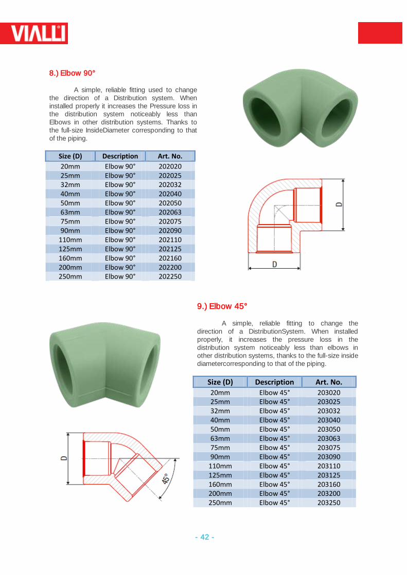
8.) Elbow 90°
A simple, reliable fitting used to change the direction of a Distribution system. When installed properly it increases the Pressure loss in the distribution system noticeably less than Elbows in other distribution systems. Thanks to the full-size InsideDiameter corresponding to that of the piping.
Size (D) Description Art. No.
20mm Elbow 90° 202020 25mm Elbow 90° 202025 32mm Elbow 90° 202032 40mm Elbow 90° 202040 50mm Elbow 90° 202050 63mm Elbow 90° 202063 75mm Elbow 90° 202075 90mm Elbow 90° 202090
110mm Elbow 90° 202110 125mm Elbow 90° 202125 160mm Elbow 90° 202160 200mm Elbow 90° 202200 250mm Elbow 90° 202250
9.) Elbow 45°
A simple, reliable fitting to change the direction of a DistributionSystem. When installed properly, it increases the pressure loss in the distribution system noticeably less than elbows in other distribution systems, thanks to the full-size inside diametercorresponding to that of the piping.
Size (D) Description Art. No.
20mm Elbow 45° 203020 25mm Elbow 45° 203025 32mm Elbow 45° 203032 40mm Elbow 45° 203040 50mm Elbow 45° 203050 63mm Elbow 45° 203063 75mm Elbow 45° 203075 90mm Elbow 45° 203090
110mm Elbow 45° 203110 125mm Elbow 45° 203125 160mm Elbow 45° 203160 200mm Elbow 45° 203200 250mm Elbow 45° 203250
- 43 -
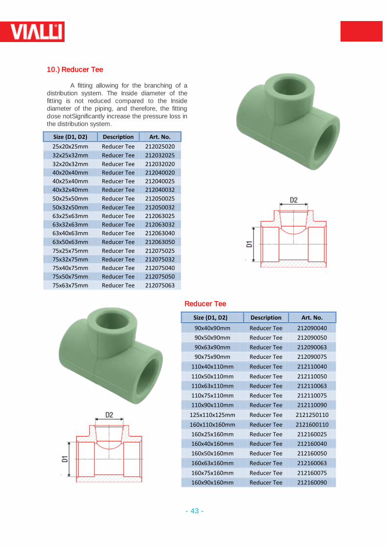
10.) Reducer Tee
A fitting allowing for the branching of a distribution system. The Inside diameter of the fitting is not reduced compared to the Inside diameter of the piping, and therefore, the fitting dose notSignificantly increase the pressure loss in the distribution system.
Size (D1, D2) Description Art. No.
25x20x25mm Reducer Tee 212025020
32x25x32mm Reducer Tee 212032025
32x20x32mm Reducer Tee 212032020
40x20x40mm Reducer Tee 212040020
40x25x40mm Reducer Tee 212040025
40x32x40mm Reducer Tee 212040032
50x25x50mm Reducer Tee 212050025
50x32x50mm Reducer Tee 212050032
63x25x63mm Reducer Tee 212063025
63x32x63mm Reducer Tee 212063032
63x40x63mm Reducer Tee 212063040
63x50x63mm Reducer Tee 212063050
75x25x75mm Reducer Tee 212075025
75x32x75mm Reducer Tee 212075032
75x40x75mm Reducer Tee 212075040
75x50x75mm Reducer Tee 212075050
75x63x75mm Reducer Tee 212075063
Reducer Tee
Size (D1, D2) Description Art. No.
90x40x90mm Reducer Tee 212090040
90x50x90mm Reducer Tee 212090050
90x63x90mm Reducer Tee 212090063
90x75x90mm Reducer Tee 212090075
110x40x110mm Reducer Tee 212110040
110x50x110mm Reducer Tee 212110050
110x63x110mm Reducer Tee 212110063
110x75x110mm Reducer Tee 212110075
110x90x110mm Reducer Tee 212110090
125x110x125mm Reducer Tee 2121250110
160x110x160mm Reducer Tee 2121600110
160x25x160mm Reducer Tee 212160025
160x40x160mm Reducer Tee 212160040
160x50x160mm Reducer Tee 212160050
160x63x160mm Reducer Tee 212160063
160x75x160mm Reducer Tee 212160075
160x90x160mm Reducer Tee 212160090
- 44 -
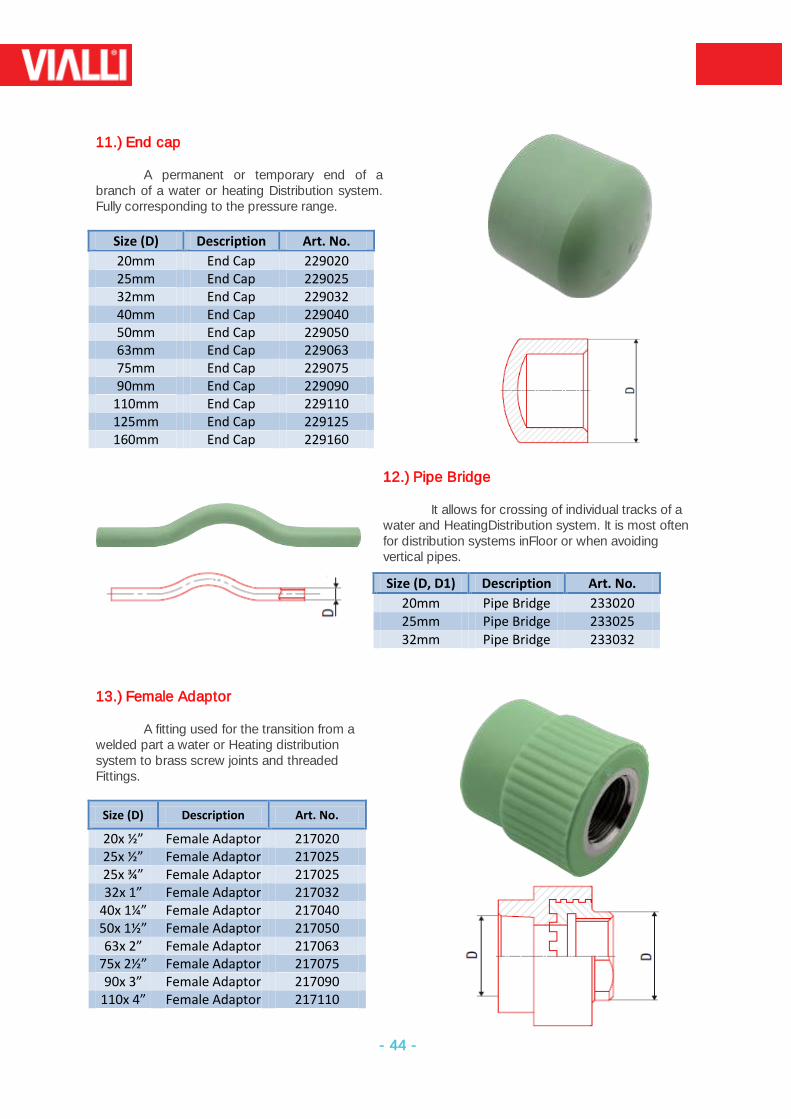
11.) End cap
A permanent or temporary end of a branch of a water or heating Distribution system. Fully corresponding to the pressure range.
Size (D) Description Art. No.
20mm End Cap 229020 25mm End Cap 229025 32mm End Cap 229032 40mm End Cap 229040 50mm End Cap 229050 63mm End Cap 229063 75mm End Cap 229075 90mm End Cap 229090
110mm End Cap 229110 125mm End Cap 229125 160mm End Cap 229160
12.) Pipe Bridge
It allows for crossing of individual tracks of a
water and HeatingDistribution system. It is most often for distribution systems inFloor or when avoiding vertical pipes.
Size (D, D1) Description Art. No.
20mm Pipe Bridge 233020 25mm Pipe Bridge 233025 32mm Pipe Bridge 233032
13.) Female Adaptor
A fitting used for the transition from a
welded part a water or Heating distribution system to brass screw joints and threaded Fittings.
Size (D) Description Art. No.
20x ½” Female Adaptor 217020 25x ½” Female Adaptor 217025 25x ¾” Female Adaptor 217025 32x 1” Female Adaptor 217032
40x 1¼” Female Adaptor 217040 50x 1½” Female Adaptor 217050 63x 2” Female Adaptor 217063
75x 2½” Female Adaptor 217075 90x 3” Female Adaptor 217090
110x 4” Female Adaptor 217110
- 45 -
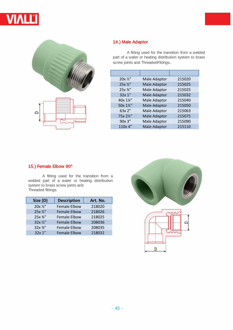
14.) Male Adaptor A fitting used for the transition from a welded
part of a water or heating distribution system to brass
screw joints and ThreadedFittings.
20x ½” Male Adaptor 215020 25x ½” Male Adaptor 215025 25x ¾” Male Adaptor 215025 32x 1” Male Adaptor 215032
40x 1¼” Male Adaptor 215040 50x 1½” Male Adaptor 215050 63x 2” Male Adaptor 215063
75x 2½” Male Adaptor 215075 90x 3” Male Adaptor 215090
110x 4” Male Adaptor 215110
15.) Female Elbow 90°
A fitting used for the transition from a welded part of a water or heating distribution system to brass screw joints and Threaded fittings.
Size (D) Description Art. No.
20x ½” Female Elbow 218020 25x ½” Female Elbow 218026 25x ¾” Female Elbow 218025 32x ½” Female Elbow 208036 32x ¾” Female Elbow 208035 32x 1” Female Elbow 218032
- 46 -
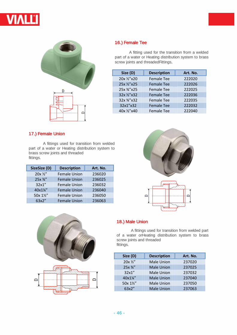
16.) Female Tee
A fitting used for the transition from a welded part of a water or Heating distribution system to brass
screw joints and threadedFittings.
Size (D) Description Art. No.
20x ½”x20 Female Tee 222020 25x ½”x25 Female Tee 222026 25x ¾”x25 Female Tee 222025 32x ½”x32 Female Tee 222036 32x ¾”x32 Female Tee 222035 32x1”x32 Female Tee 222032 40x ½”x40 Female Tee 222040
17.) Female Union
A fittings used for transition from welded part of a water or Heating distribution system to brass screw joints and threaded fittings.
SizeSize (D) Description Art. No.
20x ½” Female Union 236020 25x ¾” Female Union 236025 32x1” Female Union 236032
40x1¼” Female Union 236040 50x 1½” Female Union 236050 63x2” Female Union 236063
18.) Male Union
A fittings used for transition from welded part of a water orHeating distribution system to brass screw joints and threaded fittings.
Size (D) Description Art. No.
20x ½” Male Union 237020 25x ¾” Male Union 237025 32x1” Male Union 237032
40x1¼” Male Union 237040 50x 1½” Male Union 237050
63x2” Male Union 237063
- 47 -
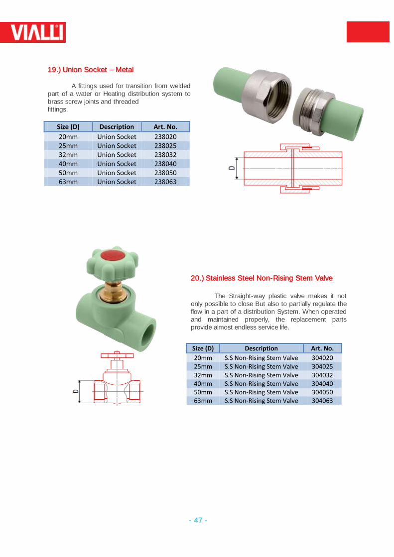
19.) Union Socket Metal
A fittings used for transition from welded part of a water or Heating distribution system to brass screw joints and threaded fittings.
Size (D) Description Art. No.
20mm Union Socket 238020 25mm Union Socket 238025 32mm Union Socket 238032 40mm Union Socket 238040 50mm Union Socket 238050 63mm Union Socket 238063
20.) Stainless Steel Non-Rising Stem Valve The Straight-way plastic valve makes it not
only possible to close But also to partially regulate the flow in a part of a distribution System. When operated and maintained properly, the replacement parts provide almost endless service life.
Size (D) Description Art. No.
20mm S.S Non-Rising Stem Valve 304020 25mm S.S Non-Rising Stem Valve 304025 32mm S.S Non-Rising Stem Valve 304032 40mm S.S Non-Rising Stem Valve 304040 50mm S.S Non-Rising Stem Valve 304050 63mm S.S Non-Rising Stem Valve 304063
- 48 -
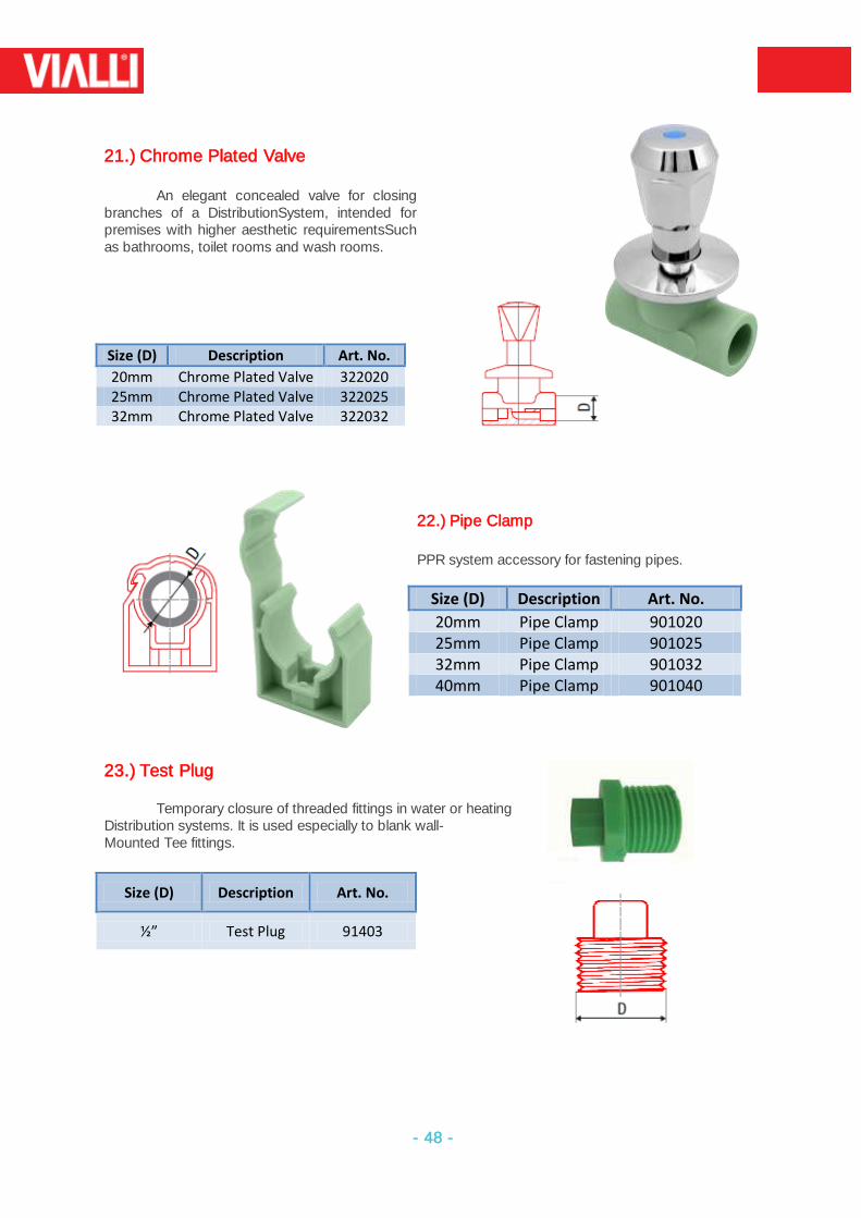
21.) Chrome Plated Valve
An elegant concealed valve for closing
branches of a DistributionSystem, intended for premises with higher aesthetic requirementsSuch as bathrooms, toilet rooms and wash rooms.
Size (D) Description Art. No.
20mm Chrome Plated Valve 322020 25mm Chrome Plated Valve 322025 32mm Chrome Plated Valve 322032
22.) Pipe Clamp PPR system accessory for fastening pipes.
Size (D) Description Art. No.
20mm Pipe Clamp 901020 25mm Pipe Clamp 901025 32mm Pipe Clamp 901032 40mm Pipe Clamp 901040
23.) Test Plug
Temporary closure of threaded fittings in water or heating
Distribution systems. It is used especially to blank wall- Mounted Tee fittings.
Size (D) Description Art. No.
½” Test Plug 91403
- 49 -
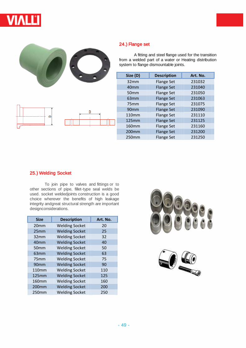
24.) Flange set A fitting and steel flange used for the transition
from a welded part of a water or Heating distribution system to flange dismountable joints.
Size (D) Description Art. No.
32mm Flange Set 231032 40mm Flange Set 231040 50mm Flange Set 231050 63mm Flange Set 231063 75mm Flange Set 231075 90mm Flange Set 231090
110mm Flange Set 231110 125mm Flange Set 231125 160mm Flange Set 231160 200mm Flange Set 231200 250mm Flange Set 231250
25.) Welding Socket
To join pipe to valves and fittings or to
other sections of pipe, fillet-type seal welds be used. socket weldedjoints construction is a good choice wherever the benefits of high leakage integrity andgreat structural strength are important designconsiderations.
Size Description Art. No.
20mm Welding Socket 20 25mm Welding Socket 25 32mm Welding Socket 32 40mm Welding Socket 40 50mm Welding Socket 50 63mm Welding Socket 63 75mm Welding Socket 75 90mm Welding Socket 90
110mm Welding Socket 110 125mm Welding Socket 125 160mm Welding Socket 160 200mm Welding Socket 200 250mm Welding Socket 250
- 50 -
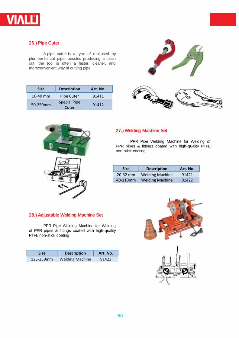
26.) Pipe Cuter
A pipe cutter is a type of tool used by
plumber to cut pipe. besides producing a clean cut, the tool is often a faster, cleaner, and moreconvenient way of cutting pipe
Size Description Art. No.
16-40 mm Pipe Cuter 91411
50-250mm Special Pipe
Cuter 91412
27.) Welding Machine Set
PPR Pipe Welding Machine for Welding of PPR pipes & fittings coated with high-quality PTFE non-stick coating
Size Description Art. No.
20-32 mm Welding Machine 91421 40-110mm Welding Machine 91422
28.) Adjustable Welding Machine Set
PPR Pipe Welding Machine for Welding
of PPR pipes & fittings coated with high-quality PTFE non-stick coating
Size Description Art. No.
125-250mm Welding Machine 91423