factory-made wrought buttwelding fittings
TRANSCRIPT
A N A M E R I C A N N A T I O N A L S T A N D A R D
ASME B16.9-2012(Revision of ASME B16.9-2007)
Factory-Made Wrought Buttwelding Fittings


ASME B16.9-2012(Revision of ASME B16.9-2007)
Factory-MadeWroughtButtweldingFittings
A N A M E R I C A N N A T I O N A L S T A N D A R D
Two Park Avenue • New York, NY • 10016 USA

Date of Issuance: February 28, 2013
The next edition of this Standard is scheduled for publication in 2017.
ASME issues written replies to inquiries concerning interpretations of technical aspects of thisStandard. Periodically certain actions of the ASME B16 Committee may be published as Cases. Casesand interpretations are published on the ASME Web site under the Committee Pages athttp://cstools.asme.org/ as they are issued.
Errata to codes and standards may be posted on the ASME Web site under the Committee Pages toprovide corrections to incorrectly published items, or to correct typographical or grammatical errorsin codes and standards. Such errata shall be used on the date posted.
The Committee Pages can be found at http://cstools.asme.org/. There is an option available toautomatically receive an e-mail notification when errata are posted to a particular code or standard.This option can be found on the appropriate Committee Page after selecting “Errata” in the “PublicationInformation” section.
ASME is the registered trademark of The American Society of Mechanical Engineers.
This code or standard was developed under procedures accredited as meeting the criteria for American NationalStandards. The Standards Committee that approved the code or standard was balanced to assure that individuals fromcompetent and concerned interests have had an opportunity to participate. The proposed code or standard was madeavailable for public review and comment that provides an opportunity for additional public input from industry, academia,regulatory agencies, and the public-at-large.
ASME does not “approve,” “rate,” or “endorse” any item, construction, proprietary device, or activity.ASME does not take any position with respect to the validity of any patent rights asserted in connection with any
items mentioned in this document, and does not undertake to insure anyone utilizing a standard against liability forinfringement of any applicable letters patent, nor assumes any such liability. Users of a code or standard are expresslyadvised that determination of the validity of any such patent rights, and the risk of infringement of such rights, isentirely their own responsibility.
Participation by federal agency representative(s) or person(s) affiliated with industry is not to be interpreted asgovernment or industry endorsement of this code or standard.
ASME accepts responsibility for only those interpretations of this document issued in accordance with the establishedASME procedures and policies, which precludes the issuance of interpretations by individuals.
No part of this document may be reproduced in any form,in an electronic retrieval system or otherwise,
without the prior written permission of the publisher.
The American Society of Mechanical EngineersTwo Park Avenue, New York, NY 10016-5990
Copyright © 2013 byTHE AMERICAN SOCIETY OF MECHANICAL ENGINEERS
All rights reservedPrinted in U.S.A.

CONTENTS
Foreword . . . . . . . . . . . . . . . . . . . . . . . . . . . . . . . . . . . . . . . . . . . . . . . . . . . . . . . . . . . . . . . . . . . . . . . . . . . . . . ivCommittee Roster . . . . . . . . . . . . . . . . . . . . . . . . . . . . . . . . . . . . . . . . . . . . . . . . . . . . . . . . . . . . . . . . . . . . . vCorrespondence With the B16 Committee . . . . . . . . . . . . . . . . . . . . . . . . . . . . . . . . . . . . . . . . . . . . . . viSummary of Changes . . . . . . . . . . . . . . . . . . . . . . . . . . . . . . . . . . . . . . . . . . . . . . . . . . . . . . . . . . . . . . . . . . vii
1 Scope . . . . . . . . . . . . . . . . . . . . . . . . . . . . . . . . . . . . . . . . . . . . . . . . . . . . . . . . . . . . . . . . . . . . . . . . . . . . . 1
2 Pressure Ratings. . . . . . . . . . . . . . . . . . . . . . . . . . . . . . . . . . . . . . . . . . . . . . . . . . . . . . . . . . . . . . . . . . . 1
3 Size. . . . . . . . . . . . . . . . . . . . . . . . . . . . . . . . . . . . . . . . . . . . . . . . . . . . . . . . . . . . . . . . . . . . . . . . . . . . . . . 2
4 Marking . . . . . . . . . . . . . . . . . . . . . . . . . . . . . . . . . . . . . . . . . . . . . . . . . . . . . . . . . . . . . . . . . . . . . . . . . . . 2
5 Material . . . . . . . . . . . . . . . . . . . . . . . . . . . . . . . . . . . . . . . . . . . . . . . . . . . . . . . . . . . . . . . . . . . . . . . . . . . 2
6 Fitting Dimensions . . . . . . . . . . . . . . . . . . . . . . . . . . . . . . . . . . . . . . . . . . . . . . . . . . . . . . . . . . . . . . . . . 3
7 Surface Contours. . . . . . . . . . . . . . . . . . . . . . . . . . . . . . . . . . . . . . . . . . . . . . . . . . . . . . . . . . . . . . . . . . . 3
8 End Preparation. . . . . . . . . . . . . . . . . . . . . . . . . . . . . . . . . . . . . . . . . . . . . . . . . . . . . . . . . . . . . . . . . . . . 3
9 Design Proof Test . . . . . . . . . . . . . . . . . . . . . . . . . . . . . . . . . . . . . . . . . . . . . . . . . . . . . . . . . . . . . . . . . . 3
10 Production Tests . . . . . . . . . . . . . . . . . . . . . . . . . . . . . . . . . . . . . . . . . . . . . . . . . . . . . . . . . . . . . . . . . . . 5
11 Tolerances . . . . . . . . . . . . . . . . . . . . . . . . . . . . . . . . . . . . . . . . . . . . . . . . . . . . . . . . . . . . . . . . . . . . . . . . . 5
Figure1 Maximum Envelope for Welding End Transitions . . . . . . . . . . . . . . . . . . . . . . . . . . . . . . . . . . 6
Tables1 Dimensions of Long Radius Elbows . . . . . . . . . . . . . . . . . . . . . . . . . . . . . . . . . . . . . . . . . . . . . . . 72 Dimensions of Long Radius Reducing Elbows . . . . . . . . . . . . . . . . . . . . . . . . . . . . . . . . . . . . . 83 Dimensions of Long Radius Returns . . . . . . . . . . . . . . . . . . . . . . . . . . . . . . . . . . . . . . . . . . . . . . 94 Dimensions of Short Radius Elbows . . . . . . . . . . . . . . . . . . . . . . . . . . . . . . . . . . . . . . . . . . . . . . . 105 Dimensions of Short Radius 180-deg Returns . . . . . . . . . . . . . . . . . . . . . . . . . . . . . . . . . . . . . . 106 Dimensions of 3D Elbows . . . . . . . . . . . . . . . . . . . . . . . . . . . . . . . . . . . . . . . . . . . . . . . . . . . . . . . . 117 Dimensions of Straight Tees and Crosses . . . . . . . . . . . . . . . . . . . . . . . . . . . . . . . . . . . . . . . . . . 118 Dimensions of Reducing Outlet Tees and Reducing Outlet Crosses . . . . . . . . . . . . . . . . . 129 Dimensions of Lap Joint Stub Ends . . . . . . . . . . . . . . . . . . . . . . . . . . . . . . . . . . . . . . . . . . . . . . . 15
10 Dimensions of Caps . . . . . . . . . . . . . . . . . . . . . . . . . . . . . . . . . . . . . . . . . . . . . . . . . . . . . . . . . . . . . . 1611 Dimensions of Reducers . . . . . . . . . . . . . . . . . . . . . . . . . . . . . . . . . . . . . . . . . . . . . . . . . . . . . . . . . . 1712 Welding Bevels and Root Face . . . . . . . . . . . . . . . . . . . . . . . . . . . . . . . . . . . . . . . . . . . . . . . . . . . . 1913 Tolerances . . . . . . . . . . . . . . . . . . . . . . . . . . . . . . . . . . . . . . . . . . . . . . . . . . . . . . . . . . . . . . . . . . . . . . . . 20
Mandatory AppendicesI Inch Tables . . . . . . . . . . . . . . . . . . . . . . . . . . . . . . . . . . . . . . . . . . . . . . . . . . . . . . . . . . . . . . . . . . . . . . . 23II References . . . . . . . . . . . . . . . . . . . . . . . . . . . . . . . . . . . . . . . . . . . . . . . . . . . . . . . . . . . . . . . . . . . . . . . . 37
Nonmandatory AppendixA Quality System Program . . . . . . . . . . . . . . . . . . . . . . . . . . . . . . . . . . . . . . . . . . . . . . . . . . . . . . . . . . 38
iii
FOREWORD
In 1921, the American Engineering Standards Committee, later the American StandardsAssociation (ASA), organized Sectional Committee B16 to unify and further develop nationalstandards for pipe flanges and fittings (and later, for valves, gaskets, and valve actuators). Cospon-sors of the B16 Committee were The American Society of Mechanical Engineers (ASME), theHeating and Piping Contractors National Association [now the Mechanical ContractorsAssociation of America (MCAA)], and the Manufacturers Standardization Society of the Valveand Fittings Industry (MSS). Cosponsors were later designated as cosecretariat organizations.
Standardization of welding fittings was initiated in 1937 by a subgroup (designated Subgroup 6)of Subcommittee 3. After consideration of several drafts, a standard was approved by theCommittee, cosponsors, and ASA, and published with the designation ASA B16.9-1940.
Revisions were made in 1950 and 1955 to add sizes up to NPS 24 and to complete coverageof fittings in some sizes. These revisions were approved and published as ASA B16.9-1951 andASA B16.9-1958. With the subgroup now designated Subcommittee 6 (later Subcommittee F),further revisions were begun to clarify the intent of the standard, to add angularity tolerances,and to include fittings of different types (long radius reducing elbows and crosses) and smallersizes (NPS 1⁄4 and NPS 1⁄2). This revision was published as ASA B16.9-1964 after ASA approval.
After reorganization of ASA, first as the United States of America Standards Institute (USASI),then as the American National Standards Institute (ANSI), with the Sectional Committee beingredesignated as an American National Standards Committee, another revision increasing the sizerange to NPS 48 and revising the text for clarity was approved and published as ANSI B16.9-1971.
In 1975, Subcommittee F began a major revision to bring the standard up to date with currentpractice and usage. Common fractions were expressed as decimals (but without intending higherprecision) and metric dimensional equivalents were added. Provisions for step-wise change ofradius for NPS 3⁄4 long radius elbows and 180-deg returns were introduced. Following StandardsCommittee, cosecretariat, and ANSI approval, the revision was published as ANSI B16.9-1978.It was updated by a corrective addendum, B16.9a-1981, issued in February 1982.
In 1982, American National Standards Committee B16 was reorganized as an ASME Committeeoperating under procedures accredited by ANSI. In ASME/ANSI B16.9-1986, the text was revisedand inch dimensions were established as the standard.
In 1991, the Subcommittee reviewed the document and made a number of revisions that wereincluded in ASME B16.9-1993. Dimensions for short pattern lap joints were also added.
In ASME B16.9-2001, short radius elbows and returns were added, which included all dimen-sions and tolerances of ASME B16.28-1994. Metric units were provided as an independent butparallel alternative standard to U.S. Customary units, and a Quality System Program appendixwas added.
In 2003, the Subcommittee reviewed the document and made a number of revisions. The scopeof the standard was changed to permit fabricated lap joint stub ends employing circumferentialor intersection welds.
In 2006, the Subcommittee reviewed the document and made a number of additions andrevisions. Segmental elbow requirements were added as were 3D elbow dimensions. Referencedocuments were updated.
In 2012, the Subcommittee reviewed the document and made numerous revisions to the designproof test in section 9 and updated the references in Mandatory Appendix II.
This Standard was approved as an American National Standard on November 16, 2012.
iv
ASME B16 COMMITTEEStandardization of Valves, Flanges, Fittings, and Gaskets
(The following is the roster of the Committee at the time of approval of this Standard.)
STANDARDS COMMITTEE OFFICERS
W. B. Bedesem, ChairG. A. Jolly, Vice Chair
C. E. O’Brien, Secretary
STANDARDS COMMITTEE PERSONNEL
A. Appleton, Alloy Stainless Products Co., Inc.R. W. Barnes, Anric Enterprises, Inc.W. B. Bedesem, ConsultantR. M. Bojarczuk, ExxonMobil Research & Engineering Co.D. F. Buccicone, Elkhart Products Corp.A. M. Cheta, Shell Exploration and Production Co.M. A. Clark, NIBCO, Inc.G. A. Cuccio, Capitol Manufacturing Co.C. E. Davila, Crane EnergyD. R. Frikken, Becht Engineering Co.R. P. Griffiths, U.S. Coast Guard
SUBCOMMITTEE F — STEEL THREADED AND WELDING FITTINGS
G. Cuccio, Chair, Capitol Manufacturing Co.A. Appleton, Vice Chair, Alloy Stainless Products Co., Inc.F. Huang, Secretary, The American Society of Mechanical EngineersW. J. Birkholz, Ezeflow USA, Inc.K. W. Doughty, Shaw Alloy Piping Products, Inc.J. P. Ellenberger, RetiredB. G. Fabian, Pennsylvania Machine Works
v
G. A. Jolly, Vogt Valves/Flowserve Corp.M. Katcher, Haynes InternationalW. N. McLean, B&L EngineeringT. A. McMahon, Emerson Process ManagementM. L. Nayyar, ConsultantC. E. O’Brien, The American Society of Mechanical EngineersW. H. Patrick, The Dow Chemical Co.R. A. Schmidt, CanadoilH. R. Sonderegger, Fluoroseal, Inc.W. M. Stephan, Flexitallic LPF. R. Volgstadt, Volgstadt & Associates, Inc.D. A. Williams, Southern Co. Generation
D. R. Frikken, Becht Engineering Co.D. Hunt, Jr., FastenalG. A. Jolly, Vogt Valves/Flowserve Corp.D. H. Monroe, ConsultantJ. P. Tucker, Flowserve Corp.G. T. Walden, WolsleyM. M. Zaidi, Jacobs Engineering Group, Inc.
CORRESPONDENCE WITH THE B16 COMMITTEE
General. ASME Standards are developed and maintained with the intent to represent theconsensus of concerned interests. As such, users of this Standard may interact with the Committeeby requesting interpretations, proposing revisions, and attending Committee meetings. Corre-spondence should be addressed to:
Secretary, B16 Standards CommitteeThe American Society of Mechanical EngineersTwo Park AvenueNew York, NY 10016-5990
As an alternative, inquiries may be submitted via e-mail to: [email protected] Revisions. Revisions are made periodically to the Standard to incorporate changes
that appear necessary or desirable, as demonstrated by the experience gained from the applicationof the Standard. Approved revisions will be published periodically.
The Committee welcomes proposals for revisions to this Standard. Such proposals should beas specific as possible, citing the paragraph number(s), the proposed wording, and a detaileddescription of the reasons for the proposal, including any pertinent documentation.
Proposing a Case. Cases may be issued for the purpose of providing alternative rules whenjustified, to permit early implementation of an approved revision when the need is urgent, or toprovide rules not covered by existing provisions. Cases are effective immediately uponASME approval and shall be posted on the ASME Committee Web page.
Requests for Cases shall provide a Statement of Need and Background Information. The requestshould identify the Standard, the paragraph, figure or table number(s), and be written as aQuestion and Reply in the same format as existing Cases. Requests for Cases should also indicatethe applicable edition(s) of the Standard to which the proposed Case applies.
Interpretations. Upon request, the B16 Committee will render an interpretation of any require-ment of the Standard. Interpretations can only be rendered in response to a written request sentto the Secretary of the B16 Standards Committee.
The request for interpretation should be clear and unambiguous. It is further recommendedthat the inquirer submit his/her request in the following format:
Subject: Cite the applicable paragraph number(s) and the topic of the inquiry.Edition: Cite the applicable edition of the Standard for which the interpretation is
being requested.Question: Phrase the question as a request for an interpretation of a specific requirement
suitable for general understanding and use, not as a request for an approvalof a proprietary design or situation. The inquirer may also include any plansor drawings, that are necessary to explain the question; however, they shouldnot contain proprietary names or information.
Requests that are not in this format may be rewritten in the appropriate format by the Committeeprior to being answered, which may inadvertently change the intent of the original request.
ASME procedures provide for reconsideration of any interpretation when or if additionalinformation that might affect an interpretation is available. Further, persons aggrieved by aninterpretation may appeal to the cognizant ASME Committee or Subcommittee. ASME does not“approve,” “certify,” “rate,” or “endorse” any item, construction, proprietary device, or activity.
Attending Committee Meetings. The B16 Standards Committee regularly holds meetings thatare open to the public. Persons wishing to attend any meeting should contact the Secretary ofthe B16 Standards Committee.
vi
ASME B16.9-2012SUMMARY OF CHANGES
Following approval by the B16 Committee and ASME, and after public review, ASME B16.9-2012was approved by the American National Standards Institute on November 16, 2012.
ASME B16.9-2012 consists of editorial changes, revisions, and corrections identified by a marginnote, (12), placed next to the affected area.
Page Location Change
3 9.1 First paragraph revised
9.2.1 First sentence revised
9.2.2 First paragraph revised
4, 5 9.3 Revised
9.4.3 Revised
9.5 Added
9.6 Added
37 Mandatory Appendix II Updated
vii

INTENTIONALLY LEFT BLANK
viii
ASME B16.9-2012
FACTORY-MADE WROUGHT BUTTWELDING FITTINGS
1 SCOPE
1.1 General
This Standard covers overall dimensions, tolerances,ratings, testing, and markings for factory-made wroughtbuttwelding fittings in sizes NPS 1⁄2 through NPS 48(DN 15 through DN 1200).
1.2 Special Fittings
Fittings may be made to special dimensions, sizes,shapes, and tolerances by agreement between the manu-facturer and the purchaser.
1.3 Fabricated Fittings
Fabricated laterals and other fittings employing cir-cumferential or intersection welds are considered pipefabrication and are not within the scope of this Standard.
Fabricated lap joint stub ends are exempt from theabove restrictions, provided they meet all the require-ments of the applicable ASTM material specificationlisted in section 5.
1.4 Relevant Units
This Standard states values in both SI (Metric) andU.S. Customary units. These systems of units are to beregarded separately as standard. Within the text, theU.S. Customary units are shown in parentheses or inseparate tables that appear in Mandatory Appendix I.The values stated in each system are not exact equiva-lents; therefore, it is required that each system of unitsbe used independently of the other. Combining valuesfrom the two systems constitutes nonconformance withthe Standard.
The designation for size is NPS for both metric- andcustomary-dimensioned fittings. Fitting pressure ratingis associated with the connecting wall thickness of pipeof equivalent size and material.
1.5 References
1.5.1 Referenced Standards. Standards and specifi-cations adopted by reference in this Standard are shownin Mandatory Appendix II. It is not considered practicalto identify the specific edition of each standard andspecification in the individual references. Instead, thespecific edition reference is identified in MandatoryAppendix II. A product made in conformance with aprior edition of referenced standards and in all other
1
respects conforming to this Standard will be consideredto be in conformance.
1.5.2 Codes and Regulations. A fitting used underthe jurisdiction of the ASME Boiler and Pressure VesselCode, the ASME Code for Pressure Piping, or a govern-mental regulation is subject to any limitation of that codeor regulation. This includes any maximum temperaturelimitation or rule governing the use of a material at lowtemperature.
1.6 Service Conditions
Criteria for selection of fitting types and materialssuitable for particular fluid service are not within thescope of this Standard.
1.7 Welding
Installation welding requirements are outside thescope of this Standard.
1.8 Quality Systems
Nonmandatory requirements relating to the fittingmanufacturer’s Quality System Program are describedin Nonmandatory Appendix A.
1.9 Convention
For determining conformance with this Standard, theconvention for fixing significant digits where limits(maximum and minimum values) are specified, shall beas defined in ASTM E29. This requires that an observedor calculated value be rounded off to the nearest unitin the last right-hand digit used for expressing the limit.Decimal values and tolerances do not imply a particularmethod of measurement.
1.10 Pressure Rating Designation
Class followed by a dimensionless number is thedesignation for pressure–temperature ratings. Standard-ized designations for flanges per ASME B16.5 referencedin this Standard are Classes 150, 300, 600, 900, 1500,and 2500.
2 PRESSURE RATINGS
2.1 Basis of Ratings
The allowable pressure ratings for fittingsdesigned in accordance with this Standard may be calcu-lated as for straight seamless pipe of equivalent material
ASME B16.9-2012
(as shown by comparison of composition and mechani-cal properties in the respective material specifications)in accordance with the rules established in the applicablesections of ASME B31, Code for Pressure Piping. Forthe calculation, applicable data for the pipe size, wallthickness, and material that are equivalent to that ofthe fitting shall be used. Pipe size, wall thickness (orschedule number), and material identity on the fittingsare in lieu of pressure rating markings.
2.2 Design of Fittings
The design of fittings shall be established by mathe-matical analyses (e.g., ASME B16.49 for bends) containedin nationally recognized pressure vessel or piping codes,or at the manufacturer’s option by proof testing in accor-dance with section 9 of this Standard. In order to meetdesign or manufacturing requirements, it is expectedthat some portion of formed fittings may have to bethicker than the pipe wall with which the fitting isintended to be used. The mathematical analyses, if used,may take into account such thicker sections. Records ofmathematical analysis and/or successful proof test datashall be available at the manufacturer ’s facility forinspection by the purchaser.
3 SIZE
NPS, followed by a dimensionless number, is the des-ignation for nominal fitting size. NPS is related to thereference nominal diameter, DN, used in internationalstandards. The relationship is, typically, as follows:
DN NPS
15 1⁄220 3⁄425 132 11⁄4
40 11⁄250 265 21⁄280 3
100 4
NOTE: For NPS > 4, the equivalence is DN p 25 � NPS.
4 MARKING
4.1 Standard Marking
Each fitting shall be permanently marked to show thefollowing:
(a) manufacturer’s name or trademark(b) material identification, either the ASTM or ASME
grade designation
2
(c) schedule number1 or nominal wall thickness inmm
(d) size — the nominal pipe size (NPS) identificationnumber related to the end connections shall be used
(e) compliance — see para. 4.4 for standard and spe-cial fitting marking
A manufacturer may supplement these mandatorymarkings with others, including a DN size designation,but confusion with the required marking shall beavoided.
4.2 Exceptions
Where the size of the fitting does not permit completemarking, the identification marks may be omitted inreverse of the order presented in para. 4.1.
4.3 Depth of Stamping
Where steel stamps are used, care shall be taken sothat the marking is not deep enough or sharp enoughto cause cracks or to reduce the wall thickness of thefitting below the minimum allowed.
4.4 Compliance
4.4.1 Standard Fittings. That the fitting was manu-factured in conformance with this Standard, includingall dimensional requirements, is certified by a prefix“WP” in the material grade designation marking.
4.4.2 Special Fittings. That the fitting was manufac-tured in conformance with this Standard, except thatdimensional requirements are as agreed between thepurchaser and the manufacturer, is certified by a supple-mentary suffix to the material grade designation mark-ing as follows:
(a) “S58” of ASTM A960 applies for fittings in accor-dance with ASTM A234, A403, and A420.
(b) “S8” applies for fittings in accordance withASTM A815.
(c) “SPLD” applies for fittings in accordance withASTM B361, B363, and B366.
5 MATERIAL
Wrought fittings covered by this Standard shall be inaccordance with ASTM A234, A403, A420, A815, B361,B363, B366, or the corresponding standard listed inSection II of the ASME Boiler and Pressure Vessel Code.The term wrought denotes fittings made of pipe, tubing,plate, or forgings. Fittings made from block forgingsmay only be supplied subject to agreement between themanufacturer and purchaser. Such fittings need not meetthe requirements of section 7.
1 Schedule number is a dimensionless number that is widely usedas a convenient designation for use in ordering pipe and fittings.It is normally associated with a group of standardized pipe wallthickness. Refer to ASME B36.10M and ASME B36.19M for com-plete details on pipe schedule numbers.
ASME B16.9-2012
6 FITTING DIMENSIONS
6.1 General
This Standard provides for a fixed position for thewelding ends with reference to either the centerline ofthe fittings or the overall dimensions. Dimensionalrequirements for these fittings are to be found in Tables 1through 11 and Tables I-1 through I-11 of MandatoryAppendix I.
6.2 Special Dimensions
6.2.1 Fatigue Loading. For applications wherefatigue loading is a concern, required minimum dimen-sions shall be furnished by the purchaser.
6.2.2 Bore Diameter. Bore diameters away from theends are not specified. If special flow path requirementsare needed, the bore dimensions shall be specified bythe purchaser.
6.2.3 Stub Ends. Service conditions and joint con-struction often dictate stub end length requirements.Therefore, the purchaser must specify long or short pat-tern fitting when ordering. [See General Note (c) inTables 9 and I-9.]
6.2.4 Segmental Elbows. Factory-made segmentsof short radius, long radius, and 3D radius elbows maybe made to meet customer angle requirements. With theexception of the B dimension, factory-made segmentsof elbows shall meet all other requirements of thisStandard. The B dimension for segmented elbows canbe calculated as follows:
For segments of 90-deg elbows
Bs p A � tan(�/2)
whereA p dimension A for appropriate 90-deg elbow
being segmented from(a) Table 1/Table I-1 for long radius elbow,
mm (in.)(b) Table 4/Table I-4 for short radius elbow,
mm (in.)(c) Table 6/Table I-6 for 3D elbow, mm (in.)
Bs p center-to-end dimension for segmented elbow� p angle of segmented elbow — 30 deg, 60 deg,
75 deg, etc.
When special elbows are intended for field seg-menting, the outside or inside diameter tolerance shallbe furnished throughout the fitting by agreementbetween the manufacturer and the purchaser. Any mis-match on the outside or inside diameter needs to becorrected in the field by grinding, back-welding, orbridging of weld to meet the applicable piping coderequirements. Although the elbow intended for field-segmenting must meet the requirements of this
3
Standard, once the field-segmented elbow is cut, it isnot a B16.9 product.
7 SURFACE CONTOURS
Where adjacent openings in fittings are not in parallelplanes, they shall be joined by a circular arc or radiuson the external surfaces. The arc or radius may be termi-nated in tangents. Except as provided for block forgings(see section 5), the projected profile of external surfacesof fittings shall not have sharp intersections (corners)and/or collapsed arcs.
8 END PREPARATION
Unless otherwise specified, the details of the weldingend preparation shall be in accordance with Table 12.Transitions from the welding bevel to the outside surfaceof the fitting and from the root face to the inside surfaceof the fitting lying within the maximum envelope shownin Fig. 1 are at the manufacturer’s option, except ascovered in Note (5) of Fig. 1 or unless otherwise specifi-cally ordered.
9 DESIGN PROOF TEST
9.1 Required Tests
Proof tests shall be made as set forth in this Standardwhen the manufacturer chooses proof testing to qualifythe fitting design. The proof test shall be based on thecomputed burst pressure of the fitting and its connectingpiping as defined in para. 9.3. A factory-made seg-mented elbow (see para. 6.2.4) that has a proof test ona geometrically similar 90-deg elbow need not be testedseparately.
Lap joint stub ends are exempt from proof testingbecause they are used in a flange assembly, which willhave different ratings depending on service application.
9.2 Test Assembly
9.2.1 Representative Components. Fittings thathave the same basic design configuration and methodof manufacture shall be selected from production fortesting and shall be identified as to material, grade, andlot, including heat treatment. They shall be inspectedfor dimensional compliance to this Standard.
9.2.2 Other Components. Straight seamless orwelded pipe whose calculated bursting strength is atleast as great as the proof test pressure as calculated inpara. 9.3 shall be welded to each end of the fitting tobe tested. Pipe sections may have the nominal wallgreater than the thickness indicated by the fitting mark-ings. That greater thickness shall not exceed 1.5 timesthe fitting markings wall. Any internal misalignmentgreater than 1.5 mm (0.06 in.) shall be reduced by taperboring at a slope not over 1:3. Any other unequal wall
(12)
(12)
(12)

(12)
ASME B16.9-2012
welding preparation shall be in accordance withASME B16.25. Length of pipe sections for closures shallbe as follows:
(a) Minimum length of pipe shall be one pipe O.D.for NPS 14 (DN 350) and smaller.
(b) Minimum length of pipe shall be one-half pipeO.D. for NPS greater than 14 (DN 350).
9.3 Test Procedure
The test fluid shall be water or other liquid. Hydro-static pressure shall be applied to the assembly.
At least three specimen tests for each fitting, joint size,or configuration are recommended. The testing factor,f, based on the number of specimen tests performed inthe table below is used in the computed test equations.
Number of Testing Factor,Tests f
1 1.102 1.053 1.00
NOTE: Tests of geometrically identical fittings that meet therequirements specified in para. 9.4 may be combined to establishthe test factor applied to a set of fittings.
The test shall be taken to rupture or held at or abovethe computed minimum proof pressure for a period ofat least 3 min. The test is successful if for each of thetests, the fitting withstands without rupture a proof testpressure at least equal to the computed minimum.
P p2StD
f
whereD p specified outside diameter of pipe
f p testing factor from in-text table listed inpara. 9.3
P p computed minimum proof test pressure forfitting
S p actual tensile strength of the test fitting, deter-mined on a specimen representative of the testfitting, which shall meet the tensile strengthrequirements of the applicable material ofsection 5
t p nominal pipe wall thickness of the pipe thatthe fitting marking identifies
NOTE: Any dimensionally consistent system of units may beused.
9.4 Applicability of Test Results
It is not necessary to conduct an individual test offittings with all combinations of sizes, wall thicknesses,and materials. A successful proof test on one representa-tive fitting may represent others to the extent describedin paras. 9.4.1, 9.4.2, and 9.4.3.
4
9.4.1 Size Range. One test fitting may be used toqualify similarly proportioned fittings with a size rangefrom one-half to twice that for the tested fitting. Thetest of a nonreducing fitting qualifies reducing fittings ofthe same pattern. The test of a reducing fitting qualifiesreductions to smaller sizes.
9.4.2 Thickness Range. One test fitting may be usedto qualify similarly proportioned fittings with t⁄D rangesfrom one-half to three times that for the tested fitting.
9.4.3 Material Grades. The pressure retainingcapacity of a geometrically identical fitting made of vari-ous grades of steel as listed in section 5 will be directlyproportional to the tensile properties of the materials,provided the yield-to-tensile ratio as specified in theapplicable specification of that material is 0.84 or less.Therefore, it is necessary to test only a single materialin a representative fitting to prove the design of thefitting.
9.5 Maintenance of Results
The manufacturer shall have a quality control (QC)program that verifies the manufacturing process usedand ensures that the resulting geometry of the fittingsor joints manufactured reasonably conforms to thegeometries tested. The QC program shall control themanufacturing drawings and maintain the QC recordsshowing conformance to these drawings.
Tests made in accordance with and at the time ofprevious editions of this test are not intended to benullified by the changes made in this edition’s test proce-dure and requirement.
Whenever a significant change is made in the geome-try or method of manufacture, the manufacturer shalleither retest the new production or show by analysisthat the change would not affect the results of prior tests.
9.6 Proof Test Report
A report of the testing for each joint configurationshall be prepared and shall include
(a) description of the test, including the number oftests and f factor used to establish the target proof test
(b) instrumentation and methods of calibrations used(c) material test reports for the assembly’s materials(d) actual final pressures for each test(e) length of time from test initiation to the time of
burst, or the hold time at or above the computed targetpressure
(f) calculations performed(g) location of rupture, if any, including a sketch(h) certification by a registered Professional Engineer
experienced in pressure component design or a licensedAuthorized Inspector
(12)
(12)
(12)
ASME B16.9-2012
The test report shall be made available at the manufac-turer’s facility for inspection by the purchaser or regula-tory authority.
10 PRODUCTION TESTS
Hydrostatic testing of wrought fittings is not requiredby this Standard. All fittings shall be capable of with-standing, without leakage or impairment of serviceabil-ity, a hydrostatic test pressure required by the applicablepiping code for seamless pipe of material equivalent to
5
the fitting material, and of the size and wall thicknessthe fitting marking identifies.
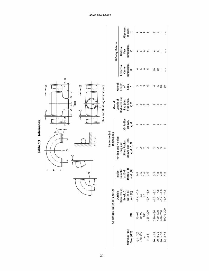
11 TOLERANCES
Tolerances for fittings are shown in Tables 13 and I-12,and apply to the nominal dimensions given in Tables 1through 11 and Tables I-1 through I-11. Where given inthe tables, the minimum and maximum dimensions arebased on these tolerances. The listings with decimals donot imply precision measurement, such as use of vernier,micrometer, electronic readout equipment, etc.
ASME B16.9-2012
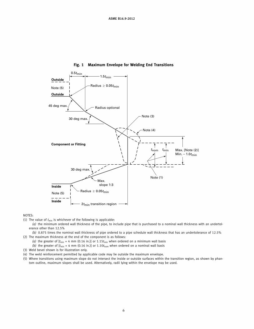
Fig. 1 Maximum Envelope for Welding End Transitions
2tmin transition region
Radius
Max. slope 1:3
Max. [Note (2)]Min. – 1.0tmin
0.5tmin1.5tmin
Note (4)
Note (5)
Note (3)
Note (1)
30 deg max.
30 deg max.
45 deg max.
0.05tmin
Radius optional
Radius 0.05tmin
tnom tmin
Inside
Inside
Outside
Outside
Component or Fitting
Note (5)
NOTES:(1) The value of tmin is whichever of the following is applicable:
(a) the minimum ordered wall thickness of the pipe, to include pipe that is purchased to a nominal wall thickness with an undertol-erance other than 12.5%
(b) 0.875 times the nominal wall thickness of pipe ordered to a pipe schedule wall thickness that has an undertolerance of 12.5%(2) The maximum thickness at the end of the component is as follows:
(a) the greater of [tmin + 4 mm (0.16 in.)] or 1.15tmin when ordered on a minimum wall basis(b) the greater of [tmin + 4 mm (0.16 in.)] or 1.10tnom when ordered on a nominal wall basis
(3) Weld bevel shown is for illustration only.(4) The weld reinforcement permitted by applicable code may lie outside the maximum envelope.(5) Where transitions using maximum slope do not intersect the inside or outside surfaces within the transition region, as shown by phan-
tom outline, maximum slopes shall be used. Alternatively, radii lying within the envelope may be used.
6

ASME B16.9-2012
Table 1 Dimensions of Long Radius ElbowsA
AB
B
Center-to-EndNominalPipe Outside 90-deg 45-degSize Diameter Elbows, Elbows,
(NPS) at Bevel A B
1⁄2 21.3 38 163⁄4 26.7 38 191 33.4 38 22
11⁄4 42.2 48 2511⁄2 48.3 57 29
2 60.3 76 3521⁄2 73.0 95 44
3 88.9 114 5131⁄2 101.6 133 57
4 114.3 152 64
5 141.3 190 796 168.3 229 958 219.1 305 127
10 273.0 381 15912 323.8 457 190
14 355.6 533 22216 406.4 610 25418 457.0 686 28620 508.0 762 31822 559.0 838 343
24 610.0 914 38126 660.0 991 40628 711.0 1 067 43830 762.0 1 143 47032 813.0 1 219 502
34 864.0 1 295 53336 914.0 1 372 56538 965.0 1 448 60040 1 016.0 1 524 63242 1 067.0 1 600 660
44 1 118.0 1 676 69546 1 168.0 1 753 72748 1 219.0 1 829 759
GENERAL NOTE: All dimensions are in millimeters.
7

ASME B16.9-2012
Table 2 Dimensions of Long Radius Reducing ElbowsA
A
Nominal NominalOutside Diameter Outside DiameterPipe Center- Pipe Center-
at Bevel at BevelSize to-End, Size to-End,(NPS) Large End Small End A (NPS) Large End Small End A
2 � 11⁄2 60.3 48.3 76 10 � 8 273.0 219.1 3812 � 11⁄4 60.3 42.2 76 10 � 6 273.0 168.3 381
2 � 1 60.3 33.4 76 10 � 5 273.0 141.3 381
21⁄2 � 2 73.0 60.3 95 12 � 10 323.8 273.0 45721⁄2 � 11⁄2 73.0 48.3 95 12 � 8 323.8 219.1 45721⁄2 � 11⁄4 73.0 42.2 95 12 � 6 323.8 168.3 457
3 � 21⁄2 88.9 73.0 114 14 � 12 355.6 323.8 5333 � 2 88.9 60.3 114 14 � 10 355.6 273.0 533
3 � 11⁄2 88.9 48.3 114 14 � 8 355.6 219.1 533
31⁄2 � 3 101.6 88.9 133 16 � 14 406.4 355.6 61031⁄2 � 21⁄2 101.6 73.0 133 16 � 12 406.4 323.8 610
31⁄2 � 2 101.6 60.3 133 16 � 10 406.4 273.0 610
4 � 31⁄2 114.3 101.6 152 18 � 16 457.0 406.4 6864 � 3 114.3 88.9 152 18 � 14 457.0 355.6 686
4 � 21⁄2 114.3 73.0 152 18 � 12 457.0 323.8 6864 � 2 114.3 60.3 152 18 � 10 457.0 273.0 686
5 � 4 141.3 114.3 190 20 � 18 508.0 457.0 7625 � 31⁄2 141.3 101.6 190 20 � 16 508.0 406.4 762
5 � 3 141.3 88.9 190 20 � 14 508.0 355.6 7625 � 21⁄2 141.3 73.0 190 20 � 12 508.0 323.8 762
20 � 10 508.0 273.0 7626 � 5 168.3 141.3 2296 � 4 168.3 114.3 229 24 � 22 610.0 559.0 914
6 � 31⁄2 168.3 101.6 229 24 � 20 610.0 508.0 9146 � 3 168.3 88.9 229 24 � 18 610.0 457.0 914
24 � 16 610.0 406.4 9148 � 6 219.1 168.3 305 24 � 14 610.0 355.6 9148 � 5 219.1 141.3 305 24 � 12 610.0 323.8 9148 � 4 219.1 114.3 305 . . . . . . . . . . . .
GENERAL NOTE: All dimensions are in millimeters.
8
ASME B16.9-2012
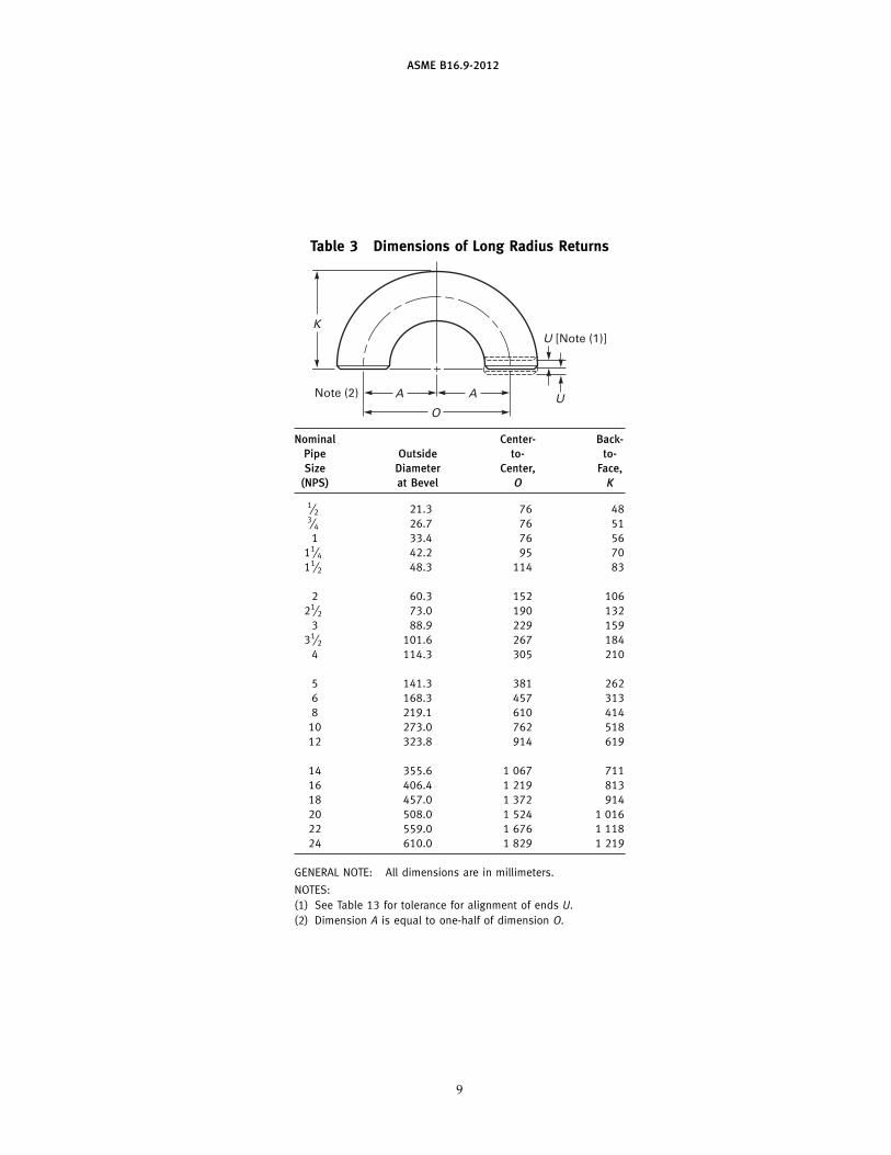
Table 3 Dimensions of Long Radius Returns
O
A A U
U [Note (1)]
Note (2)
K
Nominal Center- Back-Pipe Outside to- to-Size Diameter Center, Face,
(NPS) at Bevel O K
1⁄2 21.3 76 483⁄4 26.7 76 511 33.4 76 56
11⁄4 42.2 95 7011⁄2 48.3 114 83
2 60.3 152 10621⁄2 73.0 190 132
3 88.9 229 15931⁄2 101.6 267 184
4 114.3 305 210
5 141.3 381 2626 168.3 457 3138 219.1 610 414
10 273.0 762 51812 323.8 914 619
14 355.6 1 067 71116 406.4 1 219 81318 457.0 1 372 91420 508.0 1 524 1 01622 559.0 1 676 1 11824 610.0 1 829 1 219
GENERAL NOTE: All dimensions are in millimeters.
NOTES:(1) See Table 13 for tolerance for alignment of ends U.(2) Dimension A is equal to one-half of dimension O.
9
ASME B16.9-2012
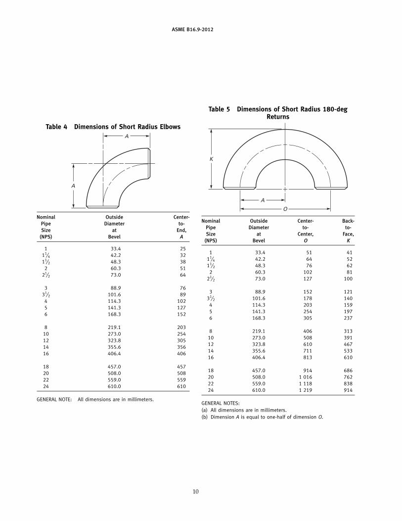
Table 4 Dimensions of Short Radius ElbowsA
A
Nominal Outside Center-Pipe Diameter to-Size at End,
(NPS) Bevel A
1 33.4 2511⁄4 42.2 3211⁄2 48.3 38
2 60.3 5121⁄2 73.0 64
3 88.9 7631⁄2 101.6 89
4 114.3 1025 141.3 1276 168.3 152
8 219.1 20310 273.0 25412 323.8 30514 355.6 35616 406.4 406
18 457.0 45720 508.0 50822 559.0 55924 610.0 610
GENERAL NOTE: All dimensions are in millimeters.
10
Table 5 Dimensions of Short Radius 180-degReturns
A
O
K
Nominal Outside Center- Back-Pipe Diameter to- to-Size at Center, Face,
(NPS) Bevel O K
1 33.4 51 4111⁄4 42.2 64 5211⁄2 48.3 76 62
2 60.3 102 8121⁄2 73.0 127 100
3 88.9 152 12131⁄2 101.6 178 140
4 114.3 203 1595 141.3 254 1976 168.3 305 237
8 219.1 406 31310 273.0 508 39112 323.8 610 46714 355.6 711 53316 406.4 813 610
18 457.0 914 68620 508.0 1 016 76222 559.0 1 118 83824 610.0 1 219 914
GENERAL NOTES:(a) All dimensions are in millimeters.(b) Dimension A is equal to one-half of dimension O.

ASME B16.9-2012
Table 6 Dimensions of 3D ElbowsA
AB
B
Center-to-EndNominalPipe Outside 90-deg 45-degSize Diameter Elbows, Elbows,
(NPS) at Bevel A B
3⁄4 26.7 57 241 33.4 76 31
11⁄4 42.2 95 3911⁄2 48.3 114 47
2 60.3 152 6321⁄2 73.0 190 79
3 88.9 229 9531⁄2 101.6 267 111
4 114.3 305 127
5 141.3 381 1576 168.3 457 1898 219.1 610 252
10 273.0 762 31612 323.8 914 378
14 355.6 1 067 44116 406.4 1 219 50518 457.0 1 372 56820 508.0 1 524 63222 559.0 1 676 694
24 610.0 1 829 75726 660.0 1 981 82128 711.0 2 134 88330 762.0 2 286 96432 813.0 2 438 1 010
34 864.0 2 591 1 07336 914.0 2 743 1 13538 965.0 2 896 1 20040 1 016.0 3 048 1 26442 1 067.0 3 200 1 326
44 1 118.0 3 353 1 38946 1 168.0 3 505 1 45348 1 219.0 3 658 1 516
GENERAL NOTE: All dimensions are in millimeters.
11
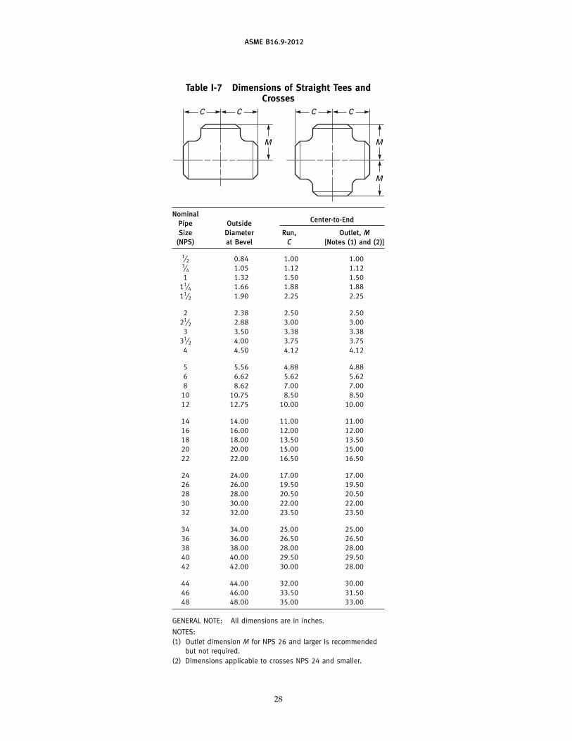
Table 7 Dimensions of Straight Tees and CrossesCC C C
M
MM
Nominal Center-to-EndPipe OutsideSize Diameter Run, Outlet, M
(NPS) at Bevel C [Notes (1) and (2)]
1⁄2 21.3 25 253⁄4 26.7 29 291 33.4 38 38
11⁄4 42.2 48 4811⁄2 48.3 57 57
2 60.3 64 6421⁄2 73.0 76 76
3 88.9 86 8631⁄2 101.6 95 95
4 114.3 105 105
5 141.3 124 1246 168.3 143 1438 219.1 178 178
10 273.0 216 21612 323.8 254 254
14 355.6 279 27916 406.4 305 30518 457.0 343 34320 508.0 381 38122 559.0 419 419
24 610.0 432 43226 660.0 495 49528 711.0 521 52130 762.0 559 55932 813.0 597 597
34 864.0 635 63536 914.0 673 67338 965.0 711 71140 1 016.0 749 74942 1 067.0 762 711
44 1 118.0 813 76246 1 168.0 851 80048 1 219.0 889 838
GENERAL NOTE: All dimensions are in millimeters.
NOTES:(1) Outlet dimension M for NPS 26 and larger is recommended
but not required.(2) Dimensions applicable to crosses NPS 24 and smaller.

ASME B16.9-2012
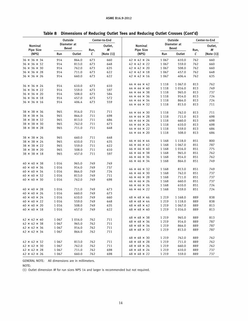
Table 8 Dimensions of Reducing Outlet Tees and Reducing Outlet Crosses
C C
M
CC
M
M
Outside Center-to-End Outside Center-to-EndDiameter at Diameter atNominal Outlet, Nominal Outlet,
Bevel BevelPipe Size Run, M Pipe Size Run, M(NPS) Run Outlet C [Note (1)] (NPS) Run Outlet C [Note (1)]
1⁄2 � 1⁄2 � 3⁄8 21.3 17.3 25 251⁄2 � 1⁄2 � 1⁄4 21.3 13.7 25 253⁄4 � 3⁄4 � 1⁄2 26.7 21.3 29 293⁄4 � 3⁄4 � 3⁄8 26.7 17.3 29 291 � 1 � 3⁄4 33.4 26.7 38 381 � 1 � 1⁄2 33.4 21.3 38 38
11⁄4 � 11⁄4 � 1 42.2 33.4 48 4811⁄4 � 11⁄4 � 3⁄4 42.2 26.7 48 4811⁄4 � 11⁄4 � 1⁄2 42.2 21.3 48 48
11⁄2 � 11⁄2 � 11⁄4 48.3 42.2 57 5711⁄2 � 11⁄2 � 1 48.3 33.4 57 5711⁄2 � 11⁄2 � 3⁄4 48.3 26.7 57 5711⁄2 � 11⁄2 � 1⁄2 48.3 21.3 57 57
2 � 2 � 11⁄2 60.3 48.3 64 602 � 2 � 11⁄4 60.3 42.2 64 572 � 2 � 1 60.3 33.4 64 512 � 2 � 3⁄4 60.3 26.7 64 44
21⁄2 � 21⁄2 � 2 73.0 60.3 76 7021⁄2 � 21⁄2 � 11⁄2 73.0 48.3 76 6721⁄2 � 21⁄2 � 11⁄4 73.0 42.2 76 6421⁄2 � 21⁄2 � 1 73.0 33.4 76 57
3 � 3 � 21⁄2 88.9 73.0 86 833 � 3 � 2 88.9 60.3 86 763 � 3 � 11⁄2 88.9 48.3 86 733 � 3 � 11⁄4 88.9 42.2 86 70
31⁄2 � 31⁄2 � 3 101.6 88.9 95 9231⁄2 � 31⁄2 � 21⁄2 101.6 73.0 95 8931⁄2 � 31⁄2 � 2 101.6 60.3 95 8331⁄2 � 31⁄2 � 11⁄2 101.6 48.3 95 79
4 � 4 � 31⁄2 114.3 101.6 105 1024 � 4 � 3 114.3 88.9 105 984 � 4 � 21⁄2 114.3 73.0 105 954 � 4 � 2 114.3 60.3 105 894 � 4 � 11⁄2 114.3 48.3 105 86
5 � 5 � 4 141.3 114.3 124 1175 � 5 � 31⁄2 141.3 101.6 124 1145 � 5 � 3 141.3 88.9 124 1115 � 5 � 21⁄2 141.3 73.0 124 1085 � 5 � 2 141.3 60.3 124 105
6 � 6 � 5 168.3 141.3 143 1376 � 6 � 4 168.3 114.3 143 1306 � 6 � 31⁄2 168.3 101.6 143 1276 � 6 � 3 168.3 88.9 143 1246 � 6 � 21⁄2 168.3 73.0 143 121
8 � 8 � 6 219.1 168.3 178 1688 � 8 � 5 219.1 141.3 178 1628 � 8 � 4 219.1 114.3 178 1568 � 8 � 31⁄2 219.1 101.6 178 152
10 � 10 � 8 273.0 219.1 216 20310 � 10 � 6 273.0 168.3 216 19410 � 10 � 5 273.0 141.3 216 19110 � 10 � 4 273.0 114.3 216 184
12 � 12 � 10 323.8 273.0 254 24112 � 12 � 8 323.8 219.1 254 22912 � 12 � 6 323.8 168.3 254 21912 � 12 � 5 323.8 141.3 254 216
14 � 14 � 12 355.6 323.8 279 27014 � 14 � 10 355.6 273.0 279 25714 � 14 � 8 355.6 219.1 279 24814 � 14 � 6 355.6 168.3 279 238
12

ASME B16.9-2012
Table 8 Dimensions of Reducing Outlet Tees and Reducing Outlet Crosses (Cont’d)
Outside Center-to-End Outside Center-to-EndDiameter at Diameter atNominal Outlet, Nominal Outlet,
Bevel BevelPipe Size Run, M Pipe Size Run, M(NPS) Run Outlet C [Note (1)] (NPS) Run Outlet C [Note (1)]
16 � 16 � 14 406.4 355.6 305 30516 � 16 � 12 406.4 323.8 305 29516 � 16 � 10 406.4 273.0 305 28316 � 16 � 8 406.4 219.1 305 27316 � 16 � 6 406.4 168.3 305 264
18 � 18 � 16 457.0 406.4 343 33018 � 18 � 14 457.0 355.6 343 33018 � 18 � 12 457.0 323.8 343 32118 � 18 � 10 457.0 273.0 343 30818 � 18 � 8 457.0 219.1 343 298
20 � 20 � 18 508.0 457.0 381 36820 � 20 � 16 508.0 406.4 381 35620 � 20 � 14 508.0 355.6 381 35620 � 20 � 12 508.0 323.8 381 34620 � 20 � 10 508.0 273.0 381 33320 � 20 � 8 508.0 219.1 381 324
22 � 22 � 20 559.0 508.0 419 40622 � 22 � 18 559.0 457.0 419 39422 � 22 � 16 559.0 406.4 419 38122 � 22 � 14 559.0 355.6 419 38122 � 22 � 12 559.0 323.8 419 37122 � 22 � 10 559.0 273.0 419 359
24 � 24 � 22 610.0 559.0 432 43224 � 24 � 20 610.0 508.0 432 43224 � 24 � 18 610.0 457.0 432 419
24 � 24 � 16 610.0 406.4 432 40624 � 24 � 14 610.0 355.6 432 40624 � 24 � 12 610.0 323.8 432 39724 � 24 � 10 610.0 273.0 432 384
26 � 26 � 24 660.0 610.0 495 48326 � 26 � 22 660.0 559.0 495 47026 � 26 � 20 660.0 508.0 495 457
26 � 26 � 18 660.0 457.0 495 44426 � 26 � 16 660.0 406.4 495 43226 � 26 � 14 660.0 355.6 495 43226 � 26 � 12 660.0 323.8 495 422
28 � 28 � 26 711 660.0 521 52128 � 28 � 24 711 610.0 521 50828 � 28 � 22 711 559.0 521 49528 � 28 � 20 711 508.0 521 483
28 � 28 � 18 711 457.0 521 47028 � 28 � 16 711 406.4 521 45728 � 28 � 14 711 355.6 521 45728 � 28 � 12 711 323.8 521 448
30 � 30 � 28 762 711.0 559 54630 � 30 � 26 762 660.0 559 54630 � 30 � 24 762 610.0 559 53330 � 30 � 22 762 559.0 559 52130 � 30 � 20 762 508.0 559 508
30 � 30 � 18 762 457.0 559 49530 � 30 � 16 762 406.4 559 48330 � 30 � 14 762 355.6 559 48330 � 30 � 12 762 323.8 559 47330 � 30 � 10 762 273.0 559 460
32 � 32 � 30 813 762.0 597 58432 � 32 � 28 813 711.0 597 57232 � 32 � 26 813 660.0 597 57232 � 32 � 24 813 610.0 597 559
32 � 32 � 22 813 559.0 597 54632 � 32 � 20 813 508.0 597 53332 � 32 � 18 813 457.0 597 52132 � 32 � 16 813 406.4 597 50832 � 32 � 14 813 355.6 597 508
34 � 34 � 32 864 813.0 635 62234 � 34 � 30 864 762.0 635 61034 � 34 � 28 864 711.0 635 59734 � 34 � 26 864 660.0 635 597
34 � 34 � 24 864 610.0 635 58434 � 34 � 22 864 559.0 635 57234 � 34 � 20 864 508.0 635 55934 � 34 � 18 864 457.0 635 54634 � 34 � 16 864 406.4 635 533
13
ASME B16.9-2012
Table 8 Dimensions of Reducing Outlet Tees and Reducing Outlet Crosses (Cont’d)
Outside Center-to-End Outside Center-to-EndDiameter at Diameter atNominal Outlet, Nominal Outlet,
Bevel BevelPipe Size Run, M Pipe Size Run, M(NPS) Run Outlet C [Note (1)] (NPS) Run Outlet C [Note (1)]
36 � 36 � 34 914 864.0 673 66036 � 36 � 32 914 813.0 673 64836 � 36 � 30 914 762.0 673 63536 � 36 � 28 914 711.0 673 62236 � 36 � 26 914 660.0 673 622
36 � 36 � 24 914 610.0 673 61036 � 36 � 22 914 559.0 673 59736 � 36 � 20 914 508.0 673 58436 � 36 � 18 914 457.0 673 57236 � 36 � 16 914 406.4 673 559
38 � 38 � 36 965 914.0 711 71138 � 38 � 34 965 864.0 711 69838 � 38 � 32 965 813.0 711 68638 � 38 � 30 965 762.0 711 67338 � 38 � 28 965 711.0 711 648
38 � 38 � 26 965 660.0 711 64838 � 38 � 24 965 610.0 711 63538 � 38 � 22 965 559.0 711 62238 � 38 � 20 965 508.0 711 61038 � 38 � 18 965 457.0 711 597
40 � 40 � 38 1 016 965.0 749 74940 � 40 � 36 1 016 914.0 749 73740 � 40 � 34 1 016 864.0 749 72440 � 40 � 32 1 016 813.0 749 71140 � 40 � 30 1 016 762.0 749 698
40 � 40 � 28 1 016 711.0 749 67340 � 40 � 26 1 016 660.0 749 67340 � 40 � 24 1 016 610.0 749 66040 � 40 � 22 1 016 559.0 749 64840 � 40 � 20 1 016 508.0 749 63540 � 40 � 18 1 016 457.0 749 622
42 � 42 � 40 1 067 1 016.0 762 71142 � 42 � 38 1 067 965.0 762 71142 � 42 � 36 1 067 914.0 762 71142 � 42 � 34 1 067 864.0 762 711
42 � 42 � 32 1 067 813.0 762 71142 � 42 � 30 1 067 762.0 762 71142 � 42 � 28 1 067 711.0 762 69842 � 42 � 26 1 067 660.0 762 698
42 � 42 � 24 1 067 610.0 762 66042 � 42 � 22 1 067 559.0 762 66042 � 42 � 20 1 067 508.0 762 66042 � 42 � 18 1 067 457.0 762 64842 � 42 � 16 1 067 406.4 762 635
44 � 44 � 42 1 118 1 067.0 813 76244 � 44 � 40 1 118 1 016.0 813 74944 � 44 � 38 1 118 965.0 813 73744 � 44 � 36 1 118 914.0 813 72444 � 44 � 34 1 118 864.0 813 72444 � 44 � 32 1 118 813.0 813 711
44 � 44 � 30 1 118 762.0 813 71144 � 44 � 28 1 118 711.0 813 69844 � 44 � 26 1 118 660.0 813 69844 � 44 � 24 1 118 610.0 813 69844 � 44 � 22 1 118 559.0 813 68644 � 44 � 20 1 118 508.0 813 686
46 � 46 � 44 1 168 1 118.0 851 80046 � 46 � 42 1 168 1 067.0 851 78746 � 46 � 40 1 168 1 016.0 851 77546 � 46 � 38 1 168 965.0 851 76246 � 46 � 36 1 168 914.0 851 76246 � 46 � 34 1 168 864.0 851 749
46 � 46 � 32 1 168 813.0 851 74946 � 46 � 30 1 168 762.0 851 73746 � 46 � 28 1 168 711.0 851 73746 � 46 � 26 1 168 660.0 851 73746 � 46 � 24 1 168 610.0 851 72446 � 46 � 22 1 168 559.0 851 724
48 � 48 � 46 1 219 1 168.0 889 83848 � 48 � 44 1 219 1 118.0 889 83848 � 48 � 42 1 219 1 067.0 889 81348 � 48 � 40 1 219 1 016.0 889 813
48 � 48 � 38 1 219 965.0 889 81348 � 48 � 36 1 219 914.0 889 78748 � 48 � 34 1 219 864.0 889 78748 � 48 � 32 1 219 813.0 889 787
48 � 48 � 30 1 219 762.0 889 76248 � 48 � 28 1 219 711.0 889 76248 � 48 � 26 1 219 660.0 889 76248 � 48 � 24 1 219 610.0 889 73748 � 48 � 22 1 219 559.0 889 737
GENERAL NOTE: All dimensions are in millimeters.
NOTE:(1) Outlet dimension M for run sizes NPS 14 and larger is recommended but not required.
14

ASME B16.9-2012
Table 9 Dimensions of Lap Joint Stub Ends
F
T
G
R
Note square corner
Note (1)
Note (2)
Enlarged Section
of Lap
R
Outside DiameterNominal Long Pattern Short Pattern Radius of Diameterof BarrelPipe Size Length, F Length, F Fillet, R of Lap, G
(NPS) Max. Min. [Notes (3), (4)] [Notes (3), (4)] [Note (5)] [Note (6)]
1⁄2 22.8 20.5 76 51 3 353⁄4 28.1 25.9 76 51 3 431 35.0 32.6 102 51 3 51
11⁄4 43.6 41.4 102 51 5 6411⁄2 49.9 47.5 102 51 6 73
2 62.4 59.5 152 64 8 9221⁄2 75.3 72.2 152 64 8 105
3 91.3 88.1 152 64 10 12731⁄2 104.0 100.8 152 76 10 140
4 116.7 113.5 152 76 11 157
5 144.3 140.5 203 76 11 1866 171.3 167.5 203 89 13 2168 222.1 218.3 203 102 13 270
10 277.2 272.3 254 127 13 32412 328.0 323.1 254 152 13 381
14 359.9 354.8 305 152 13 41316 411.0 405.6 305 152 13 47018 462.0 456.0 305 152 13 53320 514.0 507.0 305 152 13 58422 565.0 558.0 305 152 13 64124 616.0 609.0 305 152 13 692
GENERAL NOTES:(a) All dimensions are in millimeters.(b) See Table 13 for tolerances.(c) Service conditions and joint construction often dictate stub end length requirements. Therefore, the purchaser must specify long or
short pattern fitting when ordering.
NOTES:(1) Gasket face finish shall be in accordance with ASME B16.5 for raised face flanges.(2) The lap thickness, T, shall not be less than nominal pipe wall thickness. See Table 13 for maximum tolerance.(3) When short pattern stub ends are used with larger flanges in Classes 300 and 600, with most sizes in Classes 900 and higher, and
when long pattern stub ends are used with larger flanges in Classes 1500 and 2500, it may be necessary to increase the length of thestub ends in order to avoid covering the weld with the flange. Such increases in length shall be a matter of agreement between themanufacturer and purchaser.
(4) When special facings such as tongue and groove, male and female, etc., are employed, additional lap thickness must be provided andsuch additional thickness shall be in addition to (not included in) the basic length, F.
(5) These dimensions conform to the radius established for lap joint flanges in ASME B16.5.(6) This dimension conforms to standard machined facings shown in ASME B16.5. The back face of the lap shall be machined to conform
to the surface on which it sits. Where ring joint facings are to be applied, use dimension K as given in ASME B16.5.
15
ASME B16.9-2012
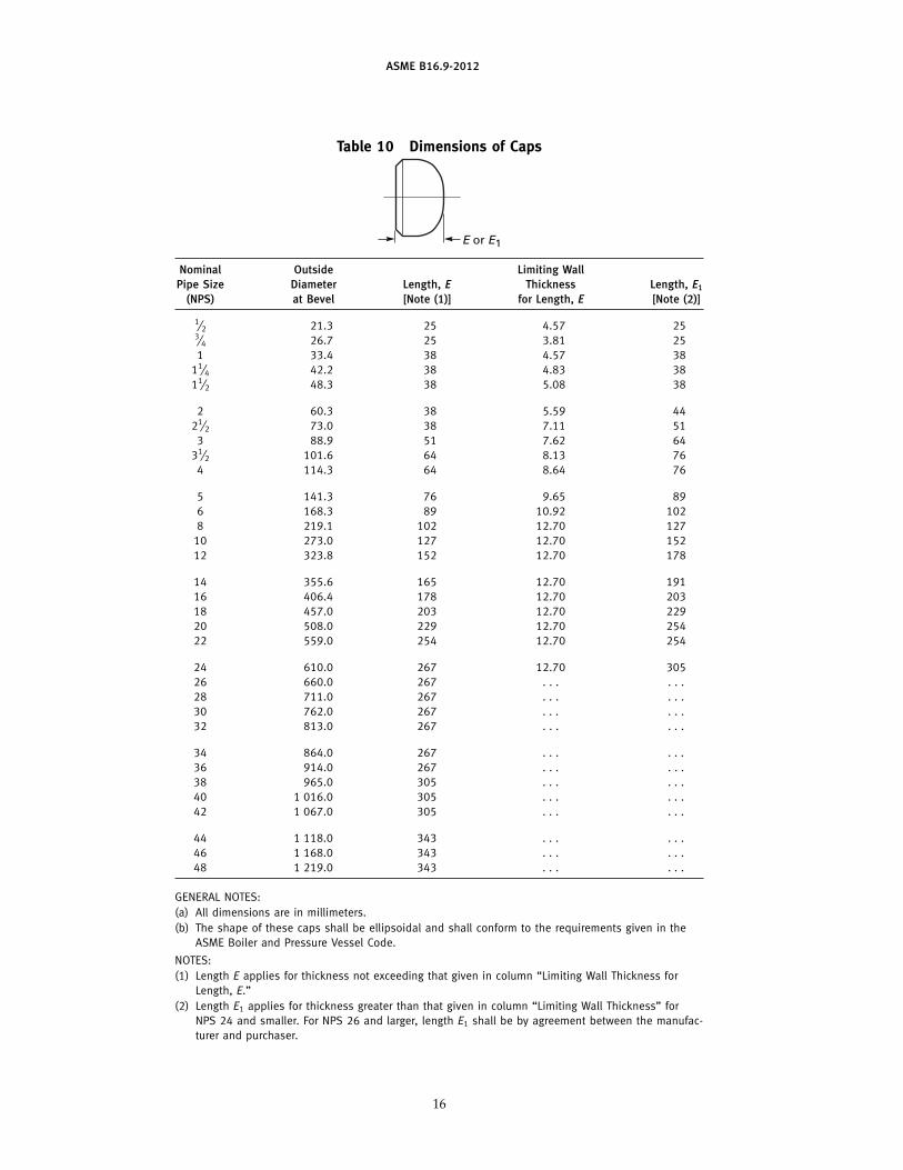
Table 10 Dimensions of Caps
E or E1
Nominal Outside Limiting WallPipe Size Diameter Length, E Thickness Length, E1
(NPS) at Bevel [Note (1)] for Length, E [Note (2)]
1⁄2 21.3 25 4.57 253⁄4 26.7 25 3.81 251 33.4 38 4.57 38
11⁄4 42.2 38 4.83 3811⁄2 48.3 38 5.08 38
2 60.3 38 5.59 4421⁄2 73.0 38 7.11 51
3 88.9 51 7.62 6431⁄2 101.6 64 8.13 76
4 114.3 64 8.64 76
5 141.3 76 9.65 896 168.3 89 10.92 1028 219.1 102 12.70 127
10 273.0 127 12.70 15212 323.8 152 12.70 178
14 355.6 165 12.70 19116 406.4 178 12.70 20318 457.0 203 12.70 22920 508.0 229 12.70 25422 559.0 254 12.70 254
24 610.0 267 12.70 30526 660.0 267 . . . . . .28 711.0 267 . . . . . .30 762.0 267 . . . . . .32 813.0 267 . . . . . .
34 864.0 267 . . . . . .36 914.0 267 . . . . . .38 965.0 305 . . . . . .40 1 016.0 305 . . . . . .42 1 067.0 305 . . . . . .
44 1 118.0 343 . . . . . .46 1 168.0 343 . . . . . .48 1 219.0 343 . . . . . .
GENERAL NOTES:(a) All dimensions are in millimeters.(b) The shape of these caps shall be ellipsoidal and shall conform to the requirements given in the
ASME Boiler and Pressure Vessel Code.
NOTES:(1) Length E applies for thickness not exceeding that given in column “Limiting Wall Thickness for
Length, E.”(2) Length E1 applies for thickness greater than that given in column “Limiting Wall Thickness” for
NPS 24 and smaller. For NPS 26 and larger, length E1 shall be by agreement between the manufac-turer and purchaser.
16
ASME B16.9-2012
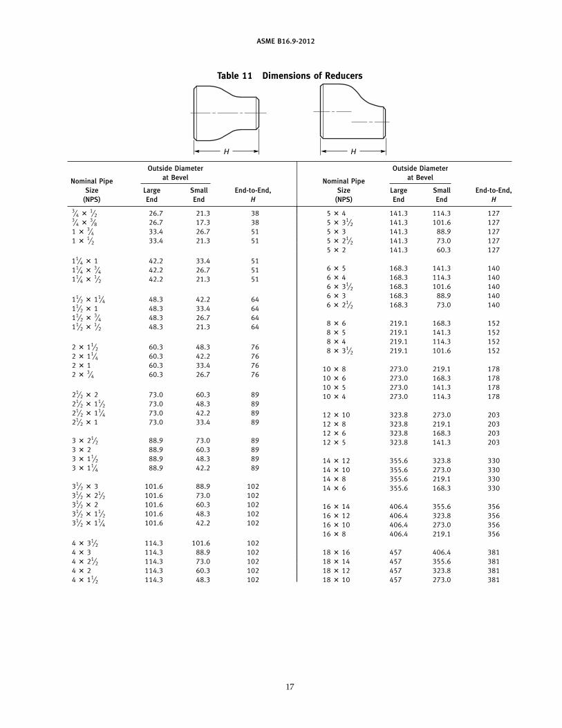
Table 11 Dimensions of Reducers
H H
Outside Diameter Outside Diameterat Bevel at BevelNominal Pipe Nominal Pipe
Size Large Small End-to-End, Size Large Small End-to-End,(NPS) End End H (NPS) End End H
3⁄4 � 1⁄2 26.7 21.3 383⁄4 � 3⁄8 26.7 17.3 381 � 3⁄4 33.4 26.7 511 � 1⁄2 33.4 21.3 51
11⁄4 � 1 42.2 33.4 5111⁄4 � 3⁄4 42.2 26.7 5111⁄4 � 1⁄2 42.2 21.3 51
11⁄2 � 11⁄4 48.3 42.2 6411⁄2 � 1 48.3 33.4 6411⁄2 � 3⁄4 48.3 26.7 6411⁄2 � 1⁄2 48.3 21.3 64
2 � 11⁄2 60.3 48.3 762 � 11⁄4 60.3 42.2 762 � 1 60.3 33.4 762 � 3⁄4 60.3 26.7 76
21⁄2 � 2 73.0 60.3 8921⁄2 � 11⁄2 73.0 48.3 8921⁄2 � 11⁄4 73.0 42.2 8921⁄2 � 1 73.0 33.4 89
3 � 21⁄2 88.9 73.0 893 � 2 88.9 60.3 893 � 11⁄2 88.9 48.3 893 � 11⁄4 88.9 42.2 89
31⁄2 � 3 101.6 88.9 10231⁄2 � 21⁄2 101.6 73.0 10231⁄2 � 2 101.6 60.3 10231⁄2 � 11⁄2 101.6 48.3 10231⁄2 � 11⁄4 101.6 42.2 102
4 � 31⁄2 114.3 101.6 1024 � 3 114.3 88.9 1024 � 21⁄2 114.3 73.0 1024 � 2 114.3 60.3 1024 � 11⁄2 114.3 48.3 102
5 � 4 141.3 114.3 1275 � 31⁄2 141.3 101.6 1275 � 3 141.3 88.9 1275 � 21⁄2 141.3 73.0 1275 � 2 141.3 60.3 127
6 � 5 168.3 141.3 1406 � 4 168.3 114.3 1406 � 31⁄2 168.3 101.6 1406 � 3 168.3 88.9 1406 � 21⁄2 168.3 73.0 140
8 � 6 219.1 168.3 1528 � 5 219.1 141.3 1528 � 4 219.1 114.3 1528 � 31⁄2 219.1 101.6 152
10 � 8 273.0 219.1 17810 � 6 273.0 168.3 17810 � 5 273.0 141.3 17810 � 4 273.0 114.3 178
12 � 10 323.8 273.0 20312 � 8 323.8 219.1 20312 � 6 323.8 168.3 20312 � 5 323.8 141.3 203
14 � 12 355.6 323.8 33014 � 10 355.6 273.0 33014 � 8 355.6 219.1 33014 � 6 355.6 168.3 330
16 � 14 406.4 355.6 35616 � 12 406.4 323.8 35616 � 10 406.4 273.0 35616 � 8 406.4 219.1 356
18 � 16 457 406.4 38118 � 14 457 355.6 38118 � 12 457 323.8 38118 � 10 457 273.0 381
17
ASME B16.9-2012
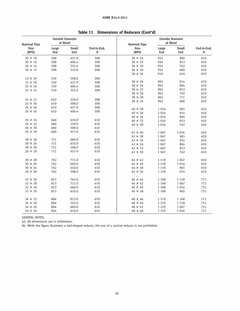
Table 11 Dimensions of Reducers (Cont’d)
Outside Diameter Outside Diameterat Bevel at BevelNominal Pipe Nominal Pipe
Size Large Small End-to-End, Size Large Small End-to-End,(NPS) End End H (NPS) End End H
20 � 18 508 457.0 50820 � 16 508 406.4 50820 � 14 508 355.6 50820 � 12 508 323.8 508
22 � 20 559 508.0 50822 � 18 559 457.0 50822 � 16 559 406.4 50822 � 14 559 355.4 508
24 � 22 610 559.0 50824 � 20 610 508.0 50824 � 18 610 457.0 50824 � 16 610 406.4 508
26 � 24 660 610.0 61026 � 22 660 559.0 61026 � 20 660 508.0 61026 � 18 660 457.0 610
28 � 26 711 660.0 61028 � 24 711 610.0 61028 � 20 711 508.0 61028 � 18 711 457.0 610
30 � 28 762 711.0 61030 � 26 762 660.0 61030 � 24 762 610.0 61030 � 20 762 508.0 610
32 � 30 813 762.0 61032 � 28 813 711.0 61032 � 26 813 660.0 61032 � 24 813 610.0 610
34 � 32 864 813.0 61034 � 30 864 762.0 61034 � 26 864 660.0 61034 � 24 864 610.0 610
36 � 34 914 864 61036 � 32 914 813 61036 � 30 914 762 61036 � 26 914 660 61036 � 24 914 610 610
38 � 36 965 914 61038 � 34 965 864 61038 � 32 965 813 61038 � 30 965 762 61038 � 28 965 711 61038 � 26 965 660 610
40 � 38 1 016 965 61040 � 36 1 016 914 61040 � 34 1 016 864 61040 � 32 1 016 813 61040 � 30 1 016 762 610
42 � 40 1 067 1 016 61042 � 38 1 067 965 61042 � 36 1 067 914 61042 � 34 1 067 864 61042 � 32 1 067 813 61042 � 30 1 067 762 610
44 � 42 1 118 1 067 61044 � 40 1 118 1 016 61044 � 38 1 118 965 61044 � 36 1 118 914 610
46 � 44 1 168 1 118 71146 � 42 1 168 1 067 71146 � 40 1 168 1 016 71146 � 38 1 168 965 711
48 � 46 1 219 1 168 71148 � 44 1 219 1 118 71148 � 42 1 219 1 067 71148 � 40 1 219 1 016 711
GENERAL NOTES:(a) All dimensions are in millimeters.(b) While the figure illustrates a bell-shaped reducer, the use of a conical reducer is not prohibited.
18

ASME B16.9-2012
Table 12 Welding Bevels and Root Face
19 (0.75)
Note (1) 1.5 (0.06) � 1.0 (0.03) (Root face)
1.5 (0.06) � 1.0 (0.03) (Root face)
22 (0.88)t
D
D
37.5 deg � 2.5 deg
37.5 deg � 2.5 deg
10 deg � 2.5 deg
Rad.
Note (1)
Note (1)
t 22 (0.88) max.
Note (1)
(a) Plain Bevel (b) Compound Bevel
Nominal Wall Thickness, t End Preparation
Less than x [Note (2)] Cut square or slightly chamfer, at manufacturer’s option (not illustrated)x to 22 (0.88), inclusive Plain bevel as in illustration (a) aboveMore than 22 (0.88) Compound bevel as in illustration (b) above
GENERAL NOTES:(a) Dimensions in parentheses are in inches.(b) Other dimensions are in millimeters.
NOTES:(1) See section 8 and Fig. 1 for transition contours.(2) x p 5 (0.19) for carbon steel or ferritic alloy steel and 3 (0.12) for austenitic alloy steel.
19
ASME B16.9-2012
Tabl
e13
Tole
ranc
es
A
AA
Q
Q
O
K
Q
Q
UU
Q
Q
P
Tees
Th
is e
nd
flu
sh a
gai
nst
sq
uar
e
Cent
er-t
o-En
dA
llFi
ttin
gs[N
otes
(1)
and
(2)]
Dim
ensi
ons
Ove
rall
180
-deg
Retu
rns
Out
side
Insi
de90
-deg
and
45-d
egLe
ngth
ofO
vera
llD
iam
eter
atD
iam
eter
Long
and
Redu
cers
and
Leng
thCe
nter
-to-
Bac
k-to
-B
evel
,D
atEn
dS
hort
Rad
ius
3DR
adiu
sLa
pJo
int
ofCe
nter
Face
Alig
nmen
tN
omin
alPi
pe[N
otes
(3)
[Not
es(3
)El
bow
san
dTe
es,
Elbo
ws,
Stu
bEn
ds,
Caps
,D
imen
sion
,D
imen
sion
,of
Ends
,S
ize
(NPS
)D
Nan
d(4
)]an
d(5
)]A,
B,
C,M
A,B
F,H
EO
KU
1 ⁄ 2to
21 ⁄ 215
–65
+1.6
,−
0.8
0.8
23
23
66
13
to31 ⁄ 2
80–
901.
61.
62
32
36
61
410
01.
61.
62
32
36
61
5to
812
5–20
0+2
.4,
−1.
61.
62
32
66
61
10to
1825
0–45
0+4
.0,
−3.
23.
22
32
610
62
20to
2450
0–60
0+6
.4,
−4.
84.
82
32
610
62
26to
3065
0–75
0+6
.4,
−4.
84.
83
65
10..
...
...
.32
to48
800–
120
0+6
.4,
−4.
84.
85
65
10..
...
...
.
20

ASME B16.9-2012
Tabl
e13
Tole
ranc
es(C
ont’
d)
Lap
Join
tS
tub
Ends
[Not
e(6
)]A
ngul
arit
yTo
lera
nces
Out
side
Fille
tN
omin
alD
iam
eter
Rad
ius
Nom
inal
Off
Off
Pipe
Siz
eof
Lap,
ofLa
p,La
pPi
peS
ize
Ang
le,
Plan
e,(N
PS)
DN
GR
Thic
knes
s(N
PS)
DN
QP
1 ⁄ 2to
21 ⁄ 215
–65
+0,
−1
+0,
−1
+1.6
,−
01 ⁄ 2
to4
15–
100
12
3to
31 ⁄ 280
–90
+0,
−1
+0,
−1
+1.6
,−
05
to8
125–
200
24
410
0+0
,−
1+0
,−
2+1
.6,
−0
10to
1225
0–30
03
55
to8
125–
200
+0,
−1
+0,
−2
+1.6
,−
014
to16
350–
400
36
10to
1825
0–45
0+0
,−
2+0
,−
2+3
.2,
−0
18to
2445
0–60
04
1020
to24
500–
600
+0,
−2
+0,
−2
+3.2
,−
026
to30
650–
750
510
26to
3065
0–75
0..
...
...
.32
to42
800–
105
05
1332
to48
800–
120
0..
...
...
.44
to48
110
0–1
200
519
GEN
ERA
LN
OTE
S:
(a)
All
dim
ensi
ons
are
inm
illim
eter
s.(b
)To
lera
nces
are
equa
lpl
usan
dm
inus
exce
ptas
note
d.
NO
TES
:(1
)Th
ein
side
diam
eter
and
the
nom
inal
wal
lth
ickn
esse
sat
ends
are
tobe
spec
ified
byth
epu
rcha
ser.
(2)
Am
inim
umw
all
thic
knes
sof
87.5
%ap
plie
sun
less
the
purc
hase
rsp
ecifi
esa
diff
eren
tw
all
thic
knes
sto
lera
nce.
See
Fig.
1,N
ote
(1)(
a).
(3)
Out
-of-
roun
dis
the
sum
ofab
solu
teva
lues
ofpl
usan
dm
inus
tole
ranc
es.
(4)
This
tole
ranc
em
ayno
tap
ply
inlo
caliz
edar
eas
offo
rmed
fitti
ngs
whe
rein
crea
sed
wal
lth
ickn
ess
isre
quir
edto
mee
tde
sign
requ
irem
ents
ofpa
ra.
2.2.
(5)
Unl
ess
othe
rwis
esp
ecifi
edby
the
purc
hase
r,th
ese
tole
ranc
esap
ply
toth
eno
min
alin
side
diam
eter
,w
hich
equa
lsth
edi
ffer
ence
betw
een
the
nom
inal
outs
ide
diam
eter
and
twic
eth
eno
min
alw
all
thic
knes
s.(6
)S
eeTa
ble
9fo
rlim
itin
gdi
men
sion
sof
outs
ide
diam
eter
ofba
rrel
.
21

INTENTIONALLY LEFT BLANK
22

ASME B16.9-2012
MANDATORY APPENDIX IINCH TABLES
This Mandatory Appendix provides tables of the stan-dard inch dimensions for fittings.
23
ASME B16.9-2012
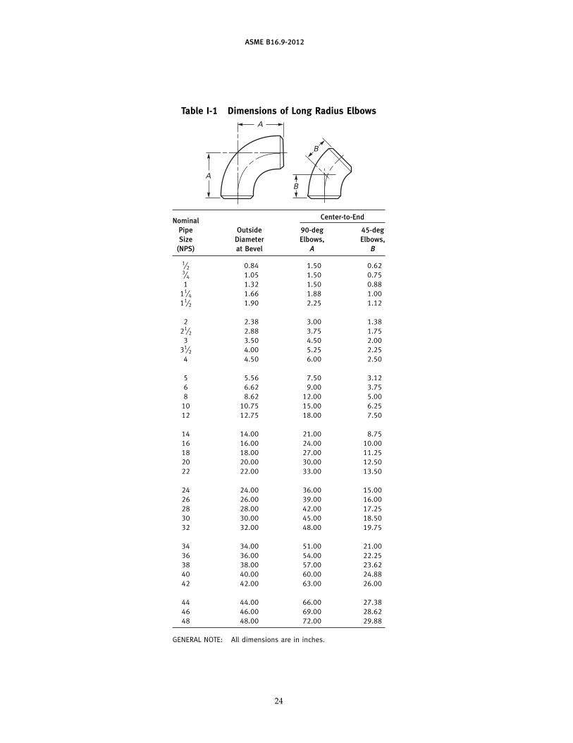
Table I-1 Dimensions of Long Radius ElbowsA
AB
B
Center-to-EndNominalPipe Outside 90-deg 45-degSize Diameter Elbows, Elbows,
(NPS) at Bevel A B
1⁄2 0.84 1.50 0.623⁄4 1.05 1.50 0.751 1.32 1.50 0.88
11⁄4 1.66 1.88 1.0011⁄2 1.90 2.25 1.12
2 2.38 3.00 1.3821⁄2 2.88 3.75 1.75
3 3.50 4.50 2.0031⁄2 4.00 5.25 2.25
4 4.50 6.00 2.50
5 5.56 7.50 3.126 6.62 9.00 3.758 8.62 12.00 5.00
10 10.75 15.00 6.2512 12.75 18.00 7.50
14 14.00 21.00 8.7516 16.00 24.00 10.0018 18.00 27.00 11.2520 20.00 30.00 12.5022 22.00 33.00 13.50
24 24.00 36.00 15.0026 26.00 39.00 16.0028 28.00 42.00 17.2530 30.00 45.00 18.5032 32.00 48.00 19.75
34 34.00 51.00 21.0036 36.00 54.00 22.2538 38.00 57.00 23.6240 40.00 60.00 24.8842 42.00 63.00 26.00
44 44.00 66.00 27.3846 46.00 69.00 28.6248 48.00 72.00 29.88
GENERAL NOTE: All dimensions are in inches.
24
ASME B16.9-2012
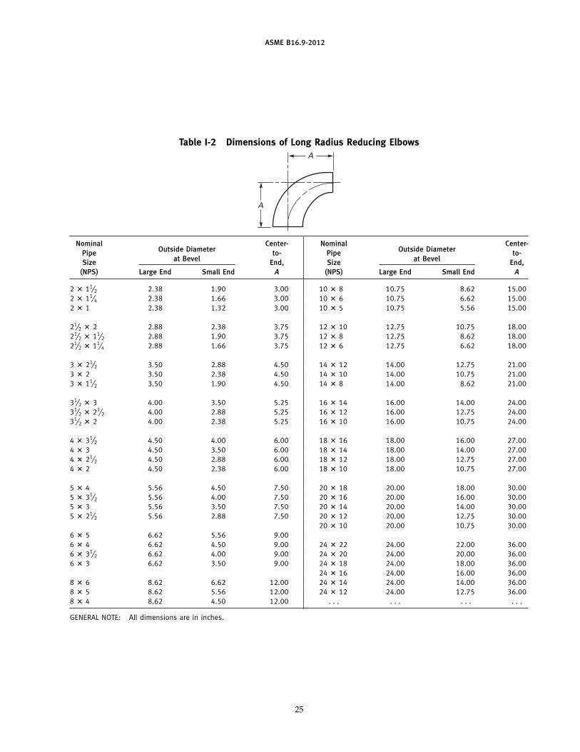
Table I-2 Dimensions of Long Radius Reducing ElbowsA
A
Nominal Center- Nominal Center-Outside Diameter Outside DiameterPipe to- Pipe to-
at Bevel at BevelSize End, Size End,(NPS) Large End Small End A (NPS) Large End Small End A
2 � 11⁄2 2.38 1.90 3.00 10 � 8 10.75 8.62 15.002 � 11⁄4 2.38 1.66 3.00 10 � 6 10.75 6.62 15.002 � 1 2.38 1.32 3.00 10 � 5 10.75 5.56 15.00
21⁄2 � 2 2.88 2.38 3.75 12 � 10 12.75 10.75 18.0021⁄2 � 11⁄2 2.88 1.90 3.75 12 � 8 12.75 8.62 18.0021⁄2 � 11⁄4 2.88 1.66 3.75 12 � 6 12.75 6.62 18.00
3 � 21⁄2 3.50 2.88 4.50 14 � 12 14.00 12.75 21.003 � 2 3.50 2.38 4.50 14 � 10 14.00 10.75 21.003 � 11⁄2 3.50 1.90 4.50 14 � 8 14.00 8.62 21.00
31⁄2 � 3 4.00 3.50 5.25 16 � 14 16.00 14.00 24.0031⁄2 � 21⁄2 4.00 2.88 5.25 16 � 12 16.00 12.75 24.0031⁄2 � 2 4.00 2.38 5.25 16 � 10 16.00 10.75 24.00
4 � 31⁄2 4.50 4.00 6.00 18 � 16 18.00 16.00 27.004 � 3 4.50 3.50 6.00 18 � 14 18.00 14.00 27.004 � 21⁄2 4.50 2.88 6.00 18 � 12 18.00 12.75 27.004 � 2 4.50 2.38 6.00 18 � 10 18.00 10.75 27.00
5 � 4 5.56 4.50 7.50 20 � 18 20.00 18.00 30.005 � 31⁄2 5.56 4.00 7.50 20 � 16 20.00 16.00 30.005 � 3 5.56 3.50 7.50 20 � 14 20.00 14.00 30.005 � 21⁄2 5.56 2.88 7.50 20 � 12 20.00 12.75 30.00
20 � 10 20.00 10.75 30.006 � 5 6.62 5.56 9.006 � 4 6.62 4.50 9.00 24 � 22 24.00 22.00 36.006 � 31⁄2 6.62 4.00 9.00 24 � 20 24.00 20.00 36.006 � 3 6.62 3.50 9.00 24 � 18 24.00 18.00 36.00
24 � 16 24.00 16.00 36.008 � 6 8.62 6.62 12.00 24 � 14 24.00 14.00 36.008 � 5 8.62 5.56 12.00 24 � 12 24.00 12.75 36.008 � 4 8.62 4.50 12.00 . . . . . . . . . . . .
GENERAL NOTE: All dimensions are in inches.
25

ASME B16.9-2012
Table I-3 Dimensions of Long Radius Returns
O
A A U
U [Note (1)]
Note (2)
K
NominalPipe Outside Center- Back-Size Diameter to-Center, to-Face,
(NPS) at Bevel O K
1⁄2 0.84 3.00 1.883⁄4 1.05 3.00 2.001 1.32 3.00 2.19
11⁄4 1.66 3.75 2.7511⁄2 1.90 4.50 3.25
2 2.38 6.00 4.1921⁄2 2.88 7.50 5.19
3 3.50 9.00 6.2531⁄2 4.00 10.50 7.25
4 4.50 12.00 8.25
5 5.56 15.00 10.316 6.62 18.00 12.318 8.62 24.00 16.31
10 10.75 30.00 20.3812 12.75 36.00 24.38
14 14.00 42.00 28.0016 16.00 48.00 32.0018 18.00 54.00 36.0020 20.00 60.00 40.0022 22.00 66.00 44.0024 24.00 72.00 48.00
GENERAL NOTE: All dimensions are in inches.
NOTES:(1) See Table I-12 for tolerance for alignment of ends U.(2) Dimension A is equal to one-half of dimension O.
26
Table I-4 Dimensions of Short Radius ElbowsA
A
Nominal OutsidePipe Diameter Center-Size at to-End,
(NPS) Bevel A
1 1.32 1.0011⁄4 1.66 1.2511⁄2 1.90 1.50
2 2.38 2.0021⁄2 2.88 2.50
3 3.50 3.0031⁄2 4.00 3.50
4 4.50 4.005 5.56 5.006 6.62 6.00
8 8.62 8.0010 10.75 10.0012 12.75 12.0014 14.00 14.0016 16.00 16.00
18 18.00 18.0020 20.00 20.0022 22.00 22.0024 24.00 24.00
GENERAL NOTE: All dimensions are in inches.
ASME B16.9-2012
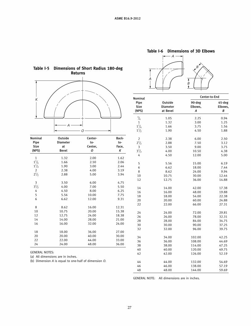
Table I-5 Dimensions of Short Radius 180-degReturns
A
O
K
Nominal Outside Center- Back-Pipe Diameter to- to-Size at Center, Face,
(NPS) Bevel O K
1 1.32 2.00 1.6211⁄4 1.66 2.50 2.0611⁄2 1.90 3.00 2.44
2 2.38 4.00 3.1921⁄2 2.88 5.00 3.94
3 3.50 6.00 4.7531⁄2 4.00 7.00 5.50
4 4.50 8.00 6.255 5.56 10.00 7.756 6.62 12.00 9.31
8 8.62 16.00 12.3110 10.75 20.00 15.3812 12.75 24.00 18.3814 14.00 28.00 21.0016 16.00 32.00 24.00
18 18.00 36.00 27.0020 20.00 40.00 30.0022 22.00 44.00 33.0024 24.00 48.00 36.00
GENERAL NOTES:(a) All dimensions are in inches.(b) Dimension A is equal to one-half of dimension O.
27
Table I-6 Dimensions of 3D ElbowsA
AB
B
Center-to-EndNominalPipe Outside 90-deg 45-degSize Diameter Elbows, Elbows,
(NPS) at Bevel A B
3⁄4 1.05 2.25 0.941 1.32 3.00 1.25
11⁄4 1.66 3.75 1.5611⁄2 1.90 4.50 1.88
2 2.38 6.00 2.5021⁄2 2.88 7.50 3.12
3 3.50 9.00 3.7531⁄2 4.00 10.50 4.38
4 4.50 12.00 5.00
5 5.56 15.00 6.196 6.62 18.00 7.448 8.62 24.00 9.94
10 10.75 30.00 12.4412 12.75 36.00 14.88
14 14.00 42.00 17.3816 16.00 48.00 19.8818 18.00 54.00 22.3820 20.00 60.00 24.8822 22.00 66.00 27.31
24 24.00 72.00 29.8126 26.00 78.00 32.3128 28.00 84.00 34.7530 30.00 90.00 37.2532 32.00 96.00 39.75
34 34.00 102.00 42.2536 36.00 108.00 44.6938 38.00 114.00 47.2540 40.00 120.00 49.7542 42.00 126.00 52.19
44 44.00 132.00 54.6946 46.00 138.00 57.1948 48.00 144.00 59.69
GENERAL NOTE: All dimensions are in inches.
ASME B16.9-2012
Table I-7 Dimensions of Straight Tees andCrosses
CC C C
M
MM
NominalCenter-to-EndPipe Outside
Size Diameter Run, Outlet, M(NPS) at Bevel C [Notes (1) and (2)]
1⁄2 0.84 1.00 1.003⁄4 1.05 1.12 1.121 1.32 1.50 1.50
11⁄4 1.66 1.88 1.8811⁄2 1.90 2.25 2.25
2 2.38 2.50 2.5021⁄2 2.88 3.00 3.00
3 3.50 3.38 3.3831⁄2 4.00 3.75 3.75
4 4.50 4.12 4.12
5 5.56 4.88 4.886 6.62 5.62 5.628 8.62 7.00 7.00
10 10.75 8.50 8.5012 12.75 10.00 10.00
14 14.00 11.00 11.0016 16.00 12.00 12.0018 18.00 13.50 13.5020 20.00 15.00 15.0022 22.00 16.50 16.50
24 24.00 17.00 17.0026 26.00 19.50 19.5028 28.00 20.50 20.5030 30.00 22.00 22.0032 32.00 23.50 23.50
34 34.00 25.00 25.0036 36.00 26.50 26.5038 38.00 28.00 28.0040 40.00 29.50 29.5042 42.00 30.00 28.00
44 44.00 32.00 30.0046 46.00 33.50 31.5048 48.00 35.00 33.00
GENERAL NOTE: All dimensions are in inches.
NOTES:(1) Outlet dimension M for NPS 26 and larger is recommended
but not required.(2) Dimensions applicable to crosses NPS 24 and smaller.
28

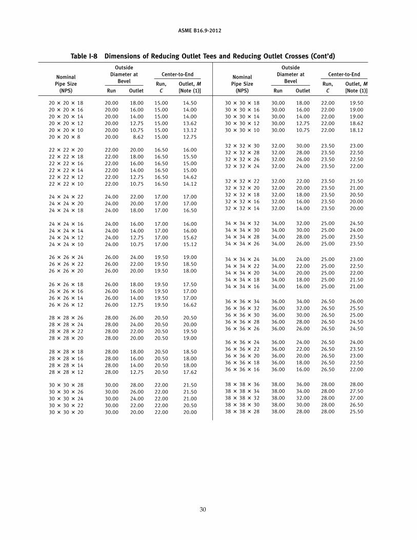
ASME B16.9-2012
Table I-8 Dimensions of Reducing Outlet Tees and Reducing Outlet Crosses
C C
M
CC
M
M
Outside OutsideDiameter at Center-to-End Diameter at Center-to-EndNominal Nominal
Bevel BevelPipe Size Run, Outlet, M Pipe Size Run, Outlet, M(NPS) Run Outlet C [Note (1)] (NPS) Run Outlet C [Note (1)]
1⁄2 � 1⁄2 � 3⁄8 0.84 0.68 1.00 1.001⁄2 � 1⁄2 � 1⁄4 0.84 0.54 1.00 1.003⁄4 � 3⁄4 � 1⁄2 1.05 0.84 1.12 1.123⁄4 � 3⁄4 � 3⁄8 1.05 0.68 1.12 1.121 � 1 � 3⁄4 1.32 1.05 1.50 1.501 � 1 � 1⁄2 1.32 0.84 1.50 1.50
11⁄4 � 11⁄4 � 1 1.66 1.32 1.88 1.8811⁄4 � 11⁄4 � 3⁄4 1.66 1.05 1.88 1.8811⁄4 � 11⁄4 � 1⁄2 1.66 0.84 1.88 1.88
11⁄2 � 11⁄2 � 11⁄4 1.90 1.66 2.25 2.2511⁄2 � 11⁄2 � 1 1.90 1.32 2.25 2.2511⁄2 � 11⁄2 � 3⁄4 1.90 1.05 2.25 2.2511⁄2 � 11⁄2 � 1⁄2 1.90 0.84 2.25 2.25
2 � 2 � 11⁄2 2.38 1.90 2.50 2.382 � 2 � 11⁄4 2.38 1.66 2.50 2.252 � 2 � 1 2.38 1.32 2.50 2.002 � 2 � 3⁄4 2.38 1.05 2.50 1.75
21⁄2 � 21⁄2 � 2 2.88 2.38 3.00 2.7521⁄2 � 21⁄2 � 11⁄2 2.88 1.90 3.00 2.6221⁄2 � 21⁄2 � 11⁄4 2.88 1.66 3.00 2.5021⁄2 � 21⁄2 � 1 2.88 1.32 3.00 2.25
3 � 3 � 21⁄2 3.50 2.88 3.38 3.253 � 3 � 2 3.50 2.38 3.38 3.003 � 3 � 11⁄2 3.50 1.90 3.38 2.883 � 3 � 11⁄4 3.50 1.66 3.38 2.75
31⁄2 � 31⁄2 � 3 4.00 3.50 3.75 3.6231⁄2 � 31⁄2 � 21⁄2 4.00 2.88 3.75 3.5031⁄2 � 31⁄2 � 2 4.00 2.38 3.75 3.2531⁄2 � 31⁄2 � 11⁄2 4.00 1.90 3.75 3.12
4 � 4 � 31⁄2 4.50 4.00 4.12 4.004 � 4 � 3 4.50 3.50 4.12 3.884 � 4 � 21⁄2 4.50 2.88 4.12 3.754 � 4 � 2 4.50 2.38 4.12 3.504 � 4 � 11⁄2 4.50 1.90 4.12 3.38
5 � 5 � 4 5.56 4.50 4.88 4.625 � 5 � 31⁄2 5.56 4.00 4.88 4.505 � 5 � 3 5.56 3.50 4.88 4.385 � 5 � 21⁄2 5.56 2.88 4.88 4.255 � 5 � 2 5.56 2.38 4.88 4.12
6 � 6 � 5 6.62 5.56 5.62 5.386 � 6 � 4 6.62 4.50 5.62 5.126 � 6 � 31⁄2 6.62 4.00 5.62 5.006 � 6 � 3 6.62 3.50 5.62 4.886 � 6 � 21⁄2 6.62 2.88 5.62 4.75
8 � 8 � 6 8.62 6.62 7.00 6.628 � 8 � 5 8.62 5.56 7.00 6.388 � 8 � 4 8.62 4.50 7.00 6.128 � 8 � 31⁄2 8.62 4.00 7.00 6.00
10 � 10 � 8 10.75 8.62 8.50 8.0010 � 10 � 6 10.75 6.62 8.50 7.6210 � 10 � 5 10.75 5.56 8.50 7.5010 � 10 � 4 10.75 4.50 8.50 7.25
12 � 12 � 10 12.75 10.75 10.00 9.5012 � 12 � 8 12.75 8.62 10.00 9.0012 � 12 � 6 12.75 6.62 10.00 8.6212 � 12 � 5 12.75 5.56 10.00 8.50
14 � 14 � 12 14.00 12.75 11.00 10.6214 � 14 � 10 14.00 10.75 11.00 10.1214 � 14 � 8 14.00 8.62 11.00 9.7514 � 14 � 6 14.00 6.62 11.00 9.38
16 � 16 � 14 16.00 14.00 12.00 12.0016 � 16 � 12 16.00 12.75 12.00 11.6216 � 16 � 10 16.00 10.75 12.00 11.1216 � 16 � 8 16.00 8.62 12.00 10.7516 � 16 � 6 16.00 6.62 12.00 10.38
18 � 18 � 16 18.00 16.00 13.50 13.0018 � 18 � 14 18.00 14.00 13.50 13.0018 � 18 � 12 18.00 12.75 13.50 12.6218 � 18 � 10 18.00 10.75 13.50 12.1218 � 18 � 8 18.00 8.62 13.50 11.75
29
ASME B16.9-2012
Table I-8 Dimensions of Reducing Outlet Tees and Reducing Outlet Crosses (Cont’d)
Outside OutsideDiameter at Center-to-End Diameter at Center-to-EndNominal Nominal
Bevel BevelPipe Size Run, Outlet, M Pipe Size Run, Outlet, M(NPS) Run Outlet C [Note (1)] (NPS) Run Outlet C [Note (1)]
20 � 20 � 18 20.00 18.00 15.00 14.5020 � 20 � 16 20.00 16.00 15.00 14.0020 � 20 � 14 20.00 14.00 15.00 14.0020 � 20 � 12 20.00 12.75 15.00 13.6220 � 20 � 10 20.00 10.75 15.00 13.1220 � 20 � 8 20.00 8.62 15.00 12.75
22 � 22 � 20 22.00 20.00 16.50 16.0022 � 22 � 18 22.00 18.00 16.50 15.5022 � 22 � 16 22.00 16.00 16.50 15.0022 � 22 � 14 22.00 14.00 16.50 15.0022 � 22 � 12 22.00 12.75 16.50 14.6222 � 22 � 10 22.00 10.75 16.50 14.12
24 � 24 � 22 24.00 22.00 17.00 17.0024 � 24 � 20 24.00 20.00 17.00 17.0024 � 24 � 18 24.00 18.00 17.00 16.50
24 � 24 � 16 24.00 16.00 17.00 16.0024 � 24 � 14 24.00 14.00 17.00 16.0024 � 24 � 12 24.00 12.75 17.00 15.6224 � 24 � 10 24.00 10.75 17.00 15.12
26 � 26 � 24 26.00 24.00 19.50 19.0026 � 26 � 22 26.00 22.00 19.50 18.5026 � 26 � 20 26.00 20.00 19.50 18.00
26 � 26 � 18 26.00 18.00 19.50 17.5026 � 26 � 16 26.00 16.00 19.50 17.0026 � 26 � 14 26.00 14.00 19.50 17.0026 � 26 � 12 26.00 12.75 19.50 16.62
28 � 28 � 26 28.00 26.00 20.50 20.5028 � 28 � 24 28.00 24.00 20.50 20.0028 � 28 � 22 28.00 22.00 20.50 19.5028 � 28 � 20 28.00 20.00 20.50 19.00
28 � 28 � 18 28.00 18.00 20.50 18.5028 � 28 � 16 28.00 16.00 20.50 18.0028 � 28 � 14 28.00 14.00 20.50 18.0028 � 28 � 12 28.00 12.75 20.50 17.62
30 � 30 � 28 30.00 28.00 22.00 21.5030 � 30 � 26 30.00 26.00 22.00 21.5030 � 30 � 24 30.00 24.00 22.00 21.0030 � 30 � 22 30.00 22.00 22.00 20.5030 � 30 � 20 30.00 20.00 22.00 20.00
30 � 30 � 18 30.00 18.00 22.00 19.5030 � 30 � 16 30.00 16.00 22.00 19.0030 � 30 � 14 30.00 14.00 22.00 19.0030 � 30 � 12 30.00 12.75 22.00 18.6230 � 30 � 10 30.00 10.75 22.00 18.12
32 � 32 � 30 32.00 30.00 23.50 23.0032 � 32 � 28 32.00 28.00 23.50 22.5032 � 32 � 26 32.00 26.00 23.50 22.5032 � 32 � 24 32.00 24.00 23.50 22.00
32 � 32 � 22 32.00 22.00 23.50 21.5032 � 32 � 20 32.00 20.00 23.50 21.0032 � 32 � 18 32.00 18.00 23.50 20.5032 � 32 � 16 32.00 16.00 23.50 20.0032 � 32 � 14 32.00 14.00 23.50 20.00
34 � 34 � 32 34.00 32.00 25.00 24.5034 � 34 � 30 34.00 30.00 25.00 24.0034 � 34 � 28 34.00 28.00 25.00 23.5034 � 34 � 26 34.00 26.00 25.00 23.50
34 � 34 � 24 34.00 24.00 25.00 23.0034 � 34 � 22 34.00 22.00 25.00 22.5034 � 34 � 20 34.00 20.00 25.00 22.0034 � 34 � 18 34.00 18.00 25.00 21.5034 � 34 � 16 34.00 16.00 25.00 21.00
36 � 36 � 34 36.00 34.00 26.50 26.0036 � 36 � 32 36.00 32.00 26.50 25.5036 � 36 � 30 36.00 30.00 26.50 25.0036 � 36 � 28 36.00 28.00 26.50 24.5036 � 36 � 26 36.00 26.00 26.50 24.50
36 � 36 � 24 36.00 24.00 26.50 24.0036 � 36 � 22 36.00 22.00 26.50 23.5036 � 36 � 20 36.00 20.00 26.50 23.0036 � 36 � 18 36.00 18.00 26.50 22.5036 � 36 � 16 36.00 16.00 26.50 22.00
38 � 38 � 36 38.00 36.00 28.00 28.0038 � 38 � 34 38.00 34.00 28.00 27.5038 � 38 � 32 38.00 32.00 28.00 27.0038 � 38 � 30 38.00 30.00 28.00 26.5038 � 38 � 28 38.00 28.00 28.00 25.50
30

ASME B16.9-2012
Table I-8 Dimensions of Reducing Outlet Tees and Reducing Outlet Crosses (Cont’d)
Outside OutsideDiameter at Center-to-End Diameter at Center-to-EndNominal Nominal
Bevel BevelPipe Size Run, Outlet, M Pipe Size Run, Outlet, M(NPS) Run Outlet C [Note (1)] (NPS) Run Outlet C [Note (1)]
38 � 38 � 26 38.00 26.00 28.00 25.5038 � 38 � 24 38.00 24.00 28.00 25.0038 � 38 � 22 38.00 22.00 28.00 24.5038 � 38 � 20 38.00 20.00 28.00 24.0038 � 38 � 18 38.00 18.00 28.00 23.50
40 � 40 � 38 40.00 38.00 29.50 29.5040 � 40 � 36 40.00 36.00 29.50 29.0040 � 40 � 34 40.00 34.00 29.50 28.5040 � 40 � 32 40.00 32.00 29.50 28.0040 � 40 � 30 40.00 30.00 29.50 27.50
40 � 40 � 28 40.00 28.00 29.50 26.5040 � 40 � 26 40.00 26.00 29.50 26.5040 � 40 � 24 40.00 24.00 29.50 26.0040 � 40 � 22 40.00 22.00 29.50 25.5040 � 40 � 20 40.00 20.00 29.50 25.0040 � 40 � 18 40.00 18.00 29.50 24.50
42 � 42 � 40 42.00 40.00 30.00 28.0042 � 42 � 38 42.00 38.00 30.00 28.0042 � 42 � 36 42.00 36.00 30.00 28.0042 � 42 � 34 42.00 34.00 30.00 28.00
42 � 42 � 32 42.00 32.00 30.00 28.0042 � 42 � 30 42.00 30.00 30.00 28.0042 � 42 � 28 42.00 28.00 30.00 27.5042 � 42 � 26 42.00 26.00 30.00 27.50
42 � 42 � 24 42.00 24.00 30.00 26.0042 � 42 � 22 42.00 22.00 30.00 26.0042 � 42 � 20 42.00 20.00 30.00 26.0042 � 42 � 18 42.00 18.00 30.00 25.5042 � 42 � 16 42.00 16.00 30.00 25.00
44 � 44 � 42 44.00 42.00 32.00 30.0044 � 44 � 40 44.00 40.00 32.00 29.5044 � 44 � 38 44.00 38.00 32.00 29.0044 � 44 � 36 44.00 36.00 32.00 28.5044 � 44 � 34 44.00 34.00 32.00 28.5044 � 44 � 32 44.00 32.00 32.00 28.00
44 � 44 � 30 44.00 30.00 32.00 28.0044 � 44 � 28 44.00 28.00 32.00 27.5044 � 44 � 26 44.00 26.00 32.00 27.5044 � 44 � 24 44.00 24.00 32.00 27.5044 � 44 � 22 44.00 22.00 32.00 27.0044 � 44 � 20 44.00 20.00 32.00 27.00
46 � 46 � 44 46.00 44.00 33.50 31.5046 � 46 � 42 46.00 42.00 33.50 31.0046 � 46 � 40 46.00 40.00 33.50 30.5046 � 46 � 38 46.00 38.00 33.50 30.0046 � 46 � 36 46.00 36.00 33.50 30.0046 � 46 � 34 46.00 34.00 33.50 29.50
46 � 46 � 32 46.00 32.00 33.50 29.5046 � 46 � 30 46.00 30.00 33.50 29.0046 � 46 � 28 46.00 28.00 33.50 29.0046 � 46 � 26 46.00 26.00 33.50 29.0046 � 46 � 24 46.00 24.00 33.50 28.5046 � 46 � 22 46.00 22.00 33.50 28.50
48 � 48 � 46 48.00 46.00 35.00 33.0048 � 48 � 44 48.00 44.00 35.00 33.0048 � 48 � 42 48.00 42.00 35.00 32.0048 � 48 � 40 48.00 40.00 35.00 32.00
48 � 48 � 38 48.00 38.00 35.00 32.0048 � 48 � 36 48.00 36.00 35.00 31.0048 � 48 � 34 48.00 34.00 35.00 31.0048 � 48 � 32 48.00 32.00 35.00 31.00
48 � 48 � 30 48.00 30.00 35.00 30.0048 � 48 � 28 48.00 28.00 35.00 30.0048 � 48 � 26 48.00 26.00 35.00 30.0048 � 48 � 24 48.00 24.00 35.00 29.0048 � 48 � 22 48.00 22.00 35.00 29.00
GENERAL NOTE: All dimensions are in inches.
NOTE:(1) Outlet dimension M for run sizes NPS 14 and larger is recommended but not required.
31
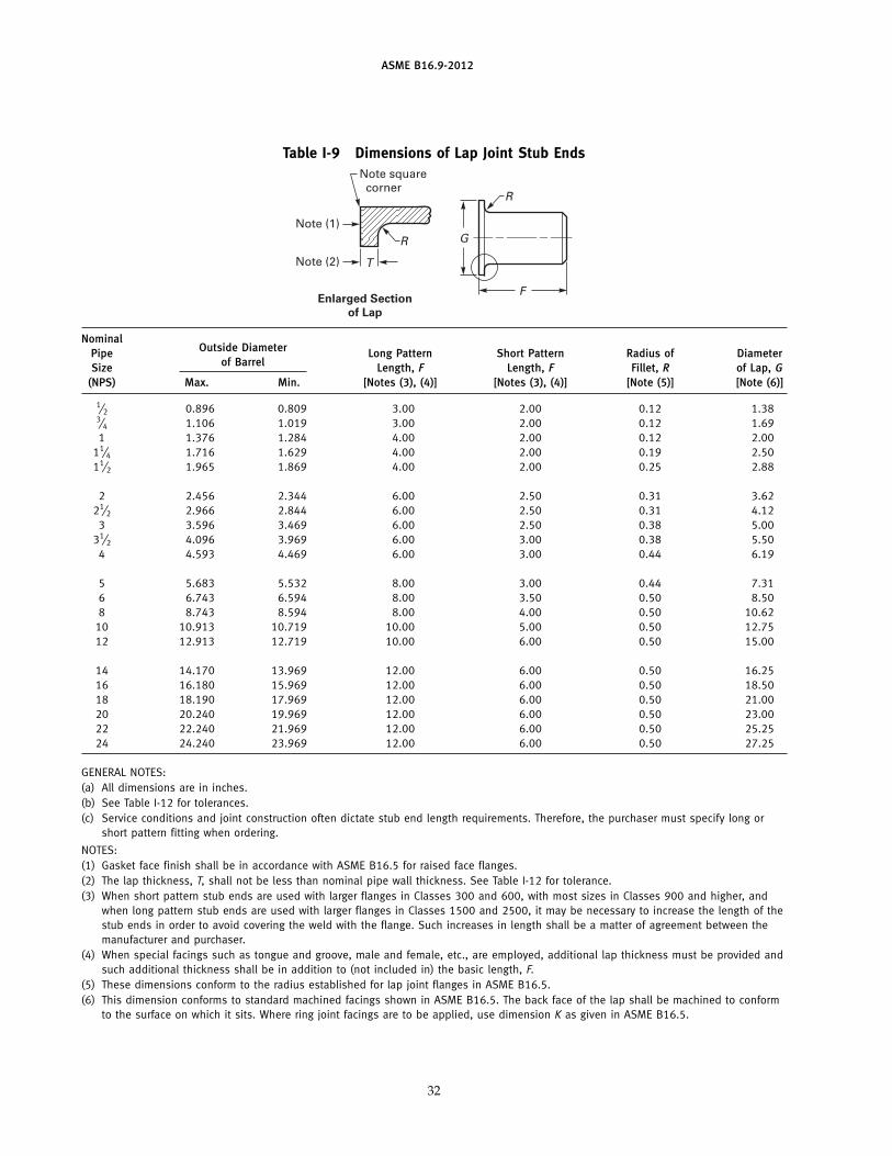
ASME B16.9-2012
Table I-9 Dimensions of Lap Joint Stub Ends
F
T
G
R
Note square corner
Note (1)
Note (2)
Enlarged Section
of Lap
R
NominalOutside DiameterPipe Long Pattern Short Pattern Radius of Diameter
of BarrelSize Length, F Length, F Fillet, R of Lap, G(NPS) Max. Min. [Notes (3), (4)] [Notes (3), (4)] [Note (5)] [Note (6)]
1⁄2 0.896 0.809 3.00 2.00 0.12 1.383⁄4 1.106 1.019 3.00 2.00 0.12 1.691 1.376 1.284 4.00 2.00 0.12 2.00
11⁄4 1.716 1.629 4.00 2.00 0.19 2.5011⁄2 1.965 1.869 4.00 2.00 0.25 2.88
2 2.456 2.344 6.00 2.50 0.31 3.6221⁄2 2.966 2.844 6.00 2.50 0.31 4.12
3 3.596 3.469 6.00 2.50 0.38 5.0031⁄2 4.096 3.969 6.00 3.00 0.38 5.50
4 4.593 4.469 6.00 3.00 0.44 6.19
5 5.683 5.532 8.00 3.00 0.44 7.316 6.743 6.594 8.00 3.50 0.50 8.508 8.743 8.594 8.00 4.00 0.50 10.62
10 10.913 10.719 10.00 5.00 0.50 12.7512 12.913 12.719 10.00 6.00 0.50 15.00
14 14.170 13.969 12.00 6.00 0.50 16.2516 16.180 15.969 12.00 6.00 0.50 18.5018 18.190 17.969 12.00 6.00 0.50 21.0020 20.240 19.969 12.00 6.00 0.50 23.0022 22.240 21.969 12.00 6.00 0.50 25.2524 24.240 23.969 12.00 6.00 0.50 27.25
GENERAL NOTES:(a) All dimensions are in inches.(b) See Table I-12 for tolerances.(c) Service conditions and joint construction often dictate stub end length requirements. Therefore, the purchaser must specify long or
short pattern fitting when ordering.
NOTES:(1) Gasket face finish shall be in accordance with ASME B16.5 for raised face flanges.(2) The lap thickness, T, shall not be less than nominal pipe wall thickness. See Table I-12 for tolerance.(3) When short pattern stub ends are used with larger flanges in Classes 300 and 600, with most sizes in Classes 900 and higher, and
when long pattern stub ends are used with larger flanges in Classes 1500 and 2500, it may be necessary to increase the length of thestub ends in order to avoid covering the weld with the flange. Such increases in length shall be a matter of agreement between themanufacturer and purchaser.
(4) When special facings such as tongue and groove, male and female, etc., are employed, additional lap thickness must be provided andsuch additional thickness shall be in addition to (not included in) the basic length, F.
(5) These dimensions conform to the radius established for lap joint flanges in ASME B16.5.(6) This dimension conforms to standard machined facings shown in ASME B16.5. The back face of the lap shall be machined to conform
to the surface on which it sits. Where ring joint facings are to be applied, use dimension K as given in ASME B16.5.
32

ASME B16.9-2012
Table I-10 Dimensions of Caps
E or E1
Nominal Outside Limiting WallPipe Size Diameter Length, E Thickness Length, E1
(NPS) at Bevel [Note (1)] for Length, E [Note (2)]
1⁄2 0.84 1.00 0.18 1.003⁄4 1.05 1.00 0.15 1.001 1.32 1.50 0.18 1.50
11⁄4 1.66 1.50 0.19 1.5011⁄2 1.90 1.50 0.20 1.50
2 2.38 1.50 0.22 1.7521⁄2 2.88 1.50 0.28 2.00
3 3.50 2.00 0.30 2.5031⁄2 4.00 2.50 0.32 3.00
4 4.50 2.50 0.34 3.00
5 5.56 3.00 0.38 3.506 6.62 3.50 0.43 4.008 8.62 4.00 0.50 5.00
10 10.75 5.00 0.50 6.0012 12.75 6.00 0.50 7.00
14 14.00 6.50 0.50 7.5016 16.00 7.00 0.50 8.0018 18.00 8.00 0.50 9.0020 20.00 9.00 0.50 10.0022 22.00 10.00 0.50 10.00
24 24.00 10.50 0.50 12.0026 26.00 10.50 . . . . . .28 28.00 10.50 . . . . . .30 30.00 10.50 . . . . . .32 32.00 10.50 . . . . . .
34 34.00 10.50 . . . . . .36 36.00 10.50 . . . . . .38 38.00 12.00 . . . . . .40 40.00 12.00 . . . . . .42 42.00 12.00 . . . . . .
44 44.00 13.50 . . . . . .46 46.00 13.50 . . . . . .48 48.00 13.50 . . . . . .
GENERAL NOTES:(a) All dimensions are in inches.(b) The shape of these caps shall be ellipsoidal and shall conform to the requirements given in the
ASME Boiler and Pressure Vessel Code.
NOTES:(1) Length E applies for thickness not exceeding that given in column “Limiting Wall Thickness for
Length, E.”(2) Length E1 applies for thickness greater than that given in column “Limiting Wall Thickness” for
NPS 24 and smaller. For NPS 26 and larger, length E1 shall be by agreement between themanufacturer and purchaser.
33
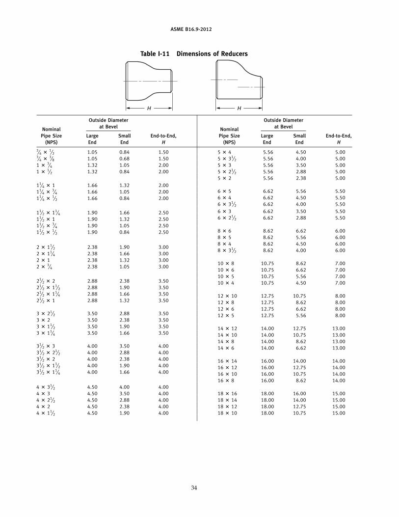
ASME B16.9-2012
Table I-11 Dimensions of Reducers
H H
Outside Diameter Outside Diameterat Bevel at BevelNominal Nominal
Pipe Size Large Small End-to-End, Pipe Size Large Small End-to-End,(NPS) End End H (NPS) End End H
3⁄4 � 1⁄2 1.05 0.84 1.503⁄4 � 3⁄8 1.05 0.68 1.501 � 3⁄4 1.32 1.05 2.001 � 1⁄2 1.32 0.84 2.00
11⁄4 � 1 1.66 1.32 2.0011⁄4 � 3⁄4 1.66 1.05 2.0011⁄4 � 1⁄2 1.66 0.84 2.00
11⁄2 � 11⁄4 1.90 1.66 2.5011⁄2 � 1 1.90 1.32 2.5011⁄2 � 3⁄4 1.90 1.05 2.5011⁄2 � 1⁄2 1.90 0.84 2.50
2 � 11⁄2 2.38 1.90 3.002 � 11⁄4 2.38 1.66 3.002 � 1 2.38 1.32 3.002 � 3⁄4 2.38 1.05 3.00
21⁄2 � 2 2.88 2.38 3.5021⁄2 � 11⁄2 2.88 1.90 3.5021⁄2 � 11⁄4 2.88 1.66 3.5021⁄2 � 1 2.88 1.32 3.50
3 � 21⁄2 3.50 2.88 3.503 � 2 3.50 2.38 3.503 � 11⁄2 3.50 1.90 3.503 � 11⁄4 3.50 1.66 3.50
31⁄2 � 3 4.00 3.50 4.0031⁄2 � 21⁄2 4.00 2.88 4.0031⁄2 � 2 4.00 2.38 4.0031⁄2 � 11⁄2 4.00 1.90 4.0031⁄2 � 11⁄4 4.00 1.66 4.00
4 � 31⁄2 4.50 4.00 4.004 � 3 4.50 3.50 4.004 � 21⁄2 4.50 2.88 4.004 � 2 4.50 2.38 4.004 � 11⁄2 4.50 1.90 4.00
5 � 4 5.56 4.50 5.005 � 31⁄2 5.56 4.00 5.005 � 3 5.56 3.50 5.005 � 21⁄2 5.56 2.88 5.005 � 2 5.56 2.38 5.00
6 � 5 6.62 5.56 5.506 � 4 6.62 4.50 5.506 � 31⁄2 6.62 4.00 5.506 � 3 6.62 3.50 5.506 � 21⁄2 6.62 2.88 5.50
8 � 6 8.62 6.62 6.008 � 5 8.62 5.56 6.008 � 4 8.62 4.50 6.008 � 31⁄2 8.62 4.00 6.00
10 � 8 10.75 8.62 7.0010 � 6 10.75 6.62 7.0010 � 5 10.75 5.56 7.0010 � 4 10.75 4.50 7.00
12 � 10 12.75 10.75 8.0012 � 8 12.75 8.62 8.0012 � 6 12.75 6.62 8.0012 � 5 12.75 5.56 8.00
14 � 12 14.00 12.75 13.0014 � 10 14.00 10.75 13.0014 � 8 14.00 8.62 13.0014 � 6 14.00 6.62 13.00
16 � 14 16.00 14.00 14.0016 � 12 16.00 12.75 14.0016 � 10 16.00 10.75 14.0016 � 8 16.00 8.62 14.00
18 � 16 18.00 16.00 15.0018 � 14 18.00 14.00 15.0018 � 12 18.00 12.75 15.0018 � 10 18.00 10.75 15.00
34
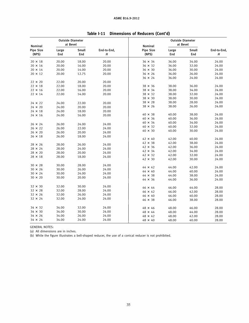
ASME B16.9-2012
Table I-11 Dimensions of Reducers (Cont’d)
Outside Diameter Outside Diameterat Bevel at BevelNominal Nominal
Pipe Size Large Small End-to-End, Pipe Size Large Small End-to-End,(NPS) End End H (NPS) End End H
20 � 18 20.00 18.00 20.0020 � 16 20.00 16.00 20.0020 � 14 20.00 14.00 20.0020 � 12 20.00 12.75 20.00
22 � 20 22.00 20.00 20.0022 � 18 22.00 18.00 20.0022 � 16 22.00 16.00 20.0022 � 14 22.00 14.00 20.00
24 � 22 24.00 22.00 20.0024 � 20 24.00 20.00 20.0024 � 18 24.00 18.00 20.0024 � 16 24.00 16.00 20.00
26 � 24 26.00 24.00 24.0026 � 22 26.00 22.00 24.0026 � 20 26.00 20.00 24.0026 � 18 26.00 18.00 24.00
28 � 26 28.00 26.00 24.0028 � 24 28.00 24.00 24.0028 � 20 28.00 20.00 24.0028 � 18 28.00 18.00 24.00
30 � 28 30.00 28.00 24.0030 � 26 30.00 26.00 24.0030 � 24 30.00 24.00 24.0030 � 20 30.00 20.00 24.00
32 � 30 32.00 30.00 24.0032 � 28 32.00 28.00 24.0032 � 26 32.00 26.00 24.0032 � 24 32.00 24.00 24.00
34 � 32 34.00 32.00 24.0034 � 30 34.00 30.00 24.0034 � 26 34.00 26.00 24.0034 � 24 34.00 24.00 24.00
36 � 34 36.00 34.00 24.0036 � 32 36.00 32.00 24.0036 � 30 36.00 30.00 24.0036 � 26 36.00 26.00 24.0036 � 24 36.00 24.00 24.00
38 � 36 38.00 36.00 24.0038 � 34 38.00 34.00 24.0038 � 32 38.00 32.00 24.0038 � 30 38.00 30.00 24.0038 � 28 38.00 28.00 24.0038 � 26 38.00 26.00 24.00
40 � 38 40.00 38.00 24.0040 � 36 40.00 36.00 24.0040 � 34 40.00 34.00 24.0040 � 32 40.00 32.00 24.0040 � 30 40.00 30.00 24.00
42 � 40 42.00 40.00 24.0042 � 38 42.00 38.00 24.0042 � 36 42.00 36.00 24.0042 � 34 42.00 34.00 24.0042 � 32 42.00 32.00 24.0042 � 30 42.00 30.00 24.00
44 � 42 44.00 42.00 24.0044 � 40 44.00 40.00 24.0044 � 38 44.00 38.00 24.0044 � 36 44.00 36.00 24.00
46 � 44 46.00 44.00 28.0046 � 42 46.00 42.00 28.0046 � 40 46.00 40.00 28.0046 � 38 46.00 38.00 28.00
48 � 46 48.00 46.00 28.0048 � 44 48.00 44.00 28.0048 � 42 48.00 42.00 28.0048 � 40 48.00 40.00 28.00
GENERAL NOTES:(a) All dimensions are in inches.(b) While the figure illustrates a bell-shaped reducer, the use of a conical reducer is not prohibited.
35
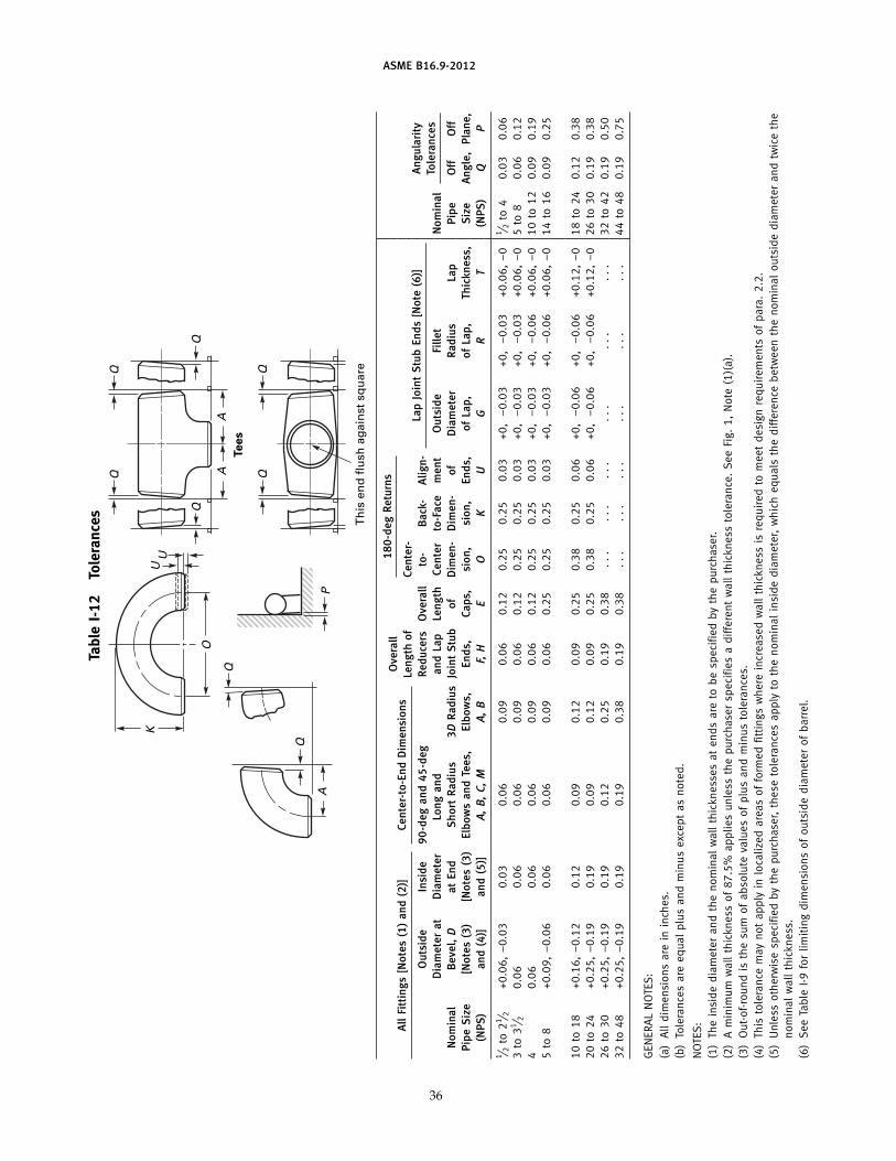
ASME B16.9-2012
Tabl
eI-
12To
lera
nces
A
AA
Q
Q
O
K
Q
Q
UU
Q
Q
P
Tees
Th
is e
nd
flu
sh a
gai
nst
sq
uar
e
180
-deg
Retu
rns
Ove
rall
All
Fitt
ings
[Not
es(1
)an
d(2
)]Ce
nter
-to-
End
Dim
ensi
ons
Leng
thof
Cent
er-
Lap
Join
tS
tub
Ends
[Not
e(6
)]A
ngul
arit
yO
utsi
deIn
side
90-d
egan
d45
-deg
Redu
cers
Ove
rall
to-
Bac
k-A
lign-
Tole
ranc
esD
iam
eter
atD
iam
eter
Long
and
and
Lap
Leng
thCe
nter
to-F
ace
men
tO
utsi
deFi
llet
Nom
inal
Nom
inal
Bev
el,
Dat
End
Sho
rtR
adiu
s3D
Rad
ius
Join
tS
tub
ofD
imen
-D
imen
-of
Dia
met
erR
adiu
sLa
pPi
peO
ffO
ffPi
peS
ize
[Not
es(3
)[N
otes
(3)
Elbo
ws
and
Tees
,El
bow
s,En
ds,
Caps
,si
on,
sion
,En
ds,
ofLa
p,of
Lap,
Thic
knes
s,S
ize
Ang
le,
Plan
e,(N
PS)
and
(4)]
and
(5)]
A,B
,C,
MA,
BF,
HE
OK
UG
RT
(NPS
)Q
P
1 ⁄ 2to
21 ⁄ 2+0
.06,
−0.
030.
030.
060.
090.
060.
120.
250.
250.
03+0
,−
0.03
+0,
−0.
03+0
.06,
−0
1 ⁄ 2to
40.
030.
063
to31 ⁄ 2
0.06
0.06
0.06
0.09
0.06
0.12
0.25
0.25
0.03
+0,
−0.
03+0
,−
0.03
+0.0
6,−
05
to8
0.06
0.12
40.
060.
060.
060.
090.
060.
120.
250.
250.
03+0
,−
0.03
+0,
−0.
06+0
.06,
−0
10to
120.
090.
195
to8
+0.0
9,−
0.06
0.06
0.06
0.09
0.06
0.25
0.25
0.25
0.03
+0,
−0.
03+0
,−
0.06
+0.0
6,−
014
to16
0.09
0.25
10to
18+0
.16,
−0.
120.
120.
090.
120.
090.
250.
380.
250.
06+0
,−
0.06
+0,
−0.
06+0
.12,
−0
18to
240.
120.
3820
to24
+0.2
5,−
0.19
0.19
0.09
0.12
0.09
0.25
0.38
0.25
0.06
+0,
−0.
06+0
,−
0.06
+0.1
2,−
026
to30
0.19
0.38
26to
30+0
.25,
−0.
190.
190.
120.
250.
190.
38..
...
...
...
...
...
.32
to42
0.19
0.50
32to
48+0
.25,
−0.
190.
190.
190.
380.
190.
38..
...
...
...
...
...
.44
to48
0.19
0.75
GEN
ERA
LN
OTE
S:
(a)
All
dim
ensi
ons
are
inin
ches
.(b
)To
lera
nces
are
equa
lpl
usan
dm
inus
exce
ptas
note
d.
NO
TES
:(1
)Th
ein
side
diam
eter
and
the
nom
inal
wal
lth
ickn
esse
sat
ends
are
tobe
spec
ified
byth
epu
rcha
ser.
(2)
Am
inim
umw
all
thic
knes
sof
87.5
%ap
plie
sun
less
the
purc
hase
rsp
ecifi
esa
diff
eren
tw
all
thic
knes
sto
lera
nce.
See
Fig.
1,N
ote
(1)(
a).
(3)
Out
-of-
roun
dis
the
sum
ofab
solu
teva
lues
ofpl
usan
dm
inus
tole
ranc
es.
(4)
This
tole
ranc
em
ayno
tap
ply
inlo
caliz
edar
eas
offo
rmed
fitti
ngs
whe
rein
crea
sed
wal
lth
ickn
ess
isre
quir
edto
mee
tde
sign
requ
irem
ents
ofpa
ra.
2.2.
(5)
Unl
ess
othe
rwis
esp
ecifi
edby
the
purc
hase
r,th
ese
tole
ranc
esap
ply
toth
eno
min
alin
side
diam
eter
,w
hich
equa
lsth
edi
ffer
ence
betw
een
the
nom
inal
outs
ide
diam
eter
and
twic
eth
eno
min
alw
all
thic
knes
s.(6
)S
eeTa
ble
I-9fo
rlim
itin
gdi
men
sion
sof
outs
ide
diam
eter
ofba
rrel
.
36

ASME B16.9-2012
MANDATORY APPENDIX IIREFERENCES
The following is a list of standards and specificationsreferenced in this Standard. Unless otherwise specified,the latest edition of ASME publications shall apply.
ASME B16.5, Pipe Flanges and Flanged Fittings: NPS 1⁄2Through NPS 24 Metric/Inch Standard
ASME B16.25, Buttwelding EndsASME B16.49, Factory-Made Wrought Steel Buttwelding
Induction Bends for Transportation and DistributionSystems
ASME B31, Code for Pressure PipingASME B36.10M, Welded and Seamless Wrought Steel
PipeASME B36.19M, Stainless Steel PipeASME Boiler and Pressure Vessel CodePublisher: The American Society of Mechanical
Engineers (ASME), Two Park Avenue, New York, NY10016-5990; Order Department: 22 Law Drive, P.O.Box 2900, Fairfield, NJ 07007-2900 (www.asme.org)
ASTM A234/A234M-11a, Specification for PipingFittings of Wrought Carbon Steel and Alloy Steel forModerate and High Temperature Service
ASTM A403/A403M-11, Specification for WroughtAustenitic Stainless Steel Piping Fittings
ASTM A420/A420M-10a, Specification for PipingFittings of Wrought Carbon Steel and Alloy Steel forLow-Temperature Service
ASTM A815/A815M-10a, Specification for WroughtFerritic, Ferritic/Austenitic and Martensitic StainlessSteel Piping Fittings
37
ASTM A960/A960M-10, Specification for CommonRequirements for Wrought Steel Piping Fittings
ASTM B361-08, Specification for Factory-Made WroughtAluminum and Aluminum-Alloy Welding Fittings
ASTM B363-06a, Specification for Seamless and WeldedUnalloyed Titanium and Titanium Alloy WeldingFittings
ASTM B366-10a, Specification for Factory-MadeWrought Nickel and Nickel Alloy Fittings
ASTM E29-08, Practice for Using Significant Digits inTest Data to Determine Conformance WithSpecifications
Publisher: American Society for Testing and Materials(ASTM International), 100 Barr Harbor Drive, P.O.Box C700, West Conshohocken, PA 19428-2959(www.astm.org)
ISO 6708:1995, Pipework components — Definition andselection of DN (nominal size)
ISO 9000:2005, Quality management systems —Fundamentals and vocabulary
ISO 9001:2008, Quality management systems —Requirements
ISO 9004:2009, Managing for the sustained success ofan organization — A quality management approach
Publisher: International Organization forStandardization (ISO Central Secretariat), 1, ch. de laVoie-Creuse, CP 56, CH-1211, Geneva 20, Switzerland(www.iso.org)
(12)

ASME B16.9-2012
NONMANDATORY APPENDIX AQUALITY SYSTEM PROGRAM
The products manufactured in accordance with thisStandard shall be produced under a Quality SystemProgram following the principles of an appropriate stan-dard from the ISO 9000 series.1 A determination of theneed for registration and/or certification of the product
1 The series is also available from the American NationalStandards Institute (ANSI) and the American Society for Quality(ASQ) as American National Standards that are identified by theprefix “Q,” replacing the prefix “ISO.” Each standard of the seriesis listed under References in Mandatory Appendix II.
38
manufacturer’s quality system by an independent orga-nization shall be the responsibility of the manufacturer.The detailed documentation demonstrating programcompliance shall be available to the purchaser at themanufacturer’s facility. A written summary descriptionof the program utilized by the product manufacturershall be available to the purchaser upon request. Theproduct manufacturer is defined as the entity whose nameor trademark appears on the product in accordance withthe marking or identification requirements of thisStandard.

B16 AMERICAN NATIONAL STANDARDS FOR PIPING,PIPE FLANGES, FITTINGS, AND VALVES
Gray Iron Pipe Flanges and Flanged Fittings (Classes 25, 125, and 250) . . . . . . . . . . . . . . . . . . . . . . . . . . . . . . . . . . . . . . . . . . . . . . . B16.1-2010Malleable Iron Threaded Fittings: Classes 150 and 300. . . . . . . . . . . . . . . . . . . . . . . . . . . . . . . . . . . . . . . . . . . . . . . . . . . . . . . . . . . . . B16.3-2011Gray Iron Threaded Fittings: Classes 125 and 250 . . . . . . . . . . . . . . . . . . . . . . . . . . . . . . . . . . . . . . . . . . . . . . . . . . . . . . . . . . . . . . . . . B16.4-2011Pipe Flanges and Flanged Fittings NPS 1⁄2 Through NPS 24 Metric/Inch Standard . . . . . . . . . . . . . . . . . . . . . . . . . . . . . . . . . . . . . . . . B16.5-2009Factory-Made Wrought Buttwelding Fittings. . . . . . . . . . . . . . . . . . . . . . . . . . . . . . . . . . . . . . . . . . . . . . . . . . . . . . . . . . . . . . . . . . . . . . . B16.9-2012Face-to-Face and End-to-End Dimensions of Valves . . . . . . . . . . . . . . . . . . . . . . . . . . . . . . . . . . . . . . . . . . . . . . . . . . . . . . . . . . . . . . . B16.10-2009Forged Fittings, Socket-Welding and Threaded . . . . . . . . . . . . . . . . . . . . . . . . . . . . . . . . . . . . . . . . . . . . . . . . . . . . . . . . . . . . . . . . . . . B16.11-2011Cast Iron Threaded Drainage Fittings . . . . . . . . . . . . . . . . . . . . . . . . . . . . . . . . . . . . . . . . . . . . . . . . . . . . . . . . . . . . . . . . . . . . . . . . . . . B16.12-2009Ferrous Pipe Plugs, Bushings, and Locknuts with Pipe Threads . . . . . . . . . . . . . . . . . . . . . . . . . . . . . . . . . . . . . . . . . . . . . . . . . . . . . B16.14-2010Cast Copper Alloy Threaded Fittings. . . . . . . . . . . . . . . . . . . . . . . . . . . . . . . . . . . . . . . . . . . . . . . . . . . . . . . . . . . . . . . . . . . . . . . . . . . . B16.15-2011Cast Copper Alloy Solder Joint Pressure Fittings . . . . . . . . . . . . . . . . . . . . . . . . . . . . . . . . . . . . . . . . . . . . . . . . . . . . . . . . . . . . . . . . . . B16.18-2012Metallic Gaskets for Pipe Flanges: Ring-Joint, Spiral-Wound, and Jacketed . . . . . . . . . . . . . . . . . . . . . . . . . . . . . . . . . . . . . . . . . . . . . B16.20-2007Nonmetallic Flat Gaskets for Pipe Flanges . . . . . . . . . . . . . . . . . . . . . . . . . . . . . . . . . . . . . . . . . . . . . . . . . . . . . . . . . . . . . . . . . . . . . . . B16.21-2005Wrought Copper and Copper Alloy Solder-Joint Pressure Fittings. . . . . . . . . . . . . . . . . . . . . . . . . . . . . . . . . . . . . . . . . . . . . . . . . . . . . B16.22-2012Cast Copper Alloy Solder Joint Drainage Fittings: DWV . . . . . . . . . . . . . . . . . . . . . . . . . . . . . . . . . . . . . . . . . . . . . . . . . . . . . . . . . . . . . B16.23-2011Cast Copper Alloy Pipe Flanges and Flanged Fittings: Classes 150, 300, 600, 900, 1500, and 2500 . . . . . . . . . . . . . . . . . . . . . . . B16.24-2011Buttwelding Ends. . . . . . . . . . . . . . . . . . . . . . . . . . . . . . . . . . . . . . . . . . . . . . . . . . . . . . . . . . . . . . . . . . . . . . . . . . . . . . . . . . . . . . . . . . . B16.25-2012Cast Copper Alloy Fittings for Flared Copper Tubes. . . . . . . . . . . . . . . . . . . . . . . . . . . . . . . . . . . . . . . . . . . . . . . . . . . . . . . . . . . . . . . . B16.26-2011Wrought Copper and Wrought Copper Alloy Solder-Joint Drainage Fittings — DWV. . . . . . . . . . . . . . . . . . . . . . . . . . . . . . . . . . . . . . . B16.29-2012Manually Operated Metallic Gas Valves for Use in Gas Piping Systems Up to 125 psi
(Sizes NPS 1⁄2 Through NPS 2) . . . . . . . . . . . . . . . . . . . . . . . . . . . . . . . . . . . . . . . . . . . . . . . . . . . . . . . . . . . . . . . . . . . . . . . . . . . . . . B16.33-2012Valves — Flanged, Threaded, and Welding End. . . . . . . . . . . . . . . . . . . . . . . . . . . . . . . . . . . . . . . . . . . . . . . . . . . . . . . . . . . . . . . . . . . B16.34-2012Orifice Flanges . . . . . . . . . . . . . . . . . . . . . . . . . . . . . . . . . . . . . . . . . . . . . . . . . . . . . . . . . . . . . . . . . . . . . . . . . . . . . . . . . . . . . . . . . . . . . B16.36-2009Large Metallic Valves for Gas Distribution: Manually Operated, NPS 21⁄2 (DN 65)
to NPS 12 (DN 300), 125 psig (8.6 bar) Maximum. . . . . . . . . . . . . . . . . . . . . . . . . . . . . . . . . . . . . . . . . . . . . . . . . . . . . . . . . . . . . . B16.38-2012Malleable Iron Threaded Pipe Unions: Classes 150, 250, and 300. . . . . . . . . . . . . . . . . . . . . . . . . . . . . . . . . . . . . . . . . . . . . . . . . . . B16.39-2009Manually Operated Thermoplastic Gas Shutoffs and Valves in Gas Distribution Systems . . . . . . . . . . . . . . . . . . . . . . . . . . . . . . . . . B16.40-2008Ductile Iron Pipe Flanges and Flanged Fittings: Classes 150 and 300 . . . . . . . . . . . . . . . . . . . . . . . . . . . . . . . . . . . . . . . . . . . . . . . . B16.42-2011Manually Operated Metallic Gas Valves for Use in Aboveground Piping Systems Up to 5 psi . . . . . . . . . . . . . . . . . . . . . . . . . . . . . B16.44-2012Cast Iron Fittings for Sovent® Drainage Systems. . . . . . . . . . . . . . . . . . . . . . . . . . . . . . . . . . . . . . . . . . . . . . . . . . . . . . . . . . .B16.45-1998 (R2006)Large Diameter Steel Flanges NPS 26 Through NPS 60 Metric/Inch Standard . . . . . . . . . . . . . . . . . . . . . . . . . . . . . . . . . . . . . . . . . . B16.47-2011Line Blanks . . . . . . . . . . . . . . . . . . . . . . . . . . . . . . . . . . . . . . . . . . . . . . . . . . . . . . . . . . . . . . . . . . . . . . . . . . . . . . . . . . . . . . . . . . . . . . . B16.48-2010Factory-Made Wrought Steel Buttwelding Induction Bends for Transportation and Distribution Systems . . . . . . . . . . . . . . . . . . . . . B16.49-2012Wrought Copper and Copper Alloy Braze-Joint Pressure Fittings . . . . . . . . . . . . . . . . . . . . . . . . . . . . . . . . . . . . . . . . . . . . . .B16.50-2001 (R2008)Copper and Copper Alloy Press-Connect Pressure Fittings . . . . . . . . . . . . . . . . . . . . . . . . . . . . . . . . . . . . . . . . . . . . . . . . . . . . . . . . . . B16.51-2011
The ASME Publications Catalog shows a complete list of all the Standards published by the Society. For a complimentary catalog, or the latestinformation about our publications, call 1-800-THE-ASME (1-800-843-2763).

ASME Services
ASME is committed to developing and delivering technical information. At ASME’s Customer Care, we make every effort to answer your questionsand expedite your orders. Our representatives are ready to assist you in the following areas:
ASME Press Member Services & Benefits Public InformationCodes & Standards Other ASME Programs Self-Study CoursesCredit Card Orders Payment Inquiries Shipping InformationIMechE Publications Professional Development Subscriptions/Journals/MagazinesMeetings & Conferences Short Courses Symposia VolumesMember Dues Status Publications Technical Papers
How can you reach us? It’s easier than ever!
There are four options for making inquiries* or placing orders. Simply mail, phone, fax, or E-mail us and a Customer Care representative willhandle your request.
Mail Call Toll Free Fax—24 hours E-Mail—24 hoursASME US & Canada: 800-THE-ASME 973-882-1717 [email protected] Law Drive, Box 2900 (800-843-2763) 973-882-5155Fairfield, New Jersey Mexico: 95-800-THE-ASME07007-2900 (95-800-843-2763)
Universal: 973-882-1167
* Customer Care staff are not permitted to answer inquiries about the technical content of this code or standard. Information as to whetheror not technical inquiries are issued to this code or standard is shown on the copyright page. All technical inquiries must be submitted inwriting to the staff secretary. Additional procedures for inquiries may be listed within.


J10912
ASME B16.9-2012