proportional relief valves - ssp fittings
TRANSCRIPT

02
Proportional Relief Valves
Liquid or Gas Service
Set Pressures: 10 to 6000 psig (0.7 to 413 bar)
Variety of Seal Materials
R Series
www.mySSP.com
Variety of End Connections
1/4 and 1/2 in. (6, 8 and 12 mm)

Industry Standard Products Made Better
At SSP, we are proud to be an American manufacturing success story.
100% of our products are made in America. All of our manufacturing is performed in our 165,000 sq. ft. facility located near Cleveland, Ohio. Our facility is the largest vertically integrated, single-site operation in the industry. In addition to manufacturing and assembly, we have closed die forging, tool & die design, product engineering and testing operations under the same roof with customer service and management.
Made in America is good business. Not only do we make everything in America, we use American suppliers too. Buying American allows us to have better quality control and a more reliable supply chain. We can work more closely within our walls and with our suppliers to improve quality, reduce costs, and shorten lead times, which means faster service and better products for you.
Support where it counts. SSP products and services are supported by more than 4000 people and 350 distributor locations around the globe. For a distributor near you, contact SSP Customer Service or visit www.mySSP.com/distributors.
ww
w.mySSP.com
R
03
Introduction ............................................. 3
Product Design ........................................ 4
Pressure-Temperature .............................5
Set and Resealing Pressure .....................5
Materials of Construction .........................6
Flow Data ...................................................7
Ordering Information .................................8
Options & Accessories ............................ 9
Special Order Instructions .................... 10
Safety, Warranty .................................... 10
TABLE of CONTENTS
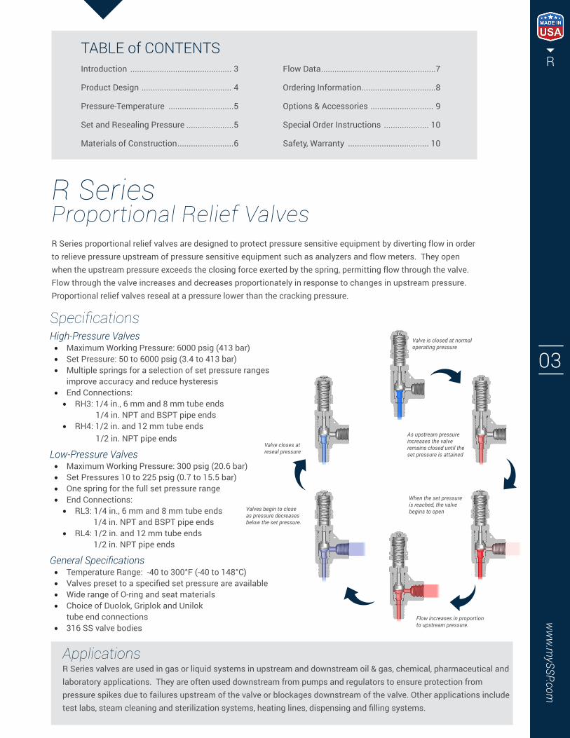
R Series Proportional Relief ValvesR Series proportional relief valves are designed to protect pressure sensitive equipment by diverting flow in order to relieve pressure upstream of pressure sensitive equipment such as analyzers and flow meters. They open when the upstream pressure exceeds the closing force exerted by the spring, permitting flow through the valve. Flow through the valve increases and decreases proportionately in response to changes in upstream pressure. Proportional relief valves reseal at a pressure lower than the cracking pressure.
SpecificationsHigh-Pressure Valves• Maximum Working Pressure: 6000 psig (413 bar)• Set Pressure: 50 to 6000 psig (3.4 to 413 bar)• Multiple springs for a selection of set pressure ranges
improve accuracy and reduce hysteresis• End Connections:
• RH3: 1/4 in., 6 mm and 8 mm tube ends 1/4 in. NPT and BSPT pipe ends
• RH4: 1/2 in. and 12 mm tube ends 1/2 in. NPT pipe ends
Low-Pressure Valves• Maximum Working Pressure: 300 psig (20.6 bar)• Set Pressures 10 to 225 psig (0.7 to 15.5 bar)• One spring for the full set pressure range• End Connections:
• RL3: 1/4 in., 6 mm and 8 mm tube ends 1/4 in. NPT and BSPT pipe ends
• RL4: 1/2 in. and 12 mm tube ends 1/2 in. NPT pipe ends
General Specifications• Temperature Range: -40 to 300°F (-40 to 148°C)• Valves preset to a specified set pressure are available• Wide range of O-ring and seat materials• Choice of Duolok, Griplok and Unilok
tube end connections• 316 SS valve bodies
ApplicationsR Series valves are used in gas or liquid systems in upstream and downstream oil & gas, chemical, pharmaceutical and laboratory applications. They are often used downstream from pumps and regulators to ensure protection from pressure spikes due to failures upstream of the valve or blockages downstream of the valve. Other applications include test labs, steam cleaning and sterilization systems, heating lines, dispensing and filling systems.
Valve is closed at normal operating pressure
As upstream pressure increases the valve remains closed until the set pressure is attained
When the set pressure is reached, the valve begins to open
Flow increases in proportion to upstream pressure.
Valves begin to close as pressure decreases below the set pressure.
Valve closes at reseal pressure

04
Product Design
RH3 RH4
Series
RL3 RL4
RH Series
4
1
6
3
5
2
7
Meets ASME B31.3 design pressure calculations
CAPAllows easy external set pressure adjustment.
SPRINGAdjusts to provide set pressure. Springs are color coded to indicate the set pressure range.
LABELIdentifies spring set pressure range. Label colors are matched with the spring colors.
LOCKNUTMaintains cap position to lock in the pressure setting.
LOCK WIRE CAPABILITYSecures cap to maintain set pressure.
STEM SEALQuad seal reduces friction for greater accuracy.
O-RINGFully supported O-ring provides durable elastomer seal for positive shutoff. See below for other designs.
2
1
6
3
7
4
5

Technical Information
Resealing PressureThe resealing pressure is the upstream pressure at which the valve closes and flow stops. It is always lower than set pressure. Every R series proportional relief valve is tested for set and resealing performance. The chart below provides parameters for resealing values within specific pressure ranges.
Note: Valves that have not been actuated for a period of time may have higher initial cracking pressures.
ww
w.mySSP.com
R
05
General Specification
Set Pressure RepeatabilityThe table below estimates the repeatability of set pressure, the pressure at which flow begins, after initial actuation of the valve.
Back Pressure(RL Series Valves only)System back pressure increases the set pressure of the RL Series valves. To compensate when setting the valve, subtract 80% of the back pressure from the desired set pressure.
Example• Desired set pressure: 200 psig. • System back pressure: 60 psig.• Set pressure: 200 - (60 x 0.80) = 152 psig
Note: Valves are set at atmospheric outlet pressure.
Series Test Set Pressurepsig (bar)
Minimum Resealing Pressure% of Set Pressure
RH3, RH4100 to 200 (6.8 to 13.7) 50
850 to 1000 (58.5 to 68.9) 85
RL3, RL410 to 20 (0.7 to 1.3) 50
175 to 225 (12.0 to 15.5) 90
SeriesRH3 RH4 RL3 / RL4
psig, (bar)
Max. Working Pressure 6000 (413 )1 6000 (413 ) 300 (20.6)
Max. Outlet Pressure2 1500 (103) 2500 (172) 225 (15.5)
Set Pressure Range 50 to 6000 (3.4 to 413) 50 to 1500 (3.4 to 103) 10 to 225 (0.7 to 15.5)
Cleaning and PackagingR Series relief valves are cleaned and packaged according to SSP Standard Cleaning and Packaging Processes. Cleaning in accordance with ASTM G93 Level C, Cleaning Methods and Cleanliness Levels for Material and Equipment Used in Oxygen-Enriched Environments is also available.
1 Up to 8000 psig (551 bar) during relief RH3 only2 Outlet pressure not to exceed inlet pressure
Temperature Set Pressure Repeatability
60 to 80°F (15 to 26°C) The greater of ± 3.0 psig (0.20 bar) or 5%
< 60°F (15°C) The greater of ± 6.0 psig (0.40 bar) or 20%
>80°F (26°C)
Seal Materials
RH Series RL Series
Temperature Range°F (°C)
RH3 RH4 Temperature Range°F (°C)
RL3 & RL4
Max Set Pressure, psig (bar) Max Set Pressure, psig (bar)
Fluorocarbon FKM 25 to 300 (-4 to 148) 6000 (413) 1500 (103) 10 to 275 (-12 to 135)
225 (15.3)Nitrile 0 to 250 (-17 to 121) 6000 (413) 1500 (103) -10 to 250 (-23 to 121)
Ethylene Propylene 30 to 250 (-1 to 121) 6000 (413) 1500 (103) -40 to 250 (-40 to 121)
PerfluoroelastomerFFKM
30 (-1) 2500 (172)
1500 (103) 30 to 200 (-1 to 93) 225 (15.3)
40 (4) 6000 (413)
70 (21) 6000 (413)
150 (65) 3000 (207)
200 (93) 1500 (103)
Pressure - Temperature

06
Technical Information
Selection and ApplicationIt is the system designer’s responsibility to determine the requirements for their application and whether R Se-ries relief valves conform to the codes.
In some systems, relief valves are required to meet specific safety codes which require valves to open completely at a set pressure. R series proportional relief valves open gradually as the pressure increases. Therefore they cannot be certified to ASME, PED, or any other codes for safety relief valves.
SSP proportional relief valves should never be used as ASME Boiler and Pressure Vessel Code safety relief devices or as “Safety Accessories” defined in the Pressure Equipment Directive 97/23/EC.
Materials of Construction
ID ComponentBody Material
316 SS
1 Plug Nickel-Plated Steel
2 Cap 316 SS / A479
3 Label Polyester
4 Lock Nut 316 SS / A479
5 Spring S17700 / AMS 5678
6 Spring Support 316 SS / A479
7* Bonnet 316 SS / A479
8* O-ring Fluorocarbon FKM
9* Quad Seal Low-Friction Coated Fluorocarbon FKM
10* Retainer 316 SS / A666
11* Stem 316 SS / A276
12* Sealing Disc Fluorocarbon FKM and316 SS / A479
13* Seat 316 SS / A479
14* Gasket PTFE-Coated316 SS / A479
15* Seat Retainer 316 SS / A479
16* O-ring Fluorocarbon FKM
17* Insert 316 SS / A479
18* Body 316 SS / A182
LubricantMolybdenum Disulfide-
Based Dry Film and PTFE-Based
RL3 OnlyRH3 Only
RH3 and RL3
* Wetted Components
RH4 and RL4
RH4 Only RL4 Only
1
9
1416
15
11
13
17
12
11
5
8
6
7
18
2
3
4
10
2
3
4
5
6
7
9
11
1
8
15
16
18
17
13
11
12
14

RH3 & RH4 SeriesAir Flow
Air Flow
Water Flow
Water Flow
ww
w.mySSP.com
R
07
Flow Data (70°F/20°C)
std. ft³/min.
std. l/min.
Inle
t Pre
ssur
e, p
sig
Inle
t Pre
ssur
e, b
ar
Flow begins at set pressure
400
600
800
1000
1200
20020
30
40
50
60
70
10 20 50 1000 5 15 35 75
300 500 1500 25000 200 400 1000 2000750100
80
RH3 RH4US gal/min.
l/min.
ΔP, p
sig
ΔP, b
ar
RH3 RH4
200
300
400
500
600
700
800
100
20
30
40
50
10
0.25 0.50 0.75 1.00 1.25 1.50 1.75 2.000
1 2 3 4 5 6 70900
60
Flow begins at set pressure
US gal/min.
l/min.
ΔP, p
sig
ΔP, b
ar
2000
3000
4000
5000
6000
7000
150
200
250
300
350
400
0.05 0.15 0.20 0.30
0.2 0.6 1.0 1.10
1000100
0.4 0.8
0.10 0.25
450
50
RH3 RH4
Flow begins at set pressure
Water Flow
RL3 & RL4 SeriesAir Flow
std ft³/min.
std l/min.
Inle
t Pre
ssur
e, ps
ig
Inle
t Pre
ssur
e, b
ar
50
100
150
200
250
300
0
5.0
7.5
10.0
12.5
15.0
02.5 5.0 7.5 10.0 12.5 15.0 17.5 20.00
75 150 225 300 375 450 5250
20.0
2.5
17.5
RL3 RL4
Flow begins at set pressure US gal/min.
l/min.
ΔP, p
sig
ΔP, b
ar
50
100
150
200
250
300
00.25 0.50 0.75 1.00 1.25 1.50 1.75 2.000
1 2 3 4 5 6 70
5.0
7.5
10.0
12.5
15.0
20.0
2.5
17.5
0
RL3 RL4
Flow begins at set pressure

08
To order, locate the Basic Part Number for the valve for your application from the tables below, then add the required options and accessories from pages 9.
C
B
AMax.
EMax.
0.06 in. (1.5 mm)lock wire hole
0.09 (2.2 mm)lock wire hole
D
HMax.
Note: RL Series valves are shipped standard with springs installed in the valve.
RH3 and RH4 Series High Pressure Valves
Inlet/Outlet Basic PartNumber
Dimensions, in. (mm)1
Type(s) Size A B C D E H
Orifice 0.14 (3.6 mm), Set Pressures from 50 to 6000 psig (3.4 to 413 bar)
Fractional Tube Fitting2 1/4 in. RH3D4 2.70
(68.6)1.44
(36.6)1.60
(40.6)0.41
(10.4)4.14(105)
4.09(104)
Metric Tube Fitting2
6 mm RH3DM6 2.70(68.6)
1.44(36.6)
1.60(40.6)
0.41(10.4)
4.14(105)
4.09(104)
8 mm RH3DM8 2.70(68.6)
1.44(36.6)
1.60(40.6)
0.41(10.4)
4.14(105)
4.09(104)
Male NPT to Tube2 1/4 in. RH34PMD4 2.70
(68.6)1.19
(30.2)1.60
(40.6)0.41
(10.4)3.89
(98.8)4.09(104)
Male NPT to Female NPT 1/4 in. RH34PM4PF 2.70
(68.6)1.19
(30.2)1.17
(29.7)0.41
(10.4)3.89
(98.8)4.09(104)
Male BSPT to Female BSPT 1/4 in. RH34MRT4FRT 2.70
(68.6)1.19
(30.2)1.17
(29.7)0.41
(10.4)3.89
(98.8)4.09(104)
Orifice 0.25 (6.4 mm), Set Pressures from 50 to1500 psig (3.4 to 103 bar)
Fractional Tube Fitting2 1/2 in. RH4D8 4.09
(104)1.83
(46.5)1.83
(46.5)0.47
(11.9)5.92(150)
5.37(136)
Metric Tube Fitting2 12 mm RH4DM12 4.09
(104)1.83
(46.5)1.83
(46.5)0.47
(11.9)5.92(150)
5.37(136)
Male NPT to Tube Fitting2 1/2 in. RH48PMD8 4.09
(104)1.43
(36.3)1.83
(46.5)0.47
(11.9)5.52(140)
5.37(136)
Male NPT to Female NPT 1/2 in. RH48PM8PF 4.09
(104)1.43
(36.3)1.43
(36.3)0.47
(11.9)5.52(140)
5.37(136)
1Dimension are for reference only and subject to change. 2Basic part numbers specify Duolok two-ferrule tube ends. For Unilok single-ferrule or Griplok dual ferrule, see page 9.
Note: RH Series valves are shipped standard without springs. To order spring kits, valves with springs installed, or factory set valves, see the instructions on page 9.
Inlet /Outlet Basic PartNumber
Dimensions, in. (mm)1
Type(s) Size A B C D E H
Orifice 0.19 (4.8 mm), Set Pressures from 10 to 225 psig (0.7 to 15.5 bar)
Fractional Tube Fitting2 1/4 in. RL3D4 2.70
(68.6)1.44
(36.6)1.60
(40.6)0.41
(10.4)4.14(105)
4.09(104)
Metric Tube Fitting2
6 mm RL3DM6 2.70(68.6)
1.44(36.6)
1.60(40.6)
0.41(10.4)
4.14(105)
4.09(104)
8 mm RL3DM8 2.70(68.6)
1.44(36.6)
1.60(40.6)
0.41(10.4)
4.14(105)
4.09(104)
Male NPT to Tube Fitting2 1/4 in. RL34PMD4 2.70
(68.6)1.19
(30.2)1.60
(40.6)0.41
(10.4)4.14(105)
4.09(104)
Male NPT to Female NPT 1/4 in. RL34PM4PF 2.70
(68.6)1.19
(30.2)1.17
(29.7)0.41
(10.4)3.89
(98.8)4.09(104)
Male BSPT to Female BSPT 1/4 in. RL34MRT4FRT 2.70
(68.6)1.19
(30.2)1.17
(29.7)0.41
(10.4)3.89
(98.8)4.09(104)
Orifice 0.25 (6.4 mm), Set Pressures from 10 to 225 psig (0.7 to 15.5 bar)
Fractional Tube Fitting2 1/2 in. RL4D8 4.09
(104)1.83
(46.5)1.83
(46.5)0.47
(11.9)5.92(150)
5.37(136)
Metric Tube Fitting2 12 mm RL4DM12 4.09
(104)1.83
(46.5)1.83
(46.5)0.47
(11.9)5.92(150)
5.37(136)
Male NPTto Tube Fitting2 1/2 in. RL48PMD8 4.09
(104)1.43
(36.3)1.83
(46.5)0.47
(11.9)5.52(140)
5.37(136)
Male NPT to Female NPT 1/2 in. RL48PM8PF 4.09
(104)1.43
(36.3)1.43
(36.3)0.47
(11.9)5.52(140)
5.37(136)
Basic Part Numbers and Dimensions
RL3 and RL4 Series Low Pressure Valves
Ordering Information
1Dimension are for reference only and subject to change. 2Base part numbers specify Duolok two-ferrule tube ends. For Unilok single-ferrule or Griplok dual ferrule, see page 9.

Spring OptionsRL Series valves are shipped with springs installed.
RH Series valves are shipped standard without springs. To order RH Series valves with factory installed springs locate the required pressure range from the table below then insert the spring designator into the part number. Example: RH3D4-316-C
Set Pressure Rangepsig (bar) Spring Designator Spring Color
RH3
50 to 350 (3.4 to 24.1) -A Blue
350 to 750 (24.1 to 51.7) -B Yellow
750 to 1500 (51.7 to 103) -C Purple
1500 to 2250 (103 to 155) -D Orange
2250 to 3000 (155 to 206) -E Brown
3000 to 4000 (206 to 275) -F White
4000 to 5000 (275 to 344) -G Red
5000 to 6000 (344 to 413) -H Green
RH4
50 to 350 (3.4 to 24.1) -A Blue
350 to 750 (24.1 to 51.7) -B Yellow
750 to 1500 (51.7 to 103) -C Purple
RL3 / RL4
10 to 225 (0.7 to 15.5) Blank N/A
Spring KitsSpring kits include the spring, spring support, label, 302 SS lock-wire with seal, and installation instructions.
To order spring kits, use the series and size followed by “-SK-177.” For RH Series valves add the spring designator from the Spring Options table above. Examples: RH4-SK-177-C RL4-SK-177
Tube Fitting End ConnectionsSSP offers three tube fitting designs. Duolok two-ferrule tube fittings are standard. To specify a different design, select the designator from the table below, then substitute it for the “D” in the part number. Example: RL3U4-316
Design Description Designator
Duolok 2-Ferrule D
Unilok 1-Ferrule U
Griplok 2-Ferrule G
Seal MaterialsThe standard seal material for R Series valves is Fluorocarbon FKM. To order non-standard seals, add the designator to the part number. Example: RH3D4-316-BN
Seal MaterialDesignator
Valve Seal Kit
Fluorocarbon FKM Blank -V
Nitrile Rubber -BN
Ethylene Propylene -EP
Perfluoroelastomer FFKM -FFKM
RH3 RH4 RL3 RL4
Basic Part Number
RH3-RK-316 RH4-RK-316 RL3-RK-316 RL4-RK-316
Kit Contents
O-rings (2)Quad-SealRetainer
Instructions
O-rings (2)Quad-Seal
Instructions
O-ringQuad-SealRetainer
Sealing DiscInstructions
O-ringQuad-Seal
Sealing DiscInstructions
Seal Replacement KitsTo order a replacement seal kit, add a seal material designator from the seal material table into the seal kit basic ordering number from the table below. Example: RL3-RK-316-V
Factory Set Valves R Series valves are available preset to a specified set pressure. Valves are set, tested, locked, and tagged with the set pressure. Certificates of testing are included. Allowable factory set pressure range is ± 5% from requested set pressure. To order preset RH Series valves, add the spring designator and the desired set pressure to the part number. For RL Series valves include the set pressure only. Example RH4D8-316-C850 or RH4D8-316-C59BAR RL3D4-316-100 or RL4D8-316-7BAR
Options & Accessories
Manual Override HandlesA manual override handle allows operators to open the valve without changing the set pressure. To order relief valves with manual override handles, add -MO to the part number. Example: RH4D4-316-MOManual override handles can only be used with:• RH3 series—A, B, and C springs only• RH4 series—A spring only• RL3 and RL4 series—standard spring
Series Maximum Height(Closed Position) Kit Part#
RH3, RL3 5.16 in. (131 mm) R3-MOK
RH4, RL4 6.78 in. (172 mm) R4-MOK
Handle diameter is 1.50 in. (38.1 mm).
Manual Override Handle KitsUse the kit part number from the table below to order man-ual override kits for your valve series. Each kit contains an aluminum handle, 316 SS pull rod and instructions.
Special CleaningValves are available cleaned in compliance with ASTM G93 Level C and CGA G-4.1, Cleaning Methods and Cleanliness Levels for Material and Equipment Used in Oxygen-Enriched Environments. To specify, add -XP98 to the part number. Example: RH3D4-316-XP98
For more information about other types of special cleaning, please contact SSP Customer Service.
ww
w.mySSP.com
R
09

10
Special OrdersThe Basic Part Numbers and Dimensions tables contain only the most popular valve configurations; many more are available. If the required valve configuration is not in the Basic Part Numbers and Dimensions tables, use the chart below to build part numbers for quotation purposes.
1 Tube fitting end connection part numbers are formatted Type followed by Size. Example: D4 Pipe ends are formatted Size followed by Type. Example: 4PF If both ends are the same, use only one end connection designator. Example: RL3D4-3162 Add options designators to the end of the Basic Part Number in alphabetical order.
Important Information IMPROPER SELECTION OR IMPROPER USE OF THE PRODUCTS DESCRIBED HEREIN OR RELATED ITEMS CAN CAUSE PERSONAL INJURY AND PROPERTY DAMAGE. It is the sole responsibility of the system designers and users to properly select and use products for their specific applications. This document has been provided to users with technical expertise as a reference for further investigation to determine specific product needs relative to their design requirements.
A B C D ERH3 4PM 4PF -316 -C825-EP-MO
Series/Size Inlet Outlet Body Material Options
A SERIES / SIZERL3 0.19 OrificeRL4 0.25 OrificeRH3 0.14 OrificeRH4 0.25 Orifice
SPRINGS
D BODY MATERIAL-316 316 SS
FACTORY SET PRESSUREAdd the actual set pressure desired. See page 9 for more information.
OTHER OPTIONS-XP98 Special Cleaning per ASTM G93, Level C and CGA G-4.1-MO Manual override handle. See notes on page 9 for limitations.
B CFractional Sizes:4 1/4 in.8 1/2 in.
Metric Sizes:M6 6 mmM8 8 mmM12 12 mm
Type:D Duolok® Tube FittingU Unilok® Tube FittingG Griplok® Tube FittingPF Female NPTPM Male NPTFRT Female BSPTMRT Male BSPT
+
SSP Limited Lifetime WarrantySSP valves are backed by the SSP Limited Lifetime Warranty. This warranty is available from your local distributor or at www.mySSP.com.
INLET1 + OUTLET1
Designator Set Pressure RangeRL3 & RL4 Series psig (bar)Blank 10 to 225 (0.7 to 15.5)
RH3 Series psig (bar)Blank No Spring
-A 50 to 350 (3.4 to 24.1)-B 350 to 750 (24.1 to 51.7)-C 750 to 1500 (51.7 to 103)-D 1500 to 2250 (103 to 155)-E 2250 to 3000 (155 to 206)-F 3000 to 4000 (206 to 275)-G 4000 to 5000 (275 to 344)-H 5000 to 6000 (344 to 413)
RH4 Series psig (bar)Blank No Spring-A 50 to 350 (3.4 to 24.1)-B 350 to 750 (24.1 to 51.7) -C 750 to 1500 (51.7 to 103)
SEAL MATERIALSBlank Fluorocarbon FKM-BN Nitrile-EP Ethylene Propylene-FFKM Perfluoroelastomer
FFKM
E OPTIONS2
D

ww
w.mySSP.com
R
11
More SSP Products
TubingSSP offers straight and coiled seamless 316 stainless steel instrumentation tubing for instrumentation, process and utility applications.
Tools & AccessoriesSSP TurnPro professional hand tools, power tools and installation training make quality tube system instal-lation faster and easier.
Tube FittingsDuolok and Griplok two- ferrule and Unilok® single ferrule tube fittings provide leak-tight installation even when intermixed with Swagelok®, Hoke Gyrolok® and Parker CPITM fittings.
ValvesThe FloLok valve offer-ing includes ball, check, metering, needle, toggle, plug, bleed, and purge valves for pressures up to 10,000 psig.
Pipe FittingsTruFit and TruFit 10K pipe fittings are available in a wide range of weld, threaded and flared connections.
Quick ConnectsSSP offers single-end shutoff, double-end shut off, and full-flow quick connects for instrumentation and process applications.
FiltersFloLok in-line and tee-type filters trap particles to clean sample fluids and protect sensitive process and analytical instrumentation components and equipment.
HoseTruFit PTFE-lined and flexible metal core hose assemblies are used in a variety of instrumentation, utility, biopharm and other applications.

8250 Boyle Parkway • Twinsburg, OH 44087
330-425-4250 • www.mySSP.com
©2021 SSP Fittings Corp. All rights reserved. PRVPC-21B
Founded 1926
Privately owned, third generation business
Modern single-site vertically integrated manufacturing facility
DFARS-compliant raw material
ISO 9001 quality management system
Limited Lifetime Warranty