the factor of safety in soil and rock mechanics - issmge
TRANSCRIPT
INTERNATIONAL SOCIETY FOR
SOIL MECHANICS AND
GEOTECHNICAL ENGINEERING
This paper was downloaded from the Online Library of the International Society for Soil Mechanics and Geotechnical Engineering (ISSMGE). The library is available here:
https://www.issmge.org/publications/online-library
This is an open-access database that archives thousands of papers published under the Auspices of the ISSMGE and maintained by the Innovation and Development Committee of ISSMGE.
The Factor of Safety in Soil and
Rock Mechanics
Le Coefficient de sécurité dans les problèmes
posés par les sols et les roches
J. FELD, Consulting Engineer, New York City, U.S.A.
SUM M A R Y
The factor of safety as defined in structural mechanics is not applicable to soil and rock problems where the criterion of safety is more often a limit of deformation or settlement rather than of stress. In soil and rock problems one must provide safety to adjacent structures as well as guarantee against collapse and damage of the one being designed or constructed. Furthermore, there are hidden dangers in possible deficiencies stemming from sample or in-situ testing of strengths, from empirical methods of analysis, and from construction procedures. The discussion of each such phase includes the limitations of theoretical, empirical, and construction knowledge at the present state of the art. Serious recent incidents with large dams are described as examples of the many pitfalls which must be avoided. For example, a chain reaction of failure due to relatively small oversights can easily occur.
The normally accepted numerical expressions for factors of safety in various classes of foundation problems are discussed with reference to experience with similar problems. The approach of the Danish Code is recommended as a more realistic estimate of loads and resistances for the static design of a problem. The possible detrimental effect on neighbouring stable structures may make a safe design of an isolated structure, unsafe in a congested area. The detrimental effect may come from the construction procedure; a truly safe design must be buildable without causing harm to existing structures. The time-dependent degradation of strengths must be considered in the design. This applies to soils affected by changes in loads and moisture content as well as to rocks affected by unloading in excavations, by plastic flow when lateral support is removed, and by aging.
Any computed factor of safety must be assessed on the reliability of the subsoil information, on the non-conformity of test samples with the actual ground condition, and on the possibility of vibration effects. Many problems require analysis on the basis of rheology, the mechanics of deformable media, and a static analysis may result in an unsafe solution even where a satisfactory factor of safety is indicated.
A satisfactory design successfully installed in one locale is no proof that the same design can be used elsewhere without thorough investigation to ensure that all present and future conditions are identical and that even construction procedures will be identical. Designs of these problems are therefore not scientific, since they cannot become repetitive experiments. If the approach to a problem is to control deformations and settlements, rather than to place a limit on stress, there seems to be a better chance that a numerical factor of safety can be determined. Otherwise, only a general trend of possible safety can be evaluated within various limits depending upon the thoroughness of the investigation, design, and construction. Illustrations are
SO M M A IRE
Le coefficient de sécurité, tel qu’il est défini en mécanique des constructions, ne s’applique pas aux problèmes posés par les sols et les roches, où le critère de sécurité dépend plus souvent de la limite que peuvent atteindre la déformation et le tassement que des contraintes. En mécanique des sols et des roches, la sécurité doit être assurée aux ouvrages adjacents tout autant que les ouvrages projetés ou en construction sont garantis contre les effondrements et les dommages. En outre certains dangers cachés peuvent découler de déficiences possibles lors des essais de résistance des échantillons ou des essais sur place, ou encore de l’empirisme des méthodes d’analyse et des procédés de construction. L’étude de chacune de ces possibilités touche également les limitations dont souffrent les connaissances théoriques, empiriques et pratiques à leur niveau actuel. L’auteur décrit les derniers accidents sérieux ayant affecté les grands barrages, comme exemples des nombreuses embûches à éviter, telles les erreurs peu importantes qui déclenchent une réaction en chaîne.
L’auteur étudie les expressions numériques qui sont normalement admises pour l’évaluation des coefficients de sécurité utilisés dans la résolution des problèmes posés par les divers genres de fondations, en se référant aux pratiques bien connues utilisées pour résoudre des problèmes similaires. L’auteur recommande les méthodes utilisées par le Code du Danemark, comme donnant la meilleure évaluation des charges et des forces de résistance dans l’étude statique d’un problème. Un ouvrage qui. isolé, serait de saine conception, peut devenir dangereux s’il se trouve dans un endroit encombré d'autres ouvrages en raison du préjudice qu’il pourrait causer à leur stabilité par son voisinage. Cet effet nuisible peut découler des méthodes de construction, et un ouvrage vraiment bien conçu devrait pouvoir se construire sans causer de tort aux ouvrages existants. On doit tenir compte de l'effrittement des forces de résistance au cours du temps lors de la conception de l’ouvrage, et ces considérations s’appliquent aussi bien aux sols soumis à des variations de charge et de contenu en humidité qu’aux roches soumises à des contraintes par diminution de charge due aux excavations, à des déformations plastiques lors de l'enlèvement des soutiens latéraux, ou encore au vieillissement.
Tout coefficient calculé de sécurité doit être évalué selon la fiabilité des renseignements sur le sous-sol, le manque de conformité entre les échantillons d’essai et l’état réel du sol et la possibilité d’effets causés par les vibrations. La résolution de nombreux problèmes nécessite une analyse basée sur la rhéologie et la mécanique des milieux déformables; une analyse simplement statique pourrait donner une solution peu sûre, même si un coefficient satisfaisant de sécurité était indiqué.
La mise en place heureuse d’un ouvrage convenablement conçu dans un certain endroit ne donne pas la preuve que ce modèle pourrait servir autre part sans qu’une étude minutieuse indique
1 8 5
given of projects where insufficiency developed from the various questioned procedures.
que toutes les conditions présentes et futures sont identiques et sans que les méthodes de construction soient aussi les mêmes. En conséquence la conception de ces ouvrages ne peut être scientifique, car ils ne constituent pas des expériences pouvant être répétées. Si le but à atteindre est de régulariser les déformations et les tassements, plutôt que d’assigner une limite aux contraintes,il semble qu’un coefficient numérique de sécurité puisse être déterminé. Dans le cas contraire, il n’est possible d’évaluer le coefficient de sécurité aux diverses distances que grossièrement, selon la perfection atteinte par les études, le tracé et la construction. L’auteur donne des illustrations d’ouvrages dont les insuffisances découlent des diverses méthodes en question.
D EFIN ITIO N OF FACTOR OF SAFETY
t h e s i m p l e s t d e f i n i t i o n is that when the actual factor of
safety becomes less than unity, the work becomes an example in the books on structural failures. But this definition is of no help in preventing such failures. History cannot be turned back, but as Confucius said, he who desires to control the future must study the past. The study of unsuccessful constructions will indicate which combination of design assump
tions and of changes in the original conditions of soil and rock, together with which construction procedures and methods, resulted in a structural failure and therefore had degraded the factor of safety below unity. Such information
is of value in teaching the limit of design minimums which in some instances may be economically sound; but when an
expendable structure has been designed, open admission of the possibility of failure should be made on the contract documents. The more important question is whether a factor of safety can be evaluated, not as a probability but as a
certainty, in soil and rock problems.A century ago, the general feeling was that certainty of
safety was not feasible and some failures were to be expected, just as a large construction operation was expected to take some lives in accidents. We are not now of that opinion. Accidents are caused by acts of avoidable omission or commission; so are failures.
In the foreword to Rolt Hammonds’ book, Engineering Structural Failures, Sir Bruce White quotes Robert Stephenson who, as President of the Institution of Civil Engineers,
said in 1856 that “he hoped that all the casualties and accidents, which had occurred during their progress, would be noticed, for nothing was so instructive to the younger
members of the profession, as records of accidents in large works, and of the means employed in repairing the damage.
A faithful account of these accidents, and of the means by which the consequences were met, was really more valuable than a description of the most successful works. The older engineers derive their most useful store of experience from the observations of these casualties which had occurred to their own and to other works.” Although one cannot but agree with the statement, such an empirical procedure is an expensive method for determining safe design and can
hardly be used as an excuse for the cases where the margin of safety was insufficient.
Trautwine’s Civil Engineers’ Pocket Book, the bible of American engineers in the period of rapid industrial development, defined “coefficient of safety,” the reciprocal of factor of safety, as the ratio between safe load and breaking load. Webster’s dictionary of the American language defines factor of safety as the ratio of the maximum strength of a piece of material or a part to the probable maximum load to be applied to it. Funk and Wagnall’s dictionary gives it as the ratio of the breaking stress to the probable greatest stress likely to be applied to any structure. These definitions do not
apply to soil and rock problems; they are limited by the assumption that the material or structure is and remains elastic and that failure results from exceeding a fixed stress limit. In our field of work, the strain spectrum is often more important. A more proper approach is found in the dictionary definition of safety, which is the state or condition of being safe in three phases; (1) freedom from danger or risk;
(2) freedom from injury; (3) harmlessness which is the state of being without hurt, loss, or liability. If these limits are not
exceeded, we would consider the design and construction satisfactory and possessed of a sufficient factor of safety. These requirements are necessary and must be included in the margin of safety provided.
In structural design, the inconsistency of concluding that
the true factor of safety of a completed structure is equal to the factor by which tested or assumed ultimate strength
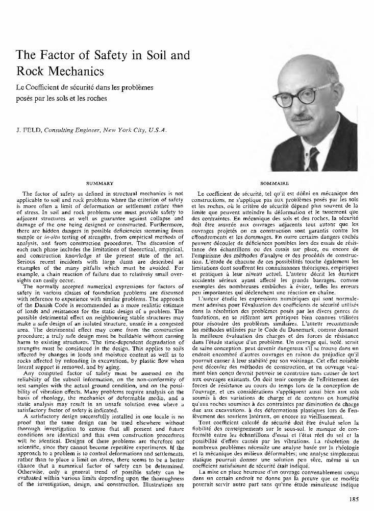
f i g . 1. Effect of additional soil loading. A b o v e , footing pulled down by heavy storage loading on floor; below, dragdown on pile
foundations due to soil consolidation.
1 8 6
values are divided to obtain permissive stress has been thoroughly argued and fairly generally discarded. The
various plastic, ultimate strength, limit strength, and load factor procedures, now even included in governmental building codes, are replacing the old concept of a factor of
safety and are considered to give a more accurate picture of the real margin of safety against failure. However, these do not provide a complete programme for structural and foundation design, which in reality requires three separate phases of investigation.
1. Static equilibrium of each element under the action of external loads and the resulting reactions between members.
2. Compatibility, as a three-dimensional analysis, of the deformed elements which must remain dimensionally stable or tolerant to the elastic changes.
3. Load transfers caused by length and shape changes of the connected elements, and the resulting stress and section revisions.
Since the complete design is dependent on the stiffness of the elements, a first solution must be considered approximate and investigated for final results.
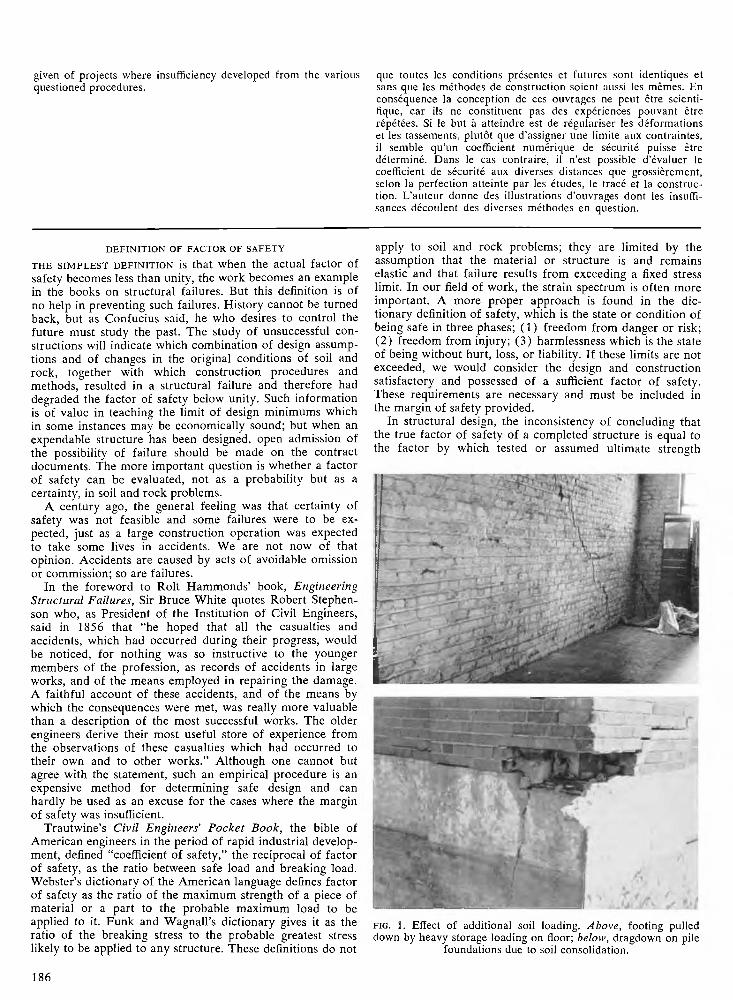
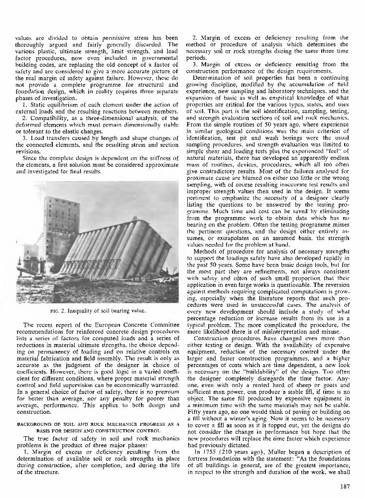
f i g . 2. Inequality of soil bearing value.
The recent report of the European Concrete Committee
recommendations for reinforced concrete design procedures lists a series of factors for computed loads and a series of reductions in material ultimate strengths, the choice depending on permanency of loading and on relative controls on material fabrication and field assembly. The result is only as accurate as the judgment of the designer in choice of coefficients. However, there is good logic in a varied coefficient for different conditions, where proper material strength control and field supervision can be economically warranted. In a general choice of factor of safety, there is no premium
for better than average, nor any penalty for poorer than average, performance. This applies to both design and
construction.
BACKGROUND OF SOIL AND ROCK M ECHANICS PROGRESS AS A
BASIS FOR DESIGN AND CONSTRUCTION CONTROL
The true factor of safety in soil and rock mechanics problems is the product of three major phases:
1. Margin of excess or deficiency resulting from the
determination of available soil or rock strengths in place during construction, after completion, and during the life of the structure.
2. Margin of excess or deficiency resulting from the method or procedure of analysis which determines the necessary soil or rock strengths during the same three time periods.
3. Margin of excess or deficiency resulting from the construction performance of the design requirements.
Determination of soil properties has been a continuing growing discipline, modified by the accumulation of field experience, new sampling and laboratory techniques, and the expansion of basic as well as empirical knowledge of what properties are critical for the various types, states, and uses of soil. This part is the soil identification, sampling, testing,
and strength evaluation sections of soil and rock mechanics. From the simple routines of 50 years ago, where experience in similar geological conditions was the main criterion of identification, test pit and wash borings were the usual sampling procedures, and strength evaluation was limited to
simple shear and loading tests plus the experienced “feel” of natural materials, there has developed an apparently endless mass of routines, devices, procedures, which all too often give contradictory results. Most of the failures analysed for proximate cause are blamed on either too little or the wrong sampling, with of course resulting inaccurate test results and improper strength values then used in the design. It seems pertinent to emphasize the necessity of a designer clearly
listing the questions to be answered by the testing programme. Much time and cost can be saved by eliminating from the programme work to obtain data which has no bearing on the problem. Often the testing programme misses the pertinent questions, and the design either entirely assumes, or extrapolates on an assumed basis, the strength values needed for the problem at hand.
Methods of procedure for analysis of necessary strengths to support the loadings safely have also developed rapidly in the past 50 years. Some have been basic design tools, but for
the most part they are refinements, not always consistent with safety and often of such small proportion that their application in even large works is questionable. The reversion
against methods requiring complicated computations is growing, especially when the literature reports that such procedures were used in unsuccessful cases. The analysis of every new development should include a study of what percentage reduction or increase results from its use in a typical problem. The more complicated the procedure, the more likelihood there is of misinterpretation and misuse.
Construction procedures have changed even more than either testing or design. With the availability of expensive equipment, reduction of the necessary control under the larger and faster construction programmes, and a higher percentages of costs which are time dependent, a new look is necessary on the “buildability” of the design. Too often the designer completely disregards the time factor. Anyone, even with only a rented herd of sheep or goats and sufficient man power, can produce a stable fill, if time is no object. The same fill produced by expensive equipment in a minimum time with the same materials may not be stable. Fifty years ago, no one would think of paving or building on a fill without a winter’s aging. Now it seems to be necessary
to cover a fill as soon as it is topped out, yet the designs do not consider the change in performance but hope that the new procedures will replace the time factor which experience had previously dictated.
In 1755 (210 years ago), Muller began a description of fortress foundations with the statement: “As the foundations of all buildings in general, are of the greatest importance, in respect to the strength and duration of the work, we shall
187
enter into all the most material particulars, which may happen in different soils, in order to execute works with all the security possible, because many great buildings have been rent into pieces, and some have fallen down, for want of having taken proper care in laying the foundation.” Muller advises that the nature and hardness of the soil must be discovered by auger holes 10 to 15 ft deep. In gravel or hard stiff clay, no sinking is to be expected; in sand or non- uniform layers, a grate of timbers crossed two ways and sometimes boarded over, should be laid under the foundation stones. Piles should be driven into soft soil only if hard layers exist below, but it is dangerous to drive piles through beds of gravel or clay with soft mud below. In this latter case, the proper solution is a timber deck to be sunk by uniform loading with the masonry, which method, Muller
says, has been used in Russia and in Flanders with good results. The entire problem of obtaining proper safety is so covered by him in a single paragraph.
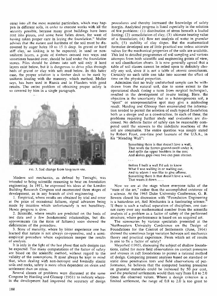
f i g . 3. Soil change from long-term use.
Modern soil mechanics, as defined by Terzaghi, was intended to bring scientific reasoning to bear on foundation engineering. In 1951, he expressed his ideas at the London Building Research Congress and enumerated three stages of development, as in any branch of civil engineering.
1. Empirical, where results are obtained by trial and error at the price of occasional failures, signal advances being made by intuition which unfortunately is not hereditary. Hence progress is slow.
2. Scientific, where results are predicted on the basis of test data and a few fundamental relationships, but disappointments (in the form of failures) soon showed the deficiencies of the procedure.
3. State of maturity, where by bitter experience one has learned that nature is not always co-operative, and a semi- empirical procedure where experiences temper the results of analysis.
It is only in the light of the last phase that safe designs can be expected. Too many computations of the factor of safety are based on the scientific method, without regard to the validity of the assumptions. It must always be kept in mind that, when dealing with non-isotropic and limitedly elastic soils and rocks, safety is more often dependent on strain and settlement than on stress.
Several classes of problems were discussed at the same Congress by Harding and GIossop (1951) to indicate where
in the development had improved the accuracy of design
procedures and thereby increased the knowledge of safety margin. Analytical progress is listed especially in the solution of five problems: (1) distribution of stress beneath a loaded footing; (2) consolidation of clay; (3) ultimate bearing value of a foundation; (4) flow net analysis of water in granular
soils; (5) stability of clay slopes. But the mathematical formulae developed are of little practical use unless accurate values for the mechanical properties of the soils are available. This led to detailed programmes of soil sampling and various attempts from both scientific and engineering points of view, at soil classification charts. It is now generally agreed that a
table of soil classes cannot be relied upon to definitely classify any soil, since it is not a table of atomic constituents.
Certainly no such table can take into account the effect of time on the physical properties.
Admission that no truly undisturbed sample can be withdrawn from the natural soil, due to some extent to the operational shock (using a term from surgical technique), resulted in the development of in-situ testing. Here, the objection is the uncertainty that in a heterogeneous soil, a “sport” or unrepresentative spot may give a misleading result. Harding and GIossop then enumerated the informa
tion needed to permit the solution of each typical foundation both as a design and as a construction. In each of these, the problems requiring further study and evaluation are discussed. No definite factor of safety can be reasonably computed until the answers to the indefinite reactions of the soil are obtainable. The entire question was simply stated by Robert Frost, one-time poet laureate of the U.S.A., in his “Mending Wall” :
Something there is that doesn’t love a wall,That sends the frozen-ground-swell under it,And spills the upper boulders in the sun;And makes gaps even two can pass abreast.
Before I built a wall I’d ask to know What I was walling in or walling out,And to whom I was like to give offense.Something there is that doesn’t love a wall,That wants it down. . . .
Now we are at the stage where everyone talks of the
“state of the art,” rather than the accomplished existence of a science. At the 1965 Duke University Conference, G. B. Sowers closed his discussion with “Foundation Engineering is a hazardous art, Soil Mechanics is a fascinating science.” If there is such a radical separation of disciplines, one cannot carry over any mathematical number from the scientific
analysis of a problem as a factor of safety of the performed structure, where performance is based on an acquired art.
The summaries by various specialists presented at the Northwestern University Conference on the Design of Foundations for the Control of Settlements (June, 1964) showed the sometimes large variation between soil mechanics theory and practical experience. From which set of results is one to fix a factor of safety?
Meyerhof (1965), discussing the subject of shallow foundations, called for more field observations on contact pressures and stresses in raft foundations to permit a rational method of design. Comparing present analyses based on standard or static cone penetration tests and field observations of performance, he believes that the computed bearing pressures on granular materials could be increased by 50 per cent,
and the predicted settlements would then vary from 0.8 to 2.0 times the observed values. Where a design criterion is a limited settlement, the range of 0.8 to 2.0 is too great to
1 8 8
warrant analysis on the basis of a reasonable factor of safety. If the upper limit is chosen, the minimum factor of safety in the computations must be 2.5. Meyerhof also stated that for shallow foundations on clay, the usual analysis, based on the sum of immediate and final consolidation settlements with an allowance for any lateral consolidation and for the effects of shearing stresses, usually give results of sufficient
accuracy.Aldrich (1965), on the subject of precompression, the
procedure for artificially preparing a soil of desired physical properties, raised questions relative to precompression analysis and suggested unsolved and controversial topics for further study. Certainly, the lack of consistent success with sand-drain consolidation operations justifies some skepticism of any claim that preconsolidation can be numerically controlled to a level where a factor of safety is predictable.
Golder (1965), on the subject of floating foundations, indicated that, though the static solution is simple, important unknowns are the effect of excavation, bottom heave, settlement and tilting, and the construction problems of performance. The serious effects on adjacent structures may well cause failures which must be attributed to the method.
Peck (1965) on the subject of pile and pier foundations, noted that outdated knowledge and misconceptions are still in use. Conferences are fine places to unlearn such information but the authority of the printed word is hard to overcome. Peck further enumerated the areas of further necessary determination: (1) the increase with time of point load where a pile passes through a compressible cohesive soil to embedment in a stiffer material; (2) estimate of pile settlements in cohesive soils; and (3) influence of size of the pile group on magnitude of settlement.
Seed (1965), on the subject of settlement analysis, stated that a great need exists for field data and research investigations before any definitive evaluation of the settlement of foundations on sands and partially saturated clays can be expected.
There seems to be a consensus that, at the present state of the science of soil mechanics and of the art of foundation engineering, the assumption that a numerical factor of safety can be determined is not warranted.
W H AT PR IC E PROGRESS? IS TH E RISK OF TH E UNDERGROUND
FACT OR EX C U SE?
In one of his last pronouncements, Terzaghi (1962) dis
cussed the basic reasons for the failures of the Malpasset Dam and Wheeler Lock from foundation inadequacies that eluded detection despite extensive site investigations, considerable testing, and the application of the most advanced analysis and theory. He states: “All foundation failures that have occurred in spite of competent subsurface exploration and strict adherence to the specifications during construction, have one feature in common: The seat of the failure was located in thin weak layers or in weak spots with very limited dimension. . . . If the failure of a structure would involve heavy loss of life or property, the structure should be designed in such a way that it would not fail even under the worst foundation conditions compatible with the available data. If no such consequence would ensue, the cost of the project can be reduced considerably by a design involving a calculated risk. . . . With increasing height and boldness
of our structures, we shall find out more about this interesting subject, but always by hindsight as we did in connection
with these failures.” These statements are not very encouraging to one looking for a factor of safety in his design.
Twenty years earlier Terzaghi wrote “Since about 1928
the attention of research men has been concentrated almost exclusively on the mathematics of stability computations and on refining the technique of sampling and testing. The results of these efforts have been very useful and illuminating. At the same time, they created a rather indiscriminate confidence in laboratory test results. In some incidents confidence is warranted, but, in many others, it can lead to erroneous conclusions, because the attention of the investigator is diverted from what is really essential.”
The reported lack of confidence in the field of large dams must result in a demand for a more realistic and rational margin of safety in foundation design. Following the Bed
ford Hills Dam failure in December 1963, the U.S. Federal Power Commission ordered a strengthened safety programme to avoid similar incidents. At five-year intervals, all F.P.C. licenced dams are to be inspected by independent consulting engineers for any indication of structural distress. The California Department of Water Resources ordered an inspection of the 971 dams within their jurisdiction. UNESCO is also exploring a programme of international dam inspection.
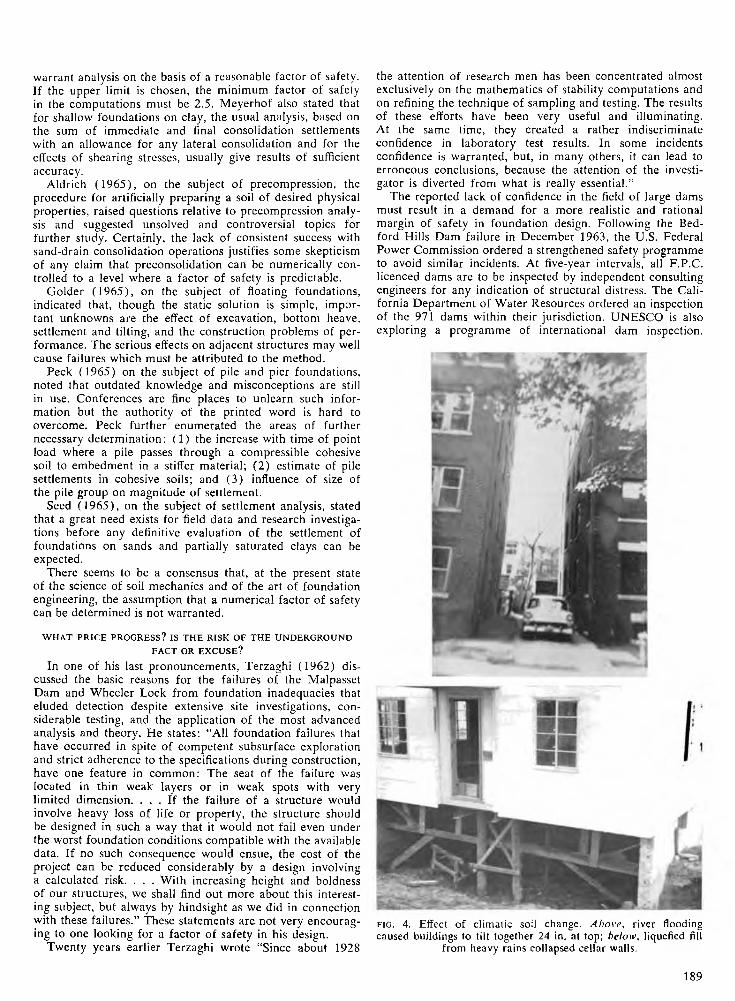
FIG. 4. Effect of climatic soil change. A bove , river flooding caused buildings to tilt together 24 in. at top; below , liquefied fill
from heavy rains collapsed cellar walls.
1 8 9
The reported results of these programmes (to April 1965) only cover the concrete disintegration and expansion of a 163-ft.-high arch dam, but the existence of such programmes shows the small reliance generally placed on the design factors of safety. The record is not too good. A 1961 Spanish study listed 1,620 dams, of which 308 had serious accidents in the period 1799-1944; foundation failures caused 40 per cent and poor construction with unequal settlement caused22 per cent of the accidents.
At the closing session of the Eighth Congress (1964) of the International Commission on Large Dams (ICOLD), President-elect J. Guthrie Brown said: “In the past, dam builders have acquired very substantial knowledge about all
the factors that contributed to the safety of the dam structure themselves, but they have had very little reliable or accurate information about the strength and nature of the
underlying strata on which the dams are supported. . . . All knowledge gained in the studies of dam design is of no avail if the foundations on which a dam is to rest are in
doubt. The recent failures have all been concerned with foundation movements or geological slips. It is from the geologist and the combined science of soil mechanics and rock mechanics that the engineer must obtain the details and scientific information he requires to confirm his own experience and judgment of the foundations on which rest the safety of his dam.”
Is the price of too rapid progress worth the risk? Has there been an unnecessary number of spectacular dam failures, and is there a correspondingly similar although unreported record in other phases of soil, rock, and foundation works?
In the U.S.A., 1800 dams were built before 1959, and 33 failures have been recorded, mostly from inadequate foundations. Seven of the failures came in one week before 1918, so that it can be argued that the designers did not have the advantage of modern soil mechanics. But even one per cent failure would involve huge losses in life and property of the 6,549 existing dams over 15 m (116 over 100 m ), 773 under construction (65 over 100 m ), and 962 projected (74 over 100 m) listed in the world-wide survey
of 1964.There were foundation failures before 1925, but the last
40 years have had their share, despite the progress in soil investigation and control, theoretical analyses of internal stress, and better graphical representation of probable failure pattern and necessary resistances to avoid movement. A few of the spectacular incidents in dams are:
1926—Lock Alpine, Michigan, a 16-ft high rolled earthfill failed after the first winter due to soil shrinkage below a frozen crust.
1926—Bonners Ferry, Idaho, 53-ft high arch on soft rock at an abutment.
1926—Tryon, North Carolina, 62-ft high arch on soft rock at an abutment.
1928—St. Francis, California, 205-ft high gravity, from rock erosion under the foundation.
1928—Lafayette, California, slide along a horizontal clay seam.
1930—Alexander, Hawaii, volcanic ash fill, where the design was based on careful soil testing, consolidation, where compressibility and permeability had been analysed, where chemical treatment was used to increase the density and impermeability of the core material, and with pressure cells and reference points under continuous observation, failed at a 95-ft height with257,000 cu.yd. of slide, centred at a point which had only moved 0.23 ft, and not at all during the two months prior to the slide.
1934—Fort Peck on Missouri River, a slide on a buried bentonitic seam.
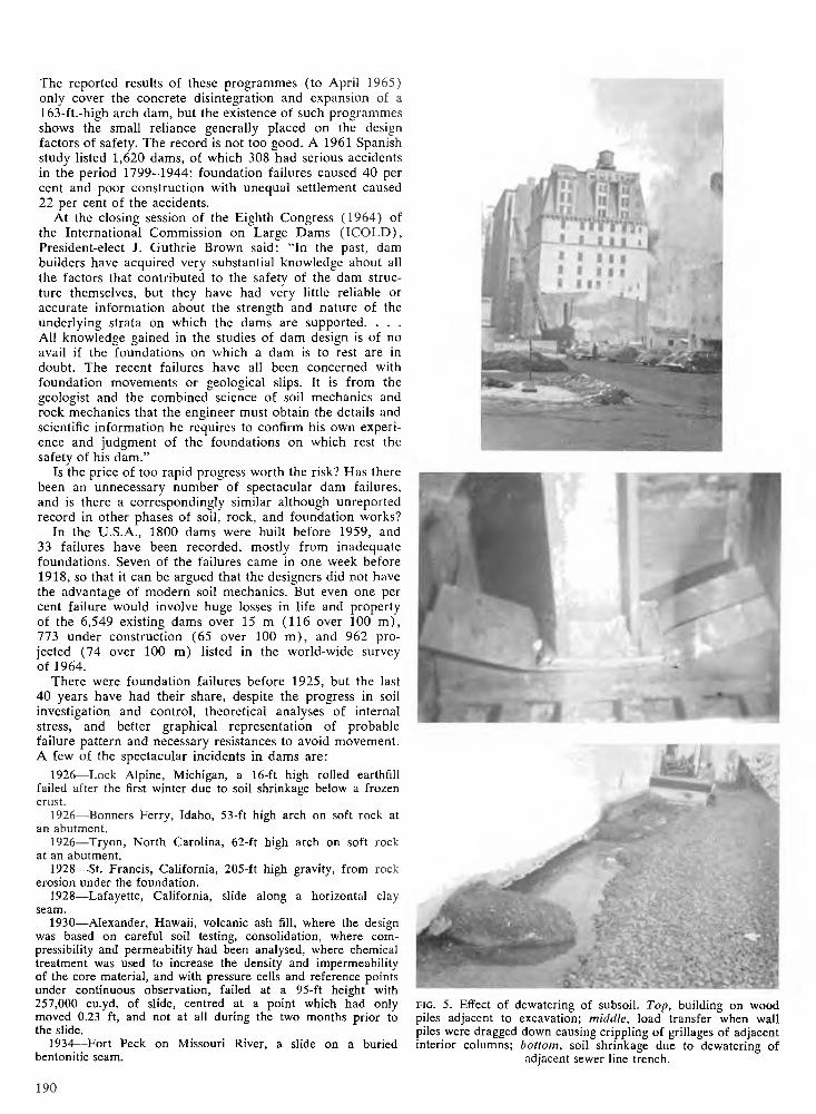
f i g . 5. Effect of dewatering of subsoil. Top, building on wood piles adjacent to excavation; middle, load transfer when wall piles were dragged down causing crippling of grillages of adjacent interior columns; bottom, soil shrinkage due to dewatering of
adjacent sewer line trench.
1 9 0
1937—Marshall Creek, Kansas, slide on a horizontal clay seam.
1937—Chingford, London, a 26-ft embankment slide on a horizontal clay seam.
1941—Flood Dike, Connecticut, slide on a horizontal clay seam.
1941—Pendleton Levee, Mississippi, slide on a horizontal clay seam.
1955—Oahe, South Dakota, a 242-ft rolled fill embankment. Start of slide was blamed on a bentonite seam in the shale base.
1957—Alamosa, Colorado, a 45-year-old hydraulic fill developed a leak 70 ft below the crest with a full reservoir.
1958—Great Western, Colorado, an earthfill was raised from 49 to 61 ft and settled 11 ft vertically with a downstream movement of 14 ft.
1959—Malpasset, southern France. With no warning of failure, the rock shifted under the left bank foundation.
1961—Waco, Texas, 140-ft earthfill slide on a zone of fractured shale located below two rock faults.
1961—Wheeler Lock, TVA system, slide on thin seams of weak material not disclosed by boring explorations, when excavation for a new lock exposed the bottom of the concrete wall and also cut across the shale containing a clav seam.
1963—Baldwin Hills, California, compacted earthfill failed by movements along fault lines under the reservoir.
1964—Malpasset, France, blamed on a slip plane within the rock below the foundations or along a higher fault plane.
1964— Vaiont, Italy, 875-ft arch destroyed by a subsurface slide of 312 million cu.yd. into the reservoir.
In the report on the Vaiont Dam, Dr. Claudio Marcello, 1964 retiring president of ICOLD, stated that “borings along a foundation may yield but a discrete sampling, and nature is not, unfortunately, so obliging as to comply with any con
tinuity rule which could allow interpolation of results in between.”
In the report on the Wheeler Lock, Terzaghi argued that no method of exploration will always reveal the existence of minor geological details such as weak spots in the rock. “Hence, instead of attempting to achieve the impossible [in subsurface exploration], we should pay more attention to the
inevitable uncertainties attached to the results of subsurface exploration of any kind. If the failure of a structure would involve heavy loss of life or property, the structure should
be designed in such a way that it would not fail under the worst foundation conditions compatible with the available data.”
If we now admit that a true determination of subsurface conditions is not possible, who must take the risk of the
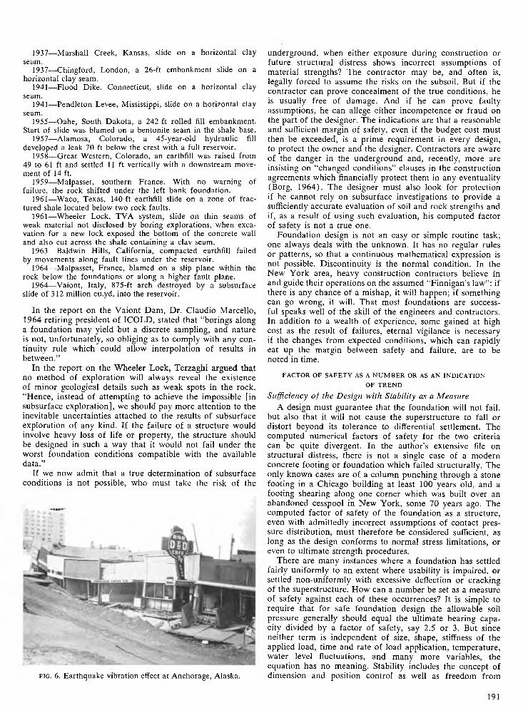
f i g . 6. Earthquake vibration effect a t Anchorage, Alaska.
underground, when either exposure during construction or future structural distress shows incorrect assumptions of material strengths? The contractor may be, and often is, legally forced to assume the risks on the subsoil. But if the contractor can prove concealment of the true conditions, he
is usually free of damage. And if he can prove faulty assumptions, he can allege either incompetence or fraud on the part of the designer. The indications are that a reasonable and sufficient margin of safety, even if the budget cost must then be exceeded, is a prime requirement in every design, to protect the owner and the designer. Contractors are aware of the danger in the underground and, recently, more are insisting on “changed conditions” clauses in the construction
agreements which financially protect them in any eventuality (Borg, 1964). The designer must also look for protection if he cannot rely on subsurface investigations to provide a sufficiently accurate evaluation of soil and rock strengths and if, as a result of using such evaluation, his computed factor of safety is not a true one.
Foundation design is not an easy or simple routine task; one always deals with the unknown. It has no regular rules
or patterns, so that a continuous mathematical expression is not possible. Discontinuity is the normal condition. In the New York area, heavy construction contractors believe in and guide their operations on the assumed “Finnigan’s law”: if there is any chance of a mishap, it will happen; if something
can go wrong, it will. That most foundations are successful speaks well of the skill of the engineers and contractors. In addition to a wealth of experience, some gained at high cost as the result of failures, eternal vigilance is necessary if the changes from expected conditions, which can rapidly eat up the margin between safety and failure, are to be noted in time.
FACTOR OF SAFETY AS A N U M B E R OR AS AN INDICATION
OF TREND
Sufficiency of the Design with Stability as a Measure
A design must guarantee that the foundation will not fail,
but also that it will not cause the superstructure to fall or distort beyond its tolerance to differential settlement. The computed numerical factors of safety for the two criteria can be quite divergent. In the author’s extensive file on structural distress, there is not a single case of a modern concrete footing or foundation which failed structurally. The only known cases are of a column punching through a stone
footing in a Chicago building at least 100 years old, and a footing shearing along one corner which was built over an abandoned cesspool in New York, some 70 years ago. The computed factor of safety of the foundation as a structure, even with admittedly incorrect assumptions of contact pressure distribution, must therefore be considered sufficient, as
long as the design conforms to normal stress limitations, or even to ultimate strength procedures.
There are many instances where a foundation has settled fairly uniformly to an extent where usability is impaired, or
settled non-uniformly with excessive deflection or cracking of the superstructure. How can a number be set as a measure of safety against each of these occurrences? It is simple to require that for safe foundation design the allowable soil pressure generally should equal the ultimate bearing capacity divided by a factor of safety, say 2.5 or 3. But since neither term is independent of size, shape, stiffness of the applied load, time and rate of load application, temperature, water level fluctuations, and many more variables, the
equation has no meaning. Stability includes the concept of dimension and position control as well as freedom from
1 9 1
collapse. The margin of safety must be set for and at a toler
able change in position. For footings, this means an agreed acceptable amount of settlement. There would then be various factors of safety for any one design for the different
amounts of settlement.Recent studies of the interaction of foundation and super
structure indicate that the critical item to be considered is not settlement, but the slope or curve of the settlement within a structure. Various stiffnesses of the superstructure have
different tolerances for change in a relative position of adjacent supports, but this is generally covered by the empirical observations that with a slope of 1:150 there is no structural damage and with a slope of 1:300 there is no architectural damage (Feld, 1965). How can a safety factor then be estimated to indicate freedom from either requirement? All footings must settle when load is applied. Nonuniformity of soil reactions, especially in short-span construction, can easily account for a differential settlement that gives an excessive slope between two supports. The answer to the problem is to consider superstructure and foundation as one structure and design the framework to either be flexible and articulated or else of sufficient rigidity to permit reaction redistribution without distress under conditions of computed unequal settlement.
Pile-driving formulas theoretically have incorporated factors of safety from 2 to 16 against failure; none of them consider amount of settlement as a criterion. On the assumption that experience in the local conditions has proven prior sufficiency, either by completed structures or by a proper load test programme, a factor of safety, as a ratio of satisfactory test load to working load, of 2 for static and 3 for
vibratory loading is considered sufficient. The true factor of safety of a completed pile job is usually lower, since the load test programme considers single isolated piles only. However, the extra margin of safety is in the overestimation of the true live load to be carried.
A computed factor of safety of 1.3 for cuts and fills and1.5 for earth dams is normal, although these figures are based on a number of uncertainties. These values are accepted however, because a factor of safety of 2.5 would make the cost of embankments and slopes so high that they would not be built. The safety of slopes as determined from an assumed form of the failure surface, and the calculated ratio between stabilizing and overturning moments on the mass considered, has been shown to be inaccurate, and should be replaced by the ratio of shearing strength to acting shearing force. Since
both values may vary and fluctuate, it becomes quite an art to fix the two values that can exist simultaneously and show the minimum factor of safety.
To avoid this general uncertainty when dealing with stress patterns, Brinch Hansen (1965) has suggested a procedure similar to the European Concrete Committee recommendations (Thomas, 1964). In any soils problem, all evaluated
loads are multiplied by coefficients which cover all possible increases as well as deficiencies of estimate during the life of
the structure, and all strengths and resistances are divided by coefficients which allow for the contingencies that might require decreases from the interpretation of test data for
uncertainties of design procedure or from performance in the field. The product of these two coefficients is not a factor of safety, but a measure of the minimum increase in strength necessary to guarantee safety at all times.
Table I summarizes the suggested Brinch Hansen coefficients, used in Denmark for the past 10 years and now
incorporated in the Danish Code of Practice for Foundation Structures. It is assumed that the most reliable pro
cedures for evaluation are followed, including strength determination by actual test and reliable pile-driving formulas, and that performance will be closely inspected and
supervised. From such a system, a reasonable indication of the factor of safety for stability of a structure can be obtained.
T A H L H I
Coefficient of
Load or resistance Increase Decrease
Dead load Weight of soil Static water pressure Dynamic water pressure Generally all live loads Engine loads Bin contents load
Stability problems Coefficient of friction Coefficient of cohesion
Danish Sheeting design Coefficient of friction
Shallow Foundations Coefficient of friction Coefficient of cohesion
Piles by load test Piles by best formulas Piles by geostatic determination
Coefficient of friction 1.2Coefficient of cohesion 2.0
Structural materials at ultimate strengthSteel 1.35Concrete 2.7
Where structures are seriously affected by uniform or
differential settlement, further limitations to a computed factor of safety are necessary. Cases of such constructions
are large tanks and bulk storage yards. There are many reports in the literature on shape distortion, even tipping of
large tanks, to the extent where use is affected even though the safety is not questioned. In a group of hemispheroidal steel tanks containing high octane fuel, where the hemispherical bottom was set on a cushion of fine dry sand, moisure infiltration lubricated the material and permitted the tanks to rotate from the action of wind pressure. The tanks were still stable, but since they did not all rotate identically in amount or direction, piping failures made operation hazardous and a hasty repair was ordered. The factor of safety from the point of use fell below one, and such possibilities must modify any computed values. Similarly bottom distortions of large tanks may affect necessary drainage or even cripple the base of the walls, and yet the structure can
be shown by computation to be stable.As pointed out by Housel (1956), in discussing the
foundation behaviour of bulk ore storage over soft soils
and fills, the concept of a factor of safety in such problems is only possible when all stresses are elastic. When progressive displacement or plastic flow can occur, and that is
the usual case, the theories of plasticity and viscosity must be used in the design, and then the margin of safety is a function of the yield value of the subsoil material. Housel sets up overload ratios on the plastic soils as restrictions to the possibility of instability. In such problems, if one is asked for a determination of a “factor of safety,” the answer must be termed in reference to a definite “safety against what”.
1.01.01.01.2
1.51.2
1.2
1.2
1.5
1.2
1.2
2.0
1.6
2.0
192
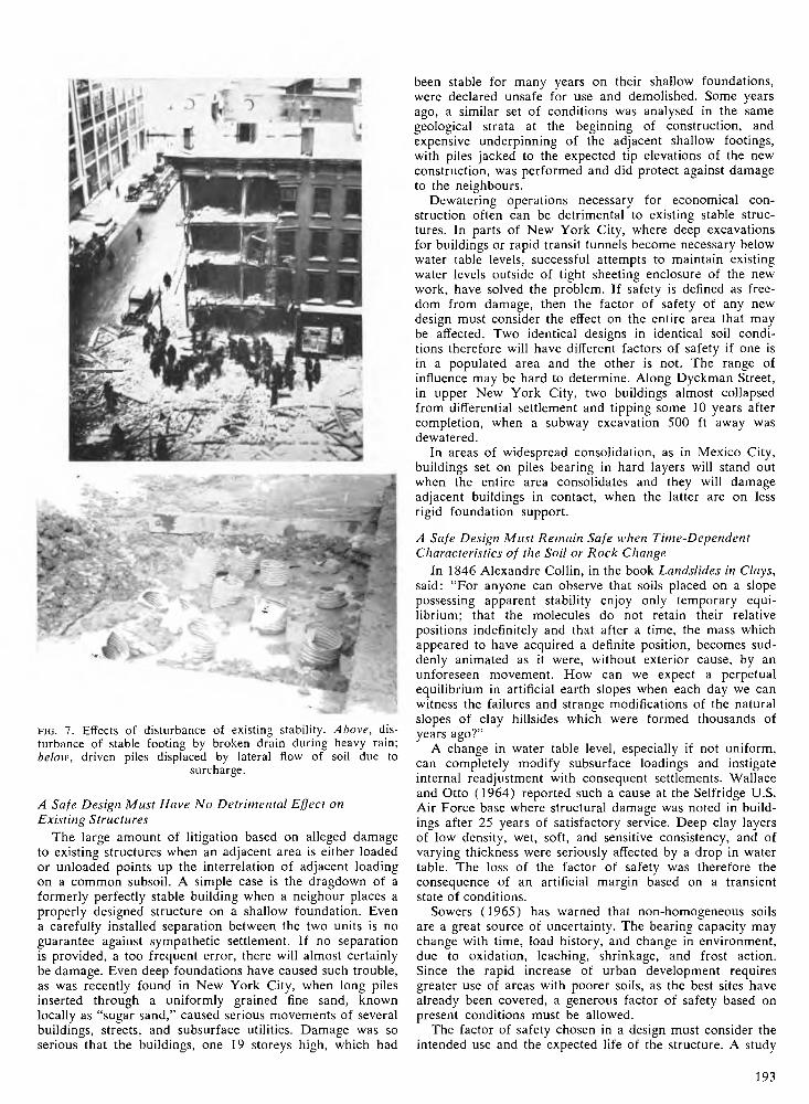
f i g . 7. Effects of disturbance of existing stability. A bove , disturbance of stable footing by broken drain during heavy rain; below, driven piles displaced by lateral flow of soil due to
surcharge.
A Safe Design Must Have No Detrimental Effect on
Existing Structures
The large amount of litigation based on alleged damage to existing structures when an adjacent area is either loaded
or unloaded points up the interrelation of adjacent loading on a common subsoil. A simple case is the dragdown of a formerly perfectly stable building when a neighour places a
properly designed structure on a shallow foundation. Even a carefully installed separation between the two units is no guarantee against sympathetic settlement. If no separation is provided, a too frequent error, there will almost certainly
be damage. Even deep foundations have caused such trouble, as was recently found in New York City, when long piles
inserted through a uniformly grained fine sand, known locally as “sugar sand,” caused serious movements of several buildings, streets, and subsurface utilities. Damage was so serious that the buildings, one 19 storeys high, which had
been stable for many years on their shallow foundations,
were declared unsafe for use and demolished. Some years ago, a similar set of conditions was analysed in the same geological strata at the beginning of construction, and
expensive underpinning of the adjacent shallow footings, with piles jacked to the expected tip elevations of the new construction, was performed and did protect against damage
to the neighbours.Dewatering operations necessary for economical con
struction often can be detrimental to existing stable structures. In parts of New York City, where deep excavations for buildings or rapid transit tunnels become necessary below water table levels, successful attempts to maintain existing water levels outside of tight sheeting enclosure of the new
work, have solved the problem. If safety is defined as freedom from damage, then the factor of safety of any new design must consider the effect on the entire area that may be affected. Two identical designs in identical soil conditions therefore will have different factors of safety if one is in a populated area and the other is not. The range of influence may be hard to determine. Along Dyckman Street, in upper New York City, two buildings almost collapsed from differential settlement and tipping some 10 years after completion, when a subway excavation 500 ft away was
dewatered.In areas of widespread consolidation, as in Mexico City,
buildings set on piles bearing in hard layers will stand out when the entire area consolidates and they will damage adjacent buildings in contact, when the latter are on less rigid foundation support.
A Safe Design Must Remain Safe when Time-Dependent Characteristics of the Soil or Rock Change
In 1846 Alexandre Collin, in the book Landslides in Clays, said: “For anyone can observe that soils placed on a slope possessing apparent stability enjoy only temporary equi
librium; that the molecules do not retain their relative positions indefinitely and that after a time, the mass which appeared to have acquired a definite position, becomes suddenly animated as it were, without exterior cause, by an unforeseen movement. How can we expect a perpetual equilibrium in artificial earth slopes when each day we can witness the failures and strange modifications of the natural slopes of clay hillsides which were formed thousands of
years ago?”A change in water table level, especially if not uniform,
can completely modify subsurface loadings and instigate internal readjustment with consequent settlements. Wallace and Otto (1964) reported such a cause at the Selfridge U.S. Air Force base where structural damage was noted in buildings after 25 years of satisfactory service. Deep clay layers of low density, wet, soft, and sensitive consistency, and of
varying thickness were seriously affected by a drop in water table. The loss of the factor of safety was therefore the consequence of an artificial margin based on a transient state of conditions.
Sowers (1965) has warned that non-homogeneous soils are a great source of uncertainty. The bearing capacity may change with time, load history, and change in environment,
due to oxidation, leaching, shrinkage, and frost action. Since the rapid increase of urban development requires
greater use of areas with poorer soils, as the best sites have already been covered, a generous factor of safety based on present conditions must be allowed.
The factor of safety chosen in a design must consider the intended use and the expected life of the structure. A study
1 9 3
of the time spectrum of load application and the soil properties at the corresponding times, based on the reasonable estimate of maximum loads and minimum strengths, will indicate the instances of greatest danger. On such combinations must a reasonable margin of safety be imposed.
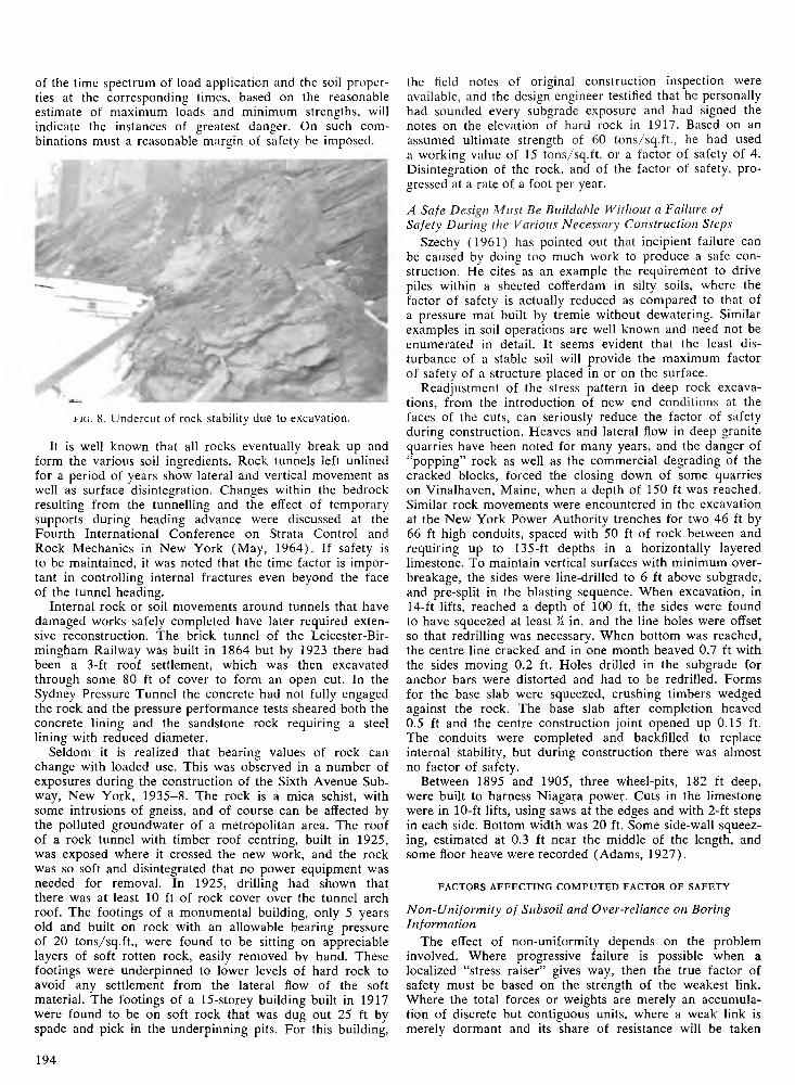
f i g . 8. Undercut of rock stability due to excavation.
It is well known that all rocks eventually break up and form the various soil ingredients. Rock tunnels left unlined for a period of years show lateral and vertical movement as well as surface disintegration. Changes within the bedrock resulting from the tunnelling and the effect of temporary supports during heading advance were discussed at the
Fourth International Conference on Strata Control and Rock Mechanics in New York (May, 1964). If safety is
to be maintained, it was noted that the time factor is important in controlling internal fractures even beyond the face of the tunnel heading.
Internal rock or soil movements around tunnels that have damaged works safely completed have later required extensive reconstruction. The brick tunnel of the Leicester-Bir- mingham Railway was built in 1864 but by 1923 there had been a 3-ft roof settlement, which was then excavated through some 80 ft of cover to form an open cut. In the Sydney Pressure Tunnel the concrete had not fully engaged the rock and the pressure performance tests sheared both the concrete lining and the sandstone rock requiring a steel lining with reduced diameter.
Seldom it is realized that bearing values of rock can change with loaded use. This was observed in a number of exposures during the construction of the Sixth Avenue Subway, New York, 1935-8. The rock is a mica schist, with
some intrusions of gneiss, and of course can be affected by the polluted groundwater of a metropolitan area. The roof of a rock tunnel with timber roof centring, built in 1925, was exposed where it crossed the new work, and the rock was so soft and disintegrated that no power equipment was needed for removal. In 1925, drilling had shown that there was at least 10 ft of rock cover over the tunnel arch roof. The footings of a monumental building, only 5 years old and built on rock with an allowable bearing pressure of 20 tons/sq.ft., were found to be sitting on appreciable layers of soft rotten rock, easily removed by hand. These footings were underpinned to lower levels of hard rock to avoid any settlement from the lateral flow of the soft material. The footings of a 15-storey building built in 1917 were found to be on soft rock that was dug out 25 ft by spade and pick in the underpinning pits. For this building,
the field notes of original construction inspection were available, and the design engineer testified that he personally had sounded every subgrade exposure and had signed the
notes on the elevation of hard rock in 1917. Based on an assumed ultimate strength of 60 tons/sq.ft., he had used
a working value of 15 tons/sq.ft. or a factor of safety of 4. Disintegration of the rock, and of the factor of safety, pro
gressed at a rate of a foot per year.
A Safe Design Must Be Builclable Without a Failure of Safety During the Various Necessary Construction Steps
Szechy (1961) has pointed out that incipient failure can
be caused by doing too much work to produce a safe construction. He cites as an example the requirement to drive piles within a sheeted cofferdam in silty soils, where the factor of safety is actually reduced as compared to that of a pressure mat built by tremie without dewatering. Similar examples in soil operations are well known and need not be enumerated in detail. It seems evident that the least disturbance of a stable soil will provide the maximum factor
of safety of a structure placed in or on the surface.Readjustment of the stress pattern in deep rock excava
tions, from the introduction of new end conditions at the faces of the cuts, can seriously reduce the factor of safety during construction. Heaves and lateral flow in deep granite quarries have been noted for many years, and the danger of “popping” rock as well as the commercial degrading of the
cracked blocks, forced the closing down of some quarries on Vinalhaven, Maine, when a depth of 150 ft was reached. Similar rock movements were encountered in the excavation at the New York Power Authority trenches for two 46 ft by 66 ft high conduits, spaced with 50 ft of rock between and requiring up to 135-ft depths in a horizontally layered limestone. To maintain vertical surfaces with minimum over- breakage, the sides were line-drilled to 6 ft above subgrade, and pre-split in the blasting sequence. When excavation, in
14-ft lifts, reached a depth of 100 ft, the sides were found to have squeezed at least li in. and the line holes were offset so that redrilling was necessary. When bottom was reached, the centre line cracked and in one month heaved 0.7 ft with the sides moving 0.2 ft. Holes drilled in the subgrade for anchor bars were distorted and had to be redrilled. Forms for the base slab were squeezed, crushing timbers wedged against the rock. The base slab after completion heaved 0.5 ft and the centre construction joint opened up 0.15 ft. The conduits were completed and backfilled to replace internal stability, but during construction there was almost
no factor of safety.Between 1895 and 1905, three wheel-pits, 182 ft deep,
were built to harness Niagara power. Cuts in the limestone were in 10-ft lifts, using saws at the edges and with 2-ft steps in each side. Bottom width was 20 ft. Some side-wall squeezing, estimated at 0.3 ft near the middle of the length, and some floor heave were recorded (Adams, 1927).
FACTORS A FFE C TIN G C O M PU T ED FACTOR OF SAFETY
Non-Uniformity of Subsoil and Over-reliance on Boring
Information
The effect of non-uniformity depends on the problem involved. Where progressive failure is possible when a
localized “stress raiser” gives way, then the true factor of safety must be based on the strength of the weakest link. Where the total forces or weights are merely an accumulation of discrete but contiguous units, where a weak link is merely dormant and its share of resistance will be taken
1 9 4
over by adjacent units, then the true factor of safety is only slightly diluted by the weak spot. Finally, no problem can assume uniformity in the subsoil; care must be exercised in avoiding a too optimistic choice, and in the case where stress raiser failure is possible, the weakest stratum or seam must be considered the controlling element.
Boring information can only be interpreted in the light
of knowledge or experience of the local geology. It is dangerous to determine a factor of safety for a design based on boring information alone. In the metropolitan New York
area, when two borings of a set for a project show substantially the same conditions, one questions the validity of the procedure and record. Considerably folded and erratic surfaced rock is covered by a variety of glacial and erosion débris. One learns how to cope with the resulting mass of uncertainty, but only when the boring information is received in a proper perspective.
A highway tunnel under the East River, to be constructed as shield driven, was designed on the basis of river soundings and borings to fix the elevation of bedrock. Except for the shore approach, it was planned and designed to be an all-earth tunnel and was so contracted. Construction soon proved that the borings were wrong, the rock protruded into the heading, irregularly and in varying amounts above invert elevation. The mystery was soon solved when abandoned
boring tubes were salvaged and found to have spring curled sections where a tube had hit sloping rock and the ends went into continuous spirals. The length of the tube used when ultimate resistance was noted had been incorrectly taken as the depth to rock.
Any computed factor of safety depending on the assumption that the boring record has disclosed the weakest spots in the subsoil must have enough cushion to compensate for the unknown and unexpected. Otherwise, the design must be
flexible for rapid change at each stage of performance, control of the job must be in the hands of the designer, because only he would recognize exposed non-conformity, and the designer must have the authority to revise and strengthen the design to keep the factor of safety within sufficient margin.
Non-Conformity of Subsoil Mass with the Physical Properties Determined from Laboratory Testing
Precision in laboratory techniques to determine the physical properties of soil samples is of no value unless the sample is truly representative of the soil in the area of incipient failure and is tested under comparable conditions of loading. A great deal of soil testing has no relation to field conditions. The rate of compression in consolidation work is known to be important, but the rate of loading in a laboratory consolidation test may be several million times that actually used in a field programme. Similar inconsistencies can be pointed out in many of the standardized routine tests, none of which can take into account volume and shape changes which occur in the subsoil along the weakest surfaces.
To obtain a realistic set of laboratory values for the physi
cal properties of even a perfectly representative soil or rock sample, one must first agree on what form of failure can occur and what soil properties are critical to resist failure in the design. It is well known that different factors of safety can be determined for the same design problem depending on the assumed failure pattern. At the Eighteenth Annual Canadian Soil Mechanics Conference (December, 1964), A. E. Insley pointed out that an effective stress analysis of a failed clay embankment showed a factor of safety of 1.2, while the <f> = 0 analysis indicated a value not over unity.
Considerable aid in picturing the internal conditions of rock and soil masses under loading can be obtained from the work of Freudenthal (1950) on inelastic behaviour. Although his work was mostly with metals and concrete, it can be properly applied to soils and rock. The problem is solved as a case of rheology (science of flow) mechanics of deformable media, a transition between a classical theory of
elasticity and of hydrodynamics, in which materials do not obey Hooke’s law of stress-strain constancy or the
Newtonian laws of viscous liquids. Forces and stresses are
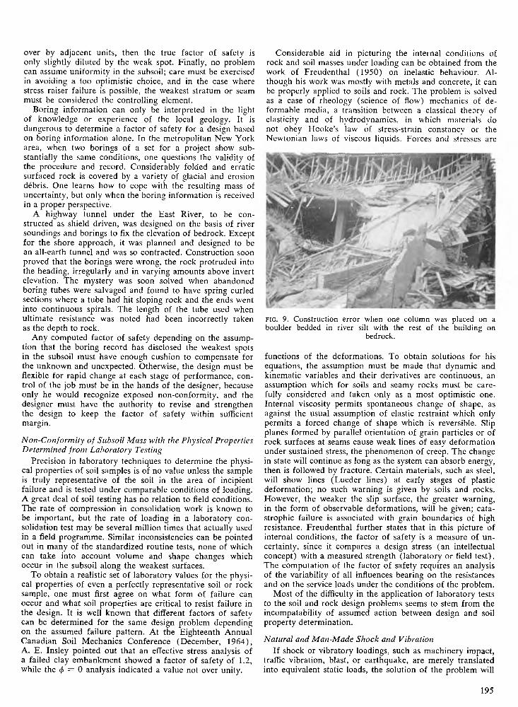
f i g . 9. Construction error when one column was placed on a boulder bedded in river silt with the rest of the building on
bedrock.
functions of the deformations. To obtain solutions for his equations, the assumption must be made that dynamic and
kinematic variables and their derivatives are continuous, an assumption which for soils and seamy rocks must be carefully considered and taken only as a most optimistic one. Internal viscosity permits spontaneous change of shape, as against the usual assumption of elastic restraint which only permits a forced change of shape which is reversible. Slip
planes formed by parallel orientation of grain particles or of rock surfaces at seams cause weak lines of easy deformation under sustained stress, the phenomenon of creep. The change in state will continue as long as the system can absorb energy,
then is followed by fracture. Certain materials, such as steel, will show lines (Lueder lines) at early stages of plastic deformation; no such warning is given by soils and rocks. However, the weaker the slip surface, the greater warning, in the form of observable deformations, will be given; catastrophic failure is associated with grain boundaries of high
resistance. Freudenthal further states that in this picture of internal conditions, the factor of safety is a measure of uncertainty, since it compares a design stress (an intellectual concept) with a measured strength (laboratory or field test). The computation of the factor of safety requires an analysis of the variability of all influences bearing on the resistances and on the service loads under the conditions of the problem.
Most of the difficulty in the application of laboratory tests to the soil and rock design problems seems to stem from the incompatability of assumed action between design and soil property determination.
Natural and Man-Made Shock and Vibration
If shock or vibratory loadings, such as machinery impact, traffic vibration, blast, or earthquake, are merely translated into equivalent static loads, the solution of the problem will
195
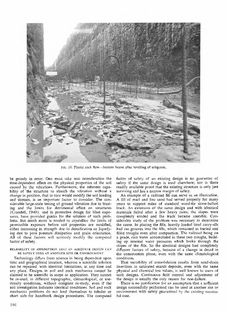
f i g . 10. Plastic rock flow—bottom heave after levelling of subgrade.
be grossly in error. One must take into consideration the time-dependent effect on the physical properties of the soil caused by the vibrations. Furthermore, the inherent capability of the structure to absorb the vibration without a change in position, that in turn would modify the soil loading and stresses, is an important factor to consider. The considerable large-scale testing of ground vibration due to blasting and the limits for detrimental effect on structures (Crandell, 1949), and in protective design for blast expo
sures, have provided guides for the solution of such problems. But much more is needed to crystallize the limits of permissible exposure before soil properties are modified, either increasing in strength due to densification or liquefying due to pore pressure dissipation and grain orientation. All of these factors will seriously modify the computed factor of safety.
R ELIABILITY OF A SSU M PTIO N THAT AN ADEQUATE DESIGN CAN
BE SAFELY USED AT ANOTHER SIT E OR E N V IR O N M EN T
Technology differs from science in being dependent upon time and geographical location, whereas a scientific solution
can be repeated, with identical limitations, at any time and any place. Designs in soil and rock mechanics cannot be claimed to be scientific in scope or application. They cannot be re-used, in different topographic, climatological, or use-
density conditions, without complete re-study, even if the soil investigation indicates identical conditions. Soil and rock mechanics problems do not lend themselves to tabular or chart aids for handbook design procedures. The computed
factor of safety of an existing design is no guarantee of safety if the same design is used elsewhere; nor is there readily available proof that the existing structure is only just surviving and has a narrow margin of safety.
An example of a railroad fill can serve as an illustration.
A fill of marl and fine sand had served properly for many years to support miles of standard wood-tie stone-ballast track. An extension of the same design and with identical
materials failed after a few heavy rains; the slopes were completely eroded and the track became unstable. Considerable study of the problem was necessary to determine the cause. In placing the fills, heavily loaded tired carry-alls had cut grooves into the fills, which remained as buried and filled troughs even after compaction. The railroad being on a grade, rain water accumulated in these two troughs, building up internal water pressures which broke through the slopes of the fills. So the identical designs had completely different factors of safety, because of a change in detail in the construction phase, even with the same climatological
conditions.That variability of consolidation results from sand-drain
insertions in saturated marsh deposits, even with the same physical and chemical test values, is well known to users of such designs. Continuous field control and adjustment of the design is usually the only reason for non-failure.
There is no justification for an assumption that a sufficient design successfully performed can be used at another site or environment with safety guaranteed by the existing successful case.
196
SUM M ARY AND CONCLUSIONS
Examples of insufficiency, indicated by collapse, by
deviations from desired position, by deleterious effects on neighbouring structures, or by high maintenance requirements of the supported structure, can only indicate limits of safety and are lessons which need rational evaluation in terms of presently recognized and accepted procedures in design and in construction. Soil and rock mechanics problems are unique in the field of engineering design, in that the experience can only be used as a guide to the determination of both sufficiency or necessity. A quantitative measure of safety is only possible in problems depending upon the principles of statics, or quite fairly in problems where the static equivalent of dynamic loading can be approximated. It is not possible in problems depending upon the principles of kinematics, or where plastic and viscous properties are dominant. It is, therefore, necessary to conclude that the concept of a numerical factor of safety is wrong and cannot exist in soil and rock mechanics problems. The only possible approach is a determination that a margin of safety exists at a stated amount of deformation (settlement, consolidation, drift, movement, etc.) and that the margin of safety will be used up when the deformation reaches a stated value. It may be difficult to explain why the superstructure is allotted a numerical factor of safety under all conditions, while the foundation must be differently regarded. But seldom is it economically sound to provide the usual and accepted margin of safety, represented by a stated numerical factor of safety of the superstructure, in the design of soil and rock mechanics problems. If in any way uncertain of the unexpected result, an increase in the margin of safety, a small part of the total cost of the project, will go a very long way in protecting the investment of the project and is cheap insurance against the possibility of insufficiency.
REFERENCES
A d a m s , E. D. (1927). History of the Niagara Falls Power Company, 1886-1918, Vol. II, p. 48.
A l d r i c h , H. P., j r . (1965). Precompression for support of shallow foundations. Jour. Soil Mechanics and Foundation Engineering Division, Proc. A.S.C.E., Paper 4267, p. 5.
Bo r g , R. F. (1964). Changed conditions clause in construction contracts. Jour. Construction Division, Proc. A.S.C.E., Paper 4035, p. 37.
C a s a g r a n d e , A. (1965). Role of the calculated risk in earthwork and foundation engineering. Jour. Soil Mechanics and Foundation Division. Proc. A.S.C.E., July, p. 1 (The Terzaghi Lecture, 1964).
C r a n d e l l , F. J. (1949). Ground vibration due to blasting and its effect upon structures. Jour. Boston Society of Civil Engineers, p. 222.
D u n l a p , O. E. (1900). New wheel pit of the Niagara Falls Power Company. Engineering News, April 5, p. 229.
Engineering News (1905). Niagara Power Plant of the Electrical Development Co. of Ontario. Nov. 9, p. 475 and Nov. 30, p. 561.
F e l d , J. (1965). Tolerance of structures to settlement. Jour. Soil Mechanics and Foundation Engineering Division, Proc. A.S.C.E. Paper 4336, p. 63.
F r e u d e n t h a l , A . M . (1 9 5 0 ) . Inelastic behaviour of engineering materials and structures. New York: John Wiley & Sons.
G o l d e r , H. Q. (1965). State-of-the-art of floating foundations. Jour. Soil Mechanics and Foundations Engineering Division, Proc. A.S.C.E., Paper 4278, p. 81.
H a n s e n , J. B r i n c h (1965). The philosophy of foundation design: design criteria, safety factors and settlement limits. Lecture at Duke University Symposium on Foundations, Raleigh, N.C.
H a r d in g , J. J. B., and R. G l o s s o p (1951). The influence of modern soil studies on the construction of foundation. Proc. Building Research Congress (London), Div. 1, Part III, p. 146.
H o u s e l , W. (1965). Discussion of foundation behaviour of iron storage yards, by R. B. Peck and T . Raamot. Jour. Soil Mechanics and Foundation Engineering Division, Proc. A.S.C.E., p. 196.
M e y e r h o f , G. G. (1965). Shallow foundations. Jour. Soil Mechanics and Foundation Engineering Division. Proc. A.S.C.E. Paper 4271, p. 21.
M u l l e r , J. (1755). Treatise containing the practical part of fortifications, p. 160. London, A. M illa r .
Peck, R. B. (1965). Pile and pier foundations. Jour. Soil Mechanics and Foundation Engineering Division, Proc. A.S.C.E., Paper 4273, p. 33.
S e e d , H. B. (1965). Settlement analyses, a review of theory and testing procedures. Jour. Soil Mechanics and Foundation Engineering Division, Proc. A.S.C.E., Paper 4275, p. 39.
So w e r s , G . F. (1965). Discussion at Symposium on Foundation Bearing Capacity and Settlement. Duke University, Raleigh, N.C.
Sz e c h y , C. (1961). Foundation failures. London, Concrete Publications, Ltd.
T e r z a g h i , K. (1943). Discussion on Pendleton Levee failure, by K. E. Fields and W. L. Wells. Trans. A.S.C.E., 1944, Vol. 73, p. 1418.
--------- (1951). Building foundations in theory and practice.Proc. Building Research Congress (London) Div. 1, Part III, p. 139.
--------- (1962). Does foundation technology really lag? Engineering News-Record, Feb. 15, 1962, p. 58.
T h o m a s , F. G. (1964). Basic parameters and terminology in the consideration of structural safety. Bull. C.I.B. (European Concrete Comm.) Vol. 3, p. 4, Commission W23.
W a l l a c e , G . B. and W . C. O t t o (1964). Differential settlement at Selfridge Air Force Base. Jour. Soil Mechanics and Foundation Engineering Division, Proc. A.S.C.E., Paper 4047, p. 197.
197