some rock mechanics aspects of petroleum engineering
TRANSCRIPT

Chapter 21
SOME ROCK MECHANICS ASPECTS OF
PETROLEUM ENGINEERING
by K. E. Gray
The status of rock mechanics as applied to petroleum production might be termed, "Rock Mechanics--A New Name for Old Problems." The petroleum industry's efforts, from its earliest days, have been con- cerned with rocks, hopefully containing hydrocarbon accumulations in economic quantities. Geophysical and geological studies, wildcat and development drilling procedures, well bore mechanics and reservoir engineering operations, and certain aspects of production operations involve rock mechanics in various ways. Stress states and temperatures of interest range from low values in surface or near-surface activities, to very high values encountered at depths now exceeding 25,000 ft; deeper and deeper drilling will continue to increase this range. Time scales vary from a few microseconds in wave propagation measure- ments and some aspects of rock behavior during drilling, to seconds, minutes or hours for other drilling and well bore mechanics problems, to several years during which the efficient and economical depletion of reservoir systems is achieved. Subsurface sedimentary formations contain various fluids, of course, and reservoir fluid movement commonly in- volves three-dimensional, three-phase (oil, gas, and water) fluid flow. Many extremely difficult problems in rock mechanics arise for the Petroleum Engineer because of fluid movement (or lack of desired movement) in a well bore or reservoir.
The discussion to follow illustrates just a few of the many topics in rock mechanics of significance to the petroleum industry. Time pre- cludes anything other than a superficial treatment of the topics men- tioned. A great deal of work has been carried out by various research groups in the petroleum field and significant efforts are continuing, as a review of the technical literature will reveal.
K. E. Gray is Chairman of the Dept. of Petroleum Engineering, University of Texas, Austin, Tex.
4O5

406 STATUS OF PRACTICAL ROCK MECHANICS
ROCK PROPERTIES AND BEHAVIOR
Various investigations of a phenomenological nature, i.e., the behavior of rock under controlled conditions of testing, have led to a need for more realistic information about the "properties" of rock. It would appear, in fact, that behavior of rock under given conditions is really a manifestation of that rock's "properties" during the event of interest. The word "property" seems inadequate actually because it implies a fixed value for some measured quantity. One might, for example, con- sider the common term, "compressire strength." A rock which has a uniaxial compressire strength of say 10,000 psi, under low loading rates may exhibit an apparent compressire strength of many times that value for loads applied over a few microseconds or even milliseconds. The point is that a numerical value for "compressire strength" has doubtful meaning outside the context of the behavioral situation (gross and local stress state, rate of loading, nature of loading, size of sample, size and size distribution of the solid constituents, temperature, presence and size of cracks or joints, and so forth). An effort is being made, then, to investigate the nature of sedimentary rocks as they exist, not as we wish they existed. Some examples are given to illustrate the anisotropic nature of rock and the time dependent nature of its apparent properties and behavior.
Low-Loading Rate Compression Tests
For many, and perhaps all, rocks, one may suspect that isotropy should be regarded as a degenerate, and probably non-existent case. Be that as it may, portions of some recently published work •, 2 should illustrate the complex nature of real materials. Fig. 1 shows a cylindrical specimen, cored at some angle, /3, to the bedding planes. The one-half inch diameter by one inch long samples were placed under a spherical stress state and then axially loaded to failure. The strain rate, •E, was low and tests of this type are often called static tests.
Fig. 2 shows the fracture strength, a•, versus fi for slate at confining pressures from 5,000 to 40,000 psi. At 5,000 psi confining pressure, minimum fracture strength occurs at fi= 30ø; as the confining pressure is increased, minimum strength occurs at larger values of fl. Both the angle of internal friction, •, and the cohesive strength, •o, are direction dependent for this rock, and consideration of such variation allows accurate prediction of fracture strength minima as shown in Fig. 2 and described elsewhere. • The non-symmetry of the fracture strength with respect to fi is another interesting feature; unpublished data from our laboratories indicate that other anisotropic "properties" of rocks are not symmetric with respect to direction.

ROCK MECHANICS ASPECTS OF PETROLEUM ENGINEERING 407
TYPICAL STRESS STATE ? I ',1... Locus of minimum I ----- 1 ZO [- strength volues predicted-I
ß • = • * fig' ' / by vorioble T• & ton
•,..• ."- ! theory for the vorious | •_. I00,'•- confining pressures '-' • • shown
ing Plones • 80 -'•\ 40,000 psi--..• •'• o,ooo
••• Confining • 40' -
,•'•• Pressure _ o,ooo zo- psi -
• '5000 psi I •z = 0.5%/minfor 0 I I I I I I
Green RiverShole 0 lO • • 50•708090 •= 0.1%•min for •-Angle Between Cleevoge Plene
Slote end •, Degrees
Fig. 1--View o! typical sample showing parameters (fi, ß and •) varied during testing.
Fig. •--Fracture strength vs. orienta- tion angle fJ ]or slate at various confining pressures.
Fig. 3 shows results for Green River Shale-1 which rock contained about 18 gal kerogen per ton of rock. Minimum strength occurred at 30 ø to the bedding plane, independent of confining pressure. Above /•=50 ø, the rock behavior was not particularly sensitive to bedding plane direction but was quite sensitive below 50 ø . As confining pres- sure was increased, the curves flattened out, indicating a trend towards isotropic behavior. As the confining pressure was increased above 15,000 psi, the amount of ductile or plastic behavior preceding failure of the specimen increased. Such behavior was not unexpected.
In Fig. 4, the results for samples of Green River Shale-2, which contained about 45 gal of kerogen per ton of rock, show again a mini- mum strength at /•=30 ø, independent of confining pressure. Note, however, the absence of any plateau in the curves and, if anything, an increase in anisotropic behavior as the confining pressure was in- creased. This rock became quite plastic at confining pressures as low as 1000 psi, hence on a gross scale the rock exhibits plasticity anisotropy. This behavior was not expected.
The observed macroscopic modes of deformation are illustrated in Fig. 5. In addition to rock type, the initial state of stress to which

408 STATUS OF PRaCtiCAL ROCE i•ECHANICS
60'-•0 • _ O0 p..si, 50
20- -
I0 • • • • • I I I 0 I0 20 30 40 50 60708090
/3-Angle Between Bedding Plane and •, DeGrees
5O
25,
15
I0 0 10 2050405060708090
/3-Angle Between Bedding Plane and •, Degrees
S--Green River Shale-1. Fracture Fio. •--Green River $haleo•. Maximum strength data. strength data.
6000t I I I I I I IF I I I t ,ooo r 4000'- - 3000
2000
]. SHEAR •B.P. a. Along bedding plane Fracture
• •B.P. b. Across bedding plane Fracture•
2. 'PLASTIC" FLOW or SLIP • o. Along bedding plane B,P.
"KINK' FLOW
Consists of o rotation I•o•ndories of bedding plane ß ß
Fig. 5--Typea o/Jailurea noted.
!ooo
T•os = 3077 2ToL
- • ••= sinp (1+ sin,,•' •.- Indicates • _ Spread in "-•x-
Data ToL = 1017 I I I I I I I I I I
0 1020 3040 50 60 70 80 90
,•-Angle Between Bedding Plane and •'1, Degrees
Fio. 6--Comparison oJ tensile strength data Jot Green River Shale-1 with GriJ- fith Theory.
ROCK I•IECHANICS ASPECTS OF PETROLEUM ENGINEERING 409
the specimen is subjected and the value of • influence the deformation mode which results. Plastic flow or slip could not be distinguished from "kink" flow on the basis of data recorded during the test; a thin section was necessary to make the distinction. x A detailed study of thin sections from the deformed specimens, using petragraphic and electron micro- scopes, has been reported?
The variation of tensile strength with bedding plane orientation for Green River Shale-1 is shown in Fig. 6. The Brazilian method, modified by strip loading, was used to obtain the data points shown in compari- son with the solid line, which results from a failure criterion suggested by Walsh and Brace 4 as an extension of the McClintock and Walsh 5 modification to Griffith's 6 tensile failure theory. Tensile strength tests at 2500 psi confining pressure indicated that the tensile strength of GRS-1 is not sensitive to con.fining pressure. 7
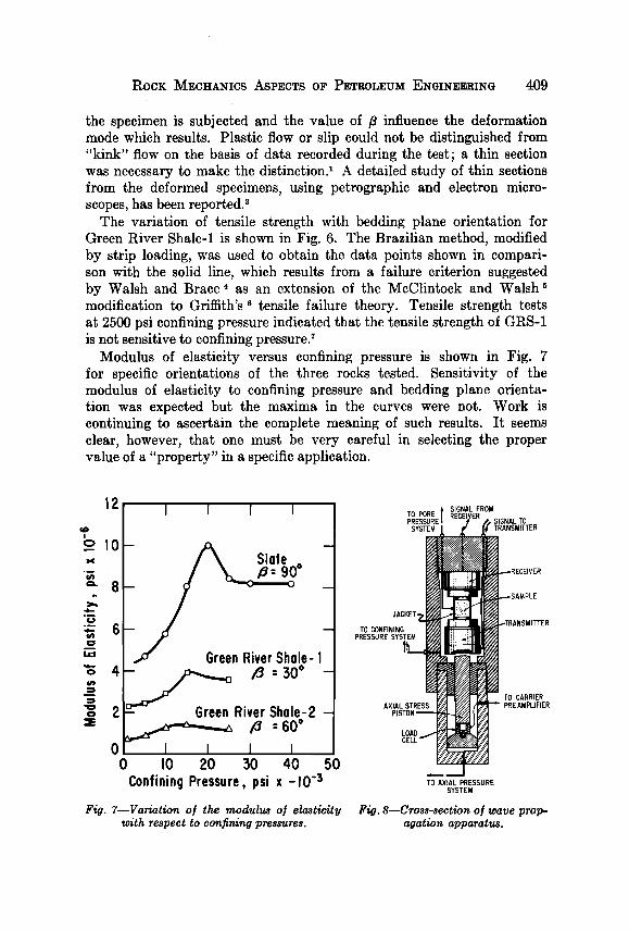
Modulus of elasticity versus confining pressure is shown in Fig. 7 for specific orientations of the three rocks tested. Sensitivity of the modulus of elasticity to confining pressure and bedding plane orienta- tion was expected but the maxima in the curves were not. Work is continuing to ascertain the complete meaning of such results. It seems clear, however, that one must be very careful in selecting the proper value of a "property" in a specific application.
12
I
_olo
I I I I
- A Slate , - :9oO
6 -
• Green River Shale- I
River Shale-2 - /'3 :60 ø
01 I I I I 0 I0 20 30 40 50
Confining Pressure, psi x -10 '3
Fig. 7--Variation of the modulus of elasticity with respect to confining pressures.
TO R ß SIGNAL FROM PO E RECEIVER PRESSURE [ • /, SIGNAL TO SYSTEM Jt ,•' ,[• TRANSMITTER
• '•RECEIVER
TO CO.FINING ,RESSURE SYSYEM
AXIAL STRESS • • • • •EAMPLIFIER
SYSTEM
F•. g--Cross-sect•n oJ wave prop- agat•n apparat•.

410 •TATUS OF PRACTICAL P•OCK i•ECHANICS
•Vave Propagation and Deformation Tests
As opposed to properties measured by rock deformation at low loading rates, dynamic directional properties of both dry and saturated rock specimens have been obtained at both simple and elevated stress states, using the equipment shown in Fig. 8. The tensor-like nature of material properties of several rocks has been determined with remarkable detail, owing to a capability for generating pure compression and shear waves? In addition, some effects of strain history have been investigated with the apparatus shown. Many well bore operations involve just a few cycles of loading and the changes in rock properties that occur are of great importance to the Petroleum Engineer. Because rock properties are strain history dependent, one would prefer to make all measure- ment in situ, i.e., in the well bore, and work now completed 8 shows great promise in this respect.
Another study 9 involved measurement of directional values for modu- lus of elasticity and Poisson's ratio by wave propagation techniques and simultaneous deformation measurements. Measurements of porosity, permeability, resistivity, compressive strength, and tensile strength were also made for the oriented core samples. All of these quantities are direction dependent. Some are loggable; some are "strength" proper- ties related to drillability of the rock. This project, and others now in progress, relate to a logging indication of drillability, which capability would be of great value to the drilling engineer. Continuous downhole monitoring of rock properties would provide, for example, a continuous log of the well. Simultaneous and continuous transmission of down- hole information would permit rig-floor optimization for minimum cost drilling and/or well bore deviation control.
Detailed description of in situ rock would be helpful in interpretation of seismic records and in attempts to model rock systems physically or mathematically. Modeling of rocks is not a new activity, but it is a dit/icult one owing to the extremely complex nature of rocks and their behavior. Realistic scaling criteria will not be possible until much more is known than at present.
Well Bore Stress State
Few topics in rock mechanics are more important to the Petroleum Engineer than the state of stress around a well bore. Prior to penetration by the drill bit, a reservoir has some stress field which resulted over geologic time. This condition is abruptly changed by the drilling opera- tion. The presence of the bore hole, movement of drilling fluid into the rock, subsequent well bore operations necessary to complete the well and

ROCK •IECHANIC$ ASPECTS OF PETROLEUM ENGINEERING 411
flow of formation fluids to the well bore serve to create, more than likely, a complicated stress state at and near the bore hole.
Paralleling experimental work on directional properties of rock, some theoretical aspects of fluid flow through anisotropic porous media have been considered?, TM Fig. 9 illustrates a reservoir of thickness, h, and radial extent, rB, containing a well bore of radius, r. The reservoir is considered to have transversely isotropic material and fluid flow properties. That is, in the horizontal direction for example, the rock exhibits fixed values for Young's modulus, E, Poisson's ratio, v, permea- bility, k, •nd areal porosity, •. In the vertical direction the rock has fixed but different values, i.e., E', /, k', and •'. For constant thickness of the reservoir and an infinite outer boundary, one might consider either (a) constant flow rate, or (b) constant flowing pressure at the well bore. Either case results in a time and position dependent pore pressure and mathematical expressions for the state of stress and radial displacement as functions of position and time have been developed. Solutions have
I i i I
Solutions for •r, l•..•. u, as f(position,time) for: Rock Properties: E,V, k, • in radial direction
E', 1) ', k', •' in vertical direction Plane Strain: I•z = 0
System 1': Infinite Reservoir ( r,,--,- • ) o. Constant Flow Rote at Well Bore b. Constant Pressure at Well Bore
System IT: Finite Reservoir (r,: finite) o. Steady State Fluid Flow õ. Constant Boundary Pressures c. Constant Pressure at Well Bore and No Flow
across Outer Boundary (Closed Reservoir)
• ...... ,•.•..
.......... i ILl I I 1 •',
•'.'.'?. ..... .
Solutions for •r, •,(7z, u, as f(pasition,time) for:
Rock Properties: E•,'P•, k•, • • in radial E2,1)2, k2.e•.) direction
E;,Vi', k;,,; } in vertical E'z.V'z. k'z. •'2 direction Plane Strain: Ez = 0
System Tlq': Finite Reservoir ( r,,: finite ) Constant Pressure at Well Bore and No [low
across Outer Boundary (Closed Reservoir )
Fig. 9--Physical system and boundary conditions /or transversely isotropic res- ervoir.
Fig. 10--Physical system and boundary conditions ]or "damaged" well bore in a transversely isotropic reservoir.

412 STATUS OF PRACTICAL ROCK MECHANICS
also been obtained for the case of finite outer boundary and fluid flow conditions of (a) steady state flow, (b) constant boundary pressures, and (c) constant pressure at the well bore and no flow at the outer boundary, i.e., a closed reservoir. A closed reservoir is a common physical situa- tion with which the reservoir engineer must deal.
Results of the work show the dramatic influence of directional prop- erties of the rock. Directional, transient fluid flow creates body stresses which are very significant relative to the total state of stress at and local to the well bore. Pressure gradients arising from reservoir fluid flow can so modify the stress state that calculations based upon the Lam• equations, for example, can be hopelessly in error. The Lam• equations, moreover, are õased upon solid body mechanics, and it is clear that the effect of porosity cannot be ignored.
Knowledge of the state of stress around a well bore is of concern to the drilling engineer, for example, in terms of rock failure in close proximity to the drill bit. Hydraulic fracturing of petroleum reser- voirs is common practice and of tremendous value. Considerations of fracture initiation and orientation illustrate the importance of realistic information about the well bore stress state. The ability to predict, from operating parameters and measurable rock properties, realistic fracture limits and dimensions is needed. The situation is complex; a petroleum reservoir may consist of many interbedded plastic and elastic layers, some thin, some thick, which interact with one another. Often the beds are inclined to the well bore. A generalized treatment which provides for a series of layered media, finite in thickness, and having directional properties and the dynamic stresses which arise due to well bore opera- tions is needed.
The drilling mud or fluid used to drill a well serves many functions, including transport of the drilled cuttings to the surface, lubrication of the drilling string, and containment of reservoir fluids within the formations penetrated. The borehole-to-formation pressure differential necessary to prevent flow into the well bore often results in a damaged zone or "skin effect" around the well bore due to invasion of mud
tiltrate and even mud solids into the formation. The physical system discussed earlier was extended as shown in Fig. 10, in which transverse isotropy is preserved but there are four sets of properties; one set in the radial direction in the damaged zone, another in the undamaged rock, one set in the vertical direction in the damaged zone, another in the undamaged rock. Solutions for the stress components at, a•, and a•. and the radial displacement ur as a function of position and time were ob- tained for a finite reservoir with a closed outer boundary and constant fluid pressure at the well bore?
If permeability near the well bore is substantially reduced, by what-

ROCK l•ECHANICS ASPECTS OF PETROLEUM ENGINEERING 413
ever means, large stress gradients and a complex stress field around the well bore may result when the well is opened to flow. Certainly such a bore hole stability problem is of great importance to the petro- leum engineer. Similarly, in poorly consolidated producing formations sand production into the well bore even under normal flow conditions is a serious problem which warrants additional analytical and experi- mental treatment.
The area of well bore mechanics includes other types of bore hole stability problems, such as casing loading due to flow of salt or shale. It is quite common to drill through the crest of salt domes to penetrate potential traps on the dome flanks. The plastic nature of salt and certain shale sections in the subsurface environment creates problems in maintaining a near-gage hole during drilling and problems relative to casing loading due to "creep" of such rocks later. The costs asso- ciated with casing collapse in a well are, of course, very large and this problem is receiving increased attention from a rock mechanics point of view.
Reservoir Description and Behavior
The reservoir engineer commonly does not identify himself as a rock mechanicist, although he is vitally interested in rock properties and behavior. Rather sophisticated approaches to various complex reservoir systems and processes have been and are being developed. It is not surprising that theoretical approaches have proceeded at a more rapid pace than efforts to establish detailed values for rock parameters which enter such mathematical results. The reservoir engineer is well aware, however, of the need for better reservoir description.. Important reser- voir rock and fluid flow parameters are obtained from well logs and in recent years heavy emphasis has been placed upon transient fluid flow analysis to establish the nature of a reservoir from well to well. Reservoir properties and behavior change during the depletion process, of course, and subsequent testing is desirable and necessary. Mathe- matical simulation of reservoir system behavior is receiving heavy empha- sis. Rock mechanics will play an ever increasing role here since the reservoir system is always out of direct reach and only a small amount of sampling of an entire reservoir is economically feasible.
Compaction of a reservoir during the depletion process is of some significance, and in the case of subsidence of large surface areas, a prob- lem which cannot be ignored. While this problem has received some attention, current and future work in rock mechanics will undoubtedly provide useful information in that area.

414 STAT•S OF PRACTICAL ROCK I•ECHANICS
DRIU,ING
It has been said that the petroleum industry is the only one which uses a five-mile long drive shaft. Certainly the on-bottom action of a drilling bit is far removed from the rig floor, where changes in rotary speed, bit weight, pump rate, etc., are controlled. The rotary drilling process has remained essentially unchanged since its introduction in the Spindletop Field in 1901. This is not to say, of course, that sub- stantial improvements in equipment and techniques have not been made. It seems reasonable, however, that detailed understanding of the complex and interrelated events that occur at and near a drilling bit should serve as the basis for possible improvements in drilling equip- ment and/or techniques. Considerable effort is being made, therefore, to investigate the various local and short term aspects of drill bit action.
Microbit Studies
An important aspect of the drilling problem is the dynamic filtra- tion which occurs below the bit, owing to a borehole-to-formation pres- sure differential. Fig. 11 shows a schematic diagram of a microbit
WEIGHT ON BIT TANK
• TURBINE FLOWMETER
CIRCULATING PUMP
F LOW ANALIZER
VACUUM TUBE VOLTMETER
FILTRATE COLLECTION
TUBE
FILTRATE FLOW LINE
SPEED ROTATING MOTOR
ROTARY ADJUSTMENT
FLOOR MODEL DRILL PRESS
HIGH PRESSURE WATER OUTLET
FLUID RESERVOIR
Fig. 11-•Schematic diagram oJ microbit drilling apparatus.

ROCK MECHANICS ASPECTS OF PETROLEUM ENGINEERING 415
drilling apparatus which has been developed to study dynamic filtration and its effect upon penetration rate> s
The drilling equipment shown is capable of rotary speeds to 250 rpm and bit weights to 1500 lb. The tests were carried out in a closed circulating system capable of borehole-to-formation pressure differentials of 1500 psi. A high-pressure pump provided circulation rates to 60 gpm and the drill fluid was continuously filtered by screen elements located within a high-pressure container. Circulation fluid pressure was main- tained constant during drilling by a high-pressure, low-volume injec- tion pump.
The rock sample, coated with adhesive and then cast in plastic pipe with epoxy (Fig. 12B), was sealed within the pressure cell body by' O rings (Fig. 12A). A transducer threaded into the borehole section of the cell provided continuous recording of the borehole pressure. Three additional transducers were positioned on the cell body to measure pore pressure within the sample ahead of the bit. The pore pressure
DRILL SHAFT • O-RINGS ADHESIVE
BRASS
BUSHING • • CAP•
•:••,',ll PLASTIC
PRESSURE GAUGE •,• • • . :ES•URE ;AUGE
H 0 L E ••AI• ' i.• ( B PRESS•E 1•'/• •J •STAINLESS '•-• • E R •J•••EEL PRESSURE
PEURE II CELL TRANSDUCERS
DRILL • •••••11•L =- I FLUID
QUICK / .•FILTRATE _O- ALVE• :• FLOW LINE (C) OPENING V
Fig. l•--Pressure cell assembly.
416 STATUS OF PRACTICAL ROCK MECHANICS
transducers just penetrated the adhesive coating around the sample and were pressure sealed upon the plastic pipe by O rings (Fig. 12C). All four transducers had an operating range of 0 to 1500 psi with 0.05 pct accuracy. A high-pressure, quick-opening valve located in the tiltrate flow line prevented flow prior to drilling.
Filtrate which passed through the rock during drilling entered the base of the calibrated tiltrate collection tube; an air column within the upper portion of the closed tube was thus compressed as liquid entered the collection tube. A 0- to 10-psig pressure transducer was used to monitor the air pressure, and a calibration curve of air column pressure vs. fluid level change in the closed tube allowed precise evaluation of tiltrate produced during a drilling test. A bit location transducer, con- sisting of a gear train, battery and precision potentiometer, continu- ously measured bit displacement during drilling.
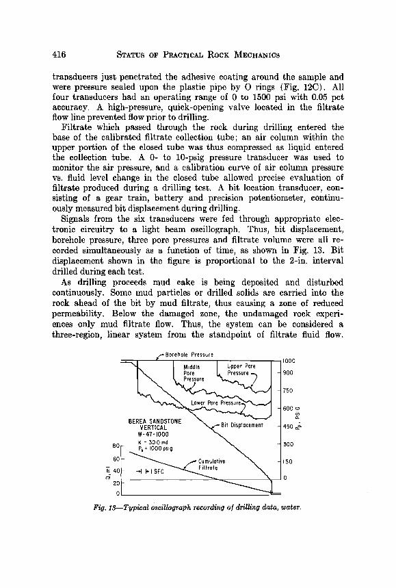
Signals from the six transducers were fed through appropriate elec- tronic circuitry to a light beam oscillograph. Thus, bit displacement, borehole pressure, three pore pressures and tiltrate volume were all re- corded simultaneously as a function of time, as shown in Fig. 13. Bit displacement shown in the figure is proportional to the 2-in. interval drilled during each test.
As drilling proceeds mud cake is being deposited and disturbed continuously. Some mud particles or drilled solids are carried into the rock ahead of the bit by mud tiltrate, thus causing a zone of reduced permeability. Below the damaged zone, the undamaged rock experi- ences only mud tiltrate flow. Thus, the system can be considered a three-region, linear system from the standpoint of tiltrate fluid flow.
g•- Borehole Pressure '• I M,ddle I Upper Pore
/ Pore I, Pressure
_ _ Lower P• BEREA SANDSTONE • ............
VERTICAL • un u•spmcemenr W- 47- I000 •
o,-, K = •0,0 md • ou r- Pb = IOOOps•g •
IOOO
900
750
600 •
450
$00
150
0
Fig. 13--Typical oscillograph recording o! drilling data, water.

ROCK MECHANICS ASPECTS OF PETROLEUM ENGINEERING 417
The pressure gradient below the bit and the average permeability of the three-region system were calculated as a function of core length from a computer program which utilized the measured pressures, distances, and tiltrate flow rates.
Fig. 14 shows typical plots of the permeability distribution and pressure gradient for drilling tests with water on Berea sandstone. The pressure gradient is high for about one-third of a centimeter below the bit, and permeability damage is evident for about one centimeter. Fig. 15 shows results for a drilling mud having a 50 cc/30 min. water loss and Fig. 16 gives typical results for a low water loss mud (13 cc/30 min.). As the water loss decreases, the pressure gradients increase and become more concentrated below the bit. Permeability damage below the bit due to solid particle invasion likewise becomes more local to the hole bottom. For the low fluid loss mud, pressure gradients over 1,000,000 psi per ft were measured for a 1000-psi borehole-to-formation pressure differential. Note that this gradient was essentially concentrated in the first one-tenth centimeter below the bit and that the corresponding permeability re- duction was likewise over a very short distance. These results graphi- cally illustrate the extremely local nature of this aspect of the drilling process. It has been shown elsewhere •3 that the penetration rate is directly related to the pressure gradient below the bit.
Since permeability distribution below the bit can be determined with
20 • 10 4
• I• X I• 4 _
• 5 • IO 4
TAP NO 3
10 6
I0 4
I0 •
10 2
I0 •
i0 •
TAP NO. •
ß ß ß ß
ß ß ß ß
0 2 3 4 5 6 ? 8 9 0 I 2 3 4 5 6 ? 8
CORE LENGTH, cm CORE LENGTH, cm
Fig. 14--Permeability Junction and pressure gradient vs. core length Jot water. Vertical Berea sandstone, PB -- 1000 psi4t.

418 STATUS OF PRACTICAL ROCK MECHANICS
5 xlO 5
4 x 10 5
•_ 3xlO 5
• ;) x 10 5
..y
0.3
• Ix I0 5
TAP NO. 2
0 I 2 3 4 5 6 7 8 9 0
CORE LENGTH, cm
TAP NO. 2
I 2 3 4 5 6 7 8 9
CORE LENGTH, cm
Fig. 15--Permeability /unction and pressure gradient vs. core length /or high fluid loss mud. Vertical Berea sandstone, PB -- 1000 psig.
15 x IO 5
,•. I0 x 10 5 c•.
• 5 x 10 5 0'3
0 0
TAP NO 3
-_
TAP NO. 3
I 2 3 •4 5 6 7 8 I 2 3 4 5 6 7 8 9
COREbENGTH, cm CORE LENGTH, cm
Fig. 16--Permeability /unction and pressure gradient vs. core length /or low fluid loss mud. Vertical Berea sandstone, PB -- 1000 psig.

ROCK •VIECHANICS ASPECTS OF PETROLEUM ENGINEERING 419
the system shown in Fig. 11, the apparatus is being used to study formation damage during drilling in terms of rock and mud system properties2 • It is of interest to know what rock and mud properties control the magnitude and extent of damage and to what degree the damage is reversible. This is of great importance to production and reservoir engineers since the damaged well's flow capacity may be significantly impaired and the well's response to stimulation techniques may be greatly compromised.
A separate investigation having to do with underbalanced drilling has been carried out with a modified version of the equipment shown in Figs. 11 and 12. In this work a system was developed whereby formation fluid was allowed to flow into the wellbore during'the drilling test? In other words, the pore fluid pressure exceeded the bore hole pressure so that a controlled "blow out" condition prevailed. Substantial increases in penetration rate can be achieved under certain circumstances and the technique is currently in limited field use.
Bit Tooth Indenta,tion Tests
In contrast to the drilling bit studies mentioned previously, con- siderable study has been made of the impact or indentation of a single bit tooth into fluid saturated rock at elevated pressures. •6, • Fig. 17 shows
••lt NITROGEN [ POLAROID • BORE HOLE • • / / CAMERA --• -.,. • a•' •1 • PRESSURE ! i I / .-----•*k ..... • X •• •. •1 [ • • ..•• •)• 0SC•LL0SC0,[S
,,ov '
BOR• '• ** ' •F -- •• I I II••111•li••Hl••-:----: -
/ •• !••111•I•1111111•••••::'C-:
•INSTR•MENTATION PANEl

420 STATUS OF PRACTICAL ROCK MECHANICS
apparatus with which a single, verticle impact of a bit tooth upon a rock specimen may be carried out under carefully controlled operational and environmental conditions. Fig. 18 shows a cross-section of the pressure vessel in which the rock sample may be subjected to indepen- dently controlled confining, pore, and borehole pressures.
Strain gages mounted on the dynamometer assembly provided a record of force on the bit tooth during impact (Fig. 18). A velocity transducer mounted on a cam follower produced an electronic signal proportional to the velocity of the follower--hence, the velocity of the dynamometer and bit tooth. The force-time and velocity-time signals were fed to an oscilloscope that was equipped with an operational ampli- fier. Thus, with electronic integration of the velocity-time signal, simul- taneous records of force-time, velocity-time and displacement-time characteristics of the bit tooth were obtained. Using a second oscilloscope, the force-time and displacement-time curves were cross-plotted to pro- duce a force-displacement record for the test.
TO CHIPPER
STRAIN GAGE LEADS
BORE HOLE PRESSURE
WEDGE
-- ROCK SAMPLE SEALED WITH EPOXY RESIN
-- CONFINING PRESSURE
COMPRESSION CHAMBER
PORE PRESSURE--
Fig. 18--Cross-sectional view oJ pressure vessel with sample ready to be impacted.

ROCK MECHANICS ASPECTS OF PETROLEUM ENGINEERING 421
Fig. 19 illustrates the three general types of crater--brittle, semi- plastic (transitional from brittle to plastic) and plastic failure--which resulted from impact tests on Berea and Bandera sandstone. For brittle- type failure in gas-saturated rocks, the craters were irregular in shape and unsymmetric about the line of tooth impact. A crushed zone usually existed directly beneath the wedge fiat. For liquid-saturated rock, more uniform craters were observed; the crater shape was quite uniform and the crater was symmetric about the line of tooth impact. The same result was reported by Podio and Gray?
The transitional mode of failure from brittle to plastic yielded sym- metric craters; one large free chip formed on each side of the wedge and a small free chip sometimes existed at each end of the wedge. A near-perfect impression of the wedge fiat was apparent in all craters. Rock deformation was continuous in this type of crater.
For a plastic-type mode of failure, no free chips were formed in establishing the crater. Plastically formed craters were symmetrical and the displaced rock laminated during the process. The laminated lip material suggests that failure occurred in finite steps rather than by continuous flow. Perfect wedge impressions were observed; smooth and uniform craters were observed when the displaced rock was removed.
At zero pore pressure (and borehole pressure), brittle failure occurred at all confining.pressures in both gas- and liquid-saturated Berea and gas-saturated Bandera. In soltrol-saturated Bandera the failure was usually by brittle failure, but in some cases it was slightly transitional.
As pore pressure was increased at constant confining pressure, the failure mechanism graded from a brittle to a ductile type. Transition occurred very early in the weaker rock (Bandera) but was delayed to smaller values of effective stress (confining pressure Pc minus pore pressure Po) for the stronger rock (Berea). Transition from brittle
BRITTLE TRANSITIONAL PLASTIC
Fig. 19--Typical craters formed during single bit tooth impact tests on permeable

422 STATUS OF PRACTICAL ROCK MECHANICS
to a more ductile behavior occurred at lower pore pressures (high effective stress) for liquid saturated rocks but was quite evident for the gas-saturated samples at higher pore pressures (low effective stress).
From observation of the samples it was evident that control of the mode of crater formation depends not only upon the strength of the rock but also upon the difference between confining pressure and pore pressure, and the nature of the pore fluid saturant, i.e., a nominal zero effective stress does not insure a given failure mode. For example, while tests at zero effective stress in nitrogen-saturated Berea resulted in craters formed in mostly brittle fashion, tests at zero effective stress using liquid-saturated Berea and Bandera yielded plastically formed craters.
Typical oscilloscope records for brittle, transitional and plastic mode of failure are shown in Fig. 20. Fig. 20-A shows brittle failure. Inspec- tion of the force-time and displacement-time curves shows that maximum force occurs after only a slight penetration. Force drops rapidly from the maximum value and there is a corresponding increase in velocity. A secondary force-time peak, lower than the first peak, corresponds to the maximum on the displacement-time curve. The force-displacement curve has a maximum value at low displacement and a secondary peak occurs at maximum displacement.
Fig. 20-B represents late transitional or semiplastic failure. Com- parison of force-time and displacement-time curves shows that maxi- mum force occurs near maximum penetration. It may be seen from the force-displacement curve that increase in force is nonlinear with wedge penetration after the initial force. Note the dramatic change in the shape of the force-displacement curve as compared to brittle failure; now maximum force occurs near the end of the curve, i.e., at maximum penetration.
Fig. 20-C shows typical oscilloscope traces for plastic failure. The force rises rapidly on contact and, after the initial force is reached, the force is linear with increasing wedge penetration. The linear rela- tionship between force and wedge penetration beyond the initial force is the main difference between plastic and semiplastic mode of crater formation.
Note also that the initial force is highest for brittle failure and de- creases as the failure mode passes through transitional to fully plastic- failure. While initial force depends upon several factors (rock type, tooth geometry, stress state, pore fluid saturant and rate of loading), the linearity between force and bit-tooth penetration for plastic failure obtained in these experiments constitutes excellent agreement with plasticity theory.
Oscilloscope records for tests on Berea sandstone at a constant con- fining pressure of 10,000 psi and pore pressures of 3000, 5000 and 8000

I•OCK i•ECHANICS ASPECTS OF PETROLEUM ENGINEERING 423
$$: 2 •/cm
I MAXIMU
INITIAL h _FORCE FORCE---•,,
DISPL.
FORCE
VEL.
A. BRITTLE DISPLACEMENT
DISPL.
FORCE
VEL.
B. TRANSITIONAL DIS PLACEMENT
DISPL. --
F OR CE
VEL.
0 1 • ,
C. PLASTIC DISPLACEMENT
Fig. •O--Typical oscilloscope records oStained during single bit tooth impact tests on permeable rocks.

424 STATUS OF PRACTICAL ROCK MECHANICS
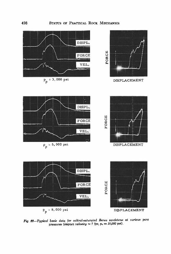
psi are shown in Fig. 21 for nitrogen-saturated samples and in Fig. 22 for soltrol-saturated ones. For nitrogen-saturated Berea, the craters are formed in a brittle fashion at 3000 psi pore pressure (nominal effective stress=7000 psi). As the pore pressure is increased (i.e., the nominal effective stress is lowered), the failure mode changes slightly to early transitional. For soltrol-saturated Berea (Fig. 22), the failure mode is in a late transitional stage even at 7000-psi effective stress and be- comes slightly more plastic at an effective stress of 2000 psi.
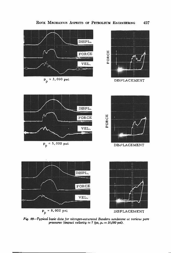
For Bandera sandstone saturated with nitrogen (Fig. 23) a transi- tion from brittle to a semiplastic failure mode is dramatically evident as the pore pressure is increased at constant confining pressure of 10,000 psi. Even at 7000-psi effective stress, a fair degree of semiplastic de- formation is observed. At a pore pressure of 8000 psi (nominal effective stress=2000 psi), the traces show well-developed semiplastic crater formation. Note the reduced rate of force buildup beyond the initial force and the linearity of the velocity-time curve. For soltrol-saturated Bandera (Fig. 24) crater formation is by plastic failure, even at 7000- psi nominal effective stress. When confining pressure and pore pres- sure are equal, i.e., when the nominal effective stress is zero, plastic failure occurs in both rocks (Fig. 20-C).
The above results clearly contradict the usual result that brittle failure obtains at zero effective stress. It seems certain that the mode
of crater formation is not just a matter of combination of confining pressure and pore pressure at hand, but rather depends upon at least three interdependent variables--nominal effective stress, pore fluid satu- rant and rock strength.
The impact velocity in these tests was only about 7 fps, but the dura- tion of the event was only about 4 millisec. Clearly, the dynamics of the situation are important. The volume of rock deformed by the bit tooth is very small. For these impact tests brittle failure was observed on nitrogen-saturated Berea sandstone at zero nominal effective stress, i.e., when confining pressure and pore pressure were equal. On the other hand, for liquid-saturated rocks the mode of failure graded from brittle to ductile behavior as the pore pressure was increased at constant confining pressure, indicating that a fully plastic mode of crater formation could be expected at zero nominal effective stress. The tests proved this to be correct as plastic instead of brittle failure was obtained when the pore pressures and confining pressures were equal.
The above observations suggest that, for dynamic tests, the nominal effective stress is not the only factor that controls the mode of failure; the nature of the interstitial fluid also has an important role in rock behav- ior. Certainly the high compressibility of nitrogen as compared to the liquid saturants used contributed to the observed brittle behavior of gas-

ROCK MECHANICS ASPECTS OF PETROLEUM ENGINEERING 425
DISPL.
FORCE
VEL.
pp 3,000 psi DISPLACEMENT
pp = 5,000 psi
DISPL.
FORCE
VEL.
DISPLACEMENT
[
DISPL.
FORCE
VEL.
pp 8, ooo psi DISPLACEMENT Fitl. Y•l--Titpical basic data Jot nitrooen-saturated Berea sandstone at various pore
pressures (impact velocitlt --• 7 Jps, po -- 10,000 psi).
426 STATUS OF PRACTICAL ROCK MECHANICS
pp = 3,000 psi
DISPL. _ •
FORCE 0 VEL.
--
DISPLACEMENT
pp = 5,000 psi
DISPL.
FORCE
VEL.
o
DISPLACEMENT
DISPL.
FORCE
VEL.
pp 8,000 psi DISPLACEMENT
Flit. •--Tltpical basic data ]or soltrol-saturated Berea sandstone at various pore pressures (impact velocitit --• 7 Ips, pc ---- 10,000 psi).
ROCK MECHANICS ASPECTS OF PETROLEUM ENGINEERING 427
i
DISPL.
FORCE
pp = 3,000 psi DISPLACElVLENT
pp = 5,000 psi
I
_ DISPL.
FORCE
VEL.
o
DISPLACEMENT
DISPL.
FORCE
VEL.
-
pp = 8,000 psi DISPLACEMENT Fig. •$--T•pical basic data Jot aitrogea-satttrated Baadera saadstone at various pore
pressures (impact velocity --• 7 Jps, po -- 10,000 psi).

428 STATUS OF PRACTICAL ROCK MECHANICS
DISPL. -
pp = 3,000 psi
FORCE
VEL.
0
DISPLACEMENT
pp 5,000 psi
DIS P L.
FORCE
VEL.
DISPLACEMENT
DISPL.
FORCE
0
pp = 8,000 psi DISPLACEMENT
Fi•;. •4--Typical basic data Ior soltrol-saturated Bandera sandstone at various pore pressures (impact velocity --• 7 Ips, po ---- 10,000 psi).

Rock MECHANICS ASPECTS OF PETROLEUM ENGIN•.•.RTNG 429
saturated rocks and ductile behavior of liquid-saturated rocks at zero nominal effective stress. However, the trend from brittle to ductile be- havior as the nominal effective stress was reduced held regardless of the pore fluid saturant. More is involved than fluid compressibility.
Podio and Gray suggested that rock behavior during bit-tooth impact is in essence a very short time-consolidation problem? The true stress state local to the tooth depends upon an interplay of deformation charac- teristics of a small volume of fluid-filled rock and the dynamics of the process. One fundamental question is, what is the pore pressure in the small volume of rock below the bit tooth during impact? Some idea of the complexity of the problem may be gained by considering the diffu- sivity equation, normally written as
•pc •72PP= k • [1]
where p•=pore fluid pressure below the bit tooth, •= rock porosity, k-- rock permeability, • = fluid viscosity, c = system compressibility and t = time. Even assuming that the saturating fluid exerts only a pressure effect upon the rock, i.e., the fluid does not react in any way with the rock matrix, it is clear that a realistic expression for p•= f(t) in the zone of deformation must be complex. Apart from known pressure dependence, it is unlikely that any of the parameters which comprise the diffusivity constant (•pc)/k are in fact constant. Values for porosity • and permea- bility k surely change rapidly during deformation of the rock by the bit tooth. Moreover, one might question whether values for fluid viscosity and compressibility are rather different from normal equilibrium PVT measurements when the fluid pressure is being changed significantly in a time period of only a few microseconds. In addition, short-term thermal effects may not be insignificant.
In summary, the actual state of stress in the small volume of rock surrounding an impacting bit tooth is unknown at present. It should be emphasized that the contradiction of ductile rock behavior at zero effec- tive stress reported by other investigators is based upon a gross or nominal effective stress. It should not be concluded that the concept of effective stress is necessarily at fault. Rather, the need is to develop a definition of effective stress that incorporates both the local nature of the event and the dynamics associated therewith.
Additional bit tooth impact tests on salt water saturated rocks with drilling mud in the borehole section of the pressure vessel (Fig. 18) have been reported elsewhere? The results showed that at a given nominal effective stress, the failure mode graded from brittle to plastic as the water loss of the drilling fluid was-reduced. Also, for a given drilling

430 S?A?us OF PP•CAL Rock •I•ECHANICS
fluid, the failure mode moved from brittle to plastic as the nominal effec- tive stress was reduced.
Drag Bit Studies
Sedimentary rocks are, in general, anisotropic in most if not all of their properties. Strength anisotropy as it relates to hole deviation is receiving considerable attention, and Fig. 25 illustrates equipment with which the planing action of a drag bit blade can be simulated. Details of the apparatus have been reported elsewhere •9, 2o as have preliminary tests on some anisotropic rocks? •
Fig. 26 shows in schematic form the motion of a drag bit blade of rake angle, •, clearance angle, •, making a depth of cut t, in a layered rock, the bedding planes of which make an angle, •, with the direction of cutting? The resultant F, of the vertical force component, Fv, and the horizontal force component, Fh, makes an angle p with the bedding planes. Planing tests have been carried out on Green River Shale at various orien- tations to the bedding plane for various values of t, R, and •.• Details of the bit forces were measured during chip formation for correlation with high-speed movies of the cutting action.
Fig. 27 shows typical results. It is obvious that forces on the drag bit
•..'• CAMERA CONTROLS SHAPER RAM
WOLLENSAK FASTAX MERjTMICi A L • ( . LLU NATOR FROM '• ..... .•.' 16 mm HIGH SPEED CAMERA METALLUR A • .... "" __ GIC L [ •..L-*! .• MICROSCOPE ..J• '"lil[•'•.' ":•.
•:•: •" :• [ PARABOLIC' '•?• '•;""-' .' :;-'.':. •'•:• • •MIRROR• •'
, '• , ß •': ,
•• • - • •• SUBJECT BEING • - _..' I•• PHOTOGRAPHED ,I • l•l ,. ..... :-.,.
.,-•.• • ', .•.
ELECTRODE • • B•• ••'••••::.:: • OSCILLOSCOPE
POLAROID II • I I

ROCK MECHANICS ASPECTS OF PETROLEUM ENGINEERING 431
DRAG BIT
BLADE
Clearance //,•// //
/.{// •;./_.• '.• ///2
blade are cyclic and are directly related to the orientation of the bedding planes, which orientation causes directional strength in the rock. Such results are to be expected and substantiate preliminary tests of a similar nature. 2• Fig. 28 shows a drag bit blade rotating in a layered, dipping formation? Results such as shown in Fig. 27 mean that the total force
300 ø 280 -
260
240
220
200 i
180 • 160
•4o 120
I00 ,
8O
60
40-
0
• , Angle between F r and Bedding Plenes 20 40 60 80 I00 120 140 160 180
I I I I I I I I I I I I I I I I I I
• o•
,_ Fr = Resultant Force
-- t = 0.010 • - • = 0 ø R = 0.005" -
• 210 I I I I I • I I I I I I I i 40 60 0 I00 120 140 160 180
•, Angle Of Bedding Plones
Fi•. •7--Variation ol loree components with bed- ding plane orientation.
(•[• RataDirection of tion
Fh A B
Be
Plane • •
Fi•. •8---•ehematic diagram oJ force components on drag bit blade•.

432 STATUS OF PRACTICAL ROCK MECHANICS
resultant on the bit will be direction dependent. A direction-dependent force resultant on the bit would be important with respect to (a) drill string vibrations and (b) hole deviation considerations. Both topics are, of course, extremely important in the drilling process.
As was mentioned earlier, directional properties of rocks have been obtained by wave propagation and/or deformation techniques. Current work is directed towards mathematical formulation of the hole deviation problem based upon measurable, directional rock properties. With the development of equipment for continuous relay of downhole information to a rig floor computer which is coupled to servo-controlled rig floor controls, it will be possible to optimize the drilling operation to include deviation control.
SUMMARY
Only a few topics in rock mechanics of interest to the petroleum engineer have been discussed. Notwithstanding the superficial treatment above, rock mechanics is basic to the petroleum industry and considerable effort is being made to solve a host of rock mechanics problems which have tremendous economic implications.
REFERENCES
1. McLamore, R. T.: Strength-Deformation Characteristics of Anisotropic Sedi- mentary Rocks, Ph.D. Dissertation, The University of Texas, Aug., 1966.
2. McLamore, R. T. and Gray, K. E.: The Mechanical Behavior of Anisotropic Sedimentary Rocks, Trans. A•ME Journal of Engineering for Industry (Feb., 1967) vol. 89, no. 1, p. 62.
3. Budd, C. H.: A Microscopic Examination of Mechanically Deformed Anisotropic Rock, M.S. Thesis, The University of Texas, Jan., 1968.
4. Walsh, J. B. and Brace, W. F.: A Fracture Criterion for Brittle Anisotropic Rock, Jour. Geoph•s. Res. (1964) vol. 69, no. 16, pp. 3449-3456.
5. McClintock, F. A. and Walsh, J. B.: Friction on Griffith Cracks in Rocks under Pressure, Proc. Fourth U.S. Natl. Cong. Appl. Mech. (1963) p. 1015.
6. Griffith, A. A.: Theory of Rupture, Proc. First Internatl. Cong. Appl. Mech. (1924) pp. 55-63.
7. McLamore, R. T. and Gray, K. E.: A Strength Criterion for Anisotropic Rocks Based Upon Ezperimental Observations, SPE 1721, Presented at 96th Annual AIME Meeting (Feb. 19-23, 1967) Los Angeles, Calif.
8. Podio, Augnsto L.: Ezperimental Determination of the Dgnamic Elastic Proper- tics of Anisotropic Rocks-Ultrasonic Pulse Method, Ph.D. I)ia•rtation, The University of Texas, June, 1968.
9. Boggus, R. F.: Directional Permeabilities, Material Propertics, and Resiztivities of •ondstones, M•. Thesis, The University of Texas, Aug., 1967.
10. Seth, M. S. and Gray, K. E.: Transient Stresses and Displacement Around a Wellbore Due to Fluid Flow in Transversely Isotropic, Porous Media: I. Infinite Reservoirs, $oc. Pet. Eng. Jour. (March, 1968) vol. 8, no. 1, p. 63.

ROCK MECHANICS ASPECTS OF PETROLEUM ENGINEERING 433
11. Seth, M. S. and Gray, K. E.: Transient Stresses and Displacement Around a Wellbore Due to Fluid Flow in Transversely Isotropic, Porous Media: II. Finite Reservoirs, $oc. Pet. Eng. Jour. (March, 1968) vol. 8, no. 1, p. 79.
12. Seth, M. S.: Stresses and Displacements in Transversely Isotropic, Porous Elastic Media Under Transient Pore Pressure, Ph.D. Dissertation, The University of Texas, Jan., 1966.
13. Young, F. S. and Gray, K. E.: Dynamic Filtration During Microbit Drilling, Jour. Pet. Tech. (Sept., 1967) vol. 19, no. 9, p. 1209.
14. Evans, W.: Rock and Drilling Fluid Properties as Related to Formation Damage, M•q. Thesis, The University of Texas, in progress.
15. Gainer, P.: A Microbit Study o! Controlled-Blowout Drilling, M•q. Thesis, The University of Texas, Aug., 1967.
16. Podio, A. and Gray, K. E.: Single-Blow Bit Tooth Impact Tests on Saturated Rocks Under Confining Pressure. I. Zero Pore Pressure, Soc. Pet. Engr. Jour. (Sept., 1965) vol. 5, no. 3, p. 389.
17. Yang, J. and Gray, K. E.: Single-Blow Bit-Tooth Impact Tests on Saturated Rocks Under Confining Pressure: II. Elevated Pore Pressures, $oc. Pet. Engr. Jour. (Dec., 1967) vol. 7, no. 4, p. 389.
18. Myers, G. M. and Gray, K. E.: Dynamic Filtration Below an Impacting Bit Tooth, SPE 1862, Presented at 42nd Annual Fall Meeting of SPE (Oct. 1-4, 1967) Houston, Texas.
19. Gray, K. E.: Fixed-Blade Pinning of Rocks in the Brittle Stress State, Ph.D. Dissertation, The University of Texas, Aug., 1962.
20. Gray, K. E., Armstrong, Frank and Gatlin, C.: Two Dimensional Study of Rock Breakage in Drag Bit Drilling at Atmospheric Pressure, Trans., AIME (1962) vol. 225, p. 93.
21. Chenevert, M. E.: The Deformation-Failure Characteristics of Laminated Sedi- mentary Rocks, Ph.D. Dissertation, The University of Texas, Jan., 1964.
22. Gray, K. E.: Some Current Rock Mechanics Research Related to Oil-Well Drilling, Paper No. 906-12-K, Presented at Spring Meeting of Southwestern District, Division of Production, API, Odessa, Texas (March 15-17, 1967).
23. Peng, Y.: Fixed-Blade Pinning of Anisotropic Rocks at Atmospheric Pressure, M•. Thesis, The University of Texas, in progress.


HYDRAULIC FRACTURING
