design analysis in rock mechanics - taylor & francis group
TRANSCRIPT
Design Analysisin Rock Mechanics
BALKEMA - Proceedings and Monographs
in Engineering Water and Earth Sciences
Design Analysisin Rock Mechanics
William G PariseauMalcolm McKinnon Endowed ChairDepartment of Mining EngineeringUniversity of Utah Salt Lake City Utah USA
LONDON LEIDEN NEW YORK PHILADELPHIA SINGAPORE
copy 2007 Taylor amp Francis
Taylor amp Francis is an imprint of theTaylor amp Francis Groupan informa business
All rights reserved No part of this publication or theinformation contained herein may be reproduced stored ina retrieval system or transmitted in any form or by any meanselectronic mechanical by photocopying recording or otherwisewithout written prior permission from the publishers
Although all care is taken to ensure integrity and the qualityof this publication and the information herein noresponsibility is assumed by the publishers nor the authorfor any damage to the property or persons as a result ofoperation or use of this publication andor the informationcontained herein
Published by Taylor amp FrancisBalkemaPO Box 447 2300 AK LeidenThe Netherlandse-mail PubNLtandfcoukwwwbalkemanl wwwtandfcouk wwwcrcpresscom
British Library Cataloguing in Publication DataA catalogue record for this book is available from the British Library
Library of Congress Cataloging in Publication DataPariseauW G
Design analysis in rock mechanics WG Pariseaup cm
Includes bibliographical references and index1 Rock mechanics ndash Textbooks I Title
TA706P37 20066241prime5132ndashdc22 2006020260
ISBN10 0ndash415ndash40357ndashX (hbk) ISBN13 978ndash0ndash415ndash40357ndash3 (hbk)ISBN10 0ndash415ndash41381ndash8 (pbk) ISBN13 978ndash0ndash415ndash41381ndash7 (pbk)ISBN10 0ndash203ndash96825ndash5 (ebk) ISBN13 978ndash0ndash203ndash96825ndash3 (ebk)
This edition published in the Taylor amp Francis e-Library 2006
ldquoTo purchase your own copy of this or any of Taylor amp Francis or Routledgersquoscollection of thousands of eBooks please go to wwweBookstoretandfcoukrdquo
Contents
Preface xiAcknowledgments xv
1 Introduction 1
11 A practical design objective 312 Problem solving 413 Units 514 Background information 6
Rock mechanics literature 6Mechanical properties of rock 7
15 Problems 7Basics 7Review of stress 8Review of strain and elasticity 10
2 Slope stability 15
21 Translational rock slope failures 18Planar block slides 18Saftey factor improvement 31Wedge failures 38
22 Rotational slope failures 60Remedial measures 68Base failures 70Toppling failures 72
23 Problems 73Planar block slides 73Wedge failures 78Rotational slides 81Dynamics toppling 85
vi Contents
3 Shafts 87
31 Single unlined naturally supported shafts 87Shaft wall stress concentration 88Unlined circular shafts 89Unlined elliptical shafts 94Unlined rectangular shafts 101Shaft wall strengths 113
32 Shaft wall support and liners 121Shaft wall bolting 122Circular shaft liners 130Circular steel rings 140
33 Multiple naturally supported shafts 142Circular shafts in a row 142Shaft pillar safety 148Two circular shafts of different diameter 153Elliptical shafts in a row 155Rectangular shafts in a row 158
34 Problems 162Single naturally supported shafts 162Supported shafts liners bolts rings 169Multiple shafts 173
4 Tunnels 175
41 Naturally supported tunnels 175Single tunnels 177Single tunnel joints 184Multiple tunnels 189
42 Tunnel support 194Fixed steel sets 194Pattern bolting ndash rock reinforcement 208Combination support 212Yieldable steel arches 218Light segment liner 219
43 Problems 220Naturally supported tunnels 220Supported tunnels 221Rock mass classification schemes RQD 226
Contents vii
5 Entries in stratified ground 229
51 Review of beam analysis 229Basic beam formulas 230Important special cases 234
52 Softrock entries 243Naturally supported roof 243Bolted roof 255Point anchored roof bolting 255Distributed anchorage roof bolting 261Roof trusses 264
53 Problems 266Naturally supported roof 266Bolted roof 268
6 Pillars in stratified ground 277
61 Pillars in a single seam 277Tributary area extraction ratio analysis 277Size effect on strength 281
62 Pillars in dipping strata 289Extraction ratio formulas for pillars in dipping seams 289An unconventional Mohrrsquos circle representation 293Generalized Mohrrsquos circle 298Backfill effects on pillar safety factors 300
63 Pillars with joints 306Flat seam pillars with joints 306Dipping seam pillars with joints 310
64 Pillars in several seams 315Columnized main entry pillars 315Staggered chain entry pillars 321
65 Barrier pillars 32466 Problems 329
7 Three-dimensional excavations 345
71 Naturally supported caverns and stopes 346Spheroidal excavations 347Cubical and brick-shaped excavations 356
72 Joints in cavern and stope walls 36373 Tabular excavations 364
viii Contents
74 Cavern and stope support 366Hardrock mine fill 367Cable bolt support 386
75 Problems 3903D Caverns 390Back fill 391Cable bolting 393
8 Subsidence 397
81 Chimneys 397Chimney cave geometry 398Caving rock flow 405Chimney cave forces 407Chimney cave water forces 417Support near caving ground 421
82 Troughs 430Limit of subsidence 431Maximum subsidence 433Critical width 433NCB subsidence profile 435Angle of draw and subsidence factor adjustments 440NCB strain profile 444Surface damage 451Multipanel multiseam subsidence 455Alternative approaches to subsidence 461
83 Problems 461Chimney caving 461Combination support 464Subsidence troughs 467
Appendix A Background literature 469
A1 Books about fundamentals of mechanics 469A2 Books about rock mechanics 470A3 Books containing rock properties 471A4 General sources of rock mechanics information 472
Appendix B Mechanical properties of intact rock and joints 473
B1 Elastic moduli of intact rock 474Youngrsquos modulus 474Poissonrsquos ratio 477Shear modulus 479Anisotropy 480
Contents ix
B2 Strength of intact rock 482Tensile strength 482Unconfined compressive strength 485Compressive strength under confining pressure 495MohrndashCoulomb strength 497HoekndashBrown strength 499DruckerndashPrager strength 499Nonlinear n-type strength 501Compressive strength test data 501
B3 Joint stiffness 507Normal stiffness 508Shear stiffness 509
B4 Joint strength 509B5 Simple combinations of intact rock and joints 512
Continuously jointed rock mass moduli 514Discontinuously jointed rock mass moduli 518Continuously jointed rock mass strengths 520Discontinuously jointed rock mass strengths 523
Appendix C Rock mass classification schemes for engineering 529
C1 Rock quality designation 529C2 Terzaghi modified scheme 529C3 RSR RMR and Q 530C4 Comparisons of Hp estimates 531
Appendix D Some useful formulas 533
D1 Stress 533Normal and shear stress on a plane 535Principal (normal) stresses 536Principal shear stresses 537Mohrrsquos circle 538
D2 Strain 539Strain rosettes 539Small strainndashdisplacement relations 541
D3 Stressndashstrain relationships Hookersquos law 541Hookersquos law in one dimension ndash Youngrsquos modulus and shear modulus 541Hookersquos law in two-dimensions ndash plane stress and plane strain 549
References 551Index 557
Preface
A preface gives the author an opportunity to explain his work what the objective is whatlevel of understanding is assumed why some material is included and some not and so forthLike most experienced practitioners and teachers of rock mechanics I find that there is a lackof suitable textbooks for undergraduate courses and consequently I rely on personal notesand handouts There are a number of reference books available that cover rock mechanics invarying degrees of depth and breadth but most are best suited for supporting graduate studyNone have a satisfactory array of worked out example problems a selection of problems forhomework assignment at the end of each chapter and a key containing detailed solutions asis customary in undergraduate textbooks
There is an opinion that rock mechanics is better left for advanced study so anyundergraduate course should be preparation for graduate study and should thereforeemphasize the more scientific features of rock mechanics My view is that there are importantpractical engineering problems in rock mechanics that should and can be addressed at theundergraduate level An important example is rock slope stability Hence the title of thisbook is Design Analysis in Rock Mechanics Emphasis is on application to practical problemsAlthough intended primarily for undergraduate study first year graduate students whoseintroduction to rock mechanics was one of engineering science may find application toengineering design of some interest
Of course not all issues in rock mechanics can be addressed in a single book The richand varied area of numerical methods and computational rock mechanics must necessarilybe left out In any event computer code usage should be learned only after a firm graspof fundamentals is in hand Numerical analyses provide much helpful guidance toward thesolution of complex problems in rock mechanics but becoming adept at keystrokes andprogram execution is no substitute for thoughtful analysis based on fundamental principles
This book builds on mechanics of materials a course that is required of almost all engineersFamiliarity with the concepts of stress strain and elastic stressndashstrain relations for axiallyloaded members for torsion of circular bars and for beams is assumed Torsion is not oftenencountered in rock mechanics design but axial load and beam bending find importantparallels with pillars in underground excavations and roof spans in stratified ground Theseproblems are essentially one-dimensional and may be handled analytically and quantitativelywith help from a calculator
The concept of stress concentration about a hole is also introduced in the first coursein mechanics of materials Application here for example is to circular mine shafts andrectangular tunnels These two-dimensional problems (plane strain) require the ability to
xii Preface
transform the state of stress and strain to a rotated set of axes The important concepts ofprincipal stresses and strains are implied in any two-dimensional analysis as is maximumshear stress Rotation of the reference axes is also needed to compute normal and shearstresses on an inclined joint in a pillar Specialized three-dimensional features of stress andstrain may also be handled
Design applications addressed in the text fall into three broad categories surfaceexcavations underground excavations and subsidence The concept of safety factor isintroduced early as an empirical index to design adequacy and is carried through the varioussections of the text Justification is found in a simple analysis using Newtonrsquos second law ofmotion to show that a factor of safety less than 1 implies acceleration Thus the generalobjective of rock mechanics which is to compute the motion of a mass of interest isreplaced by the practical objective of computing a suitably defined safety factor that servesthe particular problem at hand In this regard a distinction is made between global and localsafety factors that measure nearness to structural collapse and nearness to the elastic limit ata point respectively
Surface excavations pose questions of slope stability which is perhaps the most importantproblem area in rock mechanics because of the economic impact slope angle has on surfacemine operations Of course highway cuts and dam abutments in rock are also of considerableimportance for obvious reasons Mine operations produce enormous quantities of waste rockfrom stripping and milling that lead to soil-like slope stability problems which are alsoaddressed in the text
Underground excavations pose a greater variety of design problems Safety of shafts andtunnels is paramount and is addressed with respect to intact rock and joint failure mechanismsby building on the concept of stress concentration about holes Engineered reinforcementand support considerations are often needed to insure safety of these lifelines to theunderground Discussion of tunnel support also offers an opportunity to introduce rock massclassification systems for engineering purposes Although not a substitute for engineeringdesign familiarization with rock classification schemes is important to understanding muchof the ongoing discussion on practical design analysis in the technical literature
Stratified ground poses questions of safe roof spans and pillar sizes for natural primarysupport and what other installed support may be required for adequate ground control Hardrock excavations range over a large set of mining methods and geometries from horizontalroom and pillar excavations to stopes (excavations) in narrow steeply dipping veins to largeopen stopes and to caving methods Backfill and cable bolting are common to all exceptcaving methods which often require robust combination support systems Backfill studypresents an opportunity to consider soil size classification for engineering behavior andseepage in porous media as well as a review of the concept of effective stress
Subsidence that links the surface to the underground is divided into two parts chimneysover hardrock excavations and troughs over softrock (eg coal) excavations The goal is tounderstand the forces and geometries of both with forecasting surface motion as an objective
Sparing use of computer programs is made in the belief that understanding should precedecomputer usage Teaching key strokes is avoided but at the same time students are referred tosome menu-driven course downloads from the Department Web site and to other commercialprograms licensed to our Department Use of these programs is mainly to check analyticalsolutions that require some computations with a hand calculator or a spreadsheet Theseprograms also help to familiarize students with possibilities for interactions with consultantsafter graduation but are better deferred to more advanced courses
Preface xiii
Some comments should perhaps be made concerning the matter of references andbibliography First this book is neither an academic treatise nor a reference work for the use ofresearch investigators but rather a text for undergraduates Controversial issues under activeresearch scrutiny about which there is considerable doubt have been avoided Consequentlymuch of the material and concepts presented are in the broad area of common knowledgeSecond only publications that the author is personally acquainted with are cited This narrowsthe selection of references to those primarily in the areas of interest to the author and ofnecessity neglects a vast amount of literature of possible relevance to rock mechanics Butagain the purpose of this book is to aid in the development of a working knowledge of somebut not all important rock mechanics problems an understanding of their main physicalfeatures and how to carry out a useful design analysis for engineering action
Finally a rather long review of fundamentals was included in an earlier draft of thistext but after some debate it was omitted in favor of an immediate development of designanalysis Some instructors may elect to supplement the current material with a review ofstress principal stresses stress change strain strain rates Hookersquos law and other materialmodels and so forth However such an addition is likely to require shortening of othermaterial presented in the text that now leads to a full three-credit hour semester course of15 weeks with allowance for several examinations along the way Consideration is also beinggiven to the addition of chapters on foundations and rock dynamics The brief mention ofbearing capacity within the context of slope stability hardly does justice to this importantsubject Mention is also made of seismic loading again within the context of slope stabilitybut certainly a more systematic development of elementary wave mechanics would behelpful to understanding effects of blasting on stability of surface and underground openingsfor example
William G PariseauSalt Lake CityOctober 2006
Acknowledgments
Financial support of the Malcolm N McKinnon endowed chair in the Department ofMining Engineering at the University of Utah contributed to the expense of this workespecially toward the lengthy process of drafting and redrafting the many figures essentialto the understanding of the concepts developed in the text In this regard there remainsa longstanding unmet need for undergraduate texts in mining engineering The relativelysmall size of the discipline and market place publishing economics militate against textbookdevelopment for undergraduates A professor will find compensation for time spent muchmore advantageous in consulting and research However sharing discovery and knowledgeis at the heart of teaching that textbooks hopefully make more effective Again considerablethanks are extended to the support provided by the Malcolm McKinnon endowed chair
Acknowledgment is also made for use of figures from publications after other authors citedin the text more later
Finally appreciation is expressed to the many students who have persevered in theirintroduction to design analysis in rock mechanics using chalk board notes handouts slidesvideos and a variety of reference books but without an actual textbook
William G Pariseau
Chapter 1
Introduction
In a broad sense what one attempts to do in rock engineering is to anticipate the motion of aproposed structure under a set of given conditions The main design objective is to calculatedisplacements and as a practical matter to see whether the displacements are acceptableVery often restrictions on displacements are implied rather than stated outright This situationis almost always the case in elastic design where the displacements of the structure of interestare restricted only to the extent that they remain within the range of elastic behaviorIn rockmechanics the ldquostructurerdquo of interest is simply the rockmass adjacent to a proposed
excavation The proposed excavationmay be started at the surface or itmay be a deepening ofan existing surface excavation a start of a new underground excavation or an enlargement ofan existing underground excavation In any case the excavation plan if actually carried outwould cause changes in the forces acting in the neighborhood of the excavation and wouldtherefore cause deformation of the adjacent rock mass Of course the rock mass may alsomove in response to other forces such as those associated with earthquakes equipmentvibration blasting construction of a nearby waste dump filling or draining of an adjacentwater reservoir temperature changes and so onRegardless of the specific identity of the forces acting the associated motion must always
be consistent with basic physical laws such as the conservation of mass and the balance oflinear momentum In this respect rock is no different from other materials Any motionmust also be consistent with the purely geometrical aspects of translation rotation changein shape and change in volume that is with kinematics However physical laws such asNewtonrsquos second law of motion (balance of linear momentum) and kinematics are generallynot sufficient for the description of themotion of a deformable body The number of unknownsgenerally exceeds the number of equationsThis mathematical indeterminancy may be removed by adding to the system as many
additional equations as needed without introducing additional unknowns The general natureof such equations becomes evident following an examination of the internal mechanicalreaction of a material body to the externally applied forces The concepts of stress andstrain arise in such inquiry and the additional equations needed to complete the system areequations that relate stress to strain Stressndashstrain relationships represent a specific statementconcerning the nature or ldquoconstitutionrdquo of a material and are members of a general class ofequations referred to as constitutive equations Constitutive equations express material lawsWhereas physical laws and kinematics are common to all materials constitutive equationsserve to distinguish categories of material behavior Hookersquos law for example characterizesmaterials that respond elastically to load A system of equations that describes themotion of a
2 Introduction
sr
mc
0
r9
rarr
rarr
rarr
Figure 11 Position relative to the mass center of a body
deformable body necessarily includes all three types of equations physical laws kinematicsand material lawsIn reality a system describing the motion of a material body is only an approximation
Mathematical complexities often dictate additional simplification and idealization Questionsnaturally arise as to what simplifications should be made and once made how well theidealized representation corresponds to reality Questions of this type relate more to the artthan to the science of engineering design and have no final answers Experience can of coursebe a great aid in this regard when such experience is informed by a clear understanding ofthe fundamental concepts
Example 11 The mass center of a body is defined by
Ms =int
Vrdm
where s and r are vectors shown in Figure 11 Differentiation twice with respect to timegives the interesting result
M s =int
Badm =
intV
ρadV = P = F
that shows that the mass center moves as if it were a particle accelerating according toNewtonrsquos second law (resultant of external forces= time rate of change of linearmomentum)Thus even though one cannot determine the acceleration everywhere in the body of interestat this juncture there is a possibility of at least following the motion of the center of mass ofthe body This fact remains true even if the body disintegratesConsider a mass M of rock in a landslide or avalanche and suppose that the external forces
are (i) theweightW of the slidemass and (ii) the contact forceR acting between the slidemassand the parent rock mass from which the slide mass has become detached The contact forceR may be frictional viscous and displacement-dependent that is R = R0 + R1dsdt minus R2sR increases with speed but decreases with displacement of the mass center and resists thedownhill component of weight D = D0 According to the previous result
F = D minus R = Ms
Introduction 3
Hence
Ms + R1s minus R2s = D0 minus R0
describes the motion of the slide mass center The coefficients in this equation may dependon time and position (except M ) Over a short period of time however a reasonableassumption is that they are constant in which case the form of the solution is knownReasonable initial conditions are that the slide mass is at rest or moving at a constant speed(steady creep)
The logic followed in Example 11 illustrates in a very compact form how one proceedsfrom physical laws (conservation of mass Newtonrsquos second law) through problem simpli-fication (look at mass center motion only disregard deformation disintegration motionof individual elements) and material idealization (assumptions concerning resistance) toa mathematically tractable representation of the original problem (landslide dynamics)Of course simplification is a relative notion Here simplification means one has progressedfrom an essentially hopeless situation to a situation where useful information may beextracted In this example useful information might refer to estimation of slide mass travel inconjunction with zoning regulation for geologic hazard The solution effort required may stillbe considerable However there may also be unexpected benefits In this example ldquotrigger-ingrdquo of catastrophic landslides under load level fluctuations that were formerly safe becomesunderstandable in relatively simple physical terms
11 A practical design objective
A tacit assumption in rock mechanics that is often made in the absence of inelastic behavioris that large displacements accompanying failure are precluded Under these circumstancesdesign is essentially an analysis of safety and stability A practical design objective is thento calculate a factor of safety appropriate for the problem at handAn appropriate factor of safety depends on the problem and is an empirical index to
ldquosafetyrdquo or ldquostabilityrdquo Safety and stability are often used interchangeably in rock mechanicsalthough strictly speaking they are not synonymous Stability often connotes a possibility offast failure or the onset of large displacements below the elastic limit An example is stratabuckling where kinks in thin laminations may form suddenly below the yield point Safetytypically relates to strength and nearness to the elastic limit or yield point If forces are ofprimary concern then a ratio of forces resisting motion to forces that tend to drive the motionis an appropriate safety factor If rotation is of primary concern then a ratio of resistingto driving moments would be an appropriate safety factor When yielding at a point is ofinterest then a ratio of ldquostrengthrdquo to ldquostressrdquo defines a useful safety factor when measures ofldquostrengthrdquo and ldquostressrdquo are well defined
Example 12 Consider a rock mass high on a steep canyon wall that may pose a threat tofacilities below A reasonable index to stability is a factor of safety FS defined as a ratio offorces tending to drive the slide mass downhill to forces resisting the motion Show that asafety factor greater than one implies safety
Solution By definition FS = RD The mass center then moves according to
F = D minus R = D(1 minus FS) = Ms
4 Introduction
Hence a safety factor less than one implies downhill acceleration while a safety factor greaterthan one implies stability (uphill acceleration is physically meaningless in this situation)
Example 13 Stress concentration about a vertical shaft results in a compressive stress of8650 psi (5966 MPa) at the shaft wall where the rock mass has an unconfined compressivestrength of 12975 psi (8948 MPa) Determine the shaft wall safety factor at the consideredpoint
Solution An appropriate safety factor at the shaft wall is the ratio of strength to stressThus
FSc = Strength
Stress
= Co
σc
= 12975
8650= 8948
5966
FSc = 150
12 Problem solving
This text has been written from the point of view that whenever the main physical features ofa problem are well known as they are in the determination of tunnel support requirementsfor example then a strength of materials background should be sufficient for the develop-ment of quantitative analysis procedures The emphasis throughout is upon the time-testedengineering approach to problem solving requiring (i) a brief but concise statement as towhat is being sought (ii) a listing of pertinent known data (iii) a sketch of the ldquostructurerdquofor analysis showing in particular the applied loads and reactions (iv) the equations andassumptions used and (v) an outline of the major calculational steps taken in obtaining thedesired results Some of these steps may be combined as circumstances allow
Example 14 A large array of square support pillars are formed by excavating rooms in ahorizontal stratum 5m (164 ft) thick at a depth of 300m (984 ft) The pillars are 15m (492 ft)on edge and are spaced on 22 m (722 ft) centers Determine the average vertical stress in thepillars
Solution A large array implies that the pillars in the array are similar so consideration ofequilibrium of one pillar should reveal the relationship of forces acting at equilibrium Thepillars are the materials that remain after the rooms have been excavated and must carrythe weight of the overburden that prior to excavation was supported by all materials inthe seam
1 Sketch the geometry of the problem in plan view and vertical section2 Apply force equilibrium in the vertical direction Thus W = Fp as shown in the sketch
where W = (specific weight)(volume) and Fp = (average vertical pillar stress)(pillararea) One may estimate the overburden specific weight as say 248 kNm3(158 pcf)
3 Do calculations (248)(300)(22)(22)= Sp(15)(15) so Sp = 16 kNm2 (2320 psi)
Introduction 5
7 m
7 m
7 m15 m
15 m22 m
Room Room
Pillar
Vertical section
Overburden block on pillar
Sketches not to scale
A
WH
Ap
Fp
300 m
SurfacePlan view
13 Units
No one system of units is more ldquoscientificrdquo than another although the SI system isadvantageous in thermodynamic analysis compared with the use of pound mass and poundforce units rather than slugs and pound force often used in mechanics Why the switch tomass units in traditional engineering classes in the USA is a mystery and once a source ofunnecessary confusion for many student engineers Fortunately many texts now use metric(SI) units and English engineering units Both are also used in this text which however tiltstoward the latterBoth view Newtonrsquos second law of motion as F = ma where F is the resultant of external
forces (pound force Newton) m is mass (slug kilogram) and a is acceleration (feetsecond2metersecond2) A 1 pound force results when 1 slug is accelerated 1 fts2 Thus 1 lbf =slug-fts2 (A slug is a 32174 pound mass and 1 lbf = 1 lbm-fts2) A 1 N force resultswhen 1 kg is accelerated 1 ms2 so 1 N = kg-ms2 Sometimes both units are given withone in parentheses following the other (Example 14) Tables of data may be given in eithersystem Sometimes conversion factors are given with a table of data when both units are notpresented but not always Some useful conversion factors are given in Table 11
Example 15 An estimate of preexcavation vertical stress is 1 psi per foot of depth Thisestimate is based on an assumedoverburden specificweight of 144 pcf An improved estimatewould use 158 pcf or 11 psift that is Sv = 11h where Sv is the vertical stress in psi and his depth in feet Modify this last equation to give Sv in kNm2 with h in meters
Solution The estimate in detail isSv(kNm2)= 11(psift) 68949(Nm2psi) 3281(ftm) 10minus3 (kNN) h(m) that isSv(kNm2)= 249h(m)
6 Introduction
Table 11 Conversion factorsa
Feet (ft)b 03048 Meters (m)Inches (in) 254 Centimeters (cm)Meters (m) 32808 Feet (ft)Centimeters (cm) 03937 Inches (in)Pound force (lbf) 44482 Newton (N)c
Newton (N) 02248 Pound force (lbf)lbfsquare inch (psi) 68948 Newtonsquare meterNewtonsquare meter 14504 (10minus4) lbfsquare inch (psi)lbfft3 (pcf) 15709 Nm3
Nm3 6366 (10minus3) lbfft3 (pcf)
Notesa Multiply units on the left by the number in the middle column to obtain units
on the rightb Abbreviations for units are not terminated with a period with the exception
of inchesc Nm2 = 1 Pascal 1 kNm2 = 1 kPa 1 MNm2 = 1 MPa k = kilo (103)
M = mega (106) Also 1 bar = 14504 psi = 100 kPa 1 atm = 147 psi
Alternatively from Table 11 and the given data (158 pcf)(15709)= 248 (103) Nm3 =248 kPam within truncation and roundoff error
Example 16 Given the specific gravity (SG) of a rock sample as 267 determine thespecific weight γ in lbfft3 and kNm3
Solution By definition SG is the ratio of a given mass to the mass of water occupyingthe same volume at the same temperature This definition is thus the ratio of mass density ofthe given material ρ to the mass density of water ρw at the given temperature Thus SG=ρρw Also by definition specific weight γ is the weight of a unit volume of material andweight is the force of gravity acting on the given mass so that γ = ρg Hence γ =ρg = (SG)(ρw)g = (SG)(γw) where the last term is the specific weight of water whichis 6243 lbfft3 Thus γ = 267(6243) = 167 lbfft3 and from the conversion factor inTable 11 γ = (167 lbfft3)(15709)(10minus3) = 262 kNm3
14 Background information
Background information of interest certainly includes the technical literature in rockmechanics and data on rock properties pertinent to design analysis
Rock mechanics literature
Background literature includes texts that develop fundamentals of strength of materialsmechanics of materials elasticity theory and continuum mechanics Also included are ref-erence works in rock mechanics An annotated list of references which the author haspersonally consulted on occasion is given in Appendix A There is also a list of referencescited in the text
Introduction 7
Mechanical properties of rock
Rock properties data necessary for engineering design analysis may be found in numeroustechnical articles and handbooks Some observations on laboratory rock properties data areof interest at this stage The most important rock properties for engineering design are elasticmoduli and strengths of intact rock and joint stiffnesses and strengths Other properties suchas thermal conductivity may be important in special cases of course A discussion of intactrock rock joints and composite elastic moduli and strengths and failure criteria is given inAppendix B
15 Problems
Basics
11 Identify the three major categories of equations that form the ldquoreciperdquo for calculatingrock mass motion Give an example of each in equation form
12 If ρ is mass density explain why or why not the conservation of mass may beexpressed as
M =int
VρdV
for a body of mass M occupying volume V 13 Name the two types of external forces recognized in mechanics and give an example
of each14 A huge boulder is inadvertently cast high into the air during an open pit mine blast
Using the definition of mass center and Newtonrsquos second law of motion show that thecenter of mass of the boulder travels the same path even if it disintegrates into 1001pieces of various sizes and shapes
15 Suppose a static factor of safety is defined as the ratio of resisting to driving forcesthat is FS = RD Show that a factor of safety less than one implies acceleration isimpending
16 Given a cylindrical sandstone laboratory test specimen of diameter D and height Lsubjected to a vertical load F (force) find (a) the forces N and T acting normal andtangential to a surface inclined at an angle θ to the vertical and (b) stresses that isthe forces per unit area σ and τ on the inclined surface in terms of the applied stressσo(FA) whereA is the area acted on byF Illustratewith sketches Note The inclinedsurface is elliptical and has an area πab where a and b are the semi-axes of the ellipse
17 Given a rectangular prism of edge length D and height L subjected to a vertical load F(force) applied to the prism ends and a horizontal pressure p applied to the sides of theprism find (a) the forces N and T acting normal and tangential to a surface inclinedat an angle θ to the vertical measured in a plane parallel to a side of the prism and(b) stresses that is the forces per unit area σ and τ on the inclined surface in termsof the applied stress σo (FA) and pressure p where A is the area acted on by F Illustrate with sketches
18 Is the following equation a physical law kinematic relationship or material law
Ms =int
Vrdm
8 Introduction
Here M =mass in volume V dm = a mass element r = position vector of dm ands is the position of the mass center
19 Is the following equation a physical law kinematic relationship or material law
σ = partσ
partt
110 Darcyrsquos law for fluid flow in porous media relates the seepage velocity v to thehydraulic gradient h through a constant k (hydraulic conductivity) Thus
v = kh
Is this relationship a physical law kinematic relation or material law
Review of stress
111 Consider a ldquotwo-dimensionalrdquo state of stress in the xndashy plane characterized by
σxx = 2500 σyy = 5200 τxy = 3700
where units are psi and tension is positive Find the magnitude and direction of theprincipal stresses and illustrate with a sketch
112 Given the stress state in Problem 111 find the magnitude and direction of themaximum shear stress and illustrate with a sketch
113 Consider a ldquotwo-dimensionalrdquo state of stress in the xndashy plane characterized by
σxx = 1724 σyy = 3586 τxy = 2552
where units are MPa and tension is positive Find the magnitude and direction of theprincipal stresses and illustrate with a sketch
114 Given the stress state in Problem 113 find the magnitude and direction of themaximum shear stress and illustrate with a sketch
115 Suppose that
σxx = 2500 σyy = 5200 τxy = 3700
and the z-direction shear stresses (τzx τzy) are zero while the z-direction normal stress(σzz) is 4000 psi Find the major intermediate and minor principal stresses
116 With reference to Problem 115 find the magnitude of the maximum shear stress andshow by sketch the orientation of the plane it acts on
117 Suppose that
σxx = 1724 σyy = 3586 τxy = 2552
in MPa and the z-direction shear stresses (τzx τzy) are zero while the z-directionnormal stress (σzz) is 2759 MPa Find the major intermediate and minor principalstresses
118 With reference to Problem 117 find the magnitude of the maximum shear stress andshow by sketch the orientation of the plane it acts on
Introduction 9
119 Consider a ldquotwo-dimensionalrdquo state of stress in the xndashy plane characterized by
σxx = 5200 σyy = 2500 τxy = minus3700
where units are psi and tension is positive Find the magnitude and direction of theprincipal stresses and illustrate with a sketch
120 Consider a ldquotwo-dimensionalrdquo state of stress in the xndashy plane characterized by
σxx = 3586 σyy = 1724 τxy = minus2552
where units are MPa and tension is positive Find the magnitude and direction of theprincipal stresses and illustrate with a sketch
121 Consider a three-dimensional state of stress characterized by
σxx = 3000 σyy = 2000 τxy = 0
σzz = 4000 τzx = 0 τyz = 2500
where units are psi and compression is positive Find the magnitude and direction ofthe principal stresses and illustrate with a sketch
122 Given the stress state in Problem 121 find the state of stress relative to axesabc(σaa τca) rotated 30 counterclockwise about the z-axis
123 Consider a three-dimensional state of stress characterized by
σxx = 2069 σyy = 1379 τxy = 00
σzz = 2759 τzx = 00 τyz = 1724
where units are MPa and compression is positive Find the magnitude and directionof the principal stresses and illustrate with a sketch
124 Given the stress state in Problem 123 find the state of stress relative to axesabc(σaa τca) rotated 30 counterclockwise about the z-axis
125 Show in two dimensions that the mean normal stress σm = (σxx + σyy)2 is invariantunder a rotation of the reference axes and is equal to one-half the sum of the majorand minor principal stresses in the considered plane In the context of this probleminvariant means independent of the magnitude of the rotation angle
126 Show in two dimensions that the maximum shear stress τm = [(σxx minus σyy)2]2 +(τxy)
2(12) is invariant under a rotation of the reference axes and is equal to one-halfthe difference of the major and minor principal stresses in the considered plane
127 Consider an NX-size drill core (2-18 in 540 cm diameter) with an LD ratio (lengthto diameter) of two under an axial load of 35466 pounds (15889 kN) Find
1 The state of stress within the core sample relative to a cylindrical system ofcoordinates (rθz)
2 The state of stress relative to an abc set of axes associated with a plane that bearsdue north and dips 60 to the east The c-axis is normal to this plane the b-axis isparallel to strike and the a-axis is down dip Use the equations of transformation
3 Show by a direct resolution of force components and calculation of area thatthe normal stress (σcc) on the plane in part (2) is the same as that given by theequations of transformation
10 Introduction
4 Is the shear stress (τac) acting on the plane in part (2) the same using forces andareas as that given by the equations of transformation Show why or why not
Review of strain and elasticity
128 Strain measurements are made on a wide flat bench in a dimension stone quarryusing a 0-45-90 rosette The 0-gauge is oriented N60E Specific weight of the stone(a granite) is 162 pcf (256 kNm3) Youngrsquos modulus E = 127(10)6 psi (8759 GPa)and Poissonrsquos ratio ν = 027 Tension is considered positive Measured strains inmicrounits per unit are
ε(0) = minus1480 ε(45) = minus300 ε(90) = minus2760
Find (where x = east y = north and z = up)
1 the strains εxx εyy εxy (tensorial shear strain)2 the stresses σzz τyz τzx (in psi or MPa)3 the stresses σxx σyy and τyx (in psi or MPa)4 the strain εzz (microinches per inch or mmm)5 the strains εyz and εzx (tensorial shear strains)6 the direction of the true principal stresses σ1 σ2 σ3
where σ1 ge σ2 ge σ3 (tension is positive) and sketch7 the magnitudes of the principal stresses σ1 σ2 σ3
where σ1 ge σ2 ge σ3 (tension is positive)8 the magnitudes of the principal strains ε1 ε2 ε39 the directions of the principal strains and sketch
10 the change εv in volume per unit volume that would occur if the stresses wereentirely relieved that is reduced to zero for example by overcoring the rosette
129 Given the stresses in psi
σxx = 1500 σyy = minus2000 σzz = 3500
τxy = 600 τyz = minus300 τzx = minus500
where x = east y = north z = up compression is positive find the secondaryprincipal stresses in the zx-plane and sketch
130 Given the stresses in MPa
σxx = 1035 σyy = minus1379 σzz = 2414
τxy = 414 τyz = minus207 τzx = minus345
where x = east y = north z = up compression is positive find the secondaryprincipal stresses in the zx-plane and sketch
131 Given the strains
εxx = 2000 εyy = 3000 εzz = 4500
γxy = minus200 γyz = 300 γzx = 225
Introduction 11
where x = east y = north z = up compression is positive the units are microinchesper inch Youngrsquos modulus E = 50(10)6 psi and shear modulus G = 20(10)6 psifind the corresponding stresses for a linear homogeneous isotropic elastic response
132 Consider a cylindrical test specimen under a confining pressure of 3000 psi and anaxial stress of 3000 psi with compression positive so that in cylindrical coordinates
σzz = 3000 σrr = 3000 σθθ = 3000
τrz = 00 τzθ = 00 τθr = 00
Find
1 εrr εzz εθθ γrz γzθ γθr 2 the axial stress σzz required to maintain a zero axial strain3 the strain energy and strain energy density if the test specimen is an NX core
with a height to diameter ratio of two Note E = 24 times 106 psi ν = 020 andthe sample is isotropic
133 Given the strains
εxx = 2000 εyy = 3000 εzz = 4500
γxy = minus200 τyz = 300 γzx = 225
where x = east y = north z = up compression is positive the units are microinchesper inch Youngrsquos modulus E = 3448 GPa and shear modulus G = 1379 GPapsi find the corresponding stresses for a linear homogeneous isotropic elasticresponse
134 Consider a cylindrical test specimen under a confining pressure of 2069 MPa and anaxial stress of 2069MPa with compression positive so that in cylindrical coordinates
σzz = 2069 σrr = 2069 σθθ = 2069
τrz = 00 τzθ = 00 τθr = 00
Find
1 εrr εzz εθθ γrz γzθ γθr 2 the axial stress σzz required to maintain a zero axial strain3 the strain energy and strain energy density if the test specimen is an NX core
with a height to diameter ratio of two Note E = 1655 GPa ν = 020 and thesample is isotropic
135 Show that under complete lateral restraint and gravity loading only that the verticalnormal stress in a homogeneous isotropic linearly elastic earth at a depth z mea-sured from the surface with compression positive is γ z and that the horizontal normalstresses are equal to ν(1 minus ν) times the vertical stress where ν is Poissonrsquos ratio
136 Suppose an NX-size test cylinder with an LD ratio of two has a Youngrsquos modulusof 10 million psi a Poissonrsquos ratio of 035 and fails in uniaxial compressive at 01strain Find
1 the axial load (kN) and stress (unconfined compressive strength psi) at failure2 the relative displacement of the cylinder ends at failure (in inches)
12 Introduction
137 Suppose an NX-size test cylinder with an LD ratio of two has a Youngrsquos modulus of6897 GPa a Poissonrsquos ratio of 035 and fails in uniaxial compressive at 01 strainFind
1 the axial load (kN) and stress (unconfined compressive strength MPa) at failure2 the relative displacement of the cylinder ends at failure (in mm)
138 Consider gravity loading under complete lateral restraint in flat stratified groundwhere each stratum is homogeneous isotropic and linearly elastic Assume compres-sion is positive ν is Poissonrsquos ratio z is depth and γ is average specific weight to anyparticular depth A 250 ft thick water-bearing sandstone is encountered at a depth of1300 ft Water pressure at the top of the sandstone is 80 psi Estimate the total andeffective stresses at the center of the sandstone
139 Consider gravity loading under complete lateral restraint in flat stratified groundwhere each stratum is homogeneous isotropic and linearly elastic Assume compres-sion is positive ν is Poissonrsquos ratio z is depth and γ is average specific weight to anyparticular depth A 762 m thick water-bearing sandstone is encountered at a depth of396 m Water pressure at the top of the sandstone is 552 kPa Estimate the total andeffective stresses at the center of the sandstone
140 Consider gravity loading only under complete lateral restraint in flat strata with prop-erties given in Table 12 Vertical stress at the top of the geologic column given inTable 12 is 1000 psi Compression is positive γ is specific weight h is thicknessE is Youngrsquos modulus andG is shear modulus Find the horizontal stress at the bottomof the sandstone and the top of the limestone
141 Consider gravity loading only under complete lateral restraint in flat strata with prop-erties given in Table 13 Vertical stress at the top of the geologic column given inTable 13 is 69 MPa Compression is positive SG is specific gravity h is thickness
Table 12 Strata properties for Problem 140
Property γ h E Gstratum (pcf ) (ft) (106 psi) (106 psi)
Shale 134 120 452 183Coal 95 25 035 013Sandstone 148 50 383 153Limestone 157 74 572 240Mudstone 151 133 741 279
Table 13 Data for Problem 141
Property SG h E Gstratum (ndash) (m) (GPa) (GPa)
Shale 215 366 312 126Coal 152 76 241 09Sandstone 237 152 264 106Limestone 252 226 394 166Mudstone 242 405 511 192
Introduction 13
E is Youngrsquos modulus andG is shear modulus Find the horizontal stress at the bottomof the sandstone and the top of the limestone
142 A stress measurement made in a deep borehole at a depth of 500 m (1640 ft) indicatesa horizontal stress that is three times the vertical stress and that the vertical stress isconsistent with an estimate based on overburden weight alone that is 25 kPa permeter of depth (11 psi per ft of depth) Estimate the portions of horizontal stressassociated with weight alone and with other forces
References
Appendix D Some useful formulas
2 Slope stability
Bishop A W 1955 The use of the slip circle in thestability analysis of slopes Geotechnique Vol 5 No 1pp 7ndash17
Hamel J V 1974 Rock strength from failure cases leftbank slope stability study Libby Dam and Lake KoocanusaMontana US Army Corp of Engineers Technical ReportMRD-1-74 p 239
Janbu N 1957 Earth pressures and bearing capacitycalculations by generalized procedure of slices Proc 4thIntl Conf on Soil Mechanics Vol 1 pp 207ndash221
mdashmdash 1976 The Pit Slope Manual (R Sage ed) Canada Centrefor Mineral and Energy Technology (CANMET) In 10 separatechapters
Pariseau W G 1980 A simplemechanical model forrockslides and avalanches EngineeringGeology Vol 16 pp111ndash123
mdashmdash Rocscience software httpwwwrocsciencecom
mdashmdash Course downloadshttpwwwutaheduminingmgen5160htm and mgen5150htm
Seegmiller B L 1974 How cable bolt stabilization maybenefit open pit operations Mining Engineering Vol 26No 12 p 2934
mdashmdash 1975 Cable bolts stabilize pit slopes steepen walls tostrip less waste World Mining July Issue
3 Shafts
Cornish E 1967 Vertical shafts Mineral IndustriesBulletin Vol 10 No 5
Green A E 1940 General biharmonic analysis for a platecontaining circular holes Proc Royal Soc London SeriesA Vol 176 pp 121ndash139
Haddon R A 1967 Stresses in an infinite plate with twounequal circular holes Q J Mech 7 Appl MathVol 20
pp 277ndash291
Heller S R Jr J S Brock and R Bart 1958 Thestresses around a rectangular opening with rounded cornersin a uniformly loaded plate Proc 3rd US NationalCongress Applied Mechanics ASME NY pp 357ndash368
Howland R C 1935 Stresses in a plate containing aninfinite row of holes Proc Royal Soc London Series AVol 148 pp 471ndash491
Howland R C J and R C Knight 1939 Stress functionsfor a plate containing groups of circular holes ProcPhil Trans Vol A238 pp 357ndash392
Jaeger J C and N GW Cook 1969 Fundamentals ofRockMechanics Methuen ampCo Ltd London p 513 Ellipse253ndash260
Ling C-H 1948 On the stresses in a plate containing twocircular holes J of Applied Physics Vol 19 pp 77ndash82
Love A E H 1944 A Treatise on the Mathematical Theoryof Elasticity Dover NY p 643
Manual of Steel Construction (7th ed) AISC NY 1970National Design Specification for Wood ConstructionSupplement (1997 ed) American Forest amp Paper AssociationObert L and W I Duvall 1967 Rock Mechanics and theDesign of Structures in Rock John Wiley amp Sons Inc NYp 650 Obert L W I Duvall and R H Merrill 1960Design of underground openings in competent rock USBureau of Mines Bulletin 587 US Government PrintingOffice pp 6ndash7 Pariseau W G 1977 Estimation ofsupport Load Requirements for Underground Mine Openings byComputer Simulation of the Mining Sequence TransactionsSMEAIME Vol 262 pp 100ndash109 Stillborg B 1986Professional Users Handbook for Rock Bolting Trans TechPublications Clausthal p 145 mdashmdash ASTM Standard F 432-95Standard Specification for Roof and Rock Bolts andAccessories Copyright ASTM International 100 Barr HarborDrive West Conshocken PA 19428 Terzaghi K 1962Stability of steep slopes on hard unweathered rockGeotechnique Vol 12 No 4 pp 251ndash270 Wang J S GMogilevskaya and S L Crouch 2001 A Galerkin BoundaryIntegral Method for Nonhomogeneous Materials with CracksProc 38th US Rock Mechanics Symp Vol 2 Balkema pp1453ndash1460 4 Tunnels Bischoff J A and J D Smart 1977A method of computing a rock reinforcement system which isstructurally equivalent to an internal support system In
Proc 16th US Symp Rock Mechanics (C Fairhurst and SL Crouch eds) ASCE NY pp 279ndash184 Hoadley A 1964Essentials of Structural Design John Wiley amp Sons IncNY p 348 Kendorski F S 1977 Caving operations driftsupport design In Proc 16th US Symp Rock Mechanics(C Fairhurst and SL Crouch eds) ASCE NY pp 277ndash286Proctor R V and T L White 1968 Rock Tunneling withSteel Supports Commercial Shearing amp Stamping Company TheYoungstown Printing Co Youngstown p 291 TimoshenkoSP and S Woinoswaky-Krieger (1959) Theory of Plates andShells(2nd ed) McGrawHill Tokyo p17 5 Entries instratified ground Gere J M and S P Timoshenko 1997Mechanics of Materials PWS Publishing Company p 912Hibbeler R C 2003 Mechanics of MaterialsPrentice-Hall p 848 Popov E P 1952 Mechanics ofMaterials Prentice-Hall p 441 6 Pillars in stratifiedground Pariseau WG 1982 Shear stability of mine pillarsin dipping seams Proc 23rd US Symp Rock MechSMEAIME NY pp 1077ndash101090 mdashmdash1983 GroundControlinMulti-Level Room and PillarMines US Department ofInterior Bureau of Mines Final Report Grant NoG1115491 p 111 7 Three-dimensional excavations ASTM1998 Standard specification for steel strand uncoatedseven-wire for prestressed concrete American Society forTesting andMaterials Standard A416A 416M 96 Annual Bookof Standards Vol 0104 pp 213ndash215
Coates D F 1970 Rock Mechanics Principles CanadianMines Branch Monograph 874 (revised) Information CanadaOttawa
Landriault D D Welch and D Morrison 1996 Minetailings disposal as a paste backfill for underground minebackfill and surface waste deposition SME Short CourseNotes Little Colorado
Love A E H (1944) A Treatise on the Mathematical Theoryof Elasticity (4th ed) Dover publication NY
PariseauWG 2005 Preliminary design guidelines for largedeepunderground cavernsProc 40thUS Symp Rock MechAmerican Rock Mechanics Association No 853
Pariseau W G J R M Hill M M McDonald and L MMcNay 1976 A support-performance prediction method forhydraulic backfill US Bureau of Mines RI 8161 p 19
Sadowsky M A and E Sternberg 1949 Stressconcentration around a triaxial ellipsoidal cavity JAppl Mech Trans ASME Series E Vol 71 pp 141ndash157
Schmuck C H 1979 Cable bolting at the Homestake goldmine Mining Engineering Vol 31 No 12 pp 1677ndash1681
Terzaghi K and F E Richart Jr 1952 Stresses in rockabout cavities Geotechnique Vol 2 No 3 pp 57ndash90
8 Subsidence
Brauner G 1973 Subsidence due to underground mining (Intwo parts) 1 Theory and practices in predicting surfacedeformation US Bureau of Mines IC 8571 p 55 2Ground movements and mining damage US Bureau of MinesIC 8572 p 53
Janssen H A 1896 On the pressure of grain in silosMinutes of Proc of the Inst Civ Engr Vol 124 pp553ndash555
NCB 1975 Subsidence Engineerrsquos Handbook National CoalBoard Mining Department p 111
Peng S S 1978 Coal Mine Ground Control John Wiley ampSons p 450
Voight B and W G Pariseau 1970 State of predictiveart in subsidence engineering J Soil Mech Fnd DivASCE SM2 pp 721ndash750
Appendix B Mechanical properties of intact rock and joints
Balmer G G 1953 Physical Properties of Some TypicalFoundation Rocks US Department of Interior Bureau ofReclamation Concrete Laboratory Report No SP-39
Blair B E 1955 Physical Properties of Mine Rock-IIIUS Bureau of Mines Report of Investigations 5130
mdashmdash1956 Physical Properties of Mine Rock-IV US Bureau ofMines Report of Investigations 5244
Brechtel C E 1978 The Strength and Deformation ofSingly and Multiply Jointed Sandstone Specimens MSthesis University of Utah p 112
Brighenti G 1970 Influence of Cryogenic Temperatures onMechanical Characteristics of Rocks Proc 2nd Congress ofthe International Society for Rock Mechanics BelgradeVol 1 Theme 2 Paper 2ndash27
Chenevert M E and C Gatlin 1965 MechanicalAnisotropies of Laminated Sedimentary Rocks Society ofPetroleum Engineers Journal pp 67ndash77
Deere D U A J Henderon Jr F D Patton and E JCording (1967) Design of Surface and Near-SurfaceConstruction in Rock In Proc 8th US Symp MechanicsAIMESME NY 237ndash302
Deklotz E J and J W Brown 1967 Tests for StrengthCharacteristics of a Schistose Gneiss US Army Corps ofEngineers Omaha Technical Report No 1ndash67
Goodman R E 1968 The Effects of Joints on the Strengthof tunnels US Army Corps of Engineers Omaha TechnicalReport No 5 Hart R D P A Cundall and M L Cramer1985 Analysis of a Loading Test on a Large Basalt BlockProc 26th US Symposium on Rock Mechanics Vol 2Balkema pp 759ndash768 Hassani F G and J J Scoble1985 Frictional Mechanisms and Properties of rockDiscontinuities Proc Intl Symp on Fundamentals of RockJoints Centek Lulea pp 185ndash196 Heard H C 1960Transition from Brittle Fracture to Ductile flow inSolenhofen Limestone as a Function of TemperatureConfining Pressure and Interstitial Fluid Pressure InRock Deformation (eds D Griggs and J Handin) TheGeological Society of America Memoir 79 pp 193ndash226 HoekE 1964 Fracture of Anisotropic Rock J of the SouthAfrican Institute ofMining andMetallurgy pp 501ndash518Hoek E and E T Brown 1980 Underground Excavations inRock The Institution of Mining and Metallurgy p 527Jaeger J C and N G W Cook 1969 Fundamentals of RockMechanics Methuen amp Co p 513 Ko H-Y and K HGerstle 1976 Elastic Properties of Two Coals Int JRock Mech Min Sci amp Geomech Abstr Vol 13 No 3 pp81ndash90 Kulhawy F L 1975 Stress Deformation Propertiesof Rock and Rock Discontinuities Engineering Geology Vol9 pp 327ndash350 Lajtai E Z 1969 Shear StrengthofWeakness Planes in Rock Int J RockMech Min SciampGeomech Abstr Vol 6 No 5 pp 499ndash515 Lama R Dand V S Vutukuri 1978a Handbook on MechanicalProperties of Rocks Volume II ndash Testing Techniques andResults Trans Tech Publications pp 481 mdashmdash1978aHandbook on Mechanical Properties of Rocks Volume III ndashTesting Techniques and Results Trans Tech Publications p406 mdashmdash1978b Handbook on Mechanical Properties of RocksVolume IV ndash Testing Techniques and Results Trans TechPublications p 515 McLamore R and K E Gray 1967The Mechanical Behavior of Anisotropic Sedimentary RocksJournal of Engineering for Industry (ASME Transactions
Series B) Vol 89 pp 62ndash67 Moon H 1987 ElasticModuli of Well-Jointed Rock Masses PhD DissertationUniversity of Utah p 284 Obert L and W I Duvall1967 Rock Mechanics and the Design of Structures in RockJohn Wiley amp Sons p 650 Pariseau W G 1967 Post-yieldMechanics of Rock and Soil Mineral Industries ThePennsylvania State University College of Earth amp MineralSciences Vol 36 No 8 pp 1ndash5 mdashmdash1972 PlasticityTheory for Anisotropic Rocks and Soils Proc 10thSymposium on Rock Mechanics SMEAIME pp 267ndash295 mdashmdash1994Design Cosiderations for Stopes in Wet Mines In Proc12th Annual Workshop Generic Mineral Technology Center MineSystem Design and Ground Control Department of Mining andMinerals Engineering Virginia Polytechnic Institute andState University Blacksburg pp 37ndash48 Pariseau W GW A Hustrulid S R Swanson and L L Van Sambeek1977 Coal Pillar Strength Study (the Design of ProductionPillars in Coal Mines) USBM Contract H0242059 FinalReport p 417 Peng S S 1973 Time-dependent Aspects ofRock Behavior as Measured by a Servo-controlled HydraulicTesting Machine Int J Rock Mech Min Sci amp GeomechAbstr Vol 10 No 3 pp 235ndash246 Peng S S and E RPodnieks 1972 Relaxation and the Behavior of Failed RockInt J Rock Mech Min Sci amp Geomech Abstr Vol 9 No6 pp 669ndash712 Pomeroy C D D W Hobbs and AMahmoud 1971 The Effect of Weakness-plane Orientation onthe Fracture of Barnsley Hards by Triaxial CompressionInt J Rock Mech Min Sci amp Geomech Abstr Vol 8 No3 pp 227ndash238 Rosso R S 1976 AComparisonof JointStiffnessMeasurements inDirect Shear TriaxialCompressionand In Situ Int J Rock Mech Min Sci amp Geomech AbstrVol 13 No 6 pp 167ndash172
Singh M M 1989 Strength of Rock In PhysicalProperties of Rocks and Minerals (Y S Touloukian W RJudd and R F Roy eds) Hemisphere Publishing Corp pp83ndash121
Terzaghi K 1962 Stability of Steep slopes on HardUnweathered Rock Geotechnique Vol 12 No 4 pp251ndash270
Vutukuri V S R D Lama and S S Saluja 1974Handbook on Mechanical Properties of Rocks Volume I ndashTesting Techniques and Results Trans Tech Publications p280
Windes S L 1949a Physical Properties ofMineRock-I USBureau ofMinesReport of Investigations 4459
mdashmdash1949b Physical Properties of Mine Rock-II US Bureauof Mines Report of Investigations 4727
Wuerker R G 1956 Annotated Tables of Strength andElastic Properties of Rocks Petroleum Branch AIME Paper663-G
Zienkiewicz O C (1977) The Finite Element Method (3rded) McGraw-Hill London
Appendix C Rock mass classification schemes for engineering
Bieniawaski Z T 1989 Engineering Rock MassClassifications Wiley NY p 251
Deere D U 1963 Technical description of rock core forengineering purposes RockMech Eng Geol Vol 1 pp16ndash22
Deere D U A J Hendron Jr F D Patton and E JCording 1967 Design of surface and near-surfaceconstruction in rock Proceedings of the 8th US Symposiumon Rock Mechanics SMEAIME NY pp 237ndash302
Rose D 1982 Revising Terzaghirsquos Rock Load CoefficientsProceedings of the 23rd US Symposium on Rock MechanicsSMEAIME NY pp 953ndash960
Wickham G E and H R Tidemann 1974 Ground supportprediction model (RSR Concept) US Bureau of Mines FinalReport Contract No Ho220075 p 271
Wickham G E H R Tidemann and E H Skinner 1974Ground support prediction model RSR concept Proceedings ofthe Rapid Tunneling and Excavation Conference SMEAIMENY Vol 1 pp 691ndash707
Index
anchorage cable bolting slopes 36 cable bolting stopes386 rock bolts 22 130 roof bolts 255 261 roof trusses264
angle adjustments 440 bolting slopes optimum 36 38 dip39 dip direction 39 direction 534 draw 431 face 21 34failure surface 21 line of intersection of two planes 3941 repose of 463 slope 21 34
anisotropy from slope joints 73 519 in Hookersquos law 480orthotropy 480 548 in strength 494 transverse isotropy
480 548
arches loading 212 rock 195 stable 410 supporting 208212 yieldable steel 218
area joint plane 47 tension crack 49 tributary 227
aspect ratio 176 175
azimuth 39
base failures 70
beams building 256 entries roofs 243 steel ribs 195suspension 255 ultimate bearing capacity 71
beds friction 398 separation 246
bench crest relieving 69
berms toe 70
Bischoff J A 208 223
Bishop A W 61
Blair B E 479 486
block caving 405
blocking points 195
bolt length entries 257 shafts 123 tunnels 211 215
bolt strength 124 125
bolt types 122
bolted roof 255
bolting joints combination 216 joints shafts 125 127joints tunnels 185 pattern shafts 129 pattern tunnel208 pressure 129 211 255 265
Brazil test 482
breadth of slope 21 Brechtel C E 518 Brighenti B 493brittle-ductile transition 495 Brown E T 502 503 BrownJ W 522 buckling 3 199 219 360 414 bulk modulus 546bulking porosity 398 cable bolts shafts 130 slopes 35
stopes 386 caving 214 301 321 366 397 405 422Chenevert M E 484 chimneys 397 Coates D F 347cohesion of joints 512 of rock 505 combination support212 422 compressibility 546 compressive strengthunconfined 485 under confining pressure 495 constitutiveequations 1 Cook N G W 95 512 Cording E J 529Cornish E 137ndash38 Coulomb failure see Mohr-Coulomb failureCramer M L 510 creep (time-dependent behavior) 3critical width area 433 Cundall P A 510 Darcyrsquos law 8369 Deere D U 529 deflection beams 231 247 boltedroof 255 maximum 236 247 Deklotz E J 522 designbackground 6 dead weight load 257 elastic 1 foundations71 objective 1 3 practical 7 properties 7 silos 415dilatation 572 dip 39 dip direction 39 of line ofintersection of two planes 40 direction cosines 40 42 52364 534 discontinuities geologic 306 in muck flow 405structural 15 dowel effect in beams 255 shafts 130slopes 36 drawpoints 406 Drucker-Prager failure 345 497499 Duvall W I 88 89 243 480 490 effective stressforce 20 185 367 417 433 502 512 elastic design 1entries max roof sag 236 max roof tension 236equilibrium bolt anchorage 261 cave forces 407 downhill20 fill 304 378 limiting 71 moments in beams 231normal force 21 pillars 290 roof trusses 264 steelforces 198 stress equations 233 extraction ratiodefinition 148 279 formulas 279 290 formulas with fill377 factor of safety 3 bolted 129 210 262 cavern walls345 cohesion with respect to 34 combination support 423dipping seams 294 entries roofs 229 flat stream 279friction with respect to 34 global 16 improvement 3135 38 123 with joints 426 local 16 pillar average 148pillars with joints 306 planar sides 16 18 rotationalslides 17 60 shaft liner 133 shaft wall unlined 87shaft wall joints 115 123 single slice 61 69 steelrings 141 tunnel unbolded 209 tunnel wall joints 185217 unbolted 35 38 wall joints 346 wedge slides 38failure criteria 496 fill 367 cemented 377 hydraulicslurry 367 hydraulic conductivity 369 modulus 368 paste377 shear strength 368 forces beam shear 232 boltingreinforcement 20 25 65 123 129 256 429 chimney caves407 417 clamping 218 cohesive 20 25 driving 16 20216 effective normal 20 61 frictional resistance 25resisting 16 20 38 65 216 seismic 20 65 steel ribs198 surcharge 20 65 water 20 25 51 63 on wedge jointplanes 51 weight 20 foreland 39 friction angle 512 GatlinC 484 geology 88 461 Gere J M 230 Gerstle K H 480Goodman R E 510 Gray K E 506 groundwater 531 Hart RD 510 Hassani R G 511 513 head 33 63 196 256 369405 Hendron A J 529 Hibbeler R C 230 Hill J R M370 Hobbs D W 506 Hoek E 502 503 Hoek-Brown failure
346 499 hole shape 88 hollow cylinder model 132homogeneity definition 114 Hookersquos law 2 92 108 131230 373 476 545 invariants of stress strain 345 500537 Jaeger J C 95 512 Janbu N 79 Janssen H A 415418 461 joint persistence 18 118 213 424 jointproperties 507 509 jointed rock mass strength 18 118 512Kendorski F S 212 421 464 Ko H-Y 480 Kulhawy F L474 476 478 479 505 510 512 Lajtai E Z 524 525Lama R D 476 486 length of line of intersection 47linearity 541 longwall mining 315 364 397 430 Love AE H 131 348 McDonald M M 370 McLamore R 506 McNayL M 370 Mahmoud A 506 mass center 2 maximum shearstress 234 272 294 498 503 mean normal stress 9 300345 498 503 524 Merrill R H 88 modulus cemented fill367 hydraulic fill 379 rigidity 544 rupture 483 shear479 507 544 Youngrsquos tangent secant 474 476Mohr-Coulomb failure 497 Mohrrsquos circle 538 effect ofbackfill 299 generalized 298 joint and pillar failure308 311 unconventional 291 293
moments beams 232 234ndash243 bolting 65 cohesive 61driving 17 61 frictional 108 resisting 17 69 seismic65 slices 61 surcharge 65 weight 61
Moon H 510
muck 397 flow 398 405
neutral axis surface 231
Obert L 88 89 243 480 490
ore pass 219 398 410 428
orientation cavern axes 360 hole axis 96 108 row axis142 tunnel axis 184 tunnel row 190
Patton F D 529
Peng S S 431 491
permeability 553
permeameters 553
persistence 18 118 213 424 513
pillars barrier 324 chain staggered 321 main columnized315
Podnieks E R 491
Poissonrsquos ratio 477 479 545
Pomeroy C D 506
Popov E P 230
porosity 369 398 474
problem solving procedure 4
Proctor R V 195 197 200
Q-system 473 531
quality designation 473 529 rock mass 197 204
relieving bench 69ndash70
remedial measures 17 65 68
Richart F E Jr 350
RMR 473 531
rock arch loading 196 212 supporting 212
rock bolts 122
rock engineering 1
rock head 196 219 256
rock mass acceleration 2 angle of internal friction 18classification 197 529 cohesion 18 motion 1 structure 1
rock properties 473
roof beams maximum sag 236 245 252 peak tension 236246 316
Rose D 529 530
Rosso R S 510
RQD 529ndash532
RSR 529-530 safety 3 safety factor see factor of safetySaluja S S 476 Scoble J J 511 513 seepage rate in
fill (percolation rate) 369 shafts 87 bolting 122circular 89 of different diameters 153 elliptical 94liner thickness 133 liners circular 130 rectangular101 in a row 142 155 158 wall shear 136 shear strengthbolt 216 426 joint 115 rock 185 rock mass 21 steel 36steel-cement bond 262 shotcrete 130 194 212 216 398425 silos 414 Singh M M 483 487 size effect hole sizes154 pillar strength 282 strength 487 Skinner E H 530slope angle 15 breadth 21 geometry 15 height 15 slopesclassification 15 Smart J D 208 223 spacing blockingpoints 195 198 bolts 129 cable bolts slopes 21 36 38cable bolts stopes 388 roof trusses 264 shaft walljoints 121 shafts 142 steel rings 140 steel sets 197tunnels 189 tunnel bolts 210 214 yieldable arches 219specific gravity of rock 474 stability 3 steel rings 140sets combination 212 sets fixed 194 sets yieldable218 strength 124 125 Sternberg E 355 Stillborg B 122stopes 35 cable bolts 386 support with fill 367 strain543 NCB profile 444 rosettes 543 strength intact rockjoints jointed rock 18 118 stress 537 stress deviatoric345 500 547 stress principal stress ratio M 88 stresssecondary principal stress 537 stress tabular excavations365 stress concentration 89 arched back tunnel 178 191bricks cubes 358 circular hole 89 143 elliptical hole94 rectangular hole 104 spherical caverns 347 spheroids353 stress concentration factor 88 stress in beams 232 inchimney caves dry 408 in chimney caves wet 417 stresspeak 88 stress pillar average 148 stress pre-tunnel 175stressndashstrain relations 476 545 subsidence chimneys 397damage 451 453 subsidence factor adjustments 440definition 433 subsidence strain profiles 444 peak strainmultipliers 447 secondary peak 448 strain peaks 447superposition 459 subsidence troughs 430 limits 431maximum 433ndash34 profiles face 437 rib 444 superposition455 temporary maximum 436 superposition 143 191 455 541tensile strength 482 tension crack 19 30 49 Terzaghi K118 197 524 530 Tidemann H R 530 time-dependentbehaviors 88 131 194 302 368 toe buttress 70 topplingpillars 290 slopes 72 triaxial test 495 tributary area 277troughs 430 tunnels aspect ratio 175 orientation 175shape 175 support 194 unit weight see specific gravity ofrocu units conversion factors 6 foot-lbf-sec 5 metricSI 5 upland 39 viscosity 370 void ratio 391 Voight B 431volume planar block slide 32 tension crack correction 23wedge slide tetrahedron 48 Vutukuri V S 476 486 waterpressure 26 table 26 51 White T L 195 197 200Wickham G E 530 Windes S L 479 486
- Cover and Prelims
- Half-Title
- Title
- Copyright
- Contents
- Preface
- Acknowledgments
- Chapter 1 Introduction
- References
-

Design Analysisin Rock Mechanics
BALKEMA - Proceedings and Monographs
in Engineering Water and Earth Sciences
Design Analysisin Rock Mechanics
William G PariseauMalcolm McKinnon Endowed ChairDepartment of Mining EngineeringUniversity of Utah Salt Lake City Utah USA
LONDON LEIDEN NEW YORK PHILADELPHIA SINGAPORE
copy 2007 Taylor amp Francis
Taylor amp Francis is an imprint of theTaylor amp Francis Groupan informa business
All rights reserved No part of this publication or theinformation contained herein may be reproduced stored ina retrieval system or transmitted in any form or by any meanselectronic mechanical by photocopying recording or otherwisewithout written prior permission from the publishers
Although all care is taken to ensure integrity and the qualityof this publication and the information herein noresponsibility is assumed by the publishers nor the authorfor any damage to the property or persons as a result ofoperation or use of this publication andor the informationcontained herein
Published by Taylor amp FrancisBalkemaPO Box 447 2300 AK LeidenThe Netherlandse-mail PubNLtandfcoukwwwbalkemanl wwwtandfcouk wwwcrcpresscom
British Library Cataloguing in Publication DataA catalogue record for this book is available from the British Library
Library of Congress Cataloging in Publication DataPariseauW G
Design analysis in rock mechanics WG Pariseaup cm
Includes bibliographical references and index1 Rock mechanics ndash Textbooks I Title
TA706P37 20066241prime5132ndashdc22 2006020260
ISBN10 0ndash415ndash40357ndashX (hbk) ISBN13 978ndash0ndash415ndash40357ndash3 (hbk)ISBN10 0ndash415ndash41381ndash8 (pbk) ISBN13 978ndash0ndash415ndash41381ndash7 (pbk)ISBN10 0ndash203ndash96825ndash5 (ebk) ISBN13 978ndash0ndash203ndash96825ndash3 (ebk)
This edition published in the Taylor amp Francis e-Library 2006
ldquoTo purchase your own copy of this or any of Taylor amp Francis or Routledgersquoscollection of thousands of eBooks please go to wwweBookstoretandfcoukrdquo
Contents
Preface xiAcknowledgments xv
1 Introduction 1
11 A practical design objective 312 Problem solving 413 Units 514 Background information 6
Rock mechanics literature 6Mechanical properties of rock 7
15 Problems 7Basics 7Review of stress 8Review of strain and elasticity 10
2 Slope stability 15
21 Translational rock slope failures 18Planar block slides 18Saftey factor improvement 31Wedge failures 38
22 Rotational slope failures 60Remedial measures 68Base failures 70Toppling failures 72
23 Problems 73Planar block slides 73Wedge failures 78Rotational slides 81Dynamics toppling 85
vi Contents
3 Shafts 87
31 Single unlined naturally supported shafts 87Shaft wall stress concentration 88Unlined circular shafts 89Unlined elliptical shafts 94Unlined rectangular shafts 101Shaft wall strengths 113
32 Shaft wall support and liners 121Shaft wall bolting 122Circular shaft liners 130Circular steel rings 140
33 Multiple naturally supported shafts 142Circular shafts in a row 142Shaft pillar safety 148Two circular shafts of different diameter 153Elliptical shafts in a row 155Rectangular shafts in a row 158
34 Problems 162Single naturally supported shafts 162Supported shafts liners bolts rings 169Multiple shafts 173
4 Tunnels 175
41 Naturally supported tunnels 175Single tunnels 177Single tunnel joints 184Multiple tunnels 189
42 Tunnel support 194Fixed steel sets 194Pattern bolting ndash rock reinforcement 208Combination support 212Yieldable steel arches 218Light segment liner 219
43 Problems 220Naturally supported tunnels 220Supported tunnels 221Rock mass classification schemes RQD 226
Contents vii
5 Entries in stratified ground 229
51 Review of beam analysis 229Basic beam formulas 230Important special cases 234
52 Softrock entries 243Naturally supported roof 243Bolted roof 255Point anchored roof bolting 255Distributed anchorage roof bolting 261Roof trusses 264
53 Problems 266Naturally supported roof 266Bolted roof 268
6 Pillars in stratified ground 277
61 Pillars in a single seam 277Tributary area extraction ratio analysis 277Size effect on strength 281
62 Pillars in dipping strata 289Extraction ratio formulas for pillars in dipping seams 289An unconventional Mohrrsquos circle representation 293Generalized Mohrrsquos circle 298Backfill effects on pillar safety factors 300
63 Pillars with joints 306Flat seam pillars with joints 306Dipping seam pillars with joints 310
64 Pillars in several seams 315Columnized main entry pillars 315Staggered chain entry pillars 321
65 Barrier pillars 32466 Problems 329
7 Three-dimensional excavations 345
71 Naturally supported caverns and stopes 346Spheroidal excavations 347Cubical and brick-shaped excavations 356
72 Joints in cavern and stope walls 36373 Tabular excavations 364
viii Contents
74 Cavern and stope support 366Hardrock mine fill 367Cable bolt support 386
75 Problems 3903D Caverns 390Back fill 391Cable bolting 393
8 Subsidence 397
81 Chimneys 397Chimney cave geometry 398Caving rock flow 405Chimney cave forces 407Chimney cave water forces 417Support near caving ground 421
82 Troughs 430Limit of subsidence 431Maximum subsidence 433Critical width 433NCB subsidence profile 435Angle of draw and subsidence factor adjustments 440NCB strain profile 444Surface damage 451Multipanel multiseam subsidence 455Alternative approaches to subsidence 461
83 Problems 461Chimney caving 461Combination support 464Subsidence troughs 467
Appendix A Background literature 469
A1 Books about fundamentals of mechanics 469A2 Books about rock mechanics 470A3 Books containing rock properties 471A4 General sources of rock mechanics information 472
Appendix B Mechanical properties of intact rock and joints 473
B1 Elastic moduli of intact rock 474Youngrsquos modulus 474Poissonrsquos ratio 477Shear modulus 479Anisotropy 480
Contents ix
B2 Strength of intact rock 482Tensile strength 482Unconfined compressive strength 485Compressive strength under confining pressure 495MohrndashCoulomb strength 497HoekndashBrown strength 499DruckerndashPrager strength 499Nonlinear n-type strength 501Compressive strength test data 501
B3 Joint stiffness 507Normal stiffness 508Shear stiffness 509
B4 Joint strength 509B5 Simple combinations of intact rock and joints 512
Continuously jointed rock mass moduli 514Discontinuously jointed rock mass moduli 518Continuously jointed rock mass strengths 520Discontinuously jointed rock mass strengths 523
Appendix C Rock mass classification schemes for engineering 529
C1 Rock quality designation 529C2 Terzaghi modified scheme 529C3 RSR RMR and Q 530C4 Comparisons of Hp estimates 531
Appendix D Some useful formulas 533
D1 Stress 533Normal and shear stress on a plane 535Principal (normal) stresses 536Principal shear stresses 537Mohrrsquos circle 538
D2 Strain 539Strain rosettes 539Small strainndashdisplacement relations 541
D3 Stressndashstrain relationships Hookersquos law 541Hookersquos law in one dimension ndash Youngrsquos modulus and shear modulus 541Hookersquos law in two-dimensions ndash plane stress and plane strain 549
References 551Index 557
Preface
A preface gives the author an opportunity to explain his work what the objective is whatlevel of understanding is assumed why some material is included and some not and so forthLike most experienced practitioners and teachers of rock mechanics I find that there is a lackof suitable textbooks for undergraduate courses and consequently I rely on personal notesand handouts There are a number of reference books available that cover rock mechanics invarying degrees of depth and breadth but most are best suited for supporting graduate studyNone have a satisfactory array of worked out example problems a selection of problems forhomework assignment at the end of each chapter and a key containing detailed solutions asis customary in undergraduate textbooks
There is an opinion that rock mechanics is better left for advanced study so anyundergraduate course should be preparation for graduate study and should thereforeemphasize the more scientific features of rock mechanics My view is that there are importantpractical engineering problems in rock mechanics that should and can be addressed at theundergraduate level An important example is rock slope stability Hence the title of thisbook is Design Analysis in Rock Mechanics Emphasis is on application to practical problemsAlthough intended primarily for undergraduate study first year graduate students whoseintroduction to rock mechanics was one of engineering science may find application toengineering design of some interest
Of course not all issues in rock mechanics can be addressed in a single book The richand varied area of numerical methods and computational rock mechanics must necessarilybe left out In any event computer code usage should be learned only after a firm graspof fundamentals is in hand Numerical analyses provide much helpful guidance toward thesolution of complex problems in rock mechanics but becoming adept at keystrokes andprogram execution is no substitute for thoughtful analysis based on fundamental principles
This book builds on mechanics of materials a course that is required of almost all engineersFamiliarity with the concepts of stress strain and elastic stressndashstrain relations for axiallyloaded members for torsion of circular bars and for beams is assumed Torsion is not oftenencountered in rock mechanics design but axial load and beam bending find importantparallels with pillars in underground excavations and roof spans in stratified ground Theseproblems are essentially one-dimensional and may be handled analytically and quantitativelywith help from a calculator
The concept of stress concentration about a hole is also introduced in the first coursein mechanics of materials Application here for example is to circular mine shafts andrectangular tunnels These two-dimensional problems (plane strain) require the ability to
xii Preface
transform the state of stress and strain to a rotated set of axes The important concepts ofprincipal stresses and strains are implied in any two-dimensional analysis as is maximumshear stress Rotation of the reference axes is also needed to compute normal and shearstresses on an inclined joint in a pillar Specialized three-dimensional features of stress andstrain may also be handled
Design applications addressed in the text fall into three broad categories surfaceexcavations underground excavations and subsidence The concept of safety factor isintroduced early as an empirical index to design adequacy and is carried through the varioussections of the text Justification is found in a simple analysis using Newtonrsquos second law ofmotion to show that a factor of safety less than 1 implies acceleration Thus the generalobjective of rock mechanics which is to compute the motion of a mass of interest isreplaced by the practical objective of computing a suitably defined safety factor that servesthe particular problem at hand In this regard a distinction is made between global and localsafety factors that measure nearness to structural collapse and nearness to the elastic limit ata point respectively
Surface excavations pose questions of slope stability which is perhaps the most importantproblem area in rock mechanics because of the economic impact slope angle has on surfacemine operations Of course highway cuts and dam abutments in rock are also of considerableimportance for obvious reasons Mine operations produce enormous quantities of waste rockfrom stripping and milling that lead to soil-like slope stability problems which are alsoaddressed in the text
Underground excavations pose a greater variety of design problems Safety of shafts andtunnels is paramount and is addressed with respect to intact rock and joint failure mechanismsby building on the concept of stress concentration about holes Engineered reinforcementand support considerations are often needed to insure safety of these lifelines to theunderground Discussion of tunnel support also offers an opportunity to introduce rock massclassification systems for engineering purposes Although not a substitute for engineeringdesign familiarization with rock classification schemes is important to understanding muchof the ongoing discussion on practical design analysis in the technical literature
Stratified ground poses questions of safe roof spans and pillar sizes for natural primarysupport and what other installed support may be required for adequate ground control Hardrock excavations range over a large set of mining methods and geometries from horizontalroom and pillar excavations to stopes (excavations) in narrow steeply dipping veins to largeopen stopes and to caving methods Backfill and cable bolting are common to all exceptcaving methods which often require robust combination support systems Backfill studypresents an opportunity to consider soil size classification for engineering behavior andseepage in porous media as well as a review of the concept of effective stress
Subsidence that links the surface to the underground is divided into two parts chimneysover hardrock excavations and troughs over softrock (eg coal) excavations The goal is tounderstand the forces and geometries of both with forecasting surface motion as an objective
Sparing use of computer programs is made in the belief that understanding should precedecomputer usage Teaching key strokes is avoided but at the same time students are referred tosome menu-driven course downloads from the Department Web site and to other commercialprograms licensed to our Department Use of these programs is mainly to check analyticalsolutions that require some computations with a hand calculator or a spreadsheet Theseprograms also help to familiarize students with possibilities for interactions with consultantsafter graduation but are better deferred to more advanced courses
Preface xiii
Some comments should perhaps be made concerning the matter of references andbibliography First this book is neither an academic treatise nor a reference work for the use ofresearch investigators but rather a text for undergraduates Controversial issues under activeresearch scrutiny about which there is considerable doubt have been avoided Consequentlymuch of the material and concepts presented are in the broad area of common knowledgeSecond only publications that the author is personally acquainted with are cited This narrowsthe selection of references to those primarily in the areas of interest to the author and ofnecessity neglects a vast amount of literature of possible relevance to rock mechanics Butagain the purpose of this book is to aid in the development of a working knowledge of somebut not all important rock mechanics problems an understanding of their main physicalfeatures and how to carry out a useful design analysis for engineering action
Finally a rather long review of fundamentals was included in an earlier draft of thistext but after some debate it was omitted in favor of an immediate development of designanalysis Some instructors may elect to supplement the current material with a review ofstress principal stresses stress change strain strain rates Hookersquos law and other materialmodels and so forth However such an addition is likely to require shortening of othermaterial presented in the text that now leads to a full three-credit hour semester course of15 weeks with allowance for several examinations along the way Consideration is also beinggiven to the addition of chapters on foundations and rock dynamics The brief mention ofbearing capacity within the context of slope stability hardly does justice to this importantsubject Mention is also made of seismic loading again within the context of slope stabilitybut certainly a more systematic development of elementary wave mechanics would behelpful to understanding effects of blasting on stability of surface and underground openingsfor example
William G PariseauSalt Lake CityOctober 2006
Acknowledgments
Financial support of the Malcolm N McKinnon endowed chair in the Department ofMining Engineering at the University of Utah contributed to the expense of this workespecially toward the lengthy process of drafting and redrafting the many figures essentialto the understanding of the concepts developed in the text In this regard there remainsa longstanding unmet need for undergraduate texts in mining engineering The relativelysmall size of the discipline and market place publishing economics militate against textbookdevelopment for undergraduates A professor will find compensation for time spent muchmore advantageous in consulting and research However sharing discovery and knowledgeis at the heart of teaching that textbooks hopefully make more effective Again considerablethanks are extended to the support provided by the Malcolm McKinnon endowed chair
Acknowledgment is also made for use of figures from publications after other authors citedin the text more later
Finally appreciation is expressed to the many students who have persevered in theirintroduction to design analysis in rock mechanics using chalk board notes handouts slidesvideos and a variety of reference books but without an actual textbook
William G Pariseau
Chapter 1
Introduction
In a broad sense what one attempts to do in rock engineering is to anticipate the motion of aproposed structure under a set of given conditions The main design objective is to calculatedisplacements and as a practical matter to see whether the displacements are acceptableVery often restrictions on displacements are implied rather than stated outright This situationis almost always the case in elastic design where the displacements of the structure of interestare restricted only to the extent that they remain within the range of elastic behaviorIn rockmechanics the ldquostructurerdquo of interest is simply the rockmass adjacent to a proposed
excavation The proposed excavationmay be started at the surface or itmay be a deepening ofan existing surface excavation a start of a new underground excavation or an enlargement ofan existing underground excavation In any case the excavation plan if actually carried outwould cause changes in the forces acting in the neighborhood of the excavation and wouldtherefore cause deformation of the adjacent rock mass Of course the rock mass may alsomove in response to other forces such as those associated with earthquakes equipmentvibration blasting construction of a nearby waste dump filling or draining of an adjacentwater reservoir temperature changes and so onRegardless of the specific identity of the forces acting the associated motion must always
be consistent with basic physical laws such as the conservation of mass and the balance oflinear momentum In this respect rock is no different from other materials Any motionmust also be consistent with the purely geometrical aspects of translation rotation changein shape and change in volume that is with kinematics However physical laws such asNewtonrsquos second law of motion (balance of linear momentum) and kinematics are generallynot sufficient for the description of themotion of a deformable body The number of unknownsgenerally exceeds the number of equationsThis mathematical indeterminancy may be removed by adding to the system as many
additional equations as needed without introducing additional unknowns The general natureof such equations becomes evident following an examination of the internal mechanicalreaction of a material body to the externally applied forces The concepts of stress andstrain arise in such inquiry and the additional equations needed to complete the system areequations that relate stress to strain Stressndashstrain relationships represent a specific statementconcerning the nature or ldquoconstitutionrdquo of a material and are members of a general class ofequations referred to as constitutive equations Constitutive equations express material lawsWhereas physical laws and kinematics are common to all materials constitutive equationsserve to distinguish categories of material behavior Hookersquos law for example characterizesmaterials that respond elastically to load A system of equations that describes themotion of a
2 Introduction
sr
mc
0
r9
rarr
rarr
rarr
Figure 11 Position relative to the mass center of a body
deformable body necessarily includes all three types of equations physical laws kinematicsand material lawsIn reality a system describing the motion of a material body is only an approximation
Mathematical complexities often dictate additional simplification and idealization Questionsnaturally arise as to what simplifications should be made and once made how well theidealized representation corresponds to reality Questions of this type relate more to the artthan to the science of engineering design and have no final answers Experience can of coursebe a great aid in this regard when such experience is informed by a clear understanding ofthe fundamental concepts
Example 11 The mass center of a body is defined by
Ms =int
Vrdm
where s and r are vectors shown in Figure 11 Differentiation twice with respect to timegives the interesting result
M s =int
Badm =
intV
ρadV = P = F
that shows that the mass center moves as if it were a particle accelerating according toNewtonrsquos second law (resultant of external forces= time rate of change of linearmomentum)Thus even though one cannot determine the acceleration everywhere in the body of interestat this juncture there is a possibility of at least following the motion of the center of mass ofthe body This fact remains true even if the body disintegratesConsider a mass M of rock in a landslide or avalanche and suppose that the external forces
are (i) theweightW of the slidemass and (ii) the contact forceR acting between the slidemassand the parent rock mass from which the slide mass has become detached The contact forceR may be frictional viscous and displacement-dependent that is R = R0 + R1dsdt minus R2sR increases with speed but decreases with displacement of the mass center and resists thedownhill component of weight D = D0 According to the previous result
F = D minus R = Ms
Introduction 3
Hence
Ms + R1s minus R2s = D0 minus R0
describes the motion of the slide mass center The coefficients in this equation may dependon time and position (except M ) Over a short period of time however a reasonableassumption is that they are constant in which case the form of the solution is knownReasonable initial conditions are that the slide mass is at rest or moving at a constant speed(steady creep)
The logic followed in Example 11 illustrates in a very compact form how one proceedsfrom physical laws (conservation of mass Newtonrsquos second law) through problem simpli-fication (look at mass center motion only disregard deformation disintegration motionof individual elements) and material idealization (assumptions concerning resistance) toa mathematically tractable representation of the original problem (landslide dynamics)Of course simplification is a relative notion Here simplification means one has progressedfrom an essentially hopeless situation to a situation where useful information may beextracted In this example useful information might refer to estimation of slide mass travel inconjunction with zoning regulation for geologic hazard The solution effort required may stillbe considerable However there may also be unexpected benefits In this example ldquotrigger-ingrdquo of catastrophic landslides under load level fluctuations that were formerly safe becomesunderstandable in relatively simple physical terms
11 A practical design objective
A tacit assumption in rock mechanics that is often made in the absence of inelastic behavioris that large displacements accompanying failure are precluded Under these circumstancesdesign is essentially an analysis of safety and stability A practical design objective is thento calculate a factor of safety appropriate for the problem at handAn appropriate factor of safety depends on the problem and is an empirical index to
ldquosafetyrdquo or ldquostabilityrdquo Safety and stability are often used interchangeably in rock mechanicsalthough strictly speaking they are not synonymous Stability often connotes a possibility offast failure or the onset of large displacements below the elastic limit An example is stratabuckling where kinks in thin laminations may form suddenly below the yield point Safetytypically relates to strength and nearness to the elastic limit or yield point If forces are ofprimary concern then a ratio of forces resisting motion to forces that tend to drive the motionis an appropriate safety factor If rotation is of primary concern then a ratio of resistingto driving moments would be an appropriate safety factor When yielding at a point is ofinterest then a ratio of ldquostrengthrdquo to ldquostressrdquo defines a useful safety factor when measures ofldquostrengthrdquo and ldquostressrdquo are well defined
Example 12 Consider a rock mass high on a steep canyon wall that may pose a threat tofacilities below A reasonable index to stability is a factor of safety FS defined as a ratio offorces tending to drive the slide mass downhill to forces resisting the motion Show that asafety factor greater than one implies safety
Solution By definition FS = RD The mass center then moves according to
F = D minus R = D(1 minus FS) = Ms
4 Introduction
Hence a safety factor less than one implies downhill acceleration while a safety factor greaterthan one implies stability (uphill acceleration is physically meaningless in this situation)
Example 13 Stress concentration about a vertical shaft results in a compressive stress of8650 psi (5966 MPa) at the shaft wall where the rock mass has an unconfined compressivestrength of 12975 psi (8948 MPa) Determine the shaft wall safety factor at the consideredpoint
Solution An appropriate safety factor at the shaft wall is the ratio of strength to stressThus
FSc = Strength
Stress
= Co
σc
= 12975
8650= 8948
5966
FSc = 150
12 Problem solving
This text has been written from the point of view that whenever the main physical features ofa problem are well known as they are in the determination of tunnel support requirementsfor example then a strength of materials background should be sufficient for the develop-ment of quantitative analysis procedures The emphasis throughout is upon the time-testedengineering approach to problem solving requiring (i) a brief but concise statement as towhat is being sought (ii) a listing of pertinent known data (iii) a sketch of the ldquostructurerdquofor analysis showing in particular the applied loads and reactions (iv) the equations andassumptions used and (v) an outline of the major calculational steps taken in obtaining thedesired results Some of these steps may be combined as circumstances allow
Example 14 A large array of square support pillars are formed by excavating rooms in ahorizontal stratum 5m (164 ft) thick at a depth of 300m (984 ft) The pillars are 15m (492 ft)on edge and are spaced on 22 m (722 ft) centers Determine the average vertical stress in thepillars
Solution A large array implies that the pillars in the array are similar so consideration ofequilibrium of one pillar should reveal the relationship of forces acting at equilibrium Thepillars are the materials that remain after the rooms have been excavated and must carrythe weight of the overburden that prior to excavation was supported by all materials inthe seam
1 Sketch the geometry of the problem in plan view and vertical section2 Apply force equilibrium in the vertical direction Thus W = Fp as shown in the sketch
where W = (specific weight)(volume) and Fp = (average vertical pillar stress)(pillararea) One may estimate the overburden specific weight as say 248 kNm3(158 pcf)
3 Do calculations (248)(300)(22)(22)= Sp(15)(15) so Sp = 16 kNm2 (2320 psi)
Introduction 5
7 m
7 m
7 m15 m
15 m22 m
Room Room
Pillar
Vertical section
Overburden block on pillar
Sketches not to scale
A
WH
Ap
Fp
300 m
SurfacePlan view
13 Units
No one system of units is more ldquoscientificrdquo than another although the SI system isadvantageous in thermodynamic analysis compared with the use of pound mass and poundforce units rather than slugs and pound force often used in mechanics Why the switch tomass units in traditional engineering classes in the USA is a mystery and once a source ofunnecessary confusion for many student engineers Fortunately many texts now use metric(SI) units and English engineering units Both are also used in this text which however tiltstoward the latterBoth view Newtonrsquos second law of motion as F = ma where F is the resultant of external
forces (pound force Newton) m is mass (slug kilogram) and a is acceleration (feetsecond2metersecond2) A 1 pound force results when 1 slug is accelerated 1 fts2 Thus 1 lbf =slug-fts2 (A slug is a 32174 pound mass and 1 lbf = 1 lbm-fts2) A 1 N force resultswhen 1 kg is accelerated 1 ms2 so 1 N = kg-ms2 Sometimes both units are given withone in parentheses following the other (Example 14) Tables of data may be given in eithersystem Sometimes conversion factors are given with a table of data when both units are notpresented but not always Some useful conversion factors are given in Table 11
Example 15 An estimate of preexcavation vertical stress is 1 psi per foot of depth Thisestimate is based on an assumedoverburden specificweight of 144 pcf An improved estimatewould use 158 pcf or 11 psift that is Sv = 11h where Sv is the vertical stress in psi and his depth in feet Modify this last equation to give Sv in kNm2 with h in meters
Solution The estimate in detail isSv(kNm2)= 11(psift) 68949(Nm2psi) 3281(ftm) 10minus3 (kNN) h(m) that isSv(kNm2)= 249h(m)
6 Introduction
Table 11 Conversion factorsa
Feet (ft)b 03048 Meters (m)Inches (in) 254 Centimeters (cm)Meters (m) 32808 Feet (ft)Centimeters (cm) 03937 Inches (in)Pound force (lbf) 44482 Newton (N)c
Newton (N) 02248 Pound force (lbf)lbfsquare inch (psi) 68948 Newtonsquare meterNewtonsquare meter 14504 (10minus4) lbfsquare inch (psi)lbfft3 (pcf) 15709 Nm3
Nm3 6366 (10minus3) lbfft3 (pcf)
Notesa Multiply units on the left by the number in the middle column to obtain units
on the rightb Abbreviations for units are not terminated with a period with the exception
of inchesc Nm2 = 1 Pascal 1 kNm2 = 1 kPa 1 MNm2 = 1 MPa k = kilo (103)
M = mega (106) Also 1 bar = 14504 psi = 100 kPa 1 atm = 147 psi
Alternatively from Table 11 and the given data (158 pcf)(15709)= 248 (103) Nm3 =248 kPam within truncation and roundoff error
Example 16 Given the specific gravity (SG) of a rock sample as 267 determine thespecific weight γ in lbfft3 and kNm3
Solution By definition SG is the ratio of a given mass to the mass of water occupyingthe same volume at the same temperature This definition is thus the ratio of mass density ofthe given material ρ to the mass density of water ρw at the given temperature Thus SG=ρρw Also by definition specific weight γ is the weight of a unit volume of material andweight is the force of gravity acting on the given mass so that γ = ρg Hence γ =ρg = (SG)(ρw)g = (SG)(γw) where the last term is the specific weight of water whichis 6243 lbfft3 Thus γ = 267(6243) = 167 lbfft3 and from the conversion factor inTable 11 γ = (167 lbfft3)(15709)(10minus3) = 262 kNm3
14 Background information
Background information of interest certainly includes the technical literature in rockmechanics and data on rock properties pertinent to design analysis
Rock mechanics literature
Background literature includes texts that develop fundamentals of strength of materialsmechanics of materials elasticity theory and continuum mechanics Also included are ref-erence works in rock mechanics An annotated list of references which the author haspersonally consulted on occasion is given in Appendix A There is also a list of referencescited in the text
Introduction 7
Mechanical properties of rock
Rock properties data necessary for engineering design analysis may be found in numeroustechnical articles and handbooks Some observations on laboratory rock properties data areof interest at this stage The most important rock properties for engineering design are elasticmoduli and strengths of intact rock and joint stiffnesses and strengths Other properties suchas thermal conductivity may be important in special cases of course A discussion of intactrock rock joints and composite elastic moduli and strengths and failure criteria is given inAppendix B
15 Problems
Basics
11 Identify the three major categories of equations that form the ldquoreciperdquo for calculatingrock mass motion Give an example of each in equation form
12 If ρ is mass density explain why or why not the conservation of mass may beexpressed as
M =int
VρdV
for a body of mass M occupying volume V 13 Name the two types of external forces recognized in mechanics and give an example
of each14 A huge boulder is inadvertently cast high into the air during an open pit mine blast
Using the definition of mass center and Newtonrsquos second law of motion show that thecenter of mass of the boulder travels the same path even if it disintegrates into 1001pieces of various sizes and shapes
15 Suppose a static factor of safety is defined as the ratio of resisting to driving forcesthat is FS = RD Show that a factor of safety less than one implies acceleration isimpending
16 Given a cylindrical sandstone laboratory test specimen of diameter D and height Lsubjected to a vertical load F (force) find (a) the forces N and T acting normal andtangential to a surface inclined at an angle θ to the vertical and (b) stresses that isthe forces per unit area σ and τ on the inclined surface in terms of the applied stressσo(FA) whereA is the area acted on byF Illustratewith sketches Note The inclinedsurface is elliptical and has an area πab where a and b are the semi-axes of the ellipse
17 Given a rectangular prism of edge length D and height L subjected to a vertical load F(force) applied to the prism ends and a horizontal pressure p applied to the sides of theprism find (a) the forces N and T acting normal and tangential to a surface inclinedat an angle θ to the vertical measured in a plane parallel to a side of the prism and(b) stresses that is the forces per unit area σ and τ on the inclined surface in termsof the applied stress σo (FA) and pressure p where A is the area acted on by F Illustrate with sketches
18 Is the following equation a physical law kinematic relationship or material law
Ms =int
Vrdm
8 Introduction
Here M =mass in volume V dm = a mass element r = position vector of dm ands is the position of the mass center
19 Is the following equation a physical law kinematic relationship or material law
σ = partσ
partt
110 Darcyrsquos law for fluid flow in porous media relates the seepage velocity v to thehydraulic gradient h through a constant k (hydraulic conductivity) Thus
v = kh
Is this relationship a physical law kinematic relation or material law
Review of stress
111 Consider a ldquotwo-dimensionalrdquo state of stress in the xndashy plane characterized by
σxx = 2500 σyy = 5200 τxy = 3700
where units are psi and tension is positive Find the magnitude and direction of theprincipal stresses and illustrate with a sketch
112 Given the stress state in Problem 111 find the magnitude and direction of themaximum shear stress and illustrate with a sketch
113 Consider a ldquotwo-dimensionalrdquo state of stress in the xndashy plane characterized by
σxx = 1724 σyy = 3586 τxy = 2552
where units are MPa and tension is positive Find the magnitude and direction of theprincipal stresses and illustrate with a sketch
114 Given the stress state in Problem 113 find the magnitude and direction of themaximum shear stress and illustrate with a sketch
115 Suppose that
σxx = 2500 σyy = 5200 τxy = 3700
and the z-direction shear stresses (τzx τzy) are zero while the z-direction normal stress(σzz) is 4000 psi Find the major intermediate and minor principal stresses
116 With reference to Problem 115 find the magnitude of the maximum shear stress andshow by sketch the orientation of the plane it acts on
117 Suppose that
σxx = 1724 σyy = 3586 τxy = 2552
in MPa and the z-direction shear stresses (τzx τzy) are zero while the z-directionnormal stress (σzz) is 2759 MPa Find the major intermediate and minor principalstresses
118 With reference to Problem 117 find the magnitude of the maximum shear stress andshow by sketch the orientation of the plane it acts on
Introduction 9
119 Consider a ldquotwo-dimensionalrdquo state of stress in the xndashy plane characterized by
σxx = 5200 σyy = 2500 τxy = minus3700
where units are psi and tension is positive Find the magnitude and direction of theprincipal stresses and illustrate with a sketch
120 Consider a ldquotwo-dimensionalrdquo state of stress in the xndashy plane characterized by
σxx = 3586 σyy = 1724 τxy = minus2552
where units are MPa and tension is positive Find the magnitude and direction of theprincipal stresses and illustrate with a sketch
121 Consider a three-dimensional state of stress characterized by
σxx = 3000 σyy = 2000 τxy = 0
σzz = 4000 τzx = 0 τyz = 2500
where units are psi and compression is positive Find the magnitude and direction ofthe principal stresses and illustrate with a sketch
122 Given the stress state in Problem 121 find the state of stress relative to axesabc(σaa τca) rotated 30 counterclockwise about the z-axis
123 Consider a three-dimensional state of stress characterized by
σxx = 2069 σyy = 1379 τxy = 00
σzz = 2759 τzx = 00 τyz = 1724
where units are MPa and compression is positive Find the magnitude and directionof the principal stresses and illustrate with a sketch
124 Given the stress state in Problem 123 find the state of stress relative to axesabc(σaa τca) rotated 30 counterclockwise about the z-axis
125 Show in two dimensions that the mean normal stress σm = (σxx + σyy)2 is invariantunder a rotation of the reference axes and is equal to one-half the sum of the majorand minor principal stresses in the considered plane In the context of this probleminvariant means independent of the magnitude of the rotation angle
126 Show in two dimensions that the maximum shear stress τm = [(σxx minus σyy)2]2 +(τxy)
2(12) is invariant under a rotation of the reference axes and is equal to one-halfthe difference of the major and minor principal stresses in the considered plane
127 Consider an NX-size drill core (2-18 in 540 cm diameter) with an LD ratio (lengthto diameter) of two under an axial load of 35466 pounds (15889 kN) Find
1 The state of stress within the core sample relative to a cylindrical system ofcoordinates (rθz)
2 The state of stress relative to an abc set of axes associated with a plane that bearsdue north and dips 60 to the east The c-axis is normal to this plane the b-axis isparallel to strike and the a-axis is down dip Use the equations of transformation
3 Show by a direct resolution of force components and calculation of area thatthe normal stress (σcc) on the plane in part (2) is the same as that given by theequations of transformation
10 Introduction
4 Is the shear stress (τac) acting on the plane in part (2) the same using forces andareas as that given by the equations of transformation Show why or why not
Review of strain and elasticity
128 Strain measurements are made on a wide flat bench in a dimension stone quarryusing a 0-45-90 rosette The 0-gauge is oriented N60E Specific weight of the stone(a granite) is 162 pcf (256 kNm3) Youngrsquos modulus E = 127(10)6 psi (8759 GPa)and Poissonrsquos ratio ν = 027 Tension is considered positive Measured strains inmicrounits per unit are
ε(0) = minus1480 ε(45) = minus300 ε(90) = minus2760
Find (where x = east y = north and z = up)
1 the strains εxx εyy εxy (tensorial shear strain)2 the stresses σzz τyz τzx (in psi or MPa)3 the stresses σxx σyy and τyx (in psi or MPa)4 the strain εzz (microinches per inch or mmm)5 the strains εyz and εzx (tensorial shear strains)6 the direction of the true principal stresses σ1 σ2 σ3
where σ1 ge σ2 ge σ3 (tension is positive) and sketch7 the magnitudes of the principal stresses σ1 σ2 σ3
where σ1 ge σ2 ge σ3 (tension is positive)8 the magnitudes of the principal strains ε1 ε2 ε39 the directions of the principal strains and sketch
10 the change εv in volume per unit volume that would occur if the stresses wereentirely relieved that is reduced to zero for example by overcoring the rosette
129 Given the stresses in psi
σxx = 1500 σyy = minus2000 σzz = 3500
τxy = 600 τyz = minus300 τzx = minus500
where x = east y = north z = up compression is positive find the secondaryprincipal stresses in the zx-plane and sketch
130 Given the stresses in MPa
σxx = 1035 σyy = minus1379 σzz = 2414
τxy = 414 τyz = minus207 τzx = minus345
where x = east y = north z = up compression is positive find the secondaryprincipal stresses in the zx-plane and sketch
131 Given the strains
εxx = 2000 εyy = 3000 εzz = 4500
γxy = minus200 γyz = 300 γzx = 225
Introduction 11
where x = east y = north z = up compression is positive the units are microinchesper inch Youngrsquos modulus E = 50(10)6 psi and shear modulus G = 20(10)6 psifind the corresponding stresses for a linear homogeneous isotropic elastic response
132 Consider a cylindrical test specimen under a confining pressure of 3000 psi and anaxial stress of 3000 psi with compression positive so that in cylindrical coordinates
σzz = 3000 σrr = 3000 σθθ = 3000
τrz = 00 τzθ = 00 τθr = 00
Find
1 εrr εzz εθθ γrz γzθ γθr 2 the axial stress σzz required to maintain a zero axial strain3 the strain energy and strain energy density if the test specimen is an NX core
with a height to diameter ratio of two Note E = 24 times 106 psi ν = 020 andthe sample is isotropic
133 Given the strains
εxx = 2000 εyy = 3000 εzz = 4500
γxy = minus200 τyz = 300 γzx = 225
where x = east y = north z = up compression is positive the units are microinchesper inch Youngrsquos modulus E = 3448 GPa and shear modulus G = 1379 GPapsi find the corresponding stresses for a linear homogeneous isotropic elasticresponse
134 Consider a cylindrical test specimen under a confining pressure of 2069 MPa and anaxial stress of 2069MPa with compression positive so that in cylindrical coordinates
σzz = 2069 σrr = 2069 σθθ = 2069
τrz = 00 τzθ = 00 τθr = 00
Find
1 εrr εzz εθθ γrz γzθ γθr 2 the axial stress σzz required to maintain a zero axial strain3 the strain energy and strain energy density if the test specimen is an NX core
with a height to diameter ratio of two Note E = 1655 GPa ν = 020 and thesample is isotropic
135 Show that under complete lateral restraint and gravity loading only that the verticalnormal stress in a homogeneous isotropic linearly elastic earth at a depth z mea-sured from the surface with compression positive is γ z and that the horizontal normalstresses are equal to ν(1 minus ν) times the vertical stress where ν is Poissonrsquos ratio
136 Suppose an NX-size test cylinder with an LD ratio of two has a Youngrsquos modulusof 10 million psi a Poissonrsquos ratio of 035 and fails in uniaxial compressive at 01strain Find
1 the axial load (kN) and stress (unconfined compressive strength psi) at failure2 the relative displacement of the cylinder ends at failure (in inches)
12 Introduction
137 Suppose an NX-size test cylinder with an LD ratio of two has a Youngrsquos modulus of6897 GPa a Poissonrsquos ratio of 035 and fails in uniaxial compressive at 01 strainFind
1 the axial load (kN) and stress (unconfined compressive strength MPa) at failure2 the relative displacement of the cylinder ends at failure (in mm)
138 Consider gravity loading under complete lateral restraint in flat stratified groundwhere each stratum is homogeneous isotropic and linearly elastic Assume compres-sion is positive ν is Poissonrsquos ratio z is depth and γ is average specific weight to anyparticular depth A 250 ft thick water-bearing sandstone is encountered at a depth of1300 ft Water pressure at the top of the sandstone is 80 psi Estimate the total andeffective stresses at the center of the sandstone
139 Consider gravity loading under complete lateral restraint in flat stratified groundwhere each stratum is homogeneous isotropic and linearly elastic Assume compres-sion is positive ν is Poissonrsquos ratio z is depth and γ is average specific weight to anyparticular depth A 762 m thick water-bearing sandstone is encountered at a depth of396 m Water pressure at the top of the sandstone is 552 kPa Estimate the total andeffective stresses at the center of the sandstone
140 Consider gravity loading only under complete lateral restraint in flat strata with prop-erties given in Table 12 Vertical stress at the top of the geologic column given inTable 12 is 1000 psi Compression is positive γ is specific weight h is thicknessE is Youngrsquos modulus andG is shear modulus Find the horizontal stress at the bottomof the sandstone and the top of the limestone
141 Consider gravity loading only under complete lateral restraint in flat strata with prop-erties given in Table 13 Vertical stress at the top of the geologic column given inTable 13 is 69 MPa Compression is positive SG is specific gravity h is thickness
Table 12 Strata properties for Problem 140
Property γ h E Gstratum (pcf ) (ft) (106 psi) (106 psi)
Shale 134 120 452 183Coal 95 25 035 013Sandstone 148 50 383 153Limestone 157 74 572 240Mudstone 151 133 741 279
Table 13 Data for Problem 141
Property SG h E Gstratum (ndash) (m) (GPa) (GPa)
Shale 215 366 312 126Coal 152 76 241 09Sandstone 237 152 264 106Limestone 252 226 394 166Mudstone 242 405 511 192
Introduction 13
E is Youngrsquos modulus andG is shear modulus Find the horizontal stress at the bottomof the sandstone and the top of the limestone
142 A stress measurement made in a deep borehole at a depth of 500 m (1640 ft) indicatesa horizontal stress that is three times the vertical stress and that the vertical stress isconsistent with an estimate based on overburden weight alone that is 25 kPa permeter of depth (11 psi per ft of depth) Estimate the portions of horizontal stressassociated with weight alone and with other forces
References
Appendix D Some useful formulas
2 Slope stability
Bishop A W 1955 The use of the slip circle in thestability analysis of slopes Geotechnique Vol 5 No 1pp 7ndash17
Hamel J V 1974 Rock strength from failure cases leftbank slope stability study Libby Dam and Lake KoocanusaMontana US Army Corp of Engineers Technical ReportMRD-1-74 p 239
Janbu N 1957 Earth pressures and bearing capacitycalculations by generalized procedure of slices Proc 4thIntl Conf on Soil Mechanics Vol 1 pp 207ndash221
mdashmdash 1976 The Pit Slope Manual (R Sage ed) Canada Centrefor Mineral and Energy Technology (CANMET) In 10 separatechapters
Pariseau W G 1980 A simplemechanical model forrockslides and avalanches EngineeringGeology Vol 16 pp111ndash123
mdashmdash Rocscience software httpwwwrocsciencecom
mdashmdash Course downloadshttpwwwutaheduminingmgen5160htm and mgen5150htm
Seegmiller B L 1974 How cable bolt stabilization maybenefit open pit operations Mining Engineering Vol 26No 12 p 2934
mdashmdash 1975 Cable bolts stabilize pit slopes steepen walls tostrip less waste World Mining July Issue
3 Shafts
Cornish E 1967 Vertical shafts Mineral IndustriesBulletin Vol 10 No 5
Green A E 1940 General biharmonic analysis for a platecontaining circular holes Proc Royal Soc London SeriesA Vol 176 pp 121ndash139
Haddon R A 1967 Stresses in an infinite plate with twounequal circular holes Q J Mech 7 Appl MathVol 20
pp 277ndash291
Heller S R Jr J S Brock and R Bart 1958 Thestresses around a rectangular opening with rounded cornersin a uniformly loaded plate Proc 3rd US NationalCongress Applied Mechanics ASME NY pp 357ndash368
Howland R C 1935 Stresses in a plate containing aninfinite row of holes Proc Royal Soc London Series AVol 148 pp 471ndash491
Howland R C J and R C Knight 1939 Stress functionsfor a plate containing groups of circular holes ProcPhil Trans Vol A238 pp 357ndash392
Jaeger J C and N GW Cook 1969 Fundamentals ofRockMechanics Methuen ampCo Ltd London p 513 Ellipse253ndash260
Ling C-H 1948 On the stresses in a plate containing twocircular holes J of Applied Physics Vol 19 pp 77ndash82
Love A E H 1944 A Treatise on the Mathematical Theoryof Elasticity Dover NY p 643
Manual of Steel Construction (7th ed) AISC NY 1970National Design Specification for Wood ConstructionSupplement (1997 ed) American Forest amp Paper AssociationObert L and W I Duvall 1967 Rock Mechanics and theDesign of Structures in Rock John Wiley amp Sons Inc NYp 650 Obert L W I Duvall and R H Merrill 1960Design of underground openings in competent rock USBureau of Mines Bulletin 587 US Government PrintingOffice pp 6ndash7 Pariseau W G 1977 Estimation ofsupport Load Requirements for Underground Mine Openings byComputer Simulation of the Mining Sequence TransactionsSMEAIME Vol 262 pp 100ndash109 Stillborg B 1986Professional Users Handbook for Rock Bolting Trans TechPublications Clausthal p 145 mdashmdash ASTM Standard F 432-95Standard Specification for Roof and Rock Bolts andAccessories Copyright ASTM International 100 Barr HarborDrive West Conshocken PA 19428 Terzaghi K 1962Stability of steep slopes on hard unweathered rockGeotechnique Vol 12 No 4 pp 251ndash270 Wang J S GMogilevskaya and S L Crouch 2001 A Galerkin BoundaryIntegral Method for Nonhomogeneous Materials with CracksProc 38th US Rock Mechanics Symp Vol 2 Balkema pp1453ndash1460 4 Tunnels Bischoff J A and J D Smart 1977A method of computing a rock reinforcement system which isstructurally equivalent to an internal support system In
Proc 16th US Symp Rock Mechanics (C Fairhurst and SL Crouch eds) ASCE NY pp 279ndash184 Hoadley A 1964Essentials of Structural Design John Wiley amp Sons IncNY p 348 Kendorski F S 1977 Caving operations driftsupport design In Proc 16th US Symp Rock Mechanics(C Fairhurst and SL Crouch eds) ASCE NY pp 277ndash286Proctor R V and T L White 1968 Rock Tunneling withSteel Supports Commercial Shearing amp Stamping Company TheYoungstown Printing Co Youngstown p 291 TimoshenkoSP and S Woinoswaky-Krieger (1959) Theory of Plates andShells(2nd ed) McGrawHill Tokyo p17 5 Entries instratified ground Gere J M and S P Timoshenko 1997Mechanics of Materials PWS Publishing Company p 912Hibbeler R C 2003 Mechanics of MaterialsPrentice-Hall p 848 Popov E P 1952 Mechanics ofMaterials Prentice-Hall p 441 6 Pillars in stratifiedground Pariseau WG 1982 Shear stability of mine pillarsin dipping seams Proc 23rd US Symp Rock MechSMEAIME NY pp 1077ndash101090 mdashmdash1983 GroundControlinMulti-Level Room and PillarMines US Department ofInterior Bureau of Mines Final Report Grant NoG1115491 p 111 7 Three-dimensional excavations ASTM1998 Standard specification for steel strand uncoatedseven-wire for prestressed concrete American Society forTesting andMaterials Standard A416A 416M 96 Annual Bookof Standards Vol 0104 pp 213ndash215
Coates D F 1970 Rock Mechanics Principles CanadianMines Branch Monograph 874 (revised) Information CanadaOttawa
Landriault D D Welch and D Morrison 1996 Minetailings disposal as a paste backfill for underground minebackfill and surface waste deposition SME Short CourseNotes Little Colorado
Love A E H (1944) A Treatise on the Mathematical Theoryof Elasticity (4th ed) Dover publication NY
PariseauWG 2005 Preliminary design guidelines for largedeepunderground cavernsProc 40thUS Symp Rock MechAmerican Rock Mechanics Association No 853
Pariseau W G J R M Hill M M McDonald and L MMcNay 1976 A support-performance prediction method forhydraulic backfill US Bureau of Mines RI 8161 p 19
Sadowsky M A and E Sternberg 1949 Stressconcentration around a triaxial ellipsoidal cavity JAppl Mech Trans ASME Series E Vol 71 pp 141ndash157
Schmuck C H 1979 Cable bolting at the Homestake goldmine Mining Engineering Vol 31 No 12 pp 1677ndash1681
Terzaghi K and F E Richart Jr 1952 Stresses in rockabout cavities Geotechnique Vol 2 No 3 pp 57ndash90
8 Subsidence
Brauner G 1973 Subsidence due to underground mining (Intwo parts) 1 Theory and practices in predicting surfacedeformation US Bureau of Mines IC 8571 p 55 2Ground movements and mining damage US Bureau of MinesIC 8572 p 53
Janssen H A 1896 On the pressure of grain in silosMinutes of Proc of the Inst Civ Engr Vol 124 pp553ndash555
NCB 1975 Subsidence Engineerrsquos Handbook National CoalBoard Mining Department p 111
Peng S S 1978 Coal Mine Ground Control John Wiley ampSons p 450
Voight B and W G Pariseau 1970 State of predictiveart in subsidence engineering J Soil Mech Fnd DivASCE SM2 pp 721ndash750
Appendix B Mechanical properties of intact rock and joints
Balmer G G 1953 Physical Properties of Some TypicalFoundation Rocks US Department of Interior Bureau ofReclamation Concrete Laboratory Report No SP-39
Blair B E 1955 Physical Properties of Mine Rock-IIIUS Bureau of Mines Report of Investigations 5130
mdashmdash1956 Physical Properties of Mine Rock-IV US Bureau ofMines Report of Investigations 5244
Brechtel C E 1978 The Strength and Deformation ofSingly and Multiply Jointed Sandstone Specimens MSthesis University of Utah p 112
Brighenti G 1970 Influence of Cryogenic Temperatures onMechanical Characteristics of Rocks Proc 2nd Congress ofthe International Society for Rock Mechanics BelgradeVol 1 Theme 2 Paper 2ndash27
Chenevert M E and C Gatlin 1965 MechanicalAnisotropies of Laminated Sedimentary Rocks Society ofPetroleum Engineers Journal pp 67ndash77
Deere D U A J Henderon Jr F D Patton and E JCording (1967) Design of Surface and Near-SurfaceConstruction in Rock In Proc 8th US Symp MechanicsAIMESME NY 237ndash302
Deklotz E J and J W Brown 1967 Tests for StrengthCharacteristics of a Schistose Gneiss US Army Corps ofEngineers Omaha Technical Report No 1ndash67
Goodman R E 1968 The Effects of Joints on the Strengthof tunnels US Army Corps of Engineers Omaha TechnicalReport No 5 Hart R D P A Cundall and M L Cramer1985 Analysis of a Loading Test on a Large Basalt BlockProc 26th US Symposium on Rock Mechanics Vol 2Balkema pp 759ndash768 Hassani F G and J J Scoble1985 Frictional Mechanisms and Properties of rockDiscontinuities Proc Intl Symp on Fundamentals of RockJoints Centek Lulea pp 185ndash196 Heard H C 1960Transition from Brittle Fracture to Ductile flow inSolenhofen Limestone as a Function of TemperatureConfining Pressure and Interstitial Fluid Pressure InRock Deformation (eds D Griggs and J Handin) TheGeological Society of America Memoir 79 pp 193ndash226 HoekE 1964 Fracture of Anisotropic Rock J of the SouthAfrican Institute ofMining andMetallurgy pp 501ndash518Hoek E and E T Brown 1980 Underground Excavations inRock The Institution of Mining and Metallurgy p 527Jaeger J C and N G W Cook 1969 Fundamentals of RockMechanics Methuen amp Co p 513 Ko H-Y and K HGerstle 1976 Elastic Properties of Two Coals Int JRock Mech Min Sci amp Geomech Abstr Vol 13 No 3 pp81ndash90 Kulhawy F L 1975 Stress Deformation Propertiesof Rock and Rock Discontinuities Engineering Geology Vol9 pp 327ndash350 Lajtai E Z 1969 Shear StrengthofWeakness Planes in Rock Int J RockMech Min SciampGeomech Abstr Vol 6 No 5 pp 499ndash515 Lama R Dand V S Vutukuri 1978a Handbook on MechanicalProperties of Rocks Volume II ndash Testing Techniques andResults Trans Tech Publications pp 481 mdashmdash1978aHandbook on Mechanical Properties of Rocks Volume III ndashTesting Techniques and Results Trans Tech Publications p406 mdashmdash1978b Handbook on Mechanical Properties of RocksVolume IV ndash Testing Techniques and Results Trans TechPublications p 515 McLamore R and K E Gray 1967The Mechanical Behavior of Anisotropic Sedimentary RocksJournal of Engineering for Industry (ASME Transactions
Series B) Vol 89 pp 62ndash67 Moon H 1987 ElasticModuli of Well-Jointed Rock Masses PhD DissertationUniversity of Utah p 284 Obert L and W I Duvall1967 Rock Mechanics and the Design of Structures in RockJohn Wiley amp Sons p 650 Pariseau W G 1967 Post-yieldMechanics of Rock and Soil Mineral Industries ThePennsylvania State University College of Earth amp MineralSciences Vol 36 No 8 pp 1ndash5 mdashmdash1972 PlasticityTheory for Anisotropic Rocks and Soils Proc 10thSymposium on Rock Mechanics SMEAIME pp 267ndash295 mdashmdash1994Design Cosiderations for Stopes in Wet Mines In Proc12th Annual Workshop Generic Mineral Technology Center MineSystem Design and Ground Control Department of Mining andMinerals Engineering Virginia Polytechnic Institute andState University Blacksburg pp 37ndash48 Pariseau W GW A Hustrulid S R Swanson and L L Van Sambeek1977 Coal Pillar Strength Study (the Design of ProductionPillars in Coal Mines) USBM Contract H0242059 FinalReport p 417 Peng S S 1973 Time-dependent Aspects ofRock Behavior as Measured by a Servo-controlled HydraulicTesting Machine Int J Rock Mech Min Sci amp GeomechAbstr Vol 10 No 3 pp 235ndash246 Peng S S and E RPodnieks 1972 Relaxation and the Behavior of Failed RockInt J Rock Mech Min Sci amp Geomech Abstr Vol 9 No6 pp 669ndash712 Pomeroy C D D W Hobbs and AMahmoud 1971 The Effect of Weakness-plane Orientation onthe Fracture of Barnsley Hards by Triaxial CompressionInt J Rock Mech Min Sci amp Geomech Abstr Vol 8 No3 pp 227ndash238 Rosso R S 1976 AComparisonof JointStiffnessMeasurements inDirect Shear TriaxialCompressionand In Situ Int J Rock Mech Min Sci amp Geomech AbstrVol 13 No 6 pp 167ndash172
Singh M M 1989 Strength of Rock In PhysicalProperties of Rocks and Minerals (Y S Touloukian W RJudd and R F Roy eds) Hemisphere Publishing Corp pp83ndash121
Terzaghi K 1962 Stability of Steep slopes on HardUnweathered Rock Geotechnique Vol 12 No 4 pp251ndash270
Vutukuri V S R D Lama and S S Saluja 1974Handbook on Mechanical Properties of Rocks Volume I ndashTesting Techniques and Results Trans Tech Publications p280
Windes S L 1949a Physical Properties ofMineRock-I USBureau ofMinesReport of Investigations 4459
mdashmdash1949b Physical Properties of Mine Rock-II US Bureauof Mines Report of Investigations 4727
Wuerker R G 1956 Annotated Tables of Strength andElastic Properties of Rocks Petroleum Branch AIME Paper663-G
Zienkiewicz O C (1977) The Finite Element Method (3rded) McGraw-Hill London
Appendix C Rock mass classification schemes for engineering
Bieniawaski Z T 1989 Engineering Rock MassClassifications Wiley NY p 251
Deere D U 1963 Technical description of rock core forengineering purposes RockMech Eng Geol Vol 1 pp16ndash22
Deere D U A J Hendron Jr F D Patton and E JCording 1967 Design of surface and near-surfaceconstruction in rock Proceedings of the 8th US Symposiumon Rock Mechanics SMEAIME NY pp 237ndash302
Rose D 1982 Revising Terzaghirsquos Rock Load CoefficientsProceedings of the 23rd US Symposium on Rock MechanicsSMEAIME NY pp 953ndash960
Wickham G E and H R Tidemann 1974 Ground supportprediction model (RSR Concept) US Bureau of Mines FinalReport Contract No Ho220075 p 271
Wickham G E H R Tidemann and E H Skinner 1974Ground support prediction model RSR concept Proceedings ofthe Rapid Tunneling and Excavation Conference SMEAIMENY Vol 1 pp 691ndash707
Index
anchorage cable bolting slopes 36 cable bolting stopes386 rock bolts 22 130 roof bolts 255 261 roof trusses264
angle adjustments 440 bolting slopes optimum 36 38 dip39 dip direction 39 direction 534 draw 431 face 21 34failure surface 21 line of intersection of two planes 3941 repose of 463 slope 21 34
anisotropy from slope joints 73 519 in Hookersquos law 480orthotropy 480 548 in strength 494 transverse isotropy
480 548
arches loading 212 rock 195 stable 410 supporting 208212 yieldable steel 218
area joint plane 47 tension crack 49 tributary 227
aspect ratio 176 175
azimuth 39
base failures 70
beams building 256 entries roofs 243 steel ribs 195suspension 255 ultimate bearing capacity 71
beds friction 398 separation 246
bench crest relieving 69
berms toe 70
Bischoff J A 208 223
Bishop A W 61
Blair B E 479 486
block caving 405
blocking points 195
bolt length entries 257 shafts 123 tunnels 211 215
bolt strength 124 125
bolt types 122
bolted roof 255
bolting joints combination 216 joints shafts 125 127joints tunnels 185 pattern shafts 129 pattern tunnel208 pressure 129 211 255 265
Brazil test 482
breadth of slope 21 Brechtel C E 518 Brighenti B 493brittle-ductile transition 495 Brown E T 502 503 BrownJ W 522 buckling 3 199 219 360 414 bulk modulus 546bulking porosity 398 cable bolts shafts 130 slopes 35
stopes 386 caving 214 301 321 366 397 405 422Chenevert M E 484 chimneys 397 Coates D F 347cohesion of joints 512 of rock 505 combination support212 422 compressibility 546 compressive strengthunconfined 485 under confining pressure 495 constitutiveequations 1 Cook N G W 95 512 Cording E J 529Cornish E 137ndash38 Coulomb failure see Mohr-Coulomb failureCramer M L 510 creep (time-dependent behavior) 3critical width area 433 Cundall P A 510 Darcyrsquos law 8369 Deere D U 529 deflection beams 231 247 boltedroof 255 maximum 236 247 Deklotz E J 522 designbackground 6 dead weight load 257 elastic 1 foundations71 objective 1 3 practical 7 properties 7 silos 415dilatation 572 dip 39 dip direction 39 of line ofintersection of two planes 40 direction cosines 40 42 52364 534 discontinuities geologic 306 in muck flow 405structural 15 dowel effect in beams 255 shafts 130slopes 36 drawpoints 406 Drucker-Prager failure 345 497499 Duvall W I 88 89 243 480 490 effective stressforce 20 185 367 417 433 502 512 elastic design 1entries max roof sag 236 max roof tension 236equilibrium bolt anchorage 261 cave forces 407 downhill20 fill 304 378 limiting 71 moments in beams 231normal force 21 pillars 290 roof trusses 264 steelforces 198 stress equations 233 extraction ratiodefinition 148 279 formulas 279 290 formulas with fill377 factor of safety 3 bolted 129 210 262 cavern walls345 cohesion with respect to 34 combination support 423dipping seams 294 entries roofs 229 flat stream 279friction with respect to 34 global 16 improvement 3135 38 123 with joints 426 local 16 pillar average 148pillars with joints 306 planar sides 16 18 rotationalslides 17 60 shaft liner 133 shaft wall unlined 87shaft wall joints 115 123 single slice 61 69 steelrings 141 tunnel unbolded 209 tunnel wall joints 185217 unbolted 35 38 wall joints 346 wedge slides 38failure criteria 496 fill 367 cemented 377 hydraulicslurry 367 hydraulic conductivity 369 modulus 368 paste377 shear strength 368 forces beam shear 232 boltingreinforcement 20 25 65 123 129 256 429 chimney caves407 417 clamping 218 cohesive 20 25 driving 16 20216 effective normal 20 61 frictional resistance 25resisting 16 20 38 65 216 seismic 20 65 steel ribs198 surcharge 20 65 water 20 25 51 63 on wedge jointplanes 51 weight 20 foreland 39 friction angle 512 GatlinC 484 geology 88 461 Gere J M 230 Gerstle K H 480Goodman R E 510 Gray K E 506 groundwater 531 Hart RD 510 Hassani R G 511 513 head 33 63 196 256 369405 Hendron A J 529 Hibbeler R C 230 Hill J R M370 Hobbs D W 506 Hoek E 502 503 Hoek-Brown failure
346 499 hole shape 88 hollow cylinder model 132homogeneity definition 114 Hookersquos law 2 92 108 131230 373 476 545 invariants of stress strain 345 500537 Jaeger J C 95 512 Janbu N 79 Janssen H A 415418 461 joint persistence 18 118 213 424 jointproperties 507 509 jointed rock mass strength 18 118 512Kendorski F S 212 421 464 Ko H-Y 480 Kulhawy F L474 476 478 479 505 510 512 Lajtai E Z 524 525Lama R D 476 486 length of line of intersection 47linearity 541 longwall mining 315 364 397 430 Love AE H 131 348 McDonald M M 370 McLamore R 506 McNayL M 370 Mahmoud A 506 mass center 2 maximum shearstress 234 272 294 498 503 mean normal stress 9 300345 498 503 524 Merrill R H 88 modulus cemented fill367 hydraulic fill 379 rigidity 544 rupture 483 shear479 507 544 Youngrsquos tangent secant 474 476Mohr-Coulomb failure 497 Mohrrsquos circle 538 effect ofbackfill 299 generalized 298 joint and pillar failure308 311 unconventional 291 293
moments beams 232 234ndash243 bolting 65 cohesive 61driving 17 61 frictional 108 resisting 17 69 seismic65 slices 61 surcharge 65 weight 61
Moon H 510
muck 397 flow 398 405
neutral axis surface 231
Obert L 88 89 243 480 490
ore pass 219 398 410 428
orientation cavern axes 360 hole axis 96 108 row axis142 tunnel axis 184 tunnel row 190
Patton F D 529
Peng S S 431 491
permeability 553
permeameters 553
persistence 18 118 213 424 513
pillars barrier 324 chain staggered 321 main columnized315
Podnieks E R 491
Poissonrsquos ratio 477 479 545
Pomeroy C D 506
Popov E P 230
porosity 369 398 474
problem solving procedure 4
Proctor R V 195 197 200
Q-system 473 531
quality designation 473 529 rock mass 197 204
relieving bench 69ndash70
remedial measures 17 65 68
Richart F E Jr 350
RMR 473 531
rock arch loading 196 212 supporting 212
rock bolts 122
rock engineering 1
rock head 196 219 256
rock mass acceleration 2 angle of internal friction 18classification 197 529 cohesion 18 motion 1 structure 1
rock properties 473
roof beams maximum sag 236 245 252 peak tension 236246 316
Rose D 529 530
Rosso R S 510
RQD 529ndash532
RSR 529-530 safety 3 safety factor see factor of safetySaluja S S 476 Scoble J J 511 513 seepage rate in
fill (percolation rate) 369 shafts 87 bolting 122circular 89 of different diameters 153 elliptical 94liner thickness 133 liners circular 130 rectangular101 in a row 142 155 158 wall shear 136 shear strengthbolt 216 426 joint 115 rock 185 rock mass 21 steel 36steel-cement bond 262 shotcrete 130 194 212 216 398425 silos 414 Singh M M 483 487 size effect hole sizes154 pillar strength 282 strength 487 Skinner E H 530slope angle 15 breadth 21 geometry 15 height 15 slopesclassification 15 Smart J D 208 223 spacing blockingpoints 195 198 bolts 129 cable bolts slopes 21 36 38cable bolts stopes 388 roof trusses 264 shaft walljoints 121 shafts 142 steel rings 140 steel sets 197tunnels 189 tunnel bolts 210 214 yieldable arches 219specific gravity of rock 474 stability 3 steel rings 140sets combination 212 sets fixed 194 sets yieldable218 strength 124 125 Sternberg E 355 Stillborg B 122stopes 35 cable bolts 386 support with fill 367 strain543 NCB profile 444 rosettes 543 strength intact rockjoints jointed rock 18 118 stress 537 stress deviatoric345 500 547 stress principal stress ratio M 88 stresssecondary principal stress 537 stress tabular excavations365 stress concentration 89 arched back tunnel 178 191bricks cubes 358 circular hole 89 143 elliptical hole94 rectangular hole 104 spherical caverns 347 spheroids353 stress concentration factor 88 stress in beams 232 inchimney caves dry 408 in chimney caves wet 417 stresspeak 88 stress pillar average 148 stress pre-tunnel 175stressndashstrain relations 476 545 subsidence chimneys 397damage 451 453 subsidence factor adjustments 440definition 433 subsidence strain profiles 444 peak strainmultipliers 447 secondary peak 448 strain peaks 447superposition 459 subsidence troughs 430 limits 431maximum 433ndash34 profiles face 437 rib 444 superposition455 temporary maximum 436 superposition 143 191 455 541tensile strength 482 tension crack 19 30 49 Terzaghi K118 197 524 530 Tidemann H R 530 time-dependentbehaviors 88 131 194 302 368 toe buttress 70 topplingpillars 290 slopes 72 triaxial test 495 tributary area 277troughs 430 tunnels aspect ratio 175 orientation 175shape 175 support 194 unit weight see specific gravity ofrocu units conversion factors 6 foot-lbf-sec 5 metricSI 5 upland 39 viscosity 370 void ratio 391 Voight B 431volume planar block slide 32 tension crack correction 23wedge slide tetrahedron 48 Vutukuri V S 476 486 waterpressure 26 table 26 51 White T L 195 197 200Wickham G E 530 Windes S L 479 486
- Cover and Prelims
- Half-Title
- Title
- Copyright
- Contents
- Preface
- Acknowledgments
- Chapter 1 Introduction
- References
-
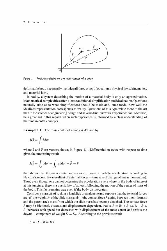
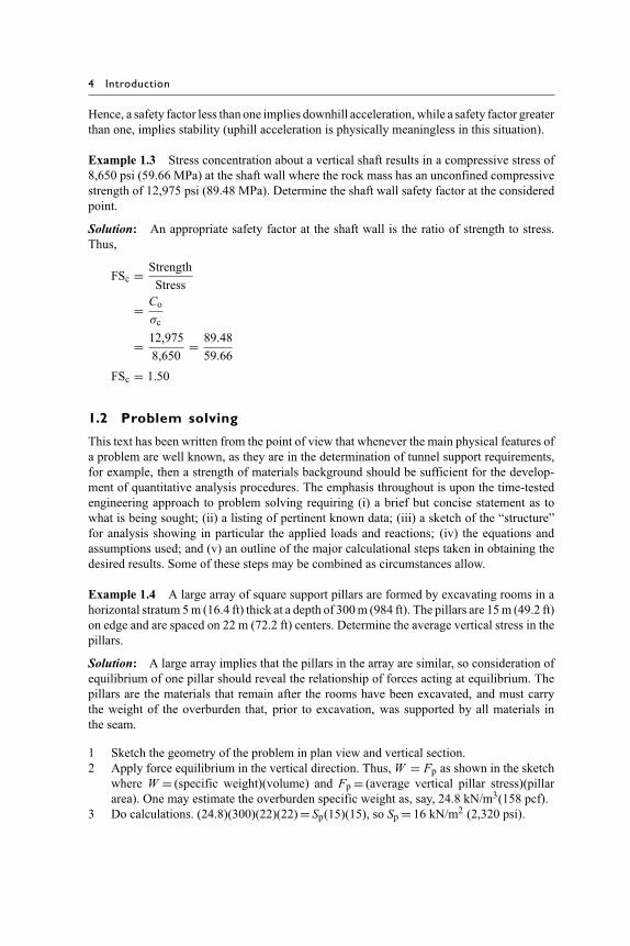
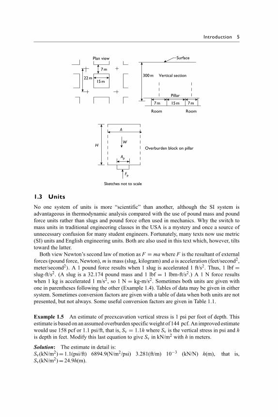
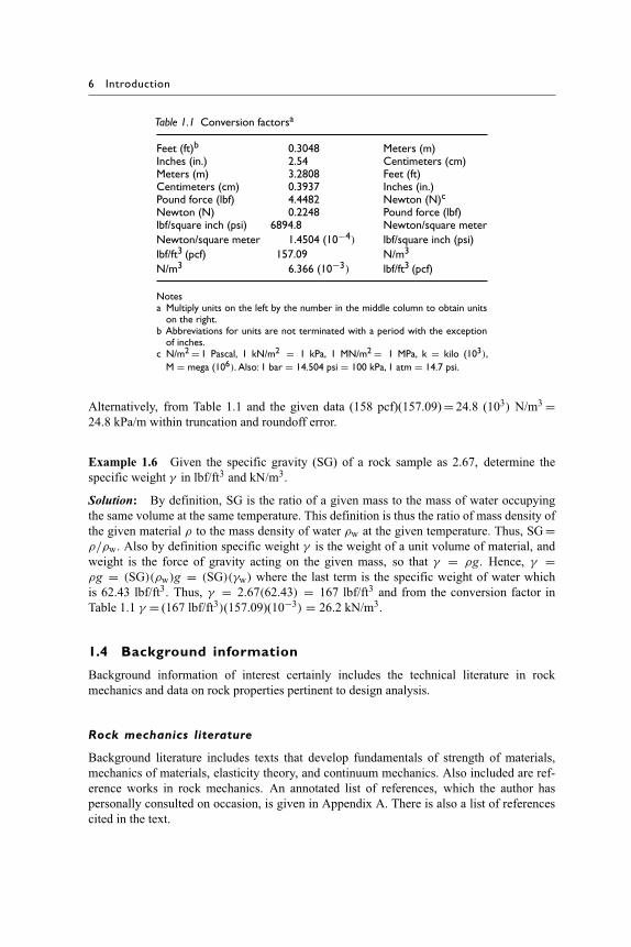
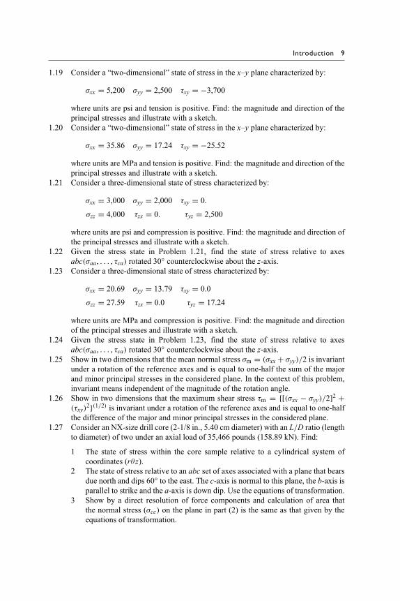
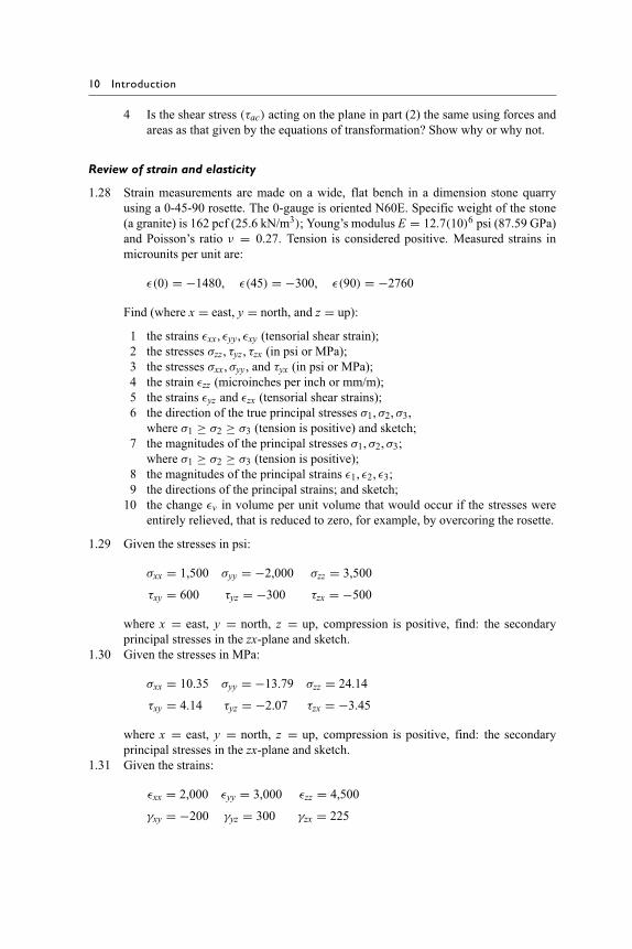
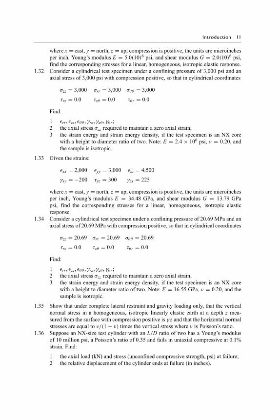
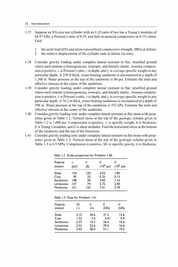
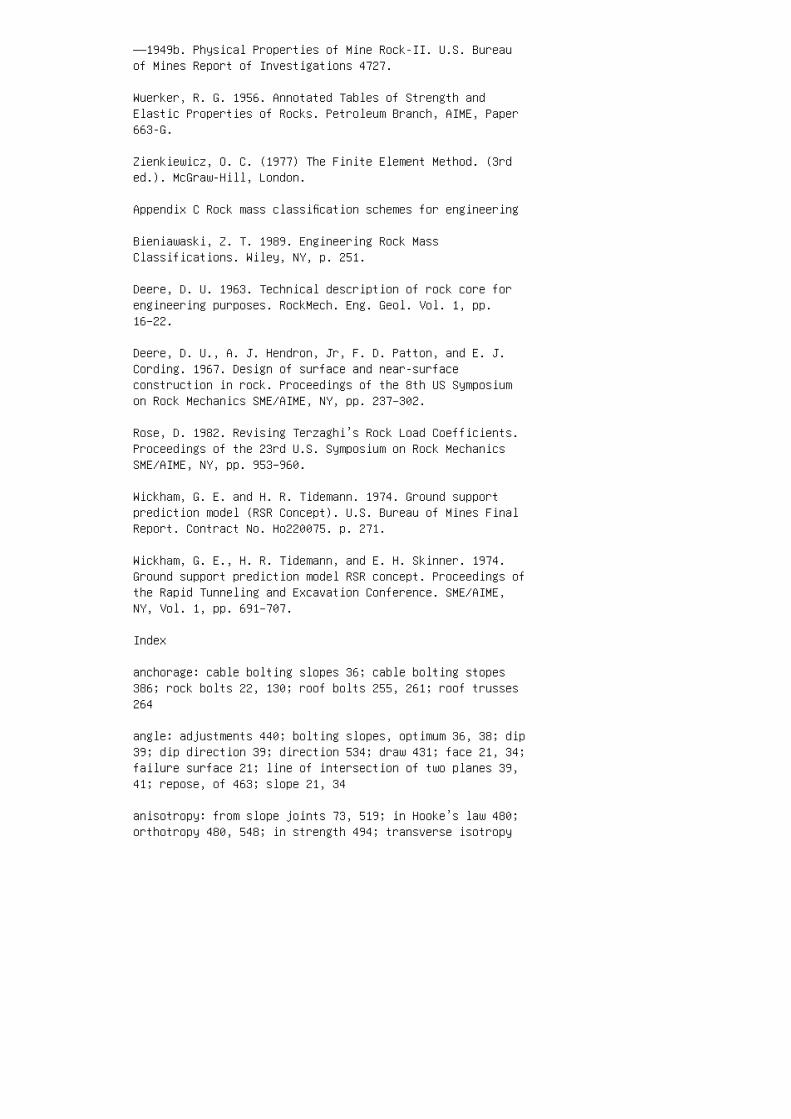