rock mechanics i course cee9577 site investigation
TRANSCRIPT

Rock Mechanics ICourse CEE9577
Site Investigation

Purpose of Site Investigation
• To obtain sufficient data for site characterization at different stages of project:of project:- Pre-feasibility- Feasibility- Detailed Design
• For rock engineering purposes, to provide sufficient data for characterization of the rock mass
• To provide sufficient data for tendering (e.g. the preparation of a Geotechnical Baseline Report – GBR) so that cost could be controlled
• To identify major risks such that they could be taken into account in the design of the surface or underground structures
Maxim of Site Investigation:Maxim of Site Investigation:Aim to be Forewarned……. So that one can be Forearmed

Different Stages of Site Investigation
Key Project Time Steps
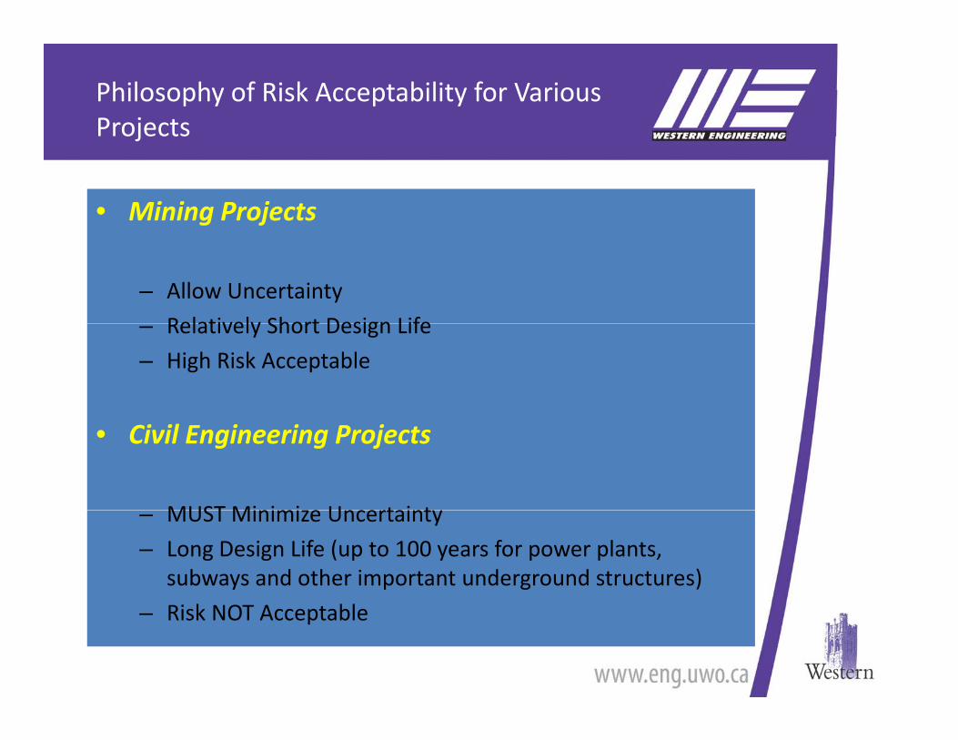
Philosophy of Risk Acceptability for Various Projectsj
• Mining Projects
– Allow Uncertainty
Relatively Short Design Life– Relatively Short Design Life
– High Risk Acceptable
• Civil Engineering Projects
MUST Minimi e Uncertainty– MUST Minimize Uncertainty
– Long Design Life (up to 100 years for power plants, subways and other important underground structures)
– Risk NOT Acceptable

Risk Exposure Vs Site Investigation Expenditurep
Site Investigation Cost:Cost:
1 to 5 % of Construction Cost

Time Scale for Site Geotechnical Data Acquisition
We do not want to be We do not want to be here!here!
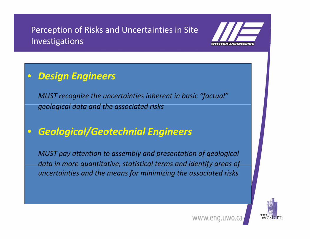
Perception of Risks and Uncertainties in Site Investigations
• Design Engineers
g
• Design Engineers
MUST recognize the uncertainties inherent in basic “factual” l i l d t d th i t d i kgeological data and the associated risks
• Geological/Geotechnial EngineersGeological/Geotechnial Engineers
MUST pay attention to assembly and presentation of geological data in more quantitative statistical terms and identify areas ofdata in more quantitative, statistical terms and identify areas of uncertainties and the means for minimizing the associated risks

Components of a Complete Geotechnical Investigation
Components of a Complete InvestigationComponents of a Complete InvestigationComponents of a Complete InvestigationComponents of a Complete Investigation

Components of Site InvestigationLiterature Survey , Terrain Evaluationy ,
Literature SurveyLiterature SurveyLiterature Surveyy
Good Project Scale jMaps Critical
Terrain EvaluationTerrain Evaluation

Components of Site InvestigationsGeophysical Techniquesp y q
Characteristics• Non‐destructive, relatively fast and low unit cost• Wide application at preliminary level, useful for planning borehole positioning• Must use with caution, never consider results to be definitive without borehole
correlation
Common Surface Techniquesf q• Seismic reflection and refraction surveys (e.g. to measure depth to bedrock)• Electrical resistivity (e.g. to measure moisture plume, buried tank or lithological
subsurface changes)• Gravity survey (to measure density contrast for geological mapping mineralGravity survey (to measure density contrast, for geological mapping, mineral
exploration, cavity survey, sediment thickness studies)• Magnetic survey (to measure buried ferromagnetic objects, mineral exploration)
Common Down‐hole TechniquesN d i• Neutron density
• Sonic and seismic velocity• Gama‐gama and electro‐resistivity technique
(to study stratification, geological structures, rock types and possible existence of cavities)

Typical Borehole Geophysical Logging

Geophysical Data Useful for Correlation

Components of Site Investigation Geological Mapping Requirements
Geological Mapping Requirements
– Review of surface outcrops, exposure or existing excavations and tunnels
– Topographic details are important (contours, elevations)– Correct definitions of dip/strike and magnetic declination– Data on lithology, structure, groundwaterData on lithology, structure, groundwater– Reference standards
• Geological Society Engineering Group (1977)• International Society of Rock Mechanics (1981)International Society of Rock Mechanics (1981)
– Consistent language– quantitative – simple measurements– simple measurements– complete specifications of the rock mass

Field Mapping of Discontinuities
03-1001-014Module 1Unit 1

Geological Mapping Method and Data Presentation
Presentation of dip and dip directions of joints and discontinuities collected f fi ld i i DIPS
Mapping of discontinuities using handheld devices
from field mapping using DIPS

Components of Site Investigation ‐ Drilling
• For engineering purposes, Soils and Rocks need to be described with respect to … ISRM, QJEG, IAEG, ASTM, BS and other pertinent standards
• Core Losses in rock, and soil sample disturbance must be minimized
• Core and Sample descriptions can only be as good as the drilling results permit
Poor Drilling results Poor Drilling results compounded by compounded by inaccurate inaccurate logginglogging leads to misconceptions, claims, cost overleads to misconceptions, claims, cost over--runs and failuresruns and failures

Components of Investigation ‐ Drilling
Drilling – General Requirements
– Diamond Drilling (wire line drilling equipment preferred) to obtain rock core for positive identification of the material pbeing investigated• Double and triple tube core barrel for engineering
purposes• Down hole core orientation device to determine dip and
direction of joints• Downhole packer testing to measure hydraulic
conductivity of different rock unitsconductivity of different rock units
– Percussion drilling (Airtrack) to obtain rock chips to identify the material being investigated (faster and cheaper but lessmaterial being investigated (faster and cheaper but less precise)

Typical Double and Triple Tube Wireline Drilling Equipment
• Small diameter equipment generally yields poorer core;generally yields poorer core; generally use minimum N size (75 mm dia hole, 50-55 mm dia core) hole and preferably use H si e ( 100 mm dia hole 61 75size (~ 100 mm dia hole 61-75 mm dia core) hole
• Triple tube or at least double ptube core barrel with a split liner is standard for most good civil investigations
• Wireline equipment allows faster drilling progress generally without loss of quality
03-1001-014Module 1Unit 1

Basic Sizes of Core Used in Geotechnical Investigations
Six Basic Sizes Available E – P
g
– E 22 mm core, 38 mm hole, 36.5 mm RX casing will go in hole– A 25‐34 mm core 48 mm hole 46 mm EX or EW casingA 25 34 mm core, 48 mm hole, 46 mm EX or EW casing– B 33‐44 mm core, 60 mm hole, 57 mm AX or AW casing– N 45‐55 mm core, 76 mm hole, 73 mm BX or BW casing– H 61‐75 mm core 93‐99 mm hole 89 mm NX or NW casing– H 61‐75 mm core, 93‐99 mm hole, 89 mm NX or NW casing– P 83‐85 mm core, 123 mm hole, 114 mm HX or HW casing– Some larger, Z, plus specials

Typical Core bits for Drilling Investigations

Track-Mounted Drill for Drilling in Difficult Terrain (e.g. Bench in Open Pit Mine)
03-1001-014Module 1Unit 1

Truck-Mounted Drill for Accessible Locations
03-1001-014Module 1Unit 1

Suggested Borehole Depths for Borehole Exploration for Certain Types of Structuresp yp
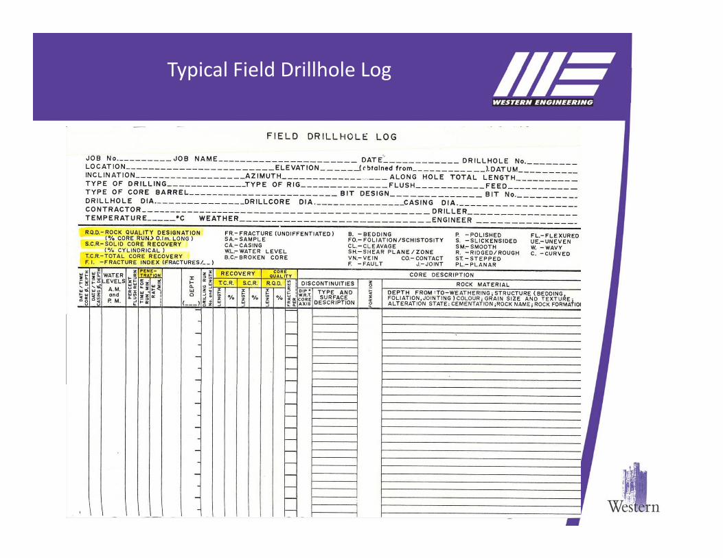
Typical Field Drillhole Log
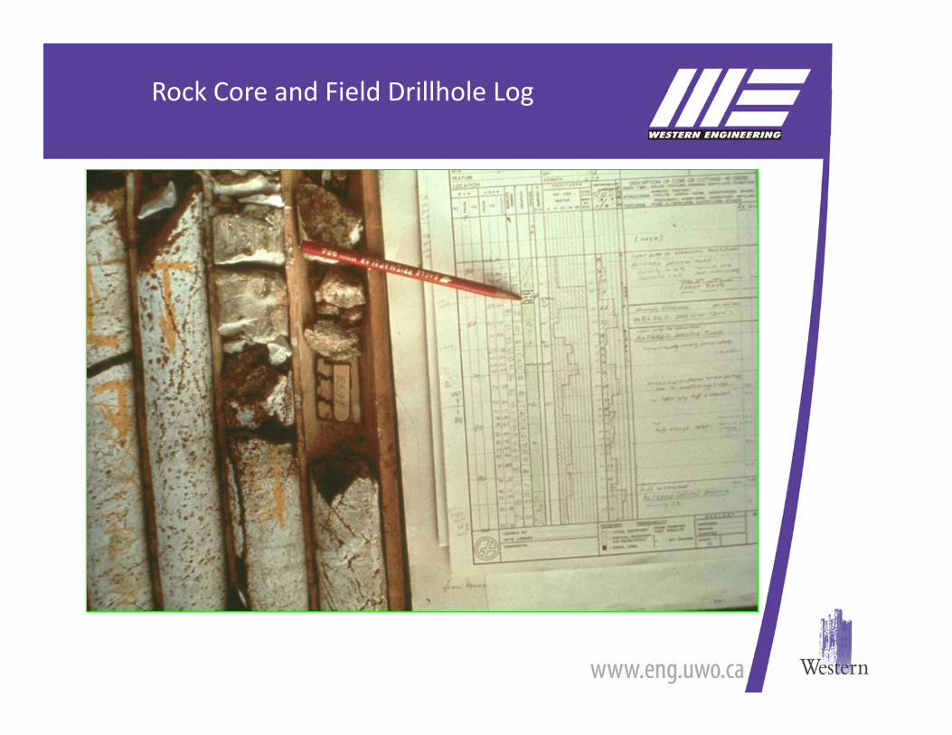
Rock Core and Field Drillhole Log

Rock Cores Recovered from Investigation

Example of Rock Core Showing Joints and Fractures intersected by Drillhole
03-1001-014Module 1Unit 1

Deere’s Classification ‐ RQD
RQD is defined as the percentage of intact core pieces longer than 100 mm (4 inches) in the total length of core. The core should be at least NW size (54.7 mm or 2 15 inches in diameter) and should be drilled with a double tube core barrelor 2.15 inches in diameter) and should be drilled with a double-tube core barrel.
If rock cores are not available
RQD = 115 – 3.3 Jv (after Palmstrom, 1982)
Where Jv is the total number of Jointsper cubic meter

Reference Length of Solid Core for RQD Calculation for different Core Diameter

Lithological and Geotechnical Rock Description Terminologyp gy

Typical Core Log Showing Core Recoveries and Rock Quality Designation (RQD)
Rock Descriptions should include:include:
• Strength
• Colour
• Bedding thickness
• Weathering grade
• Rock NAME• Rock NAME
• Discontinuity gemetry
Reference:
British Standard Institution: BS5930 Code of Practice
03-1001-014Module 1Unit 1
BS5930 – Code of Practice for Site Investigation

Components of Site InvestigationLaboratory and In Situ Tests
Laboratory Tests• Uniaxial/Triaxial compression test
• Shear test on joints (or rock‐structure contact)
• Point load test (to assess compressive strength)
• Split tensile strength – (Brazilian Test)
• Slake durability test (to test weatherability)y ( y)
• Moisture content test, Total porosity test
• Schmidt rebound hammer test (to test for hardness)
• Petrographic examination (to identify minerals in significant rock unit)
• Swelling test (free swelling test semi‐confined swelling test stress re‐build up test)Swelling test (free swelling test, semi confined swelling test, stress re build up test)
• Calcite content test
• Silica content test
Field Tests• Packer test (to measure hydraulic conductivity)
• Borehole televiewer (camera) (to view joints and fractures on borehole wall)
• Downhole geophysical test
• In situ stress measurement (overcoring or hydraulic fracturing)
• In situ shear test
• In situ plate loading test

Components of Site InvestigationTrial Excavations
Trial Excavations
The objectives of trial excavations are to allow evaluation of actual conditions to be encountered
– Test pits/trenches (to intersect exposed ore zones or fault zones)
– Small scale trial excavation – short test tunnels/driftsSmall scale trial excavation short test tunnels/drifts
– Full scale trial excavation – shafts and test adits

Underground Research Laboratory, Pinawa, CanadaExcavation by Controlled Blasting

Underground Test Adit – SAB 3 ProjectNiagara Falls – Excavated using Road Header

Time Scale for Site Geotechnical Data Acquisition
We do not want to be We do not want to be here!here!