certificate in rock mechanics - sanire
TRANSCRIPT
CERTIFICATE IN ROCK MECHANICS
LEARNING GUIDE FOR:PART 3.2 : SOFT ROCK TABULAR MINING
SOUTH AFRICAN CHAMBER OF MINES MINING NATIONAL INSTITUTE OF OF SOUTH AFRICA QUALIFICATIONS ROCK ENGINEERING AUTHORITY
PREPARED BY: MIDDINDI CONSULTING (PTY) LTD
(In cooperation with SIM Mining Consultants)
ADDITIONAL AUTHORS: D Minney, J van Vuuren
EDITED BY:D Minney
LAYOUT & DESIGN BY:The Image Foundry
2
PAPER 3: CHAPTER 1CHAPTER
1PAPER 3.2 SOFT ROCK TABULAR MINING
This section contains the syllabus for Part 2 of the COM Certificate in Rock Engineering is provided, as prepared by the South African National Insti-tute for Rock Engineering. The syllabus describes the levels of minimum knowledge and understanding and is not to be viewed as a complete list of rock engineering knowledge.
TOPICS COVEREDThis is a specific mining type paper covering rock mechanics practice ap-plicable in tabular, soft rock mining environments at all depths. The rock engineering knowledge required here is thus of a specific nature, relating to the mining of tabular orebodies in soft rock at shallow, moderate and great depth.
CRITICAL OUTCOMESThe examination is aimed at testing the candidate’s abilities in the six cognitive levels: knowledge, comprehension, application, analysis, syn-thesis and evaluation. Thus, when being examined on the topics detailed in this syllabus candidates must :
• Comprehending and understanding the general rock engineering principles covered in this syllabus and applying these to solve real world mining problems
• Applying fundamental scientific knowledge, comprehension and understanding to predict the behaviour of rock materials in real world mining environments
• Performing creative procedural design and synthesis of mine lay-outs and support systems to control and influence rock behaviour and rock failure processes
• Using engineering methods and understanding of the uses of computer packages for the computation, modelling, simulation, and evaluation of mining layouts
• Communicating, explaining and discussing the reasoning, meth-odology, results and ramifications of all the above aspects in a professional manner at all levels.
PRIOR LEARNINGThis portion of the syllabus assumes that candidates have prior learning and good understanding of :
• The field of fundamental mechanics appropriate to this part of the syllabus
• The application and manipulation of formulae appropriate to this part of the syllabus as outlined in the relevant sections of this document
• The terms, definitions and conventions appropriate to this part of the syllabus as outlined in the relevant sections of this document.
PAPER 3.2 SYLLABUS
PREAMBLE
3
PAPER 3: CHAPTER 1 STUDY MATERIALThis portion of the syllabus assumes that candidates have studied widely and have good knowledge and understanding of :
• The reference material appropriate to this part of the syllabus as outlined in the relevant sections of this document
• Other texts that are appropriate to this part of the syllabus but that may not be specifically referenced in this document
• Information appropriate to this part of the syllabus published in journals, proceedings and documents of local mining, technical and research organisations.
This syllabus is available in PDF format on the SANIRE webpage
2. GEOTECHNICAL CHARACTERISTICS2.1. GEOLOGY2.1.1. GEOLOGICAL SEQUENCESThe candidate must be able to demonstrate knowledge and understand-ing of the above subject area by being able to :
• Identify and describe the rock types associated with tabular, soft rock orebodies
• Describe, explain and discuss how the rock types associated with tabular, soft rock orebodies were formed
• Sketch, describe and discuss the geological sequences associated with tabular, soft rock orebodies.
2.1.2. GEOLOGICAL STRUCTURESThe candidate must be able to demonstrate knowledge and understand-ing of the above subject area by being able to:
• Sketch, describe and discuss major geological structures associ-ated with tabular, soft rock orebodies
• Sketch, describe and discuss geological structures that impact upon mining, such as interbedded hard rock layers and sills
• Describe, discuss and explain the effect on mining and mine sta-bility of such geological phenomena.
2.2. ROCK STRENGTHThe candidate must be able to demonstrate knowledge and understand-ing of the above subject area by being able to :
• Discuss the relative strengths of rock types associated with tabu-lar, soft rock orebodies
• Describe and discuss the geotechnical characteristics of rock types associated with tabular, soft rock orebodies
• Apply the above knowledge to the design of total extraction work-ings such as:
• Longwall mining, Shortwall mining, etc
• Apply the above knowledge to the design of partial extraction workings such as :
• Room and pillar mining, Pillar extraction,
• Partial pillar extraction, etc.
2.3. ROCKMASS CHARACTERISTICS2.3.1. GEOTECHNICAL ROCKMASS CLASSIFICATIONThe candidate must be able to demonstrate knowledge and understand-ing of the above subject area by being able to :
• Describe, discuss and apply rockmass classification techniques
4
PAPER 3: CHAPTER 1 for the selection of soft rock tabular mining methods
• Describe, discuss and apply standard rockmass classification and assessment systems to predict excavation stability
• Describe, discuss and apply the rockwall condition factor (RCF) to predict tunnel stability and support requirements
• Apply Barton’s Q system to classify a rockmass
• Apply Bieniawski’s RMR system to classify a rockmass
• Apply Laubscher’s MRMR system to classify a rockmass
• Apply the CMRR system to classify a rockmass
• Apply rockmass classification results to determine the stability of unsupported spans
• Apply rockmass classification results to determine the stability of unsupported rockslopes
• Apply rockmass classification results to determine support re-quirements for various situations
• Determine rockmass ‘m’ and ‘s’ parameters for the Hoek and Brown criterion based upon rockmass classification results
• Determine rockmass deformability from joint stiffness and rock-mass classification results.
3. ROCK AND ROCKMASS BEHAVIOUR3.1. PILLAR BEHAVIOUR3.1.1. PILLAR STRENGTHThe candidate must be able to demonstrate knowledge and understand-ing of the above subject area by being able to :
• Describe, explain and discuss the effects of the following circum-stances on the strength of pillars :
• Roof contact conditions, Floor contact conditions
• Coal strength, Jointing
• Pillar volume, Confinement
• Describe, explain and discuss the effects of confinement on pillar strength.
3.1.2. PILLAR STRESSThe candidate must be able to demonstrate knowledge and understand-ing of the above subject area by being able to :
• Sketch, describe, explain and discuss the stress distribution in a panel of pillars with barrier pillars on either side
• Sketch, describe, explain and discuss the stress distribution at mid-height of a pillar under the following conditions :
• While the pillar behaves elastically
• When the pillar is at peak strength
• After the pillar has reached peak strength
• Sketch, describe, explain and discuss how each of the above stress distributions will affect pillar spalling
• Describe, explain and discuss how pillar width to height ratio af-fects pillar stiffness
• Describe, explain and discuss how variations in pillar width to height ratio will affect the loading of pillars in a panel
• Apply the above knowledge to evaluate the performance of pillars for given pillar layouts.
5
PAPER 3: CHAPTER 1 3.1.3. PILLAR FAILUREThe candidate must be able to demonstrate knowledge and understand-ing of the above subject area by being able to :
• Describe, explain and discuss how pillar width to height ratio af-fects pillar strength
• Describe, explain and discuss how pillar width to height ratio af-fects the post peak stress-strain behaviour of pillars
• Describe, explain and discuss the significance of pillar width to height ratio in terms of the stability of bord and pillar workings
• Describe, explain and discuss how loading system stiffness will cause pillars to fail either in a controlled fashion or violently
• Describe, explain and discuss how ashfill or sandfill will affect the behaviour of failed pillars
• Describe, explain and discuss the mechanism of pillar punching into the roof strata or floor strata
• Describe, explain and discuss the effect of pillar punching on the stability of adjacent strata
• Describe, explain and discuss the effect of pillar punching on the ultimate strength of pillars
• Apply the above knowledge to evaluate given pillar layouts and their potential for violent failure.
3.2. ROOF BEHAVIOUR3.2.1. BEAMS AND PLATESThe candidate must be able to demonstrate knowledge and understand-ing of the above subject area by being able to :
• Sketch, describe, explain and discuss the phenomenon of displace-ments and deflections between strata layers over an excavation
• Sketch, describe, explain and discuss roof deflections in roadways of bord and pillar workings during different stages of development
• Describe, explain and discuss the significance of these deflections in terms of support requirements and support installation
• Sketch, describe, explain and discuss roof deflections at inter-sections of bord and pillar workings during different stages of development
• Describe, explain and discuss the significance of these deflections in terms of support requirements and support installation
• Describe, explain and discuss how beam span and beam thick-ness affect beam stability
• Sketch, describe, explain and discuss how horizontal compressive stresses allow cracked beams to remain stable
• Sketch, describe, explain and discuss how voussoir arch forma-tion allows cracked beams to remain stable
• Sketch, describe, explain and discuss the differences in behaviour between rock plates and rock beams
• Describe, explain and discuss the significance of these differences in terms of the stability of intersections
• Determine the factor of safety against sliding failure of a cracked beam in the presence of horizontal stresses
• Apply the above knowledge to evaluate given situations in terms of their potential instability
• Apply the above knowledge to determine appropriate remedial measures to improve stability.
6
PAPER 3: CHAPTER 1 3.2.2. ROOF BEHAVIOUR DURING TOTAL EXTRACTIONThe candidate must be able to demonstrate knowledge and understand-ing of the above subject area by being able to :
• The candidate must be able to demonstrate knowledge and un-derstanding of the above subject area by being able to :
• Sketch, describe, explain and discuss the behaviour of roof strata overlying total extraction panels in terms of :
• Caving propensity, Cave height, Swell factor, Strata overhang
• Continuous cave subsidence
• Describe, explain and discuss how factors such as the strength and bedding of roof strata affect the swell factor of strata
• Describe, explain and discuss how factors such as the strength and bedding of roof strata affect the overhang of strata
• Describe, explain and discuss how a strong sandstone beam or dolerite sill will affect the roof behaviour of total extraction panels
• Describe, explain and discuss how a strong sandstone beam or dolerite sill will affect loading of the abutments of total extraction panels
• Describe, explain and discuss recompaction behaviour of caved strata
• Describe, explain and discuss how the recompaction of caved strata affects the subsequent extraction of other seams
• Sketch, describe, explain and discuss stress distribution in the goaf from the edges of a panel to the centre of a panel
• Evaluate and predict roof caving behaviour for given sets of circumstances
• Evaluate and predict stresses in workings for given sets of circumstances
3.2.3. INFLUENCE OF DOLERITE SILLSThe candidate must be able to demonstrate knowledge and understand-ing of the above subject area by being able to :
• Describe, explain and discuss the effects of dolerite sills on strata behaviour in the following mining situations :
• Bord and Pillar operations, Stooping operations,
• Longwall operations
• Describe, explain and discuss the effects of dolerite sills on stress distribution in the following mining situations :
• Bord and Pillar operations, Stooping operations,
• Longwall operations
• Describe, explain and discuss the application of Galvin’s equa-tions for determining critical spans of dolerite sills
• Describe, explain and discuss the limitations of Galvin’s equa-tions for determining critical spans of dolerite sills
• Apply Galvin’s equations to determine critical spans for the fail-ure of dolerite sills
• Apply the above knowledge to the design of total extraction and room and pillar workings
3.2.4. SUBSIDENCESee Section 7
7
PAPER 3: CHAPTER 1 4. MINING LAYOUT STRATEGIES4.1. SOFT ROCK TABULAR MINING METHODS4.1.1. ROOM AND PILLARThe candidate must be able to demonstrate knowledge and understand-ing of the above subject area by being able to :
• Sketch, describe, explain and discuss the following types of room and pillar mining :
• Drilling and Blasting
• Mechanical Breaking
• Describe, explain and discuss the following aspects of each of the above methods :
• Panel layout, Ventilation method, Coal transport, Main equipment
• Describe, explain and discuss the following coal winning methods:
• Top coaling,
• Bottom coaling
• Determine areal and volumetric percentage extraction in room and pillar layouts
• Determine appropriate factors of safety for primary development in room and pillar layouts
• Determine appropriate factors of safety for secondary develop-ment in room and pillar layouts
• Describe, explain and discuss restrictions associated with the ap-plication of factors of safety
• Describe, explain and discuss conditions that may allow lower factors of safety to be used
• Describe, explain and discuss the purpose of barrier pillars in room and pillar workings
• Apply the above knowledge to design room and pillar mining lay-outs for given sets of circumstances.
4.1.2. RIB PILLARThe candidate must be able to demonstrate knowledge and understand-ing of the above subject area by being able to :
• Sketch, describe, explain and discuss the different methods of rib pillar mining
• Sketch, describe, explain and discuss the following aspects of each method :
• Panel layout, Ventilation method,
• Coal transport, Main equipment
• Sketch, describe, explain and discuss methods of stabilising the roof during rib pillar extraction
• Describe, explain and discuss how the following factors affect rib pillar extraction :
• Roof conditions, Dolerite sills, Mining height
• Apply the above knowledge to design rib pillar layouts, ex-traction sequences and appropriate support for given sets of circumstances.
4.1.3. STOOPINGThe candidate must be able to demonstrate knowledge and understand-ing of the above subject area by being able to :
8
PAPER 3: CHAPTER 1 • Sketch, describe, explain and discuss the following types of stooping operation:
• Drilling and Blasting
• Mechanical Breaking
• Describe, explain and discuss the functions of the following con-stituents in each of the above methods :
• Snooks, Breaker lines, Finger lines, Fenders
• Sketch, describe, explain and discuss roofbolt and mechanised breaker lines Describe, explain and discuss the conditions under which such breaker lines may be applicable
• Describe, explain and discuss how the following factors affect pil-lar extraction :
• Roof conditions, Dolerite sills, Mining height
• Determine appropriate factors of safety for stooping under given conditions
• Sketch, describe, explain and discuss how the stress will vary on pillars during stooping operations
• Describe, explain and discuss how this stress variation may tem-porarily affect the factor of safety of pillars
• Determine areal and volumetric percentage extraction in stoop-ing operations under given conditions
• Explain and discuss why these extraction percentages are rarely achieved in practice
• Apply the above knowledge to design stooping layouts, ex-traction sequences and appropriate support for given sets of circumstances.
4.1.4. LONGWALLThe candidate must be able to demonstrate knowledge and understand-ing of the above subject area by being able to :
• Sketch, describe, explain and discuss the different methods of longwall mining
• Sketch, describe, explain and discuss the following aspects of each method :
• Panel layout, Ventilation method,
• Coal transport, Main equipment
• Sketch, describe, explain and discuss the following longwall min-ing terms :
• Main gate, Snaking, Web, Goaf
• Gate road support, Chock shield
• Interpanel pillar, Chain pillar, Crush pillar
• Describe, explain and discuss the difference between advance longwalling and retreat longwalling
• Sketch, describe, explain and discuss the different types of pow-ered support for longwalling
• Describe, explain and discuss the advantages and disadvantages of each of the different types of powered support
• Sketch, describe, explain and discuss the stress distribution in the vicinity of longwall faces
• Sketch, describe, explain and discuss the effects of this stress redistribution on the stability of surrounding strata
• Sketch, describe, explain and discuss how the following factors affect the loading and choice of powered support for longwalls :
9
PAPER 3: CHAPTER 1 • Strength of the floor strata, Strength of the roof strata
• Massive sandstone in the roof, Dolerite sills in the roof
• Seam thickness
• Sketch, describe, explain and discuss how crush pillars may be used in longwall mining
• Describe, explain and discuss how interpanel pillars may be removed
• Describe, explain and discuss the problems associated with re-moving longwall equipment
• Describe, explain and discuss methods to successfully move and remove longwall equipment
• Apply the above knowledge to design longwall layouts for given sets of circumstances.
4.1.5. SURFACE / OPENCASTThe candidate must be able to demonstrate knowledge and understand-ing of the above subject area by being able to :
• Sketch, describe, explain and discuss the conditions under which the following mining methods are applicable :
• Strip Mining
• Open Cast Mining
• • Describe, explain and discuss the following aspects of the above mining methods :
• Method of operation, Main equipment
• Sketch, describe, explain and discuss how the following compo-nents are formed and maintained in strip mining operations :
• Box cuts, Ramps
• Spoil piles
• Coal benches, In-pit benches.
4.2. REGIONAL STABILITY STRATEGIES4.2.1. PRINCIPLES OF REGIONAL STABILITYThe candidate must be able to demonstrate knowledge and understand-ing of the above subject area by being able to :
• Describe, explain and discuss the concept of regional stability in the context of soft rock tabular mining operations at all depths
• Describe, explain and discuss methods of ensuring regional sta-bility in pillared workings
• Describe, explain and discuss how barrier pillars may be used to improve the stiffness of surrounding strata
• Describe, explain and discuss how the number and geometry of pillars in a panel may affect regional stability
• Describe, explain and discuss the effects of depth and mined-out span on the stress regime above and around shallow workings
• Describe, explain and discuss how these effects may affect re-gional stability requirements
• Apply the above knowledge to evaluate the regional stability of given mining situations
• Apply the above knowledge to determine appropriate remedial measures to improve regional stability in given situations.
10
PAPER 3: CHAPTER 1 4.2.2. REGIONAL STABILITY PILLARSThe candidate must be able to demonstrate knowledge and understand-ing of the above subject area by being able to :
• Sketch, describe, explain and discuss the functions of regional stability pillars at shallow to intermediate depth where in-stope pillars are not used as local support
• Sketch, describe, explain and discuss the functions of regional stability pillars at shallow to intermediate depth where in-stope pillars are used as local support
• Sketch, describe, explain and discuss the functions of regional stability pillars at great depth
• Design regional stability pillars for workings at shallow depths
• Design regional stability pillars for workings at intermediate depths
• Apply empirical criteria to design regional stability pillars.
4.2.3. OREBODY EXTRACTION LAYOUTSThe candidate must be able to demonstrate knowledge and understand-ing of the above subject area by being able to :
• Sketch, describe, explain and discuss orebody extraction layout strategies in respect of the following mining methods :
• Bord and pillar mining
• Rib pillar mining
• Stooping operations
• Longwall mining
• Strip mining
• Describe, explain and discuss the problems associated with ven-tilating goafs and the effect of this on panel layouts
4.2.4. SERVICE EXCAVATION LAYOUTS4.2.4.2 SERVICE EXCAVATIONSThe candidate must be able to demonstrate knowledge and understand-ing of the above subject area by being able to :
• Design stable service excavation layouts making use of rock clas-sification and stress analysis techniques
• Assess the stability of service excavation layouts in given sit-uations making use of rock classification and stress analysis techniques
• Determine modifications of shape and orientation to improve stability
• Determine support strategies to improve stability.
4.2.4.3 SHAFTSThe candidate must be able to demonstrate knowledge and understand-ing of the above subject area by being able to :
• Describe, explain and discuss expected rock conditions in vertical shafts passing through the following rock types:
• Surface weathered rock, Strongly bedded strata, Poorly bedded strata, Dolerite dyke
• Describe, explain and discuss expected rock conditions in inclined shafts passing through the following rock types:
11
PAPER 3: CHAPTER 1 • Surface weathered rock, Strongly bedded strata, Poorly bedded strata, Dolerite dyke
• Sketch, describe, explain and discuss stability problems com-monly associated with bored shafts
• Determine the stability of the following shaft types making use of rock classification techniques :
• Conventionally sunk vertical shafts, Bored vertical shafts
• Conventionally sunk inclined shafts, Bored inclined shafts
• Determine the support requirements of the following shaft types making use of rock classification technique :
• Conventionally sunk vertical shafts, Bored vertical shafts
• Conventionally sunk inclined shafts, Bored inclined shafts.
5. MINING SUPPORT STRATEGIES5.1. PILLAR DESIGN STRATEGIES5.1.1. PILLAR DESIGNThe candidate must be able to demonstrate knowledge and understand-ing of the above subject area by being able to :
• Describe, explain and discuss how the following pillar equations were derived :
• Salamon and Munro pillar equation
• Squat pillar equation
• Describe the range of applications of each of the above equations
• Describe the limits of applicability of each of the above equations
• Describe, explain and discuss how the Salamon and Munro pillar equation may be modified for use with rectangular pillars
• Describe, explain and discuss how the Salamon and Munro pillar equation may be modified for use with pillars cut by continuous miner
• Describe, explain and discuss how factors of safety are selected for pillar design
• Apply the equations for pillar strength to design pillars for given sets of circumstances
• Describe, explain and discuss the concept of tributary area theory
• Describe, explain and discuss the limitations of tributary area theory.
5.1.2. PILLAR REINFORCEMENTThe candidate must be able to demonstrate knowledge and understand-ing of the above subject area by being able to :
• Describe, explain and discuss techniques to reinforce pillars us-ing :
• Dowels,Wire mesh, Shotcrete,Fill,Other means
• Describe, explain and discuss the situations under which the dif-ferent pillar reinforcement techniques are likely to be applicable
• Describe, explain and discuss the mechanisms involved in strengthening pillars in each of the different pillar reinforcement techniques
• Apply the above knowledge to evaluate given situations and de-termine appropriate pillar reinforcement techniques.
5.2. ROOF SUPPORT STRATEGIES5.2.1. ROOM AND PILLAR ROOF SUPPORT STRATEGIES
12
PAPER 3: CHAPTER 1 The candidate must be able to demonstrate knowledge and understand-ing of the above subject area by being able to :
• Describe, explain and discuss roof support requirements in room and pillar workings for good roof conditions
• Describe, explain and discuss roof support requirements in room and pillar workings for poor roof conditions
• Calculate and determine strata suspension and/or support re-quirements for given rock conditions
• Calculate and determine strata beam creation and/or support re-quirements for given rock conditions
• Design appropriate support systems based upon support require-ment calculations.
5.2.2. PILLAR EXTRACTION ROOF SUPPORT STRATEGIESThe candidate must be able to demonstrate knowledge and understand-ing of the above subject area by being able to :
• Describe, explain and discuss roof behaviour during pillar extrac-tion operations
• Describe, explain and discuss the functions of the following com-ponents during pillar extraction :
• Snooks, Fenders, Rockbolts, Finger lines
• Sketch, describe, explain and discuss the types of roof support used in pillar extraction operations
• Sketch, describe, explain and discuss the layout of roof support used in pillar extraction operations
• Design appropriate support systems based upon assessment of given rock conditions.
5.2.3. LONGWALL ROOF SUPPORT STRATEGIESThe candidate must be able to demonstrate knowledge and understand-ing of the above subject area by being able to :
• Describe, explain and discuss roof support methods used in long-wall mining
• Calculate required roof support requirements for longwall shields based upon the height of caving using Wilson’s method
• Compare and discuss these results with actual roof support ca-pacities in South African longwalls
• Design appropriate support for total extraction mining operations for given rock conditions and mining layouts
• Describe, explain and discuss appropriate support installation se-quences for the above designs
• Design appropriate maingate and tailgate support for longwall mining in poor roof conditions
• Design appropriate tailgate area support when crush pillars are being used
• Design appropriate support for the removal of longwall equipment.
5.3. SERVICE EXCAVATION SUPPORT STRATEGIESThe candidate must be able to demonstrate knowledge and understand-ing of the above subject area by being able to :
• Describe, explain and discuss support strategies applicable to service excavation support in soft rock tabular mining operations.
13
PAPER 3: CHAPTER 1 5.4. SUPPORT DESIGN CRITERIAThe candidate must be able to demonstrate knowledge and understand-ing of the above subject area by being able to :
• Describe, explain, discuss and apply support design criteria appli-cable to excavation support in soft rock tabular mining operations.
5.5. SUPPORT AND SUPPORT SYSTEM TYPES AND CHARACTERISTICS
5.5.1. SUPPORT ELEMENTSThe candidate must be able to demonstrate knowledge and understand-ing of the above subject area by being able to :
• Describe, explain and discuss the following tendon support types in the context of soft rock operations :
• Wooden dowels, Mechanically anchored bolts, Point-anchor resin bolts
• Full-column resin bolts, Cable bolts, Sand cells
• Other commonly used support types
• Characterise the following aspects of the above support types :
• Their installation method
• Their anchoring method
• Their load bearing characteristics
• Describe, explain and discuss the applicability of the above types of tendon support in differing rock types
• Describe, explain and discuss the following types of roof support in the context of soft rock operations :
• Trusses, W-straps
• Timber tapes, Headboards
• Wire mesh, Lacing, Shotcrete
• Describe, explain and discuss the applicability of the above roof support types
• Describe, explain and discuss the limitations of the above roof support types
• Describe, explain and discuss the load bearing characteristics of the following types of support:
• Mine poles, Hydraulic props, Longwall hydraulic shields
• Cluster stick packs, Skeleton packs, Mat packs, End-grain packs
• Waste-filled pigsty, Cement-based packs
• Describe, explain and discuss the applicability of the above roof support types
• Describe, explain and discuss the limitations of the above roof support types
• Describe, explain and discuss comparative testing procedures for rockbolts
• Describe, explain and discuss the various aspects of the SABS resin specification.
5.6. BACKFILL SYSTEMSThe candidate must be able to demonstrate knowledge and understand-ing of the above subject area by being able to :
• Describe, explain and discuss the methods of placing ash fill and
14
PAPER 3: CHAPTER 1sand fill in underground workings
• Describe, explain and discuss the requirements to make ash fill-ing or sand filling successful
• Sketch, describe, explain and discuss the features of ashfill or sandfill systems to service particular blocks of ground.
6. INVESTIGATION TECHNIQUES6.1. ROCK TESTINGThe candidate must be able to demonstrate knowledge and understand-ing of the above subject area by being able to :
• Describe, explain and discuss various rock testing procedures
• Interpret and incorporate test results in analysis and design.
6.2. MONITORING6.2.1. SUBSIDENCE MONITORINGThe candidate must be able to demonstrate knowledge and understand-ing of the above subject area by being able to :
• Sketch, describe, explain and discuss the techniques used to measure surface subsidence
• Describe, explain and discuss the equipment used to measure surface subsidence
• Describe, explain and discuss how vertical and horizontal dis-placements are determined
• Describe, explain and discuss how strains and tilts may be de-rived from these determinations
• Calculate strain and tilt from given sets of measurements
• For given sets of underground mining and surface infrastructure conditions:
• State, describe, explain and discuss what types of measurements need to be made and monitored
• Describe, explain and discuss required monitoring station layouts
• Describe, explain and discuss appropriate monitoring programs.
6.2.2. IN-SITU STRESS MEASUREMENT AND MONITORINGThe candidate must be able to demonstrate knowledge and understand-ing of the above subject area by being able to :
• Sketch, describe, explain and discuss the techniques used to measure in-situ stress in the underground rockmass
• Describe, explain and discuss the equipment used to measure in-situ stress in the rockmass
• Interpret, explain and discuss given stress measurement data in terms of likely rockmass, pillar or excavation behaviour.
6.3. MODELLING6.3.1. NUMERICAL MODELLINGThe candidate must be able to demonstrate knowledge and understand-ing of the above subject area by being able to :
• Describe, explain and discuss the selection of appropriate codes to tackle various problems
• Describe, explain and discuss the input of appropriate param-eters to investigate various problems
15
PAPER 3: CHAPTER 1 • Describe, explain and discuss the interpretation of output in the investigation of various problems.
6.4. AUDITINGThe candidate must be able to demonstrate knowledge and understand-ing of the above subject area by being able to :
• Describe, explain and discuss the concept of monitoring for un-derstanding, prediction and design.
7. ROCKBREAKING IN SOFT ROCK7.1. CUTTING TECHNIQUESThe candidate must be able to demonstrate knowledge and understand-ing of the above subject area by being able to :
• Describe, explain and discuss the function and operation of cut-ters in soft rock mining operations
• Describe, explain and discuss the following aspects in respect of continuous miners and road headers in bord and pillar sections :
• The sequence of cutting, the sequence of support installation, the sequence of tramming
• Describe, explain and discuss the following aspects in respect of continuous miners and road headers in continuous haulage sys-tems :
• The layout of mining, the sequence of mining.
7.2. DRILLING TECHNIQUESThe candidate must be able to demonstrate knowledge and understand-ing of the above subject area by being able to :
• Describe, explain and discuss the mechanism of rock breaking by pick, chisel or button bit in soft rock mining operations
• Describe, explain and discuss the following drilling methods and associated equipment in soft rock mining operations :
• Percussion drilling, Rotary drilling, Diamond drilling, Raise boring,
• Tunnel boring
• Sketch, describe, explain and discuss the different rounds used in shaft sinking Describe, explain and discuss the different cuts used in shaft sinking
• Describe, explain and discuss the types of initiation used in the above rounds
• Describe, explain and discuss the sequence of initiation of blast holes used in the above rounds
• Sketch, describe, explain and discuss the different rounds used in tunnel development
• Describe, explain and discuss the different cuts used in tunnel development
• Describe, explain and discuss the types of initiation used in the above rounds
• Describe, explain and discuss the sequence of initiation of blast holes used in the above rounds
• Sketch, describe, explain and discuss blast hole layouts in drill and blast sections
• Describe, explain and discuss the direction of drilling of blast holes in drill and blast sections
16
PAPER 3: CHAPTER 1 • Describe, explain and discuss the explosive charge in blast holes in drill and blast sections
• Describe, explain and discuss the sequence of initiation of blast holes in drill and blast sections
• Describe, explain and discuss the importance of blast-hole drill-ing accuracy in the following applications :
• Shaft sinking, Chamber excavation, Tunnel development, Ore extraction
• Cushion blasting, Smooth blasting.
7.3. BLASTING PRACTICEThe candidate must be able to demonstrate knowledge and understand-ing of the above subject area by being able to :
• Describe, explain and discuss the effect of the following param-eters on blast damage:
• Explosive type, Initiation method, Initiation sequence, Hole orientation
• Describe, explain and discuss the objectives and effects of de-coupling explosives
• Describe, explain and discuss the methods by which de-coupling of explosives is achieved
• Describe, explain and discuss the following excavation cushion blasting and smooth blasting techniques :
• Pre-splitting, Concurrent smooth blasting, Post-splitting
• Describe, explain and discuss the methodologies and typical ap-plications of each technique
• List and discuss the advantages and disadvantages of these techniques
• Evaluate and determine blasting requirements for tunnels mak-ing use of knowledge of explosives
• Evaluate and determine appropriate blasting rounds to suit given conditions in tunnels
• Evaluate and determine appropriate explosive types to suit given conditions in tunnels
• Evaluate and determine blasting requirements for headings in soft rock making use of knowledge of explosives
• Evaluate and determine appropriate blasting rounds to suit given conditions in soft rock
• Evaluate and determine appropriate explosive types to suit given conditions in soft rock
• Evaluate and determine blasting requirements for headings in coal rock making use of knowledge of explosives
• Evaluate and determine appropriate blasting rounds to suit given conditions in coal
• Evaluate and determine appropriate explosive types to suit given conditions in coal
• Describe, explain and discuss the role of coal cutters in colliery blasting operations
• Describe, explain and discuss how coal cutters in colliery blasting operations fit into the production cycle.
17
PAPER 3: CHAPTER 1 8. SURFACE AND ENVIRONMENTAL EFFECTS8.1. SURFACE EFFECTS8.1.1. PRINCIPLES OF SUBSIDENCE ENGINEERINGThe candidate must be able to demonstrate knowledge and understand-ing of the above subject area by being able to :
• Describe, explain and discuss the following terms in the context of surface subsidence :
• Angle of draw, Curvature, Tilt, Critical span
• Horizontal strain, Vertical subsidence, Differential subsidence
• Describe, explain and discuss the following surface expressions of subsidence :
• Tension cracks, Compression humps, Ridges, Thrusts
• Describe, explain and discuss how mining height to depth ratio affects the type and severity of surface subsidence
• Describe, explain and discuss the effects of dolerite dykes and other geological structures on surface subsidence.
8.1.2. SUBSIDENCE ON SOUTH AFRICAN COLLIERIESThe candidate must be able to demonstrate knowledge and understand-ing of the above subject area by being able to :
• Sketch, describe, explain and discuss the typical subsidence trough over a longwall panel
• Describe, explain and discuss the difference between dynamic and static subsidence profiles
• Describe, explain and discuss the relationship between maximum subsidence and mining height
• Describe, explain and discuss how multiple seam extraction af-fects surface subsidence
• Describe, explain and discuss techniques for reducing subsidence humps by interpanel pillar extraction
• Describe, explain and discuss techniques for reducing subsidence humps by interpanel crush pillars
• Describe, explain and discuss the results of using the above two techniques to reduce subsidence humps
• Sketch, describe, explain and discuss the differences in total sub-sidence associated with the following mining methods :
• Longwall operations
• Bord and Pillar operations
• Pillar Extraction operations
• Determine the following quantities for given mining depths and mining heights using Schumann’s empirical relationships :
• Maximum subsidence, Surface strain, Surface tilt.
8.2. SURFACE PROTECTIONThe candidate must be able to demonstrate knowledge and understand-ing of the above subject area by being able to :
• Describe, explain and discuss how the following surface features are affected by subsidence :
• Roads, Buildings, Pylons, Lands, Streams, Pans
• Describe, explain and discuss possible remedial measures that may be applied to surface structures to limit subsidence damage
18
PAPER 3: CHAPTER 1• Describe, explain and discuss possible changes that may be made
to underground mining layouts to reduce subsidence damage
• Determine potential subsidence damage to the following typ of structure for given mining depths and mining heights using pub-lished damage tables :
• Roads, Buildings, Pylons.
8.3. ENVIRONMENTAL EFFECTS8.3.1. LONG-TERM STABILITY AND THE ENVIRONMENTThe candidate must be able to demonstrate knowledge and understand-ing of the above subject area by being able to :
• Describe, explain and discuss the possible effects and conse-quences of given mining methods on the following issues :
• Long-term stability of the ground surface
• Groundwater
• Ultimate closure of the mine
• Describe, explain and discuss the possible effects and conse-quences of given factors of safety on the following issues :
• Long-term stability of the ground surface
• Groundwater
• Ultimate closure of the mine.
9. MINING STRATEGIES IN DIFFICULT CIRCUMSTANCESThe candidate must be able to demonstrate knowledge and understand-ing of the above subject area by being able to :
• Describe, explain and discuss the geotechnical aspects of dealing with the following difficult circumstances :
• Mining through dykes
• Mining through burnt coal
• Mining under dolerite sills
• Mining thick seams
• Mining multiple seams
• Mining shallow seams (<40mbs)
10. GEOTECHNICAL CHARACTERISTICS10.1. GEOLOGY10.1.1. GEOLOGICAL SEQUENCES
• Van der Merwe JN & Madden BJ 2002 Rock Engineering for Un-derground Coal Mines SAIMM Special Publication Series No.7 Jhb Chapter 2
• Fauconnier CJ & Kersten RWO (ed) 1982 Increased Under-ground Extraction of Coal SAIMM Jhb Chapter 2
• Lurie J 1987 South African Geology for Mining, Metallurgi-cal, Hydrological and Civil Engineering Lexicon Publishers Jhb Chapter 9
10.1.2. GEOLOGICAL STRUCTURES
• Lurie J 1987 South African Geology for Mining, Metallurgical,
19
PAPER 3: CHAPTER 1 Hydrological and Civil Engineering Lexicon Publishers Jhb Chapter 6
• Van der Merwe JN & Madden BJ 2002 Rock Engineering for Un-derground Coal Mines SAIMM Special Publication Series No.7 Jhb
• Fauconnier CJ & Kersten RWO (ed) 1982 Increased Under-ground Extraction of Coal SAIMM Jhb Chapters 2, 3
10.1.3. ROCK STRENGTH
• Ryder JA & Jager AJ 2002 Rock Mechanics for Tabular Hard Rock Mines SIMRAC Jhb Chapter 2
• Salamon MDG & Oravecz KI 1976 Rock Mechanics in Coal Mining CoM of SA Jhb Chapter 1
• Van der Merwe JN 1995 Practical Coal Mining Strata Control Sasol Coal Division Jhb Chapter 1
• Van der Merwe JN & Madden BJ 2002 Rock Engineering for Un-derground Coal Mines SAIMM Special Publication Series No.7 Jhb Chapter 1
• Brady BHG & Brown ET 1993 Rock Mechanics for Underground Mining Chapman & Hall New York Chapter 4
• Obert L & Duvall WI 1967 Rock Mechanics and the Design of Structures in Rock John Wiley & Sons New York Chapters 10, 11
• Jaeger JC & Cook NGW 1969 Fundamentals of Rock Mechanics Chapman & Hall London Chapter 4, 6
• Budavari S (ed) 1986 Rock Mechanics in Mining Practice SAIMM Jhb Chapter 2
10.2. ROCKMASS CHARACTERISTICS10.2.1. GEOTECHNICAL ROCKMASS CLASSIFICATION
• Stacey TR 2001 Best Practice Rock Engineering Handbook for ‘Other’ Mines SIMRAC Jhb Chapter 2
• Van der Merwe JN & Madden BJ 2002 Rock Engineering for Un-derground Coal Mines SAIMM Special Publication Series No.7 Jhb Chapter 2
• Ryder JA & Jager AJ 2002 Rock Mechanics for Tabular Hard Rock Mines SIMRAC Jhb Chapter 2
• Hoek E & Brown ET 1980 Underground Excavations in Rock IMM London Chapter 2
• Brady BHG & Brown ET 1993 Rock Mechanics for Underground Mining Chapman & Hall New York Chapter 3
11. ROCK AND ROCKMASS BEHAVIOUR11.1. PILLAR BEHAVIOUR11.1.1. PILLAR STRENGTH
• Van der Merwe JN & Madden BJ 2002 Rock Engineering for Un-derground Coal Mines SAIMM Special Publication Series No.7 Jhb Chapter 4
• Van der Merwe JN 1995 Practical Coal Mining Strata Control Sasol Coal Division Jhb Chapter 2
• Ryder JA & Jager AJ 2002 Rock Mechanics for Tabular Hard Rock Mines SIMRAC Jhb Chapter 2
• Brady BHG & Brown ET 1993 Rock Mechanics for Underground Mining Chapman & Hall New York Chapter 13
20
PAPER 3: CHAPTER 1 • Salamon MDG & Oravecz KI 1976 Rock Mechanics in Coal Mining CoM of SA Jhb Chapters 1, 2
11.1.2. PILLAR STRESS
• Van der Merwe JN & Madden BJ 2002 Rock Engineering for Un-derground Coal Mines SAIMM Special Publication Series No.7 Jhb Chapter 4 Chapter 1
• Van der Merwe JN 1995 Practical Coal Mining Strata Control Sasol Coal Division Jhb Chapter 2
• Ryder JA & Jager AJ 2002 Rock Mechanics for Tabular Hard Rock Mines SIMRAC Jhb Chapter 2
• Brady BHG & Brown ET 1993 Rock Mechanics for Underground Mining Chapman & Hall New York Chapter 13
• Salamon MDG & Oravecz KI 1976 Rock Mechanics in Coal Mining CoM of SA Jhb Chapters 1, 2
11.1.3. PILLAR FAILURE
• Van der Merwe JN & Madden BJ 2002 Rock Engineering for Un-derground Coal Mines SAIMM Special Publication Series No.7 Jhb Chapter 4
• Van der Merwe JN 1995 Practical Coal Mining Strata Control Sasol Coal Division Jhb Chapter 2
• Ryder JA & Jager AJ 2002 Rock Mechanics for Tabular Hard Rock Mines SIMRAC Jhb Chapter 2
• Brady BHG & Brown ET 1993 Rock Mechanics for Underground Mining Chapman & Hall New York Chapter 13
• Salamon MDG & Oravecz KI 1976 Rock Mechanics in Coal Mining CoM of SA Jhb Chapters 1, 2
11.2. ROOF BEHAVIOUR11.2.1. BEAMS AND PLATES
• Van der Merwe JN & Madden BJ 2002 Rock Engineering for Un-derground Coal Mines SAIMM Special Publication Series No.7 Jhb Chapter 3
• Van der Merwe JN 1995 Practical Coal Mining Strata Control Sasol Coal Division Jhb Chapter 3
• Ryder JA & Jager AJ 2002 Rock Mechanics for Tabular Hard Rock Mines SIMRAC Jhb Chapter 2
11.2.2. ROOF BEHAVIOUR DURING TOTAL EXTRACTION
• Fauconnier CJ & Kersten RWO (ed) 1982 Increased Underground Extraction of Coal SAIMM Jhb Chapter 4
• Van der Merwe JN & Madden BJ 2002 Rock Engineering for Un-derground Coal Mines SAIMM Special Publication Series No.7 Jhb Chapter 3, 5 and 6
• Van der Merwe JN 1995 Practical Coal Mining Strata Control Sasol Coal Division Jhb Chapter 4
11.2.3. INFLUENCE OF DOLERITE SILLS
• Van der Merwe JN & Madden BJ 2002 Rock Engineering for Un-derground Coal Mines SAIMM Special Publication Series No.7 Jhb Chapter 3
21
PAPER 3: CHAPTER 1 • Van der Merwe JN 1995 Practical Coal Mining Strata Control Sasol Coal Division Jhb Chapter 4
• Fauconnier CJ & Kersten RWO (ed) 1982 Increased Underground Extraction of Coal SAIMM Jhb Chapter 4
• Salamon MDG & Oravecz KI 1976 Rock Mechanics in Coal Mining CoM of SA Jhb Chapter 5
11.2.4. SUBSIDENCE
• Van der Merwe JN JN & Madden BJ 2002 Rock Engineering for Underground Coal Mines SAIMM Special Publication Series No.7 Jhb Chapter 9
• see Sect 7 van der Merwe JN 1995 Practical Coal Mining Strata Control Sasol Coal Division Jhb Chapter 5
• Brady BHG & Brown ET 1993 Rock Mechanics for Underground Mining Chapman & Hall New York Chapter 16
• Obert L & Duvall WI 1967 Rock Mechanics and the Design of Structures in Rock John Wiley & Sons New York Chapter 18
• Fauconnier CJ & Kersten RWO (ed) 1982 Increased Underground Extraction of Coal SAIMM Jhb Chapter 4
• Salamon MDG & Oravecz KI 1976 Rock Mechanics in Coal Mining CoM of SA Jhb Chapter 7
12. MINING LAYOUT STRATEGIES12.1. SOFT ROCK TABULAR MINING METHODS12.1.1. BORD AND PILLAR
• Van der Merwe JN & Madden BJ 2002 Rock Engineering for Un-derground Coal Mines SAIMM Special Publication Series No.7 Jhb Chapter 4
• Fauconnier CJ & Kersten RWO (ed) 1982 Increased Underground Extraction of Coal SAIMM Jhb Chapters 2, 5
• Salamon MDG & Oravecz KI 1976 Rock Mechanics in Coal Mining CoM of SA Jhb Chapters 1, 2
• Van der Merwe JN 1995 Practical Coal Mining Strata Control Sasol Coal Division Jhb Chapter 4
12.1.2. RIB PILLAR
• Van der Merwe JN & Madden BJ 2002 Rock Engineering for Un-derground Coal Mines SAIMM Special Publication Series No.7 Jhb Chapter 4
• Fauconnier CJ & Kersten RWO (ed) 1982 Increased Underground Extraction of Coal SAIMM Jhb Chapters 5, 8
12.1.3. STOOPING
• Salamon MDG & Oravecz KI 1976 Rock Mechanics in Coal Mining CoM of SA Jhb Chapter 4
• Fauconnier CJ & Kersten RWO (ed) 1982 Increased Underground Extraction of Coal SAIMM Jhb Chapters 4, 5, 8
• Van der Merwe JN & Madden BJ 2002 Rock Engineering for Un-derground Coal Mines SAIMM Special Publication Series No.7 Jhb Chapters 5
• Van der Merwe JN 1995 Practical Coal Mining Strata Control Sasol Coal Division Jhb Chapter 4
22
PAPER 3: CHAPTER 1 12.1.4. LONGWALL
• Fauconnier CJ & Kersten RWO (ed) 1982 Increased Underground Extraction of Coal SAIMM Jhb Chapters 5, 6, 7
• Salamon MDG & Oravecz KI 1976 Rock Mechanics in Coal Mining CoM of SA Jhb Chapter 5
• Van der Merwe JN & Madden BJ 2002 Rock Engineering for Un-derground Coal Mines SAIMM Special Publication Series No.7 Jhb Chapters 6
• Van der Merwe JN 1995 Practical Coal Mining Strata Control Sasol Coal Division Jhb Chapter 4
12.1.5. SURFACE / OPENCAST
12.2. REGIONAL STABILITY STRATEGIES12.2.1. PRINCIPLES OF REGIONAL STABILITY
• Van der Merwe JN & Madden BJ 2002 Rock Engineering for Un-derground Coal Mines SAIMM Special Publication Series No.7 Jhb Chapters 4,5,6,
12.2.2. REGIONAL STABILITY PILLARS
• Van der Merwe JN & Madden BJ 2002 Rock Engineering for Un-derground Coal Mines SAIMM Special Publication Series No.7 Jhb Chapters 4
12.2.3. OREBODY EXTRACTION LAYOUTS
• Van der Merwe JN & Madden BJ 2002 Rock Engineering for Un-derground Coal Mines SAIMM Special Publication Series No.7 Jhb Chapter 4,5,6
• Van der Merwe JN 1995 Practical Coal Mining Strata Control Sasol Coal Division Jhb Chapter 4,
12.2.4. SERVICE EXCAVATION LAYOUTS
• Van der Merwe JN & Madden BJ 2002 Rock Engineering for Un-derground Coal Mines SAIMM Special Publication Series No.7 Jhb Chapters 2 and 3
12.2.4.2 SERVICE EXCAVATIONS
• Van der Merwe JN & Madden BJ 2002 Rock Engineering for Un-derground Coal Mines SAIMM Special Publication Series No.7 Jhb Chapters 2 and 3
12.2.4.3 SHAFTS
• Van der Merwe JN & Madden BJ 2002 Rock Engineering for Un-derground Coal Mines SAIMM Special Publication Series No.7 Jhb Chapters 2 and 3
• Ryder JA & Jager JA 1999 Rock Engineering Practice for Tabular Hard Rock Mines SIMRAC Jhb Chapter 7
13. MINING SUPPORT STRATEGIES13.1. PILLAR DESIGN STRATEGIES13.1.1. PILLAR DESIGN
23
PAPER 3: CHAPTER 1 • Van der Merwe JN & Madden BJ 2002 Rock Engineering for Un-derground Coal Mines SAIMM Special Publication Series No.7 Jhb Chapter 4
• Van der Merwe JN 1995 Practical Coal Mining Strata Control Sasol Coal Division Jhb Chapter 2
13.1.2. PILLAR REINFORCEMENT
• Van der Merwe JN & Madden BJ 2002 Rock Engineering for Un-derground Coal Mines SAIMM Special Publication Series No.7 Jhb Chapter 4
13.2. ROOF SUPPORT STRATEGIES13.2.1. ROOM AND PILLAR ROOF SUPPORT STRATEGIES
• Van der Merwe JN & Madden BJ 2002 Rock Engineering for Un-derground Coal Mines SAIMM Special Publication Series No.7 Jhb Chapter 3
• Van der Merwe JN 1995 Practical Coal Mining Strata Control Sasol Coal Division Jhb Chapter 3
• Salamon MDG & Oravecz KI 1976 Rock Mechanics in Coal Mining CoM of SA Jhb Chapter 6
13.2.2. PILLAR EXTRACTION ROOF SUPPORT STRATEGIES
• Van der Merwe JN & Madden BJ 2002 Rock Engineering for Un-derground Coal Mines SAIMM Special Publication Series No.7 Jhb Chapter 3,5
• Van der Merwe JN 1995 Practical Coal Mining Strata Control Sasol Coal Division Jhb Chapters 3, 4
• Salamon MDG & Oravecz KI 1976 Rock Mechanics in Coal Mining CoM of SA Jhb Chapter 6
13.2.3. LONGWALL ROOF SUPPORT STRATEGIES
• Van der Merwe JN & Madden BJ 2002 Rock Engineering for Un-derground Coal Mines SAIMM Special Publication Series No.7 Jhb Chapter 6
• Van der Merwe JN 1995 Practical Coal Mining Strata Control Sasol Coal Division Jhb Chapters 3, 4
• Salamon MDG & Oravecz KI 1976 Rock Mechanics in Coal Mining CoM of SA Jhb Chapter 6
13.3. SERVICE EXCAVATION SUPPORT STRATEGIES
• Salamon MDG & Oravecz KI 1976 Rock Mechanics in Coal Mining CoM of SA Jhb Chapter 6
13.4. SUPPORT DESIGN CRITERIA
• Van der Merwe JN & Madden BJ 2002 Rock Engineering for Un-derground Coal Mines SAIMM Special Publication Series No.7 Jhb Chapter 3 and appendix B
• Salamon MDG & Oravecz KI 1976 Rock Mechanics in Coal Mining CoM of SA Jhb Chapter 6
13.5. SUPPORT ELEMENTS
• Van der Merwe JN & Madden BJ 2002 Rock Engineering for
24
PAPER 3: CHAPTER 1 Underground Coal Mines SAIMM Special Publication Series No.7 Jhb Chapter 3 and appendix B
• Van der Merwe JN 1995 Practical Coal Mining Strata Control Sasol Coal Division Jhb Chapter 3
• Salamon MDG & Oravecz KI 1976 Rock Mechanics in Coal Mining CoM of SA Jhb Chapter 6
13.6. BACKFILL SYSTEMS
• Ryder JA & Jager AJ 2002 Rock Mechanics for Tabular Hard Rock Mines SIMRAC Jhb Chapter 7
14. INVESTIGATION TECHNIQUES14.1. ROCK TESTING
• Ryder JA & Jager AJ 2002 Rock Mechanics for Tabular Hard Rock Mines SIMRAC Jhb Chapter 2
14.2. MONITORING14.2.1. SUBSIDENCE MONITORING
• Van der Merwe JN & Madden BJ 2002 Rock Engineering for Un-derground Coal Mines SAIMM Special Publication Series No.7 Jhb Chapter 10
• Van der Merwe JN 1995 Practical Coal Mining Strata Control Sasol Coal Division Jhb Chapter 5
14.2.2. IN-SITU STRESS MEASUREMENT AND MONITORING
• Van der Merwe JN & Madden BJ 2002 Rock Engineering for Un-derground Coal Mines SAIMM Special Publication Series No.7 Jhb Chapter 10
14.3. MODELLING14.3.1. NUMERICAL MODELLING
• Van der Merwe JN & Madden BJ 2002 Rock Engineering for Un-derground Coal Mines SAIMM Special Publication Series No.7 Jhb Chapter 8
• Ryder JA & Jager AJ 2002 Rock Mechanics for Tabular Hard Rock Mines SIMRAC Jhb Chapter 8
• Jager AJ & Ryder JA 1999 Rock Engineering Practice for Tabular Hard Rock Mines SIMRAC Jhb Chapter 11
• Lightfoot N & Maccelari MJ 1998 Numerical Modelling of Mine Workings SIMRAC Jhb Chapters 1-11
14.4. AUDITING
• Jager AJ & Ryder JA 1999 Rock Engineering Practice for Tabular Hard Rock Mines SIMRAC Jhb Chapter 10
15. ROCKBREAKING IN SOFT ROCK15.1. CUTTING TECHNIQUES
15.2. DRILLING TECHNIQUES
15.3. BLASTING PRACTICE
25
PAPER 3: CHAPTER 1 • Brady BHG & Brown ET 1993 Rock Mechanics for Underground Mining Chapman & Hall New York Chapter 17
16. SURFACE AND ENVIRONMENTAL EFFECTS16.1. SURFACE EFFECTS16.1.1. PRINCIPLES OF SUBSIDENCE ENGINEERING
• Van der Merwe JN & Madden BJ 2002 Rock Engineering for Un-derground Coal Mines SAIMM Special Publication Series No.7 Jhb Chapter 9
• Van der Merwe JN 1995 Practical Coal Mining Strata Control Sasol Coal Division Jhb Chapter 5
• Brady BHG & Brown ET 1993 Rock Mechanics for Underground Mining Chapman & Hall New York Chapter 16
• Obert L & Duvall WI 1967 Rock Mechanics and the Design of Structures in Rock John Wiley & Sons New York Chapter 18
16.1.2. SUBSIDENCE ON SOUTH AFRICAN COLLIERIES
• Van der Merwe JN & Madden BJ 2002 Rock Engineering for Un-derground Coal Mines SAIMM Special Publication Series No.7 Jhb Chapter 9
• Van der Merwe JN 1995 Practical Coal Mining Strata Control Sasol Coal Division Jhb Chapter 5
• Brady BHG & Brown ET 1993 Rock Mechanics for Underground Mining Chapman & Hall New York Chapter 16
• Obert L & Duvall WI 1967 Rock Mechanics and the Design of Structures in Rock John Wiley & Sons New York Chapter 18
• Fauconnier CJ & Kersten RWO (ed) 1982 Increased Underground Extraction of Coal SAIMM Jhb Chapter 4
• Salamon MDG & Oravecz KI 1976 Rock Mechanics in Coal Mining CoM of SA Jhb Chapter 7
16.2. SURFACE PROTECTION
• Van der Merwe JN & Madden BJ 2002 Rock Engineering for Un-derground Coal Mines SAIMM Special Publication Series No.7 Jhb Chapter 9
• Van der Merwe JN 1995 Practical Coal Mining Strata Control Sasol Coal Division Jhb Chapter 5
• Salamon MDG & Oravecz KI 1976 Rock Mechanics in Coal Mining CoM of SA Jhb Chapter 7
16.3. ENVIRONMENTAL EFFECTS16.3.1. LONG-TERM STABILITY AND THE ENVIRONMENT
17. MINING STRATEGIES IN DIFFICULT CIRCUMSTANCES
• Van der Merwe JN & Madden BJ 2002 Rock Engineering for Un-derground Coal Mines SAIMM Special Publication Series No.7 Jhb Chapter 7, Appendix C
• Fauconnier CJ & Kersten RWO (ed) 1982 Increased Underground Extraction of Coal SAIMM Jhb Chapter 11
• Van der Merwe JN 1995 Practical Coal Mining Strata Control Sasol Coal Division Jhb Chapter 5
• Madden BJ & Canbulat I 2005 Shallow Depth Mining Considera-tions SAIMM 3rd Southern African Rock Engineering Symposium Jhb
26
PAPER 3.2: CHAPTER 2CHAPTER
2PAPER 3.2 SOFT ROCK TABULAR MINING
2. GEOTECHNICAL CHARACTERISTICS2.1. GEOLOGY2.1.1. GEOLOGICAL SEQUENCESThe candidate must be able to demonstrate knowledge and understand-ing of the above subject area by being able to :
• Identify and describe the rock types associated with tabular, soft rock orebodies
• Describe, explain and discuss how the rock types associated with tabular, soft rock orebodies were formed
• Sketch, describe and discuss the geological sequences associated with tabular, soft rock orebodies.
2.1.2. GEOLOGICAL STRUCTURESThe candidate must be able to demonstrate knowledge and understand-ing of the above subject area by being able to :
• Sketch, describe and discuss major geological structures associ-ated with tabular, soft rock orebodies
• Sketch, describe and discuss geological structures that impact upon mining, such as interbedded hard rock layers and sills
• Describe, discuss and explain the effect on mining and mine sta-bility of such geological phenomena.
2.2. ROCK STRENGTHThe candidate must be able to demonstrate knowledge and understand-ing of the above subject area by being able to :
• Discuss the relative strengths of rock types associated with tabu-lar, soft rock orebodies
• Describe and discuss the geotechnical characteristics of rock types associated with tabular, soft rock orebodies
• Apply the above knowledge to the design of total extraction work-ings such as:
• Longwall mining, Shortwall mining, etc
• Apply the above knowledge to the design of partial extraction workings such as :
• Room and pillar mining, Pillar extraction,
• Partial pillar extraction, etc.
2.3. ROCKMASS CHARACTERISTICS2.3.1. GEOTECHNICAL ROCKMASS CLASSIFICATIONThe candidate must be able to demonstrate knowledge and understand-ing of the above subject area by being able to :
LEARNING OUTCOMES
27
PAPER 3.2: CHAPTER 2 • Describe, discuss and apply rockmass classification techniques for the selection of soft rock tabular mining methods
• Describe, discuss and apply standard rockmass classification and assessment systems to predict excavation stability
• Describe, discuss and apply the rockwall condition factor (RCF) to predict tunnel stability and support requirements
• Apply Barton’s Q system to classify a rockmass
• Apply Bieniawski’s RMR system to classify a rockmass
• Apply Laubscher’s MRMR system to classify a rockmass
• Apply the CMRR system to classify a rockmass
• Apply rockmass classification results to determine the stability of unsupported spans
• Apply rockmass classification results to determine the stability of unsupported rockslopes
• Apply rockmass classification results to determine support re-quirements for various situations
• Determine rockmass ‘m’ and ‘s’ parameters for the Hoek and Brown criterion based upon rockmass classification results
• Determine rockmass deformability from joint stiffness and rock-mass classification results.
2. GEOTECHNICAL CHARACTERISTICS 2.1 GEOLOGY2.1.1 GEOLOGICAL SEQUENCES
IDENTIFY AND DESCRIBE THE ROCK TYPES ASSOCIATED WITH TABULAR, SOFT ROCK OREBODIES
Three basic rock types exist:
• igneous,
• sedimentary and
• metamorphic rocks.
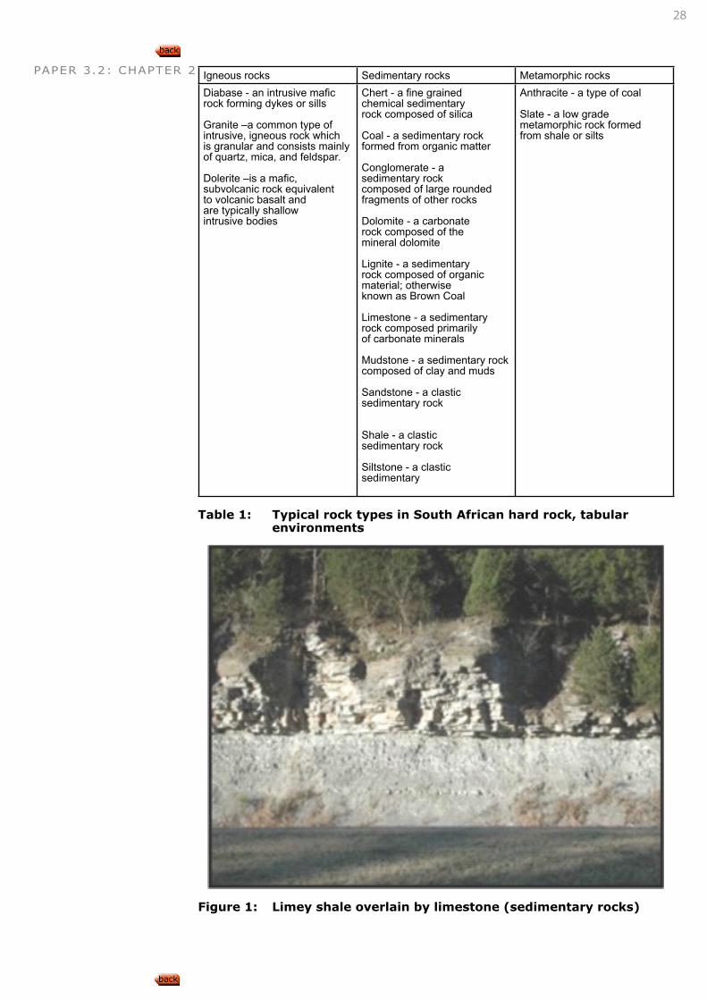
Within each of these basic categories, a large number of different rock types exist. Typical rock types that can be found within South Africa have been summarised into Table 1.
LEARNING OUTCOME 2.1.1.1
28
PAPER 3.2: CHAPTER 2 Igneous rocks Sedimentary rocks Metamorphic rocksDiabase - an intrusive mafic rock forming dykes or sills
Granite –a common type of intrusive, igneous rock which is granular and consists mainly of quartz, mica, and feldspar.
Dolerite –is a mafic, subvolcanic rock equivalent to volcanic basalt and are typically shallow intrusive bodies
Chert - a fine grained chemical sedimentary rock composed of silica
Coal - a sedimentary rock formed from organic matter
Conglomerate - a sedimentary rock composed of large rounded fragments of other rocks
Dolomite - a carbonate rock composed of the mineral dolomite
Lignite - a sedimentary rock composed of organic material; otherwise known as Brown Coal
Limestone - a sedimentary rock composed primarily of carbonate minerals
Mudstone - a sedimentary rock composed of clay and muds
Sandstone - a clastic sedimentary rock
Shale - a clastic sedimentary rock
Siltstone - a clastic sedimentary
Anthracite - a type of coal
Slate - a low grade metamorphic rock formed from shale or silts
Table 1: Typical rock types in South African hard rock, tabular environments
Figure 1: Limey shale overlain by limestone (sedimentary rocks)
29
PAPER 3.2: CHAPTER 2
DESCRIBE, EXPLAIN AND DISCUSS HOW THE ROCK TYPES ASSOCIATED WITH TABULAR, SOFT ROCK OREBODIES WERE FORMED
Igneous RocksIgneous rocks are crystalline solids that form from the cooling of magma, i.e. are formed from melted rock that has cooled down and solidified. This is an ‘exothermic’ process (i.e. it loses heat) and involves a phase change from a liquid to a solid state. The melted lava (magma) is made up of different chemical elements and different types of minerals and thus forms different rocks when is solidifies:
• If the magma crystallizes below the earth surface, it forms igne-ous rocks such as granite, pyroxenite with large grain sizes.
• If the magma crystallize above the earth surface, it forms igneous rocks such as basalt with fine grain sizes
Igneous rocks are given names based on:
• composition (chemicals and minerals they are made of, especially the silica content which relates to brightness)
• colour;
• mode of occurrence
• grain size
• hardness etc.
Sedimentary RocksIn most places on the earth’s surface (either in water or on land), the igneous rocks (which make up the majority of the crust) are covered by a thin layers of loose sediment formed through either fluvial, Aeolian, ice or solution processes.
These sediments are layered accumulations of fragments formed by the breakaway or weathering of other rocks, minerals, animal or plant ma-terial. The layers are compacted and cemented together, forming hard rocks (clastic sedimentary rocks) but can also be formed through chemi-cal accumulation (non-clastic sedimentary rocks).
Sedimentary rocks are called secondary, because they are the result of the accumulation of small pieces broken off of pre-existing rocks. There are three main types of sedimentary rocks:
• Clastic: The basic sedimentary rock consist of accumulations of little pieces of broken up rock which have piled up, compacted and cementated.
• Chemical: Many rock types form when standing water evaporates, leaving dissolved minerals behind.
• Organic: The accumulation of sedimentary debris caused by or-ganic processes. Animals consist of calcium-rich shells, bones and teeth.
The calcium can pile up on the seafloor and accumulate into a thick enough layer to form an “organic” sedimentary rock.
LEARNING OUTCOME 2.1.1.2
Rocks deep within the Earth melt because of the existing high pressure and temperature levels. The molten rock (magma) flow upward or erupts from a volcano onto the surface. When magma cools slowly (well below surface) crystals grow slowly and a coarse-grained rock forms. When the magma cools rapidly on the surface, the crystals are extremely small, and a fine-grained rock results. (Courtesy of Wikipedia)
INTERESTING INFO
The sedimentary layers are normally parallel or nearly parallel to the earth’s surface. If they are at high angles to the surface, twisted or broken, it is the result of earth movements. Sedimentary rocks are forming around us all the time. Sand and gravel on beaches or in river beds look like sandstone and conglomerate, which they will become with time. Compacted and dried mud hardens into shale with time.
INTERESTING INFO
30
PAPER 3.2: CHAPTER 2 Metamorphic Rocks
Metamorphic comes from the words “meta” (change) and “morph” (form). Any rock (sedimentary or igneous rocks) can be metamorphosed into a new rock type. All that is required is for the rock to be transformed, either physically or chemically, under the influence of temperature or pressure. The metamorphic changes in the minerals is governed by the ‘parent’ rock and thus determines the type of metamorphic rock that will be formed. E.g. limestone is metamorphosed to marble and granite is metamorphosed to a gneiss. The process of metamorphism does not melt the rocks, but instead trans-form them into denser, more compact rocks. New minerals are created either by rearrangement of mineral components or by reactions with fluids that enter the rocks.
Some kinds of metamorphic rocks (such as granite gneiss and biotite schist) are strongly banded or foliated (the parallel arrangement of cer-tain mineral grains that gives the rock a striped appearance) (Error! Reference source not found.).
Pressure or temperature can even change previously metamorphosed rocks into new types.
• Page 14, 25, 35, Lurie, J. 1987. South African Geology.
Rock-forming and rock-destroying processes have been active for billions of years. • Today, in the Guadalupe
Mountains of western Texas, you can stand on limestone, a sedimentary rock, that used to be a coral reef in a tropical sea about 250 million years ago.
• In Vermont’s Green Moun tains you can see schist, a metamorphic rock, that was once mud in a shallow sea.
• Half Dome in Yosemite Valley, California, which now stands nearly 8,800 feet above sea level, is composed of quartz monzonite, an igneous rock that solidified several thousands of feet below the earth’s surface. (Courtesy of Wikipedia)
INTERESTING INFO
The formation of the earth that finally consist of the three basic rock types described above, is found to be based on a number of theories, including, although may not be limited to the following:
• Creation: The earth was created by God in a process described in the Holy Bi-ble over a period of 7 days, according to His divine plan and through His power, as part of the total creation, consisting of a great number of solar systems;
• Nebular hypothesis: The solar system originally consisted of spin-ning nebula of gaseous material that, as it cooled down, ejected ‘outer rings’ that formed the planets, planets ejected rings to form moons;
• Meteoric theory: The sun and other stars were formed by compaction of a number of meteorites;
• Planetismal hypothesis: The earth from a vast num-ber of smaller meteorites revolving around the sun;
• Tidal theory: A star passing too close by the sun, drew (through gravitational forces) a sigar-shaped mass that broke up into several lumps, each solidifying into a planet;
• Impact theory: The start mentioned above, collided with the sun;
• Von Weizsacker’s theory: The stars and planets originated as ‘centres of con-densation’ and the sun attracted material to itself, becoming hotter;
• Big bang theory: The universe is the remainder of a large fire-ball that exploded. The debris of the explosion are constantly moving away from the position of the explosion.
INTERESTING INFO
Also refer to Paper 2, Outcomes 2.1.1.1 and 2.1.1.2
CONNECTION 1
31
PAPER 3.2: CHAPTER 2
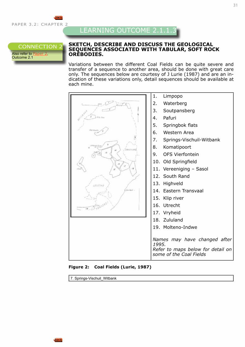
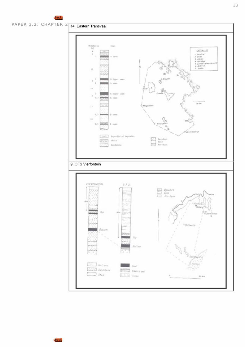
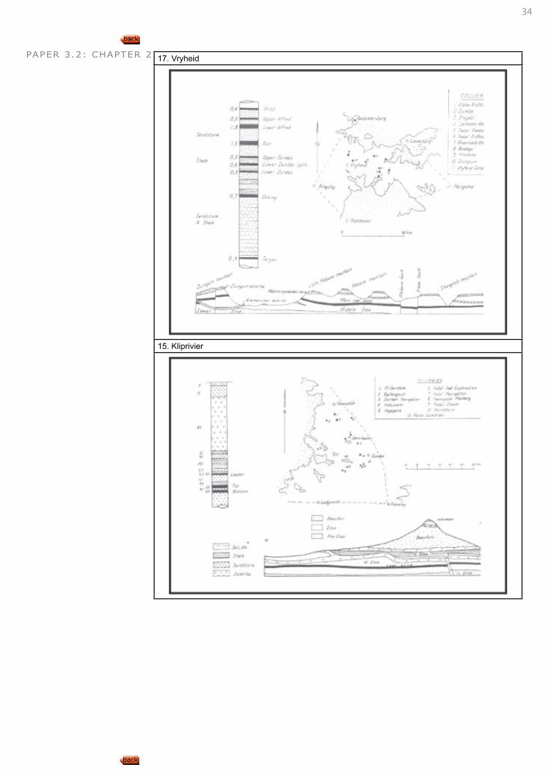
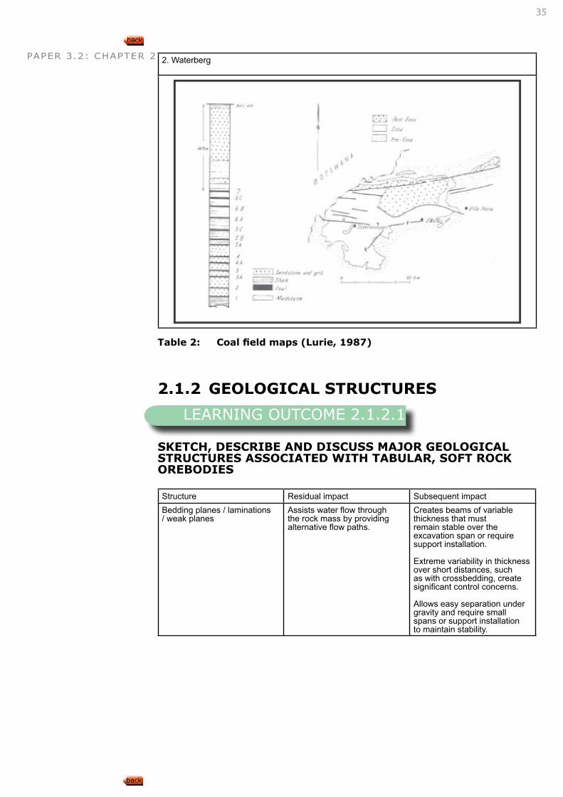
SKETCH, DESCRIBE AND DISCUSS THE GEOLOGICAL SEQUENCES ASSOCIATED WITH TABULAR, SOFT ROCK OREBODIES.
Variations between the different Coal Fields can be quite severe and transfer of a sequence to another area, should be done with great care only. The sequences below are courtesy of J Lurie (1987) and are an in-dication of these variations only, detail sequences should be available at each mine.
1. Limpopo
2. Waterberg
3. Soutpansberg
4. Pafuri
5. Springbok flats
6. Western Area
7. Springs-Vischuil-Witbank
8. Komatipoort
9. OFS Vierfontein
10. Old Springfield
11. Vereeniging – Sasol
12. South Rand
13. Highveld
14. Eastern Transvaal
15. Klip river
16. Utrecht
17. Vryheid
18. Zululand
19. Molteno-Indwe
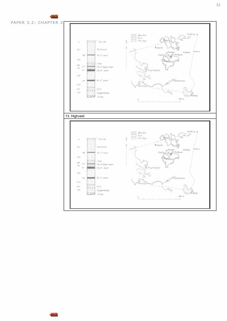
Names may have changed after 1995.Refer to maps below for detail on some of the Coal Fields
Figure 2: Coal Fields (Lurie, 1987)
7. Springs-Vischuil_Witbank
LEARNING OUTCOME 2.1.1.3
Also refer to Paper 2, Outcome 2.1
CONNECTION 2
32
PAPER 3.2: CHAPTER 2
13. Highveld
33
PAPER 3.2: CHAPTER 2 14. Eastern Transvaal
9. OFS Vierfontein
34
PAPER 3.2: CHAPTER 2 17. Vryheid
15. Kliprivier
35
PAPER 3.2: CHAPTER 2 2. Waterberg
Table 2: Coal field maps (Lurie, 1987)
2.1.2 GEOLOGICAL STRUCTURES
SKETCH, DESCRIBE AND DISCUSS MAJOR GEOLOGICAL STRUCTURES ASSOCIATED WITH TABULAR, SOFT ROCK OREBODIES
Structure Residual impact Subsequent impactBedding planes / laminations / weak planes
Assists water flow through the rock mass by providing alternative flow paths.
Creates beams of variable thickness that must remain stable over the excavation span or require support installation.
Extreme variability in thickness over short distances, such as with crossbedding, create significant control concerns.
Allows easy separation under gravity and require small spans or support installation to maintain stability.
LEARNING OUTCOME 2.1.2.1
36
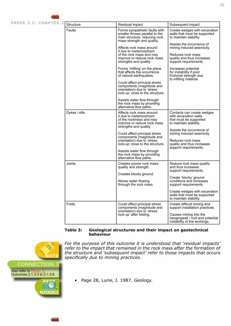
PAPER 3.2: CHAPTER 2 Structure Residual impact Subsequent impactFaults Forms sympathetic faults with
smaller throws parallel to the main structure, reducing rock mass strength and quality.
Affects rock mass around it due to metamorphism of the rock mass and may improve or reduce rock mass strengths and quality.
Forms ‘infilling’ on the plane that affects the occurrence of natural earthquakes.
Could affect principal stress components (magnitude and orientation) due to ‘stress lock-up’ close to the structure.
Assists water flow through the rock mass by providing alternative flow paths.
Create wedges with excavation walls that must be supported to maintain stability.
Assists the occurrence of mining induced seismicity.
Reduces rock mass quality and thus increases support requirements.
Increases potential for instability if poor frictional strength due to infilling material.
Dykes / sills Affects rock mass around it due to metamorphism of the rockmass and may improve or reduce rock mass strengths and quality.
Could affect principal stress components (magnitude and orientation) due to ‘stress lock-up’ close to the structure.
Assists water flow through the rock mass by providing alternative flow paths.
Contacts can create wedges with excavation walls that must be supported to maintain stability.
Assists the occurrence of mining induced seismicity.
Reduces rock mass quality and thus increases support requirements.
Joints Creates poorer rock mass quality and strength.
Creates blocky ground.
Allows water flowing through the rock mass.
Reduce rock mass quality and thus increases support requirements.
Create ‘blocky’ ground conditions and increases support requirements.
Create wedges with excavation walls that must be supported to maintain stability.
Folds Could affect principal stress components (magnitude and orientation) due to ‘stress lock-up’ after folding.
Create difficult mining and support installation practices.
Causes mining into the hangingwall / roof and potential instability of the workings.
Table 3: Geological structures and their impact on geotechnical behaviour
For the purpose of this outcome it is understood that ‘residual impacts’ refer to the impact that remained in the rock mass after the formation of the structure and ‘subsequent impact’ refer to those impacts that occurs specifically due to mining practices.
• Page 28, Lurie, J. 1987. Geology.
Also refer to Paper 2, Outcomes 2.1.3.3 to 2.1.3.6
CONNECTION 3
37
PAPER 3.2: CHAPTER 2
SKETCH, DESCRIBE AND DISCUSS GEOLOGICAL STRUCTURES THAT IMPACT UPON MINING, SUCH AS INTERBEDDED HARD ROCK LAYERS AND SILLS
The presence of the following geological structures also impact on mining in this environment:
• Sill: The sill is a horizontal igneous intrusion situated, in some coal fields, above the coal seams to be extracted. The sill var-ies in thickness and distance to the coal seams across the areas where it is present. Since it is a very competent layer, bending into mine workings below the sill is limited. Caving to the base of the sill occurs easily but terminates on the sill until spans are large enough to cause the sill to collapse. Span designs, espe-cially in caving areas, must take notice of the presence, thickness and position of the sill. Due to its high density compared to the surrounding rock, it adds additional load to pillars left intact on the coal seam. Pillar design processes must therefore also take notice of the sill thickness and density.
• Sandstone beams: Sandstone is often situated above the coal seam and forms a strong, sometimes massive beam across the mine workings. When it is jointed, it allows the displacement of the beam into workings.
• Interbedded shale and sandstone: The interbedded nature of the roof, especially due to the presence of shale, affects stability of the roof in that separation occurs easily, bending into the work-ings is increased and support effectiveness is affected.
• Dolerite dykes: The dykes are considered to be of the same age as the sills and are porphyritic in texture. It cuts through the seam and prevents mining of continuous longwalls with shearers due to it significant hardness. Panels must therefore be re-establlished beyond the dykes, affecting production and the significant con-cerns regarding the movement of the chocks and shearers to a new face.
DESCRIBE, DISCUSS AND EXPLAIN THE EFFECT ON MINING AND MINE STABILITY OF SUCH GEOLOGICAL PHENOMENA.
2.2 ROCK STRENGTH
DISCUSS THE RELATIVE STRENGTHS OF ROCK TYPES ASSOCIATED WITH TABULAR, SOFT ROCK OREBODIES
Typical rock strengths were gathered from various sources and are shown below .
LEARNING OUTCOME 2.1.2.2
Refer to “LEARNING OUTCOME 2.1.2.1” on page 35
CONNECTION 4
LEARNING OUTCOME 2.1.2.3
Refer to “LEARNING OUTCOME 2.1.2.2” on page 37
CONNECTION 5
LEARNING OUTCOME 2.2.1
38
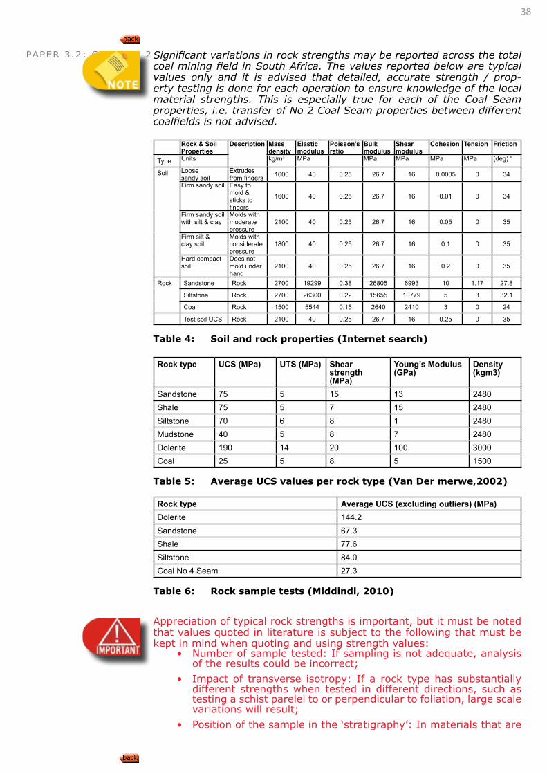
PAPER 3.2: CHAPTER 2 Significant variations in rock strengths may be reported across the total coal mining field in South Africa. The values reported below are typical values only and it is advised that detailed, accurate strength / prop-erty testing is done for each operation to ensure knowledge of the local material strengths. This is especially true for each of the Coal Seam properties, i.e. transfer of No 2 Coal Seam properties between different coalfields is not advised.
Rock & Soil Properties
Description Mass density
Elastic modulus
Poisson’s ratio
Bulk modulus
Shear modulus
Cohesion Tension Friction
Type Units kg/m3 MPa MPa MPa MPa MPa (deg) °
Soil Loose sandy soil
Extrudes from fingers 1600 40 0.25 26.7 16 0.0005 0 34
Firm sandy soil Easy to mold & sticks to fingers
1600 40 0.25 26.7 16 0.01 0 34
Firm sandy soil with silt & clay
Molds with moderate pressure
2100 40 0.25 26.7 16 0.05 0 35
Firm silt & clay soil
Molds with considerate pressure
1800 40 0.25 26.7 16 0.1 0 35
Hard compact soil
Does not mold under hand
2100 40 0.25 26.7 16 0.2 0 35
Rock Sandstone Rock 2700 19299 0.38 26805 6993 10 1.17 27.8
Siltstone Rock 2700 26300 0.22 15655 10779 5 3 32.1
Coal Rock 1500 5544 0.15 2640 2410 3 0 24
Test soil UCS Rock 2100 40 0.25 26.7 16 0.25 0 35
Table 4: Soil and rock properties (Internet search)
Rock type UCS (MPa) UTS (MPa) Shear strength (MPa)
Young’s Modulus(GPa)
Density (kgm3)
Sandstone 75 5 15 13 2480Shale 75 5 7 15 2480Siltstone 70 6 8 1 2480Mudstone 40 5 8 7 2480Dolerite 190 14 20 100 3000Coal 25 5 8 5 1500
Table 5: Average UCS values per rock type (Van Der merwe,2002)
Rock type Average UCS (excluding outliers) (MPa)Dolerite 144.2Sandstone 67.3Shale 77.6Siltstone 84.0Coal No 4 Seam 27.3
Table 6: Rock sample tests (Middindi, 2010)
Appreciation of typical rock strengths is important, but it must be noted that values quoted in literature is subject to the following that must be kept in mind when quoting and using strength values:
• Number of sample tested: If sampling is not adequate, analysis of the results could be incorrect;
• Impact of transverse isotropy: If a rock type has substantially different strengths when tested in different directions, such as testing a schist parelel to or perpendicular to foliation, large scale variations will result;
• Position of the sample in the ‘stratigraphy’: In materials that are
39
PAPER 3.2: CHAPTER 2 extremely non-homogeneous (different properties at different positions), strength results will be dependent on the position of the borehole and position of the sample within the core;
• Averaging results: The tendency to average strength test re-sults can be a dangerous practice if standard variations are large and where knowledge of the actual material strengths (such as with pillar designs) are crucial to the stability of the workings. Statistical analysis should be done carefully and with complete understanding of the abovementioned concerns.
• Outliers: Outliers should be removed from any analysis and can be done on the following basis:
• Remove results where the samples failed on existing dis-continuities since the test results report the strength of the discontinuity and not the intact sample;
• Remove those results that affect the standard deviation most, i.e. the results that appear too high;
• Keep in mind that low results could be real and could affect pillar behavior if tests were conducted for this purpose. In this case, careful consideration to the removal of low test results values is required.
DESCRIBE AND DISCUSS THE GEOTECHNICAL CHARACTERISTICS OF ROCK TYPES ASSOCIATED WITH TABULAR, SOFT ROCK OREBODIES
The most common rock types associated with tabular soft orebodies include:
Orebody Rock types Geotechnical characteristics Impact on designs for total or partial extraction mining methods
Coal
Sandstone, M
udstone, Shale, C
oal, Siltstone, D
olerite
Rock material strengths are variable with possible strong Sandstone and weaker Shale layers, often found interbedded. Sandstones are normally jointed but can also be massive and form an extremely strong layer across the mine workings. Mudstones are normally massive but can consist of clay minerals, resulting in reduction in competency. Shales are extremely laminated, splitting along bedding planes. Coal seams are carbonaceous organic deposits and can consist of peat, lignite (brown), black bituminous coal or anthracite. Siltstones are fine grained sedimentary material with clay particles.
Rock mass quality is mostly a function of the material strength and joint sets found in these rock types and can vary significantly.
Pillar design is critical due to low coal material strength
Rock mass strength of some materials (sandstone) can be high due to good material quality, affecting span and support designs, but low in materials such as Shale, resulting in reduced spans, increased support requirements etc.
Jointing requires adequate support spacing and length (tendons) design. The presence of ground water and poor strength filled joints increases the need for support installation and result in reduced spacings. The impact of jointing on rock mass strength and thus pillar design should be considered.
Table 7: Geotechnical characteristics of most common rock types in Platinum environment
LEARNING OUTCOME 2.2.2
40
PAPER 3.2: CHAPTER 2
APPLY THE ABOVE KNOWLEDGE TO THE DESIGN OF TOTAL EXTRACTION WORKINGS SUCH AS:Longwall mining, Shortwall mining, etc
In designing the mine layouts, the knowledge of the rock material in and around the coal seam and the quality of the material is critical. The de-sign of total extraction mining methods suggests that caving of the back area is contemplated.
The rock material in the roof of the seam, i.e. the type of rock and thick-ness of layers, as well as the quality of the material plays a significant role in allowing or resisting caving of the roof material. Massive sand-stone layers will prevent caving or at least delay the caving and could results in massive collapses and air blasts. This is similar to a delayed cave caused by the presence of a sill. However, if the roof consist of in-terbedded shale and sandstone, closure into the workings occurs easily and caving follows close behind the advancing face. The thickness and quality of the first sandstone beam in the roof of the workings, determine the distance behind the advancing face where caving occurs.
APPLY THE ABOVE KNOWLEDGE TO THE DESIGN OF PARTIAL EXTRACTION WORKINGS SUCH AS: ROOM AND PILLAR MINING, PILLAR EXTRACTION, PARTIAL PILLAR EXTRACTION, ETC.
In partial extractions, the competency of the coal seam and roof material form the bases of the design. Knowledge of the coal seam competence, presence of weaker layers around the coal seam (punching) determines the behavior of the pillars and thus also the pillar dimensions.
The roof competency determines the bord spacings or stable roof spans. In this span determination the type of material, thickness of layers and the quality (bedding, jointing, water, etc) of the material determines the spans to be allowed.
2.3 ROCKMASS CHARACTERISTICS2.3.1 GEOTECHNICAL ROCKMASS
CLASSIFICATION
DESCRIBE, DISCUSS AND APPLY ROCKMASS CLASSIFICATION TECHNIQUES FOR THE SELECTION OF SOFT ROCK TABULAR MINING METHODS
LEARNING OUTCOME 2.2.3
LEARNING OUTCOME 2.2.4
Refer to Paper 2 Outcome 3.1.2
CONNECTION 6
LEARNING OUTCOME 2.3.1.1
Refer to Paper 1 Outcome 6.2Refer to Paper 2 Outcome 3.1Refer to Paper 3.1 Outcome 2.3.1
CONNECTION 7
41
PAPER 3.2: CHAPTER 2
DESCRIBE, DISCUSS AND APPLY STANDARD ROCKMASS CLASSIFICATION AND ASSESSMENT SYSTEMS TO PREDICT EXCAVATION STABILITY
DESCRIBE, DISCUSS AND APPLY THE ROCKWALL CONDITION FACTOR (RCF) TO PREDICT TUNNEL STABILITY AND SUPPORT REQUIREMENTS
APPLY BARTON’S Q SYSTEM TO CLASSIFY A ROCKMASS
APPLY BIENIAWSKI’S RMR SYSTEM TO CLASSIFY A ROCKMASS
APPLY LAUBSCHER’S MRMR SYSTEM TO CLASSIFY A ROCKMASS
APPLY THE CMRR SYSTEM TO CLASSIFY A ROCKMASS
The United States Bureau of Mines (USMB) have developed the Coal Mine Roof Rating (CMRR) classification system to quantify descriptive geologi-cal information for use in coal mine design and roof support selection (Molinda et al, 1994).
The CMRR weighs the geotechnical factors that determine roof compe-tence, and combines them into a single rating on a scale from 0-100. The
LEARNING OUTCOME 2.3.1.2
Refer to Paper 1 Outcome 6.2Refer to Paper 2 Outcome 3.1Refer to Paper 3.1 Outcome 2.3.1
CONNECTION 8
LEARNING OUTCOME 2.3.1.3
Refer to Paper 1 Outcome 6.2Refer to Paper 2 Outcome 3.1Refer to Paper 3.1 Outcome 2.3.1
CONNECTION 9
LEARNING OUTCOME 2.3.1.4
Refer to Paper 1 Outcome 6.2Refer to Paper 2 Outcome 3.1Refer to Paper 3.1 Outcome 2.3.1
CONNECTION 10
LEARNING OUTCOME 2.3.1.5
Refer to Paper 1 Outcome 6.2Refer to Paper 2 Outcome 3.1Refer to Paper 3.1 Outcome 2.3.1
CONNECTION 11
LEARNING OUTCOME 2.3.1.6
Refer to Paper 1 Outcome 6.2Refer to Paper 2 Outcome 3.1Refer to Paper 3.1 Outcome 2.3.1
CONNECTION 12
LEARNING OUTCOME 2.3.1.7
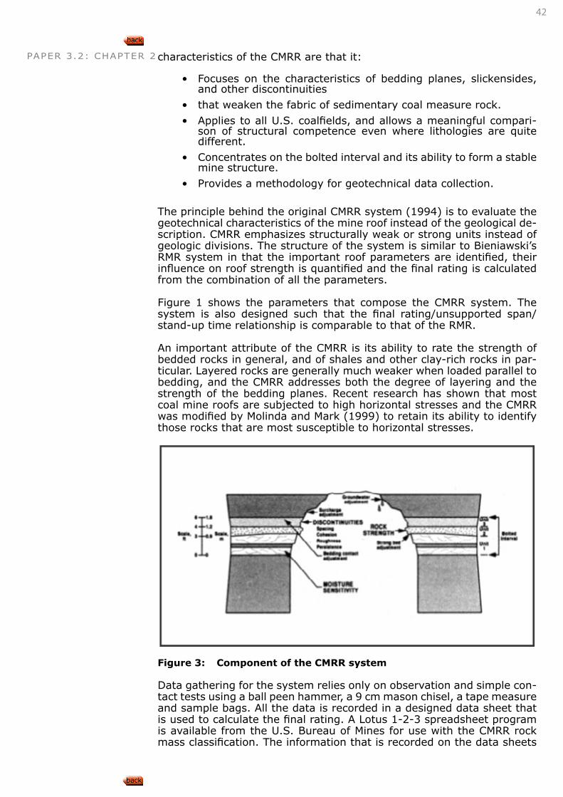
42
PAPER 3.2: CHAPTER 2 characteristics of the CMRR are that it:
• Focuses on the characteristics of bedding planes, slickensides, and other discontinuities
• that weaken the fabric of sedimentary coal measure rock.
• Applies to all U.S. coalfields, and allows a meaningful compari-son of structural competence even where lithologies are quite different.
• Concentrates on the bolted interval and its ability to form a stable mine structure.
• Provides a methodology for geotechnical data collection.
The principle behind the original CMRR system (1994) is to evaluate the geotechnical characteristics of the mine roof instead of the geological de-scription. CMRR emphasizes structurally weak or strong units instead of geologic divisions. The structure of the system is similar to Bieniawski’s RMR system in that the important roof parameters are identified, their influence on roof strength is quantified and the final rating is calculated from the combination of all the parameters.
Figure 1 shows the parameters that compose the CMRR system. The system is also designed such that the final rating/unsupported span/stand-up time relationship is comparable to that of the RMR.
An important attribute of the CMRR is its ability to rate the strength of bedded rocks in general, and of shales and other clay-rich rocks in par-ticular. Layered rocks are generally much weaker when loaded parallel to bedding, and the CMRR addresses both the degree of layering and the strength of the bedding planes. Recent research has shown that most coal mine roofs are subjected to high horizontal stresses and the CMRR was modified by Molinda and Mark (1999) to retain its ability to identify those rocks that are most susceptible to horizontal stresses.
Figure 3: Component of the CMRR system
Data gathering for the system relies only on observation and simple con-tact tests using a ball peen hammer, a 9 cm mason chisel, a tape measure and sample bags. All the data is recorded in a designed data sheet that is used to calculate the final rating. A Lotus 1-2-3 spreadsheet program is available from the U.S. Bureau of Mines for use with the CMRR rock mass classification. The information that is recorded on the data sheets
43
PAPER 3.2: CHAPTER 2 is entered into the spreadsheet program, creating a permanent computer record of the field notes. The calculation is based on rating the exposed roof that is divided into structural units. Each unit is rated individually mainly on an evaluation of the discontinuities and their characteristics. Next, the CMRR is determined for the mine roof as a whole. The ratings of the units within the bolted interval are first combined into a thickness-weighted average. Then a series of roof adjustment factors are applied with the most important being that of the strong bed. It has been found that the structural competence of a bolted mine roof is largely deter-mined by its competent member. All the parameters are combined to calculate the final CMRR.
The following is a summary of the factors that contribute to the final unit rating value:
• Compressive strength of intact rock: The ball peen hammer test is used to place rock into five classes, depending on the nature of the indentation.
• Cohesion of discontinuities: The strength of the bond between the two faces of a discontinuity is estimated by observation of roof behaviour, assisted by the chisel test.
• Roughness of discontinuity: The surface of the discontinuity is classified as “rough”, “wavy”, or “planar” by observation.
• Intensity of discontinuities: The average observed distance be-tween discontinuities within a unit.
• Persistence of discontinuity: The observed areal extent of a dis-continuity plane.
• Moisture sensitivity: Estimated from an immersion test, and only considered if significant inflows of groundwater are anticipated or if the unit is exposed to humid mine air.
After the individual unit ratings have been determined, they are summed into a single rating for the entire mine roof and adjustments are applied from tables by taking account of the following:
• Strong beds in the bolted interval
• Number of lithologic units contacts
• Groundwater and
• Surcharge
An entirely new system was developed to determine the CMRR from exploratory drill core using the Point Load Tests (PLT) to determine the strength parameters that account for approximately 60% of the final rat-ing. The new system uses both diametral (parallel to bedding) and axial perpendicular to bedding) PLT’s. The diametral tests allow the estimates of bedding plane cohesion and rock anistrophy, both of which are critical to estimating susceptibility to horizontal stresses.
Traditional core logging procedures are used to determine discontinuity spacing and roughness. To ensure compatibility with the original CMRR (1994), the new rating scales were verified by comparing drill core re-sults with nearby underground mining exposures.
A large database of strength ratings of rocks has been and the data has been partitioned to reflect the following three broad classes of roof based on a scale of 0-100:
• Weak (0-45),
• moderate (45-65), and
• strong (65-100).
44
PAPER 3.2: CHAPTER 2Table 8 shows the CMRR classes with corresponding geological conditions.
CMRR Class CMRR Region Geological conditionsWeak 0-45 Claystones, Mudrocks, ShalesModerate 45-65 Siltstones & sandstonesStrong 65-100 Sandstones
Table 8: CMRR Classes in the US, after Mark & Molinda 1994
Butcher (1999) has been documenting the application of the CMRR to South African strata conditions since it was first introduced to coal min-ing industry in 1998. Since that time, the system has been used on a limited basis owing to the fact that South African coal operations have generally been conducted in good geotechnical conditions compared to other parts of the world. Furthermore, rock classification systems have generally suffered due to the lack of trained Engineering Geologists or Rock Mechanics Engineers who can implement such systems.
Geotechnical site investigations were conducted (as part of SIMRAC COL613) from 20 fall of ground incident sites in South African coal mines. The CMRR classification system was used to classify the roof conditions at the fall sites. In addition to that, Bieniawski’s Rock mass Rating and Laubscher’s Mining Rock mass Rating were used as comparisons with the CMRR. A stress damage survey was also undertaken to relate rock mass damage to the horizontal stress regime.
In addition a coal cleat damage was done to relate maximum horizon-tal stress direction to cleat orientation. All CMRR values obtain from the underground mapping sites fell in the weak class i.e. on a scale 0-100, between 0-45. Many observations from the fall of ground site mappings in South Africa were found to collate with experiences gained in the United States.
However, a wide range of CMRR values were noted in some areas where roof conditions deteriorated in close proximity of major dykes or sills.
In another study by Butcher et al 2001, further CMRR classification stud-ies were carried out as part of a SIMRAC project to create a geotechnical database of the South African coal fields for design input into open min-ing operations. The following conclusions with respect to CMRR values for South African coal mines were made:
• Roof shale’s were generally below CMRR of 45 (weak)
• Sandstones were generally above CMRR of 45 (moderate to strong)
• Siltstones generally fell in the moderate CMRR range (45-65)
These observations correlate closely to Mark’s (1994) work that siltstones and sandstones in the U.S. were moderate to strong. The CMRR has been found to be robust enough to classify and describe the roof conditions that are found in South Africa and that it was easy to learn the technique. Experiences by Butcher (1999) with the RMR and MRMR systems showed a limited application compared to the CMRR, as they tend to overate the ground conditions by at least one class. The RMR over rated roof con-ditions due to lack of sensitivity in the allocation of joint condition and fracture values.
However, despite these advantages in some cases the CMRR values gave a wide range in areas of high horizontal stresses and in proximity of ma-jor geological features. In one case the method over rated roof conditions
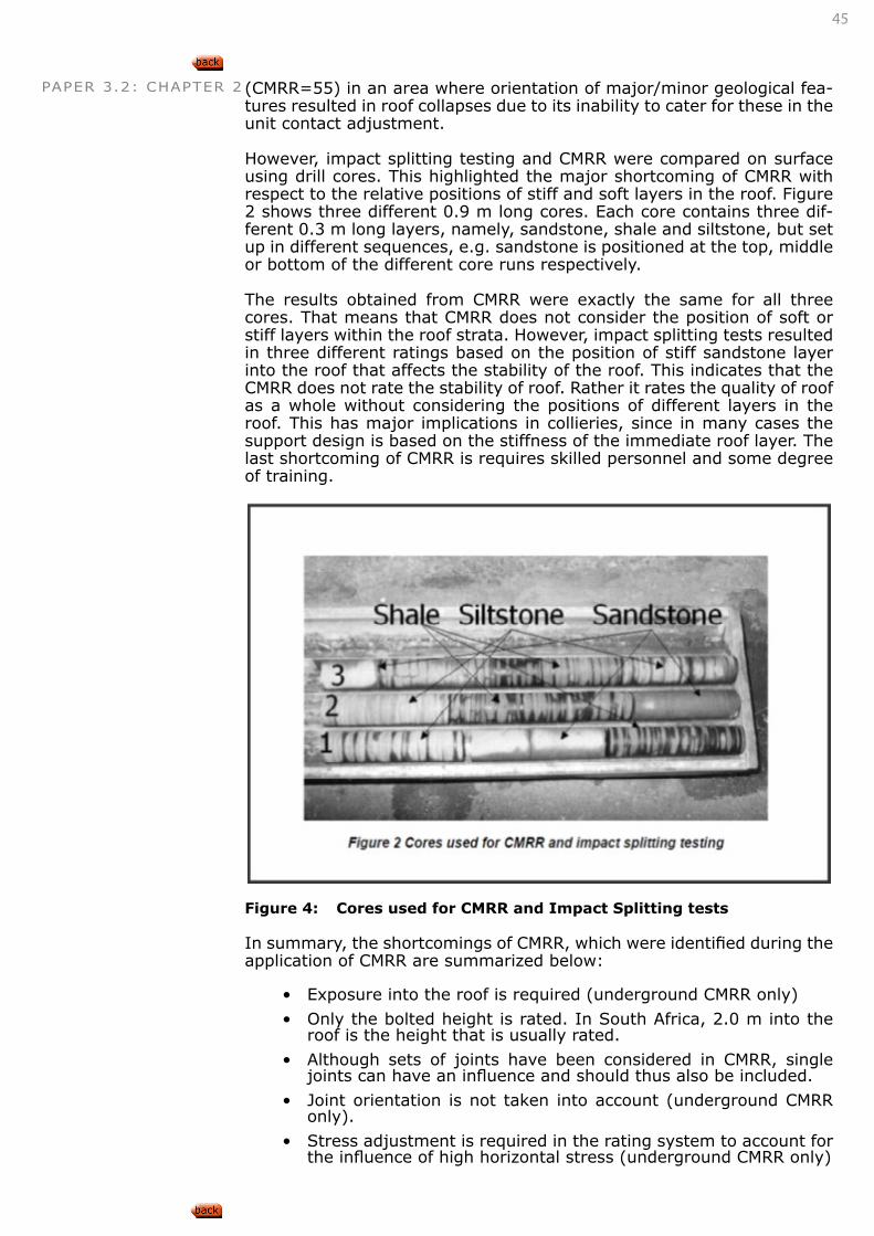
45
PAPER 3.2: CHAPTER 2 (CMRR=55) in an area where orientation of major/minor geological fea-tures resulted in roof collapses due to its inability to cater for these in the unit contact adjustment.
However, impact splitting testing and CMRR were compared on surface using drill cores. This highlighted the major shortcoming of CMRR with respect to the relative positions of stiff and soft layers in the roof. Figure 2 shows three different 0.9 m long cores. Each core contains three dif-ferent 0.3 m long layers, namely, sandstone, shale and siltstone, but set up in different sequences, e.g. sandstone is positioned at the top, middle or bottom of the different core runs respectively.
The results obtained from CMRR were exactly the same for all three cores. That means that CMRR does not consider the position of soft or stiff layers within the roof strata. However, impact splitting tests resulted in three different ratings based on the position of stiff sandstone layer into the roof that affects the stability of the roof. This indicates that the CMRR does not rate the stability of roof. Rather it rates the quality of roof as a whole without considering the positions of different layers in the roof. This has major implications in collieries, since in many cases the support design is based on the stiffness of the immediate roof layer. The last shortcoming of CMRR is requires skilled personnel and some degree of training.
Figure 4: Cores used for CMRR and Impact Splitting tests
In summary, the shortcomings of CMRR, which were identified during the application of CMRR are summarized below:
• Exposure into the roof is required (underground CMRR only)
• Only the bolted height is rated. In South Africa, 2.0 m into the roof is the height that is usually rated.
• Although sets of joints have been considered in CMRR, single joints can have an influence and should thus also be included.
• Joint orientation is not taken into account (underground CMRR only).
• Stress adjustment is required in the rating system to account for the influence of high horizontal stress (underground CMRR only)
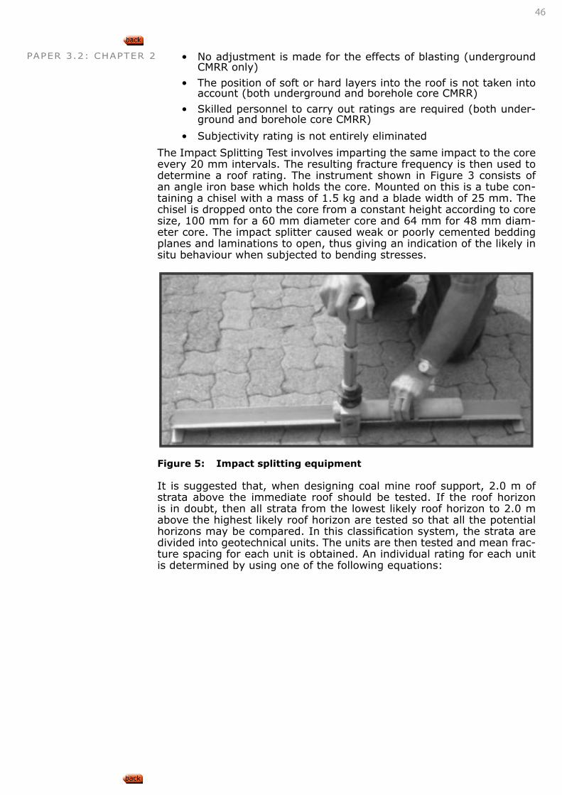
46
PAPER 3.2: CHAPTER 2 • No adjustment is made for the effects of blasting (underground CMRR only)
• The position of soft or hard layers into the roof is not taken into account (both underground and borehole core CMRR)
• Skilled personnel to carry out ratings are required (both under-ground and borehole core CMRR)
• Subjectivity rating is not entirely eliminated
The Impact Splitting Test involves imparting the same impact to the core every 20 mm intervals. The resulting fracture frequency is then used to determine a roof rating. The instrument shown in Figure 3 consists of an angle iron base which holds the core. Mounted on this is a tube con-taining a chisel with a mass of 1.5 kg and a blade width of 25 mm. The chisel is dropped onto the core from a constant height according to core size, 100 mm for a 60 mm diameter core and 64 mm for 48 mm diam-eter core. The impact splitter caused weak or poorly cemented bedding planes and laminations to open, thus giving an indication of the likely in situ behaviour when subjected to bending stresses.
Figure 5: Impact splitting equipment
It is suggested that, when designing coal mine roof support, 2.0 m of strata above the immediate roof should be tested. If the roof horizon is in doubt, then all strata from the lowest likely roof horizon to 2.0 m above the highest likely roof horizon are tested so that all the potential horizons may be compared. In this classification system, the strata are divided into geotechnical units. The units are then tested and mean frac-ture spacing for each unit is obtained. An individual rating for each unit is determined by using one of the following equations:
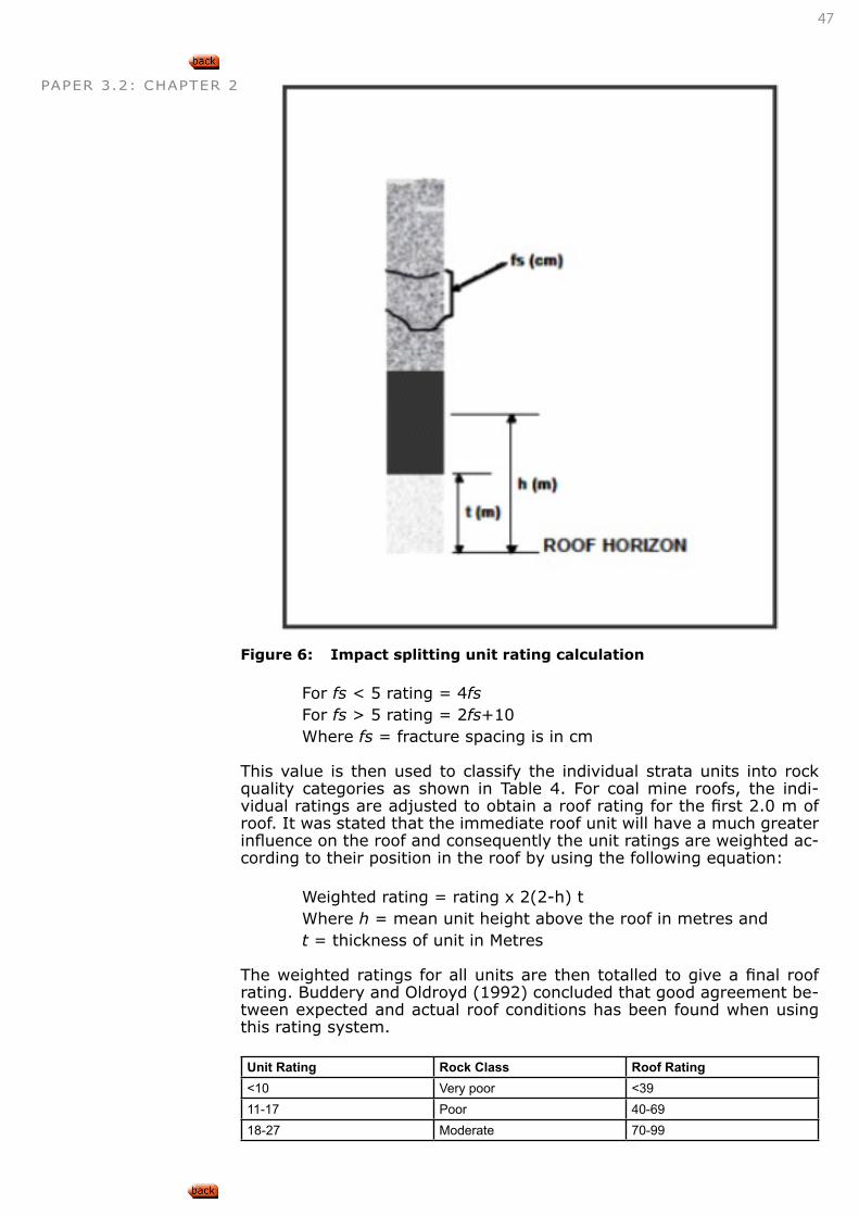
47
PAPER 3.2: CHAPTER 2
Figure 6: Impact splitting unit rating calculation
For fs < 5 rating = 4fsFor fs > 5 rating = 2fs+10Where fs = fracture spacing is in cm
This value is then used to classify the individual strata units into rock quality categories as shown in Table 4. For coal mine roofs, the indi-vidual ratings are adjusted to obtain a roof rating for the first 2.0 m of roof. It was stated that the immediate roof unit will have a much greater influence on the roof and consequently the unit ratings are weighted ac-cording to their position in the roof by using the following equation:
Weighted rating = rating x 2(2-h) tWhere h = mean unit height above the roof in metres andt = thickness of unit in Metres
The weighted ratings for all units are then totalled to give a final roof rating. Buddery and Oldroyd (1992) concluded that good agreement be-tween expected and actual roof conditions has been found when using this rating system.
Unit Rating Rock Class Roof Rating<10 Very poor <3911-17 Poor 40-6918-27 Moderate 70-99
48
PAPER 3.2: CHAPTER 2 28-32 Good 100-129>32 Very good >130
Table 9: Unit and coal roof classification system (Buddery and Old-royd, 1989)
This rating system has been recently modified by Ingwe Rock Engineer-ing to take into account areas where the immediate roof is coal. The unit rating is multiplied by 1.56, which is the density of sandstone (2500 kg/m3) divided by coal density (1600 kg/m3).
Based on this rating system the following support patterns are adopted. It should be noted that the roof support patterns are only applicable where they have been exercised for many years. Also, as will be ex-plained later in this chapter, this rating system is used together with a special current-with-mining assessment technique to adapt to changing roof conditions.
Roof Rating Estimated Support CommentVery good 1,2m x 16mm point anchor, 5
bolts in intersections onlyGood 1,2m x 16mm point anchor, 5
bolts per intersection, 2 bolts per row with rows 2m apart
Moderate 1,5m x 16mm full column, 9 bolts per intersection, 3 bolts per row with rows 1,5m apart
Poor 2m x 20mm full column, 16 bolts per intersection, 4 bolts per row with rows 1m apart, possibly with W-straps
Reduce road widths to less than 6m
Very poor Specialised support eg a combination of cable anchors, trusses, shotcrete, W-straps etc.
Very poor roofs are uneconomic and are usually only traversed to get to reserves
Table 10: Coal classification system and support (Buddery, 1989)
It has been found that in mining engineering design, the Q and RMR clas-sifications form the basis of many empirical design methods as well as the basis of failure criteria used in many numerical modelling programs. However, application of these systems in South African mining industry, specifically in coal, has been limited. The coal industry has developed a quality parameter called ‘Roof rating’ and rates a number of factors to obtain a Unit Rating Value. Below is a summary of the factors that con-tribute to the final unit rating value:
• Compressive strength of intact rock: Impact splitting test results is used to classify rock.
• Cohesion of discontinuities: The strength of the bond between the two faces of a discontinuity is estimated by observation of roof behaviour, assisted by the chisel test.
• Roughness of discontinuity: The surface of the discontinuity is classified as “rough”, “wavy”, or “planar” by observation.
• Intensity of discontinuities: The average observed distance be-tween discontinuities within a unit.
• Persistence of discontinuity: The observed areal extent of a dis-continuity plane.
• Moisture sensitivity: Estimated from an immersion test, and only considered if significant inflows of groundwater are anticipated or if the unit is exposed to humid mine air.
EXAMPLE
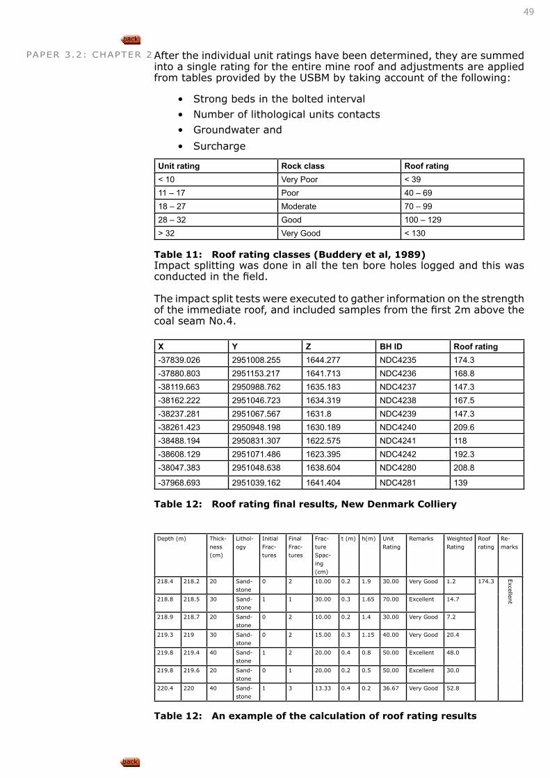
49
PAPER 3.2: CHAPTER 2 After the individual unit ratings have been determined, they are summed into a single rating for the entire mine roof and adjustments are applied from tables provided by the USBM by taking account of the following:
• Strong beds in the bolted interval
• Number of lithological units contacts
• Groundwater and
• Surcharge
Unit rating Rock class Roof rating< 10 Very Poor < 3911 – 17 Poor 40 – 6918 – 27 Moderate 70 – 9928 – 32 Good 100 – 129> 32 Very Good < 130
Table 11: Roof rating classes (Buddery et al, 1989)Impact splitting was done in all the ten bore holes logged and this was conducted in the field.
The impact split tests were executed to gather information on the strength of the immediate roof, and included samples from the first 2m above the coal seam No.4.
X Y Z BH ID Roof rating-37839.026 2951008.255 1644.277 NDC4235 174.3-37880.803 2951153.217 1641.713 NDC4236 168.8-38119.663 2950988.762 1635.183 NDC4237 147.3-38162.222 2951046.723 1634.319 NDC4238 167.5-38237.281 2951067.567 1631.8 NDC4239 147.3-38261.423 2950948.198 1630.189 NDC4240 209.6-38488.194 2950831.307 1622.575 NDC4241 118-38608.129 2951071.486 1623.395 NDC4242 192.3-38047.383 2951048.638 1638.604 NDC4280 208.8
-37968.693 2951039.162 1641.404 NDC4281 139
Table 12: Roof rating final results, New Denmark Colliery
Depth (m) Thick-ness (cm)
Lithol-ogy
Initial Frac-tures
Final Frac-tures
Frac-ture Spac-ing (cm)
t (m) h(m) Unit Rating
Remarks Weighted Rating
Roof rating
Re-marks
218.4 218.2 20 Sand-stone
0 2 10.00 0.2 1.9 30.00 Very Good 1.2 174.3
Excellen
t218.8 218.5 30 Sand-stone
1 1 30.00 0.3 1.65 70.00 Excellent 14.7
218.9 218.7 20 Sand-stone
0 2 10.00 0.2 1.4 30.00 Very Good 7.2
219.3 219 30 Sand-stone
0 2 15.00 0.3 1.15 40.00 Very Good 20.4
219.8 219.4 40 Sand-stone
1 2 20.00 0.4 0.8 50.00 Excellent 48.0
219.8 219.6 20 Sand-stone
0 1 20.00 0.2 0.5 50.00 Excellent 30.0
220.4 220 40 Sand-stone
1 3 13.33 0.4 0.2 36.67 Very Good 52.8
Table 12: An example of the calculation of roof rating results
50
PAPER 3.2: CHAPTER 2• Evaluation of roof rating systems in RSA Canbulat
• Col812 Rating systems for coal mine roofs
• Coal mine roof rating Molinda
• Development and application of the CMRR Mark
• Page 23, vd Merwe, Madden, Rock Engineering for Underground Coal Mining, 2002
APPLY ROCKMASS CLASSIFICATION RESULTS TO DETERMINE THE STABILITY OF UNSUPPORTED SPANS
APPLY ROCKMASS CLASSIFICATION RESULTS TO DETERMINE THE STABILITY OF UNSUPPORTED ROCKSLOPES
APPLY ROCKMASS CLASSIFICATION RESULTS TO DETERMINE SUPPORT REQUIREMENTS FOR VARIOUS SITUATIONS
DETERMINE ROCKMASS ‘M’ AND ‘S’ PARAMETERS FOR THE HOEK AND BROWN CRITERION BASED UPON ROCKMASS CLASSIFICATION RESULTS
DETERMINE ROCKMASS DEFORMABILITY FROM JOINT STIFFNESS AND ROCKMASS CLASSIFICATION RESULTS.
LEARNING OUTCOME 2.3.1.8
Refer to Paper 1 Outcome 6.2Refer to Paper 2 Outcome 3.1Refer to Paper 3.1 Outcome 2.3.1
CONNECTION 12
LEARNING OUTCOME 2.3.1.9
Refer to Paper 1 Outcome 6.2Refer to Paper 2 Outcome 3.1Refer to Paper 3.1 Outcome 2.3.1
CONNECTION 13
LEARNING OUTCOME 2.3.1.10
Refer to Paper 1 Outcome 6.2Refer to Paper 2 Outcome 3.1Refer to Paper 3.1 Outcome 2.3.1
CONNECTION 14
LEARNING OUTCOME 2.3.1.11
Refer to Paper 1 Outcome 6.2Refer to Paper 2 Outcome 3.1Refer to Paper 3.1 Outcome 2.3.1
CONNECTION 145
LEARNING OUTCOME 2.3.1.12
Refer to Paper 1 Outcome 6.2Refer to Paper 2 Outcome 3.1Refer to Paper 3.1 Outcome 2.3.1
CONNECTION 16
51
PAPER 3.2: CHAPTER 3CHAPTER
3PAPER 3.2 SOFT ROCK TABULAR MINING
3. ROCK AND ROCKMASS BEHAVIOUR3.1. PILLAR BEHAVIOUR3.1.1. PILLAR STRENGTH
The candidate must be able to demonstrate knowledge and understand-ing of the above subject area by being able to:
• Describe, explain and discuss the effects of the following circum-stances on the strength of pillars:
• Roof contact conditions, floor contact conditions
• Coal strength, jointing
• Pillar volume, confinement
• Describe, explain and discuss the effects of confinement on pillar strength.
3.1.2. PILLAR STRESS
The candidate must be able to demonstrate knowledge and understand-ing of the above subject area by being able to:
• Sketch, describe, explain and discuss the stress distribution in a panel of pillars with barrier pillars on either side;
• Sketch, describe, explain and discuss the stress distribution at mid-height of a pillar under the following conditions:
• While the pillar behaves elastically,
• When the pillar is at peak strength,
• After the pillar has reached peak strength
• Sketch, describe, explain and discuss how each of the above stress distributions will affect pillar spalling;
• Describe, explain and discuss how pillar width to height ratio af-fects pillar stiffness;
• Describe, explain and discuss how variations in pillar width to height ratio will affect the loading of pillars in a panel and
• Apply the above knowledge to evaluate the performance of pillars for given pillar layouts.
3.1.3. PILLAR FAILURE
The candidate must be able to demonstrate knowledge and understand-ing of the above subject area by being able to:
• Describe, explain and discuss how pillar width to height ratio af-fects pillar strength;
• Describe, explain and discuss how pillar width to height ratio af-fects the post peak stress-strain behaviour of pillars;
LEARNING OUTCOMES
52
PAPER 3.2: CHAPTER 3 • Describe, explain and discuss the significance of pillar width to height ratio in terms of the stability of bord and pillar workings;
• Describe, explain and discuss how loading system stiffness will cause pillars to fail either in a controlled fashion or violently;
• Describe, explain and discuss how ashfill or sandfill will affect the behaviour of failed pillars;
• Describe, explain and discuss the mechanism of pillar punching into the roof strata or floor strata;
• Describe, explain and discuss the effect of pillar punching on the stability of adjacent strata;
• Describe, explain and discuss the effect of pillar punching on the ultimate strength of pillars and
• Apply the above knowledge to evaluate given pillar layouts and their potential for violent failure.
3.2. ROOF BEHAVIOUR3.2.1. BEAMS AND PLATES
The candidate must be able to demonstrate knowledge and understand-ing of the above subject area by being able to:
• Sketch, describe, explain and discuss the phenomenon of displace-ments and deflections between strata layers over an excavation;
• Sketch, describe, explain and discuss roof deflections in road-ways of bord and pillar workings during different stages of development;
• Describe, explain and discuss the significance of these deflec-tions in terms of support requirements and support installation;
• Sketch, describe, explain and discuss roof deflections at inter-sections of bord and pillar workings during different stages of development;
• Describe, explain and discuss the significance of these deflec-tions in terms of support requirements and support installation;
• Describe, explain and discuss how beam span and beam thick-ness affect beam stability;
• Sketch, describe, explain and discuss how horizontal compres-sive stresses allow cracked beams to remain stable;
• Sketch, describe, explain and discuss how voussoir arch forma-tion allows cracked beams to remain stable;
• Sketch, describe, explain and discuss the differences in behav-iour between rock plates and rock beams;
• Describe, explain and discuss the significance of these differenc-es in terms of the stability of intersections;
• Determine the factor of safety against sliding failure of a cracked beam in the presence of horizontal stresses;
• Apply the above knowledge to evaluate given situations in terms of their potential instability and
• Apply the above knowledge to determine appropriate remedial measures to improve stability.
3.2.2. ROOF BEHAVIOUR DURING TOTAL EXTRACTION
The candidate must be able to demonstrate knowledge and understand-ing of the above subject area by being able to:
• Sketch, describe, explain and discuss the behaviour of roof strata overlying total extraction panels in terms of:
53
PAPER 3.2: CHAPTER 3 • Caving propensity, cave height, swell factor, strata overhang
• Continuous cave subsidence
• Describe, explain and discuss how factors such as the strength and bedding of roof strata affect the swell factor of strata;
• Describe, explain and discuss how factors such as the strength and bedding of roof strata affect the overhang of strata;
• Describe, explain and discuss how a strong sandstone beam or dolerite sill will affect the roof behaviour of total extraction panels;
• Describe, explain and discuss how a strong sandstone beam or dolerite sill will affect loading of the abutments of total extraction panels;
• Describe, explain and discuss recompaction behaviour of caved strata;
• Describe, explain and discuss how the recompaction of caved strata affects the subsequent extraction of other seams;
• Sketch, describe, explain and discuss stress distribution in the goaf from the edges of a panel to the centre of a panel;
• Evaluate and predict roof caving behaviour for given sets of cir-cumstances and
• Evaluate and predict stresses in workings for given sets of circumstances
3.2.3. INFLUENCE OF DOLERITE SILLS
The candidate must be able to demonstrate knowledge and understand-ing of the above subject area by being able to:
• Describe, explain and discuss the effects of dolerite sills on strata behaviour in the following mining situations:
• Bord and pillar operations, stooping operations,
• Long wall operations
• Describe, explain and discuss the effects of dolerite sills on stress distribution in the following mining situations:
• Bord and pillar operations, stooping operations,
• Long wall operations
• Describe, explain and discuss the application of Galvin’s equa-tions for determining critical spans of dolerite sills;
• Describe, explain and discuss the limitations of Galvin’s equa-tions for determining critical spans of dolerite sills;
• Apply Galvin’s equations to determine critical spans for the fail-ure of dolerite sills and
• Apply the above knowledge to the design of total extraction and room and pillar workings
54
PAPER 3.2: CHAPTER 3 3. ROCK AND ROCKMASS BEHAVIOUR3.1. PILLAR BEHAVIOUR3.1.1. PILLAR STRENGTH
DESCRIBE, EXPLAIN AND DISCUSS THE EFFECTS OF THE FOLLOWING CIRCUMSTANCES ON THE STRENGTH OF PILLARS: Roof contact conditions, floor contact conditions, pillar volume, confinement
Pillars with relatively high factors of safety have been reported to ‘fail’ in the past. In the evaluation of these failures, poor roof or floor material strength has been identified as one of the contributing and even control-ling factors.
In the case of specific floor stability contribution to pillar failures, the fol-lowing aspects are of importance:
• When a sill is present below the floor strata, vertical joints seem to be induced in the floor strata, reducing its strength and allow-ing heave. No flow of weak floor material occurs from below the pillars with pillars remaining relatively intact, but lost their ability to maintain roof stability, allowing to some extent ‘sagging’ of the sandstone roof beam or even collapse of the roof. Due to the sag-ging sandstone beam, pillars in the centre of the mined-out area showed signs of failure.
• Soft, sandy shale foot materials, often weakened by water and igneous material, are squeezed out from underneath the pillars. This displacement of the floor beneath the pillars towards the ex-cavations dragged portions of the pillars with and can remove even 0.5m of the pillar side wall. If the pillars were of small dimension to start off with, this could lead to failure of the remaining pillar.
• A non-complete goaf (not goafed to surface) could leed to over-stressed pillars around the panel, increasing the load on the foot material. If this material is of a weaker nature, such as laminated sandstone and shale, the material can flow out from underneath the pillars and accelerated pillar spalling results.
Preliminary design guidelines (more work was suggested) have been published by Latilla (2004) and include the following:
Note that the guidelines are only applicable to the Witbank and Highveld Number 5 Coal seam and the Kwa-Zulu-Natal and Swaziland Alfred and Main seams;
• If the FSR exceeds 10, the FOS must be re-designed so that the factor FSR/FOS < 4;
• Panel width not to exceed 150m;
• Numerical modelling is required if 7 < FSR < 10
• FSR < 7 indicates no likely foundation problems and normal de-sign methods can be adopted.
LEARNING OUTCOME 3.1.1.1
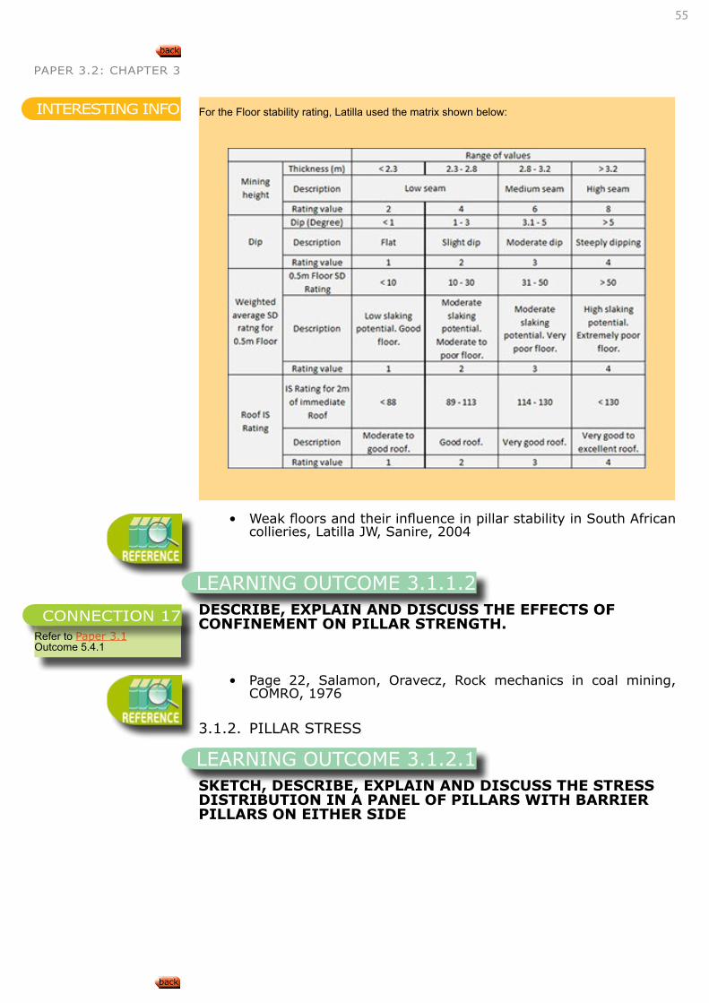
55
PAPER 3.2: CHAPTER 3
• Weak floors and their influence in pillar stability in South African collieries, Latilla JW, Sanire, 2004
DESCRIBE, EXPLAIN AND DISCUSS THE EFFECTS OF CONFINEMENT ON PILLAR STRENGTH.
• Page 22, Salamon, Oravecz, Rock mechanics in coal mining, COMRO, 1976
3.1.2. PILLAR STRESS
SKETCH, DESCRIBE, EXPLAIN AND DISCUSS THE STRESS DISTRIBUTION IN A PANEL OF PILLARS WITH BARRIER PILLARS ON EITHER SIDE
For the Floor stability rating, Latilla used the matrix shown below: INTERESTING INFO
LEARNING OUTCOME 3.1.1.2
Refer to Paper 3.1 Outcome 5.4.1
CONNECTION 17
LEARNING OUTCOME 3.1.2.1
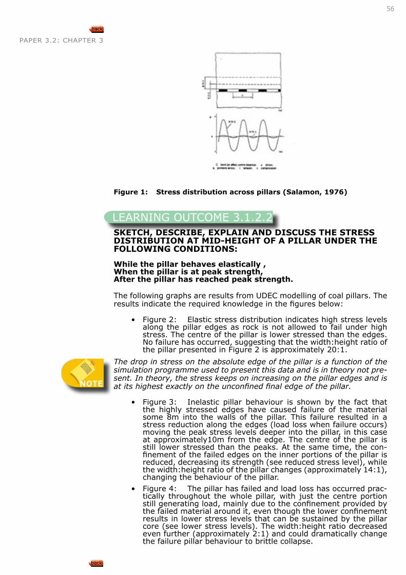
56
PAPER 3.2: CHAPTER 3
Figure 1: Stress distribution across pillars (Salamon, 1976)
SKETCH, DESCRIBE, EXPLAIN AND DISCUSS THE STRESS DISTRIBUTION AT MID-HEIGHT OF A PILLAR UNDER THE FOLLOWING CONDITIONS:
While the pillar behaves elastically , When the pillar is at peak strength, After the pillar has reached peak strength.
The following graphs are results from UDEC modelling of coal pillars. The results indicate the required knowledge in the figures below:
• Figure 2: Elastic stress distribution indicates high stress levels along the pillar edges as rock is not allowed to fail under high stress. The centre of the pillar is lower stressed than the edges.No failure has occurred, suggesting that the width:height ratio of the pillar presented in Figure 2 is approximately 20:1.
The drop in stress on the absolute edge of the pillar is a function of the simulation programme used to present this data and is in theory not pre-sent. In theory, the stress keeps on increasing on the pillar edges and is at its highest exactly on the unconfined final edge of the pillar.
• Figure 3: Inelastic pillar behaviour is shown by the fact that the highly stressed edges have caused failure of the material some 8m into the walls of the pillar. This failure resulted in a stress reduction along the edges (load loss when failure occurs) moving the peak stress levels deeper into the pillar, in this case at approximately10m from the edge. The centre of the pillar is still lower stressed than the peaks. At the same time, the con-finement of the failed edges on the inner portions of the pillar is reduced, decreasing its strength (see reduced stress level), while the width:height ratio of the pillar changes (approximately 14:1), changing the behaviour of the pillar.
• Figure 4: The pillar has failed and load loss has occurred prac-tically throughout the whole pillar, with just the centre portion still generating load, mainly due to the confinement provided by the failed material around it, even though the lower confinement results in lower stress levels that can be sustained by the pillar core (see lower stress levels). The width:height ratio decreased even further (approximately 2:1) and could dramatically change the failure pillar behaviour to brittle collapse.
LEARNING OUTCOME 3.1.2.2
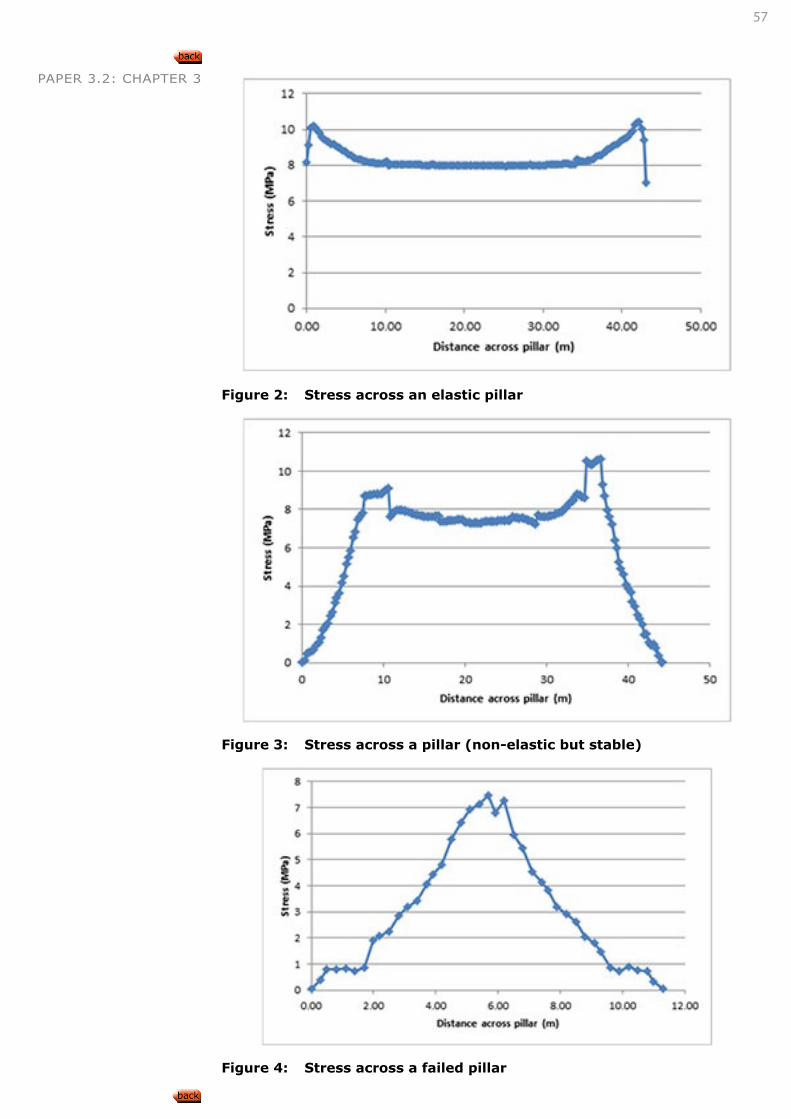
57
PAPER 3.2: CHAPTER 3
Figure 2: Stress across an elastic pillar
Figure 3: Stress across a pillar (non-elastic but stable)
Figure 4: Stress across a failed pillar
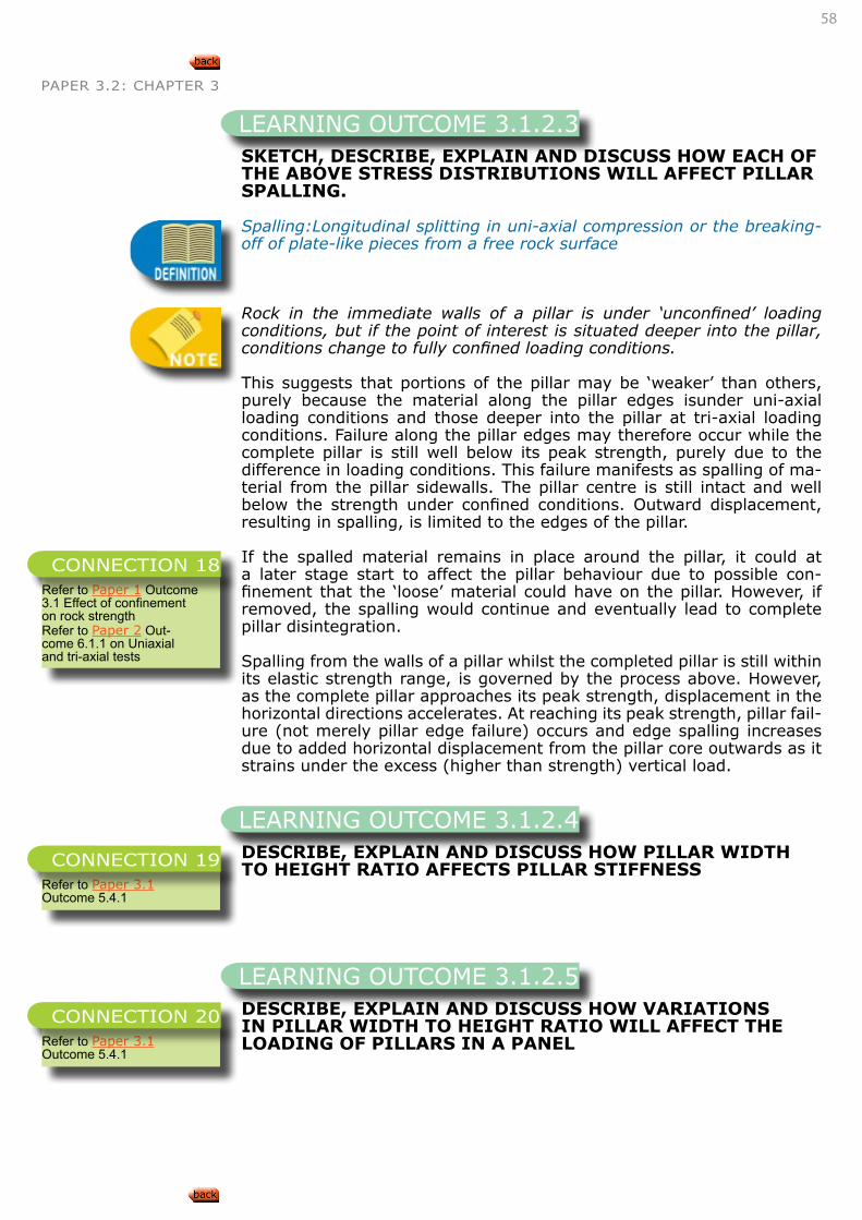
58
PAPER 3.2: CHAPTER 3
SKETCH, DESCRIBE, EXPLAIN AND DISCUSS HOW EACH OF THE ABOVE STRESS DISTRIBUTIONS WILL AFFECT PILLAR SPALLING.
Spalling:Longitudinal splitting in uni-axial compression or the breaking-off of plate-like pieces from a free rock surface
Rock in the immediate walls of a pillar is under ‘unconfined’ loading conditions, but if the point of interest is situated deeper into the pillar, conditions change to fully confined loading conditions.
This suggests that portions of the pillar may be ‘weaker’ than others, purely because the material along the pillar edges isunder uni-axial loading conditions and those deeper into the pillar at tri-axial loading conditions. Failure along the pillar edges may therefore occur while the complete pillar is still well below its peak strength, purely due to the difference in loading conditions. This failure manifests as spalling of ma-terial from the pillar sidewalls. The pillar centre is still intact and well below the strength under confined conditions. Outward displacement, resulting in spalling, is limited to the edges of the pillar.
If the spalled material remains in place around the pillar, it could at a later stage start to affect the pillar behaviour due to possible con-finement that the ‘loose’ material could have on the pillar. However, if removed, the spalling would continue and eventually lead to complete pillar disintegration.
Spalling from the walls of a pillar whilst the completed pillar is still within its elastic strength range, is governed by the process above. However, as the complete pillar approaches its peak strength, displacement in the horizontal directions accelerates. At reaching its peak strength, pillar fail-ure (not merely pillar edge failure) occurs and edge spalling increases due to added horizontal displacement from the pillar core outwards as it strains under the excess (higher than strength) vertical load.
DESCRIBE, EXPLAIN AND DISCUSS HOW PILLAR WIDTH TO HEIGHT RATIO AFFECTS PILLAR STIFFNESS
DESCRIBE, EXPLAIN AND DISCUSS HOW VARIATIONS IN PILLAR WIDTH TO HEIGHT RATIO WILL AFFECT THE LOADING OF PILLARS IN A PANEL
LEARNING OUTCOME 3.1.2.3
Refer to Paper 1 Outcome 3.1 Effect of confinement on rock strengthRefer to Paper 2 Out-come 6.1.1 on Uniaxial and tri-axial tests
CONNECTION 18
LEARNING OUTCOME 3.1.2.4
Refer to Paper 3.1 Outcome 5.4.1
CONNECTION 19
LEARNING OUTCOME 3.1.2.5
Refer to Paper 3.1 Outcome 5.4.1
CONNECTION 20
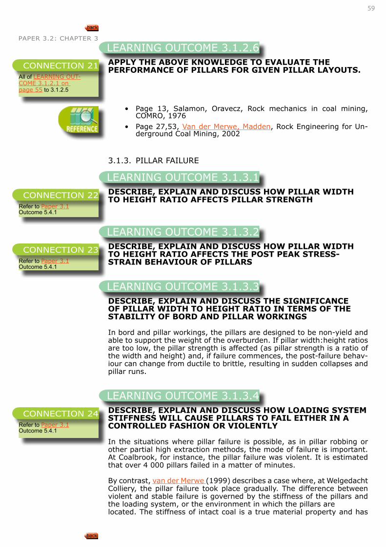
59
PAPER 3.2: CHAPTER 3
APPLY THE ABOVE KNOWLEDGE TO EVALUATE THE PERFORMANCE OF PILLARS FOR GIVEN PILLAR LAYOUTS.
• Page 13, Salamon, Oravecz, Rock mechanics in coal mining, COMRO, 1976
• Page 27,53, Van der Merwe, Madden, Rock Engineering for Un-derground Coal Mining, 2002
3.1.3. PILLAR FAILURE
DESCRIBE, EXPLAIN AND DISCUSS HOW PILLAR WIDTH TO HEIGHT RATIO AFFECTS PILLAR STRENGTH
DESCRIBE, EXPLAIN AND DISCUSS HOW PILLAR WIDTH TO HEIGHT RATIO AFFECTS THE POST PEAK STRESS-STRAIN BEHAVIOUR OF PILLARS
DESCRIBE, EXPLAIN AND DISCUSS THE SIGNIFICANCE OF PILLAR WIDTH TO HEIGHT RATIO IN TERMS OF THE STABILITY OF BORD AND PILLAR WORKINGS
In bord and pillar workings, the pillars are designed to be non-yield and able to support the weight of the overburden. If pillar width:height ratios are too low, the pillar strength is affected (as pillar strength is a ratio of the width and height) and, if failure commences, the post-failure behav-iour can change from ductile to brittle, resulting in sudden collapses and pillar runs.
DESCRIBE, EXPLAIN AND DISCUSS HOW LOADING SYSTEM STIFFNESS WILL CAUSE PILLARS TO FAIL EITHER IN A CONTROLLED FASHION OR VIOLENTLY
In the situations where pillar failure is possible, as in pillar robbing or other partial high extraction methods, the mode of failure is important. At Coalbrook, for instance, the pillar failure was violent. It is estimated that over 4 000 pillars failed in a matter of minutes.
By contrast, van der Merwe (1999) describes a case where, at Welgedacht Colliery, the pillar failure took place gradually. The difference between violent and stable failure is governed by the stiffness of the pillars and the loading system, or the environment in which the pillars arelocated. The stiffness of intact coal is a true material property and has
LEARNING OUTCOME 3.1.2.6
All of LEARNING OUT-COME 3.1.2.1 on page 55 to 3.1.2.5
CONNECTION 21
LEARNING OUTCOME 3.1.3.1
Refer to Paper 3.1 Outcome 5.4.1
CONNECTION 22
LEARNING OUTCOME 3.1.3.2
Refer to Paper 3.1 Outcome 5.4.1
CONNECTION 23
LEARNING OUTCOME 3.1.3.3
LEARNING OUTCOME 3.1.3.4
Refer to Paper 3.1 Outcome 5.4.1
CONNECTION 24
60
PAPER 3.2: CHAPTER 3 been found to be approximately 3.5 to 4.0GPa. By contrast, the post-peak stiffness of a pillar is dependent on the pillar geometry. The mode of failure, violent or controlled, depends on the post-peak slope of the pillar’s load/deformation characteristic and that of the system.
Stiffness, λ, is the ratio of force to deformation (F/ε), Where E is the Young’s Modulus and A is the pillar area.
In the case of the post-peak stiffness, the geometry of the pillar, (w/h), influences the post-peak stiffness. The greater the w/h ratio, the greater the post-peak stiffness is.
For stability λm> λc <0, where λm is the post-peak failure slope of the pil-lars and λc is the critical system stiffness for a panel of pillars, the critical system stiffness reduces with the number of pillars in a panel. Post-peak stiffness has been obtained by the back analysis of in situ coal pillar tests and laboratory tests by different researchers:
Based on the Salamon and Oravecz (1976) conceptof local system stiff-ness, violent failure can occur ifthere is more energy released from the system than isrequired by the pillar for continued deformation. Thiscon-dition is met if the system stiffness is above the post-peak stiffness of the pillar (see Figure 5).Conversely, to prevent violent failure, the pillar post-peak stiffness has to be above the system stiffness.
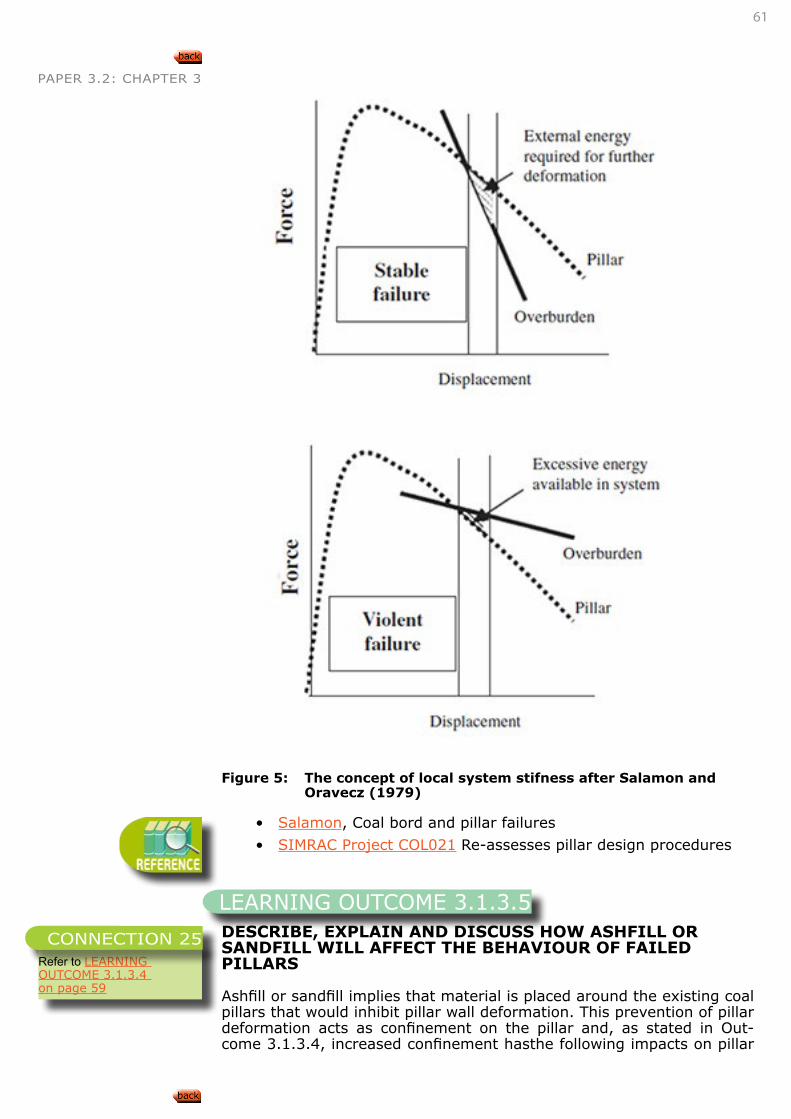
61
PAPER 3.2: CHAPTER 3
Figure 5: The concept of local system stifness after Salamon and Oravecz (1979)
• Salamon, Coal bord and pillar failures
• SIMRAC Project COL021 Re-assesses pillar design procedures
DESCRIBE, EXPLAIN AND DISCUSS HOW ASHFILL OR SANDFILL WILL AFFECT THE BEHAVIOUR OF FAILED PILLARS
Ashfill or sandfill implies that material is placed around the existing coal pillars that would inhibit pillar wall deformation. This prevention of pillar deformation acts as confinement on the pillar and, as stated in Out-come 3.1.3.4, increased confinement hasthe following impacts on pillar
LEARNING OUTCOME 3.1.3.5
Refer to LEARNING OUTCOME 3.1.3.4 on page 59
CONNECTION 25
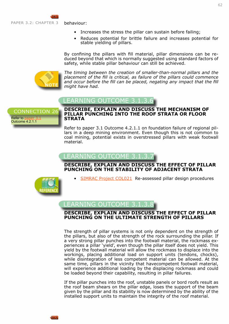
62
PAPER 3.2: CHAPTER 3 behaviour:
• Increases the stress the pillar can sustain before failing;
• Reduces potential for brittle failure and increases potential for stable yielding of pillars.
By confining the pillars with fill material, pillar dimensions can be re-duced beyond that which is normally suggested using standard factors of safety, while stable pillar behaviour can still be achieved.
The timing between the creation of smaller-than-normal pillars and the placement of the fill is critical, as failure of the pillars could commence and occur before the fill can be placed, negating any impact that the fill might have had.
DESCRIBE, EXPLAIN AND DISCUSS THE MECHANISM OF PILLAR PUNCHING INTO THE ROOF STRATA OR FLOOR STRATA
Refer to paper 3.1 Outcome 4.2.1.1 on foundation failure of regional pil-lars in a deep mining environment. Even though this is not common to coal mining, potential exists in overstressed pillars with weak footwall material.
DESCRIBE, EXPLAIN AND DISCUSS THE EFFECT OF PILLAR PUNCHING ON THE STABILITY OF ADJACENT STRATA
• SIMRAC Project COL021 Re-assessed pillar design procedures
DESCRIBE, EXPLAIN AND DISCUSS THE EFFECT OF PILLAR PUNCHING ON THE ULTIMATE STRENGTH OF PILLARS
The strength of pillar systems is not only dependent on the strength of the pillars, but also of the strength of the rock surrounding the pillar. If a very strong pillar punches into the footwall material, the rockmass ex-periences a pillar ‘yield’, even though the pillar itself does not yield. This yield by the footwall material will allow the rockmass to displace into the workings, placing additional load on support units (tendons, chocks), while disintegration of less competent material can be allowed. At the same time, pillars in the vicinity that havecompetent footwall material, will experience additional loading by the displacing rockmass and could be loaded beyond their capability, resulting in pillar failures.
If the pillar punches into the roof, unstable panels or bord roofs result as the roof beam shears on the pillar edge, loses the support of the beam given by the pillar and its stability is now determined by the ability of the installed support units to maintain the integrity of the roof material.
LEARNING OUTCOME 3.1.3.6
Refer to paper 3.1 Outcome 4.2.1.1
CONNECTION 26
LEARNING OUTCOME 3.1.3.7
LEARNING OUTCOME 3.1.3.8
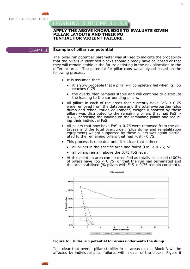
63
PAPER 3.2: CHAPTER 3
APPLY THE ABOVE KNOWLEDGE TO EVALUATE GIVEN PILLAR LAYOUTS AND THEIR POTENTIAL FOR VIOLENT FAILURE.
Example of pillar run potential
The ‘pillar run potential’ parameter was utilised to indicate the probability that the pillars in identified blocks should already have collapsed or that they will remain stable in the future assisting in the risk allocation to the different areas. The potential for pillar runs wasanalysed based on the following process:
• It is assumed that:
• it is 95% probable that a pillar will completely fail when its FoS reaches 0.75
• the overburden remains stable and will continue to distribute the loading to the surrounding pillars.
• All pillars in each of the areas that currently have FoS < 0.75 were removed from the database and the total overburden (plus dump and rehabilitation equipment) weight supported by these pillars was distributed to the remaining pillars that had FoS > 0.75, increasing the loading on the remaining pillars and reduc-ing their individual FoS.
• All pillars that now have FoS < 0.75 were removed from the da-tabase and the total overburden (plus dump and rehabilitation equipment) weight supported by these pillars was again distrib-uted to the remaining pillars that had FoS > 0.75.
• This process is repeated until it is clear that either:
• all pillars in the specific area had failed (FoS < 0.75) or
• all pillars remain above the 0.75 FoS level.
• At this point an area can be classified as totally collapsed (100% of pillars have FoS < 0.75) or that the run had terminated and the area stabilised (% pillars with FoS > 0.75 remain constant).
Figure 6: Pillar run potential for areas underneath the dump
It is clear that overall pillar stability in all areas except Block A will be affected by individual pillar failures within each of the blocks. Figure 6
LEARNING OUTCOME 3.1.3.9
EXAMPLE
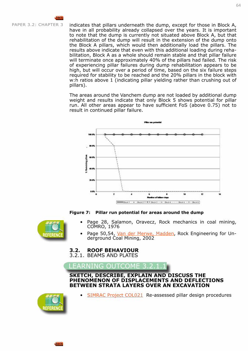
64
PAPER 3.2: CHAPTER 3 indicates that pillars underneath the dump, except for those in Block A, have in all probability already collapsed over the years. It is important to note that the dump is currently not situated above Block A, but that rehabilitation of the dump will result in the extension of the dump onto the Block A pillars, which would then additionally load the pillars. The results above indicate that even with this additional loading during reha-bilitation, Block A as a whole should remain stable and that pillar failure will terminate once approximately 40% of the pillars had failed. The risk of experiencing pillar failures during dump rehabilitation appears to be high, but will occur over a period of time, based on the six failure steps required for stability to be reached and the 20% pillars in the block with w:h ratios above 1 (indicating pillar yielding rather than crushing out of pillars).
The areas around the Vanchem dump are not loaded by additional dump weight and results indicate that only Block 5 shows potential for pillar run. All other areas appear to have sufficient FoS (above 0.75) not to result in continued pillar failure.
Figure 7: Pillar run potential for areas around the dump
• Page 28, Salamon, Oravecz, Rock mechanics in coal mining, COMRO, 1976
• Page 50,54, Van der Merwe, Madden, Rock Engineering for Un-derground Coal Mining, 2002
3.2. ROOF BEHAVIOUR3.2.1. BEAMS AND PLATES
SKETCH, DESCRIBE, EXPLAIN AND DISCUSS THE PHENOMENON OF DISPLACEMENTS AND DEFLECTIONS BETWEEN STRATA LAYERS OVER AN EXCAVATION
• SIMRAC Project COL021 Re-assessed pillar design procedures
LEARNING OUTCOME 3.2.1.1
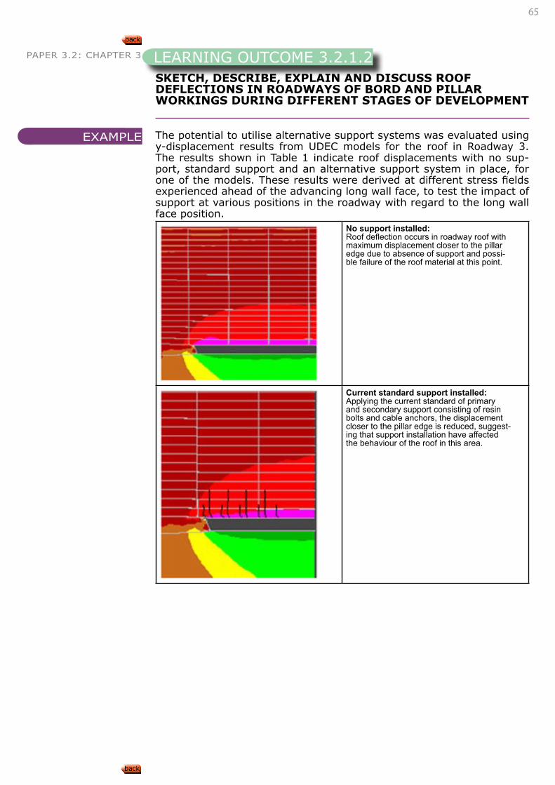
65
PAPER 3.2: CHAPTER 3
SKETCH, DESCRIBE, EXPLAIN AND DISCUSS ROOF DEFLECTIONS IN ROADWAYS OF BORD AND PILLAR WORKINGS DURING DIFFERENT STAGES OF DEVELOPMENT
The potential to utilise alternative support systems was evaluated using y-displacement results from UDEC models for the roof in Roadway 3. The results shown in Table 1 indicate roof displacements with no sup-port, standard support and an alternative support system in place, for one of the models. These results were derived at different stress fields experienced ahead of the advancing long wall face, to test the impact of support at various positions in the roadway with regard to the long wall face position.
No support installed:Roof deflection occurs in roadway roof with maximum displacement closer to the pillar edge due to absence of support and possi-ble failure of the roof material at this point.
Current standard support installed:Applying the current standard of primary and secondary support consisting of resin bolts and cable anchors, the displacement closer to the pillar edge is reduced, suggest-ing that support installation have affected the behaviour of the roof in this area.
LEARNING OUTCOME 3.2.1.2
EXAMPLE
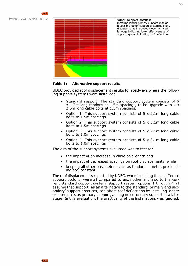
66
PAPER 3.2: CHAPTER 3 ‘Other’ Support installed:Installing longer primary support units as a possible ‘other’ support system solution, displacements increases closer to the pil-lar edge indicating lower effectiveness of support system in limiting roof deflection.
Table 1: Alternative support results UDEC provided roof displacement results for roadways where the follow-ing support systems were installed:
• Standard support: The standard support system consists of 5 x 1.2m long tendons at 1.5m spacings, to be upgrade with 4 x 2.5m long cable bolts at 1.5m spacings.
• Option 1: This support system consists of 5 x 2.1m long cable bolts to 1.5m spacings.
• Option 2: This support system consists of 5 x 3.1m long cable bolts to 1.5m spacings
• Option 3: This support system consists of 5 x 2.1m long cable bolts to 1.0m spacings
• Option 4: This support system consists of 5 x 3.1m long cable bolts to 1.0m spacings
The aim of the support systems evaluated was to test for:
• the impact of an increase in cable bolt length and
• the impact of decreased spacings on roof displacements, while
• keeping all other parameters such as tendon diameter, pre-load-ing etc. constant.
The roof displacements reported by UDEC, when installing these different support options, were all compared to each other and also to the cur-rent standard support system. Support system options 1 through 4 all assume that support, as an alternative to the standard ‘primary and sec-ondary’ support practices, can affect roof deflections by installing longer or more units as primary support, adding no secondary support at a later stage. In this evaluation, the practicality of the installations was ignored.
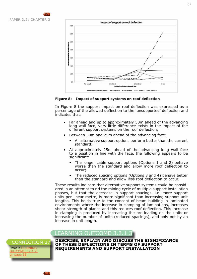
67
PAPER 3.2: CHAPTER 3
Figure 8: Impact of support systems on roof deflection
In Figure 8 the support impact on roof deflection was expressed as a percentage of the allowed deflection to the ‘unsupported’ deflection and indicates that:
• Far ahead and up to approximately 50m ahead of the advancing long wall face, very little difference exists in the impact of the different support systems on the roof deflection;
• Between 50m and 25m ahead of the advancing face:
• All alternative support options perform better than the current standard;
• At approximately 25m ahead of the advancing long wall face to a position in line with the face, the following appears to be significant:
• The longer cable support options (Options 1 and 2) behave worse than the standard and allow more roof deflection to occur;
• The reduced spacing options (Options 3 and 4) behave better than the standard and allow less roof deflection to occur.
These results indicate that alternative support systems could be consid-ered in an attempt to rid the mining cycle of multiple support installation phases, but that the decrease in support spacings, i.e. more support units per linear metre, is more significant than increasing support unit lengths. This holds true to the concept of beam building in laminated environments where the increase in clamping of laminations, increases shear strength of planes and this reduces roof deflection. This increase in clamping is produced by increasing the pre-loading on the units or increasing the number of units (reduced spacings), and only not by an increase in unit length.
DESCRIBE, EXPLAIN AND DISCUSS THE SIGNIFICANCE OF THESE DEFLECTIONS IN TERMS OF SUPPORT REQUIREMENTS AND SUPPORT INSTALLATION
LEARNING OUTCOME 3.2.1.3
Refer to LEARNING OUTCOME 3.2.1.2 on page 65
CONNECTION 27
68
PAPER 3.2: CHAPTER 3
SKETCH, DESCRIBE, EXPLAIN AND DISCUSS ROOF DEFLECTIONS AT INTERSECTIONS OF BORD AND PILLAR WORKINGS DURING DIFFERENT STAGES OF DEVELOPMENT
DESCRIBE, EXPLAIN AND DISCUSS THE SIGNIFICANCE OF THESE DEFLECTIONS IN TERMS OF SUPPORT REQUIREMENTS AND SUPPORT INSTALLATION
DESCRIBE, EXPLAIN AND DISCUSS HOW BEAM SPAN AND BEAM THICKNESS AFFECT BEAM STABILITY
• Page 174, Van der Merwe, Madden, Rock Engineering for Under-ground Coal Mining, 2002
SKETCH, DESCRIBE, EXPLAIN AND DISCUSS HOW HORIZONTAL COMPRESSIVE STRESSES ALLOW CRACKED BEAMS TO REMAIN STABLE
SKETCH, DESCRIBE, EXPLAIN AND DISCUSS HOW VOUSSOIR ARCH FORMATION ALLOWS CRACKED BEAMS TO REMAIN STABLE
Voussoir beams are defined as beams with fractures or joint situated in an environment where low/no horizontal stress exists and where the abutments are rigid. This has the result that horizontal stresses are created when the beam deflects, kinematically creating stability of the beam under certain conditions (length/thickness/material properties).By analysing the stresses in this beam, one of the following three failure modes can be estimated:
• Shear failure along the abutments,
• Crushing failure when the stress build-up exceeds the material strengths at critical positions near the abutments, or
• Buckling or snap-through failure when the normally thin beam fails due to excessive tension in the centre of the beam.
Based on work by Sofianos (1996), Ryder and Jager (2002) published the graph below that indicates possible failure modes, using a normal-ized f that is a function of the horizontal stiffness (Young’s Modulus) of
LEARNING OUTCOME 3.2.1.4
Refer to LEARNING OUTCOME 3.2.1.2 on page 65
CONNECTION 28
LEARNING OUTCOME 3.2.1.5
Refer to LEARNING OUTCOME 3.2.1.2 on page 65
CONNECTION 29
LEARNING OUTCOME 3.2.1.6
Refer to Paper 1, Outcome 2.1.11
CONNECTION 30
LEARNING OUTCOME 3.2.1.7
Refer to Paper 3.1 Outcome 3.1.1
CONNECTION 31
LEARNING OUTCOME 3.2.1.8
The word ‘voissour’ refers to the shape of a keyblock in a self-standing masonry arch.
INTERESTING INFO
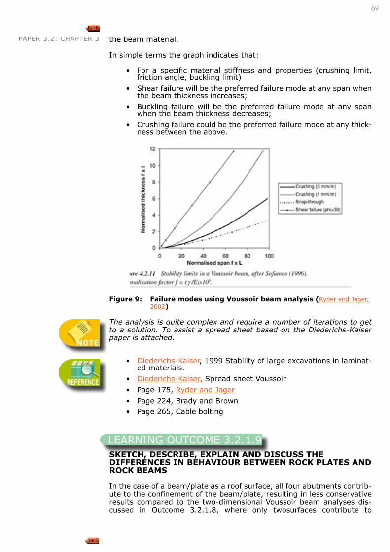
69
PAPER 3.2: CHAPTER 3 the beam material.
In simple terms the graph indicates that:
• For a specific material stiffness and properties (crushing limit, friction angle, buckling limit)
• Shear failure will be the preferred failure mode at any span when the beam thickness increases;
• Buckling failure will be the preferred failure mode at any span when the beam thickness decreases;
• Crushing failure could be the preferred failure mode at any thick-ness between the above.
Figure 9: Failure modes using Voussoir beam analysis (Ryder and Jager, 2002)
The analysis is quite complex and require a number of iterations to get to a solution. To assist a spread sheet based on the Diederichs-Kaiser paper is attached.
• Diederichs-Kaiser, 1999 Stability of large excavations in laminat-ed materials.
• Diederichs-Kaiser, Spread sheet Voussoir
• Page 175, Ryder and Jager
• Page 224, Brady and Brown
• Page 265, Cable bolting
SKETCH, DESCRIBE, EXPLAIN AND DISCUSS THE DIFFERENCES IN BEHAVIOUR BETWEEN ROCK PLATES AND ROCK BEAMS
In the case of a beam/plate as a roof surface, all four abutments contrib-ute to the confinement of the beam/plate, resulting in less conservative results compared to the two-dimensional Voussoir beam analyses dis-cussed in Outcome 3.2.1.8, where only twosurfaces contribute to
LEARNING OUTCOME 3.2.1.9
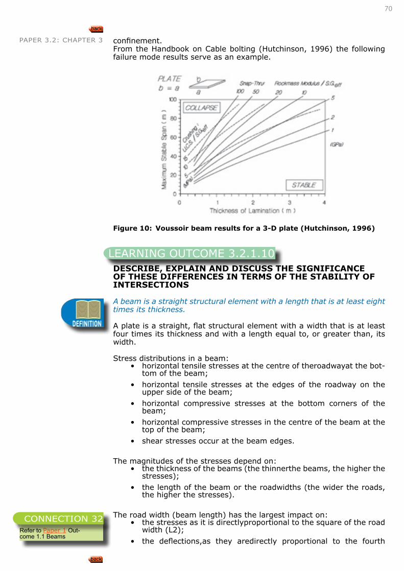
70
PAPER 3.2: CHAPTER 3 confinement.From the Handbook on Cable bolting (Hutchinson, 1996) the following failure mode results serve as an example.
Figure 10: Voussoir beam results for a 3-D plate (Hutchinson, 1996)
DESCRIBE, EXPLAIN AND DISCUSS THE SIGNIFICANCE OF THESE DIFFERENCES IN TERMS OF THE STABILITY OF INTERSECTIONS
A beam is a straight structural element with a length that is at least eight times its thickness.
A plate is a straight, flat structural element with a width that is at least four times its thickness and with a length equal to, or greater than, its width.
Stress distributions in a beam:• horizontal tensile stresses at the centre of theroadwayat the bot-
tom of the beam;
• horizontal tensile stresses at the edges of the roadway on the upper side of the beam;
• horizontal compressive stresses at the bottom corners of the beam;
• horizontal compressive stresses in the centre of the beam at the top of the beam;
• shear stresses occur at the beam edges.
The magnitudes of the stresses depend on:• the thickness of the beams (the thinnerthe beams, the higher the
stresses);
• the length of the beam or the roadwidths (the wider the roads, the higher the stresses).
The road width (beam length) has the largest impact on:• the stresses as it is directlyproportional to the square of the road
width (L2);
• the deflections,as they aredirectly proportional to the fourth
LEARNING OUTCOME 3.2.1.10
Refer to Paper 1 Out-come 1.1 Beams
CONNECTION 32
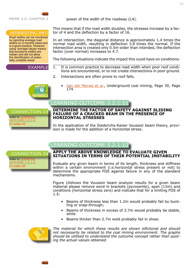
71
PAPER 3.2: CHAPTER 3 power of the width of the roadway (L4).
This means that if the road width doubles, the stresses increase by a fac-tor of 4 and the deflection by a factor of 16.
In an intersection, the diagonal distance is approximately 1.4 times the normal road width, resulting in deflection 3.8 times the normal. If the intersection area is created only 0.5m wider than intended, the deflection factor (over normal) increases to 4.7.
The following situations indicate the impact this could have on conditions:
1. It is common practice to decrease road width when poor roof condi-tions are encountered, or to not create intersections in poor ground.
2. Intersections are often prone to roof falls.
• Van der Merwe et al., Underground coal mining, Page 30, Page 174
DETERMINE THE FACTOR OF SAFETY AGAINST SLIDING FAILURE OF A CRACKED BEAM IN THE PRESENCE OF HORIZONTAL STRESSES
In the application of the Diederichs-Kaiser Voussoir beam theory, provi-sion is made for the addition of a horizontal stress.
APPLY THE ABOVE KNOWLEDGE TO EVALUATE GIVEN SITUATIONS IN TERMS OF THEIR POTENTIAL INSTABILITY
Evaluate any given beam in terms of its length, thickness and stiffness within a certain environment (i.e.horizontal stress present or not) to determine the appropriate FOS against failure in any of the standard mechanisms.
Figure 10shows the Voussoir beam analysis results for a given beam material please remove word in brackets (pyroxenite), span (12m) and conditions (horizontal stress zero) and indicate that for a limiting FOS of 1.5:
• Beams of thickness less than 1.2m would probably fail by buck-ling or snap-through;
• Beams of thickness in excess of 2.7m would probably be stable, while
• Beams thicker than 2.7m wold probably fail in shear.
The material for which these results are shown isfictional and should not necessarily be related to the coal mining environment. The graphs should be utilised to understand the outcome concept rather than quot-ing the actual values obtained.
Road widths can be monitored by reporting average road widths on a monthly basis and is a good practice. However, using ‘average’values means that excessive widths are hidden and will not allow the identification of poten-tially unstable areas.
INTERESTING INFO
EXAMPLE
LEARNING OUTCOME 3.2.1.11
Refer to LEARNING OUTCOME 3.2.1.8 on page 68
CONNECTION 33
LEARNING OUTCOME 3.2.1.12
Refer to LEARNING OUTCOME 3.2.1.8 on page 68
CONNECTION 34

72
PAPER 3.2: CHAPTER 3
Figure 11: Voussoir beam analysis for given conditions (Diederichs-Kaiser, 1999)
APPLY THE ABOVE KNOWLEDGE TO DETERMINE APPROPRIATE REMEDIAL MEASURES TO IMPROVE STABILITY.
Assuming the material is given and cannot be changed, remedial action typically consists of:
• Reduction of beam length
• Increase of beam thickness.
In the case of the example in “LEARNING OUTCOME 3.2.1.12”, the fol-lowing option becomes possible:
• Installing bolting to ensure a roof beam thickness of more than 1.2m thickness is created.
• Page 5, Van derMerwe, Madden, Rock Engineering for Under-ground Coal Mining, 2002
LEARNING OUTCOME 3.2.1.13
Refer to LEARNING OUTCOME 3.2.1.12 on page 71
CONNECTION 35
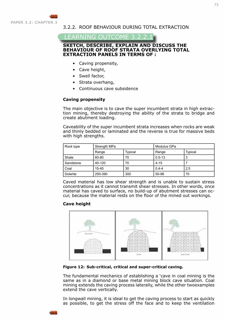
73
PAPER 3.2: CHAPTER 3 3.2.2. ROOF BEHAVIOUR DURING TOTAL EXTRACTION
SKETCH, DESCRIBE, EXPLAIN AND DISCUSS THE BEHAVIOUR OF ROOF STRATA OVERLYING TOTAL EXTRACTION PANELS IN TERMS OF :
• Caving propensity,
• Cave height,
• Swell factor,
• Strata overhang,
• Continuous cave subsidence
Caving propensity
The main objective is to cave the super incumbent strata in high extrac-tion mining, thereby destroying the ability of the strata to bridge and create abutment loading.
Caveability of the super incumbent strata increases when rocks are weak and thinly bedded or laminated and the reverse is true for massive beds with high strengths.
Rock type Strength MPa Modulus GPaRange Typical Range Typical
Shale 60-80 70 0.5-13 3Sandstone 40-120 70 4-15 7Coal 15-45 30 0.4-4 2.5Dolerite 250-390 300 50-98 70
Caved material has low shear strength and is unable to sustain stress concentrations as it cannot transmit shear stresses. In other words, once material has caved to surface, no build-up of abutment stresses can oc-cur, because the material rests on the floor of the mined out workings.
Cave height
Figure 12: Sub-critical, critical and super-critical caving.
The fundamental mechanics of establishing a ‘cave in coal mining is the same as in a diamond or base metal mining block cave situation. Coal mining extends the caving process laterally, while the other twoexamples extend the cave vertically.
In longwall mining, it is ideal to get the caving process to start as quickly as possible, to get the stress off the face and to keep the ventilation
LEARNING OUTCOME 3.2.2.1
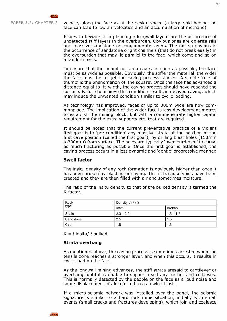
74
PAPER 3.2: CHAPTER 3 velocity along the face as at the design speed (a large void behind the face can lead to low air velocities and an accumulation of methane).
Issues to beware of in planning a longwall layout are the occurrence of undetected stiff layers in the overburden. Obvious ones are dolerite sills and massive sandstone or conglomerate layers. The not so obvious is the occurrence of sandstone or grit channels (that do not break easily) in the overburden that may lie parallel to the face, which come and go on a random basis.
To ensure that the mined-out area caves as soon as possible, the face must be as wide as possible. Obviously, the stiffer the material, the wider the face must be to get the caving process started. A simple ‘rule of thumb’ is the phenomenon of ‘the square’. Once the face has advanced a distance equal to its width, the caving process should have reached the surface. Failure to achieve this condition results in delayed caving, which may induce the unwanted condition similar to cyclic loading.
As technology has improved, faces of up to 300m wide are now com-monplace. The implication of the wider face is less development metres to establish the mining block, but with a commensurate higher capital requirement for the extra supports etc. that are required.
It should be noted that the current preventative practice of a violent first goaf is to ‘pre-condition’ any massive strata at the position of the first cave position (called the first goaf), by drilling blast holes (150mm to200mm) from surface. The holes are typically ‘over-burdened’ to cause as much fracturing as possible. Once the first goaf is established, the caving process occurs in a less dynamic and ‘gentle’ progressive manner.
Swell factor
The insitu density of any rock formation is obviously higher than once it has been broken by blasting or caving. This is because voids have been created and they are then filled with air and sometimes moisture.
The ratio of the insitu density to that of the bulked density is termed the K-factor.
Rocktype
Density t/m3 (ℓ)Insitu Broken
Shale 2.3 – 2.5 1.3 – 1.7Sandstone 2.5 1.5Coal 1.8 1.3
K = ℓ insitu/ ℓ bulked
Strata overhang
As mentioned above, the caving process is sometimes arrested when the tensile zone reaches a stronger layer, and when this occurs, it results in cyclic load on the face.
As the longwall mining advances, the stiff strata aresaid to cantilever or overhang, until it is unable to support itself any further and collapses. This is normally detected by the people on the face as a loud noise and some displacement of air referred to as a wind blast.
If a micro-seismic network was installed over the panel, the seismic signature is similar to a hard rock mine situation, initially with small events (small cracks and fractures developing), which join and coalesce
75
PAPER 3.2: CHAPTER 3 to generate the main failure fracture.
The supports on face detect the overhang by reaching their ‘yield’ load quickly and this usually occurs in the centre portion of the face, first.
Continuous cave subsidence
This occurs once the tensile zone has fully developed on surface and, if the face advances 100m, the subsidence front also advances 100m. The subsidence front often appears like a ‘boat ploughing through water’ in that the front is curved and usually lags by the ratio of the caving angle, from the actual face position.
DESCRIBE, EXPLAIN AND DISCUSS HOW FACTORS SUCH AS THE STRENGTH AND BEDDING OF ROOF STRATA AFFECT THE SWELL FACTOR OF STRATA
Coal, being a sedimentary type of deposit, is normally surrounded by sedimentary rocks such as mud, silt and sandstone. The increasing levels of clay content are accompanied by decreasing levels of insitu strength.
The occurrence of igneous dolerite dykes and sills iswell documented in the literature. These features only play a role in coal mining if they have not burnt the coal very much. Some heating from igneous activity can improve the grade of the coal, but it can also decrease the coal quality by burning it. This degree of burning is indicated by a laboratory measured factor called the dry, ash-free volatile (DAFV) content of the coal, and the minimum gate value is 25% for steam coal market. A value less than 25% indicates coal affected by insitu devolatising, and is usually uneco-nomic and is difficult to mine on account of a high density of slickensided joints.
Both the sedimentary and igneous rocks display anisotropic behaviour. The sedimentary rock structure is controlled by bedding that captures the deposition process of the deposit and is parallel to the coal seam. As with all sedimentary deposits, as the water is expelled from the material, some shrinkage occurs and this will result in a minimum of two orthogo-nal joint sets.
The igneous rock structure is usually controlled by the cooling process and the joints are perpendicular to the rock’s smallest dimension, i.e. in sills the joints are predominantly vertical and in dykes they are horizontal.
Rock strength properties are in the main controlled by their tensile and unconfined compressive strengths (UCS). Typically, the tensile strength is stated as being 10% of the UCS.
As caving is induced by tensile stress, it is the tensile strength of the rockmass that will contribute initially to the caving process. Once abut-ments are established, fresh, stress-driven fractures will develop parallel to the face and the panel sides, further degrading the rockmass.
As the rockmass breaks up, depending upon its make-up, it will form a muck or broken rock pile. If it consists of shale and mudstone, it will generate slabs that slide laterally or ‘flush’, and if it is sandstone, it will create blocks that are less laterally mobile. The broken dolerite is not normally seen, as it has to be far from the coal not to have burnt it!
The swell factor of the various materials is described in the table above.
LEARNING OUTCOME 3.2.2.2
76
PAPER 3.2: CHAPTER 3
DESCRIBE, EXPLAIN AND DISCUSS HOW FACTORS SUCH AS THE STRENGTH AND BEDDING OF ROOF STRATA AFFECT THE OVERHANG OF STRATA
The ability of a strata unit to ‘overhang’ is a function of its stiffness in resisting bending caused by its deadweight as the weaker material un-derneath it fails and falls away.For a unit to maintain its stability reflects how thick it is, how many well-defined bedding planes exist in it and the development of continuous or through going joints. Horizontal stress may assist in getting the stiff unit to deflect.
As alluded to above, the contacts between sedimentary beds often re-flect the last material to settle out of the depositional water, and these usually consist of platy materials such as clay and mica flakes.
These materials display very low cohesion across their surfaces and therefore greatly assist in getting bedding units to delaminate and ac-celerate the caving process.
DESCRIBE, EXPLAIN AND DISCUSS HOW A STRONG SANDSTONE BEAM OR DOLERITE SILL WILL AFFECT THE ROOF BEHAVIOUR OF TOTAL EXTRACTION PANELS
These layers, being stronger, temporarily arrest the continuous caving process and are the cause of ‘cyclic loading’. Sometimes, a void may oc-cur below the stiff layer and can accumulate methane, which is violently expelled into the goaf and face area when the stiff layer fails.
DESCRIBE, EXPLAIN AND DISCUSS HOW A STRONG SANDSTONE BEAM OR DOLERITE SILL WILL AFFECT LOADING OF THE ABUTMENTS OF TOTAL EXTRACTION PANELS
When a strong layer arrests the caving process to surface, the strata bridge across the panel and increase the loading onto the abutments or sides of the panel.This extra loading results in the coal face becoming softer to cut as it is pre-fractured. This may be a benefit initially, but if the problem layer does not fail, then a face break may result, possibly with some damage in the tailgate. The increased stress also holds the fractured coal and rock together, but the moment the bridging layer fails, the stress level on the fractured material drops, often to a point that face and gate road falls are exacerbated (the corollary in hard rock mining is the overstoping of a stressed crosscut or haulage).
LEARNING OUTCOME 3.2.2.3
LEARNING OUTCOME 3.2.2.4
LEARNING OUTCOME 3.2.2.5
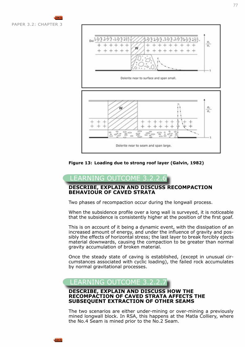
77
PAPER 3.2: CHAPTER 3
Figure 13: Loading due to strong roof layer (Galvin, 1982)
DESCRIBE, EXPLAIN AND DISCUSS RECOMPACTION BEHAVIOUR OF CAVED STRATA
Two phases of recompaction occur during the longwall process.
When the subsidence profile over a long wall is surveyed, it is noticeable that the subsidence is consistently higher at the position of the first goaf.
This is on account of it being a dynamic event, with the dissipation of an increased amount of energy, and under the influence of gravity and pos-sibly the effects of horizontal stress; the last layer to break forcibly ejects material downwards, causing the compaction to be greater than normal gravity accumulation of broken material.
Once the steady state of caving is established, (except in unusual cir-cumstances associated with cyclic loading), the failed rock accumulates by normal gravitational processes.
DESCRIBE, EXPLAIN AND DISCUSS HOW THE RECOMPACTION OF CAVED STRATA AFFECTS THE SUBSEQUENT EXTRACTION OF OTHER SEAMS
The two scenarios are either under-mining or over-mining a previously mined longwall block. In RSA, this happens at the Matla Colliery, where the No.4 Seam is mined prior to the No.2 Seam.
LEARNING OUTCOME 3.2.2.6
LEARNING OUTCOME 3.2.2.7
78
PAPER 3.2: CHAPTER 3 Under-mining situation
Mining under a previously mined goaf is easy to perform with relatively fewer problems than mining over a goaf and has no time delay constraints.The condition of the middling (floor of upper and roof of lower seam) between the two seams is the main concern. Face parallel fractures gen-erated on the first face may extend down to the lower seam.
The side abutments left from chain or barrier pillars of the upper seam may cause some stress issues. There are well documented cases where pillars are stated to have caused punching when the lower panel was offset to accommodate surface subsidence, but all too often it is a man-made problem when things go wrong on a longwall face!
If the middling is very narrow and fractured, the supports may disturb the roof when they are set.
An issue that affects the people on the lower seam is that large accumu-lations of water may have occurred in the goaf of the upper seam, and when the middling breaks, the face may become flooded causing the face to stop.
In summary, the recompaction of caved strata has a negligible impact on the mining of a lower seam.
Over-mining situation
The custom and practice in mining districts where over-mining is prac-tised is to leave the area to settle for at least fiveyears.
Currently, there are no known situations in South Africa of such a mining configuration, but it may occur in the future, particularly with the No.5 Seam
As the rockmass has been disturbed, the integrity of bedding has been broken and there is very little confinement to hold key blocks togeth-er, and leaving the ground to settle allows some re-confinement to be established.
The quantum of subsidence over barrier and chain pillars is reduced when compared to the fully goafed area. This results in rapid gradient changes, which are undesirable in a longwall mining face.
To accommodate this, the secondary panels are established within the uniformly subsided area, which infers the panels are shorter.
When the supports are ‘set’ (pressurised), the issue of the floor being pushed down and the roof being pushed up occurs! This is the main reason why the goafed area needs to be left to re-consolidate prior to mining.
Of interest is that the ventilation system needs to be a ‘force’ system, as compared to an ‘exhaust’ system, which can draw noxious gases out of the surrounding old goaf material, confirming that the goaf has not completely re-compacted!
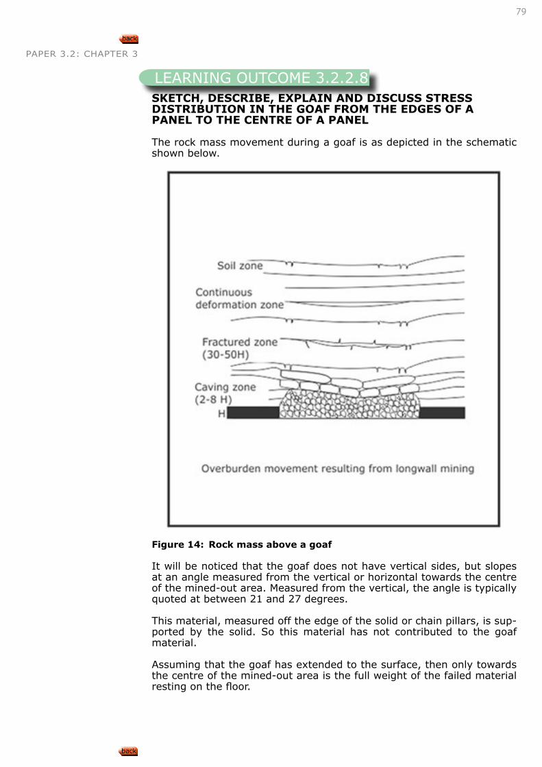
79
PAPER 3.2: CHAPTER 3
SKETCH, DESCRIBE, EXPLAIN AND DISCUSS STRESS DISTRIBUTION IN THE GOAF FROM THE EDGES OF A PANEL TO THE CENTRE OF A PANEL
The rock mass movement during a goaf is as depicted in the schematic shown below.
Figure 14: Rock mass above a goaf
It will be noticed that the goaf does not have vertical sides, but slopes at an angle measured from the vertical or horizontal towards the centre of the mined-out area. Measured from the vertical, the angle is typically quoted at between 21 and 27 degrees.
This material, measured off the edge of the solid or chain pillars, is sup-ported by the solid. So this material has not contributed to the goaf material.
Assuming that the goaf has extended to the surface, then only towards the centre of the mined-out area is the full weight of the failed material resting on the floor.
LEARNING OUTCOME 3.2.2.8
80
PAPER 3.2: CHAPTER 3
EVALUATE AND PREDICT ROOF CAVING BEHAVIOUR FOR GIVEN SETS OF CIRCUMSTANCES
As described above, the weaker the roof material, the easier it is to cave. If the roof is a very weak mudstone, the mine operator may be forced to leave a substantial amount of coal in the roof to increase its strength in face area. This technique does not materially affect the caving behaviour once it is behind the caving line of the longwall supports.
EVALUATE AND PREDICT STRESSES IN WORKINGS FOR GIVEN SETS OF CIRCUMSTANCES
This situation is difficult to determine if the panel does not have many monitoring points around it and is therefore subject to ‘opinion’ and is very subjective. If monitoring is available, then a simple numerical model would be a technique to employ to determine stress levels.
‘Workings’ could be defined as in the chain or main road development and in the face area during a panel withdrawal.
It is important to ensure longwall panels are restricted on how close they can mine to the main development. No abutment stresses from the long-wall should carried by the pillars in the main development, as the access and coal clearance systems for the life of the mine have to pass through that area and no time-related deterioration may be tolerated.
Q 3.2.2
A continuous 10.0m wide barrier pillar, at a depth of 150m divides two goafed areas, with a goaf angle of 210 on either side.
Calculate the average pillar stress/m2 of the barrier pillar. State any assumptions.
Assumptions: Density of strata is 2500kg/m3, the goaf angle extends from the top corner of the pillar, in a continuous straight line to surface.
The candidate should construct a simple line diagram, depicting the cross section view of the situation. The first unknown to be determined is the distance, on surface, from the plan pillar edge to the start of the subsid-ence. This found from the right angled triangle formed.
Tan 210 = unknown distance/150mUnknown distance = 57.6m
Volume of cantilevered block = 2 x (57.6 X 150)/2 = 8640m3
Total rock volume supported on 10m wide pil-lar = 1500 + 8640 = 10140m3
LEARNING OUTCOME 3.2.2.9
LEARNING OUTCOME 3.2.2.10
EXAMPLE
81
PAPER 3.2: CHAPTER 3 Total mass supported on pillar = 10140 x 2.5 = 25350 x 103Kg
Convert mass into force = 25350 x 9.81 X 103 = 248.6MN
Average pillar stress = 248.6/10 = 24.9 mPa
• Page 77,86, Salamon, Oravecz, Rock mechanics in coal mining, COMRO, 1976
3.2.3. INFLUENCE OF DOLERITE SILLS
DESCRIBE, EXPLAIN AND DISCUSS THE EFFECTS OF DOLERITE SILLS ON STRATA BEHAVIOUR IN THE FOLLOWING MINING SITUATIONS :
• Bord and pillar operations,
• Stooping operations,
• Long wall operations
Bord and pillar operations
Galvin wrote, based on Salamon and Oravecz (1975): It may be stated that pillar stiffness decreases with decreasing pillar width, decreasing material modulus and increasing pillar height. The stiffness of the sur-rounding strata decreases with increasing the panel width, decreasing material modulus and decreasing strata thickness. As the ratio of sur-rounding strata stiffness:pillar stiffness increases the load acting on a panel pillar decreases.
In order to satisfy equilibrium conditions, a reduction in the load act-ing on panel pillars must result in an increase in the load acting on the panel abutments. Almost invariably, inter-panel pillars, or barrier pil-lars, constitute two or more of the panel abutments. Therefore, the load acting on the inter-panel pillars will be greater than that calculated by the modified cover load, or tributary area theory (TAT). However, since inter-panel pillars are usually designed to a width:height ratio exceeding 8 and often 10, which is considered sufficient to make the pillars inde-structible, the increased load acting on these pillars will have a negligible effect on their stability. It should also be noted that when panel widths exceed about twice the seam depth, pillars in the centre of a panel are usually subjected to the full modified cover load regardless of the nature of the surrounding strata. The ratio of surrounding strata stiffness:coal strata stiffness also has a significant influence on the manner in which a collapse of bord and pillar workings occurs. This phenomenon has been described in detail by Salamon (1968), as well as Salamon and Oravecz (1975). It suffices to note that, should pillar load exceed pillar strength, the possibility of an unstable, or sudden uncontrollable, pillar collapse reduces as the magnitude of the surrounding strata stiffness:coal strata stiffness increases.
From the discussion, it may be stated for all other parameters constant
LEARNING OUTCOME 3.2.3.1
82
PAPER 3.2: CHAPTER 3 that as the modulus of elasticity of the strata surrounding a panel of lim-ited width (less than twice the depth) increases:
• the load acting on the panel pillars decreases while the load act-ing on inter-panel pillar increases, and
• the possibility of a sudden pillar collapse occurring reduces.
Therefore, it can be concluded that the presence of a massive dolerite sill in the roof strata of limited width bord and pillar panels separated by substantial inter-panel pillars results in an effective increase in the stabil-ity of the workings.
This conclusion should be verified by the practitioner using a numerical model such as MAP3D or equivalent.
Galvin further stated that thesolutions from numerical modelling veri-fy that when a massive dolerite sill is present in the super incumbent strata, the load acting on pillars in a panel of limited width is reduced significantly whilst the load acting on panel abutments is increased. In addition, as panel width increases, the load acting on pillars in the centre of the panel approaches that based on the modified cover load theory (TAT), irrespective of the presence of a massive dolerite sill in the super incumbent strata.
Finally, it is worth noting that the presence of a massive dolerite sill above bord and pillar workings can serve to mask the effects of under-sized pillars. At moderate panel widths, such pillars may not appear to be overloaded because they do not carry the full weight of the overburden. However, if the panel width continues to be increased, deflection of the dolerite sill will also increase, thereby increasing the load acting on the pillars. Eventually, the pillars in the centre of the panel may fail, resulting in a load transfer on the adjacent pillars. This behaviour, in conjunction with the fact that when the area of mining is large, the surrounding strata will behave as a ‘soft testing machine’, may result in a sudden, uncontrollable collapse of the bord and pillar workings.
The Coalbrook disaster of 1960 bears testament to this behaviour. Within a 20-minute period, more than 4000 pillars underlying a 36m dolerite sill failed. This disaster also emphasises the need to limit panel dimensions by leaving inter-panel pillars.
Stooping and long wall operations
Galvin grouped both mining methods under the terminology ‘total’ ex-traction workings, which are both practised extensively beneath massive dolerite sills in South African coal fields.
If pillar extraction operations are conducted such that negligible coal is left unrecovered in the form of snooks, fenders and the like, then the behaviour and influence of massive dolerite sills in the super incumbent strata are very similar to that in longwall mining. Therefore, no distinc-tion has been made between the two operations for the purpose of the present discussion.
The minimum panel dimension is the most important factor in inducing failure of an undermined massive dolerite sill. Experience has shown that, typically, this dimension must be at least 180m if failure of a mas-sive sill is to be achieved. When the minimum panel dimension is less than 150m, a massive sill will usually bridge over an entire panel, or even a number of adjacent panels if the inter-panel pillars are sufficiently wide.
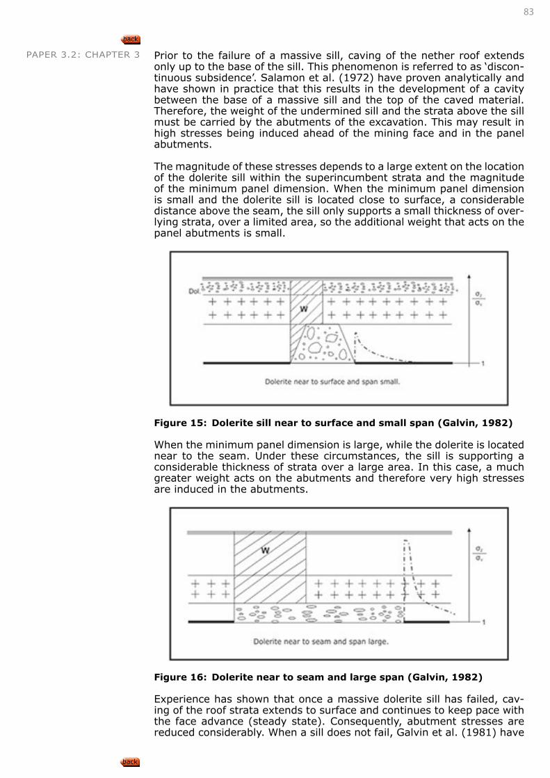
83
PAPER 3.2: CHAPTER 3 Prior to the failure of a massive sill, caving of the nether roof extends only up to the base of the sill. This phenomenon is referred to as ‘discon-tinuous subsidence’. Salamon et al. (1972) have proven analytically and have shown in practice that this results in the development of a cavity between the base of a massive sill and the top of the caved material. Therefore, the weight of the undermined sill and the strata above the sill must be carried by the abutments of the excavation. This may result in high stresses being induced ahead of the mining face and in the panel abutments.
The magnitude of these stresses depends to a large extent on the location of the dolerite sill within the superincumbent strata and the magnitude of the minimum panel dimension. When the minimum panel dimension is small and the dolerite sill is located close to surface, a considerable distance above the seam, the sill only supports a small thickness of over-lying strata, over a limited area, so the additional weight that acts on the panel abutments is small.
Figure 15: Dolerite sill near to surface and small span (Galvin, 1982)
When the minimum panel dimension is large, while the dolerite is located near to the seam. Under these circumstances, the sill is supporting a considerable thickness of strata over a large area. In this case, a much greater weight acts on the abutments and therefore very high stresses are induced in the abutments.
Figure 16: Dolerite near to seam and large span (Galvin, 1982)
Experience has shown that once a massive dolerite sill has failed, cav-ing of the roof strata extends to surface and continues to keep pace with the face advance (steady state). Consequently, abutment stresses are reduced considerably. When a sill does not fail, Galvin et al. (1981) have
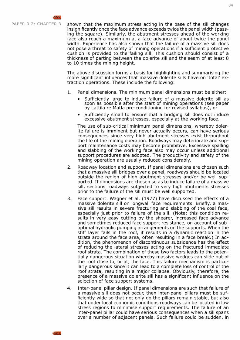
84
PAPER 3.2: CHAPTER 3 shown that the maximum stress acting in the base of the sill changes insignificantly once the face advance exceeds twice the panel width (pass-ing the square). Similarly, the abutment stresses ahead of the working face also reach a maximum at a face advance of about twice the panel width. Experience has also shown that the failure of a massive sill does not pose a threat to safety of mining operations if a sufficient protective cushion is provided to the failing sill. This cushion should consist of a thickness of parting between the dolerite sill and the seam of at least 8 to 10 times the mining height.
The above discussion forms a basis for highlighting and summarising the more significant influences that massive dolerite sills have on ‘total’ ex-traction operations. These include the following:
1. Panel dimensions. The minimum panel dimensions must be either:
• Sufficiently large to induce failure of a massive dolerite sill as soon as possible after the start of mining operations (see paper by Lattila re Matla pre-conditioning for revised syllabus), or
• Sufficiently small to ensure that a bridging sill does not induce excessive abutment stresses, especially at the working face.
The use of sub-critical minimum panel dimensions, whereby doler-ite failure is imminent but never actually occurs, can have serious consequences since very high abutment stresses exist throughout the life of the mining operation. Roadways may deteriorate and sup-port maintenance costs may become prohibitive. Excessive spalling and slabbing of the working face also may occur unless additional support procedures are adopted. The productivity and safety of the mining operation are usually reduced considerably.
2. Roadway location and support. If panel dimensions are chosen such that a massive sill bridges over a panel, roadways should be located outside the region of high abutment stresses and/or be well sup-ported. If dimensions are chosen so as to induce failure of a massive sill, sections roadways subjected to very high abutments stresses prior to the failure of the sill must be well supported.
3. Face support. Wagner et al. (1977) have discussed the effects of a massive dolerite sill on longwall face requirements. Briefly, a mas-sive sill results in severe fracturing and slabbing of the coal face, especially just prior to failure of the sill. (Note: this condition re-sults in very easy cutting by the shearer, increased face advance and sometimes reduced face support resistance, on account of sub-optimal hydraulic pumping arrangements on the supports. When the stiff layer fails in the roof, it results in a dynamic reaction in the strata around the face area, often resulting in a face break.) In ad-dition, the phenomenon of discontinuous subsidence has the effect of reducing the lateral stresses acting on the fractured immediate roof strata. The combination of these two factors leads to the poten-tially dangerous situation whereby massive wedges can slide out of the roof close to, or at, the face. This failure mechanism is particu-larly dangerous since it can lead to a complete loss of control of the roof strata, resulting in a major collapse. Obviously, therefore, the presence of a massive dolerite sill has a significant influence on the selection of face support systems.
4. Inter-panel pillar design. If panel dimensions are such that failure of a massive sill does not occur, then inter-panel pillars must be suf-ficiently wide so that not only do the pillars remain stable, but also that under local economic conditions roadways can be located in low stress regions to minimise support requirements. The failure of an inter-panel pillar could have serious consequences when a sill spans over a number of adjacent panels. Such failure could be sudden, in
85
PAPER 3.2: CHAPTER 3 view of the soft nature of the loading system, and not only lead to the failure of neighbouring pillars, but also result in large airblasts and high concentrations of methane in the mine ventilation system. When it is proposed to fail overly massive sills, the width of inter-panel pillars is based on the need to locate roadways for adjacent panels in low stress regions.
5. Surface subsidence. Schumann (1979, 1981) has analysed surface strains and tilts associated with the failure of massive dolerite sills and has concluded that they are sufficiently large to cause severe damage to any surface structure in the vicinity.
6.
This model has not been proven applicable to all conditions.
Previous investigations and theories
1. Elastic thin plate
The summary of various researchers was summarised by Galvin as follows:
Prior to failure of a massive dolerite sill, caving of the roof strata only extends up to (or near) the base of the sill. As a result of this discontinuous subsidence, a gap forms between the top of the caved material and the base of the un-caved strata.
The possibility of a sudden and violent failure of a dolerite sill can be excluded.
After the initial failure of a dolerite sill, the progress of subsidence keeps pace with the progress of mining. (This is the steady state condition; however, cycles of dolerite ‘overhang-ing’ and then failing are termed cycles and the effects are referred to as cyclic loading.)
A close agreement exists between measured displacements and those derived from elastic theory. This supports the concept that a massive dolerite sill (or other stiff layer) behaves as an elastic plate, at least up to a spanthatcorresponds to its failure.
2. Refined elastic thin plate model
Following further work at Coalbrook Collieries, failure of a dol-erite sill did not occur as was previously predicted.
Following this experience, a review of the elastic thin plate model was undertaken by Wag-ner and Galvin (1977). Particular attention was given to critical stress Sigma c, defined as:
σc=Kr ((Dd S2)/(td
2 ))
σc=Kr (1400Dd/td -800)
S=(1400tD-(800((td2)/Dd ))
0.5
Where σc is the critical stress to break the sill,DD/ tD is the depth to thickness ratio of the dolerite sill, and DD = depth to the base of the dolerite sill, tD vertical thickness of the dolerite sill,
K is a (specific weight) constant (MN/m3)
S = is the minimum panel dimension required to induce failure of a sill,Values 1400 and 800 are in metres
At the time the researchers concluded that the term DD/TD accounted for the effects of weathering on the strength of a dolerite sill. At a greater depth, a sill would be less weath-ered and therefore more competent than a sill near surface. Consequently, a greater stress would be required to induce failure of the deeper sill. Circumstances at the time did not warrant further development of this concept, with the result that Galvan’s equa-tion has been used extensively to date for the design oflongwall panel dimensions.
INTERESTING INFO
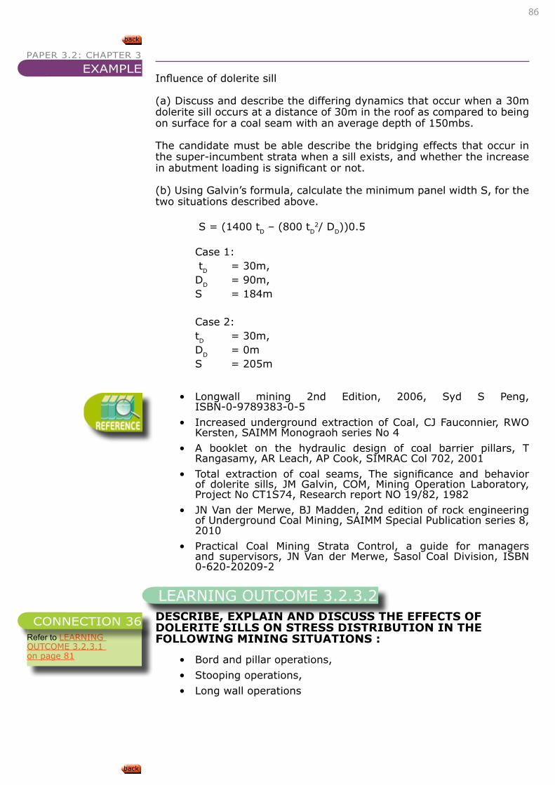
86
PAPER 3.2: CHAPTER 3
Influence of dolerite sill
(a) Discuss and describe the differing dynamics that occur when a 30m dolerite sill occurs at a distance of 30m in the roof as compared to being on surface for a coal seam with an average depth of 150mbs.
The candidate must be able describe the bridging effects that occur in the super-incumbent strata when a sill exists, and whether the increase in abutment loading is significant or not.
(b) Using Galvin’s formula, calculate the minimum panel width S, for the two situations described above.
S = (1400 tD – (800 tD2/ DD))0.5
Case 1: tD = 30m, DD = 90m, S = 184m
Case 2:tD = 30m, DD = 0m S = 205m
• Longwall mining 2nd Edition, 2006, Syd S Peng, ISBN-0-9789383-0-5
• Increased underground extraction of Coal, CJ Fauconnier, RWO Kersten, SAIMM Monograoh series No 4
• A booklet on the hydraulic design of coal barrier pillars, T Rangasamy, AR Leach, AP Cook, SIMRAC Col 702, 2001
• Total extraction of coal seams, The significance and behavior of dolerite sills, JM Galvin, COM, Mining Operation Laboratory, Project No CT1S74, Research report NO 19/82, 1982
• JN Van der Merwe, BJ Madden, 2nd edition of rock engineering of Underground Coal Mining, SAIMM Special Publication series 8, 2010
• Practical Coal Mining Strata Control, a guide for managers and supervisors, JN Van der Merwe, Sasol Coal Division, ISBN 0-620-20209-2
DESCRIBE, EXPLAIN AND DISCUSS THE EFFECTS OF DOLERITE SILLS ON STRESS DISTRIBUTION IN THE FOLLOWING MINING SITUATIONS :
• Bord and pillar operations,
• Stooping operations,
• Long wall operations
EXAMPLE
LEARNING OUTCOME 3.2.3.2
Refer to LEARNING OUTCOME 3.2.3.1 on page 81
CONNECTION 36
87
PAPER 3.2: CHAPTER 3
DESCRIBE, EXPLAIN AND DISCUSS THE APPLICATION OF GALVIN’S EQUATIONS FOR DETERMINING CRITICAL SPANS OF DOLERITE SILLS
DESCRIBE, EXPLAIN AND DISCUSS THE LIMITATIONS OF GALVIN’S EQUATIONS FOR DETERMINING CRITICAL SPANS OF DOLERITE SILLS
APPLY GALVIN’S EQUATIONS TO DETERMINE CRITICAL SPANS FOR THE FAILURE OF DOLERITE SILLS
APPLY THE ABOVE KNOWLEDGE TO THE DESIGN OF TOTAL EXTRACTION AND ROOM AND PILLAR WORKINGS
• Page 89, Salamon, Oravecz, Rock mechanics in coal mining, COMRO, 1976
3.3. SUBSIDENCE
• Page 108, Salamon, Oravecz, Rock mechanics in coal mining, COMRO, 1976
LEARNING OUTCOME 3.2.3.3
Refer to LEARNING OUTCOME 3.2.3.1 on page 81
CONNECTION 37
LEARNING OUTCOME 3.2.3.4
Refer to LEARNING OUTCOME 3.2.3.1 on page 81
CONNECTION 38
LEARNING OUTCOME 3.2.3.5
Refer to LEARNING OUTCOME 3.2.3.1 on page 81
CONNECTION 39
LEARNING OUTCOME 3.2.3.6
Refer to LEARNING OUTCOME 3.2.3.1 on page 81
CONNECTION 40
LEARNING OUTCOME 3.3.1
See Outcome 8.1 andRefer to Paper 3.1, Out-comes 6.2.3, 8.1 and 8.2
CONNECTION 41
88
PAPER 3.2: CHAPTER 4
PAPER 3.2 SOFT ROCK TABULAR MINING
4. MINING LAYOUT4.1. MINING LAYOUT STRATEGIES4.1.1. ROOM AND PILLAR
The candidate must be able to demonstrate knowledge and understand-ing of the above subject area by being able to:
• Sketch, describe, explain and discuss the following types of room and pillar mining:
• Drilling and blasting,
• Mechanical breaking
• Describe, explain and discuss the following aspects of each of the above methods:
• Panel layout,
• Ventilation method,
• Coal transport,
• Main equipment,
• Describe, explain and discuss the following coal winning methods:
• Top coaling, bottom coaling,
• Determine areal and volumetric percentage extraction in room and pillar layouts;
• Determine appropriate factors of safety for primary development in room and pillar layouts;
• Determine appropriate factors of safety for secondary develop-ment in room and pillar layouts;
• Describe, explain and discuss restrictions associated with the ap-plication of factors of safety;
• Describe, explain and discuss conditions that may allow lower factors of safety to be used;
• Describe, explain and discuss the purpose of barrier pillars in room and pillar workings; and
• Apply the above knowledge to design room and pillar mining lay-outs for given sets of circumstances.
4.1.2. RIB PILLAR
The candidate must be able to demonstrate knowledge and understand-ing of the above subject area by being able to:
• Sketch, describe, explain and discuss the different methods of rib pillar mining;
LEARNING OUTCOMES
CHAPTER
4
89
PAPER 3.2: CHAPTER 4 • Sketch, describe, explain and discuss the following aspects of each method:
• Panel layout, ventilation method,
• Coal transport, main equipment
• Sketch, describe, explain and discuss methods of stabilising the roof during rib pillar extraction;
• Describe, explain and discuss how the following factors affect rib pillar extraction:
• Roof conditions,
• Dolerite sills,
• Mining height,
• Apply the above knowledge to design rib pillar layouts, ex-traction sequences and appropriate support for given sets of circumstances.
4.1.3. STOOPING
The candidate must be able to demonstrate knowledge and understand-ing of the above subject area by being able to:
• Sketch, describe, explain and discuss the following types of stooping operation:
• Drilling and blasting,
• Mechanical breaking
• Describe, explain and discuss the functions of the following con-stituents in each of the above methods:
• Snooks,
• Breaker lines,
• Finger lines,
• Fenders,
• Sketch, describe, explain and discuss roof bolt and mechanised breaker lines;
• Describe, explain and discuss the conditions under which such breaker lines may be applicable;
• Describe, explain and discuss how the following factors affect pillar extraction:
• Roof conditions,
• Dolerite sills,
• Mining height,
• Determine appropriate factors of safety for stooping under given conditions;
• Sketch, describe, explain and discuss how the stress will vary on pillars during stooping operations;
• Describe, explain and discuss how this stress variation may tem-porarily affect the factor of safety of pillars;
• Determine areal and volumetric percentage extraction in stoop-ing operations under given conditions;
• Explain and discuss why these extraction percentages are rarely achieved in practice; and
• Apply the above knowledge to design stooping layouts, ex-traction sequences and appropriate support for given sets of circumstances.
90
PAPER 3.2: CHAPTER 44.1.4. LONG WALL
The candidate must be able to demonstrate knowledge and understand-ing of the above subject area by being able to:
• Sketch, describe, explain and discuss the different methods of long wall mining;
• Sketch, describe, explain and discuss the following aspects of each method:
• Panel layout, ventilation method,
• Coal transport, main equipment
• Sketch, describe, explain and discuss the following long wall min-ing terms:
• Main gate, snaking, web, goaf,
• Gate road support, chock shield,
• Inter panel pillar, chain pillar, crush pillar
• Describe, explain and discuss the difference between advance long walling and retreat long walling;
• Sketch, describe, explain and discuss the different types of pow-ered support for long walling;
• Describe, explain and discuss the advantages and disadvantages of each of the different types of powered support;
• Sketch, describe, explain and discuss the stress distribution in the vicinity of long wall faces;
• Sketch, describe, explain and discuss the effects of this stress redistribution on the stability of surrounding strata;
• Sketch, describe, explain and discuss how the following factors affect the loading and choice of powered support for long walls:
• Strength of the floor strata, strength of the roof strata,
• Massive sandstone in the roof, dolerite sills in the roof,
• Seam thickness
• Sketch, describe, explain and discuss how crush pillars may be used in long wall mining;
• Describe, explain and discuss how inter panel pillars may be removed;
• Describe, explain and discuss the problems associated with re-moving long wall equipment;
• Describe, explain and discuss methods to successfully move and remove long wall equipment; and
• Apply the above knowledge to design long wall layouts for given sets of circumstances.
4.1.5. SURFACE / OPENCAST
The candidate must be able to demonstrate knowledge and understand-ing of the above subject area by being able to:
• Sketch, describe, explain and discuss the conditions under which the following mining methods are applicable:
• Strip mining,
• Open cast mining
• Describe, explain and discuss the following aspects of the above mining methods:
91
PAPER 3.2: CHAPTER 4 • Method of operation,
• Main equipment,
• Sketch, describe, explain and discuss how the following compo-nents are formed and maintained in strip mining operations:
• Box cuts, ramps
• Spoil piles
• Coal benches, in-pit benches.
4.2. REGIONAL STABILITY STRATEGIES4.2.1. PRINCIPLES OF REGIONAL STABILITY
The candidate must be able to demonstrate knowledge and understand-ing of the above subject area by being able to:
• Describe, explain and discuss the concept of regional stability within the context of soft rock tabular mining operations at all depths;
• Describe, explain and discuss methods of ensuring regional sta-bility in pillared workings;
• Describe, explain and discuss how barrier pillars may be used to improve the stiffness of surrounding strata;
• Describe, explain and discuss how the number and geometry of pillars in a panel may affect regional stability;
• Describe, explain and discuss the effects of depth and mined-out span on the stress regime above and around shallow workings;
• Describe, explain and discuss how these effects may affect re-gional stability requirements;
• Apply the above knowledge to evaluate the regional stability of given mining situations; and
• Apply the above knowledge to determine appropriate remedial measures to improve regional stability in given situations.
4.2.2. REGIONAL STABILITY PILLARS
The candidate must be able to demonstrate knowledge and understand-ing of the above subject area by being able to:
• Sketch, describe, explain and discuss the functions of regional stability pillars at shallow to intermediate depth where in-stope pillars are not used as local support;
• Sketch, describe, explain and discuss the functions of regional stability pillars at shallow to intermediate depth where in-stope pillars are used as local support;
• Sketch, describe, explain and discuss the functions of regional stability pillars at great depth;
• Design regional stability pillars for workings at shallow depths;
• Design regional stability pillars for workings at intermediate depths; and
• Apply empirical criteria to design regional stability pillars.
4.3. ORE BODY EXTRACTION LAYOUTS
The candidate must be able to demonstrate knowledge and understand-ing of the above subject area by being able to:
92
PAPER 3.2: CHAPTER 4• Sketch, describe, explain and discuss ore body extraction layout
strategies in respect of the following mining methods:
• Bord and pillar mining,
• Rib pillar mining,
• Stooping operations,
• Long wall mining,
• Strip mining
• Describe, explain and discuss the problems associated with ven-tilating goafs and the effect of this on panel layouts
4.4. SERVICE EXCAVATION LAYOUTS4.4.1. SERVICE EXCAVATIONS
The candidate must be able to demonstrate knowledge and understand-ing of the above subject area by being able to:
• Design stable service excavation layouts making use of rock clas-sification and stress analysis techniques;
• Assess the stability of service excavation layouts in given sit-uations making use of rock classification and stress analysis techniques;
• Determine modifications of shape and orientation to improve sta-bility; and
• Determine support strategies to improve stability.
4.4.2. SHAFTS
The candidate must be able to demonstrate knowledge and understand-ing of the above subject area by being able to:
• Describe, explain and discuss expected rock conditions in vertical shafts passing through the following rock types:
• Surface weathered rock, strongly bedded strata, poorly bedded strata, dolerite dyke,
• Describe, explain and discuss expected rock conditions in inclined shafts passing through the following rock types:
• Surface weathered rock, strongly bedded strata, poorly bedded strata, dolerite dyke,
• Sketch, describe, explain and discuss stability problems com-monly associated with bored shafts;
• Determine the stability of the following shaft types making use of rock classification techniques:
• Conventionally sunk vertical shafts, bored vertical shafts,
• Conventionally sunk inclined shafts, bored inclined shafts
• Determine the support requirements of the following shaft types making use of rock classification technique:
• Conventionally sunk vertical shafts, bored vertical shafts,
• Conventionally sunk inclined shafts, bored inclined shafts.
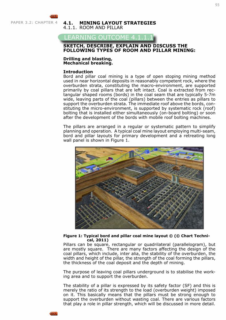
93
PAPER 3.2: CHAPTER 4 4.1. MINING LAYOUT STRATEGIES4.1.1. ROOM AND PILLAR
SKETCH, DESCRIBE, EXPLAIN AND DISCUSS THE FOLLOWING TYPES OF ROOM AND PILLAR MINING:
Drilling and blasting, Mechanical breaking.
Introduction Bord and pillar coal mining is a type of open stoping mining method used in near horizontal deposits in reasonably competent rock, where the overburden strata, constituting the macro-environment, are supported primarily by coal pillars that are left intact. Coal is extracted from rec-tangular shaped rooms (bords) in the coal seam that are typically 5-7m wide, leaving parts of the coal (pillars) between the entries as pillars to support the overburden strata. The immediate roof above the bords, con-stituting the micro-environment, is supported by systematic rock (roof) bolting that is installed either simultaneously (on-board bolting) or soon after the development of the bords with mobile roof bolting machines.
The pillars are arranged in a regular or systematic pattern to simplify planning and operation. A typical coal mine layout employing multi-seam, bord and pillar layouts for primary development and a retreating long wall panel is shown in Figure 1.
Figure 1: Typical bord and pillar coal mine layout © (© Chart Techni-cal, 2011)
Pillars can be square, rectangular or quadrilateral (parallelogram), but are mostly square. There are many factors affecting the design of the coal pillars, which include, inter alia, the stability of the overburden, the width and height of the pillar, the strength of the coal forming the pillars, the thickness of the coal deposit and the depth of mining.
The purpose of leaving coal pillars underground is to stabilise the work-ing area and to support the overburden.
The stability of a pillar is expressed by its safety factor (SF) and this is merely the ratio of its strength to the load (overburden weight) imposed on it. This basically means that the pillars must be strong enough to support the overburden without wasting coal. There are various factors that play a role in pillar strength, which will be discussed in more detail.
LEARNING OUTCOME 4.1.1.1
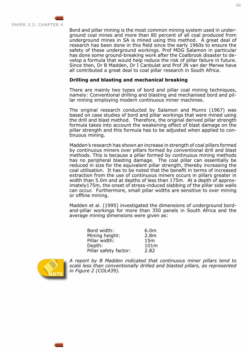
94
PAPER 3.2: CHAPTER 4Bord and pillar mining is the most common mining system used in under-ground coal mines and more than 80 percent of all coal produced from underground mines in SA is mined using this method. A great deal of research has been done in this field since the early 1960s to ensure the safety of these underground workings. Prof MDG Salamon in particular has done some ground-breaking work after the Coalbrook disaster to de-velop a formula that would help reduce the risk of pillar failure in future. Since then, Dr B Madden, Dr I Canbulat and Prof JN van der Merwe have all contributed a great deal to coal pillar research in South Africa.
Drilling and blasting and mechanical breaking
There are mainly two types of bord and pillar coal mining techniques, namely: Conventional drilling and blasting and mechanised bord and pil-lar mining employing modern continuous miner machines.
The original research conducted by Salamon and Munro (1967) was based on case studies of bord and pillar workings that were mined using the drill and blast method. Therefore, the original derived pillar strength formula takes into account the weakening effect of blast damage on the pillar strength and this formula has to be adjusted when applied to con-tinuous mining.
Madden’s research has shown an increase in strength of coal pillars formed by continuous miners over pillars formed by conventional drill and blast methods. This is because a pillar formed by continuous mining methods has no peripheral blasting damage. The coal pillar can essentially be reduced in size for the equivalent pillar strength, thereby increasing the coal utilisation. It has to be noted that the benefit in terms of increased extraction from the use of continuous miners occurs in pillars greater in width than 5.0m and at depths of less than 175m. At a depth of approx-imately175m, the onset of stress-induced slabbing of the pillar side walls can occur. Furthermore, small pillar widths are sensitive to over mining or offline mining.
Madden et al. (1995) investigated the dimensions of underground bord-and-pillar workings for more than 350 panels in South Africa and the average mining dimensions were given as:
Bord width: 6.0m Mining height: 2.8m Pillar width: 15m Depth: 101m Pillar safety factor: 2.82
A report by B Madden indicated that continuous miner pillars tend to scale less than conventionally drilled and blasted pillars, as represented in Figure 2 (COL439).
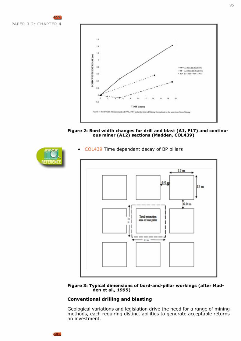
95
PAPER 3.2: CHAPTER 4
Figure 2: Bord width changes for drill and blast (A1, F17) and continu-
ous miner (A12) sections (Madden, COL439)
• COL439 Time dependant decay of BP pillars
Figure 3: Typical dimensions of bord-and-pillar workings (after Mad-den et al., 1995)
Conventional drilling and blasting
Geological variations and legislation drive the need for a range of mining methods, each requiring distinct abilities to generate acceptable returns on investment.
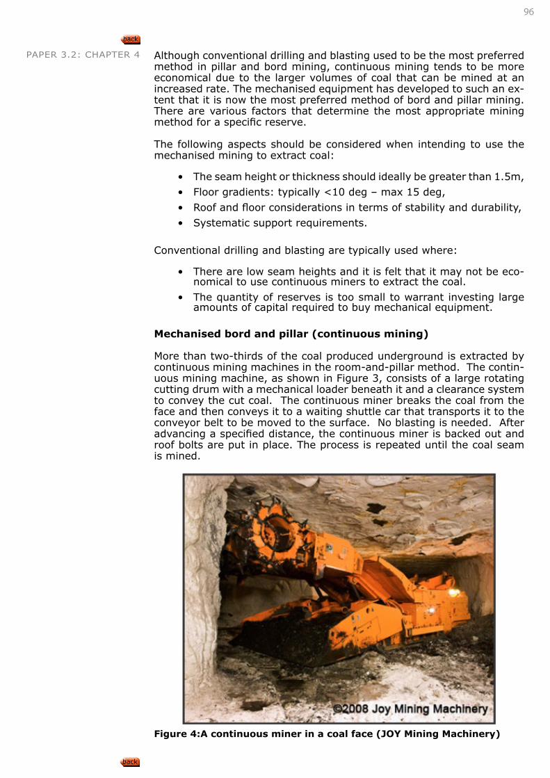
96
PAPER 3.2: CHAPTER 4 Although conventional drilling and blasting used to be the most preferred method in pillar and bord mining, continuous mining tends to be more economical due to the larger volumes of coal that can be mined at an increased rate. The mechanised equipment has developed to such an ex-tent that it is now the most preferred method of bord and pillar mining. There are various factors that determine the most appropriate mining method for a specific reserve.
The following aspects should be considered when intending to use the mechanised mining to extract coal:
• The seam height or thickness should ideally be greater than 1.5m,
• Floor gradients: typically <10 deg – max 15 deg,
• Roof and floor considerations in terms of stability and durability,
• Systematic support requirements.
Conventional drilling and blasting are typically used where:
• There are low seam heights and it is felt that it may not be eco-nomical to use continuous miners to extract the coal.
• The quantity of reserves is too small to warrant investing large amounts of capital required to buy mechanical equipment.
Mechanised bord and pillar (continuous mining)
More than two-thirds of the coal produced underground is extracted by continuous mining machines in the room-and-pillar method. The contin-uous mining machine, as shown in Figure 3, consists of a large rotating cutting drum with a mechanical loader beneath it and a clearance system to convey the cut coal. The continuous miner breaks the coal from the face and then conveys it to a waiting shuttle car that transports it to the conveyor belt to be moved to the surface. No blasting is needed. After advancing a specified distance, the continuous miner is backed out and roof bolts are put in place. The process is repeated until the coal seam is mined.
Figure 4:A continuous miner in a coal face (JOY Mining Machinery)
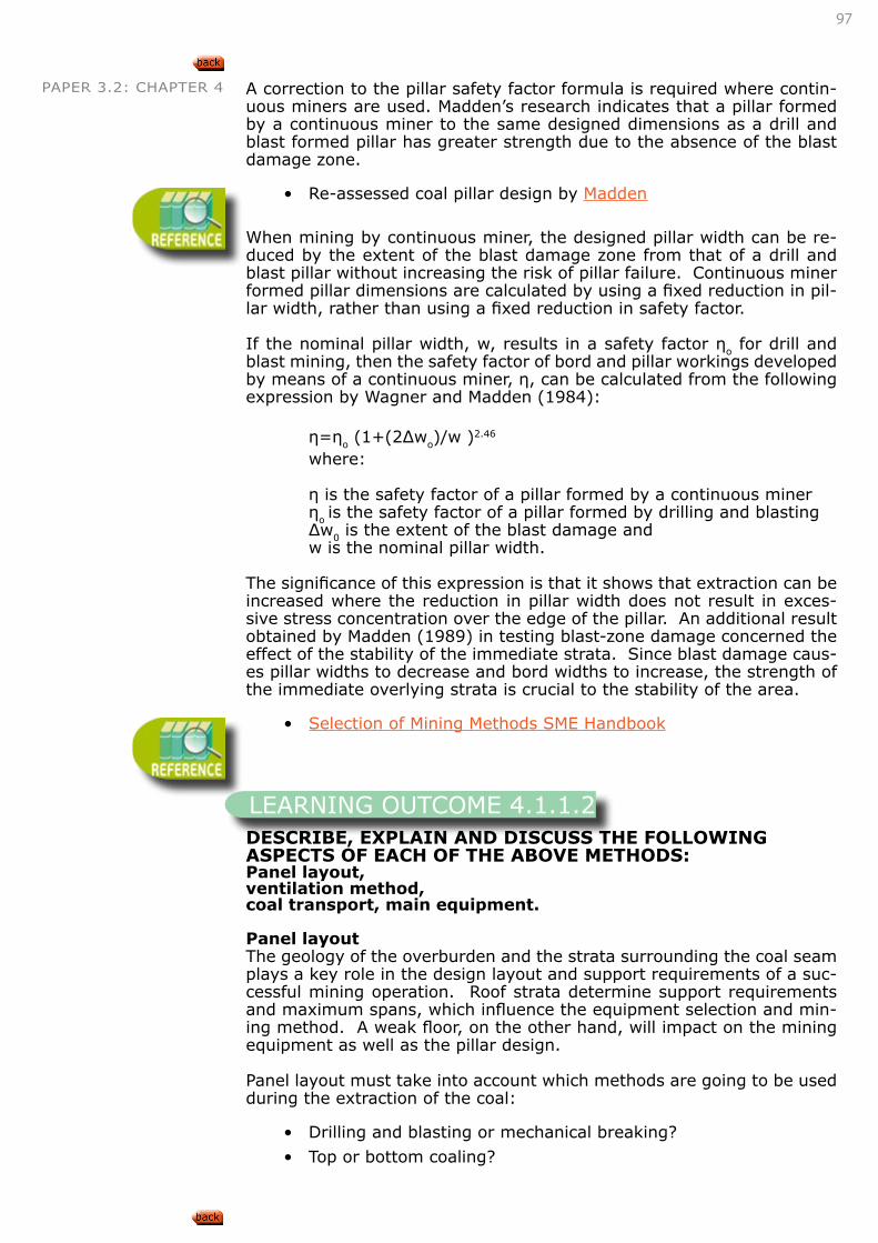
97
PAPER 3.2: CHAPTER 4 A correction to the pillar safety factor formula is required where contin-uous miners are used. Madden’s research indicates that a pillar formed by a continuous miner to the same designed dimensions as a drill and blast formed pillar has greater strength due to the absence of the blast damage zone.
• Re-assessed coal pillar design by Madden
When mining by continuous miner, the designed pillar width can be re-duced by the extent of the blast damage zone from that of a drill and blast pillar without increasing the risk of pillar failure. Continuous miner formed pillar dimensions are calculated by using a fixed reduction in pil-lar width, rather than using a fixed reduction in safety factor.
If the nominal pillar width, w, results in a safety factor ηo for drill and blast mining, then the safety factor of bord and pillar workings developed by means of a continuous miner, η, can be calculated from the following expression by Wagner and Madden (1984):
η=ηo (1+(2Δwo)/w )2.46
where:
η is the safety factor of a pillar formed by a continuous miner ηo is the safety factor of a pillar formed by drilling and blasting Δw0 is the extent of the blast damage and w is the nominal pillar width.
The significance of this expression is that it shows that extraction can be increased where the reduction in pillar width does not result in exces-sive stress concentration over the edge of the pillar. An additional result obtained by Madden (1989) in testing blast-zone damage concerned the effect of the stability of the immediate strata. Since blast damage caus-es pillar widths to decrease and bord widths to increase, the strength of the immediate overlying strata is crucial to the stability of the area.
• Selection of Mining Methods SME Handbook
DESCRIBE, EXPLAIN AND DISCUSS THE FOLLOWING ASPECTS OF EACH OF THE ABOVE METHODS:Panel layout, ventilation method, coal transport, main equipment.
Panel layoutThe geology of the overburden and the strata surrounding the coal seam plays a key role in the design layout and support requirements of a suc-cessful mining operation. Roof strata determine support requirements and maximum spans, which influence the equipment selection and min-ing method. A weak floor, on the other hand, will impact on the mining equipment as well as the pillar design.
Panel layout must take into account which methods are going to be used during the extraction of the coal:
• Drilling and blasting or mechanical breaking?
• Top or bottom coaling?
LEARNING OUTCOME 4.1.1.2
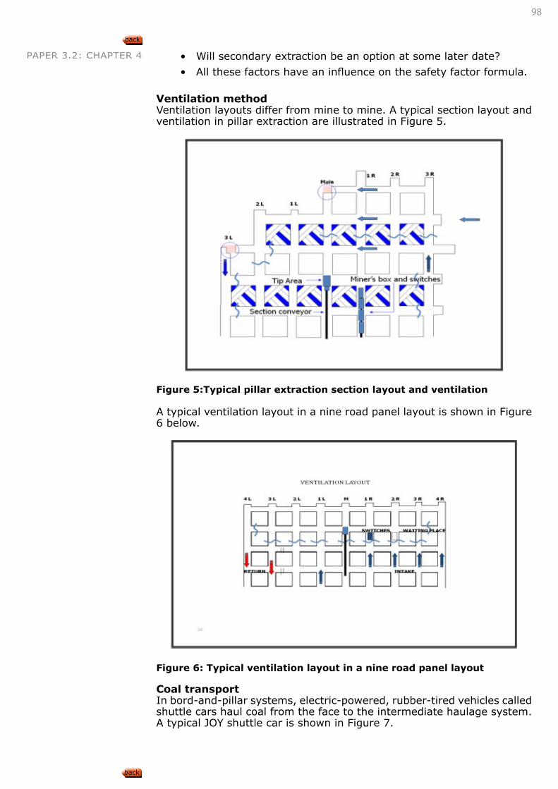
98
PAPER 3.2: CHAPTER 4 • Will secondary extraction be an option at some later date?
• All these factors have an influence on the safety factor formula.
Ventilation methodVentilation layouts differ from mine to mine. A typical section layout and ventilation in pillar extraction are illustrated in Figure 5.
Figure 5:Typical pillar extraction section layout and ventilation
A typical ventilation layout in a nine road panel layout is shown in Figure 6 below.
Figure 6: Typical ventilation layout in a nine road panel layout Coal transportIn bord-and-pillar systems, electric-powered, rubber-tired vehicles called shuttle cars haul coal from the face to the intermediate haulage system. A typical JOY shuttle car is shown in Figure 7.
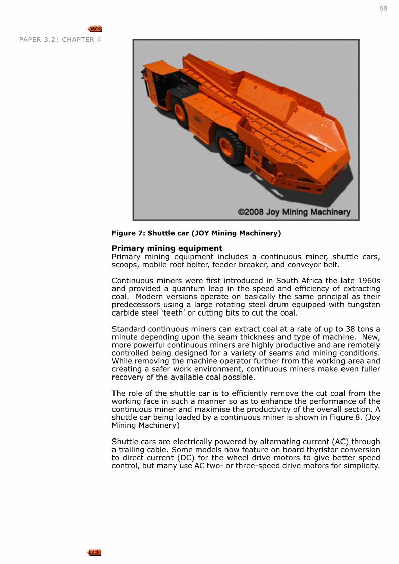
99
PAPER 3.2: CHAPTER 4
Figure 7: Shuttle car (JOY Mining Machinery)
Primary mining equipment Primary mining equipment includes a continuous miner, shuttle cars, scoops, mobile roof bolter, feeder breaker, and conveyor belt.
Continuous miners were first introduced in South Africa the late 1960s and provided a quantum leap in the speed and efficiency of extracting coal. Modern versions operate on basically the same principal as their predecessors using a large rotating steel drum equipped with tungsten carbide steel ‘teeth’ or cutting bits to cut the coal.
Standard continuous miners can extract coal at a rate of up to 38 tons a minute depending upon the seam thickness and type of machine. New, more powerful continuous miners are highly productive and are remotely controlled being designed for a variety of seams and mining conditions. While removing the machine operator further from the working area and creating a safer work environment, continuous miners make even fuller recovery of the available coal possible.
The role of the shuttle car is to efficiently remove the cut coal from the working face in such a manner so as to enhance the performance of the continuous miner and maximise the productivity of the overall section. A shuttle car being loaded by a continuous miner is shown in Figure 8. (Joy Mining Machinery)
Shuttle cars are electrically powered by alternating current (AC) through a trailing cable. Some models now feature on board thyristor conversion to direct current (DC) for the wheel drive motors to give better speed control, but many use AC two- or three-speed drive motors for simplicity.
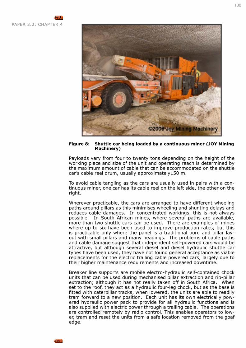
100
PAPER 3.2: CHAPTER 4
Figure 8: Shuttle car being loaded by a continuous miner (JOY Mining
Machinery)
Payloads vary from four to twenty tons depending on the height of the working place and size of the unit and operating reach is determined by the maximum amount of cable that can be accommodated on the shuttle car’s cable reel drum, usually approximately150 m.
To avoid cable tangling as the cars are usually used in pairs with a con-tinuous miner, one car has its cable reel on the left side, the other on the right.
Wherever practicable, the cars are arranged to have different wheeling paths around pillars as this minimises wheeling and shunting delays and reduces cable damages. In concentrated workings, this is not always possible. In South African mines, where several paths are available, more than two shuttle cars can be used. There are examples of mines where up to six have been used to improve production rates, but this is practicable only where the panel is a traditional bord and pillar lay-out with small pillars and many headings. The problems of cable paths and cable damage suggest that independent self-powered cars would be attractive, but although several diesel and diesel hydraulic shuttle car types have been used, they have not found general acceptance as viable replacements for the electric trailing cable powered cars, largely due to their higher maintenance requirements and increased downtime.
Breaker line supports are mobile electro-hydraulic self-contained chock units that can be used during mechanised pillar extraction and rib-pillar extraction; although it has not really taken off in South Africa. When set to the roof, they act as a hydraulic four-leg chock, but as the base is fitted with caterpillar tracks, when lowered, the units are able to readily tram forward to a new position. Each unit has its own electrically pow-ered hydraulic power pack to provide for all hydraulic functions and is also supplied with electric power through a trailing cable. The operations are controlled remotely by radio control. This enables operators to low-er, tram and reset the units from a safe location removed from the goaf edge.
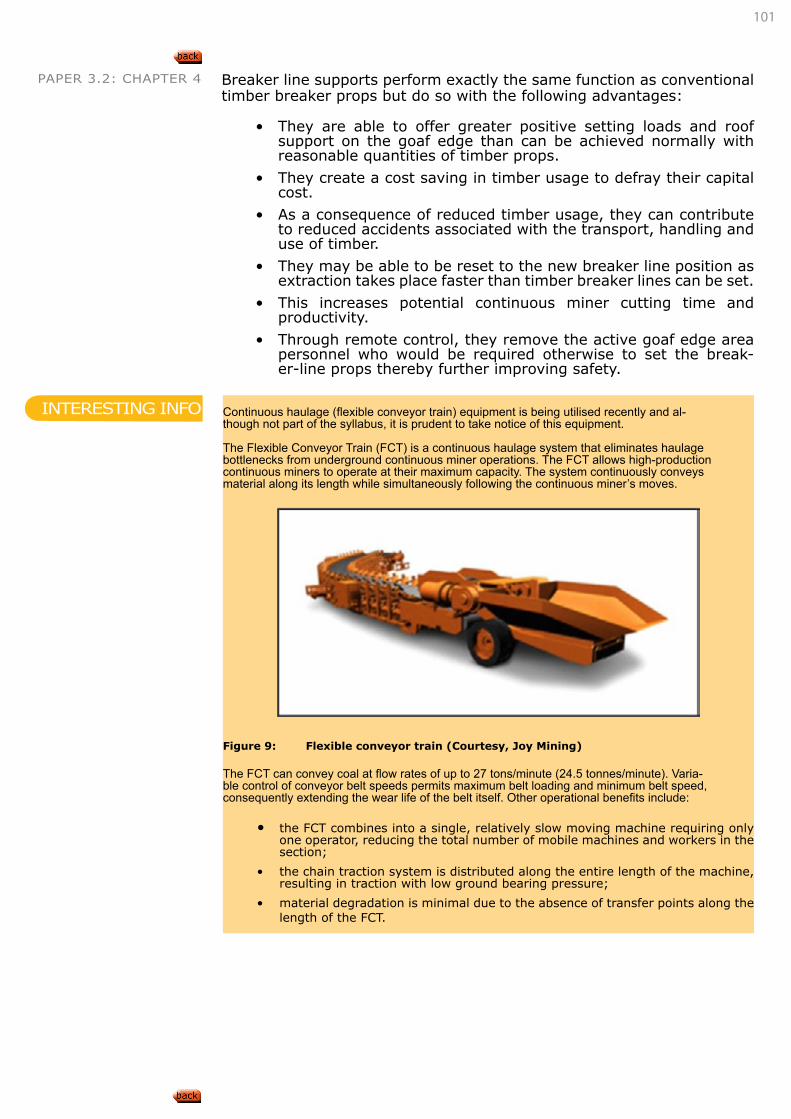
101
PAPER 3.2: CHAPTER 4 Breaker line supports perform exactly the same function as conventional timber breaker props but do so with the following advantages:
• They are able to offer greater positive setting loads and roof support on the goaf edge than can be achieved normally with reasonable quantities of timber props.
• They create a cost saving in timber usage to defray their capital cost.
• As a consequence of reduced timber usage, they can contribute to reduced accidents associated with the transport, handling and use of timber.
• They may be able to be reset to the new breaker line position as extraction takes place faster than timber breaker lines can be set.
• This increases potential continuous miner cutting time and productivity.
• Through remote control, they remove the active goaf edge area personnel who would be required otherwise to set the break-er-line props thereby further improving safety.
Continuous haulage (flexible conveyor train) equipment is being utilised recently and al-though not part of the syllabus, it is prudent to take notice of this equipment.
The Flexible Conveyor Train (FCT) is a continuous haulage system that eliminates haulage bottlenecks from underground continuous miner operations. The FCT allows high-production continuous miners to operate at their maximum capacity. The system continuously conveys material along its length while simultaneously following the continuous miner’s moves.
Figure 9: Flexible conveyor train (Courtesy, Joy Mining)
The FCT can convey coal at flow rates of up to 27 tons/minute (24.5 tonnes/minute). Varia-ble control of conveyor belt speeds permits maximum belt loading and minimum belt speed, consequently extending the wear life of the belt itself. Other operational benefits include:
• the FCT combines into a single, relatively slow moving machine requiring only one operator, reducing the total number of mobile machines and workers in the section;
• the chain traction system is distributed along the entire length of the machine, resulting in traction with low ground bearing pressure;
• material degradation is minimal due to the absence of transfer points along the length of the FCT.
INTERESTING INFO
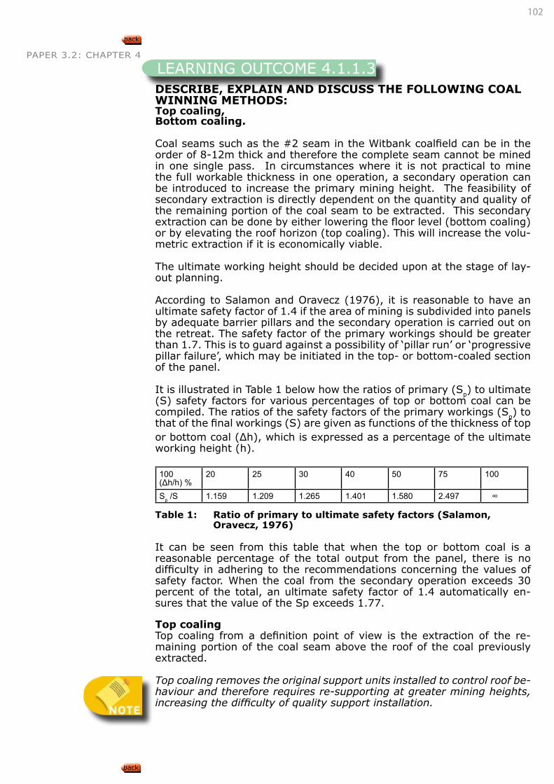
102
PAPER 3.2: CHAPTER 4
DESCRIBE, EXPLAIN AND DISCUSS THE FOLLOWING COAL WINNING METHODS:Top coaling, Bottom coaling.
Coal seams such as the #2 seam in the Witbank coalfield can be in the order of 8-12m thick and therefore the complete seam cannot be mined in one single pass. In circumstances where it is not practical to mine the full workable thickness in one operation, a secondary operation can be introduced to increase the primary mining height. The feasibility of secondary extraction is directly dependent on the quantity and quality of the remaining portion of the coal seam to be extracted. This secondary extraction can be done by either lowering the floor level (bottom coaling) or by elevating the roof horizon (top coaling). This will increase the volu-metric extraction if it is economically viable.
The ultimate working height should be decided upon at the stage of lay-out planning.
According to Salamon and Oravecz (1976), it is reasonable to have an ultimate safety factor of 1.4 if the area of mining is subdivided into panels by adequate barrier pillars and the secondary operation is carried out on the retreat. The safety factor of the primary workings should be greater than 1.7. This is to guard against a possibility of ‘pillar run’ or ‘progressive pillar failure’, which may be initiated in the top- or bottom-coaled section of the panel.
It is illustrated in Table 1 below how the ratios of primary (Sp) to ultimate (S) safety factors for various percentages of top or bottom coal can be compiled. The ratios of the safety factors of the primary workings (Sp) to that of the final workings (S) are given as functions of the thickness of top or bottom coal (Δh), which is expressed as a percentage of the ultimate working height (h).
100 (Δh/h) %
20 25 30 40 50 75 100
Sp /S 1.159 1.209 1.265 1.401 1.580 2.497 ∞
Table 1: Ratio of primary to ultimate safety factors (Salamon, Oravecz, 1976)
It can be seen from this table that when the top or bottom coal is a reasonable percentage of the total output from the panel, there is no difficulty in adhering to the recommendations concerning the values of safety factor. When the coal from the secondary operation exceeds 30 percent of the total, an ultimate safety factor of 1.4 automatically en-sures that the value of the Sp exceeds 1.77.
Top coalingTop coaling from a definition point of view is the extraction of the re-maining portion of the coal seam above the roof of the coal previously extracted.
Top coaling removes the original support units installed to control roof be-haviour and therefore requires re-supporting at greater mining heights, increasing the difficulty of quality support installation.
LEARNING OUTCOME 4.1.1.3
103
PAPER 3.2: CHAPTER 4 Bottom coalingBottom coaling is the secondary extraction of the lower portion of a coal seam following the development of the upper portion. This is more effi-cient extraction than top coaling and can be done on retreat, leaving the slender pillars in the back area.
An example of single-seam extraction with top-or bottom-coaling is giv-en by Salamon and Oravecz and will explain this concept in more detail:
Assume a 6.2m coal seam at a depth of 82m. It is intended to mine the total seam height in two steps. The primary extraction is at a 4m mining height to the true floor. In the second operation the rest of the seam is taken to the true roof. A final safety factor of 1.40 is decided on at a bord width of 6m. Find the initial and final volumetric extraction and equivalent working height. Is the safety factor after primary extraction sufficiently high to prevent pillar run?
The pillars are designed for the final geometry: W=12.2m (H=88.2m; h=6.2m; B=6m; and SF=1.4)
After the primary extraction the following parameters apply: H=88.2m; h=4m; w=12.2m; B=6m.
On the basis of case 1, the safety factor is found to be S=1.83 which is considered high enough to prevent pillar run.
The areal extraction therefore is:ea=1-(w/((w+B)))2=55.07%This is also the final volumetric extraction.
The equivalent working heights after the primary and sec-ondary extraction are h=2.20 m and 3.41 m respectively.
The volumetric extraction after primary extraction is 35.48 %.
DETERMINE A REAL AND VOLUMETRIC PERCENTAGE EXTRACTION IN ROOM AND PILLAR LAYOUTS.
The maximum volumetric extraction from a seam is obtained by:
• extracting the full mineable seam thickness and
• using the maximum safe and practical bord width.
Volumetric extraction differs from areal extraction when the total height of the seam is not extracted.
Restrictions on SF and conditions of use of lower SF.
When seams are thin SF can typically be reduced to 1.5.
% Areal Extraction=1-W2/C2 Or1-(w/(C2 (w+b)2 ))2
EXAMPLE
LEARNING OUTCOME 4.1.1.4
104
PAPER 3.2: CHAPTER 4 with barrier pillars Aext=1-((b+w))/((b+w)) (l+(n-1) w2)/((l+n.b+(n-1)w))
l = barrier widthn = no. of bords
% Volumetric extraction = Volume of coal extracted/Available volume of coal
Therefore Vext =
mining height x (centre2-pillar width2)/Minable height (total) x.centre2
Vext= (h.(C2-w2))/(m.C2 ))
DETERMINE APPROPRIATE FACTORS OF SAFETY FOR PRIMARY DEVELOPMENT IN ROOM AND PILLAR LAYOUTS.
Statistical analysis of real underground pillars back calculated the in-herent strength of a metre cube of coal as 7.2MPa. From this research stemmed the formula that the strength of a coal pillar is determined by three parameters:
• the inherent strength of the coal material
• the width of the pillar
• the height of the pillar
This formula is expressed as follows:
σ=7,2 w0,46/h0,66 (MPa),
Where:
σ = pillar strengthw = pillar widthh = pillar height
This formula is valid only for square pillars. When rectangular pillars are used, an equivalent width we,is to be used instead of w to determine pil-lar width. Wagner (1980) suggested that we, be calculated as:
we=4A/c
where A is the pillar area and c is the pillar circumference or perimeter.
This adjustment is only valid for the calculation of pillar strength.
Coal pillar strength, however, is only one part of the evaluation of pillar stability. The other part is the load acting on the pillar.
Salamon and Munro (1967) did an intensive investigation into the strength of coal pillars through the statistical analysis of ninety-eight intact and twenty-seven collapsed pillar geometries using a probabilistic notion of safety factor, defined as:
LEARNING OUTCOME 4.1.1.5
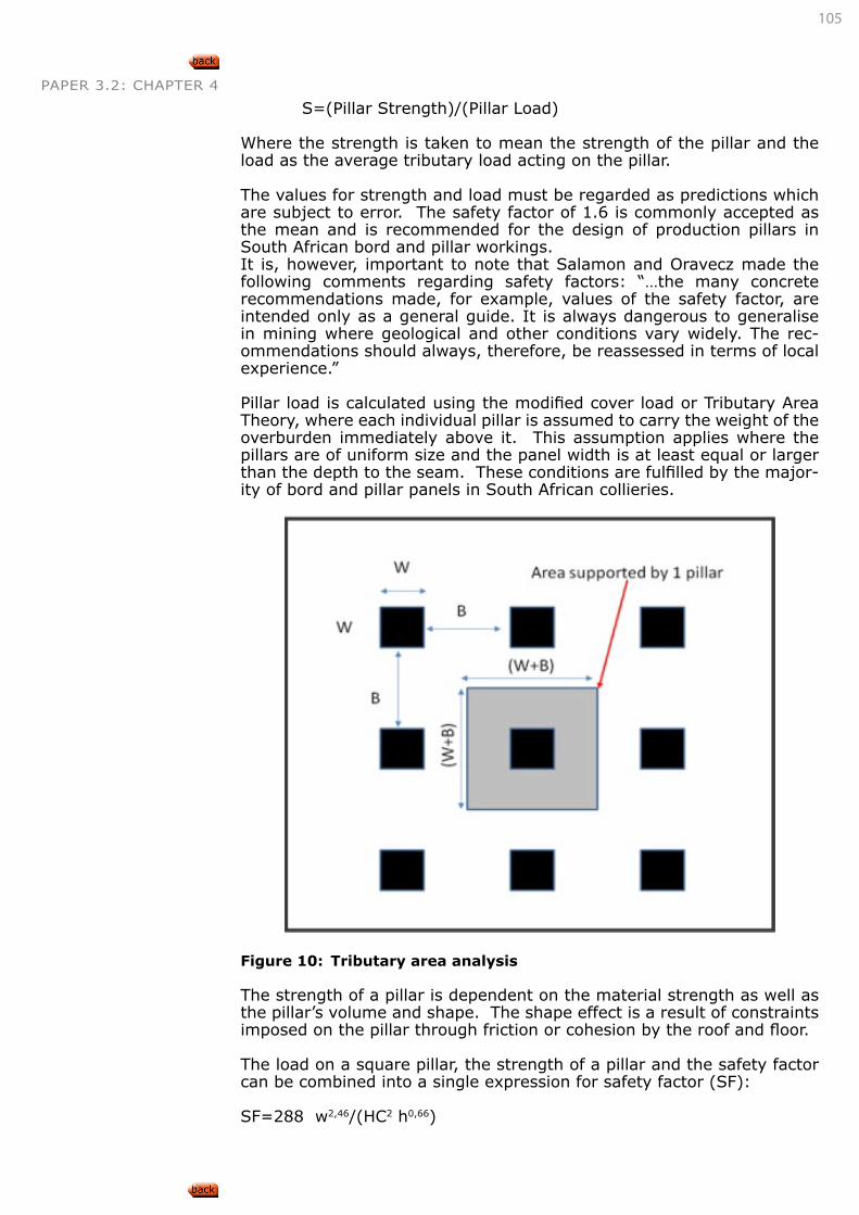
105
PAPER 3.2: CHAPTER 4
S=(Pillar Strength)/(Pillar Load)
Where the strength is taken to mean the strength of the pillar and the load as the average tributary load acting on the pillar.
The values for strength and load must be regarded as predictions which are subject to error. The safety factor of 1.6 is commonly accepted as the mean and is recommended for the design of production pillars in South African bord and pillar workings. It is, however, important to note that Salamon and Oravecz made the following comments regarding safety factors: “…the many concrete recommendations made, for example, values of the safety factor, are intended only as a general guide. It is always dangerous to generalise in mining where geological and other conditions vary widely. The rec-ommendations should always, therefore, be reassessed in terms of local experience.”
Pillar load is calculated using the modified cover load or Tributary Area Theory, where each individual pillar is assumed to carry the weight of the overburden immediately above it. This assumption applies where the pillars are of uniform size and the panel width is at least equal or larger than the depth to the seam. These conditions are fulfilled by the major-ity of bord and pillar panels in South African collieries.
Figure 10: Tributary area analysis
The strength of a pillar is dependent on the material strength as well as the pillar’s volume and shape. The shape effect is a result of constraints imposed on the pillar through friction or cohesion by the roof and floor.
The load on a square pillar, the strength of a pillar and the safety factor can be combined into a single expression for safety factor (SF):
SF=288 w2,46/(HC2 h0,66)
106
PAPER 3.2: CHAPTER 4
Where C = centres distance = (w + B) H = depth from surface to the roof of the seam B = bord width W = pillar width
Squat pillarsA squat pillar is defined as one that has a width-to-height ratio of 5 and above. The safety factor design formula of Salamon and Munro has been used very successfully in designing stable pillar geometries in SA collieries. This formula was based on collieries having a depth of mining ranging between 20m and 220m with the majority of the collieries shal-lower than 150m. In the past, most collieries operated at depths of less than 150m and the problem of designing squat pillars never arose.
A limitation of the pillar strength formula is that it assumes that the strength of a pillar increases proportionally with the power of the width-to-height ratio, which is less than unity. This limitation was not evident in the statistical study by Salamon and Munro because the collapsed pillar case history only included pillars with a width-to-height ratio of 3.6 or less. However, most of the newer collieries and some of the reserves currently being mined on the older collieries are situated at depths in excess of 150m and up to 580m.
These cases extend beyond the empirical range of Salamon and Munro’s statistical analysis. It was for this reason that Salamon extended his pil-lar strength formula to take notice of the increasing ability of a pillar to carry load with the increasing width to height ratio.
Laboratory tests on sandstone specimens were analysed to examine the suitability of the squat pillar formula to predict the strength increase with increasing width-to-height ratios. The squat pillar formula fitted the lab-oratory results well and although these laboratory results on sandstone specimens cannot be directly related to coal pillars, because of the ma-terial difference in the scale and time taken to test these samples, the general trend can be assumed similar.
Salamon and Wagner suggested that in the design of coal pillars, the squat pillar formula could be used with the critical width-to-height ratio taken as 5.0 and, although more difficult to make a realistic estimate, that the rate of pillar strength increase(ε) can be taken as 2.5. The as-sumption of the critical width-to-height ratio equal to 5 is based on the fact that no pillar with a width-to-height ratio greater than 3.75.has ever collapsed.
The squat pillar formula as given by Wagner and Madden is:
σρ=k.(Rob)/Va .{b/ε.[(R/Ro )
ε-1]+1}
Where: σp = pillar strengthk = strength of coal - unit strength of a cube = 7.2MPaV = pillar volumeRo = critical width to height ratio=5,0R = actual pillar width to height ratioε = rate of strength increase, usually taken as 2.5a = constant - statistically determined= 0.0667b = constant - statistically determined =0.5933
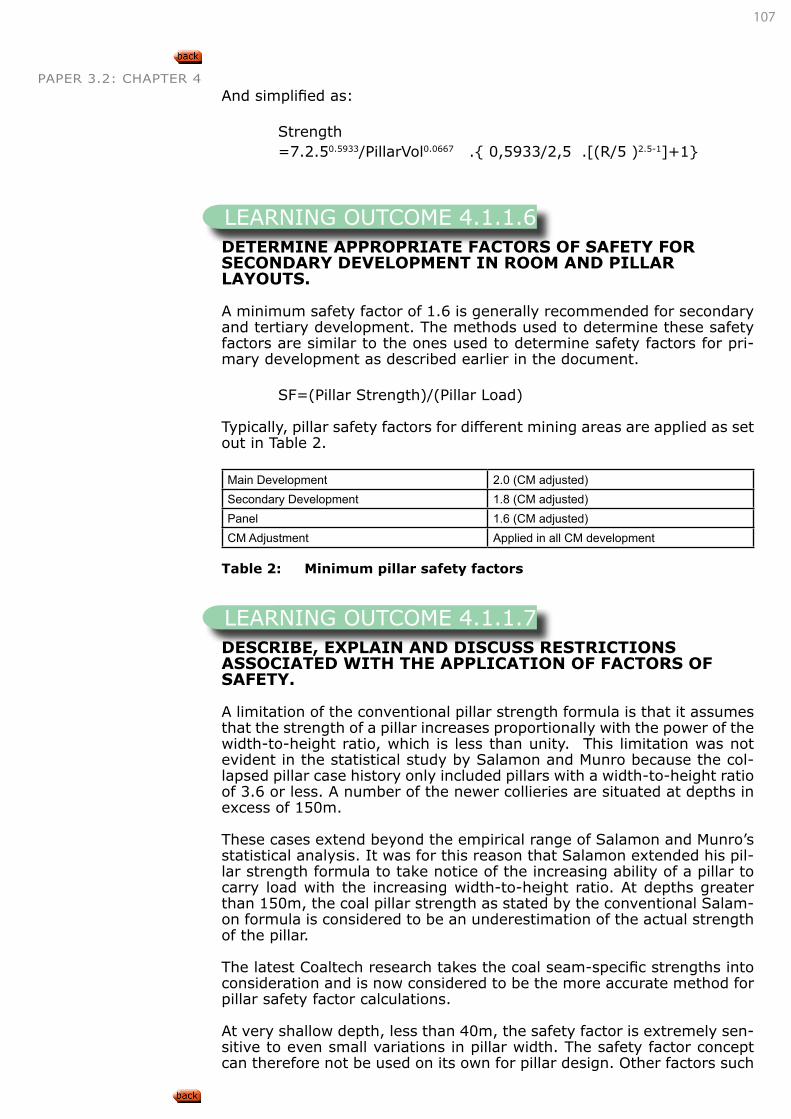
107
PAPER 3.2: CHAPTER 4And simplified as:
Strength=7.2.50.5933/PillarVol0.0667 .{ 0,5933/2,5 .[(R/5 )2.5-1]+1}
DETERMINE APPROPRIATE FACTORS OF SAFETY FOR SECONDARY DEVELOPMENT IN ROOM AND PILLAR LAYOUTS.
A minimum safety factor of 1.6 is generally recommended for secondary and tertiary development. The methods used to determine these safety factors are similar to the ones used to determine safety factors for pri-mary development as described earlier in the document.
SF=(Pillar Strength)/(Pillar Load)
Typically, pillar safety factors for different mining areas are applied as set out in Table 2.
Main Development 2.0 (CM adjusted)Secondary Development 1.8 (CM adjusted)Panel 1.6 (CM adjusted)CM Adjustment Applied in all CM development
Table 2: Minimum pillar safety factors
DESCRIBE, EXPLAIN AND DISCUSS RESTRICTIONS ASSOCIATED WITH THE APPLICATION OF FACTORS OF SAFETY.
A limitation of the conventional pillar strength formula is that it assumes that the strength of a pillar increases proportionally with the power of the width-to-height ratio, which is less than unity. This limitation was not evident in the statistical study by Salamon and Munro because the col-lapsed pillar case history only included pillars with a width-to-height ratio of 3.6 or less. A number of the newer collieries are situated at depths in excess of 150m.
These cases extend beyond the empirical range of Salamon and Munro’s statistical analysis. It was for this reason that Salamon extended his pil-lar strength formula to take notice of the increasing ability of a pillar to carry load with the increasing width-to-height ratio. At depths greater than 150m, the coal pillar strength as stated by the conventional Salam-on formula is considered to be an underestimation of the actual strength of the pillar.
The latest Coaltech research takes the coal seam-specific strengths into consideration and is now considered to be the more accurate method for pillar safety factor calculations.
At very shallow depth, less than 40m, the safety factor is extremely sen-sitive to even small variations in pillar width. The safety factor concept can therefore not be used on its own for pillar design. Other factors such
LEARNING OUTCOME 4.1.1.6
LEARNING OUTCOME 4.1.1.7
108
PAPER 3.2: CHAPTER 4 as pillar width-to-height ratio also came into play.
The ratio of panel width to mining depth must be greater than one in order for the SF calculation to be applicable and there must be a regular layout of pillars. Over and above the use of safety factors, the minimum pillar width applicable is 5m.
DESCRIBE, EXPLAIN AND DISCUSS CONDITIONS THAT MAY ALLOW LOWER FACTORS OF SAFETY TO BE USED.
Three mining conditions will allow for the use of lower pillar safety factors and they are listed as follows:
• Very low seam and mining heights will allow for the use of pillar safety factors as low as 1.5 due to the high w:h of the pillars.
• The application of continuous miners will allow the application of the so-called CM adjustment, which is essentially a reduction in the pillar safety factor due to the reduction in blast fractures.
• For top-and-bottom coaling operations or where a thin parting exists between two coal seams, an ultimate safety factor of 1.4 is allowed for mining on the retreat.
All three these points have been discuss in a fair amount of detail in this document.
DESCRIBE, EXPLAIN AND DISCUSS THE PURPOSE OF BARRIER PILLARS IN ROOM AND PILLAR WORKINGS.
Barrier pillars subdivide the mine into compartments within which a po-tential pillar collapse can be contained and therefore minimising the risk of ‘pillar run’ to neighbouring sections.
Systematic inter-panel barriers are used in addition to panel pillars, which are designed by using the pillar strength formula.
The purpose of barrier pillars in bord and pillar workings is to:
• Prevent regional pillar collapse.
• Divide areas into panels instead of large areas on fixed pillar centres.
• Create independent ventilation districts.
• Isolate development panels so they can easily be sealed off.
• Act as ventilation and water barriers.
• Barrier pillars are employed to minimise the effects of high abutment stresses on roadways and influence ground control in neighbouring panels.
• Contain ‘pillar run’– allow lower SF to be used with top and bot-tom coaling.
A well-designed barrier pillar is a very substantial support and if the width-to-height ratio of such a pillar is greater than 10 it can support an unlimited load.
LEARNING OUTCOME 4.1.1.8
LEARNING OUTCOME 4.1.1.9
109
PAPER 3.2: CHAPTER 4 The strength of barrier pillars becomes critical when the dolerite sill is too thick to be broken at realistic panel widths and the sill bridges over a number of extraction panels.
Recent experience with some pillar collapses has shown that a continu-ous barrier of the same width as the panel pillars can act as an effective barrier.
Another rule of thumb is that the barrier must be six times the mining height.
From we=4A/c,
The effective width of an infinitely long barrier pillar is twice the actual pillar width. Since the strength of the pil-lars is strongly dependent on the width-to-height ratio, it follows that the continuous barrier pillar has a much great-er strength than a square panel pillar of the same width.
APPLY THE ABOVE KNOWLEDGE TO DESIGN ROOM AND PILLAR MINING LAYOUTS FOR GIVEN SETS OF CIRCUMSTANCES.
Some of the concepts discussed above are best illustrated by the worked example below.
LEARNING OUTCOME 4.1.1.10
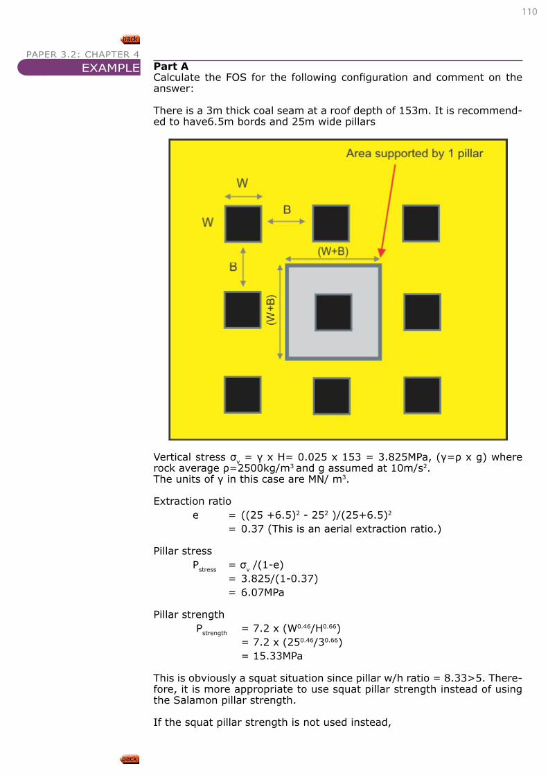
110
PAPER 3.2: CHAPTER 4Part ACalculate the FOS for the following configuration and comment on the answer:
There is a 3m thick coal seam at a roof depth of 153m. It is recommend-ed to have6.5m bords and 25m wide pillars
Vertical stress σv = γ x H= 0.025 x 153 = 3.825MPa, (γ=ρ x g) where rock average ρ=2500kg/m3 and g assumed at 10m/s2. The units of γ in this case are MN/ m3.
Extraction ratio e = ((25 +6.5)2 - 252 )/(25+6.5)2 = 0.37 (This is an aerial extraction ratio.)
Pillar stressPstress = σv /(1-e) = 3.825/(1-0.37) = 6.07MPa
Pillar strength Pstrength = 7.2 x (W0.46/H0.66) = 7.2 x (250.46/30.66) = 15.33MPa
This is obviously a squat situation since pillar w/h ratio = 8.33>5. There-fore, it is more appropriate to use squat pillar strength instead of using the Salamon pillar strength.
If the squat pillar strength is not used instead,
EXAMPLE
111
PAPER 3.2: CHAPTER 4 Factor of safety FOS = Pillar strength / Pillar stress = 15.33/6.07 = 2.53
Recommended FOS for production working pillars is 1.6. As such, FOS of 2.53 is too high.
Now redo part A of the question by applying the squat pillar formula. Comment on the answer you get for the pillar strength as compared to the Salamon pillar strength. Compare the squat pillar SF against the Salamon SF.
Part B
Calculate the pillar width to provide an FOS of 1.6. Maintain bord width of 6.5.
Pillar stress Pstress = σv /(1-e) = 3.825/(1-e)
Extraction ratio = Area mined / Total area (1-e) = 1- ((W+6.5)2-W2)/(W+6.5)2
= ((W+6.5)2-(W+6.5)2+W2)/(W+6.5)2
= W2/(W+6.5)2
Therefore
Pillar stress = 3.825(W+6.5)2/ W2
Now FOS = Pillar strength / Pillar stress
Therefore
Pillar strength = FOS x Pillar stressFor an FOS of 1.6 Pillar strength = 1.6(3.825(W+6.5)2/ W2)
But Pstrength = 7.2 x (W0.46/H0.66)
Therefore7.2 x (W0.46/H0.66) = 1.6(3.825(W+6.5)2/ W2)
Seam height is 3m therefore
3.487 x W0.46 = 6.12 x (W+6.5)2/ W2)W2.46 = 1.755(W2+13W+6.52)W2.46 = 1.755W2+2.815W+74.149W2.46-1.755W2-2.815W-74.149=0
Substitute various values of W to satisfy the equation
W Result20 354
112
PAPER 3.2: CHAPTER 4 15 -29.316 28.0415.5 -1.77
Choose pillar width of 15.5m
Part C
Calculate the new pillar strength and pillar stressPstrength = 7.2 x (15.5 0.46/30.6) = 12.3MPa
Extractione =((15.5+6.5)2-15.52)/ (15.5+6.5)2
=0.504 Or e = 50.4%
CheckFOS = Pstrength/ Pstress
= 12.3 / 7.71 = 1.6
Part D
What would the factor of safety be if a coal cutter or a continuous miner was used?
FOS = FOSblast x [1+2(W0/W)]2.46
FOS = 1.6 x [1+2(0.3/15.5)]2.46
FOS =1.76
Part ECalculate the pillar width if a coal cutter was used.
1.6 = FOSblast x [1+2(0.3/W)]2.46
FOSblast = 1.6/[(1+(0.6/W)]2.46
Pillar strength = FOS x Pillar stress7.2 x (W0.46/H0.6) = 1.6/[1+(0.6/W)]2.46 x [3.825 x (W+6.5)2]/W2
3.487W2.46[1+(0.6/W)2.46=1.6 x 3.825(W+6.5)2
W2.46[1+(0.6/W)]2.46 = 1.755(W+6.5) (W+0.6)2.46 = 1.755W2+22.82W+74.15(W+0.6)2.46-1.755W2+22.82W+74.15=0
W Result15 49.8414 -5.9513 -52.93
Therefore, pillar width is 14m
113
PAPER 3.2: CHAPTER 4• Page 41,134, Salamon, Oravecz, Rock mechanics in coal mining,
COMRO, 1976
• Page 49, 54, Van der Merwe, Madden, Rock Engineering for Un-derground Coal Mining, 2002
4.1.2. RIB PILLAR
In rib-pillar extraction, a continuous miner machine develops a panel up to 1.5 kilometres in length. This development is typically cut five metres away from the edge of the area to be mined. This leaves a five metre-wide band of coal in the form of a long, isolated rib pillar along one side of the tunnel. With the aid of timber or hydraulic props to hold up the now unstable roof, the continuous miner cuts away the rib pillar in a series of curved cutting sweeps. The machine repeats the cycle by mining into the remaining coal area, again cutting a tunnel or roadway and leaving a rib pillar.
The use of mobile roof supports (MRS) can be included, possibly remov-ing the need for hydraulic props.
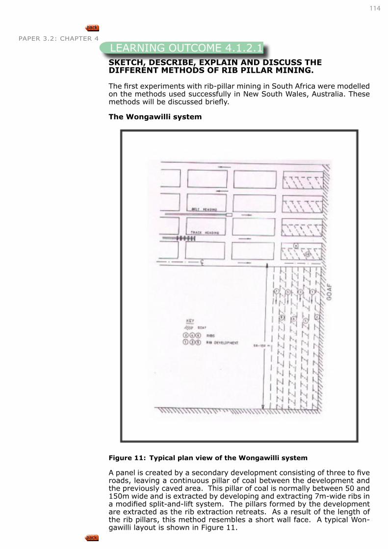
114
PAPER 3.2: CHAPTER 4
SKETCH, DESCRIBE, EXPLAIN AND DISCUSS THE DIFFERENT METHODS OF RIB PILLAR MINING.
The first experiments with rib-pillar mining in South Africa were modelled on the methods used successfully in New South Wales, Australia. These methods will be discussed briefly.
The Wongawilli system
Figure 11: Typical plan view of the Wongawilli system
A panel is created by a secondary development consisting of three to five roads, leaving a continuous pillar of coal between the development and the previously caved area. This pillar of coal is normally between 50 and 150m wide and is extracted by developing and extracting 7m-wide ribs in a modified split-and-lift system. The pillars formed by the development are extracted as the rib extraction retreats. As a result of the length of the rib pillars, this method resembles a short wall face. A typical Won-gawilli layout is shown in Figure 11.
LEARNING OUTCOME 4.1.2.1
115
PAPER 3.2: CHAPTER 4The main disadvantages of the system are:
• Excessive floor lift when splitting successive headings in a large panel;
• Difficulties when removing snooks on the return run out of each heading; and
• Difficulties with ventilating rib-pillar panels when the roof caves completely, filling all voids in the goaf area.
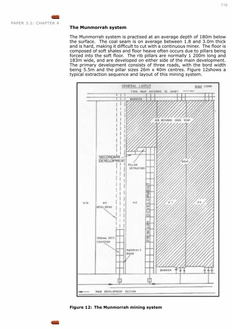
116
PAPER 3.2: CHAPTER 4The Munmorrah system
The Munmorrah system is practised at an average depth of 180m below the surface. The coal seam is on average between 1.8 and 3.0m thick and is hard, making it difficult to cut with a continuous miner. The floor is composed of soft shales and floor heave often occurs due to pillars being forced into the soft floor. The rib pillars are normally 1 200m long and 183m wide, and are developed on either side of the main development. The primary development consists of three roads, with the bord width being 5.5m and the pillar sizes 26m x 40m centres. Figure 12shows a typical extraction sequence and layout of this mining system.
Figure 12: The Munmorrah mining system
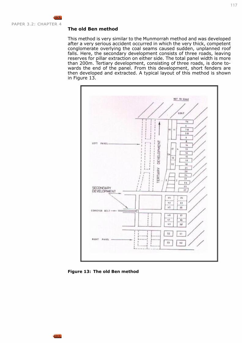
117
PAPER 3.2: CHAPTER 4The old Ben method
This method is very similar to the Munmorrah method and was developed after a very serious accident occurred in which the very thick, competent conglomerate overlying the coal seams caused sudden, unplanned roof falls. Here, the secondary development consists of three roads, leaving reserves for pillar extraction on either side. The total panel width is more than 200m. Tertiary development, consisting of three roads, is done to-wards the end of the panel. From this development, short fenders are then developed and extracted. A typical layout of this method is shown in Figure 13.
Figure 13: The old Ben method
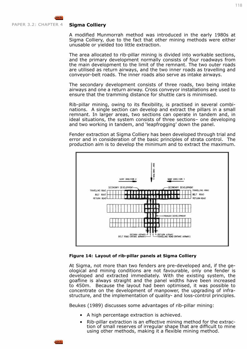
118
PAPER 3.2: CHAPTER 4 Sigma Colliery
A modified Munmorrah method was introduced in the early 1980s at Sigma Colliery, due to the fact that other mining methods were either unusable or yielded too little extraction.
The area allocated to rib-pillar mining is divided into workable sections, and the primary development normally consists of four roadways from the main development to the limit of the remnant. The two outer roads are utilised as return airways, and the two inner roads as travelling and conveyor-belt roads. The inner roads also serve as intake airways.
The secondary development consists of three roads, two being intake airways and one a return airway. Cross conveyor installations are used to ensure that the tramming distance for shuttle cars is minimised.
Rib-pillar mining, owing to its flexibility, is practised in several combi-nations. A single section can develop and extract the pillars in a small remnant. In larger areas, two sections can operate in tandem and, in ideal situations, the system consists of three sections– one developing and two working in tandem, and ‘leapfrogging’ down the panel.
Fender extraction at Sigma Colliery has been developed through trial and error and in consideration of the basic principles of strata control. The production aim is to develop the minimum and to extract the maximum.
Figure 14: Layout of rib-pillar panels at Sigma Colliery
At Sigma, not more than two fenders are pre-developed and, if the ge-ological and mining conditions are not favourable, only one fender is developed and extracted immediately. With the existing system, the goafline is always straight and the panel widths have been increased to 450m. Because the layout had been optimised, it was possible to concentrate on the development of manpower, the upgrading of infra-structure, and the implementation of quality- and loss-control principles.
Beukes (1989) discusses some advantages of rib-pillar mining:
• A high percentage extraction is achieved.
• Rib-pillar extraction is an effective mining method for the extrac-tion of small reserves of irregular shape that are difficult to mine using other methods, making it a flexible mining method.
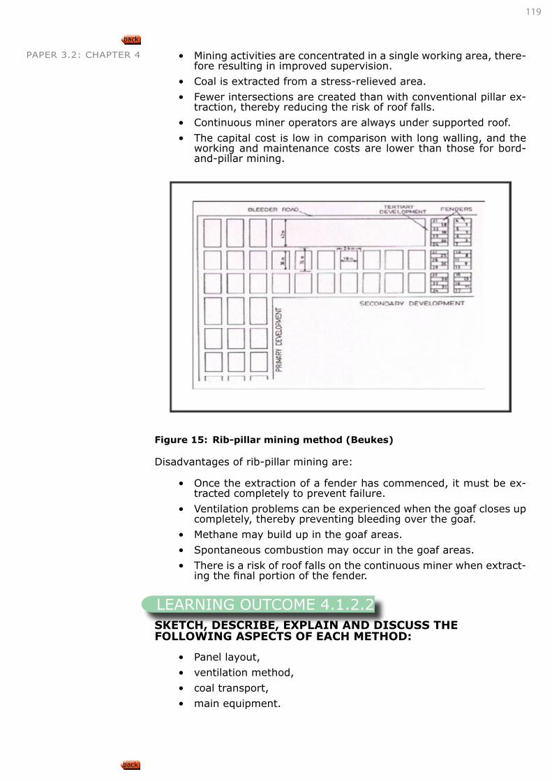
119
PAPER 3.2: CHAPTER 4 • Mining activities are concentrated in a single working area, there-fore resulting in improved supervision.
• Coal is extracted from a stress-relieved area.
• Fewer intersections are created than with conventional pillar ex-traction, thereby reducing the risk of roof falls.
• Continuous miner operators are always under supported roof.
• The capital cost is low in comparison with long walling, and the working and maintenance costs are lower than those for bord-and-pillar mining.
Figure 15: Rib-pillar mining method (Beukes)
Disadvantages of rib-pillar mining are:
• Once the extraction of a fender has commenced, it must be ex-tracted completely to prevent failure.
• Ventilation problems can be experienced when the goaf closes up completely, thereby preventing bleeding over the goaf.
• Methane may build up in the goaf areas.
• Spontaneous combustion may occur in the goaf areas.
• There is a risk of roof falls on the continuous miner when extract-ing the final portion of the fender.
SKETCH, DESCRIBE, EXPLAIN AND DISCUSS THE FOLLOWING ASPECTS OF EACH METHOD:
• Panel layout,
• ventilation method,
• coal transport,
• main equipment.
LEARNING OUTCOME 4.1.2.2
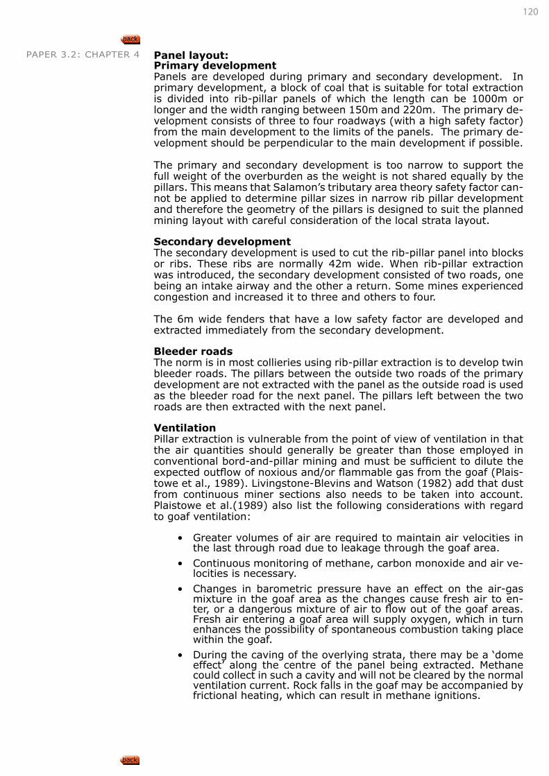
120
PAPER 3.2: CHAPTER 4 Panel layout:Primary developmentPanels are developed during primary and secondary development. In primary development, a block of coal that is suitable for total extraction is divided into rib-pillar panels of which the length can be 1000m or longer and the width ranging between 150m and 220m. The primary de-velopment consists of three to four roadways (with a high safety factor) from the main development to the limits of the panels. The primary de-velopment should be perpendicular to the main development if possible.
The primary and secondary development is too narrow to support the full weight of the overburden as the weight is not shared equally by the pillars. This means that Salamon’s tributary area theory safety factor can-not be applied to determine pillar sizes in narrow rib pillar development and therefore the geometry of the pillars is designed to suit the planned mining layout with careful consideration of the local strata layout.
Secondary developmentThe secondary development is used to cut the rib-pillar panel into blocks or ribs. These ribs are normally 42m wide. When rib-pillar extraction was introduced, the secondary development consisted of two roads, one being an intake airway and the other a return. Some mines experienced congestion and increased it to three and others to four.
The 6m wide fenders that have a low safety factor are developed and extracted immediately from the secondary development.
Bleeder roadsThe norm is in most collieries using rib-pillar extraction is to develop twin bleeder roads. The pillars between the outside two roads of the primary development are not extracted with the panel as the outside road is used as the bleeder road for the next panel. The pillars left between the two roads are then extracted with the next panel.
VentilationPillar extraction is vulnerable from the point of view of ventilation in that the air quantities should generally be greater than those employed in conventional bord-and-pillar mining and must be sufficient to dilute the expected outflow of noxious and/or flammable gas from the goaf (Plais-towe et al., 1989). Livingstone-Blevins and Watson (1982) add that dust from continuous miner sections also needs to be taken into account. Plaistowe et al.(1989) also list the following considerations with regard to goaf ventilation:
• Greater volumes of air are required to maintain air velocities in the last through road due to leakage through the goaf area.
• Continuous monitoring of methane, carbon monoxide and air ve-locities is necessary.
• Changes in barometric pressure have an effect on the air-gas mixture in the goaf area as the changes cause fresh air to en-ter, or a dangerous mixture of air to flow out of the goaf areas. Fresh air entering a goaf area will supply oxygen, which in turn enhances the possibility of spontaneous combustion taking place within the goaf.
• During the caving of the overlying strata, there may be a ‘dome effect’ along the centre of the panel being extracted. Methane could collect in such a cavity and will not be cleared by the normal ventilation current. Rock falls in the goaf may be accompanied by frictional heating, which can result in methane ignitions.
121
PAPER 3.2: CHAPTER 4 Mining at shallow depths in particular leads to disturbance of the surface strata, with major cracking. Fresh air entering the goaf via these cracks supplies oxygen, which, in turn, enhances the likelihood of spontaneous combustion taking place.
Beukes (1989) adds that if considerable quantities of gas are present in the seam or overlying strata, it is advisable for individual panels to be sealed off once extraction has been completed to prevent gases from entering the adjacent panels. Livingstone-Blevins and Watson (1982) mention three general methods used for ventilating pillar-extraction sections:
• Coursing ventilation in the section.
• Coursing the return air along the goaf line.
• Bleeding the return air, or a portion thereof, through the goaf itself to an established return airway behind the goaf.
The second method has found favour in continuous miner sections, ex-ploiting the permeable nature of the loosely caved goaf to clear dust, gas and used air away from the section and not through the section.
Figure 16: Ventilation layout for rib-pillar
Coal transport
Just as in bord-and-pillar systems, electric-powered, rubber-tired ve-hicles called shuttle cars haul coal from the face to the intermediate haulage system.
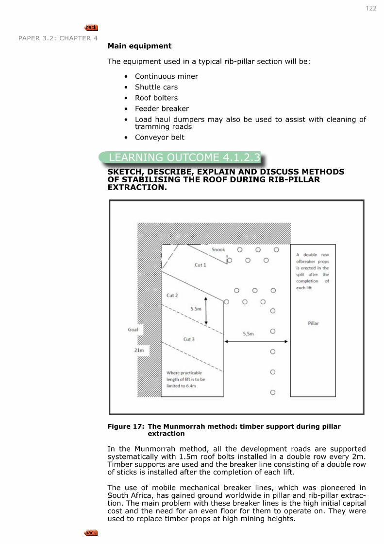
122
PAPER 3.2: CHAPTER 4Main equipment
The equipment used in a typical rib-pillar section will be:
• Continuous miner
• Shuttle cars
• Roof bolters
• Feeder breaker
• Load haul dumpers may also be used to assist with cleaning of tramming roads
• Conveyor belt
SKETCH, DESCRIBE, EXPLAIN AND DISCUSS METHODS OF STABILISING THE ROOF DURING RIB-PILLAR EXTRACTION.
Figure 17: The Munmorrah method: timber support during pillar
extraction
In the Munmorrah method, all the development roads are supported systematically with 1.5m roof bolts installed in a double row every 2m. Timber supports are used and the breaker line consisting of a double row of sticks is installed after the completion of each lift.
The use of mobile mechanical breaker lines, which was pioneered in South Africa, has gained ground worldwide in pillar and rib-pillar extrac-tion. The main problem with these breaker lines is the high initial capital cost and the need for an even floor for them to operate on. They were used to replace timber props at high mining heights.
LEARNING OUTCOME 4.1.2.3
123
PAPER 3.2: CHAPTER 4Whether single props such as timber or hydraulics props, or roof bolts or a combination of these are used, it must conform to the following:
• The method must give adequate support to the workings during primary extraction and must allow for the abutment stresses dur-ing subsequent pillar extraction.
• An effective breaker line must be provided to limit the extent of caving. It must be constructed at the goaf edge to protect the working area and to induce a break in the roof. The resistance from the breaker line must be stiff.
• It is particularly important during the use of continuous miners that the speed of erection matches the face advance.
The purpose of the support is to provide support to the immediate roof only for as long as it is required.
Removal of support must be easy and rapid.
Timber support is most often used in pillar extraction because of its simplicity in installation and the relative high resistance under small compression. Hydraulic props can be used instead of timber, but they are far heavier and more costly. Neither of these is suitable at heights exceeding 3m as they become too cumbersome.
Roof bolts are preferred as a major support system in mechanised sec-tions, but cannot be used as breaker lines under friable roof conditions.
According to Fauconnier and Kersten, the best designed support systems are those that employ bolts or timbers installed at specific intervals with an increased density at roadway intersections. Goafing is not affected by roof bolts as the height of caving usually is higher than roof bolt lengths.
At Sigma Colliery, the support rule as described by De Beer et al.(1991) provided for the installation of 1.8m full column resin roof bolts of 16mm or 20mm diameter at row intervals not exceeding 2.5m and the end bolts not more than 0.5m from the side wall. Support was up to a maximum of 1.8m from the working face. In fender development, only 67 percent of the road was supported with roof bolts. The remaining 33 percent was supported by wooden props, which also served as the first breaker line.
During fender extraction, mine poles were used as sag indicators (po-licemen sticks), breaker lines and finger lines. In areas where slips and faults were present, cable trusses were being installed at 0.6m apart for micro-roof support.
DESCRIBE, EXPLAIN AND DISCUSS HOW THE FOLLOWING FACTORS AFFECT RIB PILLAR EXTRACTION:
• Roof conditions,
• dolerite sills,
• mining height.
Roof conditionsControl of the overburden strata involves the caving of the immediate roof and the upper roof and overburden. A thick, weak and friable roof can be very heavy in relation to available temporary support and will have fewer overhangs before caving, which will create lower abutment stress.
LEARNING OUTCOME 4.1.2.4
124
PAPER 3.2: CHAPTER 4 The presence of a strong and resilient rock such as sandstone as the main roof will hinder ready caving. This causes extra weight of the pillar to be mined and creates difficult conditions on the face area. Caving becomes easier with greater depth because of the greater weight on the roof.
The amount of bending or convergence of the roof also depends on the strata. Shales and laminated sandstones bend before breaking, whereas rigid sandstones bend less. Dolerite is the most dangerous strata as it bends very little and fails suddenly.
De Beer, Hunter and Neethling (1991) explain that the success of the rib-pillar method of extraction depends to a large extent on the balance between the rate of mining and the onset of roof failure. The creation of any excavation underground leads to instability of the overlying strata. The time of failure depends on a number of factors– mainly those involv-ing the characteristics of the roof rock and the size of the excavation. In rib-pillar extraction, the onset of roof instability occurs within minutes of the enlargement of the excavation. This implies also that the locality of instability is very close to the working area at any time.
If a general case is considered where a major goaf has already formed and no abnormal overhangs are present. Immediately after a slice has been taken off a fender, the roof thus created is unsupported. Owing to the imbalance between the load on the roof plate and its support, both tensile and shear stresses are generated in the area close to the nearest solid. This eventually leads to failure, and the roof collapses. The mag-nitudes of the stresses that eventually cause failure are governed by the magnitude of the force imbalance. Therefore, the size of the unsupported plate is a very important parameter. The larger the plate, the higher the stresses that eventually cause failure and the greater the extent of the fractures that develop and, consequently, the more dramatic the effects become.
The time of failure is a function of the characteristics of the roof rock. The weaker the roof, the more readily it will fail. If the immediate roof is very competent, it may not fail even if the unsupported plate (or over-hang) is relatively large. It will then have a dramatic effect on the next fender if that has already been developed. The fender may crush sig-nificantly, and the removal of that fender will then permit bending of the roof strata until the roof eventually reaches the stage where it has to fail. Under these conditions, the collapse may be dramatic and could affect a wide area. At the other end of the scale, is the situation where a joint or a slip occurring at a rib side will induce premature failure of the roof, since the roof then has no cohesive strength at the point where the fail-ure-inducing stresses develop. It is therefore of the utmost importance to recognise such features and to install additional support ahead of time.
Roof conditions, according to Fauconnier and Kersten (1982) necessary for the correct design of a pillar extraction operation, are:
• The local roof strata must be able to bridge safety bords and slots and constantly widening diagonal spans at intersections;
• They must be capable of undergoing convergence deflection of up to 60mm during pillaring without failing.
• Together with the upper strata, they must allow early and regular caving to minimise cantilever effects and keep induced abutment stress on the pillar at a low level.
• Upper strata should cave at a steep angle to surface if possible instead of bridging the goaf.
125
PAPER 3.2: CHAPTER 4 Dolerite sillsDuring rib-pillar mining, two distinct phases can be distinguished before major goafing occurs. The first phase is the period of development during which large pillar sizes are created. The regional stress distribution can therefore be minimally affected.
The second phase is the period from the initiation of pillar extraction to the formation of the first major goaf. During this phase, stress gradually builds up on successive fenders and the surrounding rock. The size of the excavation increases and the amount of roof overhang increases. The amount of stress in the area in which people and machines are working also increases. The presence of a dolerite sill or a very competent sand-stone layer will retard goaf formation and this causes very high stresses to develop in the working area.
The time of roof collapse (goafing) is therefore a function of the charac-teristics of the roof rock. The weaker the roof, the more readily it will fail. If the roof is very competent, on the other hand, goafing may be delayed and when it finally occurs, the effects can be dramatic and accompanied by severe wind blast covering a wide area, which can lead to death or injury of personnel as well as damage to equipment.
On the other end of the scale, is a situation where a joint or a slip oc-curring at a rib side or roof will induce premature failure of the roof. It is therefore important to recognise such features and to install additional support ahead of time.
The absence of ‘stone dust’ along pillar sides and corners is a good indi-cator of increased stress caused by abutment loading.
Mining heightMining at depths in excess of 200-300 metres can produce considerable side wall spalling as the stress on the edges of the pillars is greater than the strength of coal.
As with any other total extraction method, the amount of surface subsid-ence due to pillar extraction is a function of the mining height. Therefore, constraints may be imposed by the necessity to protect surface structures.
As in Fauconnier and Kersten (1982), it is recommended that 3m be ac-cepted as a practical limit to the height of pillars that can be extracted because difficulties can be expected with supports longer than 3m.
APPLY THE ABOVE KNOWLEDGE TO DESIGN RIB PILLAR LAYOUTS, EXTRACTION SEQUENCES AND APPROPRIATE SUPPORT FOR GIVEN SETS OF CIRCUMSTANCES.
The following examples are provided in an attempt to indicate some de-sign processes:
(See mining layout discussion below for assistance in understanding these examples)Mining is carried out on the No. 4 Seam, typically around 2m in thick-ness, at a depth of approximately 200m below surface. Long wall faces are typically 230m in length and may be mined for distances in excess of 1000m. Typically, two roads are advanced first at the main and tailgate positions. These are typically each 7.2m in width (determined by the width of the continuous miner drum), and the pillar between is approxi-mately 17.4m wide (roads are on a 25m centre spacing to fit in with the standard room and pillar layout on the mine).
LEARNING OUTCOME 4.1.2.5
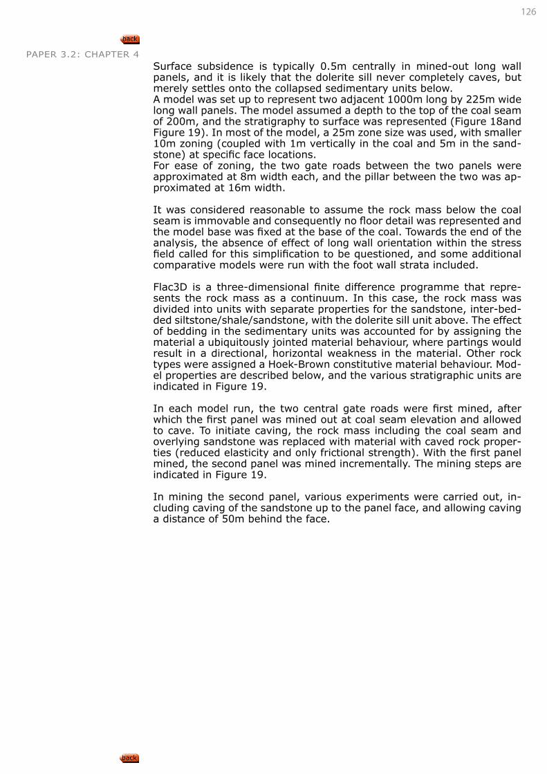
126
PAPER 3.2: CHAPTER 4 Surface subsidence is typically 0.5m centrally in mined-out long wall panels, and it is likely that the dolerite sill never completely caves, but merely settles onto the collapsed sedimentary units below. A model was set up to represent two adjacent 1000m long by 225m wide long wall panels. The model assumed a depth to the top of the coal seam of 200m, and the stratigraphy to surface was represented (Figure 18and Figure 19). In most of the model, a 25m zone size was used, with smaller 10m zoning (coupled with 1m vertically in the coal and 5m in the sand-stone) at specific face locations.For ease of zoning, the two gate roads between the two panels were approximated at 8m width each, and the pillar between the two was ap-proximated at 16m width.
It was considered reasonable to assume the rock mass below the coal seam is immovable and consequently no floor detail was represented and the model base was fixed at the base of the coal. Towards the end of the analysis, the absence of effect of long wall orientation within the stress field called for this simplification to be questioned, and some additional comparative models were run with the foot wall strata included.
Flac3D is a three-dimensional finite difference programme that repre-sents the rock mass as a continuum. In this case, the rock mass was divided into units with separate properties for the sandstone, inter-bed-ded siltstone/shale/sandstone, with the dolerite sill unit above. The effect of bedding in the sedimentary units was accounted for by assigning the material a ubiquitously jointed material behaviour, where partings would result in a directional, horizontal weakness in the material. Other rock types were assigned a Hoek-Brown constitutive material behaviour. Mod-el properties are described below, and the various stratigraphic units are indicated in Figure 19.
In each model run, the two central gate roads were first mined, after which the first panel was mined out at coal seam elevation and allowed to cave. To initiate caving, the rock mass including the coal seam and overlying sandstone was replaced with material with caved rock proper-ties (reduced elasticity and only frictional strength). With the first panel mined, the second panel was mined incrementally. The mining steps are indicated in Figure 19.
In mining the second panel, various experiments were carried out, in-cluding caving of the sandstone up to the panel face, and allowing caving a distance of 50m behind the face.
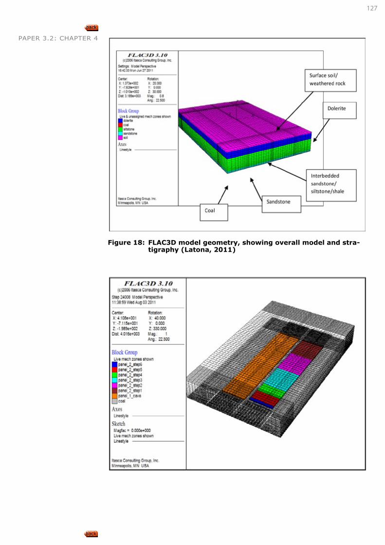
127
PAPER 3.2: CHAPTER 4
Figure 18: FLAC3D model geometry, showing overall model and stra-tigraphy (Latona, 2011)
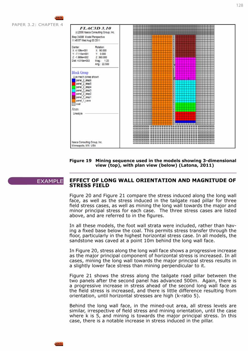
128
PAPER 3.2: CHAPTER 4
Figure 19 Mining sequence used in the models showing 3-dimensional view (top), with plan view (below) (Latona, 2011)
EFFECT OF LONG WALL ORIENTATION AND MAGNITUDE OF STRESS FIELD
Figure 20 and Figure 21 compare the stress induced along the long wall face, as well as the stress induced in the tailgate road pillar for three field stress cases, as well as mining the long wall towards the major and minor principal stress for each case. The three stress cases are listed above, and are referred to in the figures.
In all these models, the foot wall strata were included, rather than hav-ing a fixed base below the coal. This permits stress transfer through the floor, particularly in the highest horizontal stress case. In all models, the sandstone was caved at a point 10m behind the long wall face.
In Figure 20, stress along the long wall face shows a progressive increase as the major principal component of horizontal stress is increased. In all cases, mining the long wall towards the major principal stress results in a slightly lower face stress than mining perpendicular to it.
Figure 21 shows the stress along the tailgate road pillar between the two panels after the second panel has advanced 500m. Again, there is a progressive increase in stress ahead of the second long wall face as the field stress is increased, and there is little difference resulting from orientation, until horizontal stresses are high (k-ratio 5).
Behind the long wall face, in the mined-out area, all stress levels are similar, irrespective of field stress and mining orientation, until the case where k is 5, and mining is towards the major principal stress. In this case, there is a notable increase in stress induced in the pillar.
EXAMPLE
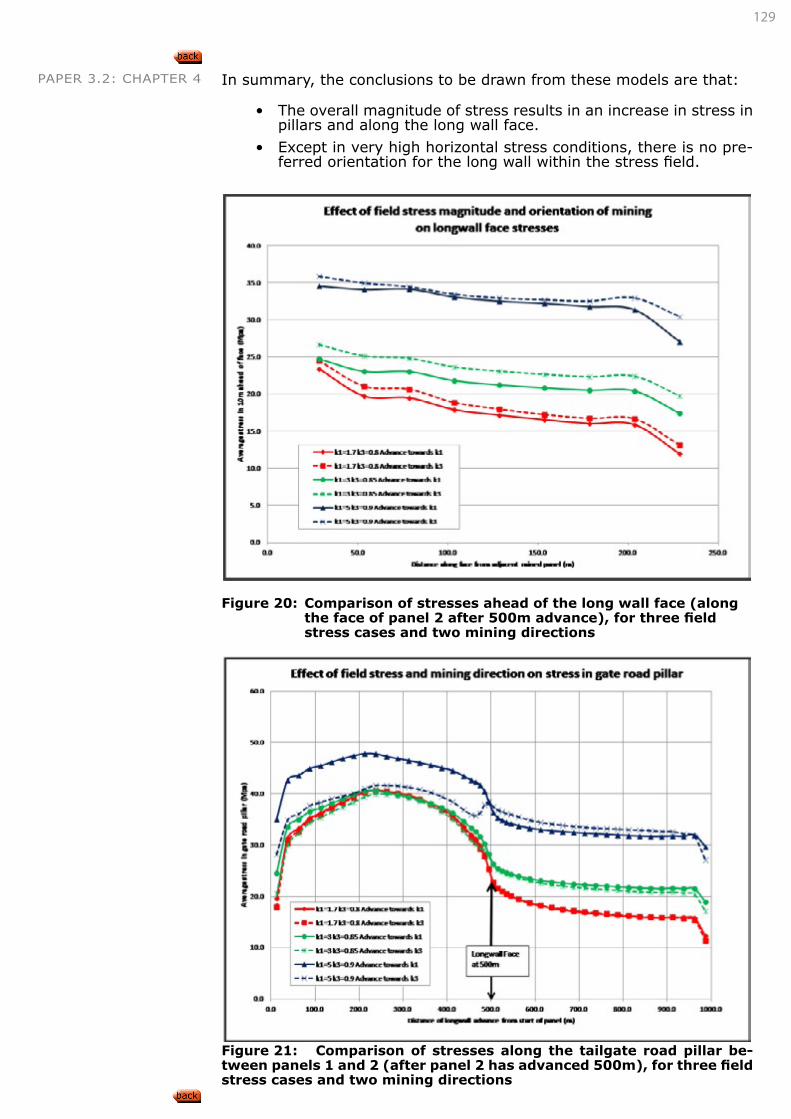
129
PAPER 3.2: CHAPTER 4 In summary, the conclusions to be drawn from these models are that:
• The overall magnitude of stress results in an increase in stress in pillars and along the long wall face.
• Except in very high horizontal stress conditions, there is no pre-ferred orientation for the long wall within the stress field.
Figure 20: Comparison of stresses ahead of the long wall face (along
the face of panel 2 after 500m advance), for three field stress cases and two mining directions
Figure 21: Comparison of stresses along the tailgate road pillar be-tween panels 1 and 2 (after panel 2 has advanced 500m), for three field stress cases and two mining directions
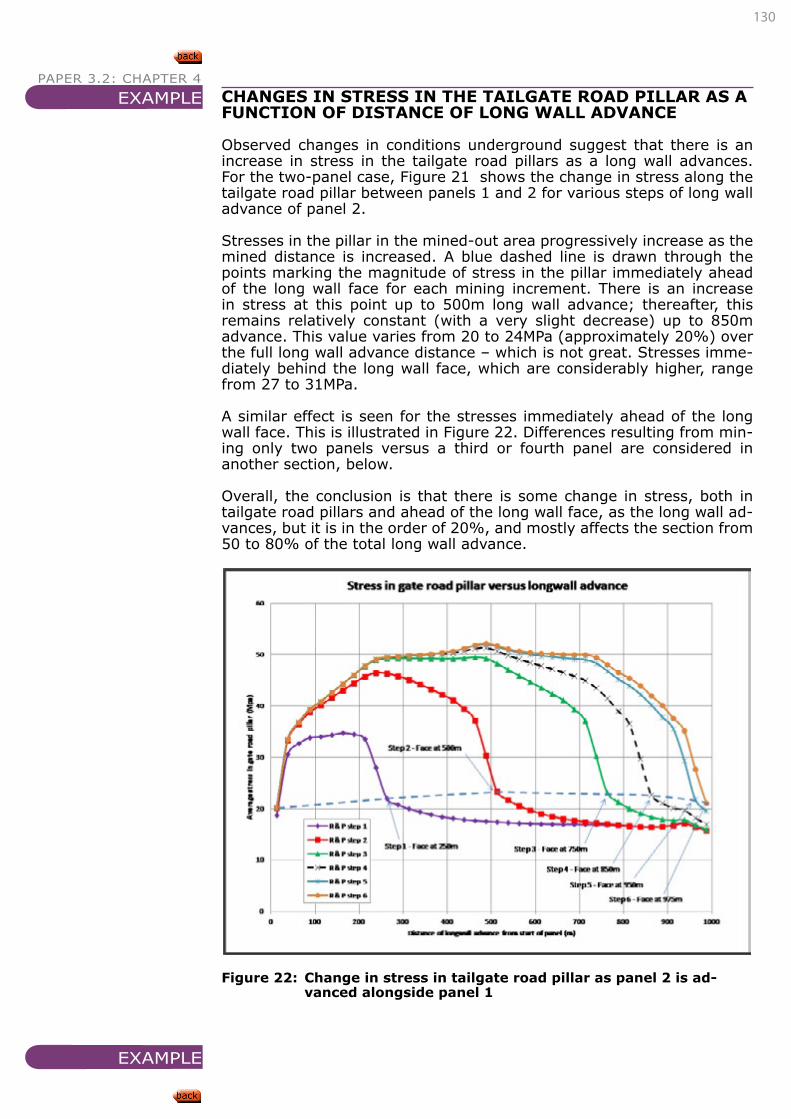
130
PAPER 3.2: CHAPTER 4
CHANGES IN STRESS IN THE TAILGATE ROAD PILLAR AS A FUNCTION OF DISTANCE OF LONG WALL ADVANCE
Observed changes in conditions underground suggest that there is an increase in stress in the tailgate road pillars as a long wall advances. For the two-panel case, Figure 21 shows the change in stress along the tailgate road pillar between panels 1 and 2 for various steps of long wall advance of panel 2.
Stresses in the pillar in the mined-out area progressively increase as the mined distance is increased. A blue dashed line is drawn through the points marking the magnitude of stress in the pillar immediately ahead of the long wall face for each mining increment. There is an increase in stress at this point up to 500m long wall advance; thereafter, this remains relatively constant (with a very slight decrease) up to 850m advance. This value varies from 20 to 24MPa (approximately 20%) over the full long wall advance distance – which is not great. Stresses imme-diately behind the long wall face, which are considerably higher, range from 27 to 31MPa.
A similar effect is seen for the stresses immediately ahead of the long wall face. This is illustrated in Figure 22. Differences resulting from min-ing only two panels versus a third or fourth panel are considered in another section, below.
Overall, the conclusion is that there is some change in stress, both in tailgate road pillars and ahead of the long wall face, as the long wall ad-vances, but it is in the order of 20%, and mostly affects the section from 50 to 80% of the total long wall advance.
Figure 22: Change in stress in tailgate road pillar as panel 2 is ad-
vanced alongside panel 1
EXAMPLE
EXAMPLE
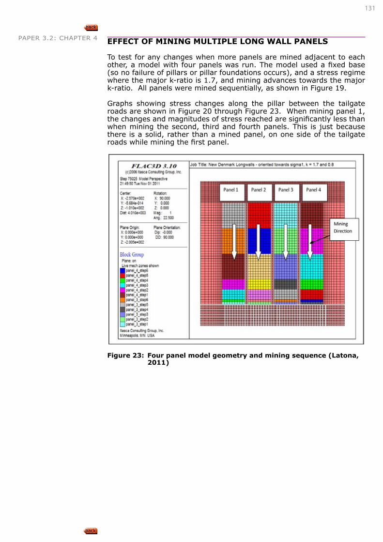
131
PAPER 3.2: CHAPTER 4 EFFECT OF MINING MULTIPLE LONG WALL PANELS
To test for any changes when more panels are mined adjacent to each other, a model with four panels was run. The model used a fixed base (so no failure of pillars or pillar foundations occurs), and a stress regime where the major k-ratio is 1.7, and mining advances towards the major k-ratio. All panels were mined sequentially, as shown in Figure 19.
Graphs showing stress changes along the pillar between the tailgate roads are shown in Figure 20 through Figure 23. When mining panel 1, the changes and magnitudes of stress reached are significantly less than when mining the second, third and fourth panels. This is just because there is a solid, rather than a mined panel, on one side of the tailgate roads while mining the first panel.
Figure 23: Four panel model geometry and mining sequence (Latona, 2011)
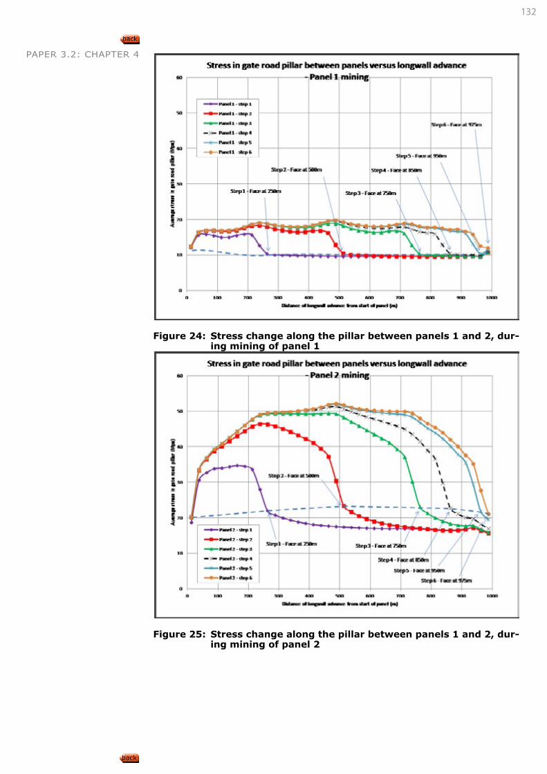
132
PAPER 3.2: CHAPTER 4
Figure 24: Stress change along the pillar between panels 1 and 2, dur-
ing mining of panel 1
Figure 25: Stress change along the pillar between panels 1 and 2, dur-
ing mining of panel 2
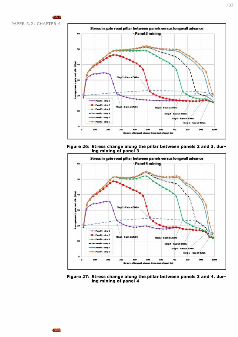
133
PAPER 3.2: CHAPTER 4
Figure 26: Stress change along the pillar between panels 2 and 3, dur-
ing mining of panel 3
Figure 27: Stress change along the pillar between panels 3 and 4, dur-
ing mining of panel 4
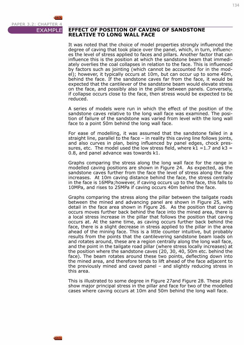
134
PAPER 3.2: CHAPTER 4
EFFECT OF POSITION OF CAVING OF SANDSTONE RELATIVE TO LONG WALL FACE
It was noted that the choice of model properties strongly influenced the degree of caving that took place over the panel, which, in turn, influenc-es the level of stress applied to faces and pillars. Another factor that can influence this is the position at which the sandstone beam that immedi-ately overlies the coal collapses in relation to the face. This is influenced by factors such as jointing (which cannot be accounted for in the mod-el); however, it typically occurs at 10m, but can occur up to some 40m, behind the face. If the sandstone caves far from the face, it would be expected that the cantilever of the sandstone beam would elevate stress on the face, and possibly also in the pillar between panels. Conversely, if collapse occurs close to the face, then stress would be expected to be reduced.
A series of models were run in which the effect of the position of the sandstone caves relative to the long wall face was examined. The posi-tion of failure of the sandstone was varied from level with the long wall face to a point 50m behind the long wall face.
For ease of modelling, it was assumed that the sandstone failed in a straight line, parallel to the face – in reality this caving line follows joints, and also curves in plan, being influenced by panel edges, chock pres-sures, etc. The model used the low stress field, where k1 =1.7 and k3 = 0.8, and panel advance was towards k1.
Graphs comparing the stress along the long wall face for the range in modelled caving positions are shown in Figure 24. As expected, as the sandstone caves further from the face the level of stress along the face increases. At 10m caving distance behind the face, the stress centrally in the face is 16MPa;however, if caving occurs up to the face, this falls to 10MPa, and rises to 25MPa if caving occurs 40m behind the face. Graphs comparing the stress along the pillar between the tailgate roads between the mined and advancing panel are shown in Figure 25, with detail in the face area shown in Figure 26. As the position that caving occurs moves further back behind the face into the mined area, there is a local stress increase in the pillar that follows the position that caving occurs at. At the same time, as caving occurs further back behind the face, there is a slight decrease in stress applied to the pillar in the area ahead of the mining face. This is a little counter intuitive, but probably results from the points that the cantilevering sandstone beam loads on and rotates around, these are a region centrally along the long wall face, and the point in the tailgate road pillar (where stress locally increases) at the position where the sandstone caves (20, 30, 40, 50m etc. behind the face). The beam rotates around these two points, deflecting down into the mined area, and therefore tends to lift ahead of the face adjacent to the previously mined and caved panel – and slightly reducing stress in this area.
This is illustrated to some degree in Figure 27and Figure 28. These plots show major principal stress in the pillar and face for two of the modelled cases where caving occurs at 10m and 50m behind the long wall face.
EXAMPLE
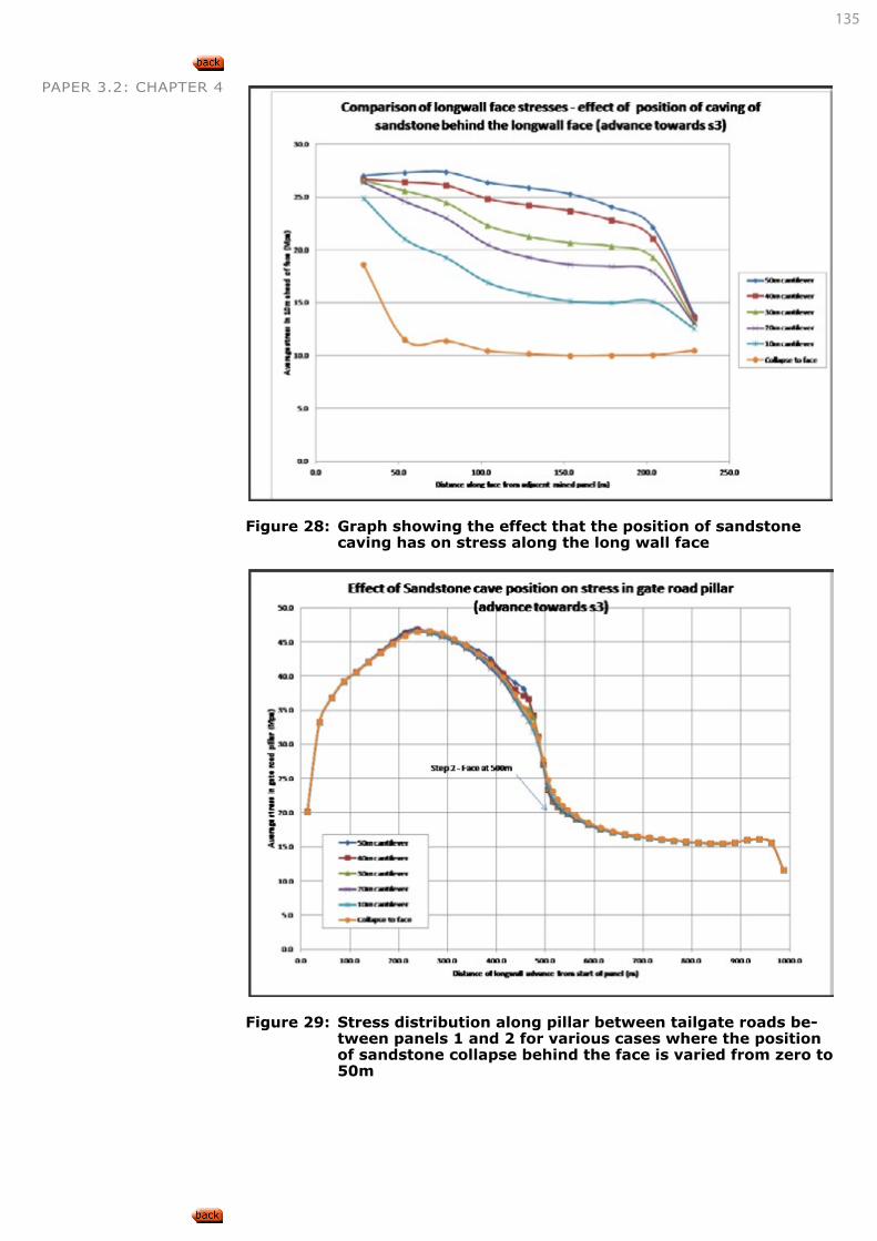
135
PAPER 3.2: CHAPTER 4
Figure 28: Graph showing the effect that the position of sandstone caving has on stress along the long wall face
Figure 29: Stress distribution along pillar between tailgate roads be-
tween panels 1 and 2 for various cases where the position of sandstone collapse behind the face is varied from zero to 50m
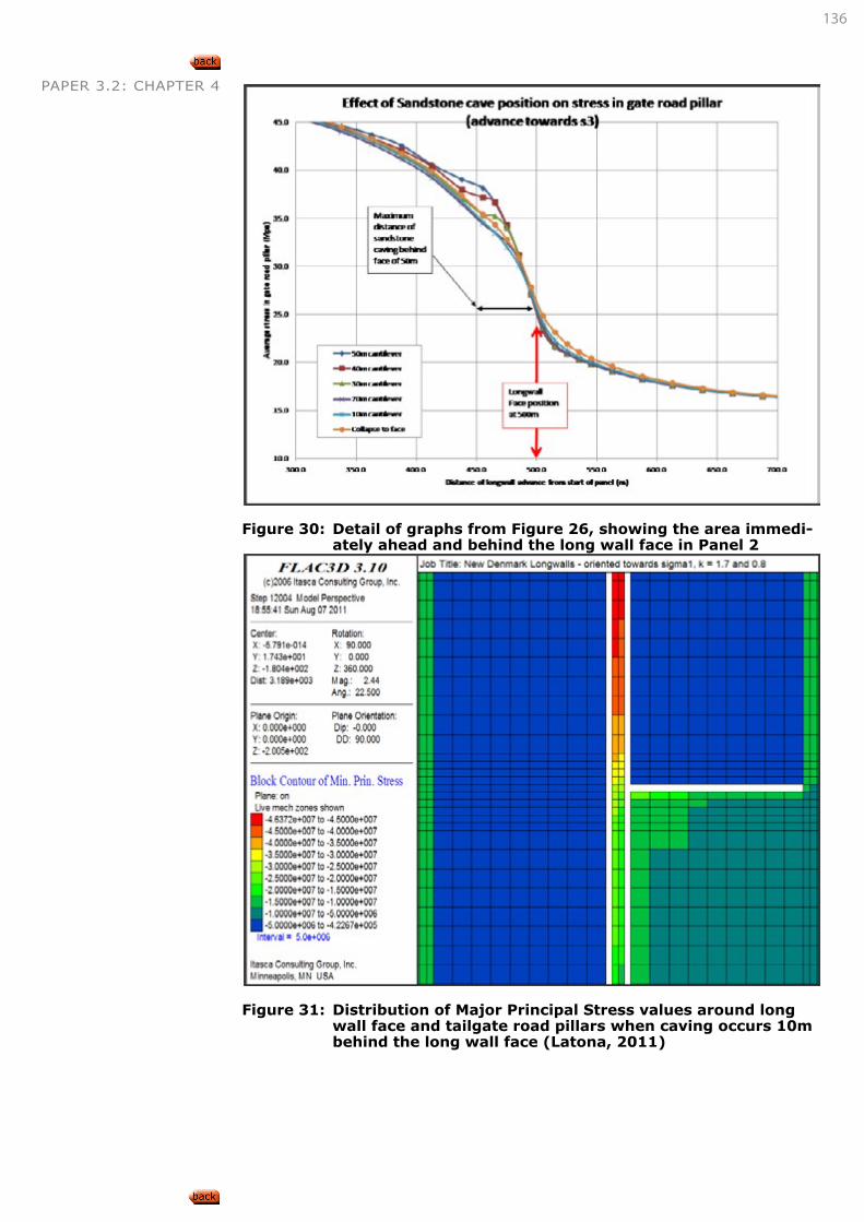
136
PAPER 3.2: CHAPTER 4
Figure 30: Detail of graphs from Figure 26, showing the area immedi-
ately ahead and behind the long wall face in Panel 2
Figure 31: Distribution of Major Principal Stress values around long
wall face and tailgate road pillars when caving occurs 10m behind the long wall face (Latona, 2011)
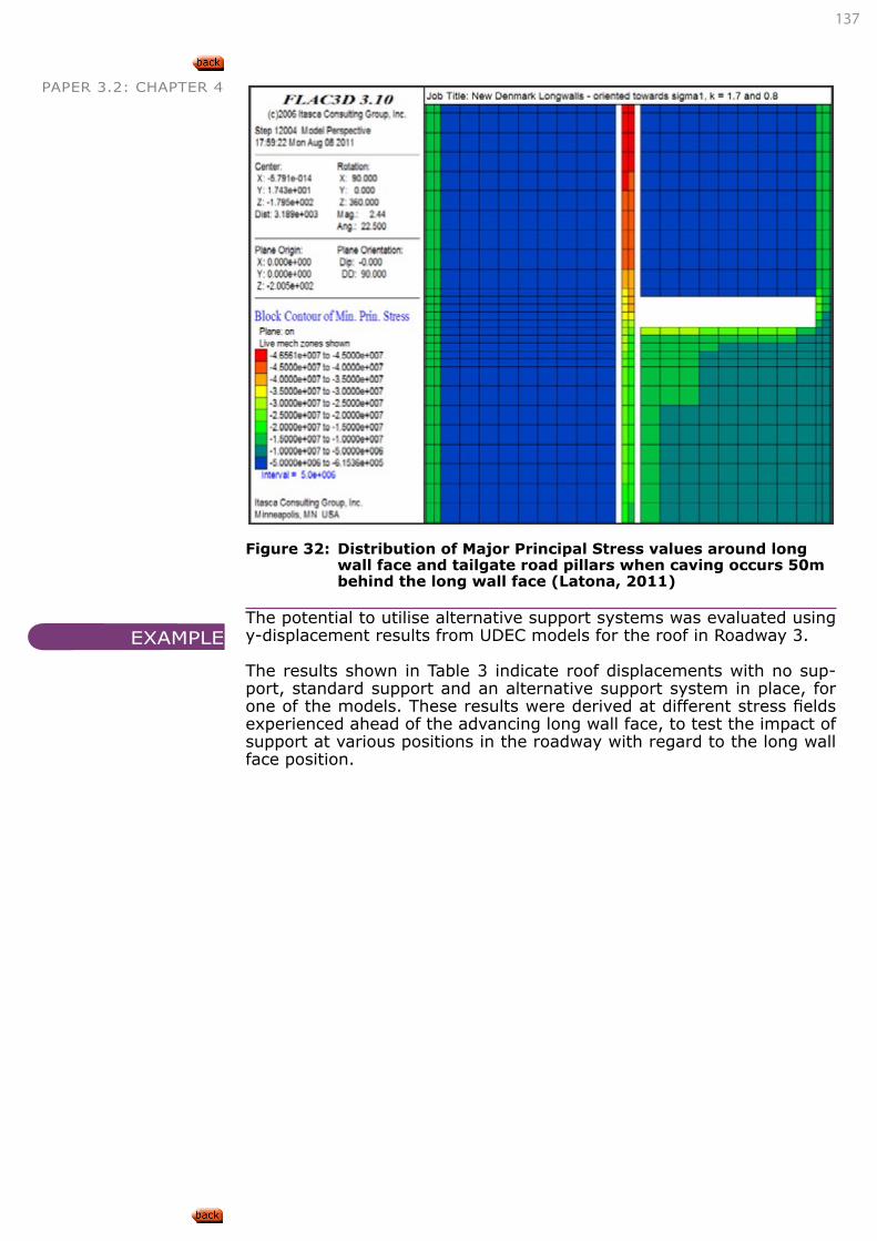
137
PAPER 3.2: CHAPTER 4
Figure 32: Distribution of Major Principal Stress values around long
wall face and tailgate road pillars when caving occurs 50m behind the long wall face (Latona, 2011)
The potential to utilise alternative support systems was evaluated using y-displacement results from UDEC models for the roof in Roadway 3.
The results shown in Table 3 indicate roof displacements with no sup-port, standard support and an alternative support system in place, for one of the models. These results were derived at different stress fields experienced ahead of the advancing long wall face, to test the impact of support at various positions in the roadway with regard to the long wall face position.
EXAMPLE
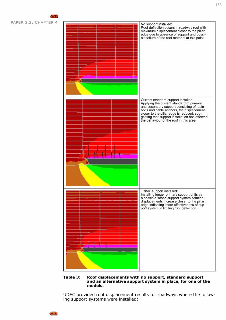
138
PAPER 3.2: CHAPTER 4 No support installed:Roof deflection occurs in roadway roof with maximum displacement closer to the pillar edge due to absence of support and possi-ble failure of the roof material at this point.
Current standard support installed:Applying the current standard of primary and secondary support consisting of resin bolts and cable anchors, the displacement closer to the pillar edge is reduced, sug-gesting that support installation has affected the behaviour of the roof in this area.
‘Other’ support installed:Installing longer primary support units as a possible ‘other’ support system solution, displacements increase closer to the pillar edge indicating lower effectiveness of sup-port system in limiting roof deflection.
Table 3: Roof displacements with no support, standard support
and an alternative support system in place, for one of the models.
UDEC provided roof displacement results for roadways where the follow-ing support systems were installed:
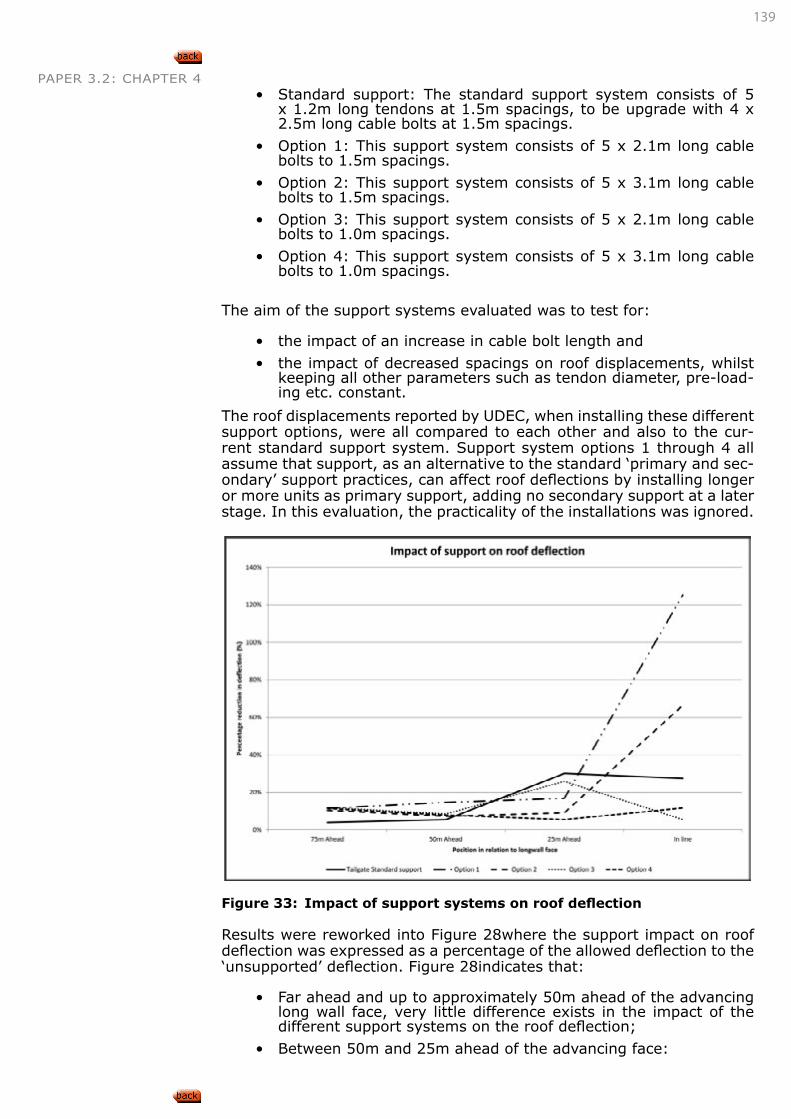
139
PAPER 3.2: CHAPTER 4• Standard support: The standard support system consists of 5
x 1.2m long tendons at 1.5m spacings, to be upgrade with 4 x 2.5m long cable bolts at 1.5m spacings.
• Option 1: This support system consists of 5 x 2.1m long cable bolts to 1.5m spacings.
• Option 2: This support system consists of 5 x 3.1m long cable bolts to 1.5m spacings.
• Option 3: This support system consists of 5 x 2.1m long cable bolts to 1.0m spacings.
• Option 4: This support system consists of 5 x 3.1m long cable bolts to 1.0m spacings.
The aim of the support systems evaluated was to test for:
• the impact of an increase in cable bolt length and
• the impact of decreased spacings on roof displacements, whilst keeping all other parameters such as tendon diameter, pre-load-ing etc. constant.
The roof displacements reported by UDEC, when installing these different support options, were all compared to each other and also to the cur-rent standard support system. Support system options 1 through 4 all assume that support, as an alternative to the standard ‘primary and sec-ondary’ support practices, can affect roof deflections by installing longer or more units as primary support, adding no secondary support at a later stage. In this evaluation, the practicality of the installations was ignored.
Figure 33: Impact of support systems on roof deflection
Results were reworked into Figure 28where the support impact on roof deflection was expressed as a percentage of the allowed deflection to the ‘unsupported’ deflection. Figure 28indicates that:
• Far ahead and up to approximately 50m ahead of the advancing long wall face, very little difference exists in the impact of the different support systems on the roof deflection;
• Between 50m and 25m ahead of the advancing face:
140
PAPER 3.2: CHAPTER 4 • All alternative support options perform better than the current standard;
• At approximately 25m ahead of the advancing long wall face to a position in line with the face, the following appears to be significant:
• The longer cable support options (Options 1 and 2) behave worse than the standard and allow more roof deflection to occur;
• The reduced spacing options (Options 3 and 4) behave better than the standard and allow less roof deflection to occur.
These results indicate that alternative support systems could be consid-ered in an attempt to rid the mining cycle of multiple support installation phases, but that the decrease in support spacings, i.e. more support units per linear metre, is more significant than increasing support unit lengths. This holds true to the concept of beam building in laminated environments where the increase in clamping of laminations increases shear strength of planes and this reduces roof deflection. This increase in clamping is produced by increasing the pre-loading on the units or increasing the number of units (reduced spacings), and only not by an increase in unit length.
4.1.3. STOOPING
Beukes (1989) defines pillar extraction as follows: “In Pillar extraction the panels consist of a bord-and-pillar mining layout where many pillars are created but only extracted at some later date as a panel must be developed completely before pillar extraction can commence. There are two basic approaches to pillar extraction. Firstly, the extraction of pillars in old workings where little or no account was taken of secondary extrac-tion during the initial panel and pillar design, and secondly, the extraction of pillars in panels designed specifically for pillar extraction.”
There are five golden rules for pillar extraction given by van der Merwe (1995): 1. Always mine towards the nearest solid
2. Never leave a half-finished pillar
3. Leave a slightly bigger snook on the intersection
4. Avoid as far as possible stooping between two goafs
5. Never change direction of sequence.
The single most important principle in stooping is to be consistent. The extraction sequence of each pillar must be a carbon copy of the previ-ous one and the rate of production must be as consistent as possible. Stooping is accompanied by significant stress cycles, repeated each time a pillar is stooped and the five golden rules are aimed at smoothing out the stress variations.
141
PAPER 3.2: CHAPTER 4
SKETCH, DESCRIBE, EXPLAIN AND DISCUSS THE FOLLOWING TYPES OF STOOPING OPERATION:
• Drilling and blasting,
• Mechanical breaking.
Drilling and blasting vs. mechanical breakingThe main difference between pillar extraction through drilling and blast-ing and through continuous miners is that when using the continuous mining method, one pillar at a time is extracted, whereas a number of pillars, even a row of pillars, can be extracted simultaneously when using conventional methods. Another difference is the angle at which the ex-traction takes place. Continuous mining is done in a straight line whereas in conventional methods the pillars are extracted at an angle of between 30° and 45°.This has an effect on the load borne by the pillars on the goaf edge.
Drilling and blasting (Conventional pillar extraction)The most commonly used methods of conventional pillar extraction are splitting and quartering and open end lift. There are, however, many different methods depending on pillar size and strata conditions and the pillars must be designed taking all factors into consideration and the ex-traction method to be used.
Factors to be considered when determining pillar size for conventional pillar extraction are outlined by Beukes (1992) as:
• The strength of the pillars must be sufficient to support the over-burden in the worst possible situation (e.g. before failure of the dolerite sill). If the strength of the pillar and the load on the pillar can be accurately determined, a safety factor can be determined by using this data. If not, Salamon and Oravecz’s recommenda-tion of a safety factor not less than 1.8 is a good guideline. When the rate of retreat is slow as in handgot pillar extraction, safety factors in excess of 2.0 are recommended.
• The size of the pillars should be designed to correspond with the extraction method. This is important as it will improve productiv-ity and prevent the formation of large snooks.
• Unnecessarily large pillars should be avoided as it will increase the time spent in extracting the pillars and thereby exposing the diminishing pillar to increased stress for too long. This could re-sult in premature failure.
• Back-to-back lifts should be avoided as far as possible.
Continuous minersFactors to be considered when designing pillars for extraction with con-tinuous miners:
• The strength of the pillars must be sufficient to support the over-burden in the worst possible situation (e.g. before failure of the dolerite sill). If the strength of the pillar and the load on the pillar can be accurately determined, a safety factor can be determined by using this data. If not, Salamon and Oravecz’s recommenda-tion of a safety factor not less than 1.8 is a good guideline. When the rate of retreat is fast as in mechanised pillar extraction, safe-ty factors of between 1.8 and 2.0 are recommended.
• The development adjacent to and through the pillar should be wide enough to accommodate the existing mining equipment.
LEARNING OUTCOME 4.1.3.1
142
PAPER 3.2: CHAPTER 4 • The extraction method should require the minimum continuous miner tramming as this reduces production time.
• The extraction method should require the minimum of breaker and finger lines as these are costly and time consuming.
If pillars are split into fenders, the fenders should be wide enough to carry the load during the extraction, but narrow enough to avoid the for-mation of excessive snooks.
Caution should be taken to not design unnecessarily large pillars as indi-vidual pillars need to be extracted in the shortest possible time to prevent the diminishing pillar being exposed to high loads for long periods.
The extraction method should aim to leave as little as possible coal be-hind in the form of snooks. Snooks may not only lead to a loss of reserves, but also prevent the overlying strata from collapsing in the planned manner and resulting in unnecessary stress on the pillars to be extracted.
Mobile roof support systems are used to protect the face from the goaf area.
DESCRIBE, EXPLAIN AND DISCUSS THE FUNCTIONS OF THE FOLLOWING CONSTITUENTS IN EACH OF THE ABOVE METHODS:
• Snooks,
• breaker lines,
• finger lines,
• fenders.
Snooks:A snook is defined as a remnant of a pillar left behind during stooping to provide short-term local support and which will not be mined out.
If the size of these remnants is excessive, they can prevent regular caving of the intermediate roof strata. Snooks are intended to stabilise the mi-cro-environment without upsetting the balance in the macro-environment.
The ideal stooping panel can be divided into three zones:
• The stooped area: where unconditional snook failure must occur;
• The working area: where temporary stability is required;
• The unstooped area: where pillars have to be unconditionally stable.
Refer to “LEARNING OUTCOME 4.1.3.3” on page 144
CONNECTION 42
LEARNING OUTCOME 4.1.3.2
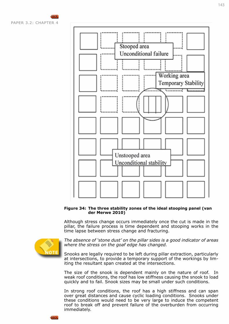
143
PAPER 3.2: CHAPTER 4
Figure 34: The three stability zones of the ideal stooping panel (van
der Merwe 2010)
Although stress change occurs immediately once the cut is made in the pillar, the failure process is time dependent and stooping works in the time lapse between stress change and fracturing.
The absence of ‘stone dust’ on the pillar sides is a good indicator of areas where the stress on the goaf edge has changed.
Snooks are legally required to be left during pillar extraction, particularly at intersections, to provide a temporary support of the workings by lim-iting the resultant span created at the intersections.
The size of the snook is dependent mainly on the nature of roof. In weak roof conditions, the roof has low stiffness causing the snook to load quickly and to fail. Snook sizes may be small under such conditions.
In strong roof conditions, the roof has a high stiffness and can span over great distances and cause cyclic loading conditions. Snooks under these conditions would need to be very large to induce the competent roof to break off and prevent failure of the overburden from occurring immediately.
144
PAPER 3.2: CHAPTER 4Snooks offer one of the most effective means of controlling pillar extrac-tion hazards in the vicinity of intersections because:
• They have a high load carrying potential.
• They are formed in-situ and therefore provide continuous resist-ance to the roof and floor displacements.
• They are a much stiffer support system than either timber or MBLS and therefore provide a greater resistance against displacement.
• They can be designed to be located in a more effective position for restricting roof span than with either timber or MBLS.
The type of extraction method also impacts on the increase in size of the intersection. Double-sided lifting (lifting left and right from a split) cre-ates a significantly larger intersection area than when only single-sided lifting is employed. The overall snook design has to cater for adequate roof control across these large intersections. An over-design of these, however, will result in negative caving effects (in preventing caving), while an under-design would result in snook softening and the possibility of their premature failure.
Breaker lines:The purpose of breaker line supports in pillar extraction is to prevent the roof collapsing from the goaf side into roadways. The ideal breaker line forms a sharp edge across the roadway, causing the roof to break off on the goaf side. To perform this function, a breaker line must be stiff and strong enough, and the individual elements, be they mine poles or bolts, must be spaced close enough together. There are three basic types of breaker lines:
• Mine poles,
• Roof bolts and
• Mobile hydraulic prop (Mobile roof support) systems.
Finger lines:A finger line is a row of timber poles installed in the centre of a cut taken from a pillar.
Fenders:A fender is defined as a strip of a pillar that has been isolated from the main body of the pillar by mining during stooping operations and which is to be mined out in the immediate next mining phase.
Fenders should be at least 5m wide to ensure adequate protection during the extraction process. In the case of extracting heights greater than 3m, it is wise to stay on the safe side and design fenders with a width-to-height ratio of at least 2.
SKETCH, DESCRIBE, EXPLAIN AND DISCUSS ROOF BOLT AND MECHANISED BREAKER LINES.
A breaker line is a row or rows of either timber poles or roof bolts in-stalled across the width of a bord specifically to:
• Arrest the planned displacement of roof strata at that point.
• Prevent roof failures from spreading.
• Form a clear demarcation between the goaf and the working area.
A roof bolt is a steel tendon anchored chemically or mechanically, com-plete with a nut and washer and meeting performance specifications.
LEARNING OUTCOME 4.1.3.3
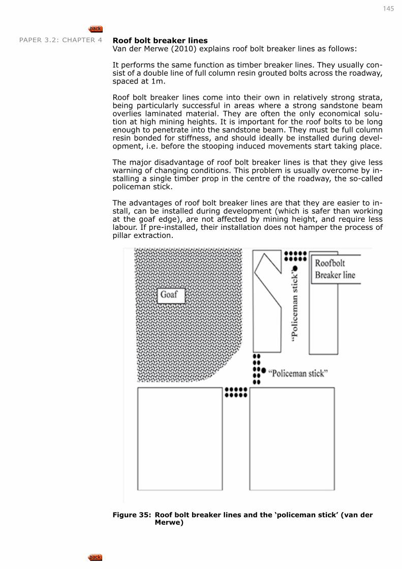
145
PAPER 3.2: CHAPTER 4 Roof bolt breaker lines Van der Merwe (2010) explains roof bolt breaker lines as follows:
It performs the same function as timber breaker lines. They usually con-sist of a double line of full column resin grouted bolts across the roadway, spaced at 1m.
Roof bolt breaker lines come into their own in relatively strong strata, being particularly successful in areas where a strong sandstone beam overlies laminated material. They are often the only economical solu-tion at high mining heights. It is important for the roof bolts to be long enough to penetrate into the sandstone beam. They must be full column resin bonded for stiffness, and should ideally be installed during devel-opment, i.e. before the stooping induced movements start taking place.
The major disadvantage of roof bolt breaker lines is that they give less warning of changing conditions. This problem is usually overcome by in-stalling a single timber prop in the centre of the roadway, the so-called policeman stick.
The advantages of roof bolt breaker lines are that they are easier to in-stall, can be installed during development (which is safer than working at the goaf edge), are not affected by mining height, and require less labour. If pre-installed, their installation does not hamper the process of pillar extraction.
Figure 35: Roof bolt breaker lines and the ‘policeman stick’ (van der
Merwe)
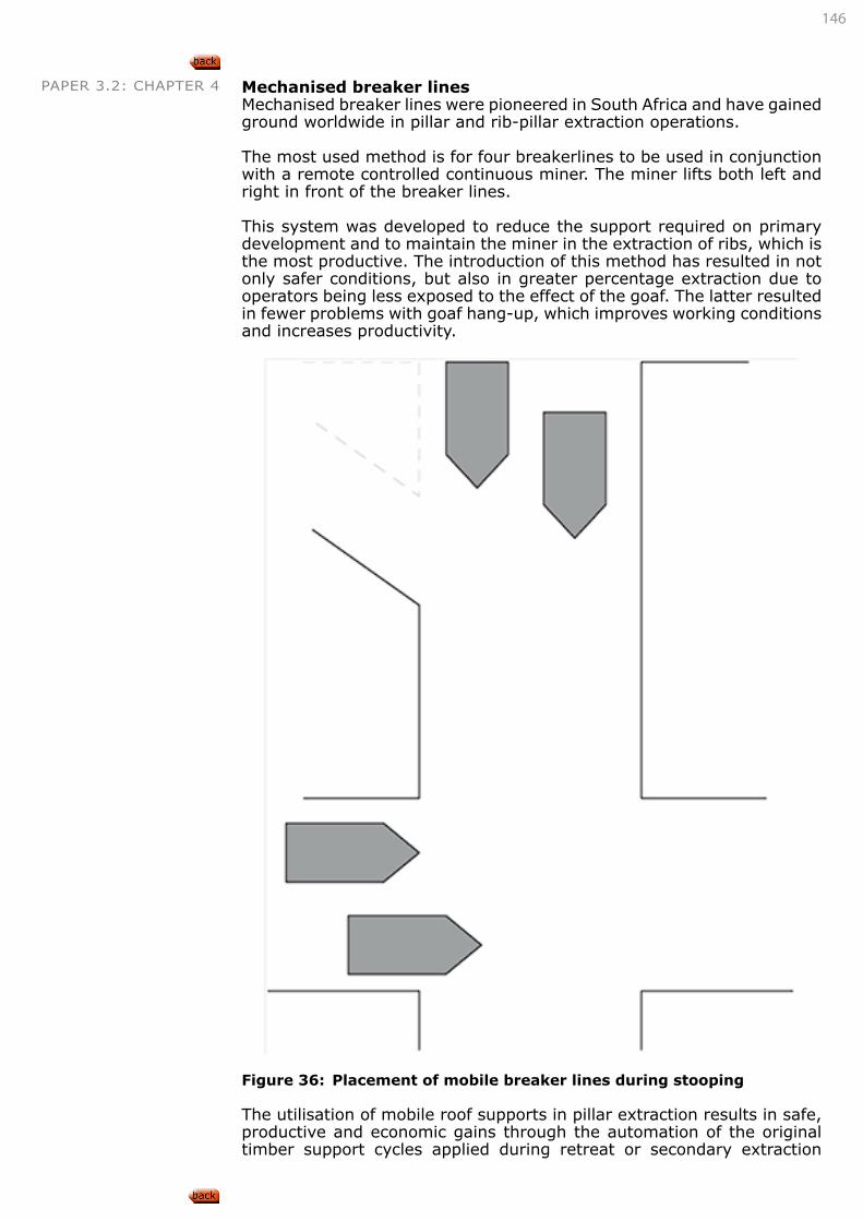
146
PAPER 3.2: CHAPTER 4 Mechanised breaker lines Mechanised breaker lines were pioneered in South Africa and have gained ground worldwide in pillar and rib-pillar extraction operations.
The most used method is for four breakerlines to be used in conjunction with a remote controlled continuous miner. The miner lifts both left and right in front of the breaker lines.
This system was developed to reduce the support required on primary development and to maintain the miner in the extraction of ribs, which is the most productive. The introduction of this method has resulted in not only safer conditions, but also in greater percentage extraction due to operators being less exposed to the effect of the goaf. The latter resulted in fewer problems with goaf hang-up, which improves working conditions and increases productivity.
Figure 36: Placement of mobile breaker lines during stooping
The utilisation of mobile roof supports in pillar extraction results in safe, productive and economic gains through the automation of the original timber support cycles applied during retreat or secondary extraction
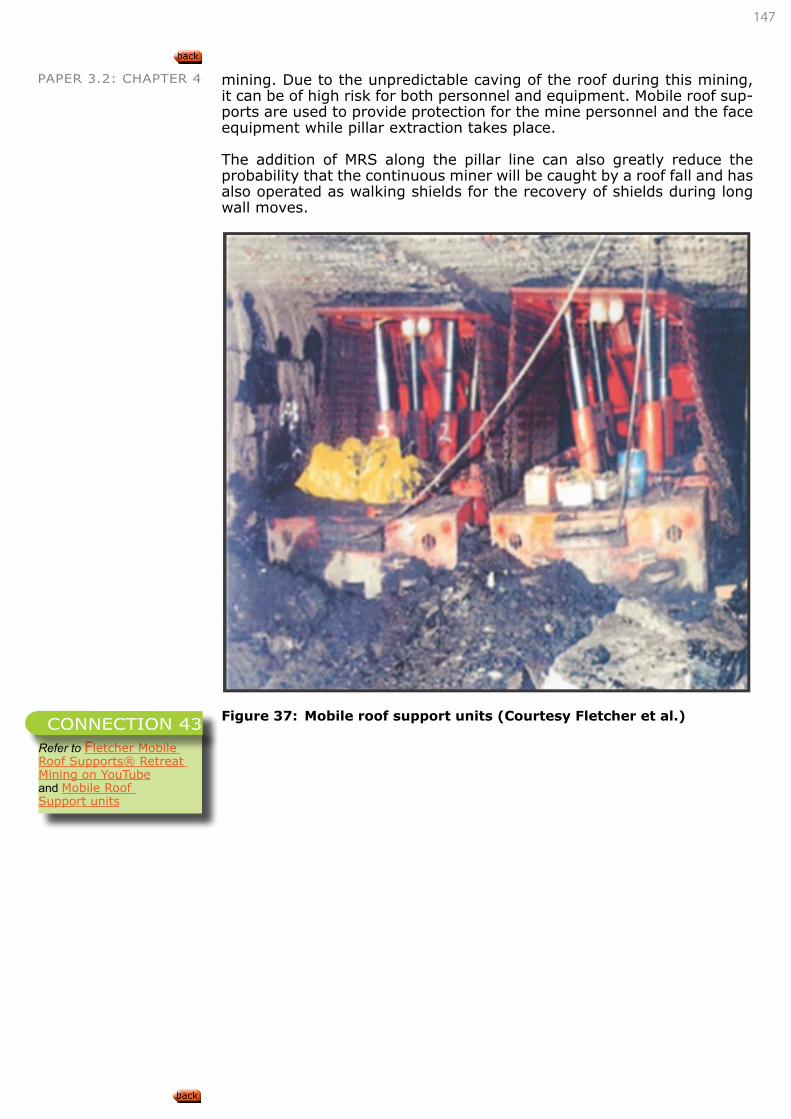
147
PAPER 3.2: CHAPTER 4 mining. Due to the unpredictable caving of the roof during this mining, it can be of high risk for both personnel and equipment. Mobile roof sup-ports are used to provide protection for the mine personnel and the face equipment while pillar extraction takes place.
The addition of MRS along the pillar line can also greatly reduce the probability that the continuous miner will be caught by a roof fall and has also operated as walking shields for the recovery of shields during long wall moves.
Figure 37: Mobile roof support units (Courtesy Fletcher et al.)
Refer to Fletcher Mobile Roof Supports® Retreat Mining on YouTubeand Mobile Roof Support units
CONNECTION 43
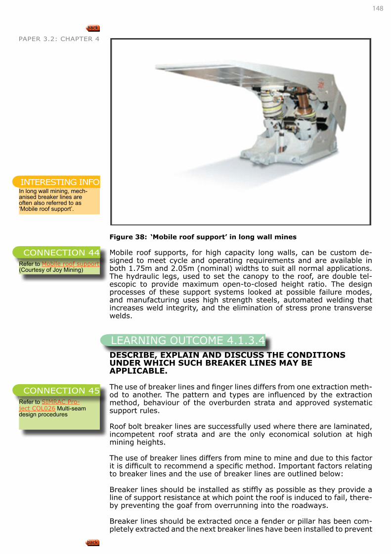
148
PAPER 3.2: CHAPTER 4
Figure 38: ‘Mobile roof support’ in long wall mines
Mobile roof supports, for high capacity long walls, can be custom de-signed to meet cycle and operating requirements and are available in both 1.75m and 2.05m (nominal) widths to suit all normal applications. The hydraulic legs, used to set the canopy to the roof, are double tel-escopic to provide maximum open-to-closed height ratio. The design processes of these support systems looked at possible failure modes, and manufacturing uses high strength steels, automated welding that increases weld integrity, and the elimination of stress prone transverse welds.
DESCRIBE, EXPLAIN AND DISCUSS THE CONDITIONS UNDER WHICH SUCH BREAKER LINES MAY BE APPLICABLE.
The use of breaker lines and finger lines differs from one extraction meth-od to another. The pattern and types are influenced by the extraction method, behaviour of the overburden strata and approved systematic support rules.
Roof bolt breaker lines are successfully used where there are laminated, incompetent roof strata and are the only economical solution at high mining heights.
The use of breaker lines differs from mine to mine and due to this factor it is difficult to recommend a specific method. Important factors relating to breaker lines and the use of breaker lines are outlined below:
Breaker lines should be installed as stiffly as possible as they provide a line of support resistance at which point the roof is induced to fail, there-by preventing the goaf from overrunning into the roadways.
Breaker lines should be extracted once a fender or pillar has been com-pletely extracted and the next breaker lines have been installed to prevent
In long wall mining, mech-anised breaker lines are often also referred to as ‘Mobile roof support’.
INTERESTING INFO
Refer to Mobile roof support (Courtesy of Joy Mining)
CONNECTION 44
LEARNING OUTCOME 4.1.3.4
Refer to SIMRAC Pro-ject COL026 Multi-seam design procedures
CONNECTION 45
149
PAPER 3.2: CHAPTER 4 load transfer. The support resistance afforded by a breaker line in the goaf should not be underestimated as it can prevent large spans of roof from goafing. As seam height decreases this becomes more important.
If the strata permit, roof bolt breaker lines can be used, but the condition and behaviour of the roof strata should be carefully assessed before roof bolt breaker lines are installed.
DESCRIBE, EXPLAIN AND DISCUSS HOW THE FOLLOWING FACTORS AFFECT PILLAR EXTRACTION:
• Roof conditions,
• dolerite sills,
• mining height
Roof conditionsA weak, friable roof will have fewer overhangs before caving and there-fore create a lower abutment stress. A strong immediate roof will vary in its length prior to breaking and then lengthen again with face advance.
The amount of bending or convergence of the roof also depends on the strata. Shales and laminated sandstones bend appreciably before ac-tually breaking. Rigid sandstone bends less. Convergence is associated with face advance and that less convergence is experienced with rapid advance.
Roof conditions necessary for the correct design of a pillar extraction operation are:
• The local roof strata must be able to safely bridge bords and splits and constantly widening diagonal spans at intersections.
• They must be capable of undergoing convergence deflection of up to, say 60mm, during pillaring without failing.
• Together with the upper strata they must allow early and regular caving to minimise cantilever effects and keep induced abutment stresses on the pillar line at a low level.
• The widths of bords and splits will depend on the nature of the roof. Productivity in primary mining favours a wide bord as op-posed to secondary mining where narrow bords improve roof control.
• A thick, weak and friable roof can be very heavy in relation to available temporary support.
• The presence of a strong and resilient rock such as sandstone as the main roof will hinder caving occurring readily. This causes extra weight to be thrown on the pillar mined, creating difficult conditions in the face area.
Dolerite sillsUnlike those in board and pillar sections, the load on pillars in stooping sections changes constantly due to the dynamic nature of the mining process. When the coal seam is overlain by a dolerite sill that does not break during initial goafing, the load on the pillars is higher than after failure of the sill or when no sill is present.
When stooping has progressed for some distance, but less than the criti-cal distance necessary to cause the sill to fail, the pillars on the goaf edge will support the weight of the strata immediately above them as well as a certain percentage of the weight of the overhang and of the unbroken strata.
LEARNING OUTCOME 4.1.3.5
150
PAPER 3.2: CHAPTER 4 When the dolerite sill fails, the pillars only have to support a percentage of the overhang in addition to the normal load. The angle of this over-hang has to be determined and it will vary from mine to mine depending on the composition and behaviour of the overburden strata. The same applies where no sill in present.
In planning for total extraction where a dolerite sill is present, there are two available options:
1. Designing panels narrow enough to ensure that the dolerite sill does not fail. This will cause the sill to bend without failing and will cause less surface subsidence than when the sill fails. This design would cause an increased load on the pillars underground.
2. Designing panels wide enough to ensure that the dolerite sill does fail. This will avoid unnecessary load on the pillars underground.
The minimum panel width or mining span that will result in dolerite fail-ure can be calculated by using Galvin’s (1972) formula:
L=√(1165t-935t2/d)+2p tanά
Where: L = minimum span resulting in dolerite failure. If the mining span is less than L, then effects of subsidence on surface will be limited to elastic deflection of the dolerite sillt = thickness of the silld = depth to base of the sillp = parting between sill base and coal topά= angle of break.
This is the angle measured off the vertical to the best straight line along the rock failure limit
Mining heightAn increase in mining height will lead to an increase in the amount of scaling from the side walls. Timber props become difficult to install and their effective loading characteristics decrease with an increase in height.
It is recommended that 3m be accepted as a practical limit to the height of pillars that can be extracted because difficulties can be expected with supports longer than 3m.
As with any other total extraction method, the amount of surface subsid-ence due to pillar extraction is a function of the mining height. Therefore, mining height constraints may be imposed by the necessity to protect surface structures.
DETERMINE APPROPRIATE FACTORS OF SAFETY FOR STOOPING UNDER GIVEN CONDITIONS.
Van der Merwe (1998) explains that in the course of pillar extraction, the pillars are subjected to varying magnitudes of stress. The stress mag-nitude is mainly a function of the status of the overburden, i.e. failed or intact, the panel width, face advance and depth of mining. The con-ventional safety factor calculation as discussed in bord and pillar takes into account only the intact overburden weight and does not cater for the stress increase during pillar extraction. This is why it was thought necessary to introduce the extraction safety factor (ESF). Van der Merwe
Refer to SIMRAC Pro-ject COL026 Multi-seam design procedures
CONNECTION 46
LEARNING OUTCOME 4.1.3.6
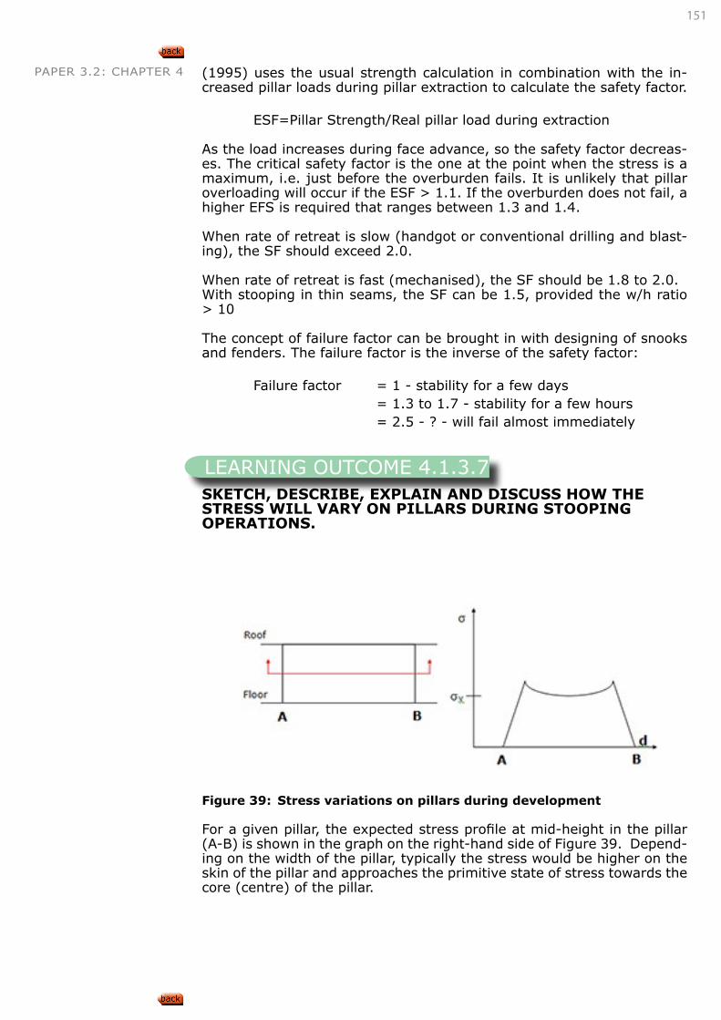
151
PAPER 3.2: CHAPTER 4 (1995) uses the usual strength calculation in combination with the in-creased pillar loads during pillar extraction to calculate the safety factor.
ESF=Pillar Strength/Real pillar load during extraction
As the load increases during face advance, so the safety factor decreas-es. The critical safety factor is the one at the point when the stress is a maximum, i.e. just before the overburden fails. It is unlikely that pillar overloading will occur if the ESF > 1.1. If the overburden does not fail, a higher EFS is required that ranges between 1.3 and 1.4.
When rate of retreat is slow (handgot or conventional drilling and blast-ing), the SF should exceed 2.0.
When rate of retreat is fast (mechanised), the SF should be 1.8 to 2.0.With stooping in thin seams, the SF can be 1.5, provided the w/h ratio > 10
The concept of failure factor can be brought in with designing of snooks and fenders. The failure factor is the inverse of the safety factor:
Failure factor = 1 - stability for a few days = 1.3 to 1.7 - stability for a few hours = 2.5 - ? - will fail almost immediately
SKETCH, DESCRIBE, EXPLAIN AND DISCUSS HOW THE STRESS WILL VARY ON PILLARS DURING STOOPING OPERATIONS.
Figure 39: Stress variations on pillars during development
For a given pillar, the expected stress profile at mid-height in the pillar (A-B) is shown in the graph on the right-hand side of Figure 39. Depend-ing on the width of the pillar, typically the stress would be higher on the skin of the pillar and approaches the primitive state of stress towards the core (centre) of the pillar.
LEARNING OUTCOME 4.1.3.7
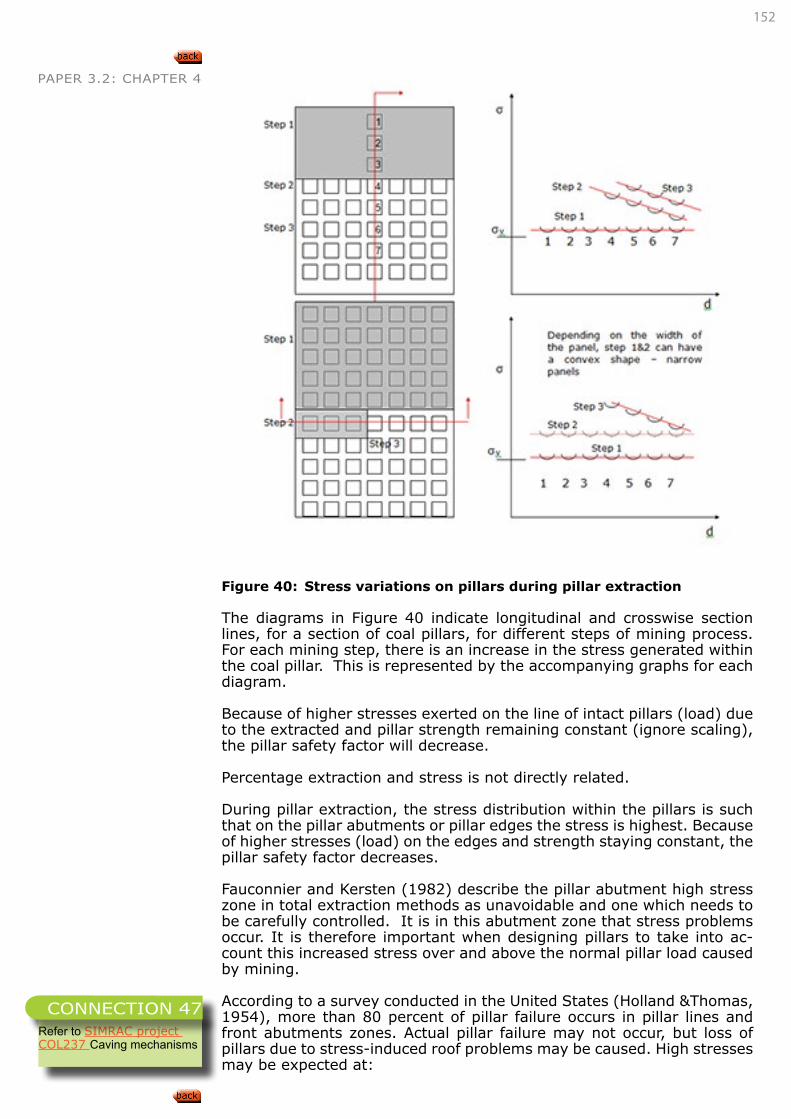
152
PAPER 3.2: CHAPTER 4
Figure 40: Stress variations on pillars during pillar extraction
The diagrams in Figure 40 indicate longitudinal and crosswise section lines, for a section of coal pillars, for different steps of mining process. For each mining step, there is an increase in the stress generated within the coal pillar. This is represented by the accompanying graphs for each diagram.
Because of higher stresses exerted on the line of intact pillars (load) due to the extracted and pillar strength remaining constant (ignore scaling), the pillar safety factor will decrease.
Percentage extraction and stress is not directly related.
During pillar extraction, the stress distribution within the pillars is such that on the pillar abutments or pillar edges the stress is highest. Because of higher stresses (load) on the edges and strength staying constant, the pillar safety factor decreases.
Fauconnier and Kersten (1982) describe the pillar abutment high stress zone in total extraction methods as unavoidable and one which needs to be carefully controlled. It is in this abutment zone that stress problems occur. It is therefore important when designing pillars to take into ac-count this increased stress over and above the normal pillar load caused by mining.
According to a survey conducted in the United States (Holland &Thomas, 1954), more than 80 percent of pillar failure occurs in pillar lines and front abutments zones. Actual pillar failure may not occur, but loss of pillars due to stress-induced roof problems may be caused. High stresses may be expected at:
Refer to SIMRAC project COL237 Caving mechanisms
CONNECTION 47
153
PAPER 3.2: CHAPTER 4• Areas close to the extraction line,
• Pillar areas close to wide roadways,
• Pillars that are larger than surrounding pillars,
• Protrusions on active pillar lines,
• Mining seams in which the coal and the adjacent strata have very different physical properties
Abutment pressures are caused by the cantilever effect of the roof beams over the mining area before goafing. The stress magnitudes will vary de-pending on the length and thickness of the beam overhanging the goaf area. The longer and stiffer the beam, the more the pressure it causes.
Van der Merwe (1990) suggested that during stooping, the pillar can no longer support its share of the overburden, and the pillars around it must carry the additional weight. From the start of the stooping operations, the additional load on the remaining pillars increases continually until the first major back break or goaf occurs. After the goaf had occurred, the previously unsupported overburden rests on the goaf material, and the only additional loading on pillars is a result of the overhang, i.e. portion of the roof/overburden that did not goaf. Pillar loads therefore reduce as shown in Figure 41 where:
• is before pillar extraction and where tributary loading is valid,
• pillar loads increase during stooping where tributary area loading is not valid and
• where pillar loads decrease after the goaf, but are still higher than tributary area.
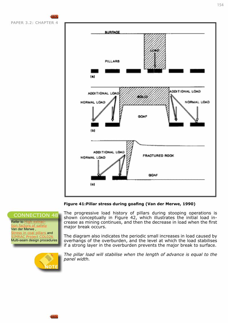
154
PAPER 3.2: CHAPTER 4
Figure 41:Pillar stress during goafing (Van der Merwe, 1990)
The progressive load history of pillars during stooping operations is shown conceptually in Figure 42, which illustrates the initial load in-crease as mining continues, and then the decrease in load when the first major break occurs.
The diagram also indicates the periodic small increases in load caused by overhangs of the overburden, and the level at which the load stabilises if a strong layer in the overburden prevents the major break to surface.
The pillar load will stabilise when the length of advance is equal to the panel width.
Refer to High extrac-tion factors of safety Van der Merwe ,Stress in coal pillars and SIMRAC Project COL026 Multi-seam design procedures
CONNECTION 48
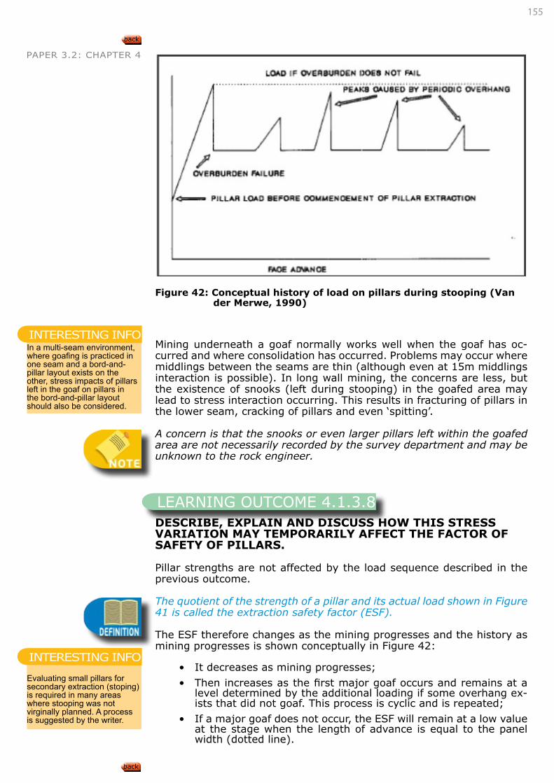
155
PAPER 3.2: CHAPTER 4
Figure 42: Conceptual history of load on pillars during stooping (Van
der Merwe, 1990)
Mining underneath a goaf normally works well when the goaf has oc-curred and where consolidation has occurred. Problems may occur where middlings between the seams are thin (although even at 15m middlings interaction is possible). In long wall mining, the concerns are less, but the existence of snooks (left during stooping) in the goafed area may lead to stress interaction occurring. This results in fracturing of pillars in the lower seam, cracking of pillars and even ‘spitting’.
A concern is that the snooks or even larger pillars left within the goafed area are not necessarily recorded by the survey department and may be unknown to the rock engineer.
DESCRIBE, EXPLAIN AND DISCUSS HOW THIS STRESS VARIATION MAY TEMPORARILY AFFECT THE FACTOR OF SAFETY OF PILLARS.
Pillar strengths are not affected by the load sequence described in the previous outcome.
The quotient of the strength of a pillar and its actual load shown in Figure 41 is called the extraction safety factor (ESF).
The ESF therefore changes as the mining progresses and the history as mining progresses is shown conceptually in Figure 42:
• It decreases as mining progresses;
• Then increases as the first major goaf occurs and remains at a level determined by the additional loading if some overhang ex-ists that did not goaf. This process is cyclic and is repeated;
• If a major goaf does not occur, the ESF will remain at a low value at the stage when the length of advance is equal to the panel width (dotted line).
In a multi-seam environment, where goafing is practiced in one seam and a bord-and-pillar layout exists on the other, stress impacts of pillars left in the goaf on pillars in the bord-and-pillar layout should also be considered.
INTERESTING INFO
LEARNING OUTCOME 4.1.3.8
Evaluating small pillars for secondary extraction (stoping) is required in many areas where stooping was not virginally planned. A process is suggested by the writer.
INTERESTING INFO
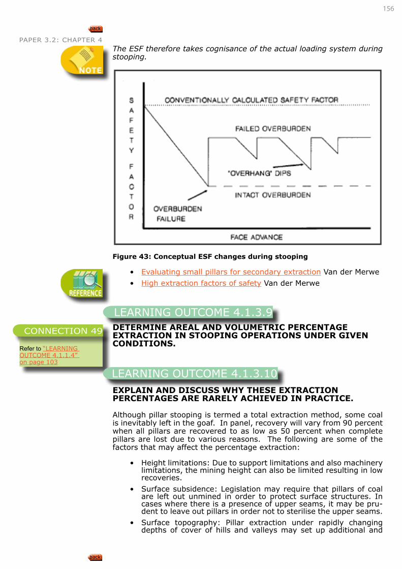
156
PAPER 3.2: CHAPTER 4The ESF therefore takes cognisance of the actual loading system during stooping.
Figure 43: Conceptual ESF changes during stooping
• Evaluating small pillars for secondary extraction Van der Merwe
• High extraction factors of safety Van der Merwe
DETERMINE AREAL AND VOLUMETRIC PERCENTAGE EXTRACTION IN STOOPING OPERATIONS UNDER GIVEN CONDITIONS.
EXPLAIN AND DISCUSS WHY THESE EXTRACTION PERCENTAGES ARE RARELY ACHIEVED IN PRACTICE.
Although pillar stooping is termed a total extraction method, some coal is inevitably left in the goaf. In panel, recovery will vary from 90 percent when all pillars are recovered to as low as 50 percent when complete pillars are lost due to various reasons. The following are some of the factors that may affect the percentage extraction:
• Height limitations: Due to support limitations and also machinery limitations, the mining height can also be limited resulting in low recoveries.
• Surface subsidence: Legislation may require that pillars of coal are left out unmined in order to protect surface structures. In cases where there is a presence of upper seams, it may be pru-dent to leave out pillars in order not to sterilise the upper seams.
• Surface topography: Pillar extraction under rapidly changing depths of cover of hills and valleys may set up additional and
LEARNING OUTCOME 4.1.3.9
Refer to “LEARNING OUTCOME 4.1.1.4” on page 103
CONNECTION 49
LEARNING OUTCOME 4.1.3.10
157
PAPER 3.2: CHAPTER 4 problematic horizontal stresses. Therefore, it may be necessary to leave out some unmined pillars for protection purposes. Pale-otopography may have the same effect on stress regimes as topography.
• Spontaneous combustion: In all methods of total extraction, some coal is left in the goaf either by accident or by design. If the coal is liable to spontaneous combustion and there is a free supply of air, there is a possibility of development of goaf fires, which may lead to premature abandonment of the workings.
• Geology: Depending on the nature of the roof strata, sometimes there can be premature goafing, which will render some pillars unminable. Sometimes, goafing is prolonged such as is the case with a dolerite sill or strong competent sandstone overburden. In such cases, when the goaf eventually occurs, it may be violent to such an extent that it destroys some coal pillars, making it impractical to mine them.
• The volumetric percentage extraction is for all practical purpos-es always less than the aerial percentage extraction for reasons discussed above. Theoretically, when the total seam thickness is extracted, the volumetric percentage extraction equals the aerial percentage extraction.
Paleotopography: The topography of a given area in the geologic past;on which the coal measures have been deposited
Apply the above knowledge to design stooping layouts, extraction sequences and appropriate support for given sets of circumstances.
The following example was extracted from a May 2004 RMC paper 2 (Coal Option). The solution was extracted from the corresponding memo. It will help in clarifying some of the discussed concepts and how they can be put to practical use.
A coal mining panel, 150m wide at a depth of 60m is to be re-mined by pillar stooping. The developed pillar centres were 14m square with 5m wide roadways. The mining height was 3m. Splitting will be done by driving a 5m wide roadway square through the pillars (i.e. leaving two fenders, each 9m long by 2m wide)
a. Determine the l Safety factor of the pillars before and after pillar splitting. Comment on the applicability of stooping in this case by looking at the SF before splitting.
b. What will the probability of failure of the pillars be after splitting given that the probability to have a stable layout is 0.087?
c. If the remaining fenders fail, how much subsidence can be expected?
d. If the pillars fail, can the failure be expected to be violent or pro-gressive? Motivate your opinion.
e. For the amount of coal to be extracted from this panel, is this the best method under the circumstances?
Motivate your answer by giving comparisons to an alternative method.
Solution
a. The SF method is one way of determining if a panel is suitable for secondary extraction or not. In general, it is recommended that
LEARNING OUTCOME 4.1.3.11
EXAMPLE
158
PAPER 3.2: CHAPTER 4 when secondary extraction is to be considered then development SF should at least be 1.8.
b. Load = 0.025.H.(c2/w2)
=0.025x60x(142/92) =3.62MPa
PStrength =7.2 x (w0.46/h0.66)
=7.2 x (90.46/30.66) =9.58MPa
FS = Strength/Load =9.58/3.62 =2.65
Since the original SF =2.65>1.8, these pillars satisfy this criterion. It should be noted, however, that this is not a “necessarily and sufficient” condition for pillar extraction to proceed. In addition, other factors such as the degree of jointing, geology, previous support effectiveness etc. also come into play.
After splitting, the pillar dimensions are 9 x 2m with 5m wide roadways.
Equivalent pillar width, We = (4A/c) = (4 x 9 x 2/(2(9+2)) = 3.27m
Load = 0.025.H.[(w1+B)(w2+B)/w1w2] =0.025 x 60 x [(14 x 7)/(9 x 2)] =8.17MPa
PStrength =7.2 x (w0.46/h0.66)
=7.2 x (3.270.46/30.66) =6MPa and,
FS = Strength/Load =6.01/8.17 =0.74
It is important here to note that when pillars are no longer square, we have to use an equivalent width to calculate the strength only. In order to calculate the pillar load, the actual pillar dimensions have to be used.
Given the probability of a stable layout as0.087, it follows that the prob-ability of failure is 1- 0.087= 0.913 or 91.3%.
c. In order to calculate the subsidence in this case, first calculate the extraction ratio e, then the equivalent mining height. Therefore:
Extraction ratio is:eext = 1- (w1w2/C1C2) = 1 - 9x2/7x4 = 0.8
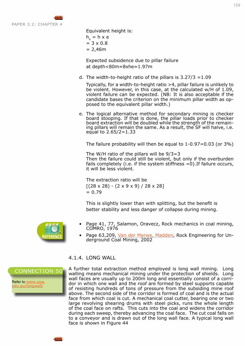
159
PAPER 3.2: CHAPTER 4
Equivalent height is:he = h x e = 3 x 0.8 = 2,46m
Expected subsidence due to pillar failure at depth<80m=8xhe=1.97m
d. The width-to-height ratio of the pillars is 3.27/3 =1.09
Typically, for a width-to-height ratio >4, pillar failure is unlikely to be violent. However, in this case, at the calculated w/H of 1.09, violent failure can be expected. (NB: It is also acceptable if the candidate bases the criterion on the minimum pillar width as op-posed to the equivalent pillar width.)
e. The logical alternative method for secondary mining is checker board stooping. If that is done, the pillar loads prior to checker board extraction will be doubled while the strength of the remain-ing pillars will remain the same. As a result, the SF will halve, i.e. equal to 2.65/2=1.33
The failure probability will then be equal to 1-0.97=0.03 (or 3%)
The W/H ratio of the pillars will be 9/3=3Then the failure could still be violent, but only if the overburden fails completely (i.e. if the system stiffness =0).If failure occurs, it will be less violent.
The extraction ratio will be [(28 x 28) - (2 x 9 x 9) / 28 x 28]= 0.79
This is slightly lower than with splitting, but the benefit is better stability and less danger of collapse during mining.
• Page 41, 77, Salamon, Oravecz, Rock mechanics in coal mining, COMRO, 1976
• Page 63,209, Van der Merwe, Madden, Rock Engineering for Un-derground Coal Mining, 2002
4.1.4. LONG WALL
A further total extraction method employed is long wall mining. Long walling means mechanical mining under the protection of shields. Long wall faces are usually up to 200m long and essentially consist of a corri-dor in which one wall and the roof are formed by steel supports capable of resisting hundreds of tons of pressure from the subsiding mine roof above. The second side of the corridor is formed of coal and is the actual face from which coal is cut. A mechanical coal cutter, bearing one or two large revolving shearing drums with steel picks, runs the whole length of the coal face on rafts. This cuts into the coal and widens the corridor during each sweep, thereby advancing the coal face. The cut coal falls on to a conveyor and is drawn out of the long wall face. A typical long wall face is shown in Figure 44
Refer to www.uow.edu.au/longwall/
CONNECTION 50
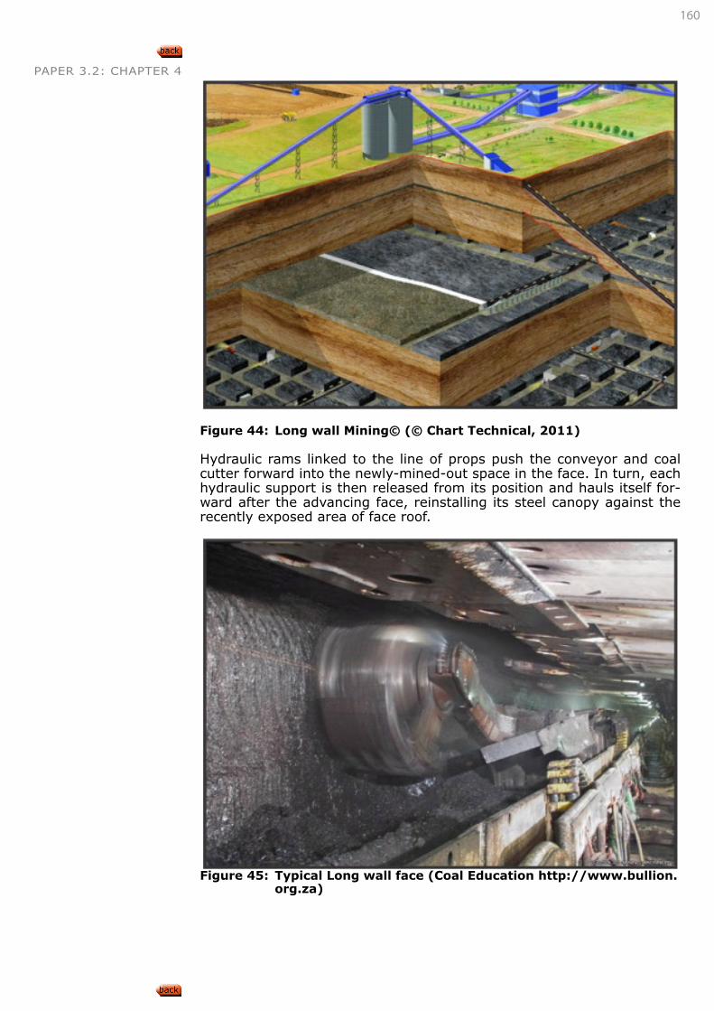
160
PAPER 3.2: CHAPTER 4
Figure 44: Long wall Mining© (© Chart Technical, 2011)
Hydraulic rams linked to the line of props push the conveyor and coal cutter forward into the newly-mined-out space in the face. In turn, each hydraulic support is then released from its position and hauls itself for-ward after the advancing face, reinstalling its steel canopy against the recently exposed area of face roof.
Figure 45: Typical Long wall face (Coal Education http://www.bullion.org.za)
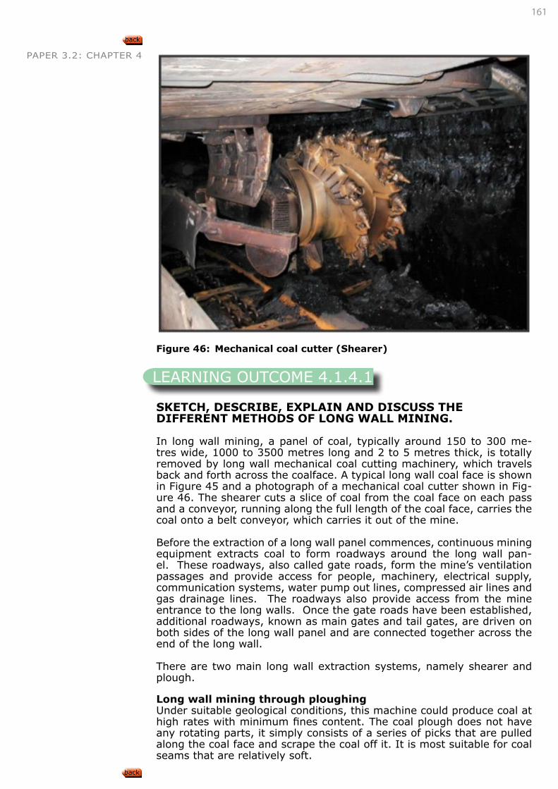
161
PAPER 3.2: CHAPTER 4
Figure 46: Mechanical coal cutter (Shearer)
SKETCH, DESCRIBE, EXPLAIN AND DISCUSS THE DIFFERENT METHODS OF LONG WALL MINING.
In long wall mining, a panel of coal, typically around 150 to 300 me-tres wide, 1000 to 3500 metres long and 2 to 5 metres thick, is totally removed by long wall mechanical coal cutting machinery, which travels back and forth across the coalface. A typical long wall coal face is shown in Figure 45 and a photograph of a mechanical coal cutter shown in Fig-ure 46. The shearer cuts a slice of coal from the coal face on each pass and a conveyor, running along the full length of the coal face, carries the coal onto a belt conveyor, which carries it out of the mine.
Before the extraction of a long wall panel commences, continuous mining equipment extracts coal to form roadways around the long wall pan-el. These roadways, also called gate roads, form the mine’s ventilation passages and provide access for people, machinery, electrical supply, communication systems, water pump out lines, compressed air lines and gas drainage lines. The roadways also provide access from the mine entrance to the long walls. Once the gate roads have been established, additional roadways, known as main gates and tail gates, are driven on both sides of the long wall panel and are connected together across the end of the long wall.
There are two main long wall extraction systems, namely shearer and plough.
Long wall mining through ploughingUnder suitable geological conditions, this machine could produce coal at high rates with minimum fines content. The coal plough does not have any rotating parts, it simply consists of a series of picks that are pulled along the coal face and scrape the coal off it. It is most suitable for coal seams that are relatively soft.
LEARNING OUTCOME 4.1.4.1
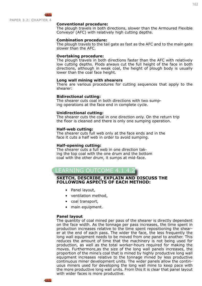
162
PAPER 3.2: CHAPTER 4Conventional procedure: The plough travels in both directions, slower than the Armoured Flexible Conveyor (AFC) with relatively high cutting depths.
Combination procedure: The plough travels to the tail gate as fast as the AFC and to the main gate slower than the AFC.
Overtaking procedure: The plough travels in both directions faster than the AFC with relatively low cutting depths. Plods always cut the full height of the face in both directions, although in weak coal, the height of plough body is usually lower than the coal face height.
Long wall mining with shearersThere are various procedures for cutting sequences that apply to the shearer:
Bidirectional cutting: The shearer cuts coal in both directions with two sump-ing operations at the face end in complete cycle.
Unidirectional cutting: The shearer cuts the coal in one direction only. On the return trip the floor is cleaned and there is only one sumping operation.
Half-web cutting: The shearer cuts full web only at the face ends and in the face it cuts a half web in order to avoid sumping.
Half-opening cutting: The shearer cuts a full web in one direction tak-ing the top coal with the one drum and the bottom coal with the other drum, it sumps at mid-face.
SKETCH, DESCRIBE, EXPLAIN AND DISCUSS THE FOLLOWING ASPECTS OF EACH METHOD:
• Panel layout,
• ventilation method,
• coal transport,
• main equipment.
Panel layoutThe quantity of coal mined per pass of the shearer is directly dependent on the face width. As the tonnage per pass increases, the time spent in production increases relative to the time spent repositioning the shear-er at the end of each pass. The wider the face, the less frequently the long wall equipment needs to be moved from one panel to another. This reduces the amount of time that the machinery is not being used for production, as well as the total worker-hours required for making the moves. Furthermore,as the size of the long wall panels increases, the proportion of the mine’s coal that is mined by highly productive long wall equipment increases relative to the tonnage mined by less productive continuous miner development units. The wider panels allow the contin-uous miners used for developing the long wall mine to keep pace with the more productive long wall units. From this it is clear that panel layout with wider faces is more productive.
LEARNING OUTCOME 4.1.4.2
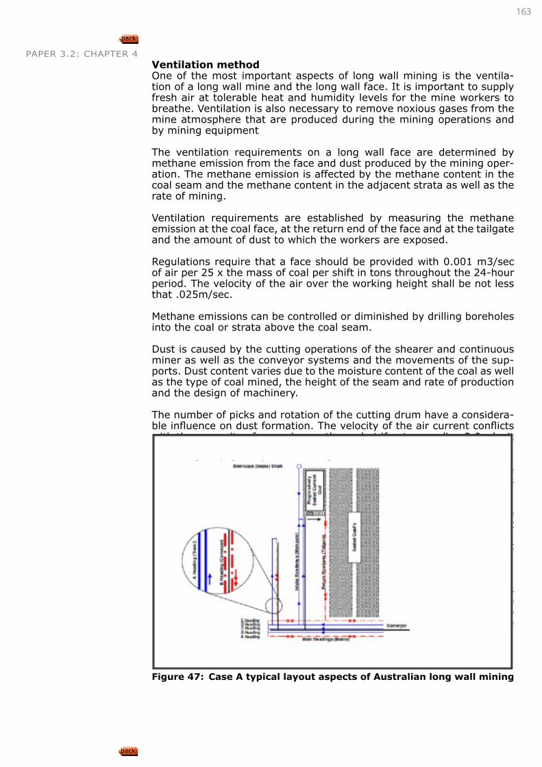
163
PAPER 3.2: CHAPTER 4Ventilation methodOne of the most important aspects of long wall mining is the ventila-tion of a long wall mine and the long wall face. It is important to supply fresh air at tolerable heat and humidity levels for the mine workers to breathe. Ventilation is also necessary to remove noxious gases from the mine atmosphere that are produced during the mining operations and by mining equipment
The ventilation requirements on a long wall face are determined by methane emission from the face and dust produced by the mining oper-ation. The methane emission is affected by the methane content in the coal seam and the methane content in the adjacent strata as well as the rate of mining.
Ventilation requirements are established by measuring the methane emission at the coal face, at the return end of the face and at the tailgate and the amount of dust to which the workers are exposed.
Regulations require that a face should be provided with 0.001 m3/sec of air per 25 x the mass of coal per shift in tons throughout the 24-hour period. The velocity of the air over the working height shall be not less that .025m/sec.
Methane emissions can be controlled or diminished by drilling boreholes into the coal or strata above the coal seam.
Dust is caused by the cutting operations of the shearer and continuous miner as well as the conveyor systems and the movements of the sup-ports. Dust content varies due to the moisture content of the coal as well as the type of coal mined, the height of the seam and rate of production and the design of machinery.
The number of picks and rotation of the cutting drum have a considera-ble influence on dust formation. The velocity of the air current conflicts with the necessity of removing methane, but if not exceeding 2.0m/s, it should not spread the dust.
The cross-sectional opening of the air current is determined by the type of support used and the method of the working face. Basic methods used in ventilating long wall faces are:Intake and return through the entries and intake through the entries and return through the entries and bleeder roads adjacent to or through the goaf. This method is successful in removing methane from the face, but the likelihood of spontaneous combustion cannot be ruled out if the coal remains in the goaf. This can be prevented by a rapid and consistent rate of advance procedures, early consideration of waste and increased resistance to the leaking of air through the waste.
A ventilation system that produces low but constant pressure across the waste will also minimise this risk. It is further important to salvage and seal off worked out faces and wastes as quickly as possible and to monitor returns from worked-out areas for changes in gas content. The following two examples from Mayers and Gillies (2000) show typical long wall ventilation methods in some Australian mines.
Figure 47: Case A typical layout aspects of Australian long wall mining
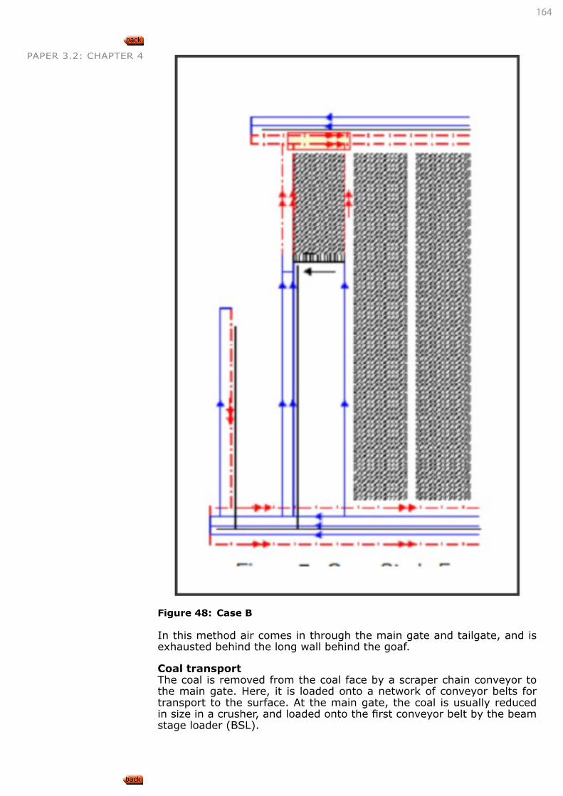
164
PAPER 3.2: CHAPTER 4
Figure 48: Case B
In this method air comes in through the main gate and tailgate, and is exhausted behind the long wall behind the goaf.
Coal transportThe coal is removed from the coal face by a scraper chain conveyor to the main gate. Here, it is loaded onto a network of conveyor belts for transport to the surface. At the main gate, the coal is usually reduced in size in a crusher, and loaded onto the first conveyor belt by the beam stage loader (BSL).
165
PAPER 3.2: CHAPTER 4 Main equipment
Key equipment used during the long wall operation includes:
• a shearer, used to cut and load the coal from the face;
• a steel chained armoured face conveyor (commonly referred to as the AFC), used to transfer the coal across the face;
• self-advancing, high capacity, hydraulic long wall supports, used to support the immediate face area as the coal is mined;
• a beam stage loader (commonly referred to as the BSL), used to transfer the coal from the face to the long wall panel conveyor;
• a crusher, used to size the coal;
• the staker jack retreats the pantechnicon along the main gate as the face advances and
• the pantechnicon incorporates the long wall services, including power supply.
SKETCH, DESCRIBE, EXPLAIN AND DISCUSS THE FOLLOWING LONG WALL MINING TERMS:
• Main gate,
• Snaking,
• Web,
• Goaf,
• Gate road support,
• Chock shield,
• Inter panel pillar,
• Chain pillar,
• Crush pillar
Main gate and tailgateUnderground roadways formed on either side of long wall block. Main gate refers to the roadway(s) containing the conveyor belt, stage loader and other services to the face area. Tailgate refers to the roadway on the return side of the long wall face. In a multiple panel situation, the tailgate is that gate road immediately adjacent to and on the goaf side of the panel.
SnakingThis describes the bending that occurs in the armoured face conveyor (AFC) behind the shearer for a distance of 10 to 15metres. This bending occurs because of the limited lateral movement possible between the pans of the conveyor, which results in the conveyor having to be ad-vanced in stages following the passage of the shearer.
WebLong wall panels are generally many hundreds of metres in length and from 50m to 250m in width. It is not possible for the shearer to just cut forward across the entire width of the panel as it advances. Usually, the shearer moves from one gate road towards the other across the face during one cut. The depth of a single cut taken by the shearer drum is called a web. When the shearer has cut the full seam thickness, and has done so from one gate road to the other across the entire face width at full drum depth, it is said to have cut a web. If this is done in two passes of the machine, then one pass is the half web. Two half webs make a
LEARNING OUTCOME 4.1.4.3
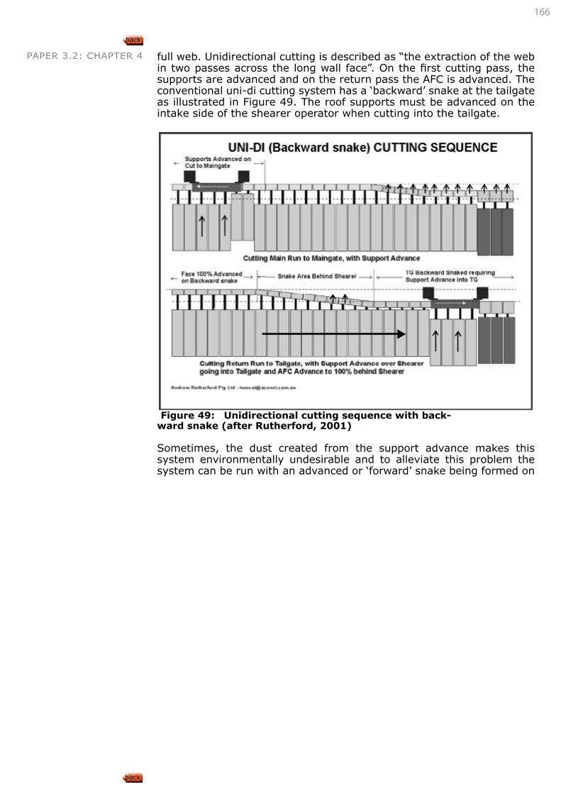
166
PAPER 3.2: CHAPTER 4 full web. Unidirectional cutting is described as “the extraction of the web in two passes across the long wall face”. On the first cutting pass, the supports are advanced and on the return pass the AFC is advanced. The conventional uni-di cutting system has a ‘backward’ snake at the tailgate as illustrated in Figure 49. The roof supports must be advanced on the intake side of the shearer operator when cutting into the tailgate.
Figure 49: Unidirectional cutting sequence with back-ward snake (after Rutherford, 2001)
Sometimes, the dust created from the support advance makes this system environmentally undesirable and to alleviate this problem the system can be run with an advanced or ‘forward’ snake being formed on
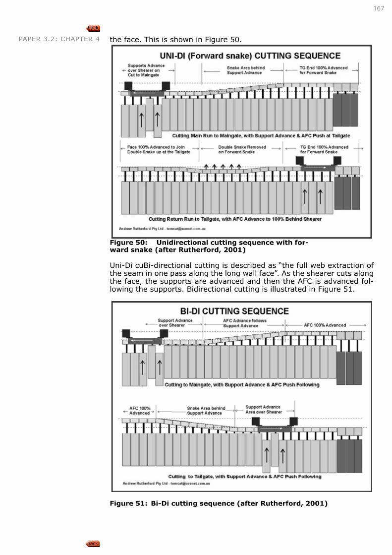
167
PAPER 3.2: CHAPTER 4 the face. This is shown in Figure 50.
Figure 50: Unidirectional cutting sequence with for-ward snake (after Rutherford, 2001)
Uni-Di cuBi-directional cutting is described as “the full web extraction of the seam in one pass along the long wall face”. As the shearer cuts along the face, the supports are advanced and then the AFC is advanced fol-lowing the supports. Bidirectional cutting is illustrated in Figure 51.
Figure 51: Bi-Di cutting sequence (after Rutherford, 2001)
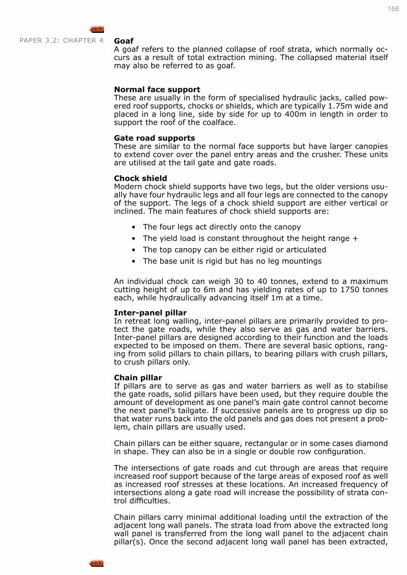
168
PAPER 3.2: CHAPTER 4 GoafA goaf refers to the planned collapse of roof strata, which normally oc-curs as a result of total extraction mining. The collapsed material itself may also be referred to as goaf.
Normal face supportThese are usually in the form of specialised hydraulic jacks, called pow-ered roof supports, chocks or shields, which are typically 1.75m wide and placed in a long line, side by side for up to 400m in length in order to support the roof of the coalface.
Gate road supportsThese are similar to the normal face supports but have larger canopies to extend cover over the panel entry areas and the crusher. These units are utilised at the tail gate and gate roads.
Chock shieldModern chock shield supports have two legs, but the older versions usu-ally have four hydraulic legs and all four legs are connected to the canopy of the support. The legs of a chock shield support are either vertical or inclined. The main features of chock shield supports are:
• The four legs act directly onto the canopy
• The yield load is constant throughout the height range +
• The top canopy can be either rigid or articulated
• The base unit is rigid but has no leg mountings
An individual chock can weigh 30 to 40 tonnes, extend to a maximum cutting height of up to 6m and has yielding rates of up to 1750 tonnes each, while hydraulically advancing itself 1m at a time.
Inter-panel pillarIn retreat long walling, inter-panel pillars are primarily provided to pro-tect the gate roads, while they also serve as gas and water barriers. Inter-panel pillars are designed according to their function and the loads expected to be imposed on them. There are several basic options, rang-ing from solid pillars to chain pillars, to bearing pillars with crush pillars, to crush pillars only.
Chain pillarIf pillars are to serve as gas and water barriers as well as to stabilise the gate roads, solid pillars have been used, but they require double the amount of development as one panel’s main gate control cannot become the next panel’s tailgate. If successive panels are to progress up dip so that water runs back into the old panels and gas does not present a prob-lem, chain pillars are usually used.
Chain pillars can be either square, rectangular or in some cases diamond in shape. They can also be in a single or double row configuration.
The intersections of gate roads and cut through are areas that require increased roof support because of the large areas of exposed roof as well as increased roof stresses at these locations. An increased frequency of intersections along a gate road will increase the possibility of strata con-trol difficulties.
Chain pillars carry minimal additional loading until the extraction of the adjacent long wall panels. The strata load from above the extracted long wall panel is transferred from the long wall panel to the adjacent chain pillar(s). Once the second adjacent long wall panel has been extracted,
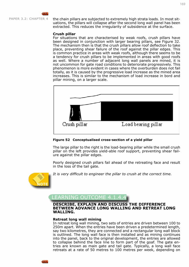
169
PAPER 3.2: CHAPTER 4 the chain pillars are subjected to extremely high strata loads. In most sit-uations, the pillars will collapse after the second long wall panel has been extracted. This reduces the irregularity of subsidence at the surface.
Crush pillarFor situations that are characterised by weak roofs, crush pillars have been designed in conjunction with larger bearing pillars, see Figure 32. The mechanism then is that the crush pillars allow roof deflection to take place, preventing shear failure of the roof against the pillar edges. This is common practice in areas with weak roofs, although there seems to be a tendency for crush pillars to be implemented in areas with good roofs as well. Where a number of adjacent long wall panels are mined, it is not uncommon for gate road conditions to deteriorate progressively. This phenomenon is more evident in cases where the overburden does not fail totally, as it is caused by the progressive load increase as the mined area increases. This is similar to the mechanism of load increase in bord and pillar mining, on a larger scale.
Figure 52 Conceptualised cross-section of a yield pillar
The large pillar to the right is the load-bearing pillar while the small crush pillar on the left provides yield-able roof support, preventing shear fail-ure against the pillar edges.
Poorly designed crush pillars fail ahead of the retreating face and result in the loss of the tail gate.
It is very difficult to engineer the pillar to crush at the correct time.
DESCRIBE, EXPLAIN AND DISCUSS THE DIFFERENCE BETWEEN ADVANCE LONG WALLING AND RETREAT LONG WALLING.
Retreat long wall miningIn retreat long wall mining, two sets of entries are driven between 100 to 250m apart. When the entries have been driven a predetermined length, say two kilometres, they are connected and a rectangular long wall block is outlined. The long wall face is then installed and as mining continues into the panel, back to the original development, the entries are allowed to collapse behind the face line to form part of the goaf. The gate en-tries are known as main gate and tail gate. Typically, a long wall face retreats at a rate of 50 metres to 100 metres per week, depending on
LEARNING OUTCOME 4.1.4.4
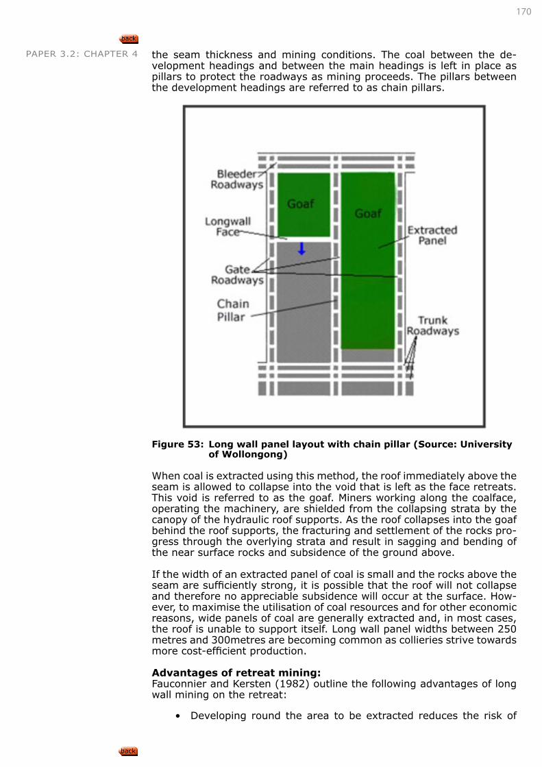
170
PAPER 3.2: CHAPTER 4 the seam thickness and mining conditions. The coal between the de-velopment headings and between the main headings is left in place as pillars to protect the roadways as mining proceeds. The pillars between the development headings are referred to as chain pillars.
Figure 53: Long wall panel layout with chain pillar (Source: University
of Wollongong)
When coal is extracted using this method, the roof immediately above the seam is allowed to collapse into the void that is left as the face retreats. This void is referred to as the goaf. Miners working along the coalface, operating the machinery, are shielded from the collapsing strata by the canopy of the hydraulic roof supports. As the roof collapses into the goaf behind the roof supports, the fracturing and settlement of the rocks pro-gress through the overlying strata and result in sagging and bending of the near surface rocks and subsidence of the ground above.
If the width of an extracted panel of coal is small and the rocks above the seam are sufficiently strong, it is possible that the roof will not collapse and therefore no appreciable subsidence will occur at the surface. How-ever, to maximise the utilisation of coal resources and for other economic reasons, wide panels of coal are generally extracted and, in most cases, the roof is unable to support itself. Long wall panel widths between 250 metres and 300metres are becoming common as collieries strive towards more cost-efficient production.
Advantages of retreat mining:Fauconnier and Kersten (1982) outline the following advantages of long wall mining on the retreat:
• Developing round the area to be extracted reduces the risk of
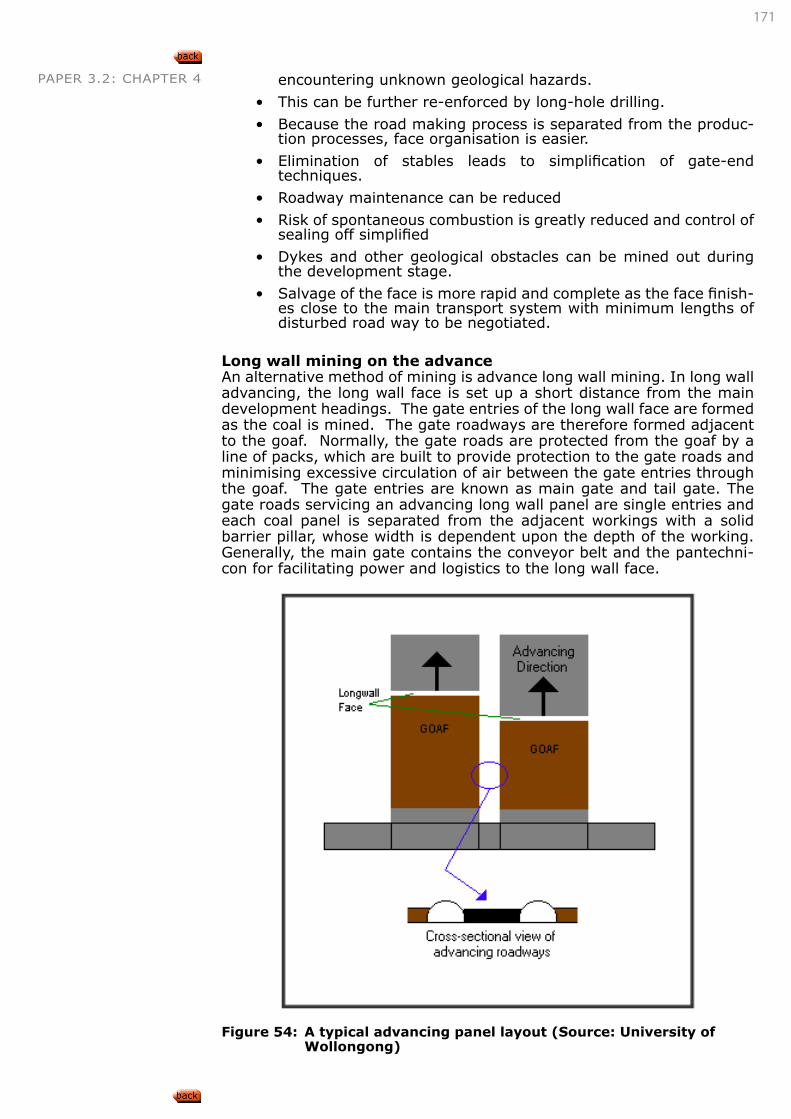
171
PAPER 3.2: CHAPTER 4 encountering unknown geological hazards.
• This can be further re-enforced by long-hole drilling.
• Because the road making process is separated from the produc-tion processes, face organisation is easier.
• Elimination of stables leads to simplification of gate-end techniques.
• Roadway maintenance can be reduced
• Risk of spontaneous combustion is greatly reduced and control of sealing off simplified
• Dykes and other geological obstacles can be mined out during the development stage.
• Salvage of the face is more rapid and complete as the face finish-es close to the main transport system with minimum lengths of disturbed road way to be negotiated.
Long wall mining on the advanceAn alternative method of mining is advance long wall mining. In long wall advancing, the long wall face is set up a short distance from the main development headings. The gate entries of the long wall face are formed as the coal is mined. The gate roadways are therefore formed adjacent to the goaf. Normally, the gate roads are protected from the goaf by a line of packs, which are built to provide protection to the gate roads and minimising excessive circulation of air between the gate entries through the goaf. The gate entries are known as main gate and tail gate. The gate roads servicing an advancing long wall panel are single entries and each coal panel is separated from the adjacent workings with a solid barrier pillar, whose width is dependent upon the depth of the working. Generally, the main gate contains the conveyor belt and the pantechni-con for facilitating power and logistics to the long wall face.
Figure 54: A typical advancing panel layout (Source: University of
Wollongong)
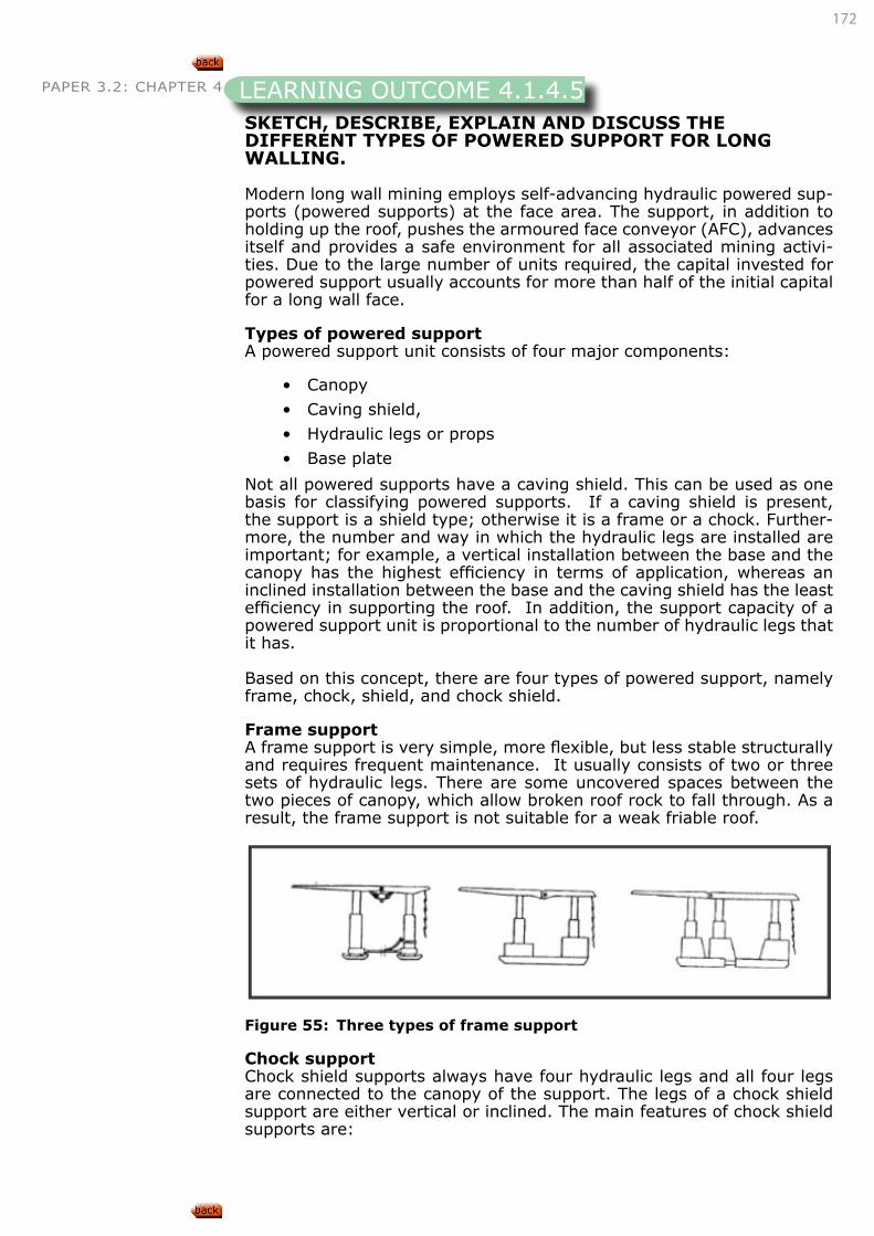
172
PAPER 3.2: CHAPTER 4
SKETCH, DESCRIBE, EXPLAIN AND DISCUSS THE DIFFERENT TYPES OF POWERED SUPPORT FOR LONG WALLING.
Modern long wall mining employs self-advancing hydraulic powered sup-ports (powered supports) at the face area. The support, in addition to holding up the roof, pushes the armoured face conveyor (AFC), advances itself and provides a safe environment for all associated mining activi-ties. Due to the large number of units required, the capital invested for powered support usually accounts for more than half of the initial capital for a long wall face.
Types of powered supportA powered support unit consists of four major components:
• Canopy
• Caving shield,
• Hydraulic legs or props
• Base plate
Not all powered supports have a caving shield. This can be used as one basis for classifying powered supports. If a caving shield is present, the support is a shield type; otherwise it is a frame or a chock. Further-more, the number and way in which the hydraulic legs are installed are important; for example, a vertical installation between the base and the canopy has the highest efficiency in terms of application, whereas an inclined installation between the base and the caving shield has the least efficiency in supporting the roof. In addition, the support capacity of a powered support unit is proportional to the number of hydraulic legs that it has.
Based on this concept, there are four types of powered support, namely frame, chock, shield, and chock shield.
Frame supportA frame support is very simple, more flexible, but less stable structurally and requires frequent maintenance. It usually consists of two or three sets of hydraulic legs. There are some uncovered spaces between the two pieces of canopy, which allow broken roof rock to fall through. As a result, the frame support is not suitable for a weak friable roof.
Figure 55: Three types of frame support
Chock supportChock shield supports always have four hydraulic legs and all four legs are connected to the canopy of the support. The legs of a chock shield support are either vertical or inclined. The main features of chock shield supports are:
LEARNING OUTCOME 4.1.4.5
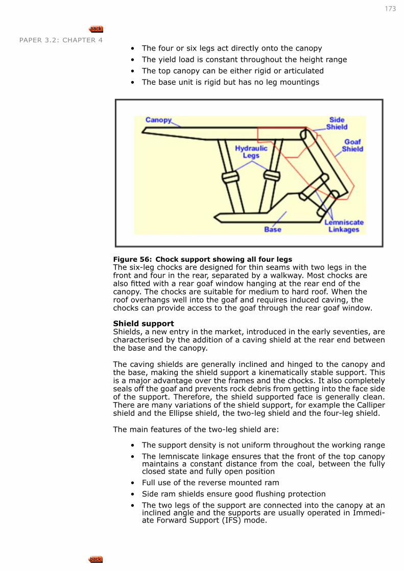
173
PAPER 3.2: CHAPTER 4• The four or six legs act directly onto the canopy
• The yield load is constant throughout the height range
• The top canopy can be either rigid or articulated
• The base unit is rigid but has no leg mountings
Figure 56: Chock support showing all four legsThe six-leg chocks are designed for thin seams with two legs in the front and four in the rear, separated by a walkway. Most chocks are also fitted with a rear goaf window hanging at the rear end of the canopy. The chocks are suitable for medium to hard roof. When the roof overhangs well into the goaf and requires induced caving, the chocks can provide access to the goaf through the rear goaf window.
Shield supportShields, a new entry in the market, introduced in the early seventies, are characterised by the addition of a caving shield at the rear end between the base and the canopy.
The caving shields are generally inclined and hinged to the canopy and the base, making the shield support a kinematically stable support. This is a major advantage over the frames and the chocks. It also completely seals off the goaf and prevents rock debris from getting into the face side of the support. Therefore, the shield supported face is generally clean. There are many variations of the shield support, for example the Calliper shield and the Ellipse shield, the two-leg shield and the four-leg shield.
The main features of the two-leg shield are:
• The support density is not uniform throughout the working range
• The lemniscate linkage ensures that the front of the top canopy maintains a constant distance from the coal, between the fully closed state and fully open position
• Full use of the reverse mounted ram
• Side ram shields ensure good flushing protection
• The two legs of the support are connected into the canopy at an inclined angle and the supports are usually operated in Immedi-ate Forward Support (IFS) mode.
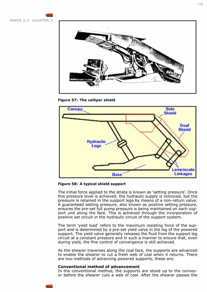
174
PAPER 3.2: CHAPTER 4
Figure 57: The calliper shield
Figure 58: A typical shield support
The initial force applied to the strata is known as ‘setting pressure’. Once this pressure level is achieved, the hydraulic supply is removed, but the pressure is retained in the support legs by means of a non-return valve. A guaranteed setting pressure, also known as positive setting pressure, ensures the pre-set full pump pressure is being maintained on each sup-port unit along the face. This is achieved through the incorporation of positive set circuit in the hydraulic circuit of the support system.
The term ‘yield load’ refers to the maximum resisting force of the sup-port and is determined by a pre-set yield valve in the leg of the powered support. The yield valve generally releases the fluid from the support leg circuit at a constant pressure and in such a manner to ensure that, even during yield, the fine control of convergence is still achieved.
As the shearer traverses along the coal face, the supports are advanced to enable the shearer to cut a fresh web of coal when it returns. There are two methods of advancing powered supports, these are:
Conventional method of advancementIn the conventional method, the supports are stood up to the convey-or before the shearer cuts a web of coal. After the shearer passes the
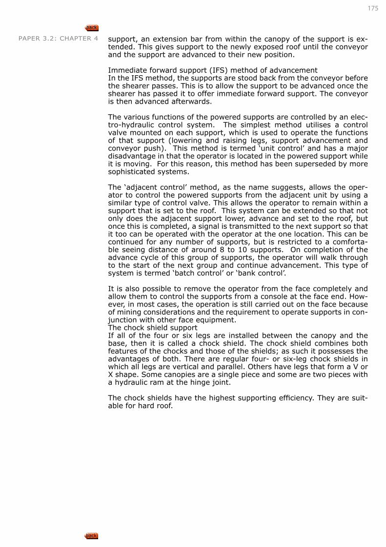
175
PAPER 3.2: CHAPTER 4 support, an extension bar from within the canopy of the support is ex-tended. This gives support to the newly exposed roof until the conveyor and the support are advanced to their new position.
Immediate forward support (IFS) method of advancementIn the IFS method, the supports are stood back from the conveyor before the shearer passes. This is to allow the support to be advanced once the shearer has passed it to offer immediate forward support. The conveyor is then advanced afterwards.
The various functions of the powered supports are controlled by an elec-tro-hydraulic control system. The simplest method utilises a control valve mounted on each support, which is used to operate the functions of that support (lowering and raising legs, support advancement and conveyor push). This method is termed ‘unit control’ and has a major disadvantage in that the operator is located in the powered support while it is moving. For this reason, this method has been superseded by more sophisticated systems.
The ‘adjacent control’ method, as the name suggests, allows the oper-ator to control the powered supports from the adjacent unit by using a similar type of control valve. This allows the operator to remain within a support that is set to the roof. This system can be extended so that not only does the adjacent support lower, advance and set to the roof, but once this is completed, a signal is transmitted to the next support so that it too can be operated with the operator at the one location. This can be continued for any number of supports, but is restricted to a comforta-ble seeing distance of around 8 to 10 supports. On completion of the advance cycle of this group of supports, the operator will walk through to the start of the next group and continue advancement. This type of system is termed ‘batch control’ or ‘bank control’.
It is also possible to remove the operator from the face completely and allow them to control the supports from a console at the face end. How-ever, in most cases, the operation is still carried out on the face because of mining considerations and the requirement to operate supports in con-junction with other face equipment. The chock shield supportIf all of the four or six legs are installed between the canopy and the base, then it is called a chock shield. The chock shield combines both features of the chocks and those of the shields; as such it possesses the advantages of both. There are regular four- or six-leg chock shields in which all legs are vertical and parallel. Others have legs that form a V or X shape. Some canopies are a single piece and some are two pieces with a hydraulic ram at the hinge joint.
The chock shields have the highest supporting efficiency. They are suit-able for hard roof.
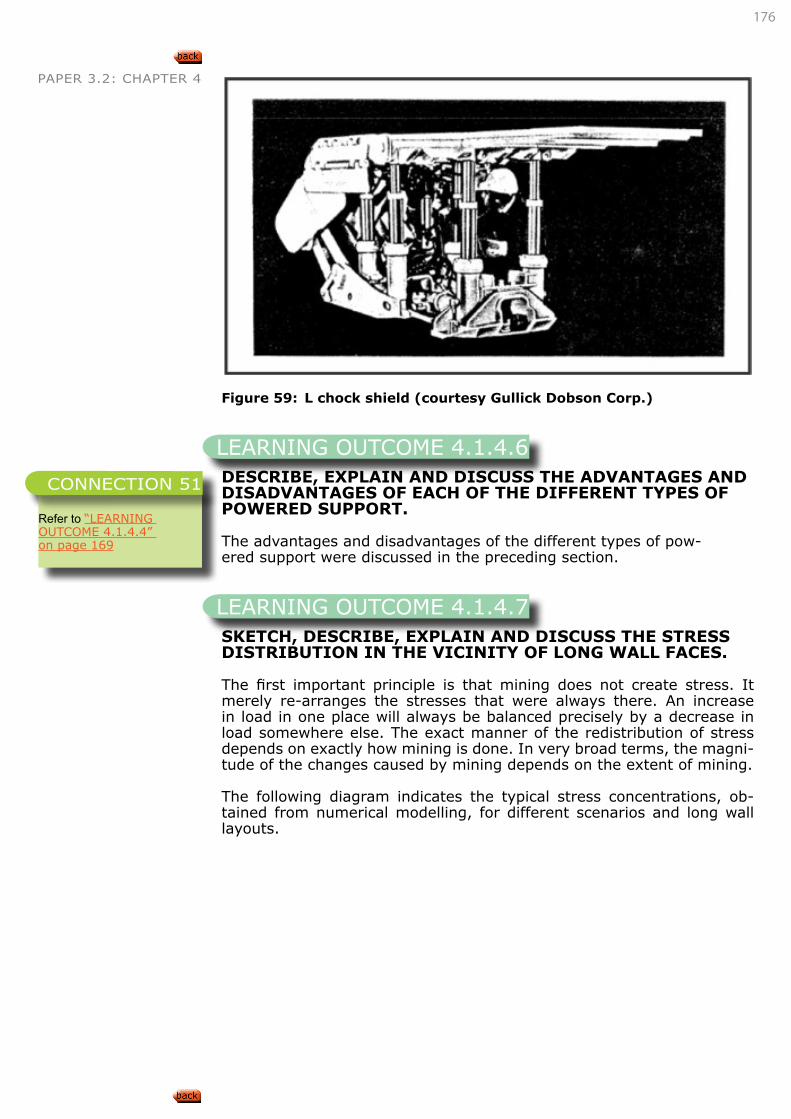
176
PAPER 3.2: CHAPTER 4
Figure 59: L chock shield (courtesy Gullick Dobson Corp.)
DESCRIBE, EXPLAIN AND DISCUSS THE ADVANTAGES AND DISADVANTAGES OF EACH OF THE DIFFERENT TYPES OF POWERED SUPPORT.
The advantages and disadvantages of the different types of pow-ered support were discussed in the preceding section.
SKETCH, DESCRIBE, EXPLAIN AND DISCUSS THE STRESS DISTRIBUTION IN THE VICINITY OF LONG WALL FACES.
The first important principle is that mining does not create stress. It merely re-arranges the stresses that were always there. An increase in load in one place will always be balanced precisely by a decrease in load somewhere else. The exact manner of the redistribution of stress depends on exactly how mining is done. In very broad terms, the magni-tude of the changes caused by mining depends on the extent of mining.
The following diagram indicates the typical stress concentrations, ob-tained from numerical modelling, for different scenarios and long wall layouts.
LEARNING OUTCOME 4.1.4.6
Refer to “LEARNING OUTCOME 4.1.4.4” on page 169
CONNECTION 51
LEARNING OUTCOME 4.1.4.7
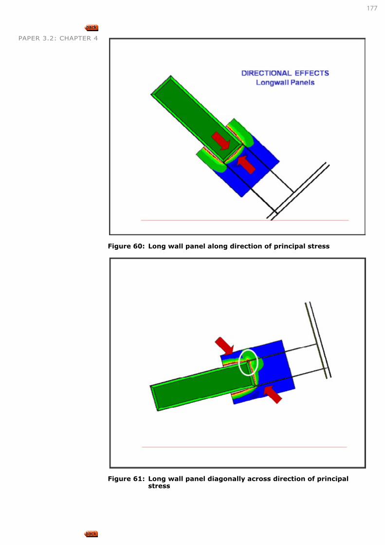
177
PAPER 3.2: CHAPTER 4
Figure 60: Long wall panel along direction of principal stress
Figure 61: Long wall panel diagonally across direction of principal
stress
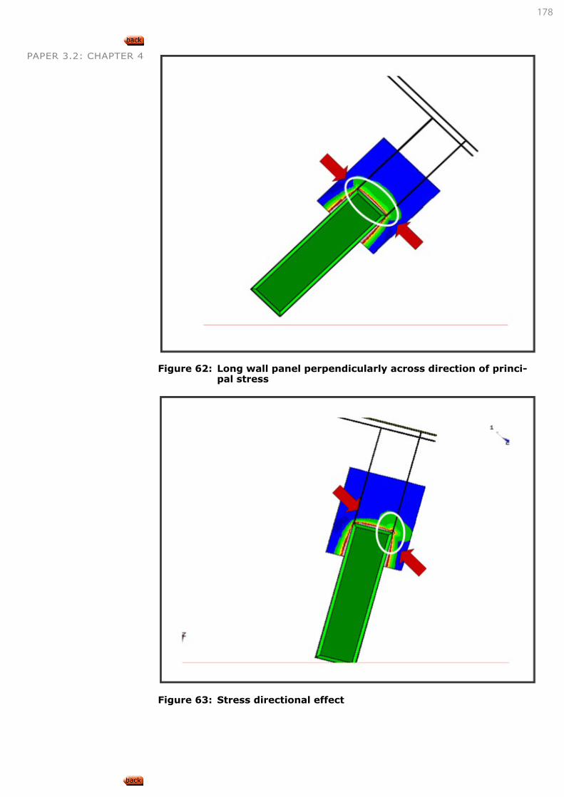
178
PAPER 3.2: CHAPTER 4
Figure 62: Long wall panel perpendicularly across direction of princi-
pal stress
Figure 63: Stress directional effect
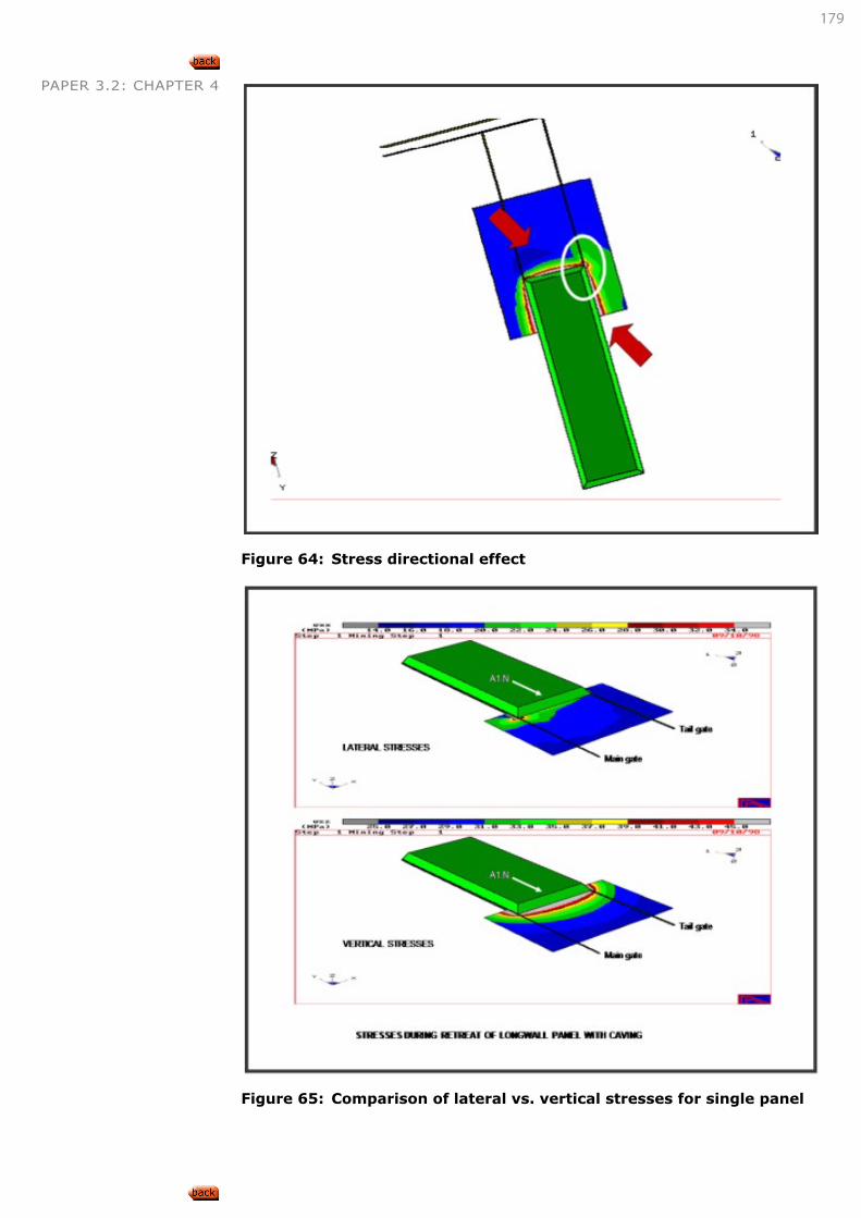
179
PAPER 3.2: CHAPTER 4
Figure 64: Stress directional effect
Figure 65: Comparison of lateral vs. vertical stresses for single panel
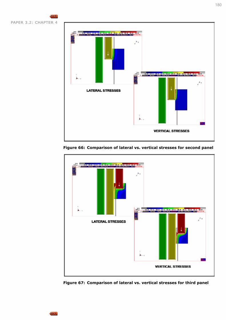
180
PAPER 3.2: CHAPTER 4
Figure 66: Comparison of lateral vs. vertical stresses for second panel
Figure 67: Comparison of lateral vs. vertical stresses for third panel
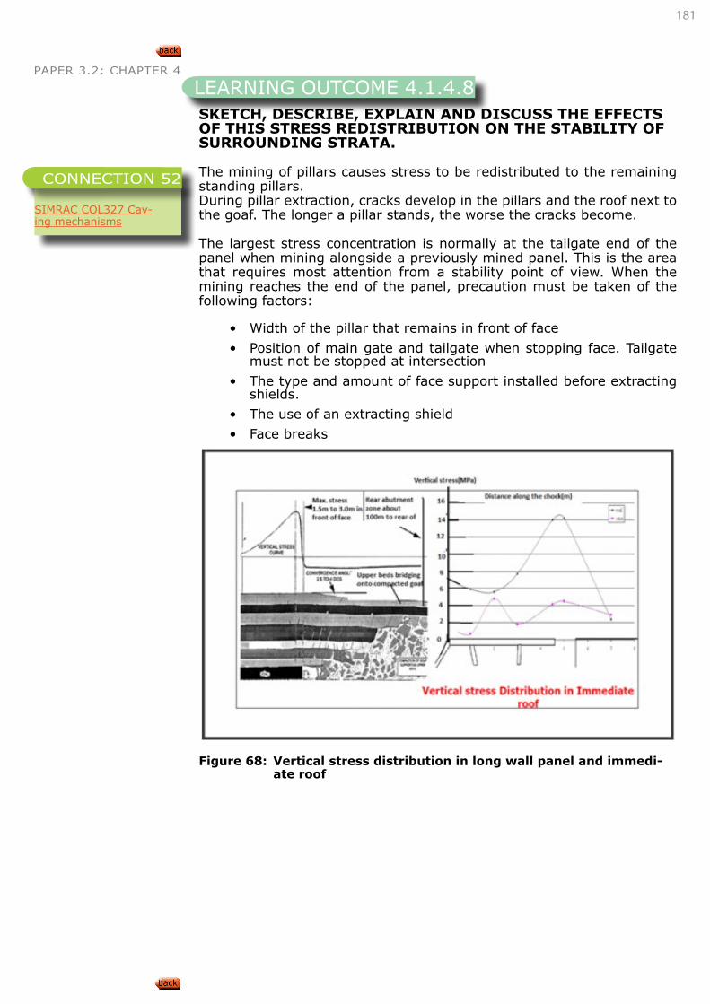
181
PAPER 3.2: CHAPTER 4
SKETCH, DESCRIBE, EXPLAIN AND DISCUSS THE EFFECTS OF THIS STRESS REDISTRIBUTION ON THE STABILITY OF SURROUNDING STRATA.
The mining of pillars causes stress to be redistributed to the remaining standing pillars.During pillar extraction, cracks develop in the pillars and the roof next to the goaf. The longer a pillar stands, the worse the cracks become.
The largest stress concentration is normally at the tailgate end of the panel when mining alongside a previously mined panel. This is the area that requires most attention from a stability point of view. When the mining reaches the end of the panel, precaution must be taken of the following factors:
• Width of the pillar that remains in front of face
• Position of main gate and tailgate when stopping face. Tailgate must not be stopped at intersection
• The type and amount of face support installed before extracting shields.
• The use of an extracting shield
• Face breaks
Figure 68: Vertical stress distribution in long wall panel and immedi-
ate roof
LEARNING OUTCOME 4.1.4.8
SIMRAC COL327 Cav-ing mechanisms
CONNECTION 52
182
PAPER 3.2: CHAPTER 4
SKETCH, DESCRIBE, EXPLAIN AND DISCUSS HOW THE FOLLOWING FACTORS AFFECT THE LOADING AND CHOICE OF POWERED SUPPORT FOR LONG WALLS:
• Strength of the floor strata,
• Strength of the roof strata,
• Massive sandstone in the roof,
• Dolerite sills in the roof,
• Seam thickness
Powered support selection is dependent on the following factors;
• Thickness and strength of the immediate roof (easily caving or massive)
• Upper main strata competency (including strong/massive units)
• Floor strength
• Capacity of support and design, to prevent spalling of the face or weakness of the roof between tip-to-face area.
In general, two-leg shields are more suitable for weak immediate roof, while four-leg shields and chock shields are excellent for medium and strong roofs. A weak immediate roof refers to roof that caves immedi-ately behind the shields, while in medium roofs, the immediate roof is relatively thin and overhangs slightly. A strong roof refers to a massive immediate roof that overhangs considerably into the goaf, such as is the case with a massive sandstone or dolerite.
Two main roof types are discussed below:
1. Massive main roof with weak immediate roof
When the main roof is massive with weak immediate roof conditions, cav-ing and bulking up of the immediate roof tends to support the main roof and this leads to less loading or weighting on the face. In this instance, higher capacity support is not required. Two-leg shields with inclined legs create compressive forces in the immediate roof and these compressive forces can hold the roof in place and the stability of the roof can be main-tained. In general, two-leg shields are most suitable for weak immediate roofs. Under immediate weak and strong roof conditions, containing overlain massive sandstone beds, high capacity, and two-leg shields of same capacity are desirable over four-leg choke shields.
2. Massive main roof with strong immediate roof
When the main roof is massive with strong immediate roof conditions, there is delayed caving and this leads to intense loading of the long wall face. In this case, supports with a higher capacity are desirable. In gen-eral, four-leg shields and chock shields are excellent for medium and strong roof.
SKETCH, DESCRIBE, EXPLAIN AND DISCUSS HOW CRUSH PILLARS MAY BE USED IN LONG WALL MINING.
As depth increases, extraction ratios associated with coal-type bord-and-pillar layouts become increasingly unfavourable. However, the increasing mining depth results in relatively smaller tensile zones, and this in turn
LEARNING OUTCOME 4.1.4.9
SIMRAC COL327 Cav-ing mechanisms
CONNECTION 53
LEARNING OUTCOME 4.1.4.10
183
PAPER 3.2: CHAPTER 4 permits the safe use of reduced levels of support resistance. The support no longer needs to carry the full weight of overburden, but rather only the weight of super incumbent strata reaching up to the furthest active weak parting in the hanging wall.
Thus small w/h ratio pillars (wlh < 3), which can provide the required reduced support resistance in their post-peak residual strength state, can be used. For example, to support the dead weight of as much as 35 m of immediate hanging wall strata, only 1 MPa of support resistance is required, and this is easily provided by the residual strength of a crushed relatively slender pillar. These types of pillars will be called crush pillars; they can be defined as pillars intended to ‘crush’ early in the life of the panel, but which have sufficient residual strength to provide the required support resistances to the immediate hanging wall, both at the face and in the back areas. These pillars can yield over a large deformation range at their residual strength level. The w/h ratios for crush pillars are typ-ically 1.7 to 2.5. Many mines exploiting Merensky Reef use crush pillars with strike dimensions of 2, 3, 4, or 6 m and dip dimensions of 2 or 3 m, separated by 0.5 to 3 m wide ventilation holes. These pillars are normally aligned on strike on the down-dip side of strike gullies, often with a 1 m siding throughout. The design of crush-pillar layouts is most commonly carried out by initially using pillar dimensions which have been successful in similar geological situations elsewhere.
Depending on the performance of the new layouts, the pillar dimensions and spacing are adjusted until the pillars provide the required behaviour. Alternatively, the initial w/h ratio for design can be specified to be 2, and if pillars do not crush initially, the w/h ratio is decreased until stable crushing is achieved. The w/h ratio normally does not exceed 2.5, and should not be less than about 1.5 in narrow stope widths. In some cas-es, the failure mode of pillars guides the w/h ratio selection. Structural weaknesses, such as thin bands of soft material or a relatively weak foundation rock, can provide the ‘crushing’ mechanism.
In long wall mining, the roadways developed to create a panel to be mined usually consist of at least two roadways with pillars formed be-tween them (chain pillars). As the long wall face is mined in retreat, the pillars are subjected to stress changes (similar to that discussed in Out-comes 4.1.3.7 and 4.1.3.8.)
When the stress on the pillar approaches and exceeds the pillar strength, the pillar will fracture, deform and eventually completely crush, usually in a controlled manner. This crushing is aimed at preventing shearing off of the roof along the chain pillar edge.
Concern is that the pillar will commence crushing before the long wall face passes the pillar position, resulting in excessive roadway closure while it is still required to allow access to the long wall face. In design, it is attempted to ensure that crushing occurs at least three splits behind the advancing face in the goaf area.
DESCRIBE, EXPLAIN AND DISCUSS HOW INTER PANEL PILLARS MAY BE REMOVED.
Van der Merwe and Madden (2010) explain the mining of inter-panel pil-lars based on real examples.
In order to improve coal reserve utilisation, the inter-panel pillars are
Refer to “LEARNING OUTCOME 4.1.4.3” on page 165
CONNECTION 54
LEARNING OUTCOME 4.1.4.11
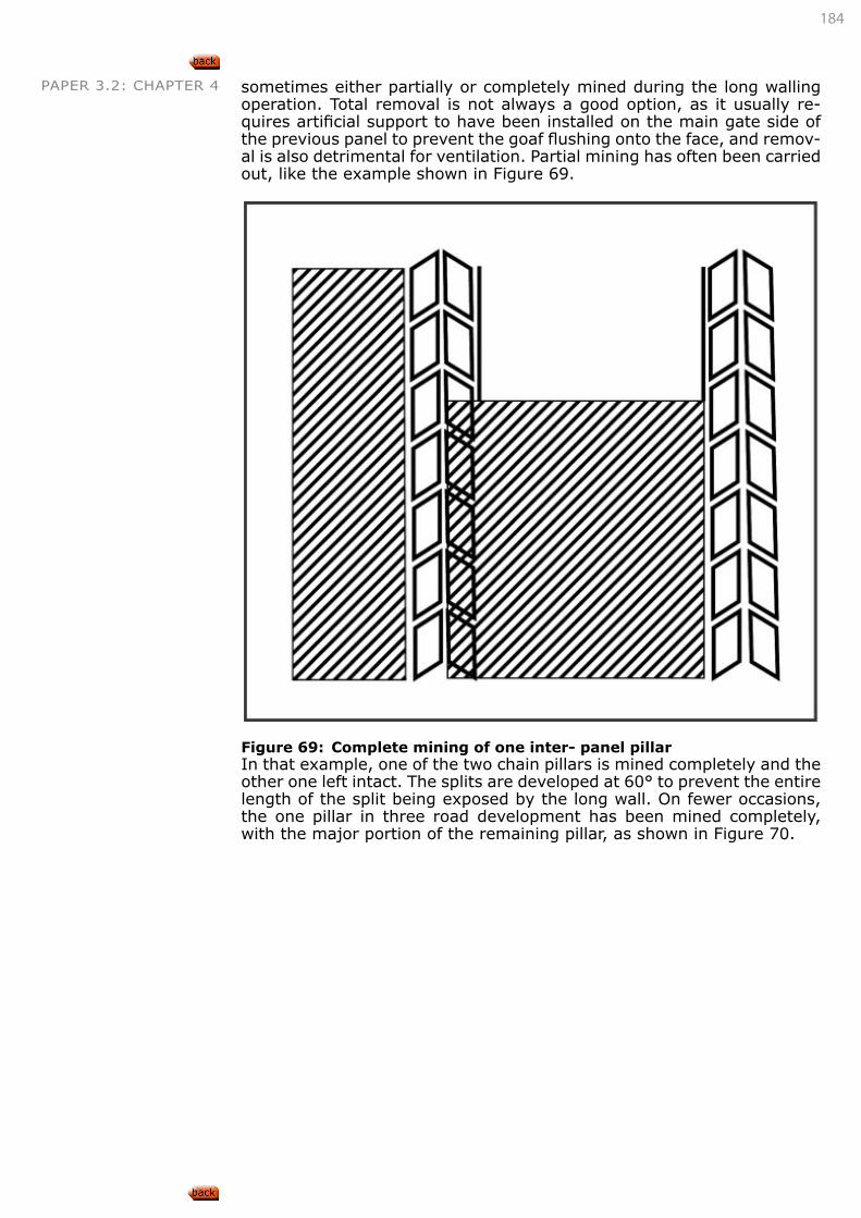
184
PAPER 3.2: CHAPTER 4 sometimes either partially or completely mined during the long walling operation. Total removal is not always a good option, as it usually re-quires artificial support to have been installed on the main gate side of the previous panel to prevent the goaf flushing onto the face, and remov-al is also detrimental for ventilation. Partial mining has often been carried out, like the example shown in Figure 69.
Figure 69: Complete mining of one inter- panel pillarIn that example, one of the two chain pillars is mined completely and the other one left intact. The splits are developed at 60° to prevent the entire length of the split being exposed by the long wall. On fewer occasions, the one pillar in three road development has been mined completely, with the major portion of the remaining pillar, as shown in Figure 70.
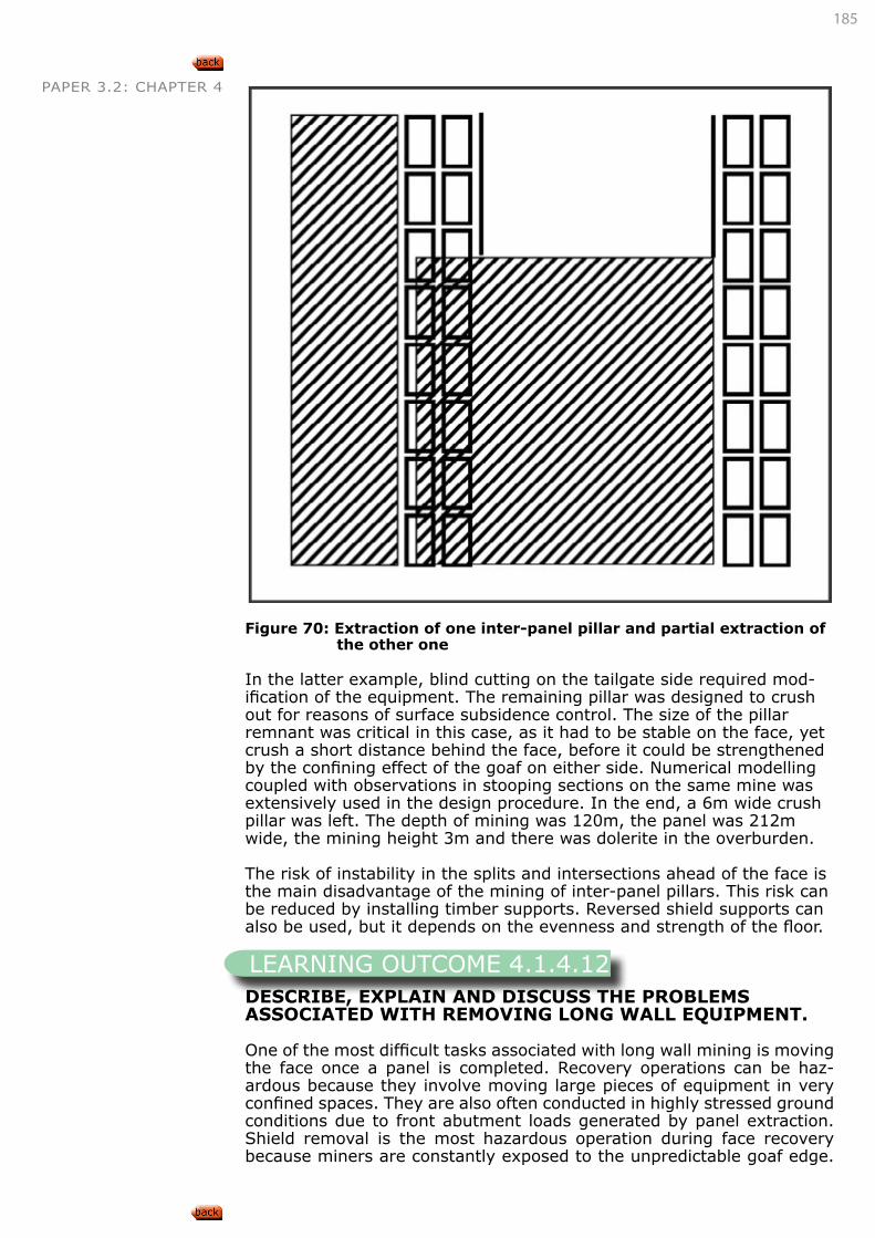
185
PAPER 3.2: CHAPTER 4
Figure 70: Extraction of one inter-panel pillar and partial extraction of
the other one
In the latter example, blind cutting on the tailgate side required mod-ification of the equipment. The remaining pillar was designed to crush out for reasons of surface subsidence control. The size of the pillar remnant was critical in this case, as it had to be stable on the face, yet crush a short distance behind the face, before it could be strengthened by the confining effect of the goaf on either side. Numerical modelling coupled with observations in stooping sections on the same mine was extensively used in the design procedure. In the end, a 6m wide crush pillar was left. The depth of mining was 120m, the panel was 212m wide, the mining height 3m and there was dolerite in the overburden.
The risk of instability in the splits and intersections ahead of the face is the main disadvantage of the mining of inter-panel pillars. This risk can be reduced by installing timber supports. Reversed shield supports can also be used, but it depends on the evenness and strength of the floor.
DESCRIBE, EXPLAIN AND DISCUSS THE PROBLEMS ASSOCIATED WITH REMOVING LONG WALL EQUIPMENT.
One of the most difficult tasks associated with long wall mining is moving the face once a panel is completed. Recovery operations can be haz-ardous because they involve moving large pieces of equipment in very confined spaces. They are also often conducted in highly stressed ground conditions due to front abutment loads generated by panel extraction. Shield removal is the most hazardous operation during face recovery because miners are constantly exposed to the unpredictable goaf edge.
LEARNING OUTCOME 4.1.4.12
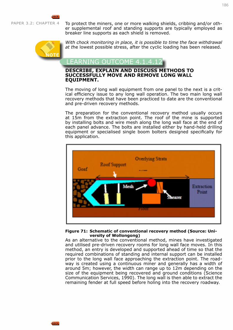
186
PAPER 3.2: CHAPTER 4 To protect the miners, one or more walking shields, cribbing and/or oth-er supplemental roof and standing supports are typically employed as breaker line supports as each shield is removed.
With chock monitoring in place, it is possible to time the face withdrawal at the lowest possible stress, after the cyclic loading has been released.
DESCRIBE, EXPLAIN AND DISCUSS METHODS TO SUCCESSFULLY MOVE AND REMOVE LONG WALL EQUIPMENT.
The moving of long wall equipment from one panel to the next is a crit-ical efficiency issue to any long wall operation. The two main long wall recovery methods that have been practiced to date are the conventional and pre-driven recovery methods.
The preparation for the conventional recovery method usually occurs at 15m from the extraction point. The roof of the mine is supported by installing bolts and wire mesh along the long wall face at the end of each panel advance. The bolts are installed either by hand-held drilling equipment or specialised single boom bolters designed specifically for this application.
Figure 71: Schematic of conventional recovery method (Source: Uni-
versity of Wollongong)As an alternative to the conventional method, mines have investigated and utilised pre-driven recovery rooms for long wall face moves. In this method, an entry is developed and supported ahead of time so that the required combinations of standing and internal support can be installed prior to the long wall face approaching the extraction point. The road-way is created using a continuous miner and generally has a width of around 5m; however, the width can range up to 12m depending on the size of the equipment being recovered and ground conditions (Science Communication Services, 1990). The long wall is then able to extract the remaining fender at full speed before holing into the recovery roadway.
LEARNING OUTCOME 4.1.4.12
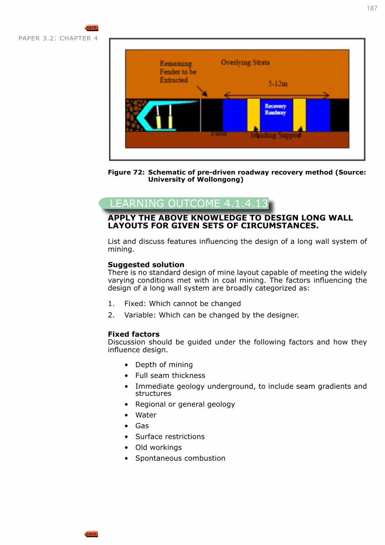
187
PAPER 3.2: CHAPTER 4
Figure 72: Schematic of pre-driven roadway recovery method (Source: University of Wollongong)
APPLY THE ABOVE KNOWLEDGE TO DESIGN LONG WALL LAYOUTS FOR GIVEN SETS OF CIRCUMSTANCES.
List and discuss features influencing the design of a long wall system of mining.
Suggested solutionThere is no standard design of mine layout capable of meeting the widely varying conditions met with in coal mining. The factors influencing the design of a long wall system are broadly categorized as:
1. Fixed: Which cannot be changed
2. Variable: Which can be changed by the designer.
Fixed factorsDiscussion should be guided under the following factors and how they influence design.
• Depth of mining
• Full seam thickness
• Immediate geology underground, to include seam gradients and structures
• Regional or general geology
• Water
• Gas
• Surface restrictions
• Old workings
• Spontaneous combustion
LEARNING OUTCOME 4.1.4.13
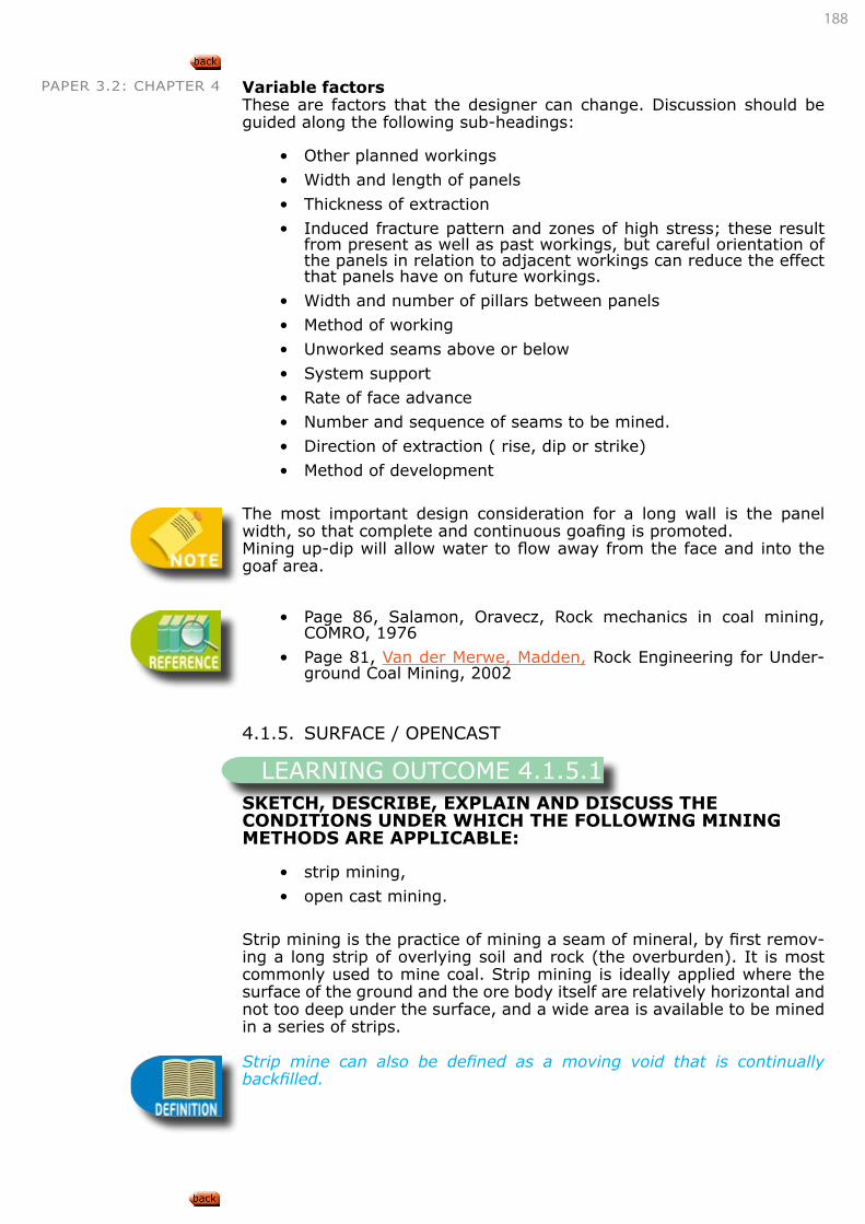
188
PAPER 3.2: CHAPTER 4 Variable factorsThese are factors that the designer can change. Discussion should be guided along the following sub-headings:
• Other planned workings
• Width and length of panels
• Thickness of extraction
• Induced fracture pattern and zones of high stress; these result from present as well as past workings, but careful orientation of the panels in relation to adjacent workings can reduce the effect that panels have on future workings.
• Width and number of pillars between panels
• Method of working
• Unworked seams above or below
• System support
• Rate of face advance
• Number and sequence of seams to be mined.
• Direction of extraction ( rise, dip or strike)
• Method of development
The most important design consideration for a long wall is the panel width, so that complete and continuous goafing is promoted.Mining up-dip will allow water to flow away from the face and into the goaf area.
• Page 86, Salamon, Oravecz, Rock mechanics in coal mining, COMRO, 1976
• Page 81, Van der Merwe, Madden, Rock Engineering for Under-ground Coal Mining, 2002
4.1.5. SURFACE / OPENCAST
SKETCH, DESCRIBE, EXPLAIN AND DISCUSS THE CONDITIONS UNDER WHICH THE FOLLOWING MINING METHODS ARE APPLICABLE:
• strip mining,
• open cast mining.
Strip mining is the practice of mining a seam of mineral, by first remov-ing a long strip of overlying soil and rock (the overburden). It is most commonly used to mine coal. Strip mining is ideally applied where the surface of the ground and the ore body itself are relatively horizontal and not too deep under the surface, and a wide area is available to be mined in a series of strips.
Strip mine can also be defined as a moving void that is continually backfilled.
LEARNING OUTCOME 4.1.5.1
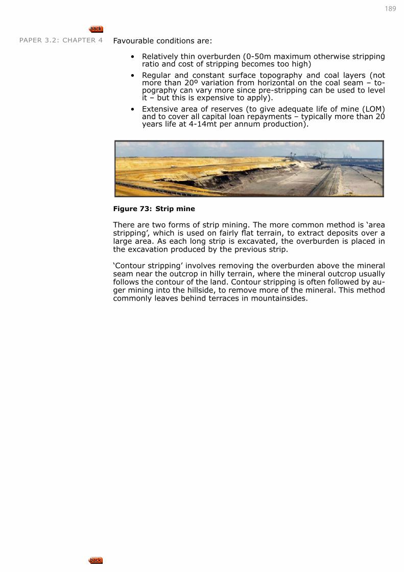
189
PAPER 3.2: CHAPTER 4 Favourable conditions are:
• Relatively thin overburden (0-50m maximum otherwise stripping ratio and cost of stripping becomes too high)
• Regular and constant surface topography and coal layers (not more than 20º variation from horizontal on the coal seam – to-pography can vary more since pre-stripping can be used to level it – but this is expensive to apply).
• Extensive area of reserves (to give adequate life of mine (LOM) and to cover all capital loan repayments – typically more than 20 years life at 4-14mt per annum production).
Figure 73: Strip mine
There are two forms of strip mining. The more common method is ‘area stripping’, which is used on fairly flat terrain, to extract deposits over a large area. As each long strip is excavated, the overburden is placed in the excavation produced by the previous strip.
‘Contour stripping’ involves removing the overburden above the mineral seam near the outcrop in hilly terrain, where the mineral outcrop usually follows the contour of the land. Contour stripping is often followed by au-ger mining into the hillside, to remove more of the mineral. This method commonly leaves behind terraces in mountainsides.
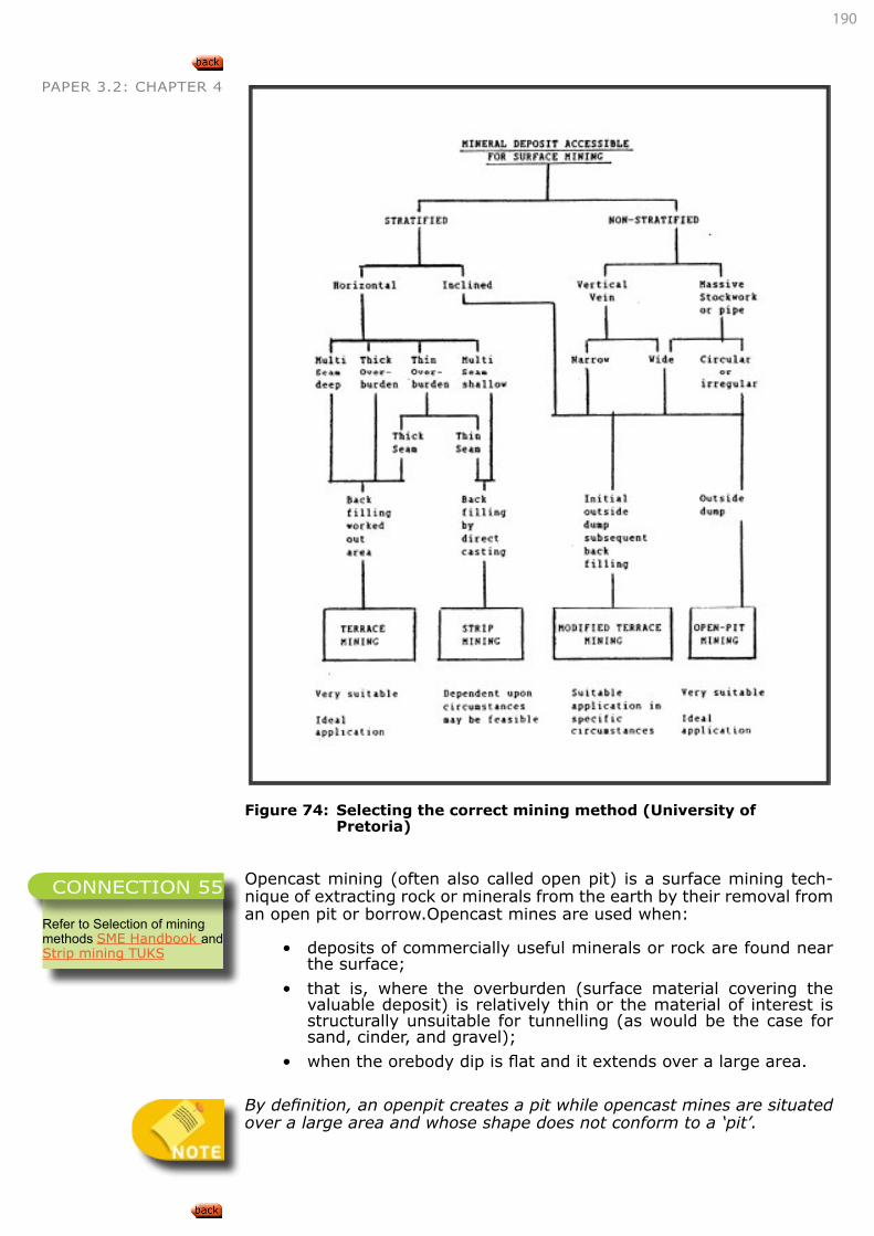
190
PAPER 3.2: CHAPTER 4
Figure 74: Selecting the correct mining method (University of
Pretoria)
Opencast mining (often also called open pit) is a surface mining tech-nique of extracting rock or minerals from the earth by their removal from an open pit or borrow.Opencast mines are used when:
• deposits of commercially useful minerals or rock are found near the surface;
• that is, where the overburden (surface material covering the valuable deposit) is relatively thin or the material of interest is structurally unsuitable for tunnelling (as would be the case for sand, cinder, and gravel);
• when the orebody dip is flat and it extends over a large area.
By definition, an openpit creates a pit while opencast mines are situated over a large area and whose shape does not conform to a ‘pit’.
Refer to Selection of mining methods SME Handbook andStrip mining TUKS
CONNECTION 55
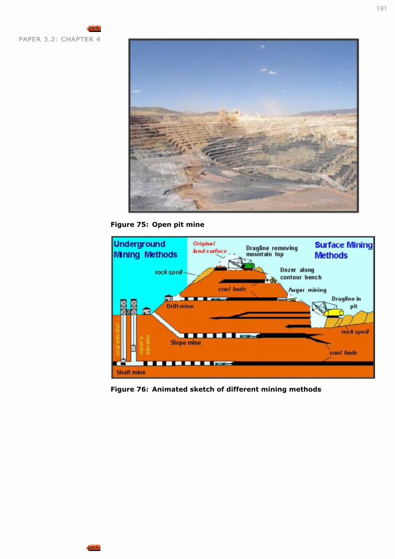
191
PAPER 3.2: CHAPTER 4
Figure 75: Open pit mine
Figure 76: Animated sketch of different mining methods
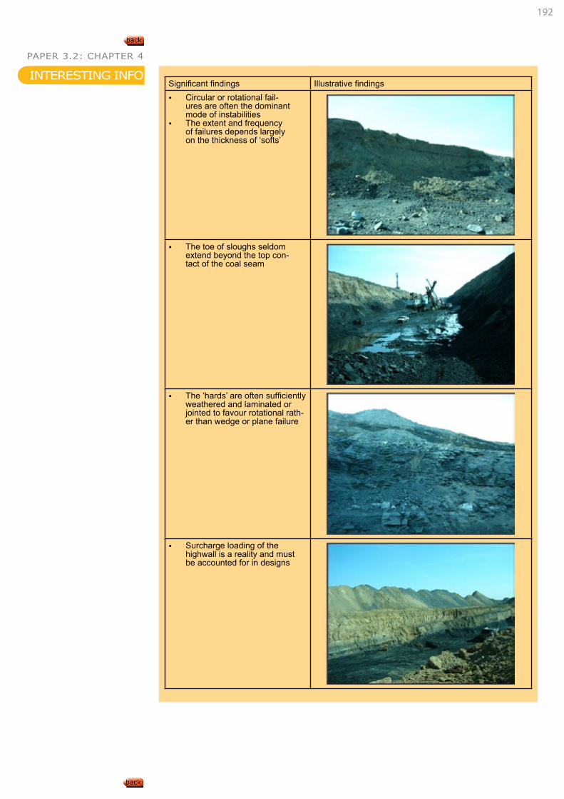
192
PAPER 3.2: CHAPTER 4
Significant findings Illustrative findings • Circular or rotational fail-
ures are often the dominant mode of instabilities
• The extent and frequency of failures depends largely on the thickness of ‘softs’
• The toe of sloughs seldom extend beyond the top con-tact of the coal seam
• The ‘hards’ are often sufficiently weathered and laminated or jointed to favour rotational rath-er than wedge or plane failure
• Surcharge loading of the highwall is a reality and must be accounted for in designs
INTERESTING INFO
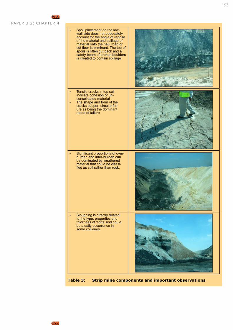
193
PAPER 3.2: CHAPTER 4
• Spoil placement on the low-wall side does not adequately account for the angle of repose of the material and spillage of material onto the haul road or cut floor is imminent. The toe of spoils is often cut back and a safety beam of broken boulders is created to contain spillage
• Tensile cracks in top soil indicate cohesion of un-consolidated material
• The shape and form of the cracks support circular fail-ure as being the dominant mode of failure
• Significant proportions of over-burden and inter-burden can be dominated by weathered material that could be classi-fied as soil rather than rock.
• Sloughing is directly related to the type, properties and thickness of ‘softs’ and could be a daily occurrence in some collieries
Table 3: Strip mine components and important observations
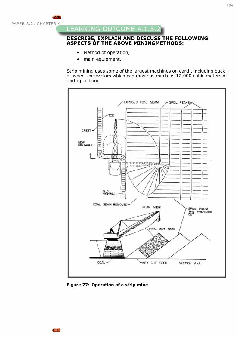
194
PAPER 3.2: CHAPTER 4
DESCRIBE, EXPLAIN AND DISCUSS THE FOLLOWING ASPECTS OF THE ABOVE MININGMETHODS:
• Method of operation,
• main equipment.
Strip mining uses some of the largest machines on earth, including buck-et-wheel excavators which can move as much as 12,000 cubic meters of earth per hour.
Figure 77: Operation of a strip mine
LEARNING OUTCOME 4.1.5.2
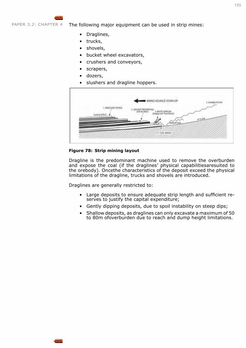
195
PAPER 3.2: CHAPTER 4 The following major equipment can be used in strip mines:
• Draglines,
• trucks,
• shovels,
• bucket wheel excavators,
• crushers and conveyors,
• scrapers,
• dozers,
• slushers and dragline hoppers.
Figure 78: Strip mining layout
Dragline is the predominant machine used to remove the overburden and expose the coal (if the draglines’ physical capabilitiesaresuited to the orebody). Oncethe characteristics of the deposit exceed the physical limitations of the dragline, trucks and shovels are introduced.
Draglines are generally restricted to:
• Large deposits to ensure adequate strip length and sufficient re-serves to justify the capital expenditure;
• Gently dipping deposits, due to spoil instability on steep dips;
• Shallow deposits, as draglines can only excavate a maximum of 50 to 80m ofoverburden due to reach and dump height limitations.
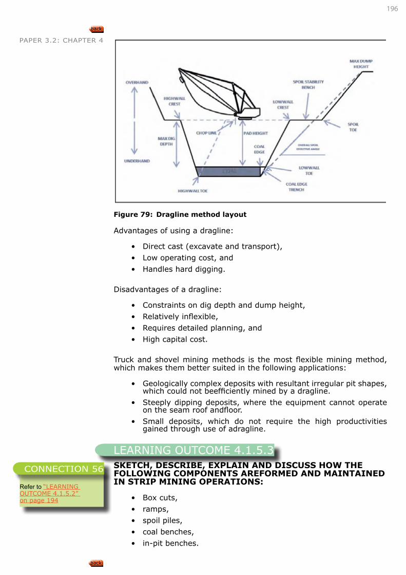
196
PAPER 3.2: CHAPTER 4
Figure 79: Dragline method layout
Advantages of using a dragline:
• Direct cast (excavate and transport),
• Low operating cost, and
• Handles hard digging.
Disadvantages of a dragline:
• Constraints on dig depth and dump height,
• Relatively inflexible,
• Requires detailed planning, and
• High capital cost.
Truck and shovel mining methods is the most flexible mining method, which makes them better suited in the following applications:
• Geologically complex deposits with resultant irregular pit shapes, which could not beefficiently mined by a dragline.
• Steeply dipping deposits, where the equipment cannot operate on the seam roof andfloor.
• Small deposits, which do not require the high productivities gained through use of adragline.
SKETCH, DESCRIBE, EXPLAIN AND DISCUSS HOW THE FOLLOWING COMPONENTS AREFORMED AND MAINTAINED IN STRIP MINING OPERATIONS:
• Box cuts,
• ramps,
• spoil piles,
• coal benches,
• in-pit benches.
LEARNING OUTCOME 4.1.5.3
Refer to “LEARNING OUTCOME 4.1.5.2” on page 194
CONNECTION 56
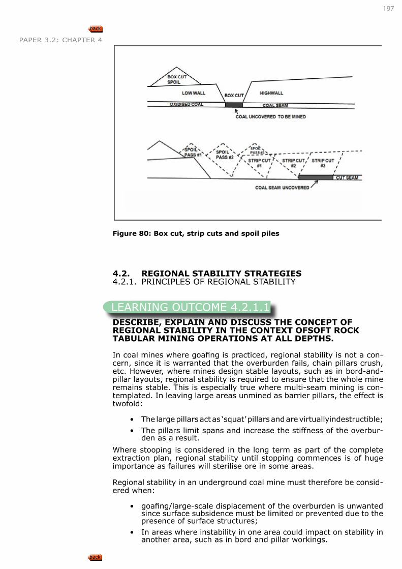
197
PAPER 3.2: CHAPTER 4
Figure 80: Box cut, strip cuts and spoil piles
4.2. REGIONAL STABILITY STRATEGIES4.2.1. PRINCIPLES OF REGIONAL STABILITY
DESCRIBE, EXPLAIN AND DISCUSS THE CONCEPT OF REGIONAL STABILITY IN THE CONTEXT OFSOFT ROCK TABULAR MINING OPERATIONS AT ALL DEPTHS.
In coal mines where goafing is practiced, regional stability is not a con-cern, since it is warranted that the overburden fails, chain pillars crush, etc. However, where mines design stable layouts, such as in bord-and-pillar layouts, regional stability is required to ensure that the whole mine remains stable. This is especially true where multi-seam mining is con-templated. In leaving large areas unmined as barrier pillars, the effect is twofold:
• The large pillars act as ‘squat’ pillars and are virtuallyindestructible;
• The pillars limit spans and increase the stiffness of the overbur-den as a result.
Where stooping is considered in the long term as part of the complete extraction plan, regional stability until stopping commences is of huge importance as failures will sterilise ore in some areas.
Regional stability in an underground coal mine must therefore be consid-ered when:
• goafing/large-scale displacement of the overburden is unwanted since surface subsidence must be limited or prevented due to the presence of surface structures;
• In areas where instability in one area could impact on stability in another area, such as in bord and pillar workings.
LEARNING OUTCOME 4.2.1.1
198
PAPER 3.2: CHAPTER 4For more detailed information on regional stability, the user is referred to the information provided in the hard rock guideline, as the concept of regional stability is a critical part of those environments.
DESCRIBE, EXPLAIN AND DISCUSS METHODS OF ENSURING REGIONAL STABILITY IN PILLARED WORKINGS.
Regional stability in pillar workings is mainly implemented to ensure that instability in areas is not transferred to adjacent mining areas. In this, the use of barrier pillars (called regional pillars in hard rock mines) is implemented to separate the mining areas into zones that potentially prevent any ‘running’ of instability into other areas.
They should therefore be able to resist increased loads imposed on them. A study showed that barrier pillars thatwere as wide as the adjacent panel pillars were able to arrest a collapse (Van derMerwe et al, 2002), suggesting that the barrier width was to be equal to the in-panel pillar width.
For more detailed information on regional stability, the user is referred to the information provided in the hard rock guideline, as the concept of regional stability is a critical part of those environments.
DESCRIBE, EXPLAIN AND DISCUSS HOW BARRIER PILLARS MAY BE USED TO IMPROVE THESTIFFNESS OF SURROUNDING STRATA.
The leaving of systematic barrier pillars in bord and pillar operations in South Africa only occurred after Salamon and Munro issued their pillar design criteria in 1967.
Barrier pillars are required, among other functions, to prevent the pos-sible collapse of underground coal workings in one area from spreading to adjacent workings. They should therefore be able to resist increased loads imposed on them. A study showed that barrier pillars, which are as wide as the adjacent panel pillars, were able to arrest a collapse.
The load on barrier pillars was found to depend largely on the behaviour of the overlying strata. Where no collapse has taken place, the barrier pillars are at a lower stress level than the adjacent pillars in the work-ings. If the width of barriers is designed to be a constant multiple of the adjacent panel pillars, they will be subject to approximately constant stresses.
Therefore, the barrier pillar width was suggested to be equal to the in-panel pillar width.
Salamon and Munro introduced two changes into the design of board and pillar workings in South Africa, the actual pillar design and the in-troduction of barriers, at the same time. Forty years of experience has confirmed that thedesign works, but there is always a question about it being overly conservative. The scientific method used to implement
Refer to Paper 3.1 Out-come 4.2.1 on page 191
CONNECTION 57
LEARNING OUTCOME 4.2.1.2
The Coalbrook disaster as well as the analysis by N Van der Merwe are good examples of regional stability impacts based on conclusions by the government mining engineer, which stated, inter alia, that: “Mining should be carried out in panels surrounded by barriers of unmined coal of dimension which will limit subsidence to a single panel in the event of pillar collapse”
INTERESTING INFO
Refer to Van der Merwe, Beyond Coalbrook... and toPaper 3.1 Outcome 4.2.1 on page 191
CONNECTION 58
LEARNING OUTCOME 4.2.1.3
199
PAPER 3.2: CHAPTER 4 changes to a system usually requires that only one factor at a time is changed, so that its specific influence can be measured. By changing two factors at the same time, the industry is left wondering if the extraction ratio can be increased, in the section, between the barriers.
To get a better understanding of the role of barriers in a bord and pillar layout, the use of 3D numerical modelling and intense monitoring around test panels would enable you as the rock engineer to make a better tech-nical design.
Barrier pillars were introduced as an improvement to the rock engineer-ing design of a pillar mining system.Time has indicated that they had some other unintended consequences. The first and most immediate was that they could be used to control ven-tilation, methane and assist with the sealing of fires.
Another use that has become accepted, without much thought, is the use of the barrier pillars as water barrier pillars.
As larger voids are created underground, they become areas where wa-ter can accumulate. This is especially true if a high extraction technique has been practised and the water table has been broken or cracks have extended to surface and intersected water courses etc.
The main source of information for designing or assessing pillars as water barriers remains the SIMRAC Project COL702, Dec 2001.
Water reporting underground from inflow of natural groundwater (largest contributor)or service water is stored primarily in compartments, dams or ponds. These water reservoirs are usually bound by coal barrier pillars. Leakage of waterthrough and around these pillars is inevitable. Although water leakage cannot be avoided, the rate and thereforethe quantity of water reporting on the dry side of the barrier pillar can be managed by engineered design. Restrictions can be placed on the minimum required barrier pillar widths, maximum allowed reservoir water head or the rate of compartment and/or roadway dewatering, depending on mining depth below surface and the geotechnical environment within which flow occurs.
The porosity and thereforethe intrinsic permeability of the rockmass in and around barrier pillars is extremely low. Water ingress is dominated by flow along rockmass discontinuities such as bedding planes, joints, stress fractures, faults, dykes and cleats. The flow path from a water-bearing area to a dry area is therefore dependent on the location, persistence and hydraulic condition of these discontinuities. The hydraulic conductivity of discontinuities is assumed to obey Darcy’s Law for laminar flow:
q = -kj a3(∆p/l)
kj = the joint permeability factor (whose the-oretical value is 1/12μ)μ = is the dynamic viscosity of the fluid,a = is the contact hydraulic aperture,l = is the length of the contact,∆p =is the water pressure between contact endpoints,q = is the rate of discharge (flow rate in m3/sec X m)
Classification of Flow Regimes
Water flow through and around coal bound barrier pillars can be classified according to the rock type hosting the discontinuities that allow water
200
PAPER 3.2: CHAPTER 4 leakage. Discharge of water onto the dry side of a barrier pillar from a flooded or partially flooded area will normally be a combination of water seeping from the roof, coal or floor. The geohydrological condition of the immediate roof, coal and floor will determine the type of flow regime per-tinent to a particular mine. The bulk of local underground collieries are described under seven possible flow regimes.
Coal bound pillar, bedded sandstone roof and floor, some vertical joints in both sandstone units.
• Leakage of water occurs through the coal seam and discrete ver-tical joints in bedded sandstone present in both roof and floor.
Coal bound pillar, bedded sandstone roof and floor, no joints present.
• Leakage of water occurs through the coal seam only, on account of the roof and floor being impermeable.
Coal bound pillar, bedded sandstone roof and laminated siltstone floor, both roof and floor have vertical joints.
• Leakage of water occurs through the coal seam and discrete ver-tical joints in bedded sandstone roof and soft (possibly damaged) laminated siltstone floor.
Coal bound pillar with a laminated siltstone roof and floor, both roof and floor have vertical joints.
• Leakage of water occurs through the coal seam and the laminat-ed siltstone roof and floor.
Coal bound pillar, bedded sandstone roof with joints present and an im-permeable sandstone floor.
• Leakage of water occurs through the coal seam and discrete ver-tical joints in the bedded sandstone roof; the floor is massive and impermeable
Coal bound pillar, bedded sandstone floor with joints present and an im-permeable sandstone roof.
• Leakage of water occurs through the coal seam and discrete ver-tical joints in the bedded sandstone floor. The roof is massive and impermeable.
Coal bound pillar, laminated siltstone roof and a bedded sandstone floor.
• Leakage of water occurs through the coal seam and the lam-inated siltstone roof and discrete vertical joints in the bedded sandstone floor.
In summary, there are a multitude of possibilities for water to get past pillars that use changes to water barriers. If you are planning to store water underground on your colliery, behind barrier pillars, it is incumbent on you to physically walk the proposed barrier while it is still accessible and map areas of faults, burnt coal, multiple joints and dykes. It is also important to record all over cutting and plot the positions of blind ends cut into the barrier as this reduces the actual width of the pillar.
This information should be used when the issue-based risk assessment is undertaken, and you as the responsible rock engineer should be able to
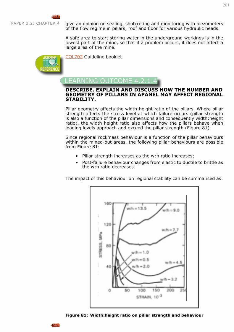
201
PAPER 3.2: CHAPTER 4 give an opinion on sealing, shotcreting and monitoring with piezometers of the flow regime in pillars, roof and floor for various hydraulic heads.
A safe area to start storing water in the underground workings is in the lowest part of the mine, so that if a problem occurs, it does not affect a large area of the mine.
COL702 Guideline booklet
DESCRIBE, EXPLAIN AND DISCUSS HOW THE NUMBER AND GEOMETRY OF PILLARS IN APANEL MAY AFFECT REGIONAL STABILITY.
Pillar geometry affects the width:height ratio of the pillars. Where pillar strength affects the stress level at which failure occurs (pillar strength is also a function of the pillar dimensions and consequently width:height ratio), the width:height ratio also affects how the pillars behave when loading levels approach and exceed the pillar strength (Figure 81).
Since regional rockmass behaviour is a function of the pillar behaviours within the mined-out areas, the following pillar behaviours are possible from Figure 81:
• Pillar strength increases as the w:h ratio increases;
• Post-failure behaviour changes from elastic to ductile to brittle as the w:h ratio decreases.
The impact of this behaviour on regional stability can be summarised as:
Figure 81: Width:height ratio on pillar strength and behaviour
LEARNING OUTCOME 4.2.1.4
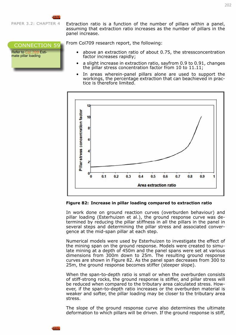
202
PAPER 3.2: CHAPTER 4 Extraction ratio is a function of the number of pillars within a panel, assuming that extraction ratio increases as the number of pillars in the panel increase.
From Col709 research report, the following:
• above an extraction ratio of about 0.75, the stressconcentration factor increases rapidly;
• a slight increase in extraction ratio, sayfrom 0.9 to 0.91, changes the pillar stress concentration factor from 10 to 11.11;
• In areas wherein-panel pillars alone are used to support the workings, the percentage extraction that can beachieved in prac-tice is therefore limited.
Figure 82: Increase in pillar loading compared to extraction ratio
In work done on ground reaction curves (overburden behaviour) and pillar loading (Esterhuizen et al.), the ground response curve was de-termined by reducing the pillar stiffness in all the pillars in the panel in several steps and determining the pillar stress and associated conver-gence at the mid-span pillar at each step.
Numerical models were used by Esterhuizen to investigate the effect of the mining span on the ground response. Models were created to simu-late mining at a depth of 450m and the panel spans were set at various dimensions from 300m down to 25m. The resulting ground response curves are shown in Figure 82. As the panel span decreases from 300 to 25m, the ground response becomes stiffer (steeper slope).
When the span-to-depth ratio is small or when the overburden consists of stiff-strong rocks, the ground response is stiffer, and pillar stress will be reduced when compared to the tributary area calculated stress. How-ever, if the span-to-depth ratio increases or the overburden material is weaker and softer, the pillar loading may be closer to the tributary area stress.
The slope of the ground response curve also determines the ultimate deformation to which pillars will be driven. If the ground response is stiff,
Refer to Col 709 Esti-mate pillar loading
CONNECTION 59
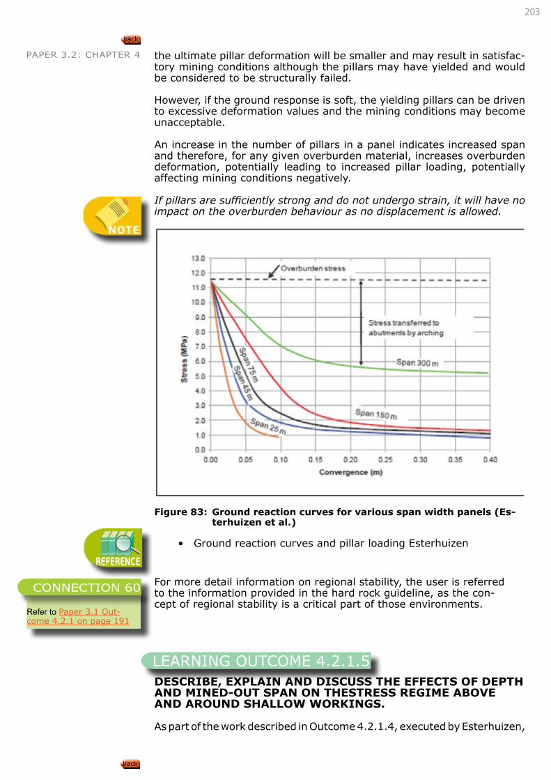
203
PAPER 3.2: CHAPTER 4 the ultimate pillar deformation will be smaller and may result in satisfac-tory mining conditions although the pillars may have yielded and would be considered to be structurally failed.
However, if the ground response is soft, the yielding pillars can be driven to excessive deformation values and the mining conditions may become unacceptable.
An increase in the number of pillars in a panel indicates increased span and therefore, for any given overburden material, increases overburden deformation, potentially leading to increased pillar loading, potentially affecting mining conditions negatively.
If pillars are sufficiently strong and do not undergo strain, it will have no impact on the overburden behaviour as no displacement is allowed.
Figure 83: Ground reaction curves for various span width panels (Es-
terhuizen et al.)
• Ground reaction curves and pillar loading Esterhuizen
For more detail information on regional stability, the user is referred to the information provided in the hard rock guideline, as the con-cept of regional stability is a critical part of those environments.
DESCRIBE, EXPLAIN AND DISCUSS THE EFFECTS OF DEPTH AND MINED-OUT SPAN ON THESTRESS REGIME ABOVE AND AROUND SHALLOW WORKINGS.
As part of the work described in Outcome 4.2.1.4, executed by Esterhuizen,
Refer to Paper 3.1 Out-come 4.2.1 on page 191
CONNECTION 60
LEARNING OUTCOME 4.2.1.5
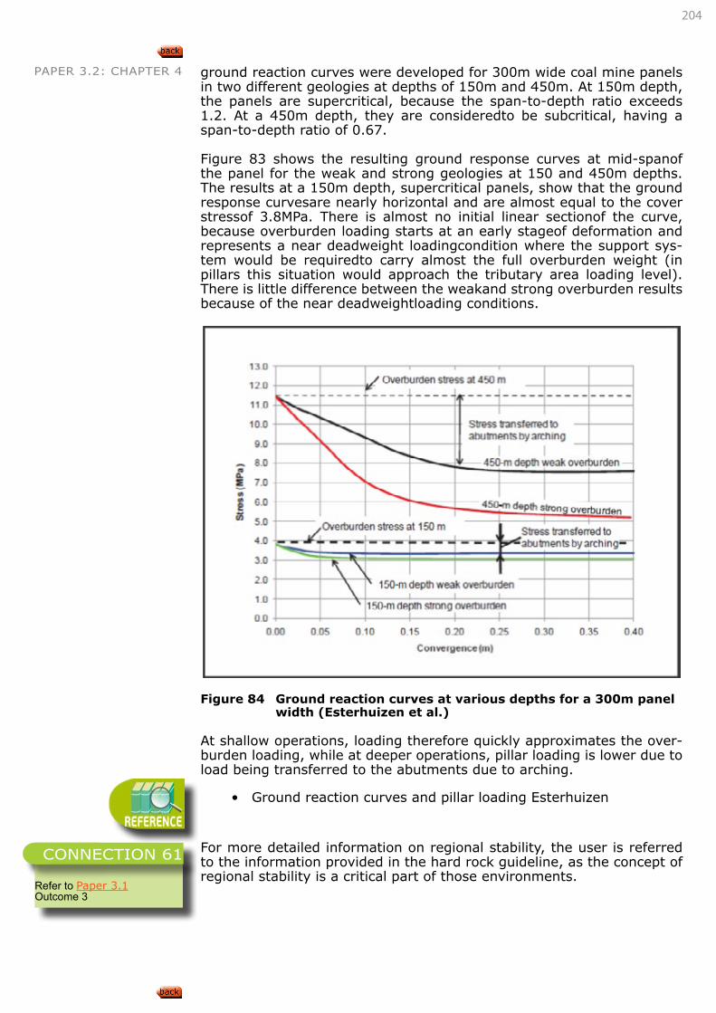
204
PAPER 3.2: CHAPTER 4 ground reaction curves were developed for 300m wide coal mine panels in two different geologies at depths of 150m and 450m. At 150m depth, the panels are supercritical, because the span-to-depth ratio exceeds 1.2. At a 450m depth, they are consideredto be subcritical, having a span-to-depth ratio of 0.67.
Figure 83 shows the resulting ground response curves at mid-spanof the panel for the weak and strong geologies at 150 and 450m depths. The results at a 150m depth, supercritical panels, show that the ground response curvesare nearly horizontal and are almost equal to the cover stressof 3.8MPa. There is almost no initial linear sectionof the curve, because overburden loading starts at an early stageof deformation and represents a near deadweight loadingcondition where the support sys-tem would be requiredto carry almost the full overburden weight (in pillars this situation would approach the tributary area loading level). There is little difference between the weakand strong overburden results because of the near deadweightloading conditions.
Figure 84 Ground reaction curves at various depths for a 300m panel
width (Esterhuizen et al.)
At shallow operations, loading therefore quickly approximates the over-burden loading, while at deeper operations, pillar loading is lower due to load being transferred to the abutments due to arching.
• Ground reaction curves and pillar loading Esterhuizen
For more detailed information on regional stability, the user is referred to the information provided in the hard rock guideline, as the concept of regional stability is a critical part of those environments.
Refer to Paper 3.1 Outcome 3
CONNECTION 61
205
PAPER 3.2: CHAPTER 4
DESCRIBE, EXPLAIN AND DISCUSS HOW THESE EFFECTS MAY AFFECT REGIONAL STABILITYREQUIREMENTS.
Increased spans and shallow depths only affect regional stability require-ments where regional stability must be maintained, i.e. in non-caving (goafing) layouts. Regional pillars or barrier pillars are therefore required to limit mining spans (panel widths) and so limit pillar stress levels as well as overburden displacement.
For more detailed information on regional stability, the user is referred to the information provided in the hard rock guideline, as the concept of regional stability is a critical part of those environments.
APPLY THE ABOVE KNOWLEDGE TO EVALUATE THE REGIONAL STABILITY OF GIVEN MININGSITUATIONS.
• Ground reaction curves and pillar loading Esterhuizen
• Design and performance of a longwall coal mine water barrier pillar
For more detailed information on regional stability, the user is re-ferred to the information provided in the hard rock guideline, as the concept of regional stability is a critical part of those environments.
APPLY THE ABOVE KNOWLEDGE TO DETERMINE APPROPRIATE REMEDIAL MEASURES TO IMPROVE REGIONAL STABILITY IN GIVEN SITUATIONS.
For more detailed information on regional stability, the user is re-ferred to the information provided in the hard rock guideline, as the concept of regional stability is a critical part of those environments.
Page 54, Van der Merwe, Madden, Rock Engineering for Underground Coal Mining, 2002
LEARNING OUTCOME 4.2.1.6
Refer to Paper 3.1 Outcome 3
CONNECTION 62
LEARNING OUTCOME 4.2.1.7
Refer to Paper 3.1 Outcome 3
CONNECTION 63
LEARNING OUTCOME 4.2.1.8
Refer to Paper 3.1 Outcome 3
CONNECTION 64
206
PAPER 3.2: CHAPTER 4 4.2.2. REGIONAL STABILITY PILLARS
This section, as given in the syllabus, is not deemed applicable to coal mines and have been removed from the learning material.
SKETCH, DESCRIBE, EXPLAIN AND DISCUSS THE FUNCTIONS OF REGIONAL STABILITY PILLARSAT SHALLOW TO INTERMEDIATE DEPTH WHERE IN-STOPE PILLARS ARE NOT USED AS LOCAL SUPPORT
For more detail information on regional stability, the user is referred to the information provided in the hard rock guideline, as the concept of regional stability is a critical part of those environments.
Refer to paper 3.1 Outcome 4.2.1
SKETCH, DESCRIBE, EXPLAIN AND DISCUSS THE FUNCTIONS OF REGIONAL STABILITY PILLARS AT SHALLOW TO INTERMEDIATE DEPTH WHERE IN-STOPE PILLARS ARE USED AS LOCAL SUPPORT
For more detail information on regional stability, the user is referred to the information provided in the hard rock guideline, as the concept of regional stability is a critical part of those environments.
Sketch, describe, explain and discuss the functions of regional stability pillars at great depth
For more detail information on regional stability, the user is referred to the information provided in the hard rock guideline, as the concept of regional stability is a critical part of those environments.
DESIGN REGIONAL STABILITY PILLARS FOR WORKINGS AT SHALLOW DEPTHS
For more detail information on regional stability, the user is referred to the information provided in the hard rock guideline, as the con-cept of regional stability is a critical part of those environments.
LEARNING OUTCOME 4.2.2.1
Refer to Paper 3.1 Outcome 4.2.1
CONNECTION 65
LEARNING OUTCOME 4.2.2.2
Refer to Paper 3.1 Outcome 4.2.1
CONNECTION 66
LEARNING OUTCOME 4.2.2.3
Refer to Paper 3.1 Out-come 4.2.1 and Design and performance of a longwall Coal mine water barrier pillar
CONNECTION 67
LEARNING OUTCOME 4.2.2.4
Refer to Paper 3.1 Outcome 4.2.1
CONNECTION 68
207
PAPER 3.2: CHAPTER 4
DESIGN REGIONAL STABILITY PILLARS FOR WORKINGS AT INTERMEDIATE DEPTHS
For more detail information on regional stability, the user is referred to the information provided in the hard rock guideline, as the con-cept of regional stability is a critical part of those environments.
APPLY EMPIRICAL CRITERIA TO DESIGN REGIONAL STABILITY PILLARS.
For more detail information on regional stability, the user is referred to the information provided in the hard rock guideline, as the con-cept of regional stability is a critical part of those environments.
4.3. OREBODY EXTRACTION LAYOUTS
SKETCH, DESCRIBE, EXPLAIN AND DISCUSS OREBODY EXTRACTION LAYOUT STRATEGIES INRESPECT OF THE FOLLOWING MINING METHODS:
• Bord and pillar mining,
• rib-pillar mining,
• stooping operations,
• longwall mining,
• strip mining.
DESCRIBE, EXPLAIN AND DISCUSS THE PROBLEMS ASSOCIATED WITH VENTILATING GOAFSAND THE EFFECT OF THIS ON PANEL LAYOUTS.
Typically, intake (fresh) air travels up the main gate, across the face, and then down the tailgate, known as ‘U’ type ventilation. Once past the face, the air is no longer fresh air, but return air carrying away coal dust and mine gases such as methane, carbon dioxide, depending on the ge-ology of the coal. Return air is extracted by ventilation fans mounted on the surface. Other ventilation methods can be used where intake air also passes the main gate and into a bleeder or back return road reducing gas emissions from the goaf onto the face, or intake air travels up the tailgate and across the face in the same direction as the face chain in a homotropal system.
Typically, to avoid coal in the goaf area spontaneously combusting, gases may be allowed to build up behind seals so as to exclude oxygen from the sealed goaf area. Where a goaf may contain an explosive mixture of methane and oxygen, nitrogen injection/inertisation may be used to
LEARNING OUTCOME 4.2.2.5
Refer to Paper 3.1 Outcome 4.2.1
CONNECTION 69
LEARNING OUTCOME 4.2.2.5
Refer to Paper 3.1 Outcome 4.2.1
CONNECTION 70
LEARNING OUTCOME 4.3.1
Refer to “MINING LAYOUT STRATEGIES” on page 93
CONNECTION 71
LEARNING OUTCOME 4.3.2
Refer to “LEARNING OUTCOME 4.1.2.2” on page 119
CONNECTION 72
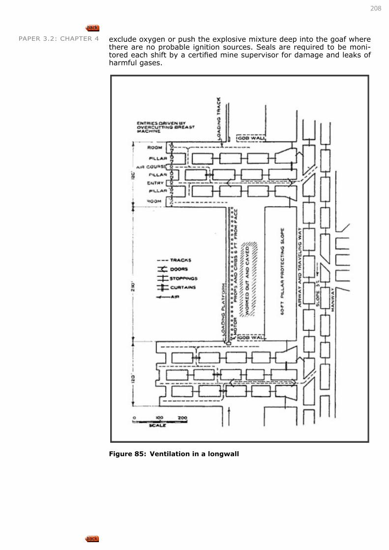
208
PAPER 3.2: CHAPTER 4 exclude oxygen or push the explosive mixture deep into the goaf where there are no probable ignition sources. Seals are required to be moni-tored each shift by a certified mine supervisor for damage and leaks of harmful gases.
Figure 85: Ventilation in a longwall
209
PAPER 3.2: CHAPTER 4 4.4. SERVICE EXCAVATION LAYOUTS4.4.1. SERVICE EXCAVATIONS
DESIGN STABLE SERVICE EXCAVATION LAYOUTS MAKING USE OF ROCK CLASSIFICATION ANDSTRESS ANALYSIS TECHNIQUES.
Refer to paper 3.1 Outcome 3.3
ASSESS THE STABILITY OF SERVICE EXCAVATION LAYOUTS IN GIVEN SITUATIONS MAKINGUSE OF ROCK CLASSIFICATION AND STRESS ANALYSIS TECHNIQUES.
Refer to paper 3.1 Outcome 3.3, 4.4.4
DETERMINE MODIFICATIONS OF SHAPE AND ORIENTATION TO IMPROVE STABILITY.
Refer to paper 3.1 Outcome 3.3, 4.4.4
DETERMINE SUPPORT STRATEGIES TO IMPROVE STABILITY.
Refer to paper 3.1 Outcome 3.3, 4.4.4
SHAFTS
DESCRIBE, EXPLAIN AND DISCUSS EXPECTED ROCK CONDITIONS IN VERTICAL SHAFTSPASSING THROUGH THE FOLLOWING ROCK TYPES:
• Surface weathered rock,
• strongly bedded strata,
• poorly bedded strata,
• dolerite dyke.
Refer to Paper 3.1 Outcome 3.3 for using rock mass classification sys-tems to estimate conditions.
LEARNING OUTCOME 4.4.1.1
Refer to Paper 3.1 Outcome 4.2.1
CONNECTION 73
LEARNING OUTCOME 4.3.2
Refer to Paper 3.1 Out-come 3.3 and 4.4.4
CONNECTION 74
LEARNING OUTCOME 4.3.2
Refer to Paper 3.1 Out-come 3.3 and 4.4.4
CONNECTION 75
LEARNING OUTCOME 4.3.2
Refer to Paper 3.1 Out-come 3.3 and 4.4.4
CONNECTION 76
LEARNING OUTCOME 4.3.2
210
PAPER 3.2: CHAPTER 4
DESCRIBE, EXPLAIN AND DISCUSS EXPECTED ROCK CONDITIONS IN INCLINED SHAFTS PASSING THROUGH THE FOLLOWING ROCK TYPES:
• Surface weathered rock,
• strongly bedded strata,
• poorly bedded strata,
• dolerite dyke.
Refer to Paper 3.1 Outcome 3.3 for using rock mass classification sys-tems to estimate conditions.
SKETCH, DESCRIBE, EXPLAIN AND DISCUSS STABILITY PROBLEMS COMMONLY ASSOCIATEDWITH BORED SHAFTS.
In bored shafts, the absence of blasting operations limits stability con-cerns to the following conditions:
• Creation of large wedges between the shaft perimeter and geo-logical structures;
• Stress fracturing and scaling due to sufficient horizontal stress levels and the creation of ‘dog-earing’ shapes;
• Poor rockmass quality areas could induce scaling on joints and bedding, especially if the bedding is not traversed at right angles.
Refer to Paper 3.1 Outcome 3.3
DETERMINE THE STABILITY OF THE FOLLOWING SHAFT TYPES MAKING USE OF ROCKCLASSIFICATION TECHNIQUES:
• Conventionally sunk vertical shafts,
• bored vertical shafts,
• conventionally sunk inclined shafts,
• bored inclined shafts.
Refer to Paper 3.1 Outcome 3.3, 4.4.4
DETERMINE THE SUPPORT REQUIREMENTS OF THE FOLLOWING SHAFT TYPES MAKING USE OF ROCK CLASSIFICATION TECHNIQUES:
• Conventionally sunk vertical shafts,
• bored vertical shafts,
• conventionally sunk inclined shafts,
• bored inclined shafts.
LEARNING OUTCOME 4.3.2
LEARNING OUTCOME 4.3.2
LEARNING OUTCOME 4.3.2
Refer to Paper 3.1 Out-come 3.3 and 4.4.4
CONNECTION 77
LEARNING OUTCOME 4.3.2
Refer to Paper 3.1 Out-come 3.3 ; 4.4.4 and 5.5
CONNECTION 78
211
PAPER 3.2: CHAPTER 5
PAPER 3.2 SOFT ROCK TABULAR MINING
5. MINING SUPPORT STRATEGIES5.1. PILLAR DESIGN STRATEGIES5.1.1. PILLAR DESIGNThe candidate must be able to demonstrate knowledge and understand-ing of the above subject area by being able to:
• Describe, explain and discuss how the following pillar equations were derived:
• Salamon and Munro pillar equation,
• Squat pillar equation
• Describe the range of applications of each of the above equations;
• Describe the limits of applicability of each of the above equations;
• Describe, explain and discuss how the Salamon and Munro pillar equation may be modified for use with rectangular pillars;
• Describe, explain and discuss how the Salamon and Munro pillar equation may be modified for use with pillars cut by continuous miner;
• Describe, explain and discuss how factors of safety are selected for pillar design;
• Apply the equations for pillar strength to design pillars for given sets of circumstances;
• Describe, explain and discuss the concept of tributary area the-ory; and
• Describe, explain and discuss the limitations of tributary area theory.
5.1.2. PILLAR REINFORCEMENTThe candidate must be able to demonstrate knowledge and understand-ing of the above subject area by being able to:
• Describe, explain and discuss techniques to reinforce pillars using:
• Dowels, wire mesh, shotcrete, fill, other means,
• Describe, explain and discuss the situations under which the dif-ferent pillar reinforcement techniques are likely to be applicable;
• Describe, explain and discuss the mechanisms involved in strengthening pillars in each of the different pillar reinforcement techniques; and
• Apply the above knowledge to evaluate given situations and de-termine appropriate pillar reinforcement techniques.
LEARNING OUTCOMES
CHAPTER
5
212
PAPER 3.2: CHAPTER 5 5.2. ROOF SUPPORT STRATEGIES5.2.1. ROOM AND PILLAR ROOF SUPPORT STRATEGIES
The candidate must be able to demonstrate knowledge and understand-ing of the above subject area by being able to:
• Describe, explain and discuss roof support requirements in room and pillar workings for good roof conditions;
• Describe, explain and discuss roof support requirements in room and pillar workings for poor roof conditions;
• Calculate and determine strata suspension and/or support re-quirements for given rock conditions;
• Calculate and determine strata beam creation and/or support re-quirements for given rock conditions; and
• Design appropriate support systems based upon support require-ment calculations.
5.2.2. PILLAR EXTRACTION ROOF SUPPORT STRATEGIES
The candidate must be able to demonstrate knowledge and understand-ing of the above subject area by being able to:
• Describe, explain and discuss roof behaviour during pillar extrac-tion operations;
• Describe, explain and discuss the functions of the following com-ponents during pillar extraction:
• Snooks, Fenders, Rockbolts, Finger lines,
• Sketch, describe, explain and discuss the types of roof support used in pillar extraction operations;
• Sketch, describe, explain and discuss the layout of roof support used in pillar extraction operations; and
• Design appropriate support systems based upon the assessment of given rock conditions.
5.2.3. LONGWALL ROOF SUPPORT STRATEGIES
The candidate must be able to demonstrate knowledge and understand-ing of the above subject area by being able to:
• Describe, explain and discuss roof support methods used in long-wall mining;
• Calculate required roof support requirements for longwall shields based upon the height of caving using Wilson’s method;
• Compare and discuss these results with actual roof support ca-pacities in South African longwalls;
• Design appropriate support for total extraction mining operations for given rock conditions and mining layouts;
• Describe, explain and discuss appropriate support installation se-quences for the above designs;
• Design appropriate maingate and tailgate support for longwall mining in poor roof conditions;
• Design appropriate tailgate area support when crush pillars are being used; and
• Design appropriate support for the removal of longwall equipment.
213
PAPER 3.2: CHAPTER 5 5.3. SERVICE EXCAVATION SUPPORT STRATEGIES
The candidate must be able to demonstrate knowledge and understand-ing of the above subject area by being able to:
• Describe, explain and discuss support strategies applicable to service excavation support in soft rock tabular mining operations.
5.4. SUPPORT DESIGN CRITERIA
The candidate must be able to demonstrate knowledge and understand-ing of the above subject area by being able to:
• Describe, explain, discuss and apply support design criteria appli-cable to excavation support in soft rock tabular mining operations.
5.5. SUPPORT AND SUPPORT SYSTEM TYPES AND CHARACTERISTICS
5.5.1. SUPPORT ELEMENTS
The candidate must be able to demonstrate knowledge and understand-ing of the above subject area by being able to:
• Describe, explain and discuss the following tendon support types within the context of soft rock operations:
• Wooden dowels, mechanically anchored bolts, point-anchor resin bolts,
• Full-column resin bolts, cable bolts, sand cells,
• Other commonly used support types
• Characterise the following aspects of the above support types:
• Their installation method,
• Their anchoring method,
• Their load bearing characteristics
• Describe, explain and discuss the applicability of the above types of tendon support in differing rock types;
• Describe, explain and discuss the following types of roof support in the context of soft rock operations:
• Trusses, W-straps,
• Timber tapes, headboards,
• Wire mesh, lacing, shotcrete
• Describe, explain and discuss the applicability of the above roof support types;
• Describe, explain and discuss the limitations of the above roof support types;
• Describe, explain and discuss the load-bearing characteristics of the following types of support:
• Mine poles, hydraulic props, longwall hydraulic shields,
• Cluster stick packs, skeleton packs, mat packs, end-grain packs,
• Waste-filled pigsty, cement-based packs
• Describe, explain and discuss the applicability of the above roof support types;
• Describe, explain and discuss the limitations of the above roof support types;
214
PAPER 3.2: CHAPTER 5
• Describe, explain and discuss comparative testing procedures for rockbolts; and
• Describe, explain and discuss the various as-pects of the SABS resin specification.
5.6. BACKFILL SYSTEMS
The candidate must be able to demonstrate knowl-edge and understanding of the above subject area by being able to:
• Describe, explain and discuss the methods of placing ashfill and sandfill in underground workings;
• Describe, explain and discuss the require-ments to make ashfilling or sandfilling successful; and
• Sketch, describe, explain and discuss the fea-tures of ashfill or sandfill systems to service particular blocks of ground.
5. MINING SUPPORT STRATEGIES5.1. PILLAR DESIGN STRATEGIES5.1.1. PILLAR DESIGN
DESCRIBE, EXPLAIN AND DISCUSS HOW THE FOLLOWING PILLAR EQUATIONS WERE DERIVED:
• Salamon and Munro pillar equation
• Squat pillar equation
• Design and performance of a longwall coal mine water barrier pillar
• New Pillar strength Van der Merwe
• SIMRAC Project COL021 Re-assessed pillar design procedures
DESCRIBE THE RANGE OF APPLICATIONS OF EACH OF THE ABOVE EQUATIONS.
DESCRIBE THE LIMITS OF APPLICABILITY OF EACH OF THE ABOVE EQUATIONS.
LEARNING OUTCOME 5.1.1.1
Refer to “LEARNING OUTCOME 4.1.1.10” on page 109
CONNECTION 79
LEARNING OUTCOME 5.1.1.2
Refer to “LEARNING OUTCOME 4.1.1.10” on page 109
CONNECTION 80
LEARNING OUTCOME 5.1.1.3
Refer to “LEARNING OUTCOME 4.1.1.10” on page 109
CONNECTION 81
215
PAPER 3.2: CHAPTER 5
DESCRIBE, EXPLAIN AND DISCUSS HOW THE SALAMON AND MUNRO PILLAR EQUATION MAY BE MODIFIED FOR USE WITH RECTANGULAR PILLARS.Salamon and Munro indicated that coal pillar strength can be determined from:
Strength = k(w0,46/h0,66)where
• the k-value is the strength of 1m3 of coal,
• w is the pillar width and
• h is the pillar height.
This equation can easily be applied to a square pillar where the width w is a constant value for all four of the pillar sides. However, when the pillar is rectangular in shape, the dimensions of the pillar are given as length L and width w, where L > w.
In this case, the pillar strength is still determined by the strength equa-tion given above, but the width w is now replaced by an ‘equivalent width’ we. Using the length L and w of the rectangular pillar, the equiva-lent width is given by:
Equivalent width = we = 4A/C = 4.L.w/2(L+w)
Where • A is the area of the pillar and
• C is the pillar circumference.
Note that this equivalent width is only used for the strength. For the pillar load, the actual dimensions are used, as given below:
Load =( dHC1C2)/w1w2 kPa
Where • H is the mining depth,
• C1 and C2 are centre-to-centre distances,
• w1 and w2 the actual widths (equal to length and width of a rec-tangular pillar) and
• d is a factor that represents the density and gravitational acceler-ation, called the unit weight, measured in kN/m3, and determined by multiplying the density with the gravitational acceleration.
Example:Unit weight = 9.81m.s-2 x 2.5 tonnes/m3 = 24.525 kN/m3.
LEARNING OUTCOME 5.1.1.4
216
PAPER 3.2: CHAPTER 5
DESCRIBE, EXPLAIN AND DISCUSS HOW THE SALAMON AND MUNRO PILLAR EQUATION MAY BE MODIFIED FOR USE WITH PILLARS CUT BY CONTINUOUS MINER.
Because the Salamon and Munro pillar design formula is based on the designed mining dimensions of workings, which were mined by the drill-and-blast method, the formula for pillar strength indirectly takes into account the weakening effect of blast damage.
Therefore, the effective width of a pillar designed according to the Salam-on and Munro formula, but mined by a continuous miner, must be greater.
The depth of blast damage into the side of a pillar has been quantified as being between 0.25 and 0.3m (Madden, 1989). The effect on the safety factor of a pillar formed by a continuous miner can be estimated on the assumption that the effective pillar width increases by twice the depth of the fractured zone, over that of a pillar mined by drill and blast methods.
If a pillar width, w, created by drilling and blasting results in a particular safety factor, then the safety factor of bord-and-pillar workings devel-oped by means of a continuous miner, η, can be calculated from the following expression, Wagner and Madden (1984):
η=η0 (1+(2Δw0)/w)2.46
Where • Δwo is the blast damage width (typically taken to be 0.3 m),
• w is the pillar width and
• ηo is the drill and blast safety factor.
This means that for pillars developed by continuous miners, the single equation for the calculation of safety factors (see Equation [7]) can be written as:
Where• w is the pillar width
• C the pillar centre-to-centre spacing
• H is the mining depth
• H is the pillar height and
• 288 is the ‘k-value / unit weight’
The value 288 is specific to a specific mining area in the RSA coal fields and should not simply be applied until the user is certain that it is appli-cable to the designed for environment.
It is important to note that for a pillar formed by a continuous miner, there is a fixed increase in pillar width by the extent of the blast-damage zone, and not a fixed increase in safety factor.
The benefit in terms of increased extraction from the use of continuous miners occurs with pillars greater in width than 5.0m and at depths of less than 175m.
Small pillar widths are sensitive to over-mining so a minimum dimension has been suggested. At a depth of approximately 175m, the onset of stress-induced slabbing of the pillar sidewalls can occur.
LEARNING OUTCOME 5.1.1.5
217
PAPER 3.2: CHAPTER 5
DESCRIBE, EXPLAIN AND DISCUSS HOW FACTORS OF SAFETY ARE SELECTED FOR PILLAR DESIGN.
Factors of safety are selected based on, inter alia, the following:• Period of time that the pillars must remain stable: the longer pil-
lars must maintain stability to protect other workings or surface structures, the higher the suggested FOS is;
• Uncertain rockmass properties: The more uncertain the rock-mass properties used for the design are, the larger the applied FOS must be;
• Risk to failure: The higher the unacceptable risk level is that is deemed acceptable by the mine, the higher the applied FOS is (see table below).
Generally, the following FOSs are deemed appropriate:• Normal single seam:
• In-panel coal pillars: 1.6
• In-panel hard rock pillar: 1.5
• Pillars protecting accesses: 2.0
• Pillars protecting surface structures: 2.0
• Multi-seam environments:
• No stress interaction is expected: Superimposed pillars at FOS 1.7;
• Stress interaction expected: Superimposed pillars at FOS 1.8
safety factor Probability of stable geometry
No of pillar col-lapses in 1 million
2,1 0,999999 <12,0 0,999994 61,9 0,999974 261,8 0,999894 1061,7 0,999586 4041,6 0,999468 15321,5 0,9947 53001,4 0,9830 170001,3 0,9508 492001,2 0,8748 1252001,1 0,7259 2741001,0 0,5000 5000000,9 0,2534 7460000,8 0.0799 9201000,7 0,0066 9934000,6 0,0060 999400
Table 1: Probability levels and FOS
LEARNING OUTCOME 5.1.1.6
218
PAPER 3.2: CHAPTER 5
APPLY THE EQUATIONS FOR PILLAR STRENGTH TO DESIGN PILLARS FOR GIVEN SETS OF CIRCUMSTANCES.
DESCRIBE, EXPLAIN AND DISCUSS THE CONCEPT OF TRIBUTARY AREA THEORY.
DESCRIBE, EXPLAIN AND DISCUSS THE LIMITATIONS OF TRIBUTARY AREA THEORY.
• Page 34, Salamon, Oravecz, Rock mechanics in coal mining, COMRO, 1976
• Page 50-59,201, Van der Merwe, Madden, Rock Engineering for Underground Coal Mining, 2002
5.1.2. PILLAR REINFORCEMENT
DESCRIBE, EXPLAIN AND DISCUSS TECHNIQUES TO REINFORCE PILLARS USING:
• Dowels,
• wire mesh,
• shotcrete,
• fill,
• other means
The most popular methods to prevent pillar failure all rely on providing lateral constraint to the pillars. This can be achieved in a number of ways, ranging from wire meshing to backfilling. In burnt coal, wire meshing is often supplemented by shotcreting. Where this is done, care should be taken to use wide aperture mesh (greater than 100 mm) and to fit the mesh snugly to the rock surface. Otherwise, the shotcrete may build up on the mesh without making contact with the rock surface.
For short-term purposes, wire mesh has been replaced by discarded con-veyor belt strips.
Backfilling is effective but relatively expensive. At Sigma Colliery, it was done on a large scale to prevent pillar failure underneath a main road. Where the underground panels are still accessible, filling could be properly controlled. Timber retaining walls with drainage holes were con-structed in the panels at intervals of 400 to 500m.
LEARNING OUTCOME 5.1.1.7
Refer to “LEARNING OUTCOME 4.1.1.10” on page 109”
CONNECTION 82
LEARNING OUTCOME 5.1.1.8
Refer to “LEARNING OUTCOME 4.1.1.10” on page 109”
CONNECTION 83
LEARNING OUTCOME 5.1.1.9
Refer to “LEARNING OUTCOME 4.1.1.10” on page 109”
CONNECTION 84
LEARNING OUTCOME 5.1.2.1
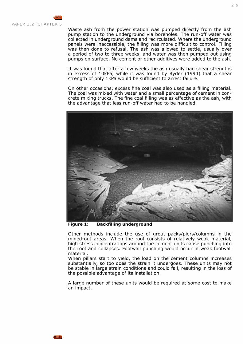
219
PAPER 3.2: CHAPTER 5Waste ash from the power station was pumped directly from the ash pump station to the underground via boreholes. The run-off water was collected in underground dams and recirculated. Where the underground panels were inaccessible, the filling was more difficult to control. Filling was then done to refusal. The ash was allowed to settle, usually over a period of two to three weeks, and water was then pumped out using pumps on surface. No cement or other additives were added to the ash.
It was found that after a few weeks the ash usually had shear strengths in excess of 10kPa, while it was found by Ryder (1994) that a shear strength of only 1kPa would be sufficient to arrest failure.
On other occasions, excess fine coal was also used as a filling material. The coal was mixed with water and a small percentage of cement in con-crete mixing trucks. The fine coal filling was as effective as the ash, with the advantage that less run-off water had to be handled.
Figure 1: Backfilling underground
Other methods include the use of grout packs/piers/columns in the mined-out areas. When the roof consists of relatively weak material, high stress concentrations around the cement units cause punching into the roof and collapses. Footwall punching would occur in weak footwall material.When pillars start to yield, the load on the cement columns increases substantially, so too does the strain it undergoes. These units may not be stable in large strain conditions and could fail, resulting in the loss of the possible advantage of its installation.
A large number of these units would be required at some cost to make an impact.
220
PAPER 3.2: CHAPTER 5
DESCRIBE, EXPLAIN AND DISCUSS THE SITUATIONS UNDER WHICH THE DIFFERENT PILLAR REINFORCEMENT TECHNIQUES ARE LIKELY TO BE APPLICABLE.
In general, pillar reinforcement is only required if pillar stability is suspect in areas where surface structures must be protected against subsidence or where undermined areas must be developed should the pillars fail.
The different reinforcement methods can best be applied as follows:• Cement columns/piers:
• Avoid using these methods when poor strength roofs or foot-walls are present.
• Avoid using where pillar failures in strong roof/footwall areas could result in large displacements, unless compressible ma-terial is used to improve the displacement characteristics.
• Apply when smaller areas of concern exist to limit financial implications.
• Backfill:
• Only viable when filling material is freely available or where environmental requirements force underground placement for disposal.
• Shallow ore body dips may hamper ease of placement, but since complete filling is not required, can be overcome.
• Hydraulically placed material would compact to a great-er extent than dry placed material and would increase the confinement on the pillars and is therefore preferred if large confinements are required.
• Can be applied to vast areas.
• Pillar surface methods (mesh/tendon support/shotcrete):
• Usually applied in only small areas or when confinement is critically required in terms of time.
• Where pillar deterioration is limited to spalling, shotcreting can terminate spalling and so confine the pillars. This is es-pecially effective when deterioration of pillar strength is also affected by environmental issues and time, as shotcrete seals the material and reduces the rate of deterioration.
• Page 56, Salamon and Oravez, 1976
LEARNING OUTCOME 5.1.2.2
221
PAPER 3.2: CHAPTER 5
DESCRIBE, EXPLAIN AND DISCUSS THE MECHANISMS INVOLVED IN STRENGTHENING PILLARS IN EACH OF THE DIFFERENT PILLAR REINFORCEMENT TECHNIQUES.
Cement columns/piers:• Installed to reduce the loading on the pillars by assuming that:
• these units would support some part of the overburden dead-weight and/or
• should pillars start to fail, these units would be able to gen-erate sufficient loads to support the overburden and prevent large-scale displacements on the pillars.
Backfill:• Backfill (any type) does not reduce pillar loading as it will not
make contact with the roof.
• It provides only a confinement role, whereby the pillar is confined to such a point that horizontal deformation is reduced/prevented, whereby the strength of the confined material is increased (as in tri-axial rock sample tests), thereby increasing the ability of the pillar to sustain much higher loads than before without increasing the risk of failure.
• To provide maximum confinement, only 2/3 of the mining height need to be filled.
Pillar surface methods (mesh/tendon support/shotcrete):• Performs a similar role to backfill, where confinement of the pillar
edges reduces horizontal deformation/displacement and therefor increases the strength of the pillar material.
• Page 56, Salamon and Oravez, 1976
APPLY THE ABOVE KNOWLEDGE TO EVALUATE GIVEN SITUATIONS AND DETERMINE APPROPRIATE PILLAR REINFORCEMENT TECHNIQUES.
• Page 56, Salamon and Oravez, 1976
LEARNING OUTCOME 5.1.2.3
LEARNING OUTCOME 5.1.2.4
Refer to “LEARNING OUT-COME 5.1.2.1” on page 218 to Outcome 5.1.2.3
CONNECTION 85
222
PAPER 3.2: CHAPTER 5 5.2. ROOF SUPPORT STRATEGIES5.2.1. ROOM AND PILLAR ROOF SUPPORT STRATEGIES
• Coal roadway support handbook Health and Safety RMT
• Improve bolt support in USA coal Spearing
• SIM020205 Support system in colleries
DESCRIBE, EXPLAIN AND DISCUSS ROOF SUPPORT REQUIREMENTS IN ROOM AND PILLAR WORKINGS FOR GOOD ROOF CONDITIONS.
DESCRIBE, EXPLAIN AND DISCUSS ROOF SUPPORT REQUIREMENTS IN ROOM AND PILLAR WORKINGS FOR POOR ROOF CONDITIONS.
CALCULATE AND DETERMINE STRATA SUSPENSION AND/OR SUPPORT REQUIREMENTS FOR GIVEN ROCK CONDITIONS.
CALCULATE AND DETERMINE STRATA BEAM CREATION AND/OR SUPPORT REQUIREMENTS FOR GIVEN ROCK CONDITIONS.
DESIGN APPROPRIATE SUPPORT SYSTEMS BASED UPON SUPPORT REQUIREMENT CALCULATIONS.
Paper 3.1 Outcome 5.2 and 5.3.2
• Page 93, Salamon, Oravecz, Rock mechanics in coal mining, COMRO, 1976
• Page 32-43,183, Van der Merwe, Madden, Rock Engineering for Underground Coal Mining, 2002
5.2.2. PILLAR EXTRACTION ROOF SUPPORT STRATEGIES
LEARNING OUTCOME 5.2.1.1
Refer to Paper 3.1 Outcome 5.2.1
CONNECTION 86
LEARNING OUTCOME 5.2.1.2
Refer to Paper 3.1 Outcome 5.2.1
CONNECTION 87
LEARNING OUTCOME 5.2.1.3
Refer to Paper 3.1 Outcome 5.2.1
CONNECTION 88
LEARNING OUTCOME 5.2.1.4
Refer to Paper 3.1 Outcome 5.2.1
CONNECTION 89
LEARNING OUTCOME 5.2.1.5
Refer to Paper 3.1 Outcome 5.2 and 5.3.2
CONNECTION 90
223
PAPER 3.2: CHAPTER 5
DESCRIBE, EXPLAIN AND DISCUSS ROOF BEHAVIOUR DURING PILLAR EXTRACTION OPERATIONS.
DESCRIBE, EXPLAIN AND DISCUSS THE FUNCTIONS OF THE FOLLOWING COMPONENTS DURING PILLAR EXTRACTION:
• Snooks,
• fenders,
• rockbolts,
• finger lines
SKETCH, DESCRIBE, EXPLAIN AND DISCUSS THE TYPES OF ROOF SUPPORT USED IN PILLAR EXTRACTION OPERATIONS.
SKETCH, DESCRIBE, EXPLAIN AND DISCUSS THE LAYOUT OF ROOF SUPPORT USED IN PILLAR EXTRACTION OPERATIONS.
DESIGN APPROPRIATE SUPPORT SYSTEMS BASED UPON ASSESSMENT OF GIVEN ROCK CONDITIONS.
• Page 93, Salamon, Oravecz, Rock mechanics in coal mining, COMRO, 1976
• Page 32-43,183,209, Van der Merwe, Madden, Rock Engineering for Underground Coal Mining, 2002
5.2.3. LONGWALL ROOF SUPPORT STRATEGIES
DESCRIBE, EXPLAIN AND DISCUSS ROOF SUPPORT METHODS USED IN LONGWALL MINING.
The current popular practice is to use the two-legged lemniscate shield support that can support approximately 1 000 tonnes before it goes into
LEARNING OUTCOME 5.2.2.1
Refer to “LEARNING OUTCOME 4.1.3.4” and “LEARNING OUTCOME 4.1.3.5” on page 149
CONNECTION 91
LEARNING OUTCOME 5.2.2.2
Refer to “LEARNING OUTCOME 4.1.3.2” on page 142
CONNECTION 92
LEARNING OUTCOME 5.2.2.3
Refer to “LEARNING OUTCOME 4.1.3.2” on page 142 and “LEARN-ING OUTCOME 4.1.3.3” on page 144
CONNECTION 93
LEARNING OUTCOME 5.2.2.4
Refer to “LEARNING OUTCOME 4.1.3.2” on page 142
CONNECTION 94
LEARNING OUTCOME 5.2.2.5
Refer to Paper 3.1 Outcome 5.2 and 5.3.2
CONNECTION 95
LEARNING OUTCOME 5.2.3.1
224
PAPER 3.2: CHAPTER 5 yield. The internal diameters of the leg cylinders are typically in the range 480 to 520mm and are pressurised with hydraulic fluid at about 480bar, at the pump.
Each support leg consists of two cylinders, typically called the minor and major stages. The minor stage is fully extended before the major stage is activated. The legs are equipped with slow release and rapid (rockburst) relief valves. The best roof control is achieved when the setting pressure is within 15 to 20% of the yield pressure, as this reduces the amount of roof sag prior to yield occurring.
It must be understood that the shield support is not supporting the over-burden all the way to surface.
Once the initial void has been created, the face advances until a point is reached variously described as the peak abutment (highest stress on the face) or the first goaf, where the first significant ‘caving’ is estab-lished. This event may be relatively localised or may extend all the way to the surface, depending on factors such as depth below surface and the geological make-up of the overburden. If it extends to the surface, the subsidence may be described as ‘dynamic subsidence’ as it is more significant than the steady-state subsidence normally associated with the longwall panel.
Peng describes the disturbed strata caused by longwall mining as follows:
• Caving zone. This is the immediate roof material that falls into the mined-out void and consists of broken rubble. Depending on the material involved, this zone typically extends upwards be-tween two and eight times the extracted seam height. This is the critical zone that the shield supports must support.
• Fractured zone. Here the overburden is broken into blocks, but no rotation of the blocks occurs. This is the zone that generates the phenomena of ‘cyclic loading’, where transient abutments are created that cause face breaks or the shield supports go into yield.
• Continuous deformation zone. This zone extends to the surface and the overburden flexes and bends, but to a large extent it is still intact.
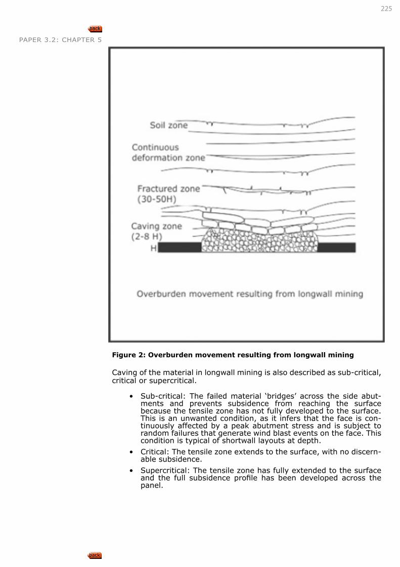
225
PAPER 3.2: CHAPTER 5
Figure 2: Overburden movement resulting from longwall mining
Caving of the material in longwall mining is also described as sub-critical, critical or supercritical.
• Sub-critical: The failed material ‘bridges’ across the side abut-ments and prevents subsidence from reaching the surface because the tensile zone has not fully developed to the surface. This is an unwanted condition, as it infers that the face is con-tinuously affected by a peak abutment stress and is subject to random failures that generate wind blast events on the face. This condition is typical of shortwall layouts at depth.
• Critical: The tensile zone extends to the surface, with no discern-able subsidence.
• Supercritical: The tensile zone has fully extended to the surface and the full subsidence profile has been developed across the panel.
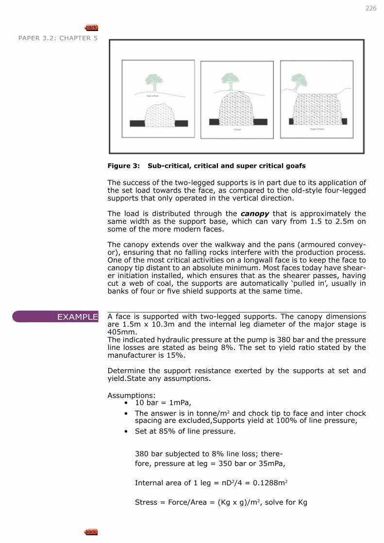
226
PAPER 3.2: CHAPTER 5
Figure 3: Sub-critical, critical and super critical goafs
The success of the two-legged supports is in part due to its application of the set load towards the face, as compared to the old-style four-legged supports that only operated in the vertical direction.
The load is distributed through the canopy that is approximately the same width as the support base, which can vary from 1.5 to 2.5m on some of the more modern faces.
The canopy extends over the walkway and the pans (armoured convey-or), ensuring that no falling rocks interfere with the production process. One of the most critical activities on a longwall face is to keep the face to canopy tip distant to an absolute minimum. Most faces today have shear-er initiation installed, which ensures that as the shearer passes, having cut a web of coal, the supports are automatically ‘pulled in’, usually in banks of four or five shield supports at the same time.
A face is supported with two-legged supports. The canopy dimensions are 1.5m x 10.3m and the internal leg diameter of the major stage is 405mm.The indicated hydraulic pressure at the pump is 380 bar and the pressure line losses are stated as being 8%. The set to yield ratio stated by the manufacturer is 15%.
Determine the support resistance exerted by the supports at set and yield.State any assumptions.
Assumptions:• 10 bar = 1mPa,
• The answer is in tonne/m2 and chock tip to face and inter chock spacing are excluded,Supports yield at 100% of line pressure,
• Set at 85% of line pressure.
380 bar subjected to 8% line loss; there-fore, pressure at leg = 350 bar or 35mPa,
Internal area of 1 leg = πD2/4 = 0.1288m2
Stress = Force/Area = (Kg x g)/m2, solve for Kg
EXAMPLE
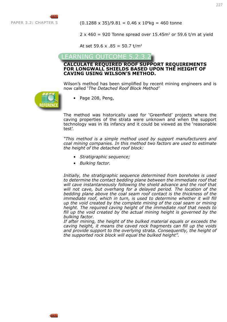
227
PAPER 3.2: CHAPTER 5 (0.1288 x 35)/9.81 = 0.46 x 10⁶kg = 460 tonne
2 x 460 = 920 Tonne spread over 15.45m2 or 59.6 t/m at yield
At set 59.6 x .85 = 50.7 t/m2
CALCULATE REQUIRED ROOF SUPPORT REQUIREMENTS FOR LONGWALL SHIELDS BASED UPON THE HEIGHT OF CAVING USING WILSON’S METHOD.
Wilson’s method has been simplified by recent mining engineers and is now called ‘The Detached Roof Block Method’
• Page 208, Peng,
The method was historically used for ‘Greenfield’ projects where the caving properties of the strata were unknown and when the support technology was in its infancy and it could be viewed as the ‘reasonable test’.
“This method is a simple method used by support manufacturers and coal mining companies. In this method two factors are used to estimate the height of the detached roof block:
• Stratigraphic sequence;
• Bulking factor.
Initially, the stratigraphic sequence determined from boreholes is used to determine the contact bedding plane between the immediate roof that will cave instantaneously following the shield advance and the roof that will not cave, but overhang for a delayed period. The location of the bedding plane above the coal seam roof contact is the thickness of the immediate roof, which in turn, is used to determine whether it will fill up the void created by the complete mining of the coal seam or mining height. The required caving height of the immediate roof that needs to fill up the void created by the actual mining height is governed by the bulking factor.If after mining, the height of the bulked material equals or exceeds the caving height, it means the caved rock fragments can fill up the voids and provide support to the overlying strata. Consequently, the height of the supported rock block will equal the bulked height”.
LEARNING OUTCOME 5.2.3.2
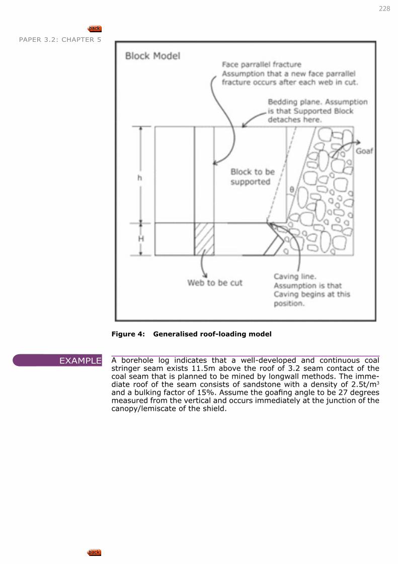
228
PAPER 3.2: CHAPTER 5
Figure 4: Generalised roof-loading model
A borehole log indicates that a well-developed and continuous coal stringer seam exists 11.5m above the roof of 3.2 seam contact of the coal seam that is planned to be mined by longwall methods. The imme-diate roof of the seam consists of sandstone with a density of 2.5t/m3 and a bulking factor of 15%. Assume the goafing angle to be 27 degrees measured from the vertical and occurs immediately at the junction of the canopy/lemiscate of the shield.
EXAMPLE
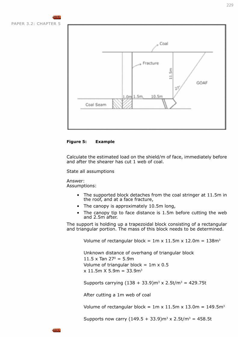
229
PAPER 3.2: CHAPTER 5
Figure 5: Example
Calculate the estimated load on the shield/m of face, immediately before and after the shearer has cut 1 web of coal.
State all assumptions
Answer:Assumptions:
• The supported block detaches from the coal stringer at 11.5m in the roof, and at a face fracture,
• The canopy is approximately 10.5m long,
• The canopy tip to face distance is 1.5m before cutting the web and 2.5m after.
The support is holding up a trapezoidal block consisting of a rectangular and triangular portion. The mass of this block needs to be determined.
Volume of rectangular block = 1m x 11.5m x 12.0m = 138m3
Unknown distance of overhang of triangular block11.5 x Tan 270 = 5.9mVolume of triangular block = 1m x 0.5 x 11.5m X 5.9m = 33.9m3
Supports carrying (138 + 33.9)m3 x 2.5t/m3 = 429.75t
After cutting a 1m web of coal
Volume of rectangular block = 1m x 11.5m x 13.0m = 149.5m3
Supports now carry (149.5 + 33.9)m3 x 2.5t/m3 = 458.5t
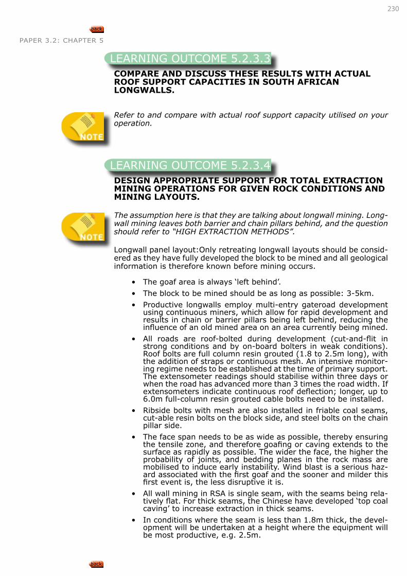
230
PAPER 3.2: CHAPTER 5
COMPARE AND DISCUSS THESE RESULTS WITH ACTUAL ROOF SUPPORT CAPACITIES IN SOUTH AFRICAN LONGWALLS.
Refer to and compare with actual roof support capacity utilised on your operation.
DESIGN APPROPRIATE SUPPORT FOR TOTAL EXTRACTION MINING OPERATIONS FOR GIVEN ROCK CONDITIONS AND MINING LAYOUTS.
The assumption here is that they are talking about longwall mining. Long-wall mining leaves both barrier and chain pillars behind, and the question should refer to “HIGH EXTRACTION METHODS”.
Longwall panel layout:Only retreating longwall layouts should be consid-ered as they have fully developed the block to be mined and all geological information is therefore known before mining occurs.
• The goaf area is always ‘left behind’.
• The block to be mined should be as long as possible: 3-5km.
• Productive longwalls employ multi-entry gateroad development using continuous miners, which allow for rapid development and results in chain or barrier pillars being left behind, reducing the influence of an old mined area on an area currently being mined.
• All roads are roof-bolted during development (cut-and-flit in strong conditions and by on-board bolters in weak conditions). Roof bolts are full column resin grouted (1.8 to 2.5m long), with the addition of straps or continuous mesh. An intensive monitor-ing regime needs to be established at the time of primary support. The extensometer readings should stabilise within three days or when the road has advanced more than 3 times the road width. If extensometers indicate continuous roof deflection; longer, up to 6.0m full-column resin grouted cable bolts need to be installed.
• Ribside bolts with mesh are also installed in friable coal seams, cut-able resin bolts on the block side, and steel bolts on the chain pillar side.
• The face span needs to be as wide as possible, thereby ensuring the tensile zone, and therefore goafing or caving extends to the surface as rapidly as possible. The wider the face, the higher the probability of joints, and bedding planes in the rock mass are mobilised to induce early instability. Wind blast is a serious haz-ard associated with the first goaf and the sooner and milder this first event is, the less disruptive it is.
• All wall mining in RSA is single seam, with the seams being rela-tively flat. For thick seams, the Chinese have developed ‘top coal caving’ to increase extraction in thick seams.
• In conditions where the seam is less than 1.8m thick, the devel-opment will be undertaken at a height where the equipment will be most productive, e.g. 2.5m.
LEARNING OUTCOME 5.2.3.3
LEARNING OUTCOME 5.2.3.4
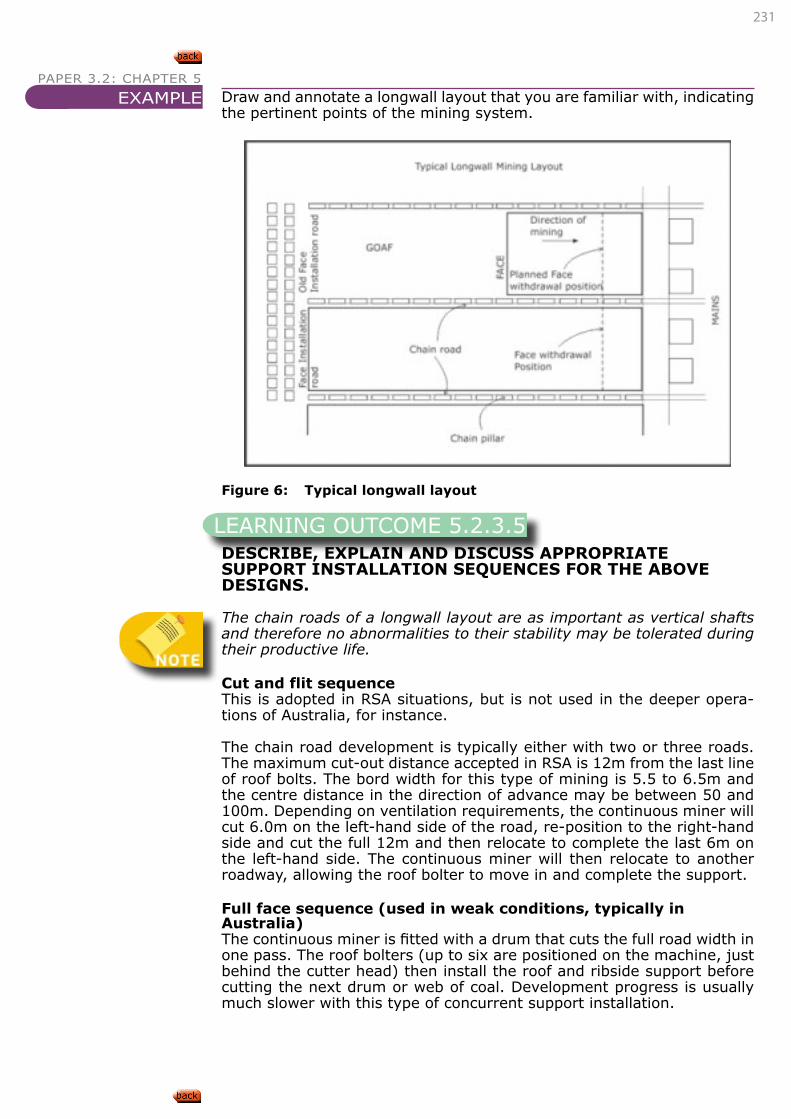
231
PAPER 3.2: CHAPTER 5
Draw and annotate a longwall layout that you are familiar with, indicating the pertinent points of the mining system.
Figure 6: Typical longwall layout
DESCRIBE, EXPLAIN AND DISCUSS APPROPRIATE SUPPORT INSTALLATION SEQUENCES FOR THE ABOVE DESIGNS.
The chain roads of a longwall layout are as important as vertical shafts and therefore no abnormalities to their stability may be tolerated during their productive life.
Cut and flit sequenceThis is adopted in RSA situations, but is not used in the deeper opera-tions of Australia, for instance.
The chain road development is typically either with two or three roads. The maximum cut-out distance accepted in RSA is 12m from the last line of roof bolts. The bord width for this type of mining is 5.5 to 6.5m and the centre distance in the direction of advance may be between 50 and 100m. Depending on ventilation requirements, the continuous miner will cut 6.0m on the left-hand side of the road, re-position to the right-hand side and cut the full 12m and then relocate to complete the last 6m on the left-hand side. The continuous miner will then relocate to another roadway, allowing the roof bolter to move in and complete the support.
Full face sequence (used in weak conditions, typically in Australia)The continuous miner is fitted with a drum that cuts the full road width in one pass. The roof bolters (up to six are positioned on the machine, just behind the cutter head) then install the roof and ribside support before cutting the next drum or web of coal. Development progress is usually much slower with this type of concurrent support installation.
EXAMPLE
LEARNING OUTCOME 5.2.3.5
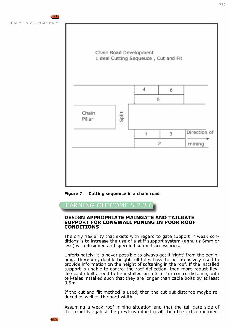
232
PAPER 3.2: CHAPTER 5
Figure 7: Cutting sequence in a chain road
DESIGN APPROPRIATE MAINGATE AND TAILGATE SUPPORT FOR LONGWALL MINING IN POOR ROOF CONDITIONS
The only flexibility that exists with regard to gate support in weak con-ditions is to increase the use of a stiff support system (annulus 6mm or less) with designed and specified support accessories.
Unfortunately, it is never possible to always get it ‘right’ from the begin-ning. Therefore, double height tell-tales have to be intensively used to provide information on the height of softening in the roof. If the installed support is unable to control the roof deflection, then more robust flex-ible cable bolts need to be installed on a 3 to 4m centre distance, with tell-tales installed such that they are longer than cable bolts by at least 0.5m.
If the cut-and-flit method is used, then the cut-out distance maybe re-duced as well as the bord width.
Assuming a weak roof mining situation and that the tail gate side of the panel is against the previous mined goaf, then the extra abutment
LEARNING OUTCOME 5.2.3.6
233
PAPER 3.2: CHAPTER 5 stresses that may cause deterioration in the tailgate require that stand-ing support be required in the form of link-n-lock skeleton packs or ‘tin cans’ (steel drums filled with concrete). This is to ensure that the return air quantity is not significantly reduced.
DESIGN APPROPRIATE TAILGATE AREA SUPPORT WHEN CRUSH PILLARS ARE BEING USED.
The design requirement is that the pillars are stable up to the point that the face passes them. This is almost impossible to get right, as sub-tle changes in the floor and roof geology and the loading regime are uncontrollable.
There are two reasons for designing a layout with crush pillars;
• To prevent ‘coal bumps’ (pillar bursts); and
• To ensure relatively uniform surface subsidence on account of the land use.
Unfortunately, a crush pillar layout is an empirical exercise, starting with larger pillars w:h of say 3:1, and then progressively reducing the pillar width. The development requirements stipulate that chain road devel-opment is often two to three years ahead of the mining, so the outputs from pillar monitoring may take five to six years to implement.
A major hazard at a deep South African longwall operation that tried to implement crush pillars was that the cyclic loading events caused the crush pillars to fail ahead of the mining face, resulting in the loss of the tail gate entry.
DESIGN APPROPRIATE SUPPORT FOR THE REMOVAL OF LONGWALL EQUIPMENT.
When the longwall panel reaches the end of a mining block, the shearer, pan line and chocks need to be removed.
This is a very intensive process and no delays can be tolerated during the process.
In strong roof situations, the bolting process may be delayed to be done during the last 5five webs. In friable ground conditions, the bolting and meshing process may begin 20 to 30m from the last web being cut.
If the mine is affected by cyclic loading, it is unwise to attempt a face withdrawal if a peak abutment is acting on the face. It is better to mine another 5 to 10m and to induce the goaf to come down.
One of the first considerations is to think of the most ideal working height required during the withdrawal process. Thick seam operations (+4.5m) will grade the mining height down to 3 to 3.5m.
Once the pan line has been withdrawn, people tend to walk beyond the cover of the chock tip and therefore the use of mesh and straps is rec-ommended to provide areal coverage.
Typical support elements on a face withdrawal are 1.8m full column
LEARNING OUTCOME 5.2.3.7
LEARNING OUTCOME 5.2.3.8
234
PAPER 3.2: CHAPTER 5 resin bolts with mesh straps. The centre portion of the face where peak abutment loads are expected could also be supported with flexible cable anchors.
It is important that the chocks are kept pressurised at their working loads for the duration of the process.
When the shield supports are to be withdrawn, two supports are used to run parallel to the face to act as the ‘recovery’ supports. They may be specifically designed supports or two supports from the tailgate that are ‘turned out’ for the process.
Their role is twofold:
• Support the roof as each end support is de-stressed prior to be-ing turned out, and
• Prevent and control the flushing of goafed material into the work-ing area.
As supports are pulled out, and depending on the custom and practice at the mining operation, props or packs may be set to provide a delay before the goaf closes the void.
• Page 93, Salamon, Oravecz, Rock mechanics in coal mining, COMRO, 1976
• Page 32-43,183, Van der Merwe, Madden, Rock Engineering for Underground Coal Mining, 2002
5.3. SERVICE EXCAVATION SUPPORT STRATEGIES
DESCRIBE, EXPLAIN AND DISCUSS SUPPORT STRATEGIES APPLICABLE TO SERVICE EXCAVATION SUPPORT IN SOFT ROCK TABULAR MINING OPERATIONS.
Refer to paper 3.1 Outcome 5.2.2
5.4. SUPPORT DESIGN CRITERIA
DESCRIBE, EXPLAIN, DISCUSS AND APPLY SUPPORT DESIGN CRITERIA APPLICABLE TO EXCAVATION SUPPORT IN SOFT ROCK TABULAR MINING OPERATIONS.
LEARNING OUTCOME 5.3.1
Refer to Paper 3.1 Outcome 5.2.2
CONNECTION 96
LEARNING OUTCOME 5.4.1
Refer to Paper 3.1 Outcome 5.3.2
CONNECTION 97
235
PAPER 3.2: CHAPTER 5 5.5. SUPPORT AND SUPPORT SYSTEM TYPES AND CHARACTERISTICS
5.5.1. SUPPORT ELEMENTS
• SIM020205 Support systems in Collieries
DESCRIBE, EXPLAIN AND DISCUSS THE FOLLOWING TENDON SUPPORT TYPES IN THE CONTEXT OF SOFT ROCK OPERATIONS:
• Wooden dowels, mechanically anchored bolts, point-anchor resin bolts
• Full-column resin bolts, cable bolts, sand cells
• Other commonly used support types
Fibreglass roof bolts have replaced wooden dowels. The purpose of using fibreglass roof bolts (historically wooden dowels) is to have a support element that can be cut through by a mechanical miner or shearer without causing damage to the picks, drum or belts etc.
In stooping, for instance, as an abutment develops on the edge of a caved area, the pillars begin to scale in the area where people are stand-ing or working, so historically, wooden dowels were used as the support. This type of ribside support is sometimes used in conjunction with plastic mesh or plastic/nylon rope to improve the areal coverage.
Wooden dowels and fibreglass bolts have higher tensile strength on ac-count of the orientation of the fibres, as compared to their shear strength, where they have a brittle behaviour.
With chain road development for longwall mining, the ribside that will be mined out as the longwall comes back is also supported with fibreglass bolts installed with resin cartridges.
Full column, resin-grouted steel boltsThis system may be used for either beam building or beam suspension support philosophy.
The steel for the bolt must be manufactured specifically for the purpose intended. It is no longer acceptable to use industrial re-bar as a roof support element.
The main reason is that the mild steel used in rebar manufacture is only approximately 250MPa, but by hot quenching (TEMKOR Process) of the rebar, the average strength of the steel is increased to 450MPa. The high strength portion of the steel is on the outer surface and is removed when the thread is cut for the nut, leaving the lower strength of the soft core to do all the work!
The typical strength of roof bolt steel is 500MPa, which is the hardest, commercial grade steel that can still be worked mechanically to roll a DIN405 thread onto it.
The resin cartridge consists of two components, i.e. the resin mastic and accelerator, kept apart by a mylor film. On mixing, the mylor film is shredded by the spinning of the bolt.
LEARNING OUTCOME 5.5.1.1
236
PAPER 3.2: CHAPTER 5 Resin cartridges can be under-mixed, correctly mixed or over-mixed.
The resin supplier’s information states the time that the product must be spun for. As the rock engineer on the colliery, you must know the spec-ifications of your roof bolters and know their RPM, thrust and torque.
It only takes approximately 30 revolutions of the bolt to fully mix the resin (assuming the annulus is correct) and therefore to know whether your roof bolter spins at 150rpm or 600rpm is quite important.
The recommended setting time of the resin should be set by you as the responsible rock engineer.
If you are installing single-speed or two-speed resin, you must be aware of the implications of your choice.
A bolt installed with single-speed resin cannot be pre-tensioned, only the nut can tighten against the washer.
Where two-speed resins are installed, the fast resin must be at the back of the hole, and will provide the anchor as the bolt is pre-tensioned. The slower setting resin, which may take up to 10 minutes to set, fills the balance of the hole.
For a full column resin bolt to work efficiently, the annulus must not ex-ceed 6mm, which is the difference between the bolt diameter (20mm) and the hole diameter (max 26mm). As the rock engineer, you must know what the diameter is of your actual roof bolt holes for the various geological formations in the roof at your colliery and the drill bit config-urations used.
Borehole diameters should be measured with a borehole micrometre at the back, mid-depth and collar of the hole, as the bit wears away during the drilling of a single hole, when estimating the required resin volume.
The choice of resin cartridge size is obviously the difference between bolt volume and annulus volume, inside the roof bolt hole. As some resin may be lost during the installation (it is momentarily thixotropic), it is good practice to allow for a slightly larger resin volume than is theoretically needed.
The performance of the resin does not require it to ‘stick or be cemented’ to either the rock or the steel bar, but its performance is totally depend-ent upon the friction properties of the surfaces and components involved.
To improve the frictional properties of the bar, it is manufactured with slightly raised (1mm) ribs; these also help with the mixing of the resin.
Furthermore, a wet drilled hole will provide a superior frictional response to that of a hole that is dry drilled, on account of the fine dust being flushed out by the water. With dry drilling, irrespective of the vacuum, fine dust always remains on the borehole walls. Despite this difference, dry-drilled holes are the most important drilling technique in South Africa and yield very acceptable results when the annulus is correct, as demon-strated by excellent short encapsulation pull test (SEPT) results.
SEPTs are conducted by covering the bolt with a low friction medium such as insulation tape, except for the length of bolt to be tested (250mm to 350mm) depending on the test procedure (results are comparative). The resin capsule used is usually shortened and care must be taken not to over-mix the resin. After allowing about an hour to elapse, the pull test is undertaken at equal load increments, with bolt deflection measured
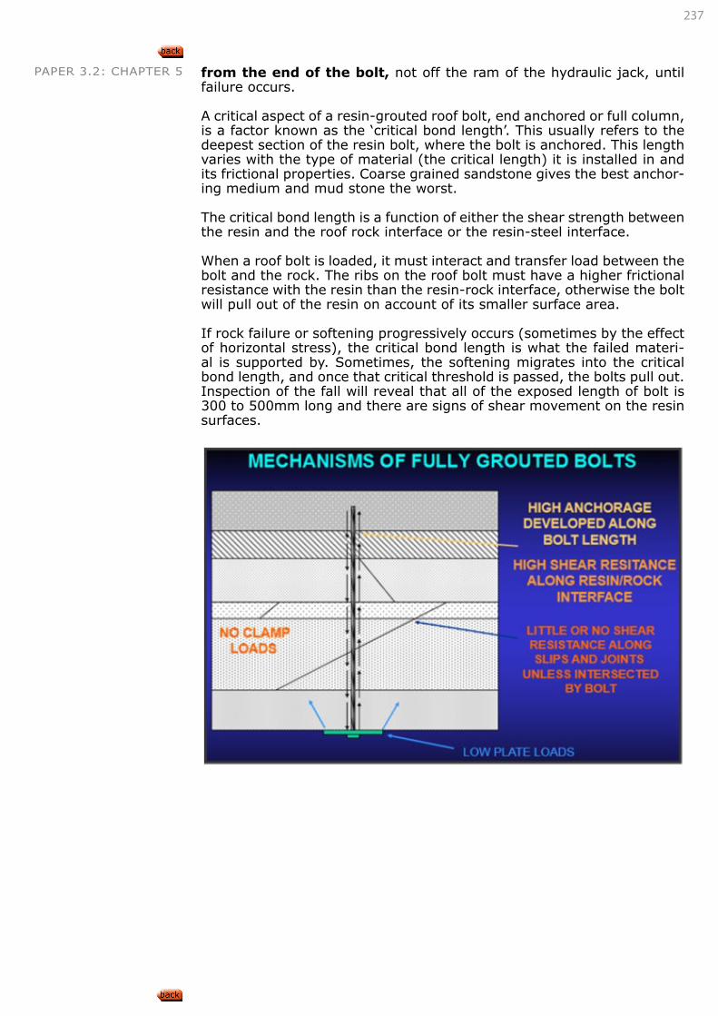
237
PAPER 3.2: CHAPTER 5 from the end of the bolt, not off the ram of the hydraulic jack, until failure occurs.
A critical aspect of a resin-grouted roof bolt, end anchored or full column, is a factor known as the ‘critical bond length’. This usually refers to the deepest section of the resin bolt, where the bolt is anchored. This length varies with the type of material (the critical length) it is installed in and its frictional properties. Coarse grained sandstone gives the best anchor-ing medium and mud stone the worst.
The critical bond length is a function of either the shear strength between the resin and the roof rock interface or the resin-steel interface.
When a roof bolt is loaded, it must interact and transfer load between the bolt and the rock. The ribs on the roof bolt must have a higher frictional resistance with the resin than the resin-rock interface, otherwise the bolt will pull out of the resin on account of its smaller surface area.
If rock failure or softening progressively occurs (sometimes by the effect of horizontal stress), the critical bond length is what the failed materi-al is supported by. Sometimes, the softening migrates into the critical bond length, and once that critical threshold is passed, the bolts pull out. Inspection of the fall will reveal that all of the exposed length of bolt is 300 to 500mm long and there are signs of shear movement on the resin surfaces.
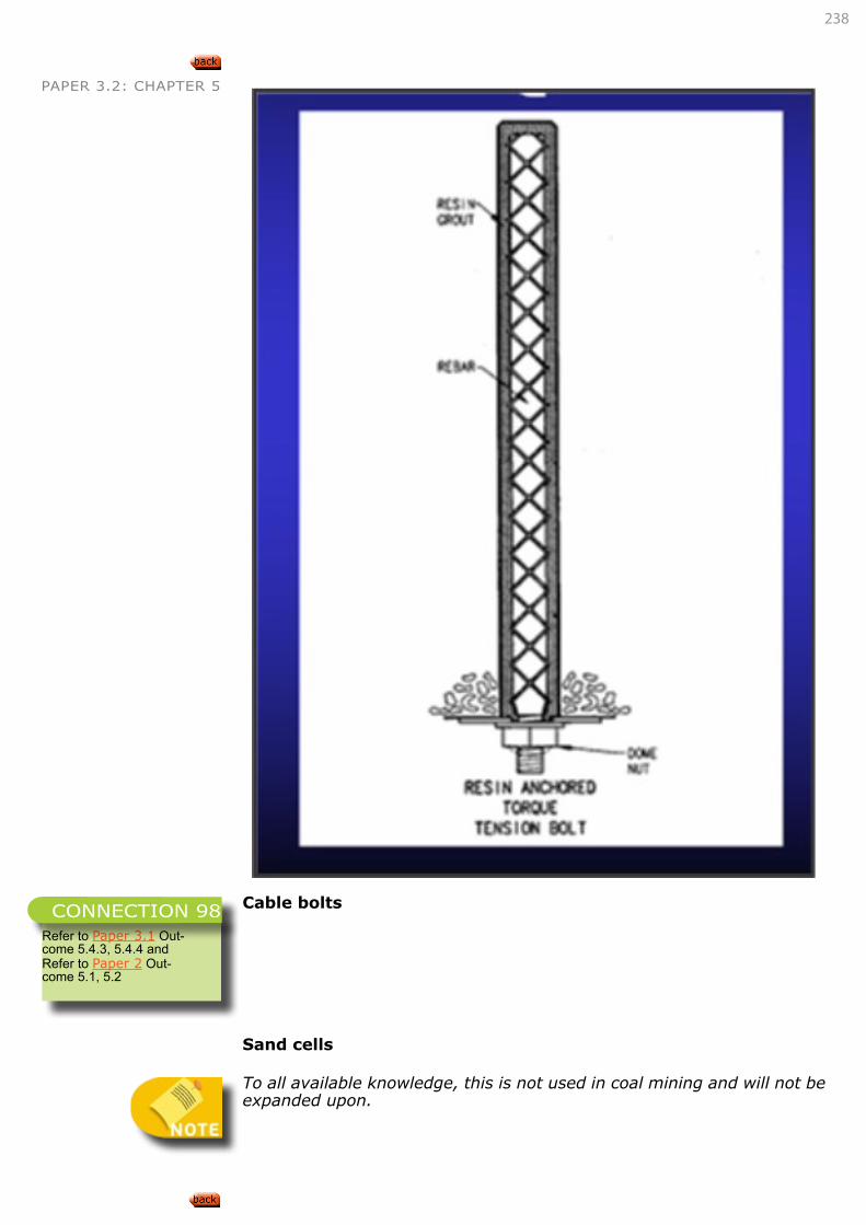
238
PAPER 3.2: CHAPTER 5
Cable bolts
Sand cells
To all available knowledge, this is not used in coal mining and will not be expanded upon.
Refer to Paper 3.1 Out-come 5.4.3, 5.4.4 andRefer to Paper 2 Out-come 5.1, 5.2
CONNECTION 98
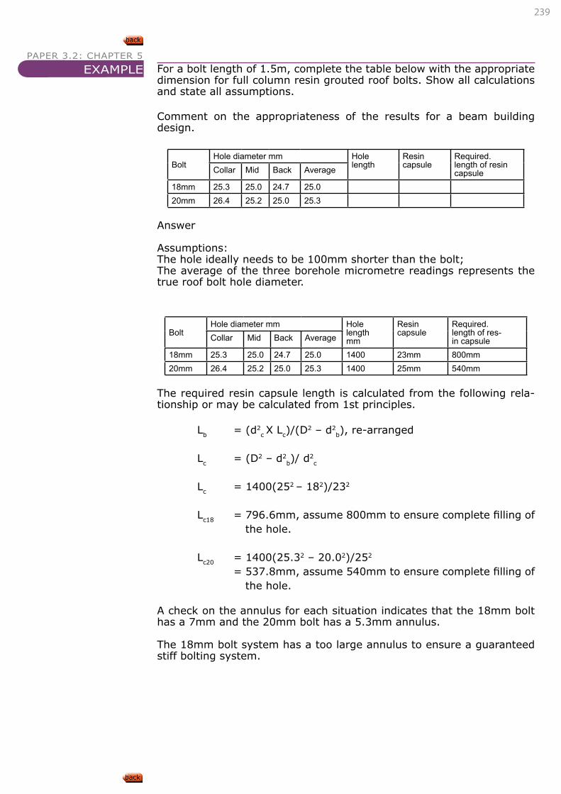
239
PAPER 3.2: CHAPTER 5
For a bolt length of 1.5m, complete the table below with the appropriate dimension for full column resin grouted roof bolts. Show all calculations and state all assumptions.
Comment on the appropriateness of the results for a beam building design.
Bolt Hole diameter mm Hole
lengthResincapsule
Required.length of resin capsuleCollar Mid Back Average
18mm 25.3 25.0 24.7 25.020mm 26.4 25.2 25.0 25.3
Answer
Assumptions:The hole ideally needs to be 100mm shorter than the bolt;The average of the three borehole micrometre readings represents the true roof bolt hole diameter.
BoltHole diameter mm Hole
lengthmm
Resincapsule
Required.length of res-in capsuleCollar Mid Back Average
18mm 25.3 25.0 24.7 25.0 1400 23mm 800mm20mm 26.4 25.2 25.0 25.3 1400 25mm 540mm
The required resin capsule length is calculated from the following rela-tionship or may be calculated from 1st principles.
Lb = (d2c X Lc)/(D
2 – d2b), re-arranged
Lc = (D2 – d2b)/ d
2c
Lc = 1400(252 – 182)/232
Lc18 = 796.6mm, assume 800mm to ensure complete filling of the hole.
Lc20 = 1400(25.32 – 20.02)/252 = 537.8mm, assume 540mm to ensure complete filling of
the hole.
A check on the annulus for each situation indicates that the 18mm bolt has a 7mm and the 20mm bolt has a 5.3mm annulus.
The 18mm bolt system has a too large annulus to ensure a guaranteed stiff bolting system.
EXAMPLE
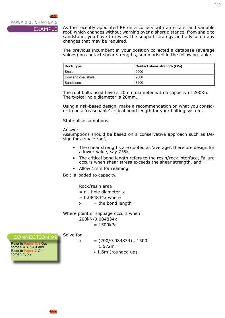
240
PAPER 3.2: CHAPTER 5
As the recently appointed RE on a colliery with an erratic and variable roof, which changes without warning over a short distance, from shale to sandstone, you have to review the support strategy and advise on any changes that may be required.
The previous incumbent in your position collected a database (average values) on contact shear strengths, summarised in the following table:
Rock Type Contact shear strength (kPa)Shale 2000Coal and coal/shale 2600Sandstone 3400
The roof bolts used have a 20mm diameter with a capacity of 200Kn.The typical hole diameter is 26mm.
Using a risk-based design, make a recommendation on what you consid-er to be a ‘reasonable’ critical bond length for your bolting system.
State all assumptions
AnswerAssumptions should be based on a conservative approach such as:De-sign for a shale roof,
• The shear strengths are quoted as ‘average’, therefore design for a lower value, say 75%,
• The critical bond length refers to the resin/rock interface, Failure occurs when shear stress exceeds the shear strength, and
• Allow 1mm for reaming.
Bolt is loaded to capacity,
Rock/resin area = π . hole diameter. x = 0.084834x where x = the bond length
Where point of slippage occurs when 200kN/0.084834x = 1500kPa
Solve for x = (200/0.084834) . 1500 = 1.572m ≈ 1.6m (rounded up)
EXAMPLE
Refer to Paper 3.1 Out-come 5.4.3, 5.4.4 andRefer to Paper 2 Out-come 5.1, 5.2
CONNECTION 99
241
PAPER 3.2: CHAPTER 5
CHARACTERISE THE FOLLOWING ASPECTS OF THE ABOVE SUPPORT TYPES:
• Their installation method
• Their anchoring method
• Their load bearing characteristics
DESCRIBE, EXPLAIN AND DISCUSS THE APPLICABILITY OF THE ABOVE TYPES OF TENDON SUPPORT IN DIFFERING ROCK TYPES.
DESCRIBE, EXPLAIN AND DISCUSS THE FOLLOWING TYPES OF ROOF SUPPORT IN THE CONTEXT OF SOFT ROCK OPERATIONS:
• Trusses, W-straps
• Timber tapes, headboards
• Wire mesh, lacing, shotcrete
DESCRIBE, EXPLAIN AND DISCUSS THE APPLICABILITY OF THE ABOVE ROOF SUPPORT TYPES.
DESCRIBE, EXPLAIN AND DISCUSS THE LIMITATIONS OF THE ABOVE ROOF SUPPORT TYPES.
LEARNING OUTCOME 5.5.1.2
Refer to Paper 3.1 Out-come 5.4.3, 5.4.4 andRefer to Paper 2 Out-come 5.1, 5.2
CONNECTION 100
LEARNING OUTCOME 5.5.1.3
Refer to Paper 3.1 Out-come 5.4.3, 5.4.4 andRefer to Paper 2 Out-come 5.1, 5.2
CONNECTION 101
LEARNING OUTCOME 5.5.1.4
Refer to Paper 3.1 Out-come 5.4.3, 5.4.4 andRefer to Paper 2 Out-come 5.1, 5.2
CONNECTION 102
LEARNING OUTCOME 5.5.1.5
Refer to Paper 3.1 Out-come 5.4.3, 5.4.4 andRefer to Paper 2 Out-come 5.1, 5.2
CONNECTION 103
LEARNING OUTCOME 5.5.1.6
Refer to Paper 3.1 Out-come 5.4.3, 5.4.4 andRefer to Paper 2 Out-come 5.1, 5.2
CONNECTION 104
242
PAPER 3.2: CHAPTER 5
DESCRIBE, EXPLAIN AND DISCUSS THE LOAD BEARING CHARACTERISTICS OF THE FOLLOWING TYPES OF SUPPORT:
• Mine poles, hydraulic props, longwall hydraulic shields
• Cluster stick packs, skeleton packs, mat packs, end-grain packs
• Waste-filled pigsty, cement-based packs
• SIMRAC Project COL327 Caving mechanisms
DESCRIBE, EXPLAIN AND DISCUSS THE APPLICABILITY OF THE ABOVE ROOF SUPPORT TYPES.
DESCRIBE, EXPLAIN AND DISCUSS THE LIMITATIONS OF THE ABOVE ROOF SUPPORT TYPES.
DESCRIBE, EXPLAIN AND DISCUSS COMPARATIVE TESTING PROCEDURES FOR ROCKBOLTS.
• SIM020205 Support system in collieries
DESCRIBE, EXPLAIN AND DISCUSS THE VARIOUS ASPECTS OF THE SABS RESIN SPECIFICATION.
• SIM020205 Support system in collieries
LEARNING OUTCOME 5.5.1.7
Refer to Paper 3.1 Out-come 5.4.3, 5.4.4 andRefer to Paper 2 Out-come 5.1, 5.2
CONNECTION 105
LEARNING OUTCOME 5.5.1.8
Refer to Paper 3.1 Out-come 5.4.3, 5.4.4 andRefer to Paper 2 Out-come 5.1, 5.2
CONNECTION 106
LEARNING OUTCOME 5.5.1.9
Refer to Paper 3.1 Out-come 5.4.3, 5.4.4 andRefer to Paper 2 Out-come 5.1, 5.2
CONNECTION 107
LEARNING OUTCOME 5.5.1.10
Refer to Paper 3.1 Out-come 5.4.3, 5.4.4 andRefer to Paper 2 Out-come 5.1, 5.2
CONNECTION 108
LEARNING OUTCOME 5.5.1.11
Refer to Paper 3.1 Out-come 5.4.3, 5.4.4 andRefer to Paper 2 Out-come 5.1, 5.2
CONNECTION 109
243
PAPER 3.2: CHAPTER 55.5.2. BACKFILL SYSTEMS
DESCRIBE, EXPLAIN AND DISCUSS THE METHODS OF PLACING ASHFILL AND SANDFILL IN UNDERGROUND WORKINGS.
DESCRIBE, EXPLAIN AND DISCUSS THE REQUIREMENTS TO MAKE ASHFILLING OR SANDFILLING SUCCESSFUL.
SKETCH, DESCRIBE, EXPLAIN AND DISCUSS THE FEATURES OF ASHFILL OR SANDFILL SYSTEMS TO SERVICE PARTICULAR BLOCKS OF GROUND.
• Palarski, Backfill in Polish coal mines
• Fly ash as backfill in coal mines
LEARNING OUTCOME 5.5.2.1
Refer to Paper 3.1 Out-come 4.2.2, 5.4.2 andPaper 2 Outcome 5.3
CONNECTION 111
LEARNING OUTCOME 5.5.2.1
Refer to “5.1.2. PIL-LAR REINFORCEMENT” on page 218
CONNECTION 112
LEARNING OUTCOME 5.5.2.1
Refer to “5.1.2. PIL-LAR REINFORCEMENT” on page 218
CONNECTION 113
244
PAPER 3.2: CHAPTER 6CHAPTER
6PAPER 3.2 SOFT ROCK TABULAR MINING
6. INVESTIGATION TECHNIQUES6.1. R OCK TESTING
The candidate must be able to demonstrate knowledge and understand-ing of the above subject area by being able to:
• Describe, explain and discuss various rock testing procedures; and
• Interpret and incorporate test results in analysis and design.
6.2. MONITORING6.2.1. SUBSIDENCE MONITORING
The candidate must be able to demonstrate knowledge and understand-ing of the above subject area by being able to:
• Sketch, describe, explain and discuss the techniques used to measure surface subsidence;
• Describe, explain and discuss the equipment used to measure surface subsidence;
• Describe, explain and discuss how vertical and horizontal dis-placements are determined;
• Describe, explain and discuss how strains and tilts may be de-rived from these determinations;
• Calculate strain and tilt from given sets of measurements;
• For given sets of underground mining and surface infrastructure conditions:
• State, describe, explain and discuss what types of measurements need to be made and monitored;
• Describe, explain and discuss required monitoring station lay-outs; and
• Describe, explain and discuss appropriate monitoring programmes.
6.2.2. IN-SITU STRESS MEASUREMENT AND MONITORING
The candidate must be able to demonstrate knowledge and understand-ing of the above subject area by being able to:
• Sketch, describe, explain and discuss the techniques used to measure in-situ stress in the underground rockmass;
• Describe, explain and discuss the equipment used to measure in-situ stress in the rockmass; and
• Interpret, explain and discuss given stress measurement data in terms of likely rockmass, pillar or excavation behaviour.
LEARNING OUTCOMES

245
PAPER 3.2: CHAPTER 6 6.3. MODELLING6.3.1. NUMERICAL MODELLING
The candidate must be able to demonstrate knowledge and understand-ing of the above subject area by being able to:
• Describe, explain and discuss the selection of appropriate codes to tackle various problems;
• Describe, explain and discuss the input of appropriate parame-ters to investigate various problems; and
• Describe, explain and discuss the interpretation of output in the investigation of various problems.
6.4. AUDITING
The candidate must be able to demonstrate knowledge and understand-ing of the above subject area by being able to:
• Describe, explain and discuss the concept of monitoring for un-derstanding, prediction and design.
246
PAPER 3.2: CHAPTER 6 6.1. R OCK TESTING
DESCRIBE, EXPLAIN AND DISCUSS VARIOUS ROCK TESTING PROCEDURES.
INTERPRET AND INCORPORATE TEST RESULTS IN ANALYSIS AND DESIGN.
6.2. MONITORING
• SIMRAC Project COL327 Caving mechanisms
6.2.1. SUBSIDENCE MONITORING
SKETCH, DESCRIBE, EXPLAIN AND DISCUSS THE TECHNIQUES USED TO MEASURE SURFACE SUBSIDENCE.
DESCRIBE, EXPLAIN AND DISCUSS THE EQUIPMENT USED TO MEASURE SURFACE SUBSIDENCE.
DESCRIBE, EXPLAIN AND DISCUSS HOW VERTICAL AND HORIZONTAL DISPLACEMENTS ARE DETERMINED.
The measuring technique applied typically records the X, Y and Z co-or-dinates of the measuring station. Subtracting subsequent readings from each other provides the changes in displacement between the measuring dates.
Using the data as provided in the X, Y and Z co-ordinates, the following is possible:
• Vertical displacement at a specific measuring point: ΔZ = Z2 – Z1
• Horizontal displacement in X Direction at a specific measuring point: ΔX = X2 – X1
• Horizontal displacement in Y direction at a specific measuring
LEARNING OUTCOME 6.1.1
Refer to Paper 2 Outcome 6.1
CONNECTION 114
LEARNING OUTCOME 6.1.2
Refer to Paper 2 Outcome 6.1
CONNECTION 115
LEARNING OUTCOME 6.2.1.1
Refer to Paper 2 Outcome 6.2Refer to Paper 3.1 Outcome 6.2.3
CONNECTION 116
LEARNING OUTCOME 6.2.1.2
Refer to Paper 2 Outcome 6.2Refer to Paper 3.1 Outcome 6.2.3
CONNECTION 117
LEARNING OUTCOME 6.2.1.3
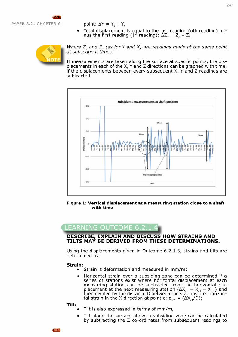
247
PAPER 3.2: CHAPTER 6 point: ΔY = Y2 – Y1
• Total displacement is equal to the last reading (nth reading) mi-nus the first reading (1st reading): ΔZT = Zn – Z1
Where Z2 and Z1 (as for Y and X) are readings made at the same point at subsequent times.
If measurements are taken along the surface at specific points, the dis-placements in each of the X, Y and Z directions can be graphed with time, if the displacements between every subsequent X, Y and Z readings are subtracted.
Figure 1: Vertical displacement at a measuring station close to a shaft with time
DESCRIBE, EXPLAIN AND DISCUSS HOW STRAINS AND TILTS MAY BE DERIVED FROM THESE DETERMINATIONS.
Using the displacements given in Outcome 6.2.1.3, strains and tilts are determined by:
Strain:• Strain is deformation and measured in mm/m;
• Horizontal strain over a subsiding zone can be determined if a series of stations exist where horizontal displacement at each measuring station can be subtracted from the horizontal dis-placement at the next measuring station (ΔXc1 = Xc1 – Xb1 ) and then divided by the distance D between the stations, i.e. horizon-tal strain in the X direction at point c: εxc1 = (ΔXc1/D);
Tilt:• Tilt is also expressed in terms of mm/m,
• Tilt along the surface above a subsiding zone can be calculated by subtracting the Z co-ordinates from subsequent readings to
LEARNING OUTCOME 6.2.1.4
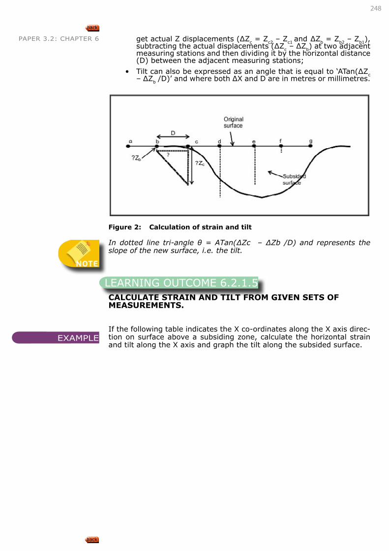
248
PAPER 3.2: CHAPTER 6 get actual Z displacements (ΔZc = Zc2 – Zc1 and ΔZb = Zb2 – Zb1), subtracting the actual displacements (ΔZc – ΔZb) at two adjacent measuring stations and then dividing it by the horizontal distance (D) between the adjacent measuring stations;
• Tilt can also be expressed as an angle that is equal to ‘ATan(ΔZc – ΔZb /D)’ and where both ΔX and D are in metres or millimetres.
Figure 2: Calculation of strain and tilt
In dotted line tri-angle θ = ATan(ΔZc – ΔZb /D) and represents the slope of the new surface, i.e. the tilt.
CALCULATE STRAIN AND TILT FROM GIVEN SETS OF MEASUREMENTS.
If the following table indicates the X co-ordinates along the X axis direc-tion on surface above a subsiding zone, calculate the horizontal strain and tilt along the X axis and graph the tilt along the subsided surface.
LEARNING OUTCOME 6.2.1.5
EXAMPLE
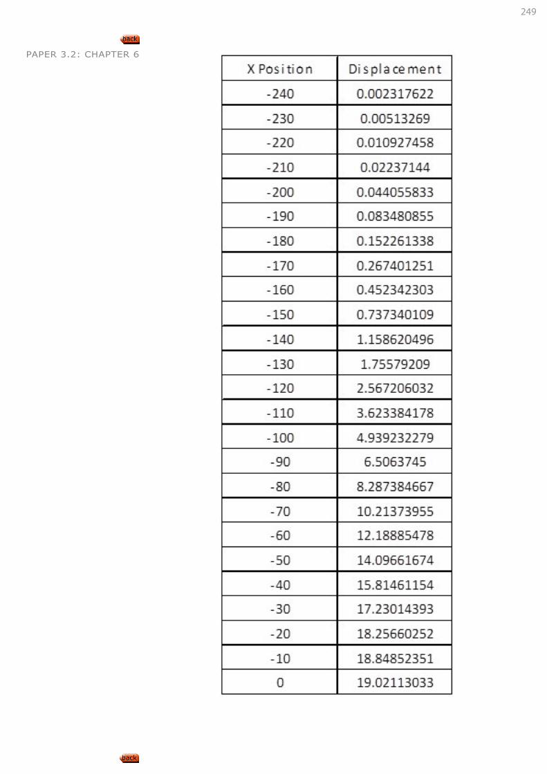
249
PAPER 3.2: CHAPTER 6
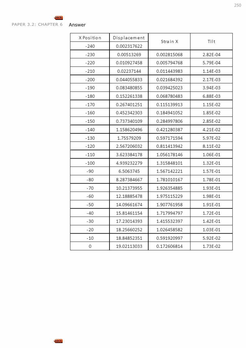
250
PAPER 3.2: CHAPTER 6 Answer
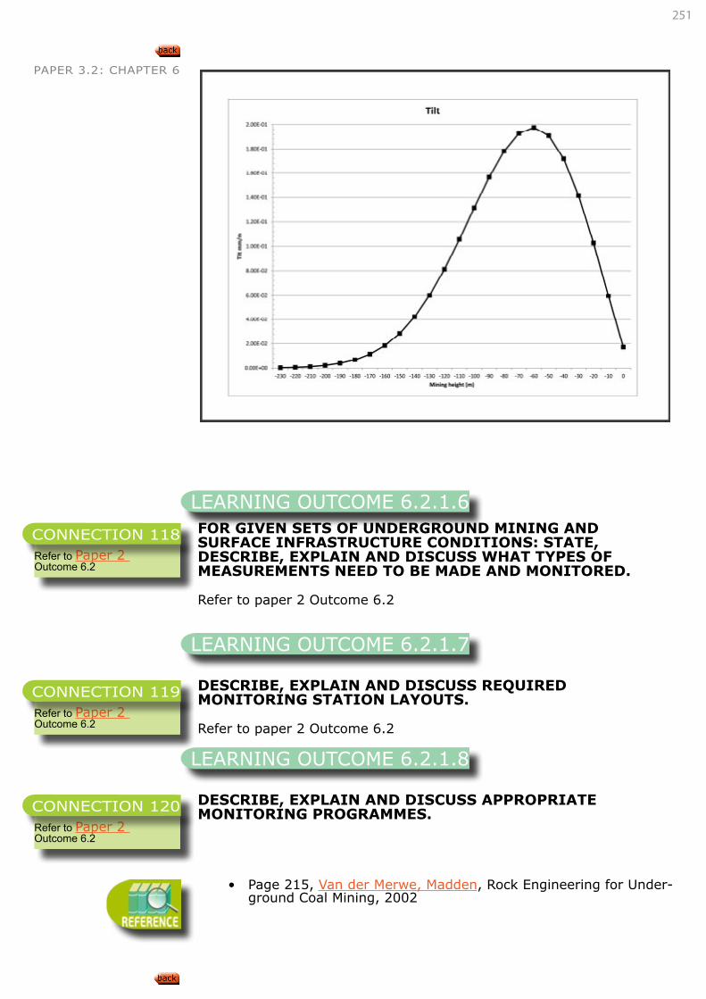
251
PAPER 3.2: CHAPTER 6
FOR GIVEN SETS OF UNDERGROUND MINING AND SURFACE INFRASTRUCTURE CONDITIONS: STATE, DESCRIBE, EXPLAIN AND DISCUSS WHAT TYPES OF MEASUREMENTS NEED TO BE MADE AND MONITORED.
Refer to paper 2 Outcome 6.2
DESCRIBE, EXPLAIN AND DISCUSS REQUIRED MONITORING STATION LAYOUTS.
Refer to paper 2 Outcome 6.2
DESCRIBE, EXPLAIN AND DISCUSS APPROPRIATE MONITORING PROGRAMMES.
• Page 215, Van der Merwe, Madden, Rock Engineering for Under-ground Coal Mining, 2002
LEARNING OUTCOME 6.2.1.6
Refer to Paper 2 Outcome 6.2
CONNECTION 118
LEARNING OUTCOME 6.2.1.7
Refer to Paper 2 Outcome 6.2
CONNECTION 119
LEARNING OUTCOME 6.2.1.8
Refer to Paper 2 Outcome 6.2
CONNECTION 120
252
PAPER 3.2: CHAPTER 66.2.2. IN-SITU STRESS MEASUREMENT AND MONITORING
SKETCH, DESCRIBE, EXPLAIN AND DISCUSS THE TECHNIQUES USED TO MEASURE IN-SITU STRESS IN THE UNDERGROUND ROCKMASS.
DESCRIBE, EXPLAIN AND DISCUSS THE EQUIPMENT USED TO MEASURE IN-SITU STRESS IN THE ROCKMASS.
Paper 1 Outcome 5.1
INTERPRET, EXPLAIN AND DISCUSS GIVEN STRESS MEASUREMENT DATA IN TERMS OF LIKELY ROCKMASS, PILLAR OR EXCAVATION BEHAVIOUR.
Stress measurement data provides the following information:• Actual principal stress levels;
• Orientation of principal stresses; and
• The k-ratios (ratios between vertical and horizontal stresses, as well as between horizontal stresses).
The impact of the k-ratio on underground excavations was discussed at length in Paper 3.1.
• Page 133, Van der Merwe, Madden, Rock Engineering for Under-ground Coal Mining, 2002
6.3. MODELLING6.3.1. NUMERICAL MODELLING
DESCRIBE, EXPLAIN AND DISCUSS THE SELECTION OF APPROPRIATE CODES TO TACKLE VARIOUS PROBLEMS.
DESCRIBE, EXPLAIN AND DISCUSS THE INPUT OF APPROPRIATE PARAMETERS TO INVESTIGATE VARIOUS PROBLEMS.
LEARNING OUTCOME 6.2.2.1
Refer to Paper 1 Outcome 5.1
CONNECTION 121
LEARNING OUTCOME 6.2.2.2
Refer to Paper 1 Outcome 5.1
CONNECTION 122
LEARNING OUTCOME 6.2.2.3
Refer to Paper 3.1 Out-comes 3.1, 3.2 and 3.3.
CONNECTION 122
LEARNING OUTCOME 6.3.1.1
Refer to Paper 2 Outcome 6.4
CONNECTION 123
LEARNING OUTCOME 6.3.1.2
Refer to Paper 2 Outcome 6.4
CONNECTION 123

253
PAPER 3.2: CHAPTER 6
DESCRIBE, EXPLAIN AND DISCUSS THE INTERPRETATION OF OUTPUT IN THE INVESTIGATION OF VARIOUS PROBLEMS.
• Page 103, Van der Merwe, Madden, Rock Engineering for Under-ground Coal Mining, 2002
6.4. AUDITING
DESCRIBE, EXPLAIN AND DISCUSS THE CONCEPT OF MONITORING FOR UNDERSTANDING, PREDICTION AND DESIGN.
LEARNING OUTCOME 6.3.1.3
Refer to Paper 2 Outcome 6.4
CONNECTION 124
LEARNING OUTCOME 6.3.1.2
Refer to Paper 2 Outcome 4.4
CONNECTION 125
254
PAPER 3.2: CHAPTER 7CHAPTER
7PAPER 3.2 SOFT ROCK TABULAR MINING
7. ROCKBREAKING IN SOFT ROCK7.1. CUTTING TECHNIQUES
The candidate must be able to demonstrate knowledge and understand-ing of the above subject area by being able to:
• Describe, explain and discuss the function and operation of cut-ters in soft rock mining operations;
• Describe, explain and discuss the following aspects in respect of continuous miners and road headers in bord and pillar sections:
• The sequence of cutting, the sequence of support installation, the sequence of tramming,
• Describe, explain and discuss the following aspects in respect of continuous miners and road headers in continuous haulage systems:
• The layout of mining, the sequence of mining.
7.2. DRILLING TECHNIQUES
The candidate must be able to demonstrate knowledge and understand-ing of the above subject area by being able to:
• Describe, explain and discuss the mechanism of rock breaking by pick, chisel or button bit in soft rock mining operations;
• Describe, explain and discuss the following drilling methods and associated equipment in soft rock mining operations:
• Percussion drilling, rotary drilling, diamond drilling, raise boring,
• Tunnel boring
• Sketch, describe, explain and discuss the different rounds used in shaft sinking;
• Describe, explain and discuss the different cuts used in shaft sinking;
• Describe, explain and discuss the types of initiation used in the above rounds;
• Describe, explain and discuss the sequence of initiation of blast holes used in the above rounds;
• Sketch, describe, explain and discuss the different rounds used in tunnel development;
• Describe, explain and discuss the different cuts used in tunnel development;
• Describe, explain and discuss the types of initiation used in the above rounds;
• Describe, explain and discuss the sequence of initiation of blast holes used in the above rounds;
LEARNING OUTCOMES
255
PAPER 3.2: CHAPTER 7 • Sketch, describe, explain and discuss blast hole layouts in drill and blast sections;
• Describe, explain and discuss the direction of drilling of blast holes in drill and blast sections;
• Describe, explain and discuss the explosive charge in blast holes in drill and blast sections;
• Describe, explain and discuss the sequence of initiation of blast holes in drill and blast sections;
• Describe, explain and discuss the importance of blast-hole drill-ing accuracy in the following applications:
• Shaft sinking, chamber excavation, tunnel development, ore,
• Extraction,
• Cushion blasting, smooth blasting.
7.3. BLASTING PRACTICE
The candidate must be able to demonstrate knowledge and understand-ing of the above subject area by being able to:
• Describe, explain and discuss the effect of the following parame-ters on blast damage:
• Explosive type, initiation method, initiation sequence, hole orientation,
• Describe, explain and discuss the objectives and effects of de-coupling explosives;
• Describe, explain and discuss the methods by which de-coupling of explosives is achieved;
• Describe, explain and discuss the following excavation cushion blasting and smooth blasting techniques:
• Pre-splitting, concurrent smooth blasting, post-splitting,
• Describe, explain and discuss the methodologies and typical ap-plications of each technique;
• List and discuss the advantages and disadvantages of these techniques;
• Evaluate and determine blasting requirements for tunnels mak-ing use of knowledge of explosives;
• Evaluate and determine appropriate blasting rounds to suit given conditions in tunnels;
• Evaluate and determine appropriate explosive types to suit given conditions in tunnels;
• Evaluate and determine blasting requirements for headings in soft rock making use of knowledge of explosives;
• Evaluate and determine appropriate blasting rounds to suit given conditions in soft rock;
• Evaluate and determine appropriate explosive types to suit given conditions in soft rock;
• Evaluate and determine blasting requirements for headings in coal rock making use of knowledge of explosives;
• Evaluate and determine appropriate blasting rounds to suit given conditions in coal;
• Evaluate and determine appropriate explosive types to suit given conditions in coal;
• Describe, explain and discuss the role of coal cutters in colliery blasting operations; and
• Describe, explain and discuss how coal cutters in colliery blasting operations fit into the production cycle.
256
PAPER 3.2: CHAPTER 77.1. ROCKBREAKING IN SOFT ROCK
The official Paper 3.2 coal syllabus was used as the guideline to deliver the material in this section. Where the syllabus refers to tunnels, this was maintained. The user is in essence referred to material guidelines in the Paper 2 and Paper 3.1 guides and it is suggested that this material is read and studied in so far as it applies or can apply to the coal mining environment.
All surface blasting methods should refer to the Paper 3.4 guidelines on surface mining.
7.1.1. CUTTING TECHNIQUES
DESCRIBE, EXPLAIN AND DISCUSS THE FUNCTION AND OPERATION OF CUTTERS IN SOFT ROCK MINING OPERATIONS.
DESCRIBE, EXPLAIN AND DISCUSS THE FOLLOWING ASPECTS IN RESPECT OF CONTINUOUS MINERS AND ROAD HEADERS IN BORD AND PILLAR SECTIONS:
• The sequence of cutting,
• the sequence of support installation,
• the sequence of tramming.
DESCRIBE, EXPLAIN AND DISCUSS THE FOLLOWING ASPECTS IN RESPECT OF CONTINUOUS MINERS AND ROAD HEADERS IN CONTINUOUS HAULAGE SYSTEMS:
• The layout of mining,
• the sequence of mining.
LEARNING OUTCOME 7.1.1.1
Refer to Outcome 4.1.1.1
Refer to “LEARNING OUTCOME 4.1.1.1” on page 93
CONNECTION 125
LEARNING OUTCOME 7.1.1.2
Refer to Outcome 4.1.1.1
Refer to “LEARNING OUTCOME 4.1.1.1” on page 93
CONNECTION 126
LEARNING OUTCOME 7.1.1.3
Refer to Outcome 4.1.1.1
Refer to “LEARNING OUTCOME 4.1.1.4” on page 103on page 3
CONNECTION 127

257
PAPER 3.2: CHAPTER 77.2. DRILLING TECHNIQUES
DESCRIBE, EXPLAIN AND DISCUSS THE MECHANISM OF ROCK BREAKING BY PICK, CHISEL OR BUTTON BIT IN SOFT ROCK MINING OPERATIONS.
DESCRIBE, EXPLAIN AND DISCUSS THE FOLLOWING DRILLING METHODS AND ASSOCIATED EQUIPMENT IN SOFT ROCK MINING OPERATIONS:
• Percussion drilling, rotary drilling, diamond drilling, raise boring,
• Tunnel boring.
SKETCH, DESCRIBE, EXPLAIN AND DISCUSS THE DIFFERENT ROUNDS USED IN SHAFT SINKING.
DESCRIBE, EXPLAIN AND DISCUSS THE DIFFERENT CUTS USED IN SHAFT SINKING.
DESCRIBE, EXPLAIN AND DISCUSS THE TYPES OF INITIATION USED IN THE ABOVE ROUNDS.
DESCRIBE, EXPLAIN AND DISCUSS THE SEQUENCE OF INITIATION OF BLAST HOLES USED IN THE ABOVE ROUNDS.
LEARNING OUTCOME 7.2.1
Refer to Paper 3.1 Outcome 7 andRefer to Paper 2 Outcome 7
CONNECTION 128
LEARNING OUTCOME 7.2.2
Refer to Paper 3.1 Outcome 7 andRefer to Paper 2 Outcome 7
CONNECTION 129
LEARNING OUTCOME 7.2.3
Refer to Paper 3.1 Outcome 7
CONNECTION 130
LEARNING OUTCOME 7.2.4
Refer to Paper 3.1 Outcome 7
CONNECTION 131
LEARNING OUTCOME 7.2.5
Refer to Paper 3.1 Outcome 7
CONNECTION 132
LEARNING OUTCOME 7.2.6
Refer to Paper 3.1 Outcome 7
CONNECTION 133
258
PAPER 3.2: CHAPTER 7
SKETCH, DESCRIBE, EXPLAIN AND DISCUSS THE DIFFERENT ROUNDS USED IN TUNNEL DEVELOPMENT.
DESCRIBE, EXPLAIN AND DISCUSS THE DIFFERENT CUTS USED IN TUNNEL DEVELOPMENT.
DESCRIBE, EXPLAIN AND DISCUSS THE TYPES OF INITIATION USED IN THE ABOVE ROUNDS.
DESCRIBE, EXPLAIN AND DISCUSS THE SEQUENCE OF INITIATION OF BLAST HOLES USED IN THE ABOVE ROUNDS.
SKETCH, DESCRIBE, EXPLAIN AND DISCUSS BLAST HOLE LAYOUTS IN DRILL AND BLAST SECTIONS.
DESCRIBE, EXPLAIN AND DISCUSS THE DIRECTION OF DRILLING OF BLAST HOLES IN DRILL AND BLAST SECTIONS.
LEARNING OUTCOME 7.2.7
Refer to Paper 3.1 Outcome 7 andRefer to Paper 2 Outcome 7
CONNECTION 134
LEARNING OUTCOME 7.2.8
Refer to Paper 3.1 Outcome 7 andRefer to Paper 2 Outcome 7
CONNECTION 135
LEARNING OUTCOME 7.2.9
Refer to Paper 3.1 Outcome 7 andRefer to Paper 2 Outcome 7
CONNECTION 136
LEARNING OUTCOME 7.2.10
Refer to Paper 3.1 Outcome 7 andRefer to Paper 2 Outcome 7
CONNECTION 137
LEARNING OUTCOME 7.2.11
Refer to Paper 3.1 Outcome 7 andRefer to Paper 2 Outcome 7
CONNECTION 138
LEARNING OUTCOME 7.2.12
Refer to Paper 3.1 Outcome 7 andRefer to Paper 2 Outcome 7
CONNECTION 139
259
PAPER 3.2: CHAPTER 7
DESCRIBE, EXPLAIN AND DISCUSS THE EXPLOSIVE CHARGE IN BLAST HOLES IN DRILL AND BLAST SECTIONS.
DESCRIBE, EXPLAIN AND DISCUSS THE SEQUENCE OF INITIATION OF BLAST HOLES IN DRILL AND BLAST SECTIONS.
7.3. BLASTING PRACTICE
DESCRIBE, EXPLAIN AND DISCUSS THE EFFECT OF THE FOLLOWING PARAMETERS ON BLAST DAMAGE:
• Explosive type,
• initiation method,
• initiation sequence,
• hole orientation.
DESCRIBE, EXPLAIN AND DISCUSS THE OBJECTIVES AND EFFECTS OF DE-COUPLING EXPLOSIVES.
DESCRIBE, EXPLAIN AND DISCUSS THE METHODS BY WHICH DE-COUPLING OF EXPLOSIVES IS ACHIEVED.
LEARNING OUTCOME 7.2.13
Refer to Paper 3.1 Outcome 7 andRefer to Paper 2 Outcome 7
CONNECTION 138
LEARNING OUTCOME 7.2.14
Refer to Paper 3.1 Outcome 7 andRefer to Paper 2 Outcome 7
CONNECTION 139
LEARNING OUTCOME 7.3.1
Refer to Paper 3.1 Outcome 7 andRefer to Paper 2 Outcome 7
CONNECTION 140
LEARNING OUTCOME 7.3.2
Refer to Paper 3.1 Outcome 7 andRefer to Paper 2 Outcome 7
CONNECTION 141
LEARNING OUTCOME 7.3.4
Refer to Paper 3.1 Outcome 7 andRefer to Paper 2 Outcome 7
CONNECTION 142
260
PAPER 3.2: CHAPTER 7
DESCRIBE, EXPLAIN AND DISCUSS THE FOLLOWING EXCAVATION CUSHION BLASTING AND SMOOTH BLASTING TECHNIQUES:
• Pre-splitting,
• concurrent smooth blasting,
• post-splitting.
DESCRIBE, EXPLAIN AND DISCUSS THE METHODOLOGIES AND TYPICAL APPLICATIONS OF EACH TECHNIQUE.
LIST AND DISCUSS THE ADVANTAGES AND DISADVANTAGES OF THESE TECHNIQUES
EVALUATE AND DETERMINE BLASTING REQUIREMENTS FOR TUNNELS MAKING USE OF KNOWLEDGE OF EXPLOSIVES.
EVALUATE AND DETERMINE APPROPRIATE BLASTING ROUNDS TO SUIT GIVEN CONDITIONS IN TUNNELS.
EVALUATE AND DETERMINE APPROPRIATE EXPLOSIVE TYPES TO SUIT GIVEN CONDITIONS IN TUNNELS.
LEARNING OUTCOME 7.35
Refer to Paper 3.1 Outcome 7 andRefer to Paper 2 Outcome 7
CONNECTION 143
LEARNING OUTCOME 7.3.6
Refer to Paper 3.1 Outcome 7 andRefer to Paper 2 Outcome 7
CONNECTION 144
LEARNING OUTCOME 7.3.7
Refer to Paper 3.1 Outcome 7 andRefer to Paper 2 Outcome 7
CONNECTION 145
LEARNING OUTCOME 7.3.8
Refer to Paper 3.1 Outcome 7 andRefer to Paper 2 Outcome 7
CONNECTION 146
LEARNING OUTCOME 7.3.9
Refer to Paper 3.1 Outcome 7 andRefer to Paper 2 Outcome 7
CONNECTION 147
LEARNING OUTCOME 7.3.10
Refer to Paper 3.1 Outcome 7 andRefer to Paper 2 Outcome 7
CONNECTION 148
261
PAPER 3.2: CHAPTER 7
EVALUATE AND DETERMINE BLASTING REQUIREMENTS FOR HEADINGS IN SOFT ROCK MAKING USE OF KNOWLEDGE OF EXPLOSIVES.
EVALUATE AND DETERMINE APPROPRIATE BLASTING ROUNDS TO SUIT GIVEN CONDITIONS IN SOFT ROCK.
EVALUATE AND DETERMINE APPROPRIATE EXPLOSIVE TYPES TO SUIT GIVEN CONDITIONS IN SOFT ROCK.
EVALUATE AND DETERMINE BLASTING REQUIREMENTS FOR HEADINGS IN COAL ROCK MAKING USE OF KNOWLEDGE OF EXPLOSIVES.
EVALUATE AND DETERMINE APPROPRIATE BLASTING ROUNDS TO SUIT GIVEN CONDITIONS IN COAL.
EVALUATE AND DETERMINE APPROPRIATE EXPLOSIVE TYPES TO SUIT GIVEN CONDITIONS IN COAL.
LEARNING OUTCOME 7.3.11
Refer to Paper 3.1 Outcome 7 andRefer to Paper 2 Outcome 7
CONNECTION 149
LEARNING OUTCOME 7.3.12
Refer to Paper 3.1 Outcome 7 andRefer to Paper 2 Outcome 7
CONNECTION 150
LEARNING OUTCOME 7.3.13
Refer to Paper 3.1 Outcome 7 andRefer to Paper 2 Outcome 7
CONNECTION 151
LEARNING OUTCOME 7.3.14
Refer to Paper 3.1 Outcome 7 andRefer to Paper 2 Outcome 7
CONNECTION 152
LEARNING OUTCOME 7.3.15
Refer to Paper 3.1 Outcome 7 andRefer to Paper 2 Outcome 7
CONNECTION 153
LEARNING OUTCOME 7.3.16
Refer to Paper 3.1 Outcome 7 andRefer to Paper 2 Outcome 7
CONNECTION 154

262
PAPER 3.2: CHAPTER 7
DESCRIBE, EXPLAIN AND DISCUSS THE ROLE OF COAL CUTTERS IN COLLIERY BLASTING OPERATIONS.
DESCRIBE, EXPLAIN AND DISCUSS HOW COAL CUTTERS IN COLLIERY BLASTING OPERATIONS FIT INTO THE PRODUCTION CYCLE.
LEARNING OUTCOME 7.3.17
Refer to Paper 3.1 Outcome 7 andRefer to Paper 2 Outcome 7
CONNECTION 155
LEARNING OUTCOME 7.3.18
Refer to Paper 3.1 Outcome 7 andRefer to Paper 2 Outcome 7
CONNECTION 156
263
PAPER 3.2: CHAPTER 8CHAPTER
8 PAPER 3.2 SOFT ROCK TABULAR MINING
8. SURFACE AND ENVIRONMENTAL EFFECTS8.1. SURFACE EFFECTS8.1.1. PRINCIPLES OF SUBSIDENCE ENGINEERING
The candidate must be able to demonstrate knowledge and understanding of the above subject area by being able to:
• Describe, explain and discuss the following terms within the context of surface subsidence:
• Angle of draw, curvature, tilt, critical span,
• Horizontal strain, vertical subsidence, differential subsidence
• Describe, explain and discuss the following surface expressions of subsidence:
• Tension cracks, compression humps, ridges, thrusts,
• Describe, explain and discuss how mining height to depth ratio affect the type and severity of surface subsidence; and
• Describe, explain and discuss the effects of dolerite dykes and other geological structures on surface subsidence.
8.1.2. SUBSIDENCE ON SOUTH AFRICAN COLLIERIES
The candidate must be able to demonstrate knowledge and understanding of the above subject area by being able to:
• Sketch, describe, explain and discuss the typical subsidence trough over a longwall panel;
• Describe, explain and discuss the difference between dynamic and static subsidence profiles;
• Describe, explain and discuss the relationship between maximum subsidence and mining height;
• Describe, explain and discuss how multiple seam extraction affects surface subsidence;
• Describe, explain and discuss techniques for reducing subsidence humps by interpanel pillar extraction;
• Describe, explain and discuss techniques for reducing subsidence humps by interpanel crush pillars;
• Describe, explain and discuss the results of using the above two techniques to reduce subsidence humps;
• Sketch, describe, explain and discuss the differences in total subsidence associated with the following mining methods:
• Longwall operations,
• Bord and pillar operations,
• Pillar extraction operations
• Determine the following quantities for given mining depths and mining heights using Schu-mann’s empirical relationships:
LEARNING OUTCOMES
264
PAPER 3.2: CHAPTER 8 • Maximum subsidence, surface strain, surface tilt.
8.2. SURFACE PROTECTION
The candidate must be able to demonstrate knowledge and understand-ing of the above subject area by being able to:
• Describe, explain and discuss how the following surface features are affected by subsidence:
• Roads, buildings, pylons, lands, streams, pans,
• Describe, explain and discuss possible remedial measures that may be applied to surface structures to limit subsidence damage;
• Describe, explain and discuss possible changes that may be made to underground mining layouts to reduce subsidence damage and
• Determine potential subsidence damage to the following types of structures for given mining depths and mining heights using published damage tables:
• Roads, buildings, pylons.
8.3. ENVIRONMENTAL EFFECTS8.3.1. LONG-TERM STABILITY AND THE ENVIRONMENT
The candidate must be able to demonstrate knowledge and understand-ing of the above subject area by being able to:
• Describe, explain and discuss the possible effects and conse-quences of given mining methods on the following issues:
• Long-term stability of the ground surface,
• Groundwater,
• Ultimate closure of the mine
• Describe, explain and discuss the possible effects and conse-quences of given factors of safety on the following issues:
• Long-term stability of the ground surface
• Groundwater
• Ultimate closure of the mine.
265
PAPER 3.2: CHAPTER 8 8. SURFACE AND ENVIRONMENTAL EFFECTS8.1. SURFACE EFFECTS
• Subsidence management plan, courtesy of:
8.1.1. PRINCIPLES OF SUBSIDENCE ENGINEERING
Mechanisms of subsidenceThe subsidence caused by high extraction mining has a different mechanism than that caused by pillar system failure. This results in differences in the magnitudes and rates of subsidence. They will be dis-cussed separately.
Mechanism of subsidence resulting from high extraction miningWhether the mining method be longwalling or pillar extraction, the es-sential facts are that the back areas are left unsupported and that the roof is allowed to collapse. The collapsed area extends vertically, and the collapsed material occupies a larger volume than it did before it collapsed due to the presence of voids in the goaf. Eventually, a stage is reached where the collapsed material makes contact with the overlying uncol-lapsed rock. Figure 1 illustrates the principle of subsidence.
At the stage where contact is made between the goaf and the overlying rockmass, the uncontrolled roof collapse ceases. If the rock material had been a continuous, unjointed mass, further subsidence would have been caused by bending of the overlying plate.
However, it is known that the overlying rockmass is jointed. Under the in-fluence of gravity, large blocks measuring several metres in all directions now slide down along pre-existing joint planes, compressing the voided goaf underneath. The more the goaf is compressed, the more resistance to further compression it offers. The process continues until the resist-ance offered by the goaf balances the weight of the overlying material.
This process explains two very important characteristics of high extrac-tion subsidence.
Firstly, the total magnitude of subsidence is significantly less than the original mining height; in the majority of typical South African cases, it is slightly less than half of the mining height. The reason that the full mining height is not manifested as subsidence is that the weight of the overlying material is insufficient to recompress the goaf material to the solid state. This, of course implies, that the nether goaf region will always be voided, with the accompanying implications for long-term ground wa-ter considerations.
Secondly, the rate of subsidence is relatively slow. It takes roughly six weeks for more than ninety percent of the full subsidence to occur, the rest occurring over a period of several years. The subsidence is not caused by free gravity-induced fall of the overburden. The rate of subsidence is governed by the rate at which the goaf can be compressed.
266
PAPER 3.2: CHAPTER 8
DESCRIBE, EXPLAIN AND DISCUSS THE FOLLOWING TERMS WITHIN THE CONTEXT OF SURFACE SUBSIDENCE:
• Angle of draw, curvature, tilt, critical span
• Horizontal strain, vertical subsidence, differential subsidence.
Refer to Figure 1:• Angle of draw: Angle between a vertical line situated above the
edge of the mined-out area and the point on surface where sub-sidence commences;
• Curvature: Uneven vertical settlement can form a convex or con-cave surface;
• Tilt: The angle from vertical through which a line perpendicular to the subsidence profile will be rotated, also indicated by the slope of the subsidence curve;
• Critical span: the mining span at which maximum surface sub-sidence occurs;
• Horizontal strain: Differential settlement of two points in relation to each other as a function of the distance between them;
• Vertical subsidence: The vertical displacement that a structure will undergo when undermined;
• Differential subsidence: Relative displacement of two points with respect to each other during subsidence.
LEARNING OUTCOME 8.1.1.1
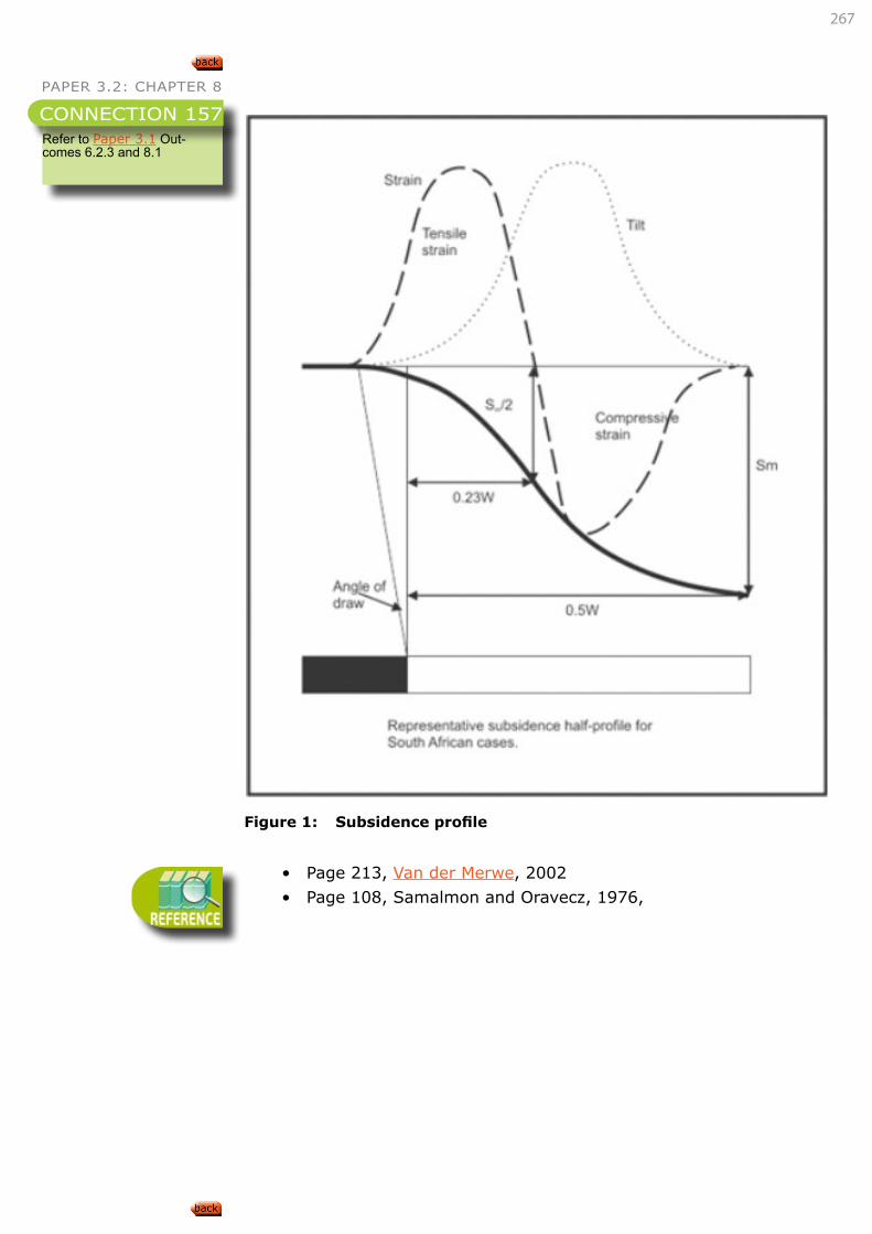
267
PAPER 3.2: CHAPTER 8
Figure 1: Subsidence profile
• Page 213, Van der Merwe, 2002
• Page 108, Samalmon and Oravecz, 1976,
Refer to Paper 3.1 Out-comes 6.2.3 and 8.1
CONNECTION 157
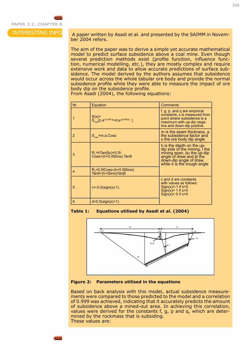
268
PAPER 3.2: CHAPTER 8
A paper written by Asadi et al. and presented by the SAIMM in Novem-ber 2004 refers.
The aim of the paper was to derive a simple yet accurate mathematical model to predict surface subsidence above a coal mine. Even though several prediction methods exist (profile function, influence func-tion, numerical modelling, etc.), they are mostly complex and require extensive work and data to allow accurate predictions of surface sub-sidence. The model derived by the authors assumes that subsidence would occur across the whole tabular ore body and provide the normal subsidence profile while they were able to measure the impact of ore body dip on the subsidence profile.From Asadi (2004), the following equations:
Nr Equation Comments
1 S(x)=Smax[c.e-f(-x/R1)g+d.e-p(x/R2)q ]
f, g, p, and q are empirical constants, x is measured from point where subsidence is a maximum with up-dip nega-tive and down-dip positive
2 Smax=m.a.Cosαm is the seam thickness, a the subsidence factor and α the ore body dip angle
3 R1=hTan(βu)+0.5l-Cosα+(h+0.5lSinα).Tanθ
h is the depth on the up-dip side of the mining, l the mining span, βu the up-dip angle of draw and βl the down-dip angle of draw, while θ is the trough angle
4 R2=0.5lCosα-(h+0.5lSinα).Tanθ+(h+lSinα)Tanβl
5 c=-0.5(sign(x)-1)
c and d are constants with values as follows:Sign(x)=-1 if x<0Sign(x)= 1 if x>0Sign(x)= 0 if x=0
6 d=0.5(sign(x)+1)
Table 1: Equations utilised by Asadi et al. (2004)
Figure 2: Parameters utilised in the equations
Based on back analysis with this model, actual subsidence measure-ments were compared to those predicted to the model and a correlation of 0.999 was achieved, indicating that it accurately predicts the amount of subsidence above a mined-out area. In achieving this correlation, values were derived for the constants f, g, p and q, which are deter-mined by the rockmass that is subsiding. These values are:
INTERESTING INFO
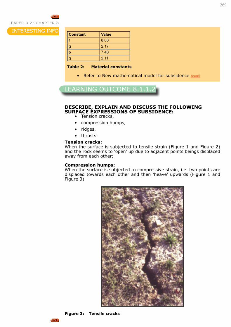
269
PAPER 3.2: CHAPTER 8
DESCRIBE, EXPLAIN AND DISCUSS THE FOLLOWING SURFACE EXPRESSIONS OF SUBSIDENCE:
• Tension cracks,
• compression humps,
• ridges,
• thrusts.
Tension cracks: When the surface is subjected to tensile strain (Figure 1 and Figure 2) and the rock seems to ‘open’ up due to adjacent points beings displaced away from each other;
Compression humps:When the surface is subjected to compressive strain, i.e. two points are displaced towards each other and then ‘heave’ upwards (Figure 1 and Figure 3)
Figure 3: Tensile cracks
Constant Valuef 8.80g 2.17p 7.40q 2.11
Table 2: Material constants
• Refer to New mathematical model for subsidence Asadi
INTERESTING INFO
LEARNING OUTCOME 8.1.1.2
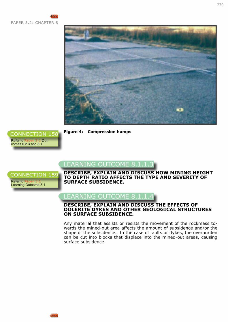
270
PAPER 3.2: CHAPTER 8
Figure 4: Compression humps
DESCRIBE, EXPLAIN AND DISCUSS HOW MINING HEIGHT TO DEPTH RATIO AFFECTS THE TYPE AND SEVERITY OF SURFACE SUBSIDENCE.
DESCRIBE, EXPLAIN AND DISCUSS THE EFFECTS OF DOLERITE DYKES AND OTHER GEOLOGICAL STRUCTURES ON SURFACE SUBSIDENCE.
Any material that assists or resists the movement of the rockmass to-wards the mined-out area affects the amount of subsidence and/or the shape of the subsidence. In the case of faults or dykes, the overburden can be cut into blocks that displace into the mined-out areas, causing surface subsidence.
Refer to Paper 3.1 Out-comes 6.2.3 and 8.1
CONNECTION 158
LEARNING OUTCOME 8.1.1.3
Refer to Paper 3.1 Learning Outcome 8.1
CONNECTION 159
LEARNING OUTCOME 8.1.1.4
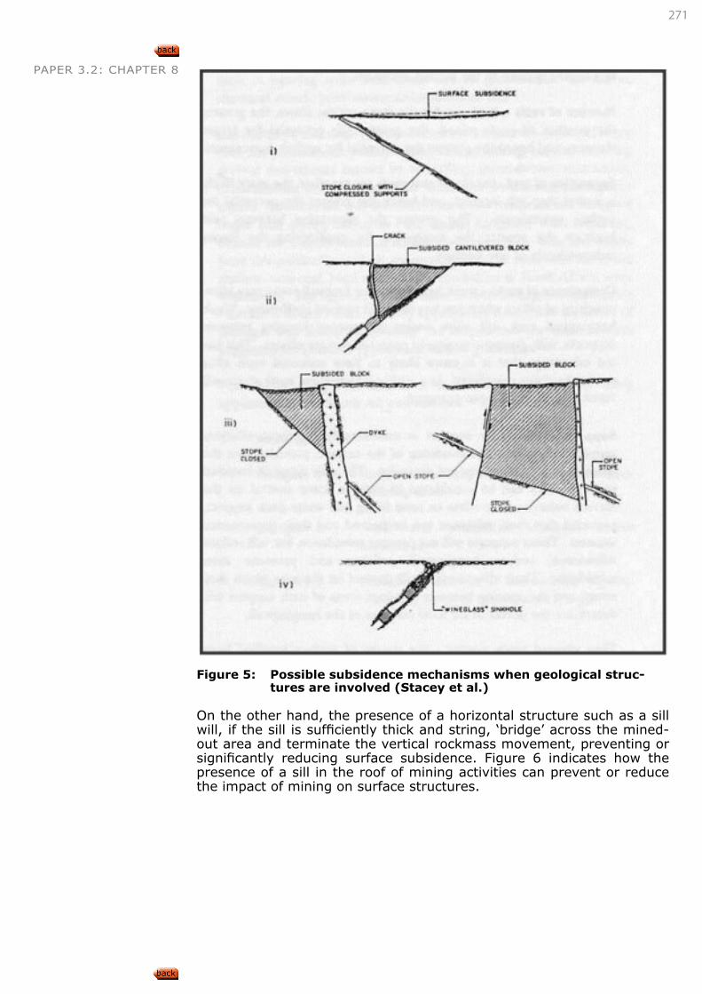
271
PAPER 3.2: CHAPTER 8
Figure 5: Possible subsidence mechanisms when geological struc-tures are involved (Stacey et al.)
On the other hand, the presence of a horizontal structure such as a sill will, if the sill is sufficiently thick and string, ‘bridge’ across the mined-out area and terminate the vertical rockmass movement, preventing or significantly reducing surface subsidence. Figure 6 indicates how the presence of a sill in the roof of mining activities can prevent or reduce the impact of mining on surface structures.
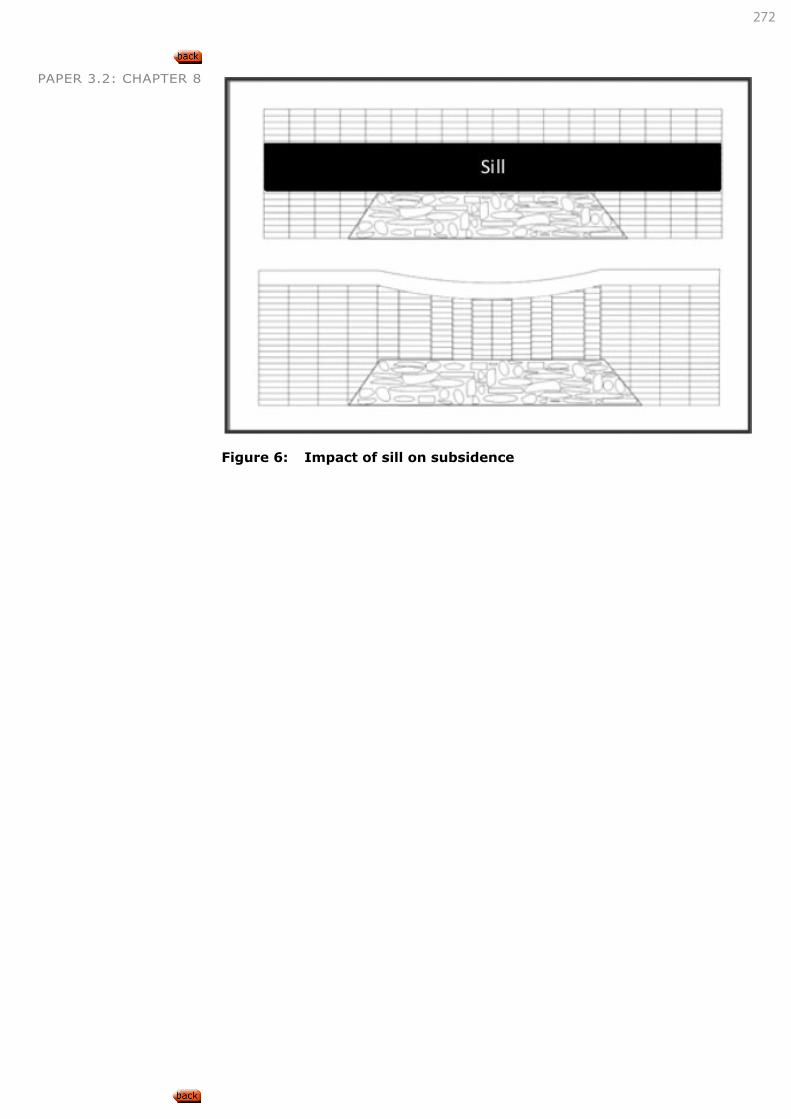
272
PAPER 3.2: CHAPTER 8
Figure 6: Impact of sill on subsidence
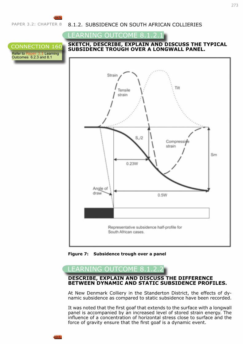
273
PAPER 3.2: CHAPTER 8 8.1.2. SUBSIDENCE ON SOUTH AFRICAN COLLIERIES
SKETCH, DESCRIBE, EXPLAIN AND DISCUSS THE TYPICAL SUBSIDENCE TROUGH OVER A LONGWALL PANEL.
Figure 7: Subsidence trough over a panel
DESCRIBE, EXPLAIN AND DISCUSS THE DIFFERENCE BETWEEN DYNAMIC AND STATIC SUBSIDENCE PROFILES.
At New Denmark Colliery in the Standerton District, the effects of dy-namic subsidence as compared to static subsidence have been recorded.
It was noted that the first goaf that extends to the surface with a longwall panel is accompanied by an increased level of stored strain energy. The influence of a concentration of horizontal stress close to surface and the force of gravity ensure that the first goaf is a dynamic event.
LEARNING OUTCOME 8.1.2.1
Refer to Paper 3.1 Learning Outcomes 6.2.3 and 8.1
CONNECTION 160
LEARNING OUTCOME 8.1.2.2
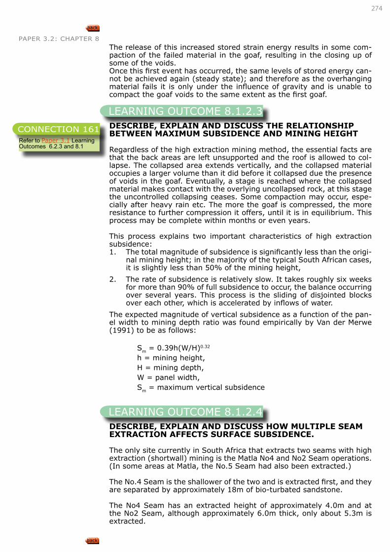
274
PAPER 3.2: CHAPTER 8The release of this increased stored strain energy results in some com-paction of the failed material in the goaf, resulting in the closing up of some of the voids.Once this first event has occurred, the same levels of stored energy can-not be achieved again (steady state); and therefore as the overhanging material fails it is only under the influence of gravity and is unable to compact the goaf voids to the same extent as the first goaf.
DESCRIBE, EXPLAIN AND DISCUSS THE RELATIONSHIP BETWEEN MAXIMUM SUBSIDENCE AND MINING HEIGHT
Regardless of the high extraction mining method, the essential facts are that the back areas are left unsupported and the roof is allowed to col-lapse. The collapsed area extends vertically, and the collapsed material occupies a larger volume than it did before it collapsed due the presence of voids in the goaf. Eventually, a stage is reached where the collapsed material makes contact with the overlying uncollapsed rock, at this stage the uncontrolled collapsing ceases. Some compaction may occur, espe-cially after heavy rain etc. The more the goaf is compressed, the more resistance to further compression it offers, until it is in equilibrium. This process may be complete within months or even years.
This process explains two important characteristics of high extraction subsidence:1. The total magnitude of subsidence is significantly less than the origi-
nal mining height; in the majority of the typical South African cases, it is slightly less than 50% of the mining height,
2. The rate of subsidence is relatively slow. It takes roughly six weeks for more than 90% of full subsidence to occur, the balance occurring over several years. This process is the sliding of disjointed blocks over each other, which is accelerated by inflows of water.
The expected magnitude of vertical subsidence as a function of the pan-el width to mining depth ratio was found empirically by Van der Merwe (1991) to be as follows:
Sm = 0.39h(W/H)0.32
h = mining height,H = mining depth,W = panel width,Sm = maximum vertical subsidence
DESCRIBE, EXPLAIN AND DISCUSS HOW MULTIPLE SEAM EXTRACTION AFFECTS SURFACE SUBSIDENCE.
The only site currently in South Africa that extracts two seams with high extraction (shortwall) mining is the Matla No4 and No2 Seam operations. (In some areas at Matla, the No.5 Seam had also been extracted.)
The No.4 Seam is the shallower of the two and is extracted first, and they are separated by approximately 18m of bio-turbated sandstone.
The No4 Seam has an extracted height of approximately 4.0m and at the No2 Seam, although approximately 6.0m thick, only about 5.3m is extracted.
LEARNING OUTCOME 8.1.2.3
Refer to Paper 3.1 Learning Outcomes 6.2.3 and 8.1
CONNECTION 161
LEARNING OUTCOME 8.1.2.4

275
PAPER 3.2: CHAPTER 8Two layouts have been attempted to create uniform subsidence:
1. The first layout (and technically preferable) was to offset the 2 and 4 Seam panels by about half a panel width. This was to even out the expected and actual extreme subsidence. After face breaks kept re-occurring on the 2 Seam face beneath the 4 Seam chain pillars, the layout was changed,
2. The second layout had no offset between the panels and the chain pillars are super-imposed on each other.
The major change that occurs with multiple seam extraction is that a subsided area that had attained stability and surface usage had been restored, is then remobilised.
DESCRIBE, EXPLAIN AND DISCUSS TECHNIQUES FOR REDUCING SUBSIDENCE HUMPS BY INTERPANEL CRUSH PILLARS.
A mine attempted to minimise surface subsidence by adopting a ‘crush’ pillar in the layout. Unfortunately, it is a hit or miss design technique as stability is required to a point where the face passes it and then it must crush out!
The average depth at the mine is 200m and the mining height was 2.0m, so the surface subsidence was approximately 1.0m. Over the positions of the ‘crush’ pillars, subsidence of approximately 0.5m was recorded.
It was found by conducting various instrumentation programs that the core of the ‘crush’ pillar was highly confined and did not crush through, and in some circumstances was pushed into the floor (foundation failure) or that steep-angled shear failures occurred in the roof strata above the pillar position. Both failure techniques resulted in subsidence over the pillar position creating the impression that pillars had crushed.
As mentioned above, it is impossible to ensure that the pillar crushes out behind the face. When the effects of cyclic loading are experienced, the ‘crush’ pillars would fail ahead of the face, usually in the tail gate, resulting in the temporary loss of the tail gate and ventilation to the face.
DESCRIBE, EXPLAIN AND DISCUSS THE RESULTS OF USING THE ABOVE TWO TECHNIQUES TO REDUCE SUBSIDENCE HUMPS.
The text above has described in some details the techniques that have been attempted to ameliorate the effects of surface subsidence and long-/shortwall mining.
It is commendable to attempt to adopt a design that is going to have minimum impact on the surface profile; however, in practice, the rock engineer never has enough information to produce a design that will de-liver the desired results.
The offset of shortwall panels was the correct design for surface man-agement, but on the 2 Seam face, the rate of change of stress or strain was too great for the face supports to manage and therefore it was aban-doned. With the improvement in face support design and management
LEARNING OUTCOME 8.1.2.5
LEARNING OUTCOME 8.1.2.6
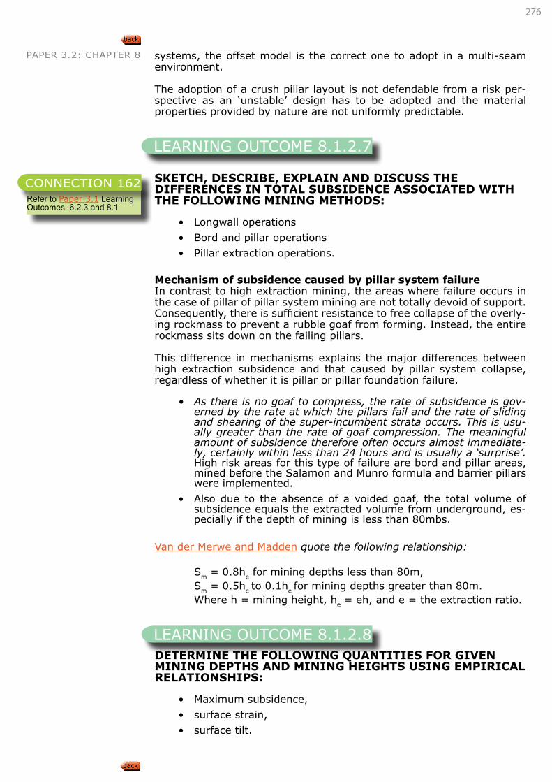
276
PAPER 3.2: CHAPTER 8 systems, the offset model is the correct one to adopt in a multi-seam environment.
The adoption of a crush pillar layout is not defendable from a risk per-spective as an ‘unstable’ design has to be adopted and the material properties provided by nature are not uniformly predictable.
SKETCH, DESCRIBE, EXPLAIN AND DISCUSS THE DIFFERENCES IN TOTAL SUBSIDENCE ASSOCIATED WITH THE FOLLOWING MINING METHODS:
• Longwall operations
• Bord and pillar operations
• Pillar extraction operations.
Mechanism of subsidence caused by pillar system failureIn contrast to high extraction mining, the areas where failure occurs in the case of pillar of pillar system mining are not totally devoid of support. Consequently, there is sufficient resistance to free collapse of the overly-ing rockmass to prevent a rubble goaf from forming. Instead, the entire rockmass sits down on the failing pillars.
This difference in mechanisms explains the major differences between high extraction subsidence and that caused by pillar system collapse, regardless of whether it is pillar or pillar foundation failure.
• As there is no goaf to compress, the rate of subsidence is gov-erned by the rate at which the pillars fail and the rate of sliding and shearing of the super-incumbent strata occurs. This is usu-ally greater than the rate of goaf compression. The meaningful amount of subsidence therefore often occurs almost immediate-ly, certainly within less than 24 hours and is usually a ‘surprise’. High risk areas for this type of failure are bord and pillar areas, mined before the Salamon and Munro formula and barrier pillars were implemented.
• Also due to the absence of a voided goaf, the total volume of subsidence equals the extracted volume from underground, es-pecially if the depth of mining is less than 80mbs.
Van der Merwe and Madden quote the following relationship:
Sm = 0.8he for mining depths less than 80m,Sm = 0.5he to 0.1he for mining depths greater than 80m.Where h = mining height, he = eh, and e = the extraction ratio.
DETERMINE THE FOLLOWING QUANTITIES FOR GIVEN MINING DEPTHS AND MINING HEIGHTS USING EMPIRICAL RELATIONSHIPS:
• Maximum subsidence,
• surface strain,
• surface tilt.
LEARNING OUTCOME 8.1.2.7
Refer to Paper 3.1 Learning Outcomes 6.2.3 and 8.1
CONNECTION 162
LEARNING OUTCOME 8.1.2.8
277
PAPER 3.2: CHAPTER 8Tilt, strain and tilt can be estimated using the following relationships:
Tm = 21.6Sm + 7mm/m ||m+ = 4.2Sm + 1.7mm/m ||m- = -9.1 Sm-2.8mm/m
Where Tm = maximum tilt, in mm/m,Sm = maximum subsidence, in m and || is in mm/m
a. Using Van der Merwe’s empirical relationship for the estimation of the surface subsidence, calculate the maximum subsidence for the following situations:
Mining height h Mining depth H Panel width W Estimated sub-sidence Sm
2.0m 200m 240m 0.83m5.0m 80m 120m 2.22m
The candidate must substitute the values in the table to obtain the value of Sm
Sm = 0.39h(W/H)0.32
h = mining height,H = mining depth,W = panel width,Sm = maximum vertical subsidence
Using the estimated subsidence above, calculate the maximum surface strain that will occur.
Candidate must substitute the value of Sm into ||m+ = 4.2Sm + 1.7mm/m
The calculated strains should come out at 5.19 mm/m and 11.02 mm/m.
b. If a standard surface conveyor belt structure, that is going to be undermined, can only sustain a strain of 5mm/m, what would you recommend to the engineer?
Without relocating the belt or slotting critical bolts holes, the in-tegrity of the belt cannot be guaranteed.
• Page 108, Salamon, Oravecz, Rock mechanics in coal mining, COMRO, 1976
• Page 113,213, Van der Merwe, Madden, Rock Engineering for Underground Coal Mining, 2002
EXAMPLE
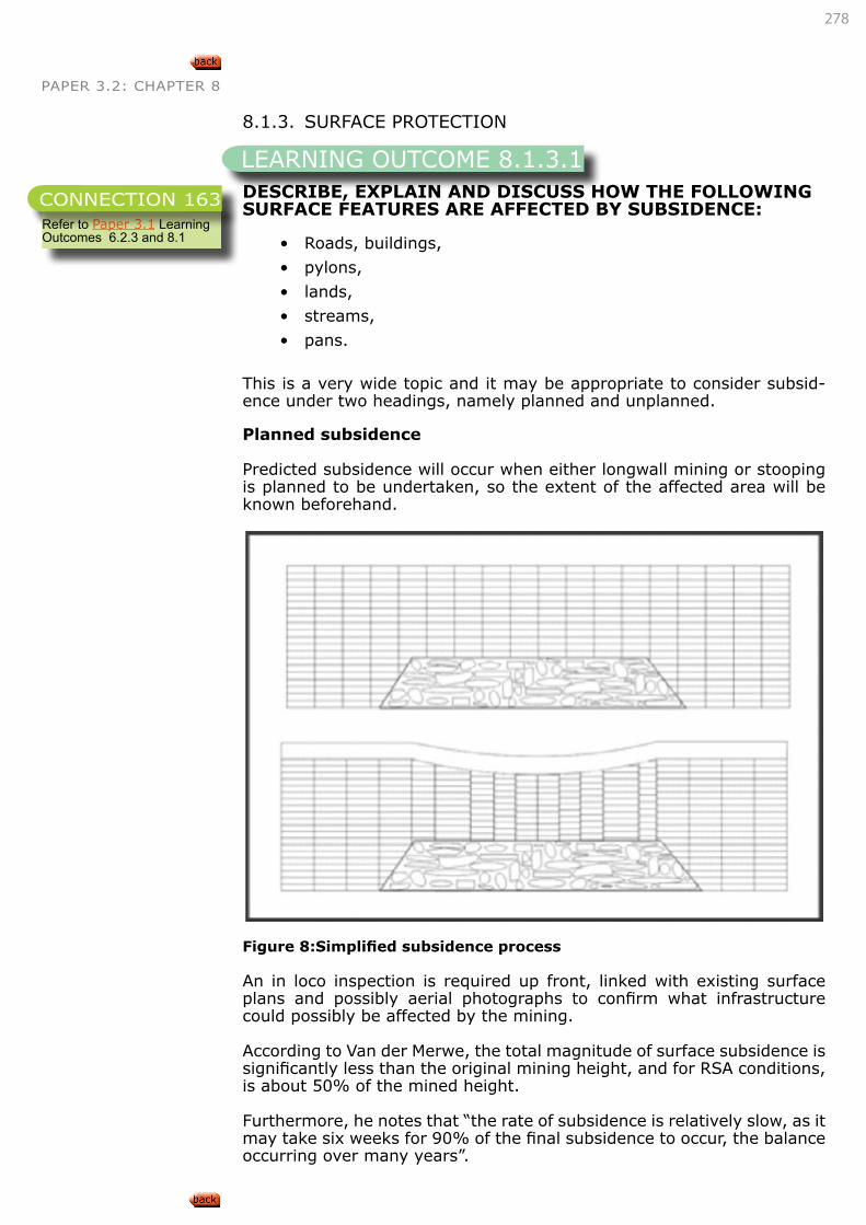
278
PAPER 3.2: CHAPTER 8
8.1.3. SURFACE PROTECTION
DESCRIBE, EXPLAIN AND DISCUSS HOW THE FOLLOWING SURFACE FEATURES ARE AFFECTED BY SUBSIDENCE:
• Roads, buildings,
• pylons,
• lands,
• streams,
• pans.
This is a very wide topic and it may be appropriate to consider subsid-ence under two headings, namely planned and unplanned.
Planned subsidence
Predicted subsidence will occur when either longwall mining or stooping is planned to be undertaken, so the extent of the affected area will be known beforehand.
Figure 8:Simplified subsidence process
An in loco inspection is required up front, linked with existing surface plans and possibly aerial photographs to confirm what infrastructure could possibly be affected by the mining.
According to Van der Merwe, the total magnitude of surface subsidence is significantly less than the original mining height, and for RSA conditions, is about 50% of the mined height.
Furthermore, he notes that “the rate of subsidence is relatively slow, as it may take six weeks for 90% of the final subsidence to occur, the balance occurring over many years”.
LEARNING OUTCOME 8.1.3.1
Refer to Paper 3.1 Learning Outcomes 6.2.3 and 8.1
CONNECTION 163
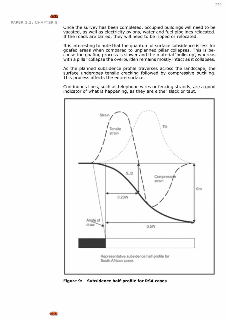
279
PAPER 3.2: CHAPTER 8Once the survey has been completed, occupied buildings will need to be vacated, as well as electricity pylons, water and fuel pipelines relocated. If the roads are tarred, they will need to be ripped or relocated.
It is interesting to note that the quantum of surface subsidence is less for goafed areas when compared to unplanned pillar collapses. This is be-cause the goafing process is slower and the material ‘bulks up’, whereas with a pillar collapse the overburden remains mostly intact as it collapses.
As the planned subsidence profile traverses across the landscape, the surface undergoes tensile cracking followed by compressive buckling. This process affects the entire surface.
Continuous lines, such as telephone wires or fencing strands, are a good indicator of what is happening, as they are either slack or taut.
Figure 9: Subsidence half-profile for RSA cases
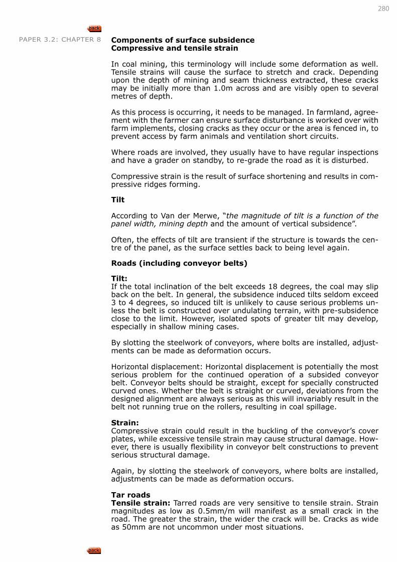
280
PAPER 3.2: CHAPTER 8 Components of surface subsidenceCompressive and tensile strain
In coal mining, this terminology will include some deformation as well. Tensile strains will cause the surface to stretch and crack. Depending upon the depth of mining and seam thickness extracted, these cracks may be initially more than 1.0m across and are visibly open to several metres of depth.
As this process is occurring, it needs to be managed. In farmland, agree-ment with the farmer can ensure surface disturbance is worked over with farm implements, closing cracks as they occur or the area is fenced in, to prevent access by farm animals and ventilation short circuits.
Where roads are involved, they usually have to have regular inspections and have a grader on standby, to re-grade the road as it is disturbed.
Compressive strain is the result of surface shortening and results in com-pressive ridges forming.
Tilt
According to Van der Merwe, “the magnitude of tilt is a function of the panel width, mining depth and the amount of vertical subsidence”.
Often, the effects of tilt are transient if the structure is towards the cen-tre of the panel, as the surface settles back to being level again.
Roads (including conveyor belts)
Tilt: If the total inclination of the belt exceeds 18 degrees, the coal may slip back on the belt. In general, the subsidence induced tilts seldom exceed 3 to 4 degrees, so induced tilt is unlikely to cause serious problems un-less the belt is constructed over undulating terrain, with pre-subsidence close to the limit. However, isolated spots of greater tilt may develop, especially in shallow mining cases.
By slotting the steelwork of conveyors, where bolts are installed, adjust-ments can be made as deformation occurs.
Horizontal displacement: Horizontal displacement is potentially the most serious problem for the continued operation of a subsided conveyor belt. Conveyor belts should be straight, except for specially constructed curved ones. Whether the belt is straight or curved, deviations from the designed alignment are always serious as this will invariably result in the belt not running true on the rollers, resulting in coal spillage.
Strain: Compressive strain could result in the buckling of the conveyor’s cover plates, while excessive tensile strain may cause structural damage. How-ever, there is usually flexibility in conveyor belt constructions to prevent serious structural damage.
Again, by slotting the steelwork of conveyors, where bolts are installed, adjustments can be made as deformation occurs.
Tar roadsTensile strain: Tarred roads are very sensitive to tensile strain. Strain magnitudes as low as 0.5mm/m will manifest as a small crack in the road. The greater the strain, the wider the crack will be. Cracks as wide as 50mm are not uncommon under most situations.
281
PAPER 3.2: CHAPTER 8Compressive strain: Due to the rigid nature of road foundations, com-pressive strains will almost invariably result in ridges on road surfaces. These tend to develop suddenly (within less than an hour) as the road foundation fails. This is the main motivation for the provision of a by-pass, for even though the ridges are flattened easily, the first motorist being confronted by an unexpected ridge is likely to take emergency evasive reaction.
Horizontal displacement: Horizontal displacement cannot be prevented, but is not considered serious.
Roads are either relocated (temporary or permanent) or are ‘ripped’ to make them into a dirt road.
Buildings
Tilt: If a building is situated in the centre of a panel, the tilts will be of a transient nature and once the area has stabilised, walls etc. will return to the vertical. During active subsidence, differential tilts may cause buck-ling of the building. Windows may crack and doors may become stuck.
Strain: Tensile strains may cause walls to crack and compressive strains may cause plaster and floors to buckle.
Horizontal displacement: Services to buildings may be cut off by horizon-tal displacement.
In reality, it is usually the farmers’ houses and barns that are affected by undermining. The simplest solution is to build the farmer a new house in an area that will not be affected by mining and knock down the house before it becomes affected by mining, and manage the damage to the barns as it occurs.
Other features that need to be considered when surface subsidence is planned, include pylons, lands (consider current and future land use), streams and pans (also consider inflow into the mine workings).
Unplanned subsidence
In contrast to high extraction mining, the areas where failure occurs in the case of pillar system mining are not devoid of support. Consequently, there is sufficient resistance to free collapse of the overlying rockmass to prevent a rubbly goaf from forming. Instead, the entire rockmass sits down on the failing pillars.
282
PAPER 3.2: CHAPTER 8
Figure 10: Subsidence in pillar layouts
This difference in mechanism explains the major differences between high extraction subsidence and that caused by pillar system collapse. Firstly, as there is no goaf to compress, the rate of subsidence is gov-erned by the rate at which the pillars fail and the rate at which the sliding and shearing between the jointed and bedded blocks. This is significant-ly greater than the rate of goaf compression. The meaningful amount of subsidence therefore occurs almost immediately, certainly within less than 24 hours. It has never been measured because it is not possible to predict when pillar failure will occur. Often, in farm land the subsidence is only detected when the crop is harvested, especially mealies, as their height masked the timing of the subsidence.
Secondly, also due to the absence of a voided goaf, the total volume of subsidence is very close to the volume of underground mining, where the mining depth is less than 80m. The magnitude of subsidence is within 80% of the effective mining height; which is the true mining height mul-tiplied by the extraction ratio; i.e. if the original mining height was 3.0m and the extraction is 70%, the effective mining height is 2.1m.
The maximum expected subsidence in the case of a pillar system failure could be estimated by:
Sm = 0.8he for mining depth less than 80m,Sm = 0.5he to 0.1he for mining depth greater than 80m,Where he = eh and e is the extraction ratio and h the original mining height.
283
PAPER 3.2: CHAPTER 8 Areas subject to sudden pillar collapse can be identified from a pre-liminary risk assessment as they usually have similar characteristics, namely:
• Mined prior to the implementation of the Salomon and Munro pillar design formula,
• No barrier pillars left in situ,
• Workings relatively shallow, < 50m below surface, inferring full tributary loading on the pillars is occurring, no bridging in stiff layers,
• % extraction exceeds 75%,
• Workings at least 50 years old.
A surface drilling programme into bords and pillars is a good way of es-timating the current condition of the pillars in such an area having some of the characteristics listed above.
• Page 125, Van der Merwe, Rock Engineering for Underground Coal Mining, 2002
•
Surface protection
1. Discuss and debate the mechanistic difference between planned and unplanned surface subsidence and what type of mining will cause these differences.Two longwalls, one extracting a 2.0m thick seam at 200m depth and the other extracting a 5.0m seam at 80m depth result in some surface subsidence. Using industry guidelines for the estimation of subsidence, indicate what you think the subsidence will be. State any assumptions you may have to make to answer this question.
2. You are concerned about an area of agricultural land that was under-mined by bord and pillar techniques in 1945, with a mining height of 2.3m, at a depth of 35m and 85% extraction. If it were to collapse, estimate the maximum depth of the surface depression.
Answers
1. The difference centres around the creation or not of a goaf. As a goaf forms, the material bulks up, eventually reducing the maximum amount of surface subsidence that may occur. The rate of surface subsidence is relatively slow and may take many years before the surface is stabilised. A goaf forms with high extraction techniques such as short- or longwall mining, or stooping. When a pillared area collapses, no goaf is able to form, so the rock moves downward in a mass, over a very short time, resulting in relatively high magnitude of subsidence.
2. The assumption (refer to notes on longwall mining) is that the panel is truly super critical, i.e. the surface is in pure tension.
3. 0.5 x 2m = 1.0m subsidence
4. 0.5 x 5m = 2.5m subsidence
5. For panels less than 80mbs, use the relationship Sm = 0.8he where he = 0.85 X 2.3m, which is 1.955.
6. Substitute 1.955 into Sm = 0.8he, which yields a value of surface subsidence of 1.5
EXAMPLE
284
PAPER 3.2: CHAPTER 8
DESCRIBE, EXPLAIN AND DISCUSS POSSIBLE REMEDIAL MEASURES THAT MAY BE APPLIED TO SURFACE STRUCTURES TO LIMIT SUBSIDENCE DAMAGE.
Conveyor belts
Even though conveyor belts in general are flexible enough to prevent strain-induced damage, they are yet rigid enough to maintain them-selves in a straight line provided they are detached from the surface. Where conveyor belts are to be undermined, it is essential to cut the bolts attaching the legs to the foundation blocks.
Pipelines
Very little additional work is required, apart from regular inspections and keeping an emergency length of pipe available in case the unexpected happens. If very good reasons exist why the pipe should not be left open for the duration of subsidence, it can be covered with a cohesionless ma-terial such as washed river sand. If large magnitudes of subsidence are expected, a bypass consisting of a snaked section of pipe to compensate for the increased length can be provided. I
Roads
In the case of road undermining, it is essential for a detailed prediction of the expected subsidence to be made.
In most cases, very little action will be needed for the undermining of a gravel road. During the period of active subsidence, the road should be patrolled on a regular basis – more than once per day. A heavy roller should be available to flatten any compressive ridges. It will seldom be necessary to construct a bypass.
For tarred roads, a bypass should be provided in most cases. However, it will usually be sufficient to construct a gravel bypass within the road reserve, instead of a tarred one beyond the area of subsidence.
Traffic should be diverted onto the bypass from the time that the mining is being carried out directly underneath the road, and should contin-ue until subsidence surveys indicate that the subsidence has practically stabilised. This will usually be approximately six weeks after mining has passed underneath the road.
Power pylons
In most cases, damage can be prevented by replacing the fixed fittings of the conductors to the pylons with rollers during the subsidence peri-od. This has the effect of freeing the pylon to move horizontally. After the subsidence has ceased, the rollers can be replaced by the normal fittings. Where the pylons are situated on the permanently sloping edge of a panel, it will sometimes be necessary to jack up the down-dip legs of the pylon and to place elevated concrete foundations underneath them.
• Page 125, Van der Merwe, Rock Engineering for Underground Coal Mining, 2002
LEARNING OUTCOME 8.1.3.2
285
PAPER 3.2: CHAPTER 8
DESCRIBE, EXPLAIN AND DISCUSS POSSIBLE CHANGES THAT MAY BE MADE TO UNDERGROUND MINING LAYOUTS TO REDUCE SUBSIDENCE DAMAGE.
DETERMINE POTENTIAL SUBSIDENCE DAMAGE TO THE FOLLOWING TYPES OF STRUCTURE FOR GIVEN MINING DEPTHS AND MINING HEIGHTS USING PUBLISHED DAMAGE TABLES:
• Roads,
• buildings,
• pylons.
• Page 108, Salamon, Oravecz, Rock mechanics in coal mining, COMRO, 1976
• Page 113,213, Van der Merwe, Madden, Rock Engineering for Underground Coal Mining, 2002
8.2. ENVIRONMENTAL EFFECTS8.2.1. LONG-TERM STABILITY AND THE ENVIRONMENT
DESCRIBE, EXPLAIN AND DISCUSS THE POSSIBLE EFFECTS AND CONSEQUENCES OF GIVEN MINING METHODS ON THE FOLLOWING ISSUES:
• Long-term stability of the ground surface,
• Groundwater,
• Ultimate closure of the mine.
Long-term stability of the ground surface
Groundwater
Mining methods that allow rockmass displacement, and especially dis-placement under a tensile stress environment, increase the potential for water flow through the rockmass and into mine workings. When water flow is a concern, stiff support systems are required and pillar systems with stable, non-yield pillars are required to maintain compression in the rockmass and limit the creation of additional conduits to allow water flow. Any high extraction methods will allow groundwater to flow and penetrate mine workings, often flowing from the mine workings at the lowest point with some level of pollution.
LEARNING OUTCOME 8.1.3.3
Refer to “LEARNING OUTCOME 8.1.3.1” on page 278
CONNECTION 164
LEARNING OUTCOME 8.1.3.3
Refer to Paper 3.1 Learning Outcomes 6.2.3 and 8.1
CONNECTION 165
LEARNING OUTCOME 8.2.1.1
Refer to “8.1. SURFACE EFFECTS” on page 265
CONNECTION 165
286
PAPER 3.2: CHAPTER 8 Ultimate closure of the mine
Mine workings that could affect surface stability, even if the original de-sign is a non-yield, stable pillar design, must continuously be monitored for subsidence as time-dependant failures are possible. However, if a high extraction mine has encountered all the surface subsidence expect-ed, monitoring will, even though prudent, probably not show any further surface impact until failure of regional/barrier pillars occur, even though it is unlikely in a goafed environment.
This simply means that ultimate closure of the mine remains a concern for all shallow working mines.
DESCRIBE, EXPLAIN AND DISCUSS THE POSSIBLE EFFECTS AND CONSEQUENCES OF GIVEN FACTORS OF SAFETY ON THE FOLLOWING ISSUES:
• Long-term stability of the ground surface,
• Groundwater,
• Ultimate closure of the mine.
FOS Long-term stability of ground surface
Groundwater Ultimate closure of the mine
Low Pillars will start to yield with time, even-tually fail and allow the collapse of the overburden into the mined-out workings.
Will allow separa-tion of strata and water flow along these paths.
Failed or high risk pil-lars make entry into old workings risky and even impossible in some cases. This means that under-ground fires cannot be controlled while access to fill areas to protect surface is impossible. Closure of the mine becomes a sig-nificant concern as risk will remain high as long as the pillars are allowed to yield/fail or that a fire rages.
Acceptable for design (1.6)
Long-term effects of pillar designs are not clearly understood and indications are that pillars will yield over the long term even if their initial FOS was sufficient. Same result could occur as for lower FOS.
Should prevent overburden dis-placement and therefore the creation of new flow paths for groundwater.
Access is possible and precautions to protect surface and allow closure of the mine risk to remain low can be implemented.
High Should remain stable but is still subjected to the long-term effects and additional load-ing by other pillars that fail or yield.
• Van der Merwe, Coal pillar life
• Van der Merwe, Coal pillar life verified
LEARNING OUTCOME 8.2.1.1
287
PAPER 3.2: CHAPTER 9
PAPER 3.2 SOFT ROCK TABULAR MINING
9. MINING STRATEGIES IN DIFFICULT CIRCUMSTANCES
The candidate must be able to demonstrate knowledge and understand-ing of the above subject area by being able to:
• Describe, explain and discuss the geotechnical aspects of dealing with the following difficult circumstances:
• Mining through dykes,
• Mining through burnt coal,
• Mining under dolerite sills’
• Mining thick seams’
• Mining multiple seams’ and
• Mining shallow seams (<40mbs).
LEARNING OUTCOMES
CHAPTER
9
288
PAPER 3.2: CHAPTER 99. MINING STRATEGIES IN DIFFICULT CIRCUMSTANCES
DESCRIBE, EXPLAIN AND DISCUSS THE GEOTECHNICAL ASPECTS OF DEALING WITH THE FOLLOWING DIFFICULT CIRCUMSTANCES:
• Mining through dykes
• Mining through burnt coal
• Mining under dolerite sills
• Mining thick seams
• Mining multiple seams
• Mining shallow seams (<40mbs)
This concept required to safely mine through difficult conditions is to ap-ply the process described as the ‘Hierarchy of Control’. This process is common sense, and consists of three ‘barriers’ to prevent harm during the difficult mining:
• Engineering controls;
• System controls; and
• People controls.
The most effective control is the first, where we either engineer out hazards (do not mine through dykes) or we place engineered barriers between people and the hazard.
The least effective control is the last one, involving people. No amount of training, certification etc. will effectively mitigate the risk. Managing legal compliance in no way impacts on managing the risk!
Mining through dykes and burnt coal – Bord and Pillar workings
From a planning perspective, it is better to layout panels between dykes than try to mine through them (Hierarchy of Control).
To ensure dykes do not occur as a surprise, a programme of underground in-seam drilling needs to be in place to detect the position of dykes. It is good practice if these holes are surveyed as well, as boreholes are known to deviate greatly in practice. As technology improves and these holes can be ‘steered’, they should be positioned in the barrier pillars between the panels, as they can be become a methane accumulating hazard (the unintended consequence)!
Furthermore, a programme of aero-magnetic surveys over the proposed mining area will greatly assist in focusing the drilling programme on known targets. Some dykes are not magnetic, so only the in-seam drill-ing programme will detect them before mining occurs.
If it is unavoidable to mine through a dyke, then it is important to know its thickness and strike direction, such that the panel can be laid out perpendicular to it. This ensures the minimum time and cost are spent passing through the dyke.
When a dyke is expected in a section, a risk assessment needs to be
LEARNING OUTCOME 9.1
289
PAPER 3.2: CHAPTER 9 undertaken so that all personnel in the section know what to expect. A good practice is to decide whether the right or left hand side of the sec-tion is likely to pick up the dyke first, and then have that outer roadway lead by about a ‘centre spacing’ to give ample warning of its exact posi-tion. This will require the use of a jet fan.
Once the dyke intersection has been confirmed, the risk assessment would give guidance (ventilation, air quantity; and belt road width re-quirements) on which roads will proceed through the dyke.
The drilling programme would give an indication of the dyke’s thickness and whether long pillars need to be created. A long pillar is created by not putting through the splits or cut troughs at the pre-planned position.
As there is burnt coal on either side of the dyke, the last split should be in un-burnt coal, which means the pillar centres and dimensions may have to change. Similarly, once the dyke is traversed, the first split must be in un-burnt coal, and this may also require a modification to the layout and cutting sequence.
A good practice is to push the straights or roads beyond the planned split position, so that the start position and the holing position can be inspect-ed beforehand, and modifications made accordingly to suit the geology exposed.
Associated with the occurrence of dykes and burnt coal are ‘slips’. These are joints that were created in the coal and the roof by the change in volume of the burnt coal and the effects of overburden stress. These fea-tures are usually at challenging angles and are heavily slickensided (also referred to as a greasy back), affording a high probability of instability.
Before the dyke is tackled, it is imperative to ensure that the burnt coal that has been exposed next to the dyke is well supported.
Often, collieries will use thin sprayed liners and/or shotcrete to seal the burnt coal surface, thereby preventing weathering effects from occur-ring. The burnt coal is sometimes saturated with water and acts like a sponge. It is important if these conditions exist to ensure that water drainage holes are left in the sealing medium. If the water is excessive, hose pipes can be grouted in to act as long-term drainage conduits and prevent a water pressure build up from occurring.
When a dyke is exposed in the roads to be taken through, the specialist dyke development crew will move into position.
The equipment used will be a percussion face drill and possibly a rotary percussion roof bolter. Typically, dykes in the coalfields have strengths between 300 to 360MPa. Hand-held jackhammers are not recommend-ed, as there is a high probability of operators being hurt by roof or rib side failures.
Because of the restriction on explosive use in coal mines, only 800 grams of permitted explosive (which is of a lower strength than typical hard rock explosives) is normally used. Coal miners are also not very good hard rock miners! The legislation has been recently updated such that the mine manager may give permission for up to 2000 grams of permit-ted explosives to be used following a rigorous risk assessment process.
The secret of success of getting through a dyke is not to drill blast holes through the dyke, but to drill as many short holes as possible in the dyke. Charged blast holes that pass through the dyke dissipate all their energy in the burnt coal on the unexposed side.
290
PAPER 3.2: CHAPTER 9The use of a burn cut, with possibly 60 blast holes and three to five de-lays usually can give meaningful results.
Once the dyke has been penetrated, it may not need much support if has been well blasted, as poor conditions in a dyke are usually as a result of poor blasting control. When standard roofbolting (rotary) equipment is used, it is unable to penetrate the exposed Dolerite, so this poses a challenge in the section. If the dyke is thin, strap support is installed that ‘bridges’ across the exposure. Mining through dykes and burnt coal – Longwall mining
If a dyke occurs in a longwall block, it is a major issue.
Historically, the practice in South Africa is to position longwalls between dykes. If a dyke occurs perpendicular to the block (i.e. parallel to the face), then the face ‘jumps the dyke’. This is done by pulling the face off and re-installing it on the other side of the dyke.
There are examples in the literature of pre-mining the dyke and either filling it with a low-grade backfill or supporting it with standing sup-port that can be cut through by the shearer. Pre-stressed brick packs have proven to be more successful than timber mat packs with regard to standing support.
If the coal has been burnt by a sill above or below the seam, a longwall would not normally mine that coal, unless it was of limited extent.
Mining under dolerite sills (also refer to notes on longwall mining)
The secret of successful mining under sills is to know the dry ash-free volatile value (DAFV), quoted as a percentage of the coal.
Where the value of volatiles is below 25%, it is a sure indication that the coal seam has been ‘burnt’ by the sill. Coal with such low DAFV less than 25% is normally taken out of reserves, so instances where mining in these conditions will occur are rare.
One example where you may have to mine through burnt coal without intersecting the Dolerite, is when the intrusion is transgressive (above or below) and comes close to the seam and then moves away again. In order to access un-burnt coal on the other side of the burnt zone, access roads need to be pushed through the burnt or devolatised coal.
The process to follow again is logical using the hierarchy of control. Roads need to be minimised in number and their dimensions reduced such that ventilation requirements are satisfied.
Face advance needs to be reduced to a minimum so support can be in-stalled as soon as possible. A good rule is to have the support equipment waiting prior to the burnt coal being cut. An advance of 2.0m is adequate per support cycle.Support will also involve thin sprayed liners or shotcrete, followed up with mesh and further shotcrete.
If roof falls occur immediately, the burnt coal is exposed, then ‘spialing’ needs to be practised, where an ‘umbrella of steel, either old drill rods, water pipes or other steel accessories are drilled into the roof of the yet to be exposed excavation. The steel increases the inherent friction in the
291
PAPER 3.2: CHAPTER 9 burnt coal such that a time opportunity is created to install the support, usually involving standing sets, prior to instability occurring.
Mining thick seams
The topic of thick seams may be split into two categories, namely:
• Discontinuous or variable thickness,
• Continuous.
Discontinuous thickness
This situation is common when the coal was laid down over an eroded topography or on dolomites.Mistakes have been made in the past when the increased thickness of coal is detected as a ‘surprise’ and to maximise production, most or all of the coal is taken out on first workings.
This may result in several undesired consequences:
• The roofbolter(s) cannot reach the roof to install support,
• Tools for barring and sounding cannot reach the roof,
• The width-to-height ratio of the pillars may now be below design specifications, resulting in a reduced factor of safety,
• Steep inclines occur, resulting in tramming difficulties with shut-tle cars, LHD’s etc., and may result in ‘runaways’,
• Accumulations of water in the belt and tractor road, making con-tinued operation hazardous.
The rule that must be applied is that the mining height must be kept to the standard for the section, such that all the roof support is installed on first workings. If coal is detected in the floor, the decision to take some or all of it out should be supported by an issue-based risk assess-ment, where the above issues are included. Other issues that need to be included are the installation of rib side support and the mapping of through-going joints in pillars, which may be caused to ‘day light when floor coal is extracted, resulting in an increased risk of rib side failure.
Continuous thick seam
Some of the issues discussed above also apply to the continuous thick seam. Historically, mining of thick seam was divided into ‘top coaling’ and ‘bottom coaling’.
The Chinese have developed a longwall technique for thick coal that is called ‘top coal caving’, which is now being tried in Australia. In southern Africa, the technique could be considered for the Heidelberg, Waterberg and Botswana coalfields. It is important for candidates to be aware of new techniques and this is one that will have increasing importance in the future.
Old workings
The historical background to this type of mining was the mining of the Witbank No 2 Seam.
In the earliest days or first workings, a select cut was taken in the mid-dle of the 2 Seam by drill and blast methods, leaving lesser quality coal in both the roof and floor. As the market conditions changed, there was a market for both floor and roof coal, but not always at the same time!
There are still under-exploited reserves in the No 2 Seam, where it was
292
PAPER 3.2: CHAPTER 9 only worked for the select cut.
The mining of the remaining coal would be with continuous miners and mechanised bolters, and therefore the limitations of the equipment need to be considered when planning such a situation.
The issue-based risk assessment would indicate that the roof would prob-ably be unsafe and would be needed to be re-mined with a continuous miner to a height that the roof bolter can successfully install quality sup-port. Often, old workings were supported with sticks or shell anchored roof bolts, which are no longer operable. This work would be done on advance until the limit of the panel has been reached.As the panel advanced, a programme of short hole floor drilling should be undertaken by the geology department to determine the thickness and qualities of the floor coal.The rock engineering department would also have a structural mapping programme in place as the section advances; to plot all the position of slips, joints, and floor rolls etc. that will impact on bottom coaling operations.
The No 2 Seam is typically 6.0m thick and the first workings by drill and blast were only 1.8m to 2.5m high, and although there was no Salamon and Munro pillar design formula at the time of mining, reasonable pillars were often left. The original survey plans were often drawn up from shift boss measurements; therefore, the pillars need to be re-surveyed and the new mining height recorded.
From this information, the current factors of safety may be determined. This information now becomes input data to the new panel risk assess-ment for the bottom coaling exercise.One of the main challenges is to decide whether the bottom coal is to be taken out on retreat or advance!
When considering such a mining situation as bottom coaling of old work-ings, creative, engineering thinking is required, as it is not a perfect mining situation. Where pre-existing small pillars exist or dominant joints are exposed, a decision needs to be made about mining all the coal that is on offer!
Because all the roads and splits are open, ventilation requirements are satisfied and therefore if the full height of some splits does not require to be mined, then it is acceptable when bottom coal may be left in situ to either strengthen a small pillar or stop a joint from day lighting in the rib side.
In the straights or roads, such flexibility may not exist and most of the coal needs to be taken to maintain safe tramming routes. Then pillars and joints will need to be supported with straps or ribside bolts.
First workings of thick seam
There are two opportunities to mine all the coal in this situation, either:
• Mine it in two cuts, if the equipment is not fit for purpose,
• Or, mine it with a single pass operation.
The most productive way to mine thick coal on first workings is with the correct suit of equipment; where the continuous miner can cut the full height of coal on offer; the roof bolting equipment can safely reach the roof and the shuttle cars can clear the coal produced.
293
PAPER 3.2: CHAPTER 9If these conditions are satisfied, then mining the thick coal is no different to mining normal seam thicknesses (1.8m to 4.0m), taking into account that the pillars are designed to an acceptable factor of safety that infers the pillar centres are larger for thick seam operations.
If because of equipment constraints, a double pass operation is consid-ered, then all the issues discussed under bottom coaling above apply, as the first cut must be taken against the final roof position so that only one support operation is undertaken.
Mining multiple seams
In South Africa, multiple seams occur in both the Witbank and Natal Coalfields and have been widely exploited as such.
It is preferable to mine the shallowest seam first and progressively ex-tract the lower seams later. However, because of varying coal qualities and marketing expertise, this often is not the case.
The major issue is the parting thickness between seams and the strength of that parting in reducing the effects of interaction.Factors that affect interaction are listed in the 2nd Edition of Rock Engi-neering of Underground Coal Mining, p. 103, as follows:
• Parting thickness,
• Parting characteristics,
• Mining method,
• Relative location of layouts,
• % recovery of the coal seams,
• Seam thickness,
• Time difference following mining previous seams,
• Depth,
• In situ stress.
Other issues that need to be considered are:
• Spontaneous combustion,
• Water accumulation on other seams, both above and below.
For bord and pillar mining between two proximal seams, interaction may only depend on parting thickness, parting characteristics and the relative position of the pillars.
The greater the parting thickness, the lower the interaction. When the seams have a parting thickness that is less than 16 to 18m, a careful risk evaluation is required. Guidelines for multi-seam bord and pillar layouts were developed by Salamon and Oravecz in 1976. Whether pillars are superimposed or not, depends on the parting distance, P, in relation to the pillar centre dis-tance, C, and the bord width, B.
The general guideline is that if the parting distance is less than 0.75 times the pillar centre distance then the pillars should be superimposed. These guidelines were formulated from numerical modelling after deter-mining the distance at which the alternating influence of bord and pillars is negligibly small.
294
PAPER 3.2: CHAPTER 9
As a rock engineer, you should be able to defend the value of ‘negligibly small’. One should not have a specific value in MPa terms, but think of it terms of a factor of safety, looking at the in situ strength of the parting, the anticipated maximum stress level and what does this value represent as a percentage increase.
With various numerical modelling packages available today, it is advis-able to run some two- and three-dimensional models. With the output, create the picture in your mind of what is happening in the parting and relate it to the actual geology, especially if there are soft or potentially lubricated layers present.
In thin parting scenarios, the Salomon and Oravecz rules or the output from the numerical modelling may indicate superimposition of the pillars on the two affected seams.This is a nightmare situation, as survey plans have to be very accurate as a ‘shift’ in centres or poor mining control will result in the pillars not being superimposed.
A common challenge for the coal rock engineers in the Witbank Coalfield is the extraction of the No 4 Seam reserves from above the No 2 Seam, when the No 2 Seam was:
• Mined prior to the development of the Salamon and Munro pillar design formula, i.e. low factor of safety pillars,
• The systematic introduction of barrier pillars, possibility of un-controlled pillar runs,
• Where the No 2 Seam is flooded and cannot be inspected,
• Where unscrupulous mining companies have ‘chequer boarded’ the No 2 Seam pillars, effectively sterilising the No 4 Seam.
When mining of the No 4 Seam in the above conditions has to be un-dertaken, a rigorous risk assessment process needs to be followed, and solutions to all the situations are available.
• SIMRAC Project COL026 Multi-seam design procedures
Low No 2 Seam FOS Pillars (usually mined prior to 1965) and flooded.
A process that has worked in the past is to begin characterising the FOS of the No 2 Seam pillars in ranges from FOS 1.0-1.1; 1.1-1.2; 1.2-1.3 etc.Then scrutinise the plans for blocks of coal or un-mined ground and try and create a picture of what creates stability for the No 4 Seam.Once high potential target areas are identified, a diamond drilling pro-gramme needs to be undertaken to confirm the following:
1. Is the roof of the No 2 Seam still in situ?
Here a known survey peg position is targeted, and the driller is re-warded for core recovery and not metres drilled!
The picture the rock engineer is trying to create is at what elevation is the contact between in situ, unfailed roof material, failed in situ roof material and the elevation of the top of the void.
A comparison is then made between the estimated roof position
295
PAPER 3.2: CHAPTER 9 from the core and the survey peg data. This process is then repeat-ed over the area of interest, such that a picture is created of the roof condition.
With this information a revised ‘mining height’ is determined.
2. Are the No 2 Seam pillars stressed?
Again, the driller is rewarded for core recovery when they drill into target pillars.
If the pillar is stressed, fractures will be near vertical; if the pillar is not stressed, the core will be continuous.
The object of the exercise is to update the FOS calculation of the pillars given the view that the rock engineer has developed from the drilling exercise. From this work, a ‘hazard map’ can be developed to prioritise areas for mining.
If very low FOS pillars on No 2 Seam need to be passed over to get to a safer area on the No 4 Seam, then extensometers should be in-stalled in the floor of the No 4 Seam and the roof of the No 2 Seam, and monitored daily. The mine should ensure that an escape strate-gy is in place for the mining crew, if the integrity of the No 4 Seam floor is compromised by movement into the No 2 Seam.
Mining thin seams
Thin seam is usually defined as anything less than 1.6m, but it can vary from province to province. In Natal, a seam thickness of 0.6m would be called ‘thin seam’!
Once fully mechanised equipment cannot cut and haul the coal, then the ‘thin seam’ criteria are reached.
When problematic roof conditions are encountered in thin seams, it is very difficult to drill roof bolt holes and install roof bolts.
To get the correct hole length (determined from extensometer and tell-tale readings), extension drill steel has to be used, which makes the drilling process far more onerous.To get rigid bolts in also presents a problem and the use of coupling or flexible bolts needs to be resorted to.
By definition, the pillars in thin seams are squat pillars.
Mining shallow seams
In South Africa, more so in the past than at present, underground mining was undertaken instead of open cast mining. In the short term it may solve an environmental problem, but in the long term has left a huge legacy problem.
Salamon and Oravecz (1976) formulated a general guideline that when the depth is less than four to five times the bord width, typically 24m to 30m depth, roof instability can occur.
Hill (1996) investigated sinkhole development in the Springs and Wit-bank Highveld coalfields and determined that the main factors influencing sinkhole development are:
296
PAPER 3.2: CHAPTER 9 • Sinkholes are unlikely to occur when the depth exceeds 40m,
• Failure occurs where sandstone layers account for less than 30% of the overburden,
• Large spans at intersections result in failure,
• Extraction height determines the height of caving before bulking arrests upward migration,
• Sinkhole development may occur decades after mining,
• Blast vibration, especially large overburden blasts, may cause failures.
The major unknowns in planned shallow mining areas are:
• The depth of weathering,
• Percentage of fresh, un-weathered sandstone in the overburden.
Modern practice is to use resistivity surveys (AC or DC) over the pro-posed mining area and ground truth the results with borehole data. The depth of weathering is never predictable and has an undulating profile of its own, not necessarily following the surface profile!
Hill (1996) suggested that the following factors should be considered when mining at shallow depths (<40m):
• Use of the safety factor alone may be misleading since other fac-tors also influence pillar stability;
• Floor failure may occur; although it is more likely to occur at depth as the load is greater. Floor failure has nevertheless oc-curred at shallow depths’;
• Bords may fail to surface, forming sinkholes;
• Working may be subject to surface climatic changes; and
• Shallow workings result in temporary or permanent changes in the groundwater table and this may lead to localised deepening of the influence of weathering.
Since Hill’s work, the role of horizontal stress has become more under-stood, and some of the floor failure noted by Hill may have driven by horizontal stress effects.
Canbulat and Madden (2004), after a review of pillar collapses, sug-gested that the new shallow depth pillar design guidelines for Witbank Coalfields No 1, 2, 4 and 5 Seams should be as follows:
• Pillar width-to-height ratio should not be less than 2.2,
• Areal percentage extraction should not be greater than 75% (in-dicates a maximum bord width of 6.5m),
• The minimum pillar width should not be less than 6.5m,
• A minimum safety factor of 2.1 should be used.
Roof support in shallow workings is often problematical for the following reasons:
• Although the immediate roof may be fresh, where the roof bolts have to anchor may be partially weathered. A good indicator is red staining in the; roof, drilling water or drill chippings,
• The presence of water, which may be under some pressure and volume, causing the resin to be flushed out of the hole before the
297
PAPER 3.2: CHAPTER 9 bolt can be inserted.
• A vacuum drill flush system can become continually blocked if the roof is saturated.
• The increased effects of horizontal stress, caused by reduced rock strengths and an increase in stress from the weathering effects above can cause the stand-up of the roof to be extremely short. This results in reduced production because of short cut-out distances (4m) and the need to continually cut out the weak roof to try and find a stable layer.
This last point is at odds with the text in 2nd Edition of Rock Engineering of Underground Coal Mining p. 118, “Roof support design methodology at shallow depth”.
In summary, mining at shallow depths is not easy mining and therefore not very productive. Before embarking on such an exercise, a rigorous risk assessment process needs to be followed using the geophysical and drilling information in a very conservatively manner.
Dyke, burnt coal etc.
A 7 road section is approaching a known 2.0m wide dyke, which strikes across the section from left to right, as depicted in the attached sketch.Using your knowledge and personal experience that you have gained working on a colliery describe the challenges posed by such a situation and propose practical solutions in a short report to your mine manager.
EXAMPLE
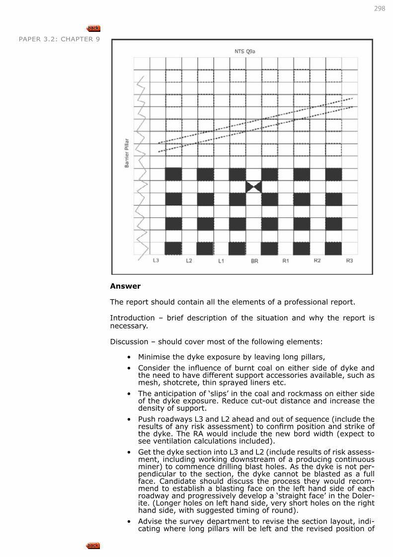
298
PAPER 3.2: CHAPTER 9
Answer
The report should contain all the elements of a professional report.
Introduction – brief description of the situation and why the report is necessary.
Discussion – should cover most of the following elements:
• Minimise the dyke exposure by leaving long pillars,
• Consider the influence of burnt coal on either side of dyke and the need to have different support accessories available, such as mesh, shotcrete, thin sprayed liners etc.
• The anticipation of ‘slips’ in the coal and rockmass on either side of the dyke exposure. Reduce cut-out distance and increase the density of support.
• Push roadways L3 and L2 ahead and out of sequence (include the results of any risk assessment) to confirm position and strike of the dyke. The RA would include the new bord width (expect to see ventilation calculations included).
• Get the dyke section into L3 and L2 (include results of risk assess-ment, including working downstream of a producing continuous miner) to commence drilling blast holes. As the dyke is not per-pendicular to the section, the dyke cannot be blasted as a full face. Candidate should discuss the process they would recom-mend to establish a blasting face on the left hand side of each roadway and progressively develop a ‘straight face’ in the Doler-ite. (Longer holes on left hand side, very short holes on the right hand side, with suggested timing of round).
• Advise the survey department to revise the section layout, indi-cating where long pillars will be left and the revised position of
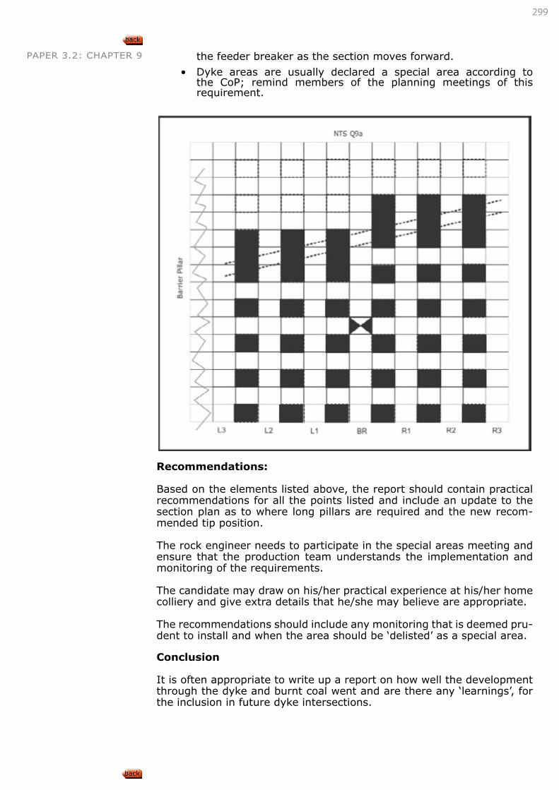
299
PAPER 3.2: CHAPTER 9 the feeder breaker as the section moves forward.
• Dyke areas are usually declared a special area according to the CoP; remind members of the planning meetings of this requirement.
Recommendations:
Based on the elements listed above, the report should contain practical recommendations for all the points listed and include an update to the section plan as to where long pillars are required and the new recom-mended tip position.
The rock engineer needs to participate in the special areas meeting and ensure that the production team understands the implementation and monitoring of the requirements.
The candidate may draw on his/her practical experience at his/her home colliery and give extra details that he/she may believe are appropriate.
The recommendations should include any monitoring that is deemed pru-dent to install and when the area should be ‘delisted’ as a special area.
Conclusion
It is often appropriate to write up a report on how well the development through the dyke and burnt coal went and are there any ‘learnings’, for the inclusion in future dyke intersections.
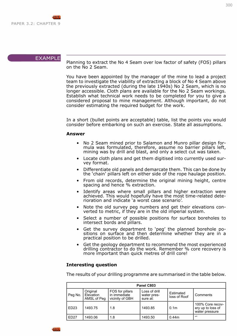
300
PAPER 3.2: CHAPTER 9
Planning to extract the No 4 Seam over low factor of safety (FOS) pillars on the No 2 Seam.
You have been appointed by the manager of the mine to lead a project team to investigate the viability of extracting a block of No 4 Seam above the previously extracted (during the late 1940s) No 2 Seam, which is no longer accessible. Cloth plans are available for the No 2 Seam workings. Establish what technical work needs to be completed for you to give a considered proposal to mine management. Although important, do not consider estimating the required budget for the work.
In a short (bullet points are acceptable) table, list the points you would consider before embarking on such an exercise. State all assumptions.
Answer
• No 2 Seam mined prior to Salamon and Munro pillar design for-mula was formulated, therefore, assume no barrier pillars left, mining was by drill and blast, and only a select cut was taken.
• Locate cloth plans and get them digitised into currently used sur-vey format.
• Differentiate old panels and demarcate them. This can be done by the ‘chain’ pillars left on either side of the rope haulage position.
• From old records, determine the original mining height, centre spacing and hence % extraction.
• Identify areas where small pillars and higher extraction were achieved. This would hopefully have the most time-related dete-rioration and indicate ‘a worst case scenario’.
• Note the old survey peg numbers and get their elevations con-verted to metric, if they are in the old imperial system.
• Select a number of possible positions for surface boreholes to intersect bords and pillars.
• Get the survey department to ‘peg’ the planned borehole po-sitions on surface and then determine whether they are in a practical position to be drilled.
• Get the geology department to recommend the most experienced drilling contractor to do the work. Remember % core recovery is more important than quick metres of drill core!
Interesting question
The results of your drilling programme are summarised in the table below.
Panel C803
Peg No.OriginalElevationAMSL of Peg
FOS for pillars in immediate vicinity of GBH
Loss of drill water pres-sure at:
Estimated loss of Roof Comments
ED23 1493.75 1.8 1493.85 0.1m100% Core recov-ery up to loss of water pressure
ED27 1493.06 1.8 1493.50 0.44m “”
EXAMPLE
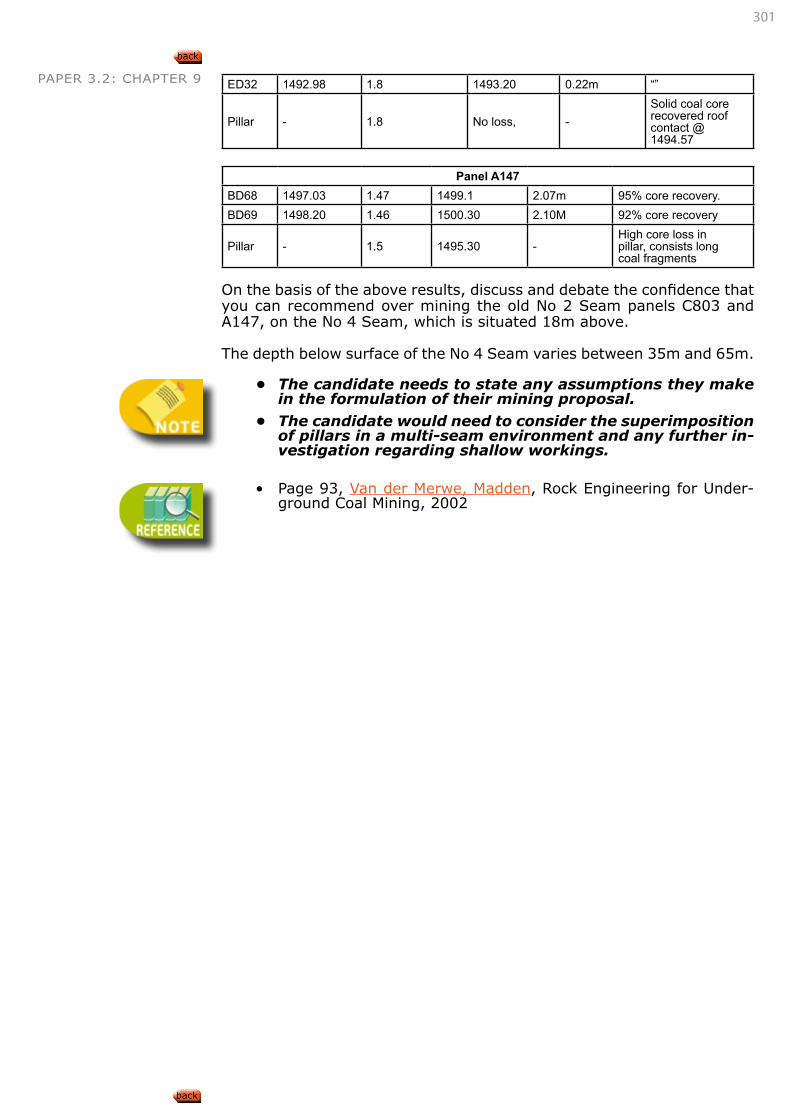
301
PAPER 3.2: CHAPTER 9 ED32 1492.98 1.8 1493.20 0.22m “”
Pillar - 1.8 No loss, -Solid coal core recovered roof contact @1494.57
Panel A147BD68 1497.03 1.47 1499.1 2.07m 95% core recovery.BD69 1498.20 1.46 1500.30 2.10M 92% core recovery
Pillar - 1.5 1495.30 -High core loss in pillar, consists long coal fragments
On the basis of the above results, discuss and debate the confidence that you can recommend over mining the old No 2 Seam panels C803 and A147, on the No 4 Seam, which is situated 18m above.
The depth below surface of the No 4 Seam varies between 35m and 65m.
• Thecandidateneedstostateanyassumptionstheymakeintheformulationoftheirminingproposal.
• Thecandidatewouldneedtoconsiderthesuperimpositionofpillarsinamulti-seamenvironmentandanyfurtherin-vestigationregardingshallowworkings.
• Page 93, Van der Merwe, Madden, Rock Engineering for Under-
ground Coal Mining, 2002