certificate of conformity
TRANSCRIPT
To verify the availability of the Approved product, please refer to www.approvalguide.com
THIS CERTIFICATE MAY ONLY BE REPRODUCED IN ITS ENTIRETY AND WITHOUT CHANGE
FM Approvals LLC. 1151 Boston-Providence Turnpike, Norwood, MA 02062 USA T: +1 (1) 781 762 4300 F: +1 (1) 781 762 9375 E-mail: [email protected] www.fmapprovals.com
F 347 (Mar 16) Page 1 of 11
CERTIFICATE OF CONFORMITY
1. HAZARDOUS (CLASSIFIED) LOCATION ELECTRICAL EQUIPMENT PER US REQUIREMENTS
2. Certificate No: FM16US0056X
3. Equipment:
(Type Reference and Name) SMV800 Series, SmartLine MultiVariable Transmitter
4. Name of Listing Company: Honeywell International Inc., Field Solutions
5. Address of Listing Company: 512 Virginia Drive
Fort Washington, PA 19034 United States
6. The examination and test results are recorded in confidential report number:
3053864 dated 18th July 2016
7. FM Approvals LLC, certifies that the equipment described has been found to comply with the following
Approval standards and other documents: FM Class 3600:2018, FM Class 3610:2018, FM Class 3611:2018, FM Class 3615:2018, FM Class 3616:2011,
FM Class 3810:2018, ANSI/IEC 60529:2004, ANSI/ISA-60079-0:2013, ANSI/ISA-60079-1:2015, ANSI/ISA-60079-11:2014, ANSI/ISA-60079-15:2013, ANSI/ISA-60079-26:2017, ANSI/ISA-60079-31:2015,
ANSI/ISA-61010-1:2012, ANSI/NEMA 250:2003 8. If the sign ‘X’ is placed after the certificate number, it indicates that the equipment is subject to specific
conditions of use specified in the schedule to this certificate. 9. This certificate relates to the design, examination and testing of the products specified herein. The FM
Approvals surveillance audit program has further determined that the manufacturing processes and quality control procedures in place are satisfactory to manufacture the product as examined, tested and Approved.
Certificate issued by:
28 September 2020 J. E. Marquedant VP, Manager - Electrical Systems
Date
SCHEDULE
to US Certificate Of Conformity No: FM16US0056X
THIS CERTIFICATE MAY ONLY BE REPRODUCED IN ITS ENTIRETY AND WITHOUT CHANGE
FM Approvals LLC. 1151 Boston-Providence Turnpike, Norwood, MA 02062 USA
T: +1 (1) 781 762 4300 F: +1 (1) 781 762 9375 E-mail: [email protected] www.fmapprovals.com
F 347 (Mar 16) Page 2 of 11
10. Equipment Ratings:
Intrinsically Safe (Entity & FISCO) Class I, II, III Division 1, Groups A, B, C, D, E, F and G T4; Intrinsically Safe
(Entity & FISCO) Class I, Zone 0, AEx ia IIC T4 Ga; Intrinsically Safe (Entity & FISCO) Class I, Zone 2, AEx ic IIC T4 Gc; Explosionproof Class I, Division 1, Groups A, B, C and D T6…T5; Flameproof Class I, Zone 1, AEx db IIC T6…T5 Gb; Flameproof Class I, Zone 0/1, AEx db IIC T6…T5 Ga/Gb; Dust Ignitionproof Class II, III, Division 1, Groups E, F and G T6…T5; Protection by Enclosure Zone 21, AEx tb IIIC T95°C Db; Nonincendive Class I, Division 2, Groups A, B, C and D, T4 and Non-Sparking Class I, Zone 2, AEx nA T4 Gc hazardous (classified) locations, indoor and outdoor (Type 4X; IP66, IP67) environments.
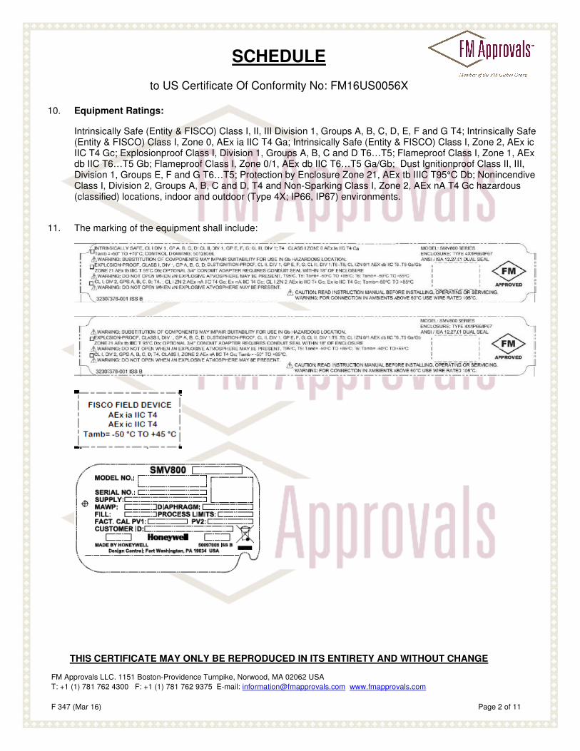
11. The marking of the equipment shall include:
SCHEDULE
to US Certificate Of Conformity No: FM16US0056X
THIS CERTIFICATE MAY ONLY BE REPRODUCED IN ITS ENTIRETY AND WITHOUT CHANGE
FM Approvals LLC. 1151 Boston-Providence Turnpike, Norwood, MA 02062 USA
T: +1 (1) 781 762 4300 F: +1 (1) 781 762 9375 E-mail: [email protected] www.fmapprovals.com
F 347 (Mar 16) Page 3 of 11
12. Description of Equipment:
General – The SMV800 Series SmartLine Multivariable Transmitter is intended to be used as a modular designed
universal level, pressure, flow, and temperature measuring transmitter for the compensated flow measurement of three separate process variables by combining sensor technologies for differential pressure, static pressure and temperature for air, gases, steam and liquids, and is suitable for applications with process temperatures up to +125 ºC (+257 ºF) and high process pressures up to 20.7 MPa (3,000 psig). Available with optional angle or flat mounting bracket, it detects a process pressure or differential process pressure and converts it into an electrical output signal. Field-exchangeable communication modules to deploy HARTTM, Honeywell Digital Enhanced (DE), FOUNDATION Fieldbus, Profibus or MODBUS communication. The instrument can be used in vessels, pipelines and steam generators as an empty or full detector.
The SmartLine Multivariable SMA810 flow transmitter is an absolute pressure based multivariable flow transmitter
suitable for lower differential pressure (PV1-DP, -25 to 25 inch H2O and -62.5 to 62.5 mbar; 0.04 % accuracy) & static pressure (PV2-AP, 0 to 100 psia and 0 to 7 bara; 0.0375 % accuracy) device lower/upper range applications, and temperature specific (PV3-Temp, -200 ºC to +850 ºC resistance temperature detectors; -250 ºC to +1820 ºC thermocouples; ±0.1 ºC to ±0.6 ºC digital accuracy) applications. The flow variable (PV4-Comp Flow) is the combination of the differential pressure (PV1-DP), static pressure (PV2-AP), and temperature specific (PV3-Temp) inputs and a few flow constants. There are approximately 40 different equations for flow which may be configured by the end-user, depending upon specific needs.
The SmartLine Multivariable SMA845 flow transmitter is an absolute pressure based multivariable flow transmitter
suitable for wider differential pressure (PV1-DP, -400 to 400 inch H2O and -1,000 to 1,000 mbar; 0.04 % accuracy) & static pressure (PV2-AP, 0 to 1,500 psia and 0 to 104 bara; 0.0375 % accuracy) device lower/upper range applications, and temperature specific (PV3-Temp, -200 ºC to +850 ºC resistance temperature detectors; -250 ºC to +1820 ºC thermocouples; ±0.1 ºC to ±0.6 ºC digital accuracy) applications. The flow variable (PV4-Comp Flow) is the combination of the differential pressure (PV1-DP), static pressure (PV2-AP), and temperature specific (PV3-Temp) inputs and a few flow constants. There are approximately 40 different equations for flow which may be configured by the end-user, depending upon specific needs.
The SmartLine Multivariable SMG870 flow transmitter is a gauge pressure based multivariable flow transmitter
suitable for wider differential pressure (PV1-DP, -400 to 400 inch H2O and -1,000 to 1,000 mbar; 0.04 % accuracy) & static pressure (PV2-AP, -14.7 to 3,000 psig and -1 to 207 barg; 0.0375 % accuracy) device lower/upper range applications, and temperature specific (PV3-Temp, -200 ºC to +850 ºC resistance temperature detectors; -250 ºC to +1820 ºC thermocouples; ±0.1 ºC to ±0.6 ºC digital accuracy) applications. The flow variable (PV4-Comp Flow) is the combination of the differential pressure (PV1-DP), static pressure (PV2-AP), and temperature specific (PV3-Temp) inputs and a few flow constants. There are approximately 40 different equations for flow which may be configured by the end-user, depending upon specific needs.
Each SmartLine multivariable transmitter may be provided with or without an internal modular basic or advanced
digital display. Where remote display viewing is required by the end-user, Fieldbus Intrinsically Safe Concept allows a combination of up to ten compact integral versions of the SmartLine multivariable transmitter, each with or without an internal display, to be configured in daisy chain wiring configuration to functionally operate in remote display arrangement from one another within the overall system assembly.
Construction – The SmartLine multivariable transmitter is constructed from one of two different double chamber
enclosure versions, each with an additional accessible compartment and slide plate cover arrangement which houses an optional snap-in configured hermetically sealed three-button magnetic reed switch assembly for local configuration for HARTTM, Honeywell Digital Enhanced (DE) and MODBUS operation, permanently attached directly to the meter body of the differential pressure, static pressure and temperature process sensor element.
SCHEDULE
to US Certificate Of Conformity No: FM16US0056X
THIS CERTIFICATE MAY ONLY BE REPRODUCED IN ITS ENTIRETY AND WITHOUT CHANGE
FM Approvals LLC. 1151 Boston-Providence Turnpike, Norwood, MA 02062 USA
T: +1 (1) 781 762 4300 F: +1 (1) 781 762 9375 E-mail: [email protected] www.fmapprovals.com
F 347 (Mar 16) Page 4 of 11
The double chamber enclosure versions with a 14-pin feedthrough connector between chambers is comprised of polyester painted A360 grade aluminum with metric or NPT threaded hubs and two threaded mating end cap covers with or without an inspection display window; or 316 stainless steel casting with metric or NPT threaded hubs and two threaded mating end cap covers with or without an inspection display window.
The base chassis of the aluminum and stainless steel casting enclosures include two lid locks for the double
chamber enclosure version. The front end cap may be comprised of a high-profile or low-profile cover with integral cover locking screw, each of which is equipped with or without a tempered glass inspection window, respectively, for viewing of the 360º rotatable (90º increments position) modular basic or advanced digital display as determined by their application requirements. Accessible behind the optional digital display is the field exchangeable communication module to deploy HARTTM, Honeywell Digital Enhanced (DE), FOUNDATION Fieldbus, Profibus or MODBUS communication; each of which is connected to the process sensor element. The rear low-profile blank end cap cover with integral cover locking screw is provided for accessibility to the field wiring terminal board for standard or advanced lightning-protection applications, and fulfills connection to the primary electronics of the communication module, process sensor element and optional digital display assembly via the feedthrough between chambers.
For the various enclosure designs by unscrewing the rear enclosure end cap cover, the connection terminals to
the signal and supply circuit are accessible. There are two M20 x 1.5 metric or 1/2 inch NPT cable entries in the sides of the enclosure; one of which is sealed with a certified cable gland, where applicable, or rigid conduit, and the other is sealed with a certified blanking plug. The enclosure may be provided with a 1/2 inch NPT Male to 3/4 inch NPT Female adapter for installation versatility. Each of the double chamber enclosures is equipped with an internal and external earthing terminal. The signal and supply circuits are electrically isolated from elements that may be earthed, while the metal elements of the SmartLine multivariable transmitter are electrically connected to earth terminals.
The electronics assemblies of the SmartLine multivariable transmitter are constructed from one of four designs.
The SMV8-D indicates the electronics version for the 2 wire (4-20 mA) analog output design transmitters with superposed Honeywell Digital Enhanced (DE) digital protocol signal. The SMV8-F indicates the electronics version for the transmitters with superposed FOUNDATION Fieldbus digital protocol signal. The SMV8-H indicates the electronics version for the 2 wire (4-20 mA) analog output design transmitters with superposed HARTTM digital protocol signal. The SMV8-P indicates the electronics version for the transmitters with superposed FOUNDATION Fieldbus digital protocol signal. The SMV8-M indicates the electronics for the transmitters with superposed MODBUS protocol signal.
For more specifics concerning construction and description details of the SmartLine multivariable transmitter,
reference the manufacturer’s sales literature and specification sheets. Ratings – The equipment is certified to the following ratings.
The ambient operating temperature range is -50 ºC to +45 ºC (FISCO) or +70 ºC (Entity) in type of protection
intrinsically safe Class/Division and AEx ia IIC apparatus, and -50 ºC to +65 ºC or +85 ºC in types of protection explosionproof/flameproof enclosure and dust-ignitionproof equipment/dust ignition protection by enclosure, and -50 ºC to +85 ºC in types of protection intrinsically safe AEx ic IIC, nonincendive/non-sparking equipment; each when properly mounted and installed.
The differential pressure (PV1-DP) and static pressure (PV2-AP) measurement process temperature range of the
media is -40 ºC to +125 ºC, each depending on the process fitting, with a maximum working pressure range of -0.1 to 20.7 MPa (-14.7 to 3,000 psig).
SCHEDULE
to US Certificate Of Conformity No: FM16US0056X
THIS CERTIFICATE MAY ONLY BE REPRODUCED IN ITS ENTIRETY AND WITHOUT CHANGE
FM Approvals LLC. 1151 Boston-Providence Turnpike, Norwood, MA 02062 USA
T: +1 (1) 781 762 4300 F: +1 (1) 781 762 9375 E-mail: [email protected] www.fmapprovals.com
F 347 (Mar 16) Page 5 of 11
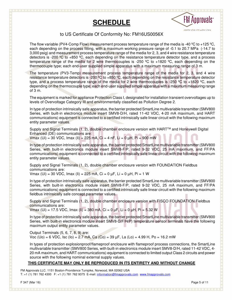
The flow variable (PV4-Comp Flow) measurement process temperature range of the media is -40 ºC to +125 ºC, each depending on the process fitting, with a maximum working pressure range of -0.1 to 20.7 MPa (-14.7 to 3,000 psig) and measurement process temperature range of the media for 2, 3, and 4 wire resistance temperature detectors is -200 ºC to +850 ºC, each depending on the resistance temperature detector type, and a process temperature range of the media for 2 wire thermocouples is -250 ºC to +1820 ºC, each depending on the thermocouple type; each end-user supplied simple apparatus with a maximum measuring range of 3 m.
The temperature (PV3-Temp) measurement process temperature range of the media for 2, 3, and 4 wire
resistance temperature detectors is -200 ºC to +850 ºC, each depending on the resistance temperature detector type, and a process temperature range of the media for 2 wire thermocouples is -250 ºC to +1820 ºC, each depending on the thermocouple type; each end-user supplied simple apparatus with a maximum measuring range of 3 m.
The equipment is marked for appliance Protection Class I, designated for installation transient overvoltages up to
levels of Overvoltage Category III and environmentally classified as Pollution Degree 2. In type of protection intrinsically safe apparatus, the barrier protected SmartLine multivariable transmitter (SMV800
Series, with built-in electronics module insert SMV8-D/H, rated 11-42 VDC, 4-20 mA maximum, and HART communications) equipment is connected to a certified intrinsically safe linear circuit with the following maximum entity parameter values.
Supply and Signal Terminals (1, 2), double chamber enclosure version with HARTTM and Honeywell Digital
Enhanced (DE) communications are: Vmax (Ui) = 30 VDC, Imax (Ii) = 225 mA, Ci = 4 nF, Li = 0 µH, Pi = 900 mW
In type of protection intrinsically safe apparatus, the barrier protected SmartLine multivariable transmitter (SMV800
Series, with built-in electronics module insert SMV8-F/P, rated 9-32 VDC, 25 mA maximum, and FF/PA communications) equipment is connected to a certified intrinsically safe linear circuit with the following maximum entity parameter values.
Supply and Signal Terminals (1, 2), double chamber enclosure version with FOUNDATION Fieldbus
communications are: Vmax (Ui) = 30 VDC, Imax (Ii) = 225 mA, Ci = 0 µF, Li = 0 µH, Pi = 1 W
In type of protection intrinsically safe apparatus, the barrier protected SmartLine multivariable transmitter (SMV800
Series, with built-in electronics module insert SMV8-F/P, rated 9-32 VDC, 25 mA maximum, and FF/PA communications) equipment is connected to a certified intrinsically safe linear circuit with the following maximum fieldbus intrinsically safe concept parameter values.
Supply and Signal Terminals (1, 2), double chamber enclosure version with FISCO FOUNDATION Fieldbus
communications are: Vmax (Ui) = 17.5 VDC, Imax (Ii) = 380 mA, Ci = 0 µF, Li = 0 µH, Pi = 5.32 W
In type of protection intrinsically safe apparatus, the barrier protected SmartLine multivariable transmitter (SMV800
Series, with built-in electronics module insert SMV8-D/F/H/P) temperature sensor terminals have the following maximum output entity parameter values.
Output Terminals (5, 6, 7, 8, 9) are:
Voc (Uo) = 6 VDC, Isc (Io) = 2.7 mA, Ca (Co) = 39 µF, La (Lo) = 4.99 H, Po = 16.2 mW In types of protection explosionproof/flameproof enclosure with flameproof process connections, the SmartLine
multivariable transmitter (SMV800 Series, with built-in electronics module insert SMV8-D/H, rated 11-42 VDC, 4-20 mA maximum, and HART communications) equipment is connected to limited output Class 2 circuits and power source with the following nominal external supply values.
SCHEDULE
to US Certificate Of Conformity No: FM16US0056X
THIS CERTIFICATE MAY ONLY BE REPRODUCED IN ITS ENTIRETY AND WITHOUT CHANGE
FM Approvals LLC. 1151 Boston-Providence Turnpike, Norwood, MA 02062 USA
T: +1 (1) 781 762 4300 F: +1 (1) 781 762 9375 E-mail: [email protected] www.fmapprovals.com
F 347 (Mar 16) Page 6 of 11
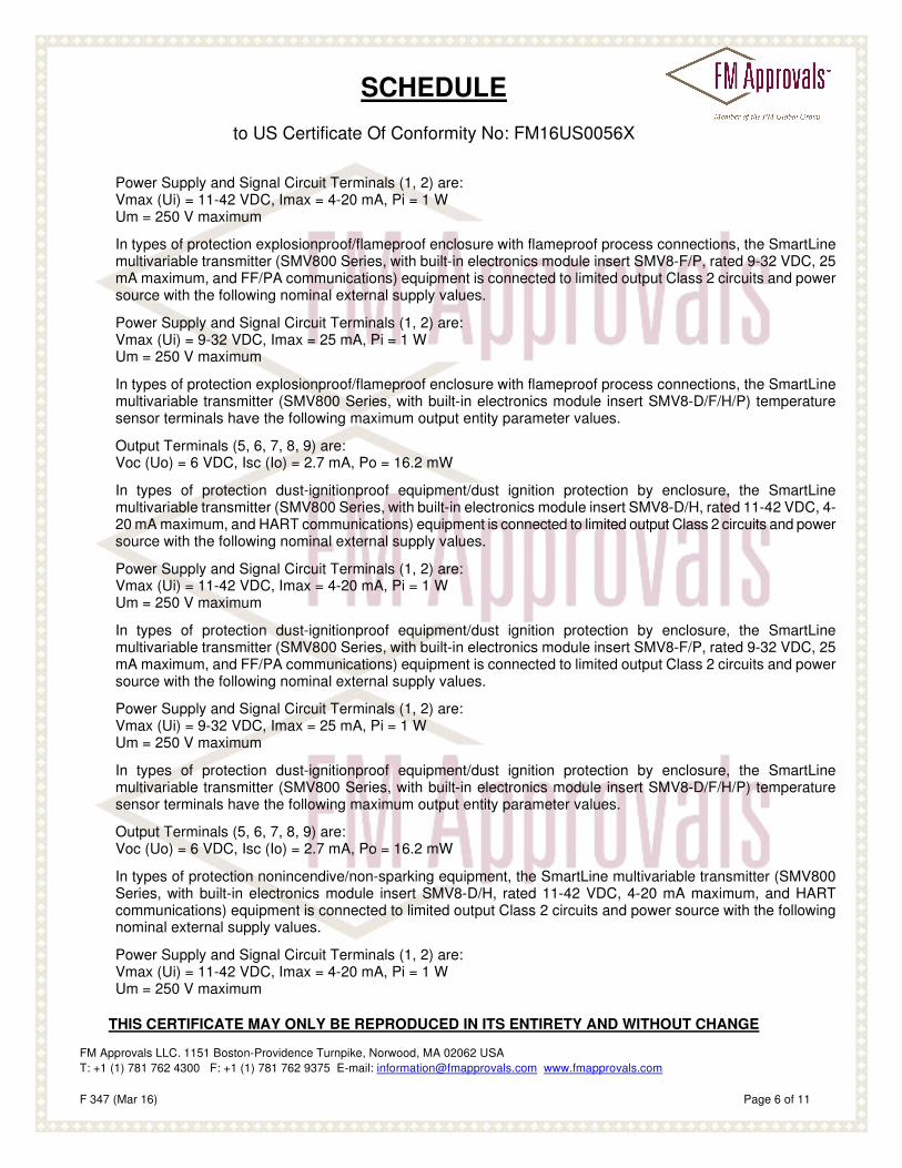
Power Supply and Signal Circuit Terminals (1, 2) are:
Vmax (Ui) = 11-42 VDC, Imax = 4-20 mA, Pi = 1 W Um = 250 V maximum
In types of protection explosionproof/flameproof enclosure with flameproof process connections, the SmartLine
multivariable transmitter (SMV800 Series, with built-in electronics module insert SMV8-F/P, rated 9-32 VDC, 25 mA maximum, and FF/PA communications) equipment is connected to limited output Class 2 circuits and power source with the following nominal external supply values.
Power Supply and Signal Circuit Terminals (1, 2) are:
Vmax (Ui) = 9-32 VDC, Imax = 25 mA, Pi = 1 W Um = 250 V maximum
In types of protection explosionproof/flameproof enclosure with flameproof process connections, the SmartLine
multivariable transmitter (SMV800 Series, with built-in electronics module insert SMV8-D/F/H/P) temperature sensor terminals have the following maximum output entity parameter values.
Output Terminals (5, 6, 7, 8, 9) are:
Voc (Uo) = 6 VDC, Isc (Io) = 2.7 mA, Po = 16.2 mW In types of protection dust-ignitionproof equipment/dust ignition protection by enclosure, the SmartLine
multivariable transmitter (SMV800 Series, with built-in electronics module insert SMV8-D/H, rated 11-42 VDC, 4-20 mA maximum, and HART communications) equipment is connected to limited output Class 2 circuits and power source with the following nominal external supply values.
Power Supply and Signal Circuit Terminals (1, 2) are:
Vmax (Ui) = 11-42 VDC, Imax = 4-20 mA, Pi = 1 W Um = 250 V maximum
In types of protection dust-ignitionproof equipment/dust ignition protection by enclosure, the SmartLine
multivariable transmitter (SMV800 Series, with built-in electronics module insert SMV8-F/P, rated 9-32 VDC, 25 mA maximum, and FF/PA communications) equipment is connected to limited output Class 2 circuits and power source with the following nominal external supply values.
Power Supply and Signal Circuit Terminals (1, 2) are:
Vmax (Ui) = 9-32 VDC, Imax = 25 mA, Pi = 1 W Um = 250 V maximum
In types of protection dust-ignitionproof equipment/dust ignition protection by enclosure, the SmartLine
multivariable transmitter (SMV800 Series, with built-in electronics module insert SMV8-D/F/H/P) temperature sensor terminals have the following maximum output entity parameter values.
Output Terminals (5, 6, 7, 8, 9) are:
Voc (Uo) = 6 VDC, Isc (Io) = 2.7 mA, Po = 16.2 mW In types of protection nonincendive/non-sparking equipment, the SmartLine multivariable transmitter (SMV800
Series, with built-in electronics module insert SMV8-D/H, rated 11-42 VDC, 4-20 mA maximum, and HART communications) equipment is connected to limited output Class 2 circuits and power source with the following nominal external supply values.
Power Supply and Signal Circuit Terminals (1, 2) are:
Vmax (Ui) = 11-42 VDC, Imax = 4-20 mA, Pi = 1 W Um = 250 V maximum
SCHEDULE
to US Certificate Of Conformity No: FM16US0056X
THIS CERTIFICATE MAY ONLY BE REPRODUCED IN ITS ENTIRETY AND WITHOUT CHANGE
FM Approvals LLC. 1151 Boston-Providence Turnpike, Norwood, MA 02062 USA
T: +1 (1) 781 762 4300 F: +1 (1) 781 762 9375 E-mail: [email protected] www.fmapprovals.com
F 347 (Mar 16) Page 7 of 11
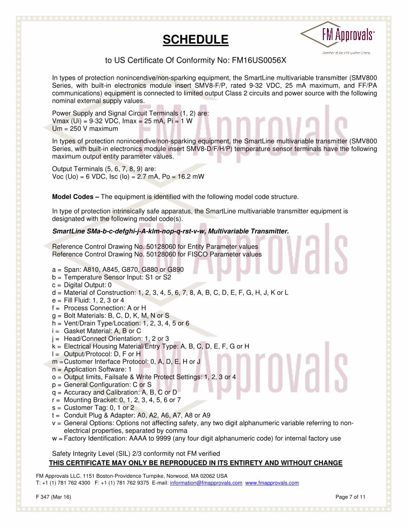
In types of protection nonincendive/non-sparking equipment, the SmartLine multivariable transmitter (SMV800 Series, with built-in electronics module insert SMV8-F/P, rated 9-32 VDC, 25 mA maximum, and FF/PA communications) equipment is connected to limited output Class 2 circuits and power source with the following nominal external supply values.
Power Supply and Signal Circuit Terminals (1, 2) are:
Vmax (Ui) = 9-32 VDC, Imax = 25 mA, Pi = 1 W Um = 250 V maximum
In types of protection nonincendive/non-sparking equipment, the SmartLine multivariable transmitter (SMV800
Series, with built-in electronics module insert SMV8-D/F/H/P) temperature sensor terminals have the following maximum output entity parameter values.
Output Terminals (5, 6, 7, 8, 9) are:
Voc (Uo) = 6 VDC, Isc (Io) = 2.7 mA, Po = 16.2 mW
Model Codes – The equipment is identified with the following model code structure.
In type of protection intrinsically safe apparatus, the SmartLine multivariable transmitter equipment is
designated with the following model code(s). SmartLine SMa-b-c-defghi-j-A-klm-nop-q-rst-v-w, Multivariable Transmitter.
Reference Control Drawing No. 50128060 for Entity Parameter values Reference Control Drawing No. 50128060 for FISCO Parameter values a = Span: A810, A845, G870, G880 or G890 b = Temperature Sensor Input: S1 or S2 c = Digital Output: 0 d = Material of Construction: 1, 2, 3, 4, 5, 6, 7, 8, A, B, C, D, E, F, G, H, J, K or L e = Fill Fluid: 1, 2, 3 or 4 f = Process Connection: A or H g = Bolt Materials: B, C, D, K, M, N or S h = Vent/Drain Type/Location: 1, 2, 3, 4, 5 or 6 i = Gasket Material: A, B or C j = Head/Connect Orientation: 1, 2 or 3 k = Electrical Housing Material/Entry Type: A, B, C, D, E, F, G or H l = Output/Protocol: D, F or H m = Customer Interface Protocol: 0, A, D, E, H or J n = Application Software: 1 o = Output limits, Failsafe & Write Protect Settings: 1, 2, 3 or 4 p = General Configuration: C or S q = Accuracy and Calibration: A, B, C or D r = Mounting Bracket: 0, 1, 2, 3, 4, 5, 6 or 7 s = Customer Tag: 0, 1 or 2 t = Conduit Plug & Adapter: A0, A2, A6, A7, A8 or A9 v = General Options: Options not affecting safety, any two digit alphanumeric variable referring to non-
electrical properties, separated by comma w = Factory Identification: AAAA to 9999 (any four digit alphanumeric code) for internal factory use Safety Integrity Level (SIL) 2/3 conformity not FM verified
SCHEDULE
to US Certificate Of Conformity No: FM16US0056X
THIS CERTIFICATE MAY ONLY BE REPRODUCED IN ITS ENTIRETY AND WITHOUT CHANGE
FM Approvals LLC. 1151 Boston-Providence Turnpike, Norwood, MA 02062 USA
T: +1 (1) 781 762 4300 F: +1 (1) 781 762 9375 E-mail: [email protected] www.fmapprovals.com
F 347 (Mar 16) Page 8 of 11
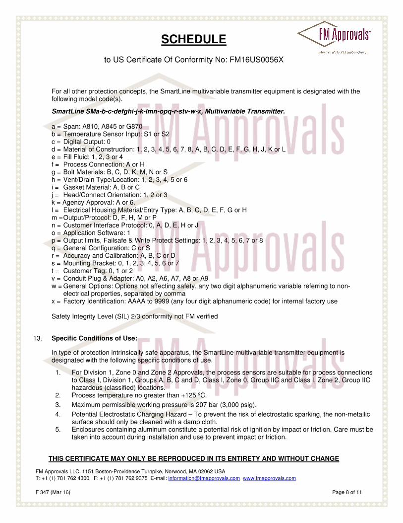
For all other protection concepts, the SmartLine multivariable transmitter equipment is designated with the following model code(s).
SmartLine SMa-b-c-defghi-j-k-lmn-opq-r-stv-w-x, Multivariable Transmitter.
a = Span: A810, A845 or G870 b = Temperature Sensor Input: S1 or S2 c = Digital Output: 0 d = Material of Construction: 1, 2, 3, 4, 5, 6, 7, 8, A, B, C, D, E, F, G, H, J, K or L e = Fill Fluid: 1, 2, 3 or 4 f = Process Connection: A or H g = Bolt Materials: B, C, D, K, M, N or S h = Vent/Drain Type/Location: 1, 2, 3, 4, 5 or 6 i = Gasket Material: A, B or C j = Head/Connect Orientation: 1, 2 or 3 k = Agency Approval: A or 6. l = Electrical Housing Material/Entry Type: A, B, C, D, E, F, G or H m = Output/Protocol: D, F, H, M or P n = Customer Interface Protocol: 0, A, D, E, H or J o = Application Software: 1 p = Output limits, Failsafe & Write Protect Settings: 1, 2, 3, 4, 5, 6, 7 or 8 q = General Configuration: C or S r = Accuracy and Calibration: A, B, C or D s = Mounting Bracket: 0, 1, 2, 3, 4, 5, 6 or 7 t = Customer Tag: 0, 1 or 2 v = Conduit Plug & Adapter: A0, A2, A6, A7, A8 or A9 w = General Options: Options not affecting safety, any two digit alphanumeric variable referring to non-
electrical properties, separated by comma x = Factory Identification: AAAA to 9999 (any four digit alphanumeric code) for internal factory use Safety Integrity Level (SIL) 2/3 conformity not FM verified
13. Specific Conditions of Use:
In type of protection intrinsically safe apparatus, the SmartLine multivariable transmitter equipment is
designated with the following specific conditions of use. 1. For Division 1, Zone 0 and Zone 2 Approvals, the process sensors are suitable for process connections
to Class I, Division 1, Groups A, B, C and D, Class I, Zone 0, Group IIC and Class I, Zone 2, Group IIC hazardous (classified) locations.
2. Process temperature no greater than +125 ºC.
3. Maximum permissible working pressure is 207 bar (3,000 psig).
4. Potential Electrostatic Charging Hazard – To prevent the risk of electrostatic sparking, the non-metallic surface should only be cleaned with a damp cloth.
5. Enclosures containing aluminum constitute a potential risk of ignition by impact or friction. Care must be taken into account during installation and use to prevent impact or friction.
SCHEDULE
to US Certificate Of Conformity No: FM16US0056X
THIS CERTIFICATE MAY ONLY BE REPRODUCED IN ITS ENTIRETY AND WITHOUT CHANGE
FM Approvals LLC. 1151 Boston-Providence Turnpike, Norwood, MA 02062 USA
T: +1 (1) 781 762 4300 F: +1 (1) 781 762 9375 E-mail: [email protected] www.fmapprovals.com
F 347 (Mar 16) Page 9 of 11
6. Instruments installed in dusty hazardous areas must be cleaned regularly to prevent buildup of dust layers. For safe operation, use only wet cloth when cleaning or wiping the device. Cleaning must only be done when local conditions around the device are free of potentially explosive atmospheres. Do not use dry cloth or any solvents.
7. The maximum permitted ambient temperature of the SmartLine multivariable transmitter is +70 ºC for Class I, Division 1 and Zone 0 and +85°C for Class I, Zone 2. To avoid the effects of process temperatures and other thermal effects, care shall be taken to ensure the surrounding ambient temperature and the ambient temperature inside the equipment enclosure does not exceed +70ºC or +85 ºC, respectively. Adherence to the manufacturer’s user’s manual must be followed for fulfillment of this requirement.
In types of protection explosionproof/flameproof enclosure with flameproof process connections, the
SmartLine multivariable transmitter equipment is designated with the following specific conditions of use. 1. For Division 1 and Zone 1 Approvals, the process sensors are suitable for process connections to
Class I, Division 1, Groups A, B, C and D and Class I, Zone 0/1, Group IIC, hazardous (classified) locations.
2. The SmartLine multivariable transmitter can be installed in the boundary wall between an area of EPL Ga/ Class I Zone 0/ Category 1 and the less hazardous area, EPL Gb/ Class I Zone 1/ Category 2. In this configuration, the process connection is installed in EPL Ga/ Class I Zone 0/ Category 1, while the transmitter housing is located in EPL Gb/ Class I Zone 1/ Category 2.
3. Process temperature no greater than +125 ºC.
4. Maximum permissible working pressure is 207 bar (3,000 psig).
5. Potential Electrostatic Charging Hazard – To prevent the risk of electrostatic sparking, the non-metallic surface should only be cleaned with a damp cloth.
6. Enclosures containing aluminum constitute a potential risk of ignition by impact or friction. Care must be taken into account during installation and use to prevent impact or friction.
7. Carbon disulphide is excluded for Ex d installations as the enclosure has a volume greater than 100 cm3.
8. The installer shall provide transient over-voltage protection external to the equipment such that the voltage at the supply terminal of the equipment does not exceed 140 % of the voltage rating of the equipment.
9. The maximum permitted ambient temperature of the SmartLine multivariable transmitter is +65 ºC or +85 ºC, depending upon temperature classification. To avoid the effects of process temperatures and other thermal effects, care shall be taken to ensure the surrounding ambient temperature and the ambient temperature inside the equipment enclosure does not exceed +65 ºC or +85 ºC, respectively. Adherence to the manufacturer’s user’s manual must be followed for fulfillment of this requirement.
10. For information on flameproof joint dimensions and repair, contact the manufacturer using instructions given in the user’s manual.
In types of protection dust-ignitionproof equipment/dust ignition protection by enclosure, the SmartLine
multivariable transmitter equipment is designated with the following specific conditions of use. 1. For Division 1 and Zone 21 Approvals, the process sensors are suitable for process connections to
Class II and III, Division 1, Groups E, F and G and Zone 21, Group IIIC, hazardous (classified) locations.
2. Process temperature no greater than +125 ºC.
3. Maximum permissible working pressure is 207 bar (3,000 psig).
4. Enclosures containing aluminum constitute a potential risk of ignition by impact or friction. Care must be taken into account during installation and use to prevent impact or friction.
SCHEDULE
to US Certificate Of Conformity No: FM16US0056X
THIS CERTIFICATE MAY ONLY BE REPRODUCED IN ITS ENTIRETY AND WITHOUT CHANGE
FM Approvals LLC. 1151 Boston-Providence Turnpike, Norwood, MA 02062 USA
T: +1 (1) 781 762 4300 F: +1 (1) 781 762 9375 E-mail: [email protected] www.fmapprovals.com
F 347 (Mar 16) Page 10 of 11
5. The installer shall provide transient over-voltage protection external to the equipment such that the voltage at the supply terminal of the equipment does not exceed 140 % of the voltage rating of the equipment.
6. Instruments installed in dusty hazardous areas must be cleaned regularly to prevent buildup of dust layers. For safe operation, use only wet cloth when cleaning or wiping the device. Cleaning must only be done when local conditions around the device are free of potentially explosive atmospheres. Do not use dry cloth or any solvents.
7. The maximum permitted ambient temperature of the SmartLine multivariable transmitter is +65 ºC or +85 ºC. To avoid the effects of process temperatures and other thermal effects, care shall be taken to ensure the surrounding ambient temperature and the ambient temperature inside the equipment enclosure does not exceed +65 ºC or +85 ºC, respectively. Adherence to the manufacturer’s user’s manual must be followed for fulfillment of this requirement.
In types of protection nonincendive/non-sparking equipment, the SmartLine multivariable transmitter
equipment is designated with the following specific conditions of use. 1. For Division 2 and Zone 2 Approvals, the process sensors are suitable for non-flammable process
connections to Class I, Division 2, Groups A, B, C and D and Class I, Zone 2, Group IIC, hazardous (classified) locations.
2. Process temperature no greater than +125 ºC.
3. Maximum permissible working pressure is 207 bar (3,000 psig).
4. Potential Electrostatic Charging Hazard – To prevent the risk of electrostatic sparking, the non-metallic surface should only be cleaned with a damp cloth.
5. Enclosures containing aluminum constitute a potential risk of ignition by impact or friction. Care must be taken into account during installation and use to prevent impact or friction.
6. The installer shall provide transient over-voltage protection external to the equipment such that the voltage at the supply terminal of the equipment does not exceed 140 % of the voltage rating of the equipment.
7. The maximum permitted ambient temperature of the SmartLine multivariable transmitter is +85 ºC. To avoid the effects of process temperatures and other thermal effects, care shall be taken to ensure the surrounding ambient temperature and the ambient temperature inside the equipment enclosure does not exceed +85 ºC. Adherence to the manufacturer’s user’s manual must be followed for fulfillment of this requirement.
14. Test and Assessment Procedure and Conditions:
This Certificate has been issued in accordance with FM Approvals US Certification Requirements.
15. Schedule Drawings:
A copy of the technical documentation has been kept by FM Approvals.
SCHEDULE
to US Certificate Of Conformity No: FM16US0056X
THIS CERTIFICATE MAY ONLY BE REPRODUCED IN ITS ENTIRETY AND WITHOUT CHANGE
FM Approvals LLC. 1151 Boston-Providence Turnpike, Norwood, MA 02062 USA
T: +1 (1) 781 762 4300 F: +1 (1) 781 762 9375 E-mail: [email protected] www.fmapprovals.com
F 347 (Mar 16) Page 11 of 11
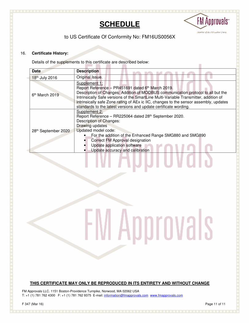
16. Certificate History:
Details of the supplements to this certificate are described below:
Date Description
18th July 2016 Original Issue.
6th March 2019
Supplement 1: Report Reference – PR451691 dated 6th March 2019. Description of Changes: Addition of MODBUS communication protocol to all but the Intrinsically Safe versions of the SmartLine Multi-Variable Transmitter, addition of intrinsically safe Zone rating of AEx ic IIC, changes to the sensor assembly, updates standards to the latest versions and update certificate wording.
28th September 2020
Supplement 2: Report Reference – RR225064 dated 28th September 2020. Description of Changes: Drawing updates Updated model code:
• For the addition of the Enhanced Range SMG880 and SMG890
• Correct FM Approval designation
• Update application software
• Update accuracy and calibration