mechanics – sph1112
TRANSCRIPT
1
SCHOOL OF SCIENCE AND HUMANITIES
DEPARTMENT OF PHYSICS
Mechanics – SPH1112
2
I. Dynamics
Rigid body:
In physics, a rigid body (also known as a rigid object) is a solid body in which deformation is zero
or so small it can be neglected. The distance between any two given points on a rigid body remains
constant in time regardless of external forces exerted on it. A rigid body is usually considered as a
continuous distribution of mass.
When force is applied on a rigid body, there will be no change in the shape or size of the rigid
body. In case of a non-rigid body the force will distort shape and/or size of the body.
Moment of inertia:
What is Inertia? It is the property of a body by virtue of which it resists change in its state of rest or
motion.
What causes inertia in a body?
Inertia in a body is due to it mass. More the mass of a body more is the inertia. For instance, it is easier
to throw a small stone farther than a heavier one. Because the heavier one has more mass, it resists
change more, that is, it has more inertia.
Moment of Inertia Definition
So we have studied that inertia is basically mass. In rotational motion, a body rotates about a fixed
axis. Each particle in the body moves in a circle with linear velocity, that is, each particle moves with
an angular acceleration. Moment of inertia is the property of the body due to which it resists angular
acceleration, which is the sum of the products of the mass of each particle in the body with the square
of its distance from the axis of rotation.
Formula for Moment of Inertia can be expressed as:
∴ Moment of inertia I = Σ miri2
The moment of inertia depends on:
a) mass of the body
b) shape and size of the body
c) distribution of mass about the axis of rotation
All the factors together determine the moment of inertia of a body.
3
we derived expressions of moments of inertia (MI) for different object forms as :
1. For a particle: I = m r 2
2. For a system of particles: I = ∑ m i r i 2
3. For a rigid body: I = ∫ r 2 đ m
Radius of Gyration
As a measure of the way in which the mass of a rotating rigid body is distributed with respect to the
axis of rotation, we define a new parameter known as the radius of gyration. It is related to the moment
of inertia and the total mass of the body.
we can write I = Mk2
where k has the dimension of length.
Therefore, the radius of gyration is the distance from the axis of a mass point whose mass is equal to
the mass of the whole body and whose moment of inertia is equal to the moment of inertia of the body
about the axis. Therefore, the moment of inertia depends not only on the mass, shape, and size of the
body but also the distribution of mass in the body about the axis of rotation.
In this module, we shall evaluate MI of different regularly shaped rigid
bodies:
1. Moment of inertia of a solid cylinder
Moment of inertia of a solid cylinder about its centre can be found using the following equation
or formula;
I = 1/2MR2
Here, M = total mass and R = radius of the cylinder.
Derivation of Moment Of Inertia Of Solid Cylinder
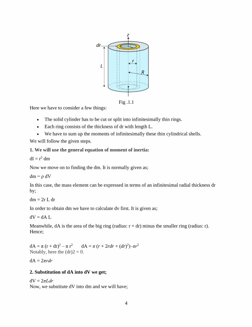
We will take a solid cylinder with mass M, radius R and length L. We will calculate its moment
of inertia about the central axis.
4
Fig .1.1
Here we have to consider a few things:
• The solid cylinder has to be cut or split into infinitesimally thin rings.
• Each ring consists of the thickness of dr with length L.
• We have to sum up the moments of infinitesimally these thin cylindrical shells.
We will follow the given steps.
1. We will use the general equation of moment of inertia:
dI = r2 dm
Now we move on to finding the dm. It is normally given as;
dm = ρ dV
In this case, the mass element can be expressed in terms of an infinitesimal radial thickness dr
by;
dm = 2r L dr
In order to obtain dm we have to calculate dv first. It is given as;
dV = dA L
Meanwhile, dA is the area of the big ring (radius: r + dr) minus the smaller ring (radius: r).
Hence;
dA = π (r + dr)2 – π r2 dA = π (r + 2rdr + (dr)2)–πr2
Notably, here the (dr)2 = 0.
dA = 2πrdr
2. Substitution of dA into dV we get;
dV = 2πLdr
Now, we substitute dV into dm and we will have;
5
dm = 2πLdr
The dm expression is further substituted into the dI equation and we get;
dl = 2πr3Ldr
3. Alternatively, we have to find the expression for density as well. We use the equation;
p = M/V
Now,
p=M/(πR2L)
4. The final step involves using integration to find the moment of inertia of the solid
cylinder. The integration basically takes the form of a polynomial integral form.
I = 2PπrL ∫ 𝑟3𝑅1
𝑅2dr I = 2PπL
𝑟4
4 I = 2π[M/(πR2L)]L
𝑅4
4
Therefore, I = ½ MR2
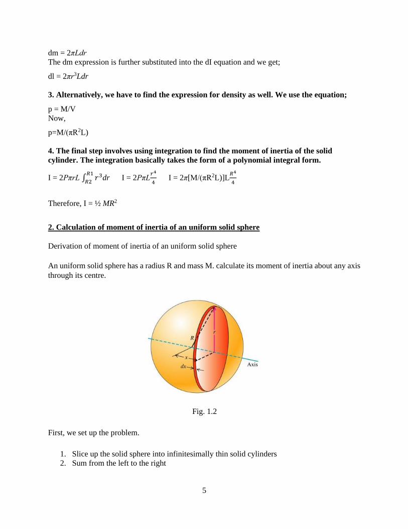
2. Calculation of moment of inertia of an uniform solid sphere
Derivation of moment of inertia of an uniform solid sphere
An uniform solid sphere has a radius R and mass M. calculate its moment of inertia about any axis
through its centre.
Fig. 1.2
First, we set up the problem.
1. Slice up the solid sphere into infinitesimally thin solid cylinders
2. Sum from the left to the right
6
the moment of inertia for a solid cylinder:
I=1
2𝑀𝑅2
Hence, for this problem,
dI=1
2𝑟2𝑑𝑚
Now, we have to find dm,
dm = ρ dV
Finding dV,
dV = πr2dx
Substitute dV into dm,
dm = ρπr2dx
Substitute dm into dI,
dI = (1/2)ρπr4dx
Now, we have to force x into the equation. Notice that x, r and R makes a triangle above. Hence,
using Pythagoras’ theorem,
r2=R2–x2
Substituting,
dI=(1/2)ρπ(R2–x2)2dx
Hence,
I=(1/2)ρπ ∫ (𝑅2 − 𝑥2)2𝑅
−𝑅dx
After expanding out and integrating, you’ll get
I=(1/2)ρπ(16/15)R5
Now, we have to find what is the density of the sphere:
ρ = M/V
ρ= 𝑀
4
3 𝜋𝑟3
Substituting, we will have:
I = (2/5) MR2
3.Calculation of moment of inertia of a thin spherical shell
7
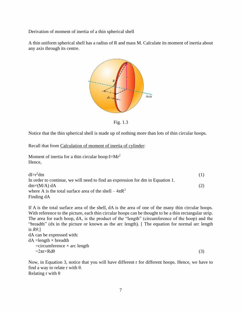
Derivation of moment of inertia of a thin spherical shell
A thin uniform spherical shell has a radius of R and mass M. Calculate its moment of inertia about
any axis through its centre.
Fig. 1.3
Notice that the thin spherical shell is made up of nothing more than lots of thin circular hoops.
Recall that from Calculation of moment of inertia of cylinder:
Moment of inertia for a thin circular hoop:I=Mr2
Hence,
dI=r2dm (1)
In order to continue, we will need to find an expression for dm in Equation 1.
dm=(M/A) dA (2)
where A is the total surface area of the shell – 4πR2
Finding dA
If A is the total surface area of the shell, dA is the area of one of the many thin circular hoops.
With reference to the picture, each thin circular hoops can be thought to be a thin rectangular strip.
The area for each hoop, dA, is the product of the “length” (circumference of the hoop) and the
“breadth” (dx in the picture or known as the arc length). [ The equation for normal arc length
is Rθ.]
dA can be expressed with:
dA =length × breadth
=circumference × arc length
=2πr×Rdθ (3)
Now, in Equation 3, notice that you will have different r for different hoops. Hence, we have to
find a way to relate r with θ.
Relating r with θ
8
Consider the above picture, notice that there is a right-angle triangle with angle θ at the centre of
the circle. Hence,
sinθ=r/R
r=Rsinθ (4)
Substitutions
Hence, using Equation 4 in Equation 3, dA can be expressed by:
dA=2πR2sinθdθ (5)
Substituting the Equation 5 into the Equation 2, we have:
dm = ((Msinθ)/2) dθ (6)
Substituting Equation 6 and the Equation 4 into Equation 1, we have:
dI=(MR2/2) sin3θdθ
Integrating with the proper limits, (from one end to the other)
I= (MR2/2) ∫ 𝑠𝑖𝑛3𝜃𝜋
0dθ
Now, we split the sin3θ into two,
I= (MR2/2) ∫ 𝑠𝑖𝑛2𝜃 sin 𝜃𝜋
0dθ
I= (MR2/2) ∫ (1 − 𝑐𝑜𝑠2𝜃) sin 𝜃𝜋
0dθ
Now, at this point, we will use the substitution: u= cosθ. Hence,
I= (MR2/2) ∫ 𝑢2 − 1 −1
1du (7)
I= (2/3) MR2 (8)
Compound Pendulum: Measurement of acceleration due to gravity (g) by a
compound pendulum
OBJECTIVE:
Use the compound pendulum to find:
1) The acceleration due to gravity g.
2) The moment of inertia of the rod.
THEORY:
Any object mounted on a horizontal axis so as to oscillate under the force of gravity is a compound
pendulum. The one used in this experiment is a uniform rod suspended at different locations along
9
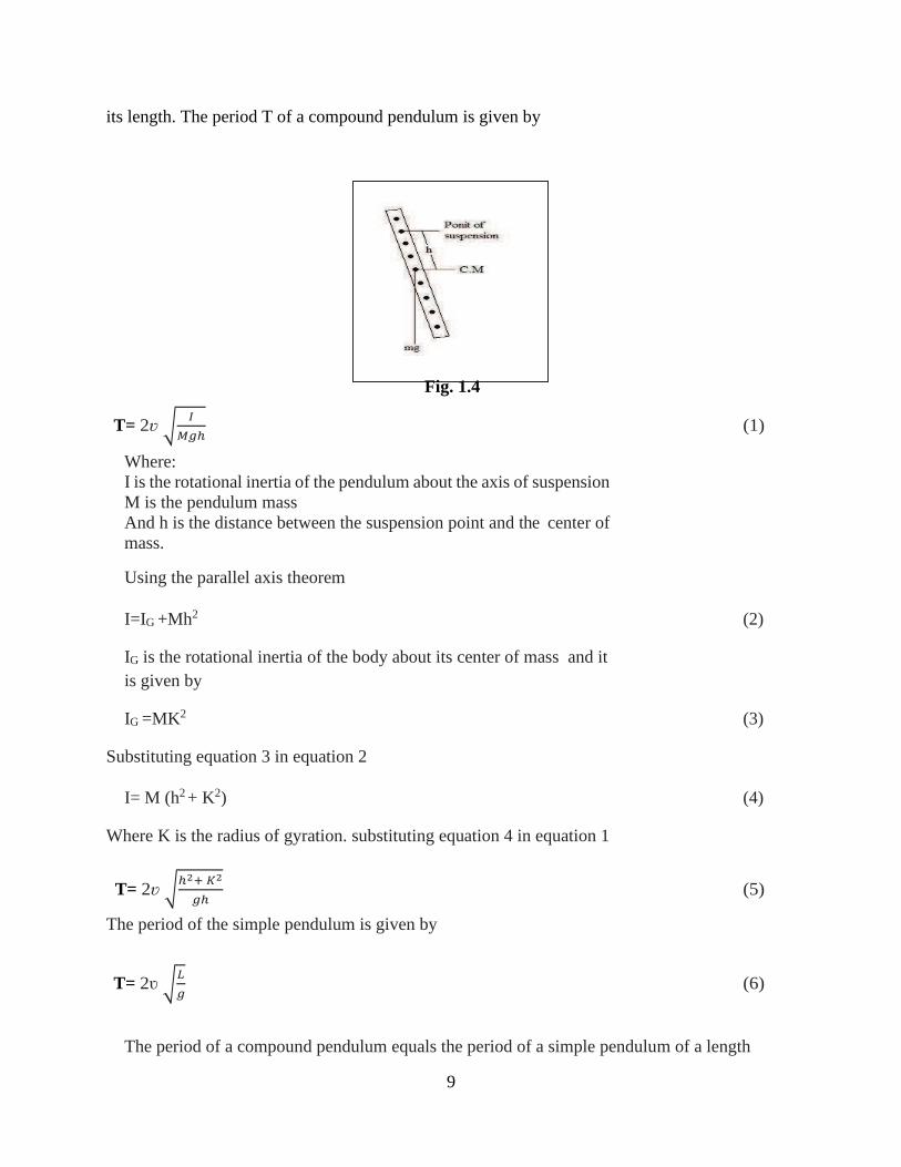
its length. The period T of a compound pendulum is given by
Fig. 1.4
T= 2ʋ √𝐼
𝑀𝑔ℎ (1)
Where:
I is the rotational inertia of the pendulum about the axis of suspension
M is the pendulum mass
And h is the distance between the suspension point and the center of
mass.
Using the parallel axis theorem
I=IG +Mh2 (2)
IG is the rotational inertia of the body about its center of mass and it
is given by
IG =MK2 (3)
Substituting equation 3 in equation 2
I= M (h2 + K2) (4)
Where K is the radius of gyration. substituting equation 4 in equation 1
T= 2ʋ √ℎ2+ 𝐾2
𝑔ℎ (5)
The period of the simple pendulum is given by
T= 2ʋ √𝐿
𝑔 (6)
The period of a compound pendulum equals the period of a simple pendulum of a length
10
L = 𝒉𝟐+ 𝑲𝟐
𝒉 (7)
This equation can be solved to find L and K:
L=h1+h2 (8)
K=√ℎ1ℎ2 (9)
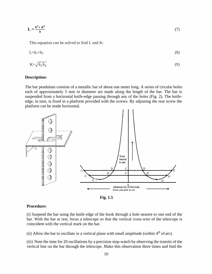
Description:
The bar pendulum consists of a metallic bar of about one meter long. A series of circular holes
each of approximately 5 mm in diameter are made along the length of the bar. The bar is
suspended from a horizontal knife-edge passing through any of the holes (Fig. 2). The knife-
edge, in turn, is fixed in a platform provided with the screws. By adjusting the rear screw the
platform can be made horizontal.
Fig. 1.5
Procedure:
(i) Suspend the bar using the knife edge of the hook through a hole nearest to one end of the
bar. With the bar at rest, focus a telescope so that the vertical cross-wire of the telescope is
coincident with the vertical mark on the bar.
(ii) Allow the bar to oscillate in a vertical plane with small amplitude (within 4o of arc).
(iii) Note the time for 20 oscillations by a precision stop-watch by observing the transits of the
vertical line on the bar through the telescope. Make this observation three times and find the
11
mean time t for 20 oscillations. Determine the time period T.
(iv) Measure the distance d of the axis of the suspension, i.e. the hole from one of the edges
of the bar by a meter scale.
(v) Repeat operation (i) to (iv) for the other holes till C.G of the bar is approached where the
time period becomes very large.
(vi) Invert the bar and repeat operations (i) to (v) for each hole starting from the extreme top.
(vii) Draw a graph with the distance d of the holes as abscissa and the time period T as
ordinate. The nature of graph will be as shown in Fig. 3.
Draw the horizontal line ABCDE parallel to the X-axis. Here A, B, D and E represent the point
of intersections of the line with the curves. Note that the curves are symmetrical about a
vertical line which meets the X-axis at the point G, which gives the position of the C.G of the
bar. This vertical line intersects with the line ABCDE at C. Determine the length AD and BE
and find the
length L of the equivalent simple pendulum from
𝐿 = AD + DE / 2.
Find also the time period T corresponding to the line ABCDE and then compute the value of g.
Draw several horizontal lines parallel to X-axis and adopting the above procedure find the value
of g for each horizontal line. Calculate the mean value of g. Alternatively, for each horizontal line
obtain the values of L and T and draw a graph with T2 as abscissa and L as ordinate. The graph
would be a straight line. By taking a convenient point on the graph, g may be calculated.
Similarly, to calculate the value of K, determine the length AC, BC or CD, CE of the
line ABCDE and compute √𝐴𝐶ΧB𝐶 or √𝐶𝐷Χ𝐶𝐸. Repeat the procedure for each horizontal
line. Find the mean of all K.

12
Observations: Table 1-Data for the T versus d graph
Serial no of
holes from one
end
Distance d of
the hole from
one end (cm)
Time for 20
oscillations
(sec)
Mean time t for
20 oscillations
(sec)
Time period
T = t/20 (sec)
One
side of
C.G
1 ….. ….
…. ….
….. …..
2 ….. …..
…… ….
…. ……
3
… …
…… ….
.…. ……
….. ……..
Other
side of
C.G
1 ….. ….
…. ….
….. …..
2 ….. …..
…… ……
…. ……
… …
…… ……
……. ……
….. ……..
13
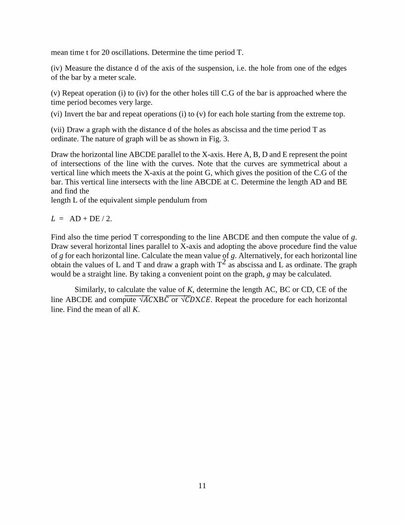
TABLE 2- The value of 𝒈 and K from T vs. d graph
No. of obs. 𝐿
(cm)
T
(sec) 𝑔 = 4𝜋2
𝐿
𝑇2
(cm/sec2)
Mean‘𝑔’
(cm/sec2
)
K
(cm) Mean ‘K’
(cm)
1. ABCDE (AD+BE)/2 .. .. √𝐴𝐶ΧB𝐶
or
2.
3.
..
..
..
..
..
..
√𝐶𝐷Χ𝐶𝐸
..
..
Reversible (Kater's) Pendulum
A physical pendulum with two adjustable knife edges for an accurate determination of "g".
What It Shows:
An important application of the pendulum is the determination of the value of the acceleration
due to gravity. By adding a second knife-edge pivot and two adjustable masses to the physical
pendulum described in the Physical Pendulum demo, the value of g can be determined to 0.2%
precision.
How It Works:
An improvement in the precision of the measurement of g was developed in 1817 by Kater. He
realised that by using a compound pendulum and suspending it from each end in turn the
requirement to measure the distance from the centre of mass to the pivot could be removed. He
made a very accurate measurement of g in London, a value that was used to define the metre
for many years. The version of Kater's reversible pendulum used in this experiment has a knife-
edge for suspension at either end: thus there are two distances, l1 and l2, and two periods T1
and T2.:
Theory
14
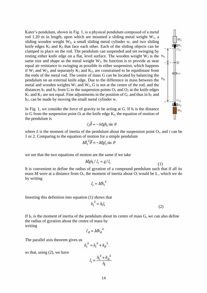
Kater’s pendulum, shown in Fig. 1, is a physical pendulum composed of a metal
rod 1.20 m in length, upon which are mounted a sliding metal weight W1, a
sliding wooden weight W2, a small sliding metal cylinder w, and two sliding
knife edges K1 and K2 that face each other. Each of the sliding objects can be
clamped in place on the rod. The pendulum can suspended and set swinging by
resting either knife edge on a flat, level surface. The wooden weight W2 is the
same size and shape as the metal weight W1. Its function is to provide as near
equal air resistance to swinging as possible in either suspension, which happens
if W1 and W2, and separately K1 and K2, are constrained to be equidistant from
the ends of the metal rod. The centre of mass G can be located by balancing the
pendulum on an external knife edge. Due to the difference in mass between the
metal and wooden weights W1 and W2, G is not at the centre of the rod, and the
distances h1 and h2 from G to the suspension points O1 and O2 at the knife edges
K1 and K2 are not equal. Fine adjustments in the position of G, and thus in h1 and
h2, can be made by moving the small metal cylinder w.
In Fig. 1, we consider the force of gravity to be acting at G. If hi is the distance
to G from the suspension point Oi at the knife edge Ki, the equation of motion of
the pendulum is
where Ii is the moment of inertia of the pendulum about the suspension point Oi, and i can be
1 or 2. Comparing to the equation of motion for a simple pendulum
we see that the two equations of motion are the same if we take
(1)
It is convenient to define the radius of gyration of a compound pendulum such that if all its
mass M were at a distance from Oi, the moment of inertia about Oi would be Ii , which we do
by writing
Inserting this definition into equation (1) shows that
(2)
If IG is the moment of inertia of the pendulum about its centre of mass G, we can also define
the radius of gyration about the centre of mass by
writing
The parallel axis theorem gives us
so that, using (2), we have
15
The period of the pendulum from either suspension point is then
(3)
Squaring (3), one can show that
and in turn,
which allows us to calculate g,
(4)
Applications
Pendulums are used to regulate pendulum clocks, and are used in scientific instruments such
as accelerometers and seismometers. Historically they were used as gravimeters to measure the
acceleration of gravity in geophysical surveys, and even as a standard of length. The problem
with using pendulums proved to be in measuring their length.
A fine wire suspending a metal sphere approximates a simple pendulum, but the wire changes
length, due to the varying tension needed to support the swinging pendulum. In addition, small
amounts of angular momentum tend to creep in, and the centre of mass of the sphere can be
hard to locate unless the sphere has highly uniform density. With a compound pendulum, there
is a point called the centre of oscillation, a distance l from the suspension point along a line
through the centre of mass, where l is the length of a simple pendulum with the same period.
When suspended from the centre of oscillation, the compound pendulum will have the same
period as when suspended from the original suspension point. The centre of oscillation can be
located by suspending from various points and measuring the periods, but it is difficult to get
an exact match in the period, so again there is uncertainty in the value of l.
With equation (4), derived by Friedrich Bessel in 1826, the situation is improved. h1 + h2, being
the distance between the knife edges, can be measured accurately. h1 – h2 is more difficult to
measure accurately, because accurate location of the centre of mass G is difficult. However, if
T1 and T2 are very nearly equal, the second term in (4) is quite small compared to the first, and
h1 – h2 does not have to be known as accurately as h1 + h2.
Kater's pendulum was used as a gravimeter to measure the local acceleration of gravity with
greater accuracy than an ordinary pendulum, because it avoids having to measure l. It was
popular from its invention in 1817 until the 1950’s, when began to be possible to directly
measure the acceleration of gravity during free fall using a Michelson interferometer. Such an
absolute gravimeter is not particularly portable, but it can be used to accurately calibrate a
relative gravimeter consisting of a mass hanging from a spring adjacent to an accurate length
scale. The relative gravimeter can then be carried to any location where it is desired to measure
the acceleration of gravity.
16
Procedure
Real Lab
• Shift the weight W1 to one end of katers pendulum and fix it. Fix the knife edge K1 just below
it.
• Keep the knife edge K2 at the other end and fix the wooden weight W2 symmetrical to other
end. Keep the small weight 'w' near to centre.
• Suspend the pendulum about the knife edge 1 and take the time for about 10 oscillations. Note
down the time t1 using a stopwatch and calculate its time period using equation T1=t1/10.
• Now suspend about knife edge K2 by inverting the pendulum and note the time t2 for 10
oscillations. Calculate T2 also.
• If T2 ≠ 𝑇1, adjust the position of knife edge K2 so that T2 ≈ 𝑇1.
• Balance the pendulum on a sharp wedge and mark the position of its centre of gravity. Measure
the distance of the knife-edge K1 as h1 and that of K2 as h2 from the centre of gravity.
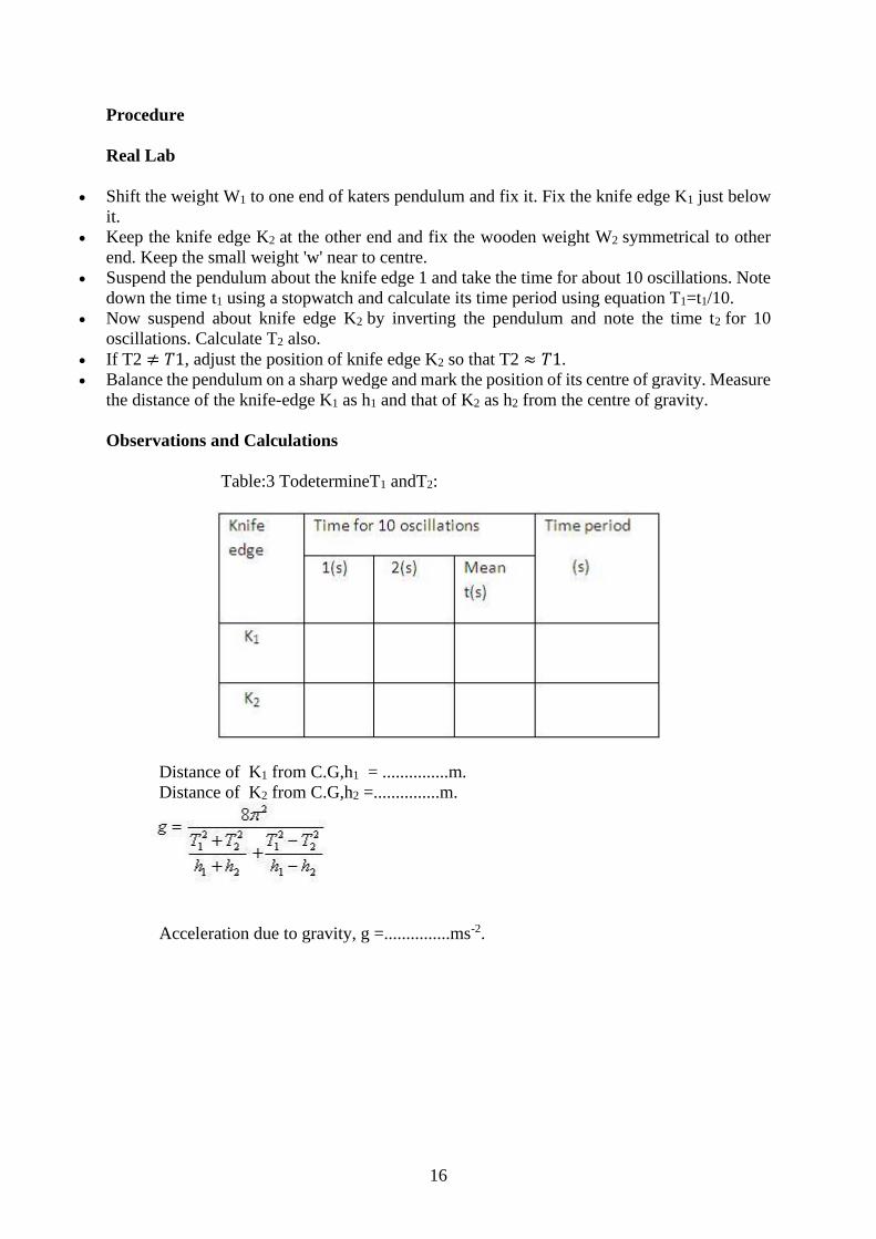
Observations and Calculations
Table:3 TodetermineT1 andT2:
Distance of K1 from C.G,h1 = ...............m.
Distance of K2 from C.G,h2 =...............m.
Acceleration due to gravity, g =...............ms-2.
17
Question Bank:
Part – A
1. Define moment of inertia.
2. What is the role of moment of inertia in rotational motion?
3. What is meant by radius of gyration? What is its physical significance?
4. State the theorem of principle axis and prove it.
5. State the theorem of parallel axis and prove it.
6. Write the analogous parameters in translational and rotational motion.
7. Calculate moment of inertia for a plane laminar body.
8. Evaluate the moment of inertia of a uniform circular disc about a diameter.
9. Evaluate the moment of inertia of a solid sphere about a tangent.
10. A solid cylinder of mss 2kg and radium 0.17m is rotating about its axis. Calculate
moment of inertia of the cylinder.
Solution: I = MR2 /2 ; I = (2 x (0.17)2 )/2 = 0.0289 kg-m2 .
11. Define ‘centre of suspension’ and ‘centre of oscillation’.
12. What is a compound pendulum? Write an expression for its time period.
13. Distinguish between a simple and compound pendulum.
14. Give advantages of compound pendulum over simple pendulum in determining the
value of g.
15. What is Kater’s reversible pendulum?
Part – B
1. Define moment of inertia. What is its physical significance? Show that, in rotator
motion, moment of inertia plays the same role as mass does in linear motion.
2. Calculate the moment of inertia of a circular disc (i) about an axis through its centre
and perpendicular to its plane (ii) about a diameter.
3. Find the moment of inertia of a solid cylinder (i) about its own axis of cylindrical
symmetry (ii) about the axis through its centre and perpendicular to its axis of
cylindrical symmetry.
4. Calculate the moment of inertia of a solid sphere (i) about a diameter (ii) about a
tangent.
5. Find the moment of inertia of a hollow sphere (i) about a diameter (ii) about a tangent.
6. Derive an expression for the time period of a compound pendulum and establish the
inter-changeability of the centre of oscillation and suspension.
7. Describe Kater’s reversible pendulum and determining acceleration due to gravity.
18
II. Statics and Hydrostatics
Statics:
Statics is the study of internal and external forces in a structure. Statics is the branch of
mechanics that deals with bodies at rest. The study of systems in which momentum does not
change is called statics, whereas dynamics involves the study of changes in momentum.
It is also defined as the branch of mechanics that is concerned with the analysis of loads
(force and torque, or "moment") acting on physical systems that do not experience an
acceleration (a=0), but rather, are in static equilibrium with their environment. The application
of Newton's second law to a system gives:
F = ma
Where bold font indicates a vector that has magnitude and direction. F is the total of the forces
acting on the system, m is the mass of the system and a is the acceleration of the system.
The summation of forces will give the direction and the magnitude of the acceleration and will
be inversely proportional to the mass. The assumption of static equilibrium of a = 0 leads to:
F= 0
The summation of forces, one of which might be unknown, allows that unknown to be found.
So when in static equilibrium, the acceleration of the system is zero and the system is either at
rest, or its center of mass moves at constant velocity. Likewise the application of the
assumption of zero acceleration to the summation of moments acting on the system leads to:
M = I⍺ = 0
Here, M is the summation of all moments acting on the system, I is the moment of inertia of
the mass and ⍺ = 0 the angular acceleration of the system, which when assumed to be zero
leads to:
M = 0
The summation of moments, one of which might be unknown, allows that unknown to be
found. These two equations together, can be applied to solve for as many as two loads (forces
and moments) acting on the system.
From Newton's first law, this implies that the net force and net torque on every part of the
system is zero. The net forces equaling zero is known as the first condition for equilibrium, and
the net torque equaling zero is known as the second condition for equilibrium.
Centre of gravity:
Centre of gravity, in physics, an imaginary point in a body of matter where, for convenience
in certain calculations, the total weight of the body may be thought to be concentrated. The
concept is sometimes useful in designing static structures (e.g., buildings and bridges) or in
predicting the behaviour of a moving body when it is acted on by gravity.
The center of gravity (not to be confused with center of mass) of a body is a point where the
weight of the body acts and total gravitational torque on the body is zero.
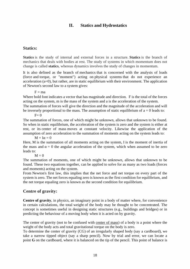
To determine the center of gravity (CG) of an irregularly shaped body (say a cardboard), we
take a narrow tipped object (say a sharp pencil). Now by trial and error, we can locate a
point G on the cardboard, where it is balanced on the tip of the pencil. This point of balance is
19
the center of gravity of the cardboard. The tip of the pencil at G provides the normal
reaction R to the total weight mg of the cardboard. The cardboard is in translational
equilibrium, as R = mg.
Fig. 2.1
Also, the cardboard is in rotational equilibrium because if it were not so, the cardboard would
tilt and fall due to an unbalanced torque. Force of gravity like m1g, m2g, m3g... etc. act on
individual particles of the cardboard. They make up the torque on the cardboard. For its particle
of mass mi, the force of gravity is mi g. If ri is the position vector of this particle from CG of
the cardboard, the torque about the CG is
CG of the cardboard is so located that the total torque on it to forces of gravity on all the
particles is zero. Thus, total torque is:
As g is a non-zero value and same for all particles of the body, so the above equation can be
written as
This is the condition, when center of mass of the body lies at the origin. As position vectors are
taken with respect to the CG, the center of gravity of the body coincides with the center of mass
of the body.
However, if the body is so extended that g varies from part to part of the body, then the center of
gravity will not coincide with center of mass of the body. For a body of small size, having
uniform density throughout, the CG of the body coincides with the center of mass. In case of
solid sphere, both CG and center of mass lie at center of the sphere. For a body of very large
dimensions and having non-uniform density, the center of gravity does not coincide with the
center of mass.
20
3
Uniform solid tetrahedron, pyramid and cone
Definition. A median of a tetrahedron is a line from a vertex to the centroid of the opposite
face.
Theorem I. The four medians of a tetrahedron are concurrent at a point ¾ of the way from a
vertex to the centroid of the opposite face.
Theorem II. The centre of mass of a uniform solid tetrahedron is at the meet of the medians.
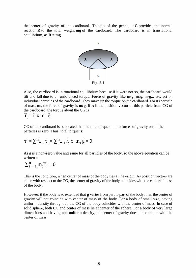
Theorem I can be derived by a similar vector geometric argument used for the plane triangle.
It is slightly more challenging than for the plane triangle, and it is left as an exercise for the
reader. I draw two diagrams (figure 1). One shows the point C1 that is ¾ of the way from the
vertex A to the centroid of the opposite face. The other shows the point C2 that is ¾ of the way
from the vertex B to the centroid of its opposite face. You should be able to show that
C1 = (A + B + D)/4.
Fig. 2.2
In fact this suffices to prove Theorem I, because, from the symmetry between A, B and D,
one is bound to arrive at the same expression for the three-quarter way mark on any of the
four medians. But for reassurance you should try to show, from the second figure, that
C2 = (A + B + D)/4
The argument for Theorem II is easy, and is similar to the corresponding argument for plane
triangles.
Pyramid
A right pyramid whose base is a regular polygon (for example, a square) can be considered to
be made up of several tetrahedra stuck together. Therefore, the centre of mass is 3/4 of the
way from the vertex to the mid-point of the base.
Cone
A right circular cone is just a special case of a regular pyramid in which the base is a polygon
with an infinite number of infinitesimal sides. Therefore, the centre of mass of a uniform right
circular cone is 3/4 of the way from the vertex to the centre of the base. We can also find the
position of the centre of mass of a solid right circular cone by calculus. We can find its volume
by calculus, too, but we'll suppose that we already know, from the theorem of Pappus, that
the volume is 1 base height.
21
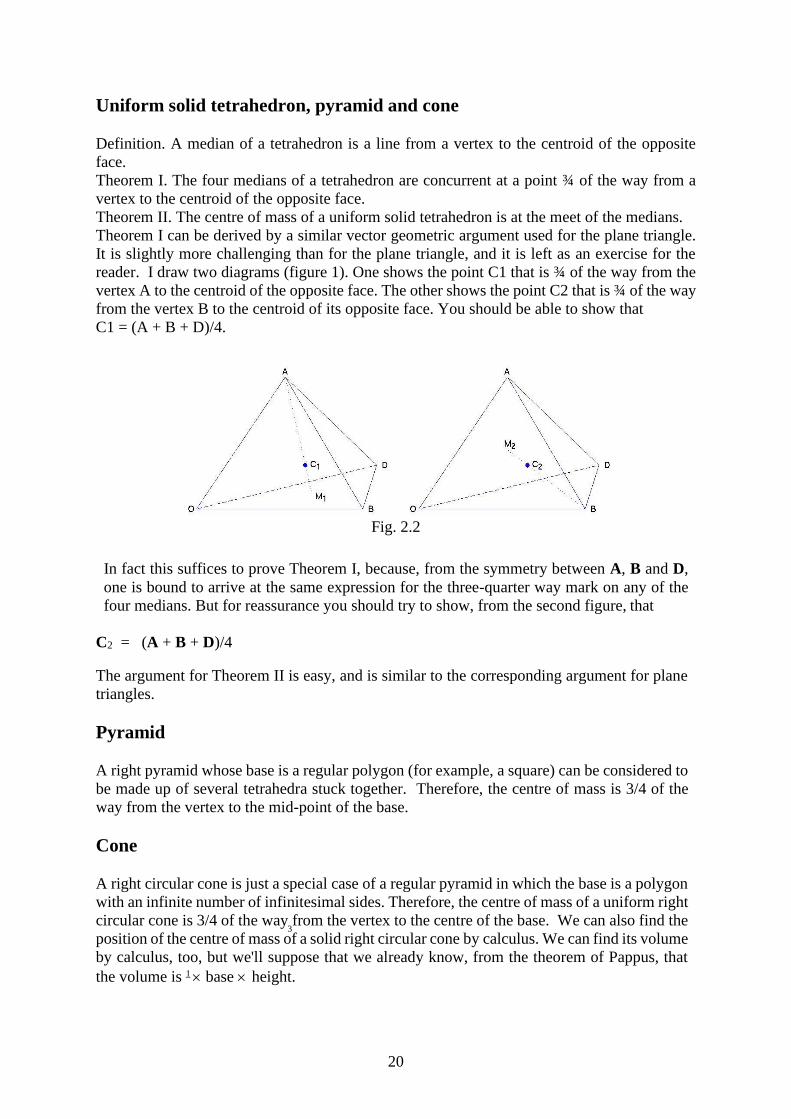
Fig. 2.3
Consider the cone in figure 2.3, generated by rotating the line y = ax/h (between x = 0 and x =
h) through 360o about the x axis. The radius of the elemental slice of thickness x at x is ax/h.
Its volume is a2 x
2x / h
. Since the volume of the entire cone is a2h/3, the mass of the slice
is
M x a2 x
2x / h
2
M ×πa2x2δx
h2 ÷
πa2h
3=
3Mx2δx
h3
where M is the total mass of the cone. The first moment of mass of the elemental slice with
respect to the y axis is 3Mx3x/h3.
The position of the centre of mass is therefore
�̅� =3
ℎ3 ∫ 𝑥3𝑑𝑥 = 3
4ℎ
ℎ
0
Hollow cone:
The surface of a hollow cone can be considered to be made up of an infinite number of
infinitesimally slender isosceles triangles, and therefore the centre of mass of a hollow cone
(without base) is 2/3 of the way from the vertex to the midpoint of the base.
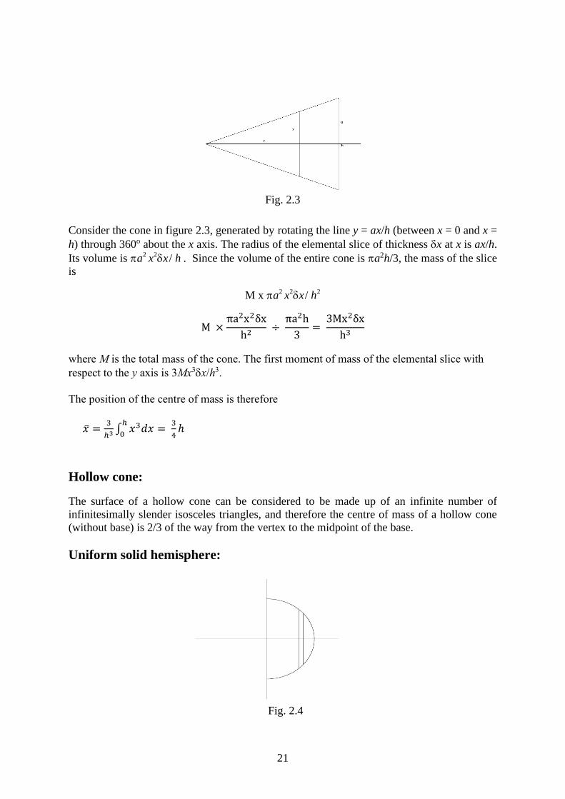
Uniform solid hemisphere:
Fig. 2.4
22
Above Figure will serve. The argument is exactly the same as for the cone. The volume of the elemental slice is y
2x = (a2
− x2 )x, and the volume of the hemisphere is a3/3, so the
mass of the slice is
M × π(a2 − x2)δx ÷ (2πa
3) =
3M(a2− x2)δx
2a3
where M is the mass of the hemisphere. The first moment of mass of the elemental slice is x
times this, so the position of the centre of mass is
�̅� =3
2𝑎3∫ 𝑥 (𝑎2 − 𝑥2)𝑑𝑥 =
3𝑎
8
𝑎
0
We may note to begin with that we would expect the centre of mass to be further from the
base than for a uniform solid hemisphere. Again, figure I.4 will serve. The area of the
elemental annulus is 2ax (NOT 2yx!) and the area of the hemisphere is 2a2.
Therefore the mass of the elemental annulus is
M 2ax (2a2 ) = Mx / a
The first moment of mass of the annulus is x times this, so the position of the centre of mass
is
�̅� = ∫𝑥
𝑎𝑑𝑥 =
𝑎
2
𝑎
0
Triangular lamina: 2/3 of way from vertex to midpoint of opposite side
Solid Tetrahedron, Pyramid, Cone: 3/4 of way from vertex to centroid of opposite face.
Hollow cone: 2/3 of way from vertex to midpoint of base.
Solid hemisphere: 3a/8
Hollow hemisphere: a/2
Centre of Pressure
When the fluid is in static condition, there will not be any relative motion between adjacent
fluid layers. The velocity gradient as well as shear stress will be zero. The forces acting on fluid
particles will be due to pressure of fluid normal to the surface and due to gravity.
Consider a plane surface of arbitrary shape immersed vertically in a static mass of fluid as
shown in Fig. 3.1.
Let,
C = Centre of gravity
P= Centre of pressure
= depth of centre of gravity from free liquid surface 1-1
ℎ̅ = depth of centre of pressure from free surface of liquid 1-1
23
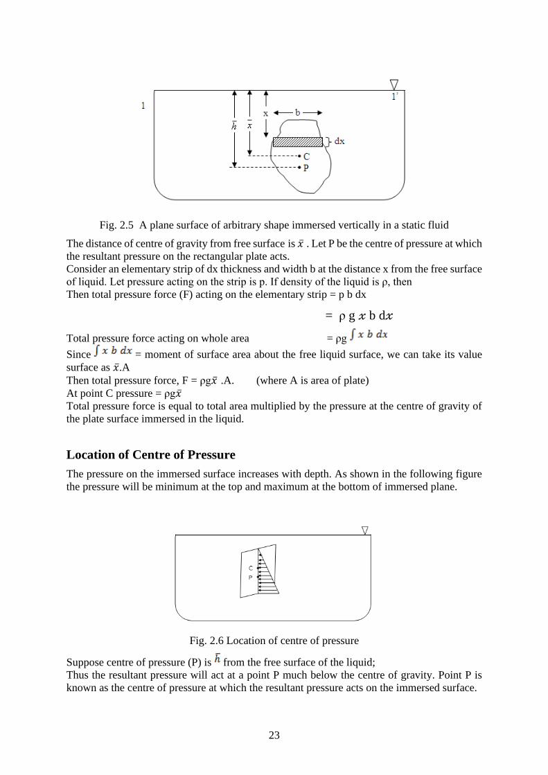
Fig. 2.5 A plane surface of arbitrary shape immersed vertically in a static fluid
The distance of centre of gravity from free surface is �̅� . Let P be the centre of pressure at which
the resultant pressure on the rectangular plate acts.
Consider an elementary strip of dx thickness and width b at the distance x from the free surface
of liquid. Let pressure acting on the strip is p. If density of the liquid is ρ, then
Then total pressure force (F) acting on the elementary strip = p b dx
= ρ g 𝓍 b d𝓍
Total pressure force acting on whole area = ρg
Since = moment of surface area about the free liquid surface, we can take its value
surface as �̅�.A
Then total pressure force, F = ρg�̅� .A. (where A is area of plate)
At point C pressure = ρg�̅�
Total pressure force is equal to total area multiplied by the pressure at the centre of gravity of
the plate surface immersed in the liquid.
Location of Centre of Pressure
The pressure on the immersed surface increases with depth. As shown in the following figure
the pressure will be minimum at the top and maximum at the bottom of immersed plane.
Fig. 2.6 Location of centre of pressure
Suppose centre of pressure (P) is from the free surface of the liquid;
Thus the resultant pressure will act at a point P much below the centre of gravity. Point P is
known as the centre of pressure at which the resultant pressure acts on the immersed surface.
24
Total pressure force acting on the elementary strip = p b d𝓍
= ρ g 𝓍 b d𝓍
Moment of pressure force about free liquid surface = ρg𝓍2 b d𝓍 Total moment of pressure force for entire area = ρg∫ 𝑥2𝑏 𝑑𝑥
Since = moment of inertia of entire surface about free surface 1-1 = Io
Total moment of pressure force for entire area = ρgIo
The sum of moment of pressure force = Fℎ̅
Equating equation (i) & (ii):
Fℎ̅ = ρgIo
ρgA �̅� ℎ̅ = ρgIo
From theorem of parallel axis for moment of inertia we have,
Here,
Ic = moment of inertia of area about an axis passing through centre of gravity.
= distance of centre of gravity from free liquid surface
Placing value of Io into (iii),
Where, Ic is moment of inertia of the immersed figure;
For rectangular surface Ic = 𝑏𝑑3
12 (b= base of rectangle, d= height or depth).
Laws of Floatation:
A body floating freely in a fluid, must obey the following laws known as laws of floatation:
1. A body floats only if its weight is equal to the weight of fluid displaced by its immersed
part.
2. For the body to float in upright position, the centre of gravity of the floating body and
the centre of buoyancy of the fluid displaced by the immersed part of the body must lie
on the same straight line.
1st law stated above is necessary for the body to float whereas the 2nd law stated above
is necessary for the body to float in upright position.
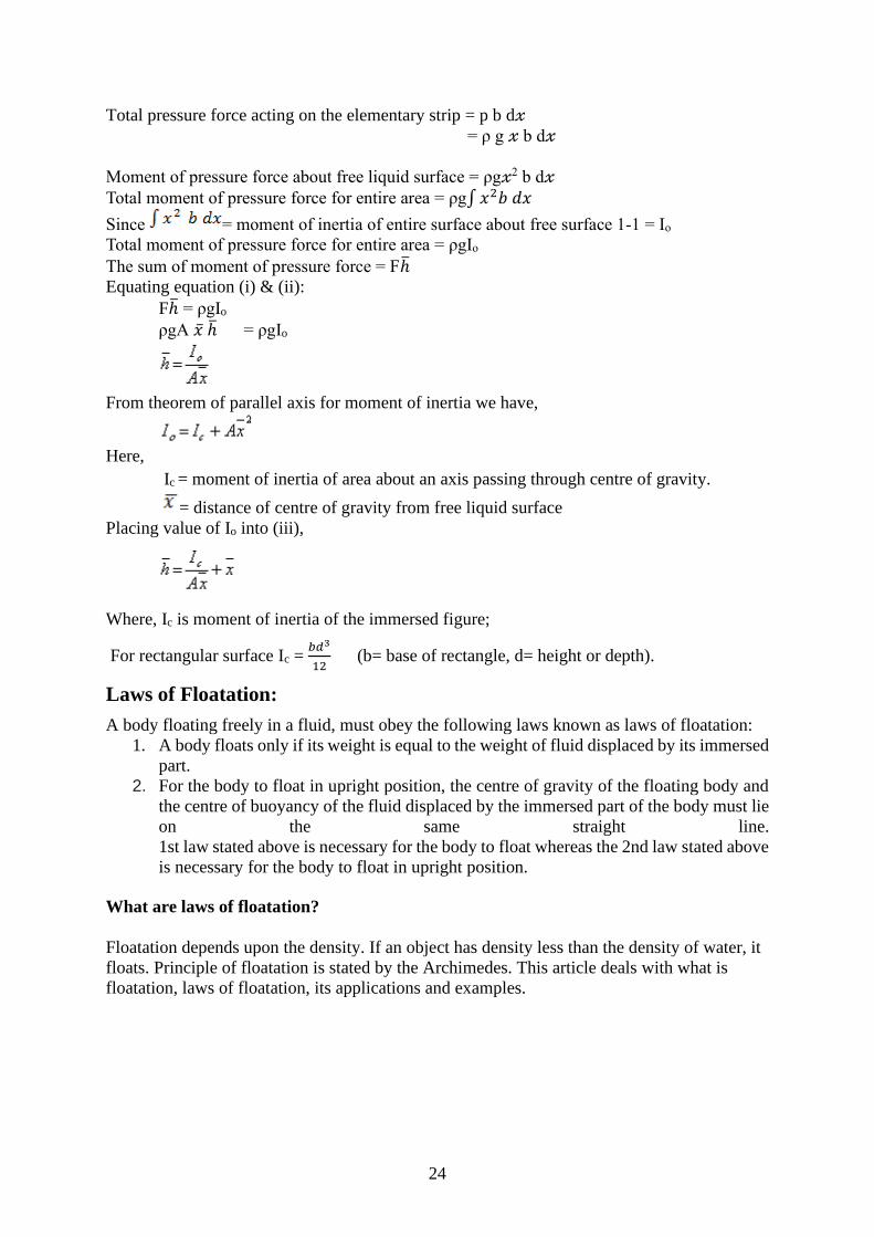
What are laws of floatation?
Floatation depends upon the density. If an object has density less than the density of water, it
floats. Principle of floatation is stated by the Archimedes. This article deals with what is
floatation, laws of floatation, its applications and examples.
25
Fig. 2.6
Archimedes, the Ancient Greek scientist first stated the principle of floatation. According to
him, all the objects placed in a liquid experience an upward force which allows the body to
float if it displaces water with the weight equal to the weight of the body. This upward force is
known as buoyant force and the law is known as the law of buoyancy. Mainly, floatation
depends upon the density. If an object has a density less than the density of water, it floats.
Like, leaf of a plant floats on the water because the density of leaf is less than the density of
water. A stone thrown in water sinks because the density of stone is more than the density of
water.
Have you ever thought that a ship weighing several tons floats while a needle sinks? This can
be explained as follows: A ship is made up of iron and steel, but it has a lot of space filled with
air. This causes the ship to displace water with a weight equal to the weight of the ship. On the
other hand, the needle displaces more water than its weight and hence it sinks.
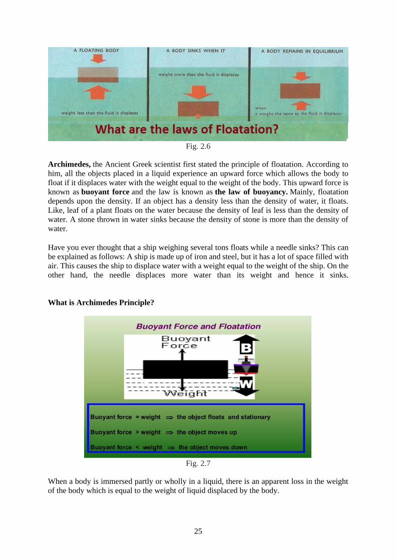
What is Archimedes Principle?
Fig. 2.7
When a body is immersed partly or wholly in a liquid, there is an apparent loss in the weight
of the body which is equal to the weight of liquid displaced by the body.
26
Laws of Floatation
A body floats in a liquid if:
- Density of the material of the body is less than or equal to the density of the liquid.
- If density of material of body is equal to density of liquid, the body floats fully submerged
in liquid in neutral equilibrium.
- When body floats in neutral equilibrium, the weight of the body is equal to the weight of
displaced liquid.
- The centre of gravity of the body and centre of gravity of the displaced liquid should be in
one vertical line.
Centre of Buoyancy: The centre of gravity of the liquid displaced by a body is known as centre
of buoyancy.
Meta centre: When a floating body is slightly tilted from equilibrium position, the centre of
buoyancy shifts. The point at which the vertical line passing through the new position of centre
of buoyancy meets with the initial line is called meta centre.
What are the conditions for stable equilibrium for floating body?
a. The meta centre must always be higher than the centre gravity of the body.
b. The line joining the centre of gravity of the body and centre of floatation should be vertical.
We know density is mass per unit volume. Its S.I unit is kg/m3 and relative density is density
of material per density of water at four degree Celsius. Relative density is measured
by Hydrometer.
- The density of sea water is more than that of normal water. That is why it is easier to swim in
seawater.
- When ice floats in water, its 1/10th the part remain outside the water.
- If ice floating in water in a vessel melts, the level of water in the vessel does not change.
- Purity of milk is measured by lactometer.
From the article we have learnt that what is floatation, how can we swim, why some objects
floats instead of sinking, what are the laws of floatation etc.
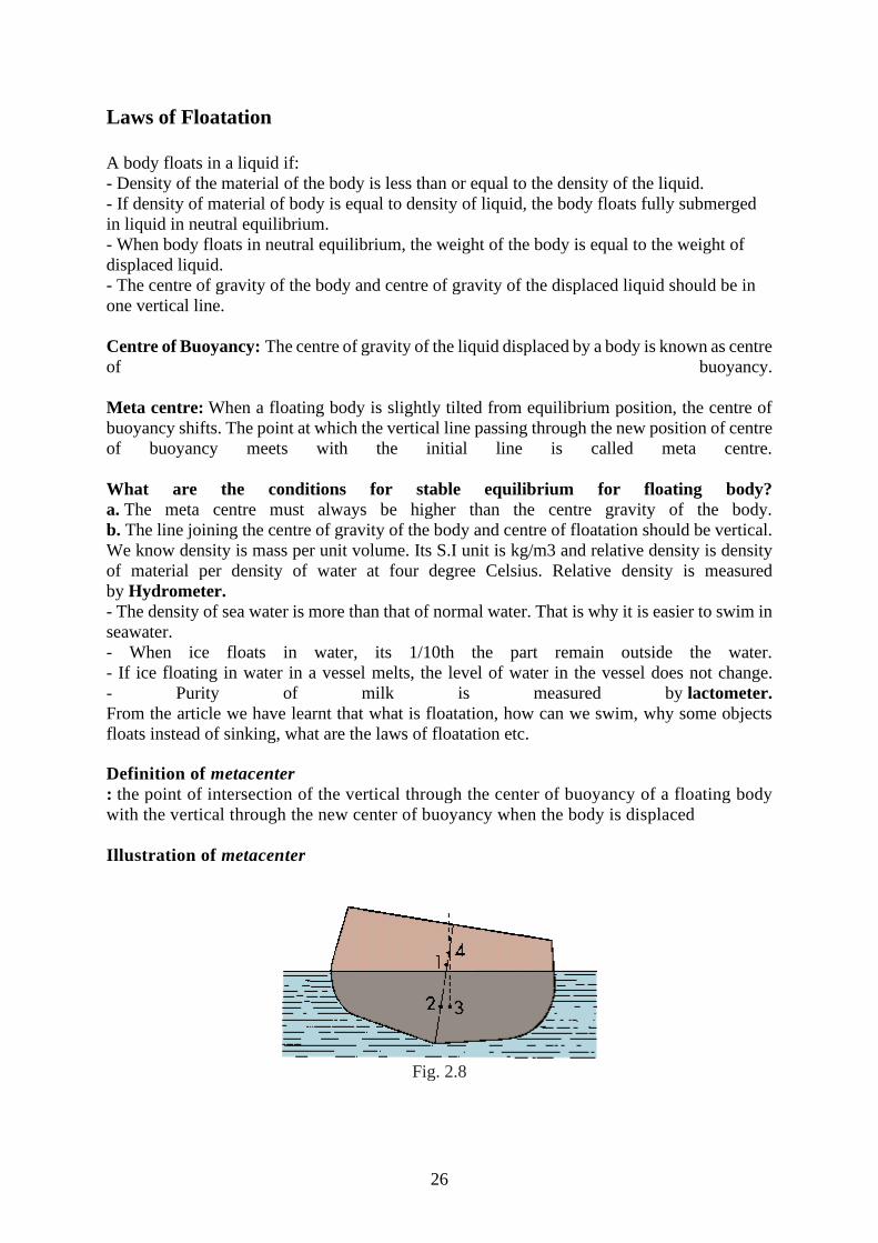
Definition of metacenter
: the point of intersection of the vertical through the center of buoyancy of a floating body
with the vertical through the new center of buoyancy when the body is displaced
Illustration of metacenter
Fig. 2.8
27
metacenter: 1 center of gravity, 2 center of buoyancy, 3 new center of buoyancy when
floating body is displaced, 4 point of intersection
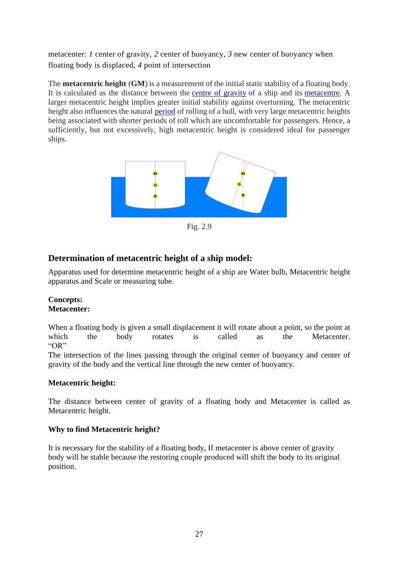
The metacentric height (GM) is a measurement of the initial static stability of a floating body.
It is calculated as the distance between the centre of gravity of a ship and its metacentre. A
larger metacentric height implies greater initial stability against overturning. The metacentric
height also influences the natural period of rolling of a hull, with very large metacentric heights
being associated with shorter periods of roll which are uncomfortable for passengers. Hence, a
sufficiently, but not excessively, high metacentric height is considered ideal for passenger
ships.
Fig. 2.9
Determination of metacentric height of a ship model:
Apparatus used for determine metacentric height of a ship are Water bulb, Metacentric height
apparatus and Scale or measuring tube.
Concepts:
Metacenter:
When a floating body is given a small displacement it will rotate about a point, so the point at
which the body rotates is called as the Metacenter.
“OR”
The intersection of the lines passing through the original center of buoyancy and center of
gravity of the body and the vertical line through the new center of buoyancy.
Metacentric height:
The distance between center of gravity of a floating body and Metacenter is called as
Metacentric height.
Why to find Metacentric height?
It is necessary for the stability of a floating body, If metacenter is above center of gravity
body will be stable because the restoring couple produced will shift the body to its original
position.
28
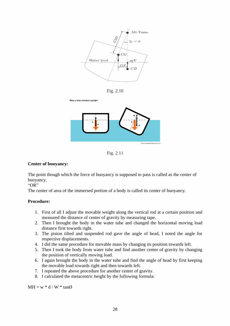
Fig. 2.10
Fig. 2.11
Center of buoyancy:
The point though which the force of buoyancy is supposed to pass is called as the center of
buoyancy.
“OR”
The center of area of the immersed portion of a body is called its center of buoyancy.
Procedure:
1. First of all I adjust the movable weight along the vertical rod at a certain position and
measured the distance of center of gravity by measuring tape.
2. Then I brought the body in the water tube and changed the horizontal moving load
distance first towards right.
3. The piston tilted and suspended rod gave the angle of head, I noted the angle for
respective displacements.
4. I did the same procedure for movable mass by changing its position towards left.
5. Then I took the body from water tube and find another center of gravity by changing
the position of vertically moving load.
6. I again brought the body in the water tube and find the angle of head by first keeping
the movable load towards right and then towards left.
7. I repeated the above procedure for another center of gravity.
8. I calculated the metacentric height by the following formula:
MH = w * d / W * tanØ
29
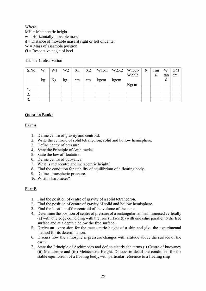
Where
MH = Metacentric height
w = Horizontally movable mass
d = Distance of movable mass at right or left of center
W = Mass of assemble position
Ø = Respective angle of heel
Table 2.1: observation
S.No. W
kg
W1
Kg
W2
kg
X1
cm
X2
cm
W1X1
kgcm
W2X2
kgcm
W1X1-
W2X2
Kgcm
𝜃 Tan 𝜃
W
tan 𝜃
GM
cm
1.
2.
3.
Question Bank:
Part A
1. Define centre of gravity and centroid.
2. Write the centroid of solid tetrahedron, solid and hollow hemisphere.
3. Define centre of pressure.
4. State the Principle of Archimedes
5. State the law of floatation.
6. Define centre of buoyancy.
7. What is metacentre and metacentric height?
8. Find the condition for stability of equilibrium of a floating body.
9. Define atmospheric pressure.
10. What is barometer?
Part B
1. Find the position of centre of gravity of a solid tetrahedron.
2. Find the position of centre of gravity of solid and hollow hemisphere.
3. Find the location of the centroid of the volume of the cone.
4. Determine the position of centre of pressure of a rectangular lamina immersed vertically
(a) with one edge coinciding with the free surface (b) with one edge parallel to the free
surface and at a depth c below the free surface.
5. Derive an expression for the metacentric height of a ship and give the experimental
method for its determination.
6. Discuss how the atmospheric pressure changes with altitude above the surface of the
earth.
7. State the Principle of Archimedes and define clearly the terms (i) Centre of buoyancy
(ii) Metacentre and (iii) Metacentric Height. Discuss in detail the conditions for the
stable equilibrium of a floating body, with particular reference to a floating ship
30
III. Frame of Reference
Laws of Mechanics:
The following are the fundamental laws of mechanics:
1.Newton’s first law
2.Newton’s second law
3.newton’s third law
4.Newton’s law of gravitation
5.Law of transmissibility of forces, and
6.Parallelogram law of forces
1.Newton’s first law
It states that everybody continues in its state of rest or of uniform motion in a straight
line unless it is compelled by an external agency acting on it.
This leads to the definition of force as the external agency which changes or tends to change
the state of rest or uniform linear motion of the body.
2.Newton’s second law
It states that the rate of change of momentum of a body is directly proportional to the
impressed force and it takes place in the direction of the force acting on it.
Thus according to this law,
Force ∞ mass x acceleration
F = ma
3.Newton’s third law
It states that for every action ther is an equal and opposite reaction.
Consider the two bodies in contact with each other. Let one body applies a force F on another.
According to this law the second body develops a reactive force R which is equal in magnitude
to force F and acts in the line same as F but in the opposite direction.
4.Newton’s law of gravitation
Everybody attracts the other body. The force of attraction between any two bodies is
dirctly proportional to their masses and inversely proportional to the square of the distance
between them. According to this law the force of attraction between the bodies of mass m1 and
mass m2 at a distance d as shown in fig. is
F=Gm1m2/d2
5.Law of Transmissibility of force
According to this law the state of rest or motion of the rigid body is unaltered if a force
acting on the body is replaced by another force of the same magnitude and direction but acting
anywhere on the body along the line of action of the replaced force.
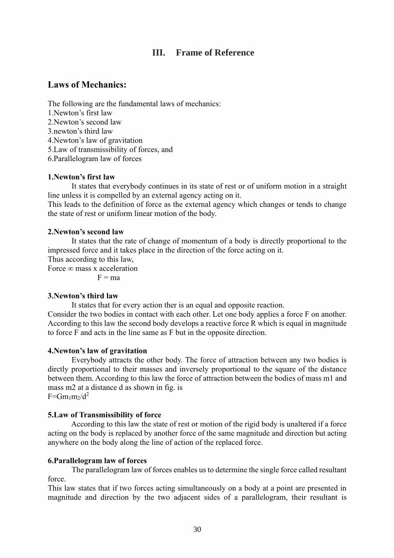
6.Parallelogram law of forces
The parallelogram law of forces enables us to determine the single force called resultant
force.
This law states that if two forces acting simultaneously on a body at a point are presented in
magnitude and direction by the two adjacent sides of a parallelogram, their resultant is
31
represented in magnitude and direction by the diagonal of the parallelogram which passes
through the point of intersection of the two sides representing the forces.
Fig. 3.1
What is a frame of reference?
We have learned about velocity, acceleration, and displacement. But all these quantities need
a frame of reference from which they are measured.
In physics, a frame of reference consists of an abstract coordinate system and the set of physical
reference points that uniquely fix the coordinate system and standardize measurements within
that frame.
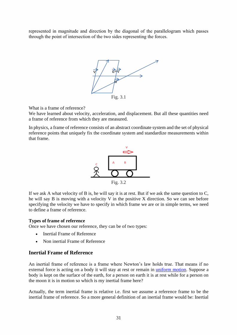
Fig. 3.2
If we ask A what velocity of B is, he will say it is at rest. But if we ask the same question to C,
he will say B is moving with a velocity V in the positive X direction. So we can see before
specifying the velocity we have to specify in which frame we are or in simple terms, we need
to define a frame of reference.
Types of frame of reference
Once we have chosen our reference, they can be of two types:
• Inertial Frame of Reference
• Non inertial Frame of Reference
Inertial Frame of Reference
An inertial frame of reference is a frame where Newton’s law holds true. That means if no
external force is acting on a body it will stay at rest or remain in uniform motion. Suppose a
body is kept on the surface of the earth, for a person on earth it is at rest while for a person on
the moon it is in motion so which is my inertial frame here?
Actually, the term inertial frame is relative i.e. first we assume a reference frame to be the
inertial frame of reference. So a more general definition of an inertial frame would be: Inertial
u
v u+v
32
frame is at rest or moves with constant velocity with respect to my assumed inertial reference
frame.
Inertial frame of reference- the systems in which the Newton’s First law of motion holds
good are called inertial frame of reference.
Example: moving in a car on cruise control
sitting at your desk
Non-inertial Frame of Reference
Now we can define non-inertial frame as a frame which is accelerated with respect to the
assumed inertial frame of reference. Newton’s law will not hold true in these frames. So in the
above example if I assume earth to be an inertial reference frame the moon becomes a non-
inertial reference frame as it is in accelerated motion with respect to earth. But if we want to
make Newton’s law hold here we need to take some mysterious forces also known as pseudo
forces.
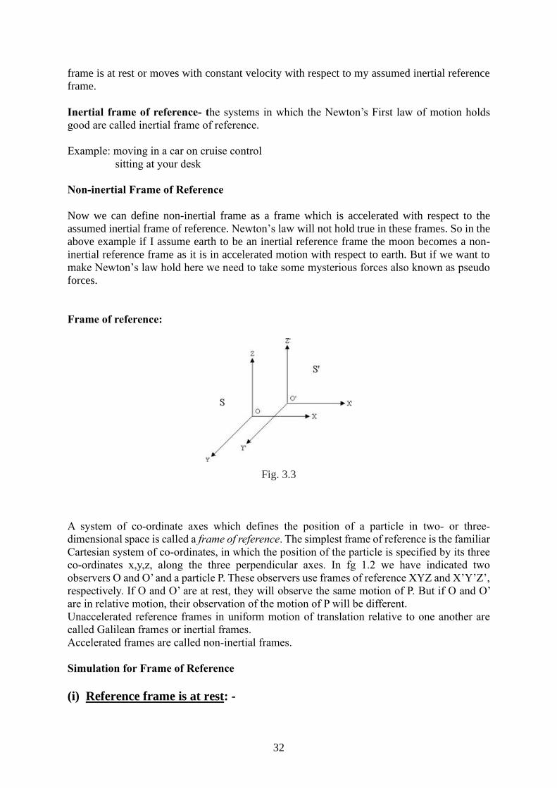
Frame of reference:
Fig. 3.3
A system of co-ordinate axes which defines the position of a particle in two- or three-
dimensional space is called a frame of reference. The simplest frame of reference is the familiar
Cartesian system of co-ordinates, in which the position of the particle is specified by its three
co-ordinates x,y,z, along the three perpendicular axes. In fg 1.2 we have indicated two
observers O and O’ and a particle P. These observers use frames of reference XYZ and X’Y’Z’,
respectively. If O and O’ are at rest, they will observe the same motion of P. But if O and O’
are in relative motion, their observation of the motion of P will be different.
Unaccelerated reference frames in uniform motion of translation relative to one another are
called Galilean frames or inertial frames.
Accelerated frames are called non-inertial frames.
Simulation for Frame of Reference
(i) Reference frame is at rest: -
33
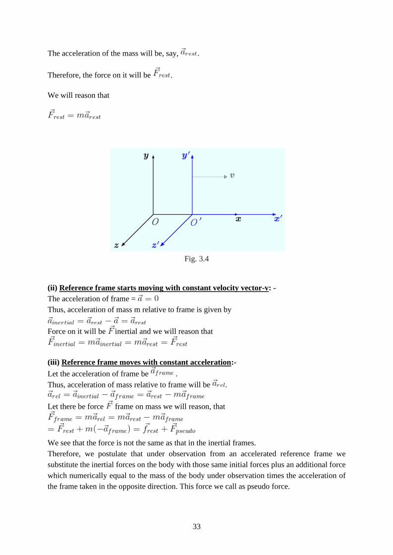
The acceleration of the mass will be, say, .
Therefore, the force on it will be .
We will reason that
Fig. 3.4
(ii) Reference frame starts moving with constant velocity vector-v: -
The acceleration of frame =
Thus, acceleration of mass m relative to frame is given by
Force on it will be inertial and we will reason that
(iii) Reference frame moves with constant acceleration:-
Let the acceleration of frame be .
Thus, acceleration of mass relative to frame will be .
Let there be force frame on mass we will reason, that
We see that the force is not the same as that in the inertial frames.
Therefore, we postulate that under observation from an accelerated reference frame we
substitute the inertial forces on the body with those same initial forces plus an additional force
which numerically equal to the mass of the body under observation times the acceleration of
the frame taken in the opposite direction. This force we call as pseudo force.
34
Newtonian Relativity:
The Newtonian principle of relativity may be stated as “Absolute motion, which is the
translation of a body from one absolute place to another absolute place, can never be detected.
Translatory motion can be perceived only in the form of motion relative to other material
bodies”. This implies that if we are drifting along at a uniform speed in a closed spaceship, all
the phenomena observed and all the experiments performed inside the ship will appear to be
the same as if the ship were not in motion. This means that the fundamental physical laws and
principles are identical in all inertial frames of reference. This is the concept of Newtonian
relativity.
Galilean transformation equations:
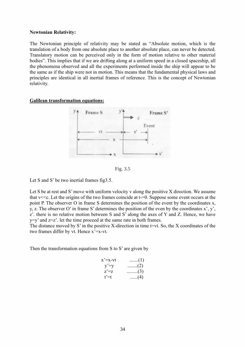
Fig. 3.5
Let S and S’ be two inertial frames fig3.5.
Let S be at rest and S’ move with uniform velocity v along the positive X direction. We assume
that v<<c. Let the origins of the two frames coincide at t-=0. Suppose some event occurs at the
point P. The observer O in frame S determines the position of the event by the coordinates x,
y, z. The observer O’ in frame S’ determines the position of the even by the coordinates x’, y’,
z’. there is no relative motion between S and S’ along the axes of Y and Z. Hence, we have
y=y’ and z=z’. let the time proceed at the same rate in both frames.
The distance moved by S’ in the positive X-direction in time t=vt. So, the X coordinates of the
two frames differ by vt. Hence x’=x-vt.
Then the transformation equations from S to S’ are given by
x’=x-vt .......(1)
y’=y ........(2)
z’=z .........(3)
t’=t ......(4)
P
35
Conservation of momentum
The law of conservation of momentum states that, in the absence of outside forces, the
total momentum of objects that interact does not change.
The amount of momentum is the same before and after they interact.
The total momentum of any group of objects remains the same, or is conserved, unless outside
forces act on the objects.
Friction is an example of an outside force.
The law of conservation of linear momentum states that if no external forces act on the
system of two colliding objects, then the vector sum of the linear momentum of each body
remains constant and is not affected by their mutual interaction.
Alternatively, it states that if net external force acting on a system is zero, the total momentum
of the system remains constant.
Proof:
Let us consider a particle of mass ‘m’ and acceleration ‘a’. Then, from 2nd law of motion,
If no external force acts on the body then, F=0,
Therefore, ‘P’ is constant or conserved.
Deduction of Law of Conservation of linear momentum for two colliding
bodies:
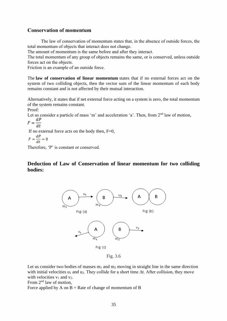
Fig. 3.6
Let us consider two bodies of masses m1 and m2 moving in straight line in the same direction
with initial velocities u1 and u2. They collide for a short time ∆t. After collision, they move
with velocities v1 and v2.
From 2nd law of motion,
Force applied by A on B = Rate of change of momentum of B
36
FAB = (m2v2-m2u2)/∆t
Similarly,
Force applied by B on A = Rate of change of momentum of A
FBA = (m1v1-m1u1)/∆t
From Newton’s 3rd law of motion,
FAB = -FBA
Or, (m2v2-m2u2)/∆t = -(m1v1-m1u1)/∆t
Or, m2v2-m2u2 = -m1v1+m1u1
Or, m1u1 + m2u2 = m1v1 + m2v2
This means the total momentum before collision is equal to total momentum after collision.
This proves the principle of co conservation of linear momentum.
Non-inertial frame of reference:
The systems in which the Newton’s First law of motion does not holds good are called non-
inertial frame of reference.
A frame of reference which is in accelerated motion with respect to an inertial frame is called
non-inertial frame of reference.
Fictitious force:
A fictitious force (also called a pseudo force, d'Alembert force, or inertial force) is a force
that appears to act on a mass whose motion is described using a non-inertial frame of reference,
such as an accelerating or rotating reference frame.
The fictitious force is an apparent force that acts on an object on a moving frame of reference.
This frame of reference could be a car or a rotating frame of reference, like the moon orbiting
the Earth.
The reason why this fictitious force occurs in objects is because of inertia, the resistance of an
object to acceleration. For example, when a person in a car stops at an intersection, then presses
the accelerator, inertia wants the person to be still since the person stopped first before
accelerating. This also applies to rotating objects because the moon experiences centripetal
acceleration, acceleration that keeps an object rotating around a point. However, inertia wants
the object to go in the direction tangent to the circular motion and results in an apparent outward
force. If this property did not exist, then the moon would not even form.
Centrifugal force:
In Newtonian mechanics, the centrifugal force is an inertial force that appears to act on all
objects when viewed in a rotating frame of reference. It is directed away from an axis passing
through the coordinate system's origin and parallel to the axis of rotation.
Coriolis force
The Coriolis force is a pseudo force that operates in all rotating frames. One way to
envision it is to imagine a rotating platform (such as a merry-go-round or a phonograph
turntable) with a perfectly smooth surface and a smooth block sliding inertially across it. The
block, having no (real) forces acting on it, moves in a straight line at constant speed in inertial
space. However, the platform rotates under it, so that to an observer on the platform, the block
appears to follow a curved trajectory, bending in the opposite direction to the motion of the
37
platform. Since the motion is curved, and hence accelerated, there appears, to the observer, to
be a force operating. That pseudoforce is called the Coriolis force.
Derivation of the centrifugal and Coriolis force
Let us start with the principal equation defining angular velocity in three dimensions,
r˙= ω × r.
(This can be derived roughly by considering a centripetal force acting on a particle. Note that
this equation applies symmetrically in inertial and rotating reference frames.)
Notice that we can in fact generalise this statement in terms of r for an arbitrary vector aa that
is known to be fixed in the rotating body.
Transformation between inertial and rotating frames
Now consider a vector aa, which we can write in Cartesian coordinates (fixed within the
body) as
a = ax 𝑖̂ + ay 𝑗̂+az �̂�.
In Newtonian mechanics, scalar quantities must be invariant for any given choice of frame, so
we can say
𝑑𝑎𝑥
𝑑𝑡|I =
𝑑𝑎𝑥
𝑑𝑡|R
where I indicates the value is for the inertial frame, and RR that the value is for the rotating
frame. Equivalent statements apply for ay and az, of course. Hence, any transformation
of aa between frames must be due to changes in the unit vectors of the basis.
Now by the product rule,
𝑑𝑎𝑥
𝑑𝑡|I =
𝑑
𝑑𝑡(ax 𝑖̂ + ay 𝑗̂ + az �̂�)
= (𝑑ax
𝑑𝑡 𝑖̂ +
𝑑ay
𝑑𝑡 𝑗̂ +
𝑑az
𝑑𝑡 �̂� ) + (ax
𝑑�̂�
𝑑𝑡+ ay
𝑑�̂�
𝑑𝑡+ az
𝑑�̂̂�
𝑑𝑡 )
Using the previous equation for angular velocity, we then have
𝑑𝑎𝑥
𝑑𝑡|I = (
𝑑ax
𝑑𝑡 𝑖̂ +
𝑑ay
𝑑𝑡 𝑗̂ +
𝑑az
𝑑𝑡 �̂� ) + ( ax ω × 𝑖̂ + ay ω × 𝑗 ̂+ az ω × �̂�)
= 𝑑𝑎
𝑑𝑡|R + ω × R
38
Now consider a position vector on the surface of a rotating body. We can write
V I = 𝑑𝑟
𝑑𝑡|I =
𝑑𝑟
𝑑𝑡|R + ω × R
and similarly, for a=v I,
𝑑2𝑟
𝑑𝑡2|I = (
𝑑
𝑑𝑡| R + ω ×)2 r
= 𝑑2𝑟
𝑑𝑡2|R + 2 ω × 𝑑𝑟
𝑑𝑡|R + ω × (ω × r).
Forces on body in rotating frame
Now consider a force acting on an object at position r (for example, gravity). Newton's third
law states
F = m 𝑑2𝑟
𝑑𝑡2|I
And so substituting this into the previous equation for 𝑑2𝑟
𝑑𝑡2|I and rearranging we get
Fnet = m 𝑑2𝑟
𝑑𝑡2|R
= F−2mω × vR− mω × (ω×r)
= F−2mω × vR + mω2r.
And here we have it. The second term on the right is the Coriolis force, and the third term is
the centrifugal force (clearly pointing away from the centre of rotation). Any interpretation of
the Coriolis and centrifugal forces then follow naturally from this single important equation.
Coriolis effect and its causes:
Coriolis effect is used to describe the Coriolis force experienced by the moving objects such
that the force is acting perpendicular to the direction of motion and to the axis of rotation.
The earth’s rotation is the main cause for Coriolis effect as the earth rotates faster at the equator
and near the poles the rotation is sluggish. This is because the rate of change in the diameter of
the earth’s latitude increases near the poles.
The air currents in the Northern hemisphere bend to the right making the objects deflect to the
right whereas in the Southern hemisphere the air currents bend to the left making the objects
deflect to the left. The Coriolis effect is noticed only for the motions occurring at large-scale
such as movement of air and water in the ocean. Example of Coriolis effect is change in weather
patterns.
39
Question Bank:
Part A
1. What is a frame of reference? Name the types of frame of reference.
2. Discuss the limitations of Newton’s laws f motion.
3. Explain what is meant by an inertial frame of reference.
4. What are the other names of inertial frame of reference?
5. Show that all other frames of reference, with constant velocity relative to it, are also
inertial frames.
6. What are the characteristics properties and its importance?
7. What do you understand by Galilean transformation and Galilean invariance?
8. What is meant by non- inertial frame of reference?
9. How do you differ non-inertial frame from inertial one?
10. What is fictitious force? Why is this force so called? Write the other names of fictitious
force.
11. Can a non-inertial frame of reference serve as an inertial frame of reference? If so, under
what condition?
12. What is Coriolis force? Is the centrifugal force fictitious one?
13. What are transformation equations?
Part – B
1. Enunciate Newton’s laws of motion and discuss their limitations.
2. Explain in detail how the two laws of motion hold good in inertial frame of reference.
3. Explain what do you understand by Galilean transformation and Galilean invariance?
Show that length and acceleration are both invariant to Galilean transformation.
4. Show that position and velocity are not invariant to Galilean transformation.
5. Enunciate the laws of conservation of momentum and energy and show that they are both
invariant to Galilean transformation.
6. What is fictitious force? Why is this force so called? Under what conditions does it come
into play?
7. What is Coriolis force? Under what conditions does it come into play?
8. Explain in detail if no force acing on a particle in an inertial frame, a force seems to be
acting it, as observed in a non-inertial frame, either in linear or circular motion with respect
to the inertial frame
40
IV. Special Theory of Relativity
Michelson -Morley Experiment
Sound waves need a medium through which to travel. In 1864 James Clerk Maxwell
showed that light is an electromagnetic wave. Therefore, it was assumed that there is
an ether which propagates light waves. This ether was assumed to be everywhere and
unaffected by matter. This ether could be used to determine an absolute reference
frame (with the help of observing how light propagates through the ether).
The Michelson-Morley experiment (circa 1885) was performed to detect the Earth’s
motion through the ether as follows:
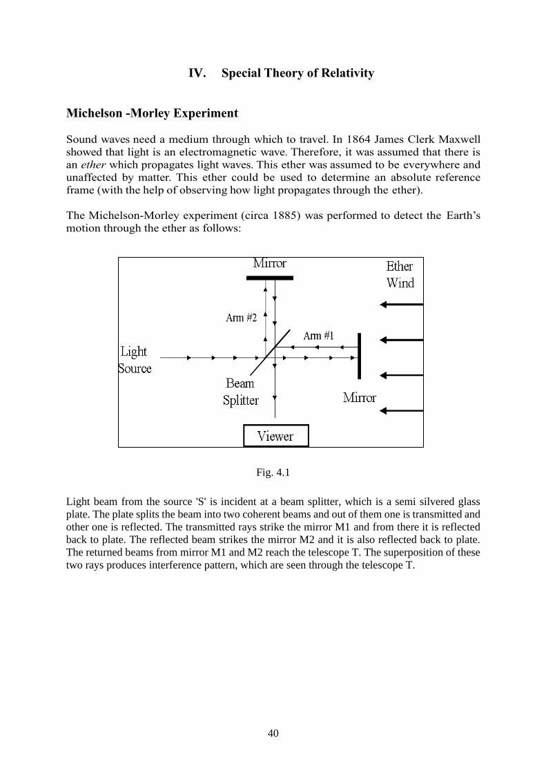
Fig. 4.1
Light beam from the source 'S' is incident at a beam splitter, which is a semi silvered glass
plate. The plate splits the beam into two coherent beams and out of them one is transmitted and
other one is reflected. The transmitted rays strike the mirror M1 and from there it is reflected
back to plate. The reflected beam strikes the mirror M2 and it is also reflected back to plate.
The returned beams from mirror M1 and M2 reach the telescope T. The superposition of these
two rays produces interference pattern, which are seen through the telescope T.
41
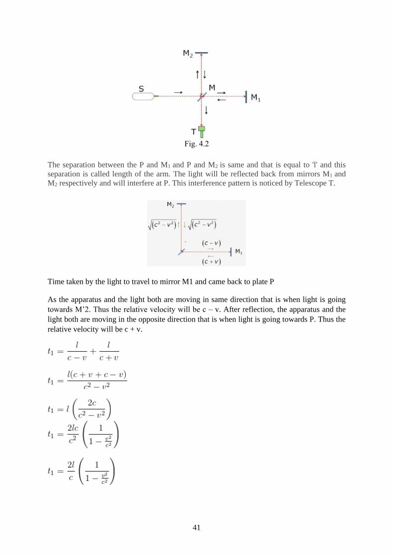
Fig. 4.2
The separation between the P and M1 and P and M2 is same and that is equal to 'l' and this
separation is called length of the arm. The light will be reflected back from mirrors M1 and
M2 respectively and will interfere at P. This interference pattern is noticed by Telescope T.
Time taken by the light to travel to mirror M1 and came back to plate P
As the apparatus and the light both are moving in same direction that is when light is going
towards M’2. Thus the relative velocity will be c – v. After reflection, the apparatus and the
light both are moving in the opposite direction that is when light is going towards P. Thus the
relative velocity will be c + v.
42
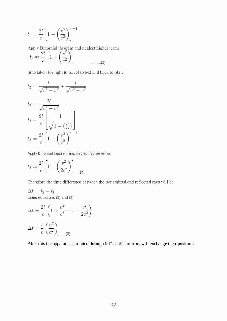
Apply Binomial theorem and neglect higher terms
.........(1)
time taken for light to travel to M2 and back to plate
Apply Binomial theorem and neglect higher terms
......(2)
Therefore the time difference between the transmitted and reflected rays will be
Using equations (1) and (2)
........(3)
After this the apparatus is rotated through so that mirrors will exchange their positions.
43
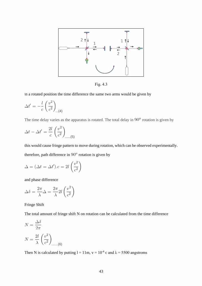
Fig. 4.3
In a rotated position the time difference the same two arms would be given by
...(4)
The time delay varies as the apparatus is rotated. The total delay in rotation is given by
......(5)
this would cause fringe pattern to move during rotation, which can be observed experimentally.
therefore, path difference in rotation is given by
and phase difference
Fringe Shift
The total amount of fringe shift N on rotation can be calculated from the time difference
.......(6)
Then N is calculated by putting l = 11m, v = 10-4 c and λ = 5500 angstroms
44
Thus N = 0.4 fringes. The experiment was performed day and night and at different times of
year. Even though the sensitivity of the set up is to detect a shift of 0.01 fringe, no such shift
was observed. Similar experiments were repeated by several groups but the result was same.
The above experiment shows that the speed of light is constant in space irrespective of the
direction and speed of inertial frame.
Explanation for negative results
The following explanations were given for the negative result of Michelson–Morley
experiment.
(i) Ether drag theory: The moving bodies drag the surrounding ether with them. So, we can say
that there is no relative motion between ether and earth
(iii) Light velocity hypothesis: This hypothesis shows that the velocity of light from a moving
source is the vector sum of velocity of light and velocity of source light. Based on some
astronomical evidences, this hypothesis was also rejected. In 1905, Einstein proposed that the
motion through ether is a meaningless concept. He does not completely rejected the idea of
ether but expressed that it can never be detected. The motion of an object relative to a frame of
reference has a physical concept.
The postulates of special theory of relativity are as follows:
i) The laws of physics are the same in all inertial frames of reference.
ii) The velocity of light in free space is a constant in all the frames of reference.
Special theory of relativity or special relativity is a physical theory which states the relationship
between space and time. This is often termed as STR theory. This is theory is based on two
postulates –
1. Laws of Physics are invariant
2. Irrespective of the light source, the speed of light in a vacuum is the same in any other
space.
Albert Einstein originally proposed this theory in one of his paper “On the Electrodynamics of
Moving Bodies”. Special relativity implies consequences like mass-energy equivalence,
relativity of simultaneity, length contraction and a universal speed limit. The conventional
notion of absolute universal time is replaced by the notion of a time that is dependent on the
reference frame and spatial position.
In relative theory, Reference frames play a vital role. It is used to measure a time of events by
using a clock. An event is nothing but an occurrence that refers to a location in space
corresponding to reference frame. For instance, the explosion of a fire flower can be considered
as an event.
45
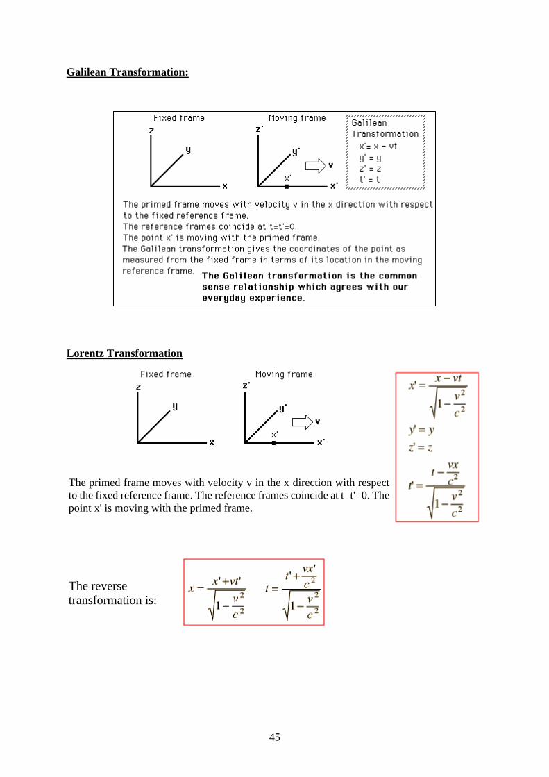
Galilean Transformation:
Lorentz Transformation
The primed frame moves with velocity v in the x direction with respect
to the fixed reference frame. The reference frames coincide at t=t'=0. The
point x' is moving with the primed frame.
The reverse
transformation is:
46
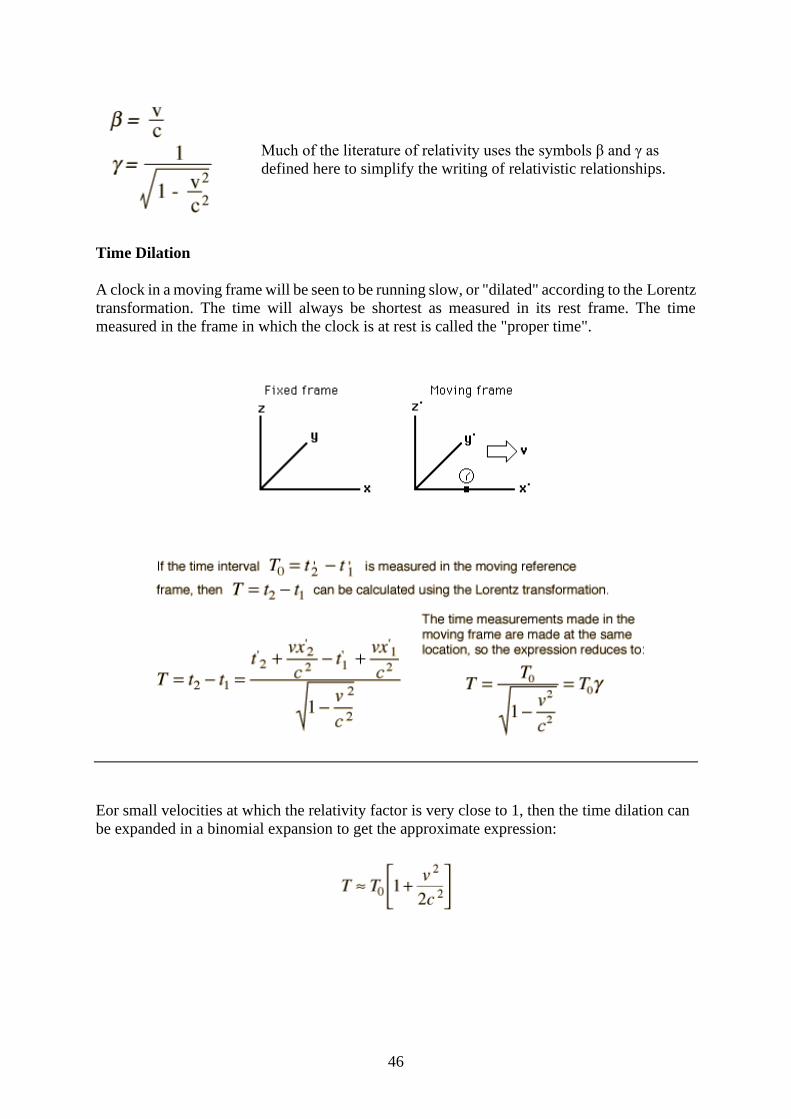
Much of the literature of relativity uses the symbols β and γ as
defined here to simplify the writing of relativistic relationships.
Time Dilation
A clock in a moving frame will be seen to be running slow, or "dilated" according to the Lorentz
transformation. The time will always be shortest as measured in its rest frame. The time
measured in the frame in which the clock is at rest is called the "proper time".
Eor small velocities at which the relativity factor is very close to 1, then the time dilation can
be expanded in a binomial expansion to get the approximate expression:
47
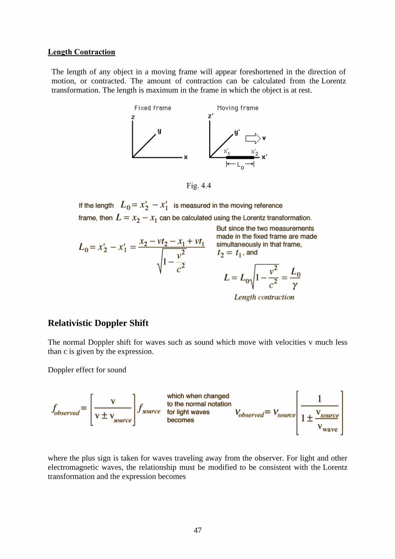
Length Contraction
The length of any object in a moving frame will appear foreshortened in the direction of
motion, or contracted. The amount of contraction can be calculated from the Lorentz
transformation. The length is maximum in the frame in which the object is at rest.
Fig. 4.4
Relativistic Doppler Shift
The normal Doppler shift for waves such as sound which move with velocities v much less
than c is given by the expression.
Doppler effect for sound
where the plus sign is taken for waves traveling away from the observer. For light and other
electromagnetic waves, the relationship must be modified to be consistent with the Lorentz
transformation and the expression becomes
48
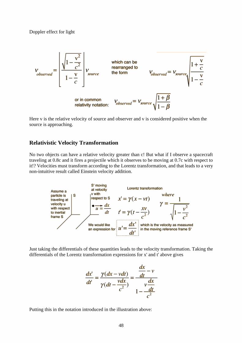
Doppler effect for light
Here v is the relative velocity of source and observer and v is considered positive when the
source is approaching.
Relativistic Velocity Transformation
No two objects can have a relative velocity greater than c! But what if I observe a spacecraft
traveling at 0.8c and it fires a projectile which it observes to be moving at 0.7c with respect to
it!? Velocities must transform according to the Lorentz transformation, and that leads to a very
non-intuitive result called Einstein velocity addition.
Just taking the differentials of these quantities leads to the velocity transformation. Taking the
differentials of the Lorentz transformation expressions for x' and t' above gives
Putting this in the notation introduced in the illustration above:
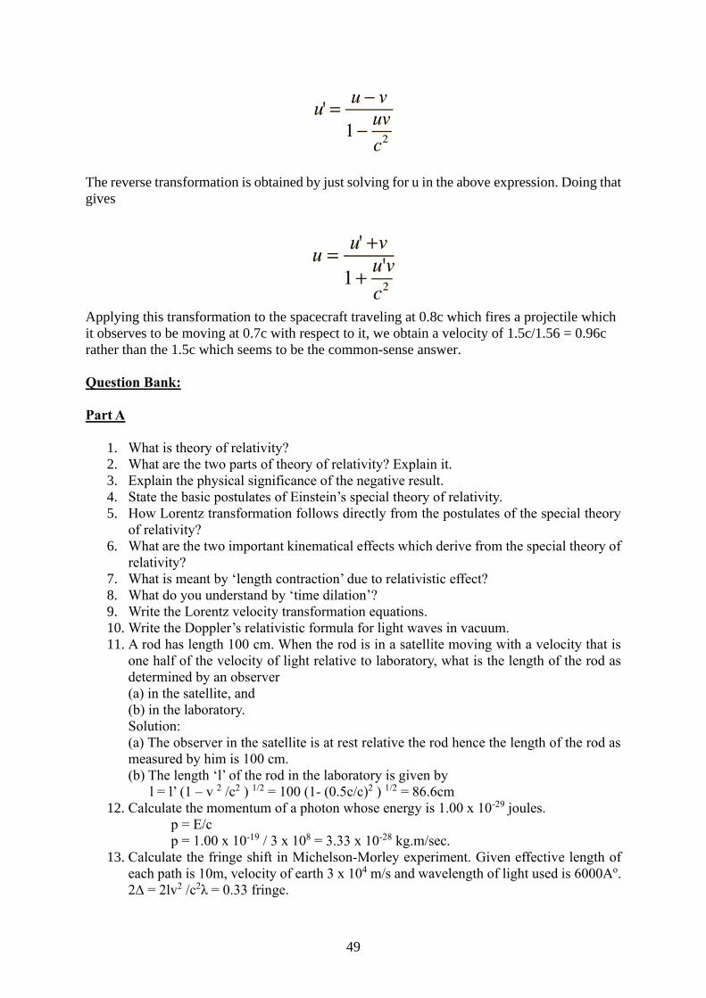
49
The reverse transformation is obtained by just solving for u in the above expression. Doing that
gives
Applying this transformation to the spacecraft traveling at 0.8c which fires a projectile which
it observes to be moving at 0.7c with respect to it, we obtain a velocity of 1.5c/1.56 = 0.96c
rather than the 1.5c which seems to be the common-sense answer.
Question Bank:
Part A
1. What is theory of relativity?
2. What are the two parts of theory of relativity? Explain it.
3. Explain the physical significance of the negative result.
4. State the basic postulates of Einstein’s special theory of relativity.
5. How Lorentz transformation follows directly from the postulates of the special theory
of relativity?
6. What are the two important kinematical effects which derive from the special theory of
relativity?
7. What is meant by ‘length contraction’ due to relativistic effect?
8. What do you understand by ‘time dilation’?
9. Write the Lorentz velocity transformation equations.
10. Write the Doppler’s relativistic formula for light waves in vacuum.
11. A rod has length 100 cm. When the rod is in a satellite moving with a velocity that is
one half of the velocity of light relative to laboratory, what is the length of the rod as
determined by an observer
(a) in the satellite, and
(b) in the laboratory.
Solution:
(a) The observer in the satellite is at rest relative the rod hence the length of the rod as
measured by him is 100 cm.
(b) The length ‘l’ of the rod in the laboratory is given by
l = l’ (1 – v 2 /c2 ) 1/2 = 100 (1- (0.5c/c)2 ) 1/2 = 86.6cm
12. Calculate the momentum of a photon whose energy is 1.00 x 10⁻²⁹ joules.
p = E/c
p = 1.00 x 10⁻¹⁹ / 3 x 108 = 3.33 x 10⁻²⁸ kg.m/sec.
13. Calculate the fringe shift in Michelson-Morley experiment. Given effective length of
each path is 10m, velocity of earth 3 x 10⁴ m/s and wavelength of light used is 6000Ao.
2∆ = 2lv2 /c2λ = 0.33 fringe.
50
14. In Michelson-Morley experiment the length of the paths of the two beans is 11 meters
each. The wavelength of the light used is 6000 Ao. If the expected fringe shift is 0.4
fringe, calculate the velocity of earth relative to ether. 2∆ = 2lv2 /c2λ from this we have
v 2 = 2∆ c2 λ/ 2l v = 3.1 x 10⁵ m/s.
15. What will be the apparent length of meter stick measured by an observer at rest,
when the stick is moving along its velocity equal to (√3/2)c.
l = lo √1 − 𝑣 2/ 𝑐 2
lo = 1m ; v = (√3/2)c
l = 0.5 m.
16. How, fast would a rocket have to go relative to an observer for its length to be contracted
to 99% of its length at rest.
l =lo √1 − 𝑣 2 /𝑐 2
l = (99/100)lo ; l/lo = 99/100
v = 0.1416 c.
17. A young lady decides on her twenty fifth birth day that it is time to slenderize. She
weights 100kg. She has heard that if she moves fast enough, she will appear thinner to
her stationary friends.
(i) How fast must she move to appear slenderized by a factor of 50%.
(ii) If she maintains her speed until the day she calls her twenty ninth birthday, how
old will her stationary friends claim shows according to their measurements?
Solution:
(i) l =lo √1 − 𝑣 2/ 𝑐 2
l/lo = 99/100 ; v = 0.866c.
(iii) ∆t’ = ∆𝑡 √1− 𝑣 2 𝑐 2 ; ∆𝑡 = 4𝑦𝑒𝑎𝑟𝑠 ; √1 − 𝑣 2/ 𝑐 2 = 1 2
∆t’ = 4 /(1/2) = 8 years
The lady will appear to be (25+ 8) = 33 years old.
18. An electron is moving with a speed of 0.85c in a direction opposite to that of a moving
photon. Calculate the relative velocity of the electron with respect to photon.
Solution:
The speed of the photon = c
The speed of the electron = 0.85c
v = 0.85c , u’ = c;
u = (𝑢 ′+ 𝑣) / (1+ 𝑣𝑢/𝑐 2 )= (c + 0.85c)/ (1+ 0.85) = c
19. A space-ship moving away from earth with velocity of 0.4c fires a rocket whose
velocity relative to space-ship is 0.6c, away from the earth. What will be the velocity
of the rocket as observed from the earth.
Solution:
Velocity of rocket relative to earth = u
Velocity of space-ship relative to earth = v
Velocity of rocket relative to space-ship = u’x
v = 0.4c , u’x = 0.6c;
ux = (𝑢𝑥 ′ + 𝑣) /(1+ 𝑣𝑢𝑥 ′ /𝑐 2) = c / (1+ 0.24) = 0.8 c.
51
Part – B
1. Describe the Michelson – Morley experiment and show how the negative results obtained
are interpreted.
2. State the fundamental postulates of special theory of relativity and deduce the Lorentz
transformations.
3. What is length contraction in special theory of relativity? Explain it by Lorentz
transformations.
4. What is time dilation in special theory of relativity? Explain it by Lorentz transformations.
5. State and deduce the law of addition of relativistic velocities and show that in no case can
the resultant velocity of a material particle be greater than c.
6. Deduce the Doppler’s relativistic formula for light from Lorentz transformation equation.
7. Derive Lorentz transformation for moment and energy.
52
V. Simple Hormonic Oscillations
Introduction: We see different kinds of motion every day. The motion of the hands of a clock,
motion of the wheels of a car, etc. Did you ever notice that these types of motion keep repeating
themselves? Such motions are periodic in nature. One such type of periodic motion is simple
harmonic motion (S.H.M.). But what is S.H.M.? Let’s find out.
Periodic Motion and Oscillations
A motion that repeats itself in equal intervals of time is periodic. We need to know what periodic
motion is to understand simple harmonic motion. Periodic motion is the motion in which an object
repeats its path in equal intervals of time. We see many examples of periodic motion in our day-
to-day life. The motion of the hands of a clock is periodic motion. The rocking of a cradle,
swinging on a swing, leaves of a tree moving to and fro due to wind breeze, these all are examples
of periodic motion. The particle performs the same set of movement again and again in a periodic
motion. One such set of movement is called an Oscillation. A great example of oscillatory
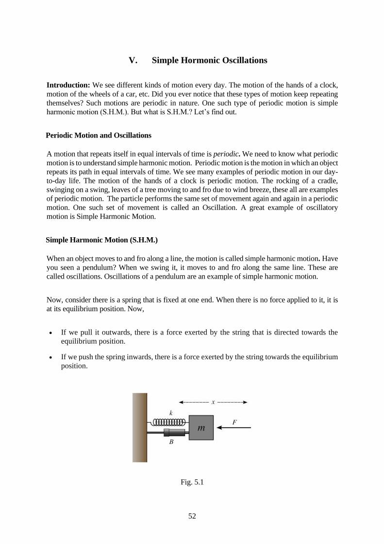
motion is Simple Harmonic Motion.
Simple Harmonic Motion (S.H.M.)
When an object moves to and fro along a line, the motion is called simple harmonic motion. Have
you seen a pendulum? When we swing it, it moves to and fro along the same line. These are
called oscillations. Oscillations of a pendulum are an example of simple harmonic motion.
Now, consider there is a spring that is fixed at one end. When there is no force applied to it, it is
at its equilibrium position. Now,
• If we pull it outwards, there is a force exerted by the string that is directed towards the
equilibrium position.
• If we push the spring inwards, there is a force exerted by the string towards the equilibrium
position.
Fig. 5.1
53
In each case, we can see that the force exerted by the spring is towards the equilibrium position.
This force is called the restoring force. Let the force be F and the displacement of the string from
the equilibrium position be x. Therefore, the restoring force is given by, F= – kx (the negative
sign indicates that the force is in opposite direction). Here, k is the constant called the force
constant. Its unit is N/m in S.I. system and dynes/cm in C.G.S. system.
Linear simple harmonic motion
Linear simple harmonic motion is defined as the linear periodic motion of a body in which the
restoring force is always directed towards the equilibrium position or mean position and its
magnitude is directly proportional to the displacement from the equilibrium position. All simple
harmonic motions are periodic in nature but all periodic motions are not simple harmonic motions.
Now, take the previous example of the string. Let its mass be m. The acceleration of the body is
given by,
a = F/m = – kx/m = – ω2x
Here, k/m = ω2 (ω is the angular frequency of the body)
Concepts of Simple Harmonic Motion (S.H.M)
• Amplitude: The maximum displacement of a particle from its equilibrium position or mean
position is its amplitude. Its S.I. unit is the metre. The dimensions are [L1M0 T0]. Its
direction is always away from the mean or equilibrium position.
• Period: The time taken by a particle to complete one oscillation is its period. Therefore,
period if S.H.M. is the least time after which the motion will repeat itself. Thus, the motion
will repeat itself after nT. where n is an integer.
• Frequency: Frequency of S.H.M. is the number of oscillations that a particle performs per
unit time. S.I. unit of frequency is hertz or r.p.s(rotations per second). Its dimensions are
[L0M0T-1].
• Phase: Phase of S.H.M. is its state of oscillation. Magnitude and direction of displacement
of particle represent the phase. The phase at the beginning of the motion is known as
Epoch(α)
Periodic and Oscillatory Motion:
We come across various kinds of motions in our daily life. You have already studied some of them
like linear and projectile motion. However, these motions are non-repetitive. Here, we are going to
learn about periodic and oscillatory motion.
Energy in simple harmonic motion
Each and every object possesses energy, either while moving or at rest. In the simple harmonic
motion, the object moves to and fro along the same path. Do you think an object possesses energy
while travelling the same path again and again? Yes, it is energy in simple harmonic motion. Let’s
learn how to calculate this energy and understand its properties.
54
The total energy that a particle possesses while performing simple harmonic motion is energy in
simple harmonic motion. Take a pendulum for example. When it is at its mean position, it is at rest.
When it moves towards its extreme position, it is in motion and as soon as it reaches its extreme
position, it comes to rest again. Therefore, in order to calculate the energy in simple harmonic
motion, we need to calculate the kinetic and potential energy that the particle possesses.
Kinetic Energy (K.E.) in S.H.M
Kinetic energy is the energy possessed by an object when it is in motion. Let’s learn how to
calculate the kinetic energy of an object. Consider a particle with mass m performing simple
harmonic motion along a path AB. Let O be its mean position. Therefore, OA = OB = a.
The instantaneous velocity of the particle performing S.H.M. at a distance x from the mean
position is given by
v = ± ω √a2 – x2
∴ v2 = ω2 ( a2 – x2)
∴ Kinetic energy= 1/2 mv2 = 1/2 m ω2 ( a2 – x2)
As, k/m = ω2 (1)
∴ k = m ω2 (2)
Kinetic energy= 1/2 k ( a2 – x2) . The equations 1 and 2 can both be used for calculating the kinetic
energy of the particle.
Learn how to calculate Velocity and Acceleration in Simple Harmonic Motion.
Potential Energy(P.E.) of Particle Performing S.H.M.
Potential energy is the energy possessed by the particle when it is at rest. Let’s learn how to
calculate the potential energy of a particle performing S.H.M. Consider a particle of
mass m performing simple harmonic motion at a distance x from its mean position. You know the
restoring force acting on the particle is F= -kx where k is the force constant.
Now, the particle is given further infinitesimal displacement dx against the restoring force F. Let
the work done to displace the particle be dw. Therefore, The work done dw during the
displacement is
dw = – fdx = – (- kx) dx = kxdx (3)
Therefore, the total work done to displace the particle now from 0 to x is
∫dw= ∫kxdx = k ∫x dx (4)
55
Hence Total work done = 1/2 K x2 = 1/2 m ω2x2
The total work done here is stored in the form of potential energy.
Therefore Potential energy = 1/2 kx2 = 1/2 m ω2x2
Equations 3 and 4 are equations of potential energy of the particle. Thus, potential energy is
directly proportional to the square of the displacement, that is P.E. α x2.
Learn the Difference between Periodic and Oscillatory Motion.
Total Energy in Simple Harmonic Motion (T.E.)
The total energy in simple harmonic motion is the sum of its potential energy and kinetic energy.
Thus, T.E. = K.E. + P.E. = 1/2 k ( a2 – x2) + 1/2 K x2 = 1/2 k a2
Hence, T.E.= E = 1/2 m ω2a2
Equation III is the equation of total energy in a simple harmonic motion of a particle performing
the simple harmonic motion. As ω2 , a2 are constants, the total energy in the simple harmonic
motion of a particle performing simple harmonic motion remains constant. Therefore, it is
independent of displacement x.
As ω= 2πf , E= 1/2 m ( 2πf )2a2
∴ E= 2mπ2f 2a2
As 2 and π2 constants, we have T.E. ∼ m, T.E. ∼ f 2, and T.E. ∼ a2
Thus, the total energy in the simple harmonic motion of a particle is:
• Directly proportional to its mass
• Directly proportional to the square of the frequency of oscillations and
• Directly proportional to the square of the amplitude of oscillation.
The law of conservation of energy states that energy can neither be created nor destroyed.
Therefore, the total energy in simple harmonic motion will always be constant. However, kinetic
energy and potential energy are interchangeable. Given below is the graph of kinetic and potential
energy vs instantaneous displacement.
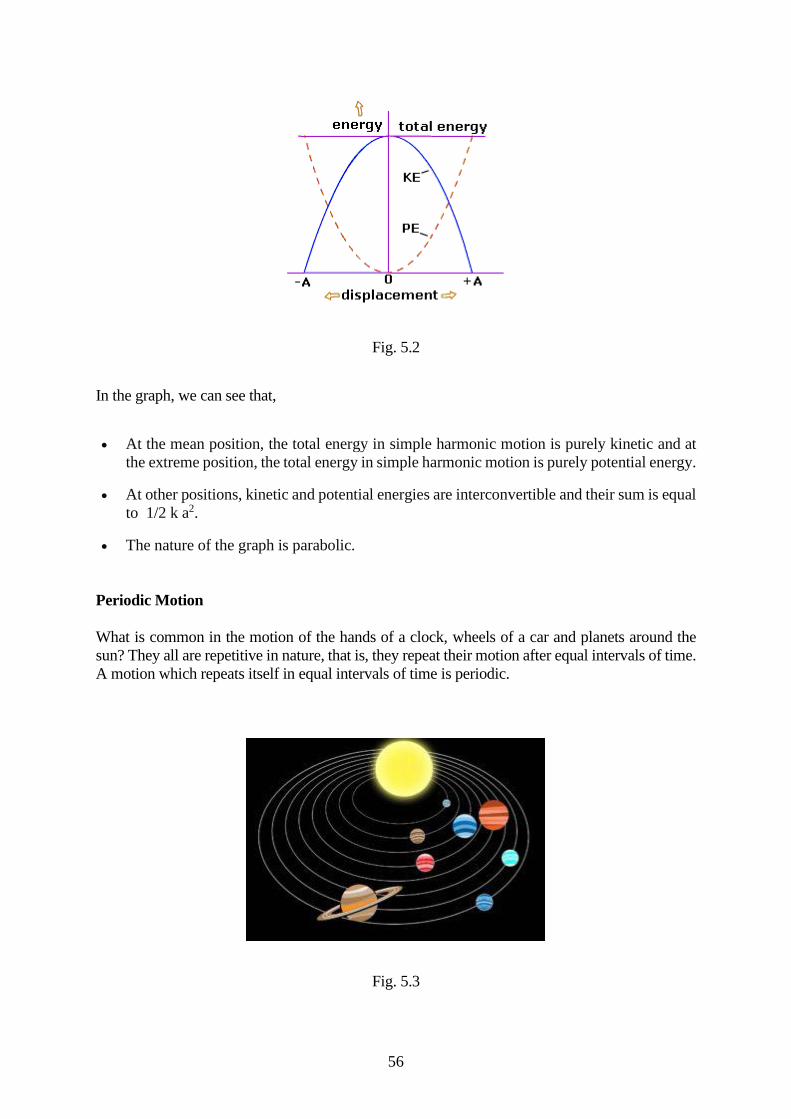
56
Fig. 5.2
In the graph, we can see that,
• At the mean position, the total energy in simple harmonic motion is purely kinetic and at
the extreme position, the total energy in simple harmonic motion is purely potential energy.
• At other positions, kinetic and potential energies are interconvertible and their sum is equal
to 1/2 k a2.
• The nature of the graph is parabolic.
Periodic Motion
What is common in the motion of the hands of a clock, wheels of a car and planets around the
sun? They all are repetitive in nature, that is, they repeat their motion after equal intervals of time.
A motion which repeats itself in equal intervals of time is periodic.
Fig. 5.3
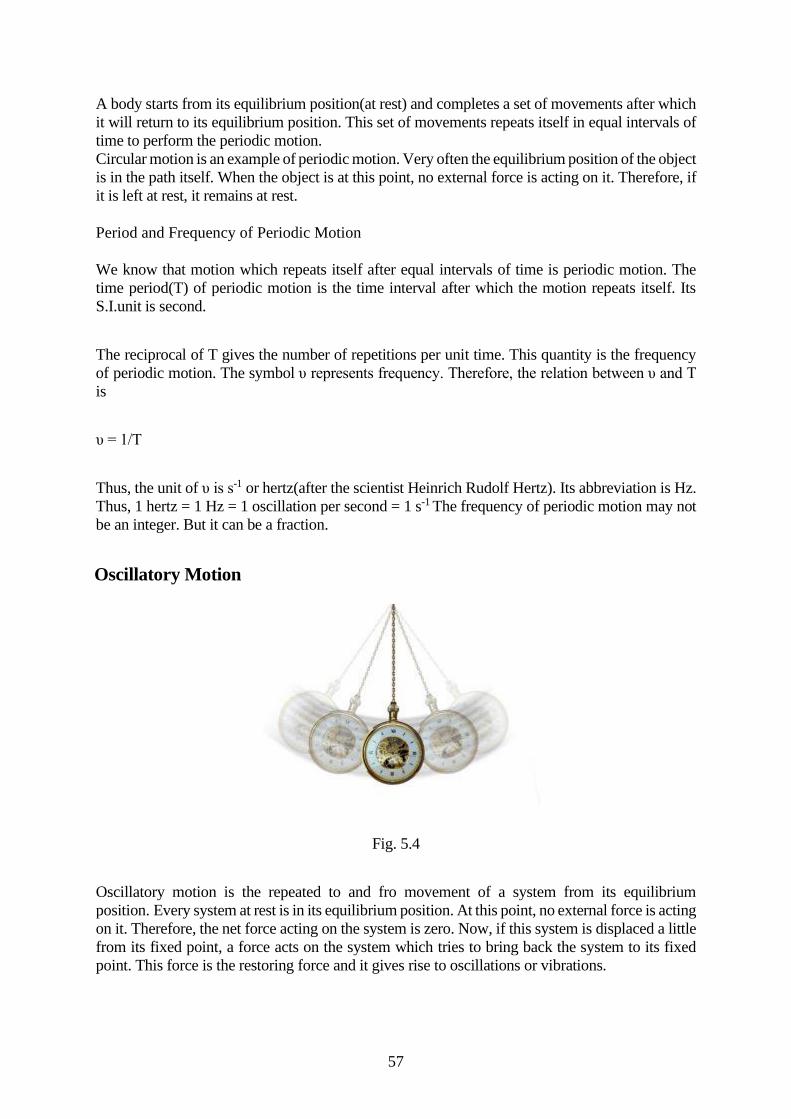
57
A body starts from its equilibrium position(at rest) and completes a set of movements after which
it will return to its equilibrium position. This set of movements repeats itself in equal intervals of
time to perform the periodic motion.
Circular motion is an example of periodic motion. Very often the equilibrium position of the object
is in the path itself. When the object is at this point, no external force is acting on it. Therefore, if
it is left at rest, it remains at rest.
Period and Frequency of Periodic Motion
We know that motion which repeats itself after equal intervals of time is periodic motion. The
time period(T) of periodic motion is the time interval after which the motion repeats itself. Its
S.I.unit is second.
The reciprocal of T gives the number of repetitions per unit time. This quantity is the frequency
of periodic motion. The symbol υ represents frequency. Therefore, the relation between υ and T
is
υ = 1/T
Thus, the unit of υ is s-1 or hertz(after the scientist Heinrich Rudolf Hertz). Its abbreviation is Hz.
Thus, 1 hertz = 1 Hz = 1 oscillation per second = 1 s-1 The frequency of periodic motion may not
be an integer. But it can be a fraction.
Oscillatory Motion
Fig. 5.4
Oscillatory motion is the repeated to and fro movement of a system from its equilibrium
position. Every system at rest is in its equilibrium position. At this point, no external force is acting
on it. Therefore, the net force acting on the system is zero. Now, if this system is displaced a little
from its fixed point, a force acts on the system which tries to bring back the system to its fixed
point. This force is the restoring force and it gives rise to oscillations or vibrations.
58
For example, consider a ball that is placed in a bowl. It will be in its equilibrium position. If
displaced a little from this point, it will oscillate in the bowl. Therefore, every oscillatory motion
is periodic but all periodic motions are not oscillatory. For instance, the circular motion is a
periodic motion but not oscillatory. Moreover, there is no significant difference between
oscillations and vibrations. In general, when the frequency is low, we call it oscillatory motion
and when the frequency is high, we call it vibrations. Furthermore, simple harmonic motion is the
simplest type of oscillatory motion. This motion takes place when the restoring force acting on
the system is directly proportional to its displacement from its equilibrium position. In practice,
oscillatory motion eventually comes to rest due to damping or frictional forces. However, we can
force them by means of some external forces. Also, a number of oscillatory motions together form
waves like electromagnetic waves.
Displacement in Oscillatory Motion
Displacement of a particle is a change in its position vector. In an oscillatory motion,
displacement simply means a change in any physical property with time.
Consider a block attached to a spring, which in turn is fixed to a rigid wall. We measure the
displacement of the block from its equilibrium position. In an oscillatory motion, we can represent
the displacement by a mathematical function of time. One of the simplest periodic functions is
given by,
f(t) = A cos ωt
If the argument, ωt, is increased by an integral multiple of 2π radians, the value of the function
remains the same. Therefore, it is periodic in nature and its period T is given by,
T = 2π/ω
Thus, the function f(t) is periodic with period T. ∴ f(t) = f(t + T). Now, if we consider a sine
function, the result will be the same. Further, taking a linear combination of sine and cosine
functions is also a periodic function with period T.
f(t) = A sin ωt + B cos ωt
Taking A = Dcos∅ and B = Dsin∅ equation V becomes, f(t) = D sin (ωt + ∅). In this equation D
and ∅ are constant and they are given by,
D = √A2 + B2 and ∅ = tan-2(B/A)
Therefore, we can express any periodic function as a superposition of sine and cosine functions
of different time periods with suitable coefficients. The period of the function is 2π/ω.
Table 5.1: Difference between Periodic and Simple Harmonic Motion
Periodic Motion Simple Harmonic Motion
In the periodic motion, the displacement of
the object may or may not be in the direction
of the restoring force.
In the simple harmonic motion, the
displacement of the object is always in the
opposite direction of the restoring force.
The periodic motion may or may not be
oscillatory.
Simple harmonic motion is always
oscillatory.
Examples are the motion of the hands of a
clock, the motion of the wheels of a car, etc.
Examples are the motion of a pendulum,
motion of a spring, etc.

59
Damped Harmonic Motion
We know that when we swing a pendulum, it will eventually come to rest due to air pressure and
friction at the support. This motion is damped simple harmonic motion. Let’s understand what it
is and how it is different from linear simple harmonic motion.
When the motion of an oscillator reduces due to an external force, the oscillator and its motion
are damped. These periodic motions of gradually decreasing amplitude are damped simple
harmonic motion. An example of a damped simple harmonic motion is a simple pendulum. In
the damped simple harmonic motion, the energy of the oscillator dissipates continuously. But for
a small damping, the oscillations remain approximately periodic. The forces which dissipate the
energy are generally frictional forces.
Fig. 5.5
Expression of damped simple harmonic motion
Let’s take an example to understand what a damped simple harmonic motion is. Consider a block
of mass m connected to an elastic string of spring constant k. In an ideal situation, if we push the
block down a little and then release it, its angular frequency of oscillation is ω = √k/ m.
However, in practice, an external force (air in this case) will exert a damping force on the motion
of the block and the mechanical energy of the block-string system will decrease. This energy that
is lost will appear as the heat of the surrounding medium.
The damping force depends on the nature of the surrounding medium. When we immerse the
block in a liquid, the magnitude of damping will be much greater and the dissipation energy is
much faster. Thus, the damping force is proportional to the velocity of the bob and acts opposite
to the direction of the velocity. If the damping force is Fd, we have,
Fd = -bυ (I)
where the constant b depends on the properties of the medium(viscosity, for example) and size
and shape of the block. Let’s say O is the equilibrium position where the block settles after
releasing it. Now, if we pull down or push the block a little, the restoring force on the block due
to spring is Fs = -kx, where x is the displacement of the mass from its equilibrium position.
Therefore, the total force acting on the mass at any time t is, F = -kx -bυ.
60
Now, if a(t) is the acceleration of mass m at time t, then by Newton’s Law of Motion along the
direction of motion, we have
ma(t) = -kx(t) – bυ(t) (II)
Here, we are not considering vector notation because we are only considering the one-dimensional
motion. Therefore, using first and second derivatives of s(t), v(t) and a(t), we have,
m(d2x/dt2) + b(dx/dt) + kx =0 (III)
This equation describes the motion of the block under the influence of a damping force which is
proportional to velocity. Therefore, this is the expression of damped simple harmonic motion. The
solution of this expression is of the form
x(t) = Ae-bt/2m cos(ω′t + ø) (IV)
where A is the amplitude and ω′ is the angular frequency of damped simple harmonic motion
given by,
ω′ = √(k/m – b2/4m2 ) (V)
The function x(t) is not strictly periodic because of the factor e-bt/2m which decreases continuously
with time. However, if the decrease is small in one-time period T, the motion is then approximately
periodic. In a damped oscillator, the amplitude is not constant but depends on time. But for small
damping, we may use the same expression but take amplitude as Ae-bt/2m
∴ E(t) =1/2 kAe-bt/2m (VI)
This expression shows that the damping decreases exponentially with time. For a small damping,
the dimensionless ratio (b/√km) is much less than 1. Obviously, if we put b = 0, all equations of
damped simple harmonic motion will turn into the corresponding equations of undamped motion.
Forced Simple Harmonic Motion
When we displace a pendulum from its equilibrium position, it oscillates to and fro about its mean
position. Eventually, its motion dies out due to the opposing forces in the medium. But can we
force the pendulum to oscillate continuously? Yes. This type of motion is known as forced simple
harmonic motion. Let’s find out what forced simple harmonic motion is.
Definition of Forced Simple Harmonic Motion
When we displace a system, say a simple pendulum, from its equilibrium position and then release
it, it oscillates with a natural frequency ω and these oscillations are free oscillations. But all free
oscillations eventually die out due to the ever-present damping forces in the surrounding.
However, an external agency can maintain these oscillations. These oscillations are known
as forced or driven oscillations. The motion that the system performs under this external agency
is known as Forced Simple Harmonic Motion. The external force is itself periodic with a
frequency ωd which is known as the drive frequency.
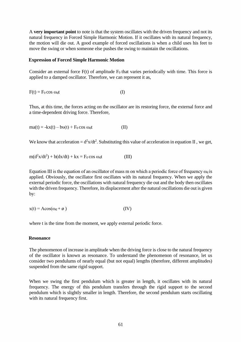
61
A very important point to note is that the system oscillates with the driven frequency and not its
natural frequency in Forced Simple Harmonic Motion. If it oscillates with its natural frequency,
the motion will die out. A good example of forced oscillations is when a child uses his feet to
move the swing or when someone else pushes the swing to maintain the oscillations.
Expression of Forced Simple Harmonic Motion
Consider an external force F(t) of amplitude F0 that varies periodically with time. This force is
applied to a damped oscillator. Therefore, we can represent it as,
F(t) = F0 cos ωdt (I)
Thus, at this time, the forces acting on the oscillator are its restoring force, the external force and
a time-dependent driving force. Therefore,
ma(t) = -kx(t) – bυ(t) + F0 cos ωdt (II)
We know that acceleration = d2x/dt2. Substituting this value of acceleration in equation II , we get,
m(d2x/dt2) + b(dx/dt) + kx = F0 cos ωdt (III)
Equation III is the equation of an oscillator of mass m on which a periodic force of frequency ωd is
applied. Obviously, the oscillator first oscillates with its natural frequency. When we apply the
external periodic force, the oscillations with natural frequency die out and the body then oscillates
with the driven frequency. Therefore, its displacement after the natural oscillations die out is given
by:
x(t) = Acos(ωd + ø ) (IV)
where t is the time from the moment, we apply external periodic force.
Resonance
The phenomenon of increase in amplitude when the driving force is close to the natural frequency
of the oscillator is known as resonance. To understand the phenomenon of resonance, let us
consider two pendulums of nearly equal (but not equal) lengths (therefore, different amplitudes)
suspended from the same rigid support.
When we swing the first pendulum which is greater in length, it oscillates with its natural
frequency. The energy of this pendulum transfers through the rigid support to the second
pendulum which is slightly smaller in length. Therefore, the second pendulum starts oscillating
with its natural frequency first.
62
At one point, the frequency with the second pendulum vibrates becomes nearly equal to the first
one. Therefore, the second pendulum now starts with the frequency of the first one, which is the
driven frequency. When this happens, the amplitude of the oscillations is maximum. Thus,
resonance takes place.
Fig. 5.6
Resonance:
The sharpness of resonance can be understood better by understanding resonance. Resonance
is defined as the tendency of a system to vibrate with an increase in amplitude at the excitation
of frequencies. Resonance frequency or resonant frequency is the maximum frequency at which
the amplitude is relatively maximum. The Q factor is used to define the sharpness of the
resonance.
Sharpness of resonance:
The sharpness of resonance is defined using the Q factor which explains how fast energy decay
in an oscillating system. The sharpness of resonance depends upon:
• Damping: Effect due to which there is a reduction in amplitude of vibrations
• Amplitude: Maximum displacement of a point on a vibrating body which is measured
from its equilibrium position.
The sharpness of resonance increases or decreases with an increase or decrease in damping and
as the amplitude increases, the sharpness of resonance decreases.
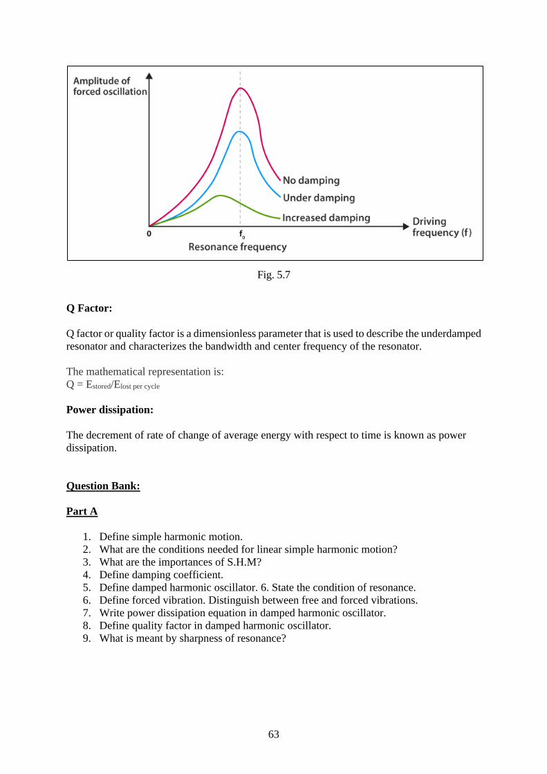
63
Fig. 5.7
Q Factor:
Q factor or quality factor is a dimensionless parameter that is used to describe the underdamped
resonator and characterizes the bandwidth and center frequency of the resonator.
The mathematical representation is:
Q = Estored/Elost per cycle
Power dissipation:
The decrement of rate of change of average energy with respect to time is known as power
dissipation.
Question Bank:
Part A
1. Define simple harmonic motion.
2. What are the conditions needed for linear simple harmonic motion?
3. What are the importances of S.H.M?
4. Define damping coefficient.
5. Define damped harmonic oscillator. 6. State the condition of resonance.
6. Define forced vibration. Distinguish between free and forced vibrations.
7. Write power dissipation equation in damped harmonic oscillator.
8. Define quality factor in damped harmonic oscillator.
9. What is meant by sharpness of resonance?
64
Part – B
1. Derive the equation of SHM and its solution.
2. Show that the total energy of particle executing simple harmonic motion is
proportional to (a) square of its amplitude (b) the square of its frequency.
3. Derive expressions for the period and amplitude of damped harmonic motion.
4. Explain in detail power dissipation in damped harmonic oscillator.
5. Explain in detail Quality factor in damped harmonic oscillator.
6. Derive an expression for forced harmonic oscillator with steady state solution.
7. What is resonance? Give some important examples of resonance. Explain sharpness
of the resonance.
TEXT / REFERENCE BOOKS
1. An introduction to mechanics, D. Kleppner, R.J. Kolenkow, 1973, McGraw-Hill.
2. Mechanics, Berkeley Physics, vol.1, C.Kittel, W.Knight, et.al. 2007, Tata McGraw-
Hill.
3. Physics, Resnick, Halliday and Walker 8/e. 2008, Wiley.
4. Analytical Mechanics, G.R. Fowles and G.L. Cassiday. 2005, Cengage Learning.
5. Feynman Lectures, Vol. I, R.P.Feynman, R.B.Leighton, M.Sands, 2008, Pearson
6. Education Introduction to Special Relativity, R. Resnick, 2005, John Wiley and
Sons.
7. Mechanics, D.S. Mathur, S. Chand and Company Limited, 2000
8. Physics for scientists and Engineers with Modern Phys., J.W. Jewett, R.A.Serway,
2010,
9. Cengage Learning Theoretical Mechanics, M.R. Spiegel, 2006, Tata McGraw Hill.
10. Mechanics -J.C. Slater and N. H. Frank (McGraw-Hill).
11. Engineering Physics, R.K. Gaur, S. L. Gupta, 2007, Dhanpat Rai.
12. Engineering Physics, Shatendra Sharma and Jyotsna Sharma, Pearson.