engineering mechanics 2016
TRANSCRIPT
22
nd International Conference
ENGINEERING MECHANICS 2016
Svratka, Czech Republic, 9 – 12 May 2016
SERVICE LIFE OF ROTORS UNDER MECHANICAL AND THERMAL
STRESS
J. Zachwieja*, K. Peszynski
**
Abstract: Dynamic balancing of a rigid rotor should, at least in its final stage, be carried out at its operational speed, where its rotational frequency is often close to its resonance frequency. It is an adverse
phenomenon, since even a minor constraint may induce high amplitude vibrations, limited by the attenuation.
The service life of a rotor, mainly its bearings is thus significantly reduced. Balancing the rotor using the
influence coefficient method at a frequency close to its resonance frequency is difficult due to the rapid
changes in phase angle of a vector of the rotor response to constraints from the attached test weights. An
optimal solution is to operate outside the rotor’s resonance zone. A quick and efficient method is to change
its rotational speed, however, it may have some side effects.
The rotors used in jet engines and power turbines, as well as rotors used in clinker cooler fans in cement
plants and heating system fans in various types of furnaces used in the glass-making industry operate in
high-temperature conditions. High temperature gradients during furnace start-up may result in thermal
stresses at the rotor disc cross-sections. Strength of steel is also rapidly reduced at high temperatures.
Cumulative effects of mechanical and thermal stresses at reduced rotor material strength may result in failure after a short period of operation. The study discusses those issues in relation to the rotors under
mechanical and thermal stresses.
Keywords: stress analysis, balancing, natural frequency, external anisotropy, resonance zone
1. Introduction
The unbalance of rotors used in industrial machinery is a main cause of vibrations, which also very often are resonant vibrations. The effect is due to the constraint frequency equal to the rotational frequency of a
rotor being close to its natural frequency.
The power turbines are rotary turbomachines designed to operate at a natural frequency only slightly different from its rotational frequency. The deformable rotor, after passing its resonance zone is self-
centred due to the gyroscopic moment. Its deflection is similar to the value of an eccentricity of
unbalanced mass.
Operation of the power turbines and turbine generators at over 10.000 min-1
give rise to many
problems. The most common issue, apart from the difficulties in maintaining stable conditions of the slide
bearing operation is breaking off of the blade resulting in a major rotor unbalance. Despite an immediate
turbine shutdown and activation of a brake system, the force exerted on the rotor is sufficient to cause its damage. It is also the case with the aircraft jet engine turbines. Actual operation of the machines must be
monitored in continuous mode, to identify the symptoms as soon as they occur (Gao, Meeker, Mayton,
2015). At the turbine rotor design stage, both numerical methods and high frequency variable load fatigue cycles are employed (Witek, 2015) . Non-linear finite element methods (Witek, 2011) with various
element types (Liu, Jiang, 2014) are used to determine the stress conditions in the rotor shaft and blade
cross-sections.
The turbine tests show that together with the resonance vibrations excited by the variable load conditions (Poursaeidi, Salavatian 2009, Liu, Jiang, 2015) blade cracking is due to the progressive
corrosion (Cuevas et all, 2013), pitting (Poursaeidi, Bakhtiari, 2014) and rotor unbalance (Witek, 2015).
* Assoc. Professor Janusz Zachwieja, PhD., Department of Applied Mechanics, University of Technology and Life Sciences in
Bydgoszcz (Poland), Kaliskiego 7, Bydgoszcz; PL, [email protected], ** Assoc. Prof. Kazimierz Peszynski, PhD.: UTP University of Science and Technology, Faculty of Mechanical Engineering, Al.
prof. S. Kaliskiego 7, 85-796 Bydgoszcz; PL, [email protected]
631
3
Attempts are made within the fracture mechanics domain, to develop high-speed rotor blade crack propagation models (Barlow, Chandra, 2005).
The radial fans are fitted with rigid rotors operating at a relatively low speed. Due to the use of
vibration dampers, the resonance frequencies of those machines are low and thus they operate within the resonance zone (Zachwieja, Holka, 2011). The conditions also apply to other machines, i.e. crushers.
The rotor can be brought out of resonant vibrations by changing its mass, mount rigidity or speed
(Zachwieja, 2012). The latter is most commonly used, however it is usually not possible to reduce the
angular velocity of the rotor. Increase in speed has a better potential due to the technical reasons, since it is related with the increase in the output of a process line the machine is part of.
2. Problem description
Gypsum is a raw material commonly used in the construction industry and is obtained in a calcination
process of gypsum rock at 1500−190
0C. The product is mostly hemihydrate. After milling, the product is
used as a structural gypsum.
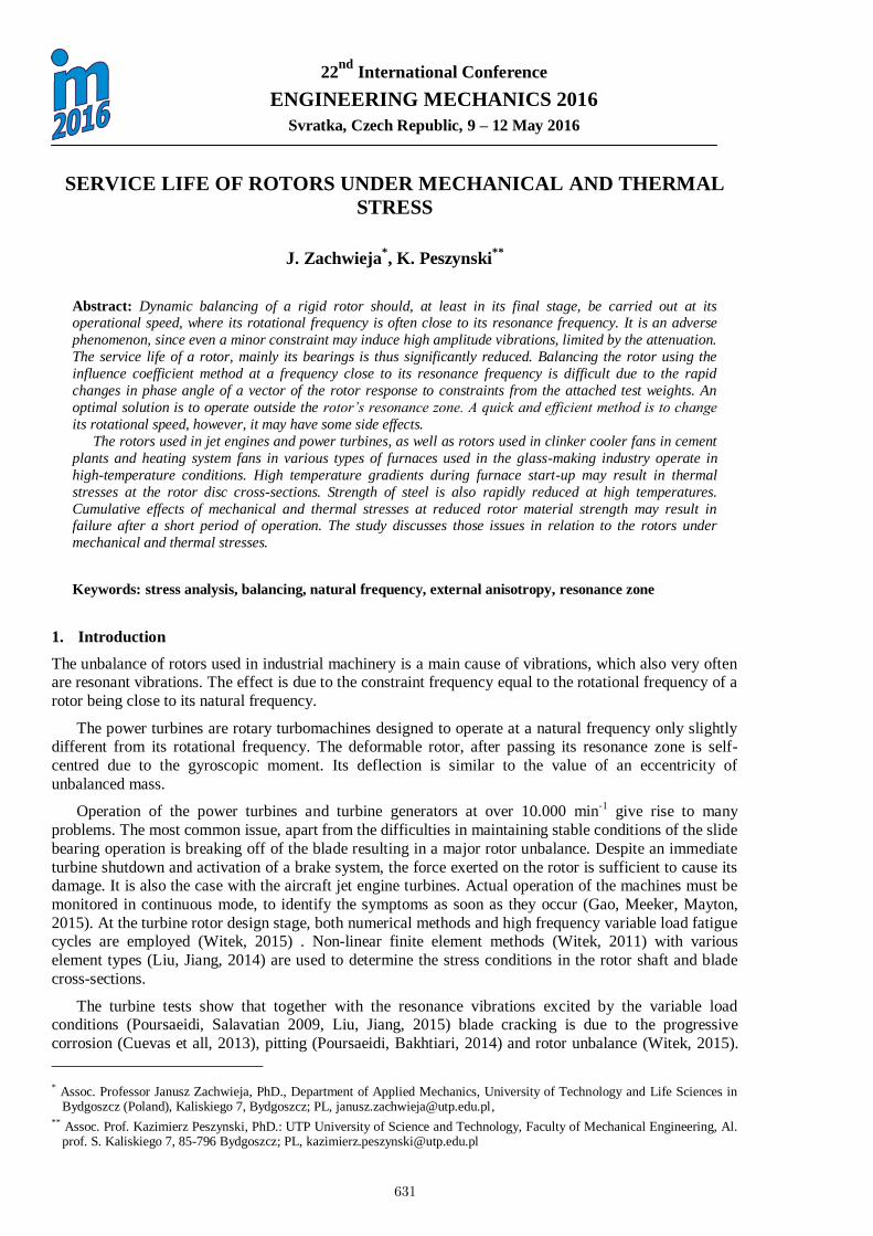
The REA-gypsum mill is a machine used for milling gypsum rocks. Rock milling is possible due to
the rotor design, which uses crushing hammers attached to the radial arms. Rotor speed is ~700 min-1
.
Fig. 1 shows a medium mill with the rotor driven via a belt transmission. The batch material in form of gypsum rocks is crumbled by falling from several meters onto the rotating crushing hammers. The
direction of material is indicated with an arrow.
Fig. 1. REA-gypsum mill view.
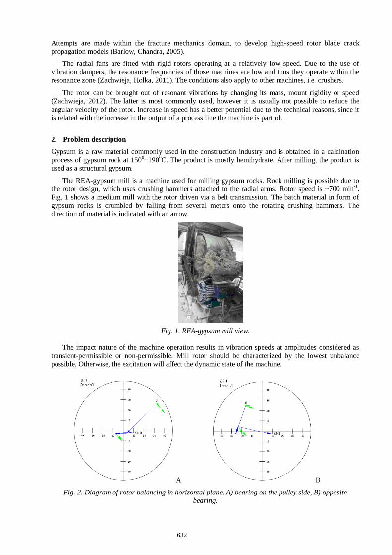
The impact nature of the machine operation results in vibration speeds at amplitudes considered as transient-permissible or non-permissible. Mill rotor should be characterized by the lowest unbalance
possible. Otherwise, the excitation will affect the dynamic state of the machine.
A B
Fig. 2. Diagram of rotor balancing in horizontal plane. A) bearing on the pulley side, B) opposite bearing.
632
4
The tested mill is characterized by the disproportion of the vibration velocity amplitude in horizontal and vertical direction, indicating an external anisotropy or resonance in the horizontal plane. Whereas the
vibration velocity amplitude for the bearings in vertical direction are permissible and reach values slightly
over 1 mm·s-1
, in horizontal direction they may reach several dozens mm·s-1. Fig. 2 shows the attempt to
balance the mill rotor mounted on a steel platform.
The diagrams showing changes in rotor unbalance vector in the horizontal plane after each run reflect
the scale of difficulty in obtaining the end result, i.e. amplitude of ~7 mm s-1
. The condition cannot be
considered satisfactory, and the subsequent runs did not improve the quality factor of balancing.
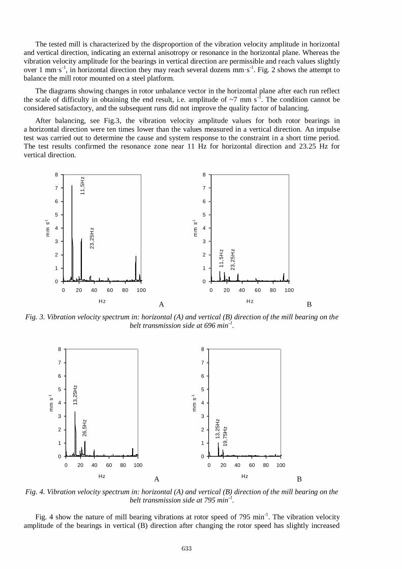
After balancing, see Fig.3, the vibration velocity amplitude values for both rotor bearings in
a horizontal direction were ten times lower than the values measured in a vertical direction. An impulse
test was carried out to determine the cause and system response to the constraint in a short time period. The test results confirmed the resonance zone near 11 Hz for horizontal direction and 23.25 Hz for
vertical direction.
23
,25
Hz
11
,5H
z
0
1
2
3
4
5
6
7
8
0 20 40 60 80 100
Hz
mm
s-1
A
23
,25
Hz
11
,5H
z
0
1
2
3
4
5
6
7
8
0 20 40 60 80 100
Hz
mm
s-1
B
Fig. 3. Vibration velocity spectrum in: horizontal (A) and vertical (B) direction of the mill bearing on the
belt transmission side at 696 min-1
.
26,5
Hz
13,2
5H
z
0
1
2
3
4
5
6
7
8
0 20 40 60 80 100
Hz
mm
s-1
A
19,7
5H
z
13,2
5H
z
0
1
2
3
4
5
6
7
8
0 20 40 60 80 100
Hz
mm
s-1
B
Fig. 4. Vibration velocity spectrum in: horizontal (A) and vertical (B) direction of the mill bearing on the belt transmission side at 795 min
-1.
Fig. 4 show the nature of mill bearing vibrations at rotor speed of 795 min-1. The vibration velocity
amplitude of the bearings in vertical (B) direction after changing the rotor speed has slightly increased
633
5
due to the increase in constraint value, however the vibration velocity amplitudes in horizontal (A) direction have decreased 1.5÷2 times.
3. Bringing the rotor out of resonance zone
The procedure of bringing the rotor out of resonance zone should be preceded by the analysis of the
effects of increased rigidity of the machine mount, since the increase in mount rigidity increases the natural frequency of the mill. The rigidity can be increased by replacing the vibration damper will less
flexible dampers. However, the mistuning value must be close to 2 .
A simple method is to change the rotor speed, if adjustable. An attempt was made to gradually increase the speed frequency with a simultaneous measurement of the vibration velocity amplitude.
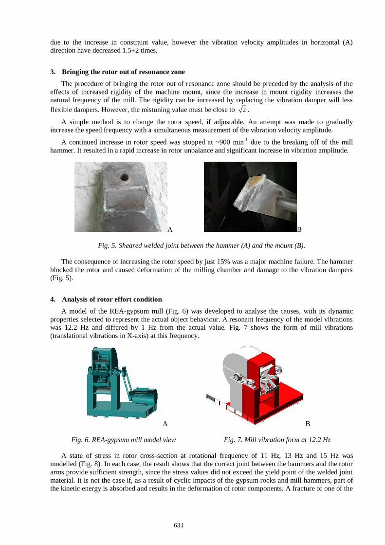
A continued increase in rotor speed was stopped at ~900 min-1
due to the breaking off of the mill
hammer. It resulted in a rapid increase in rotor unbalance and significant increase in vibration amplitude.
A B
Fig. 5. Sheared welded joint between the hammer (A) and the mount (B).
The consequence of increasing the rotor speed by just 15% was a major machine failure. The hammer
blocked the rotor and caused deformation of the milling chamber and damage to the vibration dampers (Fig. 5).
4. Analysis of rotor effort condition
A model of the REA-gypsum mill (Fig. 6) was developed to analyse the causes, with its dynamic
properties selected to represent the actual object behaviour. A resonant frequency of the model vibrations was 12.2 Hz and differed by 1 Hz from the actual value. Fig. 7 shows the form of mill vibrations
(translational vibrations in X-axis) at this frequency.
A B
Fig. 6. REA-gypsum mill model view Fig. 7. Mill vibration form at 12.2 Hz
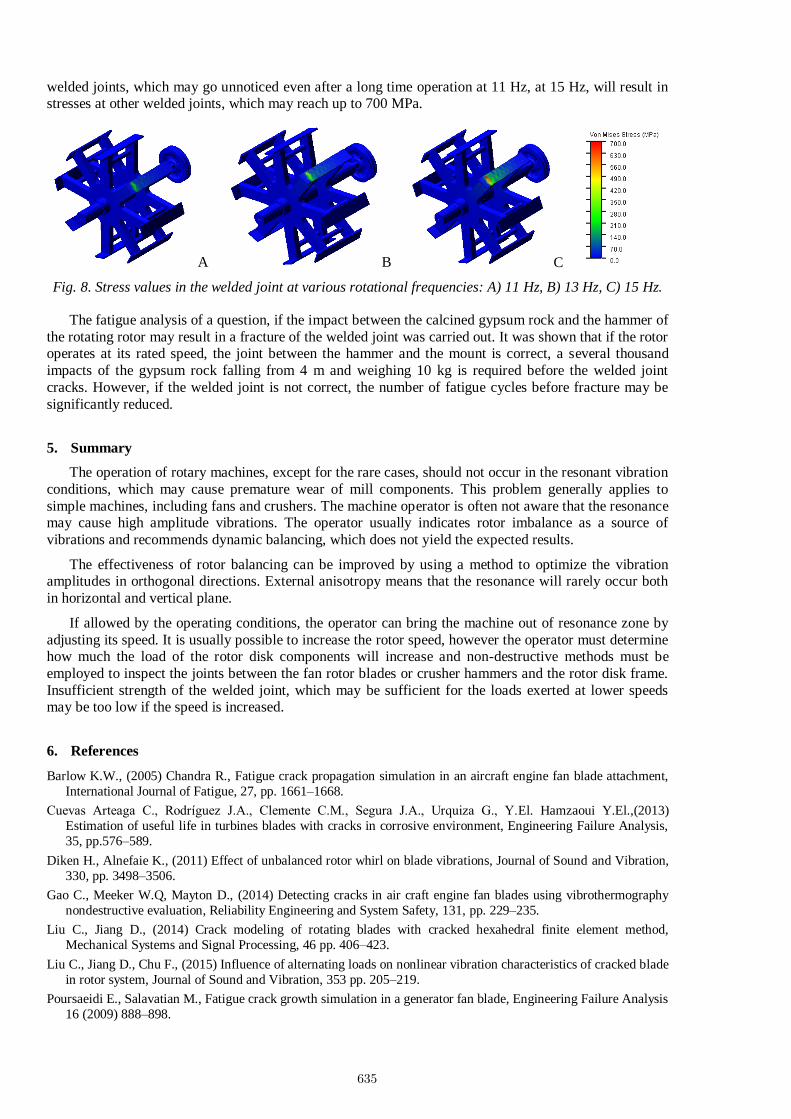
A state of stress in rotor cross-section at rotational frequency of 11 Hz, 13 Hz and 15 Hz was
modelled (Fig. 8). In each case, the result shows that the correct joint between the hammers and the rotor
arms provide sufficient strength, since the stress values did not exceed the yield point of the welded joint
material. It is not the case if, as a result of cyclic impacts of the gypsum rocks and mill hammers, part of the kinetic energy is absorbed and results in the deformation of rotor components. A fracture of one of the
634
6
welded joints, which may go unnoticed even after a long time operation at 11 Hz, at 15 Hz, will result in stresses at other welded joints, which may reach up to 700 MPa.
A B C
Fig. 8. Stress values in the welded joint at various rotational frequencies: A) 11 Hz, B) 13 Hz, C) 15 Hz.
The fatigue analysis of a question, if the impact between the calcined gypsum rock and the hammer of
the rotating rotor may result in a fracture of the welded joint was carried out. It was shown that if the rotor operates at its rated speed, the joint between the hammer and the mount is correct, a several thousand
impacts of the gypsum rock falling from 4 m and weighing 10 kg is required before the welded joint
cracks. However, if the welded joint is not correct, the number of fatigue cycles before fracture may be
significantly reduced.
5. Summary
The operation of rotary machines, except for the rare cases, should not occur in the resonant vibration
conditions, which may cause premature wear of mill components. This problem generally applies to
simple machines, including fans and crushers. The machine operator is often not aware that the resonance may cause high amplitude vibrations. The operator usually indicates rotor imbalance as a source of
vibrations and recommends dynamic balancing, which does not yield the expected results.
The effectiveness of rotor balancing can be improved by using a method to optimize the vibration amplitudes in orthogonal directions. External anisotropy means that the resonance will rarely occur both
in horizontal and vertical plane.
If allowed by the operating conditions, the operator can bring the machine out of resonance zone by
adjusting its speed. It is usually possible to increase the rotor speed, however the operator must determine how much the load of the rotor disk components will increase and non-destructive methods must be
employed to inspect the joints between the fan rotor blades or crusher hammers and the rotor disk frame.
Insufficient strength of the welded joint, which may be sufficient for the loads exerted at lower speeds may be too low if the speed is increased.
6. References
Barlow K.W., (2005) Chandra R., Fatigue crack propagation simulation in an aircraft engine fan blade attachment,
International Journal of Fatigue, 27, pp. 1661–1668.
Cuevas Arteaga C., Rodríguez J.A., Clemente C.M., Segura J.A., Urquiza G., Y.El. Hamzaoui Y.El.,(2013)
Estimation of useful life in turbines blades with cracks in corrosive environment, Engineering Failure Analysis,
35, pp.576–589.
Diken H., Alnefaie K., (2011) Effect of unbalanced rotor whirl on blade vibrations, Journal of Sound and Vibration,
330, pp. 3498–3506.
Gao C., Meeker W.Q, Mayton D., (2014) Detecting cracks in air craft engine fan blades using vibrothermography
nondestructive evaluation, Reliability Engineering and System Safety, 131, pp. 229–235.
Liu C., Jiang D., (2014) Crack modeling of rotating blades with cracked hexahedral finite element method,
Mechanical Systems and Signal Processing, 46 pp. 406–423.
Liu C., Jiang D., Chu F., (2015) Influence of alternating loads on nonlinear vibration characteristics of cracked blade
in rotor system, Journal of Sound and Vibration, 353 pp. 205–219.
Poursaeidi E., Salavatian M., Fatigue crack growth simulation in a generator fan blade, Engineering Failure Analysis
16 (2009) 888–898.
635
7
Poursaeidi E., Bakhtiari H., (2014) Fatigue crack growth simulation in a first stage of compressor blade,
Engineering Failure Analysis, 45, pp. 314–325.
Witek L., (2015) Simulation of crack growth in the compressor blade subjected to resonant vibration using hybrid
method, Engineering Failure Analysis, 49, pp. 57–66.
Witek L., (2011) Numerical stress and crack initiation analysis of the compressor blades after foreign object damage
subjected to high-cycle fatigue, Engineering Failure Analysis, 18, pp. 2111–2125.
Zachwieja J., Holka H., (2011) The effectiveness of rigid rotor balance with resonant extortion of the system with
small damping, Journal of Polish CIMAC, 6(1), pp. 211-219.
Zachwieja J., (2012) Wyważanie wirnika wentylatora promieniowego w różnych stanach dynamicznych, (Eng.
Balancing of the Radial Fan Rotor in Various Dynamic States), Wydawnictwo UTP.
636