human mechanics - dtic
TRANSCRIPT
H
o 0
o
HUMAN MECHANICSFOUR MONOGRAPHS ABRIDGED,,
W. BRAUNE and 0. FISCIIER"Center of Gravity of tllHnumn Body"
0. FISCHIER"Theoretical F,,zdaincntals for a ,Ieclankis of Living .Bodics"
J. AMA D D C"The Hlumn Motor"r rq'-
W~. T. DEMPSTER
"Space Requtirementls of the Scale'd Operator" 11 5TECHNICAL IOCUMENTARY EPORT No. AXt I,.TDR.3.1 2 3
DECEMBER 1963
BEHAVIORAL SCIENCES LABORATORY6570th AEROSPACE MEDICAL RESEARCH LABORATORIES
AEROSPACE MEDICAL DIVISIONAIR FORCE SYSTEMS COMMAND
WRIC lT-PATTERSON AIR FORCE BASE, Oi1IO
Contract Monitor: Kenneth W. KennedyProject No. 7184, Task No. 719408
(Prepared under Contract No. AF 33(616)-8091 byWilton Marion Krogman, Ph.D., LL.I). and Francis E. Johnston, Ph.D.
Graduate School of Medicine, University of Pennsylvania,Philadelphia, Pa.)
NOTICES
Whflen US Government drawings, specifications, or other data are used for anypurpose other than a definitely related government procurement operation, thegovernment thereby incurs no responsibility nor any obligation whatsoever;and the fact that the government may have formulated, furnished, or in anyway sapphed the said drawings, ,;pecifications, or other data is not to beregarded by implicaion or otherwise, as in any manner licensing the holderor any other person or corporation, or conveying any right- or permission tomanufacture, use, or sell any patented inventio-i that may in any way berelated thereto.
Qualified requesters may obtain copies from the Defense Documentation Center(DDC), Cameron Station, Alexandria, Virginia 22314. Orders will be expeditedif placed through the librarian or other person designated to request documentsfrom DDC (formerly ASTIA).
Do not return this copy. Retain or destroy.
Change of Address
Oranizations receiving reports via the 6570th Aerospace Medical ResearchLaboratories automatic mailing lists should submit the addressograph platestamp on the report envelope or refer to the code number when correspondingabout change of address.
800 - May 1964 - 162-38-769
FOREWORD
This study was initiated by the Anthropology Branch, HumanEngineering Division of the Aerospace Medical Research Labora-tories at Wright-Patterson Air Force Base, Ohio. The work wasconducted by the Graduate School of Medicine, University ofPennsylvania, under Contract AF 33(616)-8091. Dr. W.M.Krogman, Professor and Chairman of Physical Anthropology, wasthe principal investigator and Dr. F.E. Johnston, AssistantProfessor of Anthropology, Graduate College of Arts andSciences, was the co-investigator. Mr. H.T.E. Hertzberg,Chief of the Anthropology Branch, recognizing the lastingimportance of such monographs to the field of human factors,particularly to applied human mechanics, conceived the plan tohave them condensed. Mr. Kenneth W. Kennedy, also ofthe Anthropology Branch, monitored the contract. Mr. Kennedyand Mr. Hertzberg each critically reviewed the manuscripts.The work was performed in support of Project No. 7184,"Human Performance in Advanced Systems, t " Task No. 718408,"Anthropology for Design." The work sponsored by this contractwas started in June 1961 and was completed in September 1963.
The four volumes are the following:
1. Braune, W., and Fischer, 0. Uber den Schwerpunkt desmenschlichen K6rpers, mit RUcksicht auf die Aiisrustung desdeutschen Infanteristen. (The Center of Gravity of the HumanBody as Related to the Equipment of the German Infantry) Abh.d.math.-phys. cl.d. K. Sachs. Gesellsch. der Wiss., Bd. 26,S. 561-672. J889. Copyright release obtained by permissionfrom S. Herzel Verlag, Leipzig.
2. Fischer, 0. Theoretische Grundlagen fUr eine Mechanik derLebenden KFrper mit Speziellen Anwendunen auf den Menschen,sowie auf einige Bewegungs-vorqgnge an Maschinen. (TheoreticalFundamentals for a Mechanics of Living Bodies, with SpecialApplications to Man, as well as to some Processes of Motion inMachines) B.G. Teubner, Leipzig and Berlin. 1906. Copyrightrelease obtained by permission from B.G. Teubner, Leipzig.
3. Amar, j. The Human Motor: or The Scientific Foundations ofLabor and Industry, E.P. Dutton Co., N.Y.; Geo. Routledge andSons, Ltd., London. 1920. Copyright releases obtained fromE.P. Dutton and Company, New York, and Routledge and KeganPaul Ltd., London.
4. Dempster, W.T. Space Requirements of the Seatei Operator.Geometrical, Kinematic, and Mechanical Aspects of the Body withSpecial Reference to the Limbs. WADC Technical Report 55-159,Wright Air Development Center, Air Research and Development
Command, United States Air Force, Wright-Patterson Air ForceBase, Ohio. 1955.
/
ABSTRACT
Thi- report condenses four important monographs in the field ofapplied human mechanics:
The Centers of Gravity in the Human Bzdy, Braune, W., and0. Fischer: is a study of the main center of gravity in the humanbody and the centers of its several parts. It is based upon themeasurement and positional analysis of four frozen adult malecadavers, projected to an x, y, z coordinate system. The basicdata are transferred to a living adult male soldiei, with andwithout load, in differing military positions.
Theoretical Fundamentals for a Mechanics of Livino Bodies
'Fischer; 0., is the analysis of freely movable joint systems("n-link systems") in the living human body. The aim is(1) to present the kinetics of joint systems, and (2) the analysisof states of motion and equilibrium. Part I presents a three-link joint system and the n-link plane and so,.id joint system.Part II is an application to the mechanics of tne human bodyand to motion in machines (latter here omitted,.
)wThe Human Motor,Atnar , J.1, is devoted to the applicationof principles of mechanics to bodily movements, specificallyoriented to work-situations. There are discussions of muscle-bone kinetics in structure and function; the physiology of fatigueis stressed. Environmental factors are discussed: external, asclimate, temperature, altitude, etc.; internal, as heart, lungs,nutrition, etc. Experimental devices to measure energy exchangeare given. All data are finally interpreted in terms of actualwork performance in tool use, time, and motion, etc.
Space Requirements of the Seated Operator, 'Dempster. W.T.1,is the analysis of the human body, utilizing osteological Rterial,cadavers, and living subjects, in terms of body links and kihetics,diffeirntial tissue relationships, physique differences, and therange of normal variation, carried out for the purpose of moreprecisely defining the work space required by seated individualsin various tasks. The results consist in the presentation of theserequirements for a variety of seated functional postures, as wellas detailed plans for the construction of kinetically-correct two-and three-dimensional manikins.
iii
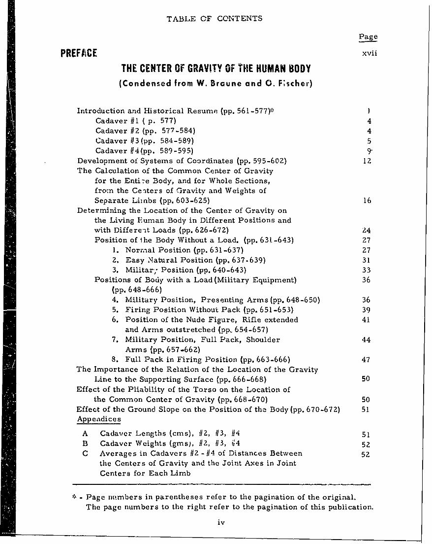
TABLE OF CONTENTS
Page
PREFACE xvii
THE CENTER OF GRAVITY OF THE HUMAN BODY(Condensed from W. Braune and 0. F;scher)
Introduction and Historical Resume (pp. 561-577).* ]
Cadaver #1 ( p. 577) 4Cadaver #2 (pp. 577-584) 4Cadaver #3(pp. 584-589) 5Cadaver #4 (pp. 589-595) 9
Development of Systems of Coordinates (pp. 595-602) 12The Calculation of the Common Center of Gravity
for the Enti-e Body, and for Whole Sections,from the Ce-iters of Gravity and Weights ofSeparate Limbs (pp. 603-625) 16
Determining the Location of the Center of Gravity onthe Living Fuman Body in Different Positions andwith Differe-t Loads (pp. 626-672) 24Position of the Body Without a Load. (pp. 631-643) 27
1. Norr.-ial Position (pp. 631-637) 272. Easy Natural Position (pp. 637-639) 313. Militar; Position (pp. 640-643) 33
Positions of Body with a Load (Military Equipment) 36(pp. 648-666)4. Military Position, Presenting Arms (pp. 648-650) 365. Firing Position Without Pack (pp. 651-653) 396. Position of the Nude Figure, Rifle extended 41
and Arms outstretched (pp, 654-657)7. Military Position, Full Pack, Shoulder 44
Arms (pp. 657-662)8. Full Pack in Firing Position (pp. 663-666) 47
The Importance of the Relation of the Location of the GravityLine to the Supporting Surface (pp. 666-668) 50
Effect of the Pliability of the Torso on the Location ofthe Common Center of Gravity (pp. 668-670) 50
Effect of the Ground Slope on the Position of the Body (pp. 670-672) 51Appeadices
A Cadaver Lengths (cms), 112, 113, 114 51B Cadaver Weights (gins), 112, 113, '4 52C Averages in Cadavers 12 - #4 of Distances Between 52
the Centers of Gravity and the Joint Axes in Joint
Centers for Each Limb
- Page nimbers in parentheses refer to the pagination of the original.
The page numbers to the right refer to the pagination of this publication.
iv
-pa -e
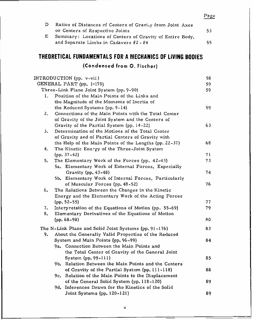
D Ratios of Distances of Centers of Gravity from Joint Axesor Centers of Respective Joints 53
E Summary: Locations of Centers of Gravity of Entire Body,
and Separate Limbs in Cadavers 112 - 114 55
THEORETICAL FUNDAMENTALS FOR A MECHANICS OF LIVING BODIES(Condensed from 0. Fischer)
INTRODUCTION (pp. v-vii) 58GENERAL PART (pp. 1-176) 59
Three-Link Plane Joint System (pp. 9-90) 59
1. Position of the Main Points of the Links andthe Magnitude of the Moments of Inertia of
the Reduced Systems (pp. 9-14) 592. Connections of the Main Points with the Total Center
of Gravity of the Joint System and the Centers of
Gravity of the Partial System (pp. 14-22) 633. Determination of the Motions of the Total Center
of Gravity and of Partial Centers of Gravity withthe Help of the Main Points of the Lengths (pp. 22-37) 68
4. The Kinetic Ene:gy of the Three-Joint System(pp. 37-42) 71
5. The Elementary Work of the Forces (pp. 42-43) 735a. Elementary Work of External Forces, Especially
Gravity (pp. 43-48) 745b. Elementary Work of Internal Forces, Particularly
of Muscular Forces (pp. 48-52) 766. The Relations Between the Changes in the Kinetic
Energy and the Elementary Work of the Acting Forces
(pp. 52-55) 777. Interpretation of the Equations of Motion (pp. 55-69) 798. Elementary Derivatives of the Equations of Motion
(pp. 68-98) 80
The N-Link Plane and Solid Joint Systems (pp. 91-176) 839. About the Generally Valid Properties of the Reduced
System and Main Points (pp. 96.-99) 849a. Connection Between the Main Points and
the Total Center of Gravity of the General JointSystem (pp. 99-111) 85
9b. Relation Between the Main Points and the Centersof Gravity of the Partial System (pp. 1 I 1-118) 88
9c. Relation of the Main Points to the Displacementof the General Solid System (pp. 118-120) 89
9d. Inferences Drawn for the Kinetics of the SolidJoint Systems (pp. 120-121) 89
v
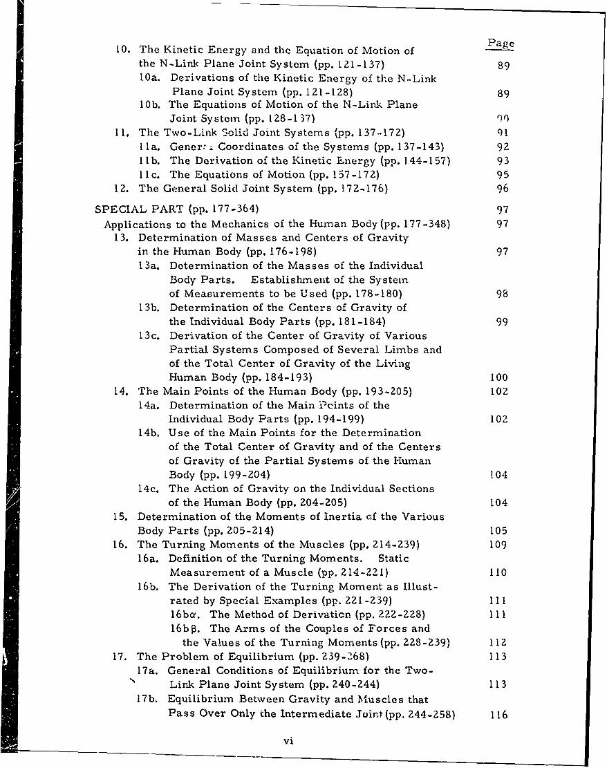
10. The Kinetic Energy and the Equation of Motion of Page
the N-Link Plane Joint System (pp. 121-137) 8910a. Derivations of the Kinetic Energy of the N-Link
Plane Joint System (pp. 12 1-128) 89
10b. The Equations of Motion of the N-Link PlaneJoint System (pp. 128-137) r)
11. The Two-Link Solid Joint Systems (pp. 137-172) 911la. Gener' ; Coordinates of the Systems (pp. 137-143) 92
lb. The Derivation of the Kinetic inergy (pp. 144-157) 931 Ic. The Equations of Motion (pp. 157-17 2) 95
12. The General Solid Joint System (pp. 17Z-176) 96
SPECIAL PART (pp. 177-364) 97
Applications to the Mechanics of the Human Body (pp. 177-348) 9713. Determination of Masses and Centers of Gravity
in the Human Body (pp. 176-198) 9713a. Determination of the Masses of the Individual
Body Parts. Establishment of the Systemof Measurements to be Used (pp. 178-180) 98
13b. Determination of the Centers of Gravity ofthe Individual Body Parts (pp. 18 1-184) 99
13c. Derivation of the Center of Gravity of VariousPartial Systems Composed of Several Limbs andof the Total Center of Gravity of the LivingHuman Body (pp. 184-193) 100
14. The Main Points of the Human Body (pp. 193-205) 10z14a. Determination of the Main Pcints of the
Individual Body Parts (pp. 194-199) 10214b, Use of the Main Points for the Determination
of the Total Center of Gravity and of the Centersof Gravity of the Partial Systems of the HumanBody (pp. 199-204) 104
14c. The Action of Gravity on the Individual Sectionsof the Human Body (pp. 204-205) 104
15. Determination of the Moments of Inertia of the VariousBody Parts (pp. 205-214) 105
16. The Turning Moments of the Muscles (pp. 214-239) 10916 a. Definition of the Turning Moments. Static
Measurement of a Muscle (pp. 214-221) 11016b. The Derivation of the Turning Moment as Illust-
rated by Special Examples (pp. 221-239) 11116bct. The Method of Derivation (pp. 222-ZZ8) ill16b5. The Arms of the Couples of Forces and
the Values of the Turning Moments (pp. 228-239) 11217. The Problem of Equilibrium (pp. 239-268) 113
17a. General Conditions of Equilibrium for the Two-Link Plane Joint System (pp. 240-244) 113
17b. Equilibrium Between Gravity and Muscles thatPass Over Only the Intermediate Joint (pp. 244-258) 116
vi
Page
17b. Equilibrium of the Arm (pp. 244-251) 116171-,. Equilibrium of the Leg (pp. 251-254) 119i7by. Equilibrium Whcn the Mass of the First Link
is to D.sappear: Standing on the Toes
(pp. 254 -256) 12017b6. Equilibrium of the Loaded Arm (pp. 257-258) 121
17c. Equilibrium Between Gravity and Two-JointMuscles (pp. 258-268) 121
l7c0. General Methods of Investigation (pp. 258-264) 12117c8. Special Example: Tvo-Joint Muscle (Long
Head of M. Biceps Brachii) (pp. 265-268) 12218. The Joint Movement Setting in at the Beginning of
the Contraction of a Muscle (pp. 269-321) 12318a. The Investigation of the Initial Movements at the
Two-Link Plane Joint System: Kinetic Measure-ments of a Muscle (pp. 271-276) 123
18b. Kinetic Measure for the Muscles of the Arm
(pp. 276-287) 12518ba. General Expressions for the Kinetic Measure
of the Muscles of the Arm (pp. 276-277) 125
18bo. One-Joint Muscles of the Elbow-Joint
(pp. 278-281) 126
I8by. One-Joint Muscles of thc Shoulder
(pp. 281-284) 128
18b6. Twvo-Joint Muscles of the Arm (pp. 284-288) 13018c. Kinetic Measure for the Muscles of the Leg
(pp. 288-295) 13118ca. Comparison of the Ratios of the Leg with
those of the Arm (pp. 288-291). 131l8c . Special Examples for the Determination of
the Kinetic Measures of the Muscle (pp. 291-295) 13418d. Initial Movements Under Simultaneous Action
of Muscles and Gravity (pp. 295-321) 13418dce. The Action of Gravity Alone (pp. 296-309) 13518do. Special Examples of the Initial Movement
as a Consequence oi the Muscles and Gravity:The Detachment of the Heels from the Grou'-d(pp. 309-321) 140
19. On the Entire Coui se of the Joint Movements During
Continued Contraction of a Muscle (pp. 321-333) 14320. Use of Equations of Motion for the Determination of
the Muscle Forces with the Movement of the Human
Body Being Known (pp. 333-348) 148
Vii
Page
Some Applications to Processes of Motion in Machines(pp. 349-364) 15321. The Resulting Mass Pressure at the Crank Mechanism
and its Balance (pp. 349-359) 153ZZ. The Motions of a Physical Pendulum with Rotary Bob
(pp. 359-364) 153
THE HUMAN MOTOR(Condensed from J. Amar)
The General Principles of Mechanics (pp. 1-84) 154I -- Statics and Kinetics (pp. 1-30) 154
II Dynamics and Energetics (pp. 31-59) 158III Resistance of Materials - Elasticity - Machines (pp. 60-84) 160
The Human Machine (pp. 85-164) 161I The Human Structure (pp. 85-116) 161
II The Muscular Motor and Alimentation (pp. 117-138) 167III Alimentation and the Experditure of Energy(pp. 139-164) 172
Human Energy (pp. 165-214) 173I The Laws of Energetic Expenditure (pp. 165-186) 173
II The Yield of the Human Machine (pp. 186-198) 180III Physiological Effects of Labor - Fatigue (pp. 199-214) 181
Man and His Environment (pp. 215-260) 183I The Internal Environment (pp. 215-ZZ6) 183
II The External Environment (pp. 227-236) 185III The External Environment (cont.) (pp. 237 -249) 188IV The External Environment (cont.) (pp. 250-260) 190
Experimental Methods (pp. 261-332) 190I Measurements and Instruments (pp. 261-288) 190
I Measurements - Dynamic Elements (pp. 289-307) 191III Measurement of Energy (pp. 308-332) 194
Industrial Labor (pp. 333-466)- 198I Body in Equilibrium and Movement - Locomotion
(pp. 333-358) 198II Industrial Labor and Locomotion (pp. 359-391) 209
III Industrial Labor - Tools (pp. 392-426) 214IV Industrial Work (cont.) (pp. 427-461) 214V General Conclusions (pp. 46Z-466) 214
viii
SPACE REQUIREMENTS OF THE SEATED OPERATOR
(Condensed from W.T. Dempster)Page
Glossary (pp. xvi - xx) 215
Introduction (pp. 1-5) 221
Materials and Methods (pp. 6-67) 223
The Link System of the Body (pp. 68-79) 234
Kinematic Aspects of Extremity Joints (pp. 80-133) 239
Application to Manikin Design (pp. 134-158) 259
A. The Three-Dimensional Model (pp. 135-152) 259
B. Drafting Board Manikins (pp. 1 52-158) 262
Work Space Requirements of the Seated Indi-,idual (pp. 159-182) 264
A. Characteristics of the Hand Space (pp. 162-173) 266
B. Characteristics of the Foot Space (pp. 173-178) 272
C. The Overall Work Space (pp. 178-182) 274
Mass Relations of Cadaver Segments (pp. 183-201) 277
Body Bulk Distribution in Living Subjects (pp. 202-216) 292
How Body Mass Affects Push and Pull Forces (pp. 217-234) 302
Conclusion - Aspects of Practical Concern (pp. 235-241) 308
Appendices
I. Plans For Three-Dimensional Manikin 310
II. Plans For Drafting Board Manikin 323
Bibliography 328
INDEX 341
ix
FIGURES
Fifgure No. Page No.
1. Diagram to Show How a Resultant Can be Obtained
from Two or More Parallel Forces 16
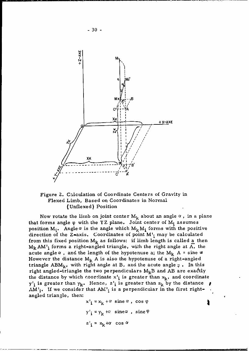
2. Calculation of Coordinate Centers of Gravity in the FlexedLimb, Based on Coordinates in Normal (Unflexed) Position 30
3. Plane Movements in a Three-Link System 60
4. Three Main Points Defined by Centers of GravityS 1, S , S 3 and Ratio of Magnitude of the Three Masses 61
5. Construction of the Total Center of Gravity, So 646. Method of Obtaining Positions of So of Each Position of -
Three Links in Relation to One Another 657. Two-Link System Where S , H1, G, I-1 are Corners of
a Parallelogram 658. Method of Obtaining So of Two-Link System Starting From
Main Point of One Line 669. Translatory Motion in Link 3 of a Three-Link System 68
10. Linear Velocities of Main Points H1 6911. Demonstration of the Work of External Forces,
Gravity, Especially 7412. Action of Equal and Opposite Forces in a Three-Link
System with Straight Pull.-Line 7613. Action of Equal and Opposite Forces in a Three-Link
System, with Pull-Line over a Link Protrusion 7614. Action of Equal and Opposite Forces in a Thiree-Link System
with Pull-Line Over Two Non-Adjacent Limbs 7715. A Six-Link System 8516. Basic Principles of the Coordinate System 9217. Joint Mechanism to Show Total Center of Gravity
for Any Body Position 10118. Duration of Oscillation for Two Axes Parallel to Each Other,
with Axes on Different Sides of the Center of Gravity 10519. Two-Link System Where Link 1 Rotates Around a Fixed Point 11320. Arms of Two Couples of Forces 11521. Flexion Positions 116Z2. Extension Positions 116Z3. Shoulder-Joint (G1 8) Related to(S 8 0) of Arm 11624. Long Axes bf Thigh Between Hip-Joint Center (G1 , .) and
Knee-Joint Center (G2 4) 11925. One-Joint Muscle in Equilibrium to Gravity, with Weight
(G'), Held in Eand 121
x
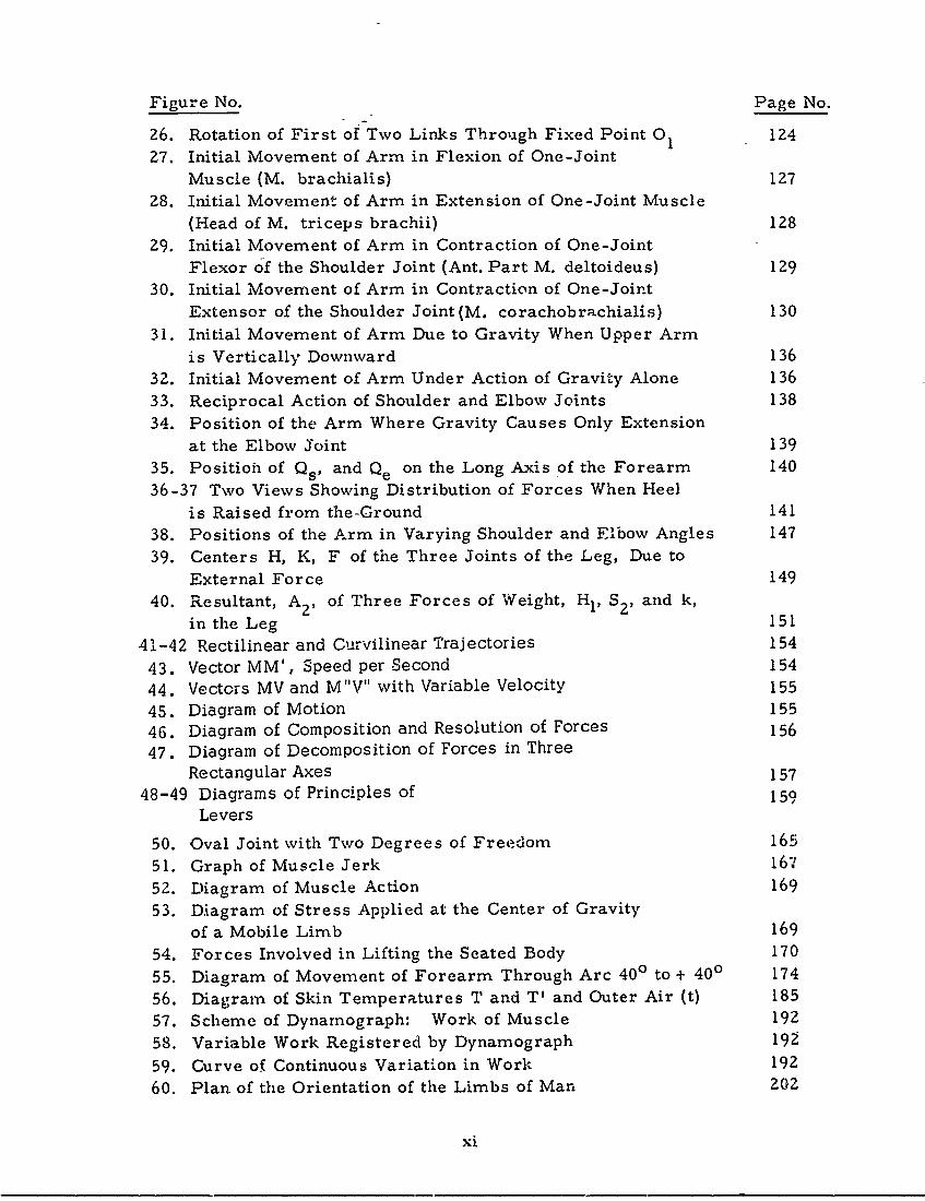
Figure No. Page No.
26. Rotation of First of Two Links Through Fixed Point 01 124
27. Initial Movement of Arm in Flexion of One-JointMuscle (M. brachialis) 127
28. Initial Movement of Arm in Extension of One-Joint Muscle
(Head of M. triceps brachii) 12829. Initial Movement of Arm in Contraction of One-Joint
Flexor of the Shoulder Joint (Ant. Part M. deltoideus) 129
30. Initial Movement of Arm in Contraction of One-JointExtensor of the Shoulder Joint(M. corachobrachialis) 130
31. Initial Movement of Arm Due to Gravity When Upper Arm
is Vertically Downward 13632. Initial Movement of Arm Under Action of Gravity Alone 136
33. Reciprocal Action of Shoulder and Elbow Joints 13834. Position of the Arm Where Gravity Causes Only Extension
at the Elbow Joint 139
35. Position of Qs1 and Qe on the Long Axis of the Forearm 140
36-37 Two Views Showing Distribution of Forces When Heel
is Raised from the-Ground 141
38. Positions of the Arm in Varying Shoulder and Elbow Angles 147
39. Centers H, K, F of the Three Joints of the Leg, Due to
External Force 149
40. Resultant, A 2 , of Three Forces of Weight, HI, S21 and k,in the Leg 151
41-42 Rectilinear and Curvilinear Trajectories 154
43. Vector MM', Speed per Second 154
44. Vectors MV and M"V" with Variable Velocity 15545. Diagram of Motion 15546. Diagram of Composition and Resolution of Forces 15647. Diagram of Decomposition of Forces in Three
Rectangular Axes 15748-49 Diagrams of Principles of 159
Levers
50. Oval Joint with Two Degrees of Freedom 165
51. Graph of Muscle Jerk 167
52. Diagram of Muscle Action 169
53. Diagram of Stress Applied at the Center of Gravityof a Mobile Limb 169
54. Forces Involved in Lifting the Seated Body 170
55. Diagram of Movement of Forearm Through Arc 400 to + 400 174
56. Diagram of Skin Temperatures T and T' and Outer Air (t) 185
57. Scheme of Dynarnograph: Work of Muscle 192
58. Variable Work Registered by Dynamograph 192
59. Curve of Continuous Variation in Work 192
60. Plan of the Orientation of the Limbs of Man 202
xi
rigure No. Page No.
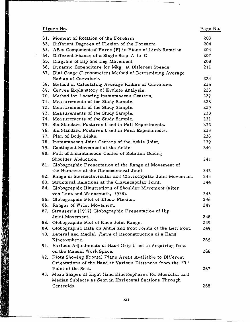
61. Moment of Rotation of the Forearm 20362. Different Degrees of Flexion of the Forearm 204
63. AB = Component of Force (F) in Plane of Limb Rotati -n 20464. Different Phases of a Single Step A to C 20765. Diagram of Hip and Leg Movement 20866. Dynamic Expenditure for Mkg at Different Speeds 211
67. Dial Gauge (Lensometer) Method of Determining Average
Radius of Curvature. ZZ468. Method of Calculating Average R..dius of Curvature. 22569. Curves Explanatory of Evolute Analysis. 22670. Method for Locating Instantaneous Centers. 227
71. Measurements of the Study Sample. 22872. Measurements of the Study Sample. L29
73. Measurements of the Study Sample. Z30
74. Measurements of the Study Sample. 23175. Six Standard Postures Used ii Pull Experiments. 232
76. Six Standard Postures Used in Push Experiments. 23377. Plan of Body Links. 23678. Instantaneous Joint Centers of the Ankle Joint. 239
79. Contingent Movement at the Ankle. 24080. Path of Instantaneous Center of Rotation During
Shoulder Abduction. 241
81. Globographic Presentation of the Range of Movement ofthe Humerus at the Glenohumeral Joint. 24Z
82. Range of Sterneclavicular and Claviscapular joint Movement. 24383. Structural Relations at the Claviscapular Joint. 24484. Globographic Illustrations of Shoulder Movement (after
von Lanz and Wachsmuth, 1938). 24585. Globographic Plot of Elbow Flexion. 246
86. Ranges of Wrist Movement. 24787. Strasser's (1917) Globographic Presentation of Hip
Joint Movement. 24888. Globographic Plot of Knee Joint Range. 24989. Globographic Data on Ankle and Foot Joints o.( the Left Foot. 249
90. Lateral and Medial Jiews of Reconstruction of a HandKinetosphere. 265
91. Various Adjustments of Hand Grip Used in Acquiring Dataon the Manual Work Space. 266
92. Plots Showing Frontal Plane Areas Available to Different
Orientations of the Hand at Various Distances from the "R"Point of the Seat. Z67
93. Mean Shapes of Eight Hand Kinetospheres for Muscular andMedian Subjects as Seen in Horizontal Sections Through
Centroids. 268
xii
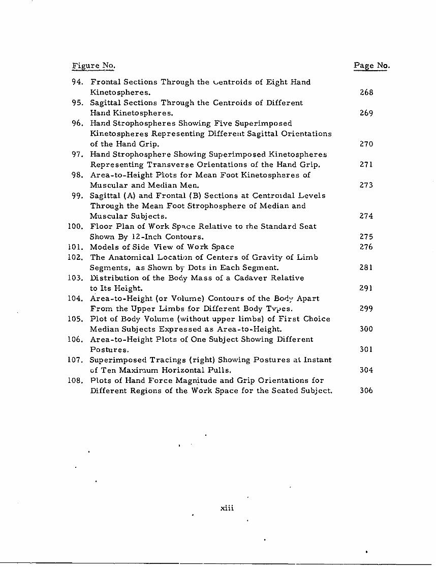
Figure No. Page No.
94. Frontal Sections Through the ,,entroids of Eight HandKineto spheres. 268
95. Sagittal Sections Through the Centroids of Different
Hand Kinetospheres. 269
96. Hand Strophospheres Showing Five SuperimposedKinetospheres Representing Different Sagittal Orientations
of the Hand Grip. 27097. Hand Strophosphere Showing Superimposed Kinetospheres
Representing Transverse Orientations of the Hand Grip. 27198. Area-to-Height Pkots for Mean Foot Kinetospheres of
Muscular and Median Men. 27399. Sagittal (A) and Frontal (B) Sections at Centroidal Levels
Through the Mean Foot Strophosphere of Median andMuscular Subjects. 274
100. Floor Plan of Work Spakce Relative to the Standard SeatShown By 12-Inch Contours. 275
101. Models of Side View of Work Space 276102. The Anatomical Location of Centers of Gravity of Limb
Segments, as Shown by Dots in Each Segment. 281103. Distribution of the Body Mass of a Cadaver Relative
to Its Height. 291104. Area-to-Height (or Volume) Contours of the Body Apart
From the Upper Limbs for Different Body Tvpes. 299105. Plot of Body Volume (without upper limbs) of First Choice
Median Subjects Expressed as Area-to-Height. 300106. Area-to-Height Plots of One Subject Showing Different
Postures. 301107. Superimposed Tracings (right) Showing Postures at Instant
of Ten Maxirmum Horizontal Pulls. 304108. Plots of Hand Force Magnitude and Grip Orientations for
Different Regions of the Work Space for the Seated Subject. 306
xiii
TABLES
Table No. Page No.
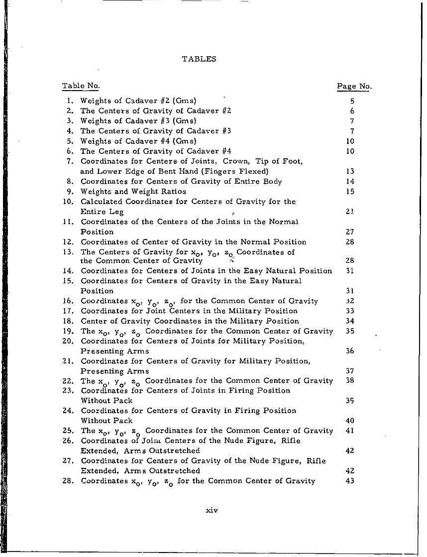
1. Weights of Cadaver #2 (Gins) 5
2. The Centers of Gravity of Cadaver #2 63. Weights of Cadaver #3 (Gms) 74. The Centers of Gravity of Cadaver #3 75. Weights of Cadaver #4 (Gins) 106. The Centers of Gravity of Cadaver #4 10
7. Coordinates for Centers of Joints, Crown, Tip of Foot,and Lower Edge of Bent Hand (Fingers Flexed) 13
8. Coordinates for Centers of Gravity of Entire Body 14
9. Weights and Weight Ratios 1510. Calculated Coordinates for Centers of Gravity for the
Entire Leg 2 '11.
11. Coordinates of the Centers of the Joints in the NormalPosition 27
12. Coordinates of Center of Gravity in the Normal Position 2813. The Centers of Gravity for x0 , yo, zo Coordinates of
the Common Center of Gravity 2814. Coordinates for Centers of Joints in the Easy Natural Position 3115. Coordinates for Centers of Gravity in the Easy Natural
Position 3116. Coordinates xo: Y.1 z0 , for the Common Center of Gravity .3217. Coordinates for Joint Centers in the Military Position 3318. Center of Gravity Coordinates in the Military Position 3419. The xo , Yo, Z0 Coordinates for the Common Center of Gravity 3520. Coordinates for Centers of Joints for Military Position,
Presenting Arms 3621. Coordinates for Centers of Gravity for Military Position,
Presenting Arms 3722. The xo , YO, zo Coordinates for the Common Center of Gravity 3823. Coordinates for Centers of Joints in Firing Position
Without Pack 3924. Coordinates for Centers of Gravity in Firing Position
Without Pack 4025. The x0, Yo ' zo Coordinates for the Common Center of Gravity 4126. Coordinates of JoinL Centers of the Nude Figure, Rifle
Extended, Arms Outstretched 4227. Coordinates for Centers of Gravity of the Nude Figure, Rifle
Extended, Arms Outstretched 4228. Coordinates xo , Yop Zo for the Common Center of Gravity 43
xiv
Table No. Page No.
29. Coordinates for the Joint Centers in Military Position,Full Pack, Shoulder Arms 44
30. Coordinates for the Centers of Gravity in Military Position,
Full Pack, Shoulder Arms 4431. Coordinates x o , Y0 1 Z0 for the Common Center of Gravity 4532. Coordinates for Joint Centers, Full Pack, Firing Position 47
33. Coordinates for the Centers of Gravity, Full Pack,Firing Position 48
34. Coordinates xo , Yo, zo for the Common Center of Gravity 4835. Weight Numbers, G, and Mass Numbers, m, for the Individual
Sections of a Living Human Being 9836. Weights, Masses, Locations of the Centers of Gravity,
and Moments of Inertia of Individual Parts of the Human Body 10737. The Values of the Radii of Inertia, xo, for Axes Through
the Center of Gravity 10938. Direct Measurements or. the Lower Extremity with
Values a2 and 4 132
39. Direct Measurements on the Lower Extremity withValues c 4 and 04,6 133
p6 1440. Breaking Stress in the Femur and Fibula 16141. Breaking (Weight) in Flexion and Shearing 16Z42. Elastic Properties of Various Materials 164
43. Caloric Expenditure and Weight 17344. Caloric Production in Intellectual Work 183
45. Volume of the Body at Different Temperatures 19146. Tactile Sensibility 197
47. Energy Expenditure per M-Kgm 21248. Energy Expended in the Ascending Walk 21349. Joint Range of Study Subjects. 25150. Estimation of Link Dimensions of Air Force Flying
Personnel Based on Ratios From Cadaver Measurements. 25551. Relative Dimensions of Extremity Links Expressed As
Ratios of One Dimension to Another. 25852. Mass of Body Parts. 27853. Mass, Upper Extremity. 279
54. Mass, Lower Extremity. 28055. Anatomical Location of Segment Centers of Gravity. 28256. Anatomical Location of Segment Centers of Gravity. 28357. Relative Distance Between Center of Gravity and Joint Axes
or Other Landmarks 284
xv
Table No. Page No.
58. Moments of Inertia About the Center of Gravity (I cg)of Body Segments. 287
59. Moments of Inertia About the Proximal Joint Center (Io)of Body Segments. 288
60. Moments of Inertia of Trunk Segments About Their
Centers of Gravity (I cg). 289
61. Moments of Inertia of Trunk Segments About SuspensionPoints (1o). 290
62. Ratio of Mean Volume of Limb Segments to Body Volume. 29363. Volume of Limb Segments in Cubic Centimeters and
Percentages of Body Volume -Rotund Physique. 29464. Volume of Limb Segments in Cubic Centimeters and
Percentages of Body Volume -Muscular Physique. 29565. Volume of Limb Segments in Cubic Centimeters and
Percentages of Body Volume - Thin Physique. -' 296
66. Volume of Limb Segments in Cubic Centimeters andPercentages of Body Volume -Median Physique. 297
xvi
PREFACE
Kenneth W. Kennedy
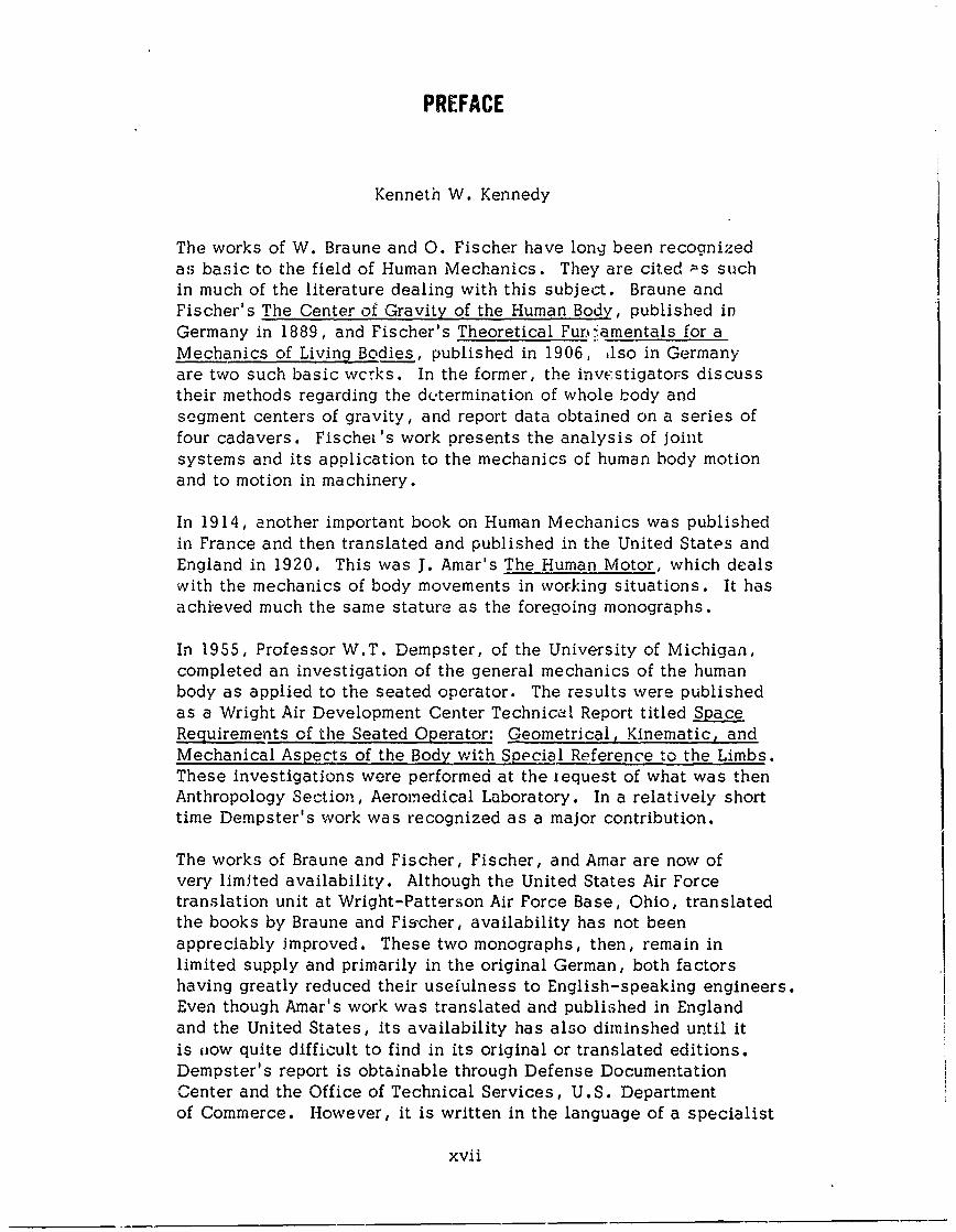
The works of W. Braune and 0. Fischer have long been recognizedas basic to the field of Human Mechanics. They are cited Ps suchin much of the literature dealing with this subject. Braune andFischer's The Center of Gravity of the Human Body, published inGermany in 1889, and Fischer's Theoretical Fur'amentals for aMechanics of Living Bodies, published in 1906, ilso in Germanyare two such basic wcrks. In the former, the invcestigators discusstheir methods regarding the determination of whole body andsegment centers of gravity, and report data obtained on a series offour cadavers. Fischei's work presents the analysis of jointsystems and its application to the mechanics of human body motionand to motion in machinery.
In 1914, another important book on Human Mechanics was publishedin France and then translated and published in the United States andEngland in 1920. This was J. Amar's The Human Motor, which dealswith the mechanics of body movements in working situations. It hasachieved much the same stature as the foregoing monographs.
In 1955, Professor W.T. Dempster, of the University of Michigan,completed an investigation of the general mechanics of the humanbody as applied to the seated operator. The results were publishedas a Wright Air Development Center Technica- Report titled SpaceRequirements of the Seated Operator: Geometrical, Kinematic, andMechanical Aspects of the Body with Special Reference to the Limbs.These investigations were performed at the iequest of what was thenAnthropology Section, Aeromedical Laboratory. In a relatively shorttime Dempster's work was recognized as a major contribution.
The works of Braune and Fischer, Fischer, and Amar are now ofvery limited availability. Although the United States Air Forcetranslation unit at Wright-Patterson Air Force Base, Ohio, translatedthe books by Braune and Fischer, availability has not beenappreciably improved. These two monographs, then, remain inlimited supply and primarily in the original German, both factorshaving greatly reduced their usefulness to English-speaking engineers.Even though Amar's work was translated and published in Englandand the United States, its availability has also diminshed until itis now quite difficult to find in its original or translated editions.Dempster's report is obtainable through Defense DocumentationCenter and the Office of Technical Services, U.S. Departmentof Commerce. However, it is written in the language of a specialist
xvii
and has been found somewhat difficult to use by some investi-gators not expeilenced in the field of Human Mechanics.
During the preparation of WADC Technical Report 56-30, AnnotatedBibliography of Applied Physical Anthropology in Human Engineering(1958), by R. Hansen and D. Cornog, the editor, Mr. Hertzberg,decided that these monographs were of too great a magnitude to berepresented adequately in the brief treatment required in thatpublication. Because of their size, limited availability, and thedifficulty some engiieers experience when interpreting their dataand methods, Mr. Hertzberg conceived the idea of having theseworl's condensed and published together in a single volume.His object was twofold: first, such treatment would draw togetherfour basic monographs, with all the essential methods and datafound in the originals; and second, the wider distribution wouldpresent to many human factors engineers imrportant sources thatotherwise might have remained inaccessible to them.
We hope that, through the labors of Drs. Krogman and Johnston,we have accomplished those purposes.
xviii
THE CENTER OF GRAVITY OF THE HUMAN BODY
(Condensed from W. Braune and 0. Fischer)

DISCLAIMER NOTICE
THIS DOCUMENT IS BEST QUALITYPRACTICABLE. THE COPY FURNISHEDTO DTIC CONTAINED A SIGNIFICANTNUMBER OF PAGES WHICH DO NOTREPRODUCE LEGIBLY.
0R C-Q:Y - BEST-© i AVAILABLE COPY
BESTAVAILABLE COPY
- I -
THE CENTER OF GRAVITY OF THE HUMAN BODY
(Condensed froma W. Braune and 0. Fischer)
Introduction and Historical Resume ( pp 561-577)
The Earth's power of attraction exerts a force on everycenter of gravity in the human body. This force acts along aline which :is theoretically connected to the Earth's center andis equal to ,the, weight of the mass at the original point. Becauseof the great distance from the Earth's center to these points allthe lines are virtua,, parallel. The resultant is a fixed straightline for every position of the body. This line does not changeas long as the liody is not displaced in space over too great adistance, while still remaining in its original parallel position. M-eline changes its position in the body as soon as the body rotatesaround it. The straight line in its changed position intersects theformer line at a d&finitc point; and all other and similar lines passthrough this pbint. The point of intersection so established Is thecommon point of attachment for all resultants of the force of theinertia, for every possible body position, i. e., it is the centerof -gravity of the entire body.
The size of the resultant equals the total body weight of allindividual vertical forces. The weights of all separate parts of thebody are united at the body's center of gravity: this is the body'sgravity line ( a line connecting the body's center of gravity with theEarth's center). It does not change its absolute position in spaceif the center of gravity is unchanged, no matter how the body is rotated.Every rotation of the body on the center of gravity changes theposition of the gravity line in relation to the body itself. As long asthe line of gravity intersects the body's supporting surface the bodyremains vertical; if the line is outside the supporting surface of thebody it may fall down. The supporting surface of the erect body isits two soles and the space between the double tangent in contactwith toe tip anu' heel.
A supporting center pf gravity can have three positions inrelation to its supporting pcint: I) it can coincide with the point( indifferent equilibrium); 2) it can be above the point, in which caseevery rotation of the body moves the center of gravity away from thevertical and lowers it ( labile equilibrium); 3) it can be below thepoint, in which case any rotation of the body raises it, and createsa moment of rotation that brings the center of gravity to its originalposition ( stable equilibrium). In labile equilibrium the center of
gravity attains its highest position in rotating on the supporting point,whereas in stable equilibrium it attains its lowest position.
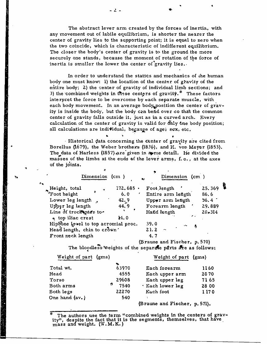
The abstract lever arm created by the forces of inertia, withany movement out of labile equilibrium, is shorter the nearer thecenter of gravity lies to the supporting point; it is equal to zero whenthe two coincide, which is characteristic of indifferent equilibrium.The closer the body's center of gravity is to the ground the moresecurely one stands, because the moment of rotation of th, e force ofinertia is smaller the lower the center of gravity lies.,
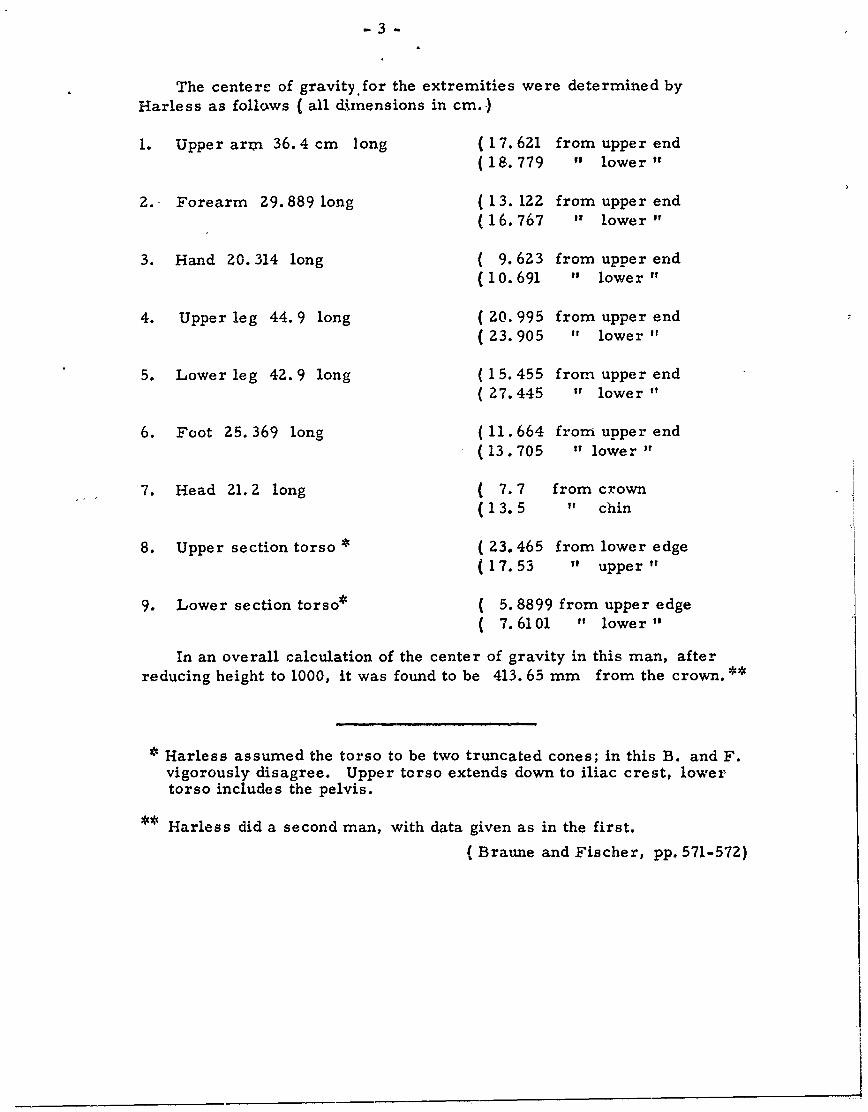
In order to understand the statics and mechanics of che humanbody one miust know: 1) the location of the center of gi-avity of theentire body; 2) the "-enter of gravity of individual limb sections; and3) the 'combined weights in tiese cent rs of gravite.* These factorsinterpret the force to be overcome by tach separate muscle, witheach body movement. In an average bodyposition the center of grav-ity is inside the body, but the body cqn befid over co that, the commoncenter of gravity falls outside it, just as in a curved arch. Everycalculation of the center of gravity is valid for drnly fne body position;all calculations are individual, becauae of atge sex, etc.
- Historical Oata concerning the Center of gravity are cited from
Borellus (1679), the Weber brothez% (183 ), and H. von Meyer (1853).The data of Harless (1857) ,mre given in tme detail. Me divided themasses of the limbs at the e'Qds cof the lever arms, f. e., at the axesof the joints.
-t
-- Dimension (cm) Dimension (cm)
SHeight, total 172. 685 Footlength 25. 369-,.Foot height 6.0 Entire arm lefigth 86.6Lower leg length ,, 42. 9 Uppwr arm length 6. 4
Up pr leg length 44. 9 Forearm length ' Z9. 889Line 3f trociiter to- HaIld length Z0,^314
, top iliac crest ki. 0Hiplbne e:-el to top acromial proc. 39.0Heaff length, chin to crown Z 1. 2Front neck length 4.7
(Braune and Fischer, p. 570)The bloodless Wveights of the separAe parts Aie as follows:
Weight of part (gins) Weight of part (gms)
Total wt. 63970 Each forearm 1160
Head 4555 Each upper arm 2070Torso 29608 Each upper leg 71 65Both arms ' 7540 - Each lower leg 28 00Both legs 22270 Each foot 117 0One hand (av.) 540
(Braune and Fischer, p. 571).
* The authors use the term "combined weights in the centers of grav-
ity", despite the fact that it is the segments, themselves, that havemass and weight. (W.M.K.)
-3-
The centere of gravity.for the extremities were determined byHarless as follows ( all dimensions in cm.)
1. Upper arm 36.4 cm long (17.621 from upper end(18.779 " lower
2. Forearm 29. 889 long (13. 122 from upper end(16.767 It lower' t
3. Hand 20. 314 long ( 9.623 from upper end(10.691 " lower 1
4. Upper leg 44.9 long (20. 995 from upper end( 23. 905 " lower "
5. Lower leg 42. 9 long (15. 455 from upper end( 27.445 ,1 lower "
6. Foot 25.369 long (11.664 from upper end(13.705 " lower t
7. Head 21. 2 long ( 7.7 from crown(13.5 " chin
8. Upper section torso ( 23.465 from lower edge(17.53 " upper"
9. Lower section torso* ( 5. 8899 from upper edge( 7.6101 " lower"
In an overall calculation of the center of gravity in this man, afterreducing height to 1000, it was found to be 413. 65 mm from the crown.**
Harless assumed the torso to be two truncated cones; in this B. and F.vigorously disagree. Upper torso extends down to iliac crest, lowertorso includes the pelvis.
* Harless did a second man, with data given as in the first.
(Braune and Fischer, pp. 571-572)
-4-
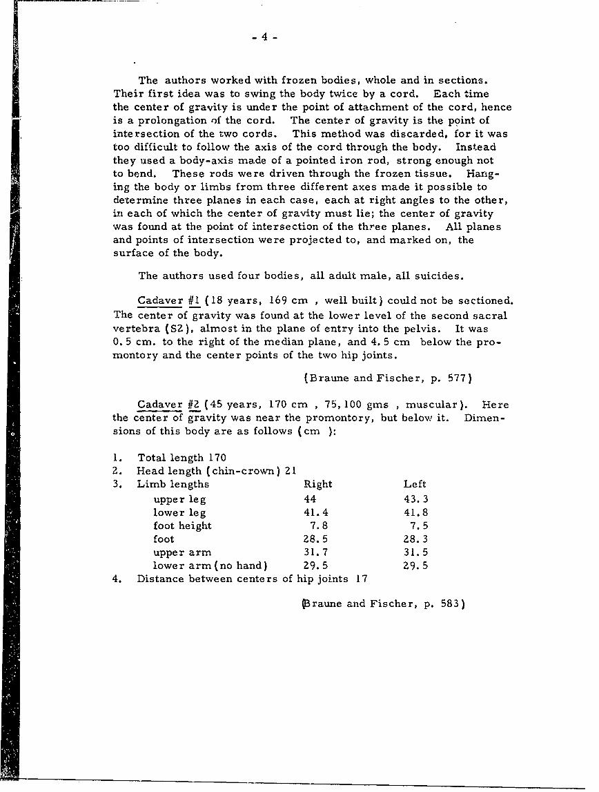
The authors worked with frozen bodies, whole and in sections.Their first idea was to swing the body twice by a cord. Each timethe center of gravity is under the point of attachment of the cord, henceis a prolongation of the cord. The center of gravity is the point ofintersection of the two cords. This method was discarded, for it wastoo difficult to follow the axis of the cord through the body. Insteadthey used a body-axis made of a pointed iron rod, strong enough notto bend. These rods were driven through the frozen tissue. Hang-ing the body or limbs from three different axes made it possible todetermine three planes in each case, each at right angles to the other,in each of which the center of gravity must lie; the center of gravitywas found at the point of intersection of the three planes. All planesand points of intersection were projected to, and marked on, thesurface of the body.
The authors used four bodies, all adult male, all suicides.
Cadaver #1 (18 years, 169 cm , well built) could not be sectioned.The center of gravity was found at the lower level of the second sacralvertebra (SZ), almost in the plane of entry into the pelvis. It was0. 5 cm. to the right of the median plane, and 4. 5 cm below the pro-montory and the center points of the two hip joints.
(Braune and Fischer, p. 577)
Cadaver #2 (45 years, 170 cm , 75, 100 gms , muscular). Herethe center of gravity was near the promontory, but below it. Dimen-sions of this body are as follows (cm):
1. Total length 1702. Head length (chin-crown) 213. Limb lengths Right Left
upper leg 44 43.3lower leg 41.4 41.8foot height 7.8 7.5foot 28.5 28.3upper arm 31.7 31.5lower arm (no hand) 29.5 29.5
4. Distance between centers of hip joints 17
Braune and Fischer, p. 583)
-5-
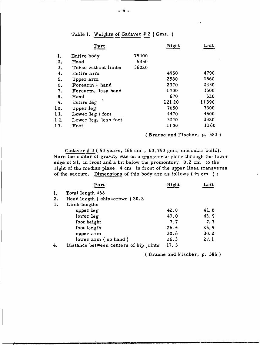
Table 1. Weights of Cadaver # 2 (Gins. )
Part Right Left
1. Entire body 751002. Head 53503. Torso without limbs 360204. Entire arm 4950 47905. Upper arm 2580 25606. Forearm + hand 2370 22307. Forearm, less hand 1700 16008. Hand 670 6209. Entire leg 12120 11890
10. Upper leg 7650 730011. Lower leg + foot 4470 45001 2. Lower leg, less foot 3210 33Z013. Foot 1100 1160
(Braune and Fischer, p. 583 )
Cadaver # 3 ( 50 years, 166 cm , 60, 750 gins; muscular build).Here the center of gravity was on a transverse plane through the loweredge of Sl, in front and a bit below the promontory, 0. 2 cm to theright of the median plane, 4 cm in front of the upper linea transversaof the sacrum. Dimensions of this body are as follows (in cm )
Part Rig Left
1. Total length 166Z. Head length ( chin-crown ) 20. 23. Limb lengths
upper leg 42.0 41.0lower leg 43.0 42.9foot height 7.7 7.7foot length 26.5 26.9upper arm 30.6 30.Zlower arm ( no hand) 26.3 27. 1
4. Distance between centers of hip joints 17. 5
(Braune and Fischer, p. 588 )
-6 -
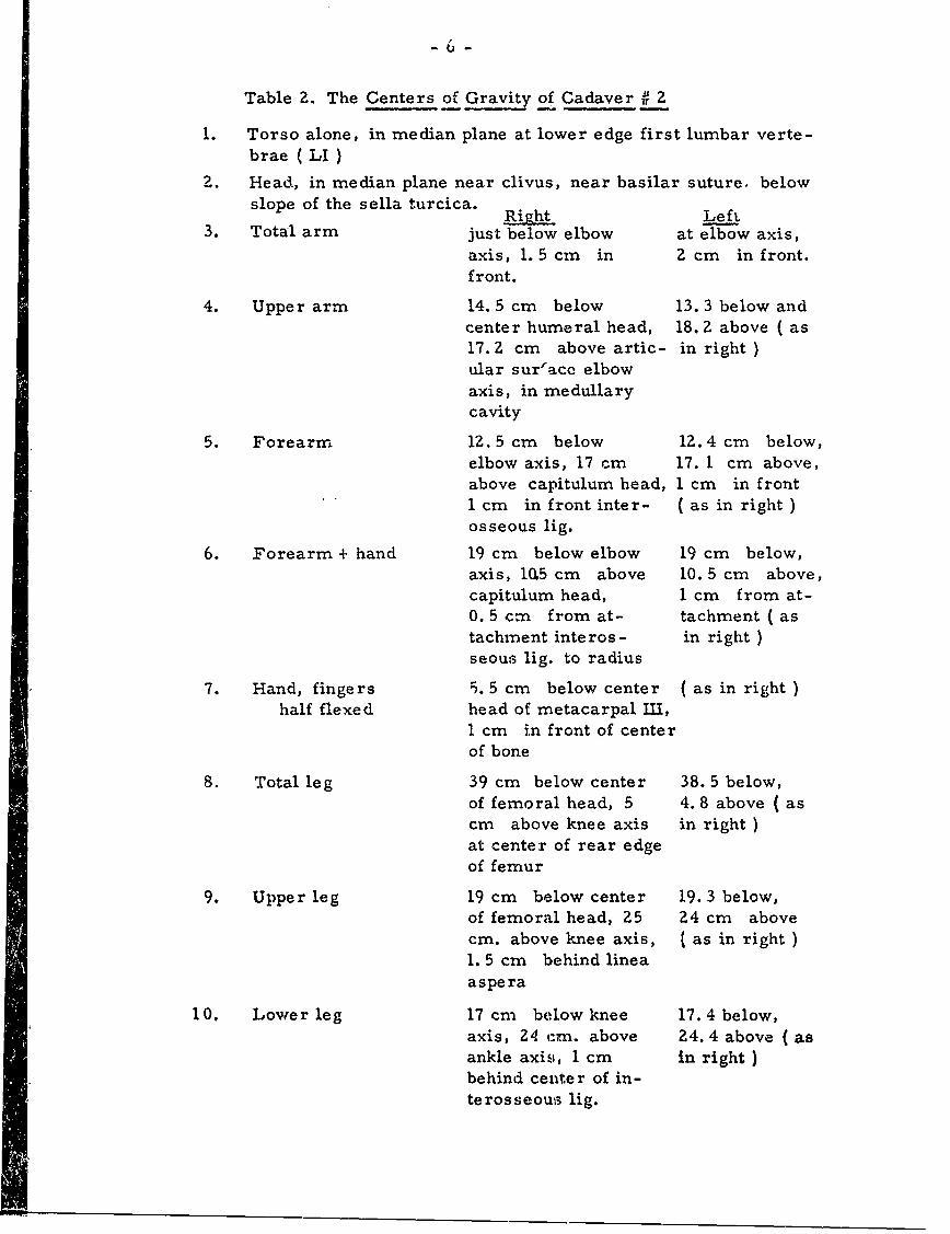
Table Z. The Centers of Gravity of Cadaver u 2
Torso alone, in median plane at lower edge first lumbar verte-
brae ( LI )
Z. Head, in median plane near clivus, near basilar suture. belowslope of the sella turcica. Righ Left
3. Total arm just below elbow at elbow axis,axis, 1. 5 cm in 2 cm in front.front.
4. Upper arm 14. 5 cm below 13. 3 below andcenter humeral head, 18. 2 above ( as17. 2 cm above artic- in right )ular sur-ace elbowaxis, in medullarycavity
5. Forearm 12. 5 cm below 12. 4 cm below,elbow axis, 17 cm 17. 1 cm above,above capitulum head, 1 cm in front1 cm in front inter- ( as in right )osseous lig.
6. Forearm + hand 19 cm below elbow 19 cm below,axis, 10.5 cm above 10. 5 cm above,capitulum head, 1 cm from at-0. 5 cm from at- tachment ( astachment interos - in right )seous lig. to radius
7. Hand, fingers 5. 5 cm below center ( as in right )half flexed head of metacarpal IMI,
1 cm in front of centerof bone
8. Total leg 39 cm below center 38. 5 below,of femoral head, 5 4. 8 above ( ascm above knee axis in right )at center of rear edgeof femur
9. Upper leg 19 cm below center 19. 3 below,of femoral head, 25 24 cm abovecm. above knee axis, ( as in right )1. 5 cm behind lineaaspera
10. Lower leg 17 cm below knee 17. 4 below,axis, 24 cm. above 24. 4 above ( asankle axis, 1 cm in right )behind center of in-terosseous hg.
-7-
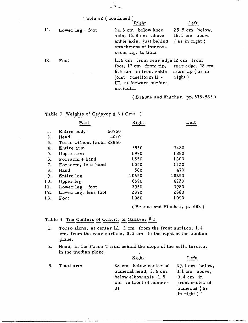
Table #2 (continued)Right Left
11. Lower leg + foot 24.6 cm below knee 25.5 cm below,axis, 16. 8 cm above 16. 3 cm above
ankle axis, just behind ( as in right )attachment of interos-seous lig. to tibia
12. Foot 11. 5 cm from rear edge 12 cm fromfoot, 17 cm from tip, rear edge, 18 cm
6. 5 cm in front ankle from tip ( as injoint, cuneiform H - right )III, at forward surfacenavicular
( Braune and Fischer, pp. 578-583 )
Table 3 Weights of Cadaver # 3 ( Gms )
Part Right Left
1. Entire body 607502. Head 40403. Torso without limbs 288504. Entire arm 3550 34805. Upper arm 1990 18806. Forearm + hand 1550 16007. Forearm, less hand 1050 11208. Hand 500 4709. Entire leg 10650 10250
10. Upper leg ,6690 622011. Lower leg+ foot 3950 398012. Lower leg, less foot 2870 288013. Foot 1060 1090
( Braune and Fischer, p. 588 )
Table 4 The Centers of Gravity of Cadaver # 3
1. Torso alone, at center Ll, 2 cm from the front surface, 1. 4cm. from the rear surface, 0. 3 cm to the right of the medianplane.
2. Head, in the Fossa Tarini behind the slope of the sella turcica,in the median plane.
RLeft
3. Total arm 28 cm below center of 29.1 cm below,humeral head, 2.. 6 cm 1.1 cm above,
below elbow axis, 1.8 0.4 cm incm in front of humer- front center of
us humerus (asin right )
-8-
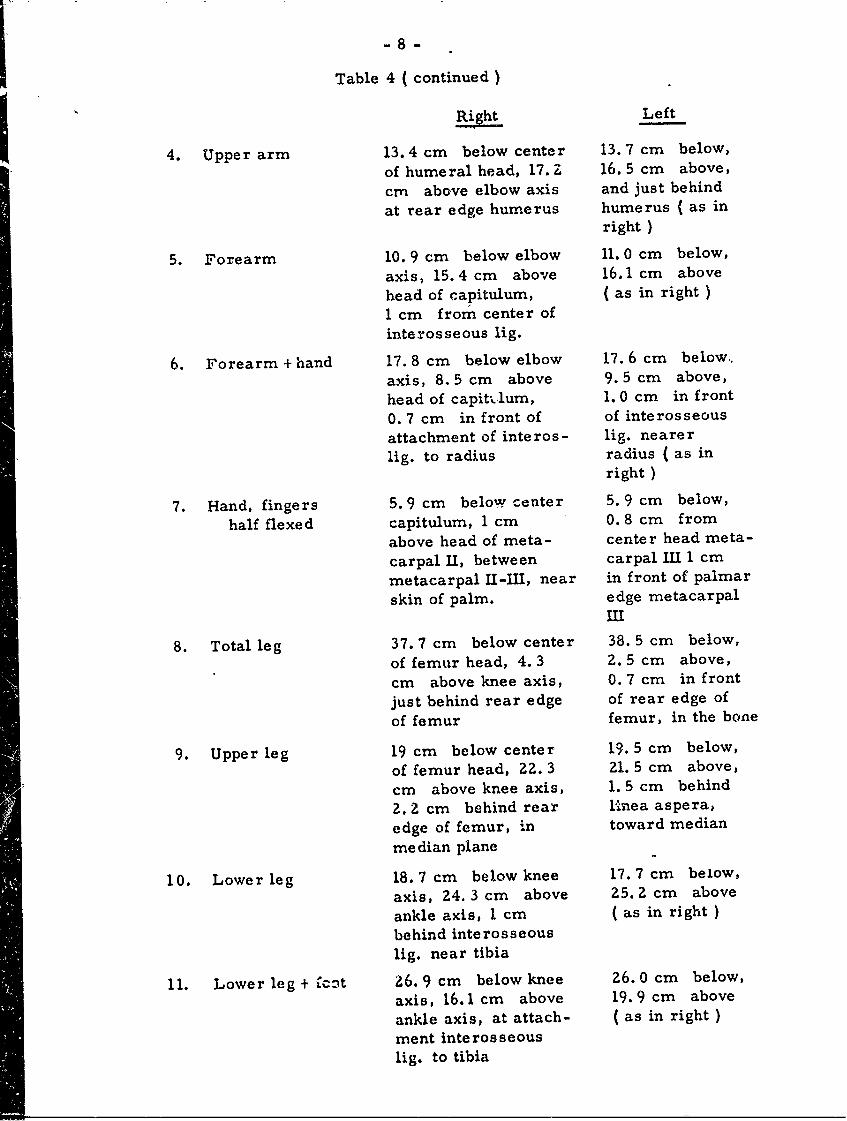
Table 4 ( continued)
Right Left
4. Upper arm 13.4 cm below center 13. 7 cm below,
of humeral head, 17. Z 16. 5 cm above,
cm above elbow axis and just behind
at rear edge humerus humerus ( as inright )
5. Forearm 10. 9 cm below elbow 11. 0 cm below,
axis, 15.4 cm above 16.1 cm above
head of capitulum, (as in right )1 cm from center ofinterosseous lig.
6. Forearm + hand 17. 8 cm below elbow 17.6 cm below.,
axis, 8. 5 cm above 9. 5 cm above,
head of capitlum, 1. 0 cm in front
0. 7 cm in front of of interosseousattachment of interos- lig. nearerlig. to radius radius ( as in
right )
7. Hand, fingers 5. 9 cm below center 5. 9 cm below,
half flexed capitulum, 1 cm 0. 8 cm from
above head of meta- center head meta-
carpal II, between carpal 11I 1 cm
metacarpal I-IMl, near in front of palmar
skin of palm. edge metacarpalIII
8. Total leg 37. 7 cm below center 38. 5 cm below,
of femur head, 4. 3 2. 5 cm above,
cm above knee axis, 0. 7 cm in front
just behind rear edge of rear edge of
of femur femur, in the bone
9. Upper leg 19 cm below center 19. 5 cm below,
of femur head, 22. 3 21. 5 cm above,
cm above knee axis, 1. 5 cm behind
Z. 2 cm behind rear l1nea aspera,edge of femur, in toward median
median plane
10. Lower leg 18.7 cm below knee 17.7 cm below,
axis, 24.3 cm above 25.2 cm above
ankle axis, 1 cm ( as in right )behind interosseouslig. near tibia
11. Lower leg + ICkt 26. 9 cm below knee 26. 0 cm below,
axis, 16.1 cm above 19.9 cm above
ankle axis, at attach- (as in right)
ment interosseouslig. to tibia
-9-
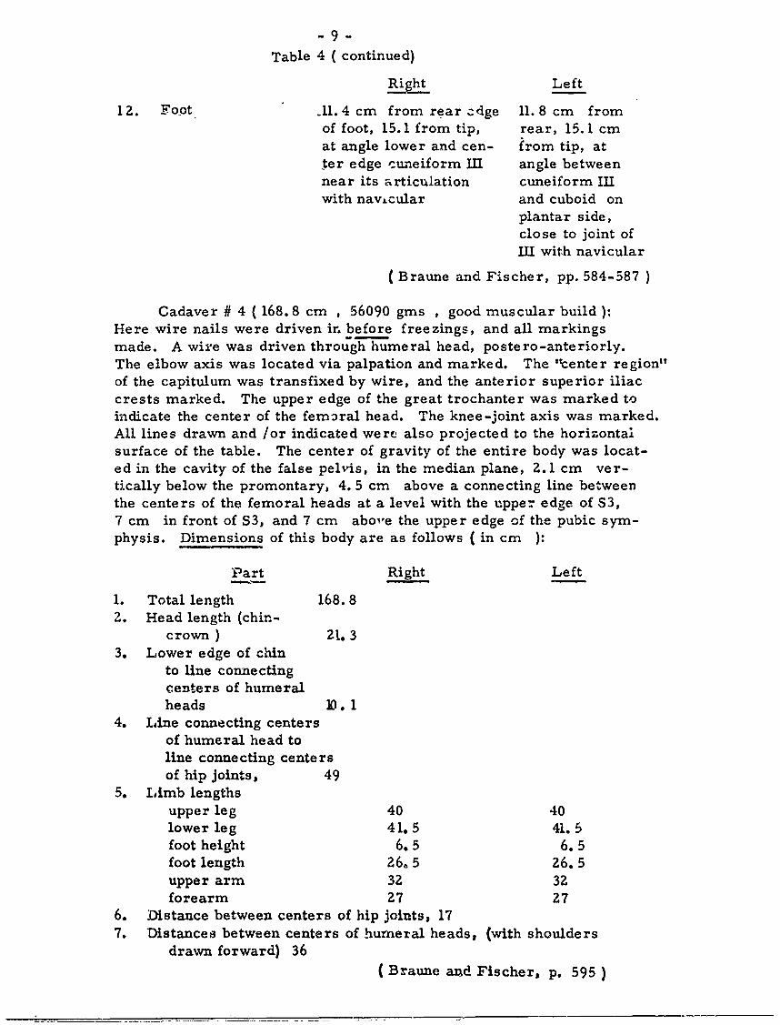
Table 4 ( continued)
RihtLeft
12. Foot 11. 4 cm from rear edge 11. 8 cm fromof foot, 15. 1 from tip, rear, 15.1 cmat angle lower and cen- from tip, atter edge cuneiform Ill angle betweennear its articulation cuneiform IIIwith navLcular and cuboid on
plantar side,close to joint ofIII with navicular
(Braune and Fischer, pp. 584-587 )
Cadaver # 4 (168.8 cm , 56090 gins , good muscular build ):Here wire nails were driven ir. before freezings, and all markingsmade. A wire was driven through humeral head, postero-anteriorly.The elbow axis was located via palpation and marked. The "center region"of the capitulum was transfixed by wire, and the anterior superior iliaccrests marked. The upper edge of the great trochanter was marked toindicate the center of the femral head. The knee-joint axis was marked.All lines drawn and /or indicated were also projected to the horizontalsurface of the table. The center of gravity of the entire body was locat-ed in the cavity of the false pelvis, in the median plane, 2.1 cm ver-tically below the promontary, 4. 5 cm above a connecting line betweenthe centers of the femoral heads at a level with the upper edge of S3,7 cm in front of S3, and 7 cm abo'e the upper edge of the pubic sym-physis. Dimensions of this body are as follows (in cm
Part Right Left
1. Total length 168.82. Head length (chin-
crown ) 21. 33. Lower edge of chin
to line connectingcenters of humeralheads 10. 1
4. Line connecting centersof humeral head toline connecting centersof hip joints, 49
5. Limb lengthsupper leg 40 40lower leg 41.5 41.5foot height 6. 5 6. 5foot length 26. 5 26.5upper arm 32 32forearm 27 27
6. Distance between centers of hip joints, 177. Distances between centers of humeral heads, (with shoulders
drawn forward) 36(Braune and Fischer p. 595)

- 10 -
Table 5. Weights of Cadaver #4 (Gins )
Part Right Left
1. Entire body 55,7002. Head, without neck 3,930
3. Torso, without limbs 23,7804. Entire arm 3520 37105. Upper arm 1730 20206. Forearm, less hand 1790 16907. Forearm, with hand 1300 12408. Hand 490 4509. Entire leg 10110 10650
10. Upper leg 6150 67501 1. Lower leg, with foot 3960 390012. Lower leg, less foot 2970 290013. Foot 990 1000
(Braune and Fischer, ;. 594)
Table 6. The Centers of Gravit, of Cadaver # 4
(see Plates- I - II)
Pl. I -II 1. Torso alone, at front surface of the upper edgeof Ll, 0. 5 cm to right of median plane, 25. 8 cmabove the line connecting the femoral heads.
2. Torso plus head plus arms, in median plane atfront edge of Tll, 29 cm above the line connectingfemoral heads.
3. Head, in median plane 0. 7 cm behind the slope ofthe sella turcica in the Fossa Tarini, and in theangle formed by the upper edge to the bridge withthe posterior lamina perforata.
Right Le ft
4. Total arm 0. 5 cm below elbow axis 0. 5 cm above0. 3 cm in front of bone elbow axis, 0. 5
cm in front ofhume rus
5. Upper arm 16. 3 cm below center 15. 3 cm belowhumeral head, 15.7 cm center hurneral
above elbow axis, in head, 16. 7 cmmedian plane, near above elbowrear edge of humerus, axis ( as inin bone right )
6. Forearm 11. 4 cm below elbow 11. 5 cm belowaxis, 15. 5 m above elbow axis, 15.1center head of capitulum cm above cent-
1. 5 cm in front interos- er head of capi-seous lig., nearer tulum ( as inradius right )
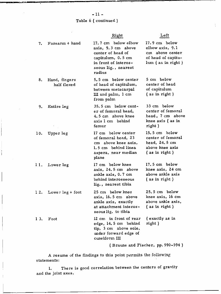
Table 6 (continued)
Right Left
7. Forearm + hand 17. 7 cm below elbow 17. 9 cm belowaxis, 9. 3 cm above elbow axis, 9.1center of head of cm above centercapitulum, 0. 5 cm of head of capitu-in front of interos- lur ( as in right )seous lig., nearestradius
8. Hand, fingers 5. 5 cm below center 5 cm belowhalf flexed of head of capitulum, center of head
between metacarpal of capitulumIll and palm, 1 cm (as in right)from palm
9. Entire leg 35. 5 cm below cent- 33 cm belower of femoral head, center of femoral4. 5 cm above knee head, 7 cm aboveaxis 1 cm behind knee axis ( as infemur right )
10. Upper leg 17 cm below center 15.5 cm belowof femoral head, 23 center of femoralcm above knee axis, head, 24. 5 cm1. 5 cm behind linea above knee axisaspera, near median ( as in right )plane
11. Lower leg 17 cm below knee 17. 5 cm belowaxis, 24. 5 cm above knee axis, 24 cmankle axis, 0. 7 cm above ankle axisbehind interosseous ( as in right )lig., nearest tibia
1 2. Lower leg+ foot Z5 cm below knee 25. 5 cm belowaxis, 16. 5 cm above knee axis, 16 cmankle axis, exactly above ankle axis,at attachment interos- ( as in right )seous lig. to tibia
1 3. Foot 12 cm in front of rear (exactly as inedge, 14. 5 cm behind right )tip, 3 cm above sole,under forward edge ofcuneiform III
( Braune and Fischer, pp. 590-594 )
A resume of the findings to this point permits the followingstatements:
1. There is good correlation between the centers of gravity
and the joint axes.
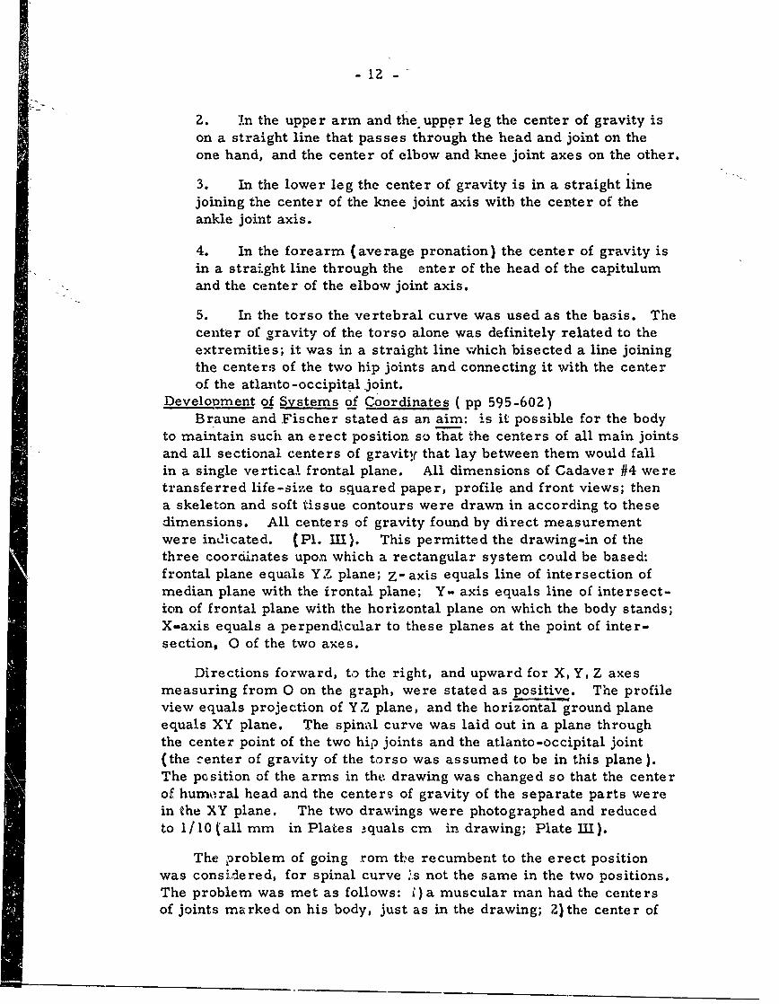
-12 -
2. in the upper arm and the upper leg the center of gravity ison a straight line that passes through the head and joint on theone hand, and the center of elbow and knee joint axes on the other.
3. In the lower leg the center of gravity is in a straight linejoining the center of the knee joint axis with the center of theankle joint axis.
4. In the forearm (average pronation) the center of gravity isin a strai.ght line through the enter of the head of the capitulumand the center of the elbow joint axis.
5. In the torso the vertebral curve was used as the basis. Thecenter of gravity of the torso alone was definitely related to theextremities; it was in a straight line which bisected a line joiningthe centers of the two hip joints and connecting it with the centerof the atlanto -occipital joint.
Development of Systems of Coordinates ( pp 595-602)Braune and Fischer stated as an aim: is it possible for the body
to maintain such an erect position so that the centers of all main jointsand all sectional centers of gravity that lay between them would fallin a single vertica.1. frontal plane. All dimensions of Cadaver #4 weretransferred life-size to squared paper, profile and front views; thena skeleton and soft tissue contours were drawn in according to thesedimensions. All centers of gravity found by direct measurementwere indicated. (Pl. III). This permitted the drawing-in of thethree coordinates upon which a rectangular system could be based:frontal plane equals YZ plane; Z- axis equals line of intersection ofmedian plane with the frontal plane; Y- axis equals line of intersect-ion of frontal plane with the horizontal plane on which the body stands;X-axis equals a perpendicular to these planes at the point of inter-section, 0 of the two axes.
Directions forward, to the right, and upward for X, Y, Z axesmeasuring from 0 on the graph, were stated as positive. The profileview equals projection of YZ plane, and the horizontal ground planeequals XY plane. The spinal curve was laid out in a plane throughthe center point of the two hip joints and the atlanto-occipital joint(the center of gravity of the torso was assumed to be in this plane).The position of the arms in the. drawing was changed so that the centerof humoral head and the centers of gravity of the separate parts werein the XY plane. The two drawings were photographed and reducedto 1/10 (all mm in Plates -quals cm in drawing; Plate III).
The problem of going rom tle recumbent to the erect positionwas considered, for spinal curve .s not the same in the two positions.The problem was met as follows: 1) a muscular man had the centersof joints marked on his body, just as in the drawing; Z) the center of
- 13 -
gravity of the head was projected to the side of the head and marked;3) two long plumb lines determined the YZ Plane; 4) the model wasthen noved until all joint markings were in the YZ Plane.
The model was then photographed, as in Plate IV ( left arm benta bit to show hip markings: consequent displacement of center ofgravity is 7 mm upward, 4 mm forward 1 mm. to right ). PlatesIII-IV compared favorably so the method was deemed acceptable. Theresult is a standard or normallbdy position n. b. p. ). The centersof gravity for the whole body and the limb systems were calculatedfor the n. b. p. from the centers of gravity for the separate sections;this is done for the control of the measurements of centers of gravityboth of the separate limbs and of the whole body.
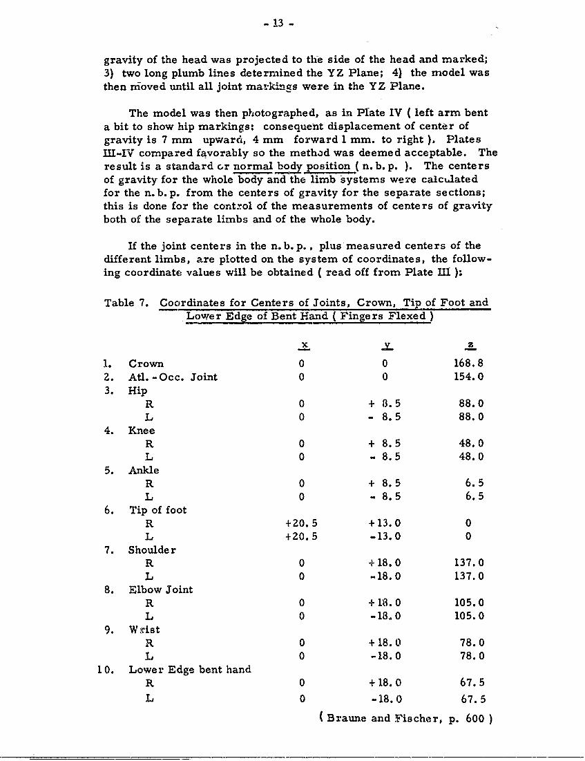
If the joint centers in the n. b. p., plus measured centers of thedifferent limbs, are plotted on the system of coordinates, the follow-ing coordinate values will be obtained ( read off from Plate III ):
Table 7. Coordinates for Centers of Joints, Crown, Tip of Foot andLower Edge of Bent Hand (Fingers Flexed)
x zy_ L
1. Crown 0 0 168.82. Atl. -Occ. Joint 0 0 154.03. Hip
R 0 + 8.5 88.0L 0 - 8.5 88.0
4. KneeR 0 + 8.5 48.0L 0 - 8.5 48.0
5. AnkleR 0 + 8.5 6.5L 0 - 8.5 6.5
6. Tip of footR +Z0.5 +13.0 0L +20.5 -13.0 0
7. ShoulderR 0 +18.0 137.0L 0 -18.0 137.0
8. Elbow JointR 0 +18.0 105.0L 0 -18,0 105.0
9. WistR 0 +18.0 78.0L 0 -18.0 78.0
10. Lower Edge bent handR 0 +18.0 67.5L 0 -18.0 67.5
(Braune and .Fischer, p. 600
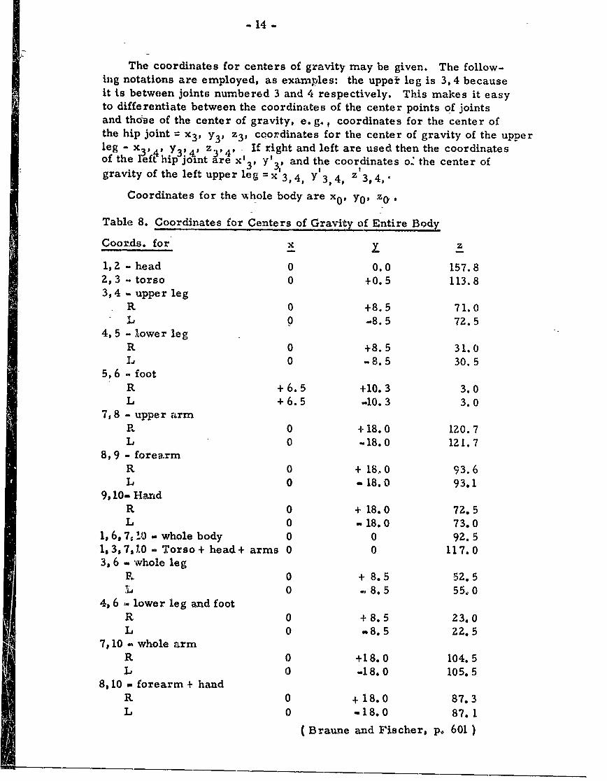
- 14 -
The coordinates for centers of gravity may be given. The follow-ing notations are employed, as examples: the upper leg is 3, 4 becauseit is between joints number6d 3 and 4 respectively. This makes it easyto differentiate between the coordinates of the center points of jointsand thoase of the center of gravity, e. g. , coordinates for the center ofthe hip joint = x 3 , Y3 , z 3, coordinates for the center of gravity of the upperleg - x 3 49 Y3 !, , z 3 , ., If right and left are used then the coordinatesof the left hip joint are x' 3 , Y'3,P and the coordinates o' the center ofgravity of the left upperleg=x 3, 4 Y 3 4, z 3,4,.
Coordinates for the %hole body are x0 , y0 , zo
Table 8. Coordinates for Centers of Gravity of Entire Body
Coornds. for x z
1,2 - head 0 0.0 157.82,3 - torso 0 +0.5 113.83,4 . upper leg
R 0 +8.5 71.0A 0 -8.5 72.5
4, 5 - lower legR 0 +8.5 31.0L 0 -8.5 30.5
5,6 - footR +6.5 +10.3 3.0L +6.5 -10.3 3.0
7,8 - upper armR 0 +18.0 120.7L 0 .-18.0 121.7
8, 9 - forearmR 0 + 18,.0 93.6L 0 -18.0 93.1
9,1 0- HandR 0 + 18.0 72.5L 0 -18.0 73.0
1,6, 7, 10 - whole body 0 0 92.51,3,7.1.0- Torso+ head+ arms 0 0 117.03, 6 - whole leg
R 0 + 8.5 52.5L 0 - 8.5 55,,0
4, 6 . lower leg and footR 0 +8.5 23.0L 0 ,8.5 ZZ. 5
7, 10 - whole armR 0 +18.0 104.5L 0 -18.0 105.5
8, 10 - forearm + handa 0 + 18.0 87.3L 0 -18.0 87.1
(Braune and Fischer, p. 601)
-15-
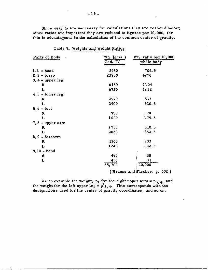
Since weights are necessary for calculations they are restated below;since ratios are important they are reduced to figures per 10, 000, forthis is advantageous in the calculation of the common center of gravity.
Table 9. Weights and Weight Ratios
Parts of Body WWt. jgms Wt, ratio per 10, 000Cad. IV whole body
1,2 - head 3930 705.52, 3 - torso 23780 4270
3, 4 - upper legR 6150 1104L 6750 1212
4, 5 - lower legR 2970 533L 2900 520.5
5, 6 - footR 990 178L 1000 179.5
7, 8 - upper armR 1730 310.5L 2020 362.5
8, 9 - forearmR 1300 233L 1240 222.5
9, 10 - handR 490 38L 450 81
55,700 10,00
(Braune and Fischer, p. 602 )
As an example the weight, p, for the right upper arm = P3, 4, andthe weight for the left upper leg = p 3, 4. This corresponds with thedesignations used for the center of gravity coordinates, and so on.
-16-
The Calculation of the Common Center Of Gravity for theEntire Body, and for Whole Sections, from the Centers
Of Gravity and Weights of Separate Limbs. (pp 603-625)
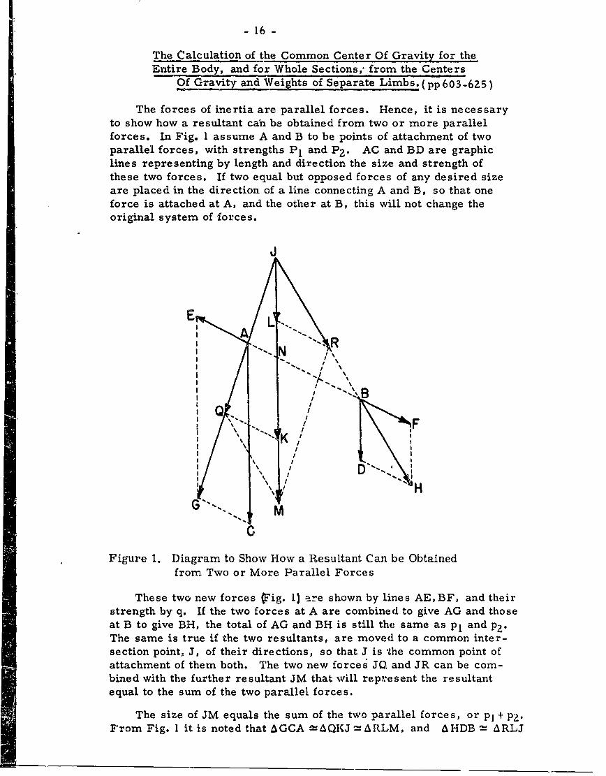
The forces of inertia are parallel forces. Hence, it is necessaryto show how a resultant can be obtained from two or more parallelforces. In Fig. 1 assume A and B to be points of attachment of twoparallel forces, with strengths P1 and P 2 . AC and BD are graphiclines representing by length and direction the size and strength ofthese two forces. If two equal but opposed forces of any desired sizeare placed in the direction of a line connecting A and B, so that oneforce is attached at A, and the other at B, this will not change theoriginal system of forces.
EA
I - I
I "" = / \
I
I
jo II * /
Figure 1. Diagram to Show ow a Resultant Can be Obtained
from Two or More Parallel Forces
These two new forces Q'ig. 1) are shown by lines AE, BF, and theirstrength by q. If the two forces at A are combined to give AG and thoseat B to give BR, the total of AG and BH is still the same as p, and p2 .The same is true if the two resultants, are moved to a common inter-section point, J, of their directions, so that J is the common point ofattachment of them both. The two new forceg JO and JR can be com-bined with the further resultant JM that wvill repr~esent the resultantequal to the sum of the two parallel forces.
The size of JM equals the sum of the two parallel forces, Or P1 + p2 .From Fig. l it is noted that AGCA =QKJ,= RLM, and AH-DB = ARLJ
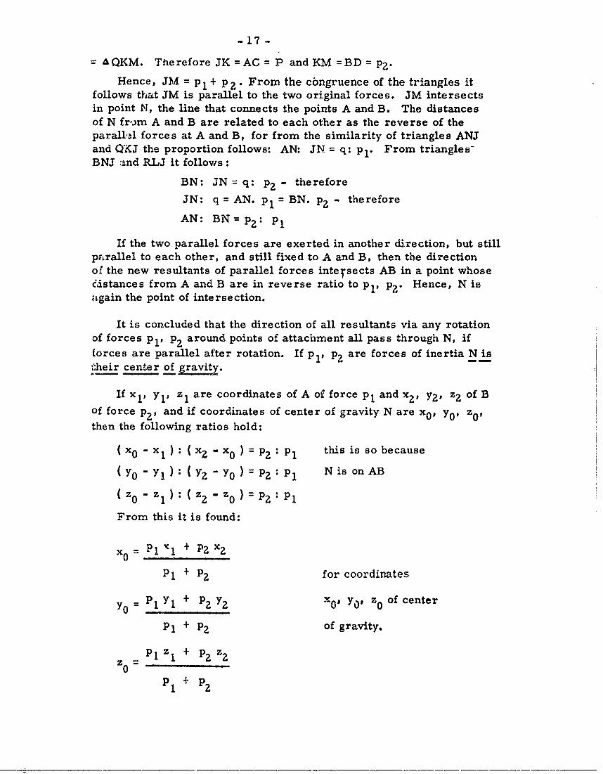
-17 -
AQKM. Therefore JK =AC P and KM =BD = PZ"
Hence, JM = p 1 + p 2 . From the cbngruence of the triangles itfollows that JM is parallel to the two original forces, JM intersectsin point N, the line that connects the points A and B. The distancesof N fr,.)m A and B are related to each other as the reverse of theparalld forces at A and B, for from the similarity of triangles ANJand Qi(J the proportion follows: AN: JN = q: pl. From triangles-BNJ :and RLJ it follows:
BN: JN=q: pZ" therefore
JN: q = AN. p1 - BN. p2 - therefore
AN: BN= p 2 : p1
If the two parallel forces are exerted in another direction, but stillparallel to each other, and still fixed to A and B, then the directionof the new resultants of parallel forces intersects AB in a point whoseedstances from A and B are in reverse ratio to pl, p2 . Hence, N isagain the point of intersection.
It is concluded that the direction of all resultants via any rotationof forces p, p2 around points of attachment all pass through N, if
forces are parallel after rotation. If pl, p2 are forces of inertia N isheir center of gaMvity.
If x 1 , Yl, zl are coordinates of A of force p1 andx 2 , y2 , z2 of B
of force P2 , and if coordinates of center of gravity N are x 0 , yo, z0 f
then the following ratios hold:
(x 0 x): (X 2 x 0 ) = P2 : Pl this is so because
(Yo - Y): (y 2 - Yo)= P : p Nis onAB
(Zo - Z l : (z 2 - zo ) = P : pl
From this it is found:
= Pl 1% + P2 X2
P + P? for coordinates
YO = P 1 Yl + p2 Y2 X o Yap Zo of center
Pl + PZ of gravity.
Pl Z1 + p2 z2
P1 + pz
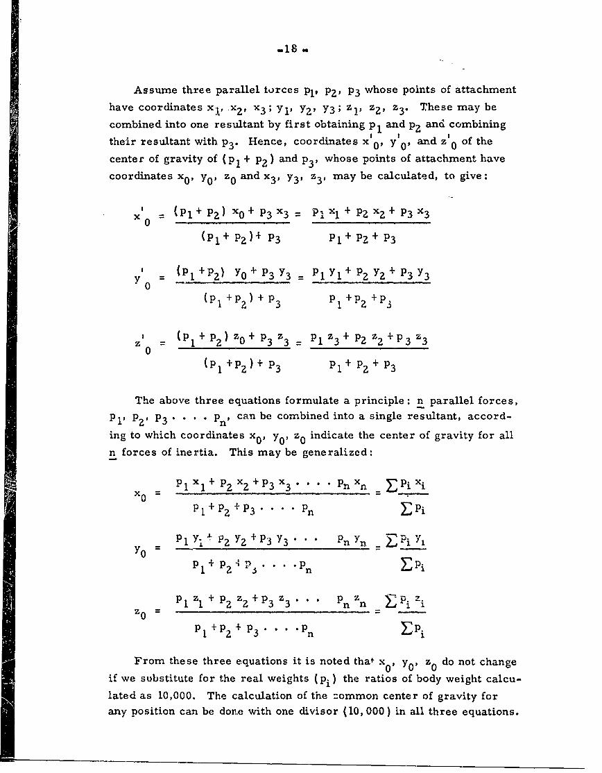
i -m18-
Assume three parallel torces pl, PZ' P3 whose points of attachmenthave coordinates x ! , _x?, Z?3 ; Yi' Y, Y3; zl, z, z 3 . These may be
combined into one resultant by first obtaining p1 and p2 and combining
their resultant with P3 . Hence, coordinates x' 0 , y1 0 and z' 0 of the
center of gravity of (p, + p2 ) and P3' whose points of attachment have
coordinates x0 , Y0 , z 0 and x 3 , Y3 , z 3, may be calculated, to give:
x 0 (p1 + PZ )xo + P3x 3
= PIXl + PZ Xz + P3X3
(Pl + P? )+ P 3 pl + PZ + P3
Y (P +P 2 ) YO + P3 Y3 Pl yl + P2 Y2 + P3 Y3
(pi +p2) + P3 P1 +P +P3
, (p1 +p 2 z 0 + p 3 z 3 PlZ3+ PZ z2+P3 z 30
(p 1 +p 2 ) + P3 Pl + P + P3
The above three equations formulate a principle: n parallel forces,Pi, P2 , P 3 . . . . Pn, can be combined into a single resultant, accord-
ing to which coordinates x0 , Y0, z0 indicate the center of gravity for all
n forces of inertia. This may be generalized:
SPlXl+ P2 x2 +P 3 X 3 PnXn PiXi
X= p=.py+~ 3 **~~ pyP I + p 2 + P3 . . .. Pn -Pi
P + P2Z Y +p 3 Y3 " Pn Yn - )ir
0 =
Pl1 + pg 2 P . . .. Pn EPi
P 1 Zl1 + P2 z 2 + p 3 z 3 " " n z n Pi :ti
Pi +P 2 + p3 . Pn P i
From these three equations it is noted that x0 , y0 z0 do not change
if we substitute for the real weights (pi) the ratios of body weight calcu-
lated as 10,000. The calculation of the :ommon center of gravity forany position can be done with one divisor (10, 000) in all three equations.
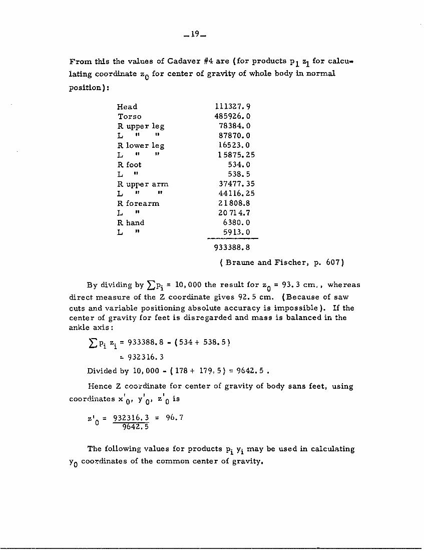
_lg9
From this the values of Cadaver #4 are (for products p, z1 for calcu-
lating coordinate zo for center of gravity of whole body in normal
position):
Head 111327.9Torso 485926.0R upper leg 78384.0L " " 87870.0R lower leg 16523.0L " " 15875.25R foot 534.0L " 538.5R upper arm 37477.35L " " 44116.25R forearm 21808.8L " 20714.7R hand 6380.0L " 5913.0
933388.8
( Braune and Fischer, p. 607)
By dividing by Ep i = 10, 000 the result for z0 = 93. 3 cm., whereas
direct measure of the Z coordinate gives 92. 5 cm. (Because of saw
cuts and variable positioning absolute accuracy is impossible ). If thecenter of gravity for feet is disregarded and mass is balanced in theankle axis:
E-Pi i = 933388.8 - (534+ 538.5)
- 932316.3
Divided by 10,000 - (178+ 179.5) 9542. .
Hence Z coordinate for center of gravity of body sans feet, using! I I
coordinates x 10 y IP z 0 is
zt0 = 932316.3 = 96.79642.5
The following values for products pi yi may be used in calculating
yo coordinates of the common center of gravity.
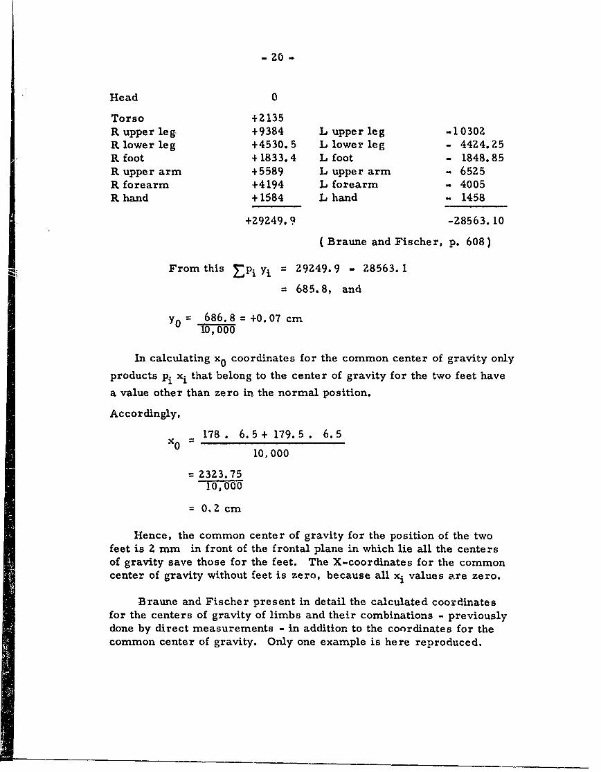
- 20 -
Head 0
Torso +Z135R upper leg +9384 L upper leg -1030ZR lower leg +4530.5 L lower leg - 4424.25" foot +1833.4 L foot - 1848.85R upper arm +5589 L upper arm " 6525R forearm +4194 L forearm - 4005R hand +1584 L hand - 1458
+Z9249.9 -28563.10
(Braune and Fischer, p. 608)
From this EPi Yj = Z9249.9 - 28563.1
= 685.8, and
Y- 6 86 .8 = +0.07 cm10,000
In calculating x0 coordinates for the common center of gravity only
products pi xi that belong to the center of gravity for the two feet have
a value other than zero in the normal position.
Accordingly,
X 178 . 6.5+ 179.5 . 6.5
10,000
= 2323.7510,000
0. 2cm
Hence, the common center of gravity for the position of the twofeet is 2 mm in front of the frontal plane in which lie all the centersof gravity save those for the feet. The X-coordinates for the commoncenter of gravity without feet is zero, because all xi values are zero.
Braune and Fischer present in detail the calculated coordinatesfor the centers of gravity of limbs and their combinations - previouslydone by direct measurements - in addition to the coordinates for thecommon center of gravity. Only one example is here reproduced.
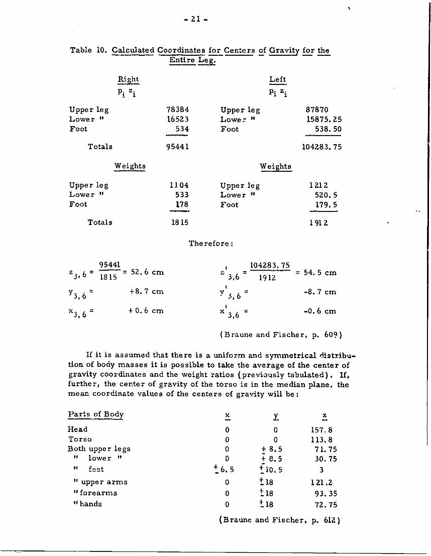
Table 10. Calculated Coordinates for Centers of Gravit for theEntire Leg.
Right LeftPi z. pi zi
Upper leg 78384 Upper leg 87870Lower " 16523 Lower " 15875.25Foot 534 Foot 538.50
Totals 95441 104283.75
Weights Weights
Upper leg 1104 Upper leg 1212Lower " 533 Lower " 520.5Foot 178 Foot 179.5
Totals 1815 1912
Therefore:
95441 , 104283.75z 36= -- =52.6 cm z,6 = = 54.5 cm
1815 3,6 191z
Y3, 6 +8.7 cm Y 3, 6 -8.7 cm
x3 , 6 +0.6 cm x 3,6 -0.6 cm
(Braune and Fischer, p. 609)
If it is assumed that there is a uniform and symmetrical distribu-tion of body masses it is possible to take the average of the center ofgravity coordinates and the weight ratios (previously tabulated). If,further, the center of gravity of the torso is in the median plane, themea. coordinate values of the centers of gravity will be:
Parts of Body x x z
Head 0 0 157.8Torso 0 0 113.8Both upper legs 0 + 8.5 71.75
" lower " 0 + 8.5 30.75" e +6.5 11 0, 5 3
" upper arms 0 t 18 121.2"forearms 0 t 18 93.35"hands 0 t 18 72.75
(Braune and Fischer, p. 612)
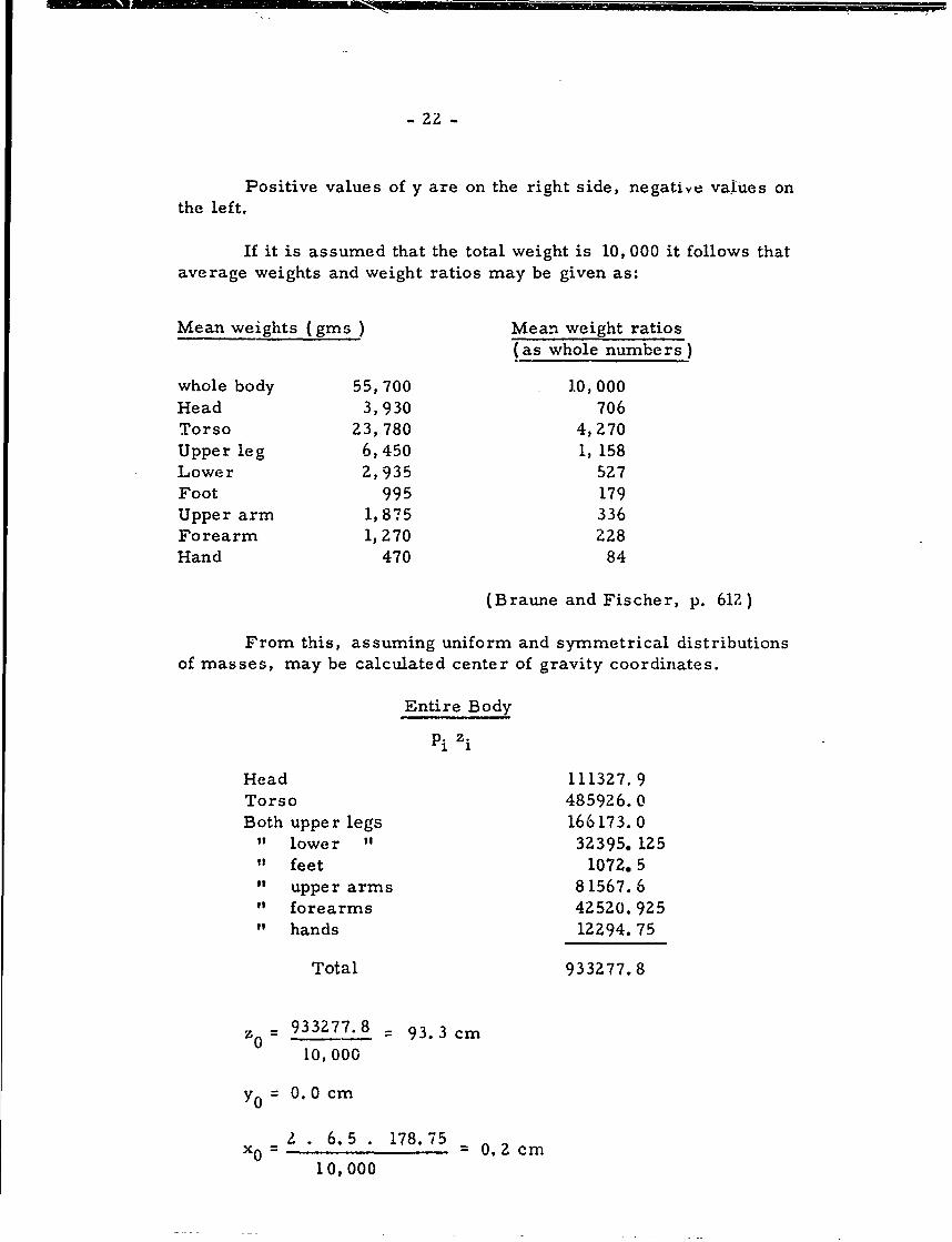
- 22. -
Positive values of y are on the right side, negative values onthe left.
If it is assumed that the total weight is 10, 000 it follows thataverage weights and weight ratios may be given as:
Mean weights (gins) Mean weight ratios
(as whole numbers)
whole body 55,700 10,000Head 3,930 706Torso 23,780 4,270Upper leg 6,450 1, 158Lower 2,935 527Foot 995 179Upper arm 1,875 336Forearm 1,270 Z28Hand 470 84
(Braune and Fischer, p. 612)
From this, assuming uniform and symmetrical distributionsof masses, may be calculated center of gravity coordinates.
Entire Body
Pi zi
Head 111327.9Torso 485926.0Both upper legs 166173.0
" lower " 32395. 125" feet 1072. 5" upper arms 81567.6" forearms 42520.925" hands 12294.75
Total 933277.8
z0 = 933277.8 = 93.3 cm10,000
YO = 0. 0 cm
2 . 6.5 . 178.75 0.2 cmx0 1=000
10, 000
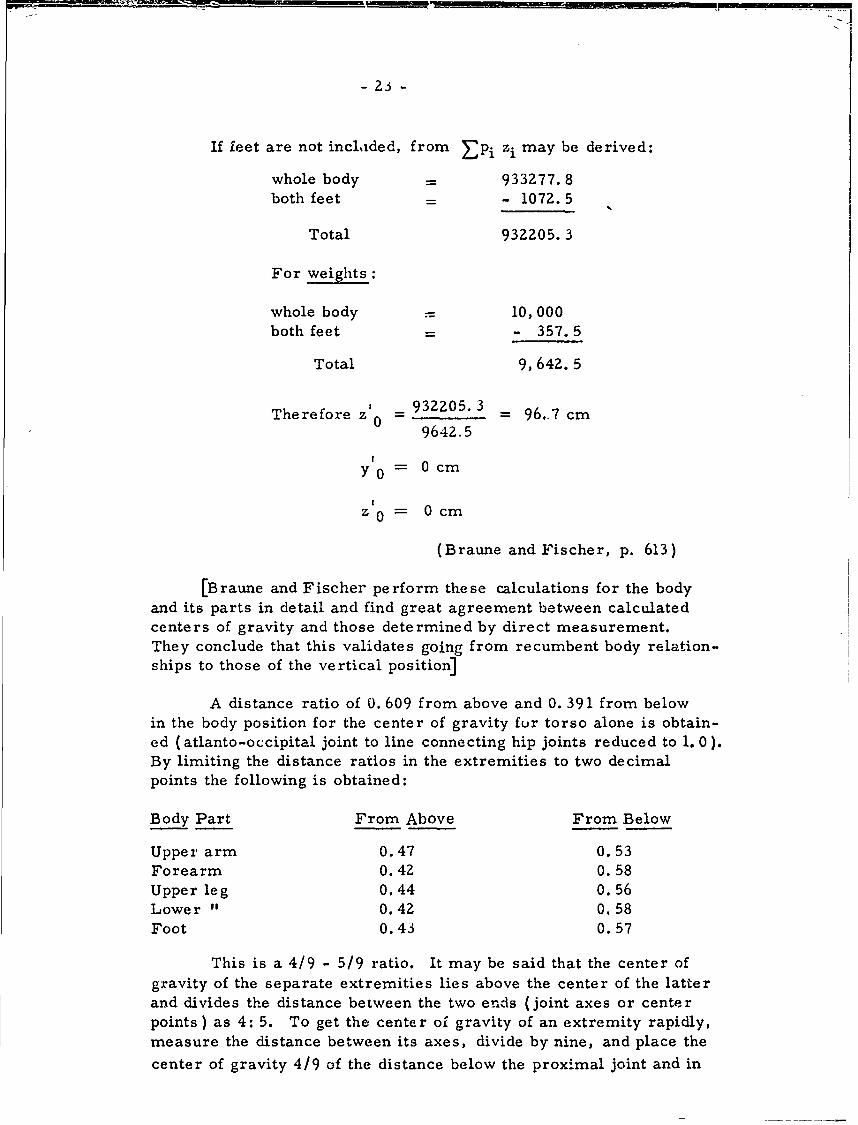
- 23 -
If feet are not incladed, from Ep i z i may be derived:
whole body = 933277.8
both feet = - 1072.5
Total 932205.3
For weights:
whole body 10,000both feet - - 357.5
Total 9,642.5
Therefore z 0 932205.3 96.7 cm9642.5
Y 0 0 cm
=z0 0 cm
(Braune and Fischer, p. 613)
[Braune and Fischer perform these calculations for the bodyand its parts in detail and find great agreement between calculatedcenters of gravity and those determined by direct measurement.They conclude that this validates going from recumbent body relation-ships to those of the vertical position]
A distance ratio of 0. 609 from above and 0. 391 from belowin the body position for the center of gravity for torso alone is obtain-ed (atlanto-occipital joint to line connecting hip joints reduced to 1. 0).By limiting the distance ratios in the extremities to two decimalpoints the following is obtained:
Body Part From Above From Below
Upper arm 0.47 0.53Forearm 0.42 0.58Upperleg 0.44 0.56Lower " 0.42 0.58Foot 0.43 0.57
This is a 4/9 - 5/9 ratio. It may be said that the center ofgravity of the separate extremities lies above the center of the latterand divides the distance between the two ends (joint axes or centerpoints ) as 4: 5. To get the center of gravity of an extremity rapidly,measure the distance between its axes, divide by nine, and place the
center of gravity 4/9 of the distance below the proximal joint and in
-24-
a straight line with the center of the joint. The cente" of gravity isalmost at the edge of the bone in the humerus and femu.r, and about1 cm from the center of the interosseous lig. (toward the curved side)in the forearm and the lower leg.
In an over-all view the findings of Braune and Fischer are inreasonable agreement with those of Harless, but not with those ofMeyer (1853).
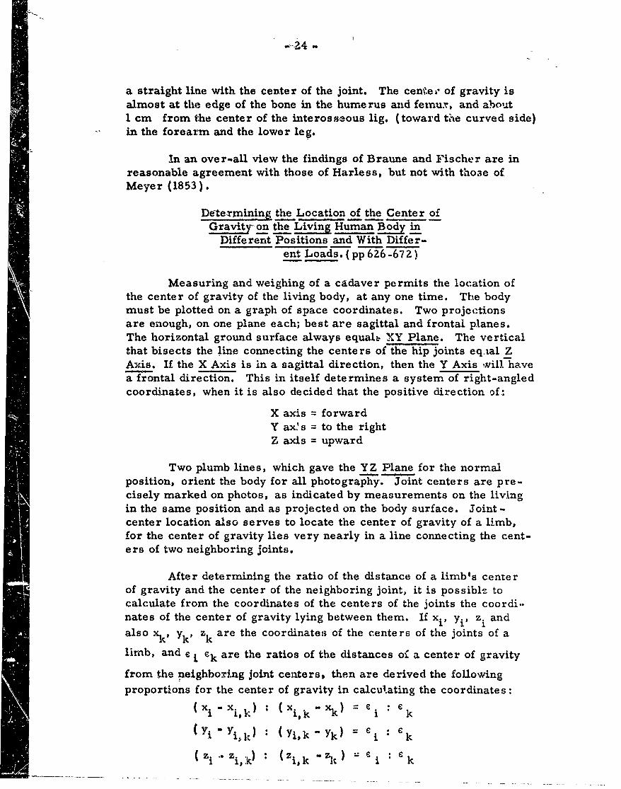
Detexrmining the Location of the Center ofGravity on the Living Human Bod in
Different Positions and With Differ-ent Loads. (pp 626-672)
Measuring and weighing of a cadaver permits the location ofthe center of gravity of the living body, at any one time. The bodymust be plotted on a graph of space coordinates. Two projectionsare enough, on one plane each; best are sagittal and frontal planes.The horizontal ground surface always equals NY Plane. The verticalthat bisects the line connecting the centers of the hip joints eq,tal ZAxis. If the X Axis is in a sagittal direction, then the Y Axis will havea frontal direction. This in itself determines a system of right-angledcoordinates, when it is also decided that the positive direction of:
X axis = forwardY ax s = to the rightZ axis = upward
Two plumb lines, which gave the YZ Plane for the normalposition, orient the body for all photography. Joint centers are pre-cisely marked on photos, as indicated by measurements on the livingin the same position and as projected on the body surface. Joint -
center location also serves to locate the center of gravity of a limb,for the center of gravity lies very nearly in a line connecting the cent-ers of two neighboring joints.
After determining the ratio of the distance of a limb's center
of gravity and the center of the neighboring joint, it is possible to
calculate from the coordinates of the centers of the joints the coordi..nates of the center of gravity lying between them. If xi, Yi, z. and
also xk, yk' zk are the coordinates of the centers of the joints of a
limb, and r i ek are the ratios of the distances oC a center of gravity
from the neighboring joint centers, then are derived the followingproportions for the center of gravity in calcu?,ating the coordinates:
(xixi, I) : (xl.-X k) = ei k
ij Yik) : (Yi, k - Yk) = "i : 6 k
(zi~zi,:k) : Zi, k "z' " i k
m 25 -
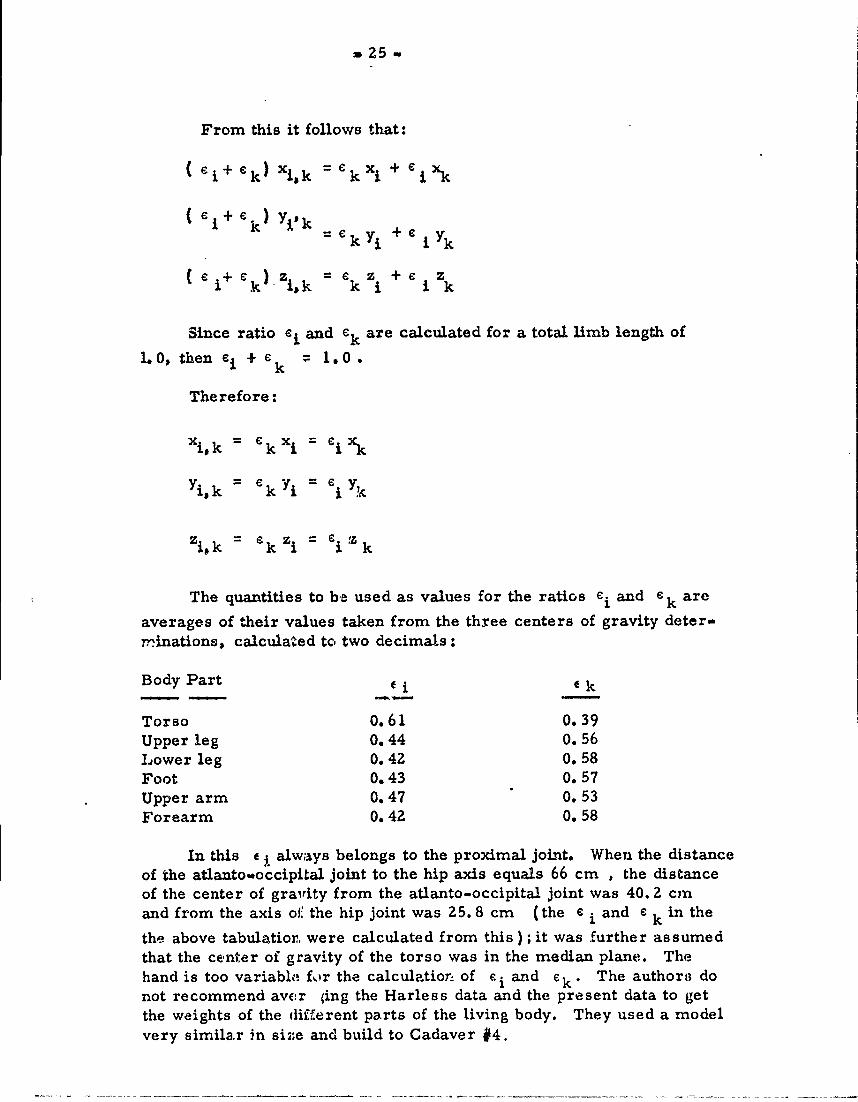
From this it follows that:
(e i + Lk) Xik = k Xi + LiXk
(ei+ ek) Yi k
e + C k) zik k i + e i Zk
Since ratio c, and ek are calculated for a total limb length of
1.0, then e i + ek 1.0.
Therefore:
xik = £kXj = 'ixk
Yi, k = k = i y
Zi, k kzi i Zk
The quantities to be used as values for the ratios e i and ek are
averages of their values taken from the three centers of gravity deter-rinations, calculated to, two decimals:
Body Part E Ek
Torso 0.61 0.39Upper leg 0. 44 0.56Lower leg 0.42 0. 58Foot 0.43 0.57Upper arm 0.47 0. 53Forearm 0. 42 0. 58
In this e j. always belongs to the proximal joint. When the distance
of the atlanto..occipital joint to the hip axis equals 66 cm , the distanceof the center of gravity from the atlanto-occipital joint was 40. 2 cm
and from the axis oI: the hip joint was 25.8 cm (the ei and e kin the
the above tabulatior were calculated from this ) ; it was further assumedthat the center of gravity of the torso was in the median plane. Thehand is too variablo fur the calculation of e i and 6 k . The authoril do
not recommend avc~r (ing the Harless data and the present data to get
the weights of the different parts of the living body. They used a modelvery similar in siZe and build to Cadaver #4.
- 26 -
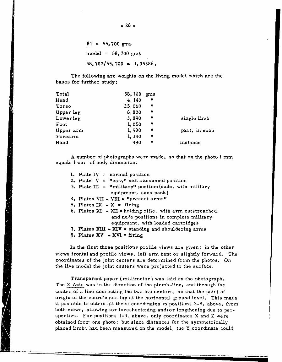
#4 = 55,700 gms
model = 58,700 gins
58,700/55,700 a 1. 05386.
The following are weights on the living model which are thebases for further study:
Total 58, 700 gmsHead 4, 140 "
Torso 25,060 "
Upper leg 6,800Lower leg 3,890 " singie limbFoot 1,050 "
Upper arm 1, 980 " part, in eachForearm 1, 340 It
Hand 490 " instance
A number of photographs were made, so that on the photo 1 rnmequals I cm of body dimension.
1. Plate IV = normal positionZ. Plate V = "easy" self-assumed position3. Plate iII = "military" position(nude, with military
equipment, sans pack)4. Plates VII - VIII = "present arms"5. Plates IX - X = firing6. Plates XI - XII = holding rifle, with arm outstreached,
and nude positions in complete militaryequipment, with loaded cartridges
7. Plates XiiY XIV = standing and shouldering arms8. Plates XV - XVI = firing
In the first three positions profile views are given; in the otherviews frontal and profile views, left arm bent or slightly forward. Thecoordinates of the joint centers are determined from the photos. Onthe live model the joint centers were projected to the surface.
Transparent pap,;r (millimeter) was laid on the photograph.The Z Axis was in the direction of the plumb-line, and through thecenter of a line conrecting the two hip centers, so that the point oforigin of the coord.nates lay at the horizontal ground level. This madeit postsible to obtain all three coordinates in pobitions 3-8, above, fromboth views, allowing for foreshortening and/or lengthening due to per-spective. For positions 1-3, abuve, only coordinates X and Z wereobtained frorr one photo; but since distances for the symmetricallyplaced limb', had been measured on the model, the Y coordinate could
- 27 -
be assumed from bilateral symmetry.
POSITION OF THE BODY WITHOUT A LOAD (pp 631-643)
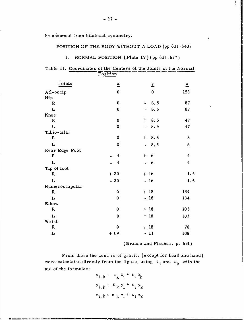
1. NORMAL POSITION (Plate IV) (pp 631 -637)
Table 11. Coordinates of the Centers of the Joints in the NormalPosition
Joints x y z
Atl-.occip 0 0 152Hip
R 0 + 8.5 87L 0 - 8.5 87
KneeR 0 + 8.5 47
L 0 - 8.5 47Tibio-talar
R 0 + 8.5 6
L 0 - 8.5 6
Rear Edge FootR 4 + 6 4
L -4 -6 4Tip of foot
R + 20 + 16 1.5
L - 20 - 16 1.5Hume ros capular
R 0 + 18 134
L 0 - 18 134Elbow
R 0 + 18 103
L 0 - 18 1U3Wrist
R 0 + 18 76
L + 19 - 11 108
(Braune and Fischer, p. 631)
From these the cent. rs of gravity (except for head and hand)were calculated directly from the figure, using ei and ek' with the
aid of the formulae :Xi, k = k X+ i +
Yi, k = kYi + i Yk
Zi, k 6 k :9. + e zk
I-28 -
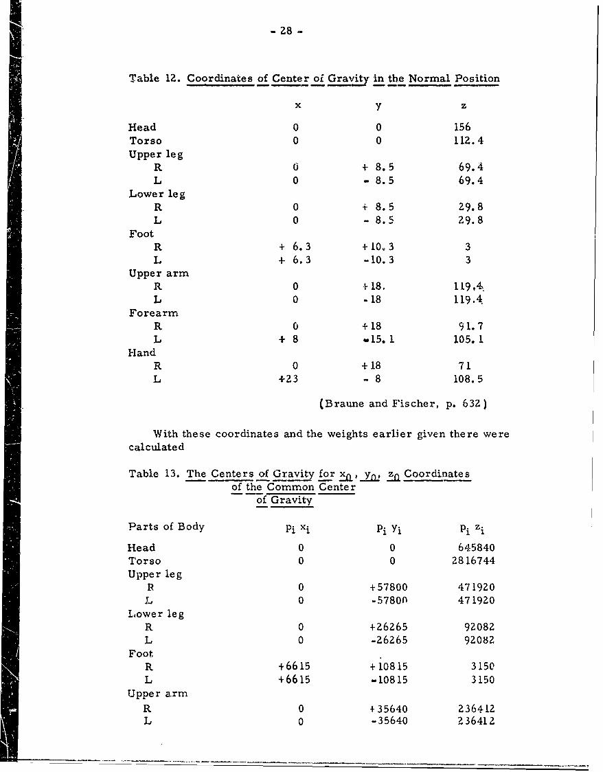
Table 12. Coordinates of Center oi Gravit, in the Normal Position
x y z
Head 0 0 156Torso 0 0 112.4Upper leg
R 0 + 8.5 69.4L 0 - 8.5 69.4
Lower legR 0 + 8.5 29.8L 0 - 8.5 29.8
FootR + 6.3 +10.3 3L 4 6.3 -10.3 3
Upper armR 0 +18. 119,4,L 0 -18 119.4
ForearmR 0 +18 91.7L + 8 w15. 1 105.1
HandR 0 +18 71L +23 - 8 108.5
(Braune and Fischer, p. 632)
With these coordinates and the weights earlier given there werecalculated
Table 13. The Centers of Gravity for xa,_yW _ft Coordinates-- of the Common Center
of Gravity
Parts of Body Pi xi pi Yi Pi zi
Head 0 0 645840Torso 0 0 2816744Upper leg
R 0 +57800 471920L 0 -57800 471920
Lower legR 0 +26265 92082L 0 -26265 92082
FootR +6615 +10815 3150L +6615 -10815 3150
Upper armR 0 + 35640 236412L 0 -35640 236412
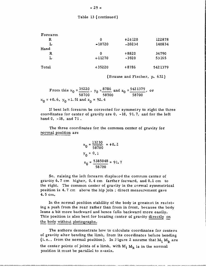
- 29 -
Table 13 (continued)
ForearmR 0 +24120 122878L -10720 -20234 140834
HandR 0 +8820 34790L +11270 -3920 53165
Total +35220 +8786 5421379
(Braune and Fischer, p. 632)
From this x = 35220 Y0 = 8786 and z = 5421379__ ,- or58700 58700 58700
X 0 = +0.6, y 0 = 1' 5 1 and z0 = 92.4
If bent left forearm be corrected for symmetry to right the threecoordinates for center of gravity are 0, -18, 91.7, and for the lefthand 0, -18, and 71 .
The three coordinates for the common center of gravity fornormal position are
13Z30x0 = 5. = .-
0 58700
Y0 = 0. 1
5385048 = 91. 758700
So, raising the left forearm displaced the common center ofgravity 6.7 cm higher, 0.4 cm farther forward, and 0. 1 cm tothe right. The common center of gravity in the n ormal symmetricalposition is 4. 7 cnr. above the hip join ; direct measurement gave4. 5 cm.
In the normal position stability of the body is greatest in resist-ing a push from the rear rather than from in front, because the bodyleans a bit more backward and hence faLls backward more easily.This position is also best for locating c:enter of gravity directly onthe body without photographs.
The authors demonstrate how to c*ALcu].ate coordinates for centersof gravity after bending the limb, from its coordinates before bending(i.e., from the normal position), In Fiigure 2 assume that M i Mk are
the center points of joints of a limb, with M i Mk is in the normalposition it must be parallel to z-axis.
- 30 -
X
N Mi+
M K '9t - 78
CL t.- A
XK+ X-AXE
X I
II
I i
N I I / /I ,:/ /
iA' ////XK ",
(/ . ... ....... ' ~ ,/
_C'
Figure Z. Calculation of Coordinate Centers of Gravity inFlexed Limb, Based on Coordinates in Normal
(Unflexed) Position
Now rotate the limb on joint center Mk about an angle a , in a planethat forms angle y with the YZ plane. Joint center of M i assumesposition M i . Angle a is the angle which MkMi forms with the positivedirection of the Zaxis. Coordinates of point M' i may be calculatedfrom this fixed position Mk as follows: if limb length is called a thenMkAM'i forms a right-angled triangle, with the right angle at A, theacute angle a , and the length of the hypotenuse a; the Mk A = sine tAHowever the distance Mk A is also the hypotenuse of a right-angledtriangle ABMk, with right angle at B, and the acute angle p . In thisright angled-triangle the two perpendiculars MkB and AB are exa'tlythe distance by which coordinate x' i is greater than xk, and coordinate
y'i is greater than Yk" Hence, z' i is greater than zk by the distance ,AM' i . If we consider that AM' i is a perpendicular in the first right-angled triangle, then:
x1i =xk+Y sinea , cosT)
Y Ii = Yk +0e sine a , sine T
z i = Zk+(Y cos
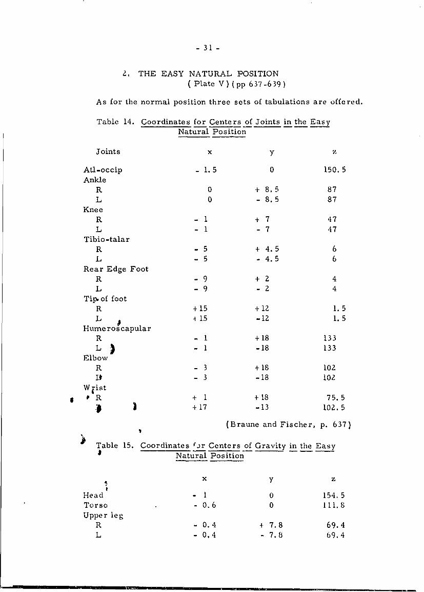
-31-
2, THE EASY NATURAL POSITION( Plate V) (pp 637-639)
As for the normal position three sets of tabulations are offered.
Table 14. Coordinates for Centers of Joints in the EasyNatural Position
Joints x y
Atl-occip - 1.5 0 150. 5Ankle
R 0 + 8.5 87L 0 - 8.5 87
KneeR - 1 + 7 47L -1 -7 47
Tibio-talarR -5 +4.5 6L - 5 -4.5 6
Rear Edge FootR -9 + Z 4L -9 -2 4
Tip. of footR +15 +12 1.5L 4 15 -12 1. 5
Hume ros capularR - 1 +18 133L 1 - -18 133
ElbowR - 3 +18 102i- 3 -18 102
W-ist
0 R + 1 +18 75.5) 3 +17 -13 102. 5
(Braune and Fischer, p. 637)
Table 15. Coordinates .jr Centers of Gravity in the EasyNatur7al Position
x y z
Head - 1 0 154. 5Torso - 0.6 0 111.8Upper leg
R - 0.4 + 7.8 69.4L - 0.4 - 7.8 69.4
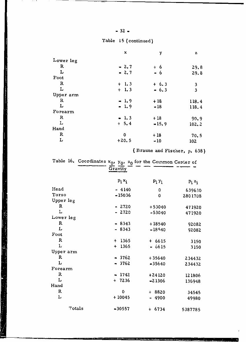
- 32 -
Table 15 (continued)
x y z
Lower legR -2 .7 + 6 29.8L - 2.7 - 6 Z9.8
FootR + 1.3 + 6.3 3L + 1.3 -6.3 3
Upper armR - 1.9 +18 118.4L - 1.9 -18 118.4
ForearmR - 1.3 +18 90.9L + 5.4 -15.9 102.Z
HandR 0 +18 70.5L +Z0.5 -10 102
( Braune and Fischer, p. 638)
Table 16. Coordinates x0 , y0 , z0 for the Common Ceprer of
Gravity - -- -
pixi Pi Yi Pi zi
Head - 4140 0 639630Torso -15036 0 2801708Upper leg
R - 2720 +53040 471920L - 2720 -53040 471920
Lower legR - 8343 + 18540 92082L - 8343 -18r40 92082
FootR + 1365 + 6615 3150L + 1365 - 6615 3150
Upper armR - 3762 +35640 234432L - 3762 -35640 234432
ForearmR - 1742 +24120 121806L + 7236 -21306 136948
HandR 0 + 8820 34545L +10045 - 4900 49980
Totals -30557 + 6734 5387785
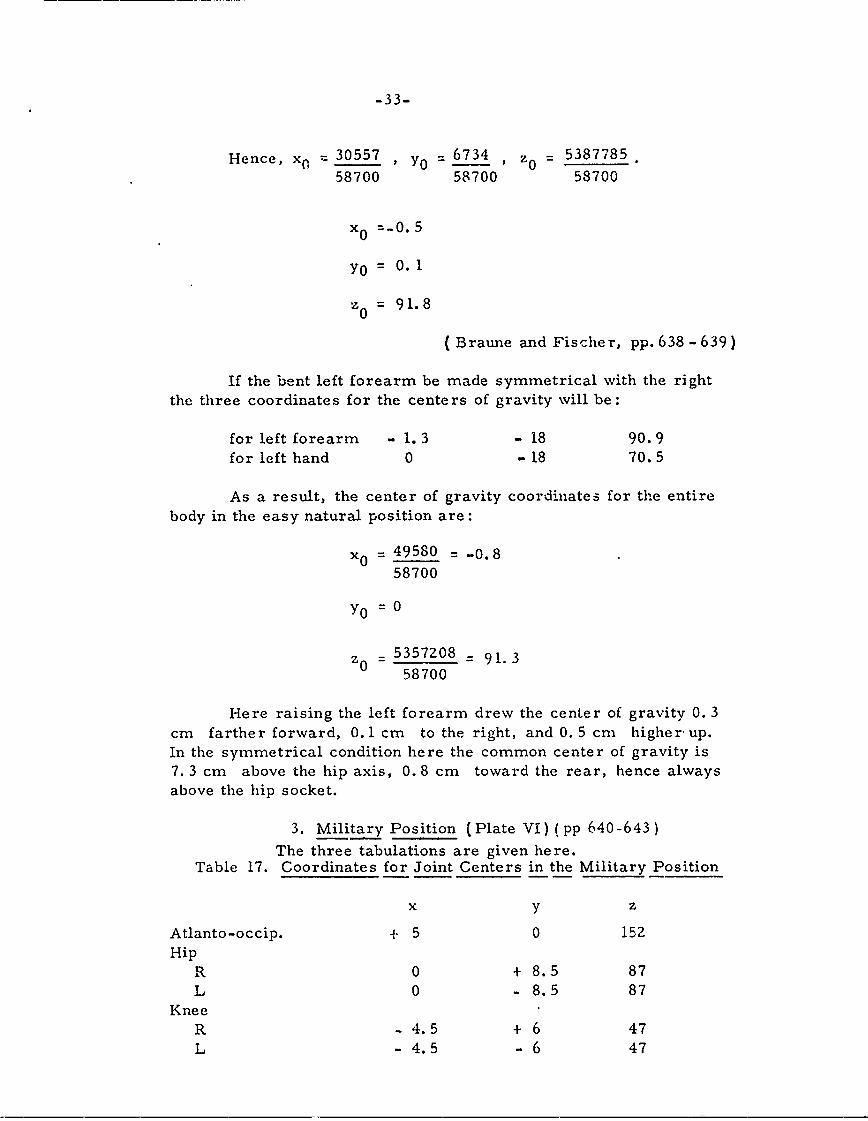
-33-
Hence, x- 30557 , Y0 = 6734 , z0 = 5387785
58700 58700 58700
x 0 =-0.5
Y0 = 0. 1
z 0 = 91.8
( Braune and Fischer, pp. 638 - 63 9)
If the bent left forearm be made symmetrical with the rightthe three coordinates for the centers of gravity will be:
for left forearm - 1.3 - 18 90.9for left hand 0 -18 70.5
As a result, the center of gravity coordinates for the entirebody in the easy natural position are:
x0 = 49580 = -0.858700
Y0 = 0
5357208 = 91.358700
Here raising the left forearm drew the center of gravity 0. 3cm farther forward, 0. 1 cm to the right, and 0. 5 cm higher- up.
In the symmetrical condition here the common center of gravity is7. 3 cm above the hip axis, 0. 8 cm toward the rear, hence alwaysabove the hip socket.
3. Military Position (Plate VI) (pp 640-643)
The three tabulations are given here.Table 17. Coordinates for Joint Centers in the Military Position
x y z
Atlanto-occip. + 5 0 152Hip
R 0 + 8.5 87L 0 - 8.5 87
KneeR -4.5 + 6 47L -4.5 -6 47
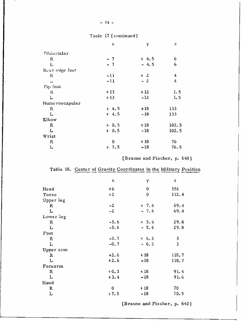
Taole 17 (continued)
x y
riblo-talarR -7 +4.5 6L -7 -4.5 6
Rcar edge footR -11 + 2 4
-I -2 4
rip footR +13 +12 1.5L +13 -12 1. 5
Hume ros capularR + 4.5 +18 133L + 4.5 -18 133
ElbowR + 0.5 +18 102.5L + 0.5 -18 102.5
WristR 0 + 18 76L 4- 7.5 -18 76.5
(Braume and Fischer, p. 640)
Table 18. Center of Gravity Coordinates in the Military Position
x y z
Head +6 0 156
Torso +2 0 112.4
Upper legR -2 + 7.4 69.4L -2 - 7.4 69.4
Lower legR -5.6 + 5.4 29.8L -5.6 - 5.4 29.8
FootR -0.7 + 6.3 3L -0.7 - 6.3 3
Upper armR +2.6 +18 118.7L +2. 6 -18 118.7
ForearmR +0.3 +18 91.4L 4.3.4 -18 91.6
HandR 0 +18 70L -7.5 -18 70.5
(Bratme and Fischer, p. 640)
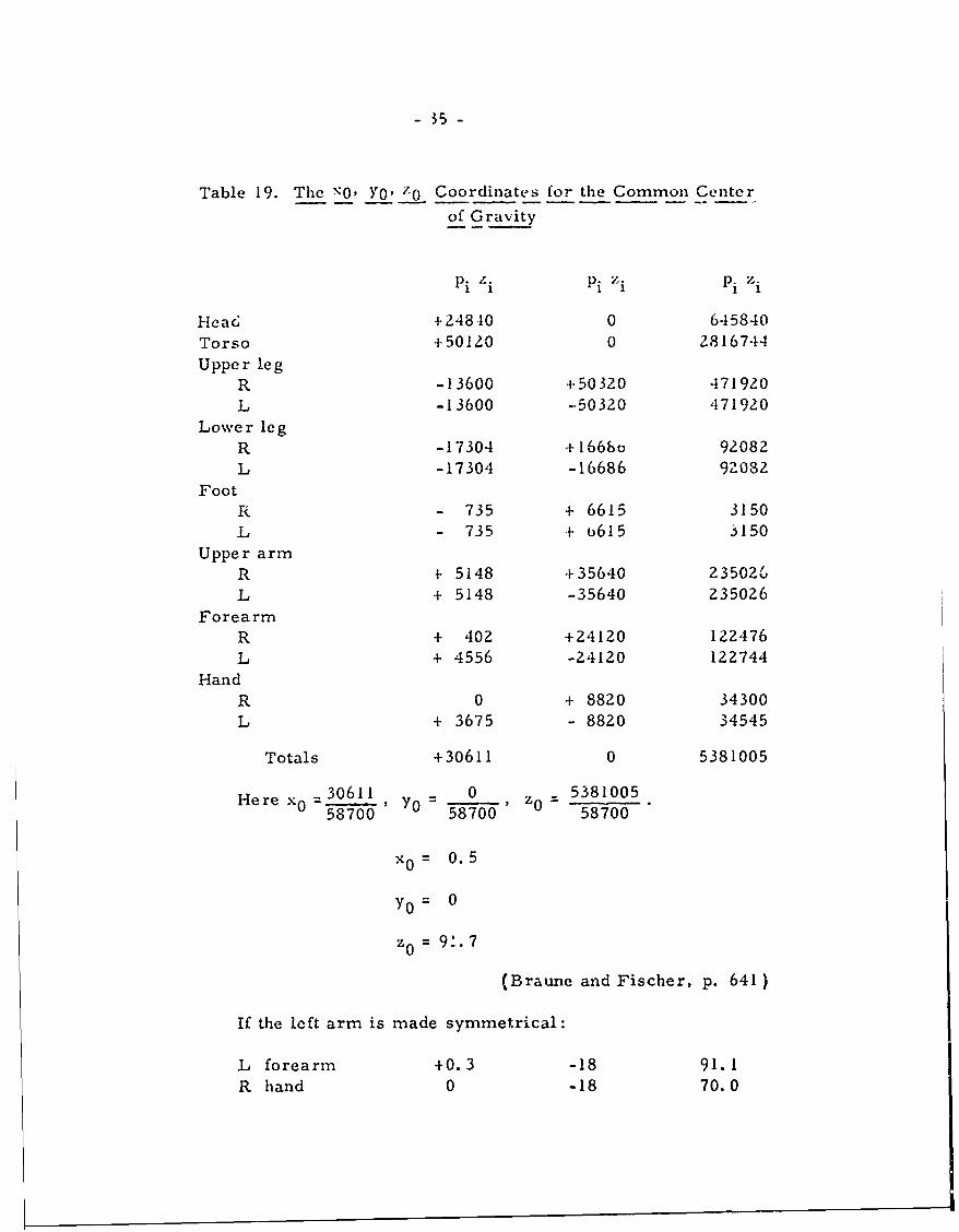
- 35 -
Table 19. The \O, Yo' z0 Coordinates for the Common Center
of Gravity
Pi /I. Pi z. Pi z.i
Heac +24840 0 645840
Torso +50120 0 28167-14
Upper legR -13600 +50320 471920
L -13600 --50320 471920Lower leg
R -17304 +1668o 92082L -17304 -16686 92082
FootR - 735 + 6615 3150
L - 735 + 6615 3150
Upper armR + 5148 +35640 23502u'
L + 5148 -35640 235026
ForearmR + 402 +24120 122,176
L + 4556 -24120 122744
HandR 0 + 8820 34300
L + 3675 - 8820 34545
Totals +30611 0 5381005
Here x 0 =30611 Y0 0 538100558700 58700 58700
x0= 0.5
Y0 = 0
z= 9.7
(Braune and Fischer, p. 641)
If the left arm is made symmetrical:
L forearm +0.3 -18 91.1R hand 0 -18 70.0
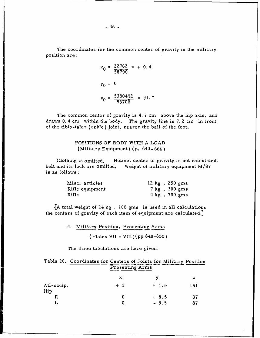
- 36 -
The coordinates for the common center of gravity in the militaryposition are:
X0 2=Z782 = + 0.458700
Y0 = 0
5380492 = 91.70 58700
The common center of gravity is 4. 7 cm above the hip axis, anddrawn 0. 4 cm within the body. The gravity line is 7. 2 cm in frontof the tibio-talar (ankle) joint, nearer the ball of the foot.
POSITIONS OF BODY WITH A LOAD(Military Equipment) (p. 643- 666)
Clothing is omitted. Helmet center of gravity is not calculated;belt and its lock are omitted. Weight of military equipment M/87is as follows:
Misc. articles 12 kg , 250 gmsRifle equipment 7 kg , 300 gmsRifle 4 kg , 700 gins
[A total weight of 24 kg , 100 gms is used in all calculationsthe centers of gravity of each item of equipment are calculated.]
4. Military Position, Presenting Arms
(Plates VII - VIII)(pp.648-650)
The three tabulations are here given.
Table 20. Coordinates for Centers of Joints for Military PositionPresenting Arms
x y z
Atl-occip. + 3 + 1.5 151Hip
R 0 + 8.5 87L 0 - 8.5 87
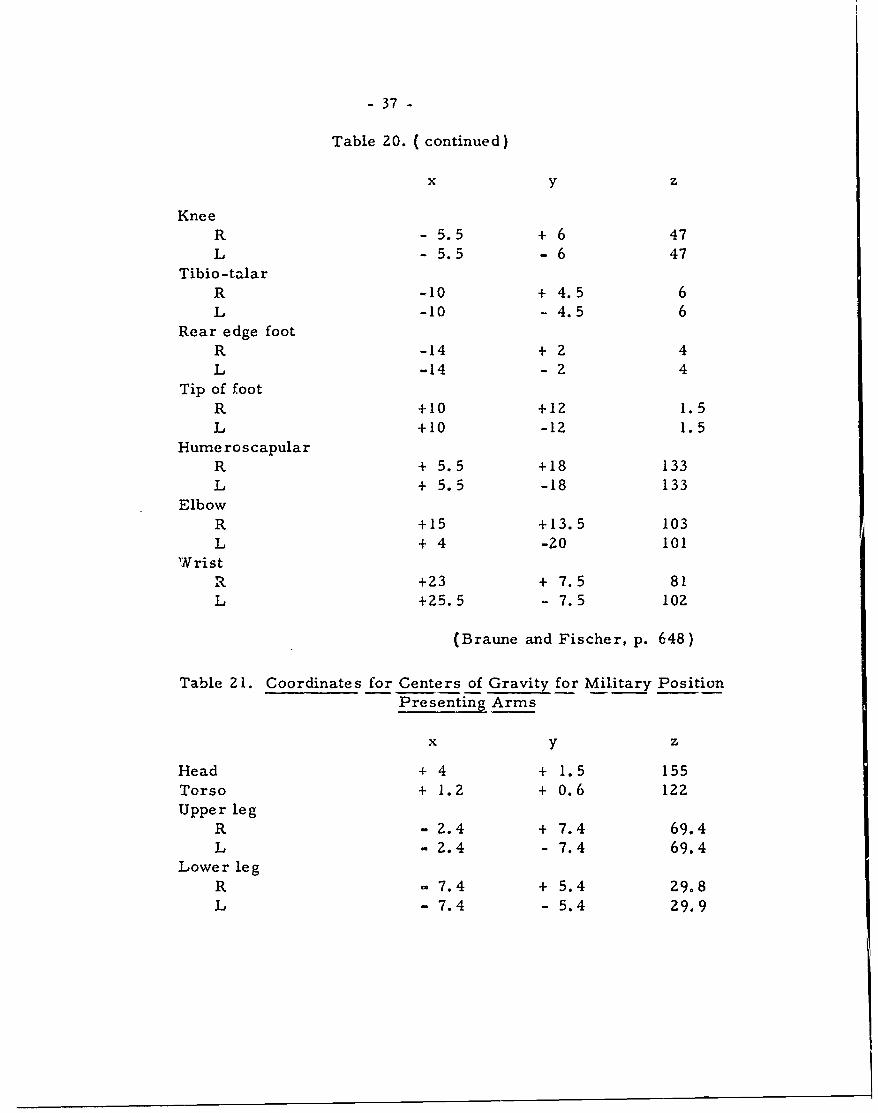
- 37 -
Table 20. (continued)
x y z
KneeR -5.5 + 6 47L -5.5 - 6 47
Tibio-talarR -10 + 4.5 6L -10 - 4.5 6
Rear edge footR -14 + 2 4L -14 - 2 4
Tip of footR +10 +12 1.5L +10 -12 1.5
Hume ros capularR + 5.5 +18 133L + 5.5 -18 133
ElbowR +15 +13.5 103L + 4 -Z0 101
WristR +23 + 7.5 81L +25.5 - 7.5 102
(Braune and Fischer, p. 648)
Table 21. Coordinates for Centers of Gravity for Military PositionPresenting Arms
x y z
Head 4 4 + 1.5 155
Torso + 1.2 + 0.6 122Upper leg
R - 2.4 + 7.4 69.4L - Z.4 - 7.4 69.4
Lower leg
R - 7.4 + 5.4 29.8L- 7.4 - 5.4 29.9
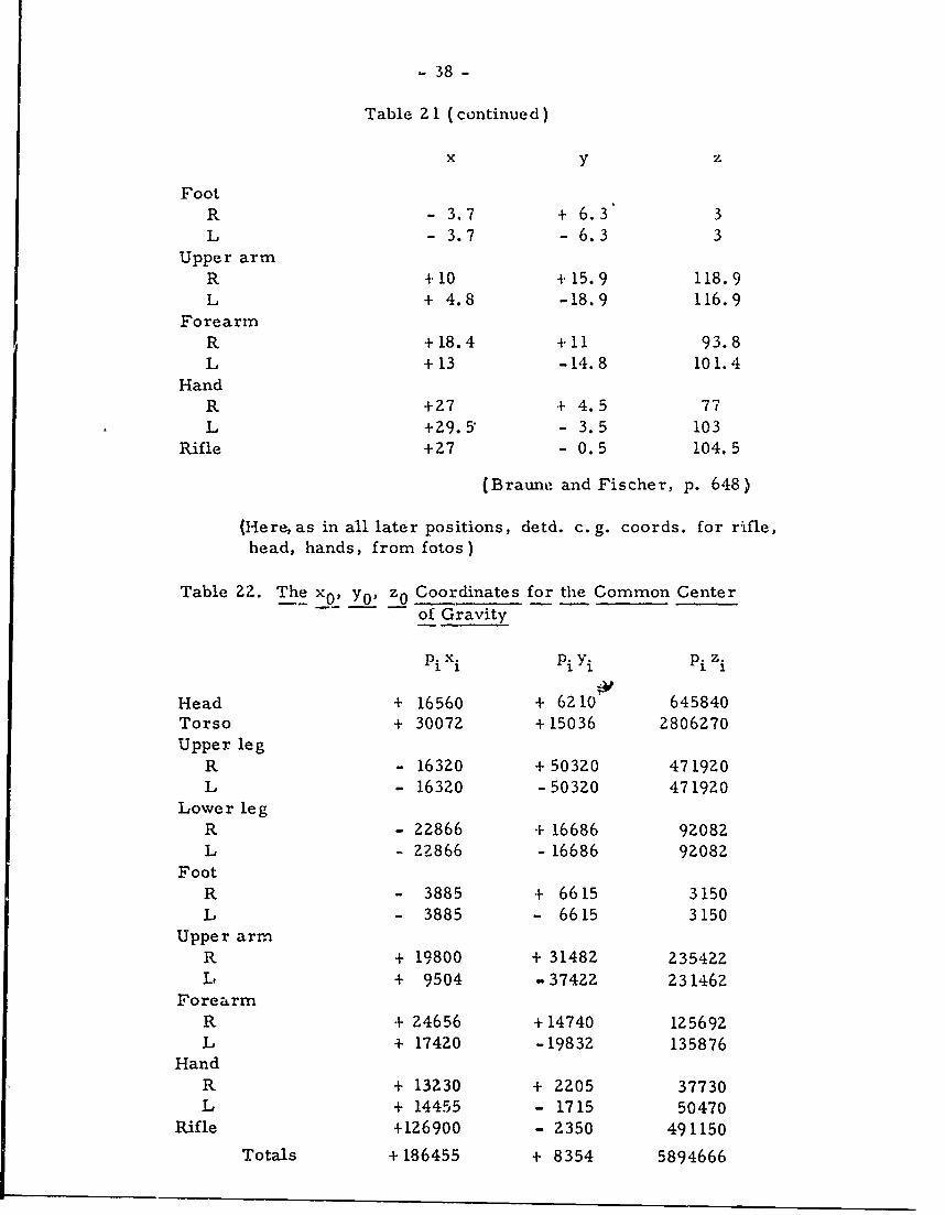
- 38 -
Table 21 (continued)
x y z
FootR - 3.7 + 6.3 3L -3.7 -6.3 3
Upper armR +10 +15.9 118.9L + 4.8 -18.9 116.9
ForearmR +18.4 +11 93.8L +13 -14.8 101.4
HandR +27 + 4.5 77L +29.5" - 3.5 103
Rifle +27 - 0.5 104.5
(Braune and Fischer, p. 648)
(Here, as in all later positions, detd. c. g. coords. for rifle,head, hands, from fotos)
Table 22. The x0 , y0 , z0 Coordinates for the Common Centerof Gravity
Pi xi Pi Yi Pi zi
Head + 16560 + 6210 645840Torso + 30072 +15036 2806270Upper leg
R - 16320 + 50320 471920L - 16320 -50320 471920
Lower leg
R - 22866 + 16686 92082L - 22866 - 16686 92082
FootR - 3885 + 6615 3150L - 3885 - 6615 3150
Upper armR + 19800 + 31482 235422L + 9504 -37422 231462
ForearmR + 24656 + 14740 125692L + 17420 -19832 135876
HandR + 13230 + 2Z05 37730L + 14455 - 1715 50470
Rifle +126900 - 2350 491150
Totals + 186455 + 8354 5894666
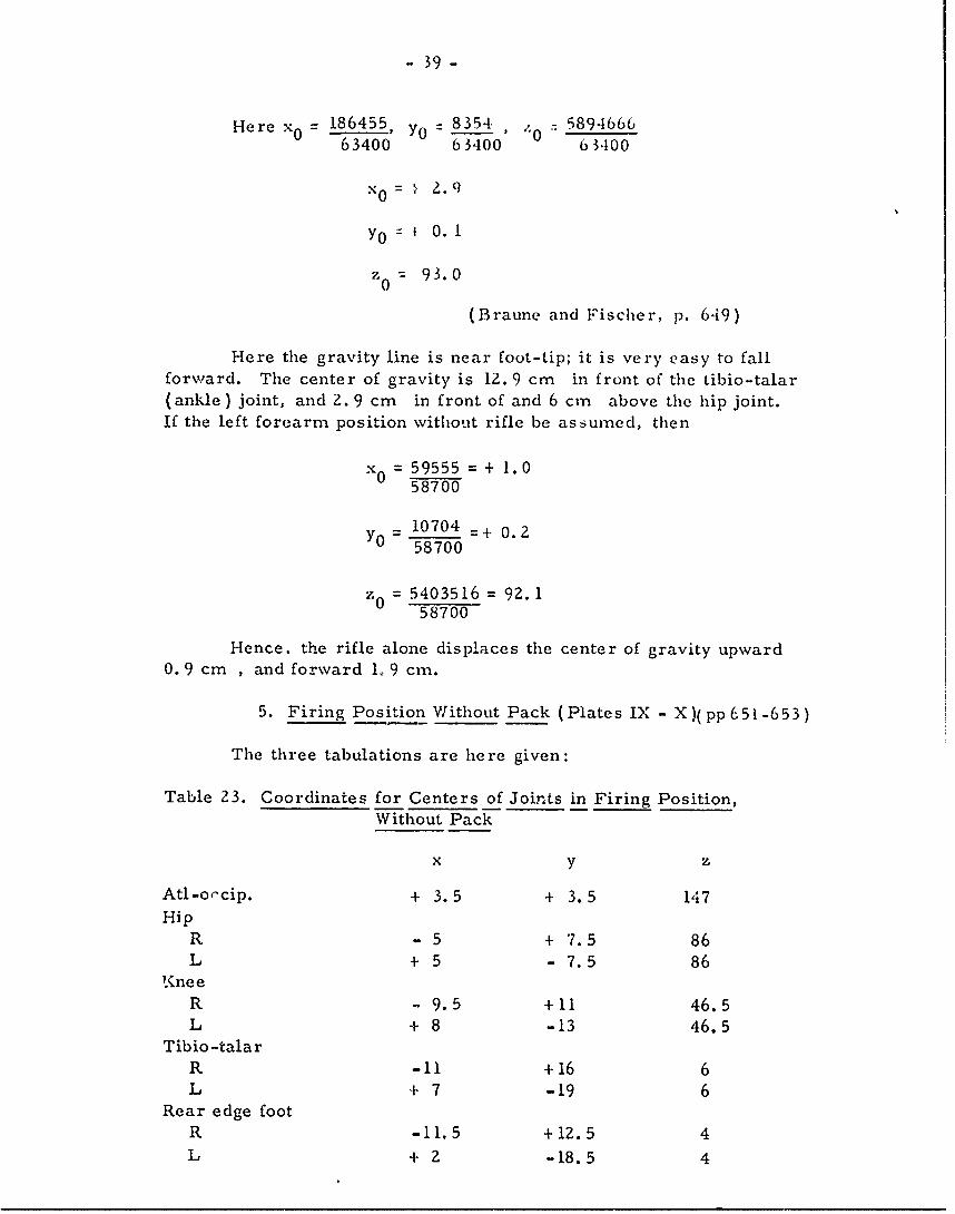
- 39-
Here 186455 y0 8354 , / 589-166663400 63400 63100
-0=. 2.9
yo = 0. 1
Zo: =93.0
(Braune and Fischer, p. 649)
Here the gravity line is near foot-tip; it is very easy to fallforward. The center of gravity is 12. 9 cm in front of the tibio-talar(ankle) joint, and 2. 9 cm in front of and 6 cm above the hip joint.If the left forearm position without rifle be assumed, then
x 0 = 59555 = + 1.058700
= 10704 =+ 0.258700
z 0 = 5403516 = 92.158700
Hence. the rifle alone displaces the center of gravity upward0. 9 cm , and forward 1. 9 cm.
5. Firing Position Without Pack (Plates IX - X)(pp 651-653)
The three tabulations are here given:
Table 23. Coordinates for Centers of Joints in Firing Position,Without Pack
x y z
Atl -o-cip. + 3.5 + 3.5 147Hip
R -5 + 7.5 86L + 5 -7.5 86
!neeR - 9.5 +11 46.5L + 8 -13 46.5
Tibio-talarR -11 +16 6L + 7 -19 6
Rear edge footR -11.5 +iZ. 5 4L + 2 -18.5 4
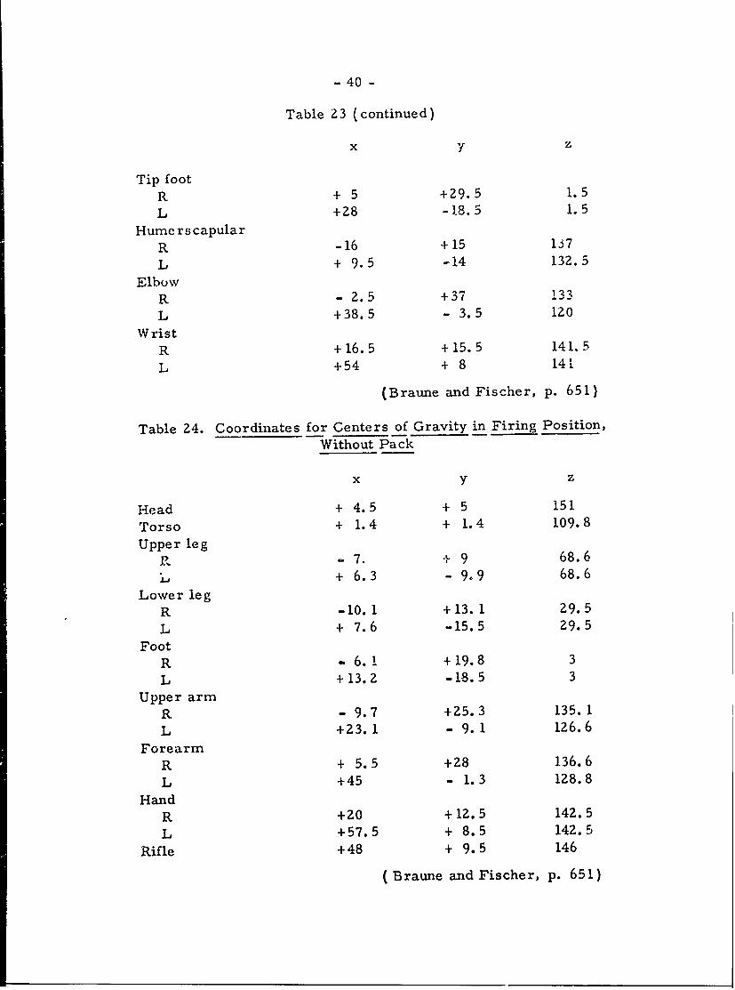
- 40 -
Table 23 (continued)
x y z
Tip footR + 5 +29.5 1.5
L +28 -1.8.5 1. 5
HumerscapularR -16 +15 137
L + 9.5 -14 132.5
ElbowR - 2.5 +37 133L +38.5 - 3.5 120
WristR +16.5 +15.5 141.5
L +54 + 8 141
(Braune and Fischer, p. 651)
Table 24. Coordinates for Centers of Gravity in Firing Position,Without Pack
x y z
Head + 4.5 + 5 151
Torso + 1.4 + 1.4 109.8
Upper legR - 7. + 9 68.6
", + 6.3 - 9.9 68.6
Lower legR -10.1 +13.1 29.5
L + 7.6 -15.5 29.5
FootR - 6.1 +19.8 3
L +13.2 -18.5 3
Upper armR - 9.7 +25.3 135.1
L +Z3.1 - 9. 1 126.6
ForearmR + 5.5 +28 136.6
L +45 - 1.3 128.8
HandR +20 +12.5 142.5
L +57.5 + 8.5 142.5
Rifle +48 + 9.5 146
(Braune and Fischer, p. 65 1)
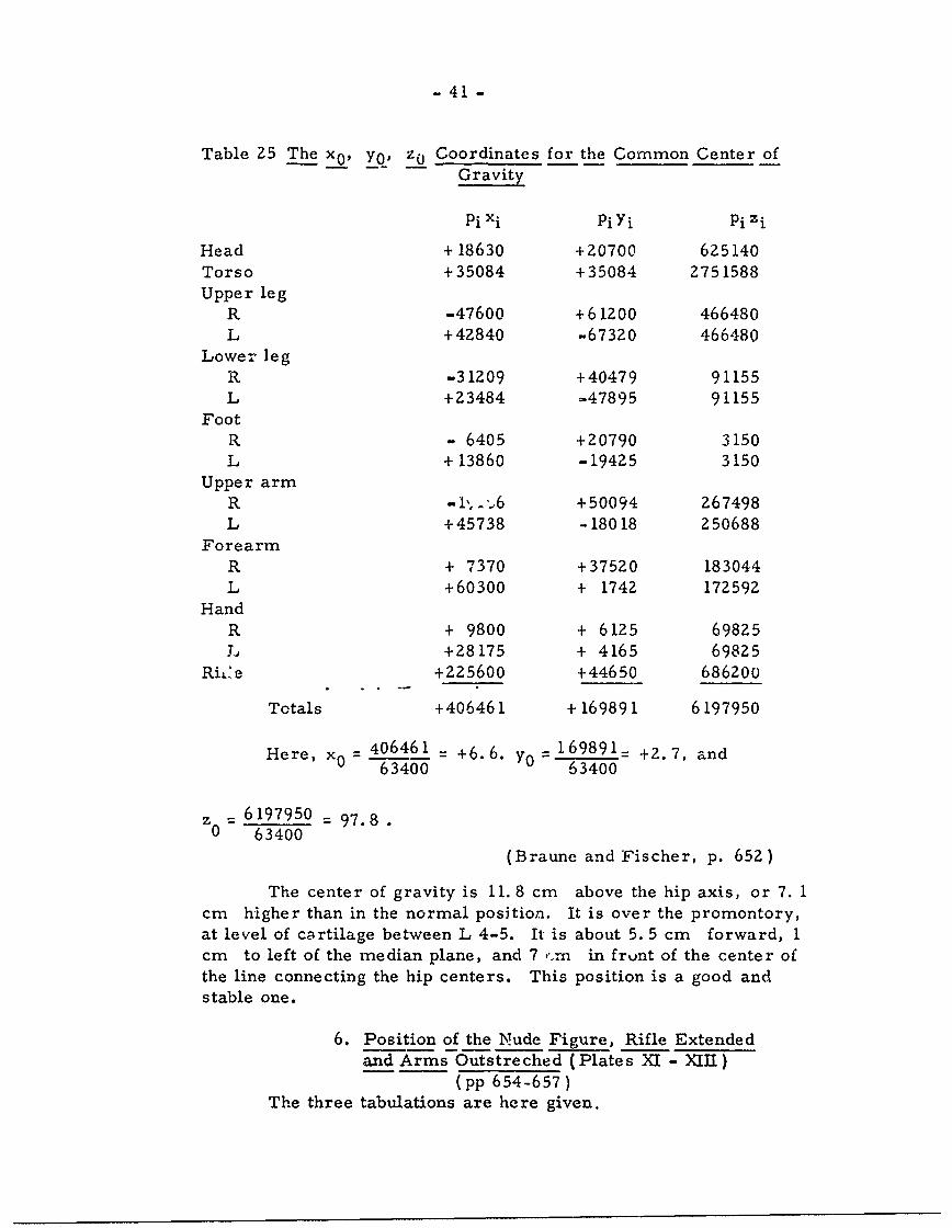
- 41 -
Table 25 The x 0 , Yo' z 0 Coordinates for the Common Center ofGravity
Pi xi piyi pi zi
Head + 18630 +20700 625140Torso +35084 +35084 2751588Upper leg
R -47600 +61200 466480L +42840 -67320 466480
Lower legR -31209 +40479 91155L +23484 -.47895 91155
FootR. - 6405 +20790 3150L + 13860 -19425 3150
Upper armR - i',. -6 +50094 267498L +45738 -18018 250688
ForearmR + 7370 +37520 183044L +60300 + 1742 172592
HandR + 9800 + 6125 69825J, +28175 + 4165 69825
RL-'e +225600 +44650 686200
Totals +406461 + 169891 6197950
He re, x0 406461= +6. 6. y 0 1 6 9 8 9 1- +2.7, and
63400 63400
6197950 - 97.80 =63400
(Braune and Fischer, p. 652)
The center of gravity is 11. 8 cm above the hip axis, or 7. 1cm higher than in the normal position. It is over the promontory,at level of cqrtilage between L 4-5. It is about 5. 5 cm forward, Icm to left of the median plane, and 7 ,.rn in frunt of the center ofthe line connecting the hip centers. This position is a good andstable one.
6. Position of the Nude Figure, Rifle Extendedand Arms Outstreched (Plates X1 - X III)
(pp 654-657 )The three tabulations are here given.
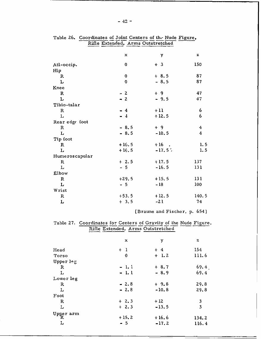
- 42 -
Table 26. Coordinates of Joint Centers of th,- Nude Figure,Rifle Extended, Arms Outstretched
x y z
Atl-occip. 0 + 3 150Hip
R 0 + 8.5 87L 0 - 8.5 87
KneeR -z + 9 47L -2 - 9.5 47
Tibio-talarR -4 +11 6L -4 +12.5 6
Rear edge footR -8.5 +9 4L - 8.5 -10.5 4
Tip footR +16.5 +16 . 1.5L +16.5 -17. 5 1.5
Hume ros capular
R + Z. 5 +17.5 137L - 5 -16.5 131
ElbowR +29.5 +15.5 131L - 5 -18 100
WristR +53.5 +12.5 140.5L + 3.5 -21 74
(Braune and Fischer, p. 654)
Table 27. Coordinates for Centers of Gravity of the Nude Figure,Rifle Extended, Arms Outstretched
x y z
Head + 1 + 4 154Torso 0 + 1.2 111.6
Upper legR -1.1 + 8.7 69.4L -1.1 -8.9 69.4
Lower legR - 2.8 + 9.8 29.8L - 2.8 -10.8 29.8
FootR + 2.3 +12 3L + 2.3 -13.5 3
Upper arma + 15. Z +16.6 134.2L - 5 -17.2 116.4
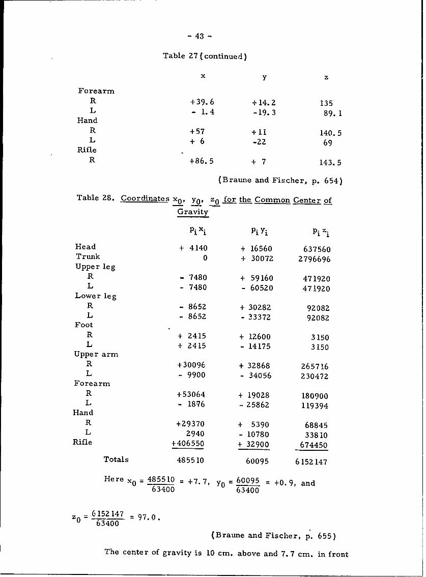
- 43 -
Table 27 (continued)
x y z
ForearmR +39.6 + 14. Z 135L - 1.4 -19.3 89.1
HandR +57 + 11 140.5L + 6 -22 69
RifleR +86.5 + 7 143.5
(Braune and Fischer, p. 654)
Table 28. Coordinates x0 , Yo, z0 for the Common Center of
Gravity
Pi xi Pi Yi Pi z.
Head + 4140 + 16560 637560Trunk 0 + 30072 2796696Upper leg
R - 7480 + 59160 471920L - 7480 - 60520 471920
Lower legR - 8652 + 30282 92082L- 8652 - 33372 92082
FootR + 2415 + 12600 3150L + 2415 - 14175 3150
Upper armR +30096 + 32868 265716L - 9900 - 34056 230472
ForearmR +53064 + 19028 180900L - 18'76 25862 119394
HandR +29370 + 5390 68845L 2940 - 10780 33810
Rifle +406550 + 32900 674450
Totals 485510 60095 6152147
Here x0 485510 = +7.7, y0 = 60095 = +0.9, and63400 63400
z- = 6152147 = 97.0.63400
(Braune and Fischer, p. 655)
The center of gravity is 10 cm. above and 7. 7 cm. in front
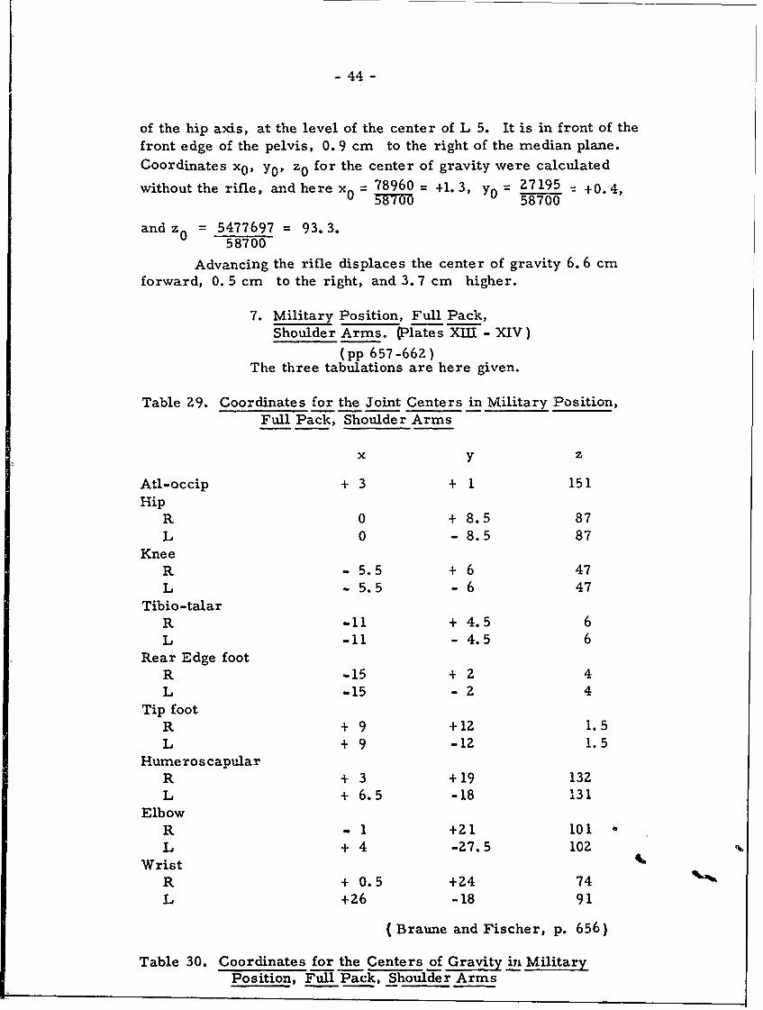
- 44 -
of the hip axis, at the level of the center of L 5. It is in front of thefront edge of the pelvis, 0. 9 cm to the right of the median plane.
Coordinates x0 , Y0 , z0 for the center of gravity were calculated
without the rifle, and here x 0 = 78960 = +1.3, y0 = 27195 _ +0.4,
3W7O 58700
and z 0 = 5477697 = 93.3.58700
Advancing the rifle displaces the center of gravity 6. 6 cmforward, 0. 5 cm to the right, and 3. 7 cm higher.
7. Military Position, Full Pack,Shoulder Arms. (Plates XIII - XIV)
(pp 657 -662)The three tabulations are here given.
Table 29. Coordinates for the Joint Centers in Military Position,Full Pack, Shoulder Arms
x y z
Atl-occip + 3 + 1 151Hip
R 0 + 8.5 87L 0 - 8.5 87
KneeR -5.5 + 6 47L - 5.5 - 6 47
Tibio-talarR 11 + 4.5 6L -11 - 4.5 6
Rear Edge footR -15 + 2 4L -15 - 2 4
Tip footR + 9 +12 1.5L + 9 -12 1.5
HumeroscapularR + 3 +19 132L + 6.5 -18 131
ElbowR -1 +21 101L + 4 -27.5 102
WristR + 0.5 +24 74L +26 -18 91
( Braune and Fischer, p. 656)
Table 30. Coordinates for the Centers of Gravity in MilitaryPosition, Full Pack, Shoulder Arms
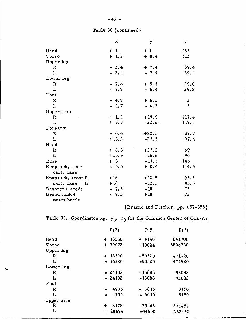
-45 -
Table 30 (continued)
x y z
Head + 4 + 1 155Torso + 1.2 + 0.4 112Upper leg
R - 2.4 + 7.4 69.4L - 2.4 - 7.4 69.4
Lower legR - 7.8 + 5.4 29.8L - 7.8 - 5.4 -9.8
FootR - 4.7 + 6.3 3L - 4.7 - 6.3 3
Upper armR + 1. 1 +19.9 117.4L + 5.3 -22.5 117.4
ForearmR - 0.4 +22.3 89.7L +13.2 -23.5 97.4
Hand1J + 0.5 +23.5 69L +29.5 -15.5 90
Rifle + 6 -11.5 143Knapsack, rear -15.5 + 0.4 114.5
cart. caseKnapsack, front R +16 +12.5 95.5
cart. case L + 16 -12.5 95.5Bayonet+ spade - 7.5 -.8 75Bread sack + - 7.5 +18 75
water bottle
(Braune and Fischer, pp. 657-658)
Table 31. Coordinates x0 , i0' z0 for the Common Center of Gravity
PiXi P yi Pi zi
Head + 16560 + 4140 641700Torso + 30072 +10024 2806720Upper leg
R + 16320 +50320 471920L - 16320 -50320 471920
Lower legR - 24102 + 16686 92082
L - 24102 -16686 92082Foot
R - 4935 + 6615 3150L - 4935 - 6615 3150
Upper armR + 2178 +39402 232452L + 10494 -44550 232452
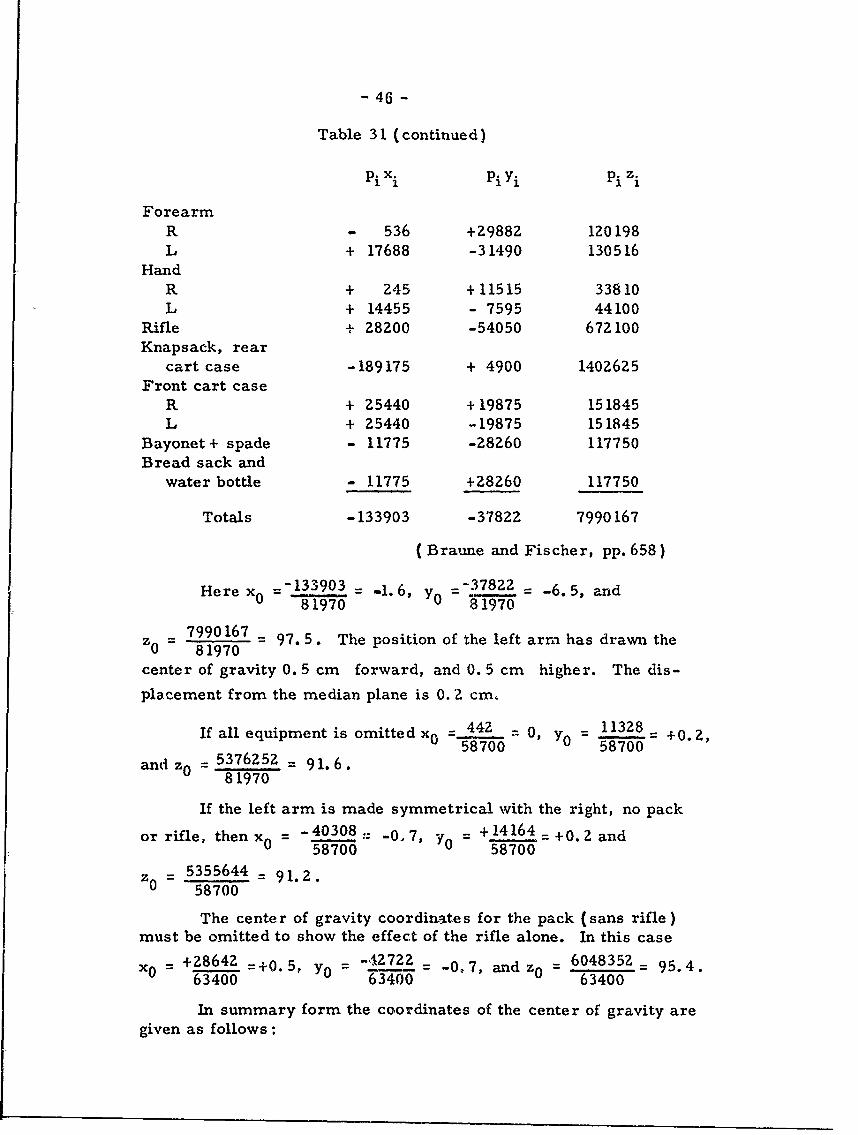
- 46 -
Table 31 (continued)
Pixi p yi Pi zi
ForearmR - 536 +29882 120198L + 17688 -31490 130516
HandR + 245 +11515 33810L + 14455 - 7595 44100
Rifle + 28200 -54050 672100Knapsack, rear
cart case -189175 + 4900 1402625Front cart case
R + 25440 + 19875 151845L + 25440 -19875 151845
Bayonet+ spade - 11775 -28Z60 117750Bread sack and
water bottle - 11775 +28260 117750
Totals -133903 -37822 7990167
( Braune and Fischer, pp. 658)
Here x0 =-133903 = -1.6, Y0 =- 37822 = -6.5, and81970 81970
z _ 7990167 = 97.5. The position of the left arm has drawn the0 81970
center of gravity 0. 5 cm forward, and 0. 5 cm higher. The dis-
placement from the median plane is 0. 2 cm,
If all equipment is omitted x0 = 442 = 0, Y0 = 11328 = +0.2,58700 58700
and z0 = 5376252 = 91.6.81970
If the left arm is made symmetrical with the right, no pack
or rifle, then x 0 = -4030 .- -0,7, Y = + 14 1 6 4 =+o.g and58700 58700
z0 = 5355644 = 91.2.58700
The center of gravity coordinates for the pack (sans rifle)must be omitted to show the effect of the rifle alone. In this case
Xo = +28642 =+0.5, yo = '1 = -0.7, and z0 = 6048352= 95.4.63400 6 34 00 63400
In summary form the coordinates of the center of gravity aregiven as follows:
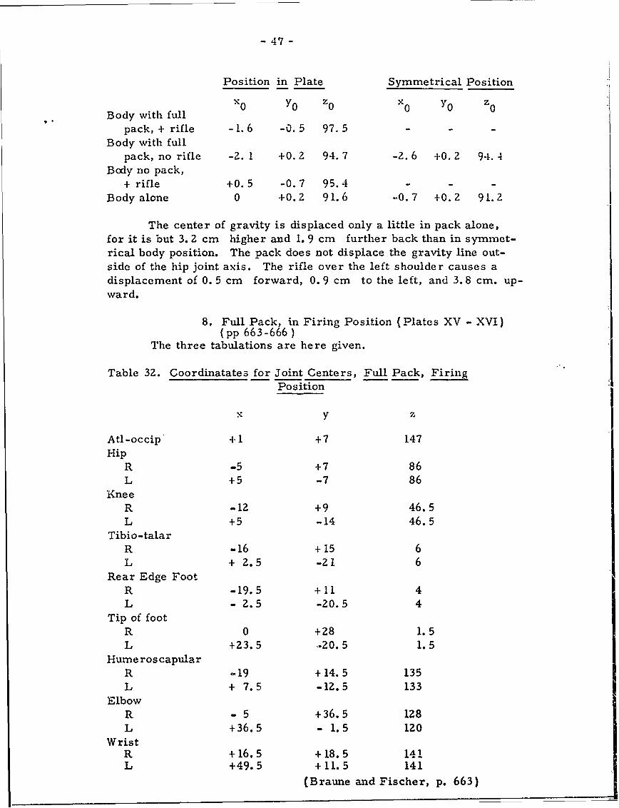
- 47-
Position in Plate Symmetrical Position
YO z x Y0 z
Body with full
pack, + rifle -1.6 -0.5 97.5 - - -
Body with fullpack, no rifle -2. 1 +0. 2 94. 7 -2. 6 +0. 2 94.4
Body no pack,+ rifle +0.5 -0.7 95.4 - - -
Body alone 0 +0.2 91.6 -.0.7 +0.2 91.2
The center of gravity is displaced only a little in pack alone,for it is but 3. 2 cm higher and 1. 9 cm further back than in symmet-
rical body position. The pack does not displace the gravity line out-side of the hip joint axis. The rifle over the left shoulder causes adisplacement of 0. 5 cm forward, 0. 9 cm to the left, and 3. 8 cm. up-
ward.
8. Full Pack, in Firing Position (Plates XV - XVI)(pp 663-666 )
The three tabulations are here given.
Table 32. Coordinatates for Joint Centers, Full Pack, FiringPosition
xy z
Atl-occip +1 +7 147Hip
R -5 +7 86L +5 -7 86
KneeR -12 +9 46.5L +5 -14 46.5
Tibio-talarR -16 +15 6L + 2.5 -21 6
Rear Edge Foot
R -19.5 +11 4L - 2.5 -20.5 4
Tip of footR 0 +28 1.5L +Z3.5 '-20.5 1.5
Hume ros capularR -19 +14.5 135L + 7.5 -12.5 133
ElbowR - 5 +36.5 128L +36.5 - 1.5 120
WristR +16.5 +18.5 14iL +49.5 +11.5 141
(Braune and Fischer, p. 663)
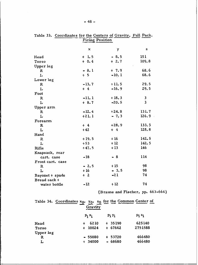
- 48 -
Table 33. Coordinates for the Centers of Gravity Full Pack,Firing Position
x y z
Head + 1.5 - 8.5 151Torso + 0.4 + 2.7 109.8
Upper legR - 8.1 + 7.9 68.6
L + 5 -10.1 68.6Lower leg
R -13.7 +11.5 29.5
L + 4 - -16.9 29.5Foot
R -11. 1 +18.3 3
L + 8.7 -20.5 3Upper arm
R -12.4 +24.8 131.7L 421.1 - 7.3 126.9
ForearmR + 4 +28.9 133.5L +42 + 4 128.8
HandR +19,.5 +16 142.5
L +53 +12 142.5Rifle +47.5 +13 146Knapsack, rear
cart. case -18 - 8 114
Front cart. caseR - 2.5 +15 98L +16 - 3.5 98
Bayonet + spade + 2 -21 74Bread sack +
water bottle -12 +12 74
(Braime and Fischer, pp. 663-664)
Table 34. Coordinates x 0 , Yo, z0 for the Common Center of
Gravity
PiXi Pi yi Pi zi
Head + 6210 + 35190 625140Torso + 10024 + 67662 2751588Upper leg
R - 55080 + 53720 466480
L + 34000 - 68680 466480
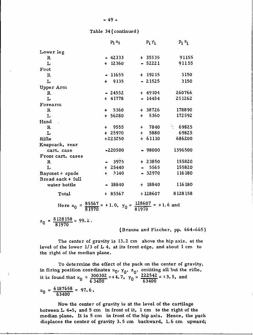
-49 -
Table 34 (continued)
Pi Xi Pi Yi Pi zi
Lower legR - 42333 + 35535 91155T. + 12360 - 52221 91155
FootR - 11655 + 19215 3150
L + 9135 - 21525 3150Upper Arm
R - 24552 + 49104 260766L + 41778 - 14454 251262
ForearmR + 5360 + 38726 178890L + 56280 + 5360 172592
HandR + 9555 + 7840 69825L + 25970 + 5880 69825
Rifle +223250 + 61110 686200Knapsack, rear
cart. case -220500 - 98000 1396500Front cart. cases
R - 3975 + 23850 155820L + 25440 - 5565 155820
Bayonet + spade + 3140 - 32970 116180Bread sack + full
water bottle - 18840 + 18840 116180
Total + 85567 + 128607 8128158
Were x0 =85567 +1. 0, Y0 128607 - +1.6 and8 1970 81970
z0 = 8128158 = 99.81970
(Braune and Fischer, pp. 664-665)
The center of gravity is 13.2 cm above the hip axis, at thelevel of the lower 1/3 of L 4, at its front edge, and about 1 cm tothe right of the median plane.
To determine the effect of the pack on the center of gravity,in firing position coordinates x0 , y0 , z 0 , omitting all but the rifle,
it is found that x = 300302 =+4.7, y0 222542 +3.5, and6 3400
63400
Z0 - 6187658 = 97.6.63400
Now the center of gravity is at the level of the cartilagebetween L 4-5, and 5 cm in front of it, 1 cm to the right of themedian plane. It is 5 cm in front of the hip axis. Hence, the packdisplaces the center of gravity 3. 5 cm backward, 1. 6 cm upward;
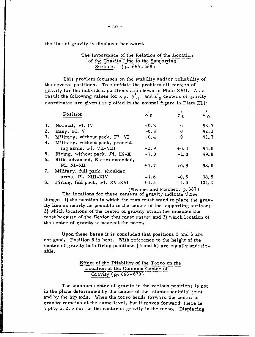
-50-
the line of gravity is displaced backward.
The Importance of the Relation of the Locationof the Gravity Line to the Supporting
Surface. ' p. 666 - 668)
This problem focusses on the stability and/or reliability ofthe several positions. To elucidate the problem all centers ofgravity for the individual positions are shown in Plate XVII. As aresult the following values for x 0' y 0, and z 0 centers of gravity
coordinates are given (as plotted in the normal figure in Plate III):
Position x 0 Y 0 - 0
1. Normal, Pl. IV +0.2 0 92.72. Easy, P1. V -0.8 0 92.33. Military, without pack, Pl. VI +0. 4 0 92. 74. Military, without pack, preseL-
ing arms, Pl. VII-VIII +2. 9 +0. 1 94.05. Firing, without pack, J?l. IX-X +7.0 -1. 0 99.86. Rifle advanced, R arm extended,
P1. X-.XII +7.7 +0.9 98.07. Military, full pack, shoulder
arms, Pl. XII-.XIV -1.6 -0.5 98.58. Firing, full pack, Pl. XV-XVI + 1. 5 + 1. 0 101. 2
(Braune and Fischer, p. 6 6 7)The locations for these centers of gravity indicate three
things: 1) the position in which the man must stand to place the grav-ity line as nearly as possible in the center of the supporting surface;2) which locations of the center of gravity strain the muscles themost because of the flexion that must ensue; and 3) which location ofthe center of gravity is nearest the norm.
Upon these bases it is concluded that positions 5 and 6 arenot good. Position 8 is best. With reference to the height of thecenter of gravity both firing positions (5 and 6) are equally undesir-able.
Effect of the Pliability of the Torso on theLocation of the Common Cente r of
Gravity (pp 668 - 670
The common center of gravity in the various positions is notin the plane determined by the center of the atlanto-occip.tal jointand by the hip axis. When the torso bends forward the center ofgravity remains at the same level, but it moves forward; there isa play of 2. 5 cm of the center of gravity in the torso. Displacing
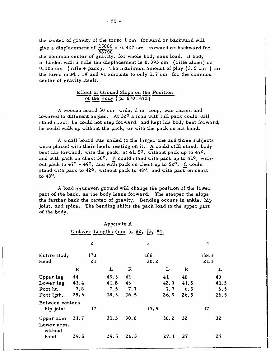
- 51 -
the center of gravity of the torso I cm forward or backward will
give a displacement of 25060 = 0. 427 cm forward or backward for58700
the common center of gravity, for whole body sans load. if bodyis loaded with a rifle the displacement is 0. 395 cm (rifle alone) or0.306 cm (rifle + pack). The maximum amount of play (2.5 cm ) forthe torso in P1 . IV and VI amounts to only 1. 7 cm for the commoncenter of gravity itself.
Effect of Ground Slope on the Positionof the Body (p. 670-672)
A wooden board 50 cm wide, 2 m long, was raised andlowered to different angles. At 320 a man with full pack could stillstand erect; he cculd not step forward, and kept his body bent forward;he could walk up without the pack, or with the pack on his head.
A small board was nailed to the larger one and three subjectswere placed with their heels resting on it. A could still stand, bodybent far forward, with the pack, at 41. 50, without pack up to 470,and with pack on chest 500. B could stand with pack up to 410, with-out pack to 470 - 490, and with pack on chest up to 520. C couldstand with pack to 420, without pack to 480, and with pack on chestto 480.
A load onuneven ground will change the position of the lowerpart of the back, as the body leans forward. The steeper the slopethe farther back the center of gravity. Bending occurs in ankle, hi-joint, and spine. The bending shifts the pack load to the upper partof the body.
Appendix A
Cadaver Lengths (cm ), #2, #3, #4
2 3 4
Entire Body 170 166 168.3Head 21 20.2 21.3
R L R L R L
Upper leg 44 43.3 42 41 40 40Lowerleg 41.4 41.8 43 42.9 41.5 41.5Foot ht. 7.8 7.5 7.7 7.7 6.5 6.5Foot lgth. 28.5 28.3 26.5 26.9 26.5 26.5
Between centership joint 17 17.5 17
Upper arm 31.7 31.5 30.6 30.2 32 32Lower arm,
withouthand 29.5 29.5 26.3 27.1 27 27
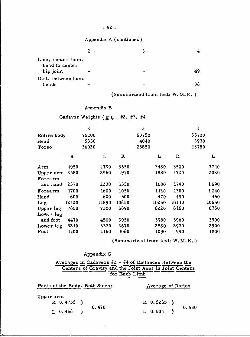
- 5Z -
Appendix A (continued)
2 3 4
Line, center hum.head to centerhip joint 49
Dist. between hum.heads 36
(Summarized from text: W. M. K. )
Appendix B
Cadaver Weights ( )* #2, #3, #4
2 3 4
Entire body 75100 60750 55700Head 5350 4040 3930Torso 36020 28850 23780
R L R L R L
Arm 4950 4790 3550 3480 35Z0 3710Upper arm 2580 2560 1990 1880 1720 2020Forearm
an(. nand 2370 2230 1550 1600 1790 1690
Forearm 1700 1600 1050 1120 1300 1240Hand 600 600 500 470 490 450Leg 121ZO 11890 10650 10250 10110 10650Upper leg 7650 7300 6690 6220 6150 6750Lowc " legand foot 4470 4500 3950 3980 3960 3900
Lower leg 3210 3320 2670 2880 2970 2900Foot 1100 1160 1060 1090 990 1000
(Summarized from text: W. M. K.)
Appendix C
Averages in Cadavers #2 - #4 of Distances Between theCenters of Gravity and the Joint Axes in Joint Centers
for Each Limb
Parts of the Body, Both Sides; Average of Ratios
Upper armR 0.4735 ) R 0.5265 )
0.470 0.530L 0.466 ) L 0.534 )
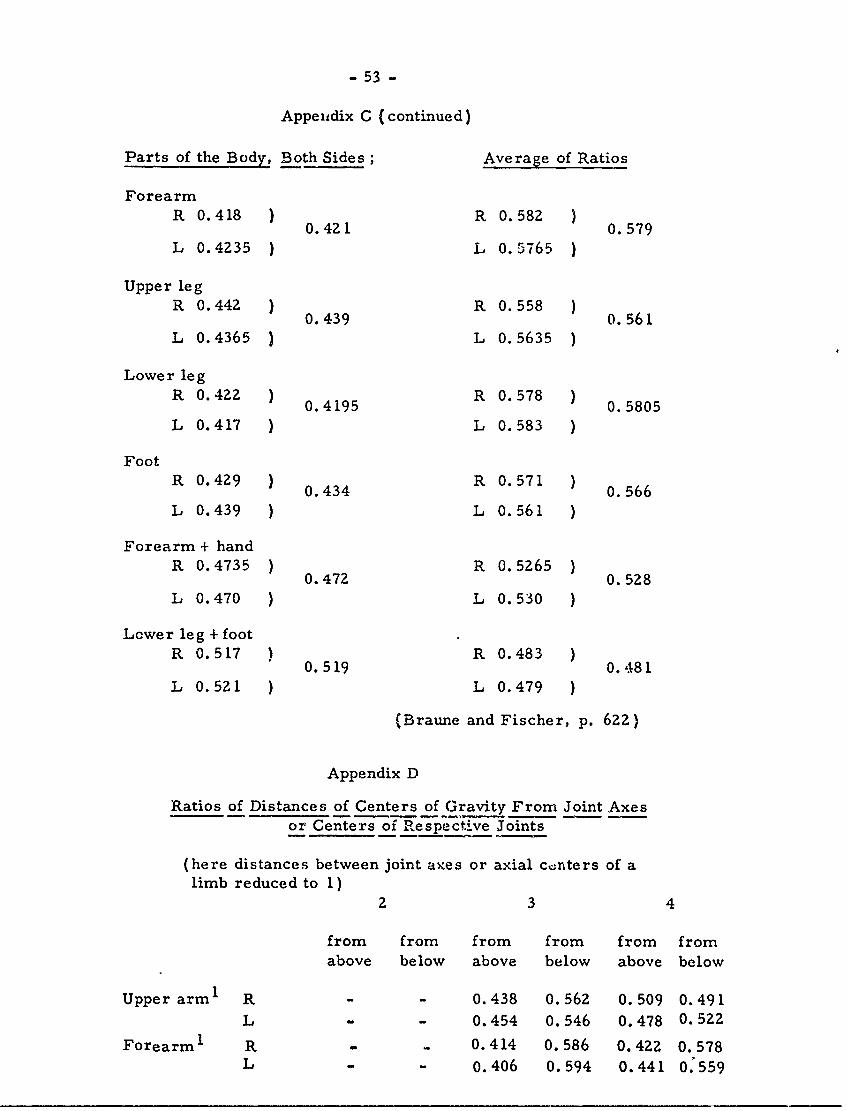
- 53 -
Appeidix C (continued)
Parts of the Body, Both Sides; Average of Ratios
ForearmR 0.418 ) R 0.582 )0. 421 0. 579
L 0.4235 ) L 0.5765 )
Upper legR 0.442 ) R 0.558 )0. 439 0. 561
L 0.4365 ) L 0.5635 )
Lower legR 0.422 0.4195 R 0.578 )0. 41950. 5805
L 0.417 ) L 0.583 )
FootR 0.429 0.434 R 0.571 ) 0.566
L 0.439 ) L 0.561 )
Forearm + handR 0.4735 ) R 0.5265 )0.472 0. 528
L 0.470 ) L 0.530 )
Lcwer leg + footR 0.517 ) R 0.483 )0.519 0.481
L 0.521 ) L 0.479 )
(Braune and Fischer, p. 622)
Appendix D
Ratios of Distances of Centers of Gravity From Joint Axesor Centers of Respective Joints
(here distances between joint axes or axial c. nters of alimb reduced to 1)
2 3 4
from from from from from fromabove below above below above below
Upper arm I R - - 0.438 0.562 0.509 0.491L - - 0.454 0.546 0.478 0.522
Forearm1 R . 0.414 0.586 0.422 0.578L - - 0.406 0.594 0.441 0:559
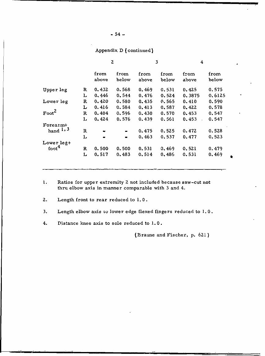
- 54-
Appendix D (continued)
2 3 4
from from from from from fromabove below above below above below
Upper leg R 0. 432 0.568 0.469 0.531 0.4Z5 0.575L 0.446 0.544 0.476 0.524 0.3875 0.6125
Lower leg R 0. 4Z0 0.580 0.435 0.565 0. 410 0. 590L 0.416 0.584 0.413 0.587 0.42Z 0.578
Foot2 R 0.404 0.596 0.430 0. 570 0.453 0.547L 0.424 0.576 0.439 0.561 0.453 0.547
Forearm+hand 1, 3 R - 0.475 0.5Z5 0.472 0.528
L - 0.463 0.537 0.477 0.5Z3Lower leg+
foot 4 R 0.500 0.500 0. 531 0,469 0. 521 0. 479L 0.517 0.483 0.514 0.486 0.531 0.469 *
I. Ratios for upper extremity 2 not included because saw-cut notthru elbow axis in manner comparable with 3 and 4.
2. Length front to rear reduced to 1. 0.
3. Length elbow axis to lower edge flexed fingers reduced to 1. 0.
4. Distance knee axis to sole reduced to 1. 0.
(Braune and Fischer, p. 621)
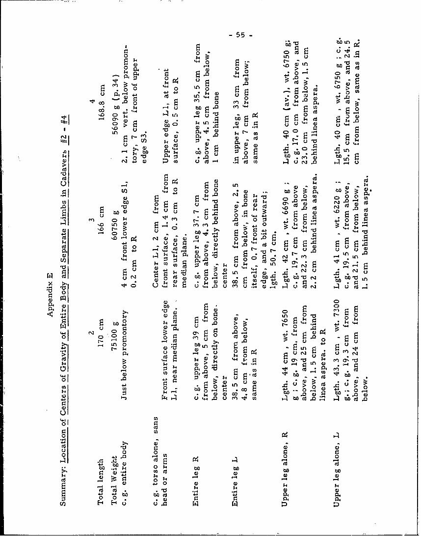
-55-
0 r-4 j.g LA C)
k. k 0 .)0 (:> c
o o0 '40 InA 0 -.0 ~ > O
.0 -4 4J 0, kk CD u0 1) k
4) 0 (d LA44 0 ~ '') 0*-000 m *.4 .-
La * - 0.~4O en ;4 (d 4 P
4 0 r
%0O uo 10 LALI) 4 b P.4 . Q~ 0
N40 cn In~- .*Ci .e 0 E 0.~
. ()44 > ~ 04. . .0 -
.51 (d -0) kdt qr
k) 0 O > (1).L44
0(0 0 co- t Q
k 0 :i 0 N5 ~ 0) %4 Cl ~00i 0 d.. -4 .3 -
0 .0 0) C 0 . _d a d )CV00 cd~~ok
4) ~ %4 u r 0'
(d 040 0j00oT Lnc 0 F 4 k -0 00
P4C 04 44-1 44- %).44*0 NNLA
0) -I 0) 01;(d 00 5c k4 0
0d r- LA u~ u t
0b . '4 >I~ 0)1-- ull0 1- N ~ cn- .
N o %4 ,0C dC tC-... 14 LALfA) 4
443 41 0)4 -4 N UL 5p 4 00 .- .. 0 1 ) . .0 0 N
0 (d; 0 - t4)k 0) 'oC 00
1. C 4. 0-4 *k Q.T -.01
4A ~ 0k .0 LA
u 0 0 4 0, .c V4 00) 0 .0
03 0. 0~00e (d-bO~~U0)
P4 u )u 0 1:
0 4 4 -4 -4 a0k 0 ;8 00 en
.-~ -%4 qq
413 0 ) $-i
-'- -4 0 V) 0) 4:j 3430 bO0C 43 .0 a) b4J 4 0o *d ra -4 . 4H o .
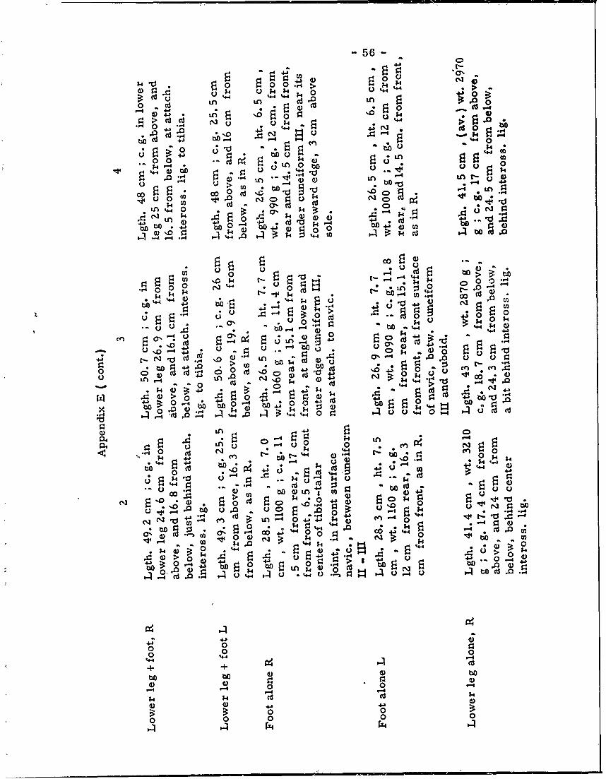
-56-
a%.k 000 o. o k ;
0 .. (4 >U 4.4k ;4 0
in '4 LO 1 Cd 1n.
'0 4a u
4 01 ,b4, 0 4C0 '.0 *g
%4 .00 14
WA -4 i I -- 4
0140 0o 0 c' c4- 'o 0 -U 0. C ) .. C
C n %" : -~ a- *4) ~ -
;* 00 .1 4.4. 4- .3U ~. 4) L k 4 04
4J 4.. 0 -4 *o to ~uoo 00 ~ to 3- .1(n
ko (D to,. . 0
'004.1 4142 , k.140904 rn0000
C.)- 4 .4'..
0U 0 ;4 ~ (
U %* -+ ;4 4)(.1~$ %44 4)W 4) A UJO
U0 (U. 44
4-X4. U o - 44 41 -
4. 04) C )
0JN c 0 0nc% J.0o 44-0 0.1 ' t
04- -(U (+ .4 d 4
4)t D 0) O
4) 4) -
>4 14 ;. (U14-to bo 4. 4.) 4)
0 ) -4 0 0 0'04 .0
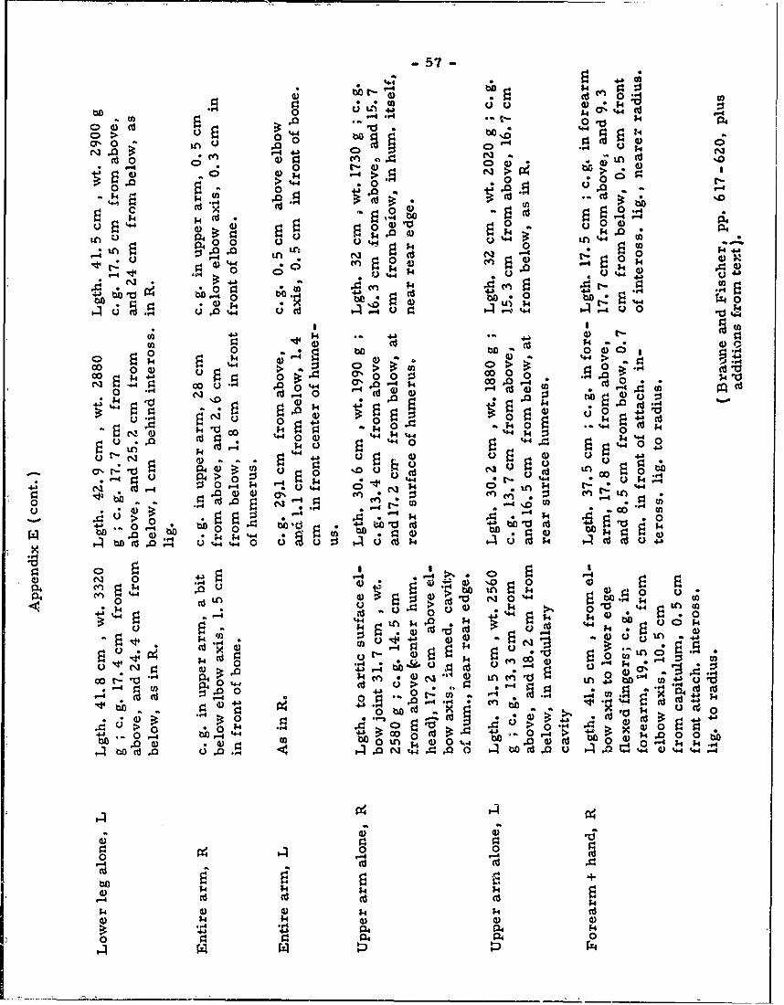
-57-
-44 a
0 £4 -
>~ 00 00'% 0 00 o C)g.
N.D~~~ .0*
0 4)0 t4 )n
-4 *0 C.'-0) ,.0 > 4 0.
c 0d 444 04a
0,' 0 0-o 0 44 34 0 -0tn%
* n 0 t t. C£44 r-4. e% 14)
't (S' *; I'db k
0 ;4 0 4
0 cn -n -0
I
.4 44J 4J)t
-o0 .. , 4) a ~ O4)0 ) 44 4 '>a -W
co ) .. D >) C >0 u G.OO .. 4£ £4vr : 0> .
N4d- (d "-40
44 *;44~~* $4 A c d
0~~~ 4a0)) *
.0 .0c 1 4$
4 0 0 44 $4 t. o4 44(d) r.-k44
.0 4)
aL~ r- c'.0' C) *UU)dLn 0
-- 4 Q* 0 '.4.
£4 -4 k 44 tz0.
J 0 ,4 4 d~*~0'
bD A 0 $4 Ok4 .4 ~dgo1
C)
0-4 0 0
04 4) 4) £4 to £4 ; )
'. ;44)4 4) t
0~~ '4)~£
(D tn 0
DISCLAIMER NOTICE
THIS DOCUMENT IS BEST QUALITYPRACTICABLE. THE COPY FURNISHEDTO DTIC CONTAINED A SIGNIFICANTNUMBER OF PAGES WHICH DO NOTREPRODUCE LEGIBLY.
0 ; BEST
Th ~o~'m ~AVAILABLE COPY
BESTAVAILABLE COPY
THEORETICAL FUNDAMENTALS FOR
A MECHANICS OF LIVING BODIES
(Condensed fromi 0. Fischer)
- 58 -
THEORETICAL FUNDAMENTALS FOR A MECHANICS OF LIVING BODIES(Condensed from 0. Fischer)
INTRODUCTION (pp v-vii)
In theoretical mechanics litle attention has been paid to freelymovable joint sytems, termed by Fischer "n- link systems. ,i Thisbook aims: I) to give the kinetics of joint systems; 2) to give statesof motion and equilibrium in Man. He introduces "certain masssystems and fixed points within the individual limbs (main points ofthe body parts)" which are similar to the center of gravity in thekinetics of a single rigid body. The unit of force is the kilogramweight, not the dyne. The unit of length is the centimeter. The unitof time is the second. The unit of mass is 981, 000 grams (the massnumber is obtained by dividing the number of grams in a body by
981, 000 or the number of kilograms by 981 ).
In order to investigate the states of motion and equilibrium ofthe living human body it is necessary to make certain assumptions inthe intezests of simplicity, even though they do not conform in detailto actual conditions. In general these assumptions concern the composi-tion and behavior of the individual body parts and the connecting jointsbetween them. More specifically the assumptions are as follows:
I) the deformation and mass shifts in body parts due to respiration, blood,muscles, etc., must be neglected; 2) body parts must be conceivedas rigid; 3) finger and hand movements must not be considered in loco-motion (e. g., finger + hand + forearm equal a single rigid body part);4) cartilage changes in joints during action must be disregarded; 5) afixed joint center, let alone a fixed j( int axis, cannot really be assumed.
Both bodies ( iuman and animal) and machines have joint systems,more intricate in the former. Individual parts are connected by joints,which are called links. Joint connections, with a fixed joint center,permit neighboring links to have 1, 2, or 3 degrees of freedom. Whenone link moves all others will perform translatory motions only.("Motions in which all points of the links have in each movement equallygreat and parallel velocities and therefore describe congruent paths.")For example, assume that a man stands on one leg, with the entiresole touching the ground; now let him raise himself upon his toes. Herethe supporting foot must rotate around a horizontal axis running approx-imately through the heads of the middle foot bones. Hence, other partsof the body cannot remain in their positions; their motion may be suchthat th !y are lifted to the same extent, though with no change of directionin their long axes. As a result these body parts will perform a transla-tory motion completely defined by the path of one point, the center ofthe foot joint axis (ankle joint). In substance the entire body, except-
ing the supporting foot, behaves as a single rigid body, lifted by the
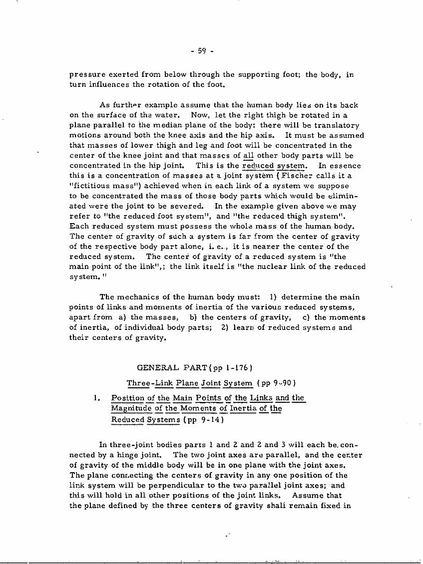
- 59 -
pressure exerted from below through the supporting foot; the body, inturn influences the rotation of the -foot.
As furthpr example assume that the human body lies on its backon the surface of the water. Now, let the right thigh be rotated in aplane parallel to the median plane of the body: there will be translatorymotions around both the knee axis and the hip axis. It must be assumedthat masses of lower thigh and leg and foot will be concentrated in thecenter of the knee joint and that masses of all other body parts will beconcentrated in the hip joint. This is the redixced system. -In essencethis is a concentration of masses at a joint system (Fischer calls it a"fictitious mass") achieved when in each link of a system we supposeto be concentrated the mass of those body parts which would be elimin-ated were the joint to be severed. In the example given above we mayrefer to "the reduced foot system", and "the reduced thigh system".Each reduced system must possess the whole mass of the human body.The center of gravity of such a system is far from the center of gravityof the respective body part alone, i. e., it is nearer the center of thereduced system. The center of gravity of a reduced system is "themain point of the link",; the link itself is "the nuclear link of the reducedsystem. "
The mechanics of the human body must: 1) determine the mainpoints of links and moments of inertia of the various reduced systems,apart from a) the masses, b) the centers of gravity, c) the momentsof inertia, of individual body parts; 2) learn of reduced systems andtheir centers of gravity.
GENERAL PART(pp 1-176)
Three-Link Plane Joint System (pp 9-90)
I. Position of the Main Points of the Links and theMagnitude of the Moments of Inertia of the
Reduced Systems (pp 9-14)
In three-joint bodies parts 1 and 2 and 2 and 3 will each be, con-nected by a hinge joint. The two joint axes are parallel, and the terierof gravity of the middle body will be in one plane with the joint axes.The plane conrnecting the centers of gravity in any one position of thelink system will be perpendicular to the two parallel joint axes; andthis will hold in all other positions of the joint links. Assume thatthe plane defined by the three centers of gravity shali remain fixed in
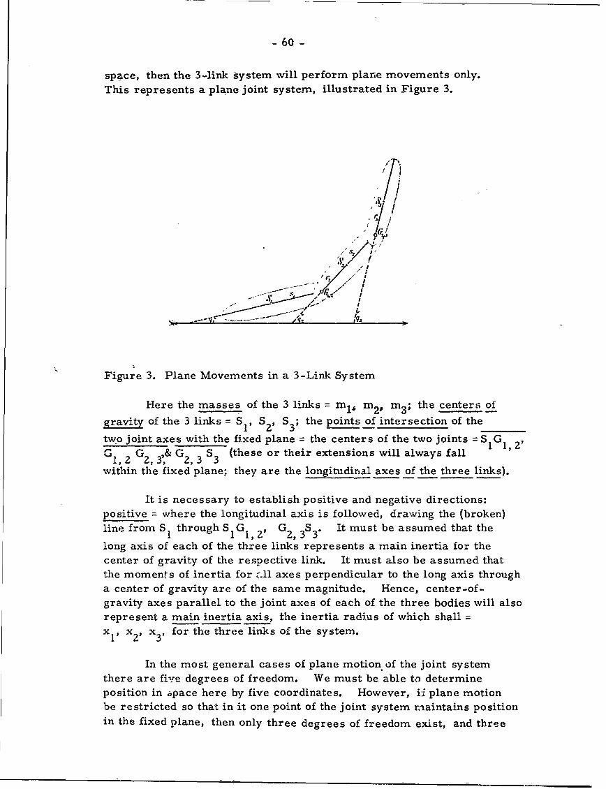
- 60 -
space, then the 3-link system will perform plane movements only.This represents a plane joint system, illustrated in Figure 3.
/ /4 w
- 3
two joint axes with the fixed plane =the centers of the two joints = S1IGi 1
'2I
G1,2G,3, G23 S3 (these or their extensions will always fallwithin the fixed plane; they are the / axes of the three links).
It is necessary to establish positive and negative directions:positive = wvhere the longitudinal axis is followed, drawing the (broken)line from S 1I through SGIG , 21 G 2,3 3S3. It must be assumed that thelong axis of each of the three l in inertia for thecenter of gravity of the respective link. I t m us t als o be assumed thatthe moments of inertia for c.11 axes perpendicular to the long axis througha center of gravity are of the same magnitude. Hence, center-of-gravity axes parallel to the joint axes of each of the three bodies will alsorepresent a main inertia axis, the inertia radius of which shallsx 1pi xv x 3 for the three links of the system.
In the most general cases of plane motion of the joint systemthere are five degrees of freedom. We must be able to determineposition in pace here by five coordinates. However, i plane motionbe restricted so that in it one point of the joint system maintains position
in the fixed plane, then only three degrees of freedom exist, and three
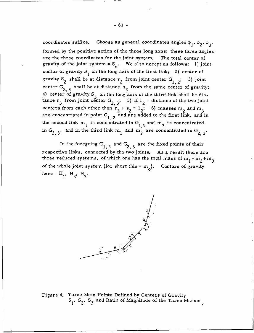
-61 -
coordinates suffice. Choose as general coordinates angles T 1, q 2, q 3,
formed by the positive action of the three long axes; these three anglesare the three coordinates for the joint system. The total center ofgravity of the joint system = S . We also accept as follows: 1) joint
0center of gravity S1 on the long axis of the first link; 2) center ofgravity S2 shall be at distance r from joint center G 1, ; 3) joint
center G2,3 shall be at distance s2 from the same center of gravity;
4) center of gravity S3 on the long axis of the third link shall be dis-tance r 3 from joint center G2,3; 5) if 12 = distance of the two joint
centers from each other then r2 + sz = 12; 6) masses m 2 and m 3
are concentrated in point G1, 2 and are added to the first link, and in
the second link m 1 is concentrated in G' and m is concentrated1 1,2 3
in G2, 3' and in the third link m I and m 2 are concentrated in G2, 3"
In the foregoing G 1,2 and G2, 3 are the fixed points of their
respective links, connected by the two joints. As a result there arethree reduced systems, of which one has the total mass of m 1 + m 2 + m 3
of the whole joint system (for short this = 0o). Centers of gravity
here= HIP H2) H 3.
/ /
; ,112 /
.1' 4
Figure 4. Three Main Points Defined by Centers of GravitySI, S2, S3 and Ratio of Magnitude of the Three Masses
2' 3 (
- 62 -
In Fig. 4 are shown the three main points defined by centersof gravity S1, S2 , S 3 , and the ratio of magnitude oi the three masses.
Intr6&uced here are the following designations:
SI1H 1 = eIH IGI1, 2 d d1
S 2H 2 = e?, G, 2 = c 2 , H2 G2 d2
S 3H3= e 3, G2, 3 H3 = c 3
(individual lengths = positive)
The following length are defined:
thch = distance of main point of the hth link from
the joint center of this linkth
dh = distance of the other joint centers of the ht-link from the main point of this link
theh = distance of the ht- main point from the pertinent
center of gravity
The following relations are therefore obtained: *
() -me I + (m 2 + m 3 ) dl = 0 (or zero)
-mc -m e + =0(" " )12 2 27m? 3 2
(m I + m 2 ) c3 + m3 = 3 0(" )
Lengths d 1 , c2 , d2 and c 3 which define the position of the three
main points in relation to the two joint centers = main lengths. Theformulae for these lengths are:
(Z) m d = Im s
moCZ = mr. + m3 1rodZ ml 1 + m2s
mo3 = m3r3
* The numbers in parentheses, as (1), (2).;.. refer to the formulanumber as given by Fischer. Obviously not all formulae will beherein cited. The basis of selection is two fold: I) introductionof (new) terms; 2) final form of a developed formula. (W. M. K. )
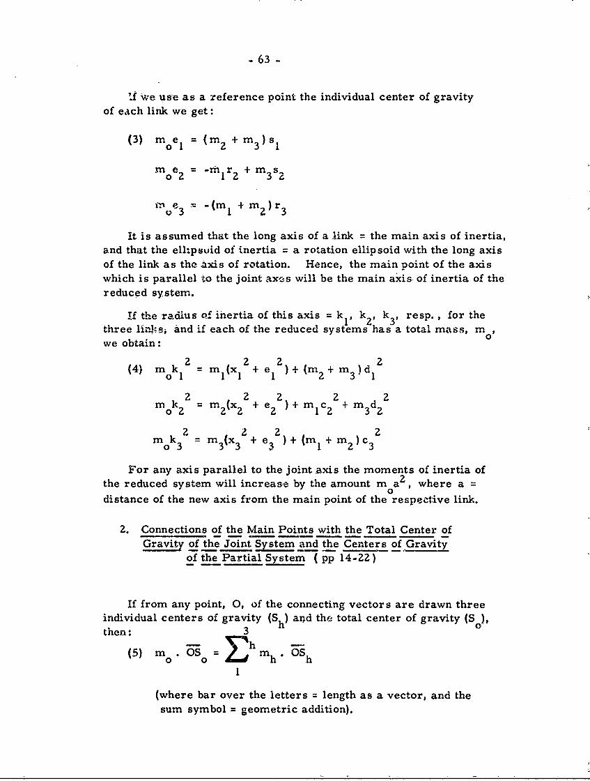
- 63 -
'I we use as a reference point the individual center of gravityof each link we get:
(3) moe I = 2 + m 3 )s I
moe 2 = -mIr2 + m3 s
In e 3 (m12 + m2 ) r 3
It is assumed that the long axis of a link = the main axis of inertia,and that the ell-psuid of inertia = a rotation ellipsoid with the long axisof the link as the axis of rotation. Hence, the main point of the axiswhich is parallel to the joint axes will be the main axis- of inertia of thereduced system.
if thze radius of inertia of this axis = k1 , k 2 , k 3 , resp., for thethree lin,3s and if each of the reduced systems has a total mass, m o0we obtain:
(4 k2 2 2 d 2
(4) m0k 1= mI(x1 + e I )+ (m 2 + m 3 ) d 1
mk32 M 2(x + e2 2 2
0k 2 =m3(x3 + e ) + (m1 + m2 ) c3
For any axis parallel to the joint axis the moments of inertia ofthe reduced system will increase by the amount m a 2 , where a =0distance of the new axis from the main point of the respective link.
2. Connections of the Main Points with the Total Center ofGravity of the Joint System and the Centers of Gravity
of the Partial System ( pp 14-22)
If from any point, 0, of the connecting vectors are drawn threeindividual centers of gravity (Sh) and thr total center of gravity (S ),then: 3
(5) m .3S m hu1
(where bar over the letters = length as a vector, and thesum symbol = geometric addition).
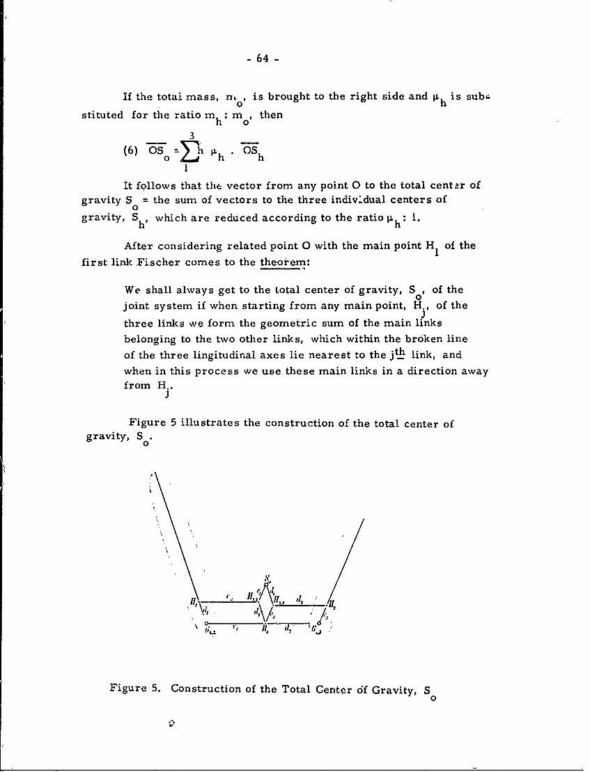
-64-
If the total, mass, n, 0 is brought to the right side and p h is subc.
stituted for the ratio m_: m , thenht 0
3
(6) OS 0o h 'hOSh
It follows that the vector from any point 0 to the total center ofgravity S = the sum of vectors to the three indiv.dual centers ofo
gravity, S which are reduced according to the ratio ph: 1.
After considering related point 0 with the main point H of the
first link Fischer comes to the theorem:
We shall always get to the total center of gravity, S , of the0joint system if when starting from any main point, H., of theJthree links we form the geometric sum of the main linksbelonging to the two other links, which within the broken lineof the three lingitudinal axes lie nearest to the jth link, and
when in this process we use these main links in a direction awayfrom H..
J
Figure 5 illustrates the construction of the total center ofgravity, So.
06
Figure 5. Construction of the Total Center df Gravity, S0
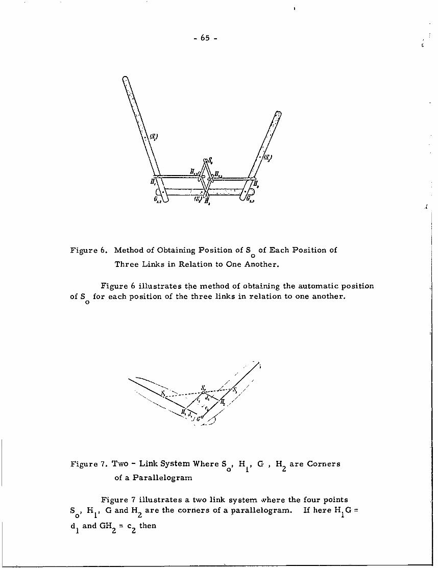
-65-
Figure 6. Method of Obtaining Position of S of Each Position of0
Three Links in Relation to One Another.
Figure 6 illustrates the method of obtaining the automatic positionof S for each position of the three links in relation to one another.
0d
"- "1/. /
Figure 7. Two - Link System Where S 0H I G H2 are Corners
of a Parallelogram
Figure 7 illustrates a two link system wvhere the four pointsS0, Hi, G and H2 are the corners of a parallelogram. If here H1 G
d and GH, = c then1 2
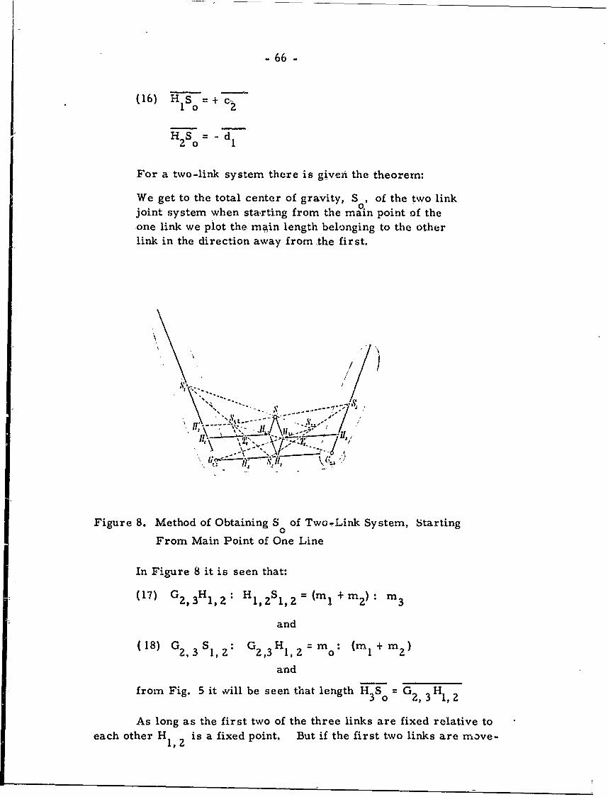
- 66 -
(16) HIs 0 =+c 2
S 0--d
For a two-link system there is given the theorem:
We get to the total center of gravity, S , of the two link0.joint system when starting from the main point of theone link we plot the- main length belonging to the otherlink in the direction away from the first.
S/x //
,.----- -- 1'I J,
("Z.4
Figure 8. Method of Obtaining S 0of Two-Link System, Starting
From Main Point of One Line
In Figure 8 it is seen that:
(17) GZ, 3 H 1,2 H 102S 1, =(m I+ m ) m 3
and
18) G2, 3 S$1, Z G 2,3H 1, 2 M mo : (m I + m 2)
and
from Fig. 5 it wvill be seen that length H 3S °0 = G 2, 3 H 1,2
As long as the first two of the three links are fixed relative toeach other Hm,2 is a fixed point. But if the first two links are move-
- 67 -
able then the first connecting joint (G, will change relative to
HI,2 just as the common center of gravity, S 1 2 of these two links
is not fixed. Now it is seen that H2, 3 in Figure 5 is the main point
of the joint system of links 2-3. Hence the following proportionapplies:
(19) G 1 2 H2, 3: H2,3 S2,3(m 2 +m 3 ): m
and
(20) G1.2S2,3: G1,2 H2,3 M 0m: (m2+ m 3 )
In getting the total center of gravity, S2 , of links 2-3, it isnot possible to start from H and H 3 : one muse start from the mainpoints obtained after the first link has been separated. If the third
link is removed from a three-joint system, the main point of the firstlink is H and will move away from G ; the main point of the
second link will be H 2', moving away from G2,3" H1 will divide
length S G 1,2 on the long axis of the first link ( Fig. 8) in the ratio
m :m 1 , and H ' will divide G S in the same way. Here Ficiier2 2 1,2 2
presents further data when HI is taken as the common center ofI!
gravity of two masses (m I + m 2) and m 3 concentrated in H I and
GI,2 and when H2 is taken as the common center of gravity of two
masses (m 1 + m 2 ) and m 3 concentrated in H 2 ' and G2,3.
The connecting line of the two centers of gravity S 1 and S2 to H1,2 at a
certain point, T2 ( Fig. 8), the position of which is independent of the
link position in G, 12 Here we may accept:
(24) T2 H m s21, Z m. -
Since 12 = r 2 + s 2 the main length, c2 , may be written as:
m2+ m m(25) c - mz -1 r --- s 22 m m 2
0 0
Here c 2 will be divided by T 2 into the two parts of the above
formulae. In like manner the point T' will be found on main length,2d.•
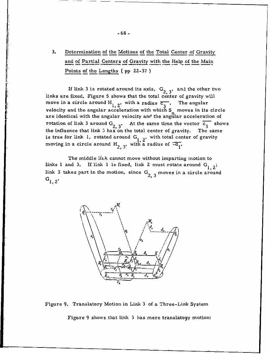
-68-
3. Determination of the Motions of the Total Center of Gravity
and of Partial Centers of Gravity with the Help of the Main
Points of the Lengths ( pp 22-37 )
If link 3 is rotated around its axis, G2, , andl the other two
links are fixed, Figure 5 shows that the total center of gravity willmove in a circle around HI, with a radius - The angular
1,2' 3velocity and the angular acceleration with which S moves in its, circleare identical with the angular velocity anc4 the angular acceleration ofrotation of link 3 around G2, 3" At the same time the vector Z3 shows
the influence that link 3 has on the total center of gravity. The sameis true for link 1, rotated around G 1 , with total center of gravitymoving in a circle around H with a radius of --W.
The middle lfrk cannot move without imparting motion tolinks 1 and 3. If link 1 is fixed, link Z must rotate around G, 1;
link 3 takes part in the motion, since G 2,3 moves in a circle around
G1, 2.
( /-- ---- -- , ' / .. .." ' l -o
,.
Figure 9. Translatory Motion in Link 3 of a Three-Link System
Figure 9 shows that link 3 has mere translatoyy motion:
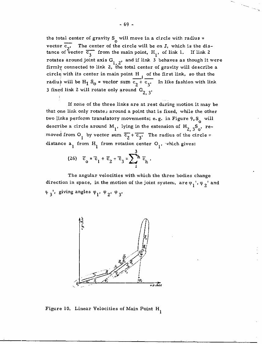
- 69 -
the total center of gravity S 0will move in a circle with radius0
vector c2 . The center of the circle will be on J, which is the dis-tance of vector F from the main point, H1 , of link 1. If link 2
rotates around joint axis G 1, , and if link 3 behaves as though it were
firmly connected to link 2, the total center of gravity will describe a1!
circl, with its center in main point H of the first link, so that theradius will be Hi So = vector sum c + c 3. In like fashion with link
3 fixed link 2 will rotate only around G2, 3"
If non-e of the three links are at rest during motion it may be
that one link only rotate.j around a point that is fixed, while the other
two links perform translatory movements; e. g. in Figure 9, S will
describe a circle around M 1 , lying in the extension of H2, S, re-
moved from 01 by vector sum c + c3 The radius of the circle -
distance a1 from H from rotation center 0 1 . which gives:
3
(26) T = - +~ "E - ch~
The angular velocities with which the three bodies change
direction in space, in the motion of the joint system, are ylP p 2 ' and
q 3 giving angles p , ' 0 3"
Figure 10. Linear Velocities of Main Point H1
- 70 -
This will give linear velocities (Figures 3 and 10 )of the main
ceinte of C , for H relative to H of p and for the totalpon 1 o2 of~ c2
center of gravity, So, relative to H1,2 of C3 3 From this results:
3()Vo = C- + f- e'-(27) v Tcz'-~ 33 -Ph+C-'h
We get tangential acceleration for H l , HI,2 and S0 of
C1 PI, c 2 0P 2 I and c 3 p 3 ' to give
( ) , 1 +
=~ hC h (ph-'h
In figure 10 0 1 is the origin of a rectangular coordinate
system (xy) within the plane of the three centers of gravity. The
positive x-axis has the direction from which are measured angles
Tl' q' 2 ' p3 " From this:
3(29) x 0 c cos Tp1 + c 2 cos 2 + c 3 csCOS3 3 Ch Cos C h t
3
YO= c1 sincy 1 + c2 sinp 2 + c 3 sin Tp3 = jch sin(h .
1
If the components of velocity, vo, and of acceleration, y, of
the total center of gravity equal x' oy1 and x'opy" owe derive:
3
(30) (31) x - E [ch siny h ' Yh " + Ch'Cosy h'2
0 = [ch cosh' h" - Ch sin(h "Th]
-71 -
The resultant velocity of H relative to G is equal to1,2 2,3
the geometric sum -d' - -PIl. The acceleration is equal to the2' 2 1 1
geometric sum of -CI 2 r d2, 1 P 2.
From this is derived:m O0
31,2 m 1 + m2
aidmo __ %,--- - 2 -z%0
0(35) r 2 "md +I ( 'I + d2 cp" + dI2P'I1 +
(index r is used to indicate the motion relativeto GZ, 3' and the components of v and y
r, 2 1,2
are derived in the direction of the coordinate axes.)
For the components x'r, 2 and y trl, 2' Fischer gives velocity in (36).
For the components x" and y" the acceleration is given in (37). Using
(35) the force Er 1, of the partial center of gravity S ,2 for motion
relative to G2,3 is given in (38) (39).
The motion of H2,3 relative to G 1 is a mere circular
motion if link 3 is translatory in rotation of link 2 about G1, 2' or if
link 3 is rigidly connected to link 2. Formulae (40) - (43) express
velocity and acceleration here.
As in the previous section components x'r, y'r, and x'r I y'r
are derived, (48) - (49); also the effect of force E 2 on S relative
to G1,2 (50); also components x'3, y' 3 , and x" 3 y"'3 (52) - (55), and
the effect of Er 3 on S 3 relative to G2, 3 (56). The components of
the direction of the coordinate axes are:
(57) X = -mo (c 3 sinyp3 *"Y3 + c 3 cos (P3 . Y3 'z),
Y m ( c 3 cos CP3 - c3 sin cp3 "
4. The Kinetic Energy of t.h, Three-Joint System. ( pp 37-42)
The kinetic energy of a system equals the sum of external andinternal forces. The external force originates in the motion of the
- 72 -
total center of gravity, and is equal to the kinetic energy of the totalmass, m , concentrated i-x the total center of gravity, S ; let v 0
0 0 0
magnitude of the velocity of S , then the external kinetic energy =2 01/2 m v . The internal force is only related to the motion of the
0 O0
system around its center of gravity, and equals the sum of the kinetic
energies of the relative motions of the individual links in relation to
the total center of gravity. The motion of each of the three linksrelative to S resolves to the translatory motion of velocity, vh, of
the individual centers of gravity, Sh, of the respective links related
to SO, and a rotation around an axis parallel to the joint axis through
S h of an angular value %h"
Hence, the kinetic energy of each link relative to the totalcenter of gravity is the sum of two components: 1) the kinetic cnergyof mass mh whicha link has when the mass moves with velocity, vh ,
of the individual center of gravity, Sh, relative to the total center of
gravity S ; 2) the kinetic energy resulting from the angular velocity,
%oIh' of the link in its rotation around the axis through Sh' If the total
center of gravity is assumed to be fixed, then consideration of smalldisplacements (movements) of links gives the following theorem:
Each displacement of the 3-link joint system relative tothe total center of gravity, So , from the positionY I P 3 into the infinitely adjacent system Y1 + dop1
Y2 + dcp2 , Y3 + dop3 can be divided into three infinitely
small rotations about axes throught the three main points,connected with translations of the two other links to whichthe respective main point does not belong.
The displacements are as follows:
(58) S 1 relative to S : -eI dy 1 -- 2"d o z - c 3 . dy 3
S2 relative to So: +dl'dy I - e 2 .dp 2 - c 3 .dcp3
S relative to So: +d'dy + d2"d-o2 - e3d33 0 1 ' 1 d2 d 2 3*
(again, the bars = geometrical addition)
The displacement components of dy I are perpendicular to the
long axis of link 1, thuse of dy 2 and d o 3 to the.long axes of links Z-3.
- 73 -
In considering the velocity, Vh, of points Sh relative to S0
Fischer employs the division of the time differential, dt, of individualcenters of gravity relative to the total center of gravity, occurring
at a certain moment.
This gives:
(59) Tr = 1/2 E mh V vh + Xh2 h 11From (58) there is then derived:(6)T / mx2 2 2 md2 ) 2
(60) Tr = 1/2 (m 1 X1 + rne I + mzdI + m 3 d 1 ) 1
+ I/(m x 22 +m I2 +me 2 +m3d 2 ) 2z
+ 1/2 (m X 2 + m c 3 + m2e 2 + e 2 ) p 2+(e mde3 2 +mdd ~e2) ,1 1/2 2 1 3 1 c .(o 3
+ (mlIelIC 2 - m 2dl1e 2 + m 3 dId 2 ) Cos (CPoI -y 2 ) . Yoi' .
+(mI elc 3 - m 2 dIC 3 - m 3 dlc 3) cos (q 1 -(P 3 )" 1 P p 3
+(mlc 2 c3 + m 2 e2 c3 - m 3 de 3 ) cos (Y 2 - Y3 ).qo2 .3
From Figures 1-2 and from (59) this may be simplified:
(61) Tr= 1/2 mk 2 . 2 + 1/2mk 2 2. Y22 + 1/2m k3 2.
+ md Ic2 cos (Yo1 -P 2 ). oP1 ' c 2 ' + modIc 3 cos (YI -pcp3 ).
cIly 3' + m od2c 3 cos (yo2 -Y3) 02, "3
If the total center of gravity S is not fixed but moves with the0velocity, v , in space, there must be added to Tr the kinetic energy201/2 m v of the motion of the total center of gravity( expressed in
0
(62) - (63)). Finally, if the point 0 of the first long axis is fixed the
expression for total energy is:
2 ,2 2 2(67) T = 1/2 m X . Y + 1/2 m X . Y 2 + ni 1 c CosoI 1 mo T2 nolZco
5. The Elementary Work of the Forces ( pp 42-43)
In the motion of the 3-link system the kinetic energy of thesystem will not remain constant. It is necessary to determine themagnitude and direction of the translation performed by the point of
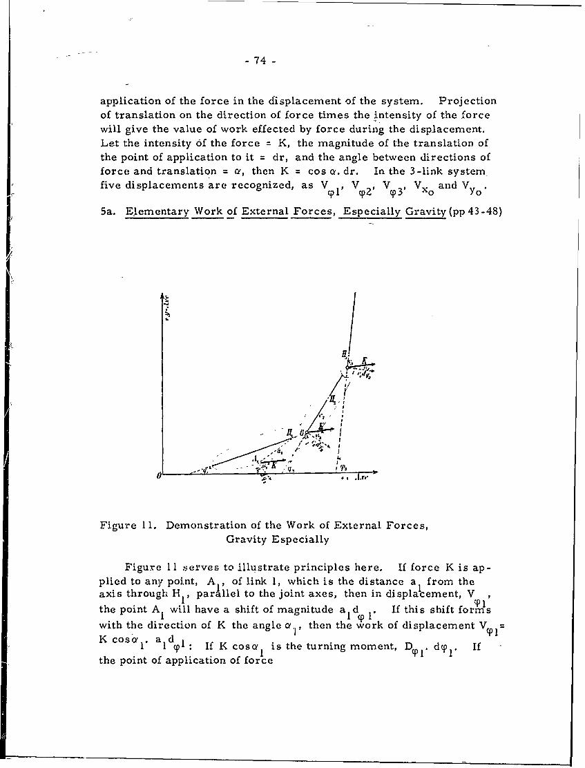
- 74 -
application of the force in the displacement of the system. Projection
of translation on the direction of force times the intensity of the forcewill give the value of work effected by force during the disp.lacement.Let the intensity of the force - K, the magnitude of the translation of
the point of application to it dr, and the angle between directions offorce and translation = a, then K = cos oY. dr. In the 3-link systemfive displacements are recognized, as V 1 , Va, V 3 , Vxo and Vy.
5a. Elementary Work of External Forces, Especially Gravity (pp 43-48)
!
0- I n
Oin ,I',- , maniud ad, a rm h
Figure 11. Demonstration of the Work of External Forces,Gravity Especially
Figure I -serves to illustrate principles here. If force K is ap-plied to any point, A. of link 1, which is the distance a I from theaxis through H,, parllel to the joint axes, then in displacement, V T,
the point A will have a shift of magnitude a d . If this shift formswith the direction of K the angle ao,, then the work of displacement V =
K COSO!l I ald 91 If Kcos I is the turning moment, D Y1. dy p. If
the point of application of force
- 75 -
coincides with the train point H then value of work in displacemeht
V = zero. In similar fashion one may proceed for V K cosc 2 .
c d and V - K cosQ' 3 . c 3 d 3 . The work of gravity on the dis-
placement Vyl is given as an example:
m 1 ge I cosy 1 - dy 1 - (m 2 g+ m 3 g)d 1 cosy I. dcp 1 .
The following two theorems are derived:
I. If force K applies to the h t- link to which belongs thefixed point 0 h then its elementary work in displacement
VY h , which alone can change the direction of the long
axis of this link, is = to the turning moment of the forcerelative to the axis through 0 h multiplied by dy h . In this
case in the other displacements the force does not perform
any work at all.
UI. If the force K applies to one of the links to which the fixedpoint 0 h does not belong, then its elementary work in the
displacement V is equal to the turning moment multipliedCDh
by d T h that the force has relative to the axis through 0 h if
the point of application of the force is shifted to the joint
point of the h t- link that within the joint system is next to
the point of application of the force.
In the displacement that corresponds to an infinitely smallrotation of the one link to which the force applies, the force
performs an elementary work equal to the product of thecorresponding angular change d by the turning moment
that the force has for the joint axis of the same link thatwithin the system is next to the point 0 h Finally, as to
the third displacement, V , the question is whether t6e jth
link within the system is nearer to or farther from the fixedpoint 0 h than the link to which the force applies. In the
first case the elementary work is equal to the turning momentmultiplied by d that the force has relative to the joint axis
ofth jnearer to he point 0 h, if its point of applicationth
is shifted to the joint point of the j-- link farthest from the
point 0 h. In the second case, however, the force does not
perform any work at all.
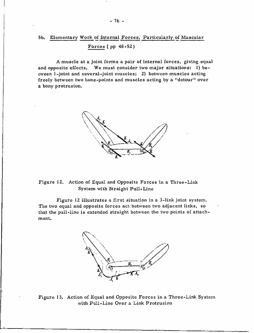
- 76 -
5b. Elementary Work of Internal Forces, Particularly of Muscular
Forces (pp 48-52)
A muscle at a joint forms a pair of internal forces, giving equal
and opposite effects. We must consider two major situations: 1) be-eween 1-joint and several-joint muscles; 2) between muscles acting
freely between two bone-points and muscles acting by a "detour" overa bony protrusion.
( .\ \ KKK
Figure 12. Action of Equal and Opposite Forces in a Three-LinkSystem with Straight Pull-Line
Figure 1Z illustrates a first situation in a 3-link joint system.
The two equal and opposite forces act between two adjacent links, so
that the pull-line is extended straight between the two points of attach-
ment.
KK
Figure 13, Action of Equal and Opposite Forces in a Three-Link Systemwith Pull-Line Over a Link Protrusion
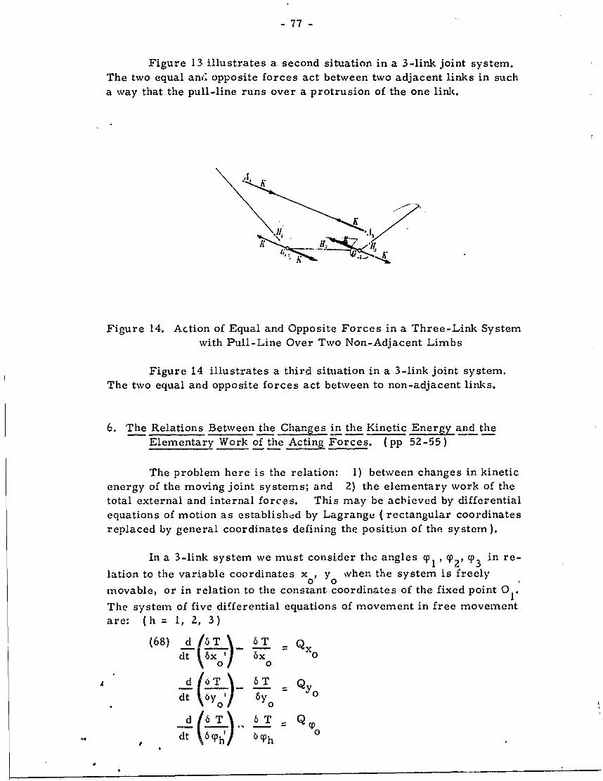
- 77 -
Figure 13 illustrates a second situation in a 3-link joint system.
The two equal and opposite forces act between two adjacent links in sucha way that the pull-line runs over a protrusion of the one link.
K .
K
Figure 14. Action of Equal and Opposite Forces in a Three-Link Systemwith Pull-Line Over Two Non-Adjacent Limbs
Figure 14 illustrates a third situation in a 3-link joint system.The two equal and opposite forces act between to non-adjacent links.
6. The Relations Between the Changes in the Kinetic Energy and theElementary Work of the Acting Forces. (pp 52-55)
The problem here is the relation: 1) between changes in kinetic
energy of the moving joint systems; and 2) the elementary work of thetotal external and internal forces. This may be achieved by differential
equations of motion as established by Lagrange ( rectangular coordinates
replaced by general coordinates defining the position of the system).
In a 3-link system we must consider the angles p1 , %,, T3 in re-
lation to the variable coordinates xo , y 0vhen the system is freely
movable, or in relation to the constant coordinates of the fixed point 01.
The system of five differential equations of movement in free movementare: (h = 1, 2, 3)
(68) d/6T 6 T Qxdt ,6x' 6 x 0
d ( 76 T 6 - Q Yo
" 00Ad 6 T Q
dt \bCyh
-78-
The five equations of motion are:
(69)- m . X "0 11o D- x
0M 0 O 0YOm .Cos (T IFoi
m {k12.c, "+ dlC3 cos (cp -Y 3 ) Yo3 '
+ dlc2 sin(cp 1-CP2 )." p2' + d 1 c3 sin(cp1 "_ 3 ). 3 1 'QY
m {kj 2cp' + d2 c 3 Cos(Cp2 -CP3 )'q0 3' I+ c 2 dI cos (Y 2 -c 1
) . Y 1
+ d2 c 3 sin(. 2 -- 3 ).q 3 '2 + c 2 d 1 sin( 2 -cP 1).C 1 ' T Q 2
mo {k 3 Z" .03I+ c 3 d 1 cos(Cp3 -q 1 ). Cp1 + c 3 d 2 cos (C03 "%0Z) . %02"
) ,. (p '2 I+ c 3 d 1 sin(cp 3 -p 1 ) " p 1 + c 3 d 2 sin(p 3 -P 2 )." 2 Q 3
Here the first two equations refer to the motion of the total centerof gravity S , and the last three to motion of the 3-link joint system and
0to the S 0(here are contained the angular acceleration and the angular
rotation of the individual links). In all equations the total mass m of
a joint system is given on the left, but the masses mh of the individual
links are not given.
Where 0 1 is fixed on the long axis of link I at distance II from
G 2' there are three equations as follows:
(70) m o 0 X 2 . I" + I I " c2 Cos 1Y 1 "Y2 ) . Y0Z" + 1 1c3 cos(T 1 "Y3). %03
+ I i C sin(1 -C 2 c). (p 2+ I Ic3sin( 1 3). co3 I = Q1
mo{X " 2 2+ 12 c 3 cos(p02 -p 3 )'(p 3 " + c 2 1 1Cos(ZCP 2 - 1)" q I"
+ I 2 c 3 sin(cp 2 - 3 )"q, 3 2 + c 2 l1 sin(y - IF, ).p 1I Q
22 22} 2 1 1YS31.( 3 '1 Cos 1 ( 3 - 1 2)sn 3 2 2 cos(cp3 -2 )'."
+ c 1 4%sin (cp - Y ). 12 + c I sin (cp 3 YZ). Cp2 IT Q*
- 79 -
Here each quantity Q equals the sum of the turning moments
exerted by all external and internal forces acting around the axis through01) G1, 2' or G2 3 , respectively, after all forces that do not apply
directly to the hZ link have been shifted, parallel to themselves, to
the joint point that is nearest them within the joint system.
In like manner Fischer gives equations (71) for the plane joint
system of two links connected with each other by a hinge joint, whenthere is free mobility, and equations (72) if point O, on the long axisof the first of two links, is fixed.
7. Interpretation of the Equations of Motion ( pp 55-69)
In general the results of the motion of each of the three links ina 3-link joint system, as a consequence of the joint connection with theothers, involve: 1) the inert masses of the other links have to be set
in motion; 2) the other links will move relative to the center of gravitythrough which they are connected with the respective links; 3) the masseswill go from the respective, link to the reduced system. This is ex-
pressed directly by Fischer as follows:
It can be gathered from the consideration made so far that the
motion of each of the three links, as a consequence of the joint
connection with the others, will not only be influenced by thefact that the inert masses of the other links generally have also
to be set in motion but also by the fact that these other links
will ds a rule moreover move relative to the center of the joint
link either immediately or through the intermediary of another
link. The influence that the inert masses of the connected
links exert on the motion of a certain link will be accounted for
when we suppose these masses to be concentrated in the nearest
joint centers, and thereby pass from the respective link to the
reduced system. As we have seen, the influence exerted by
the relative motions of the connected links is, however, repre-
sented by the forces - Er, which are equal and opposite to the
effective forces of the center of gravity of the remaining links.
If the value of these effective forces is zero, then in the motion
of the reduced system the only forces to matter will be the
forces actually present that have been designated above as the
forces of the reduced system.
Among other possibilities, the effective forces will disappear
when the other links connected with one link perform translatory
motions exclusively during the motion of the one link. An in-
-80 -
stance of disappearing effective forces is given by the
lifting up of the human body on the toes. The whole body
with only the exception of the foot standing on the floorwill then perform a translatory motion in accordance
with the motion of the foot-joint axis. Therefore, this
part of the body acts on the foot in such a way as if
whole mass of this part were concentrated in the axis
of the upper ankle joint and all forces applying to it had
their point of application in the center of the foot joint.
The disappearance of the effective force will, however,
also take place when the center of gravity to which theeffective force is related coincides permanently with the
joint center relative to which the motion of this center ofgravity has to be reckoned.
8. Elementary Derivation of the Equations of Motion ( pp 68-90))
This must be based on the theorem that the center of gravity
of any body system will move as though the mass of the entire system
vere concentrated in it, and all external forces acting upon the .iA/!.tem
were to apply in it as to their direction and magnitude. This applies
to a freely movable situation, but also when the motion of individualbodies are subject to various conditions, which are, in general, added
to the effect of the external forces.
Also needed is the theorem that a freely movable rigid body
will rotate about its center of gravity in the same way as if that center
ol gravity were not movable, but firm. Hence we must consider
only the turning moments of the external forces relative to the axis
through the center of gravity.
In a 3-link plane joint system we may consider any one link
alone. Here must be noted: I) its motion is dependent upon forces
acting upon it, plus forces on the other links; 2) action and reaction
at joints, and at a specific point in the joint, i. e. , the joint center.
In the 3-link system the motions of links 2-3 and the forces
applying to them will act on link I in G only; also, the motionsof link I will act on link 2 in G, 1' and the motion of link 3 will
act on it in G2,3 etc.
-81 -
Links 1-2 will act reciprocally upon one another as two pressureforces which may be designated as and - - The pressure
force -"oc 1-1,2 , acting in G1,2 on a partial system of links 2-3, extendsto the cent'er of gravity S2,3 and gives acceleration y2, 3 with massm , (we are here dealing with absolute acceleration). If this be ac-
cepted then their vector sum = m y (2 3)' which may be
also written as:
(89) T- , 2 = m , 3 Y2 , 3 + R(- ,3,)
If the effective force of the center of gravity for motion in space
is given as E2, 3 then:
(2,03(90) TV 2 = 2 , 3 + ( 2,3))
From the pressure force acting on link 1 in G1, z the vector
sum is: 1
(91) 2= 2, 3) + -Z, 3,' also expressed as
(92) f2 = E +E (KMFischer then demonstrates tbat the vector sum is equal to the sum
for the pressure force as in (91). This is based on the theorem ofthe center of gravity for it, i. e. the vector sum of all external forcesapplying to the joint system is equal to the absolute effective force Eof the total center of gravity, S . But not all forces, K(1) , K ,considered as external forces for each link, respectively, belong to theexternal forces of the whole joint system, as developed in (93)-(96).
In order to reduce the motion of link 1 to that of a single separatebody it will be necessary only to apply in the joint center G1,2 allforces applying to links 2-3, and, moxeover, a force equal and oppositeto the absolute force of the partial center of gravity, SZ, 3" For theregular acceleration of link 1 is derived:
D 1
(97) = D_.. 2 (where D, = the turning moment of forces onm Ix 1link 1, and x1 is the radius of inertia of link 1.).
The acceleration y1 of the center of gravity, S , becomes:
- 82
(98) j- m In (99) - (107) this is similarly
done for links 2 and 3.
It is demonstrated in (108) - (114) that in conditional mobilityof the entire joint system that link Z (joined to links 1 and 3) willrotate around the movable axis G 1 ,2 as would a rigid bodV aroundan axis at rest. Finally this may be expressed as:
m 2 "-D,2
(114) y2" = z )m (x + r )
Similarly, we have:
M3 D 2,3C'l ) (x 2 + rj)
Finally, Fischer's summary may be quoted:
In the foregoing wie have finally dealt with the reduced systemin all cases, because it was intended to show that the roadtaken leads eventually to the form of the equations of motionof the joint system that earlier had been derived from Lagrange'sgeneral equations. Besides, as a result we have come in anelementary way to a new interpretaion of the equations of motion,as opposed to the interpretation discussed in section 7. Thisnew interpretation leaves the reduced systems out of discussionand relates to the motion of the actual individual links. Althoughthe form of the equations that results from this interpretationis generally more complicated than when the interpretation isbased on the reduced systems, the new interpretation is never-theless especially important in many applications of the equationsof motion to certain problems of the physiology of motion.
- 83 -
This will first of all be true when by suitable experimentswe succeed in finding empirically for a certain motion of
an organism the paths, velocities, a-d accelerations of thecenters of gravity of all individual body parts. Then weshall also have obtained without fuither difficulty the absoluteeffective forces of these centers of gravity, and on the basisof this knowledge it will be possible for us to investigate themotion of each single link separately, without having to takefurther regard of the connection with the other links than hasalready been taken by reference to the effective forces.
Indeed, the results obtained up to now relate so far only to aplane three-link system; therefore, for the moment they canonly be applied to organisms that behave like such a three-link
joint system and certain motions.
The N-Link Plane and Solid
Joint Systems (pp 91 - 176)
From a 3-link plane joint system it is possible to go to equa-tions of motion for a plane system of n-links and for a general solidjoint system. There will be greater freedom of motion in joints,with multiple hinge joints, with parallel joint axes, and with adequate-ly simple mass distribution in the limbs.
Locomotion involves forward and lateral movement, the fornerbasic (there is some vertical motion). Walking is a plane motionwherein all body parts are more parallel to a vertical plane fixed in
space ("walking plane"); motions here are in parallel axes perpen-dicular to the walking plane in all joints, and involve muscularmechan!is. Man performs mostly solid motions in locomotion; thelarge joints have more than one degree of freedom; 1) shoulder andhip joints have three degrees of freedom; 2) elbow, knee, wrist,ankle have two. Considered here, in order, will be. 1) 2-link systems;2) differences between motions of solid-and plane-joint systems;3) n-link solid systems. A plane joint system of n-links has n + 2 de-grees of freedom where:a) plane motion is not su'bjcc to.any limiting conditions;b) several links do pot"f6"rm a closed kinetic chain. Such a systemis defined by n + 2 coordinates. We must know the two plane coordin-ates of one point of the systen, and an angle of direction for each oneof the links, choosing any point desired. The number of equationsof motion is equal to the number of the degrees of freedoin: 1) thereare n + 2 equations in completely free motion of the n-link plane joint
- 84 -
system; 2) there are only n equations where one point of one linkis fixed.
A solid joint system of n links has more degrees of freedomthan a plane joint system. The number of degrees is determinednot so much by the number of links as by the freedom of motion in
joints (generally, joints have 3 degrees of freedom). A solid joint
system has 3n + 3 degrees of freedom, and any position in spacehas 3n + 3 general coordinates; three of these will give the position
of one point of the system and three each will relate one of the n linksin space. Hence, three of the determining quantities will be therectangular solid coordinates of a point, and 3n quantities represent
coordinates of direction and hence are angles. This gives 3n + 3equations of motion in completely free mobility (three times as manyas for a plane system).
In an organic joint system few joints have 3 degrees of freedom.In the leg three parts are assuined as rigid, i. e. , thigh, leg and foot.These have 7 degrees of freedom related to the fixed pelvis ( 3 degrees
in knee + ankle); in the mobile pelvis there are 10 degrees of freedom.
It is assumed: 1) all joints in the system in each case have a fixed
joint center and 3 degrees of freedom; 2) the composition of reduced
systems and the location of main points that are identical with thccenters of gravity are still useful in the n-link systems.
9. About the Generally Valid Properties of the Reduced System
and Main Points. ( pp 96 - 99)
After severance of any one joint connection of the system, this
system shall be divided into two parts no longer connected with oneanother (there will be no closed kinematic chain.) In the human trunkoue link is in joint connection with more than two links. There are
links connected with a joint with only one link - end links (e. g., head,
hand, foot, or phalanx III in movable fingers and toes). A nuclearlink equals all joints to be severed at the link forming the nucleus of
the reduced system; these nuclear links eventually receive the entire
mass of the whole joint system. The reduced system will act as a
single rigid body, so that the center of gravity has a fixed position within
the nuclear link. The mass of the nuclear link is concentrated in its
own center of gravity. Moments of inertia of the reduced system must
be considered.
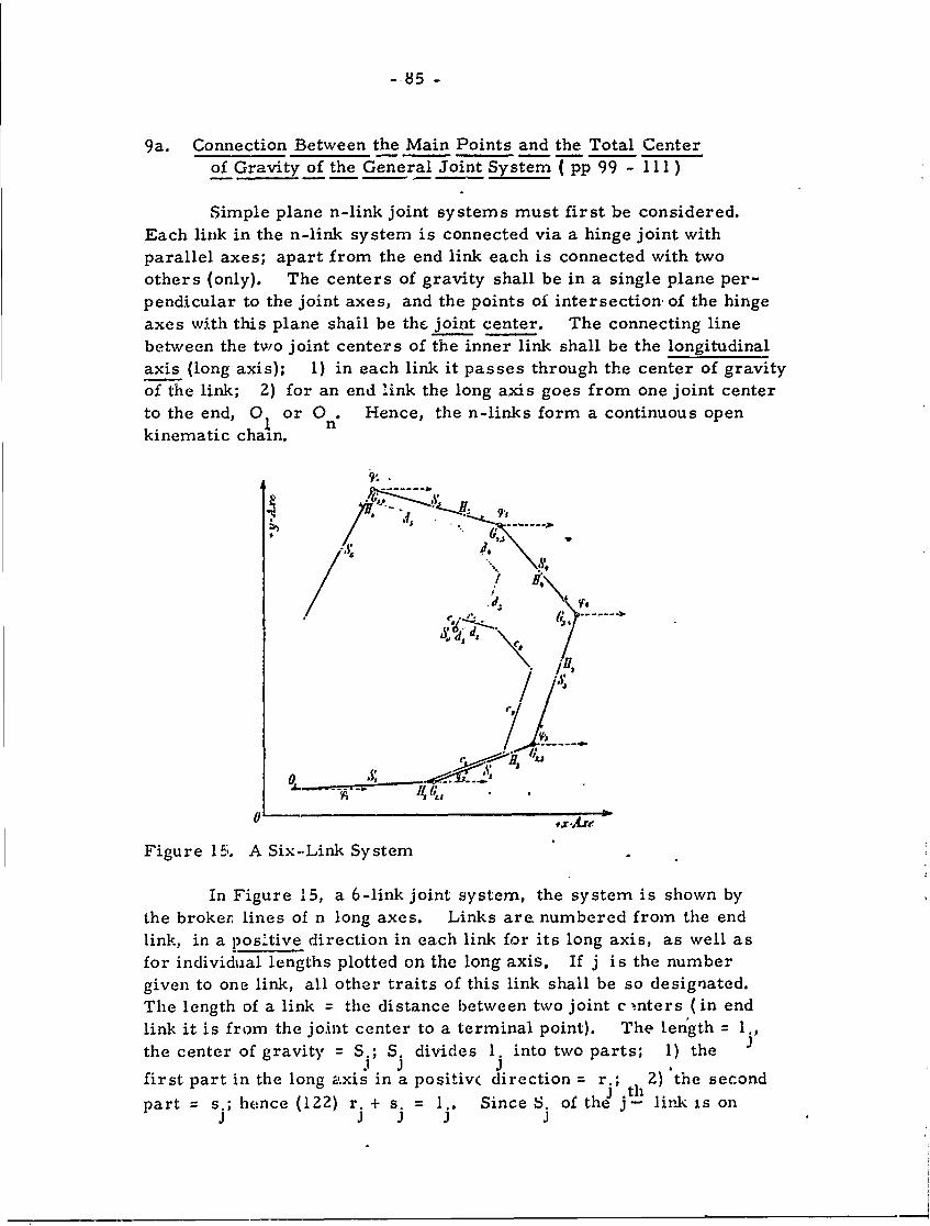
-85 -
9a. Connection Between the Main Points and the Total Centerof Gravity of the General Joint System ( pp 99 - ill)
Simple plane n-link joint systems must first be considered.
Each link in the n-link system is connected via a hinge joint with
parallel axes; apart from the end link each is connected with two
others (only). The centers of gravity shall be in a single plane per-
pendicular to the joint axes, and the points of intersection, of the hinge
axes with this plane shall be the joint center. The connecting line
between the two joint centers of the inner link shall be the longitudinal
axis (long axis); 1) in each link it passes through the center of gravityof the link; 2) for an end link the long axis goes from one joint center
to the end, 0 or 0. Hence, the n-links form a continuous open
kinematic chain.
WP6, o, ------
d, , d
Figure 15;. A Six-Link System
In Figure 15, a 6-ink joint system, the system is shown by
the broker, lines of n long axes. Links are. numbered from the end
link, in a pos'tive direction in each link for its long axis, as well as
for individual lengths plotted on the long axis. If j is the number
given to one link, all other traits of this link shall be so designated.
The length of a link = the distance between two joint c .nters (in end
link it is from the joint center to a terminal point). The length = 1.,
the center of gravity = S.; S. divides I. into two parts; 1) theJ J J
first part in the long axis in a positiv( direction = r.; . 2) the second
part = s.; hence (122) r. + s. = I.. Since 8. of the ith link is onJ J J 3 J
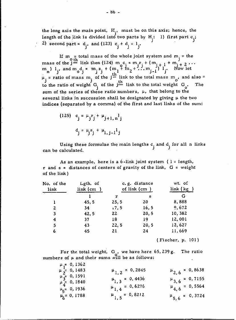
- 86 -
the long axis the main point, H., must be on this axis; hence, the
length of the link is divided into two parts by H.: 1) first part c.;
2) second part = d., and (123) c. + d. = 1.. JJJ 3 J .J
If m = total mass of the whole joint system and m. = theo0th 3mass of the j- link then ('124) m c. = m r + (m. + m. 2
m ) 1., andm d = n s. + (m. 1 n2+.m. j) I I -Tow letnl 03o j J 2h :-~ 1 J-J. "
P = ratio of mass m. of the j- link to the total mass m , and alsoJ -J .th 0
to the ratio of weight G. of the j- link to the total weight G . The
sum of the series of these ratio numbers, p, that belong to the
several links in succession shall be designated by giving p. the two
indices (separated by a comma) of the first and last links of the sum:
(125) c. = r.'+ p 13 33 j j+l,n
d.= j l ,j-l j
Using these formulae the main lengths c. and d. for all n links
can be calculated.
As an example, here is a 6-link joint system (I = length,
r and s = distances of centers of gravity of the link, G = weight
of the link)
No. of the Lgth. of c. g. distance wt. of
link link (cm) of link (cm ) link (kg)
1 r s G
1 45,5 25,5 20 8,888
2 34 L7, 5 16,5 9,672
3 42,5 22 20, 5 10, 3824 37 18 19 12,001
5 43 22, 5 20,5 12,627
6 45 21 24 11,669
(Fischer, p. 101)
For the total weight', G , we have here 65, 239 g. The ratio
numbers of 1. and their sums %ll be as follows:
1 0,1362= 0, 1483 p 1 , 2 = 0,2845 1p2 , 6 = 0,8638
p. 0, 1591
4 0, 1840 p 1, 3 = 0,4436 p.3 , 6 = 0,71550, 1936 p. 1 , 4 = 0,6276 0,4 , 6 = 0,5564
06= 0, 1788 P 1,5= 0,8212 P5, = 0;3724
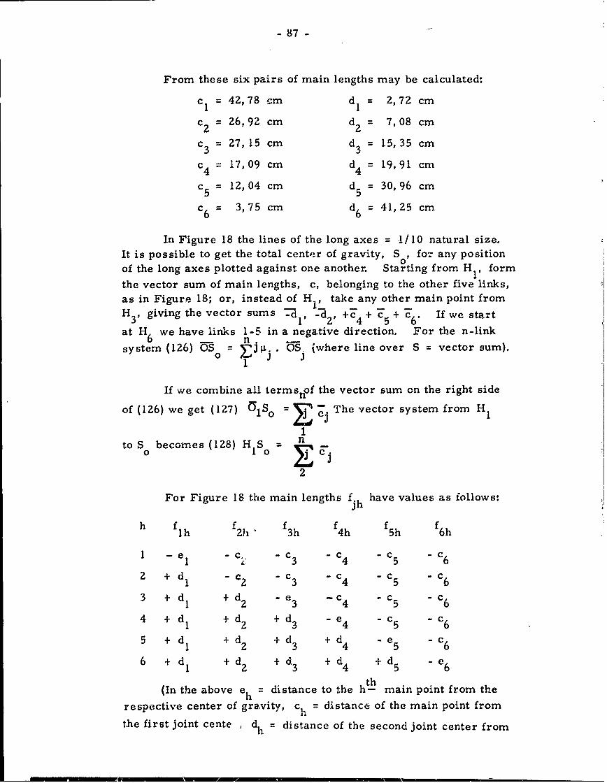
-87-
From these six pairs of main lengths may be calculated:
cI = 42,78 cm d= 2,72 cm
c 2 = 26, 92 cm d2 = 7, 08 cm
c 3 = 27,15 cm d 3 = 15,35 cm
c4 = 17,09 cm d4 = 19,91 cm
c 5 = 12,04 cm d5 = 30,96 cm
c6 = 3,75 cm d6 = 41,25 cm
In Figure 18 the lines of the long axes = -1/10 natural size.
It is possible to get the total center of gravity, S0, fo- any positionof the long axes plotted against one another. Starting from H1 , form
the vector sum of main lengths, c, belonging to the other five links,as in Figure 18; or, instead of H1 . take any other main point fromH 3 , giving the vector sums . -d 2 , +C4 + c5 + T6. If we start
at H we have links 1-5 in a negative direction. For the n-link6n
system (126) -o 0. JPj -. -S (where line over S = vector sum).1
If we combine all termsnOf the vector sum on the right side
of (126) we get (127) S E -- The vector system from H,
1to S becomes (128) H S --
2
For Figure 18 the main lengths f. have values as follows:
h flh f21 f3h f4h f5h f6h
1 -1e -c., -c 3 -c 4 -c 5 -c 6
2 + d c -c -c -c - c6
3 + dI + d2 -e 3 -c 4 -c 5 - c 6
4 + d 1 + d2 + d - e4 - c5 - 6
5 + d I + d2 + d3 + d - e 5 - c 6
6 + d I + d2 + d3 + d4 + d 5 6
(In the above eh = distance to the h-h main point from the
respective center of gravity, c, = distance of the main point from
the first joint cente , dh = distance of the second joint center from
- 88 -
the maiin point of the ht-h link. Also, the six vectors that form thevector line from S - Sh are in the same horizontal line).
Fischer illustrates via a 20-link solid joint system that the
close connections between the main points and the total center ofgravity are valid here also. The following theorem results:
In any solid joint system we shall always be led to thetotal center of gravity when, starting from the mainpoint of any one of the n links, we form the vector sumof the n-l main lengths belonging to the remaining links,w ich main lengths lie nearest within the system to thelink from the main point from which we start. Eachmain length has to be taken in the direction away fromthe respective link.
9b. Relation Between the Main Points and the Centers of Gravityof the Partial System. ( pp 111 -118)
Here is discussed in a plane n-link joint system the relationsbetween the main points of the links and the main points and the centersof gravity of the partial system. This, largely via Figure 18, is ap-plied to a solid joint ,system. As a result two theorems are form-ulated:
A. If in any one plane or solid joint system we supposeall links combined to a partial system that would falloff the entire system if one joint were severed, thenwe get the main point variable as to its position ofthis prtial system when starting from the main pointof on, link of the partial system we form the vectorsum of the main lengths that belong to the remaininglinks af the partial system and within the system lienearest to the link from the main point of, which westart, this is a di-ection away from the link.
B. The center of gravity of a partial system... will alwaysbe on the extension of the vector that connects the centerof the separation joint with the mai, point of the partialsystem. The ratio of the distance of this center ofgravity from the center of separation joint to the dis-tance of the main point from the same joint center is thesame as the ratio of the mass of th'e whole joint systemto the mass of the partial system.
89
9c. Relation of the Main Points to the Displacement of theGeneral Solid System ( pp 118-120 )
The thesis developed here is:1"if we impart to any one jointsystem a displacement in which only one link changes its orientationin space by rotation while all other links perform more translatorymotions, and we want the total center of gravity to remain at itsplace at the same time, then the rotation of the respective link musttake place about an axis through its main point. "
9d. Inferences Drawn for the Kinetics of the Solid Joint Systems(pp 120-121 )
All properties of the reduced systems and main points provedfor the plane 3-link joint system "retain their full validity in any onesolid joint system. "
10. The Kinetic Energy and the Equations of Motion of the N-LinkPlane Joint System. ( pp 121-137 )
10a. Derivations of the Kinetic Energy of the N-Link Plane Joint System(pp 121-128 )
In the plane of the long axes of the n-link system we shall fixa rectangular coordinate (xy) system, as in Figure 18. The coord-inates to the total center of fravity, S =x ,y . The positive direct-
0 0 0 0 Tion of the long axis of the j- link = angle p., with positive direction
of the X-axis. Then a portion of the joit system la defined by x ,0 0
ant. the n angle cp. Let x' and y' = the components taken in the
direction of the two coordinate axes of the velocity, v, of the total
center of gravity, S h Let cp'. = the angular velocity with whichrth J
the long axis of the j- link changes its direction in the plane of motioncommon to all long axes. Then the kinetic energy of the n-link systemcan be expressed as in a 3-link system:
9
(145) 1/Z m (x' 24 y' )o 0
For calculation of the total internal kinetic energy T, of then-link joint system:
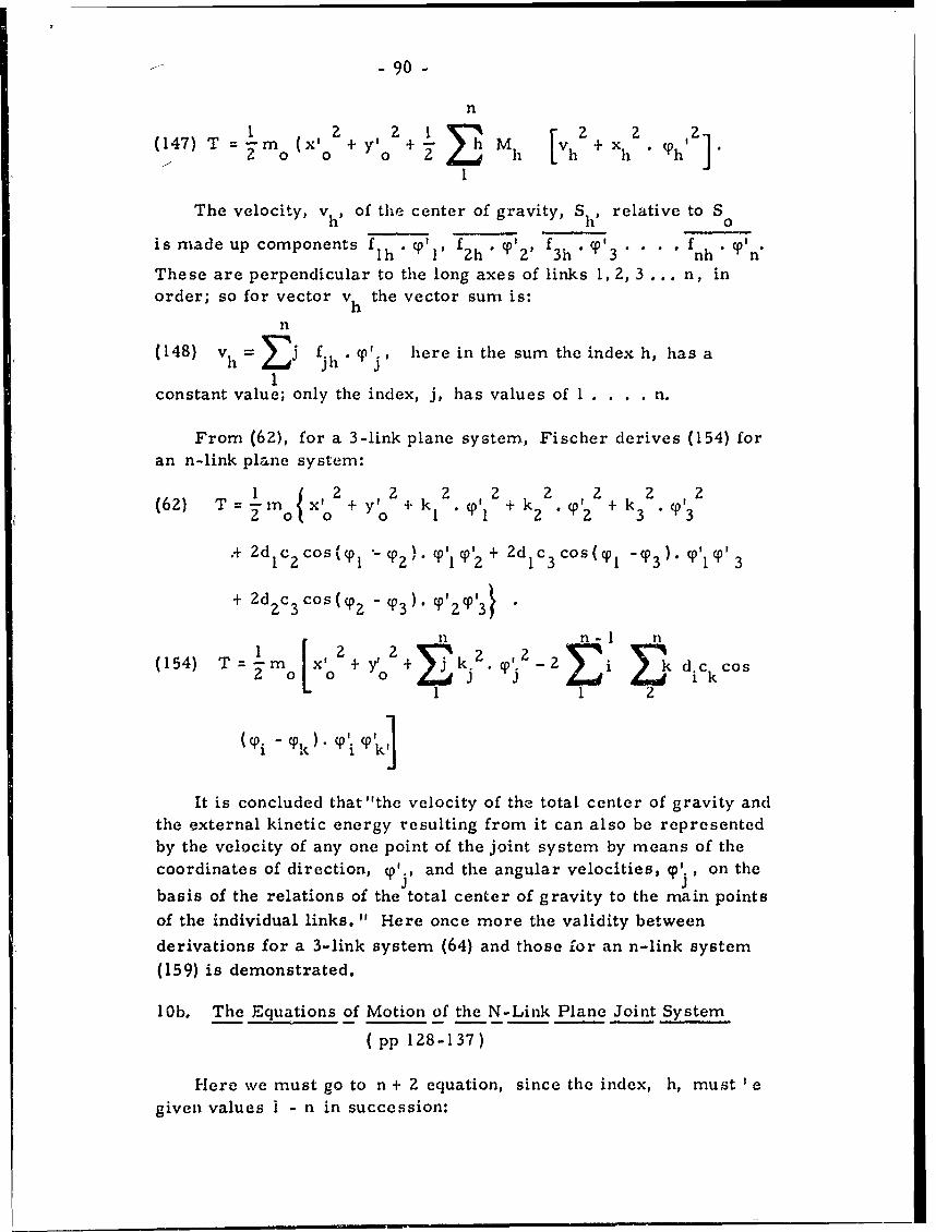
- - -90 -
n
1 2 2 r 2 2 2(147) T = -m (x'o + yo + v Mh + Xh x
1
The velocity, Vh) of the center of gravity, Shp relative to So
is made up components flh I' Ti pf " T'z f3h ' Y1'3 .... fnh ' Tn'
These are perpendicular to the long axes of links 1,2, 3 ... n, inorder; so for vector vh the vector sum is:
n
(148) v h = j f. h cpTI, here in the sum the index h, has a
1constant value; only the index, j, has values of I . . . . n.
From (62), for a 3-link plane system, Fischer derives (154) foran n-link plane system:
I 2y,2 2 k 2 o2 2 o3 2
(62) T =in ° X'I y"o + k T1 2 + k2 22 2x' kT2' +' k3 3
"+ dc 2Cos T°p T-2 ) T' I 1 '2 + Zdlc 3 cos(cp1 -T 3 )" p'I T 3
+ Zd 2 c 3 cos( 2 -( 0 T3 ) T'2 Tp3 }
n1 n - I n
(154) T 1mo Xo + o + i kdk1 1 2
I(Ti - Yk) (° i T k
It is concluded that "the velocity of the total center of gravity andthe external kinetic energy resulting from it can also be representedby the velocity of any one point of the joint system by means of thecoordinates of direction, y'., and the angular velocities, p'. , on the
basis of the relations of the total center of gravity to the main points
of the individual links, " Here once more the validity betweenderivations for a 3-link system (64) and those for an n-link system(159) is demonstrated.
10b. The Equations of Motion of the N-Link Plane Joint System
( pp 128-137)
Here we must go to n + 2 equation, since the index, h, must I agiven values i - n in succession:
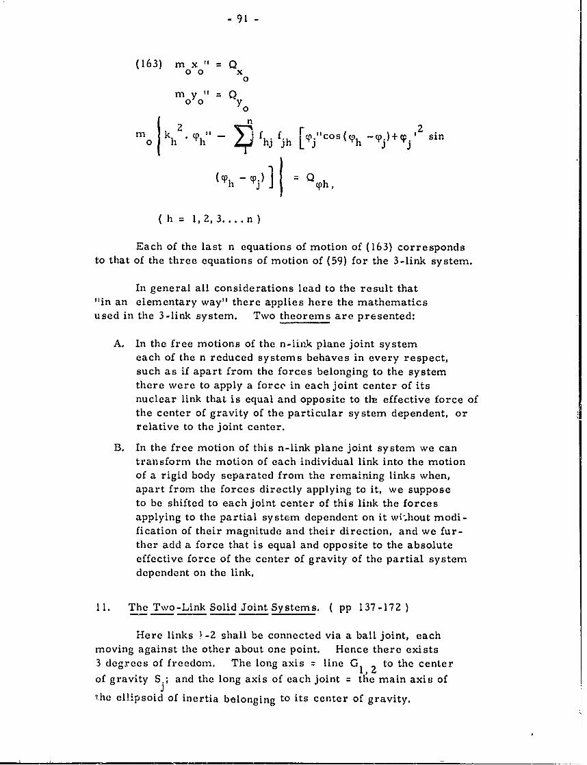
-91-
(163) m x " = Q00 x
0
monyo" = Q
n
m )kh2. ,I- hf hj f.h [Cj"cos( Ph -qj) + yj2 sin
(C0h - '0j) Q : Oph,
( h = 1,2, 3.... n )
Each of the last n equations of motion of (163) correspondsto that of the three equations of motion of (59) for the 3-link system.
In general all considerations lead to the result that"in an elementary way" there applies here the mathematicsused in the 3-link system. Two theorems are presented:
A. In the free motions of the n-link plane joint systemeach of the n reduced systems behaves in every respect,such as if apart from the forces belonging to the systemthere were to apply a force in each joint center of itsnuclear link that is equal and opposite to tie effective force ofthe center of gravity of the particular system dependent, orrelative to the joint center.
B. In the free motion of this n-link plane joint system we cantransform the motion of each individual link into the motionof a rigid body separated from the remaining links when,apart from the forces directly applying to it, we supposeto be shifted to each joint center of this link the forcesapplying to the partial system dependent on it wi.hout modi-fication of their magnitude and their direction, and we fur-ther add a force that is equal and opposite to the absoluteeffective force of the center of gravity of the partial systemdependent on the link.
11. The Two-Link Solid Joint Systems. ( pp 137-172)
Here links !-2 shall be connected via a ball joint, eachmoving against the other about one point. Hence there exists3 degrees of freedom. The long axis = line G to the center1,2of gravity S.; arid the long axis of each joint = the main axis of
e'ihe ellipsoid of inertia belonging to its center of gravity.
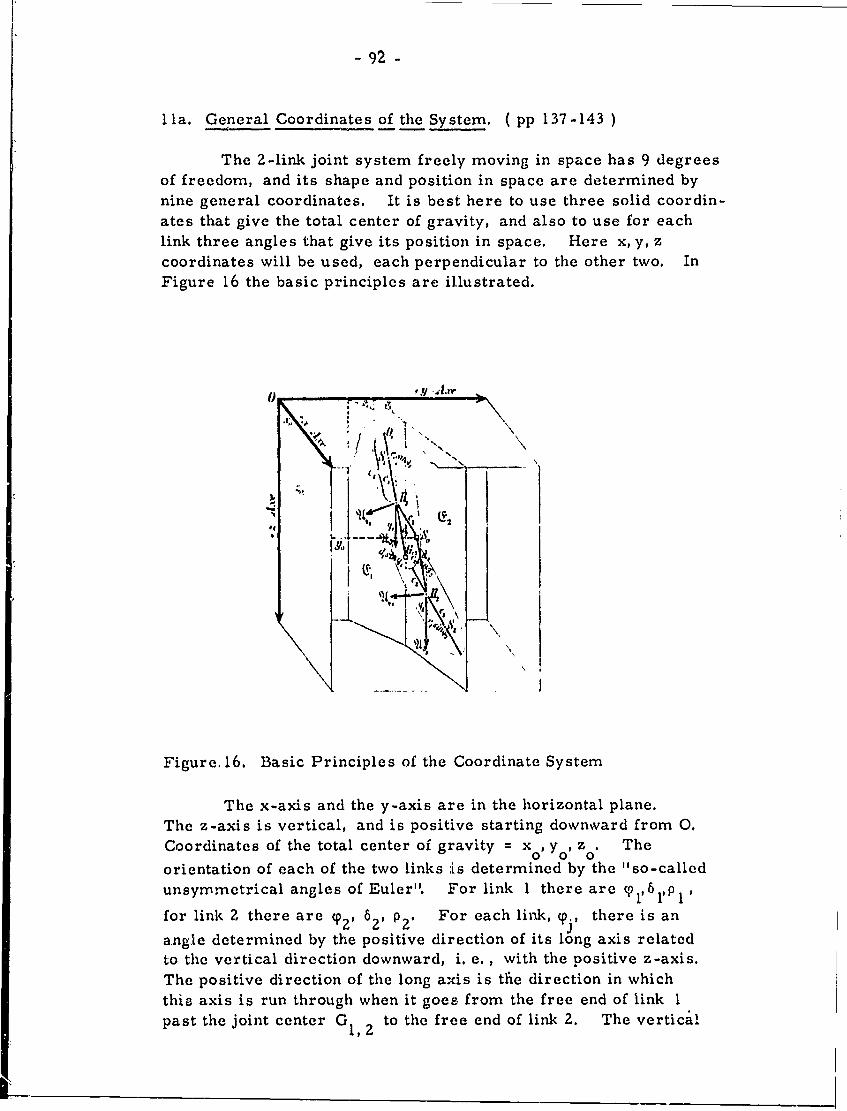
- 92 -
1la. General Coordinates of the System. (pp 137-143 )
The 2-link joint system freely moving in space has 9 degreesof freedom, and its shape and position in space are determined bynine general coordinates. It is best here to use three solid coordin-ates that give the total center of gravity, and also to use for eachlink three angles that give its position in space. Here x, y, zcoordinates will be used, each perpendicular to the other two. InFigure 16 the basic principles are illustrated.
,.j -- i,1f.11 _Aar
Figure. 16. Basic Principles of the Coordinate System
The x-axis and the y-axis are in the horizontal plane.
The z-axis is vertical, and is positive starting downw ard from .
Coordinates of the total center of gravity =Xo, Yo, zo. The
orientation of each of the two links ,is determined by the "so-called
unsymmetrical angles of Euler". For link 1 there arec0,5,l
for link 2 there are cp2, 52, p 2. For each link, 0., there is an
q.1
angue determined by the positive direction of its long axis related
to the vertical direction downward, i. e. , with the positive z-axis.The positive direction of the long axis is the direction in which
thie axis is run through when it goes from the free end of link 1past the joint center G to the free end of link . The vertical
orenaio o ac f heto iksIsdtemie b 1,"s-ale
unymtiaLnlso ue" o ikIteeaec ,6i
- 93 -
plane through each long axis (Figure 21, planes E l , E 2 ) will
be inclined against the vertical yz-plane coordinate system. The
angle of the two planes will = 6.. The perpendicular on theyz-plane may be erected in the 3 direction of the positive x-axis.
The perpendicular on the plane E. may be erected on the side from.1
which the positive section of the long axis of the link seems rotated
counter-clockwise by the angle (P., against the positive z-axis,
directed downwaid. This halfway perpendicular to the plane E.3
is called the knotline of the main point. The angle 6. is positive
if the knotline of the main point, seen from the side toward whichthe positive z-axis points (from below), seems rotated counter-clockwise around this angle against the positive x-axis. The
angle cp. has only a positive value. The two angles, cp. and 6. will
determine the direction of each long axis and also the position ofeach relative to S . From Figure 21 the following are derived:
o
md 1 mls I moC2 -m2r 2
(175) md me and (176) m 2-em2d1 = 1o1 1a2 =-2e2
moe I m2s 1 moeZ =-m r 2
Once S is determined it will be easy to locate the two0
main points by angles qe1 , 6 1 and cp2, 6?. In order to determine
the orientation of a link in space it will be necessary to fix twostraight lines within it. Fischer chooses the long axis and ahalf -ray perpendicular to it, starting from the main point (this
half-ray is the first cross axis of the link). The zero position
of a link is the position in which the positive direction of the long
axis of the iink has the direction of the positive z-axis, and the
first cross axis the direction of the positive x-axis. Fischer
similarly sets up a half-ray in the direction of the positive y-axis(this half-ray is the second cross axis of the link).
lib. The Derivation of the Kinetic Energy. ( pp 144-157
This section is based, in principle, upon the 2-link joint
system. Fischer states that for the solid system the kinetic energy
at any one time shall be determined. It will be necessary to
separate from a translatory motion of the whole system (related to
S ) the motion of the two links relative to S , and to determine0 0
the kinetic energy for the two kinds of motion of the system. "The
total kinetic energy will then again simply be the sum of the two
parts. "
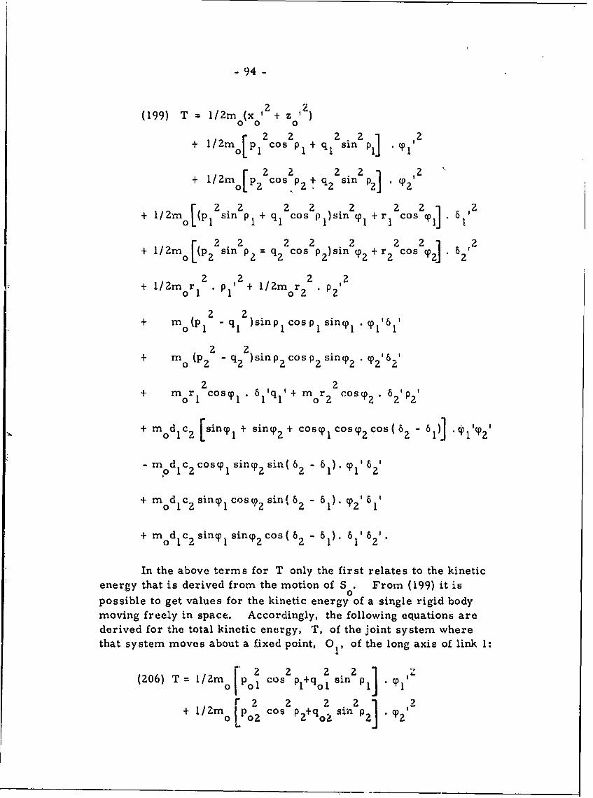
- 94 -
2,2(199) T . 1/2mo (x 0 + z 0
+ l/2m P2 cos2 P + q1 2 sin 2 P1 CP
p2 2 2 2 2+~~ I/ln[P1 2 ° n2P1+q2Cos 2+ P) sin CP r2's21
+ 1/2m [(p 22 sin2 P2 = 2os 2 )sin 2 + r 2 cos 2 P2] 2
2 2 2 2+ l/Zmor 1 PI' + l1/2mr 2 P2 '
+ m (p 1 2 q q1 2 )sinp1 ICos p siny.cp ',
+ m (P22 - q2
2 )sin p2 cos P2 siny 2 2'
2 2+ mor cosy, • 61'q' + mor 2 cos02• 6 2 2
m d c [sinq° + siny° + cosy, cosy°cos( 6. - 61 .c01'cp'01 L 1 22 ij 1
- m d C cosy01 sinypsin(62 - 61). " y°I',0 1
+ mod c sinyp, cs,2 sin( 62 - 61) z'61'
+ mod C sin sin 2 cos ( 6? - 61). 6l' 6'
In the above terms for T only the first relates to the kineticenergy that is derived from the motion of S . From (199) it is0possible to get values for the kinetic energy of a single rigid bodymoving freely in space. Accordingly, the following equations arederived for the total kinetic energy, T, of the joint system wherethat system moves about a fixed point, 01, of the long axis of link 1:
(206) T = I/ 2m Po2 cos p +qo2 sin2 P '
+ "Z 2 2 2 in2 ] . o 20 l LpIo2 cos sino P2
cosP 2+qo2 "2
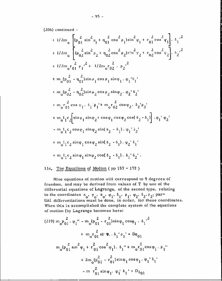
- 95-
(206) continued -
4 1 / 2m (P sin 2 P + q Cos 2 P 2 + r Cos .20 [l 01 1~ 0 os lSi 1 -0r1~sq-.6
.2 2 2 2 2 2 2 2 2+ 1/2m I(PoSin P + qOcos p 2 . -4 r02 cos 4)2 62
2 02 . 2
+l/2m r 2 ', + 112m r 2orol 1 " or02
2 2
+ mo(p 2 - qO1 )sinlp cosp I siny 1 • '1
+ 11(1 2- q 2 sillP Cos P siriq) p2 . 62'
2 2
+ m r ' co r 1 Po 01 1 ~1 o 02 2 62 p,
+ molC 1 nsin(Pinq 2 + coso 1 cOsP 2cos(6 2 =68 1 "Tp1 1P2'
o c2 cos c,' 1 (s2 s - 6 1 ' 32'
oI 1 c2 sinq1 cosCP2 sin( 62 -6). 02, 1
+ m 1 c 2 sinq1 sin 2 cos( 62 -6l). 61' 62'
11c. The Equations of Motion ( pp 157 - 172 )
Nine equations of motion will correspond to 9 degrees offreedom, and may be derived from values of T by use of the
differential equations of Lagrange, of the second type, relatingto the coordinates xo, Yo) zo, p 1, p1 PI' CP2 ' 62 P2 ; par-
tial differentiations must be done, in order, for these coordinates.When this is accomplished the complete system of the equationsof motion (by Lagrange becomes here:
2 2 20, oPl lsn0cs0 512(219) 1 . -M(p 0 2 r 2 )silly, cosyp .
2+ m 0 r sil . - 61P 1 ' = L
0 01 0o 2
+22 (p= -r 0 1 )sinp coscp 1 . 01~
2- m r 0 1 sinp 1. pl' 61' D6 0 1
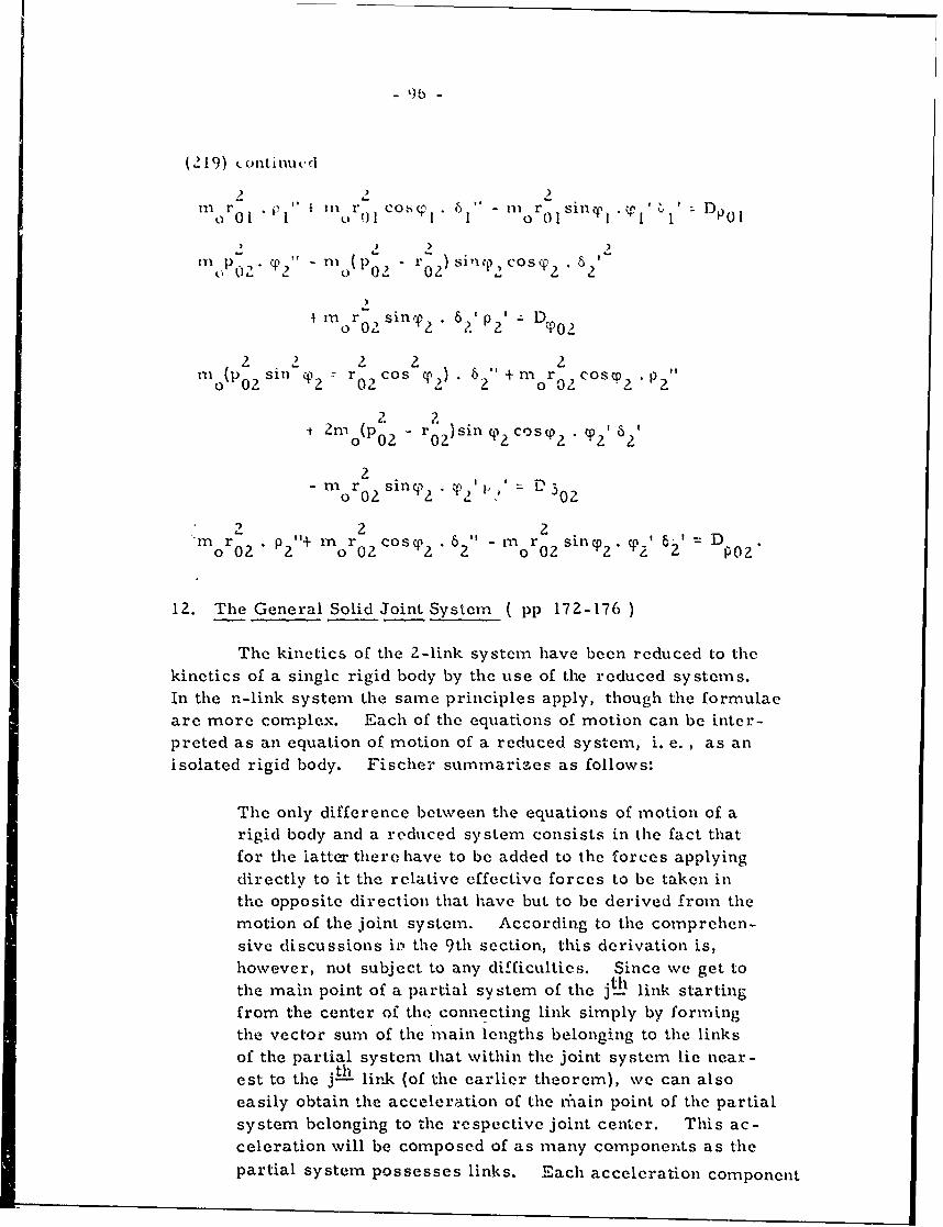
(219) )otinut.d
0 r 01 . f i 0 1 Co.C 1 6 "1 - I S114 I 'I I I D p
,, . 0) . aIV - P0 O r sinep cosp 2
)
III 2 T. ni (Dp02
rnr., sillv% 6?,' p2 I;DT?
IIo(Posin cp2 - rO cos 'T) 6 ? +m r Cos D 2.P2"
2(P- 2 0zsp 2 "p 2 ' 2
2
2 2 6in " - m2ros0n .p p' 6'5D
0r p2 2 c0 .p2" n 0 2CosCp 2 1 62" m o 2s1inP2, 2 2 -- or0 or0 oro " 2 D 02
12. The General Solid Joint System ( pp 172-176 )
The kinetics of the 2-link system have been reduced to thekinetics of a singIc rigid body by the use of the reduced systems.In the n-link system the same principles apply, though the formulaeare more complex. Each of the equations of motion can be inter-preted as an equation of motion of a reduced system, i. e. , as anisolated rigid body. Fischer summarizes as follows:
The only difference between the equations of motion of arigid body and a reduced system consists in the fact thatfor the latter there have to be added to the forces applyingdirectly to it the relative effective forces to be taken inthe opposite direction that have but to be derived from themotion of the joint system. According to the comprehen-sive discussions in. the 9th section, this derivation is,however, nut subject to any difficulties. Since we get tothe main point of a partial sv stem of the jt-h link starting
from the center of the connecting link simply by formingthe vector sum of the main lengths belonging to the linksof the partial system that within the joint system lie near-est to the jth link (of the earlier theorem), we can alsoeasily obtain the acceleration of the ni'ain point of the partialsystem belonging to the respective joint center. This ac-celeration will be composed of as many components as thepartial system possesses links. Each acceleration component
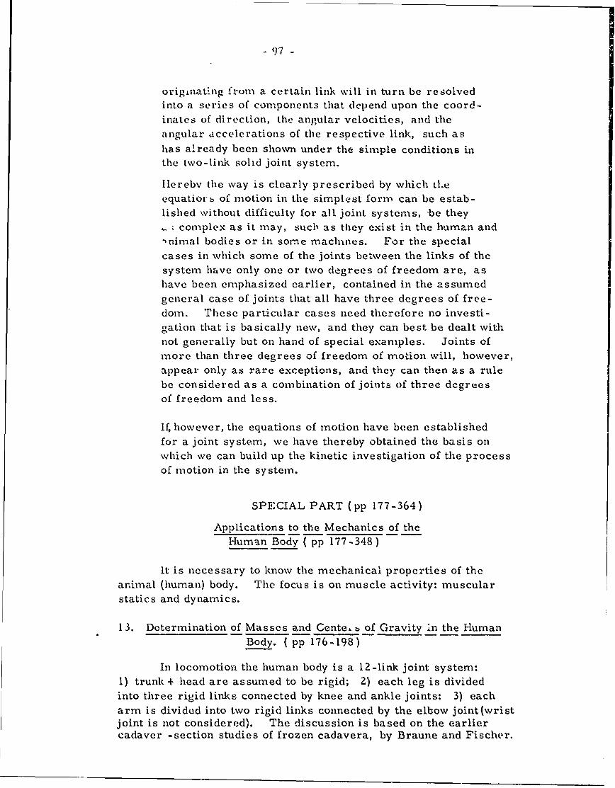
- 97 -
originat-ng from a certain link will in turn be resolvedinto a series of components that depend upon the coord-
inates of direction, the angular velocities, and theangular accelerations of the respective link, such as
has already been shown under the simple conditions inthe two-link solid joint system.
Herebv the way is clearly prescribed by which tl.e
equatiorb of" motion in the simplest form can be estab-lished without difficulty for all joint systems, be they- ; complex as it may, such as they exist in the human and
'nimal bodies or in some machies. For the special
cases in which some of the joints between the links of the
system have only one or two degrees of freedom are, ashave been emphasized earlier, contained in the assumed
general case of joints that all have three degrees of free-dom. These particular cases need therefore no investi-(Tation that is basically new, and they can best be dealt with
not generally but on hand of special examples. Joints of
more than three degrees of freedom of motion will, however,
appear only as rare exceptions, and they can then as a rulebe considered as a combination of joints of three degreesof freedom and less.
if, however, the equations of motion have been established
for a joint system, we have thereby obtained the basis onwhich we can build up the kinetic investigation of the process
of motion in the system.
SPECIAL PART (pp 177-364)
Applications to the Mechanics of theHuman Body ( pp 177-348)
It is necessary to know the mechanical properties of theanimal (human) body. The focus is on muscle activity: muscular
statics and dynamics.
13. Determination of Masses and Cente, b of Gravity in the Human
Body. ( pp 176-198)
In locomotion the human body is a 12-link joint system:
I) trunk + head are assumed to be rigid; 2) each leg is dividedinto three rigid links connected by knee and ankle joints: 3) eacharm is divided into two rigid links connected by the elbow joint(wristjoint is not considered). The discussion is based on the earliercadaver -section studies of frozen cadavera, by Braune and Fischer.
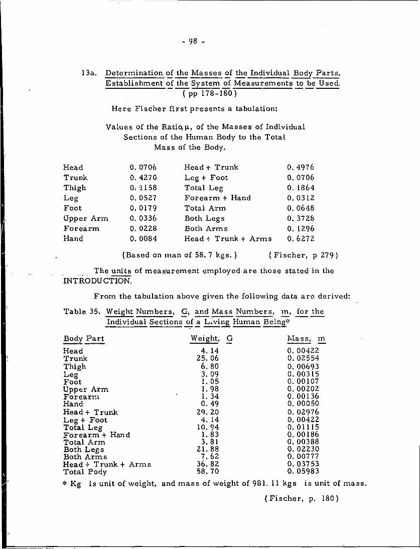
-98-
13a. Determination of the Masses of the Individual Body Parts.Establishment of the System of Measurements to be Used.
( pp 178-180)
Here Fischer first presents a tabulation:
Values of the Rati qp, of the Masses of IndividualSections of the Human Body to the Total
Mass of the Body.
Head 0. 0706 Head + Trunk 0. 4976Trunk 0.4270 Leg + Foot 0. 0706Thigh 04J158 Total Leg 0. 1864Leg 0.0527 Forearm + Hand 0. 0312Foot 0. 0179 Total Arm 0. 0648Upper Arm 0. 0336 Both Legs 0. 3728Forearm 0. 0228 Both Arms 0. 1296Hand 0. 0084 Head + Trunk + Arms 0. 6272
(Based on man of 58. 7 kgs.) (Fischer, p 279)
The units of measurement employed are those stated in theINTRODU CTION.
From the tabulation above given the following data are derived:
Table 35. Weight Numbers, G, and Mass Numbers, m., for theIndividual Sections of a Living Human Ben-
Body Part Weight, G Mass, m
Head 4. 14 0. 00422Trunk 25.06 0. 02554Thigh 6.80 0. 00693Leg 3.09 0. 00315Foot 1.05 0.00107Upper Arm 1. 98 0. 00202Forearni 1.34 0.00136Hand- 0.49 0. 00050Head + Trunk 29.20 0. 02976Leg + Foot 4. 14 0.00422Total Leg 10.94 0.01115Forearm + Hand 1.83 0. 00186Total Arm 3.81 0. 00388Both Legs 21.88 0.02230Both Arms 7.62 0. 00777Head + Trunk+ Arms 36.82 0. 03753Total Pody 58.70 0. 05983
Kg is unit of weight, and mass of weight of 981. 11 kgs is unit of mass.
(Fischer, p. 180)
- 99 -
13b. Ietermination of the Centers of Gravity of the IndividualBody Parts. ( pp 181-184
The center of gravity of the head is in the mediai plane 0. 7 cmback of the sella turcica in the fossa Tarini (at the angle formed bythe upper edge of the pons with the lamina perforata superioris). Thatfor the erect trunk is at the anterior upper edge of first sacral vertebra,SI, in the line of the atlanto-occipital joint and the middle of the hipline(line connecting the centers of R% and L hip-joints). The head-jointto hip-line axis is the kng trunk axis, passing through the shoulder-line.The center of gravity on this trunk axis divides it in the ratio of 0. 61:0. 39. Correspondingly the shoulder-line: hip-line ratio is 0. 47: 0. 53.
In the living body the head-joint (atlanto-occipital) bisects a linefrom the ear-hole to "about where the upper part of the auricle is attachedto the head. " The hip-line is established by R. and L major trochanters,and the shoulder-line by R and L-acromial processes. Because ofvertebral curves the location of the center of gravity of the trunk isvariable.
In upper/lower arm and thigh/leg the centers of gravity will fallin the long axis between the two joints, nearer the proximal than the distal.If e and e are, respectively the ratios of the distance of the center ofgraviti, from the proximal and distal joint centers, then we get:
Body Part e£1 _2
Upper arm 0. 47 0. 53Forearm 0.42 0.58Thigh 0.44 0.56Leg 0.42 0.58
In the fcot the back-to-front ratio is 0, 43: 0. 57. In the hand,with fingers slightly flexed, the center of gravity is between head ofmetacarpal III and palmar surface, 1 cm. from the bone.
As a rule the ratio in the proximal extremity parts is e 1: 2
0. 44: 0. 56 or 4:5. If 1 is the distance between two joint centersthen the ratio is 4/9 1 and 5/9 1; this holds also for the shoulder-line:hip-line ratio. In the lower leg the knee-joint: ankle-joirt ratiois 0. 61: 0. 39 or 3:2. In the forearm or elbow-joint: hand-joint theratio is 0.66: 0.34 or 2:1.
- 100 -
13c. Derivation of the Center of Gravity of Variou'- Partial Systems
Composed of Several Limbs and of thie Total Center of Gravityof the Living Human Body. ( pp 184-193 )
Thc common center of gravity of two mas-es lies on the connect-ing line of the individual centers of gravity and dividcs this line in the
inverse ratio of the masses. From the table earlier given the upper
arm and lower arm + hand have center-of-gravity ratios of 0.0312:0. 0336 (0.481: 0. 519). Similarly, trunk + head = 0. 142: 0. 853,lower leg + foot = 0. 253: 0. 747, one entire leg = 0. 379: 0. 621; trunk+ head = 0. 207: 0. 793. The total center of gravity of the entire body
is on a line connecting the center of gravity of the system head + trunk
+ both arms and the system both legs, in a ratio of 0. 373: 0. 627.
It will be best in the living body to relate the foregoing to a
rectangular solid coordinate system. For the calculation of the coord-
inates of the centers of gravity of the partial systems and of the total
center of gravity from the coordinates of the individual center of gravityn -
(1Z6) is employed: S = j. Os The vector line is to be projected
1
in succession on each of the three -axes of the rectangular coordinate
system. If the projections of the vector leading from the coordinateorigin to any point, P, on the three coordinate axes, and these arethe three rectangular coordinates of P, then we get the theorem:
Each of the three coordinates of the center of gravity of a
component system is equal to the algebraic sum of the respect-
ive coordinates of the individual centers of gravity reducedat the ratio p, when by p we understand the ratio of the massof the limb (to which the individual center of gravity belongs)
to the total mass.
Consider the body to consist of rigid sections numbered 1.... n,and designate by xhp Y1 ' z the coordinates of the center of gravity of
the n L limb for which the ratio of its mass to the total mass equalsh' Ithen, we get for the calculation of coordinates x , yo? z to the
total center of gravity: n
(220) 0 x1 +%X2 +1 3 + P.n4X nJ:L '
n
YO 11 1 I + P 2Y2 + 11 3x3 + .. lin n = n , 11 XhK1
nz 0=
1 z + 22Y 2 + 3 z3 + . n n h z h
(Here the values of 1i are from the earlier tabulation)
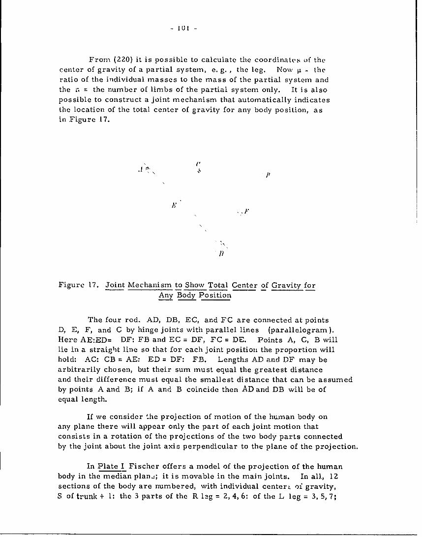
- 101 -
From (220) it is possible to calculate the coordinates of thecenter of gravity of a partial system, e. g. , the leg. Now P ; theratio of the individual masses to the mass of the partial system andthe r. = the number of limbs of the partial system only. It is alsopossible to construct a joint mechanism that automatically indicatesthe location of the total center of gravity for any body position, as
in Figure 17.
\ (I
])
Figure 17. Joint Mechanism to Show Total Center of Gravity for
Any Body Position
The four rod, AD, DB, EC, and FC are connected at pointsD, E, F, and C by hinge joints with parallel lines (parallelogram).Here AE:ED= DF: FB and EC = DF, FC = DE. Points A, C, B willlie in a straight line so that for each joint position the proportion willhold: AC: CB = AE: ED = DF: FB. Lengths AD and DF may bearbitrarily chosen, but their sum must equal the greatest distanceand their difference must equal the smallest distance that can be assumedby points A and B; if A and B coincide then AD and DB will be ofequal length.
If we consider '.he projection of motion of the human body onany plane there will appear only the part of each joint motion thatconsists in a rotation of the projections of the two body parts connectedby the joint about the joint axis perpendicular to the plane of the projection.
In Plate I Fischer offers a model of the projection of the humanbody in the median plan.; it is movable in the main joints. In all, 12sections of the body are numbered, with individual centert oi gravity,S of trunk + 1: the 3 parts of the R leg = 2, 4, 6: of the L leg = 3, 5,7;
- I10Z7 -
the 2 parts of the R arn: 8, 10; of the L arm = 9, 11; the head = 12.The joints, G, have the two numbers of the parts connected by the joint.The total centers of gravity of the parts are given several indices, i. e.
with the numbers of all body parts that belong to the respective centerof gravity. The total center of gravity of the body = S . In this Plate
the ratios previously determined are observed. L xamples are:
S S5,7 : S5,7S7 = 0.253: 0.747
S 3,5,7 S 3,S5,7S5,7 = 0.379: 0.621
SIS1, 12 Sl, 12S12 = 0. i42: 0.858
S1,8_12S0 : SoS2-7 = 0.373: 0.627
If we want to determine not only a projection of the center of
gravity but also its position in space it is best to get a solid model ofthe human body and attach it to a center-of-gravity mechanism accord-ing to the same principle.
14. The Main Points of the Human Bo_.. ( pp 193 - 205 )
Here Fischer refers to the reduced system: here is presumedto be concentrated in the center of each joint of the limb the massesof all links of the joint system in immediate or intermediate connection.For example, we get the main point of the R upper arm when in the
center of the R elbow joint we suppose to be concentrated the mass ofthe P. foreai.m + Hand; in the shoulder will be concentrated the masses
of all other body masses to the R upper arm: the center of gravity ofthis reduced R upper arm system represents the main point of the Rupper arm. Everywhere the main point will be nearer to the proximaljoint than to the center of gravity of the respective limb.
In Plate T1 the approximate position of the individual main pointsis shown. Needed only is the ratio, p, of the individual masses tototal mass.
14a. Determination of the Main Points of the Individual Body Parts.(p1 75--, )
The main point of the thi1!h equals the total center of gravity of
the three main masses concentrated in the hip-joint center, knee-joint
center, and center of gravity of the .high: ratio numbers 0.8136, 0.0706,
and 0. 1158, respectively. The main point of the thigh will divide thelong axis as 0. 122: 0. 878; if P = thigh length then the thigh main point
e.g. 0. 122 . Z from the hip-joint and 0. 878 . Z from knee-joint.In like manner lower leg is 0. 040 . A and 0. 960 .1, respectively,
- 103 -
from centers of the knee- and foot-joints. If in the foot we designater the distance between the center of the foot-joint and the center ofgravity of the foot, then the main point of the foot is 0.018 .r - and
0. 982 .r, respectively, from these two points. In the upper armthe main point equals 0. 047 .' , and 0. 953 .1, respectively, fromthe centers of shoulder-and-elbow joints. In lower arm + hand themain point equals 0. 021 . from the elbow-joint center and 0. 979from the hand-joint center.
In the trunk six mass points are concentrated (two hip-joints,two shoulder-joints, the head-joint, the center of gravity of the trunk).Each mass in hip-joint center has a ratio = 0. 1864, in shoulder-jointcenter = 0. 648, in head-joint center = 0. 766, and in center of gravityof trunk = 0.4270. If we replace the two hip-joint masses by 0. 3728,and the two shoulder-joint masses by 0. 1296 (both mid-line) only fourmasses are concentrated in the trunk. Let h = distance between the
middle of the hip-line and shoulder-line, and I = distance of hip-lineaid center of head-joint, then the main t , it = 0. 451 . h or 0. 333 .Lfrom the middle of the hip-line, or 0. 54', . h from the middle of the
shoulder-line and 0. 667 .j from the center of the head-joint. Since
6- 1. 35 greater than h, the two distances are equal only when 0. 451
is also 1. 35 times greater than 0. 333. This is actually the case.
If b = 1/2 the distance of the two hip-line centers from eachother, and if a = 1/2 the distance of the shoulder-line centers from
each other, then in the erect posture the following holds:
1) distance of the trunk main line from each hip-joint
center = 0.203. h + b2 or 01. 1-+ b
2) distance of the trunk main line from each shoulder-
point center = 40.301. h + a
If we assume the mass of the head to have a ratio number of0. 706 in the middle of the shoulder-line then the distance of the mainpoint from the middle of the hip-line = 0. 427. h and from the shoulder-line = 0. 57 3. h. Hence, the main point of the trunk would be from
the hip-joint and shoulder-joint center J0. 182. h2 + bZ Lnd
0. 328. h + a . respectively.
For the main point of the head there must be noted two differentpositions: 1) where rotation center is in the head-joint; and 2) whererotation conter is in the shoulder-line.
-104-
In 1) if I - head -joint center to top of head, then distance zf the main
point from head-joint center = 0. 018. 1 and from top of head = 0. 982.1.In Z) if h = length from mid-shoulder-fine to top of head, then distance
of the main point = 0- 049. h and 0. 951. h, (near the shoulder-line).
The lengths oetween -the joints defining a body part e id the mainpoint of the part are called main lengths; two each for thigh, lower leg,upper arm; one each for forearm + hand, foot, head; and five for the
trunk.
14b. Use of the Main Points for the -1)etermiiatiOn of the Total Centerof Gravity and of the Centers of Gravity of the Partial Systems
of the Human Body ( pp'199-204 )
It is possible to locate the total center of gravity of the human
body by means of maimpoints and main le'ngths. it is necessary onlyto start from the main point of one of the n body parts, adding in any
succession the n-i body parts that are facing the nth part. As anexample from Plate I: start from H of the trunk, which will givetwo connecting lengths c 2 and c3 of a hip-joint center, GI,2 or G 1 , 3
(respectively); with the main points H and 'H3 in the thigh, and
c4 and T5 of the knee-joint center G2,4 or G, ,5 ; with main points
H 4 and H 5 ; lower leg T6 and _c of the foot-joint center G4,6 or G5,7
main point H or H- , -C or -; and so on.
Mai, .engths are important because here we have measurements for
the action that the motion of the various body parts and body part systemexeit on the position and displacement of the total center of gravity.
A'ssume that all other body parts are fixed and then rotate the entire Rleg in the hip-joint, with no motion at knee-and ankle-joints. The totalcenter of gravity of the body will move along a circle with a ra,-lius equalto the distance of the main point of the entire R leg (1-1 6 from the2center of the hip-joint. The length GF _H_ (dsgaed,)is equal
1,2 z/, 62dsgnd~ 6'to the geometrical sum of the three main lengths thigh, leg, and footthat within the leg lie nearest the hip-joint, or:
(221) -.. ..cZ6 = c +c4 + c6
14c. The Action of ;Gravity on the Individual Sections of the Hunian Body.(, pp 204-205,)
If the foot is pressed on the floor the reaction will produce pressure
force at the- joint of each body part facing the pressure spot. The pressureforce will be equal and -opposite to the weight of the entire body. Hence,
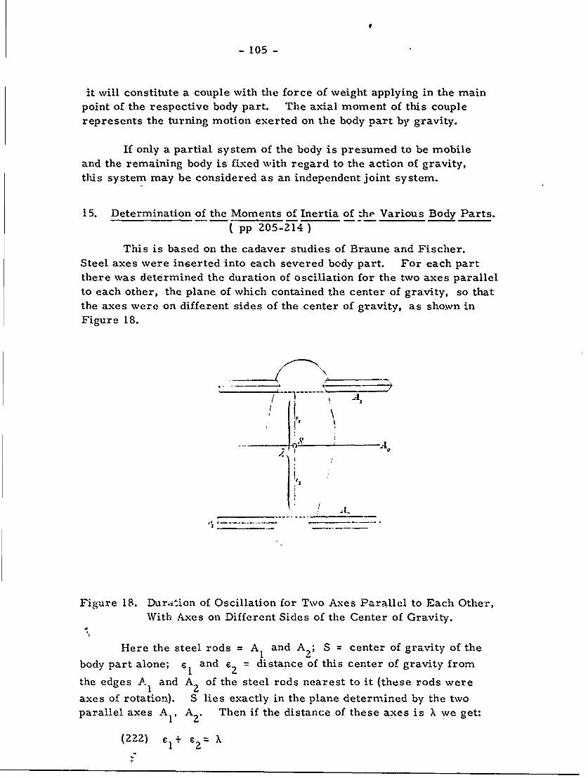
- 105 -
it will constitute a couple with the force of weight applying in the mainpoint of the respective body part. The axial moment of this couplerepresents the turning motion exerted on the body part by gravity.
If only a partial system of the body is presumed to be mobileand the remaining body is fixed with regard to the action of gravity,this system may be considered as an independent joint system.
15. Determination of the Moments of Inertia of the Various Body Parts.( pp 205-214)
This is based on the cadaver studies of Braune and Fischer.Steel axes were inserted into each severed body part. For each partthere was determined the duration of osciliation for the two axes parallel
to each other, the plane of which contained the center of gravity, so thatthe axes were on different sides of the center of gravity, as shown in
Figure 18.
Al
Figure 18. Duration of Oscillation for Two Axes Parallel to Each Other,With Axes on Different Sides of the Center of Gravity.
Here the steel rods = A 1 and A2 ; S = center of gravity of the
body part alone; e and .= distance of this center of gravity from
the edges A I and A2 of the steel rods nearest to it (these rods were
axes of rotation). S lies exactly in the plane determined by the twoparallel axes AV A2 . Then if the distance of these axes is ) we get:
(222) €1+ £2 X
- 106 -
Further designations are as follows:
m = mass of limb (without rods)
x = radius of inertia of the limb alone relative to axis0
A that goes through S and is parallel to A1 , A 2o2
VI = mass of steel rod with axis A I
6 1/2 the diagonal of its cross-section
P2 = mass of stcel rod with axis A 2
62 = 1/2 the diagonal of its cross-section
T 1=duration of oscillation of the mass system (limb +rods) at axis of rotation A1 .
T 2 = the same for A 2
g = the acceleration of gravity
First in relation to axis A I there will be the moment of inertiain the limb alone:
2 2(i 2m(x 0 + e ); and for the upper steel rod I + 61 4 61 1
2
and for the lower rod p 2 + ( 2 = 2 (622 + 3(k+ 622)2)
After deriving the same for axis A., there is obtained according
to the laws of the pendulum:
m(x 0 + eI 2 ) + 4'6 + 2 22 +3(X+6
12 9 gm S+ Pi 16 1 + p 2 (X+ 6?.)
m(X 2 + C 2) + i. 1(6 2 + 3(k+ 6 )}. 2.
grm C2 + Pnd(X+ 62)+ 1is 6
From (222) and (223) the following is derived:
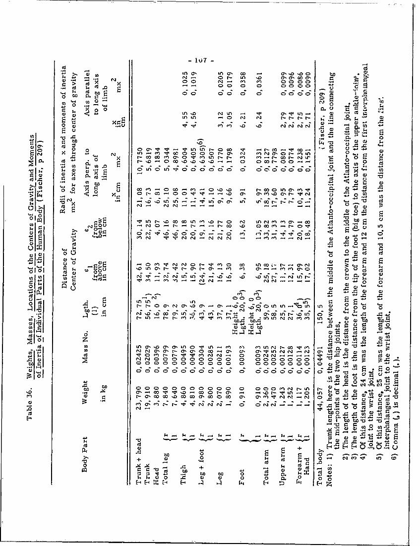
- 10J7-CU Cd
>, t a, tcA a, op -, a'0 %0 C53- ij 4 " ; aOr- LA . 'aca
-4 003 %0 00 7100 . I>U edCU C) 0 CD 0
;4 cd 0o 0; 0000C C ; ;C; a,'CDo to C .. v
q.44
0A' NLA -f.~a'4. C
C)- C) 0 -4o4 Ln .,.. N~ Ln '. ' nN
u
o0 0 0 a, 1- 1 L nr-C>co V -r-cc~ c MU WC)&4 4-i CdL~ 4 c~0 r a CDAa't-L
0d .6 r- oo 0 e C7 C>'.IV (Y nr- r- LA) M - I-- M r- N or .0 Oc-r00-0
34 C) 0. 0L 00A 000o 0 0 00 000 '.C Ud" U
CU -
-J - - - -
< 0o L t n ,a >tu ccucc 4 A 0 . ' r-c L O. A r- r t D 0
0U a ) 0 J.40 0 41 41
0 C01 ~~ 1A u)- %o oo Co LA c o0 t- o CZ LA Nq (n (n 0%a' - 0c C)C, 0 - - -r-- - -c 00 0 C 00 fn r-o~ C-.. v 4
w' L ANl -4
NN - -~~ - - - -
>~C~ 00-
c0 0 -05 C eel v m 0 C- v1 mA 0c oo LACoo - t--. m'010'-~-'--'L LA a'00A - o 00 CU CU
0.. . * AL 1 4'0' 0 'L - AC-4. 0 0
0 L) .. C).0, CU -U - Q 0 0-.-
I'- 0 C> 0 C
V -r-c o0~ - -o, La a,-6; 6oL n-bl v 0 4NN --00 00 00 0 0 0 0 00 0 ~C
16 0 C0tf ' VCO-r 0: oo oooo n Nr A %o4 C) ) -CU'
C)n-+ )~CCC)~~r U~'~ -- ~.'N 0 zNN -0
bOO (D ) -
Id k.4 0Z cn
CU~ C)(n0~ =O 0
0 .04 0
44c CO t-) V N -C> C CUj M~ C10 WUC)34> 4C0 CD a0C >C CD C 0 C) 40 C C ~
0 0 d4 00 qX ~ =~- C. 04~ C-1 H 1'
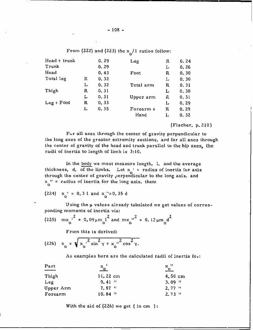
- 108 -
From (222) and (223) the x /I ratios follow:0
Head + trunk 0. 29 Leg R 0. 24Trunk 0.29 L 0.26Head 0.43 Foot R 0.30Total leg I, 0.32 L 0.30
L 0.32 Total arm R 0.31Thigh R 0.31 L 0. 30
L 0.31 Upper arm R 0.31Leg + Foot R. 0.33 L 0.29
L 0.35 Forearm + R 0.29Hand L 0.32
(Fischer, p. 210)
Fur all axes through the center of gravity perpendicular tothe long axes of the greater extremity sections, aild for all axes throughthe center of gravity of the head and trunk parallel to the hip axes, theradii of inertia to length of limb is 3:10.
In the body we must measure length, 1, and the averagethickness, d, of the limbs. Let x I = radius of inertia 'or axis0through the center of gravity perpendicular to the long axis, andx " = radius of inertia for the long axis, then:
0
(224) x ' = 0,3 l and x "=0,35 d
Using the p values already tabulated we get values of corres-ponding moments of inertia via:
2 2 ,2 2(225) mx 0 = 0, 09pm 0 1 and mx 0 = 0, 12 Lm d
0 0 0 0:
From this is derived:
(226) x 0 xo12 sin2y + x0 2 Cos 2
As examples here are the calculated radii of inertia for:
Part x' x "0 0
Thigh 11. Z2 cm 4.56 cmLeg 9.41 " 3.09 "
Upper Arm 7.87 " 2. 77Forearm 10.84 " 2.73 "
With the aid of (226) we get ( in cm
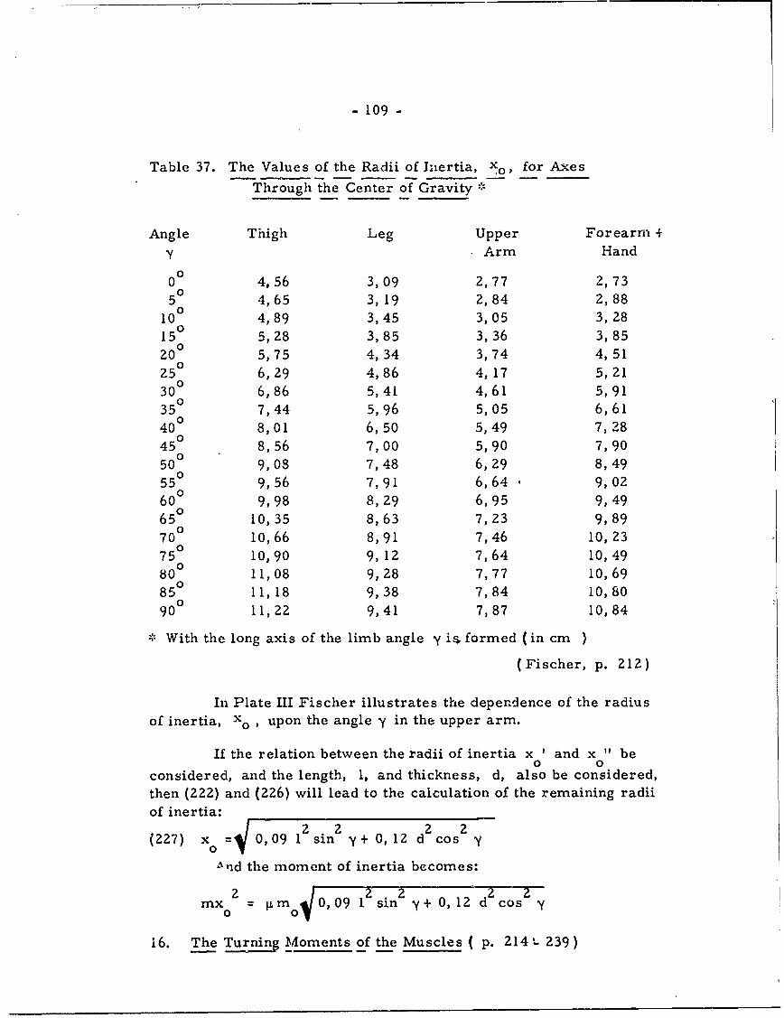
- 109 -
Table 37. The Values of the Radii of Liertia, Xo, for Axes
Through the Center of Gravity ,-
Angle Thigh Leg Upper Forearm +
y Arm Hand
00 4,56 3,09 2,77 2,7350 4,65 3, 19 2,84 2,88
100 4,89 3,45 3,05 3, 28150 5,28 3,85 3,36 3,85200 5,75 4,34 3,74 4,51250 6,29 4,86 4,17 5,2130 6,86 5,41 4,61 5,91
350 7,44 5,96 5,05 6,61
40° 8,01 6,50 5,49 7, 28
450 8,56 7,00 5,90 7,90
500 9,08 7,48 6,29 8,49550 9,56 7,91 6,64 9,02
600 9,98 8,29 6,95 9,49650 10,35 8,63 7,23 9,89700 10,66 8,91 7,46 10, 23
750 10,90 9, 12 7,64 10,49
800 11,08 9,28 7,77 10,69850 11, 18 9,38 7,84 10,80900 11,22 9,41 7,87 10,84
* With the long axis of the limb angle y is formed (in cm )
(Fischer, p. 212)
In Plate III Fischer illustrates the dependence of the radiusof inertia, xo , upon the angle y in the upper arm.
If the relation between the radii of inertia x ' and x " be0 0
considered, and the length, 1, and thickness, d, also be considered,then (222) and (226) will lead to the calculation of the remaining radiiof inertia:(227) x = 0,09 12 sin2 0,12 d2 20,09 O 12 cos
And the moment of inertia becomes:
2 2 2 d2mx = Im 40,09 sin c+O,12 Cos Y
'6. The Turning Moments of the Muscles ( p. 214 ' 239)
- 110 -
16a. Definition of the Turning Moments. Static Measurementof a Muscle. ( pp 214-221 )
In contraction or during passive tension a muscle acts ontwo points (origin and insertion) and with fo-ces on various bodyparts. If there is a bony protrusion between origin and insertionthe muscle acts as though it were two muscles, though both "parts"are stretched at the same time; hence, they behave as one. Eachof the two equal and opposite forces that arise in contraction orpassive tension exerts an external force for the body part to whichit applies: these are forces of origin and fo-ces of insertion. Bothrepresent a couple of internal forces for the entire joint system;two of such forces will act with a couple of forces upon each limbwithin the immediate sphere of action. The primary effect of amuscle is its tendency to set in rotary motion a number of body parts.
A one-joint muscle will have first the forces of insertion,then those of origin; both forces will be forces at respective jointcenters. The moments of the two couples of force are equal inmagnitude. A two-joint muscle is similar to a one-joint muscle inprinciple. One force of the couple is the muscle force at the pointof insertion, the other at a second point of insertion on the joint facingthe application point of this force. As a result a muscle acts on themiddle oi the body part with a couple of forces caused by: 1) forceof insertion and force of origin exert pressure on the joint of the bodypart nearest them; 2) this pressure is equal in magnitude and direct-ion to these forces. The two turning moments, especially for a one-joint muscle, are equal and opposite.
If a muscle deviates from a straight-line pull then for thepurpose of the three turning moments we must assume the muscleto be a combination of two one-joint muscles. In a multi-joint muscle,if only one joint remains free while the others are fixed, then themuscle will act as a one-joint muscle.
The turning moments of individual body parts can be determinedby the moments of a one-joint muscle. Let the turning moment = 1 ..... n; let turning moment D be determined by fixing all joints exceptthe one connecting first and second body parts. If the joint betweenthe second and third body parts is left free then the turning momentwill be obtained that is the resultant of D + D , and D can bederived from D.. If the joint between the third and fourth body partsis left free then we get D + D 2 + D3 ; from this one can go on toD I .... D . To the turning moments of the muscle must be added or
considered: 1) masses of the body parts; 2) mass distributionwithin each body part: 3) especially the particular kind of joint
connecton.
-111 -
16b. The Derivation of the Turning Moment as Illustrated by
Speciai Exampies. (pp 221 - 239)
Illustrated will be the M. iliacus, M. biceps femoris and
M. semimembranosus, which are in a plane perpendicular to themiddle axis of the knee-joint; hence, the plane of the couples of
force will also be perpendicular to the middle axis of the knee-joint.The muscles will tend to rotate body parts about axes parallel to
this knee-joint axis.
Here the body is considered as a 3-link system: link I
entire body less one leg- link 2 = thigh; link 3 = leg + foot. At
the same time the joint system may be considered as a plane system.
16ba. The Method of Derivation. (pp 222-228)
In the hip or knee, alone, the dependence of the turningmoments upon the position of the joints can be shown by moment
curves, and in knee + hip by moment surfaces. in plotting these
it shall be assumed that the tension of the muscle as related to the
unit of physiological cross-seLtion is the same in all positions of
the 2-link system. TherE the turning moments will be proportional
-to the product of the arm ,f the couple of force to which belongs the
number of surface units of the physiological cross-section.
If we take as a unit of turning moment I cm -kg , and if
this be represented by I mm , then the number of mm for eachordinate will give the number of cm -kgs of the turning moment
for a muscle with a tension of I kg as related to the unit of the
physiological cross-section. It is necessary to measure directly
only one turning moment for a 1-joint muscle and two turning momentsfor a 2-joint muscle.
In the anatomical model it is necessary o measure only the
arms of the various couples of force and he cross-section of the
muscles. The determination of insertion points is arbi'raxy, since
insertion involves a large area. In practice Fischer connects
insertion (attachment) points b- a thread; pelvis, femur, tibia + fibula
are projected on heavy carboard, paialiel to the median plane; these
carboard units are then cut out, oriented, and rotated as are the
real parts and their joints.
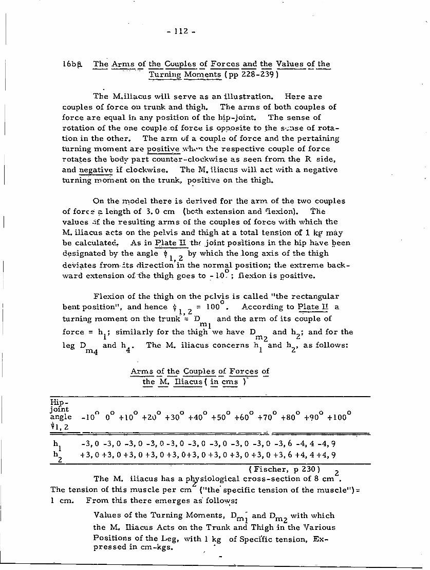
- 112 -
16bfL The Arms of the Couples of Forces and the Values of the
Turning Monents (pp Z28-230)
The M.iliacus will serve as an illustration. Here are
couples of force on trunk and. thigh. The arms of both couples offorce are equal in any position of the hip-joint. The sense ofrotation of the one couple of force is opposite to the s,;:se of rota-tion in the other. The arm of a couple of force and the pertaining
turning moment are positive win the respective couple of forcerotates the body part counter--clockwise as seen from. the R side,
and negative if clockwise. The M. iliacus will act with a negativeturning moment on the trunk, positive on the thigh.
On the model there is derived for the arm of the two couplesof force length of 3. 0 cm (both extension and 1exion). Thevalues :if the resulting arms of the couples of force with which theM. iliacus acts on the pelvis and thigh at a total tension of 1 kg may
be calculated- As in Plate iI thc joint positions in the hip have beendesignated by the angle 1, z by which the long axis of the thigh
deviates from i-ts -direction in the normal position; the extreme back-0
ward extension of,'the thigh goes to -10 ; flexion is positive.
Flexion of the thigh on the pelvis is called "the rectangular
bent position", and hence # 1,2 = 1000. According to Plate I a
turning moment on the trunk = D and the arm of its couple of
force = hl; similarly for the thigh we have Dmz and h and for the
leg D and h 4 . The M. iliacus concerns h and h2 , as follows:m4 4' 1 2
Arms of the Couples of Forces ofthe M. Iliacus (in cms )
joint 0angle -10 0 +10 +20 +30 +40 +500 +600 +700 +800 +90 +1000
*I, 2 __W_
h -3, 0 -3, 0 -3, 0 -3, 0 -3, 0 -3, 0 -3, 0 -3, 0 -3, 0 -3, 6 -4, 4 -4,9
h +3, 0 +3, 0 +3, 0 +3, 0 +3, 0+3, 0 +3, 0 +3, 0 +3, 0 +3, 6 +4, 4 +4, 92
(Fischer, p 230 ) 2The M. iliacus has a ph2 ysiological cross-section of 8 cm
The tension of this muscle per cm ("the* specific tension of the muscle") =
1 cm. From this there emerges as" follows:Values of the Turning Moments, D and Din2 with which
the M. Iliacus Acts on the Trunk and Thigh in the VariousPositions of the Leg, with 1 kg of Specific tension, Ex-pressed in cm-kgs.
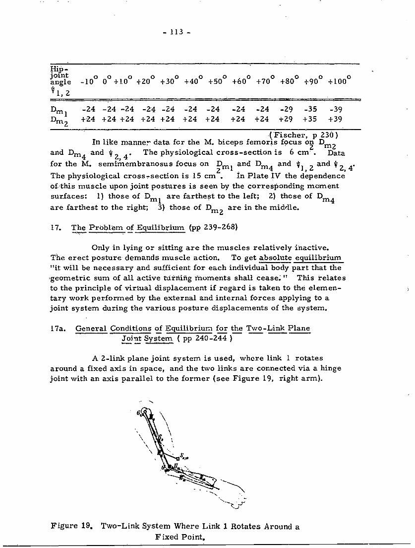
- 113 -
Hip-joint 0 0 0 00 0 0 0 0 0angle -10 0 +10 +20 +30 +40 +50 +60 +70 +80 +90 +100
Dm -24 -24 -24 -24 -24 -24 -24 -24 -24 -29 -35 -39
Dm2 +24 +24 +24 +24 +24 +24 +24 +24 +24 +29 +35 +39
(Fischer, p 230)In like manner data for the M. biceps femoris focus on Din
2 mand Din4 and 2, 4" The physiological cross-section is 6 cm. Datafor the M. semimembranosus focus on Drl and D and * and 4
2 m m 4 ~1,2 24The physiological cross-section is 15 cm in Plate IV the dependenceof-this muscle upon joint postures is seen by the corresponding momentsurfaces: 1) those of Dml are farthest to the left; 2) those of Dim4
are farthest to the right; 3) those of Dm? are in the middle.
17. The Problem of Equilibrium (pp 239-268)
Only in lying or sitting are the muscles relatively inactive.The erect posture demands muscle action. To get absolute equilibrium"it will be necessary and sufficient for each individual body part that the-geometric sum of all active turning moments shall cease." This relatesto the principle of virtual displacement if regard is taken to the elemen-tary work performed by the external and internal forces applying to ajoint system during the various posture displacements of the system.
17a. General Conditions of Equilibrium for the Two-Link PlaneJoint System ( pp 240-244 -
A 2-link plane joint system is used, whcre link 1 rotatesaround a fixed axis in space, and the two links are connected via a hingejoint with an axis parallel to the former (see Figure 19, right arm).
64
\' -
Figure 19. Two-Link System Where Link 1 Rotates Around a
Fixed Point.
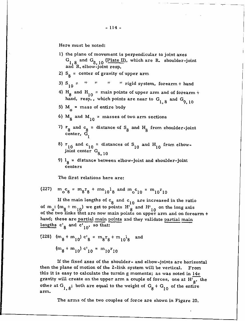
- 114-
Here must be noted:
1) the plane of movement is perpendicular to joint axesG1, 8 and G8,10 -(Plate II), which are R. shoulder-joint
and R. elbow-joint resp.
2) S8 = center of gravity of upper arm
3) S = ': " " rigid system, forearm + hand10
4) H and H = main points of upper arm and of forearm +8 10hand, resp., which points are near to G1 8 and G9 0
5) M = mass of entire body0
6) M 8 and M10 = masses of two arm sections
7) r 8 and c8 = distance of S8 and H8 from shoulder-joint
center, G1
8) r and c1 0 = distances of S10 and HI0 from elbow-
joint center G8, 10
9) 18 = distance between elbow-joint and shoulder-joint
centers
The first relations here are:
(227) moc8 = mr8 + mo 1018 and moc0 = m0 rl0
If the main lengths of c8 and c 1 0 are increased in the ratio
of m: (m 8+ m 0) we get to points H' 8 and H'10 on the long axisof the two links that are now main points on upper arm and on forearm +,hand; these are partial main points and they validate partial mainlengths c' 8 and c' 1 0, so that:
(228) (m 8 + ml0) = m8r 8 + Ml18 and
(m 8 + M1 0 ) c' 1 0 = m 1 0 r1 0
If the fixed axes of the shoulder- and elbow-joints are horizontalthen the plane of motion of the 2-link system will be vertical. Fromthis it is easy to calculate the turnin g moments; as was noted in 14cgravity will create on the upper arm a couple of forces, one at H'8, theother at G 1, ; both are equal to the weight of G 8 + G10 of the entire
arm.
The arms of the two couples of force are shown in Figure 20.
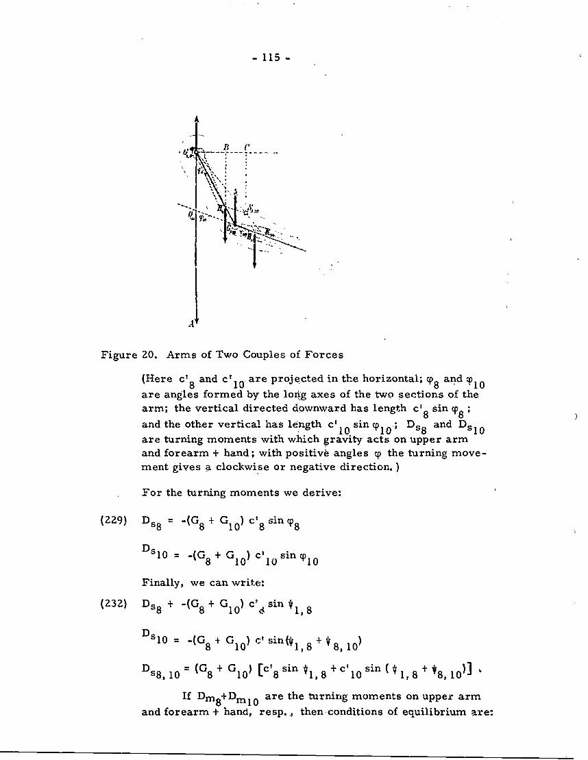
- 115 -
A
Figure 20. Arms of Two Couples of Forces
(Here c' 8 and c' 10' are projected in the horizontal; cp 8 and tP 10are angles formed by the long axes of the two sections of thearm; the vertical directed downward has length c' 8 sin cpo8 ;and the other vertical has le ngth c'110 sin cp010; D s8 and Dsl 0are turning moments with which gravity acts on upper armand forearm + hand; with positive angles c0 the turning move-
ment gives a clockwise or negative direction.)
For the turning moments we derive:
(229) D s8 =-(G 8 + G10 ) c' 8 s i n T
DsI0 -(G 8 + G10 ) cl 1 sin ,0
I0 4 B (O
Finally, we can write:
(232) D s8 + -(G 8 + G10 ) c2 4 sin *1, 8
D sl0 = (Gs8 G10 ) cl sin 0@ , 8 + * 8,10 )
D s8, 10 = (G 8 + G10 ) [c' 8 sin *1, 8 + c' 10 sin 1 , 8 + * 8,10 ]
If Dmi+Dm 0 are the turning moments on uppe armand forearm + hand, resp., thensconditions of equilibrium are:
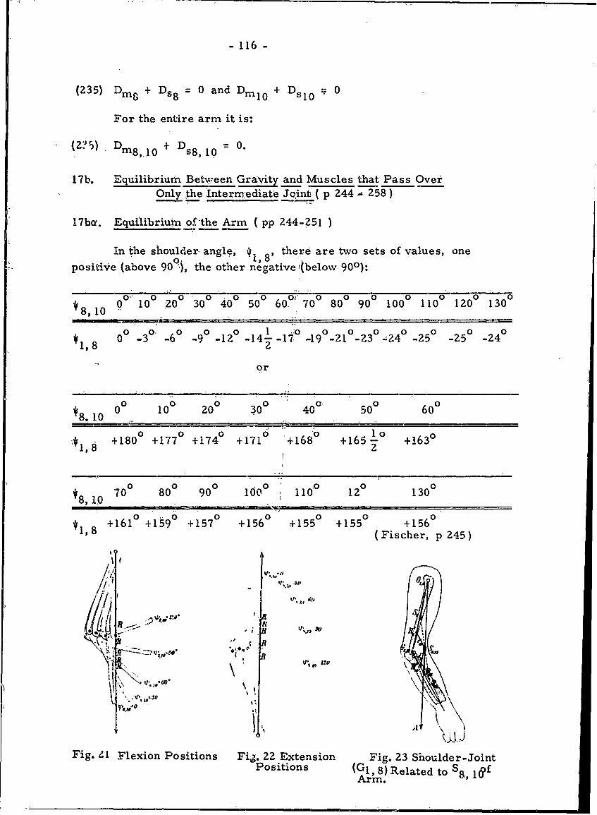
- 116 -
(235) Dm + Ds8 0 and Dim10 + Dsl= 0
For the entire arm it is:
(z:~)+ +D =0.( ) 8,.1 0 s8,10
17b. Equilibrium Between Gravity and Muscles that Pass OverOnly the 'Intermnediate Joint ( p 244 - 258)
17b. Equilibrium of the Arm ( pp 244-251 )
In the shoulder- angle, 1 8' there are two sets of values, one
positive (above 9O9), the other negative (below 900):
*8,10 0o" 100 20 0 300 400 500 60o' 70' 800 900 1000 1100 1200 1300
1 00 0 0 0 0 0 0 0, 00 -30 -6o -9o 1z° -14- -17 -19 -21°-23 ;24 -5 -25 -24
1,8 2
or
1810 00 100 200 300 40° 500 600
+1800 +1770 +1740 +1710 '+1680 +1 6 5 10 +16302
700 800 900 1000 i 1100 120 1300
*1,8 +1610 +1590 +1570 +1560 +1550 +1550 +1560(Fischer, p 245)
Jf G
1'el* II
Fig. ZI Flexion Positions Fig. 22 Extension Fig. Z3 Shoulder-JointPositions (G, 8) Related to S8, 1
Arm.
- 117 -
In Figure 21 there is a series of flexion positions shown: herethe center of gravity lies vertically below the shoulder joint.
In Figure 22 there is a series of extension positions shown:here the center of gravity lies vertically above the shoulder joint.
In Figure 23 it is assumed that the shoulder-joint center G1 ,8
is connected with the total center of gravity S8,10 of the arm, and
this connecting line extends to intersection point R 1 0 with the long axis.For any flexed posture of the elbow-joint we always get the same pointR 1 0 . In Figure 23 the triangle R10 G8 10 G1 8 is similar to triangle
S8 10 H'8 G1,8 for all elbow flexion. flence, the distance p1 0 ofpoint R10 from center G8.10 of the elbow joint has the constant valueof : C 1 0cl10
(239) p =
l0 8 8
The main point H' 8 of the arm divides 18 of the upper arm in
the ratio of 5:2.
In a single muscle let K equal the total tension and k equal thedistance of its direction of pull from the axis of the elbow-joint. Thenthe turning moment, Dml 0 , for the lower arm will be:
(240) D 0 + Kk (the + or - depends upon whether the muscleis a flexor or an extensor)
In the M. brachialis, as an example, we get total tension, asexpressed in (240) (235), (232) as follows:
(241) K= (G8 + G 10 ) c' 10 sin(* 1 ,8 + *8,10)
k
= 33. 736 sin( , 8 + *8, 10) kgs
k
From (241) we ob-in:
8, 1000 10 0 200 300 400 500 600 700 800 90 0 1000 1100 1200 1300
K in 3, 33 5,91 7,90 9,32 10,12 10,00 9,86 9,64 9,27 489 9,36 10,06 10, 33kg 0
( Fischer, p 249)
•- 118 ..
To get the specific tension of the M. brachialis divide K bythe cm of the physiological cross-section which - 12 cm 2 :
Bending angles 0in the elbow 0 10 20 30 40 50 60joint
Specific tensioninkgsper 0 .,,28 0,49 0,66 0,78 0,84 0,83
cm,
'B3ending, anglesin the elb'oow 70° 80 ° 90° 100 ° 110 0 120 130 °
joint
Specific tensionin kgs per 0, 82 0,;80 0, 77 0, 74 0, 78 0, 84 0, 86
cm (Fischer, p 249)2
The maximum tension of a muscle per cm which can keep theunloaded arm in its position is 0. 8 kgs. For a 1-joint muscle of theelbow-joint the turning moments D and Dm!10 are equal and opposite.
mm8I Hence, from (240) we get:
(242) Din8 = Kk (flexion = -, extension =
There emerges the theorem:
In the case of equilibrium between a 1-joint muscle of theelbow joint and the g:ravity of the arm, the total tension ofthe muscle to the total weight of the arm will be at the sameproportion as the distance of the vertical line passing throughthe center of the shoulder joint from the main point of theupper arm to the distance of the resulting direction of pull ofthe muscle from the, center of the elbow joint.
If we consider several muscles, 1 .... n, and i hP qht kh as
the specific tension, physiological cross-section, and the arm of thecouples of force of the nt%' muscle, resp., then from (232) we derive:
24)+ + +(244) + iIqIkIiqk 2 - ' inqnkn =(G8 + G1 0 ) c' 1 0 sin
("1,8 + *8,10)
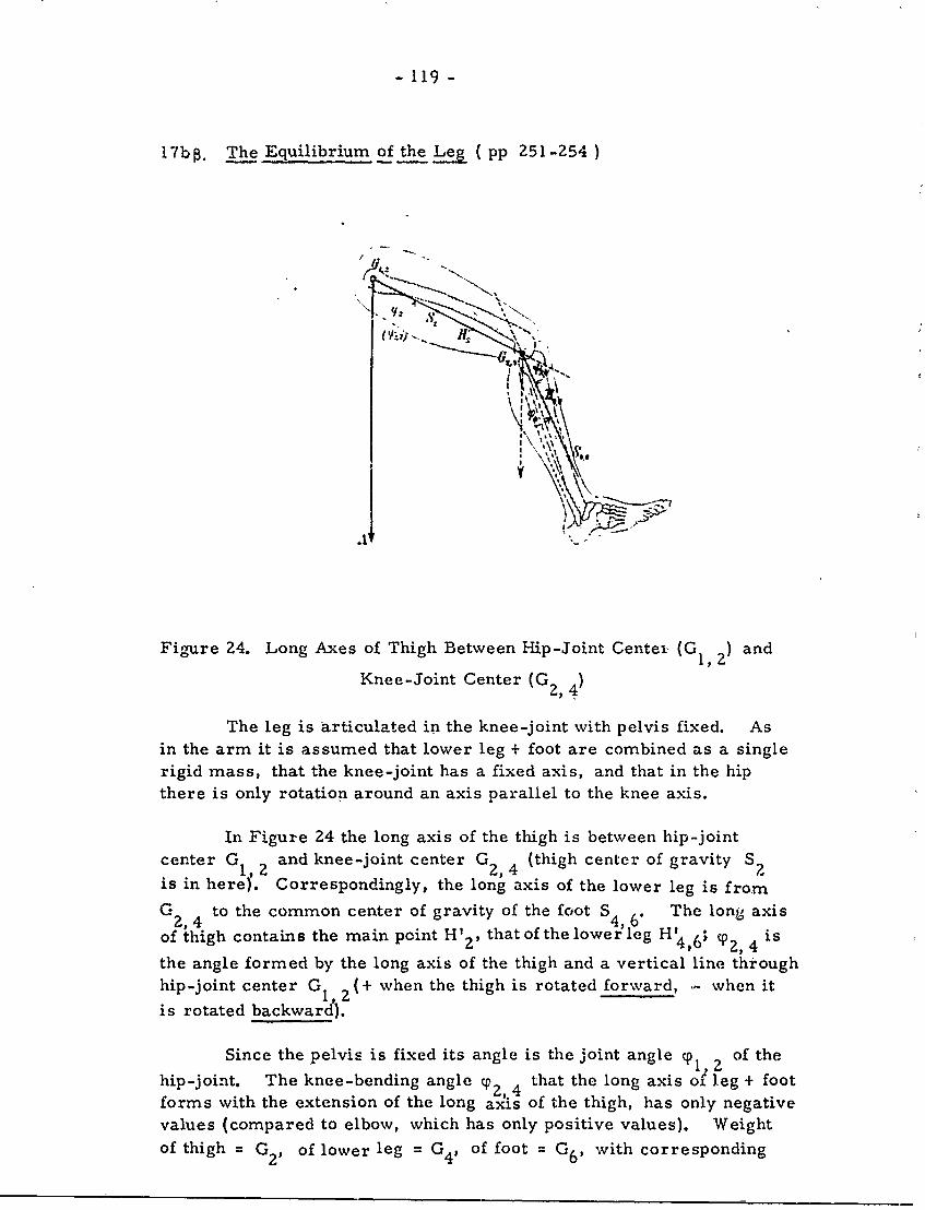
- 119 -
17b The Equilibrium of the Leg (pp 251-254)
Figure 24. Long Axes of Thigh Between Hip-Joint Center (G 1,) and
Knee-Joint Center (G 2 , 4)
The leg is articulated in the knee-joint with pelvis fixed. Asin the arm it is assumed that lower leg + foot are combined as a singlerigid mass, that the knee-joint has a fixed axis, and that in the hip
there is only rotation around an axis parallel to the knee axis.
In Figure 24 the long axis of the thigh is between hip-joint
center G 1 , 2 and knee-joint center G2,4 (thigh center of gravity S2is in here). Correspondingly, the long axis of the lower leg is from
G to the common center of gravity of the foot S4 6" The long axis2,4 4,4
of thigh contains the main peint H' 2 , that of the lowerleg H'4,6; "p2, 4 is
the angle formed by the long axis of the thigh and a vertical line throughhip-joint center G12 (+ when the thigh is rotated forward, - when it
is rotated backward).
Since the pelvis is fixed its angle is the joint angle p1,2 of the
hip-joint. The knee-bending angle cp2, 4 that the long axis of leg + foot
forms with the extension of the long axis of the thigh, has only negative
values (compared to elbow, which has only positive values). Weightof thigh = G2 , of lower leg = G 4, of foot = G 6 , with corresponding
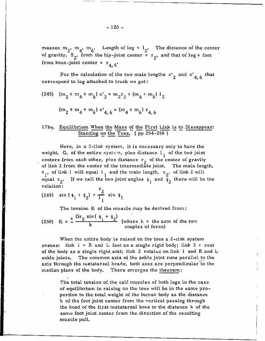
- 120 -
masses m2 , m4 m 6. Length of leg 1 2. The distance of the center
of gravity, S2 , from the hip-joint center = r 2 , and- that of leg + foot
from knee-joint center = r4, 6"
For the calculation of the two main lengths c' 2 and c' that2 4, 6correspond to leg attached to trunk we get:
(245) (m 2 + rn4 + m6 ) c'2 = m r2 + (m4 +im 6 ) 122m + 2 2 4 6 2
(m 2 +m 4 + 6) cl4. 6 =(m4 + m 6) r 4,6
17by. Equilibrium When the Mass of the First Link is to Dissappear:Standing on the To-es. (-pp 254-256) ____
Here, in a Z-link system, it is necessary only to have theweight, G, of the entire ,yst.*- , plus distance 1 1 of the two joint
centers from each other, plus distance r 2 of the center of gravityof link 2 from the center of the intermediate joint. The main length,c of link I will equal I and the main length, c z , of link 2 will
equal r 2 . If we call the two joint angles 1 and 2 there will be the
relation: r 2(249) sin(* + ) = T sin*
1 2 1si
The tension K of the muscle may be derived fron:
(250) K = + Gr z sin( 1 + *2) (where k = the arm of the twok couples of force)
When the entire body is raised on the toes a 2-ink systemensues: link I = R and L feet as a single rigid body; link 2 = restof the body as a single rigid unit; link 2 rotats on link 1 and R and Lankle joints. The common axis of the ankle joint runs parallel to theaxis ths'ough the metatarsal heads, both axes are perpendicular to themedian plane of the body. There emerges the theorem:
The total tension of the calf muscles of both legs in the caseof equilibrium in raising on the toes will be in the same pro-portion to the total weight of the human body as the distanceh of the foot joint center from the nrertical passing throughthe head of the first metatarsal bone to the distance k of thesame foot joint center from the direction of the resultingmuscle pull.
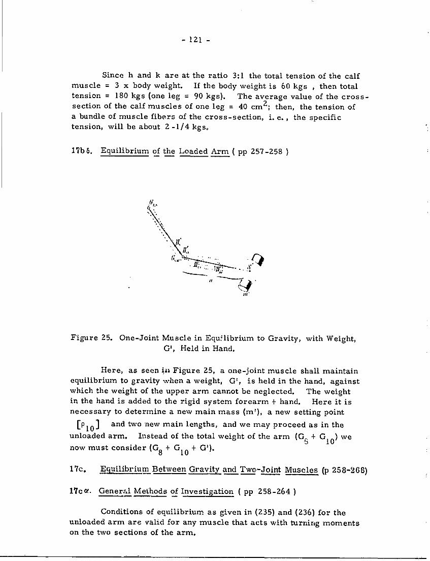
- 121 -
Since h and k are at the ratio 3:1 the total tension of the calfmuscle = 3 x body weight. If the body weight is 60 kgs , then totaltension = 180 kgs (one leg = 90 kgs). The average value of the cross-section of the calf muscles of one leg = 40 cm 2 ; then, the tension ofa bundle of muscle fibers of the cross-section, i. e. , the specifictension, will be about 2-1/4 kgs,
1%h8. Equilibrium of the Loaded Arm ( pp 257-258 )
II"!
ir
Figure 25. One-Joint Muscle in Equilibrium to Gravity, with Weight,G', Held in Hand.
Here, as seen iz, Figure 25, a one-joint muscle shall maintainequilibrium to gravity when a weight, G', is held in the hand, againstwhich the weight of the upper arm cannot be neglected. The weightin the hand is added to the rigid system forearm + hand. Here it isnecessary to determine a new main mass (m'), a new setting point
[P101 ] and two new main lengths, and we may proceed as in theunloaded arm. Instead of the total weight of the arm (GS + G10 ) we
now must consider (G8 + G + G').
17c. Equilibrium Between Gravity and Two-Joint Muscles (p 258-268)
17ca. General Methods of Investigation ( pp 258-264)
Conditions of equilibrium as given in (235) and (236) for theunloaded arm are valid for any muscle that acts with turning momentson the two sections of the arm.
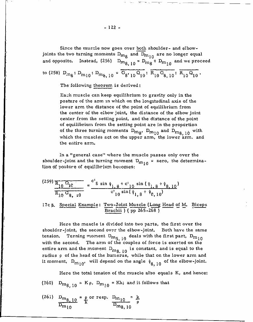
- 122 -
Since the muecle now goes over both shoulder- and elbow-joints the two turning moments Dim8 and Dml0 are no longer equal
and opposite. Instead, (256) Di 8 , 10 = Dm8 + Dml 0 and we proceed
to (258) Dml 0 : D m 8 , I 0 = G8 Q RIG R Q
Ea:h muscle can keep equilibrium to gravity only in the
posture of the arm in which on the longitudinal axis of thelower arm the distance of the point of equilibrium fromthe center of the elbow joint, the distance of the elbow joint
center from the setting point, and the distance of the pointof equilibrium from the setting point are in the proportion
of the three turning moments Dm8, DmI 0 and Dm8 ' 0 withwhich the muscles act on the upper arm, the lower" arm. and
the eintire arm.
In a "general case" where the muscle passes only over theshoulder-joint and the turning moment D ml = zero, the determina-tion Of posture of equilibrium becomes:
9 R sin 41,8 +c'10 sin( 1 .8+8 10)
= . . .10 10, 8 + e 10
17c . Special Example: Two-Joint Muscle (Long Head of M. BicepsBrachii ) (pp 265-268 )
Here the muscle is divided into two parts, the first over theshoulder-joint, the second over the elbow-joint. Both have the sametension. Turning rn.oment Din,8 10 deals with the first part, Dml 0
with the second. The arm of the couples of force is exerted on theentire arm and the rnoment Dm 8 " 10 is constant, and is equal to the
radius p of the head of the humerus, while that on the lower arm andit moment, D l 0 , will depend on the angle 8, 10 of the elbow-joint.
Here the total tension of the muscle al'so equals K, and hence:
(260) Dn8, 10 = K p, Di) 0 = Kk; and it follows that
(261) Din8, 10 = p or resp. Dinl 0 = k
Dml 0 Dm 8 , 10
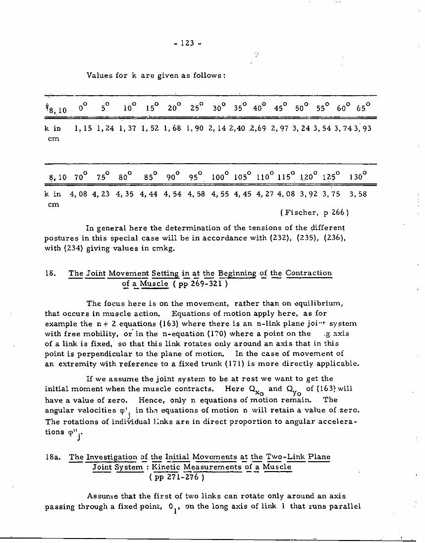
- 123
Values for k are given as follows:
0° 5° 0° 05° 0 0 0 0
8,10 0 50 10 15 200 25' 300 35' 400 45' 50' 55' 60' 650
k in 1,15 1, Z4 1,37 1,52 1,68 1,90 2,14 Z,40 2,69 Z, 97 3,24 3,54 3,743,93cm
8,10 70 ° 750 80 ° 850 90 ° 95 ° 100 105 ° 110 115 1 Z0 125 0 130 °
kin 4,08 4,Z3 4,35 4,44 4,54 4,58 4,55 4,45 4,Z7 4,08 3,92 3,75 3,58
cm(Fischer, p 266)
In general here the determination of the tensions of the differentpostures in this special case will be in-accordance with (232), (235), (236),with (Z34) giving values in cmkg.
18. The Joint Movement Setting in at the Beginning of the Contractionof a Muscle (pp 269-321)
The focus here is on the movement, rather than on equilibrium,that occurs in muscle action. Equations of motion apply here, as forexample the n + Z equations (163) where there is an n-link plane joi-t systemwith free mobility, or in the n-equation (170) where a point on the .g. axisof a link is fixed, so that this link rotates only around an axis that in thispoint is perpendicular to the plane of motion. In the case of movement ofan extremity with reference to a fixed trunk (171) is more directly applicable.
If we assume the joint system to be at rest we want to get theinitial moment when the muscle contracts. Here Qxo and QYo of (163) will
have a value of zero. Hence, only n equations of motion remain. Theangular velocities cp . in thi equations of motion n will retain a value of zero.JThe rotations of individual lnks are in direct proportion to angular accelera-tions y"pj.
18a. The Investigation of the Initial Movements at the Two-Link PlaneJoint System Kinetic Measurements of a Muscle
(pp 271-276 )
Assunme that the first of two links can rotate only around an axispassing through a fixed point, 0 ,, on the long axis of link 1 that xuns parallel
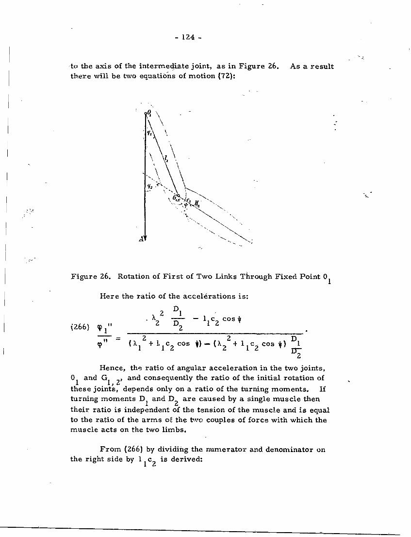
- 124 -
-to the axis of the intermediate joint, as in Figure 26. As a resultthere will be two equations of motion (72):
'10
Figure 26. Rotation of First of Two Links Through Fixed Point 01
Here the ratio of the accel-erations is:
2 DX 2 D IlC2 Cos
(266) z
+ I IC 2 cos 2)- + IC 2 cos4)
2
Hence, the ratio of angular acceleration in the two joints,0 and G , and consequently the ratio of the initial rotation of
these joints, depends only on a ratio of the turning moments. Ifturning moments D I and D 2 are caused by a single muscle then
their ratio is independent of the tension of the muscle and is equal
to the ratio of the arms of the tvo couples of force with which themuscle acts on the two limbs.
From (266) by dividing the numerator and denominator on
the right side by I 1 c2 is derived:
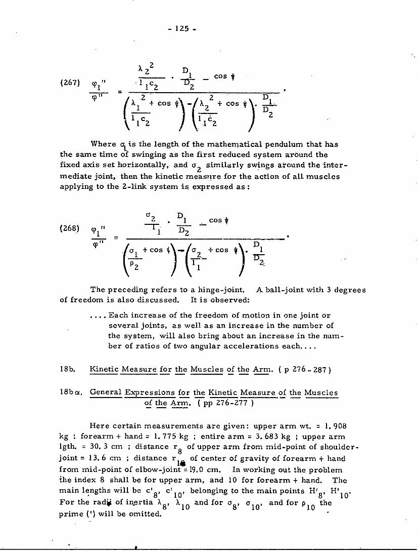
- 125 -
22 D I
(267) pl, -1 c1 1 2c0
Icos 2+Cos L D
Where ais the length of the mathematical pendulum that hasthe same time of swinging as the first reduced system around thefixed axis set horizontally, and a 2 similarly swings around the 'inter-mediate joint, then the kinetic measnre for the action of all muscles
applying to the 2-link system is expressed as:
'268 D1 cost(268) -rp DZ1 -
1 . + cos a -- _+ cos D D
The preceding refers to a hinge-joint. A ball-joint with 3 degreesof freedom is also discussed. It is observed:
.... Each increase of the freedom of motion in one joint or
several joints,, as well as an increase in the number ofthe system, will also bring about an increase in the num-ber of ratios of two angular accelerations each....
18b. Kinetic Measure for the Muscles of the Arm. ( p 276- 287)
18ba. General Expressions for the Kinetic Measure of the Musclesof the Arm. T pp 276-277 )
Here certain measurements are given: upper arm wt. = 1. 908kg : forearm + hand = 1. 775 kg ; entire arm = 3. 683 kg ; upper armlgth. = 30. 3 cm ; distance r 8 of upper arm from mid-point of shoulder-joint = 13. 6 cm ; distance r of center of gravity of forearm + handfrom mid-point of elbow-joint = 19.0 cm. In working out the problemihe index 8 shall be for upper arm, and 10 for forearm + hand. Themain lengths will be c' 8, c'0' belonging to the main points H 8 , H'manlntswl1ec 8 '8 10'For the radi of inertia X 8 X 10 and for a 8 , C 1 0 , and for p10 the
prime (') will be omitted.
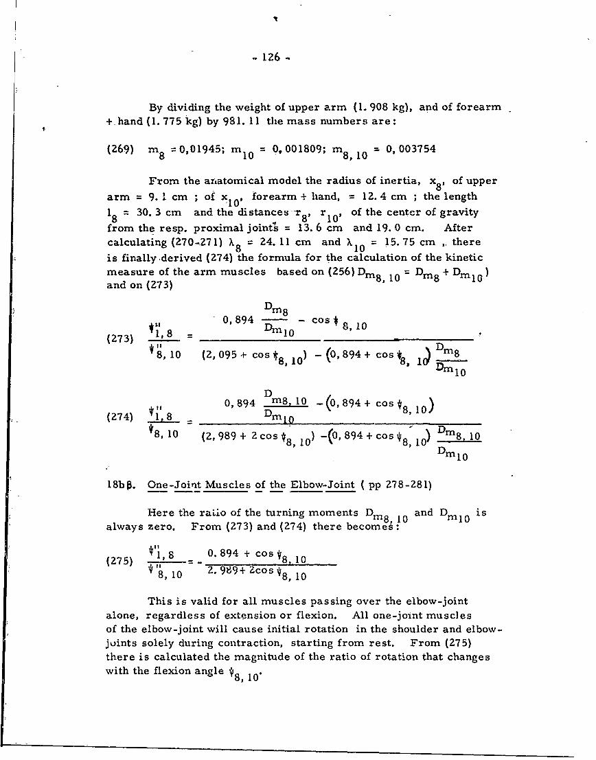
M126
By dividing the weight of upper arm (1. 908 kg), and of forearm+ hand (1. 775 kg) by 981. 11 the mass numbers are:
(269) m 8 =0,01945; m 1 0 = 0,001809; m8,10 = 0,003754
From the antatomical model the radius of inertia, x8 , of upper
arm = 9. 1 cm ; of xl0 , forearm + hand, = 12. 4 cm ; the length18 = 30. 3 cm and the distances-r 8, r1 0 , of the center of gravity
from the resp. proximal joints = 13. 6 cm and 19. 0 cm. Aftercalculating (270-271) X8 = 24. 11 cm and X10 = 15.75 cm , there
is finally ,derived (274) the formula for the calculation of the kineticmeasure of the arm muscles based on (256) Dm8 10 Dm 8 + Dml0)and on (Z73)
L, 0,894 Din8 cos * 8,10
(273) 18 Dm 0* 8,10 (2, 095 + cos8,10) -(0, 894 + cos*8 I Din8
D
0,894 m8, 10 (0,894 + cos *8 , 1 0 )(274) 1, D DM10
*8, 10 (2, 989 + 2 cos 8, 10 -(0, 894 + cos * 8, 10) D in 8 10
Dm 0
18b. One-Joint Muscles of the Elbow-Joint ( pp 278-281)
Here the raLio of the turning moments Di8, 10 and DMl0 is
always zero. From (273) and (274) there becomes:
its8 0. 894 + c os 8
(275) s *8. 10*"8, 10 Z. 989+ Zcos t8, 10
This is valid for all muscles passing over the elbow-jointalone, regardless of extension or flexion. All one-joint musc]esof the elbow-joint will cause initial rotation in the shoulder and elbow-joints solely during contraction, starting from rest. From (275)there is calculated the magnitude of the ratio of rotation that changeswith the flexion angle y8,
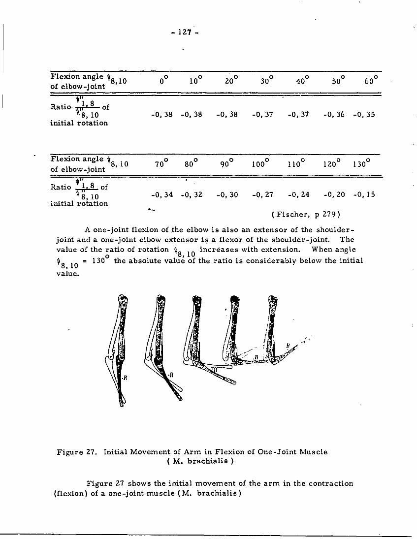
- 127 -
Flexion angle 48,l0 00 100 200 300 400 500 600
of elbow-joint
Ratio t of8,10 -0, 38 -0, 38 -0, 38 -0, 37 -0, 37 -0, 36 -0, 35
initial rotation
Flexion angle 8, 10 700 800 900 00 110 120 130of elbow-joint
Ratio of8,10 -0,34 -0,32 -0,30 -0,27 -0,24 -0,20 -0, 15
initial rotation
(-Fischer, p 279)
A one-joint flexion of the elbow is also an extensor of the shoulder-joint and a one-joint elbow extensor is a flexor of the shoulder-joint. Thevalue of the ratio of rotation *8, 10 increases with extension. When angle
48, = 1300 the absolute value of the ratio is considerably below the initial
value.
If.
Figure 27. Initial Movement of Arm in Flexion of One-Joint Muscle( M. brachialis )
Figure 27 shows the initial movement of the arm in the contraction(flexion) of a one-joint muscle (M. brachialis)
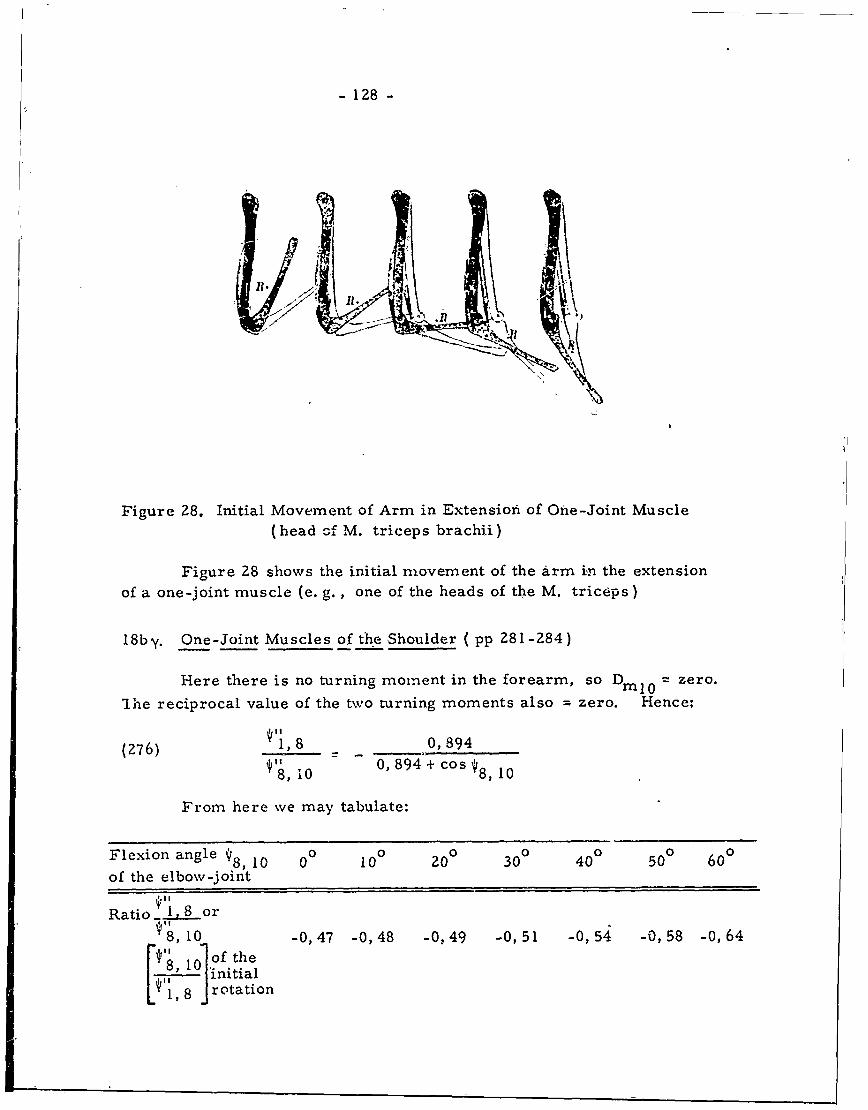
- 128 -
g,,
Figure 28. Initial Movement of Arm in -Extension of One-Joint Muscle(head of M. triceps brachii)
Figure 28 shows the initial movement of the arm in the extension
of a one-joint muscle (e. g., one of the heads of the M. triceps)
18by. One-Joint Muscles of the Shoulder ( pp 281-284)
Here there is no turning moment in the forearm, so Dml0 = zero.
"Ihe reciprocal value of the two turning moments also = zero. Hence;
(276) V1 , 8 - - 0,894
10 0, 894 + cos '8, 10
From here we may tabulate:
Flexion angle V8, 10 00 10 200 300 400 500 600
of the elbow-joint
Ratio 1, 8 or10 -0,47 -0,48 -0.49 -0,51 -0,54 -0,58 -0,64
["8 i0 o f t h e
11 J initial1, 8 rotation
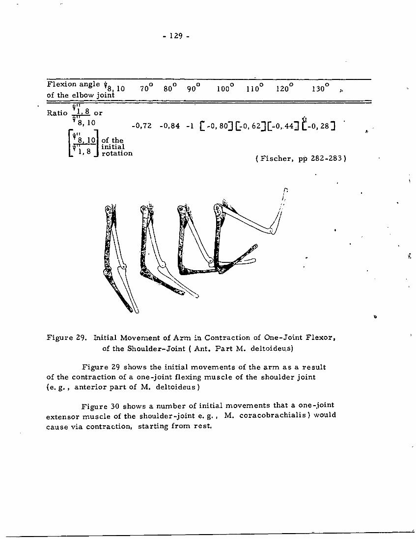
- 129 -
Flexion angle *8, 10 70 ° 80 ° 900 1000 1100 1200 1300
of the elbow joint
Ratio ,80or
8, 10 -0,72 -0,84 -1 [-O, 803[-0, 623[-0,A44j -0, 28]
E', 10] of the8 initial
0 rotation (Fischer, pp 282-283)
p
[! ,.
Figure 29. Initial Movement of Arm in Contraction of One-Joint Flexor,
of the Shoulder-Joint ( Ant. Part M. deltoideus)
Figure Z9 shows the initial movements of the arm as a resultof the contraction of a one-joint flexing muscle of the shoulder joint
(e. g., anterior part of M. deltoideus)
Figure 30 shows a number of initial movements that a one-joint
extensor muscle of the shoulder-joint e. g. , M. coracobrachialis) would
cause via contraction, starting from rest.
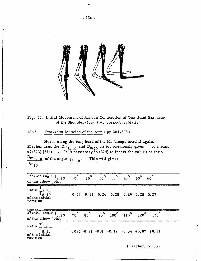
- 130 -
Fig. 30. Initial Movement of Arm in Contraction of One-Joint Extensorof the Shoulder-Joint (M. coracobrachialis)
18b 6. Two-Joint Muscles of the Arm ( pp 284-288)
Here, using the long head of the M. biceps brachii again,Fischer uses the Dm8, 10 and Dml 0 ratios previously given by meansof (273) (274) It is necessary in (274) to insert the values of ratio
Dm8 10 of the angle *8, 10" This will give:Dm8,1
Flexion angle * 8 10 00 100 200 300 400 500 600
of the elbow-joint
Ratio ,1 8*1, 10 -0, 09 -0, 21 -0, 26 -0, 28 -0, 29 -0, 28 -0, 7
of the initialrotation
Flexion angle * 8, 10 700 800 90° 100 ° 110 0 120 130 °
of the elbow-joint
Ratio 1 88,10 -, 0Z5 -0,21 -018 -0,12 -0,04 +0,07 +0,21
of the initialrotation
(Fischer, p 285)
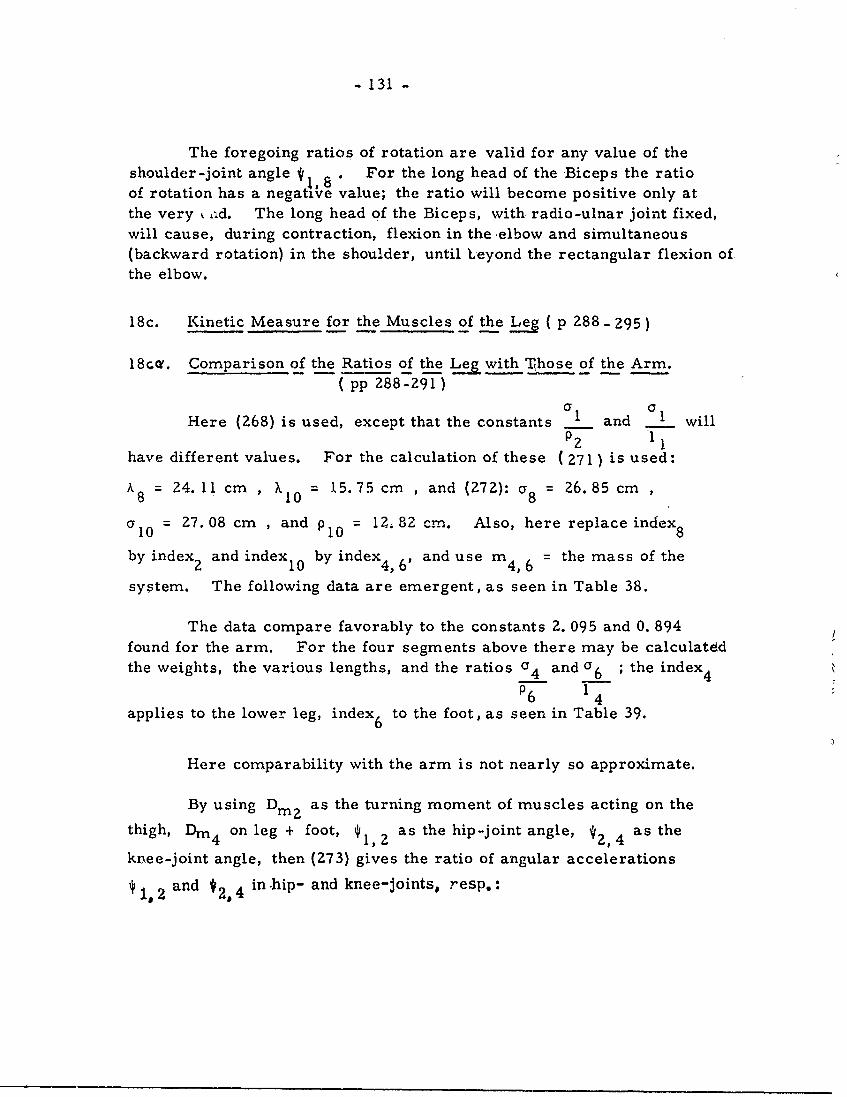
- 131 -
The foregoing ratios of rotation are valid for any value of theshoulder-joint angle ., * For the long head of the Biceps the ratioof rotation has a negative value; the ratio will become positive only atthe very t Aid. The long head of the Biceps, with radio-ulnar joint fixed,will cause, during contraction, flexion in the elbow and simultaneous
(backward rotation) in the shoulder, until Leyond the rectangular flexion ofthe elbow.
18c. Kinetic Measure for the Muscles of the Leg ( p 288 .- 295)
18cc. Comparison of the Ratios of the Leg with Those of the Arm.( pp 288-291 )
Here (268) is used, except that the constants 1 and a willP2 11
have different values. For the calculation of these ( 271 ) is used:
A8 = 24. 11 cm, X10 = 15.75 cm , and (272): a8 = 26.85 cm
a 10 = 27.08 cm , and p 10 = 12, 82 cm. Also, here replace index 8
by index 2 and index 1 0 by index4, 6' and use m4, 6 = the mass of the
system. The following data are emergent, as seen in Table 38.
The data compare favorably to the constants 2. 095 and 0. 894found for the arm. For the four segments above there may be calculated
the weights, the various lengths, and the ratios c 4 and Y6 ; the index
6 14applies to the lower leg, index 6 to the foot, as seen in Table 39.
Here comparability with the arm is not nearly so approximate.
By using Di2 as the turning moment of muscles acting on the
thigh, Din4 on leg + foot, * I 2 as the hip-joint angle, *2,4 as the
knee-joint angle, then (273) gives the ratio of angular accelerations
, 1 2 and #2, 4 in hip- and knee-joints, resp.:
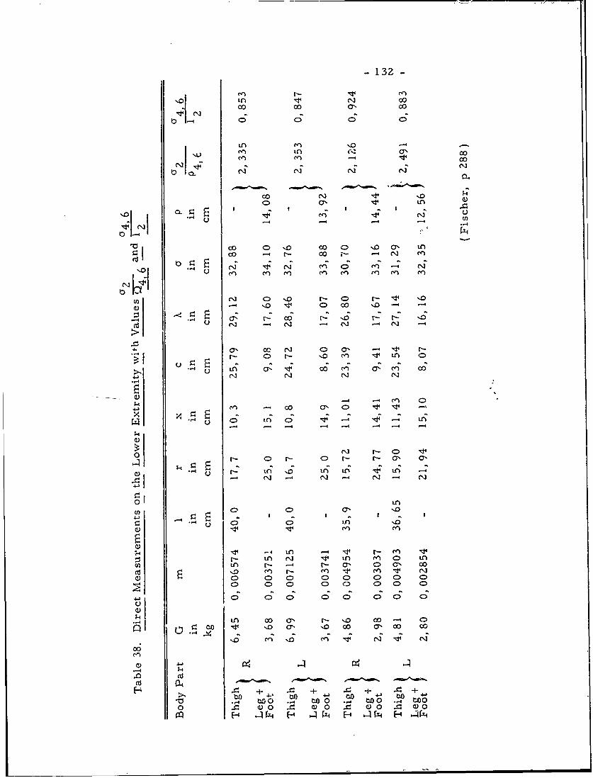
-132-
cc cc '.c
cn I.4 0 00
LA -4
00 cc 0 '0 00c o '00a% LA
C) - o r- C> r'- 11 L
UD C> 0 0 N 0 ND -- 4 '
a) - 0uo c ' -4
.) r- C- N o rn n C>-
N ~ c C)N)0LA ~ ' L
-- 4 --
LA. C- cc a'44~o C I C) r- r- a, a,
- -A - -4 -4 4 -
a)O
01 IA
) C; C) ''
inCi iq) n ) L(n LA rI- a, N> L 00
N C A Nl C> C A L C) CD C
0 C0 CD 0D 0 0 0 C)
0 C) 0 C; 0 0
00 01 o 0 0 C 7) 00 0
06c ' 0 cc - C
.0
P4 ~ + ~ +~
.'-4 t)o 0 -4 to 0 -4.. to0 rq -4 U0
0 C0 .1 4) 0~ C0 4 a0
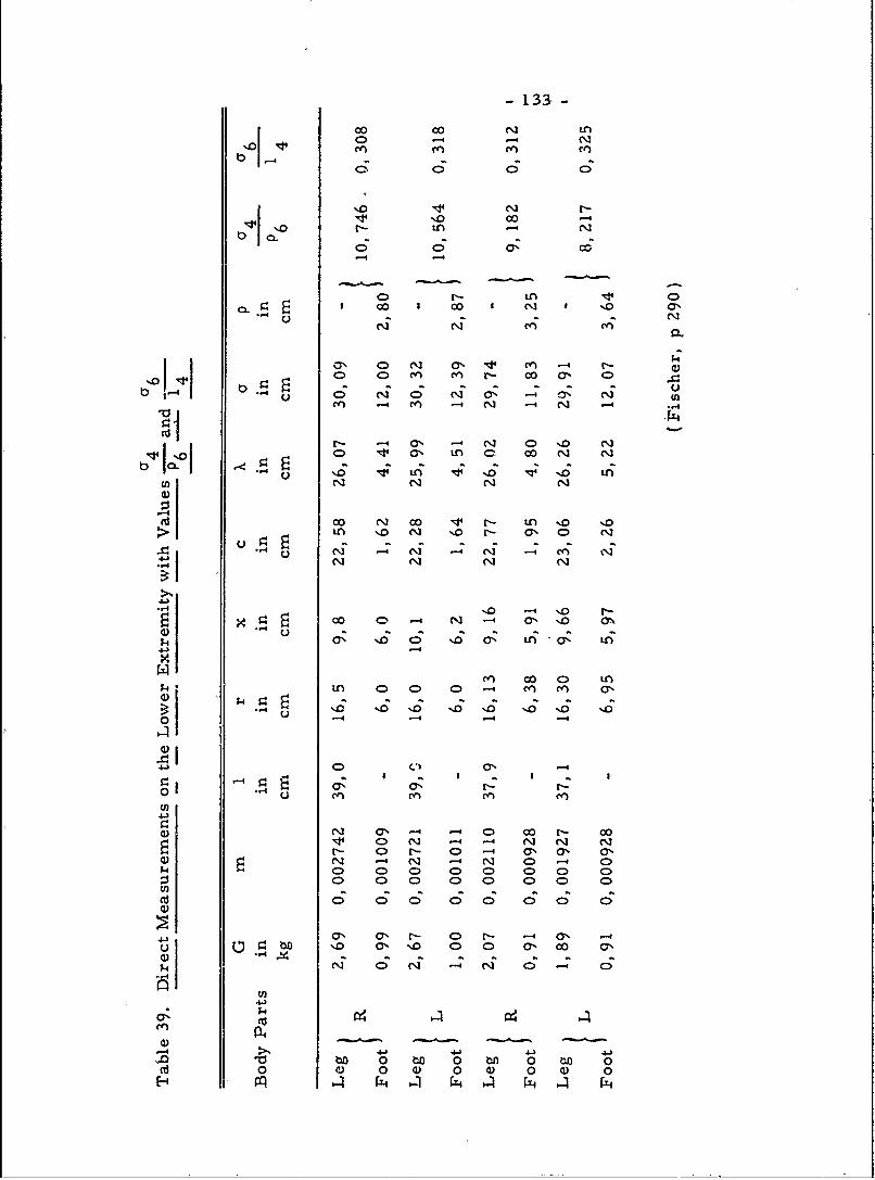
-133-
.'oj.14 0 1- --4 C
% 0 0 -0
r- tA-
CL C; C I '0a
oo 00 N~ 0"~LA -
0 o N n 0 n r- co a, a'r4 CD4 LA i - , N -4 N -I ~~n -4 a'- N0'.
0 y4 a LA C co N~ N
u '.0 v LA %4'0 ~ '0 LAN N N
o N CO 0" N%0 '.0N
LA '. '.0 Nr a' 0 N
on No -4 N tN A N
V~. -> 00 0 r 0CO 0 M~ -4 a' N. a'
0'. r-0 '0 a' A a, LAN
Co ~ ~ CO 0 LAC > CLA 0> 0) 0 4 LA LA Co
U)
47% 0 r- C)-'-4 0 -
4.4)
0 0 0o 0 0 0 0o 00 ~ 0 0) 0 01 0 0) 0
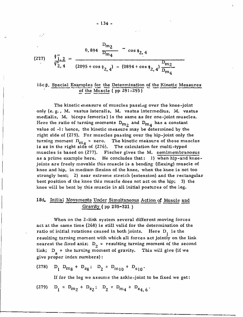
- 134 -
0,894 DCos - , 4
( '2 7) = 7) D iz,4 (2095 + cos * ) - (0894+ os 2 , 4) D m 4
ic . Special Examples fox the Determination of the Kinetic Measuresof the Muscle ( pp 291-295)
The kinetic -measure of muscles passihig over the knee-jointonly (e. g., M. vastus lateralis, M. vastus intermedius, M. vastusmedialis, M. biceps femoris) is the same as for one-joint muscles.Here the ratio of turning moments Dm and Dim4 has a constant
value of -1: hence, the kinetic measure may be determined by theright side of (275). For muscles passing over the hip-joint only theturning moment Din4 = zero. The kinetic measure of these musclesis as in the right side of (Z76). The calculation for multi-typedmuscles is based on (277). Fischer gives the M. semimembranosusas a prime example here. He concludes that: 1) when hip-and knee-joints are freely movable this muscle is a bending (flexing) muscle ofknee and hip, in medium flexion of the knee, when the knee is not toostrongly bent; 2) near extreme stretch (extension) and the rectangularbent position of the knee this muscle does not act on the hip; 3) theknee will be bent by this muscle in all initial postures of the leg.
18d. Initial Movements Under Simultaneous Action of Muscle andGravity ( pp 295-321 )
When on the 2-link system several different moving forcesact at the same time (268) is still valid for the determination of theratio of initial rotations caused in both joints. Here D 1 is the
resulting turning moment with which all forces act jointly on the linknearest the fixed axis; DZ = resulting turning moment of the second
link; D = the turning moment of gravity. This will give (if we5
give proper index numbers):(278) D 1 Din8 + Ds8; D2 : DM1 0 + DSIC
If for the leg we assume the ankle-joint to be fixed we get:
(279) D = Dmz + Dsz; D2 = Din4 + Ds4,6
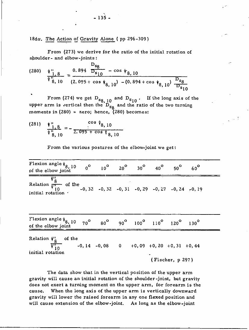
- 135 -
18da. .The Action of Gravity Alone (pp 296-309)
From (273) we derive for the ratio of the initial rotation ofs%.houlder- and elbow-joints:
(280) " = 0.894 fr - cos i8, 10
8, 10 (2. 095 + cos 8, O -(0. 894 + cos D8 sO)
From (274) we get Ds8 10 and D . If the long axis of theupper arm is vertical then the Ds8 and the ratio of the two turning
moments in (280) = zero; hence, (280) becomes:
(281) ! =_ cos 8, 10, 0 2.095 + cos *8, 10
From the various postures of the elbow-joint we get:
Flexion angle *8, 10 00 100 200 300 400 500 00
of the elbow joint
Relation v-of the10 -0, 32 -0, 32 -0, 31 -0, 29 -0,1:7 -0, 24 .0, 19
initial rotation '
Flexion angle */8, 1 0 700 800 900 1000 1100 1200 1300
of the elbow joint
Relation of the
T -0, 14 -0,08 0 +0,09 +0,20 +0,31 +0,44
initial rotation
(Fischer, p 297)
The data show that in the vertical position of the upper armgravity will cause an initial rotation of the shoulder-joint, but gravitydoes not exert a turning moment on the upper arm, for forearm is thecause. When the long axis of the upper arm is vertically downwardgravity will lower the raised forearm in any one flexed position andwill cause extension of the elbow-joint. As long as the elbow-joint
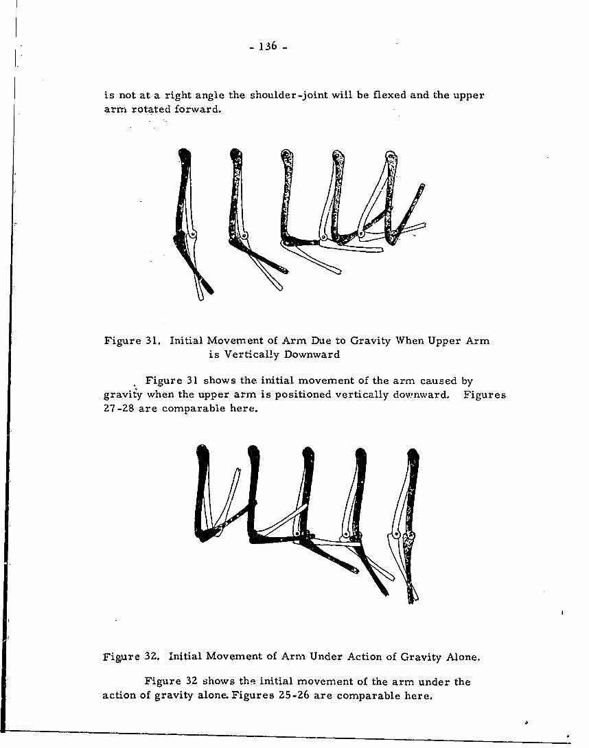
- 136 =
is not at a right angle the shoulder-joint will be flexed and the upperarm rotated forward.
Figure 31. Initial Movement of Arm Due to Gravity When Upper Armis Vertically Downward
Figure 31 shows the initial movement of the arm caused bygravity when the upper arm is positioned vertically downward. Figures27-28 are comparable here.
Figare 32. Initial Movement of Arm Under Action of Gravity Alone.
Figure 32 shows th- initial movement of the arm under the
action of gravity alone. Figures 25-26 are comparable here.
. . . . .. .. .
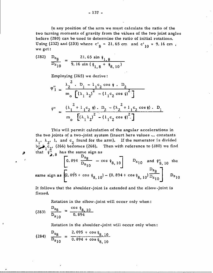
- 137 -
In any position of the arm we must calculate the ratio of thetwo turning moments of gravity from the values of the two joint anglesbefore (280) can be used to determine the ratio of initial rotations.Using (232) and (233) where c'8 = 21. 65 cm and c' = 9. 16 cm~10'we get:
(282) Ds 8 21. 65 sin * 8
D5 l 0 9. 16 sin(4l 8 +
Employing (265) we derive:
2X . DI -lC cos D 2
2 2m [ (Xl X2 ) 2 (lIC 2 Cos)3
(X1 + 1 1C2 *). D 2 - (-X2 + 1 c2 cos) . 1m [(4 1 X2 )2 Z(1 ]cs)o 1 -0( 1 C2 Cos )
This will permit calculation of the angular accelerations inthe two joints of a two-joint system (insert here values __ constantsXl1 X2' 1, and c 2 found for the arm). If the numerator is divided
b il C2 , (266) bedomes (268). Then with reference to (280) we find
that 0/" has the same sign as
,0. 8 9 4 D s l0 - cos 08, 10 DsIO and 10 the
same sign as .095 + cos 18, 10) - (0. 894 + cos *8, 10) D s0- Dsl 0
It follows that the shoulder-joint is extended and the eibow-joint isflexed.
Rotation in the elbow-joint will occur only when:
(83s = 10Ds2 0.894
Rotation in the shoulder-joint will occur only when:
Ds8 Z. 095 + cos 8, 0(s _80 0. 894 + cos '18, 10
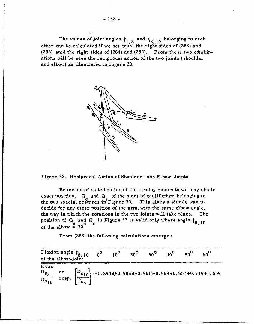
- 138 -
The values of joint angles l 8 and belonging to each1,8 8,1I0,other can be calculated if we set equal the right sides of (283) and(282) amd the right sides of (284) and (282). From these two, coinbin-ations will be seen the reciprocal action of the two joints (shoulderand elbow) as illustrated in Figure 33.
Figure 33. Reciprocal Action of Shoulder- and Elbow-Joints
By means of stated ratios of the turning moments we may obtainexact position, Q and Q of the point of equilibrium belonging toethe two special postures inSFigure 33. This gives a simple way todecide for any other position of the arm, with the same elbow angle,the way in which the rotations in the two joints will take place. Theposition of Q and Q in Figure 33 is valid only where angle_10
poito of e o 10of the elbow = 30
From (283) the following calculations emerge:
Flexion angle '8, 10 00 100 20 ° 30 ° 40 ° 500 60 °
of the elbow-jointRatio
D8 s.. or F Ds 101 (+0, 894)(+0, 908)(+0, 951)+0, 969+0,857+0, 719+0, 559
DS0resp. [Ds,
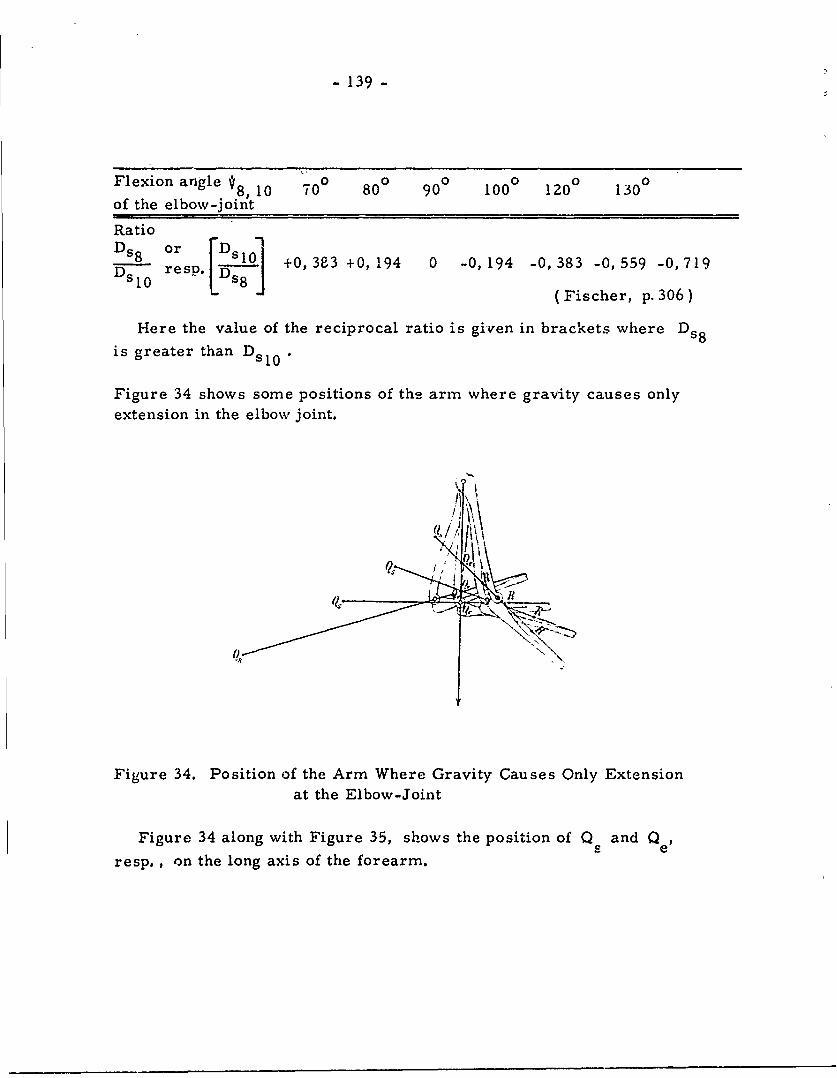
- 139 -
Flexion angle 8, 10 700 80 ° 90 100 120 130 °
of the elbow-joint
Ratio- _l0 +0,383 +0, 194 0 -0, 194 -0, 383 -0, 559 -0, 719resp'D
(Fischer, p.30 6 )
Here the value of the reciprocal ratio is given in brackets where Ds8
is greater than D s 0 *
Figure 34 shows some positions of the arm where gravity causes onlyextension in the elbow joint.
Figure 34. Position of the Arm Where Gravity Causes Only Extensionat the Elbow-Joint
Figure 34 along with Figure 35, shows the position of Q and Q eSneresp., on the long axis of the forearm.
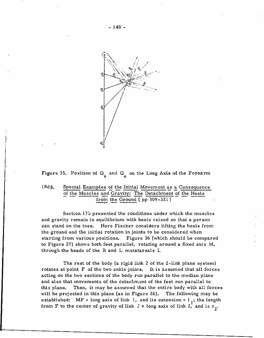
- 140 -
(9N
Figure 35. Position of Q and Q on the Long Axis of the Forearms e
18d 8 . Special Examples of the Initial Movement as a Consequenceof the Muscles and Gravity: The Detachment of the Heels
fro, the Ground ( pp 309-321)
Section 17b presented the conditions under which the musclesand gravity remain in equilibrium with heels raised so that a personcan stand on the toes. Here Fischer considers lifting the heels fromthe ground and the initial rotation in joints to be considered whenstarting from various positions. Figure 36 (which should be comparedto Figure 27) shows both feet parallel, rotating around a fixed axis M,through the heads of the R and L metatarsals I.
The rest of the body (a rigid link 2 of the 2-link plane system)rotates at point F of the two ankle joints. It is assumed that all forcesacting on the two sections of the body run parallel to the median planeand also that movements of the detach. ment of the feet run parallel tothis plane. Then, it may be assumed that the entire body with all forceswill be projected in this plane (as in Figure 26). The following may beestablished: MF = long axis of link I, and its extension = I I; the lengthfrom F to the center of gravity of link 2 = long axis of link 2, and is r .
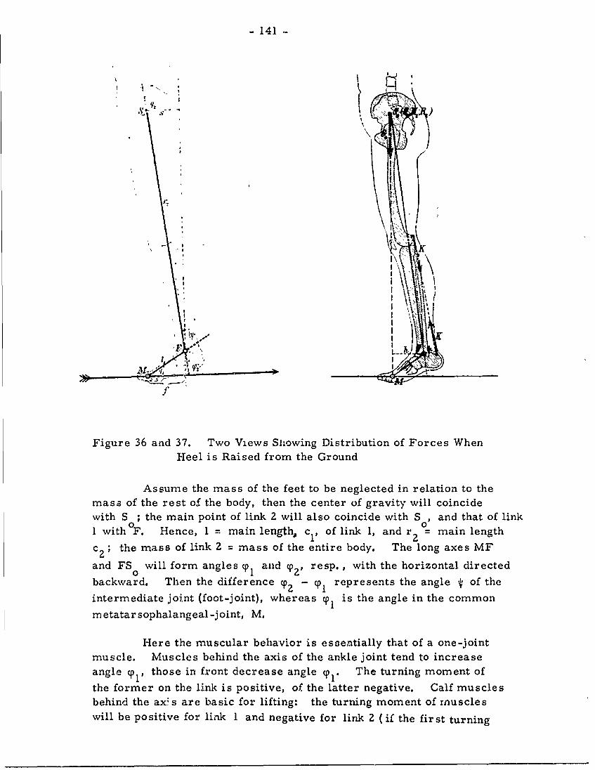
- 141
+ , . .I "- J
'I \'iI! LI
Fiur 36ad3. Tw iwI1iwn itibto fFrsWe
Hee is RasdfoteGon
mas ofters ftebdte h etrorvty wilcicd
* ' '-'I ' \II
Fgr36ad. Tw iw wn itiuino ocsWe
with S ; the main point of link 2 will also coincide with S ,and that of link1 with OF. Hence, 1 = main length, c1 , of link 1, and r 2 ~=main length
c 2 ; the mass of link 2 =mass of the entire body. The long axes MF
and FS 0will form angles cpl anid y., resp. , with the horizontal directed
0i
backward. Then the difference y.2 - y, represents the angle * of the
intermediate joint (foot-joint), whereas cp, is the angle in the common
m etatarsophalangeal-joint, M.
Here the muscular behavior is essenitially that of a one-jointmuscle. Muscles behind the axis of the ankle joint tend to increaseangle cp, those in front decrease angle cp'. The turning moment of
the former on the link is positive, of the latter negative. Calf musclesbehind the axs are basic for lifting: the turning moment of muscleswill be positive for link 1 and negative for link 2 (if the first turning
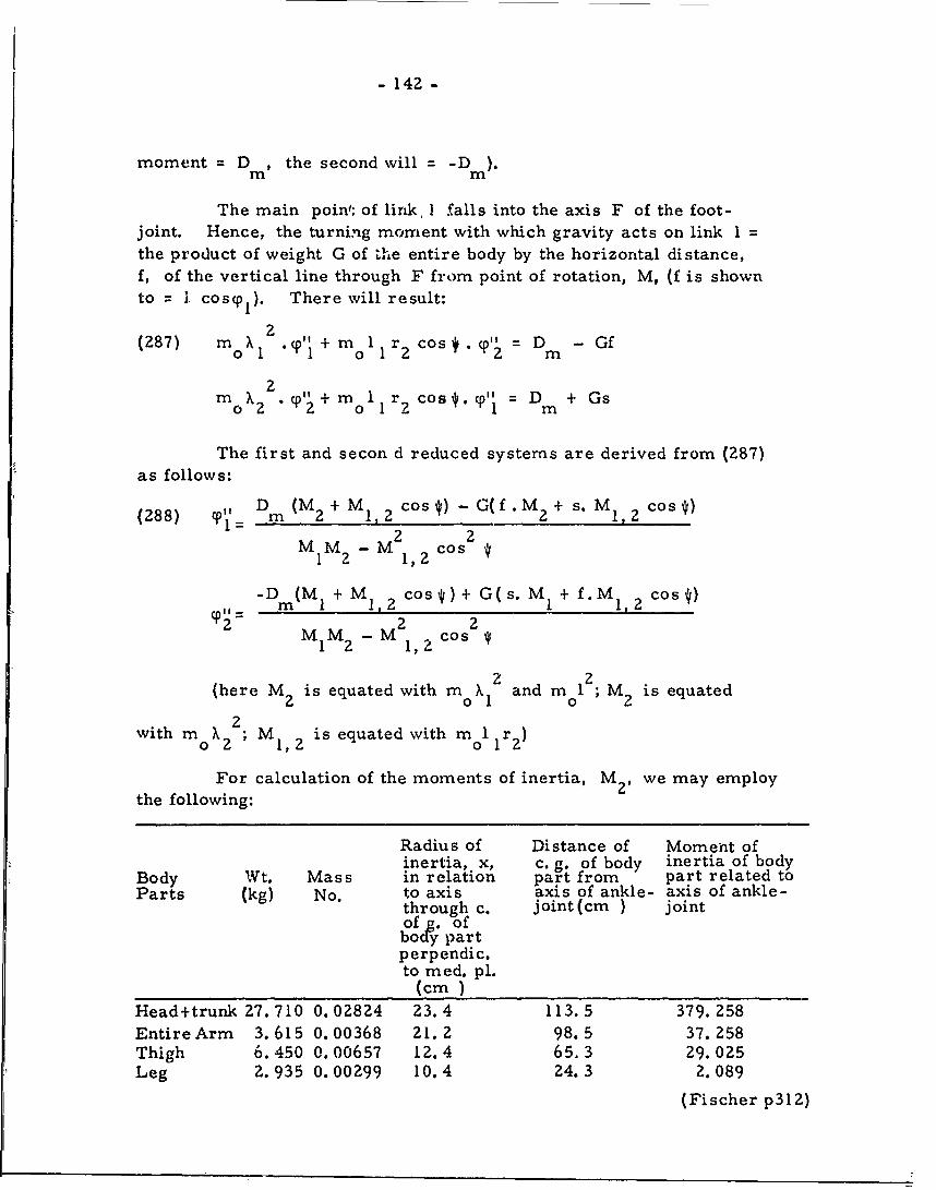
- 142 -
moment = D m , the second will = -Dn).
The main poin'; of link, I falls into the axis F of the foot-joint. Hence, the turning morment with which gravity acts on link I =
the product of weight G of the entire body by the horizontal distance,f, of the vertical line through F from point of rotation, M, (f is shownto = 1 cos0 1 ). There will result:
2(287) m+ " I +mol 1 r2 Cos cp' D - Gf
2m X2 "+ m 1 r cos." = D + Gs
o 2 o 1 "1 m
The first and secon d reduced systems are derived from (287)
as follows:
(288) Dm (M 2 + M1 ,2 cos*) - G(f.M 2 + S. M1,2 cos)
M1M2 -M 2 21,2 cos *
D -Dm(MI + M1 , 2 cos*)+ G(s. MI+ f.M 1 ,2 cos)
S M 2 M , 2
(here M2 is equated with mo X12 and mo 12 ; M2 is equated
with m X 2 ; MI,2 is equated with mo 1wi 2 1,22
For calculation of the moments of inertia, M 2 , we may employ
the following:
Radius of Distance of Moment ofinertia, x, c.g. of body inertia of body
Body Wt. Mass in relation part from part related toParts (kg) No. to axis axis of ankle- axis of ankle-
through c. joint(cm ) jointof . ofbody partperpendic.to med. pl.
(cm)Head+trunk 27. 710 0. 02824 23.4 113.5 379. 258
Entire Arm 3.615 0.00368 21. 2 98.5 37. 258Thigh 6. 450 0.00657 12.4 65. 3 29.025Leg 2.935 0.00299 10.4 24.3 2.089
(Fischer p312)
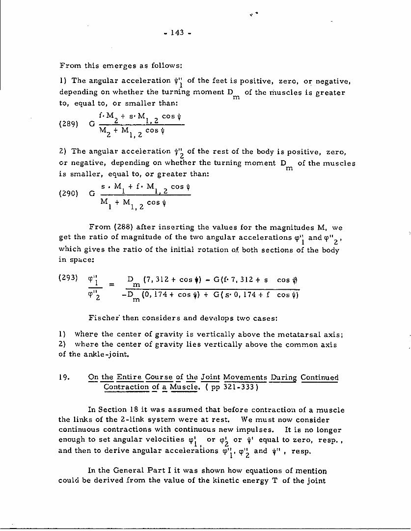
- 143 -
From this emerges as follows:
1) The angular acceleration *' of the feet is positive, zero, or negative,depending on whether the turning moment D of the muscles is greatermto, equal to, or smaller than:
f.M + s.M1, cos 9(289) G 2 1,M2 + M1,2 cos*
2) The angular acceleration 4" of the rest of the body is positive, zero,or negative, depending on whether the turning moment D of the musclesmis smaller, equal to, or greater than:
s . M + f. M. cos(290) G 1 1,2
M1 + M1, Z cos4
From (288) after inserting the values for the magnitudes M, weget the ratio of magnitude of the two angular accelerations %0 and cp",which gives the ratio of the initial rotation o( both sections of the body
in space:
(293) D1 D (7, 312 + cos4) - G(f' 7,312 + s cos
C "z -D (0, 174+ cos4) + G(s'0, 174 + f cos )m
Fischer' then considers and develops two cases:
1) where the center of gravity is vertically above the metatarsal axis;Z) where the center of gravity lies vertically above the common axisof the ankle-joint.
19. On the Entire Course of the Joint Movements J)uring ContinuedContraction of a Muscle. ( pp 321-333)
In Section 18 it was assumed that before contraction of a musclethe links of the 2-link system were at rest. We must now considercontinuous contractions with continuous new impulses. It is no longerenough to set angular velocities %I, or (p2 or ' equal to zero, resp.enough to set~~" anguadeoiie p r~ eqa o" e resp.and then to derive angular accelerations (p', (P' and *11 , resp.
In the General Part I it was shown how equations of mentioncould be derived from the value of the kinetic energy T of the joint
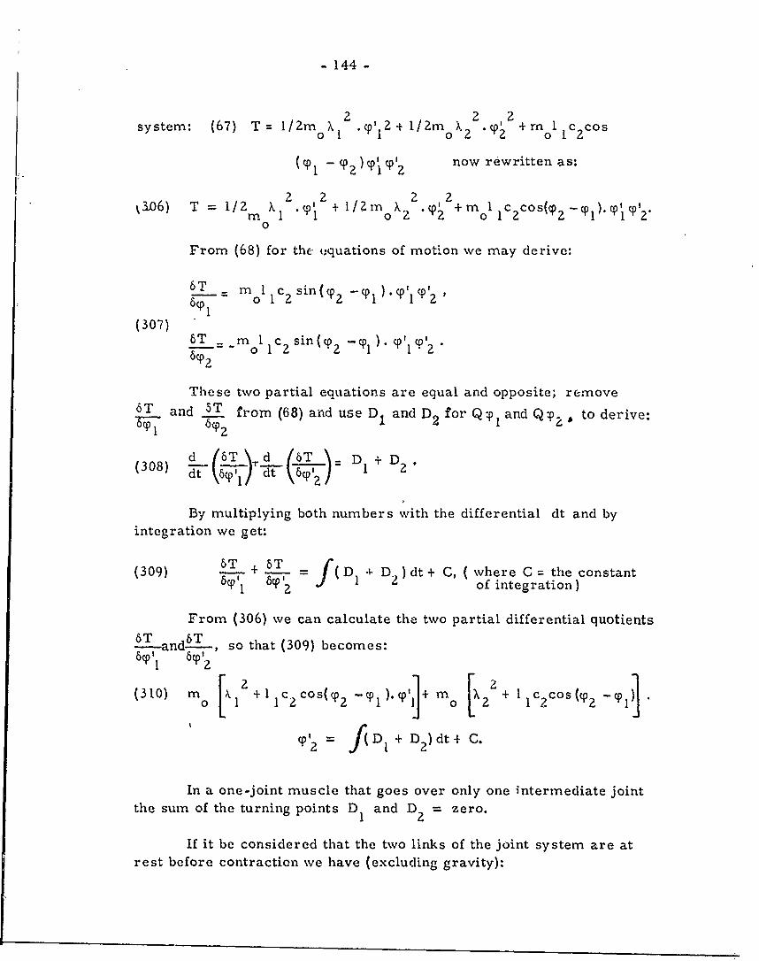
- 144 -
2 2 2system: (67) T = I/2mo X . ' 2 + 1/2mo X2 ."° +mol ICCos
(%01 - %02)PP'2 now rewritten as:
1306) T = 1/2 X T1 + /Zmo "2 1 +ool -%01 ).%01%0' 2 .0
From (68) for the tquations of motion we may derive:
6T -m oI sin (%02-Y0I %0' I'6%01
(307) 6T _m 0 12S in (y 2 -Y° = oP IC T 1%0'26T.2
These two partial equations are equal and opposite; remove6T and 5T from (68) and use D and D2 for Q:Pl and Qzp, to derive:
d 16T \ l-d 16T D +D(308) d-\)'d ( D+D
By multiplying both numbers with the differential dt and byintegration we get:
(309) -- .- + ( D 4 D )dt + C, ( where C = the constant6CP by 2 Jf 1 2of integration)
From (306) we can calculate the two partial differential quotientsT 6T
-and-, so that (309) becomes:
( 3 1 0 ) n 2k 1 [0 1 c2 cos((P2 .P + I )' (c s
C'2 = )(DI + D)dt+ C.
In a one-joint muscle that goes over only one intermediate jointthe sum of the turning points D and D2 = zero.
If it be considered that the two links of the joint system are atrest before contraction we have (excluding gravity):
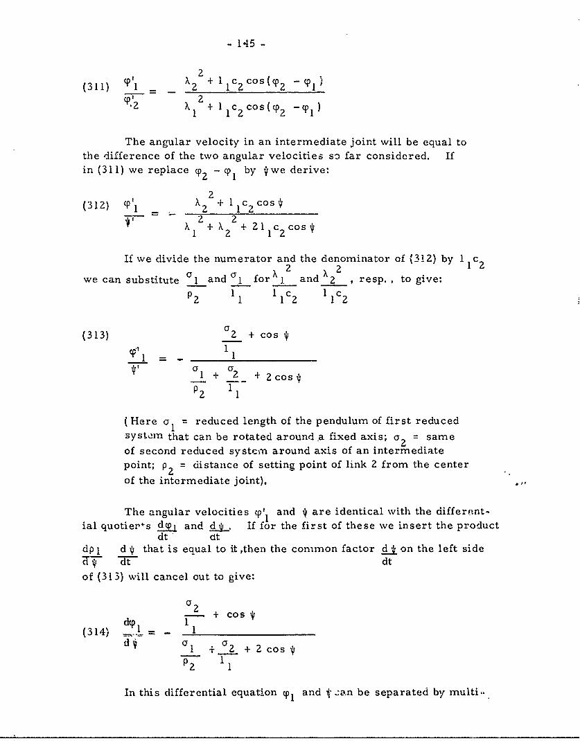
- 145 -
2(311) CPI _, 2 + IlC 2Cos (T2 - 1 )
X +1 cos1 1~ c~ (° -cp 1 )
The angular velocity in an intermediate joint will be equal tothe difference of the two angular velocities so far considered. Ifin (311) we replace cP - cpl by *we derive:
2
(312) ( l + 1 2C os2 22
1I +X + 211 c 2cos
If we divide the numerator and the denominator of (312) by 1 1 c2a 2
we can substitute a1 and 0l for and 2 , resp. , to give:
P2 1 1 1 c2 1 c2
(313) 02 + cos
11 1-+ a?-- +1 + 2cos
(Here 01 = reduced length of the pendulum of first reducedsystem that can be rotated around a fixed axis; a2 = same
of second reduced system around axis of an intermediatepoint; p 2 = distance of setting point of link 2 from the center
of the intermediate joint).
The angular velocities c0' and * are identical with the different-ial quotier+s 4ajP and d I If for the first of these we insert the product
dt - dtdp I d that is equal to it ,then the common factor d" on the left sided-td dt
of (313) will cancel out to give:
)-- + cos(314) 11d aI + C 2 + Z cos
In this differential equation q01 and 1' .:an be separated by multi-
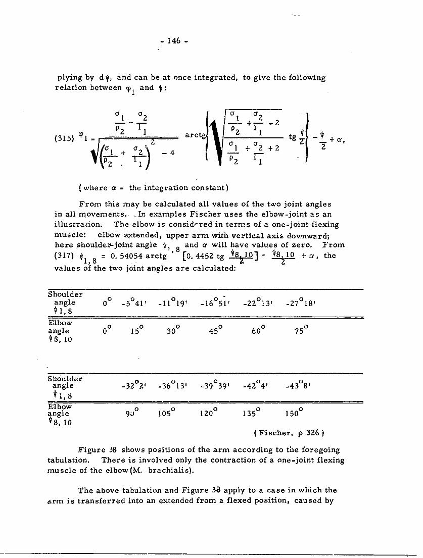
- 146 -
plying by d-*, and can be at once integrated, to give the followingrelation between y0 and J:
1 a I a a2_ 1~ -+---2_____ _1 ___ _ p2 1 t 1 _
(315) l = P, 1 - ara ._ + -+ ,I + 2 +2
(where a = the integration constant)
From this may be calculated all values of the two joint anglesin all movements.. __Ln examples Fischer uses the elbow-joint as anillustration. The elbow is considrred in terms of a one-joint flexingmuscle: elbow extended, upper arm with vertical axis downward;here shouldez-joint angle *1 8 and a will have values of zero. From(317) *1 8 = 0.54054 arctg ' [0. 4452 tg *8t10] - *8 10 +a, the
values of the two joint angles are calculated:
Shoulder0 00 0 0angle 00 _5°41 -11 19' -16051' -22 13' -27 18'
41,8Elbowangle 0 15 30 45 600 75*8, 10
Shoulderangle -32 2' -36 13' -39 39' -42 4' -43 8'* 1,8
Elbow 0 0 0 0angle 90° 105 120 135 150*8, 10
(Fischer, p 326)
Figure 38 shows positions of the arm according to the foregoingtabulation. There is involved only the contraction of a one-joint flexingmuscle of the elbow(M, brachialis).
The above tabulation and Figure 38 apply to a case in which thearm is transferred into an extended from a flexed position, caused by
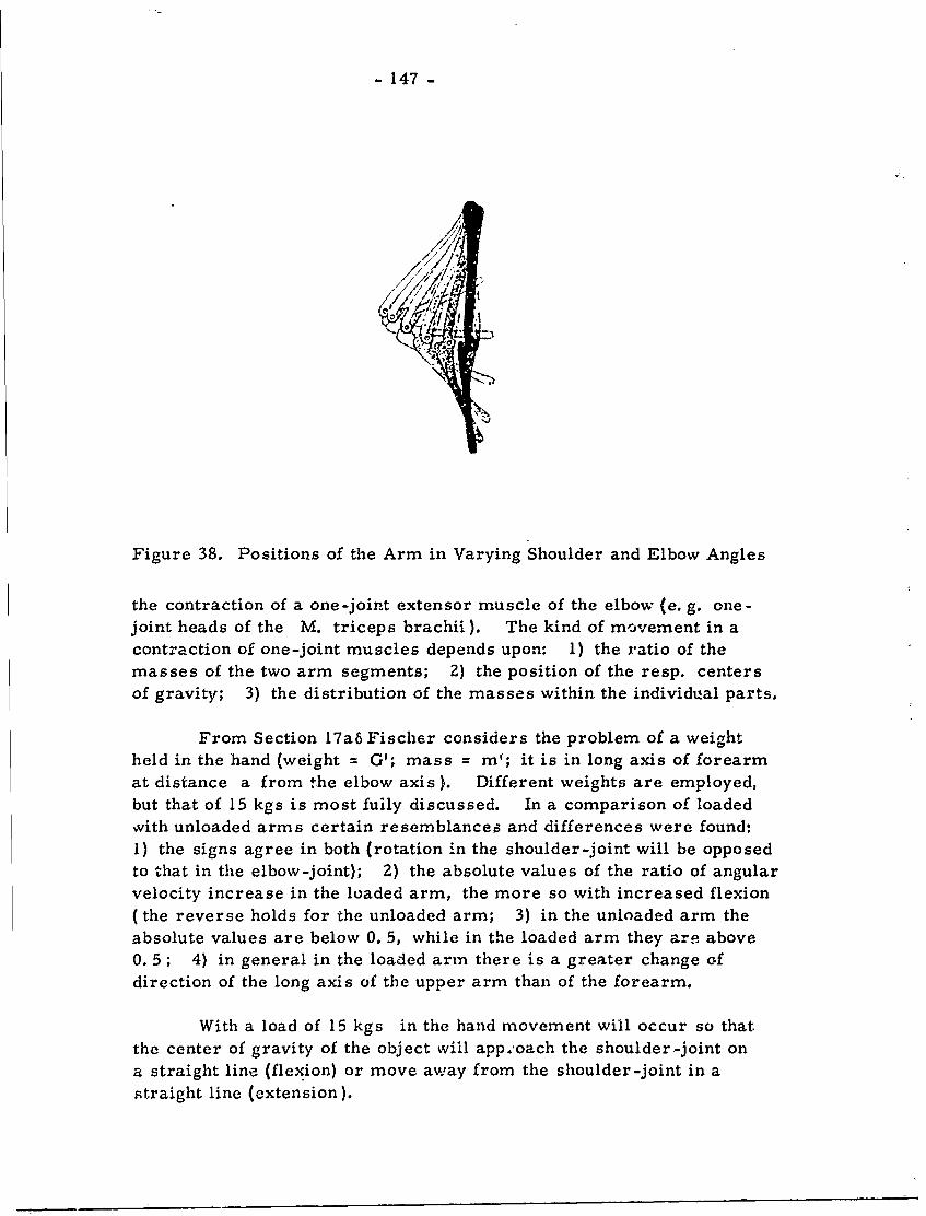
- 147 -
Figure 38. Positions of the Arm in Varying Shoulder and Elbow Angles
the contraction of a one-joint extensor muscle of the elbow (e. g. one-joint heads of the M. triceps brachii). The kind of movement in acontraction of one-joint muscles depends upon: 1) the ratio of themasses of the two arm segments; 2) the position of the resp. centersof gravity; 3) the distribution of the masses within the individual parts.
From Section 17a6 Fischer considers the problem of a weightheld in the hand (weight = G'; mass = m'; it is in long axis of forearm
at distance a from the elbow axis ). Different weights are employed,but that of 15 kgs is most fuily discussed. In a comparison of loadedwith unloaded arms certain resemblances and differences were found:1) the signs agree in both (rotation in the shoulder-joint will be opposedto that in the elbow-joint); 2) the absolute values of the ratio of angularvelocity increase in the loaded arm, the more so with increased flexion(the reverse holds for the unloaded arm; 3) in the unloaded arm theabsolute values are below 0. 5, while in the loaded arm they are above0.5 ; 4) in general in the loaded arm there is a greater change ofdirection of the long axis of the upper arm than of the forearm.
With a load of 15 kgs in the hand movement will occur so thatthe center of gravity of the object will app.'oach the shoulder-joint ona straight line (flexion) or move away from the shoulder-joint in astraight line (extension).
-148-
20. U.e of Equations of Motion for the Determination of the MuscleForces with the Movement of the Human Body Being Known.
(pp 333-348 )
Here will be considered as group 1 of problems the movementof body parts that one muscle, or several, cause under given conditionsduring their contraction (see Secs. 18-19). Group 2 of problems assumesthe state of motion of the human body to be known for the entire course ofa movement; sought are the muscle and muscular forces that effect thismovement, together with ext,rnal forces. In general, locomotion isinvolved.
In a first approximation Fischer considers the oscillations ofthe leg as a plane movement parallel to the median plane: 1) foot ismovable referrable to lower leg at ankle, giving a plane 3-link jointsystem; 2) leg is joined to hip, so the concern is not with the freemobility of the hip. Section 7 applies here (equations of motion), aswell as Section 8 (derivations of such equations).
Fischer here uses the equations of motion as follows: the rota-tion of each one of the three sections of the leg about its axis throughthe center of gravity that is perpendicular to the plane of motion, isrepresented in its dependence upon 1) the turning moment of musclesacting on the leg sections, 2) on gravity, and 3) on effective forcesto be taken in the opposite direction of the associated or attached bodyparts. The following forces for the three sections of the R leg areconsidered: 1) gravity = weight G 2 of thigh, pulling vertically down,at S2 , center of gravity of the thigh (Figure 39); 2) muscles inserting
on the thigh will set up tension forces (point of force of muscle does notalways equal point of insertion). The over-all problem is to dimensionthe intensity and direction of forces that apply to the center of gravityof the thigh in such a way that the pressure + external forces applyingto the entire leg will be able to impart to tle center of gravity of theentire leg just its acceleration present in the respective moment asto magnitude and direction.
The effective force of the entire leg is the force evenly directedwith the acceleration of the total center of gravity of the leg, the inten-sity of which is measured by the product of the mass of the entire leg(mZ, 4, 6) by the acceleration of its center of gravity. Let the mass of
the entire leg equal m 2, 4 6; let the acceleration of S. 4,6 equal
3(2, 4, 6; then the magnitude of the effective force of the entire leg will
be m., 4 , 6 YZ,4, 6
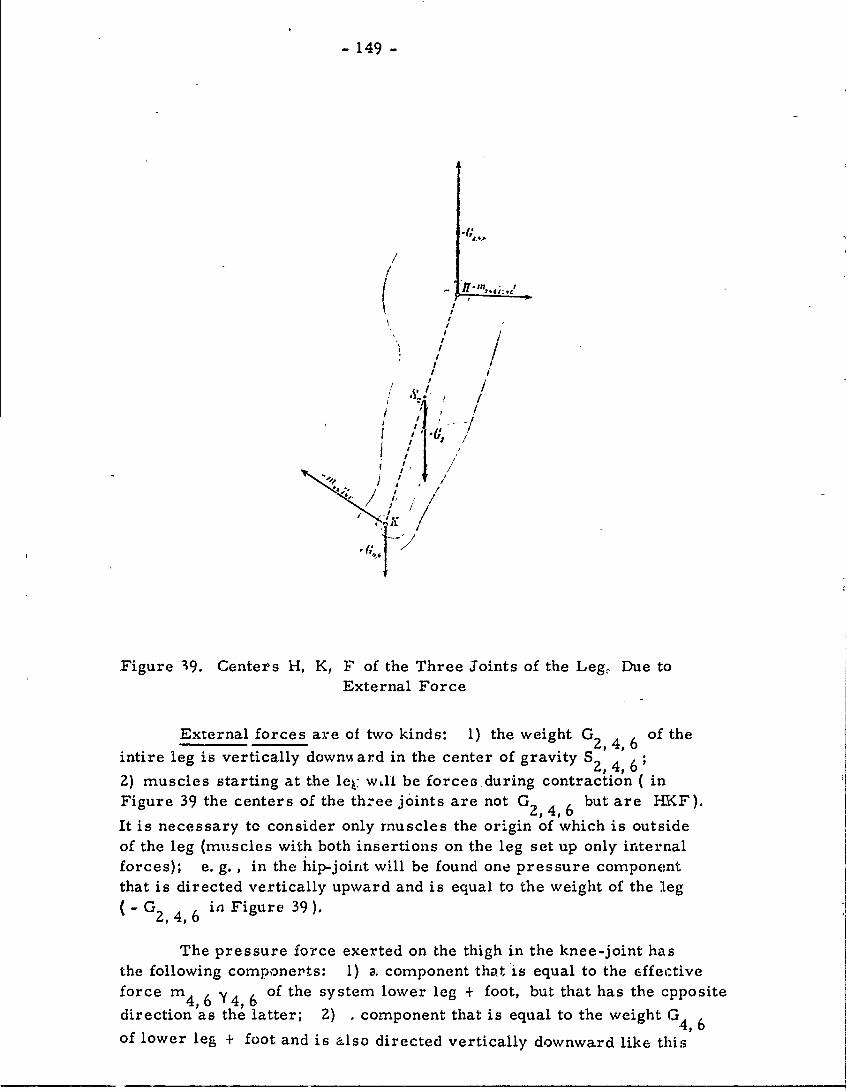
- 149 -
ry o
//
/ I -
I /I I!
/
Figure 39. Centers H, K, F of the Three Joints of the Leg, Due toExternal Force
External forces are of two kinds: 1) the weight G2,4,6 of the
intire leg is vertically downA ard in the center of gravity S2,4, 6 ;2) muscles starting at the le w,11 be forces during contraction ( in
Figure 39 the centers of the th:ee joints are not G2,4,6 but are HKF).
It is necessary to consider only muscles the origin of which is outsideof the leg (muscles with both insertions on the leg set up only internalforces); e. g. , in the hip-joint will be found one pressure componentthat is directed vertically upward and is equal to the weight of the leg(" G2 4, 6 in Figure 39).
The pressure force exerted on the thigh in the knee-joint hasthe following components: 1) a, component that is equal to the effectiveforce m 4,6 Y4_6 of the system lower leg + foot, but that has the cppositeoret t latter; 2) , component that is equal to the weight
direction a ee, 6of lower leg + foot and is also directed vertically downward like this
- 150>-
weight (Figure 39); 3) a number of components that are equal to the
external muscular forces applying directly to lower leg + foot and thathave the same direction as these forces.
Under the above forces the thigh will move as though it were free.
In Figure 39 summed as m 2 y2y , the m = mass, the -2 is the
acceleration of the center of gravity, and their product therefore is theeffective force of the thigh. Two pressure components in the hip, +m 2 , 4 .6 Y2 , 4, 6 and - m 4 , 6 Y4 ,
6 , are in the hip center, H, and knee
center, K, and will give m 2 *2 as a resultant. This .is because the
effective forces m2, 4, 6 Y2,4, 6 of the entire leg are the resultant of
three effective forces, ni 2 , m 2 y 4 , and m6 y6 , of thigh, leg, foot,resp. ; the effective force m4, 6 Y4, 6 of leg + foot is the resultant of
m 4 Y4 , m 6 Y6 . Hence, n 2 , 4, 6 Y2 , 4, 6 plus - m4, 6 Y4,6 will equal
effective force m2 Y2 "
Three forces of weight apply to H 1 , S 2 , and K. It is possible
to combine S2 Kto give G2 4 6, equal-and opposite to -G2,4, 6' The_i , 4,i 1'
point of application of this resultant ia H in Figure 40, which lies on2
the connecting length S 2K and divides this in the inverse proportion ofweight (it is near the center of -gravity of the thigh plus the leg + foot).
The force of weight, + G 2 , 4 61 applied to H2 forms with the
pressure component, - G , a couple of force acting on the thigh in
the sense of rotation, but it cannot accelerate the center of gravity.The moment of this couple represents the turning moment of gravity
exerted on the thigh in the period of oscillation (it is designated Ds2 ).
The muscle forces plus th.e pressure components in the hip and knee
form couples of force in such a way that each muscle has a special
couple of force (each musele has an equal and opposite force). In
muscles with origin and insertion oitside the thigh there will be a couple
of force in the hip-joint, with equal and opposite force in the knee-joint;
these couples of force are different from those with which gravity acts
on the thigh.
In the assumption of plane movement only those components of
muscle couples of force will act, the planes of which are parallel to
the median plane of the body. We must distinguish between couples
of force wvhich rotate the thigh clockwise (negative or -) or counter-
clockwise (positive or + ). The moment for all couples of force from
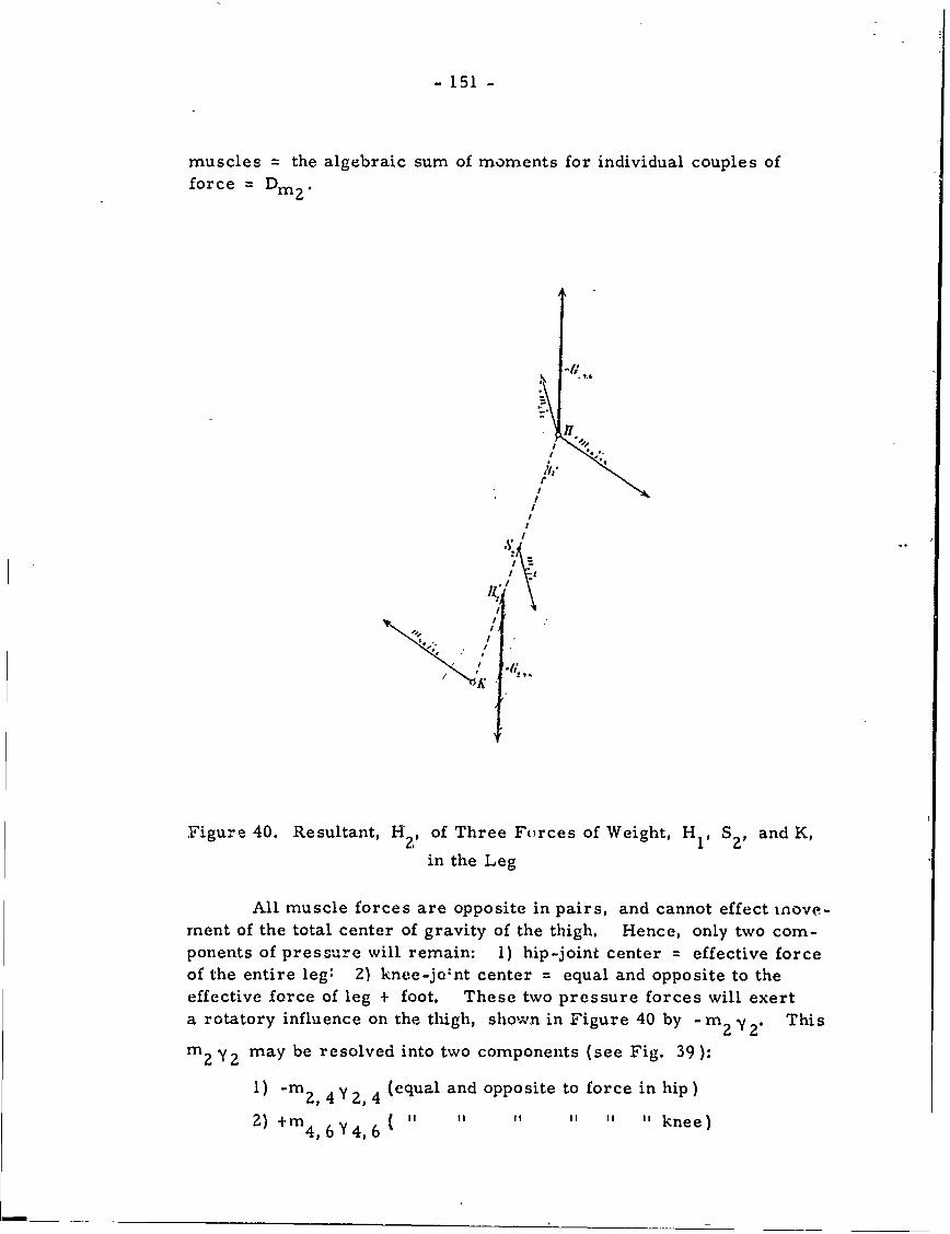
- 151 -
muscles = the algebraic sum of moments for individual couples offorce Din2 .
I.
I
Figure 40. Resultant, H of Three Forces of Weight, H l , SZ, and K,
in the Leg
All muscle forces are opposite in pairs, and cannot effect nove-ment of the total center of gravity of the thigh. Hence, only two com-ponents of pressure will remain: 1) hip-joint center = effective forceof the entire leg: 2) knee-jo'nt center = equal and opposite to theeffective force of leg + foot. These two pressure forces will exerta rotatory influence on the thigh, shown in Figure 40 by -im 2 y 2. This
m 2 Y2 may be resolved into two components (see Fig. 39):
1) -m2, 4 Y 2,4 (equal and opposite to force in hip )
2) +m4, 6 y 4 6 ( ' " " " knee)
- 152 -
This will now give two couples of force:
1) +m 2, 4,6 y 2, 4 6 , - m 2, 4,6 y 2, 4,6
2) +m4,6 Y 4,6 ' " m4,6 Y4 , 6
We can resolve force me2, 4, 6 Y 2, 4, 6 in the hip (Figure 60)
into + m4,6 Y4,6 and + mr2, Y 2 .
In the two couples of force one has two forces:
1) +m4,6 X4,6 and -m4,6 X 4, 6' -tpp'ying to hip and knee-joint centels;
2) +m2 X2 (hip) and -in Xk (thig)- r ,"f gravity, resp. Here =
acceleration of center of gravity I X4,6 = that of leg + foot.
The resultant turning moment of the effective forces for thethigh equals De 2 which is equal to the algebraic sum of moments of twocouples of force under the assumption of plane movement, and wherecounter-clockwise is -, clockwise is +.
Fischer also does for the lower leg what is above outlined forthe thigh. Here Dm 4 equals the turning moment of the muscles of
the lower leg and De 4 equals the algebraic sum of the moments of the twocouples of force. Corresponding values for the foot become Dim6 andDe 6 •
Now designate by y0 'p and y 10 as the angular accelerationsof entire leg, thigh, and leg + foot which will rotate around S., S , S6
in the period of oscillation. Also, x., x4 , x6 are the radii of inertia
in relation to axes through their centers of gravity, perpendicular to theplane of motion (cross axes)(of Sec. 15). There emerges:
(328) mh x h 'Ph = Dmh + Dsh + Deh (Where for the three sections
of the R leg - thigh, leg, foot - the h has valuesof 2, 4, 6, and for L leg values of 3, 5,7).
This formula is the equation of motion of the three sections ofthe leg in a form that is best for muscle forces.
For the four variable quantities cp h, Dmh, Dsh, and Deh three
can be determined empirically for each moment of the oscillatory move-ment. These are: the angular acceleration yh ; the turning moment
of gravity Dsh ; and the resulting turning moment of the effective forcesDeh•
- 153 -
From (328) we can calculate Dmh
2(329) Dmh mhx h cp' - Dsh - Deh
To determine the values that the three magnitudes x1 , Dsh, and
Deh possess in the three various phases of rnovem.ent of the oscillating
leg Fischer says that it is necessary to cbtain an exact kinematic analysis
of the oscillating movement (s) during walking (he refers to studies byFischer and Braune employing photographic analysis). The musclesact on the three sections of the leg with far greater turning moments
than does gravity. The oscillation of the leg in walking is not the mereswinging of a pendulum; again, muscles act more than does gravity.
Fischer concludes that in his muscle studies he has gone from the fieldof kinetics into the field of statics.
B. Some Applications to Processes of
Motion in Machines(pp 349-364)
21. The Resulting Mass Pressure at the Crank Mechanism and ItsBalance ( pp 349-359 )
22. The Motions of a Physical Pendulum with Rotary Bob (pp359-364)
These two Sections are not included in the resume.
DISCLAIMER NOTICE
THIS DOCUMENT IS BEST QUALITYPRACTICABLE. THE COPY FURNISHEDTO DTIC CONTAINED A SIGNIFICANTNUMBER OF PAGES WHICH DO NOTREPRODUCE LEGIBLY.
CR- QA BESToc, q ic- AVAILABLE COPY
BESTAVAILABLE COPY
THE HUMAN MOTOR
(Condensed from J. Amar)
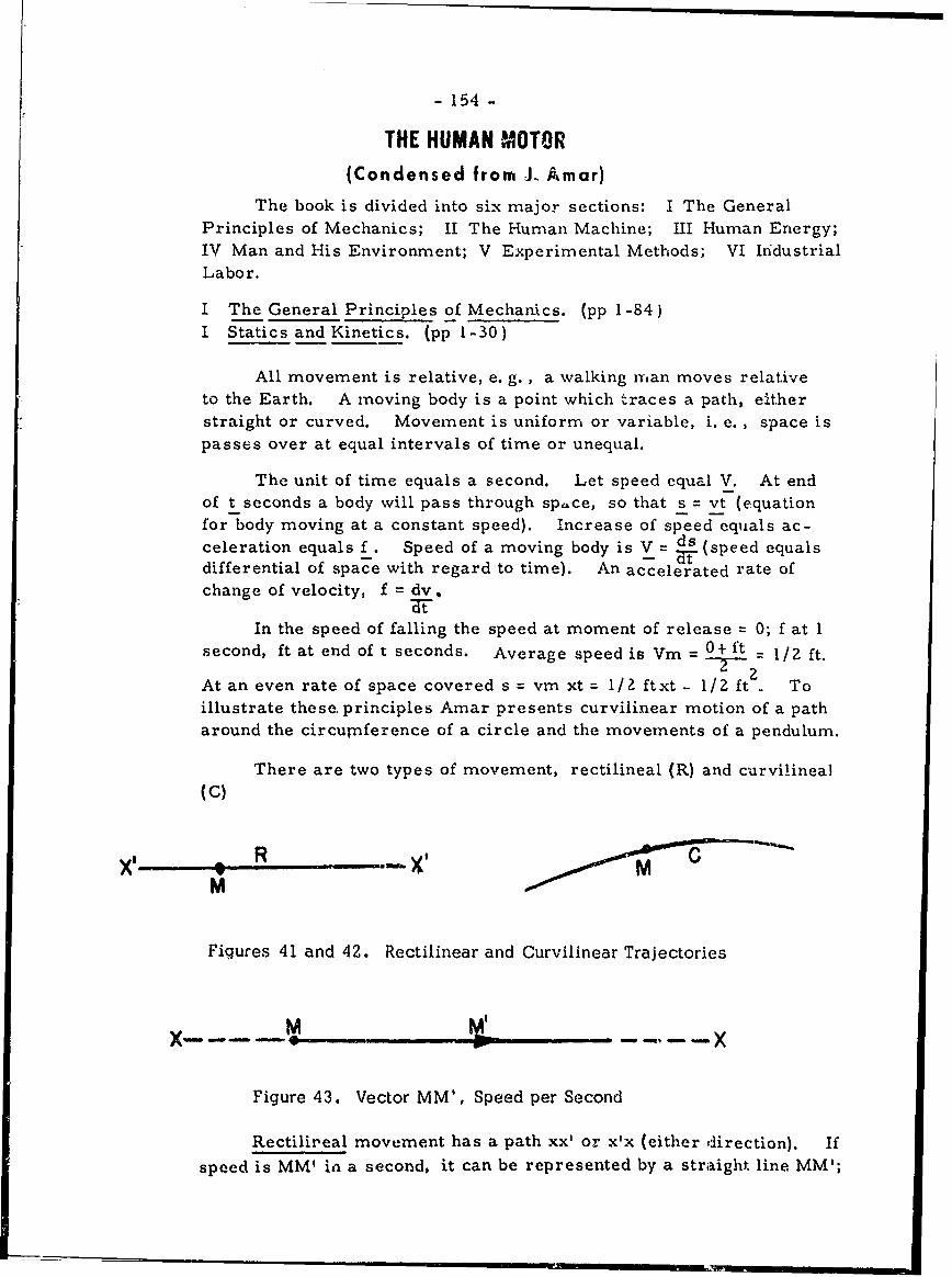
- 154 -
THE HUMAN MOTOR(Condensed from J. Amar)
The book is divided into six major sections: I The GeneralPrinciples of Mechanics; II The Human Machine; III Human Energy;IV Man and His Environment; V Experimental Methods; VI IndustrialLabor.
I The General Principles of Mechanics. (pp 1-84)I Statics and Kinetics. (pp 1-30)
All movement is relative, e. g. , a walking nfan moves relativeto the Earth. A moving body is a point which traces a path, eitherstraight or curved. Movement is uniform or variable, i. e. , space ispasses over at equal intervals of time or unequal.
The unit of time equals a second. Let speed equal V. At endof t seconds a body will pass through space, so that s = vt (equationfor body moving at a constant speed). Increase of speed equals ac-celeration equals f . Speed of a moving body is V = ds (speed equalsdifferential of space with regard to time). An accelerated rate ofchange of velocity, f = dv,
In the speed of falling the speed at moment of release = 0; f at 1second, ft at end of t seconds. Average speed is Vm = 0+ ft - 1/2 ft.T--2-At an even rate of space covered s = vm xt = 1/2 ftxt - 1/2 ft . Toillustrate these. principles Amar presents curvilinear motion of a patharound the circumference of a circle and the movements of a pendulum.
There are two types of movement, rectilineal (R) and curvilineal(C)
x'- .R -G
M '
Figures 41 and 42. Rectilinear and Curvilinear Trajectories
x M. ., , - -
Figure 43. Vector MM', Speed per Second
Rectilireal movement has a path xx' or x'x (either direction). If
speed is MM' in a second, it can be represented by a straight line MM';
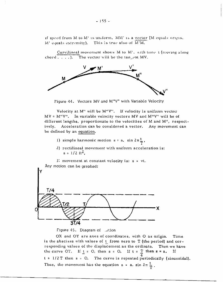
- 155 -
if speed from M to M' is uniform, MM' 1. a vector (M equalz origin.
M' equals extremity). This is true also of N'M.
Curvilineal movement shows M to M'. ,.%ith tin t (n1oving alonzchord .... ). The vector will be the tan,,ent MV.
VV i
Figure 44. Vectors MV and M"V" with Variable Velocity
Velocity at M" will be M"V". If velocity is uniform vectorMV = M"V". In variable velocity vectors MV and M"V" will be of
different lengths, proportionate to the velocities of M and M", respect-ively. Acceleration can be considered a vector. Any movement can
be defined by an equation.
1) simple harmonic motion s = a. sin 2n t
2) rectilineal movement with uniform acceleration is:
s = 1/2 ft 2 ,
3' movement at constant velocity is: s vt.Any motion can be graphed:
Y
T/4
x
3T14
Figure 45. Diagram of otion
OX and OY are axes of coordinates, with 0 as origin. Timeis the abscissa with values of t from zero to T (the period) and cor-responding values of the displacement as the ordinate. Then we havethe curve OT. If t = 0, then s = 0. If t = T then s = a. If-4t = 1/2T then s : 0. The curve is repeated periodically (sinusoidal).
Thus, the movement has the equation s = a. sin 2n LT"
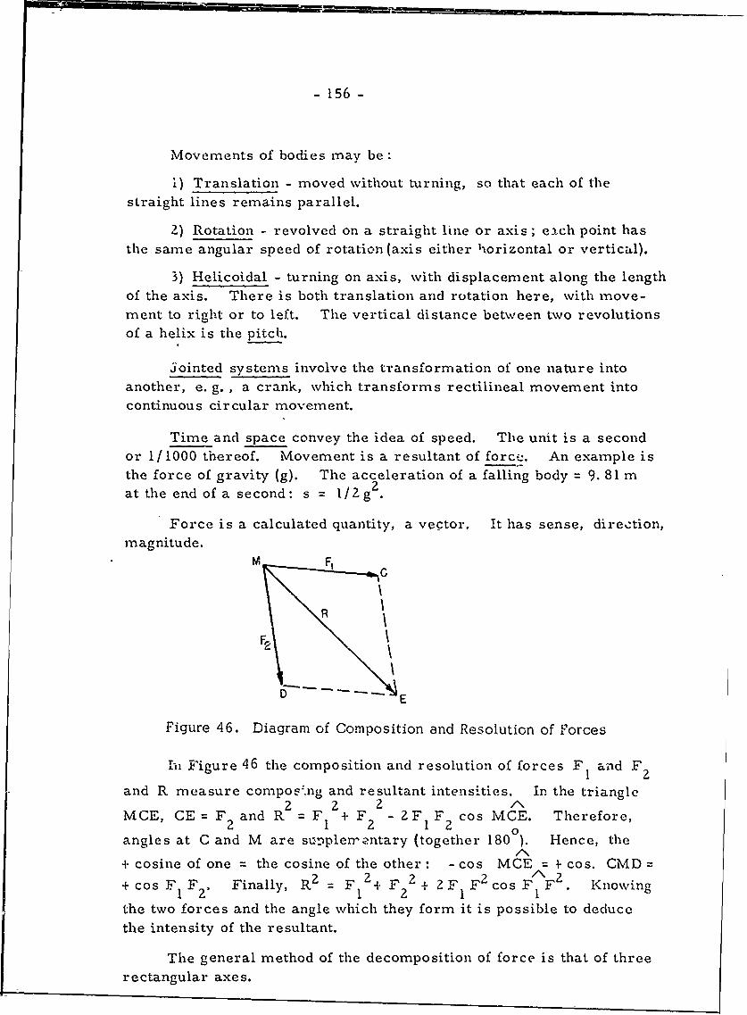
- 156 -
Movements of bodies may be:
1) Translation - moved without turning, so that each of thestraight lines remains parallel.
2) Rotation - revolved on a straight line or axis ; each point hasthe same angular speed of rotation (axis either horizontal or vertical).
3) Helicoidal - turning on axis, with displacement along the lengthof the axis. There is both translation and rotation here, with move-ment to right or to left. The vertical distance between two revolutionsof a helix is the pitch.
Jointed systems involve the transformation of one nature intoanother, e. g., a crank, which transforms rectilineal movement intocontinuous circular movement.
Time and space convey the idea of speed. The unit is a secondor 1/1000 thereof. Movement is a resultant of forcez. An example isthe force of gravity (g). The acceleration of a falling body = 9. 81 mat the end of a second: s = l/Zg2 .
Force is a calculated quantity, a vector. It has sense, direction,magnitude.
M! F,
F2
rD E
Figure 46. Diagram of Composition and Resolution of Forces
hi Figure 46 the composition and resolution of forces F 1 and F
and R measure compos'.ng and resultant intensities. In the triangle2 2 2 I2
MCE, CE = F 2 and R =F + F 2 - 2F F cos MCE. Therefore,
angles at C and M are su.pler--antary (together 180 ). Hence, the
+ cosine of one = the cosine of the other: -cos MCE = + cos. CMD== 22 F 2 co F 2 Kown+ cos F I F 2. Finally, R2 F 2+ F 2 + 2F 1 F Cos FFI. Knowing
the two forces and the angle which they form it is possible to deduce
the intensity of the resultant.
The general method of the decomposition of force is that of threerectangular axes.
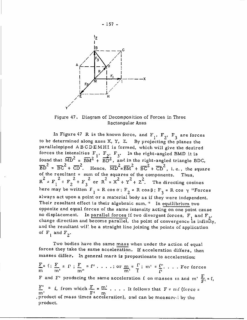
- 157 -
1z
I F
lB
/E H
/1
/I
In~~ Fiur 47Ri h nw ocadFF1F3aefre
I/1
//
Y
Figure 47. Diagram of Decomposition of Forces in ThreeRectangular Axes
In Figure 47 R is the known force, and F 1 , F2F 3 aeors
to be determined along axes X, Y, Z. By projecting the planes theparallelopiped AB CDEMHI is formed, which will give the desiredforces the intensities F . F F In the right-angled BMD it is
-2 2 ,L 3*found that MD 2 = BM + BD 2 , and in the right-angled triangle BDC,-2 -2 -2 - z - 2 -2 7 -2BD = BC + . Hence, MD =BM + C + CD , i. e. , the square
of the resultant = sum of the squares of the components. Thus,
R = 2 +F orR X + Y +Z 2 . Thedirecting cosines
here may be written F =R cosa; F = R cos : F 3 = R cos y "Forces
always act upon a point or a material body as if they were independent.Their resultant effect is their algebraic sum. " In equilibrium twoopposite and equal forces of the same intensity acting on one point causeno displacement. In parallel forces if two divergent forces, F and F 2 ,
change direction and become parallel, the point of convergence is infinity,and the resultant wil' be a straight line joining the points of applicationof F, and F
Two bodies have the same mass when under the action of equalforces they take the same acceleration. If acceleration differs, thenmasses differ. In general maps is proportionate to acceleration:
F. f, F =; F = f" ;or m= f, m' " For orcesm m M n'1 m' f f
F and F' producing the same acceleration f on masses in and m' FF1
f, from which _.......... It follows that F = nf (force =ITI ' F' m
.product of mass times acceleration), and can be trneasurc. by theproduct.
- 158 -
The intensity of gravity is P =mg (where P = weight of a body).The acceleration of gravity is constant, so P' = m'g, p" = m"g. Thus,the weights of bodies are in proportion to their masses f =m ....
P' m'where P = mg. If the unit of mass m = 1, then P = g, and the intensity
of gravity will be that of the acceleration
At Paris g = 9. 81m per sec.
The unit of mass = mass of cu. cm of H 0 at 40 C (the gramme).Unit of length is the centimeter.
Hence force of weight p = mg will be p = Igr x 980. 97 cm. =980. 97 gr cm. This is the dyne,. which is 1 or I__ of a gr. Since
g 981is constant the gramme becomes the unit of force or weight.
The center of mass or gravity is the point in a body through whichthe resultant of all weights of its parts passes, in every position thebody can assume. If all forces representing the effects of gravity onthe molecules of the body are composed, the resultant is at the centerof bulk, which is the center of gravity. A vertical line traversing abody at its center of gravity is its axis of gravity. In a composite bodythe center of gravity of each part can be found, and forces of gravitycomposed from these (e. g., a dumbbell).
Conditions of equilibrium of a body depend on the effects of gravityand the reaction on a body of its support. To produce a state of equili-brium a body on a surface must have its axis of gravity passing througha base of support (either a point upon which it rests, or within the baseupon which it rests).
II Dynamics and Energetics ( pp 31-59)
Forces are either external, as gravity, reaction, pressure, orinternal, equal and opposite, acting between various points of the system,(these latter have a zero resultant). It is assumed that the mass of thesystem is concentrated at the center of gravity, or G. Movementof the system will be the same as that of point G, acting underexternal forces only. The body will describe a parabola in space,influenced by its initial speed and by G (it is the center of gravityof the body which will describe the parabola).
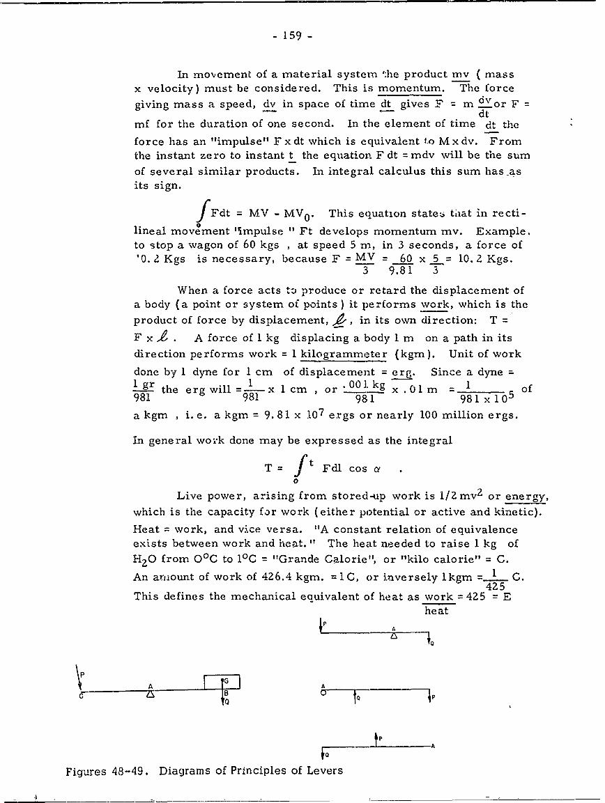
- 159 -
In movement of a material system 'he product mv ( massx velocity) must be considered. This is momentum. The force
giving mass a speed, dv in space of time dt gives F = m dvor F =-- dt
mf for the duration of one second. In the element of time dt the
force has an "impulse" F x dt which is equivalent to M x dv. From
the instant zero to instant t the equation F dt = mdv will be the sum
of several similar products. In integral calculus this sum has -asits sign.
IFdt = MV - MV 0 . This equation states tiat in recti-0
lineal movement 'impulse " Ft develops momentum mv. Example,to stop a wagon of 60 kgs , at speed 5 m, in 3 seconds, a force of'0. 2 Kgs is necessary, because F = MV = 60 x 5 = 10. 2 Kgs.
3 981 3
When a force acts to produce or retard the displacement ofa body (a point or system of points) it performs work, which is the
product of force by displacement, gz, in its own direction: T =
F x 4 . A force of I kg displacing a body 1 m on a path in its
direction performs work = 1 kilogrammeter (kgm). Unit of work
done by 1 dyne for 1 cm of displacement = erg. Since a dyne =
- gr the erg will =-x cm , or *"00'kg x .01 m = 1 of981 981 981 981 x10 5
a kgm , i.e. a kgm = 9.81 x 07 ergs or nearly 100 million ergs.
In general work done may be expressed as the integral
T= ft Fdl cos a0
Live power, arising from stored-up work is 1/Zmvz or energy,
which is the capacity for work (either potential or active and kinetic).
Heat = work, and vice versa. "A constant relation of equivalenceexists between work and heat." The heat needed to raise 1 kg of
H 2 0 from 00C to 10C = "Grande Calorie", or "kilo calorie" C.
An arnount of work of 426.4 kgm. =1C, or inversely lkgm = C.425
This defines the mechanical eauivalent of heat as work = 425 = Eheat
4 A
- 160 -
III Resistance of Materials - Elasticiw - Machines (pp 60-84)
A lever (Figures 48-49 iDs a rigid bar, movable around afixed point, the fulcrum (A). Resistance (Q) to be overcome is aforce or weight at (B) of the lever. Power is applied at the ex-tremity (C).
This is a lever of the first order
If the resistance is at the center of the lever, this is a leverof the second order
If the power is at the center of the lever, this is a lever ofthe third order
Amar presents a summary of the systems of units: unit of
time = second; unit of length centimeter (meter, kilometer; Eng-lish mile = 1, 609. 315 m , knot or nautical mile = 1. 855 m ). Unitof mass = gramme ( kilogram ) (metric ton = 1000 kgs). The cm-gr-sec system = C. G. S. system, adopted in 188 1. Unit of force =
force which gives the mass the graime an acceleration of 1 centi-meter (this is the dyne). Acceleration of gravity at Paris = 981 cm
the dyne is smaller than the weight of I gramme ( _ gr) or 1 gr =
981 dynes. The unit of work = erg, which is work of the dyne througha distance of 1 cm. As 1 kg = 981, 000 dynes and 1 m = 100 cm.it follows that the kilogrameter, the practical unit = 98 1, 000 x 100
981 x 105 ergs. Also useful is a joule (107 ergs); 107 = i
. 019 kgm (. 102 k m).
The powver of a motor = the number of units of work per sec-ond. A watt is the unit of power which gives 1 joule per second or0. 102 kgm per sec. In industry a poncelet = 100 kgm (100 = 981
watts), a horsepower = 75 kgms ( 75= 735. 75 watts)..102
In the equivalence between mechanical and thermal energy,426. 4 kgm is transformed into 1 grand calorie (C), which is the
amount of heat able to raise Ikg of H2 0 from O0 to 1°0. A grand
calorie = 426.4 x 981 x 10 5 = 418. 3 x 10⁸ ergs, or 4183 joules. If
only I gr of HZO is to be raised 10C this will give a small calorie
(c): 418.3 x l05 ergs = 4. 183 joules.
Here are summarized formulae of dimensions. Length x
lenz'gth = area; length has one dimension, I , while area has two
'dimensions, 1 ?, and volume has three dimensions = 1 3. Speed
is the quotient of length x time, expressed as the dimension 1 or it - 1 .t
- 161 -
Acceleration is the quotient of speed x time, with the dimension_ It-I =It-2. Force, f = m will have the dimension mlt - 2, nence
twork = fl = ml 2t - 2, etc. Work done may be given by the equation T
fxl = 1/2 mv 2 (in 1/2 mv 2 the speed, v, is that of the moving body;
but it must not be multiplied by time and written 1/2 mv - t. The
formulae of dimension are mlZt - Z for 1/2 mv2 . Hence, if time wereintroduced the formulae would no longer be homogeneous).
II. The Human Machine (pp 85-164)I. The Human Structu.e (pp 85-116)
The internal activity of protoplasm to maintain a continuousdynamic state demands water, food, oxygen, and heat (37. 50 C for
Man). In the vertebrate body bones = levers, muscles = powers.Bone density shifts from 1. 87 to 2. 00 in the first 30 years in Man.The heads of the long bones reveal the curve of pressures in the arches.
2The breaking stress of bone is derived from R = Ks 2 the
hsection being squared, the length equal at the most to 15 x the side ofthe section; the coefficient K = 2. 565 is in kgs , s in sq. cm , andh in decimeters.
From Young's modulus = E (where E = the elastic force
or "souplesses") the following is given:
Table 40. Breaking Stress in the Femur and Fibula
Young's Breaking StressBane Sex Age Density Modulus per mm2
FemurM 30 1.984 E = 1,819 10,500 kgM 74 1.987 2,638 7.300F 21 1.968 2, 181 6,870F 60 1.849 2,421 6,400
Fibula M 30 1.997 2,059 15,030
M 74 1.947 ? 4,335F 21 1.940 2,710 10,260F 60 0.799 ? 3,300
(Amar, p. 91)
This is from Rondelet and Hodgkinson on different woods. Thebreaking stress increases as the square of the sector, and, inversely,diminishes as the square of the length.
- 162-
Young's modulus averages 2, 300 kgs per mm 2 . The averageresistance to fracture by traction equals 12 kg in adult M, 6 kg inan old M; it is less in F, and also decreases with age. Here amodifocation of Hodgkinson's formula is used in fracture by compres-sion (1/6 higher than in traction: R 2 14 kgs on the average):
R z 2,700 x _ where h cannot exceed 1/2 decimeter and prisms
must approach a cube. Under compression for a cL e of 3 mm R -16 kg per mm 2 , and for a cube of 5 mm, R = 15 mm2 . On prismsonly 10-12 kgs is obtainable.
Rate of application of compression stress is very important,since pressure in shock has a high value : the impulse is Ft =-my,
and hence F = my ; for a short duration tF may have a very hightvalue.
In flexion and torsion the resistance of the long bones is in-
creased because thay are hollow. Amar cites Lesshaft and Messereron the weights (kgs) producing the initial fracture ( H = humerus,R = radits, U = Ulna, F = femur, T = tibia, Fi = fibula) :
H R U F T Fi
Male, age 31 850 535 550 1300 600 300Female, age 24 600 390 310 1100 650 310
To produce a complete fracture one needs 2900 kgs for thefemur, 4100 kgs for the tibia.
ihe weights (kgs ) needed to produce rupture by flexion andshearing are :
Table 41. Breaking (Weight) in Flexion and Shearing
Bone Flexion Shearing Zone of Rupture
t- 120-300 250-505 ends
R 55-l140 10F -334 midU 70-140 9". -235 everywhereF 230-475 400-810 neckT 135-500 450-1060 lower endFi 21-55 20-61 mid
(Amar, p. 93)
Torsion, acting at the end of a lever of 16 cm , produces aspiral fracture (values in kgs ): H = 40, R = 12, U = 8, F =89,T = 48, Fi = 6. Other values of interest are: 1) lumbar vertebraecompressed vertically break in M of 30 years at 1000 kg , F of 80at 2400 kg ; 2) thorax compressed transversely (ribs broken),
- 163 -
M of 30 at 200 kg , F of 82 at 40 kg ; 3) thorax compressed sagittally.M or 40 = 60 kg , F of 82 = 40 kg ; 4) pelvis crushed laterally at180 kg ; 5) sacrum crushed sagitally at 170-250 kg.
Resistance of bone increases up to old age and is greater in Mthan in F. Health and diet are also modifying factors.
Striated muscles are agents of movement. The more fibers ina muscle, the greater its resistance, i. e., resistance is proportion-ate to the mass of a muscle. For the M. sartorius Amar quotesWertheim:
Sex Age Density Young's R per mm 2
- Modulus
M 1 1.071 E = 1.271 0.070 kgM 30 1.058 0 -2 0.026M 74 1.045 0. '1 1 0.017F 21 1.049 0.857 0.040F 60 1.040 ? ?
A fresh cadaver muscle has an E = 0.95, and an R of 40 gper mm2 . Values decrease with age, and the E is higher (resistancegreater) in a contracted muscle. Tonicity is a variable factor.
Fo- tendons and cartilage the data are as follows (the Plantar
tendon):
Sex Age Density Young's R per mm 2
Modulus Rprm
M 35 1. 125 E = 139.42 4.910 kgM 40 1. 124 134.78 7. 100M 74 1. 105 200.50 5. 390F 21 1. 115 164.71 10. 380F '70 1. 114 169.21 5.610
On the ave rage a tendon has a modulus of 146 and a force ofcohesion of 7 kg. On resistance to traction Triepel found R = 5,about 1/2 that of bone. The re, !stance of cartilage to fracture isgreater in compression than in traction, i.e. , 1. 5 kg compared to0. 18 kg (Triepel). Young's Modulus is about 1. 50, or about thatof muscle.
- 164 -
The resistance of nerves is great: 25 kg to break the ulnar,55 kg to break the sciatic. R = 2-3 kg per mm2 , Young's Modulus
10. 9. Nerves are the best onductors of electricity. If 100 istaken as conductivity, K, in muscle, then muscle = 100, nerve = 588,tendon = 30, bone = 7.
Here are comparative data:
Table 42. Elastic Properties of Various Materials
Substance Density Young's Modulus R per mr 2
Bone 1.95 E = 2,300 IZ kgMuscle 1. 12 146 7Tendon 1.05 0.95 0.4Nerve 1.04 10.9 2.5India Rubber 0.92 variable 0.6Silk Thread 1. 33 650 27.51Spider Thread 1. 58 306 18.35
(Amar, p. I1)
The viscous nature of muscles and tendons renders them verysusceptible tc deformation. Fatigue is a very potent factor.
Joirl- are bones in contact at 'Iointed surfaces", which areilat or cur I (spherical, cylindrical, oval). Opposing joint sur-faces are covered by cartilage. Joint movement varies from syn-arthrosis or fixed (suture as example) to diarthrosis or freelymovable (e. g. bones of limbs or fingers, which act like levers).The shape of joints is so variable that there may be 5-6 classes,according to degrees of freedom. The freest movement = 6 degreesof freedom (3 translations, 3 rotations) . Since at joints the contactsurfaces are curved they often have 1, 2, 3 axes and 1, 2, 3 degree'of freedom (found in cylindrical, oval, or spherical joint surface ).
Systems with one degree of treedom are said to have "completeconnection ".
A spherical joint surface has one axis and permits one de-gree of freedom. As a rule the surface has a groove which formspart of the arc of a circle. Movement is in one plane. It is there-fore a hinge joint (e.g., the fingers). A pivot joint has a longitudi-nal rotation around a single axis (e.g., the radius). If the bone has a
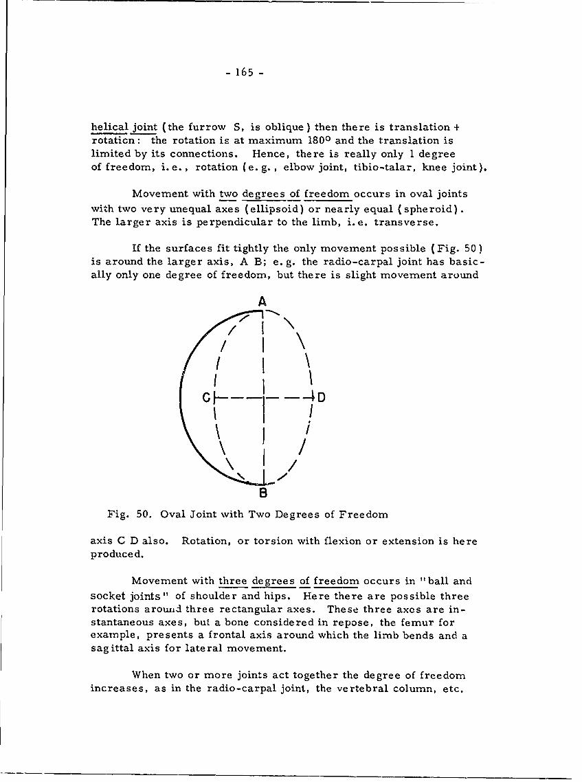
- 165 -
helical joint (the furrow S, is oblique) then there is translation +rotaticn: the rotation is at maximum 1800 and the translation islimited by its connections. Hence, there is really only 1 degreeof freedom, i. e., rotation (e. g. , elbow joint, tibio-talar, knee joint).
Movement with two degrees of freedom occurs in oval jointswith two very unequal axes (ellipsoid) or nearly equal (spheroid).The larger axis is perpendicular to the limb, i.e. transverse.
If the surfaces fit tightly the only movement possible (Fig. 50)is around the larger axis, A B; e. g. the radio-carpal joint has basic-ally only one degree of freedom, but there is slight movement around
A
e----
CH--j-A
\ 1
BFig. 50. Oval Joint with Two Degrees of Freedom
axis C D also. Rotation, or torsion with flexion or extension is hereproduced.
Movement with three degrees of freedom occurs in "ball andsocket joints" of shoulder and hips. Here there are possible threerotations arow±id three rectangular axes. These three axes are in-stantaneous axes, but a bone considered in repose, the femur forexample, presents a frontal axis around which the limb bends and asag ittal axis for lateral movement.
When two or more joints act together the degree of freedomincreases, as in the radio-carpal joint, the vertebral column, etc.
- 166 -
Amar feels that body shape as a whole is that of a prism. Theupper 1/2 of the body is called the bust. Basic body measurementsare height, weight, sitting height, thoracic circumference (at nipple),and span. The "thoracic coefficient" = SH/H.
There are two main body types: lower limbs long relative toSH (bust); and lower limbs short relative to SH. Vital capacity,via spirometer, averages 3. 75 liters of air for male, 2. 75 liters forfemale. Vital capacity increases 0. 42 liters per annum up to 30years, and increases 0. 05 and 0. 04 liters per cm. increase in stature,in males and females, respectively.
There is a relation between the surface area and the volume ofthe body, which is expressed as the relation between volume, weightand density: V =P (where P =wt. ). If the density (D) is known,
Dvolume (V) can be calculated from weight (P). In practice D is de-termined by the volume, from displacement in water. D is generallytaken as 1. 035. The surface area of the body is theoretic: assumea cube, with volume V; the side of the cube = N ! , and the
total surface of the 6 faces is 6 ( 3 47-) 2 6 3 V2 . It is
possible to substitute weight for the volume and write S =K
p
K changes with body shape, which is really not cubic. K for Man12. 312. The surface is therefore S =12. 312 3 4_- (where P
is in grammes and S is in cmt (Meek). Example: adult male of
65 kg has a surface S = 12. 312 3 = 19. 896 cm2 or 1.99m2
(really 2 i 2 ). 1o
If two individuals of different weight are considered (e. g. , anadult and a child) their surfaces will be to each other as the cube rootof the square of their weights ; hence surface area diminishes lessrapidly than weight.
13 3 G 2 3 2S 12 I. 31Z 12 T == P'2
s 12. 312
Let P' = 1/8 P , then S' = 1/4. Thus the weights vary from 8-
to I, but the surfaces will vary only from 4 to 1. Therefore, childrenhave a larger surface area relative to their weight than do adults.
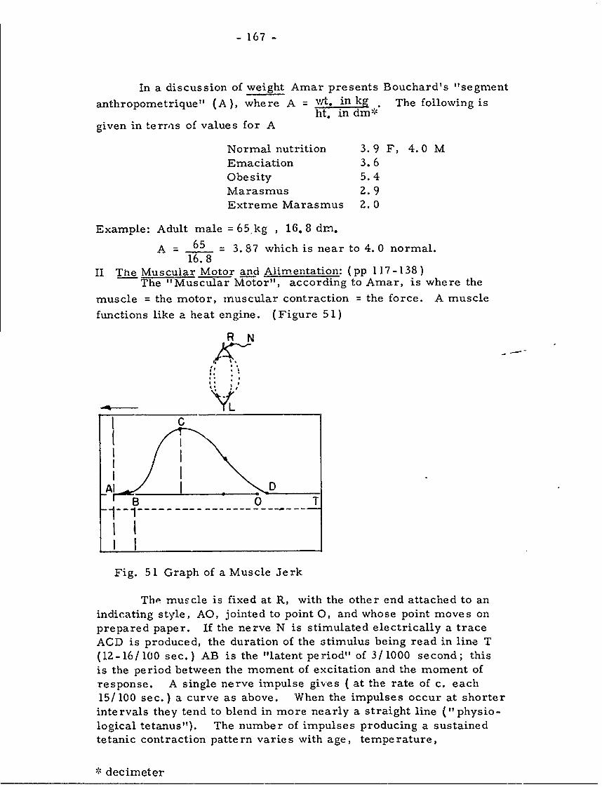
- 167 -
In a discussion of weight Amar presents Bouchard's "segment
anthropometrique" (A), where A = wt. in kg The following isht. in dm"
given in terrois of values for A
Normal nutrition 3.9 F, 4. 0 MEmaciation 3.6Obesity 5.4Marasmus 2. 9Extreme Marasmus 2.0
Example: Adult male = 65.kg , 16. 8 drn.
A = 65 = 3. 87 which is near to 4. 0 normal.16.8
II The Muscular Motor and Alim entation: (pp 117-138)The "Muscular Motor", according to Amar, is where the
muscle = the motor, muscular contraction = the force. A muscle
functions like a heat engine. (Figure 51)
R N
YWiGSB 0 T
-1--1
I I
Fig. 51 Graph of a Muscle Jerk
The muscle is fixed at R, with the other end attached to anindicating style, AO, jointed to point 0, and whose point moves onprepared paper. If the nerve N is stimulated electrically a traceACD is produced, the duration of the stimulus being read in line T(12-16/100 sec.) AB is the "latent period" of 3/1000 second; thisis the period between the moment of excitation and the moment ofresponse. A single nerve impulse gives ( at the rate of c. each15/ 100 sec.) a curve as above. When the impulses occur at shorterintervals they tend to blend in more nearly a straight line ("physio-logical tetanus"). The number of impulses producing a sustainedtetanic contraction pattern varies with age, temperature,
-- decimeter
- 168 -
weight under which muscle contracts, and its initial state. In manit corresponds to 20-30 excitations per second; when there are upto 60 per sec. the muscle remains tetanized for 4-5 minutes. Abovea frequency of 60 fatigue is very rapid.
The duration of a reflex decreases as the intensity of theexcitation increases. The following are average values:
Tactile reaction 14/ 100 sec.Visual 19/100 "
Auditory 15/100
The laws of muscle contraction show that the length is reduced,
the -width increased, but that volume is about the same. The law ofelasticity suggests that a muscle sustaining weight P will be length-ened by a quantity L =PL. If by contraction it resists elongation its
interval force will be equal and opposite to P. If it shortens by aquantity, r, while sustaining weight the interval force will exceedP by the effort necessary to restore the muscle to its original length.This supplementary effort will be proportionate to the shortening, soit will be P x r. The force of static contraction, to balance weightP with a shortening r will be F = P + Pr = P (1+ r).
Besides the work of the muscle in displacing the weight P,the shortening takes two limiting values, r and r', to which forcesof contraction F and F' will correspond, so that force has an averagevalue of F+F' = F . Now replace F by P(l+r) andF' by P
2 m(1 + r ) and the result is F P(lr+ r
m 2
The dynamic contraction accomplishes work via the averageshortening and the average forces, Fm.
According to the laws of elasticity muscular deformation isproportionate to the length of the muscle. A bone capable of exten-sive movement must be operated by a muscle capable of much deform-ation; hence, long muscles are here best. Short, thick muscles candevelop much effort because they have so many fibers.
Muscles occupy space minimally and econor:;ically; hence, asa rule, muscles are parallel to the bones they move. Muscle action(Figure 52) is a function of mass, degree of contraction, and theangle which its direction makes with the bone to be moved. A musclehas a definite moment of rotation, in relation to the axis, for each ofits positions. The moment of rotation = the product of force F of
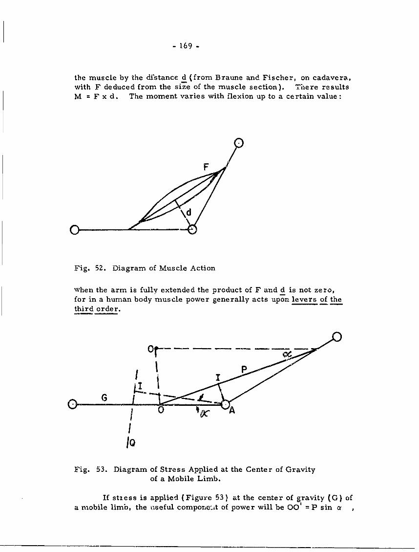
- 169 -
the muscle by the distance d (from Braune and Fischer, on cadavera,with F deduced from the size of the muscle section). There resultsM = F x d. The moment varies with flexion up to a certain value:
Fig. 52. Diagram of Muscle Action
when the arm is fully extended the product of F and d is not zero,for in a human body muscle power generally acts upon levers of thethird order.
I
Fig. 53. Diagram of Stress Applied at the Center of Gravityof a Mobile Limb.
If stiess is applied (Figure 53) at the center of gravity (G) ofa mobile limb, the useful compone'it of power will be 00' = P sin a ,
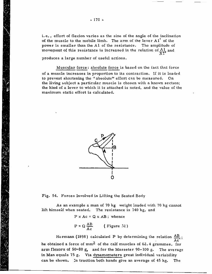
- 170 -
i. e., effort of flexion varies as the sine of the angle of the inclinationof the muscle to the mobile limb. The arm of the lever Al' of thepower is smaller than the Al of the resistance. The amplitude ofmovement of this resistance is increased in the relation of Al and
produces a large number of useful actions.
Muscular force: abcolute force is based on the fact that force
of a muscle increases in proportion to its contraction. If it is loadedto prevent shortening the "absolute" effort can be measured. Onthe living subject a particular muscle is chosen with a known section;the kind of a lever to which it is attached is noted, and the value of themaximum static effort is calculated.
I
-1 E
0
Fig. 54. Forces Involved in Lifting the Seated Body
As an example a man of 70 kg weight loaded with 70 kg cannot
lift himself when seated. The resistance is 140 kg, and
P x Ac = Q x AB; whence
p = QAB (Figure 5Z)Ac
Hermann (1898) calculated P by determining the relation ABAc
he obtained a force of mm 2 of the calf muscles of 62. 4 grammes, for
arm flexors of 50-80 g, and for the Masseter 90-100 g. The average
in Man equals 75 g. Via dynamometers great individual variability
can be shown. In traction both hands give an average of 45 kg. The
- 171 -
back pull (called " renal pull" by Quetelet) is greater iA M than in F,and increases up to about 40 years, when it decreases. In the primeof vigor an adult M = 150 kg , an adult F = 78 kg. For races in the"renal pull" Gould reported as follows: American white 144. 4 kgAmerican Negro 146. 7 kg , Mulatto 158. 3 kg , American Indian 159. 2kg.
The periodicity of voluntary muscle contractions shows a
variability: impulses in Biceps brachii equals 50 per sec. , in
Masseter equals 60-65, in the flexors of the fingers equals 8-11.Voluntary contraction is similar, in principli-, to "psysiologicaltetanus". Static effort leads to real vibratory movement, i.e., in-ternal work. There must be an expenditure of work to produce aneffort. The elastic work of traction is T = i/Z ES_ = Fl and the
L 2differential of the work in respect to the deformation will be dT_ ESI
= F ) dl L
The contraction of a muscle and its tetanic character, wherevoluntary, alternates like the stroke of a piston. The maximumrhythm is illustrated to vary: fingers, 8-9 strokes per sec. (480-540 per min. ); jaw 360; foot 210; great toe 250; forearm Z30-240;leg 120 (against the thigh). The work of the fingers is the mostrapid; there is probably a special rhythm for each muscle or groupDf muscies.
Joint movement speed also varies ; phalanges 300-400 strokesper min. , wrist 600, elbow 530, shoulder 310. Values for "unloaded"muscles are: forearm 30-35; masticatory 90- 100; fingers 150;heart 70.
Short people are relatively stronger than tall people, andquicker, because weight decreases as the cube of size, while "force"decreases as the square of the size, being proportionatc to the sectionof the muscles.
Amar discusses alimentation, classification of food stuffs, andthe composition of foods : certain tabulations may be noted.
Food Caloric Power Heat of Combustion
1 g carbohydrate 4. 10 cal 4. 20 call g fat 9. 10 " 9.40 "
1 g proteid 4. 10 " 4.75 "
Carbohydrate Fats Proteids
Heats of combustion 4. 15 cal 9. 40 cal 4. 40 calCalorific power 4. 10 " 9. 10 " 4. 10 "
Coeff. of digestibilityof normal alimen-tation 0.98 " 0.95 " 0.91 "
- 172 -
III Alimentation and the Expenditure of Energy (pr 139-164)
An "alimentary ration" is given to a determined weight ofaliments. For example, 100 g bread and 100 g dried beans gives:
carbohydrate 107. 25 g or 439. 77 cal (107. 26 x 4.10 ).f ats 1.60 g or 14.56 cal ( 1.60 x 9. 10).
proteids 28. 23 g or 115.75 cal ( Z8.23 x 4.10).
Total 570.08 cal
For maintenance rations 1 g proteid is needed for each kg
of body weight. To maintain body temperature intake must be greaterin Winter.
The evaluation of the ration involves the method of nutritiveevahlation, which is to adjust food intake to body weight (from tablesof caloric equivalents ). The oxygen method is to study the 02balance in expired air (over a given period of time). An adult malein repose consumes 26 liters of 02, measured at O°C., at normalpressure of 760 mm. It is necessary to determine the ratio betweenthe amount of energy expended, and the corresponding volume of 02consumed. Energy is proportioned to the 02 and depends on thenature of the combustible. "Mixed alimentation" has a value of 4. 90cal for the energy developed by the consumption of a liter of 02 atooC. and 760 mm. pressure. Here are examples:
Carbohyarates Fats Proteids
Calorific power of aliter of 02 at 00and 760 mm. 5. 05 Cal 4. 70 Cal 4. 53 Cal
Respiratoryquotient CO 2 /02 1.00 0.71 0.82
Some foods act on living matter directly, i. e., on musclefibers ana nerves: coffee, tea, mate, cocoa, kola, pimento, butyricacid, sodium chloride, ordinary alcohol. These are "aliments ofeconomy", or "dynamophoreb", or "nervine aliments".
Rations and energ expenditure (with calorimeter chamberat ZO°C ) may be illustrated as follows:
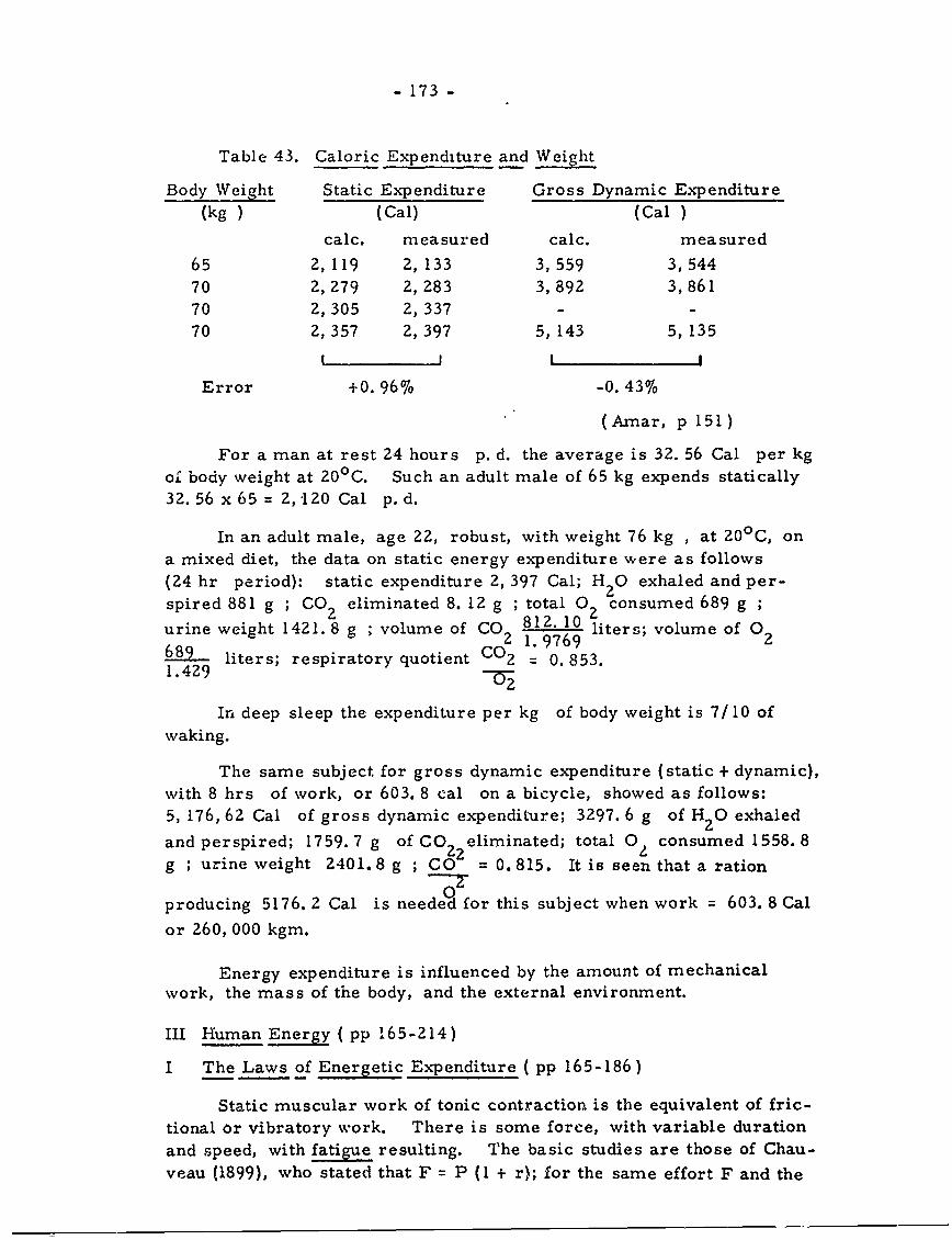
- 173 -
Table 43. Caloric Expenditure and Weight
Body Weight Static Expenditure Gross Dynamic Expenditure(kg) (Cal) (Cal )
calc. measured calc. measured
65 2,119 2, 133 3, 559 3,54470 2,279 2, 283 3,892 3,861
70 2,305 2, 337 - -
70 2, 357 2, 397 5, 143 5, 135
Error +0. 96% -0. 43%
(Arnar, p 151)
For a man at rest 24 hours p. d. the average is 32. 56 Cal per kgof body weight at 20 0 C. Such an adult male of 65 kg expends statically32.56 x 65 = 2, 120 Cal p. d.
In an adult male, age 22, robust, with weight 76 kg , at 200 C, ona mixed diet, the data on static energy expenditure were as follows
(24 hr period): static expenditure 2, 397 Cal; H 2 0 exhaled and per-
spired 881 g ; CO eliminated 8. 12 g ; total 0 consumed 689 g ;urine weight 1421.8 g ; volume of CO 812. 10 liters; volume of 0
689 2 1.9769 2
1.429 liters; respiratory quotient C02 = 0.853.
In deep sleep the expenditure per kg of body weight is 7/10 of
waking.
The same subject for gross dynamic expenditure (static + dynamic),with 8 hrs of work, or 603. 8 cal on a bicycle, showed as follows:
5, 176, 62 Cal of gross dynamic expenditure; 3297. 6 g of H 2 0 exhaled
and perspired; 1759. 7 g of CO eliminated; total 0 consumed 1558. 8g ; urine weight 2401.8 g ; CO = 0. 815. It is seen that a ration
0producing 5176. 2 Cal is needed for this subject when work = 603. 8 Cal
or 260, 000 kgm.
Energy expenditure is influenced by the amount of mechanicalwork, the mass of the body, and the external environment.
III Human Energy ( pp 165-214)
I The Laws of Energetic Expenditure ( pp 165-186)
Static muscular work of tonic contraction is the equivalent of fric-
tional or vibratory work. There is some force, with variable duration
and speed, with fatigue resulting. The basic studies are those of Chau-
veau (1899), who stated that F = P (I + r); for the same effort F and the
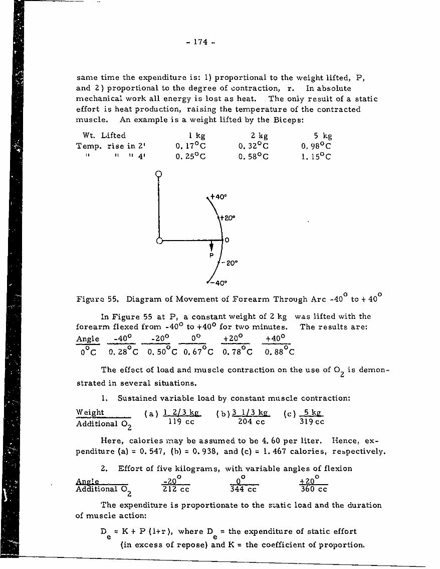
- 174 -
same time the expenditure is: 1) proportional to the weight lifted, P,and 2) proportional to the degree of contraction, r. In absolutemechanical work all energy is lost as heat. The only result of a staticeffort is heat production, raising the temperature of the contractedmuscle. An example is a weight lifted by the Biceps:
Wt. Lifted I kg 2 kg 5 kgTemp. rise in 2' 0. 170 C 0. 320C 0. 980C
" " 4' 0. 250C 0. 580C 1. 15°C
t 200
- 200
)-_40o
Figure 55. Diagram of Movement of Forearm Through Arc -400 to + 400
In Figure 55 at P, a constant weight of 2 kg was lifted with theforearm flexed from -400 to +400 for two minutes. The results are:
Angle -400 -zo0 00 +200 +400
00C 0.280C 0.500C 0.670C 0.780C 0.880C
The effect of load and muscle contraction on the use of 0 2 is demon-
strated in several situations.
1. Sustained variable load by constant muscle contraction:
Weight (a) 1 2/3kg (b) 3 l/3 kj (c) 5k
Additional 02 119 cc 204 cc 319 cc
Here, calories may be assumed to be 4. 60 per liter. Hence, ex-penditure (a) = 0. 547, (b) = 0. 938, and (c) = 1. 467 calories, rebpectively.
2. Effort of five kilograms, with variable angles of flexionSAngle 02O 0o +ZO°
Additional 0 2 212 cc 344 cc 360 cc
The expenditure is proportionate to the satic load and the durationof muscle action:
D e =sKe + P ( +r), where D = the expenditure of static effort
(in excess of repose) and K = the coefficient of proportion.
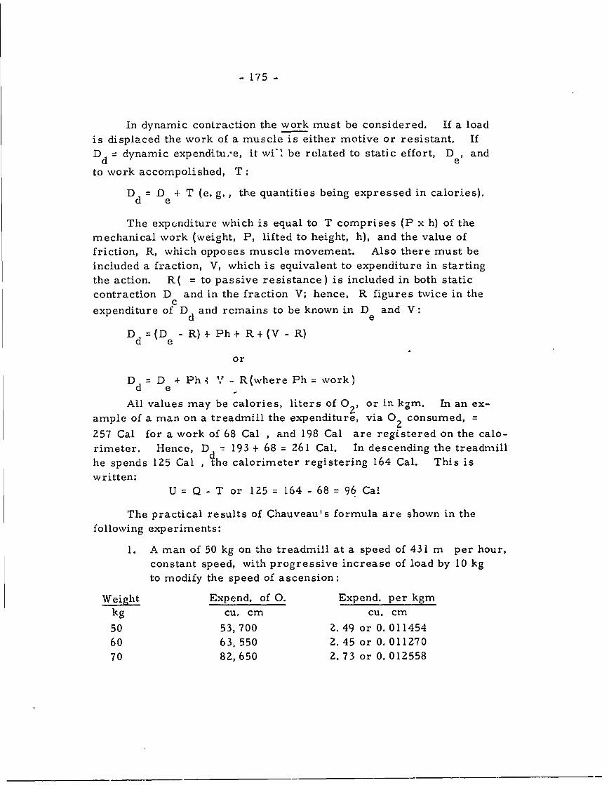
- 175 -
In dynamic contraction the work must be considered. If a load
is displaced the work of a muscle is either motive or resistant. If
Dd = dynamic expenditue, it wi-' be related to static effort, De, and
to work accompolished, T:
D d = De 4 T (e. g., the quantities being expressed in calories).
The expenditure which is equal to T comprises (P x h) oi the
mechanical work (weight, P, lifted to height, h), and the value of
friction, R, which opposes muscle movement. Also there must be
included a fraction, V, which is equivalent to expenditure in starting
the action. R( = to passive resistance) is included in both static
contraction D and in the fraction V; hence, R figures twice in thecexpenditure of Dd and remains to be known in De and V:
Dd =(D -R) + Ph+ R+(V - R)
or
Dd = D+ Ph V - R(where Ph = work)
All values may be calories, liters of O, or in kgm. In an ex-
ample of a man on a treadmill the expenditure, via 0 2 consumed, =
257 Cal for a work of 68 Cal , and 198 Cal are registered on the calo-rimeter. Hence, Dd - 193 + 68 = 261 Cal. In descending the treadmillhe spends 125 Cal , the calorimeter registering 164 Cal. This iswritten:
U Q - T or 125 = 164 - 68 = 96 Cal
The practical results of Chauveau's formula are shown in thefollowing experiments:
I. A man of 50 kg on the treadmill at a speed of 431 m per hour,constant speed, with progressive increase of load by 10 kgto modify the speed of ascension:
Weight Expend. of 0. Expend. per kgmkg cu. cm cu. cm
50 53,700 Z. 49 or 0. 011454
60 63, 550 2.45 or 0. 01127070 82,650 2. 73 or 0. 012558
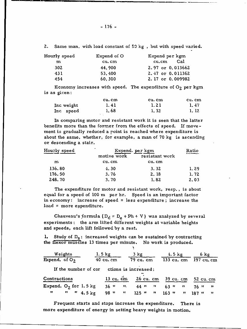
- 176 -
2. Same man, with load constant of 50 kg , but with speed varied.
Hourly speed Expend of 0 Expend per kgmIn Cu. cm cu.cm Cal
302 44,900 2.97 or 0.01366Z431 53,400 2.47 or 0.011362454 60,300 Z. 17 or 0. 009982
Economy increases with speed. The expenditure of 02 per kgmis as given:
Cu. cm cu. cm Cu. cmInc weight 1.41 1. Z 1 1.47Inc speed 1. 68 1. 32 1. 12
In comparing motor and resistant work it is seen that the latterbenefits more than the former from the effects of speed. If move-ment is gradually reduced a point is reached where expenditure isabout the same, whether, for example, a man of 70 kg is ascendingor descending a stair.
Hourly speed Expend. per kgm Ratiomotive work resistant work
rn cu. cm cu. cm
136.80 4.30 3.32 1.Z9176.50 3.76 2. 18 1. 72248.70 3.70 1.82 2.03
The expenditure for motor and resistant work, resp., is aboutequal for a speed of 100 m per hr. Speed is an important factorin economy: increase of speed = less expenditure ; increase theload = more expenditure.
Chauveau's -formula (Dd = De + Ph + V) was analyzed by several
experiments : the arm lifted different weights at variable heightsand speeds, each lift followed by a rest.
1. Study of De: increased weights can be sustained by contractingthe flexor muscles 13 times per minute. No work is produced.
Weights 1.5 kg 3 kg 4. 5 kg 6 kgExpend. of 0? 40 cu. cm 79 cu. cm 133 cu. cm 197 cu. cm
If the number of cor ctions is increased:
Contractions 13 cu. cm 26 cu. cm 39 cu. cm 52 cu. cm
Expend. 02 for 1. 5 kg 36 " 44 " " 63 " " 76 " "" " i 4. 5 kg 98 " 125 " " 163 " " 187 " "
Frequent starts and stops increase the expenditure. There is
more expenditure of energy in setting heavy weights in motion.
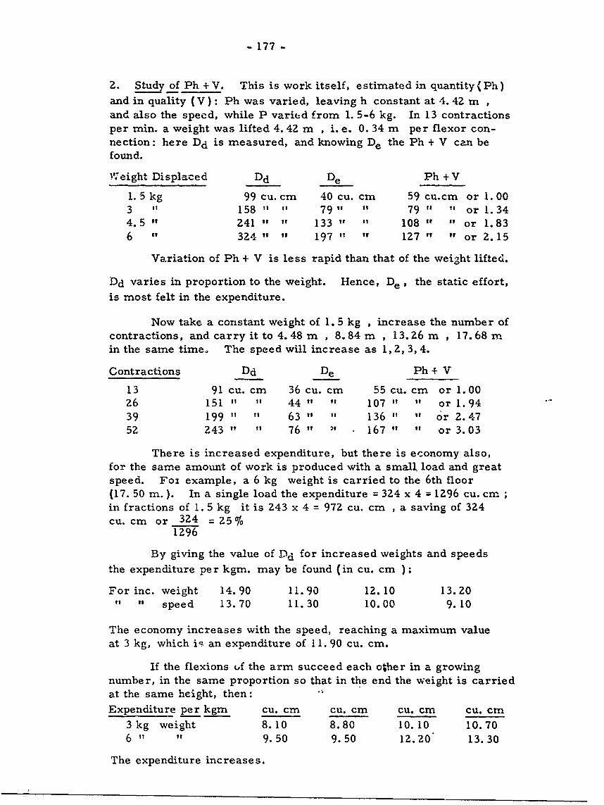
- 177 -
2. Study of Ph +V. This is work itself, estimated in quantity(Ph)
and in quality (V): Ph was varied, leaving h constant at 4. 42 m ,and also the speed, while P varied from 1. 5-6 kg. In 13 contractionsper min. a weight was lifted 4.42 m , i.e. 0. 34 m per flexor con-nection: here Dd is measured, and knowing De the Ph + V can befound.
vIeight Displaced Dd De Ph + V
1.5 kg 99 cu. cm 40 cu. cm 59 cu.cm or 1.003 " 158 " " 79" " 79 " " or 1.344.5" 241 " " 133 " " 108 " " or 1.836 324" " 197 " " 127 " " or 2. 15
Variation of Ph + V is less rapid than that of the weight lifted.
Dd varies in proportion to the weight. Hence, De , the static effort,
is most felt in the expenditure.
Now take a constant weight of 1. 5 kg , increase the number ofcontractions, and carry it to 4.48 m , 8.84m , 13.26 m , 17.68 min the same time. The speed will increase as 1, 2, 3, 4.
Contractions Dd De Ph + V
13 91 cu. cm 36 cu. cm 55 cu. cm or 1.0026 151 " " 44 " " 107 " " or 1.9439 199 " " 63 " " 136 " " or 2.4752 243" " 76" 167" " or 3.03
There is increased expenditure, but there is economy also,for the same amount of work is produced with a small load and greatspeed. Foi example, a 6 kg weight is carried to the 6th floor(17. 50 m.). In a single load the expenditure = 324 x 4 = 1296 cu. cmin fractions of 1.5 kg it is 243 x 4 = 972 cu. cm , a saving of 324cu. cm or 324 = 25%
1296
By giving the value of Dd for increased weights and speeds
the expenditure per kgm. may be found (in cu. cm ):
For inc. weight 14.90 11.90 12.10 13.20I " speed 13.70 11.30 10.00 9.10
The economy increases with the speed, reaching a maximum valueat 3 kg, which i- an expenditure of 11. 90 cu. cm.
If the flexions uf the arm succeed each other in a growing
number, in the same proportion so that in the end the weight is carriedat the same height, then:
Expenditure per kgm Cu. cm Cu. cm cu. cm cu. cm
3 kg weight 8.10 8.80 10.10 10.706 " " 9.50 9.50 12. 20' 13.30
The expenditure increases.
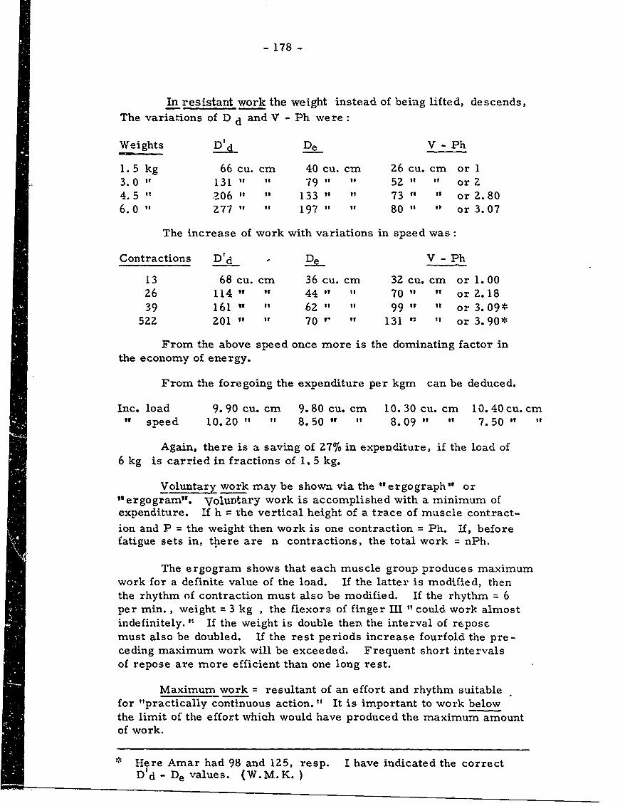
- 178 -
In resistant work the weight instead of being lifted, descends,The variations of D d and V - Ph were:
Weights D d De V - Ph
1. 5 kg 66 cu. cm 40 cu. cm Z6 cu. cm or 13.0 " 131 " " 79 It it 52 " " or Z4.5" ?06 " " 133 " " 73 " " or 2. 806.0 " Z77 " " 197 " " 80 " " or 3.07
The increase of work with variations in speed was:
Contractions D'd - De V - Ph
13 68 cu. cm 36 cu. cm 32 cu. cm or 1.0026 114 " " 44 " " 70 " " or 2. 1839 161 " " 62 " " 99 " " or 3.09*
522 ZOI " " 70 " " 131 ' 1 " or 3.90*
From the above speed once more is the dominating factor inthe economy of energy.
From the foregoing the expenditure per kgm can be deduced.
Inc. load 9.90 cu. cm 9.80 cu. cm 10. 30 cu. cm 10.40 cu. cmi speed 10.20 " " 8.50 " " 8.09 " " 7.50 " "
Again, there is a saving of 27% in expenditure, if the load of6 kg is carried in fractions of 1. 5 kg.
Voluntary work may be shown via the "ergograph" or"ergogram". Voluntary work is accomplished with a minimum ofexpenditure. If h = the vertical height of a trace of muscle contract-
ion and P = the weight then work is one contraction = Ph. If, beforefatigue sets in, there are n contractions, the total work = nPh.
The ergogram shows that each muscle group produces maximumwork for a definite value of the load. If the latter is modified, thenthe rhythm nf contraction must also be modified. If the rhythm = 6per min. , weight = 3 kg , the fiexors of finger Ill " could work almostindefinitely. " If the weight is double then the interval of reposemust also be doubled. If the rest periods increase fourfold the pre-ceding maximum work will be exceeded. Frequent short intervalsof repose are more efficient than one long rest.
Maximum work = resultant of an effort and rhythm suitablefor "practically continuous action. " It is important to work belowthe limit of the effort which would have produced the maximum amountof work.
* Here Amar had 98 and 125, resp. I have indicated the correctD'd- De values. (W.M.K.)
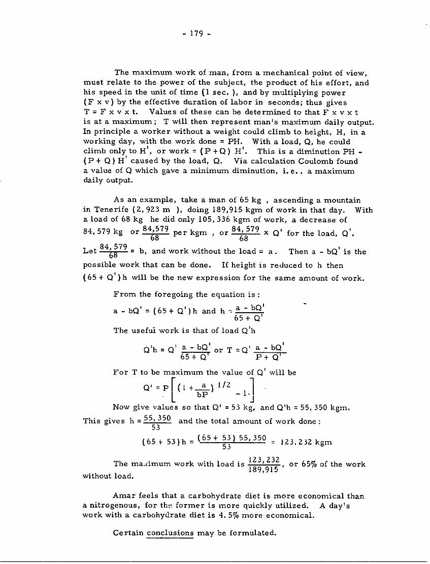
- 179 -
The maximum work of man, from a mechanical point of view,must relate to the power of the subject, the product of his effort, andhis speed in the unit of time (1 sec. ), and by multiplying power(F x v) by the effective duration of labor in seconds; thus givesT = F x v x t. Values of these can be determined to that F x v x tis at a maximum; T will then represent man's maximum daily output.In principle a worker without a weight could climb to height, H, in aworking day, with the work done = PH. With a load, Q, he couldclimb only to H', or work = (P + Q) H'. This is a diminution PH -
(P + Q) H' caused by the load, Q. Via calculation Coulomb founda value of Q which gave a minimum diminution, i. e., a maximumdaily output.
As an example, take a man of 65 kg , ascending a mountainin Tenerife (2, 923 m ), doing 189,915 kgm of work in that day. Witha load of 68 kg he did only 105, 336 kgm of work, a decrease of
84, 579 kg or 84,579 per kgm , or 84, 579 x Q' for the load, Q'.68 68
Let 84, 579 = b, and work without the load = a. Then a - bQ' is the68possible work that can be done. If height is reduced to h then
(65 + Q') h will be the new expression for the same amount of work.
From the foregoing the equation is :
a - bQ' = (65+ Q')h and h - a - bQ'65 + Q'
The useful work is that of load Q'h
Q'h = a-bQ' or T = Q a -bQ'65 + Q' P -+ G'
For T to be maximum the value of Q' will be
Q' P + a.) I/ 2
Now give values so that Q' = 53 kg, and Q'h = 55, 350 kgm.
This gives h = 55, 350 and the total amount of work done:53
(65 + 53)h= (65+ 53) 55,350 _ 123, 232 kgm53
The ma.ximum work with load is 123,232 or 65% of the work189,915
without load.
Amar feels that a carbohydrate diet is more economical thana nitrogenous, for th ; former is more quickly utilized. A day'swork with a carbohydrate diet is 4. 5% more economical.
Certain conclusions may be formulated.
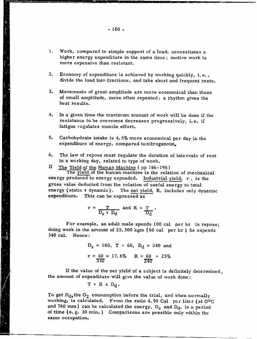
- 180 -
1. Work, compared to simple support of a load, necessitates ahigher energy expenditure in the same time; motive work ismore expensive than resistant.
2. Economy of expenditure is achieved by working quickly, i. e.,divide the load into fractions, and take short and frequent rests.
3. Movements of great amplitude are more economical than thoseof small amplitude, more often repeated; a rhythm gives thebest results.
4. In a given time the maximum amount of work will be done if theresistance to be overcome decreases progressively, i.e. iffatigue regulates muscle effort.
5. Carbohydrate intake is 4. 5% more economical per day in theexpenditure of energy, compared to nitrogenous.
6. The law of repose must regulate the duration of intervals of restin a working day, related to type of work.
II The Yield of the Human Machine ( pp 186-198)The yield of the human machine is the relation of mechanical
energy produced to energy expended. Industrial yield, r , is thegross value deducted from the relation of useful energy to totalenergy (static + dynamic). The net yield, R, includes only dynamicexpenditure. This can be expressed as
r= T and R = TDs + Dd d
For example, an adult male spends 100 cal per hr in repose;doing work in the amount of 25, 500 kgm (60 cal per hr ) he expends340 cal. Hence:
Ds = 100, T = 60, Dd = 240 and
r = 60 = 17.6% R = 60 = Z5%
If the value of the net yield of a subject is definitely determined,the amount of expenditure will give the value of work done:
T= R x Dd•
To get Ddthe OZ consumption before the trial, and when normallyworking, is calculated. From the ratio 4. 90 Cal per liter (at OOCand 760 mm) can be calculated the energy, Ds and Dd, in a periodof time (e. g. 30 min. ) Comparisons are possible only within thesame occupation.
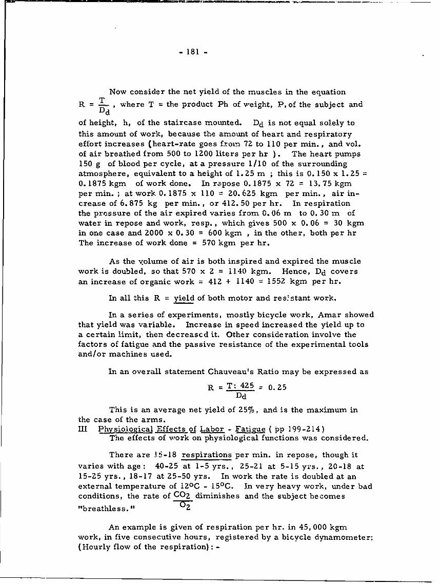
- 181 -
Now consider the net yield of the muscles in the equation
R -- , where T = the product Ph of weight, P, of the subject andDd
of height, h, of the staircase moLuted. Dd is not equal solely to
this amount of work, because the amount of heart and respiratoryeffort increases (heart-rate goes from. 72 to 110 per min., and vol.of air breathed from 500 to 1200 liters per hr ). The heart pumps150 g of blood per cycle, at a pressure 1/10 of the surroundingatmosphere, equivalent to a height of 1.25 m ; this is 0.150 x 1. 250. 1875 kgm of work done. In repose 0. 1875 x 72 = 13.75 kgmper min. ; at work 0.1875 x 110 = 20.625 kgm per min., air in-crease of 6.875 kg per min., or 412. 50 per hr. In respirationthe pressure of the air expired varies from 0. 06 m to 0. 30 m ofwater in repose and work, resp., which gives 500 x 0. 06 = 30 kgmin one case and 2000 x 0. 30 = 600 kgm , in the other, both per hrThe increase of work done = 570 kgm per hr.
As the volume of air is both inspired and expired the musclework is doubled, so that 570 x 2 = 1140 kgm. Hence, Dd coversan increase of organic work = 412 + 1140 = 1552 kgm per hr.
In all this R = yield of both motor and res'stant work.
In a series of experiments, mostly bicycle work, Amar showedthat yield was variable. Increase in speed increased the yield up toa certain limit, then decreascd it. Other consideration involve thefactors of fatigue and the passive resistance of the experimental toolsand/or machines used.
In an overall statement Chauveau's Ratio may be expressed as
R = T: 425 = 0. 25Dd
This is an average net yield of 25%, and is the maximum inthe case of the arms.III Physiological Effects of Labor - Fatigue ( pp 199-214)
The effects of work on physiological functions was considered.
There are 1i-18 respirations per min. in repose, though itvaries with age: 40-25 at 1-5 yrs., 25-21 at 5-15 yrs. , 20-18 at15-Z5 yrs., 18-17 at 25-50 yrs. In work the rate is doubled at anexternal temperature of 120C - 150C. In very heavy work, under badconditions, the rate of C02 diminishes and the subject becomes
"breathless."
An example is given of respiration per hr. in 45, 000 kgmwork, in five consecutive hours, registered by a bicycle dynamometer:(Hourly flow of the respiration): -
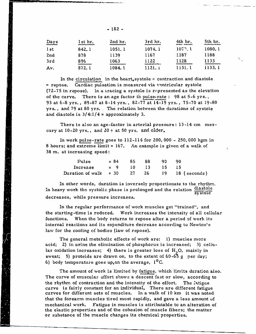
- 182 -
Days 1 st hr. Znd hr. 3rd hr. 4th hr. 5th hr.
I st 842.1 1051. 1 1074. 1 1071. 1. 1080. 1Znd 878 1139 1167 1187 11883rd 896 1063 1122 1128 1133
Av. 872.1 1084.1 1121. 1 1131. 1 1133.1
In the circulation in the heart,systole = contraction and diastolerepose. Cardiac pulsation is measured via ventricular systole
(72-75 in repose). in a tracing a systole is r-.presented as the elevationof the curve. There is an age factor in pulse-rate : 98 at 5-6 yrs. ,93 at 6-8 yrs., 89-87 at 8-14 yrs., 82-77 at 14-19 yrs., 75-70 at 19-80yrs., and 79 at 80 yrs. The relation between the durations of systoleand diastole is 3/4:1/4 = approximately 3.
There is also an age-factor in arterial pressure: 13-14 cm mer-cury at 10-20 yrs., and 20 + at 50 yrs. and older.
In work pulse-rate goes to 112-114 for 200, 000 - Z50, 000 kgm in8 hours; and extreme limit = 167. An example is given of a walk of38 m. at increasing speed:
Pulse = 84 85 88 90 90Increase = 9 10 13 15 15
Duration of walk = 30 27 26 19 18 (seconds)
In other words, duration is inversely proportionate to the rhythm.In heavy work the systolic phase is prolonged and the relation dia stole
E y to-f edecreases, while pressure increases.
In the regular performance of work muscles get "trained", andthe starting-time is reduced. Work increases the intensity of all cellularfunctions. When the body returns to repose after a period of work itsinternal reactions and its expenditure decrease according to Newton'slaw for the cooling of bodies (law of repose).
The general metabolic effects of work are: 1) muscles moreacid; 2) in urine the elimination of phosphorus is increased; 3) cellu-lar oxidation increases; 4) there is greater loss of H 0, mainly insweat; 5) proteids are drawn on, to the extent of 60-6i g per day;6) body temperature goes up,on the average, 10C.
The amount of work is limited by fatigue, which limits duration also.The curve of muscular :ffort shows a descent fast or slow, according tothe rhythm of contraction and the intensity of the effort. The latiguecurve is fairly constant for an individual. There are different fatiguecurves for different sets of muscles. In a walk of 10 km it was notedthat the forearm muscles tired most rapidly, and gave a less amount ufmechanical work. Fatigue in muscles is attributable to an alteration ofthe ela3tic properties and of the cohesion of muscle fibers; the matteror substance of the muscle changes its chemical properties.
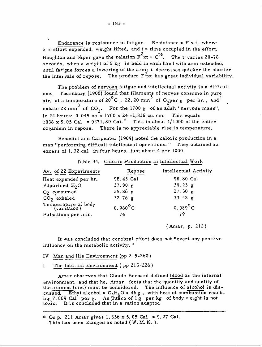
- 183 -
Endurance is resistance to fatigue. Resistance = F x t, where
F = effort expended, weight lifted, and t = time occupied in the effort.2 te
Haughton and Niper gave the relation F xt = Ct . The t varies 20-78
seconds, when a weight of 5 kg is held in each hand with arm extended,
until fat-gue forces a lowering of the arm; t decreases quicker the shorter
the inter rals of repose. The product F 2 xt has great individual variability.
The problem of nervous fatigue and intellectual activity is a difficult
one. Thurnburg (1905) found that filaments of nerves consume in pure3
air, at a temperature of 20 C , 22. 20 mm of O2 per g per hr., and
exhale 22 mm of CO For the 1700 g of an adult "nervous mass",
in 24 hours: 0. 045 cc x 1700 x 24 =1,836 cu. cm. This equals
1836 x 5.05 Cal = 9271.80 Cal. This is about 4/1000 of the entire
organism in repose. There is no appreciable rise in temperature.
Benedict and Carpenter (1909) noted the caloric production in a
man "performing difficult intellectual operations. " They obtained ail
.excess of 1. 32 cal in four hours, just about 4 per 1000.
Table 44. Caloric Production in Intellectual Work
Av. of 22 Experiments Repose Intellectual Activity
Heat expended per hr. 98. 43 Cal 98. 80 Cal
Vaporised H2 0 37. 80 g 39. 23 g
02 consumed 25. 86 g 27. 30 g
CO 2 exhaled 32. 76 g 33. 42 g
Temperature of body 0 0(variation) 0. 980°C 0. 989°C
Pulsations per min. 74 79
(Amar, p. 212)
It was concluded that cerebral effort does not "exert any positive
influence on the metabolic activity. "
IV Man and His Environment (pp 215-260)
I The Inte..ial Environment ( pp 215-226)
Amar obs'-ves that Claude Bernard defined blood as the internal
environment, and that he, Amar, feels that the quantity and quality ofthe aliment (diet) must be considered. The influence of alcohol is dis-cussed. Ethyl alcohol = C H6 0 = 46 g , with heat of combustion reach-ing 7. 069 Cal per g. An intake of 1 g per kg of body weight is nottoxic. It is concluded that in a ration adapted
, On p. 211 Amar gives 1, 836 x 5.05 Cal = 9. 27 Cal.
This has been changed as noted (W. M. K. ).
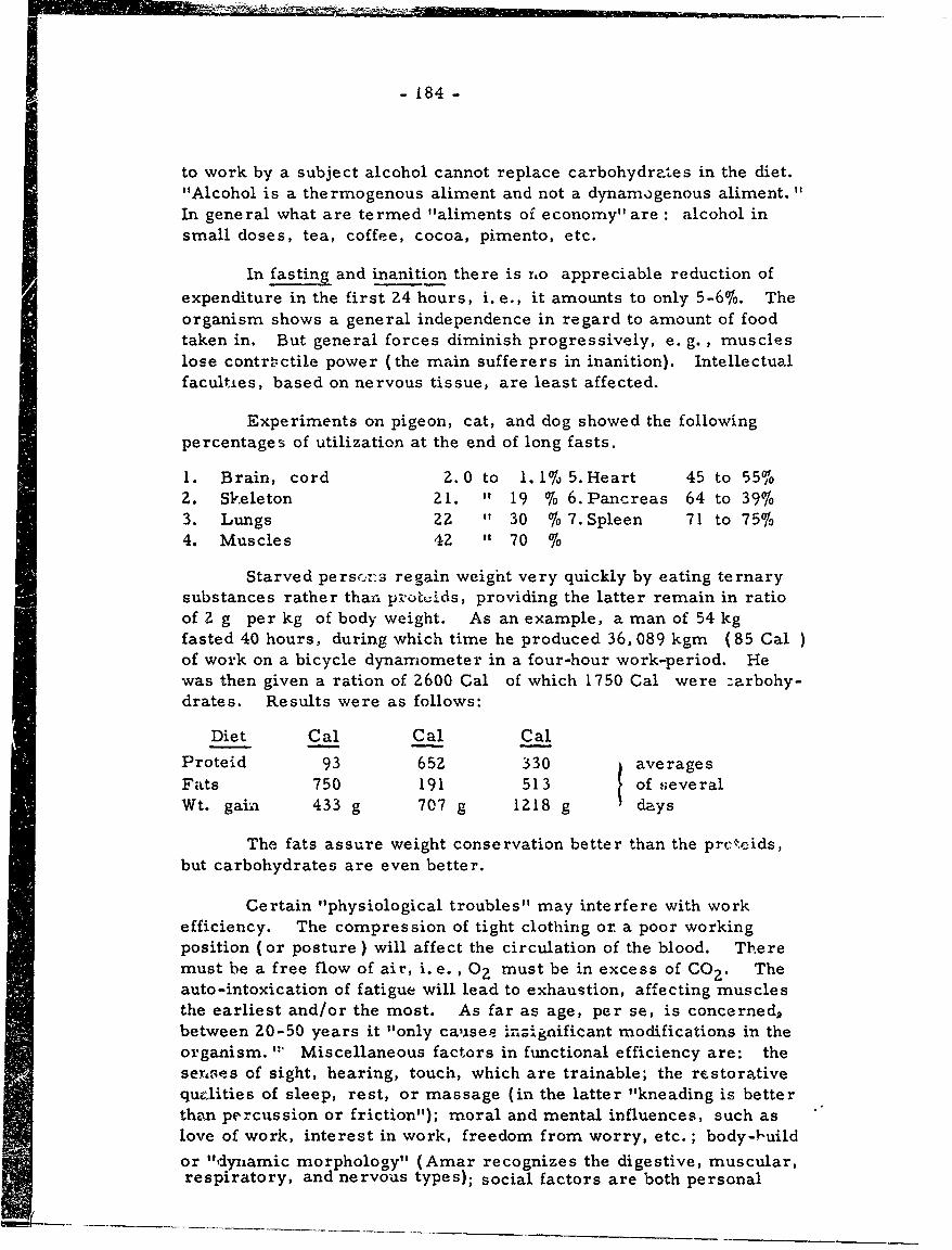
• n *-*- - + m.Ii.,L,.............:.L ,------ -
- 184 -
to work by a subject alcohol cannot replace carbohydra.es in the diet."Alcohol is a thermogenous aliment and not a dynamogenous aliment.
In general what are termed "aliments of economy" are: alcohol insmall doses, tea, coffee, cocoa, pimento, etc.
In fasting and inanition there is ro appreciable reduction ofexpenditure in the first 24 hours, i.e., it amounts to only 5-6%. Theorganism shows a general independence in regard to amount of foodtaken in. But general forces diminish progressively, e. g., muscleslose contractile power (the main sufferers in inanition). Intellectualfaculties, based on nervous tissue, are least affected.
Experiments on pigeon, cat, and dog showed the followingpercentages of utilization at the end of long fasts.
1. Brain, cord 2. 0 to 1. 1% 5. Heart 45 to 55%02. Skeleton 21. " 19 % 6. Pancreas 64 to 39%3. Lungs 22 " 30 % 7. Spleen 71 to 75%4. Muscles 42 " 70 %
Starved perscns regain weight very quickly by eating ternarysubstances rather than± p.otuids, providing the latter remain in ratioof 2 g per kg of body weight. As an example, a man of 54 kgfasted 40 hours, during which time he produced 36, 089 kgm (85 Cal )of work on a bicycle dynamometer in a four-hour work-period. Hewas then given a ration of 2600 Cal of which 1750 Cal were :arbohy-drates. Results were as follows:
Diet Cal Cal Cal
Proteid 93 652 330 averages
Fats 750 191 513 of severalWt. gain 433 g 707 g 1218 g days
The fats assure weight conservation better than the prc.cids,but carbohydrates are even better.
Certain "physiological troubles" may interfere with workefficiency. The compression of tight clothing oz a poor workingposition (or posture ) will affect the circulation of the blood. Theremust be a free flow of air, i.e. , 02 must be in excess of C02. Theauto-intoxication of fatigue will lead to exhaustion, affecting musclesthe earliest and/or the most. As far as age, per se, is concerned,between 20-50 years it "only causes in;ignificant modifications in theorganism. "' Miscellaneous factors in functional efficiency are: thesenses of sight, hearing, touch, which are trainable; the restorativequelities of sleep, rest, or massage (in the latter "kneading is betterthan percussion or friction"); moral and mental influences, such aslove of work, interest in work, freedom from worry, etc. ; body-fJuild
or "dynamic morphology" (Amar recognizes the digestive, muscular,respiratory, and nervous types); social factors are both personal
-185-
(hygiene of body and mind) and cultural (justice, concord, and thecommon prosperity of the workers).U The External Environment ( pp 227 -236)
T e external environment focuses first on the atmosphere,which is basically 79% N, 21%6 0? in volume (trace of CO = 0. 3%).Temperature variation ranges from 3. 6oC in January to 9. 30 C inJuly, in a single day. The weight of air on the body is the barometricpressure At sea level the normal pressure is 760 mm mercury.
The weight of one cu. cm of mercury = 13. 6 g hence, theweight of the barometric column = 1033 g. The average body surface= 2 sq. m ; therefore the total atmospheric pressure = 20, 000 x1033 = 20,660 kg.
Cold stimulates vital combustion, while hea. relaxes theseprocesses. Bodies cool by radiation. At lower external tempera-tures more 1:.at is lost at the surface. The speed of cooling of hotbodies increases proportionate to the excess of their own temperatureover that of the external environment.
to
570 50 T'o
Fig. 56. Diagram of Skin Temperatures, T and T', andOuter Air (t)
Let the body (Figure 56) be represented by a circle of hotwater: radiation is measured by the number of small calories emittedat 1 sq. cm surface. Here, Tt and T represent the internal and ex-ternal temperature of the skin; t is that of the surrounding air.Emission (Newton) is proportionate to the difference of temperaturebetween the surface and the external environment; the emissive power,K, is the number of cal per sec. per degree difference. In a differ- .ence of temperature ( T - t) the loss per sq. cm of radiating surfacewill be-
ql = K 1 (T - t) sin. cal
Radiation lowers the body temperature, so that heat must beproduced by the body to hold at 37. 50 C. The value of K variesaccording to the nature and color of the radiating surface. In addition
- 186 -
to radiation air carries away heat by convection. The loss viaconvection depznds on the differences of temperature (T - t) onthe surface area, but also on the shm of the surface area. Accord-ing to Peclet t'Ls factor can be represented by the coefficient K2 =
000066 c per sq. cm per sec., so that:
q) = K? (T - t) in sm. cal Hence, cal loss per
sq. crii per sec. is.
q-I + q., (Ki + KZ) (T - t).
The temperature, T, of the skin surface is neither-;easy tomeasure nor is it constant. The skin receives on its internalsurface as much heat as it loses on the external surface, i.e.,
q3 = (KI + K 2 ) (37. 5°C - T'), (Where T' = internal
cutaneous temp.).
Hence, q 3 = q + q
The conductivity of the skin, c must be determined for thenumber of sin. cal able to travc rse a surface of 1 sq.cm with athickness 1 cm in 1 sec. for a difference in temperature of 100between the internal and external walls. Here the heat transmittedis:
=lc( ' - T) in sm. cal and
q 4 = q 3 = q, + q2 = q (generally).
It is now possible to elimiaate T and T' and solve, using37. 50C. This r,,?sults in:
q= cK Z (KI + KZ) (37.5 0 C . t)
c(Kl + 2K 2 ) + eK2 (K1 +K 2 )
The average thickness of the skin, e 0. 2 cm. The coef-
ficients are: c z0.0006C c ; K I = 0. 00015 c ;K2 = 0. 000066 c.
This gives q = 9 0- 7 (37. 30C - to).
For 24 hours (.5600 % 24 sec. I a sq. cm of skin will lose0 0.as heat: Q, = 0.004294 ( 37.50C -- t in great calories.
Since adult surface area = 19, 900 sq. cm the loss will be
Q = 85. 540 Cal (37. 5C - t ° ), in an externalenvironmem of to.
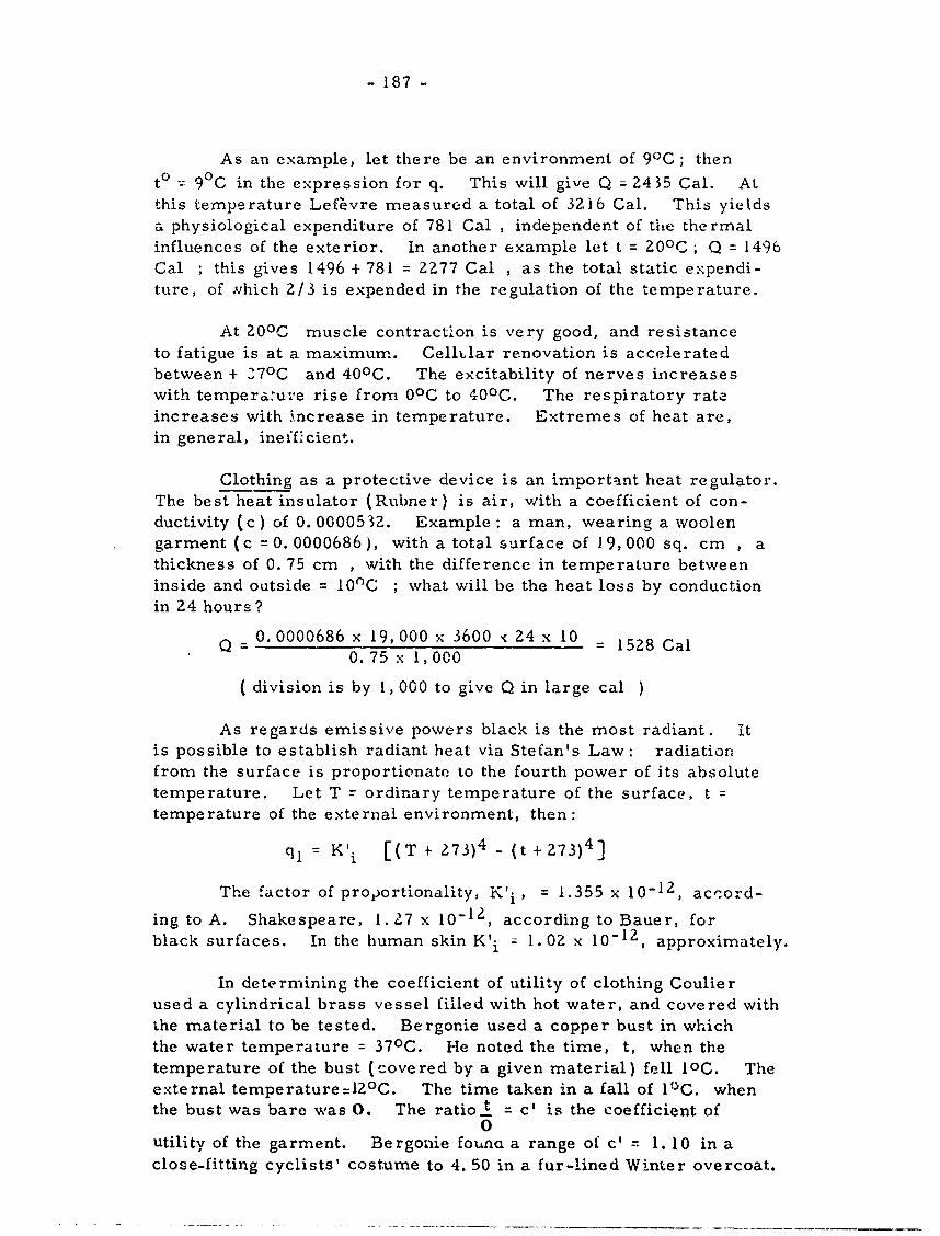
- 187 -
As an example, let there be an environment of 90C ; thento = 90C in the expression for q. This will give Q = 2435 Cal. Atthis temperature Lef~vre measured a total of 3Z16 Cal. This yietdsa physiological expenditure of 781 Cal , independent of the thermalinfluences of the exterior. In another example let t = 200C ; Q = 1496Cal ; this gives 1496 + 781 = 2277 Cal , as the total static expendi-ture, of hich 2/3 is expended in the regulation of the temperature.
At 20oc muscle contraction is very good, and resistanceto fatigue is at a maximum. CellLlar renovation is acceleratedbetween + 370 C and 40 0 C. The excitability of nerves increaseswith tempera.ure rise from 00C to 400C. The respiratory rateincreases with increase in temperature. Extremes of heat are,in general, inefficient.
Clothing as a protective device is an important heat regulator.The best heat insulator (Rubner) is air, with a coefficient of con-ductivity (c) of 0. 0000532. Example: a man, wearing a woolengarment (c 0. 0000686), with a total surface of 19, 000 sq. cm , athickness of 0. 75 cm , with the difference in temperature betweeninside and outside = 100C ; what will be the heat loss by conductionin 24 hours?
Q =0.0000686 x 19, 000 x 3600 < 24 x 10 = 1528 Cal0.75 x 1,000
( division is by 1, 000 to give Q in large cal )
As regards emissive powers black is the most radiant. Itis possible to establish radiant heat via Stefan's Law: radiationfrom the surface is proportionate to the fourth power of its absolutetemperature. Let T r ordinary temperature of the surface, ttemperature of the external environment, then:
ql = Kli [(T + 273) 4 - (t + 273) 4 ]
The factor of proportionality, K'i, = 1.355 x 10⁻¹², acrcord-
ing to A. Shakespeare, 1. 27 x 10-12, according to Bauer, forblack surfaces. In the human skin K'i Z 1.02 x 10⁻¹², approximately.
In determining the coefficient of utility of clothing Coulierused a cylindrical brass vessel filled with hot water, and covered withthe material to be tested. Bergonie used a copper bust in whichthe water temperature = 370C. He noted the time, t, when thetemperature of the bust (covered by a given material) fell 100. Theexternal temperature=120 C. The time taken in a fall of 1P0. whenthe bust was bare was 0. The ratio. = c' is the coefficient of
0utility of the garment. Be rgonie founa a range of c' = 1. 10 in aclose-fitting cyclists' costume to 4. 50 in a fur-lined Winter overcoat.
- 1,!8 -
III The External Environment (cont. ) (pp 237-49)
The hygrometric st-ate (humidity) is the ratio of the weightof water vapor contained in air to the maximum weight it couldcontain in the same volume. Let p and P be these two weights,then the hyg oinet ric state will be:
e =-- (the relative humidity)
P
The state of dryness increases as p is reduced.
In practice the weights of p and P of vapor are not considered,but its tensions ( "elastic force") f and F are given, so that:
fe = F.
The values of F may be found in Regnault's Tables ; the valueof f is determined by a hygrometer. For example, in a localityof 150 C the dew point of the hygrometer is found when t' = 50 C.For this temperature the tables give f = 6.55 mm ; for t = 150 CF = 12.70 mm. Hence:
e- 6.55 = 0.514 or 51.4 ,F 1Z. 7
Knowing f or e. the weight of water vapor per cu. m at tOccan be calculated:
290. 2 xf 290.2 xFxeP 273 +t g or p =- ~ TF--gZ73 +t273 + t
In perspiration the value o, elimination of water vapor by
the body varies inversely with the hygrometric state. At 20°Can adult male loses 900 g H2 0 in repose, 3000 g in an averageamount of work of 200, 000 kg ; in very hard work 7-8 kg of H 20
are lost. For work in the dry state an average temperature of150 C - 160 C is best.
Garments absorb water in varying amounts. Rubner foundthat the maximum quantity of HzO retained, per g of material was:
flannel 10.30 g silk tricot 3.80 gflannelette" 6. 00 ' linen 2. 10 "
wool tricot 4. 80 " cotton 0.80 "
cotton 4.20 "
Wool is equally valuable, Summer and Winter.
Speed of air current is important. For a man walking 1. 50m per sec., the air resistance is R =K x S x V?.
(R :kg , V = m , S = surface in sq. m); coefficient of resistance,
K, is 0.079 up to a speed of 40 m , a man's effective surface, S,when walking, is 0. 75 sq. m. Hence:
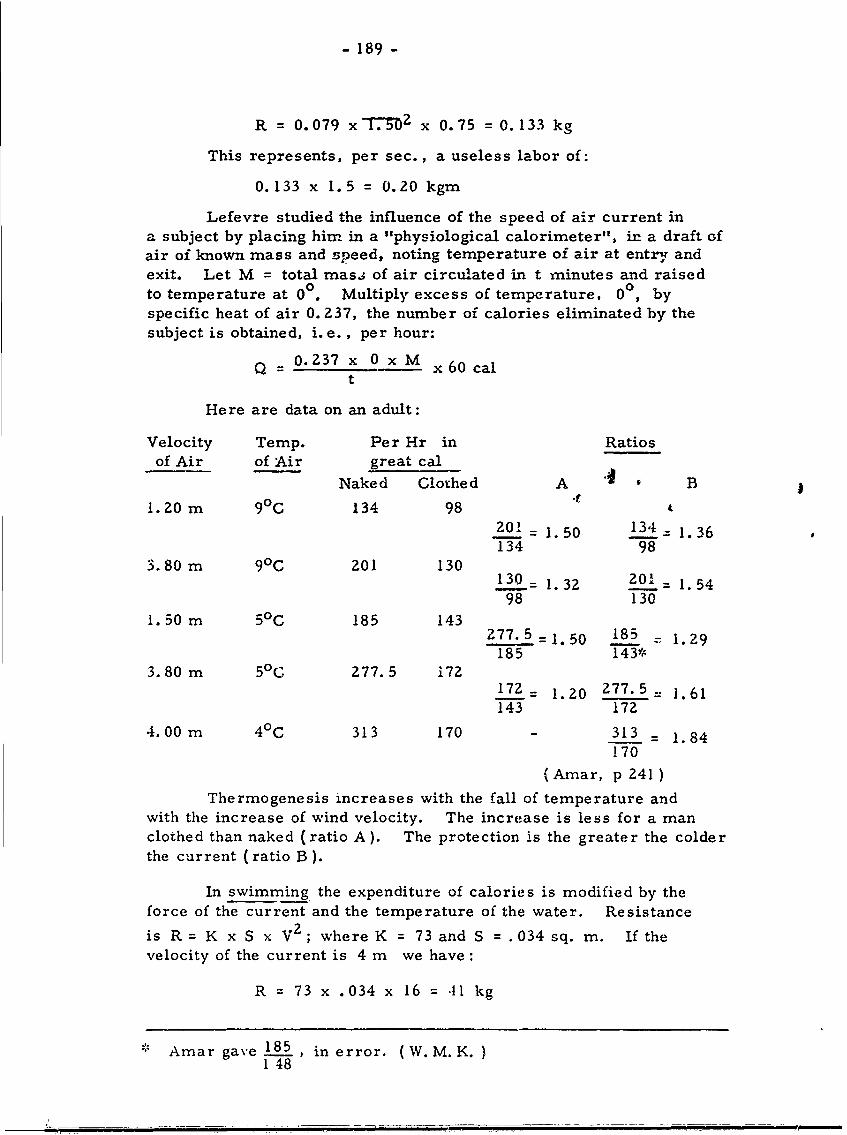
- 189 -
R = 0.079 x1.5 2 x 0.75 = 0.133 kg
This represents, per sec., a useless labor of:
0.133 x 1.5 = 0.20 kgm
Lefevre studied the influence of the speed of air current ina subject by placing him in a "physiological calorimeter", in a draft ofair of known mass and speed, noting temperature of air at entry andexit. Let M = total masa of air circulated in t minutes and raisedto temperature at 00. Multiply excess of temperature, 00, byspecific heat of air 0. 237, the number of calories eliminated by thesubject is obtained, i.e., per hour:
Q = 0. 237 x 0 x M x 60 cal
t
Here are data on an adult:
Velocity Temp. Per Hr in Ratiosof Air of Air great cal
Naked Clothed A B
1.ZO m 90C 134 98 it201 = 1.50 134 = 1. 36134 98
3.80 m 90C 201 130130= 1. 32 20 = 1 54
98 1301. 50 m 50 C 185 143
277.5 =1.50 185 1. 29185 143*
3.80 m 50 277.5 172172= 1.20 277.5= 1.61143 172
4.00 m 40C 313 170 - 313 = 1.84170
(Amar, p 241)
Thermogenesis increases with the fall of temperature andwith the increase of wind velocity. The increase is less for a manclothed than naked (ratio A). The protection is the greater the colderthe current (ratio B ).
In swimming the expenditure of calories is modified by theforce of the current and the temperature of the water. Resistance
is R = K x S x V 2 ; where K = 73 and S =.034 sq. m. If thevelocity of the current is 4 m we have:
R = 73 x .034 x 16 = 41 kg
* Amar gave i85 , in error. (W. M. K.)1 48
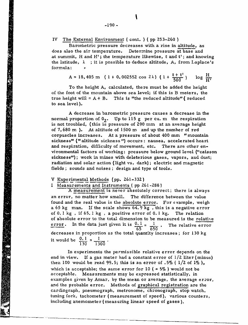
-190-
IV The External Environment { cont. ) (pp 253-260 )Barorhetric pressure decreases with a rise in altitude, as
does also the air temperature. Determine pressure at base andat summit, H and H'; the temperature likewise, t and t'; and knowingthe latitude, X ; it is possible to deduce altitude, A, from Laplace'sformula:
A= 18,405m ( l + 0.00Z55Z cos 2X) (1 + L+ logH500 H
To the height A, calculated, there must be added the heightof the foot of the mountain above sea level; if this is B meters, thetrue height will = A + B. This is "the reduced altitude" ( reducedto sea level).
A decrease in barometric pressure causes a decrease in thenormal proportion of 02. Up to 115 g per cu. m the respirationis not troubled, (this is pressure of Z90 mm at an average heightof 7,680 m ). At altitude of 1500 m and up the number of redcorpuscles increases. At a pressure of about 400 mm "mountainsickness" ("altitude sickness ") occurs : nausea, accelerated heartand respiration, difficulty of movement, etc. There are other en-vironmental factors of working: pressure below ground level ("caissonsickness"); work in mines with deleterious gases, vapors, and dust;radiation and solar action (light vs. dark); electric and magneticfields ; sounds and noises ; design and type of tools.
V Experimental Methods (pp. 261-332)I Measurements and Instruments ( pp 261-288)
A measurement is never absolutely correct; there is always
an error, no matter how small. The difference between the valuefound and the real value is the absolute error. For example, weigha 65 kg man. If the scale shows 64. 9 kg , this is a negative errorof 0. 1 kg , if 65. 1 kg , a positive error of 0. 1 kg. The relationof absolute error to the total dimension to be measured is the relativeerror. In the data just given it is 0.1 I . The relative error
decreases in proportion as the total quantity increases ; for 130 kg
it would be 0.I = .130 1300
In experiments the permissible relative error depends on theend in view. If a gas meter had a constant error of 1/2 liter (minus)then 100 would be read 99.5; this is an error of .5% ( 1/2 of 1% ),which is acceptable; the same error for 10 ( = 5% ) would not beacceptable. Measurements may be expressed statistically, inexamples given by Amar, by the mean or average, the average erzor,and the probable error. Methods of graphical registration are thecardiograph, pneumograph, metronome, chronograph, stop watch,tuning fork, tachometer (measurement of speed), various counters,including anemometer (measuring linear speed of gases).
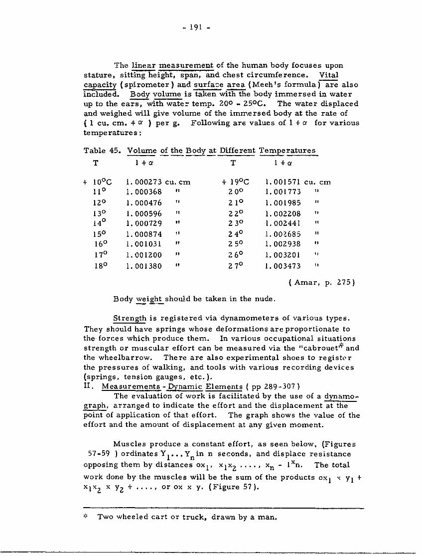
- 191 -
The linear measurement of the human body focuses uponstature, sitting height, span, and chest circumference. Vitalcapacity (spirometer) and surfaze area (Meeh's formula) are alsoincluded. Body volume is taken with the body immersed in waterup to the ears, with water temp. 200 - 250C. The water displacedand weighed will give volume of the immersed body at the rate of(1 cu. cm. + a ) per g. Following are values of I + a for varioustemperatures:
Table 45. Volume of the Body at Different Temperatures
T 1+ a T 1+a
+ 100 C 1.000273 cu. cm + 190C 1.001571 cu. cm110 1.000368 " 200 1.001773 "
120 1.000476 " 210 1.001985 "
130 1.000596 " 220 1.002208
140 1.000729 " 230 1.002441 "
150 1.000874 " 240 1.002685 "
160 1.001031 " 250 1.002938 "
170 1. 001Z00 " 2 60 1.003201 "
180 1.001380 " 270 1.003473 "
(Amar, p. 275)
Body weight should be taken in the nude.
Strength is registered via dynamometers of various types.
They should have springs whose deformations are proportionate tothe forces which produce them. In various occupational situations.
strength or muscular effort can be measured via the "cabrouet" andthe wheelbarrow. There are also experimental shoes to registerthe pressures of walking, and tools with various recording devices(springs, tension gauges, etc.).II. Measurements- Dynamic Elements ( pp 289-307)
The evaluation of work is facilitated by the use of a dynamo-graph, arranged to indicate the effort and the displacement at thepoint of application of that effort. The graph shows the value of theeffort and the amount of displacement at any given moment.
Muscles produce a constant effort, as seen below, (Figures57-59 ) ordinatesY...Yn in n seconds, and displace resistance
opposing them by distances ox i , xlx2 .... , xn - lXn. The total
work done by the muscles will be the sum of the products ox1 x yl +XIx 2 x Y2 + .... , or ox x y. (Figure 57).
Two wheeled cart or truck, drawn by a man.
- 192 -
Y
Y1I Y 1 j I 1 I
I I! [ I ' i II I j ~ I I 1f ! Ii I t I I 1I I ]I I I1 1 I I I
o x x2 x3 x4 Xn Xn
Figure 57 Scheme of Dynamograph: Work of Muscle.
If the effort were variable the total area would be as below:(Figure 58).
Y
!I I .
I I I I I I I I I I io° X X2 xn
Figure 58 Variable Work Registered by Dynamograph.
If the variation of the effort is continuous the graph wouldtake the form of a curve, C, and the area to be found would beOABx (Figure 59).
Y
iJ CA
0 x
Figure 59 Curve of Continuous Variation in Work.
- 193 -
When displacements are large they can be proportionatelyreduced ard "scaled down", e. g. on the scale Imm = 10 cm. Areascan be measured with a planimeter. In essence "the area of a graphis equal to the sum, either of a series of small equal rectangles, ....or more exactly as a series of small trapeziums". In this casedivide the base or the line of the abscissae, Ox, into a sufficientlylarge number of equal parts, d.
The value of S is given by Poncelet's formula:S = d (Y2 (+ y3+ ... Yn -)+ Y° + Yn - Y' + Yn'l
12 4 4 iThe highest limit of error is:
d (yl + Yn -1-Yo - Yn)
Ergometry and ergography are, respectively, measurementof work done and the graphic representation of work done. In variouswork or industrial situations they may measure hand, arm, leg,foot work outputs.
In considering the mechanical work done by man a c.assifica-tion of active muscles should be based upon whether they are of arms,legs, or fingers, or of several groups at once, or if the whole weightof the body is put to work at once. The use of the arm muscles isthe most variable, for they come into play wherever manual strengthor dexterity is a factor.
Amar focuses upon the work of the work of the muscles of theleg, as noted in bicycling: F = uniform pressure on each pedal; dthe diameter of the circle of the pedal; hence, work done = F x d.Per stroke of the pedal (both legs) it is T = ZFd. This is the workof both legs + the work done in advancing the loaded bicycle. Witheach stroke of the pedal the bicycle advances the distance, D, depend-ing on the gear. Let R = all resistance involved:
RxD=T= ZFd
Knowing T or R we can deduce F. A value of R is accept-able as:
R = 0.012 P+ 0. 0738 SV 2 I P = total wt. of bicycle + rider,
S = suriace area of bicycle, (about 0.60 sq. m.), and V =
speed in m. per sec. I
If slope is inclined i per meter:
R = P(0.01Z + i) + 0.73 SV 2
- 194 -
As an example: speed = 18 km per hr , on slope wherei = 0.02 m , bicycle wt. = 15kg , rider wt. = 65kg :
P = 65+ 15 - 80kg ; V 1800.0 5m per sec. Therefore,3600
R= 80 x 0.032 + 0.073 x 0.6 x 5 x 5 = 3.655 kg
The work done per hour will be 3. 655 x 18, 000 = 65, 790
kgm , and per meter will be 65, 970 = 3. 655 kgm.18,000
In descent the value of R = 80 x (-0.008) + 0.073 x 0.6 x5 x 5 = 0. 455 kg (The nature of the ground and the state of thetires will be variable factors).
Legs are basically used in locomotion but must also supportthe body in all different movements ; they must resist carried loads,while displacing this total weight on the level or on a slope. There-fore, useful work is "the product of the weight displaced by the sumof the amplitudes of the vertical oscillation of the body walking onlevel ground, or by the sum increased by the total slope that has beenclimbed." The new unit now defined is the product of I kg of wt.displaced per m covered, horizontally or on a slope : this is themeterkilogram (Mkg ).
Lifting a weight to the top of a stairs, H, will be simplyP x H. In mounting a ladder the H = vertical distance to the ground,not the length of the ladder. According to the speed of ascent a manwill expend an effort greater than P, alone; hence, muscular workexceeds mechanical work.III Measurement of Energy ( pp 308-332)
In the measurement of enery there are two forms concernedin the human machine: 1) that manifested externally in work or heat(physiological work or physiological energy); 2) that which acts fromoutside the organism (natural or meteorological). The expenditureof the human motor indicates the quantity of energy a certain amountof work entails.
The measurement of physiological energy may be done ,ia themethod of maintenance rations. The usual diet is noted; then a givendiet is set up so that every day at the same hour the subject's weightis the same ; also, the diet is related to a given constant amount ofwork. For example a subject in repose weighed 80. 2 kg. Thevariation for nine days of work was as follows:
Day 1 80.2 kg Day 6 80. 2 kg" 2 79.98 " " 7 80.2 "
" 3 80.1 " " 8 80.28w"of 4 80.18 " " 9 80.3 ", 5 80.2 "
- 195 -
The next stage of the inquiry was to note the quantities of proteids,fats, carbohydrates and the corresponding energy values from availabletables. Then age and sex were equated and Atwater's coefficients wereused:
The consumption of an adult male 1.00" " i If female 0.80
Boy 14-16 years 0.80Girl 14-16 years 0.70Child 10-13 years 0.60
" 6-9 years 0.50" 2-5 years 0.40" below 2 years 0.30
Physiological energy can also be measured via the oxygen method.The test is run in the morning, after a fast of 10 hours. The caloricpower of a liter of 0 at 00 and 760 mm will be 4. 6 cal. Respiratoryexchange is measurei via a spirometer. The gas is analyzed viaLalanie' s eudioineter or that of Bonnier and Mangin. An example ofthe use of the latter is given. Let it be assumed that there are, asdetermined by readings, 450 divisions or volumes of air to be analyzed;this will be N. Samples of air are passed through potassium, and CO2
will be absorbed; bring the reading to 600, so that the division to theleft in the apparatus will be 165; hence, N' : 600 - 165 = 435 vols. ;here CO = 450 - 435 = 15 vols. Now take a sample of pyrogallate and
absorb 0, letting N" = 600 - 240 = 360 vols. ; the 02 content is there-
fore 435 - 360 = 75 vols. in 450.
Proportions will be:
CO 2 = 5 x 100 - 3. 337
0 2 = -7 x 100= 16.66%450
With N, N', N" attained, calculations are:
C0 2 %= N-N' x 100N
= x 100N
The study is made at temperature, t, and atmospheric pressure,H, The volume, Vt, thus measured must be reduced to 0 0 C. and
760 mm pressure. The volume of a gas increeses with the temperature
- 196 .
by a = 1/273 per 10C and diminishes as the pressure rises. Thevolume at 0 C and 760 mm is
-V V HV 0 t x , or approximatelyI + C t 760
V = 0.36xV t x H
273 + t
In Laulanie's eudiometer H is a measure of dry air and the tension,F, of the water vapor at temperature t (F is found from Regnault'stables). Theiefore:
0o31 x V (H-F)V t, where
o Z73 + t
H = atmospheric pressure at the moment,
F = tension of water vapor at temperature to
The volume of the dry gases is thus determined at 00 and 760 mm.
Knowing the volume of the gases, V , for the duration of the0
experiment, and CO and 02 having been determined, it is easy todeduce:
1. The respiratory quotient CO202
2. The total 02 consumed. In pure air taken in 02 = 21%; if
analysis = 17%, then 4%6 has been utilized. Hence, theproportion, r, in the expired gases having been calculated,the quantity left in the body will be:
(21 - r) x Vo
100
3. The total CO2 eliminated. Here all the CO 2 in the expiredgases is taken. For example let v0 be the consumption ofO Z in 10 min. , of a man in repose, and CO 2 = 0. 98. A
liter of O Z = 5. 05 Cal , and vo liters represents staticexpenditure. Then:
s= v0 x 5. 05 Cal
Let v o be the amount of O Z absorbed during work, T, in10 min., and let C02 = 0.97. The coefficient 5. 05 Cal
0?will be applicable here:
q = v' x 5.05 Cal
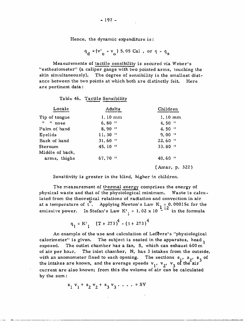
- 197 -
Hence, the dynamic expenditure is:
q d = (V'o 5.05 Cal ,or q - q
Measurements of tactile sensibility is secured via Weber's"esthesiometer" (a caliper gauge with two pointed arms, touching theskin simultaneously). The degree of sensibility is the smallest dist-ance between the two points at which both are distinctly felt. Hereare pertinent data:
Table 46. Tactile Sensibility
Locale Adults Children
Tip of tongue 1. 10 mm 1. 10 mm" " nose 6.80 14 50 "
Palm of hand 8.90 4. 50 "Eyelids 11. 30 9.00
Back of hand 31.60 I22.60 "
Sternum 45. 10 33.80Middle of back,
arms, thighs 67.70 " 40.60 "
(Amar, p. 322)
Sensitivity is greater in the blind, higher In children.
The measurement of thermal energy comprises the energy ofphysical waste and that of the physiological minimum. Waste is calcu-lated from the theoretical relations of radiation and convection in air0at a temperature of to. Applying Newton's Law K = 0. 00015c for theemissie power. In Stefan's Law K = 1. 02 x 10 11 in the formula
= K' 1 (T + 273)4 - (t+ 273)4
An example of the use and calculation of Lef~vre's "physiologicalcalorimeter" is given. The subject is seated in the apparatus, headexposed. The outlet chamber has a fan, S, which can exhaust 600mof air per hor. The inlet chamber, N, has 3 intakes from the outside,with an anomometer fixed to each opening. The sections s , s_, s ofthe intakes are known, and the average speeds vI, v2 , v3 o1 the'air'
current are also known; from this the volume of air can be calculatedby the sum :
s1 vI + Sz v + s3 v3 . . . . = SV
- 198 -
Thermometers correct to 1/10 degree are placed in front andbehind the subject to give the amount 0, by which the air is heated.
Let V = av. speed of air during the experiment, and SV = vol. in
liters. The weight of a liter of air = 1. 293 g , and so the total
mass, M, will be:
M = S x V x 1. 293 g
Correcting for air pressure, H, and air temperature, t, theimpression is:
0.36 x HM=SxVx 273+ t
The increase in temperature, 0, will be:
Q = M x 0 x 0. Z37 cal (where 0. 237 cal = specific
heat of the air)
Tables of thermal conductivity range from 0. 0000330 for com-pressed cotton to 1. 0400000 for copper. In an adult male subject Lefevrereported a value of 11.70 Cal for caloric loss of water. Also givenhere are tables of tension of vapor in mm. of mecury (Regnault, Thiesenand Scheel), and tables of sines and tangents.
VI Industrial Labor ( pp 333-466)
I Bd in Equilibrium and Movement - Locomotion ( pp 333-358)
There are two main areas here: 1) the human body in equilibriumand in motion; 2) the influences on the human body of the nature andquality of the tools and appliances used. The human body is an articulatedor jointed system which is never at complete rest, being subject to externalforces (the most important of which is gravity) and to internal forces(wherein muscular actions are basic). The human body is heterogeneouswhose density varies in different parts; it is irregular in shape; it isnot isolated in space; for it is posed on the Earth's surface, supportedby a base, i. e., the feet. The laws of mechanics apply to the human body,in both static and dynamic states.
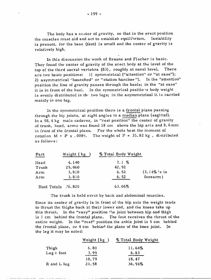
- 199 -
The body has a ceater of gravity, so that in the erect position
the muscles must aid and act to establish equilibrium. Instability
is present, for the base (feet) is small and the center of gravity is
relatively high.
In this discussion the work of Braune and Fischer is basic,
They found the center of gravity of the erect body at the level of the
top of the third sacral vertebra (S3), roughly at navel level. There
are two basic positions: 1) symmetrical ("attention" or "at ease");
2) asymmetrical "haunched" or "station hanchee "). In the "attention"
position the line of gravity passes through the heels; in the "at ease"
it is in front of the heel. In the symmetrical positio- s body weight
is evenly distributed in th- two legs; in the asymmetrical it is carried
mainly in one leg.
In the symmetrical position there is a frontal plane passing
through the hip joints, at right angles to a median plane (sagittal).
In a 58. 4 kg male cadaver, in "rest position" the center of gravity
of trunk, head, arms was found 18 cm above the hip axis and 8. 6mm
in front of the frontal plane. For the whole bust the moment of
rotation M = P x . 0086. The weight of P = 35. 82 kg , distributed
as follows :
Part Weight ( kg ) % Total Body Weight
Head 4.140 7.1 %Trunk 25. 060 42.92
Arm 3.810 6.52 (3. 14% ;s in
Arm 3.810 6.52 forearm)
Bust Totals 26. 820 63.06%
The trunk is held erect by back and abdominal muscles.
Since its center of gravity is in front of the hip axis the weight tendsto thrust the thighs back at their lower end, and the knees take up
this thrust. In the "easy" position fhe joint between hip and thigh
is 1 cm behind the frontal plane. The foot receives the thrust of the
entire weight. In the "rest ' position the ankle joint is 5 cm behind
the frontal plane, or 4 cm behind the plane of the knee joint. In
the leg it may be noted:
Weight (kg ) % Total Body Weight
Thigh 6.80 11.64%Leg+ foot 3.99 6.83
10.79 18.47
R and L leg 21.58 36.94%
- o00 -
The muscles of the sole of the foot have to balance a moment of
rotation produced by a weight of 36. 82 + 2 x 6. 8 = 50. 42 kg. The
arm of the lever is about 4 cm. in length. The Achilles tendon
pulls up the heel, so that the front of the foot is pressed on the
ground, transmitting the weight, the reaction of the ground on the
foot being equal and opposite.
Body stability is not great in either of the two symmetricalpositions. It is best in the asymmetrical position, for then the
center of gravity is directly above the leg of support. In the sitting
position, with a larger base, stability is increased. This is seen
in the measuring of 02 consumption:
Sitting 100"Haunched" 103 (the relative
' Easy" 106 expenditure
"Attention" 125 of energy )
The recumbent position gives maximum stability and efficiency,
base is maximum, expenditure of energy is 7-8% less than in sitting.
Men with heavy loads, obese men, hunchbacks, men bent with age,
and pregnant women have the center of gravity displaced.
In summary to this point: 1) the center of gravity is at about
57/100 of total height; 2) the center of gravity of the bust is 18 cm
above the transverse axis of the hips; 3) in an adult male of 65 kg
the bust is 41 kg. (63%) and the leg 24 kg ( 3 71%) of the total weight;
4) lower leg is 6. 83% of the total body weight; 5) total leg length
varies from .87-.90 m , with a weight of 12 kg (lower leg =4.4 kg.);
6) Atwater showed for an adult male in a calorimeter at 200C an ex-
penditure of energy = Z, 120 Cal , or Z120 = 1. 36 Cal per kg of65 x Z4body wt. per hr. In open air, at 140-150C , this may reach 1. 5 Cal.
When the mechanical equilibrium of the body is disturbed
movement begins. As a result there are both external and internal
forces operative, focusing on the center of gravity. The internal
forces do not affect the center of gravity. An erect body on a r'mooth
surface can only rotate around a vertical axis on which the center of
gravity remains unchanged. In the external forces the major factor
is gravity, with friction and air resistance having minor roles.
An acrobat in a leap can turn himself around a transverse axis.
Main factors are height, speed, and duration of the leap, governed
and connected by:
v .- \V'_7 ; h = 1/2 gt 2 ; t V9
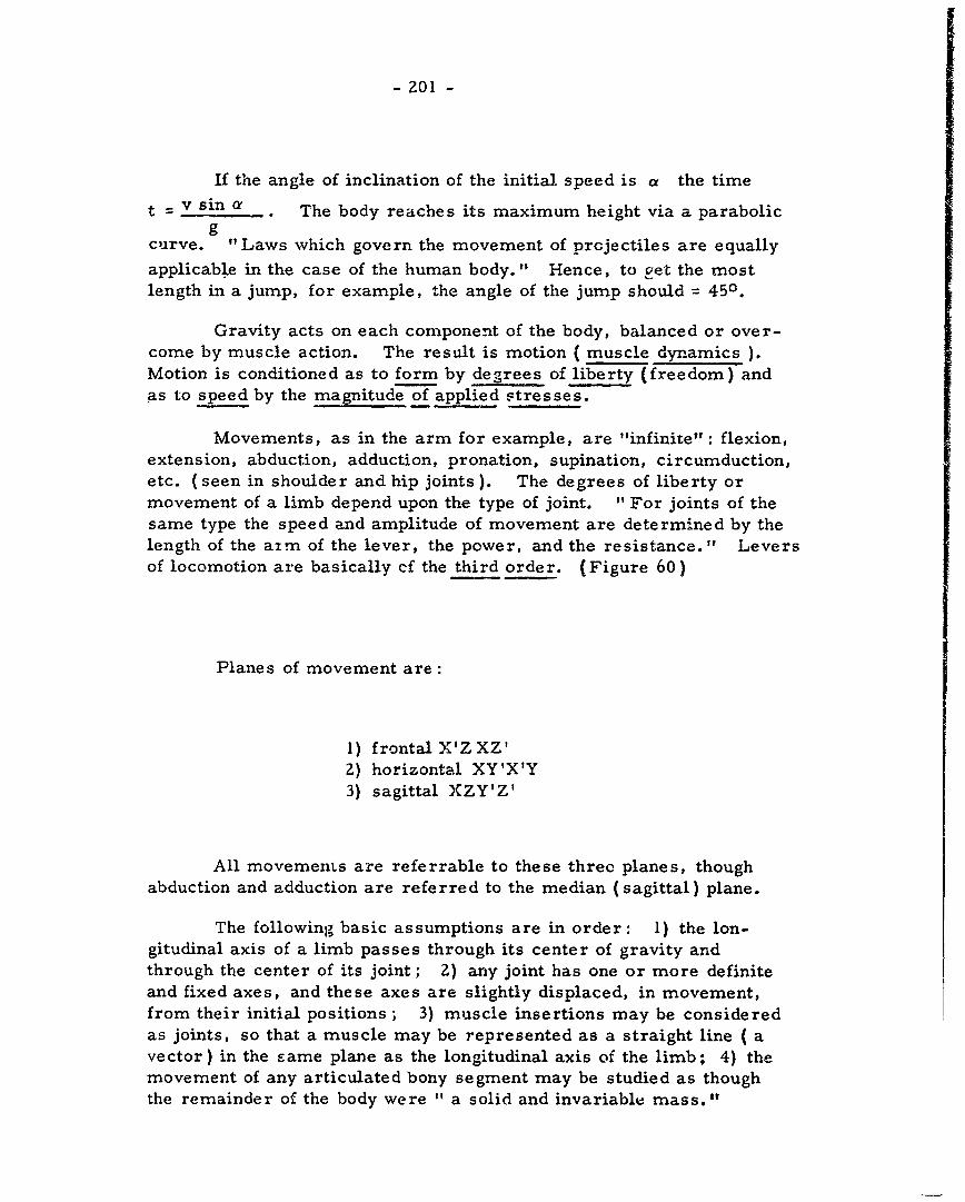
- 201 -
If the angle of inclination of the initial speed is a the time
t =v sin The body reaches its maximum height via a parabolicg
curve. "Laws which govern the movement of projectiles are equally
applicable in the case of the human body." Hence, to iet the mostlength in a jump, for example, the angle of the jump should = 450 .
Gravity acts on each component of the body, balanced or over-come by muscle action. The result is motion ( muscle dynamics ).
Motion is conditioned as to form by degrees of liberty (freedom) andas to speed by the magnitude of applied stresses.
Movements, as in the arm for example, are "infinite": flexion,extension, abduction, adduction, pronation, supination, circumduction,etc. (seen in shoulder and hip joints). The degrees of liberty ormovement of a limb depend upon the type of joint. " For joints of thesame type the speed and amplitude of movement are determined by thelength of the aim of the lever, the power, and the resistance." Leversof locomotion are basically ef the third order. (Figure 60)
Planes of movement are:
1) frontal X'ZXZ'2) horizontal XY'X'Y3) sagittal XZY'Z'
All movements are referrable to these three planes, thoughabduction and adduction are referred to the median (sagittal) plane.
The following basic assumptions are in order: 1) the lon-gitudinal axis of a limb passes through its center of gravity andthrough the center of its joint; 2) any joint has one or more definiteand fixed axes, and these axes are slightly displaced, in movement,from their initial positions ; 3) muscle insertions may be considered
as joints, so that a muscle may be represented as a straight line ( avector) in the same plane as the longitudinal axis of the limb; 4) themovement of any articulated bony segment may be studied as thoughthe remainder of the body were " a solid and invariable mass."
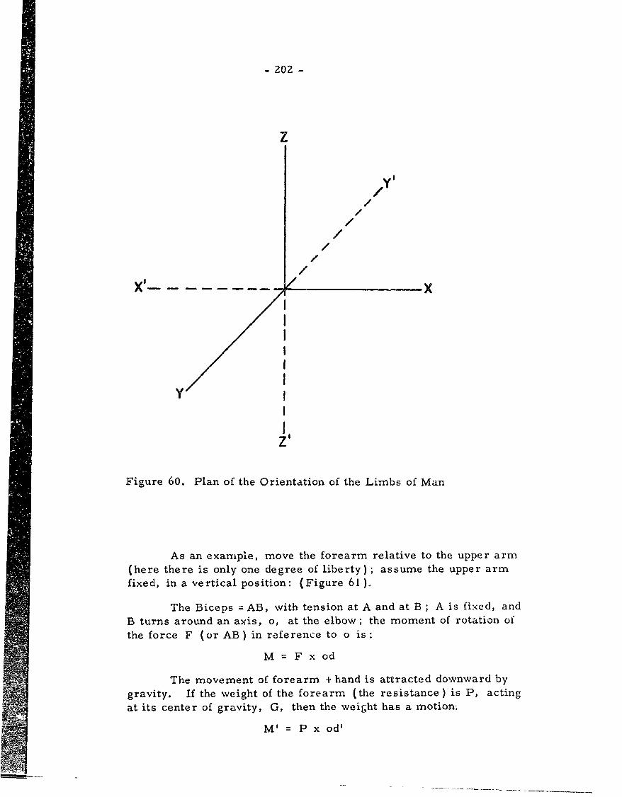
- 202 -
z
ZI //
//
//
/
y I/
Figure 60. Plan of the Orientation of the Limbs of Man
As an example, move the forearm relative to the upper arm(here there is only one degree of liberty); assume the upper armfixed, in a vertical position: (Figure 61),
The Biceps = AB, with tension at A and at B ; A is fixed, andB turns around an axis, o, at the elbow; the moment of rotation ofthe force F (or AB) in reference to o is:
M F x od
The movement of forearm + hand is attracted downward bygravity. If the weight of the forearm (the resistance) is P, acting
at its center of gravity, G, then the weight has a motion.
M1 =P x od'
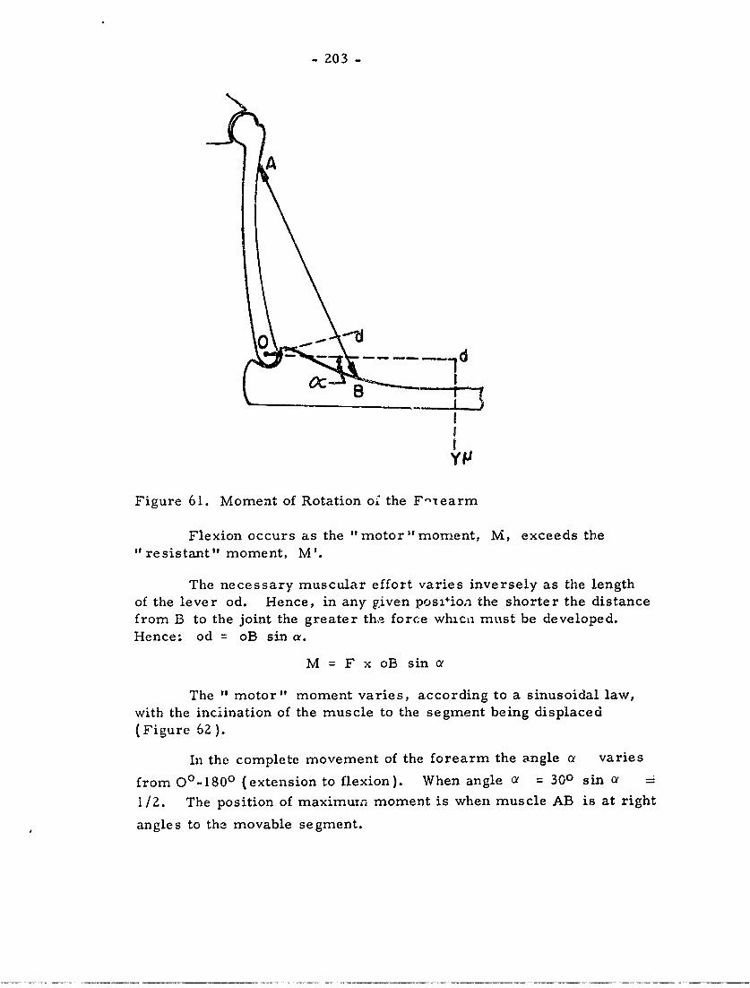
- 203 -
A
0C
EIE
YIJ
Figure 61. Moment of Rotation of the F" earm
Flexion occurs as the "motor " moment, M, exceeds the"resistant" moment, M'.
The necessary muscular effort varies inversely as the lengthof the lever od. Hence, in any given pos4ion the shorter the distancefrom B to the joint the greater the force whica must be developed.Hence: od = oB sin a.
M = F x oB sin a
The " motor" moment varies, according to a sinusoidal law,with the inciination of the muscle to the segment being displaced(Figure 62 ).
In the complete movement of the forearm the angle a varies
from 00-1800 (extension to flexion). When angle a = 300 sin e -
1/2. The position of maximum moment is when muscle AB is at right
angles to the movable segment.
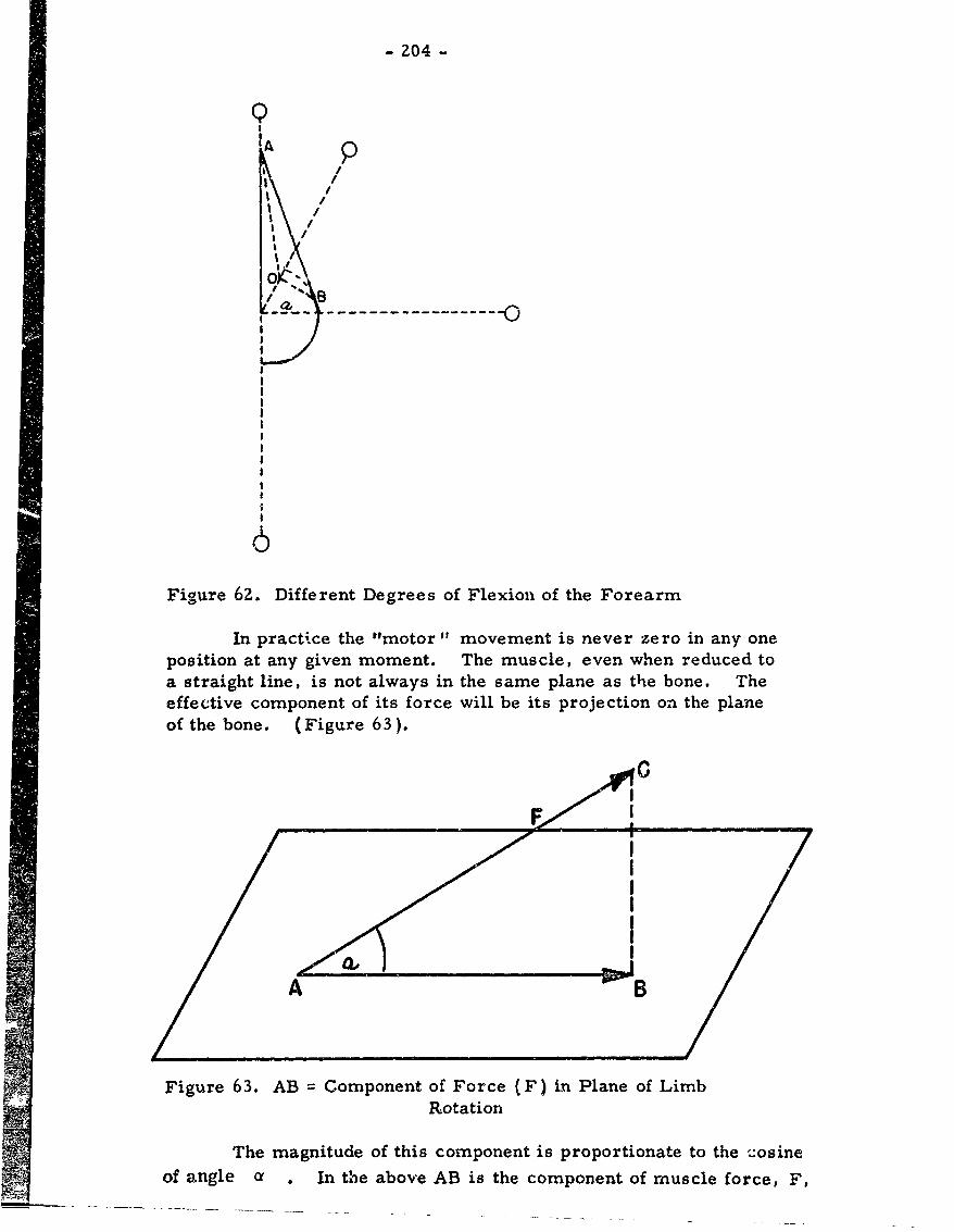
- 204 -
Q
/I A /
Figure 62. Different Degrees of Flexion of the Forearm
In practice the "motor" movement is never zero in any one
position at any given moment. The muscle, even when reduced to
a straight line, is not always in the same plane as the bone. Theeffective component of its force will be its projection on the plane
of the bone. (Figure 63).
'd I
A B
Figure 63. AB Component of Force (F) in Plane of LimbRotation
The magnitude of this component is proportionate to the cosineof angle a . In the above AB is the component of muscle force, F,
- 205 -
in the plane of limb rotation.
A movement with one degree of liberty may be due to the actionof one muscle or of several. It is necessary to consider here onlythe resultant. Any system of force can be reduced to an equivilentsingle force and a "couple. "' This is only true for a single definiteposition, since forces change during displacement. Movements withonly one degree of liberty are larger joints, e. g. forearm and lowerleg, with no rotational movement. Hence, as in the foregoing Figure,the effect of a lateral component, BC, is practically nil in flexion andextension. But the forearm can rotate in supination. Finger jointsare the only ones with a single a.xis. The elbow joint has two degreesof liberty.
Flexor muscles operate more ec,,nomically than extensors(Chauveau, Fischer).
Spherical joints have three degrees of liberty (flexion or exten-sion in the sagitta. plane, adduction in the frontal plane, plus circum-duction). Motion is more often in a single direction, around a deter-mined axis, e. g., the legs usually move in the sagittal plane.
Muszles may control two or more joints, e. g., the extensorscontrol the wrist ?nd the fingers. The same member may call intoplay in its movements a whole group of muscles. Muscle movementhas its antagonists which control or regulate speed of movement. Inprinciple, however muscles act in combisiation, more than in opposition.
The summation of energy expended in various muscle actions isnecessary to determine the "degree of fatigue. "
In body movements centers of gravity and moments of inertia canbe studied, for various parts of the body. Fischer showed that thelimbs and the head and trunk have centers of gravity referrable to acommoi origin, the line of the shoulder and hip joints.
If the trunk can be considered as a cylinder and the limbs asfrutrsit of tunvi the movements of inertia can be calculated.P
I M where the mass M equals -. I and p equals the radius
If[ OV rl'ioi. 1 Here are data on an adult male of 65 kg.
I) Ihit(hltad 4 truilk), with weight equals 50% of the whole orta. " I'j, (Coeter of gravity equals 0. 32 m from line of hip&. Dimen-him-iIil 'lth tylinder are: height equals 0.88 m , radius equals 0. 13 m.Mtviti tii merta is:
I - ( 3r2 4 4h ) 0.86
- 206 -
2. Upper arm: weight equals 2.20 kg , center of gravityequals 0. 145 m from center of shoulder joint. Height equals 0. 35m ; and compare the segment to a truncated cone: r= 0. 047 mr' 0.04 m. This gives:
I =M ]hI- - ( I + d r +(r + r')?,'Zdg 1 .. ..
3. Forearm: M=2"04kg, h equals 0.35 m , r equals 0.045g
m , r' equals 0.027 m , center of gravity equals 0.54 m , from
center of the elbow joint. Hence I equals 0. 0037.
4. For the fingers I is as follows:
Thumb 0. 000006 Ring D'. 000012Index 0.000012 Little 0. 000004Middle 0,000014
5. Entire arm: center of gravity equals 45/100 from shoulderjoint, i. e. 0. 32 m. With closed fist equals 0. 70 m. P equals 4. 20kg , r equals 0.047 m , r' equals 0. 27 m. Hence I equals 0. 03,approximately.
6. Lower leg: P equals 4.4 kg (foot included); h equals0. 44 m , r equals 0. 062 in , r' equals 0.038 m. Hence, I equals0.0i3.
7. Entire leg: P equals 12 kg , h equals 0.88 m , r equals0. 086 m , r' equals 0. 038 m. Hence, I equals 0. 146. Center ofgravity equals 0. 38 m from hip joint. Radius of gyration is calcu-lated from I equals Dvp 2 , so that p equals 0. 34 m.
From the moments of inertia the work of os:.1llation may becalculated, the angular speed being w
T = 1/Z I w 2
In the foregoing no load is carried by the subject.
Locomotion is terrestrial or aquatic, the same laws of mus-cular action applying in each. Terrestrial locomotion involveswalking, crawling, running, jumphaLg, climbing, etc. Walking hasbeen studied by Weber and Weber, Marey, and Braune ard Fischer(Figure 64).
Walking involves a disturbance of body equilibrium, withdisplacement of the legs, which alternately carry the weight of thebody. The center of gravity oscillates regularly above the leg carry-ing the weight. The leg on the ground is "the carrying leg"; the leg
in the air is the "oscillating leg." A pace is the distance betweenthe center of the feet when walking. A double pace is the
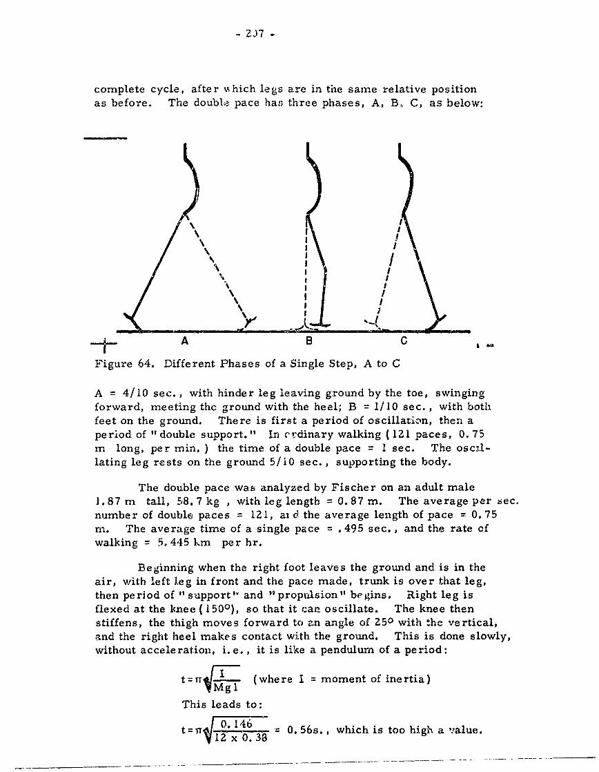
- ZJ7 -
complete cycle, after mhich legs are in the same relative positionas before. The double pace has three phases, A, B, C, as below:
" /
\II/
tA B C ,
Figure 64. Different Phases of a Single Step, A to C
A = 4/10 sec., with hinder leg leaving ground by the toe, swingingforward, meeting thc ground with the heel; B = 1/10 sec., with bothfeet on the ground. There is first a period of oscillation, then aperiod of " double support." In erdinary walking ( 121 paces, 0. 75m long, per min. ) the time of a double pace = I sec. The osc7l-lating leg rests on the ground 5/i0 sec., supporting the body.
The double pace was analyzed by Fischer on an adult male1. 87 m tall, 58. 7 kg , with leg length = 0. 87 m. The average per sec.number of double paces = 121, ai d the average length of pace = 0.75m. The average time of a single pace . 495 sec., and the rate ofwalking = 5. 445 km per hr.
Beginning when the right foot leaves the ground and is in theair, with left leg in front and the pace made, trunk is over that leg,then period of "1 support"v and "propulsion" begins. Right leg isflexed at the knee (1500), so that it can oscillate. The knee thenstiffens, the thigh moves forward to an angle of 250 with the vertical,and the right heel makes contact with the ground. This is done slowly,without acceleration, i.e., it is like a pendulum of a period:
t=I rM (where I = moment of inertia)
This leads to:
t4=r -- 4 6 0. 56s., which is too high a value.
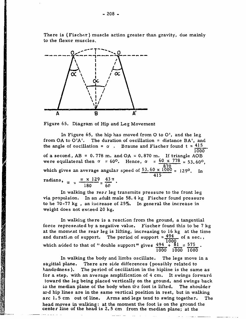
- 208 -
There is (Fischr) muscle action greater than gravity, due mainlyto the flexor muscles,
OC I
A B
Figure 65. Diagram of Hip and Leg Movement
In Figure 65, the hip has moved from 0 to 0', and the legfrom OA to O'A'. The duration of oscillation = distance BA', andthe angle of oscillation = a . Braune and Fischer found t = 415
1000of a second, AB = 0. 778 m. and OA 0. 870 m. If triangle AOBwere equilateral then o = 600. Hence, a = 60 x 778 = 53.600,870
which gives an average angular speed of 53. 60 x 1000 = 129. In
415radians . ii Tx 129 43r
180 60
In walking the rear leg transmits pressure to the front legvia propulsion. In an idult male 58.4 kg Fischer found pressureto be 70-77 kg , an increase of 25%. In general the increase inweight does not exceed 20 kg.
In walkinag there is a reaction from the ground, a tangentialforce reprcseated by a negative value. Fischer found this to be 7 kgat the mome nt the rear leg is lifting, increasing to 16 kg at the timeand duratio.n of support. The period of support = 494 of a sec.,
which added to that of " double support" gives 494 01 = 575.1000 1000 1000
In walking the body and limbs oscillate. The legs move in asagittal plane. There are side differences (possibly related tohandedness). The period of oscillation in the hipline is the same asfor a step, with an average amplification of 4 cm. It swings forwardtoward the leg being placed vertically on the ground, and swings back
to the median plane of the body when tba foot is lifted. The shoulderax-d hip lines are in the same vertical position in rest, but in walkingarc 1. 5 cm out of line. Arms and legs tend to swing together. The
head moves in walking: at the moment the foot is on the ground thecenter line of the head is 2. 5 cm from the median plane; at the
- Z09 -
moment of "double support" the difference is zero.
In summary (121 steps per min., av. speed = 5.45 km perhr ); center of gravity has a vertical oscillation of 4- cm in ampli-tude, a lateral of 1. 3 cm , and a displacement from front to backof 2. 5 cm.II Industrial Labor and Locomotion ( pp 359-391)
The work of the muscles in walking is based on Marey andon Braune and Fischer. First there is a vertical rise of the body ofC. 04 m , followed by a corresponding fall under restraint ( the one52% of the other, in terms of energy).
In an adult male of 65 kg. the muscle work is:
T = 65 x 0.04 x 5= 3. 952 kgm100
The oscillation of the leg produces work:
T 2 = 1/2 I w 2 .
Since I = 0. 146 and w = 43. the result is:60
1/21 w 2 lI/ x 0. 146 x -3 n2 = 0.370 Kgm3,600
Taking the restraint into account:
T 2 = 0.370 x 152 = 0.281 kgm2 100
The general center of gravity is subjected to a variation ofvis viva in its translation; the speed varies by about 0.60 m. Hence,
1/Z mv2 = 1/2 x .65 x 0.602 = 1. 192 kgm.9.81
To include the work of restraint of the muscles:
T 3 = 1.192 x 152 = 1.812 kgm.100
Small muscle movements of other oscillations of the trunk
are negligible. So, finally, T = T1 + T 2 + T 3 = 3.952 + 0. 281 +
1.81Z = 6.045 kgm, or on the ave rage 6 kgm per step. For a pace.778 m long the muscle work per km will be 6 x 1000 = 7,712 kgm.
.778Amar feels that since Man is adapted to walking the value of work
at each step does not exceed 4 kgrn.
There is a rhythm to walking. In each man 1.67 m tall themaximum pace length 0. 85 m. Each person has his own rhythm.
- 210 -
I
Demeny found the period cf "double support" to be 175/1000 sec.at 80 paces per min., and 50/1000 sec. at 200 paces per min. Thelateral oscillation of the trunk decreases with the rapidity of the cad-ence because the feet tend to come nearer the line of progression. Agiven distance is covered more economically by fast walking, but"beyond a certain point walking becomes so tiring that it is preferableto run."
In summary an adult male of 65 kg expends 7. 712 kgmcovering 1 km at a speed of 5, 450 m per hr. The expenditure istherefore 771Z = .119 kgm per Mkg (meterkilogram). The65 xf00corresponding work per Mkg at 80, 120, 180 paces per min. :-. 088kgm. , . 119 kgm , zand . 176 kgm , respectively.
In walking with a load the length of the step is decreased, the
period of support (especially double support) is prolonged, the footis flat on the ground, the muscle contractions in the " carrying leg"increase, and the vertical oscillation is decreased. If the load isplaced on the head the center of gravity is raised; it is better toplace the load on the shoulder and/or back. Most economical is aload of about 20 kg on the shoulder.
In walking with displacement of resistance the load may be. pushed or pulled. The periods of support and double support increase;
the body is inclined so that the center of gravity is thrown forward;the legs are slightly bent (flexed) and vertical oscillation is reduced.The effort of propulsion increases proportionate to the rebistance.
The ascending walk involves the flexion of one leg and themovement of the body and the center of gravity forward. The work -
weight of the body x the height ascended. If h = height of the stairs,T = P x h; if the load is Q then T' z (P + Q)h. Walking on an in-clined plane is a combination of walking on the level plus climbing astair.
The descending walk shows an upright body, with the "carryingleg" bent, the other leg extended (the latter then becomes the " carry-ing leg", and so on). In rapid descent the body moves forward sothat the center of gravity is advanced and the amount of work is reduced.The best step height is 7-10 cm. In descending an inclined plane thebody is inclined forward,. The pace length is greater in ascent thanin descent; steps are shorter, but more in number, and the descentis accomplished with greater speed.
In running the period of "double support" virtually disappears;there is a period of "suspension" during the alternate movement ofthe legs. Maximum speed = 10 m per sec., i.e. 3-4 paces,varying 2. 5-3. 0 m per sec. Time of pace = .20-. 35 sec. , as thelength goes from 1. 5-3.4 m. The period ot suspension increases
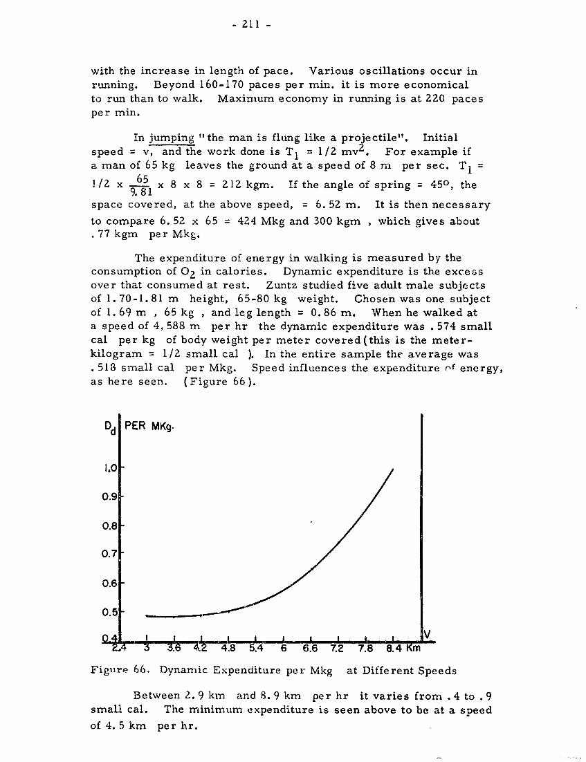
- 211 -
with the increase in length of pace. Various oscillations occur inrunning. Beyond 160-170 paces per min. it is more economicalto run than to walk. Maximum economy in running is at 220 pacesper min.
In jumping "the man is flung like a projectile". Initialspeed = v, and the work done is T 1 = I/2 my2 . For example ifa man of 65 kg leaves the ground at a speed of 8 rn per sec. T=
1/2 x 65 x 8 x 8 = 212 kgm. If the angle of spring = 450, the9.81
space covered, at the above speed, = 6. 52 m. It is then necessary
to compare 6. 52 x 65 = 424 Mkg and 300 kgm , which gives about.77 kgm per Mkg.
The expenditure of energy in walking is measured by theconsumption of 02 in calories. Dynamic expenditure is the excessover that consumed at rest. Zuntz studied five adult male subjectsof 1.70-1.81 m height, 65-80 kg weight. Chosen was one subjectof 1.69 m , 65 kg , and leg length = 0.86 m. When he walked ata speed of 4, 588 m per hr the dynamic expenditure was . 574 smallcal per kg of body weight per meter covered(this is the meter-kilogram = 1/2 small cal ). In the entire sample the average was. 518 small cal per Mkg. Speed influences the expenditure r' energy,as here seen. (Figure 66).
Dd PER MKg.
1.0
0.9
0.8
0.7
0.6
0.5 _
0 . ...'I a I I V
4 3 . .4.8 5.4 6 6.6 7.2 7.8 8.4 Km
Figure 66. Dynamic Expenditure per Mkg at Different Speeds
Between 2. 9 km and 8. 9 km per hr it varies from .4 to .9small cal. The minimum expenditure is seen above to be at a speed
of 4. 5 km per hr.
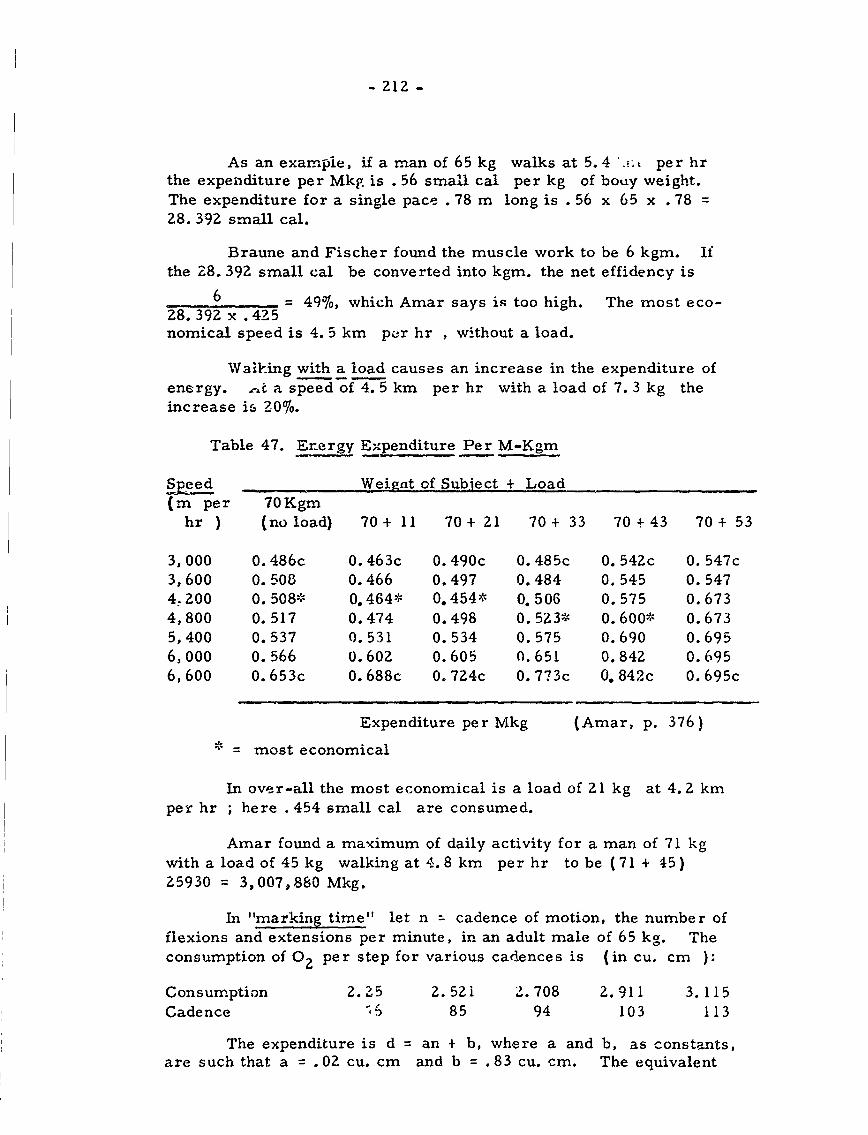
- 212 -
As an example, if a man of 65kg walks at 5.4 ., & per hrthe expenditure per Mkg is . 56 small cal per kg of bouy weight.The expenditure for a single pace .78 m long is .56 x 65 x .78 -28. 392 small cal.
Braune and Fischer found the muscle work to be 6 kgm. Ifthe L8. 392 small cal be converted into kgm. the net effidency is
6 = 49%6, which Amar says is too high. The most eco-28. 392 x .425nomical speed is 4.5 km pcr hr , without a load.
Walking with a load causes an increase in the expenditure ofenergy. ,-,t a speed of 4. 5 km per hr with a load of 7. 3 kg theincrease is 20%.
Table 47. Energy Expenditure Per M-Kgm
ed Weignt of Subject + Load(m per 70Kgm
hr } (no load) 70+ 11 70+ 21 70+ 33 70+43 70+ 53
3,000 0. 486c 0. 463c 0. 490c 0. 485c 0. 542c 0. 547c3,600 0.503 0.466 0.497 0.484 0.545 0.5474.200 0. 508* 0. 464* 0. 454- 0'N . 506 0. 575 0. 6734,800 0.517 0.474 0.498 0. 523* 0. 600*1 0.6735,400 0. 537 0. 531 0. 534 0. 575 0.690 0.6956,000 0. 566 0.602 0.605 0. 651 0.842 0.6956,600 0. 653c 0. 688c 0. 7Z4c 0. 773c 0. 842c 0. 695c
Expenditure per Mkg (Amar, p. 376)= = most economical
In over-all the most economical is a load of Z1 kg at 4. 2 kmper hr ; here . 454 small cal are consumed.
Amar found a maximum of daily activity for a man of 71 kgwith a load of 45kg walking at 4.8 km per hr to be (71 + 15)25930 = 3,007,880 Mkg.
In "marking time" let n = cadence of motion, the number offlexions and extensions per minute, in an adult male of 65 kg. Theconsumption of 02 per step for various cadences is (in cu. cm
Consumption 2.25 2. 521 2.708 2.911 3.115Cadence 85 94 103 113
The expenditure is d an + b, where a and b, as constants,are such that a = . 02 cu. cm and b = . 83 cu. cm. The equivalent
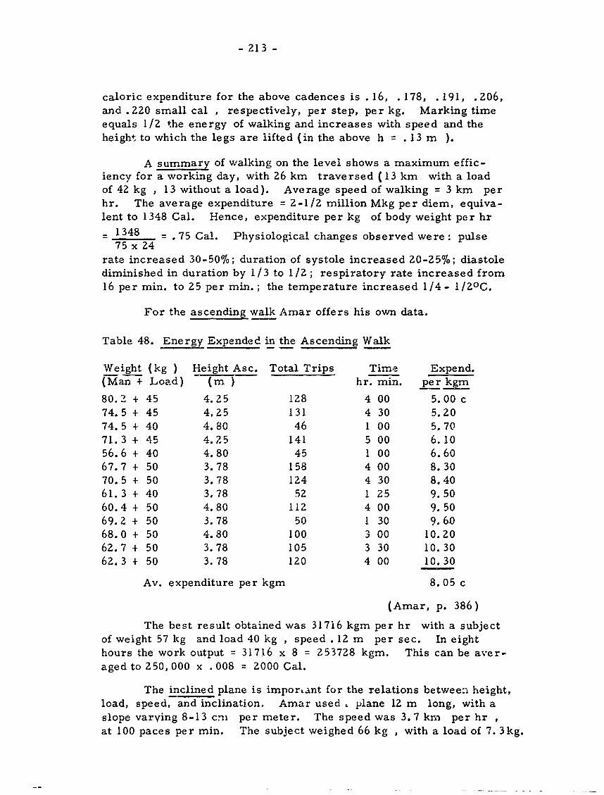
- 213 -
caloric expenditure for the above cadences is .16, .178, .191, .Z06,and . 220 small cal , respectively, per step, per kg. Marking timeequals 1/2 the energy of walking and increases with speed and theheight to which the legs are lifted (in the above h =. 13 m ).
A summary of walking on the level shows a maximum effic-iency for a working day, with 26 km traversed (13 km with a loadof 42 kg , 13 without a load). Average speed of walking = 3 km perhr. The average expenditure = 2-1/2 million Mkg per diem, equiva-lent to 1348 Cal. Hence, expenditure per kg of body weight per hr
= 1348 = .75 Cal. Physiological changes observed were: pulse75 x 24
rate increased 30-50%; duration of systole increased 20-25%; diastolediminished in duration by 1/3 to 1/2; respiratory rate increased from16 per min. to 25 per min.; the temperature increased 1/4- 1/ZOG.
For the ascending walk Amar offers his own data.
Table 48. Energy Expended in the Ascending Walk
Weight (kg ) Height Asc. Total Trips Time Expend.(Man + Load) (m) hr. min. per kgm
80.2 + 45 4.25 128 4 00 5.00 c74.5 + 45 4,25 131 4 30 5.2074.5 + 40 4.80 46 1 00 5.7071.3 + 45 4. Z5 141 5 00 6.1056.6 + 40 4.80 45 1 00 6.6067.7 + 50 3.78 158 4 00 8.3070.5 + 50 3.78 124 4 30 8.4061.3 + 40 3.78 52 1 25 9.5060.4 + 50 4.80 112 4 00 9.5069.2 + 50 3.78 50 1 30 9.64068.0 + 50 4.80 100 3 00 10.2062.7 + 50 3.78 105 3 30 10.3062.3 + 50 3.78 120 4 00 10.30
Av. expenditure per kgm 8.05 c
(Amar, p. 386)
The best result obtained was 317i6 kgm per hr with a subjectof weight 57 kg and load 40 kg , speed . 12 m per sec. In eighthours the work output = 31716 x 8 = 253728 kgm. This can be aver-aged to 250, 000 x . 008 = 2000 Gal.
The inclined plane is important for the relations between height,load, speed, and inclination, Amar used, plane 12 m long, with aslope varying 8-13 cni per meter. The speed was 3.7 km per hr ,at 100 paces per min. The subject weighed 66 kg , with a load of 7. 3kg.
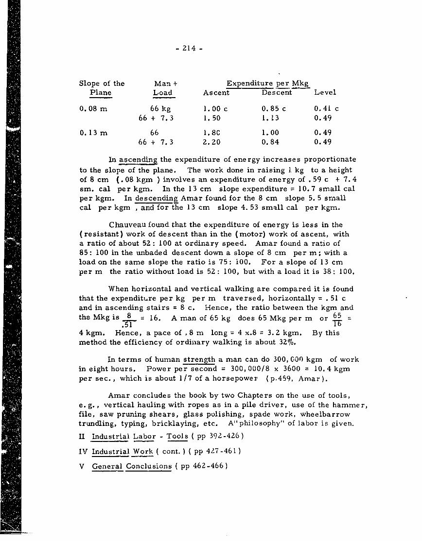
- 214 -
Slope of the Man + Expenditure per MkgPlane Load Ascent Descent Level
0.08 m 66 kg 1. 00 c 0.85 c 0.41 c
66 + 7.3 1.50 1.13 0.49
0.13 m 66 1.80 1.00 0.4966 + 7.3 2.20 0.84 0.49
In ascending the expenditure of energy increases proportionate
to the slope of the plane. The work done in raising 1 kg to a height
of 8 cm (.08 kgm ) involves an expenditure of energy of .59 c + 7. 4si. cal per kgm. In the 13 cm slope expenditure = 10.7 small calper kgm. In descending Amar found for the 8 cm slope 5. 5 smallcal per kgm , and for the 13 cm slope 4.53 small cal per kgm.
Chauveau found that the expenditure of energy is less in the(resistant) work of descent than in the (motor) work of ascent, witha ratio of about 52: 100 at ordinary speed. Amar found a ratio of85: 100 in the unbaded descent down a slope of 8 cm per m; with aload on the same slope the ratio is 75: 100. For a slope of 13 cm
per m the ratio without load is 52: 100, but with a load it is 38: 100.
When horizontal and vertical walking are compared it is found
that the expenditure per kg per m traversed, horizontally =. 51 cand in ascending stairs = 8 c. Hence, the ratio between the kgm andthe Mkgis 8 16. Aman of 65kg does 65 Mkg per m or 65.51 T
4 kgm. Hence, a pace of .8 m long = 4 x.8 = 3.2 kgm. By this
method the efficiency of ordinary walking is about 32%.
In terms of human strength a man can do 300, 000 kgm of workin eight hours. Power per second = 300, 000/8 x 3600 = 10.4 kgm
per sec., which is about 1/7 of a horsepower (p. 4 5 9, Amar).
Amar concludes the book by two Chapters on the use of tools,e. g., vertical hauling with ropes as in a pile driver, use of the hammer,file, saw pruning shears, glass polishing, spade work, wheelbarrowtrundling, typing, bricklaying, etc. A" philosophy" of labor is given.
II Industrial Labor - Tools ( pp 392-426)
IV Industrial Work ( cont. ) ( pp 427-461)
V General Conclusions ( pp 462-466)
SPACE REQUIREMENTS OF
THE SEATED OPERATOR
(Condensed from W.T. Dempster)

DISCLAIMER NOTICE
THIS DOCUMENT IS BEST QUALITYPRACTICABLE. THE COPY FURNISHEDTO DTIC CONTAINED A SIGNIFICANTNUMBER OF PAGES WHICH DO NOTREPRODUCE LEGIBLY.
C4' _ - . BESTS -- -AVAILABLE COPY
-i-hc cu-G>
BESTAVAILABLE COPY
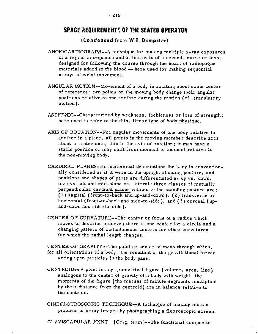
- 215 -
SPACE REQUOIREMENT, OF THE SEATED OPERATOR(Condensed frc:ti W.T. Dempster)
ANGIOCARDIOGRAPH--A technique for making multiple x-ray exposuresof a region in sequence and at intervals of a second, more or less;designed for following the course through the heart of radiopaqaematerials added to Vie blood - here used for making sequentialx-rays of wrist movement.
ANGULAR MOTION--Movement of a body in rotating about some centerof reference ; two points on the moving body change their angularpositions relative to one another during the motion (cf. translatorymotion).
ASTHENIC-.Characterized by weakness, feebleness or loss of strength;here used to refer to the thin, linear type of body physique.
AXIS OF ROTATION--For angular movements of one body relative toanother in a plane, all points in the moving member describe arcsabout a center axis, this is the axis of rotation; it may have astable position or may shift from moment to moment relative tothe non-roving body.
CARDINAL PLANES--In anatomical descriptions the Lbdy is convention-ally considered as if it were in the upright standing posture, andpositions and shapes of parts are differentiated as up vs. down,fore v-, aft and mid-plane vs. lateral : three classes of mutuallyperpendicular cardinal planes related to the standing posture are:(I) sagittal (front-to-back and up-and-down), (2) transverse orhorizontal (frcnt-to-back and side-to-side), and (3) coronal (up-and-down and side-to-side ).
CENTER O? CURVATUR.E--The center or focus of a radius whichmoves to describe a curve ; there is one center for a circle and achanging pattern of inetantaneous centers for other curvaturesfor which the radial length changes.
CENTER OF GRAVITY--The point or center of mass through which,for all orientations of a body, the resultant of the gravitational forcee
acting upon particles in the body pass.
CENTROID,-mA pcnint in any g aometrical figure (volume, area, line }analogous to the center- of gravity of a body with weight; themoments of the figure (the mafsses of minute segments multipliedby their distance from the centroid) are in balance relative tothe centroid.
CINEFLOUROSCOPIC TECHNIQUE--A technique of making motionpictures of x-ray images by photographing a fluoroscopic screen.
CLAVISCAPULAR JOINT (Orig. term)--The functional composite
- 216 -
consisting of acromiclavicular joint phus coracoclavicular joint(i. e. , coracoclavicular ligaments or trapezoid plus conoid ligaments).
CLOSED CHAIN--A sequence of several links so interconnected by joint
elements with limited degrees of freedom that only determinate orpredictable movements of the parts are possible.
COMPONENTS--According to Sheldon's system of typing body build of
each individual physique shows in different degree characteristicsof softness, roundness, and breadth (called component I), of mus-
cularity (component II) and of linearity (component III); the amountof each of the three components may be graded by inspection andmeasurements ef photographs on a seven-point scale (or on a 13-point scale counting half points).
CONGRUENCE--If the opposed articular faces of a joint were ii sinul-taneous contact with no areas that die. not coincide the joint wouldbe congruent; congruent position - a position of a joint where thecontacts are congruent.
CONTINGENT MOVEMENTS (Orig. term)--In joints of one degree offreedom of motion (viz. elbow; ankle) the relative movement of bonesforming the joint do not move exclusively in a plane on one xis ofrotation alone, rather the contracting curvatures of the joint *nduce
secondary, concomitant motion on axes perpendicular to that forthe principal movemenit; these accessory and invariate motions arecalled contingent movements.
COUPLE--A pair of equal forces acting in parallel but opposite direct-ions, not in the same line, and tending to produce rotation.
DEGREE OF FREEDOM (OF MOVEMENT)--A free body may rotate in
any angular direction about a point, i. e. , it rotates in any of the
three dimensions of space; thus it has three degrees of freedom.When its motion is so restrained that it may rotate about two per-
pendicular axes only, it has two degrees of freedom. When it islimited to movement about one axis ony, it has one degree of freedom.
DEGREE OF RESTRAINT (OF MOVEMENT)--When an unrestrained ro-tating body moves about a point in any of its three degrees of freedom,
there is a zero degree of restraint. When it may rotate about anytwo axes, movement about the third axis is restrained, i. e. , onedegree of restraint. With two degrees of restraint, movement islimited to rotation in one p'ane enly, i. e., it has one degree ofrestraint. With three degrees of restraint all angular motion isprevented.
,wow
- 217 -
DESMO-ARTHROSES (Orig. term)--A functional joint system consist-ing of a gliding joint (arthrosis) with, at an apprecia'le distance,a ligamentous binding together ( desmoses) of the bones concerned-.examples: sternoclavicular joint, claviscapular joinit.
EFFECTIVE JOINT CENTER (Orig. term )--In a compc.,.tte chain of threeor more links with interconnecting joints, the rotati( n of a distallink over two or more joints may be reiated to some point in spaceas center of rotation; this is the effective joint center.
EFFECTIVE SEAT CONTACT (Orig. term)--The mean reaction vectorat a seat (or foot rest) which opposes the gravity vector of a seatedindividual to form a couple ; its position in the sagittal plane islocated by balancing moments involving forces which act at the frontand rear of the supporting surface.
END MEMBER--The terminal segment, such as the hand, foot, head orfinger, beyond the last joint in a body joint chain.
ERGOSPHERE (Orig. term )--The total work space available to the endmember of a link system, i. e. , to a hand or foot, relative to somefixed point of reference ; the term may in addition include the wholebody of the individual and the augmented space required for facili-tating movements of other body partf..
EVOLUTE--For every systen. of curvature, called involute, a secondcurve, called evolute, may be constructed; tangents to the latterare normal to points on the involute curve; the evolute is the focusof the center of curvature of the involute arc.
EXCURSION CONE OF A JOINT (same as joint sinus)- -FChe total rangeof angular motion permitted a moving member of a joint when theother member is rigidly fixed.
GLOBOGRAPHIC PRESENTATION (OR RECORD, ETC)--A method ofshowing the angular range of joint movement upon a globe withmeridians and parallels ; one member of a joint is regarded asrigidly fixed with the functional'center of the joint at the center ofthe globe while a point on the other member describ s a circuitupon the surface of the globe which encloses -ill pos -ible positionsof the moving part.
GRAVITY LINE (LINE OF GRAVITY )--A downward vertical forcevector through the center of gravity of a body.
GREAT CIRCLE--The intersections with the surface of a sphere of aplane which passes through the center of the sphere.
- 218 -
INCONGRUENCE--When the opposed surfaces of the members of a jointarticulate in partial or ill-fitting contacts, the joint is incongruent.
INSTANTANEOUS AXIS OF MOVEMENT--When two points on a body inmotion, relative to another body or to the space of the observer,change their angular relations during the motion, this angularchange for any instant occurs in a plane, and the movement for thatinstant may be described as a rotation about a stationary perpendic-ular axis called an instantaneous axis.
INSTANTANEOUS JOINT CENTER--The momentary center about whicha body moves in rotating on a plane; a point on an instantaneousaxis of rotation. In a circular motion the center has a constantposition, for other angular motion in a plane it shifts to a new locus;successive loci describe a path of instantaneous centers.
INVOLUTE--A curve traced by a point on a taut thread as it winds upona fixed curve called an evolute ; perpendiculars to an involute curveare tangent to points on the evolute curve.
JOINT SINUS--When one member of a joint permitting at least two de-grees of freedom of movement is held fast and the other memberlink is rotated to its limits in all directions, the moving membersweeps out a conical concavity which includes within its range allpossible movements allowed by the joint structures.
KINEMATICS (N), -IC (Adj. )--The science which is concerned with themotions of bodies and systems vithout regard to forces producingthem; the geometry of moving systems.
KINETOSPHERE (Orig. term)--The space or space envelope whichencloses all possible translatory movements of the end segment ofa link system held in some constant orientation; it is defined rela-tive to some fixed reference point of the body or contact point inthe environment (seat "R" point, etc. ).
LEVERAGE--The straight line distance from the center of rotation ofa body to the point of application of a perpendicularly acting forcewhich tends to rotate the body, cf. lever arm; moment arm.
LINK--The straight line which interconnects two adjacent joint centers;the axial core line of a body segment between two joints or betweena terminal joint and the center of gravity of the end member (orbetween the terminal joint center and an external body contact).
- 219 -
MEAN DEVIATION--A measure of the variability about an average;the deviations on either side of an average, all considered aspositive values, are summated and divided by 4.
MOMENT--The effectiveness of a force in tending to twist or causemotion around a central point.
MOMENT OF INERTIA--A measure of the effectiveness of a mass inrotation. The change in angular velocity in a rigid body whichrotates through the action of a given torque depends upon both themass of the body and the distribution of that mass about the axisof rotation. Moment of inertia is the summation of the point rnassesof a body times the square of their radial distance from the axisof rotation.
MOMENT OF ROTATIONS--See TORQUE.
PERCENTILE--Any of the points which may be used to divide a seriesof quantities or values arranged in order of magnitude into 100equal groups ; thus the 50th percentile divides the sample equallywhile the 95th divides the upper five percent from the remainder.
PYKNIC--The thick set, short, stocky body build.
"R" POINT--Fixed reference point; as seat 'R" point, the midpoint ofthe junction of the seat back and the seating surface.
RADIUS OF CURVATURE--The radius of a circle drawn through three ormore consecutive points in a curve at the region of reference.
REULEAUX METHOD--A method developed by the German engineerReuleaux in 1875, for locating instantaneous centers of rotation;when any body moves in an arc, instantaneous centers for a shortphase of the motion are located at the intersections of normals tomidpoints on the mean paths of two points on a rotating body.
SEAT 'R" POINT--The fixed reference point in considerations of handand foot movements, etc. ; the midpoint of the junction of a seatingsurface and the back of the seat.
SINUS--(See joint sinus or excursion cone).
SOMATOTYPE--An overall classification of an individual's physiquebased upon an evaluation of the relative rotundity, muscularity,and linearity shown; these three components are separately evalu-ated on a seven-point scale (frequently half-points are used also).The evaluations of an individual are designated by a formula indi-
cating the quantity of each components as 1-2-7 (e. g. , I -low inrotundity; 2 - slight development of muscularity; 7 - extreme line-arity).
- 220 -
SPIROMETER--An instrument for measuring the air capacity of thelungs.
STANDARD DEVIATION--A measure, calculated by statistical methods,of the dispersion of values about their mean; one standard deviat-ion (symbol : sigma ) includes about 68 percent of the observationsabove or below mean, two standard deviations include about 95-1/2percent.
-TROPHOSPHERE (Orig. term)--The space which incloses the tota.range of movement of a point on a terminal link segment throughall possible translatory movements and for the possible endmember positions as the part rotates about one axis only of theterminal joint; the space envelope for the movement is related tocoordinates through a fixed reference point in space.
TORQUE--A measure of the effectiveness of a twisting force or couple;force times the distance from a perpendicular to the line of actionof the force to the center of rotation. Alternate term: moment ofrotation.
TRANSLATION--TRANSLATORY MOTION- -Straight or curved motionin which all points of a moving body have at each instant the samedirection and velocity. Contrast with rotation.
INTRODUCTION (Demcster, pp. -1-5)
The function of this report, based largely upon originalresearch, is to report, data essential' for three areas of knowledgein biomechanics. These are:
1), to permit the synthesizing of realistic manikins;2) to understand the bodykinematics of a seated operator
in his work space;3) to define the dimensions of the work space.
An understanding of body kinematics is essential in theproper design of the work space ; it must be remembered that thelimitations of anatomy are immutable, and that efficiency maytherefore be increased only through changes in the relationshipsof the work space itself.
There are several important factors, therefore, that mustbe considered in plahning the work space:
1), the operation of one control must not hinder that of another;2) control placement must be in terms of operational sequence;3) routinely-ope rated controls -must be separated from those
rarely used;4) b3dy comfort, particularly when operation is carried out
over long periods, must be near optimum-;5), emergency and safety fadtors must be considered.
Basic research, as in this study, must furnish informationto the design enginee.r which will enable him to meet the above re-
quirements.
Utilization of manikins, reduced or simplified scale models,becomes .extremely valuablein design engineering. However, asuitable manikin must meet several requirements. It must be com-parable to the mean build of the .population to be placed within theworkspace. (In this study, the emphasis will be upon the pilot, andhence, the builds of U.S. Air Force personnel will be considered.)In addition, a, manikin must represent a seated figure correctly, interms of joint and segment relations'. And finally, these joints andsegments must move in a fashion co mporable to actual individuals.
The postures into-which a manikin is placed must not onlyrepreseY.A human movement ranges, but also functioning bod postures,
As the actual end members involved in- the bpe'atioh, the hand andfoot require special operational significance, particularly the relation-ships to functional joint centers. Thus, how does the movement of
a particular joint affect the next member, and especially the effectiveend member?
- 222 -
Consideration, must also be made of the points at which themanikin begins to differ from the actual body system; a knowledgeof manikin limitations permits maximum efficient utilization of thework space.
These factors are all considered and discussed in this study,utilizing, whenever possible, actual experimental data. Other factorsare also analyzed, for example, the effects of body weight and theroles of muscle tension and external resistances, such- as the inertiaof body mass.
-223-
1MATERIALS AND METHODS (Dempster, pp. 6-67)
This study involves living individuals, cadavers, and skcle-,tal material. The skeletal material, numbering more than 400 spec-imens of each major bone, came from persons of unknown age, sex,or physical status ; it was a part of the University of Michigan osteo-logical collection. All measurements were carried out utilizing
standard anthropometric instruments.
The articular curvatures of joint surfaces were studied by
means of two approaches. The first was the dial gauge method, usinga Lensonieter (Figures 67 and 68). The reference pins were t0 mmapart, with the middle pin depression read to the nearest hundredthof a millimeter ; this depression represented the depth of the arc defined
by the three contact pins. The average radius of curvature was com-puted from the formulae in Figure 68.
The second method used was the evolute method, which in-dicated the changing radius of curvature which existed rather thanme-rely the average. Any regular curve,, in geometry, is called aninvolute. The evolute is the locus of centers of curvature of theinvolute. ( Figure 69). It may be visualized by observing a taut corduhwound, r,.m ,round a circular rod; a point at the moving end of the
cord desqribQs -a spiral, the involute.
The surface curvature, or cross section, of the rod is the
evolute. At all times, the taut cord is tangent to the evolute andnormal (perpendicular) to the involute. The straight line portionof the cord is the radius of curvature.
The evolute method was applied by rotating a joint surfaceupon a chalked surface through an arc. A saw cut was made in theplAne of the resulting chalk mark and the contours studied.
1. This chapter is heavily abstracted. Anyone interested in themethodological details presented by the author should refer to
the original. - FEJ.
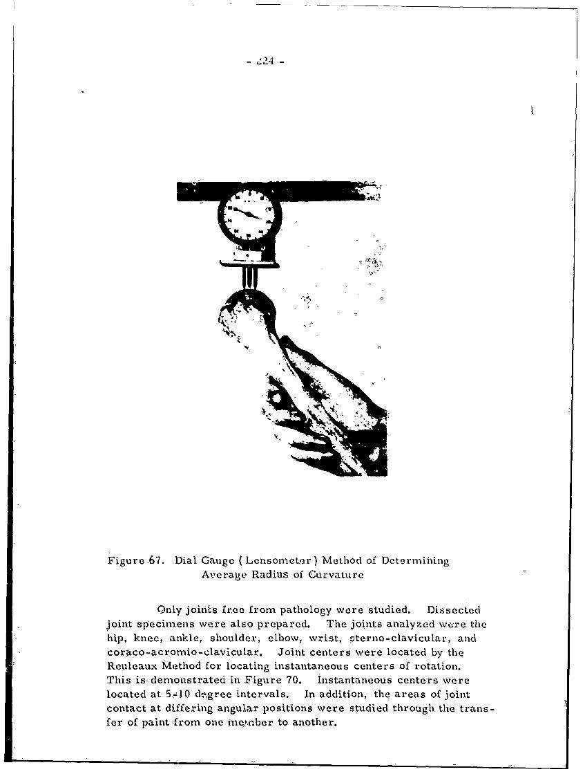
- 24 -
Figure .67. Dial Gauge (Lensometer) Method of DetermihingAverage Radius of Curvature
Only joiits free from pathology were studied. Dissected
joint specimens were also prepared. The joints analyzed w6 re thehip, knee, ankle, shoulder, elbow, wrist, sterno-clavicular, and
coraco-acromio-clavicular. Joint centers were located by theReuleaux Method for locating instantaneous centers of 'rotation.This is- demonstrated in Figure 70. instantaneous centers were
located at 5-10 dgree intervals. In addition, the areas of jointcontact at differing angular positions were studied through the trans-fer of paint ,from one inepber to another.
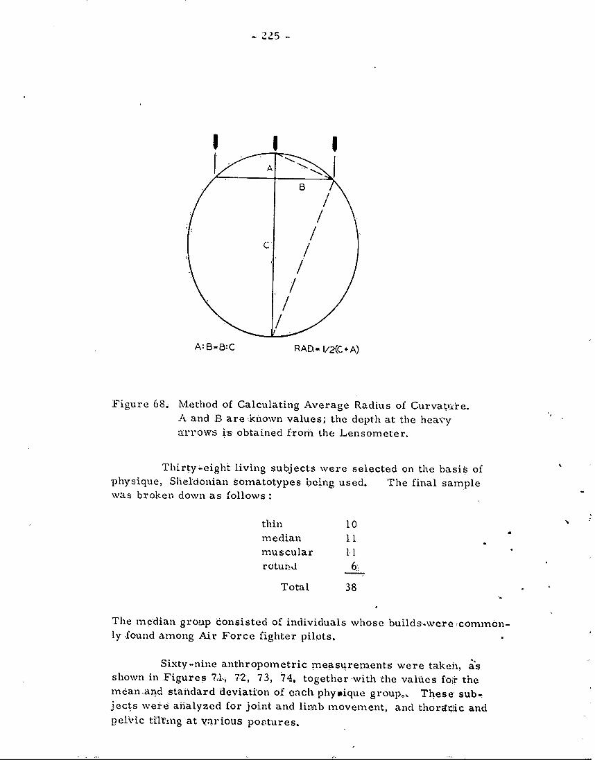
A 25-s
I I I
C / '
//
A:B B:C RAD.- 1/2(C+ A)
Figure 68. Method of Calculating Average Radius of Curvatlxre.A and B are kinown values; the depth at the heavyarrows is obtained frorh the Lensorneter.
Thirty-eight living subjects were selected on the basis of'physique, Sheldonian somatotypes being used. The final samplewas broken down as follows:
thin 10 N
median 11muscular 11rotund 6'
Total 38
The median group consisted of individuals whose builds,were common-ly found among Air Force fighter pilots.
Sixty-nine anthroppmetric measurements were takei,, asshown in Figures 7 1i 72, 73, 74, together 'with the values foir themean.and staindard deviation of each phyique group,. These, sub-jects were -analyzed for joint and liimb movement, and thorzr'ic andpelvic tilting at various postures.
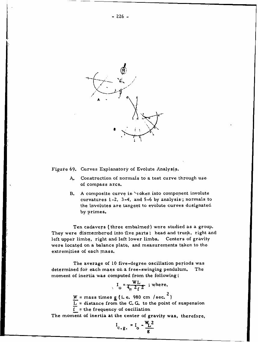
- 226 -
zz6
A-
Figure 69. Curves Explanatory of Evolute Analysis.
A. Construction of normals to a test curve through use-, of compass arcs.
B. A composite curve is,'xroken into component involutecurvatures ]-2, 3-4, and 5-6 by analysis-; normals tothe involutes are tangent to evolute curves designatedby primes.
Ten cadavers (three embalmed) were studied as a group.They were dismembered into five parts t head and trunk, right andleft upper limbs, right andc left lower limbs. Centers of gravitywere located on a balance plate, and measurements taken to the
extremities of each mass.
The average of 10 five-degree oscillation periods wasdetermined for each mass onha free-swinging pendulum. Themoment of inertia was computed from the following
W LIo - ; where,
2W mass times (i. e. 980 cm /sec. )
L distance from the C. G. to the point of suspensionF -the 'frequency ,of oscillation
The moment of inertia at the center of gravity was, therefore,
c.g. = I WL"g" T-
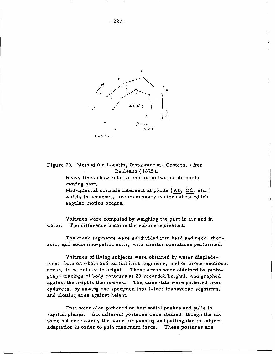
- 227
BC
oD
A
V i I'
V XED PART
Figure 70. Method for -Locating Instantaneous Centers, afterReuleaux (187.5).
Heavy lines show relative motion of two points onethemoving. part.Mid-interval normals intersect at points (AB, BC, etc. )which, in sequence, are momentary centers about whichangular motion occurs.
Volumes were computed by weighing the part in air and inwater. The difference became the volume equivalent.
The trunk segments were subdivided into head and.neck, thor-
acic, and abdomino-pelvic units, with similar operations performed.
Volumes of living subjects were obtained by water displace-ment, both on whole and partial limb segments, and on cross-sectionalareas, to be related to height. These areas were obtained by panto-graph tracings of 'body contours, at 20 recorded'heights, and graphed
against the heights themselves. The, same data were gathered fromcadavers, ,by sawing one specimen into I-inch transverse segments,and plotting area against height.
Data were also gathered on horizontal pushes and pulls in
sagittal planes. Six'different postures were studied, though the six
were not necessarily the same for pushing and pulling due to subjectadaptation in order to gain maximum force. These postures are
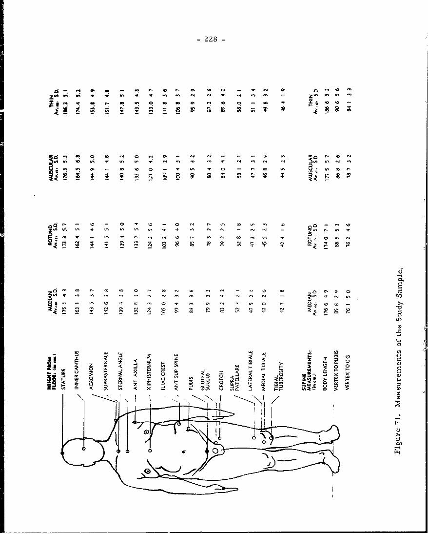
- 228-
ZW t W% V v f% -W le M% on 44 -ft m - m
0.i co %0 1^r c ^L^ m
4-- go9
No 0- Go U40 ' ~ - ' 4 -- . 1 0 - 'a '
i n L ̂ * I. U- U N V % i t ', q r m '1-. ' -F
m 0% - in r r m r. a -%' c m i
2 Go r- r- W% 0- T
Ci r 00 r-c c o o 000 E , azi
q4.4
0-
z z z z - 0-- cc >- w CUc <. -j 4i, tI-U0
< <,cc < ID j
z ~ D < x - < =. Ix D <,o < ~ D ~ 'c
C)
- D-4
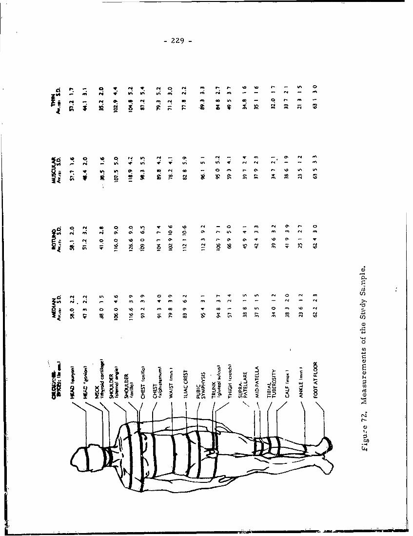
-229-
- a N ~ o N m I- ~ '0WO 0. ~C V: li ., ri Ui r' n - - - N -
- t
'0 0! '0 0 t N -- -en - 0 4 N n
p ~ W 1.4 - ~ UI ' ~v ui UN 4 .4 v4 '.4 - n
En If N! In - 0 on a- 0. - Vu~ at
v.4 0' 0% % -O 0 0 e' r t. q n In On N E
144
a R 0 0 0 0 C) (. - fn . ot 0a. % 0 N
P4 N n en V en NO a n r - - - N - a
rq 0o an 0r 00 c0 Nn 'l ' V- ~n %D 14
U%4 '4A I 0 '- ~ 0 ' n En mb fn N '
UI)
4-J
ae in -'U~i -- J. LI
- j - ,
a~u*I-- .- an. ~ U
....... ...... .....-
................
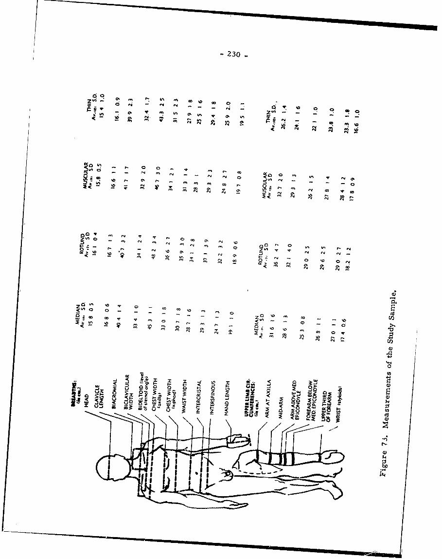
- 230
00Z O) Cc~ OD ~ 0~ 0 -
0 ,4 q V: p -- - .. 0 o
3~ Vu-rv "4 -3IN
00ff00N tOj
0l V, CO~
0 ENEN E ~ :EN >
~~00
~ 10 EN0~ 0
00 0o -O %0 20
-r '-' ON %0 0 V-"%I 11% 0
.- I L-n
<N EN AO I r-< o
14-
-- 000
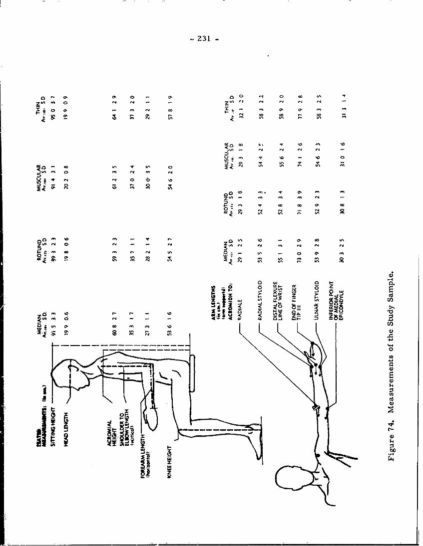
2 31-
~ ~o o' ve .4 Go 0' o - -
Ofe aD LInI
LIN 'ye r - '0%
<> r In Vn O In n
z In . f n In on en
In EN 00 00 a
'0 0, en
no EN ENaUN % - EN a
ZN enn r,4 eqn
CA 04 '.4 In -q 'Nr n 0 - 0'40e EN 'N "e EN'nE
LD.L
-J.-4
0 0 L.AC
z
- 1" 0 0 '
%4
0
0c
14t Z 4)
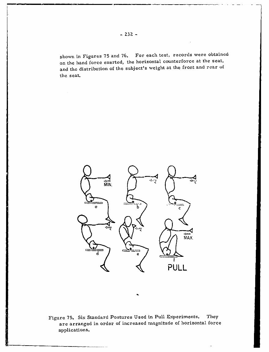
- Z32 -
shown in Figures 75 and 76. For each test, records were obtained
on the hand force exerted, the horizontal counterforce at the seat,
and the distribution of the subject's weight at the front and rear of
the seat.
MIN.
a
MAX,
d PULL
Figure 75. Six Standard Postures Used in Pull Experiments. They
are arranged in order of increased magnitude of horizontal force
applications.
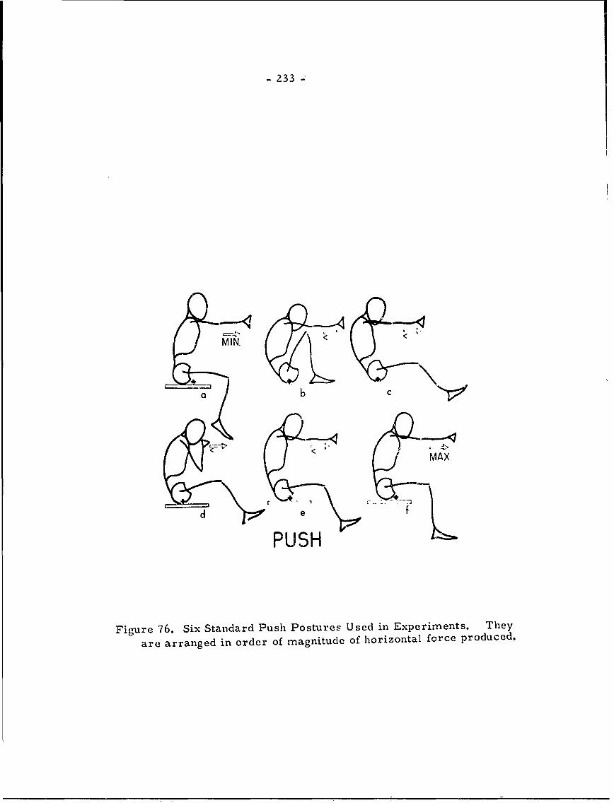
- 233 -
MIN.
a b
MAX
d e
PUSH
Figure 76. Six Standard Push Postures Used in Experiments. They
are arranged in order of magnitude of horizontal force produced.
- 234 -
THE LINK SYSTEM OF THE BODY. (Dempster, pp. 68-79)
In a mechanical and kinematic treatment of the humanbody, one must think of masses, levers, and forces, rather thanof bones and muscle. Traditional anthropometric measurementsof bone and other tissue, though of scientific and practical value,are not functional; their applicability is limited to those rather stand-ard conditions which exist when they are taken and they may not betransferred to other postures. Postural and kinematic problemsmay only be solved by a functional cystem of measurements.
Bones are not actually rigid bodies, but they may routinelybe treated as such. Forces may be transmitted along a bone or fromone bony member to another across a joint. Positions of body equili-brium are never devoid of force, but instead are maintained by eitherlow forces across joints or opposing muscles under considerabletension.
Bone masses are surrounded by non-rigid tissues, whichmove with the bones; body segments, therefore, become compositeunits involving rigid and soft tissues. The boundaries between thesesegments are difficult to locate and may often become quite arbitrary.
Due to the spiralling curvatures of some bones (e.g., theclavicle), effective force vectors from one segment to another mayfall outside the limits of the bony material. In all cases, however,these vectors foLlow straight lines passing through areas of jointcontact and through the joint centers. The spanning distances betweenthe joints are the functional equivalents of the engineer's links.
In general, links are usually considered to constitute atwo-dimensional system, with the articulating members overlappingand joined by pins acting as axes of rotation. At first though, bonemay b? considered as a link (through its basic rigidity) but this isnot strictly true. Some differences lie in the fact that body jointsrarely overlap and have no pin-centered axes; in addition, movementoccurs in any one of several directions rather than in a predictableplane. Nevertheless, the convenience of this approach warrants itsuse, with some modifications due to the nature of the biological struc-tures with which this study deals.
The body link can be visualized as the central straightline or core-line which extends longitudinally through a body segmentand terminates at both ends in axes (hinge points), about which the
- 235 -
adjacent members rotate. From this conceptualization it becomesobvious that the bony structure itself is not the link. The flaring-away from the core line, found in bones, is due to many forces,both genetic and environmental, to which the bone is submitted duringgrowth. They are eccentric specializations which have functionsirrelevant to, but compatible with, the link system of the body. Sonleof these .functions result in motion, such as rotations about the longaxes of links, which may be important functionally, but which makeup a special category, and which will not receive full treatment here.In any case, the bones provide areas of attachment for action in linkmovement.
The body links are connected by joints and the range ofmovement possible depends upon the anatomical structure of thearticulation. Though all movement between adjacent links is purelyrotational, translatory movement may be effected by reciprocalrotations of three or more links at two or more joints.
The link system of the engineer also differs from thatof the body in that engineering links are of a closed chain type,while the overall body mechanism is basically an open chain system.This means that, in the body, there is a range of non-determinatemovements, in contrast to a closed system. Many body positionsbecome possible, limited mainly by three sets of factors:
1) the range of movement of the joints;
2) the character of the joint action;
3) intrinsic mechanical factors imposed by body bulkinessor muscular control.
The satisfactory application to human engineering of mechanicalprinciples necessitates a knowledge of these factors.
For practical purposes, many minor link movements (e. g.vertebral) may be ignored. The major links are shown in Figure 75;note that segment mass is regarded as concentrated at the center ofgravity. These major links are:
1) trunk links
a) head-end member; from the atlanto-occipital joint tothe head center of gravity, plus a cervical chain ofseven links
b) thoracic link; the thoracic column and the thorax
c) lumbar chain; five minor links pluc a pelvic link
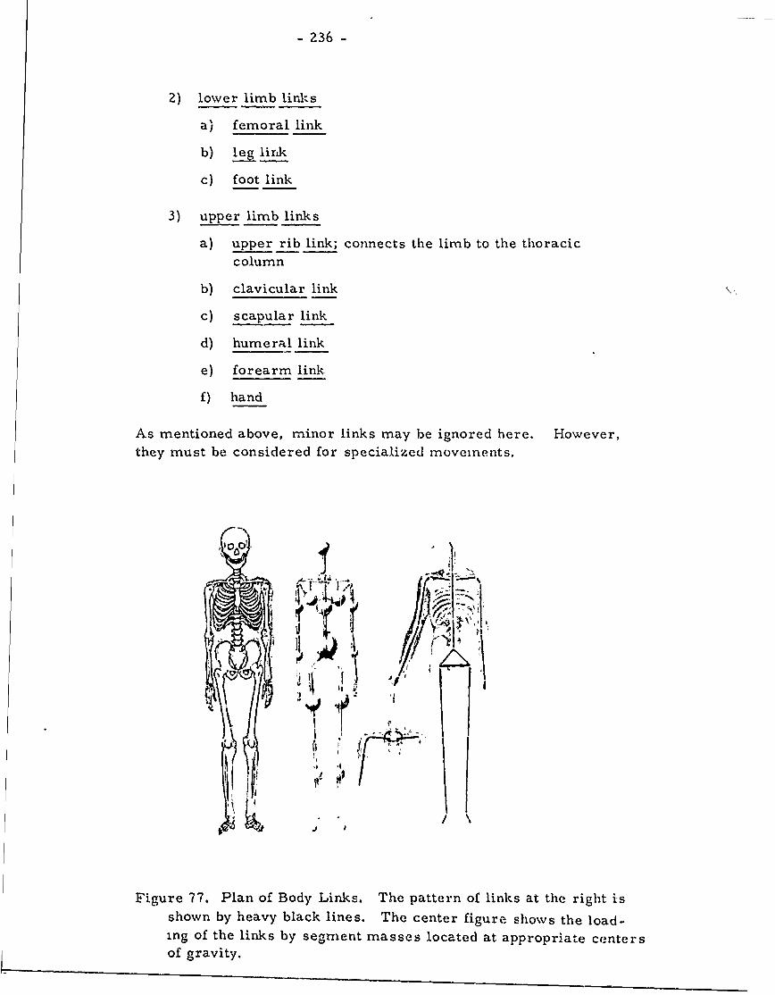
- 236 -
2) lower limb lirks
a) femoral link
b) leg link
c) foot link
3) upper limb links
a) upper rib link; connects the limb to the thoraciccolumn
b) clavicular link
c) scapular link
d) humeral link
e) forearm link
f) hand
As mentioned above, minor links may be ignored here. However,they must be considered for specialized movements.
'-I
I - .. !% -
Figure 77. Plan of Body Links. The pattern of links at the right i-sshown by heavy black lines. The center figure shows the load-ing of the links by segment masses located at appropriate centersof gravity.
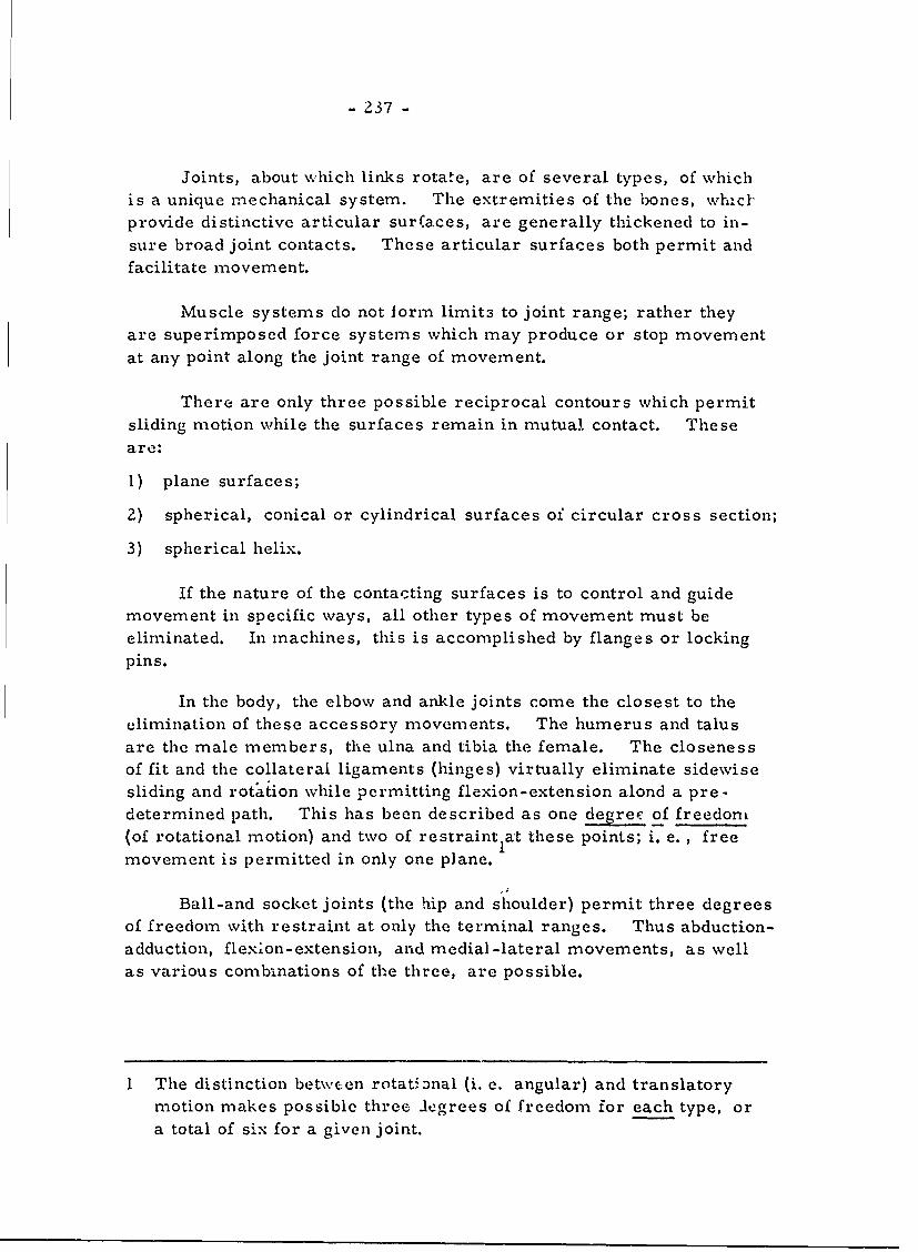
- 237 -
Joints, about whicl links rotate, are of several types, of which
is a unique mechanical system. The extremities of the bones, whzcf-provide distinctive articular sur(aces, are generally thickened to in-
sure broad joint contacts. These articular surfaces both permit andfacilitate movement.
Muscle systems do not Iorm limits to joint range; rather they
are superimposed force systems which may produce or stop movementat any point along the joint range of movement.
There are only three possible reciprocal contours which permit
sliding motion while the surfaces remain in mutual contact. Theseare:
1) plane surfaces;
2) spherical, conical or cylindrical surfaces oi circular cross section;
3) spherical helix.
If the nature of the contacting surfaces is to control and guidemovement in specific ways, all other types of movement must be
eliminated. In machines, this is accomplished by flanges or lockingpins.
In the body, the elbow and ankle joints come the closest to the
elimination of these accessory movements. The humerus and talus
are the male members, the ulna and tibia the female. The closenessof fit and the collateral ligaments (hinges) virtually eliminate sidewise
sliding and rotation while permitting flexion-extension alond a pre -
determined path. This has been described as one degree of freedom(of rotational motion) and two of restraintIat these points; i. e. , free
movement is permitted in only one plane.
.1
Ball-and socket joints (the hip and shoulder) permit three degrees
of freedom with restraint at only the terminal ranges. Thus abduction-
adduction, flexion-extension, and medial-lateral movements, as wellas various combinations of the three, are possible.
I The distinction between rotational (i. e. angular) and translatorymotion makes possible three legrees of freedom for each type, or
a total of six for a given joint.
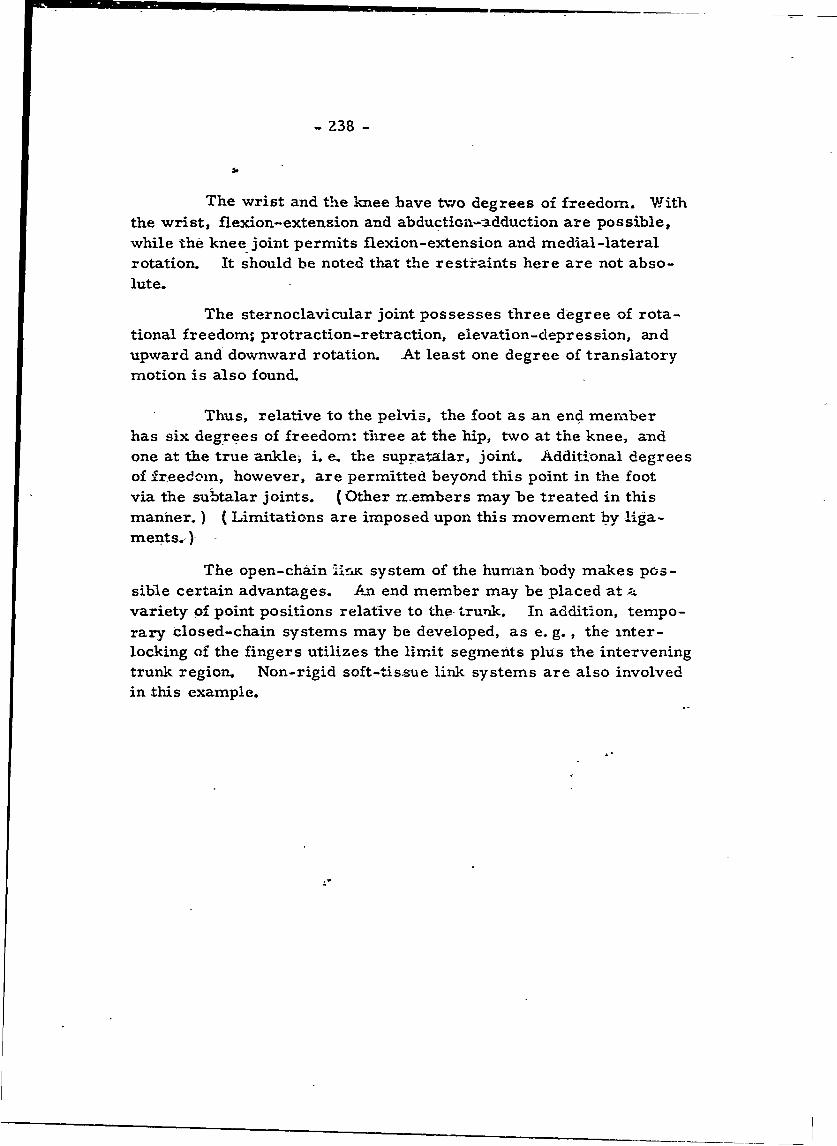
- 238 -
The wrist and the knee have two degrees of freedom. With
the wrist, flexion-extension and abductian-adduction are possible,while the knee joint permits flexion-extension and medial-lateralrotation. It should be noted that the restraints here are not abso-lute.
The sternoclavicular joint possesses three degree of rota-tional freedoms protraction-retraction, elevation-depression, andupward and downward rotation. At least one degree of translatorymotion is also found.
Thus, relative to the pelvis, the foot as an end menberhas six degrees of freedom: three at the hip, two at the knee, andone at the true ankle, i. e. the supratalar, joint. Additional degreesof freedcin, however, are permitted beyond this point in the footvia the subtalar joints. (Other rembers may be treated in thismanner.) (Limitations are imposed upon this movement by liga-ments.- )
The open-chain 1Iic system of the human body makes pos-sible certain advantages. An end member may be placed at avariety of point positions relative to the trunk. In addition, tempo-rary closed-chain systems may be developed, as e. g., the inter-locking of the fingers utilizes the limit segments plus the interveningtrunk region. Non-rigid soft-tissue link systems are also involvedin this example.
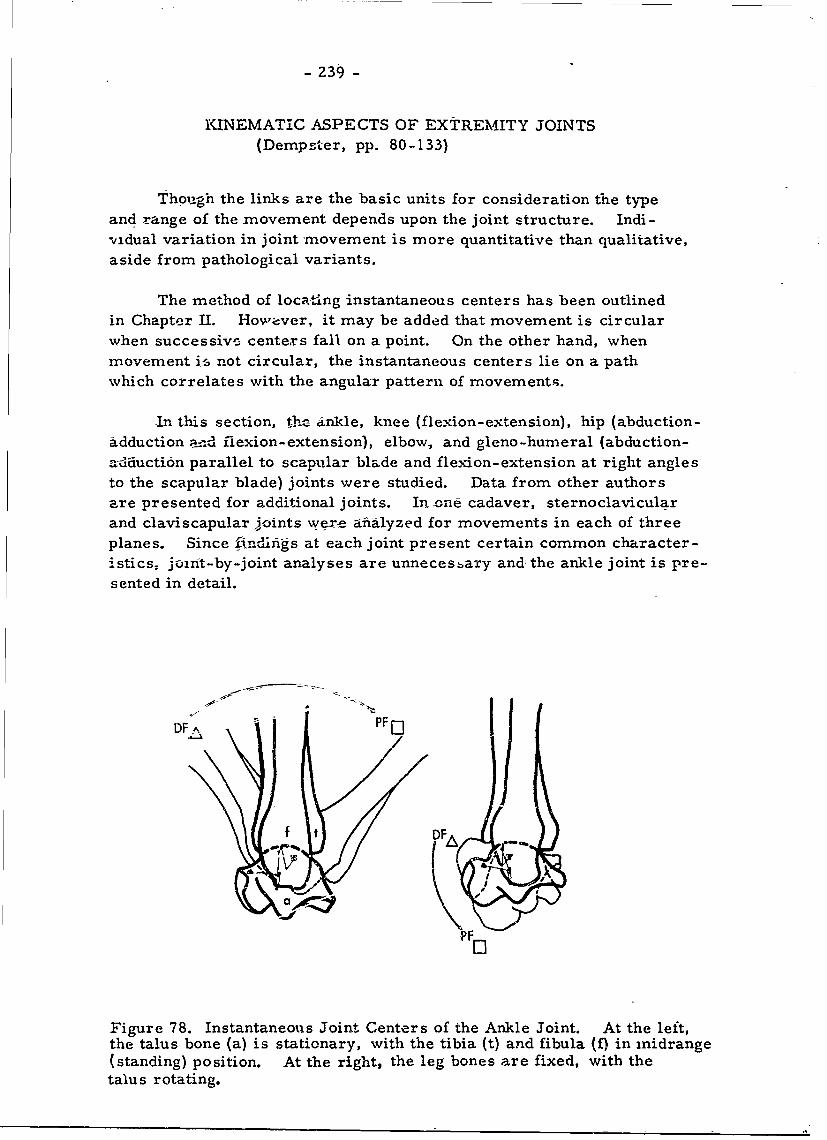
- 239 -
KINEMATIC ASPECTS OF EXTREMITY JOINTS(Dempster, pp. 80-133)
Though the links are the basic units for consideration the typeand range of the movement depends upon the joint structure. Indi-vidual variation in joint movement is more quantitative than qualitative,
aside from pathological variants.
The method of locating instantaneous centers has been outlinedin Chapter II. Hovwver, it may be added that movement is circularwhen successive centers fall on a point. On the other hand, whenmovement i6 not circular, the instantaneous centers lie on a pathwhich correlates with the angular pattern of movements.
In this section, the ankle, knee (flexion-extension), hip (abduction-adduction and flexion-extension), elbow, and gleno-humeral (abduction-
a-dduction parallel to scapular blade and flexion-extension at right anglesto the scapular blade) joints were studied. Data from other authors
are presented for additional joints. In one cadaver, sternoclavicularand claviscapular joints were afialyzed for movements in each of threeplanes. Since findifigs at each joint present certain common character-
istics, joint-by-joint analyses are unnecessary and: the ankle joint is pre-sented in detail.
DF A -PF':o
f t DFAa.,
Figure 78. Instantaneous Joint Centers of the Ankle Joint. At the left,the talus bone (a) is stationary, with the tibia (t) and fibula (f) in inidrange(standing) position. At the right, the leg bones are fixed, with thetalus rotating.
= = .. .. ... -- ;_ . .. . . . . ..
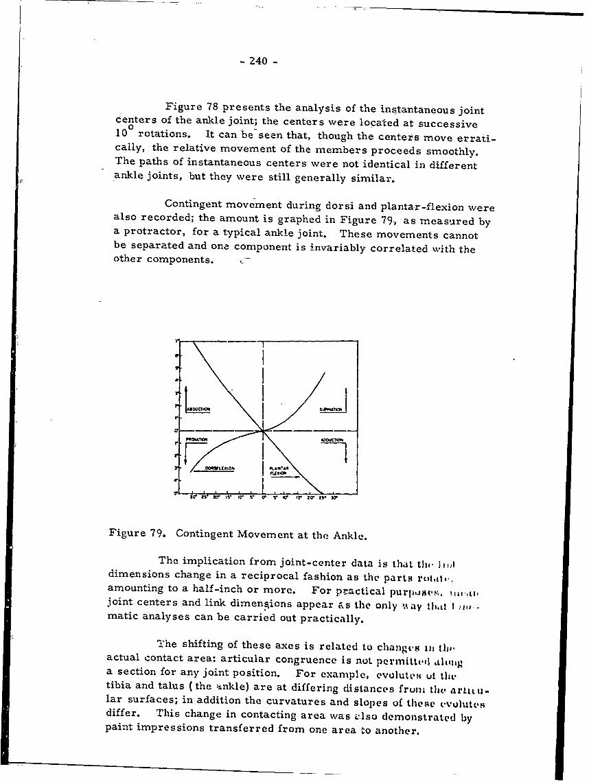
- 240 -
Figure 78 presents the analysis of the instantaneous jointcenters of the ankle joint; the centers were located at successive10 rotations. It can be seen that, though the centers move errati-cally, the relative movement of the members proceeds smoothly.The paths of instantaneous centers were not identical in differentankle joints, but they were still generally similar.
Contingent movement during dorsi and plantar-flexion werealso recorded; the amount is graphed in Figure 79, as measured bya protractor, for a typical ankle joint. These movements cannotbe separated and one component is invariably correlated with theother components.
6* I
ILY I
fI fl#X 4 I &aWTAR
Figure 79. Contingent Movement at the Ankle.
The implication from joint-center data is that th,, hicddimensions change in a reciprocal fashion as the parts rutai,,amounting to a half-inch or more. For practical purpj-siw, ,,joint centers and link dimensions appear as the only %%ay that I ,i.matic analyses can be carried out practically.
TXhe shifting of these axes is related to changes m th,,actual contact area: articular congruence is not permitted loiaga section for any joint position. For example, evoluteti ut thtstibia and talus (the inkle) are at differing distances fruni the articu-lar surfaces; in addition the curvatures and slopes of these evolutesdiffer. This change in contacting area was zlso demonstrated bypaint impressions transferred from one area to another.
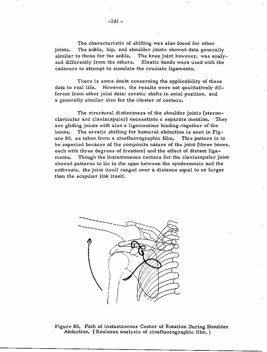
-Z41 -
The characteristic of shifting was also found for otherjoints. The ankle, hip, and shoulder joints showed data generally
similar to those for the ankle. The knee joint however, was analy-zed differently from the others. Elastic bands were used with the
cadavers to attempt to -simulate the cruciate ligaments.
There is some doubt concerning the applicability of these
data to real life. However, the results were not qualitatively dif-
ferent from other joint data: erratic shifts in axial position, anda generally similar size for the cluster of centers.
The structural distinctness of the shoulder joihnt (sterno-
clavicular and claviscapular) necessitate a separate mention. Theyare gliding joints with also a ligamentous binding-together of thebones. The erratic shifting for humeral abduction is seen in Fig-
ure- 80, as taken from a cinefluorographic film. This pattern is to
be expected because of the composite nature of the joint (three bones,each with three degrees of freedom) and the effect of distant liga-ments. Though the instantaneous centers for the claviscapular jointshowed patterns to lie in the span between the syndesmosis and thearthrosis, the joint itself ranged over a distance equal to or larger
than the scapular link itself.
Figure 80. Path of instantaneous Center of Rotation During ShoulderAbduction. (Reuleaux analysis of cinefluorographic film.)
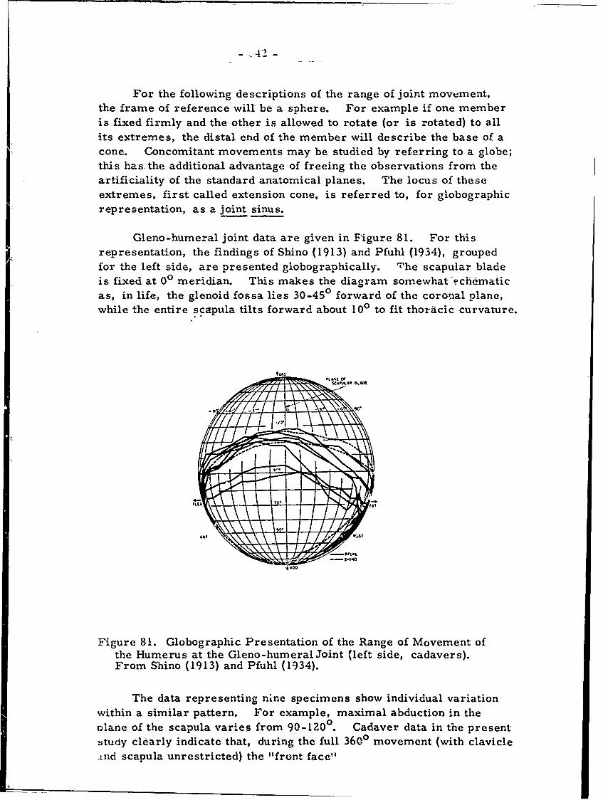
-42-
For the following descriptions of the range of joint movement,the frame of reference will be a sphere. For example if one memberis fixed firmly and the other is allowed to rotate (or is rotated) to allits extremes, the distal end of the member will describe the base of acone. Concomitant movements may be studied by referring to a globe;this has. the additional advantage of freeing the observations from theartificiality of the standard anatomical planes. The locus of theseextremes, first called extension cone, is referred to, for globographicrepresentation, as a joint sinus.
Gleno-humeral joint data are given in Figure 81. For thisrepresentation, the findings of Shino (1913) and Pfuhl (1934), groupedfor the left side, are presented globographically. The scapular bladeis fixed at 00 meridian. This makes the diagram somewhat .Fchematicas, in life, the glenoid fossa lies 30-45 ° forward of the coro0Ial plane,while the entire scapula tilts forward about 100 to fit thoracic curvature.
Figure 81. Globographic Presentation of the Range of Movement ofthe Humerus at the Gleno-humeral Joint (left side, cadavers).From Shino (1913) and Pfuhl (1934).
The data representing nine specimens show individual variationwithin a similar pattern. For example, maximal abduction in theplane of the scapula varies from 90-120 ° . Cadaver data in the presentstudy clearly indicate that, during the full 3600 movement (with clavicleand scapula unrestricted) the "front face"
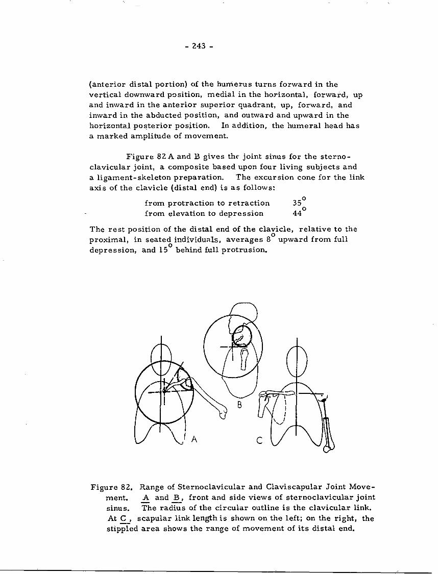
- 243 -
(anterior distal portion) of the humerus turns forward in thevertical downward position, medial in the horizontal, forward, upand inward in the anterior superior quadrant, up, forward, andinward in the abducted position, and outward and upward in thehorizontal posterior position. In addition, the humeral head hasa marked amplitude of movement.
Figure 82 A and ]B gives the joint sinus for the sterno-clavicular joint, a composite based upon four living subjects anda ligament-skeleton preparation. The excursion cone for the linkaxis of the clavicle (distal end) is as follows:
from protraction to retraction 350
from elevation to depression 44 °
The rest position of the distal end of the clavicle, relative to theproximal, in seated individuals, averages 8 upward from fulldepression, and 150 behind full protrusion.
I B
Figure 82. Range of Sternoclavicular and Claviscapular Joint Move-ment. A and B, front and side views of sternoclavicular jointsinus. The radius of the circular outline is the clavicular link.At C , scapular link length is shown on the left; on the right, thestippled area shows the range of movement of its distal end.
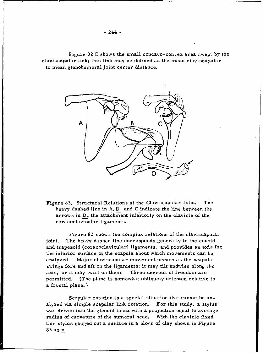
- 244:-
Figure 82 C shows the small concavo-convex area swept by theclaviscapular link; this link may be defined as the mean claviscapular
to mean glenohumeral joint center distance.
Figure 83. Structural Relations at the Claviscapular Joint, Theheavy dashed line in A, B, and C indicate the line between thearrows in D: the attachment inferiorly on the clavicle of the
coracoclavicular ligaments,
Figure 83 shows the complex relations of the claviscapularjoint. The heavy dashed line corresponds geiterally to the conoidand trapezoid (coracoclavicular) ligaments, and provides an axis forthe inferior surface of the scapula about which movemenits can beanalyzed. Major claviscapular movement occurs as the scapulaswings fore and aft on the ligaments; it may tilt endwise along tb'c
axis, or it may twist on them. Three degrees of freedom are
permitted. (The plane is somewhat obliquely oriented relative toa frontal plane. )
Scapular rotation is a special situation tlat cannot be an-alyzed via simple scapular link rotation. For this study, a styluswas driven into the glenoid fossa with a projection equal to averageradius of curvature of the humeral head. With the clavicle fixedthis stylus gouged out a surface in a block of clay shown in Figure83 as x.
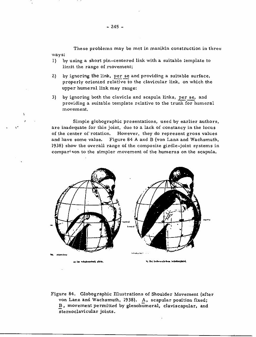
- 245 -
These problems may be met in manikin construction in threeways:1) by using a short pin-centered link with a suitable 'template to
limit the range of movement;
2) by ignoring the link, per se and providing a suitable surface,properly oriented relative to the clavicular link, on which theupper humeral link may range:
3) by ignoring both the clavicle and scapula links, per se, andproviding a suitable template relative to the trunk for humeral
movement.
Simple globographic presentations, used by earlier authors,V" are inadequate for this joint, due to a lack of constancy in the locus
of the center of rotation. However, they do represent gross valuesand have some value. Figure 84 A and B (von Lanz and Wachsmuth,1938) show the overall range of the composite girdle-joint systems incompari ;on to the simpler movement of the humerus on the scapula.
Figure 84. Globographic Illustrations of Shoulder Movement (aftervon Lanz and Wachsmuth, 1938). A, scapular position fixed;B, movement permitted by glenohumeral, claviscapular, and
sternoclavicular joints.
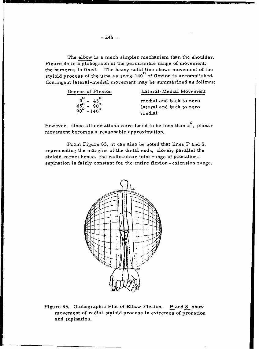
- 246 -
The elbow is a much simpler mechanism than the shoulder.Figure 85 is a globograph of the permissible range of movement;the humerus is fixed. The heavy solid line shows movement of thestyloid process of the ulna as some 1400 of flexion is accomplished.Contingent lateral-medial movement may be summarized as follows:
Degree of Flexion Lateral-Medial Movement
0 - 450 medial and back to zero0 0450 - 90 lateral and back to zero
90 medial
0
However, since all deviations were found to be less than 3 , planarmovement becomes a reasonable approximation.
From Figure 85, it can also be noted that lines P and S,representing the margins of the distal ends, closely parallel thestyloid curve; hence, the radio-ulnar joint range of pronation.-supination is fairly constant for the entire flexion - extension range.
IJ-
I"I
Figure 85. Globographic Plot of Elbow Flexion. P and S show
movement of radial styloid process in extremes of pronationand supination.
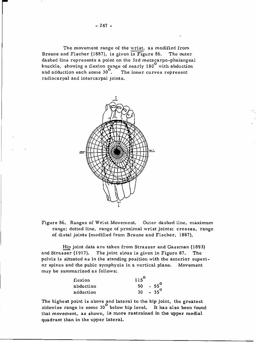
- 247 -
The movement range of the wrist, as modified fromBraune and Fischer (1887), is given in Figure 86. The outerdashed line represents a point on the 3rd metacarpo-phalangealknuckle, showing a flexion range of nearly 1800 with abductionand adduction each some 30 The inner curves representradiocarpal and intercarpal joints.
Figure 86. Ranges of Wrist Movement. Outer dashed line, maximumrange; dotted line, range of proximal wrist joints- crosses, rangeof distal joints (modified from Braune and Fischer, 1887).
Hip joint data are taken from Strasser and Gassman (1893)and Strasser (1917). The joint sinus is given in Figure 87. Thepelvis is situated as in the standing position with the anterior superi-or spines and the pubic symphysis in a vertical plane. Movementmay be summarized as follows:
flexion 1150
abduction 50 - 550
adduction 30 - 350
The highest point is above and lateral to the hip joint, the greatestsidewise range is some 30 below hip level. It has also been foundthat movement, as shown, is more restrained in the upper medialquadrant than in the upper lateral.
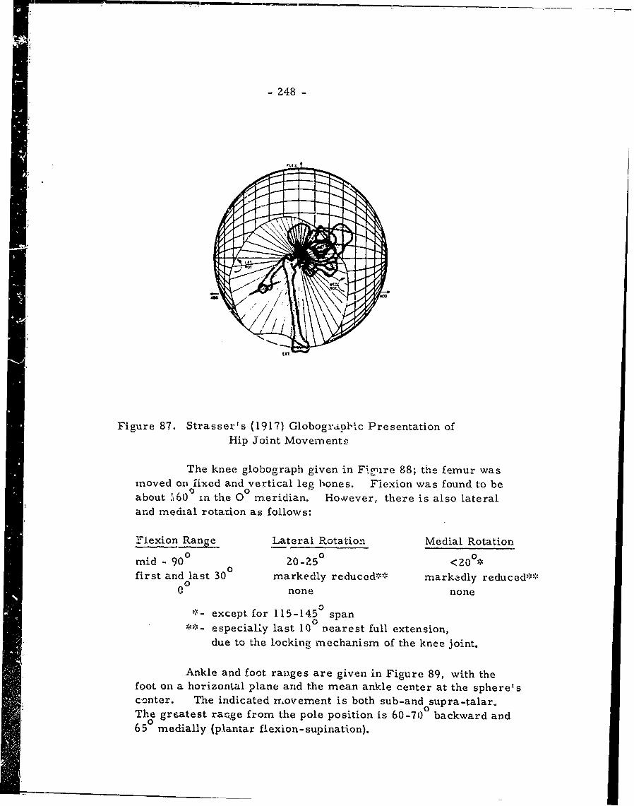
- 248 -
Figure 87. Strasser's (1917) Globograol-*c Presentation ofHip Joint Movernents
The knee globograph given in Figure 88; the femur wasmoved on fixed and vertical leg bones. Fiexion was found to beabout '160 ) in the 0 meridian. Hovever, there is also lateraland medial rotation as follows:
Flexion Range Lateral Rotation Medial Rotation
mid - 90 ° 20-50 <20°*first and last 30 markedly reduced-",:;' ma rkedly re duced'::-
000 none none
'- except for 115-145a spanSespecialy last 100 nearest full extension,
due to the locking mechanism of the knee joint.
Ankle and foot ranges are given in Figure 89, with thefoot on a horizontal plane and the mean ankle center at the sphere'scenter. The indicated rr.ovement is both sub-and supra-talar.The greatest ra.ge from the pole position is 60-70 backward and65 0 medially (plantar flexion- supination).
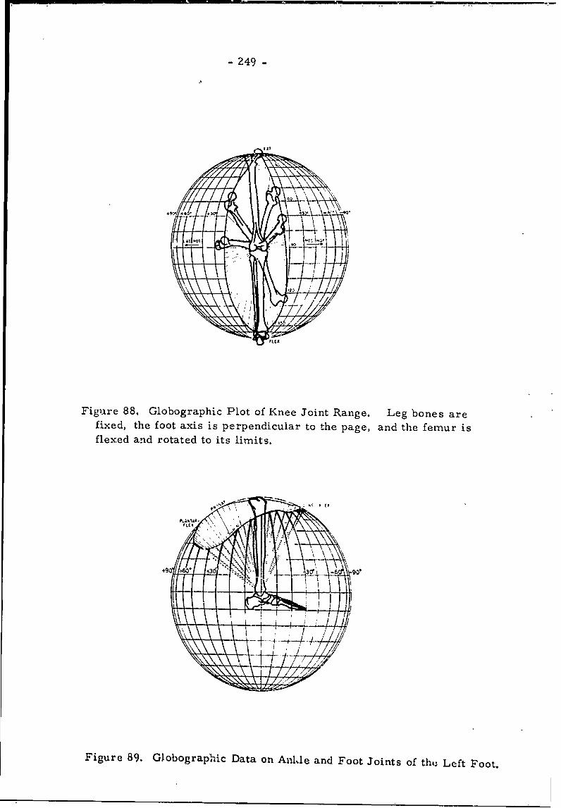
- 249 -
Figure 88. Globographic Plot of Knee Joint Range. Leg bones arefixed, the foot axis is perpendicular to the page, and the femur isflexed and rotated to its limits.
O',4NTAR-
49F igre3 Ia DA -6 F0'
Figure 89. Globographic Data on An-Ale and Foot Joints of the Left Foot.
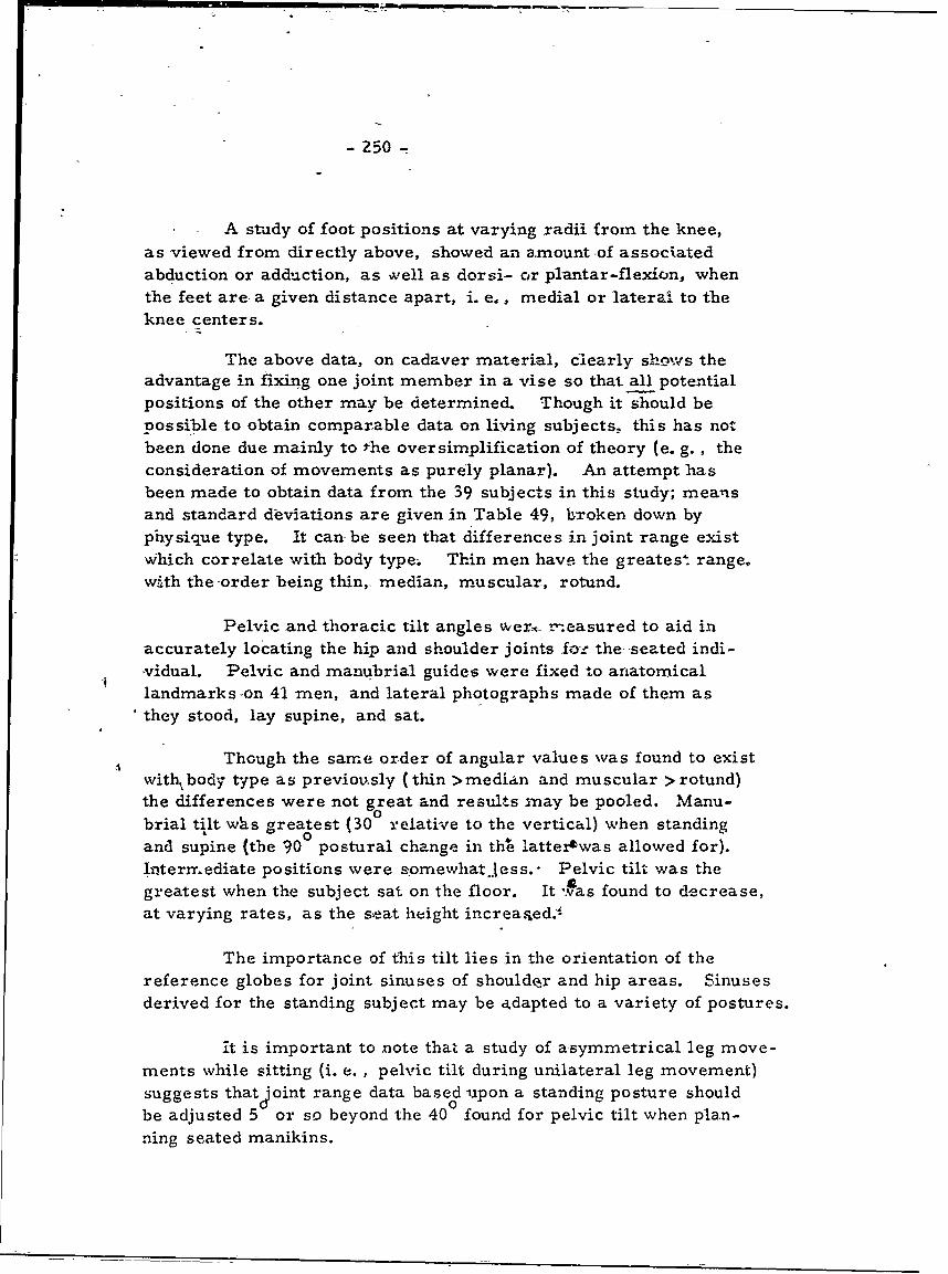
- 250
A study of foot positions at varying radii from the knee,as viewed from directly above, showed an amount of associatedabduction or adduction, as well as dorsi- or plantar-flexion, whenthe feet are- a given distance apart, i. e,, medial or lateral to theknee centers.
The above data, on cadaver material, clearly shewvs theadvantage in fixing one joint member in a vise so that all potentialpositions of the other may be determined. Though it should bepossible to obtain comparable data on living subjects, this has notbeen done due mainly to the oversimplification of theory (e. g. , theconsideration of movements as purely planar). An attempt hasbeen made to obtain data from the 39 subjects in this study; meansand standard deviations are given in Table 49, broken down byphysique type. It can be seen that differences in joint range existw~hich correlate with body type. Thin men have the greatest range,wath the order being thin,, median, muscular, rotund.
Pelvic and thoracic tilt angles werc r-.easured to aid inaccurately locating the hip and shoulder joints foz the- -seated indi--vidual. Pelvic and manubrial guides were fixed to anatomicallandmarks -on 41 men, and lateral photographs made of them asthey stood, lay supine, and sat.
Though the same order of angular values was found to existwith, body type as previously (thin >median and muscular >rotund)the differences were not great and results may be pooled. Manu-brial tilt wlis greatest (30 relative to the vertical) when standingand supine (the 90 postural change in the lattertwas allowed for).-i-teriyediate positions were somewhat Jess.- Pelvic tilt was the
greatest when the subject sat on the floor. It 'fas found to decrease,at varying rates, as the seat height increaqed.i
The importance of this tilt lies in the orientation of thereference globes for joint sinuses of shoulder and hip areas. Sinusesderived for the standing subject may be adapted to a variety of postures.
it is important to note that a study of asymmetrical leg move-ments while sitting (i. e. , pelvic tilt during unilateral leg movement)suggests that Joint range data based upon a standing posture shouldbe adjusted 5 or so beyond the 40 found for pelvic tilt when plan-ning seated manikins.
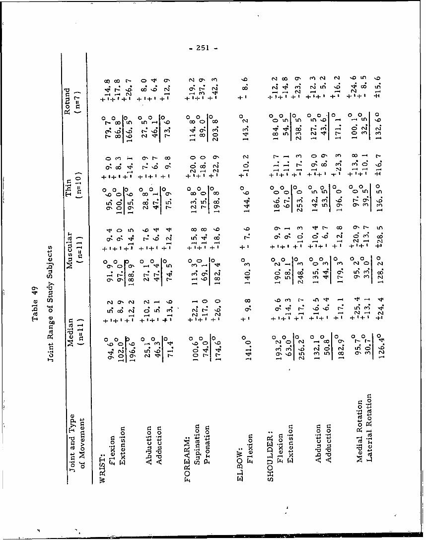
-251-
00O 00 r- 0 NO CY% '. 0 NC 0 ' C AcnN N "D tn 'D~
00, Ci N 0t: (4 06CO C4 (I'; " 0 1 CO 4 in
14 - 4n 14- 1- N -1 N N4
000 0 0 0 00 00 0 0010
r-C L0 [,.,n tn 0 COO 0 N oL tn tn n o -4 -4L M -1
r- 00 N ~ N -4 CO C OLA cn q CAM e
o 0 0 -4 .0 IN -4 N -4 -4 - 4
OCn a, r'- 00 000' C N N- -'( CA 0 CYN M O- 0
-__ N -4 (11 -4 -4 "4 -4 N -4 .- 4
0) +1+ 1+ I + I+I + I +I+ I+ I + I +5+I + + I + 5 +1+1 -rl+I
0 00 0 010 0 0 0 0 0 0 0 0 0 0 0 0 0
N.oO c ,- 00 CO CO '00 o c c)LAL 0h OA LA n
tnAO t if) t~-IL tn cIti0'00o'O N 11 r N r- a, 0O. LA tn ~ tn 6% C a% e
1-4 -4-- -4 N -.4 .-
kd4C 1 - leL '0' lt "i COC '06 V: 0'- CA c 'd (4 C 4 0'6.
:j14 + - .-4 -4 - --4' OsO NOCACO.
(o~ + I+ I+1 +1 +1 + I+ 1+1 +1 +++1 +1+ +1 +1+1 +1
0~ - 00 r 0 00 00C 0 0 0 010 0 010 0
r- -- C t-: C4 C0 Nl 0; OcO CO6 tn :-A Y%1 0' nC
a% aO N~ N1r -,o. cov 0% LA M. At r- 0C en0' 14 -44 C4 -44 -N
Nj (7% N N N -4 -.0 .- 0 0) 00 1.Q( Cn r- n -4 V1'-4 .14
1-4 -4 -- 1 N- N r-4 -4 - -4 N N
Eo+1+1+1 +1+0 +' +1+1 +' +1 +f-+ I +I+ I+ 4 + I+ 1 +1
0 0 0 00 0 00 0 00 000 00
+J o '.O . .C ' '00) I00O N 0-C 0 ' NtcllO -
~N 0 LA' . C; C4 C4 1 cO NO N4 tA O'1cN' v' N ' N D ON r- a%''0 Ln CAL CO 00 'aCA
-4
4J~ .4.
0 0 0 00-4 .q 40
0- 4
-4 A-4A(d, 0
0Z 0 ntn 40
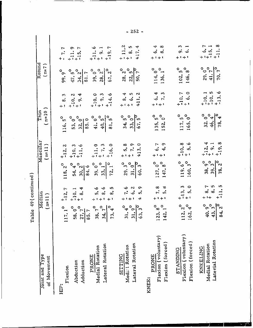
-252-
in 14 00 --4 00 4.
-4 -- 1 + -4 ---4+
+3 + + + ++ + +' + ++ + I+ +I
II 0 00 0 oolo or00 0 000 0 0 0 0
0 o, i fN ~ O>N N~ N inC 0-4 in oo ON N-r
a, t rcn 0 enN '0 N N-4 en 0 N' It r- -4 -4 -4
r c N 0( rn -0 ~ in N NO r -4tt in -,
o C) .r .; . 4 z a; .c C
-- -4 4 -4 -4 -4 -4 ..4
+' + I . + I+ I +I + a+' I +I+ I + I+ I +1+ 1+ I
-4-4
11I 0 0 0 00 0 00 00 0 00 '
N- in m 0 0 0 CO M' 0 cN a' -O '0 M~-
-44 - -4 -- -4 4 ..
u-4 N 0-4 : -4 N 4 r'0 --NL -. 4O a' a
*+' + + ++I + I + + I + + +' + + I+
0 0 0D 0 00 00 000
1-0 c,
--
O 0
-4 LALA 1- 4-4 0 0 1
N inj %0' fl ' N a'% 00 o L O NCA r- iAi
* .~ 4D 0. .4
04 0 : s L4r ;e L4 4 o3
-4-4 -4 -4 -4
+ I~ -I + I +'+ I' + 1 +1+1 +P + 1+ + t +1+ +1
a ' C )- II0 1 Y
-4 t. 4 i 0*C C4 *4 4
4.4
.- n NA LA LA rN r- LA '0 N v -- 4 '0 v 0
Cd C)
00 0 0 ., 004
4JO (d) 44 (d 0) 0 C)
..- , 0 4
C4 --
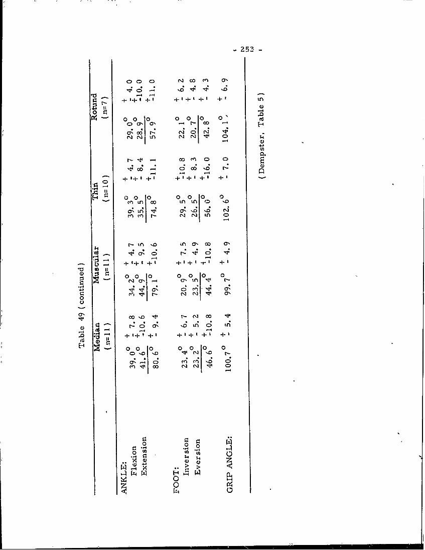
- 25 -
0 00 N cO 0",
+ I + + +'+ +
4)
N =- 4'-o oolo o olo° o (-4-bEn04
06- Oo i 0 'o. r.
000 000 0
0 0A 0 0
,a,,,, 5 .
-4
-- 4
- Lc; 4 11+6r is
0 010 0 0 01-
4.)4
(A ioNo 04~ N4 r-
a%. 0 0N 10 0
v.~ 00 0 000 0
't -4-4
n 0 00
"-4 0 0.
00
- 254-
The living subjects were studied to determine the degreeof accuracy at which shoulder and hip joint centei0s could be marked.The lateral projection of the hip joint center was found to lie with-in a 1. 7 x 1. 5 mm ellipse around the femoral trochanter, for agiven degree of accuracy in palpation. An easier method wasdetermined, whereby a line dropped vertically from the anteriorsuperior spine of the ilium (assuming a standard seated 400 pelvictilt) fell within 30 of the mean joint center. Half of the distancefrom the spine to the seat formed a reasonable estimate of themid-acetabulum. In either case, accuracy is possible only towithin a 1. 2 x 1. 5 mm ellipse.
Reasonable approximations were possible for the shoulderwithout the detailed analysis necessary for the hip.
Before the link dimensions themselves could be determined,it was necessary to gather information relative to bone length andstature. Consequently, from the data of Trotter and Gleser(1952),stature was plotted against long bone length for 710 U.S. Armypersonnel. From the osteological collection, bone lengths wereobtained which correspon ded to the 5th, 50th, and 95th percentilesfor stature of U. S. Air Force flying personnel (Hertzberg, Daniels,and Churchill, 1954). It is felt that the two military populations,selected by similar standards, correspond closely in bone length.
The bone lengths were next plotted against each other. Al-though correlations were positive, the variability was considerable.
Prior to measuring the link dimensions, the individual boneswere corrected to the actual link size. This involved the determ-ination of mean joint centers, as determined previously. Eventhough the radii of curvature of larger specimens of a given bonewere smaller, and vice versa, the errors introduced were neglig-ible, and these radii were determined by a Lensometer. Finalcorrections were worked out, and the mean percentage values aregiven in Table 50. It must be realized that these are only averages,about which individuals may vary; in addition, there will be instant-aneous variation within the bones. However, they do have a utilityin manikin construction.
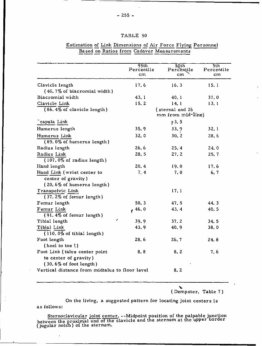
- 255 -
TABLE 50
Estimation of Link Dimensions of Air Force Flying PersonnelBased on Ratios from Cadaver Measurements
9 5th 5.0th 5thPercentile Percentile Percentile
cm cm cm
Clavicle length 17.6 16.3 15. 1(4G. 7% of biacromial width)
Biacromial width 43. 1 40. 1 37. 0Clavicle Link 15.2 14.1 13. 1
(86. 4% of clavicle length) (sternal end 26mm from mid-line)
"capula Link +3.5Humerus length 35.9 33.9 32. 1
Humerus Link 32.0 30. 2 28.6( 89. 0% of humerus length)
Radius length 26.6 25.4 24.0Radius Link 28.5 27. 2 25.7
( 107. 0% of radius length)Hand length 20.4 19.0 17.6Hand Link (wrist center to 7. 4 7.0 6.7
center of gravity)( 20. 6%6 of humerus length)
Transpelvic Link 17. 1( 37. 2% of femur length)
Femur length 50.3 47.5 44.3Femur Link f, 46.0 43.4 40.5
(91. 4% of femur length)Tibial length 39.9 37. 2 34. 5Tibial Link 43.9 40.9 38.0
( I 10.0% of tibial length)Foot length 28.6 26.7 24.8
(heel to toe 1)Foot Link (talus center point 8.8 8. 2 7.6
to center of gravity)( 30.6%6 of foot length)
Vertical distance from midtalus to floor level 8. 2
(Dempster, Table 7)
On the living, a suggested pattern for locating joint centers is
as follows:
Sternoclavicular joint center, -- Midpoint position of the palpable junctionbetween the proximal end of the clavicle and the sternum at the upper border(jugular notch) of the sternum.
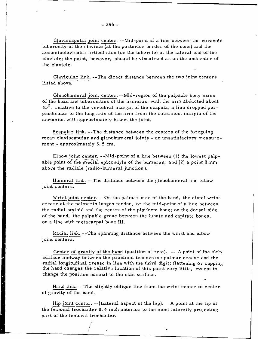
- Z56 -
Claviscapular joint center. -- Mid-point of a line between the coracoidtuberosity of the clavicle (at the posterior border of the oone) and theacromiozlavicular articulation (or the tubercle) at the lateral end of theclavicle; the point, however, should be visualized as on the underside ofthe clavicle.
Clavicular link. -- The direct distance between the two joint centerslisted above.
Glenohumeral joint center.--Mid-region of the palpable bony massof the head and tuberosities of the himerus; with the arm abducted about450, relative to the vertebral margin of the scapula; a line dropped per-pendicular to the long axis of the arm from the outermost margin of theacromion will approximately bisect the joint.
Scapular link. -- The distance between the centers of the foregoingmean claviscapular and glenohumeral joints - an unsatisfactory measure-ment - approximately 3.5 cm.
Elbow joint center. -- Mid-point of a line between (I) the lowest palp-able point of the medial epicondfle of the humerus, and (2) a point 8 mmabove the radiale (radio-humeral junction).
Humeral link. -- The distance between the glenohumeral and elbowjoint centers.
Wrist joint center. -- On the palmar side of the hand, the distal wristcrease at the palmaris longus tendon, or the mid-point of a line betweenthe radial styloid and the center of the pisiform bone; on the dorsal sideof the hand, the palpable grove between the lunate and capitate bones,on a line with metacarpal bone III.
Radial link. -- The spanning distance between the wrist and elbowjoin, centers.
Center of gravity of the hand (position of rest). -- A point of the skinsurface midway between the proximal transverse palmar crease and theradial longitudinal crease in line with the third digit; flattening or cuppingthe hand changes the relative location of this point very little, except tochange the position normal to the skin surface.
Hand link. -- The slightly oblique line from the wrist center to centerof gravity of the hand.
Hip joint center. -- (Lateral aspect of the hip). A point at the tip ofthe fenioral trochanter 0. 4 inch anterior to the most laterally projectingpart of the femoral trechanter.
/'
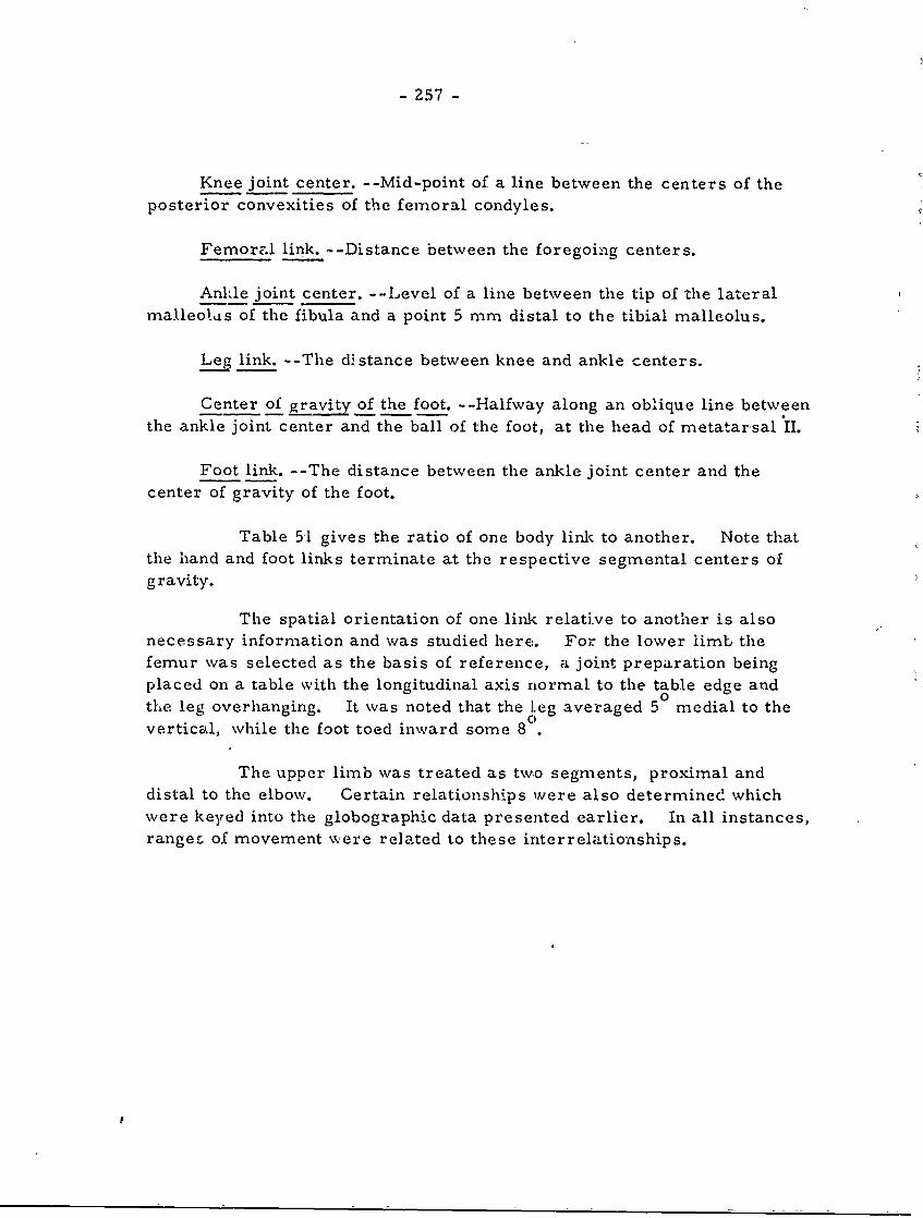
- 257 -
Knee joint center. -- Mid-point of a line between the centers of theposterior convexities of the femoral condyles.
Femoral link. -- Distance between the foregoing centers.
Ankle joint center. -- Level of a line between the tip of the lateralmalleotus of the fibula and a point 5 mm distal to the tibial malleolus.
Leg link. -- The distance between knee and ankle centers.
Center of gravity of the foot. -- Halfway along an oblique line betweenthe ankle joint center and the ball of the foot, at the head of metatarsal II.
Foot link. -- The distance between the ankle joint center and thecenter of gravity of the foot.
Table 51 gives the ratio of one body link to another. Note thatthe hand and foot links terminate at the respective segmental centers ofgravity.
The spatial orientation of one link relative to another is alsonecessary information and was studied here. For the lower limb thefemur was selected as the basis of reference, a joint preparation beingplaced on a table with the longitudinal axis normal to the table edge andthe leg overhanging. It was noted that the leg averaged 5 medial to thevertical, while the foot toed inward some 8
The upper limb was treated as two segments, proximal anddistal to the elbow. Certain relationships were also determined whichwere keyed into the globographic data presented earlier. In all instances,ranges of movement were related to these interrelationships.
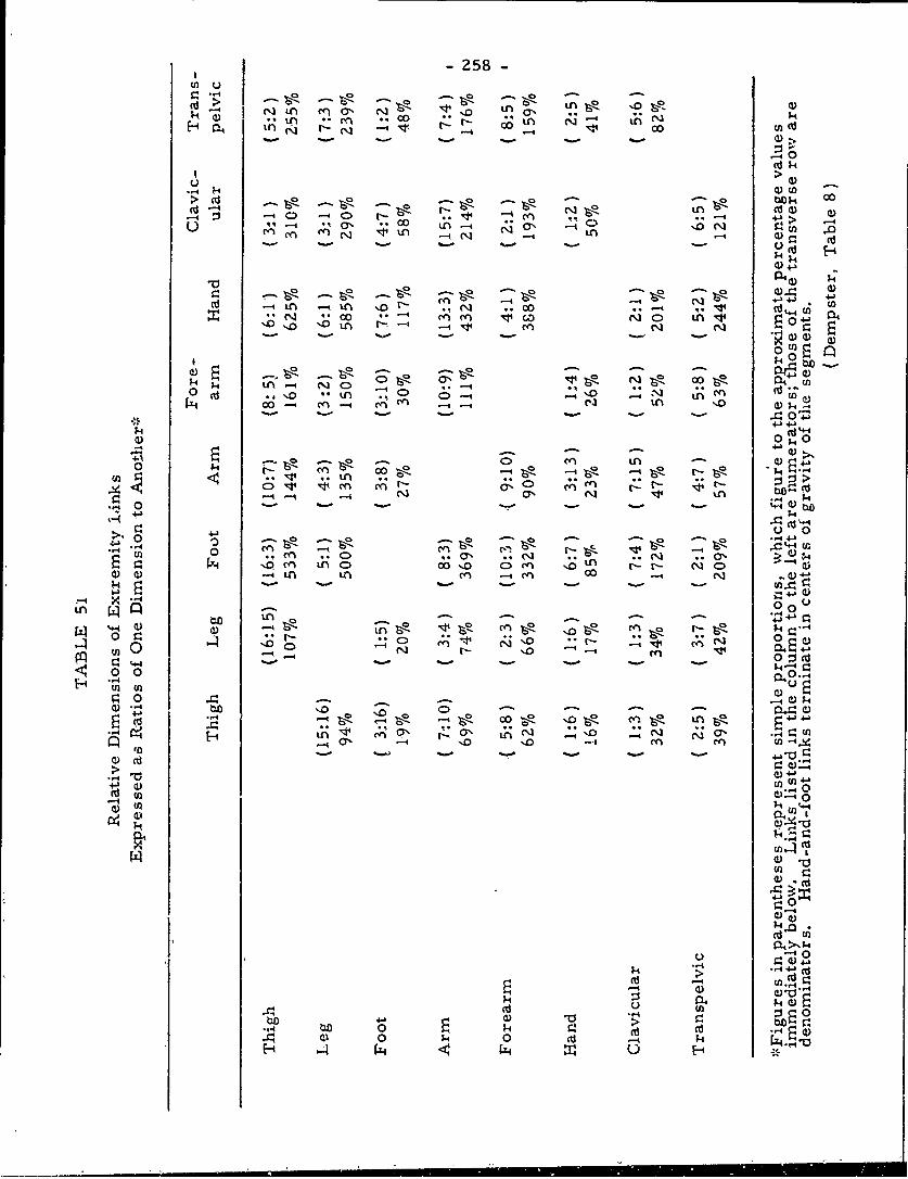
-258-
m2 u
t- ;3 Ln Iq mO N
U a) >
p0 6C~~C k )~ 0
0 * C) -- A C iO 0-i QAC
co-i~~~t >~ C . ~
1.4 4 J IL-
0) 0, (D
o ~ ~~~~ 1. U0CO i
0 ~~~ E_* -
0 CO LO - t'.M..d
MO DOiC a)00~~ M rn -l) - I-
c4. 0-4 OoU0
-> (n40 1-ic> 'n e
0) '.0 'CdO.4
0 ID -O0 ' 4-b~ 4'O *~ ~0i cn. m. Or
.i-4 M) tnO - 4)0 -4(L
tr~ 0
044
0 0)
-4 cIt ~I0i
- 259 -
APPLICATION TO MANIKIN DESIGN (Dempster, pp. 134-158)
The purpose of this chapter is to synthesize the precedingdata into constructions to duplicate the dimensions and movementsof the average individual, as nearly as possible. In this respect,
limb mechanisms are emphasized more than trunk. In addition, 'theemphasis will be upon the seated position, and will not be strictlyapplicable to standing, prone, or kneeling postures.
For this r¢eason, a manikin constructed from these data willnot be universal, though the data should bz capable of transfer to
such a mechanism. What will be possible will be the constructionof a three-dimensional manikin that is kinematically correct, asfar as the iynbs are concerned.
McFarland, et al. (1953) has shown that "average" concepts
are of little value when dealing with individuals and it becomesnecessary to consider control placement relative to smaller, as wellas larger. individuals. A given percentile range can effectively beused, depending upon the designer' s aims. Individuals outside this
range, forming only a small part of the population, can be assignedalternate duties, where body size is of no importanc'e.
Two types of manikins will be presented. First, a threedimensional model, emphasizing the limbs, with accurate linkdimensions, as well as all movements found at major points. Plans
for such a model are presented, which have been tested for function-
al accuracy. It must be remembered that the purpose is to presenta type of standard construction which will closely approximate bodymovements, uniquely controlled in life by bones, joints, and ligaments,
Second, a two dimensional manikin is presented which can
be placed on a drawing board, and which will permit adjustmentsof segments into a number of different postures. The models are
very general in their scope; however, the component parts are suit-
able for modification by the engineer for his specific purpose.
A. The. Three-Dimensional Model
Limb links were constructed of square section aiumihxm
rod with machined interconnecting joints. These joints were cen-
tered mechanisms (hinges, rod and sleeve joints, and universals)with a range of movement limited by end stops or metal guides or
templates to specific angular ranges. The general plan, of assembly
is given in Appendix F. Though the 50th percentile values were
used, larger or smaller dimensions could have been substituted.
- 260 -
Movement ranges were geared to the earlier globogratphic data, modi-fied by quantitative findings of Table 49, with the final orientation ofthe links relative to each other.
Appendix F presents detailed plans for the construction ofthe model, left side only. Note that the joints are designed togive more than the range of movement with a guide or template asa limit, defining a joint sinus, and permitting a free movementwithin the limits. Additional notes on construction follow:
(1) Stenoclavicular joint: A universal joint was set trans-versely with its inner or sternal end normal to the body mid-plane;its support represented the upper portion of the manubrium of thesternum and the joint center was one inch from the side of the mid-plane. Between the center of the universal and the sheet metal guidea rod and sleeve joint permitted additional rotation about the axis ofthe clavicular link. Suitable stops corresponding with the range ofupward and downward rotation of the clavicle were built in.
(2) Claviscapular joint, scapular link, and glenohumeraljoint: These three components were planned as an integral unit.The claviscapular joint permits three degrees of freedom of move'-ment. of the scapula with respect to clavicle; a -iniversal joint dupli-cated these movements in two axes normal to the scapular link. Theadditional rotation about the longitudinal axis of the link was builtinto a telescoping rod and sleeve joint. The distal end of the teles-coping link moved over a flat surface placed obliquely in the jointunit and its range of motion was controlled by a template. Thesocket in which the humerus sits is a part of the scapula. If oneconsiders the movement of the geometrical center of this socketwith respect to the clavicle the point actually moves on a surfacewhich has a very slight curvature (Figure 83). Since the errorintroduced is small, the slight curvature was replaced with a planeand the center of the gleno-humeral (humerus-scapula) joint traveledover this. The construction of a telescoping scapular link was anecessary compensation because of this plane, Since, as intimated,the link also rotated about its axis, this feature was also included.
At the end of the scapular link was the center of the gleno-humeral joint which represented the movement of the humerus withrespect to its socket on the scapula. This movement was providedfor by a universal joint and its angular limits were assured by anattached sheet metal guide with a central cut-out. In this instance,the universal joint was a gimbal to permit an adequate range of
- 261 -
motion. Beyond the gimbal was a rod and sleeve joint to permitan axial rotation oi the humeral link. Each joint (claviscapular
and gleno-humeral) thus had three degrees of freedom.
(3) Elbow joint: This joint was a hinge with terminal stopsto limit motion at each end of the range of movement.
(4) Forearm joints: Beyond the elbow joint proper, a rodand sleeve joint with suitable stops provided for pronation-supin-ation movement of the forearm link and -regions beyond.
t5) Wrist joint and hand assembly: This joint was a univer-
sal joint; it was provided with a sheet metal guide which was bentinto a half cylinder; on its longitudinal axis was the center of theuniversal joint, In this instance the guide was a part of a largersheet metal piece which was shaped and bent as indicated in Appen-dix F to give a general form that suggested hand, thumb, and finger
shape. Into ;his hand shape was built a projecting knobbed rod thatrepresented the grip angle relative to the axis of wrist motion; theknob end corresponded with a rod gripped in the hand and projectingfrom the thumb side of the hand.
(6) Hip joint: The center of the nip joint was mounted on alink rod, representing half of the transpelvic link, which projected86 mm. as a normal to the mid-sagittal.plane; its surfaces repre-
sented fore-and-aft and upper-and-lower directions relative to thestanding position of a man. The joint itself consisted of a universaljoint with a rod and sleeve joint just beyond; the universal joint wasspecially constructed to permit an adequate range of movement and thesheet metal guide which limited the range of movement was bent to anangle to provide sufficient clearance for the femoral link in its move-
ment.
(7) Knee joint; The knee joint in the constructed model per-mitted axial rotation of the shank link as well as flexion-extensionmovements; its movements corresponded %%ith the globographic data(Figure 88) as corrected for data on living subjects. The range ofshank rotation was actually increased to correspcnd with knee rotationplus foot abduction or adduction, Accordingly, values of Table 49
and other data on knee rotation werL utilized. Li the detail drawingsthe joint i, shown to be a combined hinge and axial joint; it was pro-vided %kith a guide and template system to limit nrotion to a normalrange. The joint was locked in the extended position with no rotat-ion possible except straight flexion; with further flexion, hov.ever,
increasing amounts of axial shank rotation ei' permitted.
-262-
(8) Ankle joint aui.1 foot assembly: The shape of the foot wasrepresented simply as a flat plate of sheet metal, suggesting the
" foot sole from heel to toe, and an oblique piece from the ball of thefoot upwa-'d toward the ankle. (The foot form might have been moreelaborately worked out like the hand section.) From the foot solepiece a vertical pillar, at a suitable distance between the heel andtoe, extended upward to the ankle joint level. This joint was repre-sented by a universal joint and the movement of the lower sectionof it was guided by a sheet metal guide plate attached to the lower endof the shank section.
(9) Though the femoral link was vertical in the standingposition, the shank section was bent inward so that a line from theknee center made an angle of 50 with the vertical.
(10) The foot abduction-adduction range was simply added tothe axial rotation range of the shank. A rod and sleeve joint belowthe ankle would provide for a separate foot range and more perfectlyrestrict the knee movement.
In addition to (10) above, inadequacies were found with rotat-ions of the hip and shoulder. In the hip, there is no provision, inthe model, for varying amounts of shank rotation as the hip rangesthrough varying degrees of flexion, as when the legs are crossed,or if one ankle is placed on the opposite knee.
In the shoulder, the humeral range of motion, with the elbowbent 900, is only about half as great when the humerus is verticallyupward as when it is vertically downward. The model shows iden-tical axial movement for the humeral link at all positions.
These movements are, however, very specialized and havegenerally negligible effects on the end members.
B. Drafting Board Manikins
These manikins were constructcd in relation to the 5th, 50th,and 95th percentiles of the dimensions of Air Force flying personnel.In planning a work space, the small manikin can be placed on thedrawing board; after its positions are noted, the large one can besubstituted and equivilant positions marked. The designer maythen determine the best functional balance between the two locations,allowing clearance for the large man, but placing assemblies withinthe reach of the smaller.
- 263 -
In manikin construction, median and muscular subjects ofthe sample were screened to determine which ones most nearlyduplicated the above percentile levels. Four anthropometriccriteria were used: stature, crotch height, acromial sitting height,and upper limb length.
The selected group was photographed nude in the standardcockpit seat (heel-eye height equals 39. 4"), side view. Tracingsof the men in each percentile group were superimposed and jointcenters for the shoulder, hip, knee, and ankle were marked. Thelower limb segments were aligned so that these contours correspond-ed as closely as possible, after which average joint centers, linklines, and contours were drawn in; average link dimensions fromTable 50 were substituted and the profile contours modified. Thesame was done for upper limb contours. The mean trunk contourwas estimated from hip and resting shoulder joint centers, enlargedto include the variability discussed earlier. (Note-analysis ofmotion pictures of arm movement while seated necessitated an en-largement of the globographic range of the humeral head for dynamicbehaviorS. The tracings were then cut out and adjacent parts unitedby a 5/32" pin.
Appendix G presents the plans for the contours of the threemanikins on a scale of 1:4. These may be cut out as desired. How-ever, any enlargement or reduction of the scale necessitates anequivalent modification in size of the assembly pins.
The artifical nature of this manikin must be emphasized,with caution exercised to insure that manikin postures truly refiectthe positions of choice which a subject would assume.
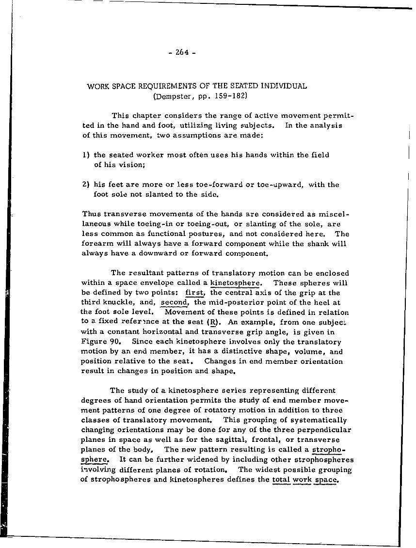
- 264 -
WORK SPACE REQUIREMENTS OF THE SEATED INDIVIDUAL(Dempster, pp. 159-182)
This chapter considers the range of active movement permit-ted in the hand and foot, utilizing living subjects. In the analysisof this movement, two assumptions are made:
I) the seated worker most often uses his hands within the fieldof his vision;
Z) his feet are more or less toe-forward or toe-upward, with thefoot sole not slanted to the side.
Thus transverse movements of the hands are considered as miscel-laneous while toeing-in or toeing-out, or slanting of the sole, areless common as functional postures, and not considered here. Theforearm will always have a forward component while the shank willalways have a downward or forward component.
The resultant patterns of translatory motion can be enclosedwithin a space envelope called a kinetosphere. These spheres willbe defined by two points: first, the central axis of the grip at thethird knuckle, and, second, the mid-posterior point of the heel atthe foot sole level. Movement of these points is defined in relationto a fixed reference at the seat (R). An example, from one subjec-.with a constant horizontal and transverse grip angle, is given inFigure 90. Since each kinetosphere involves only the translatorymotion by an end member, it has a distinctive shape, volume, andposition relative to the seat. Changes in end member orientationresult in changes in position and shape.
The study of a kinetosphere series representing differentdegrees of hand orientation permits the study of end member move-ment patterns of one degree of rotatory motion in addition to threeclasses of translatory movement. This grouping of systematicallychanging orientations may be done for any of the three perpendicularplanes in space as well as for the sagittal, frontal, or transverseplanes of the body. The new pattern resulting is called a stropho-sphere. It can be further widened by including other strophospheresinvolving different planes of rotation. The widest possible groupingof strophospheres and kinetospheres defines the total work space.
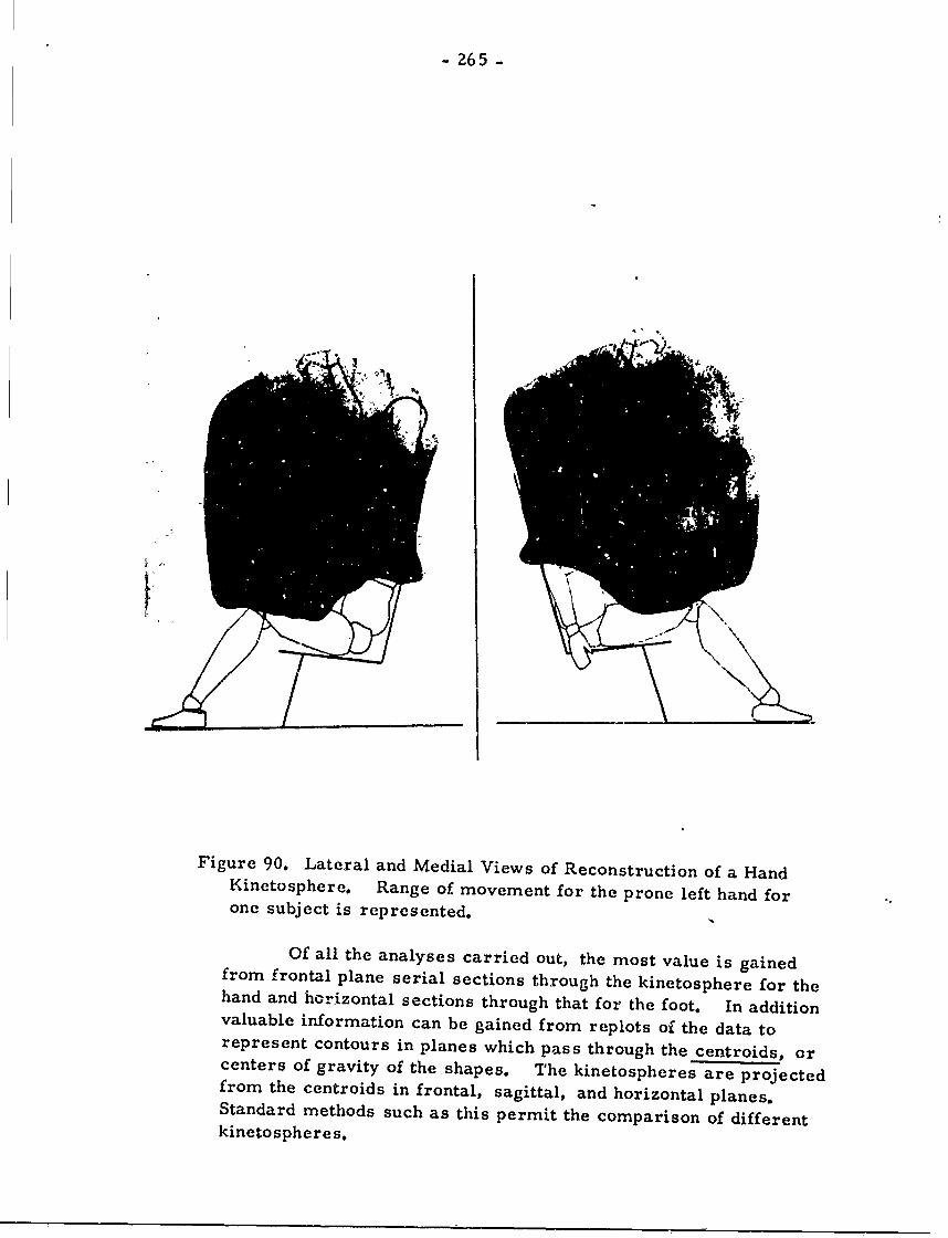
- 265 -
Figure 90. Lateral and Medial Views of Reconstruction of a HandKinetosphere. Range of movement for the prone left hand forone subject is represented.
Of all the analyses carried out, the most value is gainedfrom frontal plane serial sections through the kinetosphere for thehand and horizontal sections through that for the foot. In additionvaluable information can be gained from replots of the data torepresent contours in planes which pass through the centroids, orcenters of gravity of the shapes. The kinetospheres are projectedfrom the centroids in frontal, sagittal, and horizontal planes.Standard methods such as this permit the comparison of differentkinetospheres.
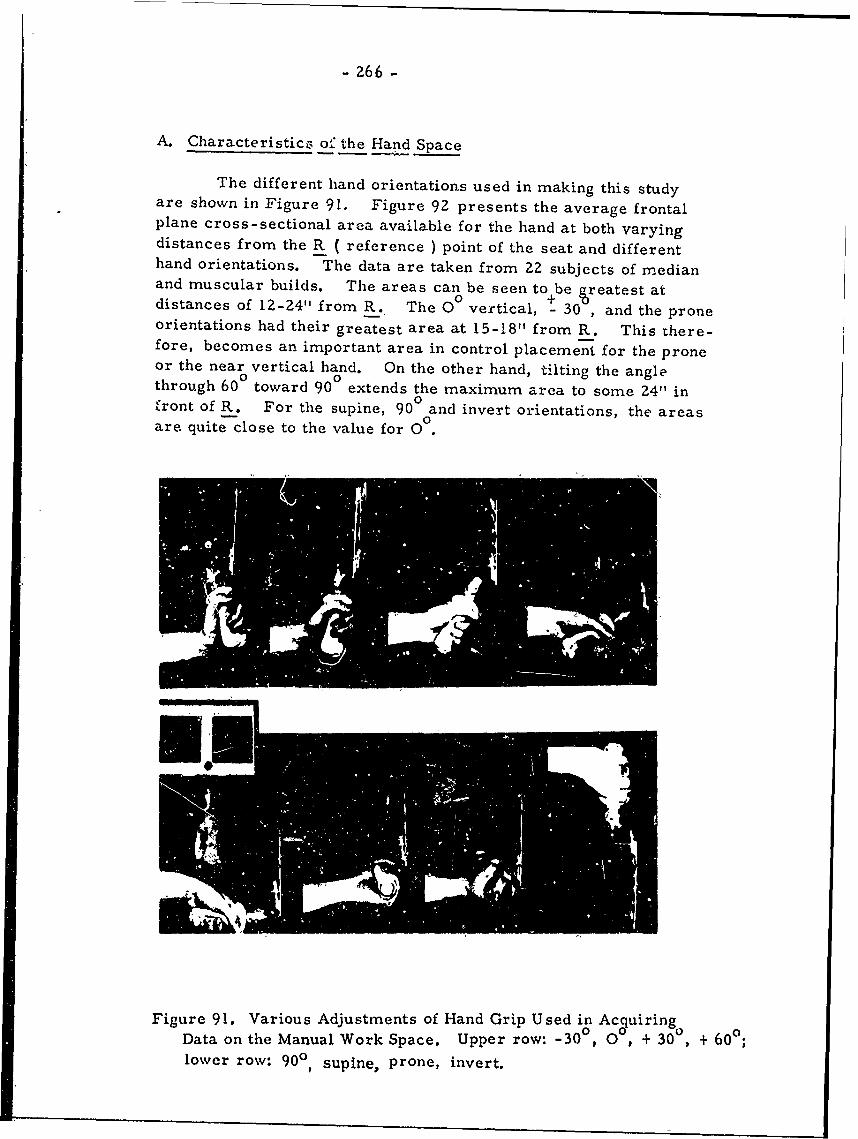
- 266 -
A. Characteristicz of the Hand Space
The different hand orientations used in making this studyare shown in Figure 91. Figure 92 presents the average frontalplane cross-sectional area available for the hand at both varyingdistances from the R ( reference ) point of the seat and differenthand orientations. The data are taken from 22 subjects of medianand muscular builds. The areas can be seen to be eatest atdistances of 12-24" from R. The 0 vertical, - 30 , and the proneorientations had their greatest area at 15-18" from R. This there-fore, becomes an important area in control placement for the proneor the near vertical hand. On the other hand, tilting the anglethrough 60 toward 90 extends the maximum area to some 24" in
C 0,front of R. For the supine, 90 and invert orientations, the areasare quite close to the value for 00.
Figure 91. Various Adjustments of Hand Grip Used in AcquiringData on the Manual Work Space. Upper row: -30, 0 , + 30 , + 60o;lower row: 900, supine, prone, invert.
- 267 -
TRANSVERSE10 - GRIP
5- 0
0
- 10 -5 0 5 10 IS 20 25 30< -SAGITTAL - ,.30W_
w GRIP._ J'--cr
DIANL STAC RM""PIT(NHS
z96
I-l
ulo
0 - , . . . , ... .. . . i .... .. . L-1o -5 0 1 5 0 t5 20 25 30
DISTANCE FROM "R" POINT (INCHES)
Figure 92. Plots Showing Frontal Plane Areas Available toDifferent Orientations of the Hand at Various Distancesfrom the "R" Point of the Seat.
The areas under the curves represent kinetosphere volumes,the larger volumes denoting a wider range tor the hand in particularhand orientations. This is summarized below.Orientation Vol. (cu. in. ) Orientation Vol. (cu. in.)
-30 19,990 +90 13,0400 24,630 Supine 13, 180
+30 19,940 Prone 20,670+60 15,850 Invert 12,920
Kinetosphere volume also varied with body build, as follows:
thin > muscular > median > rotund
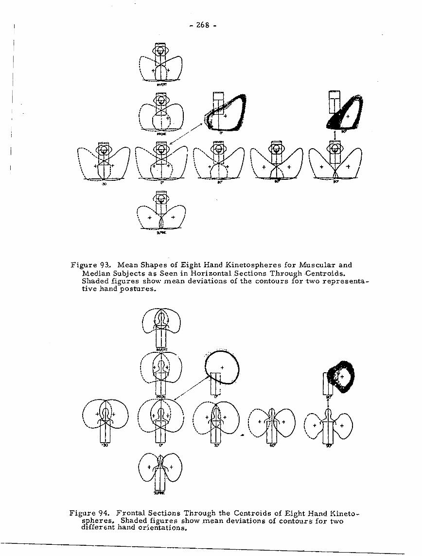
- 268 -
1++ +
Figure 93. Mean Shapes of Eight Hand Kinetospheres for Muscular andMedian Subjects as Seen in Horizontal ,Sections Through Centroids.Shaded figures show mean deviations of the contours for two representa-tive hand postures.
I
++1 (I+ + +
Figure 94. Frontal Sections Through the Centroids of Eight Hand Kineto-spheres. Shaded figures show mean deviations of contours for twodifferent hand orientations.
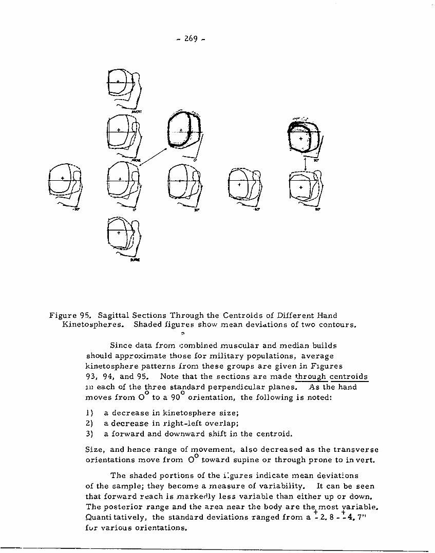
269-
Figure 95. Sagittal Sections Through the Centroids of Different HandKinetospheres. Shaded figures show mean deviations of two contours.
Since data from ':ombined muscular and median buildsshould approximate those for military populations, averagekinetosphere patterns from these groups are given in Figures93, 94, and 95. Note that the sections are made through centroids=., each of the three standard perpendicular planes. As the handmoves from 00 to a 90 orientation, the following is noted:
1) a decrease in kinetosphere size;2) a decrease in right-left overlap;
3) a forward and downward shift in the centroid.
Size, and hence range of movement, also decreased as the transverseorientations move from 00 toward supine or through prone to invert.
The shaded portions of the iLgures indicate mean deviationsof the sample; they become a measure of variability. It can be seenthat forward reach is markedly less variable than either up or down.The posterior range and the area near the body are the most variable.+ +
Quantitatively, the standard deviations ranged from a - 2. 8- -4. 7"fur various orientations.
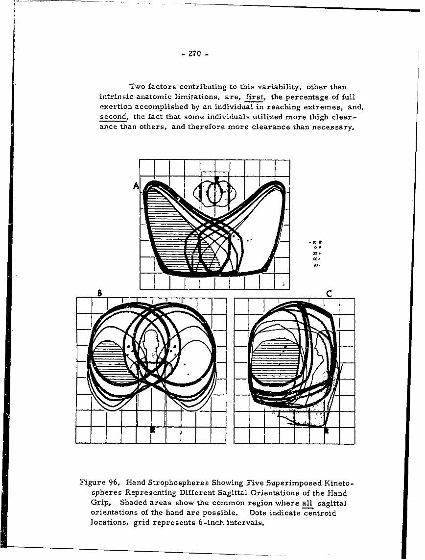
°- __ __ _ __ _ __~__ _ __ _ __ _ __ _ __ _
- 270 -
Two factors ccntributing to this variability, other thanintrinsic anatomic limitations, are, first, the percentage of fullexertion accomplished by an individual in reaching extremes, and,second, the fact that some individuals utilized more thigh clear-ance than others, and therefore more clearance than necessary.
-30t
30.
go.
Figure 96, Hand Strophospheres Showing Five S1,uperimposed Kineto-spheres Representing Different Sagittal Orientations of the HandGrip, Shaded areas show the common region where all sagittalorientations of the hand are possible. Dots indicate centroidlocations, grid represents 6-inch intervals.
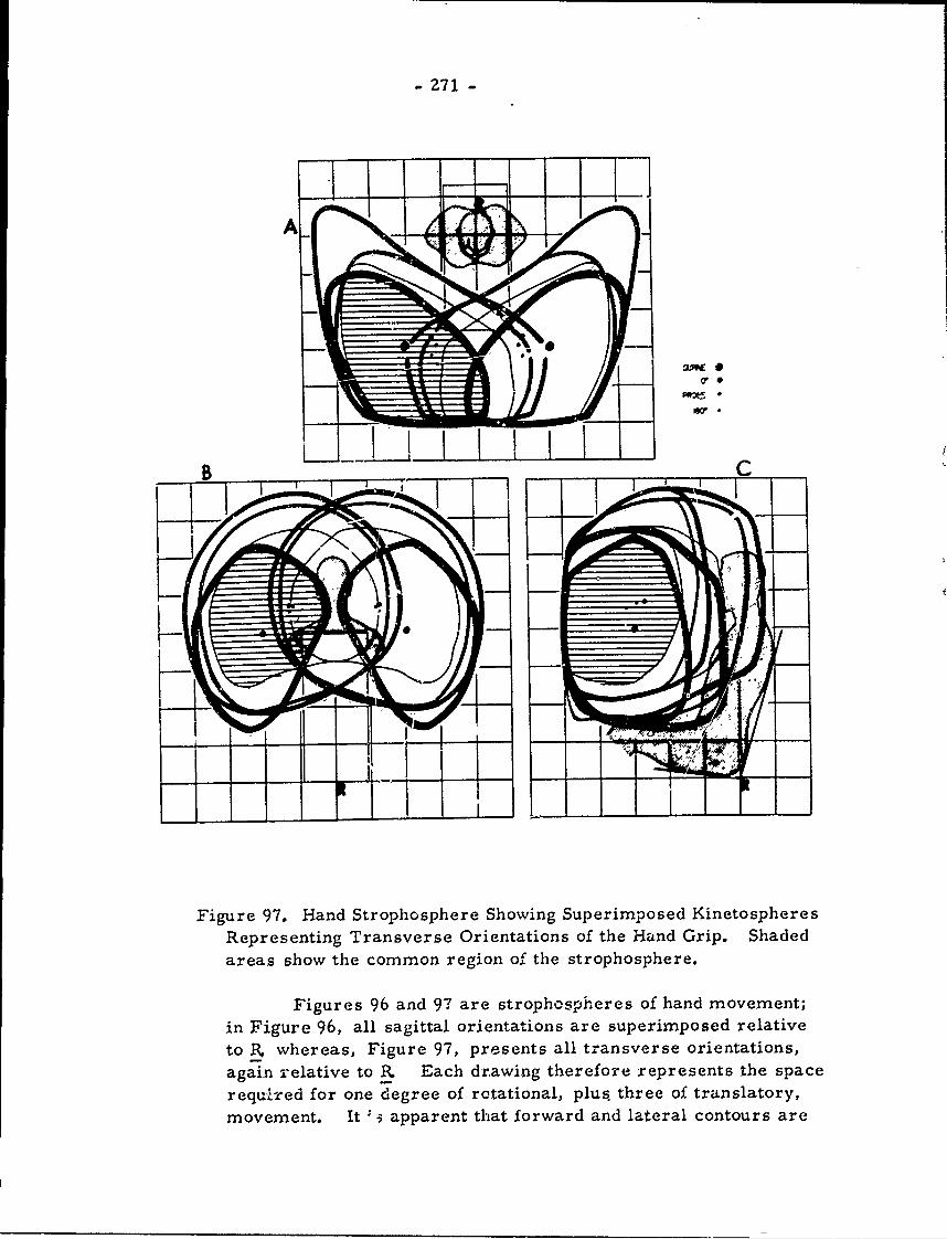
- 271 -
III
I A I
Figure 97. Hand Strophosphere Showing Superimposed KinetospheresRepresenting Transverse Orientations of the Hand Grip. Shadedareas show the common region of the strophosphere.
Figures 96 and 97 are strophospheres of hand movement;in Figure 96, all sagittal orientations are superimposed relativeto R. whereas, Figure 97, presents all transverse orientations,again relative to P. Each drawing therefore represents the space
required for one degree of rotational, plus three of translatory,movement. It "- apparent that forward and lateral contours are
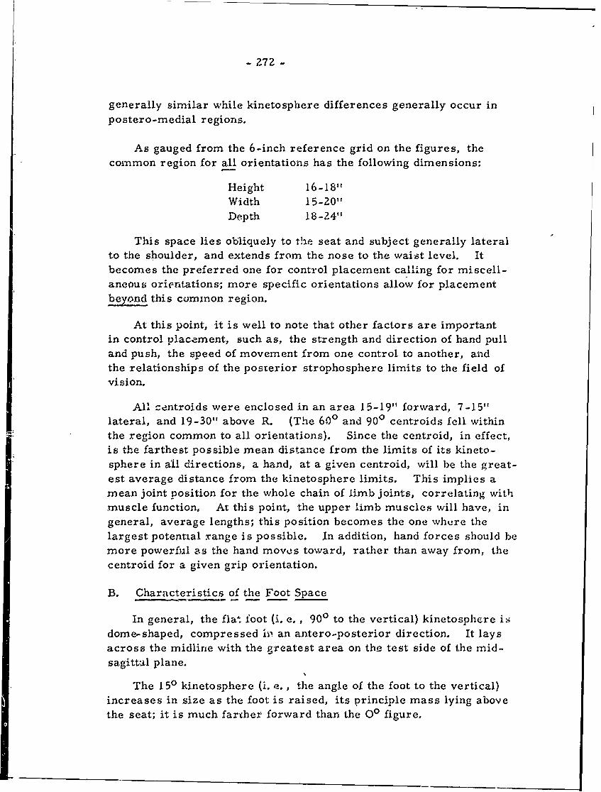
- 272 -
generally similar while kinetosphere differences generally occur inpostero-medial regions.
As gauged from the 6-inch reference grid on the figures, thecommon region for all orientations has the following dimensions:
Height 16-18"Width 15-20"Depth 18-24"
This space lies obliquely to the seat and subject generally lateralto the shoulder, and extends from the nose to the waist level. Itbecomes the preferred one for control placement calling for miscell-aneous orientations; more specific orientations allow for placementbeyond this common region.
At this point, it is well to note that other factors are importantin control placement, such as, the strength and direction of hand pulland push, the speed of movement from one control to another, aidthe relationships of the posterior strophosphere limits to the field ofvision.
All -entroids were enclosed in an area 15-19" forward, 7-15"lateral, and 19-30" above R. (The 600 and 900 centroids fell withinthe region common to all orientations). Since the centroid, in effect,is the farthest possible mean distance from the limits of its kineto-sphere in all directions, a hand, at a given centroid, will be the great-est average distance from the kinetosphere limits. This implies amean joint position for the whole chain of limb joints, correlating withmuscle function, At this point, the upper limb muscles will have, ingeneral, average lengths; this position becomes the one where thelargest potential range is possible. In addition, hand forces should bemore powerful c-s the hand moves toward, rather than away from, thecentroid for a given grip orientation.
B. Characteristics of the Foot Space
In general, the flat foot (i. e., 900 to the vertical) kinetosphere isdome-shaped, compressed i , an antero-posterior direction. It laysacross the midline with the greatest area on the test side of the mid-sagittil plane.
The 150 kinetosphere (i. a., the angle of the foot to the vertical)increases in size as the foot is raised, its principle mass lying abovethe seat; it is much farther forward than the O0 figure.
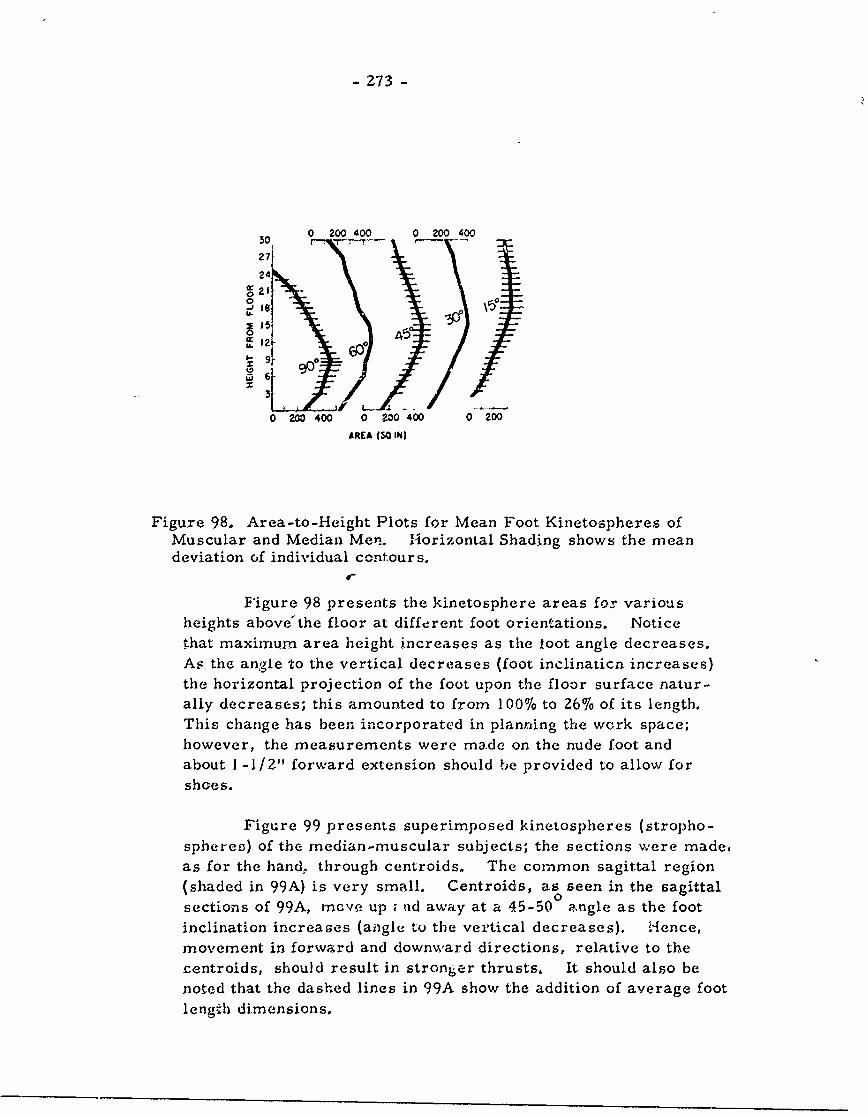
- 273 -
0 200 400 0 200 400
27
2421,
0 -
3- XI
0 200 400 0 ?00 400 0 200
AREA (30 IN)
Figure 98. Area-to-Height Plots for Mean Foot Kinetospheres ofMuscular and Median Men. Horizontal Shading shows the meandeviation of individual contours.
Figure 98 presents the kinetosphere areas for variousheights above'the floor at different foot orientations. Noticethat maximum area height increases as the toot angle decreases.As the angle 'to the vertical decreases (foot inclinaticn increases)the horizontal projection of the foot upon the floor surface natur-ally decreases; this amounted to from 100% to 26% of its length.This change has been incorporated in planning the work space;however, the measurements were made on the nude foot andabout 1-1/2" forward extension should be provided to allow forshoes.
Figure 99 presents superimposed kinetospheres (stropho-sphereo) of the median-muscular subjects; the sections were made,as for the hand, through centroids, The common sagittal region(shaded in 99A) is very small. Centroids, as seen in the sagittalsections of 99A, mcve up ; nd away at a 45-50 0ngle as the footinclination increases (angle to the vertical decreases). 1-ence,movement in forward and downward directions, relative to thecentroids, should result in stronger thrusts, It should also benoted that the dashed lines in 99A show the addition of average footlength dimensions.
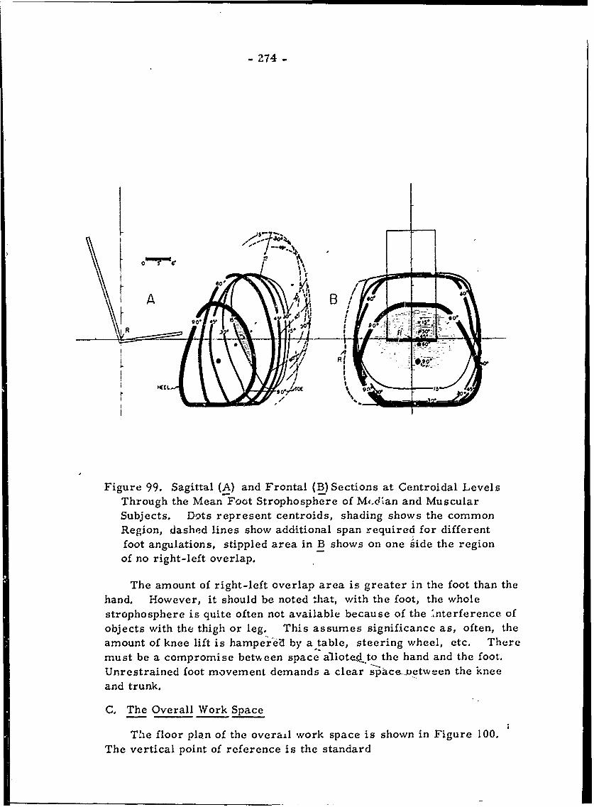
-Z74-
GotI
A 'B !:h
Thrug the MaFctStohshrofMcAnadMsur
0 R1
Figure 99. Sagittal (A) and Frontal (B) Sections at Centroidal LevelsThrough the Mean7Foot Strophosphere of M,-.dlan and Muscular
Subjects. Dots represent centroids, shading shows the commonRegion, dashed lines show additional span required for differentfoot angulations, stippled area in B shows on one Side the regionof no right-left overlap.
The amount of right-left overlap area is greater in the foot than thehand. However, it should be noted that, with the foot, the wholestrophosphere is quite often not available because of the Interference ofobjects with the thigh or leg. This assumes significance as, often, theamount of knee lift is hamper I by a table, steering wheel, etc. Theremust be a compromise between space a'llote.dto the hand and the foot.Unrestrained foot movement demands a clear space-uetween the kneeand trunk.
C. The Overall Work Space
The floor plan of the overail work space is shown in Figure 100.The vertical point of reference is the standard
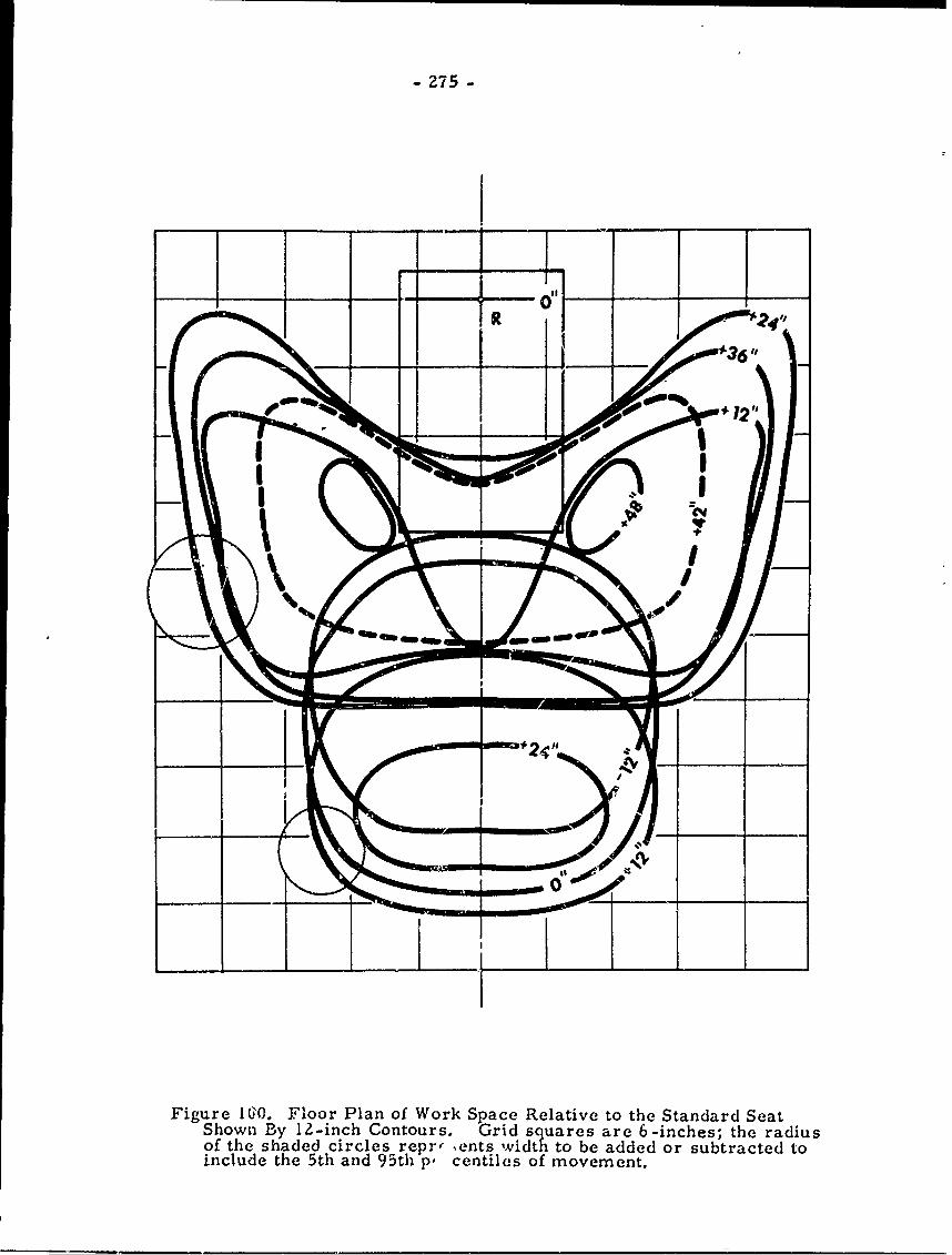
- 275 -
0R '
1 I
Figure 10. Floor Plan of Work Space Relative to the Standard SeatShown By 12-inch Contours. Grid squares are 6-inches; the radiusof the shaded circles repr, ,ents width to be added or subtracted toinclude the 5th and 95th p, centiles of movement.
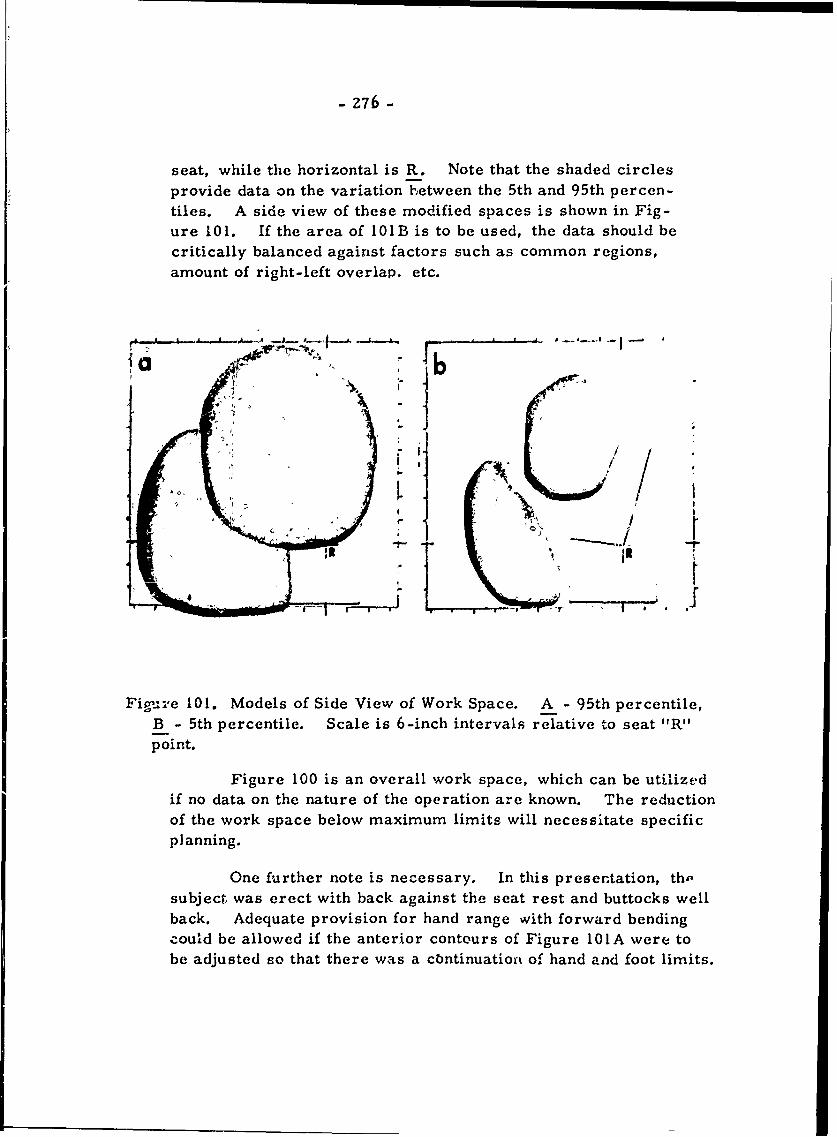
- 276 -
seat, while the horizontal is R. Note that the shaded circlesprovide data on the variation between the 5th and 95th percen-
tiles. A side view of these modified spaces is shown in Fig-ure 101. If the area of 101B is to be used, the data should be
critically balanced against factors such as common regions,
amount of right-left overlap. etc.
Fig_:ve 101. Models of Side View of Work Space. A -95th percentile,
g- I
B - 5th percentile. Scale is 0-inch intervals relative toD seat "R"point.
Figure 100 is an overall work space, which can be utilizedif no data on the nature of the operation are known. The reductionof the work space below maximum limits will necessitate specific
planning.
One further note is necessary. In this presentation, th.-subject was erect with back against the seat rest and buttocks wellback. Adequate provision for hand range wvith forward bendingcould be allowed if the anterior contours of Figure 101IA were tobe adjusted so that there wa s a cbntinuatioft of hand and foot limits.
- 277 -
MASS RELATIONS OF CADAVER SEGMENTS(Dempster, pp. 183-201)
Previously-published data on segmental mass has beenlimited to reports based on only a few cadavers. (The classicdata are from Braune and Fischer, 1890). The total number,from all sources, of adults studied has been only five. Datawill be presented here on an additional eight. This presentationwill be concerned with segments, per se, since basic data on seg-ment masses, on centers of gravity, on moments of inertia, andof parts relative to joint centers are considered more relevantin the analysis of static postures or instantaneous phases of bodymovement than a coordinate system of reference for the wholebody.
In attempting to gather data in mid-range joint positions,rather than outstretched positions, limb joints were divided inplanes that sought to separate segment masses into units ofmean size, representing, more correctly, values for a varietyof postures. The trunk mass, as described earlier, was dividedinto shoulder, neck, thorax, and abdomino-pelvis units.
The subjects were white adult males, from middle to old
age, with no obvious physical defects.
The masses of various body segments for each cadaver,together with segmental relationships in percent, are given inTables 52, 53, and 54. Certainly, errors crept into data dueto factors such as blood loss while handling, mass changes dueto water immersion, etc. , but no marked discrepancies could befound due to them. , 'ther discrepancies in percentage valuescan be attributed to rec )rding errors; calculated values, mathe-matically correct, were substituted in only the most obviouscases; otherwise the reccrded value was retained.
Centers of gravity were obtained by balancing a segmentlongitudinally with a variety o' surfaces uppermost. A dowelwas inserted into the balance point on each surface. When theestablished plane was cut transversly, the dowels pointed to theanatomical center of gravity.
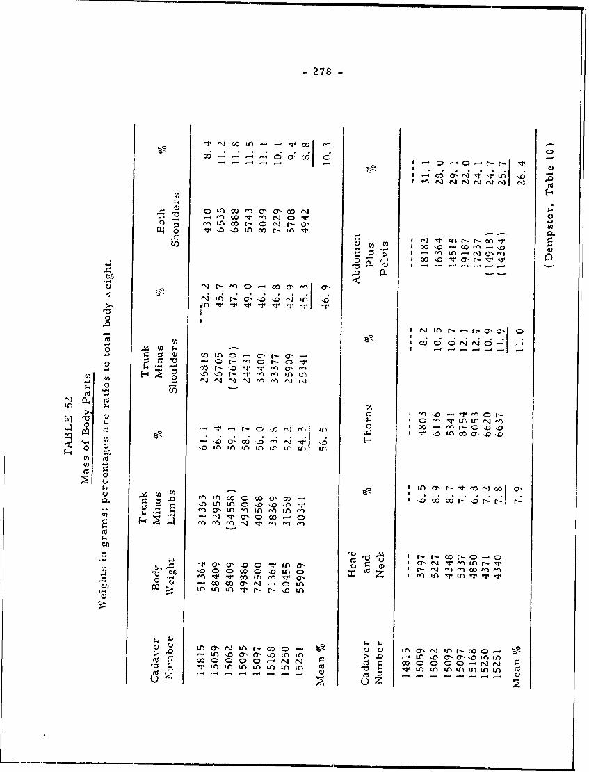
-278-
~~~~0 'a) Nf vr -r - C
*1. 00e ,arn W-J, en N 0
-- I -I- M r-I -i
1CIe nr c- -- I oo \0 - 00 f) 0 '
P~ en a - - -. , - -0 1-- 0
e- r- ~ ~ a en'0o0--
.0~i -T e'V toa- V~-
,J) a C> C)e'-jVoo r -V In --n In-
Ure ^j~ ̂ j
.. T C)
06' 0.4 1410 if n I n 1)1)I x
''o 0 LAn ' IA C A 'D 'D 10
0j)
r-~ 00C)C
0. w~ CD 'D~~N 0 inaz-5 NInVI v1
V x0I It0 In ' VA a,
it) 1.4 in 14 r- t 'D i
V~~' in* o - ' r-o -n N I - CA - o
00 C) 0 > ) NC*'00 C) > C - o' a q
1-4 -4 - -
u~14.
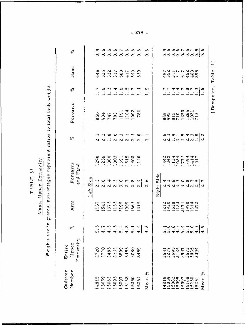
2 79-
C''.0~~ I0 D'.0 r- '0 '0'0 0a..o'o-r
1n tN r-" -0r 'L --- LA0 'T ~ NA CD 0 nLnt LAn a
NV 'en en r L v en en &I n' NO N en .0
-- o co o -n -r- I -- f-- v -- 0 - %D-
v) r-elC C )mtnL n)Di o
V, 0 n0 ;% C n 4 -a
0~~~~C C'Z C'D N NC> O0~~4'-;4
r- t en en 0 a-' ^ 00 en C- R0r(NJLn u- en N, N -N f\I I -r--
'-4
tri
O - C'0 00 -- NC'-"-V 'N N 0 . .~ . A .1 . . lN'. 4n IV IT- - - - -41 t -T - - -nnv
C) ;-
en. en en CQeiIn'I Ne l)c
-. ;4
-0 ~ ~ LA a, -J M - 0'0 0 ** e, L - 0C
c) C- -D - - N 0 - C-- - N -
LA in in tn LnAv t' tA4'nt LA ALn ALALA -m
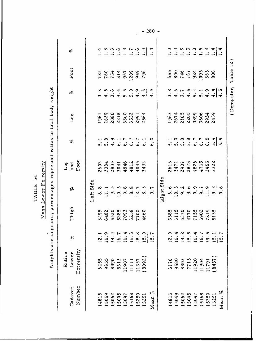
-280-
o.: ~ r n Denr-S No eninc i
0onc L O1
t'r-O 0'. LflO O no Nor-' 1 n inC 001-0 r-N n4N , ,i ) ,t : ,- >.
r- r-N NN ON Oe)ar- N CO r- N 0 C 00 0
4.)j
CON C 00c:> -.1 Snntf n ~CYNO'r a,CO.o co 40.),ina O " oN 7
en (n N) " n cn
0
0 IA'OOC\' ~ULA ''6 14O 1r u
i ' n NeJO ir 'n e'n - oo i iOn O'n00 -40)0 r> 00 C na).Z
() -4'4 N - o0O ON U Oi0
-4 U
4.)4
nV) 0..f"i n clo i n i
tCOo in cN-I inAcO w-.>
01 -o ini- N - InN nN -i
-4 -. 4 -- f
4
co5,n n c) n - - Nj oen n a-4 n i c, - c -I f- i' n O a, 00 C> " CD Nin
C: $4CNJ co n c a, - c C in en a- n 0 'Lt- LV
L4 -10 7 o r -40
NO c - 00 00 00 --
i n c'O " O in--c C Sn OcyO N -4-o Co- ~ 4-- in Noa-4-O-4n nNocc N ni
$4 C: $4D C da > ) c D - CI " cM0 w i ni n i n ni ni ni nitu'% L N O - L O.\L N O
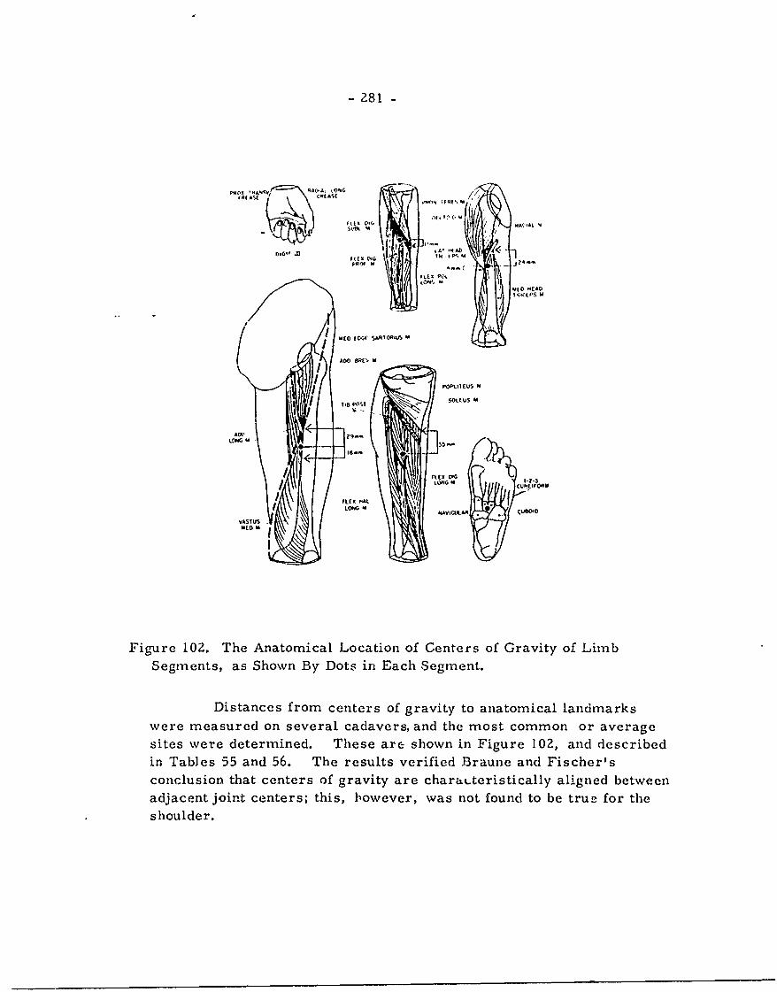
- 281 -
C'R( MESI ,C/tAS ,
I ,'Mt, ,, SM
' fD,6'f .ZI.A i4 ~
SROf M I A\
SE HEAD
EDM tC'~C SAHIOHIUDS M
ADO0~
L' G M - 2 .5 K
FiX Dec-
iir s CU IFt Oi
FILEXMAL
YASTlJS.
Figure 102. The Anatomical Location of Centers of Gravity of LimbSegments, as Shown By Dots in Each Segment.
Distances from centers of gravity to anatomical landmarks
were measured on several cadavers, and the most common or average
sites were determined. These are shown in Figure 102, and describedin Tables 55 and 56. The results verified Braune and Fischer's
conclusion that centers of gravity are charat-teristically aligned between
adjacent joint centers; this, however, was not found to be true for the
shoulder.
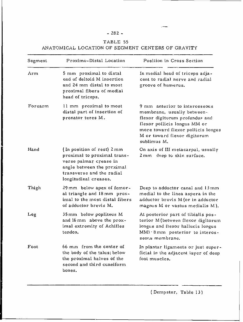
- 282 -
TABLE 55ANATOMICAL LOCATION OF SEGMENT CENTERS OF GRAVITY
Segment Proximo-Distal Location Position in Cross Section
Arm 5 mm proximal to distal In medial head of triceps adja-end of deltoid M insertion cent to radial nerve and radialand 24 mm distal to most groove of humerus.proximal fibers of medialhead of triceps.
Forearm 11 tmm proximal to most 9 mm anterior to interosseousdistal part of insertion of membrane, usually between-pronator teres M. flexor digitorum profundus and
flexor pollicis longus MM or
more toward flexor pollicis longusM or toward flexor digitorum
sublimus M.
Hand (In position of rest) 2 mm On axis of III metacarpal, usuallyproximal to proximal trans- 2mm deep to skin surface.verse palmar crease in
angle between the prcximaltransverse and the radiallongitudinal creases.
Thigh 29mm below apex of femor- Deep to adductor canal and 13mmal triangle and 18 mm prox- medial to the linea aspera in theimal to the most distal fibers adductor brevis M (or in adductorof adductor brevis M. magnus M or vastus medialis M).
Leg 35mm below popliteus M At posterior part of tibialis pos-and 16 mm above the prox- terior M(between flexor digitorumimal extremity of Achilles longus and flexor hallucis longustendon. MM -'8mm posterior to interos-
seors membrane.
Foot 66 mm from the center of In plantar ligaments or just super-the body of the talus; below ficial in the adjacent layer of deepthe proximal halves of the foot muscles.second and third cuneiformbones.
(Dempster, Table 13)
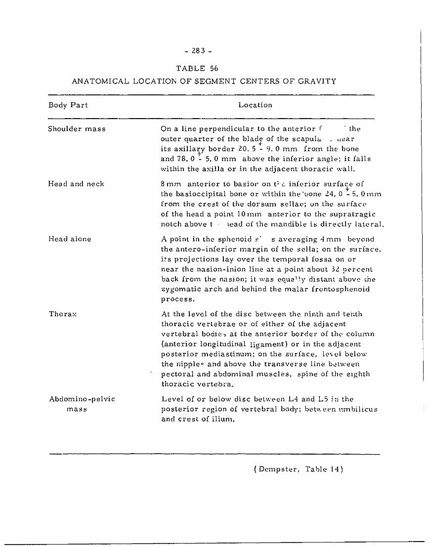
- 283 -
TABLE 56
ANATOMICAL LOCATION OF SEGMENT CENTERS OF GRAVITY
Body Part Location
Shoulder mass On a line perpendicular to the anterior f theouter quarter of the blade of the scapula . ar
its axillary border 20. 5 - 9. 0 mm from the boneand 78. 0 - 5. 0 mm above the inferior angle; it fallswithin the axilla or in the adjacent thoracic wall.
Head and neck 8 mm anterior to basior on tc inferior surface of
the basioccipital bone or within the *bone 24. 0 -5. 0 mnfrom the crest of the dorsurn sellae; on the surface
of the head a point 10 rm anterior to the supratragicnotch above t . iead of the mandible is directly lateral.
Head alone A point in the sphenoid F' s averaging 4 rm beyondthe antero-inferior margin of the sella; on the surface,its projections lay over the temporal fossa on ornear the nasion-inion line at a point about 32 percentback from the nasion; it was equa'y distant above iLezygomatic arch and behind the malar frontosphenoidprocess.
Thorax At the level of the disc between the ninth and tenththoracic vertebrae or of either of the adjacentvertebral bodic) at the anterior border of the column(anterior longitudinal ligament) or in the adjacentposterior mediastinum; on the surface, le-vel below
the nipple- and above the transverse line betweenpectoral and abdominal muscles, spine of the eighththoracic vertebra.
Abdomino-pelvic Level of or below disc between L4 and L5 in themass posterior region of vertebral body; bet%% cen i;mbilicus
and crest of ilium.
(Dempster, Table 14)
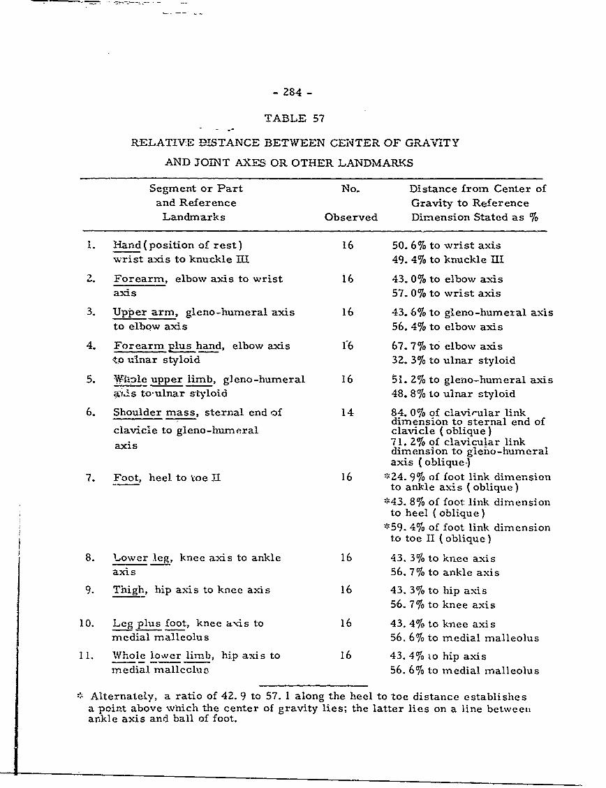
- 284 -
TABLE 57
RELATIVE DISTANCE BETWEEN CENTER OF GRAIWVTY
AND JOINT AXES OR OTHER LANDMARKS
Segment or Part No. Distance from Center ofand Reference Gravity to ReferenceLandmarks Observed Dimension Stated as 1/
1. -land(position of rest) 16 50. 6% to wrist axiswrist axis to knuckle iMI 49.4% to knuckle Il
2. Forearm, elbow axis to wrist 16 43. 0% to elbow axisaxis 57. 0%76 to wrist axis
3. Upper arm, gleno-humeral axis 16 43. 60 to gXeno-humexal a.xisto elbow axis 56. 4% to elbow axis
4. Forearm plus hand, elbow axis f6 67. 7% to elbow axis;to ulnar styloid 32. 3% to ulnar styloid
5. VWAle upper limb, g]eno-humeral 16 51. 20 to gleno-humeral axisaf-s tooulnar styloid 48. 81/ to ulnar styloid
6. Shoulder mass, sternal end of 14 84. 0%6 of clavirular linkdimension to sternal end of
clavicle to gleno-humeral clavicle (oblique)axis 7 1. 2% of clavicular link
dimension to gleiio-humeralaxis (oblique-)
7. Foot, heel to toe II 16 *24. 9% of foot link dimensionto ankle axis (oblique)
*43. 8% of foot link dimensionto heel (oblique)
*59. 4% of foot link dimensionto toe II (oblique)
8. Lower leg, knee axis to ankle 16 43. 3% to knee axisaxis 56.7% to ankle axis
9. Thigh, hip axis to knee axis 16 43. 3% to hip axis56. 7% to knee axis
10. Leg plus foot, knee axis to 16 43. 4% to knee axismedial malleolus 56. 6% to medial malleolus
11. Whole lower limb, hip axis to 16 43.4% 4to hip axismedial mallcclu3 56. 6% to medial malleolus
. Alternately, a ratio of 42. 9 to 57. 1 along the heel to toe distance establishesa point above which the center of gravity lies; the latter lies on a line betweenankle axis and ball of foot.
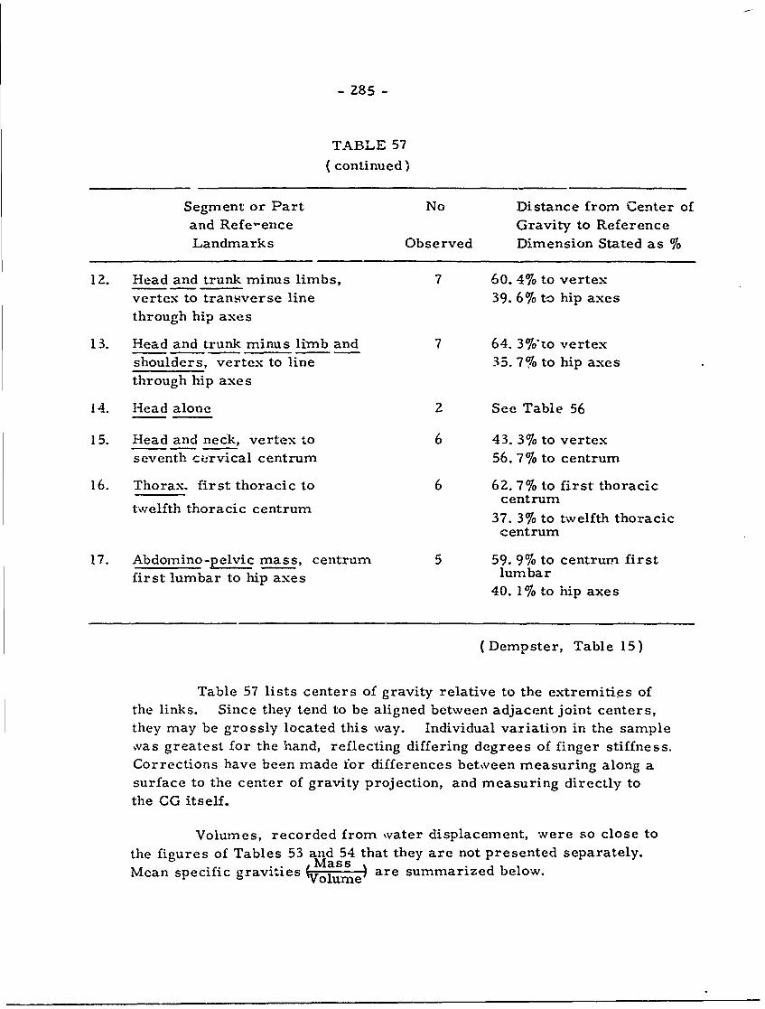
- 285 -
TABLE 57(continued)
Segment or Part No Distance from Center ofand Refe-ence Gravity to ReferenceLandmarks Observed Dimension Stated as 0
12. Head and trunk minus limbs, 7 60. 4% to vertexvertex to transverse line 39. 6% to hip axesthrough hip axes
13. Head and trunk minus limb and 7 64. 3%'to vertexshoulders, vertex to line 35. 7% to hip axesthrough hip axes
14. Head alone 2 See Table 56
15. Head and neck, vertex to 6 43. 3% to vertexseventh ci-rvical centrum 56. 7% to centrum
16. Thorax. first thoracic to 6 62. 7% to first thoraciccentrum
twelfth thoracic centrum 37. 3%/ to twelfth thoracic
centrum
17. Abdomino-pelvic mass, centrum 5 59. 9% to centrum firstfirst lumbar to hip axes lumbar
40. 1% to hip axes
(Dempster, Table 15)
Table 57 lists centers of gravity relative to the extremities ofthe links. Since they tend to be aligned between adjacent joint centers,they may be grossly located this way. Individual variation in the sample,vas greatest for the hand, reflecting differing degrees of finger stiffness.Corrections have been made for differences betveen measuring along asurface to the center of gravity projection, and measuring directly tothe CG itself.
Volumes, recorded from water displacement, were so close tothe figures of Tables 53 and 54 that they are not presented separately.Mean specific gravities Mass are summarized below.
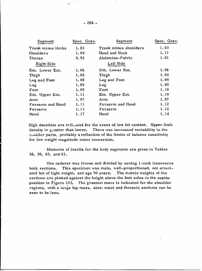
- 286 -
Segment Spec. Gray. Segment Spec. Gray.
Trunk minus limbs 1.03 Trunk minus shoulders 1.03
Shoulders 1.04 Head and Neck 1. 11
Thorax 0. 92 Abdomino-Pelvic 1.01
Right Side Left Side
Ent. Lower Ext. 1. 06 Efit. Lower Ext. 1. 06Thigh 1.05 Thigh 1.05
Leg and Fo~t 1. 08 Leg and Foot 1. 09
Leg 1.09 Leg 1.09
Foot 1.09 Foot 1.10Ent. Upper Ext. 1. 11 Ent. Upper Ext. 1. 10
Arm 1.07 Arm 1.07
Forearm and Hand 1. 11 Forearm and Hand 1. 12
Forearm 1. 13 Forearm 1. 12
Hand 1. 17 Hand 1.14
High densities are irt.i..ated for the areas of low fat content. Upper limb
density is greater than lower. There was increased variability in the
zaialler parts, probably a reflection of the limits of balance sensitivity
for low weight magnitude water immersion.
Moments of inertia for the body segments are given in Tables
58, 59, 60, and 61.
One cadaver was frozen and divided by sawing 1-inch transverse
body sections. This specimen was male, well-proportioned, not emaci-
ated but of light weight, and age 90 years. The metric weights of thesections are plotted against the height above the foot soles in the supine
position in Figure 103. The greatest mass is indicated for the shoulder
regions, with a large hip mass, also; waist and thoracic sections can be
seen to be less.
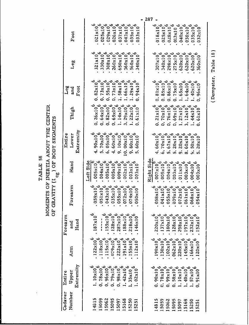
- 287
C>00C>0 0000 0 0 0 0 000>-1 - -4-4- - 4 - -- 4 -4 -4 --. 6 1-
0 0C)0 CD0.0 C 00 ' '0 C)O
0 0 00000 Noo .0 0.0 .0 0 00%0 -0
x x x xx x xx ~x x 4,4) - 0 o0 0 0 C0 r- o o t 4> ) C C
to- 4j -4 -4--- -- 1 ---
oo 00000000 % m(7 0 00 00 0000 D wa, (
- - -A - 41- -4 -- - ---XXXx x x V.x :.x x x
H 4,00000 0 00( 0 000000- ---- 4--t -- -4 14
0 0 ;4 0 0 Ln 0C>0000 00 r.-00 00 0a, uZo -ooo~ -. Z - NZ i
00~~ 0 0 0 0 0 0 0 0
0i 0 0000)0000 C> 0000C)0C D0
H04-- -4 -- 4 - -4 1-f - -4 -4 -4 4xx mx xxx x x x xx 4
0 00 D - )( 0 00C)0 00CD0
w 0. '.0 % %0 -40 %D'.0..0%0 '10 0 %.0.0 '.0 '0 '.0 %D0 '.0 000 0 000)(D000C>0
zk LnL nu f-r L V Ln rn - -40 -4L0, r- C> LA or-o o0 0-C 0Cor-0'Je..
w .~C .1ft o . . . . . .0 W 4'J4 -
00C0 00CD00 0 00C00000-4 -4 - -4 - -1- 4 --4--- - 4-410 x x ,x x xx x x x x x x
r. r- m w ar'.- c 0% C -C 00e 00 r- m "('3 - -n N- C 01) 414 N~ 0. 00 N (7.3 C7% M ('3
0 -4 -4 (3 -- 4N-4 (,] -- 4 0- N' -4 N~ -4
x x x x xx x xN~ w44 0Co 6' NJ- t N 0C0 " N0m0 0-
1z1 -4 0 N-4
(0 0 0C)0 0' C) a C00.0 --4N(%4
-4 -- -- - - - -4 -4 -. 4-4 -4-4
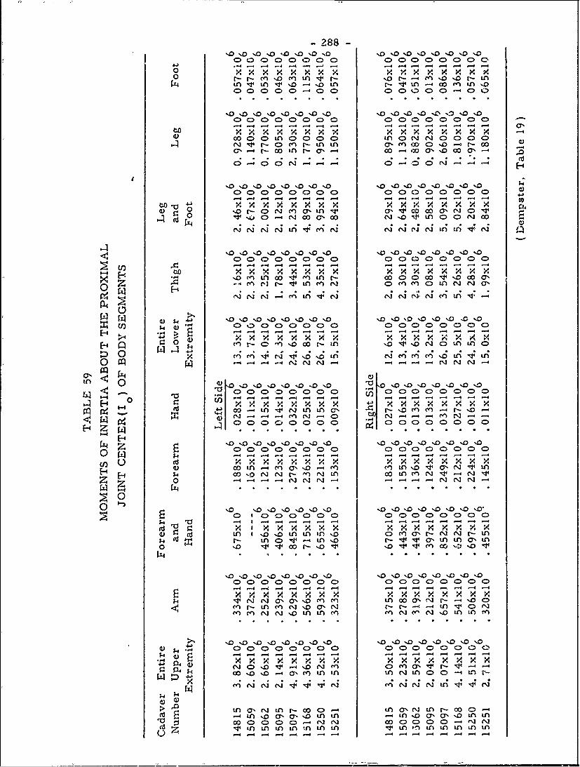
-288-
%0 '.0'.o 0 %D 0 0 0 'D %0'%0 '.D'-D'.o'.0
0 ~ r~- t- cn %o -i -r r- - - M -D -D r- n
o: nvi 6-oi -1 in -~L~ r 'N 4 .0'0 n i '
C> C C --- C-- .- C- -) - -C>C - C- C> a
tox~xx -4
c0 0 0o nr a 0 W ,% OON--4-
'0' '.0 'D.0 %0 %.0 %0 '0 '0 %D %0 %0 '.D '0 'D %0 -
00 00 00( DC 0C )0 0 0000
_-q -4 . - - - - - -4- - - -
xr x x0A ~ ~ Ll x xx0 xx V.x xx
C>0 C)0C )C 000 00 0 0 :l0 00000)CH ) -4-4- - - --4-
o 14 14 * -. .' N
0' 41)
k 0 00- In0000 0 00000000%o" i c
0 (A -4 4 -4 -
a, ml w,~O-LAN A A
-4 4 -- 4 - 4 cn -1 -0 U x xx v 11,x xx x x~x x x x04-4 " .4 N- N N -4 -4l Nq -
o Z. '0 .' .' .'.'.' . .
Z 1~0 o10 0000.o 0 D% o o% 000 0 0 001- ) -4 -- -4 -4- -4 - - -4--1-4 -4 - .
w n-4m6 o- I 0j - ' n n In4
0 .I IA3-
zo-4 -4 ~-.- - - 444 - --4 -4
C) 00 00 0 00000000 ) C-- 4 -4-4-4 -44 4 4- - - -
o 10- 1''4OL A A -4 IArNLAV 0 11 n00 11.1 r-
1-4I ' a a' I I -4 - -4 1- 1-4 -4 -
-44- -4 -4 -4 x x -X-4 - 4-"4 -4 -4-Ix -4
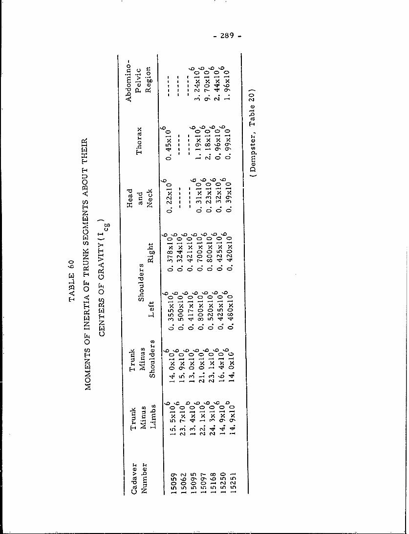
2 89-
.0 W * 0
-)
CD0)C 000
14 Nr SY 4.
0 CD C> CD CD C)
(4 ~I I~400 U)
F-' 0. I I . O.
o) C*0 o )C
C>- :D > r- -vI
00 -
Hn a c)z c)Ln
14C;C;C 6 0 0 00C
-) -4) -4 -4 -4 -
z x xU) 60 41
0
Ii%0 %. .A 0 %D 0 0C LA0
(4~- H4 -- A04 C'4
'-i (4 .o0 0;
a 0 (D C>--I"
CZz- -4-- 4
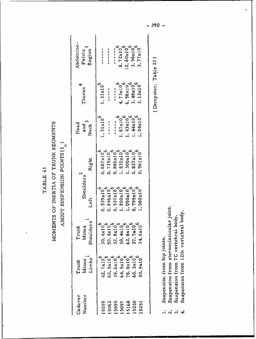
-290
> -4 1 10000X
I -I to Cl %Dr-
0 C> 0- --- 4 -4 a)
0- -n ' 4
-4' Il C4fl
all
C0 a.C)0 C>.cn -4 -4 -4-4 -4
C 0 0 CI C>C
-- I I *- - -
'. '.0 '. 0 '00 '.0'
,.oooN .
H ,~O'.
-- 4 -4 -- 4 -- 4 --4- -44-4fit -V. x x x x0x x0
U) U~~) a,0r-C
z ~ 40
r-- -~ 0)0 0 0
z.*~ cn $*4 4
k -4 0 -4-4-4V- c--4- -
~- -4 -
k~ >
-- Z1 0~~
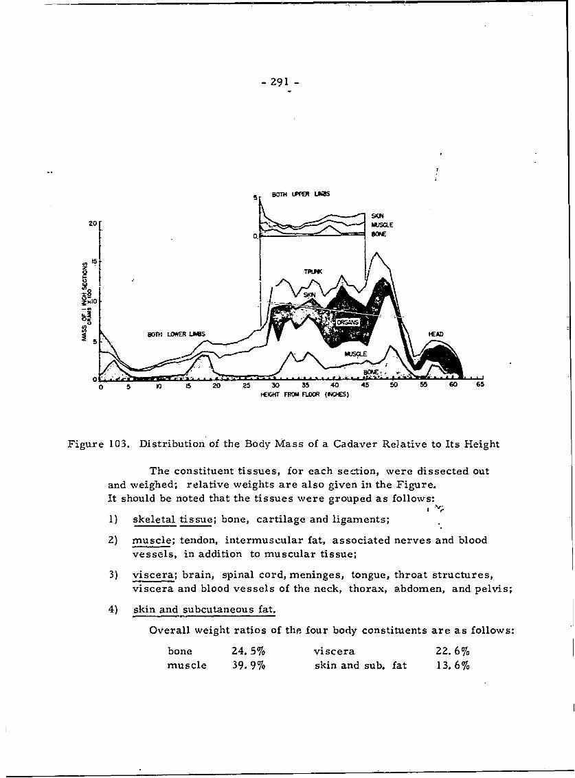
- Z91 -
5 BOTH 'P L #S
15
0 5 15 20 25 30 35 40 45 50 55 60 65
BOW,~ LOROM FLOOR (IAOC
Figure 103. Distribution of the Body Mass of a Cadaver Relative to Its Height
The constituent tissues, for each section, were dissected outand weighed; relative weights are also given in the Figure.It should be noted that the tissues were grouped as follows:
1) skeletal tissue; bone, cartilage and ligaments;
2) muscle; tendon, intermuscular fat, associated nerves and bloodvessels, in addition to muscular tissue;
3) viscera; brain, spinal cord, meninges, tongue, throat structures,viscera and blood vessels of the neck, thorax, abdomen, and pelvis;
4) skin and subcutaneous fat.
Overall weight ratios of the four body constituents are as follows:
bone 24. 5% viscera 22. 6%muscle 39.9% skin and sub. fat 13.6%
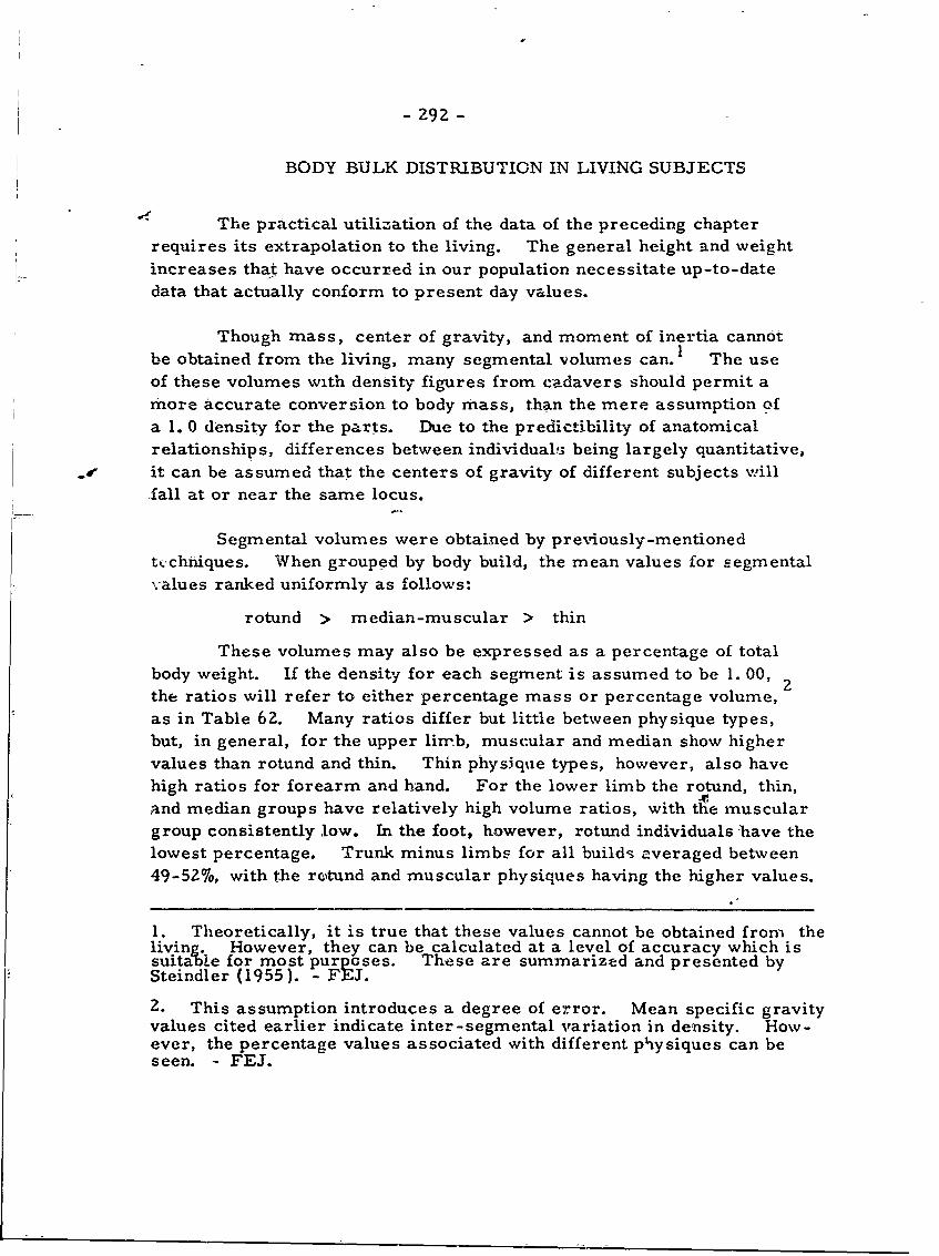
- 29Z -
BODY BULK DISTRIBUTION IN LIVING SUBJECTS
SThe practical utilization of the data of the preceding chapter
requires its extrapolation to the living. The general height and weightincreases that have occurred in our population necessitate up-to-date
data that actually conform to present day values.
Though mass, center of gravity, and moment of inertia cannotbe obtained from the living, many segmental volumes can. 1 The useof these volumes with density figures from cadavers should permit amore accurate conversion to body mass, than the mere assumption ofa 1. 0 density for the parts. Due to the predictibility of anatomicalrelationships, differences between individuals being largely quantitative,
oe it can be assumed that the centers of gravity of different subjects willfall at or near the same locus.
Segmental volumes were obtained by previously-mentionedt vchniques. When grouped by body build, the mean values for segmentalvalues ranked uniformly as follows:
rotund > median-muscular > thin
These volumes may also be expressed as a percentage of totalbody weight. If the density for each segment is assumed to be 1. 00,the ratios will refer to either percentage mass or percentage volume,as in Table 62 Many ratios differ but little between physique types,but, in general, for the upper limb, muscular and median show highervalues than rotund and thin. Thin physique types, however, also havehigh ratios for forearm and hand. For the lower limb the rotund, thin,and median groups have relatively high volume ratios, with the musculargroup consistently low. In the foot, however, rotund individuals have thelowest percentage. Trunk minus limbs for all builds averaged between49-52%, with the reGtund and muscular physiques having the higher values.
1. Theoretically, it is true that these values cannot be obtained from thelivine. However, they can be calculated at a level of accuracy which issuitabe for most purposes. These are summarized and presented bySteindler (1955). - FEJ.
2. This assumption introduces a degree of error. Mean specific gravityvalues cited earlier indicate inter-segmental variation in density. How-ever, the percentage values associated with different physiques can beseen. - FEJ.
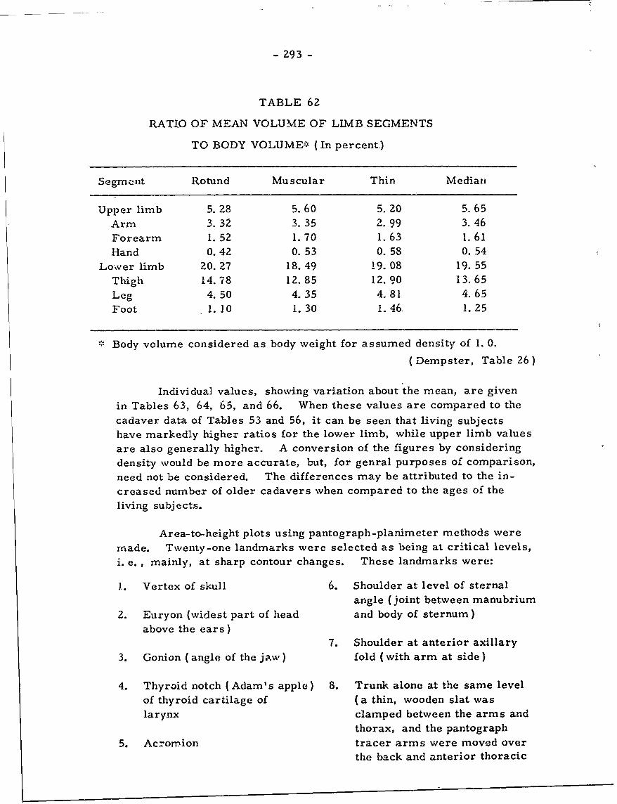
- Z93 -
TABLE 62
RATIO OF MEAN VOLUME OF LIMB SEGMENTS
TO BODY VOLUME' (In percent)
Segmenut Rotund Muscular Thin Median
Upper limb 5. 28 5. 60 5. 20 5. 65Arm 3.32 3. 35 2.99 3.46Forearm 1.52 1.70 1.63 1.61Hand 0.42 0. 53 0.58 0. 54
Lover limb 20.27 18. 49 19. 08 19. 55Thigh 14.78 12.85 12.90 13.65Leg 4.50 4.35 4.81 4.65Foot 1.10 1. 30 1.46 1.25
Body volume considered as body weight for assumed density of 1. 0.
(Dempster, Table 26)
Individual values, showing variation about the mean, are givenin Tables 63, 64, 65, and 66. When these values are compared to thecadaver data of Tables 53 and 56, it can be seen that living subjectshave markedly higher ratios for the lower limb, while upper limb valuesare also generally higher. A conversion of the figures by consideringdensity would be more accurate, but, for genral purposes of compari-son,need not be considered. The differences may be attributed to the in-creased number of older cadavers when compared to the ages of theliving subjects.
Area-to-height plots using pantograph-planimeter methods were
made. Twenty-one landmarks were selected as being at critical levels,
i. e. , mainly, at sharp contour changes. These landmarks were:
J. Vertex of skull 6. Shoulder at level of sternal
angle (joint between manubrium
2. Euryon (widest part of head and body of sternum)above the ears)
7. Shoulder at anterior axillary
3. Gonion (angle of the jaw) fold (with arm at side)
4. Thyroid notch (Adam's apple) 8. Trunk alone at the same levelof thyroid cartilage of (a thin, wooden slat was
larynx clamped between the arms andthorax, and the pantograph
5. Acromion tracer arms were movesd over
the back and anterior thoracic
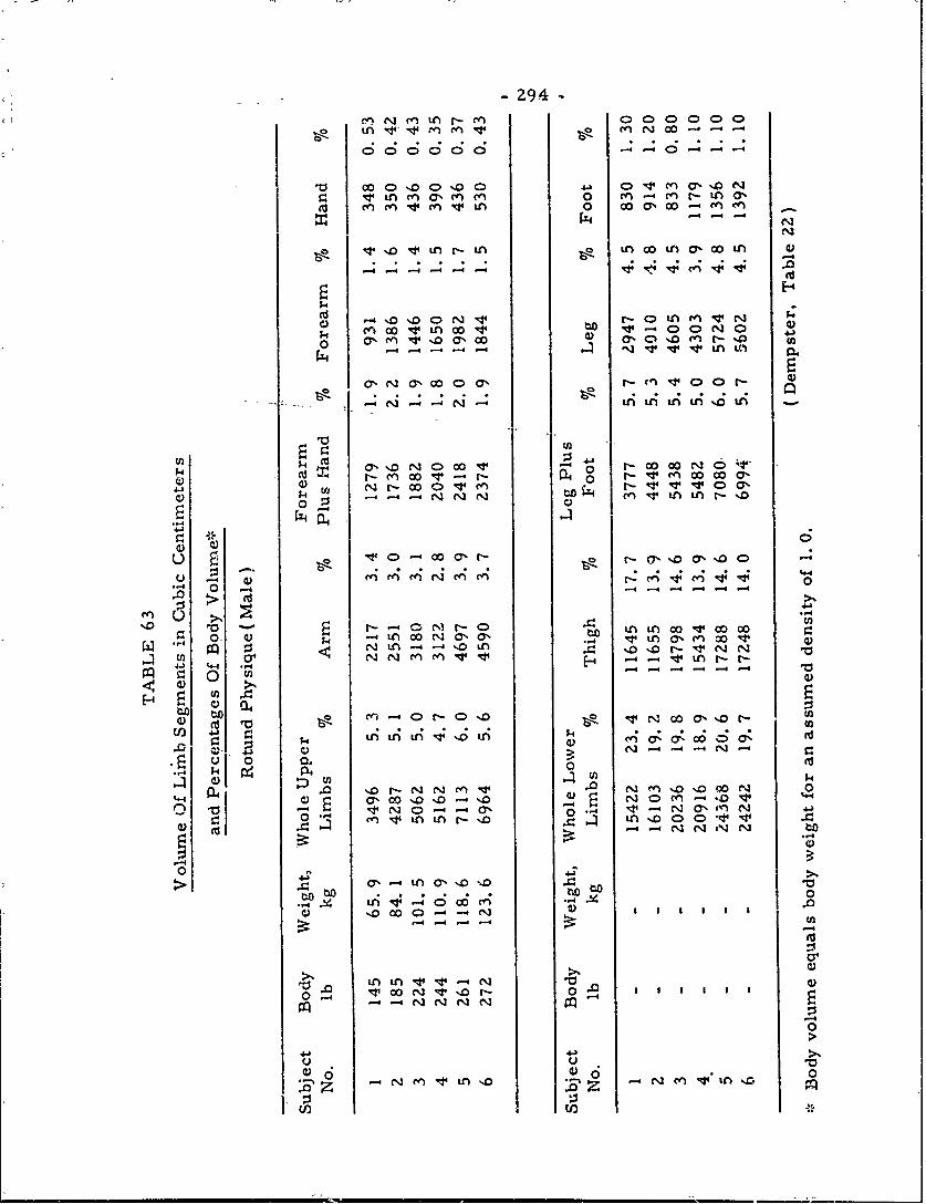
-294-
10 c ~ 0 %DC0%D0 a 4e.a %v in n acn m0 rf -4 rnr- in c
v~ i 0 ooa o ne
-4v 4--inu
a,~~~LA L O ~ f N4) oc>a -In ,0 r
.r . . . ..L; i
k a%%o Nc o v 0 - co00o-4--r-M00V- r- 0 r n0 0
r- vV V0 0
u o' co.r~-. ar % DCuZ oi l- 4 -- 4-C4 .- C44
00 -4
U0i 0U k -4 v n c cn co v~
N n Zo) r-e~ 4 r-4
v) in.
-4j 0 >-4-v 0 0.
"-4p44 4) 0
a E 40NC - 0 %D -% UN)en -'
0 cn v i i - %B0i o p co v, T
to to t to'D 00 c~ 0 r- o- N w .. U
-4 e.3---(-I
00
z 0
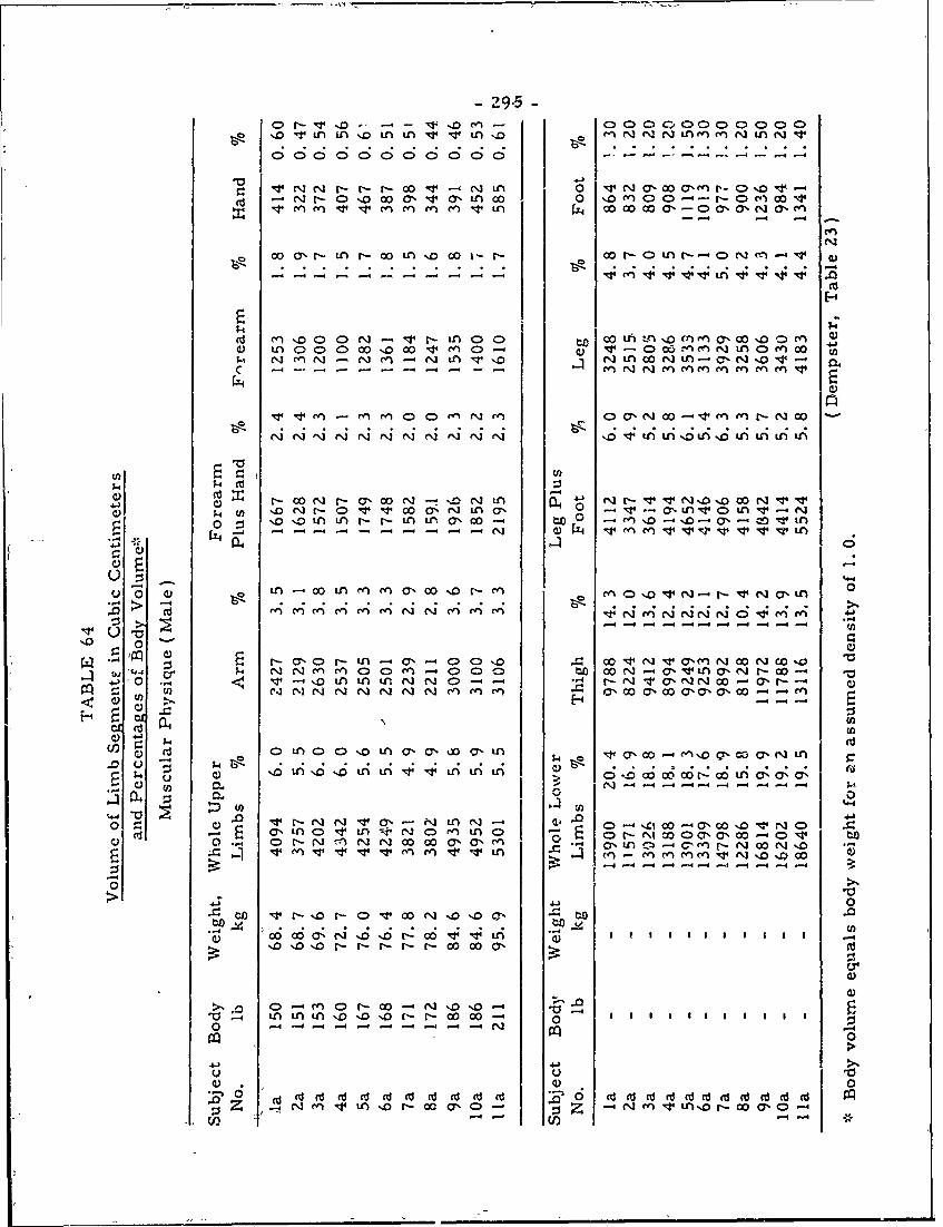
- 9.5
Sr-- V -D - " .- -- cl' > .- 0 C>00 0 0 0 0 0%9 ,o v mn mn m n v v t n ,n N c% N i, eq~ n, mi inr N v. . . . . . . .o . . . . . . . . . .<D o o CD o 44 . . . .0
m N r0 - r- r- w00- .n -i -0% -00-, D- Q -w• -4' c.1 -- 0 ,, N O ' -0" L A 0.0 .,0 t'"J 0' O C-- 1'-- 0 ' .44 -:
N r-I 0 %D W CY%' V4 O'L tn 0 ,oc >C -r DMc
w c% r- n r- w.. tn r,%o o i r-o co - c e - v .
. . . . . . . . . . . • • • • ..-
CO0' No LA N CO; .-- "'. CO u - COONo 0 LA N-, o~.0,,O0, O .-4
-- 4 -- -- -- - -- L .;
Cd n oD o o N - v r- t o c) o n :. %o m en a, coooe0 n 6,q cl w %o wJ 1,q & p 3 -D v t- C o,O%, u N tn C>M o
;. N, ON m n N t oNt o mt ,N % a
"en M3 ry)-( 0 CD- fn N'- ( " "-> 0% N CO. 00 Vq en en N 00 O,&
,_.] '" 0";' C e'00 0 0 -4 N- LA 0 0 O LA-- ',0'u O',.O'. O -- .l OI ,-,C. LA 000.. CO '.0 CO .44 ', 0 ,- i" .~ 4 "0O ' JAN 0 e " O "-
Ili mi C N 6r' ; 0",0 6 A c"..0 L 4A.0.4 n
C - w N - a, -w - N -- , -- v.;4 ' ('. N 0 ' CO N r' V V -L 0 in v 5 v
'. Z .0LA LA r- nL Lr CO 00 to 0 -"so -'. a,, - op v in
l4 N -v -n en v-v-v-0~~C)
0. - -M r. a, %O 0", 0- m0'.0 4 '-' N , OmL 0
-- 4 e- . . . .-. . . . . . .--
U,
.. 0 oo.-4, • • • • • C)
0 en oO m enO n ,.00 m Nn e4c'4 Cr, 14 r; u
00
o. c> r- -- -0 c0 - 0 q) C> o 0 N v, en.-q 00 co -"4 '. " ,,) aL C) , '- 0 C) C) o ) % r V O o 8 0 - Vv Ln n tnNO" NCO all CO N' 00 a% - -
CH 0
O Q 4 U) ":"1" " " -
E U)
.0C U C) A(J Q ) OLA'.0'.OLALA4'.4 LA;LAL 0f -.0 CO6 CO CON CO A 06 f; .U) I 6 -. -- - - -4
o0
V (A Ia. -o. -0 .' [C) V' . 3,- C - m'. LA N' Q. .0 -. IO 'CO 0'0
cd - E a OLA0.D4tvLA4w(N o m Ln a - -" 0 Sc,0 0 >v tQ N W.- 0 NC7% CY) m' C.) CO CO --4' C, fnCO r-'N"0-"0 %0
.Vm4 q Ln in~ in.4 en" en' .4n v4 LA O LJ o o% '0
0> 0
X~ to r- oNr-oN v OC'N.0'o o"a
414
C;)
t0 - NA A A . ' 0 . N C C - 0n V tn 3o r- w c% c n n% - o
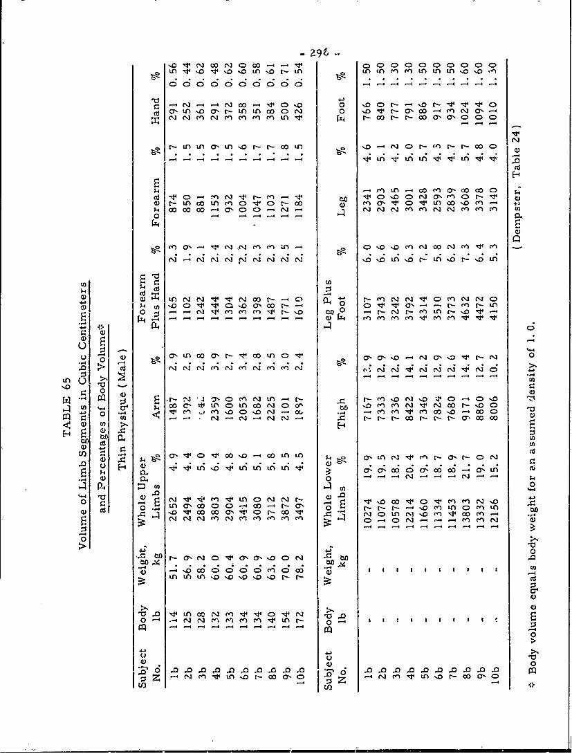
o, vA o %o in %o t-'.0NL Ln LA M Cf1 Ln M LA '0 %.0 "1
00 0 00 0 (S ; ( cs(S ; -C
a- 0'Ln .o at-Ln L oo6N 0 o t t 'Y w enN a% -
N~~~~r LA LAO' LcA '. c A'.4N N4
* N- Lnw IL 0 0 v ~ 6 r- w 0% C> It Mw 0 en.
00
c) nNNvv N NN oo r- r- A.N N V 0 enN C)L
0 - -4) NNN V 00'-- 4 0- - X n c ne
cd ~ ~~~~~~ ~ ~~ ~ ~ m-4 -4i C4e;-ic;Cl 4c;C :Cic4 -i -4i -i -4 -4i -4
0- 0nr nc 0N D4 > Cki w~ cN v uN 0 en w' A- N o '.0. ('. '.0 en C 0 r- 0, '.
' ,14 r') C.1 ( . C'.o N -~ of, -4e ('n en !J V en 0 o -c 0C-n -A N- - N N- r- NN r- r-N-O'c00O
4L C
0 0 c f 4 - r . . . . . c.0 U3 H, 0, 000AL Oa ao.c a, 0co -o'.
0 40 N N
P-4 Cn n
'1n ccaa' Ncc' NOL N. r- (n cn N %0tn0,WC C -a -0 N- -4t C:, 0
w w a 6 0 v -4 r-4 j-4 -- 4 -4 m 4 c -4 m -4
--44 -
0
- -.0 W C> a0 C.0 M 0'.0N1
04 lq 0-4 CC 'N( t :
-4-4-4 -4 -4-4 -4 -- 4
0
U .0
0 0EU 0000000.... 00........
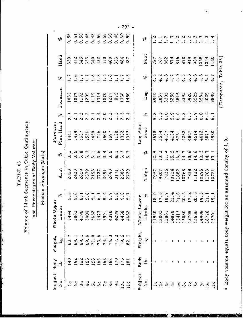
-297-
'D0 -~ CD'.0 C'M CO '.000'.Y
o n In in vi n% oi nMe
od in in 0 N 0 nc o 0 0 0 00 o [~ - - - r- - 00 N
:V4 -4 1-
- 4 -- 4 -4 -4-4-.4 -- nv tpi
inN in cyv p ,- n ooc:>c, r in c> i r- oo n v a, d la
U))
r. ;4M V N m m i >tQl ne -i no-: -o
Q) 04
001) Q4 O'0 ''0nO(~e w - o r4i nr ni -e -
>~C cn 0n(, ne nm m : nc l~ C)
in V N00 00N %0
-- I-
U)to.
W C
. .~ . . . . .
Q) n f) oinLr % Lf L) f)it i 00 t-: O-4C0N-: 0-4z 0 (k7L N N ~'.C')-
QL4 -)0 )
:: ) E~ .d N'o0y Nm O a wN N)CDN 0 C LN% %o Y o aC n r ,(-C) o- N C -- W C Y Z -C
-~- . - 4-4 -4 -4 -4 -4 >1
0
to toV
C) N. n -D N c C)
0 0 0 0 0 0 ~0 0 0 0 0040
uO~C
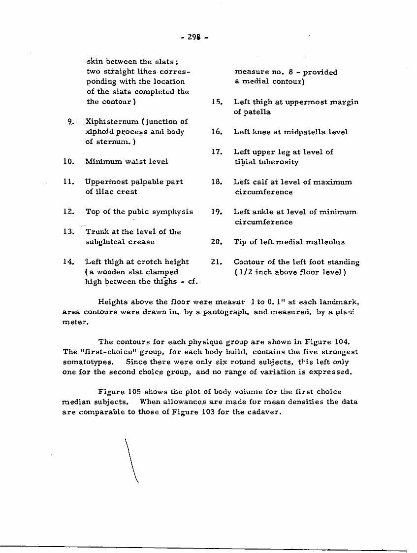
- 298 -
skin between the slats;two straight lihes- corres- measure no. 8 - providedponding with the location a medial contour)of the slats completed thethe contour) 15. Left thigh at uppermost margin
of patella9.. Xiphisternum (junction of
,dphoid process and body 16. Left knee at midpatella levelof sternum. )
17. Left upper leg at level of10. Minimum waist level tibial tuberosity
11. Uppermost palpable part 18. Left calf at level of maximumof iliac crest circumference
12. Top of the pubic symphysis 19. Left ankle at level of minimum.
circumference13'. Trunk at the level of the
subgluteal crease ZC. Tip of left medial rualleolus
14. Left thigh at crotch height 21. Contour of the left foot standing(a-wooden slat clamped (1/2 inch above floor level)high between the thighs - cf.
Heights above the floor were measur I to 0. 1" at each landmark,area contours were drawn in, by a pantograph, and measured, by a plan:meter.
The contours for each physique group are shown in Figure 104.The "first-choice" group, for each body build, contains the five strongestsomatotypes. Since there were only six rotund subjects, ti"is left onlyone for the second choice group, and no range of variation is expressed.
Figure 105 shows the plot of body volume for the first choicemedian subjects. When allowances are made for mean densities the dataare comparable to those of Figure 103 for the cadaver.
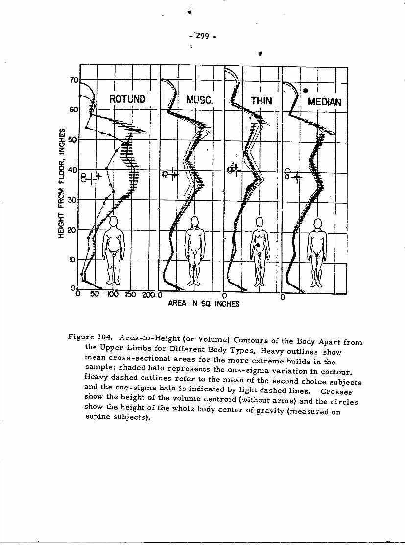
- 299 -
ROTUND MUS. THIN MEDIAN
gi2 - --
i740~5O- rri
z 30-
M l20
10- L
50 100 150 200 0 0 0AREA IN SQ INCHES
Figure 104. Area-to--Height (or Volume) Contours of the Body Apart fromthe Upper Limbs for Different Body Types. Heavy outlines showmean cross-sectional areas for the more extreme builds in thesample; shaded halo represents the one-sigma variation in contour.Heavy dashed outlines refer to the mean of the second choice subjectsand the one-sigma halo is indicated by light dashed lines. Crossesshow the height of the volume centroid (without arms) and the circlesshow the height of the whole body center of gravity (measured onsupine subjects).
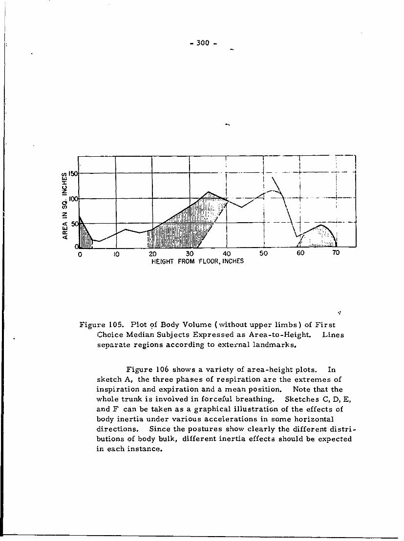
- 300 -
150U) - -
jhh :
W
C.) I
z
0 10 20 30 40 50 60 70HEIGHT FROM FLOOR, INCHES
Figure 105. Plot of Body Volume (without upper limbs) of FirstChoice Median Subjects Expressed as Area-to-Height. Linesseparate regions according to exte cnal landmarks.
Figure 106 shows a variety of area-height plots. Insketch A, the three phases of respiration are the extremes ofinspiration and expiration and a mean position. Note that thewhole trunk is involved in forceful breathing. Sketches C, D, E,and F can be taken as a graphical illustration of the effects ofbody inertia under various accelerations in some horizontaldirections. Since the postures show clearly the different distri-butions of body bulk, different inertia effects should be expectedin each instance.
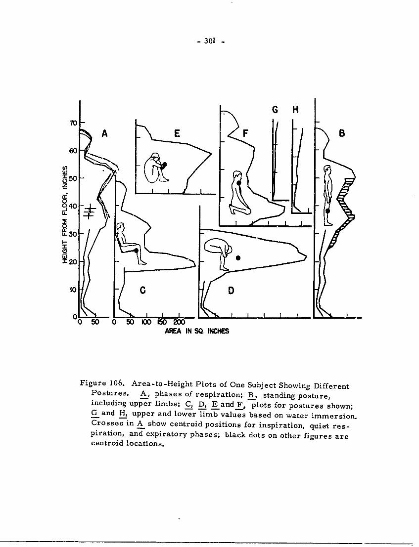
- 301 -
G H
A EFB60"
8 40I3 -
250
01
0 50 0 50 00 150 200
AREA IN SQ. INCHES
Figure 106. Area-to-Height Plots of One Subject Showing DifferentPostures. A, phases of respiration; B, standing posture,including upper limbs; C, D, E and F, plots for postures shown;G and H, upper and lower limb values based on water immersion.Crosses in A show centroid positions for inspiration, quiet res-piration, and expiratory phases; black dots on other figures arecentroid locations.
- 302 -
KOW BODY MASS AFFECTS PUSH AND PULL FORCES(Dempster, pp. Z17-Z34)
From the preceding chapters, it is clear that body bulkis distributed on the body links in a reasonably predictable way.These segmental masses, continually subjected to the accelera-tion of gravity, may be visualized as a related system of verticalforce vectors. Other forces may be involved, due to musculartension or to external factors, producing either balanced torquesor movements along paths consistent with the kinematics of thelinkages involved.
For any static posture, the several masses are balancedin the sense that the torque involving both mass and leveragedistances to the centers of gravity of the individual parts are in,equilibrium. A true balance over a period of time is only approx-imated and involves irregular volleys of muscular activity andthe fluctuation of forces. Though this maintenance of a postureinvolves dynamic muscular behavior, instantaneous posture re-corded photographically may be analyzed statically.
In this chaptur data are presented on how the body mass,exerting a vertical component, is utilized by the seated subjectto effect horizontal push and pull forces in sagittal planes.
The effect of body inertia and body dead weight, formingan anchorage and defining the actual maximum produced by thebody, may be improved upon by designers who understand theprinciples involved in the operation of dead weight in addition tothe advantages and disadvantages of effective body supports andleverages.
All horizontal and vertical forces within the plane ofaction were recorded from a hand dynamometei and six forcegauges at the seat. Side view photographs were taken to freezebody positions.
Figures 75 and 76 show the postures studied. Constantheights above seat level were used and the postures selected to
represent different patterns of body mass distribution. Thevertical line of action of the center of gravity is shown by thearrow above the seat in each posture. Each position is based
- 303 -
upon the site of the center of gravity and may be summarized asfollows:
Posture Center of Gravity Description
a most backward subject leans back pass-ively holding hand grip
f almost identical Buttocks and feet in con-to a tact with seat; strained
e forward of a trunk tensed; arms andknees flexed
d little forward of a trunk tensed and stronglyinclined backward; headback, knees sharply bent
c 3 cm forward of d subject upright in strainedposition; legs flexed
b most forward subject as far forward aspossible for positive values.
Posture differences between push and pull positions are due mainlyto tensed leg and trunk positions.
At each center of gravity vertically downward forcevectors with magnitudes equal to segment mass were assumed tooperate. Additional data from photographs on the horizontaldistances of successive C.G!s from some arbitrary point permittedthe calculation of a common center of gravity, about which momentsof the segment masses were in equilibrium. Centers of gravitycalculated in this manner were in no instances more than one cm.from the C.G!s derived by balancing.
In the actual push-pull situation, the reaction vector tobody weight (called effective seat contact) is not in the same verticalline as the whole body center of gravity; it was calculated as adistance from the rear pressure gauge. This effective seat contactwas shifted by the subject, via shifts in muscle tension, to producea maximum push (contact moved to the rear) or pull (contact movedforward).
The subject's mass, operating vertically downward at theC. G., and the equal and opposite vector at the effective seat con-tact form a couple; these opposed coplanar forces, separated by ameasureable perpendicular distance, act upon a rigid body to causerotation in their plane of action. This is diagrammed in Figure107 for pull position d.
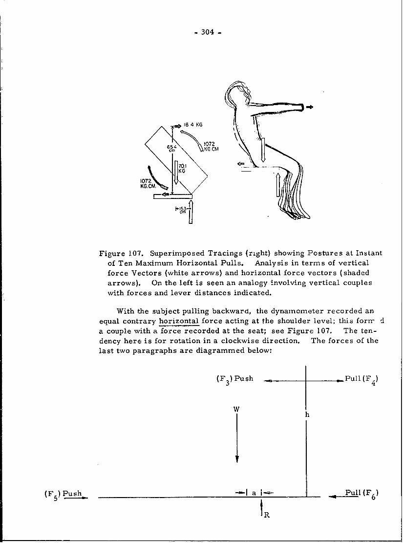
-304-
w> 16 4 KG .
654 !072 I
KG KGM 11072'KG.CM /
Figure 107. Superimposed Tracings (right) showing Postures at Instantof Ten Maximum Horizontal Pulls. Analysis in terms of verticalforce Vectors (white arrows) and horizontal force vectors (shadedarrows). On the left is seen an analogy involving vertical coupleswith forces and lever distances indicated.
With the subject pulling backward, the dynamometer recorded anequal contrary horizontal force acting at the shoulder level; this forr da couple with a force recorded at the seat; see Figure 107. The ten-dency here is for rotation in a clockwise direction. The forces of thelast two paragraphs are diagrammed below:
(F 3 ) Push Pull (F 4)
W
(F Push -- Ia- .-- - - Pull (F 6)
IR
- 305 -
The tendency to produce rotation is called moment of
rotation, or torque, and is obtained by multiplying the magnitudeof one of the forces by the perpendicular distance between them.Thus the force recorded at the dynamometer ( F ) or its recipro-cal at the seat (F 6 ), multiplied by the distance h will be the mom-
ent of rotation produced by the horizontal couple. For a push forcethe value is either (F 3 )h or (F 5 )h. Likewise for the moment
produced by the vertical couple, multiply W (or R) by a.
Any body action which lengthens the moment arm of thehorizontal couple for a constant force, will increase the torque
produced. Therefore, the straining and adjustment of the effectiveseat contact by the subject, increasing the moment produced by thevertical couple, is associated with a simultaneous increase in thepull at a fixed height above the seat. This is necessary in themaintenance of a balanced 3ystem. Since, in this study, the dis-tance between the horizontal forces was experimentally fixed, itbecame necessary for the subject to increase the magnitude of thehorizontal push or pLi. &.rce due to an increase in the vertical
moment through muscular action.
This was verified by measuring the moment arms of thevertical couples in different postures. When the horizontal forcewas low, as in posture a, the moment arm was correspondingly
short; in addition, the horizontal force was also low. The rela-tionship between the increase in force and in vertical moment armwas found to be a straight line.
A further analysis was done utilizing a foot rest. At
maximum forces, the buttocks were raised from the seat and allbody weight applied at the foot rest. This increased the momentarm of the vertical couple. However, the horizontal force that
could be accommodated did not increase directly with the increasein the vertical moment arm, as the location of the foot rest below
seat level also increased the moment arm of the horizontal couple.For more effective use of dead weight, the foot rest should belocated close to the level of the hand pull.
Forces were also found to be greater when a back rest
was utilized. The same body moment torques existed, but theback rest supplied a counterforce against which muscles couldoperate to increase the magnitude of the horizontal pushes.
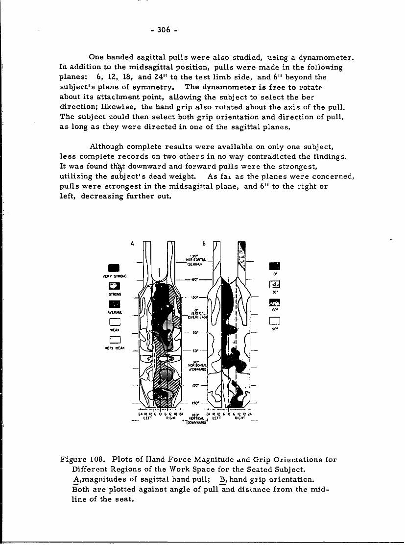
- 306 -
One handed sagittal pulls were also studied, using a dynamometer.In addition to the midsagittal position, pulls were made in the followingplanes: 6, 12, 18, and 24" to the test limb side, and 6" beyond thesubject's plane of symmetry. The dynamometer is free to rotateabout its attactment point, allowing the subject to select the berdirection; likewise, the hand grip also rotated about the axis of the pull.The subject could then select both grip orientation and direction of pull,as long as they were directed in one of the sagittal planes.
Although complete results were available on only one subject,less complete records on two others in no way contradicted the findings.It was found tht downward and forward pulls were the strongest,utilizing the subject's dead weight. As fai as the planes were concerned,pulls were strongest in the midsagittal plane, and 6" to the right orleft, decreasing further out.
AB
HGRiZOTA.
VERY STRONG 0*O
STRONG 30.
AVERAGE 0' W
C 7-10VCR T ElD
ED -A 9O"
VERI *EAK
90"
/~~'I ? --I ....
24 18 12 6 612 16 24 160- 24 18 12 6 0 6 12 1 24LEFT RIGHT VCRTCd. - LEFT RIGHT
Figure 108. Plots of Hand Force Magnitude dnd Grip Orientations forDifferent Regions of the Work Space for the Seated Subject.A,rnagnitudes of sagittal hand pull; B, hand grip orientation.Both are plotted against angle of pull and distance from the mid-line of the seat.
- 307 -
Results are shown in Figure 108, and summarized as
follows:
1) highest values are overhead, utilizing dead weight;
Z) upward and backward pulls at angulations 50°°60 below the
horizontal are also quite high;
3) pulls more than 12" from the midsagittal plane are variable,but generally low.
Muscular effort is ordinarily a limiting factor only when bracing,
body support, and dead weight utilization are maximally effective.Where body leverage and general stability is poor, they are usually
limiting factors rather than muscles.
For studying preferred hand grip orientations, four classes
were set up:
1) parallel to sagittal plane ( - 15 ); thumb counterclockwise;
2) perpendicular to sagittal plane ( - 15 ); thumb medially;
0 + 03) 30 (-15)
4) 60 (- 15)
Right handed fore-aft pulls have a most common orientationof 30 ° , within 12" right, 6" left of the midsagittal plane. At Z4"
lateral to the midsagittal plane, oblique pulls favor a 900 orientation.
Forward pulls from behind the subject tend to have 450 ( sometimesflatter ) orientations. In general, 300 angulations predominate below
the horizontal though there is variation.
- 308 -
CONCLUSION- ASPECTS OF PRACTICAL CONCERN(Dempster, pp. 235-241)
Kinematic and mechanical information on the body systemsupplies form and defines limits to the overlying phsiological andpsychological knowledge. Pursued far enough, it contributes use-ful data to the field of human engineering. This -tudy has consideredthe seated subject oriented in the direction he faces, and has deter-mined a range of space necessary to include specific classes of handand foot movements. Space envelopes presented are maximal be-cause the hampering effects of clothing have not been considered.
In summarizing the data relative to practical problems,eight points need to be considered.
1) The overall size and shap of the work space for all possiblehand orientations. This can be seen in Figure 100, while Figure 101Ashows additional tolerance to include the 95th percentile.
2) The relative volumes available for various hand and foot orien-tations are given in Figures 92 and 98, along with transverse areasin relation to R.
3) The regions of use for special orientations of the hand. Thisbecomes important where the space is not available for unrestrictedhand or foot movement. This information is given in Figures 96, 97,and 99.
4) Common regions where combinations of the eight orientationsmay be used can also be seen in the figures of 3) above.
5) Regions of right-left overlap are also shown in these figures;it v pertinent to know that the region of overlap varies considerablywith the hand orientation.
6) Kinetosphere centroids are important in defining mean positionsfrora which the end 'Member may move in any direction to the kine-tosphere limits. In addition, the centroids pin down the locus ofthe longest straight mean path of end member motion; these pathswithin the kinetosphere will, on the average, be longer if they passthrough the centroid.
7) Limb segment weight and associated rest positions. The restpositions have not been studied here and specifications cannot bemade relative to R. However, these positions require less energythan active phases; if primary controls on which the hand may restpassively are placed at or below centroid levels and nearer to thebody, they will supply support for the upper limb and obviate tiring.The hands will also be in a ready position for properly placedsecondary controls.
- 309 -
8) Preferred orientations of the hand grip are summarized inFigure 108, suggesting correct angling of hand controls for optimum
efficiency. The observed relationship of finger postures suggeststhat finger control orientation may be as important as the placement
and crientation of hand grip controls.
In all cases, the emphasis has been on underlying prin-
ciples pertinent to work space designs. Much work remains tobe done for specific operational situations.
Further studies are suggested not only along the lines of
this investigation but in four related areas.
(1) There should be an exhaustive, well-planned study on
the total range of movement at each body joint for well-defined'
population groups--male, female, special military groups, etc.This should be correlated with standard anthropometric data so
that we may learn the relative importance to the individual of body
dimensions versus the range of joint movement.
(2) There should be studies involving the kinematics and
spatial requirements of specific types of work operations. Our
studies have dealt with overall requirements, but how are the totalbody operations of desk workers, drivers of land vehicles, pilots,machine-operators, etc., effected, how do they differ, and how
much space does each require? It should be important to explore
different methods of getting this information so that new operationsmay be analyzed later to supplement basic data on key operations.
(3) More should be known about hand and foot forces and
body reactions under a large variety of operative condidons. Bodystability, bracing, leverages, the action of couples and the import-
ance of dead weight should be correlated and a number of body posi-tions hoiJ1 be compared. A search for the principles which un-
derly all possible conditions should be sought. Force duration aswell as maxima should be studied. The preferred orientations
and posturing of parts and of the facilitating joints should be under-
stood.
(4) Knowledge on the contribution of different body muscles
to purposeful, static and dynamic activities is necessary. Muscletorques and leverages should be studied, and the cooperative actions
at different joints should be known. The speed and duration of
actions and fatigue relaticns are also pertinent.
- 310 -
APPENDIX I
PLANS FOR THREE - DIMENSIONAL M-ANIKIN
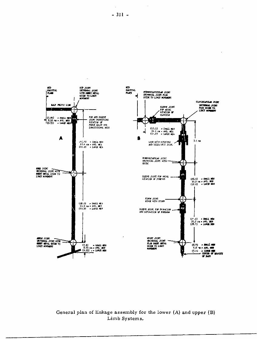
-311 -
BADMAL W7r"MAL JOINT SA01TAL1LbMl BM" OTAL FIATI MM=IA JON
WICZV1ZCSAL. JVFTL
CLAANCKIA LO
(7.95) - 5ML~ lax PO N U4j .t5 ce AVG, MU JOI PLIMcIN(9") LARGE *g5 VP17A7j OF
iLOflN1fThAL AXIS (15. 1) - slma ILKi4 1 co - Ar I~(1'".2) - LAPCZ *Gf.
SKALL bvi LINK WiiH 1407A7.05. co0--Ca - AV-.. W5. A.10 LEL Oflf ,KC.
. LARGE WN~
01a31EPOCAPTAJOIK7mUUVEkZAL .X0Z3. WITH
LuM'A .7011
5W? MTAL -.U= 70I'D= NOffleWT SLD E 401117 FC AXIAL -
i'CATJI OFI rJ'145 (26,6) . SMALL W.2 cs. -YC AV E
ELBOW JO1rH%G w17O S-CI
(58.0) - SKALL ih1.0.9 ca - AIS. MEN.
(45.9) - LJJFCE 19% SLEEVE J011w FOR PAj0
27.2 ce . Al.G, M9(2O. ) - LAS)X
AMU JOI WRIST JOINT
URIC"SA JOWS vM7 UNI3VERSAL JOINTMW16AL W= To FLI Sign FLU
1.3a owm (7) tkllas Ous T (6.7= MOLM
8:55C. .AVDNX MRMLI 7.0'a Av. SM .
General plan of linkage assembly for the lower (A) and upper (B3)Liizb Systems,
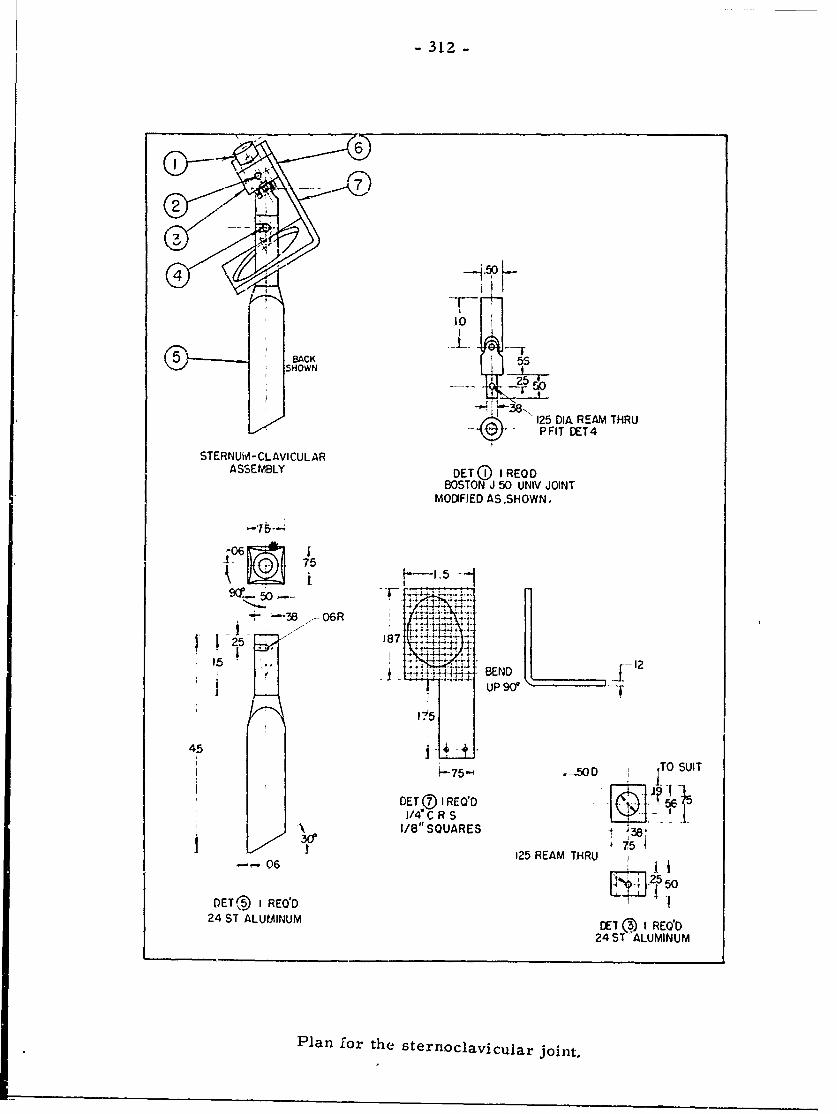
-312-
5
125 DIA REAM THRUPFIT DET4
STERNUM- CLAVICULARASSEMBLY DETQ@ IREOD
BOSTON J 50 UNIV JOINT
MODFIED AS SHOWN,
-38E I6 t41255
1,L5
187 1
-255
125 REM THR 2e~ 0END
0ETT (1 RE1 RE5 524~ ~ ~ ~~ 14 ST SLMNMETJIR
24 ST ALUMINU
Plnfrth trocaiuarjit
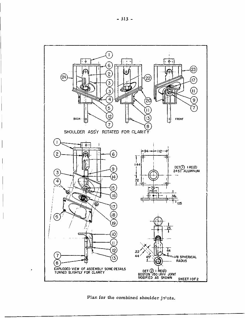
-313-
Q 23
22-0 17
3I4
SHOULDER ASS:Y ROTATED FOR CLARITrY
144 DETQ) I REQ)D
3 90 24ST ALUMINUM
72 f
7
44 45-- 1/8SPHERICAL8 - RAIUS
* ~EXPLODED VIEW OF ASSEMBLY SOME DETAILS E©IEDTURNED SLIGHTLY FOR CLARITY BOSTO 15 UJON
MODIFIED AS SHOWN SHEET IOF 2
Plan for the combined shoulder jo~its.
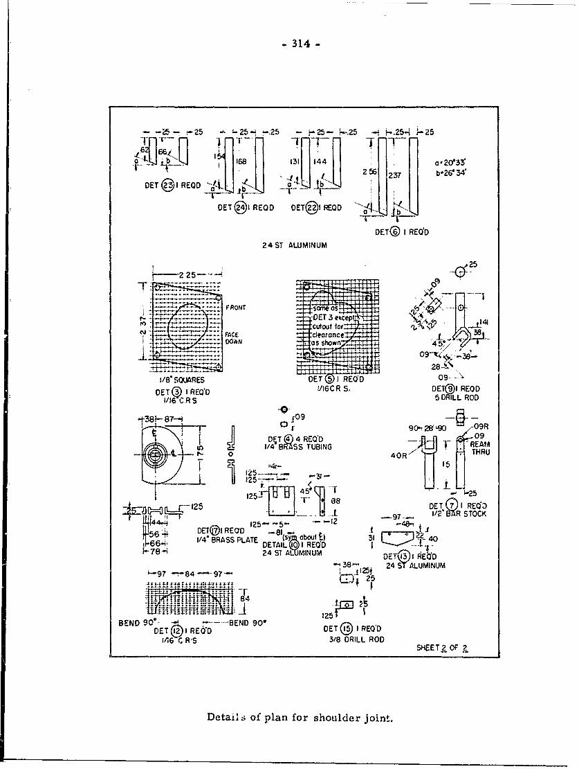
- 314 -
-- -25 25-, ,-25 - p25- 'r-,25 - t-.25-i r-25
'6f~I i HII]
6"T'--
T -~ I1 ii~ ~ 1 256 237 b-26@34'DET 02 RED -aL bK
DET @I RECD DET(@I REOD a -i
DET® I REQD
24ST ALUMINUM
V--2 25-LMT
FRONT sieoff*0r- - -4-5DET 3 e~ce I
-- :cutout tori FACE clearance J-
D.OWiN as shown 4 ,
1/8* SOUARES DET (I REUD 09-- --
DET (Q I REQ'D 'I6C R S, DET)I REOD1/16 C.R S 5 DRILL ROD
.1-38- 87 i0 A 9-- T" D4 T n 4 REO'D
) I/4BRASS TUBING REAM0 40R.11
jL =25--- 15
125125~- 4 -25
1255- DET GI R-9125- -5- -- 7 R STOCK
I:)6 ET@I REO'D -81 ", Ij564., 1/4" BRASS¢ PLATE (s bout t) 31 246 .DETAIL 10I REQ'D
78-i 24 ST ALMINUM D ')I RE'D-38- 24 ST ALUMINUM
,-97 84 97 1251U4 25
: I} :I - V
BEND 90*- ---- BEND 90*DIET @.2 I RE 'D DET I REQ'D
I06 C RS 3/8 DRILL RODSHEET 2 OF
Details of plan for shoulder join..
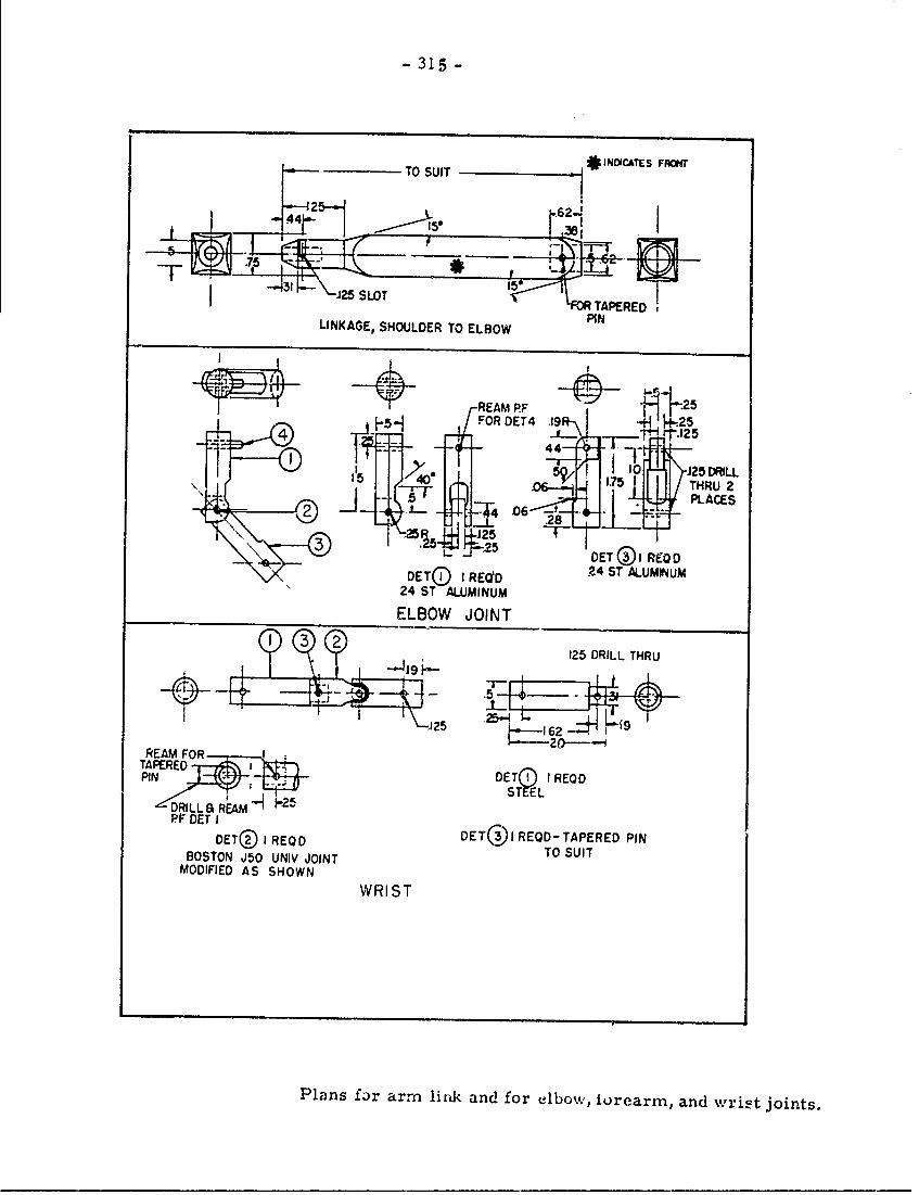
- 315 -
REAMRED
FOR DET4 19 *-. +25
T4 .1-tH 25
15 5 40 1751 THRU441 1. 0 2 RL__ _'_TTPLC S2 28'
Lw DET I REOD24S LMLM
24 ST ALUMINUM
ELBOW JOINT
125 DRILL THRU
.5
162
REAM FORTAPEREDPIN DETn5 I REOD
ST ELkDRILLSa REAM 25
PF DET IDET@ I REOD DETC@)I REOD -TAPERED PIN
BOSTON J50 UNIV JOINT TO SUITMODIFIED AS SHOWN
WRIST
Plans far arm link and for elbowv, iurearm, and wricat joints.
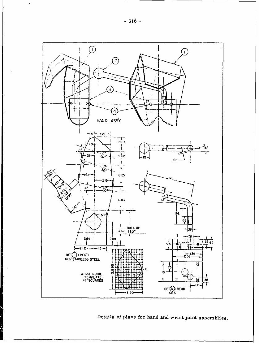
-316
630
5 175'
0 ~ 6 108
-166 8T2LS5SEL4____
Icrr
6.00
I/ SQUARES8 6
DE to I REM 1-1.3
Detilsof lan fr hnd nd ris jintass mbles
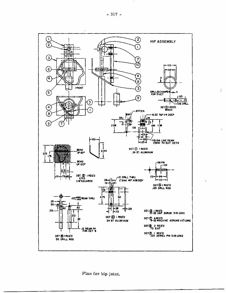
-317
2 HIP ASSEMBLY2
1
6 -
44A
FRONTDRILL CAAPER A5 ~FOR RIVET 2
_ -. 06 DRL
DETO I) REDID0370!~A. 1BRASS
6-32 TAP V/4 DEEP
20 6 j~ 0 1.94 1.39
hI2A A / Ot DA LINE REAM125- C*9NK TO SUIT DET.6
DET (1) 1 REQ'D
275 2.44 60 24 ST ALUMINUM
06P#
I/"SQUARE3 .39- C'SINK 45*xAWDEU1Ile- De I REO'D
J25 DRILL ROD
-. 23...REAM TNRU 2.75 30~,25- -
50
52 .62J2.0 E. IRW
-32 CAP SCREW 5/8 LrAG0DETO@ IREVID OCTq 4REOb
4 .J -D24 ST ALUMIN4UM -32 MACHINE SCREWS I/tLONG11 DETO 2 REODM .12 REAM PF TO SUIT
IF n ET 9DETO I REO-DDET (1I1REO'D .125 DOWEL PIN 3/8 LONG5O DRILL ROD
Plan for hip joint.
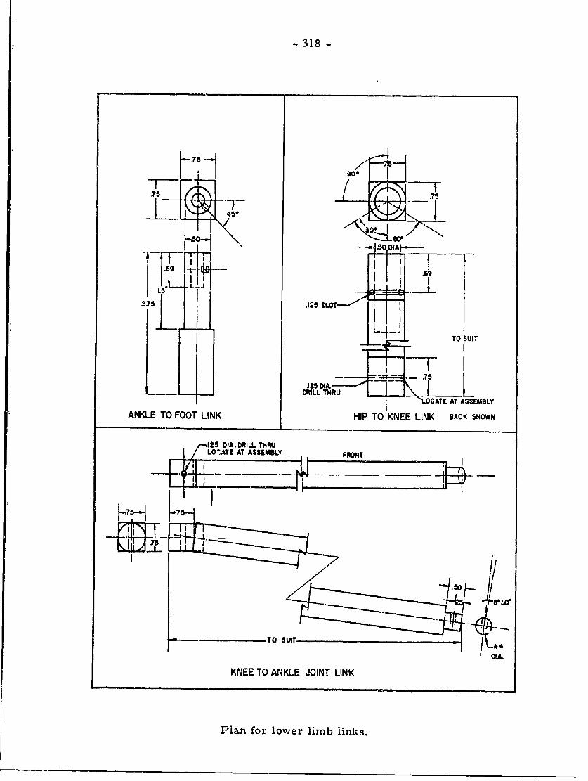
- 318 -
.75 7
450
.69
275{ .15 Lj-TO SUIT
J2501A.
DRILL THRU - OCATE AT ASSEMBLY
ANKLE TO FOOT LINK HIP TO KNEE LINK BACK SHOWN
-25 IA. RIU. THRULOATE AT ASSEMBLY FNT
yiii
TO SUIT
DIA.
KNEE TO ANKLE JOINT LINK
Plan for lower limb links.
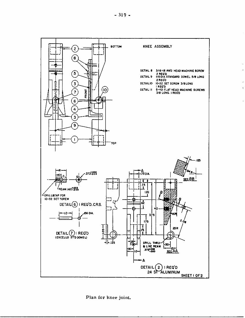
-319-
BOTTOM KNEE ASSEMBLY
DETAIL 8 3/16-I8 RN0 HEA MACHINE SCREW5 ~2 REQ'O
DETAIL 9 1/8 DIA.STANDARD DOWEL 5/S LONG2REUO
DETAILIO 10-32 SET SCREW 3/SLONGI REQOD
L 10 DETAILI11 5-40OFLATM4EAD MACHINE SCREWS7 ~3/8 LONG. I REVID
1 0~
3D9IA51A
DETAIL SETSCREWQ
SHE I 25R
PlanL(D Io kne jont
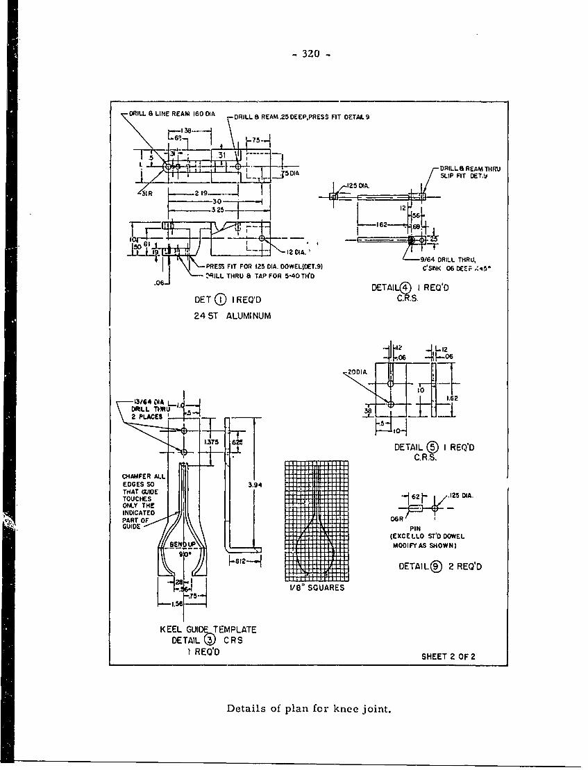
-320 -
DRILL a LINE REAM 160 DIA DRILLSa REAM .25 DE EPPRESS FIT DETAIL 9
L ~DRILLSa REAM THRU
_J,59/64 DRILL FT DRLJPRES FI/OR1512.501A.T.)C~~t(0 DE
Z3LL THR S APFO19-O
1-10 19 2 ODI,
19164 DRIA TH162
1.37 DEAI (4)T1 RL Q
DET~ ~ ~ ~ (RE1Q'DDC,,
24AFE ATALMLU
TOUCHES DIA
13/64CATE0 1.6
I - --- LDETAIL® 2 REQD
EDGES' SOUARES
KHTGIEE.GIETMLT
DETIDL CRS
REQDLL SEET 2OWEL
Details ofIF pla forknOWjont
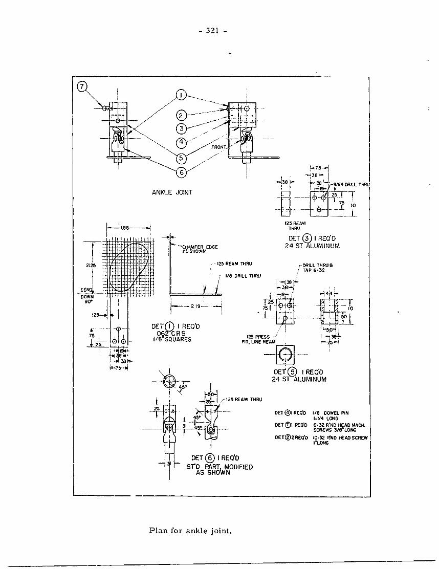
- 321 -
FRONT,
5-7
6 3-q~~~~~%S D " ri-/4RL THRU
ANKLE JOINT T*
75
125 REAMTHRtU
Lh ,DET I REQ'D.Cr'AMFER EDGE 24 ST ALUMINUM
-- ++' ''+''+"' -125 REAM THRU
2J25 +'-5-EMHIr-DRILL THRU 82J25 ..... ; /TAP 6-32
DO~WN -.*.+,- 1/8 DRILL THRU
, -4,- - .....91LDOWN__ I
!25
DET Q I REQ'D 5'p+
75 O§2-C R S 125 RSS 34+
- __-- _ 1/8 SQUARES FT, LINE REAM
DEl 1 I REQ'D-- 24 ST ALUMINUM
44DET®@I REOD 1/8 DOWEL PIN45*-J I-1/4 LONG
"__1_- OET()I REQ'O 6-32 R'ND HqAD MACH451- SCREWS 3/8 LONG
OET®2RE00 10-32 IND HEAD SCREWI I"LONG
~1 k DET®I REYD"1 V TQ~ PARTW MODIFIED
AS SHoWN
Plan for ankle joint.
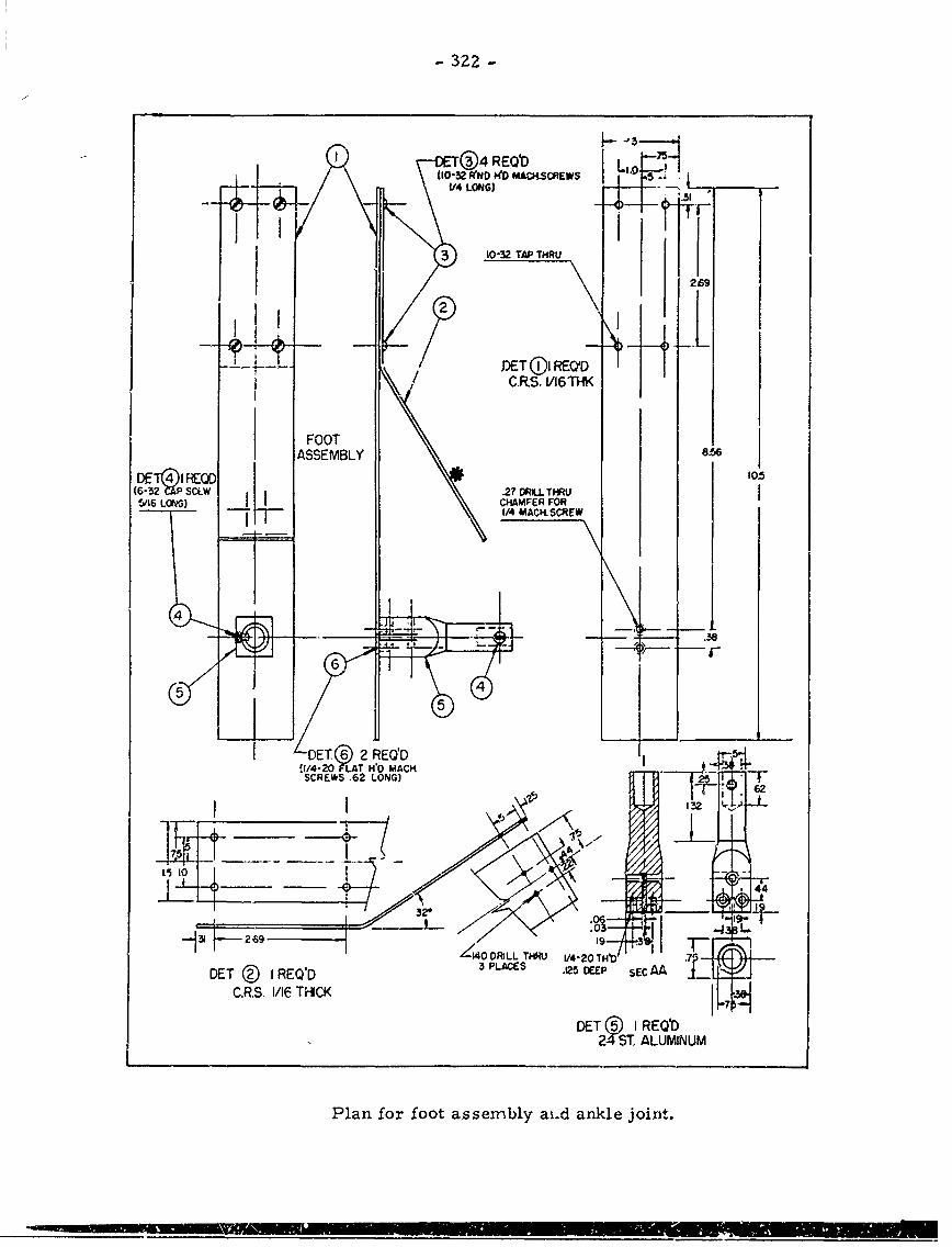
- 322 -
I3 ®4REQbD IL 5(10-32 WND MA&CK-SCREcWS
t/4 LONIG)
I 10-32 TAP THRU
1X 269
DET 01 REQ DC.RS. 1/16THK
FOOTASSEMBLY em
DE T REGO 105(63-5 V2P SC.,W .27 ORILL.THRU62 L~W CHAMFER FOR
SCL )S1/4 MACK SCREW
-rr
66
(5
E( DET 2 REQPDS -4j5*4./4-2 FLAT WD MACK2
SCREWS .62 LONG) 2 62
44319
431 269 01400DRLL THMIU 14-20 THb .5
DE D EOD3 PLACES 415 DEEP SEC AA
C.RS, 1/16 T4-CK En5IRb 7
24-ST. ALUMINUM
Plan for foot assembly ai.d ankle joint.
APPENDIX Ii
PLANS FOR DRAFTING BOARD MANIKIN
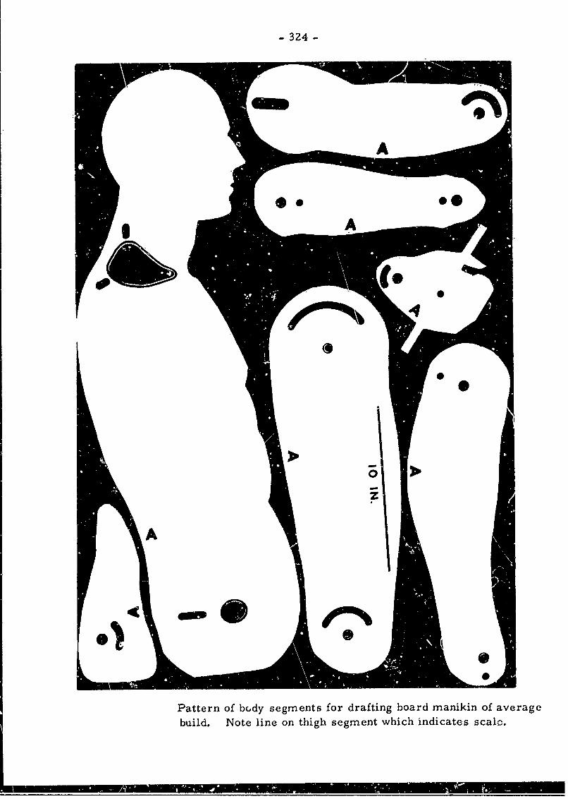
- 324 -
Pattern of bc.dy' segments for drafting board manikin of averagebuild. Note line on thigh segment which indicates scale.
KA
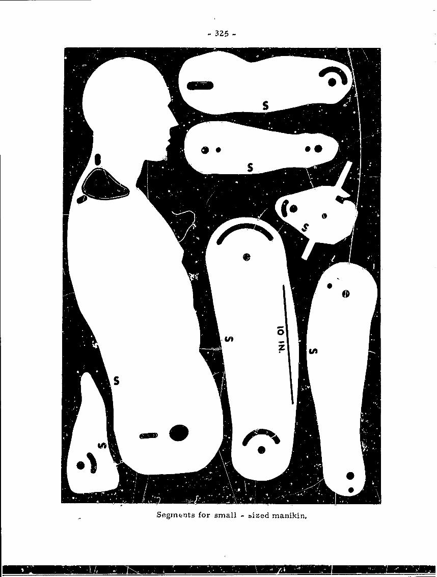
- 326
SegmeLnts for small -bized manikin,
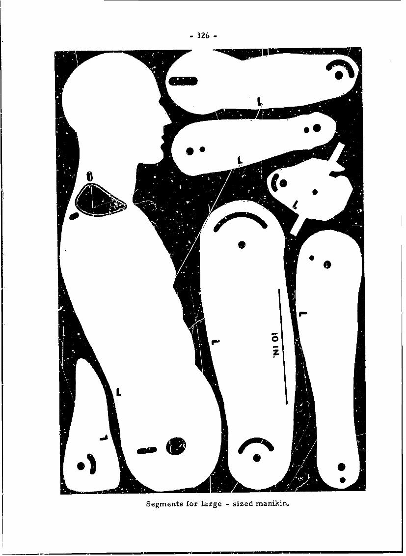
- 326 -
- #7.
Segments for large - sized manikin.
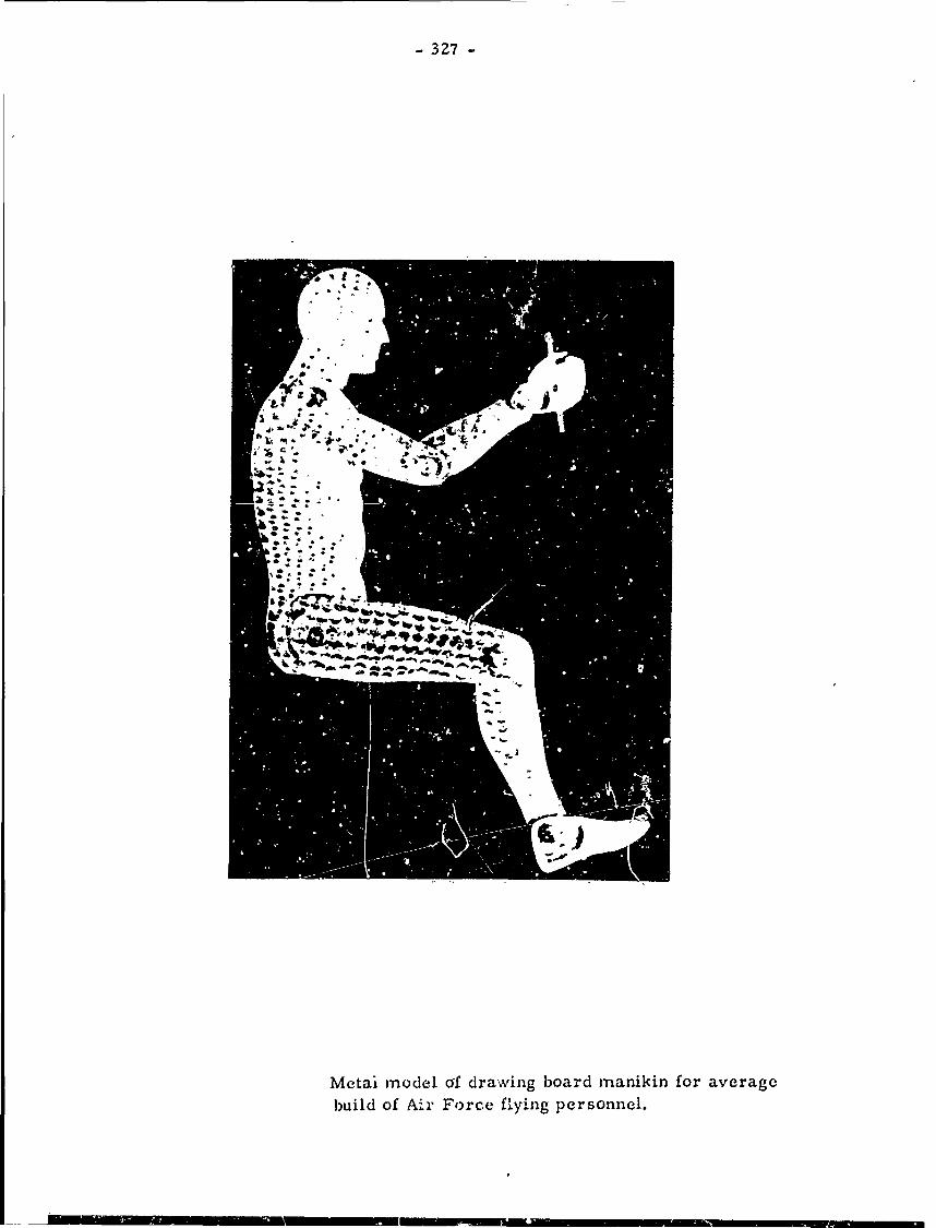
- 327 -
Metai model csf drawing board manikin for averagcbuild of Air Force flying personnel.
- 328 -
BIBLIOGRAPHY
1. Albert, E. 1876. Zur Mechanik des Hftgelenkez. Med. Jahrb. k. k. Gesellsch.d. Arzte (Wien). pp. 107-129.
2. Alderson Research Laboratories. 1954. Anthropomorphic Test Dummy-Mark III.Alderson Res. Lab., Inc., New York. 11 pp.
3. Anglesworth, R. D., ed. 1952. Manual of Upper Extremity Prosthetics. Artifi-cial Limbs Rt-bearch Project, University of California. 240 pp. (unnumbered).
4. Barnes, R. M. 1949. Motion and Time Studi. Third Edition. John Wiley andSons, New York. 559 PP.
5. Barnett, C. H. 1953. Locking at the Knee Joint. J. Anat. Volume 87. pp. 91-95.
6. Barnett, C. H. and Napier, J. R. 1952. The Axis of Rotation of the Ankle Jointin Man. Its Influence upon the Form of the Talus and the Mobility of the Fib-ula. J. Anat. Volume 86 (1). pp. 1-9.
7. Bedford, T. and Warner, C. G. 1937. Strength Test: Observations on the Effectsof Posture on Strength of Pull. Lancet. Volume 2. pp. 1328-1329.
8. Bennect, N. G. 1908. A Contribution to the Study of the Movements o' the Man-dible. Proc. Roy. Soc. Med. (Odont. Sect.). Volume 1 (3). PP. 79-98.
9. Bernstein, Nik. 1935. Untersuchungen tber die Biodynamik der Lokomotion. Bd.1. Biodynamik des Ganges des normalen erwachsenen Mannes. Institute for Exper.Med. d. Soviet Union, Moscow. 243 pp. (In Russian; German summary.)
10. Bowles, G. T. 1932. New Types of Old Americans at Harvard and at Eastern Women'sColleges. Harvard University Press, Cambridge. 144 pp.
11. Boyd, E. 1953. The Specific Gravity of the Human Body. Human Biol. Volume 5,pp. 646-672.
12. Brash, J. C., ed. 1951. Cunningham's Textbook of Anatomy. Ninth Edition. Ox-ford, New York. 1604 pp.
13. Braune, W. and Fischer, 0. 1885. Die bei Jer Untersuchung von Gelenkbewegungenanzuwendende Methode, erlautert am Geienkmechaniomuz. des Vorderarms beim Men-schen. Abh. d. math.-phyc. Cl. d. k. SAchs. Gesellsch. d. Wiss. Volume 15 (3).
pp. 315-336.
- 329 -
9 14. Braune, W. and Fischer, 0. 1887a. Untersuchungen Uber die Gelenke des men-schlichen Armei; 1. Das Ellenbogengelenk (O. Fischer); 2. Das Handgelenk (W.Braune and 0. Fischer). Abh. d. math.-phys. Cl. d. k. Shchs. Gesellsch. d.Wiss. Volume 14 (2). pp. 29-150.
15. Braune, W. and Fischer, 0. 1887b. Das Gesetz der Bewegungen in den Gelerken
and der Basis der mittleren Finger und im Handgelenk des Menschen. Abh. d.
math.-phys. Cl. d. k. S~chs. Gesellsch. d. Wiss. Volume 14 (4). pp. 203-227.
16. Braune, W. and Fischer, 0. 1888. Uber den Antheil, den die einzelnen Gelenke
des Schultergrtels am der Beweglichkeit des menschlichen Humerus haben. Abh.d. math.-phys. Cl. d. k. Shchs. Gesellsch. d. Wiss. Volump 14 (8). pp. 393-410.
0 17. Braune, W. and Fischer, 0. 1890. Uber den Schwerpunkt des menschlichen K6rpers
mit RUcksicht auf die AusrUstung des deutschen Infanteristen. Abh. 0. math.-
phys. Cl. d. k. Sachs. Gesellsch, d. Wiss. Volume 15. pp. 561-572.
18. Braune, W. and Fischer, 0. 1891. Die Bewegun'.en des Kniegelenks, nach einer
neuen Methode am lebenden Menschen gemessen. Abh. d. math.-phys. Cl. d. k.
S~chs. Gesellsch. d. Wiss. Volume 17 (2). PP. 75-150.
19. Braune, W. and Fischer, 0. 1892. Bestimmung jer Tr~gheitsmomente des mensch-
lichen K~rpers und seiner Glieder. Abh. d. math.-;hys. Cl. d. k. Sdchs. Ge-sellsch. d. Wiss. Volume 18 (8). pp. 409-492.
20. Braus, H. 1921. Anatomie des Menschen. Bewegungsapparat. J. Springer, Berlin.
Volume 1. 835 PP.
21. Breitinger, E. 1937. Zur Berechnung der Kdrperh6he aus den laingen Gliedmassen
Knochen. Anthrop. Anz., 14 (3/4). pp. 249-274.
22. Bridgman, G. B. 1920. Constructive Anatomy. Bridgman Publishing Company, Pel-ham, New York. 216 pp.
23. Brozek, J. and Ke i, A. 1952. Body Build and Body Compositions. Science,
Volume 116. pp. 140-142.
24. Bugnion, E. 1892. Le M~chanisme du genou. Recueil inaug. de l'universite
Lausanne. Viret-Genton, Lausanne.
25. Chissin, Chaim. 1906. Uber die Cffnungsbewegung les Unterkiefers und die Beteil-igung der Fusseren Pterygoidmuskeln bei derselben. Arch. f. Anat. u. Physiol.
(Anat. Abt.). pp. 41-67.
26. Churchill, E. 1951. Anthropometric Survey-Statistical Reduction of Data. Con-tract AF 33(o38)-11815. Antioch College, Yellow Springs, Ohio.
27. Churchill, E. 1952. Personal communication.
28. Clark, W. A. 1920. A System of Joint Measurements. J. Ortho. Surg., 2 (12).pp. 687-700.
• Indicates references cited in the condensed text.
- 330 -
29. Clark, L. G. and Weddell, G. M. 1944. The Pressure Which Can Be Exerted bythe Foot of a Seated Operator with the Leg in Various Positions. R. N. P.
Volume 44. Medical Research Council, Royal Naval Personnel Committee. 153 pp.
30. Careton, Thomas K. 1939. Elementary Principles and Techniques of Cinemato-I' graphic Analysi as Aids in Athletic Research. Research Quarterly, AM. Ass'n.
Health, Phys. Ed. and Recreation. Volume 10 (2). pp. 5-24.
31. Dally, J. F. H. 1908. An Inquiry into the Physiological Mechanism of Respira-tion, with Especial Reference to the Movements of the Vertebral Column and
Diaphragm. J. Anat. Volume 43. pp. 93-114.
52. Daniels, G. S., Meyers, H. C., and Churchill, E. 1953. Anthropometry of Male
Basic Trainees. WADC Technical Report 53-49, Wright Air Development Center,Wright-Patterson Air Force Base, Ohio.
33. Darcus, H. D. 1931. The Maximum Torques Developed in Pronation and Supinationof the Right Hand., J. Anat. Volume 85 (1). PP. 55-67.
34. Darcus, H. D. and Salter, Nancy. 1953. The Amplitude of Pronation and Supina-
tion with the Elbow Flexed to a Right Angle. J. Anat. Volume 87 (2). pp.
169- 184.
55. Darcus, H. D. and Weddell, H. G. 19117. Some Anatomical and Physiological Prin-
ciples Concerned in the Design of Seats for Naval War Weapons. Brit. Med.Bull., 5 (1). pp. 31-37.
36. Davis, L. E. 1949. Human Factors in Design of Manual Machine Controls. Mech.
Engin. Volume 71. pp. 811-816.
57. Dempoter, W. T. 1955. Joint Axes and Contours of the Major Extremity Joints.51 pp. Quarterly Report No. 4. Study of the Hinge Points of the Human Body.Wright Air Development Center, United States Air Force contract no. AF 18(600)-11.
38. Dempster, W. T. and Liddicoat, R. T. 1952. Compact Bone as a Non-isotropic Ma-terial. Am. J. Anat. Volume 91 (3). pp. 31-362.
59. Dupertuis, C. W. 1950. Anthropometry of Extreme Somatotypes. Am. J. Phys. An-throp. Volkume 8 n.s, (3). pp. 367-383.
hO. Dupertuis, C. W. and Hadden, J. A., Jr. 1951. On the Reconstruction of Staturefrom Long Bones. Am. J. Phys. Anthrop. Volume 9 n.s. PP. 15-54.
41. Ddpertuis, C. W., Pitte, G. C., Osserman, E. F., Welham, W. C., and Behnke, A. R.1951. Relation of Specific Gavity to Body Build in a Groue of Health Men.
J. Appl. Physiol. Volume 5 (11). pp. 676-680.
42. Dupertuis, C. W. and Tanner, J. M. 1950. The Pose of the Subject for Photogram-
metric Anthropometry with Especial Reference to Somatot j. Aai. T. Phys. An-
throp. Volume 8 n.s. (1). pp. 27-47.
4:. Eberhart, H. D. and Inman, V. T. 1951. An Evaluation of Experimental ProceduresUsed in a Fundamental Study of Locomotion. Ann. N. Y. Acad. Sci. Volume 51.pp. 1213-1228.
44. Elftman, Herbert. 1939. The Ro~ation of the Body in Walking. A-beitphysiol.Volume 10 (5). pp. 477-484.
45. Elftman, H. 1943. On Dynamics of Human Walking. Tr. N. Y. Acad. Sci. Volume6. pp. 1-4.
46. Elftmin, H. 1945. Torsion of the Lower Extremity. Am. J. Phys. Anthrop. Vol-ume 3 (3). pp. 255-265.
47. Elftman, H. 1951. The Basic Pattern of Human Locomotion. Ann. N. Y. Acad.Sci. Volume 51. pp. 1207-1212.
48. Evans, F. G. 1953. Methods of Studying the Biomechanical Significance of BoneForm. Am. J. Phys. AntILIop. Volume 11 n.s. (3). pp. 413-436.
49. Fick, R. 1904-1911, Handbuch der Anatomie und Mechanik der Gelenke. Part 1 -
Anatomie der Gelenke. 532 pp. 1904. Part 2 - Allgemeine Gelenk- und Muskel-mechanik. 576 pp. 1910. Part 3 - Spezielle Gelenk- und Muskelmechanik.688 pp. 1911. (in Bardeleben: Handbuch der Anatomie des Menschen. Volume2, Section 1. G. Fischer, Jena.)
50. Fischer, 0. 1895. Die Arbeit der Muskeln und die lebendige Kraft des menschli-
chen Krpers. Abh. d. math.-phys. Cl. d. k. Sachs. Gesellsch. d. Wiss. Vol-
ume 20 (1). pp. 4-84.
51. Fischer, 0. 1895. BeitrAge zu elner Muskeldynamik: Uber die Wirkungsweise
enggelenkiger Muskeln. Abh. d. math.-phys. Cl. d. k. S6chs. Gesellsch. d. Wiss.Volume 22. pp. 49-197.
52. Fischer, 0. 1896. BeitrAge zur Muskelstatik: Ober das Gleichgewlcht zwischen
Schwere und Muskeln am zweigliedrigen System. Abh. d. math.-phys. Cl. d. k.Sdchs. Gesellsch. d. Wiss. Volume 25 (4). pp. 267-368.
53. Fischer, 0. 1904. Der C-ng des Menschen. Abh. d. math.-phys. Cl. d. k. Stchs.Gesellsch. d. Wiss. Voltunes 21-28. Leipzig. This extensive study includedthe following parts:
Braune, W. and Fischer, 0. 1895. Der Gan des Menschen. T.Theil: Versucheam unbelasteten und belasteten Me,,'schen. Volume 21. pp. 151-322,
Fischer, 0. 1899. Der Gang des Menschen. II.Theil: die Bewegung des Ge-sammtschwerpunktes und die husseren Krhfte. Volume 25. pp. 1-130.
Fischer, 0. 1901. Der Gan des Menschen. IIT.Theil: Betrachtungen Uber die
,ieiteren Zele der Untersuchung und Uberblick Uber die Beweuen der unterenExtremithten. Volume 26. pp. 85-170.
Fischer, 0. 19 1. Der Gang des Menschen. IV.Theil: Uber die Bewegung des
Fusses und die auf denselben einwirkenden Krgfte. Volume 26. pp. 469-556.
- 332 -
Fischer, 0. 1904. Der Gang des Menschen. V.Theil: die Kinematik des Bein-
schwingens. Volume 28. pp. 319-418.
Fischer, 0. 1904. Der Gang des Menschen. VI.Theil: Uber den Einfluss der
Schwere und der Muskeln auf die Schwinguxgsbewegung des Beins. Volume 28.
pp. 531-617.
54. Fischer, 0. 1906. Theoretische Grundlagen fUr eine Mechanik dei lebenden
KOrper. B. G. Teubner, Berlin. 327 pp.
55. Fischer, 0. 1907. Kinematik organischer Gelenke. F. Vieweg and Sohn, Braun-
schweig. 261 pp., 77 figs.
56. Fischer, 0. 1909. Zur Kinematik der Gelenke vom Typus des humero-radial Ge-lenkes. Abh. d. math.-phys. Cl. d. k. SEchs. Gesellsch. d. Wiss. Volume 32.
pp. 3-77.
57. Franseen, E. B. and Hellebrandt, F. A. 1943. Postural Changes in Respiration.
Am. J. Physiol. Vclume 138. pp. 364-369.
58. Fries, E. C. and Hellebrandt, F. A. 1943. The Influence of Pregnancy on the
Location of the Center of Gravity, Postural Stability, and Body Alignment.Am. J. Obstet. and Gynecol. Volume 46 (3). pp. 374-380.
59. Gardner, E. 1950a. Reflex Muscular Responses to Stimulation of Muscular Nervesin the Cat. Am. J. Physiol. Volume 161 (1). pp. 133-141.
60. Gardner, E. 1950b. Physiology of Movable Joints. Physiol. Rev. Volume 30 (2).
pp. 127-176.
61. Garry, R. C. 1930. The Factirs Determining the Most Effective Push or Pull
Which Can Be Exerted bXa Human Being on a Straight Lever Moving in a Vertical
Plane. Arbeitsphysiol. Volume 3 (4). pp. 330-346.
62. Gilliland, A. R. 1921. Norms for Amplitude of Voluntary Movement. J. Am. Med.Ass'n. p. 1357.
63. Glanville, A. D. and Kreezer, G. 1937. The Maximum AMplitude and Velocity of
Joint Movements in Normal Male Human Adults. Human Biol. Volume 9. PP. 197-
211.
64. Goss, C. M., ed. 1948. Gray's Anatomy of the Human Body. Twenty-fifth edition.
Lea and Febiger, Philadelphia. 1478 pp.
65. Haines, R. W. 1941. A Note on the Actions of the Cruciate Ligaments of the KneeJoint. J. Anat. Volume 75. Pp. 373-375.
66. Harless, E. 1860. Die Statischen Momente der menschlichen Gliedmassen. Abh.
d. math.-phys. Cl. d. 'knil. Bayer. Akad. d. Wiss. Volume 8. pp. 69-96 and257-294.
67. Harrower, G. 1924. Mechanical Cons~deraticis in the Scapulo-humeral. Articula-
tion. J.'Anat. "Volume 58. pp. 222-227.
- 333 -
68. Hellebrandt, F. A. 1938. Standing as a Gectropic Reflex. The Mechani.:m of
the Asynchronous Rotation of Motor Unitz. Am. J. Physiol. VcLife 12:. pp.
471-474.
69. Hellebrandt, F. A., Duvall, E. N., and Moore, M. L. 1,49. The Measurement of
Joint Motion, Part 5, Reliability of Goniometr . Physiotherap. Rev. Volume
29 (6). pp. 302-307.
70. Hellebrandt, Frances A., Braun, Genevieve, and Tepper, Rubye H. 1937. The
Relation of the 'Center of Gravity to the Base of Support in Stance- Am. J.
Physiol. Volume 119. p. 113.
71. Hellebrandt, F. A. and Franseen, E. B. 1943. Physiological Study ef the Ver-
tical Stance of Man. Physiol. Rev. Volume 23. pp. 220-255.
72. Hellebrandt, F. A. and Fries, E. C. 1942. The Eccentricity of the Mfan Verti-cal Projection of the Center of Gravity d Standing. Physiotherap. Rev.
Volume 22. pp. 186-192.
* 73. Hertzberg, H. T. E., Daniels, G. S., and Churchill, E, 1954. Anthropometry ofFlying Personnel- 1950 . WADC Technical Report 52-521, Wright Air Development
Center, Wright-Patterson Air Force Base, Ohio. Actually, a preliminary sum-
mary of these data was used in the earlier phases of this work (Churchill, E.,
1951 Anthropometric Survey).
74. Hicks, J. H. 1953. The Mechanics of the Foot. I. The Joints. J. Anat. Vol-ume 87 (4). pp. 345-357.
75. Hooton, E. A. 1947. M2 from the Ape. Second edition. MacMillan, New York.
788 pp
76. Hrdlika, A. 1947. Practical Anthropometry. Third edition. Edited by T. D.
Stewart. Wistar Institute, Philadelphia. 230 pp.
77. Hugh-Jones, P. 1944. Some Physiological Aspects of Tank Driving Controls, Part
I, The Maximum Force Exertable on Hand Controls and how this Varies with Dif-
ferent Positions of the Control Relative to the Seat. BPC 44/341, PL 137, Gt.Brit., MRC-MPRC.
78. Hugh-Jones, P. 1945. Some Physiological.:Aspects of Tank Driving Controls, PartIII, The Maximum Force <ertable on Hand Controls and how this Varies witn Dif-
ferent Positionb of the Control Relative to the Seat; BP 45/410, PL 158, Git.Brit., MRC-MPRC.
79. Hugh-Jones, P. ]$47. The Effect .i Limb Position in Seated Subjects on theirAbility to Utilize the Maximum Contractile Force of the Limb Muscles. J.
Physiol. Volume 104 (1). pp. 332-344.
80. Hultkrantz, J. W. 1897. Das Ellenbogengelehk und seine Mechanik. Fischer,
Jena. 148 pp.
81. Hunsicker, Paul A. 1954. Arm Strength at Selected Degrees of Elbow Flexion.
Air Force Project No. 721 71727, United Statoes Air Force Air Materiel Comand,
Wright-Patterson Air Force Base, Dayton, Ohio;
82. Ingalls, N. tl2C. lta-!v. on th.- Femur. IV. Some Rv-atlcn. of t.e Head andCondyles ir.tho WfLt" - Am. J. Phys. Anthrop. 'iuno 10 (f)). pp.
83. Inman, V. T., 2aun,'ers, J. B. A C., and Abbott, L. C. i.-44. Observations on
the Funztion of the $-o'.!hetr Joint. J. Bone anI Joint 7 urg. Volume 26 (1).YPp. 1-2,0.
84. Kennedy, J. L. 1949. Handbcoe of Human Engineering D-ta for Design Engineers.
Tufts College Institutt! for ApLiei Expefimental Psychology. Technicul ReportSDC 1Y-1-l, Nay Expos P-6143, D ia Devicez Center, Office of Naval Research,Department Gf the Navy.
85. King, B. G. 1946. Measurements of Man for Making Machiner.& Am. J. Phys.Anthrop. Volume 6-. pp. ,i1-_I.
86. King, B. G. 1952. Y'unetit~nal Cockpit De ign Am. Engin,. Rev. Volume 11 (6).
87. Kingsley, P. C. and Olmzted, K. L. 1943. A ud of the Anle of Anteverslonof the Neck of the Femur. J. Bone and Joint Surg. Volume 50-A (3). pp. 745-
751.
88.. Kopsteg, P. E. and Wilson, P. D. 19 ). Human Limbs and Their 5ubstitulte,.McGraw-Kill. 81 pp.
89. Knese, K. H. 1950a. Die Bewegunph auf einer F-run zfldche alo Gruindlage dt-rGelenkbewegungen, dargestellt am Schultergeienk. Zts. f. Anat. u. Entwgesch.Volume 115. pp. 115-161.
90. Knese, K. H. 1950b. Kinematik der Gliedei-bewegungen darg-..tet a"I . Hif- und
Ellenbogengelehk. Zts. f. Anat. u. Entvgesch. Volume l'. pt. . -
91. Knese, K. H. 1950c. Kinematik des Kniegelenkes. Zts. ,'. Anat. a. Fntawge c:C.Volume 115. pp. 287-332.
92. Koch, H,. 1941. Fussbedieix,. Arbt:tsmactinen und Ei=Udun . Ari- - .- hutz.Volume 5. pp. 52-59.
93. Krahl, V. E. 19h7. The Tortion of the Humerus; its Localization Cau. and Di-rection in Man. Am. J. Anat. Volume 60 (5),. pP. 27>-519.
94. Langer, C 1858. Das Kniegelenk des Menschen. Sitzungsber. d. k. Akad. d.
Wiss. math.-naturw. Cl. (Wien). Volume 52. pp. 99-112.
95. Langer, 0. i865. Lehrbuch der Andtomie des Menschen. Wilhelm Braumuller,Wien. 757 pp.
96. Last, R. J. 19148. Some Anatomical Details of the Knee Joint. J. Bone andJoint Surg. Volume 30-B. pp. 683-688.
97. Lay, W. E. and Fisher, L. C. 1940. Riding Comfort and Cushions. S. A. E.
Jcurnal. Volume 47., pp. 482-496. Also mimeograph prepublication of paper
with same title.
- 335 -
98. Lehmann, G. 1927. Arbeitsphysiologische studien IV. Pfl[gers Arch. ges.Physiol. Volume 215. pp. 329-364.
99. Ludkewitsch, A. 1900. L'Articulation de le'paule. Bull. Soc. Vaud. Sci. Nat.Volume 34 (1310 .- pp. 350-371.
100. MacConaill, M. A. 1941. The Mechanical Anatomy of the Carpus and Its Bearingson Some Surgical Problems. J. Anat. Volume 75. pp. 166-175.
101. MacConaill, M. A. 1946. Studies in. the Mechanics of Synovial Joints. I. Fun-damental Principles and Diadochal Movements. Irish J. Med. Sci. Volume 6.pp. 190-199.
102. MacConaill, M. A. 946. Studies in the Mechs.,ics of Snov:ial Joints. I1. DIis.placement of Articular Surfaces and the Significance of Saddle Joints. IrishJ. Med. Sci. Volume 6. pp. 223-235.
103. MacConaill, M. A. 19146. Studies in the Mechanics of Synovial Joints. III.Hine Joints and the Nature of Intra-artijr risplacements. Irish J. Med.Sci. Volume 6. pp. 620-626.
104. MacConaill, M. A. 19148. The Movements of Bones and Joints. I. FundamentalPrinciples with Particular Reference to Rotation Movement. J. Bone and JointSurg. Volume 30-B. pp. 322-326.
105. MacConaill, M. A. 1951. The Movements of Bones and Joints. IV. The MechanicalStructure of Articulating CartiLte., J. Bone and Joint Surg. Volume 33-B (2).pp., 251-257.
106. Manouvrier, L. 1892. Determination de la taille d' pres les grandes os desmembres. Rev. mens. de l'5cole d. Anthrop (Paris). Volume 2. pp. 226-233.
107. Mantef, J. T. 19141. Movements of the Subtalar and Transverse Tarsal Joints.Anat. Rec. Volume 80. pp. 397-1410.
108. Marey, E. J. 1871. Animal Mechanivs. Appleton-Century, New York. 283 pp.
109. Marey,. E. J. 1895. Movement (transl., E. Pr.tchard). W. Heinemann, London.323 pp.
110. Martin, R. 1914. Lehrbuch der Anthrobologie. Gi Fischer, Jena. 1181 np.
Also 1928 edition.
111. Martin, W. R. and Johnson, E. E. 1952. An optimum Range of Seat Positions asDetermined by Exertion of Pressure upon a Foot Pedal. Army Med. Res. Lab.Rep. No. 86. p. 9.
1 112. McFarland, Ross A. 1953a. Human Engineering. AviatLon Age. Volume 19-(6).pp., 214-219.
ii13. McFaland, Ross A. 1953b.. Human Factors in Air Transportation: OccupationalHealth and Safety. McGraw-Hill, New York. 830'pp.
- 336-
lil. MrF:irI-,nI, R. A., IXamon, A., Stoudt, H. W., Moaelej, A. L., Dunlap, Hf. W., a n!
11ll, W. A. HW'. Human Body Size and Capabilities in th. 0eZ;In and Opera-tion of VhIcalar Equipment. Harvard School of Public Health, Boston, Mass.p. 259.
115. Meeh, Carl. 1895. Volumessung.n des menschlichen K"rpers und seiner einzelnenTheile in den verschiedenen Altersstuflen. Zts. f. Biol. Volume 15. pp. 125-147.
116. Meredith, H. V. 1941. Stature and Weight of Children of the Unitea States withReference to the Influence of Racial, Regional, Socio-economic and SecularFactors. Am. J. Dis. of Children. Volume 62. pp. 909-932.
I17. Meyer, H. 1855. Die Mechanik des Kniegelenks. Arch. T. Anat. u. Physiol.,(Anat. Abt.). pp. 497-547.
118. Meyer, G. H, -1875. Die Statik and Mechanik dts menschlichen Knochingerlstes.Win. Engelmann, Leipzig. 402 pp.
119. Mollier, S. 1938. Plastische Anatomie: Die Konstruktive Form des menschlichenK6rpers. Second Edition. Bergmann, Munich. 280 pp.
120. Moore, Mirgaret L. 1949a. The Measurement of Joint Motion, Part I, Introduc-tory Review of the Literature. Physiotherap. Rev. Volume 29 (6). pp. 195-205.
123. Moore, Margaret L. 1949b. The Measurement of Jcint Motion, Part 2? The Technicof Goniometry. Physiotherap. Rev. Volume 29 (6). pp' 256-264.
122. Morant, G. M. 1947. Anthropometric Problems in the Royal Air Force. Brit.,Med. Bull. Volume 5. pp. 25-30.
123. Morant, G. M. 1951. Surveys of the Heights and Weights of Royal Air Force Per-sonnel. Flying Personnel Research C6mmittee. FPRC 711.
124. Morton, D. J. 1935. The Human Foot, Its Evolution, Physiology and FunctionalDisorders. Columbia University Press. 244 pp.
125. AMiller, E. A. 1936. ',,_Ie 1nstis e Anordnung im Sitzen betrtigter Fusshebel.Arbeitsphysiol. Volume 9- (-). pp. 125-137.
126. Miller, E. A. and Miller, A. 1949.- ,Die ganstigste Grdsse und Anordnung vonHandrgdern. Ai'beitsphysiol. Volume 1 w 4), pp. 27-44.
127. Nitional Research Council on Artiflcial Limbs. 19.k7. Fundamental Studies ofHuman Locomotion and Other Information Relating to D'sign of Artificial Limbs.Nat. Res. Council Comm, on Artificial Limbs, Prostheti&.-Pevices Res. Project,University of California, B.rkeley, California. 19 chaptec .(no continuouspagination).
128. Newman, R. W. and 'White, R. M. 1951. Reference Anthropometry of Army n.
Report No. 180, Environmetal Protection Section, Quartermaster ClimaticResearch Laboratory.
- 33? -
129. Orlansky, J. and unlap, J. W. 1948. The Human Factor in the Design of Stickand Budder Controls for Aircraft. The Psychological Corporation, Division ofBio-mechanics, Office of Naval Research. 77 PP.
130. Pan, N. 1924. Length of Long Bones an, Their Proportion to Body Height inHindus. J. Anat. Volume 58. PP. 374-578.
131. Partridge, E. J. 19P4. Joints, the Limitations of Their Range of Movement, and
an Explanation of Certain urgical Conditions. J. Anat. Volume 58. pp. 346-
554.
132. Pearson, K. 1899. IV. Mathematical Contributions to the Theory of Evolluion.
V. On the Reconstruction of the Stature of Prehistoric Races. Philos. Tr.
Roy. Soc. Series A, Volume 192. pp. 169-244.
0 133. Pfuhl, W. 1934. Der Dewegungsumfang im Schultergelenk und der Anteil des sub-acromialen Neberg6lenks an den Schultergelenkbewegungen. Morphol. Jahrb.Volume 74. pp. 670-696.
134. Ramsey, R. W. 1941. Muscle Physics. Medical Physics (0. Glaser, ed.). YearBook Publishers, Chicago. Volume 1. pp. 784-798.
135. Randall, F. E., Damon, A., Benson, R. S., and Patt, D. i. 1946. Human Body
Size in Military Aircraft and Personal Equipment. United States Air Force
Technical Report No. 5501, United States Air Force, Air Materiel Command.
136. Raphael, D. L. 1953. An Analysis of Short Reaches and Moves. Methods-TimeMeasurementh t.J e Report 106. M. T. M. Ass'n for Standards andResearch, Ann Arbor. 56 pp.
137. Raphael, D. L. and Clapper, G. C. 1952. A Study of Simultaneous Motions.Methods-Time Measurement Research Studies, Report 105. M. T. M. Ass'n forStahdards and Research, Pittsburgh. 98 pp.
138. Rees, J. E. and Graham, N. E. 1952,, The Effect of Backrest Position on thePush Which Can Be Exerted on an Isometric Foot-pedal. J. Anat. Volume 86
(3). PP. 310-319.
139. Reuleaux, F. 1875. Theoretische Kinematik: Grundzgge einer Theorie des Ma-schinenwesens. F. Vieweg und sohn, Braunschweig, Germany. (German)
Also translated by A. B. W. Kennedy, 1876. The Kinematics of Machinery: Out-line of a Theory of Machines. Macmillan Publishing Company, London.
140. Rollet, E. 1888. De la Mensuration des os longs des membres et de s.s applica-
tions anthropologigue et medico-legale. Compt. Rendus. Volume 107. PP. 957-960.
141. Rollet, E. 1889. La Mensuration des os lonj s des membres. Arch. dI 1'Anthxopol.,Crim. Volume 4. pp. 137-161.
- 338 -
142. Roschdestwenski, J. and Fick, R. 1913. Uber die Bewegungen im W{iftgelenk unddie Arbeitsleistung der HUiLZmuskeln. Arch. f. Anat. u. Physiol. (Anat. Abt.).p Ip. 365-456.
143. Rosen, Neil G. 1922. ' Simplified Method of Measuring Amplitude of Motion inJoints. J. Bone and Joint Surg. Volume 20 (3). PP. 570-579.
144. Salter, Nancy, and Darcus, H. D. 195r2. The Effect of the Degree of Elbow Flex-ion on the Maximum Torques Developed in Pronatlon and Supination of the RightHand. J. Anat. Volume 86 (2). pp. 197-202.
145. Salter, N., and Darcus, H. D. 1953. The Amplitude of Forearm and of HumeralRotation. J. Anat. Volume 87 (4). pp. 407-418.
146. Schaeffer, J. P., ed. 1953. Morris' Humani Anatomy. Eleventh Edition. Blaki-s ton, New York. 1718 pp.
147. Schwarz, W. 1950. Die Lateralbewegungen im Kniegelenk. Anat. Anz. Volume 97(18/20). PP. 329-34.
148. Seely, F. B. and Ensign, N. E. 1945. Analytical Mechanics for Engineers. ThirdEdition. John Wiley, New York. 450 pp. (Fourth Edition, 1952, 443 pp.)
149. Sheldon, W. H., Stevens. S. S., and Tucker, W. B. 1940. The Varieties of HumailPhysique. Harper and Bros. 347 pp.
150. Sheldon, W. H., Dupertuis, C. W., and McDermott, E. 1954. Atlas of Men: AGuide for Somatotyping the Adult Male at All Ages. Harper, New York. 357 PP.
* 151. Shiino, K. 1913. Uber die Bewegungen imSchultergelenk und die Arbeitsleistungder Schultermuskeln. Ar-ch.. f., Anat. u. Physiol. (Anat. Abt.). Supplementalvolume. pp. 1-88.
152. Sinelnikoff E. and'Grigorowitsch, M. 1931. Die Bewegligkeit der Gelenke alssekundgres geschlechtliches und konstitutionelles Merkmal. Zts. t. Konstitu-tionslehre.' Volume^15 (6). pp. 679-693.
153. Smith, J. W., 1953. The Act of Standing. Acta. Orthopaed. Scand. Volume 23 (2).pp. 158-168.
154. Steindler, Arthur. 1935. Mechanics of Normal and Pathological Locomotion inMan. Charles C. Tho,as, Springfield, Ill., and Biltimore, Maryland. 424 pp.
• 155. Strasser, H. 1917. Lehrbuch der Muskel- und Gelenkmechanik. Four Volumes,1913-1917. J. Springer, Berlin.'
• 156. Strasser, H. and Gassmann, A. 1893. Hilfsmittel und Normen zur Bestimmung undVeranschaulichung der Stellungen, Bewegungen und Kraftwirkungen am Kug41gelek,insbesondere am HUIff- und Schultergelenke des Mdnschen. Anat., Hfte. Volume2 (6/7). pp. 589434.
- 339 -
157. Swearingen, J. J. 1951. Design and Construction of a Cra8h D for TestingShoulder Harness and Safety Belts. Civil Aeronautics Medical Research Lab-oratory, Department' of Commerce, Civil Aeronautics Administration AeronauticalCenter, Oklahoma City, Oklahoma. 3 pp. and figures and tables.
158. Taylor, C. L. and Blaschke, H. C. 1951. A Method for Kinematic Analysis ofMotions of the Shoulder, Arm, and Hand Complex. Ann. N. Y. Acad. Sci. Vol-ume 51 (7). pp. 251--l265.
159. Telkka, A. 1950. On the Prediction of Human Stature from the Lon Bones. ActaAnat. Volume 9. pp. 103-117. Reprinted Yearbook of Physiol. Anthrop. 1950.Volume 6. pp. 206-219.
160. Timoshenko, S. and Young, D. H. 1940. Engineering Mechanics. McGraw-Hill, NewYork. 523 pp.
161. Trotter, Mildred and Gleser, G. C. 1952. Estimation of Stature from Long Bones
of American Whites and Negroes. Am. J. Phys. Anthrop. Volume 10 n.s. (4).pp. 463-514.
162. Vierordt, H. 1893. Anatomische, physiologische und physikalische Daten undTabellen zum Gebrauche fUr Mediciner. G. 'Fischer, Jena. 400 pp.
163. von Lanz, T. and Wachsmuth, W. 1935, 1938. Praktische Anatomie, ein Lehr- undHilfsbuch der anatomischen Grundlagen grztlidhen Handelns. Volume 1. Part 3,276 pp. Part 4, 485 pp. J. Lpringer, Berlin.
164. Wakim, K., G, Gersten, J. W., Elkins, E. C., and Martin, G. M. 1950. ObjectiveRecording of Muscle Strength. Arch. Phys. Med. Volume 31 (2). pp. 90-99.
165. Walmsley, Thomas. 1928. The Articu'lar Mechanism of the Diarthroses. Bone andJoint Surg. Volume 10. pp. 40-45.
166. Weinbach, A. P. 1938. Contour Mas,) Center of Gravity, Moment of Inertia, andSurface Area of the Human Body. Hhman Biol. Volume 10 (3). pp. 356-3i'±.
167. Wiggers, C. J. 1944. Physiology in Health and Disease. Fourth Edition. Leaand Febiger, Philadelphia. 1174 pp,,,
168. Wilson, G. D. and Stasch, W. H. 1945., Photo raphic Record of Joint Motion.Arch. Phys. Med. Volume 26. pp.. 364,362.
169. Wiechec, F. and Krusen, F. 1939. A Neir Method of Joi'nt Measurement and a Revie,of the Literature. Amer. J. Surg. V lume 43 (3). pp. 659-668.
170. Wollichs, E. W. A. and Hulverscheidt, F. 1935. Die Bedienbarkeit von ILandgriffenan Vorrichtungen. Werkstattstechnik und Werksleiter. Volume 29 (10). 'pp. 193-197.
171. Woodsoa,, E. E. 1954. Human Engineering: Guide for Equipment Designers. Univ.of California Press. 813 pp.
- 40-
172. Zuppinger, liermarn. 1904. Die aktive Flexion im unbelasteten Kniegelenk.
Habiiitatioflsschrift vorgelegt der Hohen Med. Fak. zu ZWrich. J. F. Bergmann,
Wiesbaden. pp.3-4
- €5h1 -
INDEX
A
Abduction, range, of hip joint, 247, 252Acceleration, angular, of body -nd fect, 143
ratio, 2-link system, equation, 124definition and formulae, 154-155, 157, 161
in 3-link systems, 70-71mass relation to, 157
Adduction, range, hip joint, 247, 252Age, bone and muscle stress resistance as related. 163Air, resistance, in body he,.t loss, 188-189
Alcohol, ethyl, as dietary factor, 183-184Altitude, physiologic effects, 19,'
Angiocardiograph, definition, 21.
Ankle joint, center, location in living, 257construction in 3-dimensional manikin, 262, 321-322gravity center, rolation to, 39
kinematic analysis, 239-240movement range and type, 237, 248-249, 253
Area -to-height plot, in living, 293-301
Arm, equilibrium, 115-119foi.arm, gravity center, in living, 33
relation to joints, 12
joints, construction, in 3-dimensional manikin, 261movement, effect on body gravity center, 29
mechanical analysis, 202r205volume, in living, 292
gravity center location, 99gravity force couples in, 114
inertial moments, 206
joint movement speed, 171
links of, 97equilibrium, loaded, 121
n,'ovement in, 147
main points of, 103mass distance relations in, 114muscle contraction force and rhythm, 170-171
initial joint rotation ratio, 125-131
equation, 126vs. leg, 131
2-joint initial joint rotation ratios, 1-30-131,plans for, in 3-din-ensional manikin, 315, 316
position, effect on gravity center, 33, 46
-342-
as reduced system, 102
turning moment equations, 115, 117upper, gravity center of, relation to jointb, 12weight, bust and body weight as related, 200:
Asthenic, definition, 215Atmospher3, composition and pressure, i85
pressure, relation io altitude, formula, 190:temperature, body heat loss determination as related,185-187
physiologic effects, 187Atwater coefficient, in energy output determination, 195Average, concept, in human design, 259Axes, coordinate, determination, and direction, in:living,24
B
Back pull, force in, 171Back rest, push-pulil effects of, 305Bicycling, in leg.'work study, 193-194
,Body,. angular, acceleration, 143'assurmpti :ns-oncerning,. 58coordi-iate axes definition, 12coordinate systems, in gravity center determination,10o-10z'equilibriuif, '120-121
gravity center, cooidinates, equations, 100-102determination by main points, 104
gravity ce-iters and masses, determination, 97-102
initial movements in, 140-143initial joint rotation-ratios, derivation, 142-143landmarks, for area.-to-height plotsi 293, 298as 2-1ink system, 120-1-l; 140-141as 12-link system, 97,main points of, 102-105mass, horizontal push,and pull effects of, 302-307
distribution, in living, 292-300-relative to height, cadaver, 286, 291
mechanics, points of study, 59movement, muscle force dete rmiination -in, 148-153partial systems, gravity center determination by mainpoints, 104planes, cardinal, definition, 215
-343-7
gravity center as related, 199in movement, 202
surface area, in heat exchange, 186Body-build, area-to-height plots as related, 299
body segment volumes as, related, in living, 292-297components, definition, 216distribution, in biomechanic study sample, 225hand woi-k space volume relation to, 267joint movement range as related, 250-254
Body heat; (See Heat.)Body measurements. (See Measurements.)Body parts, assumptions concerning, 58
definition, in kinematic studies, 234dimensions,, 2
cadavers, 4, 5, 9of drafting board manikin, 324-326gravity action on, 104-105gravity centers, 3
anatomical location, 281-285coordinater, 21determination, 99relation to joints, 11-12
inertia moments, cadavers, 287-290determination, 105-109, 226
inertia radii, 108-109links of, 97main lengths of, 104main points, determination, 102 04mass ratios of, 98turning morment determination, 110volume, in living, 292-300weight, cadavers, 2,, 22, 278-280
in gravity center determination, cadaver, 19, 20living body, 26
Body position, arms outstretched, 41-44basic, gravity axis and stability Maintenance, in, 199-200easy natural, 31-33
gravity center coordinates for, 33energy expenditure relation to, 200effect of ground slope on, 51-errect, coordinate axes determination, 12-13military, 33-36
firing, with full pack, 47-50firing without pack,. 39-41full pack, with shoulder arms, 44-47presenting arms, 36-39,
normal, definition, 13
-34-
gravity center location and stability, 27-30relation to gravity line, 50seated, in push-pull studies, 302-303with load, 36-49
without load, 27-36
Body volume. (See Volume.),Body weight. (See Weight.)
Bones, breaking stress and elasticity, 161-164of forearm, muscle relation to in motion, 202-205long, length, link length as related, 254-255
stress resistance, 162in mechanical and kinematic problems,. 234weight, 291
BorelluE, 2Breaking stress, of bone, 161-164
cartilage, 163, 164muscle, 163, 164nerve, 163, 164
Bust, definition, 166inertial moment, 205'moment of rotation and weight distribution, lq9-200
C
Cadavers, body segments, mass relations, 277-291mechanical data on, 4, 5, 9utilization, in biomechanic study, 226-227, 250
Calorie, definition, 159, 160value, of food components, 171, 172
Calorimeter, physiological, Lefevre's, description andapplication, 197 -198Calorimetry, of food, in energy studiet, 172, 173-
method, in energy studies, 195-197
Carbohydrate, calorific value, 171energy economy in work as related, 179weight conservation effects, 184
Carbon dioxide, in calorimetry, calculations, 195-196Cartilage, breaking stress, density and elasticity, 163, 164Centroid, definition, 215
foot kinetosphere area relation to, 273-274hand kinetosphere area relation to, 268-269, 272'kinetosphere, in work space design, 308in kinetosphere analysis, 265
Chain, closed, definition, 2i6
-3 45-
kinematic, open, 85Ciauveau's formula, 173, 175
r.tio, 181Cineflouroscopic technique, definition, 215Circulatory system, work effect on, 182Ciavidle, link, location in living, 256
movement range, 243Claviscapular joint, center, location in living, 256
construction, in 3-dimensional manikin, 260definition, 215movement range, 243-245
,Cloth, water absorption by, 188Clothing, insulating properties, 187, 189Cold, body heat effects, 185Coiipression. bone resistance to, 162
cartilage resistance to, 163Conductivity, electrical, of ti.Ssues, 163
heat, coefficieit, formiae, 186-187of skin, 186-187
Convection, heat, b1ody temperature effects, 186Coordinates, qf-gravity centers, body parts, 21
calculation, 19-20in 4v;ng body, 24-25
ir 3-link systems, 61Coordinate systems, of body, 12, 24
in gravity center determination, 100-102development of, 12-152-link solid, 92-93notation method, 14
Curvature, center, definition, 215--radius, .definition, 219cf joint surface, determination methods, 223-226
D
Degree of freedom, definition, 216in joints, 83, 164-165,, 237, 238in joint systems, 58in limb motion,, 20Lin n-link systems, 83in plane joint systems, 60in solid 2-link systems, 91-92
Degree of restraint, of movement, definition, 216
-346-
Density, body, surface area and -volume as rdlated, 166Desmo-arthroses, definition, 217Dial gauge, in joint curvature analysis, method, 22.3-224Diet, energy economy, 179, 180
evaluation, methods, 172energy expenditure and, 173maintenance ration, definition, 172
in physiologic energy determination, method, 194-195-weight c'storation effects in starvation, 184
Dimensions, 'formulae '160Displacement, in 3-link systems, 74-75
in n-link solid systems. relation to main -points, 89Dynamics, principles, .158-159
ryrnamograph, in work evaluation, -191'-492Dyne, dR-nition, 160
E
Elasticity, coefficient, of bone, 161-462, 164-cartilage, 163, 164muscle, 163, 164
Ejlbow. -construction., in. 3-dimensional manikin, 261, 315initial rotation ratios, due to gravity, 135. 7
in muscle action, efuatibns:.and values, 126-127joint, center, location in living, 256,movement, range, 237, 246, 251
speed, 171reciprocal action, 138-140rot.tion in, 137
Aioaded arm, 147turning moments, 137
End member, definition, 217EndU-rance, definition and formula, 183Energetics, principles, 158-159Energy, defiuition and measurement, 159
expenditure, dynamic and static, calorimetric deter mirntions, 173in muscle work, principles, 173.181'of nervous system and in intelectUial work, 183in walking, 211-214
kinetic, 'in~joint systems, relation-to work of actingforces, '77-79
in 2-link solid systems, derivation, 93-95in 3-'4Iirik systems, 71-73
-347-
in n-link systems, 89-91physiologic and thermal, definition and' determinationmethods, 194-19,8,total, in 3-link systems; 73,yield, definition and formulae, 180-181
Environment, external, physiologic interactions with, 185-190internal, diet in, 183-185
Equilibrium, absolute, determination, methcd,, 13-of arm, 115-119
with load, 121m. biceps brachii, equation, 122conditions'for, plantu 2-link joint system, 113-116indifferent, definition, 11-joint loaded muscle, 1212-joint muscles, 121-123labile, definition, 1pf leg, 119-120mechanical, definition, 158postural, factors in, 198-199'
standing; on toes, 120-121stable, definition, 1
Erg, definition, 15-9, 160Ergogram, description, 178Ergograph, description, 17.8Ergography, in ,work output studies, 193Ergometry, in work output studies, -193Ergosphere, definition, 217Eudibmeter, Laulanie,, applieatid0, 195, 196Evolute, definition, 217
,differences, in limb movement, 240it joint curvature. analysis, -nethod, 223, 226
Extremities, joints, kinematicaspects, 239-258links, dimensions, 254-255
location in living, 255-257segment weight, cadavers, 279-280
F
Fat, -body weight conservation effect.,- 184calorific value, 171subcutaneous, weight, cadaver, 291
Fatigue, nervous, 183physiologic changes in, 181-183
Femur, breaking stress, density and elasticity, 161link, cofistruction, in 3-dimensional, manikin, 262
7348-
location in living, 256stress resistance, 162
Fibula, brea-king stress, density and elasticity, 161stress resistance, 162
Fingers, inertial moments, 206joint, movement speed, 171muscle., contraction periodicity and rhythm, 171-
Flexion, bone resistance to, 162forearm, mechanical analysis, 203-204range-, of hip, 247, 252
Foods, ca16H-ifiI opower,, X71-172
Foot, action in support and gravity axi-s-r-clatin to, 199, 200angular acceleration, 143
construction, in 3-dimensional manikin, 262, 322
gravity cente!r, cadaver, 19locati-'n in living, 257
link, location in living, 256
main points of, 103movement, range and type, 238, 248-250, 253
muscle, contraction rhythm, 171work space, analysis, 272-274, 308
volixime, physique as related, 292Foot rest, push-pull f6rce effects of, 305
Force, couple, arms of, 112definition, 216in gravity- action on arm, 114in gravity action on body, i04-105in M. iliacus action on trunk and thigh, 112in, seated push-pull studies, 303, 304
distribution, in seated push-pull studies, 302-30'effective, external and pressure, definition and analysisin leg movement, 148-153external, work in 3-link systems, 74-75
origin in 3-link systems, 71-72in forearm motion, 202-205internal, in 3-link systems, elemen.tary work of, 76-77
origin in 3-link systems, 72in n-link systems, 91in mechanics, 156-158, 159, 161
principles, 155-157unit of, 160
muscle, components, in legjmovement, 148-153in-3-l nk systems, work of, 76-77
in muscle' action and contraction, 168-171parallel, resultant, 16-18resultant, in limb movement, 205
-349-
unit of, 58work of, kinetic energy relation to, in jointsystems, 77-79
in 3-link systems, 73-77
G
Glenohume'ral joint, center, location in living, 256construction, in 3-dimensional manikin, 260'movement range, 242-243, 245
Globographic presentation, ankle and foot, 249definition, 217elbow,- 246hip, -248
knee, -249shoulder joints, 242-243, 245
Graphs, types, 'for experimental measurementpresentation, 190Great circle, definition, 217Gravity, action on arm joint initial rotation ratios, 135-137
action on body sections, 104-105axis, in basic body positions, 199
definitioi, 158.ag external force in, 3-link system, 74-75forc-e-,rules.due.-to, arm, 114movement governed by, 201muscles and, simultaneous action, 134-143turning motion of, 105
Gravity center, angle joint relation to, 39arm, 12, 33arm position effect on, 29-30, 33, 46body, 3
calculated'vs. measured, 19calculation of, 16-24, 27, 1Q0-102determination, in living, ?4A-51
from main points, 104oscYlation period in walking, 208-209'
body rhasses andi determination, 97-102of body parts, 3. 205-206
coordinate values, 21dltermination, 99
cadaver, 4, 5, 9-coordinates of, calculation from distance, ratios, g4 ,25
,equations, 100notation method, 14
di finition, 1, 215
-350-
determination, calculation vs. measurement in, 23, rapid calculation method, 23
effect of ground slope on, 51of feet, cadaver, 20
of foot, location in living, 257of hand,, l1o-cation in living, 33, 256hip axis 'rdlation to, 44, 49
in standard postures, 33, 36, 41hip joint relation to, 29,, 39
as inertia'axis, 3-link systems, 60inertia as related, 1-7
inertial moment at, formula, 226joifiLaxes relation to, 11-12
injoint systems, 63-67, 85-88leg, 12of limb segments, anatomi.cal location, 281 285
-links, n-link systems, 85link rotation effect on, 68-69in 2-link systems,, determination, 66
in 3-link systems, deter.rination, 65foide relatitin to, 72
in 6-link system, 87in n-link system, 88
effective force, 91as main point of link, 59military equipment effect on, 33, 44, 47, 49motions, in 3-link systems, determination, 68-71parallel forces as related, 17partial systems oi'body, derivation, 100-]02
determination by rnain±.points,, 104pelvis relation to, 44posture maintenance and, 199-relation to nuclear link, 84in .reduced system, 59in~seat ed push-pull studies, 302-303shoulder.f 117torso, 12torso ,movement and pliability effect on, 50-51
Gravity line, body position and, 50definition, 1, Z7location of, military position, 36, 39military pack effect on, 47relation to supporting surface, 50
Gyration, radius of body segments, -205-206
-351-
H
Hand, construction, in 3-dimensionalnanikin, 261, 316'gravity center location, 33, 99, 256
grip angle, 253,grip angle and force in sagittal pu'Ils, 306-307,link, location in living, 256-muscle, contraction-force, 170volume, in living, 292
work space, of sbated operator, 264-272, 30,8, 309Harless, 2Head, gravity center location, 99
main points of, 103-104
weight, bust and body weight a s related, 200Heat, body, air current effect ona, 189
loss-, calorimetry, 197-19
loss, determination formulAae, 185-187
in swimrhing' water factors in, 189
waste, formula,, 197of combustion of foods, 41lconductivity coefficierkt,, 198emission, definition anelf-formula, 185energy arid work relatic'n to,. 159, 160
Heel, gravity axis relation to, 199,, '200
Height, body mass distribution relative'to, cadaver, 286, 2,91'body weight relation to. 167
'Hip axis, gravity center relation to, body position effecton, 33, 36, 41, 44, 49"Hip joint, -center, location in living, 2-56
construction, in 3-dimensional manikin, 261, 313force components in leg moven' t,, 150-152gravity center relation to, 29, ,'initial rotation ratios, 134location in living subject, 254,mdvenent, range and type, 237, 247-248, 252
In walking, 208Horsepower, defiiition, ]60.
human, 214Humerus, link, location in living, 256
orientation, in movements, 242-243stress resistance, 162
Hurriidity, determination and perspiration relation
tco, 188
-352-
I
inertia, abstract lever arm -crnated by, 2forces, center of gravity and, 17
resultant determination, 16main axes of, 3-link systcmj 60, 63moment, of body segments, determination,105,-109, 205-206, 226, 287-290
definition, 219in reduced systems, 59-63
radii body part-relation to, 108-109Instruments, in physiologic studies, 190-191Intellectual activity, metabolic effects,, 183Involute, definition, 218
J
Joints, axes, gravity centers and, 11-12body segment gravity center relation to, 281, 285congruence, definition, 216degrees Qf freedom in, 83
and-muscle action ii 205and type, 237i 23&
center, coordinates, determination from photographs, 26determination, living body, 26effective, definition, 217gravity center relation to, 24-25instantaneous, definition,- 218
shifts in, 239-240in-n-link system, 85location, in living; 24
in gravity center location, 24mean, 'location in living, and link relation to,254-257notation method, plane joint systems, 60
construction,; in 3-dimensional manikin, 259-262coordinates, notation method, 14vs. engineering link articulations, 2.34-235excursion cone of, definition, 217extremity, kinematic aspects, 239-258incongruence, defini-tion, 218movement, -classification, 164-165
in continuoias muscle contraction, equations and
discussion, 143"147
-353-
initial, by muscle contraction, 123-143mechanical principle',, 201102range, living subjects, 250-254
speed, 171rotation, in continuous muscle contraction-, 148-153
initial ratios, equations and values, 125-143
gravity caused, 135-137in plane 2-link system, equation, 125
surface curvature, determination methods, 223-225
Joint sinus, definition, 218shoulder, 242-245-
Joint system, general solid, 96-97
gravity centers and main points in, 63-67, 85-886-link, description, 86-8712-link, human body as, 97plane, description, 59-60plane and solid n-link, 83-97plane 2-link, equilibrium conditions, 113-116
initial movements, 123-125plane 3-link, 59-83
kinetic energy in, 71-73plane n-link degrees of freedom in, 83
kinetic energy in, derivation, 89-90
motion equations, 90-91
solid 2,-link, 91-96kinetic energy derivation, 93-95
motion equations,, 95-96
solid n-link coordinates of, 84degrees of freedom in, 84motion equations, 84
Joule, definitibn, 160
Jumping, description,' vs. walking, 210
K
Kilogrammeter, definjion, 159Kinematics, definition). 218
of-extremity joints, 239-258Kinetics, principles, 154,458"Kinetosphere, and centroid, in work space design, 308
definition, 218of hand, 265-272of foot, 272-274
of seated operator, definition, 264Knee joiht, center, location in living, 257
-354-
construction, in 3-dimensional manikin, 261,319, 320force components in leg movement, 150-152initial rotation ratios, 134muscles, derivation of turning moment, Il1movement, range, 238, 248-249, 252
L
Leg, equilibrium, 119-120gravity center, location, 99
relation to joints, 12inertial moments, 206joints, initial "otation xatios, 131-133length, weight aid function in body support, 200-201links -97
location in living, 257main points of: 102movement, force analysis, 148-153
in walking, 207-208rifuscle, contraction. force, 170
work done by, determination methods, 193-194Length, unit of, 58, 158, 160Lensometer, in joint curvature analysis, 223-225Leverage, definition, 218Levers, principles, 159-160
Limbs, construction, in 3-dimensional manikin, 259-262,311-322
joints, kinematic aspects, 239-258links, 236
location in living and dimensions, 254-258movement, mechanical principles, 201-202
segments, center of gravity, anatomical location,281-285
mass, cadavers, 279-280volume, in living, 292-297weight and rest p(sitions, in work space iesign, 308
Links, body, construction, in 3-dimensional ma~hikin, 259-262,315, 318
dimensions, 254-255-vs. engineering links, 234-235location on living subject, 255-257major, 235-236
-355-
of body parts, 97cioss axes of, 93definition, 218description and notation, ino-n-link systems, 85-86dimensions, change with movement, 240-241end, definition, -84of extremities, ratios, 257-258in gravity center location, 64-65gravity centers of, 85as joints, 58length of, 85long axis of, definition, 875main point of, gravity center as, 59
posieton in 3-link system, 59-63motions of, in 3-link systems, 80-82nuclear, definition, 84
gravity center .ihi 84'
mass concentration in, 84-orientation of, determination, 93rotation, effect on total gravity center, 68-69
2-Link system, body as, 120, 140-141equilibrium conditions of, 113-116gravity center in, 66-67main lengths and points in, 67
,plane, initial joint rotation ratios in, 123-125multiple forces in, simultaneous action, 134
turning moments, 134
solid, 91-96coordinates of, 92-93
degrees of freedom in, 91, 92.kinetic-energy in, 93-95motion equations i , 95-96
3-Link system, acceleration in, 70-71angular velocities in, 69coordinates in, 61displacements in, 72, 74energy in, 73external and internal forces in, 71-72force and kinetic energy relation in, 77-79forces in, work of, 73-77gravity center, determination, 65gravity center motions in, determination, 68-71inertia axes in, 60, 63inertia magnitude and moments-in, 59-63
-356-
internal forces, work of, 76-77kinetic energy in, 71-73linear velocities in, 70-71link motion in, 80-82longitudinal -axes, 60mass and distance relations in, 62-63main lengths of, 6Z
mass concentration in, 61motion equations in, 70-83motion in, 79-80
muscular forces, work of, 76-77notation method, 61reduced systems in, 61translatory motion in, 68-69
turning moments in, 74-756-.ink system, description, 86-87
gravity- center in, 8712-Link system, human body as, 97
n-Link system, coordinates in, 83definition of, 58gravity center calculation in, 88kinetic energy in, 89-91link gravity centers in, -85
mass ratios of, 86motion equations in, 89-91partial, gravity center and main point relationsin, 88plane, degrees of freedom in, 83
kinetic energy in, derivation, 89-90
motion equations in, 90-91plane and solid, 83-97solid, degrees of freedom in, 84
displacement in, 89
general, 96-97weight ratios of, 86
Load, effect on muscle energy expenditure, 174, 176-178walking energy expenditure effects of, 212, 213walking mechanics as influenced by, 210
Locomotion, definition, 206movements in, 83muscle forces in, 148-153
-357-
M
Main lengths, of body parts, 104Main points, body 102-105
body parts, determination, 102-104gravity center determination by, 104knot line of, 93
of links, position in 3-link syste-n, 59-63
in n-link solid systems, relk.tien to displacement, 89
in partial n-link systems, *.elation to gravity centers, 88in reduced system, -84-89
relation with gravity centers in joint systems, 63-67,
85-88Manikin, in design engineering, requirements, 221-222
3-dimensional, construction, 259-262, 310-322drafting board, construction and use, 262-263, 323-327shoulder joint construction problems in,, 245
Marking time energy expenditure in, 212-213Mass, body, gravity centers and, determination, 9.1-102
of body segments, cadaver studies, 277-291,center definition, 158concentration, in reduced systems, 102
in 3-link systems, 61in nuclear linki 84principles and measurement, 158ratios, of body parts, 98
in n-link systems, 86unit of, 58
Materials, resistance of, 160-161Mean deviaticn, definition, 215Measurements, anthropometric, basic, 166
o biomechanic study sample, 228-231in subject selection for manikin design, 263
anthropometric and physiologic, error andinstruments in, 190-191physical, units, 158-160
Mechanics, of forearm movement, 202-205principles, 154-167
Meterkilogram, definition, 194Meyer, FL, von, 2Military equipment, effect on gravity center, 47, 49
weight of, 36Moment, definition, 219
-358-
Moment arm, length, torque relation to, in push-pull
studies, 305Moment curves and surfaces, plotting method, 111Momentum, definition, 159
Motion, angulat, definition, 215definition and factors in, 201equations, in muscle- force determination ofleg, 148-153
Motion, principles and equations,. 154-155in 3-link systems, 78-83in plane n-link systems, 89-91
in reduced, systems, 79-83in solid, 2-link systems, equations, 95-96in walking,, 83
Motor moment, in forearm movement, 203, 204Movement, axis, instantaneous, definition, 218
body, leg.force components in, 148-153contingent, of ankle, 240
defiiiition, 216fore-arm, mechanical analysis, 202-205joints, classification, 164-165
by muscle contractioh, 123-143in continuous muscle contracticn, equation anddiscussion, 143-147range, 237-238
in 3-dimensionalzmanikin, 259-262living subjects, 250-Z54
speed, 171limbs, mechanical principles, 201-202in 3-link systems, equations, 77
in locomotion, -3.
range, ankle and foot, 248-250, 252
elbow, ?A6, 251hip, 247-248, 252knee, 248-249, 252shoulder, 242-245, 251wrist, 247, 251
types and equations, 154-156total body, principles, 201
Muscle, action and contraction, principles, 167-169
action, in joint, movement, 205m. biceps bradhil, equilibrium equation, 122
in forearm action, mechanical analysis, 202-205
-359-
initial joint rotation ratios, 130specific tension, 123turning moments, 122
m. biceps femoris, turning moments, 112m. brachialis, specific and total tension, 117-118breaking stress ahd elasticity, 63, 164total tension, 120force couples in, 10forces, determination in leg movement, 148-153forces of insertion, 110forces of origin, 110m. iliacus, force couple action on trunk and-.thigh, 112
force couple arms, values for, 112physiologic cross section, 11Zturning moments, 113
insertion, as joint, 202one-joint, 110
loaded equilibrium, 1212-joint, 110
equilibrium and, equations, 121-123turning- moments, 122.
kinetic measurements. (See muscle cdntraction,)knee joint, derivation of turning moment, I1in 2-link system, total tension of, equation, 120massetezic contraction force and periodicity, 170-171multi-joint, 110primary effect, 110physiolqgical cross section, 111rnx. semimembranosus, turning moments, 113static measuirement, 110-123training and fatigue effect on, 182'turning moments of, 109-113weight, cadaver, 291work determination methods, 191-193
in walking, 209Muscle contractior, continuous, joint movements in,equations and discussion, 143-147
energy expenditure in, 173-181forces, 170-171gravity and, simultaneous action, 134-143Initial joint, rotation ratios, 123-143
arm,. 'Z5-131
equation for, arm, 126hip, 134
-360-
i-joint muscles, equation and values, arm, 126-127
equation and values, shoulder, 128-1292-joint muscles, arm, 130-131
knee, 134leg, 131-133
per-odicity and rhythm of, 171
N
Nerve, impulse frequency, for .muscle contraction,
167-468
stress resistance, 163, 164Nutritional status, segment anthropometrique asrelated, 167
0
Oscillation, of body parts, in walking, 208-209
duration of, equations, 106work of, for body segments, formula, 206
Oxygen, consumption, body position effect on, 200
in exercise, 175-178in muscle contraction, 174
pressure, altitude effect on, 190
volume, in calorimetry, determination method, 196Oxygen method, of physiologic energy determination, 195
P
Pace, definition, dtiration and length, 206-207
Pantograph, in body area-to-height plots, 298Pelvis, relation to gravity center, 44
stress resistance, 162tilt, joint movement range effects, Z50
Percentile, definition, 219
in human design, 259Perspiration, humidity as affecting, 188
Photography, in gravity center determination, in living, 24Physiology, factors, in work efficiency, 184Planimetry, in body area-to-height plots, 293
in muscular work determination, 193Poncelet, definition, 1610Power, human, 214
-361-
Protein, body weiglit conservation effect, 184
calorific value, 171Pull, forces in, seated subject body mass effecton, 302-307Pulse, rate, work effect on, 182Push, forces in, body mass of seated subject relationto, 302-307Pyknic, definition, 219
R
Radiation, heat, at body surface, 185-186Radius, link, location in living, 256
stress resistance, 16ZRation, (See Diet. )Reduced system, arm asi 102
definition, 59forces in, 91gravity center, 59main points arid properties, 84-89mass concentration in, 102inertia axis in, 63inertia moments in, 63motions in, 79-80motion equations in, derivation, 80-83
"R" point, definition, 219Renal pull (See Back, puil.)Resistance, displacement, walking with, description, 210Respiration, phases, area-to-height plots in, 300
rate, work as affecting, 181A82Respiratory quotient, in energy studies, 196
of food comnponents, 172Reuleaux method, definition, 219Ribs, stress, resistance, 16ZRifle, effect of on gravity center, 39, 44Rotation. (See also Acceleration, Joints, Muscle contraction,
Torque, Tuining itaoment.)axis, definition, 215center, of joints, study methods, Z24definition, 156moment, definition, 219
-362-
of forearm, 202-203in muscle action, 168-169
Running, description, vs. walking, 210Rhythm, of muscle contraction, 171
muscular work efficiency as related, 178, 80in zalking, 209-210
S
Scapula, link, construction,, in 3-dimensional manikin, 260location in living, 256
rotation, 244Seat contact, effective, definition, 217
in push-pull studies, 303Seated subjects, push and pull forces in, body masseffect on, 302-307
work space for, 264-276, 308-309Seat "%R" point, definition, 219
hand work space volume relation to, 267in work space definition, 264
Segment anthroponietrique, definition, 167Shearing, bone resistance to, 16ZShoulder, gravity center, relation to arm position, 117Shoulder, joint, construction, in 3-dimensional manikin,313-314
initial rotation ratios, in muscle action, equationsand values, 128-129
due to gravity, 135-137instantaneous rotation centers, 241movement, range and type, 237, 242-245, 251
speed, 171rotation in, loaded arm, 147rotation occurence, 137
reciprocal action, 138-140turning moments, 137
Sitting, energy expenditure in, 200hip and knee movement range in, 252work space in, 264-276
Skeletal tissue, weight, cadaver, 291Skin, heat conductivity and temperature, 185-186
thickness, 186
-363-
weight, cadaver, 291
Somatotype, definition, 219
Specific gravity, of body segments,, cadavers, 286
Speed. (See Velocity.)Spirometer, definition, 220
Standard deviation, definition, 220
Standing, knee movement range in, 252stability and energy expenditure in, .199, 200
Starvation, body, weight restoration after, diet effect on, 184
tissue energy expenditure in, 184Statics, principles, 154-158Sternoclavicular joint, center, location in. living, 255
construction, in 3-dimensional manikin, 260, 312
movement, range.and type, 238, 243, 245
Strength, body measurement methods, 191.human, 214
Strophosphere, definition, 220, 264
of foot, 273-274
of hand, 2701.272Support period, in walking, definition and duration, 207 -2081Stpporting point, gravity center and, 1
Supporting surface, of body, 1gravity line and, 50
Surface area, body, in heat loss, 186
volume and weight as related, 166Swimming, energy expenditure in, water factors in, 189
T
Temperature, atmospheric, body heat as related, 185-187
body, work effect on, 182, 183
change, in muscle contraction, 174-175
skin, in body heat loss determinations, 185-186water, body volume determination as related, 191
Tendon, breaking stress, density and elasticity, 163, 164Thigh, gravity center location, 99
force components in leg movement, 149-152
force couples of M. iliacus as related, 112
Thoracic coefficient, definition, 166
Thorax, stress resistance, 162Tibia, stress resistance, 162
Time, unit of, 58
-364-
Tissue, body, relative weight, cadaver, 29!Torque, definition, 220
moment arm relation to, in seated push-pull studies,305Torsion, bone resistance to, 162Torso, gravity center, relation to joints, 12
pliability, effect on gravity center, 50Touch, sensitivity, determination method, 1)7Traction, bone resistance to, 162
cartilage resistance to, 163Translatioi, definition, 58-59, 156, 220
in displacement of plane 3-link systerns, 68-69, 73
Trunk, force couples of M. iliacus, as related, 112gravity center location, 99
inertial r.-moment, 205links, 97, 235main-points of, -103-volume, in living, 292
veight, bust and body -weight as related, 200Tur.ning momentB,, in arm, 1,15, 117
of arm joints, 1:37in body parts, determination, 110, 111of muscles, 109-113, 122multiple forces, 2-link system, 134unit of, I1
u
Ulna, stress resistance, 162
V
Velocity, of body motion, 201formulae, 154 455, 160of joint movement, 171in 3-link systems, 69-71of muscle contraction, 171
energy expenditure as rclated, 176-178of walking, energy expenditure as related, 176, 177, Z1
Vertebra, stress resistance, 162Viscera, weight, cadaver, 291Vital capacity, age changes in, 166
-365-
Volume, body, area-to-height plots, 293, 298-30L-determination method and temperature effecton, 191surface area as relatedj 166
formula, 160
,W
Walk, ascending and descending, definitions, 210Walking, -energy expenditure studies in, 211-214
mechanical and energetic analyses, 206-214
motion in, 83Water, -absorption, by clothipg, 188
loss, in sweati 188
resistance, in swimming, body heat effects, 189
temperature, body volume deteimination as related, 191Watt; definition, 160Weber brothers, 2
,Weight, b'ody, 191body volume, relation to, in living,. 292, 293density, surface areaand&volume as related, 166energy expenditure as related, 175-176
.height relation to, 16'7restoration after fasting, diet in, 184
,segment weight ratio to, cadavers, 278-280of body segments, cadavers, 278-280of body tissues, 291
dead, utilization~as force, 302, 305, 30'6
Work, acceleration and -orce relation to, formula, 161definition and formulae, 159, 160, 161efficiency, of human machine, 180-181
physiologic and miscellaneous factors in, 184-185,
energy expenditure as related, 175-181in energy output determination, 194evaluation, dynamographin, 191muscular, rreasurement methods, 191-1.94
in walking, 209of oscillation of body segments, formula, 206physiologic functions as affected by, 181-183
yield, industrial and net-, definitions and deterrination
method, 180-181
Work space, design, factors in, 221practical aspects, 308-309
-6 6.
hand analysis, 266-272Loot analysis, 272-274of- seated operator, requirements, 264-276
Y
Young' s modulus, (See Elasticity, coefficient.)