dtic - - citeseerx
TRANSCRIPT

AD-A281 580 c~edure an.
rnocre artt00 ADST/WDL/TR-93003274 s undctic.
ADSTSystem Test Report ~epo~~~
for the amrnmun;
Rotary WingIeofM. ,Aircraft Airnet AeromodelanModel Merge with the ATAC ,~eine
Loral Advanced Distributed Simulation12151 -A Research Parkway ray die ZCOrlando, Florida 32826 fu, fu! tn.
m~ust be
* January 20,1994 DTIC -4 ELECTEtthw JlS
Contract No. N61339910". D.--O(.-l' 0 _Delivery Orderjq.. No014.1 srCDRL A007 .zTh
iype.
Prepared for\
Simul Atioin- Training and Instrumentation Command1~av~1Waf CenterTr~a~i Systems Division____
123G esarc ParkwayOrlando, FL 32826--3224 .
- vm~a.

- U., *, .k4
ADST/WDL/TR-93-003274
ADSTSystem Test Report
for theRotary WingAircraft Airnet Aeromodel and WeaponModel Merge with the ATAC II Baseline
Loral Advanced Distributed Simulation12151-A Research ParkwayOrlando, Florida 32826
January 20, 1994
Contract No. N61339-91-D-0001Delivery Order No. 0014CDRL A007
Prepared for
Simulation Training and Instrumentation CommandNaval Air Warfare CenterTraining Systems Division12350 Research ParkwayOrlando, FL 32826-3224
LMSMUL

ADSTIWDLITR--93-003274 January 20, I99
REPORT DOCUMENTATION PAGE]~ua~bub d ~.uiinm;T. W "iinelown,,1 I q
L~ m b bb" ISHE ONLYU4 VA"n L ~ ~ U~ A*RTAII P7ORTYOIDDA. 01 OC
Sysem Test Report for the Romay Wing Aircraft AinetAesomodel mad Weapons Model Merge nith fth ATAC 11 Baseline Casmind No, N61339-9l-D-COOl
Deliver Ordw 0 0014
URNW44CDRL A007Malm. ha; Tompema Lyaa Luck. Mary
AI2TA 5 ruuOEwr ADSr/WDILrR.93-=027412151- A Rmawch PmikwayOrlado, IL 3326
Slamstiams Tadaal'g sad Immuemuom Cammaud OMA1UU
?4awu Air Wughm CAuuer .Tralula Systms Dimiio12350 Reuuich PuamayOstuwAm Fl. 32"&63275 ___________
'.ULDISOUTIuiAVALASuIMSTATEMIXF 1 ,3 aNmiuuiou a
Approved for public ruiama distribution isI
ILAW1T(PWmmouwm
Ikwaawmr* thu results and corrective action of thu AIRNUrATACH taut acti*tm whidiwone conducted sat the ft Raickr. AL Aviation Tramiasg Facility duiring Urn periods of8-12 PFvuamy 19M and 9-18 August 1993.
KS.SWJECII ILWA110IPAME
17.SecIITCLASSOWICf1 57 ECIFMI CUASSF"A1OI 17 UCU3ANYW AISICIO 3.LITAIONOFMIACT"OF REMT1 1CF16PAM CFANSlUACT ULUNCLASSEED INA W IN~
PIN I.SdbMUNSM5
am

ADSTIWDLrTR--93-003274 Jsnuary 20. 1994
TABLE OF CONTENTSSECTION 1 - SUMMARY ............................................................................................... 11.0 PURPOSE ....................................................................................................... .1.1 APPLICABLE DOCUMENTS ............... ................1.2 TEST IDENTIICATION .......................................................................... .21.3 TEST ATTENDEES ................................... 31.4 TEST READINESS REVIEW ............................................................................... 41.5 TEST CONDUCT .................................................................................................... 5
SECTION 2 -TEST RESULTS .................................................................................... 72.0 AIRNET/ATAC II FORMAL TEST RESULTS .................................................... 72.1 Exercise "B" (Test Cases #3 and #5) ..................................................................... 72.2 Exercise "C" (Test Cases #4 and #6) .................................................................... 82.3 Exercise "A" (Test Cases #1 and #2) .................................................................... 9
SECTION 3 - CORRECTIVE ACTIONS .................................................................. 113.0 ANOMALY IDENTIFICATION ............................................................................. 113.1 STATUS AND CORRECTIVE ACTIONS ........................................................ 12
APPENDIX ................................................................................................................ 14APPENDIX A ........................................................................................................... A-IAPPENDIX B ................................................................................................................. B-iAPPENDIXC ...................................................C........................................................... C-1
DTIC TAB 0tlumnnouncedJustlf ication
ByDistributlonl
Availability Codes
Blost, I Soogu a

ADST/WDL/TR--93-003274 January 20, 1994
0 LIST OF ILLUSTRATIONS
Figure 1.0-1 Combined MIPS/MASSComp MCC and RWA Configuration ......... 1
LIST OF TABLES
Table 1.4.1 Exercise Requirements Distribution ................................................. 4Table 1.4-2 Problems Prior to Start of Formal Test Phase ................................ 5Table 1-5-1 Formal Test Phase Schedule ..................................................................Table 1.5-2 Deliverable Software Components ................................................. 6Table 1.5-3 Additional Documented Problems ................................................. 6Table 3.0-1 Category 1 - LADS PMO Direction ............................................... 11Table 3.0-2 Category 2 - Investigation/Debug Required ..................................... 11Table 3-1 Field Test Report Status/Corrective Action ................................. 13
0
0

SECION 1 - SUMMARY1.0 eUrm sI
The purpose of this report is to document the results of the AIRNET/ATAC Hltest activities which were conducted at the Ft. Rucker Aviation Training facility duringthe periods of 8 Feb. - 12 Feb. 1993, and 9 Aug. - 18 Aug. 1993. The first period ofverification was an informal test period in which the AIRNET Uprdes were verified atthe Ft. Rucker training facility on the actual RWA training configuration. The secondperiod of verification consisted of formally verifying the AIRNET Upgrades inconjunction with the merge of the upgrades on the ATAC H baseline. The Governmentwitnessed the formal verification period and this report formally documents thoseevents pertinent to this Delivery Order. The AIRNET RWA Acceptance Test Plan, dated1 Nov., 1992, and the System Integration Plan for the RWA Airnet Aeromodel andWeapons Model Merge With The ATAC U Baseline, dated 26 April, 1993, describe indetail the tests and integration process implemented for completion of this effort. Thetest was considered successful with only eleven (11) discrepancies noted, none critical,and the new baseline was deemed acceptable and ready for operational use at the Ft.Rucker training facility. Figure 1.0-1 reflects the major components of the Ft. Ruckertraining facility configuration. The Digital Message Communications Console (DMCC)was not directly connected to the SIMNET network during this test. Only six of theeight RWA units were available during the formal test verification phase at the Ft.Rucker facility.
I qu I .- Coknt lP/ASlm
GBEC GERC G BER GOEIC
RM FWA RWMA RAn
SIMNET ETHERNET
FRgure 1.0-1 Combined MIPS/MASS~ompMCC and RWA Configuration

ADST/WDLITR.-93.003274 January 20, 1994
1.1 APPLICABLE DOCUMENTS
The following documents are applicable to the extent referenced herein andwhere not specifically referenced are used as sources of additional information.
a. Recommended Spares and Support Equipment, DI-V-30801.
b. MCC Operator'i Manual, DI-MISC-80711.
c. AIRNET Data Handbook, March 14,1986.
d. System Specification for the Rotary Wing Aircraft AIRNETAeromodel and Weapons Model Conversion.. dated 6 Junte 1992.
e. Statement of Work for the Acquisition of Rotary Wing AircraftAIRNET Upgrades, dated 30 March 1992.
f. DI-DRPR-81002, Developmental Design Drawings and AssociatedLists.
g. AIRNET RWA Acceptance Test Plan, dated 1 Nov. 1992.
h. ADST/AIRNET RWA Test Procedures (ADST/WDL/TR-92-003029):1) Procedure No. Exercise "A", Witness Dated 8-18-93.2) Procedure No. Exercise "B", Witness Dated 8-18-93.3) Procedure No. Exercise "C", Witness Dated 8-18-93.
i. Software Requirements Specification for the Air to Air Combat(ATAC I) AIRNET Experiment, Rev. 2.0, dated 4 Oct. 1992.
j. System Integration Plan For The Rotary Wing Aircraft AirnetAeromodel and Weapons Model Merge with the ATAC I Baseline,dated 26 April 1993.
1.2 TEST IDENTIFICATION
There were initially a total of six (6) test cases described in the AIRNET RWAAcceptance Test Plan. These were identified as follows based on the functions whichwere being tested in each and the requirements allocations made to each test case:
a. Test Case #1 - MCC Comanche Support Upgradeb. #2 - MCC Digital Message/CommunicationsC. #3- RWA Right Model Upgraded. #4 - Improved Collective Mounte. #5- RWA Weapons Model Upgradef. #6 - Kill Communications0

ADST/WDL/TR--93-003274 January 20, 1994
During the process of developing the procedures it became obvious that acombing of the test cases in a logical manner could be accomplished to provide for amore effective and efficient test phase. Therefore, an analysis was performed tocombine the test cases into defined step-by-btep exercises which would better replicatetraining scenarios used during the Ft. Rucker training operations. This analysis resultedin combining of the above six test cases into three defined exercises.The exercises and relationship to the test cases were defined as follows:
a. Exercise "A" - Test Cases #1 and #2b. Exercise "B"- Test Cases #3 and #5c. Exercise "C" - Test Cases #2 and #4
The requirements allocation for each of the above exercises are listed by test inAppendix A, and correspondingly identified in each test procedure of Appendix C ofthis document. Appendix A also identifies those requirements which were allocated tothe Inspection/Analysis method of verification. The reports supporting the verificationof these requirements are also provided as part of each procedure package in AppendixC.
All problems were documented through the ADST SP/CR form and provided tothe Government at the end of the test period. These reports are also provided asAppendix B of this document and are identitfied in the corrective action plan in thisdocument.
S 1.3 TEST ATENDEES
The following personnel attended the AIRNET/ATAC U formal tests during the weekof 16 August 1993.
a. Bryant Lafoy (STRICOM)b. Major Hawes (US. Army)c. Capt. Chunn (U.S. Army)d. Capt. Francesconi (US. Army)e. W.O. Mason (US. Army)f. John Miller (LTS)g. Jay Anton (LTIS)h. Juan Vela (LTTS)L Randy Kubik (LADS)j. Joe Almanza (LWDL)k. Peter Desmeules (LWDL)L William Jaques (LWDL)
S

ADST/WDL/TR-.93-003274 January 20. 1994
1.4 TEST READINESS REVIEW
0 The formal tests were preceded by a Test Readiness Review meeting held on 16August, 1993. Participants were briefed on the following agenda items:
a. OBJECTIVEb. AIRNET/ATAC II ENHANCEMENTSc. TEST CONFIGURATION/TESTTOOLSd. REQUIREMENTS ALLOCATIONe. PROCEDURE REVIEWf. TEST SCHEDULEg. POST-TEST REVIEW ACTIONS
The Collective Mount modification was installed during the February, 93 timeframe and had been in operational use during this interval. A Froblem had beet,identified with its performance and subsequently resolved during this final test phase.This problem was documented as SP/CR FTR-1 and dosed during this test phase.
The Kill Communications modification was instalied in RWA units 82,83, and 87during this test phase. The installation yet to be completed was documented as SP/CRFTR-10 and reflects that the remaining 7 RWA units require the installation of the KillCommunications modification.
The allocation of requirements was presented to support the explanation of howthe ATAC II requirements were selected for verification during this effort. Allrequirements were verified through either the demonstration/test method or theID inspection/analysis method. The requirements allocated to the inspection/analysismethod were verified through the reports prepared and submitted in conjunction witheach test procedure. The distribution of the requirements over the three exercises wereidentified and are presented below in Table 1.4-1:
Table 1.4.1 Exercise Requirements Distribution
Exercise DemonstrationfTest Inspection/Analysis(AIRNET/ATAC II)
Req. Req. (Reports)"A" 61/29 25(6)"B" 42/0 18(7)"C" 17/11 12/10(5)
TOTALS 120/40 55/10j18
Seven (7) total proLlems were surfaced and documented during the pre-formaltest period conducted during week of 9 August, 1993. These problems were identifiedand presented at the Test Readiness Review. The sevenproblems documented prior tothe start of the formal test phase (Table 1.4-2) were as follows:p

ADST/WDL/TR.-93-003274 January 20. 199A
Table 1.4-2. Problems Prior to Start of Formal Test Phase
SFTR-* (SP/CR#) TITLE1 (214) Collective Mount2 (212) Bad WYSE Terminal3 (215) DMCC Termination4 (205) 30 MM Re-Supply5 (206) 20 MM/HYDRA Re-Supply6 (207) MIPS SCC Application Size7 (208) WYSE Terminal Font
The customer requested that an "in-brief' and "out-brief' be conducted prior to,and upon completion, of each exercise. This was agreed to by all parties and wasadhered to during the formal test phase. A joint agreement was also reached in how toaddress the DMCC portions of the tests. The DMCC functionality is a completelyseparate function which would be demonstrated outside the RWA cab units. Theagreement was made to execute the DMCC portion of each test after the RWA portionof each test was completed. This provided for a smoother test flow and more efficienttest schedule.
1.5 TEST CONDUCJ
All tests were formally witnessed by the Government and the user of the* AIRNET RWA training operation. Section 2 of this report describes each test, test
results, and any test anomalies encountered.
The formal test phase was initiated following the TRR on 16 August, 1993. The testswere conducted in accordance with the following schedule (Table 1.5-1):
Table 1.5-1. Formal Test Phase Schedule
DATE TESTCONDUCTED8/16/93 IExercise "B"8/17/93 Exercise "C"
_ Exercise "A"8/18/93 Final Post Test Review
The tests were conducted utilizing the following deliverable softwarecomponents (Table 1.5-2):

ADST/WDLITR--93-003274 January 20. 1994
Table 1.5-2. Deliverable Software Components
DSOFTWARE IDENTIFIER VERSION IDAIRNET MIPS MCC Phantom 2-0.0AIRNET MAC SCC 2.0.0SIMNET MASSCOMP MCC 2.0.0SIMNET MAC SCC 2.0.0SIMNET MAC Admin/Log 2.0.0GT Operatirg System GT 4.7 (Apr. 9, 1991)GT Real Time S/W rttgtr 5.7Rotary Wing Aircraft (RWA) 1.1.0Digital Message Communications Conscle (DMCC) 1.6.2Missile Server S/W 1.0 (Dec. 11, 1992)
Four (4) more problems were documented as a result of the observed tests andfollowing discassions at the "out-brief" reviews. They are identified here and describedin more detail, as applicable, in the next Section of this document.
Table 1.5-3. Additional Documented Problems
FTR-# (SPICR#) TITLE1 8 (209) Minimum Placement Distance
9 (211) New RWA S/W not loaded on all units10 (213) Install Remaining Kill Comm Mod
11 (210) Screen Freeze on Firing HYDRA MPSM
Resolution and closure of all documented problems are provided in Section 3 ofthis document.
I

ADSTIWDLITR--93-003274 Janu, 20. 199
p SECTION 2 - TEST RESULTS
2.0 AIRNETIATAC I1 FORMAL TEST RESULTS
The AIRNET/ATAC U1 tests iare identified here in the order in which they wereexecuted. A brief description is provided for each test, followed L,, any problemsencountered and a description of the problem. The tests weze conducted on 16-17 Aug.1993, at the Ft. Rucker training facility. All requirements validated during this testphase are identified in Appendix A of this document. The applicable requirements arealso identified in each respective test procedure provided as part of Appendix C of thisdocument.
2.1 Exercise "B" (Test Cases #3 and #5)
Test cases #3 and #5 were combined to demnstrate the requirements allocatedto these functions in one exercise. The primary functions allocated to these test caseswere as follows:
a. Test Case #3 - RWA Flight Model Upgradeb. Test Case #5 - RWA Weapons Model Upgrade
The test consisted of allocating one rotary wing aircraft at a specific location andestablishing the baseline flight and weapons model characteristics. The aircraft is then"flown" to a specific location under controlled conditions and weapons fired n:)ting thecharacteristics of die wt:ons as they are fired. The simulator is then halted to modifythe flight and weapons mrxnel files to known values. The ,flight path and weapons firingsequences are then repeated under the same controlled conditions. The difference in theflight and weapons characteristics between the two "flights" verify that the changestook effect. This verifies the table driven requirements allowing for the parameters ofthese various files to be modified through keyboard input. This test was successfullycompleted and all requirements allocated to this exercise were successfully verified.
Problems /Resolutions
None encountered during execution of test steps.
I

ADST/WDL/TR--93-003274 Jbnuary 20, 1994
O2.2 erciSg "L" fTest Cases #4 and #6)
Test cases #4 and #6 were combined to demonstrate the requirements allocatedto these functions in one exercise. The primary functions allocated to these test caseswere as follows:
a. Test Case #4 - Improved Collective Mountb. Test Case #6 - Kill Communications
This test consisted of loading the new RWA software on all eight RWA units andverifying they could all be booted and made operational. Three of the aircraft werethen utilized in testing flight, kill communications, and weapons fire functionality. Atvarious points throughout the exercise, the aircraft are flown, crashed intentionally, andreconstituted. The communications function is verified for its various states offunctionality during this test; ON mode, OFF mode, and AUTO mode. The DMCCportion of this test was conducted out of sequence, at no impact to the test results, andoutside the RWA cab compartments. The DMCC functionality was demonstratedutilizing one SUN host terminal and three WYSE terminals connected via tneir ownindependent network. The resident Missile Server software was also utilized during thistest in demonstrating specific ATAC II requirements related to laser, targeting, andweapons firing involving two different RWA units. This functionality was notdemonstrated utilizing the SIMNET network during this test.
The portions of this test requiring all eight RWA units were for the specificS following RWA enhancements:
a. Loading of the new RWA software on all eight units.b. Installation of the Kill Communications relay switch on all eight units.c. Installation of the Collective Mount on all eight units.
Due to the image generation component of two of the eight RWA units notbeing available at the Ft. Rucker facility during this time frame, the RWA software wasnot loaded on the two missing units. This anomaly was documented as FTR-9 and isdescribed below in conjunction with the other problems noted during the execution ofthis test.
S

i4,
ADST/WDL/TR--93-003274 January 20, 1994
Problems/Resolutions
0 ETR-E O 'SPICR-2091This anomaly was noted during this test at step 310 of the procedure. The
displacement for two vehicles, when constituted at the same location, is beingperformed at a distance of 20 meters by the AIRNET software. The requirement3.2.1.1.1.13 states that the displacement should be at a distance of 33 meters. Afterdiscussions with the operations personnel it was concluded that the requirement shouldbe reviewed prior to any planned action on mod.fication to the AIRNET software. TheGovernment has accepted the action to review the requirement before any furtherdirection is provided to resolve this anomaly. This anomaly has been categorized as aminor discrepancy.
Note: Subsequent discussions with the Government in November 1993 resulted in arequirement change to a separation of 20 meters. The test procedures included in this,document have been change to reflect this distance.
FTR-09 (SP/CR-211)This anomaly was noted prior to the actual execution of the test but has been
officially documented as occurring at step 230 of the procedure. The anomaly relates tothe actual activation of all eight RWA units, as a Comanche simulator, of which only sixwere present during the exercise. The two missing RWA units are identified as RWAuni'5 ID #84 and #88. The requirement 3.2.1.1.1.10 was therefore only partially verified.The resolution to this anomaly is for the Ft. Rucker personnel to load the new RWAsoftware on the two missing units when they are again resident at the Ft. Ruckerfacility.
2.3 Exercise "A" (Test Cases #1 and #2)
Test cases #1 and #2 were combined to demonstrate the requirements allocatedto these functions in one exercise. The primary functions allocated to these test caseswere as follows:
a. Test Case #1 - MCC Comanche Support Upgradeb. Test Case #2 - MCC Digital Message/Communications
The major part of the DMCC functionality was demonstrated during this test.The portions of the test directly related to the DMCC functionality were conductedseparately from the "in-cab" portions of the test. The modification to the conduct of thissequence did not affect the results of the test. All remaining DMCC functionalrequirements were verified during this test.
The RWA "in-cab" portion of this test consisted of first placing ammunition andre-fuel trucks at selected locations. The aircraft is then flown to the selected locationwhere the re-fueling operation takes place and is verified. The aircraft is then flown to adesignated target location where weapons are fired and expended in preparation forverification of the re-arming function. The aircraft is then flown to the designated re-arming location. It was at this portion of the test that the anomaly was detected inrelation to the re-arming of the 20MM HEI and HYDRAS, weapons types, was noted.

ADSTIWDLrTR--93-003274 Januy 20, 1994
This was officially documented at step 4410 of the test procedure and is formallydocumented as FTR-5. Requirement 3.2.1.1.2.1 was only partially satisfied as a result ofthis detected anomaly. Post-test investigations revealed three more anomalies whichhave been formally documented as related to the re-arming function. These aredescribed below.
Problems/Resolutions
FTR-4 (SP/CR-205=This problem was documented during the evaluation of the problem associated
with FTR-5. It was noted that selections allowed for loading the ammunition carrier nolonger reflect the selection for the 30 MM ammunition type.The previous version software allowed for the loading of this type of ammunition andthe selection should have remained for the new release. The software defining thisselection resides in the MASSCOMP MAC SCC console. The impact is that thisammunition type is not now available for selection when performing the re-supplyfunction. The aircraft must be reconstituted for re-arming of the aircraft for thisparticular type of weapon.
FTR-5 (SPICR-206'This problem was officially documented at step 4410 of the procedure of this
exercise. The step identifies four ammunition types to be re-armed during the re-arming process of the vehicle. The re-arming function failed for the 20 MM and theHYDRA ammunition types. The re-arming process was successful for the Hellfire andStinger missile ammunition types. The impact is that the aircraft must be reconstitutedfor re-arming of the aircraft for these two types of weapons.
FMR-11 (SP/CR-210)During the investigative efforts for FTR-5, it was noticed that the screen went
into a momentary "freeze", or hesitation, when the HYDRA MPSM weapons type wasfired. Further investigation revealed that the "in-air" dispersion of the bombs was notreflected on the screen of the aircraft conducting the firing. The "in-air" dispersion of thebombs was visible when viewing the firing via another vehicle screen which waspositioned to view the vehicle performing the HYDRA weapons fire. The explosion ofthe bombs on the ground was visible as normal for this weapons type.

V. WO'-* M-1-
ADST/WDL/TR--93-003274 January 20, 1994
SECTION 3 - CORRECTIVE ACTIONS
U0 ANOMALY DENTFICATIN
The anomalies previously discussed were separated into two categories. The firstcategory (Table 3.0-1) are those anomalies which were addressed by the Ft. Ruckerpersonnel, with LADS PMO direction, and did not require extensive investigativeefforts. The second category (Table 3.0-2) are those anomalies which requiredinvestigative efforts and were either corrected or left "as is". These actions werediscussed with the Government in November 1993. The corrective actions for all itemsare summarized in Table 3-1 in section 3.1. The Field Test Reports and SP/CR's arelisted below for the two categories:
Table 3.0-1. Category 1 - LADS PMO Direction
-rR- (SP/CR#) TnEI
2 (212) Bad WYSE Terminal7 (208) __YSE Terminal Font9 (211) New RWA S/W not. ided on all units10 (213) Install Remaining Kill Comm Mod
0 Table 3.0-2. Category 2- Investigation/Debug Required
FTR4 (SPICR#) _TITL
4 (2051 30 MM Re-Supply5-"" (206) 20 MM/HYDRA Re-Supply6 (207) MIPS SCC A plication Size8 (209 Minimum Placement Distance11 1(210) Screen Freeze on Firing HYDRA MPSM
0

ADST/WDLITR--93.003274 January 20. 1994
3.1 STATUS AND ORRECTIVE ACTIONS
The generated Test Reports (FTR) are summarized in Table 3-1 by SystemProblem/Correction Report (SP/CR). All discrepancies are closed. The SoftwareMaintenance Manual, and Vol's I and 11 of the Operators Manual have been updated ifrequired,to reflect the corrective actions performed. This test report was also updatedto change the test procedure for vehicle separation during placement (SP/CR 209).
*

Ile I
jiflaij I fi t I
1 Is I I i I! . I.. P I .I
*;I ii II m~ $111 ga * !IF
Si I. A I I I
BtA i b' • lli1,-+, IA !t 1A AlA.,ur]I.,uf.n,++ u|, |
I ..
R I I I ; ; a e

ADS'r/WDL/TR--93-003274 Jamary 20, 1994
System Test Reportfor the
Rotary WingAircraft Almet Aeromodel and WeaponModel Merge with the ATAC H Baseline
0l
FINAL
VERIFICATION TRACEABILITY MATRIX
S
APPNDXA

--. - - -I~
ADSTIWDL/TR--93-003274 January 20. 1994
IXENCIRK -A- RROUIURMENTS MATUI
OThe following tables are referenced below.
Tale 3.2.1.1 - I _____________
Weapons System JWeapon Quantity IWeapon Weiltht Notes:Hellfire 1140 1101 lbs. ea.
Stinger Is * 122.6 lbs. ea.
Rocket j620 20.6 lbs. ea. all 2.75 in rockets20 mm ammo 1500 rounds 112 lbs. total PIE orMv For a reconaissance mission 4 Hellfire may be configured with 2 Stinger. Whenconfiguring a maximum missile load dhe weapon quantitics are exclusive of each other.
Table 3.2.1.1 - 2 _____________
Configuration WeithtMax self deoloyed 17,174 lbs.Primary mission 10.112 lbs.Empty 7500 lbs.Useful load 2612 lbs.Internal fuel 1820 lbs. (280 itals.)
ISelf deploy 17670 lbs. (1180 iaols.)
REO NO. TITLE____ REQUIREMENT3.2.1.1.1.1 IeriData Base The MCC shall specify the terrain database
Definition (name and area) to be used by the RAH-66____________ ______________Comanche simulator.
3.2.1.1.1.2 Simulator Identifier The MCC shall specify the simulator vehicleidentifier to be utilized by the RAH-66 Comanche
____________ _______________simulator.
3.2.1.1.1.3 Simulator Placement The MC-C shall specify the location and heading(placement) to be utilized by the RAH-66
____________ ______________Comanche simulator.3.2.1.1.1.4 Weapons Load The MCC shall support the definition of the
weapons load for the RAH-66 Comanche____________ _______________simulator.
3.2.1.1.1.5 Weapons Weight The MCC shall impose weight and quantityand Quantity constraints in accordance with table 3.2.1.1.-I
_____________ iven below3.2.1.1.1.6 Default Weapons The MCC shall maintain a default weapons load
Load which to he used in the event that the weapons___________ ______________load is not explicitly selected.
3.2.1.1.1.7 Fueling The MCC shall support the fueling of the RAH-66_______________Comanche simulator.
3.2.1.1.1.8 Fuel Load Constraint The MCC shall impose a weight limit on theallowable fuel load in accordance with table
________________________13.2.1.1.42.

ADSTIWDLITR--93-003274 January 20. 1994
R.Q NO. TITLE REQUIREMENT3.2.1.1.1.9 Default Fuel Load The MCC shall maintain a default fuel load which
Constraint shall be used in the event that the fuel load is notexplicitly selected.
3.2.1.1.1.10 RAH-66 The MCC shall allow the configuration of one toSee Notes (1) Configuration eight RAH-66 Comanche simulators engaged in
simulated reconnaissance, tactical maneuver, orbattle exercises.
3.2.1.1.1.11 Configuration The MCC shall specify the configurationSee Notes (2) Parameters paiameters for the RAH-66 Comanche simulator
to include but not be limited to the following:3.2.1.1.2.1 Rearmament The MCC shall rearm the RAH-66 Comanche
simulator based on current weapons status andweapons load constraints contained in table3.2.1.1-1.
3.2.1.1.2.2 Resupply Vehicles The MCC shall use the same armament resupplyvehicles for the RAH-66 rearmament as thoseused for already existing and selectable on theMCC.
3.2.1.1.2.3 Weapons Load The RAH-66 Comanche simulator shall inform theRequest MCC about the current status of weapons loadupon request .
3.2.1.1.2.4 Rearm Time The time of transfer of weapons shall besimulated by the MCC.
3.2.1.1.2.5 Refueling The MCC shall refuel the RAH-66 Comanchesimulator based on current fuel status and fuelload constraints contained in table 3.2.1.1-2.
3.2.1.1.2.6 Refueling Vehicles The MCC shall use the same armament refuelingvehicles for the RAH-66 refueling as those usedfor around-based simulators.
3.2.1.1.2.7 Current Fuel Status The RAH-66 Comanche simulator shall inform theMCC of the current status of fuel remaining in thevehicle upon request.
3.2.1. 1.2.8 Fuel transfer Time The time of transfer of fuel shall be simulated bythe MCC.
3.2.1.1.2.10 Placement Upon Upon activation the simulator shall appear on theActivation terrain database at the site of the 8 digit
coordinates entered in the location entry on theSCC console.
3.2.1.1.2.11 Default Heading The MCC shall default the heading to 0 degrees
(Topographic North) should the heading entry beblank at the time of activation
3.2. 1.1.3.1 Terminate Exercise The MCC shall perform the termination of anexercise.
3.2.1.1.3.2 Termination The MCC shall perform the following duringFunctions termination of an exercise:
"* Send Deactivation Requests to all simulators"* Shutdown all Mac Consoles
_ __ *Betin initialization state

ADSTIWDL/TR--93-003274 Jaauaary 20. 1994
REO NO. TITLE REOUIREMENT3.2.1.2.2.1.2 TOC Station The Computer Digital Message function shall
Notification notify the Tactical Opentioes Center (TOC) of anincoming message and place message contents inthe TOC storafe aueue.
3.2.1.2.2.1.3 FSE Station The Computer Digital Message function shallNotification notify the Fire Support Element (FSE) of an
incoming message and place message contents inthe FSE storaae queue.
3.2.1.2.2.1.4 TOC Operator The TOC station shall display an incomingNotification of message icon upon message notification from theMessage Receipt MCC host.
3.2.1.2.2.1.5 FSE Operator The FSE station shall display an incoming messageNotification of icon upon message notification from the MCCMessage Receipt host.
3.2.1.2.2.1.6 Message Storage Messages will be automatically stored until eitherdeleted by a station operator or until themaximum message storage limits have beenattained.
3.2.1.2.2.1.6.1 Message Queuing Messages shall be automatically queued uponreceipt for either the FSE and/or the TOC.
3.2.1.2.2.1.6.2 Message Quantity The MCC system shall store a maximum of 15messages each for the FSE and TOC.
3.2.1.2.2.1.6.3 Most Recent Only the most recent messages each shall be_ _Messaxes stored for either the FSE or TOC stations.3.2.1.2.2.1.6.4 Message Type Message types received shall consist of either pre
formatted text or free text messages.3.2.1.2.2.2.1 Pre Formatted Text The TOC or FSE shall be capable of sending preSee Note (1) Messages formatted messages to the RAH-66 Comanche
player(s). A pre formatted message is anypreviously defined message file.
3.2.1.2.2.2.2 Free Text Messages The TOC or FSE shall be capable of sending freeSee Note (1) text messages to the "AH-66 Comanche player(s).
A free text message is any message entered bythe station operator within the Access Mode.
3.2.1.2.2.2.3 Sending Messages The TOC and FSE shall allow a message to be sent,deleted, retrieved for viewing, forwarded,acknowledged and replied to.
3.2. 1 .2.2.3.1 . 1 Retrieve Selected The station operator shall be able to select anyMessage message for retrieval and display from the
station's storage queue.3.2.1.2.2.3.1.2 Retrieve Function The operator shall be able to transition to AccessSee Note (3) Transition Mode, Reply, Forward, Acknowledge and Delete
I from within the Retrieve function.
3.2.1.2.2.3.2.a Message Reply The reply function shall automatically sendFunction preformatted or freehand messages to the RWA
_ player whose message has been selected.
I

ADST/WDL/TR--93-003274 January 20. 1994
REO NO. TITLE REOUIREMENT3.2.1.2.2.3.2.b Message Reply The operator shall be able to select Access Mode
Function and dhe Delete funaction from within the Reply____________ _______________function.
3.2.1.2.2.3.2.1 Reply to Selected The reply function allows the station operator toMessageSend a reply to the originator of the selected
3.2.1.2.2.3.2.2 Reply Function The operator shall be able to reply to a selected
3.2.1.2.2.3.2.3 Reply Function The operator shall transition to Access Mode and
3.2.1.2.2.3.3 Message Forward The forward function shall allow the selectedFunction message to be forwarded to the RWA player or
MCC Station. Prefonnatted or freehand messages____________ ______________can be included.
3.2.1.2.2.3.3.1I Forward Selected The forward function allows the station operatorMessage to forward the selected message from the storage
____________ ______________ ueue to another MCC station or RWA Player.
3.2.1.2.2.3.3.2 Forward Function The operator shall be able to forward the selectedMessage Type message and include either a freehand (typed)
_____________________________or a oreformatted text message if desired.3.2. 1.2.2.3.3.3 Forward Function The operator shall transition to Access Mode and
Transition the Delete function from within the Forward____________ _____________ function.
3.2.1.2.2.3.3.4 Select Access or The operator shall be able to select Access modeDelete Function and the Delete function from within the Forward
_____________________________function.
3.2.1.2.2.3.4 Acknowledge Only one Acknowledgment shall be sent for any_______Selected Message message in the storage queue.
3.2.1.2.2.3.4.1 Acknowledge The acknowle~dge function shall automaticallySelected Message acknowledges the selected message from the
____________ _______________storage queue.3.2.1.2.2.3.4.2 Acknowledge A preformatted text message will automatically
function message be sent to the message originator acknowledgingtype message receipt and display at the receiving
____ ___ ____ _ _ ____ ___ ____ ___ station.
3.2.1.2.2.3.4.3 Acknowledge The acknowledge function shall automaticallyFunction Transition transition to the retrieve function and display the
selected message unless the message has already____________ _______________beent retrieved (disolayed).
3.2.1.2.2.3.4.3.g Acknowledge If the message has already been displayed, theSee Note (3) Function Transition operator shall transition to Access Mode, Retrieve
_____________________________oa- Delete functions.3.2.1.2.2.3.5.1 Message Deletion The station operator shall be able to delete
_____________ _______________messages; from the station's storage queue.

ADSTIWDL/TR--93-003274 January 20, 1994
REO NO. TITLE REQUIREMENT3.2.1.2.2.3.5.2 Delete Function The Delete function shall return automatically to
Transition Access Mode.3.2.1.2.2.3.6 Send (originate) a The send function shall allow the station operator
Message to originate and send preformatted or freehandtext messages tc an RWA player or another MCCstation.
3.2.1.2.2.3.6.1 Send Message The send function allows the station operator tooriginate a message and send to another MCCstation or to an RWA player.
3.2.1.2.2.3.6.2 Send Function The operator shall be able to send either aMessage Type freehand (typed) or a preformatted text message.
3.2.1.2.2.3.6.3 Send Function The operator shall be able to select Access Mode,Transition Forward, or Delete function from within the Send
function."3.2.1.2.3 Segment capability Management Command and Control capability
relationships relationships are not affected by modificationsexcept as described by the DigitalMessaie/Communications caLabilities.
3.2.1.2.4. Segment External All external interfaces shall remain SIMNET 6.6.1Interface compliant.Requirements.
3.2.1.2.4.1 MCC Digital The external interface for the MCC DigitalMessage/Comm. Message/Communication Upgrade shall beUpgrades External compliant with SIMNET 6.6.1.InterfaceDescription
ATAC 11Requirements3.2.1 ATAS Symbology The RWA software shall be modified to display an
ATAS reticle model in the Out-the-Window(OTW) views when the ATAS missile is selected.
3.2.2.1 ATAS Symbology The ATAS reticle shall consist solely of a square"lock-on" reticle.
3.2.2.2 ATAS Symbology The ATAS reticle shall exhibit screen din'ensionratios equivalent to that of the 2d overlay sensorversion: horizontal extents occupying - 10% ofthe horizontal screen space, vertical extentsoccupyinst - 13% of the vertical screen space.
3.2.2.3 ATAS Symbology The ATAS reticle shall be emulated as a 3d modelin the Dynamic Elements Database (DED).
3.2.3 ATAS Symbology The RWA software shall use the existing ATASlock-on cone dimensions. i.e. +/- 10 dexrees.
3.2.8 ATAS Symbology The RWA software shall use the existing weapons__ I__ switcholotv algorithms.
I

ADSTIWDLITR--93-003274 January 20, 1994
REO NO. TITLE REOUIRFMENT3.2.9 ATAS Symbology The 3d ATAS reticle shall be displayed on the
_OTW visuals only.3.2.10.1 ATAS Symbology The RWA DEDs shall be modified to cnntain a
"normal" version of the ATAS reticle in the OTWDED for use in locking on to targets within a rangeof 3.5 km. or less.
3.2.10.2 ATAS Symbology The RWA DEDs shall be modified to contain a"modified" version of the ATAS reticle in theOTW DED for use in locking or, to targets beyondthe OTW 3.5 km. visual range. (Note: Thecurrent design concept for the modified reticle isto have it contain a "black dot" in the center to
_ signify that it is locked onto a target.)3.2.10.3 ATAS Symbology The RWA DEDs shall be modified to contain a
"null" (invisible) version of the ATAS reticle inthe Daylight Television (DTV) / Thermal DED(Note: The null version for the DTV/Thermal DEDis required in order to avoid having the sensorinadvertently display the pilots 3d reticlemodel.)
3.2.1 1. I ATAS Symbology The 2d ATAS reticle to be displayed in the sensorchannel shall consist of two dashed concentricsquares centered on the sensor line of sight whenthe ATAS missile has been selected, but is notseeking. Neither the aunal seek tone nor theaufal lock-on tone will be generated.
3.2. 1 1.2 ATAS Symbology The 2d ATAS reticle to be displayed in the sensorchannel shall consist of two dashed concentricsquares centered on the sensor line of sight whenthe ATAS missile is actively seeking. The auralseek tone will be generated.
3.2. 11.3 ATAS Symbology The 2d ATAS reticle to be displayed in the sensorchannel shall consist of two solid concentricsquares centered on the target coordinates whenthe ATAS missile is tracking a target. The aurallock-on tone will be itenerated.
3.2. 1 2 ATAS Symbology The ATAS reticles (2d in the sensor channel and3d in the OTW visuals) shall be displayed wheneither the pilot or copilot/gunner (CPO) selectsthe ATAS missile.
3.3.1.5 Manned Rotary rA Missile Server shall not be required forWing `Aircraft lautonomous Hellfire designation (as in thecurrent implementation) functionality to exist. If
I no Missile Server is present, the Hellfire works as_ in the current implementation.
I

ADSTIWDL/TR--93-003274 January 20. 1994
SREO NO. TITLE REQUIREMENT3.3.1.10 Manned Rotary The SAD menu shall be modified to allow a target
Wing Aircraft UTM grid coordinate to be manually entered as.,,_ the Hellfire destination point.
3.3. 1. 11 Manned Rotary The RWA shall incorporate a random offset,Wing Aircraft forward of the target UTM grid coordinate, as the
destination point which the Hellfire will flytoward.
3.3.1.13 Manned Rotary The Hellfire impact point shall be determined bySee Note (4) Wing Aircraft the laser designation point, whethcr local
(autonomous fire) or remote.3.3.1.14 Manned Rotary Automatic range determination shall be
Wing Aircraft displayed as a four digit integer number on thesensor display, as in the current implementation.
3.3.1. 15 Mann..-d Rotary Ranges calculated from target UTM gridWing Aircraft coordinates shall be displayed in the format
NXXXX where XXXX is the range to the coordinatein meters.
3.3.1-. 17 Manned Rotary The modes of the Hellfire missilesWing Aircraft (primary/secondary) and trajectories (LOBL, LOAL
direct, LOAL high, LOAL low) shall beimplemented only to the extent that they havebeen implemented in the current version of theRWA.
3.3.1.18 Manned Rotary The laer rangefinder/designator symbology shallWing Aircraft be displayed in the upper left corner of the
sensor display.3.3.1. 19 Manned Rotary The laser rangefinder mode symbology shall
Wing Aircraft consist of the phrase "RNG'.3.3.1.21 Manned Rotary The laser status symbology OFF/SAFE/ARM shall
Wing Aircraft be displayed in the upper left comer of thesensor display, beneath theranfefinder/designator symbology.
3.3.1.25 Manned Rotary The RWA Hellfire switchology shall remain as it isWing Aircraft in the current implementation.
3.3.1.26.1 Manned Rotary The RWA Hellfire constraint symbology shallWing Aircraft consist of a solid "in constraint" square (as in the
current implementation).3.3.1.26.2 Manned Rotary The RWA Hellfire constraint symbology shall
Wing Aircraft consist of a dashed "out of constraint" square, thesame size and shape as the "in constraint"version.
3.3.1.27 Manned Rotary The RWA Hellfire constraint limits shall remainWing Aircraft as they are in the current implementation, i.e.,
+/- 20 degrees.3.3.1.30.2 Manned Rotary The following shall be modifiable at any time the
Wing Aircraft RWA is in an active. state of simulation: Hellfire_target UTM nrid coordinates.0

ADST/WDLITR--93-003274 January 20. 1994
Notes:
(1) This requirement is satisfied for a single RAH-66 Comanche player. The proceduresverifying this requirement for multiple players may be found in Exercise "C".
(2) This requirement is satisfied for all items listed, with the exception of AirframeTime. Refer to AIRNET Inspection/Analysis Report 3 for information related tosatisfaction of the airframe portion of this requirement.
(3) Access Mode is defined as the Message Queue display, and is equivalent to Retrieve.
(4) This requirement is satisfied for local (autonomous) fire only. The proceduresverifying this requirement for remote fire may be found in Exercise "C".
0

ADSTIWDL/TR--93-003274 January 20. 1994
Rxerelse "A" Relhlrementa Ins ectlamnAnalvlss Matrix
RopertRZO NO. TITLE REQUIREMENT Reference
3.2.1.2.1.1 No Message The MCC Digital Message/ IProcessing Communications function shallRequired operate in a standby state on the MCC
system when message processing isnot required.
3.2.1.2.1.2 Transition to The MCC Digital Message I 1Active State - Communications function shallOperator Request transition to the active state upon
receipt of an MCC operator request.3.2.1.2.1.3 Transition to The MCC Digital Message / 1
Active State - PDU Communications function shallReceipt transition to the active state upon
receipt of an digital message PDU by_ the MCC.
3.2.1.2.1.4 Transition to The MCC Digital Message IStandby State Communications function shall
transition to the standby state whenthere is no activity in any of the threeactive state modes - receive, send andaccess.
3.2.1.2.2.1.1 Activation Upon The Receive Mode shall be activated IPDU Receipt upon receipt of a digital message PDU
by the MCC host.3.9.1 MCC Comanche The MCC Comanche Support Upgrade 2
Support Upgrade Segment shall be qualification testedSegment at Ft. Rocker.Qualification
3.9. l.a MCC Comanche The MCC Comanche Support Upgrade 2Support Upgrade test shall take place during theSegment program integration and test phaseQualification (I&T).
3.9.1. b MCC Comanche The MCC Comanche Support Upgrade 2Support Upgrade test shall not exceed 2 working days.SegmentQualification
3.9.1.c MCC Comanche The testing shall demonstrate the MCC 2Support Upgrade Comanche Support Upgrade providesSegment the functionality described previouslyQualification in this document.
3.9.2 MCC Digital The MCC Digital Message / 2Message I Communications Segment shall beCommunications qualification tested at Ft. Rucker.SegmentQualification
O

ADSTIWDLITR--93-(o03274 January 20, 1994
ReportREO NO. TITLE REQUIREMENT Reference
F.9.2.a IMCC Digital Mwe MCC Digital Message/1 2Message / Communications Segment test shallCommunications take place during the programSegment integration and test phase (I&T).Oualification _______
3.9.2.b MCC Digital The MCC Digital Message I2Message / Communications Segment test shallCommunications not exceed 1 working day.Segment
___________Oualification __________________ _______
3.9.2.c MCC Digital The testing shall demonstrate die MCC 2Message / Digital Message / CommunicationsCommunications Segment provides the functionalitySegment described previously in this
_________Oualification document. _______
ATAC HIReouirementi _________ __________________ _______
3. 1 .1 General Modifications to "RWA" functionality 4and capabilities shall be made solelyto the manned vehicle Generic RotaryWing Aircraft simulator unless stated
__________ ______________otherwise. _______
3.1.2 General ATAC software shall not be required 4_________ ______________to communicate via the DIS grotocol. _______
3.1.3 General Network communications shall be 4made using the currentimplementation of the SIMNET
__________ ______________ rotocol.
3. 1.4 General Where necessary, exteaslons to the 4_______ __________SfliNE proeocol shall be allowved.
3.1.5 General All software modifications will be 4made according to the guidelines andpractices of the Kefnighan and Ritchie"C" (K & R C) ProaraMming lanstualte.
3.2.4 ATAS Symbology The RWA software shall use the 5existing ATAS lock-on algorithms fordetermining which types of entities it
______________can lock on to.3.2.5 ATAS Symbology The RWA software shall use the 5
existing ATAS intervisibility___________ _______________alitorithms.________
3.2.6 ATAS Symbology The RWA software shall use the 5existing ATAS maximum lock-on
_________ _____________range of 7.0 km. _______

- V...s '" ° •.. .• : +
ADST/WDL/TR--93-003274 January 20, 1994
ReportREO NO, TITLE REOUIREMENT Reference
3.2.7 ATAS Symbology The RWA software OTW maximum 3visual range of 3.5 km. shall remainas its Is in the current sor w .
3.2.13 ATAS Symbology The ATAS reticles shall be displayed 5for all missiles of type "target-guided"as defined in the RWA data file"reconfix.rwa".
3.2.14 ATAS Symbology The ATAS reticles shall be displayed Sfor any configuration of the RWAwhich has selected a "targetguided"missile type.
3.3.1.12 Manned Rotary The Hellfire range (calculated from the 6Wing Aircraft target UTM grid coordinate or from
the laser autorangefinder) shalldetermine the initial value for theTime of Flight (TOF) overlay on the
I sensor display.
Note: The Inspection/Analysis reports were submitted as an appendix to each respectivetest procedure document.

ADST/WDL/TR--93-003274 January 20. 1994
REO NO. TITLE RRUIEMENT[3.2.1.3.1 Flight Model The Flight Model Segment Initialization State shall
Initialization State. be entered during the System Initializationprocess after system bootup. System state andstatus variables uniquely identify the RWAAirNet confituration and state.
3.2.1.3.1.1 Flight Controls Initialization oif the Flight Controls Model Sub-Initialization. Segment configuration shall be done during this
____________ ______________state upon command from the system.3.2. 1.3.1 .1I.1 Flight Controls Data Parameters to be set shall include maximum
pitch, roll and yaw rates, turning radius, flightcontrols input sensitivity and profile, physicalconstants, cenversion factors. integration
_______________constants, tains and limits.3.2.1.3.1.1.1.1 Flight Controls Data Data values shall be read from a flight controls
____________File. model initialization file.3.2.1.3.1.1.1.2 Flight Controls Data The format of the data file shall allow
___________Format modification of the data usinit a text editor.3.2.1.3.1.2 Flight Dynamics Initialization of the Flight Dynamics Model Sub-
Initialization. Segment configuration shall be done during thisstate upon command from. the system. Duringthis mode , configuration flags and variables areset which point to specific submodules and data
____________ ______________files for execution and loadinit.
3.2. 1.3. 1.2. 1 Flight Dynamics Initialization shall include downloading ofData coefficient tables for the main rotor, fuselage and
___________ ________I____ stabilizers.
3.2.1.3.1.2.1.1 Flight Dynamics Data These values shall be read from a flight dynamics___________File. model initialization file.
3.2.1.3.1.2.1.2 Flight Dynamics The format of the data file shall allow___________Data Format modification of the data usinit a text editor.
3.2. 1.3. 1.3. Engine Initialization. Initialization of the Engine Model Sub-Segmentconfiguration shall be done during this state
_______________uoon command from the system.3.2. 1.3. 1.3. 1 Engine Initialization Initialization shall include downloading of data
tables for the gas and power turbines, fuelconsumption, power output, and acceleration
______________ _________________coefficients.
3.2.1.3.1.3.1.1 Engine Data. These values shall be read from an engine model____________ _______________initialization file.
3.2.1.3.1.3.1.2 Engine Data Format The format of the data file shall allow____________ _______________modification of the data using a text editor.
3.2.1.3.2 Flight Model Run- In this in de the Flight model Segment shall be inTime State. stand-by awaiting RWA AirNet Flight mqodel
_____________ ________________ activity.

ADSTIWDLrrR--93.003274 Janvaty 20, 1994
RIM NO. TITLE REGUIREMENT3.2.1.3.2.1 Flight Model Idle During the Flight Model Idle mode. the execution
__________Mode. of the flight model functions "al -be susneaded.3.2.1.3.2.1.2 Flight Model Idle Execution shall be staie or resumed from this
________Mode Channe. mode.3.2.1.3.2.1.4 Flight Model Idle The modifications shall have no adverse affects
__________Mode Functionality, upon the Fliaht Model Idle mode functionality.3.2.1.3.2.2 Flight Model Execute During the Flight Model Execution mode, the
____________Mode. flilnht model shall be executed in real-time.3.2.1.3.2.2.3 Flight Model Execute The source of coefficient data shall be table look
__________Mode Data Sources. uos.3.2.1.3.2.2.4 Flight Model Execute The modifications shall have no adverse affects
Mode Functionality, upon the Flight Model Execute mode_____________ ________________function ality.
3.2.1.3.2.2.5 Flight Controls Model The Flight Controls Model Sub-Segment shall___________ ______________simulate the flinlht controls of the aircraft.
3.2.1.3.2.2.6 Flight Dynamics The Flight Dynamics Model Sub-Segment shallModel provide a simulation of the flight characteristics
________ ___________of the aircraft.3.2.1.3.2.2.6.b Flight Dynamics The simulation shall include portions of the flight
Model envelope including cruise, ascent, descent, hover,____________ ______________and low-level fliaht with around effect.
3.2.1.3.2.3.2 Flight Model Stop The modifications shall have no adverse affects___________Mode Functionality. upon the Flight Model Stop mode functionality.
3.2.1 .3.3 Segment Capability Flight Model Segment capability relationshipsRelationships, shall not be affected by modifications and
____________ ______________restructurinit of the fliuht model functions.3.2.1.3.3. a Segment Capability The capability relationships shall remain intact.
_____________Relationships._______________________
3.2.1.3.4 Segment External Flight Model Segment interface requirementsInterface shall not be affected by modifications and
____________Reauirements. restructurinit of the fliitht model functions.3.2.1.3.4. a Segment External The interface requirements shall remain intact.
Interface____________Requirements.
3.2.1.5 RWA Weapons The intent of the RWA Weapons Model UpgradeModel Upgrade is to improve the software by making it table
___________Seitment driven.3.2. 1.5. 1 Initialize Weapons The Initialize Weapons Segment state is entered
State during the System Initialization process after____________ ______________system bootup.
3.2.1.5.1.1.1 Guided Missile Trajectory coefficient data associated with guidedTrajectory Coefficient missiles shall be loaded at mission initialization.
____________I Data
A 14

ME W.. ..
ADST/WDLJTR--93-003274 January 20. 1994
REO NO. TITLE REQUIREMENT3.2.1.5.1.1.2 Guided Missile Trajectory coefficient data files for Guided
Trajectory Missiles shall be in a format which aflowCoefficient Data modification through a standard text editor.Format
3.2.1.5.1 . 1.3 Ballistic Missiles Trajectory coefficient data associated withTrajectory Coefficient ballistic missiles shall be loaded at missionData initialization.
3.2.1.5.1.1.4 Ballistic Missile Trajectory coefficient data files for BallisticTrajectory Missiles shall be in a format which allowCoefficient Data modification through a standard text editor.Format
3.2.1.5.1.1.5 Ballistic Rounds Trajectory coefficient data associated withTrajectory Coefficient Ballistic Rounds shall be loaded at missionData initialization.
3.2.1.5.1.1.6 Ballistic Rounds Trajectory coefficient data files for BallisticTrajectory Rounds shall be in a format which allowCoefficient Data modification through a standard text editor.Format
3.2.1.5.1.2.1 Guided Missiles Guided missile characteristics shall he initializedCharacterization via data files.
3.2.1.5.1.2.2 Ballistic Missiles Ballistic missile characte;.-tics shall be initialized_ _ Characterization via data files.
3.2.1.5.1.2.3 Ballistic Rounds Ballistic Rounds characteristics shall be initialized_ _Characterization via data files.3.2.1.5.2.4.1 Guided Missile Flyout Guided Missile Flyout shall utilize new data
strnturc.- ,ontainint trarectory and control data.3.2.1.5.2.4.3 Ballistic Missile Ballistic Missile Flyout shall utilize new data
I Fivout structures containing traiectory and control data.3.2.1.5.2.4.4 Ballistic Round Flyout Ballistic Round Flyout shall utilize new data
structures containing traiectory and control data.
A.Iq

71W -. ?Wf
ADSTIWDL/TR--93-003274 January 20, 1994
Exercise "a"W Reqh'mat Imaeettlem/Asslv[als Mat. lx
Roper&am NO, TITLE M IRMN Reference
3.2.1.3.2.1.1 Flight Model Idle Integmaton computations shaill be I___________Mode Integration. neat in a stable state._______
3.2.1.3.2.1.3 Flight Model Idle This mode shall be controlled by the I__________Mode Control. system executive. _______
3.2.1.3.2.2.1 Flight Model Execution shall be stopped from this 1Execute Mode mode.
____________Execution. _________________________
3.2.1.3.2.2.2 Flight Model The ratw of execution shall be IExecute Mode controlled by the system executive.
__________Execution Rate. _______ _____________
3.2.1.3.2.2.S.ý Flight Controls Input shall be used to calculate a 2Model resultant movement of a control
surface and corresponding output tothe flight dynamics model sub-
___________ __________ segment. _______
3.2.1.3.2.2.6.4 Flight Dynamics The simulation shalt include 3Model calculation of forces and moments,
equations of motion, weight and__________ _____________balance, and aerodynamics._______
3.?.1.3.2.2.7 Engine Model The Engine Model Sub-Segment shall 4provide core engine representation,torque generation, engine fuelsystem utilization, and transmission
_____________ ~representation. _______
3.2.1.3.2.3 Flight Model Stop During the Flight Model Stop mode, IMode. fth execution of the flight model
__________ ______________functions shall be suspended._______3.2.1.3.2.3.1 Flight Model Stop This mode shall be controlled by the I
__________MOOe Control. system executive._______3.2. 1.5.2.4.2 U" '7Data Tables Updates required Modification of 5
the source code shall be limited toreference data tables containing
__________ _____________data which is read in via data filies.3.9.3 RWA Flight Model The RWA Fligbl Meftl Upgrade 6
Upgrade Segment Segment shall be qualification tested___________Oualification at Ft. Rucker.________
3.9.3.a RWA Flight Model The RWA Flight Model Upgrade 6Upgrade Segment Segment test shall take place duringQualification the program integration and test
_________ ___________ pase (I&T)._____
A-16

ADSTIWDL/TR--93-003274 January 20. 1994
ReportRW NO. TITLE REOUIREMENT Referemee
3.9.3.b RWA Flight Model The RWA Flight Model Upgrade 6Upgrade Segment Segment test shall not exceed 2
uOalification workinE days.3.9.3.c RWA Flight Model The testing shall demonstrate the 6
Upgrade Segment RWA Flight Model Upgrade SegmentQualification provides the functionality described
previously in this document.3.9.5 RWA Weapons The RWA Weapons Model Upgrade 6
Model Upgrade Segment shall be qualification testedSegment at Ft. Rucker.Oualification
3.9.5.a RWA Weapons The RWA Weapons Model Upgrade 6Model Upgrade Segment test shall take place duringSegment the program integration and testOualification phase (MI&T.
3.9.5.b RWA Weapons The RWA Weapons Model Upgrade 6Model Upgrade Segment test shall nct exceed 2Segment working days.Oualification
3.9.5.c RWA Weapons The testing shall demonstrate the 6Model Upgrade RWA Weapons Mo~el UpgradeSegment Segment provides the functionalityQualification described previously in this
0 document.
Note: The Inspection/Analysis reports were submitted as an appendix to each respectivetest procedure document.
A-17

ADSTIWDU/TR--93-003274 January 20, 1994
KXKUCIS "C" ROJUM TSMATRIT
R190 140..... TJITLZ REOUKREDENT-3.2.1.1.1.10 RAH-66 The MCC shall alow the configuration of one to
Configuration eight RAH-66 Comanche simulators engeged insimulated reconnaissance, tactical maneuver. or
____________ _______________battle exercises.3.2.1.1.1.12 Placement Conflict The MCC shall place simulated vehicles in non-
overlapping positions and reposition vehicles____________ _______________that are located in overlapping positions.
3.2.1.1.1.13 Minimum Placement The MCC shall resolve die placement such that____________Distance the simulators are at least 33 meters apart.
3.2.1.1.2.9 Placement After The MCC shall inform the RAH-66 ComancheReconstitution simulator about its new location and heading
____________ _______________(placement) durngs reconstitution of the vehicle.3.2.1.2.2.2.1 PreFormatted Text The TOC or PSE shall be capable of sending
Mes sages preformatted messages to the RAH-66 Comancheplayerts). A preformatted message is any
____________ _______________previously defined message file.
3.2.1.2.2.2.2 Free Text Messages The TOC or FSE shall be capable of sending freetext messages to the RAH-66 Comanche player(s).A free text message is any message entered by
____________ ______________the station operator within the Access Mode.3.2. 1.4 Improved Collective The delivered hardware shall insure that existing
___________Mount software is compatible.3.2.1.4.1.5 Compatibility The Improved Collective Mount shall be
___________ ______________compatible with existinit ieneric RWA software.3.2. 1.4.2 Segment Capability Improved Colleutive Mount capability
Relationships relationships are not affected by modificationsand restructuring of the flight model functions.The capability relationships have remained
_____________ ____ ___ ___ ___ ___ intact.
3.2. 1.4.3 Segment External Improved Collective Mount interfaceInterface requirements are not affected by modifications
____________Requirements and restructuring of the fligtht model functions.3.2.1.6.1 Initialization State The Kill COMM Initialization state places the
communications system into a known state. The___________ ______________Initialization state has no modes.
3.2.1.6. 1.1 COMM On Variable The Kill COMM Initialization shall set thecommunications "COMM On" variable to enable
_______________ownsbig two-way communications.3.2.1.6.2.1 Run Time COMM On The Run Time COMM On mode shall enable two-
Mode way communications between the ownship and____________ _______________other AirNet vehicles.
A-19

ADSTIWDL/TR.-93-003274 January 20, 1994
. REQ NO. TITLE REQUIREMENT3.2.1.6.2.2 Run Time COMM Off The Run Time COMM Off mode shall disable two-
Mode way communications between the uwnship andother AirNet vehicles.
3.2.1.6.3.1 Over-rideOn Mode The "over-rideon" mode shall disable S/Wcontrol to the communications system and enable
_two-way communications.3.2.1.6.3.2 Auto Mode The "auto" mode shall enabl S/W control of the
I communication system.3.2.1.6.3.3 Over-rideOff Mode The "over-rideoff" mode shall disable S/W
control of the communications system and disableI I_ communications to other AirNet devices.
ATAC IIRequirements3.3. 1.8 Manned Rotary The Situation Awareness Display (SAD) menu
Wing Aircraft shall be modified to allow modification of eightULiser Codes A - H.
3.3.1.9 Manned Rotary The SAD keypad shall allow the user to toggleWing Aircraft through the valid laser codes plus the "normal"
rangefinder mode for use by the laser rangefinder/desiitnator.
3.3. I. 1 3 Manned Rotary The Hellfire impact point shall be determined bySee Note (1) Wing Aircraft the laser designation point, whether local___(autonomous fire) or remote.3.3.1.16.1 Manned Rotary The SAD menu and keypad shall allow the user to
Wing Aircraft Eelect laser code A - H for use as the primary codeby the Hellfire missile.
3.3.1.16.2 Manned Rotary The SAD menu and keypad shall allow the user toWing Aircraft select laser code A - H for use as the secondary
code by the Hellfire missile.3.3.1.16.3 Manned Rotary The SAD menu and keypad shall allow the user to
Wing Aircraft toggle between primary and secondary lasercode3.
3.3. 1.20 Manned Rotary The laser designator mode symbology, consistingWing Aircraft of the laser code A - H plus the four digit data
field shall be displayed for 10 seconds, afterwhich time only the laser code A - H will remaindisplayed.
3.3.1.22 Manned Rotary The Hellfire laser code A - H shall be displayedWing Aircraft near the bottom of the sensor display, in the
_same row and to the left of the TOF symbolony.3.3.1.30.1 Manned Rotary The following shall be modifiable at any time the
Wing Aircraft RWA is in an active state of simulation: LaserI code data for laser codes A - H.
3.3. 1.30.3 Manned Rotary The following shall be modifiable at any time theWing Aircraft RWA is in an active state of simulation: Laser
code to be used by the Hellfire missile
SA-19

ADST/WDL/TR--93-003274 January 20, 1994
3.3.1.30.4 Manned Rotary The following shall be modifiable at any time theWing Aircraft RWA is in an active state of simulation: Laser
code or "normal" rangefinder mode to be used by.I the laser ranifefinder/desianator.
Notes:
(1) This requirement is satisfied for remote fire only. The procedures verifying thisrequirement for local (autonomous tire) may be found in Exercise "A".
AA-20I

ADST/WDL/TR--93-003274 January 20. 1994
Exercise "C" Requiremuents Inmaaectle.IAnalvsla Mairix
ReportREO NO. TITLE REQUIREMENT Reference
3.2.1.4.1.1 Smoother The collective shall rotate smoothly IOperation around i~s pivot axis for all values of
angular velocity anticipated innormal operations for the enti.-e 450
_____ ____ __ _______________ ranite of travel. _______
3.2.1.4. 1.2 Friction The friction mechanism shall IMechanism maintain its setting within 10* of
initial pilot adjustment tt.roughoutthe entire sortie (provided no
___________ ______________ radjustment is made).________3.2.1 .4.1I.3 Continuous Range The collective friction shall be I
Adjustment cogtuinUOU31y adjustable to provide arange of 12 to 420 in-lbs of resistiveforce in both directions of rotationthroughout the entire range of
____ ____ ____ ________________ travel.________3.2.1.4.1.4 Position Sensing The collective sensing mechanism 1
Mechanism shall increase the *ravel of theposition sensing potentiometer by
_____ _____ ____ _____30%. _ _ _ _ _ _
3.9.4 Improved The Improved Collective' Mount 2Collective Mount Segment shall be qualification testedSegment it Ft. Rucker.
___________Quali fication is____________
3.9.4.a Improved The Improved Collective Mount 2Collective Mount Segment test shall take place duringSegment the program integration and test
___________Oualification ohase (I&T).________3.9.4.b Improved The Improved Collective Mount 2
Collective Mount Segment test shall not exceed ISegment working day.
____________Qualification________
3.9.4.c Improved The testing shall demonstrate the 2Collective Mount Improved Collective Mount SegmentSegment provides the functionality described
___________Oualification previously in this document.________3.9.6 Kill The Kill Communications Upgrade 2
Com'-iunications Segment shall be qualification testedUpgrade Segment at Ft. Rucker.
____________ Oualification _________________ _______
A-21

ADSTIWDL/TR--93-003274 January 20, 1994
ReportREO NO. TITLE REQUIREMENT Reference
3.9.6.a Kill The Kill Communications Upgrade 2Communications Segment test shall take place duringUpgrade Segment the program integration and testOualification phase (I&T).
3.9.6.b Kill The Kill Communications Upgrade 2Communications Segment test shall not exceed IUpgrade Segment working I day.Qualification
3.9.6.c Kill The testing shall demonstrate the 2Communications Kill Communications UpgradeUpgrade Segment Segment provides the functionalityQualification described previously in this
document.
ATAC IIRequirements3.3.1.1 Manned Rotary The RWA shall be able to check for 3
Wing Aircraft the existence of the Missile Serveron the simulation network.
3.3.1.2 Manned Rotary The RWA shall listen for an 3Wing Aircraft acknowledgement from the Missile
Server.3 .3.1'.3 Manned Rotary The RWA shall be able to handoff 3
Wing Aircraft simulation of the Hellfire missile tothe Missile Server.
3.3.1.4 Manned Rotary The RWA shall be able to cancel 3Wing Aircraft handoff of the Hellfire missile to the
Missile Server.3.3.1.6 Manned Rotary A Missile Server must be present in 3
Wing Aircraft order for remote Hellfiredesignation functionality to exist.
3.3.1.7 Manned Rotary Laser Code Data shall be in the form 4Wing Aircraft of a four digit number with digits
consisting solely of the numbers Ithru B.
3.3.1.23 Manned Rotary When laser designating, the RWA 3Wing Aircraft shall transmit PDUs onto the
simulation network describing thelocation being designated.
3.3.1.24 Manned Rotary When laser designating has stopped, 3Wing Aircraft the RWA shall transmit a PDU onto
the simulation network signifyingthis event.
3.3.1.28 Manned Rotary The SAD shahl allow laser code data 5Wing Aircraft for laser codes A - H to be saved to
disk.
A -77

ADST/WDL/TR--93-003274 January 20. 1994
Rep'srtREO NO. TITLE REQUIREMENT Reference
3.3.1.29 Manned Rotary The SAD shall allow laser code data SWing Aircraft for laser codes A - H to be retrieved
f•m disk.
Note: The Inspection/Analysis reports were submitted as an appendix to each respectivetest procedure document.
A-TA

AEMI B
ADST
SOFTWARE PROBLEMICHANGE REPORTS
(SPICR)
APPENDIX B

ADSTIWDL/TR--93-003274 Juuary 20, 1994
SPICR Form wm, NUMlnm 2o0
PART I IDENI•FICATION SITEZ FL Ftaeker
ORIGINATOR: J. Amkn - FTR 04 DATL 81101603TITLE: AIMET AT. Maseom 8CC Does not meog 3am Ano- Rw pA'*
PRIORITY PHASE AREASoues O" rae"d 1l0 im EWSSCOPE DOICONFIGURATIONSuiem Mce.C.muawo OFD r3 DoeSoftware:Hardware:
PROLEM DESRPINThe amm %Mes mibeed on the MASSCOMP MAC (8CC) ,•lam doe not and amy I b I* 300M sumstMwe. lTuhem, k t tnbe sdotd wr neo*y.
PROPOSED SOLUTION-Pqme kSe on Meseomp MAC SCC be m lale w iduds30 MM 41mn e•slea qapl
PART 1i RESOLUTION
PROBLEM RESOLUTION:--
- Urn ft mwailed(consoled. Oeownpssyi Ake
PART III STATUS
ASSIGNEE(S): STATUS: Cloeed
DISPOSITION: In Baselne
METRIC CATEGORY:
DUE DATE OPEN APPROVAL CML SIGNATURE CLOSE APPROVALNAMOE NAME:
DATE: 9130193 DATE: DATE: DATE,
B-2

ADSTIWDLIrM--93-003274 Jsmuay 20, 1994
SP/CR Form - Mif uISS: a"ePATISIETFICATION ISITE-l. ftw~ksrOUSIAYORJ. A~MuM-UTR 06 '-DATL- l 41518
TITLE: i~E ATP: I I v SW dms nd emm** 20MM or HyftPRIORITY PHASE AREA
SCOPE DWOMMPIURATION
software:Hardware:
PROPOSED SOLUTION:Pmem ema em ied uui w tMIPS b hdm w iomidar. The-* Mmapduest~awaw.AlwhIccndIune aunt cm IVU MIrs 30C. 1h9aaam ui -m vdi~nvubae.1w ps nftvqntWeb W.
PART U RESOLUTIONPROBLEM RESOLUTION:
Aimhhumam No Ig N -ie ep k mnd 1pm ei4 It The "ubh bbslng maha &*q ogp ,a I bymcwaftft *g d1W ir. IT&s hun theWb of k 1' -t mhpk nos neavaL MOO ddkvftb downmr hoewbeen updad la rebm 9w F g ill b mm*l vim nomdbiu
PATII STATUSASSIGNEE($): STATUS: cbwa
mNSPOSMON.~ LemeAs IsMETRIC CATEGORY:
DUE DATE OPEN APPROVAL CM. SIGNATURE CLOSE APPROVALNAMlAF NMEl NME:
DAME e1301e3 DATE' DATE OATEL
B-3

K'.,
ADST/WDLITR--93-003274 Jamaray 20. 1994
SPIOR Fomfn wca NUMBER: 207PATI IDEIF'ICATION I SITE: Ft. FWdmORIGINATOR: J. Ahrmum-M~ OS DATE-oi 3,1613TITLE: AINET ATp.MIPS CCm A-dm-absPRIORITY PHAMAREMinor allow si ulem 13m mlSIscope DOICONFMGURATION ;0"csoftware:Hardware:PROBLEM DEMCIPTION:l
11 mIPS sOCim eIiaEftam nowAGonalwecIp . Thvatw ahimi mapm pIoafnt f~ mm in dwarn dmuims2lorppydimsmid lm lo easmoddive.
PROPOSED SOLUTION-...
1PROBLEM RES*LUtION:00 bm Is pie 111L L- a r.j one msoUppy. Too on" Mm1m opsuie qua Uer.. ddedaloom soppy ucmit"m kA* am 14L . he emS"a -e - amv~ and ". applWallo now lb an one soppy,
ASSIGNEE(S): STATUS: CamadDISPOSITION: DocunmnblmnMETRIC CATEGORY:
DUE DATE OPEN APPROVAL C.M. SIGNATURE jCLOSE APPROVAL
DATE* 913019S DATE: DATE: DATE-
5-4

AD3T/WDL/TR--93.003274 Jinwy 20. 1994
SP/CR Fon m spa ns "a..MtoI IIEUTUUATM@ I SMT. Ft. ftakm
ORIGMNTOR: J. Ahrusn-Mr 07 DAM Wl 6,193TITLUM NET ATP. Wift Tommid Fat
Umhw 1OfW rakes 03 m EsoS-un DICONDIU 0 Usc
SeftuM a 3 .: f
Hardware-RK D 6SHWFO~
N ROOED OLUIION
~rURESOLUTION- .usoso d
MSfATUSASSINEE(S): STATUS: Chusi
mISPOSMOu& M Bodie
IMETHM CATEGORY:
O1E DATE 0MAPPROVAL CLIGAUI LWAPOA
DATE: 130133 DATELAE A
B-5

ADST/WDLJrM--93-003274 JaMMMWy 20. 1994
SPICR FOiM SIMa NUESMf goo6i ial~nTAIO SITE: ft. Ripm
OUUINATOE J. Ah..ua-M~ as IDATE: 6116193TITLE: AMUTATP MmunwM0 MOO wdv0sumPRIORITY PHASEARMiner Ofie" ipueu o3M ElmSNo. DOORURATION
Software:Hardware:
POLEM DESCKIPTION.-iAlm Admu~43..11.113mie u~~mm idd pumi pmusb d n U e muan.bUu The
jPROVOSED SCLfOW
NOdW IsA ldbrmmii uups i shfte (U muavI
ARTEu RSOUITIOt
mmd Sm. maumsafdemm.MA~wA~mdmduped m*IidSauOdbuyOedm. llmeAWMiFtx~d~d pS
ASSWIGNEE(S): STATUS: OmmudWSPOSIOE: Lone A* kmMETRIC CATESOfth
DUE DATE OPEN APPROVAL CLSIAUE COEAPOA
DATE*~ 9130193 DATE:DMAE
B-6

ADSTIWDLIrh--93-003 2 74 Jinsay 20., 1994
SP/CR Fbhrm eWON uuf. lieW 4,068KATO UTU Ft ftmbw
OIIA~bJ. Abomobh 11 1SATE W WSSt60
PRIORITY MiET AMAAmFmn~u
OMPUM mmn ~.msaI~ i uKV.' epsrm mmm F- E3 inaSp.D no.Msftemua.s k . m sca hm3 StIsSu U h e
"WsE 13013 Dft t~obmbt gWA IA~
Mon. No-

ADSTIWDLITR--93-003274 Jamwy 20, 1994
SPICR Form swor NIMSERZ ill~I OETIMPICATION I SITE- FL. ftmk
OUNAWTOR: I Atmenza-M 0S OATE. 1110193TITLE: N4IET ATP. ON ad Imed m &I milmPRIORITY IPHASEAR
M!.rOllidd misses1 El S ESCOPE IDWPCONPIGURAIIONSadeyd@M RNA - W11 1 Fw 00mSoftware: MNAAh,Hardware:PROBLEM DESCRIPTION1~iThemi bI ~g wdaws not S aeshdAM touh liemb Wi phas bwssoilldm dlis - WA SIN had
PROPOSED SOLUTION.Load new sumvms sties mum adeu~lb FT adw-4ifublU.
PART H RESOLUTIONPROBLEM RESOLUTION: IPd~vhmmud an lim bn iss &Wd bad.dlb IN ups has been eamm~i by Ft ftuku Pemuitel.
I STAT___ASSIGNEE(S): STATUS: Omi
DISPOSITION: NcmNIETC CATEGORY.
DUE DATE OPEN APPROVAL CAL SIGNATURE CLOSE APPROVAL
DATE: 12V30/93 D0ATE: DATE: DATE-
B-S

ADSTIWDLJTR--93-003274 jamuay 20. 1994
SIR Form wsm= NUMBR 212PART I IOENTIUlATION ISITE: Ft. RwkeORIGINATOR: J. Abteua@-MT 01 DATE:- 4116193TITLE: AWMET ATP-Wyes Tommn*hb"PRIORITY HEIAD AREAMinor 0111', reism cow 053
iscoPE DOICONFIGURATION Iunit ~cM (3FU 30Kcsoftware:Hardware:PROBLEM DE5CRIPTIONAI
*Wift Tamfbid (.ab GOPI AO067) wouldl notpwamrpm gernly Oudv mamagia amenowm dink.
PROPOSED SOLUTION:LORAL PtO sclim
AR IRESOLUTIONPROSLEM RESOLUTION-Tem~inm d adisfor mpdr. Rinpak hw. benounab bmf*W Im been m.mod~ Pt ~Rid worn mulmedo&WaidmsplPamo mcud wor -m n lc ivdu~ e*u omlimplam
~~!iSTATUSASSIGNNEE(S): STATUS: ha~d
DISPOSITION: Now.METRC CATEGORY-
DUE DATE OPEN APPROVAL C.M. SIGNATURE CLOSE APPROVAL
JDATE: 0130193 CATE. LATE: DAT
B-9

ADST/WDL/TR--93-003274 JamuMr 20, 1994
SP/C Fofm oil, NUMUEE: 313PATIIDENTIFICATION 1Th'f FL. ftaur
ORGNTON: 4. Anwna-FTR 10 DATE- $114193
TIL AIRNET A7h WE Commu PAW ONk"PRIOR ITY PHASE AREAMinor O"WlFahlse" WIW so1Samw DOICONFIGURATIONunit RIA DI3 DkC Osoftware:Hardware:
61,6,UUS
1PROPOSED SOLUTIOtt
PART 11 RESOLUTIONPROBLEM RESOLUINFt ftdmrps mb *Wgmun js u h nh I.,mdun na o~hsmke~~ AUG
P Wf ITUS _ _ _ASSIGNEE(S1): STATUS: aoui
DISPOSITION: NwusMETRIC CATEGORY:
DUE DATE OPEN APPROVAL CM INATURE COEAPPROVAL
DATE: 6131193 NATE* DAT: BI
B-10

ADSTIWDL/TR--93.003274 January 20. 1994
SP/CR Fofm spas iNusum: 214PATIIDENITIPICATION SI TE: Ft. RaekcORIGINATOR: J. Alammma-MT-1 DATE.- $116193TITLE: AIRNET ATP. Cebeiv MlmiiPRIORITY PHASE AREAMinor Ollcia release 1]IU 013sSCOPE DOICONFIGURATION Iunit IVA1 OF. 00csoftware:Hardware:PROBLEM DESCRIPTION:1
WhM~ dIg up on lie-1 osl1 mmiii, Wasimius m sndih lkw~iowal
PROPOSED SOLUTnION.=a WOWn Wok un callselv ummm meohualu.Has ' adb been smmpliled an wWA MI and 83
AR IRESOLUTIONPROBLEMRESOLUTIOW.-1
Riplmed ne o aolda mlmceimni~alwasodp~"pw. Complmb 21 igu0.
ART II S_ __UASSIGNEE(S): STATUS: Cbad
DisposiT'oN in BasinsMEMC CATEGORY:
DUE DATE OP0 APPROVAL CAL SIGNATURE CLS APPROVAL
B-1lI

%DST/WDL/TR--93-003274 January 20. 1944
SP/CR Form Menm NUMBEW. 215
I NISNTIMIATIOU SITU FL Resre
OSUIATOM2 I. Dlnmua..U -3 DATE- 6112193TITlEs AINST AllP DM00 X.01ralw appliveft vareals.PSMORTY ~PHASE AREAMNor 00ial release O3NW 10 sI'gOem DIONFIGURATION
software:Hardware:POSLE DIESCITO:
The DtC X-V~vcw pp~i eadihsue eli a e -,ls *Ag i eoubX Vft* to Apkaft Caimui 0.
LPRO0POS E D 6-0L ITIONf
Maps cubis isrunfot rmal~e. Raoowey piocess Is bi reboo t I.DMCC Hadt mi/or hiuusW fle wtMWmlul
Meessae in *wsss an loat
SUWpd 11" 04lM be doe to bea*4 load RcmmndW Ow DM00 X-Temig be an a aepmft elumut
Pu0s I ot l a o beiqcam
P A S S IG N ES ):S T T U : h
DISPOSITON: Not Reproducible ICant ftxMETRhC CATEGORY:
DUE DATE OPEN APPROVAL CAL SIGNATURE CLOSE APPROVALNAME:NMNAE
DATE: S130/93 DATE: DATE: DATE-
B-1 2

APPENDI
FINAL
ADST/AIRNET RWA
TEST PROCEDURES
("AS RUN")
APPENDIX C

APPENDIX C TABLE OF CONTENTS
EXERCISE A - Test Cases I and 2 ........................................ CA-i
EXERISE B - Test Cases 3 and 5 ....................... ..- 1
EXERME C - Test Caes 4 and 6 ................................ . . CC-i
C-2

ADST/WDL/TR--93-003274 Jammary 20, 1994
TIM PAGE INTENISONALLY LIE" BLANK

LOX DOC OOE ADST/WDLITR-92-003029
3200 Zanker Rd. Procedure No. EXERCISE AP.O. Box 49041 TEST CASES U&2San Jose. CA 95161-9041 Page 1 of 101
CORL NO. A009
REVISVON HISTORY 2
1.0 SCOPE 3
2.0 APPLICABLE DOCUMENTS 3
3.0 TEST ENVIRONMENT REQUIREMENTS 3
4.0 TEST PREFARATION 4
5.0 TEST PROCEDURE 8
6.0 NOTES 78
7.0 TEST FAILURESnINTERRUP'.ONS 79
8.0 GLOSSARY 80
* APPENDIX A 82
APPENDIX 8 89
APPENDIX C 92
Test Start lime/Date Test Complete Time/Date
Prepared Under Program ADST/AIRNET RWA
Contract Number N61339-911-0"0001 Equipment Serial Number NIA
Test Date DtTest e aoedDeEngineer 8 29ceProgram Date Tes itn Date8
SEngi Date Customer RepU ZkQuality Date Data Reviewed By Date
Assurance Customer RepProgram Date
Office
Release
*" DateM 92321m.3
CA.92

3200 Zenker Rd. Procedure No. EXERCISE "AP.O. Box 49041 TEST CASES 1&2San Jose. CA 95161-4041 Page 2 of 101
COAL NO. A009REVISION HISTORY
AN revised or amended pages ae listed below. Upon receipt, substitute pages of anamendment shaq be Inserted in the basic document after removal of the supersededpages. Revisions of test procedures shall be used as released.
AIGD PES
REVISION DATE By TYPE OF CANGE OR REASON AFFECTED
92321m.3a
11-92
[CA-2)

ADST/WDL/TR-92-003029
.3200 Zanker Rd. Procedure No. EXERCISE ONP.O. Box 49041 TEST CASES 1 & 2San Jose, CA 95161-9041
CORL NO. A009
1.0 scope
This document establishes the test procedure for demonstrating the capabilities as described by therequirements listed In Section 5.0 of this documenL This test procedure provides for demonstratingTest Cases No. 1 & 2 as described in the AIRNET RWA Acceptance Test Plan and missile firingcapabilities of the ATAC II RWA. Test cases 1 & 2 were combined to be efficiently demonstrated inone exercise. Exercise A'. as performed during this test.
2.0 APPLICABLE DOCUMENTS
The following documents of the issue shown form a part of the test procedure to the extent specified
herein.
a. Recommended Spares and Support Equipment, DI-V-30801
b. MCC Operator's Manual, DI-MISC-80711
c. AIRNET Data Handbook, March 14, 1986.
d. System Specification for the Rotary Wing Aircraft AIRNET Aeromodeland Weapons Model Conversion, dated 6 June 1992.
e. Statement of Work for the Acquisition of Rotary Wing Aircraft AIRNETUpgrades, dated 30 March 1992.
f. AIRNET RWA Acceptance Test Plan, dated I Nov. 1992.
g. DI-ORPR-81002, Developmental Design Drawings and Associated Lists.
h. RWA System Integration Plan, August 5, 1992.
i. Software Requirements Specification for Air to Air Combat (ATAC) II AirnetExperiment, Revision 2.0, 4/10/92
3.0 TEST ENVIRONMENT REOUCI4REMENTS
3.1 Test Conditions - Unless otherwise directed, tests shall be performed under ambientlaboratory conditions of pressure, temperature, and humidity provided that the temperature iswithin the range of plus 10 to 40 degrees Celsius.
3[CA-3)

ADST/WDLITR-92-003029
3.2 InL.tWin•nesing - Tact witnessing shall be provided by a representative Mf the LORAL WDLQuality Assurance and a designated representative df the receiving orgmaniztion.
3.3 UMamaamaa- Performance meaMsrement not applica to thi system level tet butbservmations for validation of expected results will be recorded as specified in the test procedure.
3.4 Tlranc - Tolerance measurements are not applicable to this system level test. Thetolerances used in the procedures are guidelines and not related to satisfying specific tolerancerequirements.
4.0 TEST pREPARATIO
4.1 Test Confiouration - The following diagram reflects the hardware configuration required forthis test This test configuration is based on the San Jose System Development Facility (SDF) andmay require modification when the test is executed at the FL Rucker facility. The basic componentsreflected in this block diagram are required at either facility in support of the execution of thistest.
Appletalk Network
Admin SIMNET
F74 41 -1 RM45Sytm opoet
SIMNET Ethernet Network
O-OAIRNETXFS
Figure 4.1 - I Required System Components
4ECA-4J

ADST/WDL/TR-92-003020
The ee conIguradon required for this test Is as follw:•i• 8etwers Version
"• SIIANIETI' Wm m 16,0 2.0.0"• 81WNET Mw 8C 2.0.0
"S 81MNET M Ad Aog .0.0"• AW LOPS MOC Phwdar 2.0.0"• Af im SOC 1.0.0" GT Opers"ng sm T 4.7 Apr. 9 13:36:36 PDT 1991
" GT Red Time Softwere rttgtr6.7Rotmay Wing Ai (RWA) 1.1.0: o, AXpcm r, ox, 1.o.2
4.2 599M fmflaThe system t u procedures for f l os d In Tables 4.2- I through 4.
Table 4.2 - I Rotary Wing Aircraft Simulator Set Up
AtiLon (I)
Boot the RWA GT-1 11 Simulator ( )
Verify the GT Operating System as GT 4.7 (
Download the RWA executable and data fles
Calibrate the RWA simulato ( )
Verify that the collective mount is In its most downward position ( )
Verify that the weapons arming awitches are In the armed position ( )
Initiate the real-time simulation software ( )
Initiate the RWA executable with parameter file Knox.par, keyboard control, ( )exercise number 1, and no missile server
SCCA-5J

ADSTIWDL/TR-92-003029
Table 4.2-2 AIRNET Managso,..,. Command and Control Console Set Up
Download the LOPS Phantom process and data les (
Load the Mae System Control Cosle softwre ()
Initiate the network process (
nitiate the MLIPS Phantom proce using the Fort Knox Dta Base ( )
Initiate the AIRNET MCC System Control Console Software ( )
Set up the AIRNET MCC to utilize the network (
Table 4.2 - 3 SIMNET Management, Command and Control Console Set Up
io(/)
Load the Mae System Control Console software (
Load the Mac AdminLog Console software )
'i) Initiate the SIMNET MCC System Control Console Software ( )
Initiate the SIMNET MCC Administvution/Logistics Software ( )
Initiate the MASSCOMP MCC process ( )
6[CA-6]

ADST/W DL/TR-92-003029
Table 4.2 - 4 Digital Mesage CoMoloe Set Up
hits the OMCC softw ()
Initiate a user interface for the TOc, FSE and RAH-WO ( )
Log into a console as the TOC, exercise number I ( )
Log onto the network, and set up addressees of FSE and RAH-OS, a CEOl List of ( )TOG and RAHTOC, and locations of ES9g0645 and ES967650
Log Into a console as the FSE, exercise number I (
Log onto the network, and set up addresses* of TOC. RAH-66 and RAHTOC, a CEQI ( )List of FSE, and a location of ES979700
Log into a console as the RAH-6O. exercise number I ( )
Log onto the network, and set up addressees of TOC and FSE, a CEQI List of RAN- ( )06 and RANTOC
4.3 Test Rmauirements
The technical capabilities and skills required for this teat are as folows:
e The optimum number of personnel for the conduct of this test is three (3); however it is possibleto conduct this test with a single individual.
* The tester(s) are familiar with the operation of the RWA, Including its Pilot and Co-PilotIGunner positions.
* The tester(s) are familiar with the operation of the AIRNET (MIPS-based) MCC.
e The tester(s) are familiar with the operation of the SIMNET (Masscomp-based) MCC.
e The tester(s) are familiar with the operation of the DMCC.
7ECA-7]

ADST/WDL/T R-92-003029
5O. TEST PROCEDURE
Appendix A of this document. Exercise "A" Requirements Matrix, Identifies the requirements to bevalidated during the execution of the test procedure as provided In this section. This step-by-stepprocedure prvides for en indicato on the success or failure of each step u It is executed.
5.1 Ted aaL etli- The basis for this test procedure is a simple exercise scenario and b setup. This scenari incorporates an RAH-66 Comanche into the existing AIRNET capabilities. A toplevel description of the exercise follows.
The RAH-66 takes off frm a point to the rear of the Battalion Headquarters, flyingto a point North where refueling takes place. The aircraft takes off again headingtowards a target area designated by the FSE who has fired on the target and requestedRAH-66 support. The RAH-66 fires on the target, then returns to an area nearBattalion Headquarters for rearming. Digital messages are transmitted/receivedthroughout the scenario.
5.2 Test Procedures - The test procedures which follow demonstrate requirement satisfaction
while verifying the use of an RAH-66 Comanche within the existing AIRNET system.
After each step is performed, mark the status of the action as:
S - Satisfactory with no anomaly.SA - Satisfactory with an anomaly indicated and documented.U - Unsatisfactory with an anomaly indicated and documented.
Notes:
(1) Requirements shown in standard face type are partially satisfied at the point within thetest that they are referenced.
(2) Requirements shown in bold face type are wholly satisfied at the point within the test thatthey are referenced.
(3) References to 86 FRED are to a specific simulator located at the Loral WDL SDF. Shouldthis test be run elsewhere, 88 FRED references should be replaced with any like deviceavailable at that facility.
14) References to a Battlemaster password of "foozbalr are specific to the Loral WDL SDF.
Should this test be run elsewhere, the correct Battlemaster password must be used.
(5) This procedure does not attempt to follow standard Army operating procedures.
(6) This exercise is assumed to be exercise 1.
S8
[CA-8B

ADST/WDLITR-92-003029
5.2.1 St U9 Exerecis at AIRNET System Control Console The steps in this subparagraph co.-ustof instructions for Initializing the exercise number, the role of the Management. Command andControl Console, and the exercise's geographic area.anQ 2mratr/svmarn ACtIoD fia
10 At the Almet SCC, start the A display appears showing theexercise Initialization process by exercise number, te MCC role. S SA Uclckldng on the START button. and the terrain to be used In the
exercise.
20 Verify that the MCC Is The MCC is participating In El 0 Cparticipating In Exercise 1. Exercise 1. S SA U
30 Select the default role of the MCC to The display shows the default MCC C C 0beUS. roletobeUS. S SA U
40 Verify that the terrain to be used An Overview menu is displayed E!C1Cfor the exercise is Fort Knox showing the following selectable S SA U8/14/90, SW corner: options:ES450550, NE comer: Simulator AllocationFT200050 Simulator ActivationGo to the NEXT menu. Command Post Initialization
Service Element InitializationBattlemaster
.3.2.1.1.1.1"I.
5.2.2 Set Ug the RWA Simulator as an RAH-66 Comanche - The steps in this subpar-igraph consistof instructions for initializing a Fully Reconfigurable Device (FRED) as an RAH-66 Comanche.
S121 Onerator/Svstem Action ExpectedResult /StatusJ ohck One
5 0 Select the Simulator Allocation A display appears showing the 2 J LiOption and GO to the next menu. simulators available for allocation, S SA U
including one or more FREDsimulators..3.2.1.1.1.2
60 Highlight a FRED (SDF - 8B Fred) A display appears allowing elemententry and click on the ALLOCATE assignmenL S SA Ubutton.
70 Assign the entity to A Company by The display shows the entity to be I - Cdouble clicking on US Army, then assigned to A Company. S SA U223rd Attack Helo Battalion, thenA Company.
9
[CA-9.1

ADST/WDIJTR-92-003020
8t 0 Click on fth ASSIGN button. A display appears showing fte C)( C)Wsimulators available for S SA U
activation, Iincluidng 88 FREDwhich is row shown as assigned toA Coany,. but not yet placed.
SO Ckik on the Ovewlew button. The Overview menu Is displayed. C)f 0 CS SA U
100 Select the Simnulator Activation A display appears allowing ) C COption and GO to the next menu, simulator activation. S SA U
110 Activate the simulator In A The display shows the simulator to EJ EJ1Company by double clicking on US be activated in A Company. S SA UArmy, then 223rd Attack HaloBattalion, then A Company.
120 Set a default location of ES9S0550 A display appears showing theC) )and verify that the default force is activated simulators (68 FRED S BA UUS. Go to the NEXT menu. assigned to A Company, not placea)
*3.2.1.1.1.3 (!*cation)
130 Highlight the 8B FRED entry by A display appears allowing ) )clicking on the entry and go to the simulator customnization. S SA U
* ~NEXT menu.
140 Customize 86 FRED with a tail The display reflects the customnumber of 3. a location of selections. Note that the display S BA UES95026002, an alignment of US, allows specification of a heading.a maintenance status of New, and a *3.2.1.1.1.3vehicle type of RAH-66 Comanche. *3.2.1 .1.1.11 (tail #. maint.
status).3.2.1.1.2.11 (def. heading)
15 0 Verify that the default wevapons load The display reflects the default C)ý C)is: weapons load. The weapons load is S SA. U
4 Hellfire Missiles within the quantity and weight2 Stingers requirements as noted below:0 Hydra 70 MiSI (10 lb.) 4 Hellfires 0 101 lbs. eas.320 Rounds 20 mm HEI 2 Stingers @ 22.6 lbs. elk.0 Round 20 mm PIE 320 Rounds HEI 0 0.22-t lbs. eas.
Fuel 0 1690 lbs.2 man crew 0 200 lbs. ea.Aircraft 0 7500 lbs.
Total Weight: 10,110.88 lbs.*3.2.1.1.1.5 (weapons wt.)
-3.2.1.1.1.6
10ECA-10OJ

ADSTIWDLITR-92-003029
160Verify that the default fuel load is: The display reflects the default JCI' L..J160 1690 lbe. (260 gals.) fuel lad. The fuel bad is within S SA U
the weight constraints of 1820 lbs.(280 gals.).-3.2.1.1.1.8 (fuel wt.)•3.2.1.1.1.9
17 0 Select the fuel entry mid specify a The display reflects a fuel entry Dl 0-fuel load of 1900 Ilbs. of 1900 lbs. S SA U
180 Seklc*. the Hellfire missiles ontry The display reflects a Hellfire d El Elandspecify aweapons loadcU 16. entry of 16. S SA U
190 Select the Stinger entry and The display reflects a Stinger i # ED rspecify a weapons load of 22. entry of 22. S SA U
200 Select the Hydra 70 M151 (10 The display reflects a Hydra entry Id D 1-lb.) entry and specify a weapons of 78. S SA Uload of 78.
210 Select the 20 mm HEI entry and The display reflects a HEI entry of [• E] Elspecify a weapons load of 600 600 rounds. S SA Urounds.
220 Select the ACTIVATE button. The system displays a message [2 Elindicating that an invalid fuel level S SA Uvalue has been entered.v 3.2. 1. 1.1. 8
230 Click on the OK button. The display returns to the vehicle I 'El "customization display. S SA U
240 Select the fuel entry and specify a The display reflects the custom c 0 Dfuel load of 1600 lbs. fuel selection. S SA U
•3.2.1.1.1.793.2.1.1.1.11 (fuel)
250 Select the ACTIVATE button. The system displays a message 1E l -indicating that an invalid number S SA U"of 20 mm HEI rounds has beenentered.'3.2.1.1.1.5
260 Click on the OK button. The display returns to the vehicle [' -"EJcustomization display. S SA U
270 Select the 20 mm HEI entry and The display reflects the custom EI '-- EDspecify a weapons load of 360 20 mm HEI selection. S SA Urounds. °3.2.1.1.1.4
o 3.2.1.1.1.11 (guns)
11[CA-11)

ADST/WDL/TR-92-003029
2 8 0 Select the ACTIVATE button. The system displays a message &) 1"- E-indicating that an invalid number S SA Uof Hellfire Missiles has beenentered..3.2.1.1.1.5
290 Click on the OK button. The display returns to the vehicle J r"-1 1-Icustomization display. S SA U
300 Select the Hellfire missiles entry The display reflects the custom [• ID 1-1and specify a weapons load of 6 Hellfire selection. S SA UHellfire missiles. .3.2.1.1.1.4
.3.2.1.1.1.11 (ammo)
310 Select the ACTIVATE button. The system displays a message I] ED E CDindicating that an invalid number S SA Uof Stinger-Missile has beenentered. ,y'-- R.ek,--+*3.2. 1. .1.5 1
320 Click on the OK button. The display returns to the vehicle Ij C) E'3customization display. S SA U
330 Select the fi•ga entry and The display reflects the custom l [ E :Dspecify a weapons load of %IP Stinger selection. S SA UGUiQge.. Y o3.2.1.1.1.4
.3.2.1.1.1.11 (ammo)
340 Select the ACTIVATE button. The system displays a message
indicating that an invalid number S SA Uof Hydra Rockets has been entered..3.2.1.1.1.5
350 Click on the OK button. The display returns to the vehicle E4 [2JEcustomization display. S SA U
360 Select the Hydra 70 M151 (10 The display reflects the custom [f E -'lb.) entry and specify a weapons Hydra selection. S SA Uload of 38. *3.2.1.1.1.4
*3.2.1.1.1.11 (ammo)
12(CA- 121

ADST/WDL/TR-92-003029
. 370 Select the ACTIVATE button. The display reflects the custom E:1 1 E]iweapons selections. The weapons S SA Uload is within the quantity andweight requirements as notedbelow:
6 Hellfires 0 101 lbs. ea.2 Stingers 0 22.6 lbs. ea.3# Hydras 0 20.6 Ibs. ea.360 Rounds HEI 0 0.224 lbs. ea.
Fuel 0 1600 lbs.2 man crew 0 200 lbs. ea.Aircraft 0 7500 lbs.
Total Weight 10,973.44 lbs.
A display appears showing theactivated simulatcrrs, 8B FREDassigned to A Company, placed)After a short time the RWA isactivated as an RAH-66 Comanche,the image generator visuals andsound come on.*3.2.1.1.1.4•3.2.1.1.1.5 (weapons wt.)-3.2.1.1.1.7-3.2.1.1.1.8 (fuel wt.)-3.2.1.1.1.10 (1 slm) SeeAppendix A, Note 1-3.2.1.1.1.11 See AppendixA, Note 2
380 Click on the Overview button. The Overview menu is displayed. 1Ed E1 E1S SA U
5.2.3 Set Uo Tactical Operation Center - The steps in this subparagraph consist of instructions for
initializing the Tactical Operation Center.
Ooerator/Svstem Action Expected Resul Status
390 Select the Command Post A display appears showing M 0 nDInitialization Option and GO to the Command Post selections. S SA Unext menu.
400 Select the Tactical Operation A Tactical Operations Center El El ElCenter (TOC) Option and GO to the display appears. S SA Unext menu.
E0I3

ADST/WDLITR-92-003029
410 Specify the Tactical Operation A display appears showing theCenter's alignment as US. located Command Post selections, the S SA Uat ES962648. with a configuration Tactical Operations Center (TOC)of4 HUMMVs In a square. Click on selection Is greyed out.the OK button.
420 Click on thetWC M button. The Overview menu is displayed. id [ C1 0WL. S SA U
5.2.4 .Set UpTrgets - The steps in this subparagraph consist of instructions for Initializing the
Gunnery Targets.
fte Ooerator/Svstem Action En*2ti BaaIt Status
430 Select the Battlemaster Functions A display appears requesting the Ef, ,]he..]nOption and GO to the next menu. Battlemaster password. S SA U
440 Enter the Battlemaster password The Battlemaster Overview menu & o 0(foozball) and click on the OK is displayed showing the following S SA Ubutton. selectable options:
DisplacementReconstituteGunnery TargetsResume InitializationEnd Exercise
450 Select the Gunnery Targets Option A Gunnery Targets list (empty) is Z '' Eland GO to the next menu. displayed. S SA U
460 Enter the gunnery targets as: The Battiemaster Overview menu [d F"I ri ITarget 1, Attack RWA, US, is displayed. S SA U
ES979700, Azimuth 0Target 2, Scout RWA, US,
ES980705, Azimuth 0Target 3, Tank, US,
ES980710, Azimuth 0Target 4, Scout RWA, US,
ES980715, Azimuth 0Target 5, Tank, US,
ES980720, Azimuth 0Target 6, Tank, US,
ES980725, Azimuth 0and click on the Overview button.
014[CA- 14]

ADST/WDL/TR-92-003028
S 5.2.5 Set Un Service Elements - The steps in this sibparagraph consist of instructions forInitializing the Service Elements.
s (Mporaho/viRtem Action E0 Rsl sumus
470 At the SIMNET SCC, cick on the A display appears showing theED -I 0Start button to begin the exercise types allowed. S SA UInitialization process.
480 Verify the selections as: A display appears showing the I[--i0Tw forces, each viewing qeographic areas available for the S SA Uthemselves as US and their exercise.opponents as threat, and the forcessupported by the MCC as Bothforces (local force-on-force). Goto the NEXT menu.
490 Verify the geographic area to be FL A display appears showing the Ef C3 [-'Knox 8/14/90, SW corner at exercise elements which may be S SA UES450550, NE comer at included in the exercise.FT200050. Go to the NEXT menu.
500 Select/Deselect entries until only A display appears showing [ 'I['the AdminJLogistics Center is additional exercise elements which S SA Uselected (denoted by an X in the may be included in the exercise.box). Go to the NEXT menu.
51 0 Select/Deselect entries until only A display appears allowing the [3 [ 3-'1the Combat Service Support is specification of participation for S SA Uselected (denoted by an X in the each company.box). Go to the NEXT menu.
520 Specify participation as: A display appears allowing I'i I-7A Company- Defense initiation of the initialization S SA UB Company - Offense process or parameter redefinition.C Company - Non-ParticipantD Company - Non-Participant
Go to the NEXT menu.
530 Click on the OK button to start the An Overview Menu is displayed r iinitialization process. with the following selectable S SA U
functions:Combat Service SupportSimulator AllocationAdminJLog CenterVehicle PlacementBattlemaster
540 Select the AdminJLog Center and An Admin/Log Center Initialization I-J IJ 1J-GO to the next menu. display appears. S SA U
15(CA- 15)
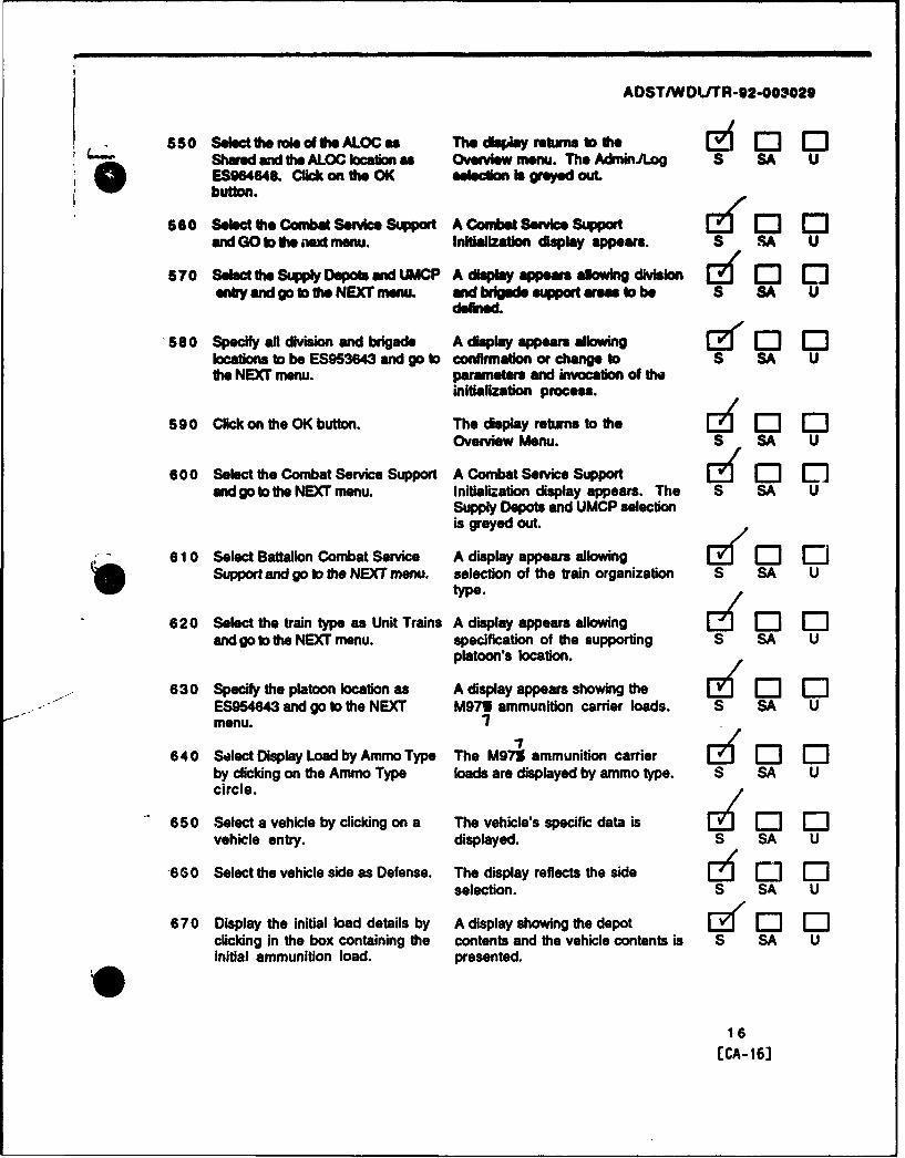
ADST/WDLITR-92-00330
550 Select lhe role of the ALOCen The dksply returns to the 2 1: 0Shared and the ALOC can as Overvimenu. The Admin.og S SA UES964n48. Ccck on the OK selection is grayed out.button.
660 Select lhe Combat Service Support A Combat Service Support [ • Dand GO to, the st menu. Initialization display appears. S, SA U
570 Selact the Supply Deo"s and UMCP A display appears islowing division Clf 1:1entry and go to the NEXT menu. and brigade support areas to be S SA U
deflned.
580 Specify all division and brigade A display appears allowinglocations to be ES953643 and go to confirmation or change to S SA Utie NEXT menu. parameters and invocation of the
initialization process.
590 Click on the OK button. The display returns to the 14 0 0Overview Menu. S SA U
600 Select the Combat Service Support A Combat Service Support Ef 0 Dand go to the NEXT menu. Initialization display appears. The S SA U
Supply Depots and UMCP selectionis grayed out.
610 Select Battalion Combat Service A display appears allowingSupport and go to the NEXT menu. selection of the train organization S SA U
type.
620 Select the train type as Unit Trains A display appears allowingand go to the NEXT menu. specification of the supporting S SA U
platoon's location.
630 Specify the platoon location as A display appears showing the E r-m oES954643 and go to the NEXT M971 ammunition carrier loads. S SA Umenu. ?
640 Select Display Load by Ammo Type The M979 ammunition carrierby clicking on the Ammo Type loads are displayed by ammo type. S SA Ucircle.
650 Select a vehicle by clicking on a The vehicle's specific data is 12 1 r-"1vehicle entry. displayed. S SA U
"630 Select the vehicle side as Defense. The display reflects the side [:] E -'-iselection. S SA U
670 Display the initial load details by A display showing the depot Ed 1 121clicking in the box containing the contents and the vehicle contents is S SA Uinitial ammunition load. presented.
16[CA-161

ADST/WDLITR-02-003029
660 Unload the ammunition carrier by The selected ammunition is (• 0 1:clicding on the vehiole's transferred from Uth buck to the S SA Uammunton type. clicking on the depoLleft arow. entering the loadmourn (tw total load on thetruck) and clicking on the Transferbutton.
6oo Repeat ammunition transfers until The armunition truck load display ' 0' -the vehicle Is empty. reflects an empty truck. S SA U
700 Select the Hellfre ammunition The Hellfire ammunition type z [1 ctype from the depot ammunition entry Is highlighted. S SA Uselection list
710 Enter an amount of 4 The specified number of Hellfire [• ( 0Jand click on the Transfer button. missiles is transferred to the S SA U
ammunition carrier.
720 Repeat the transfer steps for the The specified number of each A, "following ammunition types: ammunition type is transferred to S SA U
Stinger Missiles - Load 4 the ammunition carrier.Hydras 70 10 lb. M151- Load 420 mm HEI Rounds - Load 16
730 Click on the Done button. The display returns to the vehicle ZI E Especific data display. S SA U
740 Click on the OK button and go to the The display returns first to the dZ [ OEonext menu. M977 Ammunition Carrier's S SA U
display and then to the PalletAmmunition Carriers display.
750 Verify that 10 pallet ammunition A display appears showing the A E-'carriers are listed and go to the M978 fuel carrier loads. S SA UNEXT menu.
760 Verify that 10 M971 fuel carriers A display appears showing the 0 ID E3are listed and go to the NEXT menu. maintenance teams. S SA U
770 Verify that 10 maintenap!'e teams A display appears allowing [l -"1 [13are listed and go to the NEXT menu. confirmation or change to S SA U
parameters and invocation of theinitialization process.
17[CA-173

AOSTIWDL/TR-92-003029
7 780 Click anthe OK button. The display changes to incude a (J 0Jsmaller display which states that S SA Uthe CSS parameters we beingrecorded. Thi display disappearsafter a short time and the displayreturns to the Overview Menu. Thedisplay on the AdmIniiog consoleshows the pallet carrier status.
5.2.6 Verify the Aircraft Position and Fly to the Refuelina Point - The steps in this subpara, sphconsist of instructions for verifying the positional location of the aircraft at activation and torflying to the refueling waypoint.
ame Ooerator/Svtem Action Exece Status
790 At the RWA System Console (gt- The XY, and UTM coordinates of ekOs1), enter -c (loss than sign) to the aircraft location are displayed. S SA Udisplay the vehicle location at The recorded values areactivation. Record the values approximately equivalent to:displayed. ES95026002 => (50020,5020).X__•___.P ort. UTM 6-digits => E5950600SY _.. _._ _,_ _5.._- - o3.2.1.1.2.10'0 ~ ~ ~ Z--- 2--'L•j&&L--UT_----"-.......
/800 At the RAH-66 Instrument The lubber line is aligned with N 0 " [C
Display, verify that the lubber (North, 0 degrees). S SA Uline (indicates aircraft heading) is *-3.2.1.1.2.1 1aligned with 0 degrees North.
810 At the RAH-66 softpanel, enter a The Situational Display shows a 1 11"" Elwaypoint (the refueling location) indicating the waypoint position S SA Uat ES956655, and select it for relative to the aircraft's currentnavigation, location and heading (represented
by the center crosshairs). It alsoidentifies the aircraft's currentposition (grid coordinatesES950600), the bearing to thewaypoint (approx. 7 deg.) and therange to the waypoint (approx.5510 m.).
18[CA- 18]

ADST/WDL/TR-92-003029
820 Take off and fly a odngf-i7 The visual displays show a river 121 0 20_. . (fNM -, a .t-w -l-_, at area similar to that shown below. S SA U
200 - 250 feat and an airspeed of The waypoint is situated along the80 - 90 knots. Fly until you river NNE of the "D'.reach the waypoint area (gridcoordinates ES956655). and comato a hover at an allitude of 100 erfeet Waypoint
5.2.7 TOC Transmission of a Dioital Message to the RAH-66 Reauesting Status - The steps in thissubparagraph consist of instructions for transmission and receipt of a digital message requestingstatus.
SOperatorlSvstem Action Egegd .RBeult 5atuA
830 At the TOC DMCC, select the Report The Report (RPRT) Menu is E : :(RPRT) option from tha System displayed identifying the types of S SA UMain Menu (SYS MAIN) by clicking messages which may be senton the bezel switch. (SPOT, MTO, SHOT, SPLASH, FREE
TXT. REOT, and MOVCMD).
840 Select the Request (REOT) message A Request message display appears D Doption by clicking on the bezel showing the entries which may be S SA Uswitch. made in a Request message.
850 Select the Address (ADRS) of the The RAH-66 address is highlighted.RAH-66 by clicking on the bezel S SA Uswitch until the ertry ishighlighted.
860 Select the Type of request being The request type STATUS ismade as STATUS by clicking on the highlighted. S SA Ubezel switch until the entry ishighlighted.
870 Send the Request message by The button is momentarily [I El E-clicking on the Send Routine (SND highlighted. S SA UROUT) button. 93.2.1.2.2.2.1 (TOC, 1 player)
•3.2.1.2.2.2.3 (TOC. send).3.2.1.2.2.3.6 (pref-RWA).3.2.1.2.2.3.6.1 (RWA)o3.2.1.2.2.3.6.2 (pref)
19[CA- 191

ADST/WDL/TR-92-003029
8 880 Retur•n h, Messae Queoue The display returns to the , Vssage E d 0 oDisplay (Acces Mode) by clicking Queue Display. which shows an S SA Uan the CLEAR mid RETURN butlon, empty queue.mid then the MSGS button. *3.2.1.2.2.3.6.3 (Access Mode)
690 ClIck on the SYS MAIN button. The display returns to the System C2 ] c 0Main Menu (SYS MAIN). S SA U
900 At the RAHl-G DMCC. verify the The inooming message Ed i 0 0diplao of an mkcnng message disappears. S SA U4eew Wec -3.2.1.2.2.1.6.4 (preo)
Mesg of tM REQUEST'received from TOC
and dismiss the see by clicking onthe Dismiss button.4,,
910 Select the Message (MSGS) option The Message (MSG) Ms-u is C] - -from the System Main Menu (SYS displayed identifying the messages S SA UMAIN) by clicking on the bezel presently in the message queue.switch. The queue shows I routine Requesto0 ltRuMessage from the TOC. "
20 Seaet the Request message The message entry is highlighted. C] 1J 3received from the TOC by clicking S SA Uon the PREV/NEXT bezel switchesuntil the entry is highlighted.
930 Retrieve and display the Request The selected message is displayed C] 0 E]message by clicking on the READ and the message is acknowledged at S SA Ubutton. tie TOC.
.3.2.1.2.2.3.1.2 (ack)o3.2.1.2.2.3.4.3
940 Verify the message contents: The message content is as specified. CI []REQUEST REPORT ROUTINE S SA USENDER TOCSENT TO RAH-66FWD BYMSG SENT (date/time)XMIT LCNXMIT ALT 0 FEET
REPORT DESIRED STATUS
where date/time is of the format26 1745 JUNE 95
20
ECA-20]

ADST/WDLTR-92-003029
9 50 Return bo the Message Queue The display returns to the Message &Z'0 C:Display (Access Mode) by clicking Oueue Display. The queue shows 1 S SA Ua th Read button. routine Request Message from th
o3.2.1.2.2.3.4.3.a (Access &Retrieve Mode)
9 0 Click an he, SYS MAIN button. The display returns to the System [ ( rjMain Menu (SYS MAIN). S SA U
970 At the TOC DMCC, ve fythe The message , e imIedgmet [ - 0display Of a M4esag disappears. s SA UAcknowledgment -3.2.1.2.2.2.3 (TOC. ack)
M3.2.1.2.2.3.4.1 (auto ack)M0180a0eAckn0*edgedbRAH-66 @3.2.1.2.2.3.4.2 (ack prof)
Dismiss Iand dismiss the iee by clicking onthe Dismiss button. 'sel
980 At the RAH-66 DMCC, select the The Message (MSG) Menu is [ 'CEIMessage (MSGS) option from the displayed identifying the messages S SA USystem Main Menu (SYS MAIN) by presently in the message queue.clicking on the bezel switch. The queue shows 1 routine Request
Message from the TOC990 Selo- .the Request Message The message entry is highlighted. L/ E]
received from the TOC y clicking S SA U
on the PREV/NEXT bezel switchesuntil the entry is highlighted.
1000 Retrieve and display the Request The selected message is displayed. 1 "3message by clicking on the READ S SA Ubutton.
1010 Click on the SYS MAIN button. The display returns to the System ZCEMain Menu (SYS MAIN). S SA U
1020 At the TOC DMCC, verify that a The TOC display remains the same. E " ED EDsecond acknowledgment message is -3.2.1.2.2.3.4 S SA Unot senL
21ECA-21]

ADST/WDL/TR-92-003029
5.2.8 :AM-Se Transmission of a Digital Message to the TOC Providina Status - The steps i thissubparagraph consist of instructions for transmission and receipt of a digital message providingstatus.
Q 3orakltorstem Action EIG ResutuBM
jCheck Onel-1030 At the RAH.66. record: The recorded information is E.d --
Fuel Load: .Ibs. available from the Situational. S SA UWeapons Loed Instructional and Caution Displays.
Hellfires:Stingers: ____,__ &_ t JHydras:
20 mm HEI: ,,.I(0'." , "/" rI"-Failed Equipment ~ . ~
1040 At the RAH-66 DMCC, select the The Report (RPRT) Menu is I 0' -Report (RPRT) option from the displayed identifying the types of S SA USystem Main Menu (SYS MAIN) by messages which may be sentclicking on the bezel switch.
1050 Select the Free Text (FREE TXT) A Free Text message display ED C3message option by clicking on the appears showing the entries which S SA Ubezel switch. may be made in a Free Text
* ~message./
1060 Select the Address (ADRS) of the The TOC address is highlighted. 1 EDTOC by clicking on the bezel switch S SA Uuntil the entry is highlighted.
1070 Enter the following text in the free The text is displayed as entered.text space, using the information S SA Urecorded from the RAH-66:
Fuel Load: (Fuel Load) lbs.Weapons Load: (Weapons Load)Failed Equipment: (FailedEquipment)
Request Additional Fuel
1080 Send the Free Text message by The button is momentarily HEj E3 r-mclicking cn the Send Routine (SND highlighted. S SA UROUT) button. .3.2.1.1.2.3 (wpns status)
o3.2.1.1.2.7 (fuel status)
1090 Verify the accessibility of the The REUSE button is available from ID E-3 r1Forward function by clicking on the Message (MSG) Menu display. S SA Uthe CLEAR and RETURN button, *3.2.1.2.2.3.6.3 (forward)then the MSGS button.
22[CA-22]

ADST/WDLUTR-92-003029
S10 Clk an the SYS M N b on. The display return to the System 00 r
110Main Menu (SYS MAIN). S SA U
1110 At the TOC OMCC. vefy the The inmoming message lee Ii21r-diond o an IncomkV ng essa dmppeamL S SA U
Z & e3.2.1.2.2.1.2 (notify)*3.2.1.2.2.1.4 (display mag
,,mp, d typ FREE TEi Icon)rwold firm RAH-66 I .3.2.1.2.2.1.6.4 (freet)
and dismiss the 4ee by clicking onthe Dismiss button. l,,i,
1120 Select the Message (MSGS) cption The Message (MSG) Menu is [z o ofrom the System Main Menu (SYS displayed identifying the messages S SA UMAIN) by clicking on the bezel presently in the message queue.switch. The queue shows 1 routine Free
Text Message from the RAH-66.
1130 Select the Free Text message The message entry is highlighted. E "I oreceived from the RAH-66 by 93.2.1.2.2.1.2 (mug In S SA Uclicking on the PREV/NEXT bezel queue)switches until the entry is -3.2.1.2.2.1.6.1 msg queued TOC
1140 highlighied.
1140 Retrieve and display the Free Text The selected message is displayed. - -message by clicking on the READ -3.2.1.2.2.2.3 (TOC, view) S SA Ubutton.
1150 Verify the message contents: The message content is as specified.FREE TEXT MESSAGE ROUTINE S SA USENDER RAH-66SENT TO TOCFWD BYMSG SENT (date/ltime)XMIT LCNXMIT ALT 0 FEET
Fuel Load: (Fuel Load) lbs.Weapons Load: (Weapons Load)
Failed Equipment: (FailedEquipment)
Request Additional Fuel
where date/time is of the format26 1745 JUNE 95and the remaining free textInformation is that which wasentered.
23ECA-231

ADST/WDLUTR-92-003029
116 0 Click on th SYS MAIN buftL The d. a.y re..ms to #h System ( ' r-Main Menu (SYS MAIN). S S
1170 At the RAH6 DMUCC, verify Ow Th, !e-g 0-Idisplay of a Message S SA U
Mwesage Aclmowledged by TOC
and dismiss the Jee* by clicking onthe Dismiss button. ,,,i
5.2.9 Disoatch Refuelino Vehicle . The steps in this subparagraph consist of instructions fordispatching a refueling vehicle.
20 OoeratorlSystem Action Exgnecqd Result SAmuaeck Oneh
1180 At the AdminJLog console, select The Fuel Truck Status Menu is L h OD lJthe display which allows the displayed. S SA Ucontrol of the refueling vehicles(M977s) by selecting menu
*) displays until the Fuel TruckStatus Menu is displayed. /
1190 Select any available refueling The Vehicle entry is highlighted. ( Jf"'vehicle (a vehicle is available if ,3.2.1.1.2.6 (MCC selectable S SA Uit's entry background is white (not refueling vehicles)patterned)), by clicking on thevehicle entry. /
1200 Click on the Dispatch button. A Dispatch Fuel Truck Menu is r-" Idisplayed. S SA U
1210 Enter ES956655 as the The computed Estimated Time of IE ' Ml [lcoordinates and click on the Arrival is displayed in the format S SA UComprjte ETA button. Record the 25 1344 OctETA (o0 .1 minutes. day time month
1220 Click on the Dispatch button to The display returns to the Fuel [Edispatch the refueling vehicle. Truck Status Menu which shows S SA U
the selected truck "enroute to"ES95606550 and its ETA. /
1230 Verify that when the fuel truck The notification message E r ED Eiarrives a message stating that the disappears. S SA Utruck is ready is displayed. Clickon the Roger button.
24ECA-241

ADST/WOL/TR-92-003029
* 5.2.10 TOC Transmission of a Digital Messae Reoly to the RAH-66 Stating Refueling Vehicle Statb&- The steps In this subparagraph consist of instructions for transmission and receipt of a digitalmesage reply which states the status of the refueling vehicle.
2M OermatorSstemn Action EX2WRsutsa
1240 At the TOC DMCC, select the The Message (MSG) Menu is, E ,._,h1 ,Message (MSGS) option from the disp;ayed identifying the messages S SA USystem Main Menu (SYS MAIN) by presently in the message queue.clicking on the bezel switch. The queue shows 1 routine Free
Text Message from the RAH-66.
1250 Select the Free Text message The message entry is highlighted. E2"1E Elreceived from the RAH-66 by S SA Uclicking on the PREVINEXT bezelswitches.
1260 Reply to the Free Text message The Report (RPRT) menu is E]' i--by clicking on the REPLY button. displayed identifying the types of S SA U
messages which may be sent asreplies.-3.2.1.2.2.3.1.2 (reply) /
1270 Select the Free Text (FREE TXT) A Free Text message display E [imessage option by clicking on the appears showing the entries which S SA Ubezel switch. may be made in a Free Text
message. The RAH-66 address ishighlighted.
1280 Enter the following in the free text The text is displayed as entered. cz El C--space, using the recorced ETA S SA Uvalue:
Refueling vehicle will rendezvousat ES956655 in (ETA) minutes.
1290 Send the Free Text message by The button is momentarily El lclicking on the Send Urgent (SND highlighted. S SA UURG) button. .3.2.1.2.2.3.2.a (freet to RWA)
1300 Return to the Message Queue The display returns to the Message El --
Display (Access Mode) by clicking Queue Display. S SA Uon the CLEAR and RETURN button. y3.2.1.2.2.3.2.b (Access Mode)
and then the MSGS button. .3.2.1.2.2.3.2.3 (Access Mode)
1310 Click on the SYS MAIN button. The display returns to the System [ ElMain Menu (SYS MAIN). S SA .
I
25[CA-25]

ADST/WDL/TR-92-003029
1320 At the rlAH-66 DMCC, vetify the, The incoming mesedgen Ed E3disply ol an incoming message disappears. S SA Ui~f box
Mensap of type FREE TEXTr*Wvod from TOC
and dismiss the mieesby clicking onthe Dismiss button. *P
1330 Select the Message (MSGS) option The Message (MSG) Menu Is [ [rfrom the System Main Menu (SYS displayed identifying the messages S SA UMAIN) by clicking on the bezel presently in the message queue.switch. The queue shows 2 messages, 1
urgent Free Text Message from theTOC, 1 routine Request Messagefrom the TOC.
1340 Select the urgent Free Text The message entry is highlighted. iu "1i Ei]message received from the TOC by S SA Uclicking on the PREV/NEXT bezelswitches until the entry ishighlighted.
1350 Retrieve and display the Free Text The selected message is displayed. E" JE Jmessage by clicking on the READ S SA Ubutton.
1360 Verify the message contents: The message content is as specified. J --FREE TEXT MESSAGE URGENT S SA USENDER TOCSENT TO RAH-66FWD BYMSG SENT (date/time)XMIT LCNXMIT ALT 0 FEET
Refueling vehicle will rendezvousat ES956655 in (ETA) minutes.
where date/time is of the format26 1745 JUNE 95 and ET/ - therecorded ETA.
1370 Click on the SYS MAIN button. The display returns to the System E <'EMain Menu (SYS MAIN). S SA U
26ECA-267

ADST/WDL/TR-92-003029
1380 At the TOC DMCC. venfy the The message acnOwledge [J C1 "display of a Message disappears. S SA UAcknowledgmen
Message A•m•edged by RAH-e
dsisDismis
and dismiss the Wow by clicking onthe Dismiss button. 1,&'
1390 At the RAH-66 DMCC, select the The Message (MSG) Menu isMessage (MSGS) option from the displayed identifying the messages S SA USystem Main Menu (SYS MAIN) by presently in the message queue.clicking on the bezel switch. The queue shows 2 messages. 1
urgent Free Text Message from theTOC, 1 routine Request Messagefrom the TOC.
1400 Verify that the queue contains two The queue contains the specified [• 1"Emessages: messages. S SA UA routine REQUEST message fromtheTOCAn urgent FREE TEXT message from
*•WTOC
1410 Select the routine Request message The message entry is highlighted. Iý 0received from the TOC by clicking S SA Uon the PREV/NEXT bezel switchesuntil the entry is highlighted.
1420 Delete the message by clicking on The message is deleted from the ii E' ]'•the DELETE button. queue. The queue shows 1 urgent S SA U
Free Text message from the TOC.93.2.1.2.2.3.1.2 (delete)
1430 Select the urgent Free Text The message entry is highlighted. j• j Jmessage by clicking on the S SA UPREVWNEXT bezel switches untilthe entry is highlighted.
1440 Delete the message by clicking on The message is -eleted from the M] E] "-the DELETE button. queue; the queue is empty. S SA U
-3.2.1.2.2.3.5.1 (del msg)
1450 Click on the SYS MAIN button. The display returns to the System Ed E] 'Main Menu (SYS MAIN). S SA U
27ECA-27]

ADST/WDLITR-92-003029
5.2.11 Land Aircraft and Refuel - The steps in this subparagraph consist of instructions for landing
0o the aircraft and refueling.
2 QerattSvxtom Action E d dsauft"C~eck Cone-
1460 Wh3n the refueling vehicle The refueling vehicle Is visible and 1J6 JDL(M97%) arrives and stops, land stationary. S SA Uthe RAH-66 within a 100 meterradius of the vehicle. /
1470 Record the fuel gauge level at the The fuel level is available from the [ -i E'time of landing LJLbs. and the Instructional Display. S SA Ucurrent time '2-15
1480 Toggle the Master Weapons Arming The weapons arming switches are [21 1'"switch from Armed to Safe. on safe. S SA U
1490 Refuel the RAH-66 by monitoring The fuel gauge value rises until it Ii 1[ 1"1the fuel gauge, recording the time shows a full load of fuel, 1690 lbs. S SA Uwhen refueling is complete (i.e. ,3.2.1.1.2.5 (fuel wt.)the tank is full 1690 lbs.). ,3.2.1.1.2.6
at 2,t 7d (1q zJO,,.7,te7
1500 Verify the time of transfer against The time of transfer corresponds to -- i 0 ---ithe amount transferred. Fuel is the amount transferred. S SA Utransferred at 3gals/min. Each .3.2.1.1.2.8 (xfer time)gallon weighs 6.5 lbs. Thus 196lbs. are transferred per minute.Record the transfer rate:
lbs/min.
1510 Toggle the Master Weapons Arming The weapons aming switches are [0' ED EDSwitch from Safe to Armed. on Armed. S SA U
1520 At the AdminAog console, note the The messages are displayed until [g "I IDdisplay of the following messages the Roger button has been selected. S SA Uand dismiss each message byclicking on the Roger button.
Fuel Truck N is servicing atES95606550.
Fuel Truck N is no longerservicing at ES95606550.
,0
28[CA-28]

ADST/WDL/TR-92-003029
"5.2.12 TOC Transmission of a Digital Messaoe to the FSE Ordering FSE Movement - The steps in thissubparagraph consist of instructions for transmission and receipt of a digital message which ordersthe FSE to move to a new location.
SOperatorlSystem Action Ex S~tadus RIaflU
1530 AttheTOCDMCC,selecttheReport The Report (RPRT) Menu is eck]One.(RPRT) option from the System displayed identifying the types of S SA UMain Menu (SYS MAIN) by clicking messages which may be senton the bezel switch.
1540 Select the Move Command A Move Command message display iZI" 0 0(MOVCMD) message option by appears showing the entries which S SA Uclicking on the bezel switch. may be made in a Move CommandMessage.
1550 Select the Address (ADRS) of the The FSE address is highlighted. !E/ 0 oFSE by clicking on the bezel switch S SA Uuntil the entry is highlighted.
1560 Select the Task as Move To (MOV The MOV TO task entry is EZ/ 0 DTO) by clicking on the bezel switch highlighted. S SA Uuntil the entry is highlighted.
1570 Select When as Immediately The IMMED entry is highlighted.(IMMED) by clicking on the bezel S SA Uswitch until the entry ishighlighted.
1580 Select the Location (LCTN) as The ES960645 location entry isES960646 by clicking on the bezel highlighted. S SA Uswitch until the entry ishighlighted.
1590 Select Who as YOU by clicking on The YOU entry is highlighted. iz "'-'Ithe bezel switch until the entry is S SA Uhighlighted.
1600 Send the Move Command message The button is momentarily ] EDby clicking on the Send Routine highlighted. S SA U(SND ROUT) button. .3.2.1.2.2.3.6 (pref-MCC)
.3.2.1.2.2.3.6.1 (MCC)
1 61 0 Delete the message by clicking on The disp'ay returns to the Report E 0 1the CLEAR and RETURN button. (RPRT) menu. S SA U
*3.2.1.2.2.3.6.3 (delete)
1620 Click on the SYS MAIN button. Ths display returns to the System E i'-Main Menu (SYS MAIN). S SA U
29[CA-29J

ADST/WDLITR-92-003029
01630 AttoFSE DMCC. vriy The roigmessage? JW 0 C[the display of an kwoming message disappears. S SA U
is"m 6., .3.2.1.2.2.1.3 (notify)S*3.2.1.2.2.1.5 (display msg
amqm of.& MOVE Icon)reved from TOC
and dismiss the 4een by clicking onthe Dismiss button. hIA
1640 Slect the Message (MSGS) option The Message (MSG) Menu is 0• F-Efrom the System Main Menu (SYS displayed identifying the messages S SA UMAIN) by clicking on the bezel presently in the message queue.switch. The queue shows I routine Move
Command Message from the TOC.
1650 Select the Move Command message The message entry is highlighted. EdYE] [received from the TOC by clicking .3.2.1.2.2.1.3 (meg In S SA Uon the PREy/NEXT bezel switches queue)until the entry is highlighted. .3.2.1.2.2.1.6.1 (msg
queued fse)
"1660 Retrieve and display the Move The selected message is displayed. E 0 ElCommand message by clicking on -3.2.1.2.2.2.3 (fse view) S SA Uthe READ button.
1670 Verify the message contents: The message content is as specified. [i El 0-MOVCMD REPORT ROUTINE S SA USENDER TOCSENT TO FSEFWD BYMSG SENT (date/time)XMIT LCNXMIT ALT 0 FEET
TASK MOV TOWHO YOUWHEN IMMEDWHERE ES960645
where date/time is of the format26 1745 JUNE 95
1680 Click on the SYS MAIN button. The display returns to the System 5 Er--Main Menu (SYS MAIN). S SA U
30[CA-30]

ADST/WDL/TR-92-003029
S 1690 At the TOC DMCC, verf the The message ldgment 0ismplay d a Message disappears. S SA U
Mesage AdnmWdge by FSE
I D[smiand dismiss the eq by clicig onthe Dismiss button.' ,y
5.2.13 FSE Forward of the Movement Command Digital Message to the RAH-66. The steps in this
subparagraph consist of instructions for forwarding the FSE movement command to the RAH-66.
Sg Ooerator/Svstem Action Status
1700 At the FSE DMCC, select the The Message (MSG) Menu isE 0 -hMessage (MSGS) option from the displayed identifying the messages S SA USystem Main Menu (SYS MAIN) by presently in the message queue.clicking on the bezel switch. The queue shows 1 routine Move
Command Message from the TOC.
1710 Select the Move Command message The message entry is highlighted. EZf 0 0W received from the TOC by clicking S SA U
on the PREVINEXT bezel switchesuntil the entry Is highlighted.
1720 Forward the message by clicking on A send message display appears 0 0 'the REUSE button. allowing an address to be specified. S SA U
93.2.1.2.2.2.3 (FSE forward)*3.2.1.2.2.3.3 (pref to rwa)*3.2.1.2.2.3.3.1 (forward - rwa); 3.2.1.2.2.3.1.2 (forward)See Appendix A, Note 3
1730 Select the Address (ADRS) of the The RAH-66 address is highlighted. [6 0 0RAH-66 by clicking on the bezel S SA Uswitch until the entry ishighlighted.
1740 Send the Move Command message The button is momentarily 0 0by clicking on the Send (SEND) highlighted. S SA Ubutton.
31ECA-31]

ADSTIWDLrTR-92-003029
O17S0 Return to the Message Queue The display returns to the Message d E] C3Display (Access Mode) by clicking Queue Display. The queue shows I S SA Uon the CLEAR and RETURN button, mruine Move Command Messageand then the MSGS button, from the TOC.
93.2.1.2.2.3.3.3 (Access Mode)93.2.1.2.2.3.3.4 (Access Mode)
1760 At the RAH-66 DMCC. verify the The incoming message loe, 61. i r Idisplay of an incoming message disappears. S SA U
Mmage of type MOVEreceived from TOC
and dismiss the 4 by clicking onthe Dismiss button.'
1770 Select the Message (MSGS) option The Message (MSG) Menu is [• 0 1"-from the System Main Menu (SYS displayed identifying the messages S SA UMAIN) by clicking on the bezel presently in the message queue.switch. The queue shows 1 routine Move
Command Message from the TOC. /1780 Select the Move Command message The message entry is highlighted. [i Q ]
received from the TOC by clicking S SA Uon the PREV/NEXT bezel switchesuntil the entry is highlighted.
1790 Retrieve and display the Move The selected message is displayed. IJ ECommand message by clicking on S SA Uthe READ button.
1800 Verify the message contents: The message content is as specified. C i E"- -1'MOVCMD REPORT ROUTINE S SA USENDER TOCSENT TO RAH-66FWD BY FSEMSG SENT (date/time)XMIT LCNXMIT ALT 0 FEET
TASK MOV TOWHO YOUWHEN IMMEDWHERE ES960645
where date/time is of the format26 1745 JUNE 95
32[CA-32]

ADST/WOL/TRr92-003029
1 6s10 Click on the SYS MAIN button. The • d•play returs to the System ZA 0Main Menu (SYS MAIN). S SA U
8l 20 At the FSE DMCC, verify the The message acnl Ewa In !display afa Message disappear. S SA UAmcmowledgment .3.2.1.2.2.2.3 (tie ack)
Message Admukedged by RAH4G
and dismiss the isn-fy clicking onthe Dismissbutn W
1830 Select the Move Command message The message entry is highlighted. 1"3received from the TOC by clicking S SA Uon the PREV/NEXT bezel switchesuntil the entry is highlighted.
1840 Delete the message by clicking on The message is deleted from the E] EDthe DELETE button. queue; the queue is empty. S SA U
•3.2.1.2.2.2.3 (fse delete)
1850 Click on the SYS MAIN button. The display returns to the System [3. •J EDMain Menu (SYS MAIN). ,., SA U
5.2.14 FSE Transmission of a Movement Command Diaital Message to the RAH-66- The steps in thissubparagraph consist of instructions for the transmission and receipt of a movement command forthe RAH-66.
Btou Ooerator/System Action n i R.ul Stlatus
1860 At the FSE DMCC. select the Report The Report (RPRT) Menu is [ :J(RPRT) option from the System displayed identifying the types of S SA UMain Menu (SYS MAIN) by clicking messages which may be senton the bezel switch.
1870 Select the Move Command A Move Command Message display(MOVCMD) message option by appears showing the entries whic.h S SA Uclicking on the bezel switch. may be made in a Move Command
message./
1880 Select the Address (ADRS) of the The RAH-66 address is highlighted. J'--'J E"3RAH-66 by clicking on the bezel S SA Uswitch until the entry ishighlighted.
1890 Select the Task as Hold At (HOLD The HOLD AT task entry is 1-- 0AT) by clicking on the bezel switch highlighted. S SA Uuntil the entry is highlighted.
33
[CA-33J

ADST/WDLITR-92-003029
"- 1900 Select When as Immediately The IMMED entry Is highlighted. E[1 0) E-IMMED) by clicking on the bezel S SA U
switch until the entry ishighlighted.
101O Selec the Location (LCTN) as The ES979700 location entry Is Q 1 0ES979700 by clicking on the bezel highlighted. S SA Uswitch until the entry Ishighlighted.
1920 Select Who as YOU by clicking on The YOU entry is highlighted. I] C) Cthe bezel switch until the entry Is S SA Uhighlighted.
1930 Send the Move Command message The button is momentarily 1--1 0"by clicking on the Send Urgent highlighted. S SA U(SND URG) button. -3.2.1.2.2.2.1 (fsa, pref, 1
player) See Appendix A,Note 1*3.2.1.2.2.2.3 (fse. send)
194 0 Click on the CLEAR and RETURN The display returns to the Report ) 12button. (RPRT) Menu. S SA U
1950 Click on the SYS MAIN button. The display returns to the System 1: EMai' Menu (SYS MAIN). S SA U
1960 A th -h .. ",. verfythe TheincomingmessageiseeI, i t [" C)display of an incoming message disappears. S SA Ule" bW'c
Me=. ef tp MOVErecived frm FSE
and dismiss the icon by clicking onthe Dismiss button.
1970 Select the uuge.*Message (MSGS' The Message (MSG) Menu isoption from the System Main Menu displayed identifying the messages S SA U(SYS MAIN) by clicking on the presently in the message queue.bezel switch. The queue shows 2 messages. 1
urgent Move Command Messagefrom the FSE, 1 routine MoveCommand Message from the TOC.
1 980 Select the Move Command message The message entry is highlighted. Iz 0' :received from the FSE by clicking S SA Uon the PREV/NEXT bezel switchesuntil the entry is highlighted.
34
[CA-34J

ADST/WDLTR-92-003029
, "d 1990 Retrieve and display the Move The selected message Is displayed. 1Command message by clicking on S SA Uthe READ button.
2000 Verity the message contents: The .mesage content is as specified. -1MOVCMD REPORT URGENT S SA USENDER FSESENT TO RAH-6FWDBYMSG SENT (date/time)XMIT LCNXMIT ALT 0 FEET
TASK HOLD ATWHO YOUWHEN IMMEDWHERE ES979700
where date/time is of the format26 1745 JUNE 95
2010 Record the location from the Move The new location is avaiiable from [E Ei MCommand -S-42t17oe the Move Command WHERE entry. S SA U
2020 Delete the message by clicking on The display returns to the Message IZ 1 E -- ""the DELETE button. Queue display. The queue shows I S SA U
routine Move Command Messagefrom the TOC.
43.2.1.2.2.3.4.3.a (delete)o3.2.1.2.2.3.5.2See Appendix A, Note 3
2 0 3 0 Click on the SYS MAIN button. The display returns to the Sytenm E] 12Main Menu (SYS MAIN). S SA U
2040 At the FSE DMCC, verify the The message acýk4.ovedgment f EDdisplay of a Message disappears. S SA UAcknowledgment
Message Acknowledged by RAH-66
and dismiss the icon by clicking onthe Dismiss button. Y0
35[CA-35)

ADSTJWDLITR-92-003029
5.2.15 &Y the RAH-W6 Aircraft towards th T&gArea - The stepe in this subparagraph consistaof instructions for flying ft RAH-66 aircraft toward the target area.
21110 Operat/stemn Action
2050 At the RAH-66 softpanel, enter the The Situational Display shows a 2 [~Er O bgrid coordinates from the Move indicating the waypoint position S SA UCommand and select this waypoint relative to the aircraft's current L4j&;.as the navigation poinL location and heading (represented *t.uvj..
by the center crosshairs). It also ,identifies the bearing and range tothe waypoinL
2060 Take off again, flying at an The aircraft flies to the newaltitude of 200 - 250 feet and an location and hovers. S SA Uairspeed of 80 - 90 knots towardthe target area. At approximately4500 - 4000 meters from thetarget area, bring the aircraft to ahover at approximately 1200 -1500 ft.
5.2.16 FSE Transmission of a Digital Message to the RAH-66 and TOC Stating FSE Firing Status-The steps in this subparagraph consist of instructions for the transmission and receipt of a firingstatus message to the RAH-66 and the TOC.
SparatorlSystem Action Exg2CW Reg& Stalus
2070 At the FSE DMCC, select the Report The Report (RPRT) Menu is ne-(RPRT) option from the System displayed identifying the types of S SA UMain Menu (SYS MAIN) by clicking messages which may be senton the bezel switch.
2080 Select the Free Text (FREE TXT) A Free Text message display 1Z i EDmessage option by clicking on the appears showing the entries which S SA Ubezel switch. may be made in the Free Text
message.
2090 Select the Address (ADRS) of the The RAHTOC group address isRAH-66 and TOC group (RAHTOC) highlighted. S SA Uby clicking on the bezel switchuntil the entry is highlighted.
36ECA-36J

ADST/WDL/TR-92-003029
2100 Enter the following In the free text The text is displayed as entered. E "- 0 "-m: S SA U
Firing on Target Ineffective,Request RAH-66 SupporL
2110 Send the Free Text message by The button Is momentarily 0 0clicking on the Send Urgent (SND highlighted. S SA UURG) button. -3.2.1.2.2.2.2 (FSE free text. 1
player)o3.2.1.2.2.3.6 (freet - rwa,Mncc)e3.2.1.2.2.3.6.2 (freet)
2120 Click on the CLEAR and RETURN The display returns to the Report E l E lbutton. (RPRT) Menu. S , SA U
2130 Click on the SYS MAIN button. The display returns to the System E E lMain Menu (SYS MAIN). S SA U
2140 At the RAH-66 DMCC, verity the The incoming message4ee•,E( 0i 0display of an incoming message disappears. S SA U
Musege of type FREE TEXTruived from FSE
and dismiss the icap by clicking onthe Dismiss button. Vow
2150 Select the Message (MSGS) option The Message (MSG) Menu is I E Elfrom the System Main Menu (SYS displayed identifying the messages S SA UMAIN) by clicking on the bezel presently in the message queue.switch. The queue shows 2 messages, 1
urgent Free Text Message from theFSE, 1 routine Move CommandMessage from the TOC.
21 60 Select the Free Text message The message entry is highlighted. [;T El EDreceived from the FSE by clicking S SA Uon the PREWNEXT bezel switchesuntil the entry is highlighted.
2170 Retrieve and display the Free Text The selected message is displayed. [• EDmessage by clicking on the READ S SA Ubutton.
I37
ECA-37]

ADST/WDUTR.92-003029
2180 Verify the message contents: The message content is as specified. 13 E]FREETEX MESSAE URGENT S SA USENDER FSESENTTO RAHTOCFWDBYMSG SENT (date/time)XMIT LCNXMIT ALT 0 FEET
Firing on Target Ineffective,Request RAH-66 Support.
where date/time is of the format26 1745 JUNE 95
2190 Click on the SYS MAIN button. The display returns to the System r El ElMain Menu (SYS MAIN). S SA U
2200 At the FSE DMCC, verify the The message acknowledgment 1 E 13 U-ldisplay of a Message disappears. S SA UAcknowledgment
Message Acknowledged by RAH-66
and dismiss the iewkby clicking onthe Dismiss button. ' "
2210 At the TOC DMCC, verify the The incoming message 4ee L% l Eldisplay of an incoming message disappears. S SA Ue4nw b"~
Mensage of type FREE TEXTrmceived from FSE
and dismiss the .,Gonby clicking onthe Dismiss button. " /
2220 Select the Message (MSGS) option The Message (MSG) Menu is [I/ El Elfrom the System Main Menu (SYS displayed identifying the messages S SA UMAIN) by clicking on the bezel presently in the message queue.switch. The queue shows 2 messages, 1
urgent Free Text Message from theFSE, 1 routine Free Text Messagefrom the RAh-66.
S38
lCA-38J

ADST/WDL/TR-92-003029
2230 Select the urgent Free Text The message entry is highlighted. 2Jmessage received from the FSE by S SA Uclicking on the PREV1NEXT bezelswitches until the entry Ishighlighted. /
2240 Retrieve and display the Free Text The selected message is displayed. E -" ['-message by clicking on the READ S SA Ubutton.
2250 Verify the message contents: The message contant is as specified. E --FREETEXTMESSAE ULGBET S SA USENDER FSESENT TO RAHTOCFWD BYMSG SENT (date/time)XMIT LCN .A696Q4O-XMIT ALT 0 ft.
Firing on Target Ineffective,Request RAH-66 Support.
where date/time is of *26 1745 JUNE 95
2260 Click on the SYS MAIN button. The display returns to the System 2 Elr0Main Menu (SYS MAIN). S SA U
2270 At the FSE DMCC, verify the The message acknowledgment Z r7 0display of a Message disappears. S SA UAcknowledgment
Message Acknowledged by TOC
IL imis Iand dismiss the jam by clicking onthe Dismiss button. bIox
39ECA-39-

ADST/WDL/TR-92-003029
5.2.17 FSE Transmission of a Digital Messaoe to the RAH-66 Reouestino Fire on Targets- The stepsIn this subparagraph consist of instructions for the transmission and receipt of a firing request tothe RAH-66.
M Otperalt,/Svtemn Action Ej te Resuls
2280 At the FSE DMCC, select the Report The Report (RPRT) Menu is d D EDCh _jn_(RPRT) option from the System displayed identifying the types of S SA UMain Menu (SYS MAIN) by clicking messages which may be sent.on the bezel switch.
2290 Select the Free Text (FREE TXT) A Free Text message display • ID '-message option by clicking on the appears showing the entries which S SA Ubezel switch. may be made in a Free Text
message. /
2300 Select the Address (ADRS) of the The RAH-66 address is highlighted. I [ I" E D"1RAH-66 by clicking on the bezel S SA Uswitch until the entry ishighlighted.
2310 Enter the following in the free text The text is displayed as entered. (I I E I --space: S SA U
Request fire on targets.
2320 Send the Free Text message by The button is momentarily Di F1clicking on the Send Urgent (SND highlighted. S SA UURG) button.
2330 Click on the CLEAR and RETURN The display returns to the Report "' ID 'button. (RPRT) Menu. S// SA U
2340 Click on the SYS MAIN button. The display returns to the System [- :1 - :-Main Menu (SYS MAIN). S SA U
2350 At the RAH-66 DMCC, verify the The incoming message 4ee L,, t [D- Edisplay of an incoming message disappears. S SA U
Mensage of "yp FREE TEXTreceived from FSE
and dismiss the 4conw by clicking onthe Dismiss button. "°I
40ECA-40]

ADST/WDLITR-92-003029
2360 Select the Message (MSGS) option The Message (MSG) Menu is E '- rC0from the System Main Menu (SYS displayed identifying the messages S SA U
MAIN) by clicking on the bezel presently In the message queue.switch. The queue shows 3 messages. 2
urgent Free Text Messages fromthe FSE, 1 routine Move CommandMessage from the TOC.
2370 Select the latest Free Tet nmessage The message entry Is highlighted. [i' 0 r-]received from the FSE by ciicking S SA Uon the PREV/NEXT bezel switchosuntil the entry is highlighted.
2380 Retrieve and display the Free Text The selected message is displayed. id D omessage by clicking on the READ S SA Ubutton. /
2390 Verify the message contents: The message content is as specified. 0J-'C]FREE TEXT MESSAGE URGENT S SA USENDER FSESENT TO RAH-66FWD BYMSG SENT (date/time)XMIT LCNXMIT ALT 0 FEET
Request fire on targets.
where date/time is of the format26 1745 JUNE 95
2400 Click on the SYS MAIN button. The display returns to the System ]-1 0"Main Menu (SYS MAIN). S SA U
2410 At the FSE DMCC, verify the The message acknowledgment • r'[ 0display of a Message disappears. S SA UAcknowledgment
Message Acknowledged by RAH-66
Ii Dismiss Iand dismiss the .feeR by clicking onthe Dismiss button. b,,y
41[CA-41]J

ADSTIWDL/TR-92-003029
5.2.18 RAH-66 Reflv to Reauest for Fire on Ta tets. The steps in this subparagraph consist ofO Instructions for replying to the FSE's request for fire.
s (3peragato,3stem Action E.Wated Resuls
2420 Atth FRAH-6 DMCC, selecthe The Message (MSG) Mer.u is ---1'1O0Message (MSGS) option from the displayed identifying the messages S SA USystem Main Menu (SYS MAIN) by presently in the message queue.clicking on the bezel switch. The queue shows 3 messages, 2
urgent Free Text Messages fromthe FS=-. 1 routine Move CommandMessage from the TOC.
2430 Select the latest Free Text message The message entry is highlighted. [-- 0-received from the FSE by clicking S SA U
on the PREV94EXT bezel switchesuntil the entry is highlighted.
2440 Reply io the Free Text message The Report (RPRT) menu is Ed 1: -by clicking on the Reply button. displayed identifying the types of S SA U
messages which may be sent asreplies.o3.2.1.2.2.3.2.1 (select msgfrom queue and reply)
2 2450 Select the Free Text (FREE TXT) A Free Text message display 0 '-1message option by clicking on the appears showing the entries which S SA Ubezel switch. may be made in a Free Text
message. The FSE address ishighlighted. /
2460 Enter the following in the free text The text is displayed as entered. i:ý c:space: S SA U
Roger/
2470 Send the Free Text message by The button is momentarily -C 1clicking on the Send Routine (SND highlighted. S SA UROUT) button. o3.2.1.2.2.3.2.2 (reply freet) /
2480 Delete the message by clicking on The display returns to the Report [Z 0 -"the CLEAR and RETURN button, (RPRT) Menu, then the Message S SA Uthen the MSGS button and the Queue Display. The queue shows 2DELETE button, messages, 1 urgent Free Text
Message from the FSE, 1 routineMove Command Message from the• 3.2.112.2.3.2.b (delete)93.2.1.2.2.3.2.3 (delete)
42[CA-42]

ADST/WDL/TR-92-003029
24 9 0 Click on the SYS MAIN button. The display returns to the System E• [ E ]Main Menu (SYS MAIN). S 1 SA U
2500 At the FSE DMCC. verify the The incoming message een [ r"" EJ 13 -'display of an incoming message disappears. S SA U4eeWI.;
Me"ae of type FREE TEXTreceived from RAH-66
and dismiss the 4ee, by clicking onthe Dismiss button. Y"
2510 Select the Message (MSGS) option The Message (MSG) Menu isfrom the System Main Menu (SYS displayed identifying the messages S SA UMAIN) by clicking on the bezel presently in the message queue.switch. The queue shows 1 routine Free
Text Message from the RAH-66.
2520 Select the Free Text message The message entry is highlighted. Ii! [• E-received from the RAH-66 by S SA Uclicking on the PREV/NEXT bezelSswitches until the entry ishighlighted.
2530 Retrieve and display the Free Text The selected message is displayed.message by clicking on the READ *3.2.1.2.2.3.1.1 S SA Ubutton.
2540 Verify the message contents: The message content is as specified. Uzi, M -:FREE TEXT MESSAGE ROUTINE S SA USENDER RAH-66SENT TO FSEFWD BYMSG SENT (date/time)XMIT LCNXMIT ALT 0 FEET
Roger
where date/time is of the format26 1745 JUNE 95
2550 Click on the SYS MAIN button. The display rstums to the System [• ['-'DMain Menu (SYS MAIN). S SA U
43[CA-43J

ADST/WDL/TR-92-003029
2560 At the RAH-66 DMCC. verify the Th1 message acknowledgment Ed (Jdisplay d a Message disappears. S SA U
Messae Akdmowledged by FSE
and dismiss the a*;" by clicking onthe Dismiss button. v. P
2570 Select the Message (MSGS) option The Message (MSG) Menu is E '1 r-from the System Main Menu (SYS displayed identifying the messages S SA UMAIN) by clicking on the bezel presently in the message queue.switch. The queue shows 2 messages. 1
urgent Free Text Message from theFSE, 1 routine Move CommandMessage from the TOC.
2580 Select the Move Command message The message entry is highlighted. Sreceived from the TOC by clicking S SA U
on the PREV/NEXT bezel switchuntil the entry is highlighted. /
_2590 Delete the message by clicking on The message is deleted from the 1 0the DELETE button. queue. The queue shows 1 urgent S SA U
Free Text Message from the FSE.-3.2.1.2.2.1.6 (delete)
260 0 Click on the SYS MAIN button. The display returns to the System Cd E'Main Menu (SYS MAIN). S SA U
44[cA-441Jv

ADSTIWDL/TR-92-003029
5.2.19 Fire on the First Taroet with the Stinger - The steps in this subparagraph consist ofInstructions for firing a Stinger missile at the first target.SI Qp rah~rftstsm Action EAO•1 esb u
2q 10 At the Pllot* position, select the The Pilos Weapons Selection Z E., I.,Stinger missile by moving the Indicator is lit green, the CPG's S SA UWeapons Action Switch down. Weapons Selection Indicator is lit
red for pilot control of the Missile(MSL) 2 weapon. ATAS reticlesare displayed.
Out the WindowReticle
SSensor Reticle
Dashed Box (ow4.*.L co.s&,As%+)
°ATAC II - 3.2.1"9ATAC II - 3.2.2.1*ATAC II - 3.2.2.3*ATAC II - 3.2.9•ATAC II - 3.2.12 (pilot)
2620 Verify that the reticle is The reticle is the correct size.approximately equivalent in size to *ATAC II - 3.2.2.2 S SA Uthat displayed on the CPG sensorscreen, occupying - 10% of thehorizontal screen space and -13%of the vertical screen space. /
2630 Deselect the Stinger missile by The Weapons Selection Indicators E] 0moving the Weapons Action Switch are not lit for Missile (MSL) 2. S SA Udown. The OTW reticle disappears and the
sensor reticle converts to
F717ilI
2640 Position the aircraft so that it is The aircraft is 15 - 20 degrees off EJ i15 - 20 degrees off of the heading of the heading for the waypoint. S SA Ufor the waypoinL
45[CA-45]

ADSTIWDLOTR-92-003029
f0 2650 At the CPG position, slect the The CPG. Weapons Selection "' 0-Stinger missile by moving the Indicator is lit green, the Pilotrs S SA U
Weapons Action Switch down. lit red for CPG control of theMissile (MSL) 2 weapon. ATASreticles are displayed.
Out the WindowReticle
Snsor Reticle
D71 Z a shed Box (o,;.~i~ c~~ 1q ;
*ATAC II - 3.2.10.3*ATAC II - 3.2.11.1*ATAC II - 3.2.12 (CPG)
2660 Using the Manual Tracker The movement of the reticle I : 1' [! 3Controller, move the sensor line of cooresponds to the control of the S SA Usight until the target (Attack RWA) manual tracker. An aural seek toneIs within the dashed box of the (buz.. type tone) is heard when thereticle. Pull the weapons trigger weapons trigger is at the firstto the first detent detenL
-ATAC 11 - 3.2.11.2 /
2670 Engage the Auto Tracker by The Auto Tracker is engaged, the OZ E --"pressing the IAT/MAN switch. reticle locks onto the target but the S SA U
target is not within the firingconstraints of the weapon. Thetarget is centered in the reticle.
/
2680 At the pilot position, move the The target is within the lock-on " r-l [•Jaircraft so that it is within 10 cone dimensions of +/- 10 S SA Udegrees of the target heading. degrees.
046
ECA-461

ADST/WDL/TR-92-003029
2690 At the ,-PG position, pull the The sensor reticle converts t [ ' 'wepo Ia trigger to the first detent. S SA U
EY-SISC Box
and the OTW reticle moves to framethe target The OTW reticle has ablack dot in its center.*ATAC II - 3.2.3*ATAC II - 3.2.10.2 /
2700 Deselect the Stinger missile by The Weapons Selection Indicators • [ [Jmoving the Weapons Action Switch are not lit for Missile (MSL) 2. S SA Udown. The Ou'(-The-Window reticle
disappears, the sensor reticle goestoWI /
2710 Disengage the Auto Tracker and The sensor view returns to fixedreturn the sensor view to fixed forward; the word *FORWARD" is S SA Uforward. displayed in the lower right hand
corner of the display. The reticlegoesto
I-I-I
2720 At the pilot position, move the The target comes into view. -J Elaircraft to within visible (out- S SA Uthe-window) range of the target(Attack RWA) and hover atapproximately 1000 - 1200 ft.The visibility range is 3.5 km.
2730 Position the aircraft so that it is The aircraft is 15 - 20 degrees off [f El I•]15 - 20 degrees off of the heading of the heading for the target. S SA Ufor the target.
47ECA-47J

ADST/WDL/TR-92-003029
O 2740 At the CPG position, select the The CP's Weapons Selection Ed "1 0Stinger missile by moving the Indicator Is lit green, the Pilot's S SA UWeapons Action Switch down. lit red for CPG control of the
Misils (MSL) 2 weapon. Thereticles are displayed.
2750 Using the Manual Tracker The movement of the reticle E1 EI' J-"Controller, move the sensor line of cooresponds to the control of the S SA Usight until the target (Attack RWA) manual tracker. An aural seek toneIs within the dashed box of the (buzz type tone) is heard when thereticle. Pull the weapons trigger weapons trigger is at the firstto the first detent. detenL
2760 Engage the Auto Tracker by The Auto Tracker is engaged, the M ''J JM-"pressing the IAT/MAN switch. reticle locks onto the target. The S SA U
target is centerel in the reticie.
2770 At the pilot position, move the Lock-on is achieved and an aural Ii7 I"] I"-aircraft so that it is within 10 lock-on tone is heard. The normal S SA Udegrees of the target heading. At Out-The-Window reticle tracks tothe CPO position, pull the weapons the targei location. The sensortrigger to the first detent. reticle changes from dashed boxes
to
iO Sensor Reticle
Solid Box V .
*ATAC II- 3.2.10.1*ATAC II - 3.2.11.3
2780 Fire a Stinger Missile at t'e target A missile is fired at the [z E-"IlJby pressing the weapons trigger to locked-on target. Once the missile S SA Uthe second detent. is fired, the OTW reticle returns to
the center, the sensor reticleremains solid until the trigger isreleased.
2 7 9 0 At the CPG position, deselect the The Weapons Selection Indicators EJ -'Stinger missile by moving the are not lit for Missile (MSL) 2. S SA UWeapons Action Switch down. The sensor reticle returns to its
standard format (dashed box withline of sight indicators).9ATAC II - 3.2.8
48[CA-48]

ADST/WDL/TR-92-003029
' 2800 Disengage the Auto Tracker and .e sensor view returns to fixed [E (--return the sensor view to fixed arward; the word 'FORWARD' is S SA Uforward. displayed In the lower right hand
comer of the display.
2810 At the sofipanel. enter a new The Situational Display shows the : 0f' -"waypoint (target location) at entered waypoint, its heading and S SA UES980705 and select it for range.navigation.
2820 At the pilot position, position the The aircraft is 26 - 30 degrees off E3 J :1aircraft so that it is 25 - 30 of the heading for the target. S SA Udegrees off of the heading for thenew target.
5.2.20 Fire -in the Second and Third Taroets using the Hellfire - The steps in this subparagrapheonsist of Instructions for firing Hellfire missiles at the second (scout RWA) and third (tank)targets.
u oOperator/System Action Elpected Rngul
2830 At the CPG position, select the The CPG's Weapons SelectionHellfire missile by moving the Indicator is lit green, the Pilot's S SA UWeapons Action Svitch to the right, lit red for CPG control of Missile
(MSL) 1. The sensor reticlechanges from
LlI]to
Dashea o
2840 Using the Manual Tracker The movement of the reticle M• [ I-IController, move the sensor line of cooresponds to the control of the S SA Usight until the target (Scout RWA) manual tracker.is within the box of the reticle.
49ECA-49J

AOST/WDLUTR-92-003029
2850 Engage the Auto Tracker by The Auto Tracker is engaged, but [Zf 0- ''pressing the IAT/MAN switch, the aircraft Is outside of the lock- S SA U
on contraints (+/- 20 degrees).The reticle appears as
out ofPrelaunichConstraints
DashedBo
*ATAC II 3.3.1.26.2
2860 At the pilot position, move the Lock-on is achieved. The reticle [i r -aircraft so that it is within 20 converts from S SA Udegrees of the target heading. Out of
PrelaunchConstraints
Dashed Box
* to
In PrelauncConstraints
E W*'Solid Box
*ATAC II - 3.3.1.26.19ATAC II 3.3.1.27
2870 At the CPG position, pull the laser The laser range finder distance is [Ed I-" Mrangefinder trigger to the second displayed on the sensor display as a S SA UdetenL 4 digit integer number with a
leading zero (5 digits total).•ATAC II - 3.3.1.14
2880 Verify that the laser rangefinder The phrases "RNG" and "ARM" Ed 0- --1mode and status are displayed in appear in the upper left hand S SA Uthe upper left hand corner of the corner of the sensor display in thesensor display. format:
ARM"•ATAC II - 3.3.1.18*ATAC II - 3.3.1.190 eATAC II - 3.3.1.21
50(CA-50O

ADST/WDL/TR-92-003029
2890 At the CPG position, pull the The missile Is fired and travels Eil 0 0weapons trigger, to the location indicated by the S SA U
laser.-ATAC II - 3.3.1.5*ATAC II - 3.3.1.17 (LOBL)*ATAC II - 3.3.1.13 (ýocal) SeeNote 4, Appendix A
2900 Disengage the Auto Tracker and The sensor view returns to fixed ['-!return the sensor view to fixed forward and the word "FORWARD" S SA Uforward. is displayed in the lower right hand
corner of the display.
2910 At the sohpanel. enter a target The UTM coordinates are entered [• EUTM coordinate point as a Hellfire as a Hellfire destination point as S SA Udestination point. Enter the UTM indicated by the entrycoordinates ES980710. Target -> ES980710
following the 18th waypoint.9ATAC II 3.3.1.10*ATAC Ii - 3.3.1.30.2
2920 Verify that the CPG sensor display The range is displayed. in cishows the range to the Hellfire *ATAC II - 3.3.1.15 S SA Udestination point in the formatNXXXX where XXXX is the range to /UP ..7 •'rthe coordinate in meters (with aleading zero, 5 digits total).
2930 Using the Manual Tracker The movement of the reticle [: DController, move the sensor line of corresponds to the control of the S SA Usight until the target (Tank) is manual tracker.within the box of the reticle.
2940 Engage the Auto Tracker by The Auto Tracker is engaged. The Ei' ElCi-pressing the IAT/MAN switch. reticle is centered on the target. S SA U
2950 At the CPG position, pull the The missile is fired and travels to [f 7 Eweapons trigger to fire the missile. a location forward of the specified S SA U
UTM grid coordinates/target.*ATAC II - 3.3.1.11
2960 Using the Manual Tracker The movement of the reticle El [lController, move the sensor line of corresponds to the , of the S SAsight until the target (Scout RWA) manual tracker.is within the box of the reticle.
51ICA-511

ADST/WDLITR-92-003029
2970 Engage the Auto Tracker by The Auto Tracker Is engaged. The El' El --pressing the IAT/MAN switch. If reticle is centered on the target. S SA Unecessary, at the Pilot position,move the aircraft to within thefiring constraints.
2980 At the CPG position, pull the The missile Is fired and travels to C -"EJweapons trigger and then the laser the location indicated by the laser. S SA Urange finder tigger to the second -ATAC 11 - 3.3.1.17 (LOAL)detent. Hold the laser trigger untilthe weapon impacts.
2990 Deselect the Hellfire missile by The Weapons Selection Indicators [lid I0 0moving the Weapons Action Switch are not lit for Missile (MSL) 1. S SA Uto the right. *ATAC II - 3.3.1.25
5.2.21 Fire on the Fourth and Fifth Taroets with the Hydras and Gun - The steps in this
subparagraph consist of Instructions for firing the Hydra rockets and the gun.
Ooerator/Svstem Action E lt Status3000 At the RAH-66 sofipanel, enter a The Situational. Display shows a;h' [• k]One
waypoint (target 4 location) at indicating the waypoint position S SA UESS80720 and select it for relative to the aircraft's currentnavigation, location and heading.
3010 Fly towards the fourth target until The fourth target, a scout I "-I I '-'it comes into view. helicopter, comes into view. S SA U
3020 Fire on the target expending 2 The rockets fiyout and impact. Jz JIJHydra rockets (1 shot). S SA U
3030 The fifth target , .irectly north of The fifth target, a tank, comes intothe fourth targtt ý00 meters. If it view. S SA Uis not already visible, fly northuntil it comes into view.
3040 Fire on the target expendinig 10 - The ammunition is fired.12 rounds of ammunition. Record S SA Uthe total number of vehiclesdestroyed W-1'Return to a hover at 100 ft.
52[CA-521

ADST/WDL/TR-92-003029
5.2.22 RAH-6 Transmission of a Dioital Messaoe to the TOC with Number of Kills- The steps in". this subpsrnraph consist of instructions for transmission and receipt of a message to the TOC
giving the nLmber of targets killed.
f Oneptor/Svstem Action Ema Simi
3050 At he RAH-66 DMCC. slect the The Report (RPRT) Menti Is --1.0OEIRepxt (RPRT) option from the displayed Identifying the types of S SA USy•'ern Main Menu (SYS MAIN) by messages which may be sent.clicng on the bezel switch.
3060 Select the Free Text (FREE TXT) A Free Text message display Gf ]message option by clicking on the appears showing the entries which S SA Ubezel switch. may be made in a Free Text
message.
3070 Select the Address (ADRS) of the The TOC address is highlighted. id 0TOC by clicking on the bezel switch S SA Uuntil the entry is highlighted.
3080 Enter the following in the free text The text is displayed as entered. [.I[]¼[area, using the recorded number of S SA Uvehicles destro/jed:
Number of vehicles destroyed:(number destroyed)
3090 Send the Free Text message by The button is momentarily [ EJ 'clicking on the Send Routine (SND highlighted. S SA UROUT) button.
3100 Click on the CLEAR and RETURN The display returns to the Report E) EJbutton. (RPRT) Menu. S SA U
3110 Click on the SYS MAIN button. The display returns to the System [] E EMain Menu (SYS MAIN). S SA U
3120 At the TOC DMCC, verify the The incoming message icon Z o cdisplay of an incoming message disappears. S SA U*iell.* heif
Meua of type FREE TEXT.received from RAH-6
and dismiss the ,ic, by clicking onthe Dismiss button. VOc
53[CA-531

ADST/WDL/TR-92-003029
3130 Select the Message (MSGS) option The Me-ge (MSG) enu bis 0from the System Main Menu (SYS diplayed Identifying the messages S SA UMAIN) by clicking on the bezel presently in the message queue.switch. The queue shows 3 messages, 1
urgent Free Text Message from theFSE. 2 routine Free Text Messagesfrom the RAH-66.
3140 Select the latest Free Text message The message entry Is highlighted. m o oreceived from the RAH-66 by S SA Uclicking on the PREVINEXT bezelswitches until the entry ishighlighted.
3150 Retrieve and display the Free Text The selected message is displayed. Ed 0 0message by clicking on the READ S SA Ubutton. /
3160 Verify the message contents: The message content is as specified. E CFREETEXT MESSAGE ROUTWIE S SA USENDER RAH-66SENT TO TOCFWD BYMSG SENT (date/time)XMIT LCNXMIT ALT 0 FEET
Number of vehicles destroyed:(number destroyed)
where date/time is of the format26 1745 JUNE 95 and number isthe number of recorded vehiclesdestroyed.
3170 Click on the SYS MAIN button. The display returns to the System H EJC)Main Menu (SYS MAIN). S SA U
3180 At the RAH-66 DMCC, verify the The message acknowledgment (Y'0)C)display of a Message Receive disappears. S SA UAcknowledgment
Message Acknowledged by TOC
IDismiss Iand dismiss the .con by clicking onthe Dismiss button. -b6A
54CCA-54]

ADST/WDL/TRR-92-003029
5.2.23 TOC Forward of the Number of Kills to the FSE and Reauestina Status - The steps in thissumbparagraph consist of instruct!ns for forwarding the number of targets killed to the FSE endrequesting FSE status.
211 Ooe~raftorSvm Action fj@= Reaul
Iohck Onej-3190 Atthe TOC DMCC. selct the The Message (MSG) Menu Is W 1h Li1
Message (MSGS) option from the displayed identifying the messages S SA USystem Main Menu (SYS MAIN) by presently In the message queue.clickdng on the bezel switch. The queue shows 3 messages, 1
urgent Free Text Message from theFSE, 2 routine Free Text Messagesfrom the RAH-66.
3200 Soled the latest Free Text message The message entry is highlighted. E] Ereceived from the RAH-66 by S SA Uclicking on the PREVWNEXT bezelswitches until the entry ishighlighted.
3210 Forward the message by clicking on The Report (RPRT) MenL -1 E l 3 lthe REUSE and INCLUDE button. displayed Identifying the tyes of S SA U
messages which may be includedwith a forwarded message.
3220 Select the Request (REOT) message A Request message display appears E E Eloption by clicking on the bezel showing the entries which may be S SA Uswitch. made in a Request message. /
3230 Select the Address (ADRS) of the The FSE address is highlighted. E l ElFSE by clicking on the bezel switch S SA Uuntil the entry is highlighted.
3240 Select the Type of request being The request type STATUS is [ A l0made as STATUS by clicking on the highlighted. S SA Ubezel switch until the entry ishighlighted.
3250 Send the message to be forwarded The button is momentarily El Eland the appended Request message highlighted. S SA Uby clicking on the Send Routine *3.2.1.2.2.2.3 (toc forward)(SND ROUT) button. 93.2.1.2.2.3.3 (freet - Mcc)
93.2.1.2.2.3.3.1 (forward
m3.2.1.2.2.3.3.2 (pref) /3260 Click an the CLEAR and RETURN The display returns to the Report El
button. (RPRT) Menu. S / A U
3270 Click on the SYS MAIN button. The display returns to the System -El 1EMain Menu (SYS MAIN). S SA U
MCA-55]

ADST/WDL/TR-92-003029
3 3280 Select the Message (MSGS) option The Message (MSG) Menu is [H J 1"3from the System Main Menu (SYS displayed Identifying the messages S SA UMAIN) by clicking on the bezel presently in the message queue.switch. The queue shows 3 messages, I
urgent Free Text Message from theFSE, 2 routine Free Text Messagesfrom the RAH-66.
3290 Select the latest Free Text The message entry is highlighted. rJ 0lmessage received from the RAH-66 S Uby clicking on the PREV/NEXTbezel switches until the entry ishighlighted.
3300 Delete the message by clicking on The message is deleted from thethe DELETE button. queue. The queue shows 2 S SA U
messages, 1 urgent Free TextMessage from the FSE, 1 routineFree Text Message from the RAH-66.*3.2.1.2.2.2.3 (toc delete)
3310 Click on the SYS MAIN button. The display returns to the System El 0 0Main Menu (SYS MAIN). S SA U
3320 AttheFSEDMCC, verifythe Theincomingmessageicsebog Z 0[]O display of an incoming message disappears. S SA U
leen. boic
Message of type FREE TEXTreceived from RAH-6
E Iand dismiss the iee* by clicking onthe Dismiss button. bsk
3330 Select the Message (MSGS) option The Message (MSG) Menu is [ El 'from the System Main Menu (SYS displayed identifying the messages S SA UMAIN) by clicking on the bezel presently in the message queue.switch. The queue shows 3 messages, 1
routine Request Message from theTOC, 2 routine Free Text Messagesfrom the RAH-66.
3340 Select the latest Free Text message The message entry is highlighted. ZI [• I]received from the RAH-66 by S SA Uclicking on the PREV/NEXT bezelswitches until the entry ishighlighted.
56[CA-56]

ADST/WDL/TR-92-003029
33S0 Retreve and display the Free Text The selected message is deplwyed. o 0messag by o~kn n toe RF.AD S SA Ubutton.
3360 Verify the message contents: The message content is as specified. 2 0 0FREETWMESSAT E ROUTINE S SA USENDER RAH-66SENT TO FSEFWD BY TOCMSG SENT (date/time)XMIT LCNXMIT ALT 0 FEET
Number of vehicles destroyed:(number destroyed)
where date/time is of the format26 1745 JUNE 95 end number Isthe number of recorded vehiclesdestroyed.
3370 Return to the message queue by The display returns to the message E•E'-'clicking on the READ button. queue. S SA U
3380 Verify the display of an incoming The incoming message i ten-.[; D omessage ime bai disappears. S SA U
Memage of typ REQUESTreceived from TOC
and dismiss the jeett by clicking onthe Dismiss button. NO(
3390 Select the Request rnesage The message entry is highlighted. H' 0 0received by the TOO by clicking on S SA Uthe PREV/NEXT bezel switchesuntil the entry is highlighted.
3400 Retrieve and display the Request The selected message is displayed. S --Amessage by clicking on the READ S SA Ubutton.
57CCA-573

ADSTIWDULTR-92-003029
3410 Vety1114,M044000oawn•tm: The message contmnt is ft mpecMd. -0 m
FI~M =L*ST E FORM 8 SA U
SENDER TOCSENI TO FSEFWDBYMSQ SENT (dalamm)XITL.CNXMITALT a FEET
FRFOATR IESMO STATUS
whwe dautine b of the format2 1745 JUNE 96.
3420 Cck on Ow SYS MAIN button. The dhopa returns w , Systm ' -Main Menu (SYS MAIN). S SA U
3430 At the TOCOMCC, veiy the The mesage omfknowlfdinnt[ Ed 3dkmpy ofa Messge disappears. S SA U
ackno-ledgment (for thebon d nmesage)
Message Admudg by ISE
IIa::w Degs utn. v"
3440 Verfy the dispay of a second The emeame "alsdgment 2 0 0Messa Acknowledgment (for twe disappear. S SA Uappendudmmq,)
Meh5epAdIvh1dipde byFSE' Ij
end -disis Ohe laby clicking onthe Dismiss button. 4 .
56CCA-so]

ADST/WDL/TR-42-003029
5.2.24 PSE Rgnlv in RAN44B Ffrma Mtatm and FSF Status - The s*Ups in this subparagraph consistofinstructions fo replying to the RANl-GO's firin status message.
3450 At thSe P DMCC. select t The Message (mmG) Menu isr nLMansage WMSG) option from to* dq~ispae Identifying the messages S SA USystem Main Menu (SYS MAIN) by presently In the message queue.
icicking on the, bezel switch. The queue shows 3 messages, 1routine Request Message from theTOC, 2 routine Free Text Messagesfrom the RAH-Ge.
3460 Select the Request message The message entry Is highlighted.0received from the TOC by clickting S SA Uon the PREViNEXT bezel switchesuntil the entry Is highlighted.
3470 Reply to the Request message The Report (RPRT) Menu is[A Elby clicking on the REPLY button. displayed identifying the types of S SA U
messages which mdy be sent asreplies.
3480 Select the Free Text (FREE TXT) A Free Text message display El El1mess~ge option by clickng on the appears showing the entries which S SA Ubezel switch. may be made in a Free Text
message. The TOC address Ishighlighted.
3490 Enter Ohe following text in the The text is displayed as entered. 'E l C]"fre text space: S -SA U
Good WorkFSE Operational/
3500 Send the Free Text message by The button is momentarily El El1:clickting on the Send Routine (SND highlighted. S SA UROUT) button. *3.2.1 .2.2.2.3 (fse reply)
3510 Click on the CLEAR and RETURN The display returns to the ReportEl lbutton. (RPRT) Menu. S S
3520 CliK on the SYS MAIN button. The display returns to the System 1Main Menu (SYS MAIN). S SA U
59ECA- 593]

ADSTIWOL/TR-S24003029
- 3530 At UrnTO DUCO. Veifyg Ut The n~ messgemmm Efe C3 0J Cdisplay o amming messa-ge disappws. S SA U
Mm. sE 3 T1
and disis - rn isse by cicdfg anUrn Dksmis bauft "
3540 SelecttolbefeesvsgsMSGS)cOption Th LMPmg(MW) MOMuIs 0 0fram lbs System Main Meou (SYS dispaye IdenU6ftgd Un memg 8 SA UMAIN) by cilmodg an lbs bzel prosent/ in ths messag queu.switch. The queu show 3 messegues. 1
urgent Free Text Mossage from theFSE. 1 muoue Free Teot Messagfrom the FSE. 1 routine Free TextMessage from the RANH46.
3650 Selc the rouli Free Teod The megss entry is hlghhighted. El Emessa geý received foam lbs FSE by S SA Uc1mal -dg an lb. PR! VANEXT bezel
swkhes until lbs entry Is
3560 Reeteve endiplay lbsFree Text The selected 'mmessge Is dplayed.
3570 Vei~y the messaem contents The messagle content is as, specilled. El EliFRETWWMSA4E ROUTINE S SA USENDER FSESENTTO TIOCFWDsYMSG SENT (oolmXi LCNXMITALT O ft
where datetme is of lbs tormat26 1746 JUNE 96
3560 Ck~cknflb SYS MAIN bufton. Th. display returns I* t.e Systemn 0l EMain Menu (SYS MAIN). S SA U
60ECA-6O]

ADST/WDLITR-92-003029
3500 At~hsFSE DMCCG veify . The memg ea m 1ý P 1
Message Admowledged by TOC
and dismiss the 4eee by clicking onthe Dismiss button. D09
5.2.25 TOC Forward of FSE Reolv to RAH-66 Firina Status and FSE Status to RAH-66 - The steps inthis subparagraph consist of Instructions for the TOC to forward the FSE Reply to the RAH-66'sFiring Status (which Included the FSE Status) to the RAH-66.
BW OperatoraSvstam Action ExpectedRslt~mJ SWIM
Jheck Onej_3600 At the TOC DMCC, select t0e The Message (MSG) Menu is LiiEi°n
Message (MSGS) option from the displayed identifying the messages S SA USystem Main Menu (SYS MAIN) by presently In the message queue.clicking on the bezel switch. The queue shows 3 messages, 1
urgent Free Text Message from theFSE, 1 routine Free Text Messagefrom the FSE. 1 routine Free TextMessage from the RAH-OG.
3610 Select the routine Free Text The message entry is highlighted. E] "imessage received from the FSE by S SA Uclicking on the PREVINEXT bezelswitches until the entry ishighlighted.
3620 Forward the message by clicking on The Report (RPRT) Menu is (• El Elthe REUSE and INCLUDE button, displayed identifying the types of S SA U
messages which may be Includedwith forwarded mssage.
3630 SeecttheFreeText(FRETXT) A Free Text message display Q ' -message option by clicking on the appears showing the entries which S SA Ubezel switch. may be made in a Free Text
message.
3640 Select the Address (ADRS) of the The RAH-66 address is highlighted. E ] E ERAH-66 by clicking on the bezel S SA Uswitch until the entry ishighlighted.0
61(CA-61]

ADSTIWDL/TR-92-003029
S3650 Enter the following text in the TNe tan is displayed as entered. u ( 0 0free text space: S SA U
Congrmaalonell /3660 Send th Free Tet mesge lo be The button is momentarily , 0 0ID
kUarded and the appended Fres highlighted. S SA UText message by clicking on the -3.2.1.2.2.3.3 (forward to rwa,Sen'd Routine (SNO ROUT) button. freet)
e3.2.1.2.2.3.3.2 (freet)
3670 Click on the CLEAR and RfflNF The display returns to the Report 02f 0 -0button. (RPRT) Menu. S SA U
3660 Click on the SYS MAIN button. The display returns to the System 1Z 0 0Main Menu (SYS MAIN). S SA U
3690 At the RAH-66 DMCC, verily the The incoming nessageJc=o6;c l 0 0:display of an incoming message disapears. S SA U
Masoen of type FREF TEX'received from FSE
and dismiss the 4ewby clicking onthe Dismiss button. isax
3700 Select the Message (MSGS) option The Message (MSG) Menu is [• 0 0from the System Main Menu (SYS displayed identifying the messages S SA UMAIN) by clicking on the bezel presently in the message queue.switch. The queue shows 3 messages, 1
urgent Free Text Message from theFSE, 1 routine Free Text Messagefrom the TOC, 1 routine Free TextMeasage from the FSE. I
3710 Select the routine Free Text The message entry is highlighted. 0 0 C]message received from the FSE by S SA Uclicking on the PREVINEXT bezelswitches until the entry ishighlighted. [
3720 Retrieve anr; display the Free Text The selected message is displayed. 0 0message by clicking on the READ S SA Ubutton.
0[-623

ADST/WDL/TR-92-003029
3730 Verify the message contents: The message content is as specfied. E EFREETaCTMESSAE ROUTINE S SA USENDER FSESENT TO RAH-66FWD BY TOCMSG SENT (dateme)XMIT LCNXMIT ALT 0 FEET
Good WorkFSE Operational
where date/time is of the format26 1745 JUNE 95
3740 Return to the message queue by The display retans to the message CE-'1clicking on the READ button. queue. S SA U
3750 Verify the display of an incoming The incoming message4e-ouv7 ] 0• [Mmessage law130v disappears. S SA U
Mmap of typ FREE TEXTrmceved from TOC
and dismiss the 4coby clicking onthe Dismiss button. Q
3760 Select the Free Text message The message entry is highlighted. EJ 0"received from the TOC by clicking S SA Uon the PREV/NEXT bezel switchesuntil the entry is highlighted. /
3770 Retrieve and display the Free Text The selected message is displayed. C'--'message by clicking on the READ S SA Ubutton.
3780 Verify the message contents: The message content is as specified. cd c 0FREE TEXT MESSAGE ROUTINE S SA USENDER TOCSENT TO RAH-66FWDBYMSG SENT (date/time)XMIT LCNXMIT ALT 0 FEET
Congratulationsil
where date/time is of the format26 1745 JUNE 95.
63ECA-63J
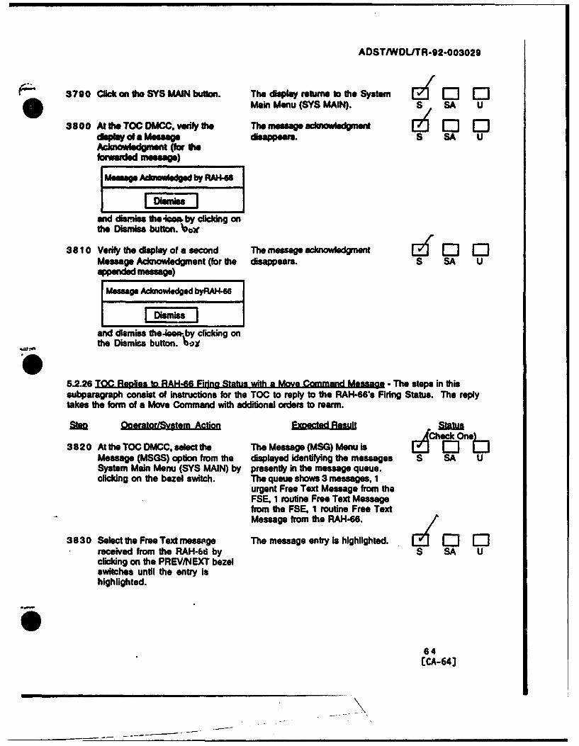
ADST/WDLJTR-92-003029
3790 Clickon to SYS MAIN button. Th. deploy reus to the System [ Q 0 0Main Menu (SYS MAIN). S SA U
3800 Ato he TO CC, ver h The meesage •aknowled-gment I-' 0 0diplay of a Message dsappears. S SA UAckowledgment (for hefowarded message
Mesagep Adwmuedged by RA, 46
and dismiss the 4eam by clicking onthe Dismiss button. l,
38 10 Verify the display of a second The messageacowegnt$ CMessage Acknowledgment (for the disappears. S SA U
Message AcnWedged byRAH-WI IsmIs
and dismiss the-iem.ýby clicking onthe Dismiss button. Ox
5.2.26 TOC Reflies to RAH-46 Firina Status with a Move Command Messae - The steps in thissubparagraph consist of instructions for the TOC to reply to the RAH-66s Firing Status. The replytakes the form of a Move Command with additional orders to rearm.
Steo Ooertor/SVstem Action Emw Sesul
3820 At the TOC DMCC, select the The Message (MSG) Menu is obMessage (MSGS) option from the displayed identifying the messages S SA USystem Main Menu (SYS MAIN) by presently in the message queue.clicking on the bezel switch. The queue shows 3 messages, 1
urgent Free Text Message from theFSE, 1 routine Free Text Messagefrom the FSE. 1 routine Free TextMessage from the RAH-66.
3830 Select the Free Text memsge The message entry is highlighted. E] 1:1received from the RAH-6W by S SA Uclicking on the PREV/NEXT bezelswitches until the entry ishighlighted.
64[CA-64]

ADSTIWDL/TR-92-003029
* 3840 Reply o the Free Textmessage by The Report (RPRT) Menuis r'- 0clicking on the REPLY button, displayed identifying the types of S SA U
massages which may be sent a&replies.
3850 Selec the Move Command (MOV Ar-Iove Command message dislay E 0 0CMD) message option by clicking appears showing the entries which S SA Uon the bezel switch. may be mede in a Move Command
message. The RAH-86 address ishighlighted.
3860 Select the Task as Move To (MOV The MOV TO task entry is 0 0TO) by clicking oa the bezel switch highlighted. S SA Uuntil the entry is highlighted.
3870 Select When as Immediately The IMMED entry is highlighted. 0 0(IMMED) by clicking on the bezel S SA Uswitch until the entry ishighlighted.
3880 Select the Location (LCTN) as The ES967650 location entry is [• 0 0ES967650 by clicking on the bezel highlighted. S SA Uswitch until the entry is
,--, highlighted.
3890 Select Who as YOU hy clicking on The YOU entry is highlighted. EJ 0 0the bezel switch until the entry is S SA Uhighlighted.
3900 Enter the following text in the The text is displayed as entered. U5 0 0-Jmm-free text space: SA U
Standby to Rearm.
3910 Send the Move Command message The button is momentarilyby c.icking on the Send Urgent highlighted. S SA U(SND URG) button. .3.2.1.2.2.2.3 (toc reply)
*3.2.1.2.2.3.2.a (reply prefto rwa)o3.2.1.2.2.3.2.2 (replyprof)
3920 Crickon theCLEAR and RETURN The display returns to the Report 1 -0button. (RPRT) Menu. S/SA U
3930 Click on the SYS MAIN button. The display returns to the System F-1Main Menu (SYS MAIN). S SA U
65[CA-651
| '

ADST/WDL/TR-92-003029
3940 At the RAH.66 DMCC. verify the The Incomng message icon 0 0-[-display of an incoming message disappears. S SA UIcon
I Meows dtyp MOVEs*Wv fivm TOC
and dismiss the icon by clicking onthe Dismiss button. /
3950 Select the Message (MSGS) option The Message (MSG) Menu is [i [3 F--from. the System Main Menu (SYS displayed identifying the messages S SA UMAIN) by clicking on the bezel presently in the message queue.switch. The queue shows 4 messages, I
urgent Move Command Messagefrom the TOC. 1 urgent Free TextMessage from the FSE, 1 routineFree Text Message from the TOC, 1routine Free Text Message from theFSE.
3960 Select the Move Command message The" message entry is highlighted."received from the TOC by clicking S SA Uon the PREV/NEXT bezel switchesuntil the entry is highlighted.
3970 Retrieve and display the Move The selected message is displayed.Command message by clicking on S SA Uthe READ button.
3980 Verify the message contents: The message content is as specified. i El ElMOVCMD REPORT URGENT S SA USENDER TOCSENT TO RAH-66FWOBYMSG SENT (date/time)XMIT LCNXMIT ALT 0 FEET
TASK MOV TOWHO YOUWHEN IMMEDWHERE ES967650
Stand by to rearm.
where date/time is of the format26 1745 JUNE 95
66ECA-66]
, i I _

ADSTIWDLITR-92-003029
3 99 0 Record fth now grid coordinates The new grid coordinates are EZf 0l 0•S ¶EI? "b$ avaoable from the Move Command. S SA U
4000 Click on the SYS MAIN button. The display returns to the System 12f E1 0Main Menu (SYS MAIN). S SA U
4o0o10 At the TOC DMC. veriy the The message rclumwe gment0display of a Message disappears. S SA UAcknowledgment
Meomg Ad•oedg.ed by RAH-6
IDismiss i
and dismiss the icon by clicking onthe Dismiss button.
5.2.27 The RAH-66 Forwards its Move Command Message to the FSE - The steps in thissubparagraph consist of instructions for the RAH-66 to forward its Move Command to the FSE.
OgeratorlSvstem Action E •eia.Reult Status
4020 At the RAH-66 DMCC, select the The Message (MSG) Menu is [E he[One:1Message (MSGS) option from the displayed identifying the messages S SA USystem Main Menu (SYS MAIN) by presently in the message queue.clicking on the bezel switch. The queue shows 4 messages, 1
urgent Move Command Messagefrom the TOC, 1 urgent Free TextMessage from the FSE, 1 routineFree Text Message from the TOC, 1routine Free Text Message from theFSE.
4030 Select the Move Command message The message entry is highlighted.received from the TOC by clicking S SA Uon the PREV/NEXT bezel switchesuntil the entry is highlighted.
4040 Forward the message by clicking on A send message display appears E - lthe REUSE button. allowing an address to be specified. S SA U
4050 Select the Address (ADRS) of the The FSE address is highlighted. Z 0 0FSE by clicking on the bezel switch S SA Uuntil the entry is highlighted.
4060 Send the Move Command to be The button is momentarily [ - -forwarded by clicking on the SEND highlighted. S SA Ubutton. .3.2.1.2.2.3.3 (forward
40 pref to mcc)
67LCA-67J

ADST/WDLITR-92-003029
4070 Verify the accessibility of the The delete function is accessible Ed 0 0Delete function by clicking on the from the Message (MSG) Menu. S SA UCLEAR and RETURN button, then e3.2.1.2.2.3.3.3 (deletethe MSGS button, from forward)
*3.2.1.2.2.3.3.4 (deletefrom forward)
4080 Click on the SYS MAIN button. The display returns to the System Eý r: r-'Main Menu (SYS MAIN). S SA U
4090 At the FSE DMCC, verify the The incoming message icon Z [-"]display of an Incoming message disappears. S SA UIcon
Meag. of type MOVEreeved from TOC
and dismiss the icon by clicking onthe Dismiss button.
4100 Select the Message (MSGS) option The Message (MSG) Menu is G 0 EDfrom the System Main Menu (SYS displayed identifying the messages S SA UMAIN) by clicking on the bezel presently in the message queue.switch. The queue shows 4 messages, 1
urgent Move Command Message, 1routine Request Message from theTOC, 2 routine Free Text Messagesfrom the RAH-66.
4110 Select the Move Command message The message entry is highlighted.received from the TOC by clicking S SA Uon the PREV/NEXT bezel switchesuntil the entry is highlighted.
4120 Retrieve and display the Free Text The selected message is displayed. [ ' " EDmessage by clicking on the READ S SA Ubutton.
68ECA-68J

ADST/WDL/TR-92-003029
4130 Verify the message contents: The message content is as specified. '- 0"MOVCMD REPORT URGENT S SA USENDER TOG
SENT TO FSEFWD BY RAH-6UMSG SENT (datetme)XMrF LCNXMIT ALT 0 FEET
TASK MOV TOWHO YOUWHEN IMMEDWHERE ES967650
Stand by to rearm.
where date/time is of the format26 1745 JUNE 95
4140 Click on the SYS MAIN button. The display returns to the System EA ' E'EMain Menu (SYS MAIN). S SA U
4150 At the RAH-66 DMCC, verify the The message acknowledgment [4'EJEJdisplay of a Message disappears. S SA U
Acknowledgment
Message Acknowledged by FSE
and dismiss the icon by clicking onthe Dismiss button.
5.2.28 Dispatch Rearming Vehicle - The steps in this subparagraph consist of instructions for
dispatch of a rearming vehicle.
sto OoeratorlSvstem Action E tatRs
4160 At the AdminJLog console., select The Ammunition Truck Status EIZOel."the display which allows the Menu is displayed. S SA Ucontrol of the rearming vehicles(M978s) by selecting menudisplays until the AmmunitionTruck Status Menu is displayed.
69[CA-69J

ADST/WDL/TR-92-003029
* 4170 Select the rearming vehicle whose Th. Vehicle entry is highghhted. Ez 0 0ammunflt, foed Is compatible ,.32.1.1.2.2 (MCC selectable S SA Uwith the RAH-66. by clicking on rearm vehicles)the vehicle enty. /
4180 Clck on the Dispatch button. The Dispatch Am.miton Truck r- I-'Menu is displayed. S SA U
4190 Enter ES967650 as the The comutd Estimated Time of M12 0) "-coordinates and clck on the Arrival Is displayed in the format S SA UCompute ETA button. Record theETA . . minutes. 25 1403 Oct
day tme month
4200 Click on the Dispatch button to The display returns to the Ef 0 rdispatch the rearming vehicle. Ammunition Truck Status Menu S SA U
which shows the truck "enrouteto' ES96706500 and its ETA.
4210 Verify that when the rearm truck The truck ready message is Y ½ C-1 -'1
arrives, a message stating that the displayed and the notification S SA Utruck is ready is displayed. Click message disappears once the Rogeron the Roger button. button has been selected.
5.2.29 TOC Transmission of Dioital Mssna. to RAH-66 Staltin Rearming Vehicle ETA - The stepsIn this subparagraph consist of insatctions for the transmission and receipt of a message statingthe rearming vehicle's ETA.
21111 Qaaoda AtonEpcted RsaUI fAwnaCeck OneL
4220 At the TOC DMCC, select the Report The Report (RPRT) Menu is Ce 0(RPPT) option from the System displayed Identifying the types of S SA UMain Menu (SYS MAIN) by clicking messages which may be senton the bezel switch. /
4230 Select the Free Text (FREE TXT) A Free Text message display[ C ) C]meswage option by clicking on the appease. showing the entries which S SA Ubezel switch. mAy be made in a Free Text
message.
4240 Select the Address (ADRSI of the The RAH-66 address is highlighted. r7 E '-RAH-66 by clicking on the b-zel S SA Uswitch until the entry ishighlighted.
70ECA-70]

ADST/WDL/TR-92-003029
4250 Enter the foicwing text In the The text is displayed as entered. El Elfree text space, using the recorded S SA UETA vahne:
Rearming vehicle will rendezvousat ES967650 in (ETA) minutes.
4260 Snd the Free Text message by The button is momentarily [E [2cickllng on the Send Routine (SNO highlighted. S SA UROUT) button. .3.2.1.2.2.2.2 (1 RWA, toe)
See Appendix A, Note I
4270 Click on the CLEAR and RETURN The display returns to the Report [L.-0button. (RPRT) Menu. S SA U
4280 Click on the SYS MAIN button. The display returns to the System El F-]Main Menu (SYS MAIN). S SA U
4290 At the RAH-66 DMCC, verify the The incoming message icon [' El o-display of an incoming message disappears. 3 SA UIcon
Mesug of type FREE XT•E Ireceived from TOC
and dismiss the icon by clicking onthe Dismiss button.
4300 Select the Message(MSGS) option The Message (MSG) Menu L ['EJE-from the System Main Menu (SYS displayed identifying the messages S SA UMAIN) by clicking on the bezel presently in the message queue.switch. The queue shows 5 messages, 1
urgent Move Command messagefrom the TOC, 1 urgent Free TextMessage from the FSE, 2 routineFree Text Messages from the TOC,1 routine Free Text Messages fromthe FSE.
4310 Select the latest Free Text message The message entry is highlighted. E 1:received from the TOC by clicking S SA Uon the PREVWNEXT bezel switchesuntil the entry is highlighted.
4320 Retrieve and display the Free Text The selected message is displayed. [ 2 Elmessage by clicking on the READ S SA Ubutton.
71[CA-713

ADSTIWDLITR-92-003029
4330 Vei~y the message oo~nletr The message content Is as sPeclled I2ýf'EJ1OIFIETEXTU9MA FKOffIE S SA USENOER TOCSENT TO RA4-66FWDBYMSG SENT (doefms)YJWLCNXIMIT ALT 0 FEET
ReAnnin vehicl wil rendezvousL at ES967660 in (ETA) minutes.
where dafte/111e Is of the format26 1745 JUNE 9W
4340 Click on One SYS MAIN button. The display returns to the System [6 J 0 QMain Menu (SYS MAIN). S SA U
4360 At us TOC DMCC. veifyw t'erhe ummessagemc-olsdga- nt rzf'+jcOcisleft ofa Message disappeare. S SA U
Memge Admwwledged by RAH-6
and dismiss One icon by clicking onteDismiss button.
5.2.30E theb RAN-es Aircraft tn Rearmin . %sti and Rearm - The step in this subparagraphconsist of Instructions for flying to the rearming location and rearming the RAH46 aircraft.
4360 At the RAH-66 softponel. enter the The Situational Display shows therearming location grid coordinates waypoint position relative to the S SA U(ES967660) and select this alreraft's current location andwaypoint for navigation, heading (represented by the center
croesh~airs). It also Identifies theaircraftrs current position, thebearing and range to the waypoint.
72ECA-723

ADST/WDL/TR-92-003029
437 Fy twads herearming location The aircraft flies to the specified [ 0 0a4 an aWltue ol 200 - 25O feet location. S SA Uand an airspee of 80 - 90 knots.
When the aircraft remachesrearming (ES967650) locationhover at an altitude of 100 ft.
4380 When th rearming vehicle The rearming vehicle Is visible and r-(M977) arrives and stops, land stationary. S SA Uthe RAH-66 within a 100 meterradius of the vehicle.
4390 Record the ammunition values The ammunition valuea we ravailable from the Instructional S SA U
Helifires: 3 Display.Stingers:Hydras: ZO20 mm HEI: 360
and the current time: ., oA
4400 Toggle the Master Weapons Arming The weapons arming switches are . - I-]Switch from armed to safe. on safe. S SA U
U 4410 Rearm the RAH-66 by monitoring The ammunition levels rise until 0 It 0the ammunition levels recording they show a full load.S SA Uthe time when each type's -3.2.1.1.2.1 (weapons wt.)rearming Is complete. -3.2.1.1.2.2 (rearm)
Hallfires: -ý. /Pjz...,. •-..OS./
Stingers: 7I.,," 140&.{ L:- * • "'o ••,•-
Hydras:20 mm HEI: ___,
73[CA-731

ADST/WDLJTR-92.003029
* 4420 VerKy each IM. Of *WiSfW The times of transfr ccolespond to & ': 1agmhu te amount transkele d for Owe amounts transferred. S SA U.ghahrnmuxanlonp. Resupply *3.2.1.1.2.4raew Ness inkam
Hellfre: 1/40 socStinger 1/40 sem
20 am: 100MG seowP*Q vj. 7
Record Owe Vrusfe rates: 4f .~ o,4
Hellfire: ______
Stinger:Hydra:20 mm.: ______
Switch from safe to armed. on armed. S SAEU
4440 At tieAdinliniogconsole note i The mesmmsagsaediplyeduntil I Odisply of tie following messages tie Roger, button has been dcckd. S SA Uarnd dismiss each message by
rIcilcdkrig on tie Roger button.
S ~Ammo Truck N Is servicing atES96706500.
Ammo Truck N Is no longerservicing at ES96706500.
4450 At tie GT System Console. note fti The messages are diPplYed.display of tie folowing messages. S BA U(The messages are repeated foreach Stinger loaded.)
RWA trying to load 1 Stinger onto(LEFT/RIGHT) WING
RWA saw I Stinger loaded onto(LEFT/RIGHT) WING
74[CA-74J

ADSTIWDLITR-92-003029
S.P.31 T~AM eaaeOr The steis in V&i subparagraph consist of instructions for W&Mn the
nsaequeue bo &W above required capacity.
4Check One~4460 At the FSE DMOCC use the sarn ft.MTC me pg queue relcts the [6 0 E3.-Me-mp swnift procedures to send messages sent by lhe FSE. S SA U
12 additional routine messages lotoe T=filling the TC=s messagequew (15 messages total)./
4470 At the TOC DMCC. veif that the The message queue holds to 15 Elý M ITOC message queue holds Vie 15 messages. S SA U
mesages
4460 Record the first and last entries in The entry information is available dl Elthe queue: from the message queue. S SA U
First: Ike I U .Last: ib1 )2t .
4490 At Me FSE DMCC, sendal16th The 16th message i sent. [dl:3 Flmessage othe TOC. S S
4500 At ft. TOG DMCC, verify ftht only The 15 most recent raessages are c -15 messages are reflected in the listed. S SA Umessage queue, and that the 15 93.2.1.2.2.1.6 (queue limit)most recent messages are listed. -3.2.1.2.2.1.6.2 (TOC)
.3.2.1.2.2.1.6.3 (TOC)
41510 At Vie TOC DMCC, use Vie same The FSE message queue reflects the El El lmessage sending proceduares to send messages sent by the TOG. S SA UI1I additional messages to the FSE,fiing the FSE's message queue(15 messages total).
4520 At the FSE DMCC, verify that the The message queue holds the 15 E :FSE message queue holds the 15S messages. S Smessages.
4530 Record fth first and last entries in The entry information is available fEl lthe queue: from the message queue. S -SA U
First:
Last:
4540 At the TOC DMCC, send a 16th The 16th message is sent. lEmessage b the FSE. most recent messages. S SA U
75
ECA- 75]

AOST/WDL/TR-92-003o2o
KI 4550~ AtO SE MouC, ve,* OWs only The 15 Most recent messages NO EJCJ15 mmaguew* Ore!ece hithe listed. S SA Umessage queue and that toe 15 3.2.1.2.2.1.6.2 (FOE)mad soon meeeagesereflsed. *3.2.1.2.2.1.6.3 (F35)
5.2.32 Terminate the Exercise - The steps In this subparagraph consist of Instructions forterminating the exercise.
4560 At the SIMET SCC, select the A display wpess requesting the 0 11 EBattiewste Functions Option and Battlemaster password. S SA UGO bo the next menu.
4570 Enter the Battlemaster password The Battlemaster Overview menu 1'3' 1:1 0(W*Abll and cdick on the OK Is displayed showing the following S SA Ubutton. selectable options:
DisplacementReconstitutionGunnery TargetsResume InitializationEnd Exercise
4580 Solect the End Exercise option and An End Exercise Confirmation 0,00JEGO to the next menu. Menu Is displayed. S BA U
4590 Respond to the Confirmation The Confirmation Display 12(f'EJEJQuestion by clicking on YES. disappears and the display returns S SA U
to the Mac windows display. TheAdminl~og Console displayreturns to the Mac windowsdisplay.e3.2.1.1.3.2 (Mac shutdown, InitState)
4600 At the NIRNET SCC, select the A display appears requesting the 1(F1cBattlemaster Functions Option end Battlemaster password. S SGo to the next menu.
4610 Enter the Battlemaster password The Battlemaster Overview menu [a' F-1(toozball) and dlick on the Ok is displayed showing the following S BA Ubutton. selectable options:
DisplacementReconstituteGunnery TargetsResume InitializationEnd Exercise
4 62 0 Select the End Exercise option end An End Exercise confirmation menu Elý ElrGo to the next menu. is displayed. S SA U
76[CA-76J

ADST/WDL/TR-92-003029
"04 630 Respond L. tOe Confirmation The Confirmation Display 2 El EQueston by clicking on YES. disappears and the display returns SA U
to the Macintosh windows screen.The CIG system console dcspay Umessage Oeactivating from MCC*and sound and visua al weterminated..3.2.1.1.3.1-3.2.1.1.3.2-3.2.1.2.3-3.2.1.2.4.3.2 1.2.4.1
77[CA-771

ADST/WDL/TR-92-003029
6.0 NOTES
Test failures will be noted In the procedure against each lost step as necessary where test results donot agree with expected results. Due to the nature of these system level tests, a simulator "crash"due to pilot error will not be constituted as a failure but an acceptable interruption. The systemprovides the capability for re-etarting at the point of where the crash occurred and will be utilizedauwing the execution of this system level test.
78[CA-764

ADST/WDLITR-92-003029
-0- 7.0 Test Falluroollnterrugtlops
NOTE ANY FALURES ENCOUNTEPE DURING THE TEST IN THIS SECfTlN.
NO. FAILUREUINTERRUPTION DESCRIPTION
79[CA-791

ADST/WDLIT R-92-0 03029
AdmlnJiogj AdmlnlstratloodLogistlcs
ARNFM Aircraft Simulation NetworkACC Admhinstrationflogistics Operations ConsoleAmmo AmmunitionBBN BoIlt Beranek. and Newman
CEDICommunications and Electronics Operations Instructionscla Computer Image Generator
CFOG Co-Pilot/GunnerDMOC Digita Mesg Communications ConsoleDhMS Digital Message Server.ErA Estimated Time of Arrival
FRED Fully Reconfigurabl. DeviceFREE 1X Free TextFSE Fire Support ElementFrWD ForwardQT-1 11 BBN Computer System/dOG supporting SimulationNEI, High Explosive IncendiaryHIM*MV High Mobility Multi-Wheeled VehicleI &T .Integration &TestIMMED Immediatelylbs. poundsICT LocationMac Macintosh Computer
MX Management Command and Control ConsoleMIPS AIRNEF MCC Host ComputerM04JO Move TO
MOVCMDMove Command
MTO Movement to OrderPDU Protocol Date UnitPIE Pyrotechnic Incendiary ExplosiveRAH-66 Comanche Helicopter
RIBCNTYPE Reconnaissance Type
RPRT ReportRWA Rotary Wing AircraftS/W Softwareasm System Control ConsoleSOF System Development Facility, Loral WOL, San Jose
SIMNET Simulation NetworkSNDR0U~rSend Routine
8M) URG Send UrgentSYS MAIN System Main Menu
XC Tactical Operations CenterUMCP Unit Maintenance Collection PointUTM Universal Transverse Mercator
WDL Western Development Labs
soECA-80J
ADST/WDL/TR-92-003029
- WW4ROY Vwen ReadyXMIT ALT Transmit AldtudeO XMIT LCN Transmit L~ocation
81[CA-81J

ADST/WDL/TR-92-003029
APPENDIX A
EXERCISE -A REOUIREMENTS MATRIX
The fllowng talWes we refernced below.
Table 3.2.1.1 - 1Wft onsSyaim [Weapon Quantity Weanorl We~d~ NolesHellfire 14' 101 be. ea.Stinuer Is* 22.6 be. ea.Rocket [62* 20.6 lbs. ea. all 2.75 in rockets20 -.m ammo [500 rounds 112 Ib. total PIE or HEI" For a reconnaissance mission 4 Hellfire may be configured with 2 Stinger. When configuring amaximum missile load the weapon quantities are exclusive of each other.
Table 3.2.1.1 - 2Conflauration WeightMax self deployed 17.174 lbs.Primary mission 10.112 lbs.Empty 7500 lbs.Useful load 2612 lbs.Internal fuel 1820 lbs. (280 gals.)Self deploy 7670 lbs. (1180 gals.)
REQ NO. TITLE REQUIREMENT3.2.1.1.1.1 Terrain Data Base The MCC shall specify the terrain database (name
Definition and area) to be used by the RAH-66 Comanchesimulator.
3.2.1.1.1.2 Simulator Identifier The MCC shall specify the simulator vehicleidentifier to be utilized by the RAH-66 Comanchesimulator.
3.2.1.1.1.3 Simulator Placement The MCC shall specity the location and heading(placement) to be utilized by the RAH-66 Comanchesimulator.
3.2.1.1.1.4 Weapons Load The MCC shall support the definition of the weaponsload for the RAH-66 Comanche simulator.
3.2.1.1.1.5 Weapons Weight and The MCC shall impose weight and quantity constraints_ Quantity in accordance with table 3.2.1.1.-1 aiven below
3.2.1.1.1.6 Default Weapons Load The MCC shall maintain a default weapons load whichto be used in the event that the weapons load is notexplicitly selected.
3.2.1.1.1.7 Fueling The MCC shall support the fueling of the RAH-66Comanche simulator.
3.2.1.1.1.8 Fuel Load Constraint The MCC shall impose a weight limit on the allowablefuel load in accordance with table 3.2.1.1.-2.
82[CA-821

ADST/WDL/TR-92-003029
O REQ NO. TITLE REQUIREMENT3.2.1.1.1.9 Default Fuel Load The MCC shall maintain a default fuel load which shall
Constraint be used in the event that the fuel load is not explicitlyselected.
3.2.1.1.1.10 RAH-66 The MCC shall allow the configuration of one to eightSee Notes (1) Configuration RAH-66 Comanche simulators engaged in simulated
reconnaissance, tactical maneuver, or battleexercises.
3.2.1.1.1.11 Configuration The MCC shall specify the configuration parametersSee Notes (2) Parameters for the RAH-66 Comanche simulator to include but
not be limited to the following:3.2.1.1.2.1 Rearmament The MCC shall rearm the RAH-66 Comanche
simulator based on current weipons status andweapons load constraints contained in table 3.2.1.1-1 .
3.2.1.1.2.2 Resupply Vehicles The MCC shall use the same armament resupplyvehicles for the RAH-66 rearmament as those usedfor already existina and selectable on the MCC.
3.2.1.1.2.3 Weapons Load Request The RAH-66 Comanche simulator shall inform theMCC about the current status of weapons load uponrequest.
3.2.1.1.2.4 Rearm Time The time of transfer of weapons shall be simulated bythe MCC.
3.2.1.1.2.5 Refueling The MCC shall refues the RAH-66 Comanchesimulator based on current fuel status and fuel loadconstraints contained in table 3.2.1.1-2.
3.2.1.1.2.6 Refueling Vehicles The MCC shall use the same armament refuelingvehicles for the RAH-66 refueling as those used forground-based simulators.
3.2.1.1.2.7 Current Fuel Status The RAH-66 Comanche simulator shall inform theMCC of the current status of fuel remaining in thevehicle upon request.
3.2.1.1.2.8 Fuel transfer Time The time of transfer of fuel shall be simulated by theMCC.
3.2.1.1.2.10 Placement Upon Upon activation the simulator shall appear on theActivation terrain databjase at the site of the 8 digit coordinates
entered in the location entry on the SCC console.3.2.1.1.2.11 Default Heading The MCC shall default the heading to 0 degrees
(Topographic North) should the heading entry beblank at tl.e time of activation
3.2.1.1.3.1 Terminate Exercise The MCC shall perform the termination of anexercise.
3.2.1.1.3.2 Termination The MCC shall perform the following duringFunctions termination of an exercise:
"* Send Deactivation Requests to all simulators"* Shutdown all Mac Consoles* Begin initialization state
083
[CA-83 ]

ADST/WDL/TR-92-003029
-REQ NO. TITLE REQUIHEMENT3.2.1.2.2.1.2 TOC Station The Computer Digitu Icssage function u.hall notify
Not~fication the Tactical Opprations Centrr (TOC) of an incomingmessage and place message contents in the TOc storage
3.2.1.2.2.1.3 FSE Station The Computer Digital Message turhcion shall notifyNotification the Fire Support Eiera:ent (eSE) of an incoring
message and place message con'.nts in the FSE storage
3.2.1.2.2.1.4 TOC Operator The TOC station shall display an incoming messageNotification of icon upon message notification from *he MCC host.Message Receipt
3.2.1.2.2.1.5 FSE Operator The FSE station shah display an incoming messageNotification of icon upon message notification from the MCC host.Message Receipt
3.2.1.2.2.1.6 Message Storage Messages will be automatically stored until eitherdeleted by a station operator or until the maximummessage storage limits have been attained.
3.2.1.2.2.1.6.1 Message Queuing Messagec shall be automatica!ly queued upon receiptfor either the FSE and/or the TOC.
3.2.1.2.2.1.6.2 Message Quantity The MCC system shall store a maximum of 15messages each for the FSE and TOC.
3.2.1.2.2.1.6.3 Most Recent Messages Only the most recent messages each shall be storedfor either the FSE or TOC stations.
3.2.1.2.2.1.6.4 Message Type Message types received shall consist of either preformatted text or free text messages.
3.2.1.2.2.2.1 Pre Formatted Text The TOC or FSE shall be capable of sending preSee Note (1) Messages formatted messages to the RAH-66 Comanche
player(s). A pre formatted message is anypreviously defined message file.
3.2.1.2.2.2.2 Free Text Messages The TOC or FSE shall be capable of sending free textSee Note (1) messages to the RAH-66 Comanche player(s). A free
text message is any message entered by the stationoperator within the Access Mode.
3.2.1.2.2.2.3 Sending Messages The TOC and FSE snall allow a message to be sent,deleted, retrieved for viewing, forwarded,acknowledoed and replied to.
3.2.1.2.2.3.1.1 Retrieve Selected The station operator shah be able to select anyMessage message for retrieval and display from the station's
storage queue.3.2.1.2.2.3.1.2 Retrieve Function The operator shall be able to transition to AccessSee Note (3) Transition Mode, Reply, Forward, Acknowledge and Delete from
within the Retrieve function.3.2.1.2.2.3.2.a Message Reply The reply function shall automatically send
Function preformatted or freehand messages to the RWA playerI whose message has been selected.
3.2.1.2.2.3.2.b Message Reply The operator shall be able to select Access Mode andI Function the Delete function from within the Reply function.0
84[CA-84]

ADST/WDLITR-92-003029
0 REQ NO. TITLE REQUIREMENT3.2.1.2.2.3.2.1 Reply to Selected The reply function allows the station operator to send
Message a reply to the originator of the selected message from_the storage queue.
3.2.1.2.2.3.2.2 Reply Function Tha operator shall be able to reply to a selectedMessage Type message by either sending a freehand (typed) or a
preformatted text message.3.2.1.2.2.3.2.3 Reply Function The operator shall transition to Access Mode and the
Transition Delete function from within the Reply function.3.2.1.2.2.3.3 Message Forward The forward function shall allow the selected message
Function to be forwarded to the RWA player or MCC Station.Preformatted or freehand messages can be included.
3.2.1.2.2.3.3.1 Forward Selected The forward function allows the station operator toMessage forward the selected message from the storage queue
to another MCC station or RWA Player.3.2.1.2.2.3.3.2 Forward Function The operator shall be able to forward the selected
Message Type message and include either a freehand (typed) or apreformatted text message if desired.
3.2.1.2.2.3.3.3 Forward Function The operator shall transition to Access Mode and theTransition Delete function from within the Forward function.
3.2.1.2.2.3.3.4 Select Access or The operator shall be able to select Access mode andDelete Function the Delete function from within the Forward function.
3.2.1.2.2.3.4 Acknowledge Selected Only one Acknowledgment shall be sent for any_Message message in the storage queue.3.2.1.2.2.3.4.1 Acknowledge Selected The acknowledge function shall automatically
Message acknowledges the selected message from the storagequeue.
3.2.1.2.2.3.4.2 Acknowledge function A preformatted text message will automatically bemessage type sent to the message originator acknowledging message
receipt and display at the receiving station.3.2.1.2.2.3.4.3 Acknowledge Function The acknowledge function shall automatically
Transition transition to the retrieve function and display theselected message unless the message has already beenretrieved (displayed).
3.2.1.2.2.3.4.3.a Acknowledge Function If the message has already been displayed, theSee Note (3) Transition operator shall transition to Access Mode, Retrieve or
Delete functions.
3.2.1.2.2.3.5.1 Message Deletion The station operator shall be able to delete messagesfrom the station's storage queue.
3.2.1.2.2.3.5.2 Delete Function The Delete function shall return automatically to
Transition Access Mode.3.2.1.2.2.3.6 Send (originate) a The send function shall allow the station operator to
Message originate and send preformatted or freehand textmessages to an RWA player or another MCC station.
3.2.1.2.2.3.6.1 Send Message The send function allows the station operator tooriginate a message and send to another MCC stationor to an RWA player.
3.2.1.2.2.3.6.2 Send Function The operator shall be able to send either a freehand
0 Message Type (typed) or a preformatted text message.
5
CA85

ADST/WDL/TR-92-003029
*REQ NO. TITLE REQUIREMENT3.2.1.2.2.3.6.3 Send Function The operator shall be able to select Access Mode,
Transition Forward, or Delete function from within the Sendfunction.
3.2.1.2.3 Segment capability Management Command and Control capabilityrelationships relationships are not affected by modifications except
as described by the Digital MessageCommunicationscapabilities.
3.2.1.2.4. Segment External AN external Interfaces shall remain SIMNET 6.6.1Interface compliant.Reauirements.
3.2.1.2.4.1 MCC Digital The external interface for the MCC DigitalMessage/Comm. Message/Communication Upgrade shall be compliantUpgrades External with SIMNET 6.6.1.Interface Description
ATAC IIRequirements3.2.1 ATAS Symbology The RWA software shall be modified to display an
ATAS reticle model in the Out-the-Window (OTW)views when the ATAS missile is selected.
3.2.2.1 ATAS Symbology The ATAS reticle shall consist solely of a square"lock-on' reticle.
3.2.2.2 ATAS Symboiogy The ATAS reticle shall exhibit screen dimensionratios equivalent to that of the 2d overlay sensorversion: horizontal extents occupying - 10% of thehorizontal screen space, vertical extents occupying -13% of the vertical screen space.
3.2.2.3 ATAS Symbology The ATAS reticle shall be emulated as a 3d model inthe Dynamic Elements Database (DED).
3.2.3 ATAS Symbology The RWA software shall use the existing ATAS lock-on cone dimensions, i.e. +/- 10 degrees.
3.2.8 ATAS Symbology The RWA software shall use the existing weaponsswitchology algorithms.
3.2.9 ATAS Symbology The 3d ATAS reticle shall be displayed on the OTWvisuals only.
3.2.10.1 ATAS Symbology The RWA DEDs shall be modified to contain a"normal" version of the ATAS reticle in the OTW DEDfor use in locking on to targets within a range of 3.5km. or less.
3.2.10.2 ATAS Symbology The FWA DEDs shall be modified to contain a"modified" version of the ATAS reticle in the OTWDED for use in locking on to targets beyond the OTW3.5 km. visual range. (Note: The current designconcept for the modified reticle is to have it contain a"black dor in the center to signify that it is lockedonto a target.)
86ECA-86)

ADST/WDL/TR-92-003029
- REQ NO. TITLE REQUIREMENT3.2.10.3 ATAS Symbology The RWA DEDs shall be modified to contain a "nur
(invisible) version of the ATAS reticle in theDaylight Television (DTV) I Thermal DED. (Note:The null version for the DTV/Thermal DED isrequired in order to avoid having the sensorinadvertently display the pilots 3d reticle model.)
3.2.11.1 ATAS Symbology The 2d ATAS reticle to be displayed in the sensorchannel shall consist of two dashed concentric squarescentered on the sensor line of sight wien the ATASmissile has been selected, but is not seeking. Neitherthe aural seek tone nor the aural lock-on tone will begenerated.
3.2.11.2 ATAS Symbology The 2d ATAS reticle to be displayed in the sensorchannel shall consist of two dashed concentric squarescentered on the sensor line of sight when the ATASmissile is actively seeking. The aural seek tone willbe Qenerated.
3.2.11.3 ATAS Symbology The 2d ATAS reticle to be displayed in the sensorchannel shall consist of two solid concentric squarescentered on the target coordinates when the ATASmissile is tracking a target The aural lock-on tonewill be generated.
3.2.12 ATAS Symbology The ATAS reticles (2d in the sensor channel and 3d inthe OTW visuals) shall be displayed when either thepilot or copilot/gunner (CPG) selects the ATASmissile.
3.3.1.5 Manned Rotary Wing A Missile Server shall not be required forAircraft autonomous Hellfire designation (as in the current
implementation) functionality to exist. If no MissileServer is present, the Hellfire works as in thecurrent implementation.
3.3.1.10 Manned Rotary Wing The SAD menu shall be modified to allow a target UTMAircraft grid coordinate to be manually entered as the Hellfire
destination point.3.3.1.11 Manned Rotary Wing The RWA shall incorporate a random offset, forward
Aircraft of the target UTM grid coordinate, as the destinationpoint which the Hellfire will fly toward.
3.3.1.13 Manned Rotary Wing The Hellfire impact point shall be determined by theSee Note (4) Aircraft laser designation point, whether local (autonomous
fire) or remote.3.3.1.14 Manned Rotary Wing Automatic range determination shall be displayed as a
Aircraft four digit integer number on the sensor display, as in_ the current implementation.
3.3.1.15 Manned Rotary Wing Ranges calculated from target UTM grid coordinatesAircraft shall be displayed in the format NXXXX where XXXX is
the range to the coordinate in meters.
0
87[CA-871

ADST/WDL/TR-92-003029
REQ NO. TITLE REQUIREMENT3.3.1.17 Manned Rotary Wing The modes of the Hellfire missiles
Aircraft (primary/secondary) and trajectories (LOBL, LOALdirect, LOAL high. LOAL low) shall be implementedonly to the extent that they have been implemented inthe current version of the RWA.
3.3.1.1S Manned Rotary Wing The leer rangelinderldasignator symbokog shall beAircraft displayed in the upper left comer of the sensor
display.3.3.1.19 Manned Rotary Wing The laser rangefinder mode symbology shall consist
Aircraft of the phrase "RNG'.3.3.1.21 Manned Rotary Wing The laser status symbology OFF/SAFE/ARM shall be
Aircraft displayed in the upper left comer of the sensordisplay, beneath the rangefinder/designatorsymboloqy.
3.3.1.25 Manned Rotary Wing The RWA Hellfire switchology shall remain as it is inAircraft the current implementation.
3.3.1.26.1 Manned Rotary Wing The RWA Hellfire constraint symbology shall consistAircraft of a solid win constraint- square (as in the current
implementation).3.3.1.26.2 Manned Rotary Wing The RWA Hellfire constraint symbology shall consist
Aircraft of a dashed 'out of constraint" square, the same sizeand shape as the "in constraint- version.
3.3.1.27 Aanned Rotary Wing The RWA Hellfire constraint limits shall remain asAircraft they are in the current implementation, i.e.. +/- 20
degrees.3.3.1.30.2 Manned Rotary Wing The following shall be modifiable at any time the RWA
Aircraft is in an active riata of simulation: Hellfire target_ UTM grid coorrainates.
Notes:
(1) This requirement is satisfied for a single RAH-66 Comanche player. The procedures verifyingthis requirement for multiple players may be found in Exercise "C".
(2) This requirement is satisfied for all items listed, with the exception of Airframe Time. Referto AIRNET Inspection/Analysis Report 3 for information related to satisfaction of the airframeportion of this requirement.
(3) Access Mode is defined as the Message Queue display, and is equivalent to Retrieve.
(4) This requirement is satisfied for local (autonomous) fire only. The procedures verifying thisrequirement for remote fire may be found in Exercise OC".
88
EC-8
, m m I : I l

ADST/WDL/TR-92-003029
Appendix B
0Exercise "Am Reaulrements Inspectlon/Anaivls Matrix
ReportREQ NO. TITLE REQUIREMENT Reference
3.2.1.2.1.1 NoMeessage The MCC Digitai Message/ 1Processing Communications function shall operate inRequired a standby state on the MCC system when
messaae processina Is not required.3.2.1.2.1.2 Transition to Active The MCC Digital Message / I
State - Operator Communications function shall transitionRequest to the active state upon receipt of an MCC
Soperator request.
3.2.1.2.1.3 Transition to Active The MCC Digital Message IState - PDU Receipt Communications function shall transition
to the active state upon receipt of andigital message PDU by the MCC.
3.2.1.2.1.4 Transition to The MCC Digital Message /Standby State Communications function shall transition
to the standby state when there is noactivity In any of the three active statemodes - receive, send and access.
3.2.1.2.2.1.1 Activation Upon The Receive Mode shall be activated upon 1PDU Receipt receipt of a digital message PDU by the
___MCC host.3.9.1 MCC Comanche The MCC Comanche Support Upgrade 2
Support Upgrade Segment shall be qualification tested atSegment Ft. Rucker.Qualification
3.9.1 .a MCC Comanche The MCC Comanche Support Upgrade test 2Support Upgrade shall take place during the programSegment integration and test phase (I&T).Qualification
3.9.1 .b MCC Comanche The MCC Comanche Support Upgrade test 2Support Upgrade shall not exceed 2 working days.SegmentQualification
3.9.1 .c MCC Comanche The testing shall demonstrate the MCC 2Support Upgrade Comanche Support Upgrade provides theSegment functionality described previously inQualification this document.
89[CA-891

ADST/WDLTR-92-003029
I ReportREQ NO. TITLE REQUIREMENT Reference
3.0.2 MCC Dow The MCC Dgital Messag / 2Memage / Communications Segment shal beCommunicatons ,ualilicaton ested at FL Rucker.
Oualifcatlon3.9.2.a MCC Digital The MCC Digital Message 2 2
Message I Communicadons Segment test shal takeCommunications place during the program Integration andSegment test phase (&T).Qualification
3.9.2.b MCC Digital The MCC Digital Message I2Message / Communications Segment test shall notCommunications exceed 1 working day.SegmentQualification
3.9.2.c MCC Digital The testing shall demonstrate the MCC 2Message I Digital Message I CommunicationsCommunications Segment provides the functionalitySegment described previously. in this document.Qualification
ATAC IIRequirements3.1.1 General Modifications to "RWA" functionality and 4
capabilities shall be made solely to themanned vehicle Generic Rotary WingAircraft simulator unless statedotherwise.
3.1.2 General ATAC software shall not be required bt 4communicate via the DIS protocol.
3.1.3 General Network communications shall be made 4using the current implementation of theSIMNET protocol.
3.1.4 General Where necessary, extensions to the 4SIMNET protocol shall be allowed.
3.1.5 General All software modifications will be made 4according to the guidelines and practicesof the Kemighan and Ritchie "C" (K & R
___C) programmina language.3.2.4 ATAS Symbology The RWA software shall use the existing 5
ATAS lock-on algorithms for determiningwhich types of entities it can lock on to.
3.2.5 ATAS Symbokogy The RWA software shall use the existing 5ATAS Intervisibility algorithms.
3.2.6 ATAS Symbology The RWA software shall use the existing 5ATAS maximum lock-on range of 7.0 kin.
090tCA-9O~t

ADSTIWDUTR-92-003029
ReportREQ NO. TITLE REOUIREMENT Reference
3.2.7 ATAS Symbology The RWA software OTW maximum visual 5range of 3.5 km. shall remain as its is inthe current software.
3.2.13 ATAS Symbology The ATAS reticles shall be displayed for 5all missiles of type "target-guided" asdefined in the RWA data file""reconfi .rwa".
3.2.14 ATAS Symbology The ATAS reticles shall be displayed for 5any configuration of the RWA which hasselected a 'target guided" missile type.
3.3.1.12 Manned Rotary The Hellfire range (calculated from the 6Wing Aircraft target UTM grid coordinate or from the
laser autorangefinder) shall determinethe initial value for the Time of Flight(TOF) overlay on the sensor display.
0
91[CA-91 J

ADST/WODLTR-92-003029
Appendix C
Exerelse A' Insnectlon/Analvsls Rog rts
Report Reference
1. MCC DOW Message Communiations Console Requirements2. MCC Comance Support and D•W m e Cm nt Coawe Qulification Requirements3& MCC Comanche Configuration Parameters Raquirnent - Airframe toe4. ATAC II General Requirements5. ATAC II ATAS Requirements6. ATAC II Hellfire Requirements
'0
92ECA-992
I-

ADST/WDLITR-92-003029
AIRNET INSPECTIOWANALNI'3 REPORT 1
O Reqt No.: 3.2.1.2.1.1 Spea. Para.: 3.2.1.2.1.13.2.1.2.1.2 3.2.1.2.1.23.2.1.2.1.3 3.2.1.2.1.33.2.1.2.1.4 3.2.1.2.1.43.2.1.2.2.1.1 3.2.1.2.2.1.1
Requirement Descriptions:
Reqt. No.: 3.2.1.2.1.1 No Message Processing RequiredThe MCC Digital Message/Ccmmunications function shall operate in a standby state on the MCCsystem when message processing is not required.
ReqL No.: 3.2.1.2.1.2 Transition to Active State - Operator RequestThe MCC Digital Message/Communications function shall transition to the active state upon receiptof an MCC operator request.
ReqL No.: 3.2.1.2.1.3 Transition to Active State - PDU ReceiptThe MCC Digital Message/Communications function shall transition to the active state upon receiptof a digital message PDU by the MCC.
Reqt. No.: 3.2.1.2.1.4 Transition to Standby StateThe MCC Digital Message/Communications function shall transition to the standby state when thereis no activity in any of the three active state modes - receive, send and access.
Reqt No.: 3.2.1.2.2.1.1 Activation Upon PDU ReceiptThe Receive Mode shall be activated upon receipt of a digital message PDU by the MCC host
Inspection Method: As designed, the MCC Digital Message/Communications function executesindependently from the AIRN,: 1" MIPS-based MCC system. It resides on a SUN workstation, linked tothe MIPS-based MCC via the SIMNET Ethernet network (Fig. 1 - 1). This platform provides thefunctionality for all DMCC consoles and message/communications processing.
The DMCC function operates in a standby state when message/communications functions are notrequired (3.2.1.2.1.1). When a message is received, either from a console user (OperatorRequest, 3.2.1.2.1.2) or from the Ethernet network (Digital Message PDU, 3.2.1.2.1.3), thefunction transitions to an active state to perform the necessary message/communicationsprocessing. When there is no activity (send, receive, operator access), the function againtransitions to its standby state (3.2.1.2.1.4). The receive mode is activated by the DigitalMessage/Communications function within the SUN workstation platform, independent of the MCChost, upon receipt of a digital message PDU via the SIMNET Ethernet network (3.2.1.2.2.1.1).
The implemented system, in conjunction with the DMCC operations demonstrated during theExercise "A" test, can be inspected to comply with the above listed requirements and Fig. 1 - 1.
93[CA-93J

ADST/WDLITRR-92-003029
Appletalk Network
Adm Fr -SIMNET Bridge MASS
sx00
SIMNET Ethernet Network"
RWYA Shiva LMIPS Sun
X-RWA
Figure 1 - 1 AIRNET Functional Configuration
VERIFIED: __
TITLE: _ _ _ _ _ _ _ _ _ _ _
* ~~~~CONCURRENCE:________
94[CA-941

ADST/WDLITR-92-003029
AIRNET INSPECTIOWANALYSIS REPORT 2
Reqt.No.: 3.9.1 Spec.Para.: 3.9.13.9.1.a 3.9.13.9.1.b 3.9.13.9.1.c 3.9.13.9.2 3.9.23.9.2.a 3.9.23.9.2.b 3.9.23.9.2.c 3.9.2
Requirement Descriptions:
ReqL No.: 3.9.1 MCC Comanche Support Upgrade Segment QualificationThe MCC Comanche Support Upgrade Segment shall be qualification tested at FL Rucker.
Reqt. No.: 3.9.1.a MCC Comanche Support Upgrade Segment QualificationThe MCC Comanche Support Upgrade test shall take place during the program integration and testphase (I&T).
ReqL No.: 3.9.1.b MCC Comanche Support Upgrade Segment QualificationThe MCC Comanche Support Upgrade test shall not exceed 2 working days.
Reqt. No.: 3.9.1.c MCC Comanche Support Upgrade Segment QualificationThe testing shall demonstrate the MCC Comanche Support Upgrade provides the functionalitydescribed previously in this document.
ReqL No.: 3.9.2 MCC Digital Message/Communications Segment QualificationQ The MCC Digital Message/Communications Segment shall be qualification tested at Ft. Rucker.
ReqL No.: 3.9.2.a MCC Digital Message/Communications Segment QualificationThe MCC Digital Message/Communications Segment test shall take place during the programintegration and test phase (I&T).
ReqL No.: 3.9.2.b MCC Digital Message/Communications Segment QualificationThe MCC Digital Message/Communications Segment test shall not exceed 1 working day.
ReqL No.: 3.9.2.c MCC Digital Message/Communications Segment QualificationThe testing shall demonstrate the MCC Digital Message/Communications Segment provides thefunctionality described previously in this document.
Inspection Method: The test procedures for Scenario A can be inspected to verify compliance withthe requirements listed above.
VERIFIED:
TITLE:
CONCURRENCE:
95[CA-95)

ADST/WDLITR-92-003029
AIRNET INSPECTIOWANALYSIS REPORT 3
Reqt. No.: 3.2.1.1.1.11 Spec. Para., 32.1.1.1.11
Requirement Descriptions:
Reqt. No., 32-1.1.1.11 Configuration ParametersThe MCC Ade specify the configuration parameters for the RAH-66 Comanche simulator lo Includebut not be Imbted to the following:
a. Tall Wat~erb. Airframs Timec. MaIntenace Statusd. FuelILorda. Wespoce Load
1. Missiles2. Rockets (HYDRA)3. Guns
Inspection Method: The test procedure provides verification of all required fields with theexception of the airframe time. The AIRNET MCC System Control Console's (SCC) user Interfacemakes use of data files which define the contents of the various window displays. Among the displaysIs one which allows customtization of the aircraft It appears as shown below.
Simulator~ 88 Tail No. [1 1liSimulator typ: FRED Location
Assigned to: A Company Headin
Vehicle type: [I H-64 Maint. Status: NewAlignment [ZIZZ
Fuel Load30 mm single barrel
Hellfire missilesStingr missiles
Hydra 70 101bHydra 70 MPSM
Hydra 70 Flechette HSet Value to: EODefault Q~ustom
This window makes use of the contents of simmodels.lisp. This file contains the vehicle. characteristics for each vehicle type including the RAH-66 Comanche. Shown below are portions of
(CCA-961

ADST/WDLITR-92-003029
simmodels.Iisp which support the generation of the previously shown menu. The first entry is forthe AH-64, the secona for the RAH-66 Comanche. Note that comments begin with ;;.
0The entries are nearly ldentical; the AH-64 entry contains a reference to airframe time. Note thatthis reference is commented out and not used In the displayed menu. Thus the menu displays for thetwo aircraft would be identical. Should it later be desirable to include the airframe time in themenu display, the airframne time could be added to the RAH-86 entry.
(fields(AH64-.FI ELDS(bumper 1 ACTINTEGER 'Tail No.' (ACTvIINMAX 1 99)'(location 1 ACT-.MAPOCOORD "Locations 0"" s)(hulL-az 1 ACT-INTEGER 'Heading" (ACT-.MINMAX 0 360) "(Deg)" '0')(fuel 2 ACT_.FLOAT 'Fuel Load" (ACTMINMAX 0 2438) 'Lbs' '2438');;(airframe 2 ACT-INTEGER 'Airframe times (ACT.MINMAX 0 5000) 'Hours' '164')(munition__30mm_bullet 2 ACTINTEGER '30mm single barrel'
(ACL..MINMAX 0 1200) 'Rounds' '1200')(munition__hellfire 2 ACTINTEGER 'Hellfire missiles'
(ACT.MINMAX 0 16) so '8')(munition....stinger 2 ACTJNTEGER 'Stinger missiles' (ACT_.MINMAX 0 4) so '4')(munition-...hydra-1Olb 2 ACTINTEGER 'Hydra 70 101lb'
(ACT.MINMAX 0 76) so '38')(munitioni...hydra..mpsm 2 ACTINTEGER 'Hydra 70 MPSM'
(ACT-MINMAX 0 76) so -0-)(munition~hydrajilech 2 ACTINTEGER 'Hydra 70 Flechette'
(ACT.MINMAX 0 76) so '0'))~~ (RAH66-.FI ELDS
(bumper 1 ACT-INTEGER 'Tail No." (ACT_.MINMAX 1 99)""(location 1 ACT-MAPCOORD 'L-ocation' 0"" 8)(hulLaz 1 ACT-INTEGER 'Heading' (ACT-MINMAX 0 360) *(Deg)' '0')(fuel 2 ACTJLOAT 'Fuel Load' (ACT_.MINMAX 0 2438) 'Lb' '2438')(munition__20mm_hei 2 ACTINTEGER n20mm HEI'
(ACT-.MINMAX 0 1200) 'Rounds' '1200')(munition....2Omm..pie 2 ACTJNTEGER '20mm PIE'
(ACTL.MINMAX 0 1200) 'Rounds' '0')(munition__hellfire 2 ACTINTEGER 'Hellfire missiles'
(ACT-.MINMAX 0 14) so '8')(munifion....stinger 2 ACT-INTEGER 'Stinger missiles' (ACT...MINMAX 0 18) "'4')
(munition.....hydra..j0lb 2 ACT-.INTEGER 'Hydra 70 101b'(ACT.MINMAX 0 62) so '38')
(munition__chaff 2 ACT-INTEGER 'Chatr(ACT-MINMAX 0 4) " '0')
(munition__flares 2 ACT-INTEGER 'Flares'(ACT-MINMAX 0 8) so0W)
The referenced data file can be reviewed and inspected for validation of this requirement.
VERIFIED: __________
TITLE: ______
CONCURRANCE:___ _____
97[CA-97)

ADST/WDL/TR-92-003029
AIRNET INSPECTIOWANALYSIS REPORT 4
ReqL No.: ATAC 1! 3.1.1 Spec. Parm.: 3.1ATACII 3.1.2 3.1ATACII 3.1.3 3.1ATACII 3.1.4 3.1ATACII 3.1.5 3.1
Requirement Descriptions:
Reqt. No.: ATAC II 3.1.1 GeneralModifications to "RWA" functionality and capabilities shall be made solely to the manned vehicleGeneric Rotary Wing Aircraft simulator unless stated otherwise.
Reqt No.: ATAC II 3.1.2 GeneralATAC software shall not be required to communicate via DIS protocol.
ReqL No.: ATAC II 3.1.3 GeneralNetwork communications shall be made using the current implementation of the SIMNET protocol.
ReqL No.: ATAC II 3.1.4 GeneralWhere necessary, extensions to the SIMNET protocol shall be allowed.
ReqL No.: ATAC II 3.1.5 GeneralAll software modifications will be made according to the guidelines and practices of the Kemighanand Ritchie '"C (K & R C) programming language.0Inspection Method: The modifications to "RWA" functionality and capabilities are limited to thosechanges made to the RWA executable; no changes were made to the real time software executable(rttgt"5.7) which runs in concert with the RWA vehicle executable. All modifications have beenmade according to the guidelines and practices of the K & R C" programming language. Each of thetest scenarios, A, B and C utilizes the existing real time executable and the new RWA executable.
The RWA executable utilizes the original SIMNET protocol software libraries with extensions forProtocol Data Units (PDUs) which allow remote designation. The software functionrwa-desig-startup (rwa-desig.c) makes a call to function rcvneLregister-desig-process..packetwhich registers the designation PDU processing routine with libRcvNet, thus allowing handling of(extension) Designation POUs.
The RWA software, in conjunction with the test scenarios, can be inspected to comply with the abovelisted requirements.
VERIFIED:
TITLE:
CONCURRENCE:
98[CA-98]

ADST/WDIJTR-92-003029
AIRNET INSPECTION/ANALYSIS REPORT 5
Reqt. No.: ATAC Ii 3.2.4 Spec. Para.: 3.2ATAC 11 3.2.5 3.2ATAC II 3.2.6 3.2ATAC II 3.2.7 3.2ATAC II 3.2.13 3.2ATAC 11 3.2.14 3.2
Requirement Descriptions:
Reqt. No.: ATAC II 3.2.4 ATAS SymbologyThe RWA software shall use the existing ATAS lock-on algorithms for determining which types ofentities it can lock on to.
ReqL No.: ATAC II 3.2.5 ATAS SymbologyThe RWA. software shall use the existing ATAS intervisibility algorithms.
ReqL No.: ATAC II &2.6 ATAS SymbologyThe RWA software shall use the existing ATAS maximum lock-on range of 7.0 km.
ReqL No.: ATAC II 3.2.7 ATAS SymbologyThe RWA software OTW maximum visual range of 3.5 km. shall remain as it is in the currentsoftware.
Reqt. No.: ATAC II 3.2.13 ATAS SymbologyThe ATAS reticles shall be displayed for all missiles of type "targeLguided" as defined in the RWAdata file.
Reqt. No.: ATAC II 3.2.14 ATAS SymbologyThe ATAC reticles shall be displayed for any configuration of the RWA which has selected a"target-guided' missile type.
Inspection Method: During vehicle start up, (sim state IDLE) function weaponsstartup is called.This function creates a list of candidate vehicles for Stinger lock on. This vehicle list includes allentities in the exercise whose domain is vehicle and environment is air (as defined by the Activateand Appearance PDUs). The original source and the ATAC II source use the same identical function.Software package rwa-weapons.c can be inspected for verification of compliance with requirement3.2.4.
Software library libnear contains software packages which house the functions dealing with ATASintervisibility. These functions identify the nearest visible target and provide this information tomissile flight functions. Difference listings of the original source against the ATAC II source reveal
changes only to the software package header. This library can be inspected for verification ofcompliance with requirement 3.2.5.
Software package rwa-weapons.c defines a constant MAX_STINGERLOCKONFRANGE to have a valueof 7000 meters (7.0 km.). Both the original source and ATAC II source contain this declaration.Package rwa-weapons.c can be inspected for verification of compliance with requirement 3.2.6.
The maximum visual range for both the original version of the RWA and the ATAC II version of theO RWA is defined in data file rwvconfg.d. This file contains entries of viewing-range 3500 (meters,
3.5 km.). This data file can be inspected for compliance with requirement 3.2.7.
99[CA-99J

ADSTIWDLITR-92-003029
The RWA data file, reconfig.rwa, identifies for each vehicle, its vehicle characteristics. IncludingO its weapons configuration. This configuration may include a weapon of type "larget.gulded'.
During aim state SIMINIT. a call is made to function firecjinit (rwajfirecU.c). This function Inturn makes a call to firectL-wasjnit (rwa_firect.c) which Initializes the weapon systemassignments. For munition types of targeLgulded (as specified In reconfig.rwa) it initializesthe state to STINGER. When the "target..guded" weapon type is selected via the WAS. a cab is madeto function weapons_selecLstinger (rwa-weapons.c) which sets the reticle type to that associatedwith the stinger. Software packages rwasfirectl.c and rwaweapons.c can be inspected forcompliance with requirements 3.2.13 and 3.2.14.
VERIFIED:
TITLE:
CONCURRENCE:
100(CA-IOo]

ADST/WDLITR-92.003029
AIRNET INSPECTIONJANALYSIS REPORT 6
ReC*X No.: ATAC 11 3.3.1.12 Spec. Puara 3.3.1
Requiremen Descritos
ReqI. No-- ATAC NI 341.12 Manned Rotaly Wing AircraftThe Heft*e range (calculated fron the target UTM grid coordinate or from the lase auzorangefinder) shall determine Ut. initial value for the Time of Flight (TOP) overlay on the sensor display.
Inspection Method: Function veh...spoc..slmulate is executed when the aim state IsSIM..SIMULATE_.STATE. One of the functions called by veh..spec..simulate is weapons..simul whichIn turn calls mlsi~le.simul. Missile..slmul provides the simulation model of the missiles (hellfireand stinger). As a part of Its functionality, missile-.simul calls hellflre-.separation which calls afunction called sendjtot~message. Send-lof-meoage causes the sensor display to be updated toinclude the time of light for the hellfire missile. The argument patsed to send~totmessage is thereturned value from a call to missile..heilflre.,calcJof. This function calculates the missile's timeof flight based upon the range to the target. Mis&He-htelfe...calc...to uses function laserjrange todetermine the range to the target. Laser-jange sets the range to the target based upon either thetarget UTM grid coordinate or the laser autorange finder value. These functions can be inspected tocomply with requirement 3.3.1.12.
VERIFIED: __________
TITLE: ____________
0 ~CONCURRENCE: _
101(CA- 1O1g

.i AL DOCCODE ADST/WDLITR-92-003029
3200 Zanker Rd. Procedur No. EXERCISE SrP.O. Box 49041 TEST CASES 3 & 5San Jose, CA 051614-041 Page 1 oal
CORL NO. A009
REVISION HISTORY 2
1.0 SCOPE 3
2.0 APPLICABLE DOCUMENTS 3
&0 TEST ENVIRONMENT REOUIAMENTS 3
4.0 TEST PREPARATION 4
5.0 TEST PROCEDURE 7
6.0 NOTES 34
7.0 TEST FALLURES/INTERRUPTIONS 35
8.0 GLOSSARY 36
APPENDIX A 38
APPENDIX B 41
APPENDIX C 43
Test Start Time/Date Test Complete Time/Date
Prepared Under Program ADSTINARNET RWAContract Number N61 339-91-D0001 Equipment Serial Number N/A
Test Date Test . Date
Engineerad.p~ at
Quality Date Data Reviewed By Date 0Assurance Customer RepProgram DateOffice
* Release _ __
Date
]mmLnu 92321m.3
[CB-l]

3200 Zenker Rd. Procedure No. EXERCISE V'P.O. Box 49041 TEST CASES 3 & SSan Jose. CA 95161-9041 Page 2 of 81
CDRL NO. AO09REVISION HISTORY
Al revised or amended pages are listed below. Upon receipt substitute pages of anamendment shall be Inserted In the basic document after removal of the supersededpages. Revisions of test procedures shall be used as released.
CHANGED PAGES
REVISION DATE By TYPE OF CHANGE OR REASON AFFECTED
92321m.3a11-92
0
(cB-2]

ADSTIWDL/TR-92-003029
3200 Zankar Rd. Procedure No. EXERCISE 0B8P.O. Box 49041 TEST CASES 3 & 6San Jose. CA 95161-9041
CORL NO. AC0B
1.0 IM.
This document establishes the test procedure for demonstrating the capabilities as described by therequirements listed in Section 5.0 of this documenL This test procedure provides for demonstratingTest Cases No. 3 & 5 as described in the AIRNET RWA Acceptance Test Plan. The two test cases werecombined to be efficiently demonstrated in one exercise, Exercise "B', as performed during thistesL
2.0 APPLICABLE DOCUMENTS
The following documents of the issue shown form a part of the test procedure to the extent specified
herein.
a. Recommended Spares and Support Equipment, DI-V-30801
b. MCC Operators Manual, DI-MISC-80711
c. AIRNET Data Handbook, March 14, 1986.
d. System Specification for the Rotary Wing Aircraft AIRNET Aeromodeland Weapons Model Conversion, dated 6 June 1992.
e. Statement of Work for the Acquisition of Rotary Wing Aircraft AIRNETUpgrades, dated 30 March 1992.
f. AIRNET RWA Acceptance Test Plan, dated 1 Nov. 1992.
g. DI-DRPR-81002, Developmental Design Drawings and Associated Lists.
h. RWA System Integration Plan, August 5, 1992.
i. Software Requirements Specification for Air to Air Combat (ATAC) II AIRNETExperiment, Revision 2.0, 04/10/92.
3.0 TEST ENVIRONMENT REQUIREMENTS
3.1 Test Conditions - Unless otherwise directed, tests shall be performed under ambientlaboratory conditions of pressure, temperature, and humidity provided that the temperature iswithin the range of plus 10 to 40 degrees Celsius.
3CCB-3J

ADST/WDL/TR-92-003029
3.2 Tes Wilnnuing- Test witnessing shall be provided by a representative of the LORAL WDLQuality Assurance and a designated representative of the receiving organization.
3.3 Measuremens - Performance measurements are not applicable to this system level test butobservations for validation of expected results will be recorded as specified in the test procedure.
3.4 Toerance - Tolerance measurements are not applicable to this system level test. Thetolerances used in the procedures are guidelines and not related to satisfying specific tolerancerequirements.
4.0 TEST PREPARATION
4.1 Test Configuration - The following diagram reflects the hardware configuration required forthis test. This test configuration is based on the San Jose System Development Facility (SDF) andmay require modification when the test is executed at the Ft. Rucker facility. The basic componentsreflected in this block diagram are required at either facility in support of the execution of thistest.
SIMNET Ethernet Network
0 D
AIRNET
Figure 4.0 - 1 Required System Components
4
CCB-41

ADST/WDL/TR-92-003029
The softwae configuration required for this test is as f~olo:Software Version
"* AIN7 MIPS MCC Phantom 2.0.0"• AIRNET Mae SOC 1.0.0
" OT Operating System GT 4.7 Apr. 9 13.'35:35 PDT 1991" GT Red Time Software rttgtr5.7" Rotay Wing Aircraft (RWA) 1.1.0
4.2 ft lefllR
The system set up procedures for this test are shown in Tables 4.2 - I through 2.
Table 4.2 - 1 Rotary Wing Aircraft Simulator Set Up
A... .)
Boot the RWA GT-1Ill Simulator ( )
Verify the GT Operating System as GT 4.7 (
Download the RWA executable and data files ( )
Calibrate the RWA simulator ( )
",O Verify that the collective mount is in its most downward position ( )
Verify that the weapons arming switches are in the armed position ( )
Table 42 - 2 AIRNET Management, Command and Control Console Set Up
Actio (/
Load the Mac System Control Console software ( )
Load the Mac AdminLog Console software ( )
Download the Masscomp Management, Command and Control software ( ) -
Initiate the MIPS Phantom process using the Fort Knox Data Base ( )
/ C-5
ECB-5/

ADSTIWDLI rR.92-003029
O 4.3 Test Reouirements
The technical capabilities and skills required for this test are as foUoww.:
* The optimum number of personnel for the conduct of this test is three (3); however it i- pi:ssibleto conduct this test with a single individual.
e The tester(s) are familiar with the operation of the RWA. including its N'ilot amid Co-PilotGunner poeitions.
* The tester(s) are familiar with the operation of the AIRNET (MIPS-based) MCC.
0
OI
6
[CB-6]

ADST/WDL/TR-92-003029
6.0 TEST PROCEDURE
Appendix A of this document, Exercise "B" Requirements Matrix, identifies the requirements to bevalidated during the execution of the test procedure as provided in this section. This step-by-stepprocedure provides for an indication on the success or failure of each step as it is executed.
5,1 TestDusaion - The basis for this tea' procedure is a simple exercise scenario and its setup. This scenario incorporates data driven flight and weapons models into the existing AIRNETcapabilities. A top level description of the test procedure follows.
A rotary wing aircraft is allocated and initialized for the exercise; the baseline datafiles for the flight and weapons model are used. The aircraft is then taken throughseveral stages of flight and weapons are fired. The exercise is ended and the flightand weapons model data files are modified. The exercise is then repeated.
5.2 Test Procedures - The test procedures which follow demonstrate requirement satisfaction
while verifying the use of data driven flight and weapons models within the existing AIRNET system.
After each step is performed, mark the status of the action as:
S - Satisfactory with no anomaly.SA - Satisfactory with an anomaly indicated and documented.U - Unsatisfactory with an anomaly indicated and documented.
Note:
(1) Requirements shown in standard face type are partially satisfied at the point within thetest that they are referenced.
(2) Requirements shown in bold face type are wholly satisfied at the point within the test thatthey are referenced.
(3) References to 8B FRED are to a specific simulator located at the Loral WDL SDF. Shouldthis test be run elsewhere, 8B FRED references should be replaced with any like deviceavailable at that facility.
(4) References to a Battlemaster password of "foozball" are specific to the Loral WDL SDF.Should this test be run elsewhere, the correct Battlemaster password must be used.
(5) This procedure does not attempt to follow standard Army operating procedures.
(6) This exercise is assumed to be exercise 1.
(7) This procedure is comprised of two passes through the same flight scenario withcomparisons made between the two. Results may vary slightly from the expected results due tothe inability to Eccurately and precisely re-fly the scenario.
e
7
(CB-7]

ADST/WDL/TR-92-003029
5.2.1 Remove Data File from Directory - The steps in this subparagraph consist of instructionsS for removing a weapons model data file from its home directory.
111 OceratorlSystem Action ExpectdResult Status
10 At the GT-111 .system console, The SIMNET/DATA directoryC c ,nlo.use the switch session button to contents Is displayed. It includes S SA Utoggle to GT-0 if the display is not files: MS_TW_BT.D (The Bumalready there. Set the default Turn Coefficients file for the TOWdirectory to ISIMNET/DATA by Missile, a Guided Missile.),entering: MS_ST_CH.D (Characteristics file
for the Stinger Missile, acd ISIMNET/DATA <cr> Ballistics Missile), and M789.D
(Trajectory file for BallisticGet a directory listing by entering Rounds).the command:
Is <cr>
2 0 Rename the file by entering: The file is renamed towbt.d. The 12 ID Eldirectory listing shows no entry S SA U
mv ms_tw_bt.d tow._bt.d <cr> for ms_tw_bt.d but includes anentry for towbt.d.
and wait 10 seconds. Get adirectory listing (Is).
0 5.2.2 Initiate the Real-Time and RWA Simulation Software - The steps in this subparagraph
consist of instructions for initiating the real-time and RWA simulation software.
Ste0 Ooerator/System Action ExpectdBReslt Status
30 Set the default directory to The A:/CIG/CONFIG directory E r7....A:CIG/CONFIG by entering: contents is displayed. It includes S SA U
file:cd <cr> runcig
Get a directory listing (Is).
40 Initiate the real time simulation The system responds with the E -i:] Esoftware by entoring: following: S SA U
source runcig <cr> Verbose mode is OFFUsing mpv interface
at the gt-0 > prompt.
8ECB-8]

AOST/WDL/TR-92-003029
50 Toggl, the display to GT-1 by The Initial display shows a line 0 wc. ,hitting the Switch Session .My drawing of a helicopter and S SA Uuntil GT-1 is reached. Set the Identifies the software revisiondefault directory to number. This is followed by CIGA'/SIMNET/BIN by entering: initialization messages and finally
STARTUP INITIALIZATIONcd /simnetibin <cr> COMP.ETE_
Initiate the RWA software byentering:
rwa knox.par -k -1 3 -c <cr>
5.2.3 Set Un the Exercise. at the AIRNET System Control Console - The steps in this subparagraphconsist of Instructions for initializing the exercise number, the role of the Management. Commandand Control Console, and the exercise's geographic area.
SsOoertorlSvstem Action EWi Salus
60 At the Aimet SCC, initiate the A display appears permitting the " " C 'SCC process by double clicking on conne-.on to the network. S SA Uthe SCC 1.0.0 AT entry.
70 Select the zone (SDF - Loral) by A list of possible hosts appears in . - Cdouble clicking on the zone entry. the hosts window. S SA U
80 Select the host (SDF - MIPs 1) by The system responds with a series 10 "D osingle clicking on the host entry of windows indicating that S SA Uand then clicking on the connect initialization is taking place.button. When initialization is complete the
Start Window is displayed.
90 At the Aimet SCC, start the A display appears showing the 1 [][exercise initialization process by exercise number, the MCC role, S SA Uclicking on the START button. and the terrain to be used in the
exercise.
100 Verify that the MCC is The MCC is participating in E2]C C3participating in Exercise 1. Exercise 1. S SA U
110 Select the default role of the MCC to The display shows the default MCC [ --- CDbe US. role to be US. S SA U
9FCB-1q
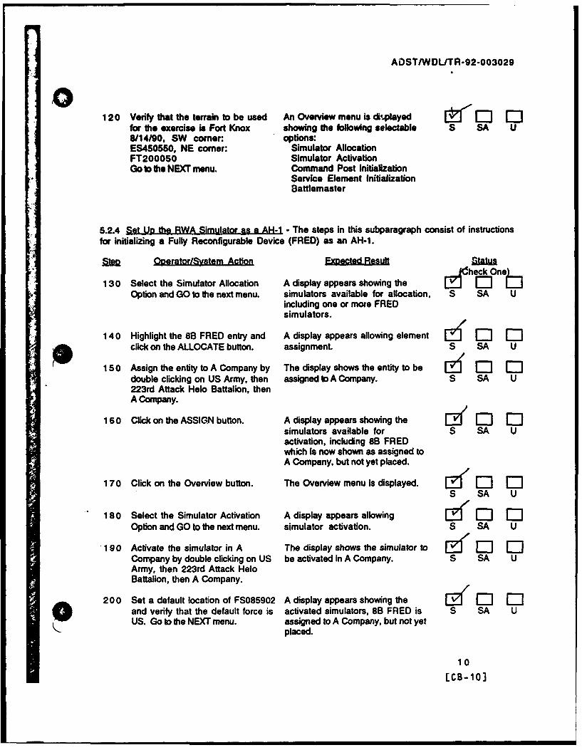
ADST/WDL/TR-92-003029
0120 Ve.f that the terrain to be used An Overview menu is diq.layed !-1J -'
for the exercise is Fort Knox showing the following selectable S SA U8/14/90. SW corner: options:ES450550, NE comer: Simulator AllocationFT200050 Simulator ActivationGo to the NEXT menu. Command Post Initialization
Service Element InitializationBattlemaster
5.2.4 Set Uo the RWA Simulator as a AH-1 - The steps in this subparagraph consist of instructions
for initializing a Fully Reconfigurable Device (FRED) as an AH-1.
3%e Ooerator/Svstem Action ExetdResult Status
130 Select the Simulator Allocation A display appears showing the Id , M OLDOption and GO to the next menu. simulators available for allocation, S SA U
including one or more FREDsimulators.
140 Highlight the 8B FRED entry and A display appears allowing element El Elclick on the ALLOCATE button. assignment. S SA U
150 Assign the entity to A Company by The display shows the entity to be I' I'-double clicking on US Army, then assigned to A Company. S SA U223rd Attack Helo Battalion, then
A Company.
160 Click on the ASSIGN button. A display appears showing the Ef '-l -simulators available for S SA Uactivation, including 8B FREDwhich is now shown as assigned toA Company, but not yet placed.
170 Click on the Overview button. The Overview menu is displayed. [Z1'EJE-S SA U
180 Select the Simulator Activation A display appears allowing y, M 0
Option and GO to the next menu. simulator activation. S SA U
.190 Activate the simulator in A The display shows the simulator to Ef ED F-1Company by double clicking on US be activated in A Company. S SA UArmy, then 223rd Attack HeloBattalion, then A Company.
200 Set a default location of FS085902 A display appears showing the IZ"EII['and verify that the default force is activated simulators, 8B FRED is S SA UUS. Go to the NEXT menu. assigned to A Company, but not yet
placed.
10
[CB-10]

ADST/WDIJTR-92-003o2g
O210 H1g9ligt the 88 FRED entry by A display appears allowing Ecicldng on the en d anl go to the simulator customization. S SA UNEXT menu.
220 Customize the 88 FRED with a taO The display refects 1he custom unumber of 2, a location of selections. S SA UFS085902. a heading of 0 degrees.an alignment of US, a maintenancestatus of New and a vehicle type ofAH-1. AN-i.
230 Verify that the default weapons load The display reflects the custom & 0 0Is: selections and a default weapons S SA U
20 mm Gating. 750 Rounds bad.Stinger 4TOW: 8Hydra 70 10lb: 0Hydra 70 MPSM: 38Hydra 70 Flechette: 0
240 Verify that the default fuel load is: The display reflects the custom fZ '-E 01703 lbs. selections and s default fuel load. S SA U
S 250 Select the ACTIVATE button. A display appears showing the [• M 0activated simulators, 8B FRED is S SA Uassigned to A Company, placed. Theactivate PDU Is sent across thenetwork Initiating theinitialization of the system,including V. weapons segmenL*3.2.1.5.1e3.2.1.5.1.1.1*3.2.1.5.1.1.3o3.2.1.5.1.1.5&3.2.1.5.1.2.1o3.2.1.5.1.2.2*3.2.1.5.1.2.3
260 Click on the Overview button. The Overview menu is displayed. Z( M 0S SA U
If this the second pass throughthese steps go to Step 400.
O11
(ce- 11J

ADST/WDL/TR-92-003029
5.2.5 Verify that the Weaoons Data File Is not Found - The steps in this subparagraph consist of9 instructions for verifying that the renamed weapons data file was not found.
QpOertor/Svstern Action E C Result 0nta --
270 At the GT-1 11 system console (gt- The specified message is displayed.1) verify the display of the (The RWA software attempted to S SA Ufollowing message: open the file, but because it was 'e;,. 'H
renamed, it was not found.)Cannotopen .3.2.1.3.2.2.3/sininet/data/ms_tw_ch.d
280 Using the switch session button, The system responds with the Id1"I[ II[toggle to GT-0. Hit the return key. GOSSIP> prompL S SA U
290 Enier 00Q to quit the real time A query is displayed asking if you [;" [J 01simulation software. are sure you want to quit. S SA U
300 Enter y (YES) <cr> in response to The system displays shutdown E " El [ -"Ethe query. messages and returns to the gt-0 > S SA U
prompt.
310 If the execution did not terminate The GT-1 11 system is rebooted.properly (i.e. error messages are The gt-0 display shows: S SA Udisplayed), reboot the GT-1 11 byhitting the reset button on the GT- Starting mpv component111 or by entering "reboot" at the Configured as GT1 11GT-0 prompt.
The gt-1 display shows:
Configured as GT1 11
The situational and instructionaldisplays are presented with defaultvalues.
320 At the AIRNET SCC, select the A display appears requesting the 1' -J -IBattlemaster Functions Option and Battlemaster password. S SA UGO to the next menu.
330 Enter the Battlemaster password The Battlemaster Overview menu ['EJ ED -](foozball) and click on the OK is displayed showing the following S SA Ubutton. selectable options:
DisplacementReconstituteGunnery TargetsResume InitializationEnd Exercise
340 Select the End Exercise option and An End Fxercise ConfirmationGO to the next menu. Menu layed. S SA U
12
rcB- 121

ADST/WDL/TR-92-003029
350 Respond to the Confirmation The Confirmation Display r'-0Qustion by clickdng on YES. disappears and the display returns S SA U
to the Macintosh windows screen.
5.2.6 Renlace Data File in Directory and Set U System - The steps in this subparagraph consist ofinstructions for replacing the weapons model data file in Its home directory and resetting thesystem.
C•lerator/Svstem Action Expected RBnul Status
360 At the GT-,11 system console, The SIMNET/DATA directory -:1 -:neIuse the switch session button to contents is displayed. It includes S SA Utoggle to GT-0 if the display is not file: TOWBT.D (The Bum Turnalready there. Set the default coefficients file for the TOWdirectory to /SIMNET/DATA by Missile, a Guided Missile.) 54';entering: o
cd /SIMNET/DATA <cr>,
Get a directory listing by entering Co.--,loLTr .
the command:
Is <cr>
9 370 Rename the file by entering: The file is renamed to ms_tw.bLd. -' I'- EJThe directory listing shows no S SA U
mv tow.bLd ms-tw bLd <cr> entry for tow._bt.d but includes anentry for ms-tw.bt.d.
and wait 10 seconds. Get adirectory listing (Is).
380 Repeat steps 60 to reset the The aircraft is initialized, the E] E] 0system. visuals and sound are active. S SA U
390 Verify that no message indicating No message indicating that the file [a rl Mthat the tile could not be found is could not be opened is output to the S SA Uoutput to the GT-1 11 system GT-1 11 system console.console. -3.2.1.3.2.2.3
-3.2.1.5
5.2.7 Saet.U2.Target - The steps in this subparagraph consist of instructions for initializing
Gunnery Targets.
SOperator/Svstem Action E Stusla
__ 400 Select the Eattlemaster Functions A display appears requesting the ['2 1 El E]Option and GO to the next menu. Battlemaster password. S SA U
13
[CB- 131

ADST/WDLITR-92-003029
O410 Erter the Battlemaster password The .3attUemaster Overview menu E(EJEJ0(foozbalP, and click on the OK is displayed showing the followmg S SA Ubutton. selecti ble options:
DispiacementReconstltuteGunnery TargetsResume InitializationEnd Exercise
420 Select the Gunnery Targets Opron A display allowing Gunnery Target [Er o] 0-and GO to the next menu. Specification appears. S SA U
430 Enter the gunnery targets as: The Battlemaster Overview menu ff 13 FE]Target 1, US, FWA, is displayed. S SA U
ES94808550, 2435Target 2, US. FWA,
ES9493851 0, 2435Target 3, US, FWA,
ES95108460, 2435Target 4, US, FWA,
ES95238420, 2435and click on the Overview button.
* 5.2.8 Fly Aircraft Through Flight Envelooe Phases - The steps in this subparagraph consist ofinstructions for flying the aircraft through the following flight envelope phases: Ascent, Hover,Cruise, Descent and Low Level Flight.
OoeratorlSystem Action Encd Rtesmulta
440 At the AH-1 softpanel, enter a The Situational Display shows a 1 n •OneLwaypoint at ES979898. and select indicating the waypoint position S SA Uit for navigation, relative to the aircraft's current
location and heading (representedby the center crosshairs). It alsoidentifies the aircraft's currentposition (grid coordinatesFS085902), the bearing to thewaypoint (approx. 267 deg.) andthe range to the waypoint (approx.10608 M.). /
4 5 0 Record the amount of fuel and the The fuel level is displayed on the [] E Ecurrent time: Instructional Display. S SA U
Fuel: £ 700 lbs.Time:
14
CCB-141

AOST/WDL/TR-92-003029
004 60 Take off noting the Wprmu at the The flight model mode transitions L.-;1'0
po- of iftoff. Ascend to an from Ide to Execute and flight S SA Ualtitude of 1000 ft. above sa level modeling begin. The flightand hover. controls and dynamics
characteristics of the aircraft wreTorque: 6 61 1. simulated. The aircraft ascent.
representative of the date in theEnter this value as Torque 1 in flight model data Sos and theStep 406.0 system responds In real-time to
,+Io the pilot's input."*3.2.1.3.2.1.2"*3.2.1.3.2.2.6"@3.2.1.3.2.2.6"-3.2.1.3.2.2.6.b (ascent)
470 Hover at 1000 ft. above sea level The aircraft hover is uf 0 0for one minute. representative of the data in the S S U
flight model data files and thesystem responds in real-time tothe pilot's input.*3.2.1.3.2.2.6.b (hover)
480 Fly at a constant cruise The aircraft cruise is r~ I -'Jspeed of approximately 100 knots representative of the data in the S SA Uwith a heading of approximately flight model data files and the267 degrees till you reach the system responds in real-time towaypoint area (3 - 4 minutes). the pilot's input.
.3.2.1.3.2.2.6.b (cruise)
490 Descend to an altitude of 35 - 45 The aircraft descent isft above ground level and hover. representative of the data In the S SA U
flight model data files and thesystem responds in real-time tothe pilot's input.-3.2.1.3.2.2.6.b (descent)
500 At the AH-1 softpanel, enter a The Situational Display shows a 2 [ J'-"1I--waypoint at ES948855, and select indicating the waypoint position S SA Uit for navigation, relative to the aircraft's current
location and heading.
510 Fly at a speod of 50 knots and at a The aircraft's low level flight is id ED 1constant altitude of 35 - 45 ft. representative of the data in the S SA Uabove ground level at a hepding of flight model data files and theapproximately 206 degrees until system responds in real-time tothe target area is approximately the pilot's input.
i ISO 4000 meters away. Hover at an -3.2.1.3.2.2.4altitude of approximately 300 ft. *3.2.1.3.2.2.6.b (low Ivi
fit)
15(CS- 15]

ADST/WDLITR-92-003029
O 5.2.9 Fire on the Taraets and Land - The steps In this subparagraph consist of instructions forfiring on the targets and landing the aircraft.
s h e oseoheat stirr Action l t2ih sif u
520 At the AH-1 Pilot Station, keeping The ~ilot's 20 mm gun selectionOne nose of the aircraft level with light transitions from unfit to IlL S SA U
the horizon, select the 20 mmGatling Gun (ballistics rounds) forfiring by pushing up on theweapons action switch.
530 Fire the gun expending The rounds fly out in a gentle arc, a C:- 0approximately 20 - 30 rounds. representative of the data in the S SA UNote the trajectory of flight for the weapons model files.fired rounds.
Une of si:ht
540 Deselect the Gatling Gun by pushing The Pilot's 20 mm gun selectionup on the weapons action switch. light transitions from lit to unlit. S SA U
_ 550 At the AH-1 Co-Pilot/Gunner The Co-Pilots Stinger selection ED D[Station. select the Stinger Missile light transitions from unlit to lit. S SA U(ballistic missile) for firing bypushing down on the weapons actionswitch.
560 Use the Manual Tracker to track The target is within the bounds ofone of the targets until the target is the line of sight reticle. S SA Uwithin the bounds of the dashed boxof the line of sight reticle.
570 Pull the trigger to the first detent. An aural seek tone is heald..l-I I1:3-7-;,A4 v4. S SA U
580 At the AH-1 Pilot Position. When the aircraft is positioned - '1 M -1Jmaneuver the aircraft into Stinger within the +/- 10 degree S SA Uprelaunch constraints (+/- 10 constraints missile lock-on isdegrees). achieved.
590 At the AH-1 Co-Pilot/Gunner The missile is launched, flies I '--1i'lPosition, fire on the target by towards the target and impacts. S SA Upulling the weapons trigger switchto the second detent.
600 Deselect the Stinger by pushing The Co-Pilot's Stinger selection E •'Elup on the weapons action switch. light transitions from lit to unlit. S SA U
16
[CB-16)

ADST/WDL/TR-92-003020
610 At the AN-i Co-Pilo/Gunner The Co-Pilots TOW selection (Z' CI0 0Station, s the TOW Missile light transitions from unfit to UL S SA U(guided missile) Ibr firing bypushing towmd the right on thewepons action awitch.
620 Us the Manuel Tracker to track The target is within the bounds of & n(E 0one of the targets until the target is the mne of sight reidle. 3 SA Uwithin the bounds of the dashed boxof the line of sight reticle.
630 At the AH-1 Pilot Position. When the aircraft Is positioned El' 0l omaneuver the aircraft into TOW within the constraints missile S SA Uprelaunch constraints, lock-on is achieved.
640 At the AH-1 Co-Pilot/Gunner The missile Is launched, flies [E 3 0Position, fire on the target by towards the target and impacts. S SA Upulling in the weapons triggerswitch.
65o Deselect the TOW by pushing The Co-Pilots TOW selection Etowards the right on the weapons light transitions from lit to unit. S SA Uaction switch.
660 At the AH-1 Pilot Station, land the The aircraft lands and flight E32 E Elaircraft. modeling is stopped. S SA U
670 Record the current fuel level and The fuel level is available from the [I E'l Elthe current time: Instructional Display. S SA U
Fuel Level: I bsTime: -2- I 4-L
Compute the fuel rate over time:
Fuel Consumption Rate: 10lbsJmin.
Record this value at Step 1590 asPass 1 Fuel Rate.
5.2.10 Terminate the Exercise - The steps i.- this subparagraph consist of instructions forterminating the exercise.
Ooerator/Svstem Action ExoecteRsult S1AWhokOneL
680 At the AIRNET SOC. select the End An End Exercise ConfirmationLJ ET MExercise option and GO to the next Menu is displayed. S SA Umenu.
17(C8- 17]

ADST/WDL/TR-92-003029
, 690 Respond to the Confirmation The Confirmation Display E ' 0 rQuestion by clicking on YES. disappears and the display returns S SA U
to the Macintosh windows screen.The CIG visuals and sound areterminated.
700 At the GT-111 system console, The simulation is terminated. Ed 0 0verify that the simulation software S SA Uis terminated. (The systemdisplays the message SIMULATORSTOPPED.)
710 Enter q to quit the GT- i simulation CIG stop messages and PDU [• 0)software. statistics are displayed followed by S SA U
the gt-1 > prompt.
720 Using the Switch Session key, The GOSSIP > prompt is displayed. 0) 0"toggle the GT-1 11 system console S SA Udisplay to GT-0 and hit return.
730 Enter Q to quit the GT-0 simulation A query is displayed asking if you [•c )C)software. are sure you want to quit. S SA U
740 Enter y (YES) <cr> in response to The system displays system [if 0] i0the query. shutdown messages and returns to S SA U
the gt-0 > prompt.
750 If the execution did not terminate The GT-111 system is rebooted. I "-0 I0-properly (i.e. error messages are The gt-0 display shows: S SA Udisplayed), reboot the GT-111 byhitting the reset button on the GT- Starting mpv component111. Configured as GT 111
The gt-1 display shows:
Configured as GT 111
The situational and instructionaldisplays are presented with defaultvalues.
18
[CB-181

ADST/WDL/TR-92-003029
5.2.11 Modify the Weapons Model - 'Me stepe in this subparagraph consist of instructions lormodifying the weapons model data tables.
contente one760 At the GT-111 system console. The /SIMNET/DATA directory S Sf Uuse tho switch session butlon to contents is displayed. It Includes S SA U
toggl to GT-0 If the display is not files:
already there. Set the default Guided Missile Files:directory to ISIMNET/DATA by MS_TW_CH.D (Characteristics)entering: MSTWBT.D (Trajectory Data)
MS_TW_CT.D (Trajectory Data)cd AJ/SIMNET/DATA <cr> Ballistic Missile Files:
MSSTCH.D (Characteristics)Get a directory listing by entering MS_STBS.D (Bum Speed Data)the command: MSSTCS.D (Coast Speed Data)
Ballistic Rounds File:Is ccm M789.D (Trajectory Data)
You will be modifying baselinefiles. It is suggested that you makea copy of these files so that theymay be easily restored at thecompletion of the exercise. Thefiles to be modified are:
mstwcs.dmsst..ch.dm789.drwaaero.drwa.engn.d
770 Initiate the text editor by entering: The editor is initiated and thecontents of file ms-tw_cs.d is S SA U
vi ms-tw.cs.d <cr> displayed.
780 Hit the j key until the cursor is The cursor is positioned on thepositioned on the line containing line containing the %_3 coefficienL S SA Uthe a-3 coefficient.
790 Hit the I key until the cursor is The cursor is positioned on the E- j [l E-positioned on the exponent eign•(wr exponent s*ga-of the a-3 S SA Ucharacter of the a_3 entry. coefficient.
800 Hit the R key, then the space bar The m-egoUwaii*ne&Rdsevende E3 0twice, then the esc key. deleted. S 1 SA U
81 0 Save the modified file contents by The file is saved and the prompt EY E] EDentering: returns to gt-0 • . S SA U
zz9 Wait 10 seconds.
19
[CB-19J

ADST/WOLITR-92-003029
40 820 At the prompt enter. The file's contents have been (0 0modified. S SA U
more metw-cs.d -cor> .3.2.1.5.1.1.2
to display the file's contents.Verify that the file's contents havebeen modified.
830 Initiate the text editor by entering: The edi:or Is initiated and the [• F- 0content=3 of file msosLch.d is S SA U
vA msst..ch.d cc, dieplayend.
840 Hit the j key until the cursor Is The cursor is positioned on thepositioned on the line containing line containing the S SA Ulhe STINGERLOCKTHRESHOLD STir" ER.PLOCKTHRESHOLD value.value.
850 Hit the I key until the cursor is The cursor is positioned on the F [ Mpositioned on the nine (9) of the 9 of the S SA USTINGERLOCKTHRESHOLD value. STINGERLOCKTHRESHOLD value.
860 Hit the R key, then enter: The original value is replaced with f 1 F0.5. S SA U
0.500000000
0 then hit the esc key.
870 Repeat the above steps for the The THETA_0 value entry reflects [ D C-THETA_0 value, entering a new the new value. S SA Uvalue of .1047.
880 Save the modified file contents by The file is saved and the prompt [ " -entering: returns to gt-0 > . S SA U
zz
Wait ten seconds.
890 At the prompt enter: The file's contents have been I• r:-modified. s SA U
more msstch.d <cr> .3.2.1.5.1.1.4
to di-'•lay the file's contents.Verity hat the file's contents havebeen modified.
900 Initiate the text editor by entering: The editor is initiated and the " -contents of fie m789.d is S SA U
vi m789.d <cr> displayed.
20
CCB-203

ADST/WDLITR-92-003026
910 Hit the j key until the cursor is The cursor is positioned on the line E2 0 "positioned on the line containing containing the second entry. S SA tthe second entry (0.033 is thefirst entry on the line).
920 Hit the I key until the cursor is The cursor is positioned on the [• El Cpositioned over the third entry of third entry of the second line. S SA tthe second line (0.018694).
930 Hit the R key, then enter: The original value is replaced with1.8694. S SA t
1.869400
then hit the esc Key.
940 Save the modified file contents by The file is saved and the prompt E [enteriiag: returns to gt-0 > . S SA t
zzWait ten seconds.
960 At the prompt enter: The file's contents have been [1 EJ Emodified. S SA L
more m789.d <cr> -3.2.1.5.1.1.6
to display the file's contents.Verify that the file's contents havebeen modified.
5.2.12 Modify Flight Model - The steps in this subparagraph consist of instructions for modifyingflight modal data tables.
OneratorlSvstemn Action ,F e Rnu
960 Get a directory listing by entering The /SIMNET/DATA directorythe command: contents is displayed. It includes S SA 1.
files:Is <cr> Flight Control & Dynamics Files:
rwa-kine.drwaaero.d
Engine Files:rwaengn.drw-en-in.d
0
21
(CB-21 I

ADST/WDL/TR-92-003029
970 Verify that file rwa-aero.d The file contains the identified Ezf - -contains (in part) the following flight controls and dynamics data. S SA Uflight controls and dynamics data -3.2.1.3.1.1.1by entering: .3.2.1.3.1.2.1
more rwaaero.d <cr>
and observing entries for:
AIRFRAME MASSGRAV_.cNSTANTVIRTUALWINGAREAVSTAB_..COP_.AC_.X
MAINROTORCOPACXHOVERLAUGROLL_P_GAINHOVERAUGPITCHIGAINHOVERAUGYAW_I_ GAIN
980 Verify that file rwa.engn.d The file contains the identified []contains (in part) the following engine data. S SA Uengine data by entering: •3.2.1.3.1.3.1
more rwaengn.d <cr>
and observing entries for:
GOVERNORB;GINESPEED_SETTING
MA)XENGINE_PERCENT_POWERMAINROTORGEAR_RATIOPOWERTRAIN_INERTIAMAXFUELFLOW
990 Initiate the text editor by entering: The editor is initiated and the E ["contents of file rwa-aero.d is S SA U
vi rwaaero.d <cr> displayed.
1000 Hit the j key until the cursor is The cursor is positioned on the line [• E -positioned on the line containing containing the ORDNANCEMASS. S SA Uthe ORDNANCE-MASS.
101 0 Hit the I key until the cursor is The cursor is positioned on the ' -positioned on the first character of first character of the S SA Uthe ORDNANC:-:_MASS (1). ORDNANCE-MASS value (1).
1020 Hit the R key, then enter: The original value is replaced with r-' I-3591.0. S SA U
3591.0
. 0 then hit the esc key.
22
-CB-22]

ADST/WDLITR-92-003029
100Save the modified fil, contents b, The file Is saved and the prompt U1 0entering: returns to gt-0 •. S SA U
zz
Wait ten seconds.
1040 At the prompt enter: The file' contents have been [A 0 "modified. S SA U
more rwaaero.d <cr> .3.2.1.3.1.1.1.2o3.2.1.3.1.2.1.2
to display the file's contents.Verify that the file's contents havebeen modified.
1050 Initiate the text editor by entering: The editor is initiated and the I ["Iijcontents of file rwaengn.d is S SA Uvi rwe_engn.d <cr> displayed.
1060 Hit the j key until the cursor is The cursor is positioned on the lastpositioned on the last line of the line of the file. S SA Ufile (MAXFIJELFLOW).
1070 Hit the I key until the cursor is The cursor is positioned on the [- [-Epositioned on the first digit of the first digit of the MAXFUELFLOW S SA UMAXFUELFLOW entry. entry.
1080 Hit the R key, then enter The original value is replaced with [-7 Ml EiIMO !40.- (approximately 10 times S SA U
770.000000 the original value).
then hit the esc key.
1090 Save the modified file contents by The Usle is saved and the prompt 121 M 1'1entering: returns to gt-0 >. S SA U
zz
Wait ten seconds.
1100 At the prompt enter: The file's contents have been f ED EDmodified. S SA U
more rwaengn.d <cr> *3.2.1.3.1.3.1.2
to display the file's contents.Verify that the file's contents havebeen modified.
9
23[CB-231
4\

AOST/WDL/TR-92-003029
5.2.13 Initiate the Real-Time and RWA Simulation Software - The steps in this subparagraph
consist of instructions for initiating the real-time and RWA simulation software.
M fleratorvm Action EnaR l
1110 At the GT-1 11 system console, The A:/CIG/CONFIG directory ehuse the switch session button to contents is displayed. It includes S SA Utoggle to GT-0 if the display is not file:already there. Set the default runcigdirectory to A'/CIG/CONFIG byentering:
cd <cr>
Get a directory listing by enteringthe command:
Is <cr>
112 0 Initiate the real time simulation The system responds with the Ed Elsoftware by entering: following: S SA U
source runcig <cr> Verbose mode is OFF=== Using mpv interface
at the gt-O > prompt.
* 1130 Toggle the display to GT-1 by The initial display shows a line E ID ohitting the Switch Session key drawing of a helicopter and S SA Uuntil GT-1 is reached. Set the identifies the software revisiondefault directory to A: by entering: number. This is followed by CIG
initialization messages and finallycd <cr> STARTUP INITIALIZATION
COMPLETEInitiate the RWA software by 93.2.1.3.1entering:
rwa knox.par -k -1 3 -c <cr>
at the gt-1 > prompt.
5.2.14 Initiate the AIRNET Management. Command and Control Console Software - The steps in thissubparagraph consist of instructions for initiating the AIRNET MCC software.
"Ooerator/System Action Expected Re.hJteck 01,
114 0 At the Aimet SCC, initiate the SCC The Macintosh windows display is EDprocess by double clicking on the replaced by a Connect Window. S SA UAIRNET SCC.0.0 entry..9.
24
[CB-24]

ADST/WDL/TR-22-O03029
115 0 Double dick on the Loral zone The system connects to the network Cd 0 --entry, then single click on tha and system loading messages are S SA UMIPS host entry. Click on the displayed for a couple of minutes.CONNECT butlon. When system loading is complete,
the SCC Start Display is presented.
5.2.15 Set Up the Exercise at the AIRNET Svsiem Control Console - The steDs in this subparagraphconsist of instructions for initializing the exercise number, the role of the Management Command,and Control Console, and the exercise's geographic area.
BMn Ooerator/Svstem Action ExscdReult slaw
1160 At the Aimet SCC. start the A display appears showing the- , 0exercise initialization process by exercise number, the MCC role, S SA Uclicking on the START button. and the terrain to be used in the
exercise.
1170 Verify that the MCC is The MCC is participating in Z 0- 0participating in Exercise 1. Exercise 1. S SA U
1180 Select the default role of the MCC to Tie display shows the default MCC Z 0be US. role to be US. SA U
1190 Verify that the terrain to be used An Overview menu is displayed ['"1'for the exercise is Fort Knox showing the following selectable S SA U8114/90, SW corner: options:ES450550, NE comer: Simulator AllocationFT200050 Simulator ActivationGo to the NEXT menu. Command Post Initialization
Service Element InitializationBattlemaster
5.2.16 Set Up the RWA Simulator as a AH-1 - The steps in this subparagraph consist ofinstructions for initializing a Fully Reconfigurable Device (FRED) as an AH-1.St Ooerator/Svstem Action Egd Satus
12 0 0 Select the Simulator Allocation A display appears showing the i hOFD .Option and GO to the next menu. simulators available for allocation, S SA U
including one or more FREDsimulators.
1210 Highlight the 8B FRED entry and A display appears allowing entity 6 I' Iclick on the ALLOCATE button. assignment. S SA U
25
(CB-25]

ADST/WDLITR-92-003029
01220 Assign the entily to A Company by The display shows the .ntity to be QZ 0 0double clicking on US Army, then assigned to A Company. S SA U223rd Attack Helo Battalion. thenA Company.
1230 Click on the ASSIGN button. A display appears showing the 0 0simulators available for S SA Uactivation, including 8B FREDwhich is now shown as assigned toA Company, but not yet placed.
12 4 0 Click on the Overview button. The Overview menu is displayed. 1 "" 0 "0S SA U
1250 Select the Simulator Activation A display appears allowing Ei 0 0"Option and GO to the next menu. simulator activation. S SA U
1260 Activate the simulator in A The display snows the simulator to 6 I0 0Company by double clicking on US be activated in A Company. S SA UArmy, then 223rd Attack HeloBattalion, then A Company.
1270 Set a default location of FS085902. A display appears showing the (z 0l ] [and verify that the default force is activated simulators, 8B FRED is S SA UUS. Go to the NEXT menu. assigned to A Company, but not yet
placed.
1280 Highlight the 8B FRED entry by - A display appears allowingclicking on the entry and go to the simulator customization. S SA UNEXT menu.
1290 Customize 8B FRED with a tail The display reflects the customnumber of 2, a location of selections. S SA UFS085902, a heading of 0 degrees,an alignment of US, a maintenancestatus of New, and a vehicle type ofAH-1. /
1300 Verify that the default weapons load The display reflects the custom [J -] -]is: selections and a defaul, weapons S SA U
20 mm Galling: 750 Rounds load.Stinger: 4TOW: 8Hydra 70 10 b: 0Hydra 70 MPSM: 38Hydra 70 Flechette: 0
1310 Verify that the default fuel load is: The display reflects the custom 1 M M1703 lbs. selections and a default fuel load. S SA U
26
[CB-26]

ADSTlWDL/TR-92-003029
1320 Select the ACTIVATE button. A display appears showing theEdoactivated simulators. 8B FRED is S SA Uassigned to A Company, placed.The RWA is activated as an AH-1,the Image generator visuals andsound come on. No messageIndicating that the weapons modelfile (MSTWCH.D) could not beopened is output to the GT-111system console. (See Section5.2.5.) The flight and weaponsmodels are initialized using thedata files. The flight model is idle.standing by for input from thepilot.*3.2.1.3.1.1:3.2.1.3.1.1.1.1.3.2.1.3.1.2: 3.2.1.3.1.2.1.1-3.2.1.3.1.3:3.2.1.3.1.3.1.1.3.2.1.3.2:3.2.1.3.2.1,3.2.1.5.1.3.2.1.5.1.1.13.2.1.5.1.1.3
-3.2.1.5.1.1.5*3.2.1.5.1.2.1•3.2.1.5.1.2.2e3.2.1.5.1.2.3*3.2.1.3.2.1.4
1330 Click on the Overview button. The Overview menu is displayed. • "- iS SA U
0
27
ECB-27]
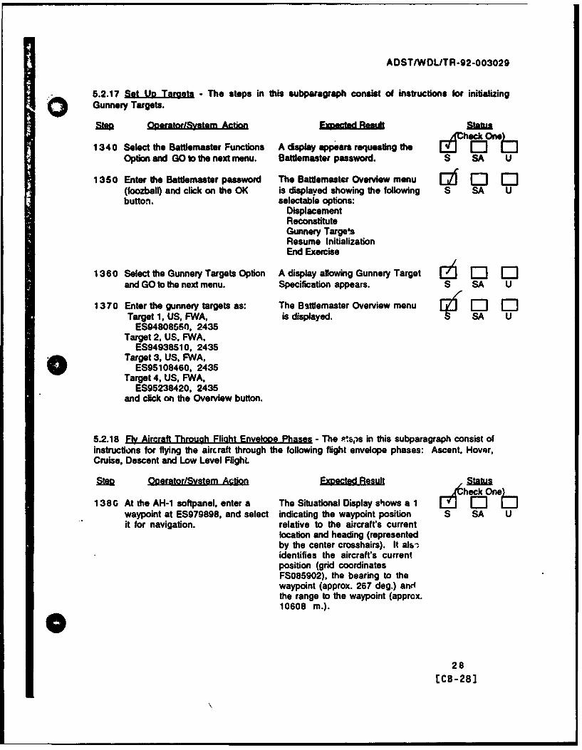
ADSTIWDLIT R-92-003029
5.2.17 SetLUaIgnh - The steps in this subparagraph consist of instructions for initializingGunnery Targets.
2 (Meratorlaystem Action Ejgg Retal Ul
1340 Select the Battlemaster Functions A display appears requesting the 1:1OE3Option and GO to the next menu. Battlemaster password. S SA U
1350 Enter the Battlemaster password The Battlemaster Overview menu 1 0i o"(foozball) and click on the OK is displayed showing the following S SA Ubutton. selectable options:
DisplacementReconstituteGunnery TargetsResume InitializationEnd Exercise
1360 Select the Gunnery Targets Option A display allowing Gunnery Targetand GO to the next menu. Specification appears. S SA U
1370 Enter the gunnery targets as: The Bsttlemaster Overview menu Ci " rTarget 1, US, FWA, is displayed. SA U
ES94808550, 2435Target 2, US, FWA,
ES94938510, 2435Target 3, US, FWA,
ES95108460, 2435Target 4, US, FWA,
ES95238420, 2435and click on the Overview button.
5.2.18 FBy Aircraft Through Flight Envelope Phases - The steps in this subparagraph consist ofinstructions for flying the aircraft through the following flight envelope phases: Ascent, Hover,Cruise, Descent and Low Level FlighL
St Ocerator/Svstem Action Emmicted Raesl.Jhock One
138G At the AH-1 softpanel, enter a The Situational Display shows a 1 [ 9E]O .waypoint at ES979898, and select indicating the waypoint position S SA Uit for navigation, relative to the aircraft's current
location and heading (representedby the center crosshairs). It als-identifies the aircraft's currentposition (grid coordinatesFS085902), the bearing to thewaypoint (approx. 267 deg.) andthe range to the waypoint (approx.10608 m.).0
28[CB-281

ADST/WDL/TR-92-0o302g
* 1390 Recordthe arount of fue and the The fudl W-41sdisplayed On the d"1: 0current time: Instructional Display. S SA U
Fuel: L&t lbsTime: T:,71 :.
1400 Take off noting the torque at the The aircraft ascent Is id 0 0point of liftoff. Ascend to an representative of the data in the S SA Ualtitude of 1000 ft. above sea level fligt model data files and theand hover, system responds in real-time to
Torque: the pilot's input.
Enter the torque as the Takeoff 2Torque value in Step 4e.
1410 Compare the torque required for The torque required for the second [J f-'this takeoff against the torque takeoff is larger due to the S SA Urequired for the first take off. increased ordnance mass.
Takeoff 1 Torque: 6W ,.Takeoff 2 Torque: V.. ".'
* 1420 Hover at 1000 ft. above sea level The aircraft hover isfor one minute. representative of the data in the S SA U
flight model data files and thesystem responds In real-time tothe pilot's input.
1430 Fly at a constant cruise The aircraft cruise is 0 E]speed of approximately 100 knots representative of the data in the S SA Uwith a heading of approximately flight model data files and the267 degrees till you reach the system responds in real-time towaypoint area (3 - 4 minutes). the pilot's input. /
1440 Descend to an altitude of 35 - 4S The aircraft descent is C i-ft. above ground level and hover. representative of the data in the S SA U
flight model data files and thesystem responds in real-time tothe pilot's input.
1450 At the AH-1 softpanel, enter a The Situational Display shows a 2 [ -"iEJE-waypoint at ES948855, and select indicating the waypoint position S SA UIt for navigation, relative to the aircraft's current
location and heading.
29[CB-291

ADST/WDoTR-92-003029
10 14 60 Fly at a speed of 50 knots and at a The aircraft's low level flight is Ed 0l Elconstant altitude of 35 - 45 ft. representative of the data in the S SA Uabovo ground level at a heading of flight model data files and theapproximately 206 degrees until system responds In real-time tothe target area is approximately the pilot's input.
a5eo 4WG meters away. Hover at an *3.2.1.3.2.2altitude of approximately 300 ft.
5.2.19 Fire on the Targets and Land - The steps in this subparag-aph consist of instructions for
firing on the targets and landing the aircraft.
SOoerator/S wtem Action ,M 29W Result Status
1470 At the AH-1 Pilot Station, keeping The Pilot's 20 mm gun selection ,e D [ ]the nose of the aircraft level with light transitions from unlit to lit. S SA Uthe horizon, select the 20 mmGatling Gun (ballistics rounds) forfiring by pushing up on theweapons action switch.
1480 Fire the gun expending The rounds fly out in a manner El " lapproximately 20 - 30 rounds. representative of the data in the S SA UNote the trajectory of flight for the weapons model files.fired rounds..
Y vYyy~* Une of sight p1
*k *
"*3.2.1 .5.2.4.41490 Deselect the Gatling Gun by pushing The Pilot's 20 mm gun selection l -- M ""D
up on tta weapons action switch. light transitions from lit to unlit. S SA U
1500 At the AH-1 Co-Pilot/Gunner The Co-Pilots Stinger selection E• -3EJ MStation, select the Stinger Missile light transitions from unlit to lit. S SA U(ballistic missile) for firing bypushing down on the weapons actionswitch. /
1510 Use the Manual Tracker to track The target is within the bounds of [ -' El Eone of the targets until the target is the ine of sight reticle. S SA Uwithin the bounds of the dashed boxof the line of sight reticle. /
1 520 Pull the trigger to the first detent. An aural seek tone is heard. E l ElS SA U
30[CB-30]

ADST/WOLITR- )2-003029
1530 At the AH-! Pilot Position, When the aircraft is positionedmaneuver the aircraft into Stinger within the +./ 45 degree S SA Uprelaunch constraints. constraints missile lock-on is
achieved.
1540 At the AH-1 Co-Pilot/Gunner The missile Is launched, flies 0 -Position, fire on the target by towards the target and impacts. S SA Upulling the weapons trigger switch .3.2.1.5.2.4.3to the second detent
1550 Deselect the Stinger by pushing The Co-Pilot's Stinger selection I -- --Dup on the weapons action switch. light transitions from lit to unlit. S SA U
1560 At the AH-1 Co-Pilot/Gunner The Co-Pilots TOW selection [J D 0Station, select the TOW Missile light transitions from unlit to lit. S SA U(guided missile) for firing bypushing towards the right on theweapons action switch.
1570 Use the Manual Tracker to track The target is within the bounds of -i '-one of the targets until the target is the line of sight reticle. S SA Uwithin the bounds of the dashed boxof the line of sight reticle.
1580 At the AH-1 Pilot Position. When the aircraft is positioned [ZI..CImaneuver the aircraft into TOW within the constraints missile S SA Uprelaunch constraints, lock-on is achieved.
1590 At the A H-1 Co-Pilot/Gunner The missile is launched, flies [C I I-"Position, fire on the target by briefly and disappears, no impact S SA Upulling in the weapons trigger is seen.switch. 93.2.1.5.2.4.1
1600 Deselect the TOW by pushing The Co-Pilot's TOW selection Ci E- Eitowards the right on the weapons light transitions from lit to unlit. S SA Uaction switch.
1610 At the AN-i Pilot Station, land the The aircraft lands and the flightaircraft. modeling is stopped. S SA U
-3.2.1.3.2.3.2
1620 Record the current fuel level and The fuel level is available from the
31
[CB-311
/

ADST/WDL/TR-92-003029
the current time: Instructional Display. S SA U
0 Fuel Level: TPO Ibs.
Time: . c1 ,
Compute the fuel rate over time:
Fuel CorsunAior Rate: dhbsimin.
Pass 1 Fuel Rate:Pass 2 Fuel Rate:
1630 Compare the fuel consumption rate The fuel consumption rate for [• [JE]during this pass against that pass 2 is approximately 5 times S SA Uobtained from pass 1. the fuel consumption rate for pass
1.
32
CCB-321

AOST/IWDLTR-92-003029
5.2.20 Terminate the Exercise - The steps In this subparagraph consist of instructions for
terminating the exercise.
AND eftoraladstem Action a toms
1640 At the AIRNET SCC, select the End An End Exercise Confirmation 0 Lh O1,_Exercise option and GO to the next Menu is displayed. S SA Umenu.
1650 Respond to the Confirmation The Confirmation Display [] -1 JQuestion by clicking on YES. disappears and the display returns S SA U
to the Macintosh windows screen.The SCC disk is ejected and the CIGvisuals and sound are terminated.
1660 At the GT-1 11 system consoie, The GT-1 11 system console I] I'- I•verity that the simulation software displays CIG stop messages Iollowed S SA Uis terminated, by the message:
SIMULATOR STOPPED'3.2.1.3.3*3.2.1.3.3.a*3.2.1.3.4*3.2.1.3.4.a
Restore the modified filesms_tw_cs.dmsst.ch.dm789.drwaaero.drwa..engn.d
to their baselined state.
33
[CB-331

ADST/WDULTR-92-003029
O 6.0o NOTES
Test failures will be noted in the procedure against each test step as necessary where test results donot agree with expected results. Due to the nature of these system level tests, a simulator "crash"due to pilot error will not be constituted as a failure but an acceptable interruption. The systemprovides the capability for re-starting at the point of where !he crash occurred and will be utilizedduring the execution of this system level test.
0'
0
34
[CB-34]

ADST/WDL/TR-92-003029
0 7.0 Test Falluresllntarruotlons
NOTE ANY FALURES ENCOUNTERED DURING THE TEST IN THIS SECTION.
NO. FAILURE/INTERRUPTION DESCRIPTION
II
35
[CB-35J

ADST/WDLITR-92-003029
6.0 Glosa3..I
AdminJLog Administration/LogisticsADRS AddressAIRNET Aircraft Simulation NetworkACUC Administration/Logistics Operations ConsoleAmmo AmmunitionBBN Bolt. Beranek, and NewmanCEO Communications and Electronics Operations InstructionsCIG Computer Image GeneratorCR3 Co-PilotlGunnerDMOC Digital Message Communications ConsoleDMS Digital Message ServsrETA Estimated rune of ArrivalFRED Fully Reconfigurable DeviceFREE TXT Free TextFSE Fire Support ElementFWD ForwardGT-111 BBN Computer System/CIG supporting SimulationHEI High Explosive IncendiaryHUMMV High Mobility Multi-Wheeled VehicleI & T Integration & TestIMMED Immediatelylbs. poundsLCTN LocationMac Macintosh ComputerM:Z: Management, Command and Control ConsoleMIPS AIRNET MCC Host ComputerMOITO Move ToMOVCMD, Move CommandN Message
LIfO Movement to OrderPill Protocol Data UnitPIE Pyrotechnic Incendiary ExplosiveRAH-66 Comanche HelicopterRB:XN ReconnaissanceRECCNTYPE Reconnaissance TypeRBOT RequestRPRT ReportRWA Rotary Wing Aircraft"S/W Software
System Control ConsoleSOF System Development Facility, Loral WDL. San JoseSIMNET Simulation NetworkSND ROUT Send RoutineSND URG Send UrgentSYS MAIN System Main Menu1XC Tactical Operations CenterUMCP Unit Maintenance Collection PointUTM Universal Transverse MercatorWD L Western Development Labs
36[CB-36]

ADST/WDL/TR-92-003029
WHN ROY When ReadyXMIT ALT Transmit AltitudeXMIT LCN Transmit Location
t,
37
[CB-371

AOST/WDLITR-92-003029
APPENDIX A
EXERCISE "No REQUIREMENTS MATRIX
REQ NO. TITLE REQUIREMENT3.2.1.3.1 Flight Model The Flight Model Segment Initialization State shael be
Initialization State. entered during the System Initialization process aftersystem bootup. System state and status variablesuniquely identify the RWA AirNet configuration andstate.
3.2.1.3.1.1 Flight Controls Initialization of the Flight Controls Model Sub-Initialization. Segment configuration shall be done during this state
upon command from the sysfem.3.2.1.3.1.1.1 Flight Controls Data Parameters to be set shall include maximum pitch,
roll and yaw rates, turning radius, flight controlsinput sensitivity and profile, physical constants,conversion factors, integration constants, gains andlimits.
3.2.1.3.1.1.1.1 Flight Controls Data Data values shall be read from a flight controls modelFile. initialization file.
3.2.1.3.1.1.1.2 Flight Controls Data The format of the data file shall allow modification ofFormat ih- data using a text editor.
3.2.1.3.1.2 Flight Dynamics Initialization of the Flight Dynamics Model Sub-Initialization. Segment configuration shall be done during this state
upon command from the system. During this mode,configuration flags and variables are set which pointto specific submodules and data files for execution andloading.
3.2.1.3.1.2.1 Flight Dynamics Data Initialization shall include downloading of coefficienttables for the main rotor, fuselage and stabilizers.
3.2.1.3.1.2.1.1 Flight Dynamics Data These values shall be read from a flight dynamicsFile. model initialization file.
3.2.1.3.1.2.1.2 Flight Dynamics Data The format of the data file shall allow modification ofFormat the data using a text editor.
3.2.1.3.1.3 Engine Initialization. Initialization of the Engine Model Sub-Segmentconfiguration shall be done during this state uponcommand from the system.
3.2.1.3.1.3.1 Engine Initialization Initialization shall include downloading of data tablesfor the gas and power turbines, fuel consumption,Dower output, and acceleration coefficients.
3.2.1.3.1.3.1.1 Engine Data. These values shall be read from an engine modelinitialization file.
3.2.1.3.1.3.1.2 Engine Data Format The format of the data file shall allow modification ofthe data using a text editor.
3.2.1.3.2 Flight Model Run-Time In this mode the Flight model Segment shall be inState. stand-by awaiting RWA AirNet Flight model activity.
3.2.1.3.2.1 Flight Model Idle Mode. During the Flight Model Idle mode, the execution ofthe flight model functions shall be suspended.
3.2.1.3.2.1.2 Flight Model Idle Mode Execution shall be started or resumed from this mode.Change.
38ECe-38J

ADSTIWDL/TR-92-003029
O REQ NO. TITLE REQUIREMENT3.2.1.3.2.1.4 Flight Model Idle Mode The modifications shall have no adverse affects upon
Functionality. the Flight Model Idle mode functionality.3.2.1.3.2.2 Flight Model Execute During the Flight Model Execution mode. the flight
Mode. model shall be executed in real-time.3.2.1.3.2.2.3 Flight Model Execute The source of coefficient data shall be table look ups.
Mode Data Sources.3.2.1.3.2.2.4 Flight Model Execute The modifications shall have no adverse affects upon
Mode Functionality. the Flight Model Execute mode functionality.3.2.1.3.2.2.5 Flight Controls Model The Flight Controls Model Sub-Segment shall
_simulate the flight controls of the aircraft.3.2.1.3.2.2.6 Flight Dynamics Model The Flight Dynamics Model Sub-Segment shall
provide a simulation of the flight characteristics ofthe aircraft.
3.2.1.3.2.2.6.b Flight Dynamics The simulation shall include portions of the flightModel envelope including cruise, ascent, descent, hover, and
_low-level flight with ground effect.3.2.1.3.2.3.2 Flight Model Stop Mode The modifications shall have no adverse affects upon
Functionality. the Flight Model Stop mode functionality.3.2.1.3.3 Segment Capability Flight Model Segment capability relationships shall
Relationships. not be affected by modifications and restructuring ofthe flight model functions.
3.2.1.3.3.a Segment Capability The capability relationships shall remain intact.Relationships.
3.2.1.3.4 Segment External Flight Model Segment interface requirements shallInterface not be affected by modifications and restructuring ofRequirements. the flight model functions.
3.2.1.3.4.a Segment External The interface requirements shall remain intact.InterfaceRequirements.
3.2.1.5 RWA Weapons Model The intent o: the RWA Weapons Modol Upgrade is toUpgrade Segment improve the software by making it table driven.
3.2.1.5.1 Initialize Weapons The Initialize Weapons Segment state is enteredState during the System Initialization process after system
bootup.3.2.1.5.1.1.1 Guided Missile Trajectory coefficient data associated with guided
Trajectory Coefficient missiles shall be loaded at mission initialization.Data
3.2.1.5.1.1.2 Guided Missile Trajectory coefficient data files for Guided MissilesTrajectory Coefficient shall be in a format which allow modificationData Format through a standard text editor.
3.2.1.5.1.1.3 Ballistic Missiles Trajectory coefficient data associated with ballisticTrajectory Coefficient missiles shall be loaded at mission initialization.Data
3.2.1.5.1.1.4 Ballistic Missile Trajectory coefficient data files for Ballistic MissilesTrajectory Coefficient shall be in a format which allow modificationData Format through a standard text editor.
3.2.1.5.1.1.5 Ballistic Rounds Trajectory coefficient data associated with BallisticTrajectory Coefficient Rounds shall be loaded at mission initialization.
,_ _ Data
39
[CB-39J

ADST/WDL/TR-92-003029
REQ NO. TITLE REQUIREMENT3.2.1.5.1.1.6 Ballistic Rounds Trajectory coefficient data files for Ballistic Rounds
Trajectory Coefficient shall be in a format which allow modificationData Format throuah a standard text editor.
3.2.1 .5.1.2.1 Guided Missiles Guided missile characteristics shall be initialized viaCharacterization data files.
3.2.1.5.1.2.2 Ballistic Missiles Ballistic missile characteristics shall be initializedCharacterization via data files.
3.2.1.5.1.2.3 Ballistic Rounds Ballistic Rounds characteristics shall be initializedCharacterization via data files.
3.2.1.5.2.4.1 Guided Missile Flyout Guided Missile Flyout shall utilize new datastructures containing traiectory and control data.
3.2.1.5.2.4.3 Ballistic Missile Ballistic Missile Flyout shall utilize new dataFIyout structures containing traiectory and control data.
3.2.1.5.2.4.4 Ballistic Round Flyout Ballistic Round Flyout shall utilize new data_structures containing trajectory and control data.
40
[ce-40]

ADST/WDLITR-92-003029
'0 Appendix B
Exercise "B" Reoaulrements InspectlonlAnalvyls Matrix
I ReportREQ NO. TITLE REQUIREMENT Reference
3.2.1.3.2.1.1 Flight Model Idle Integration computations shall be put In IMode Integration. a stable state.
3.2.1.3.2.1.3 Flight Model Idle This mode shall ie controlled by the 1Mode Control. system executive.
3.2.1.3.2.2.1 Flight Model Execute Execution shll be stopped from this IMode Execution. mode.
3.2.1.3.2.2.2 i;ght Model Execute The rate of execution shall be controlled 1Mode Execution Rate. by the system executive.
3.2.1.3.2.2.5.a Flight Controls Model Input shall be used to calculate a 2resultant movement of a control surfaceand corresponding output to the flightdynamics model sub-segment.
3.2.1.3.2.2.6.c Flight Dynamics The simulation shall include calculation 3Model of forces and moments, equations of
motion, weight and balance, andaerodynamics.
3.2.1.3.2.2.7 Engine Model The Engine Model Sub-Segment shall 4provide core engine representation,torque generation, engine fuel systemutilization, and transmissionrepresentation.
3.2.1.3.2.3 Flight Model Stop During the Flight Model Stop mode, the 1Mode. execution of the flight model functions
shall be suspended.3.2.1.3.2.3.1 Flight Model Stop This mode shall be controlled by the 1
Mode Control. system executive.3.2.1.5.2.4.2 Use of Data Tables Updates required Modification of the 5
source code shaill be limited toreference data tables containing datawhich is read in via data files.
3.9.3 RWA Flight Model The RWA Flight Model Upgrade Segment 6Upgrade Segment shall be qualification tested at Ft.Qualification Rucker.
3.9.3.a RWA Flight Model The RWA Flight Model Upgrade Segment 6Upgrade Segment test shall take place during theQualification program integration and test phase
(I&T).
41
[CB-41J

ADST/WDLITR-92-003029
ReportREQ NO. TITLE REQUIREMENT Reference
3.9.3.b RWA Flight Model The RWA Fight Model Upgrade Segment 6Upgrade Segment test shall not exceed 2 working days.Qualification
3.9.3.c RWA Flight Model The testing shall demonstrate the RWA 6Upgrade Segment Flight Model Upgrade Segment providesQualification the functionality described previously
in this document.3.9.5 RWA Weapons The RWA Weapons Model Upgrade 6
Model Upgrade Segment shall be qualification tested atSegment Ft. Rucker.Qualification
3.9.5.a RWA Weapons The RWA Weapons Model Upgrade 6Model Upgrade Segment test shall take place during theSegment program integration and test phaseQualification (I & T).
3.9.5.b RWA Weapons The RWA Weapons Model Upgrade 6Model Upgrade Segment test shall not exceed 2 workingSegment days.Qualification
3.9.5.c RWA Weapons The testing shall demonstrate the RWA 6Model Upgrade Weapons Model Upgrade SaginentSegment provides the functionality described
I Qualification previously in this document.
42
CCB-42]

ADST/WDL/TR-92-003029
'0 Appendix C
Exercise OB" InRnectlonlAnalvsls Reoorts
Report Reference
1. Fight Model Mode Requirements2. Flight Controls Requirements3. Flight Dynamics Requirements4. Engine Model Requirements5. Data Table Use6. Flight and Weapons Models Qualification Requirements7. Processing Capacity
0
43
rrR-AI

ADSTIWDOLTR-92-003029
AIRNET INSPECTION/ANALYSIS REPORT I
ReqL No.: 3.2.1.3.2.1.1 Spec. Para.: 3.2.1.3.2.1.13.2.1.3.2.1.3 3.2.1.3.2.1.33.2.1.3.2.2.1 3.2.1.3.2.2.13.2.1.3.2.2.2 3.2.1.3.2.2.23.2.1.3.2.3 3.2.1.3.2.33.2.1.3.2.3.1 3.2.1.3.2.3.1
Requirement Descriptions:
3.2.1.3.2.1.1 Flight Model Idle Mode IntegrationIntegration computations shall be put in a stable state.
3.2.1.3.2.1.3 Flight Model Idle Mode ControlThis mode shall be controlled by the system executive.
3.2.1.3.2.2.1 Flight Model Execute Mode ExecutionExecution shall be stopped from this mode.
3.2.1.3.2.2.2 Flight Model Execute Mode Execution RateThe rate of execution shall be controlled by the system executive.
3.2.1.3.2.3 Flight Model Stop ModeDuring the Flight Model Stop mode, the execution of the flight model functions shall be suspended.
3.2.1.3.2.3.1 Flight Model Stop Mode ControlThis mode shall be controlled by the system executive.
Inspection Method: The flight model simulation is dependent upon the initialization of the flightmodel itself, and the input of data affecting the state of the aircraft. Figure 1 illustrates thesoftware path related to flight model execution.
The system executive (main) program controls all execution. When the software is first initiated.it performs preliminary initialization based upon defaults and user specified run parameters.Ultimately, it invokes the simulationstatemachine. This software is executed throughout thesimulation at a real-time rate.
The simulationstate-machine software controls the execution of multiple processes whosesequence and rate of execution is determined by the simulation state (3.2.1.3.2.2.2). Executionpasses through veh.spec-startup, veh-spec-idle and veh-spec-init which perform furtherinitialization and set up (including placing the integration computations in a stable state,3.2.1.3.2.1.1) based upon the type of vehicle to be simulated. When :ompleta, the flight modelsegment has been initialized and trans;tions from an initialization state to a run-time state. It thenstands by in an idle mode awaiting activity (3.2.1.3.2.1.3).
When the simulation state is SIMSIMULATESTATE, the vehspecsimulate software is initiated.This further invokes various routines which perform the simulation of the aircraft including itsflight; the flight model segment is in execute mode. The system remains in this state/mode until the
* simulation state transitions to SIMSIMSTOPSTATE. Once transitioned to this state, simulation of
44
[CB-44]

A DSTIW DL/T R.92-003029
the aircraft's flight is terminated (flight modlel stop mode, 3.2.1.3.2.2.1) and the simulation stateIs returned to SIM-.STATE-IDLE (3.2.1.3.2.3, 3.2.1.3.2.3.1)
main System
Executive
simulation-.state...rachine
veh..specIl veh...spec-.s!TJ od
Idle veh..spocinitw veh..sWe..simat
Fstoroyn-nitaerodyn...simul
ge.aircraft-kinematic-.state
ocornteji ht arsamtrs
corn utejonifnd orces
Execute corn ute... .-damping-forces..andjnomentsMode Igenerate...gravity-.bodyjforce
Figure 1: Flight Model Execution Software Path
45ECB-45J

ADSTIWDLITR-92-oo3o2g
The software packages containing the software referenced above are as follows:
Software Package Softwrre Modulerwa-main.c main
veh-.spec-.startupvoh-.spec-idleveh..spec-initveh-.spec...simulate
____________________ veh_ spec stop ______
Iibmain/main.c simulation-state-machine _____
rwa-ctl-fsm.c controls-simulrwa-ammo.c ammo-simulrwa -fuelsys.c fuel- simul______rwa simul.c rwa-simulrwa-.aerodyn.c aerodyn-.simul
get..aircraft~kinematic~statecompute-flight-.parameterscompute-.stab-.augmentation-.gainscompute..rotor-loadscompute-.enginejtorquecompute-.rotorjforces_and~momentscompute-ift-drag...coefficientscompute-lift-drag-forcescompute-body-damping-forces~and..moments
__________________generaie~gravity-body-force
The referenced software packages can be reviewed and inspected for validation of theserequirements.
VERIFIED: __________
TITLE: ____________
CONCURRENCE: ________
46[CB-461

ADST/WDL/TR-92-003029
AIRNET INSPECTIONIANALYSiS REPORT 2
ReqL No.: 3.2.1.3.2.2.5.a Spec. Para.: 3.2.1.3.2.2.5
Requirement Descriptions:
ReqL No.: 32.1.3.2.2.5.a Flight Controls ModelInput shall be used to calculate a resultant movement of a control surface and corresponding outputto the flight dynamics model sub-segment.
Inspection Method: The software package rwa-aerodyn.c contains the function used to read the flightmodel data files and initialize flight model parameters. The function, aerodyn-init reads datafiles: rwaaero.d, rwae_in.d, rwaesp.d. and rwaesl.d.Additionally, this software package contains the functions used in the execution of the flight model,including aerodyn-simul wnich makes several function calls including:
getoaircraftkinematic-statecompute-flight-parameterscompute-stab-augmentation-gainscompute_rotorloadscompute.engine.torquecomputerotorforcesandmomentscomputejiftdragcoefficientscompute_lift.dragforcescomputeabody-damping..forcesand-momentstransform-liftdrag-forces-to-body-coordinatesgenerate-gravity-body-forceinteract.withgroundsumbody-forcesandmomentsaboutacsendtodynamics_kinematics
Function sendcto.dynamicsjkinematics makes throe function calls:
vehiclemass_init (vehiclemass, inertia-matrix)vehiclejorces (forcebody)vehicle-torques (moment.bcdy)
The parameter force-body, passed to vehicle-forces, is derived using values taken from the flightmodel data files and forces and moments derived from the resultant movement of control surfaces.Force-body Is a vector whose value is determined by summing the forces on the aircraft body (thesumming It n-e by procedure sum-bodyjorcesandmomentsabout.ac). The following valuesare summn-.:
forcebodymain_rotorlift.bodyvirtual_winglift.body-virtual-stabdrag_bodyforce.body-dampinggravity-forcebodyground jorceforce-groundeffect
47
[CB-47]

ADST/WDL/TR-92-003029
Table 1 identifies the function computing each of these values, and the flight model data values used.All flight model data values are from rwa~aero.d.
Table 1: Procedure to Data File Value Map
Procedure Value Data Table Value(s) Used in Computationcompute-rotorjforces_. force~body..main..rotor MAIN..ROTOR..MAST...TILTand~momeiits TAILROTORYMAXJI-TRUST
MAIN-.ROTORJAAX-THRUSTHOVER-AUG&CUMB-P..GAINHOVER..AUGCLIMBLGAINHOVEft.AUGYAWPGAIN
____________________________HOVER AUG YAW-I GAINtransform-lift-drag-. I if tbody~v irt u a wi ng VIRTUAL..WING..AREAforcesjto..body... LIF7LCOEFF..VIRTUAL...WINGcoordinates WING-.STALL..AOA
WING-LIFT..COEFFICIENT-FIT-0WING-.LlFT-COEFFICIENT..YlT-WING-.LIFT-.COEFFICIENT..YIT-2
_______________ _______________WING-LIFT COEFFICIENT-FIT-3transform-ift-drag-.. lift~body..ystab VSTAB...AREAforces-to-.body-. VSTAB-.STALL..SSAcoordinates __________VSTAB LIFT COEFFICIENT-1transform-jift-drag... drag...bodly P...DRAG...ASBREAKforce s-o-.body... TOTAL-WETTED...SURFACE-.AREA,coordinates INDUCED...DRAGCOEFF
P-DRAG-COEFF...CONSTP-D.RAG-.COEFF-BREAKP..DRAG-TASAAXP-DRAG COEFF MAX
compute-.body-.damping force..bcciy...damping LATERAL_.VELOCITY...DAMPINGGAIN-forces-and-moments __________VERTICAL RATE-DAMPING GAINgenerate-.gravity....ody.. gravityjforce..body AIRFRAME_.MASSforce ORDNANCE-MASS
____________________________GRAV-CCNSTANT
interact-with-ground ground-force Noneinteract-with ground force ground-effect IMAIN ROTOR GROUND EFFECT FACTOR
The referenced software packages can be reviewed and inspected for validation of this requirement.
VERIFIED: __________
TITLE: __ _ _ _ _ _ _ _ _ _ _
CONCURRENCE: ________
48(C B-48]

ADST/WDLITR-g2-oo3o2g
AIRNET INSPECTION/ANALYSIS REPORT 3
Reqt. No.: 3.2.1.3.2.2.6.c Spec. Para: 3.2.1.32.2.6
Requirement Descriptions:
ReqL No.: 3.2.1.3.2.2.6.c Flight Dynamics ModelThe simulation shall Include calculation of forces and moments, equations of motion, weight andbalance and aerodynamics.
Inspection Method: The software packages rwa..aerodyn.c. rwa..kinemat.c libupdateilibupdate.c.libdynlcalc-inert.c and libdyn/calc...udot.c contain the functions which calculate forces andmoments, equations of motion, weight and balance and aerodynamics. The related functions are:
rwa..aerodyn.c
Procedure Descriptionget~aircraft...kinematic...state Retrieves the kinematic state of the aircraft
including its airspeed, altitude, velocity,gravitational direction vector, angle of attack,
_________________________side slip angle. a force and vertical speed.compute jlight...parameters Computes the aircraft's flight parameters
including: the ambient density, temperature andpressure of the air, the dynamic pressure, the
_________________________pitch, roll and yaw rates, and the roll and pitch.interact with-ground Comp~utes the ground effect on the force.compute-gross-weiaht Computes the vehicle's mass and gross weight.compute-lift drag forces Computes the lift drag forces.compute-.body-.dampingjforces-.and.. Computes the body damping forces and moments.moments ______________________
computejift~drag..coefficients Computes the lift drag coefficients which are used________________________by fth procedure compute lift..drap forces.
ser.J-to-.dynamics-.kinematics Calls dynamics/kinemnatics procedures:vehicle..massinit (initializes the massproperties of the aircraft)vehiclejforces (sets fth vehicle forces)vehile-torques (sets the vehicle torques)These values are subsequently input to dynamicsprocedures which calculate acceleration, velocity,
_________________________ and position.sumnbody-forces-.and-moments- Computes the sum of all the forces and momentsabout ac about the aircraft.generate..gravity...body..force Calls compute-.gross...weight to get the vehicle's
gross weight and then computes the gravitational_______________________force on the aircraft body.
computejrotor..loads Computes the main rotor load torque and the taill____ ____ ____ ____ ____ ___ rotor load torque.
compute-engine-torgue Computes the engine torque.compute-rotor forces-and-moments Computes the rotor forces and moments.Ocompute-stab-auamentationgaains IComputes the stabilizer augmentation gains. _
49CCB-49J

ADST/WDL/TRR-92-003029
rwa-kinemat.c
Procedure DescriptionI veh-spec-kinematics-simul Determines vehicle specific kinematics.
libupdate/libupdate.c
Procedure Descriptionvehicle-mass init Updates the vehicle massvehicleupdate Updates the vehicle's inertial forces,
acceleration, and velocities. It callsdynamicscalcinertial_forces and
I dynamics,,calc-udot.
libdyn/calc-inert.c
Procedure [ Descriptiondynamicscalc_inertial Calculates gyroscopic torques and centrifugal
_ forces.
libdyn/calc-udot.c
SProcedure Descriptiondynamics-calcIudot Calculate new acceleration
. The referenced software packages can be reviewed and itn. acted for validation of this requirementEach of the referenced functions is unchanged from its original state (pre-data table use) with theexception of computeliftdragcoefficients which was modified to use data table values rather thanhard-coded values.
VERIFIED:
TITLE:
CONCURRENCE:
50(CB-50J

ADST/WDL/TR-92.003029
AIRNET INSPECTIONIANALYSIS REPORT 4
Reat No.: 3.2.1.3.2.2.7 Spec. Para- 3.±1.3.2.2.7
Requirement Descriptions:
Reqt. No.: 3.2.1.3.2.2.7 Engine ModelThe Engine Model Sub-Segment shall provide core engine representation, torque generation, enginefuel system utilization and transmission representation.
Inspection Method: The software package rwa.engine.c represents the Engine Model Sub-SegmenLIt contains functions which perform the simulation of the aircraft engine. The primary function isengine-simul.
The referenced software package can be reviewed and inspected for valki. o this requirement
VERIFIED:
TITLE:
CONCURRENCE:
61ECB-51

ADST/WDLJTR-92-003029
AIRNET INSPECTION/ANALYSIS REPORT 6
ReqL No.: 3.2.1.5.2.4.2 Spec. Para.: 3.2.1.5.C2.42
Requirement Descriptions:
Reqt. No.: 3.2.1.52.4.2 Use of Data TablesModification of source code shall be limited to reference data tabks containing data which Is read invia data files.
Inspection Method: Comparison of the original source (miss.hellfr.c. misa_stinger.c, miss.tow.c.and rwaohydra.c) against the updated source reveals that the modifications are limited to thereading of data files and the use of the data file parameters.
The referenced software packages and the attached difference files can be reviewed and inspected for
validation of this requirement.
VERIFIED:
TITLE:
CONCURRENCE:
SS
52CCB-52]

ADST/WDL/TR-92-003029
• j) lDifference file for mlssheilfr.c
- r $Header: la3/adst-cm/RWA/ATACII/Iibsrc/libmissile/RCS/mis"_hellfr.c.v 1.11993102115 22:17:50 cm-adst Exp $ 'I
3 P $Header: /a3/adst-cm/RWAIATACtlflibsrcflibmissile/RCS/miss.helifr.cv 1.21993/04/06 19:12:50 cm-adst Exp $ '13a4,6. * Revision 1.2 1993/04/06 19:12:50 cm-adst. A. Au-Young's changes for spcr 124
ecl 1< static char RCSID0 = "$Header:/a3/adst-cmlRWA/ATACII/libsrcjlibmissile/RCS/missihellfr.c,v 1.1 1993/02/15 22:17:50 cm-edstExp $S;
Z static char RCSIDD = "$Header: /a3/adst-cm/RWA/ATACI/libsrc/libmissile/RCS/mis$_hellf.c,v 1.2 1993/04/06 19:12:50 cm-adstExp $8;11c14< static char rciid [] - $RCSflle: miss-hallfr.cv $ $Revision: 1.1 S $State: Exp V';
Z static char rcsid 0 = "$RCSfile: miss-hellfr.cv $ SRevision: 1.2 $ $State: Exp $';13,29d15
< FILE: missihellfr.c< *AUTHOR: Bryant Collardc *MAINTAINER: Bryant Collard- "PURPOSE This file contains routines which fly out a-C missile with the characteristics of a HELLFIRE-C missile.< *HISTORY: 11/25/88 bryant: Creation4C 4/24/89 bryant. Added static memory allocation<-" 08/07/90 bryant NIU hibIva modifications.-C 08/09/90 kris: corrected flight coefficients-0
< Copyright (c) 1988 BBN Systems and Technologies, Inc.* All rights reserved.
53[CB-53]

ADST/WDL/TR-92-003029
'0 30&17.68I ggoegeOQQOe0IOge eegooe~eO 0eoeOOto*OO ********** * s ee....~eoeeeo
100
• FILE: miss-hellfr.c• AUJTHOR Bryant Collard• "MAINTAINER: Bryant CollardNO PURPOSE. This file contains routines which fly out a
* " missile with the characteristics of a HELLFIRE* "missile.
• HISTORY: 11125/68 bryant: Creation• " 4/24/89 bryant: Added static memory allocation' 08/07/90 bryant NIU librva mnodifications.*" 08/09/90 kris: corrected flight coefficients
• Copyuight (c) 1988 BSN Systems and Technologies. Inc.AN rights reserved.
.......................... .. 00 .*Ogt............................
> Revisions::o' Version Date Author Desciplton SPICR Number
1.2 3/2W3 A.Au-Yeung ported In all Aimet upgrades 124,31S"revi:.4 of AIRNET miss.helffrc
54
[CB-54J

ADST/WDLITR-92-003029
> SPIR No. Descripton of Modification
n 124 AnMet upgrades" Data File hnilhuakn>" *,Added pahename lo data dieckw.
>"9 Changed % lo 1%dDe .Hard cdeda dmfines changed to aray elements.
> • Chreter data array added.Degree of polynomial data ara added.
* " Added file reads for hellfire charact'ristics/parameters, burn speed coefficients, coast speed
•" coefficients, and time-of-flight coefficients.
" *Added "/slmneVdats/ to each data fe pathname.
> 31 increasd the size of fgets to make sure the whole line is>" read In.
49a88.96
z * Debug macro
3 Mfdef FILEDOBG2 #define P(a) a• #else•, #define P(a)o #eondlf
54,59c 101,105c #define HELLFIREARMTIME 20.0 r ticks (1.3 sec) "1< #define HELLFIRESBURNOUTTIME 36.0 P ticks (2.4 sec) 1c defline HELLFIREMAXFLIGHTJTIME 540.0 /" ticks (36 sec) "I" #define SPEED_O 30.95953043 rold 28.33333333"/ /max-speed*/" #define THETA_0 0.046542113 P0.013962634"1
2 define HELLFIREARM_TIME hellfr-miss.char[ 012 #define HELLFIREBURNOUTTIME hellfr.misa-char[ 11• defline HELLFIRE..MAXFUGHT_TIME heflfrulsachar[ 21z. define SPEEO_0 helfr.missa.cha 31• #define THETA_0 helfrnmiss-chaq 4]0
55[CB-55]

ADST/WOLITR-92.003029
64,71 c 110, 117" #eflne SIN..UNGUIOE 0.069756474 P 4 dong V" #deflne COS-UNGUIDE o.997564050
-c ddne SIN..CUMB 0.004072424 P 3.5 degsfse V-c #dsfine, COS-CUMB 0.99099708-c #do** SIN-LOCK 0.156434465 P 9 dong V4 #efire COS_.LOCK 0.987688341- ddkwn COS-TERM 0.241921896 P 76 dong
-c#defne COS-LOSE 0.939692621 P 20 dog VI
dduwm SIN-.UNGUIDE h.Uf&.miss..chad 51W edllne COS..UNGUIDE heflfr..mlss..chadf 61
2- #define SIN_.CUMB h.Ufirmiss...car 712. #detine COSCUMB hellfr-mlssha4w 8)
Wesllme SIN-.LOCK hellfr-miss..chai( 912. #deflne COS-LOCK hellfr..mlss-.char(101.o #define COS..TERM helt r..mWsaChar[1 1)3- #define COS-.LOSE hellfr...risr-char[12J78,80c024,126-c define NELLFIRETOF_.DEG 4 P* rime Of Flight for a range..-c#defln HELLFIRE_.BURN_.SPEED..DEG 3 P* Speed before motor burnout. 0/
-#define HELLFIRE...COAST-.SPEED.J)EG 5 P Speed after motor burnout. V
#de;fine HELLFIRE-.TOF-.DEG hellfr.miss..poly..deg( 01> #define HELLFIRE-.BURN-.SPEED-.DEG hallfr..miss-.poly..deq[ 11> #defin., IELLFIRE-.COAST-.SPEED-.DEG heflfr-jnia..poly..deg[ 2)
~830129cCoefficients for the TOF polynomial.
Hellfire missile characteristic parameters Initialized to default values.850131< static REAL helfire-.tof-coeft[HELLFIRETOF..DEG + 1)-
2- static REAL hellfr..miss..char[15]87,91033,147
< 18.0, Pa..-0 tick '/1.2 seconds/V-C 3.1461816e-2. r a..j ticWmeter V1
-C 3.1921274e.6, P a-.2 tickmeterA2 /< 3.5260413e-10, r a-.3 tikmeterA3- * 2.84695949-14 P s-..4 tick/meterA4 VI
56CCB-563

ADST/WDL/TR-92-003029
20.0, P •cks (1.3 ac) "36.0. ticks (2.4 sc) I
540.0, P ticks (36 W) I30.95953043, F Paxtspoed "1
• 0.046542113,• 0.069756474, P sin 4.0 dog 1• 0.997564050. P cos 4.0 dog 0/• 0.004072424, P sin 3.5 dog -1
0.999991708, P cos 3.5 dog "10.156434465, r sin 9.0 dog "1
• 0.987688341. P coo 9.0 dog "10.241921896, P coo 76.0 dog '1
• 0.939692621, P cos 20.0 dog 0/• 0.0.• 0.09Sc151- "Coefficients for the speed polynomial before motor burnout.
* Heoifire mismle polynomial degree Initialized to default values.97c1534 static REAL helIfire-bumrspeedcoeff[HELLFIRE_BURNSPEEDOEG + 11=
• static int hellfr.miss-poly.dog[ 3J =99,102c155,157C 2.0044395-2, P a.0 - meters /-C 6.7384206*-1, /P a_1 - m/tick /1
< 9.80077019-3, P a-2 - m/tickA2 '1
< -1.67622270-4 a-3 - m/tick^3 /
• 4, rtof poly degree '1• 3, Pbum speedpolydegree I•0 5 P coast speed poly degree'/1060161
< •Coefficients for the speed polynomial after motor burnout
• Coefficients for the TOF polynomial initialized to default values.
1080163< static REAL hellflrecoast speedcoeff HELLFIRECOASTSPEEDDEG + 11=
2 static REAL hllflre_tocoeff[101 -
109a1 65,200> 18.0, r a-0 tick r 1.2 seconds1> 3.1461816e-2, P as-i tick/meter °/> 3.1921274e-6, r a_2 tick/meterA2 "/> 3.5260413e-10, r a-3 tUck/meterA3 I* -2.84695949-14, P a-4 ticklmeterA4 "/* 0.0. r a_5 tick/metea5 "* 0.0, P a-6 tick/meterA6 /* 0.0, P a-_7 tick/meterA7 "/* 0.0, P a._8 tick/meter^8 "/* 0.0 P a_9 tick/meterA9 "1
57
ECB-57J

ADST/WOLTR-92-003029
Coefficients for the speed polynomial before motor burnout initialized to* default values.
static REAL hellfr9eburnspeed_coeff[10 -
> 2.0044396-2., a-. - metors /D 6.7384206o.1, P &_I - m/ick V1> 9.8007701e-3, f a-2 - m/tickA2"/> -1.6782227o-4, /" a 3 - mitickA3/> 0.0, P a_4 - m/tickA4 "/• 0.0, / as5 - m/tickAW OP 0.0, P a-6 - m/tickA6 "/* 0.0. r a_7 - m/tickA7 "/* 0.0, r a-.8. mitickA8I> 0.0 P a-9 - m/tick^9 °1• };
> Coefficients for the speed polynomial after motor burnout initialized to> default values.> /1> static REAL hellfirecoast-speed-coeff[10]
1 15c206,210< -7.9542005e-12 P a5 - m/tickA5 I
• -7.9542005e-12, P as5 - m/ntck'5 *i* 0.0, r a_6 - m/tickA6 I/• 0.0, P a_7 -m/tickA7 V* 0.0, P a_-8 - m/tickA^ "/* 0.0 P a_9 - m/ickA9"143a239,369" int I;" int datasratmp-nt;" float data_ttmp;"• char descript[80];" FILE "fp;
> P(printf('$$$$ HELLFIRE missile file data $$'.1\n'););
>•/P DEFAULT CHARACTERISTIC DATA FOR misshellfr.c READ FROM FILE /> fp = fopen(7lsimneotdata/mshfch.d','r');S if (fp==NULL)(
> fprintf(stderr, *Cannot open /simnet/data/ms-hf-ch.d\n4);exitO;
> rewind(fp);
/ Read array data /> i=0;
e -e58
(cB-58J

ADSTIWDLITR-92-0o3029
while(fscanfp.-%r. &data..tmp) I- EOF)
helltr..mias..char~i) z data..tmnp;fgets(descript, 80. Ip);P(prlntf(*h.Ifr..miasschar(%3d) Is%1 1.31 %so, 1.
> hefllk-miss-.cadil. dewcipt*);;
20 fclos.(fp);P END DEFAULT CHARACTERISTIC DATA FOR miss..ho&f.c READ FROM FILE I
/*r DEFAULT TIME-OF-FLIGHT DATA FOR missjheNf.c READ FROM FILEIfp. a fopen(/simnetldatalms-.hf...f.d'.*r);lf(fp==NULL)(
> ~fprintf(stdorr. *Cannot open isimnet~data/ma..h1tf.d~n');
> rewind(fp);
> 0 Read degree of polynomial
> fscanf(fp,*%do. &data~tinpipjnt);>hallfr..miss..poly...dog(0J = datajtmp-int;> fgots(descript. 80. fp);>P(prlntf(eheflfr-.miss..poly~deg(O) is%3d %so,
>hellfr..miss..poly~deg(OI. descript););
> o Read array data 0
> 0;o
> while(fscanf(fp.e%r. &data..tmp) I= EOF)
>hellfirej.of~coeff [i) = data...tmp;> fgets(descript, 80, fp);> P(printf("hlI~fire-.tof~cosff(%3d) is%1 1.31 % i,
> ~hellflrs-tofcoelffiJ. deacript););
> fclose(fp);> r END DEFAULT TIME-OF-FLIGHT DATA FOR missJheIffr.c READ FROM FILE I
> DEFAULT BURN SPEED DATA FOR mi~sseielkf.c READ FROM FILE ':0 fp a topen(l/simnstldata/ms~hf..bs.d',"ra);> if(fp==NULL)(.V fprintf(stdlerr. *Cannot open /simn~t/data/ms..hf..b3.do);> exito;
> rewind(fp);
59
ICB-593

ADSTIWDLITR-92-003029
I Readdegreeof polynornmia
tscanf~po%do. &data..tmpint);> hellfr..mlss-.poly..dog(l 1- data..tmp-int;
fgets(descript, 80, fp):> ,prlntf(*hellfr..miss..poly...dsg(1) is%3d %so.>h.Ilfr..misa...poly..deg(lJ. descript););
1 Read array data I
> while(fecanf(fpo%t, &datajtmp) I= EOF)
>hellfir....bum...speed..coeff(iJ = data-.tmnp;> ~fgets(descrlpt. 80, lv.);>P(prinf("h.I~fire-.burn...speed..cooff(%3d) is%1 1.31 %so. i,
> hellfire burn..speed coeffqi', descnipt););
>> Iclose~fp);P END DEFAULT BURN SPEED DATA FOR mtiss-.hgltfrxc READ FROM FILE I
> r DEFAULT COAST SPEED DATA FOR miss-.hellfr.c READ FROM FILE '> fp = fopen(ls3imnetldatalms-hf~cs.d*.r');> t(fp==NULL)(> fprintf(stderr, wCannot open Isirnnet/data/ms..hf-Cs.d~no);
> exito;,
>> rowind(fp);
> Read degree.of polyrnoial I
>fscanf(fp,*%d*. &data-.trnpjnt);>hellfr...mias..poly...deg(2J = dataitmpint;> fgets(descript, 80, fp);>P(printf(*hellfr..miss..poly..deg(2) is%3d %so,>helIfr..miss..poly..deg(2J, descript););
> Read array data I
> =0;
> whlle(fscanf(fp,*%r. &data..tmp) 1= EOF)
hellfire...coast~speed..coeff~iJ a data-.trnp;fgets(descnipt, 80, fp);
> P(printf("hellfire-.coastsPeed-.coeff(%3d) is%1 1.31 %so, i.>hellfire-.coasLsp..d...coeffli], descnipt););
>> fclose(fp);> END DEFAULT COAST SPEED DATA FOR mlssjie*l.c READ FROM FILE '
so[CB-60J

ADST/WDLITR-92-003029
Difference File for mlssestlnger.c0ci
< SHeader: /a3/adst-cm/RWA/ATACIiIlibsrc/libmissile/RCS/miss-stinger.c.v 1.11993/02/15 22:17:50 cm-adst Exp $ 1
>r $Header: /a3/adst-cm/RWA/ATACIIlibsrc/libmissile/RCS/miss.stinger.c.v 1.21993/04/06 19:12:50 cm-adit Exp $ V/3a4,6zo Revision 1.2 1993/04/06 19:12:50 cm-adst2, A. Au-Youngls changes for spcr 124
8cl I
< static char RCSIDJ = "$Header:/a3/adst-cm/RWA/ATACIllibsrc/libmissile/RCS/miss-stinger.c,v 1.1 1993/02/15 22:17:50 cm-adstExp $S;
. static char RCSIDD = *$Header /a3/adst-cm/RWA/ATACI/libsrc/Iibmissile/RCS/miss-stinger.c,v 1.2 1993/04/06 19:12:50 cm-edstExp $';11014< static char rcsid D = "$RCSfile: missstinger.cv $ $Revision: 1.1 $ $State: Exp $0;
2 static char rcsid 0 = $RCSfile: miss.stinger.cv $ $Revision: 1.2 $ $State: Exp $*;13,29d15
0: 0
< FILE: missstinger.c o
< *AUTHOR: Bryant Collard< *MAINTAINER: Bryant Collard< 'PURPOSE- This file contains routines which fly out a "-< "missile with the characteristics of a STINGER "
< "missile.< HISTORY: 12/08/88 bryant: Creation
< "04/24/89 bryant: Added static memory allocation08/07/90 bryant: NIU librva modifications.
Copyright (c) 1988 BBN Systems and Technologies, Inc.< All rights reserved.
30a17,65
61
-CB-61J

ADST/WDL/TR-92-003029
O > FILE: miss-stilnger.c2. *AUTHOR: Bryant Collard>o * MAINTAINER: Bryant Collard2,* PURPOSE. This fde contains routines which fly out a> * missile with the characteristics of a STINGER> * missile.3 * HISTORY: 12/08/88 bryant: Creation• * 04/24/89 bryant: Added static memory allocation• * 06/07/90 bryant NIU tlbrva modifications.
Copyright (c) 1988 BBN Systems and Technologies, Inc.'All rights reserved.
• Revisions:
Version Date Author Descripton SP/CR Number. . . . .. . .. . . . . . . . . . . ........
• 1.2 03/25/93 A. Au-Yeung ported in all Aimet upgrades 124,31revl.4 of AIRNET missstinger.c
.:.............t.............. .... ... t.................. ...... ........
> SP/CR No. Description of Modification> .0 .......................................................
>" 124 Aimet upgrades•* Data File Initialization.1" *Added pathename to data directory.>" Changed i to %d>* Hard coded defines changed to array elements.•" Characteristics/parameter data array added.• * Degree of polynomial data array added.•* Added file reads for stinger characteristicst>* parameters, bum speed coefficients, and coast•* speed coefficients.S* Added "/simneVdata" to each data file pathname.:0*
O* 31 Increased the size of fgetsto make sure the whole line is* Qread in.
62
[CB-623

ADST/WDLITR-92-003029
60186.94
e * Debug macro
> ifdef FILEDBG2 #define P(a) a3 #elee: #define P(a)2 #endif
55,62c99, 106- #define STINGERBURNOUTTIME 19.125 /. ticks (1.275 sec) "I- #define STINGERMAX_FLIGHTTIME 400.000 r ticks (26.667 sec) "I< #define STINGERTYPICALFLIGHT_TIME 75.0 P ticks (5.0 sec) I< #define STINGER_LOCKTHRESHOLD 0.953153895 P cos (12.5 deg) 2 1- #define SPEED_0 53.33333333 r mn/lck (800 m/eec) VI- #define THETA..0 0.0174 / red/tck (15.0 deg/sec) I< #define INVESTDISTSQ 90000.0 r (300 m) - 2 V< #define FUZEDISTSQ 400.0 r (20 m) "- 2 V
2 #define STINGERBURNOUTTIME suinger.moss.char[ 01z. #define STINGER_.MAX_FUGHTTIME stinger-miss-char( 11> #define STINGERLOCK_THRESHOLD stinger-miss-char[ 2)
SWdeorme SPEEDO0 slinger-miss-char[ 3]• #define THETA_0 stinger.missechar[ 4]> #define INVEST_DISTSQ slingernmisslchar[ 51> #define FUZEDISTSQ stingernmissecha[ 6]> #define STINGER_TYPICALFUGHTTIME seinger-miss-char[7]63a1 08,110"• #define STINGERBURN.-SPEEDDEG stingerjmiss..poly-deg[0]" #define STINGER_COASTSPEEDDEG slinger_miss_polydeg[1]
73c120,121< *Coefficients for the speed polynomial before motor burnout.
• The folowing terms set the order of the polynomials used to determine> the speed of the missile at any point in time.74al 23,127> static int etinger-missepoly.deg(2] ,">(> 1, r bum speed poly degree - speed before motor burnout I> 3 P coast speed poly degree - speed after motor burnout I• };76c129,132< static REAL slingerbumrspeedcoeff[STINGERBURNSPEEDDEG + 1) =
0
63[CB-631

ADST/WDLITR-92-003029
Stinger missile characteristic parameters Initialized to default values.
2 static REAL stinger_miss]char[1577a134,167
19.125. P ticks (1.275 sec) I1• 400.000. r ticks (26.667 sec) I
0.953153895, P coo (12.5 deg) ** 2 *l5&33333333, P r/tIck (800 mlsec) "1
• 0.0174. P radftIck (15.0 deg/sec) V: 90000.0, P (300 m) 2 "1* 400.0, r (20 m) " 2 "V• 75.0, r ticks 5.0 1* 0.0,* 0.0.• 0.0.) 0.0,> 0.0,• 0.0,• 0.0
•r/
* 'Coefficients for the speed polynomial before motor burnout Initialized to> * default values.3. rl
> static REAL stinger-bumrspeedcoeffSTINGERBURNSPEEDDEG.MAX+ 11-> (79c159,168-C 2.689324619 /P al - mntick"2 1
• 2.689324619, P a._1 - m/tick"2 V• 0.0,* 0.0,* 0.0.* 0.0,* 0.0,* 0.0,* 0.0,* 0.0,* 0.083c172,173< " Coefficients for the speed polynomial after motor burnout
• *Coefficients for the speed polynomial after motor burnout initialized todefault values.
86c176- static REAL tnger.coast..apeed.coefqSTINGERCOASTSPEEDDEG+ 1+ =
• static REAL stinger_coasLspeed coeff(STINGERCOASTSPEEDDEG_MAX + 1] =91c181,188--- -1.0176282e-7 r a-3 - m/tick"4 V1
64[CB-64]

ADSTIWDLITR-92-003029
S0.0.S0.0,
30 0.0,31 0.0,30 0.0,D. 0.0,30 0.0I 36a234,329
21 it Ij;31 it data..tmp-jnt;N. float data-U.tp;20 char descrlpt(S0J;lp FILE *fp;
DO P(printf(633333 STINGER missile file data $$$S~n*););
3. /1 DEFAULT CHARACTERISTIC DATA FOR mh.uing-s*Wc READ FROM FILE I20 fp - fopon(I/slmnot/data/ms-s.t-.ch.der');; i f(fpm=NULL)(31,fprlnt(stdorr, *Cannot open /iamneVdata/ms...Lch.dWn):
exito;
rewind(fp);
* 1 Readanay data
3. whlle(facanf(fpo%f, &data~.tmp) I= EOF)(21atinger-.mlaa..charojI - data-.tinp;31. fgets(descnipt, 80. fp);20P(printf(*tlnger..mlas..char(%3d) [*%I 1.3f %so, J.
> tlnger..miss..charUjJ.
" fcloae(fp):"~ P END DEFAULT CHARACTERISTIC DATA FOR mius~setkngr READ FROM FILE /
> P* DEFAULT BURN SPEED DATA FOR mm&.stinsrqc READ FROM FILE*I>fp a fopen(l/simnetldatalma...t..bs.d'.Ora)> if(fp==NULL)(> fprlntf(stdorr, OCannot open /simnet/data/ms..sLbs.d~n");
exito;
20 rewlnd(fp);
65ECB-65]

ADSTIWDL/TR-42-003029
I * Read dew"e of polynomnial '
1.0 fscanf(fp,%do, &datajtmp...nt);30 stinger-.mlua..poly-deg(OJ - data..tmnpjnt;20 fgato(desoript, 60. fp);30P(prlntI(ostlngor..mlss..poly..deg(O) Is%3d %s'.Zýsting~r..mlss_"_dot.dg(0J. descript););
20 1 Road array data e
)0 whil.(fscanf(fp,o%r, &datajtmp) I- EOF)(20 tinger..bum..sp..d-.cooffWD u data-.tmnp;Do fgeta(doacript. 80. Ip);>P(printf(astlnger-.bum...spoe~d..cooff(%3d) Is%l1 3f %s*. J,
210 sngor..burn..apood..coof I [ii> deacript.);)
* fctoae(fp);* r END DEFAULT BURN SPEED DATA FOR miss...ainger.: REAL) FROM FILE I
> Ps DEFAULT COAST SPEED DATA FOR miss..stingerxc READ FROM FILE I2. lp* fopen(l/simnetldatalme..stcs.d"."r');> if(fp==NULL)(> fprlnff(stdorr, *Cannot open Isimnnotldata/ms...st.cs.d~n);:0 exito;
>> rewlnd(fp);
> Read dogmaof polynomial 0
" fscanf(fp.*%d6. &data..tmpjint);" stinger-.miss-.poly...deg(1I = datajrnpjint;" fgets(descript, 80, fp);" P(prlrntf("stnger...mias..poly-.dog(l) is%3d %a.a
> stinger-m.iss...poly-.dog(1 J, dascript););
> Readarray data S
> whilo(tscanf(fp.w%r, &data..tmp) I= EOF)(>stinger-coasLspe~d..cosffUJ - data..trnp;31P fgets(descript, 80, fp);>P(printf(*stinger..coat.sop..d..coeff(%3d) Is% I 1.31 %so.
stinger..coas-sPoe~dl..coeff (i.> descript,);)
* Ps END DEFAULT COAST SPEED DATA FOR miss..asn*Wc MlAD FROM FILE
*3222aS16
66
CCB-66J

ADST/WDL/TR-92-003029
Differenee File for mlesstow.o
- /P SHealder:. /adst cIFRWA/ATACllilbrcIlbmissl~e/IFRCS/miss.tow.c,v 1.1 1993/02/1522:17:50 cmn-edt E.p $ "1
a P $Header: /a3ladst-cm/RWA/ATAClMfibwrcfbmissileRCS/mistow.cv 1.3 1993/04/0900:11:22 cm-adot Exp $ I13a4,9SRevision 1.3 1993/04/00 00:11:22 cn-adst
a P. Deooeules' change for sWa' 124
3 " Revision 1.2 1993/04/06 19:12:50 cm-edit, A. Au-Young's changes for spox 124
8014- static char RCSID0 - "$Header:. /a3adst-cmIRWA/ATACIIliIbsrcflibmissile/RCS/miss-tow.c.v 1.1 1993/02/15 22:17:50 cm-edst Exp$6;
: static char RCSIJO = *$Header: la3/adst-cmIRWA/ATACIlibsrcflibmissil./RCS/miss-tow.cv 1.3 1993/04/09 00:11:22 cm-edst Exp$';11c17< static char rcsid 1 a "SRCSfllw: missjtow.cv $ $Revlsion: 1.1 $ $State: Exp $';
3 static char rcsid 0- = $RCSfil: mlss-tow.c,v $ SRevislon: 1.3 $ $State: Exp $';113.280lS
-c FILE: miss.tow.c- *AUTHOR: Bryant Collard< 'MAINTAINER: Bryant Collard
* "PURPOSE: This fil, contains routines which fly out amissile with the characteristics of a TOW
< •missile.c 'HISTORY: 10/31/88 bryant: Creation< • 4/26/89 bryant: Added statically allocated mom
< Copyright (c) 1988 BBN Systems and Technologies, Inc.-c AN rights reserved.
29a20,68/ ******t000• • • • •• • • • • • • •• • •• - •• •• -. • .....0000 ... .............. *
67[CS-671

ADST/WDLITR-92-003029
FLE: mlass.ow.c> " O Bryant Collard0 "MAINTANER: Bryan C
* "PURPOSF This Me contain* routines which Ily out a"" missile with the c cterstic d a TOW
missile.> HISTORY: 10131188 bryant Creation
*4 /M&89 bryant: Added statically allocated mam">0
Copyright (c) 1988 SON Systems and Technologies, Inc.: * 0AN rights reserved.
I *************.*********o*** 0** eOeeeege ........... eegggeg. eoeg....eee
Revlsions:
2* Version Dat Aulhor De.sciplon SPVCR Numbe
* 1.2 032593 A. Au-Yeung ported in aM Airnet upgrades 124,31>* revl.4 of AIRNET mlss-jowA
/............** ...... *..........ee........................
> S"-/CR No. Description of Modification
>.124 Airnet upgrades>* Data File Initialization.
Added palnename todt irdoyChanged %ito %d
> Hard coded defines changed to array elements.>*Charactenstics/parameter dae array added.
Degree Of polynomial data ara8 add>Added file, reads; for TOW chrceriscsparameters,30 *bumn speed coefficients, coast speed coefficients,>* burn turn coetficlents, and coast turn coefficients.
>* Added */slmnel~datalm to each dateaIMe pathname.** 31 Increased the size of fgets to make sure the whole line is
68
(CB-68]

mm
ADST/WDL/TR-92-003029
S• eeOeeeOOeee Oe O*OOO*Oeee eOeeeeeeeeeee eeOeee eeeeee O*OOeoe e googeeeoO.O.
47a$7,96
30 Debug macto
3. Nif FILEOB
)2 ddln P(a) a
3 detfine P(a)3 #endt
52,55c101,103- deflne TOWBURNOUT_TIME 24.0 P ticks (1.6 eac) V< #deflne TO WIMNGELIMITTIME 268.35 r licks (17.89 sec) "1- deflne TOW_MAXFUGHTTIME 300.00 rticks - coo of max turn , 1.0 beyond-C this point "
3 deflne TOWBURNOUTTIME tow-mies.chw[OI> cdefline TOWRANGE_LIMITTIME tow_misa-char(1]3 #define TOWMAXFUGHTTIME townmiss-char(2)63,66c 11,114c Wdefine TOWBURNSPEEDDEG 2 / Speed before motor burnout 1- #defne TOW_COASTSPEEDDEG 3 r Speed after motor burnout -/< deflne TOWBURNTURNDEG 1 r Cosine of max turn before burnout. V-c #defte TOWCOASTTURNDEG 3 /1 Cosine of max turn after burnout V1
3 Ndefline TOWBURNSPEEDODEG townmis..poly-deg[0]3 #ddbsne TOWCOASTSPEEDDEG tow.misspoly-ded1]3 Mdeflne TOWBURNTURNDEG tow_mis_poly.ded2]S#delne TOWCOASTTURNDEG towjmius..poly.deg[3)
690c17< * Coefficients for the speed polynonial before motor burnout.
• " Tow missile characteristic parameters Initialized to default values.70a0 19,1263 static REAL towmis_;chaq5] -
* 24.0, r t :.6 eec) -1* 268.35, r %, s (17.89 sec) V> 300.00, 6 ticks - cos of max turn : 1.0 beyond this point "1* 0.0,* 0.0
72c128,132- static REAL bow.bum-speedoeffoOWBURNSPEEDDEG + 11,
:1" The following terms set the order of the polynomials used to determine* the speed and turn of the missile at any point in time.
.• static int towmiss_poly_degS]-.
69
ECB-69]

ADSTIWDLITR-92-003029
73a134.147v. 2. P Speed bhr motor burnout VI
2. 3. Speed after moor bumout'V30 1. Ps Coshe od mot turn bohr. burnout V
S . P Cosine of maxvimafter bumout'VS0 P ~oW &M&
3o Coefficients hor fte speed polynomia bohr. nmotr burnout Wik~i~ed*to doafaij values.
2. static REAL low..burn..p~eecoeff[51
M6150,152C -0.024532086 rs a_.2 - m/tick'-3 (-e2.7057910 m/sec--3) VI
S -0.024632080. is a-.2 - M/UICk-3 (.62.7057010 m/soc--3) VS0.0,S0.0
630150-cstatic REAL bwcostspeed..cofTOW_.COAST_.SPEED_.DEG.+ 11.
Sstatic REAL tow..coasLopeed..coeff[5I67.88c163,165
Ic 2.4378222s4, /0 a_.2 - m/tick"3 (0.8227650 m/sec**3) VC -2.6311111e-7 rs a-.3 - m/Uck--4 (-0.0- 33200 m/sec'-4) V
2.4378222o-4, is a_.2 - m/tik-3 (0.8227650 m/sec-3) V30 -2.6311111 e7, isa_.3 - M/Uck-4 (-0.0133200 mltsftc-4) VI
2b 0.099c176-C TOW-.BURNLTURN-.DEG, is Order of the polynomials. V
S1. Ps Order of tMe polynoials.1101c178
I i rSidewards turn.
is Skdewards turn. *1030lSOIc-3.5933960-7' is a-1 - cos(rad)ftik**2 V/
-3.5033955*-7 is a-.. - cos(red)/ticlc2 'I106c183
is Upwards turn. VI
is Upwards turn. VI1080185Ic-3.1492328o-6 is a... - cos(rad)/Uck"2 V/
-3.1492328o.6 is a... - cos(rad)/Uck**2. ~11 iceSS- is Downwards turn. V
70ECS-70]

ADSTIWDL/TR-92-003o29
113~190 P Downwards tUmn V4C*7.8194991*4 P a..1 - cosrad)Mck"2 91
-7.8194 091 0-9 /0 &_1 - cos(radAIick"2 V123c2004C TOW..COASTTURN...CEG. P Order d Ow. polynomials. V
' "3. P Order of thepolynornlahLsV125c202
P Sidewads himn. '1
P Sidewads turn.'V1 28c205
-- 5.9953750-9, _ ..2 - cos(rad)&Wc~3"
-5.995375e-9. P0 a_..2 - cos(rad)/W*k3 V1132c209
-C P Upwards turn. VI
P Upwards turn. 'I1135c212
-C 4.2318610-9, P a-.2 - cos(rad)/dck**3 V
4.231861e-9, P e-.2 - cos(rad)/tlck'3 V/. I 39c2l 6P Downwards turn. VI
P Downwards turn. VI142c219<-1.601 259e-9, s-..2 - coa(rad)/Uck'3 V1
.1.6012599-9. P* s-.2 - cos(rad)/tlck*3 V/173&251,.437
Do mt I;20 mt data...trp-int;> float data..tmp;> char descript[8OJ;> FILE *fp:
:0 Piprlntf('$SS$ TOW missile file data $$$$\n*););
-- P DEFAULT CHARACTERISTICS DATA FOR mnus ow~c READ FROM FILE 'fp fopen(7/simnet/data/msjtw..ch.d",'ro);
> If(tp==NULL)(20 fprinff(stderr, *Cannot open /simnet/data/ms-tw..ch.d~nm);
retsind(fp);
>Read array data /
71[CB-71J

AOST/WDL/TR-92-003029
while(fscanf(fp,o%r, Adataitmp) I= ECF)(w ~tow..mla...charp) - data...bnp;fgets(dlescript, 80. Ip);P(prlntf~tow..miss..char(%3ci) Ia%1 1.31 %a*. i. tow-.miss-.char[iI,
:14' END DEFAULT CHARACTERISTICS DATA FOR missjow~c READ FROM FILE I
" /I DEFAULT BURN SPEED DATA FOR minssjow~c READ FROM FILE I" Ip a fopen(/Isimnel/datalms~tw...bs.dYOra);
l0 f(fp==NULL)(21. forlndfsttdarr. 'Cannot open /simnet~data/ms-jw..bs.ctno);> exito;
> rewind(fp);
I* Read degree of polynomial V
" fscanf(fp,o%de. &data...tmp-int);" TOW-.BURN..SPEED...DEG = data-tmp-int;" fgets(descript, 80, fp);
** ~~P(printf(vtow..miss..poly..deg(0) is%3d %s", TOW..BURNSPEED-.DEG,> descuipt););
> Read aray data
while(facanf(fpo%t. &data..tmp) I= EOF)(>tow..burn..apeed..coeff[iJ = data...mp;> fgets(descript, 80, fp);>P(printf(*tow...bum...speod...coeff(%3d) is%1I 1.3f %so, 1,> tow-.bum...speed..coelffW, dlescript););
> fclose(fp);,P END DEFAULT BURN SPEED DAT A FOR minss-wc READ FROM FILE I
> P DEFAULT COAST SPEED DATA FO09 mima..k".c READ FROM FILE I:I- fp= fopenI*/imne~data/ms~tw..cs.d.*'r);
it(fp==NULL)(fprinff(stderr. "Cannot open Isimnet/data/msjtw..cs.d~iV);
> exito;
> rewind(fp);
72(CB- 72 J

ADSTIWDL/TR492.ooso2g
1 R~aWddsgrieof payncxmia'V
fscantf~p.*%d. &deta i~p-ln');TOW_.COAST-SPEED-.DEG - dUUtaJinp..ktfgats(d~escript 80. fp);P(prinf-ow..miss-.poly..deg(1) Is%3d %*.. TOW-COAST..SPEED..DEG,
descript));
I Roedan"damtI> IWO;
wtiil.(fscanf(fp.m%f, &data..tmp) I= EOF)(tow...coaLspoed...colff[i1 = dati~tmnp;tgets(descr-pt, 80, fp);P(printf(*tow..coast..speod..cooff(%3d) is%1 1 .3f %30 i
low-.coastjpeed..coeff. descript););> +I
* fcloa.(fp);* r END DEFAULT COAST SPEED DATA FOR nmiuswc READ FROM ALE I
SP DEFAULT BURN TURN DATA FOR niss..w~c READ FROM FILEfp = fopen(l/simnet/datalmsjtw..bt.do."r);if(fp==NULL)(
> ~fprintf(stdorr, 'Cannot open /simnnet/data/ma..3w..bt.d~n*);exito;
> rewind(fp);
1Read degreeof polynomnial */
> fscanf(fp,6%d`. Ldata..tmp-int);:0 TOW-B.URN-TURNDEG =oatajmrp-jnt;
"tlow..bum...turn..coeff.deg =data..tmnpjnt;"tfgats(descript, 80, tp);" P(printffow..misa..poly-.deg(2) is%3d %sm. TOW-BURN-TURN..DEG,
> descrtpt););
> 0 Read array data /
> for (i=O; I c= datajtmpjnt; I++)(> ~ facanf(fp,*%f, &data..tmp);> ~tow-burnjurn-.cooff.side~coeffliJ = dataitmp;> fgets(descript. 80, tp);51 ~P(prinff(otow burn turn coeff.side-coeff(%3d) is%1 1.3f %s, i
> tow-bumj-um..coeff.sid...coeffqij, deicript););
73[CO- 73 J

ADSTIWOLITR-92-0C3029
for (i=0; 1 4w dataiinpjint; l++)(facanfifp.%t., &data-.tmp);tow...burnjtum..coelff uP-.colff iI dataitmp;fgsts(dlescript. 80, fp):P(printf(utow-.bumn~urfl..c0off.up-C0off(%3d) is%1 1.3f %6'. 1.
j~w..bumjturn..coeff.up..cef.dciQ)
for (Iwo; I -c data-.tmnpjnt; I1e.)(fscanf(fp,*%f, &datajtmp)*.
>tew...bumj~urrLcoeff.down-.co~ff [iJ = data-tintp;> ~~~fgots(descrlpt. 80. fp); once(3)l%13 s.i>P(prinff (otow-.burn-.turn...cooff d~f..C ffd Is113 SI
>tow...bum...tum..cneff.dowfl.COeff(i], doescript););
" fcloae(fp);"~ P END DEFAULT BURN TURN DATA FOR misajtow~c READ FROM FILE /
* /0 DEFAULT COAST TURN DATA FOR missjow~c READ FROM FILE If p = fopen(/isimnotldatzimsjtwCt.d'Y'r");
> If(fp==NULL)(> ~fprintf(stderr, *Cannot open /simn.Ufdata/msew..ct.clkn8);> exito;
> rowind(fp):
> Read degree of polynomial I
" fscanf(fp,8%d4, &data-tmp-int);" TOW-.COAST-TURN...DEG = datajtmp~fit;" tow..coaatjum...coeff.deg = data..tmp~int;" fgots(descript, 80, fp);" P(printf(wtow-..miss-.poly-.deg(3) is%3d %9.u TOW-.COAST-.TURN-.DEG,
> ~deactipt););
> Read aray data I
> for (i=0; i < datajtmp-int; i*+)(> ~fscanf(fp.*%fw, &data-tmp);>tcW..coastjturn..coeff.side....osff~iI = data..tmp;:0 fgeta(descript, 80, Ip);>P(prir'tf(etow...coast-turne...oeff.sidS-cooff(%3d) is%1 1.3f %s,. i,
>tow...casLtum...coeff.side~.-cooffWi, descrpt););
>for (1-0; 1 <= datajnipjint; i++.){> fscanf(fp,*%f*, &data..tmp);> tow..coastt...urn..cooff.up..coefft.iJ = data-tmp;> fgets(descript. 80, fp);>P(printf(*tow..coasLturn..coeff.up..cooff(%3d) is%1 1.3f %s'. i,
> towcoast..tum..coeff.up..coef¶1, descript););
74[CO- 74 J

ADST/WDL/TR-92.oo3029
for 01=0; I ~-a- dalaImpjInt; J++.)(w Iscanf(tp.*%f*. &data..tmp);tow~coas~tum..cooff.down..oo~fftiJ data-tmp,.fgets(descnipt. 80. fp):
>P(prinff('tow-.coaat-.turn..cooff.down-.cooff(%3d) Is%1 1.3f %s*, i.20tow-coasLium...cooff.down-.coeffiq, desc*~););
fclose(fp);> P END DEFAULT COAST TURN DATA FOR ,nI~sjw~c READ FROM FILE1
75[CB- 75 1

ADST/WDL/TR-92-003029
Difference file for rwa-hydra.c< r $Header: Ia3/adst-cnIRWA/ATACIUsrc/rwalsrc/RCS/rwa..hydra.cv 1.1 1993/02/15
22:40:52 cm-adst Exp $ I/
r/ SHeader: la3/adst-cm/RWA/ATACII/src/rwa/src/RCS/rwa-hydra.cv 1.2 1993/04/0619:03:08 cm-adst Exp $ '1
3a4,6: * Revision 1.2 1993/04/06 19:03:08 cm-dast> 'A. Au-Yeungs changes for spcr 124
9cl 1< static char RCSID] = "$Header. /a3/adst-cm/RWA/ATACII/src/rwa/src/RCS/rwahydra.c,v1.1 1993/02/15 22:40:52 cm-adst Exp $;
> static char RCSID(] = "$Header: /a3/adst-cnmRWA/ATACIVsrc/rwa/src/RCS/rwahydra.c,v1.2 1993/04/06 19:03:08 cm-adst Exp $';11c14< static char rcsid = "$RCSfile: rwajhydra.cv $ $Revision: 1.1 S $State: Exp $';
> static char rcsid * = $RCSfile: rwajhydra.c,v $ $Revision: 1.2 $ $State: Exp $0;13,23c16,54
* *SYSTEM NAME: rwa* * FILE: rwa-hydra.c* *AUTHOR: Kris Bartol
< • SIMNET simulation of Hydra70 Rocket< *
Copyright (c) 1990 BBN Advanced Simulation Division.< 'Alt rights reserved.
* *SYSTEM NAME: rwa* * FILE: rwa-hydra.c* *AUTHOR: Kris Bartol
> 'SIMNET simulation of Hydra70 Rocket
> 'Copyright (c) 1990 BBN Advanced Simulation Division.> 'All rights reserved.
.. .. .. .. .. .. .. .. .. ......................................... 55
76
[CB-76J

ADST/WDL/TR-92-003029
Revisions:
SVerson Date Author Descipton SP/CR Nun*b,
• 1.2 03M23 A. A.Au-Yeun parted in a Almotupgrades 124.31•" revl.4 of AIRNET iwa-aerodyn.c
.ee...eoo..e.e........e..eeeeeeoe.oeo.e.ee.eeeeoe......e.............
3- SP/CR No. Description of Modification
• 124 Aimet upgrades•" Data File Initialization.
•" Added pathename to data directory.•" Hard coded defines changed to array elements.
>" Characteristics/parameter data array added.•* Added file reads for hydra rocket characteristics/parameters.>* Added "/simnet/data" to each data file pathname.
•* 31 Increased the size of fgets to make sure the whole line is• ° read in.
49a81,89
>" Debug macro> /"• Oifdef FILEDBG"• #define P(a) a" #else"• #define P(a)"• #endif
57.59c97.99" #define HYDRA_LAUNCHER_POSX 4.5" #define HYDRALAUNCHERPOSVY 0.5< #define HYDRAJLAUNCHERPOSZ -2.0
* * Define rocket characteristics.
77[CB-771

ADST/WDL/TR-92-O03029
600a01,104, > idmine HYORAJAUNCHERPOSX hydrfarkt-char[0I2 #deuliri HYDRAJ.AUNCHERJOS_Y hydra_rkt-char(1]Sdeliri HYDRAJAUCHERyOS._Z hydra_rkt-char(21
65,68c109,1124 dla•ne SOVIET.ARTICULATION (mlLtorad( 104.0))< #dfline HUL._NEG_5_PITCH (dag.tokrad( -5.0 ))"4 #dof 11% ARTICULATION-MAX (deg.tOjrd( 19.0))" #define ARTICULATION-MIN (degtob-rad( -16.0))
S#define SOVIET-ARTICULATION (miltorad(hydraJkt.char(3D)• #define HULL.NEG-5_PITCH (deg..ojrad(hydrajkLcha44j))
# define ARTICULATION-MAX (degto..rad(hydraJkkLchar[5D)• #define ARTICULATION-MIN (dag.torad(hydra*dkLchar6]))69al 14,127:, /1
•i * Hydra rocket characteristic parameters initialized to default values.21 r/
> static REAL hydrajrkLchar[7l =
* 4.5, r hydra launcher position X V1* 0.5, /" hydra launcher position Y /* -2.0, r hydra launcher position Z ./> 104.0, r mils of Soviet articulation "/• -5.0, r degrees of hull negative pitch /
* • 19.0, P degrees of maximum articulation '1* -15.0 P degrees of minimum articulation "/
89.92c147,149- static VECTOR leftjlauncher-pos = I HYDRAJAUNCHERPOSX, 0.0, 0.0):4 static VECTOR dghtLauncher.pos = ( HYDRALAUNCHERPOSX, 0.0, 0.0);< static VECTOR articulation-pos =< (0.0, HYDRA-LAUNCHERPOSY, HYDRALAUNCHERPOSZ);
" static VECTOR left.launcherpos = (4.5. 0.0, 0.0);"• static VECTOR rightLauncherpos = (4.5, 0.0, 0.0);"• static VECTOR articulation-pos , (0.0, 0.5, -2.0):250a308,343> int I;> int data.tmp-int;> float data-tap;> char descript(80];> FILE "fp;
P(prinff(*$$$$ HYDRA file data $$$n););
> P DEFAULT CHARACTERISTICS DATA FOR rmtWahydac READ FROM FILE * Ifp = fopen(alsimnetldatalrwa-hydr.d","ra);
> if(fp=-NULL)(> fprintf(stderr, 'Cannot open Isimnet/date/rwa-hydr.d~n*);> •exito;
78
[CB-781

ADST/WDLITR-S2-003029
rowlnd(fp);
I. Readawaydata 0
.0;30 whNj(ftcanf(fp,*%r. &data..tmp) I- EOF)(2bhydra..rkLeharll u data-timp;20 fgots(d~acrlt. 60. fp);DO ~P(printt(*hydrajrkLchar(%3d) Is%l 1 .3f %so 1
> hydra..rkt-.char[iJ. deacript););
2b fcloae(fp);:, P END DEFAULT CHARACTERISTCS DATA FOR ruwaJ~dmc READ FROM FILE I
DOhftjlauncher..pos(OJ m HYDRA-LAUNCHERYPOS..X;:0riohtjauncher.pos(0J= HYDRA i.AUNCHERYPOS..X;> autmication.poe(1J m HYDRAj.AUNCHERYPO&Y;
adticulation..pos(2j a HYDRA-LAUNCHERYPOS3Z;
267,268c360,38 1-C HYDRA_.AUNCHER-POS-.Y.-C YDRAJ.AUNCHER-POS..Z);
> HYDRA_.AUNCHER-POS-.Y,> HYDRA-.AUNCHER!POS-.Z);
97[CB-79J

ADST/WDL/TR-92-003029
AIRNET INSPECTIOWANALYSIS P•.PORT 6
* ReqtL No.: 3.9.3 Spec Para.: 3.9.33.9.3.a 3.9.33.9.3.b 3.9.33.9.3.c 3.9.33.9.5 3.9.53.9.5.a 3.9.53.9.5.b 3.9.53.9.5.c 3.9.5
Requirement Descriptions:
ReqL No.: 3.9.3 RWA Flight Model Upgrade Segment QualificationThe RWA Flight Model Upgrade Segment shall be qualification tested at FL Rucker.
ReqL No.: 3.9.3.a RWA Flight Model Upgrade Segment QualificationThe RWA Flight Model Upgrade Segment test shall take place during the program Integration and testphase (I&T).
ReqL No.: 3.9.3.b RWA Flight Model Upgrade Segment QualificationThe RWA Flight Model Upgrade Segment test shall not exceed 2 working days.
ReqL No.: 3.9.3.c RWA Flight Model Upgrade Segment QualificationThe testing shall demonstrate the RWA Flight Model Segment Upgrade provides the functionalitydescribed previously in this documenL
* ReqL No.: 3.9.5 RWA Weapons Model Segment QualificationThe RWA Weapons Model Upgrade Segment shall be qualfation tested at FL Rucker.
ReqL No.: 3.9.5.a RWA Weapons Model Segment QualificationThe RWA Weapons Model Upgrade Segment test shall take place during the program integration andtest phase (l&T).
Reqt. No.: 3.9.5.b RWA Weapons Model Segment QualificationThe RWA Weapons Model Upgrade Segment test shall not exceed 2 working days.
ReqL No.: 3.9.5.c RWA Weapons Model Segment QualificationThe testing shall demonstrate the RWA Weapons Model Upgrade Segment provides the functionalitydescribed previously in this documenL
Inspection Method: The test procedures for Scenario B can be inspected to verify compliance withthe requirements listed above.
VERIFIED:
TITLE:
CONCURRENCE:
80(CO -80o1

ADST/WOLITR-92-003029
AIRNET INSPECTIOWANALYSIS REPORT 7
Action tem No.: 9 Ref.: AIRNET Conversion PFR Minuts 1,'M2
Action Item Description: Add "spare lime teat' lo the tst plan.
From thq meeting minutes: "The AIRNET flight and weapon model approach and sttus waspresented by Roger Brason. ... Mr. Branson cited that the FL Rucker ait eslimated that curreauprocessing capacity was approximately 90%. Although Mr. Branson felt that the AIRNETmodifications would not cause frime overruns (15 Hz frames), he emphasized that inclusion ofenhancements from other programs could max out the system. Mr. LaFoy requested that ameasurement of the processing capacity be included in the ATP."
Inspection Method: The taT1 11 provide a user-selectable means of identifying tin"' associated withprocessing. It is the keyboard option "U8; output is displayed on the GTI 11 System Console. Notethat invocation of this option causes the Image Generator to "pause" momentarily while values areoutput. Option OW provides timing information related to frame processing.
A test was conducted the week of 04/23/93 in the Loral WDL SOF to evaluate the system processingtime required by both the baseline ATAC II executable (Version 1.0.0) and the ATAC II executableupdated to include the Aimet Aeromodel Upgrades (Version 1.1.0). The test involved running abasic exercise scenario using each of the executables. Throughout each scenario the U1 option wasexercised to identify the frame times. For each of the executables the frame times averaged 66 -67 milliseconds (column 1 of the output generated at the selection of the "U" option). Thus thereis no apparent increase In processing capacity due to the addition of the Aimet Aeromodel upgrades.' Further analysis of the processing capacity is not achievable at this time due to the lack of aperformance monitoring tool on the GT1 11.
VERIFIED:
TITLE:
CONCURRENCE:
81[CB-811

Q~ U & LDOCCO0E ADSTIWDLITR-92-003029
3200 Zarier Rd. Procedure No. EXERCISE OCP.O. Box 40041 TEST CASES 4&6Sont Jose. CA 9516149041 Page 1 of so
COAL NO. A009
REVISION HISTORY 2
TBD LIST 3
1.0 SCOPE 4
20 APPLICABLE DOCUMENTS 4
3.0 TEST ENVIRONMENT REQUIREMENTS 4
4.0 TEST PREPARATION 5
5.0 TEST PROCEDURE 10
6.0 NOTES 34
7.0 TEST FAILURESIINTERRUPTIONS 35p8.0 GLOSSARY 36APPENDIX A 38
APPENDIX 8 41
APPENDIX C 44
Test Start Time/Date Test Complete Time/Date
Prepared Under Program ADST/AIRNET RWAContract Number N61 339-91 -D0001 Equipmt Serial Number N/A
Test Date Test e eds DateEnogineer DateF69, a-*S9Eogiera DaeBY)Iin~L.yDt
Engiter ~'-Cust omer ReQuality Date Data Reviewed By DateAssurance Customer RepProgram DateOffice __________________
V" 20M 2321m.3
[CC-I]

* 3200 Z~ Rd. Procedure No. EXERCISE *CP.O. BMr 49041 TEST CASES 4"Sen Joms CA 95141-041 Pop 2 of 60
COWL NO. A00
All revised or anmened pages awe listed below. Upon receipt, subsftiue pages of anaendmernat shell be hnse-ted in UIe basic document after remtoval of the supersededpages. Revisions of teat procedures shall be used as released.
REVISOM DATE By YrEW OF CHANGE OR REASON AFFECTO
M221m.3a
[CC-2J

3200 Zanker Procedure No. EXERCISE CP.O. Box 49041 TEST CASES 46San Jose., CA 95161-9041 Page 3 of 50
CORL NO. A00O
TOD LIST
ANl To Be Defined (TBD) items are listed below. Each item is identified by itsasscxiated page number and expected date of resolution.
180 REFERENCE AFFECTED RESCL.UTICN
Missile Server Software Revision 6
92321 m.Ua
11-02
ECC-3]

ADST/WDL/TR-92-003029
3200 Zanker Rd. Procedure No. EXERCISE C'P.O. Box 49041 TEST CASES 4 & 6San Jose, CA 95161-9041
CORL NO. A009
1.0 SCOPE
Th.is document establishes the test procedure for demonstrating the capabilities as described by therequirements listed In Section 5.0 of this document This test procedure provides for demonstratingTest Cases No. 4 & 6 as described In the AIRNET RWA Acceptance Test Plan and missile flyouthandoff capabilities of the ATAC II RWA. The two test cases were combined to be efficientlydemonstrated in one exercise. Exercise "CO, as performed during this test.
2.0 APPLICABLE DOCUMENTS
The following documents of the issue shown form a part of the test procedure to the extent specified
herein.
a. Recommended Spares and Support Equipment, DI-V-30801
b. MCC Operator's Manual, DI-MISC-80711
c. AIRNET Data Handbook, March 14, 1986.
d. System Specification for the Rotary Wing Aircraft AIRNET Aeromodeland Weapons Model Conversion, dated 6 June 1992.
e. Statement of Work for the Acquisition of Rotary Wing Aircraft AIRNETUpgrades, dated 30 March 1992.
f. AIRNET RWA Acceptance Test Plan, dated 1 Nov. 1992.
g. DI-DRPR-81002, Developmental Design Drawings and Associated Lists.
h. RWA System Integration Plan, August 5, 1992.
i. Software Requirements Specification for Air to Air Combat (ATAC) 11 AIRNETExperiment, Revision 2.0, 04/10/92.
3.0 TEST ENVIRONMENT REQUIREMENTS
3.1 Test Conditions - Unless otherwise directed, tJsts shall be performed under ambientlaboratory conditions of pressure, temperature, and humidity provided that the temperature iswithin the range of plus 10 to 40 degrees Celsius.
4\cc-43
A

ADST/WDLITR-92-003029
3.2 lost WiLfnina - Test witnessing shall be provided by a representative of the LORAL WDLQuality Assurance and a designated represertative ot the receiving organizatioi.
3.3 MasuuImania. - Performance measurements are not applicable to this system level test butobsaervationa for validation of expected results will be recorded as specified in the test procedure.
3.4 jIlergric. - Tolerance measurements are not applicable to this system level test. Thetolerances used in the procedures are guideline3 and not related to satisfying specific tolerancerequirements.
4.0 TEST PREPARATION
4.1 Test Configuration - The following diagram reflects the hardware configuration required forthis test. This test configuration is based on the San Jose Systeri Development Facility (SDF) andmay require modification when tha test is executed at the Ft. Rucker facility. The basic componentsreflected in this block diagram are required at either facility in support of the execution of thistest.
RWA RWA
RWA RWA MIPS
SIMNETEthernetNetwork
MissileRWA RWA Shiva I MCCX Sefver
SRWA AJRNET
----'---[ X-RWA
Figure 4.0 - 1 Required System Components
rcc-51

ADST/WDLITR-92-003029
NOTE: This configuration Is not available at the San Jose SDF which hasonly I RWA. This RWA Is nLO configured with the upgraded collectivemount, nor with the 'comnunications kill" hardware. Thus fullvalidation of this exercise at the SOF Is prohibited.
6[CC-61

II
ADST/WDL/TR-92-003029
The softwaer configuration required for this test is as to1owv:
Software Vetsion" AINET MIPS MCC Phanom 2.0.0" AIRNETI MLi SCC 1.0.0"* GT Operating System GT 4.7 Apr. i 13:35:35 POT 1991"* GT Real Time SoAftwar rttgtrG.7"• Roty W Aircraft (RWA) 1.1.0"• Digiti Mesage Communc ale Console 1.6.2"• Muml Server MI
4.2 flxMaIM NW
The system set up pr- -dures for this test are shown In Tables 42 - 1 through 4. Repeat the set upprocedures identified Table 4.2 - 1 for each of the eight (8) RWA simulators.
Table 4.2 - I Rotary Wing Aircraft Simulator Set Up
Action
Boot the RWA GT-111 Simulator ( )
Verify the GT Operating System as GT 4.7 ( )
Download the RWA executable and data files ( ,
' Calibrate the RWA simulator ( )
Verify that the collective mount Is in Its most downward position ( )
Verify that the communications kill switch is in the software controlled mode ( )
Verify that the wsapons arming switches are in the armed position ( )
Initiate the real-time simulation software ( )
Initiate the RWA executable with parameter file Knox.par. keyboard control ( )exercise number 1. and the missile server active.
"7CCC-77

ADST/WDL/TR-92-003029
9 Table 4.2.2 AIRNET Management, Command and Control Console Set Up
Download the MIPS Phantom process and data files ( )
Load the Mac System Control Console software ( )
Initiate the network process ( )
Initiate the MIPS Phantom process using the Fort Knox Data Base ( )
Initiate the AIRNET MCC System Control CorAole Software ( )
Set up the AIRNET MCC to utilize the network ( )
Table 4.2 - 3 Digital Message Console Set Up
Actlon (4)
Initiate the DMCC software ( )
Initiate a user interface for the TOC, FSE, RAH-66-1, and RAH-66-2 ( )
S Log into a console and the network as the TO0, exercise 1
Set up an addressee of ALLIRAHS and a location of ES950700 ( )
Log into a console and the network as the FSE, exercise1 ( )
Set up an addressee of ALLRAHS ( )
Log into a console and the network as the RAH-66-1, exercise 1 ( )
Set up a CEOI List of RAH-Ge-i and ALLRAHS ( )
Log into a console and the network as the RAH-66-2, exercise 1 ( )
Set up a CEOI List of RAH-66-2 and ALLRAHS ( )
Table 4.2 - 4 Missile Server Set Up
Anl ()
Initiate the Missile Server software ( )
0
8ECC-8J

A DST/WOL/TR-92-003029
S ~ 4.3 Test Reouirements
The technical capabilities and skills required for this test are as follows:
a The optimum number of personnel for the conduct of this test is three (3); however it is possibleto conduct this test with a single individual.
* The tester(s) are familiar with the operation of the RWA, including its Pilot and Co-Pilot/
Gunner positions.
"* The tester(s) are familiar with the operation of the AIRNET (MIPS-based) MCC.
"* The tester(s) are familiar with the operation of the DMCC.
"* The tester(s) are familiar with the operation of the Missile Server.
9ECC-91

ADST/WDL/TR-92-003029
5.0 TEST PROCEDURE
Appendix A of this document Exercise "C" Requirements Matrix, Identifies the requirements to bevalidated during the execution of the test procedure as provided In this section. This step-by-stepprocedure provides for an indication on the success or failure of each step as it is executed.
6.1 TestDancrii. - The basis for this test procedure is a simple exercise scenario and its setup, Including measurement of the collective mount. This scenario incorporates communicationsbetween multiple RAH-66 Comanche aircraft. A top level description of the test procedure follows.
Eight rotary wing aircraft are allocated and Initialized for the exercise. Three of theaircraft are involved In flight and/or communications and weapons fire. Theremainder of the aircraft are not used. At various points within the exerciseaircraft are flown, crashed and reconstituted. Communications modes are modifiedand communications attempted throughout.
5.2 Test Procedures - The test procedures which follow demonstrate requirement satisfactionwhile verifying the upgrade of the collective mount and communications system control within theexisting AIRNET system.
After each step is performed, mark the status of the action as:
S - Satisfactory with no anomaly.SA - Satisfactory with an anomaly indicated and documented.U - Unsatisfactory with an anomaly indicated and documented.
Note:
(1) Requirements shown in standard face type are partially satisfied at the point within thetest that they are referenced.
(2) Requirements shown in bold face type are wholly satisfied at the point within the test thatthey are referenced.
(3) References to a Battlemaster password of "foozball are specific to the Loral WDL SDF.Should this test be run elsewhere, the correct Battlemaster password must be used.
(4) This procedure does not attempt to follow standard Army operating procedures.
(5) This exercise is assumed to be exercise 1.
10ECC-1O]

ADST/WDL/TR-92-003029
5.2.1 St Uo Exercise at AIRN=T System Control Console - The steps in this subparagraph consistof instructions for Initializing the exercise number, the role of the Management. Command andControl Console, and the exercise's geographic area.
Slap OeratrSvstem Action,_
10 At the Aimet SCC, start the A display appears showing theexercise Initialization process by exercise number, the MCC role, S SA Uclicking on the START button. and the terrain to be used in the
exercise.
20 Verify that the MCC is The MCC is participating in [Z] ciparticipating in Exercise 1. Exercise 1. S SA U
30 Select the default role of the MCC to The display shows the default MCC ["1 1'-be US. role to be US. S SA U
40 Verify that the terrain to be used An Overview menu is displayed [Z 1-- cfor the exercise is Fort Knox showing the following selectable S SA U8/14/90, SW corner: options:ES450550, NE comer: Simulator AllocationFT200050 Simulator ActivationGo to the NEXT menu. Command Post Initialization
Service Element InitializationBattlemaster
5.2.2 Set Up RWA Simulators as RAH-66 Comanches - The steps in this subparagraph consist of
instructions for initializing 8 Fully Reconfigurable Devices (FRED) as RAH-66 Comanches.
aOmerator/System Action E1 aRus
50 Select the Simulator Allocation A display appears showing the Er -- r- , .Option and GO to the next menu. simulators available for allocation, S SA U
including eight FRED simulators.
60 Highlight a FRED entry and A display appears allowing elementclick on the ALLOCATE button. assignmenL S SA U
70 Assign the entity to A Company by The display shows the entity to be [D/" ' idouble clicking on US Army, then assigned to A Company. S SA U223rd Attack Helo Battalion, thenA (ornpany.
80 Click on the ASSIGN button. A display appears showing the [ f -- E-"]simulators available for allocation, S SA Uincluding the selected FRED whichis now shown as assigned to ACompany, but not yet placed.
11[cc-il)

ADST/WDL/TR-92-003029
90 Repeat entity assignment for the The display shows 4 entities El 0 oremaining 7 FRED simulators assigned to A Company, 4 to B S SA Uassigning 4 simulators to A Company, none of which are yetCompony and 4 to B Company. placed,
100 Click on the Overview button. The Overview menu Is displayed. [Z( J1 0
110 Select the Simulator Activation A display appears allowing i'E J 'Option and GO to the next menu. simulator activation. S SA U
120 Activate one of the simulators The display shows the simulator to Cm 0-assigned to A Company in A be activated in A Company. S SA UCompany by double clicking on USArmy, then 223rd Attack HeloBattalion, then A Company.
130 Set a default location of ES950550 A display appears showing the E[EJEJand verify that the default force is activated simulators. The selected S SA UUS. Go to the NEXT menu. FRED is assigned to A Company, but
not yet placed.
140 Highlight the selected FRED entry A display appears allowing IZf rJ i3by clicking on the entry and go to simulator customization. S SA Uthe NEXT menu.
150 Customize the selected FRED with a The display reflects the custom 1: 0tail number of 1, a location of selections. S SA UES950600, a heading of 0. analignment of US, a maintenancestatus of New, and a vehicle type ofRAH-66 Comanche.
16 0 Verify that the default weapons load The display reflects the custom Ze I- 0is: selections and a default weapons S SA U
4 Hellfire Missiles load.2 Stingers0 Hydra 70 M151 (10 lb.)320 rounds 20 mm HEI"0 rounds 20 mm PIE
170 Verify that the default fuel load is: The display reflects the custom Ed 1:] c'1690 lbs. selections and a default fuel load. S SA U
180 Select the fuel entry and specify a The display reflects the custom 1! '- 0fuel load of 1500 lbs. fuel selection. S SA U
190 Select the Hellfire missiles entry The display reflects the custom EI C1 [and specify a weapons load of 6 Hellfire selection. S SA UHellfire missiles.
12[CC- 123

ADST/WDL/TR-92-003029
S 0 c00 Sol the Hydra entry and specify The display reflects On custom nI -- r-2 a weapons load of 30. Hydra selection. S SA U
P210 Selec the ACTIVATE button. A display appears showing the[activated simulators. The selected S SA UFRED is assigned to A Cnompany.
The RWA Is activated as an RAH-46Comanche. the image generatorvisuals and sound come on.
220 At the FRED device, set the radio The radio is set to be software El 0 0communications switch to the state controlled. S SA Uassociated with software control of o3.2.1.6.1the radio conmunications system .3.2.1.6.1.1(COMM ON).
230 Repeat entity activation and The display shows 8 activated C--01 ' -"communications state initialization simulator3. Each of the RWAs is S SA Ufor the remaining 7 FRED activated as an RAH-66 Comanche,simulators using the parameters the image generator visuals andshown in the table below. sound come on.
*3.2.1.1.1.10 (6 aims)
240 Click on the Overview button. The Overview menu is displayed. E ' E "ES SA U
Entity Activation Parameters for 7 FREDs
FRED/ Location Heading Weapons Fuel For all AircraftTail #12 ES951600 0 8 Hellfire Missiles 1600 Default Location: ES950550
2 Stingers Alignment US20 Hydra 70 M151 Maintenance Status: New
(10 lb.) Vehicle Type: RAH-66_3 ES952600 0 defaults 1500 Radio Comm System: COMM ON
4 ES953600 0 defaults 1600 (Software Controlled)85 ES950580 0 defaults 1400j6 ES950580 160. defaults 1200Y7 ES950560 1 0 defaults 1600
8 ES95005601 160,W defaults 1600
13[CC-131

ADST/WDL/TR-92-003029
5.2.3 6 SetLoTIUM - The seps in this subparagraph consist of instructionf br hlaizin the* Gunnery Targets.
250 Selec the Batlemasts Functions A display appears requesting the 1Z 1:One:'Option mad GO Ihe mn menu. Battlemaster passwad. S SA U
260 Enter the Batt.emaster password The Battlemaser Overview menu ff [ 0 -(loozba) and click on the OK is displayed showing the following S SA Ubutton. selectable options:
DisplacementReconstituteGunnery TargetsResume InitializationEnd Exercise
270 Select the Gunnery Targets Option A Gunnery Targets list (empty) is [ C 0Jand GO to the next menu. displayed. S SA U
280 Enter tOh gunnery targets as: The Battlemaster Overview menu • CC[E] C -ITarget 1, Attack RWA. B.1ens, is displayed. S SA U
ES970630Target 2. Attack RWA, Dole..
ES970631Target 3. Attack RWA, Betferu,
ES970632Target 4, Attack RWA. Oufensm,
ES970633and click on the Overview ujtton.
14[CC-14]

ADST/WDL/TR-92-003029
O 5.2.4 Verf Aircraft Poaltions - The steps In this subparagraph consist of instructions borverifying the positional location of the RAN-46 Comanche aircraft at activation.
AMR Qnerabtyorrvtm Action sol
290 At each RWA System Consol (gt- The X.YZ and UTM coordinates of 1ý'Er 131). enter c (less than sign) to each aircraft's location is S SA Udisplay the vehicle's location, displayed.Recod to values displayed.FREDII: X 00.!r FRED 1:
Y J.o's 04 * ES950600 m> (50000. 5000)Z T0 1. 4 , FRED2:
UTM Prs gro boo ES951600 ,. (50100. 5000)FRED52: X 4I ao,,rt L , FRED 3:
Y-e.h. ,4 , ES952600 ., (50200. 5000)z L# FRED 4:
UTM, il5bee ES953600 => (50300, 5000)FREDM3: X -,peel, , FRED 5 & 6 (Originally):
YZ sr.64 , ES950580 => (50000. 3000)"Z 7 , *-02 FRED 7:
UTM $'IM;.0&0D ES950560 => (50000. 1000)v5 FRED 4: XTo (6D *Y FRED 8 (Originally):
,. • Y 2,Tr I I CIES95005601 => (50000,1010)•,Z 1;q 1.
S!UF'M " •RJIr 80s The values for FRED 6 and FRED 8
VS4ee(FREDscd(,• X ,"oo o, • , are different than those originallyf•,_Y -• e". . specified. (X and Y values are in
.Z motrs.) ErYj91.
JIFRED 6: X reoe-+A 2V
Z J- / 4, +7UTM a 5 o0rv
j7FRED 7: X -"ooa'goY Jo,,u'i-
UTM qS06.,.FRED 8: X
YZ
UTM
300 Examine the simulated vehicle No two simulated vehicles occupy [• 0 Cpositions and verify that the the same position. S SA Usimulated vehicles do not occupy *3.2.1.1.1.12the same position.
15[cc-is]

ADST/WDLITR-92-003029
310 Examnethesmu lated vehice FRED 5 is at loa 33 meters frm [o EI l 0POO-M ýand verilyWt ,t he FRED&, S SA Upoution d vehicle FRED S Is 33 or o3.2.1.1.1.13morn metrs apart frm vehicleFF:De. ~~F7J?-t , -. ...- •FRED 6.l 1 AZ1V62
320 Verify that the position of vehicl FRED 7 Is at ls, : 33 metersf•am I d 0FRED 7 s 33 or more meters FRED S. S SA Uapat from vehicle FRED 8. .3.2.1.1.1.13
5.2.5 Transmit Free Text Digital Messages to RAH-66 Comance.Aircraft - The steps In thissubparagraph consist of instructions for sending free text digital messages between the TOC or FSEand the RAN-66 aircraft.
ft 9"eraIr/stemn Action Exece Rsl w
330 At the TOC DMCC, select the Report The Report (RPRT) Menu is 0-1O1(RPRT) option from the System displayed identifying the types of S SA UMain Menu (SYS MAIN) by clicking messages which may be sent.on the bezel switch.
340 Selec the Free Text (FREE TXT) A Free Text message display 0message option by clicking on the appears showing the entries which S SA Ubezel switch. may be made in a Free Text
messiage.
350 Select the Address (ADRS) of al The ALLRAHS a isRAH-66s (ALLRAHS) by clicking highlighted. S SA Uon the bezel switch until the entryis highlighted.
360 Enter the following in the free text The text is displayed as entered. [Z'CCare: S SA U
Exercise has commenced.
370 Send the Free Text message by The button is momentarilyclicking on the Send Routine (SND highlighted. S SA UROUT) button. -3.2.1.2.2.2.2 (TOC)
.380 Click on the CLEAR end RETURN The display returns to the Report , 01 -button. (RPRT) Menu. S SA U
390 Click on the SYS MAIN button. The display returns to the System [[ ::] 0Main (SYS MAIN) Menu. S SA U
16[CC- 161

ADST/WDL/TR-92-003029
• 400 At the FSE DMCC, select the Report The Report (RPRT) Menu Is E [--1 [](RPRT) option from the System displayed identifying the types of S SA UMain Menu (SYS MAIN) by clicking messages which may be ntLon the bezel switch.
410 Select the Free Text (FREE TXT) A Free Text message display E( -- 0 E0message option by clicking on the appears showing the entries which S SA Ubezel switch. may be made in a Free Text
Message.
420 Select the Address (ADRS) of all The ALLRAHS address is EI•"1RAH-66s (ALLRAHS) by clicking highlighted. S SA Uon the bezel switch until the entryIs highlighted.
430 Enter the following in the free text The text is displayed as entered. E " '-1raroa: S SA U
Standby for orders.
440 Send the Free Text message by The button is momentarilyclicking on the Send Routine (SND highlighted. S SA UROUT) button. -3.2.1.2.2.2.2 (FSE)
450 Click on the CLEAR and RETURN The display returns to the Report 0 0button. (RPRT) Menu. S SA U
460 Click on the SYS MAIN button. The display returns to the System [f F'1 0Main (SYS MAIN) Menu. S SA U
470 At the RAH-66-1 DMCC, verify The incoming message iW [ F-1 "the display of an incoming message disappears. S SA U• con- bo;'
Message of type FREE TEXTreceived from TOC
IDism Isand dismiss the W. by clicking on
the Dismiss button. bu4
0
17[CC- 17J

ADST/WDL/TR-92-003029
4 480 Veriy h display of an hicomktng The Incoming messge iee )*" id 0 0.mesage 0&r jv)L disapear. S SA U
Message of type FREE TEXrIreceived from FSE
and dismiss the.iee. by clicking onthe Dismiss button. )9O
490 Select the Message (MSG) option The Message (MSG) Menu is 0• 0Dfrom the System Main (SYS MAIN) displayed identifying the messages S SA UMenu by clicking on the bezel presently In the queue. Thereswitch. queue shows two messages, one
from the TOC and one from the FSE.
500 Select the Free Text message The message entry is highlighted. [d 0- 0received from the TOC by clicking S SA Uon the PREVWNEXT bezel switches.
510 Retrieve and display the message The selected message is displayed. E c- 0by clicking on the READ button. S SA U
520 Verify the message contents: The message content is as specified. E FJ FlFREETEXT MESSGE RFOUTINE S SA USENDER TOCSENT TO ALLRAHSFWDBYMSG SENT (date/time)XMIT LCNXMIT ALT 0 FEET
Exercise has commenced.
where date/time is of the format26 1745 JUNE 95.
530 Click on the READ button to return The display returns to the Message - lto the Message Queue display. Queue display. S SA U
540 Select the Free Text message The message entry is highlighted. E F"1 F-"received from the FSE by clicking S SA Uon the PREV/NEXT bezel switchesuntil the entry is highlighted..
550 Retrieve and display the message The selected message is displayed. El C1 Dby clicking on the READ button. S SA U
18[cc- 18J

ADST/WDL/TR-92-003029
0560 V~ h message contents Tho message content is as specifie CdFREE Te ME SSAGE ROUTINE S SA U
SENDER FSESENT TO ALLRAHSFWDBYMSG SENT (dae/U.)XMT LWCNXMIr ALT 0 FEET
Standby for orders.
where date/tme is of the format26 1745 JUNE 95.
570 Click on the SYS MAIN button. The display returns to the SystemMain (SYS MAIN) Menu. S SA U
470 570580 Repeat Steps *W through W& The messages are correctly C C
at the RAH-66-2 DMCC. received by RAH-66-2. S SA U
590 AttheTOCDMCC. verfythe The message acknowiedgment G Edisplay of a Message disappears. S SA UAcknowledgment from RAH-66-r
Message Acknowledged by RAH-66-1S I Dismiss- I
and dismiss the leen by clicking onthe Dismiss button. i
600 Verify the display of a Message The message acknowledgment E CAcknowledgment from RAH-66-2 disappears. S SA U
Message Acknowldged by RAH-66.2
IDismiss I
and dismiss the isee by clicking onthe Dismiss button. b6X
0
19[CC-191
S

AOST/WOL/TR-92-003029
610 At the FSE DMCC, verify the The message ackno1wledgemet Al ESof a Message disappears. S SA UAcknowledgment from RAH-66-1
Menssge Adbknowleded by RAH4-W1
IDism;iss
and dimiss the v by clicking onthe Dismiss button. bo,
6 20 Verify the display of a Message The message acknowledgementAcknowledgment from RAH-66-2 disappears. S SA U
Mege Adcwledged by RAH-.62
IDismiss::
and dismiss the •soby clicking onthe Dismiss button. bov
S 5.2.6 Transmit Pre-Formatted Dioital Messaes to RAH-66 Comanche Aircraft - The steps in thissubparagraph consist of instructions for sending Pro-Formatted digital messages between the TOCor FSE and the RAH-66 aircraft.
St Operator/System Action R Ewlua
630 At the TOC DMCC, select the Report The Report (RPRT) Menu is --[K h] l i(RPRT) option from the System displayed identifying the types of S SA UMain Menu (SYS MAIN) by clicking messages which may be senton the bezel switch.
640 Select the Move Command A Move Command message display rE'o l(MOVCMD) message option by appears showing the entries which S SA Uclicking on the bezel switch. may be made in a Move Command
message.
650 Select the Address (ADRS) of all The ALLRAHS address is E[ 0RAH-66s (ALLRAHS) by clicking highlighted. S SA Uon the bezel switch until the entryis highlighted.
660 Select the task as Move To (MOV The MOV TO task entry is E1'-1 rTO) by clicking on the bezel switch highlighted. S SA Uuntil the entry is highlighted.
20[CC-20o

ADST/WDL/TR-92-003022
670 Select When as When Ready (WHN The WHN RDY entry Is highlighted. [ El 0 0RDY) by clicking on the bezel S SA Uswitch until the entry ishighlighted.
680 Select the Location (LCTN) as The ES950700 entry is [ Erl EES950700 by clicking on the bezel highlighted. S SA Uswitch until the entry ishighlighted.
690 Select Who as YOU by clicking on The YOU entry is highlighted. 1E 0-the bezel switch until the entry is S SA Uhighlighted.
700 Send the message by clicking on the The button is momentarily E l E lSend Routine (SND ROUT) button, highlighted. S SA U
*3.2.1.2.2.2.1 (TOC)
710 Click on the CLEAR and RETURN The display returns to the Reportbutton. (RPRT) Menu. S SA U
720 C!ick on the SYS MAIN button. The display returns to the System I J 7 lDMain (SYS MAIN) Menu. S SA U
730 At the FSE DMCC, select the Report The Report (RPRT) Menu is [Z lM D(RPRT) option from the Syste n displayed identifying the types of S SA UMain Menu (SYS MAIN) by clicking messages which may be sent.on the bezel switch.
740 Select the Request (REQUEST) A Request message display C E l-] i1:message option by clicking on the appears showing the entries which S SA Ubezel switch. may be made in a Request message.
750 Select the Address (ADRS) of all The ALLRAHS address is [ 'El ["RAH-66s (ALLRAHS) by clicking highlighted. S SA Uon the bezel switch until the entryis highlighted.
760 Select the Type (TYPE) as RECON The RECON entry is highlighted.by clicking on the bezel switch S SA Uuntil the entry is highlighted.
770 Select the Reconnaissance (RECON The AIR RTE entry is highlighted. I 1 1E ElTYPE) as Air Route (AIR RTE) by S SA Uclicking on the bezel switch untilthe entry is highlighted.
780 Send the message by clicking on the The button is momentarily I[ ''i -IEISend Routine (SND ROUT) button, highlighted. S SA U
*3.2.1.2.2.2.1 (FSE)
21
[CC-21J

ADST/WDL/TR-92-003029
OA 790 Click on the CLEAR and RETURN The display returns to the Report El' 0" Ml
button. (RPRT) Menu. S SA U
800 Click on the SYS MAIN button. The display returns to the System [E- 0 EMain (SYS MAIN) Menu. S SA U
810 At the RAH-66-1 DMCC. verify The incoming message im p- [Z 0"-the display of an incoming message disappears. S SA -,en4,Ai
Message of type MOVEreceived from TOC
1 oism3 Iand dismiss the i-eoivby clicking onthe Dismiss button. 004
820 Verify the display of an incoming The incoming message ,earr " I 0 0message4um. WW disappears. S SA U
Message of type REQUESTreceived from FSE
O EOEm Iand dismiss the 4ee by clicking onthe Dismiss button. 6re,, /
830 Select the Message (MSG) option The Message (MSG) Menu is • El "-from the System Main (SYS MAIN) displayed identifying the messages S SA UMenu by clicking on the bezel presently in the queue. The queueswitch. shows two messages, one from the
TOC and one from the FSE.
840 Select the Move Command message The message entry is highlighted. El D oreceived from the TOC by clicking S SA Uon the PREV/NEXT bezel switchesuntil the entry is highlighted.
850 Retrieve and display the message The selected message is displayed. [• El Elby clicking on the READ button. S SA U
22[CC-22J

THIS
PAGE
MISSING
INORIGINAL
DOCUMENT
,crc. -a-3I

ADST/WDLITR-92-003029
9 930 At fth TOC DMCC, verity the The mesage ackno wledgent 121(0 Jdisplay of a Memge disappears. S SA UAcknowledgment from RAH-66-1
Mesge Acknowledged by RAH-W-1
and dismiss the icon~ by, clickinrg onthe Dismiss button. b
940 Verify the display of a Message The message acknowledgment 0 'Acknowledgment from RAH-66-2 disappears. S SA U
Message Acknowledked by RAH-66-2
Dismiss
and dismiss the Jean by clicking onthe Dismiss button. Wit
950 At the FSE DMCC, verify the The message acknowledgmentdisplay of a Message disappears. S SA UAcknowledgment from RAH-66-1
Message Acknowledged by RAH-66-1
1Dismiss
and dismiss theoieen.y.rclicking onthe Dismiss button. 0/
960 Verify the display of a Message The message acknowledgment I 0 -Acknowledgment from RAH-66-2 disappears. S SA U
Message Acknowledged by RAH-66-2
Dismiss
and dismiss the am, by clicking onthe Dismiss button. baýq
24[CC-24]

ADST/WDL/TR-92-003029
4A 5.2.7 Set uD Laser Codes and Verily Radio Communications Between AIRNET Vehicles - The steps inthis subparagraph consist of instructions for establishing laser cooes and verifying that thecommunications mode has been initialized to be on and that two-way radio communications arepossible between vehicles.
aft Operator/System Action Ee1od msult Sta1As
970 At the RAH-6.. I softpanel, set the The Situational Display reflects 1h[ ehmode to be used by the laser the choice of laser code mode, laser S SA Urangefinder/ designator to laser coda.A.code mode, laser code A.
980 Modify laser code A to have a value Laser code A is modified to have a
of 4321. value of 4321. S SA U*ATAC II - 3.3.1.30.1
990 Modify laser code G to have a value Laser code G is modified to have a [Erof 7777. value of 7777. The remaining S SA U
laser codes, B,C,D,E,F and H haveno value.*ATAC II - 3.3.1.8
1000 Select laser code G as the secondary Laser code G is the secondary laser IE' ED E"-code by hitting the toggle key code. S SA U(keypad 4th row, 4th column) -ATAC II - 3.3.1.16.2until code G is selected. *ATAC II - 3.3.1.30.1Select laser code G as the primary Laser code G is the primary laser l ' El Elcode by hitting the toggle key code. S SA U(keypad 4th row, 4th column) eATAC II - 3.3.1.16.1until code G is selected.
1020 Toggle between normal mode and The mode toggles between laser 1 " I'J [--laser code mode and back by using code mode, normal mode and laser S SA Uthe toggle key (keypad 4th row, code mode.3rd column) ending in laser code -ATAC II - 3.3.1.9mode. *ATAC II - 3.3.1.30.4
1030 Toggle between the primary laser The selection toggles between the E1 f"1gI''code and the secondary laser code primary and secondary codes. S SA Uand back again. eATAC II - 3.3.1.16.3
"• ATAC II - 3.3.1.30.3
1040 At the RAH-66 1 radio, send the The message is transmitted to [12, E E3message (*Using primary laser RAH-66 2 aircraft. S SA Ucode G7777 for Targets 1 - 4.") to -3.2.1.6.2.1 (one-way)RAH-66 aircraft 2.
25[CC-25J

ADST/WDL/TR-92-003029
1050 At the RAH-66 2 aircraft iae the The message is received by 0l 0l EredoI*sendamssage ( er, 1H-6 I aircraf. S SA Uusing primary laser code G7777 ,3.2.1.6.2.1 (two-way)for Targets I - 4.0) to RAH4-66aircraft 1.
1060 At the RAH-66 1 aircraft, use the The message is transmitted to 0 0"- lrado to send a message RAH-66 3 aircraft. S SA U(TCoordinated laser codes forTargets 1 - 4 with aircraft 2.') toRAH-66 aircraft 3.
1070 At the RAH-66 3 aircraft, use the The message is received by E ' 0 Elradio to send a message (ORoger.') RAH-66 1 aircraft. S SA Uto RAH-68 aircraft 1. *3.2.1.6.2.1 (2-way, vehs)
1080 At the RAH-66 2 softpanel, The Situational Display reflects [i [0 0modify the laser code value for the value of laser code mode G as S SA Ulaser code G to 7777. 7777.
1090 Select laser code G as the primary Laser code G is the primary laser [izI 0] C1code by hitting the toggle key cods. S SA U(keypad 4th row. 4th column)until code G is selected.
5.2.8 Fly Aircraft to Target Area and Fire Hellfire Missiles - The steps in this subparagraphconsist of instructions for flying aircrafts 1 and 2 and firing hellfire missiles using a remote laserdesignator. Aircraft 1 serves as the remote laser designator, aircraft 2 fires the hellfire missile.
SSts Ooerator/Svstem Action EnacedRsult Status
1100 At the RAH-66 1, take off and The aircraft takes off and hovers.hover at an altitude of 1500 ft. S SA U
1110 At the RAH-66z 2s)tpanel, enter a The Situational Display shows the ] El Ewaypoint at ES950630 and select entered waypoint, its heading S SA Uit for navigation. 4•et and range (3000 m.).
1120 Fly the aircraft to the waypoint and The airciaft flies to the waypoint 'E Dhover at an altitude of 1000 ft. and hovers. S SA Uwith a heading of 0 degrees.
1130 At the RAH-66 2 CPG position, The Weapons Selection Indicator is E' El Elselect the Hellfire missile by lit green for CPG control of Missile S SA Umoving the Weapons Action Switch (MSL) 1.to the right.
26[CC-261

ADST/WDLITR-42.003o29
1140 Using the radio, send a message to The mosge is received by RAHE o 0
RAH-66 I Indicating arrival at the 66 1. S SA Uwaypoint and requesting lsing.
1160 At the RAH-66 1. send a message to The message is received byRA- ERH E E'RA-H6 2 irnicating that lasing is 662. S SA Ubegun.
1160 At fth RAH-66 1 CPG position, The sensor display indicates thelass the target associated with laser code G plus the four digit S SA Ulaser code G. Verify the display of range field (with leading zero, 5the laser code and range on the digits total) and that the laser issensor display. on. The range is _isplayed only for
10 seconds. The laser code andreange are displayed near thebottom of the display in the samerow and to the left of the TOFsymbology.*ATAC II - 3.3.1.20*ATAC II - 3.3.1.22
1170 At the RAH-66 2 pilot position, The reticle on the CPG sensor [ " " 0move the aircraft until it is within display converts from out of S SA Uthe firing constraints, constraint form to in constraint
form when transitioning. Note thatthe vehicle may already bepositioned such that it is withinfiring constraints.
rrHOut ofPrelaunch
•.I-IL Cnstraints
27
ECC-27)

AOST/WDL/TR-92-003029
1180 At the RAH-682 CPG position. teThe missile Is fired and travels EKEJ 0 0pull the weapons trigger to fire the to the location Indicated by the S SA Umissile. remotely designated laser.
-ATAC II - 3.3.1.13 (Rem)Sea Note I Appendix A
1190 Deselect the Hellfire missile by The Weapons Selection Indicator as 021" Jmoving the Weapons Action Switch not lit for Missile (MSL) 1. S SA Uto the right.
1200 At the RAH-66 2 pilot position, The aircraft lands. Ei ' i r-E'land the aircraft. S SA U
1210 At the RAH-66 1 CPG position. The target is hit and lasing is [Z 1:1 Ddiscontinue lasing the target when discontinued. S SA Uthe fired missile has impacted.
5.2.9 Crash Aircraft 1 to Kill Communications - The steps in this subparagraph consist ofinstructions for crashing the aircraft (i.e. changing the communications mode to COMM OFF).
Sm Ooerator/Svstem Action Expected Resul Statuse pft"cOneb
1220 At the RAH-66 1 pilot position, The aircraft crashes into thepoint the nose of the aircraft ground. S SA Utowards the ground and descenduntil the vehicle crashes.
1230 Put the collective mount in its The collective mount is at its mostmost downward position. downward position. S SA U
1240 Using the radio, send a message The message is NOT transmitted to [1 El o(MESSAGE FROM AIRCRAFT 1 to RAH-66 2 aircraft. S SA U
AIRCRAF'r o RAH-66 aircraft e3.2.1.6.2.2 (one-way)2.
1250 At the RAH-66 2 a.;craft, use the The message is NOT received byradio to send a message ("MESSAGE RAH-66 1 aircraft. S SA UFROM AIRCRAFT 2 to AIRCRAFT o3.2.1.6.2.2 (two-way)1") to RAH-66 aircraft 1.
1260 At the RAH-66 1 aircraft, use the The message is NOT transmitted toradio to send a message RAH-66 3 aircraft. S SA U
('MESSAGE FROM AIRCRAFT 1 toAIRCRAFT 3") to RAH-66 aircraft3.
28ECC-28J

ADST/WOL/TR-92.00o302
1270At the RAH-66 3 aircraft, use the The messagle Is NOT received by uv2J0
radiolo send amessage('MESSAGE RAH-66 2 aircraft. S SA UFROM AIRCRAFT 3 lo AIRCRAFT 93.2.1.6.2.2 (2-way. vehs)
1") to RAH-66 aircraft 1.
5.2.10 Reconstitute Aircraft I and Inform Aircrafts 2 & !I Via Radio - The steps in thissubparagraph consist of instructions for reconstituting the crashed aircraft and sending associatedradio communications. Reconstitution reactivates radio capabilities In the software controlledgodb
SOcerator/System Action Dae 1t dReu lt 2AS lau
1280 At the AIRNET SCC, select the A display appears requesting the .Gh4c ± OnH,Battlemaster Functions option and Battlemaster password. S SA UGO to the next menu.
1290 Enter the Battlemaster password The Battlemaster Overview menu E D 0'--(foozball) and click on the OK is displayed showing the following S SA Ubutton. selectable options:
DisplacementReconstituteGunnery TargetsResume InitializationEnd Exercise
1300 Select the Reconstitute Opti.n and A display allowing reconstatutionGO to the next menu. appears. S SA U
1310 Reset the aircraft's location to The display reflects the modified 1Y 0-MES960600 and its heading to 4800 location and heading. S SA Umils (270 degrees - East).
1320 Click on the RECONSTITUTE button. The display returns to theBattlemaster OVERVIEW menu and S SA Uthe RAH-66 1 RWA isreconstituted at the specifiedlocation and heading. Thecommunications state is COMM ON.3.2.1.1.2.9 (mcc notify)
0
29
[CC-291

ADSTIWDLIT R-92.003029
* 1330 At th RAH-66 Aircraft I System The XY.Z and UTM coordinates of (ZI" 1] EJConsole (91-1). enter (loses h fth aircraft's location are S SA Usin) to display the vehicle's displayed. The recorded values arelocation. Record the values approximately equivalent to:displayed. ES960600 -" (51000. 5000)x L at 6 .o __ e3.2.1.1.2.9
UTM •'C..9 ..4.0-
1340 At the RAH-SO 1 Instrument The lubber line is aligned withdisplay, verify that the lubber line 270 degrees (West). The aircraft S SA Uis aligned with 270 degrees is positioned at its new location and(West). heading.
*3.2.1.1.2.9
1350 Using the radio send a message The message is transmitted to CE ]'(MESSAGE FROM AIRCRAFT I to RAH-66 2 aircraft S SA U
AIRCRAFT 2") to RAH-66 aircraft2.
1360 At the RAH-66 2 aircraft, use the The message is received by KE ] lradio to send a message ('MESSAGE RAH-66 1 aircraft. S SA UFROM AIRCRAFT 2 to AIRCRAFT1") to RAH-66 aircraft 1.
1370 Using the radio send a message The message is transmitted to Ef r- [-('MESSAGE FROM AIRCRAFT 1 bo RAH-66 3 aircraft. S SA U
AIRCRAFT 3") to RAH-66 aircraft3.
1380 At the RAH-66 3 aircraft, use the The message is received by EE Elradio to send a message ('MESSAGE RAH-66 1 aircraft. S SA UFROM AIRCRAFT 3 to AIRCRAFT1') to RAH-66 aircraft 1.
5.2.11 Modify the Communications Mode for Aircraft 1 and Crash the Vehicle - The steps in thissubparagraph consist of instructions for modifying the communications mode to OVERRIDE ON andcrashing the aircraft 1 vehicle.
.,19OperatorlSvstem Action Ea R esult slaw,
1390 At the RAH-66 Aircraft 1, set the The radio is set to be always [1"z 0 •jradio communications switch to the enabled. S SA Ustate associated with OVERRIDE ON(Radios Always Enabled).
30
[CC-301

ADST/WDL/TR-92-003029
10 1400 Takeofad sescond toa hoot o The aircraft crashes Into th EJ"E) 060W ft. above ground level. Point ground. S SA U
the noee of the aircraft towards theground and descend until thevehicle crashes.
1410 Using the radio send a message The message Is Wa tlo qd t-(OMESSAGE FROM AIRCRAFT 1 to RAH-66 2 aircraft. S SA U
AIRCRAFT 2") to RAH-66 aircraft #3.2.1.6.3.1 (one-way)2.
1420 At the RAH-66 2 aircraft, use the The message is received byradio to send a message (¶MESSAGE RAH-66 1 aircraft S SA UFROM AIRCRAFT 2 toAIRCRAFT *3.2.1.6.3.1 (2-way)1") to RAH-66 aircraft 1.
5.2.12 Modify the Communicsitions Mode for Aircraft 3 and Attempt Communications - The steps inthis subparagraph consist of inztructions for modifying the communications mode to OVERRIDE OFFand attempting communications with other vehicles.
SOoeratorlSvstem Action En m ed Resu lnt
1430 At the RAH-66 Aircraft 3, set the The radio is set to be alwaysradio communications switch to the disabled. S SA Ustate %ssociated with OVERRIDE OFF(Radios Always Disable1';.
144 0 Using the radio send a nssage The message is NOT transmitted to [ "" I-("MESSAGE FROM AiRCRAFT 3 to RAH-66 2 aircraft. S SA U
AIRCRAFT 2") to RAH-66 aircraft2.
1450 At the RAH-66 2 aircraft, use the The message is NOT received by [f E-- Eradio to send a message (MESSAGE RAH-66 3 aircraft. S SA UFROM AIRCRAFT 2 to AIRCRAFT ,3.2.1.6.3.33") to RAH-66 aircraft 3.
1460 At the RAH-66 Aircraft 3, use the The message is NOT transmitted to 0 E-radio to send a message (MESSAGE RAH-66 1 aircraft. S SA UFROM AIRCRAFT 3 to AIRCRAFT1) to RAH-66 aircraft 1.
1470 At the RAH-66 Aircraft 1, use the The message is NOT received by [ "E Eradio to send a message (MESSAGE RAH-66 3 aircraft. S SA UFROM AIRCRAFT 1 to AIRCRAFT •3.2.1.6.3.33') to RAH-66 aircraft 3.
31[CC-31J

ADSTIWDULTR-92-003029
5.2.13 Modify the Communications Mode for Aircraft 3 and Communicate - The steps in thissubparagraph consist of instructions for modifying the communicat!ons mode to AUTO andcommunicating with other vehicles.
amp Ooeratxr/Xstem Action Ex2C Reul Am=,lof
1480 At the RAH-66 Aircraft 3, set the The radio is set to be software 'L-icl"-O
radio communications switch to the controlled. S SA U
st10 e associated with AUTO (RadiosSoftware Controlled).
1490 Using the radio send a mess.ge The message is transmitted to EKEJEJ('MESSAGE FROM AIRCRAFT 3 to RAH-66 1 aircraft. S SA U
AIRCRAFT 1") to RAH-66 aircraft1.
1500 At the RAH-66 1 aircraft, use the The message is received by r"] 1radio to send a message ("MESSAGE RAH-66 3 aircraft. S SA UFROM AIRCRAFT 1 toAIRCRAFT o3.2.1.6.3.23") to RAH-66 aircraft 3.
1510 At the RAH-66 Aircraft 3, take off The aircraft crashes into the "E [] 'and ascend to a height of 500 ft. ground. The communications are S SA Uabove ground level. Point the no.3e now disabled.of the aircraft towards the groundand descend until the vehiclecrashes.
1520 Using the radio send a message The message is NOT transmitted to(-MESSAGE FROM AIRCRAFT 3 to RAH-66 1 aircraft. S SA U
AIRCRAFT 1") to RAH-66 aircraft1.
1530 At the RAH-66 1 aircraft, use the The message is NOT received by El I]radio to send a message ('MESSAGE RAH-66 3 aircraft. S SA UFROM AIRCRAFT 1 to AIRCRAFT -3.2.1.6.3.23") to RAH-66 aircraft 3.
32
[CC-321

ADST/WDL/TR-92-003029
@ 5.2.14 Terminate the Exercise The steps in this subparagraph consist of Instructions forterminating the exercise.
MR Ooermaftorstemn Action EagcwF3suflte statu
154 M he the ~ _ hck One)ý-Exercise option. Menu Is displayed. S SA U
1550 Respond to the Confirmation The Confirmation Display [ZI' 0 0-Question by clicking on YES. disappears and the display returns S SA U
bo the Macintosh windows screen.The CIG sound and visuals areterminated.*3.2.1.4o3.2.1.4.1.5*3.2.1.4.2*3.2.1.4.3
33ECC-331

ADST/WDL/TR-92-003029
6.o NOTES
0O Test failures will be noted in the procedure against each test step as necessary where teat results donot agree with expected results. Due to the nature of these system level tests, a simulator "crash"due to pilot error will not be constituted as a failure but an acceptable interruption. The systemprovides the capability for re-starting at the point of where the crash occurred and will be utilizedduring the execution of this system level test.
S
34(CC-34]

ADST/WDL/TR-92-003029
* 7.0 Teot Falluresllnterruntlons
NOTE ANY FALURES B40•UNTERED DURING THE TEST IN THIS SECTION
NO. FAILURE/INTERRUPTION DESCRIPTION
S
35
rcc-as1

ADST/WDLITR-92-003029
8.0 0 822LK..~
AdminJLog Administration/LogisticsAF:1S AddressAIRNET Aircraft Simulation NetworkA= Administration/Logistics Operations ConsoleAmmo AmmunitionBBN Bolt, Beranek, and NewmanCECI Communications and Electronics Operations InstructionsCIG Computer Image GeneratorCR3 Co-Pilot/GunnerUM Digital Message Communications ConsoleDMS Digital Message ServerETA Estimated Time of ArrivalFRED Fully Reconfigurable DeviceFRIEE TXT Free TextPSE Fire Support ElementFWD ForwardGT-I 11 BBN Computer System/CIG supporting SimulationHEI High Explosive IncendiaryHUMMV High Mobility Multi-Wheeled VehicleI & T Integration & TestIMMED Immediatelylbs. poundsLCTN LocationOMac Macintosh ComputerM(• Management, Command and Control ConsoleMIPS AIRNET MCC Host ComputerMOVTO Move ToMOVCD Move Command
M MessageMSGS MessagesMTO Movement to OrderPDU Protocol Daea UnitPIE Pyrotechnic Incendiary ExplosiveRAH-66 Comanche Helicopter
IEMX: RecoRnaissancePeCON1YFE Reconnaissance TypeFROT RequestRPRT ReportRWA Rotary Wing AircraftS/W SoftwareSC Sys' , n Control ConsoleSOF Sys -,n Development Facility, Loral WDL. San JoseSIMNET Simulation NetworkSND ROUT Send RoutineSND URG Send UrgentSYS MAIN System Main Menu
Tactical Operations CenterL."CP Unit Maintenance Collection Point
* UTM Universal Transverse MercatorWDL Western Development Labs
36ECC-361

ADST/WDLITR-92-003029
WHN RDY When ReadyXMIT ALT Transmit AltitudeXMIT LCN Transmit Location
37[CC-371

ADSTIWDLITR-92-003029
* APPENDIX A
EXERCISE "C" REQUIREMENTS MATRIX
REQ NO. TITLE REQUIREMENT3.2.1.1.1.10 RAH-66 The MCC shall allow the configuration of one to eight
Configuration RAH-66 Comanche simulators engaged in simulatedreconnaissance, tactical maneuver, or battle
_ exercises.3.2.1.1.1.12 Placement Conflict The MCC shall place simulated vehicles in non-
overlapping positions and reposition vehicles that arelocated in overlapping positions.
3.2.1.1.1.13 Minimum Placement The MCC shall resolve the placement such that theDistance simulators are at least 33 meters apart.
3.2.1.1.2.9 Placement After The MCC shall inform the RAH-66 ComancheReconstitution simulator about its new location and heading
(placement) during reconstitution of the vehicle.3.2.1.2.2.2.1 PreFormatted Text The TOC or FSE shall be capable of sending
Messages preformatted messages to the RAH-66 Comancheplayer(s). A preformatted message is any previouslydefined message file.
3.2.1.2.2.2.2 Free Text Messages The TOC or FSE shall be capable of sending free textmessages to the RAH-66 Comanche player(s). A freetext message is any message entered by the stationoperator within the Access Mode.
3.2.1.4 Improved Collective The delivered hardware shall insure that existingMount software Is compatible.
3.2.1.4.1.5 Compatibility The Improved Collective Mount shall be compatiblewith existing generic RWA software.
3.2.1.4.2 Segment Capability Improved Collective Mount capability relationshipsRelationships are not affected by modifications and restructuring of
the flight model functions. The capability!-relationships have remained intact.
3.2.1 A .. 3 Segment External Improved Collective IV-zunt interface requirementsIn'arfacq are not affeciac by modifications and restructuring ofRequiren.ents the flight todal iunctions.
1.' .!6. i Initialization Stato The Kill COMM Initialization state places thecommunications system into a known state. TheInitialization state has no modes.
3.2.1.6.1.1 COMM On Variable The Kill COMM Initialization shall set thecommunications "COMM Ono variable to enable
I ownship two-way communications.3.2.1.6.2.1 Run Time COMM On The Run Time COMM On mode shall enable two-way
Mode communications between the ownship and otherI _AirNet vehicles.
38[CC-381

ADST/WDL/TR-92-003029
0 REQ NO. TITLE REQUIREMENT3.2.1.6.2.2 Run Time COMM Off The Run Time COMM Off mode shall disable two-way
Mode communications between the ownship and utherAirNet vehicles.
3.2.1.6.3.1 Over-rideOn Mode The "over-rideon" mode shall disable S/W controlto the communications system and enable two-waycommunications.
3.2.1.6.3.2 AutoMode The "auto" mode shall enable S/W control of thecommunication system.
3.2.1.6.3.3 Over-rideOff Mode The "over-rideoff" mode shall disable S/W controlof the communications system and disable
I communications to other AirNet devices.
ATAC IIRequirements3.3.1.8 Manr.ed Rotary Wing The Situation Awareness Display (SAD) menu shall
Aircraft be modified to allow modification of eight Laser CodesA - H.
3.3.1.9 Manned Rotary Wing The SAD keypad shall allow the user to toggle throughAircraft the valid laser codes plus the "normal" rangefinder
mode for use by the laser range finder/designator.3.3.1.13 Manned Rotary Wing The Hellfire impact point shall be determined by theSee Note (1) Aircraft laser designation point, whether local (autonomous___fire) or remote.3.3.1.16.1 Manned Rotary Wing The SAD menu and keypad shall allow the user to
Aircraft select laser code A - H for use as the primary code bythe Hellfire missile.
3.3.1.16.2 Manned Rotary Wing The SAD menu and keypad shall allow the user toAircraft select laser code A - H for use as the secondary code
by the Hellfire missile.3.3.1.16.3 Manned Rotary Wing The SAD menu and keypad shall allow the user to
Aircraft toggle between primary and secondary laser codes.3.3.1.20 Manned Rotary Wing The laser designator mode symbology, consisting of
Aircraft the laser code A - H plus the four digit data field shallbe displayed for 10 seconds, after which time onlythe laser code A - H will remain displayed.
3.3.1.22 Manned Rotary Wing The Heflfire laser code A - H shall be displayed nearAircraft the bottom of the sensor display, in the same row and
to the left of the TOF symbology.
3.3.1.30.1 Manned Rotary Wing The following shall be modifiable at any time the RWAAircraft is in an active state of simulation: Laser code data for
;aser codes A - H.
3.3.1.30.3 Manned Rotary Wing The following shall be modifiable at any time the RWAAircraft is in an active state of simulation: Laser code to be
used by the Hellfi.e missile3.3.1.30.4 Manned Rotary Wing The following shall be modifiable at any time the RWA
Aircraft is in an active state of simulation: Laser code or"normal" rangefinder mode to be used by the laser
_ _ rangefinder/debignator.
39
[CC-39]

ADST/WDI/TR-92-003029
(1) This requireme, t Is satisfied for remote fire only. The procedures verifying this requirementfor local (autonomous fir) may be found in Exercise "AO.
040[cc-40J

ADST/WDL/TR-92-003029
* Appendix B
Exercise "C" Reaulrements InasectionlAnlalvsi Matrix
ReportREQ NO. TITLE REQUIREMENT Reference
3.2.1.4.1.1 Smoother Operation The collective shall rotate smoothly 1around its pivot axis for all values ofangular velocity anticipated in normaloperations for the entire 450 range oftravel.
3.2.1.4.1.2 Friction Mechanism Tne frictio, mechanism shall maintain 1its setting within 10% of Initial pilotadjustment throughout the entire sortie(provided no readjustment is made).
3.2.1.4.1.3 Continuous Range The collective friction shall be 1Adjustment continuously adjustable to provide a
range of 12 to 420 in-lbs of resistiveforce in both directions of rotationthroughout the entire range of travel.
3.2.1.4.1.4 Position Sensing The collective sensing mechanism shall 1Mechanism increase the travel of the position
sensing potentiometer by 30%.3.9.4 Improved Collective The Improved Collective Mount Segment 2
Mount Segment shall be qualification tested at FLQualification Rucker.
3.9.4.a Improved Collective The Improved Collective Mount Segment 2Mount Segment test shall take place during theQualification program integration and test phase
(I&T).3.9.4.b Improved Collective The Improved Collective Mount Segment 2
Mount Segment test shall not exceed 1 working day.Qualification
3.9.4.c Improved Collective The testing shall demonstrate the 2Mount Segment Improved Collective Mount SegmentQualification provides the functionality described
previously in this document.3.9.6 Kill The Kill Communications Upgrade 2
Communications Segment shall be qualification tested atUpgrade Segment Ft. Rucker.Qualification
41[CC-411

ADST/WDL/TR-92-003029
ReportREQ NO. TITLE REQUIREMENT Reference
3.9.6.a Kill The Kill Communications Upgrade 2Communications Segment test shall take place during theUpgrade Segment program integration and test phaseQualification (I&T).
3.9.6.b Kill The Kill Communications Upgrade 2Communications Segment test shall not exceed 1 workingUpgrade Segment 1 day.Qualification I
3.9.6.c Kill The testing shall demonstrate the Kill 2Communications Communications Upgrade SegmentUpgrade Segment provides the functionality describedQualification previously in this document. ___
ATAC IIRequirements3.3.1.1 Manned Rotary The RWA shall be able to check for the 3
Wing Aircraft existence of the Missile Server on thesimulation network.
3.3.1.2 Manned Rotary The RWA shall listen for an 3Wing Aircraft acknowledgement from the Missile
Server.3.3.1.3 Manned Rotary The RWA shall be able tu handoff 3
Wing Aircraft simulation of the Hellfire missile to the_ _ _ _ _ Missile Server.3.3.1.4 Manned Rotary The RWA shall be able to cancel handoff 3
Wing Aircraft of the Hellfire missile to the MissileServer.
3.3.1.6 Manned Rotary A Missile Server must be present in 3Wing Aircraft order for remote Hellfire designation
functionality to exist.3.3.1.7 Manned Rotary Laser Code Data shall be in the form of 4
Wing Aircraft a four digit number with digitsconsisting solely of the numbers 1 thru8.
3.3.1.23 Manned Rotary When laser designating, tie RWA shall 3Wing Aircraft transmit PDUs onto the simuiation
network describing the location beingdesignated.
3.3.1.24 Manned Rotary When laser designating has stopped, the 3Wing Aircraft RWA shall transmit a PDU onto the
simulation network signifying thisevent.
3.3.1.28 Manned Rotary The SAL) shall allow laser code data forWing Aircraft laser codes A - H to be saved to disk.
42[CC-42J

ADST/WDL/TR-92-003029
ReportREQ NO. TITLE REQUIREMENT Reference
3.3.1.29 Manned Rotary The SAD shall allow laser code data for 5Wing Aircraft laser codes A - H to be retrieved from
disk.
43[CC-43J

ADST/WDI/TR-92-003029
"0 Appendix C
Exercise "C" InaoectionlAnalvali Reports
Report Reference
1. Collective Mount Requirements2. Collective Mount and Kill Comm.unk:ations Qualification Requirements3. Missile Server Requirements4. Laser Code Requirer, entS. Laser Code Data File Requirements
44[CC-44J

ADST/WDL/TR-92-003029
AIRNET INSPECTION/ANALYSIS REPORT I
R Peqt. No.: 3.2.1.4.1.1 Spec. Para.: 3.2.1.4.1.13.2.1.4.1.2 3.2.1.4.1.23.2.1.4.1.3 3.2.1.4.1.33.2.1.4.1.4 3.2.1.4.1.4
Requirement Descriptions
Reqt. No.: 3.2.1.4.1.1 Smoother OperationThe collective shall rotate smoothly around its pivot axis for all values of angular velocityanticipated in ,normal operations for the entire 450 range of travel.
ReqL No.: 3.2.1.4.1.2 Friction MechanismThe friction mechanism shall maintain its setting within 10% of initial pilot adjustmentthroughout the entire sortie (provided no readjustment is made).
Reqt. No.: 3.2.1.4.1.3 Continuous Range AdjustmentThe collective friction shall be continuously adjustable to provide a range of 12 to 420 in-lbs ofresistive force in both directions of rotation throughout the entire range of travel.
Reqt. No.: 3.2.1.4.1.4 Position Sensing MechanismThe collective sensing mechanism shall increase the travel of the position sensing potentiometer by30%.
' Inspection Method: The collective mount hardwaro has been installed at Ft. Rucker and is in curry,operation. This hardware can be inspected to verity compliance with the requirements listed abovs.
VERIFIED:
TITLE:
CONCURRENCE:
[CC-451

ADST/WDLITR-92-003029
7'. AIRNET INSPECTION/ANALYSIS REPORT 2
Reqt. No.: 3.9.4 Spec. Paa.: 3.9.43.9.4.a 3.9.43.9.4.b 3.9.43.9.4.c 3.9.43.9.6 3.9.63.9.6.a 3.9.63.9.6.b 3.9.63.9.6.c 3.9.6
Requirement Descriptions
Reqt. No.: 3.9.4 Improved Collective Mount Segment QualificationThe Improved Collective Mount Segment shall be qualification tested at Ft. Rucker.
Reqt. No.: 3.9.4.a Improved Collective Mount Segment QualificationThe Improved Collective Mount Segment test shall take place during the program integration andtest phase (I&T).
Reqt. No.: 3.9.4.b Improved Collective Mount Segment QualificationThe Improved Collective Mount Segment test shall not exceed 1 working day.
Reqt. No.: 3.9.4.c Improved Collective Mount Segment QualificationThe testing shall demonstrate the Improved Collective Mount Segment provides the functionalitydescribed previously in this document.
U ) Reqt. No.: 3.9.6 Kill Communications Upgrade Segment QualificationThe Kill Communications Upgrade Segment shall be qualification tested at FL Rucker.
Reqt. No.: 3.9.6.a Kill Communications Upgrade Segment QualificationThe Kill Communications Upgrade Segment test shall take place during the program integration andtest phase (I&T).
Reqt. No.: 3.9.6.b Kill Communications Upgrade Segment QualificationThe Kill Communications Upgrade Segment test shall not exceed 1 working day.
Reqt. No.: 3.9.6.c Kill Communications Upgrade Segment QualificationThe testing shall demonstrate the Kill Communications Upgrade Segment provides the functionalitydescribed previously in this document.
Inspection Method: The test procedures for Scenario C can be inspected to verify compliance withthe requirements listed above.
VERIFIED:
TITLE:
CONCURRENCE:
46[CC460

ADST/WDUTR-92-003029
AIRNET INSPECTION/ANALYSIS REPORT 3
0 Reqt. No.: ATAC II 3.3.1.1 Spec. Para.: 3.3.1ATAC II 3.3.1.2 3.3.1ATAC 11 3.3.1.3 3.3.1ATAC II 3.3.1.4 3.3.1ATAC II 3.3.1.6 3.3.1ATAC II 3.3.1.23 3.3.1ATAC II 3.3.1.24 3.3.1
Requirement Descriptions:
ReqL No.: 3.3.1.1 Manned Rotary Wing AircraftThe RWA shall be able to check for the existence of the Missile Server on the simulation network.
ReqL No.: 3.3.1.2 Manned Rotary Wing AircraftThe RWA shall listen for an acknowledgement from the Missile Server.
ReqL No.: 3.3.1.3 Manned Rotary Wing AircraftThe RWA shall be able to handoff simulation of the Hellfire missile to the Missile Server.
ReqL No.: 3.3.1.4 Manned Rotary Wing AircraftThe RWA shall be able to cancel handoff of the Hallfire missile to Lhe Missile Server.
ReqL No.: 3.3.1.6 Manned Rotary Wing AircraftA Missile Server must be present in order for remote Hellfire designation functionality to exist.
. Reqt. No.: 3.3.1.23 Manned Rotary Wing AircraftWhan laser designating, the RWA shall transmit PDUb onto the simulation network describing thelocation being designated.
Reqt No.: 3.3.1.24 Manned Rotary Wing AircraftWhen laser designating has stopped, the RWA shall transmit a PDU onto the -'uldti,•n networksignifying this event.
Inspection Method: Function veh-spec-init is called when the simulation state isSIMSIMINITSTATE. Among other things, this function makes a call to function rwadesig.init toperform the initialization for remote laser designation processing. Rwa-desig-Init makes a call toremdesig who in turn calls remdesig-send-serverjidantify. This function checks for the existenceof a Missile Server on the simulation network by sending a request for servers to identifythemselves (Req. 3.3.1.1). Servers acknowledge their presence on the network via aDesigServerEntityVariant (Req. 3.3.1.2). Receipt of this data causes the server state to transitionallowing missile handoff. If no DesigServerEntityVariant is received remdesig-send_server-identify is again called; remote designation is allowed only if a mi.ssile server can beidentified (Req. 3.3.1.6).
Once a missile server has been identified, missile simulation can be handed off. This functionalityis accomplished by function remdesig-handoff which calls function remdesigsendhandoff whichtransmits the DesignatorHandoffVariant over the simulation network (Req. 3.3.1.4). Missilehandoff is canceled through function femdesigcancel_handoff. This functirn calls functionremdesig-sendcancel_handoff which transmits a DesignatorCancelHandoffVariant over thesimulation network (Req. 3.3.1.4).
47ECC-473

ADST/WDL/TR-92-O03029
•-..., Function remdesig-designate uses function remdesig-send-designate to transmitDOesignatorDesignate Variants over the simulation network describing the location being designated(Req. 3.3.1.23). Likewise, remdesigjstop-designate uses function remdesig..send.stop-designateto transmit DesignatorStopDesignateVariants over the simulation network identifying when laserdesignating has stopped (Req. 3.3.1.24,
These functions can be inspected for compliance with tae above listed requirements.
VERIFIED:
TITLE:
CONCURRENCE:
48
[CC-48J

AOST/WDL/TR-92-003029
AIRNET INSPECTION/ANALYSIS REPORT 4
O ReqL No.: ATAC II 3.3.1.7 Spec. Para.: 3.3.1
Requirement Descriptions:
Reqt. No.: 3.3.1.7 Manned Rotary Wing AircraftLaser Code Data shalt be In the form of a four digit number with digits consisting solely of thenumbers 1 thru 8.
Inspection Method: Furiction convert-data converts a laser code character Jata string, as inputfrom the user, to an integer value. This function firnt checks the length of the string, returning anull value if the string is not equal to four digits. It then checks each digit within the string to seeit if is in the range 1 <= digit <= 8. If an invalid digit is found, a null value is returned, otherwisethe integer version of the value is returned. Function convert~data can be inspected for compliancewith requirement 3.3.1.7.
VERIFIED:
-- LF.:
CONCURRENCE:
49
[CC-49]

ADST/WDL/TR-92-003029
AIRNET INSPECTION/ANALYSIS REPORT 5
Reqt. No.: ATAC II 3.3.1.28 Spec. Para.: 3.3.1
Reqt. No.: ATAC I! 3.3.1.29 Spec. Para.: 3.3.1
Requirement Descriptions:
ReqL No.: 3.3.1.28 Manned Rotary Wing AircraftThe SAD shall allow laser code data for laser codes A - H to be saved to disk.
ReqL No.: 3.3.1.29 Manned Rotary Wing AircraftThe SAD shall allow laser code data for laser codes A - H to be retrieved from disk.
Inspection Method: As implemented in the original ATAC II upgrade and the AIRNET upgrade to theATAC II software, laser code data can be saved/retrieved via commands entered at the GT-111System Console. Capabilities to save/retrieve laser code data via the Situation Awareness Disp:ay(SAD) were not available in the original implementation, nor are they available in the AIRNETupgrade version. The *Better" command line editor allows laser code data to be saved and retrieved.This editor is entered by entering a *B" at the command line of the standard RWA command lineeditor. Commands to save and retrieve laser code data are: "set laser save" and "set laserretrieve". The laser codes may be viewed on both the SAD and System Console (command: showlaser). The software can be inspected to verify that the AIRNET upgrades maintain the functionalityavailable in the original ATAC II executable.
VERIFIED:0•O TITLE:
CONCURRENCE:
050
(CC-SO)