principles rock damage mechanics - routledge handbooks
TRANSCRIPT

This article was downloaded by: 10.3.98.104On: 08 Feb 2022Access details: subscription numberPublisher: CRC PressInforma Ltd Registered in England and Wales Registered Number: 1072954 Registered office: 5 Howick Place, London SW1P 1WG, UK
Rock Mechanics and EngineeringVolume I: PrinciplesXia-Ting Feng
Rock damage mechanics
Publication detailshttps://www.routledgehandbooks.com/doi/10.1201/b20273-4
F.L. Pellet, A.P.S. SelvaduraiPublished online on: 13 Dec 2016
How to cite :- F.L. Pellet, A.P.S. Selvadurai. 13 Dec 2016, Rock damage mechanics from: RockMechanics and Engineering, Volume I: Principles CRC PressAccessed on: 08 Feb 2022https://www.routledgehandbooks.com/doi/10.1201/b20273-4
PLEASE SCROLL DOWN FOR DOCUMENT
Full terms and conditions of use: https://www.routledgehandbooks.com/legal-notices/terms
This Document PDF may be used for research, teaching and private study purposes. Any substantial or systematic reproductions,re-distribution, re-selling, loan or sub-licensing, systematic supply or distribution in any form to anyone is expressly forbidden.
The publisher does not give any warranty express or implied or make any representation that the contents will be complete oraccurate or up to date. The publisher shall not be liable for an loss, actions, claims, proceedings, demand or costs or damageswhatsoever or howsoever caused arising directly or indirectly in connection with or arising out of the use of this material.
Dow
nloa
ded
By:
10.
3.98
.104
At:
23:3
8 08
Feb
202
2; F
or: 9
7813
1536
4261
, cha
pter
3, 1
0.12
01/b
2027
3-4
Chapter 3
Rock damage mechanics
F.L. Pellet1 & A.P.S. Selvadurai21MINES ParisTech, Geosciences and Geoengineering Department, Fontainebleau, France2McGill University, Department of Civil Engineering and Applied Mechanics, Montreal,Canada
Abstract: Damage mechanics of rocks is a concept that requires a comprehensivepresentation as it involves multiple physical and sometimes chemical phenomena.Mechanical damage is inextricably linked to cracking and the resulting loss of mechan-ical properties. A collateral effect of damage is the alteration of the fluid transportcharacteristics of rocks that can have geoenvironmental consequences. This chapteroutlines damage characterization at the scale of the microstructure of a rock specimenand then presents different analytical approaches available to mathematically describethe evolution of the mechanical properties. These approaches essentially rely on FractureMechanics and Continuum Damage Mechanics. Finally some examples of numericalmodeling are presented to illustrate their application in the field of rock engineering. Thechapter also presents a brief review of the techniques that can be adopted to integrateresults of damage mechanics to fluid transport phenomena.
1 INTRODUCTION
Damage is a consequence of physical degradation that can impair or progressivelyweaken a structure. In geological formations, damage can affect the rock matrix, therock discontinuities or the assembly of both: the rock mass. In rock engineering, anydamage can be of concern to the serviceability and stability of structures such as rockslopes, underground openings, deep wellbores, etc.
Environmental issues related to transport and diffusion of harmful substances(radionuclides, CO2, etc) may arise due to the development of damage zones in rockformations. Damage to rock or engineered structures unavoidably generates micro tomacro-cracks, which increases the rock permeability. This has been extensively inves-tigated over the last few decades for deep geological disposal of radioactive waste(Hudson et al., 2009). Rock formation damage is also an important feature for theextraction of unconventional resources such as shale gas (Zimmerman, 2010), orgeothermal energy (Li et al., 2012).
Rock damage can occur due to either monotonic or repeated mechanical action(alteration of the in situ stress field), changes in temperature, transformation resultingfrom chemical processes or a variation in the pore pressure.
Today, several different methods have been adopted to address damage from amechanical point of view. This chapter aims to clarify the advantages and disadvan-tages of the approaches currently used to study mechanically-induced damage.

Dow
nloa
ded
By:
10.
3.98
.104
At:
23:3
8 08
Feb
202
2; F
or: 9
7813
1536
4261
, cha
pter
3, 1
0.12
01/b
2027
3-4
2 EXPERIMENTAL EVIDENCE
2.1 Investigations at the laboratory scale
The problem of damagewill first be addressed from an engineering point of view. Let usimagine an intact rock specimen, void of any defects, subjected to a uniaxial state ofstress in compression. Initially, the specimen will store the energy provided by theloading system. When this energy exceeds the specific potential energy associated withthe inter-atomic bonds of the material, these will be progressively broken and micro-cracks will appear. The final damage stage occurs when the rock specimen can nolonger sustain additional stress and the cracks coalesce to form a large macro-crack.Between the incipient loading and the final collapse, the specimen undergoes successivetransitional states of damage, from slight to moderate and finally severe damage.
Figure 1a illustrates a typical stress–strain curve for a rock specimen axially loaded incompression. Measurement of the axial strain ε1 and lateral strain ε3 allows thecomputation of the volume variation of the specimen, referred to as the volumetricstrain, εv. After the crack closure (σcc), the onset of damage is evidenced by the loss oflinearity in the variation of the lateral deformation. This corresponds to the nucleationof cracks, which results in a slower decrease in volume change (σci, for crack initiation).The specimen is then slightly damaged.With a further increase in the loading, the crackwill grow steadily until the energy provided by the loading system leads to unstablecrack propagation. The transition point between these two propagation modes (σci, forcrack damage) is indicated by the change of the volume variation passing from compac-tion to dilation. At this time, thematerial is severely damaged. The loading process thencontinues until total failure of the specimen is observed (σcf, for crack failure). Figure 1bshows a thin section extracted from a shale rock specimen after failure. Macro-cracknetworks as well as micro-cracks are clearly visible.
σ1
σcc
σci
σcd
σcf
σ1
ε3
ε3 ε1nf
a) b)
ε1
εvol
II
III
IV
V
I
Figure 1 (a) Typical stress–strain curve for a rock specimen axially loadedwith characteristic thresholdsdefining different damage intensity; (b) Macro-crack and micro-crack networks in a shalespecimen (80 mm in height) loaded in mono-axial compression (Pellet, 2015).
66 Pellet & Selvadurai
Dow
nloa
ded
By:
10.
3.98
.104
At:
23:3
8 08
Feb
202
2; F
or: 9
7813
1536
4261
, cha
pter
3, 1
0.12
01/b
2027
3-4
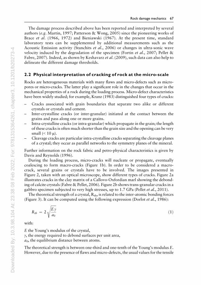
The damage process described above has been reported and interpreted by severalauthors (e.g. Martin, 1997; Patterson & Wong, 2005) since the pioneering works ofBrace et al. (1966, 1972) and Bieniawski (1967). At the present time, standardlaboratory tests can be supplemented by additional measurements such as theAcoustic Emission activity (Stanchits et al., 2006) or changes in ultra-sonic wavevelocity induced by the degradation of the specimen (Fortin et al., 2007; Pellet &Fabre, 2007). Indeed, as shown by Keshavarz et al. (2009), such data can also help todelineate the different damage thresholds.
2.2 Physical interpretation of cracking of rock at the micro-scale
Rocks are heterogeneous materials with many flaws and micro-defects such as micro-pores or micro-cracks. The latter play a significant role in the changes that occur in themechanical properties of a rock during the loading process. Micro-defect characteristicshave been widely studied; for example, Kranz (1983) distinguished four types of cracks:
– Cracks associated with grain boundaries that separate two alike or differentcrystals or crystals and cement.
– Inter-crystalline cracks (or inter-granular) initiated at the contact between thegrains and pass along one or more grains.
– Intra-crystalline cracks (or intra-granular) which propagate in the grain; the lengthof these cracks is oftenmuch shorter than the grain size and the opening can be verysmall (˂ 10 μ).
– Cleavage cracks are particular intra-crystalline cracks separating the cleavage planesof a crystal; they occur as parallel networks to the symmetry planes of the mineral.
Further information on the rock fabric and petro-physical characteristics is given byDavis and Reynolds (1996).
During the loading process, micro-cracks will nucleate or propagate, eventuallycoalescing to form macro-cracks (Figure 1b). In order to be considered a macro-crack, several grains or crystals have to be involved. The images presented inFigure 2, taken with an optical microscope, show different types of cracks. Figure 2aillustrates cracks in the clay matrix of a Callovo-Oxfordian marl showing the debond-ing of calcite crystals (Fabre& Pellet, 2006). Figure 2b shows trans-granular cracks in agabbro specimen subjected to very high stresses, up to 1.7 GPa (Pellet et al., 2011).
The theoretical strength of a crystal, Rth, is related to the inter-atomic bonding forces(Figure 3). It can be computed using the following expression (Dorlot et al., 1986):
Rth ¼ 2
ffiffiffiffiffiffiE γa0
sð1Þ
with:
E the Young’s modulus of the crystal,γ, the energy required to debond surfaces per unit area,a0, the equilibrium distance between atoms.
The theoretical strength is between one-third and one-tenth of the Young’s modulus E.However, due to the presence of flaws andmicro-defects, the usual values for the tensile
Rock damage mechanics 67

Dow
nloa
ded
By:
10.
3.98
.104
At:
23:3
8 08
Feb
202
2; F
or: 9
7813
1536
4261
, cha
pter
3, 1
0.12
01/b
2027
3-4
strength of rocks are much lower, in the order of 1/100 to 1/1000 of the Young’smodulus.
In summary, since most rocks are formed by an assemblage of various types of crystals,fracturing can occur at different scales. At the scale of the micro-structure, damage couldresult from inter-granular bonds breaking or sometimes rupturing within the crystal. Thistype of rupture is referred to as dislocation mechanics (McClintock & Argon, 1966).
3 CONSTITUTIVE MODELING
3.1 Introduction
Constitutive modeling of damage evolution has motivated numerous studies in recentdecades. Basically, there are two approaches: The first is based on the theories of
E
a0
Figure 3 Schematic of crystal atomic bonding.
a) b)
Figure 2 Crack damage in rocks specimens: (a) Inter-granular cracks in Callovo-Oxfordian marl (Fabre& Pellet, 2006); b) Trans-granular micro-cracks in plagioclase crystals of a gabbro (Pellet et al.2011). Note that the development of micro-cracks crosses the original crystal twinning.
68 Pellet & Selvadurai
Dow
nloa
ded
By:
10.
3.98
.104
At:
23:3
8 08
Feb
202
2; F
or: 9
7813
1536
4261
, cha
pter
3, 1
0.12
01/b
2027
3-4
fracture mechanics while the second is derived from continuum damage mechanics. Inthe following sections the main aspects of both approaches will be reviewed and thedomain of validity of each method will be identified.
3.2 Linear fracture mechanics
3.2.1 Energy balance consideration
It is important to review the basic concepts involved in fracture mechanics. Griffith(1924) formulated a rupture criterion for a material based on energy balance. Heacknowledged that defects (pore spaces, cracks or structural defects such as disloca-tions in the crystal lattice or grain boundaries) can exist in any material and stressamplification at such defects will govern the failure stress.
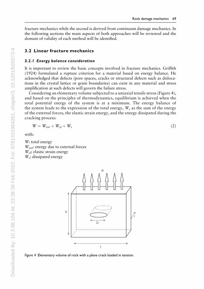
Considering an elementary volume subjected to a uniaxial tensile stress (Figure 4),and based on the principles of thermodynamics, equilibrium is achieved when thetotal potential energy of the system is at a minimum. The energy balance ofthe system leads to the expression of the total energy, W, as the sum of the energyof the external forces, the elastic strain energy, and the energy dissipated during thecracking process:
W ¼ Wext þWel þWs ð2Þwith:
W: total energyWext: energy due to external forcesWel: elastic strain energyWs: dissipated energy
b
2c
l
t
σ
Figure 4 Elementary volume of rock with a plane crack loaded in tension.
Rock damage mechanics 69

Dow
nloa
ded
By:
10.
3.98
.104
At:
23:3
8 08
Feb
202
2; F
or: 9
7813
1536
4261
, cha
pter
3, 1
0.12
01/b
2027
3-4
During extension, the crack length increases from 2c to 2(c + dc) and the conserva-tion of energy gives:
∂W∂c
¼ ∂Wext
∂cþ ∂Wel
∂cþ ∂Ws
∂c¼ 0 ð3Þ
The energy release rate G is therefore defined as:
G ¼ � 12
∂∂c
Wext þ Welð Þ ð4Þ
The energy dissipated by the crack propagation is assumed to vary linearly with theincrease in crack length, i.e.:
dWs ¼ 4γ dc ð5Þwhere γ is the specific energy of the material.
By substituting the expressions 4 and 5 in Equation 3, the crack static equilibrium isobtained when:
G ¼ 2 γ ð6ÞConsider the particular case of an elastic plate of unit thickness with a through crack oflength 2c and subjected to a uniaxial tensile stress (Figure 4). The change in elasticenergy caused by the introduction of the crack in the elastic plate (Jaeger et al., 2008) isgiven by:
Wel ¼πσ2 c2
Eð7Þ
where E is the Young’s modulus of the plate material and c is the crack half-length.According to the virtual work principle and for a constant load, it can be shown that:
Wext ¼ � 2Wel ð8ÞThus, according to Equations 4 and 7, the rate of energy releaseG (Equation 4) can beexpressed as a function of the stress and the crack length as follows:
G ¼ � 12∂Wel
∂c¼ π c σ 2
Eð9Þ
The equilibrium condition (Equation 6) is then used to calculate the critical failurecondition (Equation 10) and the critical stress, σc is given by:
π c σ 2 ¼ 2 γE ð10Þ
σc ¼ffiffiffiffiffiffiffiffiffiffi2 γEπ c
rð11Þ
Note that the critical failure stress depends not only on the intrinsic material properties(Young’s modulus E, and the specific surface energy γ) but also on the crack length, 2c.In particular, the critical value of the stress is lower when the length of the crack is
70 Pellet & Selvadurai
Dow
nloa
ded
By:
10.
3.98
.104
At:
23:3
8 08
Feb
202
2; F
or: 9
7813
1536
4261
, cha
pter
3, 1
0.12
01/b
2027
3-4
larger. The expression of the critical stress in the case of an arbitrarily oriented crack ina biaxial tensile stress field is presented by Eftis (1987) and extensive discussions aregiven in many texts on crack and fracture mechanics and in the volume by Sih (1991).
Griffith’s analysis was extended to the case of an inclined crack in a biaxial stress fieldtaking into account the friction on the crack faces (Jaeger et al., 2008). Under theseconditions, the critical failure condition becomes:
π c ð j τj � μσn Þ 2 ¼ 2 γE ð12Þwhere σn and j τj are, respectively, the normal stress and shear stress acting in the crackand μ is the friction coefficient between the two faces of the crack.
In this analysis, Griffith states that the energy dissipated by the propagation of thecrack is solely due to the extension of the crack surface. In fact, this analysis reflectscrack initiation rather than crack propagation. Other forms of energy dissipation mustbe taken into account during the crack propagation; for example, plastic energydissipation, which is associated with high stress concentrations at the crack tip, andkinetic energy, related to the acceleration of the crack propagation. In the case of apurely brittle process, the plastic deformation energy can be neglected. On the otherhand, it seems incorrect to neglect the effects of kinetic energy dissipation even in thecase of quasi-static loading. This will be discussed in the next paragraph.
3.2.2 Steady and unsteady crack propagation
Extending Griffith’s analysis, considering energy dissipation due to inertia, leads tothe calculation of the total energy (Equation 2), by including a term for the kineticenergy, Wcin:
W ¼ Wext þWel þWs þWcin ð13ÞCrack propagation will be steady if the kinetic energy remains constant during thecracking process:
∂Wcin
∂c¼ 0 ð14Þ
From the equilibrium equation (Equation 13) and the definitions provided byEquations 4 and 5, we obtain:
G ¼ 2 γ ð15ÞWe thus recover the Griffith equilibrium condition for a static crack (Equation 6).However, the significance of Equation 15 is that it represents the condition of crackpropagation at a constant rate; but crack propagation will be unsteady if the kineticenergy increases:
∂Wcin
∂c> 0 ð16Þ
Therefore, from the balance Equation 13 and the definitions (4) and (5):
G > 2 γ; ð17Þ
Rock damage mechanics 71

Dow
nloa
ded
By:
10.
3.98
.104
At:
23:3
8 08
Feb
202
2; F
or: 9
7813
1536
4261
, cha
pter
3, 1
0.12
01/b
2027
3-4
Resuming the system of uniaxial tensile elementary volume (Figure 4), the axialdeformation is then expressed by:
ε ¼ σEeff
ð18Þ
with Eeff, the effective Young’s Modulus:
Eeff ¼E
1 þ 2π c2=btð19Þ
ε ¼ σE
1 þ 2π c2=bt� ð20Þ
By introducing the stability condition (15) into Equation 20, we obtain the stabilitycriterion in the stress–strain plane:
ε ¼ σE
þ 8γ2 E
π b t σ3ð21Þ
Representation of Equation 21 in the stress–strain plane is shown in Figure 5 (curveAB). For the undamaged material (a plate without a crack), Hooke’s law is satisfiedwith a modulus of elasticity E (line OA). For a plate with a crack half-length c = c1,thematerial also followsHooke’s law butwith a lowermodulusEeff (Equation 19) thanthe virgin material (line OP’, Fig. 5). When the stability curve AB is reached, the cracksteadily grows to a point P00 where unloading is achieved. According to Equation 19,unloading shows a weaker effective modulus of elasticity (line P00O). The surface area
c = 0
V
P
A
0
s
e
G > 2g
G = 2g
QF
PÕ
PÕÕ
B
FÕ
c < c1 < c2
c = cc
c = c1
c = c2Eeff
E
Figure 5 Griffith’s stability criterion for an elementary volume in the stress–strain plane.
72 Pellet & Selvadurai
Dow
nloa
ded
By:
10.
3.98
.104
At:
23:3
8 08
Feb
202
2; F
or: 9
7813
1536
4261
, cha
pter
3, 1
0.12
01/b
2027
3-4
between segments OP0, P00O and P0P, corresponds to the energy expended for crackpropagation.
It should be noted that if the initial half-length of the crack is less than c = bt/6π(corresponding to the point where the tangent to the curve is vertical, point V), then thepropagation of the crack will be initially unstable (line PQ). The excess energy repre-sented by the area PQV, is then transformed into kinetic energy. Part of this energyenables the crack to propagate beyond the stability limit (point Q) to point F 0. The areaQF0F represents the surface energy needed to propagate the crack, although some of theenergy is dissipated as heat. The remaining kinetic energy is emitted in the material aselastic waves. In addition, for a stress-imposed loading, the crack propagation can beunstable since stability is only possible if there is a decrease in the stress. For a strain-imposed loading, two types of post peak behavior are observed depending on the initiallength of the crack. The first (Type I) occurs when the crack length is such that c < cc,and requires an increase in the energy transmitted to the specimen to obtain a steadypropagation. In contrast, when the initial crack length is such that c > cc, energy has tobe extracted from the specimen to stabilize the crack propagation (Type II). Point V,where c = cc, represents the case where the energy of the specimen is in equilibriumwiththe energy necessary for crack propagation. Wawersik and Fairhurst (1970) experi-mentally observed the presence of these two post-peak behavior patterns by controllingfailure using a servo-controlled testing machine. In the case of a behavior of type II,known as “snap–back”, only the control of transverse deformation allows the controlof rupture.
The case of overall compressive stress was studied by Cook (1965). The stabilitycurve has the same characteristics as that shown in Figure 5. Following Cook’sapproach, Martin and Chandler (1994) found, using Lac du Bonnet granite, that thechange of stress marks the initiation of unstable crack propagation during progressivedamage of the Griffith criterion type.
The Griffith global energy approach shows that the essential phenomena governingthe behavior of a cracked body lie near the crack tip. Fracture mechanics investigatesissues of the initiation and development of cracks by analyzing the stress in the vicinityof the crack. In the case of a brittle elastic solid, the presence of cracks leads to stresssingularities. The study of these singularities allows the definition of stress intensityfactors that correspond to the particular kinematics of the crack propagation. Thesestress intensity factors control the behavior of the crack.
When the stored elastic energy is close to the specific surface energy (G= 2γ), crackspropagate sub-critically (Atkinson, 1984); in other words, the propagation rate islower than the sonic velocity. In contrast, when the stored elastic energy is muchhigher, cracks propagate super-critically.
In all cases, the cracks develop in the direction of the minor compressive stress orperpendicular to the major principal stress.
3.2.3 Griffith crack initiation criterion
In the case of complex loadings, stress analysis at the vicinity of the crack tip is requiredto determine the crack propagation criterion, the length increase and the orientationchange. For this purpose, the discipline of Fracture Mechanics has been developed andwidely used since Griffith (1924).
Rock damage mechanics 73
Dow
nloa
ded
By:
10.
3.98
.104
At:
23:3
8 08
Feb
202
2; F
or: 9
7813
1536
4261
, cha
pter
3, 1
0.12
01/b
2027
3-4
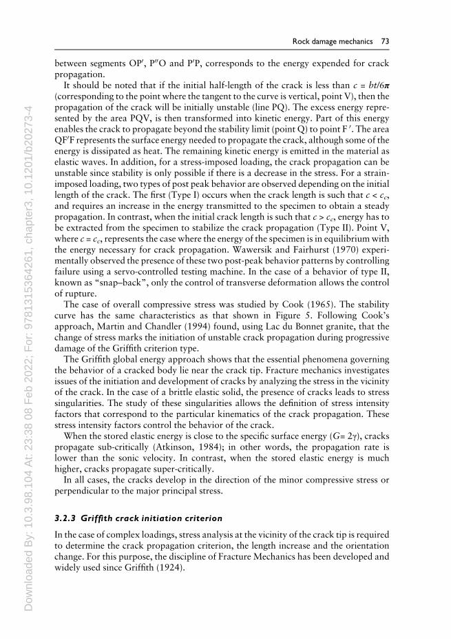
In order to study the stress field around an elliptical cavity in a plate subjected to auniaxial tensile stress, as shown in Figure 6a, the solution for the stress distributionat the periphery of the crack has to be calculated using the theory of elasticity(Inglis-Kirsch type solution) (Timoshenko & Goodier, 1970; Little, 1973; Barber,2010; Selvadurai, 2000a).
Referring to Figure 6, the stress σyy is largest at thewall of the cavity, where the ellipsecurvature radius is the smallest (point C). Thus:
σyy ðcÞ ¼ 1þ 2ffiffiffiffiffiffiffic=ρ
pð22Þ
Subsequently, the stress σyy gradually decreases to the lowest value corresponding tothe applied field, σ.
The stress σxx increases rapidly to reach a maximum near the end of the ellipse andthen gradually decreases to approach zero. The area of influence of the cavity is of theorder of the length c and the stress gradients are very high in the length zone of thecurvature radius of the cavity ρ. According to Equation 22 for a semi-axis cavity of half-length c, the greater the radius of curvature the smaller the stress.
3.2.4 Stress field and fracture modes
Consider plane problems (2D) for which all the components of the tensors of stressesand deformations depend only on two Cartesian or polar coordinates. The crack isassumed to be in a homogeneous medium, which is isotropic linear elastic.
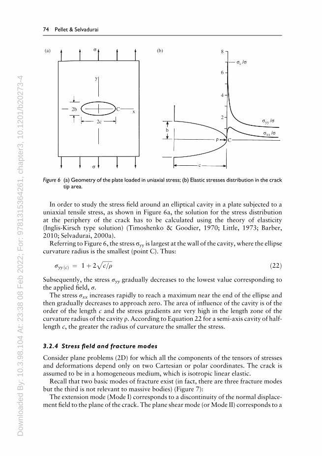
Recall that two basic modes of fracture exist (in fact, there are three fracture modesbut the third is not relevant to massive bodies) (Figure 7):
The extension mode (Mode I) corresponds to a discontinuity of the normal displace-ment field to the plane of the crack. The plane shearmode (orMode II) corresponds to a
y
2b
(a) (b)s
sc /s
syy /s
sxx /sr
s
2c
b
C
c
C x2
4
6
8
Figure 6 (a) Geometry of the plate loaded in uniaxial stress; (b) Elastic stresses distribution in the cracktip area.
74 Pellet & Selvadurai
Dow
nloa
ded
By:
10.
3.98
.104
At:
23:3
8 08
Feb
202
2; F
or: 9
7813
1536
4261
, cha
pter
3, 1
0.12
01/b
2027
3-4
shift of the edges of the crack parallel to the plane of the crack along a sliding directionnormal to the crack front. For any load, several basic fracture modes may overlap. Thisis referred to as a mixed fracture mode.
Solving the equilibrium equations with the compatibility conditions leads to a bi-harmonic equation for a stress function. The exact solution of this problem wasestablished by Muskhelishvili (1953) based on the solution by Westergaard (1939)and expresses the stress fields and displacement in the crack for each of the three modesin coordinate systems.
The solution introduces the notion of stress intensity factors KIc and KIIc for Mode Iand Mode II fracture, respectively. Knowledge of these stress intensity factors willallow the determination of the stresses and displacements in the fissured structure.Conversely, if we know the stresses and displacements, it is possible to determine thestress intensity factors. For example, in the simple case of a plane infinite mediumcontaining a crack of length 2c loaded inMode I by a stress σ, the stress intensity factorcan be expressed in the form:
KI ¼ σffiffiffiffiffiffiπ c
p ð23ÞThe stress intensity factor is measured in units N.m–3/2 or MPa.m 1/2.
A similar approach can lead to the establishment of the stress intensity factor KII forMode II fractures (Irwin, 1957).
3.2.4.1 Failure criterion in the open mode (Mode I)
In the tensile mode, stress at the tip of the crack is infinite. Therefore, a crack initiationcriterion can be introduced based on the concept of a critical threshold for the factorKI.This criterion postulates that:
KI ≤KIc No crack propagation
KI ¼ KIc Crack propagation onset
The critical value, KIc, is the toughness, a physical characteristic of the material(Atkinson and Meredith, 1987). Toughness values obtained from the literature(Table 1) show a significant scatter, which results from the high parameter sensitivityto the investigative method used and the environmental conditions (pressure, tempera-ture, fluid). Note that toughness increases rapidly with the pressure applied.
s
s
t
t
t
t
Mode I Mode II Mode III
Figure 7 The three main fracture modes; in rock mechanics only Mode I and Mode II are relevant.
Rock damage mechanics 75
Dow
nloa
ded
By:
10.
3.98
.104
At:
23:3
8 08
Feb
202
2; F
or: 9
7813
1536
4261
, cha
pter
3, 1
0.12
01/b
2027
3-4
In terms of energy, crack growth requires that the released energy is higher than thespecific energy, which leads to the establishment of the following equation:
W ¼ Wel �Ws ð24Þ
Therefore, when∂W∂c
≥0, stress at the crack tip is:
σ ≥
ffiffiffiffiffiffiffiffiffiffi2 γEπ c
r≥ σt ð25Þ
Remember that the energy release rate G controls the crack behavior:
G > 2γ instabilityG = 2γ controlled steady cracking (the kinetic energy does not increase)
3.2.4.2 Failure criterion in the mixed mode
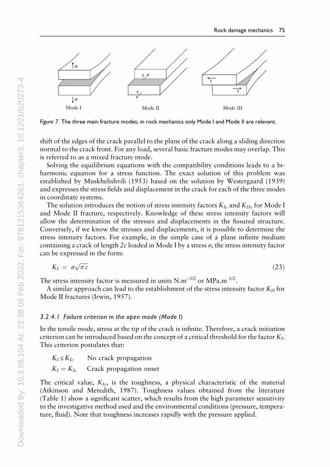
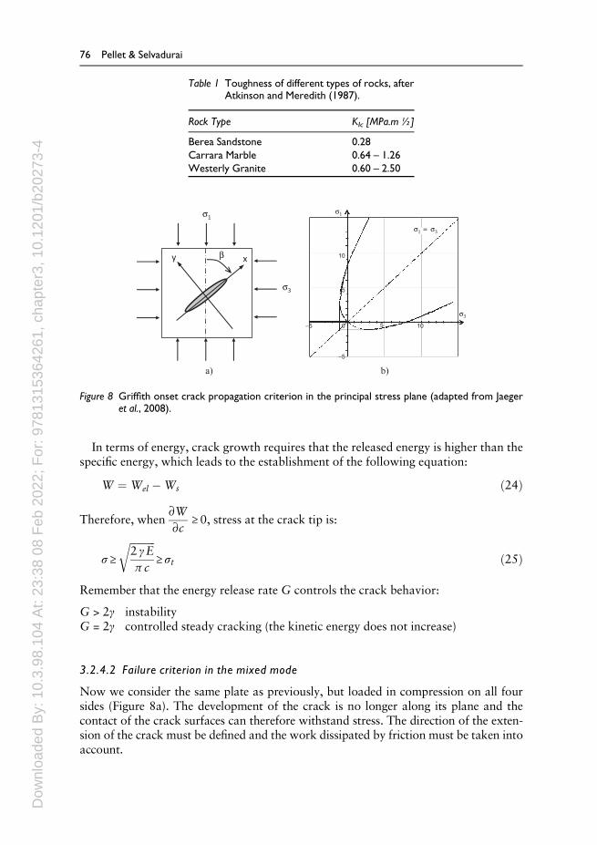
Now we consider the same plate as previously, but loaded in compression on all foursides (Figure 8a). The development of the crack is no longer along its plane and thecontact of the crack surfaces can therefore withstand stress. The direction of the exten-sion of the crack must be defined and the work dissipated by friction must be taken intoaccount.
Table 1 Toughness of different types of rocks, afterAtkinson and Meredith (1987).
Rock Type KIc [MPa.m ½]
Berea Sandstone 0.28Carrara Marble 0.64 – 1.26Westerly Granite 0.60 – 2.50
xy
s1
a) b)
s3
b
–5
0–5 5 10
5
10
s1
s3
s1 = s3
Figure 8 Griffith onset crack propagation criterion in the principal stress plane (adapted from Jaegeret al., 2008).
76 Pellet & Selvadurai

Dow
nloa
ded
By:
10.
3.98
.104
At:
23:3
8 08
Feb
202
2; F
or: 9
7813
1536
4261
, cha
pter
3, 1
0.12
01/b
2027
3-4
In the mixed mode, the definition of a failure criterion is therefore more difficult.However, linear fracture mechanics makes it possible to find a relationship between thestress intensity factors and the rate of energy release, G, when the crack grows inextension. This relationship is known as the Irwin formula:
G ¼ 3 � 4�ð Þ þ 18G
K2I þ K2
II
� ð24Þ In plane strain
where G is the shear modulus.The Griffith onset crack propagation criterion (Equations 25 and 26) thus gener-
alizes the original criterion:
ðσ1 � σ3Þ2 � 8 ⋅ σt ⋅ ðσ1 þ σ3Þ ¼ 0 if σ1 > 3 ⋅ σ3 ð25Þσ3 ¼ � σt if σ1 < 3 ⋅ σ3 ð26Þ
Note, however, that the growth assumption of fissure in extension is a seriouslimitation to the application of the Irwin formula. In fact, this assumption is onlyvalid in the case of a failure mode in pure opening (Mode I); in the case of a mixedmode, the crack deviates from its plane. Other onset failure criteria in themixedmodeare available in the literature, namely the criterion of maximum normal stress, theenergy criterion of minimal elastic deformation, the criterion of maximum energy ofrestitution, etc.
3.3 Continuum damage mechanics
Continuum damage mechanics was first developed for structural engineering(Kachanov, 1958), with a special emphasis on structural elements loaded in tension.This approach has attracted particular interest in the design of concrete structures(Chaboche, 1988; Bažant, 1991; Lemaitre, 1996; Selvadurai, 2004).
The motivation for this approach was based on the evidence that, under certainloading conditions, the development of micro-cracks that spread throughout the mate-rial does not necessarily cause a macroscopic fracture. However, gradual deteriorationof physical properties such as strength and stiffness are observed, sometimes wellbefore rupture occurs. A comprehensive understanding andmodeling of these phenom-ena that precede rupture is therefore of great practical interest.
ContinuumDamageMechanics was developed within the framework of ContinuumMechanics. This method enables the analysis of how the development of micro-defectsinfluences the overall behavior of the material using a phenomenological approach,which describes the evolution of the material structure with internal state variables.
Let us suppose that the effects of micro-debonding in a Representative ElementaryVolume (REV) of a solid body can be described using mechanical variables calleddamage variables. Since such damage variables are macroscopic variables thatreflect the state of the loss of mechanical integrity, they can be considered as internalstate variables from a thermodynamic point of view. With these assumptions,damage problems can be analyzed based on the principles of thermodynamics ofirreversible processes. Therefore, the phenomenological damage model can bedefined by:
Rock damage mechanics 77
Dow
nloa
ded
By:
10.
3.98
.104
At:
23:3
8 08
Feb
202
2; F
or: 9
7813
1536
4261
, cha
pter
3, 1
0.12
01/b
2027
3-4
– A law of transformation,– A principle of equivalence,– The nature of the damage variable,– The evolution law of the damage variable.
3.3.1 Law of transformation
Phenomenological models appeal to the effective macroscopic quantities whose role is todefine the damage state of thematerial. Thus, a heterogeneously damagedmaterial obeysthe same mechanical constitutive laws as its homogeneous undamaged equivalent; how-ever, the states of stress and strain undergo changes from the nominal configuration. This
change is made via a law of transformation, defined by the tensors M¼4¼
σ and M¼4¼
ε, linkingthe effective variables (eσ;eε) to nominal values (σ; ε) as follows:
eσ σ;Dð Þ ¼ M¼4¼
σ Dð Þ : σ ð27Þeε ε;Dð Þ ¼ M
¼4¼ε Dð Þ : ε ð28Þ
The tensors M¼4¼
σ and M¼4¼
ε are linear operators that apply a symmetric tensor of thesecond order on itself and which are functions of the damage variable, formallydenoted by D. When there is zero damage, the actual magnitudes coincide with thenominal values, and the transport tensor coincides with the unity.
Zheng and Betten (1996) demonstrated, by analyzing the general form of thetransformation law, that the transport tensor must be an isotropic function of itsarguments. Assuming a damage variable as a tensor of order two, this mathematicalcondition is:
M¼4¼
QDQT� �
¼ QM¼4¼
Dð ÞQT 8Q2� ð29Þ
where Θ is the full group of orthogonal transformations Q.
3.3.2 Principle of equivalence
The principle of equivalence can be expressed in terms of deformation, stress or energy.The principle of equivalence in deformation implies that the effective deformation isequal to the nominal deformation, thus:
eε ¼ ε ð30Þ
eσ ¼ M¼4¼
σ Dð Þ : σ ð31ÞMore explicitly, it means that any representation of the deformational state of adamaged material can be described by the constitutive laws of an undamaged mediumby simply replacing the nominal stress by the effective stress. This leads to the conceptof the effective stress, which is not to be confused with the Terzaghi effective stress,which can be defined through reciprocal analysis, as the stress to be applied to the
78 Pellet & Selvadurai

Dow
nloa
ded
By:
10.
3.98
.104
At:
23:3
8 08
Feb
202
2; F
or: 9
7813
1536
4261
, cha
pter
3, 1
0.12
01/b
2027
3-4
undamaged volume element to achieve the same strain as that caused by the nominalstress applied to the damaged volume element.
The principle of equivalence in stress is defined by assuming that the effective stress,eσ, is equal to the nominal stress, σ, i.e., the effective deformation causes the same stressas the application of the nominal strain to the damaged volume:
eσ ¼ σ ð32Þ
eε ¼ Mε
¼4¼Dð Þ : ε ð33Þ
Finally, the equivalence energy principle is established assuming that the effectiveelastic energy density, eW , is equal to the nominal density of elastic energy, W. Thisassumption is expressed by:
eσ ¼ M¼4¼
σ Dð Þ : σ ð34Þ
eε ¼ M¼4¼
ε Dð Þ : ε ð35Þ
eW ¼ 12eσ : eε ð36Þ
W ¼ 12σ : ε ð37Þ
eW ¼ W ð38Þ
3.3.3 Damage variable
Since the work of Kachanov (1958), a new variable is available to describe the internalstate of a damaged material in the context of continuum mechanics. As indicatedbefore, the notion of damage is closely linked to micro-structural aspects. However,the damage variable introduced byKachanov described the presence ofmicro-defects ina comprehensivemanner. The advantage of this homogenized approach is that it allowsthe indirect determination of the influence of the state of damage on the overall strengthof the material through simple measurements.
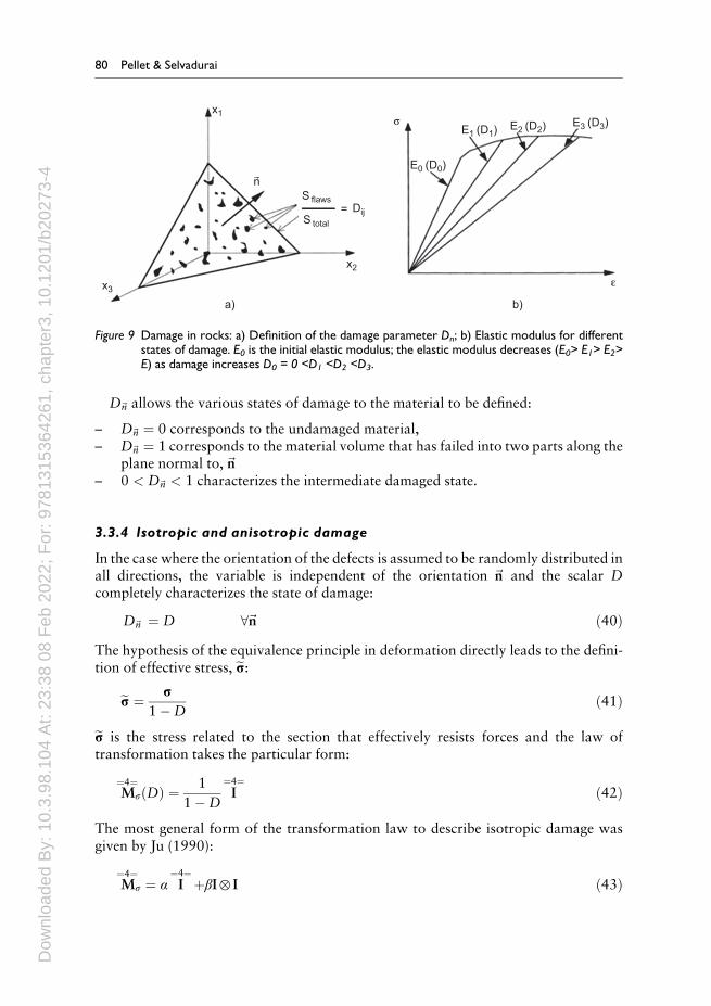
Although the authors have not detailed the physical significance of this variable, itcan be easily understood by using the concept of a Representative Elementary Volume(REV). Let us consider a REV in a damaged solid (Figure 9). Assuming that Stotal isthe area of a section of a volume element indicated by the normal~n, and Sflaws is thearea of all micro-cracks and micro-pores, the classical damage variable can then beexpressed by:
D~n¼Sflaws
Stotalð39Þ
From a physical point of view the damage variable,D~n, is the ratio between the area ofdistributed micro-defects on the total area of the element in the plane normal to thedirection,~n.
Rock damage mechanics 79
Dow
nloa
ded
By:
10.
3.98
.104
At:
23:3
8 08
Feb
202
2; F
or: 9
7813
1536
4261
, cha
pter
3, 1
0.12
01/b
2027
3-4
D~n allows the various states of damage to the material to be defined:
– D~n ¼ 0 corresponds to the undamaged material,– D~n ¼ 1 corresponds to the material volume that has failed into two parts along the
plane normal to,~n– 0 < D~n < 1 characterizes the intermediate damaged state.
3.3.4 Isotropic and anisotropic damage
In the case where the orientation of the defects is assumed to be randomly distributed inall directions, the variable is independent of the orientation ~n and the scalar Dcompletely characterizes the state of damage:
D~n ¼ D 8~n ð40ÞThe hypothesis of the equivalence principle in deformation directly leads to the defini-tion of effective stress, eσ:
eσ ¼ σ1�D
ð41Þ
eσ is the stress related to the section that effectively resists forces and the law oftransformation takes the particular form:
M¼4¼
σ Dð Þ ¼ 11�D
I¼4¼
ð42Þ
The most general form of the transformation law to describe isotropic damage wasgiven by Ju (1990):
M¼4¼
σ ¼ α I¼4¼
þβI⊗ I ð43Þ
x1
x3
x2
nS flaws
s
e
=S total
Dij
E0 (D0)
E1 (D1)
a) b)
E2 (D2) E3 (D3)
Figure 9 Damage in rocks: a) Definition of the damage parameter Dn; b) Elastic modulus for differentstates of damage. E0 is the initial elastic modulus; the elastic modulus decreases (E0> E1> E2>E) as damage increases D0 = 0 <D1 <D2 <D3.
80 Pellet & Selvadurai
Dow
nloa
ded
By:
10.
3.98
.104
At:
23:3
8 08
Feb
202
2; F
or: 9
7813
1536
4261
, cha
pter
3, 1
0.12
01/b
2027
3-4
where α and β are two independent or dependent scalar variables, with α ≥1 and�1=3 ≤ β=α ≤0 to ensure positivity of the stiffness tensor. The interpretation of iso-tropic damage does not necessarily imply a scalar variable.
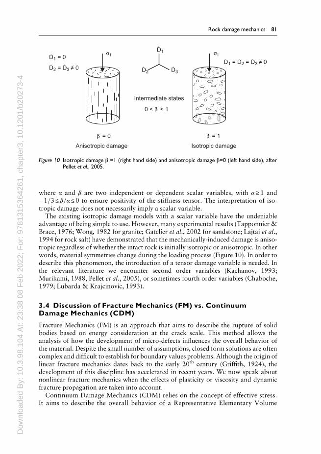
The existing isotropic damage models with a scalar variable have the undeniableadvantage of being simple to use. However, many experimental results (Tapponnier &Brace, 1976; Wong, 1982 for granite; Gatelier et al., 2002 for sandstone; Lajtai et al.,1994 for rock salt) have demonstrated that the mechanically-induced damage is aniso-tropic regardless of whether the intact rock is initially isotropic or anisotropic. In otherwords, material symmetries change during the loading process (Figure 10). In order todescribe this phenomenon, the introduction of a tensor damage variable is needed. Inthe relevant literature we encounter second order variables (Kachanov, 1993;Murikami, 1988, Pellet et al., 2005), or sometimes fourth order variables (Chaboche,1979; Lubarda & Krajcinovic, 1993).
3.4 Discussion of Fracture Mechanics (FM) vs. ContinuumDamage Mechanics (CDM)
Fracture Mechanics (FM) is an approach that aims to describe the rupture of solidbodies based on energy consideration at the crack scale. This method allows theanalysis of how the development of micro-defects influences the overall behavior ofthe material. Despite the small number of assumptions, closed form solutions are oftencomplex and difficult to establish for boundary values problems. Although the origin oflinear fracture mechanics dates back to the early 20th century (Griffith, 1924), thedevelopment of this discipline has accelerated in recent years. We now speak aboutnonlinear fracture mechanics when the effects of plasticity or viscosity and dynamicfracture propagation are taken into account.
Continuum Damage Mechanics (CDM) relies on the concept of effective stress.It aims to describe the overall behavior of a Representative Elementary Volume
Intermediate states
Anisotropic damage
b = 0
0 < b < 1
s1 s1
b = 1
Isotropic damage
Ḋ1 = 0Ḋ1
Ḋ2 Ḋ3Ḋ2 = Ḋ3 ≠ 0
Ḋ1 = Ḋ2 = Ḋ3 ≠ 0
Figure 10 Isotropic damage β =1 (right hand side) and anisotropic damage β=0 (left hand side), afterPellet et al., 2005.
Rock damage mechanics 81
Dow
nloa
ded
By:
10.
3.98
.104
At:
23:3
8 08
Feb
202
2; F
or: 9
7813
1536
4261
, cha
pter
3, 1
0.12
01/b
2027
3-4
(REV) by decreasing the material stiffness (elastic moduli) with the damage states.This is a phenomenological approach, which is easier to incorporate in computa-tional codes.
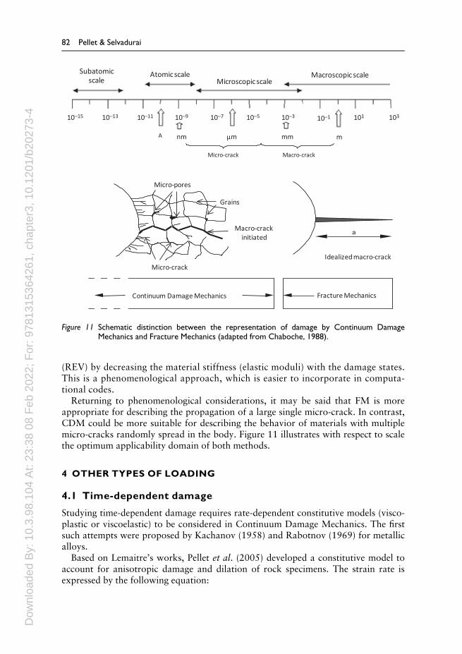
Returning to phenomenological considerations, it may be said that FM is moreappropriate for describing the propagation of a large single micro-crack. In contrast,CDM could be more suitable for describing the behavior of materials with multiplemicro-cracks randomly spread in the body. Figure 11 illustrates with respect to scalethe optimum applicability domain of both methods.
4 OTHER TYPES OF LOADING
4.1 Time-dependent damage
Studying time-dependent damage requires rate-dependent constitutive models (visco-plastic or viscoelastic) to be considered in Continuum Damage Mechanics. The firstsuch attempts were proposed by Kachanov (1958) and Rabotnov (1969) for metallicalloys.
Based on Lemaitre’s works, Pellet et al. (2005) developed a constitutive model toaccount for anisotropic damage and dilation of rock specimens. The strain rate isexpressed by the following equation:
a
Continuum Damage Mechanics Fracture Mechanics
Grains
Micro-pores
Micro-crack
Macro-crack initiated
Idealized macro-crack
Micro-crack Macro-crack
Atomic scaleMicroscopic scale
Macroscopic scaleSubatomic scale
10Ð15 10Ð13 10Ð11 10Ð9 10Ð7 10Ð5 10Ð3 10Ð1
mmmnm mm
101 103
A
Figure 11 Schematic distinction between the representation of damage by Continuum DamageMechanics and Fracture Mechanics (adapted from Chaboche, 1988).
82 Pellet & Selvadurai
Dow
nloa
ded
By:
10.
3.98
.104
At:
23:3
8 08
Feb
202
2; F
or: 9
7813
1536
4261
, cha
pter
3, 1
0.12
01/b
2027
3-4
_εvp ¼ ∂Ω∂σij
¼ 32
11�D
σeq1�Dð ÞKp1=M
� �N Sσeq
ð44Þ
whereΩ is the visco-plastic potential;K,N andM are the viscoplastic parameters of themodel; σeq is the von Mises stress; S is the stress deviator and p is a variable thatrepresents strain hardening.
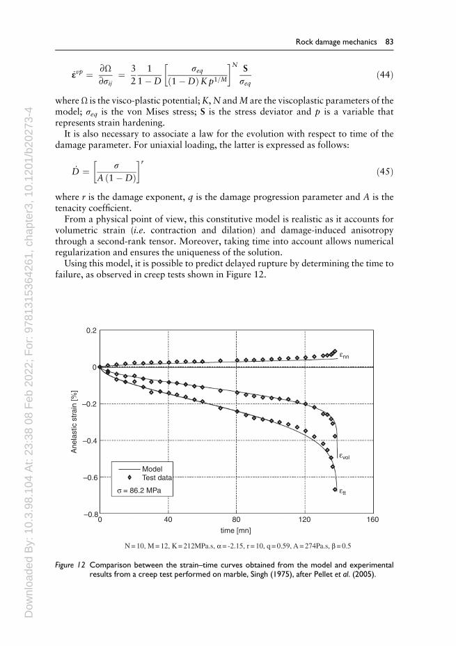
It is also necessary to associate a law for the evolution with respect to time of thedamage parameter. For uniaxial loading, the latter is expressed as follows:
_D ¼ σA 1�Dð Þ� �r
ð45Þ
where r is the damage exponent, q is the damage progression parameter and A is thetenacity coefficient.
From a physical point of view, this constitutive model is realistic as it accounts forvolumetric strain (i.e. contraction and dilation) and damage-induced anisotropythrough a second-rank tensor. Moreover, taking time into account allows numericalregularization and ensures the uniqueness of the solution.
Using this model, it is possible to predict delayed rupture by determining the time tofailure, as observed in creep tests shown in Figure 12.
0.2
0
–0.2
–0.4
Ane
last
ic s
trai
n [%
]
–0.6
–0.80 40 80
time [mn]
N = 10, M = 12, K = 212MPa.s, a= -2.15, r = 10, q = 0.59, A = 274Pa.s, b= 0.5
Model
εvol
εnn
εtt
Test data
σ = 86.2 MPa
120 160
Figure 12 Comparison between the strain–time curves obtained from the model and experimentalresults from a creep test performed on marble, Singh (1975), after Pellet et al. (2005).
Rock damage mechanics 83
Dow
nloa
ded
By:
10.
3.98
.104
At:
23:3
8 08
Feb
202
2; F
or: 9
7813
1536
4261
, cha
pter
3, 1
0.12
01/b
2027
3-4
4.2 Damage under cyclic loading
The gradual weakening of rock properties can also be highlighted by performing cyclicloading tests. There are two types of cyclic tests: type 1,where the loading is cycled betweentwo prescribed limits, and type 2,where the loading is increased fromone cycle to the next.Most of the published data on type 1 tests are aimed at producing S–N curves, that relatethe maximum stress, S, applied to a specimen to the number of cycles prior to specimenfailure N. It has been shown (Costin & Holcomb, 1981) that cycling decreases rockstrength, possibly by a combination of cyclic fatigue and stress corrosion. Over the lastfew decades several experimental programs have been performed to characterize rockbehavior under static and cyclic behavior. The objective is to characterize the progressivedevelopment of damage in rocks under cyclic loading (Erarslan &Williams, 2012).
Gatelier et al. (2002) presented an extensive laboratory investigation of the mechan-ical properties of sandstone, which exhibits transversely isotropic behavior. Particularattention was paid to the influence of the structural anisotropy on the progressivedevelopment of pre-peak damage. Uniaxial and triaxial cyclic tests were performed forseveral orientations of the isotropy planes with respect to the principal stress directionsin order to quantify the irreversible strains and the changes of oriented moduli with thecumulative damage. Two main mechanisms are involved throughout the loadingprocess: compaction and micro-cracking.
Compaction is active at all stress levels. In uniaxial tests, both mechanisms wereshown to be strongly influenced by the inclination of loading with respect to the planesof isotropy. However, with increased confining pressures, the influence of anisotropy issignificantly reduced.
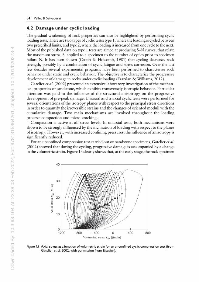
For an unconfined compression test carried out on sandstone specimens, Gatelier et al.(2002) showed that during the cycling, progressive damage is accompanied by a changein the volumetric strain. Figure 13 clearly shows that, at the early stage, the rock specimen
40
30
20
10
0–1200 –800 –400
Volumetric strain evol [mm/m]
Axi
al s
tres
s s n
n [M
Pa]
0 400 800
Figure 13 Axial stress as a function of volumetric strain for an unconfined cyclic compression test (fromGatelier et al. 2002, with permission from Elsevier).
84 Pellet & Selvadurai

Dow
nloa
ded
By:
10.
3.98
.104
At:
23:3
8 08
Feb
202
2; F
or: 9
7813
1536
4261
, cha
pter
3, 1
0.12
01/b
2027
3-4
tends to contract whereas later in the cycling process, it exhibits dilation. This observa-tion is useful when developing an appropriate constitutive model.
4.3 Thermo-mechanical damage
Inmany situations, rock formations can be subjected to high temperatures that can leadto drastic changes in their mechanical properties. For example, in energy and environ-mental engineering, such as geothermal energy production, deep geologic disposal ofhigh-level radioactive waste or tunnels that have experienced fire accidents, specialattention has to be paid to thermal damage. In all these examples, the question thatneeds to be addressed is the same: how do changes in temperature influence the physicaland mechanical properties of rocks?
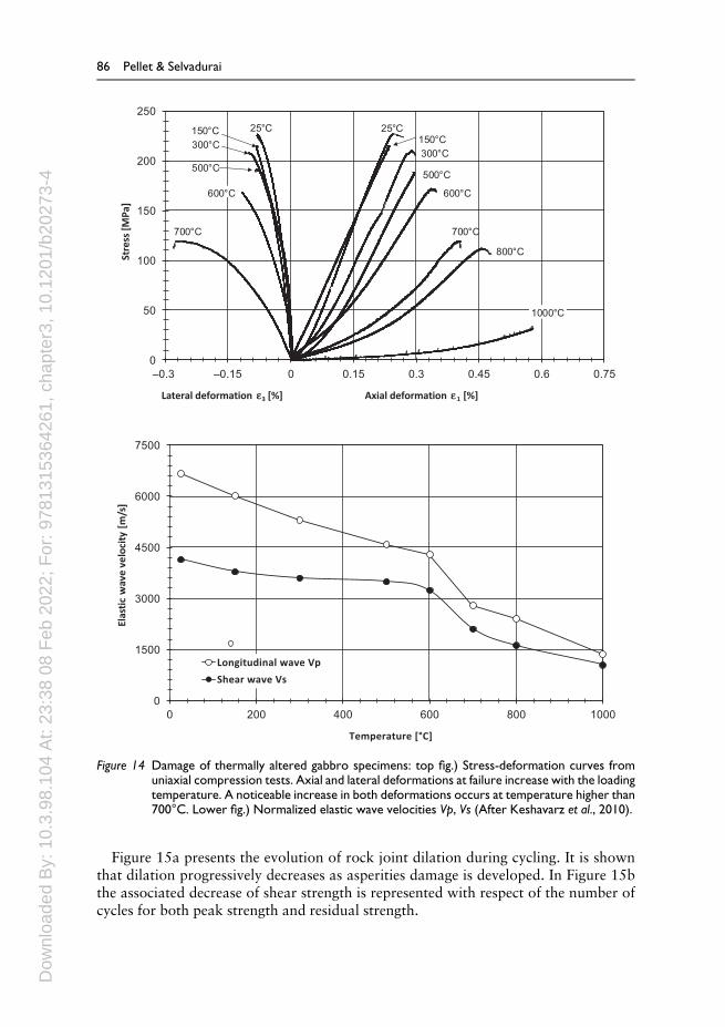
Keshavarz et al. (2010) showed that thermal loading of rocks at high temperaturesinduces changes in their mechanical properties. In this study, a hard gabbro was testedin the laboratory. Specimens were slowly heated to a maximum temperature of 1,000°C. Following this thermal loading, the specimens were subjected to uniaxial compres-sion. A drastic decrease of both unconfined compressive strength and elastic moduliwas observed (Figure 14). The thermal damage to the rock was also highlighted bymeasuring elastic wave velocities and monitoring acoustic emissions during testing.The micro-mechanisms of rock degradation were investigated by analyzing thin sec-tions after each stage of thermal loading. It was found that there is a critical tempera-ture above which drastic changes in mechanical properties occur. Indeed, below atemperature of 600°C, micro-cracks start to develop due to a difference in the thermalexpansion coefficients of the crystals. At higher temperatures (above 600°C), oxidationof Fe and Mg atoms, as well as bursting of fluid inclusions, are the principal causes ofdamage.
4.4 Rock joint damage
Thus far, we have focused on damage to the rock material (rock matrix). However, it iswell known that discontinuities (joints, faults, etc.) are of the utmost importance inanalyzing rock mass behavior (Vallier et al., 2010). Traditionally, the mechanicalbehavior of rock discontinuities is analyzed with shear tests in different loading condi-tions: Constant Normal Load (CNL), Constant Normal Stiffness (CNS) or ConstantVolume (CV). The two latter tests require advanced testing equipment to allow controlof the displacements in the 3 spatial directions (Boulon, 1995) (see also Selvadurai &Boulon, 1995; Nguyen & Selvadurai, 1998).
Jafari et al. (2004) studied the variation of the shear strength of rock joints due tocyclic loadings. Artificial joint surfaces were prepared using a developed moldingmethod that used special mortar; shear tests were then performed on these samplesunder both static and cyclic loading conditions. Different levels of shear displace-ment were applied to the samples to study joint behavior before and during con-siderable relative shear displacement. It was found that the shear strength of joints isrelated to the rate of displacement (shearing velocity), number of loading cycles andstress amplitude. Finally, based on the experimental results, mathematical modelswere developed for the evaluation of shear strength under cyclic loading conditions.
Rock damage mechanics 85
Dow
nloa
ded
By:
10.
3.98
.104
At:
23:3
8 08
Feb
202
2; F
or: 9
7813
1536
4261
, cha
pter
3, 1
0.12
01/b
2027
3-4
Figure 15a presents the evolution of rock joint dilation during cycling. It is shownthat dilation progressively decreases as asperities damage is developed. In Figure 15bthe associated decrease of shear strength is represented with respect of the number ofcycles for both peak strength and residual strength.
0
50
100
150
200
250
–0.3 –0.15 0 0.15 0.3 0.45 0.6 0.75
Stre
ss [M
Pa]
Lateral deformation ε ε3 [%] Axial deformation 1 [%]
150°C300°C
500°C
600°C
700°C
800°C
1000°C
25°C25°C
600°C
700°C
150°C300°C
500°C
0
1500
3000
4500
6000
7500
0 200 400 600 800 1000
Elas
tic
wav
e ve
loci
ty [
m/s
]
Temperature [¡C]
Longitudinal wave Vp
Shear wave Vs
Figure 14 Damage of thermally altered gabbro specimens: top fig.) Stress-deformation curves fromuniaxial compression tests. Axial and lateral deformations at failure increase with the loadingtemperature. A noticeable increase in both deformations occurs at temperature higher than700°C. Lower fig.) Normalized elastic wave velocities Vp, Vs (After Keshavarz et al., 2010).
86 Pellet & Selvadurai

Dow
nloa
ded
By:
10.
3.98
.104
At:
23:3
8 08
Feb
202
2; F
or: 9
7813
1536
4261
, cha
pter
3, 1
0.12
01/b
2027
3-4
b)1.00
0.95
0.90
Nor
mal
ized
She
ar S
treng
th, t
p [M
Pa]
0.85
0.800 500 1000 1500
Number of Cycles (NC)
2000 2500 3000
Peak strengthResidual strength
τp = –0.06ln(NC) + 3.07
τp = –0.06ln(NC) + 3.43
3500
Figure 15b Cyclic shear test on rock discontinuity: Normalized shear strength as a function of thenumber of cycles (Jafari et al., 2004).
1.20a)
1.00
0.80
0.60
0.40
Nor
mal
Dis
plac
emen
t, m
m
0.20
0.00
–0.20Shear Displacement, mm
0.0 2.0 4.0 6.0 8.0 10.0 12.0 14.0 16.0 18.0
Figure 15a Cyclic shear test on rock discontinuity: Normal displacement versus shear displacementwhile cycling; (Jafari et al., 2004).

Dow
nloa
ded
By:
10.
3.98
.104
At:
23:3
8 08
Feb
202
2; F
or: 9
7813
1536
4261
, cha
pter
3, 1
0.12
01/b
2027
3-4
5 PERMEABILITY EVOLUTION WITH DAMAGE
During the development of damage in a rock, the permeability characteristics can bealtered through either the development of discrete fractures or the development ofcontinuum damage in the form of micro-cracks and micro-voids. The consequences ofsuch damage development not only cause a reduction in the stiffness characteristics of therock but also contribute to enhanced fluid flow through the accessible pore space of therock. The development of enhanced fluid flow through rocks is of particular interestto geoenvironmental endeavors that focus on deep geologic disposal of hazardousnuclear wastes (Selvadurai & Nguyen, 1995, 1997; Nguyen et al., 2005) andcontaminants (Testa, 1994; Apps&Tsang, 1996; Selvadurai, 2006), geologic seques-tration of greenhouse gases (Pijaudier-Cabot & Pereira, 2013; Selvadurai, 2013) andother energy extraction endeavors. In particular, excavation damaged zones in repo-sitories used for storage of hazardous waste or in resources extraction activitiescan experience permeability alterations that will alter the fluid transport character-istics and consequently the potential for the enhanced migration of hazardoussubstances from repositories. The alteration of permeability of rocks during damageevolution is therefore of considerable importance to geoenvironmental applications.The influence of micro-crack generation and damage on the evolution of hydraulicconductivity of saturated geomaterials has been discussed by Zoback and Byerlee(1975), who present results of tests conducted on granite that indicate increases of upto a factor of four in the magnitude of the permeability. Results by Shiping et al.(1994) on sandstone indicate that for all combinations of stress states employed intheir tests, the permeability increased by an order of magnitude. In triaxial tests onanisotropic granite Kiyama et al. (1996) presented results that also indicate increasesin the permeability characteristics. Coste et al. (2001) present the results of experi-ments involving rocks and clay stone; their conclusions support the assumption of anincrease in the permeability, of up to two-orders of magnitude, with an increase indeviator stresses. Focusing on the behavior of cementitious materials, the experimen-tal results presented by Samaha and Hover (1992) indicate an increase in the perme-ability of concrete subjected to compression. Results by Gawin et al. (2002) dealwith the thermo-mechanical damage of concrete at high temperatures. In theirstudies, empirical relationships have been proposed to describe the alterations inthe fluid transport characteristics as a function of temperature and damage; here thedominant agency responsible for the alterations is identified as thermally-induced gen-eration of micro-cracks and fissures (see also, Schneider & Herbst, 1989; Bary, 1996).Also, Bary et al. (2000) present experimental results concerning the evolution of perme-ability of concrete subjected to axial stresses, in connectionwith themodeling of concretegravity dams that are subjected to fluid pressures. Gas permeability evolution in naturalsalt during deformation is given by Stormont and Daemen (1992), Schulze et al. (2001),and Popp et al. (2001). While the mechanical behavior of natural salt can deviate from abrittle response that is usually associated with brittle rocks, the studies support thegeneral trend of permeability increase with damage evolution that leads to increases inthe porosity. The article by Popp et al. (2001) also contains a comprehensive review offurther experimental studies in the area of gas permeability evolution in salt duringhydrostatic compaction and triaxial deformation, in the presence of creep. Time-depen-dent effects can also occur in brittle materials due to the sub-critical propagation of
88 Pellet & Selvadurai
Dow
nloa
ded
By:
10.
3.98
.104
At:
23:3
8 08
Feb
202
2; F
or: 9
7813
1536
4261
, cha
pter
3, 1
0.12
01/b
2027
3-4
micro-cracks, a phenomenon known as stress corrosion (Shao et al., 1997). In a recentstudy, Bossart et al. (2002) observed an alteration in permeability of an argillaceousmaterial around deep excavations, a phenomenon attributed to the alteration of theproperties of the material in the EDZ.
Souley et al. (2001) describe the excavation damage-induced alterations in thepermeability of granite of the Canadian Shield; they observed an approximatelyfour-orders of magnitude increase in the permeability in the EDZ. It is noted, how-ever, that some of this data is applicable to stress states where there can be substantialdeviations from the elastic response of the material as a result of the generation oflocalized shear zones and foliation-type extensive brittle fracture, which may beindicative of discrete fracture generation as opposed to the development of conti-nuum damage. The data presented by Souley et al. (2001) has recently been re-examined by Massart and Selvadurai (2012, 2014), who used computational homo-genization techniques to account for permeability evolution in rock experiencingdilatancy and damage.
It should also be noted that not all stress states contribute to increases in thepermeability of geomaterials. The work of Brace et al. (1978) and Gangi (1978)indicates that the permeability of granitic material can indeed decrease with anincrease in confining stresses. These conclusions are also supported by Patsouls andGripps (1982) in connection with permeability reduction in chalk with an increase inthe confining stresses. Wang and Park (2002) also discuss the process of fluid perme-ability reduction in sedimentary rocks and coal in relation to stress levels. A furtherset of experimental investigations, notably those by Li et al. (1994, 1997) and ZhuandWong (1997) point to the increase in permeability with an increase in the deviatorstress levels. These investigations, however, concentrate on the behavior of thegeomaterial at post-peak and, more often in the strain softening range. Again, theseexperimental investigations, although of considerable interest in their own right, arenot within the scope of the current chapter that primarily deals with permeabilityevolution during damage in the elastic range. The experimental studies by Selvaduraiand Głowacki (2008) conducted on Indiana Limestone, similarly indicate the perme-ability reduction of a rock during isotropic compression up to 60 MPa. The studiesalso indicate the presence of permeability hysteresis during quasi-static load cycling.The internal fabric of the rock can also affect the enhancement of permeability ofrocks even during isotropic compression. The experimental work conducted bySelvadurai et al. (2011) on the highly heterogeneous Cobourg Limestone indicatesthat the permeability can increase during the application of isotropic stress states. Inthis case the external isotropic stress state can result in locally anisotropic stress statesthat can lead to permeability enhancement through dilatancy at the boundaries ofheterogeneities.
5.1 Modeling saturated porous media with continuum damage
The modeling of fluid-saturated porous media that experience continuum damagecan be approached at various levels, the simplest of which is the modification ofthe equations of classical poroelasticity developed by Biot (1941) (see also Rice &Cleary, 1976; Detournay & Cheng, 1993; Selvadurai, 1996; Wang, 2000; Cheng,2016; Selvadurai & Suvorov, 2016) to account for damage evolution in the
Rock damage mechanics 89
Dow
nloa
ded
By:
10.
3.98
.104
At:
23:3
8 08
Feb
202
2; F
or: 9
7813
1536
4261
, cha
pter
3, 1
0.12
01/b
2027
3-4
porous fabric and the enhancement of the permeability characteristics of the fluid-saturated medium by damage evolution. In the case of an intact poroelasticmaterial, considering Hookean isotropic elastic behavior of the porous skeleton,the principle of mass conservation and Darcy’s law applicable to an isotropicporous medium, the coupled constitutive equations governing the displacementfield uðx; tÞ and the pore pressure field pðx; tÞ in a fluid-saturated body void ofbody or inertia forces can be expressed in the form
μr2u þ μ
1� 2�ð Þr r:uð Þ þ αrp ¼ 0 ð46Þ
and
κ βr2p � ∂p∂t
þ αβ∂∂t
r:uð Þ ¼ 0 ð47Þ
In (46) and (47)
α ¼ 3 �u � �ð ÞeB 1� 2�ð Þ 1þ �uð Þ; β ¼ 2μ 1� 2�ð Þ 1þ �uð Þ2
9 �u � �ð Þ 1� 2�uð Þ ð48Þ
ν and μ are the “drained values” of Poisson’s ratio and the linear elastic shearmodulus applicable to the porous fabric, �u is the undrained Poisson’s ratio and eB isthe pore pressure parameter introduced by Skempton (1954), κ ¼ k=γwð Þ is a perme-ability parameter, which is related to the hydraulic conductivity k and the unit weightof the pore fluid γw and r, r and r2 are, respectively, the gradient, divergence andLaplace’s operators. When damage occurs in a general fashion the elasticity and fluidtransport characteristics of the rock can result in the development of properties thatcan be anisotropic. If full anisotropy evolution with damage is considered, theelasticity parameters increase to 21 constants and the fluid transport parametersincrease to six. Therefore the generalized treatment of damage-induced alterationsto coupled poroelasticity effects can result in an unmanageable set of parameters anddamage evolution laws. This has restricted the application of damage mechanics tothe study of coupled poroelasticity problems. The prudent approach is to restrictattention to isotropic damage evolution that can be specified in terms of the effectivestress defined by (41) and the strain equivalent hypothesis. The alterations in theelastic stress–strain relationships for the damaged isotropic elastic skeleton can berepresented in the form
σ ¼ 2 1�Dð Þμ εþ 2 1�Dð Þμ�1� 2�ð Þ r:uð Þ I þ α p I ð49Þ
where D is the isotropic damage parameter and implicit in (49) is the assumption thatPoisson’s ratio remains unaltered during the damage process and alterations to theisotropic Lamé and other elastic constants and the permeability parameters maintainthe energetic requirements
μðDÞ > 0 ; 0 ≤ eBðDÞ ≤ 1 ; � 1 < �ðDÞ < �uðDÞ ≤0:5 ; κðDÞ > 0 ð50Þ
90 Pellet & Selvadurai
Dow
nloa
ded
By:
10.
3.98
.104
At:
23:3
8 08
Feb
202
2; F
or: 9
7813
1536
4261
, cha
pter
3, 1
0.12
01/b
2027
3-4
This assumption makes the incorporation of influences of damage on the poroelasticresponse more manageable. In addition to the specification of the constitutive rela-tions for the damaged geomaterial skeleton, it is also necessary to prescribe damageevolution criteria that can be postulated either by appeal to micro-mechanicalconsiderations or determined by experiment. Examples of the evolution of thedamage parameter with either stress or strain have been presented in the literatureand references to these studies are given by Mahyari and Selvadurai (1998),Selvadurai (2004) and Selvadurai and Shirazi (2004, 2005); the experimental infor-mation that describes the variation of the poroelastic parameters with damage isgenerally scarce. Also, the extent of damage necessary to create substantial altera-tions to permeability evolution is generally small. By and large, the porous skeletonof the fluid-saturated rock can remain elastic with a small change in the elasticityparameters during which the permeability of the rock can change substantially.Based on this observation, Selvadurai (2004) introduced the concept of“Stationary Damage” in poroelastic solids where the skeletal elasticity propertiesremain at a constant value after the initiation of elastic damage and alterations in thehydraulic conductivity characteristics are determined at the damage level corre-sponding to the stationary damage or elastic estimates. Zoback and Byerlee (1975)have documented results of experiments conducted on granite and Shiping et al.(1994) give similar results for tests conducted on sandstone. They observed that thepermeability characteristics of these materials can increase by an order of magnitudebefore the attainment of the peak values of stress and they can increase up to two-orders of magnitude in the strain softening regime where micro-cracks tend tolocalize in shear faults. Kiyama et al. (1996) also observed similar results for thepermeability evolution of granites subjected to a tri-axial stress state. This wouldsuggest that localization phenomena could result in significant changes in the perme-ability in the localization zones. It must be emphasized that in this study the processof localization is excluded from the analysis and all changes in permeability are atstress states well below those necessary to initiate localization or global failure of thematerial. Furthermore, in keeping with the approximation concerning scalar iso-tropic dependency of the elasticity properties on the damage parameter, we shallassume that the alterations in the permeability characteristics also follow an isotropicform. This is clearly an approximation with reference to the mechanical response ofbrittle geomaterials that tend to developmicro-cracking along the dominant directionof stressing, leading to higher permeabilities in orthogonal directions. The studies byMahyari and Selvadurai (1998) suggest the following postulates for the evolution ofhydraulic conductivity as a function of the parameter ξd:
kd ¼ ð1þ eαξdÞk ; kd ¼ ð1þ eβξ2dÞk ð51Þ
where kd is the hydraulic conductivity applicable to the damaged material, k isthe hydraulic conductivity of the undamaged material, ξd is the equivalent shearstrain, which is related to the second invariant of the strain deviator tensor, and eα and eβare material constants. This approach has enabled the application of isotropicdamage mechanics concepts to examine the time-dependent effects that can materializein fluid-saturated poroelastic media where the porous fabric undergoes mechanicaldamage with an attendant increase in the hydraulic conductivity characteristics.
Rock damage mechanics 91
Dow
nloa
ded
By:
10.
3.98
.104
At:
23:3
8 08
Feb
202
2; F
or: 9
7813
1536
4261
, cha
pter
3, 1
0.12
01/b
2027
3-4
5.2 Application of the concept of “Stationary Damage”
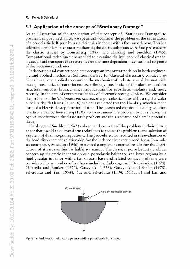
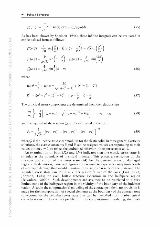
As an illustration of the application of the concept of “Stationary Damage” toproblems in poromechanics, we specifically consider the problem of the indentationof a poroelastic halfspace by a rigid circular indenter with a flat smooth base. This is acelebrated problem in contact mechanics; the elastic solutions were first presented inthe classic studies by Boussinesq (1885) and Harding and Sneddon (1945).Computational techniques are applied to examine the influence of elastic damage-induced fluid transport characteristics on the time dependent indentational responseof the Boussinesq indenter.
Indentation and contact problems occupy an important position in both engineer-ing and applied mechanics. Solutions derived for classical elastostatic contact pro-blems have been applied to examine the mechanics of indentors used for materialstesting, mechanics of nano-indentors, tribology, mechanics of foundations used forstructural support, biomechanical applications for prosthetic implants and, morerecently, in the area of contact mechanics of electronic storage devices. We considerthe problem of the frictionless indentation of a poroelastic material by a rigid circularpunch with a flat base (Figure 16), which is subjected to a total load P0, which is in theform of a Heaviside step function of time. The associated classical elasticity solutionwas first given by Boussinesq (1885), who examined the problem by considering theequivalence between the elastostatic problem and the associated problem in potentialtheory.
Harding and Sneddon (1945) subsequently examined the problem in their classicpaper that uses Hankel transform techniques to reduce the problem to the solution ofa system of dual integral equations. The procedure also resulted in the evaluation ofthe load-displacement relationship for the indentor in exact closed form. In a sub-sequent paper, Sneddon (1946) presented complete numerical results for the distri-bution of stresses within the halfspace region. The classical poroelasticity problemconcerning the static indentation of a poroelastic halfspace and layer regions by arigid circular indentor with a flat smooth base and related contact problems wereconsidered by a number of authors including Agbezuge and Deresiewicz (1974),Chiarella and Booker (1975), Gaszynski (1976), Gaszynski and Szefer (1978),Selvadurai and Yue (1994), Yue and Selvadurai (1994, 1995a, b) and Lan and
P(t) = P0H(t)rigid cylindrical indenter
r
z
Figure 16 Indentation of a damage susceptible poroelastic halfspace.
92 Pellet & Selvadurai
Dow
nloa
ded
By:
10.
3.98
.104
At:
23:3
8 08
Feb
202
2; F
or: 9
7813
1536
4261
, cha
pter
3, 1
0.12
01/b
2027
3-4
Selvadurai (1996), using differing boundary conditions related to the pore pressureat the surface of the halfspace both within the contact zone and exterior to it. Theseauthors also use different computational schemes for the numerical solution of theresulting integral equations and for the inversion of Laplace transforms. Of relatedinterest are problems associated with the dynamic problem of a rigid foundationeither in smooth contact or bonded to the surface of a halfspace (Halpern &Christiano, 1986; Kassir & Xu, 1988; Philippacopoulos, 1989; Senjuntichai &Rajapakse, 1996), where, in certain circumstances, the static transient poroelasticitysolution can be recovered. The former studies will form a basis for a comparison withthe modeling involving stationary damage; here we will consider only changes in thehydraulic conductivity characteristics, which will be altered corresponding to theinitial elastic strains induced during the loading of the indenter. Also, the loadapplied is specified in the form of a Heaviside step function in time. In order todetermine the stationary spatial variation of hydraulic conductivity propertieswithin the halfspace region, it is first necessary to determine the distribution of theequivalent shear strain ξd in the halfspace region. Formally, the distribution ξd(r, z),is determined by considering the stress state in the halfspace region associated withthe elastic contact stress distribution at the indenter-elastic halfspace region, which isgiven by
σzzðr; 0Þ ¼ P0
2πaffiffiffiffiffiffiffiffiffiffiffiffiffiffiffia2 � r2
p ; r2 ð0; aÞ ð52Þ
and the classical solution by Boussinesq (1885) for the problem of the action of aconcentrated normal load at the surface of a halfspace region (see also Selvadurai,2000a, 2001). The displacement distribution at the surface of the halfspace region isgiven by
uzðr; 0Þ ¼D
2Dπ
sin�1 ar
� � ; r2ð0; aÞ
; r2ða;∞Þ:
8><>: ð53Þ
The stress state in the halfspace region is given by
σrrðρ; ζ Þ ¼ � P0
2πa2J01 þ 2e�fJ01 � J10g � ζ J02 �
1ρfð1� 2e�ÞJ10 � ζ J12g
� �
σθθðρ; ζ Þ ¼ � P0
2πa22e� J10 þ
1ρfð1� 2e�ÞJ10 � ζ J12g
� �σzzðρ; ζ Þ ¼ � P0
2πa2½J01 þ ζ J02�
σrzðρ; ζ Þ ¼ � P0
2πa2½ζ J12� ð54Þ
where e� is Poisson’s ratio for the elastic solid and the infinite integrals Jmn ðρ; ζ Þ aredefined by
Rock damage mechanics 93
Dow
nloa
ded
By:
10.
3.98
.104
At:
23:3
8 08
Feb
202
2; F
or: 9
7813
1536
4261
, cha
pter
3, 1
0.12
01/b
2027
3-4
Jmn ðρ; ζ Þ ¼ð ∞
0sn�1 sinðsÞ expð�sζ ÞJmðsρÞds: ð55Þ
As has been shown by Sneddon (1946), these infinite integrals can be evaluated inexplicit closed form as follows:
J01ðρ; ζ Þ ¼1ffiffiffiffiR
p sin�
2
� �; J10ðρ; ζ Þ ¼
1ρ
1�ffiffiffiffiR
psin
�
2
� �� �
J11ðρ; ζ Þ ¼�
ρffiffiffiffiR
p sin θ � �
2
� �; J12ðρ; ζ Þ ¼
ρR3=2
sin3�2
� �J02ðρ; ζ Þ ¼
�
R3=2sin
32ð�� θÞ ð56Þ
where
tan θ ¼ 1ζ
; tan� ¼ 2ζ
ðρ2 þ ζ 2 � 1Þ ; �2 ¼ ð1þ ζ 2Þ
R2 ¼ ½ ρ2 þ ζ 2 � 1� 2 þ 4ζ 2� ; ρ ¼ r
a; ζ ¼ z
a: ð57Þ
The principal stress components are determined from the relationships
σ1σ3
)¼ 1
2σrr þ σzzð Þ �
ffiffiffiffiffiffiffiffiffiffiffiffiffiffiffiffiffiffiffiffiffiffiffiffiffiffiffiffiffiffiffiffiffiffiffiffiffiðσrr � σzzÞ2 þ 4σ2rz
q� �; σ2 ¼ σθθ ð58Þ
and the equivalent shear strain ξd can be expressed in the form
ξd ¼ 1
2ffiffiffi3
p eμ ðσ1 � σ3Þ2 þ ðσ3 � σ2Þ2 þ ðσ2 � σ1Þ2h i1=2
ð59Þ
where eμ is the linear elastic shearmodulus for the elastic solid. In these general elasticitysolutions, the elastic constants eμ and e� can be assigned values corresponding to theirvalues at time t ¼ 0, to reflect the undrained behavior of the poroelastic solid.
An examination of both (52) and (54) indicates that the elastic stress state issingular at the boundary of the rigid indenter. This places a restriction on therigorous application of the stress state (54) for the determination of damagedregions. By definition, damaged regions are assumed to experience only finite levelsof isotropic damage that would maintain the elastic character of the material. Thesingular stress state can result in either plastic failure of the rock (Ling, 1973;Johnson, 1985) or even brittle fracture extension in the halfspace region(Selvadurai, 2000b). Such developments are assumed to be restricted to a verylimited zone of the halfspace region in the vicinity of the boundary of the indenterregion. Also, in the computational modeling of the contact problem, no provision ismade for the incorporation of special elements at the boundary of the contact zoneto account for the singular stress state that can be identified from mathematicalconsiderations of the contact problem. In the computational modeling, the mesh
94 Pellet & Selvadurai

Dow
nloa
ded
By:
10.
3.98
.104
At:
23:3
8 08
Feb
202
2; F
or: 9
7813
1536
4261
, cha
pter
3, 1
0.12
01/b
2027
3-4
configuration is suitably refined to account for the sharp stress gradients that willresult from the elastic stress state (Figure 17).
The distribution of equivalent shear strain is accounted for by assigning the values ofthe equivalent strains to the integration points within the elements. These in turn areconverted to alterations in the hydraulic conductivity characteristics of the mediumthrough the use of the expressions (51) that relate the hydraulic conductivity to theequivalent shear strain. In the study by Selvadurai (2004), the computational modelingwas performed using the general purpose finite element code ABAQUS, although anycomputational code that is capable of examining poroelasticity problems for inhomo-geneous media can be adopted for the purpose.
An 8-noded isoparametric finite element is used in the modeling and the integrationsare performed at the nine Gaussian points. The displacements are specified at all nodesand the pore pressures are specified only at the corner nodes.
The application of the “Stationary Damage Concept” to the examination of theporoelastic contact problem where the porous skeleton can experience damage due tostress states that will not induce plastic collapse or extensive plastic failure in the rockinvolves the following steps:
– Apply the loadings to the elastic domain and determine the equivalent shear strainξd in the domain.
– Determine the distribution of permeability alteration in the region by appeal to theprescribed variation of permeability with ξd. This will result in a poroelasticdomain with a permeability heterogeneity.
a
P(t) = P0H(t) rigid cylindrical indenter
60a
n : unit normal to the boundary
n • ∇p = 0
n • ∇p = 0
p = 0r
z
Figure 17 Finite element discretization of the damage susceptible spherical poroelastic region for thecylindrical indenter problem.
Rock damage mechanics 95

Dow
nloa
ded
By:
10.
3.98
.104
At:
23:3
8 08
Feb
202
2; F
or: 9
7813
1536
4261
, cha
pter
3, 1
0.12
01/b
2027
3-4
– Solve the poroelasticity problem where the loads are applied at a prescribed timevariation, where the elasticity and permeability characteristics are as implied by theprevious steps.
We consider the computational modeling of the indentation problem where the porefluid that saturates the porous elastic solid is assumed to be incompressible. The indenteris subjected to a load with a time variation in the form of a Heaviside step function i.e.:
PðtÞ ¼ P0HðtÞ; t > 0 ð60Þwhere P0 is the magnitude of the total load acting on the indentor. Since the saturatingfluid is assumed to be incompressible, the undrained behavior of the fluid-saturatedporoelastic medium at time t ¼ 0 corresponds to an elastic state with e� ¼ 1=2. Theinitial elastic strains that induce the spatial distribution of damage during the indenta-tion are evaluated by setting e� ¼ 1=2 in the principal stresses computed, using the stressstate (52), relevant to the smooth indentation of the halfspace with the porous rigidcircular cylinder.
The finite element discretization of the halfspace domain used for the analysis of theindentation of the poroelastic halfspace by the porous rigid circular smooth indenter, ofradius a ¼ 2m, is shown in Figure 17. To exactlymodel a poroelastic halfspace region itis necessary to incorporate special infinite elements that capture the spatial decay in thepressure and displacement fields (see e.g. Simoni & Schrefler, 1987; Selvadurai &Gopal, 1989). These procedures were, however, unavailable in the computationalmodeling software. The poroelastic halfspace region is modeled as a hemisphericaldomain, where the outer boundary is located at a large distance (60 a) from the origin(Figure 17). This external spherical boundary is considered to be rigid and all dis-placements on this boundary are constrained to be zero. The boundary is alsoconsidered to be impervious, thereby imposing Neumann boundary conditions forthe pore pressure field at this spherical surface. (It is noted here that computationswere also performed by prescribing Dirichlet boundary conditions on this surface.The consolidation responses computed were essentially independent of the far fieldpore pressure boundary condition.) The accuracy of the discretization procedures,particularly with reference to the location of the external spherical boundary at adistance 60 a, was first verified through comparisons with Boussinesq’s solution forthe indentation an elastic halfspace region by a cylindrical punch. The value of theelastic displacement of the rigid circular indenter can be determined to an accuracy ofapproximately three percent. The computational modeling of the poroelastic inden-tation problem is performed by specifying the following values for the materialparameters generally applicable to a geomaterial such as sandstone (Selvadurai,2004): hydraulic conductivity k ¼ 1� 10�6 m=s; unit weight of pore fluidγw ¼ 1� 104N=m3; Young’s modulus. E ¼ 8:3GPa; Poisson’s ratio � ¼ 0:195; thecorresponding coefficient of consolidation, defined by
c ¼ 2μkγw
¼ 0:6946m2=s: ð61Þ
Figure 18 illustrates the comparison between the analytical solution for the time-dependent variation in the rigid displacement of the circular indentor given byChiarella and Booker (1975) and the computational results obtained for the
96 Pellet & Selvadurai
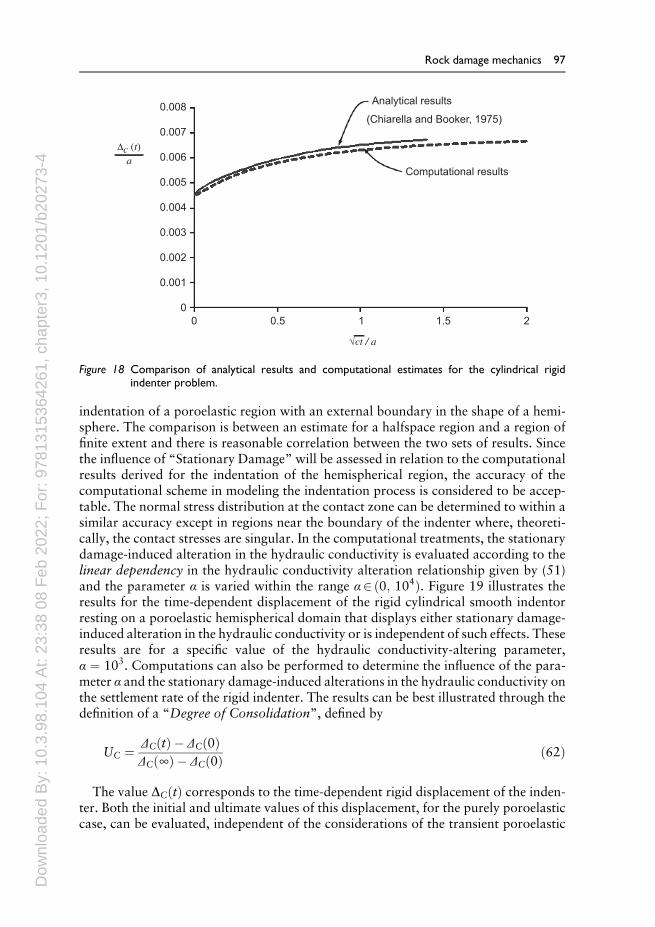
Dow
nloa
ded
By:
10.
3.98
.104
At:
23:3
8 08
Feb
202
2; F
or: 9
7813
1536
4261
, cha
pter
3, 1
0.12
01/b
2027
3-4
indentation of a poroelastic region with an external boundary in the shape of a hemi-sphere. The comparison is between an estimate for a halfspace region and a region offinite extent and there is reasonable correlation between the two sets of results. Sincethe influence of “Stationary Damage”will be assessed in relation to the computationalresults derived for the indentation of the hemispherical region, the accuracy of thecomputational scheme in modeling the indentation process is considered to be accep-table. The normal stress distribution at the contact zone can be determined to within asimilar accuracy except in regions near the boundary of the indenter where, theoreti-cally, the contact stresses are singular. In the computational treatments, the stationarydamage-induced alteration in the hydraulic conductivity is evaluated according to thelinear dependency in the hydraulic conductivity alteration relationship given by (51)and the parameter α is varied within the range α2 ð0; 104Þ. Figure 19 illustrates theresults for the time-dependent displacement of the rigid cylindrical smooth indentorresting on a poroelastic hemispherical domain that displays either stationary damage-induced alteration in the hydraulic conductivity or is independent of such effects. Theseresults are for a specific value of the hydraulic conductivity-altering parameter,α ¼ 103. Computations can also be performed to determine the influence of the para-meter α and the stationary damage-induced alterations in the hydraulic conductivity onthe settlement rate of the rigid indenter. The results can be best illustrated through thedefinition of a “Degree of Consolidation”, defined by
UC ¼ ΔCðtÞ � ΔCð0ÞΔCð∞Þ � ΔCð0Þ ð62Þ
The value DCðtÞ corresponds to the time-dependent rigid displacement of the inden-ter. Both the initial and ultimate values of this displacement, for the purely poroelasticcase, can be evaluated, independent of the considerations of the transient poroelastic
0.008Analytical results
(Chiarella and Booker, 1975)
Computational results
0.007
0.006
0.005
Dc (t)
0.004
0.003
0.002
0.001
0
0 0.5 1 1.5 2
√ct / a
a
Figure 18 Comparison of analytical results and computational estimates for the cylindrical rigidindenter problem.
Rock damage mechanics 97
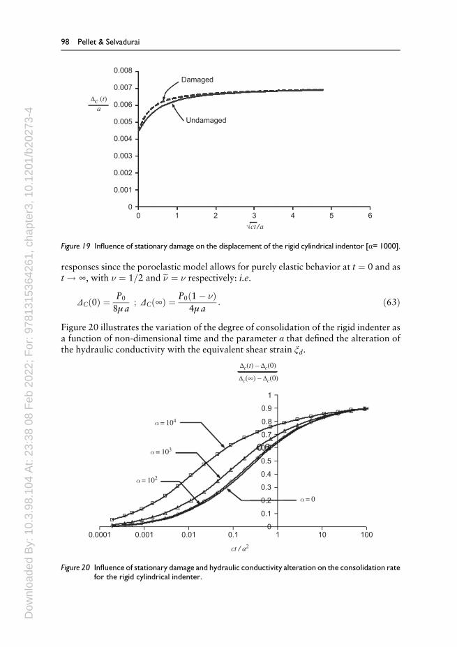
Dow
nloa
ded
By:
10.
3.98
.104
At:
23:3
8 08
Feb
202
2; F
or: 9
7813
1536
4261
, cha
pter
3, 1
0.12
01/b
2027
3-4
responses since the poroelastic model allows for purely elastic behavior at t ¼ 0 and ast ! ∞, with � ¼ 1=2 and e� ¼ � respectively: i.e.
ΔCð0Þ ¼ P0
8μ a; ΔCð∞Þ ¼ P0ð1� �Þ
4μ a: ð63Þ
Figure 20 illustrates the variation of the degree of consolidation of the rigid indenter asa function of non-dimensional time and the parameter α that defined the alteration ofthe hydraulic conductivity with the equivalent shear strain ξd.
0.008
Undamaged
Damaged0.007
0.006
0.005
Dc (t)
0.004
0.003
0.002
0.001
0
0 1 2 3 4 5 6
√ct /a
a
Figure 19 Influence of stationary damage on the displacement of the rigid cylindrical indentor [α= 1000].
1
0.9
0.8
0.7
0.6
0.5
0.4
0.3
0.2
0.1
00.0001 0.001 0.01 0.1 1 10 100
ct / a2
Dc(t) – Dc(0)
Dc(∞) – Dc(0)
α = 104
α = 103
α = 102
α = 0
Figure 20 Influence of stationary damage and hydraulic conductivity alteration on the consolidation ratefor the rigid cylindrical indenter.
98 Pellet & Selvadurai

Dow
nloa
ded
By:
10.
3.98
.104
At:
23:3
8 08
Feb
202
2; F
or: 9
7813
1536
4261
, cha
pter
3, 1
0.12
01/b
2027
3-4
6 NUMERICAL MODELING OF DAMAGE
We have seen in Section 3 that, from a theoretical point of view, two main approachesexist to model rock damage. These are based either on Continuum Mechanics, or onFracture Mechanics.
In terms of numerical modeling, the continuum approach is classically handled usingthe Finite ElementMethod whereas fracturing is more difficult to deal with numerically.However, relatively recently, methods have been developed to incorporate the nucleationand propagation of cracks in an originally continuousmedium. Thesemethods belong tothe family of Extended Finite Element Methods (XFEM). An alternative approach is theFinite Discrete ElementMethod (FDEM), which is also a recent computational tool thatcombines the Finite Element Method with the Discrete Element Method (DEM).
Currently, these methods are difficult to use in an engineering context because of thecomplexity of rock structures and the lack of knowledge of the boundary and initialconditions. For rock engineering problems, the computational time required is stillcumbersome.
6.1 Modeling a loading test with CDM
Identification ofmodel parameters is based on experiments such as creep tests, relaxationtests and quasi-static tests. Figure 21 shows the numericalmodeling of a compression testperformed with a low strain rate of loading (Fabre& Pellet, 2006). Both axial strain andlateral strain are well reproduced by the model. Additionally, the calculated change involumetric strain (contraction-dilation) is consistent with the observed location.
00
Strain [%]
Experimental data
e = 10–8 s–1
evole3 e4
Numerical simulation
Axi
al s
tress
[MP
a]
–0.2–0.4–0.6
E = 6000 MPa; v = 0.17; N= 25; M = 3.17; K= 340 MPa.s; a = 0; r = 11.3; q = 0.25; A = 95.5 MPa.s ; b = 0.29
0.2 0.4 0.6 0.8 1
5
10
15
20
25
30
Figure 21 Modeling of a uniaxial compressive test performed on shale (Fabre & Pellet, 2006).
Rock damage mechanics 99
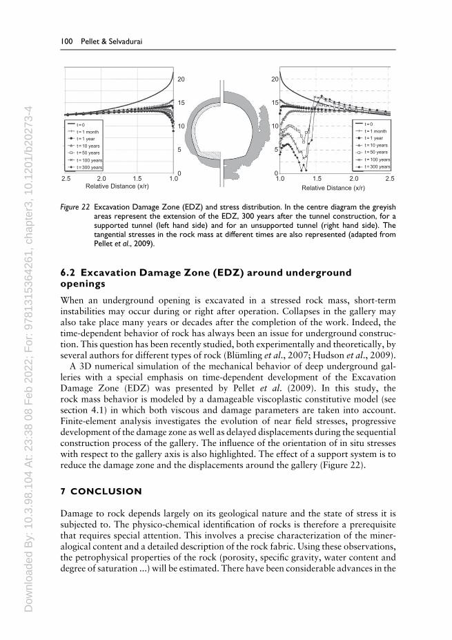
Dow
nloa
ded
By:
10.
3.98
.104
At:
23:3
8 08
Feb
202
2; F
or: 9
7813
1536
4261
, cha
pter
3, 1
0.12
01/b
2027
3-4
6.2 Excavation Damage Zone (EDZ) around undergroundopenings
When an underground opening is excavated in a stressed rock mass, short-terminstabilities may occur during or right after operation. Collapses in the gallery mayalso take place many years or decades after the completion of the work. Indeed, thetime-dependent behavior of rock has always been an issue for underground construc-tion. This question has been recently studied, both experimentally and theoretically, byseveral authors for different types of rock (Blümling et al., 2007; Hudson et al., 2009).
A 3D numerical simulation of the mechanical behavior of deep underground gal-leries with a special emphasis on time-dependent development of the ExcavationDamage Zone (EDZ) was presented by Pellet et al. (2009). In this study, therock mass behavior is modeled by a damageable viscoplastic constitutive model (seesection 4.1) in which both viscous and damage parameters are taken into account.Finite-element analysis investigates the evolution of near field stresses, progressivedevelopment of the damage zone as well as delayed displacements during the sequentialconstruction process of the gallery. The influence of the orientation of in situ stresseswith respect to the gallery axis is also highlighted. The effect of a support system is toreduce the damage zone and the displacements around the gallery (Figure 22).
7 CONCLUSION
Damage to rock depends largely on its geological nature and the state of stress it issubjected to. The physico-chemical identification of rocks is therefore a prerequisitethat requires special attention. This involves a precise characterization of the miner-alogical content and a detailed description of the rock fabric. Using these observations,the petrophysical properties of the rock (porosity, specific gravity, water content anddegree of saturation ...) will be estimated. There have been considerable advances in the
20
15
10t = 0t = 1 montht = 1 yeart = 10 yearst = 50 yearst = 100 yearst = 300 years
t = 0t = 1 montht = 1 yeart = 10 yearst = 50 yearst = 100 yearst = 300 years
02.5 2.0
Relative Distance (x/r)1.5 1.0 1.0 1.5
Relative Distance (x/r)2.0 2.5
5
20
15
10
0
5
Figure 22 Excavation Damage Zone (EDZ) and stress distribution. In the centre diagram the greyishareas represent the extension of the EDZ, 300 years after the tunnel construction, for asupported tunnel (left hand side) and for an unsupported tunnel (right hand side). Thetangential stresses in the rock mass at different times are also represented (adapted fromPellet et al., 2009).
100 Pellet & Selvadurai

Dow
nloa
ded
By:
10.
3.98
.104
At:
23:3
8 08
Feb
202
2; F
or: 9
7813
1536
4261
, cha
pter
3, 1
0.12
01/b
2027
3-4
digital treatment of experimental data over the last two decades, associated with thedevelopment of new testing equipment (Scanning Electron Microscope, MagneticResonance Imaging, Acoustic Tomography, etc.) that has greatly facilitated the identi-fication of the rock type and its in situ state.
Laboratory testing can then be used to determine the mechanical properties of therock under investigation; these include the strength and deformability. Here, too,modern techniques allow complex mechanical tests involving high pressure-high tem-perature, to be combined with physical measures such as acoustic activity or thevelocity of elastic waves. 3D visualization by X-ray computed tomography (CT) ofthe pore space helps to localize the areas of deformation and cracking.
Constitutivemodels can only be developed based on an understanding and knowledgeof the detailed characterization of the state of the rock both in its intact state and aftermechanical testing. We have seen that there are twomain approaches employed in RockMechanics for damage characterization: Continuum Damage Mechanics and FractureMechanics. The first, formulated in the context of the thermo-dynamics of irreversibleprocesses, lends itself to numerical modeling although certain hypotheses (shear failuremode, small deformations, etc.) must be invoked. For example, processing softeningbehavior inevitably requires regularizing the solution by introducing a time variable toestablish a rate-dependent model. If the model is rate-independent, such an approachshould be reserved for the damage suffered before the peak stress is achieved.
The second approach, Fracture Mechanics, is older and also more physical in that itaddresses the failure mode by extension (Mode I: crack opening), which is frequentlyobserved experimentally. However, this fails tomeet the assumption of a continuum andis therefore inconvenient to implement, particularly if multiple crack generation, crackbranching and discrete fragmentation is involved. However the introduction in the lastten years of the XFEM technique (eXtended Finite Element Method) allows the twoapproaches to be combined. The engineering applications of these advances are limited;in particular, it is difficult to account for the merging of several networks of cracks.
The use of a constitutive model for full-scale processes requires many adaptationsthat go beyond the simple consideration of the scale effect. The need to account fordamage discontinuities is paramount and often the time effects are equally important.Under certain loading conditions the effects of repeated actions (cyclic and/or dynamic)can be the most important consideration: loadings of a thermo-hydro-mechanicalorigin are often related to damage through permeability changes.
Over the past two decades, great progress has been made on the experimental char-acterization of damage in rocks and rock masses and numerical methodologies haveimproved substantially. Future developments should particularly focus on the develop-ment of numerical tools for the identification of the parameters to be used in constitutivemodels by means of inverse analysis of measurements made on real structures.
REFERENCES
Agbezuge, L.K. and Deresiewicz, H. (1974) On the indentation of a consolidating halfspace.Israel J. Tech., 12: 322–338.
Apps, J.A. and Tsang, C.-F. (Eds.) (1996)Deep Injection Disposal of Hazardous and IndustrialWaste, Academic Press, San Diego.
Rock damage mechanics 101
Dow
nloa
ded
By:
10.
3.98
.104
At:
23:3
8 08
Feb
202
2; F
or: 9
7813
1536
4261
, cha
pter
3, 1
0.12
01/b
2027
3-4
Atkinson, B.K. (1984) Sub-critical crack growth in geological materials. J. Geophys. Res.,89(B6): 4077–4114.
Atkinson, B.K. and Meredith, P.G. (1987) Experimental fracture mechanics data for rocks andminerals, In Fracture Mechanics of Rock, B.K. Atkinson Ed., Academic Press Geology Series,San Diego: 477–525.
Barber, J.R. (2010) Elasticity, Solid Mechanics and Its Applications, Vol. 172, Springer-Verlag,Berlin.
Bary, B. (1996) Etude de couplage hydraulique-mecanique dans le beton endomage, Lab. Meca.et Tech., CNRS, de Cachan, Univ. Paris XI, Publ. 11.
Bary, B., Bournazel, J.-P. and Bourdarot, E. (2000) Poro-damage approach to hydrofractureanalysis of concrete. J. Eng. Mech., ASCE, 126: 937–943.
Bažant, Z.P. (1991) Why continuum damage is nonlocal: Micromechanics arguments. J. Eng.Mech., 117(5): 1070–1087.
Bieniawski, Z.T. (1967)Mechanism of brittle fracture of rock, Parts I, II and III. Int. J. RockMech.Min. Sci. Geomech. Abstr., 4(4): 395–430.
Biot,M.A. (1941)General theory of three-dimensional consolidation. J. Appl. Phys., 12, 155–164.Blümling, P., Bernier, F., Lebon, P. and Martin, C.D. (2007) The excavation damaged zone in
clay formations time-dependent behaviour and influence on performance assessment. Phy.Chem. Earth, Parts A/B/C 32(8–14): 588–599.
Bossart, P., Meier, P.M., Moeri, A., Trick, T. andMayor, J.-C. (2002) Geological and hydrauliccharacterization of the excavation disturbed zone in the Opalinus Clay of the Mont TerriRock Laboratory. Eng. Geol., 66: 19–38.
Boulon, M. (1995) A 3D direct shear device for testing the mechanical behaviour and thehydraulic conductivity of rock joints, in: Rossmanith, P. (ed.), Proc. Mechanics of Jointedand Faulted Rock: 407–413.
Boussinesq, J. (1885) Applications des potentials a l’etude de l’equilibre et du mouvement dessolides elastique, Gauthier-Villars, Paris.
Brace, W.F., Paulding, B.W. and Scholz, C. (1966) Dilatancy in the fracture of crystalline rocks.J. Geophys. Res., 71(16): 3939–3953.
Brace,W.F., Silver, E., Hadley, K. and Goetze, C. (1972)Cracks and Pores: A Closer Look, NewSeries Published by: American Association for the Advancement of Science Vol. 178, No.4057: 162–164,
Brace, W.F., Walsh, J.B. and Frangos, W.T. (1978) Permeability of granite under high pressure.J. Geophys. Res., 73: 2225–2236.
Chaboche, J.L. (1979) Le concept de contrainte effective appliqué à l’élasticité et à laviscoplasticité en présence d’un endommagement anisotrope, in J. P. Boehler ed.,Mechanical Behaviour of Anisotropic Solids, Colloque Euromech 115, Villard de Lans,France : 737–759.
Chaboche, J. L. (1988) Continuum damage mechanics, Part I: General concepts, Part II:Damage growth, crack initiation, and crack growth. J. Appl. Mech. Trans. ASME, 55:55–72.
Cheng, A.H.-D. (2016) Poroelasticity, Springer-Verlag, Berlin.Chiarella, C. and Booker, J.R. (1975) The time-settlement behaviour of a rigid die resting on a
deep clay layer. Q. J. Mech. Appl. Math., 28: 317–328.Cook, N.G.W. (1965) The failure of rocks. Int. J. Rock Mech. Min. Sci., 2: 389–403.Coste, F., Bounenni, A., Chanchole, S. and Su, K. (2001) Amethod for measuring hydraulic and
hydromechanical properties during damage in materials with low permeability, G.3S, EcolePolytechnique, Palaiseau (Unpublished Report).
Costin, L.S. and Holcomb, D.J. (1981) Time dependent failure of rocks. Tectonophysics, 79:279–296.
102 Pellet & Selvadurai

Dow
nloa
ded
By:
10.
3.98
.104
At:
23:3
8 08
Feb
202
2; F
or: 9
7813
1536
4261
, cha
pter
3, 1
0.12
01/b
2027
3-4
Davis, G.H. and Reynolds, S.J. (1996) Structural Geology of Rocks and Regions, John Wiley &Sons, New York.
Detournay, E. and Cheng, A.H.-D. (1993) Fundamentals of poroelasticity, in: ComprehensiveRock Engineering Principles, Practice and Projects Vol. II, Analysis and Design Methods(Fairhurst, C. Ed.) Ch. 5, Pergamon Press, Oxford, pp. 113–171.
Dorlot, J.M., Bailon J.P. and Masounave J. (1986) Des Matériaux, Ecole Polytechnique deMontréal, Deuxième Edition.
Eftis, J. (1987) On the fracture stress for the inclined crack under biaxial load.Eng. Fract. Mech.,26: 105–125.
Erarslan, N. and Williams, D.J. (2012) The damage mechanism of rock fatigue and its relation-ship to the fracture toughness of rocks. Int. J. Rock Mech. Min. Sci., 56: 15–26.
Fabre, G. and Pellet, F.L. (2006) Creep and time dependent damage in argillaceous rocks. Int.J. Rock Mech. Min. Sci., 43(6): 950–960.
Fortin, J., Gueguen, Y. and Schubnel, A. (2007) Effect of pore collapse and grain crushing onultrasonic velocities and Vp/Vs. J. Geophys. Res., 112: 1–16.
Gangi, A.F. (1978) Variation of whole and fractured porous rock permeability with confiningpressure, Int. J. Rock Mech. Min. Sci., 15: 249–257.
Gaszynski, J. (1976) On a certain solution of dual integral equations and its application tocontact problems. Arch. Mech. Stos., 28: 75–88.
Gaszynski, J. and Szefer, G. (1978) Axisymmetric problem of the indenter for the consolidatingsemi-space with mixed boundary conditions. Arch. Mech. Stos., 30: 17–26.
Gatelier, N., Pellet, F.L. and Loret, B. (2002)Mechanical damage of an anisotropic rock under cyclictriaxial tests. Int. J. Rock Mech. Min. Sci., 39(3): 335–354.
Gawin, D., Pesavento, F. and Schrefler, B.A. (2002) Simulation of damage-permeability couplingin hygro-thermo-mechanical analysis of concrete at high temperature. Commun. Numer.Meth. Eng., 18: 113–119.
Griffith, A.A. (1924) Theory of rupture, Proc. Int. Congr. Appl. Mech., Delft, pp. 55–63.Halpern,M.R. andChristiano, P. (1986) Steady state harmonic response of a rigid plate bearing on
a liquid-saturated poroelastic halfspace. Earthquake Eng. Struct. Dyn., 14: 439–454.Harding, J.W. and Sneddon, I.N. (1945) The elastic stresses produced by the indentation of the
plane of a semi-infinite elastic solid by a rigid punch. Proc. Cambridge Philos. Soc., 41: 16–26.Hudson, J.A., Bäckström, A., Rutqvist, J., Jing, L., Backers, T., Chijimatsu,M., Christiansson, R.,
Feng, X.-T., Kobayashi, A., Koyama, T., Lee, H.-S., Neretnieks, I., Pan, P.-Z., Rinne, M. andShen, B.-T., (2009) Characterising and modelling the excavation damaged zone in crystallinerock in the context of radioactive waste disposal. Environ. Geol., 57(6): 1275–1297.
Irwin, G.H. (1957) Analyses of stresses and strains near the end of the crack traversing a plate.J. Appl. Mech., 24: 361–364.
Jaeger, J.C., Cook, N.G. and Zimmerman, R.W. (2008) Fundamentals of Rock Mechanics,Fourth Edition, Blackwell Publishing, Oxford, UK.
Jafari, M.K, Pellet, F., Boulon, M. and Amini Hosseini, K. (2004) Experimental study ofmechanical behaviour of rock joints under cyclic loadings. Rock Mech. Rock Eng, 37: 3–23.
Johnson, K.L. (1985) Contact Mechanics, Cambridge University Press, Cambridge.Ju, J.W. (1990) Isotropic and anisotropic damage variables in continuum damage mechanics. J.
Eng. Mech. , 116: 2764–2770.Kachanov, M. (1993) Elastic solids with many cracks and related problems. Adv. Appl. Mech.,
30: 259–445.Kachanov, L.M. (1958) Time of the rupture process under creep conditions. Izv. Adad. Nauk.
USSR Otd. Tekh., 8: 26–31.Kassir, M.K. and Xu, J. (1988) Interaction functions of a rigid strip bonded to a saturated elastic
halfspace. Int. J. Solids Struct., 24: 915–936.
Rock damage mechanics 103
Dow
nloa
ded
By:
10.
3.98
.104
At:
23:3
8 08
Feb
202
2; F
or: 9
7813
1536
4261
, cha
pter
3, 1
0.12
01/b
2027
3-4
Keshavarz,M., Pellet, F.L. and Amini Hosseini, K. (2009),Comparing the effectiveness of energyand hit rate parameters of acoustic emission for prediction of rock failure, Proc. 2nd SinorockSymp., Hong Kong, China, CDRom.
Keshavarz,M., Pellet, F. L. and Loret, B. (2010)Damage and changes inmechanical properties ofa gabbro thermally loaded up to 1000 °C. Pure Appl. Geophys., 167: 1511–1523.
Kiyama, T., Kita, H., Ishijima, Y., Yanagidani, T., Akoi, K. and Sato, T. (1996) Permeability inanisotropic granite under hydrostatic compression and tri-axial compression including post-failure region, Proc. 2nd North Amer. Rock Mech. Symp., 1643–1650.
Kranz, R.L. (1983) Microcracks in rocks: A review, Tectonophysics, 100: 449–480.Lajtai, E.Z., Carter, B.J. and Duncan, E. J. S. (1994) En echelon crack-arrays in potash salt rock.
Rock. Mech. Rock. Eng., 27(2): 89–111.Lan, Q. and Selvadurai, A.P.S. (1996) Interacting indentors on a poroelastic half-space, J. Appl.
Math. Phys. (ZAMP), 47: 695–716.Lemaitre, J. (1996) A Course on Damage Mechanics. Berlin Heidelberg, Springer-Verlag.Li, L.C., Tang, C.A., Li, G., Wang, S.Y., Liang, Z.Z. and Zhang, Y.B. (2012) Numerical
Simulation of 3D Hydraulic Fracturing Based on an Improved Flow-Stress-Damage Modeland a Parallel FEM Technique. Rock Mech. Rock Eng., 45:801–818.
Li, S.P., Li, Y.S. andWu, Z.Y. (1994) Permeability-strain equations corresponding to the completestress-strain path of Yinzhuang sandstone. Int. J. Rock Mech. Min. Sci., 31: 383–391.
Li, S.P., Li, Y.S. and Wu, Z.Y. (1997) Effect of confining pressure, pore pressure and specimendimensions on permeability of Yinzhuang Sandstone. Int. J. Rock Mech. Min. Sci., 34: PaperNo. 175.
Ling, F.F (1973) Surface Mechanics, John Wiley, New YorkLittle, R.W. (1973) Elasticity, Prentice-Hall, Upper Saddle River, NJ.Lubarda, V.A. and Krajcinovic, D. (1993) Damage tensors and the cracks density distribution.
Int. J. Solids Struct., 30: 2859–2877.Mahyari, A.T. and Selvadurai, A.P.S. (1998) Enhanced consolidation in brittle geomaterials
susceptible to damage. Mech. Cohes.-Frict. Mater., 3: 291–303.Martin, C.D. and Chandler, N.A. (1994) The progressive fracture of Lac du Bonnet granite. Int.
J. Rock Mech. Min. Sci. Geomech. Abst., 31: 643–659.Martin, C.D. (1997) The effect of cohesion loss and stress path on brittle rock strength.
Seventeenth Canadian Geotechnical Colloquium: Can Geotech J., 34(5): 698–725.Massart, T.J. and Selvadurai, A.P.S. (2012) Stress-induced permeability evolution in quasi-brittle
geomaterials. J. Geophys. Res (Solid Earth), 117(B1): doi 10.1029/2012JB009251.Massart, T.J. and Selvadurai, A.P.S. (2014) Computational modelling of crack-induced perme-
ability evolution in granite with dilatant cracks. Int. J. Rock Mech. Min. Sci., 70: 593–604.McClintock, F.A. and Argon, A.S. (1966) Mechanical Behavior of Materials, Addison-Wesley
Publishing Company, Reading, MA.Murikami, S. (1988), Mechanical modeling of material damage, J. Appl. Mech. Transaction of
the ASME, 55: 280–286.Muskhelishvili, N.I. (1953) Some Basic Problems of the Mathematical Theory of Elasticity,
P. Noordhoff Ltd., Groningen, Holland.Nguyen, T.S. and Selvadurai, A.P.S. (1998) A model for coupled mechanical and hydraulic
behavior of a rock joint. Int. J. Numer. Anal. Methods Geomech., 22: 29–48.Nguyen, T.S., Selvadurai, A.P.S. and Armand, G. (2005) modeling of the FEBEX THM experi-
ment using a state surface approach. Int. J. Rock Mech. Min. Sci., 42: 639–651.Patsouls, G. and Gripps, J.C. (1982) An investigation of the permeability of Yorkshire Chalk
under differing pore water and confining pressure conditions. Energy Sources, 6: 321–334.Patterson, M.S. and Wong, T.F. (2005) Experimental Rock Deformation – the Brittle Field,
Springer, Berlin Heidelberg.
104 Pellet & Selvadurai
Dow
nloa
ded
By:
10.
3.98
.104
At:
23:3
8 08
Feb
202
2; F
or: 9
7813
1536
4261
, cha
pter
3, 1
0.12
01/b
2027
3-4
Pellet, F.L., Hajdu, A., Deleruyelle, F. and Besnus, F. (2005) A viscoplastic constitutive modelincluding anisotropic damage for the time dependent mechanical behaviour of rock. Int. J.Numer. Anal. Methods Geomech., 29(9): 941–970.
Pellet, F.L. (2015) Micro-structural analysis of time-dependent cracking in shale. Environ.Geotechnics, 2(2): 78–86.
Pellet, F.L. and Fabre, G. (2007) Damage evaluation with P-wave velocity measurements duringuniaxial compression tests on argillaceous rocks. Int. J. Geomech. (ASCE), 7(6): 431–436.
Pellet, F.L., Keshavarz, M. and Amini-Hosseini, K. (2011) Mechanical damage of a crystallinerock having experienced ultra high deviatoric stress up to 1.7 GPa. Int. J. Rock Mech. Min.Sci., 48: 1364–1368.
Pellet, F.L., Roosefid, M. and Deleruyelle, F. (2009) On the 3D numerical modelling of thetime-dependent development of the Damage Zone around underground galleries during andafter excavation. Tunnelling Underground Space Technol., 24(6): 665–674.
Philippacopoulos, A.J. (1989) Axisymmetric vibration of disk resting on saturated layered half-space. J. Eng. Mech. Div., Proc. ASCE, 115: 1740–1759.
Pijaudier-Cabot, G. and Pereira, J.-M. (2013) Geomechanics of CO2 Storage Facilities, JohnWiley, Hoboken, NJ.
Popp, T., Kern, H. and Schulze, O. (2001) Evolution of dilatancy and permeability in rock saltduring hydrostatic compaction and triaxial deformation. J. Geophys. Res., 106: 4061–4078.
Rabotnov, Y.N. (1969) Creep rupture, Proceedings 12th International Congress on Theoreticaland Applied Mechanics (ICTAM), Springer, Stanford, CA: 342–349.
Rice, J.R. and Cleary, M.P. (1976) Some basic stress diffusion solution for fluid-saturated elasticporous media with compressible constituents. Rev. Geophys. Space Phys., 14: 227–241.
Samaha, H.R. and Hover, K.C. (1992) Influence of micro-cracking on the mass transportproperties of concrete. ACI Mat. J., 89: 416–424.
Schneider, U. and Herbst, H.J. (1989) Permeabilitaet und porositaet von beton bei hohentemperature. Deut. Aussch. Fuer Stahlbeton, 403: 345–365.
Schulze, O., Popp, T. and Kern, H. (2001) Development of damage and permeability in deform-ing rock salt. Eng. Geol., 61: 163–180.
Selvadurai, A.P.S. (Ed.) (1996)Mechanics of Poroelastic Media, Kluwer Acad. Publ., Dordrecht,The Netherlands.
Selvadurai, A.P.S. (2000a) Partial Differential Equations in Mechanics, Vol. 2. The Bi-harmonicEquation, Poisson’s Equation, Springer-Verlag, Berlin.
Selvadurai, A.P.S. (2000b) Fracture evolution during indentation of a brittle elastic solid.Mech.Cohes.-Frict. Mater., 5: 325–339.
Selvadurai, A.P.S. (2001) On Boussinesq’s problem. Int. J. Eng. Sci., 39: 317–322.Selvadurai, A.P.S. (2004) Stationary damage modelling of poroelastic contact. Int. J. Solids
Struct., 41: 2043–2064Selvadurai, A.P.S. (2006) Gravity-driven advective transport during deep geological disposal of
contaminants. Geophys. Res. Lett., 33: L08408, doi: 10.1029/2006GL025944.Selvadurai, A.P.S. (2013). Caprock breach: A potential threat to secure geologic sequestration,
Ch. 5 inGeomechanics of CO2 Storage Facilities (G. Pijaudier-Cabot and J.-M. Pereira Eds.),John Wiley, Hoboken, NJ, pp.75–93.
Selvadurai, A.P.S. and Boulon, M.J. (eds.) (1995) Mechanics of Geomaterial Interfaces, Studiesin Applied Mechanics, Vol 42, Elsevier Sciences, Amsterdam.
Selvadurai, A.P.S. and Głowacki, A. (2008) Evolution of permeability hysteresis of IndianaLimestone during isotropic compression. Ground Water, 46: 113–119.
Selvadurai, A.P.S. and Gopal, K.R. (1989) A composite infinite element for modelling unbounded saturated soil media. J. Geotech. Eng., ASCE, 115: 1633–1646.
Selvadurai, A.P.S. and Nguyen, T.S. (1995) Computational modelling of isothermal consol-idation of fractured media. Comput. Geotech., 17:39–73.
Rock damage mechanics 105
Dow
nloa
ded
By:
10.
3.98
.104
At:
23:3
8 08
Feb
202
2; F
or: 9
7813
1536
4261
, cha
pter
3, 1
0.12
01/b
2027
3-4
Selvadurai, A.P.S. and Nguyen, T.S. (1997) Scoping analyses of the coupled thermal-hydrologi-cal-mechanical behaviour of the rock mass around a nuclear fuel waste repository. Eng.Geol., 47: 379–400.
Selvadurai, A.P.S. and Shirazi, A. (2004) Mandel-Cryer effects in fluid inclusions in damagesusceptible poroelastic media. Comput. Geotech., 37: 285–300.
Selvadurai, A.P.S. and Shirazi, A. (2005) An elliptical disc anchor in a damage-susceptibleporoelastic medium. Int. J. Numer. Methods Engng., 16: 2017–2039.
Selvadurai, A.P.S. and Suvorov, A.P. (2016) Thermo-Poroelasticity and Geomechanics,Cambridge University Press, Cambridge.
Selvadurai, A.P.S. and Yue, Z.Q. (1994) On the indentation of a poroelastic layer. Int. J. Numer.Anal. Meth. Geomech., 18: 161–175.
Selvadurai, A.P.S., Letendre, A. and Hekimi, B. (2011) Axial flow hydraulicpulse testing of anargillaceous limestone. Environ. Earth Sci., 64(8): 2047–2058.
Senjuntichai, T. and Rajapakse, R.K.N.D. (1996) Dynamics of a rigid strip bonded to a multi-layered poroelastic medium, in: Mechanics of Poroelastic Media (A.P.S. Selvadurai, Ed.)Proceedings of the Specialty Conference on Recent Developments in Poroelasticity KluwerAcademic Publ., Dordrecht, 353–369.
Shao, J.F., Duveau, G., Hoteit, N., Sibai, M. and Bart, M. (1997) Time-dependent continuousdamage model for deformation and failure of brittle rock. Int. J. Rock Mech. Min. Sci., 34:385, Paper No. 285.
Shiping, L., Yushou, L., Yi, L., Zhenye, W. and Gang, Z. (1994) Permeability-strain equationscorresponding to the complete stress-strain path of Yinzhuang Sandstone. Int. J. Rock Mech.Min. Sci. and Geomech. Abstr., 31: 383–391.
Sih, G.C. (1991) Mechanics of Fracture Initiation and Propagation, Springer-Verlag, Berlin.Simoni, L. and Schrefler, B.A. (1987)Mapped infinite elements in soil consolidation. Int. J. Num.
Meth. Eng., 24: 513–527.Singh, D.P. (1975) A study of creep of rocks. Int. J. Rock Mech. Min. Sci. Geomech. Abstr.,
12:271–276.Skempton, A.W. (1954) The pore pressure coefficients A and B. Geotechnique, 4: 143–147.Sneddon, I.N. (1946) Boussinesq’s problem for a flat-ended cylinder. Proc. Camb. Phil. Soc., 42:
29–39.Souley, M., Homand, F., Pepa, S. and Hoxha, D. (2001) Damage-induced permeability changes
in granite: a case example at the URL in Canada. Int. J. Rock Mech. Min. Sci., 38: 297–310.Stanchits, S., Vinciguerra, S. and Dresen, G. (2006) Ultrasonic velocities, acoustic emission char-
acteristics and crack damage of basalt and granite. Pure Appl. Geophys., 163(5–6): 974–993.Stormont, J.C. and Daemen, J.J.K. (1992) Laboratory study of gas permeability of rock salt
during deformation. Int. J. Rock Mech. Min. Sci., 29: 325–342.Tapponnier, P. and Brace, W.F. (1976) Development of stress-induced microcracks in Westerly
granite. Int. J. Rock Mech. Min. Sci. & Geomech. Abstr., 13: 103–112, 1976.Testa, S.M. (1994) Geological Aspects of Hazardous Waste Management, CRC Press, Boca
Raton, FL.Timoshenko, S.P. and Goodier, J.N (1970) Theory of Elasticity, McGraw-Hill, New York.Vallier, F., Mitani, Y., Boulon M., Esaki, T. and Pellet, F.L. (2010) A shear model accounting
scale effect in rock joints behavior. Rock Mech. Rock Eng. 43 (5): 581–595.Wang, H. (2000) Theory of Linear Poroelasticity with Applications to Geomechanics and
Hydrogeology, Princeton University Press, Princeton.Wang, J.-A. and Park, H.D. (2002) Fluid permeability of sedimentary rocks in a complete stress-
strain process. Eng. Geol., 63: 291–300.Wawersik, W.R, and Fairhurst, C. (1970) A study of brittle rock fracture in laboratory compres-
sion experiments. Int. J. Rock Mech. Min. Sci. & Geomech. Abstr., 7: 561–575.Westergaard, H.M. (1939) Bearing pressures and cracks. J. Appl. Mech., 6: 49–53.
106 Pellet & Selvadurai
Dow
nloa
ded
By:
10.
3.98
.104
At:
23:3
8 08
Feb
202
2; F
or: 9
7813
1536
4261
, cha
pter
3, 1
0.12
01/b
2027
3-4
Wong, T.F. (1982) Micromechanics of faulting in Westerly granite. Int. J. Rock Mech. Min. Sci.& Geomech. Abstr., 19: 49–64.
Yue, Z.Q. and Selvadurai, A.P.S. (1994) On the asymmetric indentation of a poroelastic layer.Appl. Math. Modelling, 18: 161–175.
Yue, Z.Q. and Selvadurai, A.P.S. (1995a) Contact problems for saturated poroelastic solid.J. Eng. Mech., Proc. ASCE, 121:502–512.
Yue, Z.Q. and Selvadurai, A.P.S. (1995b) On themechanics of a rigid disc inclusion embedded ina fluid saturated poroelastic medium. Int. J. Eng. Sci., 33: 1633–1662.
Zheng, Q.S. and Betten J., (1996) On damage effective stress and equivalence hypothesis. Int. J.Damage Mech. 5: 219–240.
Zhu,W. andWong, T.-F. (1997) Transition from brittle faulting to cataclastic flow: permeabilityevolution. J. Geophys. Res., 102: 3027–3041.
Zimmerman, R.W. (2010) Some rock mechanics issues in petroleum engineering, RockMechanics in Civil and Environmental Engineering, Proceedings of the European RockMechanics Symposium, EUROCK 2010, Lausanne; Switzerland, pp. 39–44.
Zoback, M.D. and Byerlee, J.D. (1975) The effect of micro-crack dilatancy on the permeabilityof Westerly Granite. J. Geophys. Res., 80: 752–755.
Rock damage mechanics 107