specifications - bidnet
TRANSCRIPT
SPECIFICATIONS
Project Manual
Volume 2 of 2
City of New Orleans
Criminal Evidence
Processing Complex
July 15, 2019
DOCUMENT 00003
1
City of New Orleans
Criminal Evidence Processing Complex
TABLE OF CONTENTS
VOLUME 1
INTRODUCTORY INFORMATION
00003 TABLE OF CONTENTS
00005 PROJECT DIRECTORY
00007 SEALS/STAMP PAGES
DIVISION 0 – STANDARD PROJECTS Provided by City of New Orleans Capital Projects Administration
00110 INSTRUCTIONS TO BIDDERS
00300 FORM OF PROPOSAL
00500 SAMPLE AGREEMENT FORM
00600 BOND AND CERTIFICATES
00720 GENERAL CONDITIONS OF THE CONTRACT
00730 SPECIAL CONDITIONS FOR FEMA CONTRACTS
00740 SPECIAL CONDITIONS FOR HUD CONTRACTS (PASSTHROUGH)
00750 SECTION 3 PROJECT PLAN
DIVISION 1 – GENERAL REQUIREMENTS
01010 SUMMARY OF WORK
01026 APPLICATION FOR PAYMENT
01035 CONTRACT MODIFICATION PROCEDURES
01038 REQUEST FOR INFORMATION
01050 PROJECT CONTROLS (SURVEYING)
01200 PROJECT MEETINGS
01230 ALTERNATES
01300 SUBMITTALS
01310 CONSTRUCTION PROGRESS
01322 PHOTOGRAPHIC DOCUMENTATION
01400 QUALITY REQUIREMENTS
01500 TEMPORARY FACILITIES
01580 PROJECT SIGN
01630 SUBSTITUTIONS PROCEDURES
01700 CONTRACT CLOSEOUT
01710 CLEANING
01720 PROJECT RECORD DOCUMENTS
01730 OPERATION AND MAINTENANCE DATA
01740 WARRANTIES AND BONDS
DIVISION 2 – SITE CONSTRUTION
DOCUMENT 00003
2
02050 DEMOLITION
02100 SITE PREPARATION
02140 DEWATERING AND DRAINAGE
02200 EARTHWORK
02230 GRANULAR MATERIALS
02270 EROSION AND SEDIMENTATION CONTROL
02311 EXCAVATION SUPPORT AND PROTECTION
02356 HIGH STRAIN DYNAMIC PILE TESTING
02361 TERMITE CONTROL
02365 PRESTRESSED, PRECAST CONCRETE PILES
02495 GEOTECHNICAL INSTRUMENTATION
02515 CONCRETE WALKWAYS
02577 ASPHALTIC CONCRETE PAVING
02578 PERMEABLE ARTICULATING CONCRETE BLOCK
02580 PAVING STRIPING AND MARKING
02605 PRECAST CONCRETE MANHOLES AND STRUCTURES
02616 DUCTILE IRON PIPE AND FITTINGS
02622 POLYVINYL CHLORIDE (PVC) GRAVITY PIPE
02640 VALVES, HYDRANTS AND APPURTENANCES
02826 ORNAMENTAL METAL FENCES AND GATES
02900 LANDSCAPING FOR REFERENCE ONLY
02901 PLANTING SOILS FOR REFERENCE ONLY
02902 LANDSCAPING MAINTENANCE FOR REFERENCE ONLY
02931 LOAMING AND SODDING
DIVISION 3 -CONCRETE
03100 CONCRETE FORMWORK
03200 CONCRETE REINFORCEMENT
03250 CONCRETE JOINTS AND JOINT ACCESSORIES
03300 CAST-IN-PLACE CONCRETE03301 CONCRETE REINFORCING STEEL
03301 CONCRETE AND REINFORCING STEEL
03313 LIGHTWEIGHT STRUCTURAL CONCRETE
03350 CONCRETE FINISHES
03450 ARCHITECTURAL PRECAST CONCRETE
03553 POLISHED CONCRETE TOPPING
03600 GROUT
03740 MODIFICATIONS TO EXISTING CONCRETE
03800 CONCRETE ELECTRICAL RACEWAY ENCASEMENT
DIVISION 4 -MASONRY
04200 UNIT MASONRY
DIVISION 5 -METALS
05120 STRUCTURAL STEEL
05310 STEEL FLOOR DECK
05311 STEEL ROOF DECK
DOCUMENT 00003
3
05400 COLD-FORMED METAL FRAMING
05500 MISCELLANEOUS METALS
05510 METAL STAIRS
05730 DECORATIVE METAL RAILINGS
DIVISION 6 -WOOD AND PLASTICS
06100 ROUGH CARPENTRY
06160 SHEATHING
06200 FINISH CARPENTRY
06401 FIBER REINFORCED PLASTIC PANELING
06610 SIMULATED STONE COUNTERTOPS
DIVISION 7 – THERMAL AND MOISTURE PROTECTION
07115 BITUMINOUS DAMPPROOFING
07140 COLD FLUID-APPLIED WATERPROOFING
07160 CRYSTALLINE WATERPROOFING
07190 WATER REPELLANTS
07210 BUILDING INSULATION
07421 INSULATED CORE METAL WALL PANELS
07430 COMPOSITE METAL PANEL SYSTEM
07520 SBS MODIFIED BITUMINOUS MEMBRANE ROOFING
07620 SHEET METAL FLASHING AND TRIM
07720 ROOF ACCESSORIES
07811 SPRAYED FIRE-RESISTIVE MATERIALS
07850 FIRESTOPPING
07901 CAULKING AND JOINT SEALANTS
DIVISION 8 -DOORS AND WINDOWS
08110 HOLLOW METAL DOORS AND FRAMES
08200 WOOD DOORS
08311 ACCESS DOORS AND FRAMES
08330 COILING COUNTER DOORS
08331 OVERHEAD COILING DOORS
08361 SECTIONAL OVERHEAD DOORS
08411 ALUMINUM-FRAMED ENTRANCES AND STOREFRONTS
08710 DOOR HARDWARE
08800 GLAZING
08830 MIRRORS
08911 GLAZED ALUMINUM CURTAIN WALLS
DIVISION 9 -FINISHES
09111 NON-STRUCTURAL METAL FRAMING
09250 GYPSUM BOARD
09265 GYPSUM BOARD SHAFTWALL ASSEMBLIES
DOCUMENT 00003
4
09310 TILE
09510 ACOUSTICAL CEILINGS
09650 RESILIENT FLOORING
09680 CARPET TILE
09720 WALLCOVERINGS
09900 PAINTING
09960 HIGH-PERFORMANCE COATINGS
09967 INTUMESCENT PAINTS
09973 DRY ERASE COATINGS
DIVISION 10 ¬SPECIALTIES
10140 SIGNAGE
10155 STAINLESS STEEL TOILET COMPARTMENTS
10200 LOUVERS
10240 METAL ARCHITECTURAL MESH
10265 IMPACT-RESISTANT WALL PROTECTION
10350 FLAGPOLE
10441 DEDICATION PLAQUE
10500 METAL LOCKERS
10511 METAL EVIDENCE LOCKERS
10520 FIRE PROTECTION SPECIALTIES
10673 MOBILE STORAGE SHELVING TRACK
10800 TOILET AND BATH ACCESSORIES
VOLUME 2
DIVISION 11 -EQUIPMENT
11160 LOADING DOCK EQUIPMENT
11400 REFRIGERATION EQUIPMENT
11451 APPLIANCES
11500 BALLISTIC RECOVERY SYSTEM
11610 LABORATORY FUME HOODS AND RELATED PRODUCTS
DIVISION 12 -FURNISHINGS
12240 ROLLER WINDOW SHADES
12360 LABORATORY CASEWORK
12480 ENTRANCE FLOOR MAT
DIVISION 13 ¬SPECIAL CONSTRUCTION
13100 LIGHTNING PROTECTION
13110 BULLET RESISTANT PARTITIONS AND EQUIPMENT
DOCUMENT 00003
5
DIVISION 13 ¬SPECIAL CONSTRUCTION (Continued)
13730 ACCESS CONTROL
13731 BURGLARY/ACCESS CONTROL/CCTV INTRUSION DETECTION SYSTEM
13732 VIDEO SECURITY SURVEILLANCE MANAGEMENT SYSTEM
13852 DIGITAL ADDRESSABLE FIRE ALARM SYSTEM
13911 IDENTIFICATION FOR FIRE-SUPPRESSION PIPING AND EQUIPMENT
13915 GENERAL-DUTY VALVES FOR FIRE PROTECTION PIPING
13921 ELECTRIC-DRIVE, CENTRIFUGAL FIRE PUMPS
13930 WET-PIPE FIRE-SUPPRESSION SPRINKLERS
13935 DRY-PIPE FIRE-SUPPRESSION SPRINKLERS
13974 FIRE-SUPPRESSION STANDPIPES
13976 FIRE DEPARTMENT CONNECTIONS
DIVISION 14 -CONVEYING SYSTEMS
14210 ELECTRIC TRACTION ELEVATORS
14450 VEHICLE LIFTS
DIVISION 15 – MECHANICAL SYSTEMS
15056 COMMON MOTOR REQUIREMENTS FOR FIRE SUPPRESSION EQUIPMENT
15057 COMMON MOTOR REQUIREMENTS FOR PLUMBING EQUIPMENT
15058 COMMON MOTOR REQUIREMENTS FOR HVAC EQUIPMENT
15061 HANGERS AND SUPPORTS FOR PLUMBING PIPING AND EQUIPMENT
15062 HANGERS AND SUPPORTS FOR HVAC PIPING AND EQUIPMENT
15068 VIBRATION CONTROLS FOR HVAC
15071 VIBRATION CONTROLS FOR FIRE-SUPPRESSION PIPING AND EQUIPMENT
15076 IDENTIFICATION FOR PLUMBING PIPING AND EQUIPMENT
15077 IDENTIFICATION FOR HVAC PIPING AND EQUIPMENT
15085 PLUMBING PIPING INSULATION
15086 DUCT INSULATION
15088 HVAC PIPING INSULATION
15091 SLEEVES AND SLEEVE SEALS FOR FIRE-SUPPRESSION PIPING
15092 SLEEVES AND SLEEVE SEALS FOR PLUMBING PIPING
15093 SLEEVES AND SLEEVE SEALS FOR HVAC PIPING
15096 ESCUTCHEONS FOR FIRE-SUPPRESSION PIPING
15097 ESCUTCHEONS FOR PLUMBING PIPING
15098 ESCUTCHEONS FOR HVAC PIPING
15111 GENERAL-DUTY VALVES FOR PLUMBING PIPING
15112 GENERAL-DUTY VALVES FOR HVAC PIPING
15126 METERS AND GAGES FOR PLUMBING PIPING
15127 METERS AND GAGES FOR HVAC PIPING
DOCUMENT 00003
6
15140 DOMESTIC WATER PIPING
15145 DOMESTIC WATER PIPING SPECIALTIES
15150 SANITARY WASTE AND VENT PIPING
15155 SANITARY WASTE PIPING SPECIALTIES
15160 STORM DRAINAGE PIPING
15165 STORM DRAINAGE PIPING SPECIALTIES
15179 HYDRONIC PIPING SPECIALTIES
15181 HYDRONIC PIPING
15185 HYDRONIC PUMPS
15188 WATER TREATMENT FOR CLOSED-LOOP HYDRONIC SYSTEM
15412 EMERGENCY PLUMBING FIXTURES
15416 COMMERCIAL WATER CLOSETS
15417 COMMERCIAL URINALS
15421 COMMERCIAL LAVATORIES
15422 COMMERCIAL SINKS
15423 COMMERCIAL SHOWERS
15426 DRINKING FOUNTAINS
15441 DOMESTIC WATER PUMPS
15485 ELECTRIC WATER HEATERS
15629 SCROLL WATER CHILLERS
15725 MODULAR INDOOR CENTRAL-STATION AIR-HANDLING UNITS
15738 SPLIT-SYSTEM AIR-CONDITIONING UNITS
15815 METAL DUCTS
15820 DUCT ACCESSORIES
15840 AIR TERMINAL UNITS
15855 DIFFUSERS, REGISTERS, AND GRILLES
15900 HVAC INSTRUMENTATION AND CONTROLS
15940 SEQUENCE OF OPERATION
15950 TESTING, ADJUSTING, AND BALANCING
DIVISION 16 – ELECTRICAL SYSTEMS
16050 – BASIC ELECTRICAL REQUIREMENTS
16060 GROUNDING AND BONDING
16062 GROUNDING AND BONDING FOR COMMUNICATIONS SYSTEMS
16073 HANGERS AND SUPPORTS FOR ELECTRICAL SYSTEMS
16075 ELECTRICAL IDENTIFICATION
16091 SLEEVES AND SLEEVE SEALS FOR ELECTRICAL RACEWAYS AND CABLING
16120 CONDUCTORS AND CABLES
16130 RACEWAYS AND BOXES
16139 CABLE TRAYS
16140 WIRING DEVICES
16231 PACKED ENGINE GENERATORS
16264 STATIC UNINTERRUPTIBLE POWER SUPPLY
16289 SURGE PROTECTION FOR LOW-VOLTAGE ELECTRICAL POWER CIRCUITS
DOCUMENT 00003
7
16410 ENCLOSED SWITCHES AND CIRCUIT BREAKERS
16415 TRANSFER SWITCHES
16420 ENCLOSED CONTROLLERS
16442 PANELBOARDS
16461 LOW-VOLTAGE TRANSFORMERS
16491 FUSES
16511 INTERIOR LIGHTING
16521 EXTERIOR LIGHTING
16711 PATHWAYS FOR COMMUNICATIONS SYSTEMS
16717 COMMUNICATIONS HORIZONTAL CABLING
16721 DIGITAL, ADDRESSABLE FIRE ALARM SYSTEM
APPENDIX A
GEOTECHNICAL DATA (FOR INFORMATION PURPOSES ONLY)
APPENDIX B
Green Infrastructure SPECIAL PROVISIONS
GI 0100 GREEN INFRASTRUCTURE DEFINITION OF TERMS
GI 0124 GREEN INFRASTRUCTURE SUBMITTAL REQUIREMENTS
GI 0126 SITE ACTIVITY PLAN FOR PROJECTS CONTAINING GREEN INFRASTRUCTURE
GI 0200 EARTHWORK FOR GREEN INFRASTRUCTURE
GI 0204 EROSION AND SEDIMENTATION CONTROL FOR STORMWATER MANAGEMENT
FACILITIES
GI 0206 GEOSYNTHETICS FOR GREEN INFRASTRUCTURE
GI 0605 PERMEABLE ARTICULATING CONCRETE BLOCK
GI 0703 DOMED DRAIN INLETS FOR GREEN INFRASTRUCTURE
GI 0704 UNDERDRAINS FOR GREEN INFRASTRUCTURE
GI 0708 MODULAR SUSPENDED PAVEMENT SYSTEMS
GI 0718 TREE AND VEGETATION PROTECTION FOR GREEN INFRASTRUCTURE
GI 0720 GREEN INFRASTRUCTURE ESTABLISHMENT
GI 1003 AGGREGATES FOR GREEN INFRASTRUCTURE
GI 1005 BIORETENTION SOILS FOR GREEN INFRASTRUCTURE
REFERENCE
CITY OF NEW ORLEANS, DEPARTMENT OF PUBLIC WORKS GENERAL SPECIFICATIONS
FOR STREET PAVING, 2015 EDITION – NOT INCLUDED
CITY OF NEW ORLEANS, DEPARTMENT OF PARKS AND PARKWAYS SPECIFICATIONS –
NOT INCLUDED

© 2018 CDM Smith 6459-93709All Rights Reserved
City of New Orleans Loading Dock EquipmentCriminal Evidence Processing Complex 11160 - 1
SECTION 11160 LOADING DOCK EQUIPMENT
PART 1 GENERAL
1.01 SUMMARY
A. Section Includes:
1. Dock Bumpers at Vehicle Inspection Bays & Loading Dock.
2. Dock Leveler at Loading Dock
B. Related Sections:
1. Division 3 Section "Cast-in-Place Concrete” for concrete work for recessed loading dock equipment.
2. Division 5 Section "Structural Steel" for loading dock platform edge.
1.02 DEFINITIONS
A. Operating Range: Maximum amount of travel above and below the loading dock level.
B. Working Range: Recommended amount of travel above and below the loading dock level for which loading and unloading operations can take place.
1.03 SUBMITTALS
A. Product Data: For dock bumpers and dock leveler
B. Shop Drawings: For loading dock equipment. Include details and attachments to other work.
1.04 PROJECT CONDITIONS
A. Field Measurements: Verify actual dimensions of construction contiguous with loading dock equipment by field measurements before fabrication.
PART 2 PRODUCTS
2.01 MATERIALS
A. Steel Plates, Shapes, and Bars: ASTM 36/A 36M.
B. Rolled-Steel Floor Plate: ASTM A 786/A 786M, rolled from steel plate complying with ASTM A 572/A 572M, Grade 55 (380).
C. Steel Tubing: ASTM A 500, cold formed.
D. Welding Rods and Bare Electrodes: Select according to AWS specifications for metal alloy welded.
© 2018 CDM Smith 6459-93709All Rights Reserved
City of New Orleans Loading Dock EquipmentCriminal Evidence Processing Complex 11160 - 2
E. Wood: DOC PS 20 dimension lumber, select structural grade, kiln dried.
F. Pressure-Treated Wood: DOC PS 20 dimension lumber, select structural grade, kiln dried, and pressure treated with waterborne preservatives to comply with AWPA C2.
2.02 DOCK BUMPERS
A. Manufacturers: Subject to compliance with requirements, available manufacturers offering products that may be incorporated into the Work include, but are not limited to, the following.
1. Chalfant Dock Equipment.
2. Durable Corporation.
3. Ellis Industries, Inc.
4. Pawling Corporation; Architectural Products Division.
5. Pioneer Loading Dock Equipment.
6. SPX Dock Products - Kelley.
B. Laminated-Tread Dock Bumper: Fabricated from multiple, uniformly thick plies cut from fabric-reinforced rubber tires. Laminate plies under pressure on not less than two 3/4-inch- (19-mm-) diameter, steel supporting rods that are welded at one end to 1/4-inch- (6-mm-) thick, structural-steel end angle and secured with a nut and angle at the other end. Fabricate angles with predrilled anchor holes and sized to provide not less than 1 inch (25 mm) of tread plies extending beyond the face of closure angles.
1. Thickness: 4-1/2 inches (114 mm).
2. Vertical Style: 8 inches (203 mm) wide by 20 inches (508 mm) high.
2.03 STEEL FINISHES
A. Galvanizing: Hot-dip galvanize components as indicated to comply with the following:
1. ASTM A 123/A 123M for iron and steel loading dock equipment.
B. Galvanized-Steel Finish: Immediately after cleaning and pretreating, apply manufacturer's standard two-coat, baked-on finish consisting of prime coat and thermosetting topcoat in manufacturer's standard color.
2.04 DOCK LEVELER
A. Basis of Design: Rite-Hite Mechanical Edge of Dock Leveler Model 2554
1. Available service rangesa. Vertical range
1) Above dock level: 3”2) Below dock level: 3”
© 2018 CDM Smith 6459-93709All Rights Reserved
City of New Orleans Loading Dock EquipmentCriminal Evidence Processing Complex 11160 - 3
2. Dynamically Rated Load Capacities – 3 mph & 10% grade or less a. 20K = 10,000 lbs.
3. Widtha. 66 in
4. Lip projection beyond bumper facea. 12” standard
2.05 OPERATION
A. Steps for operation of mechanical RHE
B. Remove handle from storage position in bumper
C. Insert handle into riser socket on RHE
D. Pull back on handle until lip is approximately horizontal. Force to actuate varies from 35 lbs. to 65 lbs. depending on model (longer, higher capacity models require more force to actuate). Handle position need not be lower than average operator’s hip height (approximately 30”). Total arc travel of handle is approximately 60 degrees.
E. Push forward on handle until lip extends and rests on truck bed.
2.06 STRUCTURAL REPLACEMENT
A. lip-deck section can be replaced without any grinding, burning, welding, etc.
2.07 DOCK LEVEL BUMPERS
A. 16” projection
B. 12” x 13” face
C. Bumper located on each side of RHE
PART 3 EXECUTION
3.01 EXAMINATION
A. Examine areas and conditions for compliance with requirements for installation tolerances and other conditions affecting performance of loading dock equipment.
B. Proceed with installation only after unsatisfactory conditions have been corrected.
3.02 PREPARATION
A. Coordinate size and location of loading dock equipment indicated to be attached to or recessed into concrete or masonry, and furnish anchoring devices with templates, diagrams, and instructions for their installation.
© 2018 CDM Smith 6459-93709All Rights Reserved
City of New Orleans Loading Dock EquipmentCriminal Evidence Processing Complex 11160 - 4
3.03 INSTALLATION
A. Dock Bumpers: Attach dock bumpers to face of loading dock in a manner that complies with requirements indicated for spacing, arrangement, and position relative to top of platform and anchorage.
1. Welded Attachment: Plug-weld anchor holes in contact with steel inserts and fillet weld at other locations or:
2. Bolted Attachment: Attach dock bumpers to preset anchor bolts embedded in concrete or to cast-in-place inserts or threaded studs welded to embedded-steel plates or angles. If preset anchor bolts, cast-in-place inserts, or threaded studs welded to embedded-steel plates or angles are not provided, attach dock bumpers by drilling and anchoring with expansion anchors and bolts.
END OF SECTION

©2018 CDM Smith 6459-93709
All Rights Reserved
City of New Orleans Refrigeration Equipment
Criminal Evidence Processing Complex 11400 - 1
SECTION 11400
REFRIGERATION EQUIPMENT
PART 1 - GENERAL
1.1 RELATED DOCUMENTS
A. Drawings and general provisions of the Contract, including General and Supplementary
Conditions and Division 01 Specification Sections, apply to this Section.
1.2 SUMMARY
A. Section Includes:
1. Walk-in refrigeration equipment.
2. Alternate 1: Walk-in Refrigeration Freezer Combo Unit
B. Owner-Furnished Equipment: Where indicated, Owner will furnish equipment for installation
by Contractor.
C. Related Requirements:
1. Section 01230 Alternates
1.3 COORDINATION
A. Coordinate foodservice equipment layout and installation with other work, including layout and
installation of lighting fixtures, HVAC equipment, and fire-suppression system components.
B. Coordinate locations and requirements of utility service connections.
C. Coordinate sizes, locations, and requirements of the following:
1. Overhead equipment supports.
2. Equipment bases.
3. Insulated floors.
4. Floor areas with positive slopes to drains.
5. Floor sinks and drains serving foodservice equipment.
6. Roof curbs, equipment supports, and penetrations.
1.4 PREINSTALLATION MEETINGS
A. Preinstallation Conference: Conduct conference at Project site.
©2018 CDM Smith 6459-93709
All Rights Reserved
City of New Orleans Refrigeration Equipment
Criminal Evidence Processing Complex 11400 - 2
1.5 ACTION SUBMITTALS
A. Product Data: For each type of product. Include the following:
1. Manufacturer's model number.
2. Accessories and components that will be included for Project.
3. Clearance requirements for access and maintenance.
4. Utility service connections for water, drainage, power, and fuel; include roughing-in
dimensions.
B. Shop Drawings: For fabricated equipment. Include plans, elevations, sections, roughing-in
dimensions, fabrication details, utility service requirements, and attachments to other work.
C. Samples for Initial Selection: For units with factory-applied color finishes.
D. Samples for Verification: For each factory-applied color finish required, in manufacturer's
standard sizes.
1.6 INFORMATIONAL SUBMITTALS
A. Coordination Drawings: For lab facilities.
1. Indicate locations of refrigeration and freezer equipment and connections to utilities.
2. Key equipment using same designations as indicated on Drawings.
3. Include plans and elevations; clearance requirements for equipment access and
maintenance; details of equipment supports; and utility service characteristics.
4. Include details of seismic bracing for equipment.
B. Sample Warranty: For special warranty.
1.7 CLOSEOUT SUBMITTALS
A. Operation and Maintenance Data: For foodservice equipment to include in emergency,
operation, and maintenance manuals.
1. In addition to items specified in Section 01730 "Operation and Maintenance Data,"
include the following:
a. For each refrigeration and freezer equipment items, include the following:
1) Designation indicated on Drawings.
2) Manufacturer's name and model number.
3) List of factory-authorized service agencies including addresses and
telephone numbers.
©2018 CDM Smith 6459-93709
All Rights Reserved
City of New Orleans Refrigeration Equipment
Criminal Evidence Processing Complex 11400 - 3
1.8 FIELD CONDITIONS
A. Field Measurements: Verify actual dimensions of construction contiguous with refrigeration and
freezer equipment by field measurements before fabrication. Indicate measurements on
Coordination Drawings.
1.9 WARRANTY
A. Refrigeration Compressor Warranty: Manufacturer agrees to repair or replace compressors that
fail in materials or workmanship within specified warranty period.
1. Failure includes, but is not limited to, inability to maintain set temperature.
2. Warranty Period: Five years from date of Substantial Completion.
PART 2 - PRODUCTS
2.1 PERFORMANCE REQUIREMENTS
A. NSF Standards: Provide equipment that bears NSF Certification Mark or UL Classification
Mark certifying compliance with applicable NSF standards.
B. UL Certification: Provide electric and fuel-burning equipment and components that are
evaluated by UL for fire, electric shock, and casualty hazards according to applicable safety
standards, and that are UL certified for compliance and labeled for intended use.
C. Regulatory Requirements: Install equipment to comply with the following:
1. ASHRAE 15, "Safety Code for Mechanical Refrigeration."
2. NFPA 54, "National Fuel Gas Code."
3. NFPA 70, "National Electrical Code."
4. NFPA 96, "Ventilation Control and Fire Protection of Commercial Cooking Operations."
2.2 WALK-IN REFRIGERATION EQUIPMENT
A. Walk-in Refrigeration Unit Base Bid:
1. Basis of Design: Basis of Design Master-Bilt
a. Manufacturer Rep Velkey & Associates 908 Highway 15 North - New Albany,
MS 38652
b. Phone: (662) 534-9061 - Toll Free: (800) 647-1284
2. Description: (1) 13' 6" long, 11' 7" wide, 8' 6" high, Master-Bilt 4" Urethane Foam Walk-
In, NSF Construction, FM Spec Tested Per ASTM E84-03. Cooler 35F. With Floor.
Floor Reinforced with 3/4'' Exterior Grade Plywood With (1) 36" Wide Interior Floor
Ramp.
a. Refrigeration Unit Model Number DLC36098ZZ/860567/01
1) 36" x 78" LH Hinged, Medium Temp, ColdSeal Max Door With ., Combo
Light Switch/Thermometer, 14 Watt LED Light Fixture, (2) K-1248 Spring-
Loaded Cam-Lift Hinges, K-091C Handle/Strike/Release, K-1094 Door
©2018 CDM Smith 6459-93709
All Rights Reserved
City of New Orleans Refrigeration Equipment
Criminal Evidence Processing Complex 11400 - 4
Closer, Heavy-duty 10 Ga St/St Threshold, Int Ramp Threshold.Wall and
Ceiling Panels: Interlocking insulating panels.Floors: Insulated floor panels.
b. Temperature Monitoring System: Electronic monitoring and remote audible alarm
system that warns when temperatures register 10 deg F (6 deg C) above or below
set temperature.
c. Closure Panels and Trim: Include closure panels and trim.
d. Electrical Service: Equip unit for connection to service indicated on Drawings.
3. Finishes:
a. Exposed Exterior Finish: 22 Ga. Smooth Stainless Steel
b. Interior Finish: 22 Ga. Smooth Stainless Steel
c. Closure Panels and Trim: Matched to exposed exterior finish of panels.
d. Interior Floor and ramp: 16 Ga. Stainless Steel
4. Refrigeration Systems Remote system with preassembled condensing unit and evaporator
assemblies.
a. Exterior Condensing Units: Include winter control, crankcase heater, and enclosed
weatherproof housing.
5.
1) Model Number: MHMD012AC 1.25HP Cond Unit 208-230/60/3 R-
448A/R-449A, Hood & LAK, Medium Temp 35F., 10957 BTUH System
Capacity. With Mounted Timer. With Hermetic Compressor. Sized for 100
F. Temperature at Condenser. 38" (L) 27" (W) 18" (H) Base: M2 @ 240#.
MCA: 19, MOP: 20, RLA: 5, LRA: 36. Connections - Liquid: 0.375",
Suction: 0.875".
2) Model Number: E1MD0136A-TA Evap 115/60/1 Low Profile R-448A/R-
449A, Air Defrost , Medium Temp 35F., 13600 BTUH Evaporator
Capacity. 44" (L) 16" (W) 17" (H) @ 58#. Fan Amps: 1.6.
3) Model Number: MBWR030 4 Year Extended Compressor Warranty, 1.5-
3HP
B. Walk-in Refrigeration Freezer Combo Unit Alternate 1:
1. Basis of Design: Basis of Design Master-Bilt
a. Manufacturer Rep Velkey & Associates 908 Highway 15 North - New Albany,
MS 38652
b. Phone: (662) 534-9061 - Toll Free: (800) 647-1284
2. Description: (1) 27' 10 1/2" long, 11' 7" wide, 8' 6" high, Master-Bilt 4" Urethane Foam
Walk-In, NSF Construction, FM Spec Tested Per ASTM E84-03. Cooler/Freezer
Combination (2 compartments); Freezer -10F. With Floor, Cooler 35F. With Floor. Floor
Reinforced with 3/4'' Exterior Grade Plywood, With (1) 36" Wide Interior Floor Ramp.
a. Refrigeration Unit Model Number DLC36098ZZ/860564/02
1) 36" x 78" LH Hinged, Medium Temp, ColdSeal Max Door With ., Combo
Light Switch/Thermometer, 14 Watt LED Light Fixture, (2) K-1248 Spring-
Loaded Cam-Lift Hinges, K-091C Handle/Strike/Release, K-1094 Door
Closer, Heavy-duty 10 Ga St/St Threshold, Int Ramp Threshold.
b. Freezer Unit Model Number DLF36094ZZ/860564/01
1) 36" x 78" LH Hinged, Low Temp, ColdSeal Max Door With ., 3'' Pressure
Relief Port, Combo Light Switch/Thermometer, 14 Watt LED Light Fixture,
(2) K-1248 Spring-Loaded Cam-Lift Hinges, K-091C
Handle/Strike/Release, K-1094 Door Closer, Heavy-duty 10 Ga St/St
©2018 CDM Smith 6459-93709
All Rights Reserved
City of New Orleans Refrigeration Equipment
Criminal Evidence Processing Complex 11400 - 5
Threshold.Wall and Ceiling Panels: Interlocking insulating panels.Floors:
Insulated floor panels.
c. Temperature Monitoring System: Electronic monitoring and remote audible alarm
system that warns when temperatures register 10 deg F (6 deg C) above or below
set temperature.
d. Closure Panels and Trim: Include closure panels and trim.
e. Electrical Service: Equip unit for connection to service indicated on Drawings.
3. Finishes:
a. Exposed Exterior Finish: 22 Ga. Smooth Stainless Steel
b. Interior Finish: 22 Ga. Smooth Stainless Steel
c. Closure Panels and Trim: Matched to exposed exterior finish of panels.
d. Interior Floor and ramp: 16 Ga. Stainless Steel
4. Refrigeration Systems Remote system with preassembled condensing unit and evaporator
assemblies.
a. Exterior Condensing Units: Include winter control, crankcase heater, and enclosed
weatherproof housing.
1) Model Number: ( 1 ) MSLD050AC 5HP Cond Unit 208-230/60/3 R-
448A/R-449A, Hood & LAK Scroll Compressor, Low Temp -10F., 14812
BTUH System Capacity. With Mounted Timer. Sized for 100 F.
Temperature at Condenser. 30" (L) 31" (W) 26" (H) Base: M3 @ 250#.
MCA: 38, MOP: 40, RLA: 17, LRA: 123. Connections - Liquid: 0.5",
Suction: 0.875".
2) Model Number: ( 1 ) MHMD012AC 1.25HP Cond Unit 208-230/60/3 R-
448A/R-449A, Hood & LAK, Medium Temp 35F., 10957 BTUH System
Capacity. With Mounted Timer. With Hermetic Compressor. Sized for 100
F. Temperature at Condenser. 38" (L) 27" (W) 18" (H) Base: M2 @ 240#.
MCA: 19, MOP: 20, RLA: 5, LRA: 36. Connections - Liquid: 0.375",
Suction: 0.875".
3) Model Number: ( 1 ) E1LD0166B-TE Evap 208-230/60/1 Low Profile
R-448A/R-449A, Elec Defrost , Low Temp -10F., 16600 BTUH Evaporator
Capacity. 60" (L) 16" (W) 17" (H) @ 85#. Fan Amps: 1.5, Defrost Amps:
14.3.
4) Model Number: ( 1 ) E1MD0136A-TA Evap 115/60/1 Low Profile R-
448A/R-449A, Air Defrost , Medium Temp 35F., 13600 BTUH Evaporator
Capacity. 44" (L) 16" (W) 17" (H) @ 58#. Fan Amps: 1.6.
5) Model Number: ( 1 ) MBWR050S 4 Year Extended Compressor
Warranty, 3.5-5HPS
6) Model Number: ( 1 ) MBWR030 4 Year Extended Compressor Warranty,
1.5-3HP
2.3 MISCELLANEOUS MATERIALS
A. Installation Accessories, General: NSF certified for end-use application indicated.
©2018 CDM Smith 6459-93709
All Rights Reserved
City of New Orleans Refrigeration Equipment
Criminal Evidence Processing Complex 11400 - 6
B. Elastomeric Joint Sealant: ASTM C 920; silicone. Type S (single component), Grade NS
(nonsag), Class 25, Use NT (nontraffic) related to exposure, and Use M, G, A, or O as
applicable to joint substrates indicated.
1. Public Health and Safety Requirements:
a. Sealant is certified for compliance with NSF standards for end-use application
indicated.
b. Washed and cured sealant complies with the FDA's regulations for use in areas that
come in contact with food.
2. Cylindrical Sealant Backing: ASTM C 1330, Type C, closed-cell polyethylene, in
diameter greater than joint width.
2.4 FINISHES
A. Stainless-Steel Finishes:
1. Surface Preparation: Remove tool and die marks and stretch lines, or blend into finish.
2. Polished Finishes: Grind and polish surfaces to produce uniform finish, free of cross
scratches.
a. Run grain of directional finishes with long dimension of each piece.
b. When polishing is completed, passivate and rinse surfaces. Remove embedded
foreign matter and leave surfaces chemically clean.
B. Powder-Coat Finishes: Immediately after cleaning and pretreating, electrostatically apply
manufacturer's standard, baked-polymer, thermosetting powder finish. Comply with resin
manufacturer's written instructions for application, baking, and minimum dry film thickness.
PART 3 - EXECUTION
3.1 INSTALLATION
A. Install equipment level and plumb, according to manufacturer's written instructions.
1. Connect equipment to utilities.
2. Provide cutouts in equipment, neatly formed, where required to run service lines through
equipment to make final connections.
B. Complete equipment assembly where field assembly is required.
1. Provide closed butt and contact joints that do not require a filler.
C. Install equipment with access and maintenance clearances that comply with manufacturer's
written installation instructions and with requirements of authorities having jurisdiction.
D. Install closure-trim strips and similar items requiring fasteners in a bed of sealant.
©2018 CDM Smith 6459-93709
All Rights Reserved
City of New Orleans Refrigeration Equipment
Criminal Evidence Processing Complex 11400 - 7
E. Install joint sealant in joints between equipment and abutting surfaces with continuous joint
backing unless otherwise indicated. Produce airtight, watertight, vermin-proof, sanitary joints.
3.2 CLEANING AND PROTECTING
A. After completing installation of equipment, repair damaged finishes.
B. Clean and adjust equipment as required to produce ready-for-use condition.
C. Protect equipment from damage during remainder of the construction period.
3.3 DEMONSTRATION
A. Engage a factory-authorized service representative to train Owner's maintenance personnel to
adjust, operate, and maintain foodservice equipment.
END OF SECTION

©2018 CDM Smith 6459-93709
All Rights Reserved
City of New Orleans Refrigeration Equipment
Criminal Evidence Processing Complex 11400 - 8
This page is blank.
© 2018 CDM Smith 6459-93709All Rights Reserved
City of New Orleans AppliancesCriminal Evidence Processing Complex 11451- 1
SECTION 11451APPLIANCES
PART 1 GENERAL
1.01 SCOPE OF WORK
A. General: Provide Kitchen Appliances in accordance with requirements of the Contract Documents.
B. Section includes:
1. ADA Refrigerator/freezer.
2. ADA Dishwasher installed under 34” counter height.
1.02 RELATED WORK
A. Division 6 Section "Architectural Woodwork".
B. Division 15 Sections for water distribution piping connections.
C. Division 15 Sections for drainage and vent piping connections.
D. Division 16 Sections for services and connections.
1.03 SUBMITTALS
A. General: Furnish submittals simultaneously with submittals for adjacent casework, specified in Division 6 “Architectural Woodwork”.
B. Product Data: Submit manufacturer’s literature, specifications and installation instructions describing the general properties of each appliance to be used in the Work.
C. Shop Drawings and Appliance Schedule: Submit shop drawings for the layout of the Work. Prepare plans and elevations at not less than 1/4-inch = 1-ft. scale.
D. Closeout Submittals: Submit for Owner’s documentation.
1. Warranties.
2. Maintenance Data.
1.04 QUALITY ASSURANCE
A. Regulatory Requirements: Comply with applicable requirements of the laws, codes, ordinances and regulations of Federal, State and Municipal authorities having jurisdiction. Obtain necessary approvals from authorities having jurisdiction.
© 2018 CDM Smith 6459-93709All Rights Reserved
City of New Orleans AppliancesCriminal Evidence Processing Complex 11451- 2
B. Installer Qualifications: An employer of workers trained and approved by manufacturer for installation and maintenance of units required for this Project.
C. Product Options: Information on Drawings and in Specifications establishes requirements for product's aesthetic effects and performance characteristics. Aesthetic effects are indicated by dimensions, arrangements, alignment, and profiles of components and assemblies as they relate to sightlines, to one another, and to adjoining construction. Performance characteristics are indicated by criteria subject to verification by one or more methods including preconstruction testing, field testing, and in-service performance.
D. Regulatory Requirements, Accessibility: Where appliances are indicated to comply with accessibility requirements, comply with the U.S. Architectural & Transportation Barriers Compliance Board's "Americans with Disabilities Act (ADA), Accessibility Guidelines for Buildings and Facilities (ADAAG)."
1.05 DELIVERY, STORAGE, AND HANDLING
A. Packing, Shipping, Handling, and Unloading: Protect architectural woodwork during transit, delivery, storage and handling to prevent damage. Cover and keep covered with non-staining protective wrapping.
PART 2 PRODUCTS
2.01 MANUFACTURERS
A. In other Part 2 articles where titles below introduce lists, the following requirements apply to product selection:
1. Basis-of-Design Product: The design for each appliance is based on the product named. Subject to compliance with requirements, provide either the named product or a comparable product by one of the other manufacturers specified.
2.02 BREAK ROOM APPLIANCES
A. ADA Refrigerator/Freezer:
1. Basis-of-Design Product: “GZS22DSJSS” 21.9 Cu. Ft. Counter-Depth Side-By-Side Refrigerator with Dispenser; GE.
2. Key Features:a. 70-inches tall.b. Integrated shelf support system – Provides strong, flexible support.c. Adjustable slide-out, spill-proof glass shelves - Raised edges help contain spills and make
clean up quick and easy.d. Adjustable Clear Look door bins - Hold gallon containers with ease and free up valuable
shelf space.e. Quick Ice setting - Create ice up to 50% faster than normal settings.f. Turbo Cool setting - Drops interior temperature to maintain freshness after frequent
openings.
© 2018 CDM Smith 6459-93709All Rights Reserved
City of New Orleans AppliancesCriminal Evidence Processing Complex 11451- 3
g. ADA Compliant
3. Plumbing Requirements: Water supply and cut-off.a. Refer to Division 15 Sections and Drawings specific plumbing requirements.
4. Power Requirements: 120 Volt, 60Hhz, 15 Amp.a. Refer to Division 16 Sections and Drawings for specific electrical requirements
B. ADA Dishwasher:
1. Basis-of-Design Product: “GLDT696DSS” Built-In Dishwasher with Hidden Controls; GE.
2. Key Features:a. Bright annealed stainless steel interior, stainless steel tub and door liner.b. Control Type: Fully Integrated Electronic, top controls, 3 Touchpads.c. Dishwasher Control Features: Start/Reset Pad, 1 "Clean" Light, 1 "Sanitized", Light
Cycle Progress Indicators, 2 Digit Display Cycle Countdown.d. Wash System: 5-Level Towerless.e. Wash System Features: Dual Pumps and Motors, Automatic Temperature Control,
Automatic Temperature Sensing Drain Hose.f. Sensor: Clean Sensor.g. Wash Arms: 3-Direct Feed, Lower, Middle, Upper.h. Water Filtration System: 2-Stage Self-Cleaning Filtratrion with Extra Fine Filter.i. Dispenser: Rinse Aid with Indicator and Adjustment.j. Dishwasher Cycles: Heavy Wash, Normal Wash, Light Wash, Glasses Sanitize (NSF
Certified), Rinse Only.k. ADA-compliant - Dishwasher design allows for simple operation and easy access.l. Dishwasher Options: Delay Start 1-24 Hr.m. Rack Features: 1 piece molded Silverware Basket with 1 cell cover, Ball-Tipped Tines, 2
Plastic Utility Shelves with Stem Safe.n. Dishwasher Drying Features: Multi-Wattage Calrod Heater.o. Can be installed under 34” counter
3. Plumbing Requirements: Water supply and cut-off.a. Refer to Division 15 Sections and Drawings specific plumbing requirements.
4. Power Requirements: 120 Volt, 60Hhz, 9.1 Amp.a. Refer to Division 16 Sections and Drawings for specific electrical requirements.
PART 3 EXECUTION
3.01 GENERAL
A. Manufacturer's Instructions: Install the work of this Section, including components and accessories in accordance with the manufacturer's instructions, except where more stringent requirements are shown or specified, and where project conditions require extra precautions or provisions to ensure satisfactory performance of the Work. If there is a conflict between the requirements listed below and the construction drawings, this discrepancy shall be brought to the attention of the architect.

© 2018 CDM Smith 6459-93709All Rights Reserved
City of New Orleans AppliancesCriminal Evidence Processing Complex 11451- 4
3.02 EXAMINATION
A. Verification of Conditions: Examine the areas to receive the Work and the conditions under which the Work would be performed. Coordinate breakroom appliances with millwork and counter surface as well as electrical and water connections. Remedy conditions detrimental to the proper and timely completion of the Work. Do not proceed until unsatisfactory conditions have been corrected.
END OF SECTION
© 2019 CDM Smith 6459-93709
All Rights Reserved
City of New Orleans Ballistic Recovery System
Criminal Evidence Processing Complex 11500- 1
SECTION 11500
BALLISTIC RECOVERY SYSTEM
PART 1 GENERAL
1.01 SCOPE OF WORK
A. General: Furnish and install one bullet recovery system for use in forensic examinations as shown
in the drawings and specifications. System must fit into the location provided without alteration to
architectural design. System will enable the recovery of projectiles fired from an assortment of
firearms with a maximum kinetic energy equivalent to a .338 win.mag. Cartridge. System will fully
contain water under all firing conditions. The system must be proof-tested to 13,000 ft-lbs. (50
bmg) before leaving the manufacturer. System construction will maximize safety of personnel and
minimize damage to the recovered projectile. Self-contained design will incorporate all necessary
components on a single, transportable structure. These components will include, but not be limited
to: one-piece shooting tank; water filtration; automatic lid operation; solid-state underwater
lighting; integral vacuum recovery of projectiles; and optionally, brass catcher; remote firing stand;
air spring suspension of the tank; hepa air filtration. Contractor will be required to demonstrate a
fully operational system prior to shipment. Further contractor requirements include on-site training,
5-yr. Tank warranty and two-year parts and labor warranty.
1.02 RELATED WORK
A. Division 15 Sections for water distribution piping connections.
B. Division 15 Sections for drainage and vent piping connections.
C. Division 16 Sections for services and connections.
1.03 SUBMITTALS
A. Product Data: Submit manufacturer’s literature, specifications and installation instructions
describing the equipment to be used in the Work.
B. Shop Drawings and Schedule: Submit shop drawings for the layout of the Work. Prepare plans
and elevations at not less than 1/4-inch = 1-ft. scale indicating equipment layout, dimensions,
clearances, and location and size of services.
C. Closeout Submittals: Submit for Owner’s documentation.
1. Warranties.
2. Operations and Maintenance Data.
1.04 WARRANTY
A. A written warranty covering performance, as well as defects in materials and workmanship will be
required. Bullet recovery vessel will be warranted against leaks for a period of 5 years, and that
© 2019 CDM Smith 6459-93709
All Rights Reserved
City of New Orleans Ballistic Recovery System
Criminal Evidence Processing Complex 11500- 2
any required repairs will be made without expense to customer. All other components will be
warranted against manufacturing defects for a period of 2 years.
1.05 QUALITY ASSURANCE
A. Regulatory Requirements: Comply with applicable requirements of the laws, codes, ordinances and
regulations of Federal, State and Municipal authorities having jurisdiction. Obtain necessary
approvals from authorities having jurisdiction.
B. Installer Qualifications: An employer of workers trained and approved by manufacturer for
installation and maintenance of unit required for this Project.
C. Product: system must be a regularly manufactured item by the vendor, with at least four prior law
enforcement installations. References, literature/brochures, and photographs must accompany
submittal. Proposal must address each of the requirements contained herein. Vendor must
demonstrate history of performance and financial responsibility. Provide list of five similar
projects.
1.06 DELIVERY, STORAGE, AND HANDLING
A. Packing, Shipping, Handling, and Unloading: Protect during transit, delivery, storage and handling
to prevent damage. Cover and keep covered with non-staining protective wrapping.
B. Delivery/acceptance: System will be delivered complete within pledge date after receipt of order.
System will be ready for acceptance testing at the vendor’s facility within that time frame. Vendor
will deliver the system to customer’s facility.
PART 2 PRODUCTS
2.01 MANUFACTURERS
A. In other Part 2 articles where titles below introduce lists, the following requirements apply to
product selection:
1. Basis-of-Design Product: The Ballistic Recovery System is based on a system by Cyber
National Inc . Subject to compliance with requirements, provide either the named product or a
comparable product by one of the other manufacturers specified.
2.02 MATERIALS
A. The following items are to be constructed of type 304 or 316 stainless steel:
1. Bullet recovery tank and lid, lid hinges, air filter housing, all weldments and reinforcements to
the tank, all screws, bolts, nuts and washers used by the vendor in the construction of the
system. Nylok nuts are required where vibration and shock are present in mechanical fittings.
Underwater lighting housing will be constructed of stainless.
B. All plumbing and piping are to be constructed of stainless steel. The initial piping fittings at the
tank must be stainless steel due to the strength requirements imposed by shock.
© 2019 CDM Smith 6459-93709
All Rights Reserved
City of New Orleans Ballistic Recovery System
Criminal Evidence Processing Complex 11500- 3
C. The use of galvanized piping or fittings is prohibited. The joining or abutment of dissimilar metals
that would provide conditions for galvanic corrosion is prohibited. Brass to stainless is allowed.
D. Platform walkway will be constructed of aluminum checker decking. Handrails will be constructed
of anodized aluminum tubing.
2.01 FABRICATION
A. The bullet recovery tank shall be a one-piece welded design having minimum overall interior
dimensions of 101 inches length, 28 inches width, and 57.5 inches height tank bottom, target end
and all remaining sides shall be a minimum of 1/4" stainless steel. The sides and bottom of the tank
will be welded as follows: tig welded inside and out, followed by mig welding inside and out,
yielding a total of four independent welds on all tank abutments. Interior and exterior sides will be
given a finish grade of 2b (satin). Inside and outside bottom will be free of scale and clean, but
otherwise unfinished.
B. Tank lid will be at least 11 gauge s-s, cross-folded diagonally for added rigidity, and finished with a
grade 2b. Lid will be raised and lowered by using a pneumatic, hydraulic, or motorized mechanical
means. Lid actuation should be smooth, quiet and crisp, and speed of opening or closing should be
user adjustable. The lid construction should be such that water or condensation does not drain
outside the tank when operated. Water must not be ejected or leaked from the system, including the
lid and shooting port during firing of any cartridge up to the system’s maximum rating, i.e. 338 win
mag. A simple means of disconnecting the actuator/s and manually raising the lid should be
incorporated.
C. Shooting port will be a 6" sch. 40 s-s tube, angled such that the centerline of the tube extends to the
abutment of the tank bottom and target end. Length of the tube will be sufficient to prevent a fired
projectile from leaving the tank, regardless of the firearm shooting angle. The shooting tube
extending into the tank will remain above the intended waterline of the tank, which is 48". The tube
will include a ‘v’ notched nylon or similar block to rest the barrel of the firearm under test.
D. Tank bracing will consist of no less than 3" x 1/4” s-s angle around the exterior at heights of 20",
40", and 57.5" (top edge).
E. A surface skimmer will be employed opposite the shooting port and plumbed in a manner to enable
floating debris to be rapidly cleared, thus providing an unobstructed view of the bottom.
F. Except for water inlet, vacuum wand and air duct, no other interior plumbing or piping will be
allowed. The entire floor of the tank will be unobstructed, visible and accessible to the operator.
Inlet and outlet ports for water and drain must be constructed in such a fashion as to prevent bullets
from entering or becoming trapped in the exterior piping.
G. The entire interior floor will be covered with a 1/8" white hdpe mat. The mat is secured with
removable stainless steel angle sufficient to insure the mat will not lift. No adhesive or sealant is
used. The mat is easily removed and replaced.
H. A shooting platform of suitable height will be incorporated into the structure. The platform will
allow a minimum of 48" distance between the shooting port and the rear handrails. A 24" walkway
© 2019 CDM Smith 6459-93709
All Rights Reserved
City of New Orleans Ballistic Recovery System
Criminal Evidence Processing Complex 11500- 4
of the same height will traverse the entire length of the tank. Platform surface will be constructed of
1/8" aluminum checker decking. An accessory tray for firearms and ammunition will be provided.
I. Two tiers of anodized aluminum tube handrails will enclose the entire platform and walkway.
J. Entire structure, including all operating systems, will be mounted on a single, portable platform, the
footprint not to exceed 16 feet in length and approximately 5 feet wide.
2.02 INTERIOR LIGHTING
A. The interior of the tank will be illuminated with a minimum of 100 watts equivalent solid-state
(led) lighting. The interior lighting circuit must be driven from a low voltage transformer intended
for underwater lighting, ul rated, and powered from a ground-fault interrupter circuit breaker.
B. The lamp will be mounted below the water line in a water-tight housing of s-s. The lamp and
housing must be able to withstand the shock imposed by firing without damaging the watertight
integrity of the housing.
C. The lamp must be conveniently replaceable without draining the tank.
2.03 BULLET RECOVERY
A. Bullets will be easily and quickly recovered from the bottom of the tank. An integrated vacuum
system and wand attachment will be utilized, with the capability of gathering a minimum of twelve
44 magnum, 180 grain projectiles in a single batch.
B. After gathering, the projectiles and their accompanying fragments will be discharged into a mesh
stainless steel basket using a simple operator control. Recovery procedure will enable the operator
to access the entire bottom area of the tank from the walkway. The vacuum system will have the
additional capability of cleaning the tank using the wand and a supplied cleaning accessory.
2.04 PLUMBING/PIPING
A. Isolation valves will be appropriately provided and will be of bronze with stainless wetted parts.
B. If the tank is to be free-floating, all plumbing and electrical to the tank must be provided with
flexible connections.
C. Supply water connection is 3/4" fpt at city pressure.
2.05 WATER FILTRATION
A. A commercial grade custom stainless steel water pump and high performance cartridge filter will be
provided. Pump will be continuous-duty rated to at least 10gpm capacity with sufficient pressure to
© 2019 CDM Smith 6459-93709
All Rights Reserved
City of New Orleans Ballistic Recovery System
Criminal Evidence Processing Complex 11500- 5
establish a visible surface flow from front to rear of tank. Pump must be protected by a loss of
pressure switch with a delay-on-make time delay to enable a restart in the event of loss of prime.
2.06 AIR FILTRATION
A. A high-pressure blower capable of evacuating the tank air volume within10 seconds will be
provided. Blower must be capable of pulling air from around the shooter and into the tank without
exposing the shooter to airborne lead and particulates.
B. The exhaust system shall be circuited as follows: room air is drawn into the tank through the
shooting port, exhausted from the tank through a plenum, into the filter box, into the intake side of
the blower, and discharged to room atmosphere. The circuiting must prevent the infiltration of
water into the filter cabinet resulting from high-energy blasts.
C. The filter housing may be stainless steel, (see materials) and constructed in a manner that prevents
the bypassing of air-borne lead particles into the atmosphere. Filter elements will consist of a 30%
pre-filter and a laboratory-certified 99.97% hepa filter.
2.07 ELECTRICAL/CONTROLS
A. A single power source shall be utilized, 115 vac, 40 amps single phase. Customer will provide a
wall-mounted disconnect for same. The operation of the water pump, air blower, interior light, and
the raise/lower lid functions shall be remotely controlled from the shooting platform. The
enclosures for the remote box and the main control panel will be constructed of stainless or
aluminum, and the enclosures and user switches will be nema 12 rated. A ‘sonalert’ type audible
warning device must be activated when the lid is commanded to the down position. When the air
blower is engaged, the water pump will be interlocked so as to simultaneously disengage.
B. If the tank is to be isolated from the frame by suspension on air springs, suitable grounding of the
tank to the frame, and from the frame to earth ground will be ensured. Power for all electrical
components must be provided through vendor-supplied gfi breakers. All plumbing and electrical to
the tank must be provided with flexible connections.
C. All electrical work performed will conform to the latest edition of the national electrical code.
2.08 ACCESSORIES TO BE PROVIDED:
A. Brass catcher
1. Catches ejected brass from semi-automatic handguns or rifles.
B. Accessory tray
1. 12" x 36" padded tray for holding firearms, ammunition and evidence. May be mounted at any
location along top handrail.
C. Remote firing stand
© 2019 CDM Smith 6459-93709
All Rights Reserved
City of New Orleans Ballistic Recovery System
Criminal Evidence Processing Complex 11500- 6
1. Must capture and hold firearm rigidly in position, enabling the operator to fire a suspected
faulty weapon from a safe distance. Fully-adjustable fixture will mount on the tank structure
and self-align with the shooting port centerline. Must accommodate handguns and long guns
with or without magazines.
D. Air spring isolation
1. Four independently inflatable air springs, 2000 lbs. Capacity each, to enable the containment
vessel to “free-float”. Isolates the vessel from the building structure, minimizing the shock
transmitted when firing.
PART 3 EXECUTION
3.01 GENERAL
A. Manufacturer's Instructions: Install the work of this Section, including components and accessories
in accordance with the manufacturer's instructions, except where more stringent requirements are
shown or specified, and where project conditions require extra precautions or provisions to ensure
satisfactory performance of the Work. If there is a conflict between the requirements listed below
and the construction drawings, this discrepancy shall be brought to the attention of the architect.
3.01 DELIVERY/ACCEPTANCE
A. System will be delivered complete within pledge date after receipt of order. System will be ready
for acceptance testing at the vendor’s facility within that time frame. Vendor will deliver the system
to customer’s facility.
B. Testing will include live firing by designated firearms examiner
C. Vendor will notify the assigned representative of customer two weeks prior to planned shipping
date. Upon acceptance, vendor will be authorized to ship the system to customer’s facility.
3.02 INSTALLATION
A. It is the contractor’s responsibility to off load the equipment from the delivery trailer and place it
within the facility. Coordination to complete the installation is the responsibility of the contractor
and the supplier.
B. Contractor is to provide stubs for drain, water supply and electrical, all within 10 ft. Of the system’s
position. Full coordination of the procurement and installation of the system will be the
responsibility of the contractor including make all electrical and plumbing connections to the
system, and provide start-up services to make the system completely operational.
C. Provide on-site instruction in the proper operation and maintenance of the system. Provide
schematics, operating and maintenance manual.
D. Include acceptance testing prior to delivery of the system, shipping to the job site, start-up, on-site
instruction for operation and maintenance of the system, and all electrical, piping drawings,
© 2019 CDM Smith 6459-93709
All Rights Reserved
City of New Orleans Ballistic Recovery System
Criminal Evidence Processing Complex 11500- 7
operation and maintenance manuals, and documentation sufficient to install and maintain the
system.
3.03 EXAMINATION
A. Verification of Conditions: Examine the areas to receive the Work and the conditions under which
the Work would be performed.
B. Protect system from construction dust and debris until time to turn over to building owner.
END OF SECTION

© 2019 CDM Smith 6459-93709
All Rights Reserved
City of New Orleans Ballistic Recovery System
Criminal Evidence Processing Complex 11500- 8
This page is blank.

© 2018 CDM Smith 6459-93709
All Rights Reserved
City of New Orleans Laboratory Fume Hoods and Related Products
Criminal Evidence Processing Complex 11610 - 1
SECTION 11610 – LABORATORY FUME HOODS AND RELATED PRODUCTS
PART 1 - GENERAL
1.01 SUMMARY
A. Section Includes:
1. Bench-top High-Performance Laboratory Fume Hoods.
2. Service fixtures (ie. water, gas, etc.) and electrical service fittings in fume hoods.
3. Piping and wiring within service fittings, light fixtures, switches, and other electrical
devices.
4. Fume hood base support.
5. Work Surfaces within fume hoods.
6. Laboratory sinks and cup sinks in fume hoods.
7. Filler panels and ceiling enclosures for fume hoods.
B. Related Sections:
1. Section : Furnish and installation of plumbing utilities and final connections to
fume hoods.
2. Section : Furnishing and installation of exhaust duct work and equipment, and
final connection of hoods.
3. Section : Furnishing and installation of electrical utilities and final connections
to hoods.
1.02 SCOPE AND CLASSIFICATION
A. This specification covers the requirements for the purchase of bench mounted laboratory fume
hoods for use with remote exhaust blower systems.
B. Bench-mounted laboratory fume hoods in 4, 5, 6 and 8-foot widths, internal depth of 27.2" and
external depth of 37.7" is required.
C. This specification sets the intent for quality, performance and appearance.
1.03 REFERENCES
A. The laboratory hoods must conform to the following regulations and standards.
1. SEFA 1-2010, Scientific Equipment and Furniture Association , Recommended Practices
for Laboratory Fume Hoods
2. SEFA 8-2010, Recommended Practices for Laboratory Grade Metal Casework, 8.0
Cabinet Surface Finish Tests
3. NFPA 45-2011, National Fire Protection Association, Fire Protection for Laboratories
Using Chemicals
4. ASTM E84-09C, ANSI 2.5, NFPA 255, UL 723, UBC 8-1 (42-1), Standard Test method
for Surface Burning Characteristics of Building Materials
5. ASHRAE 110-95, American Society of Heating, Refrigerating, and Air-Conditioning
Engineers, Method of Testing Performance of Laboratory Fume Hoods
© 2018 CDM Smith 6459-93709
All Rights Reserved
City of New Orleans Laboratory Fume Hoods and Related Products
Criminal Evidence Processing Complex 11610 - 2
6. ANSI/AIHA Z9.5-2011, American Industrial Hygiene Association, Laboratory
Ventilation
7. OSHA, Federal Register 29 CFR Part 1910, Occupational Safety & Health
Administration, U.S. Department of Labor, Occupational exposures to hazardous
chemicals in laboratories.
B. The laboratory fume hoods must carry the ETL listed mark for the following.
1. UL 61010-1 (formerly 3101-1), Underwriters Laboratories Inc., Electrical Equipment for
Laboratory Use
2. CAN/CSA C22.2 No. 61010-1, Canadian Standards Association, Safety Requirements for
Electrical Equipment for Measurement, Control and Laboratory Use
3. UL 1805, Underwriters Laboratories Inc., Standard for Laboratory Hoods and Cabinets
C. 230 volt model fume hoods must carry the CE conformity marking as required by the Council
of European Communities.
1.04 PERFORMANCE REQUIREMENTS
A. General Design Requirements (See Part 2 for details)
1. Fume hoods shall function as ventilated, enclosed workspaces, designed to capture,
contain and exhaust fumes, vapors and particulate matter produced or generated within the
enclosure.
2. Fume hood shall be factory designed to function as a by-pass fume hood or as a variable
air volume fume hood without modification.
3. Structure and Materials of construction
a. Hoods are of double-wall construction
b. Powder-coated, cold rolled steel exterior
c. Galvanized steel support members
d. Sheet molded composite panel internal liner
4. Baffles
a. Perforated primary baffle designed to pull air in horizontal streams to minimize the
air roll pattern associated with traditional fume hoods.
b. Baffle slot pattern designed to optimize face velocity profile.
c. A secondary baffle is located behind the primary perforated baffle to counteract
upward air streams that produce roll.
d. Moving or adjustable baffles are not acceptable
5. Sash
a. Maximum opening is 28".
b. Unobstructed viewing height is 37.5".
c. Hood incorporates a perforated sash handle to bleed air into the hood chamber
directing fume concentrations away from the user's breathing zone.
6. Airfoil:
a. Hoods are provided with an air foil across the bottom of the sash area to allow
airflow into the hood regardless of user's position.
7. Hoods are provided with an upper dilution air supply for by-pass air to bathe the sash
interior and upper interior and to provide 5-10% of the hood's air volume requirements.
8. Besides the exhaust blower, no additional blowers are required for specified containment.
9. Access for maintenance is from both the front, interior, and exterior sides of the hood.
10. Services:
© 2018 CDM Smith 6459-93709
All Rights Reserved
City of New Orleans Laboratory Fume Hoods and Related Products
Criminal Evidence Processing Complex 11610 - 3
a. Furnishing and delivering all service outlets, accessory fittings, electrical
receptacles and switches, as listed in these specifications, equipment schedules or
as shown on drawings.
b. Plumbing fittings mounted on the fume hood superstructures shall be pre-plumbed
per section 2.03.
c. Final plumbing and electrical connections are the responsibility of those
contractors fulfilling requirements of Divisions [15 and 16].
d. All electrical services are pre-wired to a single point internal junction box at the
top right of the hood.
11. Hoods without service fixtures pass through a 38" opening without disassembly.
B. Containment
1. The purpose of this section is to set a standard of performance for the bidder’s laboratory
fume hood before award of contract, and may not necessarily represent the operating
conditions of the hoods after installation. Before or after award of contract, owners may
require representative witness to said testing at their option, with failure to meet passing
criteria as grounds for rejection of the bidder. Test data shall be provided at no cost to the
owner.
2. Evaluation of manufacturer’s standard product shall take place in manufacturer’s test
facility meeting the following criteria.
a. Lab to be located at manufacturer’s place of business for the testing of bench-
mounted laboratory hoods in accordance with ASHRAE Standard 110.
b. Room shall accommodate hoods up to 16’ wide, while maintaining sufficient area
so that a minimum of 15 feet of clear space is available in front of and 5’ on both
sides of hoods for viewing tests.
c. The facility's ventilation system shall have adequate heating and air conditioning
so that room air temperatures can be maintained within the desired ranges.
d. One hundred percent non-recirculated air to be both carbon and HEPA filtered to
ensure removal of contaminants that could interfere with containment testing
before entering the lab.
e. Make-up air to the test room shall be ceiling-supplied through any combination of
multiple diffusers to either minimize adverse airflow, or increase it depending on
test objectives.
f. Exhaust volumes shall be computer controlled and measured via AMCA calibrated
orifices and flow station at each exhaust trunk.
g. Room pressurization must be digitally monitored, and variable depending on test
objectives.
h. All equipment must be properly calibrated.
i. Qualified personnel familiar with the laboratory and its operation shall be available
to perform the test.
j. Include the following instrumentation and test equipment:
1) Properly calibrated hot wire thermal anemometer capable of measuring air
velocities from 10 to 600 ft/minute; correlate with computer data acquisition
format to provide simultaneous readings at all points.
2) Theatrical smoke generator or other source of high volume smoke.
3) Smoke tubes or other source of localized smoke.
4) Leakmeter with traceable calibration, calibrated just before test, to indicated
concentration of sulfur hexafluoride.
5) Tracer gas: Sulfur hexafluoride supplied from a cylinder with two stage
regulator.
© 2018 CDM Smith 6459-93709
All Rights Reserved
City of New Orleans Laboratory Fume Hoods and Related Products
Criminal Evidence Processing Complex 11610 - 4
6) Adjustable mannequin, 5' 0' to 5'8" in height, with reasonable human
proportions, clothed in a smock
7) Inclined manometer with graduations no greater than 0.2 inch of water.
8) Ejector system: Tracer gas ejector built to specific ASHRAE-110
requirements.
9) Critical orifice: Sized to provide tracer gas at four or eight liters per minute
at an upstream pressure sufficient to maintain release rate.
10) Data acquisition software to include HoodPro™ and LabMeasurePro™
from Exposure Control Technologies, Inc.
3. Hood shall be tested to ASHRAE 110 modified test method as detailed below.
4. Some fume hoods may use face velocity controls, motorized baffles, integral auxiliary
make up, or supply fans. Because all of these devices are subject to failure, containment
testing shall show both operational containment and product containment with these
systems off.
5. Fume hood sashes shall be placed in their full open position, at least 28” from the work
surface, unless noted otherwise.
6. Ambient Temperature: 68 to 74 degrees F
7. Average Face Velocity: Face velocity average shall be 40 and 50fpm, as noted below in
subsection 8.d, parts 1 and 2 respectively, plus or minus 5%.
a. An imaginary grid is formed comprised of equal 12” by 12” squares, or smaller,
across the face opening of the laboratory hood. Airflow velocity readings are
taken at the intersections of these grids with calibrated hot wire anemometer over a
twenty second period of time. Probes shall communicate readings to a computer
data acquisition package, which will provide an average of each reading over the
one-minute period and also an overall average upon completion of data acquisition.
Face velocity shall be determined by averaging readings at the hood face.
b. Average face velocity must be achieved without exceeding the CFM noted in part
C.
8. Tracer Gas Detection: Hood shall achieve a rating of 4.0AM0.00 maximum average and
4.0AM0.01 maximum spike (unless specifically otherwise noted), wherein:
a. 4.0 = tracer gas release in liters/minute, AM = as manufactured, 0.01 = tracer gas
in parts per million (PPM)
b. With the ejector body 6" from the rear of the sash plane, the test shall be conducted
for each ejector position noted.
1) Left position with ejector 12" from the left interior wall.
2) Center position with ejector equidistant from the sidewalls.
3) Right position with ejector 12" from the right interior wall.
c. Install mannequin positioned in front of the hood, centered on the ejector.
d. Detector probes shall be placed 3” in front of the sash plane. The test shall be
conducted for each detector probe position and corresponding face velocity.
1) Detector probe in the region of the nose and mouth of the mannequin.
Test with average face velocity of 40 fpm.
2) With the mannequin height reduced 4”, place detector probe in the chest of
the mannequin, and even with the height of the ejector. Test with average
face velocity of 50 fpm.
e. Open tracer gas valve, and collect readings with a computer data acquisition
package, which is capable of monitoring and visually recording a minimum of one
reading per second for a minimal five minute time period for each position.
f. The single control rating of the fume hood shall be the results of the test position
yielding the highest average levels of tracer gas in any of the six
mannequin/ejector configurations.
© 2018 CDM Smith 6459-93709
All Rights Reserved
City of New Orleans Laboratory Fume Hoods and Related Products
Criminal Evidence Processing Complex 11610 - 5
g. With the ejector and mannequin in the center position, detector probe in the region
of the nose and mouth of the mannequin, average face velocity of 40 fpm, tracer
gas released, and concentration recorded, open and close the sash in a smooth
motion. Test to be repeated three times, with peak values of 0.01 PPM or less.
h. With the mannequin removed, the periphery of the hood is traversed by the probe
at 1” in front of the hood opening at a rate of 3 inches per second. The hood shall
have a maximum perimeter reading of 0.01 PPM or less.
9. Flow Visualization:
a. Test the operation of the lower air bypass airflow opening and hood periphery by
introducing light smoke under the air foil, and around the perimeter of the sash
opening. If any smoke that enters the hood reverses directions and escapes from
any of these locations, the hood fails this portion of the test and receives no rating.
b. Introduce smoke along both walls and the hood floor in a line parallel to the hood
face and 6 inches (152 mm) back into the hood. Define air movement toward the
face of the hood as reverse airflow and define lack of movement as dead air space.
All smoke should be carried to the back of the hood and out.
c. Introduce a large volume of smoke at the work surface in the center of the hood,
and 6” inside the plane of the sash. The smoke shall not get entrained in an interior
vortex, and shall clear in a single pass.
10. All data on the above, including instrumentation and equipment, and test conditions shall
be provided on a report, including the average face velocities, and a separate graph-type
performance curve on all tracer gas tests for all required fume hood widths. Performance
test data for a 6’ representative hood shall be conducted by an independent testing agency
and by a specific individual certified to perform such tests by the National Environmental
Balancing Bureau (NEBB).
C. Efficiencies
1. The fume hood shall maintain constant volumetric rate (+/- 5 CFM) and static pressure
losses (+/- 0.01” H2O) across all sash positions. Without any modifications, the hood
shall also maintain a sufficiently restricted by-pass for use with a variable air volume
(VAV) system.
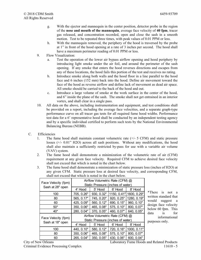
2. The fume hood shall demonstrate a minimization of the volumetric rate of air (CFM)
requirement at any given face velocity. Required CFM to achieve desired face velocity
shall not exceed that which is noted in the chart below.
3. The fume hood shall demonstrate a minimization of static pressure loss (inches of H2O) at
any given CFM. Static pressure loss at desired face velocity, and corresponding CFM,
shall not exceed that which is noted in the chart below.
*There is not a
written standard that
would suggest a
design face velocity
below 60 fpm. This
data is for
informational
purposes only.
4' Hood 5' Hood 6' Hood 8' Hood
100 705, 0.26" 930, 0.32" 1150, 0.41" 1600, 0.29"
80 565, 0.17" 745, 0.20" 920, 0.25" 1280, 0.19"
60 425, 0.09" 560, 0.12" 690, 0.15" 960, 0.10"
50* 350, 0.06" 465, 0.08" 575, 0.10" 800, 0.07"
40* 280, 0.04" 370, 0.05" 460, 0.07" 640, 0.05"
4' Hood 5' Hood 6' Hood 8' Hood
100 440, 0.10" 580, 0.12" 720, 0.16" 1000, 0.11"
80 350, 0.06" 465, 0.08" 575, 0.10" 800, 0.07"
60 265, 0.04" 350, 0.05" 430, 0.06" 600, 0.04"
Face Velocity (fpm)
Sash at 18" open
Face Velocity (fpm)
Sash at 28" open
Airflow Volumetric Rate (CFM) @
Static Pressure (inches of water)
Airflow Volumetric Rate (CFM) @
Static Pressure (inches of water)

© 2018 CDM Smith 6459-93709
All Rights Reserved
City of New Orleans Laboratory Fume Hoods and Related Products
Criminal Evidence Processing Complex 11610 - 6
D. Noise Criterion: The hood shall have a Noise Criterion (NC) rating of less than 50; measured
36” in front of the hood with full open sash, at 100 fpm face velocity. NC is a factor of sound
pressure level (dB) and frequency.
E. Illumination: Shall be a minimum average of 80 foot-candles inside the work area. Work area
is defined as the area inside the lined portion of the fume hood, from the face of baffle to sash
plane, from interior left to interior right, and from the work surface to a height of 28 inches.
F. Materials of Construction: Interior and Exterior materials of construction and finishes shall meet
the requirements in Part 2 of this specification.
1.05 QUALITY ASSURANCE
A. Fume hoods shall be designed, including comprehensive engineering analysis, by a qualified,
licensed Professional Engineer.
B. Manufacturer’s Qualifications
1. ISO 9001 Certified manufacturing plant and processes.
2. Ten installations of equal or larger size and requirements. Provide contact at each.
3. Only hood manufacturers who have had fume hoods as a principal product for 50 years
are considered.
C. Fume hoods shall be Made in America
1. 95% or more of raw material and component suppliers shall be United States based.
2. Stainless and cold rolled steel used in manufacturing shall be sourced from United States
steel mills.
3. Final product must be fabricated and assembled within the United States of America.
4. Owner reserves the right to evaluate Made in America claims for compliance with the
Bureau of Consumer Protection.
D. Supply all equipment in accordance with this specification. Offering a product differing in
materials, construction, or performance from this specification requires written approval
obtained seven days or more before the proposal deadline.
E. The owner/architect reserves the right to reject qualified or alternate proposals and to award
based on product value where such action assures the owner greater integrity of product.
F. Manufacturer's warranty against defects in material or workmanship on its fume hoods will be
for 1 year from date of installation or 2 years from date of purchase, whichever is sooner, and
includes replacement of parts (except lamps) and labor.
1.06 SUBMITTALS
A. Action Submittals
1. Laboratory hood specification sheets and product manuals shall be submitted by the hood
manufacturer upon request, and include safe and proper operation and maintenance
information.
2. Shop Drawings: Include plans, elevations, sections, and details.
© 2018 CDM Smith 6459-93709
All Rights Reserved
City of New Orleans Laboratory Fume Hoods and Related Products
Criminal Evidence Processing Complex 11610 - 7
a. Indicate details for anchoring fume hoods to permanent building construction
including locations of blocking and other supports.
b. Indicate locations and types of service fittings together with associated service
supply connection required.
c. Indicate duct connections, electrical connections, and locations of access panels.
d. Include roughing-in information for mechanical, plumbing, and electrical
connections.
e. Provide face opening, volumetric rates, and static pressure drop data.
3. Submit a document detailing the information supplied on the Hood Safety Practices Label
to verify compliance to specifications.
B. Informational Submittals
1. Product Test Reports: Showing compliance with specified performance requirements,
including NEBB representative test report as defined previously.
2. Independent validation:
a. Written verification that the laboratory fume hoods carry the ETL listed mark for
the following.
1) UL 61010-1 (formerly 3101-1), Underwriters Laboratories Inc., Electrical
Equipment for Laboratory Use
2) CAN/CSA C22.2 No. 61010-1, Canadian Standards Association, Safety
Requirements for Electrical Equipment for Measurement, Control and
Laboratory Use
3) UL 1805, Underwriters Laboratories Inc., Standard for Laboratory Hoods
and Cabinets
b. Written verification that 230 volt model fume hoods carry the CE conformity
marking as required by the Council of European Communities.
c. Written verification from an outside testing agency confirming coating compliance
to SEFA 8-2010, Recommended Practices for Laboratory Grade Metal Casework,
8.0 Cabinet Surface Finish Tests
3. Documentation of ISO 9001 Certified manufacturing plant and processes.
4. List of five installations (of equal or larger size and requirements) is available upon
request. Provide contact at each.
5. Declaration of Made in America. Owner reserves the right to evaluate Made in America
claims for compliance with the Bureau of Consumer Protection.
C. Material Submittals
1. Samples for Verification: of the hood exterior wall material, interior liner and baffle
material, epoxy work surface material, and color selection chips are available from the
hood manufacturer upon request.
© 2018 CDM Smith 6459-93709
All Rights Reserved
City of New Orleans Laboratory Fume Hoods and Related Products
Criminal Evidence Processing Complex 11610 - 8
1.07 DELIVERY, STORAGE, AND HANDLING
A. Protect finished surfaces during handling and installation with protective covering of
polyethylene film or another suitable material.
B. Schedule delivery of equipment so that spaces are sufficiently complete that equipment can be
installed immediately following delivery.
1.08 PROJECT CONDITIONS
A. Environmental Limitations: Do not deliver or install fume hoods until building is enclosed, wet
work and utility roughing-in are complete, and HVAC system is operating and maintaining
temperature and relative humidity at occupancy levels during the remainder of the construction
period.
PART 2 - PRODUCTS
2.01 MANUFACTURERS
A. Acceptable Manufacturer: Labconco Corporation, 8811 Prospect Avenue, Kansas City,
Missouri 64132
B. Basis-of-Design Product: Labconco Protector XStream
2.02 MATERIALS
A. Hood Interior Liner and Baffle
1. Liner material must comply with UL 1805, and be listed within NRTL test report as proof
of compliance.
2. General Material Properties
a. Nonflammable, corrosion and chemical-resistant
b. Sheet molded homogenous polyester panels
c. Minimum thickness is 3/16"
d. Smooth, white finish
3. Mechanical Properties
a. Tensile Strength: 7,500 PSI (51.7 Mpa)
b. Tensile Modulus: 1.7 x 10^6 PSI (11,700 Mpa)
c. Flexural Strength: 21,000 PSI (145 Mpa)
d. Flexural Strength at 130 degrees C: 12,900 PSI (89 Mpa)
e. Compressive Strength: 32,500 PSI (224 Mpa)
f. IZOD Impact Strength (Notched): 8.4 Ft Lb/in (4.5 J/cm)
4. Flame and Smoke Characteristics
a. Flame retardant, self-extinguishing, with a flame spread rating of 25 or less in
accordance with ASTM-E84
b. Oxygen Index: 35%
c. Smoke Density: 115
5. Physical Properties
a. Water Absorption: 0.4%
b. Specific Gravity: 4.81
© 2018 CDM Smith 6459-93709
All Rights Reserved
City of New Orleans Laboratory Fume Hoods and Related Products
Criminal Evidence Processing Complex 11610 - 9
c. Coefficient of Thermal Expansion: 2 In/in/ degree C x 10^-5
d. Thermal Conductivity: 1.9 BTU/Hr/Ft^2/In/degree F
6. Chemical Resistance
a. Splash and Spill Resistance:
1) Suspend sample panel in a vertical plane
2) Apply five drops of each reagent listed with an eyedropper
3) Apply liquid reagents at top of panel and allow to flow down full panel
height
b. Fume Resistance:
1) Place 25 milliliters of reagent into 100 milliliters beakers and position panel
over beaker tops in the proper sequence. Ensure beaker pouring lip permits
air to enter the interior atmosphere.
2) After 24 hours remove panel, flush with water, clean with detergent, rinse,
wipe dry and evaluate
c. Evaluation ratings: Change in surface finish and function shall be described by the
following numerical ratings
1) No Effect: No change in color or gloss
2) Excellent: Slight detectable change in color or gloss, but no change to the
function or life of the work surface material
3) Good: Clearly discernible change in color or gloss, but no significant
impairment of function or life
4) Fair: Objectionable change in appearance due to surface discoloration or
etch, possibly resulting in deterioration of function over an extended period
5) Failure: Pitting, cratering or erosion of work surface material; obvious and
significant deterioration
d. Required minimum results for each reagent (Reagent: Fume Resistance Rating,
Splash and Spill Resistance Rating)
1) Hydrochloric Acid (37%): 2,1
2) Sulfuric Acid (33%): 2,1
3) Sulfuric Acid (77%): 1,1
4) Sulfuric Acid (96%): 1,2
5) Formic Acid (90%): 2,1
6) Nitric Acid (20%): 2,2
7) Nitric Acid (30%): 1,2
8) Nitric Acid (70%): 3,2
9) Hydrofluoric Acid (48%): 2,2
10) Phosphoric Acid (85%): 1,1
11) Chromic Acid (60%): 1,4
12) Acetic Acid (98%): 1,1
13) Ammonium Hydroxide (20%): 1,1
14) Sodium Hydroxide (10%): 1,1
15) Sodium Hydroxide (20%): 1,3
16) Sodium Hydroxide (40%): 1,3
17) Sodium Hydroxide Flake: 1,-
18) Sodium Sulfide: 1,1
19) Zinc Chloride: 2,1
20) Tincture of Iodine: 3,3
21) Silver Nitrate: 2,1
22) Methyl Alcohol: 1,1
23) Ethyl Alcohol: 1,1
24) Butyl Alcohol: 1,1
© 2018 CDM Smith 6459-93709
All Rights Reserved
City of New Orleans Laboratory Fume Hoods and Related Products
Criminal Evidence Processing Complex 11610 - 10
25) Benzene: 1,1
26) Xylene: 1,1
27) Toluene: 1,1
28) Gasoline: 1,1
29) Dichloro Acetic Acid: 2,2
30) Dimethyl Formanide: 2,2
31) Ethyl Acetate: 1,1
32) Amyl Acetate: 1,1
33) Acetone: 1,1
34) Chloroform: 1,1
35) Carbon Tetrachloride: 1,1
36) Phenol: 2,2
37) Cresol: 1,1
38) Formaldehyde: 1,1
39) Trichloroethylene: 1,1
40) Ethyl Ether: 1,1
41) Furfural: 1,3
42) Methylene Chloride: 1,1
43) Mono Chloro Benzene: 1,1
44) Dioxane: 1,1
45) Methyl Ethyl Ketone: 1,1
46) Acid Dichromate: 1,2
47) Hydrogen Peroxide: 1,1
48) Napthalene: 1,1
B. Sheet Steel
1. Side panels and access panels 20-gauge (or heavier) sheet steel.
2. Hood corner posts are 16-gauge sheet steel.
3. Ceiling enclosure panels are 18 gauge sheet steel.
4. Cold-rolled, commercial steel (CS) sheet, complying with ASTM A 1008/A 1008M.
C. Chemical Resistant Finish
1. General: Prepare, treat, and finish welded assemblies after welding. Prepare, treat, and
finish components that are to be assembled with mechanical fasteners before assembling.
2. Chemical and Physical Resistance of Finish System: Finish complies with acceptance
levels of cabinet surface finish tests in SEFA 8. Third party validation required.
3. Powder-coat process required. Paint processes that release Volatile Organic Compounds
(VOC) are not acceptable
4. Color for Fume Hood Finish:
a. Glacier White
b. As selected by architect from Manufacturer’s full range
D. Safety Glass
1. Tempered
a. Clarity and temper test to be as specified in latest edition of Glass Tempering
Association, Engineering Standards Manual, Section 8.1.
b. Surface and interior visible quality to be as specified per ASTM C 1036, Standard
Specification for Flat Glass, Table 4, Quality level Q3.
2. Laminated The primary standard for fume hood sash construction is UL1805. Either
laminated or tempered is acceptable per this standard. However, laminated glass will
break under a lower stress than tempered. Typically, tempered glass can handle a 5 times
© 2018 CDM Smith 6459-93709
All Rights Reserved
City of New Orleans Laboratory Fume Hoods and Related Products
Criminal Evidence Processing Complex 11610 - 11
greater point load than laminated without breakage. If broken, laminated glass may stay
together better than tempered because of the inner layer. However, an explosion violent
enough to break the inner layer will show laminated glass as more dangerous than
tempered. Recommend tempered safety glass exclusively, or list laminated and tempered
as equals.
2.03 CONSTRUCTION
A. Superstructure:
1. Self-supporting, rigid structural assembly, to support inner wall consisting of fume hood
liner and outer wall of sheet metal exterior.
2. Fabricated from galvanized steel.
3. Space shall accommodate fume hood wiring and plumbing components for service
fixtures.
4. Access to fixture valves concealed in wall provided by exterior removable access panels,
gasket access panels on the inside liner walls, or through removable access panels on the
front posts.
B. Exterior
1. Fabricate from steel sheet with component parts screwed together.
2. Apply chemical-resistant finish to interior and exterior surfaces of component parts before
assembly.
3. Interchangeable side panels shall lift off without the use of tools to allow access to
plumbing lines, service fittings, electrical wiring, counterbalance sash weights, and light
fixtures. Exposed fasteners or hardware, and Velcro type fasteners, are not acceptable.
4. Corner posts
a. Pre-punched and plugged to accommodate up to 4 service fixtures per side
b. All services are accessible from the front of the hood.
c. Aerodynamic shape
d. Accommodate two electrical duplexes per side.
e. Right hand corner post includes electrical switches and pre-cut for Airflow monitor
installation.
f. Un-used penetrations shall be plugged.
5. Top and sides of face opening to provide an aerodynamic shape to ensure smooth, even
flow of air into fume hood.
6. Panel above header shall be removable without the use of tools to allow access to
mechanical connection, electrical wiring, counterbalance sash weights, and light fixtures.
Exposed fasteners or hardware, and Velcro type fasteners, are not acceptable.
C. Dimensions
1. Overall exterior dimensions are as follows:
a. 4 foot nominal width: 48” w x 59” h x 37.7” d
2. Overall interior dimensions are as follows:
a. 4 foot nominal width: 38.1” w x 48” h x 27.2” d
D. Hood Liner
1. Adhere interior liner components to superstructure.
2. Stainless steel fasteners shall be used on the interior ceiling for structural integrity.
3. Fasteners exposed to chemical environment are not acceptable.
© 2018 CDM Smith 6459-93709
All Rights Reserved
City of New Orleans Laboratory Fume Hoods and Related Products
Criminal Evidence Processing Complex 11610 - 12
4. Punch fume hood lining side panels to receive four service fittings, for use with remote
controls, per side. Provide removable plug buttons for holes not used for indicated
fittings.
5. Each side wall shall include an oval interior access panel to provide access to the side wall
of the fume hood for plumbing service access. Access panel material shall be that of the
liner, and gasketed to form a vapor proof seal.
E. Hood Baffle
1. Baffle system shall be designed to optimize the face velocity profile, and to capture a
wide range of gaseous densities without adjustment or moving components.
2. Include a two-baffle system.
a. Primary baffle: Shall provide a continuous horizontal slot at the work surface.
Baffle panels shall have multiple horizontal slots, with a chamfered entry. Slot
pattern shall be proven to optimize face velocity profile, and direct air in a non-
turbulent/laminar flow stream from the hood face into the baffle in a single pass.
b. Secondary baffle: located between the primary baffle and the back wall of the
hood, neutralizes any upward air streams and reduce air stream roll.
3. The baffle system shall be constructed with the same material as the fume hood liner.
4. The baffles shall be removable for cleaning. The primary baffles shall be two pieces to
allow removal without the use of tools.
5. Exposed components to be non-metallic. Metal components exposed to chemical
environment are not acceptable.
6. Moving parts or adjustment of any kind is not acceptable.
F. Exhaust Connection
1. 316 stainless steel with Chemical-Resistant Finish
2. 12.81" ID to accommodate any 12” nominal duct without the need for a transition adapter.
4, 5, and 6-foot hoods have one exhaust connection, and 8-foot hoods have two exhaust
connections. Additional components required to accommodate 12” nominal mechanical
system are not acceptable.
3. Ducting shall go inside the duct collar to ensure condensate travels into the hood and
evaporates. Duct collars that allow duct connection over the collar are not acceptable.
G. Airfoil
1. Cold Rolled Steel or 316 stainless steel with Chemical-Resistant Finish.
2. Airfoil shall have an aerodynamic radius to sweep the air into the hood with minimal
turbulence. Airfoil directs airflow across work top to remove heavier-than-air gases.
3. Must have 5 rows of perforations to allow the air to bypass underneath and through the
foil and sweep across the work surface to prevent any back flow of fumes escaping from
the front of the hood opening. This airflow continues even if blocked by the presence of
the operator.
4. Foil must extend back under the sash to prevent closure of the lower by-pass opening
when the sash is in the fully closed position, directly on top of the airfoil.
H. Sash Assembly
1. Glass: Fully tempered safety glass or glaze with laminated safety glass with unobstructed,
side-to-side view of fume hood interior and service fixture connections.
2. Dimensions: The full sash opening height is 28", the total unobstructed viewing height is
37.5" measured from the work surface.
3. Sash Tracks: Steel with Chemical Resistant Finish. Shall include bump stops for opening
and closing.
© 2018 CDM Smith 6459-93709
All Rights Reserved
City of New Orleans Laboratory Fume Hoods and Related Products
Criminal Evidence Processing Complex 11610 - 13
4. Sash Handle: extruded aluminum with Chemical Resistant Finish. Sash handle includes a
perforated air passage directly atop the handle to bleed air into the hood chamber and
direct chemical fumes away from the user's breathing zone. The handle is ergonomic in
design and is easy to grasp when operating
5. Sash guides: Corrosion resistant extruded poly-vinyl chloride.
6. Sash System
a. Vertical Sash (Cable and Pulley)
1) Hoods have a single vertical sash counterbalanced by a single weight.
2) Sash and weight to be connected via aircraft cable meeting MIL-W-83420
Military Specification.
3) Rear pulleys shall be connected via timing shaft to prevent sash tilting and
permit one finger operation at any point along full width sash handle.
Maximum 7 pounds pull required to raise or lower sash throughout its full
length of travel.
4) Design system to hold sash at any position without creep and to prevent sash
drop in the event of cable failure.
5) Include a defeatable, and automatically resetting sash stop positioned for an
18” sash height.
I. Electrical Components
1. Lighting
a. Provide UL Listed, high-efficiency, quick-start, T8 fluorescent lighting systems,
including bulbs.
1) 4 Foot Hoods - 2 each, 3-foot 25-watt fluorescent lamps
b. Vapor-Proof: all electrical components shall be outside of the contaminated air
space. Lighting shall be located behind a laminated safety glass shield, sealed to
the top of the hood liner.
c. The fluorescent light assemblies shall be serviceable from outside the fume hood
cavity, without the use of tools.
d. Light switch to be included on the lower right corner post, at heights compliant
with the Americans with Disabilities Act (ADA).
2. Blower Switch
a. Hoods shall be provided without a blower switch, as they will share a single
mechanical system with other hoods.
3. Electrical Receptacles
a. The hoods shall accommodate up to four (two per corner post) electrical
receptacles as indicted in schedule or drawings. Options to include:
1) 115 volt, 60 Hz, three-wire polarized and grounded electrical duplex
2) 115 volt, 60 Hz, three-wire polarized and grounded electrical duplex, with
Ground Fault Circuit Interruption (GFCI)
3) 230volt, 60 Hz, three-wire polarized and grounded electrical duplex
b. Receptacles shall be individually wired to field wiring box, and each rated at 20
Amperes.
c. Cover plates shall be acid resistant thermoplastic.
4. Wiring
a. Every electrical component shall be individually wired to a single point internal
field wiring box (including individual duplexes/receptacles).
b. Field wiring box to be 7” x 4” x 2.5”, grounded, and have (12) 7/8” diameter
knock out penetrations.
c. Final wiring and circuit dedication is to be by others.
© 2018 CDM Smith 6459-93709
All Rights Reserved
City of New Orleans Laboratory Fume Hoods and Related Products
Criminal Evidence Processing Complex 11610 - 14
d. Each receptacle circuit shall accommodate being wired to a dedicated building
circuit rated at 20A, or the receptacles ganged together on a building circuit with
the total load not exceeding 20 Amperes.
5. Fume hood to have third party validation of compliance to UL 1805 and UL 61010-1 by a
Nationally Recognized Testing Laboratory (NRTL)
J. Upper Dilution Air Supply
1. Located behind and above the sash to introduce between 5 and 10% of the required hood
air volume, and maintain sufficient exhaust air volume through hood to adequately dilute
hazardous fumes regardless of sash position.
2. This device bathes the sash interior above the work area to eliminate chemical fumes
along the sash plane near the operator's critical breathing zone.
3. Shall act as a by-pass opening controlled by sash position. If on a constant volume
mechanical system, the hood shall not have a change in static pressure or exhaust volume
across all sash positions.
4. Shall offer a significant restriction to the by-pass opening to allow the use of a VAV
mechanical system without modification to the by-pass opening.
K. Hood Safety Practices Label: Corrosion resistant plate attached to the left corner post of the
fume hood with the following Hood Safety Practices:
1. For use with substances that produce hazardous levels of airborne chemicals: gas, fumes,
vapors, dust
2. Do not put your head in the hood.
3. Minimize drafts and sudden movements in front of the hood.
4. Work a minimum of six inches inside the hood.
5. Elevate equipment above the work surface.
6. Keep sill and baffle unobstructed.
7. Do not use the hood for storage.
8. Adjust the sash to smallest opening possible when in use.
9. Close sash when unattended.
10. Do not remove any of the hood components.
11. Do not place flammable solvents near heat, flame or sparks.
12. Do not evaporate large amounts of flammable liquids.
13. Wipe up spills immediately.
14. Routinely validate airflow.
15. If the ventilation system malfunctions, or airflow alarm indicates unsafe condition, close
sash and discontinue hood operation immediately-call for help.
16. Do not use with Biohazards and Perchloric Acid
L. Fume Hood Accessories
1. Service Fixtures: Color-coded hose nozzle outlets and valves mounted inside the fume
hood and controlled from the exterior with color-coded index handles
a. The hoods are equipped without service fixtures or will be provided with a total of
up to 8 service fixtures as indicated in schedule.
b. Hose connectors located inside the fume hood cavity are chemically-resistant,
glass-filled polypropylene with 6 serrations.
c. Service lines shall be factory installed from valve to outlet
1) Copper tubing unless otherwise noted
2) Brass service lines for gas
3) Stainless steel service lines for Deionized Water
© 2018 CDM Smith 6459-93709
All Rights Reserved
City of New Orleans Laboratory Fume Hoods and Related Products
Criminal Evidence Processing Complex 11610 - 15
4) Connections shall be made with quick-connect compression fittings on the
inlet and outlet of the valve body, soldered and brazed connections not
easily disassembled are not acceptable.
5) Inlet tubing not included
d. Valves
1) Extruded brass valve and rotating seat, TFE-coated silicone bronze stem and
TFE packing.
2) Fixture handles are plastic and color coded as well as labeled for the
designated type of service.
3) Fixtures are rated at maximum pressure of 200 psi.
4) Coefficient of flow for the valve, Cv=0.43.
5) Valves are front loaded, located on the fume hood corner post for remote
use, and include:
a) Hot and cold tap water (flow rate 3.5 GPM or 13.25 LPM at 67 psi at
full open
b) Natural gas (theoretical flow rate of 71CFM at 100 psi, provides 1095
BTU/Sec at a density of .667 Lbs/CU. FT.)
c) Air (theoretical flow rate of 59 CFM at 100psi)
d) Vacuum (theoretical flow rate of 6 CFM at 10 psi)
e) Nitrogen
f) Argon
g) Steam
h) Oxygen (include oxygen compatible lubricant)
i) Deionized/Distilled water (Nickel plated and stainless steel
components)
2. Tissue Screen: Provide epoxy-coated, stainless-steel screen at bottom baffle opening to
prevent paper from being drawn into the exhaust plenum behind baffles.
3. Rear Finish Panel: Shall be the same materials and coating as the hood exterior.
4. Ceiling Enclosure Panels:
a. Provide filler panels matching fume hood exterior to enclose space above fume
hoods at front and sides of fume hoods and extending from tops of fume hoods to
ceiling.
b. Exposed fasteners are not acceptable.
c. Height adjustment to be within the following ranges as specified in the schedule.
1) 18.6 – 24.4”
5. Distillation Grid: Include stainless steel rods, connectors, and factory drilled liner.
6. Fire Suppression System: An ABC dry powder fire suppression system, with 165 degree
Fahrenheit fusible link, shall be factory supplied and prepped, and field installed through
the ceiling of the fume hood.
7. Face Velocity Monitor/Alarm
a. Digital Airflow Monitor
1) Provide audible and visual alarm in the event of an unsafe face velocity.
2) Alarm must sit flush with the fume hood corner post.
3) Based on a thermally compensated thermistor in the alarm module, and air
passing through a separate airstream into the hood interior.
4) Velocity shall be displayed digitally on the user facing LCD in fpm or m/s.
5) LED lights display red for alarm, yellow for caution, and green for normal
operation.
6) Must include external alarm and night setback functions.
7) Alarm mute shall be accessible from the front of the monitor; visual alarm
must remain activated until alarm condition is corrected.
© 2018 CDM Smith 6459-93709
All Rights Reserved
City of New Orleans Laboratory Fume Hoods and Related Products
Criminal Evidence Processing Complex 11610 - 16
8) UL Listed electrical components
9) Calibration shall be through a menu driven step by step procedure.
10) Calibration is the responsibility of the owner, following a complete
balancing of the mechanical system, and concurrently with As-Installed
testing.
b. Audio/Visual Airflow Monitor
1) Provide audible and visual alarm in the event of an unsafe face velocity.
2) Alarm must sit flush with the fume hood corner post.
3) Based on a thermally compensated thermistor in the alarm module, and air
passing through a separate airstream into the hood interior.
4) LED lights display red for alarm and green for normal operation.
5) Must include external alarm and night setback functions.
6) Alarm mute shall be accessible from the front of the monitor; visual alarm
must remain activated until alarm condition is corrected.
7) UL Listed electrical components
8) Calibration shall be through a front located potentiometer.
9) Calibration is the responsibility of the owner, following a complete
balancing of the mechanical system, and concurrently with As-Installed
testing.
c. Variable Air Volume (VAV) Prepared
1) Fume hoods shall come factory prepared with the proper cutouts and
brackets to field mount specified, TSI Model FHC50-01, or equal, VAV
controller and sash position sensor.
M. Work Surface
1. 1.25” thick, molded from solid modified epoxy resin, with smooth, non-specular, black
finish.
2. One inch radius front edge for optimal fume hood performance.
3. 3/8” dished area to match the fume hood interior work space and form a water tight pan
for spill containment.
4. Include a 2.5” diameter hole on each side for service pass-through and piping. Hole to be
covered by hood superstructure upon installation.
5. Include two 1.5” diameter penetrations to accommodate base cabinet venting. Holes to be
located outside of dished area and under the fume hood baffles. Include plugs.
6. Physical Properties:
a. Flexural Strength: Not less than 10,000 psi.
b. Modulus of Elasticity: Not less than 2,000,000 psi.
c. Hardness (Rockwell M): Not less than 100.
d. Water Absorption (24 Hours): Not more than 0.02 percent.
e. Heat Distortion Point: Not less than 260 deg F.
f. Flame-Spread Index: 25 or less per ASTM E 84.
N. Supporting Base Cabinets
1. Base cabinets shall be in depths of 22", widths, quantities, and types called out in the
equipment schedule or drawings, and meet the requirements of this specification.
2. Construction requirements for all cabinets
a. Exterior construction is 18 gauge (or heavier) cold rolled sheet steel with Chemical
Resistant Finish.
b. Hinges are 10 gauge (or heavier) plate with self-clinching pilot pin. Knuckle,
bullet, or piano type hinges are not accepted.
c. The rear panel will feature a 12" x 8" removable plumbing access panel.
d. Units 24" wide or less have only one door.
© 2018 CDM Smith 6459-93709
All Rights Reserved
City of New Orleans Laboratory Fume Hoods and Related Products
Criminal Evidence Processing Complex 11610 - 17
e. Each cabinet includes four leveling feet.
f. Capable of supporting up to 800 pounds.
g. A 14" filler panel is required to increases the cabinet depth to 36".
3. Standard Storage
a. Overall exterior dimensions:
1) 48" 48" w x 22" d x 35.5"-36.75"
b. Flush pull handles are ABS, low gloss black.
4. Acid Storage
a. Overall exterior dimensions:
1) 48" 48" w x 22" d x 35.5"-36.75"
b. Completely lined with a polyethylene corrosion resistant liner. The liner is 3/16"
thick, with a vacuum formed PVC liner pan at the bottom to contain spills. Each
door has a 3/16" sheet polyethylene liner.
c. The cabinet is labeled: "ACID".
d. Flush pull handles are ABS, low gloss black.
e. Each cabinet is vented into the fume hood with a 1-1/2" vent pipe. It should
provide a positive airflow directly into the fume hood exhaust system.
f. Supply an epoxy coated steel shelf with PVC liner pan if indicated in the schedule.
g. Acid cabinets with louvers are not acceptable
5. Solvent Storage
a. Overall exterior dimensions:
1) 48" 48" w x 22" d x 35.5"-36.75"
b. Solvent storage cabinets are specifically designed for the storage of flammable and
combustible liquids.
c. Solvent Storage Cabinet must be compliant with NFPA 30 “Flammability and
Combustible Liquids Code.”
d. Cabinets 30" wide and greater shall be tested and approved by Factory Mutual to
meet Factory Mutual Approval Standard 6050.
e. The bottoms, top, sides, and doors are fabricated of 18 gauge steel and are all
double panel construction with a 1-1/2" air space between panels.
f. All joints are welded or screwed to provide a rigid enclosure. A 2" deep liquid
tight pan that covers the entire bottom of the cabinet is furnished to contain liquid
leaks and spills.
g. A full-depth, 18 gauge steel, adjustable shelf is also provided. Shelves are sealed
leak tight.
h. Two diametrically opposed flame arrestor vents with spark screens are provided in
the back of the cabinet, as well as a grounding screw.
i. The cabinet has an interior finish same as the exterior.
j. The cabinet is labeled: "FLAMMABLE - KEEP FIRE AWAY".
k. The right hand door shall have a three point latching device.
l. Door handles include a key lock. Solvent storage handles are locking lever handles
with bright chrome finish.
m. If noted on the schedule, self-closing/self-latching models shall be provided with a
fusible-link feature to ensure the doors will close if the temperature outside the
cabinet exceeds 165 degrees Fahrenheit. The doors are synchronized so that both
doors will fully close.
PART 3 - EXECUTION
© 2018 CDM Smith 6459-93709
All Rights Reserved
City of New Orleans Laboratory Fume Hoods and Related Products
Criminal Evidence Processing Complex 11610 - 18
3.01 EXAMINATION
A. Examine areas, with installer present, for compliance with requirements for installation
tolerances and other conditions affecting performance of fume hoods.
B. Coordinate with other trades for the proper and correct installation of plumbing and electrical
rough-in and for rough opening dimensions required for the installation of the hood.
C. Proceed with installation only after unsatisfactory conditions have been corrected.
3.02 INSTALLATION
A. General: Install fume hoods according to shop drawings and manufacturer's written
instructions.
B. Install level, plumb, and true; shim as required, using concealed shims, and securely anchor to
building and adjacent laboratory casework.
C. Securely attach access panels, but provide for easy removal and secure reattachment. Where
fume hoods abut other finished work, apply filler strips and scribe for accurate fit, with
fasteners concealed where practical.
D. Neighboring splash blocks shall not be attached directly to the hood.
E. Install according to standards required by authority having jurisdiction.
F. Sequence installations to ensure utility connections are achieved in an orderly and expeditious
manner.
G. Touch up minor damaged surfaces caused by installation. Replace damaged components as
directed by Architect.
3.03 FIELD QUALITY CONTROL
A. NFPA 45 requires that fume hoods be field tested when installed.
B. Field test installed fume hoods according to ASHRAE 110 to verify compliance with
performance requirements.
1. Adjust fume hoods, hood exhaust fans, building's HVAC system, and make other
corrections until tested hoods perform as specified in fume hood schedule.
2. After making corrections, retest fume hoods that failed to perform as specified.
3.04 ADJUSTING AND CLEANING
A. Adjust moving parts for smooth, near silent, accurate sash operation with one hand. Adjust
sashes for uniform contact of rubber bumpers. Verify that counterbalances operate without
interference.
B. Clean finished surfaces, including both sides of glass; touch up as required; and remove or
refinish damaged or soiled areas to match original factory finish, as approved by Architect.
C. Clean adjacent construction and surfaces that may have been soiled in the course of installation
of work in this section.
D. Provide all necessary protective measures to prevent exposure of equipment and surfaces from
exposure to other construction activity.
E. Advise contractor of procedures and precautions for protection of material and installed
equipment and casework from damage by work of other trades.
© 2019 CDM Smith 6459-93709
All Rights Reserved
City of New Orleans Roller Window Shades
Criminal Evidence Processing Complex 12240 - 1
SECTION 12240
ROLLER SHADES
PART 1 GENERAL
1.01 SECTION INCLUDES
A. Sunscreen roller shades.
B. Room darkening and sunscreen double roller shades.
1.02 RELATED SECTIONS
A. Section 06100 - Rough Carpentry: Wood blocking and grounds for mounting roller shades and
accessories.
B. Section 092116 - Gypsum Board Assemblies: Coordination with gypsum board assemblies for
installation of shade pockets, closures and related accessories.
C. Section 09250 - Acoustical Ceilings: Coordination with acoustical ceiling systems for
installation of shade pockets, closures and related accessories.
D. Division 16 - Electrical: Electric service for motor controls.
1.03 REFERENCES
A. ASTM G 21 - Standard Practice for Determining Resistance of Synthetic Polymeric Materials
to Fungi.
B. NFPA 70 - National Electrical Code.
C. NFPA 701 - Fire Tests for Flame-Resistant Textiles and Films.
1.04 SUBMITTALS
A. Submit under provisions of Section 01 30 00.
B. Product Data: Manufacturer's data sheets on each product to be used, including:
1. Preparation instructions and recommendations.
2. Styles, material descriptions, dimensions of individual components, profiles, features,
finishes and operating instructions.
3. Storage and handling requirements and recommendations.
4. Mounting details and installation methods.
5. Typical wiring diagrams including integration of motor controllers with building
management system, audiovisual and lighting control systems as applicable..
© 2019 CDM Smith 6459-93709
All Rights Reserved
City of New Orleans Roller Window Shades
Criminal Evidence Processing Complex 12240 - 2
C. Shop Drawings: Plans, elevations, sections, product details, installation details, operational
clearances, wiring diagrams and relationship to adjacent work.
1. Prepare shop drawings on Autocad format using base sheets provided electronically by the
Architect.
D. Window Treatment Schedule: For all roller shades. Use same room designations as indicated
on the Drawings and include opening sizes and key to typical mounting details.
E. Selection Samples: For each finish product specified, one set of shade cloth options and
aluminum finish color samples representing manufacturer's full range of available colors and
patterns.
F. Verification Samples: For each finish product specified, one complete set of shade components,
unassembled, demonstrating compliance with specified requirements. Shadecloth sample and
aluminum finish sample as selected. Mark face of material to indicate interior faces.
G. Maintenance Data: Methods for maintaining roller shades, precautions regarding cleaning
materials and methods, instructions for operating hardware and controls.
1.05 QUALITY ASSURANCE
A. Manufacturer Qualifications: Obtain roller shades through one source from a single
manufacturer with a minimum of twenty years experience in manufacturing products
comparable to those specified in this section.
B. Installer Qualifications: Installer trained and certified by the manufacturer with a minimum of
ten years experience in installing products comparable to those specified in this section.
C. Fire-Test-Response Characteristics: Passes NFPA 701 small and large-scale vertical burn.
Materials tested shall be identical to products proposed for use.
D. Electrical Components: NFPA Article 100 listed and labeled by either UL or ETL or other
testing agency acceptable to authorities having jurisdiction, marked for intended use, and tested
as a system. Individual testing of components will not be acceptable in lieu of system testing.
E. Anti-Microbial Characteristics: 'No Growth' per ASTM G 21 results for fungi ATCC9642,
ATCC 9644, ATCC9645.
F. Mock-Up: Provide a mock-up (manual shades only) of one roller shade assembly for evaluation
of mounting, appearance and accessories.
1. Locate mock-up in window designated by Architect.
2. Do not proceed with remaining work until, mock-up is accepted by Architect.
3. Mockup may be incorporated into finish work.
© 2019 CDM Smith 6459-93709
All Rights Reserved
City of New Orleans Roller Window Shades
Criminal Evidence Processing Complex 12240 - 3
1.06 DELIVERY, STORAGE, AND HANDLING
A. Deliver shades in factory-labeled packages, marked with manufacturer and product name, fire-
test-response characteristics, and location of installation using same room designations
indicated on Drawings and in the Window Treatment Schedule.
1.07 PROJECT CONDITIONS
A. Environmental Limitations: Do not install roller shades until construction and wet and dirty
finish work in spaces, including painting, is complete and ambient temperature and humidity
conditions are maintained at the levels indicated for Project when occupied for its intended use.
B. Field Measurements: Where roller shades are indicated to fit to other construction, verify
dimensions of other construction by field measurements before fabrication and indicate
measurements on Shop Drawings. Allow clearances for operable glazed units' operation
hardware throughout the entire operating range.
C. Coordinate fabrication schedule with construction progress to avoid delaying the Work.
1.08 WARRANTY
A. Roller Shade Hardware and Chain Warranty: Manufacturer's standard non-depreciating twenty-
five year limited warranty.
B. Standard Shadecloth: Manufacturer's standard twenty-five year warranty.
C. Ecoveil Shadecloth: Manufacturer's standard ten year warranty.
D. Roller Shade Motors and Motor Control Systems: Manufacturer's standard non-depreciating
five year warranty.
E. Roller Shade Installation: One year from date of Substantial Completion, not including
scaffolding, lifts or other means to reach inaccessible areas.
2.01 MANUFACTURERS
A. Basis of Design Manufacturer: Mecho, Inc., which is located at: 42-03 35th St.; Long Island
City, NY 11101; Tel: 718-729-2020; Fax: 718-729-2941;
Email:[email protected]; Web:www.mechoshade.com
B. Requests for substitutions will be considered in accordance with provisions of Section 01630.
C. Alternates#1: Refer to Alternate #1 Fourth Floor Reflected Ceiling Plan sheets for extent and
configuration of additional shades.
2.02 ROLLER SHADE TYPE AND SHADECLOTH
A. Manually Operated Shades:
1. Mounting: Recess mounted with ceiling pocket and fascia.
© 2019 CDM Smith 6459-93709
All Rights Reserved
City of New Orleans Roller Window Shades
Criminal Evidence Processing Complex 12240 - 4
2. Configuration: Single solar shadecloth.
B. Motorized Operated Shades:
1. Basis of Design: Urbanshade Double Bracket System
2. Configuration: Double solar and blackout shadecloth.
a. One manual solar shade and one motorized blackout shade.
3. Solar Shadecloths:
a. Fabric: ThermoVeil 0900, 0-1 percent visually translucent extra-dense linear
weave pattern.
b. Color: Selected from manufacturer's standard colors.
4. Blackout Shadecloths:
a. Fabric: Classic Blackout 0700, Vinyl coated fabric blackout material same color
reverse side (for exterior).
2.03 SHADE BAND
A. Shade Bands: Construction of shade band includes the fabric, the hem weight, hem-pocket,
shade roller tube, and the attachment of the shade band to the roller tube. Sewn hems and open
hem pockets are not acceptable.
1. Hem Pockets and Hem Weights: Fabric hem pocket with RF-welded seams (including
welded ends) and concealed hem weights. Hem weights shall be of appropriate size and
weight for shade band. Hem weight shall be continuous inside a sealed hem pocket. Hem
pocket construction and hem weights shall be similar, for all shades within one room.
2. Shade Band and Shade Roller Attachment:
a. Use extruded aluminum shade roller tube of a diameter and wall thickness required to
support shade fabric without excessive deflection. Roller tubes less than 1.55 inch
(39.37 mm) in diameter for manual shades, and less than 2.55 inches (64.77 mm) for
motorize shades are not acceptable.
b. Provide for positive mechanical engagement with drive / brake mechanism.
c. Provide for positive mechanical attachment of shade band to roller tube; shade band
shall be made removable / replaceable with a "snap-on" "snap-off" spline mounting,
without having to remove shade roller from shade brackets.
d. Mounting spline shall not require use of adhesives, adhesive tapes, staples, and/or
rivets.
e. Any method of attaching shade band to roller tube that requires the use of: adhesive,
adhesive tapes, staples, and/or rivets are not acceptable.
2.04 SHADE FABRLCATION
A. Fabricate units to completely fill existing openings from head to sill and jamb-to-jamb, unless
specifically indicated otherwise.
B. Fabricate shadecloth to hang flat without buckling or distortion. Fabricate with heat-sealed
trimmed edges to hang straight without curling or raveling. Fabricate unguided shadecloth to
roll true and straight without shifting sideways more than 1/8 inch (3.18 mm) in either direction

© 2019 CDM Smith 6459-93709
All Rights Reserved
City of New Orleans Roller Window Shades
Criminal Evidence Processing Complex 12240 - 5
per 8 feet (2438 mm) of shade height due to warp distortion or weave design. Fabricate hem as
follows:
1. Hembar: Exposed hembar.
2. Hembar: Exposed blackout hembar with polybond seal for blackout shades.
C. Provide battens in standard shades as required to assure proper tracking and uniform rolling of
the shadebands. Contractor shall be responsible for assuring the width-to-height (W:H) ratios
shall not exceed manufacturer's standards or, in absence of such standards, shall be responsible
for establishing appropriate standards to assure proper tracking and rolling of the shadecloth
within specified standards. Battens shall be roll-formed stainless steel or tempered steel, as
required.
D. For railroaded shadebands, provide seams in railroaded multi-width shadebands as required to
meet size requirements and in accordance with seam alignment as acceptable to Architect.
Seams shall be properly located. Furnish battens in place of plain seams when the width, height,
or weight of the shade exceeds manufacturer's standards. In absence of such standards, assure
proper use of seams or battens as required to, and assure the proper tracking of the railroaded
multi-width shadebands.
E. Provide battens for railroaded shades when width-to-height (W:H) ratios meet or exceed
manufacturer's standards. In absence of manufacturer's standards, be responsible for proper use
and placement of battens to assure proper tracking and roll of shadebands.
F. Blackout shadebands, to be used with side channels, shall have horizontally mounted, roll-
formed stainless steel or tempered-steel battens not more than 3 feet (115 mm) on center
extending fully into the side channels. Battens shall be concealed in a integrally-colored fabric
to match the inside and outside colors of the shadeband, in accordance with manufacturer's
published standards for spacing and requirements.
1. Battens shall be roll formed of stainless steel or tempered steel and concave to match the
contour of the roller tube.
2. Batten pockets shall be self-colored fabric front and back RF welded into the shadecloth. A
self-color opaque liner shall be provided front and back to eliminate any see through of the
batten pocket that shall not exceed 1-1/2 inches (38.1 mm) high and be totally opaque. A
see-through moire effect, which occurs with multiple layers of transparent fabrics, shall not
be acceptable.
2.05 COMPONENTS
A. Access and Material Requirements:
1. Provide shade hardware allowing for the removal of shade roller tube from brackets
without removing hardware from opening and without requiring end or center supports to
be removed.
2. Provide shade hardware that allows for removal and re-mounting of the shade bands
without having to remove the shade tube, drive or operating support brackets.
© 2019 CDM Smith 6459-93709
All Rights Reserved
City of New Orleans Roller Window Shades
Criminal Evidence Processing Complex 12240 - 6
3. Use only Delrin engineered plastics by DuPont for all plastic components of shade
hardware. Styrene based plastics, and /or polyester, or reinforced polyester will not be
acceptable.
B. Manual Operated Chain Drive Hardware and Brackets:
1. Provide for universal, regular and offset drive capacity, allowing drive chain to fall at front,
rear or non-offset for all shade drive end brackets. Universal offset shall be adjustable for
future change.
2. Provide hardware capable for installation of a removable fascia, for both regular and/or
reverse roll, which shall be installed without exposed fastening devices of any kind.
3. Provide shade hardware system that allows for removable regular and/or reverse roll
fascias to be mounted continuously across two or more shade bands without requiring
exposed fasteners of any kind.
4. Provide shade hardware system that allows for operation of multiple shade bands (multi-
banded shades) by a single chain operator, subject to manufacturer's design criteria.
Connectors shall be offset to assure alignment from the first to the last shade band.
5. Provide shade hardware system that allows multi-banded manually operated shades to be
capable of smooth operation when the axis is offset a maximum of 6 degrees on each side
of the plane perpendicular to the radial line of the curve, for a 12 degrees total offset.
6. Provide positive mechanical engagement of drive mechanism to shade roller tube. Friction
fit connectors for drive mechanism connection to shade roller tube are not acceptable
7. Provide shade hardware constructed of minimum 1/8-inch (3.18 mm) thick plated steel or
heavier as required to support 150 percent of the full weight of each shade.
8. Drive Bracket / Brake Assembly:
a. MechoShade Drive Bracket model M5 shall be fully integrated with all Mecho
(formerly MechoShade) accessories, including, but not limited to: SnapLoc fascia,
room darkening side / sill channels, center supports and connectors for multi-banded
shades.
b. M5 drive sprocket and brake assembly shall rotate and be supported on a welded 3/8
inch (9.525 mm) steel pin.
c. The brake shall be an over-running clutch design which disengages to 90 percent
during the raising and lowering of a shade. The brake shall withstand a pull force of
50 lbs. (22 kg) in the stopped position.
d. The braking mechanism shall be applied to an oil-impregnated hub on to which the
brake system is mounted. The oil impregnated hub design includes an articulated
brake assembly, which assures a smooth, non-jerky operation in raising and lowering
the shades. The assembly shall be permanently lubricated. Products that require
externally applied lubrication and or not permanently lubricated are not acceptable.
e. The entire M5 assembly shall be fully mounted on the steel support bracket, and fully
independent of the shade tube assembly, which may be removed and reinstalled
without effecting the roller shade limit adjustments.
f. Drive Chain: #10 qualified stainless steel chain rated to 90 lb. (41 kg) minimum
breaking strength. Nickel plate chain shall not be accepted.
© 2019 CDM Smith 6459-93709
All Rights Reserved
City of New Orleans Roller Window Shades
Criminal Evidence Processing Complex 12240 - 7
2.06 ACCESSORLES
A. Roller Shade Pocket: For recessed mounting in acoustical tile, or drywall ceilings as indicated
on the Drawings.
1. Provide either extruded aluminum and or formed steel shade pocket, sized to accommodate
roller shades, with exposed extruded aluminum closure mount, tile support and removable
closure panel to provide access to shades.
a. Provide "Vented Pocket" such that there will be a minimum of four 1 inch (25.4 mm)
diameter holes per foot allowing the solar gain to flow above the ceiling line.
B. Fascia:
1. Continuous removable extruded aluminum fascia that attaches to shade mounting brackets
without the use of adhesives, magnetic strips, or exposed fasteners.
2. Fascia shall be able to be installed across two or more shade bands in one piece.
3. Fascia shall fully conceal brackets, shade roller and fabric on the tube.
4. Provide bracket / fascia end caps where mounting conditions expose outside of roller shade
brackets.
5. Notching of Fascia for manual chain shall not be acceptable.
C. Room Darkening Channels:
1. Side Channels, ElectroShade: Extruded aluminum with polybond edge seals and SnapLoc-
mounting brackets and with concealed fastening. Exposed fastening is not acceptable.
Units 2-1/2 inches (63.5 mm) wide by 1-3/16 inches (30.1 mm) deep; two-band center
channels 5 inches (127 mm) wide by 1-3/16 inches (30.1 mm) deep. The 2-5/8-inch (66.6
mm) double-center channels may be installed at center-support positions of multi-band-
shade ElectroShades. MechoShade side channels 2-5/8 inches (66.6 mm) may be used as
center supports for ElectroShades. Also provide for use with manually operated room
darkening MechoShades over 8 feet (2438 mm) in height.
2. Sill Channels: Extruded aluminum with polybond edge seals and SnapLoc-mounting
brackets and with concealed fastening. Exposed fastening is not acceptable.
3. Channel Color: Selected from manufacturer's standard colors.
4. Channel Color: Custom color.
2.07 MOTORIZED ROLLER SHADE OPERATORS
A. General: Provide factory-assembled motorized shade operation systems designed for lifting
shades of type, size, weight, construction, use, and operation frequency indicated. Provide
operation systems of size and capacity and with features, characteristics, and accessories
suitable for Project conditions and recommended by shade manufacturer, complete with electric
motors and factory-pre-wired motor controls, remote-control stations, power disconnect
switches, enclosures protecting controls and all operating parts, and accessories required for
© 2019 CDM Smith 6459-93709
All Rights Reserved
City of New Orleans Roller Window Shades
Criminal Evidence Processing Complex 12240 - 8
reliable operation without malfunction. Include wiring from motor controls to motors.
Coordinate operator wiring requirements and electrical characteristics with the building
electrical system.
B. Comply with NFPA 70.
C. Control Equipment: Comply with NEMA ICS 1, NEMA ICS 2, and NEMA ICS 6 with NFPA
70 Class 2 control circuit, maximum 24-V ac or dc.
D. Electric Motors: UL-approved or -recognized, asynchronous, totally enclosed, insulated,
capacitor-start motors, complying with NEMA MG I, with thermal overload protection, brake,
permanently lubricated bearings, and limit switches; sized by shade manufacturer to start and
operate size and weight of shade considering service factor or considering Project's service
conditions without exceeding nameplate ratings.
1. Service Factor: According to NEMA MG 1, unless otherwise indicated.
2. Motor Characteristics: Coordinate voltage rating with electrical service.
3. Motor Mounting: Within manufacturer's standard roller enclosure.
E. Remote Controls: Electric controls with NEMA ICS 6, Type 1 enclosure for recessed or flush
mounting. Provide the following devices for remote-control activation of shades:
1. Control Stations: Room control grouping of shade with “up and down” positions for
blackout shades.
F. Finish: All exposed metal components: To be selected by the Architect from manufacturer’s
standards.
3.01 EXAMINATION
A. Do not begin installation until substrates have been properly prepared.
B. If substrate preparation is the responsibility of another installer, notify Architect of
unsatisfactory preparation before proceeding.
3.02 PREPARATION
A. Clean surfaces thoroughly prior to installation.
B. Prepare surfaces using the methods recommended by the manufacturer for achieving the best
result for the substrate under the project conditions.
3.03 INSTALLATION
A. Install roller shades level, plumb, square, and true according to manufacturer's written
instructions, and located so shade band is not closer than 2 inches (50 mm) to interior face of
glass. Allow proper clearances for window operation hardware.
© 2019 CDM Smith 6459-93709
All Rights Reserved
City of New Orleans Roller Window Shades
Criminal Evidence Processing Complex 12240 - 9
B. Adjust and balance roller shades to operate smoothly, easily, safely, and free from binding or
malfunction throughout entire operational range.
C. Clean roller shade surfaces after installation, according to manufacturer's written instructions.
D. Engage Installer to train Owner's maintenance personnel to adjust, operate and maintain roller
shade systems.
3.04 PROTECTION
A. Protect installed products until completion of project.
B. Touch-up, repair or replace damaged products before Substantial Completion.
END OF SECTION
© 2019 CDM Smith 6459-93709
All Rights Reserved
City of New Orleans Roller Window Shades
Criminal Evidence Processing Complex 12240 - 10
This page is blank.
© 2019 CDM Smith 6459-93709
All Rights Reserved
City of New Orleans Laboratory Casework
Criminal Evidence Processing Complex 12360 - 1
SECTION 12360
LABORATORY CASEWORK
PART 1 GENERAL
1.01 SCOPE OF WORK
A. Furnish all labor, materials, equipment and incidentals required and design and deliver
laboratory casework for the Project as shown on the Drawings and as specified herein.
B. The work includes:
1. Wood laboratory casework
2. Utility-space framing at backs of base cabinets and between backs of base cabinets
3. Filler and closure panels
4. Laboratory countertops
5. Mobile Stainless Worktables
6. Shelves.
7. Laboratory sinks
8. Laboratory accessories.
9. Water, laboratory gas, and electrical service fittings.
1.02 RELATED WORK
A. Wood blocking for anchoring laboratory casework is included in Section 06100.
B. Non-Load-Bearing Steel Framing for reinforcements in metal-framed partitions for anchoring
laboratory casework is included in Section 05400.
C. Fume hoods, including base cabinets and countertops under fume hoods are included in Section
11610.
D. Installing service fittings specified in this Section, including connecting service utilities are
included in Divisions 15.
1.03 SUBMITTALS
A. Submit in accordance with Section 01300 the following:
1. Product Data: For each type of product indicated.
2. Shop Drawings: For laboratory casework. Include plans, elevations, sections, details, and
attachments to other work.
a. Indicate locations of hardware and keying of locks.

© 2019 CDM Smith 6459-93709
All Rights Reserved
City of New Orleans Laboratory Casework
Criminal Evidence Processing Complex 12360 - 2
b. Indicate locations and types of service fittings.
c. Indicate locations of blocking and reinforcements required for installing laboratory
casework.
d. Include details of utility spaces showing supports for conduits and piping.
e. Include details of support framing system.
f. Include details of exposed conduits, if required, for service fittings.
g. Indicate locations of and clearances from adjacent walls, doors, windows, other
building components, and other laboratory equipment.
h. Include coordinated dimensions for laboratory equipment specified in other Sections.
B. Samples for Initial Selection: For factory-applied finishes and other materials requiring color
selection.
C. Samples: For each type of cabinet finish and each type of countertop material indicated, in
manufacturer's standard sizes.
D. Samples: Unless otherwise directed, approved full-size Samples may become part of the
completed Work, if in an undisturbed condition at time of Substantial Completion. Notify
Engineer of their exact locations. If not incorporated into the Work, retain acceptable full-size
Samples at Project site and remove when directed by Engineer.
1. One of each type of hardware item specified.
E. Delegated-Design Submittal: For laboratory casework indicated to comply with seismic
performance requirements, including analysis data signed and sealed by the qualified
professional engineer responsible for their preparation.
F. Qualification Data: For qualified manufacturer.
G. Product Test Reports for Casework: Based on evaluation of comprehensive tests performed by
a qualified testing agency, indicating compliance of laboratory casework with requirements of
specified product standard.
H. Product Test Reports for Countertop Surface Material: Based on evaluation of comprehensive
tests performed by a qualified testing agency, indicating compliance of laboratory countertop
surface materials with requirements specified for chemical and physical resistance.
1.04 REFERENCE STANDARDS
A. American Hardboard Association
1. AHA A135.4 - Basic Hardboard
B. ASTM International
1. ASTM A 240/A 240M - Standard Specification for Chromium and Chromium-Nickel
Stainless Steel Plate, Sheet, and Strip for Pressure Vessels and for General Applications
2. ASTM C 1172 - Standard Specification for Laminated Architectural Flat Glass
C. American Society of Civil Engineers/Structural Engineering Institute
© 2019 CDM Smith 6459-93709
All Rights Reserved
City of New Orleans Laboratory Casework
Criminal Evidence Processing Complex 12360 - 3
1. ASCE/SEI 7 - Minimum Design Loads for Buildings and Other Structures
D. Builders Hardware Manufacturers Association
1. BHMA A156.9 - Cabinet Hardware
2. BHMA A156.11 - Cabinet Locks
E. FM Approvals
F. Hardwood Plywood & Veneer Association
1. HPVA HP-1-2000: Hardwood and Decorative Plywood
G. The Institute of Electrical and Electronics Engineers, Inc.
1. IEEE C62.41.2 - Recommended Practice on Characterization of Surges in Low-Voltage
(1000 V and Less) AC Power Circuits
2. IEEE C62.45 - Recommended Practice on Surge Testing for Equipment Connected to
Low-Voltage (1000 V and Less) AC Power Circuits
H. National Electrical Manufacturers Association
1. NEMA WD 1- General Requirements for Wiring Devices
2. NEMA WD 6 - Wiring Devices - Dimensional Requirements
I. NFPA
1. NFPA 30 - Flammable and Combustible Liquids Code
2. NFPA 70 – National Electrical Code
J. Scientific Equipment & Furniture Association
1. SEFA 2.3 – Installations
2. SEFA 8 - Casework Recommended Practice
K. Underwriters Laboratories Inc.
1. UL 20 - Standard for Safety General-Use Snap Switches
2. UL 498 - Attachment Plugs and Receptacles
3. UL 943 - Ground-Fault Circuit-Interrupters
L. AWI
1. Architectural Woodwork Casework Details
© 2019 CDM Smith 6459-93709
All Rights Reserved
City of New Orleans Laboratory Casework
Criminal Evidence Processing Complex 12360 - 4
2. Architectural Woodwork Institute
M. U.S. Department of Commerce, National Institute of Standards and Technology
1. DOC PS 1 - U.S. Product Standard for Construction and Industrial Plywood
N. Where reference is made to one of the above or other referenced standards, the revisions in
effect at the time of bid opening shall apply.
1.05 DEFINITIONS
A. MDF: Medium-density fiberboard.
B. Exposed Surfaces of Casework: Surfaces visible when doors and drawers are closed, including
bottoms of cabinets more than 48 inches (1200 mm) above floor, and visible surfaces in open
cabinets or behind glass doors.
1. Ends of cabinets, including those installed directly against walls or other cabinets, are
defined as "exposed."
2. Ends of cabinets indicated to be installed directly against and completely concealed by
walls or other cabinets are defined as "concealed."
C. Semi-exposed Surfaces of Casework: Surfaces behind opaque doors, such as cabinet interiors,
shelves, and dividers; interiors and sides of drawers; and interior faces of doors. Tops of
cabinets 78 inches (1980 mm) or more above floor are defined as "semi-exposed."
D. Concealed Surfaces of Casework: Include sleepers, web frames, dust panels, and other surfaces
not usually visible after installation.
E. Hardwood Plywood: A panel product composed of layers or plies of veneer, or of veneers in
combination with lumber core, hardboard core, MDF core, or particleboard core, joined with
adhesive and faced both front and back with hardwood veneers.
1.06 PERFORMANCE REQUIREMENTS
A. System Structural Performance: Laboratory casework and support framing system shall
withstand the effects of the following gravity loads and stresses without permanent deformation,
excessive deflection, or binding of drawers and doors:
1. Support Framing System: 600 lb./ft. (900 kg/m)
2. Suspended Base Cabinets (Internal Load): 160 lb./ft. (240 kg/m)
3. Work Surfaces (Including Tops of Suspended Base Cabinets): 160 lb./ft. (240 kg/m) .
4. Wall Cabinets (Upper Cabinets): 160 lb./ft. (240 kg/m)
5. Shelves: 40 lb./sq. ft. (200 kg/sq. m).
© 2019 CDM Smith 6459-93709
All Rights Reserved
City of New Orleans Laboratory Casework
Criminal Evidence Processing Complex 12360 - 5
B. Delegated Design: Design laboratory casework, including comprehensive engineering analysis
by a qualified professional engineer, using seismic performance requirements and design
criteria indicated.
1.07 QUALITY ASSURANCE
A. Manufacturer Qualifications: A qualified manufacturer that produces casework of types
indicated for this Project that has been tested for compliance with SEFA 8.
B. Source Limitations: Obtain laboratory casework from single source from single manufacturer
who has been engaged in successful production for a period of not less than five years.
1. Obtain countertops, sinks, accessories and service fittings from casework manufacturer.
C. Product Designations: Drawings indicate sizes and configurations of laboratory casework by
referencing designated manufacturer's catalog numbers. Other manufacturers' laboratory
casework of similar sizes and similar door and drawer configurations and complying with the
Specifications may be considered.
D. Casework Product Standard: Comply with SEFA 8, "Laboratory Furniture - Casework,
Shelving and Tables - Recommended Practices."
E. Flammable Liquid Storage: Where cabinets are indicated for solvent or flammable liquid
storage, provide units that are listed and labeled as complying with requirements in NFPA 30 by
a testing and inspecting agency acceptable to authorities having jurisdiction
F. Electrical Components, Devices, and Accessories: Listed and labeled as defined in NFPA 70,
by a qualified testing agency, and marked for intended location and application.
G. Keying Conference: coordinate keying with owner and incorporate in final shop drawing
submission
H. Pre-installation Conference: Conduct conference at Project site
1.08 DELIVERY, STORAGE, AND HANDLING
A. Protect finished surfaces during handling and installation with protective covering of
polyethylene film or other suitable material.
1.09 PROJECT CONDITIONS
A. Environmental Limitations: Do not deliver or install laboratory casework until building is
enclosed, utility roughing-in and wet work are complete and dry, and temporary HVAC system
is operating and maintaining temperature and relative humidity at occupancy levels during the
remainder of the construction period.
1.10 COORDINATION
A. Coordinate layout and installation of framing and reinforcements for support of laboratory
casework.

© 2019 CDM Smith 6459-93709
All Rights Reserved
City of New Orleans Laboratory Casework
Criminal Evidence Processing Complex 12360 - 6
B. Coordinate installation of laboratory casework with installation of fume hoods and other
laboratory equipment.
1.11 EXTRA MATERIALS
A. Furnish complete touchup kit for each type and color of metal laboratory casework provided.
Include fillers, primers, paints, and other materials necessary to perform permanent repairs to
damaged laboratory casework finish.
B. Furnish complete touchup kit for each type and color of wood laboratory casework provided.
Include scratch fillers, stains, finishes, and other materials necessary to perform permanent
repairs to damaged laboratory casework finish.
C. Furnish extra materials that match products installed and that are packaged with protective
covering for storage and identified with labels describing contents.
1. Cabinet Mounting Clips and Related Hardware: Quantity equal to 5 percent of amount
installed, but no fewer than 20 of each type.
2. Modular Countertop Units: One extra units of each length and material installed.
PART 2 PRODUCTS
2.01 WOOD CABINET AND TABLE MATERIALS
A. General:
1. Maximum Moisture Content for Lumber: 7 percent for hardwood and 12 percent for
softwood.
2. Hardwood Plywood: HPVA HP-1, either veneer core or particleboard core, unless
otherwise indicated.
3. Particleboard: ANSI A208.1, Grade M-2.
4. Hardboard: AHA A135.4, Class 1 Tempered.
5. Edge banding for Wood-Veneered Construction: Minimum 1/8-inch- (3-mm-) thick, solid
wood of same species as face veneer
a. Colors: As selected by Engineer from manufacturer's full range.
B. Exposed Materials:
1. General: Provide materials that are selected and arranged for compatible grain and color.
Do not use materials adjacent to one another that are noticeably dissimilar in color, grain,
figure, or natural character markings.
2. Wood Species: White birch
© 2019 CDM Smith 6459-93709
All Rights Reserved
City of New Orleans Laboratory Casework
Criminal Evidence Processing Complex 12360 - 7
3. Plywood: Hardwood plywood with face veneer of species indicated, selected for
compatible color and grain. Grade A exposed faces at least 1/50 inch (0.5 mm) thick, and
Grade J crossbands. Provide backs of same species as faces.
a. Face Veneer Cut: Plain sliced
4. Solid Wood: Clear hardwood lumber of species indicated and selected for grain and color
compatible with exposed hardwood plywood.
C. Semi-exposed Materials:
1. Solid Wood: Sound hardwood lumber, selected to eliminate appearance defects, of any
species similar in color and grain to exposed solid wood.
2. Plywood: Hardwood plywood of any species similar in color and grain to faces and Grade
J crossbands. Provide backs of same species as faces.
3. Provide solid wood or hardwood plywood for semi-exposed surfaces unless otherwise
indicated.
4. Metal for Steel Drawer Pans: Cold-rolled, carbon-steel sheet complying with ASTM A
1008/A 1008M; matte finish; suitable for exposed applications.
D. Concealed Materials:
1. Solid Wood: Any species, with no defects affecting strength or utility.
2. Plywood: Hardwood plywood. Provide backs of same species as faces.
3. Particleboard.
4. MDF.
5. Hardboard.
2.02 AUXILIARY CABINET MATERIALS
A. Acid Storage-Cabinet Lining: 1/4-inch- (6-mm-) thick, glass-fiber cement board complying
with ASTM C 1186
B. Glass for Glazed Doors: Clear float glass complying with ASTM C 1036, Type I, Class 1,
Quality-Q3; not less than 3.0 mm thick.
C. Glass for Glazed Doors: Clear tempered glass complying with ASTM C 1048, Kind FT,
Condition A, Type I, Class 1, Quality-Q3; not less than 5.0 mm thick.
D. Glass for Glazed Doors: Clear laminated tempered glass complying with ASTM C 1172, Kind
LT, Condition A, Type I, Class I, Quality-Q3; with two lites not less than 3.0 mm thick and
with clear, polyvinyl butyral interlayer.
© 2019 CDM Smith 6459-93709
All Rights Reserved
City of New Orleans Laboratory Casework
Criminal Evidence Processing Complex 12360 - 8
E. Frameless Glass Doors: Clear tempered glass complying with ASTM C 1048, Kind FT,
Condition A, Type I, Class 1, Quality-Q3; not less than 5.0 mm thick; with exposed edges
seamed before tempering.
2.03 COUNTERTOP TABLE TOP SHELF AND SINK MATERIALS
A. Epoxy: Factory-molded, modified epoxy-resin formulation with smooth, non-specular finish.
1. Manufacturers: Provide products by one of the following:
a. Durcon Company (The).
b. Epoxyn Products.
c. Laboratory Tops, Inc.
d. Prime industries, Inc.
e. Or equal.
2. Physical Properties:
a. Flexural Strength: Not less than 10,000 psi (70 MPa).
b. Modulus of Elasticity: Not less than 2,000,000 psi (1400 MPa).
c. Hardness (Rockwell M): Not less than 100.
d. Water Absorption (24 Hours): Not more than 0.02 percent.
e. Heat Distortion Point: Not less than 260 deg F (127 deg C).
3. Chemical Resistance: Epoxy-resin material has the following ratings when tested with
indicated reagents according to NEMA LD 3, Test Procedure 3.4.5:
a. No Effect: Acetic acid (98 percent), acetone, ammonium hydroxide (28 percent),
benzene, carbon tetrachloride, dimethyl formamide, ethyl acetate, ethyl alcohol, ethyl
ether, methyl alcohol, nitric acid (70 percent), phenol, sulfuric acid (60 percent), and
toluene.
b. Slight Effect: Chromic acid (60 percent) and sodium hydroxide (50 percent).
4. Color: Black.
5. Locations: Rooms A417 (ALT 1), A418 (ALT 1), and A509 , A519, A523
B. Stainless-Steel Countertops: Made from stainless-steel sheet, not less than 0.062-inch (1.59-
mm) nominal thickness, with No. 4 satin finish.
1. Extend top down 1 inch (25 mm) at edges with a 1/2-inch (13-mm) return flange under
frame. Apply heavy coating of heat-resistant, sound-deadening mastic to undersurface.
2. Form backsplash coved to and integral with top surface.
3. Provide raised (marine) edge around perimeter of countertops containing sinks; pitch two
ways to sink to provide drainage without channeling or grooving.
4. Provide raised (marine) edge around perimeter of countertops at sinks, where indicated;
pitch two ways to sink to provide drainage without channeling or grooving.
5. Punch holes for service fittings at factory.

© 2019 CDM Smith 6459-93709
All Rights Reserved
City of New Orleans Laboratory Casework
Criminal Evidence Processing Complex 12360 - 9
6. Reinforce underside of countertop with channels or use thicker metal sheet where
necessary to insure rigidity without deflection.
7. Weld shop-made joints.
8. Where field-made joints are required, provide hairline butt-joints mechanically bolted
through continuous channels welded to underside at edges of joined ends. Keep field
jointing to a minimum.
9. Where stainless-steel sinks or cup sinks occur in stainless-steel countertops, factory weld
into one integral unit.
10. After fabricating and welding, grind surfaces smooth and polish as needed to produce
uniform, directionally textured finish with no evidence of welds and free of cross scratches.
Passivate and rinse surfaces; remove embedded foreign matter and leave surfaces clean.
C. Stainless-Steel Shelves: Made from stainless-steel sheet, not less than 0.050-inch (1.27-mm)
nominal thickness, with No. 4 satin finish. Weld shop-made joints. Fold down front edge 3/4
inch (19 mm); fold up back edge 3 inches (75 mm). Provide integral stiffening brackets, formed
by folding up ends 3/4 inch (19 mm) and welding to upturned back edgeAfter fabricating, grind
welds smooth and polish as needed to produce uniform, directionally textured finish with no
evidence of welds and free of cross scratches. Passivate and rinse surfaces; remove embedded
foreign matter and leave surfaces clean.
D. Stainless-Steel Sinks: Made from stainless-steel sheet, not less than 0.050-inch (1.27-mm)
nominal thickness. Fabricate with corners rounded and coved to at least 5/8-inch (16-mm)
radius. Slope sink bottoms to outlet. Provide double-wall construction for sink partitions with
top edge rounded to at least 1/2-inch (13-mm) diameter. Provide continuous butt-welded joints.
After fabricating and welding, grind surfaces smooth and polish as needed to produce uniform
finish with no evidence of welds and free of cross scratches. Passivate and rinse surfaces;
remove embedded foreign matter and leave surfaces clean.
1. Punch holes for fittings at factory.
2. Provide with stainless-steel strainers and tailpieces.
3. Provide with integral rims except where located in stainless-steel countertops.
4. Apply 1/8-inch- (3-mm-) thick coating of heat-resistant, sound-deadening mastic to
undersink surfaces.
E. Cup Sinks: Stainless steel, 3-by-6-inch (75-by-150-mm) oval
1. Provide with stainless-steel strainers and integral tailpieces.
F. Troughs: Stainless steel. Pitch to drains not less than 1/8 inch/foot (10 mm/m). Except where
troughs empty into sinks, provide NPS 1-1/2 (DN 40) outlets with strainers and tailpieces.
1. Stainless-Steel Troughs: Made from stainless-steel sheet, not less than 0.050-inch (1.27-
mm) nominal thickness. Fabricate with corners rounded and coved to at least 5/8-inch (16-
mm) radius. Provide continuous butt-welded joints. After fabricating and welding, grind
© 2019 CDM Smith 6459-93709
All Rights Reserved
City of New Orleans Laboratory Casework
Criminal Evidence Processing Complex 12360 - 10
surfaces smooth and polish as needed to produce uniform finish with no evidence of welds
and free of cross scratches. Passivate and rinse surfaces; remove embedded foreign matter
and leave surfaces clean. Provide stainless-steel strainers and tailpieces.
G. Locations: All laboratory counters not listed in Section 2.03, paragraph A item 5 above.
2.04 WOOD CABINETS AND TABLES
A. Manufacturers: Provide products by one of the following:
1. Advanced Lab Concepts, Inc.
2. Fisher Hamilton L.L.C.
3. Kewaunee Scientific Corporation; Laboratory Products Group.
4. Laboratory Design & Supply.
5. Sheldon Laboratory Systems.
6. South Texas Woodmill, Inc.
7. Or equal.
B. Design: Lipped overlay with radiused edges.
1. Provide1/8-inch (3.2-mm) reveals between doors and drawers that are adjacent.
C. Grain Direction:
1. Vertical on both doors and drawer fronts, with continuous vertical matching.
2. Vertical on doors, horizontal on drawer fronts.
3. Lengthwise on face frame members.
4. Vertical on end panels.
5. Side to side on bottoms and tops of units.
6. Vertical on knee-space panels.
7. Horizontal on aprons and table frames.
D. Veneer Matching:
1. None required; select and arrange veneers for compatible grain and color.
2. Provide veneers for each cabinet from a single flitch, book and running matched
a. Provide continuous matching of adjacent drawer fronts within each cabinet.

© 2019 CDM Smith 6459-93709
All Rights Reserved
City of New Orleans Laboratory Casework
Criminal Evidence Processing Complex 12360 - 11
3. Provide veneers for each elevation from a single flitch, book and running matched
a. Provide continuous matching of adjacent drawer fronts within each cabinet and end
matching between drawer fronts of adjacent cabinets.
E. Construction: Provide wood-faced laboratory casework of the following minimum
construction:
1. Bottoms of Base Cabinets and Tall Cabinets: 3/4-inch- (19-mm-) thick hardwood
plywood.
2. Tops and Bottoms of Wall Cabinets and Tops of Tall Cabinets: 1-inch- (25-mm-) thick
veneer-core hardwood plywood.
3. Ends of Cabinets: 3/4-inch- (19-mm-) thick hardwood plywood.
4. Shelves: 1-inch- (25-mm-) thick veneer-core hardwood plywood.
5. Base Cabinet Top Frames: 3/4-by-2-inch (19-by-50-mm) solid wood with mortise and
tenon or doweled connections, glued and pinned or screwed.
6. Base Cabinet Stretchers: 3/4-by-4-1/2-inch (19-by-114-mm) panel product strips or solid
wood boards at front and back of cabinet, glued and pinned or screwed.
7. Base Cabinet Subtops: 3/4-inch- (19-mm-) thick panel product glued and pinned or
screwed.
8. Backs of Cabinets: 3/4-inch- (19-mm-) thick, hardwood plywood where exposed, 1/2-
inch- (12.7-mm-) thick, hardwood plywood dadoed into sides, bottoms, and tops where not
exposed.
9. Drawer Fronts: 3/4-inch- (19-mm-) thick, hardwood plywood or solid hardwood.
10. Drawer Sides and Backs: 1/2-inch- (12.7-mm-) thick, solid hardwood or hardwood
plywood, with glued dovetail or multiple-dowel joints.
11. Drawer Bottoms: 1/4-inch- (6.4-mm-) thick, veneer-core hardwood plywood glued and
dadoed into front, back, and sides of drawers. Use 1/2-inch- (12.7-mm-) thick material for
drawers more than 24 inches (600 mm) wide.
12. Drawer Bodies: Steel drawer pans formed from 0.036-inch- (0.91-mm-) thick metal,
metallic phosphate treated, and finished with manufacturer's standard 2-coat, baked-enamel
finish consisting of prime coat and thermosetting topcoat with a minimum dry film
thickness of 1 mil (0.025 mm) for topcoat and 2 mils (0.05 mm) for system.
13. Doors 48 Inches (1200 mm) High or Less: 3/4 inch (19 mm) thick, with particleboard or
MDF cores, solid hardwood stiles and rails, and hardwood face veneers and crossbands.
14. Doors More Than 48 Inches (1200 mm) High: 1-1/16 inches (27 mm) thick, with
honeycomb cores, solid hardwood stiles and rails, and hardwood face veneers and
crossbands.

© 2019 CDM Smith 6459-93709
All Rights Reserved
City of New Orleans Laboratory Casework
Criminal Evidence Processing Complex 12360 - 12
15. Doors More Than 48 Inches (1200 mm) High: 1-1/8 inches (29 mm) thick, with
particleboard cores and hardwood face veneers and crossbands.
16. Stiles and Rails of Glazed Doors 48 Inches (1200 mm) High or Less: 3/4-inch- (19-mm-)
thick, solid hardwood.
17. Stiles and Rails of Glazed Doors More Than 48 Inches (1200 mm) High: 1-1/16-inch- (27-
mm-) thick, solid wood with hardwood face veneers.
F. Tables: Solid hardwood legs, not less than 2 inches (50 mm) square with solid hardwood
stretchers as needed to comply with product standard. Bolt stretchers to legs and cross-
stretchers, and bolt legs to table aprons. Provide leveling device at bottom of each leg.
1. Leg Shoes: Black vinyl or rubber, open-bottom, slip-on type.
G. Mobile Worktable: Type 304 stainless steel work surface, bottom H- frame, and legs.
1. Size: 30" x 60" heavy-duty work table features 1 5/8" diameter legs
2. 5" poly swivel casters (two with brakes).
H. Utility-Space Framing: Laboratory casework manufacturer's standard steel framing units
consisting of 2 steel slotted channels complying with MFMA-4, not less than 1-5/8 inches (41
mm) square by 0.105-inch (2.66-mm) nominal thickness, and connected at top and bottom by
U-shaped brackets made from 1-1/4-by-1/4-inch (32-by-6-mm) steel flat bars. Framing units
may be made by welding specified channel material into rectangular frames instead of using U-
shaped brackets.
I. Filler and Closure Panels: Provide where indicated and as needed to close spaces between
cabinets and walls, ceilings, and indicated equipment. Fabricate from same material and with
same finish as adjacent exposed cabinet surfaces unless otherwise indicated.
1. Provide utility-space closure panels at spaces between base cabinets where utility space
would otherwise be exposed, including spaces below countertops.
2. Provide closure panels at ends of utility spaces where utility space would otherwise be
exposed.
3. Provide knee-space panels (modesty panels) at spaces between base cabinets, where
indicated. Fabricate from same material and with same finish as exposed cabinet backs.
2.05 LABORATORY CASEWORK SYSTEM
A. Manufacturers: Provide products by one of the following:
1. Fisher Hamilton L.L.C.
2. Kewaunee Scientific Corporation; Laboratory Product Group.
3. Or equal.
© 2019 CDM Smith 6459-93709
All Rights Reserved
City of New Orleans Laboratory Casework
Criminal Evidence Processing Complex 12360 - 13
B. Provide casework manufacturer's standard integrated system that includes support framing,
suspended modular cabinets, filler and closure panels, wall panels, countertops, and fittings
needed to assemble system. System includes hardware and fasteners for securing support
framing to permanent construction.
1. Cabinet Construction: Wood.
2. Cabinets can be removed and reinstalled without use of special tools for relocation within
system.
3. Base cabinets can be removed without providing temporary support for, or removing,
countertops.
4. Sinks are supported independent of base cabinets.
5. Support framing has provision for fastening pipe supports at utility space in not more than
1-inch (25-mm) increments.
6. System includes filler and closure panels to close spaces between support framing,
cabinets, shelves, countertops, floors, and walls unless otherwise indicated. Fabricate
panels from same material and with same finish as metal cabinets and with hemmed or
flanged edges.
C. Support Framing: Casework manufacturer's standard system consisting of vertical supports and
connecting braces and rails as follows:
1. Cabinets, shelves, and countertops are supported from vertical supports except where floor-
supported base cabinets are indicated. Vertical positioning of supported cabinets, shelves,
and countertops can be varied in 1-inch (25-mm) increments through full height of
supports.
2. Vertical supports rest on adjustable leveling bases and are secured to floor with metal clips
fastened to floor.
3. Vertical supports are installed with braces and rails connecting them to each other and to
permanent building walls to create a stable, rigid structure with framed utility spaces where
indicated.
4. Vertical supports are braced at floor with cantilevered horizontal leg members where
indicated.
D. Under-cabinet Task-Light Fixtures: Single-tube fluorescent fixtures with switch and heavy-
duty cord and plug.
1. Finish: Baked enamel.
2. Diffusers: Virgin acrylic with high resistance to yellowing and other changes due to aging,
heat, and UV radiation.
3. Ballast Sound Rating: A.

© 2019 CDM Smith 6459-93709
All Rights Reserved
City of New Orleans Laboratory Casework
Criminal Evidence Processing Complex 12360 - 14
E. Countertops: Provide in modular lengths indicated, without seams.
2.06 WOOD FINISH
A. Preparation: Sand lumber and plywood before assembling. Sand edges of doors, drawer fronts,
and molded shapes with profile-edge sander. Sand after assembling for uniform smoothness at
least equivalent to that produced by 220-grit sanding and without machine marks, cross sanding,
or other surface blemishes.
B. Staining: Remove fibers and dust and apply stain to exposed and semi-exposed surfaces as
necessary to match approved Samples. Apply stain in a manner that will produce a consistent
appearance. Apply wash-coat sealer before applying stain to closed-grain wood species.
1. Stain Color: As selected by Architect from manufacturer's full range.
C. Chemical-Resistant Finish: Apply laboratory casework manufacturer's standard three-coat,
chemical-resistant, transparent finish. Sand and wipe clean between coats. Topcoat(s) may be
omitted on concealed surfaces.
1. Chemical and Physical Resistance of Finish System: Finish complies with acceptance
levels of cabinet surface finish tests in SEFA 8. Acceptance level for chemical spot test
shall be no more than four Level 3 conditions.
2.07 HARDWARE
A. General: Provide laboratory casework manufacturer's standard, commercial-quality, heavy-duty
hardware complying with requirements indicated for each type.
B. Hinges for Wood Cabinets: Frameless concealed hinges (European type) complying with
BHMA A156.9, Type B01602, 135degrees of opening, self-closing.
C. Sliding Door Pulls: Stainless-steel recessed flush pulls.
1. Design and Size: Round, 3/4-inch (19-mm) diameter by 3/16 inch (5 mm) deep
D. Pulls: Recessed aluminum pulls. Provide 2 pulls for drawers more than 24 inches (600 mm)
wide.
E. Door Catches: Nylon-roller spring catches. Provide 2 catches on doors more than 48 inches
(1200 mm) high.
F. Drawer Slides: Side mounted, epoxy-coated steel, self-closing; designed to prevent rebound
when drawers are closed; complying with BHMA A156.9, Type B05091.
1. Provide Grade 1HD-100; for drawers not more than 6 inches (150 mm) high and 24 inches
(600 mm) wide.
2. Provide Grade 1HD-200; for drawers more than 6 inches (150 mm) high or 24 inches (600
mm) wide.
3. Standard Duty (Grade 1): Full extension type, with polymer rollers.

© 2019 CDM Smith 6459-93709
All Rights Reserved
City of New Orleans Laboratory Casework
Criminal Evidence Processing Complex 12360 - 15
4. Heavy Duty (Grade 1HD-100 and Grade 1HD-200): Full-overtravel-extension, ball-
bearing type.
G. Label Holders: Stainless steel; sized to receive standard label cards approximately 1 by 2
inches (25 by 50 mm), attached with screws or rivets. Provide on all drawers.
H. Locks for Metal Cabinets: Cam or half-mortise type with 5-pin tumbler, brass with chrome-
plated finish; complying with BHMA A156.11, Type E07281, E07111, or E07021.
1. Provide a minimum of two keys per lock and two master keys.
2. Provide on all drawers and doors.
3. Keying: Key locks alike within each room; key each room separately each lock separately
4. Master Key System: Key all locks to be operable by master key.
I. Locks for Wood Cabinets: Cam type with 5-pin tumbler, brass with chrome-plated finish;
complying with BHMA A156.11, Type E07281
1. Provide a minimum of two keys per lock and two master keys.
2. Provide on all drawers and doors.
3. Keying: Key each lock separately.
4. Master Key System: Key all locks to be operable by master key.
J. Sliding-Door Hardware Sets: Laboratory casework manufacturer's standard, to suit type and
size of sliding-door units.
K. Adjustable Shelf Supports for Wood Cabinets: Powder-coated steel shelf rests complying with
BHMA A156.9, Type B04013.
L. Adjustable Shelf Supports for Wood Cabinets: Mortise-type, powder-coated steel standards and
shelf rests complying with BHMA A156.9, Types B04071 and B04091.
M. Adjustable Wall Shelf Supports: Surface-type steel standards and steel shelf brackets, with
epoxy powder-coated finish, complying with BHMA A156.9, Types B04102 and B04112.
2.08 COUNTERTOPS, TABLE TOPS SHELVES AND SINKS
A. Countertops, General: Provide units with smooth surfaces in uniform plane free of defects.
Make exposed edges and corners straight and uniformly beveled. Provide front and end
overhang of 1 inch (25 mm), with continuous drip groove on underside 1/2 inch (13 mm) from
edge.
B. Sinks, General: Provide sizes indicated or laboratory casework manufacturer's closest standard
size of equal or greater volume, as approved by Engineer.

© 2019 CDM Smith 6459-93709
All Rights Reserved
City of New Orleans Laboratory Casework
Criminal Evidence Processing Complex 12360 - 16
1. Outlets: Provide with strainers and tailpieces, NPS 1-1/2 (DN 40), unless otherwise
indicated.
2. Overflows: For each sink except cup sinks, provide overflow of standard beehive or open-
top design with separate strainer. Height 2 inches (50 mm) less than sink depth. Provide in
same material as strainer.
C. Epoxy Countertops Table Tops and Sinks:
1. Countertop Fabrication: Fabricate with factory cutouts for sinks, holes for service fittings
and accessories, and with butt joints assembled with epoxy adhesive and concealed metal
splines.
a. Countertop Configuration: Flat, thick, with beveled edge and corners, and with drip
groove and integral coved backsplash.
b. Countertop Configuration: As indicated.
c. Countertop Construction: Uniform throughout full thickness.
d. Product Option: Phenolic-composite countertops may be substituted for epoxy
countertops at Contractor's option.
2. Table-Top Fabrication:
a. Table-Top Configuration: Flat, 1 inch (25 mm) thick, with beveled edge and corners,
and with drip groove at perimeter.
b. Table-Top Construction: Uniform throughout full thickness.
c. Product Option: Phenolic-composite table tops may be substituted for epoxy table
tops at Contractor's option.
3. Sink Fabrication: Molded in 1 piece with smooth surfaces, coved corners, and bottom
sloped to outlet; 1/2-inch (13-mm) minimum thickness.
a. Provide with polypropylene strainers and tailpieces.
b. Provide sinks for drop-in installation with 1/4-inch- (6-mm-) thick lip around
perimeter of sink.
c. Provide integral sinks in epoxy countertops, bonded to countertops with invisible joint
line.
d. Provide manufacturer's recommended adjustable support system for table- and
cabinet-type installations.
2.09 LABORATORY ACCESSORIES
A. Reagent Shelves: Provide as indicated, fabricated from same material as adjacent countertop,
unless otherwise indicated.
B. Burette Rods: Aluminum or stainless-steel rods, 1/2 inch (13 mm) in diameter and 18 inches
(450 mm) long, threaded on 1 end to fit tapered plug adapter for flush socket receptacle. Provide
with tapered plug adapter and receptacle.
C. Upright Rod Assembly and Metal Crossbar: Aluminum or stainless steel. Two vertical rods and
1 horizontal crossbar, 3/4 inch (19 mm) in diameter and 36 inches (900 mm) long, unless
otherwise indicated; 2 flush socket receptacles and 2 crossbar clamps. Ends of vertical rods are
tapered to fit receptacles; all other rod ends are rounded.

© 2019 CDM Smith 6459-93709
All Rights Reserved
City of New Orleans Laboratory Casework
Criminal Evidence Processing Complex 12360 - 17
D. Greenlaw Arm Assembly: Aluminum or stainless-steel vertical rod, tapered on one end to fit
flush socket receptacle. Adjustable crossbar of hardwood with black, acid-resistant finish,
secured to upright with adjustable clamp. Provide with receptacle.
E. Lattice Assembly: Aluminum or stainless-steel, vertical and horizontal rod lattice assembly
with 3/4-inch- (19-mm-) diameter rods at approximately 12 inches (300 mm) O.C. with two
flush socket receptacles for mounting.
1. Size: 36 inches (900 mm) wide by 36 inches (900 mm) high.
F. Pegboards: Stainless-steel pegboards with removable polypropylene pegs and stainless-steel
drip troughs with drain outlet.
2.10 WATER AND LABORATORY GAS SERVICE FITTINGS
A. Manufacturers: Provide products by one of the following:
1. Broen A/S.
2. Chicago Faucet Company (The); a Geberit company.
3. WaterSaver Faucet Co.
4. Or equal.
B. Service Fittings: Provide units that comply with SEFA 7, "Laboratory and Hospital Fixtures -
Recommended Practices." Provide fittings complete with washers, locknuts, nipples, and other
installation accessories. Include wall and deck flanges, escutcheons, handle extension rods, and
similar items.
1. Provide units that comply with "Vandal-Resistant Faucets and Fixtures" recommendations
in SEFA 7.
C. Materials: Fabricated from cast or forged red brass unless otherwise indicated.
1. Reagent-Grade Water Service Fittings: Polypropylene, PVC, or PVDF for parts in contact
with water.
D. Finish: Acid- and solvent-resistant powder coating complying with requirements in SEFA 7 for
corrosion-resistant finishes.
1. Provide chemical-resistant powder coating in laboratory casework manufacturer's standard
metallic brown, aluminum, white, or other color as approved by Engineer.
E. Water Valves and Faucets: Provide units complying with ASME A112.18.1, with renewable
seats, designed for working pressure up to 80 psig (550 kPa).
1. Vacuum Breakers: Provide ASSE 1035 vacuum breakers on water fittings with serrated
outlets.
2. Aerators: Provide aerators on water fittings that do not have serrated outlets.

© 2019 CDM Smith 6459-93709
All Rights Reserved
City of New Orleans Laboratory Casework
Criminal Evidence Processing Complex 12360 - 18
3. Self-Closing Valves: Provide self-closing valves where indicated.
F. Ground-Key Cocks: Tapered core and handle of one-piece forged brass, ground and lapped,
and held in place under constant spring pressure. Provide units designed for working pressure
up to 40 psig (280 kPa), with serrated outlets.
G. Ball Valves: Chrome-plated ball and PTFE seals. Handle requires no more than 5 lbf (22 N) to
operate. Provide units designed for working pressure up to 75 psig (520 kPa), with serrated
outlets.
1. Where ball valves are indicated for fuel-gas use, provide locking safety handles that must
be pushed in before being turned on.
H. Steam Valves: Stainless-steel seat and PTFE seat disc. Provide units designed for steam
working pressure up to 20 psig (140 kPa), with serrated outlets.
I. Needle Valves: Provide units with renewable, self-centering, floating cones and renewable
seats of stainless steel or Monel metal, with removable serrated outlets.
1. Provide units designed for working pressure up to 60 psig (410 kPa).
J. Hand of Fittings: Furnish right-hand fittings unless fitting designation is followed by "L."
K. Remote-Control Valves: Provide needle valves, straight-through or angle type as indicated for
fume hoods and where indicated.
L. Handles: Provide three- or four-arm, forged-brass handles for valves unless otherwise
indicated.
1. Provide lever-type handles for ground-key cocks. Lever handle aligns with outlet when
valve is closed and is perpendicular to outlet when valve is fully open.
2. Provide lever-type handles for ball valves unless otherwise indicated. Lever handle aligns
with outlet when valve is closed and is perpendicular to outlet when valve is fully open.
3. Provide heat-resistant plastic handles for steam valves.
4. Provide knurled, molded plastic handles for needle valves.
M. Service-Outlet Identification: Provide color-coded plastic discs with embossed identification,
secured to each service-fitting handle to be tamper resistant. Comply with SEFA 7 for colors
and embossed identification.
2.11 ELECTRICAL SERVICE FITTINGS
A. Service Fittings, General: Provide units complete with metal housings, receptacles, terminals,
switches, pilot lights, device plates, accessories, and gaskets required for mounting on
laboratory casework.
B. Receptacles: Comply with NEMA WD 1, NEMA WD 6, and UL 498. Duplex type,
Configuration 5 20R.
© 2019 CDM Smith 6459-93709
All Rights Reserved
City of New Orleans Laboratory Casework
Criminal Evidence Processing Complex 12360 - 19
1. Receptacle Grade: Hospital grade unless otherwise indicated.
2. Color of Receptacles: Black in cabinets & epoxy counters & splash unless otherwise
required by NFPA 70.
3. GFCI Receptacles: Straight blade, feed-through type. Comply with UL 943, Class A,
Hospital grade, and include indicator light that is lighted when device is tripped.
4. TVSS (Transient Voltage Surge Suppressor) Receptacles: Comply with UL 1449, with
integral TVSS in line to ground, line to neutral, and neutral to ground.
a. TVSS Components: Multiple metal-oxide varistors; with a nominal clamp-level
rating of 400 V and a minimum single transient pulse energy dissipation of 240 J,
according to IEEE C62.41.2 and IEEE C62.45.
b. Active TVSS Indication: Visual and audible, with light visible in face of device to
indicate device is "active" or "no longer in service."
c. Receptacle Type: Hospital grade, with isolated-ground terminal.
d. Identification: Distinctive marking on face of device to denote TVSS-type unit.
e. Color of TVSS Receptacles: Blue.
C. Switches: Comply with NEMA WD 1 and UL 20. Provide single-pole, double-pole, or 3-way
switches as required; rated 120 to 277-V ac; and in amperage capacities to suit units served.
1. Color of Switches: brown at wood cabinerts, black at epoxy resin counters and black with
Stainless steel plates at stainless steel counters. unless otherwise indicated or required by
NFPA 70.
2. Provide pilot light adjacent to switch or neon-lighted handle, illuminated when switch is
"ON," where noted as "PL" next to switch identification.
3. Provide key-operated switch where noted as "KEY" next to switch identification.
4. Provide thermal-overload switches, single or double pole, as required, with maximum
overcurrent trip setting to suit particular motor controlled.
D. Service Fittings, General: Provide units with metal housings and gaskets required for mounting
on laboratory casework. Receptacles, terminals, switches, pilot lights, device plates, and
accessories are included in Division 16.
E. Pedestal-Type Fittings: Cast-aluminum housings with sloped single face or two faces, as
indicated, with neoprene gasket under base and with concealed mounting holes in base for
attaching to laboratory casework. Provide holes tapped for conduits.
F. Line-Type Fittings: Provide with cast-metal boxes with threaded holes for mounting on rigid
steel conduit. Provide cover plates same size as boxes.
G. Recessed-Type Fittings: Provide with galvanized-steel boxes.
H. Finishes for Service-Fitting Components: Provide housings or boxes for pedestal- and line-type
fittings with manufacturer's standard baked-on, chemical-resistant enamel in color as selected
by Engineer from manufacturer's full range.
© 2019 CDM Smith 6459-93709
All Rights Reserved
City of New Orleans Laboratory Casework
Criminal Evidence Processing Complex 12360 - 20
I. Cover Plates: Provide satin finish, Type 304, stainless-steel cover plates with formed, beveled
edges.
J. Cover-Plate Identification: Use 1/4-inch- (6-mm-) high letters unless otherwise indicated. For
stainless steel or chrome-plated metal, stamp or etch plate and fill in letters with black enamel.
1. Provide at the following locations:
a. Receptacles other than standard 125-V duplex, grounding type.
b. Switches and thermal-overload switches.
c. Pilot lights when located remotely from associated equipment or switch, where
function is not obvious.
d. Receptacles, switches, and other locations indicated.
2. Provide the following information:
a. Voltage and phase for receptacles other than standard 125-V duplex, grounding type.
b. Indicate equipment being controlled by switches and thermal-overload switches.
c. Indicate equipment being controlled for pilot lights when located remotely from
associated equipment or switch, where function is not obvious.
d. Number of breaker in panelboard that controls device.
PART 3 EXECUTION
3.01 EXAMINATION
A. Examine areas, with Installer present, for compliance with requirements for installation
tolerances, location of reinforcements, and other conditions affecting performance of laboratory
casework.
B. Proceed with installation only after unsatisfactory conditions have been corrected.
3.02 INSTALLATION OF CABINETS
A. Comply with installation requirements in SEFA 2.3. Install level, plumb, and true; shim as
required, using concealed shims. Where laboratory casework abuts other finished work, apply
filler strips and scribe for accurate fit, with fasteners concealed where practical. Do not exceed
the following tolerances:
1. Variation of Tops of Base Cabinets from Level: 1/16 inch in 10 feet (1.5 mm in 3 m).
2. Variation of Bottoms of Upper Cabinets from Level: 1/8 inch in 10 feet (3 mm in 3 m).
3. Variation of Faces of Cabinets from a True Plane: 1/8 inch in 10 feet (3 mm in 3 m).
4. Variation of Adjacent Surfaces from a True Plane (Lippage): 1/32 inch (0.8 mm).
5. Variation in Alignment of Adjacent Door and Drawer Edges: 1/16 inch (1.5 mm).
B. Utility-Space Framing: Secure to floor with two fasteners at each frame. Fasten to partition
framing, wood blocking, or metal reinforcements in partitions and to base cabinets.

© 2019 CDM Smith 6459-93709
All Rights Reserved
City of New Orleans Laboratory Casework
Criminal Evidence Processing Complex 12360 - 21
C. Base Cabinets: Fasten cabinets to utility-space framing, partition framing, wood blocking, or
reinforcements in partitions with fasteners spaced not more than 24 inches (600 mm) O.C. Bolt
adjacent cabinets together with joints flush, tight, and uniform.
1. Where base cabinets are installed away from walls, fasten to floor at toe space at not more
than 24 inches (600 mm) O.C. and at sides of cabinets with not less than two fasteners per
side.
D. Wall Cabinets: Fasten to hanging strips, masonry, partition framing, blocking, or
reinforcements in partitions. Fasten each cabinet through back, near top, at not less than 24
inches (600 mm) O.C.
E. Install hardware uniformly and precisely. Set hinges snug and flat in mortises.
F. Adjust laboratory casework and hardware so doors and drawers align and operate smoothly
without warp or bind and contact points meet accurately. Lubricate operating hardware as
recommended by manufacturer.
3.03 INSTALLATION OF COUNTERTOPS
A. Comply with installation requirements in SEFA 2.3. Abut top and edge surfaces in one true
plane with flush hairline joints and with internal supports placed to prevent deflection. Locate
joints only where shown on Shop Drawings.
B. Field Jointing: Where possible, make in same manner as shop-made joints using dowels,
splines, fasteners, adhesives, and sealants recommended by manufacturer. Prepare edges in shop
for field-made joints.
1. Use concealed clamping devices for field-made joints in plastic-laminate countertops.
Locate clamping devices within 6 inches (150 mm) of front and back edges and at intervals
not exceeding 24 inches (600 mm). Tighten according to manufacturer's written
instructions to exert a uniform heavy pressure at joints.
C. Fastening:
1. Secure countertops, except for epoxy countertops, to cabinets with Z-type fasteners or
equivalent, using two or more fasteners at each cabinet front, end, and back.
2. Secure epoxy countertops to cabinets with epoxy cement, applied at each corner and along
perimeter edges at not more than 48 inches (1200 mm) O.C.
3. Where necessary to penetrate countertops with fasteners, countersink heads approximately
1/8 inch (3 mm) and plug hole flush with material equal to countertop in chemical
resistance, hardness, and appearance.
D. Provide required holes and cutouts for service fittings.
E. Seal unfinished edges and cutouts in plastic-laminate countertops with heavy coat of
polyurethane varnish.
© 2019 CDM Smith 6459-93709
All Rights Reserved
City of New Orleans Laboratory Casework
Criminal Evidence Processing Complex 12360 - 22
F. Provide scribe moldings for closures at junctures of countertop, curb, and splash with walls as
recommended by manufacturer for materials involved. Match materials and finish to adjacent
laboratory casework. Use chemical-resistant, permanently elastic sealing compound where
recommended by manufacturer.
G. Carefully dress joints smooth, remove surface scratches, and clean entire surface.
3.04 INSTALLATION OF SINKS
A. Comply with installation requirements in SEFA 2.3.
B. Underside Installation of Epoxy Sinks: Use laboratory casework manufacturer's recommended
adjustable support system for table- and cabinet-type installations. Set top edge of sink unit in
sink and countertop manufacturers' recommended chemical-resistant sealing compound or
adhesive and firmly secure to produce a tight and fully leakproof joint. Adjust sink and securely
support to prevent movement. Remove excess sealant or adhesive while still wet and finish joint
for neat appearance.
3.05 INSTALLATION OF LABORATORY ACCESSORIES
A. Install accessories according to Shop Drawings, installation requirements in SEFA 2.3, and
manufacturer's written instructions.
B. Securely fasten adjustable shelving supports, stainless-steel shelves, and pegboards to partition
framing, wood blocking, or reinforcements in partitions.
C. Install shelf standards plumb and at heights to align shelf brackets for level shelves. Install
shelving level and straight, closely fitted to other work where indicated.
D. Securely fasten pegboards to partition framing, wood blocking, or reinforcements in partitions.
3.06 INSTALLATION OF SERVICE FITTINGS
A. Comply with requirements in Divisions 15 and 16 Sections for installing water and laboratory
gas service fittings and electrical devices.
B. Install fittings according to Shop Drawings, installation requirements in SEFA 2.3, and
manufacturer's written instructions. Set bases and flanges of sink- and countertop-mounted
fittings in sealant recommended by manufacturer of sink or countertop material. Securely
anchor fittings to laboratory casework unless otherwise indicated.
3.07 CLEANING AND PROTECTING
A. Clean finished surfaces, touch up as required, and remove or refinish damaged or soiled areas to
match original factory finish, as approved by Engineer.
B. Protect countertop surfaces during construction with 6-mil (0.15-mm) plastic or other suitable
water-resistant covering. Tape to underside of countertop at a minimum of 48 inches (1200 mm)
O.C.
© 2019 CDM Smith 6459-93709
All Rights Reserved
City of New Orleans Laboratory Casework
Criminal Evidence Processing Complex 12360 - 23
3.08 SERVICE-FITTING SCHEDULE
A. Refer to plumbing and electrical specifications
END OF SECTION

© 2019 CDM Smith 6459-93709
All Rights Reserved
City of New Orleans Laboratory Casework
Criminal Evidence Processing Complex 12360 - 24
This page is blank.
© 2018 CDM Smith 6459-93709All Rights Reserved
City of New Orleans Entrance Floor MatCriminal Evidence Processing Complex 12480 - 1
SECTION 12480ENTRANCE FLOOR MATS AND FRAMES
PART 1 GENERAL
1.01 SUMMARY
A. Section includes: Entrance matting systems, including recessed and surface mounted aluminum foot grids]
B. Related Sections: Section(s) related to this section include:
1. Section 03100 – Concrete Formwork1. Section 03300 - Cast-In-Place Concrete.
1.02 REFERENCES
A. Standards listed by reference, including revisions by issuing authority, form a part of this specification section to extent indicated. The Standards listed here are identified with a designation number, title or other designation established by the issuing authority.
B. American Society for Testing and Materials (ASTM):
1. ASTM D2047 Coefficient of Friction (James Method)
2. ASTM E648 Critical Radiant Flux
3. ASTM B117 Product Corrosion to Salt
1.03 SYSTEM DESCRIPTION
A. Performance Requirements: Provide recessed aluminum entrance floor mat system, which has been manufactured and installed to maintain performance criteria stated by manufacturer without defects, damage or failure.
1.04 SUBMITTALS
A. General: Submit listed submittals in accordance with the Conditions of the Contract and Division 1 Submittal Procedures Section.
B. Product data: Submit product data, including manufacturer's specification sheet and installation instructions for specified products. Include methods of installation and substrate preparation for each type of substrate.
© 2018 CDM Smith 6459-93709All Rights Reserved
City of New Orleans Entrance Floor MatCriminal Evidence Processing Complex 12480 - 2
C. Shop drawings: Submit shop drawings showing layout, profiles and product components, including anchorage, accessories, finish colors, patterns and textures.
D. Samples: Submit samples for each type and color of exposed entrance mat, frames and accessories required. Provide sample of mat materials.
E. Quality Assurance Submittals: (1) Certified test reports showing compliance with specified performance characteristics and physical properties, and (2) Manufacturer’s Installation Instructions.
F. Closeout Submittals: (1) Cleaning & Maintenance Data (Include methods for maintaining installed products and precautions against cleaning materials and methods detrimental to finishes and performance), and (2) Warranty.
1.05 QUALITY ASSURANCE
A. Installer: Installer should be highly experienced in performing work of this section, having previously done work similar to that required for this project.
1.06 SEQUENCING/SCHEDULING
A. Ordering: Comply with Manufacturer’s ordering instructions and lead-time requirements to avoid construction delays.
B. Delivery: Deliver materials in Manufacturer’s original, unopened, undamaged packaging.
C. Storage: Store materials at temperature and in humidity conditions recommended by manufacturer and protect from exposure to harmful weather conditions.
D. Installation: Except as otherwise indicated herein, sequencing or scheduling for performance of work of this section in relation with other work is Contractor's option. Delay installation of mats until near time of substantial completion for the project.
1.07 PROJECT CONDITIONS
A. Temperature: Maintain temperature where products will be installed before, during and after installation as recommended by Manufacturer.
B. Field Measurements: Where possible, verify actual measurements by field measuring before fabrication and include measurements in shop drawings. To avoid construction delays, coordinate field measurements and fabrication schedule based upon construction progress.
PART 2 PRODUCTS
2.01 ACCEPTABLE MANUFACTURER
A. Provide Nuway® foot grille by Mats Inc., 179 Campanelli Parkway, Stoughton, MA, 02072; telephone 800-628-7462 or 781-344-1536; fax 781-344-1537; www.matsinc.com. or equal
© 2018 CDM Smith 6459-93709All Rights Reserved
City of New Orleans Entrance Floor MatCriminal Evidence Processing Complex 12480 - 3
2.02 RECESSED ALUMINUM FOOT GRILLE MATERIALS
A. Recessed Aluminum Foot Grid: Nuway® Tuftiguard Design with choice of colored buffed rubber wiper strips with aluminum scraper bars or equal.
B. Recessed Aluminum Foot Grid:
1. Thickness 11/16”
2. Wiper Strip Colors: Charcoal
3. Scraper Bar Colors: Aluminum
4. Construction: Closed
5. Frame type: Deep frame 1 inch depth
C. Fabrication for Recessed Aluminum Foot Grids and framing will have the following characteristics:
1. Size: Fabricate entrance mats as units, but do not exceed manufacturer’s size recommendation.
2. Joints: Where joints in the entrance mats are necessary space them symmetrically and away from normal traffic ways.
3. Entrance Mats with Curved Perimeter: Provide full size templates to the manufacturer to ensure accurate fabrication.
a. Mats Frames: Fabricate frames in single lengths. Where frame dimensions exceed maximum available lengths, use minimum number of pieces possible with hairline joints equally spaced.
b. Corners: Miter corners.
c. Protective Coating: Coat surface off frame, which will contact cementitious material with zinc chromate primer conforming to SAE AMS 3110F.
4. Surface Mounted Frames: Mats Inc. matting systems standard ramp surface frame, drill and counter sunk to receive floor-fixing screws.
D. Testing and Standards
1. ASTM D2047 Coefficient of Friction (James Method): 0.79
2. ASTM E648 Critical Radiant Flux: Class 1
3. ASTM B117 Product Corrosion to Salt: Able to sustain 100 hours of salt fog without any notable changes
4. Rolling load Standard Model (12mm, Classic, closed construction, charcoal wiper strips with aluminum scraper bars): 1,000 lbs/wheel
PART 3 EXECUTION

© 2018 CDM Smith 6459-93709All Rights Reserved
City of New Orleans Entrance Floor MatCriminal Evidence Processing Complex 12480 - 4
3.01 SUBSTRATE PREPARATION
A. Examine substrates and conditions where floor mats will be installed. Do not proceed with installation until unsatisfactory conditions are corrected. Sub floor shall be clean and dry, and within acceptable tolerances.
3.02 INSTALLATION
A. Sizes: Shop-fabricate units of floor mat to greatest extent possible in sizes as indicated. Where not indicated otherwise, provide single unit for each mat installation, but do not exceed manufacturer's maximum size recommendation for units intended for removal and cleaning. Where joints in mats are necessary, space symmetrically and away from normal traffic lanes. Miter corner joints in framing elements with hairline joints or provide prefabricated corner units without joints. Where possible, verify sizes by field measurement before shop fabrication.
B. Accessories: Where indicated for recessed or wall-to-wall applications, provide aluminum framework as recommended by manufacturer General: Strictly comply with manufacturer’s installation instructions and recommendations. Coordinate installation with adjacent work to ensure proper clearances and to prevent tripping hazards.
3.03 CLEANING AND PROTECTION
A. General Cleaning: Refer to Manufacturer’s Cleaning and Maintenance Instructions.B. Owner’s Personnel: Instruct Owner’s personnel in proper maintenance procedures.C. Protection: Protect installed product and finish surfaces from damage during construction and until
acceptance.
END OF SECTION
© 2018 CDM Smith 6459-93709All Rights Reserved
City of New Orleans Lightning ProtectionCriminal Evidence Processing Complex 13730 - 1
SECTION 13100 - LIGHTNING PROTECTION
PART 1 - GENERAL
1.1 RELATED DOCUMENTS
A. Drawings and general provisions of the Contract, including General and Supplementary Conditions and Division 01 Specification Sections, apply to this Section.
1.2 SUMMARY
A. Section includes lightning protection for building and site components.
1.3 ACTION SUBMITTALS
A. Product Data: For each type of product indicated.
B. Shop Drawings: For air terminals and mounting accessories.
1. Layout of the lightning protection system, along with details of the components to be used in the installation.
2. Include indications for use of raceway, data on how concealment requirements will be met, and calculations required by NFPA 780 for bonding of grounded and isolated metal bodies.
1.4 INFORMATIONAL SUBMITTALS
A. Qualification Data: For qualified Installer and manufacturer. Include data on listing or certification by UL.
B. Certification, signed by Contractor, that roof adhesive is approved by manufacturer of roofing material.
C. Field quality-control reports.
D. Comply with recommendations in NFPA 780, Annex D, "Inspection and Maintenance of Lightning Protection Systems," for maintenance of the lightning protection system.
E. Other Informational Submittals: Plans showing dimensioned as-built locations of grounding features, including the following:
1. Ground rods.2. Ground loop conductor.

© 2018 CDM Smith 6459-93709All Rights Reserved
City of New Orleans Lightning ProtectionCriminal Evidence Processing Complex 13730 - 2
1.5 QUALITY ASSURANCE
A. Installer Qualifications: Certified by LPI as a Master Installer/Designer, trained and approved for installation of units required for this Project.
B. System Certificate:
1. UL Master Label.2. LPI System Certificate.3. UL Master Label Recertification.
C. Electrical Components, Devices, and Accessories: Listed and labeled as defined in NFPA 780, "Definitions" Article.
1.6 COORDINATION
A. Coordinate installation of lightning protection with installation of other building systems and components, including electrical wiring, supporting structures and building materials, metal bodies requiring bonding to lightning protection components, and building finishes.
B. Coordinate installation of air terminals attached to roof systems with roofing manufacturer and Installer.
C. Flashings of through-roof assemblies shall comply with roofing manufacturers' specifications.
PART 2 - PRODUCTS
2.1 LIGHTNING PROTECTION SYSTEM COMPONENTS
A. Comply with UL 96 and NFPA 780.
B. Roof-Mounted Air Terminals: NFPA 780, Class I unless otherwise indicated.
1. Manufacturers: Subject to compliance with requirements, provide products by one of the following
2. Basis-of-Design Product: Subject to compliance with requirements, provide comparable product by one of the following:
a. East Coast Lightning Equipment Inc.b. ERICO International Corporation.c. Harger.d. Heary Bros. Lightning Protection Co. Inc.e. Independent Protection Co.f. Preferred Lightning Protection.g. Robbins Lightning, Inc.h. Thompson Lightning Protection, Inc.
© 2018 CDM Smith 6459-93709All Rights Reserved
City of New Orleans Lightning ProtectionCriminal Evidence Processing Complex 13730 - 3
3. Air Terminals More than 24 Inches (600 mm) Long: With brace attached to the terminal at not less than half the height of the terminal.
4. Single-Membrane, Roof-Mounted Air Terminals: Designed specifically for single-membrane roof system materials. Comply with requirements in roofing Sections.
C. Main and Bonding Conductors: Copper.
D. Ground Loop Conductor: The same size and type as the main conductor except tinned.
E. Ground Rods: Copper-clad steel; 3/4 inch (19 mm) in diameter by 10 feet (3 m).
F. Heavy-Duty, Stack-Mounted, Lightning Protection Components: Solid copper.
PART 3 - EXECUTION
3.1 INSTALLATION
A. Install lightning protection components and systems according to UL 96A and NFPA 780.
B. Install conductors with direct paths from air terminals to ground connections. Avoid sharp bends.
C. Conceal the following conductors:
1. System conductors.2. Down conductors.3. Interior conductors.4. Conductors within normal view of exterior locations at grade within 200 feet (60 m) of
building.
D. Cable Connections: Use crimped or bolted connections for all conductor splices and connections between conductors and other components. Use exothermic-welded connections in underground portions of the system.
E. Cable Connections: Use exothermic-welded connections for all conductor splices and connections between conductors and other components.
1. Exception: In single-ply membrane roofing, exothermic-welded connections may be used only below the roof level.
F. Air Terminals on Single-Ply Membrane Roofing: Comply with roofing membrane and adhesive manufacturer's written instructions.
G. Bond extremities of vertical metal bodies exceeding 60 feet (18 m) in length to lightning protection components.
© 2018 CDM Smith 6459-93709All Rights Reserved
City of New Orleans Lightning ProtectionCriminal Evidence Processing Complex 13730 - 4
H. Ground Loop: Install ground-level, potential equalization conductor and extend around the perimeter of structure.
1. Bury ground ring not less than 24 inches (600 mm) from building foundation.2. Bond ground terminals to the ground loop.3. Bond grounded building systems to the ground loop conductor within 12 feet (3.6 m) of
grade level.
I. Bond lightning protection components with intermediate-level interconnection loop conductors to grounded metal bodies of building at 60-foot (18-m) intervals.
3.2 SLEEVE AND SLEEVE-SEAL INSTALLATION FOR ELECTRICAL PENETRATIONS
A. Install sleeves and sleeve seals at penetrations of exterior floor and wall assemblies. Comply with requirements in Section 16091 "Sleeves and Sleeve Seals for Electrical Raceways and Cabling."
3.3 CORROSION PROTECTION
A. Do not combine materials that can form an electrolytic couple that will accelerate corrosion in the presence of moisture unless moisture is permanently excluded from junction of such materials.
B. Use conductors with protective coatings where conditions cause deterioration or corrosion of conductors.
3.4 FIELD QUALITY CONTROL
A. Notify Architect at least 48 hours in advance of inspection before concealing lightning protection components.
B. UL Inspection: Meet requirements to obtain a UL Master Label for system.
C. LPI System Inspection: Meet requirements to obtain an LPI System Certificate.
END OF SECTION 13100
© 2018 CDM Smith 6459-93709
All Rights Reserved
City of New Orleans Lighting Protection
Criminal Evidence Processing Complex 13100 - 1
SECTION 13100 - LIGHTNING PROTECTION
PART 1 - GENERAL
1.1 RELATED DOCUMENTS
A. Drawings and general provisions of the Contract, including General and Supplementary
Conditions and Division 01 Specification Sections, apply to this Section.
1.2 SUMMARY
A. Section includes lightning protection for [structures] [structure elements] [building site
components].
1.3 ACTION SUBMITTALS
A. Product Data: For each type of product indicated.
B. Shop Drawings: For air terminals and mounting accessories.
1. Layout of the lightning protection system, along with details of the components to be
used in the installation.
2. Include indications for use of raceway, data on how concealment requirements will be
met, and calculations required by NFPA 780 for bonding of grounded and isolated metal
bodies.
1.4 INFORMATIONAL SUBMITTALS
A. Qualification Data: For qualified Installer and manufacturer. Include data on listing or
certification by UL.
B. Certification, signed by Contractor, that roof adhesive is approved by manufacturer of roofing
material.
C. Field quality-control reports.
D. Comply with recommendations in NFPA 780, Annex D, "Inspection and Maintenance of
Lightning Protection Systems," for maintenance of the lightning protection system.
E. Other Informational Submittals: Plans showing dimensioned as-built locations of grounding
features, including the following:
1. Ground rods.
2. Ground loop conductor.
© 2018 CDM Smith 6459-93709
All Rights Reserved
City of New Orleans Lighting Protection
Criminal Evidence Processing Complex 13100 - 2
1.5 QUALITY ASSURANCE
A. Installer Qualifications: Certified by [UL] [or] [LPI as a Master Installer/Designer], trained
and approved for installation of units required for this Project.
B. System Certificate:
1. UL Master Label.
2. LPI System Certificate.
3. UL Master Label Recertification.
C. Electrical Components, Devices, and Accessories: Listed and labeled as defined in NFPA 780,
"Definitions" Article.
1.6 COORDINATION
A. Coordinate installation of lightning protection with installation of other building systems and
components, including electrical wiring, supporting structures and building materials, metal
bodies requiring bonding to lightning protection components, and building finishes.
B. Coordinate installation of air terminals attached to roof systems with roofing manufacturer and
Installer.
C. Flashings of through-roof assemblies shall comply with roofing manufacturers' specifications.
PART 2 - PRODUCTS
2.1 LIGHTNING PROTECTION SYSTEM COMPONENTS
A. Comply with UL 96 and NFPA 780.
B. Roof-Mounted Air Terminals: NFPA 780, Class I, aluminum unless otherwise indicated.
1. Manufacturers: Subject to compliance with requirements, available manufacturers
offering products that may be incorporated into the Work include, but are not limited to,
the following:
a. East Coast Lightning Equipment Inc.
b. ERICO International Corporation.
c. Harger.
d. Heary Bros. Lightning Protection Co. Inc.
e. Independent Protection Co.
f. Preferred Lightning Protection.
g. Robbins Lightning, Inc.
h. Thompson Lightning Protection, Inc.
Air Terminals More than 24 Inches Long: With brace attached to the terminal at not less
than half the height of the terminal.
© 2018 CDM Smith 6459-93709
All Rights Reserved
City of New Orleans Lighting Protection
Criminal Evidence Processing Complex 13100 - 3
2. Single-Membrane, Roof-Mounted Air Terminals: Designed specifically for single-
membrane roof system materials. Comply with requirements in roofing Sections.
C. Main and Bonding Conductors: Aluminum.
D. Ground Loop Conductor: The same size and type as the main conductor except tinned.
E. Ground Rods: Copper-clad steel; 3/4 inch in diameter by 10 feet long.
F. Heavy-Duty, Stack-Mounted, Lightning Protection Components: Solid copper.
PART 3 - EXECUTION
3.1 INSTALLATION
A. Install lightning protection components and systems according to UL 96A and NFPA 780.
B. Install conductors with direct paths from air terminals to ground connections. Avoid sharp
bends.
C. Conceal the following conductors:
1. System conductors.
2. Down conductors.
3. Interior conductors.
4. Conductors within normal view of exterior locations at grade within 200 feet of building.
D. Cable Connections: Use crimped or bolted connections for all conductor splices and
connections between conductors and other components. Use exothermic-welded connections in
underground portions of the system.
E. Cable Connections: Use exothermic-welded connections for all conductor splices and
connections between conductors and other components.
1. Exception: In single-ply membrane roofing, exothermic-welded connections may be used
only below the roof level.
F. Air Terminals on Single-Ply Membrane Roofing: Comply with roofing membrane and adhesive
manufacturer's written instructions.
G. Bond extremities of vertical metal bodies exceeding 60 feet in length to lightning protection
components.
H. Ground Loop: Install ground-level, potential equalization conductor and extend around the
perimeter of structure.
1. Bury ground ring not less than 24 inches from building foundation.
2. Bond ground terminals to the ground loop.
3. Bond grounded building systems to the ground loop conductor within 12 feet of grade
level.
© 2018 CDM Smith 6459-93709
All Rights Reserved
City of New Orleans Lighting Protection
Criminal Evidence Processing Complex 13100 - 4
I. Bond lightning protection components with intermediate-level interconnection loop conductors
to grounded metal bodies of building at 60-foot intervals.
3.2 SLEEVE AND SLEEVE-SEAL INSTALLATION FOR ELECTRICAL PENETRATIONS
A. Install sleeves and sleeve seals at penetrations of exterior floor and wall assemblies. Comply
with requirements in Section 16091 "Sleeves and Sleeve Seals for Electrical Raceways and
Cabling."
3.3 CORROSION PROTECTION
A. Do not combine materials that can form an electrolytic couple that will accelerate corrosion in
the presence of moisture unless moisture is permanently excluded from junction of such
materials.
B. Use conductors with protective coatings where conditions cause deterioration or corrosion of
conductors.
3.4 FIELD QUALITY CONTROL
A. Notify Architect at least 48 hours in advance of inspection before concealing lightning
protection components.
B. UL Inspection: Meet requirements to obtain a UL Master Label for system.
C. LPI System Inspection: Meet requirements to obtain an LPI System Certificate.
END OF SECTION 13100
© 2019 CDM Smith 6459-93709
All Rights Reserved
City of New Orleans Bullet Resistant Partitions and Equipment
Criminal Evidence Processing Complex 13110 - 1
SECTION 13110
BULLET RESISTANT PARTITIONS AND EQUIPMENT
PART 1 GENERAL
1.01 SECTION INCLUDES
A. Bullet Resistant Transaction Modules (Windows)
B. Bullet Resistant Doors
C. Bullet Resistant Fiberglass Panels
D. Bullet Resistant Pass-Through Drawers
1.02 RELATED SECTIONS
A. Section 06100 - Rough Carpentry.
B. Section 08710 - Hardware.
C. Section 08800 - Glass Glazing.
1.03 REFERENCES
A. ASTM A 666 - Standard Specification for Annealed or Cold-Worked Austenitic Stainless Steel
Sheet, Strip, Plate and Flat Bar.
B. ASTM B 209/B 209M - Standard Specification for Aluminum and Aluminum-Alloy Sheet and
Plate.
C. NIJ Standard 0108.01 - (National Institute of Justice) Standard for Ballistic Resistant Protective
Materials.
D. Underwriters Laboratories: UL 752 - Standard for Bullet Resisting Equipment.
1.04 PERFORMANCE REQUIREMENTS
A. Design, fabricate and install all partition materials specified in this section to meet or exceed the
requirements of UL 752.
1.05 SUBMITTALS
A. Submit under provisions of Section 01330.
B. Product Data: Manufacturer's data sheets on each product to be used, including:
1. Preparation instructions and recommendations.
© 2019 CDM Smith 6459-93709
All Rights Reserved
City of New Orleans Bullet Resistant Partitions and Equipment
Criminal Evidence Processing Complex 13110 - 2
2. Storage and handling requirements and recommendations.
3. Installation methods.
C. Shop Drawings: Submit Manufacturer approved shop drawings detailing plan, section and
elevation views as necessary to ensure proper field installation procedures. Coordinate
locations with those listed in the Contract Drawings. Verification of existing conditions and
field verification required as part of shop drawing submittal.Selection Samples: For each finish
product specified, two complete sets of color chips representing manufacturer's full range of
available colors and patterns.
D. Verification Samples: For each finish product specified, two samples, minimum size 6 inches
(150 mm) square, representing actual product, color, and patterns.
1.06 QUALITY ASSURANCE
A. Manufacturer Qualifications: All primary products specified in this section will be supplied by
a single manufacturer with a minimum of ten (10) years experience.
B. Installer Qualifications: All products listed in this section are to be installed by a single installer
with a minimum of five (5) years demonstrated experience in installing products of the same
type and scope as specified.
C. Mock-Up: Provide a mock-up for evaluation of surface preparation techniques and application
workmanship.
1. Finish areas designated by Architect.
2. Do not proceed with remaining work until workmanship, color, and sheen are approved by
Architect.
3. Refinish mock-up area as required to produce acceptable work.
1.07 DELIVERY, STORAGE, AND HANDLING
A. Store products in manufacturer's unopened packaging until ready for installation.
B. Store and dispose of hazardous materials, and materials contaminated by hazardous materials, in
accordance with requirements of local authorities having jurisdiction.
1.08 PROJECT CONDITIONS
A. Maintain environmental conditions (temperature, humidity, and ventilation) within limits
recommended by manufacturer for optimum results. Do not install products under
environmental conditions outside manufacturer's absolute limits.

© 2019 CDM Smith 6459-93709
All Rights Reserved
City of New Orleans Bullet Resistant Partitions and Equipment
Criminal Evidence Processing Complex 13110 - 3
1.09 WARRANTY
A. At project closeout, provide to Owner or Owners Representative an executed copy of the
manufacturer's standard limited warranty against manufacturing defect, outlining its terms,
conditions, and exclusions from coverage.
PART 2 PRODUCTS
2.01 MANUFACTURERS
A. Basis of design manufacturer: Design is based on aluminum bullet resistant fixed windows,
transaction drawer, bullet resistant partition systems manufactured by C.R. Laurence Co., Inc.
(800) 421-6144
B. Or Equal
2.02 BULLET RESISTANT TRANSACTION MODULES
A. Construction:
1. Model: Interior - All aluminum fixed window voice around transaction window.
2. Basis of design: CRLNIVIA Aluminum Narrow Inset Frame Interior Glazed Vision
window
3. Rating: UL 752 Protection Level 3.
4. Frame: Aluminum tube and fixed glazing channel. Glazing is wrapped with anodized
aluminum channels.
5. Finish All aluminum to be clear anodized.
6. Counter Construction: Stainless Steel, No. 4 Brushed Finish.
7. Unit Size: 36” wide x 60” high
B. Glazing: As specified in Article 20.2 of this section. Meets Underwriters Laboratories Standard
752 for bullet resistance.
1. Glazing Type: Lexan, 1 ¼”
C. Voice Transmission:
1. System Type: Natural Voice Transmission Surround sound
2. Provide for two way “natural voice” or “surround sound” communication permitted by the
design of the window jambs and glazing technique. Units must be manufactured in strict
accordance with the specifications, design and details. No field alterations to the
© 2019 CDM Smith 6459-93709
All Rights Reserved
City of New Orleans Bullet Resistant Partitions and Equipment
Criminal Evidence Processing Complex 13110 - 4
construction of the units fabricated under the acceptable standards shall be allowed unless
approved by the manufacturer and the architect.
2.03 BULLET RESISTANT DOORS
A. Door Type:
1. Steel Door: All steel, bullet-resistant protective barrier, hung on a steel frame. Peepholes,
view windows and door scopes are pre-drilled and factory installed in accordance with the
Contract Documents for installation into specified system.
B. Door Construction:
1. Aluminum: Ballistic aluminum frame, pre-drilled in accordance with the Contract
Documents for installation into specified system. Extruded and keyed aluminum spline
joinery with continuous 3/8 inch (10mm) diameter steel tie rod at door top and bottom
rails.
a. Clear anodized
2. Steel, prime painted. Field painting as designated in door schedule
3. Glazing: As specified in Article 2.2 of this section. Meets Underwriters Laboratories
Standard 752 for bullet resistance.
a. Rating: UL 752 Level 3.
4. Hardware: refer to specification section 08710
a. View window: 12” x 12” mounted at ADA compliant height
2.04 BULLET RESISTANT FIBERGLASS PANELS
A. Bullet resistant fiberglass armor tested and approved to meet U.L. 752 for the level of protection
specified.
1. Basis of design is CRL Level 3 Panels
a. Rating: UL 752 Level 3, UN Listed.
b. Panel Thickness: 7/16 inch (10mm).
c. Panel Weight: 4.31 Lbs per square foot (19.56 kg/sm).
d. Panel size 96” x 48”
B. Location shown on drawings.
2.05 PASS-THROUGH DRAWERS
A. Through Wall Drawer: Secure drawer with removable stainless steel deal tray for money and
credit card transactions. Deal tray is removable to provide a larger transfer area. Lockable
storage compartment with a forward-hinge cover conceals contents from customer view.
1. Basis of Design CRL TD1724TW
© 2019 CDM Smith 6459-93709
All Rights Reserved
City of New Orleans Bullet Resistant Partitions and Equipment
Criminal Evidence Processing Complex 13110 - 5
2. Protection Level 3 Special Order
3. Size: 17” wide x 27” deep x 14 5/8” High
PART 3 EXECUTION
3.01 EXAMINATION
A. Do not begin installation until substrates have been properly prepared.
B. If substrate preparation is the responsibility of another installer, notify Architect of
unsatisfactory preparation before proceeding.
3.02 PREPARATION
A. Clean surfaces thoroughly prior to installation.
B. Prepare surfaces using the methods recommended by the manufacturer for achieving the best
result for the substrate under the project conditions.
3.03 INSTALLATION
A. Install in accordance with manufacturer's instructions.
3.04 PROTECTION
A. Protect installed products until completion of project.
B. Touch-up, repair or replace damaged products before Substantial Completion.
END OF SECTION
© 2019 CDM Smith 6459-93709
All Rights Reserved
City of New Orleans Bullet Resistant Partitions and Equipment
Criminal Evidence Processing Complex 13110 - 6
This page is blank.
© 2018 CDM Smith 6459-93709
All Rights Reserved
City of New Orleans Access Controls
Criminal Evidence Processing Complex 13730 - 1
SECTION 13730 - ACCESS CONTROL
PART 1 GENERAL
1.1 SECTION INCLUDES
A. Access and security management system. (Pro-Watch)
B. Integrated security management system. (Win-Pak)
C. Web based modular access control system. (NetAXS-4 Access System)
D. Web based access control system. (NetAXS-123 Access System)
E. Visitor management system. (Lobbyworks)
F. Access control readers.
G. Access control credentials.
H. Access control cables.
1.2 RELATED SECTIONS
A. Section 26 05 00 - Common Work Results for Electrical.
B. Section 27 11 23 - Communications Cable Management and Ladder Rack.
1.3 REFERENCES
A. Electronic Industries Alliance (EIA):
1. RS232C - Interface between Data Terminal Equipment and Data Communications
Equipment Employing Serial Binary Data Interchange.
2. RS485 - Electrical Characteristics of Generators and Receivers for use in Balanced
Digital Multi-Point Systems.
B. Federal Communications Commission (FCC):
1. FCC Part 15 - Radio Frequency Device.
2. FCC Part 68 - Connection of Terminal Equipment to the Telephone Network.
C. Federal Information Processing Standards (FIPS):
1. Advanced Encryption Standard (AES) (FIPS 197).
2. FIPS 201: Personal Identity Verification (PIV) of Federal Employees and Contractors.
D. National Fire Protection Association (NFPA):
1. NFPA70 - National Electrical Code.
E. Homeland Security Presidential Directive 12 (HSPD-12).
F. Underwriters Laboratories (UL):
1. UL294 - Access Control System Units.
2. UL1076 - Proprietary Burglar Alarm Units and Systems.
© 2018 CDM Smith 6459-93709
All Rights Reserved
City of New Orleans Access Controls
Criminal Evidence Processing Complex 13730 - 1
1.4 SECURITY MANAGEMENT SYSTEM DESCRIPTION
A. Pro-Watch: The Security Management System shall function as an electronic access control
system and shall integrate alarm monitoring, CCTV, digital video, ID badging and database
management into a single platform. A modular and network-enabled architecture shall allow
maximum versatility for tailoring secure and dependable access and alarm monitoring
solutions.
B. FIPS Certification: The system shall support FIPS 201 certification.
C. WIN-PAK: The Integrated Security Management System (ISMS) shall function as an
electronic access control system and shall integrate the alarm monitoring, CCTV, digital
video, ID badging and database management into a single platform. ISMS shall function as a
one-stop gateway for all the access control needs. A modular and network-enabled
architecture shall allow maximum versatility for tailoring secure and dependable access and
alarm monitoring solutions. The following definitions are applicable for the WIN-PAK
system:
1. Access Card: A coded employee card, usually the size of a credit card, recognizable to
the access control system and read by a reader to allow access. It can be used for
photo identification of the cardholder and for other data collection purposes. Card
technologies include magnetic strips, wiegand-effect, proximity (active/passive),
barium ferrite, and smart/intelligent cards.
2. Abstract Device: An Abstract Device (ADV) is a logical representation of a physical
device. The ADVs can be associated with any hardware device, including
communication interfaces, panels, alarm points, entrances, and CCTV equipment. The
ADVs help in monitoring the device status and controlling the actions of a physical
device through the Control Map, Floor Plan, or Alarm View.
3. Access Control System: An interconnected set of controllers, managing the entrance
and exit of people through secure areas.
4. Access Level: The door or combination of doors and/or barriers an individual is
authorized to pass through.
5. Anti-Pass back (Anti-Tailgating): This feature protects against more than one person
using the same card or number. It defines each system card reader and card ID number
as IN, OUT or other. Once a card is granted access to an IN reader, it must be
presented to an OUT reader before another IN reader access is granted. Cards will
continue to have access to all authorized OTHER readers.
6. Alarm: A signal that indicates a problem.
7. Alarm input: A device that is monitored by the access control panel. An alarm signal
will be generated if the device is activated.
8. Badge: Badge is a template or a design for creating a card. WIN-PAK includes a full-
featured badge layout utility for designing, creating, and printing badges. Badge
design includes magnetic stripe encoding, bar coding, signatures, and so on.
9. Bar Code: A method of encoding information using lines and blank spaces of varying
size and thickness to represent alphanumeric characters.
10. Biometrics: A general term for the verification of individuals using unique biological
characteristics (i.e. fingerprints, hand geometry, voice analysis, the retinal pattern in
the eye).
11. Card and Card Holder: A card is an identity proof of a person and a card holder is a
person who holds the card. Multiple cards can be assigned to a single card holder to
provide different access.
© 2018 CDM Smith 6459-93709
All Rights Reserved
City of New Orleans Access Controls
Criminal Evidence Processing Complex 13730 - 1
12. Controller: A microprocessor based circuit board that manages access to a secure area.
The controller receives information that it uses to determine through which doors and
at what times cardholders are granted access to secure areas. Based on that
information, the controller can lock/unlock doors, sound alarms, and communicate
status to a host computer.
13. Communication Port: A hardware device that allows a computer to communicate with
external devices.
14. Card Reader: A device that retrieves information stored on an access card and
transmits that information to a controller.
15. Network or Digital Video Recorder (DVR): A security system device that records the
video from the surveillance cameras (IP and/or Analog) on a hard disk.
16. Door: A generic term for a securable entry way. In many access control applications a
"door" may actually be a gate, turnstile, elevator door, or similar device.
17. Duress: Forcing a person to provide access to a secure area against that person's
wishes.
18. Guard Tour: A defined route of a security guard.
19. Host Computer: The central controlling computer from which access control software
applications are run.
20. Input: An electronic sensor on a controller that detects a change of state in a device
outside the controller
21. Keypad: An alphanumeric grid which allows a user to enter an identification code. A
flat device which has buttons that may be pressed in a sequence to send data to a
controller, and which differs from a typewriter-like computer board.
22. Online Help: A reference program within most software programs that provides basic
descriptions and instructions on how to use that software program.
23. Output Relay: A device that changes its state upon receiving a signal from a
controller. Typically the state change prompts an action outside of the controller such
as activating or inactivating a device. The auxiliary relays found in access control
panels or NODES that control external devices.
24. Reader: A device that "receives" an identification code from a card, key tag, magnetic
stripe card, bar code card, or related item. Refers to the "front end" that a user must
interact with to allow access. Readers can be keypads, card readers, proximity readers,
and so on.
25. RS232: A serial communication protocol used for connecting data terminal devices.
RS-232 is the most commonly used communication protocol.
26. Server: The host computer, which has the ISMS functions.
27. Shunt Time: The length of time a door open alarm is suppressed (shunted) after a
valid card access or free egress request. This time should be just enough to allow a
card user to open a door or gate, pass through, and then close it.
28. Time zones: "Schedules" that allow cards to function or not function depending on the
time of day. This is used to limit access to the facility. The schedule may include not
only time but which days of the week a card is valid.
29. Wiegand Card: An access control card based on the Wiegand effect. Small bits of
specially processed wire are embedded in the card in a pattern that uniquely identifies
the card. This identification information can then be decoded by a Wiegand reader.
30. Wiegand Reader: A reader capable of reading the information encoded on a Wiegand
card.
31. Video Management System (VMS): An enterprise-class video management and
storage solution.
© 2018 CDM Smith 6459-93709
All Rights Reserved
City of New Orleans Access Controls
Criminal Evidence Processing Complex 13730 - 1
1.5 SUBMITTALS
A. Submit under provisions of Section 01 30 00 - Administrative Requirements.
B. Product Data: Manufacturer's data sheets on each product to be used, including:
1. Preparation instructions and recommendations.
2. Storage and handling requirements and recommendations.
3. Installation methods.
C. Verification Samples: For each finish product specified, two samples, minimum size 6
inches (150 mm) square representing actual product, color, and patterns.
D. Manufacturer's Product Data: Submit manufacturer's data sheets indicating systems and
components proposed for use.
E. Shop Drawings: Submit complete shop drawings indicating system components, wiring
diagrams and load calculations.
F. Record Drawings: During construction maintain record drawings indicating location of
equipment and wiring. Submit an electronic version of record drawings for the Security
Management System not later than Substantial Completion of the project.
G. Operation and Maintenance Data: Submit manufacturer's operation and maintenance data,
customized to the Security Management System installed. Include system and operator
manuals.
H. Maintenance Service Agreement: Submit a sample copy of the manufacturer's maintenance
service agreement, including cost and services for a two year period for Owner's review.
1.6 QUALITY ASSURANCE
A. Manufacturer: Minimum ten years experience in manufacturing and maintaining Security
Management Systems. Manufacturer shall be Microsoft Silver Certified.
B. Installer must be certified by Honeywell Integrated Security Dealer Service Certification
Program (DSCP).
1.7 DELIVERY, STORAGE, AND HANDLING
A. Store products in manufacturer's unopened packaging until ready for installation.
1.8 PROJECT CONDITIONS
A. Maintain environmental conditions (temperature, humidity, and ventilation) within limits
recommended by manufacturer for optimum results. Do not install products under
environmental conditions outside manufacturer's recommended limits.
1.9 WARRANTY
A. Manufacturer's Warranty: Submit manufacturer's standard warranty for the security
management system.
PART 2 PRODUCTS

© 2018 CDM Smith 6459-93709
All Rights Reserved
City of New Orleans Access Controls
Criminal Evidence Processing Complex 13730 - 1
2.1 MANUFACTURERS
A. Acceptable Manufacturer: Honeywell Security and Fire, which is located at: 2700
Blankenbaker Pkwy. Suite 150; Louisville, KY 40299; Toll Free Tel: 800-323-4576;
Email:request info ([email protected]); Web:www.security.honeywell.com
B. Substitutions: Not permitted.
C. Requests for substitutions will be considered in accordance with provisions of Section 01 60
00 - Product Requirements.
2.2 ACCESS AND SECURITY MANAGEMENT SYSTEM (PRO-WATCH)
A. Security Management System Manufacturer: Pro-Watch Security Management Suite as
manufactured by the Honeywell Security Group.
B. The Security Management System shall function as an electronic access control system and
shall integrate alarm monitoring, CCTV, digital and network video, ID badging and database
management into a single platform. A modular and network-enabled architecture shall allow
maximum versatility for tailoring secure and dependable access and alarm monitoring
solutions.
C. Access Control Software Suite: The Security Management System shall offer a security
management software suite available in four scalable versions: The Security Management
System platform shall offer a complete access control solution: alarm monitoring, video
imaging, ID badging and video surveillance control. Provide the following software system:
1. Pro-Watch Lite Edition: The Security Management System shall utilize the Microsoft
SQL Express database for applications with one to four users and up to 32 controlled
doors. The Security Management System shall operate in Windows 7
Ultimate/Professional as the host operating system.
2. Pro-Watch Professional Edition. Professional Edition: The Security Management
System shall utilize Microsoft SQL Express (SQL 2008 or later) database for
applications from one to five users and up to 64 controlled doors. The Security
Management System shall provide a set of tools to easily backup, restore and maintain
the Security Management System database. The Security Management System shall
allow for expansion to Corporate and/or Enterprise Edition without changing the user
interface or database structure. The Security Management System shall operate in
Windows 7 Ultimate/Professional as the host operating system.
3. Pro-Watch Corporate Edition: The Security Management System shall operate in the
Windows Server 2012 (64-bit) and Windows Server 2012 R2 (64-bit) environment
and utilize SQL Server 2012 SP1 (32-bit and 64-bit) as the database engine.
4. Pro-Watch Enterprise Edition: The Security Management System shall incorporate
regional server architecture. Regional sites shall operate autonomously with all
information required to maintain security locally. The enterprise server shall maintain
any critical system information via synchronization with each regional site. A single
enterprise server shall provide global management of all regional servers and shall act
as a central collecting point for all hardware configurations, cardholder and clearance
code data and transaction history. The enterprise server and regional server(s) shall
support Windows Server 2012 (64-bit) and Windows Server 2012 R2 (64-bit).
D. Software Requirements: The Security Management System shall be a modular and network-

© 2018 CDM Smith 6459-93709
All Rights Reserved
City of New Orleans Access Controls
Criminal Evidence Processing Complex 13730 - 1
enabled access control system. The Security Management System shall be capable of
controlling multiple remote sites, alarm monitoring, video imaging, ID badging, paging,
digital video and CCTV switching and control that allows for easy expansion or
modification of inputs and remote control stations. The Security Management System
control at a central computer location shall be under the control of a single software program
and shall provide full integration of all components. It shall be alterable at any time
depending upon facility requirements. Security Management System reconfiguration shall be
accomplished online through system programming. The Security Management System shall
include the following:
1. Multi-User/Network Capabilities: The Security Management System shall support
multiple operator workstations via local area network/wide area network
(LAN/WAN). The communications between the workstations and the server computer
shall utilize the TCP/IP standard over industry standard IEEE 802.3 (Ethernet). The
communications between the server and workstations shall be supervised, and shall
automatically generate alarm messages when the server is unable to communicate
with a workstation. The operators on the network server shall have the capability to
log on to workstations and remotely configure devices for the workstation. Standard
operator permission levels shall be enforced, with full operator audit.
2. Concurrent Licensing: The Security Management System shall support concurrent
client workstation licensing. The Security Management System application shall be
installed on any number of client workstations, and shall provide the ability for any of
the client workstations to connect to the database server as long as the maximum
number of concurrent connections purchased has not been exceeded.
3. Security Key: The Security Management System shall only require a software security
key to be present on the application server for the Security Management System to
operate. Security keys shall not be required at the client workstations. The Security
Management System shall allow a user to read the information that is programmed on
the server security key. The Security Management System shall support the
installation, update, and termination of the security key.
4. Terminal Services: The Security Management System shall support Windows Server
2008 Terminal Services. Terminal Services shall allow the Security Management
System server application to reside on the Windows Terminal Server. Operating
systems supporting a standard web browser shall be capable of utilizing the thin client
architecture. The Security Management System shall support unlimited connections,
based on concurrent licensing, to the Security Management System software. Full
functionality shall be obtained through the intranet connection allowing full
administration and monitoring without the need for a local installation.
5. Relational Database Management System: The Security Management System shall
support industry standard relational database management systems. This shall include
relational database management system Microsoft SQL Server 2012 SP1.
6. Database Partitioning: The Security Management System shall provide the option to
restrict access to sensitive information by user ID.
7. Memory: Proprietary software programs and control logic information used to
coordinate and drive system hardware shall be stored in read-only memory.
8. LDAP/ Microsoft Active Directory Services: The Security Management System shall
provide support of Lightweight Directory Access Protocol (LDAP) for enabling the
user to locate organizations, individuals, and other resources such as files and devices
in a network, whether on the public internet or on a private intranet. The Security
Management System shall provide a direct link to Microsoft Active Directory
Services. The Security Management System shall allow the transfer of Active
© 2018 CDM Smith 6459-93709
All Rights Reserved
City of New Orleans Access Controls
Criminal Evidence Processing Complex 13730 - 1
Directory users into the database via the Data Transfer Utility. Conversely, Security
Management System users shall be capable of being exported to the Active Directory.
9. Unicode: The Security Management System shall utilize Unicode worldwide character
set standard. The Security Management System shall support double-byte character
sets to facilitate adaptation of the Security Management System user interface and
documentation to new international markets. Language support shall include at a
minimum English, Spanish, Portuguese, French, German and Simple Chinese.
10. Encryption: The Security Management System shall provide multiple levels of data
encryption
a. True 128-bit AES data encryption between the host and intelligent controllers.
The encryption shall ensure data integrity that is compliant with the
requirements of FIPS-197 and SCIF environments. Master keys shall be
downloaded to the intelligent controller, which shall then be authenticated
through the Security Management System based on a successful match.
b. Transparent database encryption, including log files and backups
c. SQL secure connections via SSL
11. Supervised Alarm Points: Both supervised and non-supervised alarm point monitoring
shall be provided. Upon recognition of an alarm, the system shall be capable of
switching CCTV cameras that are associated with the alarm point.
12. Compliance and Validation: The Security Management System shall incorporate
signature authentication where modifications to Security Management System
resources will require either a single or dual signature authentication. Administrators
will have the ability to select specified devices in the Security Management System
where data manipulation will be audited and signatures will be required to account for
the data modification. Upon resource modification, the user will be required to enter a
reason for change or select a predefined reason from a list. All data will be securely
stored and maintained in the database and can be viewed using the reporting tool. This
functionality will meet the general requirements of Validation and Compliance
through Digital Signatures with special attention to the case of Title 21 CFR Part 11
Part B compliance.
13. Clean Room Solution:
a. Overview: The Security Management System shall provide a clean room
solution which enables users to manage their "Clean Environments" or other
areas requiring special restricted access through a process-oriented graphical
user interface (GUI).
b. Configuration: The user shall have the capability of adding, editing, or deleting
clean rooms. Each "clean room" shall be capable of having a contamination
level set. Entry to a higher level contamination area shall automatically restrict
access to cleaner level areas. Individual cards shall be capable of being reset on
an immediate one time, automatic, or per-hour basis.
E. Security Management System Operational Requirements:
1. System Operations:
a. Windows Authentication Login: The Security Management System shall use an
integrated login method which accepts the user ID of the person who has
logged on to Windows.
b. Password: The Security Management System shall use an integrated
authentication method which utilizes Windows user accounts and policies.
c. Information Access: The Security Management System shall be capable of
limiting operator access to sensitive information. Operators shall have proper

© 2018 CDM Smith 6459-93709
All Rights Reserved
City of New Orleans Access Controls
Criminal Evidence Processing Complex 13730 - 1
authorization to edit the information.
d. Shadow Login: The Security Management System shall allow users to login
over a currently logged-on user without having the current user log off the
Security Management System or out of the Windows operating system.
e. Graphical User Interface: The Security Management System shall be fully
compliant with Microsoft graphical user interface standards, with the look and
feel of the software being that of a standard Windows application, including
hardware tree-based system configuration.
f. Guard Tour: The Security Management System shall include a guard tour
module, which shall allow the users to program guard tours for their facility.
The tours shall not require the need for independent or dedicated readers.
g. Secure Mode Verification (e.g., force guard to do a visual verify): The Security
Management System shall provide ' secure mode' control from the verification
viewer. This shall allow a user or guard to decide the access of an individual
who presents his/her card at a designated secure mode reader.
h. Database Partitioning: The Security Management System shall support dynamic
partitioning. A Security Management System in which partitions are set up at
installation and cannot be easily changed shall not be acceptable.
i. Status Groups: The Security Management System shall support a real-time
system status monitor that graphically depicts all logical devices.
j. Keyboard Accelerators: The Security Management System shall allow the user
to use a shortcut key to enable designated system commands.
k. Automatically Disable Card upon Lack of Use: The Security Management
System shall allow system operators to set a predefined time period in which
cardholders shall swipe their card through a card reader in the Security
Management System.
l. User Functions and ADA Ability: The Security Management System shall
provide user functions and ADA (Americans with Disabilities Act) ability that
provides the capability to trigger an event at the Security Management System
intelligent controller when a defined card is presented.
m. Pathways: The Security Management System shall support the capability of
programming pathways. A pathway shall be an object that combines input
points to be masked (shunted) for a set duration, and an output point to be
activated, when a particular card receives a local grant at a reader.
n. Database Audit Log: The Security Management System shall be capable of
creating an audit log in the history file following any change made to the
Security Management System database by an operator.
o. Operator Log: The Security Management System shall be capable of creating
an action log in the history file following actions performed by an operator.
p. Alarm Routing: The Security Management System shall be capable of defining
routing groups that determine what event information shall be routed to a user
or class of users.
q. Global and Nested Anti-passback: The Security Management System shall
support the use of an optional anti-passback mode, in which cardholders are
required to follow a proper in/out sequence within the assigned area.
r. Two Person Rule: The Security Management System shall support a "two
person rule" to restrict access to specific access areas unless two cardholders
present two different valid cards to the reader one after the other within a period
time defined by the door unlock time multiplied by a factor of 2.
s. Occupancy Restrictions: The Security Management System shall allow the user
© 2018 CDM Smith 6459-93709
All Rights Reserved
City of New Orleans Access Controls
Criminal Evidence Processing Complex 13730 - 1
to define the minimum and maximum occupancy allowed in a designated area.
t. Multiple Sequential Card Swipes to Initiate Procedure: The Security
Management System shall allow the user to define a logical device, quantity of
consecutive identical events, a time period and a Security Management System
procedure to trigger when the event occurs a maximum quantity of times in the
allocated time period.
u. Hardware Templates: The Security Management System shall include the
ability to define hardware templates (door templates) in order to simplify the
process of creating an access control system. Hardware templates shall allow a
user to define a "typical" door configuration and then use that template over and
over in the process of defining doors.
v. MRDT. Pro-Watch can accommodate Mercury Intrusion hardware like the
Mercury MRDT ("Mercury Digital Terminal") with keypad. MRDT works with
PW-6000 panel to provide intrusion functionality. Mercury Intrusion requires a
special Pro-Watch license.
2. Access Control Functional Requirements: Functions shall include validation based on
time of day, day of week, holiday scheduling, site code verification, automatic or
manual retrieval of cardholder photographs, and access validation based on positive
verification of card/PIN, card, and video. The following features shall be
programmable and shall be capable of being modified by a user with the proper
authorization:
a. Time Zones: Shall define the period during which a reader, card, alarm point,
door, or other system feature is active or inactive. In addition to Monday-
Sunday, there shall be at least one day of the week called Holiday.
b. Holidays: The application shall allow holidays to be entered into the Security
Management System. Holidays shall have a start date plus duration defining
multiple days. Holidays shall have a holiday type of 1, 2, or 3, which may be
defined by the user.
c. Response Codes: The Security Management System shall allow the user to
enter a predefined code to represent a response to an alarm occurring in the
facility.
d. Clearance Codes: The Security Management System shall allow the user to
establish groups of readers at a facility for the purpose of granting or denying
access to badge holders. Clearance codes shall be assigned to companies and
individuals employed by the company, and may be modified for individual
users in the badge holder maintenance application.
e. Companies: Each badge holder entered into the Security Management System
shall be assigned a company code identifying the individual's employer. The
company information dialog box displays and maintains information related to
companies having access to the facility.
f. Group Access: The Security Management System shall allow a user or group of
users via company selection, a temporary denial of access to specific readers or
areas based on a preconfigured event. The group access function shall limit
access to a group of cardholders, overriding all other access criteria.
g. Event: Definitions shall be shipped with system software but shall be capable,
upon installation, of being modified, added to, or deleted from the Security
Management System.
h. Alarm Pages: Security Management System shall include the capability to
create an unlimited number of customized alarm pages for the alarm monitor
and each shall be assignable to users and user classes.
© 2018 CDM Smith 6459-93709
All Rights Reserved
City of New Orleans Access Controls
Criminal Evidence Processing Complex 13730 - 1
i. Event Types: Definitions shall be shipped with system software but shall be
capable, upon installation, of being modified, added to, or deleted from the
Security Management System.
j. Dynamic Graphical Maps: The Security Management System shall provide the
user with the means to add maps and indicator icons to maps that shall
represent input/output points, logical devices, or cameras located throughout
the Security Management System. Security Management System maps shall
display the state and condition of alarm points. The Security Management
System shall also provide the ability to monitor the channels or panels.
k. Brass Keys: Shall maintain information related to assets that are issued in the
facility, including brass keys, laptops, RSA keys, cell phones, company cards,
etc.
l. ID Badging Client: The Security Management System Shall maintain
information related to a badge holder's card access privileges. Upon entering
this application, a window shall appear on the screen and all actions (add,
modify, or delete) involving badges and cards shall be initiated from this
window. Access privileges shall be linked to the cards used to gain access to
doors in the facility. Modifications shall be made by adding or deleting
clearance codes, or by door types assigned to the cards or to a badge holder.
m. ID Badging System: The Security Management System shall include
seamlessly integrated ID badging system.
n. Users: Information related to the users of the Security Management System
software shall be stored in the database. Users entered into the Security
Management System shall be assigned the access privileges of the class to
which they are assigned.
o. Elevator Control: The elevator control shall be of the Security Management
System intelligent controller-based line of devices. The elevator control shall
include the following functional features:
1) Elevator call: Valid card read calls elevator to the floor. No reader in the
elevator car.
2) Floor control: Valid card read in the elevator car enables selectable floor
buttons.
3) Floor select: Valid card read in the elevator car enables selectable floor
buttons and logs which floor is selected after the card is presented.
p. Data Transfer Unit (DTU): The DTU enables data to be imported from an
external system directly into the Security Management System database and
also exported from Pro-Watch to an external system.
1) Insert only: If a "data file key column #" shall be provided, the DTU will
only insert a new badge record if the key column value is not found. An
error shall be displayed in the log file if an existing badge record is
found. If no "data file key column #" is provided, every record will be
inserted into the Security Management System.
2) Updates only: The DTU shall use the "data file key column #" to look for
the matching Security Management System record. An error shall be
logged in the log file if the badge holder is not found in the Security
Management System database.
3) Inserts, updates: The DTU shall use the "data file key column #" to look
for the matching Security Management System record. If a matching
record is not found, the DTU shall insert the data. If a matching record is
found, the record shall be updated.
© 2018 CDM Smith 6459-93709
All Rights Reserved
City of New Orleans Access Controls
Criminal Evidence Processing Complex 13730 - 1
4) DTU shall support SOAP web services.
q. Generic Channel Interface: The Security Management System shall provide the
ability to define generic communications channels over serial port or TCP/IP
network socket including IP address and port/socket, to support custom
integration of external foreign devices. The Security Management System shall
generate events based on data received from the channel matching operator pre-
defined instructions.
3. Application Localization: The Security Management System shall support at least
seven languages including English. The languages available shall include German,
French, Spanish, Italian, Chinese (simplified), Portuguese (Brazil), Norwegian,
Chinese (Traditional), Danish, and Dutch, All database resources will be localized,
and will include a standard U.S. English help file.
4. Event Manager: The Security Management System shall utilize an event manager as a
component of system administration and offer the ability to have users control the
amount of data stored as well as a quick snapshot of the logged data in the system.
Using the various logs in event manager, the user will be able to gather information
about events, auditing, and operator actions. The logs are defined as follows: Event
log, audit log, unacknowledged alarms.
F. Intelligent Controllers - Hardware Requirements:
1. Distributed architecture shall allow controllers to operate independently of the host.
The architecture shall place key access decisions, event/action processing and alarm
monitoring functions within the controllers, eliminating degraded mode operation.
2. Flash memory management shall support firmware updates and revisions to be
downloaded to the system. Upgrades to the hardware and software shall occur
seamlessly without the loss of database, configurations, or historical report data.
3. Manufacturers: Subject to compliance with requirements, provide Field Controllers or
comparable product by one of the following:
a. Honeywell Security Star II (Legacy support only)
b. Honeywell Security PW-2000
c. Honeywell Security PW-3000 (Legacy support only)
d. Honeywell Security PW-5000
e. Honeywell Security PW-6000
f. Honeywell Security PW-6101ICE
4. Cardkey Controllers: The Security Management System software suite shall provide
functionality to Cardkey Controllers using Nodal Protocol B, the Cardkey Controllers
D620 (Firmware revision PS-143D or PS143-E), and the Cardkey D600AP (Firmware
Revisions PS-155A or PS-155B). Supported interface is currently, but not limited to,
standard STI and STIE devices. Minimum functionality to be supported:
a. Controller to host communications.
b. Downloading of cards.
c. Downloading of Security Management System parameters.
d. Downloading of reader parameters.
e. Downloading of input point parameters.
f. Downloading of relay output point parameters.
G. Field Hardware:
1. The security management system shall be equipped with access control field hardware
required to receive alarms and administer all access granted/denied decisions. All field
hardware shall meet UL requirements.
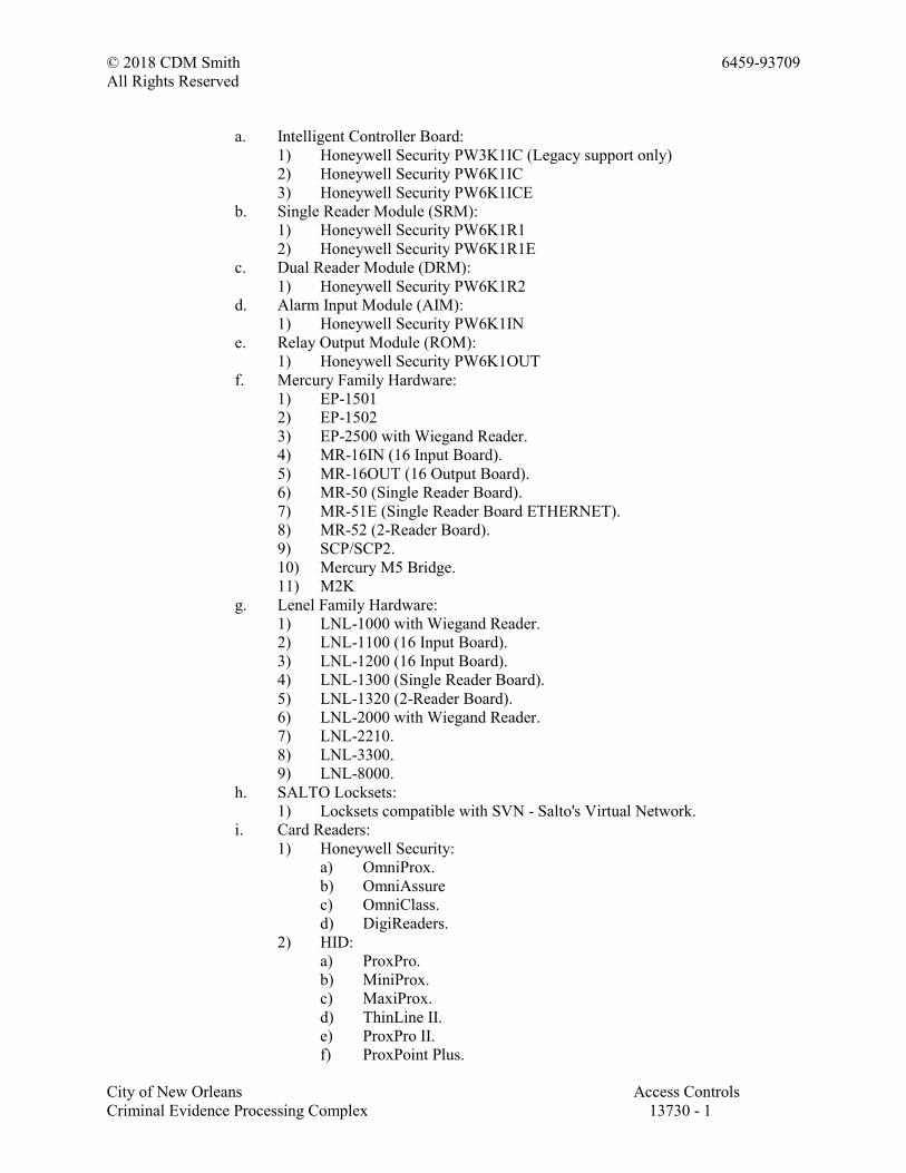
© 2018 CDM Smith 6459-93709
All Rights Reserved
City of New Orleans Access Controls
Criminal Evidence Processing Complex 13730 - 1
a. Intelligent Controller Board:
1) Honeywell Security PW3K1IC (Legacy support only)
2) Honeywell Security PW6K1IC
3) Honeywell Security PW6K1ICE
b. Single Reader Module (SRM):
1) Honeywell Security PW6K1R1
2) Honeywell Security PW6K1R1E
c. Dual Reader Module (DRM):
1) Honeywell Security PW6K1R2
d. Alarm Input Module (AIM):
1) Honeywell Security PW6K1IN
e. Relay Output Module (ROM):
1) Honeywell Security PW6K1OUT
f. Mercury Family Hardware:
1) EP-1501
2) EP-1502
3) EP-2500 with Wiegand Reader.
4) MR-16IN (16 Input Board).
5) MR-16OUT (16 Output Board).
6) MR-50 (Single Reader Board).
7) MR-51E (Single Reader Board ETHERNET).
8) MR-52 (2-Reader Board).
9) SCP/SCP2.
10) Mercury M5 Bridge.
11) M2K
g. Lenel Family Hardware:
1) LNL-1000 with Wiegand Reader.
2) LNL-1100 (16 Input Board).
3) LNL-1200 (16 Input Board).
4) LNL-1300 (Single Reader Board).
5) LNL-1320 (2-Reader Board).
6) LNL-2000 with Wiegand Reader.
7) LNL-2210.
8) LNL-3300.
9) LNL-8000.
h. SALTO Locksets:
1) Locksets compatible with SVN - Salto's Virtual Network.
i. Card Readers:
1) Honeywell Security:
a) OmniProx.
b) OmniAssure
c) OmniClass.
d) DigiReaders.
2) HID:
a) ProxPro.
b) MiniProx.
c) MaxiProx.
d) ThinLine II.
e) ProxPro II.
f) ProxPoint Plus.
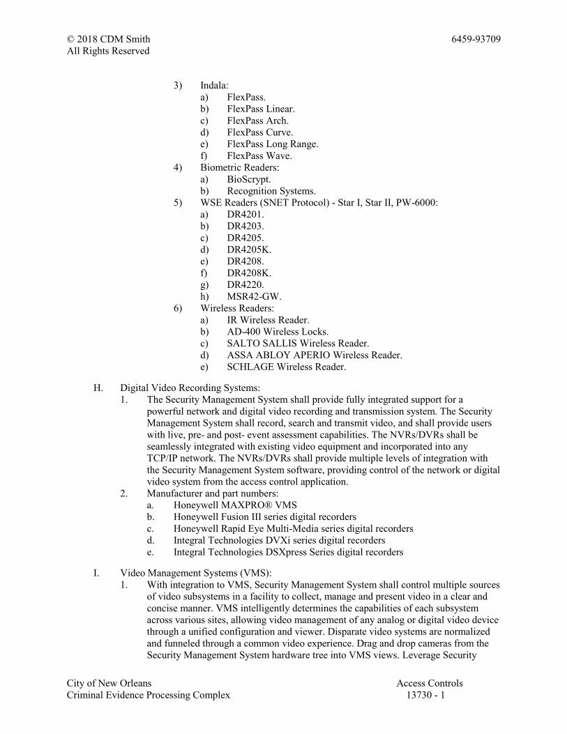
© 2018 CDM Smith 6459-93709
All Rights Reserved
City of New Orleans Access Controls
Criminal Evidence Processing Complex 13730 - 1
3) Indala:
a) FlexPass.
b) FlexPass Linear.
c) FlexPass Arch.
d) FlexPass Curve.
e) FlexPass Long Range.
f) FlexPass Wave.
4) Biometric Readers:
a) BioScrypt.
b) Recognition Systems.
5) WSE Readers (SNET Protocol) - Star I, Star II, PW-6000:
a) DR4201.
b) DR4203.
c) DR4205.
d) DR4205K.
e) DR4208.
f) DR4208K.
g) DR4220.
h) MSR42-GW.
6) Wireless Readers:
a) IR Wireless Reader.
b) AD-400 Wireless Locks.
c) SALTO SALLIS Wireless Reader.
d) ASSA ABLOY APERIO Wireless Reader.
e) SCHLAGE Wireless Reader.
H. Digital Video Recording Systems:
1. The Security Management System shall provide fully integrated support for a
powerful network and digital video recording and transmission system. The Security
Management System shall record, search and transmit video, and shall provide users
with live, pre- and post- event assessment capabilities. The NVRs/DVRs shall be
seamlessly integrated with existing video equipment and incorporated into any
TCP/IP network. The NVRs/DVRs shall provide multiple levels of integration with
the Security Management System software, providing control of the network or digital
video system from the access control application.
2. Manufacturer and part numbers:
a. Honeywell MAXPRO® VMS
b. Honeywell Fusion III series digital recorders
c. Honeywell Rapid Eye Multi-Media series digital recorders
d. Integral Technologies DVXi series digital recorders
e. Integral Technologies DSXpress Series digital recorders
I. Video Management Systems (VMS):
1. With integration to VMS, Security Management System shall control multiple sources
of video subsystems in a facility to collect, manage and present video in a clear and
concise manner. VMS intelligently determines the capabilities of each subsystem
across various sites, allowing video management of any analog or digital video device
through a unified configuration and viewer. Disparate video systems are normalized
and funneled through a common video experience. Drag and drop cameras from the
Security Management System hardware tree into VMS views. Leverage Security

© 2018 CDM Smith 6459-93709
All Rights Reserved
City of New Orleans Access Controls
Criminal Evidence Processing Complex 13730 - 1
Management System alarm integration and advanced features such as pursuit that help
the operator track a target through a set of sequential cameras with a single click to
select a new central camera and surrounding camera views.
2. Manufacturer and part numbers:
a. Honeywell Security MAXPRO VMS.
J. Intercom Interface:
1. The interface shall provide control of both remote and master intercom stations from
within the Security Management System application. The Security Management
System shall allow the user to define the site, channel, description, and address as well
as provide a checkbox for primary station.
2. Administrators shall have the capability to program a list of intercom functions that
report to the alarm-monitoring module as events. These functions shall coincide with
the intercom functions provided with the intercom system. For each intercom
function, Security Management System administrators shall be able to define an
alphanumeric event description 1 to 40 characters in length and shall also be able to
set the parameter value of that function.
3. The intercom interface shall allow for secondary annunciation of intercom calls,
events, and alarms in the alarm-monitoring window. Intercom reporting to the alarm
monitoring window shall report as any other access control alarm and shall have the
same annunciation and display properties as access control alarms.
4. All intercom calls, events, and alarms that report into the Security Management
System shall be stored in the system database for future audit trail and reporting
capabilities. Intercom events shall include but not be limited to: Station busy, Station
free, Intercom call to busy station, Intercom call to private station, Station
disconnected, Function dialed outside connection, Intelligent station ID, Station reset,
Station lamp test, Audio program changed, Group hunt occurred, Mail message, Digit
dialed during connection, Direct access key pressed, Handset off hook, M-key
pressed, C-key pressed
5. Manufacturer(s) and part numbers:
a. Stentofon/Zenitel Alphacom series intercoms.
b. Commend series intercoms.
K. Intrusion Detection Panels:
1. Honeywell VISTA-128FBP, VISTA-128BPE, VISTA-128BPT, VISTA-250FBP,
VISTA-250BPE, and VISTA-250BPT Controllers:
a. General Requirements: The Security Management System shall support
hardwired and TCP/IP communication for the VISTA 128FBP/VISTA-250
FBP panel. Each panel shall have 8 partitions and 15 zone lists. Zones,
partitions, and the top-level panel shall have an events page, with all supported
events present. Features:
1) Disarm and unlock a door on card swipe.
2) Arm and lock a door on card swipe.
3) Common area arm/disarm.
4) Access denied if intrusion system is in alarm or armed.
5) Monitor and log intrusion system events and alarms in the Security
Management System.
6) Associate intrusion system events and alarms to video surveillance
integrations.
2. Honeywell Galaxy Dimension GD264 and GD520 Controllers:

© 2018 CDM Smith 6459-93709
All Rights Reserved
City of New Orleans Access Controls
Criminal Evidence Processing Complex 13730 - 1
a. Security Management System users are able to control and monitor group and
zone status using the Security Management System client, and control the
individual zones and groups using Security Management System Access
control credentials. Depending on the combined user profiles and access
permissions defined in Security Management System, a Security Management
System cardholder is allowed or denied permission to arm/disarm zones and
groups. The access control functionality of the intrusion panel is disabled when
the integration is operational. Features:
1) Disarm a zone on a card swipe.
2) Arm a zone on consecutive card swipes. Security Management System
will support definition of quantity of swipes required and the timeout
time in seconds to recognize consecutive swipes.
3) Security Management System supports linking of intrusion panel users
with Security Management System cardholders.
4) Security Management System operators may be given control
permissions for intrusion input and output alarms.
5) Security Management System can associate alarm events with video
commands to look at current or historic footage.
6) Security Management System stores and reports on intrusion events.
L. Software Development Kit (SDK)
1. Security Management System shall permit custom integration with other third party
systems through an SDK. SDK shall support the OBIX communication protocol and
interface directly with the Niagara Framework for support of additional
communications protocols.
2. Manufacturer and part numbers:
a. Honeywell Security HSDK.
M. Visitor Management System
1. The Visitor Management System shall allow the user to track visitors, employees,
assets and deliveries as they enter and exit the facilities.
2. The system shall also support printing of custom designed visitor passes with details
like expiration date, visit area, host being visited, and visit purpose.
3. Manufacturer and part numbers:
a. Honeywell Security LobbyWorks.
N. Web Client:
1. Web Alarms
2. Web Events
3. Web Badging
4. Web Reports
O. Supported Web Browsers:
1. (Windows) Internet Explorer 11
2. (Windows) Google Chrome Version 42
2.3 INTEGRATED SECURITY MANAGEMENT SYSTEM
A. Product: WIN-PAK Access System as manufactured by the Honeywell Security Group.
B. The Integrated Security Management System (ISMS) shall function as an electronic access
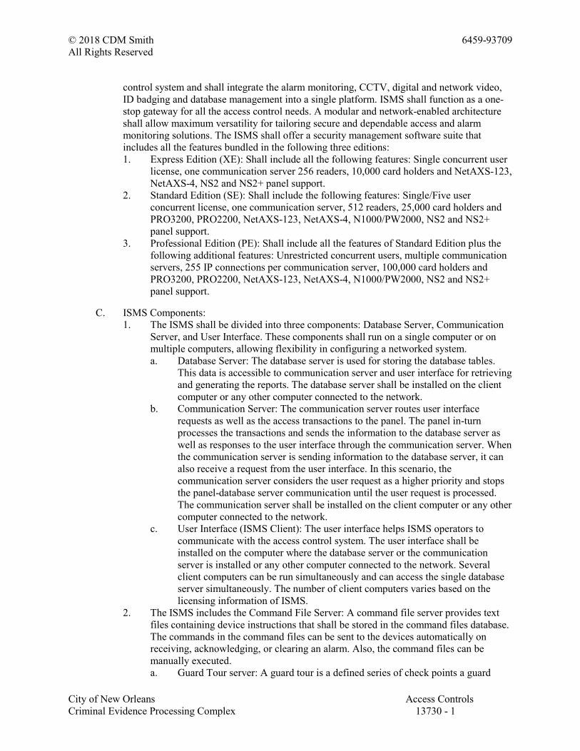
© 2018 CDM Smith 6459-93709
All Rights Reserved
City of New Orleans Access Controls
Criminal Evidence Processing Complex 13730 - 1
control system and shall integrate the alarm monitoring, CCTV, digital and network video,
ID badging and database management into a single platform. ISMS shall function as a one-
stop gateway for all the access control needs. A modular and network-enabled architecture
shall allow maximum versatility for tailoring secure and dependable access and alarm
monitoring solutions. The ISMS shall offer a security management software suite that
includes all the features bundled in the following three editions:
1. Express Edition (XE): Shall include all the following features: Single concurrent user
license, one communication server 256 readers, 10,000 card holders and NetAXS-123,
NetAXS-4, NS2 and NS2+ panel support.
2. Standard Edition (SE): Shall include the following features: Single/Five user
concurrent license, one communication server, 512 readers, 25,000 card holders and
PRO3200, PRO2200, NetAXS-123, NetAXS-4, N1000/PW2000, NS2 and NS2+
panel support.
3. Professional Edition (PE): Shall include all the features of Standard Edition plus the
following additional features: Unrestricted concurrent users, multiple communication
servers, 255 IP connections per communication server, 100,000 card holders and
PRO3200, PRO2200, NetAXS-123, NetAXS-4, N1000/PW2000, NS2 and NS2+
panel support.
C. ISMS Components:
1. The ISMS shall be divided into three components: Database Server, Communication
Server, and User Interface. These components shall run on a single computer or on
multiple computers, allowing flexibility in configuring a networked system.
a. Database Server: The database server is used for storing the database tables.
This data is accessible to communication server and user interface for retrieving
and generating the reports. The database server shall be installed on the client
computer or any other computer connected to the network.
b. Communication Server: The communication server routes user interface
requests as well as the access transactions to the panel. The panel in-turn
processes the transactions and sends the information to the database server as
well as responses to the user interface through the communication server. When
the communication server is sending information to the database server, it can
also receive a request from the user interface. In this scenario, the
communication server considers the user request as a higher priority and stops
the panel-database server communication until the user request is processed.
The communication server shall be installed on the client computer or any other
computer connected to the network.
c. User Interface (ISMS Client): The user interface helps ISMS operators to
communicate with the access control system. The user interface shall be
installed on the computer where the database server or the communication
server is installed or any other computer connected to the network. Several
client computers can be run simultaneously and can access the single database
server simultaneously. The number of client computers varies based on the
licensing information of ISMS.
2. The ISMS includes the Command File Server: A command file server provides text
files containing device instructions that shall be stored in the command files database.
The commands in the command files can be sent to the devices automatically on
receiving, acknowledging, or clearing an alarm. Also, the command files can be
manually executed.
a. Guard Tour server: A guard tour is a defined series of check points a guard

© 2018 CDM Smith 6459-93709
All Rights Reserved
City of New Orleans Access Controls
Criminal Evidence Processing Complex 13730 - 1
must activate within a given amount of time. The check points are readers or
input points where the guard presents the card or presses the button.
b. Tracking and Muster Server: A muster server is enabled in the event of an
emergency and allows the card holders to swipe the readers. Muster areas are
logical areas that contain readers to be used by the card holders, only if there is
a call for muster (in the event of a disaster, for example).
c. Schedule Server: A schedule server schedules the list of events to be performed
at a predetermined time and intervals such as hourly, daily, or monthly.
d. Video Management Server: A video management server provides interface to
connect to various DVR's/NVR's. In addition, it also provides CCTV control
with live monitor display, PTZ control of cameras and video playback
operations.
D. Integrated Security Management System Operational Requirements:
1. The ISMS shall be a modular and network-enabled access control system capable of
controlling multiple remote sites, alarm monitoring, video imaging, ID badging,
paging, digital video and CCTV switching and control that allows for easy expansion
or modification of inputs and remote control stations. The ISMS control at a central
computer location shall be under the control of a single software program and shall
provide full integration of all components. It shall be alterable at any time depending
upon facility requirements. The ISMS reconfiguration shall be accomplished online
through system programming.
2. The ISMS application shall have the major functional capabilities (considered
essential for the system) categorized as follows:
a. General:
1) All the databases shall have the ability to add, delete, report, view, and
edit information.
2) All the system transactions shall be saved in a retrievable file.
3) All the events shall be logged by date and time.
4) All the system transactions or selected system transactions shall be saved
in a disk file.
5) The end-user shall have the provision to make any system configuration
changes such as, but not limited to door open time, door contact shunt
time, point and reader names, when and where a cardholder is valid, and
the ability to add or modify card databases at any time.
6) Shall support "Global Anti-pass back", feature allowing cardholder to
enter/exit any such defined card reader on the same intelligent control
panel or RS-485 drop-line consisting of 2 and 4 door controllers.
7) Anti-pass back modes shall include: hard (no forgiveness), soft (allows
access but generates an alarm event) and timed for all readers on the
intelligent controller, on specified reader or card for a definable period of
time up to 32,000 seconds.
8) Shall support the "Duress" feature, where a PIN is used in conjunction
with a card read; the numbers of digits are selected using the keypad
where the PIN number is a value different from the normal PIN.
9) Shall support the "Two card holder" rule, where two valid, non-identical
"cards" must be used within a 20 second period to grant access.
10) Shall have the option to display the time when a card holder using a
reader has accessed (opened) the door or the card was used, but the door
was not opened.

© 2018 CDM Smith 6459-93709
All Rights Reserved
City of New Orleans Access Controls
Criminal Evidence Processing Complex 13730 - 1
11) Shall support the "Latch mode" operation where the first card read
unlocks the door and the second card read locks it.
12) Shall provide a mode of system operation that stores system commands
not accepted by the hardware.
13) Shall provide a mode of system operation that requires the operator to
enter a response to an event when acknowledging it from the alarm view
window.
14) Shall provide a mode of system operation that allows acknowledged
alarms to be automatically cleared.
15) Shall provide a mode of system operation where when an acknowledged,
but not cleared event will be reissued requiring acknowledgement when
the event changes to an alarm or trouble state.
16) Shall provide a mode of system operation that does not allow the
operator to clear an alarm before prior to it being restored to normal.
17) Shall provide the ability for manual operator control of system output
relays. The manual functions shall include the ability to energize, de-
energize, return to time zone, or pulse the output relay. The pulse time
shall be a programmable setting.
18) Shall provide the ability for manual operator control of system doors.
The manual functions shall include the ability to Lock, Un-Lock,
Disable, Card only, Card-Pin only, Pin only, exit only and site code only.
19) Shall provide the ability to automatically display stored "video image" of
cardholder, and switch real-time camera from CCTV or digital video
server to card reader location for specific card usage.
20) The cardholder "video image" pop-up shall be activated based on a
priority level set to the cardholder or reader. Information in the pop-up
shall include, but not be limited to the card holder's primary image a live
video pop-up showing the person who initiated the pop-up, entrance
name, time, date, cardholder name, and status. User shall be able to
display up to 40 note fields. The size of the pop-ups shall be adjustable
by the operator.
21) Shall support multiple card reader technology including: Proximity,
Wiegand effect, Biometrics, Magnetic stripe, Bar Code, Keypad,
Card/keypad (PIN), High-speed long range Vehicle ID, and Smart Card.
22) Shall provide an option for taking scheduled automatic backups of any or
all database system files. A means to restore these files from a simple
menu shall exist.
23) Shall provide the ability to address up to 255 serial communication ports
per communication server, where each port can be configured for either
hardwired, or dial-up. When configured for dial-up, any one port can
support multiple dial-up locations.
24) Communication from the access control communication server to the
remote intelligent control panels shall be selectable. Communication
options shall be RS-232 directly to the intelligent control, via RS-485
converter, dial-up, leased line from a defined communication port or by
LAN/WAN using an IP address for direct connection to the intelligent
controller via network interface card. When using IP addressing it shall
be un-acceptable to use a communication port converter device on the
communication server side of the transmission. A minimum of 255 such
IP connections shall be allowed per communication server.

© 2018 CDM Smith 6459-93709
All Rights Reserved
City of New Orleans Access Controls
Criminal Evidence Processing Complex 13730 - 1
25) All commands and updates to the panels shall be verified and shall
automatically retry if communications fail.
26) Shall provide a system scheduler that shall automatically: Call remote
locations to retrieve history transactions and update panel information,
including time and date, Activate or deactivate cards locally or at remote
dial-up sites, Initiate a pre-programmed command event/action,
Synchronize system to intelligent controller time, Run a pre-defined
(template) History report, Run a pre-defined (template) Card Holder
report, Card frequency report defined by reader(s), over a defined period
of time with disposition options to automatically report or report and de-
activate card or change the access level of the card, Frequency shall be
defined as Never, Now, Once, Hourly, Daily, and Weekly, Once per 2
weeks, and Monthly.
27) Shall provide drop boxes for all system-required information that the
user has previously entered.
28) Shall provide the ability to initiate an email (via SMTP) or page to a
paging system based on a transaction state. A transaction state shall be
defined as but not limited to Normal, Alarm, Trouble, Ajar, Trace, Not
Found, Anti-Pass back Violation, PIN Violation, Time Zone Violation,
Site Code Violation, Door Used, Duress, No Second Card Presented,
Trace Card or Expired Card, and System Alarms including, Panel Com,
Panel Power Failure, Modem Pool, Guard Tour, and Tamper. Intrusion
partition events including but not limited to: Alarm, Alarm Cancel, Aram
Away, Arm Stay, Auto Arm, Auto Disarm, Bypass, Disarm, Early Arm,
Early Disarm, Fail to Arm, Fail to Disarm, Normal, Not Ready, Part
Arm, Quick Arm, Recent Close, Remote Arm, Remote Disarm,
Unbypass, User Code Added, User Code Deleted, user Code Edited.
Intrusion zone events including but not limited to: Alarm, Alarm Restore,
Bypass, Fault, Fault Restore, Normal, Trouble, Trouble Restore, and
Unbypass. Intrusion output events including but not limited to: Alarm,
Communication Loss, Normal, Tamper, and Tamper Restore. Intrusion
panel events including but not limited to: Access Denied, Automatic
Test, Comm Fail, Comm Restore, Faults, Faults Restore, Line Restore,
Line Trouble, Manual Test, Pager Restore, Pager Trouble, AC Restore,
AC Trouble, Alarm, Battery Low, Battery Low Restore, Disarm,
Normal, Recent Close, Reset, Panic Alarm, Power Up, Program begin,
Program Changed, Program End, System Shutdown, System Shutdown
Restore, Tamper Alarm, Tamper Restore, Test End, Test Start,
Time/Date changed.
29) Shall include a "host grant" mode of operation that requires the host
computer to grant accesses to "valid" cards. An alternate host grant mode
shall allow the card access information to be downloaded along with
unlocking the door for "valid" cards.
b. Cards: Shall provide a simple card and card holder database import utility. The
utility shall be password protected and accessible only to administrators of the
access control system. Information that can be imported shall include but not be
limited to: First Name, Last Name, Card Number, Activation Date, De-
activation Date, Status, up to 40 note fields and Photo Images. A simple CSV
(comma separated value) file shall be used for the importing of data and image
file names.
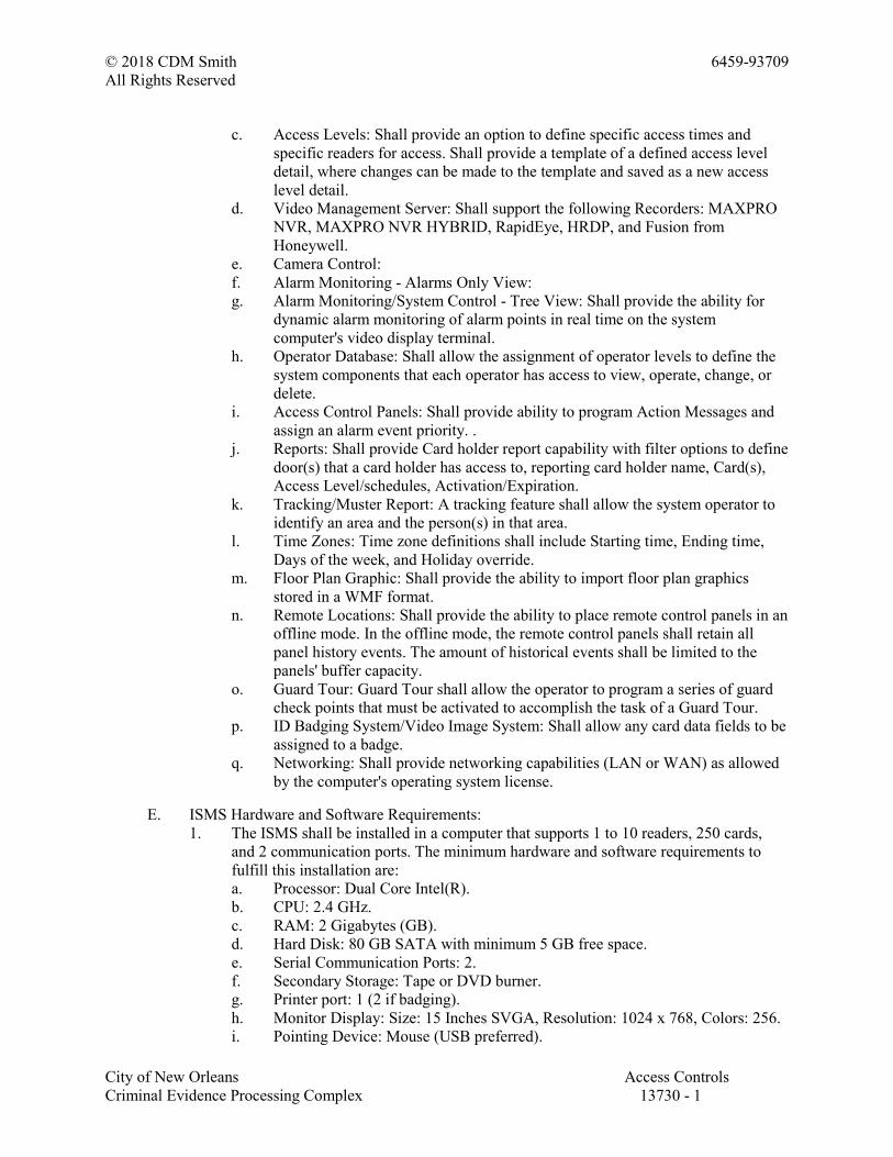
© 2018 CDM Smith 6459-93709
All Rights Reserved
City of New Orleans Access Controls
Criminal Evidence Processing Complex 13730 - 1
c. Access Levels: Shall provide an option to define specific access times and
specific readers for access. Shall provide a template of a defined access level
detail, where changes can be made to the template and saved as a new access
level detail.
d. Video Management Server: Shall support the following Recorders: MAXPRO
NVR, MAXPRO NVR HYBRID, RapidEye, HRDP, and Fusion from
Honeywell.
e. Camera Control:
f. Alarm Monitoring - Alarms Only View:
g. Alarm Monitoring/System Control - Tree View: Shall provide the ability for
dynamic alarm monitoring of alarm points in real time on the system
computer's video display terminal.
h. Operator Database: Shall allow the assignment of operator levels to define the
system components that each operator has access to view, operate, change, or
delete.
i. Access Control Panels: Shall provide ability to program Action Messages and
assign an alarm event priority. .
j. Reports: Shall provide Card holder report capability with filter options to define
door(s) that a card holder has access to, reporting card holder name, Card(s),
Access Level/schedules, Activation/Expiration.
k. Tracking/Muster Report: A tracking feature shall allow the system operator to
identify an area and the person(s) in that area.
l. Time Zones: Time zone definitions shall include Starting time, Ending time,
Days of the week, and Holiday override.
m. Floor Plan Graphic: Shall provide the ability to import floor plan graphics
stored in a WMF format.
n. Remote Locations: Shall provide the ability to place remote control panels in an
offline mode. In the offline mode, the remote control panels shall retain all
panel history events. The amount of historical events shall be limited to the
panels' buffer capacity.
o. Guard Tour: Guard Tour shall allow the operator to program a series of guard
check points that must be activated to accomplish the task of a Guard Tour.
p. ID Badging System/Video Image System: Shall allow any card data fields to be
assigned to a badge.
q. Networking: Shall provide networking capabilities (LAN or WAN) as allowed
by the computer's operating system license.
E. ISMS Hardware and Software Requirements:
1. The ISMS shall be installed in a computer that supports 1 to 10 readers, 250 cards,
and 2 communication ports. The minimum hardware and software requirements to
fulfill this installation are:
a. Processor: Dual Core Intel(R).
b. CPU: 2.4 GHz.
c. RAM: 2 Gigabytes (GB).
d. Hard Disk: 80 GB SATA with minimum 5 GB free space.
e. Serial Communication Ports: 2.
f. Secondary Storage: Tape or DVD burner.
g. Printer port: 1 (2 if badging).
h. Monitor Display: Size: 15 Inches SVGA, Resolution: 1024 x 768, Colors: 256.
i. Pointing Device: Mouse (USB preferred).
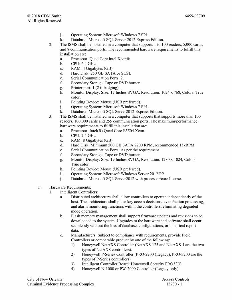
© 2018 CDM Smith 6459-93709
All Rights Reserved
City of New Orleans Access Controls
Criminal Evidence Processing Complex 13730 - 1
j. Operating System: Microsoft Windows 7 SP1.
k. Database: Microsoft SQL Server 2012 Express Edition.
2. The ISMS shall be installed in a computer that supports 1 to 100 readers, 5,000 cards,
and 8 communication ports. The recommended hardware requirements to fulfill this
installation are:
a. Processor: Quad Core Intel Xeon® .
b. CPU: 2.4 GHz.
c. RAM: 4 Gigabytes (GB).
d. Hard Disk: 250 GB SATA or SCSI.
e. Serial Communication Ports: 2.
f. Secondary Storage: Tape or DVD burner.
g. Printer port: 1 (2 if badging).
h. Monitor Display: Size: 17 Inches SVGA, Resolution: 1024 x 768, Colors: True
color.
i. Pointing Device: Mouse (USB preferred).
j. Operating System: Microsoft Windows 7 SP1.
k. Database: Microsoft SQL Server2012 Express Edition.
3. The ISMS shall be installed in a computer that supports that supports more than 100
readers, 100,000 cards and 255 communication ports, The maximum/performance
hardware requirements to fulfill this installation are:
a. Processor: Intel(R) Quad Core E5504 Xeon.
b. CPU: 2.4 GHz.
c. RAM: 8 Gigabytes (GB).
d. Hard Disk: Minimum 500 GB SATA 7200 RPM, recommended 15kRPM.
e. Serial Communication Ports: As per the requirement.
f. Secondary Storage: Tape or DVD burner.
g. Monitor Display: Size: 19 Inches SVGA, Resolution: 1280 x 1024, Colors:
True color.
h. Pointing Device: Mouse (USB preferred).
i. Operating System: Microsoft Windows Server 2012 R2.
j. Database: Microsoft SQL Server2012 with processor/core license.
F. Hardware Requirements:
1. Intelligent Controllers:
a. Distributed architecture shall allow controllers to operate independently of the
host. The architecture shall place key access decisions, event/action processing,
and alarm monitoring functions within the controllers, eliminating degraded
mode operation.
b. Flash memory management shall support firmware updates and revisions to be
downloaded to the system. Upgrades to the hardware and software shall occur
seamlessly without the loss of database, configurations, or historical report
data.
c. Manufacturers: Subject to compliance with requirements, provide Field
Controllers or comparable product by one of the following:
1) Honeywell NetAXS Controller (NetAXS-123 and NetAXS-4 are the two
types of NetAXS controllers).
2) Honeywell P-Series Controller (PRO-2200 (Legacy), PRO-3200 are the
types of P-Series controllers).
3) Intelligent Controller Board: Honeywell Security PRO32IC
4) Honeywell N-1000 or PW-2000 Controller (Legacy only).
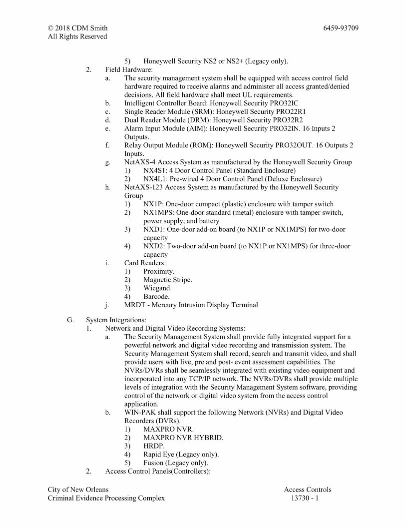
© 2018 CDM Smith 6459-93709
All Rights Reserved
City of New Orleans Access Controls
Criminal Evidence Processing Complex 13730 - 1
5) Honeywell Security NS2 or NS2+ (Legacy only).
2. Field Hardware:
a. The security management system shall be equipped with access control field
hardware required to receive alarms and administer all access granted/denied
decisions. All field hardware shall meet UL requirements.
b. Intelligent Controller Board: Honeywell Security PRO32IC
c. Single Reader Module (SRM): Honeywell Security PRO22R1
d. Dual Reader Module (DRM): Honeywell Security PRO32R2
e. Alarm Input Module (AIM): Honeywell Security PRO32IN. 16 Inputs 2
Outputs.
f. Relay Output Module (ROM): Honeywell Security PRO32OUT. 16 Outputs 2
Inputs.
g. NetAXS-4 Access System as manufactured by the Honeywell Security Group
1) NX4S1: 4 Door Control Panel (Standard Enclosure)
2) NX4L1: Pre-wired 4 Door Control Panel (Deluxe Enclosure)
h. NetAXS-123 Access System as manufactured by the Honeywell Security
Group
1) NX1P: One-door compact (plastic) enclosure with tamper switch
2) NX1MPS: One-door standard (metal) enclosure with tamper switch,
power supply, and battery
3) NXD1: One-door add-on board (to NX1P or NX1MPS) for two-door
capacity
4) NXD2: Two-door add-on board (to NX1P or NX1MPS) for three-door
capacity
i. Card Readers:
1) Proximity.
2) Magnetic Stripe.
3) Wiegand.
4) Barcode.
j. MRDT - Mercury Intrusion Display Terminal
G. System Integrations:
1. Network and Digital Video Recording Systems:
a. The Security Management System shall provide fully integrated support for a
powerful network and digital video recording and transmission system. The
Security Management System shall record, search and transmit video, and shall
provide users with live, pre and post- event assessment capabilities. The
NVRs/DVRs shall be seamlessly integrated with existing video equipment and
incorporated into any TCP/IP network. The NVRs/DVRs shall provide multiple
levels of integration with the Security Management System software, providing
control of the network or digital video system from the access control
application.
b. WIN-PAK shall support the following Network (NVRs) and Digital Video
Recorders (DVRs).
1) MAXPRO NVR.
2) MAXPRO NVR HYBRID.
3) HRDP.
4) Rapid Eye (Legacy only).
5) Fusion (Legacy only).
2. Access Control Panels(Controllers):
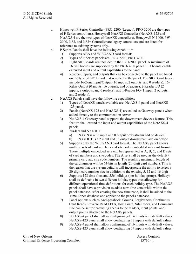
© 2018 CDM Smith 6459-93709
All Rights Reserved
City of New Orleans Access Controls
Criminal Evidence Processing Complex 13730 - 1
a. Honeywell P-Series Controller (PRO-2200 (Legacy), PRO-3200 are the types
of P-Series controllers), Honeywell NetAXS Controller (NetAXS-123 and
NetAXS-4 are the two types of NetAXS controllers). Honeywell N-1000, PW-
2000, NS2, and NS2+ Controller are legacy controllers and are listed for
reference to existing systems only.
b. P Series Panels shall have the following capabilities:
1) Supports ABA and WIEGAND card formats.
2) Types of P-Series panels are: PRO-2200, PRO-3200.
3) Eight SIO Boards are included in the PRO-2000 panel. A maximum of
16 SIO boards are supported by the PRO-3200 panel. SIO boards enable
extended input and output capabilities to the panel.
4) Readers, inputs, and outputs that can be connected to the panel are based
on the type of SIO Board that is added to the panel. The SIO Board types
include 16-Zone Input/Output (16 inputs, 2 outputs, and 0 readers), 16-
Relay Output (0 inputs, 16 outputs, and o readers), 2-Reader I/O (2
inputs, 8 outputs, and 6 readers), and 1-Reader I/O (1 input, 2 outputs,
and 2 readers).
c. NetAXS Panels shall have the following capabilities:
1) Types of NetAXS panels available are: NetAXS-4 panel and NetAXS-
123 panel.
2) Panels (NetAXS-123 and NetAXS-4) are called as Gateway panels when
added directly to the communication server.
3) NetAXS-4 Gateway panel supports the downstream devices feature. This
feature shall extend the input and output capabilities of the NetAXS-4
panels.
4) NX4IN and NX4OUT
a) NX4IN is a 32 input and 0 output downstream add on device
b) NX4OUT is a 2 input and 16 output downstream add on device
5) Supports only the WIEGAND card format. The NetAXS panel allows
multiple sets of card numbers and site codes embedded in a card format.
These multiple embedded sets will be represented as A, B, C, and D sets
of card numbers and site codes. The A set shall be used as the default /
primary card and site code numbers. The resulting maximum length of
the card number will be 64-bits in length (20-digit card number). This is
the reason that the system defaults will incorporate the ability to select a
20-digit card number size in addition to the existing 5, 12 and 16 digit
6) Supports 128 time slots and 256 holidays (per holiday group). Holidays
shall be definable in two different holiday types thus allowing for
different operational time definitions for each holiday type. The NetAXS
panels shall have a provision to add a new time zone while within the
panel database. After creating the new time zone, it shall be added to the
Time Zones database and applied to the panel's database.
7) Panel options such as Anti-passback, Groups, Forgiveness, Continuous
Card Reads, Reverse Read LEDs, Host Grant, Site Codes, and Command
File can be set for providing access to the readers, input points, and
output points attached to the NetAXS panels.
8) NetAXS-4 panel shall allow configuring of 14 inputs with default values.
NetAXS-123 panel shall allow configuring 17 inputs with default values.
9) NetAXS-4 panel shall allow configuring of 16 inputs with default values.
NetAXS-123 panel shall allow configuring 14 inputs with default values.
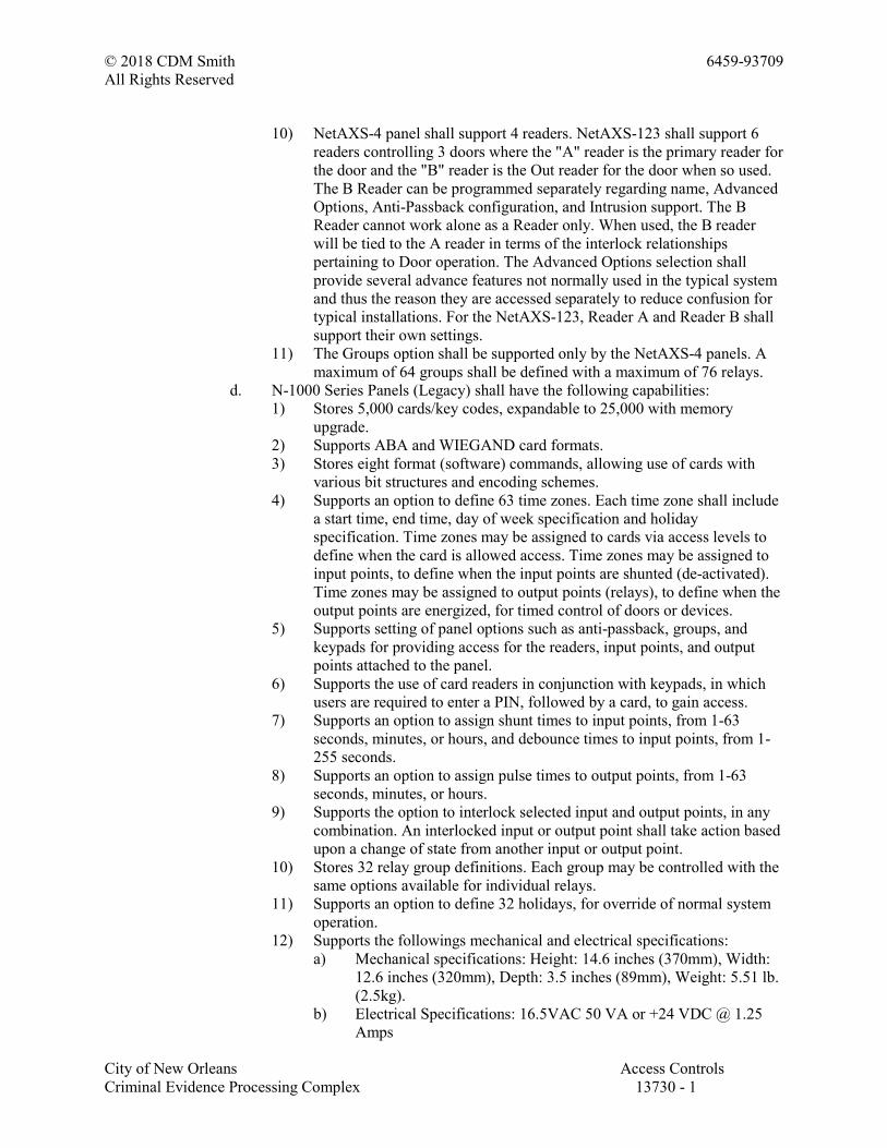
© 2018 CDM Smith 6459-93709
All Rights Reserved
City of New Orleans Access Controls
Criminal Evidence Processing Complex 13730 - 1
10) NetAXS-4 panel shall support 4 readers. NetAXS-123 shall support 6
readers controlling 3 doors where the "A" reader is the primary reader for
the door and the "B" reader is the Out reader for the door when so used.
The B Reader can be programmed separately regarding name, Advanced
Options, Anti-Passback configuration, and Intrusion support. The B
Reader cannot work alone as a Reader only. When used, the B reader
will be tied to the A reader in terms of the interlock relationships
pertaining to Door operation. The Advanced Options selection shall
provide several advance features not normally used in the typical system
and thus the reason they are accessed separately to reduce confusion for
typical installations. For the NetAXS-123, Reader A and Reader B shall
support their own settings.
11) The Groups option shall be supported only by the NetAXS-4 panels. A
maximum of 64 groups shall be defined with a maximum of 76 relays.
d. N-1000 Series Panels (Legacy) shall have the following capabilities:
1) Stores 5,000 cards/key codes, expandable to 25,000 with memory
upgrade.
2) Supports ABA and WIEGAND card formats.
3) Stores eight format (software) commands, allowing use of cards with
various bit structures and encoding schemes.
4) Supports an option to define 63 time zones. Each time zone shall include
a start time, end time, day of week specification and holiday
specification. Time zones may be assigned to cards via access levels to
define when the card is allowed access. Time zones may be assigned to
input points, to define when the input points are shunted (de-activated).
Time zones may be assigned to output points (relays), to define when the
output points are energized, for timed control of doors or devices.
5) Supports setting of panel options such as anti-passback, groups, and
keypads for providing access for the readers, input points, and output
points attached to the panel.
6) Supports the use of card readers in conjunction with keypads, in which
users are required to enter a PIN, followed by a card, to gain access.
7) Supports an option to assign shunt times to input points, from 1-63
seconds, minutes, or hours, and debounce times to input points, from 1-
255 seconds.
8) Supports an option to assign pulse times to output points, from 1-63
seconds, minutes, or hours.
9) Supports the option to interlock selected input and output points, in any
combination. An interlocked input or output point shall take action based
upon a change of state from another input or output point.
10) Stores 32 relay group definitions. Each group may be controlled with the
same options available for individual relays.
11) Supports an option to define 32 holidays, for override of normal system
operation.
12) Supports the followings mechanical and electrical specifications:
a) Mechanical specifications: Height: 14.6 inches (370mm), Width:
12.6 inches (320mm), Depth: 3.5 inches (89mm), Weight: 5.51 lb.
(2.5kg).
b) Electrical Specifications: 16.5VAC 50 VA or +24 VDC @ 1.25
Amps
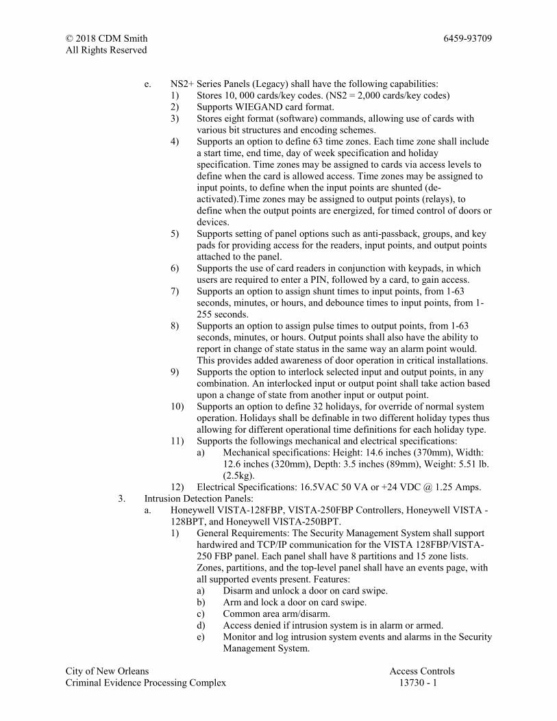
© 2018 CDM Smith 6459-93709
All Rights Reserved
City of New Orleans Access Controls
Criminal Evidence Processing Complex 13730 - 1
e. NS2+ Series Panels (Legacy) shall have the following capabilities:
1) Stores 10, 000 cards/key codes. (NS2 = 2,000 cards/key codes)
2) Supports WIEGAND card format.
3) Stores eight format (software) commands, allowing use of cards with
various bit structures and encoding schemes.
4) Supports an option to define 63 time zones. Each time zone shall include
a start time, end time, day of week specification and holiday
specification. Time zones may be assigned to cards via access levels to
define when the card is allowed access. Time zones may be assigned to
input points, to define when the input points are shunted (de-
activated).Time zones may be assigned to output points (relays), to
define when the output points are energized, for timed control of doors or
devices.
5) Supports setting of panel options such as anti-passback, groups, and key
pads for providing access for the readers, input points, and output points
attached to the panel.
6) Supports the use of card readers in conjunction with keypads, in which
users are required to enter a PIN, followed by a card, to gain access.
7) Supports an option to assign shunt times to input points, from 1-63
seconds, minutes, or hours, and debounce times to input points, from 1-
255 seconds.
8) Supports an option to assign pulse times to output points, from 1-63
seconds, minutes, or hours. Output points shall also have the ability to
report in change of state status in the same way an alarm point would.
This provides added awareness of door operation in critical installations.
9) Supports the option to interlock selected input and output points, in any
combination. An interlocked input or output point shall take action based
upon a change of state from another input or output point.
10) Supports an option to define 32 holidays, for override of normal system
operation. Holidays shall be definable in two different holiday types thus
allowing for different operational time definitions for each holiday type.
11) Supports the followings mechanical and electrical specifications:
a) Mechanical specifications: Height: 14.6 inches (370mm), Width:
12.6 inches (320mm), Depth: 3.5 inches (89mm), Weight: 5.51 lb.
(2.5kg).
12) Electrical Specifications: 16.5VAC 50 VA or +24 VDC @ 1.25 Amps.
3. Intrusion Detection Panels:
a. Honeywell VISTA-128FBP, VISTA-250FBP Controllers, Honeywell VISTA -
128BPT, and Honeywell VISTA-250BPT.
1) General Requirements: The Security Management System shall support
hardwired and TCP/IP communication for the VISTA 128FBP/VISTA-
250 FBP panel. Each panel shall have 8 partitions and 15 zone lists.
Zones, partitions, and the top-level panel shall have an events page, with
all supported events present. Features:
a) Disarm and unlock a door on card swipe.
b) Arm and lock a door on card swipe.
c) Common area arm/disarm.
d) Access denied if intrusion system is in alarm or armed.
e) Monitor and log intrusion system events and alarms in the Security
Management System.
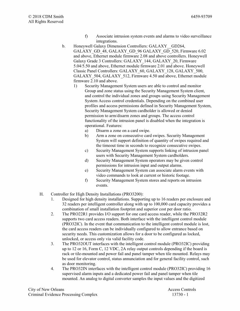
© 2018 CDM Smith 6459-93709
All Rights Reserved
City of New Orleans Access Controls
Criminal Evidence Processing Complex 13730 - 1
f) Associate intrusion system events and alarms to video surveillance
integrations.
b. Honeywell Galaxy Dimension Controllers: GALAXY__GD264,
GALAXY_GD_48, GALAXY_GD_96 GALAXY_GD_520, Firmware 6.02
and above, Ethernet module firmware 2.08 and above controllers. Honeywell
Galaxy Grade 3 Controllers: GALAXY_144, GALAXY_20, Firmware
5.04/5.50 and above, Ethernet module firmware 2.01 and above. Honeywell
Classic Panel Controllers: GALAXY_60, GALAXY_128, GALAXY_500,
GALAXY_504, GALAXY_512, Firmware 4.50 and above, Ethernet module
firmware 2.10 and above.
1) Security Management System users are able to control and monitor
Group and zone status using the Security Management System client,
and control the individual zones and groups using Security Management
System Access control credentials. Depending on the combined user
profiles and access permissions defined in Security Management System,
Security Management System cardholder is allowed or denied
permission to arm/disarm zones and groups. The access control
functionality of the intrusion panel is disabled when the integration is
operational. Features:
a) Disarm a zone on a card swipe.
b) Arm a zone on consecutive card swipes. Security Management
System will support definition of quantity of swipes required and
the timeout time in seconds to recognize consecutive swipes.
c) Security Management System supports linking of intrusion panel
users with Security Management System cardholders.
d) Security Management System operators may be given control
permissions for intrusion input and output alarms.
e) Security Management System can associate alarm events with
video commands to look at current or historic footage.
f) Security Management System stores and reports on intrusion
events.
H. Controller for High Density Installations (PRO3200):
1. Designed for high density installations. Supporting up to 16 readers per enclosure and
32 readers per intelligent controller along with up to 100,000 card capacity provides a
combination of small installation footprint and superior cost per door ratio.
2. The PRO22R1 provides I/O support for one card access reader, while the PRO32R2
supports two card access readers. Both interface with the intelligent control module
(PRO32IC). In the event that communication to the intelligent control module is lost,
the card access readers can be individually configured to allow entrance based on
security needs. This customization allows for a door to be configured as locked,
unlocked, or access only via valid facility code.
3. The PRO32OUT interfaces with the intelligent control module (PRO32IC) providing
up to 12 or 16, Form C, 12 VDC, 2A relay output controls depending if the board is
rack or tile-mounted and power fail and panel tamper when tile mounted. Relays may
be used for elevator control, status annunciation and for general facility control, such
as door monitoring.
4. The PRO32IN interfaces with the intelligent control module (PRO32IC) providing 16
supervised alarm inputs and a dedicated power fail and panel tamper when tile
mounted. An analog to digital converter samples the input values and the digitized
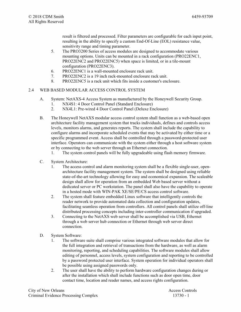
© 2018 CDM Smith 6459-93709
All Rights Reserved
City of New Orleans Access Controls
Criminal Evidence Processing Complex 13730 - 1
result is filtered and processed. Filter parameters are configurable for each input point,
resulting in the ability to specify a custom End-Of-Line (EOL) resistance value,
sensitivity range and timing parameter.
5. The PRO3200 Series of access modules are designed to accommodate various
mounting options. Units can be mounted in a rack configuration (PRO22ENC1,
PRO22ENC2 and PRO22ENC5) when space is limited, or in a tile-mount
configuration (PRO22ENC3).
6. PRO22ENC1 is a wall-mounted enclosure rack unit.
7. PRO22ENC2 is a 19 inch rack-mounted enclosure rack unit.
8. PRO22ENC5 is a rack unit which fits inside a customer's enclosure.
2.4 WEB BASED MODULAR ACCESS CONTROL SYSTEM
A. System: NetAXS-4 Access System as manufactured by the Honeywell Security Group.
1. NX4S1: 4 Door Control Panel (Standard Enclosure)
2. NX4L1: Pre-wired 4 Door Control Panel (Deluxe Enclosure)
B. The Honeywell NetAXS modular access control system shall function as a web-based open
architecture facility management system that tracks individuals, defines and controls access
levels, monitors alarms, and generates reports. The system shall include the capability to
configure alarms and incorporate scheduled events that may be activated by either time or a
specific programmed event. Access shall be controlled through a password-protected user
interface. Operators can communicate with the system either through a host software system
or by connecting to the web server through an Ethernet connection.
1. The system control panels will be fully upgradeable using flash memory firmware.
C. System Architecture:
1. The access control and alarm monitoring system shall be a flexible single-user, open-
architecture facility management system. The system shall be designed using reliable
state-of-the-art technology allowing for easy and economical expansion. The scaleable
design shall allow for operation from an embedded Web based server without a
dedicated server or PC workstation. The panel shall also have the capability to operate
in a hosted mode with WIN-PAK XE/SE/PE/CS access control software.
2. The system shall feature embedded Linux software that intelligently controls the
reader network to provide automated data collection and configuration updates,
facilitating seamless operation from controllers. All control panels shall utilize off-line
distributed processing concepts including inter-controller communication if upgraded.
3. Connecting to the NetAXS web server shall be accomplished via USB, Ethernet
through a web server hub connection or Ethernet through web server direct
connection.
D. System Software:
1. The software suite shall comprise various integrated software modules that allow for
the full integration and retrieval of transactions from the hardware, as well as alarm
monitoring, reporting, and scheduling capabilities. The software modules shall allow
editing of personnel, access levels, system configuration and reporting to be controlled
by a password protected user interface. System operation for individual operators shall
be possible using assigned passwords only.
2. The user shall have the ability to perform hardware configuration changes during or
after the installation which shall include functions such as door open time, door
contact time, location and reader names, and access rights configuration.
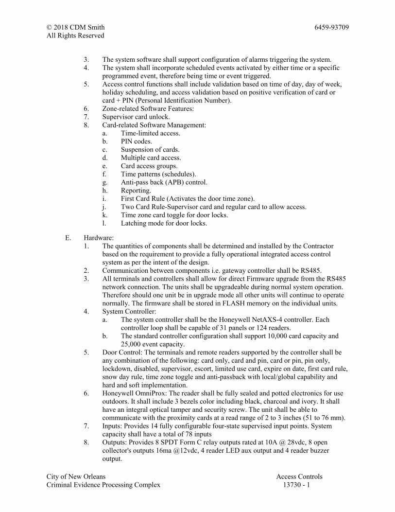
© 2018 CDM Smith 6459-93709
All Rights Reserved
City of New Orleans Access Controls
Criminal Evidence Processing Complex 13730 - 1
3. The system software shall support configuration of alarms triggering the system.
4. The system shall incorporate scheduled events activated by either time or a specific
programmed event, therefore being time or event triggered.
5. Access control functions shall include validation based on time of day, day of week,
holiday scheduling, and access validation based on positive verification of card or
card + PIN (Personal Identification Number).
6. Zone-related Software Features:
7. Supervisor card unlock.
8. Card-related Software Management:
a. Time-limited access.
b. PIN codes.
c. Suspension of cards.
d. Multiple card access.
e. Card access groups.
f. Time patterns (schedules).
g. Anti-pass back (APB) control.
h. Reporting.
i. First Card Rule (Activates the door time zone).
j. Two Card Rule-Supervisor card and regular card to allow access.
k. Time zone card toggle for door locks.
l. Latching mode for door locks.
E. Hardware:
1. The quantities of components shall be determined and installed by the Contractor
based on the requirement to provide a fully operational integrated access control
system as per the intent of the design.
2. Communication between components i.e. gateway controller shall be RS485.
3. All terminals and controllers shall allow for direct Firmware upgrade from the RS485
network connection. The units shall be upgradeable during normal system operation.
Therefore should one unit be in upgrade mode all other units will continue to operate
normally. The firmware shall be stored in FLASH memory on the individual units.
4. System Controller:
a. The system controller shall be the Honeywell NetAXS-4 controller. Each
controller loop shall be capable of 31 panels or 124 readers.
b. The standard controller configuration shall support 10,000 card capacity and
25,000 event capacity.
5. Door Control: The terminals and remote readers supported by the controller shall be
any combination of the following: card only, card and pin, card or pin, pin only,
lockdown, disabled, supervisor, escort, limited use card, expire on date, first card rule,
snow day rule, time zone toggle and anti-passback with local/global capability and
hard and soft implementation.
6. Honeywell OmniProx: The reader shall be fully sealed and potted electronics for use
outdoors. It shall include 3 bezels color including black, charcoal and ivory. It shall
have an integral optical tamper and security screw. The unit shall be able to
communicate with the proximity cards at a read range of 2 to 3 inches (51 to 76 mm).
7. Inputs: Provides 14 fully configurable four-state supervised input points. System
capacity shall have a total of 78 inputs
8. Outputs: Provides 8 SPDT Form C relay outputs rated at 10A @ 28vdc, 8 open
collector's outputs 16ma @12vdc, 4 reader LED aux output and 4 reader buzzer
output.
© 2018 CDM Smith 6459-93709
All Rights Reserved
City of New Orleans Access Controls
Criminal Evidence Processing Complex 13730 - 1
9. Cards and Database: The card and event buffer capacity shall be 10,000 card capacity
and 25,000 event capacity. The firm ware revision shall have on-board flash memory
for field firmware revisions and feature expansion. Offline database backup shall be
available. Export capabilities for card database, alarms and events. The panel shall
support 128 unique card formats and 8 site codes. Maximum card format size shall be
75bit suitable for handling the card format of PIV, TWIC, and FRAC cards. The time
zones support will be a minimum of 127 with 128 access levels and 255 holidays.
10. Reports and Analysis: The system shall be capable of integrated reports, import/export
of card database and alarms and events can be exported and saved in offline storage.
11. Embedded Web Server: Supported browsers shall include Internet Explorer. The web
browser control will allow full control monitor, view live events and manually control
doors and readers. Secure web browsing shall be SSL and SHA-1 secure socket layer
encryption.
12. System Information: The system shall support Global Geographic Time Zone support
and Daylight Saving Time support. The processor will be Freescale Coldfire 32-bit.
The system shall be CE and FCC compliant with UL-294 listing.
13. System Testing: The Contractor shall demonstrate the functionality of the system
upon completion of installation, and shall document the result of all tests and provide
these results to the Customer.
14. Warranty: All equipment and systems shall be guaranteed by the Contractor for a
period of one year commencing with the filing date of the Notice of Completion,
provided the system has been inspected and signed off by the Owner. The guarantee
shall cover all costs for Warranty Service, including parts, labor, prompt field service,
pick-up, transportation, and delivery.
2.5 WEB BASED ACCESS CONTROL SYSTEM
A. System: NetAXS-123 Access System as manufactured by the Honeywell Security Group.
1. NX1P: One-door compact (plastic) enclosure with tamper switch.
2. NX1MPS: One-door standard (metal) enclosure with tamper switch, power supply,
and battery.
3. NXD1: One-door add-on board (to NX1P or NX1MPS) for two-door capacity.
4. NXD2: Two-door add-on board (to NX1P or NX1MPS) for three-door capacity.
B. The Access Control System shall function as a Web-based open-architecture facility
management system that tracks individuals, defines and controls access levels, monitors
alarms, and generates reports. The system shall include the capability to configure alarms
and incorporate scheduled events that may be activated by either time or a specific
programmed event. Access shall be controlled through a password-protected user interface.
Operators can communicate with the system either through a host software system or by
connecting to the Web server through an Ethernet connection.
C. The NetAXS-123 Door Access System shall include, as a minimum, the following
performance:
1. The NetAXS-123 Door Access System shall be protected by the most extensive
support services in the industry, including Customer Service, Pre-Sales Applications
Assistance, After-Sales Technical Assistance, access to Technical Online Support, and
Online Training using web conferencing.
2. The NetAXS-123 Door Access System and its components shall be thoroughly tested
before shipping from the manufacturer's facility.
© 2018 CDM Smith 6459-93709
All Rights Reserved
City of New Orleans Access Controls
Criminal Evidence Processing Complex 13730 - 1
3. The door access system shall support easy remote management anywhere with an
Internet connection.
4. The door access system shall allow you to purchase the exact amount of access
control doors immediately required, and to easily add more access controlled doors in
the future.
5. The door access system shall be capable of being web based and controlled using a
web browser, and seamless integration with Honeywell's MAXPRO Cloud and/or
WIN-PAK XE, WIN-PAK SE, Win-PAK PE, and WIN-PAK CS access control
software.
6. The door access system web user interface shall support Google ChromeTM.
7. The door access system shall support SSL and SHA-1 secure socket layer encryption.
8. The door access system shall allow each TCP/IP network connected door controller to
support connection of up to 31 downstream door controllers by way of a standard
RS485 data bus, for control of up to 123 downstream doors in a single web interface.
9. The door access system shall support up to 10,000 user cards and up to 128 unique
card formats up to 75 bits, and eight site codes.
10. The door access system shall support up to 127 time zones, 128 access levels, and 255
holidays.
11. The door access system shall maintain up to 25,000 status event log.
12. The door access system shall provide a number of door control modes including Card
only, card and PIN, PIN only, lockdown, disabled, supervisor, escort, limited use card,
expire on date, first card rule, snow day rule, time zone toggle, local and global anti-
passback, duress and others.
13. The door access system shall support interlocks for custom actions.
14. The door access system shall include integrated basic reports, import/export of the
card database, and Alarms and event exporting to offline storage in a CSV database.
15. The door access system shall be designed to be user friendly and shall be easily to
train the system user.
16. The door access system shall feature dynamic screen updating over a web connection,
continually collecting and displaying door and system status for immediate display.
17. The door access system browser shall feature full control of the system to monitor and
view live events and to manually control doors and readers.
18. Door access system status shall include the door state, alarms, events, inputs, outputs,
power and other operational status.
19. The door access system shall feature a Supervisor First capability that allows a
supervisor to present his ID card once to the reader and to give individual access. If a
supervisor presents a card twice, this shall enable access for their team, allowing
members of the team to gain access during a specified time zone.
20. The door access system shall feature an Escort mode for a Non-supervisor cardholder.
The system allows the supervisor to first present his card, and then an escorted person
to present his card to maintain accompanied access while in the escort mode.
21. The door access system shall offer options to be powered by PoE (Power over
Ethernet), or to be powered by way of an external power supply.
22. The door access system enclosure shall offer connection to one, two or three doors by
simply exchanging optional cards to accommodate the door control requirement.
23. The door access system processors shall features a System MTBF (Mean Time
between Failure) of 250,000 hours.
24. The door access system shall provide a multi-lingual user interface, including English,
Italian, French, Dutch, Spanish, German, Czech, Simplified Chinese and Arabic.
© 2018 CDM Smith 6459-93709
All Rights Reserved
City of New Orleans Access Controls
Criminal Evidence Processing Complex 13730 - 1
D. The NX1P Door access Controller shall have the following mechanical specifications:
1. Unit Dimensions: 7.75 inches H x 7.75 inches W x 2.75 inches D (20 mm H x 20 mm
W x 7 mm D).
2. Ethernet Connector: RJ45.
3. Enclosure Type: High Impact Plastic.
4. Wiring Access Holes: 7.
E. The NX1MPS Door Access Controller shall have the following mechanical specifications:
1. Unit Dimensions: 13.9 inches H x 11.9 inches W x 4.7 inches D (35 mm H x 31 mm
W x 12 mm D).
2. Enclosure Type: Metal.
3. Wiring Access Holes: 19.
F. The NX1P access door controller shall have the following electrical specifications:
1. Voltage: 450mA @ 12VDC.
2. Power over Ethernet 802.3af.
3. Power Consumption: < 6 Watts.
G. The NX1MPS access door controller shall have the following electrical specifications:
1. Voltage: 93VAC to 264 VAC, 50/60 Hz, 12VDC @ 3.5A.
2. Power Consumption: < 45 Watts.
H. The NetAXS-123 Door Access System shall be designed to meet the following
environmental conditions:
1. Operating Temperature: 32 to 122 degrees F (0 degrees to 50 degrees C).
2. Storage Temperature: -67 degrees to 185 degrees F (-55 degrees to 85 degrees C).
3. Emissions: FCC: Part 15, Class B.
4. CE: EN55013.
2.6 VISITOR MANAGEMENT SYSTEM
A. Product; Lobbyworks as manufactured by the Honeywell Security Group: The Visitor
Management System shall allow the user to track visitors, employees, assets and deliveries
as they enter and exit the facilities. The system shall also support printing of custom
designed visitor passes with details like expiration date, visit area, host being visited, and
visit purpose.
B. The Visitor Management System shall allow the user to:
1. Keep track of contractors and consultant timesheets.
2. Track which employees have regular personal visitors.
3. Secure visitor log.
4. Clearly identify visitors by category, to restrict access to vulnerable goods and
information.
5. Designate special areas for visitors with custom badges.
6. Process most visitors in 20 seconds.
7. Track and print temporary parking passes.
8. Print vehicle window stickers.
9. Use self-expiring badges to tighten security.
10. Generate end-of-day reports to ensure regulatory compliance.
11. Label information packets with personalized customer information.
© 2018 CDM Smith 6459-93709
All Rights Reserved
City of New Orleans Access Controls
Criminal Evidence Processing Complex 13730 - 1
C. Visitor Pre-Registration:
1. Visitor pre-registration to include security level, length of stay, and maximum entries.
2. Visitor pre-registration by using FrontDesk, Microsoft Office Outlook Calendar or
through Web-based application.
3. Group/Event pre-registration, pre-loading of visitor picture, badge pre-printing, and
arrival instructions.
4. Complete visitor registration processing within 20 seconds.
D. Visitor Information Capture:
1. Quick and complete capture of visitor information as an essential component for
proper record keeping and security checks.
2. Capture of visitor information using various hardware devices. The tasks that can be
performed include scanning business cards, scanning driver license, capturing visitor
photo, capturing visitor signature, and 2D barcode scanning of driver licenses.
3. Quick processing of large groups of visitors through queuing of captured data.
E. Visitor Authentication:
1. Recalling previous visit information (including pictures) when a visitor revisits.
2. Detecting each attempted visit and deterring potential security breaches before they
affect the user facilities.
3. Importing guests ranging from disgruntled ex-employees to known felons into the
watch list to alert personnel of a potential threat to the organization.
4. Authenticating a person as having proper identification and determining that he or she
is who they claim to be.
F. Visitor Authorization:
1. Enforcing visitor authorization prior to printing a badge, entering the premises,
authorizing visits at reception, security lobby, or remotely by the host employee.
2. Delegating authorization responsibility to specific individuals.
3. Providing a denied visitors list.
G. Visitor Badges Generation:
1. Provide quick, cost-effective, and individualized badging as an essential component of
proper visitor identification.
2. Allow printing of individualized visitor badges containing name, picture, expiration
date, and valid access areas.
3. Customize badge templates for visitors, VIPs and contractors.
4. Supports tight integration with Pro-Watch Security systems that allow the assignment
of access control privileges via barcode or card to visitors
H. Host Notification:
1. Of a visitor's arrival by e-mail messages or real-time network messaging.
2. When a visitor does not sign out.
I. Visitor Tracking:
1. Track events automatically by an accurate log as they relate to the visitor's activities
on site.
2. Track the number of times the visitor signs in and signs out.
3. Support quick sign in and out using a barcode scanner.
4. Provide proactive checking for expired visits and network notification to hosts and
visitors of expired visits.
© 2018 CDM Smith 6459-93709
All Rights Reserved
City of New Orleans Access Controls
Criminal Evidence Processing Complex 13730 - 1
5. Provide web access to the visitor manifest.
J. Security Policies:
1. Provide accurate and consistent application of security policies.
2. Provide a means to view picture and a person's attributes, reason for being on the
watch list, and the action to be performed upon visitor's arrival.
3. Check each visitor against his/her previous visit information.
4. Ensure that visitors sign out by tracking expired visits and informing their hosts.
5. Allow host to extend a visit or assign host responsibilities to another employee.
K. Host Management:
1. Assign the capabilities available to employees based on their requirement.
2. Differentiate permanent and temporary employees; limit the number of daily and
concurrent visitors per host.
3. The Front Desk operator shall:
a. Assign temporary day cards in Pro-Watch for Pro-Watch employees who have
forgotten their card.
b. Have an option to assign either Pro-Watch access privileges to match their
permanent card or a visitor privilege. The permanent card is automatically
disabled while the temp card is active.
c. Be able to do a visual verify of the employee to their photo at the Front Desk.
L. Traffic Reporting:
1. Traffic reports - per station, per building, per company, per employee, and per
department.
2. Detailed visit reports.
3. Time and attendance reports for contractors and other visitors.
4. Reports on demand, or schedule reports for regular generation and e-mail delivery.
M. Assets and Deliveries:
1. Track assets and deliveries as they arrive and depart premises.
2. Generate asset and delivery tags and scan assets and deliveries in and out with a
barcode scanner.
3. Provide e-mail notification of delivery recipient for unreturned assets.
N. Self-Registration Kiosk:
1. Provide a fully featured visitor kiosk to handle visitor registration needs in a busy or
unattended lobby. The Kiosk shall be used to perform touchscreen visitor registration
using a visitor's business card or driver license.
2. Allow to sign visitors in and out with voice agent scripted behavior, voice, and text
message prompts. The Kiosk shall be used to take picture of visitors for true visitor
identification, as well as display visitation rules/non-disclosure agreement.
3. Print a visitor badge at the self-registration station or at a remote FrontDesk and allow
for remote authorization of the visit by the host or security desk. The Kiosk shall
notify the hosting employee when their visitor arrives.
O. Security Audit Compliance:
1. Secure database.
2. Audit log.
3. Tamper proof visitor records.
4. Audit reports.
© 2018 CDM Smith 6459-93709
All Rights Reserved
City of New Orleans Access Controls
Criminal Evidence Processing Complex 13730 - 1
5. Backup and restore capabilities.
2.7 ACCESS CONTROL READERS
A. Contactless Smart Card Readers:
1. Contactless Smart Card readers shall be "single-package" type, combining electronics
and antenna in one package in the following configurations:
2. Provide surface mounting style 13.56 MHz or 13.56 MHz and 125 kHz prox
contactless smart card readers suitable for minimal space mounting configurations as
shown on the project plans.
3. Contactless smart card readers shall comply with ISO 15693, ISO 14443A (CSN), and
ISO 14443B and shall read credentials that comply with these standards.
4. Contactless smart card readers shall output credential data in compliance with the SIA
AC-01 Wiegand standard as follows:
a. Reads standard proximity format data from OmniClass cards and outputs data
as encoded.
b. Reads card serial number (CSN) of a MIFARE or DESFIRE card with
configurable outputs as 26-bit, 32-bit, 34-bit, 40-bit, or 56-bit.
5. Data security with OmniClass cards shall use up to 128-bit authentication keys to
reduce the risk of compromised data or duplicate cards. The contactless smart card
reader and OmniClass cards shall require matching keys in order to function together.
All RF data transmission between the card and the reader shall be encrypted, using a
secure algorithm. Card readers shall be provided with keys that are compatible with
the OmniClass cards.
6. The reader shall be of potted, polycarbonate material, sealed to a NEMA rating of 4X
(IP65).
7. The contactless smart card reader shall provide the ability to change operational
features in the field through the use of a factory-programmed command card.
Additionally, firmware may be updated by flashing the reader. Command card
operational programming options shall include:
a. Output configurations.
b. LED & Audio configurations.
c. Keypad configurations.
8. Contactless smart card readers shall provide the following programmable audio/visual
indication:
a. An audio transducer shall provide various tone sequences to signify: access
granted, access denied, power up, and diagnostics.
b. A high-intensity light bar shall provide clear visual status (red/green/amber)
that is visible even in bright sunlight.
9. Contactless smart card readers shall meet the following certifications:
a. UL 294.
b. Canada/UL 294.
c. FCC Certification.
d. Canada Radio Certification.
e. EU and CB Scheme Electrical Safety.
f. EU - R&TTE Directive.
g. CE Mark (Europe).
h. IP55 Rated.
i. C-Tick (New Zealand/Australia/Taiwan).
10. Contactless smart card readers shall meet the following environmental specifications:
© 2018 CDM Smith 6459-93709
All Rights Reserved
City of New Orleans Access Controls
Criminal Evidence Processing Complex 13730 - 1
a. Operating temperature: -30 to 150 degrees F (-35 to 65 degrees C).
b. Operating humidity: 5% to 95% relative humidity non-condensing.
c. Weatherized design suitable to withstand harsh environments.
11. Contactless smart card reader cabling requirements shall be:
a. Manufacturer: Honeywell Cable
b. Cable distance: (Wiegand): 500 feet (150m).
c. Cable type: 6-conductor #22 AWG minimum with overall foil shield and drain
wire
d. Standard reader termination: 18 inches (.5m) cable pigtail.
12. Warranty of contactless smart card readers shall be lifetime against defects in
materials and workmanship.
B. Product: OM15 Mullion 13.56 MHz Contactless Smart Card Readers as manufactured by the
Honeywell Security Group:
1. Typical contactless smart card read range shall be:
a. 2 inches - 3 inches (5.0 - 7.6 cm) using OmniClass card.
b. 1 inches (2.5 cm) using OmniClass Key Fob.
c. 1 inches(2.5 cm) using OmniClass Sticker (Tag).
d. 1 inches - 1.5 inches (2.5 - 3.8 cm) using OmniClass + HID 125KHz Prox card.
e. 1 inches - 2 inches (2.5 - 5.0 cm) using MIFARE Card (card serial number
only).
2. Contactless smart card readers shall meet the following electrical specifications:
a. Operating voltage: 5 - 16 VDC, reverse voltage protected. Linear power supply
recommended.
b. Current requirements: (average/peak) 60/90mA @ 12 VDC.
3. Contactless smart card readers shall meet the following physical specifications:
a. Dimensions: 1.90 inches x 6 inches x .90 inches (4.8 cm x 15.3 cm x 2.3 cm).
b. Weight: 3.2.oz (90.7 g).
c. Material: UL94 Polycarbonate.
d. Two-part design with separate mounting plate and reader body.
e. Color: Black.
C. Product: OM16 Mullion 13.56 MHz Contactless Smart and 125 kHz Prox Card Readers as
manufactured by the Honeywell Security Group:
1. Typical contactless smart card read range shall be:
a. 2 inches - 3 inches (5.0 - 7.6 cm) using OmniClass card.
b. 1 inches (2.5 cm) using OmniClass Key Fob.
c. 1 inches(2.5 cm) using OmniClass Sticker (Tag).
d. 1 inches - 1.5 inches (2.5 - 3.8 cm) using OmniClass + HID 125KHz Prox card.
e. 1 inches - 2 inches (2.5 - 5.0 cm) using MIFARE Card (card serial number
only).
f. 1 inches - 3.5 inches (2.5 - 8.9 cm) using 125 kHz Prox card
2. Contactless smart card readers shall meet the following electrical specifications:
a. Operating voltage: 5 - 16 VDC, reverse voltage protected. Linear power supply
recommended.
b. Current requirements: (average/peak) 75/100mA @ 12 VDC.
3. Contactless smart card readers shall meet the following physical specifications:
a. Dimensions: 1.90 inches x 6 inches x .90 inches (4.8 cm x 15.3 cm x 2.3 cm).
b. Weight: 3.2.oz (90.7 g).
c. Material: UL94 Polycarbonate.
© 2018 CDM Smith 6459-93709
All Rights Reserved
City of New Orleans Access Controls
Criminal Evidence Processing Complex 13730 - 1
d. Two-part design with separate mounting plate and reader body
e. Color: Black.
D. Product: OM30 Mini-Mullion 13.56 MHz Contactless Smart Card Readers as manufactured
by the Honeywell Security Group:
1. Typical contactless smart card read range shall be:
a. 2 inches - 3 inches (5.0 - 7.6 cm) using OmniClass card.
b. 1 inches (2.5 cm) using OmniClass Key Fob.
c. 1 inches(2.5 cm) using OmniClass Sticker (Tag).
d. 1 inches - 1.5 inches (2.5 - 3.8 cm) using OmniClass + HID 125KHz Prox card.
e. 1 inches - 2 inches (2.5 - 5.0 cm) using MIFARE Card (card serial number
only).
2. Contactless smart card readers shall meet the following electrical specifications:
a. Operating voltage: 5 - 16 VDC, reverse voltage protected. Linear power supply
recommended.
b. Current requirements: (average/peak) 60/90mA @ 12 VDC.
3. Contactless smart card readers shall meet the following physical specifications:
a. Dimensions: 1.90 inches x 4.04 inches x .80 inches (4.83cm x 10.26 cm x 2.03
cm).
b. Weight: 3.2.oz (90.7 g).
c. Material: UL94 Polycarbonate.
d. Two-part design with separate mounting plate and reader body.
e. Color: Black.
E. Product: OM31 Mini-Mullion 13.56 MHz Contactless Smart and 125 kHz Prox Card
Readers as manufactured by the Honeywell Security Group:
1. Typical contactless smart card read range shall be:
a. 2 inches - 3 inches (5.0 - 7.6 cm) using OmniClass card.
b. 1 inches (2.5 cm) using OmniClass Key Fob.
c. 1 inches(2.5 cm) using OmniClass Sticker (Tag).
d. 1 inches - 1.5 inches (2.5 - 3.8 cm) using OmniClass + HID 125KHz Prox card.
e. 1 inches - 2 inches (2.5 - 5.0 cm) using MIFARE Card (card serial number
only).
f. 1 inches - 3.5 inches (2.5 - 8.9 cm) using 125 kHz Prox Card
2. Contactless smart card readers shall meet the following electrical specifications:
a. Operating voltage: 5 - 16 VDC, reverse voltage protected. Linear power supply
recommended.
b. Current requirements: (average/peak) 75/100mA @ 12 VDC.
3. Contactless smart card readers shall meet the following physical specifications:
a. Dimensions: 1.90 inches x 4.04 inches x .80 inches (4.83cm x 10.26 cm x 2.03
cm).
b. Weight: 3.2.oz (90.7 g).
c. Material: UL94 Polycarbonate.
d. Two-part design with separate mounting plate and reader body.
e. Color: Black.
F. Product: OM40 US Single-Gang 13.56 MHz Contactless Smart Card Readers as
manufactured by the Honeywell Security Group:
1. Typical contactless smart card read range shall be:
a. 2.5 inches - 4.5 inches (6.3 - 11.4 cm) using OmniClass card.
© 2018 CDM Smith 6459-93709
All Rights Reserved
City of New Orleans Access Controls
Criminal Evidence Processing Complex 13730 - 1
b. 1 inches (2.5 cm) using OmniClass Key Fob.
c. 1 inches (2.5 cm) using OmniClass Sticker (Tag).
d. 1.5 inches - 2 inches (3.8 - 5.0 cm) using OmniClass + 125KHz HID Prox card.
e. 1 inches - 2 inches (2.5 - 5.0 cm) using MIFARE Card (card serial number
only).
2. Contactless smart card readers shall meet the following physical specifications:
a. Dimensions: 3.30" x 4.80" x .85" (8.38cm x 12.19 cm x 2.16 cm).
b. Weight: 8.8.oz (249.5 g).
c. Material: UL94 Polycarbonate.
d. Two-part design with separate mounting plate and reader body.
e. Color: Black.
3. Contactless smart card readers shall meet the following electrical specifications:
a. Operating voltage: 5 - 16 VDC, reverse voltage protected. Linear power supply
recommended.
b. Current requirements: (average/peak) 65/90mA @ 12 VDC.
G. Product: OM41 US Single-Gang 13.56 MHz Contactless Smart and 125 kHz Prox Card
Readers as manufactured by the Honeywell Security Group:
1. Typical contactless smart card read range shall be:
a. 2.5 inches - 4.5 inches (6.3 - 11.4 cm) using OmniClass card.
b. 1 inches (2.5 cm) using OmniClass Key Fob.
c. 1 inches (2.5 cm) using OmniClass Sticker (Tag).
d. 1.5 inches - 2 inches (3.8 - 5.0 cm) using OmniClass + 125KHz HID Prox card.
e. 1 inches - 2 inches (2.5 - 5.0 cm) using MIFARE Card (card serial number
only).
f. 1 inches - 3.5 inches (2.5 - 8.9 cm) using 125 kHz Prox Card
2. Contactless smart card readers shall meet the following physical specifications:
a. Dimensions: 3.30 inches x 4.80 inches x .85 inches (8.38 cm x 12.19 cm x 2.16
cm).
b. Weight: 8.8 oz (249.5 g).
c. Material: UL94 Polycarbonate.
d. Two-part design with separate mounting plate and reader body.
e. Color: Black.
3. Contactless smart card readers shall meet the following electrical specifications:
a. Operating voltage: 5 - 16 VDC, reverse voltage protected. Linear power supply
recommended.
b. Current requirements: (average/peak) 85/100mA @ 12 VDC.
H. Product: OM55 13.56 MHz Contactless Smart Card with Keypad Readers as manufactured
by the Honeywell Security Group:
1. Typical contactless smart card read range shall be:
a. 3 inches - 4 inches (7.6 - 10.1 cm) using OmniClass card.
b. 1 inches - 1.5 inches (2.5 - 3.8 cm) using OmniClass Key Fob.
c. 1 inches - 1.5 inches (2.5 - 3.8 cm) using OmniClass Sticker (Tag).
d. 1.5 inches - 2.0 inches (3.8 - 5.0 cm) using OmniClass + 125KHz HID Prox
card.
e. 1 inches - 2 inches (2.5 - 5.0 cm) using MIFARE Card (card serial number
only).
2. Contactless smart card readers shall meet the following physical specifications:
a. Dimensions: 3.30 inches x 4.80 inches x .90 inches (8.38cm x 12.19 cm x 2.28
© 2018 CDM Smith 6459-93709
All Rights Reserved
City of New Orleans Access Controls
Criminal Evidence Processing Complex 13730 - 1
cm).
b. Weight: 10oz (283.4 g).
c. Material: UL94 Polycarbonate.
d. Two-part design with separate mounting plate and reader body.
e. Color: Black.
3. Contactless smart card readers shall meet the following electrical specifications:
a. Operating voltage: 5 - 16 VDC, reverse voltage protected. Linear power supply
recommended.
b. Current requirements: (average/peak) 85/100mA @ 12 VDC.
I. Product: OM56 13.56 MHz Contactless Smart and 125 kHz Prox Card W/ Keypad Readers
as manufactured by the Honeywell Security Group:
1. Typical contactless smart card read range shall be:
a. 3 inches - 4 inches (7.6 - 10.1 cm) using OmniClass card.
b. 1 inches - 1.5 inches (2.5 - 3.8 cm) using OmniClass Key Fob.
c. 1 inches - 1.5 inches (2.5 - 3.8 cm) using OmniClass Sticker (Tag).
d. 1.5 inches - 2.0 inches (3.8 - 5.0 cm) using OmniClass + 125KHz HID Prox
card.
e. 1 inches - 2 inches (2.5 - 5.0 cm) using MIFARE Card (card serial number
only).
f. 1 inches - 3.5 inches (2.5 - 8.9 cm) using 125 kHz Prox Card
2. Contactless smart card readers shall meet the following physical specifications:
a. Dimensions: 3.30 inches x 4.80 inches x .90 inches (8.38cm x 12.19 cm x 2.28
cm).
b. Weight: 10oz (283.4 g).
c. Material: UL94 Polycarbonate.
d. Two-part design with separate mounting plate and reader body.
e. Color: Black.
3. Contactless smart card readers shall meet the following electrical specifications:
a. Operating voltage: 5 - 16 VDC, reverse voltage protected. Linear power supply
recommended.
b. Current requirements: (average/peak) 95/105mA @ 12 VDC.
J. Contactless Proximity Card Readers:
1. Card readers shall be "single-package" type, combining electronics and antenna in one
package in the following configurations:
2. Provide surface mounting style 125kHz contactless proximity card readers suitable for
minimal space mounting configurations as shown on the project plans.
3. Contactless proximity card readers shall output credential data in compliance with the
SIA AC-01 Wiegand standard as follows:
a. Reads standard proximity format data from OmniProx cards and outputs data in
Wiegand format.
b. Reads card number with formats up 84 bits.
4. The reader shall be of potted, polycarbonate material, sealed to a NEMA rating of 4X
(IP65).
5. The contactless proximity card reader shall provide the ability to change operational
features in the field through the use of a factory-programmed command card.
Additionally, firmware may be updated by flashing the reader. Command card
operational programming options shall include:
a. Output configurations.

© 2018 CDM Smith 6459-93709
All Rights Reserved
City of New Orleans Access Controls
Criminal Evidence Processing Complex 13730 - 1
b. LED & Audio configurations.
c. Keypad configurations.
6. Contactless proximity card readers shall provide the following programmable
audio/visual indication:
a. An audio transducer shall provide various tone sequences to signify: access
granted, access denied, power up, and diagnostics.
b. A high-intensity light bar shall provide clear visual status (red/green/amber)
that is visible even in bright sunlight.
7. Contactless proximity card readers shall meet the following certifications:
a. UL 294.
b. Canada/UL 294.
c. FCC Certification.
d. ROHS compliant
e. Canada Radio Certification.
f. CE Mark (Europe).
8. Contactless proximity card readers shall meet the following environmental
specifications:
a. Operating temperature: -25 to 145 degrees F (-31 to 63 degrees C).
b. Operating humidity: 0% to 95% relative humidity non-condensing.
c. Weatherized design suitable to withstand harsh environments.
9. Contactless proximity card reader cabling requirements shall be:
a. Manufacturer: Honeywell Cable
b. Cable distance: (Wiegand): 500 feet (150m).
c. Cable type: 6-conductor #22 AWG minimum with overall foil shield and drain
wire.
d. Standard reader termination: 18 inches (.5m) cable pigtail.
10. Warranty of contactless proximity card readers shall be lifetime against defects in
materials and workmanship.
K. Product: OP10 Mini-Mullion 125kHz Contactless Proximity Card Readers as manufactured
by the Honeywell Security Group:
1. Typical contactless proximity card read range shall be:
a. 1.5 inches - 4 inches (3.8 - 10.2 cm) using OmniProx card
2. Contactless proximity card readers shall meet the following electrical specifications:
a. Operating voltage: 5.0 - 16 VDC, reverse voltage protected. Linear power
supply recommended.
b. Current requirements: 60/120mA @ 12 VDC.
3. Contactless proximity card readers shall meet the following physical specifications:
a. Dimensions: 3.15 inches x 1.57 inches x 0.50 inches (80cm x 40 cm x 12.8 cm).
b. Material: UL94 Polycarbonate.
c. Two-part design with separate reader body and cover.
d. Color: Black, charcoal gray & ivory interchangeable bezels.
4. Contactless card reader shall be Honeywell OP10 compatible with selected card
media.
L. Product: OP30 Mullion 125kHz Contactless Proximity Card Readers as manufactured by the
Honeywell Security Group:
1. Typical contactless proximity card read range shall be:
a. 1.5 inches - 4 inches (3.8 - 10.2 cm) using OmniProx card
2. Contactless proximity card readers shall meet the following electrical specifications:
© 2018 CDM Smith 6459-93709
All Rights Reserved
City of New Orleans Access Controls
Criminal Evidence Processing Complex 13730 - 1
a. Operating voltage: 5.0 - 16 VDC, reverse voltage protected. Linear power
supply recommended.
b. Current requirements: 60/120mA @ 12 VDC.
3. Contactless proximity card readers shall meet the following physical specifications:
a. Dimensions: 5.71 inches x 1.69 inches x 0.79 inches (145cm x 43 cm x 20 cm).
b. Material: UL94 Polycarbonate.
c. Two-part design with separate reader body and cover.
d. Color: Black, charcoal gray & ivory interchangeable bezels.
4. Contactless proximity card reader shall be Honeywell OP30 compatible with selected
card media.
M. Product: OP40 Single-Gang (US) 125kHz Contactless Proximity Card Readers as
manufactured by the Honeywell Security Group:
1. Typical Contactless proximity Card read range shall be:
a. 1.5 inches - 4 inches (3.8 - 10.2 cm) using OmniProx card
2. Contactless proximity Card readers shall meet the following electrical specifications:
a. Operating voltage: 5.0 - 16 VDC, reverse voltage protected. Linear power
supply recommended.
b. Current requirements: 60/120mA @ 12 VDC.
3. Contactless proximity Card readers shall meet the following physical specifications:
a. Dimensions: 4.33 inches x 2.95 inches x 0.59 inches (110cm x 75 cm x 15 cm).
b. Material: UL94 Polycarbonate.
c. Two-part design with separate reader body and cover.
d. Color: Black, charcoal gray & ivory interchangeable bezels.
4. Contactless proximity Card reader shall be Honeywell OP40 compatible with
selected card media.
N. Product: OP45 Single-Gang (EU/APAC) 125kHz Contactless Proximity Card Readers as
manufactured by the Honeywell Security Group:
1. Typical Contactless proximity Card read range shall be:
a. 1.5 inches - 4 inches (3.8 - 10.2 cm) using OmniProx card
2. Contactless proximity Card readers shall meet the following electrical specifications:
a. Operating voltage: 5.0 - 16 VDC, reverse voltage protected. Linear power
supply recommended.
b. Current requirements: 60/120mA @ 12 VDC.
3. Contactless proximity Card readers shall meet the following physical specifications:
a. Dimensions: 3.5 inches x 3.5 inches x 0.595 inches (88.9 cm x 88.9 cm x 15
cm).
b. Material: UL94 Polycarbonate.
c. Two-part design with separate reader body and cover.
d. Color: Black, charcoal gray & ivory interchangeable bezels
4. Contactless proximity Card reader shall be Honeywell OP45 compatible with selected
card media.
O. Product: OP90 Single-Gang (US) 125kHz Contactless Proximity Card Vandal Resistant
Readers as manufactured by the Honeywell Security Group:
1. Typical Contactless proximity Card read range shall be:
a. 1.5 inches - 4 inches (3.8 - 10.2 cm) using OmniProx card
2. Contactless proximity Card readers shall meet the following electrical specifications:
a. Operating voltage: 5.0 - 16 VDC, reverse voltage protected. Linear power
© 2018 CDM Smith 6459-93709
All Rights Reserved
City of New Orleans Access Controls
Criminal Evidence Processing Complex 13730 - 1
supply recommended.
b. Current requirements: 60/120mA @ 12 VDC.
3. Contactless proximity Card readers shall meet the following physical specifications:
a. Dimensions: 4.5 inches x 3.15 inches x 0.59 inches (114cm x 80 cm x 15 cm).
b. Material: UL94 Polycarbonate.
c. Two-part design with reader body and cover.
d. Color: Silver.
4. Contactless proximity Card reader shall be Honeywell OP90 compatible with
selected card media.
P. Product: OP95 Single-Gang (US) 125kHz Contactless Proximity Card Vandal Resistant
Readers + Keypad as manufactured by the Honeywell Security Group:
1. Typical Contactless proximity Card read range shall be:
a. 1.5 inches - 4 inches (3.8 - 10.2 cm) using OmniProx card
2. Contactless proximity Card readers shall meet the following electrical specifications:
a. Operating voltage: 5.0 - 16 VDC, reverse voltage protected. Linear power
supply recommended.
b. Current requirements: 60/120mA @ 12 VDC.
3. Contactless proximity Card readers shall meet the following physical specifications:
a. Dimensions: 4.5 inches x 3.15 inches x 0.59 inches (114cm x 80 cm x 15 cm).
b. Material: UL94 Polycarbonate.
c. Two-part design with separate reader body and cover.
d. Color: Silver
4. Contactless proximity Card reader shall be Honeywell OP95 compatible with selected
card media.
2.8 ACCESS CONTROL CREDENTIALS
A. Access cards shall be used with access readers to gain entry to access controlled portals (e.g.;
doors, gates, turnstiles) and to hold information specific to the user and shall be Contactless
Smart Card or Contactless Proximity Card technology credentials.
B. Contactless Smart Cards
1. Single Technology Access Card:
a. The card shall meet the following standards for contactless smart cards: ISO
15693 and ISO 14443B2.
b. The card shall meet ISO 7810 specifications for length, width, thickness,
flatness, card construction and durability, and shall be in a form suitable for
direct two-sided dye-sublimation or thermal transfer printing on the specified
badge printer.
c. Presentation to the access control reader at any angle within a minimum of one
inch (25 mm) shall result in an accurate reading of the card.
d. Unique 64-bit, fixed card serial number, used for anti-collision and key
diversification.
e. The card shall support capability, with a minimum of 2 Kbits (256 bytes) of
EEPROM memory or 16 Kbits (2048 bytes) of EEPROM memory. The 2 Kbit
card shall have a minimum of 2 Application Areas, and the 16Kbit shall have
either 2 or 16 Application Areas to support future applications. Data retention
shall be 10 years, nominal. Wiegand card data up to 84 bits in length shall be
factory programmed in Application Area 1 for use with access control systems.
© 2018 CDM Smith 6459-93709
All Rights Reserved
City of New Orleans Access Controls
Criminal Evidence Processing Complex 13730 - 1
f. Each Application Area on the card shall be secured with up to a 128-bit unique,
diversified security key, such that data stored in that area cannot be accessed or
modified until the card and reader have completed a mutual authentication
process.
g. The card shall be capable of completing any write operation, even if the card is
removed from the RF field during that operation.
h. The card shall be warranted against defects in materials and workmanship for
two years, or if multiple technologies are used: with a magnetic stripe the card
shall have a fifteen month warranty; or with a contact chip, the card shall have a
one year warranty.
i. Provide "smart" access cards, compatible with the specified card readers. Cards
shall be encoded with Wiegand card data, at the factory.
j. The card shall not carry any identification showing the location of the property
unless otherwise specified herein.
k. The card shall be capable of accepting a slot punch on one end, allowing it to be
hung from a strap/clip in a vertical orientation.
2. Multiple Technology Access Card:
a. The card shall support 13.56 MHz OmniClass contactless smart chip and
antenna plus any or all of the following technologies, simultaneously:
1) 125 kHz HID Proximity chip and antenna.
2) Magnetic Stripe.
3) Embedded Contact Smart Chip Module.
b. The card shall be available with a 13.56 MHz OmniClass contactless smart chip
and antenna plus a Wiegand Strip with an optional magnetic stripe, meeting all
ISO 7810 standards except for card thickness, which shall be 0.037 inch (0.939
mm). The card will not be available with 125 kHz proximity technology and/or
an embedded contact smart chip module.
3. Access Key Fob:
a. The Key Fob shall meet the following standards for contactless smart cards:
ISO 15693 and ISO 14443B2.
b. The Key Fob shall be constructed of durable injection molded polycarbonate
plastic, with a slot molded into one end, and shall be suitable for placement on
a key ring.
c. Presentation to the access control reader at any angle within one inch (25 mm)
shall result in an accurate reading of the key fob.
d. Provide key fobs compatible with the specified card readers.
e. The key fob shall not carry any identification showing the location of the
property unless otherwise specified herein.
f. The key fob shall be warranted against defects in materials and workmanship
for two years.
4. Access Sticker:
a. The Sticker shall meet the following standards for contactless smart cards: ISO
15693 and ISO 14443B2.
b. The Sticker shall be a flat disc-shaped unit with a polycarbonate cover and a
self-stick adhesive back.
c. The Sticker shall be capable of affixation to non-metallic personal items such as
PDAs, cell phones, business assets, or to existing access control or
identification cards for the purpose of transitioning from earlier technologies to
contactless smart cards.
d. The Sticker shall not be used with tractor-feed (full insertion) readers.
© 2018 CDM Smith 6459-93709
All Rights Reserved
City of New Orleans Access Controls
Criminal Evidence Processing Complex 13730 - 1
e. Presentation to the access control reader at any angle within one inch (25 mm)
shall result in an accurate reading of the Sticker.
f. The Sticker shall be warranted against defects in materials and workmanship
for two years.
g. Provide Access Stickers compatible with the specified card readers.
h. The Sticker shall not carry any identification showing the location of the
property unless otherwise specified herein.
C. Contactless Proximity Cards:
1. The card shall meet the following standards for contactless proximity cards:
a. 125 kHz HID Proximity chip and antenna
b. The card shall meet ISO 7810 specifications for length, width, thickness,
flatness, card construction and durability, and shall be in a form suitable for
direct two-sided dye-sublimation or thermal transfer printing on the specified
badge printer.
c. Presentation to the access control reader at any angle within a minimum of one
inch (25 mm) shall result in an accurate reading of the card.
d. The card shall be capable of completing any write operation, even if the card is
removed from the RF field during that operation.
e. The card shall be warranted against defects in materials and workmanship for
two years, or if multiple technologies are used: with a magnetic stripe the card
shall have a fifteen month warranty.
f. Provide "smart" access cards, compatible with the specified card readers. Cards
shall be encoded with Wiegand card data, at the factory in 26 or 34 bit formats.
g. The card shall not carry any identification showing the location of the property
unless otherwise specified herein.
h. The card shall be capable of accepting a slot punch on one end, allowing it to be
hung from a strap/clip in a vertical orientation
2.9 ACCESS CONTROL CABLES
A. Access Control System components shall be connected using the following Honeywell
Genesis Series Cables:
1. Shielded 6-Conductor Reader Cables: foil shielded with drain wire, stranded copper
conductors:
a. 22AWG:
1) General Purpose Rated: CM, CL2, Sunlight Resistant Listed: Part #:
1206.
2) Riser Rated: CMR, CL2R, FT4, Sunlight Resistant Listed: Part #: 2206.
3) Plenum Rated: CMP, CL2P, FT6 Listed: Part #: 3206.
b. 18AWG:
1) General Purpose Rated: CM, CL2, Sunlight Resistant Listed: Part #:
1216.
2) Riser Rated: CMR, CL2R, FT4, Sunlight Resistant Listed: Part #: 2216.
3) Plenum Rated: CMP, CL2P, FT6 Listed: Part #: 3216.
2. Unshielded 18AWG 2-Conductor Power/Door Cables: Stranded copper conductors:
a. General Purpose Rated: CM, CL2, Sunlight Resistant Listed: Part #: 1118.
1) Riser Rated: CMR, CL2R, FT4, Sunlight Resistant Listed: Part #: 2114.
2) Plenum Rated: CMP, CL2P, FT6 Listed: Part #: 3114.
3. Shielded 22AWG 2-Conductor Alarm Cables: foil shielded with drain wire, stranded
© 2018 CDM Smith 6459-93709
All Rights Reserved
City of New Orleans Access Controls
Criminal Evidence Processing Complex 13730 - 1
copper conductors:
a. General Purpose Rated: CM, CL2, Sunlight Resistant Listed: Part #: 1202.
1) Riser Rated: CMR, CL2R, FT4, Sunlight Resistant Listed: Part #: 2202.
2) Plenum Rated: CMP, CL2P, FT6 Listed: Part #: 3202.
4. Bundled Access Control Cables: 4 components, Profusion unjacketed bundle.
a. Part #: 2195, Riser Rated, CMR, CL2R, FT4, Sunlight Resistant Listed.
1) Component 1: 22 AWG, 6 stranded conductors, shielded.
2) Component 2: 18 AWG, 4 stranded conductors.
3) Component 3: 22 AWG, 2 stranded conductors.
4) Component 4: 22 AWG, 4 stranded conductors.
b. Part #: 2295, Riser Rated, CMR, CL2R, FT4, Sunlight Resistant Listed.
1) Component 1: 22 AWG, 6 stranded conductors, shielded.
2) Component 2: 18 AWG, 4 stranded conductors, shielded.
3) Component 3: 22 AWG, 2 stranded conductors, shielded.
4) Component 4: 22 AWG, 4 stranded conductors, shielded.
c. Part #: 3195, Plenum Rated, CMP, CL2P, FT6 Listed.
1) Component 1: 22 AWG, 6 stranded conductors, shielded.
2) Component 2: 18 AWG, 4 stranded conductors.
3) Component 3: 22 AWG, 2 stranded conductors.
4) Component 4: 22 AWG, 4 stranded conductors.
d. Part #: 3295, Plenum Rated, CMP, CL2P, FT6 Listed.
1) Component 1: 22 AWG, 6 stranded conductors, shielded.
2) Component 2: 18 AWG, 4 stranded conductors, shielded.
3) Component 3: 22 AWG, 2 stranded conductors, shielded.
4) Component 4: 22 AWG, 4 stranded conductors, shielded.
5. Bundled Access Control Cables: 4 components, Overall jacketed bundle.
a. Part #: 2196, Riser Rated, CMR, CL2R, FT4, Sunlight Resistant Listed.
1) Component 1: 22 AWG, 6 stranded conductors, shielded.
2) Component 2: 18 AWG, 4 stranded conductors.
3) Component 3: 22 AWG, 2 stranded conductors.
4) Component 4: 22 AWG, 4 stranded conductors.
b. Part #: 2296, Riser Rated, CMR, CL2R, FT4, Sunlight Resistant Listed.
1) Component 1: 22 AWG, 6 stranded conductors, shielded.
2) Component 2: 18 AWG, 4 stranded conductors, shielded.
3) Component 3: 22 AWG, 2 stranded conductors, shielded.
4) Component 4: 22 AWG, 4 stranded conductors, shielded.
c. Part #: 3196, Plenum Rated, CMP, CL2P, FT6 Listed.
1) Component 1: 22 AWG, 6 stranded conductors, shielded.
2) Component 2: 18 AWG, 4 stranded conductors.
3) Component 3: 22 AWG, 2 stranded conductors.
4) Component 4: 22 AWG, 4 stranded conductors.
d. Part #: 3296, Plenum Rated, CMP, CL2P, FT6 Listed.
1) Component 1: 22 AWG, 6 stranded conductors, shielded.
2) Component 2: 18 AWG, 4 stranded conductors, shielded.
3) Component 3: 22 AWG, 2 stranded conductors, shielded.
4) Component 4: 22 AWG, 4 stranded conductors, shielded.
PART 3 EXECUTION
3.1 EXAMINATION
© 2018 CDM Smith 6459-93709
All Rights Reserved
City of New Orleans Access Controls
Criminal Evidence Processing Complex 13730 - 1
A. Examine site conditions to determine site conditions are acceptable without qualifications.
Notify Owner in writing if deficiencies are found. Starting work is evidence that site
conditions are acceptable.
3.2 PREPARATION
A. Clean surfaces thoroughly prior to installation.
B. Prepare surfaces using the methods recommended by the manufacturer for achieving the best
result for the substrate under the project conditions.
3.3 INSTALLATION
A. System, including but not limited to access control, alarm monitoring and reporting, time
management, and user identification cards shall be installed in accordance with the
manufacturer's installation instructions.
B. Supervise installation to appraise ongoing progress of other trades and contracts, make
allowances for all ongoing work, and coordinate the requirements of the installation of the
System.
3.4 FIELD TESTING AND CERTIFICATION
A. Testing: The control, alarm monitoring and reporting, time management, and user
identification cards shall be tested in accordance with the following:
1. Conduct a complete inspection and test of all installed access control and security
monitoring equipment. This includes testing and verifying connection to equipment of
other divisions such as life safety and elevators.
2. Provide staff to test all devices and all operational features of the System for witness
by the Owner's representative and authorities having jurisdiction as applicable.
3. Correct deficiencies until satisfactory results are obtained.
4. Submit written copies of test results.
3.5 PROTECTION
A. Protect installed products until completion of project.
B. Touch-up, repair or replace damaged products before Substantial Completion.
END OF SECTION
© 2018 CDM Smith 6459-93709
All Rights Reserved
City of New Orleans Intrusion Detection System
Criminal Evidence Processing Complex 13731 - 1
13731 - INTRUSION DETECTION SYSTEM.
PART 1 GENERAL
1.1 SECTION INCLUDES
A. Burglary/access control/CCTV intrusion detection system.
B. Intrusion detection cables.
1.2 RELATED SECTIONS
A. Section 26 05 00 - Common Work Results for Electrical.
B. Section 26 05 00 - Common Work Results for Electrical.
C. Section 27 11 23 - Communications Cable Management and Ladder Rack.
1.3 REFERENCES
A. Reference Standards: Provide systems which meet or exceed the requirements of the
following publications and organizations as applicable to the Work of this Section:
1. Underwriters Laboratories Inc. (UL):
a. UL 365: Police Station Connected Burglar Alarm Units and Systems.
b. UL 609: Local Burglar Alarm Units and Systems.
c. UL 636: Holdup Alarm Units and Systems.
d. UL 684: Local, Central Station, and Remote Station.
e. UL 985: Household Fire-Warning System Units
f. UL 1037: Antitheft Alarms and Devices
g. UL 1610: Central-Station Burglar-Alarm Units.
h. UL 1635: Installation and Classification of Residential Burglar Alarm Systems.
2. Federal Communications Commission (FCC):
a. Code of Federal Regulations Title 47: Part 15: Radio Frequency Devices.
b. Code of Federal Regulations Title 47: Part 68: Connection of Terminal
Equipment to the Telephone Network.
1.4 REFERENCES
A. Reference Standards: Provide systems which meet or exceed the requirements of the
following publications and organizations as applicable to the Work of this Section:
1. Underwriters Laboratories Inc. (UL):
a. UL 365: Police Station Connected Burglar Alarm Units and Systems.
b. UL 609: Local Burglar Alarm Units and Systems.
c. UL 985: Household Fire-Warning System Units
2. Federal Communications Commission (FCC):
a. Code of Federal Regulations Title 47: Part 15: Radio Frequency Devices.
b. Code of Federal Regulations Title 47: Part 68: Connection of Terminal
Equipment to the Telephone Network.
1.5 REFERENCES
© 2018 CDM Smith 6459-93709
All Rights Reserved
City of New Orleans Intrusion Detection System
Criminal Evidence Processing Complex 13731 - 2
A. Reference Standards: Provide systems which meet or exceed the requirements of the
following publications and organizations as applicable to the Work of this Section:
1. Underwriters Laboratories Inc. (UL):
a. UL 365: Police Station Connected Burglar Alarm Units and Systems.
b. UL 636: Holdup Alarm Units and Systems.
c. UL 684: Local, Central Station, and Remote Station.
d. UL 985: Household Fire-Warning System Units
e. UL 1037: Antitheft Alarms and Devices
f. UL 1610: Central-Station Burglar-Alarm Units.
g. UL 1635: Installation and Classification of Residential Burglar Alarm Systems.
2. Federal Communications Commission (FCC):
a. Code of Federal Regulations Title 47: Part 15: Radio Frequency Devices.
b. Code of Federal Regulations Title 47: Part 68: Connection of Terminal
Equipment to the Telephone Network.
1.6 SUBMITTALS
A. Submit under provisions of Section 01 30 00 - Administrative Requirements.
B. Manufacturer's Product Data: Submit manufacturer's data sheets indicating systems and
components proposed for use, including instruction manuals.
C. Shop Drawings: Submit complete shop drawings including connection diagrams for
interfacing equipment, list of connected equipment, and locations for major equipment
components.
D. Record Drawings: During construction maintain record drawings indicating location of
equipment and wiring. Submit an electronic version of record drawings not later than
Substantial Completion of the project.
E. Operation and Maintenance Data: Submit manufacturer's operation and maintenance data,
customized to the system installed. Include system and operator manuals.
F. Field Tests: Submit results of field testing of every device including date, testing personnel,
retesting date if applicable, and confirmation that every device passed field testing.
G. Maintenance Service Agreement: Submit a sample copy of the manufacturer's maintenance
service agreement, including cost and services for a one year period for Owner's review.
Maintenance shall include, but not be limited to, labor and materials to repair the system,
provide test and adjustments, and regular inspections.
H. Verification Samples: For each finish product specified, two samples, minimum size 6
inches (150 mm) square, represent actual product, color, and patterns.
1.7 QUALITY ASSURANCE
A. Manufacturer: Minimum ten years of experience in manufacturing and maintaining similar
systems. Alarm manufacturer shall be certified compliant with ISO 9001.
B. Installer: Minimum two years of experience installing similar systems, and acceptable to the
manufacturer.
© 2018 CDM Smith 6459-93709
All Rights Reserved
City of New Orleans Intrusion Detection System
Criminal Evidence Processing Complex 13731 - 3
C. Mock-Up: Provide a mock-up for evaluation of surface preparation techniques and
application workmanship.
1. Finish areas designated by Architect.
2. Do not proceed with remaining work until workmanship, color, and sheen are
approved by Architect.
3. Refinish mock-up area as required to produce acceptable work.
1.8 DELIVERY, STORAGE, AND HANDLING
A. Deliver materials in manufacturer's labeled packages. Store and handle in accordance with
manufacturer's requirements, in a facility with environmental conditions within
recommended limits.
B. Store products in manufacturer's unopened packaging until ready for installation.
1.9 PROJECT CONDITIONS
A. Maintain environmental conditions (temperature, humidity, and ventilation) within limits
recommended by manufacturer for optimum results. Do not install products under
environmental conditions outside manufacturer's recommended limits.
PART 2 PRODUCTS
2.1 MANUFACTURERS
A. Acceptable Manufacturer: Honeywell Security and Fire. Toll Free Tel: 800-323-4576;
Email: [email protected]; Web: www.security.honeywell.com.
B. Substitutions: Not permitted.
C. Requests for substitutions will be considered in accordance with provisions of Section 01 60
00 - Product Requirements.
2.2 INTRUSION DETECTION CONTROL PANELS
A. Basis-of-design shall be the Honeywell VISTA 20P Burglary System:
1. Listed for UL Commercial Burglary.
2. The control panel shall be a two (2)-partition, UL commercial burglary control panel
that supports up to 48 zones using basic hardwired, zone expanders, and wireless
zones. It shall also provide supervision of the bell output, RF receivers, and relay
modules. In addition, the control shall provide the ability to schedule time-driven
events, and allow certain operations to be automated by pressing a single button. The
system shall be capable of interfacing with an ECP long range radio (LRR) unit that
can send Contact ID messages, and alphanumeric paging devices.
3. System Power - The Fire and Burglary Alarm System shall operate using standard 120
volts AC, 50/60 Hz power.
a. Control Primary Power - Transformer power shall be 16.5 VAC, 40VA.
b. Backup Battery - A rechargeable 12 VDC, gel type, lead acid backup battery
shall be provided. The battery shall be rated between 7 and 34-ampere hours
(AH).
c. Alarm Power - Alarm power shall be 12 VDC, 1.0 amps for each bell output
d. Auxiliary Standby Power - Standby power shall be 12 VDC, 600 mA
© 2018 CDM Smith 6459-93709
All Rights Reserved
City of New Orleans Intrusion Detection System
Criminal Evidence Processing Complex 13731 - 4
maximum.
e. Fusing - The battery input, auxiliary, and bell outputs shall be protected using
PTC circuit breakers. All outputs shall be power limited.
4. Communications Options
a. Internet reporting - The system shall be capable of communicating with the
central station via the internet using Alarmnet-I and the Honeywell model
7847i internet communicator. It shall provide the user with the ability to control
the system via a browser interface (i.e. Internet Explorer). All packet data
transmitted to the monitoring station shall be encrypted with a minimum of 256
bits of encryption.
b. GSM/GPRS reporting - The system shall be capable of communicating with the
central station by way of wireless GSM/GPRS using Alarmnet-GSM/GPRS
service. The installer shall furnish a Honeywell model GSMX4G or equivalent.
It shall provide the user with the ability to control the system via a browser
interface (i.e. Internet Explorer). All packet data transmitted to the monitoring
station shall be encrypted.
c. Combined AlarmNet-I (Internet) and AlarmNet-GSM (Global System for
Mobile) - The facility system shall be monitored using both the AlarmNet-I and
the AlarmNet-G Communication services. The system shall use Honeywell's
AlarmNet iGSMV4G transmitter or equivalent. The communication service
shall employ a two-way Internet connection through AlarmNet Communication
Service as the primary method of communication, and then the two-way GPRS
(General Packet Radio Service) as the secondary means of communication and
shall use SMS (Short Message Service) as a tertiary means of communication.
The equipment shall be UL listed for use in this application. The installer shall
follow manufacturer's instructions when installing the AlarmNet unit.
d. High Security, Combined AlarmNet-I (Internet) and AlarmNet-GSM (Global
System for Mobile) - The facility system shall be monitored using both the
AlarmNet communication services. The system shall use Honeywell's
AlarmNet iGSMHS4G communicator or equivalent. The communication
service shall employ a high-security two-way Internet connection through
AlarmNet Communication Service as the primary method of communication,
and then the high-security two-way GPRS (General Packet Radio Service) as
the secondary means of communication and shall use SMS (Short Message
Service) as a tertiary means of communication. The equipment shall be UL
listed for use in this application. The installer shall follow manufacturer's
instructions when installing the AlarmNet unit.
e. CDMA reporting - The system shall be capable of communicating with the
central station by way of wireless CDMA using AlarmNet service. The installer
shall furnish a Honeywell model CDMA-X or equivalent. It shall provide the
user with the ability to control the system via a browser interface (i.e. Internet
Explorer). All packet data transmitted to the monitoring station shall be
encrypted.
5. User interface options:
a. Keypad, Alpha Display: The system keypad shall include a two-line,
alphanumeric LCD display. Use the Honeywell Vista 6160 keypad or
equivalent. The installer shall follow manufacturer's installation instructions
when installing system equipment.
b. Premium Keypad, Alpha Display: The system keypad shall include a two-line,
reverse display alphanumeric LCD display. Use the Honeywell Vista 6460
© 2018 CDM Smith 6459-93709
All Rights Reserved
City of New Orleans Intrusion Detection System
Criminal Evidence Processing Complex 13731 - 5
keypad or equivalent. The installer shall follow manufacturer's installation
instructions when installing system equipment.
c. Keypad: Color Graphic Touch Screen Display: The system keypad shall
employ a dynamic, interactive graphic touch screen display. Use the Honeywell
Vista 6280 keypad or equivalent. The installer shall follow manufacturer's
installation instructions when installing system equipment.
d. Keypad: Color Graphic Touch Screen Display, ZWAVE, IP Camera, Remote
control support: The system keypad shall employ a dynamic, interactive
graphic touch screen display. Use the Honeywell Tuxedo Touch Screen keypad
or equivalent. The keypad shall feature the ability to integrate with up to 232
ZWAVE devices, and 32 compatible IP Cameras. The Touch Screen keypad
shall provide a web page on the Local Area Network featuring system status
and remote control functions. The installer shall follow manufacturer's
installation instructions when installing system equipment.
B. Basis-of-design shall be the Honeywell VISTA 21iP Burglary System:
1. ETL listed for Residential Fire and Burglary and Commercial Burglary
2. The control panel shall be a two (2)-partition, ETL listed commercial burglary control
panel that supports up to 48 zones using basic hardwired, zone expanders, and
wireless zones. It shall also provide supervision of the bell output, RF receivers, and
relay modules. In addition, the control shall provide the ability to schedule time-
driven events, and allow certain operations to be automated by pressing a single
button. The system shall be capable of interfacing with an ECP long range radio
(LRR) unit that can send Contact ID messages, and alphanumeric paging devices. The
control shall provide integrated access control and CCTV-switching capability. The
system shall integrate with facility doors, windows, and departments. The system shall
also integrate with external systems, such as building appliances and building alert
systems for remote control and central collection of external system alerts. When
integrated with external systems, the system shall connect to the external system to
receive status changes by way of a dry contact output from the external system. The
system shall use its user interface to provide local status messages from external
systems, providing for the initiation of local building policies. The system may
transmit information to an off-site monitoring service to provide initiation of remote
policies when appropriate.
3. System Power - The Fire and Burglary Alarm System shall operate using standard 120
volts AC, 50/60 Hz power.
a. Control Primary Power - Transformer power shall be 16.5 VAC, 40VA.
b. Backup Battery - A rechargeable 12 VDC, gel type, lead acid backup battery
shall be provided. The battery shall be rated between 4 and 34-ampere hours
(AH).
c. Alarm Power - Alarm power shall be 12 VDC, 2.0 amps for each bell output
d. Auxiliary Standby Power - Standby power shall be 12 VDC, 600 mA
maximum.
e. Fusing - The battery input, auxiliary, and bell outputs shall be protected using
PTC circuit breakers. All outputs shall be power limited.
C. Communication Options.
1. Internet reporting - The system shall be capable of communicating with the central
station via the internet using Alarmnet-I using its built-in internet communicator. It
shall provide the user with the ability to control the system via a browser interface (i.e.
© 2018 CDM Smith 6459-93709
All Rights Reserved
City of New Orleans Intrusion Detection System
Criminal Evidence Processing Complex 13731 - 6
Internet Explorer). All packet data transmitted to the monitoring station shall be
encrypted with a minimum of 256 bits of encryption.
2. GSM/GPRS reporting - The system shall be capable of communicating with the
central station by way of wireless GSM/GPRS using Alarmnet-GSM/GPRS service.
The installer shall furnish a Honeywell model VISTA-GSM or equivalent. It shall
provide the user with the ability to control the system via a browser interface (i.e.
Internet Explorer). All packet data transmitted to the monitoring station shall be
encrypted.
3. Combined AlarmNet-I (Internet) and AlarmNet-GSM (Global System for Mobile) -
The facility system shall be monitored using both the AlarmNet-I and the AlarmNet-G
Communication services. The system shall use Honeywell's AlarmNet iGSMV4G
transmitter or equivalent. The communication service shall employ a two-way Internet
connection through AlarmNet Communication Service as the primary method of
communication, and then the two-way GPRS (General Packet Radio Service) as the
secondary means of communication and shall use SMS (Short Message Service) as a
tertiary means of communication. The equipment shall be UL listed for use in this
application. The installer shall follow manufacturer's instructions when installing the
AlarmNet unit.
4. High Security, Combined AlarmNet-I (Internet) and AlarmNet-GSM (Global System
for Mobile) - The facility system shall be monitored using both the AlarmNet
communication services. The system shall use Honeywell's AlarmNet iGSMHS4G
communicator or equivalent. The communication service shall employ a high-security
two-way Internet connection through AlarmNet Communication Service as the
primary method of communication, and then the high-security two-way GPRS
(General Packet Radio Service) as the secondary means of communication and shall
use SMS (Short Message Service) as a tertiary means of communication. The
equipment shall be UL listed for use in this application. The installer shall follow
manufacturer's instructions when installing the AlarmNet unit.
5. CDMA reporting - The system shall be capable of communicating with the central
station by way of wireless CDMA using AlarmNet service. The installer shall furnish
a Honeywell model CDMA-X or equivalent. It shall provide the user with the ability
to control the system via a browser interface (i.e. Internet Explorer). All packet data
transmitted to the monitoring station shall be encrypted.
D. User interface options
1. Keypad, Alpha Display: The system keypad shall include a two-line, alphanumeric
LCD display. Use the Honeywell Vista 6160 keypad or equivalent. The installer shall
follow manufacturer's installation instructions when installing system equipment.
2. Premium Keypad, Alpha Display: The system keypad shall include a two-line, reverse
display alphanumeric LCD display. Use the Honeywell Vista 6460 keypad or
equivalent. The installer shall follow manufacturer's installation instructions when
installing system equipment.
3. Keypad: Color Graphic Touch Screen Display: The system keypad shall employ a
dynamic, interactive graphic touch screen display. Use the Honeywell Vista 6280
keypad or equivalent. The installer shall follow manufacturer's installation instructions
when installing system equipment.
4. Keypad: Color Graphic Touch Screen Display, ZWAVE, IP Camera, Remote control
support: The system keypad shall employ a dynamic, interactive graphic touch screen
display. Use the Honeywell Tuxedo Touch Screen keypad or equivalent. The keypad
shall feature the ability to integrate with up to 232 ZWAVE devices, and 32
© 2018 CDM Smith 6459-93709
All Rights Reserved
City of New Orleans Intrusion Detection System
Criminal Evidence Processing Complex 13731 - 7
compatible IP Cameras. The Touch Screen keypad shall provide a web page on the
Local Area Network featuring system status and remote control functions. The
installer shall follow manufacturer's installation instructions when installing system
equipment.
E. The Control Panel shall be enclosed in a metal cabinet, suitable for wall mounting. The
dimensions shall not exceed 14.5 inches (36.8 cm) in height, 12.5 inches (31.8 cm) in width
or 3 inches (7.6 cm) in depth.
F. Environmental Conditions - The System shall be designed to meet the following
environmental conditions.
1. Storage Temperature - The system shall be designed for a storage temperature of -10
degree C to 70 degree C.
2. Operating Temperature - The system shall be designed for an operating temperature of
0 degree C to 50 degree (32 degree F to 120 degree F).
3. Humidity - The system shall be designed for normal operation in an 85% relative
humidity environment.
4. Electromagnetic Interference - The system shall meet or exceed the requirements of
FCC Part 15, Class B devices, FCC Part 68, IEC EMC directive.
G. Control Panel:
1. Compatible Detection Devices: Conventional.
2. Partitions: 2.
3. System Users: 48.
4. Access Readers: 0.
5. Total Inputs: 48.
6. Onboard Inputs: 8.
7. Addressable Inputs: 40.
8. Wireless Inputs: 40.
9. Onboard Communication: Digital Dialer, TCP/IP.
10. Communication Choices: Digital Dialer, TCP/IP, GSM.
11. Event Log: 100.
12. Basic Hardwired Zones - The control shall provide eight (8) style-B hardwire zones
with the following characteristics:
a. EOLR supervision (if required for zones 1-8): Shall support N.O. or N.C.
sensors (EOLR supervision required for UL installations).
b. Individually assignable to one of two (2) partitions.
c. Supports up to 16 two-wire smoke detectors on one selected zone.
d. Supports four-wire smoke or heat detectors on any zone (power to four-wire
smoke detectors must be supervised with an EOL device).
13. Expansion Zones:
a. ECP Zone Expansion - The control shall support up to 40 additional hardwire
zones using a built-in four-wire polling (ECP) loop interface. The polling loop
shall provide power and data to remote point modules, and constantly monitor
the status of all zones on the loop. The polling loop zones shall have the
following characteristics:
1) Interface with RPM (Remote Point Module) devices that provide Class
B, Style Y (e.g., 4219).
2) Individually assignable to one of two (2) partitions.
3) Supervised by the control panel.
© 2018 CDM Smith 6459-93709
All Rights Reserved
City of New Orleans Intrusion Detection System
Criminal Evidence Processing Complex 13731 - 8
b. Wireless Expansion - The control shall support up to 40 wireless zones using a
5800 series RF receiver (fewer if using hardwire and/or polling loop zones).
Wireless zones shall have the following characteristics:
1) Supervised by control panel for check-in signals (except certain non-
supervised transmitters).
2) Tamper-protection for supervised zones.
3) Individually assignable to one of eight (8) partitions.
4) Supports wireless devices listed for Commercial Burglary using the
5881ENHC RF Receiver.
14. Partitions - The control shall provide the ability to operate two (2) separate areas, each
functioning as if it had its own control.
15. User Codes - The control shall accommodate 48 user codes, all of which can operate
any or all partitions. Certain characteristics must be assignable to each user code, as
follows:
a. Authority level (Master, Manager, or several other Operator levels). Each User
Code (other than the installer code) shall be capable of being assigned the same
or a different level of authority for each partition that it will operate.
b. Opening/Closing central station reporting.
c. Specific partitions that the code can operate.
d. Global arming capability (ability to arm all partitions the code has access to in
one command).
e. Use of an RF (button) to arm and disarm the system (RF key must first be
enrolled into the system).
16. Peripheral Devices - The control shall support up to 16 addressable ECP devices,
which can be any combination of keypads, RF receivers, relay modules, annunciator
modules, and interactive phone modules. Peripheral devices have the following
characteristics:
a. Each device set to an individual address according to the device's instructions.
b. Each device enabled in system programming.
c. Each device's address shall be supervisable (via programming).
17. Keypad/Annunciator - The control shall accommodate up to sixteen (16) keypads or
five (5) touch-screen (i.e., advanced user interface) keypads. The keypads shall be
capable of the following:
a. Performing all system arming functions.
b. Being assigned to any partition.
c. Providing four programmable single-button function keys, which can be used
for:
1) Panic Functions - activated by wired and wireless keypads; reported
separately by partition.
2) Keypad Macros - 32 keypad macro commands per system (each macro is
a series of keypad commands). Assignable to the A, B, C, and D keys by
partition.
18. Keypad/Annunciator - The control shall accommodate up to eight (8) keypads or four
(4) touch-screen (i.e., advanced user interface) keypads. The keypads shall be capable
of the following:
a. Performing all system arming functions.
b. Being assigned to any partition.
c. Providing four programmable single-button function keys, which can be used
for:
1) Panic Functions - activated by wired and wireless keypads; reported
© 2018 CDM Smith 6459-93709
All Rights Reserved
City of New Orleans Intrusion Detection System
Criminal Evidence Processing Complex 13731 - 9
separately by partition.
2) Keypad Macros - 32 keypad macro commands per system (each macro is
a series of keypad commands). Assignable to the A, B, C, and D keys by
partition.
19. Output Relays - A total of 16 relay outputs shall be accommodated using relay
modules. Each relay module shall provide four (4) Form C (normally open and
normally closed) relays for general-purpose use or two (2) Class-B, Style-Y
supervised notification appliance circuit outputs, when using the 4204CF module. The
relays shall be capable of being:
a. Programmed to activate in response to system events.
b. Programmed to activate using time intervals.
c. Activated manually.
d. Assigned an alpha descriptor.
e. Used for Class B, Style-Y supervised bell outputs (4204CF module).
f. Use of 4204 (ECP) relays.
20. Keyswitch - The control shall support the ADEMCO 4146 Keyswitch on any one of
the system's 8 partitions. If used, zone 7 is no longer available as a protection zone.
21. Voltage Triggers - The system shall provide voltage triggers, which change state for
different conditions. Used with LRR (Long Range Radio) equipment or other devices
such as a remote keypad sounder, keyswitch ARMED and READY LEDs, or a printer
to print the system's event log.
22. Event Log - The System shall maintain a log of different event types (enabled in
programming). The event log shall provide the following characteristics:
a. Stores up to 100 events.
b. Viewable at the keypad or through the use of Compass software.
23. Scheduling - Provides the following scheduling capabilities:
a. Open/close schedules (for control of arming/disarming and reporting).
b. Holiday schedules (allows different time windows for open/close schedules).
c. Timed events (for activation of relays, auto-bypassing and un-bypassing, auto-
arming and disarming, etc.).
d. Access schedules (for limiting system access to users by time)
e. End User Output Programming Mode (provides 20 timers for relay control).
f. The system shall automatically adjust for daylight savings time.
24. Communication Features - Supports the following formats and features for the
primary and secondary central station receivers:
a. Formats
1) ADEMCO Low Speed (Standard or Expanded).
2) Sescoa/Radionics.
3) ADEMCO Express.
4) ADEMCO High Speed.
5) ADEMCO Contact ID.
b. Backup Reporting: The system shall support backup reporting via the
following:
1) Secondary phone number.
2) ECP long range radio (LRR) interface.
3) Ability to select long range radio (LRR) or dialup as the primary
reporting method (dynamic signaling feature).
25. Audio Alarm Verification; Provides a programmable Audio Alarm Verification
(AAV) that can be used in conjunction with an output relay to permit voice dialog
between an operator at the central station and a person at the premises.
© 2018 CDM Smith 6459-93709
All Rights Reserved
City of New Orleans Intrusion Detection System
Criminal Evidence Processing Complex 13731 - 10
26. Cross-Zoning Capability - Helps prevent false alarms by preventing a zone from
going into alarm unless its cross-zone is also faulted within 5 minutes.
27. Pager Interface - The Control Panel shall be capable of sending event information to
an alphanumeric pager via a VA-8201 pager interface device.
28. Exit Error False Alarm Prevention Feature - The System shall be capable of
differentiating between an actual alarm and an alarm caused by leaving an entry/exit
door open. If not subsequently disarmed, the control panel shall:
a. Bypass the faulted E/E zone(s) and/or interior zones and arm the system.
b. Generate an Exit Error report by user and by zone so the central station knows
it was an exit alarm and who caused it.
29. Programming - The Control shall be capable of being programmed locally or remotely
using the ADEMCO Compass Downloader and shall be capable of:
a. Uploading and downloading all programming information at 300 baud.
b. Uploading and displaying firmware revision levels from the control.
H. Conventional Detection Devices. The system shall integrate with facility doors, windows,
and departments. The system shall also integrate with external systems, such as building
appliances and building alert systems for remote control and central collection of external
system alerts. When integrated with external systems, the system shall connect to the
external system to receive status changes by way of a dry contact output from the external
system. The system shall use its user interface to provide local status messages from external
systems, providing for the initiation of local building policies. The system may transmit
information to an off-site monitoring service to provide initiation of remote policies when
appropriate.
1. Grouped Zone Inputs - System zone inputs allow the system to sense the change in
state of an output from an external device, such as a door/window position sensor, a
motion detector, a relay output from an appliance, the output of an external alert
system, or other devices that provide a dry closure output. System zone inputs shall be
available for connection of sensing devices at the control panel and 4219 zone
expander modules located at designated locations. The installer shall follow
manufacturer's instructions when installing and programming system equipment.
2. Wood Frame Doors, Concealed Sensor, conventional - The system shall monitor the
opened and closed position of doors in the facility. The installer shall install a
Honeywell Model 951WG Recessed sensor or equivalent. The installer shall follow
manufacturer instructions while installing and programming system equipment.
3. Wood Frame Doors and Windows, Exposed Sensor, Conventional - The system shall
monitor the opened and closed position of doors and windows in the facility. The
installer shall install a Honeywell Model 7939WG Exposed Door/window Sensor, or
equivalent. The installer shall follow manufacturer instructions while installing and
programming system equipment.
4. Wood Frame Doors and Windows, Exposed, Armored, Conventional - The system
shall monitor the opened and closed position of doors and windows in the facility. The
installer shall install a Honeywell Model 960 Armored Door Sensor, or equivalent.
The installer shall follow manufacturer instructions while installing and programming
system equipment.
5. Hollow Metal Frame Doors and windows, concealed, conventional - The system shall
monitor the opened and closed position of doors in the facility. The installer shall
install a Honeywell Model 947-75T concealed sensor, equipped with the steel door
adapter or equivalent. The installer shall follow manufacturer instructions while
installing and programming system equipment.
© 2018 CDM Smith 6459-93709
All Rights Reserved
City of New Orleans Intrusion Detection System
Criminal Evidence Processing Complex 13731 - 11
6. Hollow Metal Frame Doors and Windows, Exposed, Armored, Conventional - The
system shall monitor the opened and closed position of doors and windows in the
facility. The installer shall install a Honeywell Model 960 Armored Door Sensor, or
equivalent. The installer shall follow manufacturer instructions while installing and
programming system equipment.
7. Hollow Metal Frame Doors and Windows, Exposed Sensor, Conventional - The
system shall monitor the opened and closed position of doors and windows in the
facility. The installer shall install a Honeywell Model 7939WG Exposed
Door/window Sensor, or equivalent. The installer shall follow manufacturer
instructions while installing and programming system equipment.
8. Filled Metal Frame Doors and Windows, Exposed, conventional- The system shall
monitor the opened and closed position of doors and windows in the facility. The
installer shall install a Honeywell Model 7939WG Exposed sensor, or equivalent. The
installer shall follow manufacturer instructions while installing and programming
system equipment.
9. Filled Steel Frame Doors, Exposed, Armored, conventional - The system shall
monitor the opened and closed position of doors in the facility. The installer shall
install a Honeywell Model 960 Armored Door Sensor, or equivalent. The installer
shall follow manufacturer instructions while installing and programming system
equipment.
10. Roof Hatches, Exposed, Armored, Conventional - The system shall monitor the
opened and closed position of hatches and access doors to the roof of the facility. The
installer shall install a Honeywell Model 960 Armored Door Sensor, or equivalent.
The installer shall follow manufacturer instructions while installing and programming
system equipment.
11. Hatches, Exposed, Conventional - The system shall monitor the opened and closed
position of doors in the facility. The installer shall install a Honeywell Model
7939WG Exposed Door Sensor, or equivalent. The installer shall follow manufacturer
instructions while installing and programming system equipment.
12. Overhead Doors - The system shall monitor the opened and closed position of
overhead bay doors in the facility. The installer shall install a Honeywell Model 957
Overhead Door sensor, or equivalent. The installer shall follow manufacturer
instructions while installing and programming system equipment.
13. Glass Break Detector, Conventional - Selected areas in the protected site will use
glass break detectors to sense the breaking of windows. Where designated in the
plans, install a Honeywell Model FG1625T Glass Break detector or equivalent. The
installer shall follow manufacturer's instructions when installing, testing and
programming system equipment.
14. Glass Break Detector, Conventional, Flush-mounted - Selected areas in the protected
site will use glass break detectors to sense the breaking of windows. Where designated
in the plans, install a Honeywell Model FG1625RFM Glass Break detector or
equivalent. The installer shall follow manufacturer's instructions when installing,
testing and programming system equipment.
15. Passive Infrared Motion Detector, Ceiling-mounted, Conventional - Selected areas in
the protected site will use motion detectors to sense motion in rooms or areas of
rooms. Where designated in the plans, install a Honeywell Model IS280CM Ceiling
Mounted Passive Infrared Motion Detector or equivalent. The installer shall follow
manufacturer's instructions when installing and programming system equipment.
16. Passive Infrared Motion Detector, Wall-mounted, Conventional - Selected areas in the
protected site will use motion detectors to sense motion in rooms or areas of rooms.
© 2018 CDM Smith 6459-93709
All Rights Reserved
City of New Orleans Intrusion Detection System
Criminal Evidence Processing Complex 13731 - 12
Where designated in the plans, install a Honeywell Model IS3035 Passive Infrared
Motion Detector or equivalent. The installer shall follow manufacturer's instructions
when installing and programming system equipment.
17. Dual-Tec Motion Detector, Wall-mounted, Conventional - Selected areas in the
protected site will use motion detectors to sense motion in rooms or areas of rooms.
Where designated in the plans, install a Honeywell Model DT8050 Dual-Tec Motion
Detector or equivalent. The installer shall follow manufacturer's instructions when
installing and programming system equipment.
18. DUAL-TEC Motion Detector, Ceiling-mounted, Conventional - Selected areas in the
protected site will use motion detectors to sense motion in rooms or areas of rooms.
Where designated in the plans, install a Honeywell Model DT6360STC Ceiling
Mounted DUAL TEC Motion Detector or equivalent. The installer shall follow
manufacturer's instructions when installing and programming system equipment.
19. Dual-Tec Motion Detector, anti-mask, Wall-mounted, Conventional - Selected areas
in the protected site will use motion detectors to sense motion in rooms or areas of
rooms. Where designated in the plans, install a Honeywell Model DT-906 Dual-Tec
Motion Detector or equivalent with anti-mask detection capabilities. The installer
shall follow manufacturer's instructions when installing and programming system
equipment.
20. Vibration Sensors - The system shall include Vibration Sensors where designated.
When the sensor detects vibration, the sensor shall send messages indicating the fault
to the control panel. The model number of the vibration sensor is the Honeywell
SC100 or equivalent. The installer shall follow manufacturer's instructions when
installing and programming system equipment.
21. Temperature Threshold Detector - Selected areas in the facility will use Temperature
Threshold detectors to sense high or low level temperatures within a designated area.
Locations for Temperature Threshold detectors may be in kitchens, laboratories,
server rooms, classrooms or other areas where temperature threshold notification is
critical. For each Temperature Threshold detector, install a Honeywell zone input
module and a Honeywell TS300 Temperature Threshold detector and T280R
Temperature Probe or equivalent, and an appropriate power supply. The installer shall
follow manufacturer's instructions when installing and programming system
equipment.
22. Leak, Flood, Water Level - The system shall monitor the level of water in a
designated location. The installer shall install a Honeywell Model 470-12 Water
Sensor and FP280 or 470PB Water Probe, or equivalent. The owner may monitor air
conditioning duct drip pans, areas beneath water heaters and tanks, refrigeration drain
basins, sump pumps, basements, or restrooms. The installer shall follow manufacturer
instructions while installing and programming system equipment.
23. Carbon Monoxide Detector, Conventional - Selected areas in the facility will use
carbon monoxide detectors to sense high levels of carbon monoxide. Locations for
carbon monoxide detectors may be in parking garages, kitchens, laboratories, near
fireplaces, or in natural gas fueled heater closets. For each carbon monoxide detector,
install a System Sensor CO1224 Carbon Monoxide detector or equivalent, and an
appropriate power supply. The installer shall follow manufacturer's instructions when
installing and programming system equipment.
24. Natural Gas Detector - Selected areas in the facility will use natural gas detectors to
sense high levels of natural gas. Locations for natural gas detectors may be in
kitchens, laboratories, near fireplaces, or in natural gas fueled heater closets. For each
natural gas detector, install a Honeywell zone input module and a Macurco MA-
© 2018 CDM Smith 6459-93709
All Rights Reserved
City of New Orleans Intrusion Detection System
Criminal Evidence Processing Complex 13731 - 13
GD2A natural gas detector or equivalent, and an appropriate power supply. The
installer shall follow manufacturer's instructions when installing and programming
system equipment.
25. Panic and Emergency Buttons - The system shall include manual panic buttons under
desks, in storage rooms, in walk-in refrigeration units and other designated locations.
The panic button shall be the Honeywell Model 269R or equivalent. The installer shall
follow manufacturer's instructions when installing and programming system
equipment.
26. Holdup Device - Foot Rail, Conventional - The system shall include Foot Rail
Devices on the floor below the customer service station or below designated desks
within the protected location. The Foot Rail devices are the Honeywell Model 266 or
equivalent. The installer shall follow manufacturer's instructions when installing and
programming system equipment.
27. Holdup Device - Bill Trap, Conventional - The system shall include Bill Trap Devices
inside of money drawers in customer service areas. The Bill trap devices are the
Honeywell Model 264 or equivalent. The installer shall follow manufacturer's
instructions when installing and programming system equipment.
28. Safe or Vault Protection: Monitor the status of the Safe. For each Safe, the installer
shall provide complete protection integrated with the system including seismic
detectors such as the Honeywell SC100 or equivalent where designated.
29. ATM and Cabinet Protection: Monitor the status of the ATM or file cabinet. For each
Safe, the installer shall provide complete protection integrated with the system
including seismic detectors such as the Honeywell SC105 or equivalent where
designated.
30. Photo Beam, 100 Feet, conventional - The system shall monitor the status of photo
beam units installed in the facility. The installer shall install a Honeywell Model CK-
IB100D Photo Beam Sensor, or equivalent. The installer shall follow manufacturer
instructions while installing and programming system equipment.
31. Photo Beam, 200 Feet, conventional - The system shall monitor the status of photo
beam units installed in the facility. The installer shall install a Honeywell Model
IB200D Photo Beam Sensor, or equivalent. The installer shall follow manufacturer
instructions while installing and programming system equipment.
I. Wireless Detection Devices. The system shall integrate with facility doors, windows, and
departments. The system shall also integrate with external systems, such as building
appliances and building alert systems for remote control and central collection of external
system alerts. When integrated with external systems, the system shall connect to the
external system to receive status changes by way of a dry contact output from the external
system. The system shall use its user interface to provide local status messages from external
systems, providing for the initiation of local building policies. The system may transmit
information to an off-site monitoring service to provide initiation of remote policies when
appropriate.
1. Wireless Receivers for Commercial Applications - The system shall include one
Commercial Wireless Receiver where designated. The wireless receiver shall be UL
Listed, Factory Mutual Approved, MEA Listed, and CSFM Listed for the application.
The wireless receiver shall receive messages from wireless devices indicating device
detection loop open, normal, shorted, tamper alarm, and low battery status when sent
from transmitters associated with the system. Each wireless transmitter shall send
periodic check-in signals to its associated control panel. The transmitter's associated
control panel shall report any missing transmitter within four and one-half hours. Each
© 2018 CDM Smith 6459-93709
All Rights Reserved
City of New Orleans Intrusion Detection System
Criminal Evidence Processing Complex 13731 - 14
transmitter shall report any low battery condition a minimum of seven days before its
battery becomes too discharged to power the transmitter. The transmitter's associated
control panel shall report any low battery condition by providing a local indication at
system keypads, and shall send a trouble report to the central monitoring station. The
model number of the receiver is Honeywell 5881ENHC or equivalent. The installer
shall follow manufacturer's instructions when installing and programming system
equipment.
2. Wireless Repeaters for Commercial Applications - The system shall include
Commercial Wireless Repeaters where designated. The wireless repeater shall be UL
Listed for the application. The wireless repeater shall receive and forward messages
from wireless devices indicating device detection loop open, normal, shorted, tamper
alarm, and low battery status when sent from transmitters associated with the system.
Each wireless transmitter shall send periodic check-in signals to its associated control
panel. The transmitter's associated control panel shall report any missing transmitter
within four and one-half hours. Each transmitter shall report any low battery condition
a minimum of seven days before its battery becomes too discharged to power the
transmitter. The transmitter's associated control panel shall report any low battery
condition by providing a local indication at system keypads, and shall send a trouble
report to the central monitoring station. The model number of the repeater is
Honeywell 5800RP or equivalent. The installer shall follow manufacturer's
instructions when installing and programming system equipment.
3. 5817CB Universal Transmitter for zone inputs. The system shall include Wireless
transmitters where designated. When the device is triggered and normal, the wireless
transmitter shall send messages indicating the state of the device to the control panel.
Each wireless transmitter shall send periodic check-in signals to its associated control
panel. The transmitter's associated control panel shall report any missing transmitter
within four and one-half hours. Each transmitter shall report any low battery condition
a minimum of seven days before its battery becomes too discharged to power the
transmitter. Each transmitter shall include an internal tamper switch, and shall send a
tamper alert to the control panel when removed from its installed location. The
transmitter's associated control panel shall report any low battery condition by
providing a local indication at system keypads, and shall send a trouble report to the
central monitoring station. The transmitter shall be model number 5817CB or
equivalent. The installer shall follow manufacturer's instructions when installing and
programming system equipment.
4. Wireless Door Sensors for Wood Jambs, concealed - The system shall include
Wireless Door Sensors for Wood Jamb Doors where designated. When the door is
opened and closed, the wireless door sensor shall send messages indicating the state of
the door to the control panel. Each wireless transmitter shall send periodic check-in
signals to its associated control panel. The door sensor's associated control panel shall
report any missing door sensor within four and one-half hours. Each transmitter shall
report any low battery condition a minimum of seven days before its battery becomes
too discharged to power the transmitter. Each door sensor shall include an internal
tamper switch, and shall send a tamper alert to the control panel when removed from
its installed location. The transmitter's associated control panel shall report any low
battery condition by providing a local indication at system keypads, and shall send a
trouble report to the central monitoring station. The model number of the wireless
door sensor is the 5818MN or equivalent. The installer shall follow manufacturer's
instructions when installing and programming system equipment.
5. Wood Frame Doors and Windows, Exposed, Wireless - The system shall monitor the
© 2018 CDM Smith 6459-93709
All Rights Reserved
City of New Orleans Intrusion Detection System
Criminal Evidence Processing Complex 13731 - 15
opened and closed position of doors in the facility. The installer shall install a
Honeywell Model 7939WG Exposed Door Sensor, and a 5817CB wireless transmitter
or equivalent. The installer shall follow manufacturer instructions while installing and
programming system equipment.
6. Wood Frame Doors and Windows, Exposed, Armored, Conventional - The system
shall monitor the opened and closed position of doors and windows in the facility. The
installer shall install a Honeywell Model 960 Armored Door Sensor, or equivalent.
The installer shall follow manufacturer instructions while installing and programming
system equipment.
7. Wireless Door Sensors for Hollow Metal Door Frames, concealed - The system shall
include Wireless Door Sensors for Hollow Metal Jamb Doors where designated. The
when the door is opened and closed, the wireless door sensor shall send messages
indicating the state of the door to the control panel. Each wireless transmitter shall
send periodic check-in signals to its associated control panel. The door sensor's
associated control panel shall report any missing door sensor within four and one-half
hours. Each transmitter shall report any low battery condition a minimum of seven
days before its battery becomes too discharged to power the transmitter. Each door
sensor shall include an internal tamper switch, and shall send a tamper alert to the
control panel when removed from its installed location. The transmitter's associated
control panel shall report any low battery condition by providing a local indication at
system keypads, and shall send a trouble report to the central monitoring station. The
model number of the door sensor is the 947-75T and the 5817CB Wireless transmitter
or equivalent. The installer shall follow manufacturer's instructions when installing
and programming system equipment.
8. Hollow Metal Frame Doors and Windows, Exposed, Wireless - The system shall
monitor the opened and closed position of doors and windows in the facility. The
installer shall install a Honeywell Model 7939WG Exposed Sensor, and the 5817CB
Wireless transmitter or equivalent. The installer shall follow manufacturer instructions
while installing and programming system equipment.
9. Hollow Metal Frame Doors and Windows, Exposed, Armored, Conventional - The
system shall monitor the opened and closed position of doors and windows in the
facility. The installer shall install a Honeywell Model 960 Armored Door Sensor, or
equivalent. The installer shall follow manufacturer instructions while installing and
programming system equipment.
10. Filled Metal Frame Doors and Windows, Exposed, Wireless- The system shall
monitor the opened and closed position of doors and windows in the facility. The
installer shall install a Honeywell Model 7939WG Exposed sensor, and the 5817CB
Wireless transmitter or equivalent. The installer shall follow manufacturer instructions
while installing and programming system equipment.
11. Filled Metal Frame Doors and Windows, Exposed, Armored, Wireless- The system
shall monitor the opened and closed position of doors and windows in the facility. The
installer shall install a Honeywell Model 960 Exposed sensor, and the 5817CB
Wireless transmitter or equivalent. The installer shall follow manufacturer instructions
while installing and programming system equipment.
12. Wireless Door Sensors for Roof Hatches, exposed, Armored - The system shall
include Wireless Door Sensors for Roof Hatches where designated. When the door is
opened and closed, the wireless door sensor shall send messages indicating the state of
the door to the control panel. Each wireless transmitter shall send periodic check-in
signals to its associated control panel. The door sensor's associated control panel shall
report any missing door sensor within four and one-half hours. Each transmitter shall
© 2018 CDM Smith 6459-93709
All Rights Reserved
City of New Orleans Intrusion Detection System
Criminal Evidence Processing Complex 13731 - 16
report any low battery condition a minimum of seven days before its battery becomes
too discharged to power the transmitter. Each wireless transmitter shall include an
internal tamper switch, a back tamper switch, and shall send a tamper alert to the
control panel when removed from its installed location, or when opened. The
transmitter's associated control panel shall report any low battery condition by
providing a local indication at system keypads, and shall send a trouble report to the
central monitoring station. The model number of the door sensor is the Ademco 960
and the 5817CB Wireless transmitter or equivalent. The installer shall follow
manufacturer's instructions when installing and programming system equipment.
13. Hatch doors, exposed, wireless - The system shall monitor the opened and closed
position of hatches in the facility. The installer shall install a Honeywell Model
7939WG Exposed Sensor, and the 5817CB Wireless transmitter or equivalent. The
installer shall follow manufacturer instructions while installing and programming
system equipment.
14. Wireless Door Sensors for Overhead Rollup Doors - The system shall include
Wireless Door Sensors for Overhead Rollup Doors where designated. When the door
is opened and closed, the wireless door sensor shall send messages indicating the state
of the door to the control panel. Each wireless transmitter shall send periodic check-in
signals to its associated control panel. The door sensor's associated control panel shall
report any missing door sensor within four and one-half hours. Each transmitter shall
report any low battery condition a minimum of seven days before its battery becomes
too discharged to power the transmitter. Each wireless transmitter shall include an
internal tamper switch, a back tamper switch, and shall send a tamper alert to the
control panel when removed from its installed location, or when opened. The
transmitter's associated control panel shall report any low battery condition by
providing a local indication at system keypads, and shall send a trouble report to the
central monitoring station. The model number of the door sensor is the ADEMCO 957
and the 5817CB Wireless transmitter or equivalent. The installer shall follow
manufacturer's instructions when installing and programming system
15. Glass Break Detector, Wireless - Selected areas in the protected site will use glass
break detectors to sense the breaking of windows. Where designated in the plans,
install a Honeywell Model 5853 Glass Break detector or equivalent. The installer shall
follow manufacturer's instructions when installing, testing and programming system
equipment.
16. Passive Infrared Motion Detector, Wall-mounted, Wireless - Selected areas in the
protected site will use motion detectors to sense motion in rooms or areas of rooms.
Where designated in the plans, install a Honeywell Model 5800PIR-COM Wireless
Motion Detector or equivalent. The installer shall follow manufacturer's instructions
when installing and programming system equipment.
17. Dual-Tec Motion Detector, Wall-mounted, Wireless - Selected areas in the protected
site will use motion detectors to sense motion in rooms or areas of rooms. Where
designated in the plans, install a Honeywell Model 5898 Wireless Motion Detector or
equivalent. The installer shall follow manufacturer's instructions when installing and
programming system equipment.
18. Dual-Tec Motion Detector, Wall-mounted, Curtain, Wireless - Selected areas in the
protected site will use motion detectors to sense motion in rooms or areas of rooms.
Where designated in the plans, install a Honeywell Model 5898 Wireless Motion
Detector or equivalent. The installer shall follow manufacturer's instructions when
installing and programming system equipment.
19. Temperature Threshold Detector, Wireless - Selected areas in the facility will use
© 2018 CDM Smith 6459-93709
All Rights Reserved
City of New Orleans Intrusion Detection System
Criminal Evidence Processing Complex 13731 - 17
Temperature Threshold detectors to sense high or low level temperatures within a
designated area. Locations for Temperature Threshold detectors may be in kitchens,
laboratories, server rooms, classrooms or other areas where temperature threshold
notification is critical. For each Temperature Threshold detector, install a Honeywell
5821 wireless temperature alarm transmitter and a Honeywell TS280R Temperature
probe or equivalent. The installer shall follow manufacturer's instructions when
installing and programming system equipment.
20. Leak, Flood, Water Level, Wireless - The system shall monitor the level of water in a
designated location. The installer shall install a Honeywell Model 5821 Water Sensor
with a FP280 remote probe or equivalent. The owner may monitor air conditioning
duct drip pans, areas beneath water heaters and tanks, refrigeration drain basins, sump
pumps, basements, or restrooms. The installer shall follow manufacturer instructions
while installing and programming system equipment.
21. Carbon Monoxide Detector, Wireless - Selected areas in the facility will use carbon
monoxide detectors to sense high levels of carbon monoxide. Locations for carbon
monoxide detectors may be in parking garages, kitchens, laboratories, near fireplaces,
or in natural gas fueled heater closets. For each carbon monoxide detector, install a
System Sensor CO1224 Carbon Monoxide detector or equivalent, and an appropriate
power supply. The installer shall follow manufacturer's instructions when installing
and programming system equipment.
22. Holdup Device - Two-button, Conventional - The system shall include Two-button
Holdup Devices at customer windows. The holdup devices shall be the Honeywell
Model 268 two-button holdup button or equivalent. The installer shall follow
manufacturer's instructions when installing and programming system equipment.
23. Asset Protection, Wireless - Selected indoor assets within the protected site will use
wireless indoor asset protection devices to sense protected object Asset Protection.
Where designated in the plans, install a Honeywell Model 5870API Wireless Asset
Detector or equivalent. The installer shall follow manufacturer's instructions when
installing and programming system equipment.
24. Outdoor Passive Infrared Motion Detector, Wall, Post, or Pole-mounted, Wireless -
Selected outdoor areas in the protected site will use outdoor motion detectors to sense
motion. Where designated in the plans, install a Honeywell Model 5800PIR-OD
Wireless Motion Detector or equivalent. The installer shall follow manufacturer's
instructions when installing and programming system equipment.
J. SPECIAL ALERT SYSTEMS
1. Server Room Alert Systems - The system shall be provide sensing of critical
conditions within the server room. The system shall alert the user when the
temperature is too high, when the humidity is too high, when air conditioning
condensation drip pans require draining and when there is an extended power failure.
2. Kitchen Alert Systems - The system shall be provide sensing of critical conditions
within the kitchen or food processing facility. The system shall alert the user when the
temperature is too high, when the humidity is too high, when air conditioning
condensation drip pans require draining and when there is an extended power failure.
3. Safe or Vault Protection - The system shall monitor the status of the Safe. For each
Safe, the installer shall provide complete protection integrated with the system. The
installer shall follow manufacturer's instructions when installing and programming
system equipment.
4. Vending Machine Protection - The system shall monitor the status of the Vending
Machine. For each Vending Machine, the installer shall provide complete protection
© 2018 CDM Smith 6459-93709
All Rights Reserved
City of New Orleans Intrusion Detection System
Criminal Evidence Processing Complex 13731 - 18
integrated with the system. The installer shall follow manufacturer's instructions when
installing and programming system equipment.
5. Gas Water Heater Alert Systems - The system shall provide sensing of critical
conditions within the water heater room. The system shall alert the user in the event of
natural gas leaks, carbon monoxide presence, and in the event of water leaks.
6. Automatic Door Locking - Selected doors in the facility will use system automatic
door locking capabilities to restrict entry to into the facility, yet allow free exit by
those who have completed their business. For each automatic locking door, install a
4204 relay output module, a power supply, and an electric locking device. The
installer shall follow manufacturer's instructions when installing and programming
system equipment.
7. Automatic Door Holders - Selected doors in the facility will use system automatic
door holder capabilities to hold doors open until particular system events release the
door. For each automatic locking door, install a 4204 relay output module, a power
supply, and an electric magnetic door holder device. The installer shall follow
manufacturer's instructions when installing and programming system equipment.
8. Energy Management - The system shall be connected to the central EMS system for
the purposes of affecting the operation of heat and air conditioning appliances when
the partition is armed.
9. Energy Management - The system shall be connected to each HVAC thermostat for
the purposes of disabling heat and air conditioning appliances when the partition is
armed.
10. Refrigeration Temperature Threshold Detector - Selected refrigeration units in the
facility will use Temperature Threshold detectors to sense high temperature levels.
Locations for Temperature Threshold detectors may be in kitchens or laboratories. For
each Temperature Threshold detector, connect a Honeywell TS300 Temperature
Threshold detector or equivalent to a zone input, and include an appropriate power
supply. The installer shall follow manufacturer's instructions when installing and
programming system equipment.
K. Sirens, Sounders and Indicators
1. Siren, Outdoor, High Output in Enclosure - The system shall monitor the status of
protected openings and areas in the armed and disarmed state. When an audible alarm
occurs, the system shall sound a Honeywell Model 702 Siren or equivalent inside of
the Model 743BE Enclosure. The installer shall install the siren as directed by
manufacturer instructions.
2. Siren Enclosure, Outdoor, Large - For large sirens, the system shall be mounted inside
of the Model 743BE Enclosure. The installer shall install the siren as directed by
manufacturer instructions.
3. Siren Indoor/Outdoor in Enclosure- The system shall monitor the status of protected
openings and areas in the armed and disarmed state. When an audible alarm occurs,
the system shall sound a Honeywell Model 719 Siren or equivalent located inside a
742BE Enclosure. The installer shall install the siren as directed by manufacturer
instructions.
4. Siren Indoor/Outdoor- The system shall monitor the status of protected openings and
areas in the armed and disarmed state. When an audible alarm occurs, the system shall
sound a Honeywell Model 748LC Siren or equivalent. The installer shall install the
siren as directed by manufacturer instructions.
5. Siren Indoor, Wireless - The system shall monitor the status of protected openings and
areas in the armed and disarmed state. When an audible alarm occurs, the system shall
© 2018 CDM Smith 6459-93709
All Rights Reserved
City of New Orleans Intrusion Detection System
Criminal Evidence Processing Complex 13731 - 19
sound a Honeywell Model 5800WAVE Wireless Siren or equivalent. The installer
shall install the siren as directed by manufacturer instructions.
6. Siren Indoor - The system shall monitor the status of protected openings and areas in
the armed and disarmed state. When an audible alarm occurs, the system shall sound a
Honeywell Model Wave2 Siren or equivalent. The installer shall install the siren as
directed by manufacturer instructions.
7. Siren Indoor, Flush Mount - The system shall monitor the status of protected openings
and areas in the armed and disarmed state. When an audible alarm occurs, the system
shall sound a Honeywell Model Wave2F Siren or equivalent. The installer shall install
the siren as directed by manufacturer instructions.
8. Strobe, Indoor/Outdoor - The system shall monitor the status of protected openings
and areas in the armed and disarmed state. When an alarm occurs, the system shall
indicate the alarm with a Honeywell Model 710 Strobe or equivalent. The installer
shall install the strobe as directed by manufacturer instructions.
2.3 INTRUSION DETECTION CONTROL PANELS
A. Basis-of-design shall be the Honeywell VISTA 128BPT System, a burglary/access
control/CCTV switching system that includes the following capabilities:
1. Listed for UL Commercial Burglary.
2. Compatible Detection Devices: Addressable.
3. Addressable Inputs: 120.
4. Access Readers: 8.
5. Onboard Communication: Digital Dialer.
6. Onboard Inputs: 9.
7. Communication Choices: Digital Dialer, TCP/IP, GSM.
8. Event Log: 512.
9. Supports up to 128 zones.
10. Supports up to 8 separate partitions.
11. Supports up to 150 users.
12. Supports commercial wireless devices.
13. Wireless Inputs: 127.
14. Provides integrated security, access control, and CCTV switching capability.
15. Provides supervision of peripheral devices.
16. Supports up to 96 relay outputs.
17. Supports long-range radio (LRR) communication.
18. Provides scheduling capability to allow for automated operations.
19. Supports alarm reporting via Internet.
20. Interfaces with automation software.
21. Monitors smoke detector maintenance signals.
22. Capable of being installed using existing wiring.
B. Basis-of-design shall be the Honeywell VISTA 250BPT System, a burglary/access
control/CCTV switching system that includes the following capabilities:
1. Listed for UL Commercial Burglary.
2. Compatible Detection Devices: Addressable.
3. Addressable Inputs: 241.
4. Access Readers: 15.
5. Onboard Communication: Digital Dialer.
6. Onboard Inputs: 9.
© 2018 CDM Smith 6459-93709
All Rights Reserved
City of New Orleans Intrusion Detection System
Criminal Evidence Processing Complex 13731 - 20
7. Communication Choices: Digital Dialer, TCP/IP, GSM.
8. Event Log: 1024.
9. Supports up to 250 zones.
10. Supports up to 8 separate partitions.
11. Supports up to 250 users.
12. Supports commercial wireless devices.
13. Wireless Inputs: 249.
14. Provides integrated security, access control, and CCTV switching capability.
15. Provides supervision of peripheral devices.
16. Supports up to 96 relay outputs.
17. Supports long-range radio (LRR) communication.
18. Provides scheduling capability to allow for automated operations.
19. Supports alarm reporting via Internet.
20. Interfaces with automation software.
21. Monitors smoke detector maintenance signals.
22. Capable of being installed using existing wiring.
C. Environmental Conditions: System shall be designed to function in the following
environmental conditions:
1. Storage Temperature: Designed for a storage temperature of -10 degree C to 70 degree
C.
2. Operating Temperature: System shall be designed for an operating temperature of 0
degree C to 50 degree C (32 degree F to 120 degree F).
3. Humidity: System shall be designed for normal operation in an 85% relative humidity
environment.
4. Electromagnetic Interference: System shall meet or exceed the requirements of FCC
Part 15, Class B devices, FCC Part 68, IEC EMC directive.
D. Power Requirements: Components shall have the following electrical specifications. The
system shall operate using standard 120 VAC, 50 Hz/60 Hz power.
1. Control Primary Power: Transformer power shall be 16.5 VAC, 40 VA.
2. Backup Battery: Rechargeable 12 VDC, gel type, lead acid backup battery shall be
provided. The battery shall be rated between 12 and 34-ampere hours (AH).
3. Alarm Power: 12 VDC, 1.7 amps for each bell output
4. Auxiliary Standby Power: 12 VDC, 0.75 amp maximum.
5. Total Power: Combined auxiliary standby and alarm currents shall be 2.3 amps.
6. Fusing: The battery input, auxiliary, and bell outputs shall be protected using PTC
circuit breakers. All outputs shall be power limited.
E. Control Panel Enclosure: A metal cabinet, suitable for wall mounting. Dimensions shall not
exceed 14.5 inches (36.8 cm) in height, 12.5 inches (31.8 cm) in width or 3 inches (7.6 cm)
in depth.
F. Control Panel: The control panel shall be an 8-partition, UL commercial and burglary
control panel that supports zones using basic hardwired, polling loop, and wireless zones, RF
receivers, and relay modules. The control shall provide the ability to schedule time-driven
events, and allow certain operations to be automated by pressing a single button. The system
shall be capable of interfacing with an ECP long range radio (LRR) unit that can send
Contact ID messages. The control shall provide integrated access control and CCTV-
switching capability with the use of a single downloader and database.
© 2018 CDM Smith 6459-93709
All Rights Reserved
City of New Orleans Intrusion Detection System
Criminal Evidence Processing Complex 13731 - 21
1. Basic Hardwired Zones: Control shall provide 8 style-B hardwire zones with the
following characteristics:
a. EOLR supervision (if required for zones 2-8) shall support N.O. or N.C.
sensors (EOLR supervision required for UL installations).
b. Zones/Points shall be individually assignable to any partition.
c. Supports up to 16 two-wire smoke detectors on zone 1.
d. Supports four-wire smoke or heat detectors on any zone (power to four-wire
smoke detectors must be supervised with an EOL device).
2. Expansion Zones:
a. Polling Loop Expansion: Control shall support up to 120 additional hardwire
zones using a built-in two-wire polling (multiplex) loop interface. The polling
loop shall provide power and data to remote point modules, and constantly
monitor the status of all zones on the loop. Maximum current draw shall not
exceed 128 mA. The polling loop zones shall have the following
characteristics:
1) Interface with RPM (Remote Point Module) devices that provide Class
B, Style Y (e.g., 4208U/4208SN) or a combination of Class B, Style Y,
and Class A, Style Z (e.g., 4208SNF) zones.
2) Individually assignable to one of 8 partitions.
3) Supervised by the control panel.
4) A 12,000 feet (3658 m) wire runs capability without using shielded
cable.
5) Each RPM (Remote Point Module) enclosure shall be tamper protected.
b. Wireless Expansion Zone: Control shall support wireless zones using a 5800
series RF receiver (fewer if using hardwire and/or polling loop zones). Wireless
zones shall have the following characteristics:
1) Supervised by control panel for check-in signals (except certain non-
supervised transmitters).
2) Tamper-protection for supervised zones.
3) Individually assignable to one of 8 partitions.
4) Individually assignable to bell outputs and/or auxiliary relays.
5) Support wireless devices listed for Commercial Burglary using the
5881ENHC RF Receiver.
3. Partitions: Control shall provide the ability to operate e8 separate areas, each
functioning as if it had its own control. Partitioning features shall include:
a. A Common Lobby partition (1-8), which can be programmed to perform the
following functions:
1) Arm automatically when the last partition that shares the common lobby
is armed.
2) Disarm when the first partition that shares the common lobby is
disarmed.
b. A Master partition (9), used strictly to assign keypads for the purpose of
viewing the status of all 8 partitions at the same time (master keypads).
c. Assignable by zone.
d. Assignable by keypad/annunciator.
e. Assignable by relay to one or all 8 partitions.
f. Ability to display burglary and panic and/or trouble conditions at all other
partitions' keypads (as a selectable choice).
g. Certain system features selectable by partition, such as entry/exit delay and
subscriber account number.
© 2018 CDM Smith 6459-93709
All Rights Reserved
City of New Orleans Intrusion Detection System
Criminal Evidence Processing Complex 13731 - 22
4. User Codes: Control shall accommodate user codes, all of which can operate any or
all partitions. Certain characteristics must be assigned to each user code, as follows:
a. Authority level (Master, Manager, or several other Operator levels). Each User
Code (other than the installer code) shall be capable of being assigned the same
or a different level of authority for each partition that it will operate.
b. Opening/Closing central station reporting.
c. Specific partitions that the code can operate.
d. Global arming capability (ability to arm all partitions the code has access to in
one command).
e. Use of an RF (button) to arm and disarm the system (RF key must first be
enrolled into the system).
5. Peripheral Devices: Control shall support up to 30 addressable ECP devices, which
can be any combination of keypads, RF receivers, relay modules, and interactive
phone module. Peripheral devices have the following characteristics:
a. Each device set to an individual address according to the device's instructions.
b. Each device enabled in system programming.
c. Each device's address shall be supervisable (via programming).
6. Keypad/Annunciator: Control shall accommodate up to 16 keypads or six (6) touch-
screen (i.e.; advanced user interface) keypads. The keypads shall be capable of the
following
a. Performing all system arming functions.
b. Being assigned to any partition.
c. Providing four programmable single-button function keys, which can be used
for:
1) Panic Functions: activated by wired and wireless keypads; reported
separately by partition.
2) Keypad Macros: 32 keypad macro commands per system (each macro is
a series of keypad commands). Assignable to the A, B, C, and D keys by
partition.
7. Output Relays: A total of 96 relay outputs shall be accommodated using relay
modules. Each relay module shall provide four (4) Form C (normally open and
normally closed) relays for general-purpose use. The relays shall be capable of being:
a. Programmed to activate in response to system events.
b. Programmed to activate using time intervals.
c. Activated manually.
d. Assigned an alpha descriptor.
e. A combination of 4204 (ECP) and 4101SN (polling loop) relays.
8. Integrated Access Control: Control shall be capable of the following:
a. Providing a command that activates relays to allow access doors to open (e.g.,
lobby door), lights to be turned on or off, etc.
b. Becoming a fully integrated access control system by using numerous VistaKey
Single-Door Access Control Modules.
c. Supporting up to 15 VistaKey Access Control Modules. The VistaKey Access
Control Modules shall use the same Compass Downloader as the Vista-250BPT
and shall be programmable from the Compass Downloader or the
Keypad/Annunciators.
d. Assigning any number of access control relays to each partition (up to 96 for
the system).
e. Supporting up to 500 access card holders using VistaKey.
9. Commercial Wireless Equipment: Control shall be compatible with UL Listed
© 2018 CDM Smith 6459-93709
All Rights Reserved
City of New Orleans Intrusion Detection System
Criminal Evidence Processing Complex 13731 - 23
Commercial Wireless Security equipment including:
a. ADEMCO 5881ENHC Commercial Wireless Receiver: The receiver shall be
capable of receiving as many points as the control panel is rated for. Up to two
(2) Receivers may be used on any system. Receivers may be remotely located
anywhere on the system Keypad/Annunciator bus.
b. Honeywell 5808W3 Wireless Photoelectric Smoke and Heat Detector: The
device shall be UL 268 listed and shall have Maintenance Alert capability and
Automatic Drift Compensation.
c. ADEMCO 5809 Wireless 135D Fixed Temperature and Rate of Rise Heat
Detector: The device shall be UL 521 listed for commercial applications.
d. ADEMCO 5817CB Wireless Universal Contact Monitoring Transmitter: This
device shall be capable of making any conventional UL listed contact device a
wireless device. The device shall be UL listed for commercial burglary
applications as follows: UL 365, 609, 1023, 1076 and 1610 for security and
nurse call.
e. ADEMCO 5869 Wireless Hold Up Switch/Transmitter: This device shall be
UL 636 listed for commercial burglary applications.
10. Keyswitch: Control shall support the ADEMCO 4146 Keyswitch on any one of the
system's 8 partitions. If used, zone 7 is no longer available as a protection zone.
11. Voltage Triggers: System shall provide voltage triggers, which change state for
different conditions. Used with devices such as a remote keypad sounder or keyswitch
ARMED and READY LEDs.
12. Event Log: System shall maintain a log of different event types (enabled in
programming). The event log shall provide the following characteristics:
a. Stories events.
b. Viewable at the keypad or through the use of Compass software.
c. Printable on a serial printer, including zone alpha descriptors.
13. Scheduling: Provides the following scheduling capabilities:
a. Open/close schedules (for control of arming/disarming and reporting).
b. Holiday schedules (allows different time windows for open/close schedules).
c. Timed events (for activation of relays, auto-bypassing and un-bypassing, auto-
arming and disarming, etc.).
d. Access schedules (for limiting system access to users by time).
e. End User Output Programming Mode (provides 20 timers for relay control).
f. The system shall automatically adjust for daylight savings time.
14. Communication Features: Supports the following formats and features for the primary
and secondary central station receivers:
a. Formats: ADEMCO Express; ADEMCO Contact ID 4 and 10 Digit Acct
number.
b. Backup reporting: The system shall support backup reporting via the following:
Secondary phone number; ECP long-range radio (LRR) interface; with ability
to select long range radio (LRR) or dialup as the primary reporting method
(dynamic signaling feature).
c. Internet reporting: The system shall be capable of communicating with the
central station via the internet using Alarmnet-i. It shall provide the user with
the ability to control the system via a browser interface (i.e., AOL, Netscape,
Internet Explorer). All packet data transmitted to the monitoring station shall be
encrypted with a minimum of 1024 bits of encryption.
15. Audio Alarm Verification: Provides a programmable Audio Alarm Verification
(AAV) that can be used in conjunction with an output relay to permit voice dialog
© 2018 CDM Smith 6459-93709
All Rights Reserved
City of New Orleans Intrusion Detection System
Criminal Evidence Processing Complex 13731 - 24
between an operator at the central station and a person at the premises.
16. Cross-Zoning Capability: Helps prevent false alarms by preventing a zone from going
into alarm unless its cross-zone is also faulted within 5 minutes.
a. Alarm notification appliances, including but not limited to sirens horns, bells
and strobes.
b. Auxiliary devices capable of operating using full-wave rectified unfiltered
voltage.
17. Exit Error False Alarm Prevention Feature: System shall be capable of differentiating
between an actual alarm and an alarm caused by leaving an entry/exit door open. If
not subsequently disarmed, the control panel shall:
a. Bypass the faulted E/E zone(s) and/or interior zones and arm the system.
b. Generate an Exit Error report by user and by zone so the central station knows
it was an exit alarm and who caused it.
18. Built-in User's Manual and Descriptor Review: For end-user convenience, the control
panel shall contain a built-in User's Manual. It shall include the following capabilities:
a. By depressing any of the function keys on the keypad for five (5) seconds, a
brief explanation of that function shall scroll across the alphanumeric display.
b. By depressing the READY key for five (5) seconds, all programmed zone
descriptors shall be displayed (one at a time). This feature shall provide a check
for installers and ensure all descriptors have been entered properly.
19. Programming: Control shall be capable of being programmed locally or remotely
using the ADEMCO Compass Downloader and shall be capable of:
a. Uploading and downloading all programming information at 300 baud.
b. Uploading and displaying firmware revision levels from the control.
20. Automation Software: The Control shall be capable of interfacing with automation
software via an RS232 input on a single partition.
G. Communications Options
1. Internet reporting - The system shall be capable of communicating with the central
station via the internet using Alarmnet-I and the Honeywell model 7847i internet
communicator. It shall provide the user with the ability to control the system via a
browser interface (i.e. Internet Explorer). All packet data transmitted to the
monitoring station shall be encrypted with a minimum of 256 bits of encryption.
2. GSM/GPRS reporting - The system shall be capable of communicating with the
central station by way of wireless GSM/GPRS using Alarmnet-GSM/GPRS service.
The installer shall furnish a Honeywell model GSMV4G or equivalent. It shall
provide the user with the ability to control the system via a browser interface (i.e.
Internet Explorer). All packet data transmitted to the monitoring station shall be
encrypted.
3. Combined AlarmNet-I (Internet) and AlarmNet-GSM (Global System for Mobile) -
The facility system shall be monitored using both the AlarmNet-I and the AlarmNet-G
Communication services. The system shall use Honeywell's AlarmNet iGSMV4G
transmitter or equivalent. The communication service shall employ a two-way Internet
connection through AlarmNet Communication Service as the primary method of
communication, and then the two-way GPRS (General Packet Radio Service) as the
secondary means of communication and shall use SMS (Short Message Service) as a
tertiary means of communication. The equipment shall be UL listed for use in this
application. The installer shall follow manufacturer's instructions when installing the
AlarmNet unit.
4. High Security, Combined AlarmNet-I (Internet) and AlarmNet-GSM (Global System
© 2018 CDM Smith 6459-93709
All Rights Reserved
City of New Orleans Intrusion Detection System
Criminal Evidence Processing Complex 13731 - 25
for Mobile) - The facility system shall be monitored using both the AlarmNet
communication services. The system shall use Honeywell's AlarmNet iGSMHS4G
communicator or equivalent. The communication service shall employ a high-security
two-way Internet connection through AlarmNet Communication Service as the
primary method of communication, and then the high-security two-way GPRS
(General Packet Radio Service) as the secondary means of communication and shall
use SMS (Short Message Service) as a tertiary means of communication. The
equipment shall be UL listed for use in this application. The installer shall follow
manufacturer's instructions when installing the AlarmNet unit.
H. User Interfaces
1. Keypad, Alpha Display: The system keypad shall include a two-line, alphanumeric
LCD display. Use the Honeywell Vista 6160 keypad or equivalent. The installer shall
follow manufacturer's installation instructions when installing system equipment.
2. Premium Keypad, Alpha Display: The system keypad shall include a two-line, reverse
display alphanumeric LCD display. Use the Honeywell Vista 6460 keypad or
equivalent. The installer shall follow manufacturer's installation instructions when
installing system equipment.
3. Keypad: Color Graphic Touch Screen Display: The system keypad shall employ a
dynamic, interactive graphic touch screen display. Use the Honeywell Vista 6280
keypad or equivalent. The installer shall follow manufacturer's installation instructions
when installing system equipment.
4. Keypad: Color Graphic Touch Screen Display, ZWAVE, IP Camera, Remote control
support: The system keypad shall employ a dynamic, interactive graphic touch screen
display. Use the Honeywell Tuxedo Touch Screen keypad or equivalent. The keypad
shall feature the ability to integrate with up to 232 ZWAVE devices, and 32
compatible IP Cameras. The Touch Screen keypad shall provide a web page on the
Local Area Network featuring system status and remote control functions. The
installer shall follow manufacturer's installation instructions when installing system
equipment.
I. VPLEX Addressable Detection Devices. System shall integrate with facility doors, windows,
and departments. The system shall also integrate with external systems, such as building
appliances and building alert systems for remote control and central collection of external
system alerts. When integrated with external systems, the system shall connect to the
external system to receive status changes by way of a dry contact output from the external
system. The system shall use its user interface to provide local status messages from external
systems, providing for the initiation of local building policies. The system may transmit
information to an off-site monitoring service to provide initiation of remote policies when
appropriate. The installer shall follow manufacturer's instructions when installing and
programming system equipment.
1. VPLEX Bus Extensions: Extended system VPLEX bus branch circuits shall be scale
able to increase the total size of the bus in larger installations. Branch circuits leading
from different buildings or from different floors in multi-story buildings shall be
isolated from one another so that a shorted or grounded branch circuit is isolated away
from other near-side branch circuits, allowing other VPLEX devices to be isolated so
that they can continue to operate. The installer shall furnish Honeywell Model 4297
VPLEX Bus Extender modules for each 128 mA of current required on the VPLEX
bus.
2. VSI Bus Isolation and Integrity: System VPLEX bus branch circuits shall be isolated
© 2018 CDM Smith 6459-93709
All Rights Reserved
City of New Orleans Intrusion Detection System
Criminal Evidence Processing Complex 13731 - 26
from one another so that a shorted, overloaded, or grounded branch circuit is isolated
away from other near-side branch circuits, allowing undamaged VPLEX bus circuits
to continue to operate. VSI Isolation modules shall be installed at near-side
connections to cable runs leading to additional buildings, at cable runs leading to
additional floors in multi-story buildings, and at junction boxes leading to multiple
VPLEX branch circuits within the system. The installer shall use the Honeywell VSI
module or equivalent.
3. Individual Zone Input: When zone inputs shall be located next to individual detection
devices, system zone inputs allow the system to sense the change in state of an output
from an external device, such as a door/window position sensor, a motion detector, a
relay output from an appliance, the output of an external alert system, or other devices
that provide a dry closure output. The installer shall furnish Honeywell Model
4193SN zone input modules for each detection device that will be connected to the
VPLEX Bus.
4. Wood Frame Doors, VPLEX, concealed: Monitor the opened and closed position of
doors in the facility. The installer shall install a Honeywell Model 4191SN-WH
Recessed 1/2" sensor or equivalent. The installer shall follow manufacturer
instructions while installing and programming system equipment.
5. Wood Doors and Windows, Exposed, VPLEX: Monitor the opened and closed
position of doors and windows in the facility. The installer shall install a Honeywell
Model 4939SN Exposed Addressable Sensor, or equivalent. The installer shall follow
manufacturer instructions while installing and programming system equipment.
6. Wood Frame Doors and Windows, Exposed, Armored, VPLEX: Monitor the opened
and closed position of doors and windows in the facility. The installer shall install a
Honeywell Model 960 Armored Door Sensor, or equivalent. The installer shall follow
manufacturer instructions while installing and programming system equipment.
7. Hollow Steel Frame Doors, VPLEX, Concealed: Monitor the opened and closed
position of doors in the facility. The installer shall install a Honeywell Model
4191SN-WH Recessed 1/2" sensor, equipped with the steel door adapter or
equivalent. The installer shall follow manufacturer instructions while installing and
programming system equipment.
8. Hollow Metal Doors and Windows, Exposed, VPLEX: Monitor the opened and closed
position of doors and windows in the facility. The installer shall install a Honeywell
Model 4939SN Exposed Addressable Sensor, or equivalent. The installer shall follow
manufacturer instructions while installing and programming system equipment.
9. Hollow Metal Frame Doors and Windows, Exposed, Armored, VPLEX: Monitor the
opened and closed position of doors and windows in the facility. The installer shall
install a Honeywell Model 960 Armored Door Sensor, or equivalent. The installer
shall follow manufacturer instructions while installing and programming system
equipment.
10. Filled Metal Doors and Windows, Exposed, VPLEX: Monitor the opened and closed
position of doors and windows in the facility. The installer shall install a Honeywell
Model 4939SN Exposed Addressable Sensor, or equivalent. The installer shall follow
manufacturer instructions while installing and programming system equipment.
11. Filled Steel Frame Doors, VPLEX, Exposed, Armored: Monitor the opened and
closed position of doors in the facility. The installer shall install a Honeywell Model
960 Door sensor, and a 4193SN or equivalent. The installer shall follow manufacturer
instructions while installing and programming system equipment.
12. Roof Hatches, Exposed, Armored: Monitor the opened and closed position of hatches
and access doors to the roof of the facility. The installer shall install a Honeywell
© 2018 CDM Smith 6459-93709
All Rights Reserved
City of New Orleans Intrusion Detection System
Criminal Evidence Processing Complex 13731 - 27
Model 960 Armored Door Sensor, and a 4193SN or equivalent. The installer shall
follow manufacturer instructions while installing and programming system equipment.
13. Roof Hatch Doors, Exposed, VPLEX: Monitor the opened and closed position of
doors in the facility. The installer shall install a Honeywell Model 4939SN Exposed
Addressable Sensor, or equivalent. The installer shall follow manufacturer instructions
while installing and programming system equipment.
14. Overhead Doors: Monitor the opened and closed position of overhead bay doors in the
facility. The installer shall install a Honeywell Model 4959SN Overhead Door sensor,
or equivalent. The installer shall follow manufacturer instructions while installing and
programming system equipment.
15. Glass Break Detector, VPLEX: Selected areas in the protected site will use glass
break detectors to sense the breaking of windows. Where designated in the plans,
install a Honeywell Model FG1625SN Glass Break detector or equivalent. The
installer shall follow manufacturer's instructions when installing, testing and
programming system equipment.
16. Glass Break Detector, VPLEX, Flush-Mounted, Concealed: Selected areas in the
protected site will use concealed glass break detectors to sense the breaking of
windows. Where designated in the plans, install a Honeywell Model FG1625RFM
Glass Break detector or equivalent and a 4193SN zone input device along with an
approved power supply. The installer shall follow manufacturer's instructions when
installing, testing and programming system equipment.
17. Glass Break Detector, Flush Mount, VPLEX: Selected areas in the protected site will
use glass break detectors to sense the breaking of windows. Where designated in the
plans, install a Honeywell Model FG1625F Flush-mount Glass Break detector or
equivalent and a 4193SN zone input device. The installer shall follow manufacturer's
instructions when installing, testing and programming system equipment.
18. Passive Infrared Motion Detector, Wall-Mounted, VPLEX: Selected areas in the
protected site will use motion detectors to sense motion in rooms or areas of rooms.
Where designated in the plans, install a Honeywell Model IS2500SN VPLEX PIR
Motion Detector or equivalent.
19. Passive Infrared Motion Detector, Ceiling-mounted, VPLEX: Selected areas in the
protected site will use motion detectors to sense motion in rooms or areas of rooms.
Where designated in the plans, install a 4193SN zone input module and a Honeywell
Model IS280CM Ceiling Mounted Passive Infrared Motion Detector with the
appropriate power supply or equivalent.
20. Passive Infrared Motion Detector, Ceiling-Mounted, VPLEX: Selected areas in the
protected site will use motion detectors to sense motion in rooms or areas of rooms.
Where designated in the plans, install a Honeywell Model 997 Passive Infrared
Motion Detector or equivalent.
21. Dual-Tec Motion Detector, Wall-Mounted, VPLEX: Selected areas in the protected
site will use motion detectors to sense motion in rooms or areas of rooms. Where
designated in the plans, install a Honeywell Model DT7500SN VPLEX Dual-Tec
Motion Detector or equivalent.
22. Dual-Tec Motion Detector, Anti-Mask, Wall-Mounted, VPLEX: Selected areas in the
protected site will use motion detectors to sense motion in rooms or areas of rooms.
Where designated in the plans, install a Honeywell Model DT-906 Dual-Tec Motion
Detector or equivalent with anti-mask detection capabilities.
23. Photo Beam, 100 Feet, VPLEX: Monitor the status of photo beam units installed in
the facility. The installer shall install a Honeywell Model IB100D Photo Beam
Sensor, or equivalent. The installer shall follow manufacturer instructions while
© 2018 CDM Smith 6459-93709
All Rights Reserved
City of New Orleans Intrusion Detection System
Criminal Evidence Processing Complex 13731 - 28
installing and programming system equipment.
24. Photo Beam, 200 Feet, VPLEX: Monitor the status of photo beam units installed in
the facility. The installer shall install a Honeywell Model IB200D Photo Beam
Sensor, or equivalent. The installer shall follow manufacturer instructions while
installing and programming system equipment.
25. Vibration Sensors: Include Vibration Sensors where designated. When the sensor
detects vibration, the sensor shall send messages indicating the fault to the control
panel. Each vibration sensor shall report a trouble condition if disconnected from its
zone expander. The model number of the vibration sensor is the SC100 or equivalent.
26. Refrigeration Temperature Threshold Detector: Selected refrigeration units in the
facility will use Temperature Threshold detectors to sense high temperature levels.
Locations for Temperature Threshold detectors may be in kitchens, laboratories, for
each Temperature Threshold detector, install a Honeywell 4193SN zone input module
and a Honeywell TS300 Temperature Threshold detector or equivalent, and an
appropriate power supply.
27. Leak, Flood, Water Level: Monitor the level of water in a designated location. The
installer shall install a Honeywell Model 470-12 Water Sensor and FP280 or 470PB
Water Probe, or equivalent. The owner may monitor air conditioning duct drip pans,
areas beneath water heaters and tanks, refrigeration drain basins, sump pumps,
basements, or restrooms. The installer shall follow manufacturer instructions while
installing and programming system equipment.
28. Carbon Monoxide Detector, VPLEX: Selected areas in the facility will use carbon
monoxide detectors to sense high levels of carbon monoxide. Locations for carbon
monoxide detectors may be in parking garages, kitchens, laboratories, near fireplaces,
or in natural gas fueled heater closets. For each carbon monoxide detector, install a
Honeywell 4193SN zone input module and a System Sensor CO1224 Carbon
Monoxide detector or equivalent, and an appropriate power supply.
29. Natural Gas Detector: Selected areas in the facility will use natural gas detectors to
sense high levels of natural gas. Locations for natural gas detectors may be in
kitchens, laboratories, near fireplaces, or in natural gas fueled heater closets. For each
natural gas detector, install a 4193SN Honeywell zone input module and a Macurco
MA-GD2A natural gas detector or equivalent, and an appropriate power supply.
30. Panic Buttons: Include manual panic buttons under desks, in storage rooms, in walk-in
refrigeration units and other designated locations. The panic button shall be the
Honeywell Model 269SN or equivalent.
31. Holdup Device - Foot Rail, VPLEX - The system shall include Foot Rail Devices on
the floor below the customer service station or below designated desks within the
protected location. The Foot Rail devices are the Honeywell Model 266 or equivalent.
Install with a 4193SN zone input device. The installer shall follow manufacturer's
instructions when installing and programming system equipment.
32. Holdup Device, Bill Trap, VPLEX: Include Bill Trap Devices, Honeywell Model 264
or equivalent inside of money drawers in customer service areas.
J. Conventional Devices. The system shall integrate with facility doors, windows, and
departments. The system shall also integrate with external systems, such as building
appliances and building alert systems for remote control and central collection of external
system alerts. When integrated with external systems, the system shall connect to the
external system to receive status changes by way of a dry contact output from the external
system. The system shall use its user interface to provide local status messages from external
systems, providing for the initiation of local building policies. The system may transmit
© 2018 CDM Smith 6459-93709
All Rights Reserved
City of New Orleans Intrusion Detection System
Criminal Evidence Processing Complex 13731 - 29
information to an off-site monitoring service to provide initiation of remote policies when
appropriate.
1. Grouped Zone Input: When zone input devices shall be located in the control panel
room or at designated locations in the protected location., system zone inputs allow
the system to sense the change in state of an output from an external device, such as a
door/window position sensor, a motion detector, a relay output from an appliance, the
output of an external alert system, or other devices that provide a dry closure output.
The installer shall furnish Honeywell Model 4208SN zone input modules for each 8
detection devices that will be connected to the system.
2. Wood Frame Doors, Concealed Sensor, conventional - The system shall monitor the
opened and closed position of doors in the facility. The installer shall install a
Honeywell Model 951WG Recessed sensor or equivalent. The installer shall follow
manufacturer instructions while installing and programming system equipment.
3. Wood Frame Doors and Windows, Exposed Sensor, Conventional - The system shall
monitor the opened and closed position of doors and windows in the facility. The
installer shall install a Honeywell Model 7939WG Exposed Door/window Sensor, or
equivalent. The installer shall follow manufacturer instructions while installing and
programming system equipment.
4. Wood Frame Doors and Windows, Exposed, Armored, Conventional - The system
shall monitor the opened and closed position of doors and windows in the facility. The
installer shall install a Honeywell Model 960 Armored Door Sensor, or equivalent.
The installer shall follow manufacturer instructions while installing and programming
system equipment.
5. Hollow Metal Frame Doors and windows, concealed, conventional - The system shall
monitor the opened and closed position of doors in the facility. The installer shall
install a Honeywell Model 947-75T concealed sensor, equipped with the steel door
adapter or equivalent. The installer shall follow manufacturer instructions while
installing and programming system equipment.
6. Hollow Metal Frame Doors and Windows, Exposed, Armored, Conventional - The
system shall monitor the opened and closed position of doors and windows in the
facility. The installer shall install a Honeywell Model 960 Armored Door Sensor, or
equivalent. The installer shall follow manufacturer instructions while installing and
programming system equipment.
7. Hollow Metal Frame Doors and Windows, Exposed Sensor, Conventional - The
system shall monitor the opened and closed position of doors and windows in the
facility. The installer shall install a Honeywell Model 7939WG Exposed
Door/window Sensor, or equivalent. The installer shall follow manufacturer
instructions while installing and programming system equipment.
8. Filled Metal Frame Doors and Windows, Exposed, conventional- The system shall
monitor the opened and closed position of doors and windows in the facility. The
installer shall install a Honeywell Model 7939WG Exposed sensor, or equivalent. The
installer shall follow manufacturer instructions while installing and programming
system equipment.
9. Filled Steel Frame Doors, Exposed, Armored, conventional - The system shall
monitor the opened and closed position of doors in the facility. The installer shall
install a Honeywell Model 960 Armored Door Sensor, or equivalent. The installer
shall follow manufacturer instructions while installing and programming system
equipment.
10. Roof Hatches, Exposed, Armored, Conventional - The system shall monitor the
opened and closed position of hatches and access doors to the roof of the facility. The
© 2018 CDM Smith 6459-93709
All Rights Reserved
City of New Orleans Intrusion Detection System
Criminal Evidence Processing Complex 13731 - 30
installer shall install a Honeywell Model 960 Armored Door Sensor, or equivalent.
The installer shall follow manufacturer instructions while installing and programming
system equipment.
11. Hatches, Exposed, Conventional - The system shall monitor the opened and closed
position of doors in the facility. The installer shall install a Honeywell Model
7939WG Exposed Door Sensor, or equivalent. The installer shall follow manufacturer
instructions while installing and programming system equipment.
12. Overhead Doors - The system shall monitor the opened and closed position of
overhead bay doors in the facility. The installer shall install a Honeywell Model 957
Overhead Door sensor, or equivalent. The installer shall follow manufacturer
instructions while installing and programming system equipment.
13. Glass Break Detector, Conventional - Selected areas in the protected site will use
glass break detectors to sense the breaking of windows. Where designated in the
plans, install a Honeywell Model FG1625T Glass Break detector or equivalent. The
installer shall follow manufacturer's instructions when installing, testing and
programming system equipment.
14. Glass Break Detector, Conventional, Flush-mounted - Selected areas in the protected
site will use glass break detectors to sense the breaking of windows. Where designated
in the plans, install a Honeywell Model FG1625RFM Glass Break detector or
equivalent. The installer shall follow manufacturer's instructions when installing,
testing and programming system equipment.
15. Passive Infrared Motion Detector, Ceiling-mounted, Conventional - Selected areas in
the protected site will use motion detectors to sense motion in rooms or areas of
rooms. Where designated in the plans, install a Honeywell Model IS280CM Ceiling
Mounted Passive Infrared Motion Detector or equivalent. The installer shall follow
manufacturer's instructions when installing and programming system equipment.
16. Passive Infrared Motion Detector, Wall-mounted, Conventional - Selected areas in the
protected site will use motion detectors to sense motion in rooms or areas of rooms.
Where designated in the plans, install a Honeywell Model IS3035 Passive Infrared
Motion Detector or equivalent. The installer shall follow manufacturer's instructions
when installing and programming system equipment.
17. Dual-Tec Motion Detector, Wall-mounted, Conventional - Selected areas in the
protected site will use motion detectors to sense motion in rooms or areas of rooms.
Where designated in the plans, install a Honeywell Model DT8050 Dual-Tec Motion
Detector or equivalent. The installer shall follow manufacturer's instructions when
installing and programming system equipment.
18. DUAL-TEC Motion Detector, Ceiling-mounted, Conventional - Selected areas in the
protected site will use motion detectors to sense motion in rooms or areas of rooms.
Where designated in the plans, install a Honeywell Model DT6360STC Ceiling
Mounted DUAL TEC Motion Detector or equivalent. The installer shall follow
manufacturer's instructions when installing and programming system equipment.
19. Dual-Tec Motion Detector, anti-mask, Wall-mounted, Conventional - Selected areas
in the protected site will use motion detectors to sense motion in rooms or areas of
rooms. Where designated in the plans, install a Honeywell Model DT-906 Dual-Tec
Motion Detector or equivalent with anti-mask detection capabilities. The installer
shall follow manufacturer's instructions when installing and programming system
equipment.
20. Vibration Sensors - The system shall include Vibration Sensors where designated.
When the sensor detects vibration, the sensor shall send messages indicating the fault
to the control panel. The model number of the vibration sensor is the ADEMCO 11 or
© 2018 CDM Smith 6459-93709
All Rights Reserved
City of New Orleans Intrusion Detection System
Criminal Evidence Processing Complex 13731 - 31
equivalent. The installer shall follow manufacturer's instructions when installing and
programming system equipment.
21. Temperature Threshold Detector - Selected areas in the facility will use Temperature
Threshold detectors to sense high or low level temperatures within a designated area.
Locations for Temperature Threshold detectors may be in kitchens, laboratories,
server rooms, classrooms or other areas where temperature threshold notification is
critical. For each Temperature Threshold detector, install a Honeywell zone input
module and a Honeywell TS300 Temperature Threshold detector and T280R
Temperature Probe or equivalent, and an appropriate power supply. The installer shall
follow manufacturer's instructions when installing and programming system
equipment.
22. Leak, Flood, Water Level - The system shall monitor the level of water in a
designated location. The installer shall install a Honeywell Model 470-12 Water
Sensor and FP280 or 470PB Water Probe, or equivalent. The owner may monitor air
conditioning duct drip pans, areas beneath water heaters and tanks, refrigeration drain
basins, sump pumps, basements, or restrooms. The installer shall follow manufacturer
instructions while installing and programming system equipment.
23. Carbon Monoxide Detector, Conventional - Selected areas in the facility will use
carbon monoxide detectors to sense high levels of carbon monoxide. Locations for
carbon monoxide detectors may be in parking garages, kitchens, laboratories, near
fireplaces, or in natural gas fueled heater closets. For each carbon monoxide detector,
install a System Sensor CO1224 Carbon Monoxide detector or equivalent, and an
appropriate power supply. The installer shall follow manufacturer's instructions when
installing and programming system equipment.
24. Natural Gas Detector - Selected areas in the facility will use natural gas detectors to
sense high levels of natural gas. Locations for natural gas detectors may be in
kitchens, laboratories, near fireplaces, or in natural gas fueled heater closets. For each
natural gas detector, install a Honeywell zone input module and a Macurco MA-
GD2A natural gas detector or equivalent, and an appropriate power supply. The
installer shall follow manufacturer's instructions when installing and programming
system equipment.
25. Panic and Emergency Buttons - The system shall include manual panic buttons under
desks, in storage rooms, in walk-in refrigeration units and other designated locations.
The panic button shall be the Honeywell Model 269R or equivalent. The installer shall
follow manufacturer's instructions when installing and programming system
equipment.
26. Holdup Device - Foot Rail, Conventional - The system shall include Foot Rail
Devices on the floor below the customer service station or below designated desks
within the protected location. The Foot Rail devices are the Honeywell Model 266 or
equivalent. The installer shall follow manufacturer's instructions when installing and
programming system equipment.
27. Holdup Device - Bill Trap, Conventional - The system shall include Bill Trap Devices
inside of money drawers in customer service areas. The Bill trap devices are the
Honeywell Model 264 or equivalent. The installer shall follow manufacturer's
instructions when installing and programming system equipment.
28. Safe or Vault Protection: Monitor the status of the Safe. For each Safe, the installer
shall provide complete protection integrated with the system including seismic
detectors such as the Honeywell SC100 or equivalent where designated.
29. ATM and Cabinet Protection: Monitor the status of the ATM or file cabinet. For each
Safe, the installer shall provide complete protection integrated with the system
© 2018 CDM Smith 6459-93709
All Rights Reserved
City of New Orleans Intrusion Detection System
Criminal Evidence Processing Complex 13731 - 32
including seismic detectors such as the Honeywell SC105 or equivalent where
designated.
30. Photo Beam, 100 Feet, conventional - The system shall monitor the status of photo
beam units installed in the facility. The installer shall install a Honeywell Model CK-
IB100D Photo Beam Sensor, or equivalent. The installer shall follow manufacturer
instructions while installing and programming system equipment.
31. Photo Beam, 200 Feet, conventional - The system shall monitor the status of photo
beam units installed in the facility. The installer shall install a Honeywell Model
IB200D Photo Beam Sensor, or equivalent. The installer shall follow manufacturer
instructions while installing and programming system equipment.
K. Wireless Detection Devices. The system shall integrate with facility doors, windows, and
departments. The system shall also integrate with external systems, such as building
appliances and building alert systems for remote control and central collection of external
system alerts. When integrated with external systems, the system shall connect to the
external system to receive status changes by way of a dry contact output from the external
system. The system shall use its user interface to provide local status messages from external
systems, providing for the initiation of local building policies. The system may transmit
information to an off-site monitoring service to provide initiation of remote policies when
appropriate.
1. Wireless Receivers for Commercial Applications - The system shall include up to two
Commercial Wireless Receivers where designated. The wireless receiver shall be UL
Listed, Factory Mutual Approved, MEA Listed, and CSFM Listed for the application.
The wireless receiver shall receive messages from wireless devices indicating device
detection loop open, normal, shorted, tamper alarm, and low battery status when sent
from transmitters associated with the system. Each wireless transmitter shall send
periodic check-in signals to its associated control panel. The transmitter's associated
control panel shall report any missing transmitter within four and one-half hours. Each
transmitter shall report any low battery condition a minimum of seven days before its
battery becomes too discharged to power the transmitter. The transmitter's associated
control panel shall report any low battery condition by providing a local indication at
system keypads, and shall send a trouble report to the central monitoring station. The
model number of the receiver is Honeywell 5881ENHC or equivalent. The installer
shall follow manufacturer's instructions when installing and programming system
equipment.
2. Wireless Repeaters for Commercial Applications - The system shall include
Commercial Wireless Repeaters where designated. The wireless repeater shall be UL
Listed for the application. The wireless repeater shall receive and forward messages
from wireless devices indicating device detection loop open, normal, shorted, tamper
alarm, and low battery status when sent from transmitters associated with the system.
Each wireless transmitter shall send periodic check-in signals to its associated control
panel. The transmitter's associated control panel shall report any missing transmitter
within four and one-half hours. Each transmitter shall report any low battery condition
a minimum of seven days before its battery becomes too discharged to power the
transmitter. The transmitter's associated control panel shall report any low battery
condition by providing a local indication at system keypads, and shall send a trouble
report to the central monitoring station. The model number of the repeater is
Honeywell 5800RP or equivalent. The installer shall follow manufacturer's
instructions when installing and programming system equipment.
3. 5817CB Universal Transmitter for zone inputs. The system shall include Wireless
© 2018 CDM Smith 6459-93709
All Rights Reserved
City of New Orleans Intrusion Detection System
Criminal Evidence Processing Complex 13731 - 33
transmitters where designated. When the device is triggered and normal, the wireless
transmitter shall send messages indicating the state of the device to the control panel.
Each wireless transmitter shall send periodic check-in signals to its associated control
panel. The transmitter's associated control panel shall report any missing transmitter
within four and one-half hours. Each transmitter shall report any low battery condition
a minimum of seven days before its battery becomes too discharged to power the
transmitter. Each transmitter shall include an internal tamper switch, and shall send a
tamper alert to the control panel when removed from its installed location. The
transmitter's associated control panel shall report any low battery condition by
providing a local indication at system keypads, and shall send a trouble report to the
central monitoring station. The transmitter shall be model number 5817CB or
equivalent. The installer shall follow manufacturer's instructions when installing and
programming system equipment.
4. Wireless Door Sensors for Wood Jambs, concealed - The system shall include
Wireless Door Sensors for Wood Jamb Doors where designated. When the door is
opened and closed, the wireless door sensor shall send messages indicating the state of
the door to the control panel. Each wireless transmitter shall send periodic check-in
signals to its associated control panel. The door sensor's associated control panel shall
report any missing door sensor within four and one-half hours. Each transmitter shall
report any low battery condition a minimum of seven days before its battery becomes
too discharged to power the transmitter. Each door sensor shall include an internal
tamper switch, and shall send a tamper alert to the control panel when removed from
its installed location. The transmitter's associated control panel shall report any low
battery condition by providing a local indication at system keypads, and shall send a
trouble report to the central monitoring station. The model number of the wireless
door sensor is the 5818MN or equivalent. The installer shall follow manufacturer's
instructions when installing and programming system equipment.
5. Wood Frame Doors and Windows, Exposed, Wireless - The system shall monitor the
opened and closed position of doors in the facility. The installer shall install a
Honeywell Model 7939WG Exposed Door Sensor, and a 5817CB wireless transmitter
or equivalent. The installer shall follow manufacturer instructions while installing and
programming system equipment.
6. Wood Frame Doors and Windows, Exposed, Armored, Conventional - The system
shall monitor the opened and closed position of doors and windows in the facility. The
installer shall install a Honeywell Model 960 Armored Door Sensor, or equivalent.
The installer shall follow manufacturer instructions while installing and programming
system equipment.
7. Wireless Door Sensors for Hollow Metal Door Frames, concealed - The system shall
include Wireless Door Sensors for Hollow Metal Jamb Doors where designated. The
when the door is opened and closed, the wireless door sensor shall send messages
indicating the state of the door to the control panel. Each wireless transmitter shall
send periodic check-in signals to its associated control panel. The door sensor's
associated control panel shall report any missing door sensor within four and one-half
hours. Each transmitter shall report any low battery condition a minimum of seven
days before its battery becomes too discharged to power the transmitter. Each door
sensor shall include an internal tamper switch, and shall send a tamper alert to the
control panel when removed from its installed location. The transmitter's associated
control panel shall report any low battery condition by providing a local indication at
system keypads, and shall send a trouble report to the central monitoring station. The
model number of the door sensor is the 947-75T and the 5817CB Wireless transmitter
© 2018 CDM Smith 6459-93709
All Rights Reserved
City of New Orleans Intrusion Detection System
Criminal Evidence Processing Complex 13731 - 34
or equivalent. The installer shall follow manufacturer's instructions when installing
and programming system equipment.
8. Hollow Metal Frame Doors and Windows, Exposed, Wireless - The system shall
monitor the opened and closed position of doors and windows in the facility. The
installer shall install a Honeywell Model 7939WG Exposed Sensor, and the 5817CB
Wireless transmitter or equivalent. The installer shall follow manufacturer instructions
while installing and programming system equipment.
9. Hollow Metal Frame Doors and Windows, Exposed, Armored, Conventional - The
system shall monitor the opened and closed position of doors and windows in the
facility. The installer shall install a Honeywell Model 960 Armored Door Sensor, or
equivalent. The installer shall follow manufacturer instructions while installing and
programming system equipment.
10. Filled Metal Frame Doors and Windows, Exposed, Wireless- The system shall
monitor the opened and closed position of doors and windows in the facility. The
installer shall install a Honeywell Model 7939WG Exposed sensor, and the 5817CB
Wireless transmitter or equivalent. The installer shall follow manufacturer instructions
while installing and programming system equipment.
11. Filled Metal Frame Doors and Windows, Exposed, Armored, Wireless- The system
shall monitor the opened and closed position of doors and windows in the facility. The
installer shall install a Honeywell Model 960 Exposed sensor, and the 5817CB
Wireless transmitter or equivalent. The installer shall follow manufacturer instructions
while installing and programming system equipment.
12. Wireless Door Sensors for Roof Hatches, exposed, Armored - The system shall
include Wireless Door Sensors for Roof Hatches where designated. When the door is
opened and closed, the wireless door sensor shall send messages indicating the state of
the door to the control panel. Each wireless transmitter shall send periodic check-in
signals to its associated control panel. The door sensor's associated control panel shall
report any missing door sensor within four and one-half hours. Each transmitter shall
report any low battery condition a minimum of seven days before its battery becomes
too discharged to power the transmitter. Each wireless transmitter shall include an
internal tamper switch, a back tamper switch, and shall send a tamper alert to the
control panel when removed from its installed location, or when opened. The
transmitter's associated control panel shall report any low battery condition by
providing a local indication at system keypads, and shall send a trouble report to the
central monitoring station. The model number of the door sensor is the Ademco 960
and the 5817CB Wireless transmitter or equivalent. The installer shall follow
manufacturer's instructions when installing and programming system equipment.
13. Hatch doors, exposed, wireless - The system shall monitor the opened and closed
position of hatches in the facility. The installer shall install a Honeywell Model
7939WG Exposed Sensor, and the 5817CB Wireless transmitter or equivalent. The
installer shall follow manufacturer instructions while installing and programming
system equipment.
14. Wireless Door Sensors for Overhead Rollup Doors - The system shall include
Wireless Door Sensors for Overhead Rollup Doors where designated. When the door
is opened and closed, the wireless door sensor shall send messages indicating the state
of the door to the control panel. Each wireless transmitter shall send periodic check-in
signals to its associated control panel. The door sensor's associated control panel shall
report any missing door sensor within four and one-half hours. Each transmitter shall
report any low battery condition a minimum of seven days before its battery becomes
too discharged to power the transmitter. Each wireless transmitter shall include an
© 2018 CDM Smith 6459-93709
All Rights Reserved
City of New Orleans Intrusion Detection System
Criminal Evidence Processing Complex 13731 - 35
internal tamper switch, a back tamper switch, and shall send a tamper alert to the
control panel when removed from its installed location, or when opened. The
transmitter's associated control panel shall report any low battery condition by
providing a local indication at system keypads, and shall send a trouble report to the
central monitoring station. The model number of the door sensor is the ADEMCO 957
and the 5817CB Wireless transmitter or equivalent. The installer shall follow
manufacturer's instructions when installing and programming system
15. Glass Break Detector, Wireless - Selected areas in the protected site will use glass
break detectors to sense the breaking of windows. Where designated in the plans,
install a Honeywell Model 5853 Glass Break detector or equivalent. The installer shall
follow manufacturer's instructions when installing, testing and programming system
equipment.
16. Passive Infrared Motion Detector, Wall-mounted, Wireless - Selected areas in the
protected site will use motion detectors to sense motion in rooms or areas of rooms.
Where designated in the plans, install a Honeywell Model 5800PIR-COM Wireless
Motion Detector or equivalent. The installer shall follow manufacturer's instructions
when installing and programming system equipment.
17. Dual-Tec Motion Detector, Wall-mounted, Wireless - Selected areas in the protected
site will use motion detectors to sense motion in rooms or areas of rooms. Where
designated in the plans, install a Honeywell Model 5898 Wireless Motion Detector or
equivalent. The installer shall follow manufacturer's instructions when installing and
programming system equipment.
18. Dual-Tec Motion Detector, Wall-mounted, Curtain, Wireless - Selected areas in the
protected site will use motion detectors to sense motion in rooms or areas of rooms.
Where designated in the plans, install a Honeywell Model 5898 Wireless Motion
Detector or equivalent. The installer shall follow manufacturer's instructions when
installing and programming system equipment.
19. Temperature Threshold Detector, Wireless - Selected areas in the facility will use
Temperature Threshold detectors to sense high or low level temperatures within a
designated area. Locations for Temperature Threshold detectors may be in kitchens,
laboratories, server rooms, classrooms or other areas where temperature threshold
notification is critical. For each Temperature Threshold detector, install a Honeywell
5821 wireless temperature alarm transmitter and a Honeywell TS280R Temperature
probe or equivalent. The installer shall follow manufacturer's instructions when
installing and programming system equipment.
20. Leak, Flood, Water Level, Wireless - The system shall monitor the level of water in a
designated location. The installer shall install a Honeywell Model 5821 Water Sensor
with a FP280 remote probe or equivalent. The owner may monitor air conditioning
duct drip pans, areas beneath water heaters and tanks, refrigeration drain basins, sump
pumps, basements, or restrooms. The installer shall follow manufacturer instructions
while installing and programming system equipment.
21. Carbon Monoxide Detector, Wireless - Selected areas in the facility will use carbon
monoxide detectors to sense high levels of carbon monoxide. Locations for carbon
monoxide detectors may be in parking garages, kitchens, laboratories, near fireplaces,
or in natural gas fueled heater closets. For each carbon monoxide detector, install a
System Sensor CO1224 Carbon Monoxide detector or equivalent, and an appropriate
power supply. The installer shall follow manufacturer's instructions when installing
and programming system equipment.
22. Holdup Device - Two-button, Conventional - The system shall include Two-button
Holdup Devices at customer windows. The holdup devices shall be the Honeywell
© 2018 CDM Smith 6459-93709
All Rights Reserved
City of New Orleans Intrusion Detection System
Criminal Evidence Processing Complex 13731 - 36
Model 268 two-button holdup button or equivalent. The installer shall follow
manufacturer's instructions when installing and programming system equipment.
23. Asset Protection, Wireless - Selected indoor assets within the protected site will use
wireless indoor asset protection devices to sense protected object Asset Protection.
Where designated in the plans, install a Honeywell Model 5870API Wireless Asset
Detector or equivalent. The installer shall follow manufacturer's instructions when
installing and programming system equipment.
24. Outdoor Passive Infrared Motion Detector, Wall, Post, or Pole-mounted, Wireless -
Selected outdoor areas in the protected site will use outdoor motion detectors to sense
motion. Where designated in the plans, install a Honeywell Model 5800PIR-OD
Wireless Motion Detector or equivalent. The installer shall follow manufacturer's
instructions when installing and programming system equipment.
L. SPECIAL APPLICATIONS
1. Automatic Door Locking: Selected doors in the facility will use system automatic
door locking capabilities to restrict entry to into the facility, yet allow free exit by
those who have completed their business. For each automatic locking door, install a
4101SN relay output module, a power supply, and an electric locking device.
2. Automatic Door Holders: Selected doors in the facility will use system automatic door
holder capabilities to hold doors open until particular system events release the door.
For each automatic locking door, install a 4101SN relay output module, a power
supply, and an electric magnetic door holder device.
3. Energy Management: The system shall be connected to the central EMS system for
the purposes of affecting the operation of heat and air conditioning appliances when
the partition is armed.
4. Energy Management: The system shall be connected to each HVAC thermostat for the
purposes of disabling heat and air conditioning appliances when the partition is armed.
5. Server Room Alert Systems: The system shall provide sensing of critical conditions
within the server room. The system shall alert the user when the temperature is too
high, when the humidity is too high, when air conditioning condensation drip pans
require draining and when there is an extended power failure.
6. Natural Gas Detector: Selected areas in the facility will use natural gas detectors to
sense high levels of natural gas. Locations for natural gas detectors may be in
kitchens, laboratories, near fireplaces, or in natural gas fueled heater closets. For each
natural gas detector, install a Honeywell zone input module and a Macurco MA-
GD2A natural gas detector or equivalent, and an appropriate power supply.
7. Kitchen Alert Systems: The system shall provide sensing of critical conditions within
the kitchen or food processing facility. The system shall alert the user when the
temperature is too high, when the humidity is too high, when air conditioning
condensation drip pans require draining and when there is an extended power failure.
8. Safe or Vault Protection: Monitor the status of the Safe. For each Safe, the installer
shall provide complete protection integrated with the system including seismic
detectors such as the Honeywell SC100 or equivalent where designated.
9. Vending Machine Protection: Monitor the status of the Vending Machine. For each
Vending Machine, the installer shall provide complete protection integrated with the
system.
10. Gas Water Heater Alert Systems: The system shall be provide sensing of critical
conditions within the water heater room. The system shall alert the user in the event of
natural gas leaks, carbon monoxide presence, and in the event of water leaks.
© 2018 CDM Smith 6459-93709
All Rights Reserved
City of New Orleans Intrusion Detection System
Criminal Evidence Processing Complex 13731 - 37
M. Sirens, Sounders and Indicators
1. Siren, Outdoor, High Output in Enclosure: Monitor the status of protected openings
and areas in the armed and disarmed state. When an audible alarm occurs, the system
shall sound a Honeywell Model 702 Siren or equivalent inside of the Model 743BE
Enclosure. The installer shall install the siren as directed by manufacturer instructions.
2. Siren Enclosure, Outdoor, Large: For large sirens, the system shall be mounted inside
of the Model 743BE Enclosure. The installer shall install the siren as directed by
manufacturer instructions.
3. Siren Indoor/Outdoor in Enclosure: Monitor the status of protected openings and areas
in the armed and disarmed state. When an audible alarm occurs, the system shall
sound a Honeywell Model 719 Siren or equivalent located inside a 742BE Enclosure.
The installer shall install the siren as directed by manufacturer instructions.
4. Siren Indoor/Outdoor: Monitor the status of protected openings and areas in the armed
and disarmed state. When an audible alarm occurs, the system shall sound a
Honeywell Model 748LC Siren or equivalent. The installer shall install the siren as
directed by manufacturer instructions.
5. Siren Indoor, Wireless: Monitor the status of protected openings and areas in the
armed and disarmed state. When an audible alarm occurs, the system shall sound a
Honeywell Model 5800WAVE Wireless Siren or equivalent. The installer shall install
the siren as directed by manufacturer instructions.
6. Siren Indoor: Monitor the status of protected openings and areas in the armed and
disarmed state. When an audible alarm occurs, the system shall sound a Honeywell
Model Wave2 Siren or equivalent. The installer shall install the siren as directed by
manufacturer instructions.
7. Siren Indoor, Flush Mount: Monitor the status of protected openings and areas in the
armed and disarmed state. When an audible alarm occurs, the system shall sound a
Honeywell Model Wave2F Siren or equivalent. The installer shall install the siren as
directed by manufacturer instructions.
8. Strobe, Indoor/Outdoor: Monitor the status of protected openings and areas in the
armed and disarmed state. When an alarm occurs, the system shall indicate the alarm
with a Honeywell Model 710 Strobe or equivalent. The installer shall install the strobe
as directed by manufacturer instructions.
2.4 INTRUSION DETECTION CABLES
A. Intrusion Detection System components shall be connected using the following Honeywell
Genesis Series Cables:
1. Keypads use four conductor, 18AWG with 22AWG, non-shielded cable:
a. Element 1: 18AWG:
1) General Purpose applications: Part #: 1119.
2) Riser applications: Part #: 2115.
3) Plenum applications: Part #: 3115.
b. Element 2: 22AWG:
1) General Purpose applications: Part #: 1104.
2) Riser applications: Part #: 2104.
3) Plenum applications: Part #: 3104.
2. VPLEX Zone Expanders shall connect to a VPLEX data bus using two conductor,
18AWG, non-shielded cable.
a. General Purpose applications: Part #: 1118.
b. Riser applications: Part #: 2114.
© 2018 CDM Smith 6459-93709
All Rights Reserved
City of New Orleans Intrusion Detection System
Criminal Evidence Processing Complex 13731 - 38
c. Plenum applications: Part #: 3114.
d. Direct burial applications: Part #: 4156.
3. VPLEX Fire detection devices and two wire fire detection devices connect using two
conductor, 18AWG, non-shielded fire alarm cable.
a. General Purpose applications: Part #: 4106.
b. Riser applications: Part #: 4306.
c. Plenum applications: Part #: 4506.
d. Direct burial applications: Part #: 4156.
4. Four wire fire detection devices connect using four conductor, 18AWG, non-shielded
fire alarm cable.
a. General Purpose applications: Part #: 4107.
b. Riser applications: Part #: 4307.
c. Plenum applications: Part #: 4507.
d. Direct burial applications: Part #: 4157.
5. Unpowered detection devices connect to zone inputs using two conductor, 22AWG,
non-shielded cable.
a. General Purpose applications: Part #: 1102.
b. Riser applications: Part #: 2102.
c. Plenum applications: Part #: 3102.
6. Powered detection devices connect to zone inputs using four conductor, 18AWG, non-
shielded cable.
a. General Purpose applications: Part #: 1119.
b. Riser applications: Part #: 2115.
c. Plenum applications: Part #: 3115.
d. Direct burial applications: Part #: 4157.
7. The Bell output shall use two conductor, 16AWG, non-shielded cable.
a. General Purpose applications: Part #: 1125.
b. Riser applications: Part #: 2121.
c. Plenum applications: Part #: 3121.
8. Power connections for control panels shall be made using two conductor, 16AWG,
non-shielded cable.
a. General Purpose applications: Part #: 1125.
b. Riser applications: Part #: 2121.
c. Plenum applications: Part #: 3121.
9. Ground connections to control panels shall be made using 14AWG solid insulated
copper ground wire.
a. General Purpose applications: Part #: 1131.
PART 3 EXECUTION
3.1 EXAMINATION
A. Examine site conditions prior to installation. Notify Architect and Owner in writing if
unsuitable conditions are encountered. Do not start installation until site conditions are
acceptable.
3.2 INSTALLATION
A. Intrusion detection and fire alarm control panel system shall be installed and tested in
accordance with manufacturer's installation instructions.
1. Coordinate interfaces with Owner's representative where appropriate.
© 2018 CDM Smith 6459-93709
All Rights Reserved
City of New Orleans Intrusion Detection System
Criminal Evidence Processing Complex 13731 - 39
2. Provide backboxes, pullboxes, connectors, supports, conduit, cable, and wire for a
complete and reliable installation. Obtain Owner's approval for exact location of all
boxes, conduit, and wiring runs prior to installation.
3. Install conduit, cable, and wire parallel and square with building lines, including
raised floors areas. Do not exceed forty percent fill in conduits. Gather wires and tie to
create an orderly installation.
4. Coordinate with other trades to provide proper sequencing of installation.
3.3 FIELD COMMISSIONING AND CERTIFICATION
A. Field Commissioning: Test system as recommended by manufacturer, including the
following:
1. Conduct complete inspection and testing of equipment, including verification of
operation with connected equipment.
2. Test devices and demonstrate operational features for Owner's representative and
authorities having jurisdiction as applicable.
3. Correct deficiencies until satisfactory results are obtained.
4. Submit written copies of test results.
3.4 TRAINING
A. Conduct on-site system training, with the number of sessions and length of sessions as
recommended by the manufacturer. Training shall include administration, provisioning,
configuration, operation and diagnostics.
3.5 PROTECTION
A. Protect installed products until completion of project.
B. Touch-up, repair or replace damaged products before Substantial Completion.
END OF SECTION
© 2018 CDM Smith 6459-93709
All Rights Reserved
City of New Orleans Video Security Surveillance Management System
Criminal Evidence Processing Complex 13732 - 1
13732 - VIDEO SECURITY SURVEILLANCE MANAGEMENT SYSTEM
PART 1 GENERAL
1.1 SECTION INCLUDES
A. Video surveillance and management system.
1. Video Management System (VMS).
2. Network Video Recorders (NVR).
3. Encoders.
4. Fixed Cameras.
5. PTZ Cameras.
6. Network & IP Cables.
1.2 RELATED SECTIONS
A. Section 26 05 00 - Common Work Results for Electrical.
B. Section 26 05 00 - Common Work Results for Electrical.
C. Section 27 11 23 - Communications Cable Management and Ladder Rack.
1.3 REFERENCES.
A. Canadian ICES-003.
B. Consultative Committee for International Radio (CCIR).
C. Conformity for Europe (CE).
D. Electronic Industry Association (EIA).
E. Federal Communications Commission (FCC).
F. Joint Photographic Experts Group (JPEG).
G. National Television Systems Committee (NTSC).
H. Phase Alternating Line (PAL).
I. Underwriters Laboratories Inc. (UL).
1.4 DEFINITIONS
A. HD (High-definition) - refers to video having resolution substantially higher than traditional
television systems. HD has one or two million pixels per frame.
B. CIF (Common Intermediate Format) - refers to a standard video format, which is categorized
based on the resolution.
1.5 SUBMITTALS

© 2018 CDM Smith 6459-93709
All Rights Reserved
City of New Orleans Video Security Surveillance Management System
Criminal Evidence Processing Complex 13732 - 2
A. General: Submittals shall be made in accordance with the Conditions of the Contract and
Submittal Procedure Section 01 30 00 - Administrative Requirements.
B. Manufacturer's Product Data: Submit manufacturer's data sheets indicating systems and
components proposed for use, including instruction manuals.
C. Shop Drawings: Submit complete shop drawings including connection diagrams for
interfacing equipment, list of connected equipment, and locations for major equipment
components.
D. Record Drawings: During construction maintain record drawings indicating location of
equipment and wiring. Submit an electronic version of record drawings not later than
Substantial Completion of the project.
E. Operation and Maintenance Data: Submit manufacturer's operation and maintenance data,
customized to the system installed. Include system and operator manuals.
F. Field Tests: Submit results of field testing of every device including date, testing personnel,
retesting date (if applicable), and confirmation that every device passed field testing.
G. Maintenance Service Agreement: Submit a sample copy of the manufacturer's maintenance
service agreement, including cost and services for a one year period for Owner's review.
Maintenance shall include, but not be limited to, labor and materials to repair the system,
tests and adjustments, and regular inspections.
H. Verification Samples: For each finish product specified, two samples, minimum size 6
inches (150 mm) square representing actual product, color, and patterns.
1.6 QUALITY ASSURANCE
A. Manufacturer: Minimum ten years experience in manufacturing and maintaining video
management systems. Manufacturer shall provide toll-free technical assistance and support
available 24/7.
1. Manufacturer shall provide customer service, pre-sales applications assistance, after-
sales technical assistance, access to online technical support, and online training using
Web conferencing.
2. Manufacturer shall provide 24/7 technical assistance and support by means of a toll-
free telephone number at no extra charge.
B. Manufacturing Location: Provide equipment assembled in the United States.
C. Installer: Minimum two years experience installing similar systems, and acceptable to the
manufacturer of the video management system.
D. Power Requirements: Components shall have the following electrical specifications: 100-
240 V AC (50 Hz/60 Hz) or as specified for individual products within part 2 of the
specification.
E. Mock-Up: Provide a mock-up for evaluation of surface preparation techniques and
application workmanship.
1. Finish areas designated by Architect.
2. Do not proceed with remaining work until workmanship is approved by Architect.
© 2018 CDM Smith 6459-93709
All Rights Reserved
City of New Orleans Video Security Surveillance Management System
Criminal Evidence Processing Complex 13732 - 3
3. Rebuild mock-up area as required to produce acceptable work.
1.7 PRE-INSTALLATION MEETINGS
A. Convene minimum two weeks prior to starting work of this section.
1.8 DELIVERY, STORAGE, AND HANDLING
A. Deliver and store products in manufacturer's unopened packaging bearing the brand name
and manufacturer's identification until ready for installation.
B. Handling: Handle materials to avoid damage.
1.9 PROJECT CONDITIONS
A. Maintain environmental conditions (temperature, humidity, and ventilation) within limits
recommended by manufacturer for optimum results. Do not install products under
environmental conditions outside manufacturer's recommended limits.
1.10 SEQUENCING
A. Ensure that products of this section are supplied to affected trades in time to prevent
interruption of construction progress.
1.11 WARRANTY
A. Manufacturer's Warranty: Submit manufacturer's standard one-year warranty for the video
surveillance system.
PART 2 PRODUCTS
2.1 MANUFACTURERS
A. Acceptable Manufacturer: Honeywell Security and Fire, which is located at: 2700
Blankenbaker Pkwy. Suite 150; Louisville, KY 40299; Toll Free Tel: 800-323-4576;
Email:[email protected]; Web:www.security.honeywell.com
B. Substitutions: Not permitted.
C. Requests for substitutions will be considered in accordance with provisions of Section 01 60
00 - Product Requirements.
2.2 VIDEO MANAGEMENT SYSTEM (VMS)
A. The Video Management System (VMS) shall control multiple sources of video surveillance
subsystems in a facility to collect, manage and present video in a clear and concise manner.
VMS shall intelligently determine the capabilities of each subsystem across a single or
multiple sites, allowing video management of any compatible analog or digital video device
through a unified configuration platform and viewer.
B. Product: Honeywell MAXPRO VMS as manufactured by the Honeywell Security and Fire.
C. System Components:
1. VMS server, controller containing a database of all network-connected cameras,
© 2018 CDM Smith 6459-93709
All Rights Reserved
City of New Orleans Video Security Surveillance Management System
Criminal Evidence Processing Complex 13732 - 4
integrated components and their configurations.
2. Workstations that render video and act as a main user/machine interface.
D. Operational Requirements:
1. VMS shall provide a single graphical user interface (GUI) to monitor, control and
administer digital video surveillance equipment from multiple systems and platforms.
2. VMS shall include a fully scalable enterprise-class media management system to
enable simultaneous live monitoring from multiple stations and be configurable for
storage both on and off site.
3. VMS software shall be configured to store and to view images captured by one
camera or numerous cameras and monitor connections across an unlimited number of
servers.
4. The VMS application shall have following major capabilities:
a. Capable of managing pentaplex user operations of attached recording devices
simultaneously, including live viewing, recording, playback, archiving of video
data to an external storage device, and handling the exchange of data between
the server and a remote workstation.
b. Live viewing of up to 64 cameras on a single workstation with up to four
monitors set up at CIF resolution. For D1 resolution, the number of live streams
shall be benchmarked based on the client hardware configuration deployed.
c. Integration with multiple digital and network video recording devices.
d. Integration with multiple video matrix switchers and matrix keyboards.
e. The number of recorders and switchers shall be scalable within a network to
handle any size of installation.
f. Capable of managing the integration with multiple digital IP cameras through
compatible recording devices.
g. Integration with electronic access control systems.
h. Integration with video analytics and a data management utility.
i. Capable of managing failover and redundant capabilities of the recording
device(s) and the database server.
j. Capable of managing the investigation and video archive search tools of the
recording devices.
k. Capable of managing advanced search capabilities of the recording devices.
l. Capable of managing motion detection-based recording.
m. Multi-level user access rights for managing viewing rights and access to the
recorder functions.
n. Capable of managing continuous, scheduled, manual, event-based and alarm-
based recording features of the recording devices.
o. Support for both multicast and Unicast network topologies and communication
protocols.
p. Macro capability to allow for custom scripts and to provide both customization
and third party integration.
q. Support for both centralized and distributed architectures.
r. Simultaneous use of multiple video compression including H.264, MPEG-4 and
M-JPEG.
s. Utilization of off-the-shelf computer workstations, servers, networking and
storage equipment.
5. Mode for User Login: VMS Server and Workstation shall have the option of two
modes of user logins:
a. Windows Authentication: Uses the Windows logged-in user name.
© 2018 CDM Smith 6459-93709
All Rights Reserved
City of New Orleans Video Security Surveillance Management System
Criminal Evidence Processing Complex 13732 - 5
b. User DB Authentication: Uses a preconfigured user name and password.
6. VMS Workstation shall provide the following operator functions:
a. Configuration: The operator (with Administrator privileges) shall have the
option to configure VMS. VMS shall support live updates of all configurations.
The following configurations shall be possible:
1) Recorders Configuration: Option to add/edit/delete recorders.
2) Camera Configuration: Option to add/edit/delete cameras and associate
to a particular recorder or switcher and map to a particular site, partition
or event group.
3) Monitor Configuration: Option to add/edit/delete monitors and map to a
particular site, partition, event group or keyboard. It shall provide an
option to add a digital monitor and associate it with a particular
workstation. It shall provide an option to configure a digital monitor with
a default salvo and startup in full screen. It shall provide an option to add
an analog monitor and associate it with a particular switcher. Option to
save a digital correction in the video input page.
4) Switcher Configuration: Option to add/edit/delete analog video
switchers.
5) Keyboard Configuration: Option to add/edit/delete keyboard controllers.
6) User Management (Users and Roles): Option to add/edit/delete roles and
associate to predefined privileges and then add/edit/delete users and
associate users with roles. Option to associate permissions with salvo
selection and tool bar buttons.
7) Site Configuration: Option to add/edit/delete a site.
8) Workstation Configuration: Option to add/edit/delete a workstation.
9) Event Group Configuration: Option to add/edit/delete event groups.
Support of bulk event association to enable/disable and adjust events for
recorders and inputs in bulk.
10) Partition Configuration: Option to add/edit/delete partitions.
11) Sequence Configuration: Option to add/edit/delete a scan sequences.
12) Intercept Key Configuration: Option to add/edit/delete intercept keys
from UltraKey keyboards to change the key function to a new and
desired function.
13) System Macro Configuration: Option to add/edit/delete macros. Option
to restore macros. Execute button option to trigger selected macros
provides mechanism for testing written macros.
14) Port Configuration: Option to add/edit/delete keyboard controllers and
analog video switchers to the ports available on the controller.
b. Viewer:
1) Capable of being launched multiple times on the same workstation a
minimum of four (4) times to display four (4) viewers on four (4)
separate monitors per workstation.
2) Main video viewing screen capable of showing 1x1, 2x2, 3x3, 4x4, 1x5,
2x8, and 1x12 salvos of live or recorded video. The Viewer application
shall be capable of a full screen mode where only the video salvo is
displayed.
3) Each Viewer has the capability to be associated to a specific monitor on
a workstation and be assigned a unique output number that is either
selectable from the viewer device tree, an UltraKey controller, or from a
system macro.
© 2018 CDM Smith 6459-93709
All Rights Reserved
City of New Orleans Video Security Surveillance Management System
Criminal Evidence Processing Complex 13732 - 6
4) Capable of saving current salvo as a View and allowing the user to select
the saved view by either dragging and dropping it into the viewer, or
using an UltraKey controller, or a system macro.
5) Capable of selecting a particular camera or salvo by using the mouse to
drag it onto the main video viewing screen. Users shall also have an
undo/redo option for camera drag/drop and salvo selection from the
viewer and UltraKey controller.
6) Capable of switching an analog camera to an analog or digital monitor so
that the system will recognize to switch to the analog matrix switch or to
pull the video from an encoder.
7) Capable of choosing My Salvos (unique to the current operator) or
Shared Salvos while saving a salvo.
8) Capable of allowing duplicate salvo names to be set by different users
and in different locations.
9) Capable of dragging any monitor defined in the system onto a video
panel and take control of that monitor.
10) Option to send a command to the controller to switch a particular analog
camera onto the analog monitor through a drag and drop operation.
11) Capable of configuring and running scan sequences.
12) Capable of independently adjusting the contrast, brightness, and
saturation settings for each camera.
13) Support for both analog and digital PTZs through the GUI or the
keyboard.
14) Capable of exporting user selected images or video clips. A digital
signature shall be attached to every exported clip.
15) Clip Creation: The Clip Creation facility shall permit multi-camera clip
generation.
a) Story clips allow for selecting multiple cameras at different times
to create a single clip to play the cameras back in order. Also
supports saving salvo information in a story clip.
b) Salvo clips provide an instant clip export button to create an
instant clip while maintaining the salvo information. Supports pre-
determined pre- and post-times that are user-configurable in the
preferences.
c) Clip preview window facility supports play back of the individual
cameras prior to commencing clip creation.
d) Capable of manually setting the clip duration in the clip creation
window for each camera.
16) Capable of playing back the exported video clips. Each video channel
that is being recorded by the recording system shall be overlaid with text
and a time stamp that is customizable by the user.
17) Allows the user to initiate recording through the GUI or controller.
18) Capable of complete alarm management for the alarms coming from
recorders or switchers.
19) Application launch pad launches other applications from within the
Viewer.
20) Control of operator messaging, allowing operators to communicate with
each other. Operators can exchange text, images and annotated video
sources. Operators can hand over a video source to another operator
using messaging.
© 2018 CDM Smith 6459-93709
All Rights Reserved
City of New Orleans Video Security Surveillance Management System
Criminal Evidence Processing Complex 13732 - 7
21) Ability to set up surrounding camera views. Support for setting presets in
surrounding cameras.
22) Option to perform various operations through the context menu on a
particular video (live/recorded/sequence). These operations include: Full
screen, point and drag, enable square select, maintain aspect ratio, toggle
text, digital PTZ, add bookmark, send message, start recording, stop
recording, mark in, mark out, save image, save image as, and show
surrounding cameras.
23) Ability to manage the timeline control of the recording device, which
provides camera recording statistics. Timeline control shall have the
following features: Mark in/out (with looping facility), bookmark
(including for all playing cameras or all selected cameras or removing all
bookmarks), snapshot, time slider, time search, time jump, and play
controls. Timeline control shall also include dedicated buttons for step
reverse and step forward and keyboard shortcuts for playback operations.
24) Support for bookmark searches based on cameras, time duration, and
comments.
25) Controllable by a keyboard controller connected to the VMS
server/controller with the following major features: selecting salvos,
ending monitor commands, switching operations, and PTZ control
operations.
26) Preference configuration including: fps of unselected panels, rendered
type, preview pane, and text display format.
c. Search: The Search facility shall include searches based on date and time.
d. Reports: The Report facility shall include event history reports and audit log
reports.
e. Remote Monitor: The Remote Monitor facility shall allow operators to control
a remote monitor connected to another workstation and perform review
capabilities so that both the local operator and the remote viewer can
simultaneously watch the same video.
E. VMS Environmental Conditions:
1. Video management system shall be designed to function in the following
environmental conditions:
a. Operating Temperature: shall be between 5 degree C and 40 degree C (40
degree F - 104 degree F) non-condensing.
b. Emissions: CFR 47 Part 15 Subpart B EN55022, EN61000-3-2, EN61000-3-3,
CISPR 22.
c. Immunity: EN55024.
d. Safety: UL60950, NWGQ (7), IEC60950, IEC 60825-1:2001.
F. VMS Integrations:
1. Recorders: VMS shall support integration with digital and network video recorders
(DVRs/NVRs). VMS shall have the ability to access and manage necessary functions
of the recording devices through the VMS client interface, such as live video,
recorded video, camera configuration, PTZ control and other associated functions.
The system shall support the following recorders:
a. Honeywell MAXPRO NVR PE.
b. Honeywell MAXPRO NVR SE.
c. Honeywell MAXPRO NVR XE.
© 2018 CDM Smith 6459-93709
All Rights Reserved
City of New Orleans Video Security Surveillance Management System
Criminal Evidence Processing Complex 13732 - 8
d. Honeywell MAXPRO NVR HYBRID PE.
e. Honeywell MAXPRO NVR HYBRID SE.
f. Honeywell MAXPRO NVR HYBRID XE.
g. Honeywell Enterprise Series.
h. Honeywell IP Engine.
i. Honeywell Rapid Eye HYBRID.
j. Honeywell Fusion NVR.
k. Honeywell Fusion HYBRID.
2. Analog Video Switchers: VMS shall support matrix switcher integration including
camera call up, monitor switching, video command support and PTZ support. The
video subsystem shall be the controller device for video cameras, monitors, and
VCRs, and shall associate camera inputs with monitor outputs. The system shall allow
users to program video monitors and video cameras to execute commands upon
recognition of an alarm or any other condition within the system. The user shall be
able to add, edit, delete, and partition video subsystems. The system shall support the
following analog video switchers:
a. Honeywell VideoBloX Series.
b. Ultrak MAXPRO-1000.
c. Pelco 9600 Series.
d. American Dynamics.
e. Vicon.
f. Burle.
3. Video Analytics:
a. VMS shall support video analytics integration with Honeywell's Active Alert
solution.
4. Data Management Utility:
a. VMS shall support data analytics integration with Honeywell's Integrated Data
Manager solution.
5. IP Surveillance Control Keyboards:
a. VMS shall support full integration with the Honeywell HJK7000 UltraKey Plus
fully programmable touch screen keyboard and joy stick controller.
b. VMS shall support full integration with the Honeywell HJC5000 UltraKey Lite
fully programmable keyboard and joystick controller.
6. Electronic Access Control Systems:
a. Honeywell Pro-Watch Release 3.8 or later.
b. Honeywell WIN-PAK Release 4.0 or later.
G. System Hardware:
1. VMS Server: Server shall operate with no performance degradation using the
following minimum hardware and operating system configuration:
a. Processor:
1) Up to 5 Client Server: Single Intel Quad Core Xeon E3 1224V3 3.2
GHz.
2) Up to 10 Client Server: Single Intel 6 Core Xeon E5 2630V2 2.6 GHz.
3) Up to 25 Client Server: Dual Intel 6 Core Xeon E5 2630V2 2.6 GHz.
b. System Memory (RAM):
1) Up to 5 Client Server: 8 GB.
2) Greater than 5 Client Server: 16 GB.
c. Optical Drive: DVD+/-RW.
d. Hard Disk Drives: Two separate hard drives or two sets of RAID arrays.
© 2018 CDM Smith 6459-93709
All Rights Reserved
City of New Orleans Video Security Surveillance Management System
Criminal Evidence Processing Complex 13732 - 9
1) Disk/RAID set 1 utilizing 7200 SATA or 10K-15K RPM SCSI 146 GB.
2) Disk/RAID set 2 utilizing 7200 SATA or 10K-15K RPM SCSI 146 GB.
3) If fault tolerance is required, RAID set one is RAID 1 or 10 and RAID
set two is RAID 10 or 0 + 1.
e. Network Interface Card (NIC): Dual or compatible pair of NICs, 1 Gbps.
f. Human Interface: 102-key keyboard and a mouse pointing device.
g. Graphics Adapter: 32-bit color or higher, video resolution 1280x1024 pixels,
65K colors non-interlaced.
h. Operating System: Original software CDs and startup installation diskettes for:
1) Windows Server 2008 R2 Standard 64-bit OR Windows Server 2012 64-
bit.
2) Microsoft SQL Express 2008 R2 OR SQL Express 2012.
i. Windows Media Player Version 12.
j. For installations where the system is integrated with Honeywell IP Engine
recording software with more than 500 cameras, install a separate IP Engine
database server. The specification of this server shall be determined based on
end-user deployment requirements.
2. VMS Workstation: Workstation shall operate with no performance degradation using
the following minimum hardware and operating system configuration:
a. Processor: Intel Core i7-4770K, 3.5 GHz.
b. System Memory (RAM): 8 GB.
c. Optical Drive: DVD-RW.
d. Hard Disk Drives: Single disk or RAID 7200 SATA 250 GB or 10K to 15K
SCSI 250 GB; RAID 0 or 0+1.
e. Network Interface Card (NIC): 1 Gbps.
f. Human Interface: 102-key keyboard and a mouse pointing device.
g. Graphics Adapter: 2 x 256MB PCIe x16 NVIDIA Quadro NVS 285, Dual DVI
or Dual VGA or DVI+VGA; Video resolution 1280x1024 pixels, 32-bit.
1) Dual Monitor Workstation: NVIDIA Quadro NVS300 512 MB PCI-E
x12.
2) Four Monitor Workstation: NVIDIA Quadro NVS510 2 GB PCI-E x16.
h. Operating System: Windows 7 Pro 32- and 64-bit or Windows 8.1 Professional
64-bit.
i. Windows Media Player Version 12.
2.3 NETWORK VIDEO RECORDERS
A. Product: Honeywell MAXPRO NVR PE Network Video Recording System.
1. Manufacturer:
a. Network Video Recording System, Manufacturer Honeywell MAXPRO NVR
PE Network Video Recording System, www.honeywell.com/security.
2. System Description:
a. The Network Video Recorder (NVR) supports simultaneous recording, remote
viewing and search, and system management for up to 64 IP cameras including
high definition formats. Multiple NVRs may be deployed for system expansion
using a distributed architecture and integrated with the multi-site software or
enterprise video management system.
b. Basis-of-design is the Honeywell MAXPRO NVR PE.
3. System Components:
a. NVR Server: The NVR Server shall contain the recording engine, database of
© 2018 CDM Smith 6459-93709
All Rights Reserved
City of New Orleans Video Security Surveillance Management System
Criminal Evidence Processing Complex 13732 - 10
all network-connected cameras and encoders, integrated components and their
configurations. Server shall be provided as a combined hardware and software
device.
b. Workstation Software (NVR Client): The NVR Client software shall render
video and act as a main human/machine interface.
4. System Hardware:
a. MAXPRO NVR PE Server: NVR Server shall operate with no performance
degradation using the following minimum hardware and operating system
configuration:
1) 2U 8 bay storage unit with SAS hard drives.
2) Processor: Intel Core i7-4790, 3.6 GHz, Intel HD Graphics 4600.
3) Memory: 8 GB.
4) Power supply: Dual redundant 820 W.
5) OS Drives: 2 x 2.5" 128 GB SATA solid state drives, RAID 1 support.
6) Operating system: Windows Embedded Standard 7, 64-bit SP1.
7) Database: Microsoft SQL Server Express 2008 R2.
8) Storage capacities: 4 TB to 32 TB raw storage, Video storage
redundancy with RAID 5/6 support.
9) Video Storage Hard Disk Options: 8 field-upgradable 1 TB, 2 TB, 3 TB,
or 4 TB SAS Hard Disk Drive options.
10) Optical drive: DVD-RW.
11) Network interface: Dual 1 Gigabit Ethernet.
12) RAID card: 6 GB SAS/SATA RAID card, PCI Express x8, supports
RAID levels up to 6+0.
13) Human Interface: 102-key keyboard and a mouse pointing device.
14) Monitor Output: HDMI with DVI-D to HDMI adapter or VGA or DVI-D
or Display Port (1 monitor support).
15) Rack kit: Rack kit for use with 2U chassis.
5. Quality Assurance:
a. Environmental Conditions: The NVR shall be designed to function in the
following environmental conditions:
1) Operating Temperature: 32 degree F to 95 degree F (0 degree C to 35
degree C).
2) Emissions: FCC part 15B Class A; EN 55022 Class A.
3) Immunity: EN 50130-4.
4) Safety: ANSI / UL 60950-1; CAN / CSA C22.2 No. 60950-1; IEC
60950-1.
5) RoHS: EN 50581.
b. Power Requirements: NVR shall have the following electrical specifications:
1) Input Voltage: 110/220 VAC 50/60 Hz.
2) Operating Voltage: 110V/220V Auto Sensing.
3) Power Dissipation:
a) Average BTU rating = 800 BTU/HR.
b) Peak BTU rating = 2800 BTU/HR.
6. Operational Requirements Specific to MAXPRO NVR PE:
a. NVR shall provide a user-friendly graphical user interface (GUI) to configure
the cameras, create schedules for recording, perform video surveillance and
recording operations, and view various reports.
b. NVR shall be configured to store and to view images captured by 64 cameras.
c. NVR shall have following major capabilities:
© 2018 CDM Smith 6459-93709
All Rights Reserved
City of New Orleans Video Security Surveillance Management System
Criminal Evidence Processing Complex 13732 - 11
1) Record and monitor up to 64 IP channels at 1920 fps at 4CIF/VGA or
1920 fps at 720p HD or 1920 fps at 1080p (4 Mbps bitrate) HD per
MAXPRO NVR PE. Network bandwidth/throughput supported per NVR
with Incoming: 256 Mbps, Outgoing: 425 Mbps providing a Total: 681
Mbps. Archival support of 25 channels at 4 Mbps bitrate each (100 Mbps
total archival throughput capacity per MAXPRO NVR PE), with
outgoing archival storage throughput of 275 Mbps. Multi-stream support
with maximum 128 streams per MAXPRO NVR PE. Support for
configuring one (1) preferred stream for continuous recording and one
(1) preferred stream for live video/motion based recording per camera.
Support for One-Way Audio (for specific IP cameras) with live,
playback and clip export on NVR desktop client for up to 64 IP channels.
2) Live viewing of up to 64 IP cameras on a single remote workstation with
up to two (2) monitors set up at CIF resolution. For 4CIF and HD
resolution, the number of live streams needs to be benchmarked based on
client hardware configuration deployed. Cost-effective enhanced HD
video rendering on remote desktop clients with support for monitoring of
up to 18 1080p HD cameras in real time (30 fps)/540 fps 1080p HD with
no-time lapse using the GPU capabilities of in-built processor graphics
with 4th generation Intel Core Processors for client systems. Up to 4
1080p HD at 30 fps/120 fps on local client.
B. Product: Honeywell MAXPRO NVR HYBRID PE Network Video Recording System:
1. Manufacturer:
a. HYBRID Network Video Recording System (HYBRID NVR) Manufacturer:
Honeywell MAXPRO NVR HYBRID PE Network Video Recording System,
www.honeywell.com/security.
2. System Description:
a. The HYBRID Network Video Recorder (NVR) supports simultaneous
recording, viewing, search, and system management for up to 64 channels - any
combination of either up to 64 IP cameras including high definition formats or
up to 16 analog cameras. Multiple HYBRID NVRs may be deployed for system
expansion using a distributed architecture and integrated with the multi-site
software or enterprise video management system.
b. Basis-of-design is the Honeywell MAXPRO NVR HYBRID PE.
3. System Components:
a. NVR HYBRID Server: The NVR HYBRID Server shall contain the recording
engine, database of all analog cameras, network-connected cameras and
encoders, integrated components and their configurations. Server shall be
provided as a combined hardware and software device.
b. Workstation Software (NVR HYBRID Client): The NVR HYBRID Client
software shall render video and act as a main human/machine interface.
4. System Hardware:
a. MAXPRO NVR HYBRID PE Server: NVR HYBRID Server shall operate with
no performance degradation using the following minimum hardware and
operating system configuration:
1) 2U 8 bay storage unit with SAS hard drives.
2) Processor: Intel Core i7-4790 3.6 GHz, Intel HD Graphics 4600.
3) Memory: 8 GB.
4) Power supply: Dual redundant 820 W.
© 2018 CDM Smith 6459-93709
All Rights Reserved
City of New Orleans Video Security Surveillance Management System
Criminal Evidence Processing Complex 13732 - 12
5) OS Drives: 2 x 2.5" 128 GB SATA solid state drives, RAID 1 support.
6) Operating system: Windows Embedded Standard 7, 64-bit SP1.
7) Database: Microsoft SQL Express 2008 R2.
8) Storage capacities: 4 TB to 32 TB raw storage, video storage redundancy
with RAID 5/6 support.
9) Video Storage Hard Disk Options: 8 field-upgradable 1 TB or 2 TB or 3
TB or 4 TB SAS Hard Disk Drive options.
10) Optical drive: DVD-RW.
11) Analog video inputs: 16 looping, BNC 1 Vp-p at 75 Ohms.
12) Inputs and outputs: 16 NO/NC - selectable inputs, 4 relay outputs, 1
RS485 PTZ control port.
13) Network interface: Dual 1 Gigabit Ethernet.
14) Human Interface: 102-key keyboard and a mouse pointing device.
15) Monitor Output: HDMI with DVI-D to HDMI adapter or VGA or DVI-D
or Display port (1 monitor support) and RCA Spot monitor output.
16) Rack kit: Rack kit for use with 2U chassis.
5. Quality Assurance:
a. Environmental Conditions: The NVR HYBRID shall be designed to function in
the following environmental conditions:
1) Operating Temperature: 32 degree F to 95 degree F (0 degree C to 35
degree C).
2) Emissions: FCC part 15B Class A.
3) Safety: ANSI / UL 60950-1; CAN / CSA C22.2 No. 60950-1.
b. Power Requirements: The NVR HYBRID shall have the following electrical
specifications:
1) Input Voltage: 110-220 VAC 50/60 Hz.
c. Power Dissipation:
1) Average BTU rating = 830 BTU/HR.
2) Peak BTU rating = 2800 BTU/HR.
6. Operational Requirements Specific to MAXPRO NVR HYBRID PE:
a. NVR HYBRID shall provide a user-friendly graphical user interface (GUI) to
configure the cameras, create schedules for recording, perform video
surveillance and recording operations, and view various reports.
b. NVR HYBRID shall be configured to store and to view images captured by 64
cameras.
c. NVR HYBRID shall have following major capabilities:
1) Record and monitor up to 64 channels with combination of 16 analog
with 480 fps at CIF NTSC or 120 fps at 4CIF NTSC and 48 IP with 1440
fps at 1080p (4 Mbps bitrate) HD; OR all 64 IP channels at 1920 fps at
720p HD or 1920 fps at 1080p (4 Mbps bitrate) HD per MAXPRO NVR
HYBRID PE. Network bandwidth/throughput supported per NVR
HYBRID with Incoming: 256 Mbps, Outgoing: 425 Mbps providing a
total: 681 Mbps. Archival support of 25 channels at 4 Mbps bitrate each
(100 Mbps total archival throughput capacity per MAXPRO NVR
Hybrid PE), with outgoing archival storage throughput of 275 Mbps.
Multi-stream support with maximum 128 streams per MAXPRO NVR
Hybrid PE. Support for configuring one (1) preferred stream for
continuous recording and one (1) preferred stream for live video/motion
based recording per camera. Support for One-Way Audio (for specific IP
cameras) with live, playback and clip export on NVR HYBRID desktop
© 2018 CDM Smith 6459-93709
All Rights Reserved
City of New Orleans Video Security Surveillance Management System
Criminal Evidence Processing Complex 13732 - 13
client for up to 64 IP channels.
2) Live viewing of up to 64 cameras on a single remote workstation with up
to two (2) monitors set up at CIF resolution. For 4CIF and HD
resolution, the number of live streams needs to be benchmarked based on
client hardware configuration deployed. Cost-effective enhanced HD
video rendering on remote desktop clients with support for monitoring of
up to 18 1080p HD cameras in real time (30 fps)/540 fps 1080p HD with
no-time lapse using the GPU capabilities of in-built processor graphics
with 4th generation Intel Core Processors for client systems. Up to 4
1080p HD at 30 fps/120 fps on local client.
C. Product: Honeywell MAXPRO NVR SE Network Video Recording System.
1. Manufacturer:
a. Network Video Recording System (NVR) Manufacturer: Honeywell MAXPRO
NVR SE Network Video Recording System, www.honeywell.com/security.
2. System Description:
a. The Network Video Recorder (NVR) supports simultaneous recording,
viewing, search, and system management for up to 64 IP cameras including
high definition formats. Multiple NVRs may be deployed for system expansion
using a distributed architecture and integrated with the multi-site software or
enterprise video management system.
b. Basis-of-design is the Honeywell MAXPRO NVR SE.
3. System Components:
a. NVR Server: The NVR Server shall contain the recording engine, database of
all network-connected cameras and encoders, integrated components and their
configurations. Server shall be provided as a combined hardware and software
device.
b. Workstation Software (NVR Client): The NVR Client software shall render
video and act as a main human/machine interface.
4. System Hardware:
a. MAXPRO NVR SE Server: NVR Server shall operate with no performance
degradation using the following minimum hardware and operating system
configuration:
1) 2U 6 bay storage unit with SATA hard drives.
2) Processor: Intel Core i7-4790, 3.6 GHz, Intel HD Graphics 4600.
3) Memory: 8 GB.
4) Power supply: Single 400 W.
5) OS Partition: 100 GB partition in storage drive 1.
6) Operating system: Windows Embedded Standard 7, 64-bit SP1.
7) Database: Microsoft SQL Server Express 2008 R2.
8) Storage capacities: 1 TB to 24 TB with 6 bays - 1 operating system and
storage drive, 5 field-upgradable, 1, 2, 3 or 4 TB SATA hard drives.
9) Video Storage Hard Disk Options: 6 field-upgradable 1 TB, 2 TB, 3 TB
or 4 TB SATA Hard Disk Drive options.
10) Optical drive: DVD-RW.
11) Network interface: Two 1 Gigabit Ethernet included.
12) Human Interface: 102-key keyboard and a mouse pointing device.
13) Monitor Output: Dual monitor support: HDMI, VGA, DVI-D, Display
Port.
14) Rack kit: Rack kit for use with 2U chassis.
© 2018 CDM Smith 6459-93709
All Rights Reserved
City of New Orleans Video Security Surveillance Management System
Criminal Evidence Processing Complex 13732 - 14
5. Quality Assurance:
a. Environmental Conditions: The NVR shall be designed to function in the
following environmental conditions:
1) Operating Temperature: 40 degree F to 104 degree F (5 degree C to 40
degree C).
2) Emissions: FCC part 15B Class B.
3) Safety: ANSI / UL 60950-1; CAN / CSA C22.2 No. 60950-1.
b. Power Requirements: NVR shall have the following electrical specifications:
1) Input Voltage: 110-240 VAC 50/60 Hz.
2) Power Dissipation:
a) Average BTU rating = 570 BTU/HR.
b) Peak BTU rating = 1370 BTU/HR.
6. Operational Requirements Specific For MAXPRO NVR SE.
a. NVR shall provide a user-friendly graphical user interface (GUI) to configure
the cameras, create schedules for recording, perform video surveillance and
recording operations, and view various reports.
b. NVR shall be configured to store and to view images captured by 64 cameras.
c. NVR shall have following major capabilities:
1) Record and monitor up to 64 IP channels at 1920 fps at 4CIF/VGA or
1920 fps at 720p HD or 1280 fps at 1080p (4 Mbps bitrate) HD per
MAXPRO NVR SE. Network bandwidth/throughput supported per NVR
with Incoming: 160 Mbps, Outgoing: 350 Mbps providing a total: 510
Mbps. Archival support of 16 channels at 4 Mbps bitrate each (64 Mbps
total archival throughput capacity per MAXPRO NVR SE), with
outgoing archival storage throughput of 200 Mbps. Multi-stream support
with maximum 128 streams per MAXPRO NVR SE. Support for
configuring one (1) preferred stream for continuous recording and one
(1) preferred stream for live video/motion based recording per camera.
Support for One-Way Audio (for specific IP cameras) with live,
playback and clip export on NVR desktop client for up to 64 IP channels.
2) Live viewing of up to 64 IP cameras on a single remote workstation with
up to two (2) monitors set up at CIF resolution. For 4CIF and HD
resolution, the number of live streams needs to be benchmarked based on
client hardware configuration deployed. Cost-effective enhanced HD
video rendering on remote desktop clients with support for monitoring of
up to 18 1080p HD cameras in real time (30 fps)/540 fps 1080p HD with
no-time lapse using the GPU capabilities of in-built processor graphics
with 4th generation Intel Core Processors for client systems. Up to 4
1080p HD at 20 fps/80 fps on local client.
D. Product: Honeywell MAXPRO NVR HYBRID SE Network Video Recording System.
1. Manufacturer:
a. HYBRID Network Video Recording System (HYBRID NVR) Manufacturer:
Honeywell MAXPRO NVR HYBRID SE Network Video Recording System,
www.honeywell.com/security.
2. System Description:
a. The HYBRID Network Video Recorder (NVR) supports simultaneous
recording, viewing, search, and system management for up to 64 channels - any
combination of either up to 64 IP cameras including high definition formats or
up to 16 analog cameras. Multiple HYBRID NVRs may be deployed for system
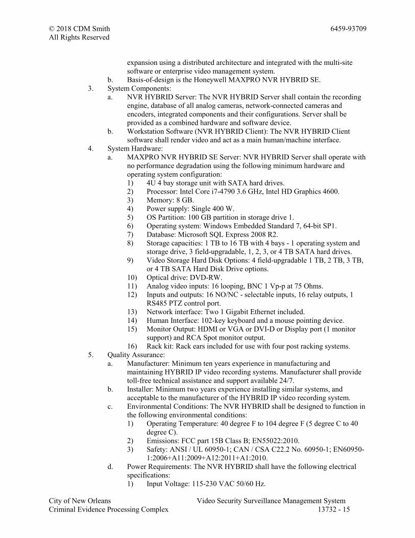
© 2018 CDM Smith 6459-93709
All Rights Reserved
City of New Orleans Video Security Surveillance Management System
Criminal Evidence Processing Complex 13732 - 15
expansion using a distributed architecture and integrated with the multi-site
software or enterprise video management system.
b. Basis-of-design is the Honeywell MAXPRO NVR HYBRID SE.
3. System Components:
a. NVR HYBRID Server: The NVR HYBRID Server shall contain the recording
engine, database of all analog cameras, network-connected cameras and
encoders, integrated components and their configurations. Server shall be
provided as a combined hardware and software device.
b. Workstation Software (NVR HYBRID Client): The NVR HYBRID Client
software shall render video and act as a main human/machine interface.
4. System Hardware:
a. MAXPRO NVR HYBRID SE Server: NVR HYBRID Server shall operate with
no performance degradation using the following minimum hardware and
operating system configuration:
1) 4U 4 bay storage unit with SATA hard drives.
2) Processor: Intel Core i7-4790 3.6 GHz, Intel HD Graphics 4600.
3) Memory: 8 GB.
4) Power supply: Single 400 W.
5) OS Partition: 100 GB partition in storage drive 1.
6) Operating system: Windows Embedded Standard 7, 64-bit SP1.
7) Database: Microsoft SQL Express 2008 R2.
8) Storage capacities: 1 TB to 16 TB with 4 bays - 1 operating system and
storage drive, 3 field-upgradable, 1, 2, 3, or 4 TB SATA hard drives.
9) Video Storage Hard Disk Options: 4 field-upgradable 1 TB, 2 TB, 3 TB,
or 4 TB SATA Hard Disk Drive options.
10) Optical drive: DVD-RW.
11) Analog video inputs: 16 looping, BNC 1 Vp-p at 75 Ohms.
12) Inputs and outputs: 16 NO/NC - selectable inputs, 16 relay outputs, 1
RS485 PTZ control port.
13) Network interface: Two 1 Gigabit Ethernet included.
14) Human Interface: 102-key keyboard and a mouse pointing device.
15) Monitor Output: HDMI or VGA or DVI-D or Display port (1 monitor
support) and RCA Spot monitor output.
16) Rack kit: Rack ears included for use with four post racking systems.
5. Quality Assurance:
a. Manufacturer: Minimum ten years experience in manufacturing and
maintaining HYBRID IP video recording systems. Manufacturer shall provide
toll-free technical assistance and support available 24/7.
b. Installer: Minimum two years experience installing similar systems, and
acceptable to the manufacturer of the HYBRID IP video recording system.
c. Environmental Conditions: The NVR HYBRID shall be designed to function in
the following environmental conditions:
1) Operating Temperature: 40 degree F to 104 degree F (5 degree C to 40
degree C).
2) Emissions: FCC part 15B Class B; EN55022:2010.
3) Safety: ANSI / UL 60950-1; CAN / CSA C22.2 No. 60950-1; EN60950-
1:2006+A11:2009+A12:2011+A1:2010.
d. Power Requirements: The NVR HYBRID shall have the following electrical
specifications:
1) Input Voltage: 115-230 VAC 50/60 Hz.
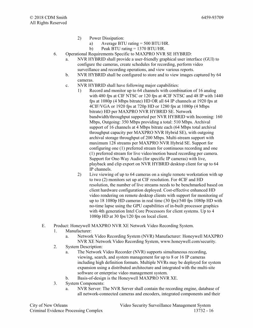
© 2018 CDM Smith 6459-93709
All Rights Reserved
City of New Orleans Video Security Surveillance Management System
Criminal Evidence Processing Complex 13732 - 16
2) Power Dissipation:
a) Average BTU rating = 500 BTU/HR.
b) Peak BTU rating = 1370 BTU/HR.
6. Operational Requirements Specific to MAXPRO NVR SE HYBRID:
a. NVR HYBRID shall provide a user-friendly graphical user interface (GUI) to
configure the cameras, create schedules for recording, perform video
surveillance and recording operations, and view various reports.
b. NVR HYBRID shall be configured to store and to view images captured by 64
cameras.
c. NVR HYBRID shall have following major capabilities:
1) Record and monitor up to 64 channels with combination of 16 analog
with 480 fps at CIF NTSC or 120 fps at 4CIF NTSC and 48 IP with 1440
fps at 1080p (4 Mbps bitrate) HD OR all 64 IP channels at 1920 fps at
4CIF/VGA or 1920 fps at 720p HD or 1280 fps at 1080p (4 Mbps
bitrate) HD per MAXPRO NVR HYBRID SE. Network
bandwidth/throughput supported per NVR HYBRID with Incoming: 160
Mbps, Outgoing: 350 Mbps providing a total: 510 Mbps. Archival
support of 16 channels at 4 Mbps bitrate each (64 Mbps total archival
throughput capacity per MAXPRO NVR Hybrid SE), with outgoing
archival storage throughput of 200 Mbps. Multi-stream support with
maximum 128 streams per MAXPRO NVR Hybrid SE. Support for
configuring one (1) preferred stream for continuous recording and one
(1) preferred stream for live video/motion based recording per camera.
Support for One-Way Audio (for specific IP cameras) with live,
playback and clip export on NVR HYBRID desktop client for up to 64
IP channels.
2) Live viewing of up to 64 cameras on a single remote workstation with up
to two (2) monitors set up at CIF resolution. For 4CIF and HD
resolution, the number of live streams needs to be benchmarked based on
client hardware configuration deployed. Cost-effective enhanced HD
video rendering on remote desktop clients with support for monitoring of
up to 18 1080p HD cameras in real time (30 fps)/540 fps 1080p HD with
no-time lapse using the GPU capabilities of in-built processor graphics
with 4th generation Intel Core Processors for client systems. Up to 4
1080p HD at 30 fps/120 fps on local client.
E. Product: Honeywell MAXPRO NVR XE Network Video Recording System.
1. Manufacturer:
a. Network Video Recording System (NVR) Manufacturer: Honeywell MAXPRO
NVR XE Network Video Recording System, www.honeywell.com/security.
2. System Description:
a. The Network Video Recorder (NVR) supports simultaneous recording,
viewing, search, and system management for up to 8 or 16 IP cameras
including high definition formats. Multiple NVRs may be deployed for system
expansion using a distributed architecture and integrated with the multi-site
software or enterprise video management system.
b. Basis-of-design is the Honeywell MAXPRO NVR XE.
3. System Components:
a. NVR Server: The NVR Server shall contain the recording engine, database of
all network-connected cameras and encoders, integrated components and their
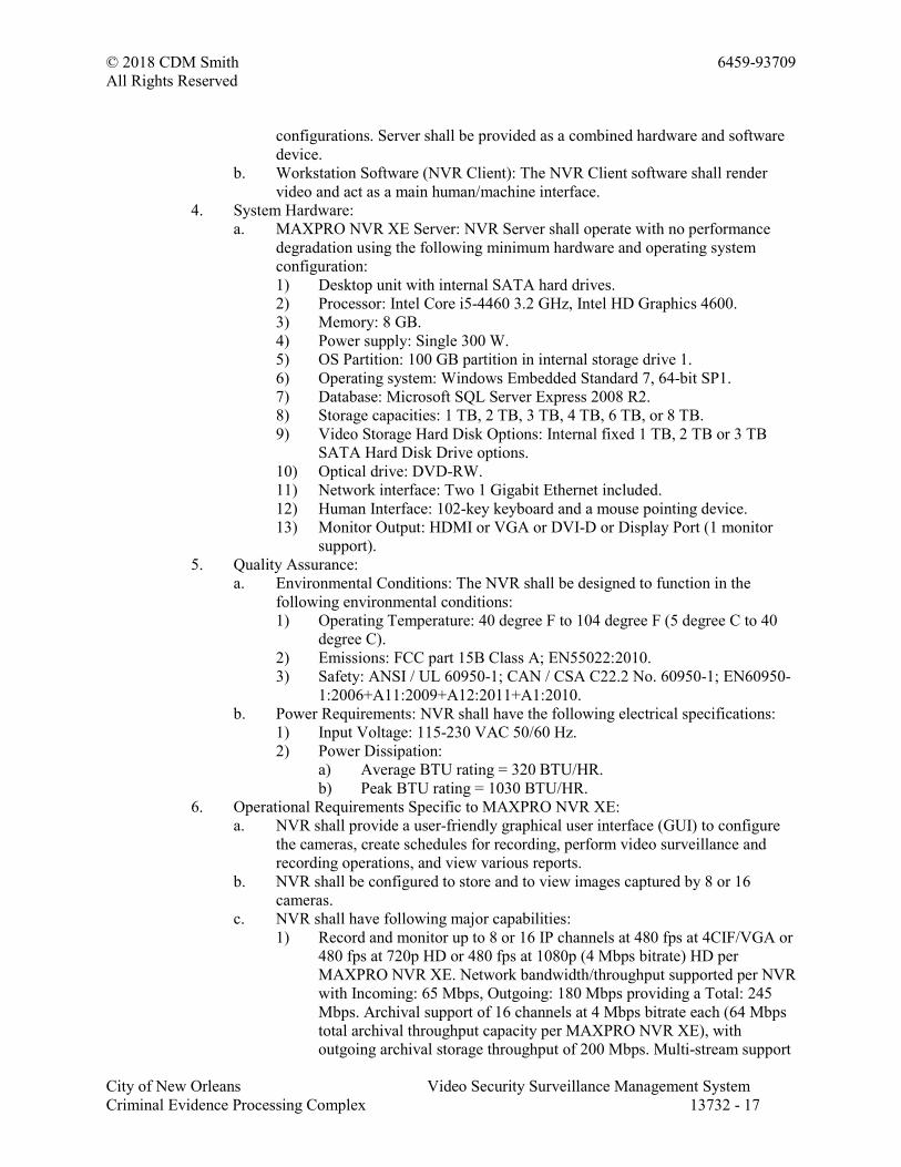
© 2018 CDM Smith 6459-93709
All Rights Reserved
City of New Orleans Video Security Surveillance Management System
Criminal Evidence Processing Complex 13732 - 17
configurations. Server shall be provided as a combined hardware and software
device.
b. Workstation Software (NVR Client): The NVR Client software shall render
video and act as a main human/machine interface.
4. System Hardware:
a. MAXPRO NVR XE Server: NVR Server shall operate with no performance
degradation using the following minimum hardware and operating system
configuration:
1) Desktop unit with internal SATA hard drives.
2) Processor: Intel Core i5-4460 3.2 GHz, Intel HD Graphics 4600.
3) Memory: 8 GB.
4) Power supply: Single 300 W.
5) OS Partition: 100 GB partition in internal storage drive 1.
6) Operating system: Windows Embedded Standard 7, 64-bit SP1.
7) Database: Microsoft SQL Server Express 2008 R2.
8) Storage capacities: 1 TB, 2 TB, 3 TB, 4 TB, 6 TB, or 8 TB.
9) Video Storage Hard Disk Options: Internal fixed 1 TB, 2 TB or 3 TB
SATA Hard Disk Drive options.
10) Optical drive: DVD-RW.
11) Network interface: Two 1 Gigabit Ethernet included.
12) Human Interface: 102-key keyboard and a mouse pointing device.
13) Monitor Output: HDMI or VGA or DVI-D or Display Port (1 monitor
support).
5. Quality Assurance:
a. Environmental Conditions: The NVR shall be designed to function in the
following environmental conditions:
1) Operating Temperature: 40 degree F to 104 degree F (5 degree C to 40
degree C).
2) Emissions: FCC part 15B Class A; EN55022:2010.
3) Safety: ANSI / UL 60950-1; CAN / CSA C22.2 No. 60950-1; EN60950-
1:2006+A11:2009+A12:2011+A1:2010.
b. Power Requirements: NVR shall have the following electrical specifications:
1) Input Voltage: 115-230 VAC 50/60 Hz.
2) Power Dissipation:
a) Average BTU rating = 320 BTU/HR.
b) Peak BTU rating = 1030 BTU/HR.
6. Operational Requirements Specific to MAXPRO NVR XE:
a. NVR shall provide a user-friendly graphical user interface (GUI) to configure
the cameras, create schedules for recording, perform video surveillance and
recording operations, and view various reports.
b. NVR shall be configured to store and to view images captured by 8 or 16
cameras.
c. NVR shall have following major capabilities:
1) Record and monitor up to 8 or 16 IP channels at 480 fps at 4CIF/VGA or
480 fps at 720p HD or 480 fps at 1080p (4 Mbps bitrate) HD per
MAXPRO NVR XE. Network bandwidth/throughput supported per NVR
with Incoming: 65 Mbps, Outgoing: 180 Mbps providing a Total: 245
Mbps. Archival support of 16 channels at 4 Mbps bitrate each (64 Mbps
total archival throughput capacity per MAXPRO NVR XE), with
outgoing archival storage throughput of 200 Mbps. Multi-stream support
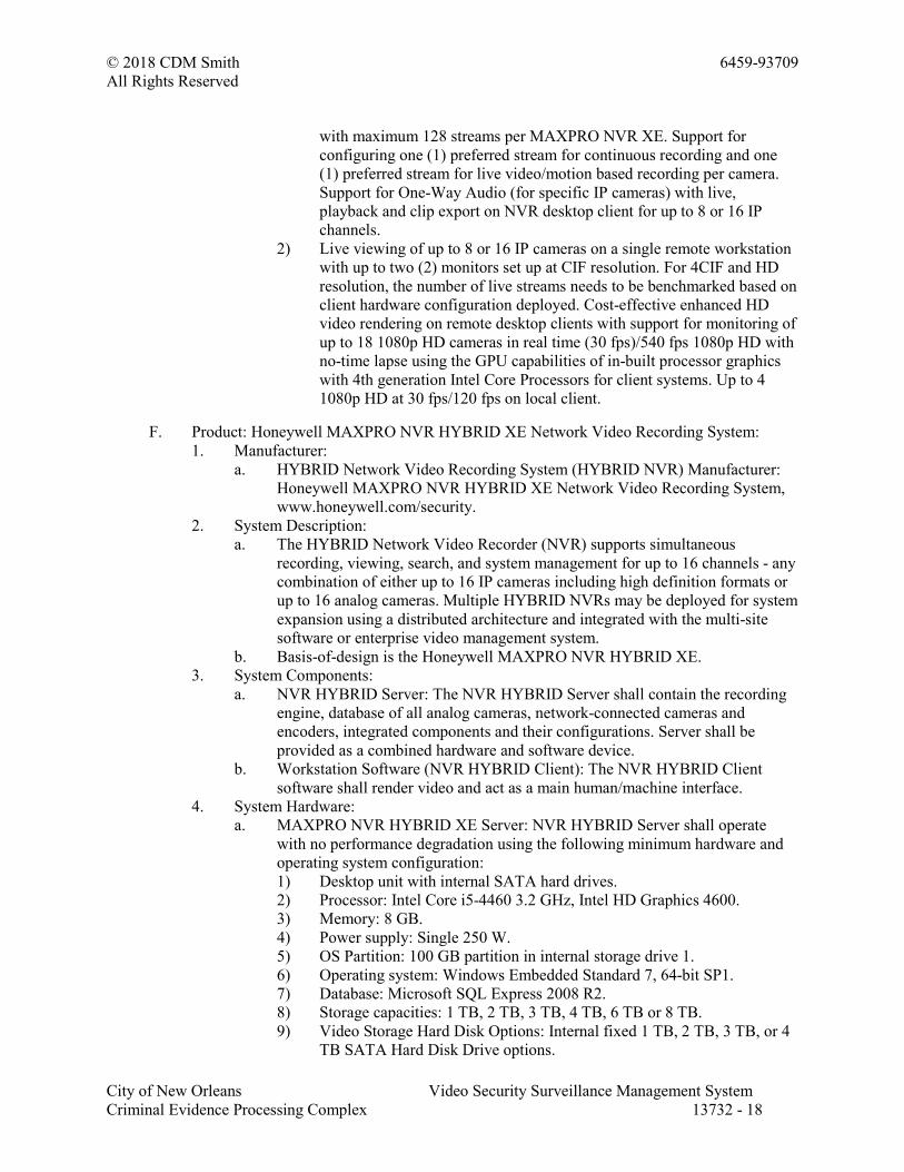
© 2018 CDM Smith 6459-93709
All Rights Reserved
City of New Orleans Video Security Surveillance Management System
Criminal Evidence Processing Complex 13732 - 18
with maximum 128 streams per MAXPRO NVR XE. Support for
configuring one (1) preferred stream for continuous recording and one
(1) preferred stream for live video/motion based recording per camera.
Support for One-Way Audio (for specific IP cameras) with live,
playback and clip export on NVR desktop client for up to 8 or 16 IP
channels.
2) Live viewing of up to 8 or 16 IP cameras on a single remote workstation
with up to two (2) monitors set up at CIF resolution. For 4CIF and HD
resolution, the number of live streams needs to be benchmarked based on
client hardware configuration deployed. Cost-effective enhanced HD
video rendering on remote desktop clients with support for monitoring of
up to 18 1080p HD cameras in real time (30 fps)/540 fps 1080p HD with
no-time lapse using the GPU capabilities of in-built processor graphics
with 4th generation Intel Core Processors for client systems. Up to 4
1080p HD at 30 fps/120 fps on local client.
F. Product: Honeywell MAXPRO NVR HYBRID XE Network Video Recording System:
1. Manufacturer:
a. HYBRID Network Video Recording System (HYBRID NVR) Manufacturer:
Honeywell MAXPRO NVR HYBRID XE Network Video Recording System,
www.honeywell.com/security.
2. System Description:
a. The HYBRID Network Video Recorder (NVR) supports simultaneous
recording, viewing, search, and system management for up to 16 channels - any
combination of either up to 16 IP cameras including high definition formats or
up to 16 analog cameras. Multiple HYBRID NVRs may be deployed for system
expansion using a distributed architecture and integrated with the multi-site
software or enterprise video management system.
b. Basis-of-design is the Honeywell MAXPRO NVR HYBRID XE.
3. System Components:
a. NVR HYBRID Server: The NVR HYBRID Server shall contain the recording
engine, database of all analog cameras, network-connected cameras and
encoders, integrated components and their configurations. Server shall be
provided as a combined hardware and software device.
b. Workstation Software (NVR HYBRID Client): The NVR HYBRID Client
software shall render video and act as a main human/machine interface.
4. System Hardware:
a. MAXPRO NVR HYBRID XE Server: NVR HYBRID Server shall operate
with no performance degradation using the following minimum hardware and
operating system configuration:
1) Desktop unit with internal SATA hard drives.
2) Processor: Intel Core i5-4460 3.2 GHz, Intel HD Graphics 4600.
3) Memory: 8 GB.
4) Power supply: Single 250 W.
5) OS Partition: 100 GB partition in internal storage drive 1.
6) Operating system: Windows Embedded Standard 7, 64-bit SP1.
7) Database: Microsoft SQL Express 2008 R2.
8) Storage capacities: 1 TB, 2 TB, 3 TB, 4 TB, 6 TB or 8 TB.
9) Video Storage Hard Disk Options: Internal fixed 1 TB, 2 TB, 3 TB, or 4
TB SATA Hard Disk Drive options.
© 2018 CDM Smith 6459-93709
All Rights Reserved
City of New Orleans Video Security Surveillance Management System
Criminal Evidence Processing Complex 13732 - 19
10) Optical drive: DVD-RW.
11) Analog video inputs: 16 looping , BNC 1 Vp-p at 75 Ohms (looping
outputs with accessory cables).
12) Inputs and outputs: 16 NO/NC - selectable inputs, 16 relay outputs, 1
RS485 PTZ control port.
13) Network interface: Two 1 Gigabit Ethernet included.
14) Human Interface: 102-key keyboard and a mouse pointing device.
15) Monitor Output: HDMI or VGA or DVI-D or Display Port (1 monitor
support), RCA Spot monitor output.
16) Rack kit: Rack ears included for use with four post racking systems.
5. Quality Assurance:
a. Manufacturer: Minimum ten years experience in manufacturing and
maintaining HYBRID IP video recording systems. Manufacturer shall provide
toll-free technical assistance and support available 24/7.
b. Installer: Minimum two years experience installing similar systems, and
acceptable to the manufacturer of the HYBRID IP video recording system.
c. Environmental Conditions: The NVR HYBRID shall be designed to function in
the following environmental conditions:
1) Operating Temperature: 40 degree F to 104 degree F (5 degree C to 40
degree C).
2) Emissions: FCC part 15B Class A; EN55022:2010.
3) Safety: ANSI / UL 60950-1; CAN / CSA C22.2 No. 60950-1; EN60950-
1:2006+A11:2009+A12:2011+A1:2010.
d. Power Requirements: The NVR HYBRID shall have the following electrical
specifications:
1) Input Voltage: 115-230 VAC 50/60 Hz.
2) Power Dissipation:
e. Average BTU rating = 340 BTU/HR.
f. Peak BTU rating = 860 BTU/HR.
6. Operational Requirements Specific to MAXPRO NVR XE HYBRID:
a. NVR HYBRID shall provide a user-friendly graphical user interface (GUI) to
configure the cameras, create schedules for recording, perform video
surveillance and recording operations, and view various reports.
b. NVR HYBRID shall be configured to store and to view images captured by 16
cameras.
c. NVR HYBRID shall have following major capabilities:
1) Record and monitor up to 16 channels with combination of 16 analog
with 480 fps at CIF NTSC or 120 fps at 4CIF NTSC; OR combination of
8 analog with 100 fps at 4CIF NTSC and 8 IP with 240 fps at 720p HD
or 240 fps at 1080p (4 Mbps bitrate) HD; OR all 16 IP with 480 fps at
4CIF/VGA or 480 fps at 720p HD or 480 fps at 1080p (4 Mbps bitrate)
HD per MAXPRO NVR HYBRID XE. Network bandwidth/throughput
supported per NVR HYBRID with Incoming: 65 Mbps, Outgoing: 180
Mbps providing a Total: 245 Mbps. Archival support of 16 channels at 4
Mbps bitrate each (64 Mbps total archival throughput capacity per
MAXPRO NVR Hybrid XE), with outgoing archival storage throughput
of 200 Mbps. Multi-stream support with maximum 128 streams per
MAXPRO NVR Hybrid XE. Support for configuring one (1) preferred
stream for continuous recording and one (1) preferred stream for live
video/motion based recording per camera. Support for One-Way Audio
© 2018 CDM Smith 6459-93709
All Rights Reserved
City of New Orleans Video Security Surveillance Management System
Criminal Evidence Processing Complex 13732 - 20
(for specific IP cameras) with live, playback and clip export on NVR
HYBRID desktop client for up to 16 IP channels.
2) Live viewing of up to 16 cameras on a single remote workstation with up
to two (2) monitors set up at CIF resolution. For 4CIF and HD
resolution, the number of live streams needs to be benchmarked based on
client hardware configuration deployed. Cost-effective enhanced HD
video rendering on remote desktop clients with support for monitoring of
up to 18 1080p HD cameras in real time (30 fps)/540 fps 1080p HD with
no-time lapse using the GPU capabilities of in-built processor graphics
with 4th generation Intel Core Processors for client systems. Up to 4
1080p HD at 30 fps/120 fps on local client.
G. Other NVR Operational Requirements:
1. Powerful investigation and video archive search tools from remote client.
2. Capable of managing motion detection-based recording with pre-event and post-event
recording based on camera-based motion detection or Server-based motion detection
events (SMART VMD) and "advanced" search on recordings from remote client.
3. Preview and Calendar Search permitting search for videos and events-based on user-
selected date and time from remote client. SMART motion search - fast and efficient
forensic search and investigation for objects/motion on recorded video using
Honeywell SMART motion detection Analytics algorithms on the client PC without
impacting the NVR Server load.
4. Simultaneous use of multiple video compressions including MJPEG, MPEG-4 and
H.264.
5. Internationalization - supports the following languages: French, German, Russian,
Italian, Spanish, Dutch, Arabic and English.
6. Email on alarm.
7. Instant clip creation from snapshot.
8. Dynamic IP Camera Discovery - Automatically discover all compatible cameras
connected to NVR.
9. Multi-level user access rights for viewing and manages access to the recorder
functions.
10. Capable of managing continuous, scheduled, manual, event-based, and alarm-based
recording features.
11. Advanced security features with encryption support for communication between
desktop client to NVR and secure https login for web client and mobile apps.
12. Support for web client and mobile apps.
13. Mode for User Login: NVR shall have the option of two modes of user logins:
a. Windows Authentication: Uses Windows logged-in user name.
b. User DB Authentication: Uses preconfigured user name and password.
14. Workstation (NVR Client) shall provide the following operator options:
a. Configuration: The operator (with Administrator privileges) shall have the
option to configure the NVR. Live update of all configurations is supported.
The following configurations shall be possible:
1) System Configuration: Provide options to configure the system level
settings.
2) Camera Configuration: Provide options to add/edit/delete IP cameras and
encoders.
3) Schedules: Provide options to configure schedule-based recording for
cameras connected to the NVR.

© 2018 CDM Smith 6459-93709
All Rights Reserved
City of New Orleans Video Security Surveillance Management System
Criminal Evidence Processing Complex 13732 - 21
4) Input and Output: Provide options to configure camera input and output.
5) Sequences: Provide options to group a fixed number of cameras to view
video.
6) User Management (Users and Roles): Provide option to add/edit/delete
users.
7) Clip Deletion Settings: Provide the ability to automatically utilize more
storage on event-initiated recording.
8) Independent deletion setting for continuous recording.
9) Independent deletion setting for event recording.
10) Surrounding Cameras: Provide option to grant a user the ability to view a
single camera surrounded by the cameras programmed as the
"Surrounding Cameras".
11) Profile Cameras: Multi-zoom views on HD video and support to create
virtual cameras by digitally zooming into the field of view. For example:
zooming in on a cash register in one view of the HD camera while at the
same time monitoring the cashier in the zoomed out view of that HD
camera.
15. Configurations for cameras connected to NVR:
a. Camera Configuration: The user shall be able to configure the following
parameters for each camera connected to the NVR.
1) Camera Name.
2) IP Address.
3) Camera Type.
4) Fixed/PTZ.
5) Continuous Recording: All cameras added shall be defaulted to "24/7"
recording with the option to select other recording modes.
6) Event-based Recording: Shall be "None" by default, with the option to
select motion-based recording.
7) User name: Shall display and enable setting the user name for a camera.
8) Password: Shall enable setting the password for a camera.
9) Camera Advanced Settings: Shall enable configuration of Video Format,
Compression Format, Resolution, Compression, Video Frame Rate,
GOP, Record Quality Settings, Clip Deletion Settings, Launching Web
View of camera for Advanced Setup, Motion detection zones
configuration for Server-based motion detection, Video Archival
Settings, Multi-Stream Settings and Video Preview. Shall enable
configuration of RTSP URL for cameras or encoders added with camera
type - Generic RTSP.
b. The following video recording options shall be supported:
1) Scheduled-based recording: The system shall support the ability to
schedule recordings for each individual camera for times in the future.
By default, the NVR shall be pre-loaded with the following four
schedules: 24x7, Weekday, Daytime, and Nighttime, which cannot be
edited. A maximum of 50 schedules can be created in the NVR.
2) User-based recording: The user shall be able to configure user activated
settings for recording moments of interest while viewing live video from
a camera. After configuring the user activated settings, the operator can
start recording of video when needed. The video is recorded for the time
period specified in the System settings for user activated recording. The
User-based Recording Time Duration shall be selectable from a list of
© 2018 CDM Smith 6459-93709
All Rights Reserved
City of New Orleans Video Security Surveillance Management System
Criminal Evidence Processing Complex 13732 - 22
values ranging between 30 seconds and 5 minutes.
3) Event-based recording: Event-based recording shall be possible on
SMART Video Motion Detection and alarm triggers. The NVR must be
capable of managing motion detection-based recording with pre-event
and post-event recording based on camera and Server-based motion
detection events. The server-based SMART VMD analytics must be
object-based and not traditional pixel-based, reducing false alarms due to
changing light conditions, video noise, rain or other false alarm triggers
that occur using pixel-based (traditional) VMD.
16. Viewer: The NVR Viewer shall have the following minimum capabilities:
a. Main video viewing screen capable of showing 1, 4, 9, 16, and other
customized split salvos of live or recorded video. Standard presets shall be
customizable to the user preferences.
b. Capable of saving current salvo as a View and allowing the user to drag this
view at any later point in time.
c. Capable of configuring and running scan sequences.
d. Capable of adjusting the contrast, brightness, and saturation settings for each
camera independently.
e. Capable of exporting user selected image or video clips in simple .wmv, .asf,
.mpvc and .bmp formats. Capable of attaching a digital signature for
authentication of exported clips in .wmv format.
f. Capability to play back the video clips exported. Each video channel that is
being recorded by the recording system shall be overlaid with text and a time
stamp that is customizable by the user.
g. MAXPRO Video Container (.mpvc) format support - only playable in
MAXPRO desktop clients and standalone Clip Player. Features quicker exports
of raw video and support for estimating clip size and split to multiple clips to
ensure clip storage media matches. Include the clip player with exported clip
for easier review of video evidence and efficient investigation. Clip Player -
Portable standard secure player for archived and exported clips (*.mpvc), 360
camera de-warping and 2x2 Salvo support. Smooth playback support with up to
256x review speed. No software needed to run on a Windows PC, with the
option to include the clip player with the exported clip.
h. Allow the user to initiate recording through the GUI or a controller.
i. Capability of complete alarm management for the alarms coming from the
NVR.
j. Facility of surrounding camera view.
k. Option to perform various operations through context menu on a particular
video (live/recorded/sequence). These operations include: Full screen, point and
drag, maintain aspect ratio, toggle text, digital PTZ, add bookmark, start
recording, stop recording, mark in, mark out, save image, save image as, show
surrounding cameras.
l. Ability to manage timeline control of the recording device, which provides
camera recording statistics. Timeline control shall have the following features:
Mark input (with looping facility), bookmark, snapshot, time slider, time jump,
play controls.
m. Preference configuration including: frame rate of unselected panels, rendered
type, preview pane, text display format.
17. Search: The Search facility shall include search for recorded video and events based
on date and time.
© 2018 CDM Smith 6459-93709
All Rights Reserved
City of New Orleans Video Security Surveillance Management System
Criminal Evidence Processing Complex 13732 - 23
18. Reports: The Report facility shall include event history report and audit log report.
H. NVR Integrations:
1. NVR shall be compatible with the following interoperability standards:
a. Physical Security Interoperability Alliance (PSIA).
b. Open Network Video Interface Forum Profile S (ONVIF Profile S).
c. Real Time Streaming Protocol (RTSP).
2. NVR shall be compatible with the following Fixed and PTZ IP cameras.
a. Honeywell Performance Series and equIP Series IP cameras.
b. Supports IP cameras from the following manufacturers. Please contact
Honeywell for the complete list of manufacturers and models.
1) AXIS Communications.
2) Sony.
3) Panasonic.
4) Bosch.
5) Samsung.
6) Vivotek.
7) Pelco.
3. NVR shall be compatible with the following encoders:
a. Honeywell HVE Series Encoders.
b. Supports Encoders from the following manufacturers. Please contact
Honeywell for the complete list of manufacturers and models.
1) AXIS Communications.
2) Sony.
3) Panasonic.
4) Bosch.
5) Samsung.
6) Vivotek.
4. NVR shall be compatible with the following 360 degree Camera solutions. Please
contact Honeywell for the complete list of models.
a. Oncam Grandeye.
b. Immervision Enables - Panomorph Lenses.
c. AXIS 360 degree /180 degree.
d. Arecont 360 degree /180 degree.
5. NVR shall be compatible with the following Multi-site Video Management Systems:
a. Honeywell MAXPRO Viewer.
6. NVR shall be compatible with the following Video Management Systems:
a. Honeywell MAXPRO VMS.
7. NVR shall be compatible with the following Access Control Security System:
a. Honeywell Pro-Watch Access Control System through MAXPRO VMS and
MAXPRO Viewer.
b. Honeywell WIN-PAK Access Control System.
8. Video Analytics supported through MAXPRO VMS:
a. Honeywell Active Alert.
9. IP Surveillance Control Keyboards supported through MAXPRO VMS:
a. Honeywell HJK7000 UltraKey Plus.
b. Honeywell HJC5000 UltraKey Lite.
c. Honeywell HJC4000 UltraKey Touch.
I. Workstation Hardware:
© 2018 CDM Smith 6459-93709
All Rights Reserved
City of New Orleans Video Security Surveillance Management System
Criminal Evidence Processing Complex 13732 - 24
1. NVR Workstation: NVR Workstation shall operate with no performance degradation
using the following recommended hardware and operating system configuration for
rendering up to eighteen (18) 1080p HD cameras in real time (30 fps)/540 fps at
1080p HD with no time-lapse:
a. Processor: Intel Core i7-4790, 3.6 GHz or equivalent 4th generation Intel Core
Processors for client systems. GPU rendering by NVR client is not currently
supported on 6th generation Intel(r) Core(tm) processors (Skylake processors)
and CPU rendering should be used by uninstalling the GPU driver.
b. Graphics Adapter: In-built Processor Graphics (GPU): Intel HD Graphics 4600
or equivalent.
c. System Memory (RAM): 8 GB.
d. Optical Drive: DVD-RW.
e. Hard Disk Drives: Single Disk or RAID 0 or 0+1 10K SATA 80GB or 10K to
15K SAS 73 GB.
f. Network Interface Card (NIC): 1 Gbps.
g. Human Interface: 102-key keyboard and a mouse pointing device.
h. Operating System: Microsoft Windows 7 Professional 64-bit SP1, Windows 8.1
Professional 64-bit, or Windows 10 Professional 64-bit.
J. Manufacturer Support:
1. Manufacturer shall provide customer service, pre-sales applications assistance, after-
sales technical assistance, access to technical online support, and online training using
Web conferencing.
2. Manufacturer shall provide 24/7 technical assistance and support via a toll-free
telephone number at no extra charge.
K. NVR Environmental Conditions:
1. The NVR shall be designed to function in the following environmental conditions:
a. Operating Temperature: 32 degree F to 95 degree F (0 degree C to 35 degree
C).
b. Emissions: FCC part 15B Class A.
c. Safety: ANSI / UL 60950-1; CAN / CSA C22.2 No. 60950-1.
2.4 ENCODERS
A. The audio/video encoder shall offer the latest in technology, providing unparalleled stability,
security, and ease of use, with advanced algorithms, fast capture rates, and a unique
Graphical User Interface (GUI).
B. The audio/video encoder is a complete analog-to-digital conversion solution. The
combination of motion detection, audio, recording resolutions, remote notification
technologies, and local and remote storage, shall provide an extremely flexible and reliable
solution.
1. Remote video software (the Honeywell IP Utility), that runs on a Microsoft Windows-
based personal computer. The Honeywell IP Utility is used for remotely accessing
multiple HVE Encoders for the purpose of viewing live video, searching and playing
back recorded video, and backing up video clips.
C. Available as a 1-channel configuration with encoding capability up to 30 fps at 4CIF
resolution (NTSC), and data storage from 4 GB (microSDHC card) to 32 GB.
1. Product: Honeywell HVE1 Audio/Video Encoder.
© 2018 CDM Smith 6459-93709
All Rights Reserved
City of New Orleans Video Security Surveillance Management System
Criminal Evidence Processing Complex 13732 - 25
2. HVE1 Audio/Video Encoder shall work with one (1) analog camera and transmit
audio and video over a network. It will use the latest encoding technology to digitize
analog audio and video signals.
3. HVE1 Audio/Video Encoder shall be configured to work with a Network Video
Recorder (NVR) to store and to view images.
4. HVE1 Audio/Video Encoder software shall be user configured via a web client on a
personal computer running a current version of the Internet Explorer web browser.
D. Available as a 4-channel configuration with encoding capability up to 30 fps at 4CIF
resolution (NTSC), and data storage from 16 GB (microSDHC card) to 32 GB.
1. Product: Honeywell HVE4 Audio/Video Encoder.
2. HVE4 Audio/Video Encoder shall work with up to four (4) analog cameras and
transmit audio and video over a network. It will use the latest encoding technology to
digitize analog audio and video signals.
3. HVE4 Audio/Video Encoder shall be configured to work with a Network Video
Recorder (NVR) to store and to view images.
4. HVE4 Audio/Video Encoder software shall be user configured via a web client on a
personal computer running a current version of the Internet Explorer web browser.
E. Available as an 8-channel configuration with encoding capability up to 30 fps at 4CIF
resolution (NTSC), and data storage up to 4 TB.
1. Product: Honeywell HVE8 Audio/Video Encoder.
2. HVE8 Audio/Video Encoder shall work with up to eight (8) analog cameras and
transmit audio and video over a network. It will use the latest encoding technology to
digitize analog audio and video signals.
3. HVE8 Audio/Video Encoder shall be configured to work with a Network Video
Recorder (NVR) to store and to view images.
4. HVE8 Audio/Video Encoder software shall be user configured via a web client on a
personal computer running a current version of the Internet Explorer web browser.
2.5 FIXED CAMERAS
A. Performance Standards: IP camera system shall meet or exceed the following camera
specifications:
1. Imager: CMOS (Progressive Scan).
2. Video Streaming: Configurable resolution and frame rate for each selected
MJPEG/H.264 stream.
a. Plus H.264+/H.265: HBD8GR1, H4D8GR1, HCD8G, HSW2G1.
b. Plus H.264H/B: H3W2GR1, H3W2GR2, H3W4GR1, H4L2GR1, H4W2GR1,
H4W2GR2, H4W4GR1, HBL2GR1, HBW2GR1, HBW2GR3, HBW4GR1,
HCL2G, HCW2G, HCW4G.
3. On Board Storage: Up to 128 GB microSDHS (Class10) support. Card not included.
4. Intelligent Video: Face detection, Video motion detection.
5. Fixed Cameras Privacy Zones: Conceals up to 4 areas of a scene from viewing and
recording.
6. PTZ Cameras Privacy Zones: Conceals up to 24 areas of a scene from viewing and
recording.
7. Compression:
a. Triple Stream H.265 Compression: H.265 (3X) and H.265/H.264/MJPEG -
HFD6GR1, HFD8GR1.
© 2018 CDM Smith 6459-93709
All Rights Reserved
City of New Orleans Video Security Surveillance Management System
Criminal Evidence Processing Complex 13732 - 26
b. Triple Stream H.265 Compression: H.265 (3X) and
H.265/H.264+/H.264/MJPEG - H4D8GR1, HBD8GR1, HCD8G, HWS2G1.
c. Triple Stream H.264 Compression: H.264 (3X) and
H.264/H.264H/H.264B/MJPEG - H3W2GR1, H3W2GR2, H3W4GR1,
H4L2GR1, H4W2GR1, H4W2GR2, H4W4GR1, HBL2GR1, HBW2GR1,
HBW2GR3, HBW4GR1, HCW2G, HCL2G, HCW4G.
8. Security: Multiple user access levels with password protection.
9. Features: NTP Time Sync, Multiple Browser Support, Date/ Time Stamp Embedded.
10. Remote firmware updates.
11. Audio Support: Two-way (No audio - HSW2G1).
12. Regulatory: FCC, CE, UL/CSA Listed.
B. Product Series: equIP Series Models as manufactured by Honeywell Security and Fire:
1. True Day/Night IP Box Camera System:
a. Mechanical Specifications:
1) Unit Dimensions (L x H x D): 4.92 x 2.72 x 2.98 inches (125.0 x 69.0 x
75.8.0 mm), without a lens.
2) Unit Weight: 1.21 lb (0.55 kg) camera only.
3) Connectors:
a) Video Output: BNC connector.
b) Lens: 4-pin connector.
c) Network: RJ-45 connector.
d) Power Input: DC jack/2-pin terminal block.
e) Alarm I/O: Screw block.
f) Audio In: 3.5 mm mono phone jack.
g) Audio Out: 3.5 mm mono phone jack.
4) Construction: Die-cast Aluminum
b. Electrical Specifications:
1) Voltage: 12 V DC, 24 V AC, or PoE IEEE 802.3af.
2) Power Consumption:
a) 12 V DC/24 V AC: 6.5 watts max. - HCW2G, HCL2G, HCW4G
b) 12 V DC/24 V AC: 8.0 watts max. - HCD8G
c) PoE: PD Type 1, Class 0, 12.95 watts (max).
c. Designed to meet the following environmental conditions:
1) Operating temperature: -22 degree F (-30 degree C) to 140 degree F (60
degree C).
2) Relative Humidity: 0-95 percent, non-condensing.
3) Emissions: FCC, Part 15; EN 55022; AS/NZS CISPR 22:2009+A1
(2010).
d. Model HCD8G: 12 MP Indoor Box WDR Storage. 24 V AC/12 V DC/PoE, 8
W.
e. Model HCL2G: 2 MP Indoor Box Super WDR TDN Storage. 24 V AC/12 V
DC/PoE, 6.5 W.
f. Model HCW2G: 2 MP Indoor Box WDR Storage. 24 V AC/12 V DC/PoE, 6.5
W.
g. Model HCW4G: 4 MP Indoor Box WDR TDN Storage. 24 V AC/12 V
DC/PoE, 6.5 W.
h. Lens option: HLM105V42MPD: 10.5 - 42.0 mm high definition 12 megapixel
lens, F1.5 (sold separately).
i. Lens option: HLM37V16MPD: 3.7 - 16.0 mm high definition 12 megapixel

© 2018 CDM Smith 6459-93709
All Rights Reserved
City of New Orleans Video Security Surveillance Management System
Criminal Evidence Processing Complex 13732 - 27
lens, F1.5 (sold separately).
j. Lens option: HLM27V12MPD: 2.7 - 12.0 mm high definition 4 megapixel lens,
F1.6 (sold separately) (not for HCD8G).
k. Lens option: HLM5V50MPD: 5.0 - 50.0 mm high definition 4 megapixel lens,
F1.6 (sold separately) (not for HCD8G).
2. TDN Indoor IP Bullet Camera System:
a. Mechanical specifications:
1) Unit Dimensions (L x H): 11.1 x 4.3 inches (281.0 x 110.0 mm).
2) Unit Weight: 4.4 lb (2.0 kg) camera only.
3) Network Connectors: RJ-45 connector.
4) IR LEDs:
a) LEDs (see model).
b) IR Illumination Distance (see model). IR illumination is dependent
on scene reflectance.
5) Construction: Die-cast aluminum with powder coat
b. Electrical specifications:
1) Voltage: 12 V DC, 24 V AC, or PoE IEEE 802.3af.
2) Power Consumption:
a) 24 V AC: 12.0 watts max. - HBW2GR1, HBW2GR3, HBW4GR1.
b) 24 V AC: 14.5 watts max. - HBL2GR1.
c) 24 V AC: 18.0 watts max. - HBD8GR1.
d) PoE: Type 0, Class 0, 12.0 watts (max) - HBW2GR1, HBW2GR3,
HBW4GR1.
e) PoE: PD Type 1, Class 4, 14.5 watts (max). - HBL2GR1.
f) PoE: PD Type 1, Class 4, 12.95 watts (max). - HBD8GR1.
c. Designed to meet the following environmental conditions:
1) Operating Temperature: -40 degree F (-40 degree C) to 140 degree F (60
degree C).
2) Relative Humidity:
a) HBL2GR1/HBW2GR1/HBW2GR3/HBW4GR1: 10-100 percent,
non-condensing.
b) HBD8GR1: 0-95 percent, non-condensing.
3) Emissions:
a) HBL2GR1/HBW2GR1/HBW2GR3/HBW4GR1: FCC, Part 15;
EN 55022; Complies with RCM (AS/NZS).
b) HBD8GR1: FCC, Part 15B; EN 55032; AS/NZS CISPR 22:2009+
A1(2010).
d. Model HBD8GR1: 12 MP Indoor TDN 4K Ultra HD Low Light IR Bullet
Storage. 5.1 - 12.8 mm MFZ. PoE+, 18.0 W. 4 IR LEDs, up to 210 ft (65 m).
e. Model HBL2GR1: 2 MP Indoor TDN Ultra Low Light IR Bullet Storage. 2.7-
12.0 mm MFZ. PoE, 14.5 W. 4 IR LEDs, up to 195 ft (60 m).
f. Model HBW2GR1: 2 MP Indoor TDN Low Light IR Bullet Storage. 2.7-12.0
mm MFZ. PoE, 12.0 W. 4 IR LEDs, up to 195 ft (60 m).
g. Model HBW2GR3: 2 MP Indoor TDN Low Light IR Bullet Storage. 5.0-50.0
mm MFZ. PoE, 12.0 W. 4 IR LEDs, up to 195 ft (60 m).
h. Model HBW4GR1: 4 MP Indoor TDN Low Light IR Bullet Storage. 2.7-12.0
mm MFZ. PoE, 12.0 W. 4 IR LEDs, up to 195 ft (60 m).
3. IR TDN Indoor Dome IP Camera System:
a. Mechanical specifications:
1) Unit Dimensions: diameter 4.96 x 4.80 inches (diameter 126.0 x 122
© 2018 CDM Smith 6459-93709
All Rights Reserved
City of New Orleans Video Security Surveillance Management System
Criminal Evidence Processing Complex 13732 - 28
mm), without a lens.
2) Unit Weight: 1.26 lb (0.57 kg).
3) Connectors:
a) Power Input: 2-pin terminal block.
b) Video Output (AUX): BNC connector (75 ohms).
c) Network: RJ-45 connector.
d) Alarm I/O: 4-pin terminal block.
e) Audio I/O: 2-pin terminal block.
4) IR LEDs:
a) LEDs (see model).
b) IR Illumination Distance (see model). IR illumination is dependent
on scene reflectance.
5) Construction: Polycarbonate-Lid and Skirt, Die-cast Aluminum Camera
Base, RAL 9003.
b. Electrical specifications:
1) Voltage: 12 V DC / 24 V AC; PoE IEEE 802.3af.
2) Power Consumption:
a) 9 watts max.
b) PoE: PD Type 1 Class 0. 12.95 watts (max).
c. Designed to meet the following environmental conditions:
1) Operating Temperature: -22 degree F (-30 degree C) and 122 degree F
(50 degree C).
2) Relative Humidity: 0-95 percent, non-condensing.
3) Emissions: FCC, Part 15; CE - EN 55022; Complies with RCM
(AS/NZS).
d. Indoor Dome:
1) Model H3W2GR1: 2 MP Indoor Dome WDR TDN Storage. 2.7-12.0
mm MFZ. 24 V AC/12 V DC/PoE, 9 W. 2 IR LEDs, up to 65 ft (20 m).
2) Model H3W2GR2: 3 MP Indoor Dome WDR TDN Storage. 7.0 - 22.0
mm MFZ. 24 V AC/12 V DC/PoE, 9 W. 2 IR LEDs, up to 65 ft (20 m).
3) Model H3W4GR1: 4 MP Indoor Dome WDR TDN Storage. 2.7-12.0
mm MFZ. 24 V AC/12 V DC/PoE, 9 W. 2 IR LEDs, up to 65 ft (20 m).
4. Network Height Strip Camera System:
a. Mechanical specifications:
1) Unit Dimensions (W x H x D): 1.88 x 34.1 x 1.16 inches (48.0 x 867.0 x
29.4 mm).
2) Unit Weight: 1.98 lb (0.9 kg).
3) Connectors:
a) Power Input: 2.1 mm jack.
b) Network: RJ-45 connector.
4) Construction: Extruded aluminum with scratch-coated acrylic front.
b. Electrical specifications:
1) Voltage: 12 V DC.
2) Power Consumption: 2.2 watts max.
c. Designed to meet the following environmental conditions:
1) Operating Temperature: -22 degree F (-30 degree C) and 140 degree F
(60 degree C).
2) Relative Humidity: 0-95 percent, non-condensing.
3) Emissions: FCC, Part 15B.
d. Model HSW2G1: 1080p Network Height Strip Storage. 2.8 mm Fixed Lens. 12
© 2018 CDM Smith 6459-93709
All Rights Reserved
City of New Orleans Video Security Surveillance Management System
Criminal Evidence Processing Complex 13732 - 29
V DC, 2.2 W.
5. Network TDN Superior HD IR Fisheye Camera System:
a. Mechanical specifications:
1) Unit Dimensions (W x H): diameter 5.9 x 2.2 inches (diameter 150.2 x
55.8 mm).
2) Unit Weight: 1.1 lb (0.5 kg).
3) Connectors:
a) Power Input: 2.1 mm jack.
b) Network: RJ-45 connector.
c) Audio I/O: RCA jack.
d) Alarm I/O: Wires
4) IR LEDs:
a) LEDs: 3
b) Illumination Distance: Up to 25 ft (8 m)
5) Construction: Die-cast aluminum with powder coat.
b. Electrical specifications:
1) Voltage: 12 V DC, PoE IEEE 802.3af Class 0.
2) Power Consumption:
a) 12 V DC: 10.0 watts max. (with IR LEDs on)
b) PoE: PD Type 1, Class 0, 10.0 watts (max).
c. Designed to meet the following environmental conditions:
1) Operating Temperature: -22 degree F (-30 degree C) and 140 degree F
(60 degree C).
2) Relative Humidity: 0-95 percent, non-condensing.
3) Ingress Protection Rating: IP67.
4) Vandal Resistance Rating: IK10.
5) Emissions: FCC, Part 15B; CE - EN 55032; AS/NZS CISPR 22:2009+
A1(2010).
d. Model HFD6GR1: 6 MP TDN Superior HD IR Fisheye Storage. 1.7 mm Fixed
Fisheye Lens. 12 V DC, 10.0 W. 3 IR LEDs.
e. Model HFD8GR1: 12 MP TDN Superior HD IR Fisheye Storage. 1.7 mm
Fixed Fisheye Lens. 12 V DC, 10.0 W. 3 IR LEDs.
6. True Day/Night IR Rugged Outdoor Dome IP Camera System:
a. Mechanical specifications:
1) Unit Dimensions (W x H): 6.2 x 4.6 inches (159.0 x 118.0 mm).
2) Unit Weight: 2.3 lb (1.05 kg) camera only.
3) Connectors:
a) Network: RJ-45 connector.
b) Aux Video Output: BNC connector.
c) Alarm I/O: 3-pin terminal block.
d) Audio I/O: 2-pin terminal block.
e) Power Input: 2-pin terminal block.
4) IR LEDs:
a) LEDs (see model).
5) IR Illumination Distance (see model). IR illumination is dependent on
scene reflectance.
6) Construction: Die-cast aluminum housing with powder coat.
b. Electrical specifications:
1) Voltage:
a) 12 V DC, 24 V AC, or PoE+ (802.3af) Class 4 - H4D8GR1.
© 2018 CDM Smith 6459-93709
All Rights Reserved
City of New Orleans Video Security Surveillance Management System
Criminal Evidence Processing Complex 13732 - 30
b) 12 V DC, 24 V AC, or PoE (802.3af) Class 0 -
H4L2GR1/H4W2GR1/H4W2GR2/H4W4GR1.
2) Power Consumption:
a) 12 V DC/24 V AC: 18.0 watts max. - H4D8GR1
b) 12 V DC/24 V AC: 10.5 watts max. -
H4L2GR1/H4W2GR1/H4W2GR2/H4W4GR1
c) PoE: PoE+ (802.3af) Class 4, 18.0 watts (max) - H4D8GR1.
d) PoE: PoE (802.3af) Class 0, 10.5 watts (max) -
H4L2GR1/H4W2GR1/H4W2GR2/H4W4GR1.
c. Designed to meet the following environmental conditions:
1) Operating temperature: -40 degree F (-40 degree C) to 140 degree F (60
degree C).
2) Relative Humidity:
a) 0-95 percent, non-condensing - H4D8GR1.
b) 10-100 percent, non-condensing -
H4L2GR1/H4W2GR1/H4W2GR2/H4W4GR1.
3) Ingress Protection Rating: IP67.
4) Vandal Resistance Rating: IK10.
5) Emissions:
a) FCC, Part 15; EN 55022; Complies with RCM (AS/NZS) -
H4W2GR1, H4W2GR2, H4L2GR1, H4W4GR1.
b) FCC, Part 15B; EN 55032; AS/NZS CISPR 22:2009+ A1(2010) -
H4D8GR1.
d. Model H4D8GR1 12 MP TDN 4K Ultra HD Low Light IR Rugged Outdoor
Minidome Storage. 4.1-12.8 mm MFZ. 24 V AC/12 V DC/PoE, 18.0 W. 3
LEDs, up to 145 ft (45 m).
e. Model H4L2GR1 2 MP TDN Ultra Low Light IR Rugged Outdoor Minidome
Storage. 2.7-12.0 MFZ. 24 V AC/12 V DC/PoE, 12.0 W. 3 LEDs, up to 150 ft
(50 m).
f. Model H4W2GR1 2 MP TDN Low Light IR Rugged Outdoor Minidome
Storage. 2.7-12.0 MFZ. 24 V AC/12 V DC/PoE, 12.0 W. 3 LEDs, up to 150 ft
(50 m).
g. Model H4W2GR2 2 MP TDN Low Light IR Rugged Outdoor Minidome
Storage. 7.0-22.0 MFZ. 24 V AC/12 V DC/PoE, 12.0 W. 3 LEDs, up to 150 ft
(50 m).
h. Model H4W4GR1 4 MP TDN Low Light IR Rugged Outdoor Minidome
Storage. 2.7-12.0 MFZ. 24 V AC/12 V DC/PoE, 12.0 W. 3 LEDs, up to 150 ft
(50 m).
C. Mounts and Brackets
1. Indoor Wall Mount Bracket: HD3-MK2
a. Weight: 0.18 lb (0.08 kg)
b. Construction/Finish: Polycarbonate/White powder coating
c. Dimensions: 3.82 x 6.06 x 4.76 in. (97.0 x 154.0 x 121.0 mm)
d. Compatible with: H3W2GR1/H3W2GR2/H3W4GR1.
2. Wall Mount Bracket: HD4CHIP-WK2
a. Weight: 1.34 lb (0.61 kg)
b. Construction/Finish: Die-cast aluminum/White powder coating
c. Dimensions: 5.48 x 8.50 x 4.65 in. (139.3 x 215.9 x 118.0 mm)
d. Compatible with: H4W2GR1/H4W2GR2/H4L2GR1/H4W4GR1/H4D8GR1
© 2018 CDM Smith 6459-93709
All Rights Reserved
City of New Orleans Video Security Surveillance Management System
Criminal Evidence Processing Complex 13732 - 31
(optional + HB34G-CM/HB4G-PM).
3. Pendant Mount Bracket: HD4CHIP-PK2
a. Weight: 0.82 lb (0.37 kg)
b. Construction/Finish: Die-cast aluminum /White powder coating
c. Dimensions: 1.82 x diameter 6.49 in. (46.2 x diameter 164.7 mm)
d. Compatible with: H4W2GR1/H4W2GR2/H4L2GR1/H4W4GR1/H4D8GR1.
4. Corner Mount Adapter: HB34G-CM
a. Weight: 3.7 lb (1.7 kg)
b. Construction/Finish: SECC /White powder coating
c. Dimensions: 6.7 x 9.6 x 5.4 in. (170.0 x 243.0 x 138.0 mm)
d. Compatible with:
H4W2GR1/H4W2GR2/H4L2GR1/H4W4GR1/H4D8GR1+HD4CHIP-WK2;
HBW2GR1/HBW2GR3/HBL2GR1/HBW4GR1/HBD8GR1 (+ HBG-BB);
HFD6GR1/HFD8GR1 + HFG-PK + HFG-WK.
5. Bullet Camera Back Box: HBG-BB
a. Weight: 0.67 lb (0.31 kg)
b. Construction/Finish: Die-cast aluminum /Gray powder coating
c. Dimensions: diameter 4.29 x 1.61 in. (diameter 109.0 x 41.0 mm)
d. Compatible with: HBW2GR1/HBW2GR3/HBL2GR1/HBW4GR1/HBD8GR1
(+ HB34G-CM/HB4G-PM).
6. Pole Mount Adapter: HB4G-PM
a. Weight: 2.05 lb (0.93 kg)
b. Construction/Finish: SECC /White powder coating
c. Dimensions: 5.1 x 6.7 x 1.8 in. (130.4 x 170.0 x 45.0 mm)
d. Compatible with: H4W2GR1/H4W2GR2/H4L2GR1/H4W4GR1/H4D8GR1 +
HD4CHIP-WK2; HBW2GR1/HBW2GR3/HBL2GR1/HBW4GR1/HBD8GR1
(+ HBG-BB); HFD6GR1/HFD8GR1 + HFG-PK + HFG-WK.
7. Fisheye Pendant Mount Bracket: HFG-PK
a. Weight: 0.46 lb (0.21 kg)
b. Construction/Finish: Die-cast Aluminum /White powder coating
c. Dimensions: 5.9 x 5.9 x 1.5 in. (150.8 x 150.8 x 37.0 mm)
d. Compatible with: HFD6GR1/HFD8GR1 (+ HFG-WK) (+ HB34G-CM/HB4G-
PM).
8. Fisheye Wall Mount Bracket: HFG-WK
a. Weight: 1.54 lb (0.7 kg)
b. Construction/Finish: Die-cast aluminum /White powder coating
c. Dimensions: 5.3 x 5.3 x 7.4 in. (134.0 x 134.0 x 187.5 mm)
d. Compatible with: HFD6GR1/HFG8GR1 (+ HFG-PK) (+ HB34G-CM/HB4G-
PM).
2.6 PTZ CAMERAS
A. HDZ Series TDN 1080p True Day/Night In/Outdoor High Speed 30x Zoom IP PTZ
Cameras:
1. Provide a True Day/Night 1080p In/Outdoor high speed IP PTZ dome camera with
30x zoom lens for video surveillance; including design, supply, installation and
commissioning.
a. Components: In/Outdoor dome housing, camera scan unit, cabling, and a web-
based GUI that provides complete control of the IP PTZ dome settings and live
video access.
© 2018 CDM Smith 6459-93709
All Rights Reserved
City of New Orleans Video Security Surveillance Management System
Criminal Evidence Processing Complex 13732 - 32
2. The HDZ Series PTZ dome camera shall use one of the following:
a. A rugged, discreet, outdoor IP67- and IK10-rated impact-resistant enclosure
that can be easily installed directly to a ceiling, wall or roof with either the wall
or pendant mounting accessories: HDZ302DE, HDZ302LIK.
b. A rugged, discreet, outdoor IP66- and IK10-rated impact-resistant enclosure
that can be easily installed directly to a ceiling, wall or roof with either the wall
or pendant mounting accessories: HDZ302D.
c. A rugged, discreet, outdoor IP67-rated waterproof enclosure with lens wiper
that can be easily installed directly to a ceiling, wall or roof with either the wall
or ceiling mounting accessories: HDZ302LIW.
d. A rugged, discreet enclosure that is designed for in-ceiling installation:
HDZ302DIN.
3. Standards: ONVIF Profile S and Profile G (HDZ302LIK/HDZ302LIW Profile S,
only)
4. Regulatory Requirements:
a. Emissions:
1) EU - EN55022; NA - FCC Part 15B, AS/NZL - CISPR 22:2009+A1
(2010): HDZ302LIK, HDZ302LIW.
2) EU - EN55032; NA - FCC Part 15B, AS/NZL - CISPR 22:2009+A1
(2010): HDZ302D, HDZ302DE, HDZ302DIN.
5. Environmental Requirements:
a. Operating Temperature:
1) -40 Degree C (-40 Degree F) to 70 Degree C (158 Degree F):
HDZ302DE, HDZ302LIK, HDZ302LIW.
2) -40 Degree C (-40 Degree F) to 60 Degree C (140 Degree F): HDZ302D.
3) -10 Degree C (14 Degree F) to 60 Degree C (140 Degree F):
HDZ302DIN.
b. Relative Humidity:
1) Less than 95 percent, non-condensing: HDZ302D, HDZ302DE,
HDZ302DIN.
2) Less than 90 percent, non-condensing: HDZ302LIK, HDZ302LIW.
c. Ingress Protection Rating:
1) IP67: HDZ302DE, HDZ302LIK, HDZ302LIW.
2) IP66: HDZ302D, HDZ302DIN.
d. IK10 Vandal Resistance Rating: HDZ302D, HDZ302DE, HDZ302DIN (bubble
only), HDZ302LIK.
6. Performance:
a. Resolution:
1) 1080p (1920 x 1080) at 60 fps (NTSC) or 50 fps (PAL), as well as
support for lower resolutions (1.3 M, 720p, D1, CIF): HDZ302D,
HDZ302DE, HDZ302DIN.
2) 1080p (1920 x 1080) at 30 fps (NTSC) or 25 fps (PAL), as well as
support for lower resolutions (720p, D1, CIF) at 60 fps (NTSC) or 50 fps
(PAL): HDZ302LIK and HDZ302LIW.
b. Streaming:
1) Triple stream codec support including H.265, H.264, and MJPEG:
HDZ302D, HDZ302DE, and HDZ302DIN.
2) Triple stream codec support including: H.264, MPEG4, and MJPEG:
HDZ302LIK and HDZ302LIW.
3) Plus MPEG4: HDZ302LIK; HDZ302LIW.
© 2018 CDM Smith 6459-93709
All Rights Reserved
City of New Orleans Video Security Surveillance Management System
Criminal Evidence Processing Complex 13732 - 33
c. Minimal Illumination:
1) 0.005 lux (color) / 0.0005 lux (B/W) at F1.6: HDZ302D, HDZ302DE,
and HDZ302DIN.
2) 0.005 lux (color) / 0.0005 lux (B/W) at F1.6; 0 lux IR on: HDZ302LIK
and HDZ302LIW.
d. Compression:
1) Dual Stream Compression: H.264 and H.264/MJPEG -
HDZ302LIK/HDZ302LIW.
2) Triple Stream H.265 Compression: H.265 (3X) and
H.265/H.264/MJPEG -HDZ302DE, HDZ302D, HDZ302DIN.
7. Power Requirements:
a. Input Voltage:
1) 24 V AC +/-25 percent, 3A, 50/60 Hz or PoE+ Class 4: HDZ302DE.
2) 24 V AC +/-25 percent, 1.5 A, 50/60 Hz or PoE+ Class 4: HDZ302D and
HDZ302DIN.
3) 24 V AC +/-10 percent, 3A, 50/60 Hz or High PoE Class 5: HDZ302LIK
and HDZ302LIW.
b. Power Consumption:
1) 13.0 W maximum (31.0 W with heater on): HDZ302DE.
2) 13.0 W maximum (23.0 W with heater on): HDZ302D.
3) 13.0 W maximum: HDZ302DIN.
4) 24.0 W maximum (38.0 W maximum with IR on): HDZ302LIK.
5) 24.0 W maximum (32.0 W maximum with IR on): HDZ302LIW.
8. HDZ TDN IR 1080p 30x Zoom WDR IP NTSC/PAL PTZ Dome Series:
a. Model: HDZ302D - Network TDN PTZ 5" Indoor/Outdoor Dome, WDR,
H.265/H.264, IK10, IP66. Storage. 4.5 - 135.0 mm, F1.6-F4.4 30X Optical
Zoom.
b. Model: HDZ302DE - Network TDN PTZ 6" Indoor/Outdoor Dome, WDR,
H.265/H.264, IK10, IP67. Storage. 4.5 - 135.0 mm, F1.6-F4.4 30X Optical
Zoom.
c. Model: HDZ302DIN - Network TDN PTZ Indoor, In-Ceiling Dome, WDR,
H.265/H.264, IK10. Storage. 4.5 - 135.0 mm, F1.6-F4.4 30X Optical Zoom.
d. Model: HDZ302LIK - Network TDN IR PTZ Dome, WDR, H.264, IK10.
Storage. 6.0 - 180 mm, F1.6-F4.8 30X Optical Zoom. IR LED up to 656 ft (200
m).
e. Model: HDZ302LIW - Network TDN IR PTZ Dome, WDR, H.264, Wiper.
Storage. 6.0 - 180 mm, F1.6-F4.8 30X Optical Zoom. IR LED up to 492 ft (150
m).
B. Mounts and Brackets
1. PTZ Ceiling Mount: HDZCM1
a. Weight: 1.72 lb (0.78 kg)
b. Construction/Finish: Die-cast Aluminum/Polycarbonate/White powder coating
c. Dimensions: 9.27 X diameter 5.26 in. (235.5 X diameter 133.6 mm)
d. Compatible with: HDZ302LIW/HDZ302LIK/HDZ302D/HDZ302DE (+
HDZCM2/HDZCM3).
2. 220 mm Ceiling Mount Extension Pole for HDZCM1: HDZCM2
a. Weight: 1.12 lb (0.51 kg)
b. Construction/Finish: Die-cast Aluminum/White powder coating
c. Dimensions: 8.7 X diameter 2.1 in. (220.0 X diameter 53.0 mm)
© 2018 CDM Smith 6459-93709
All Rights Reserved
City of New Orleans Video Security Surveillance Management System
Criminal Evidence Processing Complex 13732 - 34
d. Compatible with: HDZ302LIW/HDZ302LIK/HDZ302D/HDZ302DE +
HDZCM1.
3. 420 mm Ceiling Mount Extension Pole for HDZCM1: HDZCM3
a. Weight: 2.29 lb (1.04 kg)
b. Construction/Finish: Die-cast Aluminum/White powder coating
c. Dimensions: 16.5 x diameter 2.1 in. (420.0 x diameter 53.0 mm)
d. Compatible with: HDZ302LIW/HDZ302LIK/HDZ302D/HDZ302DE +
HDZCM1.
4. PTZ Wall Mount: HDZWM1
a. Weight: 1.46 lb (0.66 kg)
b. Construction/Finish: Die-cast Aluminum/White powder coating
c. Dimensions: 10.0 x 4.5 x 6.3 in. (255.0 x 115.0 x 160.0 mm)
d. Compatible with: HDZ302LIW/HDZ302LIK/HDZ302D/HDZ302DE (+
HDZJB) (+ HDZCMA/HDZPMA).
5. PTZ Corner Mount Adapter for Wall Mount: HDZCMA
a. Weight: 3.7 lb (1.7 kg)
b. Construction/Finish: SECC/White powder coating
c. Dimensions: 6.7 x 9.6 x 5.4 in. (170.0 x 243.0 x 138.0 mm)
d. Compatible with: HDZ302LIW/HDZ302LIK/HDZ302D/HDZ302DE + HDZJB
+ HDZWM1/HDZWM2; HDZ302D + HDZGM + HDZJB.
6. PTZ Pole Mount Adapter for Wall Mount: HDZPMA
a. Weight: 2.05 lb (0.93 kg)
b. Construction/Finish: SECC/White powder coating
c. Dimensions: 5.1 x 6.7 x 1.8 in. (130.4 x 170.0 x 45.0 mm)
d. Compatible with: HDZ302LIW/HDZ302LIK/HDZ302D/HDZ302DE + HDZJB
+ HDZWM1/HDZWM2; HDZ302D + HDZGM + HDZJB.
7. PTZ Junction Box: HDZJB
a. Weight: 1.17 lb (0.53 kg)
b. Construction/Finish: Die-cast Aluminum/White powder coating
c. Dimensions: 6.3 x 4.5 x 1.5 in. (160.0 x 115.0 x 38.8 mm)
d. Compatible with: HDZ302LIW/HDZ302LIK/HDZ302D/HDZ302DE +
HDZWM1/HDZWM2 + HDZPMA/HDZCMA; HDZ302D + HDZGM (+
HDZCMA/HDZPMA).
8. PTZ Wall Mount with Access Hole: HDZWM2
a. Weight: 3.64 lb (1.65 kg)
b. Construction/Finish: Die-cast Aluminum/White powder coating
c. Dimensions: 12.4 x 4.5 x 6.3 in. (315.2 x 115.0 x 160.0 mm)
d. Compatible with: HDZ302LIW/HDZ302LIK/HDZ302D/HDZ302DE (+
HDZJB) (+ HDZCMA/HDZPMA).
9. 1.5" NPT Adapter: HDZNPTA
a. Weight: 0.5 lb (0.23 kg)
b. Construction/Finish: Die-cast Aluminum/White powder coating
c. Dimensions: 1.9 x 2.8 in. (48.0 x 72.0 mm)
10. PTZ Gooseneck Wall Mount: HDZGM
a. Weight: 1.08 lb (0.49 kg)
b. Construction/Finish: Die-cast Aluminum/White powder coating
c. Dimensions: 8.99 x 4.53 x 6.30 in. (228.3 x 115.0 x 160.0 mm)
d. Compatible with: HDZ302D (+ HDZJB) (+HDZCMA/HDZPMA).
2.7 NETWORK & IP CABLES
© 2018 CDM Smith 6459-93709
All Rights Reserved
City of New Orleans Video Security Surveillance Management System
Criminal Evidence Processing Complex 13732 - 35
A. Video System components shall be connected using the following Honeywell Genesis Series
Cables:
B. Category 6A Cables: Unshielded twisted copper pairs, dielectric spline between pairs: UL
13, UL 444, NEC Articles 800 and 725, verified to TIA/EIA-568-C.2 Cat 6A:
1. Riser Rated: Polypropylene Insulation, PVC Jacket: CMR, CL2R, FT4, Sunlight
Resistant Listed:
a. Part #.: 5193, Cat 6A (500 MHz.).
2. Plenum Rated: FEP insulation, low-smoke PVC jacket: CMP, CL2P, FT6 listed:
a. Part #.: 5393, Cat 6A (500 MHz.).
C. Category 6 Plus Cables: Unshielded twisted copper pairs, dielectric spline between pairs: UL
13, UL 444, NEC Articles 800 and 725, verified to TIA/EIA-568-C.2 Cat 6:
1. Riser Rated: Polypropylene Insulation, PVC Jacket: CMR, CL2R, FT4, Sunlight
Resistant Listed:
a. Part #.: 5092, Cat 6 Plus (500 MHz.).
2. Plenum Rated: FEP insulation, low-smoke PVC jacket: CMP, CL2P, FT6 listed:
a. Part #.: 5102, Cat 6 (500 MHz.).
D. Category 6 Cables: Unshielded twisted copper pairs: UL 13, UL 444, NEC Articles 800 and
725, verified to TIA/EIA-568-C.2 Cat 6:
1. Riser Rated: Polypropylene Insulation, PVC Jacket: CMR, CL2R, FT4, Sunlight
Resistant Listed:
a. Part #.: 6360, Cat 6 (350 MHz.).
2. Plenum Rated: FEP insulation, low-smoke PVC jacket: CMP, CL2P, FT6 listed:
a. Part #.: 6361, Cat 6A (350 MHz.).
E. Shielded Category 6 Cables: Foil shielded twisted copper pairs (F/UTP), dielectric spline
between pairs: UL 13, UL 444, NEC Articles 800 and 725, verified to TIA/EIA-568-C.2 Cat
6:
1. Riser Rated: Polypropylene Insulation, PVC Jacket: CMR, CL2R, FT4, Sunlight
Resistant Listed:
a. Part #.: 5192, Shielded Cat 6 Plus (500 MHz.).
2. Plenum Rated: FEP insulation, low-smoke PVC jacket: CMP, CL2P, FT6 listed:
a. Part #.: 5392, Shielded Cat 6 (500 MHz.).
F. Category 5e Cables: Unshielded twisted copper pairs: UL 13, UL 444, NEC Articles 800 and
725, verified to TIA/EIA-568-C.2 Cat 5e:
1. Riser Rated: Polypropylene Insulation, PVC Jacket: CMR, CL2R, FT4, Sunlight
Resistant Listed:
a. Part #.: 5078, Cat 5e (350 MHz.).
2. Plenum Rated: FEP insulation, low-smoke PVC jacket: CMP, CL2P, FT6 listed:
a. Part #.: 5088, Cat 5e (350 MHz.).
3. Direct Burial Rated: Polypropylene insulation, LLDPE jacket: Direct Burial, Sunlight
Resistant, Wet Location Approved:
a. Part No.: 5090, Cat 5e (350 MHz.).
G. Shielded Category 5e Cables: Foil shielded twisted copper pairs (F/UTP): UL 13, UL 444,
NEC Articles 800 and 725, verified to TIA/EIA-568-C.2 Cat 5e:
1. Riser Rated: Polypropylene Insulation, PVC Jacket: CMR, CL2R, FT4, Sunlight
Resistant Listed:
© 2018 CDM Smith 6459-93709
All Rights Reserved
City of New Orleans Video Security Surveillance Management System
Criminal Evidence Processing Complex 13732 - 36
a. Part No.: 5178, Shielded Cat 6 Plus (500 MHz.).
2. Plenum Rated: FEP insulation, low-smoke PVC jacket: CMP, CL2P, FT6 listed:
a. Part No.: 5388, Shielded Cat 6 (500 MHz.).
PART 3 EXECUTION
3.1 EXAMINATION
A. Do not begin installation until substrates have been properly prepared.
B. Examine site conditions prior to installation. Notify Architect and Owner in writing if
unsuitable conditions are encountered. Do not start installation until site conditions are
acceptable.
C. If preparation is the responsibility of another installer, notify Architect in writing of
deviations from manufacturer's recommended installation tolerances and conditions.
3.2 INSTALLATION
A. All components of the video management system shall be thoroughly tested before shipping
to the project location.
B. Video management system shall be installed, programmed and tested in accordance with
manufacturer's installation instructions.
1. Coordinate interfaces with Owner's representative where appropriate.
2. Provide backboxes, racks, connectors, supports, conduit, cable, and wire for a
complete and reliable installation. Obtain Owner's approval for exact location of all
boxes, conduit, and wiring runs prior to installation.
3. Install conduit, cable, and wire parallel and square with building lines, including
raised floors areas. Do not exceed forty percent (40 percent) fill in conduits. Gather
wires and tie to create an orderly installation.
4. Coordinate with other trades to provide proper sequencing of installation.
3.3 FIELD COMMISSIONING AND CERTIFICATION
A. Field Commissioning: Test video management system as recommended by manufacturer,
including the following:
1. Conduct complete inspection and testing of equipment, including verification of
operation with connected equipment.
2. Test devices and demonstrate operational features for Owner's representative and
authorities having jurisdiction, as applicable.
3. Correct deficiencies until satisfactory results are obtained.
4. Submit written copies of test results.
3.4 TRAINING
A. Conduct on-site system administrator and security/surveillance operator training, with the
number of sessions and length of sessions as recommended by the video management system
manufacturer. Training shall include administration, provisioning, configuration, operation,
and diagnostics.
3.5 PROTECTION
© 2018 CDM Smith 6459-93709
All Rights Reserved
City of New Orleans Video Security Surveillance Management System
Criminal Evidence Processing Complex 13732 - 37
A. Protect installed products until completion of project.
B. Touch up, repair or replace damaged products before Substantial Completion.
END OF SECTION

© 2018 CDM Smith 6459-93709
All Rights Reserved
City of New Orleans Digital, Addressable Fire-Alarm System
Criminal Evidence Processing Complex 13852 - 1
SECTION 13852 - DIGITAL, ADDRESSABLE FIRE-ALARM SYSTEM
PART 1 - GENERAL
1.1 RELATED DOCUMENTS
A. Drawings and general provisions of the Contract, including General and Supplementary
Conditions and Division 01 Specification Sections, apply to this Section.
1.2 SUMMARY
A. Section Includes:
1. Fire-alarm control unit.
2. Manual fire-alarm boxes.
3. System smoke detectors.
4. Air-sampling smoke detectors.
5. Nonsystem smoke detectors.
6. Heat detectors.
7. Notification appliances.
8. Device guards.
9. Firefighters' two-way telephone communication service.
10. Firefighters' smoke-control station.
11. Magnetic door holders.
12. Remote annunciator.
13. Graphic annunciator.
14. Addressable interface device.
15. Digital alarm communicator transmitter.
16. Radio alarm transmitter.
17. Network communications.
18. System printer.
B. Related Requirements:
1. Section 16718 "Conductors and Cables for Electronic Safety and Security" for cables and
conductors for fire-alarm systems.
1.3 DEFINITIONS
A. EMT: Electrical Metallic Tubing.
B. FACP: Fire Alarm Control Panel.
C. HLI: High Level Interface.
D. NICET: National Institute for Certification in Engineering Technologies.
© 2018 CDM Smith 6459-93709
All Rights Reserved
City of New Orleans Digital, Addressable Fire-Alarm System
Criminal Evidence Processing Complex 13852 - 2
E. PC: Personal computer.
F. VESDA: Very Early Smoke-Detection Apparatus.
1.4 ACTION SUBMITTALS
A. Product Data: For each type of product, including furnished options and accessories.
1. Include construction details, material descriptions, dimensions, profiles, and finishes.
2. Include rated capacities, operating characteristics, and electrical characteristics.
B. Shop Drawings: For fire-alarm system.
1. Comply with recommendations and requirements in the "Documentation" section of the
"Fundamentals" chapter in NFPA 72.
2. Include plans, elevations, sections, details, and attachments to other work.
3. Include details of equipment assemblies. Indicate dimensions, weights, loads, required
clearances, method of field assembly, components, and locations. Indicate conductor
sizes, indicate termination locations and requirements, and distinguish between factory
and field wiring.
4. Detail assembly and support requirements.
5. Include voltage drop calculations for notification-appliance circuits.
6. Include battery-size calculations.
7. Include input/output matrix.
8. Include statement from manufacturer that all equipment and components have been tested
as a system and meet all requirements in this Specification and in NFPA 72.
9. Include performance parameters and installation details for each detector.
10. Verify that each duct detector is listed for complete range of air velocity, temperature,
and humidity possible when air-handling system is operating.
11. Provide program report showing that air-sampling detector pipe layout balances
pneumatically within the airflow range of the air-sampling detector.
12. Include plans, sections, and elevations of heating, ventilating, and air-conditioning ducts,
drawn to scale; coordinate location of duct smoke detectors and access to them.
a. Show critical dimensions that relate to placement and support of sampling tubes,
detector housing, and remote status and alarm indicators.
b. Show field wiring required for HVAC unit shutdown on alarm.
c. Show field wiring and equipment required for HVAC unit shutdown on alarm and
override by firefighters' control system.
d. Show field wiring and equipment required for HVAC unit shutdown on alarm and
override by firefighters' smoke-evacuation system.
e. Locate detectors according to manufacturer's written recommendations.
f. Show air-sampling detector pipe routing.
13. Include voice/alarm signaling-service equipment rack or console layout, grounding
schematic, amplifier power calculation, and single-line connection diagram.
14. Include floor plans to indicate final outlet locations showing address of each addressable
device. Show size and route of cable and conduits and point-to-point wiring diagrams.
C. General Submittal Requirements:

© 2018 CDM Smith 6459-93709
All Rights Reserved
City of New Orleans Digital, Addressable Fire-Alarm System
Criminal Evidence Processing Complex 13852 - 3
1. Submittals shall be approved by authorities having jurisdiction prior to submitting them
to Architect.
2. Shop Drawings shall be prepared by persons with the following qualifications:
a. Trained and certified by manufacturer in fire-alarm system design.
b. NICET-certified, fire-alarm technician; Level III minimum.
c. Licensed or certified by authorities having jurisdiction.
D. Delegated-Design Submittal: For notification appliances and smoke and heat detectors, in
addition to submittals listed above, indicate compliance with performance requirements and
design criteria, including analysis data signed and sealed by the qualified professional engineer
responsible for their preparation.
1. Drawings showing the location of each notification appliance and smoke and heat
detector, ratings of each, and installation details as needed to comply with listing
conditions of the device.
2. Design Calculations: Calculate requirements for selecting the spacing and sensitivity of
detection, complying with NFPA 72. Calculate spacing and intensities for strobe signals
and sound-pressure levels for audible appliances.
3. Indicate audible appliances required to produce square wave signal per NFPA 72.
1.5 INFORMATIONAL SUBMITTALS
A. Qualification Data: For Installer.
B. Seismic Qualification Certificates: For fire-alarm control unit, accessories, and components,
from manufacturer.
1. Basis for Certification: Indicate whether withstand certification is based on actual test of
assembled components or on calculation.
2. Dimensioned Outline Drawings of Equipment Unit: Identify center of gravity and locate
and describe mounting and anchorage provisions.
3. Detailed description of equipment anchorage devices on which the certification is based
and their installation requirements.
C. Field quality-control reports.
1.6 Sample Warranty: For special warranty.
1.7 CLOSEOUT SUBMITTALS
A. Operation and Maintenance Data: For fire-alarm systems and components to include in
emergency, operation, and maintenance manuals.
1. In addition to items specified in Section 01782 "Operation and Maintenance Data,"
include the following:
© 2018 CDM Smith 6459-93709
All Rights Reserved
City of New Orleans Digital, Addressable Fire-Alarm System
Criminal Evidence Processing Complex 13852 - 4
a. Comply with the "Records" section of the "Inspection, Testing and Maintenance"
chapter in NFPA 72.
b. Provide "Fire Alarm and Emergency Communications System Record of
Completion Documents" according to the "Completion Documents" Article in the
"Documentation" section of the "Fundamentals" chapter in NFPA 72.
c. Complete wiring diagrams showing connections between all devices and
equipment. Each conductor shall be numbered at every junction point with
indication of origination and termination points.
d. Riser diagram.
e. Device addresses.
f. Air-sampling system sample port locations and modeling program report showing
layout meets performance criteria.
g. Record copy of site-specific software.
h. Provide "Inspection and Testing Form" according to the "Inspection, Testing and
Maintenance" chapter in NFPA 72, and include the following:
1) Equipment tested.
2) Frequency of testing of installed components.
3) Frequency of inspection of installed components.
4) Requirements and recommendations related to results of maintenance.
5) Manufacturer's user training manuals.
i. Manufacturer's required maintenance related to system warranty requirements.
j. Abbreviated operating instructions for mounting at fire-alarm control unit and each
annunciator unit.
B. Software and Firmware Operational Documentation:
1. Software operating and upgrade manuals.
2. Program Software Backup: On magnetic media or compact disk, complete with data files.
3. Device address list.
4. Printout of software application and graphic screens.
1.8 MAINTENANCE MATERIAL SUBMITTALS
A. Furnish extra materials that match products installed and that are packaged with protective
covering for storage and identified with labels describing contents.
1. Lamps for Remote Indicating Lamp Units: Quantity equal to 10 percent of amount
installed, but no fewer than one unit.
2. Lamps for Strobe Units: Quantity equal to 10 percent of amount installed, but no fewer
than one unit.
3. Smoke Detectors, Fire Detectors: Quantity equal to 10 percent of amount of each type
installed, but no fewer than one unit of each type.
4. Detector Bases: Quantity equal to two percent of amount of each type installed, but no
fewer than one unit of each type.
5. Keys and Tools: One extra set for access to locked or tamperproofed components.
6. Audible and Visual Notification Appliances: One of each type installed.
7. Fuses: Two of each type installed in the system. Provide in a box or cabinet with
compartments marked with fuse types and sizes.
© 2018 CDM Smith 6459-93709
All Rights Reserved
City of New Orleans Digital, Addressable Fire-Alarm System
Criminal Evidence Processing Complex 13852 - 5
8. Filters for Air-Sampling Detectors: Quantity equal to two percent of amount of each type
installed, but no fewer than one unit of each type.
9. Air-Sampling Fan: Quantity equal to one for every five detectors, but no fewer than one
unit of each type.
1.9 QUALITY ASSURANCE
A. Installer Qualifications: Personnel shall be trained and certified by manufacturer for installation
of units required for this Project.
B. Installer Qualifications: Installation shall be by personnel certified by NICET as fire-alarm
Level II technician.
C. NFPA Certification: Obtain certification according to NFPA 72 by an NRTL (nationally
recognized testing laboratory).
D. NFPA Certification: Obtain certification according to NFPA 72 by a UL-listed alarm company.
E. NFPA Certification: Obtain certification according to NFPA 72 in the form of a placard by an
FM Global-approved alarm company.
F. NFPA Certification: Obtain certification according to NFPA 72.
1.10 PROJECT CONDITIONS
A. Perform a full test of the existing system prior to starting work. Document any equipment or
components not functioning as designed.
B. Interruption of Existing Fire-Alarm Service: Do not interrupt fire-alarm service to facilities
occupied by Owner or others unless permitted under the following conditions and then only
after arranging to provide temporary guard service according to requirements indicated:
1. Notify Architect no fewer than seven days in advance of proposed interruption of fire-
alarm service.
2. Do not proceed with interruption of fire-alarm service without Architect's written
permission.
C. Use of Devices during Construction: Protect devices during construction unless devices are
placed in service to protect the facility during construction.
1.11 SEQUENCING AND SCHEDULING
A. Existing Fire-Alarm Equipment: Maintain existing equipment fully operational until new
equipment has been tested and accepted. As new equipment is installed, label it "NOT IN
SERVICE" until it is accepted. Remove labels from new equipment when put into service, and
label existing fire-alarm equipment "NOT IN SERVICE" until removed from the building.
© 2018 CDM Smith 6459-93709
All Rights Reserved
City of New Orleans Digital, Addressable Fire-Alarm System
Criminal Evidence Processing Complex 13852 - 6
B. Equipment Removal: After acceptance of new fire-alarm system, remove existing disconnected
fire-alarm equipment and wiring.
1.12 WARRANTY
A. Special Warranty: Manufacturer agrees to repair or replace fire-alarm system equipment and
components that fail in materials or workmanship within specified warranty period.
1. Warranty Extent: All equipment and components not covered in the Maintenance Service
Agreement.
2. Warranty Period: Five years from date of Substantial Completion.
PART 2 - PRODUCTS
2.1 SYSTEM DESCRIPTION
A. Source Limitations for Fire-Alarm System and Components: Components shall be compatible
with, and operate as an extension of, existing system. Provide system manufacturer's
certification that all components provided have been tested as, and will operate as, a system.
B. Noncoded, UL-certified addressable system, with multiplexed signal transmission horn/strobe
evacuation.
C. Automatic sensitivity control of certain smoke detectors.
D. All components provided shall be listed for use with the selected system.
E. Electrical Components, Devices, and Accessories: Listed and labeled as defined in NFPA 70, by
a qualified testing agency, and marked for intended location and application.
2.2 SYSTEMS OPERATIONAL DESCRIPTION
A. Fire-alarm signal initiation shall be by one or more of the following devices:
1. Manual stations.
2. Heat detectors.
3. Flame detectors.
4. Smoke detectors.
5. Duct smoke detectors.
6. Air-sampling smoke-detection system (VESDA).
7. Carbon monoxide detectors.
8. Combustible gas detectors.
9. Automatic sprinkler system water flow.
10. Preaction system.
11. Fire-extinguishing system operation.
12. Fire standpipe system.
13. Dry system pressure flow switch.
© 2018 CDM Smith 6459-93709
All Rights Reserved
City of New Orleans Digital, Addressable Fire-Alarm System
Criminal Evidence Processing Complex 13852 - 7
14. Fire pump running.
B. Fire-alarm signal shall initiate the following actions:
1. Continuously operate alarm notification appliances.
2. Identify alarm and specific initiating device at fire-alarm control unit, connected network
control panels, off-premises network control panels, and remote annunciators.
3. Transmit an alarm signal to the remote alarm receiving station.
4. Unlock electric door locks in designated egress paths.
5. Release fire and smoke doors held open by magnetic door holders.
6. Activate voice/alarm communication system.
7. Switch heating, ventilating, and air-conditioning equipment controls to fire-alarm mode.
8. Activate smoke-control system (smoke management) at firefighters' smoke-control
system panel.
9. Activate stairwell and elevator-shaft pressurization systems.
10. Close smoke dampers in air ducts of designated air-conditioning duct systems.
11. Activate preaction system.
12. Recall elevators to primary or alternate recall floors.
13. Activate elevator power shunt trip.
14. Activate emergency lighting control.
15. Activate emergency shutoffs for gas and fuel supplies.
16. Record events in the system memory.
17. Record events by the system printer.
18. Indicate device in alarm on the graphic annunciator.
C. Supervisory signal initiation shall be by one or more of the following devices and actions:
1. Valve supervisory switch.
2. High- or low-air-pressure switch of a dry-pipe or preaction sprinkler system.
3. Alert and Action signals of air-sampling detector system.
4. Elevator shunt-trip supervision.
5. Fire pump running.
6. Fire-pump loss of power.
7. Fire-pump power phase reversal.
8. Independent fire-detection and -suppression systems.
9. User disabling of zones or individual devices.
10. Loss of communication with any panel on the network.
D. System trouble signal initiation shall be by one or more of the following devices and actions:
1. Open circuits, shorts, and grounds in designated circuits.
2. Opening, tampering with, or removing alarm-initiating and supervisory signal-initiating
devices.
3. Loss of communication with any addressable sensor, input module, relay, control
module, remote annunciator, printer interface, or Ethernet module.
4. Loss of primary power at fire-alarm control unit.
5. Ground or a single break in internal circuits of fire-alarm control unit.
6. Abnormal ac voltage at fire-alarm control unit.
© 2018 CDM Smith 6459-93709
All Rights Reserved
City of New Orleans Digital, Addressable Fire-Alarm System
Criminal Evidence Processing Complex 13852 - 8
7. Break in standby battery circuitry.
8. Failure of battery charging.
9. Abnormal position of any switch at fire-alarm control unit or annunciator.
10. Voice signal amplifier failure.
11. Hose cabinet door open.
E. System Supervisory Signal Actions:
1. Initiate notification appliances.
2. Identify specific device initiating the event at fire-alarm control unit, connected network
control panels, off-premises network control panels, and remote annunciators.
3. Record the event on system printer.
4. After a time delay of 200 seconds, transmit a trouble or supervisory signal to the remote
alarm receiving station.
5. Transmit system status to building management system.
6. Display system status on graphic annunciator.
2.3 PERFORMANCE REQUIREMENTS
A. Seismic Performance: Fire-alarm control unit and raceways shall withstand the effects of
earthquake motions determined according to ASCE/SEI 7.
1. The term "withstand" means "the unit will remain in place without separation of any parts
from the device when subjected to the seismic forces specified."
2.4 FIRE-ALARM CONTROL UNIT
A. Manufacturers: Subject to compliance with requirements, available manufacturers offering
products that may be incorporated into the Work include, but are not limited to, the following:
1. Bosch Security Systems.
2. Faraday.
3. Fike Corporation.
4. Fire-Lite Alarms.
5. GAMEWELL.
6. GE UTC Fire & Security; A United Technologies Company.
7. Keltron Corporation.
8. Mircom Technologies, Ltd.
9. Notifier.
10. Siemens Industry, Inc.; Fire Safety Division.
11. Silent Knight.
12. SimplexGrinnell LP.
B. General Requirements for Fire-Alarm Control Unit:
1. Field-programmable, microprocessor-based, modular, power-limited design with
electronic modules, complying with UL 864.
© 2018 CDM Smith 6459-93709
All Rights Reserved
City of New Orleans Digital, Addressable Fire-Alarm System
Criminal Evidence Processing Complex 13852 - 9
a. System software and programs shall be held in nonvolatile flash, electrically
erasable, programmable, read-only memory, retaining the information through
failure of primary and secondary power supplies.
b. Include a real-time clock for time annotation of events on the event recorder and
printer.
c. Provide communication between the FACP and remote circuit interface panels,
annunciators, and displays.
d. The FACP shall be listed for connection to a central-station signaling system
service.
e. Provide nonvolatile memory for system database, logic, and operating system and
event history. The system shall require no manual input to initialize in the event of
a complete power down condition. The FACP shall provide a minimum 500-event
history log.
2. Addressable Initiation Device Circuits: The FACP shall indicate which communication
zones have been silenced and shall provide selective silencing of alarm notification
appliance by building communication zone.
3. Addressable Control Circuits for Operation of Notification Appliances and Mechanical
Equipment: The FACP shall be listed for releasing service.
C. Alphanumeric Display and System Controls: Arranged for interface between human operator at
fire-alarm control unit and addressable system components including annunciation and
supervision. Display alarm, supervisory, and component status messages and the programming
and control menu.
1. Annunciator and Display: Liquid-crystal type, 80 characters, minimum.
2. Keypad: Arranged to permit entry and execution of programming, display, and control
commands.
D. Alphanumeric Display and System Controls: Arranged for interface between human operator at
fire-alarm control unit and addressable system components including annunciation and
supervision. Display alarm, supervisory, and component status messages and the programming
and control menu.
1. Annunciator and Display: Liquid-crystal type, two line(s) of 40 characters, minimum.
2. Keypad: Arranged to permit entry and execution of programming, display, and control
commands.
E. Initiating-Device, Notification-Appliance, and Signaling-Line Circuits:
1. Pathway Class Designations: NFPA 72, Class A.
2. Pathway Survivability: Level 0.
3. Install no more than 50 addressable devices on each signaling-line circuit.
4. Serial Interfaces:
a. One dedicated RS 485 port for central-station operation using point ID DACT.
b. One RS 485 port for remote annunciators, Ethernet module, or multi-interface
module (printer port).
c. One USB port for PC configuration.
d. One RS 232 port for VESDA HLI connection.
e. One RS 232 port for voice evacuation interface.
© 2018 CDM Smith 6459-93709
All Rights Reserved
City of New Orleans Digital, Addressable Fire-Alarm System
Criminal Evidence Processing Complex 13852 - 10
F. Stairwell and Elevator Shaft Pressurization: Provide an output signal using an addressable relay
to start the stairwell and elevator shaft pressurization system. Signal shall remain on until alarm
conditions are cleared and fire-alarm system is reset. Signal shall not stop in response to alarm
acknowledge or signal silence commands.
1. Pressurization starts when any alarm is received at fire-alarm control unit.
2. Alarm signals from smoke detectors at pressurization air supplies have a higher priority
than other alarm signals that start the system.
G. Smoke-Alarm Verification:
1. Initiate audible and visible indication of an "alarm-verification" signal at fire-alarm
control unit.
2. Activate an approved "alarm-verification" sequence at fire-alarm control unit and
detector.
3. Record events by the system printer.
4. Sound general alarm if the alarm is verified.
5. Cancel fire-alarm control unit indication and system reset if the alarm is not verified.
H. Notification-Appliance Circuit:
1. Audible appliances shall sound in a three-pulse temporal pattern, as defined in NFPA 72.
2. Where notification appliances provide signals to sleeping areas, the alarm signal shall be
a 520-Hz square wave with an intensity 15 dB above the average ambient sound level or
5 dB above the maximum sound level, or at least 75 dBA, whichever is greater, measured
at the pillow.
3. Visual alarm appliances shall flash in synchronization where multiple appliances are in
the same field of view, as defined in NFPA 72.
I. Elevator Recall:
1. Elevator recall shall be initiated only by one of the following alarm-initiating devices:
a. Elevator lobby detectors except the lobby detector on the designated floor.
b. Smoke detector in elevator machine room.
c. Smoke detectors in elevator hoistway.
2. Elevator controller shall be programmed to move the cars to the alternate recall floor if
lobby detectors located on the designated recall floors are activated.
3. Water-flow alarm connected to sprinkler in an elevator shaft and elevator machine room
shall shut down elevators associated with the location without time delay.
a. Water-flow switch associated with the sprinkler in the elevator pit may have a
delay to allow elevators to move to the designated floor.
J. Door Controls: Door hold-open devices that are controlled by smoke detectors at doors in
smoke-barrier walls shall be connected to fire-alarm system.
K. Remote Smoke-Detector Sensitivity Adjustment: Controls shall select specific addressable
smoke detectors for adjustment, display their current status and sensitivity settings, and change
those settings. Allow controls to be used to program repetitive, time-scheduled, and automated
© 2018 CDM Smith 6459-93709
All Rights Reserved
City of New Orleans Digital, Addressable Fire-Alarm System
Criminal Evidence Processing Complex 13852 - 11
changes in sensitivity of specific detector groups. Record sensitivity adjustments and
sensitivity-adjustment schedule changes in system memory, and print out the final adjusted
values on system printer.
L. Transmission to Remote Alarm Receiving Station: Automatically transmit alarm, supervisory,
and trouble signals to a remote alarm station.
M. Voice/Alarm Signaling Service: Central emergency communication system with redundant
microphones, preamplifiers, amplifiers, and tone generators provided as a special module that is
part of fire-alarm control unit.
1. Indicate number of alarm channels for automatic, simultaneous transmission of different
announcements to different zones or for manual transmission of announcements by use of
the central-control microphone. Amplifiers shall comply with UL 1711.
a. Allow the application of, and evacuation signal to, indicated number of zones and,
at the same time, allow voice paging to the other zones selectively or in any
combination.
b. Programmable tone and message sequence selection.
c. Standard digitally recorded messages for "Evacuation" and "All Clear."
d. Generate tones to be sequenced with audio messages of type recommended by
NFPA 72 and that are compatible with tone patterns of notification-appliance
circuits of fire-alarm control unit.
2. Status Annunciator: Indicate the status of various voice/alarm speaker zones and the
status of firefighters' two-way telephone communication zones.
3. Preamplifiers, amplifiers, and tone generators shall automatically transfer to backup
units, on primary equipment failure.
N. Printout of Events: On receipt of signal, print alarm, supervisory, and trouble events. Identify
zone, device, and function. Include type of signal (alarm, supervisory, or trouble) and date and
time of occurrence. Differentiate alarm signals from all other printed indications. Also print
system reset event, including same information for device, location, date, and time. Commands
initiate the printing of a list of existing alarm, supervisory, and trouble conditions in the system
and a historical log of events.
O. Primary Power: 24-V dc obtained from 120-V ac service and a power-supply module. Initiating
devices, notification appliances, signaling lines, trouble signals, supervisory and digital alarm
communicator transmitters and digital alarm radio transmitters shall be powered by 24-V dc
source.
1. Alarm current draw of entire fire-alarm system shall not exceed 80 percent of the power-
supply module rating.
P. Secondary Power: 24-V dc supply system with batteries, automatic battery charger, and
automatic transfer switch.
1. Batteries: Sealed lead calcium.
Q. Instructions: Computer printout or typewritten instruction card mounted behind a plastic or
glass cover in a stainless-steel or aluminum frame. Include interpretation and describe
© 2018 CDM Smith 6459-93709
All Rights Reserved
City of New Orleans Digital, Addressable Fire-Alarm System
Criminal Evidence Processing Complex 13852 - 12
appropriate response for displays and signals. Briefly describe the functional operation of the
system under normal, alarm, and trouble conditions.
2.5 PREACTION SYSTEM
A. Initiate Presignal Alarm: This function shall cause an audible and visual alarm and indication to
be provided at the FACP. Activation of an initiation device connected as part of a preaction
system shall be annunciated at the FACP only, without activation of the general evacuation
alarm.
2.6 MANUAL FIRE-ALARM BOXES
A. Manufacturers: Subject to compliance with requirements, available manufacturers offering
products that may be incorporated into the Work include, but are not limited to, the following:
1. AMSECO - A Potter Brand.
2. Bosch Security Systems.
3. Cooper Wheelock.
4. Faraday.
5. Federal Signal Corporation.
6. Fike Corporation.
7. Fire-Lite Alarms.
8. GAMEWELL.
9. GE UTC Fire & Security; A United Technologies Company.
10. Keltron Corporation.
11. Mircom Technologies, Ltd.
12. Notifier.
13. Siemens Industry, Inc.; Fire Safety Division.
14. Silent Knight.
15. SimplexGrinnell LP.
16. System Sensor.
B. General Requirements for Manual Fire-Alarm Boxes: Comply with UL 38. Boxes shall be
finished in red with molded, raised-letter operating instructions in contrasting color; shall show
visible indication of operation; and shall be mounted on recessed outlet box. If indicated as
surface mounted, provide manufacturer's surface back box.
1. Single-action mechanism, pull-lever type; with integral addressable module arranged to
communicate manual-station status (normal, alarm, or trouble) to fire-alarm control unit.
2. Double-action mechanism requiring two actions to initiate an alarm, pull-lever type; with
integral addressable module arranged to communicate manual-station status (normal,
alarm, or trouble) to fire-alarm control unit.
3. Station Reset: Key- or wrench-operated switch.
4. Indoor Protective Shield: Factory-fabricated, clear plastic enclosure hinged at the top to
permit lifting for access to initiate an alarm. Lifting the cover actuates an integral battery-
powered audible horn intended to discourage false-alarm operation.
5. Weatherproof Protective Shield: Factory-fabricated, clear plastic enclosure hinged at the
top to permit lifting for access to initiate an alarm.
© 2018 CDM Smith 6459-93709
All Rights Reserved
City of New Orleans Digital, Addressable Fire-Alarm System
Criminal Evidence Processing Complex 13852 - 13
2.7 SYSTEM SMOKE DETECTORS
A. Manufacturers: Subject to compliance with requirements, available manufacturers offering
products that may be incorporated into the Work include, but are not limited to, the following:
1. Bosch Security Systems.
2. Faraday.
3. Fenwal Protection Systems; A UTC Fire & Security Company.
4. Fire-Lite Alarms.
5. GAMEWELL.
6. GE UTC Fire & Security; A United Technologies Company.
7. Gentex Corporation.
8. Harrington Signal, Inc.
9. Keltron Corporation.
10. Mircom Technologies, Ltd.
11. Notifier.
12. Siemens Industry, Inc.; Fire Safety Division.
13. Silent Knight.
14. SimplexGrinnell LP.
15. System Sensor.
B. General Requirements for System Smoke Detectors:
1. Comply with UL 268; operating at 24-V dc, nominal.
2. Detectors shall be four-wire type.
3. Integral Addressable Module: Arranged to communicate detector status (normal, alarm,
or trouble) to fire-alarm control unit.
4. Base Mounting: Detector and associated electronic components shall be mounted in a
twist-lock module that connects to a fixed base. Provide terminals in the fixed base for
connection to building wiring.
5. Self-Restoring: Detectors do not require resetting or readjustment after actuation to
restore them to normal operation.
6. Integral Visual-Indicating Light: LED type, indicating detector has operated and power-
on status.
7. Remote Control: Unless otherwise indicated, detectors shall be digital-addressable type,
individually monitored at fire-alarm control unit for calibration, sensitivity, and alarm
condition and individually adjustable for sensitivity by fire-alarm control unit.
a. Rate-of-rise temperature characteristic of combination smoke- and heat-detection
units shall be selectable at fire-alarm control unit for 15 or 20 deg F per minute.
b. Fixed-temperature sensing characteristic of combination smoke- and heat-detection
units shall be independent of rate-of-rise sensing and shall be settable at fire-alarm
control unit to operate at 135 or 155 deg F.
c. Multiple levels of detection sensitivity for each sensor.
d. Sensitivity levels based on time of day.
C. Photoelectric Smoke Detectors:
1. Detector address shall be accessible from fire-alarm control unit and shall be able to
identify the detector's location within the system and its sensitivity setting.
© 2018 CDM Smith 6459-93709
All Rights Reserved
City of New Orleans Digital, Addressable Fire-Alarm System
Criminal Evidence Processing Complex 13852 - 14
2. An operator at fire-alarm control unit, having the designated access level, shall be able to
manually access the following for each detector:
a. Primary status.
b. Device type.
c. Present average value.
d. Present sensitivity selected.
e. Sensor range (normal, dirty, etc.).
D. Ionization Smoke Detector:
1. Detector address shall be accessible from fire-alarm control unit and shall be able to
identify the detector's location within the system and its sensitivity setting.
2. An operator at fire-alarm control unit, having the designated access level, shall be able to
manually access the following for each detector:
a. Primary status.
b. Device type.
c. Present average value.
d. Present sensitivity selected.
e. Sensor range (normal, dirty, etc.).
E. Duct Smoke Detectors: Photoelectric type complying with UL 268A.
1. Detector address shall be accessible from fire-alarm control unit and shall be able to
identify the detector's location within the system and its sensitivity setting.
2. An operator at fire-alarm control unit, having the designated access level, shall be able to
manually access the following for each detector:
a. Primary status.
b. Device type.
c. Present average value.
d. Present sensitivity selected.
e. Sensor range (normal, dirty, etc.).
3. Weatherproof Duct Housing Enclosure: NEMA 250, Type 4X; NRTL listed for use with
the supplied detector for smoke detection in HVAC system ducts.
4. Each sensor shall have multiple levels of detection sensitivity.
5. Sampling Tubes: Design and dimensions as recommended by manufacturer for specific
duct size, air velocity, and installation conditions where applied.
6. Relay Fan Shutdown: Fully programmable relay rated to interrupt fan motor-control
circuit.
2.8 PROJECTED BEAM SMOKE DETECTORS
A. Projected Beam Light Source and Receiver: Designed to accommodate small angular
movements and continue to operate and not cause nuisance alarms.
B. Detector Address: Accessible from fire-alarm control unit and able to identify the detector's
location within the system and its sensitivity setting.
© 2018 CDM Smith 6459-93709
All Rights Reserved
City of New Orleans Digital, Addressable Fire-Alarm System
Criminal Evidence Processing Complex 13852 - 15
C. An operator at fire-alarm control unit, having the designated access level, shall be able to
manually access the following for each detector:
1. Primary status.
2. Device type.
3. Present average value.
4. Present sensitivity selected.
5. Sensor range (normal, dirty, etc.).
2.9 CARBON MONOXIDE DETECTORS
A. General: Carbon monoxide detector listed for connection to fire-alarm system.
1. Mounting: Adapter plate for outlet box mounting.
2. Testable by introducing test carbon monoxide into the sensing cell.
3. Detector shall provide alarm contacts and trouble contacts.
4. Detector shall send trouble alarm when nearing end-of-life, power supply problems, or
internal faults.
5. Comply with UL 2075.
6. Locate, mount, and wire according to manufacturer's written instructions.
7. Provide means for addressable connection to fire-alarm system.
8. Test button simulates an alarm condition.
2.10 MULTICRITERIA DETECTORS
A. Mounting: Adapter plate for outlet box mounting.
B. Integral Addressable Module: Arranged to communicate detector status (normal, alarm, or
trouble) to fire-alarm control unit.
C. Automatically adjusts its sensitivity by means of drift compensation and smoothing algorithms.
The detector shall send trouble alarm if it is incapable of compensating for existing conditions.
D. Test button tests all sensors in the detector.
E. An operator at fire-alarm control unit, having the designated access level, shall be able to
manually access the following for each detector:
1. Primary status.
2. Device type.
3. Present sensitivity selected.
4. Sensor range (normal, dirty, etc.).
F. Sensors: The detector shall be comprised of four sensing elements including a smoke sensor, a
carbon monoxide sensor, an infrared sensor, and a heat sensor.
1. Smoke sensor shall be photoelectric type as described in "System Smoke Detectors"
Article.
2. Carbon monoxide sensor shall be as described in "Carbon Monoxide Detectors" Article.
© 2018 CDM Smith 6459-93709
All Rights Reserved
City of New Orleans Digital, Addressable Fire-Alarm System
Criminal Evidence Processing Complex 13852 - 16
3. Heat sensor shall be as described in "Heat Detectors" Article.
4. Each sensor shall be separately listed according to requirements for its detector type.
2.11 NONSYSTEM SMOKE DETECTORS
A. General Requirements for Nonsystem Smoke Detectors:
1. Nonsystem smoke detectors shall be listed as compatible with the fire-alarm equipment
installed or shall have a contact closure interface listed for the connected load.
2. Nonsystem smoke detectors shall meet the monitoring for integrity requirements in
NFPA 72.
B. Single-Station Smoke Detectors:
1. Comply with UL 217; suitable for NFPA 101, residential occupancies; operating at 120-
V ac with 9-V dc battery as the secondary power source. Provide with "low" or "missing"
battery chirping-sound device.
2. Auxiliary Relays: One Form C, rated at 0.5 A.
3. Audible Notification Appliance: Piezoelectric sounder rated at 90 dBA at 10 feet
according to UL 464.
4. Visible Notification Appliance: 177-cd strobe.
5. Heat sensor, 135 deg F combination rate-of-rise and fixed temperature.
6. Test Switch: Push to test; simulates smoke at rated obscuration.
7. Tandem Connection: Allow tandem connection of number of indicated detectors; alarm
on one detector shall actuate notification on all connected detectors.
8. Plug-in Arrangement: Detector and associated electronic components shall be mounted in
a plug-in module that connects to a fixed base. Provide terminals in the fixed base for
connection to building wiring.
9. Self-Restoring: Detectors shall not require resetting or readjustment after actuation to
restore them to normal operation.
10. Integral Visual-Indicating Light: LED type, indicating detector has operated and power-
on status.
C. Single-Station Duct Smoke Detectors:
1. Comply with UL 268A; operating at 120-V ac.
2. Sensor: LED or infrared light source with matching silicon-cell receiver.
a. Detector Sensitivity: Smoke obscuration between 2.5 and 3.5 percent/foot when
tested according to UL 268A.
3. Base Mounting: Detector and associated electronic components shall be mounted in a
twist-lock module that connects to a fixed base. The fixed base shall be designed for
mounting directly to air duct. Provide terminals in the fixed base for connection to
building wiring.
a. Weatherproof Duct Housing Enclosure: NEMA 250, Type 4X; listed for use with
the supplied detector.
© 2018 CDM Smith 6459-93709
All Rights Reserved
City of New Orleans Digital, Addressable Fire-Alarm System
Criminal Evidence Processing Complex 13852 - 17
4. Sampling Tubes: Design and dimensions as recommended by manufacturer for specific
duct size, air velocity, and installation conditions where applied.
5. Relay Fan Shutdown: Rated to interrupt fan motor-control circuit.
2.12 HEAT DETECTORS
A. Manufacturers: Subject to compliance with requirements, available manufacturers offering
products that may be incorporated into the Work include, but are not limited to, the following:
1. Bosch Security Systems.
2. Faraday.
3. Fire-Lite Alarms.
4. GAMEWELL.
5. GE UTC Fire & Security; A United Technologies Company.
6. Gentex Corporation.
7. Harrington Signal, Inc.
8. Keltron Corporation.
9. Mircom Technologies, Ltd.
10. Notifier.
11. Siemens Industry, Inc.; Fire Safety Division.
12. Silent Knight.
13. SimplexGrinnell LP.
14. System Sensor.
B. General Requirements for Heat Detectors: Comply with UL 521.
1. Temperature sensors shall test for and communicate the sensitivity range of the device.
C. Heat Detector, Combination Type: Actuated by either a fixed temperature of 135 deg F or a rate
of rise that exceeds 15 deg F per minute unless otherwise indicated.
1. Mounting: Adapter plate for outlet box mounting.
2. Integral Addressable Module: Arranged to communicate detector status (normal, alarm,
or trouble) to fire-alarm control unit.
D. Heat Detector, Fixed-Temperature Type: Actuated by temperature that exceeds a fixed
temperature of 190 deg F.
1. Mounting: Adapter plate for outlet box mounting.
2. Integral Addressable Module: Arranged to communicate detector status (normal, alarm,
or trouble) to fire-alarm control unit.
E. Continuous Linear Heat-Detector System:
1. Detector Cable: Rated detection temperature 155 deg F. Listed for "regular" service and a
standard environment. Cable includes two steel actuator wires twisted together with
spring pressure, wrapped with protective tape, and finished with PVC outer sheath. Each
actuator wire is insulated with heat-sensitive material that reacts with heat to allow the
cable twist pressure to short circuit wires at the location of elevated temperature.
© 2018 CDM Smith 6459-93709
All Rights Reserved
City of New Orleans Digital, Addressable Fire-Alarm System
Criminal Evidence Processing Complex 13852 - 18
2. Control Unit: Two-zone or multizone unit as indicated. Provide same system power
supply, supervision, and alarm features as specified for fire-alarm control unit.
3. Signals to Fire-Alarm Control Unit: Any type of local system trouble shall be reported to
fire-alarm control unit as a composite "trouble" signal. Alarms on each detection zone
shall be individually reported to central fire-alarm control unit as separately identified
zones.
4. Integral Addressable Module: Arranged to communicate detector status (normal, alarm,
or trouble) to fire-alarm control unit.
2.13 AIR-SAMPLING SMOKE DETECTOR
A. Manufacturers: Subject to compliance with requirements, available manufacturers offering
products that may be incorporated into the Work include, but are not limited to, the following:
1. Ansul Incorporated; Tyco International Ltd.
2. Fenwal Protection Systems; A UTC Fire & Security Company.
3. Fike Corporation.
4. Notifier.
5. Xtralis Pty Ltd.
B. General Description:
1. Air-sampling smoke detector shall be laser based using a piping system and a fan to
transport the particles of combustion to the detector.
2. Provide two levels of alarm from each zone covered by the detector and two supervisory
levels of alarm from each detector.
3. The air being sampled shall pass through filters to remove dust particulates greater than
20 microns before entering the detection chamber.
4. Detectors shall have the capability via RS 485 to connect up to 100 detectors in a
network.
5. Detectors shall communicate with the fire-alarm control unit via addressable, monitored
dry contact closures, RS 485, and interface modules. Provide a minimum of six relays,
individually programmable remotely for any function.
6. Pipe airflow balancing calculations shall be performed using approved calculation
software.
C. Detector:
1. Detector, Filter, Aspirator, and Relays: Housed in a mounting box and arranged in such a
way that air is drawn from the detection area and a sample passed through the dual-stage
filter and detector by the aspirator.
2. Obscuration Sensitivity Range: 0.005 - 6 percent obs/ft..
3. Four independent, field-programmable, smoke-alarm thresholds per sensor pipe and a
programmable scan time delay. The threshold set points shall be programmable.
a. The four alarm thresholds may be used as follows:
1) Alarm Level 1 (Alert): Activate a visual and an audible supervisory alarm.
© 2018 CDM Smith 6459-93709
All Rights Reserved
City of New Orleans Digital, Addressable Fire-Alarm System
Criminal Evidence Processing Complex 13852 - 19
2) Alarm Level 2 (Action): Activate shutdown of electrical/HVAC equipment
and activate a visual and an audible supervisory alarm.
3) Alarm Level 3 (Fire 1): Activate building alarm systems and initiate call to
fire response unit.
4) Alarm Level 4 (Fire 2): Activate suppression system or other
countermeasures.
b. Final Detection System Settings: Approved by Architect.
c. Initial Detection Alarm Settings:
1) Alarm Level 1 (Alert): 0.08 percent obs/ft..
2) Alarm Level 2 (Action): 1.0 percent obs/ft..
3) Alarm Level 3 (Fire 1): 2.0 percent obs/ft..
4) Alarm Level 4 (Fire 2): 4.0 percent obs/ft..
4. Power Supply:
a. Regulated 24-V dc, monitored by the fire-alarm control unit, with battery backup.
b. Battery backup shall provide 24 hours' standby, followed by 30 minutes at
maximum connected load.
5. Detector shall also transmit the following faults:
a. Detector.
b. Airflow.
c. Filter.
d. System.
e. Zone.
f. Network.
g. Power.
6. Provide four in-line sample pipe inlets that shall contain a flow sensor for each pipe inlet.
The detector shall be capable of identifying the pipe from which smoke was detected.
7. Aspirator: Air pump capable of allowing for multiple sampling pipe runs up to 650 feet in
total, (four pipe runs per detector) with a transport time of less than 120 seconds from the
farthest sample port.
8. Air-Sampling Flow Rates Outside Manufacturer's Specified Range: Result in a trouble
alarm.
9. Provide software-programmable relays rated at 2 A at 30-V dc for alarm and fault
conditions.
10. Provide built-in event and smoke logging; store smoke levels, alarm conditions, operator
actions, and faults with date and time of each event. Each detector (zone) shall be capable
of storing up to 18,000 events.
11. Urgent and Minor Faults. Minor faults shall be designated as trouble alarms. Urgent
faults, which indicate the unit may not be able to detect smoke, shall be designated as
supervisory alarms.
D. Displays:
1. Include display module within each detector.
2. Each display shall provide the following features at a minimum:
© 2018 CDM Smith 6459-93709
All Rights Reserved
City of New Orleans Digital, Addressable Fire-Alarm System
Criminal Evidence Processing Complex 13852 - 20
a. A bar-graph display.
b. Four independent, high-intensity alarm indicators (Alert, Action, Fire 1, and
Fire 2), corresponding to the four alarm thresholds of the indicated sector.
c. Alarm threshold indicators for Alert, Action, and Fire 1.
d. LED indication that the first alarm sector is established.
e. Detector fault and airflow fault indicators.
f. LED indicators shall be provided for faults originating in the particular zone (Zone
Fault), faults produced by the overall smoke-detection system, and faults resulting
from network wiring errors (Network Fault).
g. Minor and urgent LED fault indicators.
E. Sampling Tubes:
1. Smooth bore with a nominal 1-inch OD and a 7/8-inch ID. Sampling pipe with between
5/8- and 1-inch ID can be used in specifically approved locations when recommended by
manufacturer.
2. Pipe Material: CPVC and complying with UL 1887, "Safety Fire Test of Plastic Sprinkler
Pipe for Visible Flame and Smoke Characteristics."
3. Joints in the sampling pipe shall be airtight. Use solvent cement approved by the pipe
manufacturer on all joints except at entry to the detector.
4. Identify piping with labels reading: "Aspirating Smoke Detector Pipe - Do Not Paint or
Disturb" along its entire length at regular intervals according to NFPA 72.
5. Support pipes at not more than 60-inch centers.
6. Fit end of each trunk or branch pipe with an end cap and drilled with a hole appropriately
sized to achieve the performance as specified and as calculated by the system design.
F. Sampling Holes:
1. Sampling holes of 5/64 inch, or other sized holes per manufacturer's written instructions,
shall be separated by not more than the maximum distance allowable for conventional
smoke detectors. Intervals may vary according to calculations.
2. Follow manufacturer's written recommendations to determine the number and spacing of
sampling points and the distance from sampling points to ceiling or roof structure and to
forced ventilation systems.
3. Each sampling point shall be identified by an applied decal.
2.14 NOTIFICATION APPLIANCES
A. Manufacturers: Subject to compliance with requirements, available manufacturers offering
products that may be incorporated into the Work include, but are not limited to, the following:
1. Cooper Wheelock.
2. Federal Signal Corporation.
3. GE UTC Fire & Security; A United Technologies Company.
4. Gentex Corporation.
5. Harrington Signal, Inc.
6. Keltron Corporation.
7. Mircom Technologies, Ltd.
8. Siemens Industry, Inc.; Fire Safety Division.
9. SimplexGrinnell LP.
© 2018 CDM Smith 6459-93709
All Rights Reserved
City of New Orleans Digital, Addressable Fire-Alarm System
Criminal Evidence Processing Complex 13852 - 21
10. System Sensor.
B. General Requirements for Notification Appliances: Individually addressed, connected to a
signaling-line circuit, equipped for mounting as indicated, and with screw terminals for system
connections.
C. General Requirements for Notification Appliances: Connected to notification-appliance signal
circuits, zoned as indicated, equipped for mounting as indicated, and with screw terminals for
system connections.
1. Combination Devices: Factory-integrated audible and visible devices in a single-
mounting assembly, equipped for mounting as indicated, and with screw terminals for
system connections.
D. Chimes, Low-Level Output: Vibrating type, 75-dBA minimum rated output.
E. Chimes, High-Level Output: Vibrating type, 81-dBA minimum rated output.
F. Horns: Electric-vibrating-polarized type, 24-V dc; with provision for housing the operating
mechanism behind a grille. Comply with UL 464. Horns shall produce a sound-pressure level of
90 dBA, measured 10 feet from the horn, using the coded signal prescribed in UL 464 test
protocol.
G. Visible Notification Appliances: Xenon strobe lights complying with UL 1971, with clear or
nominal white polycarbonate lens mounted on an aluminum faceplate. The word "FIRE" is
engraved in minimum 1-inch-high letters on the lens.
1. Rated Light Output:
a. 15 cd.
b. 15/30/75/110 cd, selectable in the field.
2. Mounting: Wall mounted unless otherwise indicated.
3. For units with guards to prevent physical damage, light output ratings shall be determined
with guards in place.
4. Flashing shall be in a temporal pattern, synchronized with other units.
5. Strobe Leads: Factory connected to screw terminals.
6. Mounting Faceplate: Factory finished, red.
H. Voice/Tone Notification Appliances:
1. Comply with UL 1480.
2. Speakers for Voice Notification: Locate speakers for voice notification to provide the
intelligibility requirements of the "Notification Appliances" and "Emergency
Communications Systems" chapters in NFPA 72.
3. High-Range Units: Rated 2 to 15 W.
4. Low-Range Units: Rated 1 to 2 W.
5. Mounting: Flush semirecessed or surface mounted and bidirectional.
6. Matching Transformers: Tap range matched to acoustical environment of speaker
location.
© 2018 CDM Smith 6459-93709
All Rights Reserved
City of New Orleans Digital, Addressable Fire-Alarm System
Criminal Evidence Processing Complex 13852 - 22
I. Exit Marking Audible Notification Appliance:
1. Exit marking audible notification appliances shall meet the audibility requirements in
NFPA 72.
2. Provide exit marking audible notification appliances at the entrance to all building exits.
3. Provide exit marking audible notification appliances at the entrance to areas of refuge
with audible signals distinct from those used for building exit marking.
2.15 FIREFIGHTERS' TWO-WAY TELEPHONE COMMUNICATION SERVICE
A. Dedicated, two-way, supervised, telephone voice communication links between fire-alarm
control unit, the fire command center, and remote firefighters' telephone stations. Supervised
telephone lines shall be connected to talk circuits by controls in a control module. Provide the
following:
1. Common-talk type for firefighter use only.
2. Selective-talk type for use by firefighters and fire wardens.
3. Controls to disconnect phones from talk circuits if too many phones are in use
simultaneously. An indicator lamp shall flash if a phone is disconnected from the talk
circuits.
4. Addressable firefighters' phone modules to monitor and control a loop of firefighter
phones. Module shall be capable of differentiating between normal, off-hook, and trouble
conditions.
5. Audible Pulse and Tone Generator, and High-Intensity Lamp: When a remote telephone
is taken off the hook, it causes an audible signal to sound and a high-intensity lamp to
flash at the fire-alarm control unit.
6. Selector panel controls to provide for simultaneous operation of up to six telephones in
selected zones. Indicate ground faults and open or shorted telephone lines on the panel
front by individual LEDs.
7. Display: digital to indicate location of caller.
8. Remote Telephone Cabinet: Flush- or surface-mounted cabinet as indicated, factory-
standard red finish, with handset.
a. Install one-piece handset to cabinet with vandal-resistant armored cord. Silk-
screened or engraved label on cabinet door, designating "Fire Emergency Phone."
b. With "break-glass" type door access lock.
9. Remote Telephone Jack Stations: Single-gang, stainless-steel-plate mounted plug,
engraved "Fire Emergency Phone."
10. Handsets: 2 push-to-talk-type sets stored in a cabinet adjacent to fire-alarm control unit in
the fire command center.
2.16 FIREFIGHTERS' SMOKE-CONTROL SYSTEM
A. Initiate Smoke-Management Sequence of Operation:
1. Comply with sequence of operation as described in Section 15940 "Sequence of
Operation."
© 2018 CDM Smith 6459-93709
All Rights Reserved
City of New Orleans Digital, Addressable Fire-Alarm System
Criminal Evidence Processing Complex 13852 - 23
2. Fire-alarm system shall provide all interfaces and control points required to properly
activate smoke-management systems.
3. First fire-alarm system initiating device to go into alarm condition shall activate the
smoke-control functions.
4. Subsequent devices going into alarm condition shall have no effect on the smoke-control
mode.
B. Addressable Relay Modules:
1. Provide address-setting means on the module. Store an internal identifying code for
control panel use to identify the module type.
2. Allow the control panel to switch the relay contacts on command.
3. Have a minimum of two normally open and two normally closed contacts available for
field wiring.
4. Listed for controlling HVAC fan motor controllers.
2.17 MAGNETIC DOOR HOLDERS
A. Description: Units are equipped for wall or floor mounting as indicated and are complete with
matching doorplate.
1. Electromagnets: Require no more than 3 W to develop 25-lbf holding force.
2. Wall-Mounted Units: Flush mounted unless otherwise indicated.
3. Rating: 24-V ac or dc.
4. Rating: 120-V ac.
B. Material and Finish: Match door hardware.
2.18 GRAPHIC ANNUNCIATOR
A. Manufacturers: Subject to compliance with requirements, available manufacturers offering
products that may be incorporated into the Work include, but are not limited to, the following:
1. GE UTC Fire & Security; A United Technologies Company.
2. Harrington Signal, Inc.
3. Keltron Corporation.
4. Mircom Technologies, Ltd.
5. Siemens Industry, Inc.; Fire Safety Division.
6. SimplexGrinnell LP.
B. Graphic Annunciator Panel: Mounted in an aluminum frame with nonglare, minimum 3/16-
inch-thick, clear acrylic cover over graphic representation of the facility. Detector locations
shall be represented by red LED lamps. Normal system operation shall be indicated by a
lighted, green LED. Trouble and supervisory alarms shall be represented by an amber LED.
1. Comply with UL 864.
2. Operating voltage shall be 24-V dc provided by a local 24-V power supply provided with
the annunciator.
© 2018 CDM Smith 6459-93709
All Rights Reserved
City of New Orleans Digital, Addressable Fire-Alarm System
Criminal Evidence Processing Complex 13852 - 24
3. Include built-in voltage regulation, reverse polarity protection, RS 232/422 serial
communications, and a lamp test switch.
4. Surface mounted in a NEMA 250, Type 1 cabinet, with key lock and no exposed screws
or hinges.
5. Graphic representation of the facility shall be a CAD drawing and each detector shall be
represented by an LED in its actual location. CAD drawing shall be at 1/8-inch per foot
scale or larger.
6. The LED representing a detector shall flash two times per second while detector is an
alarm.
C. Graphic Annunciator Workstation: PC-based, with fire-alarm annunciator software with
historical logging, report generation, and a graphic interface showing all alarm points in the
system. PC with operating system software, minimum 128GB hard drive, digital display
monitor, with wireless keyboard and mouse.
2.19 REMOTE ANNUNCIATOR
A. Description: Annunciator functions shall match those of fire-alarm control unit for alarm,
supervisory, and trouble indications. Manual switching functions shall match those of fire-alarm
control unit, including acknowledging, silencing, resetting, and testing.
1. Mounting: Flush cabinet, NEMA 250, Type 1.
B. Display Type and Functional Performance: Alphanumeric display and LED indicating lights
shall match those of fire-alarm control unit. Provide controls to acknowledge, silence, reset, and
test functions for alarm, supervisory, and trouble signals.
2.20 ADDRESSABLE INTERFACE DEVICE
A. General:
1. Include address-setting means on the module.
2. Store an internal identifying code for control panel use to identify the module type.
3. Listed for controlling HVAC fan motor controllers.
B. Monitor Module: Microelectronic module providing a system address for alarm-initiating
devices for wired applications with normally open contacts.
C. Integral Relay: Capable of providing a direct signal to elevator controller to initiate elevator
recall.
1. Allow the control panel to switch the relay contacts on command.
2. Have a minimum of two normally open and two normally closed contacts available for
field wiring.
D. Control Module:
1. Operate notification devices.
2. Operate solenoids for use in sprinkler service.

© 2018 CDM Smith 6459-93709
All Rights Reserved
City of New Orleans Digital, Addressable Fire-Alarm System
Criminal Evidence Processing Complex 13852 - 25
2.21 DIGITAL ALARM COMMUNICATOR TRANSMITTER
A. Digital alarm communicator transmitter shall be acceptable to the remote central station and
shall comply with UL 632.
B. Functional Performance: Unit shall receive an alarm, supervisory, or trouble signal from fire-
alarm control unit and automatically capture one telephone line(s) and dial a preset number for a
remote central station. When contact is made with central station(s), signals shall be transmitted.
If service on either line is interrupted for longer than 45 seconds, transmitter shall initiate a local
trouble signal and transmit the signal indicating loss of telephone line to the remote alarm
receiving station over the remaining line. Transmitter shall automatically report telephone
service restoration to the central station. If service is lost on both telephone lines, transmitter
shall initiate the local trouble signal.
C. Local functions and display at the digital alarm communicator transmitter shall include the
following:
1. Verification that both telephone lines are available.
2. Programming device.
3. LED display.
4. Manual test report function and manual transmission clear indication.
5. Communications failure with the central station or fire-alarm control unit.
D. Digital data transmission shall include the following:
1. Address of the alarm-initiating device.
2. Address of the supervisory signal.
3. Address of the trouble-initiating device.
4. Loss of ac supply.
5. Loss of power.
6. Low battery.
7. Abnormal test signal.
8. Communication bus failure.
E. Secondary Power: Integral rechargeable battery and automatic charger.
F. Self-Test: Conducted automatically every 24 hours with report transmitted to central station.
2.22 RADIO ALARM TRANSMITTER
A. Transmitter shall comply with NFPA 1221 and 47 CFR 90.
B. Description: Manufacturer's standard commercial product; factory assembled, wired, and tested;
ready for installation and operation.
© 2018 CDM Smith 6459-93709
All Rights Reserved
City of New Orleans Digital, Addressable Fire-Alarm System
Criminal Evidence Processing Complex 13852 - 26
1. Packaging: A single, modular, NEMA 250, Type 1 metal enclosure with a tamper-
resistant flush tumbler lock.
2. Signal Transmission Mode and Frequency: VHF or UHF 2-W power output, coordinated
with operating characteristics of the established remote alarm receiving station designated
by Owner.
3. Normal Power Input: 120-V ac.
4. Secondary Power: Integral-sealed, rechargeable, 12-V battery and charger. Comply with
NFPA 72 requirements for battery capacity; submit calculations.
5. Antenna: Omnidirectional, coaxial half-wave, dipole type with driving point impedance
matched to transmitter and antenna cable output impedance. Wind-load strength of
antenna and mounting hardware and supports shall withstand 130 mph with a gust factor
of 1.3 without failure.
6. Antenna Cable: Coaxial cable with impedance matched to the transmitter output
impedance.
7. Antenna-Cable Connectors: Weatherproof.
8. Alarm Interface Devices: Circuit boards, modules, and other auxiliary devices, integral to
the transmitter, matching fire-alarm and other system outputs to message-generating
inputs of the transmitter that produce required message transmissions.
C. Functional Performance: Unit shall receive alarm, supervisory, or trouble signal from fire-alarm
control unit or from its own internal sensors or controls and shall automatically transmit signal
along with a unique code that identifies the transmitting station to the remote alarm receiving
station. Transmitted messages shall correspond to standard designations for fire-reporting
system to which the signal is being transmitted and shall include separately designated
messages in response to the following events or conditions:
1. Transmitter Low-Battery Condition: Sent when battery voltage is below 85 percent of
rated value.
2. System Test Message: Initiated manually by a test switch within the transmitter cabinet,
or automatically at an optionally preselected time, once every 24 hours, with transmission
time controlled by a programmed timing device integral to transmitter controls.
3. Transmitter Trouble Message: Actuated by failure, in excess of one-minute duration, of
the transmitter normal power source, derangement of the wiring of the transmitter, or any
alarm input interface circuit or device connected to it.
4. Local Fire-Alarm-System Trouble Message: Initiated by events or conditions that cause a
trouble signal to be indicated on the building system.
5. Local Fire-Alarm-System Alarm Message: Actuated when the building system goes into
an alarm state. Identifies device that initiated the alarm.
6. Local Fire-Alarm-System, Supervisory-Alarm Message: Actuated when the building
alarm system indicates a supervisory alarm.
2.23 NETWORK COMMUNICATIONS
A. Provide network communications for fire-alarm system according to fire-alarm manufacturer's
written requirements.
B. Provide network communications pathway per manufacturer's written requirements and
requirements in NFPA 72 and NFPA 70.
C. Provide integration gateway using BACnet for connection to building automation system.
© 2018 CDM Smith 6459-93709
All Rights Reserved
City of New Orleans Digital, Addressable Fire-Alarm System
Criminal Evidence Processing Complex 13852 - 27
2.24 SYSTEM PRINTER
A. Printer shall be listed and labeled as an integral part of fire-alarm system.
2.25 DEVICE GUARDS
A. Description: Welded wire mesh of size and shape for the manual station, smoke detector, gong,
or other device requiring protection.
1. Factory fabricated and furnished by device manufacturer.
2. Finish: Paint of color to match the protected device.
PART 3 - EXECUTION
3.1 EXAMINATION
A. Examine areas and conditions for compliance with requirements for ventilation, temperature,
humidity, and other conditions affecting performance of the Work.
1. Verify that manufacturer's written instructions for environmental conditions have been
permanently established in spaces where equipment and wiring are installed, before
installation begins.
B. Examine roughing-in for electrical connections to verify actual locations of connections before
installation.
C. Proceed with installation only after unsatisfactory conditions have been corrected.
3.2 EQUIPMENT INSTALLATION
A. Comply with NFPA 72, NFPA 101, and requirements of authorities having jurisdiction for
installation and testing of fire-alarm equipment. Install all electrical wiring to comply with
requirements in NFPA 70 including, but not limited to, Article 760, "Fire Alarm Systems."
1. Devices placed in service before all other trades have completed cleanup shall be
replaced.
2. Devices installed but not yet placed in service shall be protected from construction dust,
debris, dirt, moisture, and damage according to manufacturer's written storage
instructions.
B. Equipment Mounting: Install fire-alarm control unit on concrete base. Comply with
requirements for concrete base specified in Section 03300 "Cast-in-Place Concrete."
1. Install seismic bracing. Comply with requirements in Section 16074 "Seismic Controls
for Electrical Systems."
2. Install dowel rods to connect concrete base to concrete floor. Unless otherwise indicated,
install dowel rods on 18-inch centers around the full perimeter of concrete base.
© 2018 CDM Smith 6459-93709
All Rights Reserved
City of New Orleans Digital, Addressable Fire-Alarm System
Criminal Evidence Processing Complex 13852 - 28
3. For supported equipment, install epoxy-coated anchor bolts that extend through concrete
base and anchor into structural concrete floor.
4. Place and secure anchorage devices. Use setting drawings, templates, diagrams,
instructions, and directions furnished with items to be embedded.
5. Install anchor bolts to elevations required for proper attachment to supported equipment.
C. Equipment Mounting: Install fire-alarm control unit on finished floor.
1. Comply with requirements for seismic-restraint devices specified in Section 16074
"Seismic Controls for Electrical Systems."
D. Install wall-mounted equipment, with tops of cabinets not more than 78 inches above the
finished floor.
1. Comply with requirements for seismic-restraint devices specified in Section 16074
"Seismic Controls for Electrical Systems."
E. Manual Fire-Alarm Boxes:
1. Install manual fire-alarm box in the normal path of egress within 60 inches of the exit
doorway.
2. Mount manual fire-alarm box on a background of a contrasting color.
3. The operable part of manual fire-alarm box shall be between 42 inches and 48 inches
above floor level. All devices shall be mounted at the same height unless otherwise
indicated.
F. Smoke- or Heat-Detector Spacing:
1. Comply with the "Smoke-Sensing Fire Detectors" section in the "Initiating Devices"
chapter in NFPA 72, for smoke-detector spacing.
2. Comply with the "Heat-Sensing Fire Detectors" section in the "Initiating Devices"
chapter in NFPA 72, for heat-detector spacing.
3. Smooth ceiling spacing shall not exceed 30 feet.
4. Spacing of detectors for irregular areas, for irregular ceiling construction, and for high
ceiling areas shall be determined according to Annex A or Annex B in NFPA 72.
5. HVAC: Locate detectors not closer than 36 inches from air-supply diffuser or return-air
opening.
6. Lighting Fixtures: Locate detectors not closer than 12 inches from any part of a lighting
fixture and not directly above pendant mounted or indirect lighting.
G. Install a cover on each smoke detector that is not placed in service during construction. Cover
shall remain in place except during system testing. Remove cover prior to system turnover.
H. Duct Smoke Detectors: Comply with NFPA 72 and NFPA 90A. Install sampling tubes so they
extend the full width of duct. Tubes more than 36 inches long shall be supported at both ends.
1. Do not install smoke detector in duct smoke-detector housing during construction. Install
detector only during system testing and prior to system turnover.
I. Air-Sampling Smoke Detectors: If using multiple pipe runs, the runs shall be pneumatically
balanced.
© 2018 CDM Smith 6459-93709
All Rights Reserved
City of New Orleans Digital, Addressable Fire-Alarm System
Criminal Evidence Processing Complex 13852 - 29
J. Elevator Shafts: Coordinate temperature rating and location with sprinkler rating and location.
Do not install smoke detectors in sprinklered elevator shafts.
K. Single-Station Smoke Detectors: Where more than one smoke alarm is installed within a
dwelling or suite, they shall be connected so that the operation of any smoke alarm causes the
alarm in all smoke alarms to sound.
L. Remote Status and Alarm Indicators: Install in a visible location near each smoke detector,
sprinkler water-flow switch, and valve-tamper switch that is not readily visible from normal
viewing position.
M. Audible Alarm-Indicating Devices: Install not less than 6 inches below the ceiling. Install bells
and horns on flush-mounted back boxes with the device-operating mechanism concealed behind
a grille. Install all devices at the same height unless otherwise indicated.
N. Visible Alarm-Indicating Devices: Install adjacent to each alarm bell or alarm horn and at least
6 inches below the ceiling. Install all devices at the same height unless otherwise indicated.
O. Device Location-Indicating Lights: Locate in public space near the device they monitor.
P. Antenna for Radio Alarm Transmitter: Mount to building structure where indicated. Use
mounting arrangement and substrate connection that resists 130-mph wind load with a gust
factor of 1.3 without damage.
3.3 PATHWAYS
A. Pathways above recessed ceilings and in nonaccessible locations may be routed exposed.
1. Exposed pathways located less than 96 inches above the floor shall be installed in EMT.
B. Pathways shall be installed in EMT.
C. Exposed EMT shall be painted red enamel.
3.4 CONNECTIONS
A. For fire-protection systems related to doors in fire-rated walls and partitions and to doors in
smoke partitions, comply with requirements in Section 08710 "Door Hardware." Connect
hardware and devices to fire-alarm system.
1. Verify that hardware and devices are listed for use with installed fire-alarm system before
making connections.
B. Make addressable connections with a supervised interface device to the following devices and
systems. Install the interface device less than 36 inches from the device controlled. Make an
addressable confirmation connection when such feedback is available at the device or system
being controlled.
© 2018 CDM Smith 6459-93709
All Rights Reserved
City of New Orleans Digital, Addressable Fire-Alarm System
Criminal Evidence Processing Complex 13852 - 30
1. Alarm-initiating connection to smoke-control system (smoke management) at firefighters'
smoke-control system panel.
2. Alarm-initiating connection to stairwell and elevator-shaft pressurization systems.
3. Smoke dampers in air ducts of designated HVAC duct systems.
4. Magnetically held-open doors.
5. Electronically locked doors and access gates.
6. Alarm-initiating connection to elevator recall system and components.
7. Alarm-initiating connection to activate emergency lighting control.
8. Alarm-initiating connection to activate emergency shutoffs for gas and fuel supplies.
9. Supervisory connections at valve supervisory switches.
10. Supervisory connections at low-air-pressure switch of each dry-pipe sprinkler system.
11. Supervisory connections at elevator shunt-trip breaker.
12. Data communication circuits for connection to building management system.
13. Data communication circuits for connection to mass notification system.
14. Supervisory connections at fire-extinguisher locations.
15. Supervisory connections at fire-pump power failure including a dead-phase or phase-
reversal condition.
16. Supervisory connections at fire-pump engine control panel.
3.5 IDENTIFICATION
A. Identify system components, wiring, cabling, and terminals. Comply with requirements for
identification specified in Section 16075 "Electrical Identification."
B. Install framed instructions in a location visible from fire-alarm control unit.
3.6 GROUNDING
A. Ground fire-alarm control unit and associated circuits; comply with IEEE 1100. Install a ground
wire from main service ground to fire-alarm control unit.
B. Ground shielded cables at the control panel location only. Insulate shield at device location.
3.7 FIELD QUALITY CONTROL
A. Field tests shall be witnessed by Architect.
B. Manufacturer's Field Service: Engage a factory-authorized service representative to test and
inspect components, assemblies, and equipment installations, including connections.
C. Perform tests and inspections.
D. Perform the following tests and inspections:
1. Visual Inspection: Conduct visual inspection prior to testing.
© 2018 CDM Smith 6459-93709
All Rights Reserved
City of New Orleans Digital, Addressable Fire-Alarm System
Criminal Evidence Processing Complex 13852 - 31
a. Inspection shall be based on completed record Drawings and system
documentation that is required by the "Completion Documents, Preparation" table
in the "Documentation" section of the "Fundamentals" chapter in NFPA 72.
b. Comply with the "Visual Inspection Frequencies" table in the "Inspection" section
of the "Inspection, Testing and Maintenance" chapter in NFPA 72; retain the
"Initial/Reacceptance" column and list only the installed components.
2. System Testing: Comply with the "Test Methods" table in the "Testing" section of the
"Inspection, Testing and Maintenance" chapter in NFPA 72.
3. Test audible appliances for the public operating mode according to manufacturer's written
instructions. Perform the test using a portable sound-level meter complying with Type 2
requirements in ANSI S1.4.
4. Test audible appliances for the private operating mode according to manufacturer's
written instructions.
5. Test visible appliances for the public operating mode according to manufacturer's written
instructions.
6. Factory-authorized service representative shall prepare the "Fire Alarm System Record of
Completion" in the "Documentation" section of the "Fundamentals" chapter in NFPA 72
and the "Inspection and Testing Form" in the "Records" section of the "Inspection,
Testing and Maintenance" chapter in NFPA 72.
E. Reacceptance Testing: Perform reacceptance testing to verify the proper operation of added or
replaced devices and appliances.
F. Fire-alarm system will be considered defective if it does not pass tests and inspections.
G. Prepare test and inspection reports.
H. Maintenance Test and Inspection: Perform tests and inspections listed for weekly, monthly,
quarterly, and semiannual periods. Use forms developed for initial tests and inspections.
I. Annual Test and Inspection: One year after date of Substantial Completion, test fire-alarm
system complying with visual and testing inspection requirements in NFPA 72. Use forms
developed for initial tests and inspections.
3.8 MAINTENANCE SERVICE
A. Initial Maintenance Service: Beginning at Substantial Completion, maintenance service shall
include 12 months' full maintenance by skilled employees of manufacturer's designated service
organization. Include preventive maintenance, repair or replacement of worn or defective
components, lubrication, cleaning, and adjusting as required for proper operation. Parts and
supplies shall be manufacturer's authorized replacement parts and supplies.
1. Include visual inspections according to the "Visual Inspection Frequencies" table in the
"Testing" paragraph of the "Inspection, Testing and Maintenance" chapter in NFPA 72.
2. Perform tests in the "Test Methods" table in the "Testing" paragraph of the "Inspection,
Testing and Maintenance" chapter in NFPA 72.
3. Perform tests per the "Testing Frequencies" table in the "Testing" paragraph of the
"Inspection, Testing and Maintenance" chapter in NFPA 72.
© 2018 CDM Smith 6459-93709
All Rights Reserved
City of New Orleans Digital, Addressable Fire-Alarm System
Criminal Evidence Processing Complex 13852 - 32
3.9 SOFTWARE SERVICE AGREEMENT
A. Comply with UL 864.
B. Technical Support: Beginning at Substantial Completion, service agreement shall include
software support for two years.
C. Upgrade Service: At Substantial Completion, update software to latest version. Install and
program software upgrades that become available within two years from date of Substantial
Completion. Upgrading software shall include operating system and new or revised licenses for
using software.
1. Upgrade Notice: At least 30 days to allow Owner to schedule access to system and to
upgrade computer equipment if necessary.
3.10 DEMONSTRATION
A. Train Owner's maintenance personnel to adjust, operate, and maintain fire-alarm system.
END OF SECTION 13852
© 2018 CDM Smith 6459-93709
All Rights Reserved
City of New Orleans Identification for Fire-Suppression Piping and Equipment
Criminal Evidence Processing Complex 13911 - 1
SECTION 13911 - IDENTIFICATION FOR FIRE-SUPPRESSION PIPING AND EQUIPMENT
PART 1 - GENERAL
1.1 RELATED DOCUMENTS
A. Drawings and general provisions of the Contract, including General and Supplementary
Conditions and Division 01 Specification Sections, apply to this Section.
1.2 SUMMARY
A. Section Includes:
1. Equipment labels.
2. Warning signs and labels.
3. Pipe labels.
4. Stencils.
5. Valve tags.
6. Warning tags.
1.3 ACTION SUBMITTALS
A. Product Data: For each type of product.
B. Equipment-Label Schedule: Include a listing of all equipment to be labeled and the proposed
content for each label.
C. Valve Schedules: Valve numbering scheme.
1.4 CLOSEOUT SUBMITTALS
A. Maintenance Data: For each piping system to include in maintenance manuals.
PART 2 - PRODUCTS
2.1 EQUIPMENT LABELS
A. Metal Labels for Equipment:
1. Material and Thickness: stainless steel, 0.025 inch aluminum, or 0.032 inch thick, with
predrilled holes for attachment hardware.
2. Letter Color: White.
3. Background Color: Red.
© 2018 CDM Smith 6459-93709
All Rights Reserved
City of New Orleans Identification for Fire-Suppression Piping and Equipment
Criminal Evidence Processing Complex 13911 - 2
4. Minimum Label Size: Length and width vary for required label content, but not less than
2-1/2 by 3/4 inch.
5. Fasteners: Stainless-steel rivets or self-tapping screws.
B. Plastic Labels for Equipment:
1. Material and Thickness: Multilayer, multicolor, plastic labels for mechanical engraving,
1/16 inch thick, with predrilled holes for attachment hardware.
2. Letter Color: White.
3. Background Color: Red.
4. Maximum Temperature: Able to withstand temperatures up to 160 deg F.
5. Minimum Label Size: Length and width vary for required label content, but not less than
2-1/2 by 3/4 inch.
6. Adhesive: Contact-type permanent adhesive, compatible with label and with substrate.
C. Equipment-Label Schedule: For each item of equipment to be labeled, on 8-1/2-by-11-inch
bond paper. Tabulate equipment identification number and identify Drawing numbers where
equipment is indicated (plans, details, and schedules) and the Specification Section number and
title where equipment is specified. Equipment schedule shall be included in operation and
maintenance data.
2.2 WARNING SIGNS AND LABELS
A. Material and Thickness: Multilayer, multicolor, plastic labels for mechanical engraving, 1/16
inch thick, with predrilled holes for attachment hardware.
B. Letter Color: Black.
C. Background Color: Yellow.
D. Maximum Temperature: Able to withstand temperatures up to 160 deg F.
E. Minimum Label Size: Length and width vary for required label content, but not less than 2-1/2
by 3/4 inch.
F. Minimum Letter Size: 1/4 inch for name of units if viewing distance is less than 24 inches, 1/2
inch for viewing distances up to 72 inches, and proportionately larger lettering for greater
viewing distances. Include secondary lettering two-thirds to three-fourths the size of principal
lettering.
G. Fasteners: Stainless-steel rivets or self-tapping screws.
H. Adhesive: Contact-type permanent adhesive, compatible with label and with substrate.
I. Label Content: Include caution and warning information, plus emergency notification
instructions.
© 2018 CDM Smith 6459-93709
All Rights Reserved
City of New Orleans Identification for Fire-Suppression Piping and Equipment
Criminal Evidence Processing Complex 13911 - 3
2.3 PIPE LABELS
A. General Requirements for Manufactured Pipe Labels: Preprinted, color-coded, with lettering
indicating service and showing flow direction.
B. Self-Adhesive Pipe Labels: Printed plastic with contact-type, permanent-adhesive backing.
C. Pipe-Label Contents: Include identification of piping service using same designations or
abbreviations as used on Drawings; pipe size; and an arrow indicating flow direction.
1. Flow-Direction Arrows: Integral with piping-system service lettering to accommodate
both directions, or as separate unit on each pipe label to indicate flow direction.
2. Lettering Size: At least 1-1/2 inches high.
D. Pipe-Label Colors:
1. Background Color: Red.
2. Letter Color: White.
2.4 VALVE TAGS
A. Valve Tags: Stamped or engraved with 1/4-inch letters for piping-system abbreviation and 1/2-
inch numbers.
1. Tag Material: stainless steel, 0.025 inch or aluminum, 0.032 inch thick, with predrilled
holes for attachment hardware.
2. Fasteners: Brass wire-link chain or S-hook.
3. Valve-Tag Color: Red.
4. Letter Color: White.
B. Valve Schedules: For each piping system, on 8-1/2-by-11-inch bond paper. Tabulate valve
number, piping system, system abbreviation (as shown on valve tag), location of valve (room or
space), normal-operating position (open, closed, or modulating), and variations for
identification. Mark valves for emergency shutoff and similar special uses.
1. Valve-tag schedule shall be included in operation and maintenance data.
2.5 WARNING TAGS
A. Warning Tags: Preprinted or partially preprinted, accident-prevention tags, of plasticized card
stock with matte finish suitable for writing.
1. Size: 3 by 5-1/4 inches minimum.
2. Fasteners: Brass grommet and wire.
3. Nomenclature: Large-size primary caption such as "DANGER," "CAUTION," or "DO
NOT OPERATE."
4. Color: Yellow background with black lettering.
© 2018 CDM Smith 6459-93709
All Rights Reserved
City of New Orleans Identification for Fire-Suppression Piping and Equipment
Criminal Evidence Processing Complex 13911 - 4
PART 3 - EXECUTION
3.1 PREPARATION
A. Clean piping and equipment surfaces of substances that could impair bond of identification
devices, including dirt, oil, grease, release agents, and incompatible primers, paints, and
encapsulants.
3.2 LABEL INSTALLATION
A. Coordinate installation of identifying devices with completion of covering and painting of
surfaces where devices are to be applied.
B. Coordinate installation of identifying devices with locations of access panels and doors.
C. Install or permanently fasten labels on each major item of mechanical equipment.
D. Locate equipment labels where accessible and visible.
E. Pipe-Label Locations: Locate pipe labels where piping is exposed or above accessible ceilings
in finished spaces; machine rooms; accessible maintenance spaces such as shafts, tunnels, and
plenums; and exterior exposed locations as follows:
1. Near each valve and control device.
2. Near each branch connection excluding short takeoffs. Where flow pattern is not obvious,
mark each pipe at branch.
3. Near penetrations through walls, floors, ceilings, and inaccessible enclosures.
4. At access doors, manholes, and similar access points that permit view of concealed
piping.
5. Near major equipment items and other points of origination and termination.
6. Spaced at maximum intervals of 50 feet Insert dimension along each run. Reduce
intervals to 25 feet Insert dimension in areas of congested piping and equipment.
7. On piping above removable acoustical ceilings. Omit intermediately spaced labels.
3.3 VALVE-TAG INSTALLATION
A. Install tags on valves and control devices in piping systems. List tagged valves in a valve-tag
schedule.
B. Valve-Tag Application Schedule: Tag valves according to size, shape, and with captions similar
to those indicated in "Valve-Tag Size and Shape" Subparagraph below:
1. Valve-Tag Size and Shape:
a. Fire-Suppression Standpipe: 2 inches, square.
b. Wet-Pipe Sprinkler System: 2 inches, square.
c. Dry-Pipe Sprinkler System: 2 inches, square.
© 2018 CDM Smith 6459-93709
All Rights Reserved
City of New Orleans Identification for Fire-Suppression Piping and Equipment
Criminal Evidence Processing Complex 13911 - 5
3.4 WARNING-TAG INSTALLATION
A. Write required message on, and attach warning tags to, equipment and other items where
required.
END OF SECTION 13911
© 2018 CDM Smith 6459-93709
All Rights Reserved
City of New Orleans General-Duty Valves for Water-Based Fire-Suppression Piping
Criminal Evidence Processing Complex 13915 - 1
SECTION 13915 - GENERAL-DUTY VALVES FOR WATER-BASED FIRE-SUPPRESSION PIPING
PART 1 - GENERAL
1.1 RELATED DOCUMENTS
A. Drawings and general provisions of the Contract, including General and Supplementary Conditions and
Division 01 Specification Sections, apply to this Section.
1.2 SUMMARY
A. Section Includes:
1. Two-piece ball valves with indicators.
2. Bronze butterfly valves with indicators.
3. Iron butterfly valves with indicators.
4. Check valves.
5. Bronze OS&Y gate valves.
6. Iron OS&Y gate valves.
7. NRS gate valves.
8. Indicator posts.
9. Trim and drain valves.
1.3 DEFINITIONS
A. NBR: Acrylonitrile-butadiene, Buna-N, or nitrile rubber.
B. NRS: Nonrising stem.
C. OS&Y: Outside screw and yoke.
D. SBR: Styrene-butadiene rubber.
1.4 ACTION SUBMITTALS
A. Product Data: For each type of valve.
1.5 DELIVERY, STORAGE, AND HANDLING
A. Prepare valves for shipping as follows:
1. Protect internal parts against rust and corrosion.
2. Protect threads, flange faces, and weld ends.
3. Set valves open to minimize exposure of functional surfaces.
B. Use the following precautions during storage:
1. Maintain valve end protection.
© 2018 CDM Smith 6459-93709
All Rights Reserved
City of New Orleans General-Duty Valves for Water-Based Fire-Suppression Piping
Criminal Evidence Processing Complex 13915 - 2
2. Store valves indoors and maintain at higher than ambient dew point temperature. If outdoor
storage is necessary, store valves off the ground in watertight enclosures.
C. Use sling to handle large valves; rig sling to avoid damage to exposed parts. Do not use operating handles
or stems as lifting or rigging points.
D. Protect flanges and specialties from moisture and dirt.
PART 2 - PRODUCTS
2.1 GENERAL REQUIREMENTS FOR VALVES
A. UL Listed: Valves shall be listed in UL's "Online Certifications Directory" under the headings listed
below and shall bear UL mark:
1. Main Level: HAMV - Fire Main Equipment.
a. Level 1: HCBZ - Indicator Posts, Gate Valve.
b. Level 1: HLOT - Valves.
1) Level 3: HLUG - Ball Valves, System Control.
2) Level 3: HLXS - Butterfly Valves.
3) Level 3: HMER - Check Valves.
4) Level 3: HMRZ - Gate Valves.
2. Main Level: VDGT - Sprinkler System & Water Spray System Devices.
a. Level 1: VQGU - Valves, Trim and Drain.
B. FM Global Approved: Valves shall be listed in its "Approval Guide," under the headings listed below:
1. Automated Sprinkler Systems:
a. Indicator posts.
b. Valves.
1) Gate valves.
2) Check valves.
a) Single check valves.
3) Miscellaneous valves.
C. Source Limitations for Valves: Obtain valves for each valve type from single manufacturer.
D. ASME Compliance:
1. ASME B16.1 for flanges on iron valves.
2. ASME B1.20.1 for threads for threaded-end valves.
3. ASME B31.9 for building services piping valves.
E. AWWA Compliance: Comply with AWWA C606 for grooved-end connections.
© 2018 CDM Smith 6459-93709
All Rights Reserved
City of New Orleans General-Duty Valves for Water-Based Fire-Suppression Piping
Criminal Evidence Processing Complex 13915 - 3
F. NFPA Compliance: Comply with NFPA 24 for valves.
G. Valve Pressure Ratings: Not less than the minimum pressure rating indicated or higher as required by
system pressures.
H. Valve Sizes: Same as upstream piping unless otherwise indicated.
I. Valve Actuator Types:
1. Worm-gear actuator with handwheel for quarter-turn valves, except for trim and drain valves.
2. Handwheel: For other than quarter-turn trim and drain valves.
3. Handlever: For quarter-turn trim and drain valves NPS 2 and smaller.
2.2 TWO-PIECE BALL VALVES WITH INDICATORS
A. Manufacturers: Subject to compliance with requirements, available manufacturers offering products that
may be incorporated into the Work include, but are not limited to, the following:
1. NIBCO INC.
2. Victaulic Company.
B. Description:
1. UL 1091, except with ball instead of disc and FM Global standard for indicating valves (butterfly
or ball type), Class Number 1112.
2. Minimum Pressure Rating: 175 psig.
3. Body Design: Two piece.
4. Body Material: Forged brass or bronze.
5. Port Size: Full or standard.
6. Seats: PTFE.
7. Stem: Bronze or stainless steel.
8. Ball: Chrome-plated brass.
9. Actuator: Worm gear or traveling nut.
10. Supervisory Switch: Internal or external.
11. End Connections for Valves NPS 1 through NPS 2: Threaded ends.
12. End Connections for Valves NPS 2-1/2: Grooved ends.
2.3 BRONZE BUTTERFLY VALVES WITH INDICATORS
A. Manufacturers: Subject to compliance with requirements, available manufacturers offering products that
may be incorporated into the Work include, but are not limited to, the following:
1. Fivalco Inc.
2. Globe Fire Sprinkler Corporation.
3. Milwaukee Valve Company.
B. Description:
1. Standard: UL 1091 and FM Global standard for indicating valves, (butterfly or ball type), Class
Number 1112.
2. Minimum: Pressure rating: 175 psig.
3. Body Material: Bronze.
4. Seat Material: EPDM.
© 2018 CDM Smith 6459-93709
All Rights Reserved
City of New Orleans General-Duty Valves for Water-Based Fire-Suppression Piping
Criminal Evidence Processing Complex 13915 - 4
5. Stem Material: Bronze or stainless steel.
6. Disc: Bronze.
7. Actuator: Worm gear or traveling nut.
8. Supervisory Switch: Internal or external.
9. Ends Connections for Valves NPS 1 through NPS 2: Threaded ends.
10. Ends Connections for Valves NPS 2-1/2: Grooved ends.
2.4 IRON BUTTERFLY VALVES WITH INDICATORS
A. Manufacturers: Subject to compliance with requirements, available manufacturers offering products that
may be incorporated into the Work include, but are not limited to, the following:
1. Anvil International, Inc.
2. Fivalco Inc.
3. Globe Fire Sprinkler Corporation.
4. Kennedy Valve; a division of McWane, Inc.
5. NIBCO INC.
6. Tyco Fire & Building Products LP.
7. Victaulic Company.
B. Description:
1. Standard: UL 1091 and FM Global standard for indicating valves, (butterfly or ball type), Class
Number 112.
2. Minimum Pressure Rating: 175 psig.
3. Body Material: Cast or ductile iron with nylon, EPDM, epoxy, or polyamide coating.
4. Seat Material: EPDM.
5. Stem: Stainless steel.
6. Disc: Ductile iron, and EPDM or SBR coated.
7. Actuator: Worm gear or traveling nut.
8. Supervisory Switch: Internal or external.
9. Body Design: Grooved-end connections.
2.5 CHECK VALVES
A. Manufacturers: Subject to compliance with requirements, available manufacturers offering products that
may be incorporated into the Work include, but are not limited to, the following:
1. Anvil International, Inc.
2. Fire Protection Products, Inc.
3. Fivalco Inc.
4. Globe Fire Sprinkler Corporation.
5. Kennedy Valve; a division of McWane, Inc.
6. Matco-Norca.
7. Mueller Co.; Water Products Division.
8. NIBCO INC.
9. Reliable Automatic Sprinkler Co., Inc.
10. Shurjoint Piping Products.
11. Tyco Fire & Building Products LP.
12. United Brass Works, Inc.
13. Venus Fire Protection Ltd.
14. Victaulic Company.
15. Viking Corporation.
© 2018 CDM Smith 6459-93709
All Rights Reserved
City of New Orleans General-Duty Valves for Water-Based Fire-Suppression Piping
Criminal Evidence Processing Complex 13915 - 5
16. Watts Water Technologies, Inc.
17. Wilson & Cousins Inc.
B. Description:
1. Standard: UL 312 and FM Global standard for swing check valves, Class Number 1210.
2. Minimum Pressure Rating: 175 psig.
3. Type: Single swing check.
4. Body Material: Cast iron, ductile iron, or bronze.
5. Clapper: Bronze, ductile iron, or stainless steel with elastomeric seal.
6. Clapper Seat: Brass, bronze, or stainless steel.
7. Hinge Shaft: Bronze or stainless steel.
8. Hinge Spring: Stainless steel.
9. End Connections: Flanged, grooved, or threaded.
2.6 IRON OS&Y GATE VALVES
A. Manufacturers: Subject to compliance with requirements, available manufacturers offering products that
may be incorporated into the Work include, but are not limited to, the following:
1. American Cast Iron Pipe Company; Waterous Company subsidiary.
2. Clow Valve Company; a division of McWane, Inc.
3. Hammond Valve.
4. Kennedy Valve; a division of McWane, Inc.
5. Mueller Co.; Water Products Division.
6. NIBCO INC.
7. Victaulic Company.
8. Watts Water Technologies, Inc.
B. Description:
1. Standard: UL 262 and FM Global standard for fire-service water control valves (OS&Y- and
NRS-type gate valves).
2. Minimum Pressure Rating: 175 psig.
3. Body and Bonnet Material: Cast or ductile iron.
4. Wedge: Cast or ductile iron, or bronze with elastomeric coating.
5. Wedge Seat: Cast or ductile iron, or bronze with elastomeric coating.
6. Stem: Brass or bronze.
7. Packing: Non-asbestos PTFE.
8. Supervisory Switch: External.
9. End Connections: Grooved.
2.7 NRS GATE VALVES
A. Manufacturers: Subject to compliance with requirements, available manufacturers offering products that
may be incorporated into the Work include, but are not limited to, the following:
1. American Cast Iron Pipe Company; Waterous Company subsidiary.
2. Clow Valve Company; a division of McWane, Inc.
3. Kennedy Valve; a division of McWane, Inc.
4. Mueller Co.; Water Products Division.
5. NIBCO INC.
6. Victaulic Company.
© 2018 CDM Smith 6459-93709
All Rights Reserved
City of New Orleans General-Duty Valves for Water-Based Fire-Suppression Piping
Criminal Evidence Processing Complex 13915 - 6
B. Description:
1. Standard: UL 262 and FM Global standard for fire-service water control valves (OS&Y- and
NRS-type gate valves).
2. Minimum Pressure Rating: 175 psig.
3. Body and Bonnet Material: Cast or ductile iron.
4. Wedge: Cast or ductile iron with elastomeric coating.
5. Wedge Seat: Cast or ductile iron, or bronze with elastomeric coating.
6. Stem: Brass or bronze.
7. Packing: Non-asbestos PTFE.
8. Supervisory Switch: External.
9. End Connections: Grooved.
2.8 TRIM AND DRAIN VALVES
A. Ball Valves:
1. Manufacturers: Subject to compliance with requirements, available manufacturers offering
products that may be incorporated into the Work include, but are not limited to, the following:
a. Conbraco Industries, Inc.; Apollo Valves.
b. Fire-End & Croker Corporation.
c. Fire Protection Products, Inc.
d. Flowserve.
e. FNW; Ferguson Enterprises, Inc.
f. Jomar International, LTD.
g. Kitz Corporation.
h. Legend Valve.
i. Metso Automation USA Inc.
j. Milwaukee Valve Company.
k. NIBCO INC.
l. Potter Roemer.
m. Red-White Valve Corporation.
n. Tyco Fire & Building Products LP.
o. Victaulic Company.
p. Watts Water Technologies, Inc.
2. Description:
a. Pressure Rating: 175 psig.
b. Body Design: Two piece.
c. Body Material: Forged brass or bronze.
d. Port size: Full or standard.
e. Seats: PTFE.
f. Stem: Bronze or stainless steel.
g. Ball: Chrome-plated brass.
h. Actuator: Handlever.
i. End Connections for Valves NPS 1 through NPS 2-1/2: Threaded ends.
j. End Connections for Valves NPS 1-1/4 and NPS 2-1/2: Grooved ends.
B. Angle Valves:
1. Manufacturers: Subject to compliance with requirements, available manufacturers offering
products that may be incorporated into the Work include, but are not limited to, the following:
© 2018 CDM Smith 6459-93709
All Rights Reserved
City of New Orleans General-Duty Valves for Water-Based Fire-Suppression Piping
Criminal Evidence Processing Complex 13915 - 7
a. Fire Protection Products, Inc.
b. NIBCO INC.
c. United Brass Works, Inc.
2. Description:
a. Pressure Rating: 175 psig.
b. Body Material: Brass or bronze.
c. Ends: Threaded.
d. Stem: Bronze.
e. Disc: Bronze.
f. Packing: Asbestos free.
g. Handwheel: Malleable iron, bronze, or aluminum.
C. Globe Valves:
1. Manufacturers: Subject to compliance with requirements, available manufacturers offering
products that may be incorporated into the Work include, but are not limited to, the following:
a. NIBCO INC.
b. United Brass Works, Inc.
2. Description:
a. Pressure Rating: 175 psig.
b. Body Material: Bronze with integral seat and screw-in bonnet.
c. Ends: Threaded.
d. Stem: Bronze.
e. Disc Holder and Nut: Bronze.
f. Disc Seat: Nitrile.
g. Packing: Asbestos free.
h. Handwheel: Malleable iron, bronze, or aluminum.
PART 3 - EXECUTION
3.1 EXAMINATION
A. Examine valve interior for cleanliness, freedom from foreign matter, and corrosion. Remove special
packing materials, such as blocks, used to prevent disc movement during shipping and handling.
B. Operate valves in positions from fully open to fully closed. Examine guides and seats made accessible by
such operations.
C. Examine threads on valve and mating pipe for form and cleanliness.
D. Examine mating flange faces for conditions that might cause leakage. Check bolting for proper size,
length, and material. Verify that gasket is of proper size, that its material composition is suitable for
service, and that it is free from defects and damage.
E. Do not attempt to repair defective valves; replace with new valves.
© 2018 CDM Smith 6459-93709
All Rights Reserved
City of New Orleans General-Duty Valves for Water-Based Fire-Suppression Piping
Criminal Evidence Processing Complex 13915 - 8
3.2 GENERAL REQUIREMENTS FOR VALVE INSTALLATION
A. Comply with requirements in the following Sections for specific valve installation requirements and
applications:
1. Section 13930 "Wet-Pipe Fire-Suppression Sprinklers" for application of valves in wet-pipe, fire-
suppression sprinkler systems.
2. Section 13935 "Dry-Pipe Fire-Suppression Sprinklers" for application of valves in dry-pipe, fire-
suppression sprinkler systems.
3. Section 13974 "Fire-Suppression Standpipes" for application of valves in fire-suppression
standpipes.
B. Install listed fire-protection shutoff valves supervised-open, located to control sources of water supply
except from fire-department connections. Install permanent identification signs indicating portion of
system controlled by each valve.
C. Install check valve in each water-supply connection. Install backflow preventers instead of check valves
in potable-water-supply sources.
D. Install valves having threaded connections with unions at each piece of equipment arranged to allow easy
access, service, maintenance, and equipment removal without system shutdown. Provide separate support
where necessary.
E. Install valves in horizontal piping with stem at or above the pipe center.
F. Install valves in position to allow full stem movement.
G. Install valve tags. Comply with requirements in Section 13911 "Identification for Fire-Suppression Piping
and Equipment" for valve tags and schedules and signs on surfaces concealing valves; and the NFPA
standard applying to the piping system in which valves are installed. Install permanent identification signs
indicating the portion of system controlled by each valve.
H. Install listed fire-protection shutoff valves supervised-open, located to control sources of water supply
except from fire-department connections.
I. Install check valve in each water-supply connection. Install backflow preventers instead of check valves
in potable-water-supply sources.
END OF SECTION 13915
© 2018 CDM Smith 6459-93709
All Rights Reserved
City of New Orleans Electric-Drive, Centrifugal Fire Pumps
Criminal Evidence Processing Complex 13921 - 1
SECTION 13921 - ELECTRIC-DRIVE, CENTRIFUGAL FIRE PUMPS
PART 1 - GENERAL
1.1 RELATED DOCUMENTS
A. Drawings and general provisions of the Contract, including General and Supplementary
Conditions and Division 01 Specification Sections, apply to this Section.
1.2 SUMMARY
A. Section Includes:
1. In-line fire pumps.
2. Fire-pump accessories and specialties.
3. Flowmeter systems.
1.3 PERFORMANCE REQUIREMENTS
A. Pump Equipment, Accessory, and Specialty Pressure Rating: 175 psig minimum unless higher
pressure rating is indicated.
1.4 ACTION SUBMITTALS
A. Product Data: For each type of product indicated. Include rated capacities, operating
characteristics, performance curves, electrical characteristics, and furnished specialties and
accessories.
B. Shop Drawings: For fire pumps, motor drivers, and fire-pump accessories and specialties.
Include plans, elevations, sections, details, and attachments to other work.
1. Detail equipment assemblies and indicate dimensions, weights, loads, required
clearances, method of field assembly, components, and location and size of each field
connection.
2. Wiring Diagrams: For power, signal, and control wiring.
1.5 INFORMATIONAL SUBMITTALS
A. Seismic Qualification Certificates: For fire pumps, accessories, and components, from
manufacturer.
1. Basis for Certification: Indicate whether withstand certification is based on actual test of
assembled components or on calculation.
2. Dimensioned Outline Drawings of Equipment Unit: Identify center of gravity and locate
and describe mounting and anchorage provisions.
© 2018 CDM Smith 6459-93709
All Rights Reserved
City of New Orleans Electric-Drive, Centrifugal Fire Pumps
Criminal Evidence Processing Complex 13921 - 2
3. Detailed description of equipment anchorage devices on which the certification is based
and their installation requirements.
B. Product Certificates: For each fire pump, from manufacturer.
C. Source quality-control reports.
D. Field quality-control reports.
1.6 CLOSEOUT SUBMITTALS
A. Operation and Maintenance Data: For fire pumps to include in operation and maintenance
manuals.
1.7 QUALITY ASSURANCE
A. Electrical Components, Devices, and Accessories: Listed and labeled as defined in NFPA 70, by
a qualified testing agency, and marked for intended location and application.
B. NFPA Compliance: Comply with NFPA 20, "Installation of Stationary Pumps for Fire
Protection."
1.8 COORDINATION
A. Coordinate sizes and locations of concrete bases with actual equipment provided.
PART 2 - PRODUCTS
2.1 GENERAL REQUIREMENTS FOR CENTRIFUGAL FIRE PUMPS
A. Description: Factory-assembled and -tested fire-pump and driver unit.
B. Base: Fabricated and attached to fire-pump and driver unit with reinforcement to resist
movement of pump during seismic events when base is anchored to building substrate.
C. Finish: Red paint applied to factory-assembled and -tested unit before shipping.
2.2 IN-LINE FIRE PUMPS
A. Manufacturers: Subject to compliance with requirements, available manufacturers offering
products that may be incorporated into the Work include, but are not limited to, the following:
1. A-C Fire Pump Systems; a business of ITT Industries.
2. Corcoran Piping System Co.
3. Patterson Pump Company; a subsidiary of the Gorman-Rupp Company.
4. Peerless Pump, Inc.
© 2018 CDM Smith 6459-93709
All Rights Reserved
City of New Orleans Electric-Drive, Centrifugal Fire Pumps
Criminal Evidence Processing Complex 13921 - 3
5. Pentair Pump Group; Aurora Pump.
6. Pentair Pump Group; Fairbanks Morse.
7. Plad Equipment, Ltd.
8. Reddy-Buffaloes Pump Company.
9. S.A. Armstrong Limited.
B. Pump:
1. Standard: UL 448, for in-line pumps for fire service.
2. Casing: Radially split case, cast iron with ASME B16.1 pipe-flange connections.
3. Impeller: Cast bronze, statically and dynamically balanced, and keyed to shaft.
4. Wear Rings: Replaceable bronze.
5. Shaft and Sleeve: Steel shaft with bronze sleeve.
a. Shaft Bearings: Grease-lubricated ball bearings in cast-iron housing.
b. Seals: Stuffing box with minimum of four rings of graphite-impregnated braided
yarn and bronze packing gland.
6. Mounting: Pump and driver shaft is vertical, with motor above pump and pump on base.
C. Coupling: None or rigid.
D. Driver:
1. Standard: UL 1004A.
2. Type: Electric motor; NEMA MG 1, polyphase Design B.
2.3 VERTICALLY MOUNTED, SINGLE-STAGE, SPLIT-CASE FIRE PUMPS
A. Manufacturers: Subject to compliance with requirements, available manufacturers offering
products that may be incorporated into the Work include, but are not limited to, the following:
1. A-C Fire Pump Systems; a business of ITT Industries.
2. Patterson Pump Company; a subsidiary of the Gorman-Rupp Company.
3. Peerless Pump, Inc.
4. Pentair Pump Group; Aurora Pump.
5. Reddy-Buffaloes Pump Company.
B. Pump:
1. Standard: UL 448, for split-case pumps for fire service.
2. Casing: Axially split case, cast iron with ASME B16.1 pipe-flange connections.
3. Impeller: Cast bronze, statically and dynamically balanced, and keyed to shaft.
4. Wear Rings: Replaceable bronze.
5. Shaft and Sleeve: Steel shaft with bronze sleeve.
a. Shaft Bearings: Grease-lubricated ball bearings in cast-iron housing.
b. Seals: Stuffing box with minimum of four rings of graphite-impregnated braided
yarn and bronze packing gland.
© 2018 CDM Smith 6459-93709
All Rights Reserved
City of New Orleans Electric-Drive, Centrifugal Fire Pumps
Criminal Evidence Processing Complex 13921 - 4
6. Mounting: Pump and driver shafts are vertical, with motor above pump and pump on
base.
C. Coupling: Flexible and capable of absorbing torsional vibration and shaft misalignment. Include
metal coupling guard.
D. Driver:
1. Standard: UL 1004A.
2. Type: Electric motor; NEMA MG 1, polyphase Design B.
2.4 FIRE-PUMP ACCESSORIES AND SPECIALTIES
A. Automatic Air-Release Valves: Comply with NFPA 20 for installation in fire-pump casing.
B. Circulation Relief Valves: UL 1478, brass, spring loaded; for installation in pump discharge
piping.
C. Relief Valves:
1. Manufacturers: Subject to compliance with requirements, available manufacturers
offering products that may be incorporated into the Work include, but are not limited to,
the following:
a. BERMAD Control Valves.
b. CLA-VAL Automatic Control Valves.
c. Kunkle Valve; a part of Tyco International Ltd.
d. OCV Control Valves.
e. Watts Regulator Company; a division of Watts Water Technologies, Inc.
f. Zurn Plumbing Products Group; Wilkins Water Control Products.
2. Description: UL 1478, bronze or cast iron, spring loaded; for installation in fire-
suppression water-supply piping.
D. Inlet Fitting: Eccentric tapered reducer at pump suction inlet.
E. Outlet Fitting: Concentric tapered reducer at pump discharge outlet.
F. Discharge Cone: Closed or open type.
G. Hose Valve Manifold Assembly:
1. Standard: Comply with requirements in NFPA 20.
2. Header Pipe: ASTM A 53/A 53M, Schedule 40, galvanized steel with ends threaded
according to ASME B1.20.1.
3. Header Pipe Fittings: ASME B16.4, galvanized cast-iron threaded fittings.
4. Automatic Drain Valve: UL 1726.
5. Manifold:
© 2018 CDM Smith 6459-93709
All Rights Reserved
City of New Orleans Electric-Drive, Centrifugal Fire Pumps
Criminal Evidence Processing Complex 13921 - 5
a. Test Connections: Comply with UL 405 except provide outlets without clappers
instead of inlets.
b. Body: Flush type, brass or ductile iron, with number of outlets required by
NFPA 20.
c. Nipples: ASTM A 53/A 53M, Schedule 40, galvanized-steel pipe with ends
threaded according to ASME B1.20.1.
d. Adapters and Caps with Chain: Brass or bronze, with outlet threaded according to
NFPA 1963 and matching local fire-department threads.
e. Escutcheon Plate: Brass or bronze; rectangular.
f. Hose Valves: UL 668, bronze, with outlet threaded according to NFPA 1963 and
matching local fire-department threads.
g. Exposed Parts Finish: Rough brass.
h. Escutcheon Plate Marking: Equivalent to "FIRE PUMP TEST."
6. Manifold:
a. Test Connections: Comply with UL 405 except provide outlets without clappers
instead of inlets.
b. Body: Exposed type, brass, with number of outlets required by NFPA 20.
c. Escutcheon Plate: Brass or bronze; round.
d. Hose Valves: UL 668, bronze, with outlet threaded according to NFPA 1963 and
matching local fire-department threads. Include caps and chains.
e. Exposed Parts Finish: Rough brass.
f. Escutcheon Plate Marking: Equivalent to "FIRE PUMP TEST."
2.5 FLOWMETER SYSTEMS
A. Manufacturers: Subject to compliance with requirements, available manufacturers offering
products that may be incorporated into the Work include, but are not limited to, the following:
1. Emerson Process Management; Rosemount Division.
2. Fire Research Corp.
3. Gerand Engineering Co.
4. Hydro Flow Products, Inc.
5. Hyspan Precision Products, Inc.
6. Meriam Process Technologies.
7. Preso Meters; Division of Racine Federated Inc.
8. Reddy-Buffaloes Pump Company.
9. Victaulic Company.
B. Description: UL-listed or FM-Approved, fire-pump flowmeter system with capability to
indicate flow to not less than 175 percent of fire-pump rated capacity.
C. Pressure Rating: 175 psig minimum.
D. Sensor: Annubar probe, orifice plate, or venturi unless otherwise indicated. Sensor size shall
match pipe, tubing, flowmeter, and fittings.
E. Permanently Mounted Flowmeter: Compatible with flow sensor; with dial not less than 4-1/2
inches in diameter. Include bracket or device for wall mounting.
© 2018 CDM Smith 6459-93709
All Rights Reserved
City of New Orleans Electric-Drive, Centrifugal Fire Pumps
Criminal Evidence Processing Complex 13921 - 6
1. Tubing Package: NPS 1/8 or NPS 1/4 soft copper or plastic tubing with copper or brass
fittings and valves.
F. Portable Flowmeter: Compatible with flow sensor; with dial not less than 4-1/2 inches in
diameter and with two 12-foot-long hoses in carrying case.
2.6 GROUT
A. Standard: ASTM C 1107, Grade B, post-hardening and volume-adjusting, dry, hydraulic-
cement grout.
B. Characteristics: Nonshrink and recommended for interior and exterior applications.
C. Design Mix: 5000-psi, 28-day compressive strength.
D. Packaging: Premixed and factory packaged.
2.7 SOURCE QUALITY CONTROL
A. Testing: Test and inspect fire pumps according to UL 448 requirements for "Operation Test"
and "Manufacturing and Production Tests."
1. Verification of Performance: Rate fire pumps according to UL 448.
B. Fire pumps will be considered defective if they do not pass tests and inspections.
C. Prepare test and inspection reports.
PART 3 - EXECUTION
3.1 EXAMINATION
A. Examine equipment bases and anchorage provisions, with Installer present, for compliance with
requirements and for conditions affecting performance of fire pumps.
B. Examine roughing-in for fire-suppression piping systems to verify actual locations of piping
connections before fire-pump installation.
C. Proceed with installation only after unsatisfactory conditions have been corrected.
3.2 INSTALLATION
A. Fire-Pump Installation Standard: Comply with NFPA 20 for installation of fire pumps, relief
valves, and related components.
B. Equipment Mounting:

© 2018 CDM Smith 6459-93709
All Rights Reserved
City of New Orleans Electric-Drive, Centrifugal Fire Pumps
Criminal Evidence Processing Complex 13921 - 7
1. Install fire pumps on cast-in-place concrete equipment bases. Comply with requirements
for equipment bases and foundations specified in [Section 03301 "Miscellaneous Cast-
in-Place Concrete."]
2. Comply with requirements for vibration isolation and seismic control devices specified in
Section 15072 "Vibration and Seismic Controls for Fire-Suppression Piping and
Equipment."
3. Comply with requirements for vibration isolation devices specified in Section 15071
"Vibration Controls for Fire-Suppression Piping and Equipment."
C. Install fire-pump suction and discharge piping equal to or larger than sizes required by
NFPA 20.
D. Support piping and pumps separately so weight of piping does not rest on pumps.
E. Install valves that are same size as connecting piping. Comply with requirements for fire-
protection valves specified in Section 13974 "Fire-Suppression Standpipes." Section 13930
"Wet-Pipe Fire-Suppression Sprinklers."
F. Install pressure gages on fire-pump suction and discharge flange pressure-gage tappings.
Comply with requirements for pressure gages specified in Section 13930 "Wet-Pipe Fire-
Suppression Sprinklers."
G. Install piping hangers and supports, anchors, valves, gages, and equipment supports according
to NFPA 20.
H. Install flowmeters and sensors. Install flowmeter-system components and make connections
according to NFPA 20 and manufacturer's written instructions.
I. Electrical Wiring: Install electrical devices furnished by equipment manufacturers but not
factory mounted. Furnish copies of manufacturers' wiring diagram submittals to electrical
Installer.
J. Wiring Method: Conceal conductors and cables in accessible ceilings, walls, and floors where
possible.
3.3 ALIGNMENT
A. Align split-case pump and driver shafts after complete unit has been leveled on concrete base,
grout has set, and anchor bolts have been tightened.
B. After alignment is correct, tighten anchor bolts evenly. Fill baseplate completely with grout,
with metal blocks and shims or wedges in place. Tighten anchor bolts after grout has hardened.
Check alignment and make required corrections.
C. Align piping connections.
D. Align pump and driver shafts for angular and parallel alignment according to HI 1.4 and to
tolerances specified by manufacturer.
© 2018 CDM Smith 6459-93709
All Rights Reserved
City of New Orleans Electric-Drive, Centrifugal Fire Pumps
Criminal Evidence Processing Complex 13921 - 8
3.4 CONNECTIONS
A. Comply with requirements for piping and valves specified in Section 13930 "Wet-Pipe Fire-
Suppression Sprinklers." Drawings indicate general arrangement of piping, fittings, and
specialties.
B. Install piping adjacent to pumps and equipment to allow service and maintenance.
C. Connect relief-valve discharge to drainage piping or point of discharge.
D. Connect flowmeter-system meters, sensors, and valves to tubing.
E. Connect fire pumps to their controllers.
3.5 IDENTIFICATION
A. Identify system components. Comply with requirements for fire-pump marking according to
NFPA 20.
3.6 FIELD QUALITY CONTROL
A. Test each fire pump with its controller as a unit. Comply with requirements for electric-motor-
driver fire-pump controllers specified in Section 13929 "Controllers for Fire-Pump Drivers."
B. Manufacturer's Field Service: Engage a factory-authorized service representative to inspect, test,
and adjust components, assemblies, and equipment installations, including connections.
C. Perform tests and inspections.
1. Manufacturer's Field Service: Engage a factory-authorized service representative to
inspect components, assemblies, and equipment installations, including connections, and
to assist in testing.
D. Tests and Inspections:
1. After installing components, assemblies, and equipment including controller, test for
compliance with requirements.
2. Test according to NFPA 20 for acceptance and performance testing.
3. Leak Test: After installation, charge system and test for leaks. Repair leaks and retest
until no leaks exist.
4. Operational Test: After electrical circuitry has been energized, start units to confirm
proper motor rotation and unit operation.
5. Test and adjust controls and safeties. Replace damaged and malfunctioning controls and
equipment.
E. Components, assemblies, and equipment will be considered defective if they do not pass tests
and inspections.
F. Prepare test and inspection reports.
© 2018 CDM Smith 6459-93709
All Rights Reserved
City of New Orleans Electric-Drive, Centrifugal Fire Pumps
Criminal Evidence Processing Complex 13921 - 9
G. Furnish fire hoses in number, size, and length required to reach storm drain or other acceptable
location to dispose of fire-pump test water. Hoses are for tests only and do not convey to
Owner.
3.7 STARTUP SERVICE
A. Engage a factory-authorized service representative to perform startup service.
1. Complete installation and startup checks according to manufacturer's written instructions.
2. .
3.8 DEMONSTRATION
A. Engage a factory-authorized service representative to train Owner's maintenance personnel to
adjust, operate, and maintain fire pumps.
END OF SECTION 13921
© 2018 CDM Smith 6459-93709
All Rights Reserved
City of New Orleans Wet-Pipe Fire-Suppression Sprinklers
Criminal Evidence Processing Complex 13930 - 1
SECTION 13930 - WET-PIPE FIRE-SUPPRESSION SPRINKLERS
PART 1 - GENERAL
1.1 RELATED DOCUMENTS
A. Drawings and general provisions of the Contract, including General and Supplementary Conditions and
Division 01 Specification Sections, apply to this Section.
1.2 SUMMARY
A. Section Includes:
1. Pipes, fittings, and specialties.
2. Fire-protection valves.
3. Sprinklers.
4. Alarm devices.
5. Manual control stations.
6. Control panels.
7. Pressure gages.
B. Related Sections:
1. Section 13921 "Electric-Drive, Centrifugal Fire Pumps" for fire pumps, pressure-maintenance
pumps, and fire-pump controllers.
2. Section 13935 "Dry-Pipe Fire-Suppression Sprinklers" for dry-pipe sprinkler piping.
3. Section 13974 "Fire-Suppression Standpipes" for standpipe piping.
4. Section 13976 "Fire-Department Connections" for exposed-, flush-, and yard-type fire-department
connections.
1.3 DEFINITIONS
A. High-Pressure Sprinkler Piping: Wet-pipe sprinkler system piping designed to operate at working
pressure higher than standard 175 psig, but not higher than 250 psig.
B. Standard-Pressure Sprinkler Piping: Wet-pipe sprinkler system piping designed to operate at working
pressure of 175 psig maximum.
1.4 SYSTEM DESCRIPTIONS
A. Wet-Pipe Sprinkler System: Automatic sprinklers are attached to piping containing water and that is
connected to water supply through alarm valve. Water discharges immediately from sprinklers when they
are opened. Sprinklers open when heat melts fusible link or destroys frangible device. Hose connections
are included if indicated.
B. Deluge Sprinkler System: Open sprinklers are attached to piping connected to water supply through
deluge valve. Fire-detection system, in same area as sprinklers, opens valve. Water flows into piping
system and discharges from attached sprinklers when valve opens.
© 2018 CDM Smith 6459-93709
All Rights Reserved
City of New Orleans Wet-Pipe Fire-Suppression Sprinklers
Criminal Evidence Processing Complex 13930 - 2
1.5 PERFORMANCE REQUIREMENTS
A. Standard-Pressure Piping System Component: Listed for 175-psig minimum working pressure.
B. High-Pressure Piping System Component: Listed for 250-psig minimum working pressure.
C. Delegated Design: Design sprinkler system(s), including comprehensive engineering analysis by a
qualified professional engineer, using performance requirements and design criteria indicated.
D. Sprinkler system design shall be approved by authorities having jurisdiction.
1. Margin of Safety for Available Water Flow and Pressure: 10 <Insert number> percent, including
losses through water-service piping, valves, and backflow preventers.
2. Sprinkler Occupancy Hazard Classifications:
a. Automobile Parking Areas: Ordinary Hazard, Group 1.
b. Building Service Areas: Ordinary Hazard, Group 1.
c. Electrical Equipment Rooms: Ordinary Hazard, Group 1.
d. General Storage Areas: Ordinary Hazard, Group 1.
e. Mechanical Equipment Rooms: Ordinary Hazard, Group 1.
f. Office and Public Areas: Light Hazard.
3. Minimum Density for Automatic-Sprinkler Piping Design:
a. Light-Hazard Occupancy: 0.10 gpm over 1500-sq. ft. area.
b. Ordinary-Hazard, Group 1 Occupancy: 0.15 gpm over 1500-sq. ft. area.
4. Maximum Protection Area per Sprinkler: Per UL listing.
5. Total Combined Hose-Stream Demand Requirement: According to NFPA 13 unless otherwise
indicated:
a. Light-Hazard Occupancies: 100 gpm for 30 minutes.
b. Ordinary-Hazard Occupancies: 250 gpm for 60 to 90 minutes.
1.6 SUBMITTALS
A. Product Data: For each type of product indicated. Include rated capacities, operating characteristics,
electrical characteristics, and furnished specialties and accessories.
B. Shop Drawings: For wet-pipe sprinkler systems. Include plans, elevations, sections, details, and
attachments to other work.
1. Wiring Diagrams: For power, signal, and control wiring.
C. Delegated-Design Submittal: For sprinkler systems indicated to comply with performance requirements
and design criteria, including analysis data signed and sealed by the qualified professional engineer
responsible for their preparation.
D. Coordination Drawings: Sprinkler systems, drawn to scale, on which the following items are shown and
coordinated with each other, using input from installers of the items involved:
1. Domestic water piping.
2. Compressed air piping.
© 2018 CDM Smith 6459-93709
All Rights Reserved
City of New Orleans Wet-Pipe Fire-Suppression Sprinklers
Criminal Evidence Processing Complex 13930 - 3
3. HVAC hydronic piping.
4. Items penetrating finished ceiling include the following:
a. Lighting fixtures.
b. Air outlets and inlets.
E. Qualification Data: For qualified Installer and professional engineer.
F. Approved Sprinkler Piping Drawings: Working plans, prepared according to NFPA 13, that have been
approved by authorities having jurisdiction, including hydraulic calculations if applicable.
G. Welding certificates.
H. Fire-hydrant flow test report.
I. Field Test Reports and Certificates: Indicate and interpret test results for compliance with performance
requirements and as described in NFPA 13. Include "Contractor's Material and Test Certificate for
Aboveground Piping."
J. Field quality-control reports.
K. Operation and Maintenance Data: For sprinkler specialties to include in emergency, operation, and
maintenance manuals.
1.7 QUALITY ASSURANCE
A. Installer Qualifications:
1. Installer's responsibilities include designing, fabricating, and installing sprinkler systems and
providing professional engineering services needed to assume engineering responsibility. Base
calculations on results of fire-hydrant flow test.
a. Engineering Responsibility: Preparation of working plans, calculations, and field test
reports by a qualified professional engineer.
B. Welding Qualifications: Qualify procedures and operators according to ASME Boiler and Pressure
Vessel Code.
C. Electrical Components, Devices, and Accessories: Listed and labeled as defined in NFPA 70, by a
qualified testing agency, and marked for intended location and application.
D. NFPA Standards: Sprinkler system equipment, specialties, accessories, installation, and testing shall
comply with the following:
1. NFPA 13, "Installation of Sprinkler Systems."
2. NFPA 13R, "Installation of Sprinkler Systems in Residential Occupancies up to and Including
Four Stories in Height."
3. NFPA 24, "Installation of Private Fire Service Mains and Their Appurtenances."
1.8 COORDINATION
A. Coordinate layout and installation of sprinklers with other construction that penetrates ceilings, including
light fixtures, HVAC equipment, and partition assemblies.
© 2018 CDM Smith 6459-93709
All Rights Reserved
City of New Orleans Wet-Pipe Fire-Suppression Sprinklers
Criminal Evidence Processing Complex 13930 - 4
1.9 EXTRA MATERIALS
A. Furnish extra materials that match products installed and that are packaged with protective covering for
storage and identified with labels describing contents.
1. Sprinkler Cabinets: Finished, wall-mounted, steel cabinet with hinged cover, and with space for
minimum of six spare sprinklers plus sprinkler wrench. Include number of sprinklers required by
NFPA 13 and sprinkler wrench. Include separate cabinet with sprinklers and wrench for each type
of sprinkler used on Project.
PART 2 - PRODUCTS
2.1 PIPING MATERIALS
A. Comply with requirements in "Piping Schedule" Article for applications of pipe, tube, and fitting
materials, and for joining methods for specific services, service locations, and pipe sizes.
2.2 STEEL PIPE AND FITTINGS
A. Standard Weight, Galvanized- and Black-Steel Pipe: ASTM A 53/A 53M, Type E, Grade B. Pipe ends
may be factory or field formed to match joining method.
B. Galvanized- and Black-Steel Pipe Nipples: ASTM A 733, made of ASTM A 53/A 53M, standard-weight,
seamless steel pipe with threaded ends.
C. Galvanized and Uncoated, Steel Couplings: ASTM A 865, threaded.
D. Galvanized and Uncoated, Gray-Iron Threaded Fittings: ASME B16.4, Class 125, standard pattern.
E. Malleable- or Ductile-Iron Unions: UL 860.
F. Grooved-Joint, Steel-Pipe Appurtenances:
1. Manufacturers: Subject to compliance with requirements, available manufacturers offering
products that may be incorporated into the Work include, but are not limited to, the following:
a. Anvil International, Inc.
b. Corcoran Piping System Co.
c. National Fittings, Inc.
d. Shurjoint Piping Products.
e. Tyco Fire & Building Products LP.
f. Victaulic Company.
2. Pressure Rating: 175 psig minimum.
3. Galvanized and Uncoated, Grooved-End Fittings for Steel Piping: ASTM A 47/A 47M, malleable-
iron casting or ASTM A 536, ductile-iron casting; with dimensions matching steel pipe.
4. Grooved-End-Pipe Couplings for Steel Piping: AWWA C606 and UL 213, rigid pattern, unless
otherwise indicated, for steel-pipe dimensions. Include ferrous housing sections, EPDM-rubber
gasket, and bolts and nuts.
G. Steel Pressure-Seal Fittings: UL 213, FM-approved, 175-psig pressure rating with steel housing, rubber
O-rings, and pipe stop; for use with fitting manufacturers' pressure-seal tools.
© 2018 CDM Smith 6459-93709
All Rights Reserved
City of New Orleans Wet-Pipe Fire-Suppression Sprinklers
Criminal Evidence Processing Complex 13930 - 5
1. Manufacturers: Subject to compliance with requirements, available manufacturers offering
products that may be incorporated into the Work include, but are not limited to, the following:
a. Victaulic Company.
2.3 COPPER TUBE AND FITTINGS
A. Hard Copper Tube: ASTM B 88, Type L water tube, drawn temper.
B. Cast-Copper, Solder-Joint Fittings: ASME B16.18, pressure fittings.
C. Wrought-Copper, Solder-Joint Fittings: ASME B16.22, pressure fittings.
D. Bronze Flanges: ASME B16.24, Class 150, with solder-joint ends.
E. Copper Unions: MSS SP-123, cast-copper-alloy, hexagonal-stock body, with ball-and-socket, metal-to-
metal seating surfaces, and solder-joint or threaded ends.
F. Copper Pressure-Seal Fittings:
1. Manufacturers: Subject to compliance with requirements, available manufacturers offering
products that may be incorporated into the Work include, but are not limited to, the following:
a. Viega; Plumbing & Heating Systems.
2. Standard: UL 213.
3. NPS 2 and Smaller: Wrought-copper fitting with EPDM-rubber O-ring seal in each end.
4. NPS 2-1/2 to NPS 4: Cast-bronze fitting with EPDM-rubber O-ring seal in each end.
G. Grooved-Joint, Copper-Tube Appurtenances:
1. Manufacturers: Subject to compliance with requirements, available manufacturers offering
products that may be incorporated into the Work include, but are not limited to, the following:
a. Anvil International, Inc.
b. Shurjoint Piping Products.
c. Victaulic Company.
2. Grooved-End, Copper Fittings: ASTM B 75, copper tube or ASTM B 584, bronze castings.
3. Grooved-End-Tube Couplings: To fit copper-tube dimensions, with design similar to
AWWA C606. Include ferrous housing sections, EPDM-rubber gasket suitable for hot and cold
water, and bolts and nuts.
2.4 PIPING JOINING MATERIALS
A. Brazing Filler Metals: AWS A5.8/A5.8M, BCuP Series, copper-phosphorus alloys for general-duty
brazing unless otherwise indicated.
B. Welding Filler Metals: Comply with AWS D10.12M/D10.12 for welding materials appropriate for wall
thickness and chemical analysis of steel pipe being welded.
2.5 SPRINKLER SPECIALTY PIPE FITTINGS
© 2018 CDM Smith 6459-93709
All Rights Reserved
City of New Orleans Wet-Pipe Fire-Suppression Sprinklers
Criminal Evidence Processing Complex 13930 - 6
A. Branch Outlet Fittings:
1. Manufacturers: Subject to compliance with requirements, available manufacturers offering
products that may be incorporated into the Work include, but are not limited to, the following:
a. Anvil International, Inc.
b. National Fittings, Inc.
c. Shurjoint Piping Products.
d. Tyco Fire & Building Products LP.
e. Victaulic Company.
2. Standard: UL 213.
3. Pressure Rating: 175 psig minimum.
4. Body Material: Ductile-iron housing with EPDM seals and bolts and nuts.
5. Type: Mechanical-T and -cross fittings.
6. Configurations: Snap-on and strapless, ductile-iron housing with branch outlets.
7. Size: Of dimension to fit onto sprinkler main and with outlet connections as required to match
connected branch piping.
8. Branch Outlets: Grooved, plain-end pipe, or threaded.
B. Flow Detection and Test Assemblies:
1. Manufacturers: Subject to compliance with requirements, available manufacturers offering
products that may be incorporated into the Work include, but are not limited to, the following:
a. AGF Manufacturing Inc.
b. Reliable Automatic Sprinkler Co., Inc.
c. Tyco Fire & Building Products LP.
d. Victaulic Company.
2. Standard: UL's "Fire Protection Equipment Directory" listing or "Approval Guide," published by
FM Global, listing.
3. Pressure Rating: 175 psig minimum.
4. Body Material: Cast- or ductile-iron housing with orifice, sight glass, and integral test valve.
5. Size: Same as connected piping.
6. Inlet and Outlet: Threaded.
C. Branch Line Testers:
1. Manufacturers: Subject to compliance with requirements, available manufacturers offering
products that may be incorporated into the Work include, but are not limited to, the following:
a. Elkhart Brass Mfg. Company, Inc.
b. Fire-End & Croker Corporation.
c. Potter Roemer.
2. Standard: UL 199.
3. Pressure Rating: 175 psig.
4. Body Material: Brass.
5. Size: Same as connected piping.
6. Inlet: Threaded.
7. Drain Outlet: Threaded and capped.
8. Branch Outlet: Threaded, for sprinkler.
D. Sprinkler Inspector's Test Fittings:
© 2018 CDM Smith 6459-93709
All Rights Reserved
City of New Orleans Wet-Pipe Fire-Suppression Sprinklers
Criminal Evidence Processing Complex 13930 - 7
1. Manufacturers: Subject to compliance with requirements, available manufacturers offering
products that may be incorporated into the Work include, but are not limited to, the following:
a. AGF Manufacturing Inc.
b. Triple R Specialty.
c. Tyco Fire & Building Products LP.
d. Victaulic Company.
e. Viking Corporation.
2. Standard: UL's "Fire Protection Equipment Directory" listing or "Approval Guide," published by
FM Global, listing.
3. Pressure Rating: 175 psig minimum.
4. Body Material: Cast- or ductile-iron housing with sight glass.
5. Size: Same as connected piping.
6. Inlet and Outlet: Threaded.
E. Adjustable Drop Nipples:
1. Manufacturers: Subject to compliance with requirements, available manufacturers offering
products that may be incorporated into the Work include, but are not limited to, the following:
a. CECA, LLC.
b. Corcoran Piping System Co.
c. Merit Manufacturing; a division of Anvil International, Inc.
2. Standard: UL 1474.
3. Pressure Rating: 250 psig minimum.
4. Body Material: Steel pipe with EPDM-rubber O-ring seals.
5. Size: Same as connected piping.
6. Length: Adjustable.
7. Inlet and Outlet: Threaded.
F. Flexible, Sprinkler Hose Fittings:
1. Manufacturers: Subject to compliance with requirements, available manufacturers offering
products that may be incorporated into the Work include, but are not limited to, the following:
a. Fivalco Inc.
b. FlexHead Industries, Inc.
c. Gateway Tubing, Inc.
2. Standard: UL 1474.
3. Type: Flexible hose for connection to sprinkler, and with bracket for connection to ceiling grid.
4. Pressure Rating: 175 psig minimum.
5. Size: Same as connected piping, for sprinkler.
2.6 SPRINKLERS
A. Manufacturers: Subject to compliance with requirements, available manufacturers offering products that
may be incorporated into the Work include, but are not limited to, the following:
1. AFAC Inc.
2. Globe Fire Sprinkler Corporation.
3. Reliable Automatic Sprinkler Co., Inc.
© 2018 CDM Smith 6459-93709
All Rights Reserved
City of New Orleans Wet-Pipe Fire-Suppression Sprinklers
Criminal Evidence Processing Complex 13930 - 8
4. Tyco Fire & Building Products LP.
5. Venus Fire Protection Ltd.
6. Victaulic Company.
7. Viking Corporation.
B. General Requirements:
1. Standard: UL's "Fire Protection Equipment Directory" listing or "Approval Guide," published by
FM Global, listing.
2. Pressure Rating for Residential Sprinklers: 175 psig maximum.
3. Pressure Rating for Automatic Sprinklers: 175 psig minimum.
4. Pressure Rating for High-Pressure Automatic Sprinklers: 250 psig minimum.
C. Automatic Sprinklers with Heat-Responsive Element:
1. Early-Suppression, Fast-Response Applications: UL 1767.
2. Nonresidential Applications: UL 199.
3. Characteristics: Nominal 1/2-inch orifice with Discharge Coefficient K of 5.6, and for "Ordinary"
temperature classification rating unless otherwise indicated or required by application.
D. Open Sprinklers with Heat-Responsive Element Removed: UL 199.
1. Characteristics:
a. Nominal 1/2-inch Orifice: With Discharge Coefficient K between 5.3 and 5.8.
E. Sprinkler Finishes:
1. Chrome plated.
2. Bronze.
3. Painted.
F. Special Coatings:
1. Wax.
2. Lead.
3. Corrosion-resistant paint.
G. Sprinkler Escutcheons: Materials, types, and finishes for the following sprinkler mounting applications.
Escutcheons for concealed, flush, and recessed-type sprinklers are specified with sprinklers.
1. Ceiling Mounting: Chrome-plated steel, one piece, flat.
2. Sidewall Mounting: Chrome-plated steel, one piece, flat.
H. Sprinkler Guards:
1. Manufacturers: Subject to compliance with requirements, available manufacturers offering
products that may be incorporated into the Work include, but are not limited to, the following:
a. Reliable Automatic Sprinkler Co., Inc.
b. Tyco Fire & Building Products LP.
c. Victaulic Company.
d. Viking Corporation.
2. Standard: UL 199.
© 2018 CDM Smith 6459-93709
All Rights Reserved
City of New Orleans Wet-Pipe Fire-Suppression Sprinklers
Criminal Evidence Processing Complex 13930 - 9
3. Type: Wire cage with fastening device for attaching to sprinkler.
2.7 ALARM DEVICES
A. Alarm-device types shall match piping and equipment connections.
B. Water-Motor-Operated Alarm:
1. Manufacturers: Subject to compliance with requirements, available manufacturers offering
products that may be incorporated into the Work include, but are not limited to, the following:
a. Globe Fire Sprinkler Corporation.
b. Tyco Fire & Building Products LP.
c. Victaulic Company.
d. Viking Corporation.
2. Standard: UL 753.
3. Type: Mechanically operated, with Pelton wheel.
4. Alarm Gong: Cast aluminum with red-enamel factory finish.
5. Size: 10-inch diameter.
6. Components: Shaft length, bearings, and sleeve to suit wall construction.
7. Inlet: NPS 3/4.
8. Outlet: NPS 1 drain connection.
C. Water-Flow Indicators:
1. Manufacturers: Subject to compliance with requirements, available manufacturers offering
products that may be incorporated into the Work include, but are not limited to, the following:
a. ADT Security Services, Inc.
b. McDonnell & Miller; ITT Industries.
c. Potter Electric Signal Company.
d. System Sensor; a Honeywell company.
e. Viking Corporation.
f. Watts Industries (Canada) Inc.
2. Standard: UL 346.
3. Water-Flow Detector: Electrically supervised.
4. Components: Two single-pole, double-throw circuit switches for isolated alarm and auxiliary
contacts, 7 A, 125-V ac and 0.25 A, 24-V dc; complete with factory-set, field-adjustable retard
element to prevent false signals and tamperproof cover that sends signal if removed.
5. Type: Paddle operated.
6. Pressure Rating: 250 psig.
7. Design Installation: Horizontal or vertical.
D. Pressure Switches:
1. Manufacturers: Subject to compliance with requirements, available manufacturers offering
products that may be incorporated into the Work include, but are not limited to, the following:
a. AFAC Inc.
b. Barksdale, Inc.
c. Detroit Switch, Inc.
d. Potter Electric Signal Company.
© 2018 CDM Smith 6459-93709
All Rights Reserved
City of New Orleans Wet-Pipe Fire-Suppression Sprinklers
Criminal Evidence Processing Complex 13930 - 10
e. System Sensor; a Honeywell company.
f. Tyco Fire & Building Products LP.
g. United Electric Controls Co.
h. Viking Corporation.
2. Standard: UL 346.
3. Type: Electrically supervised water-flow switch with retard feature.
4. Components: Single-pole, double-throw switch with normally closed contacts.
5. Design Operation: Rising pressure signals water flow.
E. Valve Supervisory Switches:
1. Manufacturers: Subject to compliance with requirements, available manufacturers offering
products that may be incorporated into the Work include, but are not limited to, the following:
a. Fire-Lite Alarms, Inc.; a Honeywell company.
b. Kennedy Valve; a division of McWane, Inc.
c. Potter Electric Signal Company.
d. System Sensor; a Honeywell company.
2. Standard: UL 346.
3. Type: Electrically supervised.
4. Components: Single-pole, double-throw switch with normally closed contacts.
5. Design: Signals that controlled valve is in other than fully open position.
F. Indicator-Post Supervisory Switches:
1. Manufacturers: Subject to compliance with requirements, available manufacturers offering
products that may be incorporated into the Work include, but are not limited to, the following:
a. Potter Electric Signal Company.
b. System Sensor; a Honeywell company.
2. Standard: UL 346.
3. Type: Electrically supervised.
4. Components: Single-pole, double-throw switch with normally closed contacts.
5. Design: Signals that controlled indicator-post valve is in other than fully open position.
2.8 MANUAL CONTROL STATIONS
A. Description: UL listed or FM approved, hydraulic operation, with union, NPS 1/2 pipe nipple, and bronze
ball valve. Include metal enclosure labeled "MANUAL CONTROL STATION" with operating
instructions and cover held closed by breakable strut to prevent accidental opening.
2.9 CONTROL PANELS
A. Description: Single-area, two-area, or single-area cross-zoned control panel as indicated, including
NEMA ICS 6, Type 1 enclosure, detector, alarm, and solenoid-valve circuitry for operation of deluge
valves. Panels contain power supply; battery charger; standby batteries; field-wiring terminal strip;
electrically supervised solenoid valves and polarized fire-alarm bell; lamp test facility; single-pole,
double-throw auxiliary alarm contacts; and rectifier.
© 2018 CDM Smith 6459-93709
All Rights Reserved
City of New Orleans Wet-Pipe Fire-Suppression Sprinklers
Criminal Evidence Processing Complex 13930 - 11
1. Panels: UL listed and FM approved when used with thermal detectors and Class A detector circuit
wiring. Electrical characteristics are 120-V ac, 60 Hz, with 24-V dc rechargeable batteries.
2. Manual Control Stations: Electric operation, metal enclosure, labeled "MANUAL CONTROL
STATION" with operating instructions and cover held closed by breakable strut to prevent
accidental opening.
3. Manual Control Stations: Hydraulic operation, with union, NPS 1/2 pipe nipple, and bronze ball
valve. Include metal enclosure labeled "MANUAL CONTROL STATION" with operating
instructions and cover held closed by breakable strut to prevent accidental opening.
2.10 PRESSURE GAGES
A. Manufacturers: Subject to compliance with requirements, available manufacturers offering products that
may be incorporated into the Work include, but are not limited to, the following:
1. AMETEK; U.S. Gauge Division.
2. Ashcroft, Inc.
3. Brecco Corporation.
4. WIKA Instrument Corporation.
B. Standard: UL 393.
C. Dial Size: 3-1/2- to 4-1/2-inch diameter.
D. Pressure Gage Range: 0 to 250 psig minimum.
E. Water System Piping Gage: Include "WATER" or "AIR/WATER" label on dial face.
F. Air System Piping Gage: Include retard feature and "AIR" or "AIR/WATER" label on dial face.
PART 3 - EXECUTION
3.1 PREPARATION
A. Perform fire-hydrant flow test according to NFPA 13 and NFPA 291. Use results for system design
calculations required in "Quality Assurance" Article.
B. Report test results promptly and in writing.
3.2 SERVICE-ENTRANCE PIPING
A. Connect sprinkler piping to water-service piping for service entrance to building. Comply with
requirements for exterior piping in Section 02515 "Facility Fire-Suppression Water-Service Piping."
B. Install shutoff valve, check valve, pressure gage, and drain at connection to water service.
3.3 WATER-SUPPLY CONNECTIONS
A. Install shutoff valve, backflow preventer, pressure gage, drain, and other accessories indicated at
connection to water-distribution piping. Comply with requirements for backflow preventers in
Section 15145 "Domestic Water Piping Specialties."
© 2018 CDM Smith 6459-93709
All Rights Reserved
City of New Orleans Wet-Pipe Fire-Suppression Sprinklers
Criminal Evidence Processing Complex 13930 - 12
B. Install shutoff valve, check valve, pressure gage, and drain at connection to water supply.
3.4 PIPING INSTALLATION
A. Locations and Arrangements: Drawing plans, schematics, and diagrams indicate general location and
arrangement of piping. Install piping as indicated, as far as practical.
1. Deviations from approved working plans for piping require written approval from authorities
having jurisdiction. File written approval with Architect before deviating from approved working
plans.
B. Piping Standard: Comply with requirements for installation of sprinkler piping in NFPA 13.
C. Install seismic restraints on piping. Comply with requirements for seismic-restraint device materials and
installation in NFPA 13.
D. Use listed fittings to make changes in direction, branch takeoffs from mains, and reductions in pipe sizes.
E. Install unions adjacent to each valve in pipes NPS 2 and smaller.
F. Install "Inspector's Test Connections" in sprinkler system piping, complete with shutoff valve, and sized
and located according to NFPA 13.
G. Install sprinkler piping with drains for complete system drainage.
H. Install sprinkler control valves, test assemblies, and drain risers adjacent to standpipes when sprinkler
piping is connected to standpipes.
I. Install automatic (ball drip) drain valve at each check valve for fire-department connection, to drain
piping between fire-department connection and check valve. Install drain piping to and spill over floor
drain or to outside building.
J. Install alarm devices in piping systems.
K. Install hangers and supports for sprinkler system piping according to NFPA 13. Comply with
requirements for hanger materials in NFPA 13.
L. Install pressure gages on riser or feed main, at each sprinkler test connection, and at top of each
standpipe. Include pressure gages with connection not less than NPS 1/4 and with soft metal seated globe
valve, arranged for draining pipe between gage and valve. Install gages to permit removal, and install
where they will not be subject to freezing.
M. Pressurize and check preaction sprinkler system piping and air-pressure maintenance devices.
N. Fill sprinkler system piping with water.
O. Install sleeves for piping penetrations of walls, ceilings, and floors. Comply with requirements for sleeves
specified in Section 15091 "Sleeves and Sleeve Seals for Fire-Suppression Piping."
P. Install sleeve seals for piping penetrations of concrete walls and slabs. Comply with requirements for
sleeve seals specified in Section 15091 "Sleeves and Sleeve Seals for Fire-Suppression Piping."
Q. Install escutcheons for piping penetrations of walls, ceilings, and floors. Comply with requirements for
escutcheons specified in Section 15096 "Escutcheons for Fire-Suppression Piping."
© 2018 CDM Smith 6459-93709
All Rights Reserved
City of New Orleans Wet-Pipe Fire-Suppression Sprinklers
Criminal Evidence Processing Complex 13930 - 13
3.5 JOINT CONSTRUCTION
A. Install couplings, flanges, flanged fittings, unions, nipples, and transition and special fittings that have
finish and pressure ratings same as or higher than system's pressure rating for aboveground applications
unless otherwise indicated.
B. Install unions adjacent to each valve in pipes NPS 2 and smaller.
C. Install flanges, flange adapters, or couplings for grooved-end piping on valves, apparatus, and equipment
having NPS 2-1/2 and larger end connections.
D. Ream ends of pipes and tubes and remove burrs. Bevel plain ends of steel pipe.
E. Remove scale, slag, dirt, and debris from inside and outside of pipes, tubes, and fittings before assembly.
F. Flanged Joints: Select appropriate gasket material in size, type, and thickness suitable for water service.
Join flanges with gasket and bolts according to ASME B31.9.
G. Threaded Joints: Thread pipe with tapered pipe threads according to ASME B1.20.1. Cut threads full and
clean using sharp dies. Ream threaded pipe ends to remove burrs and restore full ID. Join pipe fittings
and valves as follows:
1. Apply appropriate tape or thread compound to external pipe threads.
2. Damaged Threads: Do not use pipe or pipe fittings with threads that are corroded or damaged.
H. Steel-Piping, Pressure-Sealed Joints: Join lightwall steel pipe and steel pressure-seal fittings with tools
recommended by fitting manufacturer.
I. Welded Joints: Construct joints according to AWS D10.12M/D10.12, using qualified processes and
welding operators according to "Quality Assurance" Article.
1. Shop weld pipe joints where welded piping is indicated. Do not use welded joints for galvanized-
steel pipe.
J. Steel-Piping, Cut-Grooved Joints: Cut square-edge groove in end of pipe according to AWWA C606.
Assemble coupling with housing, gasket, lubricant, and bolts. Join steel pipe and grooved-end fittings
according to AWWA C606 for steel-pipe joints.
K. Steel-Piping, Roll-Grooved Joints: Roll rounded-edge groove in end of pipe according to AWWA C606.
Assemble coupling with housing, gasket, lubricant, and bolts. Join steel pipe and grooved-end fittings
according to AWWA C606 for steel-pipe grooved joints.
L. Copper-Tubing Grooved Joints: Roll rounded-edge groove in end of tube according to AWWA C606.
Assemble coupling with housing, gasket, lubricant, and bolts. Join copper tube and grooved-end fittings
according to AWWA C606 for steel-pipe grooved joints.
M. Copper-Tubing, Pressure-Sealed Joints: Join copper tube and copper pressure-seal fittings with tools
recommended by fitting manufacturer.
N. Dissimilar-Material Piping Joints: Make joints using adapters compatible with materials of both piping
systems.
3.6 INSTALLATION OF COVER SYSTEM FOR SPRINKLER PIPING
© 2018 CDM Smith 6459-93709
All Rights Reserved
City of New Orleans Wet-Pipe Fire-Suppression Sprinklers
Criminal Evidence Processing Complex 13930 - 14
A. Install cover system, brackets, and cover components for sprinkler piping according to manufacturer's
"Installation Manual" and with NFPA 13 or NFPA 13R for supports.
3.7 VALVE AND SPECIALTIES INSTALLATION
A. Install listed fire-protection valves, trim and drain valves, specialty valves and trim, controls, and
specialties according to NFPA 13 and authorities having jurisdiction.
B. Install listed fire-protection shutoff valves supervised open, located to control sources of water supply
except from fire-department connections. Install permanent identification signs indicating portion of
system controlled by each valve.
C. Install check valve in each water-supply connection. Install backflow preventers instead of check valves
in potable-water-supply sources.
D. Specialty Valves:
1. General Requirements: Install in vertical position for proper direction of flow, in main supply to
system.
2. Alarm Valves: Include bypass check valve and retarding chamber drain-line connection.
3. Deluge Valves: Install in vertical position, in proper direction of flow, and in main supply to
deluge system. Install trim sets for drain, priming level, alarm connections, ball drip valves,
pressure gages, priming chamber attachment, and fill-line attachment.
3.8 SPRINKLER INSTALLATION
A. Install sprinklers in suspended ceilings in center of narrow dimension of acoustical ceiling panels.
B. Install dry-type sprinklers with water supply from heated space. Do not install pendent or sidewall, wet-
type sprinklers in areas subject to freezing.
C. Install sprinklers into flexible, sprinkler hose fittings and install hose into bracket on ceiling grid.
3.9 IDENTIFICATION
A. Install labeling and pipe markers on equipment and piping according to requirements in NFPA 13.
3.10 FIELD QUALITY CONTROL
A. Perform tests and inspections.
B. Tests and Inspections:
1. Leak Test: After installation, charge systems and test for leaks. Repair leaks and retest until no
leaks exist.
2. Test and adjust controls and safeties. Replace damaged and malfunctioning controls and
equipment.
3. Flush, test, and inspect sprinkler systems according to NFPA 13, "Systems Acceptance" Chapter.
4. Energize circuits to electrical equipment and devices.
5. Coordinate with fire-alarm tests. Operate as required.
6. Coordinate with fire-pump tests. Operate as required.
© 2018 CDM Smith 6459-93709
All Rights Reserved
City of New Orleans Wet-Pipe Fire-Suppression Sprinklers
Criminal Evidence Processing Complex 13930 - 15
7. Verify that equipment hose threads are same as local fire-department equipment.
C. Sprinkler piping system will be considered defective if it does not pass tests and inspections.
D. Prepare test and inspection reports.
3.11 CLEANING
A. Clean dirt and debris from sprinklers.
B. Remove and replace sprinklers with paint other than factory finish.
3.12 DEMONSTRATION
A. Train Owner's maintenance personnel to adjust, operate, and maintain specialty valves and pressure-
maintenance pumps.
3.13 PIPING SCHEDULE
A. Piping between Fire-Department Connections and Check Valves: Galvanized, standard-weight steel pipe
with grooved ends; grooved-end fittings; grooved-end-pipe couplings; and grooved joints.
B. Sprinkler specialty fittings may be used, downstream of control valves, instead of specified fittings.
C. Copper-tube, extruded-tee connections may be used for tee branches in copper tubing instead of specified
copper fittings. Branch-connection joints must be brazed.
D. Standard-pressure, wet-pipe sprinkler system, NPS 2 and smaller, shall be one of the following:
1. Standard-weight, galvanized-steel pipe with threaded ends; galvanized, gray-iron threaded fittings;
and threaded joints.
2. Standard-weight, black-steel pipe with cut- or roll-grooved ends; uncoated, grooved-end fittings
for steel piping; grooved-end-pipe couplings for steel piping; and grooved joints.
3. Standard-weight galvanized-steel pipe with cut-grooved ends; galvanized, grooved-end fittings for
steel piping; grooved-end-pipe couplings for steel piping; and grooved joints.
4. Type L, hard copper tube with plain ends; cast- or wrought-copper solder-joint fittings; and
brazed joints.
5. Type L, hard copper tube with plain ends; copper pressure-seal fittings; and pressure-sealed joints.
6. NPS 2, Type L, hard copper tube with roll-grooved ends; copper, grooved-end fittings; grooved-
end-tube couplings; and grooved joints.
E. Standard-pressure, wet-pipe sprinkler system, NPS 2-1/2 to NPS 4, shall be one of the following:
1. Standard-weight, black-steel pipe with cut- or roll-grooved ends; uncoated, grooved-end fittings
for steel piping; grooved-end-pipe couplings for steel piping; and grooved joints.
2. Standard-weight, galvanized-steel pipe with cut-grooved ends; galvanized, grooved-end fittings
for steel piping; grooved-end-pipe couplings for steel piping; and grooved joints.
F. Standard-pressure, wet-pipe sprinkler system, NPS 5 and larger, shall be the following:
1. Standard-weight, black-steel pipe with cut- or roll-grooved ends; uncoated, grooved-end fittings
for steel piping; grooved-end-pipe couplings for steel piping; and grooved joints.
© 2018 CDM Smith 6459-93709
All Rights Reserved
City of New Orleans Wet-Pipe Fire-Suppression Sprinklers
Criminal Evidence Processing Complex 13930 - 16
3.14 SPRINKLER SCHEDULE
A. Use sprinkler types in subparagraphs below for the following applications:
1. Rooms without Ceilings: Upright sprinklers.
2. Rooms with Suspended Ceilings: Pendent, recessed, flush, and concealed sprinklers as indicated.
3. Wall Mounting: Sidewall sprinklers.
4. Spaces Subject to Freezing: Upright sprinklers.
B. Provide sprinkler types in subparagraphs below with finishes indicated.
1. Concealed Sprinklers: Rough brass, with factory-painted white cover plate.
2. Flush Sprinklers: Bright chrome, with painted white escutcheon.
3. Recessed Sprinklers: Bright chrome, with bright chrome escutcheon.
4. Residential Sprinklers: Dull chrome.
5. Upright Pendent and Sidewall Sprinklers: Chrome plated in finished spaces exposed to view;
rough bronze in unfinished spaces not exposed to view; wax coated where exposed to acids,
chemicals, or other corrosive fumes.
END OF SECTION 13930
© 2018 CDM Smith 6459-93709
All Rights Reserved
City of New Orleans Dry-Pipe Fire-Suppression Sprinklers
Criminal Evidence Processing Complex 13935 - 1
SECTION 13935 - DRY-PIPE FIRE-SUPPRESSION SPRINKLERS
PART 1 - GENERAL
1.1 RELATED DOCUMENTS
A. Drawings and general provisions of the Contract, including General and Supplementary Conditions and
Division 01 Specification Sections, apply to this Section.
1.2 SUMMARY
A. Section Includes:
1. Pipes, fittings, and specialties.
2. Fire-protection valves.
3. Fire-department connections.
4. Sprinkler specialty pipe fittings.
5. Sprinklers.
6. Alarm devices.
7. Manual control stations.
8. Control panels.
9. Pressure gages.
B. Related Sections:
1. Section 13852 "Digital, Addressable Fire-Alarm System" for alarm devices not specified in this
Section.
2. Section 13921 "Electric-Drive, Centrifugal Fire Pumps" for fire pumps, pressure-maintenance
pumps, and fire-pump controllers.
3. Section 13930 "Wet-Pipe Fire-Suppression Sprinklers" for wet-pipe sprinkler piping.
4. Section 13974 "Fire-Suppression Standpipes" for standpipe piping.
5. Section 13976 "Fire-Department Connections" for exposed-, flush-, and yard-type fire-department
connections.
1.3 DEFINITIONS
A. Standard-Pressure Sprinkler Piping: Dry-pipe sprinkler system piping designed to operate at working
pressure 175 psig maximum.
1.4 SYSTEM DESCRIPTIONS
A. Dry-Pipe Sprinkler System: Automatic sprinklers are attached to piping containing compressed air.
Opening of sprinklers releases compressed air and permits water pressure to open dry-pipe valve. Water
then flows into piping and discharges from sprinklers that are open.
B. Combined Dry-Pipe and Preaction Sprinkler System: Automatic sprinklers are attached to piping
containing compressed air. Fire-detection system in same area as sprinklers actuates tripping devices that
open dry-pipe valve without loss of air pressure and actuates fire alarm. Water discharges from sprinklers
that have opened.
© 2018 CDM Smith 6459-93709
All Rights Reserved
City of New Orleans Dry-Pipe Fire-Suppression Sprinklers
Criminal Evidence Processing Complex 13935 - 2
C. Single-Interlock Preaction Sprinkler System: Automatic sprinklers are attached to piping containing low-
pressure air. Actuation of fire-detection system in same area as sprinklers opens deluge valve, permitting
water to flow into piping and to discharge from sprinklers that have opened.
D. Double-Interlock Preaction Sprinkler System: Automatic sprinklers are attached to piping containing low-
pressure air. Actuation of a fire-detection system in the same area as sprinklers opens the deluge valve
permitting water to flow into the sprinkler piping; a closed solenoid valve in the sprinkler piping is
opened by another fire-detection device; then water will discharge from sprinklers that have opened.
1.5 PERFORMANCE REQUIREMENTS
A. Standard-Pressure Piping System Component: Listed for 175-psig minimum working pressure.
B. Delegated Design: Design sprinkler system(s), including comprehensive engineering analysis by a
qualified professional engineer, using performance requirements and design criteria indicated.
C. Sprinkler system design shall be approved by authorities having jurisdiction.
1. Margin of Safety for Available Water Flow and Pressure: 10 percent, including losses through
water-service piping, valves, and backflow preventers.
2. Sprinkler Occupancy Hazard Classifications:
a. Automobile Parking Areas: Ordinary Hazard, Group 1.
b. Building Service Areas: Ordinary Hazard, Group 1.
c. General Storage Areas: Ordinary Hazard, Group 1.
d. Office and Public Areas: Ordinary Hazard, Group 1.
3. Minimum Density for Automatic-Sprinkler Piping Design:
a. Ordinary-Hazard, Group 1 Occupancy: 0.15 gpm over 1500-sq. ft. area.
4. Maximum Protection Area per Sprinkler: Per UL listing.
5. Maximum Protection Area per Sprinkler:
a. Office Spaces: 120 sq. ft..
b. Storage Areas: 130 sq. ft..
c. Other Areas: According to NFPA 13 recommendations unless otherwise indicated.
6. Total Combined Hose-Stream Demand Requirement: According to NFPA 13 unless otherwise
indicated:
a. Ordinary-Hazard Occupancies: 250 gpm for 60 to 90 minutes.
1.6 ACTION SUBMITTALS
A. Product Data: For each type of product indicated.
B. Shop Drawings: For dry-pipe sprinkler systems. Include plans, elevations, sections, details, and
attachments to other work.
1. Wiring Diagrams: For power, signal, and control wiring.
© 2018 CDM Smith 6459-93709
All Rights Reserved
City of New Orleans Dry-Pipe Fire-Suppression Sprinklers
Criminal Evidence Processing Complex 13935 - 3
C. Delegated-Design Submittal: For sprinkler systems indicated to comply with performance requirements
and design criteria, including analysis data signed and sealed by the qualified professional engineer
responsible for their preparation.
1.7 INFORMATIONAL SUBMITTALS
A. Coordination Drawings: Sprinkler systems, drawn to scale, on which the following items are shown and
coordinated with each other, using input from installers of the items involved:
1. Domestic water piping.
2. Compressed air piping.
3. HVAC hydronic piping.
4. Items penetrating finished ceiling including the following:
a. Lighting fixtures.
b. Air outlets and inlets.
B. Qualification Data: For qualified Installer and professional engineer.
C. Approved Sprinkler Piping Drawings: Working plans, prepared according to NFPA 13, that have been
approved by authorities having jurisdiction, including hydraulic calculations if applicable.
D. Fire-hydrant flow test report.
E. Field Test Reports and Certificates: Indicate and interpret test results for compliance with performance
requirements and as described in NFPA 13. Include "Contractor's Material and Test Certificate for
Aboveground Piping."
F. Field quality-control reports.
1.8 CLOSEOUT SUBMITTALS
A. Operation and Maintenance Data: For sprinkler specialties to include in emergency, operation, and
maintenance manuals.
1.9 MAINTENANCE MATERIAL SUBMITTALS
A. Furnish extra materials that match products installed and that are packaged with protective covering for
storage and identified with labels describing contents.
1. Sprinkler Cabinets: Finished, wall-mounted, steel cabinet with hinged cover, and with space for
minimum of six spare sprinklers plus sprinkler wrench. Include number of sprinklers required by
NFPA 13 and sprinkler wrench. Include separate cabinet with sprinklers and wrench for each type
of sprinkler used on Project.
1.10 QUALITY ASSURANCE
A. Installer Qualifications:
© 2018 CDM Smith 6459-93709
All Rights Reserved
City of New Orleans Dry-Pipe Fire-Suppression Sprinklers
Criminal Evidence Processing Complex 13935 - 4
1. Installer's responsibilities include designing, fabricating, and installing sprinkler systems and
providing professional engineering services needed to assume engineering responsibility. Base
calculations on results of fire-hydrant flow test.
a. Engineering Responsibility: Preparation of working plans, calculations, and field test
reports by a qualified professional engineer.
B. Electrical Components, Devices, and Accessories: Listed and labeled as defined in NFPA 70, by a
qualified testing agency, and marked for intended location and application.
C. NFPA Standards: Sprinkler system equipment, specialties, accessories, installation, and testing shall
comply with the following:
1. NFPA 13, "Installation of Sprinkler Systems."
2. NFPA 13R, "Installation of Sprinkler Systems in Residential Occupancies up to and Including
Four Stories in Height."
3. NFPA 24, "Installation of Private Fire Service Mains and Their Appurtenances."
1.11 COORDINATION
A. Coordinate layout and installation of sprinklers with other construction that penetrates ceilings, including
light fixtures, HVAC equipment, and partition assemblies.
PART 2 - PRODUCTS
2.1 PIPING MATERIALS
A. Comply with requirements in "Piping Schedule" Article for applications of pipe, tube, and fitting
materials, and joining methods for specific services, service locations, and pipe sizes.
2.2 STEEL PIPE AND FITTINGS
A. Standard Weight, Galvanized-Steel Pipe: ASTM A 53/A 53M, Type E, Grade B. Pipe ends may be
factory or field formed to match joining method.
B. Galvanized-Steel Pipe Nipples: ASTM A 733, made of ASTM A 53/A 53M, standard-weight, seamless
steel pipe with threaded ends.
C. Galvanized, Steel Couplings: ASTM A 865, threaded.
D. Galvanized, Gray-Iron Threaded Fittings: ASME B16.4, Class 125, standard pattern.
E. Malleable- or Ductile-Iron Unions: UL 860.
F. Cast-Iron Flanges: ASME B16.1, Class 125.
G. Grooved-Joint, Steel-Pipe Appurtenances:
1. Manufacturers: Subject to compliance with requirements, available manufacturers offering
products that may be incorporated into the Work include, but are not limited to, the following:
© 2018 CDM Smith 6459-93709
All Rights Reserved
City of New Orleans Dry-Pipe Fire-Suppression Sprinklers
Criminal Evidence Processing Complex 13935 - 5
a. Anvil International, Inc.
b. Corcoran Piping System Co.
c. National Fittings, Inc.
d. Shurjoint Piping Products.
e. Tyco Fire & Building Products LP.
f. Victaulic Company.
2. Pressure Rating: 175 psig minimum.
3. Galvanized, Grooved-End Fittings for Steel Piping: ASTM A 47/A 47M, malleable-iron casting or
ASTM A 536, ductile-iron casting; with dimensions matching steel pipe.
4. Grooved-End-Pipe Couplings for Steel Piping: AWWA C606 and UL 213, rigid pattern, unless
otherwise indicated, for steel-pipe dimensions. Include ferrous housing sections, EPDM-rubber
gasket, and bolts and nuts.
2.3 COPPER TUBE AND FITTINGS
A. Hard Copper Tube: ASTM B 88, Type L water tube, drawn temper.
B. Cast-Copper, Solder-Joint Fittings: ASME B16.18, pressure fittings.
C. Wrought-Copper, Solder-Joint Fittings: ASME B16.22, pressure fittings.
D. Bronze Flanges: ASME B16.24, Class 150, with solder-joint ends.
E. Copper Unions: MSS SP-123, cast-copper-alloy, hexagonal-stock body, with ball-and-socket, metal-to-
metal seating surfaces, and solder-joint or threaded ends.
F. Copper Pressure-Seal Fittings:
1. Manufacturers: Subject to compliance with requirements, available manufacturers offering
products that may be incorporated into the Work include, but are not limited to, the following:
a. Viega; Plumbing & Heating Systems.
2. Standard: UL 213.
3. NPS 2 and Smaller: Wrought-copper fitting with EPDM-rubber O-ring seal in each end.
4. NPS 2-1/2 to NPS 4: Cast-bronze fitting with EPDM-rubber O-ring seal in each end.
G. Grooved-Joint, Copper-Tube Appurtenances:
1. Manufacturers: Subject to compliance with requirements, available manufacturers offering
products that may be incorporated into the Work include, but are not limited to, the following:
a. Anvil International, Inc.
b. Shurjoint Piping Products.
c. Victaulic Company.
2. Grooved-End, Copper Fittings: ASTM B 75, copper tube or ASTM B 584, bronze castings.
3. Grooved-End-Tube Couplings: To fit copper tube, with dimensions and design similar to
AWWA C606. Include ferrous housing sections, EPDM-rubber gasket suitable for hot and cold
water, and bolts and nuts.
2.4 PIPING JOINING MATERIALS
© 2018 CDM Smith 6459-93709
All Rights Reserved
City of New Orleans Dry-Pipe Fire-Suppression Sprinklers
Criminal Evidence Processing Complex 13935 - 6
A. Brazing Filler Metals: AWS A5.8/A5.8M, BCuP Series, copper-phosphorus alloys for general-duty
brazing unless otherwise indicated.
2.5 SPECIALTY VALVES
A. General Requirements:
1. Standard: UL's "Fire Protection Equipment Directory" listing or "Approval Guide," published by
FM Global, listing.
2. Pressure Rating:
a. Standard-Pressure Piping Specialty Valves: 175 psig minimum.
b. High-Pressure Piping Specialty Valves: 250 psig minimum.
3. Body Material: Cast or ductile iron.
4. Size: Same as connected piping.
5. End Connections: Flanged or grooved.
B. Dry-Pipe Valves:
1. Manufacturers: Subject to compliance with requirements, available manufacturers offering
products that may be incorporated into the Work include, but are not limited to, the following:
a. AFAC Inc.
b. Globe Fire Sprinkler Corporation.
c. Reliable Automatic Sprinkler Co., Inc.
d. Tyco Fire & Building Products LP.
e. Venus Fire Protection Ltd.
f. Victaulic Company.
g. Viking Corporation.
2. Standard: UL 260
3. Design: Differential-pressure type.
4. Include UL 1486, quick-opening devices, trim sets for air supply, drain, priming level, alarm
connections, ball drip valves, pressure gages, priming chamber attachment, and fill-line
attachment.
5. Air-Pressure Maintenance Device:
a. Manufacturers: Subject to compliance with requirements, available manufacturers offering
products that may be incorporated into the Work include, but are not limited to, the
following:
1) AFAC Inc.
2) Globe Fire Sprinkler Corporation.
3) Reliable Automatic Sprinkler Co., Inc.
4) Tyco Fire & Building Products LP.
5) Venus Fire Protection Ltd.
6) Victaulic Company.
7) Viking Corporation.
b. Standard: UL 260.
c. Type: Automatic device to maintain minimum air pressure in piping.
© 2018 CDM Smith 6459-93709
All Rights Reserved
City of New Orleans Dry-Pipe Fire-Suppression Sprinklers
Criminal Evidence Processing Complex 13935 - 7
d. Include shutoff valves to permit servicing without shutting down sprinkler piping, bypass
valve for quick filling, pressure regulator or switch to maintain pressure, strainer, pressure
ratings with 14- to 60-psig adjustable range, and 175-psig outlet pressure.
6. Air Compressor:
a. Manufacturers: Subject to compliance with requirements, available manufacturers offering
products that may be incorporated into the Work include, but are not limited to, the
following:
1) Gast Manufacturing Inc.
2) General Air Products, Inc,
3) Viking Corporation.
b. Standard: UL's "Fire Protection Equipment Directory" listing or "Approval Guide,"
published by FM Global, listing.
c. Motor Horsepower: Fractional.
d. Power: 120-V ac, 60 Hz, single phase.
C. Automatic (Ball Drip) Drain Valves:
1. Manufacturers: Subject to compliance with requirements, provide products by one of the
following:
a. AFAC Inc.
b. Reliable Automatic Sprinkler Co., Inc.
c. Tyco Fire & Building Products LP.
2. Standard: UL 1726.
3. Pressure Rating: 175 psig minimum.
4. Type: Automatic draining, ball check.
5. Size: NPS 3/4.
6. End Connections: Threaded.
2.6 SPRINKLER SPECIALTY PIPE FITTINGS
A. General Requirements for Dry-Pipe-System Fittings: UL listed for dry-pipe service.
B. Branch Outlet Fittings:
1. Manufacturers: Subject to compliance with requirements, available manufacturers offering
products that may be incorporated into the Work include, but are not limited to, the following:
a. Anvil International, Inc.
b. National Fittings, Inc.
c. Shurjoint Piping Products.
d. Tyco Fire & Building Products LP.
e. Victaulic Company.
2. Standard: UL 213.
3. Pressure Rating: 175 psig minimum.
4. Body Material: Ductile-iron housing with EPDM seals and bolts and nuts.
5. Type: Mechanical-T and -cross fittings.
6. Configurations: Snap-on and strapless, ductile-iron housing with branch outlets.
© 2018 CDM Smith 6459-93709
All Rights Reserved
City of New Orleans Dry-Pipe Fire-Suppression Sprinklers
Criminal Evidence Processing Complex 13935 - 8
7. Size: Of dimension to fit onto sprinkler main and with outlet connections as required to match
connected branch piping.
8. Branch Outlets: Grooved, plain-end pipe, or threaded.
C. Flow Detection and Test Assemblies:
1. Manufacturers: Subject to compliance with requirements, available manufacturers offering
products that may be incorporated into the Work include, but are not limited to, the following:
a. AGF Manufacturing Inc.
b. Reliable Automatic Sprinkler Co., Inc.
c. Tyco Fire & Building Products LP.
d. Victaulic Company.
2. Standard: UL's "Fire Protection Equipment Directory" listing or "Approval Guide," published by
FM Global, listing.
3. Pressure Rating: 175 psig minimum.
4. Body Material: Cast- or ductile-iron housing with orifice, sight glass, and integral test valve.
5. Size: Same as connected piping.
6. Inlet and Outlet: Threaded.
D. Branch Line Testers:
1. Manufacturers: Subject to compliance with requirements, available manufacturers offering
products that may be incorporated into the Work include, but are not limited to, the following:
a. Elkhart Brass Mfg. Company, Inc.
b. Fire-End & Croker Corporation.
c. Potter Roemer.
2. Standard: UL 199.
3. Pressure Rating: 175 psig minimum.
4. Body Material: Brass.
5. Size: Same as connected piping.
6. Inlet: Threaded.
7. Drain Outlet: Threaded and capped.
8. Branch Outlet: Threaded, for sprinkler.
E. Sprinkler Inspector's Test Fittings:
1. Manufacturers: Subject to compliance with requirements, available manufacturers offering
products that may be incorporated into the Work include, but are not limited to, the following:
a. AGF Manufacturing Inc.
b. Triple R Specialty.
c. Tyco Fire & Building Products LP.
d. Victaulic Company.
e. Viking Corporation.
2. Standard: UL's "Fire Protection Equipment Directory" listing or "Approval Guide," published by
FM Global, listing.
3. Pressure Rating: 175 psig minimum.
4. Body Material: Cast- or ductile-iron housing with sight glass.
5. Size: Same as connected piping.
6. Inlet and Outlet: Threaded.
© 2018 CDM Smith 6459-93709
All Rights Reserved
City of New Orleans Dry-Pipe Fire-Suppression Sprinklers
Criminal Evidence Processing Complex 13935 - 9
F. Adjustable Drop Nipples:
1. Manufacturers: Subject to compliance with requirements, available manufacturers offering
products that may be incorporated into the Work include, but are not limited to, the following:
a. CECA, LLC.
b. Corcoran Piping System Co.
c. Merit Manufacturing; a division of Anvil International, Inc.
2. Standard: UL 1474.
3. Pressure Rating: 250 psig minimum.
4. Body Material: Steel pipe with EPDM O-ring seals.
5. Size: Same as connected piping.
6. Length: Adjustable.
7. Inlet and Outlet: Threaded.
G. Flexible, Sprinkler Hose Fittings:
1. Manufacturers: Subject to compliance with requirements, available manufacturers offering
products that may be incorporated into the Work include, but are not limited to, the following:
a. Fivalco Inc.
b. FlexHead Industries, Inc.
c. Gateway Tubing, Inc.
2. Standard: UL 1474.
3. Type: Flexible hose for connection to sprinkler, and with bracket for connection to ceiling grid.
4. Pressure Rating: 175 psig minimum.
5. Size: Same as connected piping, for sprinkler.
2.7 SPRINKLERS
A. Manufacturers: Subject to compliance with requirements, available manufacturers offering products that
may be incorporated into the Work include, but are not limited to, the following:
1. AFAC Inc.
2. Globe Fire Sprinkler Corporation.
3. Reliable Automatic Sprinkler Co., Inc.
4. Tyco Fire & Building Products LP.
5. Venus Fire Protection Ltd.
6. Victaulic Company.
7. Viking Corporation.
B. General Requirements:
1. Standard: UL's "Fire Protection Equipment Directory" listing or "Approval Guide," published by
FM Global, listing.
2. Pressure Rating for Residential Sprinklers: 175 psig maximum.
3. Pressure Rating for Automatic Sprinklers: 175 psig minimum.
4. Pressure Rating for High-Pressure Automatic Sprinklers: 250 psig minimum.
C. Automatic Sprinklers with Heat-Responsive Element:
1. Nonresidential Applications: UL 199.
© 2018 CDM Smith 6459-93709
All Rights Reserved
City of New Orleans Dry-Pipe Fire-Suppression Sprinklers
Criminal Evidence Processing Complex 13935 - 10
2. Characteristics: Nominal 1/2-inch orifice with discharge coefficient K of 5.6, and for "Ordinary"
temperature classification rating unless otherwise indicated or required by application.
D. Sprinkler Finishes:
1. Chrome plated.
E. Sprinkler Escutcheons: Materials, types, and finishes for the following sprinkler mounting applications.
Escutcheons for concealed, flush, and recessed-type sprinklers are specified with sprinklers.
1. Ceiling Mounting: Chrome-plated steel, one piece, flat.
2. Sidewall Mounting: Chrome-plated steel , one piece, flat.
F. Sprinkler Guards:
1. Manufacturers: Subject to compliance with requirements, available manufacturers offering
products that may be incorporated into the Work include, but are not limited to, the following:
a. Reliable Automatic Sprinkler Co., Inc.
b. Tyco Fire & Building Products LP.
c. Victaulic Company.
d. Viking Corporation.
2. Standard: UL 199.
3. Type: Wire cage with fastening device for attaching to sprinkler.
2.8 ALARM DEVICES
A. Alarm-device types shall match piping and equipment connections.
B. Water-Motor-Operated Alarm:
1. Manufacturers: Subject to compliance with requirements, available manufacturers offering
products that may be incorporated into the Work include, but are not limited to, the following:
a. Globe Fire Sprinkler Corporation.
b. Tyco Fire & Building Products LP.
c. Victaulic Company.
d. Viking Corporation.
2. Standard: UL 753.
3. Type: Mechanically operated, with Pelton wheel.
4. Alarm Gong: Cast aluminum with red-enamel factory finish.
5. Size: 10-inch diameter.
6. Components: Shaft length, bearings, and sleeve to suit wall construction.
7. Inlet: NPS 3/4.
8. Outlet: NPS 1 drain connection.
C. Electrically Operated Alarm Bell:
1. Manufacturers: Subject to compliance with requirements, available manufacturers offering
products that may be incorporated into the Work include, but are not limited to, the following:
a. Fire-Lite Alarms; a Honeywell company.
© 2018 CDM Smith 6459-93709
All Rights Reserved
City of New Orleans Dry-Pipe Fire-Suppression Sprinklers
Criminal Evidence Processing Complex 13935 - 11
b. Notifier; a Honeywell company.
c. Potter Electric Signal Company.
2. Standard: UL 464.
3. Type: Vibrating, metal alarm bell.
4. Size: 6-inch minimum diameter.
5. Finish: Red-enamel factory finish, suitable for outdoor use.
D. Pressure Switches:
1. Manufacturers: Subject to compliance with requirements, available manufacturers offering
products that may be incorporated into the Work include, but are not limited to, the following:
a. AFAC Inc.
b. Barksdale, Inc.
c. Detroit Switch, Inc.
d. Potter Electric Signal Company.
e. System Sensor; a Honeywell company.
f. Tyco Fire & Building Products LP.
g. United Electric Controls Co.
h. Viking Corporation.
2. Standard: UL 346.
3. Type: Electrically supervised water-flow switch with retard feature.
4. Components: Single-pole, double-throw switch with normally closed contacts.
5. Design Operation: Rising pressure signals water flow.
E. Valve Supervisory Switches:
1. Manufacturers: Subject to compliance with requirements, available manufacturers offering
products that may be incorporated into the Work include, but are not limited to, the following:
a. Fire-Lite Alarms; a Honeywell company.
b. Kennedy Valve; a division of McWane, Inc.
c. Potter Electric Signal Company.
d. System Sensor; a Honeywell company.
2. Standard: UL 346.
3. Type: Electrically supervised.
4. Components: Single-pole, double-throw switch with normally closed contacts.
5. Design: Signals that controlled valve is in other than fully open position.
2.9 MANUAL CONTROL STATIONS
A. Description: UL listed or FM Global approved, hydraulic operation, with union, NPS 1/2 pipe nipple, and
bronze ball valve. Include metal enclosure labeled "MANUAL CONTROL STATION" with operating
instructions and cover held closed by breakable strut to prevent accidental opening.
2.10 CONTROL PANELS
A. Description: Single-area, two-area, or single-area cross-zoned type control panel as indicated, including
NEMA ICS 6, Type 1 enclosure, detector, alarm, and solenoid-valve circuitry for operation of deluge
valves. Panels contain power supply; battery charger; standby batteries; field-wiring terminal strip;
© 2018 CDM Smith 6459-93709
All Rights Reserved
City of New Orleans Dry-Pipe Fire-Suppression Sprinklers
Criminal Evidence Processing Complex 13935 - 12
electrically supervised solenoid valves and polarized fire-alarm bell; lamp test facility; single-pole,
double-throw auxiliary alarm contacts; and rectifier.
1. Panels: UL listed and FM Global approved when used with thermal detectors and Class A detector
circuit wiring. Electrical characteristics are 120-V ac, 60 Hz, with 24-V dc rechargeable batteries.
2. Manual Control Stations: Electric operation, metal enclosure, labeled "MANUAL CONTROL
STATION" with operating instructions and cover held closed by breakable strut to prevent
accidental opening.
3. Manual Control Stations: Hydraulic operation, with union, NPS 1/2 pipe nipple, and bronze ball
valve. Include metal enclosure labeled "MANUAL CONTROL STATION" with operating
instructions and cover held closed by breakable strut to prevent accidental opening.
2.11 PRESSURE GAGES
A. Manufacturers: Subject to compliance with requirements, available manufacturers offering products that
may be incorporated into the Work include, but are not limited to, the following:
1. AMETEK, Inc.; U.S. Gauge Division.
2. Ashcroft, Inc.
3. Brecco Corporation.
4. WIKA Instrument Corporation.
B. Standard: UL 393.
C. Dial Size: 3-1/2- to 4-1/2-inch diameter.
D. Pressure Gage Range: 0 to 250 psig minimum.
E. Water System Piping Gage: Include "WATER" or "AIR/WATER" label on dial face.
F. Air System Piping Gage: Include retard feature and "AIR" or "AIR/WATER" label on dial face.
PART 3 - EXECUTION
3.1 PREPARATION
A. Perform fire-hydrant flow test according to NFPA 13 and NFPA 291. Use results for system design
calculations required in "Quality Assurance" Article.
B. Report test results promptly and in writing.
3.2 SERVICE-ENTRANCE PIPING
A. Connect sprinkler piping to water-service piping for service entrance to building. Comply with
requirements in Section 02515 "Facility Fire-Suppression Water-Service Piping" for exterior piping.
B. Install shutoff valve, check valve, pressure gage, and drain at connection to water service.
3.3 WATER-SUPPLY CONNECTIONS
© 2018 CDM Smith 6459-93709
All Rights Reserved
City of New Orleans Dry-Pipe Fire-Suppression Sprinklers
Criminal Evidence Processing Complex 13935 - 13
A. Connect sprinkler piping to building's interior water-distribution piping. Comply with requirements in
Section 15140 "Domestic Water Piping" for interior piping.
B. Install shutoff valve, pressure gage, drain, and other accessories indicated at connection to water-
distribution piping.
C. Install shutoff valve, check valve, pressure gage, and drain at connection to water supply.
3.4 PIPING INSTALLATION
A. Locations and Arrangements: Drawing plans, schematics, and diagrams indicate general location and
arrangement of piping. Install piping as indicated, as far as practical.
1. Deviations from approved working plans for piping require written approval from authorities
having jurisdiction. File written approval with Architect before deviating from approved working
plans.
B. Piping Standard: Comply with requirements in NFPA 13 for installation of sprinkler piping.
C. Use listed fittings to make changes in direction, branch takeoffs from mains, and reductions in pipe sizes.
D. Install unions adjacent to each valve in pipes NPS 2 and smaller.
E. Install "Inspector's Test Connections" in sprinkler system piping, complete with shutoff valve, and sized
and located according to NFPA 13.
F. Install sprinkler piping with drains for complete system drainage.
G. Install sprinkler control valves, test assemblies, and drain risers adjacent to standpipes when sprinkler
piping is connected to standpipes.
H. Install automatic (ball drip) drain valves to drain piping between fire-department connections and check
valves. Drain to floor drain or to outside building.
I. Connect compressed-air supply to dry-pipe sprinkler piping.
J. Connect air compressor to the following piping and wiring:
1. Pressure gages and controls.
2. Electrical power system.
3. Fire-alarm devices, including low-pressure alarm.
K. Install alarm devices in piping systems.
L. Install hangers and supports for sprinkler system piping according to NFPA 13. Comply with
requirements in NFPA 13 for hanger materials.
M. Install pressure gages on riser or feed main, at each sprinkler test connection, and at top of each
standpipe. Include pressure gages with connection not less than NPS 1/4 and with soft metal seated globe
valve, arranged for draining pipe between gage and valve. Install gages to permit removal, and install
where they will not be subject to freezing.
N. Drain dry-pipe sprinkler piping.
© 2018 CDM Smith 6459-93709
All Rights Reserved
City of New Orleans Dry-Pipe Fire-Suppression Sprinklers
Criminal Evidence Processing Complex 13935 - 14
O. Pressurize and check dry-pipe sprinkler system piping and air-pressure maintenance devices.
P. Install sleeves for piping penetrations of walls, ceilings, and floors. Comply with requirements for sleeves
specified in Section 15091 "Sleeves and Sleeve Seals for Fire-Suppression Piping."
Q. Install sleeve seals for piping penetrations of concrete walls and slabs. Comply with requirements for
sleeve seals specified in Section 15091 "Sleeves and Sleeve Seals for Fire-Suppression Piping."
R. Install escutcheons for piping penetrations of walls, ceilings, and floors. Comply with requirements for
escutcheons specified in Section 15096 "Escutcheons for Fire-Suppression Piping."
3.5 JOINT CONSTRUCTION
A. Install couplings, flanges, flanged fittings, unions, nipples, and transition and special fittings that have
finish and pressure ratings same as or higher than system's pressure rating for aboveground applications
unless otherwise indicated.
B. Install unions adjacent to each valve in pipes NPS 2 and smaller.
C. Install flanges, flange adapters, or couplings for grooved-end piping on valves, apparatus, and equipment
having NPS 2-1/2 and larger end connections.
D. Ream ends of pipes and tubes and remove burrs. Bevel plain ends of steel pipe.
E. Remove scale, slag, dirt, and debris from inside and outside of pipes, tubes, and fittings before assembly.
F. Threaded Joints: Thread pipe with tapered pipe threads according to ASME B1.20.1. Cut threads full and
clean using sharp dies. Ream threaded pipe ends to remove burrs and restore full ID. Join pipe fittings
and valves as follows:
1. Apply appropriate tape or thread compound to external pipe threads.
2. Damaged Threads: Do not use pipe or pipe fittings with threads that are corroded or damaged.
G. Steel-Piping, Cut-Grooved Joints: Cut square-edge groove in end of pipe according to AWWA C606.
Assemble coupling with housing, gasket, lubricant, and bolts. Join steel pipe and grooved-end fittings
according to AWWA C606 for steel-pipe joints.
H. Brazed Joints: Join copper tube and fittings according to CDA's "Copper Tube Handbook," "Brazed
Joints" Chapter.
I. Copper-Tubing Grooved Joints: Roll rounded-edge groove in end of tube according to AWWA C606.
Assemble coupling with housing, gasket, lubricant, and bolts. Join copper tube and grooved-end fittings
according to AWWA C606 for steel-pipe grooved joints.
J. Copper-Tubing, Pressure-Sealed Joints: Join copper tube and copper pressure-seal fittings with tools
recommended by fitting manufacturer.
K. Dissimilar-Material Piping Joints: Make joints using adapters compatible with materials of both piping
systems.
3.6 VALVE AND SPECIALTIES INSTALLATION
© 2018 CDM Smith 6459-93709
All Rights Reserved
City of New Orleans Dry-Pipe Fire-Suppression Sprinklers
Criminal Evidence Processing Complex 13935 - 15
A. Install listed fire-protection valves, trim and drain valves, specialty valves and trim, controls, and
specialties according to NFPA 13 and authorities having jurisdiction.
B. Install listed fire-protection shutoff valves supervised open, located to control sources of water supply
except from fire-department connections. Install permanent identification signs indicating portion of
system controlled by each valve.
C. Install check valve in each water-supply connection. Install backflow preventers instead of check valves
in potable-water-supply sources.
D. Specialty Valves:
1. General Requirements: Install in vertical position for proper direction of flow, in main supply to
system.
2. Dry-Pipe Valves: Install trim sets for air supply, drain, priming level, alarm connections, ball drip
valves, pressure gages, priming chamber attachment, and fill-line attachment.
a. Install air compressor and compressed-air supply piping.
b. Air-Pressure Maintenance Device: Install shutoff valves to permit servicing without
shutting down sprinkler system; bypass valve for quick system filling; pressure regulator or
switch to maintain system pressure; strainer; pressure ratings with 14- to 60-psig adjustable
range; and 175-psig maximum inlet pressure.
c. Install compressed-air supply piping from building's compressed-air piping system.
3.7 SPRINKLER INSTALLATION
A. Install sprinklers in suspended ceilings in center of narrow dimension of acoustical ceiling panels.
B. Install dry-type sprinklers with water supply from heated space. Do not install pendent or sidewall, wet-
type sprinklers in areas subject to freezing.
C. Install sprinklers into flexible, sprinkler hose fittings and install hose into bracket on ceiling grid.
3.8 IDENTIFICATION
A. Install labeling and pipe markers on equipment and piping according to requirements in NFPA 13.
B. Identify system components, wiring, cabling, and terminals. Comply with requirements for identification
specified in Section 16075 "Electrical Identification."
3.9 FIELD QUALITY CONTROL
A. Perform tests and inspections.
B. Tests and Inspections:
1. Leak Test: After installation, charge systems and test for leaks. Repair leaks and retest until no
leaks exist.
2. Test and adjust controls and safeties. Replace damaged and malfunctioning controls and
equipment.
3. Flush, test, and inspect sprinkler systems according to NFPA 13, "Systems Acceptance" Chapter.
4. Energize circuits to electrical equipment and devices.
© 2018 CDM Smith 6459-93709
All Rights Reserved
City of New Orleans Dry-Pipe Fire-Suppression Sprinklers
Criminal Evidence Processing Complex 13935 - 16
5. Start and run air compressors.
6. Coordinate with fire-alarm tests. Operate as required.
7. Coordinate with fire-pump tests. Operate as required.
8. Verify that equipment hose threads are same as local fire-department equipment.
C. Sprinkler piping system will be considered defective if it does not pass tests and inspections.
D. Prepare test and inspection reports.
3.10 CLEANING
A. Clean dirt and debris from sprinklers.
B. Remove and replace sprinklers with paint other than factory finish.
3.11 DEMONSTRATION
A. Engage a factory-authorized service representative to train Owner's maintenance personnel to adjust,
operate, and maintain specialty valves.
3.12 PIPING SCHEDULE
A. Piping between Fire-Department Connections and Check Valves: Galvanized, standard-weight steel pipe
with threaded ends; cast-iron threaded fittings; and threaded joints.
B. Sprinkler specialty fittings may be used, downstream of control valves, instead of specified fittings.
C. Copper-tube, extruded-tee connections may be used for tee branches in copper tubing instead of specified
copper fittings. Branch-connection joints must be brazed.
D. Standard-pressure, dry-pipe sprinkler system, NPS 2 and smaller, shall be one of the following:
1. Standard-weight, galvanized-steel pipe with threaded ends; galvanized, gray-iron threaded fittings;
and threaded joints.
2. Standard-weight, galvanized-steel pipe with cut-grooved ends; galvanized, grooved-end fittings
for steel piping; grooved-end-pipe couplings for steel piping; and grooved joints.
3. Type L, hard copper tube with plain ends; cast- or wrought-copper solder-joint fittings; and brazed
joints.
4. Type L, hard copper tube with plain ends; copper pressure-seal fittings; and pressure-sealed joints.
5. NPS 2, Type L, hard copper tube with roll-grooved ends; copper, grooved-end fittings; grooved-
end-tube couplings; and grooved joints.
E. Standard-pressure, dry-pipe sprinkler system, NPS 2-1/2 to NPS 4, shall be the following:
1. Standard-weight, galvanized-steel pipe with cut-grooved ends; galvanized, grooved-end fittings
for steel piping; grooved-end-pipe couplings for steel piping; and grooved joints.
F. Standard-pressure, dry-pipe sprinkler system, NPS 5 and NPS 6, shall be the following:
1. Standard-weight, galvanized-steel pipe with cut-grooved ends; galvanized, grooved-end fittings
for steel piping; grooved-end-pipe couplings for steel piping; and grooved joints.
© 2018 CDM Smith 6459-93709
All Rights Reserved
City of New Orleans Dry-Pipe Fire-Suppression Sprinklers
Criminal Evidence Processing Complex 13935 - 17
3.13 SPRINKLER SCHEDULE
A. Use sprinkler types in subparagraphs below for the following applications:
1. Rooms without Ceilings: Upright sprinklers.
2. Rooms with Suspended Ceilings: Dry pendent sprinklers.
3. Wall Mounting: Dry sidewall sprinklers.
4. Spaces Subject to Freezing: Upright sprinklers.
B. Provide sprinkler types in subparagraphs below with finishes indicated.
1. Concealed Sprinklers: Rough brass, with factory-painted white cover plate.
2. Flush Sprinklers: Bright chrome, with painted white escutcheon.
3. Recessed Sprinklers: Bright chrome, with bright chrome escutcheon.
4. Upright, Pendent, and Sidewall Sprinklers: Chrome plated in finished spaces exposed to view;
rough bronze in unfinished spaces not exposed to view; wax coated where exposed to acids,
chemicals, or other corrosive fumes.
END OF SECTION 13935
© 2018 CDM Smith 6459-93709
All Rights Reserved
City of New Orleans Fire-Suppression Standpipes
Criminal Evidence Processing Complex 13974 - 1
SECTION 13974 - FIRE-SUPPRESSION STANDPIPES
PART 1 - GENERAL
1.1 RELATED DOCUMENTS
A. Drawings and general provisions of the Contract, including General and Supplementary Conditions and
Division 01 Specification Sections, apply to this Section.
1.2 SUMMARY
A. Section Includes:
1. Pipes, fittings, and specialties.
2. Fire-protection specialty valves.
3. Hose connections.
4. Alarm devices.
5. Manual control stations.
6. Control panels.
7. Pressure gages.
B. Related Requirements:
1. Section 13852 "Digital, Addressable Fire-Alarm System" for connections to alarm devices.
2. Section 13915 "General-Duty Valves for Water-Based Fire-Suppression Piping."
3. Section 13930 "Wet-Pipe Fire-Suppression Sprinklers" for wet-pipe sprinkler piping.
4. Section 13935 "Dry-Pipe Fire-Suppression Sprinklers" for dry-pipe sprinkler piping.
5. Section 13976 "Fire-Department Connections" for exposed wall-mounted and yard fire hydrants.
1.3 DEFINITIONS
A. Standard-Pressure Standpipe Piping: Fire-suppression standpipe piping designed to operate at working
pressure 175 psig maximum.
1.4 ACTION SUBMITTALS
A. Product Data: For each type of product. Include rated capacities, operating characteristics, electrical
characteristics, and furnished specialties and accessories.
B. Shop Drawings: For fire-suppression standpipes.
1. Include plans, elevations, sections, and attachment details.
2. Include diagrams for power, signal, and control wiring.
C. Delegated-Design Submittal: For standpipe systems indicated to comply with performance requirements
and design criteria, including analysis data signed and sealed by the qualified professional engineer
responsible for their preparation.

© 2018 CDM Smith 6459-93709
All Rights Reserved
City of New Orleans Fire-Suppression Standpipes
Criminal Evidence Processing Complex 13974 - 2
1.5 INFORMATIONAL SUBMITTALS
A. Coordination Drawings: Fire-suppression standpipes, drawn to scale, on which the following items are
shown and coordinated with each other, using input from installers of the items involved:
1. Domestic water piping.
2. Compressed-air piping.
3. HVAC hydronic piping.
B. Qualification Data: For Installer and professional engineer.
C. Approved Standpipe Drawings: Working plans, prepared according to NFPA 14, that have been approved
by authorities having jurisdiction, including hydraulic calculations if applicable.
D. Welding certificates.
E. Fire-hydrant flow test report.
F. Field Test Reports and Certificates: Indicate and interpret test results for compliance with performance
requirements and as described in NFPA 14. Include "Contractor's Material and Test Certificate for
Aboveground Piping" and "Contractor's Material and Test Certificate for Underground Piping."
G. Field quality-control reports.
1.6 CLOSEOUT SUBMITTALS
A. Operation and Maintenance Data: For fire-suppression standpipes specialties to include in emergency,
operation, and maintenance manuals.
1.7 QUALITY ASSURANCE
A. Installer Qualifications:
1. Installer's responsibilities include designing, fabricating, and installing fire-suppression standpipes
and providing professional engineering services needed to assume engineering responsibility. Base
calculations on results of fire-hydrant flow test.
a. Engineering Responsibility: Preparation of working plans, calculations, and field test
reports by a qualified professional engineer.
B. Welding Qualifications: Qualify procedures and operators according to ASME Boiler and Pressure
Vessel Code.
C. Electrical Components, Devices, and Accessories: Listed and labeled as defined in NFPA 70, by a
qualified testing agency, and marked for intended location and application.
D. NFPA Standards: Fire-suppression standpipe equipment, specialties, accessories, installation, and testing
shall comply with NFPA 14.
1.8 PROJECT CONDITIONS
© 2018 CDM Smith 6459-93709
All Rights Reserved
City of New Orleans Fire-Suppression Standpipes
Criminal Evidence Processing Complex 13974 - 3
PART 2 - PRODUCTS
2.1 SYSTEM DESCRIPTIONS
A. Manual Wet-Type, Class I Standpipe System: Includes NPS 2-1/2 hose connections. Has small water
supply to maintain water in standpipes. Piping is wet, but water must be pumped into standpipes to satisfy
demand.
2.2 PERFORMANCE REQUIREMENTS
A. Standard-Pressure, Fire-Suppression Standpipe System Component: Listed for 175-psig minimum
working pressure.
B. Delegated Design: Design fire-suppression standpipes, including comprehensive engineering analysis by
a qualified professional engineer, using performance requirements and design criteria indicated.
C. Fire-suppression standpipe design shall be approved by authorities having jurisdiction.
1. Minimum residual pressure at each hose-connection outlet is as follows:
a. NPS 2-1/2 Hose Connections: 100 psig.
2.3 PIPING MATERIALS
A. Comply with requirements in "Piping Schedule" Article for applications of pipe, tube, and fitting
materials and for joining methods for specific services, service locations, and pipe sizes.
2.4 BLACK STEEL PIPE AND ASSOCIATED FITTINGS
A. Schedule 40: ASTM A 53/A 53M, Type E, Grade B; with factory- or field-formed ends to accommodate
joining method.
B. Uncoated, Steel Couplings: ASTM A 865/A 865M, threaded.
C. Uncoated, Gray-Iron Threaded Fittings: ASME B16.4, Class 125, standard pattern.
D. Grooved-Joint, Steel-Pipe Appurtenances:
1. Manufacturers: Subject to compliance with requirements, available manufacturers offering
products that may be incorporated into the Work include, but are not limited to, the following:
a. Anvil International, Inc.
b. Corcoran Piping System Co.
c. National Fittings, Inc.
d. Shurjoint Piping Products.
e. Tyco Fire & Building Products LP.
f. Victaulic Company.
2. Pressure Rating: 175 psig minimum.
3. Galvanized and Uncoated, Grooved-End Fittings for Steel Piping: ASTM A 47/A 47M, malleable-
iron casting or ASTM A 536, ductile-iron casting; with dimensions matching steel pipe.
© 2018 CDM Smith 6459-93709
All Rights Reserved
City of New Orleans Fire-Suppression Standpipes
Criminal Evidence Processing Complex 13974 - 4
4. Grooved-End-Pipe Couplings for Steel Piping: AWWA C606 and UL 213, rigid pattern, unless
otherwise indicated, for steel-pipe dimensions. Include ferrous housing sections, EPDM-rubber
gasket, and bolts and nuts.
2.5 GALVANIZED-STEEL PIPE AND ASSOCIATED FITTINGS
A. Schedule 40: ASTM A 53/A 53M, Type E, Grade B; with factory- or field-formed ends to accommodate
joining method.
B. Galvanized-Steel Pipe Nipples: ASTM A 733, made of ASTM A 53/A 53M or ASTM A 106/A 106M,
Standard Weight, seamless steel pipe with threaded ends.
C. Galvanized, Gray-Iron Threaded Fittings: ASME B16.4, Class 125, standard pattern.
D. Malleable-Iron Unions:
1. ASME B16.39, Class 150.
2. Hexagonal-stock body.
3. Ball-and-socket, metal-to-metal, bronze seating surface.
4. Threaded ends.
E. Appurtenances for Grooved-End, Galvanized-Steel Pipe:
1. Manufacturers: Subject to compliance with requirements, available manufacturers offering
products that may be incorporated into the Work include, but are not limited to, the following:
a. Anvil International, Inc.
b. Grinnell Mechanical Products; Tyco Fire Products LP.
c. Shurjoint Piping Products.
d. Victaulic Company.
2. Fittings for Grooved-End, Galvanized-Steel Pipe: Galvanized, ASTM A 47/A 47M, malleable-
iron casting; ASTM A 106/A 106M, steel pipe; or ASTM A 536, ductile-iron casting; with
dimensions matching steel pipe.
3. Fittings for Grooved-End, Galvanized-Steel Pipe:
a. AWWA C606 for steel-pipe dimensions.
b. Ferrous housing sections.
c. EPDM-rubber gaskets suitable for hot and cold water.
d. Bolts and nuts.
e. Minimum Pressure Rating:
1) NPS 8 and Smaller: 600 psig.
2.6 COPPER TUBE AND ASSOCIATED FITTINGS
A. Hard Copper Tube: ASTM B 88, Type L water tube, drawn temper.
B. Cast-Copper, Solder-Joint Fittings: ASME B16.18, pressure fittings.
C. Wrought-Copper, Solder-Joint Fittings: ASME B16.22, pressure fittings.
D. Bronze Flanges: ASME B16.24, Class 150, with solder-joint ends.
© 2018 CDM Smith 6459-93709
All Rights Reserved
City of New Orleans Fire-Suppression Standpipes
Criminal Evidence Processing Complex 13974 - 5
E. Copper Unions: MSS SP-123, cast-copper-alloy, hexagonal-stock body, with ball-and-socket, metal-to-
metal seating surfaces, and solder-joint or threaded ends.
F. Grooved-Joint, Copper-Tube Appurtenances:
1. Manufacturers: Subject to compliance with requirements, available manufacturers offering
products that may be incorporated into the Work include, but are not limited to, the following:
a. Anvil International, Inc.
b. Shurjoint Piping Products.
c. Victaulic Company.
2. Grooved-End, Copper Fittings: ASTM B 75, copper tube or ASTM B 584, bronze castings.
3. Grooved-End-Tube Couplings: To fit copper tube dimensions, with design similar to
AWWA C606. Include ferrous housing sections, EPDM-rubber gasket suitable for hot and cold
water, and bolts and nuts.
2.7 SPECIALTY VALVES
A. General Requirements:
1. Standard: UL's "Fire Protection Equipment Directory" listing or FM Global's "Approval Guide."
2. Pressure Rating:
a. Standard-Pressure Piping Specialty Valves: 175 psig minimum.
b. High-Pressure Piping Specialty Valves: 250 psig minimum.
3. Body Material: Cast or ductile iron.
4. Size: Same as connected piping.
5. End Connections: Flanged or grooved.
B. Alarm Valves:
1. Manufacturers: Subject to compliance with requirements, available manufacturers offering
products that may be incorporated into the Work include, but are not limited to, the following:
a. Globe Fire Sprinkler Corporation.
b. Reliable Automatic Sprinkler Co., Inc.
c. Tyco Fire & Building Products LP.
d. Venus Fire Protection Ltd.
e. Victaulic Company.
f. Viking Corporation.
2. Standard: UL 193.
3. Design: For horizontal or vertical installation.
4. Include trim sets for bypass, drain, electrical sprinkler alarm switch, pressure gages, retarding
chamber, and fill-line attachment with strainer.
5. Drip Cup Assembly: Pipe drain without valves and separate from main drain piping.
6. Drip Cup Assembly: Pipe drain with check valve to main drain piping.
C. Pressure-Reducing Valves:
1. Manufacturers: Subject to compliance with requirements, available manufacturers offering
products that may be incorporated into the Work include, but are not limited to, the following:
© 2018 CDM Smith 6459-93709
All Rights Reserved
City of New Orleans Fire-Suppression Standpipes
Criminal Evidence Processing Complex 13974 - 6
a. CLA-VAL Automatic Control Valves.
b. Fire-End & Croker Corporation.
c. Fire Protection Products, Inc.
d. Guardian Fire Equipment, Inc.
e. OCV Control Valves.
f. Potter Roemer.
g. Zurn Plumbing Products Group; Wilkins Water Control Products Division.
2. UL 668 hose valve, with integral UL 1468 reducing device.
3. Pressure Rating: 300 psig minimum.
4. Material: Brass or bronze.
5. Inlet: Female pipe threads.
6. Outlet: Threaded with or without adapter having male hose threads.
7. Pattern: Angle or gate.
8. Finish: Rough brass or bronze.
D. Automatic (Ball Drip) Drain Valves:
1. Manufacturers: Subject to compliance with requirements, available manufacturers offering
products that may be incorporated into the Work include, but are not limited to, the following:
a. Reliable Automatic Sprinkler Co., Inc.
b. Tyco Fire & Building Products LP.
2. Standard: UL 1726.
3. Pressure Rating: 175 psig minimum.
4. Type: Automatic draining, ball check.
5. Size: NPS 3/4.
6. End Connections: Threaded.
2.8 HOSE CONNECTIONS
A. Adjustable-Valve Hose Connections:
1. Manufacturers: Subject to compliance with requirements, available manufacturers offering
products that may be incorporated into the Work include, but are not limited to, the following:
a. Brooks Equipment Co., Inc.
b. Elkhart Brass Mfg. Company, Inc.
c. Fire-End & Croker Corporation.
d. Fire Protection Products, Inc.
e. GMR International Equipment Corporation.
f. Guardian Fire Equipment, Inc.
g. Potter Roemer.
h. Tyco Fire & Building Products LP.
i. Wilson & Cousins Inc.
j. Zurn Plumbing Products Group; Wilkins Water Control Products Division.
2. Standard: UL 668 hose valve, with integral UL 1468 reducing or restricting pressure-control
device, for connecting fire hose.
3. Pressure Rating: 300 psig minimum.
4. Material: Brass or bronze.
5. Size: NPS 1-1/2 or NPS 2-1/2, as indicated.
6. Inlet: Female pipe threads.
© 2018 CDM Smith 6459-93709
All Rights Reserved
City of New Orleans Fire-Suppression Standpipes
Criminal Evidence Processing Complex 13974 - 7
7. Outlet: Male hose threads with lugged cap, gasket, and chain. Include hose valve threads
according to NFPA 1963 and matching local fire-department threads.
8. Pattern: Angle or gate.
9. Pressure-Control Device Type: Pressure reducing.
10. Finish: Rough brass or bronze.
B. Nonadjustable-Valve Hose Connections:
1. Manufacturers: Subject to compliance with requirements, available manufacturers offering
products that may be incorporated into the Work include, but are not limited to, the following:
a. Brooks Equipment Co., Inc.
b. Elkhart Brass Mfg. Company, Inc.
c. Fire-End & Croker Corporation.
d. Fire Protection Products, Inc.
e. GMR International Equipment Corporation.
f. Guardian Fire Equipment, Inc.
g. Kennedy Valve; a division of McWane, Inc.
h. Mueller Co.; Water Products Division.
i. NIBCO INC.
j. Potter Roemer.
k. Tyco Fire & Building Products LP.
l. Viking Corporation.
m. Wilson & Cousins Inc.
2. Standard: UL 668 hose valve for connecting fire hose.
3. Pressure Rating: 300 psig minimum.
4. Material: Brass or bronze.
5. Size: NPS 1-1/2 or NPS 2-1/2, as indicated.
6. Inlet: Female pipe threads.
7. Outlet: Male hose threads with lugged cap, gasket, and chain. Include hose valve threads
according to NFPA 1963 and matching local fire-department threads.
8. Pattern: Angle or gate.
9. Finish: Rough brass or bronze.
2.9 ALARM DEVICES
A. Alarm-device types shall match piping and equipment connections.
B. Electrically Operated Alarm Bell:
1. Manufacturers: Subject to compliance with requirements, available manufacturers offering
products that may be incorporated into the Work include, but are not limited to, the following:
a. Fire-Lite Alarms, Inc.; a Honeywell company.
b. Notifier; a Honeywell company.
c. Potter Electric Signal Company.
2. Standard: UL 464.
3. Type: Vibrating, metal alarm bell.
4. Size: 6-inch minimum diameter.
5. Finish: Red-enamel factory finish, suitable for outdoor use.
C. Water-Flow Indicators:
© 2018 CDM Smith 6459-93709
All Rights Reserved
City of New Orleans Fire-Suppression Standpipes
Criminal Evidence Processing Complex 13974 - 8
1. Manufacturers: Subject to compliance with requirements, available manufacturers offering
products that may be incorporated into the Work include, but are not limited to, the following:
a. ADT Security Services, Inc.
b. McDonnell & Miller; ITT Industries.
c. Potter Electric Signal Company.
d. System Sensor; a Honeywell company.
e. Viking Corporation.
f. Watts Industries (Canada) Inc.
2. Standard: UL 346.
3. Water-Flow Detector: Electrically supervised.
4. Components: Two single-pole, double-throw circuit switches for isolated alarm and auxiliary
contacts, 7 A, 125-V ac and 0.25 A, 24-V dc; complete with factory-set, field-adjustable retard
element to prevent false signals and tamperproof cover that sends signal if removed.
5. Type: Paddle operated.
6. Pressure Rating: 250 psig.
7. Design Installation: Horizontal or vertical.
D. Pressure Switches:
1. Manufacturers: Subject to compliance with requirements, available manufacturers offering
products that may be incorporated into the Work include, but are not limited to, the following:
a. Barksdale, Inc.
b. Detroit Switch, Inc.
c. Potter Electric Signal Company.
d. System Sensor; a Honeywell company.
e. Tyco Fire & Building Products LP.
f. United Electric Controls Co.
g. Viking Corporation.
2. Standard: UL 346.
3. Type: Electrically supervised water-flow switch with retard feature.
4. Components: Single-pole, double-throw switch with normally closed contacts.
5. Design Operation: Rising pressure signals water flow.
E. Valve Supervisory Switches:
1. Manufacturers: Subject to compliance with requirements, available manufacturers offering
products that may be incorporated into the Work include, but are not limited to, the following:
a. Fire-Lite Alarms, Inc.; a Honeywell company.
b. Kennedy Valve; a division of McWane, Inc.
c. Potter Electric Signal Company.
d. System Sensor; a Honeywell company.
2. Standard: UL 346.
3. Type: Electrically supervised.
4. Components: Single-pole, double-throw switch with normally closed contacts.
5. Design: Signals that controlled valve is in other than fully open position.
F. Indicator-Post Supervisory Switches:
© 2018 CDM Smith 6459-93709
All Rights Reserved
City of New Orleans Fire-Suppression Standpipes
Criminal Evidence Processing Complex 13974 - 9
1. Manufacturers: Subject to compliance with requirements, available manufacturers offering
products that may be incorporated into the Work include, but are not limited to, the following:
a. Potter Electric Signal Company.
b. System Sensor; a Honeywell company.
2. Standard: UL 346.
3. Type: Electrically supervised.
4. Components: Single-pole, double-throw switch with normally closed contacts.
5. Design: Signals that controlled indicator-post valve is in other than fully open position.
2.10 MANUAL CONTROL STATIONS
A. Description: UL listed or FM Global approved, hydraulic operation, with union, NPS 1/2 pipe nipple, and
bronze ball valve. Include metal enclosure labeled "MANUAL CONTROL STATION" with operating
instructions and cover held closed by breakable strut to prevent accidental opening.
2.11 CONTROL PANELS
A. Description: Single-area, two-area, or single-area cross-zoned control panel as indicated, including
NEMA ICS 6, Type 1 enclosure, detector, alarm, and solenoid-valve circuitry for operation of deluge
valves. Panels contain power supply; battery charger; standby batteries; field-wiring terminal strip;
electrically supervised solenoid valves and polarized fire-alarm bell; lamp test facility; single-pole,
double-throw auxiliary alarm contacts; and rectifier.
1. Panels: UL listed and FM Global approved when used with thermal detectors and Class A detector
circuit wiring. Electrical characteristics are 120-V ac, 60 Hz, with 24-V dc rechargeable batteries.
2. Manual Control Stations: Electric operation, metal enclosure, labeled "MANUAL CONTROL
STATION" with operating instructions and cover held closed by breakable strut to prevent
accidental opening.
3. Manual Control Stations: Hydraulic operation, with union, NPS 1/2 pipe nipple, and bronze ball
valve. Include metal enclosure labeled "MANUAL CONTROL STATION" with operating
instructions and cover held closed by breakable strut to prevent accidental opening.
PART 3 - EXECUTION
3.1 PREPARATION
A. Perform fire-hydrant flow test according to NFPA 14 and NFPA 291. Use results for system design
calculations required in "Quality Assurance" Article.
B. Report test results promptly and in writing.
3.2 EXAMINATION
A. Examine roughing-in for hose connections and stations to verify actual locations of piping connections
before installation.
B. Examine walls and partitions for suitable thickness, fire- and smoke-rated construction, framing for hose-
station cabinets, and other conditions where hose connections and stations are to be installed.
© 2018 CDM Smith 6459-93709
All Rights Reserved
City of New Orleans Fire-Suppression Standpipes
Criminal Evidence Processing Complex 13974 - 10
C. Proceed with installation only after unsatisfactory conditions have been corrected.
3.3 SERVICE-ENTRANCE PIPING
A. Connect fire-suppression standpipe piping to water-service piping at service entrance into building.
Comply with requirements for exterior piping in Section 02515 "Facility Fire-Suppression Water-Service
Piping."
B. Install shutoff valve, pressure gage, drain, and other accessories at connection to fire-suppression water-
service piping.
C. Install shutoff valve, check valve, pressure gage, and drain at connection to water service.
3.4 WATER-SUPPLY CONNECTIONS
A. Connect fire-suppression standpipe piping to building's interior water-distribution piping. Comply with
requirements for interior piping in Section 15140 "Domestic Water Piping."
B. Install shutoff valve, pressure gage, drain, and other accessories at connection to water-distribution
piping.
C. Install shutoff valve, check valve, pressure gage, and drain at connection to water supply.
3.5 PIPING INSTALLATION
A. Locations and Arrangements: Drawing plans, schematics, and diagrams indicate general location and
arrangement of piping. Install piping as indicated, as far as practical.
1. Deviations from approved working plans for piping require written approval from authorities
having jurisdiction. File written approval with Architect before deviating from approved working
plans.
B. Piping Standard: Comply with requirements in NFPA 14 for installation of fire-suppression standpipe
piping.
C. Install seismic restraints on piping. Comply with requirements in NFPA 13 for seismic-restraint device
materials and installation.
D. Install listed fittings to make changes in direction, branch takeoffs from mains, and reductions in pipe
sizes.
E. Install drain valves on standpipes. Extend drain piping to outside of building.
F. Install automatic (ball drip) drain valves to drain piping between fire-department connections and check
valves. Drain to floor drain or outside building.
G. Install alarm devices in piping systems.
H. Install hangers and supports for standpipe system piping according to NFPA 14. Comply with
requirements in NFPA 13 for hanger materials.
© 2018 CDM Smith 6459-93709
All Rights Reserved
City of New Orleans Fire-Suppression Standpipes
Criminal Evidence Processing Complex 13974 - 11
I. Install pressure gages on riser or feed main and at top of each standpipe. Include pressure gages with
connection not less than NPS 1/4 and with soft-metal seated globe valve, arranged for draining pipe
between gage and valve. Install gages to permit removal, and install where they are not subject to
freezing.
J. Drain dry-type standpipe system piping.
K. Pressurize and check dry-type standpipe system piping and air-pressure maintenance devices.
L. Fill wet-type standpipe system piping with water.
M. Install electric heating cables and pipe insulation on wet-type fire-suppression standpipe piping in areas
subject to freezing. Comply with requirements for heating cables in Section 15777 "Heat Tracing for
Fire-Suppression Piping" and for piping insulation in Section 15081 "Fire-Suppression Systems
Insulation."
N. Connect compressed-air or nitrogen supply to dry-pipe sprinkler piping.
O. Connect air compressor to the following piping and wiring:
1. Pressure gages and controls.
2. Electrical power system.
3. Fire-alarm devices, including low-pressure alarm.
P. Install sleeves for piping penetrations of walls, ceilings, and floors. Comply with requirements for sleeves
specified in Section 15091 "Sleeves and Sleeve Seals for Fire-Suppression Piping."
Q. Install sleeve seals for piping penetrations of concrete walls and slabs. Comply with requirements for
sleeve seals specified in Section 15091 "Sleeves and Sleeve Seals for Fire-Suppression Piping."
R. Install escutcheons for piping penetrations of walls, ceilings, and floors. Comply with requirements for
escutcheons specified in Section 15096 "Escutcheons for Fire-Suppression Piping."
3.6 JOINT CONSTRUCTION
A. Install couplings, flanges, flanged fittings, unions, nipples, and transition and special fittings that have
finish and pressure ratings same as or higher than system's pressure rating for aboveground applications
unless otherwise indicated.
B. Install unions adjacent to each valve in pipes NPS 2 and smaller.
C. Install flanges, flange adapters, or couplings for grooved-end piping on valves, apparatus, and equipment
having NPS 2-1/2 and larger end connections.
D. Ream ends of pipes and tubes, and remove burrs. Bevel plain ends of steel pipe.
E. Remove scale, slag, dirt, and debris from inside and outside of pipes, tubes, and fittings before assembly.
F. Threaded Joints: Thread pipe with tapered pipe threads according to ASME B1.20.1. Cut threads full and
clean using sharp dies. Ream threaded pipe ends to remove burrs and restore full ID. Join pipe fittings
and valves as follows:
1. Apply appropriate tape or thread compound to external pipe threads.
2. Damaged Threads: Do not use pipe or pipe fittings with threads that are corroded or damaged.
© 2018 CDM Smith 6459-93709
All Rights Reserved
City of New Orleans Fire-Suppression Standpipes
Criminal Evidence Processing Complex 13974 - 12
G. Steel-Piping, Cut-Grooved Joints: Cut square-edge groove in end of pipe according to AWWA C606.
Assemble coupling with housing, gasket, lubricant, and bolts. Join steel pipe and grooved-end fittings
according to AWWA C606 for steel-pipe joints.
H. Steel-Piping, Roll-Grooved Joints: Roll rounded-edge groove in end of pipe according to AWWA C606.
Assemble coupling with housing, gasket, lubricant, and bolts. Join steel pipe and grooved-end fittings
according to AWWA C606 for steel-pipe grooved joints.
I. Brazed Joints: Join copper tube and fittings according to CDA's "Copper Tube Handbook," "Brazed
Joints" Chapter.
J. Copper-Tubing Grooved Joints: Roll rounded-edge groove in end of tube according to AWWA C606.
Assemble coupling with housing, gasket, lubricant, and bolts. Join copper tube and grooved-end fittings
according to AWWA C606 for steel-pipe grooved joints.
K. Dissimilar-Material Piping Joints: Make joints using adapters compatible with materials of both piping
systems.
3.7 VALVE AND SPECIALTIES INSTALLATION
A. Install listed fire-protection valves, trim and drain valves, specialty valves and trim, controls, and
specialties according to NFPA 14 and authorities having jurisdiction.
B. Install listed fire-protection shutoff valves supervised-open, located to control sources of water supply
except from fire-department connections. Install permanent identification signs indicating portion of
system controlled by each valve.
C. Install check valve in each water-supply connection. Install backflow preventers instead of check valves
in potable-water-supply sources.
D. Specialty Valves:
1. General Requirements: Install in vertical position for proper direction of flow, in main supply to
system.
2. Alarm Valves: Install bypass check valve and retarding chamber drain-line connection.
3. Dry-Pipe Valves: Install trim sets for air supply, drain, priming level, alarm connections, ball drip
valves, pressure gages, priming chamber attachment, and fill-line attachment.
a. Install air compressor and compressed-air supply piping.
b. Air-Pressure Maintenance Device: Install shutoff valves to permit servicing without
shutting down sprinkler system; bypass valve for quick system filling; pressure regulator or
switch to maintain system pressure; strainer; pressure ratings with 14- to 60-psig adjustable
range; and 175-psig maximum inlet pressure.
c. Install compressed-air supply piping from building's compressed-air piping system.
3.8 HOSE-CONNECTION INSTALLATION
A. Install hose connections adjacent to standpipes.
B. Install freestanding hose connections for access and minimum passage restriction.
C. Install NPS 2-1/2 hose connections with quick-disconnect NPS 2-1/2 by NPS 1-1/2 reducer adapter and
flow-restricting device.
© 2018 CDM Smith 6459-93709
All Rights Reserved
City of New Orleans Fire-Suppression Standpipes
Criminal Evidence Processing Complex 13974 - 13
D. Install wall-mounted-type hose connections in cabinets. Include pipe escutcheons, with finish matching
valves, inside cabinet where water-supply piping penetrates cabinet. Install valves at angle required for
connection of fire hose. Comply with requirements for cabinets in Section 10522 "Fire Protection
Cabinets."
3.9 FIRE-DEPARTMENT CONNECTION INSTALLATION
A. Install wall-type fire-department connections.
B. Install automatic (ball drip) drain valve at each check valve for fire-department connection.
3.10 IDENTIFICATION
A. Install labeling and pipe markers on equipment and piping according to requirements in NFPA 14.
B. Identify system components, wiring, cabling, and terminals. Comply with requirements for identification
specified in Section 16075 "Electrical Identification."
3.11 FIELD QUALITY CONTROL
A. Perform tests and inspections.
B. Tests and Inspections:
1. Leak Test: After installation, charge systems and test for leaks. Repair leaks and retest until no
leaks exist.
2. Test and adjust controls and safeties. Replace damaged and malfunctioning controls and
equipment.
3. Flush, test, and inspect standpipe systems according to NFPA 14, "System Acceptance" Chapter.
4. Energize circuits to electrical equipment and devices.
5. Start and run air compressors.
6. Coordinate with fire-alarm tests. Operate as required.
7. Coordinate with fire-pump tests. Operate as required.
8. Verify that equipment hose threads are same as local fire-department equipment.
C. Fire-suppression standpipe system will be considered defective if it does not pass tests and inspections.
D. Prepare test and inspection reports.
3.12 DEMONSTRATION
A. Train Owner's maintenance personnel to adjust, operate, and maintain specialty valves.
3.13 PIPING SCHEDULE
A. Piping between Fire-Department Connections and Check Valves: Galvanized, standard-weight steel pipe
with grooved ends; grooved-end fittings; grooved-end-pipe couplings; and grooved joints.
B. Standard-pressure, wet-type fire-suppression standpipe piping, NPS 4 and smaller, shall be one of the
following:

© 2018 CDM Smith 6459-93709
All Rights Reserved
City of New Orleans Fire-Suppression Standpipes
Criminal Evidence Processing Complex 13974 - 14
1. Schedule 40, black-steel pipe with threaded ends; uncoated, gray-iron threaded fittings; and
threaded joints.
2. Schedule 40, galvanized-steel pipe with threaded ends; galvanized, gray-iron threaded fittings; and
threaded joints.
3. Schedule 40, black-steel pipe with cut- or roll-grooved ends; uncoated, grooved-end fittings for
steel piping; grooved-end-pipe couplings for steel piping; and grooved joints.
4. Schedule 40, galvanized-steel pipe with cut-grooved ends; galvanized, grooved-end fittings for
steel piping; grooved-end-pipe couplings for steel piping; and grooved joints.
5. Type L, hard copper tube with plain ends; cast- or wrought-copper solder-joint fittings; and
brazed joints.
6. Type L, hard copper tube with roll-grooved ends; copper, grooved-end fittings; grooved-end-tube
couplings; and grooved joints.
C. Standard-pressure, wet-type fire-suppression standpipe piping, NPS 5 to NPS 8, shall be the following:
1. Schedule 40, black-steel pipe with cut- or roll-grooved ends; uncoated, grooved-end fittings for
steel piping; grooved-end-pipe couplings for steel piping; and grooved joints.
END OF SECTION 13974
© 2018 CDM Smith 6459-93709
All Rights Reserved
City of New Orleans Fire-Department Connections
Criminal Evidence Processing Complex 13976 - 1
SECTION 13976 - FIRE-DEPARTMENT CONNECTIONS
PART 1 - GENERAL
1.1 RELATED DOCUMENTS
A. Drawings and general provisions of the Contract, including General and Supplementary Conditions and
Division 01 Specification Sections, apply to this Section.
1.2 SUMMARY
A. Section Includes:
1. Exposed-type fire-department connections.
2. Flush-type fire-department connections.
3. Yard-type fire-department connections.
1.3 ACTION SUBMITTALS
A. Product Data: For each type of product.
1. Include construction details, material descriptions, dimensions of individual components and
profiles, and finishes for each fire-department connection.
PART 2 - PRODUCTS
2.1 EXPOSED-TYPE FIRE-DEPARTMENT CONNECTION
A. Manufacturers: Subject to compliance with requirements, available manufacturers offering products that
may be incorporated into the Work include, but are not limited to, the following:
1. American Fire Hose & Cabinet.
2. Elkhart Brass Mfg. Company, Inc.
3. Fire-End & Croker Corporation.
4. Fire Protection Products, Inc.
5. GMR International Equipment Corporation.
6. Guardian Fire Equipment, Inc.
7. Venus Fire Protection Ltd.
8. Wilson & Cousins Inc.
B. Standard: UL 405.
C. Type: Exposed, projecting, for wall mounting.
D. Pressure Rating: 175 psig minimum.
E. Body Material: Corrosion-resistant metal.
© 2018 CDM Smith 6459-93709
All Rights Reserved
City of New Orleans Fire-Department Connections
Criminal Evidence Processing Complex 13976 - 2
F. Inlets: Brass with threads according to NFPA 1963 and matching local fire-department sizes and threads.
Include extension pipe nipples, brass lugged swivel connections, and check devices or clappers.
G. Caps: Brass, lugged type, with gasket and chain.
H. Escutcheon Plate: Round, brass, wall type.
I. Outlet: Back, with pipe threads.
J. Number of Inlets: Two.
K. Escutcheon Plate Marking: Similar to "AUTO SPKR & STANDPIPE."
L. Finish: Polished chrome plated.
M. Outlet Size: NPS 6.
PART 3 - EXECUTION
3.1 EXAMINATION
A. Examine conditions, with Installer present, for compliance with requirements for installation tolerances
and other conditions affecting performance of fire-department connections.
B. Examine roughing-in for fire-suppression standpipe system to verify actual locations of piping
connections before fire-department connection installation.
C. Proceed with installation only after unsatisfactory conditions have been corrected.
3.2 INSTALLATION
A. Install wall-type fire-department connections.
B. Install automatic (ball-drip) drain valve at each check valve for fire-department connection.
END OF SECTION 13976
© 2019 CDM Smith 6459-93709All Rights Reserved
City of New Orleans Electric Traction ElevatorsCriminal Evidence Processing Complex 14210 - 1
SECTION 14210ELECTRIC TRACTION ELEVATORS
PART 1 GENERAL
1.01 SUMMARY
A. This section includes: Passenger electric traction elevators.
B. All terms of this specification shall have their meaning defined in the American Society of Mechanical Engineers Safety Code for Elevators and Escalators A17.1 and hereinafter referred to as the ANSI A17.1 Code, including all revisions and authorized changes to date.
1.02 RELATED WORK AND RELATED SECTIONS
A. Provide the following in accordance with the requirements of the ANSI A17.1 Code plus applicable Model Building Code. For specific rules, refer to ANSI A17.1. State or local requirements must be used if more stringent.
1. Clear, plumb hoistway, with variations not to exceed 1'' at any point in the first 100 ft. Tolerance may increase at 1/32” for each additional 10 ft. up to a maximum of 2”. Minimum two hours of fire resistance rating of hoistway walls.
2. 75° Bevel guards on all projections, recesses or setbacks over 2'' (4'' for A17.1 2000 areas) except for loading or unloading.
3. Supports for rail brackets at pit, each floor and overhead. Maximum allowable vertical spacing of rail supports, without backing.
4. Divider beams between hoistway at each floor and overhead, for guide rail bracket supports.
5. Hoist beam(s) in the overhead.
6. Temporary electrical power for each group of elevator hoistways for installation equipment, 220VAC, single phase, 60Hz., GFCI protected.
7. Light outlet for each elevator, in center of hoistway.
8. Recesses, supports, and patching, as required, to accommodate hall button boxes, signal fixtures, etc.
9. All barricades outside elevator hoistways as required by regulatory agencies.
10. Dry pit reinforced to sustain normal vertical forces from rails and buffers. Pit floor to be level and free of debris.
11. Convenience outlet and light fixture in pit with switch located adjacent to the access door.
© 2019 CDM Smith 6459-93709All Rights Reserved
City of New Orleans Electric Traction ElevatorsCriminal Evidence Processing Complex 14210 - 2
12. Where access to the pit is by means of the lowest hoistway entrance, vertical ladder of non-combustible material extending 42'' minimum above sill of access door or handgrips shall be provided to the same height.
13. Enclosed and protected machine room or control room depending on equipment configuration.
14. Access to the machine room or control room and machinery space as required by the governing code or authority.
15. Lighting, convenience outlets, heating, cooling and ventilation of machine room or control room, and machinery space. Machine room or control room temperature to be maintained between 55 and 90 degrees F. Machinery space temperature to be maintained between 32 and 122 degrees F when machine is in overhead.
16. A fused disconnect switch for each elevator and light switch located per the National Electrical Code (NFPA No. 70), and where practical, located inside the machine room or control room adjacent to the door.
17. Suitable copper feeder, ground and branch wiring circuits for signal system and power operated door, included main line switch. Feeder and branch wiring circuits for car light and fan, including main line switch.
18. Convenience outlet and telephone outlet on control panel.
19. Cutout through hoistway wall for wiring ducts and conduit. Coordinate location with elevator furnished.
20. All conduit and wire runs remote from either the machine room or control room or the hoistways.
21. Heat, smoke or products of combustion sensing devices connected to elevator machine room or control room terminals when such devices are required. Make contacts on the sensors should be sided for 120 volt D.C.
22. Finished flooring in elevator cab.
23. Construct entrance walls and finished floors after door frames and sills are in place. Verify rough opening size.
24. The interface of the elevator wall with the hoistway entrance assembly shall be in strict compliance with the elevator requirements.
25. Filling and grouting around entrances.
26. For sill support by the elevator contractor, hoistway capable of accepting anchor stud type fasteners must be provided.
27. Coordinate fixtures in elevator hoistway partitions.
28. Where openings occur, all walls and sill supports must be plumb.
© 2019 CDM Smith 6459-93709All Rights Reserved
City of New Orleans Electric Traction ElevatorsCriminal Evidence Processing Complex 14210 - 3
29. Power for sump pump. Refer to Division 15 Sections for Sump pump and pit drainage.
30. Cameras and Card Readers: Refer to Division 16 Section: Security Systems.
1.03 QUALITY ASSURANCE
A. The elevator installer shall be a company specializing in manufacturing and installing elevator equipment with not less than ten years successful experience.
B. All designs, clearances, construction, workmanship and material, unless specifically excepted, shall be in accordance with the requirements of the ANSI code, handicap accessibility, Americans with Disabilities Act and all codes having legal jurisdiction. The ANSI A17.1 Code shall govern except where codes having legal jurisdiction include more rigid requirements or conflict with the ANSI A17.1 Code.
C. The elevator shall follow design and manufacturing procedures, certified in accordance with International Organization for Standardization (ISO9001-2000) to meet product and service requirements for quality assurance for new products.
D. Seismic Requirements: Design Category B.
1.04 SUBMITTALS
A. Shop Drawings: Show plans, elevations, sections, wiring diagrams and large-scale details indicating service at each landing, machine control room layout, coordination with building structure, relationships with other construction, and locations of equipment and signals. Include large-scale layout of car control station. Indicate variations from specified requirements, maximum dynamic and static loads imposed on building structure at points of support, and maximum and average power demands.
B. Samples for Initial Selection: For finishes involving color selection.
C. Manufacturer Certificates: Signed by elevator manufacturer certifying that hoistway, pit, and machine room layout and dimensions, as shown on Drawings, and electrical service, as shown and specified, are adequate for elevator system being provided.
D. Qualification Data: For Installer.
E. Operation and Maintenance Data: For elevators to include in emergency, operation, and maintenance manuals.
F. Inspection and Acceptance Certificates and Operating Permits: As required by authorities having jurisdiction for normal, unrestricted elevator use.
G. Warranty: Warranty specified in this Section.
H. Continuing Maintenance Proposal: Service agreement specified in this Section.
I. Submit complete working drawings, showing the location of all equipment, loads, and all other information necessary to render a totally functional elevator for the Project.

© 2019 CDM Smith 6459-93709All Rights Reserved
City of New Orleans Electric Traction ElevatorsCriminal Evidence Processing Complex 14210 - 4
J. Renewal Parts Catalogs and Maintenance Instructions.
1.05 WARRANTY
A. Special Manufacturer's Warranty: Manufacturer's standard form in which manufacturer agrees to repair, restore, or replace defective elevator work within specified warranty period.
1. Warranty Period: One year from date of Substantial Completion.
1.06 MAINTENANCE
A. The elevator included in these specifications shall receive regular maintenance on each unit for a period of 12 months after the completion of work described herein or acceptance thereof by beneficial use, whichever is earlier.
B. Trained employees shall make periodic examinations and perform work including necessary adjusting, greasing, oiling and replacing parts to keep the elevator in operation, except parts that require replacement because of accidents, vandalism, misuse or negligence by parties other than the manufacturer.
C. The elevator installer shall perform all work under this Agreement, except emergency minor adjustment call-back service, during regular working hours. The elevator installer shall provide emergency minor adjustment call back service, during regular working hours.
D. Should the owner request that examinations, cleaning, lubrication, adjustments, repairs, replacements or emergency minor adjustment callback service (unless included above) be performed on other than the elevator contractor's regular working hours of his regular working days, the elevator contractor shall absorb the straight time labor charges and the owner shall compensate the elevator contractor for the overtime premium, travel time and expense at his normal billing rates.
E. The elevator control system can incorporate a built-in remote diagnostic module to relay the constant status of the elevator and control system to a 24 hours 7 days a week central monitoring facility. The remote monitoring device is capable of transmitting information on the current status of the elevator, including any malfunction, system error or shutdown.
PART 2 PRODUCTS/OPERATIONS
2.01 ACCEPTABLE MANUFACTURERS
A. Available Manufacturers: Subject to compliance with requirements, manufacturers offering products that may be incorporated into the Work include, but are not limited to, the following:
1. KONE Inc.
2. Otis Elevator Co.
3. Schindler Elevator Corp., as the basis of design, 504-613-2304.
4. ThyssenKrupp Elevator.
© 2019 CDM Smith 6459-93709All Rights Reserved
City of New Orleans Electric Traction ElevatorsCriminal Evidence Processing Complex 14210 - 5
B. Manufacturers other than Schindler: These Specifications and the Drawings were developed using Schindler Elevator Company requirements for materials, dimensions and construction of hoistways and pits. If approved products from a manufacturer other than Schindler is used on the Project, any adjustments to dimensions of pit, hoistway, supporting framing, over-rides and associate components shall be accomplished by the Contractor and submitted to the Architect for review and approval before submission of shop drawings. Changes from the Documents shall be highlighted for ready recognition. Any additional cost for adjustments due to the use of an optional manufacturer, shall be the responsibility of the Contractor.
2.02 ELEVATOR SYSTEM AND COMPONENTS
A. Elevator Equipment Summary:
1. Machine Room Type: Machine Room Less
2. Counterweight Location: Side
3. Service: Hospital/Service
4. Quantity of Units: 2
5. Capacity: 5000 lbs. AIA
6. Speed: 200 fpm
7. Travel: 63’-0” XX for Elevator 1: 47’-3” XX for Elevator 2
8. Landings: 5 for Elevator 1: 5 for Elevator 2
9. Front Openings: 6 for Elevator 1: 5 for Elevator 2
10. Rear Openings: 1 for Elevator 1 at First Floor: 1 for Elevator 2 at First Floor
11. Operation: Microprocessor Group Automatic Operation
12. Platform Size: 6'-1'' wide x 10'-7” deep
13. Door Type: Two Speed Side Opening
14. Cab Height: 9’-0”
15. Guide Rails: 15 lb. per foot
16. Hoistway Entrances: 4'-0'' wide x 8’-0' high
17. Power Supply: 480 Volts 3 Phase 60 Hz
18. Contract Maintenance: 12 months with emergency callback, during regular working hours
© 2019 CDM Smith 6459-93709All Rights Reserved
City of New Orleans Electric Traction ElevatorsCriminal Evidence Processing Complex 14210 - 6
B. Additional Features:
1. Braille and Audible Signals
2. Dispatch Protection
3. Door Nudging
4. Emergency Lighting
5. Failed Car
6. False Car Canceling
7. Firefighter 's Service
8. Independent Service Feature
9. Infrared Light Curtain Door Protection
10. Inspection Service
11. Load Weigh Bypass
12. Locking Service Panel in Car Operating Panel
13. Remote Monitoring Capable
14. Telephone (ADA compliant)
15. Rough-in for camera in elevator cabs and flush mounted card reader for elevator control in the main car operating panel as specified in Division 16 Section “Security Systems” and as shown on the Security System Drawings.
2.03 MATERIALS AND COMPONENTS
A. Stainless steel with #4 satin finish.
B. Thresholds and hoistway entrance sills: Extruded aluminum.
C. Machines, microprocessor controller, controls, pushbuttons and wiring: UL, CSA or CUL approved.
D. Buffers, attachment brackets and anchors: Designed and sized according to code with safety factors.
E. Machine shall consist of gearless permanent magnet AC motor with integral drive sheave, normal and emergency brakes.
F. A manual brake release lever shall be provided attached to the control cabinet for rescue of passengers. A visual display shall be provided within the control cabinet, which indicates car position, speed and direction.
© 2019 CDM Smith 6459-93709All Rights Reserved
City of New Orleans Electric Traction ElevatorsCriminal Evidence Processing Complex 14210 - 7
G. The machine shall be mounted to support channels.
H. A governor shall be mounted to the rail system in the hoistway overhead and shall be capable of manual reset from outside the hoistway.
2.04 CAB
A. Cab: 9'-0'' high from finished floor to underside of canopy.
B. Cab Walls: 115 Cab of #4 satin stainless steel with “pins and pads”; Schindler, as the basis of design.
C. Ceiling: SC04 #4 satin stainless steel with 6 panels and 6 disc lights; Schindler, as the basis of design.
D. Front returns shall be of integral construction. Transoms shall run full width of cab and will be finished in #4 stainless steel.
E. Cab doors shall be flush design both sides, rib construction, finished in #4 stainless steel.
F. Exhaust Fan: One speed mounted in cab transom or canopy.
G. Handrail: 1/4'' x 2'' flat in brushed aluminum mounted on the side walls.
H. Threshold: Extruded aluminum.
I. Cab Finish Flooring: Luxury Vinyl Tile, LVT-1, refer to finish schedule drawings sheet A-7.01.
J. Rough-in for camera in elevator cabs and card reader for elevator control in the main car operating panel as specified in Division 16 Section “Security Systems” and as shown on the Security System Drawings.
2.05 HOISTWAY ENTRANCES
A. Hoistway door and frame construction shall be UL rated, with required fire rating. Doors shall be of rigid flush panel construction and contain sound-deadening material. Frames shall be securely fastened at the corners to form a unit frame. Frames shall be bolted.
B. Exposed areas of the corridor frames shall be finished in #4 satin stainless steel.
C. Doors shall be finished in #4 satin stainless steel.
D. Sills shall be extruded aluminum on all floors.
2.06 CAB FIXTURES
A. The main car operating panel shall be mounted in the return and comply with handicap requirements. Pushbuttons and illuminating indications shall be included for each floor served, and emergency buttons and switches shall be provided per code. Switches for car light and accessories shall be provided.
© 2019 CDM Smith 6459-93709All Rights Reserved
City of New Orleans Electric Traction ElevatorsCriminal Evidence Processing Complex 14210 - 8
B. The following cab fixtures shall also be provided:
1. Car Lantern(s)
2. Digital Car Position Indicator
3. Locking Service Panel in Car Operating Panel
4. Telephone (ADA compliant)
5. Card Reader in main operating panel to limit access to Fourth Floor, as per Division 16 Section “Security Systems”
2.07 HALL FIXTURES
A. An up button and down button at intermediate floors and a single button at each terminal floor at a height to comply with handicap requirements.
B. Hall Lanterns: Up at first floor, up or down at intermediate floors and down at top floors.
C. Hall Fixtures: Schindler Vandal-Resistant HT Series, as the basis of design. Verify exact location of hall fixtures with the Architect.
PART 3 EXECUTION
3.01 GENERAL
A. Prior to commencing elevator installation, inspect hoistways, hoistway openings, pits and machine rooms as constructed. Verify that hoistway, pit, machine rooms or control rooms and openings are of correct size and within tolerance and are ready for work of this section. Notify General Contractor in writing of any dimensional discrepancies or other conditions detrimental to the proper installation or performance of elevator work. Do not proceed with elevator installation until unsatisfactory conditions have been corrected in a manner acceptable to the installer. Arrange for temporary electrical power to be available for installation work and testing of elevator components.
3.02 INSTALLATION OF ELEVATOR SYSTEM
A. Coordinate elevator work with work of other trades, for proper time and sequence to avoid construction delays.
B. Set entrances in vertical alignment with car openings, and aligned with plumb hoistway lines.
C. Adjust for smooth acceleration and deceleration of car so not to cause passenger discomfort. Adjust doors to prevent opening of doors at any landing on the corridor side unless the car is at rest at that landing, or is in the leveling zone and stopping at that landing. Adjust automatic floor leveling feature at each floor to achieve within 1/4'' of the landing.

© 2019 CDM Smith 6459-93709All Rights Reserved
City of New Orleans Electric Traction ElevatorsCriminal Evidence Processing Complex 14210 - 9
3.03 PERMITS AND TESTS
A. The elevator contractor shall obtain and pay for all necessary Municipal and State permits and relating to the installation of the elevator at his expense, shall make all tests as required by governing codes in effect at the time of the award. The elevator contractor shall be reimbursed for any permits, tests or equipment necessitated by governing authorities after the date of the award.
END OF SECTION
© 2019 CDM Smith 6459-93709All Rights Reserved
City of New Orleans Electric Traction ElevatorsCriminal Evidence Processing Complex 14210 - 10
This page is blank.
© 2019 CDM Smith 6459-93709All Rights Reserved
City of New Orleans Vehicle LiftsCriminal Evidence Processing Complex 14450 - 1
SECTION 14450VEHICLE LIFTS
PART 1 GENERAL
1.01 SUMMARY
A. Furnish all labor, materials, equipment and incidentals required and design to install two heavy duty two-post, frame contact, above ground lift design for lifting vehicle weighing up to 10,000 lbs.
B. Related Requirements:
1. Section 03300 Concrete.
2. Section 15211 Compressed-Air Systems.
3. Section 16140 Wiring Devices.
1.02 REFERENCES
A. American National Standards Institute (ANSI)/Automotive Lift Institute (ALI):
1. ANSI/ALI ALCTV -2006 - Standard for Automotive Lifts - Safety Requirements for Construction, Testing and Validation.
B. National Electrical Manufacturers Association (NEMA):
1. NEMA Standards Publication 250-2003, Enclosures for Electrical Equipment (1000 Volts Maximum).
C. Underwriters Laboratories (UL):
1. UL 201 - Garage Equipment.
1.03 ADMINISTRATIVE REQUIREMENTS
A. Coordination: Coordinate work of this Section with work of other trades for proper time and sequence to avoid construction delays. Comply with Section 013030 Submittals Procedures.
B. Pre-installation Meetings: Conduct pre-installation meeting one week prior to commencing work of this Section to verify project requirements, substrate conditions and coordination with other building subtrades, and to review manufacturer's installation instructions and manufacturer's warranty requirements. Comply with Section 01 31 10 - Project Management and Coordination.
1.04 SUBMITTALS
A. General: Submit listed submittals in accordance with Contract Conditions and Section 01330 - Submittal Procedures.
B. Product Data: Submit specified products as follows:
© 2019 CDM Smith 6459-93709All Rights Reserved
City of New Orleans Vehicle LiftsCriminal Evidence Processing Complex 14450 - 2
1. Manufacturer's product data, including manufacturer's technical data sheet.
2. Manufacturer's installation instructions.
3. Catalog pages illustrating products to be incorporated into project.
4. Material Safety Data Sheets (MSDS).
C. Shop Drawings: Indicate information on shop drawings as follows:
1. Full layout of all lifts in the facility with dimensions and details shown for services and conduits between lift(s) and the control console(s).
D. Qualification Statements: Submit letter of verification that installer is acceptable to the manufacturer.
1.05 CLOSEOUT SUBMITTALS
A. General: Submit listed submittals in accordance with Contract Conditions and Section 01330 - Submittal Procedures.
B. Operation and Maintenance Data:
1. Submit operation and maintenance data for installed products in accordance with Section 01770 - Closeout Procedures. Include:
a. Manufacturer's instructions detailing maintenance requirements.b. Parts catalog showing complete list of available parts.c. Replacement parts with cuts and identifying numbers.d. Videography of equipment operation and maintenance.
C. Warranty Documentation: Submit warranty documents specified.
1.06 QUALITY ASSURANCE
A. Qualifications:
1. Manufacturer:a. Having five years’ experience manufacturing components similar to or exceeding
requirements of project.b. Having sufficient capacity to produce and deliver required materials without causing
delay in work.c. Capable of providing field service representation during construction.
2. Installer: Acceptable to manufacturer.
1.07 DELIVERY, STORAGE, AND HANDLING
A. Delivery and Acceptance Requirements:
1. Deliver materials in manufacturer's original packaging with identification labels intact and in sizes to suit project.
© 2019 CDM Smith 6459-93709All Rights Reserved
City of New Orleans Vehicle LiftsCriminal Evidence Processing Complex 14450 - 3
B. Storage and Handling Requirements:
1. Store materials protected from exposure to harmful weather conditions and at temperatures recommended by manufacturer.
1.08 WARRANTY
A. Warranty: Refer to Contract Conditions and Section 1740 - Warranties for project warranty provisions.
B. Manufacturer's Warranty: Submit, for Owner's acceptance, manufacturer's standard warranty document executed by authorized company official. Manufacturer's warranty is in addition to, and does not limit, other rights Owner may have under other Contract Documents.
1. Warranty Term: Twenty-five years structural, 10 years Mechanical, plus limited lifetime cylinder seal warranty commencing on date of substantial completion.
PART 2 PRODUCTS
2.01 HYDRAULIC/MECHANICAL IN-GROUND LIFT SYSTEM
A. Manufacturer:
1. Basis of Design: Mohawka. Contact: Mohawk Resources, LDT., P.O. Box 110, 65 Vrooman Ave., Amsterdam,
NY 12010, Telephone: 800-833-2006; 518-842-1289; www.mohawklifts.com.
2. Provide components and materials specified from a single manufacturer.
2.02 GENERAL REQUIREMENTS
A. Description:
1. Type: Provide the following:a. Drop-in, bolt-in, recessed, removable and re-locatable scissor-style vehicle lift system
assembly. Basis of Design: Mohawk Model System 1.
2. Regulatory Requirements:a. Equipment must be supplied by all ANSI, ALI/ETL Safety booklet, ANSI operations,
Installation and maintenance booklets, ANSI/ALI ALOIM-2008 Standards and lifting point guides1) Equipment must be supplied with all ANSI, ALI/ETL safety decals. Decals must be
permanently placed on the lift in clear view. For the operator. 2) The manufacturer must be a firm regularly engaged in the design and manufacturing of
the type equipment specified herein for a minimum of five years, manufacturing two
B. Performance Criteria:
1. Lift System: To ANSI/ALI ALCTV - 2006.
2. Electrical Control Console Enclosure: To UL 201, NEMA 4X rated.
© 2019 CDM Smith 6459-93709All Rights Reserved
City of New Orleans Vehicle LiftsCriminal Evidence Processing Complex 14450 - 4
3. Lift Capacity: Capable of raising 10,000 lbs. (4535.92 kg) minimum
4. Lifting Stroke: 72” minimum measured from floor to under swing arm.
5. Lifting Height: 78 ½” with 3” truck adapter. 81 ½” with 6” truck adaptor, 84 ½” when the 3” and 6” adaptor are stacked to 9”.
6. Lift Speed: 45 second minimum.
7. Synchronization: Hydraulic fluid displacement using no chains, cables, or overhead obstruction.
8. Lifting height: 6’ under arm,
9. Overall Width: 11’-10” adjustable
10. Width between Posts: 10’ adjustable
11. Weight: 2500 lbs. (1088.62 kg.)
12. Minimum Concrete Floor Requirements: 4000 psi
13. Design Load Factor of Safety: 3:1.
C. Assembly: Include the following components.
1. Concrete containment.a. Concrete Containment Drainage: Drainage: Drains to the oil/water separator.
2. Continuous recess assembly.
3. Movable carriage travel frame and insert.
4. Lift unit assemblies.
5. Rack.
6. Accessory adapters.
7. Hydraulic system.
8. Freestanding control console.
9. Safety system.a. Pendant control mechanism, NEMA 4 rated, rated for use in NEC Class 1, Div. 2
hazardous locations.b. Emergency E-Stop Buttons: Equip to de-energize power to all outputs of the printed
circuit board (PCB) control system and optional pendant, if specified. Provide requirement for resetting the E-stop to re-energize the control system.
c. Lift Cylinders: Operated from pedestal.
D. Operation:
© 2019 CDM Smith 6459-93709All Rights Reserved
City of New Orleans Vehicle LiftsCriminal Evidence Processing Complex 14450 - 5
1. Hydraulic/mechanical.
E. Electrical Requirements:
1. Motor Rating: 2.5 HP/208-230v, Single-phase
F. Lifting Arm: Constructed of 2 piece of Grade A 55 B structural tubing
G. Tubing must have a minimum tensile strength of 75,000 PSI and minimum yield strength of 60,000 PSI.
2.03 SOURCE QUALITY CONTROL
A. Certification: Provide lift(s) that meet(s) the Automotive Lift Institute (ALI) Certification Program as accredited by the American National Standards Institute (ANSI).
PART 3 EXECUTION
3.01 EXAMINATION
A. Verification of Conditions: Verify that conditions of substrates previously installed under other sections or contracts are acceptable for product installation in accordance with manufacturer's instructions prior to vehicle lift installation.
1. Inform Architect and owner’s representative of unacceptable conditions immediately upon discovery.
2. Proceed with installation only after unacceptable conditions have been remedied and after receipt of written approval from Owner’s Representative and Architect.
3.02 PREPARATION
A. Ensure structure or substrate is adequate to support vehicle lift(s).
3.03 INSTALLATION
A. Coordinate installation of components in accordance with Section 01700 – Execution Requirements.
B. Coordinate vehicle lift work with work of other trades for proper time and sequence to avoid construction delays.
C. Install vehicle lift(s) in accordance with manufacturer's written instructions.
D. Accurately fit, align, securely fasten and install free from distortion or defects.
3.04 ADJUSTING
A. Adjust components and systems for correct function and operation in accordance with manufacturer's written instructions.
B. Lubricate moving parts to operate smoothly and fit accurately.
© 2019 CDM Smith 6459-93709All Rights Reserved
City of New Orleans Vehicle LiftsCriminal Evidence Processing Complex 14450 - 6
3.05 CLEANING
A. Upon completion, remove surplus materials, rubbish, tools and equipment in accordance with Section 01710 - Final Cleaning.
3.06 CLOSEOUT ACTIVITIES
A. Demonstration and Training:
1. Coordinate requirements for vehicle lift demonstration with Section 01730- Operations and Maintenance Data.
2. Instruct Owner's designated maintenance personnel in care, adjustment and operation of vehicle lift(s).
3. Provide competent instructor for not less than 1 four-hour training session(s) after completion and acceptance of work. Provide video of training as described as Section 01730- Operations and maintenance Data.
4. Forward statement to Owner and Architect countersigned by maintenance personnel confirming that these instructions have been provided.
3.07 PROTECTION
A. Protect installed product from damage during construction in accordance with Section 01710- Cleaning.
B. Repair or replace damage to adjacent materials caused by vehicle lift installation.
3.08 MAINTENANCE
A. Coordinate maintenance requirements with Section 01700 – Contract Closeout and Section 01730- Operation and Maintenance Data.
END OF SECTION
© 2018 CDM Smith 6459-93709
All Rights Reserved
City of New Orleans Common Motor Requirements for Fire Suppression Equipment
Criminal Evidence Processing Complex 15056 - 1
SECTION 15056 - COMMON MOTOR REQUIREMENTS FOR FIRE SUPPRESSION EQUIPMENT
PART 1 - GENERAL
1.1 SUMMARY
A. Section includes general requirements for single-phase and polyphase, general-purpose,
horizontal, small and medium, squirrel-cage induction motors for use on ac power systems up to
600 V and installed at equipment manufacturer's factory or shipped separately by equipment
manufacturer for field installation.
1.2 COORDINATION
A. Coordinate features of motors, installed units, and accessory devices to be compatible with the
following:
1. Motor controllers.
2. Torque, speed, and horsepower requirements of the load.
3. Ratings and characteristics of supply circuit and required control sequence.
4. Ambient and environmental conditions of installation location.
PART 2 - PRODUCTS
2.1 GENERAL MOTOR REQUIREMENTS
A. Comply with NEMA MG 1 unless otherwise indicated.
2.2 MOTOR CHARACTERISTICS
A. Duty: Continuous duty at ambient temperature of 40 deg C and at altitude of 3300 feet above
sea level.
B. Capacity and Torque Characteristics: Sufficient to start, accelerate, and operate connected loads
at designated speeds, at installed altitude and environment, with indicated operating sequence,
and without exceeding nameplate ratings or considering service factor.
2.3 POLYPHASE MOTORS
A. Description: NEMA MG 1, Design B, medium induction motor.
B. Efficiency: Energy efficient, as defined in NEMA MG 1.
C. Service Factor: 1.15.

© 2018 CDM Smith 6459-93709
All Rights Reserved
City of New Orleans Common Motor Requirements for Fire Suppression Equipment
Criminal Evidence Processing Complex 15056 - 2
D. Multispeed Motors: Variable torque.
1. For motors with 2:1 speed ratio, consequent pole, single winding.
2. For motors with other than 2:1 speed ratio, separate winding for each speed.
E. Rotor: Random-wound, squirrel cage.
F. Bearings: Regreasable, shielded, antifriction ball bearings suitable for radial and thrust loading.
G. Temperature Rise: Match insulation rating.
H. Insulation: Class F.
I. Code Letter Designation:
1. Motors 15 HP and Larger: NEMA starting Code F or Code G.
2. Motors Smaller than 15 HP: Manufacturer's standard starting characteristic.
J. Enclosure Material: Cast iron for motor frame sizes 324T and larger; rolled steel for motor
frame sizes smaller than 324T.
2.4 POLYPHASE MOTORS WITH ADDITIONAL REQUIREMENTS
A. Motors Used with Reduced-Voltage and Multispeed Controllers: Match wiring connection
requirements for controller with required motor leads. Provide terminals in motor terminal box,
suited to control method.
B. Motors Used with Variable Frequency Controllers: Ratings, characteristics, and features
coordinated with and approved by controller manufacturer.
1. Windings: Copper magnet wire with moisture-resistant insulation varnish, designed and
tested to resist transient spikes, high frequencies, and short time rise pulses produced by
pulse-width modulated inverters.
2. Energy- and Premium-Efficient Motors: Class B temperature rise; Class F insulation.
3. Inverter-Duty Motors: Class F temperature rise; Class H insulation.
4. Thermal Protection: Comply with NEMA MG 1 requirements for thermally protected
motors.
2.5 SINGLE-PHASE MOTORS
A. Motors larger than 1/20 hp shall be one of the following, to suit starting torque and
requirements of specific motor application:
1. Permanent-split capacitor.
2. Split phase.
3. Capacitor start, inductor run.
4. Capacitor start, capacitor run.
B. Multispeed Motors: Variable-torque, permanent-split-capacitor type.
© 2018 CDM Smith 6459-93709
All Rights Reserved
City of New Orleans Common Motor Requirements for Fire Suppression Equipment
Criminal Evidence Processing Complex 15056 - 3
C. Bearings: Prelubricated, antifriction ball bearings or sleeve bearings suitable for radial and
thrust loading.
D. Motors 1/20 HP and Smaller: Shaded-pole type.
E. Thermal Protection: Internal protection to automatically open power supply circuit to motor
when winding temperature exceeds a safe value calibrated to temperature rating of motor
insulation. Thermal-protection device shall automatically reset when motor temperature returns
to normal range.
PART 3 - EXECUTION (Not Applicable)
END OF SECTION 15056
© 2018 CDM Smith 6459-93709
All Rights Reserved
City of New Orleans Common Motor Requirements for Plumbing Equipment
Criminal Evidence Processing Complex 15057 - 1
SECTION 15057 - COMMON MOTOR REQUIREMENTS FOR PLUMBING EQUIPMENT
PART 1 - GENERAL
1.1 SUMMARY
A. Section includes general requirements for single-phase and polyphase, general-purpose,
horizontal, small and medium, squirrel-cage induction motors for use on ac power systems up to
600 V and installed at equipment manufacturer's factory or shipped separately by equipment
manufacturer for field installation.
1.2 COORDINATION
A. Coordinate features of motors, installed units, and accessory devices to be compatible with the
following:
1. Motor controllers.
2. Torque, speed, and horsepower requirements of the load.
3. Ratings and characteristics of supply circuit and required control sequence.
4. Ambient and environmental conditions of installation location.
PART 2 - PRODUCTS
2.1 GENERAL MOTOR REQUIREMENTS
A. Comply with NEMA MG 1 unless otherwise indicated.
2.2 MOTOR CHARACTERISTICS
A. Duty: Continuous duty at ambient temperature of 40 deg C and at altitude of 3300 feet above
sea level.
B. Capacity and Torque Characteristics: Sufficient to start, accelerate, and operate connected loads
at designated speeds, at installed altitude and environment, with indicated operating sequence,
and without exceeding nameplate ratings or considering service factor.
2.3 POLYPHASE MOTORS
A. Description: NEMA MG 1, Design B, medium induction motor.
B. Efficiency: Energy efficient, as defined in NEMA MG 1.
C. Service Factor: 1.15.
© 2018 CDM Smith 6459-93709
All Rights Reserved
City of New Orleans Common Motor Requirements for Plumbing Equipment
Criminal Evidence Processing Complex 15057 - 2
D. Multispeed Motors: Variable torque.
1. For motors with 2:1 speed ratio, consequent pole, single winding.
2. For motors with other than 2:1 speed ratio, separate winding for each speed.
E. Rotor: Random-wound, squirrel cage.
F. Bearings: Regreasable, shielded, antifriction ball bearings suitable for radial and thrust loading.
G. Temperature Rise: Match insulation rating.
H. Insulation: Class F.
I. Code Letter Designation:
1. Motors 15 HP and Larger: NEMA starting Code F or Code G.
2. Motors Smaller than 15 HP: Manufacturer's standard starting characteristic.
J. Enclosure Material: Cast iron for motor frame sizes 324T and larger; rolled steel for motor
frame sizes smaller than 324T.
2.4 POLYPHASE MOTORS WITH ADDITIONAL REQUIREMENTS
A. Motors Used with Reduced-Voltage and Multispeed Controllers: Match wiring connection
requirements for controller with required motor leads. Provide terminals in motor terminal box,
suited to control method.
B. Motors Used with Variable Frequency Controllers: Ratings, characteristics, and features
coordinated with and approved by controller manufacturer.
1. Windings: Copper magnet wire with moisture-resistant insulation varnish, designed and
tested to resist transient spikes, high frequencies, and short time rise pulses produced by
pulse-width modulated inverters.
2. Energy- and Premium-Efficient Motors: Class B temperature rise; Class F insulation.
3. Inverter-Duty Motors: Class F temperature rise; Class H insulation.
4. Thermal Protection: Comply with NEMA MG 1 requirements for thermally protected
motors.
2.5 SINGLE-PHASE MOTORS
A. Motors larger than 1/20 hp shall be one of the following, to suit starting torque and
requirements of specific motor application:
1. Permanent-split capacitor.
2. Split phase.
3. Capacitor start, inductor run.
4. Capacitor start, capacitor run.
B. Multispeed Motors: Variable-torque, permanent-split-capacitor type.
© 2018 CDM Smith 6459-93709
All Rights Reserved
City of New Orleans Common Motor Requirements for Plumbing Equipment
Criminal Evidence Processing Complex 15057 - 3
C. Bearings: Prelubricated, antifriction ball bearings or sleeve bearings suitable for radial and
thrust loading.
D. Motors 1/20 HP and Smaller: Shaded-pole type.
E. Thermal Protection: Internal protection to automatically open power supply circuit to motor
when winding temperature exceeds a safe value calibrated to temperature rating of motor
insulation. Thermal-protection device shall automatically reset when motor temperature returns
to normal range.
PART 3 - EXECUTION (Not Applicable)
END OF SECTION 15057
© 2018 CDM Smith 6459-93709
All Rights Reserved
City of New Orleans Common Motor Requirements for HVAC Equipment
Criminal Evidence Processing Complex 15058 - 1
SECTION 15058 - COMMON MOTOR REQUIREMENTS FOR HVAC EQUIPMENT
PART 1 - GENERAL
1.1 SUMMARY
A. Section includes general requirements for single-phase and polyphase, general-purpose,
horizontal, small and medium, squirrel-cage induction motors for use on ac power systems up to
600 V and installed at equipment manufacturer's factory or shipped separately by equipment
manufacturer for field installation.
1.2 COORDINATION
A. Coordinate features of motors, installed units, and accessory devices to be compatible with the
following:
1. Motor controllers.
2. Torque, speed, and horsepower requirements of the load.
3. Ratings and characteristics of supply circuit and required control sequence.
4. Ambient and environmental conditions of installation location.
PART 2 - PRODUCTS
2.1 GENERAL MOTOR REQUIREMENTS
A. Comply with NEMA MG 1 unless otherwise indicated.
2.2 MOTOR CHARACTERISTICS
A. Duty: Continuous duty at ambient temperature of 40 deg C and at altitude of 3300 feet above
sea level.
B. Capacity and Torque Characteristics: Sufficient to start, accelerate, and operate connected loads
at designated speeds, at installed altitude and environment, with indicated operating sequence,
and without exceeding nameplate ratings or considering service factor.
2.3 POLYPHASE MOTORS
A. Description: NEMA MG 1, Design B, medium induction motor.
B. Efficiency: Energy efficient, as defined in NEMA MG 1.
C. Service Factor: 1.15.
© 2018 CDM Smith 6459-93709
All Rights Reserved
City of New Orleans Common Motor Requirements for HVAC Equipment
Criminal Evidence Processing Complex 15058 - 2
D. Multispeed Motors: Variable torque.
1. For motors with 2:1 speed ratio, consequent pole, single winding.
2. For motors with other than 2:1 speed ratio, separate winding for each speed.
E. Rotor: Random-wound, squirrel cage.
F. Bearings: Regreasable, shielded, antifriction ball bearings suitable for radial and thrust loading.
G. Temperature Rise: Match insulation rating.
H. Insulation: Class F.
I. Code Letter Designation:
1. Motors 15 HP and Larger: NEMA starting Code F or Code G.
2. Motors Smaller than 15 HP: Manufacturer's standard starting characteristic.
J. Enclosure Material: Cast iron for motor frame sizes 324T and larger; rolled steel for motor
frame sizes smaller than 324T.
2.4 POLYPHASE MOTORS WITH ADDITIONAL REQUIREMENTS
A. Motors Used with Reduced-Voltage and Multispeed Controllers: Match wiring connection
requirements for controller with required motor leads. Provide terminals in motor terminal box,
suited to control method.
B. Motors Used with Variable Frequency Controllers: Ratings, characteristics, and features
coordinated with and approved by controller manufacturer.
1. Windings: Copper magnet wire with moisture-resistant insulation varnish, designed and
tested to resist transient spikes, high frequencies, and short time rise pulses produced by
pulse-width modulated inverters.
2. Energy- and Premium-Efficient Motors: Class B temperature rise; Class F insulation.
3. Inverter-Duty Motors: Class F temperature rise; Class H insulation.
4. Thermal Protection: Comply with NEMA MG 1 requirements for thermally protected
motors.
2.5 SINGLE-PHASE MOTORS
A. Motors larger than 1/20 hp shall be one of the following, to suit starting torque and
requirements of specific motor application:
1. Permanent-split capacitor.
2. Split phase.
3. Capacitor start, inductor run.
4. Capacitor start, capacitor run.
B. Multispeed Motors: Variable-torque, permanent-split-capacitor type.
© 2018 CDM Smith 6459-93709
All Rights Reserved
City of New Orleans Common Motor Requirements for HVAC Equipment
Criminal Evidence Processing Complex 15058 - 3
C. Bearings: Prelubricated, antifriction ball bearings or sleeve bearings suitable for radial and
thrust loading.
D. Motors 1/20 HP and Smaller: Shaded-pole type.
E. Thermal Protection: Internal protection to automatically open power supply circuit to motor
when winding temperature exceeds a safe value calibrated to temperature rating of motor
insulation. Thermal-protection device shall automatically reset when motor temperature returns
to normal range.
PART 3 - EXECUTION (Not Applicable)
END OF SECTION 15058
© 2018 CDM Smith 6459-93709
All Rights Reserved
City of New Orleans Hangers and Supports for Plumbing Piping and Equipment
Criminal Evidence Processing Complex 15061 - 1
SECTION 15061 - HANGERS AND SUPPORTS FOR PLUMBING PIPING AND EQUIPMENT
PART 1 - GENERAL
1.1 SUMMARY
A. Section Includes:
1. Metal pipe hangers and supports.
2. Trapeze pipe hangers.
3. Thermal-hanger shield inserts.
4. Fastener systems.
5. Pipe positioning systems.
6. Equipment supports.
1.2 PERFORMANCE REQUIREMENTS
A. Delegated Design: Design trapeze pipe hangers and equipment supports, including
comprehensive engineering analysis by a qualified professional engineer, using performance
requirements and design criteria indicated.
B. Structural Performance: Hangers and supports for plumbing piping and equipment shall
withstand the effects of gravity loads and stresses within limits and under conditions indicated
according to ASCE/SEI 7.
1. Design supports for multiple pipes capable of supporting combined weight of supported
systems, system contents, and test water.
2. Design equipment supports capable of supporting combined operating weight of
supported equipment and connected systems and components.
3. Design seismic-restraint hangers and supports for piping and equipment.
1.3 ACTION SUBMITTALS
A. Product Data: For each type of product indicated.
1.4 INFORMATIONAL SUBMITTALS
A. Welding certificates.
1.5 QUALITY ASSURANCE
A. Structural Steel Welding Qualifications: Qualify procedures and personnel according to
AWS D1.1/D1.1M, "Structural Welding Code - Steel."
© 2018 CDM Smith 6459-93709
All Rights Reserved
City of New Orleans Hangers and Supports for Plumbing Piping and Equipment
Criminal Evidence Processing Complex 15061 - 2
B. Pipe Welding Qualifications: Qualify procedures and operators according to ASME Boiler and
Pressure Vessel Code.
PART 2 - PRODUCTS
2.1 METAL PIPE HANGERS AND SUPPORTS
A. Carbon-Steel Pipe Hangers and Supports:
1. Description: MSS SP-58, Types 1 through 58, factory-fabricated components.
2. Galvanized Metallic Coatings: Pregalvanized or hot dipped.
3. Nonmetallic Coatings: Plastic coating, jacket, or liner.
4. Padded Hangers: Hanger with fiberglass or other pipe insulation pad or cushion to
support bearing surface of piping.
5. Hanger Rods: Continuous-thread rod, nuts, and washer made of carbon steel.
2.2 TRAPEZE PIPE HANGERS
A. Description: MSS SP-69, Type 59, shop- or field-fabricated pipe-support assembly made from
structural carbon-steel shapes with MSS SP-58 carbon-steel hanger rods, nuts, saddles, and U-
bolts.
2.3 THERMAL-HANGER SHIELD INSERTS
A. Insulation-Insert Material for Cold Piping: ASTM C 552, Type II cellular glass with 100-psig
minimum compressive strength and vapor barrier.
B. Insulation-Insert Material for Hot Piping: ASTM C 552, Type II cellular glass with 100-psig
minimum compressive strength.
C. For Trapeze or Clamped Systems: Insert and shield shall cover entire circumference of pipe.
D. For Clevis or Band Hangers: Insert and shield shall cover lower 180 degrees of pipe.
E. Insert Length: Extend 2 inches beyond sheet metal shield for piping operating below ambient air
temperature.
2.4 FASTENER SYSTEMS
A. Powder-Actuated Fasteners: Threaded-steel stud, for use in hardened portland cement concrete
with pull-out, tension, and shear capacities appropriate for supported loads and building
materials where used.
B. Mechanical-Expansion Anchors: Insert-wedge-type, zinc-coated steel anchors, for use in
hardened portland cement concrete; with pull-out, tension, and shear capacities appropriate for
supported loads and building materials where used.
© 2018 CDM Smith 6459-93709
All Rights Reserved
City of New Orleans Hangers and Supports for Plumbing Piping and Equipment
Criminal Evidence Processing Complex 15061 - 3
2.5 PIPE POSITIONING SYSTEMS
A. Description: IAPMO PS 42, positioning system of metal brackets, clips, and straps for
positioning piping in pipe spaces; for plumbing fixtures in commercial applications.
2.6 EQUIPMENT SUPPORTS
A. Description: Welded, shop- or field-fabricated equipment support made from structural carbon-
steel shapes.
2.7 MISCELLANEOUS MATERIALS
A. Structural Steel: ASTM A 36/A 36M, carbon-steel plates, shapes, and bars; black and
galvanized.
B. Grout: ASTM C 1107, factory-mixed and -packaged, dry, hydraulic-cement, nonshrink and
nonmetallic grout; suitable for interior and exterior applications.
1. Properties: Nonstaining, noncorrosive, and nongaseous.
2. Design Mix: 5000-psi, 28-day compressive strength.
PART 3 - EXECUTION
3.1 HANGER AND SUPPORT INSTALLATION
A. Metal Pipe-Hanger Installation: Comply with MSS SP-69 and MSS SP-89. Install hangers,
supports, clamps, and attachments as required to properly support piping from the building
structure.
B. Metal Trapeze Pipe-Hanger Installation: Comply with MSS SP-69 and MSS SP-89. Arrange for
grouping of parallel runs of horizontal piping, and support together on field-fabricated trapeze
pipe hangers.
1. Pipes of Various Sizes: Support together and space trapezes for smallest pipe size or
install intermediate supports for smaller diameter pipes as specified for individual pipe
hangers.
2. Field fabricate from ASTM A 36/A 36M, carbon-steel shapes selected for loads being
supported. Weld steel according to AWS D1.1/D1.1M.
C. Thermal-Hanger Shield Installation: Install in pipe hanger or shield for insulated piping.
D. Fastener System Installation:
1. Install powder-actuated fasteners for use in lightweight concrete or concrete slabs less
than 4 inches thick in concrete after concrete is placed and completely cured. Use
operators that are licensed by powder-actuated tool manufacturer. Install fasteners
according to powder-actuated tool manufacturer's operating manual.
© 2018 CDM Smith 6459-93709
All Rights Reserved
City of New Orleans Hangers and Supports for Plumbing Piping and Equipment
Criminal Evidence Processing Complex 15061 - 4
2. Install mechanical-expansion anchors in concrete after concrete is placed and completely
cured. Install fasteners according to manufacturer's written instructions.
E. Pipe Positioning-System Installation: Install support devices to make rigid supply and waste
piping connections to each plumbing fixture.
F. Install hangers and supports complete with necessary attachments, inserts, bolts, rods, nuts,
washers, and other accessories.
G. Equipment Support Installation: Fabricate from welded-structural-steel shapes.
H. Install hangers and supports to allow controlled thermal and seismic movement of piping
systems, to permit freedom of movement between pipe anchors, and to facilitate action of
expansion joints, expansion loops, expansion bends, and similar units.
I. Install lateral bracing with pipe hangers and supports to prevent swaying.
J. Install building attachments within concrete slabs or attach to structural steel. Install additional
attachments at concentrated loads, including valves, flanges, and strainers, NPS 2-1/2 and larger
and at changes in direction of piping. Install concrete inserts before concrete is placed; fasten
inserts to forms and install reinforcing bars through openings at top of inserts.
K. Load Distribution: Install hangers and supports so that piping live and dead loads and stresses
from movement will not be transmitted to connected equipment.
L. Pipe Slopes: Install hangers and supports to provide indicated pipe slopes and to not exceed
maximum pipe deflections allowed by ASME B31.9 for building services piping.
M. Insulated Piping:
1. Attach clamps and spacers to piping.
a. Piping Operating above Ambient Air Temperature: Clamp may project through
insulation.
b. Piping Operating below Ambient Air Temperature: Use thermal-hanger shield
insert with clamp sized to match OD of insert.
c. Do not exceed pipe stress limits allowed by ASME B31.9 for building services
piping.
2. Install MSS SP-58, Type 39, protection saddles if insulation without vapor barrier is
indicated. Fill interior voids with insulation that matches adjoining insulation.
a. Option: Thermal-hanger shield inserts may be used. Include steel weight-
distribution plate for pipe NPS 4 and larger if pipe is installed on rollers.
3. Install MSS SP-58, Type 40, protective shields on cold piping with vapor barrier. Shields
shall span an arc of 180 degrees.
a. Option: Thermal-hanger shield inserts may be used. Include steel weight-
distribution plate for pipe NPS 4 and larger if pipe is installed on rollers.
© 2018 CDM Smith 6459-93709
All Rights Reserved
City of New Orleans Hangers and Supports for Plumbing Piping and Equipment
Criminal Evidence Processing Complex 15061 - 5
4. Shield Dimensions for Pipe: Not less than the following:
a. NPS 1/4 to NPS 3-1/2: 12 inches long and 0.048 inch thick.
b. NPS 4: 12 inches long and 0.06 inch thick.
c. NPS 5 and NPS 6: 18 inches long and 0.06 inch thick.
d. NPS 8 to NPS 14: 24 inches long and 0.075 inch thick.
e. NPS 16 to NPS 24: 24 inches long and 0.105 inch thick.
5. Pipes NPS 8 and Larger: Include wood or reinforced calcium-silicate-insulation inserts of
length at least as long as protective shield.
6. Thermal-Hanger Shields: Install with insulation same thickness as piping insulation.
3.2 EQUIPMENT SUPPORTS
A. Fabricate structural-steel stands to suspend equipment from structure overhead or to support
equipment above floor.
B. Grouting: Place grout under supports for equipment and make bearing surface smooth.
C. Provide lateral bracing, to prevent swaying, for equipment supports.
3.3 METAL FABRICATIONS
A. Cut, drill, and fit miscellaneous metal fabrications for trapeze pipe hangers and equipment
supports.
B. Fit exposed connections together to form hairline joints. Field weld connections that cannot be
shop welded because of shipping size limitations.
C. Field Welding: Comply with AWS D1.1/D1.1M procedures for shielded, metal arc welding;
appearance and quality of welds; and methods used in correcting welding work; and with the
following:
1. Use materials and methods that minimize distortion and develop strength and corrosion
resistance of base metals.
2. Obtain fusion without undercut or overlap.
3. Remove welding flux immediately.
4. Finish welds at exposed connections so no roughness shows after finishing and so
contours of welded surfaces match adjacent contours.
3.4 ADJUSTING
A. Hanger Adjustments: Adjust hangers to distribute loads equally on attachments and to achieve
indicated slope of pipe.
B. Trim excess length of continuous-thread hanger and support rods to 1-1/2 inches.
© 2018 CDM Smith 6459-93709
All Rights Reserved
City of New Orleans Hangers and Supports for Plumbing Piping and Equipment
Criminal Evidence Processing Complex 15061 - 6
3.5 PAINTING
A. Touchup: Clean field welds and abraded areas of shop paint. Paint exposed areas immediately
after erecting hangers and supports. Use same materials as used for shop painting. Comply with
SSPC-PA 1 requirements for touching up field-painted surfaces.
1. Apply paint by brush or spray to provide a minimum dry film thickness of 2.0 mils.
B. Touchup: Cleaning and touchup painting of field welds, bolted connections, and abraded areas
of shop paint on miscellaneous metal are specified in Section 09960 "High-Performance
Coatings."
C. Galvanized Surfaces: Clean welds, bolted connections, and abraded areas and apply
galvanizing-repair paint to comply with ASTM A 780.
3.6 HANGER AND SUPPORT SCHEDULE
A. Specific hanger and support requirements are in Sections specifying piping systems and
equipment.
B. Comply with MSS SP-69 for pipe-hanger selections and applications that are not specified in
piping system Sections.
C. Use hangers and supports with galvanized metallic coatings for piping and equipment that will
not have field-applied finish.
D. Use nonmetallic coatings on attachments for electrolytic protection where attachments are in
direct contact with copper tubing.
E. Use padded hangers for piping that is subject to scratching.
F. Use thermal-hanger shield inserts for insulated piping and tubing.
G. Horizontal-Piping Hangers and Supports: Unless otherwise indicated and except as specified in
piping system Sections, install the following types:
1. Adjustable, Steel Clevis Hangers (MSS Type 1): For suspension of noninsulated or
insulated, stationary pipes NPS 1/2 to NPS 30.
2. Yoke-Type Pipe Clamps (MSS Type 2): For suspension of up to 1050 deg F, pipes NPS 4
to NPS 24, requiring up to 4 inches of insulation.
3. Carbon- or Alloy-Steel, Double-Bolt Pipe Clamps (MSS Type 3): For suspension of
pipes NPS 3/4 to NPS 36, requiring clamp flexibility and up to 4 inches of insulation.
4. Adjustable, Steel Band Hangers (MSS Type 7): For suspension of noninsulated,
stationary pipes NPS 1/2 to NPS 8.
5. U-Bolts (MSS Type 24): For support of heavy pipes NPS 1/2 to NPS 30.
6. Pipe Saddle Supports (MSS Type 36): For support of pipes NPS 4 to NPS 36, with steel-
pipe base stanchion support and cast-iron floor flange or carbon-steel plate.
7. Pipe Stanchion Saddles (MSS Type 37): For support of pipes NPS 4 to NPS 36, with
steel-pipe base stanchion support and cast-iron floor flange or carbon-steel plate, and
with U-bolt to retain pipe.
© 2018 CDM Smith 6459-93709
All Rights Reserved
City of New Orleans Hangers and Supports for Plumbing Piping and Equipment
Criminal Evidence Processing Complex 15061 - 7
8. Single-Pipe Rolls (MSS Type 41): For suspension of pipes NPS 1 to NPS 30, from two
rods if longitudinal movement caused by expansion and contraction might occur.
H. Vertical-Piping Clamps: Unless otherwise indicated and except as specified in piping system
Sections, install the following types:
1. Extension Pipe or Riser Clamps (MSS Type 8): For support of pipe risers NPS 3/4 to
NPS 24.
2. Carbon- or Alloy-Steel Riser Clamps (MSS Type 42): For support of pipe risers NPS 3/4
to NPS 24 if longer ends are required for riser clamps.
I. Hanger-Rod Attachments: Unless otherwise indicated and except as specified in piping system
Sections, install the following types:
1. Steel Turnbuckles (MSS Type 13): For adjustment up to 6 inches for heavy loads.
2. Steel Clevises (MSS Type 14): For 120 to 450 deg F piping installations.
J. Building Attachments: Unless otherwise indicated and except as specified in piping system
Sections, install the following types:
1. Top-Beam C-Clamps (MSS Type 19): For use under roof installations with bar-joist
construction, to attach to top flange of structural shape.
2. Side-Beam or Channel Clamps (MSS Type 20): For attaching to bottom flange of beams,
channels, or angles.
3. Center-Beam Clamps (MSS Type 21): For attaching to center of bottom flange of beams.
4. Welded Beam Attachments (MSS Type 22): For attaching to bottom of beams if loads are
considerable and rod sizes are large.
5. C-Clamps (MSS Type 23): For structural shapes.
6. Welded-Steel Brackets: For support of pipes from below, or for suspending from above
by using clip and rod. Use one of the following for indicated loads:
a. Light (MSS Type 31): 750 lb.
b. Medium (MSS Type 32): 1500 lb.
c. Heavy (MSS Type 33): 3000 lb.
7. Side-Beam Brackets (MSS Type 34): For sides of steel or wooden beams.
8. Plate Lugs (MSS Type 57): For attaching to steel beams if flexibility at beam is required.
K. Saddles and Shields: Unless otherwise indicated and except as specified in piping system
Sections, install the following types:
1. Steel-Pipe-Covering Protection Saddles (MSS Type 39): To fill interior voids with
insulation that matches adjoining insulation.
2. Protection Shields (MSS Type 40): Of length recommended in writing by manufacturer
to prevent crushing insulation.
3. Thermal-Hanger Shield Inserts: For supporting insulated pipe.
L. Comply with MSS SP-69 for trapeze pipe-hanger selections and applications that are not
specified in piping system Sections.
© 2018 CDM Smith 6459-93709
All Rights Reserved
City of New Orleans Hangers and Supports for Plumbing Piping and Equipment
Criminal Evidence Processing Complex 15061 - 8
M. Use pipe positioning systems in pipe spaces behind plumbing fixtures to support supply and
waste piping for plumbing fixtures.
END OF SECTION 15061
© 2018 CDM Smith 6459-93709
All Rights Reserved
City of New Orleans Hangers and Supports for HVAC Piping and Equipment
Criminal Evidence Processing Complex 15062 - 1
SECTION 15062 - HANGERS AND SUPPORTS FOR HVAC PIPING AND EQUIPMENT
PART 1 - GENERAL
1.1 SUMMARY
A. Section Includes:
1. Metal pipe hangers and supports.
2. Trapeze pipe hangers.
3. Thermal-hanger shield inserts.
4. Fastener systems.
5. Equipment supports.
1.2 PERFORMANCE REQUIREMENTS
A. Delegated Design: Design trapeze pipe hangers and equipment supports, including
comprehensive engineering analysis by a qualified professional engineer, using performance
requirements and design criteria indicated.
B. Structural Performance: Hangers and supports for HVAC piping and equipment shall withstand
the effects of gravity loads and stresses within limits and under conditions indicated according
to ASCE/SEI 7.
1. Design supports for multiple pipes capable of supporting combined weight of supported
systems, system contents, and test water.
2. Design equipment supports capable of supporting combined operating weight of
supported equipment and connected systems and components.
1.3 ACTION SUBMITTALS
A. Product Data: For each type of product indicated.
B. Delegated-Design Submittal: For trapeze hangers indicated to comply with performance
requirements and design criteria, including analysis data signed and sealed by the qualified
professional engineer responsible for their preparation.
1.4 INFORMATIONAL SUBMITTALS
A. Welding certificates.
1.5 QUALITY ASSURANCE
A. Structural Steel Welding Qualifications: Qualify procedures and personnel according to
AWS D1.1/D1.1M, "Structural Welding Code - Steel."
© 2018 CDM Smith 6459-93709
All Rights Reserved
City of New Orleans Hangers and Supports for HVAC Piping and Equipment
Criminal Evidence Processing Complex 15062 - 2
B. Pipe Welding Qualifications: Qualify procedures and operators according to ASME Boiler and
Pressure Vessel Code.
PART 2 - PRODUCTS
2.1 METAL PIPE HANGERS AND SUPPORTS
A. Carbon-Steel Pipe Hangers and Supports:
1. Description: MSS SP-58, Types 1 through 58, factory-fabricated components.
2. Galvanized Metallic Coatings: Pregalvanized or hot dipped.
3. Nonmetallic Coatings: Plastic coating, jacket, or liner.
4. Padded Hangers: Hanger with fiberglass or other pipe insulation pad or cushion to
support bearing surface of piping.
5. Hanger Rods: Continuous-thread rod, nuts, and washer made of carbon steel.
B. Copper Pipe Hangers:
1. Description: MSS SP-58, Types 1 through 58, copper-coated-steel, factory-fabricated
components.
2. Hanger Rods: Continuous-thread rod, nuts, and washer made of copper-coated steel.
2.2 TRAPEZE PIPE HANGERS
A. Description: MSS SP-69, Type 59, shop- or field-fabricated pipe-support assembly made from
structural carbon-steel shapes with MSS SP-58 carbon-steel hanger rods, nuts, saddles, and U-
bolts.
2.3 THERMAL-HANGER SHIELD INSERTS
A. Insulation-Insert Material for Cold Piping: ASTM C 552, Type II cellular glass with 100-psig
minimum compressive strength and vapor barrier.
B. For Trapeze or Clamped Systems: Insert and shield shall cover entire circumference of pipe.
C. For Clevis or Band Hangers: Insert and shield shall cover lower 180 degrees of pipe.
D. Insert Length: Extend 2 inches beyond sheet metal shield for piping operating below ambient air
temperature.
2.4 FASTENER SYSTEMS
A. Powder-Actuated Fasteners: Threaded-steel stud, for use in hardened portland cement concrete
with pull-out, tension, and shear capacities appropriate for supported loads and building
materials where used.
© 2018 CDM Smith 6459-93709
All Rights Reserved
City of New Orleans Hangers and Supports for HVAC Piping and Equipment
Criminal Evidence Processing Complex 15062 - 3
B. Mechanical-Expansion Anchors: Insert-wedge-type, zinc-coated steel anchors, for use in
hardened portland cement concrete; with pull-out, tension, and shear capacities appropriate for
supported loads and building materials where used.
2.5 EQUIPMENT SUPPORTS
A. Description: Welded, shop- or field-fabricated equipment support made from structural carbon-
steel shapes.
2.6 MISCELLANEOUS MATERIALS
A. Structural Steel: ASTM A 36/A 36M, carbon-steel plates, shapes, and bars; black and
galvanized.
B. Grout: ASTM C 1107, factory-mixed and -packaged, dry, hydraulic-cement, nonshrink and
nonmetallic grout; suitable for interior and exterior applications.
1. Properties: Nonstaining, noncorrosive, and nongaseous.
2. Design Mix: 5000-psi, 28-day compressive strength.
PART 3 - EXECUTION
3.1 HANGER AND SUPPORT INSTALLATION
A. Metal Pipe-Hanger Installation: Comply with MSS SP-69 and MSS SP-89. Install hangers,
supports, clamps, and attachments as required to properly support piping from the building
structure.
B. Metal Trapeze Pipe-Hanger Installation: Comply with MSS SP-69 and MSS SP-89. Arrange for
grouping of parallel runs of horizontal piping, and support together on field-fabricated trapeze
pipe hangers.
1. Pipes of Various Sizes: Support together and space trapezes for smallest pipe size or
install intermediate supports for smaller diameter pipes as specified for individual pipe
hangers.
2. Field fabricate from ASTM A 36/A 36M, carbon-steel shapes selected for loads being
supported. Weld steel according to AWS D1.1/D1.1M.
C. Thermal-Hanger Shield Installation: Install in pipe hanger or shield for insulated piping.
D. Fastener System Installation:
1. Install powder-actuated fasteners for use in lightweight concrete or concrete slabs less
than 4 inches thick in concrete after concrete is placed and completely cured. Use
operators that are licensed by powder-actuated tool manufacturer. Install fasteners
according to powder-actuated tool manufacturer's operating manual.
© 2018 CDM Smith 6459-93709
All Rights Reserved
City of New Orleans Hangers and Supports for HVAC Piping and Equipment
Criminal Evidence Processing Complex 15062 - 4
2. Install mechanical-expansion anchors in concrete after concrete is placed and completely
cured. Install fasteners according to manufacturer's written instructions.
E. Install hangers and supports complete with necessary attachments, inserts, bolts, rods, nuts,
washers, and other accessories.
F. Equipment Support Installation: Fabricate from welded-structural-steel shapes.
G. Install hangers and supports to allow controlled thermal and seismic movement of piping
systems, to permit freedom of movement between pipe anchors, and to facilitate action of
expansion joints, expansion loops, expansion bends, and similar units.
H. Install lateral bracing with pipe hangers and supports to prevent swaying.
I. Install building attachments within concrete slabs or attach to structural steel. Install additional
attachments at concentrated loads, including valves, flanges, and strainers, NPS 2-1/2 and larger
and at changes in direction of piping. Install concrete inserts before concrete is placed; fasten
inserts to forms and install reinforcing bars through openings at top of inserts.
J. Load Distribution: Install hangers and supports so that piping live and dead loads and stresses
from movement will not be transmitted to connected equipment.
K. Pipe Slopes: Install hangers and supports to provide indicated pipe slopes and to not exceed
maximum pipe deflections allowed by ASME B31.9 for building services piping.
L. Insulated Piping:
1. Attach clamps and spacers to piping.
a. Piping Operating above Ambient Air Temperature: Clamp may project through
insulation.
b. Piping Operating below Ambient Air Temperature: Use thermal-hanger shield
insert with clamp sized to match OD of insert.
c. Do not exceed pipe stress limits allowed by ASME B31.9 for building services
piping.
2. Install MSS SP-58, Type 39, protection saddles if insulation without vapor barrier is
indicated. Fill interior voids with insulation that matches adjoining insulation.
a. Option: Thermal-hanger shield inserts may be used. Include steel weight-
distribution plate for pipe NPS 4 and larger if pipe is installed on rollers.
3. Install MSS SP-58, Type 40, protective shields on cold piping with vapor barrier. Shields
shall span an arc of 180 degrees.
a. Option: Thermal-hanger shield inserts may be used. Include steel weight-
distribution plate for pipe NPS 4 and larger if pipe is installed on rollers.
4. Shield Dimensions for Pipe: Not less than the following:
a. NPS 1/4 to NPS 3-1/2: 12 inches long and 0.048 inch thick.
© 2018 CDM Smith 6459-93709
All Rights Reserved
City of New Orleans Hangers and Supports for HVAC Piping and Equipment
Criminal Evidence Processing Complex 15062 - 5
b. NPS 4: 12 inches long and 0.06 inch thick.
c. NPS 5 and NPS 6: 18 inches long and 0.06 inch thick.
5. Thermal-Hanger Shields: Install with insulation same thickness as piping insulation.
3.2 EQUIPMENT SUPPORTS
A. Fabricate structural-steel stands to suspend equipment from structure overhead or to support
equipment above floor.
B. Grouting: Place grout under supports for equipment and make bearing surface smooth.
C. Provide lateral bracing, to prevent swaying, for equipment supports.
3.3 METAL FABRICATIONS
A. Cut, drill, and fit miscellaneous metal fabrications for trapeze pipe hangers and equipment
supports.
B. Fit exposed connections together to form hairline joints. Field weld connections that cannot be
shop welded because of shipping size limitations.
C. Field Welding: Comply with AWS D1.1/D1.1M procedures for shielded, metal arc welding;
appearance and quality of welds; and methods used in correcting welding work; and with the
following:
1. Use materials and methods that minimize distortion and develop strength and corrosion
resistance of base metals.
2. Obtain fusion without undercut or overlap.
3. Remove welding flux immediately.
4. Finish welds at exposed connections so no roughness shows after finishing and so
contours of welded surfaces match adjacent contours.
3.4 ADJUSTING
A. Hanger Adjustments: Adjust hangers to distribute loads equally on attachments and to achieve
indicated slope of pipe.
B. Trim excess length of continuous-thread hanger and support rods to 1-1/2 inches.
3.5 PAINTING
A. Touchup: Clean field welds and abraded areas of shop paint. Paint exposed areas immediately
after erecting hangers and supports. Use same materials as used for shop painting. Comply with
SSPC-PA 1 requirements for touching up field-painted surfaces.
1. Apply paint by brush or spray to provide a minimum dry film thickness of 2.0 mils.
© 2018 CDM Smith 6459-93709
All Rights Reserved
City of New Orleans Hangers and Supports for HVAC Piping and Equipment
Criminal Evidence Processing Complex 15062 - 6
B. Galvanized Surfaces: Clean welds, bolted connections, and abraded areas and apply
galvanizing-repair paint to comply with ASTM A 780.
3.6 HANGER AND SUPPORT SCHEDULE
A. Specific hanger and support requirements are in Sections specifying piping systems and
equipment.
B. Comply with MSS SP-69 for pipe-hanger selections and applications that are not specified in
piping system Sections.
C. Use hangers and supports with galvanized metallic coatings for piping and equipment that will
not have field-applied finish.
D. Use nonmetallic coatings on attachments for electrolytic protection where attachments are in
direct contact with copper tubing.
E. Use carbon-steel pipe hangers and supports and metal trapeze pipe hangers and attachments for
general service applications.
F. Use copper-plated pipe hangers and copper attachments for copper piping and tubing.
G. Use padded hangers for piping that is subject to scratching.
H. Use thermal-hanger shield inserts for insulated piping and tubing.
I. Horizontal-Piping Hangers and Supports: Unless otherwise indicated and except as specified in
piping system Sections, install the following types:
1. Adjustable, Steel Clevis Hangers (MSS Type 1): For suspension of noninsulated or
insulated, stationary pipes NPS 1/2 to NPS 30.
2. Yoke-Type Pipe Clamps (MSS Type 2): For suspension of up to 1050 deg F, pipes NPS 4
to NPS 24, requiring up to 4 inches of insulation.
3. Carbon- or Alloy-Steel, Double-Bolt Pipe Clamps (MSS Type 3): For suspension of
pipes NPS 3/4 to NPS 36, requiring clamp flexibility and up to 4 inches of insulation.
4. Adjustable, Steel Band Hangers (MSS Type 7): For suspension of noninsulated,
stationary pipes NPS 1/2 to NPS 8.
5. U-Bolts (MSS Type 24): For support of heavy pipes NPS 1/2 to NPS 30.
6. Pipe Saddle Supports (MSS Type 36): For support of pipes NPS 4 to NPS 36, with steel-
pipe base stanchion support and cast-iron floor flange or carbon-steel plate.
7. Pipe Stanchion Saddles (MSS Type 37): For support of pipes NPS 4 to NPS 36, with
steel-pipe base stanchion support and cast-iron floor flange or carbon-steel plate, and
with U-bolt to retain pipe.
J. Vertical-Piping Clamps: Unless otherwise indicated and except as specified in piping system
Sections, install the following types:
1. Extension Pipe or Riser Clamps (MSS Type 8): For support of pipe risers NPS 3/4 to
NPS 24.

© 2018 CDM Smith 6459-93709
All Rights Reserved
City of New Orleans Hangers and Supports for HVAC Piping and Equipment
Criminal Evidence Processing Complex 15062 - 7
2. Carbon- or Alloy-Steel Riser Clamps (MSS Type 42): For support of pipe risers NPS 3/4
to NPS 24 if longer ends are required for riser clamps.
K. Hanger-Rod Attachments: Unless otherwise indicated and except as specified in piping system
Sections, install the following types:
1. Steel Turnbuckles (MSS Type 13): For adjustment up to 6 inches for heavy loads.
L. Building Attachments: Unless otherwise indicated and except as specified in piping system
Sections, install the following types:
1. Steel or Malleable Concrete Inserts (MSS Type 18): For upper attachment to suspend
pipe hangers from concrete ceiling.
2. Top-Beam C-Clamps (MSS Type 19): For use under roof installations with bar-joist
construction, to attach to top flange of structural shape.
3. Side-Beam or Channel Clamps (MSS Type 20): For attaching to bottom flange of beams,
channels, or angles.
4. Center-Beam Clamps (MSS Type 21): For attaching to center of bottom flange of beams.
5. Welded Beam Attachments (MSS Type 22): For attaching to bottom of beams if loads are
considerable and rod sizes are large.
6. C-Clamps (MSS Type 23): For structural shapes.
7. Welded-Steel Brackets: For support of pipes from below, or for suspending from above
by using clip and rod. Use one of the following for indicated loads:
a. Light (MSS Type 31): 750 lb.
b. Medium (MSS Type 32): 1500 lb.
c. Heavy (MSS Type 33): 3000 lb.
8. Side-Beam Brackets (MSS Type 34): For sides of steel or wooden beams.
9. Plate Lugs (MSS Type 57): For attaching to steel beams if flexibility at beam is required.
M. Saddles and Shields: Unless otherwise indicated and except as specified in piping system
Sections, install the following types:
1. Steel-Pipe-Covering Protection Saddles (MSS Type 39): To fill interior voids with
insulation that matches adjoining insulation.
2. Protection Shields (MSS Type 40): Of length recommended in writing by manufacturer
to prevent crushing insulation.
3. Thermal-Hanger Shield Inserts: For supporting insulated pipe.
N. Spring Hangers and Supports: Unless otherwise indicated and except as specified in piping
system Sections, install the following types:
1. Spring Cushions (MSS Type 48): For light loads if vertical movement does not exceed 1-
1/4 inches.
2. Spring-Cushion Roll Hangers (MSS Type 49): For equipping Type 41, roll hanger with
springs.
3. Variable-Spring Base Supports (MSS Type 52): Preset to indicated load and limit
variability factor to 25 percent to allow expansion and contraction of piping system from
base support.
© 2018 CDM Smith 6459-93709
All Rights Reserved
City of New Orleans Hangers and Supports for HVAC Piping and Equipment
Criminal Evidence Processing Complex 15062 - 8
O. Comply with MSS SP-69 for trapeze pipe-hanger selections and applications that are not
specified in piping system Sections.
P. Use powder-actuated fasteners or mechanical-expansion anchors instead of building
attachments where required in concrete construction.
END OF SECTION 15062
© 2018 CDM Smith 6459-93709
All Rights Reserved
City of New Orleans Vibration Controls for HVAC
Criminal Evidence Processing Complex 15068 - 1
SECTION 15068 - VIBRATION CONTROLS FOR HVAC
PART 1 - GENERAL
1.1 SUMMARY
A. Section Includes:
1. Elastomeric isolation pads.
2. Restrained-spring isolators.
3. Pipe-riser resilient supports.
4. Resilient pipe guides.
5. Spring hangers.
1.2 ACTION SUBMITTALS
A. Product Data: For each type of product.
B. Delegated-Design Submittal: For each vibration isolation device.
1. Include design calculations for selecting vibration isolators.
PART 2 - PRODUCTS
2.1 ELASTOMERIC ISOLATION PADS
A. Elastomeric Isolation Pads:.
1. Manufacturers: Subject to compliance with requirements, available manufacturers
offering products that may be incorporated into the Work include, but are not limited to,
the following:
a. Ace Mountings Co., Inc.
b. Isolation Technology, Inc.
c. Kinetics Noise Control, Inc.
d. Mason Industries, Inc.
2. Fabrication: Single or multiple layers of sufficient durometer stiffness for uniform
loading over pad area.
3. Size: Factory or field cut to match requirements of supported equipment.
4. Pad Material: Oil and water resistant with elastomeric properties.
5. Surface Pattern: Ribbed pattern.
6. Infused nonwoven cotton or synthetic fibers.
7. Load-bearing metal plates adhered to pads.
© 2018 CDM Smith 6459-93709
All Rights Reserved
City of New Orleans Vibration Controls for HVAC
Criminal Evidence Processing Complex 15068 - 2
2.2 RESTRAINED-SPRING ISOLATORS
A. Freestanding, Laterally Stable, Open-Spring Isolators with Vertical-Limit Stop Restraint:.
1. Manufacturers: Subject to compliance with requirements, available manufacturers
offering products that may be incorporated into the Work include, but are not limited to,
the following:
a. Ace Mountings Co., Inc.
b. Isolation Technology, Inc.
c. Kinetics Noise Control, Inc.
d. Mason Industries, Inc.
2. Housing: Steel housing with vertical-limit stops to prevent spring extension due to weight
being removed.
a. Base with holes for bolting to structure with an elastomeric isolator pad attached to
the underside. Bases shall limit floor load to 500 psig.
b. Top plate with threaded mounting holes.
c. Internal leveling bolt that acts as blocking during installation.
3. Restraint: Limit stop as required for equipment and authorities having jurisdiction.
4. Outside Spring Diameter: Not less than 80 percent of the compressed height of the spring
at rated load.
5. Minimum Additional Travel: 50 percent of the required deflection at rated load.
6. Lateral Stiffness: More than 80 percent of rated vertical stiffness.
7. Overload Capacity: Support 200 percent of rated load, fully compressed, without
deformation or failure.
2.3 PIPE-RISER RESILIENT SUPPORT
A. Description: All-directional, acoustical pipe anchor consisting of two steel tubes separated by a
minimum 1/2-inch-thick neoprene.
1. Vertical-Limit Stops: Steel and neoprene vertical-limit stops arranged to prevent vertical
travel in both directions.
2. Maximum Load Per Support: 500 psigon isolation material providing equal isolation in
all directions.
2.4 RESILIENT PIPE GUIDES
A. Description: Telescopic arrangement of two steel tubes or post and sleeve arrangement
separated by a minimum 1/2-inch-thick neoprene.
1. Factory-Set Height Guide with Shear Pin: Shear pin shall be removable and reinsertable
to allow for selection of pipe movement. Guides shall be capable of motion to meet
location requirements.
© 2018 CDM Smith 6459-93709
All Rights Reserved
City of New Orleans Vibration Controls for HVAC
Criminal Evidence Processing Complex 15068 - 3
2.5 SPRING HANGERS
A. Combination Coil-Spring and Elastomeric-Insert Hanger with Spring and Insert in
Compression:
1. Manufacturers: Subject to compliance with requirements, available manufacturers
offering products that may be incorporated into the Work include, but are not limited to,
the following:
a. Ace Mountings Co., Inc.
b. Kinetics Noise Control, Inc.
c. Mason Industries, Inc.
2. Frame: Steel, fabricated for connection to threaded hanger rods and to allow for a
maximum of 30 degrees of angular hanger-rod misalignment without binding or reducing
isolation efficiency.
3. Outside Spring Diameter: Not less than 80 percent of the compressed height of the spring
at rated load.
4. Minimum Additional Travel: 50 percent of the required deflection at rated load.
5. Lateral Stiffness: More than 80 percent of rated vertical stiffness.
6. Overload Capacity: Support 200 percent of rated load, fully compressed, without
deformation or failure.
7. Elastomeric Element: Molded, oil-resistant rubber or neoprene. Steel-washer-reinforced
cup to support spring and bushing projecting through bottom of frame.
8. Adjustable Vertical Stop: Steel washer with neoprene washer "up-stop" on lower
threaded rod.
9. Self-centering hanger rod cap to ensure concentricity between hanger rod and support
spring coil.
PART 3 - EXECUTION
3.1 VIBRATION CONTROL DEVICE INSTALLATION
A. Coordinate the location of embedded connection hardware with supported equipment
attachment and mounting points and with requirements for concrete reinforcement and
formwork.
B. Installation of vibration isolators must not cause any change of position of equipment, piping, or
ductwork resulting in stresses or misalignment.
END OF SECTION 15068
© 2018 CDM Smith 6459-93709
All Rights Reserved
City of New Orleans Vibration Controls for Fire-Suppression Piping and Equipment
Criminal Evidence Processing Complex 15071 - 1
SECTION 15071 - VIBRATION CONTROLS FOR FIRE-SUPPRESSION PIPING AND EQUIPMENT
PART 1 - GENERAL
1.1 RELATED DOCUMENTS
A. Drawings and general provisions of the Contract, including General and Supplementary
Conditions and Division 01 Specification Sections, apply to this Section.
1.2 SUMMARY
A. Section Includes:
1. Elastomeric isolation pads.
2. Elastomeric isolation mounts.
3. Restrained elastomeric isolation mounts.
1.3 ACTION SUBMITTALS
A. Product Data: For each type of product.
B. Delegated-Design Submittal: For each vibration isolation device.
1. Include design calculations for selecting vibration isolators and for designing vibration
isolation bases.
PART 2 - PRODUCTS
2.1 ELASTOMERIC ISOLATION PADS
A. Elastomeric Isolation Pads:
1. Manufacturers: Subject to compliance with requirements, available manufacturers
offering products that may be incorporated into the Work include, but are not limited to,
the following:
a. Ace Mountings Co., Inc.
b. California Dynamics Corporation.
c. Isolation Technology, Inc.
d. Kinetics Noise Control, Inc.
e. Mason Industries, Inc.
f. Vibration Eliminator Co., Inc.
g. Vibration Isolation.
h. Vibration Mountings & Controls, Inc.
© 2018 CDM Smith 6459-93709
All Rights Reserved
City of New Orleans Vibration Controls for Fire-Suppression Piping and Equipment
Criminal Evidence Processing Complex 15071 - 2
2. Fabrication: Single or multiple layers of sufficient durometer stiffness for uniform
loading over pad area.
3. Size: Factory or field cut to match requirements of supported equipment.
4. Pad Material: Oil and water resistant with elastomeric properties.
5. Surface Pattern: Ribbed pattern.
6. Infused nonwoven cotton or synthetic fibers.
7. Load-bearing metal plates adhered to pads.
2.2 ELASTOMERIC ISOLATION MOUNTS
A. Double-Deflection, Elastomeric Isolation Mounts:
1. Manufacturers: Subject to compliance with requirements, available manufacturers
offering products that may be incorporated into the Work include, but are not limited to,
the following:
a. Ace Mountings Co., Inc.
b. California Dynamics Corporation.
c. Isolation Technology, Inc.
d. Kinetics Noise Control, Inc.
e. Mason Industries, Inc.
f. Vibration Eliminator Co., Inc.
g. Vibration Isolation.
h. Vibration Mountings & Controls, Inc.
2. Mounting Plates:
a. Top Plate: Encapsulated steel load transfer top plates, factory drilled and
threaded with threaded studs or bolts.
b. Baseplate: Encapsulated steel bottom plates with holes provided for anchoring to
support structure.
3. Elastomeric Material: Molded, oil-resistant rubber, neoprene, or other elastomeric
material.
2.3 RESTRAINED ELASTOMERIC ISOLATION MOUNTS
A. Restrained Elastomeric Isolation Mounts:
1. Manufacturers: Subject to compliance with requirements, available manufacturers
offering products that may be incorporated into the Work include, but are not limited to,
the following:
a. Ace Mountings Co., Inc.
b. California Dynamics Corporation.
c. Isolation Technology, Inc.
d. Kinetics Noise Control, Inc.
e. Mason Industries, Inc.
f. Vibration Eliminator Co., Inc.
© 2018 CDM Smith 6459-93709
All Rights Reserved
City of New Orleans Vibration Controls for Fire-Suppression Piping and Equipment
Criminal Evidence Processing Complex 15071 - 3
g. Vibration Isolation.
h. Vibration Mountings & Controls, Inc.
2. Description: All-directional isolator with restraints containing two separate and opposing
elastomeric elements that prevent central threaded element and attachment hardware from
contacting the housing during normal operation.
a. Housing: Cast-ductile iron or welded steel.
b. Elastomeric Material: Molded, oil-resistant rubber, neoprene, or other elastomeric
material.
PART 3 - EXECUTION
3.1 VIBRATION CONTROL DEVICE INSTALLATION
A. Coordinate the location of embedded connection hardware with supported equipment
attachment and mounting points and with requirements for concrete reinforcement and
formwork specified in Section 03300 "Cast-in-Place Concrete."
B. Installation of vibration isolators must not cause any change of position of equipment, piping, or
ductwork resulting in stresses or misalignment.
END OF SECTION 15071
© 2018 CDM Smith 6459-93709
All Rights Reserved
City of New Orleans Identification for Plumbing Piping and Equipment
Criminal Evidence Processing Complex 15076 - 1
SECTION 15076 - IDENTIFICATION FOR PLUMBING PIPING AND EQUIPMENT
PART 1 - GENERAL
1.1 SUMMARY
A. Section Includes:
1. Equipment labels.
2. Warning signs and labels.
3. Pipe labels.
1.2 ACTION SUBMITTAL
A. Product Data: For each type of product indicated.
PART 2 - PRODUCTS
2.1 EQUIPMENT LABELS
A. Plastic Labels for Equipment:
1. Material and Thickness: Multilayer, multicolor, plastic labels for mechanical engraving,
1/16 inch thick.
2. Letter Color: White.
3. Background Color: Black.
4. Maximum Temperature: Able to withstand temperatures up to 160 deg F.
5. Minimum Label Size: Length and width vary for required label content, but not less than
2-1/2 by 3/4 inch.
6. Minimum Letter Size: 1/4 inch for name of units if viewing distance is less than 24
inches, 1/2 inch for viewing distances up to 72 inches, and proportionately larger lettering
for greater viewing distances. Include secondary lettering two-thirds to three-fourths the
size of principal lettering.
7. Adhesive: Contact-type permanent adhesive, compatible with label and with substrate.
B. Label Content: Include equipment's Drawing designation or unique equipment number.
2.2 WARNING SIGNS AND LABELS
A. Material and Thickness: Multilayer, multicolor, plastic labels for mechanical engraving, 1/16
inch thick.
B. Letter Color: White.
C. Background Color: Red.
© 2018 CDM Smith 6459-93709
All Rights Reserved
City of New Orleans Identification for Plumbing Piping and Equipment
Criminal Evidence Processing Complex 15076 - 2
D. Maximum Temperature: Able to withstand temperatures up to 160 deg F.
E. Minimum Label Size: Length and width vary for required label content, but not less than 2-1/2
by 3/4 inch.
F. Minimum Letter Size: 1/4 inch for name of units if viewing distance is less than 24 inches, 1/2
inch for viewing distances up to 72 inches, and proportionately larger lettering for greater
viewing distances. Include secondary lettering two-thirds to three-fourths the size of principal
lettering.
G. Adhesive: Contact-type permanent adhesive, compatible with label and with substrate.
H. Label Content: Include caution and warning information, plus emergency notification
instructions.
2.3 PIPE LABELS
A. General Requirements for Manufactured Pipe Labels: Preprinted, color-coded, with lettering
indicating service, and showing flow direction.
B. Self-Adhesive Pipe Labels: Printed plastic with contact-type, permanent-adhesive backing.
C. Pipe Label Contents: Include identification of piping service using same designations or
abbreviations as used on Drawings, pipe size, and an arrow indicating flow direction.
1. Flow-Direction Arrows: Integral with piping system service lettering to accommodate
both directions, or as separate unit on each pipe label to indicate flow direction.
2. Lettering Size: At least 1-1/2 inches high.
PART 3 - EXECUTION
3.1 PREPARATION
A. Clean piping and equipment surfaces of substances that could impair bond of identification
devices, including dirt, oil, grease, release agents, and incompatible primers, paints, and
encapsulants.
3.2 EQUIPMENT LABEL INSTALLATION
A. Install or permanently fasten labels on each major item of mechanical equipment.
B. Locate equipment labels where accessible and visible.
3.3 PIPE LABEL INSTALLATION
A. Piping Color-Coding: Painting of piping is specified in Section 09960 "High-Performance
Coatings."
© 2018 CDM Smith 6459-93709
All Rights Reserved
City of New Orleans Identification for Plumbing Piping and Equipment
Criminal Evidence Processing Complex 15076 - 3
B. Locate pipe labels where piping is exposed or above accessible ceilings in finished spaces;
machine rooms; accessible maintenance spaces such as shafts, tunnels, and plenums; and
exterior exposed locations as follows:
1. Near each valve and control device.
2. Near each branch connection, excluding short takeoffs for fixtures and terminal units.
Where flow pattern is not obvious, mark each pipe at branch.
3. Near penetrations through walls, floors, ceilings, and inaccessible enclosures.
4. At access doors, manholes, and similar access points that permit view of concealed
piping.
5. Near major equipment items and other points of origination and termination.
6. Spaced at maximum intervals of 50 feet along each run. Reduce intervals to 25 feet in
areas of congested piping and equipment.
7. On piping above removable acoustical ceilings. Omit intermediately spaced labels.
C. Pipe Label Color Schedule:
1. Domestic Water Piping:
a. Background Color: Blue.
b. Letter Color: White.
2. Sanitary Waste and Storm Drainage Piping:
a. Background Color: Black.
b. Letter Color: White.
END OF SECTION 15076

© 2018 CDM Smith 6459-93709
All Rights Reserved
City of New Orleans Identification for HVAC Piping and Equipment
Criminal Evidence Processing Complex 15077 - 1
SECTION 15077 - IDENTIFICATION FOR HVAC PIPING AND EQUIPMENT
PART 1 - GENERAL
1.1 SUMMARY
A. Section Includes:
1. Equipment labels.
2. Pipe labels.
1.2 ACTION SUBMITTAL
A. Product Data: For each type of product indicated.
PART 2 - PRODUCTS
2.1 EQUIPMENT LABELS
A. Plastic Labels for Equipment:
1. Material and Thickness: Multilayer, multicolor, plastic labels for mechanical engraving,
1/16 inch thick, and having predrilled holes for attachment hardware.
2. Letter Color: Black.
3. Background Color: White.
4. Maximum Temperature: Able to withstand temperatures up to 160 deg F.
5. Minimum Label Size: Length and width vary for required label content, but not less than
2-1/2 by 3/4 inch.
6. Minimum Letter Size: 1/4 inch for name of units if viewing distance is less than 24
inches, 1/2 inch for viewing distances up to 72 inches, and proportionately larger lettering
for greater viewing distances. Include secondary lettering two-thirds to three-fourths the
size of principal lettering.
7. Adhesive: Contact-type permanent adhesive, compatible with label and with substrate.
B. Label Content: Include equipment's Drawing designation or unique equipment number,
Drawing numbers where equipment is indicated (plans, details, and schedules), plus the
Specification Section number and title where equipment is specified.
2.2 PIPE LABELS
A. General Requirements for Manufactured Pipe Labels: Preprinted, color-coded, with lettering
indicating service, and showing flow direction.
B. Self-Adhesive Pipe Labels: Printed plastic with contact-type, permanent-adhesive backing.
© 2018 CDM Smith 6459-93709
All Rights Reserved
City of New Orleans Identification for HVAC Piping and Equipment
Criminal Evidence Processing Complex 15077 - 2
C. Pipe Label Contents: Include identification of piping service using same designations or
abbreviations as used on Drawings, pipe size, and an arrow indicating flow direction.
1. Flow-Direction Arrows: Integral with piping system service lettering to accommodate
both directions, or as separate unit on each pipe label to indicate flow direction.
2. Lettering Size: At least 1-1/2 inches high.
PART 3 - EXECUTION
3.1 PREPARATION
A. Clean piping and equipment surfaces of substances that could impair bond of identification
devices, including dirt, oil, grease, release agents, and incompatible primers, paints, and
encapsulants.
3.2 EQUIPMENT LABEL INSTALLATION
A. Install or permanently fasten labels on each major item of mechanical equipment.
B. Locate equipment labels where accessible and visible.
3.3 PIPE LABEL INSTALLATION
A. Locate pipe labels where piping is exposed or above accessible ceilings in finished spaces;
machine rooms; accessible maintenance spaces such as shafts, tunnels, and plenums; and
exterior exposed locations as follows:
1. Near each valve and control device.
2. Near each branch connection, excluding short takeoffs for fixtures and terminal units.
Where flow pattern is not obvious, mark each pipe at branch.
3. Near penetrations through walls, floors, ceilings, and inaccessible enclosures.
4. At access doors, manholes, and similar access points that permit view of concealed
piping.
5. Near major equipment items and other points of origination and termination.
6. Spaced at maximum intervals of 50 feet along each run. Reduce intervals to 25 feet in
areas of congested piping and equipment.
7. On piping above removable acoustical ceilings. Omit intermediately spaced labels.
B. Pipe Label Color Schedule:
1. Chilled-Water Piping:
a. Background Color: Blue.
b. Letter Color: White.
2. Refrigerant Piping:
a. Background Color: Black.
© 2018 CDM Smith 6459-93709
All Rights Reserved
City of New Orleans Identification for HVAC Piping and Equipment
Criminal Evidence Processing Complex 15077 - 3
b. Letter Color: White.
END OF SECTION 15077
© 2018 CDM Smith 6459-93709
All Rights Reserved
City of New Orleans Plumbing Piping Insulation
Criminal Evidence Processing Complex 15085 - 1
SECTION 15085 - PLUMBING PIPING INSULATION
PART 1 - GENERAL
1.1 SUMMARY
A. Section includes insulating the following plumbing piping services:
1. Domestic hot-water piping.
2. Domestic recirculating hot-water piping.
3. Supplies and drains for handicap-accessible lavatories and sinks.
1.2 ACTION SUBMITTALS
A. Product Data: For each type of product indicated.
1.3 INFORMATIONAL SUBMITTALS
A. Field quality-control reports.
1.4 QUALITY ASSURANCE
A. Surface-Burning Characteristics: For insulation and related materials, as determined by testing
identical products according to ASTM E 84 by a testing agency acceptable to authorities having
jurisdiction. Factory label insulation and jacket materials and adhesive, mastic, tapes, and
cement material containers, with appropriate markings of applicable testing agency.
1. Insulation Installed Indoors: Flame-spread index of 25 or less, and smoke-developed
index of 50 or less.
B. Comply with the following applicable standards and other requirements specified for
miscellaneous components:
1. Supply and Drain Protective Shielding Guards: ICC A117.1.
PART 2 - PRODUCTS
2.1 INSULATION MATERIALS
A. Comply with requirements in "Piping Insulation Schedule, General," "Indoor Piping Insulation
Schedule," and "Outdoor, Aboveground Piping Insulation Schedule" articles for where
insulating materials shall be applied.
B. Products shall not contain asbestos, lead, mercury, or mercury compounds.
© 2018 CDM Smith 6459-93709
All Rights Reserved
City of New Orleans Plumbing Piping Insulation
Criminal Evidence Processing Complex 15085 - 2
C. Mineral-Fiber, Preformed Pipe Insulation:
1. Products: Subject to compliance with requirements, provide one of the following:
a. Fibrex Insulations Inc.; Coreplus 1200.
b. Johns Manville; Micro-Lok.
c. Knauf Insulation; 1000-Degree Pipe Insulation.
d. Owens Corning; Fiberglas Pipe Insulation.
2.2 INSULATING CEMENTS
A. Mineral-Fiber, Hydraulic-Setting Insulating and Finishing Cement: Comply with ASTM C 449.
1. Products: Subject to compliance with requirements, available products that may be
incorporated into the Work include, but are not limited to, the following:
a. Ramco Insulation, Inc.; Ramcote 1200 and Quik-Cote.
2.3 ADHESIVES
A. Materials shall be compatible with insulation materials, jackets, and substrates and for bonding
insulation to itself and to surfaces to be insulated, unless otherwise indicated.
B. Mineral-Fiber Adhesive: Comply with MIL-A-3316C, Class 2, Grade A.
1. Products: Subject to compliance with requirements, provide one of the following:
a. Childers Brand, Specialty Construction Brands, Inc., a business of H. B. Fuller
Company; CP-127.
b. Eagle Bridges - Marathon Industries; 225.
c. Foster Brand, Specialty Construction Brands, Inc., a business of H. B. Fuller
Company; 85-60/85-70.
2. For indoor applications, adhesive shall have a VOC content of 80 g/L or less when
calculated according to 40 CFR 59, Subpart D (EPA Method 24).
C. ASJ Adhesive, and FSK Jacket Adhesive: Comply with MIL-A-3316C, Class 2, Grade A for
bonding insulation jacket lap seams and joints.
1. Products: Subject to compliance with requirements, provide one of the following:
a. Childers Brand, Specialty Construction Brands, Inc., a business of H. B. Fuller
Company; CP-82.
b. Eagle Bridges - Marathon Industries; 225.
c. Foster Brand, Specialty Construction Brands, Inc., a business of H. B. Fuller
Company; 85-20.
2. For indoor applications, adhesive shall have a VOC content of 50 g/L or less when
calculated according to 40 CFR 59, Subpart D (EPA Method 24).
© 2018 CDM Smith 6459-93709
All Rights Reserved
City of New Orleans Plumbing Piping Insulation
Criminal Evidence Processing Complex 15085 - 3
2.4 MASTICS
A. Materials shall be compatible with insulation materials, jackets, and substrates; comply with
MIL-PRF-19565C, Type II.
1. For indoor applications, use mastics that have a VOC content of 50 g/L or less when
calculated according to 40 CFR 59, Subpart D (EPA Method 24).
B. Vapor-Barrier Mastic: Water based; suitable for indoor use on below-ambient services.
1. Products: Subject to compliance with requirements, available products that may be
incorporated into the Work include, but are not limited to, the following:
a. Foster Brand, Specialty Construction Brands, Inc., a business of H. B. Fuller
Company; 30-80/30-90.
b. Vimasco Corporation; 749.
2. Water-Vapor Permeance: ASTM E 96/E 96M, Procedure B, 0.013 perm at 43-mil dry
film thickness.
3. Service Temperature Range: Minus 20 to plus 180 deg F.
4. Solids Content: ASTM D 1644, 58 percent by volume and 70 percent by weight.
5. Color: White.
2.5 SEALANTS
A. ASJ Flashing Sealants, and Vinyl, PVDC, and PVC Jacket Flashing Sealants:
1. Products: Subject to compliance with requirements, available products that may be
incorporated into the Work include, but are not limited to, the following:
a. Childers Brand, Specialty Construction Brands, Inc., a business of H. B. Fuller
Company; CP-76.
2. Materials shall be compatible with insulation materials, jackets, and substrates.
3. Fire- and water-resistant, flexible, elastomeric sealant.
4. Service Temperature Range: Minus 40 to plus 250 deg F.
5. Color: White.
6. For indoor applications, sealants shall have a VOC content of 420 g/L or less when
calculated according to 40 CFR 59, Subpart D (EPA Method 24).
2.6 FACTORY-APPLIED JACKETS
A. Insulation system schedules indicate factory-applied jackets on various applications. When
factory-applied jackets are indicated, comply with the following:
1. ASJ: White, kraft-paper, fiberglass-reinforced scrim with aluminum-foil backing;
complying with ASTM C 1136, Type I.
© 2018 CDM Smith 6459-93709
All Rights Reserved
City of New Orleans Plumbing Piping Insulation
Criminal Evidence Processing Complex 15085 - 4
2.7 FIELD-APPLIED FABRIC-REINFORCING MESH
A. Woven Polyester Fabric: Approximately 1 oz./sq. yd. with a thread count of 10 strands by 10
strands/sq. in., in a Leno weave, for pipe.
1. Products: Subject to compliance with requirements, available products that may be
incorporated into the Work include, but are not limited to, the following:
a. Foster Brand, Specialty Construction Brands, Inc., a business of H. B. Fuller
Company; Mast-A-Fab.
b. Vimasco Corporation; Elastafab 894.
2.8 TAPES
A. ASJ Tape: White vapor-retarder tape matching factory-applied jacket with acrylic adhesive,
complying with ASTM C 1136.
1. Products: Subject to compliance with requirements, available products that may be
incorporated into the Work include, but are not limited to, the following:
a. ABI, Ideal Tape Division; 428 AWF ASJ.
b. Avery Dennison Corporation, Specialty Tapes Division; Fasson 0836.
c. Compac Corporation; 104 and 105.
d. Venture Tape; 1540 CW Plus, 1542 CW Plus, and 1542 CW Plus/SQ.
2. Width: 3 inches.
3. Thickness: 11.5 mils.
4. Adhesion: 90 ounces force/inch in width.
5. Elongation: 2 percent.
6. Tensile Strength: 40 lbf/inch in width.
7. ASJ Tape Disks and Squares: Precut disks or squares of ASJ tape.
2.9 SECUREMENTS
A. Aluminum Bands: ASTM B 209, Alloy 3003, 3005, 3105, or 5005; Temper H-14, 0.020 inch
thick, 1/2 inch wide with wing seal or closed seal.
1. Products: Subject to compliance with requirements, available products that may be
incorporated into the Work include, but are not limited to, the following:
a. ITW Insulation Systems; Gerrard Strapping and Seals.
b. RPR Products, Inc.; Insul-Mate Strapping and Seals.
B. Staples: Outward-clinching insulation staples, nominal 3/4-inch-wide, stainless steel or Monel.
C. Wire: 0.080-inch nickel-copper alloy.
© 2018 CDM Smith 6459-93709
All Rights Reserved
City of New Orleans Plumbing Piping Insulation
Criminal Evidence Processing Complex 15085 - 5
1. Manufacturers: Subject to compliance with requirements, available manufacturers
offering products that may be incorporated into the Work include, but are not limited to,
the following:
a. C & F Wire.
2.10 PROTECTIVE SHIELDING GUARDS
A. Protective Shielding Pipe Covers:
1. Manufacturers: Subject to compliance with requirements, provide products by one of the
following:
a. Engineered Brass Company.
b. Insul-Tect Products Co.; a subsidiary of MVG Molded Products.
c. McGuire Manufacturing.
d. Plumberex.
e. Truebro; a brand of IPS Corporation.
f. Zurn Industries, LLC; Tubular Brass Plumbing Products Operation.
2. Description: Manufactured plastic wraps for covering plumbing fixture hot- and cold-
water supplies and trap and drain piping. Comply with Americans with Disabilities Act
(ADA) requirements.
B. Protective Shielding Piping Enclosures:
1. Manufacturers: Subject to compliance with requirements, available manufacturers
offering products that may be incorporated into the Work include, but are not limited to,
the following:
a. Truebro; a brand of IPS Corporation.
b. Zurn Industries, LLC; Tubular Brass Plumbing Products Operation.
2. Description: Manufactured plastic enclosure for covering plumbing fixture hot- and cold-
water supplies and trap and drain piping. Comply with ADA requirements.
PART 3 - EXECUTION
3.1 PREPARATION
A. Surface Preparation: Clean and dry surfaces to receive insulation. Remove materials that will
adversely affect insulation application.
B. Coordinate insulation installation with the trade installing heat tracing. Comply with
requirements for heat tracing that apply to insulation.
© 2018 CDM Smith 6459-93709
All Rights Reserved
City of New Orleans Plumbing Piping Insulation
Criminal Evidence Processing Complex 15085 - 6
3.2 GENERAL INSTALLATION REQUIREMENTS
A. Install insulation materials, accessories, and finishes with smooth, straight, and even surfaces;
free of voids throughout the length of piping including fittings, valves, and specialties.
B. Install insulation materials, forms, vapor barriers or retarders, jackets, and thicknesses required
for each item of pipe system as specified in insulation system schedules.
C. Install accessories compatible with insulation materials and suitable for the service. Install
accessories that do not corrode, soften, or otherwise attack insulation or jacket in either wet or
dry state.
D. Install insulation with longitudinal seams at top and bottom of horizontal runs.
E. Install multiple layers of insulation with longitudinal and end seams staggered.
F. Do not weld brackets, clips, or other attachment devices to piping, fittings, and specialties.
G. Keep insulation materials dry during application and finishing.
H. Install insulation with tight longitudinal seams and end joints. Bond seams and joints with
adhesive recommended by insulation material manufacturer.
I. Install insulation with least number of joints practical.
J. Where vapor barrier is indicated, seal joints, seams, and penetrations in insulation at hangers,
supports, anchors, and other projections with vapor-barrier mastic.
1. Install insulation continuously through hangers and around anchor attachments.
2. For insulation application where vapor barriers are indicated, extend insulation on anchor
legs from point of attachment to supported item to point of attachment to structure. Taper
and seal ends at attachment to structure with vapor-barrier mastic.
3. Install insert materials and install insulation to tightly join the insert. Seal insulation to
insulation inserts with adhesive or sealing compound recommended by insulation
material manufacturer.
4. Cover inserts with jacket material matching adjacent pipe insulation. Install shields over
jacket, arranged to protect jacket from tear or puncture by hanger, support, and shield.
K. Apply adhesives, mastics, and sealants at manufacturer's recommended coverage rate and wet
and dry film thicknesses.
L. Install insulation with factory-applied jackets as follows:
1. Draw jacket tight and smooth.
2. Cover circumferential joints with 3-inch-wide strips, of same material as insulation
jacket. Secure strips with adhesive and outward clinching staples along both edges of
strip, spaced 4 inches o.c.
3. Overlap jacket longitudinal seams at least 1-1/2 inches. Install insulation with
longitudinal seams at bottom of pipe. Clean and dry surface to receive self-sealing lap.
Staple laps with outward clinching staples along edge at [2 inches] [4 inches] o.c.
© 2018 CDM Smith 6459-93709
All Rights Reserved
City of New Orleans Plumbing Piping Insulation
Criminal Evidence Processing Complex 15085 - 7
a. For below-ambient services, apply vapor-barrier mastic over staples.
4. Cover joints and seams with tape, according to insulation material manufacturer's written
instructions, to maintain vapor seal.
5. Where vapor barriers are indicated, apply vapor-barrier mastic on seams and joints and at
ends adjacent to pipe flanges and fittings.
M. Cut insulation in a manner to avoid compressing insulation more than 75 percent of its nominal
thickness.
N. Finish installation with systems at operating conditions. Repair joint separations and cracking
due to thermal movement.
O. Repair damaged insulation facings by applying same facing material over damaged areas.
Extend patches at least 4 inches beyond damaged areas. Adhere, staple, and seal patches similar
to butt joints.
P. For above-ambient services, do not install insulation to the following:
1. Vibration-control devices.
2. Testing agency labels and stamps.
3. Nameplates and data plates.
4. Cleanouts.
3.3 PENETRATIONS
A. Insulation Installation at Roof Penetrations: Install insulation continuously through roof
penetrations.
1. Seal penetrations with flashing sealant.
2. For applications requiring only indoor insulation, terminate insulation above roof surface
and seal with joint sealant. For applications requiring indoor and outdoor insulation,
install insulation for outdoor applications tightly joined to indoor insulation ends. Seal
joint with joint sealant.
3. Extend jacket of outdoor insulation outside roof flashing at least 2 inches below top of
roof flashing.
4. Seal jacket to roof flashing with flashing sealant.
B. Insulation Installation at Underground Exterior Wall Penetrations: Terminate insulation flush
with sleeve seal. Seal terminations with flashing sealant.
C. Insulation Installation at Aboveground Exterior Wall Penetrations: Install insulation
continuously through wall penetrations.
1. Seal penetrations with flashing sealant.
2. For applications requiring only indoor insulation, terminate insulation inside wall surface
and seal with joint sealant. For applications requiring indoor and outdoor insulation,
install insulation for outdoor applications tightly joined to indoor insulation ends. Seal
joint with joint sealant.
© 2018 CDM Smith 6459-93709
All Rights Reserved
City of New Orleans Plumbing Piping Insulation
Criminal Evidence Processing Complex 15085 - 8
3. Extend jacket of outdoor insulation outside wall flashing and overlap wall flashing at
least 2 inches.
4. Seal jacket to wall flashing with flashing sealant.
D. Insulation Installation at Interior Wall and Partition Penetrations (That Are Not Fire Rated):
Install insulation continuously through walls and partitions.
E. Insulation Installation at Fire-Rated Wall and Partition Penetrations: Install insulation
continuously through penetrations of fire-rated walls and partitions.
1. Comply with requirements in Section 07841 "Through-Penetration Firestop Systems" for
firestopping and fire-resistive joint sealers.
F. Insulation Installation at Floor Penetrations:
1. Pipe: Install insulation continuously through floor penetrations.
2. Seal penetrations through fire-rated assemblies. Comply with requirements in
Section 07841 "Through-Penetration Firestop Systems."
3.4 GENERAL PIPE INSULATION INSTALLATION
A. Requirements in this article generally apply to all insulation materials except where more
specific requirements are specified in various pipe insulation material installation articles.
B. Insulation Installation on Fittings, Valves, Strainers, Flanges, and Unions:
1. Install insulation over fittings, valves, strainers, flanges, unions, and other specialties with
continuous thermal and vapor-retarder integrity unless otherwise indicated.
2. Insulate pipe elbows using preformed fitting insulation or mitered fittings made from
same material and density as adjacent pipe insulation. Each piece shall be butted tightly
against adjoining piece and bonded with adhesive. Fill joints, seams, voids, and irregular
surfaces with insulating cement finished to a smooth, hard, and uniform contour that is
uniform with adjoining pipe insulation.
3. Insulate tee fittings with preformed fitting insulation or sectional pipe insulation of same
material and thickness as used for adjacent pipe. Cut sectional pipe insulation to fit. Butt
each section closely to the next and hold in place with tie wire. Bond pieces with
adhesive.
4. Insulate valves using preformed fitting insulation or sectional pipe insulation of same
material, density, and thickness as used for adjacent pipe. Overlap adjoining pipe
insulation by not less than two times the thickness of pipe insulation, or one pipe
diameter, whichever is thicker. For valves, insulate up to and including the bonnets, valve
stuffing-box studs, bolts, and nuts. Fill joints, seams, and irregular surfaces with
insulating cement.
5. Insulate strainers using preformed fitting insulation or sectional pipe insulation of same
material, density, and thickness as used for adjacent pipe. Overlap adjoining pipe
insulation by not less than two times the thickness of pipe insulation, or one pipe
diameter, whichever is thicker. Fill joints, seams, and irregular surfaces with insulating
cement. Insulate strainers so strainer basket flange or plug can be easily removed and
replaced without damaging the insulation and jacket. Provide a removable reusable
© 2018 CDM Smith 6459-93709
All Rights Reserved
City of New Orleans Plumbing Piping Insulation
Criminal Evidence Processing Complex 15085 - 9
insulation cover. For below-ambient services, provide a design that maintains vapor
barrier.
6. Insulate flanges and unions using a section of oversized preformed pipe insulation.
Overlap adjoining pipe insulation by not less than two times the thickness of pipe
insulation, or one pipe diameter, whichever is thicker.
3.5 INSTALLATION OF MINERAL-FIBER PREFORMED PIPE INSULATION
A. Insulation Installation on Straight Pipes and Tubes:
1. Secure each layer of preformed pipe insulation to pipe with wire or bands and tighten
bands without deforming insulation materials.
2. Where vapor barriers are indicated, seal longitudinal seams, end joints, and protrusions
with vapor-barrier mastic and joint sealant.
3. For insulation with factory-applied jackets on above-ambient surfaces, secure laps with
outward clinched staples at 6 inches o.c.
4. For insulation with factory-applied jackets on below-ambient surfaces, do not staple
longitudinal tabs. Instead, secure tabs with additional adhesive as recommended by
insulation material manufacturer and seal with vapor-barrier mastic and flashing sealant.
B. Insulation Installation on Pipe Flanges:
1. Install preformed pipe insulation to outer diameter of pipe flange.
2. Make width of insulation section same as overall width of flange and bolts, plus twice the
thickness of pipe insulation.
3. Fill voids between inner circumference of flange insulation and outer circumference of
adjacent straight pipe segments with mineral-fiber blanket insulation.
4. Install jacket material with manufacturer's recommended adhesive, overlap seams at least
1 inch, and seal joints with flashing sealant.
C. Insulation Installation on Pipe Fittings and Elbows:
1. Install preformed sections of same material as straight segments of pipe insulation when
available.
2. When preformed insulation elbows and fittings are not available, install mitered sections
of pipe insulation, to a thickness equal to adjoining pipe insulation. Secure insulation
materials with wire or bands.
D. Insulation Installation on Valves and Pipe Specialties:
1. Install preformed sections of same material as straight segments of pipe insulation when
available.
2. When preformed sections are not available, install mitered sections of pipe insulation to
valve body.
3. Arrange insulation to permit access to packing and to allow valve operation without
disturbing insulation.
4. Install insulation to flanges as specified for flange insulation application.
© 2018 CDM Smith 6459-93709
All Rights Reserved
City of New Orleans Plumbing Piping Insulation
Criminal Evidence Processing Complex 15085 - 10
3.6 FIELD QUALITY CONTROL
A. Perform tests and inspections.
B. Tests and Inspections:
1. Inspect pipe, fittings, strainers, and valves, randomly selected by Architect, by removing
field-applied jacket and insulation in layers in reverse order of their installation. Extent of
inspection shall be limited to three locations of straight pipe, three locations of threaded
fittings, three locations of welded fittings, three locations of threaded valves, and three
locations of flanged valves for each pipe service defined in the "Piping Insulation
Schedule, General" Article.
C. All insulation applications will be considered defective Work if sample inspection reveals
noncompliance with requirements.
3.7 PIPING INSULATION SCHEDULE, GENERAL
A. Acceptable preformed pipe and tubular insulation materials and thicknesses are identified for
each piping system and pipe size range. If more than one material is listed for a piping system,
selection from materials listed is Contractor's option.
B. Items Not Insulated: Unless otherwise indicated, do not install insulation on the following:
1. Drainage piping located in crawl spaces.
2. Underground piping.
3. Chrome-plated pipes and fittings unless there is a potential for personnel injury.
3.8 INDOOR PIPING INSULATION SCHEDULE
A. Domestic Hot and Recirculated Hot Water: Insulation shall be the following:
1. Mineral-Fiber, Preformed Pipe Insulation, Type I: 1 inch thick.
B. Stormwater and Overflow: Insulation shall be the following:
1. Mineral-Fiber, Preformed Pipe Insulation, Type I: 1 inch thick.
C. Exposed Sanitary Drains, Domestic Water, Domestic Hot Water, and Stops for Plumbing
Fixtures for People with Disabilities: Insulation shall be the following:
1. Mineral-Fiber, Preformed Pipe Insulation, Type I: 1 inch thick.
END OF SECTION 15085

© 2018 CDM Smith 6459-93709
All Rights Reserved
City of New Orleans Duct Insulation
Criminal Evidence Processing Complex 15086 - 1
SECTION 15086 - DUCT INSULATION
PART 1 - GENERAL
1.1 SUMMARY
A. Section includes insulating the following duct services:
1. Indoor, concealed supply and outdoor air.
2. Indoor, exposed supply and outdoor air.
3. Indoor, concealed return located in unconditioned space.
4. Indoor, exposed return located in unconditioned space.
5. Indoor, concealed, Type I, commercial, kitchen hood exhaust.
6. Indoor, concealed exhaust between isolation damper and penetration of building exterior.
7. Outdoor, exposed supply and return.
B. Related Sections:
1. Section 15087 "HVAC Equipment Insulation."
2. Section 15088 "HVAC Piping Insulation."
3. Section 15815 "Metal Ducts" for duct liners.
1.2 ACTION SUBMITTALS
A. Product Data: For each type of product indicated.
1.3 QUALITY ASSURANCE
A. Surface-Burning Characteristics: For insulation and related materials, as determined by testing
identical products according to ASTM E 84, by a testing agency acceptable to authorities
having jurisdiction. Factory label insulation and jacket materials and adhesive, mastic, tapes,
and cement material containers, with appropriate markings of applicable testing agency.
1. Insulation Installed Indoors: Flame-spread index of 25 or less, and smoke-developed
index of 50 or less.
2. Insulation Installed Outdoors: Flame-spread index of 75 or less, and smoke-developed
index of 150 or less.
PART 2 - PRODUCTS
2.1 INSULATION MATERIALS
A. Comply with requirements in "Duct Insulation Schedule, General," "Indoor Duct and Plenum
Insulation Schedule," and "Aboveground, Outdoor Duct and Plenum Insulation Schedule"
articles for where insulating materials shall be applied.
© 2018 CDM Smith 6459-93709
All Rights Reserved
City of New Orleans Duct Insulation
Criminal Evidence Processing Complex 15086 - 2
B. Products shall not contain asbestos, lead, mercury, or mercury compounds.
C. Products that come in contact with stainless steel shall have a leachable chloride content of less
than 50 ppm when tested according to ASTM C 871.
D. Insulation materials for use on austenitic stainless steel shall be qualified as acceptable
according to ASTM C 795.
E. Foam insulation materials shall not use CFC or HCFC blowing agents in the manufacturing
process.
F. Mineral-Fiber Blanket Insulation: Mineral or glass fibers bonded with a thermosetting resin.
Comply with ASTM C 553, Type II and ASTM C 1290, Type III with factory-applied FSK
jacket. Factory-applied jacket requirements are specified in "Factory-Applied Jackets" Article.
1. Products: Subject to compliance with requirements, available products that may be
incorporated into the Work include, but are not limited to, the following:
a. CertainTeed Corp.; SoftTouch Duct Wrap.
b. Johns Manville; Microlite.
c. Knauf Insulation; Friendly Feel Duct Wrap.
d. Manson Insulation Inc.; Alley Wrap.
e. Owens Corning; SOFTR All-Service Duct Wrap.
2.2 ADHESIVES
A. Materials shall be compatible with insulation materials, jackets, and substrates and for bonding
insulation to itself and to surfaces to be insulated unless otherwise indicated.
B. Mineral-Fiber Adhesive: Comply with MIL-A-3316C, Class 2, Grade A.
1. Products: Subject to compliance with requirements, available products that may be
incorporated into the Work include, but are not limited to, the following:
a. Childers Brand, Specialty Construction Brands, Inc., a business of H. B. Fuller
Company; CP-127.
b. Eagle Bridges - Marathon Industries; 225.
c. Foster Brand, Specialty Construction Brands, Inc., a business of H. B. Fuller
Company; 85-60/85-70.
d. Mon-Eco Industries, Inc.; 22-25.
2. For indoor applications, adhesive shall have a VOC content of 80 g/L or less when
calculated according to 40 CFR 59, Subpart D (EPA Method 24).
3. Adhesive shall comply with the testing and product requirements of the California
Department of Health Services' "Standard Practice for the Testing of Volatile Organic
Emissions from Various Sources Using Small-Scale Environmental Chambers."
C. ASJ Adhesive, and FSK Jacket Adhesive: Comply with MIL-A-3316C, Class 2, Grade A for
bonding insulation jacket lap seams and joints.

© 2018 CDM Smith 6459-93709
All Rights Reserved
City of New Orleans Duct Insulation
Criminal Evidence Processing Complex 15086 - 3
1. Products: Subject to compliance with requirements, available products that may be
incorporated into the Work include, but are not limited to, the following:
a. Childers Brand, Specialty Construction Brands, Inc., a business of H. B. Fuller
Company; CP-82.
b. Eagle Bridges - Marathon Industries; 225.
c. Foster Brand, Specialty Construction Brands, Inc., a business of H. B. Fuller
Company; 85-50.
d. Mon-Eco Industries, Inc.; 22-25.
2. For indoor applications, adhesive shall have a VOC content of 50 g/L or less when
calculated according to 40 CFR 59, Subpart D (EPA Method 24).
3. Adhesive shall comply with the testing and product requirements of the California
Department of Health Services' "Standard Practice for the Testing of Volatile Organic
Emissions from Various Sources Using Small-Scale Environmental Chambers."
2.3 MASTICS
A. Materials shall be compatible with insulation materials, jackets, and substrates; comply with
MIL-PRF-19565C, Type II.
1. For indoor applications, use mastics that have a VOC content of 50 g/L or less when
calculated according to 40 CFR 59, Subpart D (EPA Method 24).
B. Vapor-Barrier Mastic: Water based; suitable for indoor use on below ambient services.
1. Products: Subject to compliance with requirements, available products that may be
incorporated into the Work include, but are not limited to, the following:
a. Foster Brand, Specialty Construction Brands, Inc., a business of H. B. Fuller
Company; 30-80/30-90.
b. Vimasco Corporation; 749.
2. Water-Vapor Permeance: ASTM E 96/E 96M, Procedure B, 0.013 perm at 43-mil dry
film thickness.
3. Service Temperature Range: Minus 20 to plus 180 deg F.
4. Solids Content: ASTM D 1644, 58 percent by volume and 70 percent by weight.
5. Color: White.
C. Breather Mastic: Water based; suitable for indoor and outdoor use on above ambient services.
1. Products: Subject to compliance with requirements, available products that may be
incorporated into the Work include, but are not limited to, the following:
a. Childers Brand, Specialty Construction Brands, Inc., a business of H. B. Fuller
Company; CP-10.
b. Eagle Bridges - Marathon Industries; 550.
c. Foster Brand, Specialty Construction Brands, Inc., a business of H. B. Fuller
Company; 46-50.
d. Mon-Eco Industries, Inc.; 55-50.
© 2018 CDM Smith 6459-93709
All Rights Reserved
City of New Orleans Duct Insulation
Criminal Evidence Processing Complex 15086 - 4
e. Vimasco Corporation; WC-1/WC-5.
2. Water-Vapor Permeance: ASTM F 1249, 1.8 perms at 0.0625-inch dry film thickness.
3. Service Temperature Range: Minus 20 to plus 180 deg F.
4. Solids Content: 60 percent by volume and 66 percent by weight.
5. Color: White.
2.4 SEALANTS
A. FSK and Metal Jacket Flashing Sealants:
1. Products: Subject to compliance with requirements, available products that may be
incorporated into the Work include, but are not limited to, the following:
a. Childers Brand, Specialty Construction Brands, Inc., a business of H. B. Fuller
Company; CP-76.
b. Eagle Bridges - Marathon Industries; 405.
c. Foster Brand, Specialty Construction Brands, Inc., a business of H. B. Fuller
Company; 95-44.
d. Mon-Eco Industries, Inc.; 44-05.
2. Materials shall be compatible with insulation materials, jackets, and substrates.
3. Fire- and water-resistant, flexible, elastomeric sealant.
4. Service Temperature Range: Minus 40 to plus 250 deg F.
5. Color: Aluminum.
6. For indoor applications, use sealants that have a VOC content of 420 g/L or less when
calculated according to 40 CFR 59, Subpart D (EPA Method 24).
7. Sealants shall comply with the testing and product requirements of the California
Department of Health Services' "Standard Practice for the Testing of Volatile Organic
Emissions from Various Sources Using Small-Scale Environmental Chambers."
B. ASJ Flashing Sealants, and Vinyl and PVC Jacket Flashing Sealants:
1. Products: Subject to compliance with requirements, available products that may be
incorporated into the Work include, but are not limited to, the following:
a. Childers Brand, Specialty Construction Brands, Inc., a business of H. B. Fuller
Company; CP-76.
2. Materials shall be compatible with insulation materials, jackets, and substrates.
3. Fire- and water-resistant, flexible, elastomeric sealant.
4. Service Temperature Range: Minus 40 to plus 250 deg F.
5. Color: White.
6. For indoor applications, sealants shall have a VOC content of 420 g/L or less when
calculated according to 40 CFR 59, Subpart D (EPA Method 24).
7. Sealants shall comply with the testing and product requirements of the California
Department of Health Services' "Standard Practice for the Testing of Volatile Organic
Emissions from Various Sources Using Small-Scale Environmental Chambers."
© 2018 CDM Smith 6459-93709
All Rights Reserved
City of New Orleans Duct Insulation
Criminal Evidence Processing Complex 15086 - 5
2.5 FACTORY-APPLIED JACKETS
A. Insulation system schedules indicate factory-applied jackets on various applications. When
factory-applied jackets are indicated, comply with the following:
1. ASJ: White, kraft-paper, fiberglass-reinforced scrim with aluminum-foil backing;
complying with ASTM C 1136, Type I.
2. ASJ-SSL: ASJ with self-sealing, pressure-sensitive, acrylic-based adhesive covered by a
removable protective strip; complying with ASTM C 1136, Type I.
3. FSK Jacket: Aluminum-foil, fiberglass-reinforced scrim with kraft-paper backing;
complying with ASTM C 1136, Type II.
2.6 FIELD-APPLIED FABRIC-REINFORCING MESH
A. Woven Polyester Fabric: Approximately 1 oz./sq. yd. with a thread count of 10 strands by 10
strands/sq. in., in a Leno weave, for ducts.
1. Products: Subject to compliance with requirements, available products that may be
incorporated into the Work include, but are not limited to, the following:
a. Foster Brand, Specialty Construction Brands, Inc., a business of H. B. Fuller
Company; Mast-A-Fab.
b. Vimasco Corporation; Elastafab 894.
2.7 FIELD-APPLIED JACKETS
A. Field-applied jackets shall comply with ASTM C 921, Type I, unless otherwise indicated.
B. FSK Jacket: Aluminum-foil-face, fiberglass-reinforced scrim with kraft-paper backing.
2.8 TAPES
A. ASJ Tape: White vapor-retarder tape matching factory-applied jacket with acrylic adhesive,
complying with ASTM C 1136.
1. Products: Subject to compliance with requirements, available products that may be
incorporated into the Work include, but are not limited to, the following:
a. ABI, Ideal Tape Division; 428 AWF ASJ.
b. Avery Dennison Corporation, Specialty Tapes Division; Fasson 0836.
c. Compac Corporation; 104 and 105.
d. Venture Tape; 1540 CW Plus, 1542 CW Plus, and 1542 CW Plus/SQ.
2. Width: 3 inches.
3. Thickness: 11.5 mils.
4. Adhesion: 90 ounces force/inch in width.
5. Elongation: 2 percent.
6. Tensile Strength: 40 lbf/inch in width.
© 2018 CDM Smith 6459-93709
All Rights Reserved
City of New Orleans Duct Insulation
Criminal Evidence Processing Complex 15086 - 6
7. ASJ Tape Disks and Squares: Precut disks or squares of ASJ tape.
B. FSK Tape: Foil-face, vapor-retarder tape matching factory-applied jacket with acrylic adhesive;
complying with ASTM C 1136.
1. Products: Subject to compliance with requirements, available products that may be
incorporated into the Work include, but are not limited to, the following:
a. ABI, Ideal Tape Division; 491 AWF FSK.
b. Avery Dennison Corporation, Specialty Tapes Division; Fasson 0827.
c. Compac Corporation; 110 and 111.
d. Venture Tape; 1525 CW NT, 1528 CW, and 1528 CW/SQ.
2. Width: 3 inches.
3. Thickness: 6.5 mils.
4. Adhesion: 90 ounces force/inch in width.
5. Elongation: 2 percent.
6. Tensile Strength: 40 lbf/inch in width.
7. FSK Tape Disks and Squares: Precut disks or squares of FSK tape.
2.9 SECUREMENTS
A. Aluminum Bands: ASTM B 209, Alloy 3003, 3005, 3105, or 5005; Temper H-14, 0.020 inch thick, 3/4
inch wide with wing seal or closed seal.
1. Products: Subject to compliance with requirements, available products that may be incorporated
into the Work include, but are not limited to, the following:
a. ITW Insulation Systems; Gerrard Strapping and Seals.
b. RPR Products, Inc.; Insul-Mate Strapping, Seals, and Springs.
B. Insulation Pins and Hangers:
1. Metal, Adhesively Attached, Perforated-Base Insulation Hangers: Baseplate welded to projecting
spindle that is capable of holding insulation, of thickness indicated, securely in position indicated
when self-locking washer is in place. Comply with the following requirements:
a. Products: Subject to compliance with requirements, available products that may be
incorporated into the Work include, but are not limited to, the following:
1) AGM Industries, Inc.; Tactoo Perforated Base Insul-Hangers.
2) GEMCO; Perforated Base.
3) Midwest Fasteners, Inc.; Spindle.
b. Baseplate: Perforated, galvanized carbon-steel sheet, 0.030 inch thick by 2 inches square.
c. Spindle: Copper- or zinc-coated, low-carbon steel, fully annealed, 0.106-inch-diameter
shank, length to suit depth of insulation indicated.
d. Adhesive: Recommended by hanger manufacturer. Product with demonstrated capability to
bond insulation hanger securely to substrates indicated without damaging insulation,
hangers, and substrates.
2. Self-Sticking-Base Insulation Hangers: Baseplate welded to projecting spindle that is capable of
holding insulation, of thickness indicated, securely in position indicated when self-locking washer
is in place. Comply with the following requirements:

© 2018 CDM Smith 6459-93709
All Rights Reserved
City of New Orleans Duct Insulation
Criminal Evidence Processing Complex 15086 - 7
a. Products: Subject to compliance with requirements, available products that may be
incorporated into the Work include, but are not limited to, the following:
1) AGM Industries, Inc.; Tactoo Self-Adhering Insul-Hangers.
2) GEMCO; Peel & Press.
3) Midwest Fasteners, Inc.; Self Stick.
b. Baseplate: Galvanized carbon-steel sheet, 0.030 inch thick by 2 inches square.
c. Spindle: Copper- or zinc-coated, low-carbon steel, fully annealed, 0.106-inch-diameter
shank, length to suit depth of insulation indicated.
d. Adhesive-backed base with a peel-off protective cover.
3. Insulation-Retaining Washers: Self-locking washers formed from 0.016-inch-thick, galvanized-
steel sheet, with beveled edge sized as required to hold insulation securely in place but not less
than 1-1/2 inches in diameter.
a. Products: Subject to compliance with requirements, available products that may be
incorporated into the Work include, but are not limited to, the following:
1) AGM Industries, Inc.; RC-150.
2) GEMCO; R-150.
3) Midwest Fasteners, Inc.; WA-150.
4) Nelson Stud Welding; Speed Clips.
b. Protect ends with capped self-locking washers incorporating a spring steel insert to ensure
permanent retention of cap in exposed locations.
C. Staples: Outward-clinching insulation staples, nominal 3/4-inch-wide, stainless steel or Monel.
D. Wire: 0.062-inch soft-annealed, galvanized steel.
1. Manufacturers: Subject to compliance with requirements, available manufacturers offering
products that may be incorporated into the Work include, but are not limited to, the following:
a. C & F Wire.
PART 3 - EXECUTION
3.1 PREPARATION
A. Surface Preparation: Clean and dry surfaces to receive insulation. Remove materials that will adversely
affect insulation application.
3.2 GENERAL INSTALLATION REQUIREMENTS
A. Install insulation materials, accessories, and finishes with smooth, straight, and even surfaces; free of
voids throughout the length of ducts and fittings.
B. Install insulation materials, vapor barriers or retarders, jackets, and thicknesses required for each item of
duct system as specified in insulation system schedules.
C. Install accessories compatible with insulation materials and suitable for the service. Install accessories
that do not corrode, soften, or otherwise attack insulation or jacket in either wet or dry state.
© 2018 CDM Smith 6459-93709
All Rights Reserved
City of New Orleans Duct Insulation
Criminal Evidence Processing Complex 15086 - 8
D. Install insulation with longitudinal seams at top and bottom of horizontal runs.
E. Install multiple layers of insulation with longitudinal and end seams staggered.
F. Keep insulation materials dry during application and finishing.
G. Install insulation with tight longitudinal seams and end joints. Bond seams and joints with adhesive
recommended by insulation material manufacturer.
H. Install insulation with least number of joints practical.
I. Where vapor barrier is indicated, seal joints, seams, and penetrations in insulation at hangers, supports,
anchors, and other projections with vapor-barrier mastic.
1. Install insulation continuously through hangers and around anchor attachments.
2. For insulation application where vapor barriers are indicated, extend insulation on anchor legs
from point of attachment to supported item to point of attachment to structure. Taper and seal
ends at attachment to structure with vapor-barrier mastic.
3. Install insert materials and install insulation to tightly join the insert. Seal insulation to insulation
inserts with adhesive or sealing compound recommended by insulation material manufacturer.
J. Apply adhesives, mastics, and sealants at manufacturer's recommended coverage rate and wet and dry
film thicknesses.
K. Install insulation with factory-applied jackets as follows:
1. Draw jacket tight and smooth.
2. Cover circumferential joints with 3-inch-wide strips, of same material as insulation jacket. Secure
strips with adhesive and outward clinching staples along both edges of strip, spaced 4 inches o.c.
3. Overlap jacket longitudinal seams at least 1-1/2 inches. Clean and dry surface to receive self-
sealing lap. Staple laps with outward clinching staples along edge at 2 inches o.c.
a. For below ambient services, apply vapor-barrier mastic over staples.
4. Cover joints and seams with tape, according to insulation material manufacturer's written
instructions, to maintain vapor seal.
5. Where vapor barriers are indicated, apply vapor-barrier mastic on seams and joints and at ends
adjacent to duct flanges and fittings.
L. Cut insulation in a manner to avoid compressing insulation more than 75 percent of its nominal
thickness.
M. Finish installation with systems at operating conditions. Repair joint separations and cracking due to
thermal movement.
N. Repair damaged insulation facings by applying same facing material over damaged areas. Extend
patches at least 4 inches beyond damaged areas. Adhere, staple, and seal patches similar to butt joints.
3.3 PENETRATIONS
A. Insulation Installation at Roof Penetrations: Install insulation continuously through roof penetrations.
1. Seal penetrations with flashing sealant.
© 2018 CDM Smith 6459-93709
All Rights Reserved
City of New Orleans Duct Insulation
Criminal Evidence Processing Complex 15086 - 9
2. For applications requiring only indoor insulation, terminate insulation above roof surface and seal
with joint sealant. For applications requiring indoor and outdoor insulation, install insulation for
outdoor applications tightly joined to indoor insulation ends. Seal joint with joint sealant.
3. Extend jacket of outdoor insulation outside roof flashing at least 2 inches below top of roof
flashing.
4. Seal jacket to roof flashing with flashing sealant.
B. Insulation Installation at Aboveground Exterior Wall Penetrations: Install insulation continuously
through wall penetrations.
1. Seal penetrations with flashing sealant.
2. For applications requiring only indoor insulation, terminate insulation inside wall surface and seal
with joint sealant. For applications requiring indoor and outdoor insulation, install insulation for
outdoor applications tightly joined to indoor insulation ends. Seal joint with joint sealant.
3. Extend jacket of outdoor insulation outside wall flashing and overlap wall flashing at least 2
inches.
4. Seal jacket to wall flashing with flashing sealant.
C. Insulation Installation at Interior Wall and Partition Penetrations (That Are Not Fire Rated): Install
insulation continuously through walls and partitions.
D. Insulation Installation at Fire-Rated Wall and Partition Penetrations: Terminate insulation at fire damper
sleeves for fire-rated wall and partition penetrations. Externally insulate damper sleeves to match
adjacent insulation and overlap duct insulation at least 2 inches.
1. Comply with requirements in Section 078413 "Penetration Firestopping" for firestopping and
fire-resistive joint sealers.
3.4 INSTALLATION OF MINERAL-FIBER INSULATION
A. Blanket Insulation Installation on Ducts and Plenums: Secure with adhesive and insulation pins.
1. Apply adhesives according to manufacturer's recommended coverage rates per unit area, for 100
percent coverage of duct and plenum surfaces.
2. Apply adhesive to entire circumference of ducts and to all surfaces of fittings and transitions.
3. Install either capacitor-discharge-weld pins and speed washers or cupped-head, capacitor-
discharge-weld pins on sides and bottom of horizontal ducts and sides of vertical ducts as
follows:
a. On duct sides with dimensions 18 inches and smaller, place pins along longitudinal
centerline of duct. Space 3 inches maximum from insulation end joints, and 16 inches o.c.
b. On duct sides with dimensions larger than 18 inches, place pins 16 inches o.c. each way,
and 3 inches maximum from insulation joints. Install additional pins to hold insulation
tightly against surface at cross bracing.
c. Pins may be omitted from top surface of horizontal, rectangular ducts and plenums.
d. Do not overcompress insulation during installation.
e. Impale insulation over pins and attach speed washers.
f. Cut excess portion of pins extending beyond speed washers or bend parallel with insulation
surface. Cover exposed pins and washers with tape matching insulation facing.
4. For ducts and plenums with surface temperatures below ambient, install a continuous unbroken
vapor barrier. Create a facing lap for longitudinal seams and end joints with insulation by
removing 2 inches from one edge and one end of insulation segment. Secure laps to adjacent
insulation section with 1/2-inch outward-clinching staples, 1 inch o.c. Install vapor barrier
© 2018 CDM Smith 6459-93709
All Rights Reserved
City of New Orleans Duct Insulation
Criminal Evidence Processing Complex 15086 - 10
consisting of factory- or field-applied jacket, adhesive, vapor-barrier mastic, and sealant at joints,
seams, and protrusions.
a. Repair punctures, tears, and penetrations with tape or mastic to maintain vapor-barrier seal.
b. Install vapor stops for ductwork and plenums operating below 50 deg F at 18-foot
intervals. Vapor stops shall consist of vapor-barrier mastic applied in a Z-shaped pattern
over insulation face, along butt end of insulation, and over the surface. Cover insulation
face and surface to be insulated a width equal to two times the insulation thickness, but not
less than 3 inches.
5. Overlap unfaced blankets a minimum of 2 inches on longitudinal seams and end joints. At end
joints, secure with steel bands spaced a maximum of 18 inches o.c.
6. Install insulation on rectangular duct elbows and transitions with a full insulation section for each
surface. Install insulation on round and flat-oval duct elbows with individually mitered gores cut
to fit the elbow.
7. Insulate duct stiffeners, hangers, and flanges that protrude beyond insulation surface with 6-inch-
wide strips of same material used to insulate duct. Secure on alternating sides of stiffener, hanger,
and flange with pins spaced 6 inches o.c.
3.5 FIELD-APPLIED JACKET INSTALLATION
A. Where FSK jackets are indicated, install as follows:
1. Draw jacket material smooth and tight.
2. Install lap or joint strips with same material as jacket.
3. Secure jacket to insulation with manufacturer's recommended adhesive.
4. Install jacket with 1-1/2-inch laps at longitudinal seams and 3-inch-wide joint strips at end joints.
5. Seal openings, punctures, and breaks in vapor-retarder jackets and exposed insulation with vapor-
barrier mastic.
B. Where PVC jackets are indicated, install with 1-inch overlap at longitudinal seams and end joints; for
horizontal applications, install with longitudinal seams along top and bottom of tanks and vessels. Seal
with manufacturer's recommended adhesive.
1. Apply two continuous beads of adhesive to seams and joints, one bead under lap and the finish
bead along seam and joint edge.
C. Where metal jackets are indicated, install with 2-inch overlap at longitudinal seams and end joints.
Overlap longitudinal seams arranged to shed water. Seal end joints with weatherproof sealant
recommended by insulation manufacturer. Secure jacket with stainless-steel bands 12 inches o.c. and at
end joints.
3.6 FINISHES
A. Insulation with ASJ or Other Paintable Jacket Material: Paint jacket with paint system identified below
and as specified in Section 09911 "Exterior Painting" and Section 09912 "Interior Painting."
1. Flat Acrylic Finish: Two finish coats over a primer that is compatible with jacket material and
finish coat paint. Add fungicidal agent to render fabric mildew proof.
a. Finish Coat Material: Interior, flat, latex-emulsion size.
B. Color: Final color as selected by Architect. Vary first and second coats to allow visual inspection of the
completed Work.
© 2018 CDM Smith 6459-93709
All Rights Reserved
City of New Orleans Duct Insulation
Criminal Evidence Processing Complex 15086 - 11
C. Do not field paint aluminum or stainless-steel jackets.
3.7 FIELD QUALITY CONTROL
A. Perform tests and inspections.
B. Tests and Inspections:
1. Inspect ductwork, randomly selected by Architect, by removing field-applied jacket and
insulation in layers in reverse order of their installation. Extent of inspection shall be limited to
one location(s) for each duct system defined in the "Duct Insulation Schedule, General" Article.
C. All insulation applications will be considered defective Work if sample inspection reveals
noncompliance with requirements.
3.8 DUCT INSULATION SCHEDULE, GENERAL
A. Plenums and Ducts Requiring Insulation:
1. Indoor, concealed supply and outdoor air.
2. Indoor, exposed supply and outdoor air.
3. Indoor, concealed return located in unconditioned space.
4. Indoor, exposed return located in unconditioned space.
5. Indoor, concealed, Type I, commercial, kitchen hood exhaust.
6. Indoor, concealed exhaust between isolation damper and penetration of building exterior.
7. Indoor, exposed exhaust between isolation damper and penetration of building exterior.
8. Outdoor, concealed supply and return.
9. Outdoor, exposed supply and return.
B. Items Not Insulated:
1. Fibrous-glass ducts.
2. Metal ducts with duct liner of sufficient thickness to comply with energy code and
ASHRAE/IESNA 90.1.
3. Factory-insulated flexible ducts.
4. Factory-insulated plenums and casings.
5. Flexible connectors.
6. Vibration-control devices.
7. Factory-insulated access panels and doors.
3.9 INDOOR DUCT AND PLENUM INSULATION SCHEDULE
A. Concealed, Supply-Air Duct and Plenum Insulation: Mineral-fiber blanket, 2 inches thick and 1.5-lb/cu.
ft. nominal density.
B. Concealed, Return-Air Duct and Plenum Insulation: Mineral-fiber blanket, 2 inches thick and 1.5-lb/cu.
ft. nominal density.
C. Concealed, Outdoor-Air Duct and Plenum Insulation: Mineral-fiber blanket, 2 inches thick and 1.5-
lb/cu. ft. nominal density.
© 2018 CDM Smith 6459-93709
All Rights Reserved
City of New Orleans Duct Insulation
Criminal Evidence Processing Complex 15086 - 12
D. Concealed, Exhaust-Air Duct and Plenum Insulation: Mineral-fiber blanket, 2 inches thick and 1.5-
lb/cu. ft. nominal density.
E. Concealed, Type I, Commercial, Kitchen Hood Exhaust Duct and Plenum Insulation: Fire-rated blanket
or board; thickness as required to achieve 2-hour fire rating.
F. Exposed, Supply-Air Duct and Plenum Insulation: Mineral-fiber blanket, 2 inches thick and 1.5-lb/cu.
ft. nominal density.
G. Exposed, Return-Air Duct and Plenum Insulation: Mineral-fiber blanket, 2 inches thick and 1.5-lb/cu. ft.
nominal density.
H. Exposed, Outdoor-Air Duct and Plenum Insulation: Mineral-fiber blanket, 2 inches thick and 1.5-lb/cu.
ft. nominal density.
I. Exposed, Exhaust-Air Duct and Plenum Insulation: Mineral-fiber blanket, 2 inches thick and 1.5-lb/cu.
ft. nominal density.
END OF SECTION 15086
© 2018 CDM Smith 6459-93709
All Rights Reserved
City of New Orleans HVAC Piping Insulation
Criminal Evidence Processing Complex 15088 - 1
SECTION 15088 - HVAC PIPING INSULATION
1.1 SUMMARY
A. Section includes insulating the following HVAC piping systems:
1. Chilled-water indoors and outdoors.
2. Heating hot-water piping, indoors.
3. Refrigerant suction and hot-gas piping, indoors and outdoors.
B. Related Sections:
1. Section 15086 "Duct Insulation."
1.2 ACTION SUBMITTALS
A. Product Data: For each type of product indicated.
1.3 INFORMATIONAL SUBMITTALS
A. Field quality-control reports.
1.4 QUALITY ASSURANCE
A. Surface-Burning Characteristics: For insulation and related materials, as determined by testing
identical products according to ASTM E 84, by a testing and inspecting agency acceptable to
authorities having jurisdiction. Factory label insulation and jacket materials and adhesive,
mastic, tapes, and cement material containers, with appropriate markings of applicable testing
agency.
1. Insulation Installed Indoors: Flame-spread index of 25 or less, and smoke-developed
index of 50 or less.
2. Insulation Installed Outdoors: Flame-spread index of 75 or less, and smoke-developed
index of 150 or less.
PART 2 - PRODUCTS
2.1 INSULATION MATERIALS
A. Products shall not contain asbestos, lead, mercury, or mercury compounds.
B. Products that come in contact with stainless steel shall have a leachable chloride content of less
than 50 ppm when tested according to ASTM C 871.
© 2018 CDM Smith 6459-93709
All Rights Reserved
City of New Orleans HVAC Piping Insulation
Criminal Evidence Processing Complex 15088 - 2
C. Foam insulation materials shall not use CFC or HCFC blowing agents in the manufacturing
process.
D. Flexible Elastomeric Insulation: Closed-cell, sponge- or expanded-rubber materials. Comply
with ASTM C 534, Type I for tubular materials.
1. Products: Subject to compliance with requirements, available products that may be
incorporated into the Work include, but are not limited to, the following:
a. Aeroflex USA, Inc.; Aerocel.
b. Armacell LLC; AP Armaflex.
c. K-Flex USA; Insul-Lock, Insul-Tube, and K-FLEX LS.
E. Mineral-Fiber, Preformed Pipe Insulation:
1. Products: Subject to compliance with requirements, available products that may be
incorporated into the Work include, but are not limited to, the following:
a. Fibrex Insulations Inc.; Coreplus 1200.
b. Johns Manville; Micro-Lok.
c. Knauf Insulation; 1000-Degree Pipe Insulation.
d. Manson Insulation Inc.; Alley-K.
e. Owens Corning; Fiberglas Pipe Insulation.
2. Type I, 850 deg F Materials: Mineral or glass fibers bonded with a thermosetting resin.
Comply with ASTM C 547, Type I, Grade A, with factory-applied ASJ. Factory-applied
jacket requirements are specified in "Factory-Applied Jackets" Article.
F. Mineral-Fiber, Pipe Insulation Wicking System: Preformed pipe insulation complying with
ASTM C 547, Type I, Grade A, with absorbent cloth factory-applied to the entire inside surface
of preformed pipe insulation and extended through the longitudinal joint to outside surface of
insulation under insulation jacket. Factory apply a white, polymer, vapor-retarder jacket with
self-sealing adhesive tape seam and evaporation holes running continuously along the
longitudinal seam, exposing the absorbent cloth.
1. Products: Subject to compliance with requirements, available products that may be
incorporated into the Work include, but are not limited to, the following:
a. Knauf Insulation; Permawick Pipe Insulation.
b. Owens Corning; VaporWick Pipe Insulation.
2.2 INSULATING CEMENTS
A. Mineral-Fiber, Hydraulic-Setting Insulating and Finishing Cement: Comply with ASTM C 449.
1. Products: Subject to compliance with requirements, available products that may be
incorporated into the Work include, but are not limited to, the following:
a. Ramco Insulation, Inc.; Ramcote 1200 and Quik-Cote.
© 2018 CDM Smith 6459-93709
All Rights Reserved
City of New Orleans HVAC Piping Insulation
Criminal Evidence Processing Complex 15088 - 3
2.3 ADHESIVES
A. Materials shall be compatible with insulation materials, jackets, and substrates and for bonding
insulation to itself and to surfaces to be insulated unless otherwise indicated.
B. Flexible Elastomeric and Polyolefin Adhesive: Comply with MIL-A-24179A, Type II, Class I.
1. Products: Subject to compliance with requirements, available products that may be
incorporated into the Work include, but are not limited to, the following:
a. Aeroflex USA, Inc.; Aeroseal.
b. Armacell LLC; Armaflex 520 Adhesive.
c. Foster Brand, Specialty Construction Brands, Inc., a business of H. B. Fuller
Company; 85-75.
d. K-Flex USA; R-373 Contact Adhesive.
2. For indoor applications, adhesive shall have a VOC content of 50 g/L or less when
calculated according to 40 CFR 59, Subpart D (EPA Method 24).
3. Adhesive shall comply with the testing and product requirements of the California
Department of Health Services' "Standard Practice for the Testing of Volatile Organic
Emissions from Various Sources Using Small-Scale Environmental Chambers."
C. Mineral-Fiber Adhesive: Comply with MIL-A-3316C, Class 2, Grade A.
1. Products: Subject to compliance with requirements, available products that may be
incorporated into the Work include, but are not limited to, the following:
a. Childers Brand, Specialty Construction Brands, Inc., a business of H. B. Fuller
Company; CP-127.
b. Eagle Bridges - Marathon Industries; 225.
c. Foster Brand, Specialty Construction Brands, Inc., a business of H. B. Fuller
Company; 85-60/85-70.
d. Mon-Eco Industries, Inc.; 22-25.
2. For indoor applications, adhesive shall have a VOC content of 80 g/L or less when
calculated according to 40 CFR 59, Subpart D (EPA Method 24).
D. ASJ Adhesive, and FSK and PVDC Jacket Adhesive: Comply with MIL-A-3316C, Class 2,
Grade A for bonding insulation jacket lap seams and joints.
1. Products: Subject to compliance with requirements, available products that may be
incorporated into the Work include, but are not limited to, the following:
a. Childers Brand, Specialty Construction Brands, Inc., a business of H. B. Fuller
Company; CP-82.
b. Eagle Bridges - Marathon Industries; 225.
c. Foster Brand, Specialty Construction Brands, Inc., a business of H. B. Fuller
Company; 85-50.
d. Mon-Eco Industries, Inc.; 22-25.
© 2018 CDM Smith 6459-93709
All Rights Reserved
City of New Orleans HVAC Piping Insulation
Criminal Evidence Processing Complex 15088 - 4
2. For indoor applications, adhesive shall have a VOC content of 50 g/L or less when
calculated according to 40 CFR 59, Subpart D (EPA Method 24).
3. Adhesive shall comply with the testing and product requirements of the California
Department of Health Services' "Standard Practice for the Testing of Volatile Organic
Emissions from Various Sources Using Small-Scale Environmental Chambers."
E. PVC Jacket Adhesive: Compatible with PVC jacket.
1. Products: Subject to compliance with requirements, available products that may be
incorporated into the Work include, but are not limited to, the following:
a. Dow Corning Corporation; 739, Dow Silicone.
b. Johns Manville; Zeston Perma-Weld, CEEL-TITE Solvent Welding Adhesive.
c. P.I.C. Plastics, Inc.; Welding Adhesive.
d. Speedline Corporation; Polyco VP Adhesive.
2. For indoor applications, adhesive shall have a VOC content of 50 g/L or less when
calculated according to 40 CFR 59, Subpart D (EPA Method 24).
3. Adhesive shall comply with the testing and product requirements of the California
Department of Health Services' "Standard Practice for the Testing of Volatile Organic
Emissions from Various Sources Using Small-Scale Environmental Chambers."
2.4 MASTICS
A. Materials shall be compatible with insulation materials, jackets, and substrates; comply with
MIL-PRF-19565C, Type II.
1. For indoor applications, use mastics that have a VOC content of 50 g/L or less when
calculated according to 40 CFR 59, Subpart D (EPA Method 24).
B. Vapor-Barrier Mastic: Water based; suitable for indoor use on below-ambient services.
1. Products: Subject to compliance with requirements, available products that may be
incorporated into the Work include, but are not limited to, the following:
a. Foster Brand, Specialty Construction Brands, Inc., a business of H. B. Fuller
Company; 30-80/30-90.
b. Vimasco Corporation; 749.
2. Water-Vapor Permeance: ASTM E 96/E 96M, Procedure B, 0.013 perm at 43-mil dry
film thickness.
3. Service Temperature Range: Minus 20 to plus 180 deg F.
4. Solids Content: ASTM D 1644, 58 percent by volume and 70 percent by weight.
5. Color: White.
C. Breather Mastic: Water based; suitable for indoor and outdoor use on above-ambient services.
1. Products: Subject to compliance with requirements, available products that may be
incorporated into the Work include, but are not limited to, the following:
© 2018 CDM Smith 6459-93709
All Rights Reserved
City of New Orleans HVAC Piping Insulation
Criminal Evidence Processing Complex 15088 - 5
a. Childers Brand, Specialty Construction Brands, Inc., a business of H. B. Fuller
Company; CP-10.
b. Eagle Bridges - Marathon Industries; 550.
c. Foster Brand, Specialty Construction Brands, Inc., a business of H. B. Fuller
Company; 46-50.
d. Mon-Eco Industries, Inc.; 55-50.
e. Vimasco Corporation; WC-1/WC-5.
2. Water-Vapor Permeance: ASTM F 1249, 1.8 perms at 0.0625-inch dry film thickness.
3. Service Temperature Range: Minus 20 to plus 180 deg F.
4. Solids Content: 60 percent by volume and 66 percent by weight.
5. Color: White.
2.5 SEALANTS
A. Joint Sealants:
1. Joint Sealants for Cellular-Glass Products: Subject to compliance with requirements,
available products that may be incorporated into the Work include, but are not limited to,
the following:
a. Childers Brand, Specialty Construction Brands, Inc., a business of H. B. Fuller
Company; CP-76.
b. Eagle Bridges - Marathon Industries; 405.
c. Foster Brand, Specialty Construction Brands, Inc., a business of H. B. Fuller
Company; 30-45.
d. Mon-Eco Industries, Inc.; 44-05.
e. Pittsburgh Corning Corporation; Pittseal 444.
2. Materials shall be compatible with insulation materials, jackets, and substrates.
3. Permanently flexible, elastomeric sealant.
4. Service Temperature Range: Minus 100 to plus 300 deg F.
5. Color: White or gray.
6. For indoor applications, sealants shall have a VOC content of 420 g/L or less when
calculated according to 40 CFR 59, Subpart D (EPA Method 24).
7. Sealants shall comply with the testing and product requirements of the California
Department of Health Services' "Standard Practice for the Testing of Volatile Organic
Emissions from Various Sources Using Small-Scale Environmental Chambers."
B. FSK and Metal Jacket Flashing Sealants:
1. Products: Subject to compliance with requirements, available products that may be
incorporated into the Work include, but are not limited to, the following:
a. Childers Brand, Specialty Construction Brands, Inc., a business of H. B. Fuller
Company; CP-76.
b. Eagle Bridges - Marathon Industries; 405.
c. Foster Brand, Specialty Construction Brands, Inc., a business of H. B. Fuller
Company; 95-44.
d. Mon-Eco Industries, Inc.; 44-05.
© 2018 CDM Smith 6459-93709
All Rights Reserved
City of New Orleans HVAC Piping Insulation
Criminal Evidence Processing Complex 15088 - 6
2. Materials shall be compatible with insulation materials, jackets, and substrates.
3. Fire- and water-resistant, flexible, elastomeric sealant.
4. Service Temperature Range: Minus 40 to plus 250 deg F.
5. Color: Aluminum.
6. For indoor applications, sealants shall have a VOC content of 420 g/L or less when
calculated according to 40 CFR 59, Subpart D (EPA Method 24).
7. Sealants shall comply with the testing and product requirements of the California
Department of Health Services' "Standard Practice for the Testing of Volatile Organic
Emissions from Various Sources Using Small-Scale Environmental Chambers."
C. ASJ Flashing Sealants, and Vinyl, PVDC, and PVC Jacket Flashing Sealants:
1. Products: Subject to compliance with requirements, available products that may be
incorporated into the Work include, but are not limited to, the following:
a. Childers Brand, Specialty Construction Brands, Inc., a business of H. B. Fuller
Company; CP-76.
2. Materials shall be compatible with insulation materials, jackets, and substrates.
3. Fire- and water-resistant, flexible, elastomeric sealant.
4. Service Temperature Range: Minus 40 to plus 250 deg F.
5. Color: White.
6. For indoor applications, sealants shall have a VOC content of 420 g/L or less when
calculated according to 40 CFR 59, Subpart D (EPA Method 24).
7. Sealants shall comply with the testing and product requirements of the California
Department of Health Services' "Standard Practice for the Testing of Volatile Organic
Emissions from Various Sources Using Small-Scale Environmental Chambers."
2.6 FACTORY-APPLIED JACKETS
A. Insulation system schedules indicate factory-applied jackets on various applications. When
factory-applied jackets are indicated, comply with the following:
1. ASJ: White, kraft-paper, fiberglass-reinforced scrim with aluminum-foil backing;
complying with ASTM C 1136, Type I.
2. FSK Jacket: Aluminum-foil, fiberglass-reinforced scrim with kraft-paper backing;
complying with ASTM C 1136, Type II.
a. Products: Subject to compliance with requirements, available products that may be
incorporated into the Work include, but are not limited to, the following:
1) Dow Chemical Company (The); Saran 540 Vapor Retarder Film and
Saran 560 Vapor Retarder Film.
3. Vinyl Jacket: White vinyl with a permeance of 1.3 perms when tested according to
ASTM E 96/E 96M, Procedure A, and complying with NFPA 90A and NFPA 90B.
© 2018 CDM Smith 6459-93709
All Rights Reserved
City of New Orleans HVAC Piping Insulation
Criminal Evidence Processing Complex 15088 - 7
2.7 FIELD-APPLIED FABRIC-REINFORCING MESH
A. Woven Polyester Fabric: Approximately 1 oz./sq. yd. with a thread count of 10 strands by 10
strands/sq. in., in a Leno weave, for pipe.
1. Products: Subject to compliance with requirements, available products that may be
incorporated into the Work include, but are not limited to, the following:
a. Foster Brand, Specialty Construction Brands, Inc., a business of H. B. Fuller
Company; Mast-A-Fab.
b. Vimasco Corporation; Elastafab 894.
2.8 FIELD-APPLIED JACKETS
A. Field-applied jackets shall comply with ASTM C 921, Type I, unless otherwise indicated.
B. FSK Jacket: Aluminum-foil face, fiberglass-reinforced scrim with kraft-paper backing.
C. Aluminum Jacket: Comply with ASTM B 209, Alloy 3003, 3005, 3105, or 5005, Temper H-14.
1. Products: Subject to compliance with requirements, available products that may be
incorporated into the Work include, but are not limited to, the following:
a. Childers Brand, Specialty Construction Brands, Inc., a business of H. B. Fuller
Company; Metal Jacketing Systems.
b. ITW Insulation Systems; Aluminum and Stainless Steel Jacketing.
c. RPR Products, Inc.; Insul-Mate.
2. Sheet and roll stock ready for shop or field sizing.
3. Finish and thickness are indicated in field-applied jacket schedules.
4. Moisture Barrier for Indoor Applications: 1-mil-thick, heat-bonded polyethylene and
kraft paper.
5. Moisture Barrier for Outdoor Applications: 3-mil-thick, heat-bonded polyethylene and
kraft paper.
6. Factory-Fabricated Fitting Covers:
a. Same material, finish, and thickness as jacket.
b. Preformed 2-piece or gore, 45- and 90-degree, short- and long-radius elbows.
c. Tee covers.
d. Flange and union covers.
e. End caps.
f. Beveled collars.
g. Valve covers.
h. Field fabricate fitting covers only if factory-fabricated fitting covers are not
available.
D. Self-Adhesive Outdoor Jacket: 60-mil-thick, laminated vapor barrier and waterproofing
membrane for installation over insulation located aboveground outdoors; consisting of a
rubberized bituminous resin on a crosslaminated polyethylene film covered with white
aluminum-foil facing.
© 2018 CDM Smith 6459-93709
All Rights Reserved
City of New Orleans HVAC Piping Insulation
Criminal Evidence Processing Complex 15088 - 8
1. Products: Subject to compliance with requirements, available products that may be
incorporated into the Work include, but are not limited to, the following:
a. Polyguard Products, Inc.; Alumaguard 60.
2.9 TAPES
A. ASJ Tape: White vapor-retarder tape matching factory-applied jacket with acrylic adhesive,
complying with ASTM C 1136.
1. Products: Subject to compliance with requirements, available products that may be
incorporated into the Work include, but are not limited to, the following:
a. ABI, Ideal Tape Division; 428 AWF ASJ.
b. Avery Dennison Corporation, Specialty Tapes Division; Fasson 0836.
c. Compac Corporation; 104 and 105.
d. Venture Tape; 1540 CW Plus, 1542 CW Plus, and 1542 CW Plus/SQ.
2. Width: 3 inches.
3. Thickness: 11.5 mils.
4. Adhesion: 90 ounces force/inch in width.
5. Elongation: 2 percent.
6. Tensile Strength: 40 lbf/inch in width.
7. ASJ Tape Disks and Squares: Precut disks or squares of ASJ tape.
B. FSK Tape: Foil-face, vapor-retarder tape matching factory-applied jacket with acrylic adhesive;
complying with ASTM C 1136.
1. Products: Subject to compliance with requirements, available products that may be
incorporated into the Work include, but are not limited to, the following:
a. ABI, Ideal Tape Division; 491 AWF FSK.
b. Avery Dennison Corporation, Specialty Tapes Division; Fasson 0827.
c. Compac Corporation; 110 and 111.
d. Venture Tape; 1525 CW NT, 1528 CW, and 1528 CW/SQ.
2. Width: 3 inches.
3. Thickness: 6.5 mils.
4. Adhesion: 90 ounces force/inch in width.
5. Elongation: 2 percent.
6. Tensile Strength: 40 lbf/inch in width.
7. FSK Tape Disks and Squares: Precut disks or squares of FSK tape.
2.10 SECUREMENTS
A. Aluminum Bands: ASTM B 209, Alloy 3003, 3005, 3105, or 5005; Temper H-14, 0.020 inch
thick, 3/4 inch wide with wing seal or closed seal.
© 2018 CDM Smith 6459-93709
All Rights Reserved
City of New Orleans HVAC Piping Insulation
Criminal Evidence Processing Complex 15088 - 9
1. Products: Subject to compliance with requirements, available products that may be
incorporated into the Work include, but are not limited to, the following:
a. ITW Insulation Systems; Gerrard Strapping and Seals.
b. RPR Products, Inc.; Insul-Mate Strapping, Seals, and Springs.
B. Staples: Outward-clinching insulation staples, nominal 3/4-inch-wide, stainless steel or Monel.
C. Wire: 0.062-inch soft-annealed, galvanized steel.
1. Manufacturers: Subject to compliance with requirements, available manufacturers
offering products that may be incorporated into the Work include, but are not limited to,
the following:
a. C & F Wire.
PART 3 - EXECUTION
3.1 PREPARATION
A. Surface Preparation: Clean and dry surfaces to receive insulation. Remove materials that will
adversely affect insulation application.
B. Coordinate insulation installation with the trade installing heat tracing. Comply with
requirements for heat tracing that apply to insulation.
C. Mix insulating cements with clean potable water; if insulating cements are to be in contact with
stainless-steel surfaces, use demineralized water.
3.2 GENERAL INSTALLATION REQUIREMENTS
A. Install insulation materials, accessories, and finishes with smooth, straight, and even surfaces;
free of voids throughout the length of piping including fittings, valves, and specialties.
B. Install insulation materials, forms, vapor barriers or retarders, jackets, and thicknesses required
for each item of pipe system as specified in insulation system schedules.
C. Install accessories compatible with insulation materials and suitable for the service. Install
accessories that do not corrode, soften, or otherwise attack insulation or jacket in either wet or
dry state.
D. Install insulation with longitudinal seams at top and bottom of horizontal runs.
E. Install multiple layers of insulation with longitudinal and end seams staggered.
F. Do not weld brackets, clips, or other attachment devices to piping, fittings, and specialties.
G. Keep insulation materials dry during application and finishing.
© 2018 CDM Smith 6459-93709
All Rights Reserved
City of New Orleans HVAC Piping Insulation
Criminal Evidence Processing Complex 15088 - 10
H. Install insulation with tight longitudinal seams and end joints. Bond seams and joints with
adhesive recommended by insulation material manufacturer.
I. Install insulation with least number of joints practical.
J. Where vapor barrier is indicated, seal joints, seams, and penetrations in insulation at hangers,
supports, anchors, and other projections with vapor-barrier mastic.
1. Install insulation continuously through hangers and around anchor attachments.
2. For insulation application where vapor barriers are indicated, extend insulation on anchor
legs from point of attachment to supported item to point of attachment to structure. Taper
and seal ends at attachment to structure with vapor-barrier mastic.
3. Install insert materials and install insulation to tightly join the insert. Seal insulation to
insulation inserts with adhesive or sealing compound recommended by insulation
material manufacturer.
4. Cover inserts with jacket material matching adjacent pipe insulation. Install shields over
jacket, arranged to protect jacket from tear or puncture by hanger, support, and shield.
K. Apply adhesives, mastics, and sealants at manufacturer's recommended coverage rate and wet
and dry film thicknesses.
L. Install insulation with factory-applied jackets as follows:
1. Draw jacket tight and smooth.
2. Cover circumferential joints with 3-inch-wide strips, of same material as insulation
jacket. Secure strips with adhesive and outward clinching staples along both edges of
strip, spaced 4 inches o.c.
3. Overlap jacket longitudinal seams at least 1-1/2 inches. Install insulation with
longitudinal seams at bottom of pipe. Clean and dry surface to receive self-sealing lap.
Staple laps with outward clinching staples along edge at 2 inches o.c.
a. For below-ambient services, apply vapor-barrier mastic over staples.
4. Cover joints and seams with tape, according to insulation material manufacturer's written
instructions, to maintain vapor seal.
5. Where vapor barriers are indicated, apply vapor-barrier mastic on seams and joints and at
ends adjacent to pipe flanges and fittings.
M. Cut insulation in a manner to avoid compressing insulation more than 75 percent of its nominal
thickness.
N. Finish installation with systems at operating conditions. Repair joint separations and cracking
due to thermal movement.
O. Repair damaged insulation facings by applying same facing material over damaged areas.
Extend patches at least 4 inches beyond damaged areas. Adhere, staple, and seal patches similar
to butt joints.
P. For above-ambient services, do not install insulation to the following:
1. Vibration-control devices.
© 2018 CDM Smith 6459-93709
All Rights Reserved
City of New Orleans HVAC Piping Insulation
Criminal Evidence Processing Complex 15088 - 11
2. Testing agency labels and stamps.
3. Nameplates and data plates.
4. Manholes.
5. Handholes.
6. Cleanouts.
3.3 PENETRATIONS
A. Insulation Installation at Roof Penetrations: Install insulation continuously through roof
penetrations.
1. Seal penetrations with flashing sealant.
2. For applications requiring only indoor insulation, terminate insulation above roof surface
and seal with joint sealant. For applications requiring indoor and outdoor insulation,
install insulation for outdoor applications tightly joined to indoor insulation ends. Seal
joint with joint sealant.
3. Extend jacket of outdoor insulation outside roof flashing at least 2 inches below top of
roof flashing.
4. Seal jacket to roof flashing with flashing sealant.
B. Insulation Installation at Underground Exterior Wall Penetrations: Terminate insulation flush
with sleeve seal. Seal terminations with flashing sealant.
C. Insulation Installation at Aboveground Exterior Wall Penetrations: Install insulation
continuously through wall penetrations.
1. Seal penetrations with flashing sealant.
2. For applications requiring only indoor insulation, terminate insulation inside wall surface
and seal with joint sealant. For applications requiring indoor and outdoor insulation,
install insulation for outdoor applications tightly joined to indoor insulation ends. Seal
joint with joint sealant.
3. Extend jacket of outdoor insulation outside wall flashing and overlap wall flashing at
least 2 inches.
4. Seal jacket to wall flashing with flashing sealant.
D. Insulation Installation at Interior Wall and Partition Penetrations (That Are Not Fire Rated):
Install insulation continuously through walls and partitions.
E. Insulation Installation at Fire-Rated Wall and Partition Penetrations: Install insulation
continuously through penetrations of fire-rated walls and partitions.
F. Insulation Installation at Floor Penetrations:
1. Pipe: Install insulation continuously through floor penetrations.
2. Seal penetrations through fire-rated assemblies. Comply with requirements in
Section 078413 "Penetration Firestopping."
© 2018 CDM Smith 6459-93709
All Rights Reserved
City of New Orleans HVAC Piping Insulation
Criminal Evidence Processing Complex 15088 - 12
3.4 GENERAL PIPE INSULATION INSTALLATION
A. Requirements in this article generally apply to all insulation materials except where more
specific requirements are specified in various pipe insulation material installation articles.
B. Insulation Installation on Fittings, Valves, Strainers, Flanges, and Unions:
1. Install insulation over fittings, valves, strainers, flanges, unions, and other specialties with
continuous thermal and vapor-retarder integrity unless otherwise indicated.
2. Insulate pipe elbows using preformed fitting insulation or mitered fittings made from
same material and density as adjacent pipe insulation. Each piece shall be butted tightly
against adjoining piece and bonded with adhesive. Fill joints, seams, voids, and irregular
surfaces with insulating cement finished to a smooth, hard, and uniform contour that is
uniform with adjoining pipe insulation.
3. Insulate tee fittings with preformed fitting insulation or sectional pipe insulation of same
material and thickness as used for adjacent pipe. Cut sectional pipe insulation to fit. Butt
each section closely to the next and hold in place with tie wire. Bond pieces with
adhesive.
4. Insulate valves using preformed fitting insulation or sectional pipe insulation of same
material, density, and thickness as used for adjacent pipe. Overlap adjoining pipe
insulation by not less than two times the thickness of pipe insulation, or one pipe
diameter, whichever is thicker. For valves, insulate up to and including the bonnets, valve
stuffing-box studs, bolts, and nuts. Fill joints, seams, and irregular surfaces with
insulating cement.
5. Insulate strainers using preformed fitting insulation or sectional pipe insulation of same
material, density, and thickness as used for adjacent pipe. Overlap adjoining pipe
insulation by not less than two times the thickness of pipe insulation, or one pipe
diameter, whichever is thicker. Fill joints, seams, and irregular surfaces with insulating
cement. Insulate strainers so strainer basket flange or plug can be easily removed and
replaced without damaging the insulation and jacket. Provide a removable reusable
insulation cover. For below-ambient services, provide a design that maintains vapor
barrier.
6. Insulate flanges and unions using a section of oversized preformed pipe insulation.
Overlap adjoining pipe insulation by not less than two times the thickness of pipe
insulation, or one pipe diameter, whichever is thicker.
7. Cover segmented insulated surfaces with a layer of finishing cement and coat with a
mastic. Install vapor-barrier mastic for below-ambient services and a breather mastic for
above-ambient services. Reinforce the mastic with fabric-reinforcing mesh. Trowel the
mastic to a smooth and well-shaped contour.
8. For services not specified to receive a field-applied jacket except for flexible elastomeric
and polyolefin, install fitted PVC cover over elbows, tees, strainers, valves, flanges, and
unions. Terminate ends with PVC end caps. Tape PVC covers to adjoining insulation
facing using PVC tape.
9. Stencil or label the outside insulation jacket of each union with the word "union." Match
size and color of pipe labels.
C. Insulate instrument connections for thermometers, pressure gages, pressure temperature taps,
test connections, flow meters, sensors, switches, and transmitters on insulated pipes. Shape
insulation at these connections by tapering it to and around the connection with insulating
cement and finish with finishing cement, mastic, and flashing sealant.

© 2018 CDM Smith 6459-93709
All Rights Reserved
City of New Orleans HVAC Piping Insulation
Criminal Evidence Processing Complex 15088 - 13
D. Install removable insulation covers at locations indicated. Installation shall conform to the
following:
1. Make removable flange and union insulation from sectional pipe insulation of same
thickness as that on adjoining pipe. Install same insulation jacket as adjoining pipe
insulation.
2. When flange and union covers are made from sectional pipe insulation, extend insulation
from flanges or union long at least two times the insulation thickness over adjacent pipe
insulation on each side of flange or union. Secure flange cover in place with stainless-
steel or aluminum bands. Select band material compatible with insulation and jacket.
3. Construct removable valve insulation covers in same manner as for flanges, except divide
the two-part section on the vertical center line of valve body.
4. When covers are made from block insulation, make two halves, each consisting of
mitered blocks wired to stainless-steel fabric. Secure this wire frame, with its attached
insulation, to flanges with tie wire. Extend insulation at least 2 inches over adjacent pipe
insulation on each side of valve. Fill space between flange or union cover and pipe
insulation with insulating cement. Finish cover assembly with insulating cement applied
in two coats. After first coat is dry, apply and trowel second coat to a smooth finish.
5. Unless a PVC jacket is indicated in field-applied jacket schedules, finish exposed
surfaces with a metal jacket.
3.5 INSTALLATION OF FLEXIBLE ELASTOMERIC INSULATION
A. Seal longitudinal seams and end joints with manufacturer's recommended adhesive to eliminate
openings in insulation that allow passage of air to surface being insulated.
B. Insulation Installation on Pipe Flanges:
1. Install pipe insulation to outer diameter of pipe flange.
2. Make width of insulation section same as overall width of flange and bolts, plus twice the
thickness of pipe insulation.
3. Fill voids between inner circumference of flange insulation and outer circumference of
adjacent straight pipe segments with cut sections of sheet insulation of same thickness as
pipe insulation.
4. Secure insulation to flanges and seal seams with manufacturer's recommended adhesive
to eliminate openings in insulation that allow passage of air to surface being insulated.
C. Insulation Installation on Pipe Fittings and Elbows:
1. Install mitered sections of pipe insulation.
2. Secure insulation materials and seal seams with manufacturer's recommended adhesive to
eliminate openings in insulation that allow passage of air to surface being insulated.
D. Insulation Installation on Valves and Pipe Specialties:
1. Install preformed valve covers manufactured of same material as pipe insulation when
available.
2. When preformed valve covers are not available, install cut sections of pipe and sheet
insulation to valve body. Arrange insulation to permit access to packing and to allow
valve operation without disturbing insulation.
© 2018 CDM Smith 6459-93709
All Rights Reserved
City of New Orleans HVAC Piping Insulation
Criminal Evidence Processing Complex 15088 - 14
3. Install insulation to flanges as specified for flange insulation application.
4. Secure insulation to valves and specialties and seal seams with manufacturer's
recommended adhesive to eliminate openings in insulation that allow passage of air to
surface being insulated.
3.6 INSTALLATION OF MINERAL-FIBER PREFORMED PIPE INSULATION
A. Insulation Installation on Straight Pipes and Tubes:
1. Secure each layer of preformed pipe insulation to pipe with wire or bands and tighten
bands without deforming insulation materials.
2. Where vapor barriers are indicated, seal longitudinal seams, end joints, and protrusions
with vapor-barrier mastic and joint sealant.
3. For insulation with factory-applied jackets on above-ambient surfaces, secure laps with
outward-clinched staples at 6 inches o.c.
4. For insulation with factory-applied jackets on below-ambient surfaces, do not staple
longitudinal tabs. Instead, secure tabs with additional adhesive as recommended by
insulation material manufacturer and seal with vapor-barrier mastic and flashing sealant.
B. Insulation Installation on Pipe Flanges:
1. Install preformed pipe insulation to outer diameter of pipe flange.
2. Make width of insulation section same as overall width of flange and bolts, plus twice the
thickness of pipe insulation.
3. Fill voids between inner circumference of flange insulation and outer circumference of
adjacent straight pipe segments with mineral-fiber blanket insulation.
4. Install jacket material with manufacturer's recommended adhesive, overlap seams at least
1 inch, and seal joints with flashing sealant.
C. Insulation Installation on Pipe Fittings and Elbows:
1. Install preformed sections of same material as straight segments of pipe insulation when
available.
2. When preformed insulation elbows and fittings are not available, install mitered sections
of pipe insulation, to a thickness equal to adjoining pipe insulation. Secure insulation
materials with wire or bands.
D. Insulation Installation on Valves and Pipe Specialties:
1. Install preformed sections of same material as straight segments of pipe insulation when
available.
2. When preformed sections are not available, install mitered sections of pipe insulation to
valve body.
3. Arrange insulation to permit access to packing and to allow valve operation without
disturbing insulation.
4. Install insulation to flanges as specified for flange insulation application.
© 2018 CDM Smith 6459-93709
All Rights Reserved
City of New Orleans HVAC Piping Insulation
Criminal Evidence Processing Complex 15088 - 15
3.7 FIELD-APPLIED JACKET INSTALLATION
A. Where FSK jackets are indicated, install as follows:
1. Draw jacket material smooth and tight.
2. Install lap or joint strips with same material as jacket.
3. Secure jacket to insulation with manufacturer's recommended adhesive.
4. Install jacket with 1-1/2-inch laps at longitudinal seams and 3-inch-wide joint strips at
end joints.
5. Seal openings, punctures, and breaks in vapor-retarder jackets and exposed insulation
with vapor-barrier mastic.
B. Where metal jackets are indicated, install with 2-inch overlap at longitudinal seams and end
joints. Overlap longitudinal seams arranged to shed water. Seal end joints with weatherproof
sealant recommended by insulation manufacturer. Secure jacket with stainless-steel bands 12
inches o.c. and at end joints.
3.8 FIELD QUALITY CONTROL
A. Perform tests and inspections.
B. Tests and Inspections:
1. Inspect pipe, fittings, strainers, and valves, randomly selected by Architect, by removing
field-applied jacket and insulation in layers in reverse order of their installation. Extent of
inspection shall be limited to three locations of straight pipe, three locations of threaded
fittings, three locations of welded fittings, two locations of threaded strainers, two
locations of welded strainers, three locations of threaded valves, and three locations of
flanged valves for each pipe service defined in the "Piping Insulation Schedule, General"
Article.
C. All insulation applications will be considered defective Work if sample inspection reveals
noncompliance with requirements.
3.9 PIPING INSULATION SCHEDULE, GENERAL
A. Acceptable preformed pipe and tubular insulation materials and thicknesses are identified for
each piping system and pipe size range. If more than one material is listed for a piping system,
selection from materials listed is Contractor's option.
B. Items Not Insulated: Unless otherwise indicated, do not install insulation on the following:
1. Drainage piping located in crawl spaces.
2. Chrome-plated pipes and fittings unless there is a potential for personnel injury.
3.10 INDOOR PIPING INSULATION SCHEDULE
A. Chilled Water, above 40 Deg F: Insulation shall be the following:
© 2018 CDM Smith 6459-93709
All Rights Reserved
City of New Orleans HVAC Piping Insulation
Criminal Evidence Processing Complex 15088 - 16
1. Mineral-Fiber, Preformed Pipe, Type I or Pipe Insulation Wicking System: 2 inches
thick.
B. Refrigerant Suction and Hot-Gas Piping: Flexible elastomeric, 1 inch thick.
C. Refrigerant Suction and Hot-Gas Flexible Tubing: Flexible elastomeric, 1 inch thick.
3.11 OUTDOOR, ABOVEGROUND PIPING INSULATION SCHEDULE
A. Chilled Water and Brine: Insulation shall be the following:
1. Mineral-Fiber, Preformed Pipe Insulation, Type I: 3 inches thick.
B. Refrigerant Suction and Hot-Gas Piping: Insulation shall be the following:
1. Flexible Elastomeric: 2 inches thick.
C. Refrigerant Suction and Hot-Gas Flexible Tubing: Insulation shall be the following:
1. Flexible Elastomeric: 2 inches thick.
3.12 INDOOR, FIELD-APPLIED JACKET SCHEDULE
A. Install jacket over insulation material. For insulation with factory-applied jacket, install the
field-applied jacket over the factory-applied jacket.
B. If more than one material is listed, selection from materials listed is Contractor's option.
C. Piping, Concealed:
1. None.
D. Piping, Exposed:
1. None.
3.13 OUTDOOR, FIELD-APPLIED JACKET SCHEDULE
A. Install jacket over insulation material. For insulation with factory-applied jacket, install the
field-applied jacket over the factory-applied jacket.
B. If more than one material is listed, selection from materials listed is Contractor's option.
C. Piping, Concealed:
1. Aluminum, Smooth: 0.032 inch thick.
D. Piping, Exposed:
© 2018 CDM Smith 6459-93709
All Rights Reserved
City of New Orleans HVAC Piping Insulation
Criminal Evidence Processing Complex 15088 - 17
E. PVC: 30 mils thick.
END OF SECTION 15088
© 2018 CDM Smith 6459-93709
All Rights Reserved
City of New Orleans Sleeves and Sleeve Seals for Fire-Suppression Piping
Criminal Evidence Processing Complex 15091 - 1
SECTION 15091 - SLEEVES AND SLEEVE SEALS FOR FIRE-SUPPRESSION PIPING
PART 1 - GENERAL
1.1 SUMMARY
A. Section Includes:
1. Sleeves.
2. Grout.
1.2 ACTION SUBMITTALS
A. Product Data: For each type of product indicated.
PART 2 - PRODUCTS
2.1 SLEEVES
A. Galvanized-Steel Wall Pipes: ASTM A 53/A 53M, Schedule 40, with plain ends and welded
steel collar; zinc coated.
2.2 GROUT
A. Standard: ASTM C 1107/C 1107M, Grade B, post-hardening and volume-adjusting, dry,
hydraulic-cement grout.
B. Characteristics: Nonshrink; recommended for interior and exterior applications.
C. Design Mix: 5000-psi, 28-day compressive strength.
D. Packaging: Premixed and factory packaged.
PART 3 - EXECUTION
3.1 SLEEVE INSTALLATION
A. Install sleeves for piping passing through penetrations in floors, partitions, roofs, and walls.
B. Install sleeves in concrete floors, concrete roof slabs, and concrete walls as new slabs and walls
are constructed.
1. Cut sleeves to length for mounting flush with both surfaces.
a. Exception: Extend sleeves installed in floors of mechanical equipment areas or
other wet areas 2 inches above finished floor level.
© 2018 CDM Smith 6459-93709
All Rights Reserved
City of New Orleans Sleeves and Sleeve Seals for Fire-Suppression Piping
Criminal Evidence Processing Complex 15091 - 2
2. Using grout, seal the space outside of sleeves in slabs and walls without sleeve-seal
system.
C. Install sleeves for pipes passing through interior partitions.
1. Cut sleeves to length for mounting flush with both surfaces.
2. Install sleeves that are large enough to provide 1/4-inch annular clear space between
sleeve and pipe or pipe insulation.
3. Seal annular space between sleeve and piping or piping insulation; use joint sealants
appropriate for size, depth, and location of joint. Comply with requirements for sealants
specified in Section 079200 "Joint Sealants."
a. Fire-Barrier Penetrations: Maintain indicated fire rating of walls, partitions,
ceilings, and floors at pipe penetrations. Seal pipe penetrations with firestop
materials. Comply with requirements for firestopping specified in Section 078413
"Penetration Firestopping.”
END OF SECTION 15091
© 2018 CDM Smith 6459-93709
All Rights Reserved
City of New Orleans Sleeves and Sleeve Seals for Plumbing Piping
Criminal Evidence Processing Complex 15092 - 1
SECTION 15092 - SLEEVES AND SLEEVE SEALS FOR PLUMBING PIPING
PART 1 - GENERAL
1.1 SUMMARY
A. Section Includes:
1. Sleeves.
2. Grout.
1.2 ACTION SUBMITTALS
A. Product Data: For each type of product indicated.
PART 2 - PRODUCTS
2.1 SLEEVES
A. Galvanized-Steel-Sheet Sleeves: 0.0239-inch minimum thickness; round tube closed with
welded longitudinal joint.
2.2 GROUT
A. Standard: ASTM C 1107/C 1107M, Grade B, post-hardening and volume-adjusting, dry,
hydraulic-cement grout.
B. Characteristics: Nonshrink; recommended for interior and exterior applications.
C. Design Mix: 5000-psi, 28-day compressive strength.
D. Packaging: Premixed and factory packaged.
PART 3 - EXECUTION
3.1 SLEEVE INSTALLATION
A. Install sleeves for piping passing through penetrations in floors, partitions, roofs, and walls.
B. Install sleeves in concrete floors, concrete roof slabs, and concrete walls as new slabs and walls
are constructed.
1. Cut sleeves to length for mounting flush with both surfaces.
a. Exception: Extend sleeves installed in floors of mechanical equipment areas or
other wet areas 2 inches above finished floor level.
© 2018 CDM Smith 6459-93709
All Rights Reserved
City of New Orleans Sleeves and Sleeve Seals for Plumbing Piping
Criminal Evidence Processing Complex 15092 - 2
2. Using grout, seal the space outside of sleeves in slabs and walls without sleeve-seal
system.
C. Install sleeves for pipes passing through interior partitions.
1. Cut sleeves to length for mounting flush with both surfaces.
2. Install sleeves that are large enough to provide 1/4-inch annular clear space between
sleeve and pipe or pipe insulation.
3. Seal annular space between sleeve and piping or piping insulation; use joint sealants
appropriate for size, depth, and location of joint. Comply with requirements for sealants
specified in Section 07920 "Joint Sealants."
D. Fire-Barrier Penetrations: Maintain indicated fire rating of walls, partitions, ceilings, and floors
at pipe penetrations. Seal pipe penetrations with firestop materials. Comply with requirements
for firestopping specified in Section 07841 "Through-Penetration Firestop Systems."
3.2 SLEEVE SCHEDULE
A. Use sleeves and sleeve seals for the following piping-penetration applications:
1. Exterior Concrete Walls above Grade:
a. Piping Smaller Than NPS 6: Galvanized-steel-pipe sleeves.
b. Piping NPS 6 and Larger: Galvanized-steel-pipe sleeves.
2. Concrete Slabs-on-Grade:
a. Piping Smaller Than NPS 6: Galvanized-steel-pipe sleeves.
1) Select sleeve size to allow for 1-inch annular clear space between piping and
sleeve for installing sleeve-seal system.
b. Piping NPS 6 and Larger: Galvanized-steel-pipe sleeves.
1) Select sleeve size to allow for 1-inch annular clear space between piping and
sleeve for installing sleeve-seal system.
3. Concrete Slabs above Grade:
a. Piping Smaller Than NPS 6: Galvanized-steel-pipe sleeves.
b. Piping NPS 6 and Larger: Galvanized-steel-pipe sleeves.
4. Interior Partitions:
a. Piping Smaller Than NPS 6: Galvanized-steel-pipe sleeves.
b. Piping NPS 6 and Larger: Galvanized-steel-pipe sleeves.
END OF SECTION 15092
© 2018 CDM Smith 6459-93709
All Rights Reserved
City of New Orleans Sleeves and Sleeve Seals for HVAC Piping
Criminal Evidence Processing Complex 15093 - 1
SECTION 15093 - SLEEVES AND SLEEVE SEALS FOR HVAC PIPING
PART 1 - GENERAL
1.1 SUMMARY
A. Section Includes:
1. Sleeves.
2. Grout.
1.2 ACTION SUBMITTALS
A. Product Data: For each type of product indicated.
PART 2 - PRODUCTS
2.1 SLEEVES
A. Galvanized-Steel-Sheet Sleeves: 0.0239-inch minimum thickness; round tube closed with
welded longitudinal joint.
2.2 GROUT
A. Standard: ASTM C 1107/C 1107M, Grade B, post-hardening and volume-adjusting, dry,
hydraulic-cement grout.
B. Characteristics: Nonshrink; recommended for interior and exterior applications.
C. Design Mix: 5000-psi, 28-day compressive strength.
D. Packaging: Premixed and factory packaged.
PART 3 - EXECUTION
3.1 SLEEVE INSTALLATION
A. Install sleeves for piping passing through penetrations in floors, partitions, roofs, and walls.
B. For sleeves that will have sleeve-seal system installed, select sleeves of size large enough to
provide 1-inch annular clear space between piping and concrete slabs and walls.
1. Sleeves are not required for core-drilled holes.
© 2018 CDM Smith 6459-93709
All Rights Reserved
City of New Orleans Sleeves and Sleeve Seals for HVAC Piping
Criminal Evidence Processing Complex 15093 - 2
C. Install sleeves in concrete floors, concrete roof slabs, and concrete walls as new slabs and walls
are constructed.
1. Cut sleeves to length for mounting flush with both surfaces.
a. Exception: Extend sleeves installed in floors of mechanical equipment areas or
other wet areas 2 inches above finished floor level.
2. Using grout, seal the space outside of sleeves in slabs and walls without sleeve-seal
system.
D. Install sleeves for pipes passing through interior partitions.
1. Cut sleeves to length for mounting flush with both surfaces.
2. Install sleeves that are large enough to provide 1/4-inch annular clear space between
sleeve and pipe or pipe insulation.
3. Seal annular space between sleeve and piping or piping insulation; use joint sealants
appropriate for size, depth, and location of joint. Comply with requirements for sealants
specified in Section 079200 "Joint Sealants."
E. Fire-Barrier Penetrations: Maintain indicated fire rating of walls, partitions, ceilings, and floors
at pipe penetrations. Seal pipe penetrations with firestop materials. Comply with requirements
for firestopping specified in Section 078413 "Penetration Firestopping."
3.2 SLEEVE SCHEDULE
A. Use sleeves and sleeve seals for the following piping-penetration applications:
1. Exterior Concrete Walls above Grade:
a. Piping Smaller Than NPS 6: Galvanized-steel-pipe sleeves.
b. Piping NPS 6 and Larger: Galvanized-steel-pipe sleeves.
END OF SECTION 15093
© 2018 CDM Smith 6459-93709
All Rights Reserved
City of New Orleans Escutcheons for Fire-Suppression Piping
Criminal Evidence Processing Complex 15096 - 1
SECTION 15096 - ESCUTCHEONS FOR FIRE-SUPPRESSION PIPING
PART 1 - GENERAL
1.1 SUMMARY
A. Section Includes:
1. Escutcheons.
2. Floor plates.
1.2 ACTION SUBMITTALS
A. Product Data: For each type of product indicated.
PART 2 - PRODUCTS
2.1 ESCUTCHEONS
A. One-Piece, Stamped-Steel Type: With chrome-plated finish and spring-clip fasteners.
2.2 FLOOR PLATES
A. One-Piece Floor Plates: Cast-iron flange with holes for fasteners.
PART 3 - EXECUTION
3.1 INSTALLATION
A. Install escutcheons for piping penetrations of walls, ceilings, and finished floors.
B. Install escutcheons with ID to closely fit around pipe, tube, and insulation of piping and with OD
that completely covers opening.
1. Escutcheons for New Piping:
a. Piping with Fitting or Sleeve Protruding from Wall: One-piece, deep-pattern type.
b. Chrome-Plated Piping: One-piece, cast-brass type with polished, chrome-plated finish.
c. Insulated Piping: One-piece, stamped-steel type.
d. Bare Piping at Wall and Floor Penetrations in Finished Spaces: One-piece, stamped-
steel type.
e. Bare Piping at Ceiling Penetrations in Finished Spaces: One-piece, stamped-steel type.
f. Bare Piping in Unfinished Service Spaces: One-piece, stamped-steel type.
g. Bare Piping in Equipment Rooms: One-piece, stamped-steel type.
C. Install floor plates for piping penetrations of equipment-room floors.
© 2018 CDM Smith 6459-93709
All Rights Reserved
City of New Orleans Escutcheons for Fire-Suppression Piping
Criminal Evidence Processing Complex 15096 - 2
D. Install floor plates with ID to closely fit around pipe, tube, and insulation of piping and with OD
that completely covers opening.
1. New Piping: One-piece, floor-plate type.
3.2 FIELD QUALITY CONTROL
A. Replace broken and damaged escutcheons and floor plates using new materials.
END OF SECTION 15096
© 2018 CDM Smith 6459-93709
All Rights Reserved
City of New Orleans Escutcheons for Plumbing Piping
Criminal Evidence Processing Complex 15097 - 1
SECTION 15097 - ESCUTCHEONS FOR PLUMBING PIPING
PART 1 - GENERAL
1.1 SUMMARY
A. Section Includes:
1. Escutcheons.
2. Floor plates.
1.2 ACTION SUBMITTALS
A. Product Data: For each type of product indicated.
PART 2 - PRODUCTS
2.1 ESCUTCHEONS
A. One-Piece, Cast-Brass Type: With polished, chrome-plated finish and setscrew fastener.
B. One-Piece, Deep-Pattern Type: Deep-drawn, box-shaped brass with chrome-plated finish and
spring-clip fasteners.
C. One-Piece, Stamped-Steel Type: With chrome-plated finish and spring-clip fasteners.
2.2 FLOOR PLATES
A. One-Piece Floor Plates: Cast-iron flange with holes for fasteners.
PART 3 - EXECUTION
3.1 INSTALLATION
A. Install escutcheons for piping penetrations of walls, ceilings, and finished floors.
B. Install escutcheons with ID to closely fit around pipe, tube, and insulation of piping and with
OD that completely covers opening.
1. Escutcheons for New Piping:
a. Piping with Fitting or Sleeve Protruding from Wall: One-piece, deep-pattern type.
b. Insulated Piping: One-piece, stamped-steel type.

© 2018 CDM Smith 6459-93709
All Rights Reserved
City of New Orleans Escutcheons for Plumbing Piping
Criminal Evidence Processing Complex 15097 - 2
c. Bare Piping at Wall and Floor Penetrations in Finished Spaces: One-piece, cast-
brass type with polished, chrome-plated finish.
d. Bare Piping at Ceiling Penetrations in Finished Spaces: One-piece, cast-brass type
with polished, chrome-plated finish.
e. Bare Piping in Unfinished Service Spaces: One-piece, cast-brass type with
polished, chrome-plated finish.
f. Bare Piping in Unfinished Service Spaces: One-piece, stamped-steel type.
g. Bare Piping in Equipment Rooms: One-piece, cast-brass type with polished,
chrome-plated finish.
h. Bare Piping in Equipment Rooms: One-piece, stamped-steel type.
C. Install floor plates for piping penetrations of equipment-room floors.
D. Install floor plates with ID to closely fit around pipe, tube, and insulation of piping and with OD
that completely covers opening.
1. New Piping: One-piece, floor-plate type.
3.2 FIELD QUALITY CONTROL
A. Replace broken and damaged escutcheons and floor plates using new materials.
END OF SECTION 15097
© 2018 CDM Smith 6459-93709
All Rights Reserved
City of New Orleans Escutcheons for HVAC Piping
Criminal Evidence Processing Complex 15098 - 1
SECTION 15098 - ESCUTCHEONS FOR HVAC PIPING
PART 1 - GENERAL
1.1 SUMMARY
A. Section Includes:
1. Escutcheons.
2. Floor plates.
1.2 ACTION SUBMITTALS
A. Product Data: For each type of product indicated.
PART 2 - PRODUCTS
2.1 ESCUTCHEONS
A. One-Piece, Stamped-Steel Type: With chrome-plated finish and spring-clip fasteners.
2.2 FLOOR PLATES
A. One-Piece Floor Plates: Cast-iron flange with holes for fasteners.
PART 3 - EXECUTION
3.1 INSTALLATION
A. Install escutcheons for piping penetrations of walls, ceilings, and finished floors.
B. Install escutcheons with ID to closely fit around pipe, tube, and insulation of piping and with
OD that completely covers opening.
1. Escutcheons for New Piping:
a. Piping with Fitting or Sleeve Protruding from Wall: One-piece, deep-pattern type.
b. Chrome-Plated Piping: One-piece, cast-brass type with polished, chrome-plated
finish.
c. Insulated Piping: One-piece, stamped-steel type.
d. Bare Piping at Wall and Floor Penetrations in Finished Spaces: One-piece, cast-
brass type with polished, chrome-plated finish.
© 2018 CDM Smith 6459-93709
All Rights Reserved
City of New Orleans Escutcheons for HVAC Piping
Criminal Evidence Processing Complex 15098 - 2
e. Bare Piping at Wall and Floor Penetrations in Finished Spaces: One-piece,
stamped-steel type.
f. Bare Piping at Ceiling Penetrations in Finished Spaces: One-piece, cast-brass type
with polished, chrome-plated finish.
g. Bare Piping at Ceiling Penetrations in Finished Spaces: One-piece, stamped-steel
type.
h. Bare Piping in Unfinished Service Spaces: One-piece, cast-brass type with
polished, chrome-plated finish.
i. Bare Piping in Unfinished Service Spaces: One-piece, stamped-steel type.
j. Bare Piping in Equipment Rooms: One-piece, cast-brass type with polished,
chrome-plated finish.
k. Bare Piping in Equipment Rooms: One-piece, stamped-steel type.
C. Install floor plates for piping penetrations of equipment-room floors.
D. Install floor plates with ID to closely fit around pipe, tube, and insulation of piping and with OD
that completely covers opening.
1. New Piping: One-piece, floor-plate type.
3.2 FIELD QUALITY CONTROL
A. Replace broken and damaged escutcheons and floor plates using new materials.
END OF SECTION 15098
© 2018 CDM Smith 6459-93709
All Rights Reserved
City of New Orleans General-Duty Valves for Plumbing Piping
Criminal Evidence Processing Complex 15111 - 1
SECTION 15111 - GENERAL-DUTY VALVES FOR PLUMBING PIPING
PART 1 - GENERAL
1.1 SUMMARY
A. Section Includes:
1. Brass ball valves.
2. Bronze ball valves.
3. Bronze gate valves.
4. Bronze globe valves.
1.2 ACTION SUBMITTALS
A. Product Data: For each type of valve indicated.
1.3 QUALITY ASSURANCE
A. ASME Compliance: ASME B16.10 and ASME B16.34 for ferrous valve dimensions and design
criteria.
B. NSF Compliance: NSF 61 for valve materials for potable-water service.
PART 2 - PRODUCTS
2.1 GENERAL REQUIREMENTS FOR VALVES
A. Refer to valve schedule articles for applications of valves.
B. Valve Pressure and Temperature Ratings: Not less than indicated and as required for system
pressures and temperatures.
C. Valve Sizes: Same as upstream piping unless otherwise indicated.
D. Valve Actuator Types:
1. Gear Actuator: For quarter-turn valves NPS 8 and larger.
2. Handwheel: For valves other than quarter-turn types.
3. Handlever: For quarter-turn valves NPS 6 and smaller.
E. Valves in Insulated Piping: With 2-inch stem extensions and the following features:
1. Gate Valves: With rising stem.
© 2018 CDM Smith 6459-93709
All Rights Reserved
City of New Orleans General-Duty Valves for Plumbing Piping
Criminal Evidence Processing Complex 15111 - 2
2. Ball Valves: With extended operating handle of non-thermal-conductive material, and
protective sleeve that allows operation of valve without breaking the vapor seal or
disturbing insulation.
F. Valve-End Connections:
1. Solder Joint: With sockets according to ASME B16.18.
2. Threaded: With threads according to ASME B1.20.1.
2.2 BRASS BALL VALVES
A. Two-Piece, Regular-Port, Brass Ball Valves with Brass Trim:
1. Manufacturers: Subject to compliance with requirements, provide products by one of the
following:
a. Hammond Valve.
b. Jamesbury; a subsidiary of Metso Automation.
c. Legend Valve.
d. Marwin Valve; a division of Richards Industries.
e. Milwaukee Valve Company.
2. Description:
a. Standard: MSS SP-110.
b. SWP Rating: 150 psig.
c. CWP Rating: 600 psig.
d. Body Design: Two piece.
e. Body Material: Forged brass.
f. Ends: Threaded.
g. Seats: PTFE or TFE.
h. Stem: Brass.
i. Ball: Chrome-plated brass.
j. Port: Regular.
2.3 BRONZE BALL VALVES
A. Two-Piece, Regular-Port, Bronze Ball Valves with Bronze Trim:
1. Manufacturers: Subject to compliance with requirements, provide products by one of the
following:
a. American Valve, Inc.
b. Crane Co.; Crane Valve Group; Jenkins Valves.
c. Milwaukee Valve Company.
d. NIBCO INC.
2. Description:
© 2018 CDM Smith 6459-93709
All Rights Reserved
City of New Orleans General-Duty Valves for Plumbing Piping
Criminal Evidence Processing Complex 15111 - 3
a. Standard: MSS SP-110.
b. SWP Rating: 150 psig.
c. CWP Rating: 600 psig.
d. Body Design: Two piece.
e. Body Material: Bronze.
f. Ends: Threaded.
g. Seats: PTFE or TFE.
h. Stem: Bronze.
i. Ball: Chrome-plated brass.
j. Port: Regular.
2.4 BRONZE GATE VALVES
A. Class 125, RS Bronze Gate Valves:
1. Manufacturers: Subject to compliance with requirements, provide products by one of the
following:
a. American Valve, Inc.
b. Crane Co.; Crane Valve Group; Crane Valves.
c. NIBCO INC.
d. Powell Valves.
e. Watts Regulator Co.; a division of Watts Water Technologies, Inc.
2. Description:
a. Standard: MSS SP-80, Type 2.
b. CWP Rating: 200 psig.
c. Body Material: ASTM B 62, bronze with integral seat and screw-in bonnet.
d. Ends: Solder joint.
e. Stem: Bronze.
f. Disc: Solid wedge; bronze.
g. Packing: Asbestos free.
h. Handwheel: Malleable iron, bronze, or aluminum.
2.5 BRONZE GLOBE VALVES
A. Class 125, Bronze Globe Valves with Bronze Disc:
1. Manufacturers: Subject to compliance with requirements, available manufacturers
offering products that may be incorporated into the Work include, but are not limited to,
the following:
a. Crane Co.; Crane Valve Group; Crane Valves.
b. Crane Co.; Crane Valve Group; Stockham Division.
c. Hammond Valve.
d. Kitz Corporation.
e. Milwaukee Valve Company.
f. NIBCO INC.
© 2018 CDM Smith 6459-93709
All Rights Reserved
City of New Orleans General-Duty Valves for Plumbing Piping
Criminal Evidence Processing Complex 15111 - 4
g. Powell Valves.
h. Red-White Valve Corporation.
i. Watts Regulator Co.; a division of Watts Water Technologies, Inc.
j. Zy-Tech Global Industries, Inc.
2. Description:
a. Standard: MSS SP-80, Type 1.
b. CWP Rating: 200 psig.
c. Body Material: ASTM B 62, bronze with integral seat and screw-in bonnet.
d. Ends: Threaded or solder joint.
e. Stem and Disc: Bronze.
f. Packing: Asbestos free.
g. Handwheel: Malleable iron.
PART 3 - EXECUTION
3.1 VALVE INSTALLATION
A. Install valves with unions or flanges at each piece of equipment arranged to allow service,
maintenance, and equipment removal without system shutdown.
B. Locate valves for easy access and provide separate support where necessary.
C. Install valves in horizontal piping with stem at or above center of pipe.
D. Install valves in position to allow full stem movement.
3.2 ADJUSTING
A. Adjust or replace valve packing after piping systems have been tested and put into service but
before final adjusting and balancing. Replace valves if persistent leaking occurs.
3.3 GENERAL REQUIREMENTS FOR VALVE APPLICATIONS
A. If valve applications are not indicated, use the following:
1. Shutoff Service: Ball or gate valves.
2. Throttling Service: Globe or ball valves.
B. If valves with specified SWP classes or CWP ratings are not available, the same types of valves
with higher SWP class or CWP ratings may be substituted.
C. Select valves, except wafer types, with the following end connections:
1. For Copper Tubing, NPS 2 and Smaller: Threaded ends except where solder-joint valve-
end option is indicated in valve schedules below.
© 2018 CDM Smith 6459-93709
All Rights Reserved
City of New Orleans General-Duty Valves for Plumbing Piping
Criminal Evidence Processing Complex 15111 - 5
2. For Copper Tubing, NPS 2-1/2 to NPS 4: Flanged ends except where threaded valve-end
option is indicated in valve schedules below.
3.4 DOMESTIC, HOT- AND COLD-WATER VALVE SCHEDULE
A. Pipe NPS 2 and Smaller:
1. Bronze Valves: May be provided with solder-joint ends instead of threaded ends.
2. Bronze Angle Valves: Class 125, bronze disc.
3. Ball Valves: Two piece, regular port, brass or bronze with brass trim.
4. Bronze Swing Check Valves: Class 125, bronze disc.
5. Bronze Gate Valves: Class 125, RS.
6. Bronze Globe Valves: Class 125, bronze disc.
B. Pipe NPS 2-1/2 and Larger:
1. Iron Valves, NPS 2-1/2 to NPS 4: May be provided with threaded ends instead of flanged
ends.
2. Iron Swing Check Valves: Class 125, metal seats.
3. Iron Gate Valves: Class 125, OS&Y.
4. Iron Globe Valves: Class 125.
3.5 SANITARY-WASTE AND STORM-DRAINAGE VALVE SCHEDULE
A. Pipe NPS 2 and Smaller:
1. Bronze and Brass Valves: May be provided with solder-joint ends instead of threaded
ends.
2. Ball Valves: Two piece, regular port, brass or bronze with brass trim.
3. Bronze Swing Check Valves: Class 125, bronze disc.
4. Bronze Gate Valves: Class 125, RS.
5. Bronze Globe Valves: Class 125, bronze disc.
B. Pipe NPS 2-1/2 and Larger:
1. Iron Valves, NPS 2-1/2 to NPS 4: May be provided with threaded ends instead of flanged
ends.
2. Iron Swing Check Valves: Class 125, metal seats.
3. Iron Gate Valves: Class 125, OS&Y.
4. Iron Globe Valves: Class 125.
END OF SECTION 15111
© 2018 CDM Smith 6459-93709
All Rights Reserved
City of New Orleans General-Duty Valves fore HVAC Piping
Criminal Evidence Processing Complex 15112 - 1
SECTION 15112 - GENERAL-DUTY VALVES FOR HVAC PIPING
PART 1 - GENERAL
1.1 SUMMARY
A. Section Includes:
1. Bronze ball valves.
2. Iron, single-flange butterfly valves.
3. Bronze gate valves.
4. Iron gate valves.
5. Bronze globe valves.
6. Iron globe valves.
7. Chainwheels.
B. Related Sections:
1. Section 15077 "Identification for HVAC Piping and Equipment" for valve tags and
schedules.
1.2 ACTION SUBMITTALS
A. Product Data: For each type of valve indicated.
PART 2 - PRODUCTS
2.1 GENERAL REQUIREMENTS FOR VALVES
A. Refer to HVAC valve schedule articles for applications of valves.
B. Valve Pressure and Temperature Ratings: Not less than indicated and as required for system
pressures and temperatures.
C. Valve Sizes: Same as upstream piping unless otherwise indicated.
D. Valve Actuator Types:
1. Gear Actuator: For quarter-turn valves NPS 8 and larger.
2. Handwheel: For valves other than quarter-turn types.
3. Handlever: For quarter-turn valves NPS 6 and smaller.
E. Valves in Insulated Piping: With 2-inch stem extensions and the following features:
1. Gate Valves: With rising stem.
© 2018 CDM Smith 6459-93709
All Rights Reserved
City of New Orleans General-Duty Valves fore HVAC Piping
Criminal Evidence Processing Complex 15112 - 2
2. Ball Valves: With extended operating handle of non-thermal-conductive material, and
protective sleeve that allows operation of valve without breaking the vapor seal or
disturbing insulation.
3. Butterfly Valves: With extended neck.
F. Valve-End Connections:
1. Flanged: With flanges according to ASME B16.1 for iron valves.
2. Solder Joint: With sockets according to ASME B16.18.
3. Threaded: With threads according to ASME B1.20.1.
2.2 BRASS BALL VALVES
A. Two-Piece, Full-Port, Brass Ball Valves with Stainless-Steel Trim:
1. Manufacturers: Subject to compliance with requirements, available manufacturers
offering products that may be incorporated into the Work include, but are not limited to,
the following:
a. Crane Co.; Crane Valve Group; Crane Valves.
b. Crane Co.; Crane Valve Group; Jenkins Valves.
c. Flow-Tek, Inc.; a subsidiary of Bray International, Inc.
d. Hammond Valve.
e. Jamesbury; a subsidiary of Metso Automation.
f. Kitz Corporation.
g. Marwin Valve; a division of Richards Industries.
h. Milwaukee Valve Company.
i. RuB Inc.
2. Description:
a. Standard: MSS SP-110.
b. SWP Rating: 150 psig.
c. CWP Rating: 600 psig.
d. Body Design: Two piece.
e. Body Material: Forged brass.
f. Ends: Threaded.
g. Seats: PTFE or TFE.
h. Stem: Stainless steel.
i. Ball: Stainless steel, vented.
j. Port: Full.
2.3 BRONZE BALL VALVES
A. Two-Piece, Full-Port, Bronze Ball Valves with Bronze Trim:
1. Manufacturers: Subject to compliance with requirements, available manufacturers
offering products that may be incorporated into the Work include, but are not limited to,
the following:
© 2018 CDM Smith 6459-93709
All Rights Reserved
City of New Orleans General-Duty Valves fore HVAC Piping
Criminal Evidence Processing Complex 15112 - 3
a. American Valve, Inc.
b. Conbraco Industries, Inc.; Apollo Valves.
c. Crane Co.; Crane Valve Group; Crane Valves.
d. Hammond Valve.
e. Lance Valves; a division of Advanced Thermal Systems, Inc.
f. Legend Valve.
g. Milwaukee Valve Company.
h. NIBCO INC.
i. Red-White Valve Corporation.
j. Watts Regulator Co.; a division of Watts Water Technologies, Inc
2. Description:
a. Standard: MSS SP-110.
b. SWP Rating: 150 psig.
c. CWP Rating: 600 psig.
d. Body Design: Two piece.
e. Body Material: Bronze.
f. Ends: Threaded.
g. Seats: PTFE or TFE.
h. Stem: Bronze.
i. Ball: Chrome-plated brass.
j. Port: Full.
B. Two-Piece, Full-Port, Bronze Ball Valves with Stainless-Steel Trim:
1. Manufacturers: Subject to compliance with requirements, available manufacturers
offering products that may be incorporated into the Work include, but are not limited to,
the following:
a. Conbraco Industries, Inc.; Apollo Valves.
b. Crane Co.; Crane Valve Group; Crane Valves.
c. Hammond Valve.
d. Lance Valves; a division of Advanced Thermal Systems, Inc.
e. Milwaukee Valve Company.
f. NIBCO INC.
g. Watts Regulator Co.; a division of Watts Water Technologies, Inc.
2. Description:
a. Standard: MSS SP-110.
b. SWP Rating: 150 psig.
c. CWP Rating: 600 psig.
d. Body Design: Two piece.
e. Body Material: Bronze.
f. Ends: Threaded.
g. Seats: PTFE or TFE.
h. Stem: Stainless steel.
i. Ball: Stainless steel, vented.
j. Port: Full.
© 2018 CDM Smith 6459-93709
All Rights Reserved
City of New Orleans General-Duty Valves fore HVAC Piping
Criminal Evidence Processing Complex 15112 - 4
C. Two-Piece, Regular-Port, Bronze Ball Valves with Stainless-Steel Trim:
1. Manufacturers: Subject to compliance with requirements, available manufacturers
offering products that may be incorporated into the Work include, but are not limited to,
the following:
a. Conbraco Industries, Inc.; Apollo Valves.
b. Crane Co.; Crane Valve Group; Jenkins Valves.
c. Hammond Valve.
d. Milwaukee Valve Company.
2. Description:
a. Standard: MSS SP-110.
b. SWP Rating: 150 psig.
c. CWP Rating: 600 psig.
d. Body Design: Two piece.
e. Body Material: Bronze.
f. Ends: Threaded.
g. Seats: PTFE or TFE.
h. Stem: Stainless steel.
i. Ball: Stainless steel, vented.
j. Port: Regular.
2.4 IRON, SINGLE-FLANGE BUTTERFLY VALVES
A. 150 CWP, Iron, Single-Flange Butterfly Valves with EPDM Seat and Stainless-Steel Disc:
1. Manufacturers: Subject to compliance with requirements, available manufacturers
offering products that may be incorporated into the Work include, but are not limited to,
the following:
a. ABZ Valve and Controls; a division of ABZ Manufacturing, Inc.
b. Bray Controls; a division of Bray International.
c. Conbraco Industries, Inc.; Apollo Valves.
d. Cooper Cameron Valves; a division of Cooper Cameron Corp.
e. Crane Co.; Crane Valve Group; Jenkins Valves.
f. Crane Co.; Crane Valve Group; Stockham Division.
g. DeZurik Water Controls.
h. Hammond Valve.
i. Kitz Corporation.
j. Milwaukee Valve Company.
k. Mueller Steam Specialty; a division of SPX Corporation.
l. NIBCO INC.
m. Norriseal; a Dover Corporation company.
n. Red-White Valve Corporation.
o. Spence Strainers International; a division of CIRCOR International.
p. Sure Flow Equipment Inc.
q. Tyco Valves & Controls; a unit of Tyco Flow Control.
r. Watts Regulator Co.; a division of Watts Water Technologies, Inc.
© 2018 CDM Smith 6459-93709
All Rights Reserved
City of New Orleans General-Duty Valves fore HVAC Piping
Criminal Evidence Processing Complex 15112 - 5
2. Description:
a. Standard: MSS SP-67, Type I.
b. CWP Rating: 150 psig.
c. Body Design: Lug type; suitable for bidirectional dead-end service at rated
pressure without use of downstream flange.
d. Body Material: ASTM A 126, cast iron or ASTM A 536, ductile iron.
e. Seat: EPDM.
f. Stem: One- or two-piece stainless steel.
g. Disc: Stainless steel.
B. 200 CWP, Iron, Single-Flange Butterfly Valves with EPDM Seat and Aluminum-Bronze Disc:
1. Manufacturers: Subject to compliance with requirements, available manufacturers
offering products that may be incorporated into the Work include, but are not limited to,
the following:
a. ABZ Valve and Controls; a division of ABZ Manufacturing, Inc.
b. Conbraco Industries, Inc.; Apollo Valves.
c. Cooper Cameron Valves; a division of Cooper Cameron Corp.
d. Crane Co.; Crane Valve Group; Jenkins Valves.
e. Crane Co.; Crane Valve Group; Stockham Division.
f. DeZurik Water Controls.
g. Flo Fab Inc.
h. Hammond Valve.
i. Kitz Corporation.
j. Legend Valve.
k. Milwaukee Valve Company.
l. NIBCO INC.
m. Norriseal; a Dover Corporation company.
n. Red-White Valve Corporation.
o. Spence Strainers International; a division of CIRCOR International.
p. Watts Regulator Co.; a division of Watts Water Technologies, Inc.
2. Description:
a. Standard: MSS SP-67, Type I.
b. CWP Rating: 200 psig.
c. Body Design: Lug type; suitable for bidirectional dead-end service at rated
pressure without use of downstream flange.
d. Body Material: ASTM A 126, cast iron or ASTM A 536, ductile iron.
e. Seat: EPDM.
f. Stem: One- or two-piece stainless steel.
g. Disc: Aluminum bronze.
2.5 BRONZE GATE VALVES
A. Class 150, RS Bronze Gate Valves:
© 2018 CDM Smith 6459-93709
All Rights Reserved
City of New Orleans General-Duty Valves fore HVAC Piping
Criminal Evidence Processing Complex 15112 - 6
1. Manufacturers: Subject to compliance with requirements, available manufacturers
offering products that may be incorporated into the Work include, but are not limited to,
the following:
a. Crane Co.; Crane Valve Group; Crane Valves.
b. Crane Co.; Crane Valve Group; Stockham Division.
c. Hammond Valve.
d. Kitz Corporation.
e. Milwaukee Valve Company.
f. NIBCO INC.
g. Powell Valves.
h. Watts Regulator Co.; a division of Watts Water Technologies, Inc.
i. Zy-Tech Global Industries, Inc.
2. Description:
a. Standard: MSS SP-80, Type 2.
b. CWP Rating: 300 psig.
c. Body Material: ASTM B 62, bronze with integral seat and union-ring bonnet.
d. Ends: Threaded.
e. Stem: Bronze.
f. Disc: Solid wedge; bronze.
g. Packing: Asbestos free.
h. Handwheel: Malleable iron, bronze, or aluminum.
2.6 IRON GATE VALVES
A. Class 125, OS&Y, Iron Gate Valves:
1. Manufacturers: Subject to compliance with requirements, available manufacturers
offering products that may be incorporated into the Work include, but are not limited to,
the following:
a. Crane Co.; Crane Valve Group; Crane Valves.
b. Crane Co.; Crane Valve Group; Jenkins Valves.
c. Crane Co.; Crane Valve Group; Stockham Division.
d. Flo Fab Inc.
e. Hammond Valve.
f. Kitz Corporation.
g. Legend Valve.
h. Milwaukee Valve Company.
i. NIBCO INC.
j. Powell Valves.
k. Red-White Valve Corporation.
l. Watts Regulator Co.; a division of Watts Water Technologies, Inc.
m. Zy-Tech Global Industries, Inc.
2. Description:
a. Standard: MSS SP-70, Type I.
© 2018 CDM Smith 6459-93709
All Rights Reserved
City of New Orleans General-Duty Valves fore HVAC Piping
Criminal Evidence Processing Complex 15112 - 7
b. NPS 2-1/2 to NPS 12, CWP Rating: 200 psig.
c. NPS 14 to NPS 24, CWP Rating: 150 psig.
d. Body Material: ASTM A 126, gray iron with bolted bonnet.
e. Ends: Flanged.
f. Trim: Bronze.
g. Disc: Solid wedge.
h. Packing and Gasket: Asbestos free.
2.7 BRONZE GLOBE VALVES
A. Class 150, Bronze Globe Valves with Nonmetallic Disc:
1. Manufacturers: Subject to compliance with requirements, available manufacturers
offering products that may be incorporated into the Work include, but are not limited to,
the following:
a. Crane Co.; Crane Valve Group; Crane Valves.
b. Hammond Valve.
c. Kitz Corporation.
d. Milwaukee Valve Company.
e. NIBCO INC.
f. Powell Valves.
g. Red-White Valve Corporation.
h. Watts Regulator Co.; a division of Watts Water Technologies, Inc.
i. Zy-Tech Global Industries, Inc.
2. Description:
a. Standard: MSS SP-80, Type 2.
b. CWP Rating: 300 psig.
c. Body Material: ASTM B 62, bronze with integral seat and union-ring bonnet.
d. Ends: Threaded.
e. Stem: Bronze.
f. Disc: PTFE or TFE.
g. Packing: Asbestos free.
h. Handwheel: Malleable iron, bronze, or aluminum.
2.8 IRON GLOBE VALVES
A. Class 125, Iron Globe Valves:
1. Manufacturers: Subject to compliance with requirements, available manufacturers
offering products that may be incorporated into the Work include, but are not limited to,
the following:
a. Crane Co.; Crane Valve Group; Crane Valves.
b. Crane Co.; Crane Valve Group; Jenkins Valves.
c. Crane Co.; Crane Valve Group; Stockham Division.
d. Hammond Valve.
© 2018 CDM Smith 6459-93709
All Rights Reserved
City of New Orleans General-Duty Valves fore HVAC Piping
Criminal Evidence Processing Complex 15112 - 8
e. Kitz Corporation.
f. Milwaukee Valve Company.
g. NIBCO INC.
h. Powell Valves.
i. Red-White Valve Corporation.
j. Watts Regulator Co.; a division of Watts Water Technologies, Inc.
k. Zy-Tech Global Industries, Inc.
2. Description:
a. Standard: MSS SP-85, Type I.
b. CWP Rating: 200 psig.
c. Body Material: ASTM A 126, gray iron with bolted bonnet.
d. Ends: Flanged.
e. Trim: Bronze.
f. Packing and Gasket: Asbestos free.
PART 3 - EXECUTION
3.1 EXAMINATION
A. Examine valve interior for cleanliness, freedom from foreign matter, and corrosion. Remove
special packing materials, such as blocks, used to prevent disc movement during shipping and
handling.
B. Operate valves in positions from fully open to fully closed. Examine guides and seats made
accessible by such operations.
C. Examine threads on valve and mating pipe for form and cleanliness.
D. Examine mating flange faces for conditions that might cause leakage. Check bolting for proper
size, length, and material. Verify that gasket is of proper size, that its material composition is
suitable for service, and that it is free from defects and damage.
E. Do not attempt to repair defective valves; replace with new valves.
3.2 VALVE INSTALLATION
A. Install valves with unions or flanges at each piece of equipment arranged to allow service,
maintenance, and equipment removal without system shutdown.
B. Locate valves for easy access and provide separate support where necessary.
C. Install valves in horizontal piping with stem at or above center of pipe.
D. Install valves in position to allow full stem movement.
© 2018 CDM Smith 6459-93709
All Rights Reserved
City of New Orleans General-Duty Valves fore HVAC Piping
Criminal Evidence Processing Complex 15112 - 9
E. Install chainwheels on operators for butterfly, gate, and globe valves NPS 4 and larger and more
than 96 inches above floor. Extend chains to 60 inches above finished floor.
F. Install swing check valves for proper direction of flow and in horizontal position with hinge pin
level.
3.3 ADJUSTING
A. Adjust or replace valve packing after piping systems have been tested and put into service but
before final adjusting and balancing. Replace valves if persistent leaking occurs.
3.4 GENERAL REQUIREMENTS FOR VALVE APPLICATIONS
A. If valve applications are not indicated, use the following:
1. Shutoff Service: Ball, butterfly, or gate valves.
2. Throttling Service, Except Steam: Globe or ball or butterfly valves.
3. Pump-Discharge Check Valves:
a. NPS 2 and Smaller: Bronze swing check valves with bronze disc.
b. NPS 2-1/2 and Larger: Iron swing check valves with lever and weight or with
spring.
B. If valves with specified SWP classes or CWP ratings are not available, the same types of valves
with higher SWP classes or CWP ratings may be substituted.
C. Select valves, except wafer types, with the following end connections:
1. For Copper Tubing, NPS 2 and Smaller: Threaded ends except where solder-joint valve-
end option is indicated in valve schedules below.
2. For Copper Tubing, NPS 2-1/2 to NPS 4: Flanged ends except where threaded valve-end
option is indicated in valve schedules below.
3. For Copper Tubing, NPS 5 and Larger: Flanged ends.
4. For Steel Piping, NPS 2 and Smaller: Threaded ends.
5. For Steel Piping, NPS 2-1/2 to NPS 4: Flanged ends except where threaded valve-end
option is indicated in valve schedules below.
6. For Steel Piping, NPS 5 and Larger: Flanged ends.
3.5 CHILLED-WATER VALVE SCHEDULE
A. Pipe NPS 2 and Smaller:
1. Bronze and Brass Valves: May be provided with solder-joint ends instead of threaded
ends.
2. Bronze Angle Valves: Class 125, bronze disc.
3. Ball Valves: Two piece, full port, brass or bronze with bronze trim.
4. Bronze Swing Check Valves: Class 150, bronze disc.
5. Bronze Gate Valves: Class 150, RS, bronze.
© 2018 CDM Smith 6459-93709
All Rights Reserved
City of New Orleans General-Duty Valves fore HVAC Piping
Criminal Evidence Processing Complex 15112 - 10
6. Bronze Globe Valves: Class 150, bronze disc.
B. Pipe NPS 2-1/2 and Larger:
1. Iron Valves, NPS 2-1/2 to NPS 4: May be provided with threaded ends instead of flanged
ends.
2. Iron, Single-Flange Butterfly Valves, NPS 2-1/2 to NPS 12: 200 CWP, EPDM seat,
stainless-steel disc.
3. High-Performance Butterfly Valves: Class 150, single flange.
4. Iron Swing Check Valves: Class 125, metal seats.
5. Iron Swing Check Valves with Closure Control, NPS 2-1/2 to NPS 12: Class 125, lever
and spring.
6. Iron Gate Valves: Class 125, OS&Y.
7. Iron Globe Valves: Class 125.
3.6 HEATING-WATER VALVE SCHEDULE
A. Pipe NPS 2 and Smaller:
1. Bronze and Brass Valves: May be provided with solder-joint ends instead of threaded
ends.
2. Ball Valves: Two piece, full port, brass or bronze with bronze stainless-steel trim.
3. Bronze Swing Check Valves: Class 150, bronze disc.
4. Bronze Gate Valves: Class 150, RS.
5. Bronze Globe Valves: Class 150, bronze disc.
B. Pipe NPS 2-1/2 and Larger:
1. Iron Valves, NPS 2-1/2 to NPS 4: May be provided with threaded ends instead of flanged
ends.
2. Iron, Single-Flange Butterfly Valves, NPS 2-1/2 to NPS 12: 200 CWP, EPDM seat,
stainless-steel disc.
3. High-Performance Butterfly Valves: Class 150, single flange.
4. Iron Swing Check Valves: Class 125, metal seats.
5. Iron Swing Check Valves with Closure Control, NPS 2-1/2 to NPS 12: Class 125, lever
and spring.
6. Iron Gate Valves: Class 125, OS&Y.
7. Iron Globe Valves, NPS 2-1/2 to NPS 12: Class 125.
END OF SECTION 15112
© 2018 CDM Smith 6459-93709
All Rights Reserved
City of New Orleans Meters for Plumbing Piping
Criminal Evidence Processing Complex 15126 - 1
SECTION 15126 - METERS AND GAGES FOR PLUMBING PIPING
PART 1 - GENERAL
1.1 SUMMARY
A. Section Includes:
1. Bimetallic-actuated thermometers.
2. Liquid-in-glass thermometers.
3. Thermowells.
4. Dial-type pressure gages.
5. Gage attachments.
1.2 ACTION SUBMITTALS
A. Product Data: For each type of product indicated.
1.3 INFORMATIONAL SUBMITTALS
A. Product certificates.
1.4 CLOSEOUT SUBMITTALS
A. Operation and maintenance data.
PART 2 - PRODUCTS
2.1 BIMETALLIC-ACTUATED THERMOMETERS
A. Manufacturers: Subject to compliance with requirements, provide products by one of the
following:
1. Ashcroft Inc.
2. Dwyer Instrument, Inc.
3. Marsh Bellofram.
4. Miljoco Corporation.
5. Tel-Tru Manufacturing Company.
6. Watts Regulator Co.; a div. of Watts Water Technologies, Inc.
B. Standard: ASME B40.200.
C. Case: Liquid-filled and sealed type(s); stainless steel with 5-inch nominal diameter.
© 2018 CDM Smith 6459-93709
All Rights Reserved
City of New Orleans Meters for Plumbing Piping
Criminal Evidence Processing Complex 15126 - 2
D. Dial: Nonreflective aluminum with permanently etched scale markings and scales in deg F.
E. Connector Type(s): Union joint, adjustable angle, with unified-inch screw threads.
F. Connector Size: 1/2 inch, with ASME B1.1 screw threads.
G. Stem: 0.25 or 0.375 inch in diameter; stainless steel.
H. Window: Plain glass or plastic.
I. Ring: Stainless steel.
J. Element: Bimetal coil.
K. Pointer: Dark-colored metal.
L. Accuracy: Plus or minus 1 percent of scale range.
2.2 LIQUID-IN-GLASS THERMOMETERS
A. Metal-Case, Industrial-Style, Liquid-in-Glass Thermometers:
1. Manufacturers: Subject to compliance with requirements, provide products by one of the
following:
a. Flo Fab Inc.
b. Miljoco Corporation.
c. Tel-Tru Manufacturing Company.
d. Winters Instruments - U.S.
2. Standard: ASME B40.200.
3. Case: Cast aluminum; 7-inch nominal size unless otherwise indicated.
4. Case Form: Adjustable angle unless otherwise indicated.
5. Tube: Glass with magnifying lens and blue or red organic liquid.
6. Tube Background: Nonreflective aluminum with permanently etched scale markings
graduated in deg F.
7. Window: Glass or plastic.
8. Stem: Aluminum and of length to suit installation.
a. Design for Thermowell Installation: Bare stem.
9. Connector: 1-1/4 inches, with ASME B1.1 screw threads.
10. Accuracy: Plus or minus 1 percent of scale range or one scale division, to a maximum of
1.5 percent of scale range.
2.3 THERMOWELLS
A. Thermowells:
1. Standard: ASME B40.200.
© 2018 CDM Smith 6459-93709
All Rights Reserved
City of New Orleans Meters for Plumbing Piping
Criminal Evidence Processing Complex 15126 - 3
2. Description: Pressure-tight, socket-type fitting made for insertion into piping tee fitting.
3. Material for Use with Copper Tubing: CNR or CUNI.
4. Material for Use with Steel Piping: CRES.
5. Type: Stepped shank unless straight or tapered shank is indicated.
6. External Threads: NPS 1/2, NPS 3/4, or NPS 1, ASME B1.20.1 pipe threads.
7. Internal Threads: 1/2, 3/4, and 1 inch, with ASME B1.1 screw threads.
8. Bore: Diameter required to match thermometer bulb or stem.
9. Insertion Length: Length required to match thermometer bulb or stem.
10. Lagging Extension: Include on thermowells for insulated piping and tubing.
11. Bushings: For converting size of thermowell's internal screw thread to size of
thermometer connection.
B. Heat-Transfer Medium: Mixture of graphite and glycerin.
2.4 PRESSURE GAGES
A. Direct-Mounted, Metal-Case, Dial-Type Pressure Gages:
1. Manufacturers: Subject to compliance with requirements, provide products by one of the
following:
a. AMETEK, Inc.; U.S. Gauge.
b. Ashcroft Inc.
c. Dwyer Instruments, Inc.
d. Flo Fab Inc.
e. Miljoco Corporation.
f. Tel-Tru Manufacturing Company.
g. Watts Regulator Co.; a div. of Watts Water Technologies, Inc.
h. Winters Instruments - U.S.
2. Standard: ASME B40.100.
3. Case: Liquid-filled type(s); cast aluminum or drawn steel; 4-1/2-inch nominal diameter.
4. Pressure-Element Assembly: Bourdon tube unless otherwise indicated.
5. Pressure Connection: Brass, with NPS 1/4 or NPS 1/2, ASME B1.20.1 pipe threads and
bottom-outlet type unless back-outlet type is indicated.
6. Movement: Mechanical, with link to pressure element and connection to pointer.
7. Dial: Nonreflective aluminum with permanently etched scale markings graduated in psi.
8. Pointer: Dark-colored metal.
9. Window: Glass.
10. Ring: Stainless steel.
11. Accuracy: Grade A, plus or minus 1 percent of middle half of scale range.
2.5 GAGE ATTACHMENTS
A. Snubbers: ASME B40.100, brass; with NPS 1/4 or NPS 1/2, ASME B1.20.1 pipe threads and
piston-type surge-dampening device. Include extension for use on insulated piping.
B. Valves: Brass ball, with NPS 1/4 or NPS 1/2, ASME B1.20.1 pipe threads.
© 2018 CDM Smith 6459-93709
All Rights Reserved
City of New Orleans Meters for Plumbing Piping
Criminal Evidence Processing Complex 15126 - 4
PART 3 - EXECUTION
3.1 INSTALLATION
A. Install thermowells with socket extending one-third of pipe diameter and in vertical position in
piping tees.
B. Install thermowells of sizes required to match thermometer connectors. Include bushings if
required to match sizes.
C. Install thermowells with extension on insulated piping.
D. Fill thermowells with heat-transfer medium.
E. Install direct-mounted thermometers in thermowells and adjust vertical and tilted positions.
F. Install remote-mounted thermometer bulbs in thermowells and install cases on panels; connect
cases with tubing and support tubing to prevent kinks. Use minimum tubing length.
G. Install direct-mounted pressure gages in piping tees with pressure gage located on pipe at the
most readable position.
H. Install remote-mounted pressure gages on panel.
I. Install valve and snubber in piping for each pressure gage for fluids.
J. Install thermometers in the following locations:
1. Inlet and outlet of each water heater.
2. Inlets and outlets of each domestic water heat exchanger.
3. Inlet and outlet of each domestic hot-water storage tank.
K. Install pressure gages in the following locations:
1. Building water service entrance into building.
2. Inlet and outlet of each pressure-reducing valve.
3. Suction and discharge of each domestic water pump.
L. Install meters and gages adjacent to machines and equipment to allow service and maintenance
of meters, gages, machines, and equipment.
M. Adjust faces of meters and gages to proper angle for best visibility.
3.2 THERMOMETER SCHEDULE
A. Thermometers at inlet and outlet of each domestic water heater shall be the following:
1. Liquid-filled, bimetallic-actuated type.
© 2018 CDM Smith 6459-93709
All Rights Reserved
City of New Orleans Meters for Plumbing Piping
Criminal Evidence Processing Complex 15126 - 5
B. Thermometers at inlets and outlets of each domestic water heat exchanger shall be the
following:
1. Liquid-filled, bimetallic-actuated type.
C. Thermometers at inlet and outlet of each domestic hot-water storage tank shall be one of the
following:
1. Liquid-filled, bimetallic-actuated type.
2. Industrial-style, liquid-in-glass type.
D. Thermometer stems shall be of length to match thermowell insertion length.
3.3 THERMOMETER SCALE-RANGE SCHEDULE
A. Scale Range for Domestic Hot-Water Piping: 0 to 250 deg F.
3.4 PRESSURE-GAGE SCHEDULE
A. Pressure gages at discharge of each water service into building shall be one of the following:
1. Liquid-filled, direct-mounted, metal case.
B. Pressure gages at suction and discharge of each domestic water pump shall be the following:
1. Liquid-filled, direct-mounted, metal case.
3.5 PRESSURE-GAGE SCALE-RANGE SCHEDULE
A. Scale Range for Water Service Piping: 0 to 160 psi.
B. Scale Range for Domestic Water Piping: 0 to 160 psi.
END OF SECTION 15126
© 2018 CDM Smith 6459-93709
All Rights Reserved
City of New Orleans Meters and Gages for HVAC Piping
Criminal Evidence Processing Complex 15127 - 1
SECTION 15127 - METERS AND GAGES FOR HVAC PIPING
PART 1 - GENERAL
1.1 SUMMARY
A. Section Includes:
1. Bimetallic-actuated thermometers.
2. Liquid-in-glass thermometers.
3. Thermowells.
4. Dial-type pressure gages.
5. Gage attachments.
1.2 ACTION SUBMITTALS
A. Product Data: For each type of product indicated.
B. Wiring Diagrams: For power, signal, and control wiring.
1.3 INFORMATIONAL SUBMITTALS
A. Product certificates.
1.4 CLOSEOUT SUBMITTALS
A. Operation and maintenance data.
PART 2 - PRODUCTS
2.1 LIQUID-IN-GLASS THERMOMETERS
A. Metal-Case, Industrial-Style, Liquid-in-Glass Thermometers:
1. Manufacturers: Subject to compliance with requirements, available manufacturers
offering products that may be incorporated into the Work include, but are not limited to,
the following:
a. Flo Fab Inc.
b. Miljoco Corporation.
c. Palmer Wahl Instrumentation Group.
d. Tel-Tru Manufacturing Company.
e. Trerice, H. O. Co.
f. Weiss Instruments, Inc.
© 2018 CDM Smith 6459-93709
All Rights Reserved
City of New Orleans Meters and Gages for HVAC Piping
Criminal Evidence Processing Complex 15127 - 2
g. Winters Instruments - U.S.
2. Standard: ASME B40.200.
3. Case: Cast aluminum; [7-inch] [9-inch] nominal size unless otherwise indicated.
4. Case Form: Cast aluminum; 7-inch nominal size unless otherwise indicated.
5. Case Form: Adjustable angle unless otherwise indicated.
6. Tube: Glass with magnifying lens and blue or red organic liquid.
7. Tube Background: Nonreflective aluminum with permanently etched scale markings
graduated in deg F.
8. Window: Glass.
9. Stem: Aluminum and of length to suit installation.
a. Design for Air-Duct Installation: With ventilated shroud.
b. Design for Thermowell Installation: Bare stem.
10. Connector: 1-1/4 inches, with ASME B1.1 screw threads.
11. Accuracy: Plus or minus 1 percent of scale range or one scale division, to a maximum of
1.5 percent of scale range.
2.2 DUCT-THERMOMETER MOUNTING BRACKETS
A. Description: Flanged bracket with screw holes, for attachment to air duct and made to hold
thermometer stem.
2.3 THERMOWELLS
A. Thermowells:
1. Standard: ASME B40.200.
2. Description: Pressure-tight, socket-type fitting made for insertion into piping tee fitting.
3. Material for Use with Copper Tubing: CNR or CUNI.
4. Material for Use with Steel Piping: CRES.
5. Type: Stepped shank unless straight or tapered shank is indicated.
6. External Threads: NPS 1/2, NPS 3/4, or NPS 1, ASME B1.20.1 pipe threads.
7. Internal Threads: 1/2, 3/4, and 1 inch, with ASME B1.1 screw threads.
8. Bore: Diameter required to match thermometer bulb or stem.
9. Insertion Length: Length required to match thermometer bulb or stem.
10. Lagging Extension: Include on thermowells for insulated piping and tubing.
11. Bushings: For converting size of thermowell's internal screw thread to size of
thermometer connection.
B. Heat-Transfer Medium: Mixture of graphite and glycerin.
2.4 PRESSURE GAGES
A. Direct-Mounted, Metal-Case, Dial-Type Pressure Gages:
© 2018 CDM Smith 6459-93709
All Rights Reserved
City of New Orleans Meters and Gages for HVAC Piping
Criminal Evidence Processing Complex 15127 - 3
1. Manufacturers: Subject to compliance with requirements, available manufacturers
offering products that may be incorporated into the Work include, but are not limited to,
the following:
a. AMETEK, Inc.; U.S. Gauge.
b. Ashcroft Inc.
c. Ernst Flow Industries.
d. Flo Fab Inc.
e. Marsh Bellofram.
f. Miljoco Corporation.
g. Noshok.
h. Palmer Wahl Instrumentation Group.
i. REOTEMP Instrument Corporation.
j. Tel-Tru Manufacturing Company.
k. Trerice, H. O. Co.
l. Watts Regulator Co.; a div. of Watts Water Technologies, Inc.
m. Weiss Instruments, Inc.
n. WIKA Instrument Corporation - USA.
o. Winters Instruments - U.S.
2. Standard: ASME B40.100.
3. Case: Sealed type(s); cast aluminum or drawn steel; 4-1/2-inch nominal diameter.
4. Pressure-Element Assembly: Bourdon tube unless otherwise indicated.
5. Pressure Connection: Brass, with NPS 1/4 or NPS 1/2, ASME B1.20.1 pipe threads and
bottom-outlet type unless back-outlet type is indicated.
6. Movement: Mechanical, with link to pressure element and connection to pointer.
7. Dial: Nonreflective aluminum with permanently etched scale markings graduated in psi.
8. Pointer: Dark-colored metal.
9. Window: Glass.
10. Ring: Metal.
11. Accuracy: Grade A, plus or minus 1 percent of middle half of scale range.
2.5 GAGE ATTACHMENTS
A. Snubbers: ASME B40.100, brass; with NPS 1/4 or NPS 1/2, ASME B1.20.1 pipe threads and
piston-type surge-dampening device. Include extension for use on insulated piping.
B. Siphons: Loop-shaped section of steel pipe with NPS 1/4 or NPS 1/2 pipe threads.
C. Valves: Brass ball, with NPS 1/4 or NPS 1/2, ASME B1.20.1 pipe threads.
PART 3 - EXECUTION
3.1 INSTALLATION
A. Install thermowells with socket extending a minimum of 2 inches into fluid and in vertical
position in piping tees.
© 2018 CDM Smith 6459-93709
All Rights Reserved
City of New Orleans Meters and Gages for HVAC Piping
Criminal Evidence Processing Complex 15127 - 4
B. Install thermowells of sizes required to match thermometer connectors. Include bushings if
required to match sizes.
C. Install thermowells with extension on insulated piping.
D. Fill thermowells with heat-transfer medium.
E. Install direct-mounted thermometers in thermowells and adjust vertical and tilted positions.
F. Install remote-mounted thermometer bulbs in thermowells and install cases on panels; connect
cases with tubing and support tubing to prevent kinks. Use minimum tubing length.
G. Install duct-thermometer mounting brackets in walls of ducts. Attach to duct with screws.
H. Install direct-mounted pressure gages in piping tees with pressure gage located on pipe at the
most readable position.
I. Install remote-mounted pressure gages on panel.
J. Install valve and snubber in piping for each pressure gage for fluids (except steam).
K. Install flow indicators in piping systems in accessible positions for easy viewing.
L. Assemble and install connections, tubing, and accessories between flow-measuring elements
and flowmeters according to manufacturer's written instructions.
M. Install permanent indicators on walls or brackets in accessible and readable positions.
N. Install connection fittings in accessible locations for attachment to portable indicators.
O. Install thermometers in the following locations:
1. Inlet and outlet of each hydronic zone.
2. Inlet and outlet of each hydronic boiler.
3. Two inlets and two outlets of each chiller.
4. Inlet and outlet of each hydronic coil in air-handling units.
5. Two inlets and two outlets of each hydronic heat exchanger.
6. Inlet and outlet of each thermal-storage tank.
7. Outside-, return-, supply-, and mixed-air ducts.
P. Install pressure gages in the following locations:
1. Discharge of each pressure-reducing valve.
2. Inlet and outlet of each chiller chilled-water and condenser-water connection.
3. Suction and discharge of each pump.
3.2 CONNECTIONS
A. Install meters and gages adjacent to machines and equipment to allow service and maintenance
of meters, gages, machines, and equipment.

© 2018 CDM Smith 6459-93709
All Rights Reserved
City of New Orleans Meters and Gages for HVAC Piping
Criminal Evidence Processing Complex 15127 - 5
3.3 ADJUSTING
A. After installation, calibrate meters according to manufacturer's written instructions.
B. Adjust faces of meters and gages to proper angle for best visibility.
3.4 THERMOMETER SCHEDULE
A. Thermometers at inlet and outlet of each hydronic zone shall be the following:
1. Industrial-style, liquid-in-glass type.
B. Thermometers at inlet and outlet of each hydronic boiler shall be the following:
1. Industrial-style, liquid-in-glass type.
C. Thermometers at inlets and outlets of each chiller shall be the following:
1. Industrial-style, liquid-in-glass type.
D. Thermometers at inlet and outlet of each hydronic coil in air-handling units and built-up central
systems shall be the following:
1. Industrial-style, liquid-in-glass type.
E. Thermometer stems shall be of length to match thermowell insertion length.
3.5 THERMOMETER SCALE-RANGE SCHEDULE
A. Scale Range for Chilled-Water Piping: 0 to 100 deg F.
B. Scale Range for Heating, Hot-Water Piping: 20 to 240 deg F.
3.6 PRESSURE-GAGE SCHEDULE
A. Pressure gages at discharge of each pressure-reducing valve shall be one of the following:
1. Sealed,-mounted, metal case.
2. Sealed,-mounted, plastic case.
B. Pressure gages at inlet and outlet of each chiller chilled-water and condenser-water connection
shall be the following:
1. Sealed, direct-mounted, metal case.
© 2018 CDM Smith 6459-93709
All Rights Reserved
City of New Orleans Meters and Gages for HVAC Piping
Criminal Evidence Processing Complex 15127 - 6
C. Pressure gages at suction and discharge of each pump shall be the following:
1. Sealed, direct-mounted, metal case.
3.7 PRESSURE-GAGE SCALE-RANGE SCHEDULE
A. Scale Range for Chilled-Water Piping: 0 to 100 psi.
B. Scale Range for Heating, Hot-Water Piping: 0 to 100 psi.
END OF SECTION 15127
© 2018 CDM Smith 6459-93709
All Rights Reserved
City of New Orleans Domestic Water Piping
Criminal Evidence Processing Complex 15140 - 1
SECTION 15140 - DOMESTIC WATER PIPING
PART 1 - GENERAL
1.1 ACTION SUBMITTALS
A. Product Data: For transition fittings and dielectric fittings.
1.2 INFORMATIONAL SUBMITTALS
A. System purging and disinfecting activities report.
B. Field quality-control reports.
PART 2 - PRODUCTS
2.1 PIPING MATERIALS
A. Comply with requirements in "Piping Schedule" Article for applications of pipe, tube, fitting
materials, and joining methods for specific services, service locations, and pipe sizes.
B. Potable-water piping and components shall comply with NSF 14 and NSF 61 and the
regulations of the New Orleans Sewerage and Water Board.
2.2 COPPER TUBE AND FITTINGS
A. Hard Copper Tube: ASTM B 88, Type L water tube, drawn temper.
B. Soft Copper Tube: ASTM B 88, Type K water tube, annealed temper.
C. Cast-Copper, Solder-Joint Fittings: ASME B16.18, pressure fittings.
D. Wrought-Copper, Solder-Joint Fittings: ASME B16.22, wrought-copper pressure fittings.
E. Copper Unions:
1. MSS SP-123.
2. Cast-copper-alloy, hexagonal-stock body.
3. Ball-and-socket, metal-to-metal seating surfaces.
4. Solder-joint or threaded ends.
2.3 DUCTILE-IRON PIPE AND FITTINGS
A. Mechanical-Joint, Ductile-Iron Pipe:
© 2018 CDM Smith 6459-93709
All Rights Reserved
City of New Orleans Domestic Water Piping
Criminal Evidence Processing Complex 15140 - 2
1. AWWA C151/A21.51, with mechanical-joint bell and plain spigot end unless grooved or
flanged ends are indicated.
2. Glands, Gaskets, and Bolts: AWWA C111/A21.11, ductile- or gray-iron glands, rubber
gaskets, and steel bolts.
B. Standard-Pattern, Mechanical-Joint Fittings:
1. AWWA C110/A21.10, ductile or gray iron.
2. Glands, Gaskets, and Bolts: AWWA C111/A21.11, ductile- or gray-iron glands, rubber
gaskets, and steel bolts.
2.4 PIPING JOINING MATERIALS
A. Pipe-Flange Gasket Materials:
1. AWWA C110/A21.10, rubber, flat face, 1/8 inch thick or ASME B16.21, nonmetallic
and asbestos free unless otherwise indicated.
2. Full-face or ring type unless otherwise indicated.
B. Metal, Pipe-Flange Bolts and Nuts: ASME B18.2.1, carbon steel unless otherwise indicated.
C. Solder Filler Metals: ASTM B 32, lead-free alloys.
D. Flux: ASTM B 813, water flushable.
E. Brazing Filler Metals: AWS A5.8/A5.8M, BCuP Series, copper-phosphorus alloys for general-
duty brazing unless otherwise indicated.
2.5 TRANSITION FITTINGS
A. General Requirements:
1. Same size as pipes to be joined.
2. Pressure rating at least equal to pipes to be joined.
3. End connections compatible with pipes to be joined.
B. Fitting-Type Transition Couplings: Manufactured piping coupling or specified piping system
fitting.
2.6 DIELECTRIC FITTINGS
A. General Requirements: Assembly of copper alloy and ferrous materials with separating
nonconductive insulating material. Include end connections compatible with pipes to be joined.
B. Dielectric Unions:
1. Manufacturers: Subject to compliance with requirements, provide products by one of the
following:
© 2018 CDM Smith 6459-93709
All Rights Reserved
City of New Orleans Domestic Water Piping
Criminal Evidence Processing Complex 15140 - 3
a. Capitol Manufacturing Company; member of the Phoenix Forge Group.
b. Central Plastics Company.
c. Hart Industries International, Inc.
d. Watts; a division of Watts Water Technologies, Inc.
e. Wilkins; a Zurn company.
2. Standard: ASSE 1079.
3. Pressure Rating: 125 psig minimum at 180 deg F.
4. End Connections: Solder-joint copper alloy and threaded ferrous.
PART 3 - EXECUTION
3.1 EARTHWORK
A. Comply with requirements in Section 02300 "Earthwork" for excavating, trenching, and
backfilling.
3.2 PIPING INSTALLATION
A. Drawing plans, schematics, and diagrams indicate general location and arrangement of domestic
water piping. Indicated locations and arrangements are used to size pipe and calculate friction
loss, expansion, and other design considerations. Install piping as indicated unless deviations to
layout are approved on coordination drawings.
B. Install copper tubing under building slab according to CDA's "Copper Tube Handbook."
C. Install ductile-iron piping under building slab with restrained joints according to AWWA C600
and AWWA M41.
D. Install shutoff valve, hose-end drain valve, strainer, pressure gage, and test tee with valve inside
the building at each domestic water-service entrance. Comply with requirements for pressure
gages in Section 15126 "Meters and Gages for Plumbing Piping" and with requirements for
drain valves and strainers in Section 15145 "Domestic Water Piping Specialties."
E. Install shutoff valve immediately upstream of each dielectric fitting.
F. Install water-pressure-reducing valves downstream from shutoff valves. Comply with
requirements for pressure-reducing valves in Section 15145 "Domestic Water Piping
Specialties."
G. Install domestic water piping level with 0.25 percent slope downward toward drain and plumb.
H. Install piping concealed from view and protected from physical contact by building occupants
unless otherwise indicated and except in equipment rooms and service areas.
I. Install piping indicated to be exposed and piping in equipment rooms and service areas at right
angles or parallel to building walls. Diagonal runs are prohibited unless specifically indicated
otherwise.
© 2018 CDM Smith 6459-93709
All Rights Reserved
City of New Orleans Domestic Water Piping
Criminal Evidence Processing Complex 15140 - 4
J. Install piping above accessible ceilings to allow sufficient space for ceiling panel removal, and
coordinate with other services occupying that space.
K. Install piping to permit valve servicing.
L. Install nipples, unions, special fittings, and valves with pressure ratings the same as or higher
than the system pressure rating used in applications below unless otherwise indicated.
M. Install piping free of sags and bends.
N. Install fittings for changes in direction and branch connections.
O. Install unions in copper tubing at final connection to each piece of equipment, machine, and
specialty.
P. Install thermometers on outlet piping from each water heater.
Q. Install thermostats in hot-water circulation piping. Comply with requirements for thermostats in
Section 15441 "Domestic Water Pumps."
R. Install sleeves for piping penetrations of walls, ceilings, and floors. Comply with requirements
for sleeves specified in Section 15092 "Sleeves and Sleeve Seals for Plumbing Piping."
S. Install sleeve seals for piping penetrations of concrete walls and slabs. Comply with
requirements for sleeve seals specified in Section 15092 "Sleeves and Sleeve Seals for
Plumbing Piping."
T. Install escutcheons for piping penetrations of walls, ceilings, and floors. Comply with
requirements for escutcheons specified in Section 15097 "Escutcheons for Plumbing Piping."
U. Ream ends of pipes and tubes and remove burrs. Bevel plain ends of steel pipe.
V. Remove scale, slag, dirt, and debris from inside and outside of pipes, tubes, and fittings before
assembly.
W. Threaded Joints: Thread pipe with tapered pipe threads according to ASME B1.20.1. Cut
threads full and clean using sharp dies. Ream threaded pipe ends to remove burrs and restore
full ID. Join pipe fittings and valves as follows:
1. Apply appropriate tape or thread compound to external pipe threads.
2. Damaged Threads: Do not use pipe or pipe fittings with threads that are corroded or
damaged.
X. Soldered Joints for Copper Tubing: Apply ASTM B 813, water-flushable flux to end of tube.
Join copper tube and fittings according to ASTM B 828 or CDA's "Copper Tube Handbook."
Y. Joints for Dissimilar-Material Piping: Make joints using adapters compatible with materials of
both piping systems.
© 2018 CDM Smith 6459-93709
All Rights Reserved
City of New Orleans Domestic Water Piping
Criminal Evidence Processing Complex 15140 - 5
3.3 TRANSITION FITTING INSTALLATION
A. Install transition couplings at joints of dissimilar piping.
B. Transition Fittings in Underground Domestic Water Piping:
1. Fittings for NPS 1-1/2 and Smaller: Fitting-type coupling.
2. Fittings for NPS 2 and Larger: Sleeve-type coupling.
3.4 DIELECTRIC FITTING INSTALLATION
A. Install dielectric fittings in piping at connections of dissimilar metal piping and tubing.
B. Dielectric Fittings for NPS 2 and Smaller: Use dielectric couplings.
3.5 HANGER AND SUPPORT INSTALLATION
A. Comply with requirements for seismic-restraint devices in Section 15073 "Vibration and
Seismic Controls for Plumbing Piping and Equipment."
B. Comply with requirements for pipe hanger, support products, and installation in Section 15061
"Hangers and Supports for Plumbing Piping and Equipment."
1. Vertical Piping: MSS Type 8 or 42, clamps.
2. Individual, Straight, Horizontal Piping Runs:
a. 100 Feet and Less: MSS Type 1, adjustable, steel clevis hangers.
b. Longer Than 100 Feet: MSS Type 43, adjustable roller hangers.
3. Base of Vertical Piping: MSS Type 52, spring hangers.
C. Support vertical piping and tubing at base and at each floor.
D. Rod diameter may be reduced one size for double-rod hangers, to a minimum of 3/8 inch.
E. Install hangers for copper tubing with the following maximum horizontal spacing and minimum
rod diameters:
1. NPS 3/4 and Smaller: 60 inches with 3/8-inch rod.
2. NPS 1 and NPS 1-1/4: 72 inches with 3/8-inch rod.
3. NPS 1-1/2 and NPS 2: 96 inches with 3/8-inch rod.
F. Install supports for vertical copper tubing every 10 feet.
G. Install hangers for steel piping with the following maximum horizontal spacing and minimum
rod diameters:
1. NPS 1-1/4 and Smaller: 84 inches with 3/8-inch rod.
2. NPS 1-1/2: 108 inches with 3/8-inch rod.
3. NPS 2: 10 feet with 3/8-inch rod.
© 2018 CDM Smith 6459-93709
All Rights Reserved
City of New Orleans Domestic Water Piping
Criminal Evidence Processing Complex 15140 - 6
4. NPS 2-1/2: 11 feet with 1/2-inch rod.
5. NPS 3 and NPS 3-1/2: 12 feet with 1/2-inch rod.
6. NPS 4 and NPS 5: 12 feet with 5/8-inch rod.
7. NPS 6: 12 feet with 3/4-inch rod.
H. Install supports for vertical steel piping every 15 feet.
I. Support piping and tubing not listed in this article according to MSS SP-69 and manufacturer's
written instructions.
3.6 CONNECTIONS
A. Drawings indicate general arrangement of piping, fittings, and specialties.
B. When installing piping adjacent to equipment and machines, allow space for service and
maintenance.
C. Connect domestic water piping to exterior water-service piping. Use transition fitting to join
dissimilar piping materials.
D. Connect domestic water piping to water-service piping with shutoff valve; extend and connect
to the following:
1. Water Heaters: Cold-water inlet and hot-water outlet piping in sizes indicated, but not
smaller than sizes of water heater connections.
2. Plumbing Fixtures: Cold- and hot-water-supply piping in sizes indicated, but not smaller
than that required by plumbing code.
3. Equipment: Cold- and hot-water-supply piping as indicated, but not smaller than
equipment connections. Provide shutoff valve and union for each connection.
3.7 IDENTIFICATION
A. Identify system components. Comply with requirements for identification materials and
installation in Section 15076 "Identification for Plumbing Piping and Equipment."
B. Label pressure piping with system operating pressure.
3.8 FIELD QUALITY CONTROL
A. Perform the following tests and inspections:
1. Piping Inspections:
a. Do not enclose, cover, or put piping into operation until it has been inspected and
approved by authorities having jurisdiction.
b. During installation, notify authorities having jurisdiction at least one day before
inspection must be made. Perform tests specified below in presence of authorities
having jurisdiction:

© 2018 CDM Smith 6459-93709
All Rights Reserved
City of New Orleans Domestic Water Piping
Criminal Evidence Processing Complex 15140 - 7
1) Roughing-in Inspection: Arrange for inspection of piping before concealing
or closing in after roughing in and before setting fixtures.
2) Final Inspection: Arrange for authorities having jurisdiction to observe tests
specified in "Piping Tests" Subparagraph below and to ensure compliance
with requirements.
c. Reinspection: If authorities having jurisdiction find that piping will not pass tests
or inspections, make required corrections and arrange for reinspection.
d. Reports: Prepare inspection reports and have them signed by authorities having
jurisdiction.
2. Piping Tests:
a. Fill domestic water piping. Check components to determine that they are not air
bound and that piping is full of water.
b. Test for leaks and defects in new piping and parts of existing piping that have been
altered, extended, or repaired. If testing is performed in segments, submit a
separate report for each test, complete with diagram of portion of piping tested.
c. Leave new, altered, extended, or replaced domestic water piping uncovered and
unconcealed until it has been tested and approved. Expose work that was covered
or concealed before it was tested.
d. Cap and subject piping to static water pressure of 50 psig above operating pressure,
without exceeding pressure rating of piping system materials. Isolate test source
and allow it to stand for four hours. Leaks and loss in test pressure constitute
defects that must be repaired.
e. Repair leaks and defects with new materials, and retest piping or portion thereof
until satisfactory results are obtained.
f. Prepare reports for tests and for corrective action required.
B. Domestic water piping will be considered defective if it does not pass tests and inspections.
C. Prepare test and inspection reports.
3.9 ADJUSTING
A. Perform the following adjustments before operation:
1. Close drain valves, hydrants, and hose bibbs.
2. Open shutoff valves to fully open position.
3. Open throttling valves to proper setting.
4. Remove plugs used during testing of piping and for temporary sealing of piping during
installation.
5. Remove filter cartridges from housings and verify that cartridges are as specified for
application where used and are clean and ready for use.
6. Check plumbing specialties and verify proper settings, adjustments, and operation.
© 2018 CDM Smith 6459-93709
All Rights Reserved
City of New Orleans Domestic Water Piping
Criminal Evidence Processing Complex 15140 - 8
3.10 CLEANING
A. Clean and disinfect potable domestic water piping as follows:
1. Purge new piping and parts of existing piping that have been altered, extended, or
repaired before using.
2. Use purging and disinfecting procedures prescribed by authorities having jurisdiction; if
methods are not prescribed, use procedures described in either AWWA C651 or
AWWA C652 or follow procedures described below:
a. Flush piping system with clean, potable water until dirty water does not appear at
outlets.
b. Fill and isolate system according to either of the following:
1) Fill system or part thereof with water/chlorine solution with at least 50 ppm
of chlorine. Isolate with valves and allow to stand for 24 hours.
c. Flush system with clean, potable water until no chlorine is in water coming from
system after the standing time.
d. Repeat procedures if biological examination shows contamination.
e. Submit water samples in sterile bottles to authorities having jurisdiction.
B. Prepare and submit reports of purging and disinfecting activities. Include copies of water-
sample approvals from authorities having jurisdiction.
C. Clean interior of domestic water piping system. Remove dirt and debris as work progresses.
3.11 PIPING SCHEDULE
A. Transition and special fittings with pressure ratings at least equal to piping rating may be used
in applications below unless otherwise indicated.
B. Fitting Option: Extruded-tee connections and brazed joints may be used on aboveground
copper tubing.
C. Under-building-slab, domestic water piping, NPS 2 and smaller, shall be the following:
1. Soft copper tube, Type K; wrought-copper, solder-joint pressure fittings; and soldered
joints only. No flanges or valves underground.
D. Aboveground domestic water piping, NPS 2 and smaller, shall be one of the following:
1. Hard copper tube, ASTM B 88, Type L; cast- or wrought-copper, solder-joint fittings;
and soldered joints.
END OF SECTION 15140
© 2018 CDM Smith 6459-93709
All Rights Reserved
City of New Orleans Domestic Water Piping Specialties
Criminal Evidence Processing Complex 15145 - 1
SECTION 15145 - DOMESTIC WATER PIPING SPECIALTIES
PART 1 - GENERAL
1.1 SUMMARY
A. Section Includes:
1. Vacuum breakers.
2. Backflow preventers.
3. Water pressure-reducing valves.
4. Temperature-actuated, water mixing valves.
5. Strainers.
6. Hose bibbs.
7. Wall hydrants.
8. Drain valves.
9. Water-hammer arresters.
10. Trap-seal primer valves.
B. Related Requirements:
1. Section 15126 "Meters and Gages for Plumbing Piping" for thermometers, pressure
gages, and flow meters in domestic water piping.
2. Section 15140 "Domestic Water Piping" for water meters.
3. Section 15412 "Emergency Plumbing Fixtures" for water tempering equipment.
4. Section 15426 "Drinking Fountains" for water filters for water coolers.
5. Section 15428 "Remote Water Coolers" for water filters for water coolers.
1.2 ACTION SUBMITTALS
A. Product Data: For each type of product.
1.3 INFORMATIONAL SUBMITTALS
A. Field quality-control reports.
1.4 CLOSEOUT SUBMITTALS
A. Operation and maintenance data.
© 2018 CDM Smith 6459-93709
All Rights Reserved
City of New Orleans Domestic Water Piping Specialties
Criminal Evidence Processing Complex 15145 - 2
PART 2 - PRODUCTS
2.1 GENERAL REQUIREMENTS FOR PIPING SPECIALTIES
A. Potable-water piping and components shall comply with NSF 61 and NSF 14. Mark "NSF-pw"
on plastic piping components.
2.2 PERFORMANCE REQUIREMENTS
A. Minimum Working Pressure for Domestic Water Piping Specialties: 125 psig unless otherwise
indicated.
2.3 VACUUM BREAKERS
A. Pipe-Applied, Atmospheric-Type Vacuum Breakers:
1. Standard: ASSE 1001.
2. Size: NPS 1/4 to NPS 3, as required to match connected piping.
3. Body: Bronze.
4. Inlet and Outlet Connections: Threaded.
5. Finish: Rough bronze.
B. Hose-Connection Vacuum Breakers:
1. Standard: ASSE 1011.
2. Body: Bronze, nonremovable, with manual drain.
3. Outlet Connection: Garden-hose threaded complying with ASME B1.20.7.
4. Finish: Rough bronze.
2.4 BACKFLOW PREVENTERS
A. Reduced-Pressure-Principle Backflow Preventers:
1. Standard: ASSE 1013.
2. Operation: Continuous-pressure applications.
3. Pressure Loss: 12 psig maximum, through middle third of flow range.
4. Size: 4”, 8”.
5. Body: Bronze for NPS 2 and smaller; cast iron with interior lining that complies with
AWWA C550 or that is FDA approved for NPS 2-1/2 and larger.
6. End Connections: Threaded for NPS 2 and smaller; flanged for NPS 2-1/2 and larger.
7. Configuration: Designed for horizontal, straight-through flow.
8. Accessories:
a. Valves NPS 2 and Smaller: Ball type with threaded ends on inlet and outlet.
b. Valves NPS 2-1/2 and Larger: Outside-screw and yoke-gate type with flanged ends
on inlet and outlet.
c. Air-Gap Fitting: ASME A112.1.2, matching backflow-preventer connection.
© 2018 CDM Smith 6459-93709
All Rights Reserved
City of New Orleans Domestic Water Piping Specialties
Criminal Evidence Processing Complex 15145 - 3
2.5 WATER PRESSURE-REDUCING VALVES
A. Water Regulators:
1. Manufacturers: Subject to compliance with requirements, available manufacturers
offering products that may be incorporated into the Work include, but are not limited to,
the following:
a. Cash Acme; a division of Reliance Worldwide Corporation.
b. Conbraco Industries, Inc.
c. Honeywell International Inc.
d. Watts; a division of Watts Water Technologies, Inc.; Watts Regulator Company.
e. Zurn Industries, LLC; Plumbing Products Group; Wilkins Water Control Products.
2. Standard: ASSE 1003.
3. Pressure Rating: Initial working pressure of 150 psig.
4. Body: Bronze with chrome-plated finish for NPS 2 and smaller; cast iron with interior
lining that complies with AWWA C550 or that is FDA approved for NPS 2-1/2 and
NPS 3.
5. Valves for Booster Heater Water Supply: Include integral bypass.
6. End Connections: Threaded for NPS 2 and smaller; flanged for NPS 2-1/2 and NPS 3.
2.6 BALANCING VALVES
A. Memory-Stop Balancing Valves:
1. Manufacturers: Subject to compliance with requirements, provide products by one of the
following:
a. Conbraco Industries, Inc.
b. Crane Co.; Crane Valve Group; Crane Valves.
c. Milwaukee Valve Company.
d. NIBCO Inc.
2. Standard: MSS SP-110 for two-piece, copper-alloy ball valves.
3. Pressure Rating: 400-psig minimum CWP.
4. Size: NPS 2 or smaller.
5. Body: Copper alloy.
6. Port: Standard or full port.
7. Ball: Chrome-plated brass.
8. Seats and Seals: Replaceable.
9. End Connections: Solder joint or threaded.
10. Handle: Vinyl-covered steel with memory-setting device.
2.7 TEMPERATURE-ACTUATED, WATER MIXING VALVES
A. Primary, Thermostatic, Water Mixing Valves:
© 2018 CDM Smith 6459-93709
All Rights Reserved
City of New Orleans Domestic Water Piping Specialties
Criminal Evidence Processing Complex 15145 - 4
1. Manufacturers: Subject to compliance with requirements, provide products by one of the
following:
a. Armstrong International, Inc.
b. Lawler Manufacturing Company, Inc.
c. Leonard Valve Company.
d. Powers; a division of Watts Water Technologies, Inc.
e. Symmons Industries, Inc.
2. Standard: ASSE 1017.
3. Pressure Rating: 125 psi minimum unless otherwise indicated.
4. Type: Exposed-mounted, thermostatically controlled, water mixing valve.
5. Material: Bronze body with corrosion-resistant interior components.
6. Connections: Threaded inlets and outlet.
7. Accessories: Manual temperature control, check stops on hot- and cold-water supplies,
and adjustable, temperature-control handle.
8. Tempered-Water Setting: 115 deg F.
9. Tempered-Water Design Flow Rate: 2 gpm.
10. Valve Finish: Chrome plated.
11. Piping Finish: Chrome plated.
12. Cabinet: Factory fabricated, stainless steel, for recessed mounting and with hinged,
stainless-steel door.
2.8 STRAINERS FOR DOMESTIC WATER PIPING
A. Y-Pattern Strainers:
1. Pressure Rating: 125 psig minimum unless otherwise indicated.
2. Body: Bronze for NPS 2 and smaller; cast iron with interior lining that complies with
AWWA C550 or that is FDA approved, epoxy coated and for NPS 2-1/2 and larger.
3. End Connections: Threaded for NPS 2 and smaller; flanged for NPS 2-1/2 and larger.
4. Screen: Stainless steel with round perforations unless otherwise indicated.
5. Perforation Size:
a. Strainers NPS 2 and Smaller: 0.020 inch.
b. Strainers NPS 2-1/2 to NPS 4: 0.045 inch.
c. Strainers NPS 5 and Larger: 0.10 inch.
6. Drain: Pipe plug.
2.9 HOSE BIBBS
A. Hose Bibbs:
1. Standard: ASME A112.18.1 for sediment faucets.
2. Body Material: Bronze.
3. Seat: Bronze, replaceable.
4. Supply Connections: NPS 1/2 or NPS 3/4 threaded or solder-joint inlet.
5. Outlet Connection: Garden-hose thread complying with ASME B1.20.7.
© 2018 CDM Smith 6459-93709
All Rights Reserved
City of New Orleans Domestic Water Piping Specialties
Criminal Evidence Processing Complex 15145 - 5
6. Pressure Rating: 125 psig.
7. Vacuum Breaker: Integral nonremovable, drainable, hose-connection vacuum breaker
complying with ASSE 1011.
8. Finish for Equipment Rooms: Rough bronze, or chrome or nickel plated.
9. Finish for Service Areas: Rough bronze.
10. Finish for Finished Rooms: Chrome or nickel plated.
11. Operation for Equipment Rooms: Wheel handle or operating key.
12. Operation for Service Areas: Wheel handle.
13. Operation for Finished Rooms: Wheel handle.
14. Include operating key with each operating-key hose bibb.
15. Include integral wall flange with each chrome- or nickel-plated hose bibb.
2.10 WALL HYDRANTS
A. Nonfreeze Wall Hydrants WH-1:
1. Standard: ASME A112.21.3M for concealed-outlet, self-draining wall hydrants.
2. Pressure Rating: 125 psig.
3. Operation: Loose key.
4. Casing and Operating Rod: Of length required to match wall thickness. Include wall
clamp.
5. Inlet: NPS 3/4 or NPS 1.
6. Outlet: Concealed, with integral vacuum breaker and garden-hose thread complying with
ASME B1.20.7.
7. Box: Deep, flush mounted with cover.
8. Box and Cover Finish: Polished nickel bronze.
9. Outlet: Exposed, with integral vacuum breaker and garden-hose thread complying with
ASME B1.20.7.
10. Nozzle and Wall-Plate Finish: Polished nickel bronze.
11. Operating Keys(s): Two with each wall hydrant.
2.11 DRAIN VALVES
A. Ball-Valve-Type, Hose-End Drain Valves:
1. Standard: MSS SP-110 for standard-port, two-piece ball valves.
2. Pressure Rating: 400-psig minimum CWP.
3. Size: NPS 3/4.
4. Body: Copper alloy.
5. Ball: Chrome-plated brass.
6. Seats and Seals: Replaceable.
7. Handle: Vinyl-covered steel.
8. Inlet: Threaded or solder joint.
9. Outlet: Threaded, short nipple with garden-hose thread complying with ASME B1.20.7
and cap with brass chain.

© 2018 CDM Smith 6459-93709
All Rights Reserved
City of New Orleans Domestic Water Piping Specialties
Criminal Evidence Processing Complex 15145 - 6
2.12 WATER-HAMMER ARRESTERS
A. Water-Hammer Arresters:
1. Manufacturers: Subject to compliance with requirements, available manufacturers
offering products that may be incorporated into the Work include, but are not limited to,
the following:
a. AMTROL, Inc.
b. Josam Company.
c. MIFAB, Inc.
d. Precision Plumbing Products, Inc.
e. Sioux Chief Manufacturing Company, Inc.
f. Smith, Jay R. Mfg. Co.; Division of Smith Industries, Inc.
g. Tyler Pipe; Wade Div.
h. Watts Drainage Products.
i. Zurn Industries, LLC; Plumbing Products Group; Specification Drainage Products.
2. Standard: ASSE 1010 or PDI-WH 201.
3. Type: Copper tube with piston.
4. Size: ASSE 1010, Sizes AA and A through F, or PDI-WH 201, Sizes A through F.
2.13 TRAP-SEAL PRIMER DEVICE
A. Supply-Type, Trap-Seal Primer Device:
1. Manufacturers: Subject to compliance with requirements, provide products by one of the
following:
a. MIFAB, Inc.
b. Precision Plumbing Products, Inc.
c. Smith, Jay R. Mfg. Co.; Division of Smith Industries, Inc.
d. Watts; a division of Watts Water Technologies, Inc.; Watts Regulator Company.
2. Standard: ASSE 1018.
3. Pressure Rating: 125 psig minimum.
4. Body: Bronze.
5. Inlet and Outlet Connections: NPS 1/2 threaded, union, or solder joint.
6. Gravity Drain Outlet Connection: NPS 1/2 threaded or solder joint.
7. Finish: Chrome plated, or rough bronze for units used with pipe or tube that is not
chrome finished.
© 2018 CDM Smith 6459-93709
All Rights Reserved
City of New Orleans Domestic Water Piping Specialties
Criminal Evidence Processing Complex 15145 - 7
PART 3 - EXECUTION
3.1 INSTALLATION
A. Install backflow preventers in each water supply to mechanical equipment and systems and to
other equipment and water systems that may be sources of contamination. Comply with
authorities having jurisdiction.
1. Locate backflow preventers in same room as connected equipment or system.
2. Install drain for backflow preventers with atmospheric-vent drain connection with air-gap
fitting, fixed air-gap fitting, or equivalent positive pipe separation of at least two pipe
diameters in drain piping and pipe-to-floor drain. Locate air-gap device attached to or
under backflow preventer. Simple air breaks are unacceptable for this application.
3. Do not install bypass piping around backflow preventers.
B. Install water regulators with inlet and outlet shutoff valves. Install pressure gages on inlet and
outlet.
C. Install balancing valves in locations where they can easily be adjusted.
D. Install water-hammer arresters in water piping according to PDI-WH 201.
E. Install supply-type, trap-seal primer valves with outlet piping pitched down toward drain trap a
minimum of 1 percent, and connect to floor-drain body, trap, or inlet fitting. Adjust valve for
proper flow.
3.2 CONNECTIONS
A. Comply with requirements for ground equipment in Section 16060 "Grounding and Bonding."
B. Fire-retardant-treated-wood blocking is specified in Section 16120 "Conductors and Cables" for
electrical connections.
3.3 FIELD QUALITY CONTROL
A. Perform the following tests and inspections:
1. Test each reduced-pressure-principle backflow preventer according to authorities having
jurisdiction and the device's reference standard.
B. Domestic water piping specialties will be considered defective if they do not pass tests and
inspections.
C. Prepare test and inspection reports.
3.4 ADJUSTING
A. Set field-adjustable pressure set points of water pressure-reducing valves.
© 2018 CDM Smith 6459-93709
All Rights Reserved
City of New Orleans Domestic Water Piping Specialties
Criminal Evidence Processing Complex 15145 - 8
B. Set field-adjustable flow set points of balancing valves.
C. Set field-adjustable temperature set points of temperature-actuated, water mixing valves.
END OF SECTION 15145
© 2018 CDM Smith 6459-93709
All Rights Reserved
City of New Orleans Sanitary Waste and Vent Piping
Criminal Evidence Processing Complex 15150 - 1
SECTION 15150 - SANITARY WASTE AND VENT PIPING
PART 1 - GENERAL
1.1 SUMMARY
A. Section Includes:
1. Pipe, tube, and fittings.
2. Specialty pipe fittings.
B. Related Section:
1. Section 02530 "Sanitary Sewerage" for sanitary sewerage piping and structures outside
the building.
1.2 ACTION SUBMITTALS
A. Product Data: For each type of product indicated.
1.3 QUALITY ASSURANCE
A. Piping materials shall bear label, stamp, or other markings of specified testing agency.
B. Comply with NSF/ANSI 14, "Plastics Piping Systems Components and Related Materials," for
plastic piping components. Include marking with "NSF-dwv" for plastic drain, waste, and vent
piping and "NSF-sewer" for plastic sewer piping.
PART 2 - PRODUCTS
2.1 PIPING MATERIALS
A. Comply with requirements in "Piping Schedule" Article for applications of pipe, tube, fitting
materials, and joining methods for specific services, service locations, and pipe sizes.
2.2 CPVC PIPE AND FITTINGS
A. Solid-Wall PVC Pipe: ASTM D 2846, drain, waste, and vent.
B. CPVC Socket Fittings: ASTM D 2845, made to ASTM D 3311, drain, waste, and vent patterns
and to fit Schedule 40 pipe.
C. Adhesive Primer: ASTM F 656.
© 2018 CDM Smith 6459-93709
All Rights Reserved
City of New Orleans Sanitary Waste and Vent Piping
Criminal Evidence Processing Complex 15150 - 2
1. Adhesive primer shall have a VOC content of 550 g/L or less when calculated according
to 40 CFR 59, Subpart D (EPA Method 24).
2. Adhesive primer shall comply with the testing and product requirements of the California
Department of Health Services' "Standard Practice for the Testing of Volatile Organic
Emissions from Various Sources Using Small-Scale Environmental Chambers."
D. Solvent Cement: ASTM D 2564.
1. PVC solvent cement shall have a VOC content of 510 g/L or less when calculated
according to 40 CFR 59, Subpart D (EPA Method 24).
2. Solvent cement shall comply with the testing and product requirements of the California
Department of Health Services' "Standard Practice for the Testing of Volatile Organic
Emissions from Various Sources Using Small-Scale Environmental Chambers."
2.3 SPECIALTY PIPE FITTINGS
A. Transition Couplings:
1. General Requirements: Fitting or device for joining piping with small differences in OD's
or of different materials. Include end connections same size as and compatible with pipes
to be joined.
2. Fitting-Type Transition Couplings: Manufactured piping coupling or specified piping
system fitting.
3. Unshielded, Nonpressure Transition Couplings:
a. Manufacturers: Subject to compliance with requirements, available manufacturers
offering products that may be incorporated into the Work include, but are not
limited to, the following:
1) Dallas Specialty & Mfg. Co.
2) Fernco Inc.
3) Mission Rubber Company; a division of MCP Industries, Inc.
4) Plastic Oddities; a division of Diverse Corporate Technologies, Inc.
b. Standard: ASTM C 1173.
c. Description: Elastomeric, sleeve-type, reducing or transition pattern. Include shear
ring and corrosion-resistant-metal tension band and tightening mechanism on each
end.
d. Sleeve Materials:
1) For Plastic Pipes: ASTM F 477, elastomeric seal or ASTM D 5926, PVC.
2) For Dissimilar Pipes: ASTM D 5926, PVC or other material compatible
with pipe materials being joined.
4. Shielded, Nonpressure Transition Couplings:
a. Manufacturers: Subject to compliance with requirements, available manufacturers
offering products that may be incorporated into the Work include, but are not
limited to, the following:
1) Cascade Waterworks Mfg. Co.
© 2018 CDM Smith 6459-93709
All Rights Reserved
City of New Orleans Sanitary Waste and Vent Piping
Criminal Evidence Processing Complex 15150 - 3
2) Mission Rubber Company; a division of MCP Industries, Inc.
b. Standard: ASTM C 1460.
c. Description: Elastomeric or rubber sleeve with full-length, corrosion-resistant
outer shield and corrosion-resistant-metal tension band and tightening mechanism
on each end.
PART 3 - EXECUTION
3.1 EARTH MOVING
A. Comply with requirements for excavating, trenching, and backfilling specified in Section 02300
"Earthwork."
3.2 PIPING INSTALLATION
A. Drawing plans, schematics, and diagrams indicate general location and arrangement of piping
systems. Indicated locations and arrangements were used to size pipe and calculate friction loss,
expansion, pump sizing, and other design considerations. Install piping as indicated unless
deviations to layout are approved on coordination drawings.
B. Install piping in concealed locations unless otherwise indicated and except in equipment rooms
and service areas.
C. Install piping indicated to be exposed and piping in equipment rooms and service areas at right
angles or parallel to building walls. Diagonal runs are prohibited unless specifically indicated
otherwise.
D. Install piping above accessible ceilings to allow sufficient space for ceiling panel removal.
E. Install piping at indicated slopes.
F. Install piping free of sags and bends.
G. Install fittings for changes in direction and branch connections.
H. Make changes in direction for soil and waste drainage and vent piping using appropriate
branches, bends, and long-sweep bends. Sanitary tees and short-sweep 1/4 bends may be used
on vertical stacks if change in direction of flow is from horizontal to vertical. Use long-turn,
double Y-branch and 1/8-bend fittings if two fixtures are installed back to back or side by side
with common drain pipe. Straight tees, elbows, and crosses may be used on vent lines. Do not
change direction of flow more than 90 degrees. Use proper size of standard increasers and
reducers if pipes of different sizes are connected. Reducing size of drainage piping in direction
of flow is prohibited.
I. Lay buried building drainage piping beginning at low point of each system. Install true to grades
and alignment indicated, with unbroken continuity of invert. Place hub ends of piping upstream.
Install required gaskets according to manufacturer's written instructions for use of lubricants,
© 2018 CDM Smith 6459-93709
All Rights Reserved
City of New Orleans Sanitary Waste and Vent Piping
Criminal Evidence Processing Complex 15150 - 4
cements, and other installation requirements. Maintain swab in piping and pull past each joint as
completed.
J. Install soil and waste drainage and vent piping at the following minimum slopes unless
otherwise indicated:
1. Building Sanitary Drain: 2 percent downward in direction of flow for piping NPS 3 and
smaller; 1 percent downward in direction of flow for piping NPS 4 and larger.
2. Horizontal Sanitary Drainage Piping: 2 percent downward in direction of flow.
3. Vent Piping: 1 percent down toward vertical fixture vent or toward vent stack.
K. Install aboveground CPVC piping according to ASTM D 2846.
L. Install underground CPVC piping according to ASTM D 2321.
M. Plumbing Specialties:
1. Install backwater valves in sanitary waste gravity-flow piping. Comply with requirements
for backwater valves specified in Section 15155 "Sanitary Waste Piping Specialties."
2. Install cleanouts at grade and extend to where building sanitary drains connect to building
sanitary sewers in sanitary drainage gravity-flow piping. Comply with requirements for
cleanouts specified in Section 15155 "Sanitary Waste Piping Specialties."
3. Install drains in sanitary drainage gravity-flow piping. Comply with requirements for
drains specified in Section 15155 "Sanitary Waste Piping Specialties."
N. Do not enclose, cover, or put piping into operation until it is inspected and approved by
authorities having jurisdiction.
O. Install sleeves for piping penetrations of walls, ceilings, and floors. Comply with requirements
for sleeves specified in Section 15092 "Sleeves and Sleeve Seals for Plumbing Piping."
P. Install sleeve seals for piping penetrations of concrete walls and slabs. Comply with
requirements for sleeve seals specified in Section 15092 "Sleeves and Sleeve Seals for
Plumbing Piping."
Q. Install escutcheons for piping penetrations of walls, ceilings, and floors. Comply with
requirements for escutcheons specified in Section 15097 "Escutcheons for Plumbing Piping."
3.3 JOINT CONSTRUCTION
A. Plastic, Nonpressure-Piping, Solvent-Cement Joints: Clean and dry joining surfaces. Join pipe
and fittings according to the following:
1. Comply with ASTM F 402 for safe-handling practice of cleaners, primers, and solvent
cements.
2. CPVC Piping: Join according to ASTM D 2855 and ASTM D 2665 Appendixes.
© 2018 CDM Smith 6459-93709
All Rights Reserved
City of New Orleans Sanitary Waste and Vent Piping
Criminal Evidence Processing Complex 15150 - 5
3.4 SPECIALTY PIPE FITTING INSTALLATION
A. Transition Couplings:
1. Install transition couplings at joints of piping with small differences in OD's.
2. In Drainage Piping: Shielded, nonpressure transition couplings.
3.5 VALVE INSTALLATION
A. Backwater Valves: Install backwater valves in piping subject to backflow.
1. Horizontal Piping: Horizontal backwater valves. Use normally closed type unless
otherwise indicated.
2. Floor Drains: Drain outlet backwater valves unless drain has integral backwater valve.
3. Install backwater valves in accessible locations.
4. Comply with requirements for backwater valve specified in Section 15155 "Sanitary
Waste Piping Specialties."
3.6 HANGER AND SUPPORT INSTALLATION
A. Comply with requirements for seismic-restraint devices specified in Section 15073 "Vibration
and Seismic Controls for Plumbing Piping and Equipment."
B. Comply with requirements for pipe hanger and support devices and installation specified in
Section 15061 "Hangers and Supports for Plumbing Piping and Equipment."
1. Install carbon-steel pipe hangers for horizontal piping in noncorrosive environments.
2. Install carbon-steel pipe support clamps for vertical piping in noncorrosive environments.
3. Install stainless-steel pipe support clamps for vertical piping in corrosive environments.
4. Vertical Piping: MSS Type 8 or Type 42, clamps.
5. Install individual, straight, horizontal piping runs:
a. 100 Feet and Less: MSS Type 1, adjustable, steel clevis hangers.
b. Longer Than 100 Feet: MSS Type 43, adjustable roller hangers.
6. Multiple, Straight, Horizontal Piping Runs 100 Feet or Longer: MSS Type 44, pipe rolls.
Support pipe rolls on trapeze.
7. Base of Vertical Piping: MSS Type 52, spring hangers.
C. Support horizontal piping and tubing within 12 inches of each fitting, valve, and coupling.
D. Support vertical piping and tubing at base and at each floor.
E. Rod diameter may be reduced one size for double-rod hangers, with 3/8-inch minimum rods.
F. Install hangers for CPVC piping with the following maximum horizontal spacing and minimum
rod diameters:
1. NPS 1-1/2 and NPS 2: 48 inches with 3/8-inch rod.
© 2018 CDM Smith 6459-93709
All Rights Reserved
City of New Orleans Sanitary Waste and Vent Piping
Criminal Evidence Processing Complex 15150 - 6
2. NPS 3: 48 inches with 1/2-inch rod.
3. NPS 4 and NPS 5: 48 inches with 5/8-inch rod.
4. NPS 6 and NPS 8: 48 inches with 3/4-inch rod.
G. Install supports for vertical CPVC piping every 48 inches.
H. Support piping and tubing not listed above according to MSS SP-69 and manufacturer's written
instructions.
3.7 CONNECTIONS
A. Drawings indicate general arrangement of piping, fittings, and specialties.
B. Connect soil and waste piping to exterior sanitary sewerage piping. Use transition fitting to join
dissimilar piping materials.
C. Connect drainage and vent piping to the following:
1. Plumbing Fixtures: Connect drainage piping in sizes indicated, but not smaller than
required by plumbing code.
2. Plumbing Fixtures and Equipment: Connect atmospheric vent piping in sizes indicated,
but not smaller than required by authorities having jurisdiction.
3. Plumbing Specialties: Connect drainage and vent piping in sizes indicated, but not
smaller than required by plumbing code.
4. Install test tees (wall cleanouts) in conductors near floor and floor cleanouts with cover
flush with floor.
5. Comply with requirements for backwater valves cleanouts and drains specified in
Section 15155 "Sanitary Waste Piping Specialties."
6. Equipment: Connect drainage piping as indicated. Provide shutoff valve if indicated and
union for each connection. Use flanges instead of unions for connections NPS 2-1/2 and
larger.
D. Where installing piping adjacent to equipment, allow space for service and maintenance of
equipment.
E. Make connections according to the following unless otherwise indicated:
1. Install unions, in piping NPS 2 and smaller, adjacent to each valve and at final connection
to each piece of equipment.
2. Install flanges, in piping NPS 2-1/2 and larger, adjacent to flanged valves and at final
connection to each piece of equipment.
3.8 IDENTIFICATION
A. Identify exposed sanitary waste and vent piping. Comply with requirements for identification
specified in Section 15076 "Identification for Plumbing Piping and Equipment."
© 2018 CDM Smith 6459-93709
All Rights Reserved
City of New Orleans Sanitary Waste and Vent Piping
Criminal Evidence Processing Complex 15150 - 7
3.9 FIELD QUALITY CONTROL
A. During installation, notify authorities having jurisdiction at least 24 hours before inspection
must be made. Perform tests specified below in presence of authorities having jurisdiction.
1. Roughing-in Inspection: Arrange for inspection of piping before concealing or closing-in
after roughing-in and before setting fixtures.
2. Final Inspection: Arrange for final inspection by authorities having jurisdiction to
observe tests specified below and to ensure compliance with requirements.
B. Reinspection: If authorities having jurisdiction find that piping will not pass test or inspection,
make required corrections and arrange for reinspection.
C. Reports: Prepare inspection reports and have them signed by authorities having jurisdiction.
D. Test sanitary drainage and vent piping according to procedures of authorities having jurisdiction
or, in absence of published procedures, as follows:
1. Test for leaks and defects in new piping and parts of existing piping that have been
altered, extended, or repaired. If testing is performed in segments, submit separate report
for each test, complete with diagram of portion of piping tested.
2. Leave uncovered and unconcealed new, altered, extended, or replaced drainage and vent
piping until it has been tested and approved. Expose work that was covered or concealed
before it was tested.
3. Roughing-in Plumbing Test Procedure: Test drainage and vent piping except outside
leaders on completion of roughing-in. Close openings in piping system and fill with water
to point of overflow, but not less than 10-foot head of water. From 15 minutes before
inspection starts to completion of inspection, water level must not drop. Inspect joints for
leaks.
4. Finished Plumbing Test Procedure: After plumbing fixtures have been set and traps filled
with water, test connections and prove they are gastight and watertight. Plug vent-stack
openings on roof and building drains where they leave building. Introduce air into piping
system equal to pressure of 1-inch wg. Use U-tube or manometer inserted in trap of water
closet to measure this pressure. Air pressure must remain constant without introducing
additional air throughout period of inspection. Inspect plumbing fixture connections for
gas and water leaks.
5. Repair leaks and defects with new materials and retest piping, or portion thereof, until
satisfactory results are obtained.
6. Prepare reports for tests and required corrective action.
3.10 CLEANING AND PROTECTION
A. Clean interior of piping. Remove dirt and debris as work progresses.
B. Protect drains during remainder of construction period to avoid clogging with dirt and debris
and to prevent damage from traffic and construction work.
C. Place plugs in ends of uncompleted piping at end of day and when work stops.
© 2018 CDM Smith 6459-93709
All Rights Reserved
City of New Orleans Sanitary Waste and Vent Piping
Criminal Evidence Processing Complex 15150 - 8
D. Exposed CPVC Piping: Protect plumbing vents exposed to sunlight with two coats of water-
based latex paint.
3.11 PIPING SCHEDULE
A. Flanges and unions may be used on aboveground pressure piping unless otherwise indicated.
B. Aboveground, soil and waste piping NPS 4 and smaller shall be the following:
1. Solid-wall CPVC pipe, CPVC socket fittings, and solvent-cemented joints.
2. Dissimilar Pipe-Material Couplings: Shielded, nonpressure transition couplings.
C. Aboveground, soil and waste piping NPS 5 and larger shall be the following:
1. Solid-wall CPVC pipe, CPVC socket fittings, and solvent-cemented joints.
2. Dissimilar Pipe-Material Couplings: Shielded, nonpressure transition couplings.
3.
D. Aboveground, vent piping NPS 4 and smaller shall be the following:
1. Solid-wall CPVC pipe, CPVC socket fittings, and solvent-cemented joints.
2. Dissimilar Pipe-Material Couplings: Shielded, nonpressure transition couplings.
E. Aboveground, vent piping NPS 5 and larger shall be the following:
1. Solid-wall CPVC pipe, CPVC socket fittings, and solvent-cemented joints.
2. Dissimilar Pipe-Material Couplings: Shielded, nonpressure transition couplings.
F. Underground, soil, waste, and vent piping NPS 4 and smaller shall be the following:
1. Solid-wall CPVC pipe, CPVC socket fittings, and solvent-cemented joints.
2. Dissimilar Pipe-Material Couplings: Shielded, nonpressure transition couplings.
G. Underground, soil and waste piping NPS 5 and larger shall be the following:
1. Solid-wall CPVC pipe, CPVC socket fittings, and solvent-cemented joints.
2. Dissimilar Pipe-Material Couplings: Shielded, nonpressure transition couplings.
END OF SECTION 15150
© 2018 CDM Smith 6459-93709
All Rights Reserved
City of New Orleans Sanitary Waste Piping Specialties
Criminal Evidence Processing Complex 15155 - 1
SECTION 15155 - SANITARY WASTE PIPING SPECIALTIES
PART 1 - GENERAL
1.1 SUMMARY
A. Section Includes:
1. Cleanouts.
2. Floor drains.
3. Trench drains.
4. Roof flashing assemblies.
5. Miscellaneous sanitary drainage piping specialties.
6. Flashing materials.
7. Oil-Water separators.
1.2 ACTION SUBMITTALS
A. Product Data: For each type of product indicated. Include rated capacities, operating
characteristics, and accessories for grease interceptors.
1.3 QUALITY ASSURANCE
A. Drainage piping specialties shall bear label, stamp, or other markings of specified testing
agency.
PART 2 - PRODUCTS
2.1 CLEANOUTS
A. Exposed Cast-Iron Cleanouts :
1. Available Manufacturers: Subject to compliance with requirements, manufacturers
offering products that may be incorporated into the Work include, but are not limited to,
the following:
2. Manufacturers: Subject to compliance with requirements, provide products by one of the
following:
a. Josam Company; Josam Div.
b. MIFAB, Inc.
c. Smith, Jay R. Mfg. Co.; Division of Smith Industries, Inc.
d. Tyler Pipe; Wade Div.
e. Watts Drainage Products Inc.
f. Zurn Plumbing Products Group; Specification Drainage Operation.
© 2018 CDM Smith 6459-93709
All Rights Reserved
City of New Orleans Sanitary Waste Piping Specialties
Criminal Evidence Processing Complex 15155 - 2
3. Standard: ASME A112.36.2M for cast iron for cleanout test tee.
4. Size: Same as connected drainage piping
5. Body Material: Hub-and-spigot, cast-iron soil pipe T-branch as required to match
connected piping.
6. Closure: Countersunk, cast-iron plug.
7. Closure Plug Size: Same as or not more than one size smaller than cleanout size.
B. Cast-Iron Floor Cleanouts CO:
1. Available Manufacturers: Subject to compliance with requirements, manufacturers
offering products that may be incorporated into the Work include, but are not limited to,
the following:
2. Manufacturers: Subject to compliance with requirements, provide products by one of the
following:
a. Josam Company; Josam Div.
b. Smith, Jay R. Mfg. Co.; Division of Smith Industries, Inc.
c. Tyler Pipe; Wade Div.
d. Watts Drainage Products Inc.
e. Zurn Plumbing Products Group; Light Commercial Operation.
3. Standard: ASME A112.36.2M for cast-iron soil pipe with cast-iron ferrule and threaded,
adjustable housing cleanout.
4. Size: Same as connected branch.
5. Type: Cast-iron soil pipe with cast-iron ferrule with Threaded, adjustable housing.
6. Body or Ferrule: Cast iron.
7. Clamping Device: Not required.
8. Outlet Connection: Spigot.
9. Closure: Brass plug with straight threads and gasket.
10. Adjustable Housing Material: Cast iron with threads.
11. Frame and Cover Material and Finish: Nickel-bronze, copper alloy.
12. Frame and Cover Shape: Round.
13. Top Loading Classification: Heavy Duty.
14. Riser: ASTM A 74, Service class, cast-iron drainage pipe fitting and riser to cleanout.
C. Cast-Iron Wall Cleanouts WCO:
1. Available Manufacturers: Subject to compliance with requirements, manufacturers
offering products that may be incorporated into the Work include, but are not limited to,
the following:
2. Manufacturers: Subject to compliance with requirements, provide products by one of the
following:
a. Josam Company; Josam Div.
b. MIFAB, Inc.
c. Smith, Jay R. Mfg. Co.; Division of Smith Industries, Inc.
d. Tyler Pipe; Wade Div.
e. Watts Drainage Products Inc.
f. Zurn Plumbing Products Group; Specification Drainage Operation.
3. Standard: ASME A112.36.2M. Include wall access.
© 2018 CDM Smith 6459-93709
All Rights Reserved
City of New Orleans Sanitary Waste Piping Specialties
Criminal Evidence Processing Complex 15155 - 3
4. Size: Same as connected drainage piping.
5. Body: Hub-and-spigot, cast-iron soil pipe T-branch as required to match connected
piping.
6. Closure: Countersunk, drilled-and-threaded brass plug.
7. Closure Plug Size: Same as or not more than one size smaller than cleanout size.
8. Wall Access: Round, flat, chrome-plated brass or stainless-steel cover plate with screw.
2.2 FLOOR DRAINS
A. Cast-Iron Floor Drains:
1. Available Manufacturers: Subject to compliance with requirements, manufacturers
offering products that may be incorporated into the Work include, but are not limited to,
the following:
2. Basis-of-Design Product: Subject to compliance with requirements, provide the product
indicated on Drawings or a comparable product by one of the following:
a. Commercial Enameling Co.
b. Josam Company; Josam Div.
c. MIFAB, Inc.
d. Smith, Jay R. Mfg. Co.; Division of Smith Industries, Inc.
e. Tyler Pipe; Wade Div.
f. Watts Drainage Products Inc.
g. Zurn Plumbing Products Group; Light Commercial Operation.
2.3 TRENCH DRAINS
A. Trench Drains TD:
1. Basis-of-Design Product: Subject to compliance with requirements, provide product
indicated on Drawings or comparable product by one of the following:
a. Commercial Enameling Co.
b. Josam Company; Josam Div.
c. MIFAB, Inc.
d. Prier Products, Inc.
e. Smith, Jay R. Mfg. Co.; Division of Smith Industries, Inc.
f. Tyler Pipe; Wade Div.
g. Watts Drainage Products Inc.
h. Zurn Plumbing Products Group; Light Commercial Operation.
i. Zurn Plumbing Products Group; Specification Drainage Operation.
2. Standard: ASME A112.6.3 for trench drains.
3. Material: Ductile or gray iron.
4. Flange: Seepage.
5. Clamping Device: Required (center section only).
6. Outlet: Bottom (center section only).
7. Number of sections: 3
8. Grate Material: Ductile iron or gray iron.
© 2018 CDM Smith 6459-93709
All Rights Reserved
City of New Orleans Sanitary Waste Piping Specialties
Criminal Evidence Processing Complex 15155 - 4
9. Grate Finish: Painted.
10. Dimensions of Frame and Grate: 12 by 12 inches per section
11. Top Loading Classification: Heavy Duty.
12. Trap Material: Cast iron.
13. Trap Pattern: Standard P-trap.
2.4 ROOF FLASHING ASSEMBLIES
A. Roof Flashing Assemblies :
1. Available Manufacturers: Subject to compliance with requirements, manufacturers
offering products that may be incorporated into the Work include, but are not limited to,
the following:
2. Manufacturers: Subject to compliance with requirements, provide products by one of the
following:
a. Acorn Engineering Company; Elmdor/Stoneman Div.
b. Thaler Metal Industries Ltd.
B. Description: Manufactured assembly made of 4.0-lb/sq. ft., 0.0625-inch- thick, lead flashing
collar and skirt extending at least 6 inches from pipe, with galvanized-steel boot reinforcement
and counterflashing fitting.
1. Open-Top Vent Cap: Without cap.
2. Low-Silhouette Vent Cap: With vandal-proof vent cap.
2.5 MISCELLANEOUS SANITARY DRAINAGE PIPING SPECIALTIES
A. Floor-Drain, Trap-Seal Primer Fittings:
1. Description: Cast iron, with threaded inlet and threaded or spigot outlet, and trap-seal
primer valve connection.
2. Size: Same as floor drain outlet with NPS 1/2 side inlet.
B. Air-Gap Fittings :
1. Standard: ASME A112.1.2, for fitting designed to ensure fixed, positive air gap between
installed inlet and outlet piping.
2. Body: Bronze or cast iron.
3. Inlet: Opening in top of body.
4. Outlet: Larger than inlet.
5. Size: Same as connected waste piping and with inlet large enough for associated indirect
waste piping.
C. Sleeve Flashing Device:
1. Description: Manufactured, cast-iron fitting, with clamping device, that forms sleeve for
pipe floor penetrations of floor membrane. Include galvanized-steel pipe extension in top
© 2018 CDM Smith 6459-93709
All Rights Reserved
City of New Orleans Sanitary Waste Piping Specialties
Criminal Evidence Processing Complex 15155 - 5
of fitting that will extend 1 inch above finished floor and galvanized-steel pipe extension
in bottom of fitting that will extend through floor slab.
2. Size: As required for close fit to riser or stack piping.
D. Vent Caps:
1. Description: Cast-iron body with threaded or hub inlet and vandal-proof design. Include
vented hood and setscrews to secure to vent pipe.
2. Size: Same as connected stack vent or vent stack.
2.6 FLASHING MATERIALS
A. Lead Sheet: ASTM B 749, Type L51121, copper bearing, with the following minimum weights
and thicknesses, unless otherwise indicated:
1. General Use: 4.0-lb/sq. ft., 0.0625-inch thickness.
2. Vent Pipe Flashing: 3.0-lb/sq. ft., 0.0469-inch thickness.
3. Burning: 6-lb/sq. ft., 0.0938-inch thickness.
B. Fasteners: Metal compatible with material and substrate being fastened.
C. Metal Accessories: Sheet metal strips, clamps, anchoring devices, and similar accessory units
required for installation; matching or compatible with material being installed.
D. Solder: ASTM B 32, lead-free alloy.
E. Bituminous Coating: SSPC-Paint 12, solvent-type, bituminous mastic.
2.7 OIL-WATER SEPARATORS
A. Oil-Water Separators :
1. Manufacturers: Subject to compliance with requirements, provide products by one of the
following:
a. Gainey’s Concrete Products.
b. Rockford Separators
c. Lee’s Precast Concrete, Inc.
2. Type: Factory-fabricated interceptor for separating and removing light oil from
wastewater.
3. Body Material: Class 1 concrete of 4500PSI at 28 days.
4. Capacity: 1000 Gallon
5. Inlet and Outlet Size: 4”
6. RING & COVER: Traffic Duty Cast Iron 24” nominal
7. End Connections: Threaded.
8. Mounting: Subsurface.
© 2018 CDM Smith 6459-93709
All Rights Reserved
City of New Orleans Sanitary Waste Piping Specialties
Criminal Evidence Processing Complex 15155 - 6
PART 3 - EXECUTION
3.1 INSTALLATION
A. Install backwater valves in building drain piping. For interior installation, provide cleanout deck
plate flush with floor and centered over backwater valve cover, and of adequate size to remove
valve cover for servicing.
B. Install cleanouts in aboveground piping and building drain piping according to the following,
unless otherwise indicated:
1. Size same as drainage piping up to NPS 4. Use NPS 4 for larger drainage piping unless
larger cleanout is indicated.
2. Locate at each change in direction of piping greater than 45 degrees.
3. Locate at minimum intervals of 50 feet for piping NPS 4 and smaller and 100 feet for
larger piping.
4. Locate at base of each vertical soil and waste stack.
C. For floor cleanouts for piping below floors, install cleanout deck plates with top flush with
finished floor.
D. For cleanouts located in concealed piping, install cleanout wall access covers, of types
indicated, with frame and cover flush with finished wall.
E. Install floor drains at low points of surface areas to be drained. Set grates of drains flush with
finished floor, unless otherwise indicated.
1. Position floor drains for easy access and maintenance.
2. Set floor drains below elevation of surrounding finished floor to allow floor drainage. Set
with grates depressed according to the following drainage area radii:
a. Radius, 30 Inches or Less: Equivalent to 1 percent slope, but not less than 1/4-inch
total depression.
b. Radius, 30 to 60 Inches: Equivalent to 1 percent slope.
c. Radius, 60 Inches or Larger: Equivalent to 1 percent slope, but not greater than 1-
inch total depression.
3. Install floor-drain flashing collar or flange so no leakage occurs between drain and
adjoining flooring. Maintain integrity of waterproof membranes where penetrated.
4. Install individual traps for floor drains connected to sanitary building drain, unless
otherwise indicated.
F. Install roof flashing assemblies on sanitary stack vents and vent stacks that extend through roof.
G. Install flashing fittings on sanitary stack vents and vent stacks that extend through roof.
H. Assemble open drain fittings and install with top of hub 1 inch above floor.
I. Install deep-seal traps on floor drains and other waste outlets, if indicated.
© 2018 CDM Smith 6459-93709
All Rights Reserved
City of New Orleans Sanitary Waste Piping Specialties
Criminal Evidence Processing Complex 15155 - 7
J. Install floor-drain, trap-seal primer fittings on inlet to floor drains that require trap-seal primer
connection.
1. Exception: Fitting may be omitted if trap has trap-seal primer connection.
2. Size: Same as floor drain inlet.
K. Install air-gap fittings on draining-type backflow preventers and on indirect-waste piping
discharge into sanitary drainage system.
L. Install sleeve flashing device with each riser and stack passing through floors with waterproof
membrane.
M. Install vent caps on each vent pipe passing through roof.
N. Install traps on plumbing specialty drain outlets. Omit traps on indirect wastes unless trap is
indicated.
3.2 CONNECTIONS
A. Comply with requirements in Section 15150 "Sanitary Waste and Vent Piping" for piping
installation requirements. Drawings indicate general arrangement of piping, fittings, and
specialties.
B. Install piping adjacent to equipment to allow service and maintenance.
C. Grease Interceptors: Connect inlet and outlet to unit, and connect flow-control fitting and vent
to unit inlet piping. Install valve on outlet of automatic drawoff-type unit.
3.3 FLASHING INSTALLATION
A. Fabricate flashing from single piece unless large pans, sumps, or other drainage shapes are
required. Join flashing according to the following if required:
1. Lead Sheets: Burn joints of lead sheets 6.0-lb/sq. ft., 0.0938-inch thickness or thicker.
Solder joints of lead sheets 4.0-lb/sq. ft., 0.0625-inch thickness or thinner.
B. Install sheet flashing on pipes, sleeves, and specialties passing through or embedded in floors
and roofs with waterproof membrane.
1. Pipe Flashing: Sleeve type, matching pipe size, with minimum length of 10 inches, and
skirt or flange extending at least 8 inches around pipe.
2. Sleeve Flashing: Flat sheet, with skirt or flange extending at least 8 inches around sleeve.
3. Embedded Specialty Flashing: Flat sheet, with skirt or flange extending at least 8 inches
around specialty.
C. Set flashing on floors and roofs in solid coating of bituminous cement.
D. Secure flashing into sleeve and specialty clamping ring or device.
© 2018 CDM Smith 6459-93709
All Rights Reserved
City of New Orleans Sanitary Waste Piping Specialties
Criminal Evidence Processing Complex 15155 - 8
E. Install flashing for piping passing through roofs with counterflashing or commercially made
flashing fittings, according to Section 07620 "Sheet Metal Flashing and Trim."
F. Extend flashing up vent pipe passing through roofs and turn down into pipe, or secure flashing
into cast-iron sleeve having calking recess.
3.4 LABELING AND IDENTIFYING
A. Equipment Nameplates and Signs: Install engraved plastic-laminate equipment nameplate or
sign on or near each grease interceptor.
B. Distinguish among multiple units, inform operator of operational requirements, indicate safety
and emergency precautions, and warn of hazards and improper operations, in addition to
identifying unit. Nameplates and signs are specified in Section 15076 “Identification for
Plumbing Piping and Equipment."
3.5 PROTECTION
A. Protect drains during remainder of construction period to avoid clogging with dirt or debris and
to prevent damage from traffic or construction work.
B. Place plugs in ends of uncompleted piping at end of each day or when work stops.
END OF SECTION 15155
© 2018 CDM Smith 6459-93709
All Rights Reserved
City of New Orleans Storm Drainage Piping
Criminal Evidence Processing Complex 15160 - 1
SECTION 15160 - STORM DRAINAGE PIPING
PART 1 - GENERAL
1.1 SUMMARY
A. Section Includes:
1. Pipe, tube, and fittings.
2. Specialty pipe fittings.
B. Related Section:
1. Section 02630 "Storm Drainage" for storm drainage piping outside the building.
1.2 ACTION SUBMITTALS
A. Product Data: For each type of product indicated.
1.3 QUALITY ASSURANCE
A. Piping materials shall bear label, stamp, or other markings of specified testing agency.
B. Comply with NSF/ANSI 14, "Plastics Piping System Components and Related Materials," for
plastic piping components. Include marking with "NSF-drain" for plastic drain piping and
"NSF-sewer" for plastic sewer piping.
PART 2 - PRODUCTS
2.1 HUBLESS, CAST-IRON SOIL PIPE AND FITTINGS
A. Pipe and Fittings: ASTM A 888 or CISPI 301.
B. CISPI, Hubless-Piping Couplings:
1. Manufacturers: Subject to compliance with requirements, provide products by one of the
following:
a. ANACO-Husky.
b. Dallas Specialty & Mfg. Co.
c. Fernco Inc.
d. Matco-Norca, Inc.
e. MIFAB, Inc.
f. Stant.
g. Tyler Pipe.
© 2018 CDM Smith 6459-93709
All Rights Reserved
City of New Orleans Storm Drainage Piping
Criminal Evidence Processing Complex 15160 - 2
2. Standards: ASTM C 1277 and CISPI 310.
3. Description: Stainless-steel corrugated shield with stainless-steel bands and tightening
devices; and ASTM C 564, rubber sleeve with integral, center pipe stop.
2.2 SPECIALTY PIPE FITTINGS
A. Transition Couplings:
1. General Requirements: Fitting or device for joining piping with small differences in
OD's or of different materials. Include end connections same size as and compatible with
pipes to be joined.
2. Unshielded, Nonpressure Transition Couplings:
a. Manufacturers: Subject to compliance with requirements, provide products by one
of the following:
1) Dallas Specialty & Mfg. Co.
2) Fernco Inc.
3) Mission Rubber Company; a division of MCP Industries, Inc.
b. Standard: ASTM C 1173.
c. Description: Elastomeric, sleeve-type, reducing or transition pattern. Include
shear ring and corrosion-resistant-metal tension band and tightening mechanism on
each end.
d. Sleeve Materials:
1) For Cast-Iron Soil Pipes: ASTM C 564, rubber.
PART 3 - EXECUTION
3.1 EARTH MOVING
A. Comply with requirements for excavating, trenching, and backfilling specified in Section 02300
"Earthwork."
3.2 PIPING INSTALLATION
A. Drawing plans, schematics, and diagrams indicate general location and arrangement of piping
systems. Indicated locations and arrangements were used to size pipe and calculate friction loss,
expansion, pump sizing, and other design considerations. Install piping as indicated unless
deviations from layout are approved on coordination drawings.
B. Install piping in concealed locations unless otherwise indicated and except in equipment rooms
and service areas.
© 2018 CDM Smith 6459-93709
All Rights Reserved
City of New Orleans Storm Drainage Piping
Criminal Evidence Processing Complex 15160 - 3
C. Install piping indicated to be exposed and piping in equipment rooms and service areas at right
angles or parallel to building walls. Diagonal runs are prohibited unless specifically indicated
otherwise.
D. Install piping above accessible ceilings to allow sufficient space for ceiling panel removal.
E. Install piping at indicated slopes.
F. Install piping free of sags and bends.
G. Install fittings for changes in direction and branch connections.
H. Make changes in direction for storm drainage piping using appropriate branches, bends, and
long-sweep bends. Do not change direction of flow more than 90 degrees. Use proper size of
standard increasers and reducers if pipes of different sizes are connected. Reducing size of
drainage piping in direction of flow is prohibited.
I. Lay buried building storm drainage piping beginning at low point of each system. Install true to
grades and alignment indicated, with unbroken continuity of invert. Place hub ends of piping
upstream. Install required gaskets according to manufacturer's written instructions for use of
lubricants, cements, and other installation requirements. Maintain swab in piping and pull past
each joint as completed.
J. Install storm drainage piping at the following minimum slopes unless otherwise indicated:
1. Building Storm Drain: 1/8” downward in direction of flow for piping NPS 3 and smaller;
1/4” downward in direction of flow for piping NPS 4 and larger.
2. Horizontal Storm-Drainage Piping: 1/4” downward in direction of flow.
K. Install cast-iron soil piping according to CISPI's "Cast Iron Soil Pipe and Fittings Handbook,"
Chapter IV, "Installation of Cast Iron Soil Pipe and Fittings."
1. Install encasement on underground piping according to ASTM A 674 or AWWA C105.
L. Plumbing Specialties:
1. Install backwater valves in storm drainage gravity-flow piping. Comply with
requirements for backwater valves specified in Section 15165 "Storm Drainage Piping
Specialties."
2. Install cleanouts at grade and extend to where building storm drains connect to building
storm sewers in storm drainage gravity-flow piping. Install cleanout fitting with closure
plug inside the building in storm drainage force-main piping. Comply with requirements
for cleanouts specified in Section 15165 "Storm Drainage Piping Specialties."
3. Install drains in storm drainage gravity-flow piping. Comply with requirements for drains
specified in Section 15165 "Storm Drainage Piping Specialties."
M. Do not enclose, cover, or put piping into operation until it is inspected and approved by
authorities having jurisdiction.
N. Install sleeves for piping penetrations of walls, ceilings, and floors. Comply with requirements
for sleeves specified in Section 15092 "Sleeves and Sleeve Seals for Plumbing Piping."
© 2018 CDM Smith 6459-93709
All Rights Reserved
City of New Orleans Storm Drainage Piping
Criminal Evidence Processing Complex 15160 - 4
O. Install sleeve seals for piping penetrations of concrete walls and slabs. Comply with
requirements for sleeve seals specified in Section 15092 "Sleeves and Sleeve Seals for
Plumbing Piping."
P. Install escutcheons for piping penetrations of walls, ceilings, and floors. Comply with
requirements for escutcheons specified in Section 15097 "Escutcheons for Plumbing Piping."
3.3 JOINT CONSTRUCTION
A. Join hub-and-spigot, cast-iron soil piping with gasketed joints according to CISPI's "Cast Iron
Soil Pipe and Fittings Handbook" for compression joints.
B. Join hubless, cast-iron soil piping according to CISPI 310 and CISPI's "Cast Iron Soil Pipe and
Fittings Handbook" for hubless-piping coupling joints.
C. Flanged Joints: Align bolt holes. Select appropriate gasket material, size, type, and thickness.
Install gasket concentrically positioned. Use suitable lubricants on bolt threads. Torque bolts in
cross pattern.
D. Transition Couplings:
1. Install transition couplings at joints of piping with small differences in OD's.
2. In Drainage Piping: Unshielded, nonpressure transition couplings.
3.4 VALVE INSTALLATION
A. Backwater Valves: Install backwater valves in piping subject to backflow.
1. Horizontal Piping: Horizontal backwater valves. Use normally closed type unless
otherwise indicated.
2. Install backwater valves in accessible locations.
3. Comply with requirements for backwater valves specified in Section 15165 "Storm
Drainage Piping Specialties."
3.5 HANGER AND SUPPORT INSTALLATION
A. Comply with requirements for seismic-restraint devices specified in Section 15073 "Vibration
and Seismic Controls for Plumbing Piping and Equipment."
B. Comply with requirements for pipe hanger and support devices and installation specified in
Section 15061 "Hangers and Supports for Plumbing Piping and Equipment."
1. Install carbon-steel pipe hangers for horizontal piping in noncorrosive environments.
2. Install carbon-steel pipe support clamps for vertical piping in noncorrosive environments.
3. Install stainless-steel pipe support clamps for vertical piping in corrosive environments.
4. Vertical Piping: MSS Type 8 or Type 42, clamps.
5. Individual, Straight, Horizontal Piping Runs:
© 2018 CDM Smith 6459-93709
All Rights Reserved
City of New Orleans Storm Drainage Piping
Criminal Evidence Processing Complex 15160 - 5
a. 100 Feet and Less: MSS Type 1, adjustable, steel clevis hangers.
b. Longer Than 100 Feet: MSS Type 43, adjustable roller hangers.
6. Multiple, Straight, Horizontal Piping Runs 100 Feet or Longer: MSS Type 44, pipe rolls.
Support pipe rolls on trapeze.
7. Base of Vertical Piping: MSS Type 52, spring hangers.
C. Support horizontal piping and tubing within 12 inches of each fitting, valve, and coupling.
D. Support vertical piping and tubing at base and at each floor.
E. Rod diameter may be reduced one size for double-rod hangers, with 3/8-inch minimum rods.
F. Install hangers for cast-iron soil piping with the following maximum horizontal spacing and
minimum rod diameters:
1. NPS 1-1/2 and NPS 2: 60 inches with 3/8-inch rod.
2. NPS 3: 60 inches with 1/2-inch rod.
3. NPS 4 and NPS 5: 60 inches with 5/8-inch rod.
4. NPS 6 and NPS 8: 60 inches with 3/4-inch rod.
5. NPS 10 and NPS 12: 60 inches with 7/8-inch rod.
6. Spacing for 10-foot pipe lengths may be increased to 10 feet. Spacing for fittings is
limited to 60 inches.
G. Install supports for vertical cast-iron soil piping every 15 feet.
H. Support piping and tubing not listed above according to MSS SP-69 and manufacturer's written
instructions.
3.6 CONNECTIONS
A. Drawings indicate general arrangement of piping, fittings, and specialties.
B. Connect interior storm drainage piping to exterior storm drainage piping. Use transition fitting
to join dissimilar piping materials.
C. Connect storm drainage piping to roof drains and storm drainage specialties.
1. Install test tees (wall cleanouts) in conductors near floor, and floor cleanouts with cover
flush with floor.
2. Comply with requirements for backwater valves cleanouts and drains specified in
Section 15165 "Storm Drainage Piping Specialties."
D. Where installing piping adjacent to equipment, allow space for service and maintenance of
equipment.
© 2018 CDM Smith 6459-93709
All Rights Reserved
City of New Orleans Storm Drainage Piping
Criminal Evidence Processing Complex 15160 - 6
3.7 IDENTIFICATION
A. Identify exposed storm drainage piping. Comply with requirements for identification specified
in Section 15076 "Identification for Plumbing Piping and Equipment."
3.8 FIELD QUALITY CONTROL
A. During installation, notify authorities having jurisdiction at least 24 hours before inspection
must be made. Perform tests specified below in presence of authorities having jurisdiction.
1. Roughing-in Inspection: Arrange for inspection of piping before concealing or closing-in
after roughing-in.
2. Final Inspection: Arrange for final inspection by authorities having jurisdiction to
observe tests specified below and to ensure compliance with requirements.
B. Reinspection: If authorities having jurisdiction find that piping will not pass test or inspection,
make required corrections and arrange for reinspection.
C. Reports: Prepare inspection reports and have them signed by authorities having jurisdiction.
D. Test storm drainage piping according to procedures of authorities having jurisdiction or, in
absence of published procedures, as follows:
1. Test for leaks and defects in new piping and parts of existing piping that have been
altered, extended, or repaired. If testing is performed in segments, submit separate report
for each test, complete with diagram of portion of piping tested.
2. Leave uncovered and unconcealed new, altered, extended, or replaced storm drainage
piping until it has been tested and approved. Expose work that was covered or concealed
before it was tested.
3. Test Procedure: Test storm drainage piping, except outside leaders, on completion of
roughing-in. Close openings in piping system and fill with water to point of overflow, but
not less than 10-foot head of water. From 15 minutes before inspection starts until
completion of inspection, water level must not drop. Inspect joints for leaks.
4. Repair leaks and defects with new materials and retest piping, or portion thereof, until
satisfactory results are obtained.
5. Prepare reports for tests and required corrective action.
3.9 CLEANING
A. Clean interior of piping. Remove dirt and debris as work progresses.
B. Protect drains during remainder of construction period to avoid clogging with dirt and debris
and to prevent damage from traffic and construction work.
C. Place plugs in ends of uncompleted piping at end of day and when work stops.
© 2018 CDM Smith 6459-93709
All Rights Reserved
City of New Orleans Storm Drainage Piping
Criminal Evidence Processing Complex 15160 - 7
3.10 PIPING SCHEDULE
A. Flanges and unions may be used on aboveground pressure piping unless otherwise indicated.
A. Aboveground storm drainage piping NPS 6 and smaller shall be the following:
1. Hubless, cast-iron soil pipe and fittings; heavy-duty, hubless-piping couplings; and
coupled joints.
2. Dissimilar Pipe-Material Couplings: Unshielded, nonpressure transition couplings.
B. Aboveground, storm drainage piping NPS 8 and larger shall be the following:
1. Hubless, cast-iron soil pipe and fittings; heavy-duty, hubless-piping couplings; and
coupled joints.
2. Dissimilar Pipe-Material Couplings: Unshielded, nonpressure transition couplings.
C. Underground storm drainage piping NPS 6 and smaller shall be the following:
1. Hubless, cast-iron soil pipe and fittings; heavy-duty, hubless-piping couplings; and
coupled joints.
2. Dissimilar Pipe-Material Couplings: Unshielded, nonpressure transition couplings.
D. Underground, storm drainage piping NPS 8 and larger shall be the following:
1. Hubless, cast-iron soil pipe and fittings; cast-iron, hubless-piping couplings; and coupled
joints.
2. Dissimilar Pipe-Material Couplings: Unshielded, nonpressure transition couplings.
END OF SECTION 15160
© 2018 CDM Smith 6459-93709
All Rights Reserved
City of New Orleans Storm Drainage Piping Specialties
Criminal Evidence Processing Complex 15165 - 1
SECTION 15165 - STORM DRAINAGE PIPING SPECIALTIES
PART 1 - GENERAL
1.1 SUMMARY
A. Section Includes:
1. Roof drains.
2. Miscellaneous storm drainage piping specialties.
3. Cleanouts.
4. Backwater valves.
5. Trench drains.
6. Flashing materials.
1.2 ACTION SUBMITTALS
A. Product Data: For each type of product indicated.
1.3 QUALITY ASSURANCE
A. Drainage piping specialties shall bear label, stamp, or other markings of specified testing
agency.
PART 2 - PRODUCTS
2.1 METAL ROOF DRAINS
A. Cast-Iron, Large-Sump, General-Purpose Roof Drains RD-1 & 2:
1. Standard: ASME A112.6.4, for general-purpose roof drains.
2. Body Material: Cast iron.
3. Dimension of Body: Nominal 15 - inch diameter.
4. Combination Flashing Ring and Gravel Stop: Required.
5. Outlet: Bottom.
6. Extension Collars: Required on RD-2.
7. Underdeck Clamp: Required.
8. Expansion Joint: Required.
9. Sump Receiver Plate: Required.
10. Dome Material: Cast iron.
11. Water Dam: 2 inches high for RD-2.
© 2018 CDM Smith 6459-93709
All Rights Reserved
City of New Orleans Storm Drainage Piping Specialties
Criminal Evidence Processing Complex 15165 - 2
2.2 MISCELLANEOUS STORM DRAINAGE PIPING SPECIALTIES
A. Downspout Nozzles:
1. Description: Bronze body with hubless inlet and bronze wall flange with mounting holes.
2. Size: Same as connected conductor.
2.3 CLEANOUTS
A. Test Tees:
1. Standard: ASME A112.36.2M and ASTM A 74, ASTM A 888, or CISPI 301, for
cleanout test tees.
2. Size: Same as connected drainage piping.
3. Body Material: Hub-and-spigot, cast-iron soil-pipe T-branch or hubless, cast-iron soil-
pipe test tee as required to match connected piping.
4. Closure Plug: Countersunk or raised head.
5. Closure Plug Size: Same as or not more than one size smaller than cleanout size.
2.4 BACKWATER VALVES
A. Cast-Iron, Horizontal Backwater Valves:
1. Standard: ASME A112.14.1, for backwater valves.
2. Size: Same as connected piping.
3. Body Material: Cast iron.
4. Cover: Cast iron with bolted or threaded access check valve.
5. End Connections: hubless.
6. Check Valve: Removable, bronze, swing check, factory assembled or field modified to
hang open for airflow unless subject to backflow condition.
7. Extension: ASTM A 74, Service class; full-size, cast-iron soil-pipe extension to field-
installed cleanout at floor; replaces backwater valve cover.
2.5 FLASHING MATERIALS
A. Copper Sheet: ASTM B 152/B 152M, 12 oz./sq. ft..
B. Zinc-Coated Steel Sheet: ASTM A 653/A 653M, with 0.20 percent copper content and 0.04-
inch minimum thickness unless otherwise indicated. Include G90 hot-dip galvanized, mill-
phosphatized finish for painting if indicated.
C. Elastic Membrane Sheet: ASTM D 4068, flexible, chlorinated polyethylene, 40-mil minimum
thickness.
D. Fasteners: Metal compatible with material and substrate being fastened.
E. Metal Accessories: Sheet metal strips, clamps, anchoring devices, and similar accessory units
required for installation; matching or compatible with material being installed.
© 2018 CDM Smith 6459-93709
All Rights Reserved
City of New Orleans Storm Drainage Piping Specialties
Criminal Evidence Processing Complex 15165 - 3
F. Solder: ASTM B 32, lead-free alloy.
PART 3 - EXECUTION
3.1 INSTALLATION
A. Install roof drains at low points of roof areas according to roof membrane manufacturer's
written installation instructions.
1. Install flashing collar or flange of roof drain to prevent leakage between drain and
adjoining roofing. Maintain integrity of waterproof membranes where penetrated.
2. Install expansion joints, if indicated, in roof drain outlets.
3. Position roof drains for easy access and maintenance.
B. Install downspout adapters on outlet of back-outlet parapet roof drains and connect to sheet
metal downspouts.
C. Install downspout boots at grade with top 12 inches above grade. Secure to building wall.
D. Install conductor nozzles at exposed bottom of conductors where they spill onto grade.
E. Install cleanouts in aboveground piping and building drain piping according to the following
instructions unless otherwise indicated:
1. Use cleanouts the same size as drainage piping up to NPS 4. Use NPS 4 for larger
drainage piping unless larger cleanout is indicated.
2. Locate cleanouts at each change in direction of piping greater than 45 degrees.
3. Locate cleanouts at minimum intervals of 50 feet for piping NPS 4 and smaller and 100
feet for larger piping.
4. Locate cleanouts at base of each vertical soil and waste stack.
F. For floor cleanouts for piping below floors, install cleanout deck plates with top flush with
finished floor.
G. For cleanouts located in concealed piping, install cleanout wall access covers, of types
indicated, with frame and cover flush with finished wall.
H. Install horizontal backwater valves in floor with cover flush with floor.
I. Install test tees in vertical conductors and near floor.
J. Install wall cleanouts in vertical conductors. Install access door in wall if indicated.
K. Install trench drains at low points of surface areas to be drained. Set grates of drains flush with
finished surface unless otherwise indicated.
L. Install sleeve flashing device with each conductor passing through floors with waterproof
membrane.
© 2018 CDM Smith 6459-93709
All Rights Reserved
City of New Orleans Storm Drainage Piping Specialties
Criminal Evidence Processing Complex 15165 - 4
3.2 CONNECTIONS
A. Comply with requirements for piping specified in Section 15160 "Storm Drainage Piping."
Drawings indicate general arrangement of piping, fittings, and specialties.
3.3 FLASHING INSTALLATION
A. Fabricate flashing from single piece of metal unless large pans, sumps, or other drainage shapes
are required. Join flashing according to the following if required:
1. Lead Sheets: Burn joints of 6.0-lb/sq. ft. lead sheets, 0.0938-inch thickness or thicker.
Solder joints of 4.0-lb/sq. ft. lead sheets, 0.0625-inch thickness or thinner.
2. Copper Sheets: Solder joints of copper sheets.
B. Install sheet flashing on pipes, sleeves, and specialties passing through or embedded in floors
and roofs with waterproof membrane.
1. Pipe Flashing: Sleeve type, matching the pipe size, with a minimum length of 10 inches
and with skirt or flange extending at least 8 inches around pipe.
2. Sleeve Flashing: Flat sheet, with skirt or flange extending at least 8 inches around sleeve.
3. Embedded Specialty Flashing: Flat sheet, with skirt or flange extending at least 8 inches
around specialty.
C. Set flashing on floors and roofs in solid coating of bituminous cement.
D. Secure flashing into sleeve and specialty clamping ring or device.
E. Fabricate and install flashing and pans, sumps, and other drainage shapes.
3.4 PROTECTION
A. Protect drains during remainder of construction period to avoid clogging with dirt or debris and
to prevent damage from traffic or construction work.
B. Place plugs in ends of uncompleted piping at end of each day or when work stops.
END OF SECTION 15165
© 2018 CDM Smith 6459-93709
All Rights Reserved
City of New Orleans Hydronic Piping Specialties
Criminal Evidence Processing Complex 15179 - 1
SECTION 15179 - HYDRONIC PIPING SPECIALTIES
PART 1 - GENERAL
1.1 SUMMARY
A. Section includes special-duty valves and specialties for the following:
1. Chilled-water piping.
2. Makeup-water piping.
3. Condensate Drain Piping
1.2 ACTION SUBMITTALS
A. Product Data: For each type of the following:
1. Valves: Include flow and pressure drop curves based on manufacturer's testing for
calibrated-orifice balancing valves and automatic flow-control valves.
2. Hydronic specialties.
1.3 CLOSEOUT SUBMITTALS
A. Operation and maintenance data.
1.4 QUALITY ASSURANCE
A. ASME Compliance: Safety valves and pressure vessels shall bear the appropriate ASME label.
Fabricate and stamp air separators and expansion tanks to comply with ASME Boiler and
Pressure Vessel Code: Section VIII, Division 1.
PART 2 - PRODUCTS
2.1 PERFORMANCE REQUIREMENTS
A. Hydronic piping components and installation shall be capable of withstanding the following
minimum working pressure and temperature unless otherwise indicated:
1. Chilled-Water Piping: 150psig at 200 deg F.
2. Makeup-Water Piping: 80 psig at 150 deg F.
3. Condensate-Drain Piping: 150 deg F.
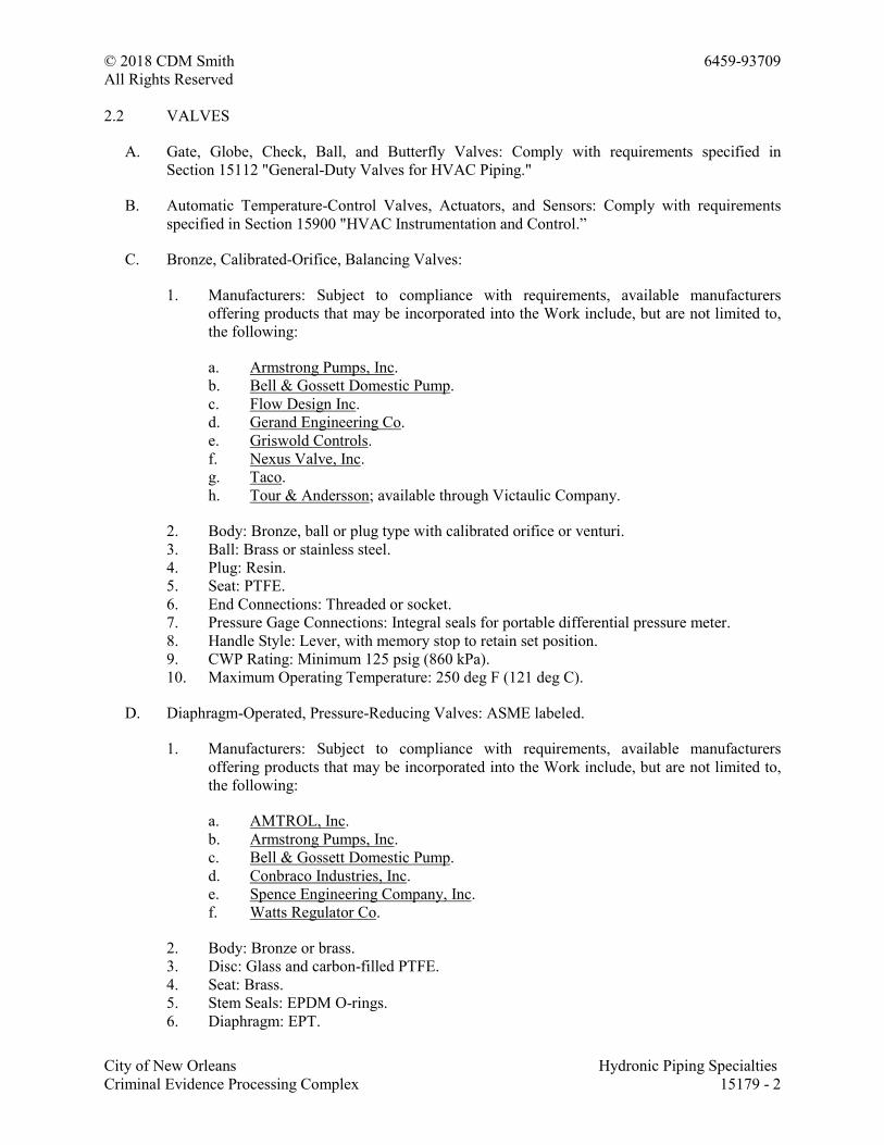
© 2018 CDM Smith 6459-93709
All Rights Reserved
City of New Orleans Hydronic Piping Specialties
Criminal Evidence Processing Complex 15179 - 2
2.2 VALVES
A. Gate, Globe, Check, Ball, and Butterfly Valves: Comply with requirements specified in
Section 15112 "General-Duty Valves for HVAC Piping."
B. Automatic Temperature-Control Valves, Actuators, and Sensors: Comply with requirements
specified in Section 15900 "HVAC Instrumentation and Control.”
C. Bronze, Calibrated-Orifice, Balancing Valves:
1. Manufacturers: Subject to compliance with requirements, available manufacturers
offering products that may be incorporated into the Work include, but are not limited to,
the following:
a. Armstrong Pumps, Inc.
b. Bell & Gossett Domestic Pump.
c. Flow Design Inc.
d. Gerand Engineering Co.
e. Griswold Controls.
f. Nexus Valve, Inc.
g. Taco.
h. Tour & Andersson; available through Victaulic Company.
2. Body: Bronze, ball or plug type with calibrated orifice or venturi.
3. Ball: Brass or stainless steel.
4. Plug: Resin.
5. Seat: PTFE.
6. End Connections: Threaded or socket.
7. Pressure Gage Connections: Integral seals for portable differential pressure meter.
8. Handle Style: Lever, with memory stop to retain set position.
9. CWP Rating: Minimum 125 psig (860 kPa).
10. Maximum Operating Temperature: 250 deg F (121 deg C).
D. Diaphragm-Operated, Pressure-Reducing Valves: ASME labeled.
1. Manufacturers: Subject to compliance with requirements, available manufacturers
offering products that may be incorporated into the Work include, but are not limited to,
the following:
a. AMTROL, Inc.
b. Armstrong Pumps, Inc.
c. Bell & Gossett Domestic Pump.
d. Conbraco Industries, Inc.
e. Spence Engineering Company, Inc.
f. Watts Regulator Co.
2. Body: Bronze or brass.
3. Disc: Glass and carbon-filled PTFE.
4. Seat: Brass.
5. Stem Seals: EPDM O-rings.
6. Diaphragm: EPT.
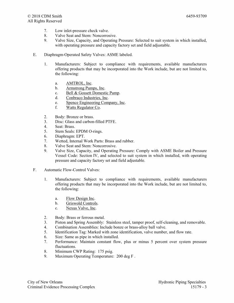
© 2018 CDM Smith 6459-93709
All Rights Reserved
City of New Orleans Hydronic Piping Specialties
Criminal Evidence Processing Complex 15179 - 3
7. Low inlet-pressure check valve.
8. Valve Seat and Stem: Noncorrosive.
9. Valve Size, Capacity, and Operating Pressure: Selected to suit system in which installed,
with operating pressure and capacity factory set and field adjustable.
E. Diaphragm-Operated Safety Valves: ASME labeled.
1. Manufacturers: Subject to compliance with requirements, available manufacturers
offering products that may be incorporated into the Work include, but are not limited to,
the following:
a. AMTROL, Inc.
b. Armstrong Pumps, Inc.
c. Bell & Gossett Domestic Pump.
d. Conbraco Industries, Inc.
e. Spence Engineering Company, Inc.
f. Watts Regulator Co.
2. Body: Bronze or brass.
3. Disc: Glass and carbon-filled PTFE.
4. Seat: Brass.
5. Stem Seals: EPDM O-rings.
6. Diaphragm: EPT.
7. Wetted, Internal Work Parts: Brass and rubber.
8. Valve Seat and Stem: Noncorrosive.
9. Valve Size, Capacity, and Operating Pressure: Comply with ASME Boiler and Pressure
Vessel Code: Section IV, and selected to suit system in which installed, with operating
pressure and capacity factory set and field adjustable.
F. Automatic Flow-Control Valves:
1. Manufacturers: Subject to compliance with requirements, available manufacturers
offering products that may be incorporated into the Work include, but are not limited to,
the following:
a. Flow Design Inc.
b. Griswold Controls.
c. Nexus Valve, Inc.
2. Body: Brass or ferrous metal.
3. Piston and Spring Assembly: Stainless steel, tamper proof, self-cleaning, and removable.
4. Combination Assemblies: Include bonze or brass-alloy ball valve.
5. Identification Tag: Marked with zone identification, valve number, and flow rate.
6. Size: Same as pipe in which installed.
7. Performance: Maintain constant flow, plus or minus 5 percent over system pressure
fluctuations.
8. Minimum CWP Rating: 175 psig.
9. Maximum Operating Temperature: 200 deg F .
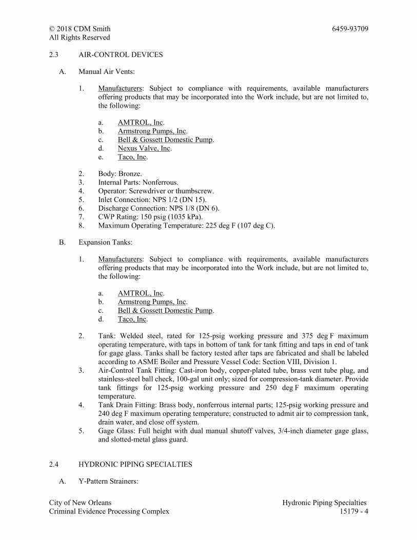
© 2018 CDM Smith 6459-93709
All Rights Reserved
City of New Orleans Hydronic Piping Specialties
Criminal Evidence Processing Complex 15179 - 4
2.3 AIR-CONTROL DEVICES
A. Manual Air Vents:
1. Manufacturers: Subject to compliance with requirements, available manufacturers
offering products that may be incorporated into the Work include, but are not limited to,
the following:
a. AMTROL, Inc.
b. Armstrong Pumps, Inc.
c. Bell & Gossett Domestic Pump.
d. Nexus Valve, Inc.
e. Taco, Inc.
2. Body: Bronze.
3. Internal Parts: Nonferrous.
4. Operator: Screwdriver or thumbscrew.
5. Inlet Connection: NPS 1/2 (DN 15).
6. Discharge Connection: NPS 1/8 (DN 6).
7. CWP Rating: 150 psig (1035 kPa).
8. Maximum Operating Temperature: 225 deg F (107 deg C).
B. Expansion Tanks:
1. Manufacturers: Subject to compliance with requirements, available manufacturers
offering products that may be incorporated into the Work include, but are not limited to,
the following:
a. AMTROL, Inc.
b. Armstrong Pumps, Inc.
c. Bell & Gossett Domestic Pump.
d. Taco, Inc.
2. Tank: Welded steel, rated for 125-psig working pressure and 375 deg F maximum
operating temperature, with taps in bottom of tank for tank fitting and taps in end of tank
for gage glass. Tanks shall be factory tested after taps are fabricated and shall be labeled
according to ASME Boiler and Pressure Vessel Code: Section VIII, Division 1.
3. Air-Control Tank Fitting: Cast-iron body, copper-plated tube, brass vent tube plug, and
stainless-steel ball check, 100-gal unit only; sized for compression-tank diameter. Provide
tank fittings for 125-psig working pressure and 250 deg F maximum operating
temperature.
4. Tank Drain Fitting: Brass body, nonferrous internal parts; 125-psig working pressure and
240 deg F maximum operating temperature; constructed to admit air to compression tank,
drain water, and close off system.
5. Gage Glass: Full height with dual manual shutoff valves, 3/4-inch diameter gage glass,
and slotted-metal glass guard.
2.4 HYDRONIC PIPING SPECIALTIES
A. Y-Pattern Strainers:
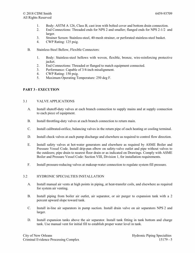
© 2018 CDM Smith 6459-93709
All Rights Reserved
City of New Orleans Hydronic Piping Specialties
Criminal Evidence Processing Complex 15179 - 5
1. Body: ASTM A 126, Class B, cast iron with bolted cover and bottom drain connection.
2. End Connections: Threaded ends for NPS 2 and smaller; flanged ends for NPS 2-1/2 and
larger.
3. Strainer Screen: Stainless-steel, 40-mesh strainer, or perforated stainless-steel basket.
4. CWP Rating: 125 psig.
B. Stainless-Steel Bellow, Flexible Connectors:
1. Body: Stainless-steel bellows with woven, flexible, bronze, wire-reinforcing protective
jacket.
2. End Connections: Threaded or flanged to match equipment connected.
3. Performance: Capable of 3/4-inch misalignment.
4. CWP Rating: 150 psig.
5. Maximum Operating Temperature: 250 deg F.
PART 3 - EXECUTION
3.1 VALVE APPLICATIONS
A. Install shutoff-duty valves at each branch connection to supply mains and at supply connection
to each piece of equipment.
B. Install throttling-duty valves at each branch connection to return main.
C. Install calibrated-orifice, balancing valves in the return pipe of each heating or cooling terminal.
D. Install check valves at each pump discharge and elsewhere as required to control flow direction.
E. Install safety valves at hot-water generators and elsewhere as required by ASME Boiler and
Pressure Vessel Code. Install drip-pan elbow on safety-valve outlet and pipe without valves to
the outdoors; pipe drain to nearest floor drain or as indicated on Drawings. Comply with ASME
Boiler and Pressure Vessel Code: Section VIII, Division 1, for installation requirements.
F. Install pressure-reducing valves at makeup-water connection to regulate system fill pressure.
3.2 HYDRONIC SPECIALTIES INSTALLATION
A. Install manual air vents at high points in piping, at heat-transfer coils, and elsewhere as required
for system air venting.
B. Install piping from boiler air outlet, air separator, or air purger to expansion tank with a 2
percent upward slope toward tank.
C. Install in-line air separators in pump suction. Install drain valve on air separators NPS 2 and
larger.
D. Install expansion tanks above the air separator. Install tank fitting in tank bottom and charge
tank. Use manual vent for initial fill to establish proper water level in tank.
© 2018 CDM Smith 6459-93709
All Rights Reserved
City of New Orleans Hydronic Piping Specialties
Criminal Evidence Processing Complex 15179 - 6
1. Install tank fittings that are shipped loose.
2. Support tank from floor or structure above with sufficient strength to carry weight of
tank, piping connections, fittings, plus tank full of water. Do not overload building
components and structural members.
E. Install expansion tanks on the floor. Vent and purge air from hydronic system, and ensure that
tank is properly charged with air to suit system Project requirements.
END OF SECTION 15179
© 2018 CDM Smith 6459-93709
All Rights Reserved
City of New Orleans Hydronic Piping
Criminal Evidence Processing Complex 15181 - 1
SECTION 15181 - HYDRONIC PIPING
PART 1 - GENERAL
1.1 SUMMARY
A. Section includes pipe and fitting materials and joining methods for the following:
1. Chilled-water piping.
2. Makeup-water piping.
3. Condensate-drain piping.
1.2 ACTION SUBMITTALS
A. Product Data: For each type of the following:
1. Plastic pipe and fittings with solvent cement.
2. RTRP and RTRF with adhesive.
3. Pressure-seal fittings.
4. Chemical treatment.
1.3 INFORMATIONAL SUBMITTALS
A. Field quality-control reports.
1.4 QUALITY ASSURANCE
A. ASME Compliance: Comply with ASME B31.9, "Building Services Piping," for materials,
products, and installation.
PART 2 - PRODUCTS
2.1 PERFORMANCE REQUIREMENTS
A. Hydronic piping components and installation shall be capable of withstanding the following
minimum working pressure and temperature unless otherwise indicated:
1. Hot-Water Heating Piping: 150psig at 200 deg F.
2. Chilled-Water Piping: 150psig at 200 deg F.
3. Makeup-Water Piping: 80 psig at 150 deg F.
© 2018 CDM Smith 6459-93709
All Rights Reserved
City of New Orleans Hydronic Piping
Criminal Evidence Processing Complex 15181 - 2
2.2 COPPER TUBE AND FITTINGS
A. Drawn-Temper Copper Tubing: ASTM B 88, Type L.
B. Annealed-Temper Copper Tubing: ASTM B 88, Type K.
C. DWV Copper Tubing: ASTM B 306, Type DWV.
D. Wrought-Copper Unions: ASME B16.22.
2.3 STEEL PIPE AND FITTINGS
A. Steel Pipe: ASTM A 53/A 53M, black steel with plain ends; welded and seamless, Grade B, and
wall thickness as indicated in "Piping Applications" Article.
B. Malleable-Iron Unions: ASME B16.39; Classes 150, 250, and 300 as indicated in "Piping
Applications" Article.
C. Cast-Iron Pipe Flanges and Flanged Fittings: ASME B16.1, Classes 25, 125, and 250; raised
ground face, and bolt holes spot faced as indicated in "Piping Applications" Article.
D. Wrought Cast- and Forged-Steel Flanges and Flanged Fittings: ASME B16.5, including bolts,
nuts, and gaskets of the following material group, end connections, and facings:
1. Material Group: 1.1.
2. End Connections: Butt welding.
3. Facings: Raised face.
E. Grooved Mechanical-Joint Fittings and Couplings:
1. Manufacturers: Subject to compliance with requirements, available manufacturers
offering products that may be incorporated into the Work include, but are not limited to,
the following:
a. Anvil International, Inc.
b. Central Sprinkler Company.
c. Star Pipe Products.
d. Victaulic Company.
2. Joint Fittings: ASTM A 536, Grade 65-45-12 ductile iron; ASTM A 47/A 47M,
Grade 32510 malleable iron; ASTM A 53/A 53M, Type F, E, or S, Grade B fabricated
steel; or ASTM A 106/A 106M, Grade B steel fittings with grooves or shoulders
constructed to accept grooved-end couplings; with nuts, bolts, locking pin, locking
toggle, or lugs to secure grooved pipe and fittings.
3. Couplings: Ductile- or malleable-iron housing and EPDM gasket of central cavity
pressure-responsive design; with nuts, bolts, locking pin, locking toggle, or lugs to secure
grooved pipe and fittings.
© 2018 CDM Smith 6459-93709
All Rights Reserved
City of New Orleans Hydronic Piping
Criminal Evidence Processing Complex 15181 - 3
2.4 JOINING MATERIALS
A. Pipe-Flange Gasket Materials: Suitable for chemical and thermal conditions of piping system
contents.
1. ASME B16.21, nonmetallic, flat, asbestos free, 1/8-inch maximum thickness unless
otherwise indicated.
a. Full-Face Type: For flat-face, Class 125, cast-iron and cast-bronze flanges.
b. Narrow-Face Type: For raised-face, Class 250, cast-iron and steel flanges.
B. Flange Bolts and Nuts: ASME B18.2.1, carbon steel, unless otherwise indicated.
C. Solder Filler Metals: ASTM B 32, lead-free alloys. Include water-flushable flux according to
ASTM B 813.
D. Brazing Filler Metals: AWS A5.8/A5.8M, BCuP Series, copper-phosphorus alloys for joining
copper with copper; or BAg-1, silver alloy for joining copper with bronze or steel.
E. Welding Filler Metals: Comply with AWS D10.12M/D10.12 for welding materials appropriate
for wall thickness and chemical analysis of steel pipe being welded.
F. Gasket Material: Thickness, material, and type suitable for fluid to be handled and working
temperatures and pressures.
2.5 DIELECTRIC FITTINGS
A. General Requirements: Assembly of copper alloy and ferrous materials with separating
nonconductive insulating material. Include end connections compatible with pipes to be joined.
B. Dielectric Unions:
1. Manufacturers: Subject to compliance with requirements, available manufacturers
offering products that may be incorporated into the Work include, but are not limited to,
the following:
a. A.Y. McDonald Mfg. Co.
b. Capitol Manufacturing Company.
c. Central Plastics Company.
d. Hart Industries International, Inc.
e. Jomar International, Ltd.
f. Matco-Norca.
g. Watts Regulator Co.
h. Zurn Industries, LLC; AquaSpec Commercial Faucet Products.
2. Description:
a. Standard: ASSE 1079.
b. Pressure Rating: 150 psig.
c. End Connections: Solder-joint copper alloy and threaded ferrous.
© 2018 CDM Smith 6459-93709
All Rights Reserved
City of New Orleans Hydronic Piping
Criminal Evidence Processing Complex 15181 - 4
2.6 BYPASS CHEMICAL FEEDER
A. Description: Welded steel construction; 125-psig working pressure; 5-gal. capacity; with fill
funnel and inlet, outlet, and drain valves.
1. Chemicals: Specially formulated, based on analysis of makeup water, to prevent
accumulation of scale and corrosion in piping and connected equipment.
PART 3 - EXECUTION
3.1 PIPING APPLICATIONS
A. Chilled-water piping, aboveground, NPS 2and smaller, shall be any of the following:
1. Type L, drawn-temper copper tubing, wrought-copper fittings, and soldered joints.
2. Schedule 40 steel pipe; Class 150, malleable-iron fittings; cast-iron flanges and flange
fittings; and threaded joints.
B. Chilled-water piping, aboveground, NPS 2-1/2 and larger, shall be the following:
1. Schedule 40 steel pipe; grooved, mechanical joint coupling and fittings; and grooved,
mechanical joints.
C. Makeup-water piping installed aboveground shall be the following:
1. Type L, drawn-temper copper tubing, wrought-copper fittings, and soldered joints.
D. Condensate-Drain Piping: Schedule 40 PVC plastic pipe and fittings and solvent-welded joints.
3.2 PIPING INSTALLATIONS
A. Drawing plans, schematics, and diagrams indicate general location and arrangement of piping
systems. Install piping as indicated unless deviations to layout are approved on Coordination
Drawings.
B. Install piping in concealed locations unless otherwise indicated and except in equipment rooms
and service areas.
C. Install piping indicated to be exposed and piping in equipment rooms and service areas at right
angles or parallel to building walls. Diagonal runs are prohibited unless specifically indicated
otherwise.
D. Install piping above accessible ceilings to allow sufficient space for ceiling panel removal.
E. Install piping to permit valve servicing.
F. Install piping at indicated slopes.
© 2018 CDM Smith 6459-93709
All Rights Reserved
City of New Orleans Hydronic Piping
Criminal Evidence Processing Complex 15181 - 5
G. Install piping free of sags and bends.
H. Install fittings for changes in direction and branch connections.
I. Install piping to allow application of insulation.
J. Select system components with pressure rating equal to or greater than system operating
pressure.
K. Install groups of pipes parallel to each other, spaced to permit applying insulation and servicing
of valves.
L. Install drains, consisting of a tee fitting, NPS 3/4 ball valve, and short NPS 3/4threaded nipple
with cap, at low points in piping system mains and elsewhere as required for system drainage.
M. Install piping at a uniform grade of 0.2 percent upward in direction of flow.
N. Reduce pipe sizes using eccentric reducer fitting installed with level side up.
O. Install branch connections to mains using mechanically formed tee fittings in main pipe, with
the branch connected to the bottom of the main pipe. For up-feed risers, connect the branch to
the top of the main pipe.
P. Install valves according to Section 15112 "General-Duty Valves for HVAC Piping."
Q. Install unions in piping, NPS 2 and smaller, adjacent to valves, at final connections of
equipment, and elsewhere as indicated.
R. Install flanges in piping, NPS 2-1/2 and larger, at final connections of equipment and elsewhere
as indicated.
S. Install shutoff valve immediately upstream of each dielectric fitting.
T. Comply with requirements in Section 15077 "Identification for HVAC Piping and Equipment"
for identifying piping.
U. Install sleeves for piping penetrations of walls, ceilings, and floors. Comply with requirements
for sleeves specified in Section 15093 "Sleeves and Sleeve Seals for HVAC Piping."
V. Install sleeve seals for piping penetrations of concrete walls and slabs. Comply with
requirements for sleeve seals specified in Section 15093 "Sleeves and Sleeve Seals for HVAC
Piping."
W. Install escutcheons for piping penetrations of walls, ceilings, and floors. Comply with
requirements for escutcheons specified in Section 15098 "Escutcheons for HVAC Piping."
3.3 DIELECTRIC FITTING INSTALLATION
A. Install dielectric fittings in piping at connections of dissimilar metal piping and tubing.
B. Dielectric Fittings for NPS 2 and Smaller: Use dielectric unions.
© 2018 CDM Smith 6459-93709
All Rights Reserved
City of New Orleans Hydronic Piping
Criminal Evidence Processing Complex 15181 - 6
C. Dielectric Fittings for NPS 2-1/2 to NPS 4: Use dielectric flanges.
D. Dielectric Fittings for NPS 5 and Larger: Use dielectric flange kits.
3.4 HANGERS AND SUPPORTS
A. Comply with requirements in Section 15062 "Hangers and Supports for HVAC Piping and
Equipment" for hanger, support, and anchor devices. Comply with the following requirements
for maximum spacing of supports.
B. Install the following pipe attachments:
1. Adjustable steel clevis hangers for individual horizontal piping less than 20 feetlong.
2. Adjustable roller hangers and spring hangers for individual horizontal piping 20 feet or
longer.
3. Pipe Roller: MSS SP-58, Type 44 for multiple horizontal piping 20 feetor longer,
supported on a trapeze.
4. Spring hangers to support vertical runs.
5. Provide copper-clad hangers and supports for hangers and supports in direct contact with
copper pipe.
6. On plastic pipe, install pads or cushions on bearing surfaces to prevent hanger from
scratching pipe.
C. Install hangers for steel piping with the following maximum spacing and minimum rod sizes:
1. NPS 3/4: Maximum span, 7 feet.
2. NPS 1: Maximum span, 7 feet.
3. NPS 1-1/2: Maximum span, 9 feet.
4. NPS 2: Maximum span, 10 feet.
5. NPS 2-1/2: Maximum span, 11 feet.
6. NPS 3 and Larger: Maximum span, 12 feet.
D. Install hangers for drawn-temper copper piping with the following maximum spacing and
minimum rod sizes:
1. NPS 3/4: Maximum span, 5 feet; minimum rod size, 1/4 inch.
2. NPS 1: Maximum span, 6 feet; minimum rod size, 1/4 inch.
3. NPS 1-1/4:Maximum span, 7 feet; minimum rod size, 3/8 inch.
4. NPS 1-1/2: Maximum span, 8 feet; minimum rod size, 3/8 inch.
5. NPS 2: Maximum span, 8 feet; minimum rod size, 3/8 inch.
E. Support vertical runs at roof, at each floor, and at 10-foot intervals between floors.
3.5 PIPE JOINT CONSTRUCTION
A. Ream ends of pipes and tubes and remove burrs. Bevel plain ends of steel pipe.
B. Remove scale, slag, dirt, and debris from inside and outside of pipe and fittings before
assembly.
© 2018 CDM Smith 6459-93709
All Rights Reserved
City of New Orleans Hydronic Piping
Criminal Evidence Processing Complex 15181 - 7
C. Soldered Joints: Apply ASTM B 813, water-flushable flux, unless otherwise indicated, to tube
end. Construct joints according to ASTM B 828 or CDA's "Copper Tube Handbook," using
lead-free solder alloy complying with ASTM B 32.
D. Brazed Joints: Construct joints according to AWS's "Brazing Handbook," "Pipe and Tube"
Chapter, using copper-phosphorus brazing filler metal complying with AWS A5.8/A5.8M.
E. Flanged Joints: Select appropriate gasket material, size, type, and thickness for service
application. Install gasket concentrically positioned. Use suitable lubricants on bolt threads.
F. Grooved Joints: Assemble joints with coupling and gasket, lubricant, and bolts. Cut or roll
grooves in ends of pipe based on pipe and coupling manufacturer's written instructions for pipe
wall thickness. Use grooved-end fittings and rigid, grooved-end-pipe couplings.
G. Mechanically Formed, Copper-Tube-Outlet Joints: Use manufacturer-recommended tool and
procedure, and brazed joints.
3.6 TERMINAL EQUIPMENT CONNECTIONS
A. Sizes for supply and return piping connections shall be the same as or larger than equipment
connections.
B. Install control valves in accessible locations close to connected equipment.
C. Install bypass piping with globe valve around control valve. If parallel control valves are
installed, only one bypass is required.
D. Install ports for pressure gages and thermometers at coil inlet and outlet connections. Comply
with requirements in Section 15172 "Meters and Gages for HVAC Piping."
3.7 CHEMICAL TREATMENT
A. Fill system with fresh water and add liquid alkaline compound with emulsifying agents and
detergents to remove grease and petroleum products from piping. Circulate solution for a
minimum of 24 hours, drain, clean strainer screens, and refill with fresh water.
B. Add initial chemical treatment and maintain water quality in ranges noted above for the first
year of operation.
3.8 FIELD QUALITY CONTROL
A. Prepare hydronic piping according to ASME B31.9 and as follows:
1. Leave joints, including welds, uninsulated and exposed for examination during test.
2. Provide temporary restraints for expansion joints that cannot sustain reactions due to test
pressure. If temporary restraints are impractical, isolate expansion joints from testing.
3. Flush hydronic piping systems with clean water; then remove and clean or replace
strainer screens.
© 2018 CDM Smith 6459-93709
All Rights Reserved
City of New Orleans Hydronic Piping
Criminal Evidence Processing Complex 15181 - 8
4. Isolate equipment from piping. If a valve is used to isolate equipment, its closure shall be
capable of sealing against test pressure without damage to valve. Install blinds in flanged
joints to isolate equipment.
5. Install safety valve, set at a pressure no more than one-third higher than test pressure, to
protect against damage by expanding liquid or other source of overpressure during test.
B. Perform the following tests on hydronic piping:
1. Use ambient temperature water as a testing medium unless there is risk of damage due to
freezing. Another liquid that is safe for workers and compatible with piping may be used.
2. While filling system, use vents installed at high points of system to release air. Use drains
installed at low points for complete draining of test liquid.
3. Isolate expansion tanks and determine that hydronic system is full of water.
4. Subject piping system to hydrostatic test pressure that is not less than 1.5 times the
system's working pressure. Test pressure shall not exceed maximum pressure for any
vessel, pump, valve, or other component in system under test. Verify that stress due to
pressure at bottom of vertical runs does not exceed 90 percent of specified minimum
yield strength or 1.7 times the "SE" value in Appendix A in ASME B31.9, "Building
Services Piping."
5. After hydrostatic test pressure has been applied for at least 10 minutes, examine piping,
joints, and connections for leakage. Eliminate leaks by tightening, repairing, or replacing
components, and repeat hydrostatic test until there are no leaks.
6. Prepare written report of testing.
C. Perform the following before operating the system:
1. Open manual valves fully.
2. Inspect pumps for proper rotation.
3. Set makeup pressure-reducing valves for required system pressure.
4. Inspect air vents at high points of system and determine if all are installed and operating
freely (automatic type), or bleed air completely (manual type).
5. Set temperature controls so all coils are calling for full flow.
6. Inspect and set operating temperatures of hydronic equipment, such as boilers, chillers,
cooling towers, to specified values.
7. Verify lubrication of motors and bearings.
END OF SECTION 15181
© 2018 CDM Smith 6459-93709
All Rights Reserved
City of New Orleans Hydronic Pumps
Criminal Evidence Processing Complex 15185 - 1
SECTION 15185 - HYDRONIC PUMPS
PART 1 - GENERAL
1.1 SUMMARY
A. Section Includes:
1. Close-coupled, end-suction centrifugal pumps.
2. Separately coupled, base-mounted, end-suction centrifugal pumps.
1.2 ACTION SUBMITTALS
A. Product Data: For each type of pump.
B. Shop Drawings: For each pump.
1. Show pump layout and connections.
2. Include setting drawings with templates for installing foundation and anchor bolts and
other anchorages.
3. Include diagrams for power, signal, and control wiring.
1.3 CLOSEOUT SUBMITTALS
A. Operation and maintenance data.
PART 2 - PRODUCTS
2.1 CLOSE-COUPLED, END-SUCTION CENTRIFUGAL PUMPS
A. Manufacturers: Subject to compliance with requirements, available manufacturers offering
products that may be incorporated into the Work include, but are not limited to, the following:
1. American-Marsh Pumps.
2. Armstrong Pumps Inc.
3. Buffalo Pumps, Inc.
4. ITT Corporation; Bell & Gossett.
5. ITT Corporation; Goulds Pumps.
6. Patterson Pump Co.; a subsidiary of the Gorman-Rupp Co.
7. Peerless Pump Company.
8. TACO Incorporated.
B. Description: Factory-assembled and -tested, centrifugal, overhung-impeller, close-coupled, end-
suction pump as defined in HI 1.1-1.2 and HI 1.3; designed for installation with pump and
motor shafts mounted horizontally.
© 2018 CDM Smith 6459-93709
All Rights Reserved
City of New Orleans Hydronic Pumps
Criminal Evidence Processing Complex 15185 - 2
C. Pump Construction:
1. Casing: Radially split, cast iron, with replaceable bronze wear rings, drain plug at bottom
and air vent at top of volute, threaded gage tappings at inlet and outlet, and flanged
connections.
2. Impeller: ASTM B 584, cast bronze; statically and dynamically balanced, keyed to shaft,
and secured with a locking cap screw. For constant-speed pumps, trim impeller to match
specified performance.
3. Pump Shaft: Stainless steel.
4. Mechanical Seal: Carbon rotating ring against a ceramic seat held by a stainless-steel
spring, and Buna-N bellows and gasket. Include water slinger on shaft between motor
and seal.
5. Pump Bearings: Permanently lubricated ball bearings.
D. Motor: Single speed and rigidly mounted to pump casing with integral pump support.
1. Electrical Components, Devices, and Accessories: Listed and labeled as defined in
NFPA 70, by a qualified testing agency, and marked for intended location and
application.
2. Comply with NEMA designation, temperature rating, service factor, and efficiency
requirements for motors specified in Section 15058 "Common Motor Requirements for
HVAC Equipment."
a. Enclosure: Totally enclosed, fan cooled.
b. Enclosure Materials: Cast iron.
c. Motor Bearings: Grease-lubricated ball bearings.
d. Efficiency: Premium efficient.
e. NEMA Design: 4.
f. Service Factor: 1.15.
E. Capacities and Characteristics:
1. Capacity: 240.
2. Total Dynamic Head: 64.
3. Maximum Operating Pressure: 175 psig.
4. Maximum Continuous Operating Temperature: 225 deg F.
5. Motor Horsepower: 10.
6. Electrical Characteristics:
a. Volts: 460.
b. Phase: Three.
c. Hertz: 60.
2.2 SEPARATELY COUPLED, BASE-MOUNTED, END-SUCTION CENTRIFUGAL PUMPS
A. Manufacturers: Subject to compliance with requirements, available manufacturers offering
products that may be incorporated into the Work include, but are not limited to, the following:
1. American-Marsh Pumps.
2. Armstrong Pumps Inc.
3. Aurora Pump; Division of Pentair Pump Group.
© 2018 CDM Smith 6459-93709
All Rights Reserved
City of New Orleans Hydronic Pumps
Criminal Evidence Processing Complex 15185 - 3
4. ITT Corporation; Bell & Gossett.
5. Peerless Pump Company.
6. Scot Pump; Div. of Ardox Corp.
7. TACO Incorporated.
B. Description: Factory-assembled and -tested, centrifugal, overhung-impeller, separately coupled,
end-suction pump as defined in HI 1.1-1.2 and HI 1.3; designed for base mounting, with pump
and motor shafts horizontal.
C. Pump Construction:
1. Casing: Radially split, cast iron, with replaceable bronze wear rings, threaded gage
tappings at inlet and outlet, drain plug at bottom and air vent at top of volute, and flanged
connections. Provide integral mount on volute to support the casing, and provide attached
piping to allow removal and replacement of impeller without disconnecting piping or
requiring the realignment of pump and motor shaft.
2. Impeller: ASTM B 584, cast bronze; statically and dynamically balanced, keyed to shaft,
and secured with a locking cap screw. For pumps not frequency-drive controlled, trim
impeller to match specified performance.
3. Pump Shaft: Stainless steel.
4. Seal: Mechanical seal consisting of carbon rotating ring against a ceramic seat held by a
stainless-steel spring, and Buna-N bellows and gasket.
5. Seal: Packing seal consisting of stuffing box with a minimum of four rings of graphite-
impregnated braided yarn with bronze lantern ring between center two graphite rings, and
bronze packing gland.
6. Pump Bearings: Grease-lubricated ball bearings in cast-iron housing with grease fittings.
D. Shaft Coupling: Molded-rubber insert and interlocking spider capable of absorbing vibration.
Couplings shall be drop-out type to allow disassembly and removal without removing pump
shaft or motor. EPDM coupling sleeve for variable-speed applications.
E. Coupling Guard: Dual rated; ANSI B15.1, Section 8; OSHA 1910.219 approved; steel;
removable; attached to mounting frame.
F. Mounting Frame: Welded-steel frame and cross members, factory fabricated from
ASTM A 36/A 36M channels and angles. Fabricate to mount pump casing, coupling guard, and
motor.
G. Motor: Single speed, secured to mounting frame, with adjustable alignment.
1. Electrical Components, Devices, and Accessories: Listed and labeled as defined in
NFPA 70, by a qualified testing agency, and marked for intended location and
application.
2. Comply with NEMA designation, temperature rating, service factor, and efficiency
requirements for motors specified in Section 15058 "Common Motor Requirements for
HVAC Equipment."
a. Enclosure: Totally enclosed, fan cooled.
b. Enclosure Materials: Cast iron.
c. Motor Bearings: Grease-lubricated ball bearings.
d. Efficiency: Premium efficient.
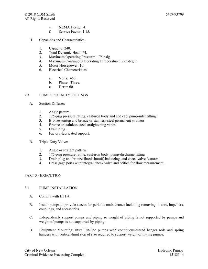
© 2018 CDM Smith 6459-93709
All Rights Reserved
City of New Orleans Hydronic Pumps
Criminal Evidence Processing Complex 15185 - 4
e. NEMA Design: 4.
f. Service Factor: 1.15.
H. Capacities and Characteristics:
1. Capacity: 240.
2. Total Dynamic Head: 64.
3. Maximum Operating Pressure: 175 psig.
4. Maximum Continuous Operating Temperature: 225 deg F.
5. Motor Horsepower: 10.
6. Electrical Characteristics:
a. Volts: 460.
b. Phase: Three.
c. Hertz: 60.
2.3 PUMP SPECIALTY FITTINGS
A. Suction Diffuser:
1. Angle pattern.
2. 175-psig pressure rating, cast-iron body and end cap, pump-inlet fitting.
3. Bronze startup and bronze or stainless-steel permanent strainers.
4. Bronze or stainless-steel straightening vanes.
5. Drain plug.
6. Factory-fabricated support.
B. Triple-Duty Valve:
1. Angle or straight pattern.
2. 175-psig pressure rating, cast-iron body, pump-discharge fitting.
3. Drain plug and bronze-fitted shutoff, balancing, and check valve features.
4. Brass gage ports with integral check valve and orifice for flow measurement.
PART 3 - EXECUTION
3.1 PUMP INSTALLATION
A. Comply with HI 1.4.
B. Install pumps to provide access for periodic maintenance including removing motors, impellers,
couplings, and accessories.
C. Independently support pumps and piping so weight of piping is not supported by pumps and
weight of pumps is not supported by piping.
D. Equipment Mounting: Install in-line pumps with continuous-thread hanger rods and spring
hangers with vertical-limit stop of size required to support weight of in-line pumps.
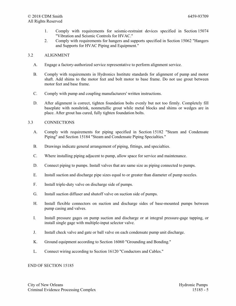
© 2018 CDM Smith 6459-93709
All Rights Reserved
City of New Orleans Hydronic Pumps
Criminal Evidence Processing Complex 15185 - 5
1. Comply with requirements for seismic-restraint devices specified in Section 15074
"Vibration and Seismic Controls for HVAC."
2. Comply with requirements for hangers and supports specified in Section 15062 "Hangers
and Supports for HVAC Piping and Equipment."
3.2 ALIGNMENT
A. Engage a factory-authorized service representative to perform alignment service.
B. Comply with requirements in Hydronics Institute standards for alignment of pump and motor
shaft. Add shims to the motor feet and bolt motor to base frame. Do not use grout between
motor feet and base frame.
C. Comply with pump and coupling manufacturers' written instructions.
D. After alignment is correct, tighten foundation bolts evenly but not too firmly. Completely fill
baseplate with nonshrink, nonmetallic grout while metal blocks and shims or wedges are in
place. After grout has cured, fully tighten foundation bolts.
3.3 CONNECTIONS
A. Comply with requirements for piping specified in Section 15182 "Steam and Condensate
Piping" and Section 15184 "Steam and Condensate Piping Specialties."
B. Drawings indicate general arrangement of piping, fittings, and specialties.
C. Where installing piping adjacent to pump, allow space for service and maintenance.
D. Connect piping to pumps. Install valves that are same size as piping connected to pumps.
E. Install suction and discharge pipe sizes equal to or greater than diameter of pump nozzles.
F. Install triple-duty valve on discharge side of pumps.
G. Install suction diffuser and shutoff valve on suction side of pumps.
H. Install flexible connectors on suction and discharge sides of base-mounted pumps between
pump casing and valves.
I. Install pressure gages on pump suction and discharge or at integral pressure-gage tapping, or
install single gage with multiple-input selector valve.
J. Install check valve and gate or ball valve on each condensate pump unit discharge.
K. Ground equipment according to Section 16060 "Grounding and Bonding."
L. Connect wiring according to Section 16120 "Conductors and Cables."
END OF SECTION 15185
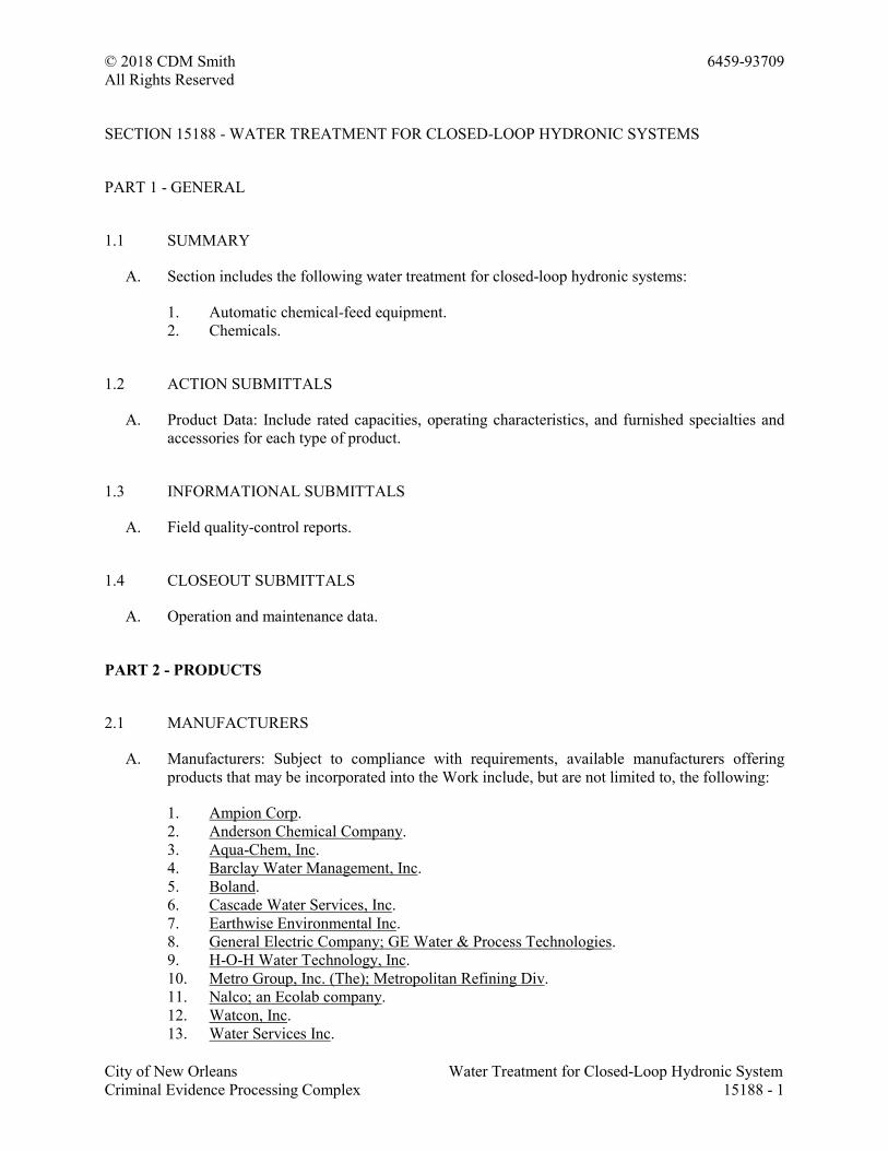
© 2018 CDM Smith 6459-93709
All Rights Reserved
City of New Orleans Water Treatment for Closed-Loop Hydronic System
Criminal Evidence Processing Complex 15188 - 1
SECTION 15188 - WATER TREATMENT FOR CLOSED-LOOP HYDRONIC SYSTEMS
PART 1 - GENERAL
1.1 SUMMARY
A. Section includes the following water treatment for closed-loop hydronic systems:
1. Automatic chemical-feed equipment.
2. Chemicals.
1.2 ACTION SUBMITTALS
A. Product Data: Include rated capacities, operating characteristics, and furnished specialties and
accessories for each type of product.
1.3 INFORMATIONAL SUBMITTALS
A. Field quality-control reports.
1.4 CLOSEOUT SUBMITTALS
A. Operation and maintenance data.
PART 2 - PRODUCTS
2.1 MANUFACTURERS
A. Manufacturers: Subject to compliance with requirements, available manufacturers offering
products that may be incorporated into the Work include, but are not limited to, the following:
1. Ampion Corp.
2. Anderson Chemical Company.
3. Aqua-Chem, Inc.
4. Barclay Water Management, Inc.
5. Boland.
6. Cascade Water Services, Inc.
7. Earthwise Environmental Inc.
8. General Electric Company; GE Water & Process Technologies.
9. H-O-H Water Technology, Inc.
10. Metro Group, Inc. (The); Metropolitan Refining Div.
11. Nalco; an Ecolab company.
12. Watcon, Inc.
13. Water Services Inc.
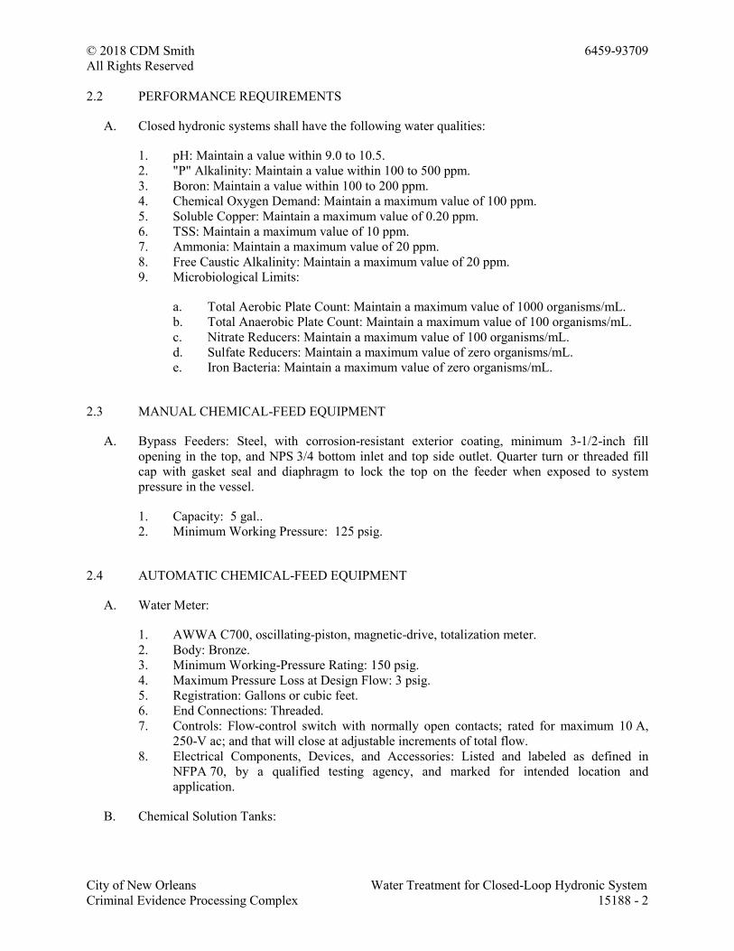
© 2018 CDM Smith 6459-93709
All Rights Reserved
City of New Orleans Water Treatment for Closed-Loop Hydronic System
Criminal Evidence Processing Complex 15188 - 2
2.2 PERFORMANCE REQUIREMENTS
A. Closed hydronic systems shall have the following water qualities:
1. pH: Maintain a value within 9.0 to 10.5.
2. "P" Alkalinity: Maintain a value within 100 to 500 ppm.
3. Boron: Maintain a value within 100 to 200 ppm.
4. Chemical Oxygen Demand: Maintain a maximum value of 100 ppm.
5. Soluble Copper: Maintain a maximum value of 0.20 ppm.
6. TSS: Maintain a maximum value of 10 ppm.
7. Ammonia: Maintain a maximum value of 20 ppm.
8. Free Caustic Alkalinity: Maintain a maximum value of 20 ppm.
9. Microbiological Limits:
a. Total Aerobic Plate Count: Maintain a maximum value of 1000 organisms/mL.
b. Total Anaerobic Plate Count: Maintain a maximum value of 100 organisms/mL.
c. Nitrate Reducers: Maintain a maximum value of 100 organisms/mL.
d. Sulfate Reducers: Maintain a maximum value of zero organisms/mL.
e. Iron Bacteria: Maintain a maximum value of zero organisms/mL.
2.3 MANUAL CHEMICAL-FEED EQUIPMENT
A. Bypass Feeders: Steel, with corrosion-resistant exterior coating, minimum 3-1/2-inch fill
opening in the top, and NPS 3/4 bottom inlet and top side outlet. Quarter turn or threaded fill
cap with gasket seal and diaphragm to lock the top on the feeder when exposed to system
pressure in the vessel.
1. Capacity: 5 gal..
2. Minimum Working Pressure: 125 psig.
2.4 AUTOMATIC CHEMICAL-FEED EQUIPMENT
A. Water Meter:
1. AWWA C700, oscillating-piston, magnetic-drive, totalization meter.
2. Body: Bronze.
3. Minimum Working-Pressure Rating: 150 psig.
4. Maximum Pressure Loss at Design Flow: 3 psig.
5. Registration: Gallons or cubic feet.
6. End Connections: Threaded.
7. Controls: Flow-control switch with normally open contacts; rated for maximum 10 A,
250-V ac; and that will close at adjustable increments of total flow.
8. Electrical Components, Devices, and Accessories: Listed and labeled as defined in
NFPA 70, by a qualified testing agency, and marked for intended location and
application.
B. Chemical Solution Tanks:
© 2018 CDM Smith 6459-93709
All Rights Reserved
City of New Orleans Water Treatment for Closed-Loop Hydronic System
Criminal Evidence Processing Complex 15188 - 3
1. Chemical-resistant reservoirs fabricated from high-density opaque polyethylene with
minimum 110 percent containment vessel.
2. Molded cover with recess for mounting pump.
3. Capacity: 30 gal..
C. Chemical Solution Injection Pumps:
1. Self-priming, positive displacement; rated for intended chemical with minimum 25
percent safety factor for design pressure and temperature.
2. Adjustable flow rate.
3. Metal and thermoplastic construction.
4. Built-in relief valve.
5. Fully enclosed, continuous-duty, single-phase motor. Comply with requirements in
Section 230513 "Common Motor Requirements for HVAC Equipment."
6. Electrical Components, Devices, and Accessories: Listed and labeled as defined in
NFPA 70, by a qualified testing agency, and marked for intended location and
application.
D. Chemical Solution Tubing: Polyethylene tubing with compression fittings and joints except
ASTM A 269, Type 304, stainless steel for steam boiler injection assemblies.
E. Injection Assembly:
1. Quill: Minimum NPS 1/2 with insertion length sufficient to discharge into at least 25
percent of pipe diameter.
2. Ball Valve: Two-piece, stainless steel; selected to fit quill.
3. Packing Gland: Mechanical seal on quill of sufficient length to allow quill removal
during system operation.
4. Assembly Pressure/Temperature Rating: Minimum 600 psig at 200 deg F.
2.5 CHEMICALS
A. Chemicals shall be as recommended by water-treatment system manufacturer that are
compatible with piping system components and connected equipment and that can attain water
quality specified in "Performance Requirements" Article.
PART 3 - EXECUTION
3.1 WATER ANALYSIS
A. Perform an analysis of supply water to determine quality of water available at Project site.
3.2 INSTALLATION
A. Install chemical application equipment on concrete bases, level and plumb. Maintain
manufacturer's recommended clearances. Arrange units so controls and devices that require
servicing are accessible. Anchor chemical tanks and floor-mounting accessories to substrate.
© 2018 CDM Smith 6459-93709
All Rights Reserved
City of New Orleans Water Treatment for Closed-Loop Hydronic System
Criminal Evidence Processing Complex 15188 - 4
B. Install seismic restraints for equipment and floor-mounting accessories and anchor to building
structure. Comply with requirements in Section 230548 "Vibration and Seismic Controls for
HVAC" for seismic restraints.
C. Install water testing equipment on wall near water chemical application equipment.
D. Install interconnecting control wiring for chemical treatment controls and sensors.
E. Mount sensors and injectors in piping circuits.
F. Bypass Feeders: Install in closed hydronic systems, including hot-water heating and chilled
water, and equipped with the following:
1. Install bypass feeder in a bypass circuit around circulating pumps unless otherwise
indicated on Drawings.
2. Install water meter in makeup-water supply.
3. Install test-coupon assembly in bypass circuit around circulating pumps unless otherwise
indicated on Drawings.
4. Install a gate or full-port ball isolation valves on inlet, outlet, and drain below the feeder
inlet.
5. Install a swing check on the inlet after the isolation valve.
G. Where installing piping adjacent to equipment, allow space for service and maintenance.
H. Make piping connections between HVAC water-treatment equipment and dissimilar-metal
piping with dielectric fittings. Comply with requirements in Section 232116 "Hydronic Piping
Specialties"
I. Install shutoff valves on HVAC water-treatment equipment inlet and outlet. Metal general-duty
valves are specified in Section 230523 "General-Duty Valves for HVAC Piping."
J. Comply with requirements in Section 221119 "Domestic Water Piping Specialties" for
backflow preventers required in makeup-water connections to potable-water systems.
K. Confirm applicable electrical requirements in electrical Sections for connecting electrical
equipment.
L. Ground equipment according to Section 260526 "Grounding and Bonding for Electrical
Systems."
M. Connect wiring according to Section 260519 "Low-Voltage Electrical Power Conductors and
Cables."
3.3 FIELD QUALITY CONTROL
A. Perform the following tests and inspections:
1. Inspect field-assembled components and equipment installation, including piping and
electrical connections.
© 2018 CDM Smith 6459-93709
All Rights Reserved
City of New Orleans Water Treatment for Closed-Loop Hydronic System
Criminal Evidence Processing Complex 15188 - 5
2. Inspect piping and equipment to determine that systems and equipment have been
cleaned, flushed, and filled with water, and are fully operational before introducing
chemicals for water-treatment system.
3. Place HVAC water-treatment system into operation and calibrate controls during the
preliminary phase of hydronic systems' startup procedures.
4. Do not enclose, cover, or put piping into operation until it is tested and satisfactory test
results are achieved.
5. Test for leaks and defects. If testing is performed in segments, submit separate report for
each test, complete with diagram of portion of piping tested.
6. Leave uncovered and unconcealed new, altered, extended, and replaced water piping until
it has been tested and approved. Expose work that has been covered or concealed before
it has been tested and approved.
7. Cap and subject piping to static water pressure of 50 psig above operating pressure,
without exceeding pressure rating of piping system materials. Isolate test source and
allow test pressure to stand for four hours. Leaks and loss in test pressure constitute
defects.
8. Repair leaks and defects with new materials and retest piping until no leaks exist.
B. Equipment will be considered defective if it does not pass tests and inspections.
C. Prepare test and inspection reports.
END OF SECTION 15188
© 2018 CDM Smith 6459-93709
All Rights Reserved
City of New Orleans Emergency Plumbing Fixtures
Criminal Evidence Processing Complex 15412 - 1
SECTION 15412 - EMERGENCY PLUMBING FIXTURES
PART 1 - GENERAL
1.1 SUMMARY
A. Section Includes:
1. Combination units.
1.2 ACTION SUBMITTALS
A. Product Data: For each type of product indicated.
B. Shop Drawings: Diagram power, signal, and control wiring.
1.3 INFORMATIONAL SUBMITTALS
A. Field quality-control test reports.
1.4 CLOSEOUT SUBMITTALS
A. Operation and maintenance data.
1.5 QUALITY ASSURANCE
A. Electrical Components, Devices, and Accessories: Listed and labeled as defined in NFPA 70, by
a qualified testing agency, and marked for intended location and application.
B. ANSI Standard: Comply with ANSI Z358.1, "Emergency Eyewash and Shower Equipment."
C. NSF Standard: Comply with NSF 61, "Drinking Water System Components - Health Effects,"
for fixture materials that will be in contact with potable water.
D. Regulatory Requirements: Comply with requirements in ICC/ANSI A117.1, "Accessible and
Usable Buildings and Facilities"; Public Law 90-480, "Architectural Barriers Act"; and Public
Law 101-336, "Americans with Disabilities Act"; for plumbing fixtures for people with
disabilities.
© 2018 CDM Smith 6459-93709
All Rights Reserved
City of New Orleans Emergency Plumbing Fixtures
Criminal Evidence Processing Complex 15412 - 2
PART 2 - PRODUCTS
2.1 COMBINATION UNITS
A. Accessible, Plumbed Emergency Shower with Eyewash Combination Units,:
1. Manufacturers: Subject to compliance with requirements, available manufacturers
offering products that may be incorporated into the Work include, but are not limited to,
the following:
a. Acorn Safety; a division of Acorn Engineering Company.
b. Bradley Corporation.
c. Encon Safety Products.
d. Guardian Equipment Co.
e. Haws Corporation.
f. Sellstrom Manufacturing Company.
g. Speakman Company.
h. WaterSaver Faucet Co.
2. Piping:
a. Material: Chrome-plated brass or stainless steel.
b. Unit Supply: NPS 1-1/4 minimum.
c. Unit Drain: Outlet at back or side near bottom.
3. Shower:
a. Capacity: Not less than 20 gpm for at least 15 minutes.
b. Supply Piping: NPS 1 with flow regulator and stay-open control valve.
c. Control-Valve Actuator: Pull rod.
d. Shower Head: 8-inch-minimum diameter, chrome-plated brass or stainless steel.
e. Mounting: Pedestal.
4. Eyewash Unit:
a. Capacity: Not less than 0.4 gpm for at least 15 minutes.
b. Supply Piping: NPS 1/2 with flow regulator and stay-open control valve.
c. Control-Valve Actuator: Paddle.
d. Spray-Head Assembly: Two receptor-mounted spray heads.
e. Receptor: Chrome-plated brass or stainless-steel bowl.
f. Mounting: Attached shower pedestal.
g. Drench-Hose Option: May be provided instead of eyewash unit.
1) Capacity: Not less than 0.4 gpm for at least 15 minutes.
2) Drench Hose: Hand-held spray head with squeeze-handle actuator and hose.
3) Mounting: Bracket on shower pedestal.
© 2018 CDM Smith 6459-93709
All Rights Reserved
City of New Orleans Emergency Plumbing Fixtures
Criminal Evidence Processing Complex 15412 - 3
2.2 SOURCE QUALITY CONTROL
A. Certify performance of emergency plumbing fixtures by independent testing organization
acceptable to authorities having jurisdiction.
PART 3 - EXECUTION
3.1 EMERGENCY PLUMBING FIXTURE INSTALLATION
A. Assemble emergency plumbing fixture piping, fittings, control valves, and other components.
B. Install fixtures level and plumb.
C. Fasten fixtures to substrate.
D. Install shutoff valves in water-supply piping to fixtures. Use ball, gate, or globe valve if specific
type valve is not indicated. Install valves chained or locked in open position if permitted. Install
valves in locations where they can easily be reached for operation. Comply with requirements
for valves specified in Section 15111 "General-Duty Valves for Plumbing Piping."
1. Exception: Omit shutoff valve on supply to group of plumbing fixtures that includes
emergency equipment.
2. Exception: Omit shutoff valve on supply to emergency equipment if prohibited by
authorities having jurisdiction.
E. Install shutoff valve and strainer in steam piping and shutoff valve in condensate return piping.
Comply with requirements for steam and condensate piping specified in Section 15182 "Steam
and Condensate Piping" and Section 15184 "Steam and Condensate Piping Specialties."
F. Install dielectric fitting in supply piping to emergency equipment if piping and equipment
connections are made of different metals. Comply with requirements for dielectric fittings
specified in Section 15140 "Domestic Water Piping."
G. Install thermometers in supply and outlet piping connections to water-tempering equipment.
Comply with requirements for thermometers specified in Section 15126 "Meters and Gages for
Plumbing Piping."
H. Install trap and waste piping on drain outlet of emergency equipment receptors that are
indicated to be directly connected to drainage system. Comply with requirements for waste
piping specified in Section 15150 "Sanitary Waste and Vent Piping."
I. Install indirect waste piping on drain outlet of emergency equipment receptors that are indicated
to be indirectly connected to drainage system. Comply with requirements for waste piping
specified in Section 15150 "Sanitary Waste and Vent Piping."
J. Install escutcheons on piping wall and ceiling penetrations in exposed, finished locations.
Comply with requirements for escutcheons specified in Section 15097 "Escutcheons for
Plumbing Piping."
© 2018 CDM Smith 6459-93709
All Rights Reserved
City of New Orleans Emergency Plumbing Fixtures
Criminal Evidence Processing Complex 15412 - 4
K. Fill self-contained fixtures with flushing fluid.
3.2 CONNECTIONS
A. Connect cold-water-supply piping to plumbed emergency plumbing fixtures not having water-
tempering equipment. Comply with requirements for cold-water piping specified in
Section 15140 "Domestic Water Piping."
B. Connect hot- and cold-water-supply piping to hot- and cold-water, water-tempering equipment.
Connect output from water-tempering equipment to emergency plumbing fixtures. Comply with
requirements for hot- and cold-water piping specified in Section 15140 "Domestic Water
Piping."
C. Connect steam and cold-water-supply and condensate return piping to steam and cold water-
tempering equipment. Connect output from water-tempering equipment to emergency plumbing
fixtures. Comply with requirements for cold-water piping specified in Section 15140 "Domestic
Water Piping" and comply with requirements for steam and condensate piping specified in
Section 15182 "Steam and Condensate Piping" and Section 15184 "Steam and Condensate
Piping Specialties."
D. Connect cold water and electrical power to electric heating water-tempering equipment. Comply
with requirements for cold-water piping specified in Section 15140 "Domestic Water Piping."
E. Directly connect emergency plumbing fixture receptors with trapped drain outlet to sanitary
waste and vent piping. Comply with requirements for waste piping specified in Section 15150
"Sanitary Waste and Vent Piping."
F. Indirectly connect emergency plumbing fixture receptors without trapped drain outlet to
sanitary waste or storm drainage piping.
G. Where installing piping adjacent to emergency plumbing fixtures, allow space for service and
maintenance of fixtures.
3.3 IDENTIFICATION
A. Install equipment nameplates or equipment markers on emergency plumbing fixtures and
equipment and equipment signs on water-tempering equipment. Comply with requirements for
identification materials specified in Section 15076 "Identification for Plumbing Piping and
Equipment."
3.4 FIELD QUALITY CONTROL
A. Mechanical-Component Testing: After plumbing connections have been made, test for
compliance with requirements. Verify ability to achieve indicated capacities.
B. Tests and Inspections:
1. Perform each visual and mechanical inspection.
© 2018 CDM Smith 6459-93709
All Rights Reserved
City of New Orleans Emergency Plumbing Fixtures
Criminal Evidence Processing Complex 15412 - 5
2. Leak Test: After installation, charge system and test for leaks. Repair leaks and retest
until no leaks exist.
3. Operational Test: After electrical circuitry has been energized, start units to confirm
proper unit operation.
4. Test and adjust controls and safeties. Replace damaged and malfunctioning controls and
equipment.
C. Emergency plumbing fixtures will be considered defective if they do not pass tests and
inspections.
D. Prepare test and inspection reports.
3.5 ADJUSTING
A. Adjust or replace fixture flow regulators for proper flow.
B. Adjust equipment temperature settings.
END OF SECTION 15412
© 2018 CDM Smith 6459-93709
All Rights Reserved
City of New Orleans Commercial Water Closets
Criminal Evidence Processing Complex 15416 - 1
SECTION 15416 - COMMERCIAL WATER CLOSETS
PART 1 - GENERAL
1.1 SUMMARY
A. Section Includes:
1. Water closets.
2. Flushometer valves.
3. Toilet seats.
1.2 ACTION SUBMITTALS
A. Product Data: For each type of product.
1.3 CLOSEOUT SUBMITTALS
A. Operation and Maintenance Data: For flushometer valves to include in operation and
maintenance manuals.
PART 2 - PRODUCTS
2.1 BASIS-OF-DESIGN PRODUCTS: Subject to compliance with requirements, provide products
indicated or comparable product.
A. Water Closet WC-1
American Standard Madera 3351.101, wall mounted, elongated, flushometer toilet, 1.1-1.6 gpf,
white vitreous china, w/ Royal Model 111 exposed water closet flushometer flush valve, 1.1
gpf. American Standard 5905.100 seat - extra heavy duty open front less cover. Josem Model
14064 water closet carrier. Fixture shall be in compliance with ASME A112.19.2-2008.
B. Water Closet WC-2
American Standard Madera 3351.101, wall mounted, elongated, flushometer toilet, 1.1-1.6 gpf,
white vitreous china, w/ Royal model 111 exposed water closet flushometer flush valve, 1.1 gpf.
American Standard 5905.100 seat - extra heavy duty open front less cover. Josem model 14064
water closet carrier. Fixture shall be in compliance with ASME A112.19.2-2008, ANSI A117.1,
and ADA requirements.
© 2018 CDM Smith 6459-93709
All Rights Reserved
City of New Orleans Commercial Water Closets
Criminal Evidence Processing Complex 15416 - 2
PART 3 - EXECUTION
3.1 INSTALLATION
A. Water-Closet Installation:
1. Install level and plumb according to roughing-in drawings.
2. Install accessible, wall-mounted water closets at mounting height for
handicapped/elderly, according to ICC/ANSI A117.1.
B. Support Installation:
1. Install supports, affixed to building substrate, for floor-mounted, back-outlet water
closets.
2. Use carrier supports with waste-fitting assembly and seal.
3. Install wall-mounted, back-outlet water-closet supports with waste-fitting assembly and
waste-fitting seals; and affix to building substrate.
C. Flushometer-Valve Installation:
1. Install flushometer-valve, water-supply fitting on each supply to each water closet.
2. Attach supply piping to supports or substrate within pipe spaces behind fixtures.
3. Install lever-handle flushometer valves for accessible water closets with handle mounted
on open side of water closet.
4. Install actuators in locations that are easy for people with disabilities to reach.
D. Install toilet seats on water closets.
E. Wall Flange and Escutcheon Installation:
1. Install wall flanges or escutcheons at piping wall penetrations in exposed, finished
locations and within cabinets and millwork.
2. Install deep-pattern escutcheons if required to conceal protruding fittings.
3. Comply with escutcheon requirements specified in Section 15097 "Escutcheons for
Plumbing Piping."
F. Joint Sealing:
1. Seal joints between water closets and walls and floors using sanitary-type, one-part,
mildew-resistant silicone sealant.
2. Match sealant color to water-closet color.
3. Comply with sealant requirements specified in Section 07920 "Joint Sealants."
3.2 CONNECTIONS
A. Connect water closets with water supplies and soil, waste, and vent piping. Use size fittings
required to match water closets.
B. Comply with water piping requirements specified in Section 15140 "Domestic Water Piping."
© 2018 CDM Smith 6459-93709
All Rights Reserved
City of New Orleans Commercial Water Closets
Criminal Evidence Processing Complex 15416 - 3
C. Comply with soil and waste piping requirements specified in Section 15150 "Sanitary Waste
and Vent Piping."
D. Where installing piping adjacent to water closets, allow space for service and maintenance.
3.3 ADJUSTING
A. Operate and adjust water closets and controls. Replace damaged and malfunctioning water
closets, fittings, and controls.
B. Adjust water pressure at flushometer valves to produce proper flow.
3.4 CLEANING AND PROTECTION
A. Clean water closets and fittings with manufacturers' recommended cleaning methods and
materials.
B. Install protective covering for installed water closets and fittings.
C. Do not allow use of water closets for temporary facilities unless approved in writing by Owner.
END OF SECTION 15416
© 2018 CDM Smith 6459-93709
All Rights Reserved
City of New Orleans Commercial Urinals
Criminal Evidence Processing Complex 15417 - 1
SECTION 15417 - COMMERCIAL URINALS
PART 1 - GENERAL
1.1 SUMMARY
A. Section Includes:
1. Urinals.
2. Flushometer valves.
1.2 ACTION SUBMITTALS
A. Product Data: For each type of product.
1.3 CLOSEOUT SUBMITTALS
A. Operation and Maintenance Data: For flushometer valves to include in operation and
maintenance manuals.
PART 2 - PRODUCTS
2.1 BASIS-OF-DESIGN PRODUCTS: Subject to compliance with requirements, provide products
indicated or comparable product.
A. Urinal U-1
American Standard Decorum high efficiency urinal system 6042.453; - 0.125 gpf, exposed top
spud urinal, white, w/3/4" universal back spud, barrier free, w/ Josam Model 17560-UR wall
carrier; American Standard manual piston-type urinal flush valve, shall be in compliance with
ASSE 1037, ANSI/ASME A112.19.2, and the Americans with Disabilities Act.
PART 3 - EXECUTION
3.1 EXAMINATION
A. Examine roughing-in of water supply and sanitary drainage and vent piping systems to verify
actual locations of piping connections before urinal installation.
B. Examine walls and floors for suitable conditions where urinals will be installed.
C. Proceed with installation only after unsatisfactory conditions have been corrected.
© 2018 CDM Smith 6459-93709
All Rights Reserved
City of New Orleans Commercial Urinals
Criminal Evidence Processing Complex 15417 - 2
3.2 INSTALLATION
A. Urinal Installation:
1. Install urinals level and plumb according to roughing-in drawings.
2. Install wall-hung, back-outlet urinals onto waste fitting seals and attached to supports.
3. Install accessible, wall-mounted urinals at mounting height for the handicapped/elderly,
according to ICC/ANSI A117.1.
4. Install trap-seal liquid in waterless urinals.
B. Support Installation:
1. Install supports, affixed to building substrate, for wall-hung urinals.
2. Use off-floor carriers with waste fitting and seal for back-outlet urinals.
3. Use carriers without waste fitting for urinals with tubular waste piping.
4. Use chair-type carrier supports with rectangular steel uprights for accessible urinals.
C. Flushometer-Valve Installation:
1. Install flushometer-valve water-supply fitting on each supply to each urinal.
2. Attach supply piping to supports or substrate within pipe spaces behind fixtures.
3. Install lever-handle flushometer valves for accessible urinals with handle mounted on
open side of compartment.
4. Install fresh batteries in battery-powered, electronic-sensor mechanisms.
D. Wall Flange and Escutcheon Installation:
1. Install wall flanges or escutcheons at piping wall penetrations in exposed, finished
locations.
2. Install deep-pattern escutcheons if required to conceal protruding fittings.
3. Comply with escutcheon requirements specified in Section 15097 "Escutcheons for
Plumbing Piping."
E. Joint Sealing:
1. Seal joints between urinals and walls and floors using sanitary-type, one-part, mildew-
resistant silicone sealant.
2. Match sealant color to urinal color.
3. Comply with sealant requirements specified in Section 07920 "Joint Sealants."
3.3 CONNECTIONS
A. Connect urinals with water supplies and soil, waste, and vent piping. Use size fittings required
to match urinals.
B. Comply with water piping requirements specified in Section 15140 "Domestic Water Piping."
C. Comply with soil and waste piping requirements specified in Section 15150 "Sanitary Waste
and Vent Piping."
© 2018 CDM Smith 6459-93709
All Rights Reserved
City of New Orleans Commercial Urinals
Criminal Evidence Processing Complex 15417 - 3
D. Where installing piping adjacent to urinals, allow space for service and maintenance.
3.4 ADJUSTING
A. Operate and adjust urinals and controls. Replace damaged and malfunctioning urinals, fittings,
and controls.
B. Adjust water pressure at flushometer valves to produce proper flow.
C. Install fresh batteries in battery-powered, electronic-sensor mechanisms.
3.5 CLEANING AND PROTECTION
A. Clean urinals and fittings with manufacturers' recommended cleaning methods and materials.
B. Install protective covering for installed urinals and fittings.
C. Do not allow use of urinals for temporary facilities unless approved in writing by Owner.
END OF SECTION 15417
© 2018 CDM Smith 6459-93709
All Rights Reserved
City of New Orleans Commercial Lavatories
Criminal Evidence Processing Complex 15421 - 1
SECTION 15421 - COMMERCIAL LAVATORIES
PART 1 - GENERAL
1.1 SUMMARY
A. Section Includes:
1. Lavatories.
2. Faucets.
1.2 ACTION SUBMITTALS
A. Product Data: For each type of product.
1.3 INFORMATIONAL SUBMITTALS
A. Coordination Drawings: Counter cutout templates for mounting of counter-mounted lavatories.
1.4 CLOSEOUT SUBMITTALS
A. Operation and Maintenance Data: For lavatories and faucets to include in operation and
maintenance manuals.
1. In addition to items specified in Section 01782 "Operation and Maintenance Data,"
include the following:
a. Servicing and adjustments of automatic faucets.
PART 2 - PRODUCTS
2.1 BASIS-OF-DESIGN PRODUCTS: Subject to compliance with requirements, provide products
indicated or comparable product.
A. Lavatory L-1
Kohler Bachata Model K-2609-SU-NA, under-mount bathroom sink, 20-gage stainless steel,
oval basin with overflow, with basin clamp assembly and no faucet holes; Symmons Dia model
SLW-3512, two handle widespread lavatory faucet with pop-up drain assembly in polished
chrome finish, aerator, 2.2 gpm flow rate, 1/2 inch ips supply adapters, and 20 inch braided
supply hoses; 1-1/4" x1-1/2" 17-guage cast brass, slip joint type p-trap; and Pro-Extreme
X4333,trap and pipe insulation, shall meet ANSI A112.18 and ADA standards.
© 2018 CDM Smith 6459-93709
All Rights Reserved
City of New Orleans Commercial Lavatories
Criminal Evidence Processing Complex 15421 - 2
2.2 SUPPLY FITTINGS
A. NSF Standard: Comply with NSF/ANSI 61, "Drinking Water System Components - Health
Effects," for supply-fitting materials that will be in contact with potable water.
B. Standard: ASME A112.18.1/CSA B125.1.
C. Supply Piping: Chrome-plated-brass pipe or chrome-plated copper tube matching water-supply
piping size. Include chrome-plated-brass or stainless-steel wall flange.
D. Supply Stops: Chrome-plated-brass, one-quarter-turn, ball-type or compression valve with inlet
connection matching supply piping.
E. Operation: Wheel handle.
F. Risers:
1. NPS 1/2.
2. Chrome-plated, soft-copper flexible tube riser.
2.3 WASTE FITTINGS
A. Standard: ASME A112.18.2/CSA B125.2.
B. Drain: Grid type with NPS 1-1/4 offset and straight tailpiece.
C. Trap:
1. Size: NPS 1-1/2 by NPS 1-1/4.
2. Material: Chrome-plated, two-piece, cast-brass trap and swivel elbow with 0.032-inch-
thick brass tube to wall; and chrome-plated, brass or steel wall flange.
3. Material: Stainless-steel, two-piece trap and swivel elbow with 0.012-inch-thick
stainless-steel tube to wall; and stainless-steel wall flange.
PART 3 - EXECUTION
3.1 EXAMINATION
A. Examine roughing-in of water supply and sanitary drainage and vent piping systems to verify
actual locations of piping connections before lavatory installation.
B. Examine counters and walls for suitable conditions where lavatories will be installed.
C. Proceed with installation only after unsatisfactory conditions have been corrected.
3.2 INSTALLATION
A. Install lavatories level and plumb according to roughing-in drawings.
© 2018 CDM Smith 6459-93709
All Rights Reserved
City of New Orleans Commercial Lavatories
Criminal Evidence Processing Complex 15421 - 3
B. Install supports, affixed to building substrate, for wall-mounted lavatories.
C. Install accessible wall-mounted lavatories at handicapped/elderly mounting height for people
with disabilities or the elderly, according to ICC/ANSI A117.1.
D. Install wall flanges or escutcheons at piping wall penetrations in exposed, finished locations.
Use deep-pattern escutcheons if required to conceal protruding fittings. Comply with
escutcheon requirements specified in Section 15097 "Escutcheons for Plumbing Piping."
E. Seal joints between lavatories and counters and walls using sanitary-type, one-part, mildew-
resistant silicone sealant. Match sealant color to fixture color. Comply with sealant requirements
specified in Section 07920 "Joint Sealants."
F. Install protective shielding pipe covers and enclosures on exposed supplies and waste piping of
accessible lavatories. Comply with requirements in Section 15085 "Plumbing Piping
Insulation."
3.3 CONNECTIONS
A. Connect fixtures with water supplies, stops, and risers, and with traps, soil, waste, and vent
piping. Use size fittings required to match fixtures.
B. Comply with water piping requirements specified in Section 15140 "Domestic Water Piping."
C. Comply with soil and waste piping requirements specified in Section 15150 "Sanitary Waste
and Vent Piping."
3.4 ADJUSTING
A. Operate and adjust lavatories and controls. Replace damaged and malfunctioning lavatories,
fittings, and controls.
B. Adjust water pressure at faucets to produce proper flow.
C. Install fresh batteries in battery-powered, electronic-sensor mechanisms.
3.5 CLEANING AND PROTECTION
A. After completing installation of lavatories, inspect and repair damaged finishes.
B. Clean lavatories, faucets, and other fittings with manufacturers' recommended cleaning methods
and materials.
C. Provide protective covering for installed lavatories and fittings.
D. Do not allow use of lavatories for temporary facilities unless approved in writing by Owner.
END OF SECTION 15421
© 2018 CDM Smith 6459-93709
All Rights Reserved
City of New Orleans Commercial Sinks
Criminal Evidence Processing Complex 15422 - 1
SECTION 15422 - COMMERCIAL SINKS
PART 1 - GENERAL
1.1 SUMMARY
A. Section Includes:
1. Service basins.
2. Service sinks.
3. Utility sinks.
4. Handwash sinks.
5. Sink faucets.
6. Laminar-flow, faucet-spout outlets.
7. Supply fittings.
8. Waste fittings.
1.2 ACTION SUBMITTALS
A. Product Data: For each type of product.
1.3 INFORMATIONAL SUBMITTALS
A. Coordination Drawings: Counter cutout templates for mounting of counter-mounted lavatories.
1.4 CLOSEOUT SUBMITTALS
A. Maintenance data.
PART 2 - PRODUCTS
2.1 BASIS-OF-DESIGN PRODUCTS: Subject to compliance with requirements, provide products
indicated or comparable product.
A. Kitchen Sink S-1
Elkay Model ECTSRAD25226BGL - top mount sink, 18 gauge stainless steel, 25"x22"x6"
deep, single bowl, Grohe model Minta 32319G dual spray pull-down faucet, polished chrome
finish, 1.5 gpm flow, single handle operation, braided stainless steel supply hoses, 1-1/2" 17-
gage cast brass, chrome plated, slip joint p-trap; meets ANSI a112.18 and ADA standards.
B. Resin Lab Sink w/ Eyewash S-2
© 2018 CDM Smith 6459-93709
All Rights Reserved
City of New Orleans Commercial Sinks
Criminal Evidence Processing Complex 15422 - 2
Integrated resin counter and lab sink, Elkay Model LK406GN05T4 4" centerset faucet with 5"
gooseneck spout and 4" wristblade handles, with Bradley model S19-200B faucet-mount
eyewash.
C. Resin Lab Sink S-3
Integrated resin counter and lab sink, Elkay Model LK406GN05T4 4" centerset faucet with 5"
gooseneck spout and 4" wristblade handles.
D. Stainless Steel Lab Sink w/ Eyewash S-4
Integrated stainless steel counter and lab sink, Elkay Model LK406GN05T4 4" centerset faucet
with 5" gooseneck spout and 4" wristblade handles, with Bradley model S19-200B faucet-
mount eyewash.
E. Stainless Steel Lab Sink S-5
Integrated stainless steel counter and lab sink, Elkay Model LK406GN05T4 4" centerset faucet
with 5" gooseneck spout and 4" wristblade handles.
F. Resin Lab Sink w/ Deionization S-6
Integrated resin counter and lab sink, Elkay Model LK406GN05T4 4" centerset faucet with 5"
gooseneck spout and 4" wristblade handles, Elkay model LK535GN04L2 single control faucet
with 4" gooseneck and 2” lever handle connected to service deionization system.
G. Mop Basin
Fiat TSB3001 mop sink – 32L x 32W x 12D bowl, precast terrazzo basin with stainless steel
caps on all curbs, integrally cast stainless steel drain. Fiat 830AA faucet - wall mount 8" center
bucket hook, 9" spout reach, 4 arm handles, 3/4" hose thread on spout, and 3 foot rubber hose.
2.2 SUPPLY FITTINGS
A. NSF Standard: Comply with NSF/ANSI 61, "Drinking Water System Components - Health
Effects," for supply-fitting materials that will be in contact with potable water.
B. Standard: ASME A112.18.1/CSA B125.1.
C. Supply Piping: Chrome-plated brass pipe or chrome-plated copper tube matching water-supply
piping size. Include chrome-plated brass or stainless-steel wall flange.
D. Supply Stops: Chrome-plated brass, one-quarter-turn, ball-type or compression valve with inlet
connection matching supply piping.
E. Operation: Wheel handle.
F. Risers:
1. NPS 1/2
2. Chrome-plated, soft-copper flexible tube.
© 2018 CDM Smith 6459-93709
All Rights Reserved
City of New Orleans Commercial Sinks
Criminal Evidence Processing Complex 15422 - 3
2.3 WASTE FITTINGS
A. Standard: ASME A112.18.2/CSA B125.2.
B. Drain: Grid type with NPS 1-1/2 offset and straight tailpiece.
C. Trap:
1. Size: NPS 1-1/2.
2. Material: Chrome-plated, two-piece, cast-brass trap and swivel elbow with 0.032-inch-
thick brass tube to wall; and chrome-plated brass or steel wall flange.
3. Material: Stainless-steel, two-piece trap and swivel elbow with 0.012-inch-thick
stainless-steel tube to wall; and stainless-steel wall flange.
PART 3 - EXECUTION
3.1 EXAMINATION
A. Examine roughing-in of water supply and sanitary drainage and vent piping systems to verify
actual locations of piping connections before sink installation.
B. Examine walls, floors, and counters for suitable conditions where sinks will be installed.
C. Proceed with installation only after unsatisfactory conditions have been corrected.
3.2 INSTALLATION
A. Install sinks level and plumb according to roughing-in drawings.
B. Install supports, affixed to building substrate, for wall-hung sinks.
C. Install accessible wall-mounted sinks at handicapped/elderly mounting height according to
ICC/ANSI A117.1.
D. Set floor-mounted sinks in leveling bed of cement grout.
E. Install water-supply piping with stop on each supply to each sink faucet.
1. Exception: Use ball, gate, or globe valves if supply stops are not specified with sink.
Comply with valve requirements specified in Section 15111 "General-Duty Valves for
Plumbing Piping."
2. Install stops in locations where they can be easily reached for operation.
F. Install wall flanges or escutcheons at piping wall penetrations in exposed, finished locations.
Use deep-pattern escutcheons if required to conceal protruding fittings. Comply with
escutcheon requirements specified in Section 15097 "Escutcheons for Plumbing Piping."
© 2018 CDM Smith 6459-93709
All Rights Reserved
City of New Orleans Commercial Sinks
Criminal Evidence Processing Complex 15422 - 4
G. Seal joints between sinks and counters, floors, and walls using sanitary-type, one-part, mildew-
resistant silicone sealant. Match sealant color to fixture color. Comply with sealant requirements
specified in Section 07920 "Joint Sealants."
H. Install protective shielding pipe covers and enclosures on exposed supplies and waste piping of
accessible sinks. Comply with requirements in Section 15085 "Plumbing Piping Insulation."
3.3 CONNECTIONS
A. Connect sinks with water supplies, stops, and risers, and with traps, soil, waste, and vent piping.
Use size fittings required to match fixtures.
B. Comply with water piping requirements specified in Section 15140 "Domestic Water Piping."
C. Comply with soil and waste piping requirements specified in Section 15150 "Sanitary Waste
and Vent Piping."
3.4 ADJUSTING
A. Operate and adjust sinks and controls. Replace damaged and malfunctioning sinks, fittings, and
controls.
B. Adjust water pressure at faucets to produce proper flow.
3.5 CLEANING AND PROTECTION
A. After completing installation of sinks, inspect and repair damaged finishes.
B. Clean sinks, faucets, and other fittings with manufacturers' recommended cleaning methods and
materials.
C. Provide protective covering for installed sinks and fittings.
D. Do not allow use of sinks for temporary facilities unless approved in writing by Owner.
END OF SECTION 15422
© 2018 CDM Smith 6459-93709
All Rights Reserved
City of New Orleans Commercial Showers
Criminal Evidence Processing Complex 15423 - 1
SECTION 15423 - COMMERCIAL SHOWERS
PART 1 - GENERAL
1.1 SUMMARY
A. Section Includes:
1. Individual showers.
2. Shower faucets.
3. Grout.
1.2 ACTION SUBMITTALS
A. Product Data: For each type of product.
1.3 CLOSEOUT SUBMITTALS
A. Maintenance data.
PART 2 - PRODUCTS
2.1 BASIS-OF-DESIGN PRODUCTS: Subject to compliance with requirements, provide products
indicated or comparable product.
A. Shower SH-1
Simmons 3501-CYL-B; built-in shower system with concealed supplies and thermostatic
mixing valve, 2.5 gpm shower head.
2.2 GROUT
A. Standard: ASTM C 1107/C 1107M, Grade B, post-hardening and volume-adjusting, dry,
hydraulic-cement grout.
B. Characteristics: Nonshrink; recommended for interior and exterior applications.
C. Design Mix: 5000-psi, 28-day compressive strength.
D. Packaging: Premixed and factory packaged.
© 2018 CDM Smith 6459-93709
All Rights Reserved
City of New Orleans Commercial Showers
Criminal Evidence Processing Complex 15423 - 2
PART 3 - EXECUTION
3.1 INSTALLATION
A. Assemble shower components according to manufacturers' written instructions.
B. Install showers level and plumb according to roughing-in drawings.
C. Install water-supply piping with stop on each supply to each shower faucet.
1. Exception: Use ball, gate, or globe valves if supply stops are not specified with shower.
Comply with valve requirements specified in Section 15111 "General-Duty Valves for
Plumbing Piping."
2. Install stops in locations where they can be easily reached for operation.
D. Install shower flow-control fittings with specified maximum flow rates in shower arms.
E. Set shower receptors in leveling bed of cement grout.
F. Install wall flanges or escutcheons at piping wall penetrations in exposed, finished locations.
Use deep-pattern escutcheons if required to conceal protruding fittings. Comply with
escutcheons requirements specified in Section 15097 "Escutcheons for Plumbing Piping."
G. Seal joints between showers and floors and walls using sanitary-type, one-part, mildew-resistant
silicone sealant. Match sealant color to fixture color. Comply with sealant requirements
specified in Section 07920 "Joint Sealants."
3.2 CONNECTIONS
A. Connect fixtures with water supplies, stops, and risers, and with traps, soil, waste, and vent
piping. Use size fittings required to match fixtures.
B. Comply with water piping requirements specified in Section 15140 "Domestic Water Piping."
C. Comply with traps and soil and waste piping requirements specified in Section 15150 "Sanitary
Waste and Vent Piping."
3.3 ADJUSTING
A. Operate and adjust showers and controls. Replace damaged and malfunctioning showers,
fittings, and controls.
B. Adjust water pressure at faucets to produce proper flow.
3.4 CLEANING AND PROTECTION
A. After completing installation of showers, inspect and repair damaged finishes.
© 2018 CDM Smith 6459-93709
All Rights Reserved
City of New Orleans Commercial Showers
Criminal Evidence Processing Complex 15423 - 3
B. Clean showers, faucets, and other fittings with manufacturers' recommended cleaning methods
and materials.
C. Provide protective covering for installed fixtures and fittings.
D. Do not allow use of showers for temporary facilities unless approved in writing by Owner.
END OF SECTION 15423
© 2018 CDM Smith 6459-93709
All Rights Reserved
City of New Orleans Drinking Fountains
Criminal Evidence Processing Complex 15426 - 1
SECTION 15426 - DRINKING FOUNTAINS
PART 1 - GENERAL
1.1 SUMMARY
A. Section includes drinking fountains and related components.
1.2 ACTION SUBMITTALS
A. Product Data: For each type of drinking fountains.
1.3 CLOSEOUT SUBMITTALS
A. Maintenance Data: For drinking fountains to include in maintenance manuals.
PART 2 - PRODUCTS
2.1 BASIS-OF-DESIGN PRODUCTS: Subject to compliance with requirements, provide products
indicated or comparable product.
A. Drinking Fountain EWC-1
Haws H1101.8HPS barrier free ADA dual wall mount fountain with push pad activation, Haws
MTGFR-LG mounting frame, and Haws HCR8 remote drinking fountain water chiller.
PART 3 - EXECUTION
3.1 EXAMINATION
A. Examine roughing-in for water-supply and sanitary drainage and vent piping systems to verify
actual locations of piping connections before fixture installation.
B. Examine walls and floors for suitable conditions where fixtures will be installed.
C. Proceed with installation only after unsatisfactory conditions have been corrected.
3.2 INSTALLATION
A. Install fixtures level and plumb according to roughing-in drawings. For fixtures indicated for
children, install at height required by authorities having jurisdiction.
© 2018 CDM Smith 6459-93709
All Rights Reserved
City of New Orleans Drinking Fountains
Criminal Evidence Processing Complex 15426 - 2
B. Set pedestal drinking fountains on floor.
C. Install off-the-floor carrier supports, affixed to building substrate, for wall-mounted fixtures.
D. Install water-supply piping with shutoff valve on supply to each fixture to be connected to
domestic-water distribution piping. Use ball, gate, or globe valve. Install valves in locations
where they can be easily reached for operation. Valves are specified in Section 15111 "General-
Duty Valves for Plumbing Piping."
E. Install trap and waste piping on drain outlet of each fixture to be connected to sanitary drainage
system.
F. Install wall flanges or escutcheons at piping wall penetrations in exposed, finished locations.
Use deep-pattern escutcheons where required to conceal protruding fittings. Comply with
escutcheon requirements specified in Section 15097 "Escutcheons for Plumbing Piping."
G. Seal joints between fixtures and walls using sanitary-type, one-part, mildew-resistant, silicone
sealant. Match sealant color to fixture color. Comply with sealant requirements specified in
Section 07920 "Joint Sealants."
H. Adjust fixture flow regulators for proper flow and stream height.
3.3 CONNECTIONS
A. Connect fixtures with water supplies, stops, and risers, and with traps, soil, waste, and vent
piping. Use size fittings required to match fixtures.
B. Comply with water piping requirements specified in Section 15140 "Domestic Water Piping."
C. Install ball, gate, or globe shutoff valve on water supply to each fixture. Comply with valve
requirements specified in Section 15111 "General-Duty Valves for Plumbing Piping."
D. Comply with soil and waste piping requirements specified in Section 15150 "Sanitary Waste
and Vent Piping."
3.4 CLEANING
A. After installation, inspect unit. Remove paint splatters and other spots, dirt, and debris. Repair
damaged finish to match original finish.
B. Clean fixtures, on completion of installation, according to manufacturer's written instructions.
C. Provide protective covering for installed fixtures.
D. Do not allow use of fixtures for temporary facilities unless approved in writing by Owner.
END OF SECTION 15426
© 2018 CDM Smith 6459-93709
All Rights Reserved
City of New Orleans Domestic Water Pumps
Criminal Evidence Processing Complex 15441 - 1
SECTION 15441 - DOMESTIC WATER PUMPS
PART 1 - GENERAL
1.1 SUMMARY
A. Section Includes:
1. In-line, sealless centrifugal pumps.
2. Horizontally mounted, in-line, close-coupled centrifugal pumps.
1.2 ACTION SUBMITTALS
A. Product Data: For each type of product indicated.
1.3 CLOSEOUT SUBMITTALS
A. Operation and maintenance data.
1.4 QUALITY ASSURANCE
A. Electrical Components, Devices, and Accessories: Listed and labeled as defined in NFPA 70, by
a qualified testing agency, and marked for intended location and application.
B. UL Compliance: Comply with UL 778 for motor-operated water pumps.
PART 2 - PRODUCTS
2.1 IN-LINE, SEALLESS CENTRIFUGAL PUMPS
A. Manufacturers: Subject to compliance with requirements, provide products by one of the
following:
1. Armstrong Pumps Inc.
2. Bell & Gossett Domestic Pump; ITT Corporation.
3. Grundfos Pumps Corp.
4. TACO Incorporated.
B. Description: Factory-assembled and -tested, in-line, close-coupled, canned-motor, sealless,
overhung-impeller centrifugal pumps.
C. Pump Construction:
© 2018 CDM Smith 6459-93709
All Rights Reserved
City of New Orleans Domestic Water Pumps
Criminal Evidence Processing Complex 15441 - 2
1. Pump and Motor Assembly: Hermetically sealed, replaceable-cartridge type with motor
and impeller on common shaft and designed for installation with pump and motor shaft
horizontal.
2. Casing: Bronze, with threaded or companion-flange connections.
3. Impeller: Plastic.
4. Motor: Single speed, unless otherwise indicated.
D. Capacities and Characteristics:
1. Capacity: 240.
2. Total Dynamic Head: 85.
3. Minimum Working Pressure: 125 psig.
4. Maximum Continuous Operating Temperature: 220 deg F.
5. Inlet and Outlet Size: 4 inch NPS.
6. Pump Speed: 1750 rpm.
7. Pump Control: Thermostat.
8. Motor Horsepower: 1 hp.
9. Electrical Characteristics:
a. Volts: 120.
b. Phases: Single.
c. Hertz: 60.
2.2 HORIZONTALLY MOUNTED, IN-LINE, CLOSE-COUPLED CENTRIFUGAL PUMPS
A. Basis-of-Design Product: Subject to compliance with requirements, provide product indicated
on Drawings CP-1 or comparable product by one of the following:
1. Armstrong Pumps Inc.
2. Grundfos Pumps Corp.
3. TACO Incorporated.
B. Description: Factory-assembled and -tested, in-line, multi-stage, close-coupled, overhung-
impeller centrifugal pumps designed for installation with pump and motor shaft horizontal.
C. Pump Construction:
1. Casing: Radially split with threaded companion-flange connections for pumps with
NPS 2 pipe connections and flanged connections for pumps with NPS 2-1/2 pipe
connections.
2. Impeller: Statically and dynamically balanced, closed, and keyed to shaft.
3. Shaft and Shaft Sleeve: Steel shaft with deflector, with copper-alloy shaft sleeve. Include
water slinger on shaft between motor and seal.
4. Seal: Mechanical, with carbon-steel rotating ring, stainless-steel spring, ceramic seat, and
rubber bellows and gasket.
5. Bearings: Oil-lubricated; bronze-journal or ball type.
6. Shaft Coupling: Flexible, capable of absorbing torsional vibration and shaft
misalignment.
© 2018 CDM Smith 6459-93709
All Rights Reserved
City of New Orleans Domestic Water Pumps
Criminal Evidence Processing Complex 15441 - 3
D. Motor: Single speed, with grease-lubricated ball bearings; and resiliently or rigidly mounted to
pump casing.
E. Capacities and Characteristics:
1. Capacity: 375 gpm.
2. Total Dynamic Head: 85 feet.
3. Casing Material: Cast iron.
4. Impeller Material: ASTM B 584, cast bronze or stainless steel.
5. Minimum Operating Pressure: 175 psig.
6. Maximum Continuous Operating Temperature: 225 deg F.
7. Inlet and Outlet Size: 6 inch.
8. Pump Control: Pressure switch.
9. Pump Speed: 1750 RPM.
2.3 MOTORS
A. Comply with NEMA designation, temperature rating, service factor, enclosure type, and
efficiency requirements for motors specified in Section 15057 "Common Motor Requirements
for Plumbing Equipment."
1. Motor Sizes: Minimum size as indicated. If not indicated, large enough so driven load
will not require motor to operate in service factor range above 1.0.
2.4 CONTROLS
A. Pressure Switches: Electric, adjustable for control of water-supply pump.
1. Type: Water-immersion pressure sensor, for installation in piping.
2. Enclosure: NEMA 250, Type 4X.
3. Operation of Pump: On or off.
4. Transformer: Provide if required.
5. Power Requirement: 120 V, ac.
6. Settings: Start pump at 30 psi and stop pump at 120 psi.
B. Thermostats: Electric; adjustable for control of 110 deg F hot-water circulation pump.
1. Type: Water-immersion temperature sensor, for installation in piping.
2. Range: 65 to 200 deg F.
3. Enclosure: NEMA 250, Type 4X.
4. Operation of Pump: On or off.
5. Transformer: Provide if required.
6. Power Requirement: 24 V, ac.
7. Settings: Start pump at 105 deg F and stop pump at 115 deg F.
C. Thermostats: Electric; adjustable for control of 140 deg F hot-water circulation pump.
1. Type: Water-immersion temperature sensor, for installation in piping.
2. Range: 65 to 200 deg F.
© 2018 CDM Smith 6459-93709
All Rights Reserved
City of New Orleans Domestic Water Pumps
Criminal Evidence Processing Complex 15441 - 4
3. Enclosure: NEMA 250, Type 4X.
4. Operation of Pump: On or off.
5. Transformer: Provide if required.
6. Power Requirement: 24 V, ac.
7. Settings: Start pump at 105 deg F and stop pump at 115 deg F.
PART 3 - EXECUTION
3.1 PUMP INSTALLATION
A. Comply with HI 1.4.
B. Install in-line, sealless centrifugal pumps with shaft horizontal unless otherwise indicated.
C. Install horizontally mounted, in-line, close-coupled centrifugal pumps with shaft horizontal.
D. Install continuous-thread hanger rods and spring hangers with vertical-limit stop of size required
to support pump weight.
1. Comply with requirements for vibration isolation devices specified in Section 15078
"Vibration Controls for Plumbing Piping and Equipment." Fabricate brackets or supports
as required.
2. Comply with requirements for hangers and supports specified in Section 15061 "Hangers
and Supports for Plumbing Piping and Equipment."
E. Install thermostats in hot-water return piping.
F. G. Install pressure switches in water supply piping.
3.2 CONNECTIONS
A. Comply with requirements for piping specified in Section 15140 "Domestic Water Piping."
Drawings indicate general arrangement of piping, fittings, and specialties.
B. Install piping adjacent to pumps to allow service and maintenance.
C. Connect domestic water piping to pumps. Install suction and discharge piping equal to or
greater than size of pump nozzles.
1. Install flexible connectors adjacent to pumps in suction and discharge piping of the
following pumps:
a. Horizontally mounted, in-line, close-coupled centrifugal pumps.
b. Comply with requirements for flexible connectors specified in Section 15140
"Domestic Water Piping."
2. Install shutoff valve and strainer on suction side of each pump, and check, shutoff, and
throttling valves on discharge side of each pump. Install valves same size as connected
piping. Comply with requirements for valves specified in Section 15111 "General-Duty
© 2018 CDM Smith 6459-93709
All Rights Reserved
City of New Orleans Domestic Water Pumps
Criminal Evidence Processing Complex 15441 - 5
Valves for Plumbing Piping" and comply with requirements for strainers specified in
Section 15145 "Domestic Water Piping Specialties."
3. Install pressure gage and snubber at suction of each pump and pressure gage and snubber
at discharge of each pump. Install at integral pressure-gage tappings where provided or
install pressure-gage connectors in suction and discharge piping around pumps. Comply
with requirements for pressure gages and snubbers specified in Section 15126 "Meters
and Gages for Plumbing Piping."
D. Connect thermostats to pumps that they control.
3.3 ADJUSTING
A. Adjust domestic water pumps to function smoothly, and lubricate as recommended by
manufacturer.
B. Adjust initial temperature set points.
C. Set field-adjustable switches and circuit-breaker trip ranges as indicated.
END OF SECTION 15441

© 2018 CDM Smith 6459-93709
All Rights Reserved
City of New Orleans Electric Water Heaters
Criminal Evidence Processing Complex 15485 - 1
SECTION 15485 - ELECTRIC WATER HEATERS
PART 1 - GENERAL
1.1 SUMMARY
A. Section Includes:
1. Commercial, electric, storage, domestic-water heaters.
2. Commercial, light-duty, storage, electric, domestic-water heaters.
3. Thermostat-control, electric, tankless, domestic-water heaters.
4. Domestic-water heater accessories.
1.2 ACTION SUBMITTALS
A. Product Data: For each type and size of domestic-water heater indicated.
B. Shop Drawings:
1. Wiring Diagrams: For power, signal, and control wiring.
1.3 INFORMATIONAL SUBMITTALS
A. Domestic-Water Heater Labeling: Certified and labeled by testing agency acceptable to
authorities having jurisdiction.
B. Source quality-control reports.
C. Field quality-control reports.
D. Warranty: Sample of special warranty.
1.4 CLOSEOUT SUBMITTALS
A. Operation and maintenance data.
1.5 QUALITY ASSURANCE
A. Electrical Components, Devices, and Accessories: Listed and labeled as defined in NFPA 70, by
a qualified testing agency, and marked for intended location and application.
B. ASHRAE/IESNA Compliance: Applicable requirements in ASHRAE/IESNA 90.1.
© 2018 CDM Smith 6459-93709
All Rights Reserved
City of New Orleans Electric Water Heaters
Criminal Evidence Processing Complex 15485 - 2
C. ASME Compliance: Where ASME-code construction is indicated, fabricate and label
commercial, domestic-water heater storage tanks to comply with ASME Boiler and Pressure
Vessel Code: Section VIII, Division 1.
D. NSF Compliance: Fabricate and label equipment components that will be in contact with
potable water to comply with NSF 61, "Drinking Water System Components - Health Effects."
1.6 WARRANTY
A. Special Warranty: Manufacturer's standard form in which manufacturer agrees to repair or
replace components of electric, domestic-water heaters that fail in materials or workmanship
within specified warranty period.
1. Warranty Periods: From date of Substantial Completion.
a. Commercial, Electric, Storage, Domestic-Water Heaters:
1) Storage Tank: Five years.
2) Controls and Other Components: Five years.
b. Electric, Tankless, Domestic-Water Heaters: Five years.
PART 2 - PRODUCTS
2.1 COMMERCIAL, ELECTRIC, DOMESTIC-WATER HEATERS
A. Commercial, Electric, Storage, Domestic-Water Heaters:
1. Basis-of-Design Product: Subject to compliance with requirements, provide product
indicated on Drawings or comparable product by one of the following:
a. American Water Heaters.
b. Bradford White Corporation.
c. Cemline Corporation.
d. Electric Heater Company (The).
e. GSW Water Heating.
f. HESco Industries, Inc.
g. Lochinvar Corporation.
h. Precision Boilers, Inc.
i. PVI Industries, LLC.
j. RECO USA.
k. Rheem Manufacturing Company.
l. Smith, A. O. Water Products Co.; a division of A. O. Smith Corporation.
m. State Industries.
n. Vaughn Manufacturing Corporation.
2. Standard: UL 1453.
3. Storage-Tank Construction: Non-ASME-code, steel vertical arrangement.
© 2018 CDM Smith 6459-93709
All Rights Reserved
City of New Orleans Electric Water Heaters
Criminal Evidence Processing Complex 15485 - 3
a. Tappings: Factory fabricated of materials compatible with tank and piping
connections. Attach tappings to tank before testing.
1) NPS 2 and Smaller: Threaded ends according to ASME B1.20.1.
2) NPS 2-1/2 and Larger: Flanged ends according to ASME B16.5 for steel and
stainless-steel flanges, and according to ASME B16.24 for copper and
copper-alloy flanges.
b. Pressure Rating: 150 psig.
c. Interior Finish: Comply with NSF 61 barrier materials for potable-water tank
linings, including extending lining material into tappings.
4. Factory-Installed Storage-Tank Appurtenances:
a. Anode Rod: Replaceable magnesium.
b. Drain Valve: Corrosion-resistant metal complying with ASSE 1005.
c. Insulation: Comply with ASHRAE/IESNA 90.1.
d. Jacket: Steel with enameled finish.
e. Heating Elements: Electric, screw-in or bolt-on immersion type arranged in
multiples of three.
f. Temperature Control: Adjustable thermostat.
g. Safety Controls: High-temperature-limit and low-water cutoff devices or systems.
h. Relief Valves: ASME rated and stamped for combination temperature-and-
pressure relief valves. Include one or more relief valves with total relieving
capacity at least as great as heat input, and include pressure setting less than
domestic-water heater working-pressure rating. Select one relief valve with sensing
element that extends into storage tank.
5. Special Requirements: NSF 5 construction.
B. Commercial, Light-Duty, Storage, Electric, Domestic-Water Heaters:
1. Basis-of-Design Product: Subject to compliance with requirements, provide product
indicated on Drawings or comparable product by one of the following:
a. American Water Heaters.
b. Bradford White Corporation.
c. Electric Heater Company (The).
d. GSW Water Heating.
e. Heat Transfer Products, Inc.
f. Lochinvar Corporation.
g. Rheem Manufacturing Company.
h. Smith, A. O. Water Products Co.; a division of A. O. Smith Corporation.
i. State Industries.
2. Standard: UL 174.
3. Storage-Tank Construction: Steel, vertical arrangement.
a. Tappings: ASME B1.20.1 pipe thread.
b. Pressure Rating: 150 psig.
© 2018 CDM Smith 6459-93709
All Rights Reserved
City of New Orleans Electric Water Heaters
Criminal Evidence Processing Complex 15485 - 4
c. Interior Finish: Comply with NSF 61 barrier materials for potable-water tank
linings, including extending lining material into tappings.
4. Factory-Installed Storage-Tank Appurtenances:
a. Anode Rod: Replaceable magnesium.
b. Dip Tube: Required unless cold-water inlet is near bottom of tank.
c. Drain Valve: ASSE 1005.
d. Insulation: Comply with ASHRAE/IESNA 90.1.
e. Jacket: Steel with enameled finish.
f. Heat-Trap Fittings: Inlet type in cold-water inlet and outlet type in hot-water
outlet.
g. Heating Elements: Two; electric, screw-in immersion type; wired for simultaneous
operation unless otherwise indicated. Limited to 12 kW total.
h. Temperature Control: Adjustable thermostat.
i. Safety Control: High-temperature-limit cutoff device or system.
j. Relief Valve: ASME rated and stamped for combination temperature-and-pressure
relief valves. Include relieving capacity at least as great as heat input, and include
pressure setting less than domestic-water heater working-pressure rating. Select
relief valve with sensing element that extends into storage tank.
5. Special Requirements: NSF 5 construction with legs for off-floor installation.
2.2 ELECTRIC, TANKLESS, DOMESTIC-WATER HEATERS
A. Thermostat-Control, Electric, Tankless, Domestic-Water Heaters:
1. Basis-of-Design Product: Subject to compliance with requirements, provide product
indicated on Drawings or comparable product by one of the following:
a. Bosch Water Heating.
b. Chronomite Laboratories, Inc.
c. E-Tankless Water Heaters Corp.
d. Keltech, Inc.
e. Niagara Industries, Inc.
f. Rheem.
2. Standard: UL 499 for electric, tankless, (domestic-water heater) heating appliance.
3. Construction: Copper piping or tubing complying with NSF 61 barrier materials for
potable water, without storage capacity.
a. Connections: ASME B1.20.1 pipe thread.
b. Pressure Rating: 150 psig.
c. Heating Element: Resistance heating system.
d. Temperature Control: Thermostat.
e. Safety Control: High-temperature-limit cutoff device or system.
f. Jacket: Aluminum or steel with enameled finish or plastic.
4. Support: Bracket for wall mounting.
© 2018 CDM Smith 6459-93709
All Rights Reserved
City of New Orleans Electric Water Heaters
Criminal Evidence Processing Complex 15485 - 5
2.3 DOMESTIC-WATER HEATER ACCESSORIES
A. Drain Pans: Corrosion-resistant metal with raised edge. Comply with ANSI/CSA LC 3. Include
dimensions not less than base of domestic-water heater, and include drain outlet not less than
NPS 3/4 with ASME B1.20.1 pipe threads or with ASME B1.20.7 garden-hose threads.
B. Piping-Type Heat Traps: Field-fabricated piping arrangement according to
ASHRAE/IESNA 90.1.
C. Heat-Trap Fittings: ASHRAE 90.2.
D. Pressure-Reducing Valves: ASSE 1003 for water. Set at 25-psig-maximum outlet pressure
unless otherwise indicated.
E. Combination Temperature-and-Pressure Relief Valves: ASME rated and stamped. Include
relieving capacity at least as great as heat input, and include pressure setting less than domestic-
water heater working-pressure rating. Select relief valves with sensing element that extends into
storage tank.
F. Pressure Relief Valves: ASME rated and stamped. Include pressure setting less than domestic-
water heater working-pressure rating.
G. Vacuum Relief Valves: ANSI Z21.22/CSA 4.4.
H. Shock Absorbers: ASSE 1010 or PDI-WH 201, Size A water hammer arrester.
I. Domestic-Water Heater Stands: Manufacturer's factory-fabricated steel stand for floor
mounting, capable of supporting domestic-water heater and water. Include dimension that will
support bottom of domestic-water heater a minimum of 18 inches above the floor.
J. Domestic-Water Heater Mounting Brackets: Manufacturer's factory-fabricated steel bracket for
wall mounting, capable of supporting domestic-water heater and water.
2.4 SOURCE QUALITY CONTROL
A. Factory Tests: Test and inspect domestic-water heaters specified to be ASME-code
construction, according to ASME Boiler and Pressure Vessel Code.
B. Hydrostatically test commercial domestic-water heaters to minimum of one and one-half times
pressure rating before shipment.
C. Electric, domestic-water heaters will be considered defective if they do not pass tests and
inspections. Comply with requirements in Section 01400 "Quality Requirements" for retesting
and reinspecting requirements and Section 01700 "Execution Requirements" for requirements
for correcting the Work.
D. Prepare test and inspection reports.
© 2018 CDM Smith 6459-93709
All Rights Reserved
City of New Orleans Electric Water Heaters
Criminal Evidence Processing Complex 15485 - 6
PART 3 - EXECUTION
3.1 DOMESTIC-WATER HEATER INSTALLATION
A. Commercial, Electric, Domestic-Water Heater Mounting: Install commercial, electric,
domestic-water heaters on concrete base. Comply with requirements for concrete bases
specified in Section 03300 "Cast-in-Place Concrete."
1. Exception: Omit concrete bases for commercial, electric, domestic-water heaters if
installation on stand, bracket, suspended platform, or directly on floor is indicated.
2. Maintain manufacturer's recommended clearances.
3. Arrange units so controls and devices that require servicing are accessible.
4. Install dowel rods to connect concrete base to concrete floor. Unless otherwise indicated,
install dowel rods on 18-inch centers around the full perimeter of concrete base.
5. For supported equipment, install epoxy-coated anchor bolts that extend through concrete
base and anchor into structural concrete floor.
6. Place and secure anchorage devices. Use setting drawings, templates, diagrams,
instructions, and directions furnished with items to be embedded.
7. Install anchor bolts to elevations required for proper attachment to supported equipment.
8. Anchor domestic-water heaters to substrate.
B. Electric, Tankless, Domestic-Water Heater Mounting: Install electric, tankless, domestic-water
heaters on wall bracket.
1. Maintain manufacturer's recommended clearances.
2. Arrange units so controls and devices that require servicing are accessible.
3. Place and secure anchorage devices. Use setting drawings, templates, diagrams,
instructions, and directions furnished with items to be embedded.
4. Install anchor bolts to elevations required for proper attachment to supported equipment.
5. Anchor domestic-water heaters to substrate.
C. Install electric, domestic-water heaters level and plumb, according to layout drawings, original
design, and referenced standards. Maintain manufacturer's recommended clearances. Arrange
units so controls and devices needing service are accessible.
1. Install shutoff valves on domestic-water-supply piping to domestic-water heaters and on
domestic-hot-water outlet piping. Comply with requirements for shutoff valves specified
in Section 15111 "General-Duty Valves for Plumbing Piping."
D. Install commercial, electric, domestic-water heaters with seismic-restraint devices. Comply with
requirements for seismic-restraint devices specified in Section 15073 "Vibration and Seismic
Controls for Plumbing Piping and Equipment."
E. Install combination temperature-and-pressure relief valves in top portion of storage tanks. Use
relief valves with sensing elements that extend into tanks. Extend commercial-water-heater
relief-valve outlet, with drain piping same as domestic-water piping in continuous downward
pitch, and discharge by positive air gap onto closest floor drain.
© 2018 CDM Smith 6459-93709
All Rights Reserved
City of New Orleans Electric Water Heaters
Criminal Evidence Processing Complex 15485 - 7
F. Installpressure relief valves in water piping for electric, domestic-water heaters without storage.
Extend commercial-water-heater relief-valve outlet, with drain piping same as domestic-water
piping in continuous downward pitch, and discharge by positive air gap onto closest floor drain.
G. Install water-heater drain piping as indirect waste to spill by positive air gap into open drains or
over floor drains. Install hose-end drain valves at low points in water piping for electric,
domestic-water heaters that do not have tank drains. Comply with requirements for hose-end
drain valves specified in Section 15145 "Domestic Water Piping Specialties."
H. Install thermometers on outlet piping of electric, domestic-water heaters. Comply with
requirements for thermometers specified in Section 15126 "Meters and Gages for Plumbing
Piping."
I. Install pressure-reducing valve with integral bypass relief valve in electric, domestic-water
booster-heater inlet piping and water hammer arrester in booster-heater outlet piping. Set
pressure-reducing valve for outlet pressure of 25 psig. Comply with requirements for pressure-
reducing valves and water hammer arresters specified in Section 15145 "Domestic Water Piping
Specialties."
J. Install piping-type heat traps on inlet and outlet piping of electric, domestic-water heater storage
tanks without integral or fitting-type heat traps.
K. Fill electric, domestic-water heaters with water.
L. Charge domestic-water compression tanks with air.
3.2 CONNECTIONS
A. Comply with requirements for piping specified in Section 15140 "Domestic Water Piping."
Drawings indicate general arrangement of piping, fittings, and specialties.
B. Where installing piping adjacent to electric, domestic-water heaters, allow space for service and
maintenance of water heaters. Arrange piping for easy removal of domestic-water heaters.
3.3 IDENTIFICATION
A. Identify system components. Comply with requirements for identification specified in
Section 15076 "Identification for Plumbing Piping and Equipment."
3.4 FIELD QUALITY CONTROL
A. Perform tests and inspections.
1. Manufacturer's Field Service: Engage a factory-authorized service representative to
inspect components, assemblies, and equipment installations, including connections, and
to assist in testing.
2. Leak Test: After installation, charge system and test for leaks. Repair leaks and retest
until no leaks exist.
© 2018 CDM Smith 6459-93709
All Rights Reserved
City of New Orleans Electric Water Heaters
Criminal Evidence Processing Complex 15485 - 8
3. Operational Test: After electrical circuitry has been energized, start units to confirm
proper operation.
4. Test and adjust controls and safeties. Replace damaged and malfunctioning controls and
equipment.
B. Electric, domestic-water heaters will be considered defective if they do not pass tests and
inspections. Comply with requirements in Section 01400 "Quality Requirements" for retesting
and reinspecting requirements and Section 01700 "Execution Requirements" for requirements
for correcting the Work.
C. Prepare test and inspection reports.
END OF SECTION 15485

© 2018 CDM Smith 6459-93709
All Rights Reserved
City of New Orleans Scroll Water Chillers
Criminal Evidence Processing Complex 15629 - 1
SECTION 15629 - SCROLL WATER CHILLERS
PART 1 - GENERAL
1.1 SUMMARY
A. Section Includes: Packaged, air-cooled, electric-motor-driven, scroll water chillers.
1.2 ACTION SUBMITTALS
A. Product Data: Include refrigerant, rated capacities, operating characteristics, furnished
specialties, and accessories.
1.3 INFORMATIONAL SUBMITTALS
A. Certificates: For certification required in "Quality Assurance" Article.
B. Startup service reports.
C. Warranty.
1.4 CLOSEOUT SUBMITTALS
A. Operation and maintenance data.
1.5 QUALITY ASSURANCE
A. ARI Certification: Certify chiller according to ARI 590 certification program.
B. ARI Rating: Rate water chiller performance according to requirements in ARI 506/110, "Water
Chilling Packages Using the Vapor Compression Cycle."
C. ASHRAE Compliance: ASHRAE 15 for safety code for mechanical refrigeration.
D. ASHRAE/IESNA 90.1 Compliance: Applicable requirements in ASHRAE/IESNA 90.1,
Section 6 - "Heating, Ventilating, and Air-Conditioning."
E. ASME Compliance: Fabricate and stamp water chiller heat exchangers to comply with ASME
Boiler and Pressure Vessel Code.
F. Comply with NFPA 70.

© 2018 CDM Smith 6459-93709
All Rights Reserved
City of New Orleans Scroll Water Chillers
Criminal Evidence Processing Complex 15629 - 2
1.6 WARRANTY
A. Special Warranty: Manufacturer's standard form in which manufacturer agrees to repair or
replace components of water chillers that fail in materials or workmanship within specified
period.
1. Compressor Warranty Period: Five years from date of Substantial Completion.
PART 2 - PRODUCTS
2.1 PACKAGED AIR-COOLED WATER CHILLERS
A. Basis-of-Design Product: Subject to compliance with requirements, provide the product
indicated on Drawings or a comparable product by one of the following:
1. Carrier Corporation.
2. McQuay International.
3. Trane.
4. York International Corporation.
B. Description: Factory-assembled and run-tested water chiller complete with base and frame,
condenser casing, compressors, compressor motors and motor controllers, evaporator,
condenser coils, condenser fans and motors, electrical power, controls, and accessories.
C. Fabricate base, frame, and attachment to water chiller components strong enough to resist
movement during a seismic event when water chiller base is anchored to field support structure.
D. Cabinet:
1. Base: Galvanized-steel base extending the perimeter of water chiller. Secure frame,
compressors, and evaporator to base to provide a single-piece unit.
2. Frame: Rigid galvanized-steel frame secured to base and designed to support cabinet,
condenser, control panel, and other chiller components not directly supported from base.
3. Casing: Galvanized steel.
4. Finish: Coat base, frame, and casing with a corrosion-resistant coating capable of
withstanding a 500-hour salt-spray test according to ASTM B 117.
5. Sound-reduction package consisting of the following:
a. Acoustic enclosure around compressors.
b. Reduced-speed fans with acoustic treatment.
c. Designed to reduce sound level without affecting performance.
6. Security Package: Provide security grilles with fasteners for additional protection of
compressors, evaporator, and condenser coils. Grilles shall be coated for corrosion
resistance and shall be removable for service access.
E. Compressors:
1. Description: Positive-displacement direct drive with hermetically sealed casing.
© 2018 CDM Smith 6459-93709
All Rights Reserved
City of New Orleans Scroll Water Chillers
Criminal Evidence Processing Complex 15629 - 3
2. Each compressor provided with suction and discharge service valves, crankcase oil
heater, and suction strainer.
3. Operating Speed: Nominal 3600 rpm for 60-Hz applications.
4. Capacity Control: On-off compressor cycling.
5. Oil Lubrication System: Automatic pump with strainer, sight glass, filling connection,
filter with magnetic plug, and initial oil charge.
6. Vibration Isolation: Mount individual compressors on vibration isolators.
F. Compressor Motors:
1. Hermetically sealed and cooled by refrigerant suction gas.
2. High-torque, two-pole induction type with inherent thermal-overload protection on each
phase.
G. Compressor Motor Controllers:
1. Across the Line: NEMA ICS 2, Class A, full voltage, nonreversing.
H. Refrigeration:
1. Refrigerant: R-410a. Classified as Safety Group A1 according to ASHRAE 34.
2. Refrigerant Compatibility: Parts exposed to refrigerants shall be fully compatible with
refrigerants, and pressure components shall be rated for refrigerant pressures.
3. Refrigerant Circuit: Each circuit shall include a thermal-expansion valve, refrigerant
charging connections, a hot-gas muffler, compressor suction and discharge shutoff
valves, a liquid-line shutoff valve, a replaceable-core filter-dryer, a sight glass with
moisture indicator, a liquid-line solenoid valve, and an insulated suction line.
4. Refrigerant Isolation: Factory install positive shutoff isolation valves in the compressor
discharge line and the refrigerant liquid-line to allow the isolation and storage of the
refrigerant charge in the chiller condenser.
I. Evaporator:
1. Brazed-plate or shell-and-tube design, as indicated.
2. Shell and Tube:
a. Description: Direct-expansion, shell-and-tube design with fluid flowing through
the shell and refrigerant flowing through the tubes within the shell.
b. Code Compliance: Tested and stamped according to ASME Boiler and Pressure
Vessel Code.
c. Shell Material: Carbon steel.
d. Shell Heads: Removable carbon-steel heads with multipass baffles designed to
ensure positive oil return and located at each end of the tube bundle.
e. Shell Nozzles: Fluid nozzles located along the side of the shell and terminated with
mechanical-coupling end connections for connection to field piping.
f. Tube Construction: Individually replaceable copper tubes with enhanced fin
design, expanded into tube sheets.
3. Brazed Plate:
a. Direct-expansion, single-pass, brazed-plate design.
© 2018 CDM Smith 6459-93709
All Rights Reserved
City of New Orleans Scroll Water Chillers
Criminal Evidence Processing Complex 15629 - 4
b. Type 316 stainless-steel construction.
c. Code Compliance: Tested and stamped according to ASME Boiler and Pressure
Vessel Code.
d. Fluid Nozzles: Terminate with mechanical-coupling end connections for
connection to field piping.
4. Heater: Factory-installed and -wired electric heater with integral controls designed to
protect the evaporator to minus 20 deg F.
5. Remote Mounting: Designed for remote field mounting where indicated. Provide kit for
field installation.
J. Air-Cooled Condenser:
1. Plate-fin coil with integral subcooling on each circuit, rated at 450 psig.
a. Construct coils of copper tubes mechanically bonded to aluminum with precoated
epoxy-phenolic fins.
b. Coat coils with a baked epoxy corrosion-resistant coating after fabrication.
c. Hail Protection: Provide condenser coils with louvers, baffles, or hoods to protect
against hail damage.
2. Fans: Direct-drive propeller type with statically and dynamically balanced fan blades,
arranged for vertical air discharge.
3. Fan Motors: Totally enclosed nonventilating (TENV) or totally enclosed air over (TEAO)
enclosure, with permanently lubricated bearings, and having built-in overcurrent- and
thermal-overload protection.
4. Fan Guards: Steel safety guards with corrosion-resistant coating.
K. Electrical Power:
1. Factory-installed and -wired switches, motor controllers, transformers, and other
electrical devices necessary shall provide a single-point field power connection to water
chiller.
2. House in a unit-mounted, NEMA 250, Type 3R enclosure with hinged access door with
lock and key or padlock and key.
3. Wiring shall be numbered and color-coded to match wiring diagram.
4. Install factory wiring outside of an enclosure in a raceway.
5. Field power interface shall be to NEMA KS 1, heavy-duty, nonfused disconnect switch.
6. Provide branch power circuit to each motor and to controls with one of the following
disconnecting means:
a. NEMA KS 1, heavy-duty, fusible switch with rejection-type fuse clips rated for
fuses. Select and size fuses to provide Type 2 protection according to IEC 60947-
4-1.
7. Provide each motor with overcurrent protection.
8. Overload relay sized according to UL 1995, or an integral component of water chiller
control microprocessor.
9. Phase-Failure and Undervoltage: Solid-state sensing with adjustable settings.
10. Provide power factor correction capacitors to correct power factor to 0.95 at full load.
© 2018 CDM Smith 6459-93709
All Rights Reserved
City of New Orleans Scroll Water Chillers
Criminal Evidence Processing Complex 15629 - 5
11. Transformer: Unit-mounted transformer with primary and secondary fuses and sized with
enough capacity to operate electrical load plus spare capacity.
a. Power unit-mounted controls where indicated.
b. Power unit-mounted, ground fault interrupt (GFI) duplex receptacle.
12. Control Relays: Auxiliary and adjustable time-delay relays.
13. Indicate the following for water chiller electrical power supply:
a. Current, phase to phase, for all three phases.
b. Voltage, phase to phase and phase to neutral for all three phases.
c. Three-phase real power (kilowatts).
d. Three-phase reactive power (kilovolt amperes reactive).
e. Power factor.
f. Running log of total power versus time (kilowatt hours).
g. Fault log, with time and date of each.
L. Controls:
1. Stand-alone, microprocessor based.
2. Enclosure: Share enclosure with electrical power devices or provide a separate enclosure
of matching construction.
3. Operator Interface: Keypad or pressure-sensitive touch screen. Multiple-character,
backlit, liquid-crystal display or light-emitting diodes. Display the following:
a. Date and time.
b. Operating or alarm status.
c. Operating hours.
d. Outside-air temperature if required for chilled-water reset.
e. Temperature and pressure of operating set points.
f. Entering and leaving temperatures of chilled water.
g. Refrigerant pressures in evaporator and condenser.
h. Saturation temperature in evaporator and condenser.
i. No cooling load condition.
j. Elapsed time meter (compressor run status).
k. Pump status.
l. Antirecycling timer status.
m. Percent of maximum motor amperage.
n. Current-limit set point.
o. Number of compressor starts.
4. Control Functions:
a. Manual or automatic startup and shutdown time schedule.
b. Entering and leaving chilled-water temperatures, control set points, and motor load
limit. Chilled-water leaving temperature shall be reset based on return-water
temperature.
c. Current limit and demand limit.
d. External water chiller emergency stop.
e. Antirecycling timer.
f. Automatic lead-lag switching.

© 2018 CDM Smith 6459-93709
All Rights Reserved
City of New Orleans Scroll Water Chillers
Criminal Evidence Processing Complex 15629 - 6
5. Manual-Reset Safety Controls: The following conditions shall shut down water chiller
and require manual reset:
a. Low evaporator pressure or high condenser pressure.
b. Low chilled-water temperature.
c. Refrigerant high pressure.
d. High or low oil pressure.
e. High oil temperature.
f. Loss of chilled-water flow.
g. Control device failure.
M. Insulation:
1. Material: Closed-cell, flexible elastomeric, thermal insulation complying with
ASTM C 534, Type I, for tubular materials and Type II, for sheet materials.
2. Thickness: 1-1/4 inches.
3. Factory-applied insulation over cold surfaces of water chiller components.
a. Adhesive: As recommended by insulation manufacturer and applied to 100 percent
of insulation contact surface. Seal seams and joints.
4. Apply protective coating to exposed surfaces of insulation.
N. Accessories:
1. Factory-furnished, chilled-water flow switches for field installation.
2. Individual compressor suction and discharge pressure gages with shutoff valves for each
refrigeration circuit.
3. Factory-furnished spring isolators for field installation.
2.2 SOURCE QUALITY CONTROL
A. Perform functional test of water chillers before shipping.
B. Factory test and inspect evaporator according to ASME Boiler and Pressure Vessel Code:
Section VIII, Division 1. Stamp with ASME label.
C. For water chillers located outdoors, rate sound power level according to ARI 370 procedure.
PART 3 - EXECUTION
3.1 WATER CHILLER INSTALLATION
A. Install water chillers on support structure indicated.
B. Equipment Mounting:
1. Install water chillers on cast-in-place concrete equipment bases. Comply with
requirements for equipment bases and foundations.

© 2018 CDM Smith 6459-93709
All Rights Reserved
City of New Orleans Scroll Water Chillers
Criminal Evidence Processing Complex 15629 - 7
2. Comply with requirements for vibration isolation devices specified in Section 15068
"Vibration Controls for HVAC."
C. Maintain manufacturer's recommended clearances for service and maintenance.
D. Charge water chiller with refrigerant if not factory charged and fill with oil if not factory
installed.
E. Install separate devices furnished by manufacturer and not factory installed.
3.2 CONNECTIONS
A. Comply with requirements in Section 15181 "Hydronic Piping" and Section 232116 "Hydronic
Piping Specialties."Section 15179 "Hydronic Piping Specialties." Drawings indicate general
arrangement of piping, fittings, and specialties.
B. Install piping adjacent to chiller to allow service and maintenance.
C. Evaporator Fluid Connections: Connect to evaporator inlet with shutoff valve, strainer, flexible
connector, thermometer, and plugged tee with pressure gage. Connect to evaporator outlet with
shutoff valve, balancing valve, flexible connector, flow switch, thermometer, plugged tee with
pressure gage, flow meter, and drain connection with valve. Make connections to water chiller
with a union, flange, or mechanical coupling.
D. Connect each drain connection with a union and drain pipe and extend pipe, full size of
connection, to floor drain. Provide a shutoff valve at each connection if required.
3.3 STARTUP SERVICE
A. Engage a factory-authorized service representative to perform startup service.
B. Inspect field-assembled components, equipment installation, and piping and electrical
connections for proper assemblies, installations, and connections.
C. Complete installation and startup checks according to manufacturer's written instructions and
perform the following:
1. Verify that refrigerant charge is sufficient and water chiller has been leak tested.
2. Verify that pumps are installed and functional.
3. Verify that thermometers and gages are installed.
4. Operate water chiller for run-in period.
5. Check bearing lubrication and oil levels.
6. Verify proper motor rotation.
7. Verify static deflection of vibration isolators, including deflection during water chiller
startup and shutdown.
8. Verify and record performance of chilled-water flow and low-temperature interlocks.
9. Verify and record performance of water chiller protection devices.
10. Test and adjust controls and safeties. Replace damaged or malfunctioning controls and
equipment.

© 2018 CDM Smith 6459-93709
All Rights Reserved
City of New Orleans Scroll Water Chillers
Criminal Evidence Processing Complex 15629 - 8
D. Prepare a written startup report that records results of tests and inspections.
END OF SECTION 15629
© 2018 CDM Smith 6459-93709
All Rights Reserved
City of New Orleans Modular Indoor Central-Station Air-Handling Units
Criminal Evidence Processing Complex 15725 - 1
SECTION 15725 - MODULAR INDOOR CENTRAL-STATION AIR-HANDLING UNITS
PART 1 - GENERAL
1.1 SUMMARY
A. Section Includes:
1. Variable-air-volume, single-zone air-handling units.
1.2 ACTION SUBMITTALS
A. Product Data: For each air-handling unit indicated.
1. Unit dimensions and weight.
2. Cabinet material, metal thickness, finishes, insulation, and accessories.
3. Fans:
a. Certified fan-performance curves with system operating conditions indicated.
b. Certified fan-sound power ratings.
c. Fan construction and accessories.
d. Motor ratings, electrical characteristics, and motor accessories.
4. Certified coil-performance ratings with system operating conditions indicated.
5. Dampers, including housings, linkages, and operators.
6. Filters with performance characteristics.
1.3 INFORMATIONAL SUBMITTALS
A. Source quality-control reports.
B. Field quality-control reports.
1.4 CLOSEOUT SUBMITTALS
A. Operation and Maintenance Data: For air-handling units to include in emergency, operation, and
maintenance manuals.
1.5 MAINTENANCE MATERIAL SUBMITTALS
A. Furnish extra materials that match products installed and that are packaged with protective
covering for storage and identified with labels describing contents.
1. Filters: Two set(s) for each air-handling unit.
2. Gaskets: Two set(s) for each access door.

© 2018 CDM Smith 6459-93709
All Rights Reserved
City of New Orleans Modular Indoor Central-Station Air-Handling Units
Criminal Evidence Processing Complex 15725 - 2
1.6 QUALITY ASSURANCE
A. Electrical Components, Devices, and Accessories: Listed and labeled as defined in NFPA 70, by
a qualified testing agency, and marked for intended location and application.
B. NFPA Compliance: Comply with NFPA 90A for design, fabrication, and installation of air-
handling units and components.
C. ARI Certification: Air-handling units and their components shall be factory tested according to
ARI 430, "Central-Station Air-Handling Units," and shall be listed and labeled by ARI.
D. ASHRAE/IESNA 90.1 Compliance: Applicable requirements in ASHRAE/IESNA 90.1,
Section 6 - "Heating, Ventilating, and Air-Conditioning."
E. Comply with NFPA 70.
1.7 COORDINATION
A. Coordinate sizes and locations of concrete bases with actual equipment provided.
B. Coordinate sizes and locations of structural-steel support members, if any, with actual
equipment provided.
PART 2 - PRODUCTS
2.1 MANUFACTURERS
A. Basis-of-Design Product: Subject to compliance with requirements, provide product indicated
on Drawings or comparable product by one of the following:
1. Carrier Corporation; a unit of United Technologies Corp.
2. Engineered Air.
3. Mammoth Inc.
4. YORK; a Johnson Controls company.
2.2 UNIT CASINGS
A. General Fabrication Requirements for Casings:
1. Forming: Form walls, roofs, and floors with at least two breaks at each joint.
2. Casing Joints: Sheet metal screws or pop rivets.
3. Sealing: Seal all joints with water-resistant sealant.
4. Factory Finish for Steel and Galvanized-Steel Casings: Immediately after cleaning and
pretreating, apply manufacturer's standard two-coat, baked-on enamel finish, consisting
of prime coat and thermosetting topcoat.
5. Airstream Surfaces: Surfaces in contact with the airstream shall comply with
requirements in ASHRAE 62.1.

© 2018 CDM Smith 6459-93709
All Rights Reserved
City of New Orleans Modular Indoor Central-Station Air-Handling Units
Criminal Evidence Processing Complex 15725 - 3
B. Casing Insulation and Adhesive:
1. Materials: ASTM C 1071, Type II.
2. Minimum R-value: R-13.
3. Location and Application: Encased between outside and inside casing.
C. Inspection and Access Panels and Access Doors:
1. Panel and Door Fabrication: Formed and reinforced, double-wall and insulated panels of
same materials and thicknesses as casing.
2. Inspection and Access Panels:
a. Fasteners: Two or more camlock type for panel lift-out operation. Arrangement
shall allow panels to be opened against air-pressure differential.
b. Gasket: Neoprene, applied around entire perimeters of panel frames.
c. Size: Large enough to allow inspection and maintenance of air-handling unit's
internal components.
3. Access Doors:
a. Hinges: A minimum of two ball-bearing hinges or stainless-steel piano hinge and
two wedge-lever-type latches, operable from inside and outside. Arrange doors to
be opened against air-pressure differential.
b. Gasket: Neoprene, applied around entire perimeters of panel frames.
c. Size: At least 15 inches wide by full height of unit casing up to a maximum height
of 60 inches.
4. Locations and Applications:
a. Fan Section: Doors and inspection and access panels.
b. Access Section: Doors.
c. Coil Section: Inspection and access panel.
d. Damper Section: Doors.
e. Filter Section: Inspection and access panels large enough to allow periodic
removal and installation of filters.
f. Mixing Section: Doors.
g. Humidifier Section: Doors.
D. Condensate Drain Pans:
1. Fabricated with two percent slope in at least two planes to collect condensate from
cooling coils (including coil piping connections, coil headers, and return bends) and from
humidifiers and to direct water toward drain connection.
a. Length: Extend drain pan downstream from leaving face.
b. Depth: A minimum of 2 inches deep.
2. Formed sections.
© 2018 CDM Smith 6459-93709
All Rights Reserved
City of New Orleans Modular Indoor Central-Station Air-Handling Units
Criminal Evidence Processing Complex 15725 - 4
3. Double-wall, galvanized-steel sheet with space between walls filled with foam insulation
and moisture-tight seal.
4. Drain Connection: Located at lowest point of pan and sized to prevent overflow.
Terminate with threaded nipple on both ends of pan.
a. Minimum Connection Size: NPS 2.
5. Pan-Top Surface Coating: Asphaltic waterproofing compound.
6. Units with stacked coils shall have an intermediate drain pan to collect condensate from
top coil.
E. Air-Handling-Unit Mounting Frame: Formed galvanized-steel channel or structural channel
supports, designed for low deflection, welded with integral lifting lugs.
2.3 FAN, DRIVE, AND MOTOR SECTION
A. Fan and Drive Assemblies: Statically and dynamically balanced and designed for continuous
operation at maximum-rated fan speed and motor horsepower.
1. Shafts: Designed for continuous operation at maximum-rated fan speed and motor
horsepower, and with field-adjustable alignment.
a. Turned, ground, and polished hot-rolled steel with keyway. Ship with a protective
coating of lubricating oil.
b. Designed to operate at no more than 70 percent of first critical speed at top of fan's
speed range.
B. Plenum Fan Housings: Steel frame and panel; fabricated without fan scroll and volute housing.
C. Airfoil, Centrifugal Fan Wheels: Smooth-curved inlet flange, backplate, and hollow die-formed
airfoil-shaped blades continuously welded at tip flange and backplate; cast-iron or cast-steel hub
riveted to backplate and fastened to shaft with set screws.
D. Fan Shaft Bearings:
1. Prelubricated and Sealed, Ball Bearings: Self-aligning, pillow-block type with a rated life
of 200,000 hours according to ABMA 9.
E. Internal Vibration Isolation: Fans shall be factory mounted with manufacturer's standard
vibration isolation mounting devices having a minimum static deflection of 1 inch.
F. Motor: Comply with NEMA designation, temperature rating, service factor, enclosure type, and
efficiency requirements for motors specified in Section 230513 "Common Motor Requirements
for HVAC Equipment."
1. Enclosure Type: Totally enclosed, fan cooled.
2. NEMA Premium (TM) efficient motors as defined in NEMA MG 1.
3. Motor Sizes: Minimum size as indicated. If not indicated, large enough so driven load
will not require motor to operate in service factor range above 1.2.
© 2018 CDM Smith 6459-93709
All Rights Reserved
City of New Orleans Modular Indoor Central-Station Air-Handling Units
Criminal Evidence Processing Complex 15725 - 5
4. Controllers, Electrical Devices, and Wiring: Comply with requirements for electrical
devices and connections specified in electrical Sections.
5. Mount unit-mounted disconnect switches on exterior of unit.
G. Variable Frequency Controllers: Refer to Section 19269 “Variable-Frequency Motor
Controllers”
2.4 COIL SECTION
A. General Requirements for Coil Section:
1. Comply with ARI 410.
2. Fabricate coil section to allow removal and replacement of coil for maintenance and to
allow in-place access for service and maintenance of coil(s).
3. Coils shall not act as structural component of unit.
2.5 AIR FILTRATION SECTION
A. General Requirements for Air Filtration Section:
1. Comply with NFPA 90A.
2. Provide minimum arrestance according to ASHRAE 52.1, and a minimum efficiency
reporting value (MERV) according to ASHRAE 52.2.
3. Provide filter holding frames arranged for flat or angular orientation, with access doors
on both sides of unit. Filters shall be removable from one side or lifted out from access
plenum.
B. Disposable Panel Filters:
1. Factory-fabricated, viscous-coated, flat-panel type.
2. Thickness: 2 inches.
3. Merv (ASHRAE 52.2): 8.
4. Media: Interlaced glass fibers sprayed with nonflammable adhesive and antimicrobial
agent.
5. Frame: Galvanized steel, with metal grid on outlet side, steel rod grid on inlet side,
hinged, and with pull and retaining handles.
C. Filter Gage:
1. 3-1/2-inch-diameter, diaphragm-actuated dial in metal case.
2. Vent valves.
3. Black figures on white background.
4. Front recalibration adjustment.
5. 2 percent of full-scale accuracy.
6. Range: 0- to 4.0-inch wg.
7. Accessories: Static-pressure tips with integral compression fittings, 1/4-inch aluminum
tubing, and 2- or 3-way vent valves.
© 2018 CDM Smith 6459-93709
All Rights Reserved
City of New Orleans Modular Indoor Central-Station Air-Handling Units
Criminal Evidence Processing Complex 15725 - 6
2.6 DAMPERS
A. General Requirements for Dampers: Leakage rate, according to AMCA 500, "Laboratory
Methods for Testing Dampers for Rating," shall not exceed 2 percent of air quantity at 2000-
fpm face velocity through damper and 4-inch wg pressure differential.
B. Electronic Damper Operators:
1. Electronic damper position indicator shall have visual scale indicating percent of travel
and 2- to 10-V dc, feedback signal.
2. Operator Motors:
a. Comply with NEMA designation, temperature rating, service factor, enclosure
type, and efficiency requirements for motors specified in Section 230513
"Common Motor Requirements for HVAC Equipment."
b. Size to operate with sufficient reserve power to provide smooth modulating action
or two-position action.
c. Permanent Split-Capacitor or Shaded-Pole Type: Gear trains completely oil
immersed and sealed. Equip spring-return motors with integral spiral-spring
mechanism in housings designed for easy removal for service or adjustment of
limit switches, auxiliary switches, or feedback potentiometer.
3. Nonspring-Return Motors for Dampers Larger Than 25 Sq. Ft.: Size for running torque of
150 in. x lbf and breakaway torque of 300 in. x lbf.
4. Size dampers for running torque calculated as follows:
a. Parallel-Blade Damper with Edge Seals: 7 inch-lb/sq. ft. of damper.
b. Opposed-Blade Damper with Edge Seals: 5 inch-lb/sq. ft. of damper.
c. Parallel-Blade Damper without Edge Seals: 4 inch-lb/sq. ft of damper.
d. Opposed-Blade Damper without Edge Seals: 3 inch-lb/sq. ft. of damper.
e. Dampers with 2- to 3-Inch wg of Pressure Drop or Face Velocities of 1000 to 2500
fpm: Increase running torque by 1.5.
f. Dampers with 3- to 4-Inch wg of Pressure Drop or Face Velocities of 2500 to 3000
fpm: Increase running torque by 2.0.
5. Coupling: V-bolt and V-shaped, toothed cradle.
6. Overload Protection: Electronic overload or digital rotation-sensing circuitry.
7. Fail-Safe Operation: Mechanical, spring-return mechanism with external, manual gear
release on nonspring-return actuators.
8. Power Requirements (Modulating): Maximum 10 VA at 24-V ac or 8 W at 24-V dc.
9. Proportional Signal: 2- to 10-V dc or 4 to 20 mA, and 2- to 10-V dc position feedback
signal.
10. Temperature Rating: 40 to 104 deg F.
11. Run Time: 12 seconds open, 5 seconds closed.
C. Face-and-Bypass Dampers: Opposed-blade, galvanized-steel dampers with cadmium-
plated steel operating rods rotating in sintered stainless steel sleeve bearings mounted in a single
galvanized-steel frame and with operating rods connected with a common linkage. Provide
blade gaskets and edge seals, and mechanically fasten blades to operating rod.
© 2018 CDM Smith 6459-93709
All Rights Reserved
City of New Orleans Modular Indoor Central-Station Air-Handling Units
Criminal Evidence Processing Complex 15725 - 7
D. Outdoor- and Return-Air Dampers: Low-leakage, double-skin, airfoil-blade, galvanized-steel
dampers with compressible jamb seals and extruded-vinyl blade edge seals in opposed-blade
arrangement with cadmium-plated steel operating rods rotating in stainless-steel sleeve bearings
mounted in a single galvanized-steel frame, and with operating rods connected with a common
linkage. Leakage rate shall not exceed 5 cfm/sq. ft. at 1-inch wg and 9 cfm/sq. ft. at 4-inch wg.
E. Mixing Section: Multiple-blade, air-mixer assembly located immediately downstream of mixing
section.
F. Combination Filter and Mixing Section:
1. Cabinet support members shall hold 2-inch-thick, pleated, flat, permanent or throwaway
filters.
2. Multiple-blade, air-mixer assembly shall mix air to prevent stratification, located
immediately downstream of mixing box.
2.7 CAPACITIES AND CHARACTERISTICS
A. Casing:
1. Outside Casing: Galvanized steel, minimum 0.052 inch thick.
2. Inside Casing: Galvanized steel, solid, minimum 0.052 inch thick.
3. Floor Plate: Galvanized steel, minimum 0.052 inch thick.
4. Insulation Thickness: 2 inches.
5. Static-Pressure Classifications for Unit Sections before Fans: 8-inch wg.
6. Static-Pressure Classifications for Unit Sections after Fans: 8-inch wg.
B. Supply Fan:
1. Drive: Direct.
2. Type: Steel, airfoil centrifugal.
3. Number of Fan Wheels: 1.
4. Fan Housing and Wheel Coating: Hot-dip galvanized;.
C. Exhaust Fan:
1. Drive: Direct.
2. Type: Steel, airfoil centrifugal.
3. Number of Fan Wheels: 1.
4. Fan Housing and Wheel Coating: Hot-dip galvanized;.
D. Cooling Coil, Water:
1. Piping Connections: Threaded, same end of coil.
2. Tube Material: Copper.
3. Fin Type: Plate.
4. Fin Material: Aluminum.
5. Fin and Tube Joint: Mechanical bond.
6. Headers:
© 2018 CDM Smith 6459-93709
All Rights Reserved
City of New Orleans Modular Indoor Central-Station Air-Handling Units
Criminal Evidence Processing Complex 15725 - 8
a. Seamless copper tube with brazed joints, prime coated.
b. Provide insulated cover to conceal headers exposed outside casings.
7. Frames: Channel frame, 0.052-inchthick galvanized steel.
8. Coil Working-Pressure Ratings: 200 psig, 325 deg F.
E. Cooling Coil, Refrigerant:
1. Piping Connections: Threaded, same end of coil.
2. Tube Material: Copper.
3. Fin Type: Plate.
4. Fin Material: Aluminum.
5. Fin and Tube Joint: Mechanical bond.
6. Headers:
a. Seamless copper tube with brazed joints, prime coated.
b. Provide insulated cover to conceal headers exposed outside casings.
7. Frames: Channel frame, 0.052-inchthick galvanized steel.
8. Coil Working-Pressure Ratings: 350 psig, 325 deg F.
9. Refrigerant Type: R410A.
2.8 SOURCE QUALITY CONTROL
A. Fan Sound-Power Level Ratings: Comply with AMCA 301, "Methods for Calculating Fan
Sound Ratings from Laboratory Test Data." Test fans according to AMCA 300, "Reverberant
Room Method for Sound Testing of Fans." Fans shall bear AMCA-certified sound ratings seal.
B. Fan Performance Rating: Factory test fan performance for airflow, pressure, power, air density,
rotation speed, and efficiency. Rate performance according to AMCA 210, "Laboratory
Methods of Testing Fans for Aerodynamic Performance Rating."
C. Water Coils: Factory tested to 300 psig according to ARI 410 and ASHRAE 33.
D. Refrigerant Coils: Factory tested to 450 psig according to ARI 410 and ASHRAE 33.
PART 3 - EXECUTION
3.1 EXAMINATION
A. Examine areas and conditions, with Installer present, for compliance with requirements for
installation tolerances and other conditions affecting performance of the Work.
B. Examine casing insulation materials and filter media before air-handling unit installation. Reject
insulation materials and filter media that are wet, moisture damaged, or mold damaged.
C. Examine roughing-in for hydronic and condensate drainage piping systems and electrical
services to verify actual locations of connections before installation.
© 2018 CDM Smith 6459-93709
All Rights Reserved
City of New Orleans Modular Indoor Central-Station Air-Handling Units
Criminal Evidence Processing Complex 15725 - 9
D. Proceed with installation only after unsatisfactory conditions have been corrected.
3.2 INSTALLATION
A. Equipment Mounting:
1. Install air-handling units on cast-in-place concrete equipment bases. Comply with
requirements for equipment bases and foundations specified in Section 033000 "Cast-in-
Place Concrete."
2. Comply with requirements for vibration isolation devices specified in Section 230548.13
"Vibration Controls for HVAC."
B. Arrange installation of units to provide access space around air-handling units for service and
maintenance.
C. Do not operate fan system until filters (temporary or permanent) are in place. Replace
temporary filters used during construction and testing, with new, clean filters.
D. Install filter-gage, static-pressure taps upstream and downstream of filters. Mount filter gages on
outside of filter housing or filter plenum in accessible position. Provide filter gages on filter
banks, installed with separate static-pressure taps upstream and downstream of filters.
3.3 CONNECTIONS
A. Comply with requirements for piping specified in other Sections. Drawings indicate general
arrangement of piping, fittings, and specialties.
B. Install piping adjacent to air-handling unit to allow service and maintenance.
C. Connect piping to air-handling units mounted on vibration isolators with flexible connectors.
D. Connect condensate drain pans using NPS 1-1/4, ASTM B 88, Type M copper tubing. Extend to
nearest equipment or floor drain. Construct deep trap at connection to drain pan and install
cleanouts at changes in direction.
E. Chilled-Water Piping: Comply with applicable requirements in Section 15181"Hydronic
Piping" and Section 232116 Hydronic Piping Specialties." Install shutoff valve and union or
flange at each coil supply connection. Install balancing valve and union or flange at each coil
return connection.
F. Refrigerant Piping: Comply with applicable requirements in Section 15183 "Refrigerant
Piping." Install shutoff valve and union or flange at each supply and return connection.
G. Connect duct to air-handling units with flexible connections. Comply with requirements in
Section 15820 "Duct Accessories."
© 2018 CDM Smith 6459-93709
All Rights Reserved
City of New Orleans Modular Indoor Central-Station Air-Handling Units
Criminal Evidence Processing Complex 15725 - 10
3.4 FIELD QUALITY CONTROL
A. Manufacturer's Field Service: Engage a factory-authorized service representative to inspect, test,
and adjust components, assemblies, and equipment installations, including connections.
B. Perform tests and inspections.
1. Manufacturer's Field Service: Engage a factory-authorized service representative to
inspect components, assemblies, and equipment installations, including connections, and
to assist in testing.
C. Tests and Inspections:
1. Leak Test: After installation, fill water and steam coils with water, and test coils and
connections for leaks.
2. Charge refrigerant coils with refrigerant and test for leaks.
3. Fan Operational Test: After electrical circuitry has been energized, start units to confirm
proper motor rotation and unit operation.
4. Test and adjust controls and safeties. Replace damaged and malfunctioning controls and
equipment.
D. Air-handling unit or components will be considered defective if unit or components do not pass
tests and inspections.
E. Prepare test and inspection reports.
3.5 STARTUP SERVICE
A. Engage a factory-authorized service representative to perform startup service.
1. Complete installation and startup checks according to manufacturer's written instructions.
2. Verify that shipping, blocking, and bracing are removed.
3. Verify that unit is secure on mountings and supporting devices and that connections to
piping, ducts, and electrical systems are complete. Verify that proper thermal-overload
protection is installed in motors, controllers, and switches.
4. Verify proper motor rotation direction, free fan wheel rotation, and smooth bearing
operations. Reconnect fan drive system, align belts, and install belt guards.
5. Verify that bearings, pulleys, belts, and other moving parts are lubricated with factory-
recommended lubricants.
6. Verify that zone dampers fully open and close for each zone.
7. Verify that face-and-bypass dampers provide full face flow.
8. Verify that outdoor- and return-air mixing dampers open and close, and maintain
minimum outdoor-air setting.
9. Comb coil fins for parallel orientation.
10. Verify that proper thermal-overload protection is installed for electric coils.
11. Install new, clean filters.
12. Verify that manual and automatic volume control and fire and smoke dampers in
connected duct systems are in fully open position.
B. Starting procedures for air-handling units include the following:
© 2018 CDM Smith 6459-93709
All Rights Reserved
City of New Orleans Modular Indoor Central-Station Air-Handling Units
Criminal Evidence Processing Complex 15725 - 11
1. Energize motor; verify proper operation of motor, drive system, and fan wheel. Adjust
fan to indicated rpm.
2. Measure and record motor electrical values for voltage and amperage.
3. Manually operate dampers from fully closed to fully open position and record fan
performance.
3.6 ADJUSTING
A. Adjust damper linkages for proper damper operation.
B. Comply with requirements in Section 15950 "Testing, Adjusting, and Balancing for HVAC" for
air-handling system testing, adjusting, and balancing.
3.7 CLEANING
A. After completing system installation and testing, adjusting, and balancing air-handling unit and
air-distribution systems and after completing startup service, clean air-handling units internally
to remove foreign material and construction dirt and dust. Clean fan wheels, cabinets, dampers,
coils, and filter housings, and install new, clean filters.
3.8 DEMONSTRATION
A. Engage a factory-authorized service representative to train Owner's maintenance personnel to
adjust, operate, and maintain air-handling units.
END OF SECTION 15725
© 2018 CDM Smith 6459-93709
All Rights Reserved
City of New Orleans Split-System Air-Conditioning Units
Criminal Evidence Processing Complex 15738 - 1
SECTION 15738 - SPLIT-SYSTEM AIR-CONDITIONING UNITS
PART 1 - GENERAL
1.1 SUMMARY
A. Section includes split-system air-conditioning and heat-pump units consisting of separate
evaporator-fan and compressor-condenser components.
1.2 ACTION SUBMITTALS
A. Product Data: For each type of product indicated.
1.3 INFORMATIONAL SUBMITTALS
A. Warranty: Sample of special warranty.
1.4 CLOSEOUT SUBMITTALS
A. Operation and maintenance data.
1.5 QUALITY ASSURANCE
A. Electrical Components, Devices, and Accessories: Listed and labeled as defined in NFPA 70, by
a qualified testing agency, and marked for intended location and application.
B. ASHRAE Compliance:
1. Fabricate and label refrigeration system to comply with ASHRAE 15, "Safety Standard
for Refrigeration Systems."
1.6 WARRANTY
A. Special Warranty: Manufacturer's standard form in which manufacturer agrees to repair or
replace components of split-system air-conditioning units that fail in materials or workmanship
within specified warranty period.
1. Warranty Period:
a. For Compressor: Five year(s) from date of Substantial Completion.
b. For Parts: Five year(s) from date of Substantial Completion.
c. For Labor: Five year(s) from date of Substantial Completion.
© 2018 CDM Smith 6459-93709
All Rights Reserved
City of New Orleans Split-System Air-Conditioning Units
Criminal Evidence Processing Complex 15738 - 2
PART 2 - PRODUCTS
2.1 MANUFACTURERS
A. Basis-of-Design Product: Subject to compliance with requirements, provide product indicated
on Drawings or comparable product by one of the following:
1. Carrier Corporation; Home Comfort and HVAC Building & Industrial Systems.
2. Trane; a business of American Standard companies.
3. YORK; a Johnson Controls company.
2.2 INDOOR UNITS (5 TONS OR LESS)
A. Concealed Evaporator-Fan Components:
1. Chassis: Galvanized steel with flanged edges, removable panels for servicing, and
insulation on back of panel.
2. Insulation: Faced, glass-fiber duct liner.
3. Refrigerant Coil: Copper tube, with mechanically bonded aluminum fins and thermal-
expansion valve. Comply with ARI 206/110.
4. Fan: Forward-curved, double-width wheel of galvanized steel; directly connected to
motor.
5. Fan Motors:
a. Comply with NEMA designation, temperature rating, service factor, enclosure
type, and efficiency requirements specified in Section 15058 "Common Motor
Requirements for HVAC Equipment."
b. Multitapped, multispeed with internal thermal protection and permanent
lubrication.
c. Wiring Terminations: Connect motor to chassis wiring with plug connection.
6. Airstream Surfaces: Surfaces in contact with the airstream shall comply with
requirements in ASHRAE 62.1.
7. Filters: Permanent, cleanable.
8. Condensate Drain Pans:
a. Fabricated with one percent slope in at least two planes to collect condensate from
cooling coils (including coil piping connections, coil headers, and return bends)
and humidifiers, and to direct water toward drain connection.
1) Length: Extend drain pan downstream from leaving face to comply with
ASHRAE 62.1.
2) Depth: A minimum of 2 inches deep.
b. Single-wall, galvanized-steel sheet.
c. Drain Connection: Located at lowest point of pan and sized to prevent overflow.
Terminate with threaded nipple on one end of pan.
1) Minimum Connection Size: NPS 1.
© 2018 CDM Smith 6459-93709
All Rights Reserved
City of New Orleans Split-System Air-Conditioning Units
Criminal Evidence Processing Complex 15738 - 3
d. Pan-Top Surface Coating: Asphaltic waterproofing compound.
9. Air Filtration Section:
a. General Requirements for Air Filtration Section:
1) Comply with NFPA 90A.
2) Filter-Holding Frames: Arranged for flat or angular orientation, with access
doors on both sides of unit. Filters shall be removable from one side or lifted
out from access plenum.
b. Disposable Panel Filters:
1) Factory-fabricated, viscous-coated, flat-panel type.
2) Thickness: 1 inch.
3) Merv according to ASHRAE 52.2: 8.
4) Media: Interlaced glass fibers sprayed with nonflammable adhesive.
5) Frame: Galvanized steel, with metal grid on outlet side, steel rod grid on
inlet side, and hinged; with pull and retaining handles.
2.3 OUTDOOR UNITS (5 TONS OR LESS)
A. Air-Cooled, Compressor-Condenser Components:
1. Casing: Steel, finished with baked enamel in color selected by Architect, with removable
panels for access to controls, weep holes for water drainage, and mounting holes in base.
Provide brass service valves, fittings, and gage ports on exterior of casing.
2. Compressor: Hermetically sealed with crankcase heater and mounted on vibration
isolation device. Compressor motor shall have thermal- and current-sensitive overload
devices, start capacitor, relay, and contactor.
a. Compressor Type: Scroll.
b. Two-speed compressor motor with manual-reset high-pressure switch and
automatic-reset low-pressure switch.
c. Refrigerant Charge: R-410A.
d. Refrigerant Coil: Copper tube, with mechanically bonded aluminum fins and liquid
subcooler. Comply with ARI 206/110.
3. Fan: Aluminum-propeller type, directly connected to motor.
4. Motor: Permanently lubricated, with integral thermal-overload protection.
5. Low Ambient Kit: Permits operation down to 0 deg F.
6. Mounting Base: Polyethylene.
2.4 ACCESSORIES
A. Control equipment and sequence of operation are specified in Section 15900 "HVAC
Instrumentation and Controls" and Section 15940 "Sequence of Operation."
B. Thermostat: Low voltage with subbase to control compressor and evaporator fan.
© 2018 CDM Smith 6459-93709
All Rights Reserved
City of New Orleans Split-System Air-Conditioning Units
Criminal Evidence Processing Complex 15738 - 4
C. Automatic-reset timer to prevent rapid cycling of compressor.
D. Refrigerant Line Kits: Soft-annealed copper suction and liquid lines factory cleaned, dried,
pressurized, and sealed; factory-insulated suction line with flared fittings at both ends.
E. Drain Hose: For condensate.
PART 3 - EXECUTION
3.1 INSTALLATION
A. Install units level and plumb.
B. Install evaporator-fan components using manufacturer's standard mounting devices securely
fastened to building structure.
C. Install roof-mounted, compressor-condenser components on equipment supports specified in
Section 07720 "Roof Accessories." Anchor units to supports with removable, cadmium-plated
fasteners.
D. Equipment Mounting:
1. Install ground-mounted, compressor-condenser components on polyethylene mounting
base.
2. Comply with requirements for vibration isolation devices specified in Section 15068
"Vibration Controls for HVAC."
E. Install and connect precharged refrigerant tubing to component's quick-connect fittings. Install
tubing to allow access to unit.
3.2 CONNECTIONS
A. Where piping is installed adjacent to unit, allow space for service and maintenance of unit.
B. Duct Connections: Duct installation requirements are specified in Section 15815 "Metal Ducts."
Drawings indicate the general arrangement of ducts. Connect supply and return ducts to split-
system air-conditioning units with flexible duct connectors. Flexible duct connectors are
specified in Section 15820 "Duct Accessories."
3.3 FIELD QUALITY CONTROL
A. Perform tests and inspections.
1. Manufacturer's Field Service: Engage a factory-authorized service representative to
inspect components, assemblies, and equipment installations, including connections, and
to assist in testing.
B. Tests and Inspections:
© 2018 CDM Smith 6459-93709
All Rights Reserved
City of New Orleans Split-System Air-Conditioning Units
Criminal Evidence Processing Complex 15738 - 5
1. Leak Test: After installation, charge system and test for leaks. Repair leaks and retest
until no leaks exist.
2. Operational Test: After electrical circuitry has been energized, start units to confirm
proper motor rotation and unit operation.
3. Test and adjust controls and safeties. Replace damaged and malfunctioning controls and
equipment.
C. Remove and replace malfunctioning units and retest as specified above.
D. Prepare test and inspection reports.
3.4 DEMONSTRATION
A. Train Owner's maintenance personnel to adjust, operate, and maintain units.
END OF SECTION 15738
© 2018 CDM Smith 6459-93709
All Rights Reserved
City of New Orleans Metal Ducts
Criminal Evidence Processing Complex 15815 - 1
SECTION 15815 - METAL DUCTS
PART 1 - GENERAL
1.1 SUMMARY
A. Section Includes:
1. Rectangular ducts and fittings.
2. Round ducts and fittings.
3. Sheet metal materials.
4. Sealants and gaskets.
5. Hangers and supports.
B. Related Sections:
1. Section 15950 "Testing, Adjusting, and Balancing for HVAC" for testing, adjusting, and
balancing requirements for metal ducts.
2. Section 15820 "Air Duct Accessories" for dampers, sound-control devices, duct-
mounting access doors and panels, turning vanes, and flexible ducts.
1.2 PERFORMANCE REQUIREMENTS
A. Delegated Duct Design: Duct construction, including sheet metal thicknesses, seam and joint
construction, reinforcements, and hangers and supports, shall comply with SMACNA's "HVAC
Duct Construction Standards - Metal and Flexible" and performance requirements and design
criteria indicated in "Duct Schedule" Article.
B. Airstream Surfaces: Surfaces in contact with the airstream shall comply with requirements in
ASHRAE 62.1.
1.3 ACTION SUBMITTALS
A. Product Data: For each type of product indicated.
B. Shop Drawings:
1. Fabrication, assembly, and installation, including plans, elevations, sections, components,
and attachments to other work.
2. Factory- and shop-fabricated ducts and fittings.
3. Duct layout indicating sizes, configuration, and static-pressure classes.
4. Elevation of top of ducts.
5. Dimensions of main duct runs from building grid lines.
6. Fittings.
7. Reinforcement and spacing.
8. Seam and joint construction.
© 2018 CDM Smith 6459-93709
All Rights Reserved
City of New Orleans Metal Ducts
Criminal Evidence Processing Complex 15815 - 2
9. Penetrations through fire-rated and other partitions.
10. Equipment installation based on equipment being used on Project.
11. Locations for duct accessories, including dampers, turning vanes, and access doors and
panels.
12. Hangers and supports, including methods for duct and building attachment and vibration
isolation.
C. Delegated-Design Submittal:
1. Sheet metal thicknesses.
2. Joint and seam construction and sealing.
3. Reinforcement details and spacing.
4. Materials, fabrication, assembly, and spacing of hangers and supports.
5. Design Calculations: Calculations, including analysis data signed and sealed by the
qualified professional engineer responsible for their preparation for selecting hangers and
supports.
1.4 INFORMATIONAL SUBMITTALS
A. Coordination Drawings: Plans, drawn to scale, on which the following items are shown and
coordinated with each other, using input from installers of the items involved:
1. Duct installation in congested spaces, indicating coordination with general construction,
building components, and other building services. Indicate proposed changes to duct
layout.
2. Suspended ceiling components.
3. Structural members to which duct will be attached.
4. Size and location of initial access modules for acoustical tile.
5. Penetrations of smoke barriers and fire-rated construction.
6. Items penetrating finished ceiling including the following:
a. Lighting fixtures.
b. Air outlets and inlets.
c. Speakers.
d. Sprinklers.
e. Access panels.
f. Perimeter moldings.
B. Welding certificates.
1.5 QUALITY ASSURANCE
A. Welding Qualifications: Qualify procedures and personnel according to the following:
1. AWS D1.1/D1.1M, "Structural Welding Code - Steel," for hangers and supports.
2. AWS D9.1M/D9.1, "Sheet Metal Welding Code," for duct joint and seam welding.
B. ASHRAE Compliance: Applicable requirements in ASHRAE 62.1, Section 5 - "Systems and
Equipment" and Section 7 - "Construction and System Start-up."
© 2018 CDM Smith 6459-93709
All Rights Reserved
City of New Orleans Metal Ducts
Criminal Evidence Processing Complex 15815 - 3
C. ASHRAE/IESNA Compliance: Applicable requirements in ASHRAE/IESNA 90.1,
Section 6.4.4 - "HVAC System Construction and Insulation."
PART 2 - PRODUCTS
2.1 RECTANGULAR DUCTS AND FITTINGS
A. General Fabrication Requirements: Comply with SMACNA's "HVAC Duct Construction
Standards - Metal and Flexible" based on indicated static-pressure class unless otherwise
indicated.
B. Transverse Joints: Select joint types and fabricate according to SMACNA's "HVAC Duct
Construction Standards - Metal and Flexible," Figure 2-1, "Rectangular Duct/Transverse
Joints," for static-pressure class, applicable sealing requirements, materials involved, duct-
support intervals, and other provisions in SMACNA's "HVAC Duct Construction Standards -
Metal and Flexible."
C. Longitudinal Seams: Select seam types and fabricate according to SMACNA's "HVAC Duct
Construction Standards - Metal and Flexible," Figure 2-2, "Rectangular Duct/Longitudinal
Seams," for static-pressure class, applicable sealing requirements, materials involved, duct-
support intervals, and other provisions in SMACNA's "HVAC Duct Construction Standards -
Metal and Flexible."
D. Elbows, Transitions, Offsets, Branch Connections, and Other Duct Construction: Select types
and fabricate according to SMACNA's "HVAC Duct Construction Standards - Metal and
Flexible," Chapter 4, "Fittings and Other Construction," for static-pressure class, applicable
sealing requirements, materials involved, duct-support intervals, and other provisions in
SMACNA's "HVAC Duct Construction Standards - Metal and Flexible."
2.2 ROUND DUCTS AND FITTINGS
A. General Fabrication Requirements: Comply with SMACNA's "HVAC Duct Construction
Standards - Metal and Flexible," Chapter 3, "Round, Oval, and Flexible Duct," based on
indicated static-pressure class unless otherwise indicated.
1. Manufacturers: Subject to compliance with requirements, available manufacturers
offering products that may be incorporated into the Work include, but are not limited to,
the following:
a. Lindab Inc.
b. McGill AirFlow LLC.
c. SEMCO Incorporated.
d. Sheet Metal Connectors, Inc.
e. Spiral Manufacturing Co., Inc.
B. Transverse Joints: Select joint types and fabricate according to SMACNA's "HVAC Duct
Construction Standards - Metal and Flexible," Figure 3-1, "Round Duct Transverse Joints," for
static-pressure class, applicable sealing requirements, materials involved, duct-support intervals,
© 2018 CDM Smith 6459-93709
All Rights Reserved
City of New Orleans Metal Ducts
Criminal Evidence Processing Complex 15815 - 4
and other provisions in SMACNA's "HVAC Duct Construction Standards - Metal and
Flexible."
1. Transverse Joints in Ducts Larger Than 60 Inches in Diameter: Flanged.
C. Longitudinal Seams: Select seam types and fabricate according to SMACNA's "HVAC Duct
Construction Standards - Metal and Flexible," Figure 3-2, "Round Duct Longitudinal Seams,"
for static-pressure class, applicable sealing requirements, materials involved, duct-support
intervals, and other provisions in SMACNA's "HVAC Duct Construction Standards - Metal and
Flexible."
1. Fabricate round ducts larger Than 90 inches in diameter with butt-welded longitudinal
seams.
D. Tees and Laterals: Select types and fabricate according to SMACNA's "HVAC Duct
Construction Standards - Metal and Flexible," Figure 3-5, "90 Degree Tees and Laterals," and
Figure 3-6, "Conical Tees," for static-pressure class, applicable sealing requirements, materials
involved, duct-support intervals, and other provisions in SMACNA's "HVAC Duct
Construction Standards - Metal and Flexible."
2.3 SHEET METAL MATERIALS
A. General Material Requirements: Comply with SMACNA's "HVAC Duct Construction
Standards - Metal and Flexible" for acceptable materials, material thicknesses, and duct
construction methods unless otherwise indicated. Sheet metal materials shall be free of pitting,
seam marks, roller marks, stains, discolorations, and other imperfections.
B. Galvanized Sheet Steel: Comply with ASTM A 653/A 653M.
1. Galvanized Coating Designation: G90.
2. Finishes for Surfaces Exposed to View: Mill phosphatized.
C. Carbon-Steel Sheets: Comply with ASTM A 1008/A 1008M, with oiled, matte finish for
exposed ducts.
D. Reinforcement Shapes and Plates: ASTM A 36/A 36M, steel plates, shapes, and bars; black and
galvanized.
1. Where black- and galvanized-steel shapes and plates are used to reinforce aluminum
ducts, isolate the different metals with butyl rubber, neoprene, or EPDM gasket materials.
E. Tie Rods: Galvanized steel, 1/4-inch minimum diameter for lengths 36 inches or less; 3/8-inch
minimum diameter for lengths longer than 36 inches.
2.4 SEALANT AND GASKETS
A. General Sealant and Gasket Requirements: Surface-burning characteristics for sealants and
gaskets shall be a maximum flame-spread index of 25 and a maximum smoke-developed index
of 50 when tested according to UL 723; certified by an NRTL.
© 2018 CDM Smith 6459-93709
All Rights Reserved
City of New Orleans Metal Ducts
Criminal Evidence Processing Complex 15815 - 5
B. Two-Part Tape Sealing System:
1. Tape: Woven cotton fiber impregnated with mineral gypsum and modified
acrylic/silicone activator to react exothermically with tape to form hard, durable, airtight
seal.
2. Tape Width: 4 inches.
3. Sealant: Modified styrene acrylic.
4. Water resistant.
5. Mold and mildew resistant.
6. Maximum Static-Pressure Class: 10-inch wg, positive and negative.
7. Service: Indoor and outdoor.
8. Service Temperature: Minus 40 to plus 200 deg F.
9. Substrate: Compatible with galvanized sheet steel.
10. For indoor applications, sealant shall have a VOC content of 250 g/L or less when
calculated according to 40 CFR 59, Subpart D (EPA Method 24).
C. Water-Based Joint and Seam Sealant:
1. Application Method: Brush on.
2. Solids Content: Minimum 65 percent.
3. Shore A Hardness: Minimum 20.
4. Water resistant.
5. Mold and mildew resistant.
6. VOC: Maximum 75 g/L (less water).
7. Maximum Static-Pressure Class: 10-inch wg, positive and negative.
8. Service: Indoor or outdoor.
9. Substrate: Compatible with galvanized sheet steel.
D. Flanged Joint Sealant: Comply with ASTM C 920.
1. General: Single-component, acid-curing, silicone, elastomeric.
2. Type: S.
3. Grade: NS.
4. Class: 25.
5. Use: O.
6. For indoor applications, sealant shall have a VOC content of 250 g/L or less when
calculated according to 40 CFR 59, Subpart D (EPA Method 24).
E. Flange Gaskets: Butyl rubber, neoprene, or EPDM polymer with polyisobutylene plasticizer.
F. Round Duct Joint O-Ring Seals:
1. Seal shall provide maximum 3 cfm/100 sq. ft. at 1-inch wg and shall be rated for10-inch
wg static-pressure class, positive or negative.
2. EPDM O-ring to seal in concave bead in coupling or fitting spigot.
2.5 HANGERS AND SUPPORTS
A. Hanger Rods for Noncorrosive Environments: Cadmium-plated steel rods and nuts.
© 2018 CDM Smith 6459-93709
All Rights Reserved
City of New Orleans Metal Ducts
Criminal Evidence Processing Complex 15815 - 6
B. Hanger Rods for Corrosive Environments: Electrogalvanized, all-thread rods or galvanized rods
with threads painted with zinc-chromate primer after installation.
C. Strap and Rod Sizes: Comply with SMACNA's "HVAC Duct Construction Standards - Metal
and Flexible," Table 5-1, "Rectangular Duct Hangers Minimum Size," and Table 5-2,
"Minimum Hanger Sizes for Round Duct."
D. Steel Cables for Galvanized-Steel Ducts: Galvanized steel complying with ASTM A 603.
E. Steel Cable End Connections: Cadmium-plated steel assemblies with brackets, swivel, and bolts
designed for duct hanger service; with an automatic-locking and clamping device.
F. Duct Attachments: Sheet metal screws, blind rivets, or self-tapping metal screws; compatible
with duct materials.
G. Trapeze and Riser Supports:
1. Supports for Galvanized-Steel Ducts: Galvanized-steel shapes and plates.
PART 3 - EXECUTION
3.1 DUCT INSTALLATION
A. Drawing plans, schematics, and diagrams indicate general location and arrangement of duct
system. Indicated duct locations, configurations, and arrangements were used to size ducts and
calculate friction loss for air-handling equipment sizing and for other design considerations.
Install duct systems as indicated unless deviations to layout are approved on Shop Drawings and
Coordination Drawings.
B. Install ducts according to SMACNA's "HVAC Duct Construction Standards - Metal and
Flexible" unless otherwise indicated.
C. Install round ducts in maximum practical lengths.
D. Install ducts with fewest possible joints.
E. Install factory- or shop-fabricated fittings for changes in direction, size, and shape and for
branch connections.
F. Unless otherwise indicated, install ducts vertically and horizontally, and parallel and
perpendicular to building lines.
G. Install ducts close to walls, overhead construction, columns, and other structural and permanent
enclosure elements of building.
H. Install ducts with a clearance of 1 inch, plus allowance for insulation thickness.
I. Route ducts to avoid passing through transformer vaults and electrical equipment rooms and
enclosures.
© 2018 CDM Smith 6459-93709
All Rights Reserved
City of New Orleans Metal Ducts
Criminal Evidence Processing Complex 15815 - 7
J. Where ducts pass through non-fire-rated interior partitions and exterior walls and are exposed to
view, cover the opening between the partition and duct or duct insulation with sheet metal
flanges of same metal thickness as the duct. Overlap openings on four sides by at least 1-1/2
inches.
K. Where ducts pass through fire-rated interior partitions and exterior walls, install fire dampers.
Comply with requirements in Section 15820 "Air Duct Accessories" for fire and smoke
dampers.
L. Protect duct interiors from moisture, construction debris and dust, and other foreign
materials. Comply with SMACNA's "IAQ Guidelines for Occupied Buildings Under
Construction," Appendix G, "Duct Cleanliness for New Construction Guidelines."
3.2 INSTALLATION OF EXPOSED DUCTWORK
A. Protect ducts exposed in finished spaces from being dented, scratched, or damaged.
B. Trim duct sealants flush with metal. Create a smooth and uniform exposed bead. Do not use
two-part tape sealing system.
C. Grind welds to provide smooth surface free of burrs, sharp edges, and weld splatter.
D. Maintain consistency, symmetry, and uniformity in the arrangement and fabrication of fittings,
hangers and supports, duct accessories, and air outlets.
E. Repair or replace damaged sections and finished work that does not comply with these
requirements.
3.3 ADDITIONAL INSTALLATION REQUIREMENTS FOR COMMERCIAL KITCHEN
HOOD EXHAUST DUCT
A. Install commercial kitchen hood exhaust ducts without dips and traps that may hold grease, and
sloped a minimum of 2 percent to drain grease back to the hood.
B. Install fire-rated access panel assemblies at each change in direction and at maximum intervals
of 12 feet in horizontal ducts, and at every floor for vertical ducts, or as indicated on Drawings.
Locate access panel on top or sides of duct a minimum of 1-1/2 inches from bottom of duct.
C. Do not penetrate fire-rated assemblies except as allowed by applicable building codes and
authorities having jurisdiction.
3.4 DUCT SEALING
A. Seal ducts for duct static-pressure, seal classes, and leakage classes specified in "Duct
Schedule" Article according to SMACNA's "HVAC Duct Construction Standards - Metal and
Flexible."
© 2018 CDM Smith 6459-93709
All Rights Reserved
City of New Orleans Metal Ducts
Criminal Evidence Processing Complex 15815 - 8
B. Seal ducts to the following seal classes according to SMACNA's "HVAC Duct Construction
Standards - Metal and Flexible":
1. Comply with SMACNA's "HVAC Duct Construction Standards - Metal and Flexible."
2. Outdoor, Supply-Air Ducts: Seal Class A.
3. Outdoor, Exhaust Ducts: Seal Class C.
4. Outdoor, Return-Air Ducts: Seal Class C.
5. Unconditioned Space, Supply-Air Ducts in Pressure Classes 2-Inch wg and Lower: Seal
Class B.
6. Unconditioned Space, Supply-Air Ducts in Pressure Classes Higher Than 2-Inch wg: Seal
Class A.
7. Unconditioned Space, Exhaust Ducts: Seal Class C.
8. Unconditioned Space, Return-Air Ducts: Seal Class B.
9. Conditioned Space, Supply-Air Ducts in Pressure Classes 2-Inch wg and Lower: Seal
Class C.
10. Conditioned Space, Supply-Air Ducts in Pressure Classes Higher Than 2-Inch wg: Seal
Class B.
11. Conditioned Space, Exhaust Ducts: Seal Class B.
12. Conditioned Space, Return-Air Ducts: Seal Class C.
3.5 HANGER AND SUPPORT INSTALLATION
A. Comply with SMACNA's "HVAC Duct Construction Standards - Metal and Flexible,"
Chapter 5, "Hangers and Supports."
B. Building Attachments: Concrete inserts, powder-actuated fasteners, or structural-steel fasteners
appropriate for construction materials to which hangers are being attached.
1. Where practical, install concrete inserts before placing concrete.
2. Install powder-actuated concrete fasteners after concrete is placed and completely cured.
3. Use powder-actuated concrete fasteners for standard-weight aggregate concretes or for
slabs more than 4 inches thick.
4. Do not use powder-actuated concrete fasteners for lightweight-aggregate concretes or for
slabs less than 4 inches thick.
5. Do not use powder-actuated concrete fasteners for seismic restraints.
C. Hanger Spacing: Comply with SMACNA's "HVAC Duct Construction Standards - Metal and
Flexible," Table 5-1, "Rectangular Duct Hangers Minimum Size," and Table 5-2, "Minimum
Hanger Sizes for Round Duct," for maximum hanger spacing; install hangers and supports
within 24 inches of each elbow and within 48 inches of each branch intersection.
D. Hangers Exposed to View: Threaded rod and angle or channel supports.
E. Support vertical ducts with steel angles or channel secured to the sides of the duct with welds,
bolts, sheet metal screws, or blind rivets; support at each floor and at a maximum intervals of 16
feet.
F. Install upper attachments to structures. Select and size upper attachments with pull-out, tension,
and shear capacities appropriate for supported loads and building materials where used.
© 2018 CDM Smith 6459-93709
All Rights Reserved
City of New Orleans Metal Ducts
Criminal Evidence Processing Complex 15815 - 9
3.6 CONNECTIONS
A. Make connections to equipment with flexible connectors complying with Section 15820 "Air
Duct Accessories."
B. Comply with SMACNA's "HVAC Duct Construction Standards - Metal and Flexible" for
branch, outlet and inlet, and terminal unit connections.
3.7 DUCT CLEANING
A. Clean new duct system(s) before testing, adjusting, and balancing.
B. Use service openings for entry and inspection.
1. Create new openings and install access panels appropriate for duct static-pressure class if
required for cleaning access. Provide insulated panels for insulated or lined duct. Patch
insulation and liner as recommended by duct liner manufacturer. Comply with
Section 15820 "Air Duct Accessories" for access panels and doors.
2. Disconnect and reconnect flexible ducts as needed for cleaning and inspection.
3. Remove and reinstall ceiling to gain access during the cleaning process.
C. Particulate Collection and Odor Control:
1. When venting vacuuming system inside the building, use HEPA filtration with 99.97
percent collection efficiency for 0.3-micron-size (or larger) particles.
2. When venting vacuuming system to outdoors, use filter to collect debris removed from
HVAC system, and locate exhaust downwind and away from air intakes and other points
of entry into building.
D. Clean the following components by removing surface contaminants and deposits:
1. Air outlets and inlets (registers, grilles, and diffusers).
2. Supply, return, and exhaust fans including fan housings, plenums (except ceiling supply
and return plenums), scrolls, blades or vanes, shafts, baffles, dampers, and drive
assemblies.
3. Air-handling unit internal surfaces and components including mixing box, coil section,
air wash systems, spray eliminators, condensate drain pans, humidifiers and
dehumidifiers, filters and filter sections, and condensate collectors and drains.
4. Coils and related components.
5. Return-air ducts, dampers, actuators, and turning vanes except in ceiling plenums and
mechanical equipment rooms.
6. Supply-air ducts, dampers, actuators, and turning vanes.
7. Dedicated exhaust and ventilation components and makeup air systems.
E. Mechanical Cleaning Methodology:
1. Clean metal duct systems using mechanical cleaning methods that extract contaminants
from within duct systems and remove contaminants from building.
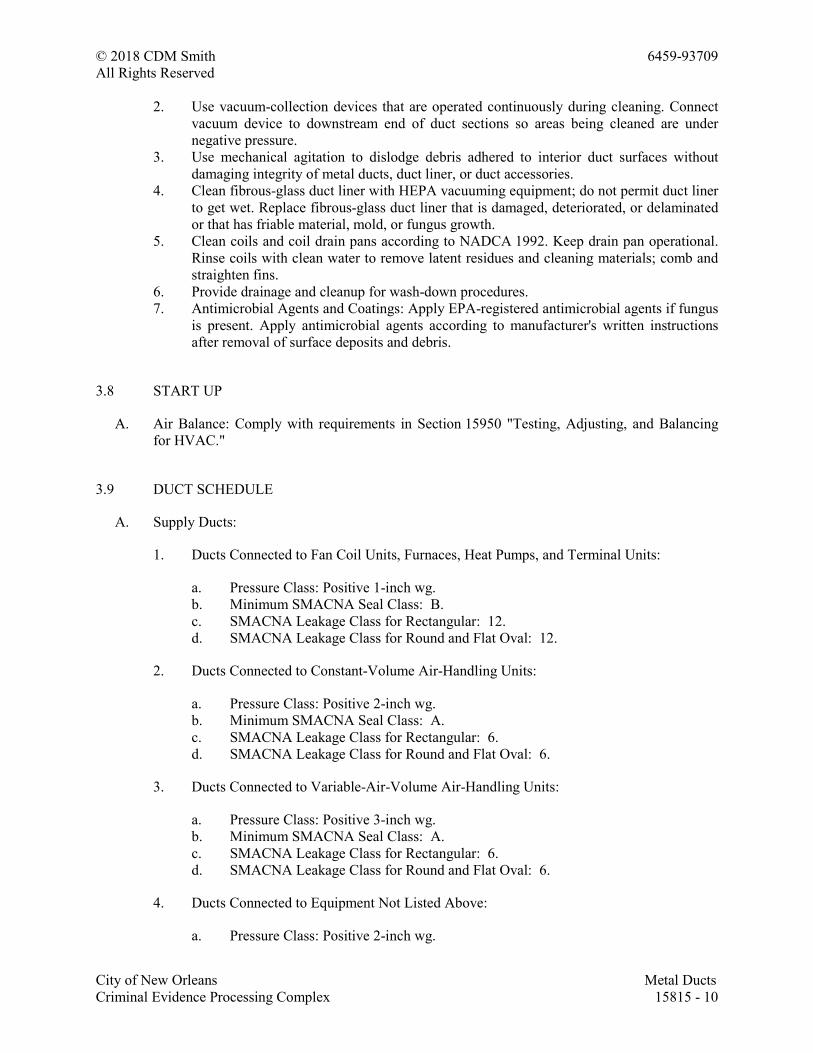
© 2018 CDM Smith 6459-93709
All Rights Reserved
City of New Orleans Metal Ducts
Criminal Evidence Processing Complex 15815 - 10
2. Use vacuum-collection devices that are operated continuously during cleaning. Connect
vacuum device to downstream end of duct sections so areas being cleaned are under
negative pressure.
3. Use mechanical agitation to dislodge debris adhered to interior duct surfaces without
damaging integrity of metal ducts, duct liner, or duct accessories.
4. Clean fibrous-glass duct liner with HEPA vacuuming equipment; do not permit duct liner
to get wet. Replace fibrous-glass duct liner that is damaged, deteriorated, or delaminated
or that has friable material, mold, or fungus growth.
5. Clean coils and coil drain pans according to NADCA 1992. Keep drain pan operational.
Rinse coils with clean water to remove latent residues and cleaning materials; comb and
straighten fins.
6. Provide drainage and cleanup for wash-down procedures.
7. Antimicrobial Agents and Coatings: Apply EPA-registered antimicrobial agents if fungus
is present. Apply antimicrobial agents according to manufacturer's written instructions
after removal of surface deposits and debris.
3.8 START UP
A. Air Balance: Comply with requirements in Section 15950 "Testing, Adjusting, and Balancing
for HVAC."
3.9 DUCT SCHEDULE
A. Supply Ducts:
1. Ducts Connected to Fan Coil Units, Furnaces, Heat Pumps, and Terminal Units:
a. Pressure Class: Positive 1-inch wg.
b. Minimum SMACNA Seal Class: B.
c. SMACNA Leakage Class for Rectangular: 12.
d. SMACNA Leakage Class for Round and Flat Oval: 12.
2. Ducts Connected to Constant-Volume Air-Handling Units:
a. Pressure Class: Positive 2-inch wg.
b. Minimum SMACNA Seal Class: A.
c. SMACNA Leakage Class for Rectangular: 6.
d. SMACNA Leakage Class for Round and Flat Oval: 6.
3. Ducts Connected to Variable-Air-Volume Air-Handling Units:
a. Pressure Class: Positive 3-inch wg.
b. Minimum SMACNA Seal Class: A.
c. SMACNA Leakage Class for Rectangular: 6.
d. SMACNA Leakage Class for Round and Flat Oval: 6.
4. Ducts Connected to Equipment Not Listed Above:
a. Pressure Class: Positive 2-inch wg.
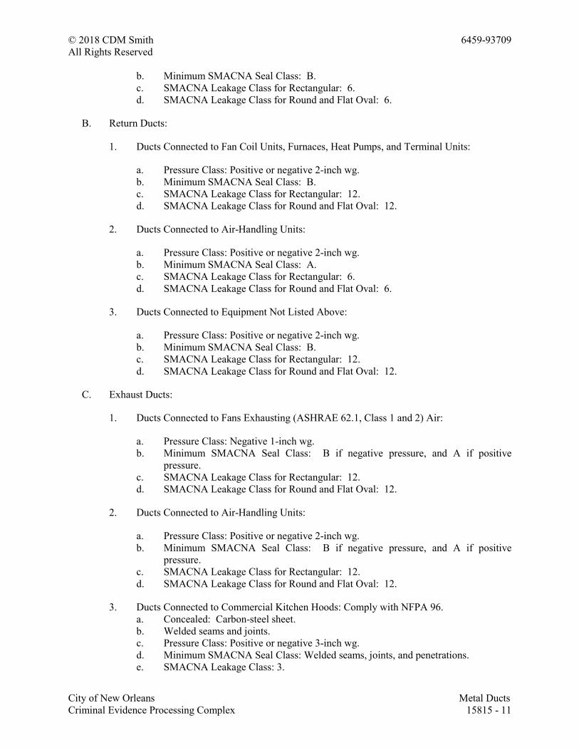
© 2018 CDM Smith 6459-93709
All Rights Reserved
City of New Orleans Metal Ducts
Criminal Evidence Processing Complex 15815 - 11
b. Minimum SMACNA Seal Class: B.
c. SMACNA Leakage Class for Rectangular: 6.
d. SMACNA Leakage Class for Round and Flat Oval: 6.
B. Return Ducts:
1. Ducts Connected to Fan Coil Units, Furnaces, Heat Pumps, and Terminal Units:
a. Pressure Class: Positive or negative 2-inch wg.
b. Minimum SMACNA Seal Class: B.
c. SMACNA Leakage Class for Rectangular: 12.
d. SMACNA Leakage Class for Round and Flat Oval: 12.
2. Ducts Connected to Air-Handling Units:
a. Pressure Class: Positive or negative 2-inch wg.
b. Minimum SMACNA Seal Class: A.
c. SMACNA Leakage Class for Rectangular: 6.
d. SMACNA Leakage Class for Round and Flat Oval: 6.
3. Ducts Connected to Equipment Not Listed Above:
a. Pressure Class: Positive or negative 2-inch wg.
b. Minimum SMACNA Seal Class: B.
c. SMACNA Leakage Class for Rectangular: 12.
d. SMACNA Leakage Class for Round and Flat Oval: 12.
C. Exhaust Ducts:
1. Ducts Connected to Fans Exhausting (ASHRAE 62.1, Class 1 and 2) Air:
a. Pressure Class: Negative 1-inch wg.
b. Minimum SMACNA Seal Class: B if negative pressure, and A if positive
pressure.
c. SMACNA Leakage Class for Rectangular: 12.
d. SMACNA Leakage Class for Round and Flat Oval: 12.
2. Ducts Connected to Air-Handling Units:
a. Pressure Class: Positive or negative 2-inch wg.
b. Minimum SMACNA Seal Class: B if negative pressure, and A if positive
pressure.
c. SMACNA Leakage Class for Rectangular: 12.
d. SMACNA Leakage Class for Round and Flat Oval: 12.
3. Ducts Connected to Commercial Kitchen Hoods: Comply with NFPA 96.
a. Concealed: Carbon-steel sheet.
b. Welded seams and joints.
c. Pressure Class: Positive or negative 3-inch wg.
d. Minimum SMACNA Seal Class: Welded seams, joints, and penetrations.
e. SMACNA Leakage Class: 3.
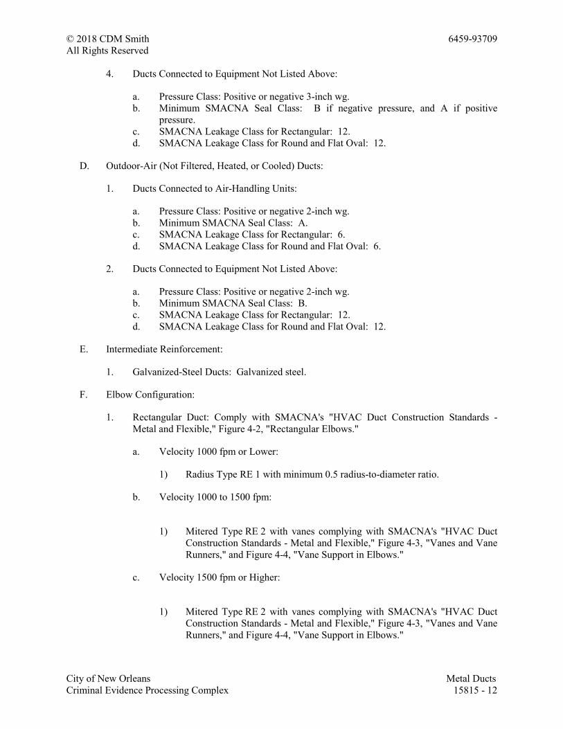
© 2018 CDM Smith 6459-93709
All Rights Reserved
City of New Orleans Metal Ducts
Criminal Evidence Processing Complex 15815 - 12
4. Ducts Connected to Equipment Not Listed Above:
a. Pressure Class: Positive or negative 3-inch wg.
b. Minimum SMACNA Seal Class: B if negative pressure, and A if positive
pressure.
c. SMACNA Leakage Class for Rectangular: 12.
d. SMACNA Leakage Class for Round and Flat Oval: 12.
D. Outdoor-Air (Not Filtered, Heated, or Cooled) Ducts:
1. Ducts Connected to Air-Handling Units:
a. Pressure Class: Positive or negative 2-inch wg.
b. Minimum SMACNA Seal Class: A.
c. SMACNA Leakage Class for Rectangular: 6.
d. SMACNA Leakage Class for Round and Flat Oval: 6.
2. Ducts Connected to Equipment Not Listed Above:
a. Pressure Class: Positive or negative 2-inch wg.
b. Minimum SMACNA Seal Class: B.
c. SMACNA Leakage Class for Rectangular: 12.
d. SMACNA Leakage Class for Round and Flat Oval: 12.
E. Intermediate Reinforcement:
1. Galvanized-Steel Ducts: Galvanized steel.
F. Elbow Configuration:
1. Rectangular Duct: Comply with SMACNA's "HVAC Duct Construction Standards -
Metal and Flexible," Figure 4-2, "Rectangular Elbows."
a. Velocity 1000 fpm or Lower:
1) Radius Type RE 1 with minimum 0.5 radius-to-diameter ratio.
b. Velocity 1000 to 1500 fpm:
1) Mitered Type RE 2 with vanes complying with SMACNA's "HVAC Duct
Construction Standards - Metal and Flexible," Figure 4-3, "Vanes and Vane
Runners," and Figure 4-4, "Vane Support in Elbows."
c. Velocity 1500 fpm or Higher:
1) Mitered Type RE 2 with vanes complying with SMACNA's "HVAC Duct
Construction Standards - Metal and Flexible," Figure 4-3, "Vanes and Vane
Runners," and Figure 4-4, "Vane Support in Elbows."
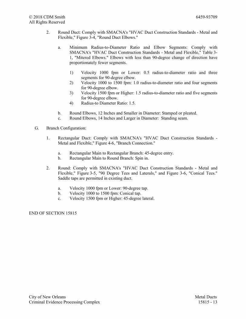
© 2018 CDM Smith 6459-93709
All Rights Reserved
City of New Orleans Metal Ducts
Criminal Evidence Processing Complex 15815 - 13
2. Round Duct: Comply with SMACNA's "HVAC Duct Construction Standards - Metal and
Flexible," Figure 3-4, "Round Duct Elbows."
a. Minimum Radius-to-Diameter Ratio and Elbow Segments: Comply with
SMACNA's "HVAC Duct Construction Standards - Metal and Flexible," Table 3-
1, "Mitered Elbows." Elbows with less than 90-degree change of direction have
proportionately fewer segments.
1) Velocity 1000 fpm or Lower: 0.5 radius-to-diameter ratio and three
segments for 90-degree elbow.
2) Velocity 1000 to 1500 fpm: 1.0 radius-to-diameter ratio and four segments
for 90-degree elbow.
3) Velocity 1500 fpm or Higher: 1.5 radius-to-diameter ratio and five segments
for 90-degree elbow.
4) Radius-to Diameter Ratio: 1.5.
b. Round Elbows, 12 Inches and Smaller in Diameter: Stamped or pleated.
c. Round Elbows, 14 Inches and Larger in Diameter: Standing seam.
G. Branch Configuration:
1. Rectangular Duct: Comply with SMACNA's "HVAC Duct Construction Standards -
Metal and Flexible," Figure 4-6, "Branch Connection."
a. Rectangular Main to Rectangular Branch: 45-degree entry.
b. Rectangular Main to Round Branch: Spin in.
2. Round: Comply with SMACNA's "HVAC Duct Construction Standards - Metal and
Flexible," Figure 3-5, "90 Degree Tees and Laterals," and Figure 3-6, "Conical Tees."
Saddle taps are permitted in existing duct.
a. Velocity 1000 fpm or Lower: 90-degree tap.
b. Velocity 1000 to 1500 fpm: Conical tap.
c. Velocity 1500 fpm or Higher: 45-degree lateral.
END OF SECTION 15815
© 2018 CDM Smith 6459-93709
All Rights Reserved
City of New Orleans Duct Accessories
Criminal Evidence Processing Complex 15820 - 1
SECTION 15820 - DUCT ACCESSORIES
PART 1 - GENERAL
1. Backdraft and pressure relief dampers.
2. Manual volume dampers.
3. Control dampers.
4. Fire dampers.
5. Smoke dampers.
6. Flange connectors.
7. Turning vanes.
8. Duct-mounted access doors.
9. Flexible connectors.
10. Flexible ducts.
11. Duct accessory hardware.
B. Related Requirements:
1. Section 283111 "Digital, Addressable Fire-Alarm System" for duct-mounted fire and
smoke detectors.
2. Section 283112 "Zoned (DC-Loop) Fire-Alarm System" for duct-mounted fire and smoke
detectors.
1.2 ACTION SUBMITTALS
A. Product Data: For each type of product.
B. Shop Drawings: For duct accessories. Include plans, elevations, sections, details and
attachments to other work.
1. Detail duct accessories fabrication and installation in ducts and other construction.
Include dimensions, weights, loads, and required clearances; and method of field
assembly into duct systems and other construction. Include the following:
a. Special fittings.
b. Manual volume damper installations.
c. Control-damper installations.
d. Fire-damper and smoke-damper installations, including sleeves; and duct-mounted
access doors.
e. Wiring Diagrams: For power, signal, and control wiring.
1.3 CLOSEOUT SUBMITTALS
A. Operation and maintenance data.
© 2018 CDM Smith 6459-93709
All Rights Reserved
City of New Orleans Duct Accessories
Criminal Evidence Processing Complex 15820 - 2
PART 2 - PRODUCTS
2.1 ASSEMBLY DESCRIPTION
A. Comply with SMACNA's "HVAC Duct Construction Standards - Metal and Flexible" for
acceptable materials, material thicknesses, and duct construction methods unless otherwise
indicated. Sheet metal materials shall be free of pitting, seam marks, roller marks, stains,
discolorations, and other imperfections.
2.2 MATERIALS
A. Galvanized Sheet Steel: Comply with ASTM A 653/A 653M.
1. Galvanized Coating Designation: G90.
2. Exposed-Surface Finish: Mill phosphatized.
B. Extruded Aluminum: Comply with ASTM B 221, Alloy 6063, Temper T6.
C. Reinforcement Shapes and Plates: Galvanized-steel reinforcement where installed on
galvanized sheet metal ducts; compatible materials for aluminum and stainless-steel ducts.
D. Tie Rods: Galvanized steel, 1/4-inch minimum diameter for lengths 36 inches or less; 3/8-inch
minimum diameter for lengths longer than 36 inches.
2.3 BACKDRAFT AND PRESSURE RELIEF DAMPERS
A. Manufacturers: Subject to compliance with requirements, available manufacturers offering
products that may be incorporated into the Work include, but are not limited to, the following:
1. Air Balance Inc.; a division of Mestek, Inc.
2. American Warming and Ventilating; a division of Mestek, Inc.
3. Cesco Products; a division of Mestek, Inc.
4. Greenheck Fan Corporation.
5. Lloyd Industries, Inc.
6. Nailor Industries Inc.
7. NCA Manufacturing, Inc.
8. Pottorff.
9. Ruskin Company.
10. Vent Products Company, Inc.
B. Description: Gravity balanced.
C. Maximum Air Velocity: 2000 fpm.
D. Maximum System Pressure: 3-inch wg.
E. Frame: Hat-shaped, 0.094-inch-thick, galvanized sheet steel, with welded corners or
mechanically attached and mounting flange.
© 2018 CDM Smith 6459-93709
All Rights Reserved
City of New Orleans Duct Accessories
Criminal Evidence Processing Complex 15820 - 3
F. Blades: Multiple single-piece blades, center pivoted, maximum 6-inch width, 0.025-inch-thick,
roll-formed aluminum with sealed edges.
G. Blade Action: Parallel.
H. Blade Seals: Neoprene, mechanically locked.
I. Blade Axles:
1. Material: Galvanized steel.
2. Diameter: 0.20 inch.
J. Tie Bars and Brackets: Galvanized steel.
K. Return Spring: Adjustable tension.
L. Bearings: synthetic pivot bushings.
M. Accessories:
1. Adjustment device to permit setting for varying differential static pressure.
2. Counterweights and spring-assist kits for vertical airflow installations.
3. Electric actuators.
4. Chain pulls.
5. Screen Mounting: Front mounted in sleeve.
a. Sleeve Thickness: 20 gage minimum.
b. Sleeve Length: 6 inches minimum.
6. Screen Mounting: Rear mounted.
7. Screen Material: Galvanized steel.
8. Screen Type: Insect.
9. 90-degree stops.
2.4 MANUAL VOLUME DAMPERS
A. Standard, Steel, Manual Volume Dampers:
1. Manufacturers: Subject to compliance with requirements, available manufacturers
offering products that may be incorporated into the Work include, but are not limited to,
the following:
a. Air Balance Inc.; a division of Mestek, Inc.
b. American Warming and Ventilating; a division of Mestek, Inc.
c. Flexmaster U.S.A., Inc.
d. McGill AirFlow LLC.
e. Nailor Industries Inc.
f. Pottorff.
g. Ruskin Company.
h. Trox USA Inc.
© 2018 CDM Smith 6459-93709
All Rights Reserved
City of New Orleans Duct Accessories
Criminal Evidence Processing Complex 15820 - 4
i. Vent Products Company, Inc.
2. Standard leakage rating, with linkage outside airstream.
3. Suitable for horizontal or vertical applications.
4. Frames:
a. Frame: Hat-shaped, 0.094-inch-thick, galvanized sheet steel.
b. Mitered and welded corners.
c. Flanges for attaching to walls and flangeless frames for installing in ducts.
5. Blades:
a. Multiple or single blade.
b. Parallel- or opposed-blade design.
c. Stiffen damper blades for stability.
d. Galvanized-steel, 0.064 inch thick.
6. Blade Axles: Galvanized steel.
7. Bearings:
a. Oil-impregnated bronze.
b. Dampers in ducts with pressure classes of 3-inch wg or less shall have axles full
length of damper blades and bearings at both ends of operating shaft.
8. Tie Bars and Brackets: Galvanized steel.
B. Standard, Aluminum, Manual Volume Dampers:
1. Manufacturers: Subject to compliance with requirements, available manufacturers
offering products that may be incorporated into the Work include, but are not limited to,
the following:
a. Air Balance Inc.; a division of Mestek, Inc.
b. American Warming and Ventilating; a division of Mestek, Inc.
c. McGill AirFlow LLC.
d. Nailor Industries Inc.
e. Pottorff.
f. Ruskin Company.
g. Trox USA Inc.
h. Vent Products Company, Inc.
2. Standard leakage rating, with linkage outside airstream.
3. Suitable for horizontal or vertical applications.
4. Frames: Hat-shaped, 0.10-inch-thick, aluminum sheet channels; frames with flanges for
attaching to walls and flangeless frames for installing in ducts.
5. Blades:
a. Multiple or single blade.
b. Parallel- or opposed-blade design.
c. Stiffen damper blades for stability.
d. Roll-Formed Aluminum Blades: 0.10-inch-thick aluminum sheet.
© 2018 CDM Smith 6459-93709
All Rights Reserved
City of New Orleans Duct Accessories
Criminal Evidence Processing Complex 15820 - 5
e. Extruded-Aluminum Blades: 0.050-inch-thick extruded aluminum.
6. Blade Axles: Galvanized steel.
7. Bearings:
a. Molded synthetic.
b. Dampers in ducts with pressure classes of 3-inch wg or less shall have axles full
length of damper blades and bearings at both ends of operating shaft.
8. Tie Bars and Brackets: Aluminum.
C. Jackshaft:
1. Size: 0.5-inch diameter.
2. Material: Galvanized-steel pipe rotating within pipe-bearing assembly mounted on
supports at each mullion and at each end of multiple-damper assemblies.
3. Length and Number of Mountings: As required to connect linkage of each damper in
multiple-damper assembly.
D. Damper Hardware:
1. Zinc-plated, die-cast core with dial and handle made of 3/32-inch-thick zinc-plated steel,
and a 3/4-inch hexagon locking nut.
2. Include center hole to suit damper operating-rod size.
3. Include elevated platform for insulated duct mounting.
2.5 CONTROL DAMPERS
A. Manufacturers: Subject to compliance with requirements, available manufacturers offering
products that may be incorporated into the Work include, but are not limited to, the following:
1. American Warming and Ventilating; a division of Mestek, Inc.
2. Arrow United Industries; a division of Mestek, Inc.
3. Cesco Products; a division of Mestek, Inc.
4. Greenheck Fan Corporation.
5. Lloyd Industries, Inc.
6. McGill AirFlow LLC.
7. Metal Form Manufacturing, Inc.
8. Nailor Industries Inc.
9. NCA Manufacturing, Inc.
10. Pottorff.
11. Ruskin Company.
12. Vent Products Company, Inc.
13. Young Regulator Company.
B. Frames:
1. Hat shaped.
2. 0.094-inch-thick, galvanized sheet steel.
3. Mitered and welded corners.
© 2018 CDM Smith 6459-93709
All Rights Reserved
City of New Orleans Duct Accessories
Criminal Evidence Processing Complex 15820 - 6
C. Blades:
1. Multiple blade with maximum blade width of 6 inches.
2. Opposed-blade design.
3. Galvanized-steel.
4. 0.064 inch thick single skin.
5. Blade Edging: Closed-cell neoprene.
6. Blade Edging: Inflatable seal blade edging, or replaceable rubber seals.
D. Blade Axles: 1/2-inch-diameter; galvanized steel; blade-linkage hardware of zinc-plated steel
and brass; ends sealed against blade bearings.
1. Operating Temperature Range: From minus 40 to plus 200 deg F.
E. Bearings:
1. Oil-impregnated bronze.
2. Dampers in ducts with pressure classes of 3-inch wg or less shall have axles full length of
damper blades and bearings at both ends of operating shaft.
3. Thrust bearings at each end of every blade.
2.6 FIRE DAMPERS
A. Manufacturers: Subject to compliance with requirements, available manufacturers offering
products that may be incorporated into the Work include, but are not limited to, the following:
1. Air Balance Inc.; a division of Mestek, Inc.
2. Arrow United Industries; a division of Mestek, Inc.
3. Cesco Products; a division of Mestek, Inc.
4. Greenheck Fan Corporation.
5. Nailor Industries Inc.
6. NCA Manufacturing, Inc.
7. Pottorff.
8. Prefco; Perfect Air Control, Inc.
9. Ruskin Company.
10. Vent Products Company, Inc.
11. Ward Industries, Inc.; a division of Hart & Cooley, Inc.
B. Type: Dynamic; rated and labeled according to UL 555 by an NRTL.
C. Closing rating in ducts up to 4-inch wg static pressure class and minimum 2000-fpm velocity.
D. Fire Rating: 1-1/2 hours.
E. Frame: Curtain type with blades outside airstream; fabricated with roll-formed, 0.034-inch-
thick galvanized steel; with mitered and interlocking corners.
F. Mounting Sleeve: Factory- or field-installed, galvanized sheet steel.
1. Minimum Thickness: 0.05 thick, as indicated, and of length to suit application.
© 2018 CDM Smith 6459-93709
All Rights Reserved
City of New Orleans Duct Accessories
Criminal Evidence Processing Complex 15820 - 7
2. Exception: Omit sleeve where damper-frame width permits direct attachment of
perimeter mounting angles on each side of wall or floor; thickness of damper frame must
comply with sleeve requirements.
G. Mounting Orientation: Vertical or horizontal as indicated.
H. Blades: Roll-formed, interlocking, 0.024-inch-thick, galvanized sheet steel. In place of
interlocking blades, use full-length, 0.034-inch-thick, galvanized-steel blade connectors.
I. Horizontal Dampers: Include blade lock and stainless-steel closure spring.
J. Heat-Responsive Device: Replaceable, 165 deg F rated, fusible links.
2.7 SMOKE DAMPERS
A. Manufacturers: Subject to compliance with requirements, available manufacturers offering
products that may be incorporated into the Work include, but are not limited to, the following:
1. Air Balance Inc.; a division of Mestek, Inc.
2. Cesco Products; a division of Mestek, Inc.
3. Greenheck Fan Corporation.
4. Nailor Industries Inc.
5. Pottorff.
6. Ruskin Company.
B. General Requirements: Label according to UL 555S by an NRTL.
C. Smoke Detector: Integral, factory wired for single-point connection.
D. Frame: Hat-shaped, 0.094-inch-thick, galvanized sheet steel, with welded corners and mounting
flange.
E. Blades: Roll-formed, horizontal, interlocking, 0.034-inch-thick, galvanized sheet steel.
F. Leakage: Class I.
G. Rated pressure and velocity to exceed design airflow conditions.
H. Mounting Sleeve: Factory-installed, 0.039-inch-thick, galvanized sheet steel; length to suit wall
or floor application with factory-furnished silicone calking.
I. Damper Motors: two-position action.
J. Comply with NEMA designation, temperature rating, service factor, enclosure type, and
efficiency requirements for motors specified in Section 15058 "Common Motor Requirements
for HVAC Equipment."
1. Motor Sizes: Minimum size as indicated. If not indicated, large enough so driven load
will not require motor to operate in service factor range above 1.0.
© 2018 CDM Smith 6459-93709
All Rights Reserved
City of New Orleans Duct Accessories
Criminal Evidence Processing Complex 15820 - 8
2. Controllers, Electrical Devices, and Wiring: Comply with requirements for electrical
devices and connections specified in Section 15900 "HVAC Instrumentation and
Control."
3. Permanent-Split-Capacitor or Shaded-Pole Motors: With oil-immersed and sealed gear
trains.
4. Spring-Return Motors: Equip with an integral spiral-spring mechanism where indicated.
Enclose entire spring mechanism in a removable housing designed for service or
adjustments. Size for running torque rating of 150 in. x lbf and breakaway torque rating
of 150 in. x lbf.
5. Outdoor Motors and Motors in Outdoor-Air Intakes: Equip with O-ring gaskets designed
to make motors weatherproof. Equip motors with internal heaters to permit normal
operation at minus 40 deg F.
6. Nonspring-Return Motors: For dampers larger than 25 sq. ft., size motor for running
torque rating of 150 in. x lbf and breakaway torque rating of 300 in. x lbf.
7. Electrical Connection: 115 V, single phase, 60 Hz.
K. Accessories:
1. Auxiliary switches for signaling fan control or position indication.
2. Momentary test switch, damper mounted.
2.8 FLANGE CONNECTORS
A. Manufacturers: Subject to compliance with requirements, available manufacturers offering
products that may be incorporated into the Work include, but are not limited to, the following:
1. Ductmate Industries, Inc.
2. Nexus PDQ; Division of Shilco Holdings Inc.
3. Ward Industries, Inc.; a division of Hart & Cooley, Inc.
B. Description: Add-on, factory-fabricated, slide-on transverse flange connectors, gaskets, and
components.
C. Material: Galvanized steel.
D. Gage and Shape: Match connecting ductwork.
2.9 TURNING VANES
A. Manufacturers: Subject to compliance with requirements, available manufacturers offering
products that may be incorporated into the Work include, but are not limited to, the following:
1. Ductmate Industries, Inc.
2. Duro Dyne Inc.
3. Elgen Manufacturing.
4. METALAIRE, Inc.
5. SEMCO Incorporated.
6. Ward Industries, Inc.; a division of Hart & Cooley, Inc.
© 2018 CDM Smith 6459-93709
All Rights Reserved
City of New Orleans Duct Accessories
Criminal Evidence Processing Complex 15820 - 9
B. Manufactured Turning Vanes for Metal Ducts: Curved blades of galvanized sheet steel; support
with bars perpendicular to blades set; set into vane runners suitable for duct mounting.
1. Acoustic Turning Vanes: Fabricate airfoil-shaped aluminum extrusions with perforated
faces and fibrous-glass fill.
C. General Requirements: Comply with SMACNA's "HVAC Duct Construction Standards - Metal
and Flexible"; Figures 4-3, "Vanes and Vane Runners," and 4-4, "Vane Support in Elbows."
D. Vane Construction: Double wall.
2.10 DUCT-MOUNTED ACCESS DOORS
A. Manufacturers: Subject to compliance with requirements, available manufacturers offering
products that may be incorporated into the Work include, but are not limited to, the following:
1. American Warming and Ventilating; a division of Mestek, Inc.
2. Cesco Products; a division of Mestek, Inc.
3. Ductmate Industries, Inc.
4. Elgen Manufacturing.
5. Flexmaster U.S.A., Inc.
6. Greenheck Fan Corporation.
7. McGill AirFlow LLC.
8. Nailor Industries Inc.
9. Pottorff.
10. Ventfabrics, Inc.
11. Ward Industries, Inc.; a division of Hart & Cooley, Inc.
B. Duct-Mounted Access Doors: Fabricate access panels according to SMACNA's "HVAC Duct
Construction Standards - Metal and Flexible"; Figures 7-2, "Duct Access Doors and Panels,"
and 7-3, "Access Doors - Round Duct."
1. Door:
a. Double wall, rectangular.
b. Galvanized sheet metal with insulation fill and thickness as indicated for duct
pressure class.
c. Vision panel.
d. Hinges and Latches: 1-by-1-inchbutt or piano hinge and cam latches.
e. Fabricate doors airtight and suitable for duct pressure class.
2. Frame: Galvanized sheet steel, with bend-over tabs and foam gaskets.
3. Number of Hinges and Locks:
a. Access Doors Less Than 12 Inches Square: No hinges and two sash locks.
b. Access Doors up to 18 Inches Square: Two hinges and two sash locks.
c. Access Doors up to 24 by 48 Inches: Three hinges and two compression
latches with outside and inside handles.
d. Access Doors Larger Than 24 by 48 Inches: Four hinges and two compression
latches with outside and inside handles.
© 2018 CDM Smith 6459-93709
All Rights Reserved
City of New Orleans Duct Accessories
Criminal Evidence Processing Complex 15820 - 10
C. Pressure Relief Access Door:
1. Door and Frame Material: Galvanized sheet steel.
2. Door: Double wall with insulation fill with metal thickness applicable for duct pressure
class.
3. Operation: Open outward for positive-pressure ducts and inward for negative-pressure
ducts.
4. Factory set at 3.0- to 8.0-inch wg.
5. Doors close when pressures are within set-point range.
6. Hinge: Continuous piano.
7. Latches: Cam.
8. Seal: Neoprene or foam rubber.
9. Insulation Fill: 1-inch-thick, fibrous-glass or polystyrene-foam board.
2.11 DUCT ACCESS PANEL ASSEMBLIES
A. Manufacturers: Subject to compliance with requirements, available manufacturers offering
products that may be incorporated into the Work include, but are not limited to, the following:
1. Ductmate Industries, Inc.
2. Flame Gard, Inc.
3. 3M.
B. Labeled according to UL 1978 by an NRTL.
C. Panel and Frame: Minimum thickness 0.0528-inch carbon steel.
D. Fasteners: Carbon steel. Panel fasteners shall not penetrate duct wall.
E. Gasket: Comply with NFPA 96; grease-tight, high-temperature ceramic fiber, rated for
minimum 2000 deg F.
F. Minimum Pressure Rating: 10-inch wg, positive or negative.
2.12 FLEXIBLE CONNECTORS
A. Manufacturers: Subject to compliance with requirements, available manufacturers offering
products that may be incorporated into the Work include, but are not limited to, the following:
1. Ductmate Industries, Inc.
2. Duro Dyne Inc.
3. Elgen Manufacturing.
4. Ventfabrics, Inc.
5. Ward Industries, Inc.; a division of Hart & Cooley, Inc.
B. Materials: Flame-retardant or noncombustible fabrics.
C. Coatings and Adhesives: Comply with UL 181, Class 1.
© 2018 CDM Smith 6459-93709
All Rights Reserved
City of New Orleans Duct Accessories
Criminal Evidence Processing Complex 15820 - 11
D. Metal-Edged Connectors: Factory fabricated with a fabric strip 3-1/2 inches wide attached to
two strips of 2-3/4-inch-wide, 0.028-inch-thick, galvanized sheet steel or 0.032-inch-thick
aluminum sheets. Provide metal compatible with connected ducts.
E. Indoor System, Flexible Connector Fabric: Glass fabric double coated with neoprene.
1. Minimum Weight: 26 oz./sq. yd..
2. Tensile Strength: 480 lbf/inch in the warp and 360 lbf/inch in the filling.
3. Service Temperature: Minus 40 to plus 200 deg F.
F. Outdoor System, Flexible Connector Fabric: Glass fabric double coated with weatherproof,
synthetic rubber resistant to UV rays and ozone.
1. Minimum Weight: 24 oz./sq. yd..
2. Tensile Strength: 530 lbf/inch in the warp and 440 lbf/inch in the filling.
3. Service Temperature: Minus 50 to plus 250 deg F.
2.13 FLEXIBLE DUCTS
A. Manufacturers: Subject to compliance with requirements, available manufacturers offering
products that may be incorporated into the Work include, but are not limited to, the following:
1. Flexmaster U.S.A., Inc.
2. McGill AirFlow LLC.
3. Ward Industries, Inc.; a division of Hart & Cooley, Inc.
B. Noninsulated, Flexible Duct: UL 181, Class 1, 2-ply vinyl film supported by helically wound,
spring-steel wire.
1. Pressure Rating: 10-inch wg positive and 1.0-inch wg negative.
2. Maximum Air Velocity: 4000 fpm.
3. Temperature Range: Minus 10 to plus 160 deg F.
C. Insulated, Flexible Duct: UL 181, Class 1, aluminum laminate and polyester film with latex
adhesive supported by helically wound, spring-steel wire; fibrous-glass insulation; polyethylene
vapor-barrier film.
1. Pressure Rating: 10-inch wg positive and 1.0-inch wg negative.
2. Maximum Air Velocity: 4000 fpm.
3. Temperature Range: Minus 20 to plus 210 deg F.
4. Insulation R-value: Comply with ASHRAE/IESNA 90.1.
D. Flexible Duct Connectors:
1. Clamps: Nylon strap in sizes 3 through 18 inches, to suit duct size.
© 2018 CDM Smith 6459-93709
All Rights Reserved
City of New Orleans Duct Accessories
Criminal Evidence Processing Complex 15820 - 12
2.14 DUCT ACCESSORY HARDWARE
A. Instrument Test Holes: Cast iron or cast aluminum to suit duct material, including screw cap
and gasket. Size to allow insertion of pitot tube and other testing instruments and of length to
suit duct-insulation thickness.
B. Adhesives: High strength, quick setting, neoprene based, waterproof, and resistant to gasoline
and grease.
PART 3 - EXECUTION
3.1 INSTALLATION
A. Install duct accessories according to applicable details in SMACNA's "HVAC Duct
Construction Standards - Metal and Flexible" for metal ducts and in NAIMA AH116, "Fibrous
Glass Duct Construction Standards," for fibrous-glass ducts.
B. Install duct accessories of materials suited to duct materials; use galvanized-steel accessories in
galvanized-steel and fibrous-glass ducts, stainless-steel accessories in stainless-steel ducts, and
aluminum accessories in aluminum ducts.
C. Install backdraft dampers at inlet of exhaust fans or exhaust ducts as close as possible to exhaust
fan unless otherwise indicated.
D. Install volume dampers at points on supply, return, and exhaust systems where branches extend
from larger ducts. Where dampers are installed in ducts having duct liner, install dampers with
hat channels of same depth as liner, and terminate liner with nosing at hat channel.
1. Install steel volume dampers in steel ducts.
E. Set dampers to fully open position before testing, adjusting, and balancing.
F. Install test holes at fan inlets and outlets and elsewhere as indicated.
G. Install fire and smoke dampers according to UL listing.
H. Install duct access doors on sides of ducts to allow for inspecting, adjusting, and maintaining
accessories and equipment at the following locations:
1. On both sides of duct coils.
2. At outdoor-air intakes and mixed-air plenums.
3. At drain pans and seals.
4. Downstream from control dampers and equipment.
5. Adjacent to and close enough to fire or smoke dampers, to reset or reinstall fusible links.
Access doors for access to fire or smoke dampers having fusible links shall be pressure
relief access doors and shall be outward operation for access doors installed upstream
from dampers and inward operation for access doors installed downstream from dampers.
6. At each change in direction and at maximum 50-foot spacing.
7. Control devices requiring inspection.
© 2018 CDM Smith 6459-93709
All Rights Reserved
City of New Orleans Duct Accessories
Criminal Evidence Processing Complex 15820 - 13
8. Elsewhere as indicated.
I. Install access doors with swing against duct static pressure.
J. Access Door Sizes:
1. One-Hand or Inspection Access: 8 by 5 inches.
2. Two-Hand Access: 12 by 6 inches.
3. Head and Hand Access: 18 by 10 inches.
4. Head and Shoulders Access: 21 by 14 inches.
5. Body Access: 25 by 14 inches.
6. Body plus Ladder Access: 25 by 17 inches.
K. Label access doors according to Section 15077 "Identification for HVAC Piping and
Equipment" to indicate the purpose of access door.
L. Install flexible connectors to connect ducts to equipment.
M. Connect terminal units to supply ducts with maximum 12-inch lengths of flexible duct. Do not
use flexible ducts to change directions.
N. Connect diffusers or light troffer boots to ducts with maximum 84 inch lengths of flexible duct
clamped or strapped in place.
O. Connect flexible ducts to metal ducts with draw bands.
P. Install duct test holes where required for testing and balancing purposes.
3.2 FIELD QUALITY CONTROL
A. Tests and Inspections:
1. Operate dampers to verify full range of movement.
2. Inspect locations of access doors and verify that purpose of access door can be
performed.
3. Operate fire and smoke dampers to verify full range of movement and verify that proper
heat-response device is installed.
4. Inspect turning vanes for proper and secure installation.
END OF SECTION 15820
© 2018 CDM Smith 6459-93709
All Rights Reserved
City of New Orleans Air Terminal Units
Criminal Evidence Processing Complex 15840 - 1
SECTION 15840 - AIR TERMINAL UNITS
PART 1 - GENERAL
1.1 SUMMARY
A. Section Includes:
1. Fan-powered air terminal units.
2. Shutoff, single-duct air terminal units.
1.2 ACTION SUBMITTALS
A. Product Data: For each type of product indicated.
1.3 INFORMATIONAL SUBMITTALS
A. Field quality-control reports.
1.4 CLOSEOUT SUBMITTALS
A. Operation and maintenance data.
1.5 QUALITY ASSURANCE
A. Electrical Components, Devices, and Accessories: Listed and labeled as defined in NFPA 70, by
a qualified testing agency, and marked for intended location and application.
B. ASHRAE Compliance: Applicable requirements in ASHRAE 62.1, Section 5 - "Systems and
Equipment" and Section 7 - "Construction and System Start-Up."
PART 2 - PRODUCTS
2.1 PARALLEL FAN-POWERED AIR TERMINAL UNITS
A. Basis-of-Design Product: Subject to compliance with requirements, provide product indicated
on Drawings or comparable product by one of the following:
1. Anemostat Products; a Mestek Company.
2. Nailor Industries Inc.
3. Price Industries.
4. Titus.
5. Trane; a business of American Standard Companies.
© 2018 CDM Smith 6459-93709
All Rights Reserved
City of New Orleans Air Terminal Units
Criminal Evidence Processing Complex 15840 - 2
B. Configuration: Volume-damper assembly and fan in parallel arrangement inside unit casing
with control components inside a protective metal shroud.
C. Casing: 0.034-inch steel, single wall.
1. Casing Lining: Adhesive attached, 3/4-inch- thick, coated, fibrous-glass duct liner
complying with ASTM C 1071, and having a maximum flame-spread index of 25 and a
maximum smoke-developed index of 50, for both insulation and adhesive, when tested
according to ASTM E 84.
a. Cover liner with nonporous foil.
2. Air Inlets: Round stub connections or S-slip and drive connections for duct attachment.
3. Air Outlet: S-slip and drive connections.
4. Access: Removable panels for access to parts requiring service, adjustment, or
maintenance; with airtight gasket and quarter-turn latches.
5. Fan: Forward-curved centrifugal, located at plenum air inlet.
6.
D. Volume Damper: Galvanized steel with flow-sensing ring and peripheral gasket and self-
lubricating bearings.
1. Maximum Damper Leakage: ARI 880 rated, 3 percent of nominal airflow at 3-inch wg
inlet static pressure.
E. Motor:
1. Comply with NEMA designation, temperature rating, service factor, enclosure type, and
efficiency requirements for motors specified in Section 15058 "Common Motor
Requirements for HVAC Equipment."
2. Type: Permanent-split capacitor with SCR for speed adjustment.
3. Fan-Motor Assembly Isolation: Rubber isolators.
4. Enclosure: Totally enclosed, fan cooled.
5. Enclosure Materials: Cast iron.
6. Efficiency: Premium efficient.
7. Service Factor: 1.15.
8. Motor Speed: Single speed.
a. Speed Control: Infinitely adjustable with electronic controls.
9. Electrical Characteristics:
a. Horsepower: 1/8.
b. Volts: 277.
c. Phase: Single.
d. Hz: 60.
F. Filters: Minimum arrestance according to ASHRAE 52.1 and a minimum efficiency reporting
value (MERV) according to ASHRAE 52.2.
1. Material: Polyurethane foam having 70 percent arrestance and 3 MERV.
© 2018 CDM Smith 6459-93709
All Rights Reserved
City of New Orleans Air Terminal Units
Criminal Evidence Processing Complex 15840 - 3
2. Material: Glass fiber treated with adhesive; having 80 percent arrestance and 5 MERV.
3. Thickness: 1 inch.
G. Electric-Resistance Heating Coils: Nickel-chromium heating wire, free of expansion noise and
hum, mounted in ceramic inserts in a galvanized-steel housing; with primary automatic, and
secondary manual, reset thermal cutouts. Terminate elements in stainless-steel, machine-staked
terminals secured with stainless-steel hardware.
1. Location: Plenum air inlet.
2. Stage(s): varies
3. Access door interlocked disconnect switch.
4. Downstream air temperature sensor with local connection to override discharge-air
temperature to not exceed a maximum temperature set point (adjustable.)
5. Nickel chrome 80/20 heating elements.
6. Airflow switch for proof of airflow.
7. Fan interlock contacts.
8. Fuses in terminal box for overcurrent protection (for coils more than 48 A).
9. Mercury contactors.
10. Magnetic contactor for each step of control (for three-phase coils).
H. Factory-Mounted and -Wired Controls: Electrical components mounted in control box with
removable cover. Incorporate single-point electrical connection to power source.
1. Control Transformer: Factory mounted for control voltage on electric and electronic
control units with terminal strip in control box for field wiring of thermostat and power
source.
2. Wiring Terminations: Fan and controls to terminal strip. Terminal lugs to match
quantities, sizes, and materials of branch-circuit conductors. Enclose terminal lugs in
terminal box that is sized according to NFPA 70.
3. Disconnect Switch: Factory-mounted, fuse type.
I. Control Panel Enclosure: NEMA 250, Type 1, with access panel sealed from airflow and
mounted on side of unit.
J. Electric Controls: 24-V damper actuator with wall-mounted electric thermostat and appropriate
mounting hardware.
K. Electronic Controls: Bidirectional damper operator and microprocessor-based controller with
integral airflow transducer and room sensor. Control devices shall be compatible with
temperature controls specified in Section 15900 "HVAC Instrumentation and Controls" and
shall have the following features:
1. Occupied and unoccupied operating mode.
2. Remote reset of airflow or temperature set points.
3. Adjusting and monitoring with portable terminal.
4. Communication with temperature-control system specified in Section 15900 "HVAC
Instrumentation and Controls."
© 2018 CDM Smith 6459-93709
All Rights Reserved
City of New Orleans Air Terminal Units
Criminal Evidence Processing Complex 15840 - 4
2.2 SHUTOFF, SINGLE-DUCT AIR TERMINAL UNITS
A. Basis-of-Design Product: Subject to compliance with requirements, provide product indicated
on Drawings or comparable product by one of the following:
1. Anemostat Products; a Mestek Company.
2. Nailor Industries Inc.
3. Price Industries.
4. Titus.
5. Trane; a business of American Standard Companies.
B. Configuration: Volume-damper assembly inside unit casing with control components inside a
protective metal shroud.
C. Casing: 0.034-inch steel, single wall.
1. Casing Lining: Adhesive attached, 3/4-inch- thick, coated, fibrous-glass duct liner
complying with ASTM C 1071, and having a maximum flame-spread index of 25 and a
maximum smoke-developed index of 50, for both insulation and adhesive, when tested
according to ASTM E 84.
a. Cover liner with nonporous foil.
b. Cover liner with nonporous foil and perforated metal.
2. Air Inlet: Round stub connection or S-slip and drive connections for duct attachment.
3. Air Outlet: S-slip and drive connections.
4. Access: Removable panels for access to parts requiring service, adjustment, or
maintenance; with airtight gasket.
5. Airstream Surfaces: Surfaces in contact with the airstream shall comply with
requirements in ASHRAE 62.1.
D. Regulator Assembly: System-air-powered bellows section incorporating polypropylene bellows
for volume regulation and thermostatic control. Bellows shall operate at temperatures from 0 to
140 deg F, shall be impervious to moisture and fungus, shall be suitable for 10-inch wg static
pressure, and shall be factory tested for leaks.
E. Volume Damper: Galvanized steel with peripheral gasket and self-lubricating bearings.
1. Maximum Damper Leakage: ARI 880 rated, 3 percent of nominal airflow at 3-inch wg
inlet static pressure.
F. Electric-Resistance Heating Coils: Nickel-chromium heating wire, free of expansion noise and
hum, mounted in ceramic inserts in a galvanized-steel housing; with primary automatic, and
secondary manual, reset thermal cutouts. Terminate elements in stainless-steel, machine-staked
terminals secured with stainless-steel hardware.
1. Access door interlocked disconnect switch.
2. Downstream air temperature sensor with local connection to override discharge-air
temperature to not exceed a maximum temperature set point (adjustable.)
3. Nickel chrome 80/20 heating elements.
4. Airflow switch for proof of airflow.
5. Fan interlock contacts.
© 2018 CDM Smith 6459-93709
All Rights Reserved
City of New Orleans Air Terminal Units
Criminal Evidence Processing Complex 15840 - 5
6. Fuses in terminal box for overcurrent protection (for coils more than 48 A).
7. Mercury contactors.
8. Magnetic contactor for each step of control (for three-phase coils).
G. Direct Digital Controls: Single-package unitary controller and actuator specified in
Section 15900 "HVAC Instrumentation and Controls."
H. Direct Digital Controls: Bidirectional damper operators and microprocessor-based controller
and room sensor. Control devices shall be compatible with temperature controls specified in
Section 15900 "HVAC Instrumentation and Controls" and shall have the following features:
1. Damper Actuator: 24 V, powered closed, powered open.
2. Terminal Unit Controller: Pressure-independent, variable-air-volume controller with
electronic airflow transducer with multipoint velocity sensor at air inlet, factory
calibrated to minimum and maximum air volumes, and having the following features:
a. Occupied and unoccupied operating mode.
b. Remote reset of airflow or temperature set points.
c. Adjusting and monitoring with portable terminal.
d. Communication with temperature-control system specified in Section 15900
"HVAC Instrumentation and Controls."
3. Room Sensor: Wall mounted, with temperature set-point adjustment and access for
connection of portable operator terminal.
2.3 HANGERS AND SUPPORTS
A. Hanger Rods for Noncorrosive Environments: Cadmium-plated steel rods and nuts.
B. Hanger Rods for Corrosive Environments: Electrogalvanized, all-thread rods or galvanized rods
with threads painted with zinc-chromate primer after installation.
C. Steel Cables: Galvanized steel complying with ASTM A 603.
D. Steel Cable End Connections: Cadmium-plated steel assemblies with brackets, swivel, and bolts
designed for duct hanger service; with an automatic-locking and clamping device.
E. Air Terminal Unit Attachments: Sheet metal screws, blind rivets, or self-tapping metal screws;
compatible with duct materials.
F. Trapeze and Riser Supports: Steel shapes and plates for units with steel casings; aluminum for
units with aluminum casings.
2.4 SOURCE QUALITY CONTROL
A. Factory Tests: Test assembled air terminal units according to ARI 880.
1. Label each air terminal unit with plan number, nominal airflow, maximum and minimum
factory-set airflows, and ARI certification seal.
© 2018 CDM Smith 6459-93709
All Rights Reserved
City of New Orleans Air Terminal Units
Criminal Evidence Processing Complex 15840 - 6
PART 3 - EXECUTION
3.1 INSTALLATION
A. Install air terminal units level and plumb. Maintain sufficient clearance for normal service and
maintenance.
B. Install wall-mounted thermostats.
3.2 HANGER AND SUPPORT INSTALLATION
A. Comply with SMACNA's "HVAC Duct Construction Standards - Metal and Flexible,"
Chapter 5, "Hangers and Supports."
B. Building Attachments: Concrete inserts, powder-actuated fasteners, or structural-steel fasteners
appropriate for construction materials to which hangers are being attached.
1. Where practical, install concrete inserts before placing concrete.
2. Install powder-actuated concrete fasteners after concrete is placed and completely cured.
3. Use powder-actuated concrete fasteners for standard-weight aggregate concretes and for
slabs more than 4 inches thick.
4. Do not use powder-actuated concrete fasteners for lightweight-aggregate concretes and
for slabs less than 4 inches thick.
5. Do not use powder-actuated concrete fasteners for seismic restraints.
C. Hangers Exposed to View: Threaded rod and angle or channel supports.
D. Install upper attachments to structures. Select and size upper attachments with pull-out, tension,
and shear capacities appropriate for supported loads and building materials where used.
3.3 CONNECTIONS
A. Install piping adjacent to air terminal unit to allow service and maintenance.
B. Connect ducts to air terminal units according to Section 15815 "Metal Ducts."
C. Make connections to air terminal units with flexible connectors complying with requirements in
Section 15820 "Duct Accessories."
3.4 IDENTIFICATION
A. Label each air terminal unit with plan number, nominal airflow, and maximum and minimum
factory-set airflows. Comply with requirements in Section 15077 "Identification for HVAC
Piping and Equipment" for equipment labels and warning signs and labels.
© 2018 CDM Smith 6459-93709
All Rights Reserved
City of New Orleans Air Terminal Units
Criminal Evidence Processing Complex 15840 - 7
3.5 FIELD QUALITY CONTROL
A. Perform tests and inspections.
1. Manufacturer's Field Service: Engage a factory-authorized service representative to
inspect components, assemblies, and equipment installations, including connections, and
to assist in testing.
B. Air terminal unit will be considered defective if it does not pass tests and inspections.
C. Prepare test and inspection reports.
3.6 STARTUP SERVICE
A. Engage a factory-authorized service representative to perform startup service.
1. Complete installation and startup checks according to manufacturer's written instructions.
2. Verify that inlet duct connections are as recommended by air terminal unit manufacturer
to achieve proper performance.
3. Verify that controls and control enclosure are accessible.
4. Verify that control connections are complete.
5. Verify that nameplate and identification tag are visible.
6. Verify that controls respond to inputs as specified.
3.7 DEMONSTRATION
A. Engage a factory-authorized service representative to train Owner's maintenance personnel to
adjust, operate, and maintain air terminal units.
END OF SECTION 15840
© 2018 CDM Smith 6459-93709
All Rights Reserved
City of New Orleans Diffusers, Registers, and Grilles
Criminal Evidence Processing Complex 15855 - 1
SECTION 15855 - DIFFUSERS, REGISTERS, AND GRILLES
PART 1 - GENERAL
1.1 SUMMARY
A. Section Includes:
1. Rectangular and square ceiling diffusers.
2. Louver face diffusers.
3. Linear slot diffusers.
4. Adjustable bar registers and grilles.
5. Fixed face registers and grilles.
B. Related Sections:
1. Section 15820 "Duct Accessories" for fire and smoke dampers and volume-control
dampers not integral to diffusers, registers, and grilles.
1.2 ACTION SUBMITTALS
A. Product Data: For each type of product indicated, include the following:
1. Data Sheet: Indicate materials of construction, finish, and mounting details; and
performance data including throw and drop, static-pressure drop, and noise ratings.
2. Diffuser, Register, and Grille Schedule: Indicate drawing designation, room location,
quantity, model number, size, and accessories furnished.
PART 2 - PRODUCTS
2.1 CEILING DIFFUSERS
A. Rectangular and Square Ceiling Diffusers:
1. Basis-of-Design Product: Subject to compliance with requirements, provide product
indicated on Drawings or comparable product by one of the following:
a. A-J Manufacturing Co., Inc.
b. Anemostat Products; a Mestek company.
c. Carnes.
d. Hart & Cooley Inc.
e. Krueger.
f. METALAIRE, Inc.
g. Nailor Industries Inc.
© 2018 CDM Smith 6459-93709
All Rights Reserved
City of New Orleans Diffusers, Registers, and Grilles
Criminal Evidence Processing Complex 15855 - 2
h. Price Industries.
i. Titus.
j. Tuttle & Bailey.
B. Louver Face Diffuser:
1. Basis-of-Design Product: Subject to compliance with requirements, provide product
indicated on Drawings or comparable product by one of the following:
a. A-J Manufacturing Co., Inc.
b. Anemostat Products; a Mestek company.
c. Carnes.
d. METALAIRE, Inc.
e. Nailor Industries Inc.
f. Price Industries.
g. Titus.
h. Tuttle & Bailey.
2.2 REGISTERS AND GRILLES
A. Adjustable Bar Register:
1. Basis-of-Design Product: Subject to compliance with requirements, provide product
indicated on Drawings or comparable product by one of the following:
a. A-J Manufacturing Co., Inc.
b. Anemostat Products; a Mestek company.
c. Carnes.
d. Dayus Register & Grille Inc.
e. Hart & Cooley Inc.
f. Krueger.
g. METALAIRE, Inc.
h. Nailor Industries Inc.
i. Price Industries.
j. Titus.
k. Tuttle & Bailey.
B. Fixed Face Grille:
1. Basis-of-Design Product: Subject to compliance with requirements, provide product
indicated on Drawings or comparable product by one of the following:
a. A-J Manufacturing Co., Inc.
b. Anemostat Products; a Mestek company.
c. Carnes.
d. Dayus Register & Grille Inc.
e. Hart & Cooley Inc.
f. Krueger.
g. Nailor Industries Inc.
© 2018 CDM Smith 6459-93709
All Rights Reserved
City of New Orleans Diffusers, Registers, and Grilles
Criminal Evidence Processing Complex 15855 - 3
h. Price Industries.
i. Titus.
j. Tuttle & Bailey.
C. Linear Bar Grille:
1. Basis-of-Design Product: Subject to compliance with requirements, provide product
indicated on Drawings or comparable product by one of the following:
a. A-J Manufacturing Co., Inc.
b. Anemostat Products; a Mestek company.
c. Carnes.
d. Dayus Register & Grille Inc.
e. Hart & Cooley Inc.
f. Krueger.
g. Nailor Industries Inc.
h. Price Industries.
i. Titus.
j. Tuttle & Bailey.
2.3 SOURCE QUALITY CONTROL
A. Verification of Performance: Rate diffusers, registers, and grilles according to ASHRAE 70,
"Method of Testing for Rating the Performance of Air Outlets and Inlets."
PART 3 - EXECUTION
3.1 INSTALLATION
A. Install diffusers, registers, and grilles level and plumb.
B. Ceiling-Mounted Outlets and Inlets: Drawings indicate general arrangement of ducts, fittings,
and accessories. Air outlet and inlet locations have been indicated to achieve design
requirements for air volume, noise criteria, airflow pattern, throw, and pressure drop. Make final
locations where indicated, as much as practical. For units installed in lay-in ceiling panels,
locate units in the center of panel. Where architectural features or other items conflict with
installation, notify Architect for a determination of final location.
C. Install diffusers, registers, and grilles with airtight connections to ducts and to allow service and
maintenance of dampers, air extractors, and fire dampers.
3.2 ADJUSTING
A. After installation, adjust diffusers, registers, and grilles to air patterns indicated, or as directed,
before starting air balancing.
END OF SECTION 15855
© 2018 CDM Smith 6459-93709
All Rights Reserved
City of New Orleans HVAC Instrumentation and Controls
Criminal Evidence Processing Complex 15900 - 1
SECTION 15900 - HVAC INSTRUMENTATION AND CONTROLS
PART 1 - GENERAL
1.1 SUMMARY
A. This Section includes control equipment for HVAC systems and components, including control
components for terminal heating and cooling units not supplied with factory-wired controls.
B. See Section 15940 "Sequence of Operation" for requirements that relate to this Section.
1.2 ACTION SUBMITTALS
A. Product Data: For each control device indicated.
B. Shop Drawings:
1. Schematic flow diagrams.
2. Power, signal, and control wiring diagrams.
3. Details of control panel faces.
4. Damper schedule.
5. Valve schedule.
6. DDC System Hardware: Wiring diagrams, schematic floor plans, and schematic control
diagrams.
7. Control System Software: Schematic diagrams, written descriptions, and points list.
1.3 INFORMATIONAL SUBMITTALS
A. Field quality-control test reports.
1.4 CLOSEOUT SUBMITTALS
A. Operation and maintenance data.
B. Software and firmware operational documentation.
1.5 QUALITY ASSURANCE
A. Electrical Components, Devices, and Accessories: Listed and labeled as defined in NFPA 70,
Article 100, by a testing agency acceptable to authorities having jurisdiction, and marked for
intended use.
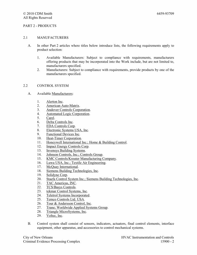
© 2018 CDM Smith 6459-93709
All Rights Reserved
City of New Orleans HVAC Instrumentation and Controls
Criminal Evidence Processing Complex 15900 - 2
PART 2 - PRODUCTS
2.1 MANUFACTURERS
A. In other Part 2 articles where titles below introduce lists, the following requirements apply to
product selection:
1. Available Manufacturers: Subject to compliance with requirements, manufacturers
offering products that may be incorporated into the Work include, but are not limited to,
manufacturers specified.
2. Manufacturers: Subject to compliance with requirements, provide products by one of the
manufacturers specified.
2.2 CONTROL SYSTEM
A. Available Manufacturers:
1. Alerton Inc.
2. American Auto-Matrix.
3. Andover Controls Corporation.
4. Automated Logic Corporation.
5. Carel.
6. Delta Controls Inc.
7. EDA Controls Corp.
8. Electronic Systems USA, Inc.
9. Functional Devices Inc.
10. Heat-Timer Corporation.
11. Honeywell International Inc.; Home & Building Control.
12. Impact Energy Controls Corp.
13. Invensys Building Systems.
14. Johnson Controls, Inc.; Controls Group.
15. KMC Controls/Kreuter Manufacturing Company.
16. Luwa USA, Inc.; Textile Air Engineering.
17. McQuay International.
18. Siemens Building Technologies, Inc.
19. Solidyne Corp.
20. Staefa Control System Inc.; Siemens Building Technologies, Inc.
21. TAC Americas, INC.
22. TCS/Basys Controls.
23. tekmar Control Systems, Inc.
24. Teletrol Systems Incorporated.
25. Temco Controls Ltd. USA.
26. Tour & Andersson Control, Inc.
27. Trane; Worldwide Applied Systems Group.
28. Triangle MicroSystems, Inc.
29. Voltec, Inc.
B. Control system shall consist of sensors, indicators, actuators, final control elements, interface
equipment, other apparatus, and accessories to control mechanical systems.
© 2018 CDM Smith 6459-93709
All Rights Reserved
City of New Orleans HVAC Instrumentation and Controls
Criminal Evidence Processing Complex 15900 - 3
C. Control system shall consist of sensors, indicators, actuators, final control elements, interface
equipment, other apparatus, accessories, and software connected to distributed controllers
operating in multiuser, multitasking environment on token-passing network and programmed to
control mechanical systems. An operator workstation permits interface with the network via
dynamic color graphics with each mechanical system, building floor plan, and control device
depicted by point-and-click graphics.
2.3 DDC EQUIPMENT
A. Operator Workstation: PC-based microcomputer with minimum configuration as follows:
1. Motherboard: With 8 integrated USB 2.0 ports, integrated Intel Pro 10/100 (Ethernet),
integrated audio, bios, and hardware monitoring.
2. Processor: Intel Pentium 5, MHz.
3. Random-Access Memory: 512 MB.
4. Graphics: Video adapter, minimum 1600 x 1200 pixels, 64-MB video memory, with TV
out.
5. Monitor: 20 inches, LCD color.
6. Keyboard: QWERTY, 105 keys in ergonomic shape.
7. Floppy-Disk Drive: 1.44 MB.
8. Hard-Disk Drive: 80 GB.
9. DVD-ROM Read/Write Drive: 48x24x48.
10. Mouse: Three button, optical.
11. Uninterruptible Power Supply: 2 kVa.
12. Operating System: Microsoft Windows 10 with high-speed Internet access.
13. Printer: Color, ink-jet type as follows:
a. Print Head: 4800 x 1200 dpi optimized color resolution.
b. Paper Handling: Minimum of 100 sheets.
c. Application Software.
B. Control Units: Modular, comprising processor board with programmable, nonvolatile, random-
access memory; local operator access and display panel; integral interface equipment; and
backup power source.
1. Units monitor or control each I/O point; process information; execute commands from
other control units, devices, and operator stations; and download from or upload to
operator workstation.
2. Stand-alone mode control functions operate regardless of network status. Functions
include the following:
a. Global communications.
b. Discrete/digital, analog, and pulse I/O.
c. Monitoring, controlling, or addressing data points.
d. Software applications, scheduling, and alarm processing.
e. Testing and developing control algorithms without disrupting field hardware and
controlled environment.
C. Local Control Units: Modular, comprising processor board with electronically programmable,
nonvolatile, read-only memory; and backup power source.
© 2018 CDM Smith 6459-93709
All Rights Reserved
City of New Orleans HVAC Instrumentation and Controls
Criminal Evidence Processing Complex 15900 - 4
1. Units monitor or control each I/O point, process information, and download from or
upload to operator workstation or diagnostic terminal unit.
2. Stand-alone mode control functions operate regardless of network status. Functions
include the following:
a. Global communications.
b. Discrete/digital, analog, and pulse I/O.
c. Monitoring, controlling, or addressing data points.
3. Local operator interface provides for download from or upload to operator workstation.
D. I/O Interface: Hardwired inputs and outputs may tie into system through controllers. Protect
points so that shorting will cause no damage to controllers.
1. Binary Inputs: Allow monitoring of on-off signals without external power.
2. Pulse Accumulation Inputs: Accept up to 10 pulses per second.
3. Analog Inputs: Allow monitoring of low-voltage (0- to 10-V dc), current (4 to 20 mA), or
resistance signals.
4. Binary Outputs: Provide on-off or pulsed low-voltage signal, selectable for normally
open or normally closed operation with three-position (on-off-auto) override switches and
status lights.
5. Analog Outputs: Provide modulating signal, either low voltage (0- to 10-V dc) or current
(4 to 20 mA) with status lights, two-position (auto-manual) switch, and manually
adjustable potentiometer.
6. Tri-State Outputs: Provide two coordinated binary outputs for control of three-point,
floating-type electronic actuators.
7. Universal I/Os: Provide software selectable binary or analog outputs.
E. Power Supplies: Transformers with Class 2 current-limiting type or overcurrent protection; limit
connected loads to 80 percent of rated capacity. DC power supply shall match output current
and voltage requirements and be full-wave rectifier type with the following:
1. Output ripple of 5.0 mV maximum peak to peak.
2. Combined 1 percent line and load regulation with 100-mic.sec. response time for 50
percent load changes.
3. Built-in overvoltage and overcurrent protection and be able to withstand 150 percent
overload for at least 3 seconds without failure.
F. Power Line Filtering: Internal or external transient voltage and surge suppression for
workstations or controllers with the following:
1. Minimum dielectric strength of 1000 V.
2. Maximum response time of 10 nanoseconds.
3. Minimum transverse-mode noise attenuation of 65 dB.
4. Minimum common-mode noise attenuation of 150 dB at 40 to 100 Hz.
© 2018 CDM Smith 6459-93709
All Rights Reserved
City of New Orleans HVAC Instrumentation and Controls
Criminal Evidence Processing Complex 15900 - 5
2.4 UNITARY CONTROLLERS
A. Unitized, capable of stand-alone operation with sufficient memory to support its operating
system, database, and programming requirements, and with sufficient I/O capacity for the
application.
1. Configuration: Local keypad and display; diagnostic LEDs for power, communication,
and processor; wiring termination to terminal strip or card connected with ribbon cable;
memory with bios; and 72-hour battery backup.
2. Operating System: Manage I/O communication to allow distributed controllers to share
real and virtual object information and allow central monitoring and alarms.Perform
automatic system diagnostics; monitor system and report failures.
3. Enclosure: Dustproof rated for operation at 32 to 120 deg F.
2.5 ANALOG CONTROLLERS
A. Step Controllers: 6- or 10-stage type, with heavy-duty switching rated to handle loads and
operated by electric motor.
B. Electric, Outdoor-Reset Controllers: Remote-bulb or bimetal rod-and-tube type, proportioning
action with adjustable throttling range, adjustable set point, scale range minus 10 to plus 70
deg F, and single- or double-pole contacts.
C. Electronic Controllers: Wheatstone-bridge-amplifier type, in steel enclosure with provision for
remote-resistance readjustment. Identify adjustments on controllers, including proportional band
and authority.
1. Single controllers can be integral with control motor if provided with accessible control
readjustment potentiometer.
D. Fan-Speed Controllers: Solid-state model providing field-adjustable proportional control of
motor speed from maximum to minimum of 55 percent and on-off action below minimum fan
speed. Controller shall briefly apply full voltage, when motor is started, to rapidly bring motor
up to minimum speed. Equip with filtered circuit to eliminate radio interference.
2.6 ELECTRONIC SENSORS
A. Description: Vibration and corrosion resistant; for wall, immersion, or duct mounting as
required.
B. Thermistor Temperature Sensors and Transmitters:
1. Available Manufacturers:
a. BEC Controls Corporation.
b. Ebtron, Inc.
c. Heat-Timer Corporation.
d. I.T.M. Instruments Inc.
e. MAMAC Systems, Inc.
© 2018 CDM Smith 6459-93709
All Rights Reserved
City of New Orleans HVAC Instrumentation and Controls
Criminal Evidence Processing Complex 15900 - 6
f. RDF Corporation.
2. Accuracy: Plus or minus 0.5 deg F at calibration point.
3. Wire: Twisted, shielded-pair cable.
4. Insertion Elements in Ducts: Single point, 8 inches long; use where not affected by
temperature stratification or where ducts are smaller than 9 sq. ft..
5. Averaging Elements in Ducts: 72 inches long, flexible; use where prone to temperature
stratification or where ducts are larger than 10 sq. ft..
6. Insertion Elements for Liquids: Brass or stainless-steel socket with minimum insertion
length of 2-1/2 inches.
7. Room Sensor Cover Construction: Manufacturer's standard locking covers.
a. Set-Point Adjustment: Exposed.
b. Set-Point Indication: Exposed.
c. Thermometer: Exposed.
8. Outside-Air Sensors: Watertight inlet fitting, shielded from direct sunlight.
9. Room Security Sensors: Stainless-steel cover plate with insulated back and security
screws.
C. RTDs and Transmitters:
1. Available Manufacturers:
a. BEC Controls Corporation.
b. MAMAC Systems, Inc.
c. RDF Corporation.
2. Accuracy: Plus or minus 0.2 percent at calibration point.
3. Wire: Twisted, shielded-pair cable.
4. Insertion Elements in Ducts: Single point, 8 inches long; use where not affected by
temperature stratification or where ducts are smaller than 9 sq. ft..
5. Averaging Elements in Ducts: 18 inches long, rigid; use where prone to temperature
stratification or where ducts are larger than 9 sq. ft.; length as required.
6. Insertion Elements for Liquids: Brass socket with minimum insertion length of 2-1/2
inches.
7. Room Sensor Cover Construction: Manufacturer's standard locking covers.
a. Set-Point Adjustment: Exposed.
b. Set-Point Indication: Exposed.
c. Thermometer: Exposed.
8. Outside-Air Sensors: Watertight inlet fitting, shielded from direct sunlight.
9. Room Security Sensors: Stainless-steel cover plate with insulated back and security
screws.
D. Humidity Sensors: Bulk polymer sensor element.
1. Available Manufacturers:
a. BEC Controls Corporation.
© 2018 CDM Smith 6459-93709
All Rights Reserved
City of New Orleans HVAC Instrumentation and Controls
Criminal Evidence Processing Complex 15900 - 7
b. General Eastern Instruments.
c. MAMAC Systems, Inc.
d. ROTRONIC Instrument Corp.
e. TCS/Basys Controls.
f. Vaisala.
2. Accuracy: 2 percent full range with linear output.
3. Room Sensor Range: 20 to 80 percent relative humidity.
4. Room Sensor Cover Construction: Manufacturer's standard locking covers.
a. Set-Point Adjustment: Exposed.
b. Set-Point Indication: Exposed.
c. Thermometer: Concealed.
5. Duct Sensor: 20 to 80 percent relative humidity range with element guard and mounting
plate.
6. Outside-Air Sensor: 20 to 80 percent relative humidity range with mounting enclosure,
suitable for operation at outdoor temperatures of minus 22 to plus 185 deg F.
7. Duct and Sensors: With element guard and mounting plate, range of 0 to 100 percent
relative humidity.
E. Pressure Transmitters/Transducers:
1. Available Manufacturers:
a. BEC Controls Corporation.
b. General Eastern Instruments.
c. MAMAC Systems, Inc.
d. ROTRONIC Instrument Corp.
e. TCS/Basys Controls.
f. Vaisala.
2. Static-Pressure Transmitter: Nondirectional sensor with suitable range for expected input,
and temperature compensated.
a. Accuracy: 2 percent of full scale with repeatability of 0.5 percent.
b. Output: 4 to 20 mA.
c. Building Static-Pressure Range: 0- to 0.25-inch wg.
d. Duct Static-Pressure Range: 0- to 5-inch wg.
3. Water Pressure Transducers: Stainless-steel diaphragm construction, suitable for service;
minimum 150-psig operating pressure; linear output 4 to 20 mA.
4. Water Differential-Pressure Transducers: Stainless-steel diaphragm construction, suitable
for service; minimum 150-psig operating pressure and tested to 300-psig; linear output 4
to 20 mA.
5. Differential-Pressure Switch (Air or Water): Snap acting, with pilot-duty rating and with
suitable scale range and differential.
6. Pressure Transmitters: Direct acting for gas or liquid service; range suitable for system;
linear output 4 to 20 mA.
© 2018 CDM Smith 6459-93709
All Rights Reserved
City of New Orleans HVAC Instrumentation and Controls
Criminal Evidence Processing Complex 15900 - 8
2.7 STATUS SENSORS
A. Status Inputs for Fans: Differential-pressure switch with pilot-duty rating and with adjustable
range of 0- to 5-inch wg.
B. Status Inputs for Pumps: Differential-pressure switch with pilot-duty rating and with adjustable
pressure-differential range of 8 to 60 psig, piped across pump.
C. Status Inputs for Electric Motors: Comply with ISA 50.00.01, current-sensing fixed- or split-
core transformers with self-powered transmitter, adjustable and suitable for 175 percent of rated
motor current.
D. Voltage Transmitter (100- to 600-V ac): Comply with ISA 50.00.01, single-loop, self-powered
transmitter, adjustable, with suitable range and 1 percent full-scale accuracy.
E. Current Switches: Self-powered, solid-state with adjustable trip current, selected to match
current and system output requirements.
F. Electronic Valve/Damper Position Indicator: Visual scale indicating percent of travel and 2- to
10-V dc, feedback signal.
G. Water-Flow Switches: Bellows-actuated mercury or snap-acting type with pilot-duty rating,
stainless-steel or bronze paddle, with appropriate range and differential adjustment, in
NEMA 250, Type 1 enclosure.
1. Available Manufacturers:
a. BEC Controls Corporation.
b. I.T.M. Instruments Inc.
2.8 GAS DETECTION EQUIPMENT
A. Available Manufacturers:
1. B. W. Technologies.
2. CEA Instruments, Inc.
3. Ebtron, Inc.
4. Gems Sensors Inc.
5. Greystone Energy Systems Inc.
6. Honeywell International Inc.; Home & Building Control.
7. INTEC Controls, Inc.
8. I.T.M. Instruments Inc.
9. MSA Canada Inc.
10. QEL/Quatrosense Environmental Limited.
11. Sauter Controls Corporation.
12. Sensidyne, Inc.
13. TSI Incorporated.
14. Vaisala.
15. Vulcain Inc.
© 2018 CDM Smith 6459-93709
All Rights Reserved
City of New Orleans HVAC Instrumentation and Controls
Criminal Evidence Processing Complex 15900 - 9
B. Carbon Dioxide Sensor and Transmitter: Single detectors using solid-state infrared sensors;
suitable over a temperature range of 23 to 130 deg F and calibrated for 0 to 2 percent, with
continuous or averaged reading, 4- to 20-mA output;, for wall mounting.
C. Occupancy Sensor: Passive infrared, with time delay, daylight sensor lockout, sensitivity
control, and 180-degree field of view with vertical sensing adjustment; for flush mounting.
2.9 THERMOSTATS
A. Available Manufacturers:
1. Erie Controls.
2. Danfoss Inc.; Air-Conditioning and Refrigeration Div.
3. Heat-Timer Corporation.
4. Sauter Controls Corporation.
5. tekmar Control Systems, Inc.
6. Theben AG - Lumilite Control Technology, Inc.
B. Electric, solid-state, microcomputer-based room thermostat with remote sensor.
1. Automatic switching from heating to cooling.
2. Preferential rate control to minimize overshoot and deviation from set point.
3. Set up for four separate temperatures per day.
4. Instant override of set point for continuous or timed period from 1 hour to 31 days.
5. Short-cycle protection.
6. Programming based on every day of week.
7. Selection features include degree F or degree C display, 12- or 24-hour clock, keyboard
disable, remote sensor, and fan on-auto.
8. Battery replacement without program loss.
9. Thermostat display features include the following:
a. Time of day.
b. Actual room temperature.
c. Programmed temperature.
d. Programmed time.
e. Duration of timed override.
f. Day of week.
g. System mode indications include "heating," "off," "fan auto," and "fan on."
C. Low-Voltage, On-Off Thermostats: NEMA DC 3, 24-V, bimetal-operated, mercury-switch
type, with adjustable or fixed anticipation heater, concealed set-point adjustment, 55 to 85 deg F
set-point range, and 2 deg F maximum differential.
D. Line-Voltage, On-Off Thermostats: Bimetal-actuated, open contact or bellows-actuated,
enclosed, snap-switch or equivalent solid-state type, with heat anticipator; listed for electrical
rating; with concealed set-point adjustment, 55 to 85 deg F set-point range, and 2 deg F
maximum differential.
1. Electric Heating Thermostats: Equip with off position on dial wired to break ungrounded
conductors.
© 2018 CDM Smith 6459-93709
All Rights Reserved
City of New Orleans HVAC Instrumentation and Controls
Criminal Evidence Processing Complex 15900 - 10
2. Selector Switch: Integral, manual on-off-auto.
E. Remote-Bulb Thermostats: On-off or modulating type, liquid filled to compensate for changes
in ambient temperature; with copper capillary and bulb, unless otherwise indicated.
1. Bulbs in water lines with separate wells of same material as bulb.
2. Bulbs in air ducts with flanges and shields.
3. Averaging Elements: Copper tubing with either single- or multiple-unit elements,
extended to cover full width of duct or unit; adequately supported.
4. Scale settings and differential settings are clearly visible and adjustable from front of
instrument.
5. On-Off Thermostat: With precision snap switches and with electrical ratings required by
application.
6. Modulating Thermostats: Construct so complete potentiometer coil and wiper assembly is
removable for inspection or replacement without disturbing calibration of instrument.
F. Room Thermostat Cover Construction: Manufacturer's standard locking covers.
1. Set-Point Adjustment: Exposed.
2. Set-Point Indication: Exposed.
3. Thermometer: Concealed.
G. Immersion Thermostat: Remote-bulb or bimetal rod-and-tube type, proportioning action with
adjustable throttling range and adjustable set point.
H. Airstream Thermostats: Two-pipe, fully proportional, single-temperature type; with adjustable
set point in middle of range, adjustable throttling range, plug-in test fitting or permanent
pressure gage, remote bulb, bimetal rod and tube, or averaging element.
2.10 ACTUATORS
A. Electric Motors: Size to operate with sufficient reserve power to provide smooth modulating
action or two-position action.
1. Comply with requirements in Section 15058 "Common Motor Requirements for HVAC
Equipment."
2. Permanent Split-Capacitor or Shaded-Pole Type: Gear trains completely oil immersed
and sealed. Equip spring-return motors with integral spiral-spring mechanism in housings
designed for easy removal for service or adjustment of limit switches, auxiliary switches,
or feedback potentiometer.
3. Nonspring-Return Motors for Valves Larger Than NPS 2-1/2: Size for running torque of
150 in. x lbf and breakaway torque of 300 in. x lbf.
4. Nonspring-Return Motors for Dampers Larger Than 25 Sq. Ft.: Size for running torque of
150 in. x lbf and breakaway torque of 300 in. x lbf.
5. Spring-Return Motors for Dampers Larger Than 25 Sq. Ft.: Size for running and
breakaway torque of 150 in. x lbf.
B. Electronic Actuators: Direct-coupled type designed for minimum 60,000 full-stroke cycles at
rated torque.
© 2018 CDM Smith 6459-93709
All Rights Reserved
City of New Orleans HVAC Instrumentation and Controls
Criminal Evidence Processing Complex 15900 - 11
1. Available Manufacturers:
a. Belimo Aircontrols (USA), Inc.
2. Valves: Size for torque required for valve close off at maximum pump differential
pressure.
3. Dampers: Size for running torque calculated as follows:
a. Parallel-Blade Damper with Edge Seals: 7 inch-lb/sq. ft. of damper.
b. Opposed-Blade Damper with Edge Seals: 5 inch-lb/sq. ft. of damper.
c. Parallel-Blade Damper without Edge Seals: 4 inch-lb/sq. ft of damper.
d. Opposed-Blade Damper without Edge Seals: 3 inch-lb/sq. ft. of damper.
e. Dampers with 2- to 3-Inch wg of Pressure Drop or Face Velocities of 1000 to 2500
fpm: Increase running torque by 1.5.
f. Dampers with 3- to 4-Inch wg of Pressure Drop or Face Velocities of 2500 to 3000
fpm: Increase running torque by 2.0.
4. Coupling: V-bolt and V-shaped, toothed cradle.
5. Overload Protection: Electronic overload or digital rotation-sensing circuitry.
6. Fail-Safe Operation: Mechanical, spring-return mechanism. Provide external, manual
gear release on nonspring-return actuators.
7. Power Requirements (Two-Position Spring Return): 120-V ac.
8. Power Requirements (Modulating): Maximum 10 VA at 24-V ac or 8 W at 24-V dc.
9. Proportional Signal: 2- to 10-V dc or 4 to 20 mA, and 2- to 10-V dc position feedback
signal.
10. Temperature Rating: Minus 22 to plus 122 deg F.
11. Temperature Rating (Smoke Dampers): Minus 22 to plus 250 deg F.
12. Run Time: 12 seconds open, 5 seconds closed.
2.11 CONTROL VALVES
A. Available Manufacturers:
1. Danfoss Inc.; Air Conditioning & Refrigeration Div.
2. Erie Controls.
3. Hayward Industrial Products, Inc.
4. Magnatrol Valve Corporation.
5. Neles-Jamesbury.
6. Parker Hannifin Corporation; Skinner Valve Division.
7. Pneuline Controls.
8. Sauter Controls Corporation.
B. Control Valves: Factory fabricated, of type, body material, and pressure class based on
maximum pressure and temperature rating of piping system, unless otherwise indicated.
C. Hydronic system globe valves shall have the following characteristics:
1. NPS 2 and Smaller: Class 125 bronze body, bronze trim, rising stem, renewable
composition disc, and screwed ends with backseating capacity repackable under pressure.
© 2018 CDM Smith 6459-93709
All Rights Reserved
City of New Orleans HVAC Instrumentation and Controls
Criminal Evidence Processing Complex 15900 - 12
2. NPS 2-1/2 and Larger: Class 125 iron body, bronze trim, rising stem, plug-type disc,
flanged ends, and renewable seat and disc.
3. Internal Construction: Replaceable plugs and stainless-steel or brass seats.
a. Single-Seated Valves: Cage trim provides seating and guiding surfaces for plug on
top and bottom.
b. Double-Seated Valves: Balanced plug; cage trim provides seating and guiding
surfaces for plugs on top and bottom.
4. Sizing: 3-psig maximum pressure drop at design flow rate or the following:
a. Two Position: Line size.
b. Three-Way Modulating: Twice the load pressure drop, but not more than value
specified above.
5. Flow Characteristics: Two-way valves shall have equal percentage characteristics; three-
way valves shall have linear characteristics.
6. Close-Off (Differential) Pressure Rating: Combination of actuator and trim shall provide
minimum close-off pressure rating of 150 percent of total system (pump) head for two-
way valves and 100 percent of pressure differential across valve or 100 percent of total
system (pump) head.
D. Butterfly Valves: 200-psig, 150-psig maximum pressure differential, ASTM A 126 cast-iron or
ASTM A 536 ductile-iron body and bonnet, extended neck, stainless-steel stem, field-
replaceable EPDM or Buna N sleeve and stem seals.
1. Body Style: Wafer.
2. Disc Type: Nickel-plated ductile iron.
3. Sizing: 1-psig maximum pressure drop at design flow rate.
E. Terminal Unit Control Valves: Bronze body, bronze trim, two or three ports as indicated,
replaceable plugs and seats, and union and threaded ends.
1. Rating: Class 125 for service at 125 psig and 250 deg F operating conditions.
2. Sizing: 3-psig maximum pressure drop at design flow rate, to close against pump shutoff
head.
3. Flow Characteristics: Two-way valves shall have equal percentage characteristics; three-
way valves shall have linear characteristics.
2.12 DAMPERS
A. Available Manufacturers:
1. Air Balance Inc.
2. Don Park Inc.; Autodamp Div.
3. TAMCO (T. A. Morrison & Co. Inc.).
4. United Enertech Corp.
5. Vent Products Company, Inc.
© 2018 CDM Smith 6459-93709
All Rights Reserved
City of New Orleans HVAC Instrumentation and Controls
Criminal Evidence Processing Complex 15900 - 13
B. Dampers: AMCA-rated, opposed-blade design; 0.108-inch-minimum thick, galvanized-steel or
0.125-inch-minimum thick, extruded-aluminum frames with holes for duct mounting; damper
blades shall not be less than 0.064-inch-thick galvanized steel with maximum blade width of 8
inches and length of 48 inches.
1. Secure blades to 1/2-inch-diameter, zinc-plated axles using zinc-plated hardware, with
oil-impregnated sintered bronze blade bearings, blade-linkage hardware of zinc-plated
steel and brass, ends sealed against spring-stainless-steel blade bearings, and thrust
bearings at each end of every blade.
2. Operating Temperature Range: From minus 40 to plus 200 deg F.
3. Edge Seals, Standard Pressure Applications: Closed-cell neoprene.
4. Edge Seals, Low-Leakage Applications: Use inflatable blade edging or replaceable
rubber blade seals and spring-loaded stainless-steel side seals, rated for leakage at less
than 10 cfm per sq. ft. of damper area, at differential pressure of 4-inch wg when damper
is held by torque of 50 in. x lbf; when tested according to AMCA 500D.
2.13 CONTROL CABLE
A. Electronic and fiber-optic cables for control wiring are specified in Section 16717
"Communications Horizontal Cabling."
PART 3 - EXECUTION
3.1 INSTALLATION
A. Verify location of thermostats, humidistats, and other exposed control sensors with Drawings
and room details before installation. Install devices 60 inches above the floor.
1. Install averaging elements in ducts and plenums in crossing or zigzag pattern.
B. Install guards on thermostats in the following locations:
1. Entrances.
2. Public areas.
3. Where indicated.
C. Install automatic dampers according to Section 15820 "Duct Accessories."
D. Install damper motors on outside of duct in warm areas, not in locations exposed to outdoor
temperatures.
E. Install labels and nameplates to identify control components according to Section 15077
"Identification for HVAC Piping and Equipment."
F. Install hydronic instrument wells, valves, and other accessories according to Section 232116
"Hydronic Piping Specialties."Section 15179 "Hydronic Piping Specialties."
© 2018 CDM Smith 6459-93709
All Rights Reserved
City of New Orleans HVAC Instrumentation and Controls
Criminal Evidence Processing Complex 15900 - 14
G. Install refrigerant instrument wells, valves, and other accessories according to Section 15183
"Refrigerant Piping."
H. Install duct volume-control dampers according to Section 15815 "Metal Ducts" and
Section 15816 "Nonmetal Ducts."
I. Install electronic and fiber-optic cables according to Section 16717 "Communications
Horizontal Cabling."
3.2 ELECTRICAL WIRING AND CONNECTION INSTALLATION
A. Install raceways, boxes, and cabinets according to Section 16130 "Raceways and Boxes."
B. Install building wire and cable according to Section 16120 "Conductors and Cables."
C. Install signal and communication cable according to Section 16717 "Communications
Horizontal Cabling."
1. Conceal cable, except in mechanical rooms and areas where other conduit and piping are
exposed.
2. Install exposed cable in raceway.
3. Install concealed cable in raceway.
4. Bundle and harness multiconductor instrument cable in place of single cables where
several cables follow a common path.
5. Fasten flexible conductors, bridging cabinets and doors, along hinge side; protect against
abrasion. Tie and support conductors.
6. Number-code or color-code conductors for future identification and service of control
system, except local individual room control cables.
7. Install wire and cable with sufficient slack and flexible connections to allow for vibration
of piping and equipment.
D. Connect manual-reset limit controls independent of manual-control switch positions. Automatic
duct heater resets may be connected in interlock circuit of power controllers.
E. Connect hand-off-auto selector switches to override automatic interlock controls when switch is
in hand position.
3.3 FIELD QUALITY CONTROL
A. Manufacturer's Field Service: Engage a factory-authorized service representative to inspect, test,
and adjust field-assembled components and equipment installation, including connections, and
to assist in field testing. Report results in writing.
B. Perform the following field tests and inspections and prepare test reports:
1. Operational Test: After electrical circuitry has been energized, start units to confirm
proper unit operation. Remove and replace malfunctioning units and retest.
2. Test and adjust controls and safeties.
© 2018 CDM Smith 6459-93709
All Rights Reserved
City of New Orleans HVAC Instrumentation and Controls
Criminal Evidence Processing Complex 15900 - 15
3. Test calibration of controllers by disconnecting input sensors and stimulating operation
with compatible signal generator.
4. Test each point through its full operating range to verify that safety and operating control
set points are as required.
5. Test each control loop to verify stable mode of operation and compliance with sequence
of operation. Adjust PID actions.
6. Test each system for compliance with sequence of operation.
7. Test software and hardware interlocks.
C. DDC Verification:
1. Verify that instruments are installed before calibration, testing, and loop or leak checks.
2. Check instruments for proper location and accessibility.
3. Check instrument installation for direction of flow, elevation, orientation, insertion depth,
and other applicable considerations.
4. Check instrument tubing for proper fittings, slope, material, and support.
5. Check pressure instruments, piping slope, installation of valve manifold, and self-
contained pressure regulators.
6. Check temperature instruments and material and length of sensing elements.
7. Check control valves. Verify that they are in correct direction.
8. Check air-operated dampers. Verify that pressure gages are provided and that proper
blade alignment, either parallel or opposed, has been provided.
9. Check DDC system as follows:
a. Verify that DDC controller power supply is from emergency power supply, if
applicable.
b. Verify that wires at control panels are tagged with their service designation and
approved tagging system.
c. Verify that spare I/O capacity has been provided.
d. Verify that DDC controllers are protected from power supply surges.
D. Replace damaged or malfunctioning controls and equipment and repeat testing procedures.
3.4 DEMONSTRATION
A. Engage a factory-authorized service representative to train Owner's maintenance personnel to
adjust, operate, and maintain HVAC instrumentation and controls. Refer to Section 01820
"Demonstration and Training."
END OF SECTION 15900
© 2018 CDM Smith 6459-93709
All Rights Reserved
City of New Orleans Sequence of Operation
Criminal Evidence Processing Complex 15940 - 1
SECTION 15940 - SEQUENCE OF OPERATION
PART 1 - GENERAL
1.1 SUMMARY
A. This Section includes control sequences for HVAC systems, subsystems, and equipment.
B. See Section 15900 "HVAC Instrumentation and Controls" for control equipment and devices
and for submittal requirements.
1.2 CENTRAL REFRIGERATION EQUIPMENT SEQUENCES
A. Start and Stop Chilled-Water Pump(s):
1. Input Device: Flow switch in condenser-water circuit.
2. Output Device: DDC system command to starter relay.
3. Action: Energize pump(s).
4. Display:
a. Chilled-water flow indication.
b. Chilled-water pump(s) on-off status.
c. Chilled-water pump(s) on-off indication.
B. Start and Stop Chiller(s):
1. Input Device: Flow switches in condenser-water and chilled-water circuit.
2. Output Device: Chiller terminal strip.
3. Action: Energize chiller internal control circuit.
4. Display:
a. Condenser-water flow indication.
b. Chilled-water flow indication.
c. Chiller(s) on-off status.
d. Chiller(s) on-off indication.
e. Chilled-water supply and return temperature.
f. Chilled-water temperature control-point adjustment.
C. Alternate Chiller(s):
1. Input Device: DDC system software.
2. Output Device: Chiller terminal strip.
3. Action: Operate chiller(s) on lead-lag, alternating each startup.
4. Display: Chiller(s) on-off indication.
D. Alarm Chiller(s) Start Failure:
1. Input Device: Chiller software signal.
© 2018 CDM Smith 6459-93709
All Rights Reserved
City of New Orleans Sequence of Operation
Criminal Evidence Processing Complex 15940 - 2
2. Output Device: DDC system alarm.
3. Action: Signal alarm.
4. Display: Chiller "failure-to-start" indication.
E. Chilled-Water Level:
1. Input Device: Expansion tank liquid sensor.
2. Output Device: DDC system alarm.
3. Action: Signal alarm.
4. Display: Expansion tank low-level alarm.
F. Chilled-Water Supply Temperature:
1. Input Device: Temperature sensor in common chilled-water supply piping.
2. Output Device: Integral chiller controls.
3. Action: Maintain constant leaving chilled-water temperature.
a. Display: Chilled-water supply temperature.
G. Operator Station Display: Indicate the following on operator workstation display terminal:
1. DDC system graphic.
2. DDC system status, on-off.
3. Outdoor-air temperature.
4. Cooling (software) demand indication.
5. Time and time schedule.
6. Chilled-water pump(s) on-off status.
7. Chilled-water pump(s) on-off indication.
8. Chilled-water flow indication.
9. Refrigeration machine on-off indication.
10. Chilled-water supply temperature.
11. Chilled-water return temperature.
12. Chilled-water temperature control-point adjustment.
13. Chiller(s) on-off status.
14. Chiller(s) on-off indication.
15. Chiller "failure-to-start" indication.
16. Expansion tank low-level alarm.
17. Chilled-water pressure drop through chiller.
18. Chiller chilled-water supply and return temperature.
19. System capacity in tons.
1.3 AIR-HANDLING-UNIT CONTROL SEQUENCES
A. Start and Stop Supply Fan(s):
1. Enable: Freeze Protection:
a. Input Device: Duct-mounted averaging element thermostat, located before supply
fan.
b. Output Device: Hard wired through motor starter; DDC system alarm.
© 2018 CDM Smith 6459-93709
All Rights Reserved
City of New Orleans Sequence of Operation
Criminal Evidence Processing Complex 15940 - 3
c. Action: Allow start if duct temperature is above 37 deg F; signal alarm if fan fails
to start as commanded.
2. Enable: High-Temperature Protection:
a. Input Device: Duct-mounted thermostat, located in return air.
b. Output Device: Hard wired through motor starter; DDC system alarm.
c. Action: Allow start if duct temperature is below 300 deg F.
3. Initiate: Occupied Time Schedule:
a. Input Device: DDC system time schedule.
b. Output Device: Binary output to motor starter.
c. Action: Energize fan(s).
4. Initiate: Unoccupied Time Schedule:
a. Input Device: DDC system demand.
b. Output Device: Binary output to motor starter.
c. Action: Energize fan(s).
5. Unoccupied Ventilation:
a. Input Device: DDC system time schedule and output.
b. Output Device: DDC system binary output to motor starter.
c. Action: Cycle fan(s) during unoccupied periods.
6. Display: Supply-fan on-off indication.
B. Supply Fan(s) Variable-Volume Control:
1. Occupied Time Schedule:
a. Input Device: DDC system time schedule.
b. Output Device: Binary output.
c. Action: Enable control.
2. Volume Control:
a. Input Device: Static-pressure transmitter sensing supply-duct static pressure
referenced to conditioned-space static pressure.
b. Output Device: DDC system analog output to motor speed controller. Set
variable-speed drive to minimum speed when fan is stopped.
c. Action: Maintain constant supply-duct static pressure.
3. High Pressure:
a. Input Device: Static-pressure transmitter sensing supply-duct static pressure
referenced to static pressure outside the duct.
b. Output Device: DDC system binary output to alarm panel.
© 2018 CDM Smith 6459-93709
All Rights Reserved
City of New Orleans Sequence of Operation
Criminal Evidence Processing Complex 15940 - 4
c. Action: Stop fan and signal alarm when static pressure rises above excessive-
static-pressure set point.
4. Display:
a. Supply-fan-discharge static-pressure indication.
b. Supply-fan-discharge static-pressure set point.
c. Supply-fan airflow rate.
d. Supply-fan speed.
5. Unoccupied Ventilation:
a. Input Device: DDC system time schedule and output.
b. Output Device: DDC system binary output to motor starter.
c. Action: Cycle fan(s) during unoccupied periods.
6. Display: Return-fan on-off indication.
C. Filters: During occupied periods, when fan is running, differential air-pressure transmitters
exist.
1. Differential Pressure:
a. Input Device: Differential-pressure switches.
b. Output Device: DDC system alarm.
c. Action: Signal alarm on low- and high-pressure conditions.
2. Display:
a. Filter air-pressure-drop indication.
D. Hydronic Cooling Coil:
1. Occupied Time Schedule:
a. Input Device: DDC system time schedule.
b. Output Device: Binary output.
c. Action: Enable control.
2. Discharge-Air Temperature:
a. Input Device: Electronic temperature sensor.
b. Output Device: Normally closed modulating control valve.
c. Action: Maintain supply-air temperature set point of 55 deg F.
3. Temperature Reset:
a. Input Device: Electronic temperature sensor in return air.
b. Output Device: DDC system in straight-line relationship for the following
conditions:
© 2018 CDM Smith 6459-93709
All Rights Reserved
City of New Orleans Sequence of Operation
Criminal Evidence Processing Complex 15940 - 5
1) 60 deg F when return-air temperature is 70 deg F.
2) 55 deg F when return-air temperature is 75 deg F.
c. Action: Reset supply-air temperature set point of 55 deg F.
4. Unoccupied Time Schedule:
a. Input Device: DDC system time schedule.
b. Output Device: Binary output.
c. Action: Disable control.
5. Display:
a. Fan-discharge air-temperature indication.
b. Fan-discharge air-temperature set point.
c. Cooling-coil air-temperature indication.
d. Cooling-coil air-temperature set point.
e. Cooling-coil control-valve position.
E. Coordination of Air-Handling Unit Sequences: Ensure that preheat, mixed-air, heating-coil, and
cooling-coil controls have common inputs and do not overlap in function.
F. Operator Station Display: Indicate the following on operator workstation display terminal:
1. DDC system graphic.
2. DDC system on-off indication.
3. DDC system occupied/unoccupied mode.
4. Outdoor-air-temperature indication.
5. Supply-fan on-off indication.
6. Supply-fan-discharge static-pressure indication.
7. Supply-fan-discharge static-pressure set point.
8. Supply-fan airflow rate.
9. Supply-fan speed.
10. Building static-pressure indication.
11. Building static-pressure set point.
12. Filter air-pressure-drop indication.
13. Fan-discharge air-temperature indication.
14. Fan-discharge air-temperature set point.
15. Cooling-coil air-temperature indication.
16. Cooling-coil air-temperature set point.
17. Cooling-coil control-valve position.
18. Room temperature indication.
19. Room temperature set point.
1.4 TERMINAL UNIT OPERATING SEQUENCE
A. Cabinet Unit Heater, Hydronic:
1. Room Temperature:
© 2018 CDM Smith 6459-93709
All Rights Reserved
City of New Orleans Sequence of Operation
Criminal Evidence Processing Complex 15940 - 6
a. Input Device: Electronic temperature sensor.
b. Output Device: DDC system binary output.
c. Action: Cycle fan to maintain temperature.
2. Low-Temperature Safety:
a. Input Device: Line-voltage, on-off thermostat, pipe mounted.
b. Output Device: Hard wired.
c. Action: Stop fan when condensate temperature falls below 35 deg F.
3. Display:
a. Room temperature indication.
b. Room temperature set point.
B. Cabinet Unit Heater, Electric: Room thermostat cycles fan and sequences stages of heating.
C. Unit Heater, Electric: Room thermostat cycles fan and sequences stages of heating.
1.5 VENTILATION SEQUENCES
A. Outdoor Air Supply Fan: Occupancy sensor energizes fan.
B. Exhaust Fan: Occupancy sensor cycles fan.
PART 2 - PRODUCTS (Not Applicable)
PART 3 - EXECUTION (Not Applicable)
END OF SECTION 15940
© 2018 CDM Smith 6459-93709
All Rights Reserved
City of New Orleans Testing, Adjusting, and Balancing
Criminal Evidence Processing Complex 15950 - 1
SECTION 15950 - TESTING, ADJUSTING, AND BALANCING
PART 1 - GENERAL
1.1 SUMMARY
A. Section Includes:
1. Balancing Air Systems:
a. Constant-volume air systems.
b. Variable-air-volume systems.
2. Balancing Hydronic Piping Systems:
a. Constant-flow hydronic systems.
1.2 DEFINITIONS
A. AABC: Associated Air Balance Council.
B. NEBB: National Environmental Balancing Bureau.
C. TAB: Testing, adjusting, and balancing.
D. TABB: Testing, Adjusting, and Balancing Bureau.
E. TAB Specialist: An entity engaged to perform TAB Work.
1.3 INFORMATIONAL SUBMITTALS
A. Certified TAB reports.
1.4 QUALITY ASSURANCE
A. TAB Contractor Qualifications: Engage a TAB entity certified by AABC NEBB or TABB.
1. TAB Technician: Employee of the TAB contractor and who is certified by AABC NEBB
or TABB as a TAB technician.
B. Certify TAB field data reports and perform the following:
1. Review field data reports to validate accuracy of data and to prepare certified TAB
reports.
2. Certify that the TAB team complied with the approved TAB plan and the procedures
specified and referenced in this Specification.
© 2018 CDM Smith 6459-93709
All Rights Reserved
City of New Orleans Testing, Adjusting, and Balancing
Criminal Evidence Processing Complex 15950 - 2
C. TAB Report Forms: Use standard TAB contractor's forms approved by Architect.
D. Instrumentation Type, Quantity, Accuracy, and Calibration: As described in ASHRAE 111,
Section 5, "Instrumentation."
PART 2 - PRODUCTS (Not Applicable)
PART 3 - EXECUTION
3.1 EXAMINATION
A. Examine the Contract Documents to become familiar with Project requirements and to discover
conditions in systems' designs that may preclude proper TAB of systems and equipment.
B. Examine systems for installed balancing devices, such as test ports, gage cocks, thermometer
wells, flow-control devices, balancing valves and fittings, and manual volume dampers. Verify
that locations of these balancing devices are accessible.
C. Examine the approved submittals for HVAC systems and equipment.
D. Examine design data including HVAC system descriptions, statements of design assumptions
for environmental conditions and systems' output, and statements of philosophies and
assumptions about HVAC system and equipment controls.
E. Examine equipment performance data including fan and pump curves.
1. Relate performance data to Project conditions and requirements, including system effects
that can create undesired or unpredicted conditions that cause reduced capacities in all or
part of a system.
2. Calculate system-effect factors to reduce performance ratings of HVAC equipment when
installed under conditions different from the conditions used to rate equipment
performance. To calculate system effects for air systems, use tables and charts found in
AMCA 201, "Fans and Systems," or in SMACNA's "HVAC Systems - Duct Design."
Compare results with the design data and installed conditions.
F. Examine system and equipment installations and verify that field quality-control testing,
cleaning, and adjusting specified in individual Sections have been performed.
G. Examine test reports specified in individual system and equipment Sections.
H. Examine HVAC equipment and filters and verify that bearings are greased, belts are aligned
and tight, and equipment with functioning controls is ready for operation.
I. Examine terminal units, such as variable-air-volume boxes, and verify that they are accessible
and their controls are connected and functioning.
J. Examine strainers. Verify that startup screens are replaced by permanent screens with indicated
perforations.

© 2018 CDM Smith 6459-93709
All Rights Reserved
City of New Orleans Testing, Adjusting, and Balancing
Criminal Evidence Processing Complex 15950 - 3
K. Examine three-way valves for proper installation for their intended function of diverting or
mixing fluid flows.
L. Examine heat-transfer coils for correct piping connections and for clean and straight fins.
M. Examine system pumps to ensure absence of entrained air in the suction piping.
N. Examine operating safety interlocks and controls on HVAC equipment.
O. Report deficiencies discovered before and during performance of TAB procedures. Observe and
record system reactions to changes in conditions. Record default set points if different from
indicated values.
3.2 PREPARATION
A. Prepare a TAB plan that includes strategies and step-by-step procedures.
B. Complete system-readiness checks and prepare reports. Verify the following:
1. Permanent electrical-power wiring is complete.
2. Hydronic systems are filled, clean, and free of air.
3. Automatic temperature-control systems are operational.
4. Equipment and duct access doors are securely closed.
5. Balance, smoke, and fire dampers are open.
6. Isolating and balancing valves are open and control valves are operational.
7. Ceilings are installed in critical areas where air-pattern adjustments are required and
access to balancing devices is provided.
8. Windows and doors can be closed so indicated conditions for system operations can be
met.
3.3 GENERAL PROCEDURES FOR TESTING AND BALANCING
A. Perform testing and balancing procedures on each system according to the procedures contained
in SMACNA's "HVAC Systems - Testing, Adjusting, and Balancing" and in this Section.
B. Cut insulation, ducts, pipes, and equipment cabinets for installation of test probes to the
minimum extent necessary for TAB procedures.
1. After testing and balancing, patch probe holes in ducts with same material and thickness
as used to construct ducts.
2. Install and join new insulation that matches removed materials. Restore insulation,
coverings, vapor barrier, and finish according to Section 230713 "Duct Insulation,"
Section 230716 "HVAC Equipment Insulation," Section 230719 "HVAC Piping
Insulation."
C. Mark equipment and balancing devices, including damper-control positions, valve position
indicators, fan-speed-control levers, and similar controls and devices, with paint or other
suitable, permanent identification material to show final settings.
© 2018 CDM Smith 6459-93709
All Rights Reserved
City of New Orleans Testing, Adjusting, and Balancing
Criminal Evidence Processing Complex 15950 - 4
D. Take and report testing and balancing measurements in inch-pound (IP) units.
3.4 GENERAL PROCEDURES FOR BALANCING AIR SYSTEMS
A. Prepare test reports for both fans and outlets. Obtain manufacturer's outlet factors and
recommended testing procedures. Crosscheck the summation of required outlet volumes with
required fan volumes.
B. Prepare schematic diagrams of systems' "as-built" duct layouts.
C. For variable-air-volume systems, develop a plan to simulate diversity.
D. Determine the best locations in main and branch ducts for accurate duct-airflow measurements.
E. Check airflow patterns from the outdoor-air louvers and dampers and the return- and exhaust-air
dampers through the supply-fan discharge and mixing dampers.
F. Locate start-stop and disconnect switches, electrical interlocks, and motor starters.
G. Verify that motor starters are equipped with properly sized thermal protection.
H. Check dampers for proper position to achieve desired airflow path.
I. Check for airflow blockages.
J. Check condensate drains for proper connections and functioning.
K. Check for proper sealing of air-handling-unit components.
L. Verify that air duct system is sealed as specified in Section 233113 "Metal Ducts."
3.5 PROCEDURES FOR CONSTANT-VOLUME AIR SYSTEMS
A. Adjust fans to deliver total indicated airflows within the maximum allowable fan speed listed by
fan manufacturer.
1. Measure total airflow.
a. Where sufficient space in ducts is unavailable for Pitot-tube traverse
measurements, measure airflow at terminal outlets and inlets and calculate the total
airflow.
2. Measure fan static pressures as follows to determine actual static pressure:
a. Measure outlet static pressure as far downstream from the fan as practical and
upstream from restrictions in ducts such as elbows and transitions.
b. Measure static pressure directly at the fan outlet or through the flexible connection.
c. Measure inlet static pressure of single-inlet fans in the inlet duct as near the fan as
possible, upstream from the flexible connection, and downstream from duct
restrictions.
© 2018 CDM Smith 6459-93709
All Rights Reserved
City of New Orleans Testing, Adjusting, and Balancing
Criminal Evidence Processing Complex 15950 - 5
d. Measure inlet static pressure of double-inlet fans through the wall of the plenum
that houses the fan.
3. Measure static pressure across each component that makes up an air-handling unit,
rooftop unit, and other air-handling and -treating equipment.
a. Report the cleanliness status of filters and the time static pressures are measured.
4. Measure static pressures entering and leaving other devices, such as sound traps, heat-
recovery equipment, and air washers, under final balanced conditions.
5. Review Record Documents to determine variations in design static pressures versus
actual static pressures. Calculate actual system-effect factors. Recommend adjustments to
accommodate actual conditions.
6. Obtain approval from Architect for adjustment of fan speed higher or lower than
indicated speed. Comply with requirements in Sections for air-handling units for
adjustment of fans, belts, and pulley sizes to achieve indicated air-handling-unit
performance.
7. Do not make fan-speed adjustments that result in motor overload. Consult equipment
manufacturers about fan-speed safety factors. Modulate dampers and measure fan-motor
amperage to ensure that no overload will occur. Measure amperage in full-cooling, full-
heating, economizer, and any other operating mode to determine the maximum required
brake horsepower.
B. Adjust volume dampers for main duct, submain ducts, and major branch ducts to indicated
airflows within specified tolerances.
1. Measure airflow of submain and branch ducts.
a. Where sufficient space in submain and branch ducts is unavailable for Pitot-tube
traverse measurements, measure airflow at terminal outlets and inlets and calculate
the total airflow for that zone.
2. Measure static pressure at a point downstream from the balancing damper, and adjust
volume dampers until the proper static pressure is achieved.
3. Remeasure each submain and branch duct after all have been adjusted. Continue to adjust
submain and branch ducts to indicated airflows within specified tolerances.
C. Measure air outlets and inlets without making adjustments.
1. Measure terminal outlets using a direct-reading hood or outlet manufacturer's written
instructions and calculating factors.
D. Adjust air outlets and inlets for each space to indicated airflows within specified tolerances of
indicated values. Make adjustments using branch volume dampers rather than extractors and the
dampers at air terminals.
1. Adjust each outlet in same room or space to within specified tolerances of indicated
quantities without generating noise levels above the limitations prescribed by the
Contract Documents.
2. Adjust patterns of adjustable outlets for proper distribution without drafts.
© 2018 CDM Smith 6459-93709
All Rights Reserved
City of New Orleans Testing, Adjusting, and Balancing
Criminal Evidence Processing Complex 15950 - 6
3.6 PROCEDURES FOR VARIABLE-AIR-VOLUME SYSTEMS
A. Compensating for Diversity: When the total airflow of all terminal units is more than the
indicated airflow of the fan, place a selected number of terminal units at minimum set-point
airflow with the remainder at maximum airflow condition until the total airflow of the terminal
units equals the indicated airflow of the fan. Select the reduced-airflow terminal units so they
are distributed evenly among the branch ducts.
B. Pressure-Independent, Variable-Air-Volume Systems: After the fan systems have been adjusted,
adjust the variable-air-volume systems as follows:
1. Set outdoor-air dampers at minimum, and set return- and exhaust-air dampers at a
position that simulates full-cooling load.
2. Select the terminal unit that is most critical to the supply-fan airflow and static pressure.
Measure static pressure. Adjust system static pressure so the entering static pressure for
the critical terminal unit is not less than the sum of the terminal-unit manufacturer's
recommended minimum inlet static pressure plus the static pressure needed to overcome
terminal-unit discharge system losses.
3. Measure total system airflow. Adjust to within indicated airflow.
4. Set terminal units at maximum airflow and adjust controller or regulator to deliver the
designed maximum airflow. Use terminal-unit manufacturer's written instructions to
make this adjustment. When total airflow is correct, balance the air outlets downstream
from terminal units the same as described for constant-volume air systems.
5. Set terminal units at minimum airflow and adjust controller or regulator to deliver the
designed minimum airflow. Check air outlets for a proportional reduction in airflow the
same as described for constant-volume air systems.
a. If air outlets are out of balance at minimum airflow, report the condition but leave
outlets balanced for maximum airflow.
6. Remeasure the return airflow to the fan while operating at maximum return airflow and
minimum outdoor airflow.
a. Adjust the fan and balance the return-air ducts and inlets the same as described for
constant-volume air systems.
7. Measure static pressure at the most critical terminal unit and adjust the static-pressure
controller at the main supply-air sensing station to ensure that adequate static pressure is
maintained at the most critical unit.
8. Record final fan-performance data.
3.7 GENERAL PROCEDURES FOR HYDRONIC SYSTEMS
A. Prepare test reports with pertinent design data, and number in sequence starting at pump to end
of system. Check the sum of branch-circuit flows against the approved pump flow rate. Correct
variations that exceed plus or minus 5 percent.
B. Prepare schematic diagrams of systems' "as-built" piping layouts.
© 2018 CDM Smith 6459-93709
All Rights Reserved
City of New Orleans Testing, Adjusting, and Balancing
Criminal Evidence Processing Complex 15950 - 7
C. Prepare hydronic systems for testing and balancing according to the following, in addition to the
general preparation procedures specified above:
1. Open all manual valves for maximum flow.
2. Check liquid level in expansion tank.
3. Check makeup water-station pressure gage for adequate pressure for highest vent.
4. Check flow-control valves for specified sequence of operation, and set at indicated flow.
5. Set differential-pressure control valves at the specified differential pressure. Do not set at
fully closed position when pump is positive-displacement type unless several terminal
valves are kept open.
6. Set system controls so automatic valves are wide open to heat exchangers.
7. Check pump-motor load. If motor is overloaded, throttle main flow-balancing device so
motor nameplate rating is not exceeded.
8. Check air vents for a forceful liquid flow exiting from vents when manually operated.
3.8 PROCEDURES FOR CONSTANT-FLOW HYDRONIC SYSTEMS
A. Measure water flow at pumps. Use the following procedures except for positive-displacement
pumps:
1. Verify impeller size by operating the pump with the discharge valve closed. Read
pressure differential across the pump. Convert pressure to head and correct for
differences in gage heights. Note the point on manufacturer's pump curve at zero flow
and verify that the pump has the intended impeller size.
a. If impeller sizes must be adjusted to achieve pump performance, obtain approval
from Architect and comply with requirements in Section 232123 "Hydronic
Pumps."
2. Check system resistance. With all valves open, read pressure differential across the pump
and mark pump manufacturer's head-capacity curve. Adjust pump discharge valve until
indicated water flow is achieved.
a. Monitor motor performance during procedures and do not operate motors in
overload conditions.
3. Verify pump-motor brake horsepower. Calculate the intended brake horsepower for the
system based on pump manufacturer's performance data. Compare calculated brake
horsepower with nameplate data on the pump motor. Report conditions where actual
amperage exceeds motor nameplate amperage.
4. Report flow rates that are not within plus or minus 10 percent of design.
B. Measure flow at all automatic flow control valves to verify that valves are functioning as
designed.
C. Measure flow at all pressure-independent characterized control valves, with valves in fully open
position, to verify that valves are functioning as designed.
D. Set calibrated balancing valves, if installed, at calculated presettings.
© 2018 CDM Smith 6459-93709
All Rights Reserved
City of New Orleans Testing, Adjusting, and Balancing
Criminal Evidence Processing Complex 15950 - 8
E. Measure flow at all stations and adjust, where necessary, to obtain first balance.
1. System components that have Cv rating or an accurately cataloged flow-pressure-drop
relationship may be used as a flow-indicating device.
F. Measure flow at main balancing station and set main balancing device to achieve flow that is 5
percent greater than indicated flow.
G. Adjust balancing stations to within specified tolerances of indicated flow rate as follows:
1. Determine the balancing station with the highest percentage over indicated flow.
2. Adjust each station in turn, beginning with the station with the highest percentage over
indicated flow and proceeding to the station with the lowest percentage over indicated
flow.
3. Record settings and mark balancing devices.
H. Measure pump flow rate and make final measurements of pump amperage, voltage, rpm, pump
heads, and systems' pressures and temperatures including outdoor-air temperature.
I. Measure the differential-pressure-control-valve settings existing at the conclusion of balancing.
J. Check settings and operation of each safety valve. Record settings.
3.9 PROCEDURES FOR MOTORS
A. Motors, 1/2 HP and Larger: Test at final balanced conditions and record the following data:
1. Manufacturer's name, model number, and serial number.
2. Motor horsepower rating.
3. Motor rpm.
4. Efficiency rating.
5. Nameplate and measured voltage, each phase.
6. Nameplate and measured amperage, each phase.
7. Starter thermal-protection-element rating.
B. Motors Driven by Variable-Frequency Controllers: Test for proper operation at speeds varying
from minimum to maximum. Test the manual bypass of the controller to prove proper
operation. Record observations including name of controller manufacturer, model number,
serial number, and nameplate data.
3.10 PROCEDURES FOR CHILLERS
A. Balance water flow through each evaporator to within specified tolerances of indicated flow
with all pumps operating. With only one chiller operating in a multiple chiller installation, do
not exceed the flow for the maximum tube velocity recommended by the chiller manufacturer.
Measure and record the following data with each chiller operating at design conditions:
1. Evaporator-water entering and leaving temperatures, pressure drop, and water flow.
© 2018 CDM Smith 6459-93709
All Rights Reserved
City of New Orleans Testing, Adjusting, and Balancing
Criminal Evidence Processing Complex 15950 - 9
2. Evaporator and condenser refrigerant temperatures and pressures, using instruments
furnished by chiller manufacturer.
3. Power factor if factory-installed instrumentation is furnished for measuring kilowatts.
4. Kilowatt input if factory-installed instrumentation is furnished for measuring kilowatts.
5. Capacity: Calculate in tons of cooling.
6. For air-cooled chillers, verify condenser-fan rotation and record fan and motor data
including number of fans and entering- and leaving-air temperatures.
3.11 PROCEDURES FOR CONDENSING UNITS
A. Verify proper rotation of fans.
B. Measure entering- and leaving-air temperatures.
C. Record compressor data.
3.12 TOLERANCES
A. Set HVAC system's air flow rates and water flow rates within the following tolerances:
1. Supply, Return, and Exhaust Fans and Equipment with Fans: Plus or minus 10 percent.
2. Air Outlets and Inlets: Plus or minus 10 percent.
3. Heating-Water Flow Rate: Plus or minus 10 percent.
4. Cooling-Water Flow Rate: Plus or minus 10 percent.
3.13 REPORTING
A. Initial Construction-Phase Report: Based on examination of the Contract Documents as
specified in "Examination" Article, prepare a report on the adequacy of design for systems'
balancing devices. Recommend changes and additions to systems' balancing devices to facilitate
proper performance measuring and balancing. Recommend changes and additions to HVAC
systems and general construction to allow access for performance measuring and balancing
devices.
B. Status Reports: Prepare monthly progress reports to describe completed procedures, procedures
in progress, and scheduled procedures. Include a list of deficiencies and problems found in
systems being tested and balanced. Prepare a separate report for each system and each building
floor for systems serving multiple floors.
3.14 FINAL REPORT
A. General: Prepare a certified written report; tabulate and divide the report into separate sections
for tested systems and balanced systems.
1. Include a certification sheet at the front of the report's binder, signed and sealed by the
certified testing and balancing engineer.
2. Include a list of instruments used for procedures, along with proof of calibration.
© 2018 CDM Smith 6459-93709
All Rights Reserved
City of New Orleans Testing, Adjusting, and Balancing
Criminal Evidence Processing Complex 15950 - 10
B. Final Report Contents: In addition to certified field-report data, include the following:
1. Pump curves.
2. Fan curves.
3. Manufacturers' test data.
4. Field test reports prepared by system and equipment installers.
5. Other information relative to equipment performance; do not include Shop Drawings and
product data.
C. General Report Data: In addition to form titles and entries, include the following data:
1. Title page.
2. Name and address of the TAB contractor.
3. Project name.
4. Project location.
5. Architect's name and address.
6. Engineer's name and address.
7. Contractor's name and address.
8. Report date.
9. Signature of TAB supervisor who certifies the report.
10. Table of Contents with the total number of pages defined for each section of the report.
Number each page in the report.
11. Summary of contents including the following:
a. Indicated versus final performance.
b. Notable characteristics of systems.
c. Description of system operation sequence if it varies from the Contract
Documents.
12. Nomenclature sheets for each item of equipment.
13. Data for terminal units, including manufacturer's name, type, size, and fittings.
14. Notes to explain why certain final data in the body of reports vary from indicated values.
15. Test conditions for fans and pump performance forms including the following:
a. Settings for outdoor-, return-, and exhaust-air dampers.
b. Conditions of filters.
c. Cooling coil, wet- and dry-bulb conditions.
d. Face and bypass damper settings at coils.
e. Fan drive settings including settings and percentage of maximum pitch diameter.
f. Inlet vane settings for variable-air-volume systems.
g. Settings for supply-air, static-pressure controller.
h. Other system operating conditions that affect performance.
D. System Diagrams: Include schematic layouts of air and hydronic distribution systems. Present
each system with single-line diagram and include the following:
1. Quantities of outdoor, supply, return, and exhaust airflows.
2. Water and steam flow rates.
3. Duct, outlet, and inlet sizes.
4. Pipe and valve sizes and locations.
5. Terminal units.
© 2018 CDM Smith 6459-93709
All Rights Reserved
City of New Orleans Testing, Adjusting, and Balancing
Criminal Evidence Processing Complex 15950 - 11
6. Balancing stations.
7. Position of balancing devices.
3.15 ADDITIONAL TESTS
A. Within 90 days of completing TAB, perform additional TAB to verify that balanced conditions
are being maintained throughout and to correct unusual conditions.
B. Seasonal Periods: If initial TAB procedures were not performed during near-peak summer and
winter conditions, perform additional TAB during near-peak summer and winter conditions.
END OF SECTION 15950

© 2018 CDM Smith 6459-93709
All Rights Reserved
City of New Orleans Basic Electrical Requirements
Criminal Evidence Processing Complex 16050 - 1
SECTION 16050 - BASIC ELECTRICAL REQUIREMENTS
PART 1 – GENERAL
1.1 DESCRIPTION
A. This section is an extension of the General Requirements and certain items of a common or
administrative nature that pertain to all electrical work.
B. The work of this section consists of furnishing materials, equipment, constant competent
supervision, special tools, test equipment, technicians, and labor necessary for installation of a
complete working electrical system as indicated herein and on the Drawings.
C. The work shall include but not necessarily be limited to the following:
1. Connections to service from points of termination by utility company for street lighting
systems.
2. Power distribution systems feeder and branch circuits / panels / wiring /devices / etc.
3. Ductbanks, and manholes, utility connections, track and catenary system connections and
cabling systems.
4. Raceways and fittings.
5. Grounding.
1.2 QUALITY ASSURANCE
A. The electrical installation shall conform to the requirements of the latest edition of the National
Electrical Code (NEC). Notify Construction Manager of conflicts before performance.
B. Electrical material shall be built and tested in accordance with the applicable standards of the
National Electrical Manufacturers' Association (NEMA), the American National Standards
Institute (ANSI) the American Society for Testing and Materials (ASTM), and the Institute of
Electrical and Electronic Engineers (IEEE)
C. Electrical materials shall be new and unused and shall be listed and labeled for the service
intended by Underwriters' Laboratories, Inc., where such labeling service is available.
D. Applicable sections of the following codes and standards shall also be followed:
1. NFPA - National Fire Protection Association including NFPA-101, Life Safety Code.
2. OSHA Code of Federal Regulations (for construction practices).
3. Standard Building Code (latest edition) as adopted by the State of Louisiana.
4. Applicable state and local codes/ordinances.
5. CBM - Certified Ballast Manufacturer
6. IPCEA - Insulated Power Cable Engineers' Association
7. FM - Factory Mutual
8. ETL - Electrical Testing Laboratories
9. IES - Illuminating Engineering Society
10. NECA
© 2018 CDM Smith 6459-93709
All Rights Reserved
City of New Orleans Basic Electrical Requirements
Criminal Evidence Processing Complex 16050 - 2
E. Include all items of labor and materials required to comply with the above referenced codes and
standards. Where quantities, sizes, or other requirements indicated on Drawings or herein
specified are in excess of the requirements of the standards and codes, the Specifications or
Drawings shall govern.
1.3 GENERAL REQUIREMENTS
A. Permits: Obtain and pay for all necessary permits, inspections, connection charges, fees,
insurance, bond, licenses, and comply with all governing laws, ordinances, rules and regulations
including those of the National Fire Protection Association and all municipal, state or other
authority having jurisdiction over the work.
B. Certificates of Inspection: Upon completion and before the date of substantial completion of each
designated Phase, furnish a certificate of inspection issued by the proper authorities to the effect
that the installation is in full conformity with all local and state requirements.
1.4 COORDINATION
A. Lay out the work and be responsible for its correctness. Take such measurements as may be
necessary to assure approved fitting and proper installation of work, and all other work depending
thereon.
B. Arrange work in a neat, well organized manner with exposed conduit and similar services running
parallel with primary lines of the construction, as high as possible with a minimum of 8'-0"
overhead clearance or as directed by the Construction Manager.
C. Perform all work in the best and most substantial manner by workmen skilled in the work to be
done. Provide adequate supervision at all times.
D. Cooperate with other contractors to avoid complications between the installations of the various
items of equipment. Advise other trades of openings required in their work for the subsequent
move-in of large units of electrical equipment.
E. Locate operating and control equipment properly to provide easy access, and arrange entire
electrical work with adequate access for operation and maintenance.
F. Where the method of installation is not certain, ask for details. Lack of details, not requested,
will not be an excuse for improper installation, and any such work must be corrected.
G. Coordination Drawings: For locations where several elements of electrical or combined
mechanical and electrical work must be sequenced and positioned with precision in order to fit
into the available space, prepare coordination drawings showing the actual physical dimensions
(at accurate scale, minimum 1/4") required for the installation.
H. Prepare and submit coordination drawings prior to purchase-fabrication-installation of any of the
elements involved in the coordination.
1.5 DRAWINGS AND SPECIFICATIONS
© 2018 CDM Smith 6459-93709
All Rights Reserved
City of New Orleans Basic Electrical Requirements
Criminal Evidence Processing Complex 16050 - 3
A. Contract Documents (Drawings and Specifications) are intended to convey the scope of work and
indicate general arrangements of equipment, fixtures and piping, and approximate sizes and
locations of equipment and outlets. Follow these documents in laying out the work, check all
Drawings to become familiar with all conditions affecting the work, and verify spaces in which
the work will be installed.
B. The contract documents are diagrammatic in showing certain but not all, physical relationships
which must be established within the electrical work. Its interface with other work including
plumbing, fire protection and mechanical work, is the exclusive responsibility of the Contractor.
The Drawings show approximate locations only of selected feeders, branch circuits, outlets, etc.,
except where specific routing or dimensions are indicated. The Construction Manager reserves
the right to make reasonable changes in locations indicated before roughing-in without additional
cost to the Owner.
C. Because of the small scale of the Drawings, it is not possible to indicate all of the offsets, fittings,
and accessories required. Contractor shall investigate the structural and finish conditions affecting
Division 16 work and shall arrange such work accordingly, furnishing fittings, bends, junction
boxes, pull boxes, access panels, and accessories required to meet such conditions.
D. These Specifications, together with the accompanying Drawings, contemplate apparatus fully
erected, and in satisfactory operating condition with the Contractor furnishing and installing
everything that may be necessary to complete the job.
1.6 SUBMITTALS
A. Refer to SECTION 013300 - SUBMITTAL REQUIREMENTS. The following paragraphs are an
extension of SECTION 013300.
B. Review of shop drawings shall in no way modify the contract or relieve the Contractor from
compliance with the contract.
C. Names of manufacturers or catalog numbers are listed in the Specification in order to establish a
standard for the type, general design and quality of the product required. Where "or approved
equal" is indicated, other products similar in design and of equal quality and complying with the
Drawings and Specifications will be considered for acceptance. See SECTION 016000 –
MATERIALS AND EQUIPMENT.
D. Any item not specified herein, but submitted as a substitute for the specified item, shall be
submitted in accordance with SECTION 016000 - MATERIALS AND EQUIPMENT and
accompanied by manufacturer's documentation stating/illustrating the following applicable
information in addition to the specific information requested in other sections:
1. Dimensions/weight.
2. Electrical ratings-voltage, amperage, short circuit capability, etc.
3. Construction - gauge of steel/aluminum, paint finish/application method, color, NEMA
type, etc.
4. Warranty.
5. Local manufacturer's representative or nearest stocking distributor.
6. Length of time the product has been available to the public.
7. Any deviations.
© 2018 CDM Smith 6459-93709
All Rights Reserved
City of New Orleans Basic Electrical Requirements
Criminal Evidence Processing Complex 16050 - 4
E. Submittals:
1. Listed below are submittals required for transmittal.
a. Lighting Fixtures
b. Lighting Controls
c. Lamps
d. Raceways
e. Pull boxes
f. Connectors
g. Fuses and disconnect kits
h. Circuit Breakers
i. Wiring Devices
j. Panelboards
k. Conductors
l. Phasing plan to replace street lights
m. Traction Power system installation
n. Packaged engine generators
o. Enclosed switched and transfer switches
p.
2. Further descriptions or information required with submittals shall be included with the
description of materials specified herein as follows:
a. Grounding Products: Include a complete grounding system diagram with
materials and ground conductor sizes.
b. Miscellaneous Electrical Controls and Control Wiring: Include control wiring
diagrams for all miscellaneous electrical controls.
3. Corrections or comments made on submittals during the review do not relieve the
Contractor from compliance with requirements of the contract documents. Submittals
will be checked for general conformance with the design concept of the project and
general compliance with information given in the contract documents. Review of the
submittals shall not relieve the Contractor from responsibility for confirming and
correlating all quantities and dimensions, coordinating work with that of all other trades,
and performing work in a safe and satisfactory manner. Review of submittals shall not
permit any deviation from Drawings and Specifications. Submittals must be
accompanied by signed statement from contractor, stating that he has reviewed the
submittal and checked it for compliance.
4. Contractor shall provide products as specified if submittals for review of materials are not
received within thirty (30) days after award of the Contract.
1.7 PROTECTION OF APPARATUS
A. At all times the Contractor shall take precautions necessary to protect his apparatus from damage.
Failure on the part of the Contractor to comply with the above to the Construction Manager's
satisfaction shall be sufficient cause for the rejection of the particular piece of apparatus in
question.
© 2018 CDM Smith 6459-93709
All Rights Reserved
City of New Orleans Basic Electrical Requirements
Criminal Evidence Processing Complex 16050 - 5
1.8 PROJECT/SITE CONDITIONS
A. Visit the site before bidding to become familiar with conditions under which the work will be
performed.
B. No additional compensation will be allowed for failure to be so informed.
1.9 CUTTING AND PATCHING
A. Do all cutting, fitting, and all other work that may be required to make the several parts come
together and fit. Cutting for equipment entry shall be under other Divisions. Do not endanger
any work by cutting, digging, or otherwise, and do not cut or alter the work of any other
Divisions, except with the consent of the Construction Manager. Cutting shall be done under the
supervision of the Project Superintendent.
B. It is the responsibility of this Division to coordinate with other responsible Divisions for
required cutting and patching.
1.10 INSERTS AND THIMBLES
A. Set in place as form work progresses, all necessary inserts and thimbles as may be required.
Cutting of beams or of concrete slabs or walls will not be permitted.
B. All thimbles set in concrete shall be of standard pipe, plain ends, and shall be of proper size to
allow for freedom around piping passing through thimble.
C. Thimbles set in the walls, partitions or in chases where structural requirements will allow, shall
be of rigid galvanized steel conduit.
D. Inserts shall be nailed to form work and shall be of size to allow for installation of hangers for
the particular pipe served.
1.11 RECORD DRAWINGS
A. Prepare Record Drawings in accordance with the requirements in Division 1.
B. In addition to the requirements specified in Division 1, indicate the following installed
conditions:
1. Equipment locations (exposed and concealed), dimensioned from prominent project lines.
2. Approved substitutions, Contract Modifications, actual equipment and materials installed.
3. Complete As-Built Drawings of Division 16 work shown and not shown on the contract
drawings in the new and existing facilities.
C. Equipment Manuals:
1. Before the date of substantial completion, Contractor shall furnish to the Construction
Manager three (3) bound sets of descriptive, dimensional and parts data on all major
items of electrical equipment and material including those items listed above under "Shop
Drawings:".
© 2018 CDM Smith 6459-93709
All Rights Reserved
City of New Orleans Basic Electrical Requirements
Criminal Evidence Processing Complex 16050 - 6
2. Each set of this literature shall be bound in a permanent type hard cover ring binder and
shall be suitably indexed.
3. This submittal shall be accompanied by final Electrical Inspection Certificate from the
authority having jurisdiction.
1.12 WARRANTY/GUARANTEE
A. Except where longer periods of warranty are specified, guarantee all labor and materials for a
period of twelve (12) months from the date of final acceptance of the particular phase of the
work. Repair all defective materials and work; replace with new materials and/or equipment,
any material and/or equipment failing to give satisfactory service.
B. During the period of guarantee, promptly correct any defects in equipment, materials or
workmanship without cost to the City of New Orleans.
C. Guarantee includes equipment capacity and performance ratings specified without excessive
noise levels. Any deficiencies in equipment specified shall be promptly corrected.
D. Contractor's warranty shall include an inspection of the system one (1) week before the end of
the one (1) year warranty period. Replace or repair any items found to be defective at this time.
1.13 TESTS AND BALANCING
A. At such times as the Construction Manager directs, conduct operating tests to demonstrate that
the electrical systems are installed and will operate properly and in accordance with the
requirements of this Specification. Tests shall be performed in the presence of the Construction
Manager's representative. Furnish instruments and personnel required for such tests.
B. Perform tests to show Construction Manager that the power and lighting loads are equally divided
among phases of feeders serving each piece of equipment and each panelboard, and record the
results of such tests and turn over to the Construction Manager.
C. Any work and materials tested and found varying from the requirements of the Drawings and
Specifications shall be replaced without additional cost to the City of New Orleans.
D. This section does not relieve the Contractor from testing equipment installed under this Division
but not listed in this section. Contractor is required to test all equipment, feeders, etc., installed
under this Division.
PART 2 - PRODUCTS
2.1 GENERAL
A. Refer to DIVISION 01 sections for general requirements on products, materials and equipment.
The provisions outlined below expand or modify the requirements as applicable to electrical
work. Refer to other DIVISION 26 sections for additional requirements.
B. Materials and equipment shall conform in all respects to the requirements set forth in these
Specifications and the accompanying Drawings.
© 2018 CDM Smith 6459-93709
All Rights Reserved
City of New Orleans Basic Electrical Requirements
Criminal Evidence Processing Complex 16050 - 7
C. Provide products which are compatible with other products of the electrical work, and with other
work requiring interface with the electrical work, including electrical connections and control
devices. For exposed electrical work, coordinate colors and finishes with the Construction
Manager. Determine in advance of purchase that equipment and materials proposed for
installation will fit into the confines indicated, leaving adequate clearance as required by
applicable codes, and for adjustment, repair, or replacement.
2.2 MANUFACTURERS' NAMEPLATES
A. Each major component of the equipment shall have the manufacturer's name, address, model
number, and rating on a plate securely affixed in a conspicuous place. The nameplate of a
distributing agent will not be acceptable. NEMA Code ratings, or other data which are die-
stamped into the surface of the equipment shall be stamped in an easily visible location.
PART 3 – EXECUTION
3.1 GENERAL
A. Visit the site before bidding to determine existing conditions and assume all responsibility and
bear all expenses in allowing for these conditions in the bid.
B. Obtain all necessary permits, pay all legal fees and charges, pay all utility charges, and comply
with all state and local building codes and safety laws, ordinances and regulations relating to the
building and public health and safety.
C. No work shall be concealed until approved by the local inspector and all local regulations are
adhered to.
D. Upon completion, a certificate of approval from the appropriate regulatory agency shall be
furnished to the Construction Manager.
E. Cooperate with other trades in installing work in order that there will be no conflict of space
required by conduit, piping, ducts, outlets, etc. If an interference develops, it shall be referred to
the Construction Manager for a decision as to which equipment, piping, conduit, etc, is to be
relocated. Such relocations shall be made without additional cost to the Owner.
F. Study all sections of the Specifications and Drawings. Notify Construction Manager of conflict
between Drawings and Specifications before bidding. The Construction Manager's decision will
govern.
G. Electrical Drawings are diagrammatic except where dimensioned. Do not scale. Follow
manufacturer's certified shop drawings for accuracy. Consult Construction Manager in cases of
doubt or conflict. Unless noted as fixed, dimensions are based on the product of one (1)
manufacturer. Verify dimensions with certified shop Drawings of the materials actually approved
and purchased.
3.2 TEMPORARY WIRING, LIGHTING AND POWER AT THE SITE
© 2018 CDM Smith 6459-93709
All Rights Reserved
City of New Orleans Basic Electrical Requirements
Criminal Evidence Processing Complex 16050 - 8
A. Furnish and install provisions for temporary electrical service for the street lighting system as
indicated and construction light and power during the construction period conforming to the
contract documents, all local code and State labor law requirements. Temporary light and power
provisions to be included shall be as hereinafter specified and as required in SECTION 015000 -
TEMPORARY FACILITIES AND CONTROL.
B. Arrange for temporary service with the Utility Company.
C. Furnish, install, and maintain all temporary service equipment as required until permanent service
is installed switch-over of temporary systems on the permanent service when latter is ready for
same.
D. Furnish, install, maintain, and switch on and off on all regular work days a complete temporary
light system, for the construction work site while under construction.
E. Provide a temporary aerial cable to operate the new street lights during the period when the
existing street light standards are removed and the new underground lighting conduit and wiring
have not been installed. Contractor shall completely remove the temporary aerial cable system
after the underground feeders are operational.
F. Provide any and/or all relocations of temporary electric facilities as necessary to clear the
permanent installations of all trades.
2.3 WIRING FOR EQUIPMENT BY OTHERS
2.4 Electrical service for all equipment furnished under this Specification and/or indicated on the
Drawings shall be roughed-in and connected under this Section. It is the responsibility of the
Contractor to obtain correct roughing-in dimensions and requirements for this equipment.
2.5 WORKMANSHIP
A. Install all materials and electrical components of the work in accordance with instructions of
manufacturer following the best modern construction practices and conforming with the Contract
Documents. Workmanship shall be first class, in both function and appearance, whether finally
concealed or exposed and shall be performed by experienced workmen skilled in the type of work.
As practicable, the lines of all components of the system shall be perpendicular or parallel. In
general, workmanship shall conform to guidelines set forth in NECA manuals.
2.6 CLEANING UP
A. Remove once per week and at the completion of the work all empty cartons, scrap wire,
raceways, rubbish, etc., accumulated on the project as a result of work performed.
B. Remove all marks, stains, fingerprints, bugs, dust and other foreign material from all electrical
components. Refinish damaged surfaces and restore original finish to the satisfaction of the
Construction Manager.
2.7 SAFETY
© 2018 CDM Smith 6459-93709
All Rights Reserved
City of New Orleans Basic Electrical Requirements
Criminal Evidence Processing Complex 16050 - 9
A. It shall be the Contractor's responsibility to do all things necessary in the pursuit of the
installation or testing to provide safe conditions in which to work.
2.8 MOUNTING HEIGHTS
A. Unless otherwise noted on the Drawings or required by the Construction Manager, the following
mounting heights shall apply:
B. Toggle Switches 4'-0" CL
C. Receptacles 18" CL
D. Upon approval of the Construction Manager mounting heights may be adjusted, except where
mounting heights are dictated by code.
END OF SECTION 16050
© 2018 CDM Smith 6459-93709
All Rights Reserved
City of New Orleans Grounding and Bonding
Criminal Evidence Processing Complex 16060 - 1
SECTION 16060 - GROUNDING AND BONDING
PART 1 - GENERAL
1.1 RELATED DOCUMENTS
A. Drawings and general provisions of the Contract, including General and Supplementary
Conditions and Division 01 Specification Sections, apply to this Section.
1.2 SUMMARY
A. Section includes grounding and bonding systems and equipment.
B. Section includes grounding and bonding systems and equipment, plus the following special
applications:
1. Underground distribution grounding.
2. Ground bonding common with lightning protection system.
3. Foundation steel electrodes.
1.3 ACTION SUBMITTALS
A. Product Data: For each type of product indicated.
1.4 INFORMATIONAL SUBMITTALS
A. As-Built Data: Plans showing dimensioned as-built locations of grounding features specified in
"Field Quality Control" Article, including the following:
1. Test wells.
2. Ground rods.
3. Ground rings.
4. Grounding arrangements and connections for separately derived systems.
B. Qualification Data: For testing agency and testing agency's field supervisor.
C. Field quality-control reports.
1.5 CLOSEOUT SUBMITTALS
A. Operation and Maintenance Data: For grounding to include in emergency, operation, and
maintenance manuals.
1. In addition to items specified in Section 01782 "Operation and Maintenance Data,"
include the following:
© 2018 CDM Smith 6459-93709
All Rights Reserved
City of New Orleans Grounding and Bonding
Criminal Evidence Processing Complex 16060 - 2
a. Instructions for periodic testing and inspection of grounding features at test wells
ground rings based on NFPA 70B.
1) Tests shall determine if ground-resistance or impedance values remain
within specified maximums, and instructions shall recommend corrective
action if values do not.
2) Include recommended testing intervals.
1.6 QUALITY ASSURANCE
A. Testing Agency Qualifications: Member company of NETA or an NRTL.
1. Testing Agency's Field Supervisor: Certified by NETA to supervise on-site testing.
B. Electrical Components, Devices, and Accessories: Listed and labeled as defined in NFPA 70, by
a qualified testing agency, and marked for intended location and application.
C. Comply with UL 467 for grounding and bonding materials and equipment.
PART 2 - PRODUCTS
2.1 MANUFACTURERS
A. Manufacturers: Subject to compliance with requirements, provide products by the following or
equal:
B. Basis-of-Design Product: Subject to compliance with requirements, provide product indicated
on Drawings or comparable product by one of the following:
1. Burndy; Part of Hubbell Electrical Systems.
2. Dossert; AFL Telecommunications LLC.
3. ERICO International Corporation.
4. Fushi Copperweld Inc.
5. Galvan Industries, Inc.; Electrical Products Division, LLC.
6. Harger Lightning and Grounding.
7. ILSCO.
8. O-Z/Gedney; A Brand of the EGS Electrical Group.
9. Robbins Lightning, Inc.
10. Siemens Power Transmission & Distribution, Inc.
2.2 SYSTEM DESCRIPTION
A. Electrical Components, Devices, and Accessories: Listed and labeled as defined in NFPA 70, by
a qualified testing agency, and marked for intended location and application.
B. Comply with UL 467 for grounding and bonding materials and equipment.
© 2018 CDM Smith 6459-93709
All Rights Reserved
City of New Orleans Grounding and Bonding
Criminal Evidence Processing Complex 16060 - 3
2.3 CONDUCTORS
A. Insulated Conductors: Copper or tinned-copper wire or cable insulated for 600 V unless
otherwise required by applicable Code or authorities having jurisdiction.
B. Bare Copper Conductors:
1. Solid Conductors: ASTM B 3.
2. Stranded Conductors: ASTM B 8.
3. Tinned Conductors: ASTM B 33.
4. Bonding Cable: 28 kcmil, 14 strands of No. 17 AWG conductor, 1/4 inch in diameter.
5. Bonding Conductor: No. 4 or No. 6 AWG, stranded conductor.
6. Bonding Jumper: Copper tape, braided conductors terminated with copper ferrules; 1-5/8
inches wide and 1/16 inch thick.
7. Tinned Bonding Jumper: Tinned-copper tape, braided conductors terminated with copper
ferrules; 1-5/8 inches wide and 1/16 inch thick.
C. Grounding Bus: Predrilled rectangular bars of annealed copper, 1/4 by 4 inches in cross section,
with 9/32-inch holes spaced 1-1/8 inches apart. Stand-off insulators for mounting shall comply
with UL 891 for use in switchboards, 600 V and shall be Lexan or PVC, impulse tested at
5000 V.
2.4 CONNECTORS
A. Listed and labeled by an NRTL acceptable to authorities having jurisdiction for applications in
which used and for specific types, sizes, and combinations of conductors and other items
connected.
B. Bolted Connectors for Conductors and Pipes: Copper or copper alloy.
C. Welded Connectors: Exothermic-welding kits of types recommended by kit manufacturer for
materials being joined and installation conditions.
D. Bus-Bar Connectors: Mechanical type, cast silicon bronze, solderless compression-type wire
terminals, and long-barrel, two-bolt connection to ground bus bar.
2.5 GROUNDING ELECTRODES
A. Ground Rods: Copper-clad steel; 3/4 inch by 10 feet.
PART 3 - EXECUTION
3.1 APPLICATIONS
A. Conductors: Install solid conductor for No. 8 AWG and smaller, and stranded conductors for
No. 6 AWG and larger unless otherwise indicated.
© 2018 CDM Smith 6459-93709
All Rights Reserved
City of New Orleans Grounding and Bonding
Criminal Evidence Processing Complex 16060 - 4
B. Underground Grounding Conductors: Install bare tinned-]copper conductor, No. 4/0 AWG
minimum.
1. Bury at least 24 inches below grade.
2. Duct-Bank Grounding Conductor: Bury 12 inches above duct bank when indicated as
part of duct-bank installation.
C. Isolated Grounding Conductors: Green-colored insulation with continuous yellow stripe. On
feeders with isolated ground, identify grounding conductor where visible to normal inspection,
with alternating bands of green and yellow tape, with at least three bands of green and two
bands of yellow.
D. Grounding Bus: Install in electrical equipment rooms, in rooms housing service equipment, and
elsewhere as indicated.
1. Install bus horizontally, on insulated spacers 2 inches minimum from wall, 6 inches
above finished floor unless otherwise indicated.
2. Where indicated on both sides of doorways, route bus up to top of door frame, across top
of doorway, and down; connect to horizontal bus.
E. Conductor Terminations and Connections:
1. Pipe and Equipment Grounding Conductor Terminations: Bolted connectors.
2. Underground Connections: Welded connectors except at test wells and as otherwise
indicated.
3. Connections to Ground Rods at Test Wells: Bolted connectors.
4. Connections to Structural Steel: Welded connectors.
3.2 GROUNDING AT THE SERVICE
A. Equipment grounding conductors and grounding electrode conductors shall be connected to the
ground bus. Install a main bonding jumper between the neutral and ground buses.
3.3 GROUNDING SEPARATELY DERIVED SYSTEMS
A. Generator: Install grounding electrode(s) at the generator location. The electrode shall be
connected to the equipment grounding conductor and to the frame of the generator.
3.4 GROUNDING UNDERGROUND DISTRIBUTION SYSTEM COMPONENTS
A. Comply with IEEE C2 grounding requirements.
B. Grounding Manholes and Handholes: Install a driven ground rod through manhole or handhole
floor, close to wall, and set rod depth so 4 inches will extend above finished floor. If necessary,
install ground rod before manhole is placed and provide No. 1/0 AWG bare, tinned-copper
conductor from ground rod into manhole through a waterproof sleeve in manhole wall. Protect
ground rods passing through concrete floor with a double wrapping of pressure-sensitive
© 2018 CDM Smith 6459-93709
All Rights Reserved
City of New Orleans Grounding and Bonding
Criminal Evidence Processing Complex 16060 - 5
insulating tape or heat-shrunk insulating sleeve from 2 inches above to 6 inches below concrete.
Seal floor opening with waterproof, nonshrink grout.
C. Grounding Connections to Manhole Components: Bond exposed-metal parts such as inserts,
cable racks, pulling irons, ladders, and cable shields within each manhole or handhole, to
ground rod or grounding conductor. Make connections with No. 4 AWG minimum, stranded,
hard-drawn copper bonding conductor. Train conductors level or plumb around corners and
fasten to manhole walls. Connect to cable armor and cable shields according to written
instructions by manufacturer of splicing and termination kits.
D. Pad-Mounted Transformers and Switches: Install two ground rods and ground ring around the
pad. Ground pad-mounted equipment and noncurrent-carrying metal items associated with
substations by connecting them to underground cable and grounding electrodes. Install tinned-
copper conductor not less than No. 2 AWG for ground ring and for taps to equipment grounding
terminals. Bury ground ring not less than 6 inches from the foundation.
3.5 EQUIPMENT GROUNDING
A. Install insulated equipment grounding conductors with all feeders and branch circuits.
B. Install insulated equipment grounding conductors with the following items, in addition to those
required by NFPA 70:
1. Feeders and branch circuits.
2. Lighting circuits.
3. Receptacle circuits.
4. Single-phase motor and appliance branch circuits.
5. Three-phase motor and appliance branch circuits.
6. Flexible raceway runs.
7. Armored and metal-clad cable runs.
8. Busway Supply Circuits: Install insulated equipment grounding conductor from
grounding bus in the switchgear, switchboard, or distribution panel to equipment
grounding bar terminal on busway.
9. X-Ray Equipment Circuits: Install insulated equipment grounding conductor in circuits
supplying x-ray equipment.
C. Air-Duct Equipment Circuits: Install insulated equipment grounding conductor to duct-mounted
electrical devices operating at 120 V and more, including air cleaners, heaters, dampers,
humidifiers, and other duct electrical equipment. Bond conductor to each unit and to air duct
and connected metallic piping.
D. Water Heater, Heat-Tracing, and Antifrost Heating Cables: Install a separate insulated
equipment grounding conductor to each electric water heater and heat-tracing cable. Bond
conductor to heater units, piping, connected equipment, and components.
E. Isolated Grounding Receptacle Circuits: Install an insulated equipment grounding conductor
connected to the receptacle grounding terminal. Isolate conductor from raceway and from
panelboard grounding terminals. Terminate at equipment grounding conductor terminal of the
applicable derived system or service unless otherwise indicated.
© 2018 CDM Smith 6459-93709
All Rights Reserved
City of New Orleans Grounding and Bonding
Criminal Evidence Processing Complex 16060 - 6
F. Isolated Equipment Enclosure Circuits: For designated equipment supplied by a branch circuit
or feeder, isolate equipment enclosure from supply circuit raceway with a nonmetallic raceway
fitting listed for the purpose. Install fitting where raceway enters enclosure, and install a
separate insulated equipment grounding conductor. Isolate conductor from raceway and from
panelboard grounding terminals. Terminate at equipment grounding conductor terminal of the
applicable derived system or service unless otherwise indicated.
G. Poles Supporting Outdoor Lighting Fixtures: Install grounding electrode and a separate
insulated equipment grounding conductor in addition to grounding conductor installed with
branch-circuit conductors.
H. Metallic Fences: Comply with requirements of IEEE C2.
1. Grounding Conductor: Bare, tinned] copper, not less than No. 8 AWG.
2. Gates: Shall be bonded to the grounding conductor with a flexible bonding jumper.
3. Barbed Wire: Strands shall be bonded to the grounding conductor.
3.6 INSTALLATION
A. Grounding Conductors: Route along shortest and straightest paths possible unless otherwise
indicated or required by Code. Avoid obstructing access or placing conductors where they may
be subjected to strain, impact, or damage.
B. Ground Bonding Common with Lightning Protection System: Comply with NFPA 780 and
UL 96 when interconnecting with lightning protection system. Bond electrical power system
ground directly to lightning protection system grounding conductor at closest point to electrical
service grounding electrode. Use bonding conductor sized same as system grounding electrode
conductor, and install in conduit.
C. Ground Rods: Drive rods until tops are 2 inches below finished floor or final grade unless
otherwise indicated.
1. Interconnect ground rods with grounding electrode conductor below grade and as
otherwise indicated. Make connections without exposing steel or damaging coating if
any.
2. For grounding electrode system, install at least three rods spaced at least one-rod length
from each other and located at least the same distance from other grounding electrodes,
and connect to the service grounding electrode conductor.
D. Test Wells: Ground rod driven through drilled hole in bottom of handhole. Handholes are
specified in Section 02584 "Underground Ducts and Utility Structures," and shall be at least 12
inches deep, with cover.
1. Test Wells: Install at least one test well for each service unless otherwise indicated.
Install at the ground rod electrically closest to service entrance. Set top of test well flush
with finished grade or floor.
E. Bonding Straps and Jumpers: Install in locations accessible for inspection and maintenance
except where routed through short lengths of conduit.
© 2018 CDM Smith 6459-93709
All Rights Reserved
City of New Orleans Grounding and Bonding
Criminal Evidence Processing Complex 16060 - 7
1. Bonding to Structure: Bond straps directly to basic structure, taking care not to penetrate
any adjacent parts.
2. Bonding to Equipment Mounted on Vibration Isolation Hangers and Supports: Install
bonding so vibration is not transmitted to rigidly mounted equipment.
3. Use exothermic-welded connectors for outdoor locations; if a disconnect-type connection
is required, use a bolted clamp.
F. Grounding and Bonding for Piping:
1. Metal Water Service Pipe: Install insulated copper grounding conductors, in conduit,
from building's main service equipment, or grounding bus, to main metal water service
entrances to building. Connect grounding conductors to main metal water service pipes;
use a bolted clamp connector or bolt a lug-type connector to a pipe flange by using one of
the lug bolts of the flange. Where a dielectric main water fitting is installed, connect
grounding conductor on street side of fitting. Bond metal grounding conductor conduit or
sleeve to conductor at each end.
2. Water Meter Piping: Use braided-type bonding jumpers to electrically bypass water
meters. Connect to pipe with a bolted connector.
3. Bond each aboveground portion of gas piping system downstream from equipment
shutoff valve.
G. Bonding Interior Metal Ducts: Bond metal air ducts to equipment grounding conductors of
associated fans, blowers, electric heaters, and air cleaners. Install tinned bonding jumper to
bond across flexible duct connections to achieve continuity.
H. Grounding for Steel Building Structure: Install a driven ground rod at base of each corner
column and at intermediate exterior columns at distances not more than 60 feet apart.
I. Ground Ring: Install a grounding conductor, electrically connected to each building structure
ground rod and to each steel column, extending around the perimeter of building area or item
indicated.
1. Install tinned-copper conductor not less than No. 4/0 AWG for ground ring and for taps
to building steel.
2. Bury ground ring not less than 24 inches from building's foundation.
J. Concrete-Encased Grounding Electrode (Ufer Ground): Fabricate according to NFPA 70; use a
minimum of 20 feet of bare copper conductor not smaller than No. 4 AWG.
1. If concrete foundation is less than 20 feet long, coil excess conductor within base of
foundation.
2. Bond grounding conductor to reinforcing steel in at least four locations and to anchor
bolts. Extend grounding conductor below grade and connect to building's grounding grid
or to grounding electrode external to concrete.
K. Concrete-Encased Grounding Electrode (Ufer Ground): Fabricate according to NFPA 70; using
electrically conductive coated steel reinforcing bars or rods, at least 20 feet long. If reinforcing
is in multiple pieces, connect together by the usual steel tie wires or exothermic welding to
create the required length.
© 2018 CDM Smith 6459-93709
All Rights Reserved
City of New Orleans Grounding and Bonding
Criminal Evidence Processing Complex 16060 - 8
3.7 FIELD QUALITY CONTROL
A. Testing Agency: Engage a qualified testing agency to perform tests and inspections.
B. Manufacturer's Field Service: Engage a factory-authorized service representative to inspect, test,
and adjust components, assemblies, and equipment installations, including connections.
C. Perform tests and inspections.
1. Manufacturer's Field Service: Engage a factory-authorized service representative to
inspect components, assemblies, and equipment installations, including connections, and
to assist in testing.
D. Tests and Inspections:
1. After installing grounding system but before permanent electrical circuits have been
energized, test for compliance with requirements.
2. Inspect physical and mechanical condition. Verify tightness of accessible, bolted,
electrical connections with a calibrated torque wrench according to manufacturer's
written instructions.
3. Test completed grounding system at each location where a maximum ground-resistance
level is specified, at service disconnect enclosure grounding terminal[ at ground test
wells, and at individual ground rods. Make tests at ground rods before any conductors are
connected.
a. Measure ground resistance no fewer than two full days after last trace of
precipitation and without soil being moistened by any means other than natural
drainage or seepage and without chemical treatment or other artificial means of
reducing natural ground resistance.
b. Perform tests by fall-of-potential method according to IEEE 81.
4. Prepare dimensioned Drawings locating each test well, ground rod and ground-rod
assembly, and other grounding electrodes. Identify each by letter in alphabetical order,
and key to the record of tests and observations. Include the number of rods driven and
their depth at each location, and include observations of weather and other phenomena
that may affect test results. Describe measures taken to improve test results.
E. Grounding system will be considered defective if it does not pass tests and inspections.
F. Prepare test and inspection reports.
G. Report measured ground resistances that exceed the following values:
1. Power and Lighting Equipment or System with Capacity of 500 kVA and Less: 10 ohms.
2. Power and Lighting Equipment or System with Capacity of 500 to 1000 kVA: 5 ohms.
3. Power and Lighting Equipment or System with Capacity More Than 1000 kVA: 3 ohms.
4. Power Distribution Units or Panelboards Serving Electronic Equipment: 1 ohm(s).
5. Substations and Pad-Mounted Equipment: 5 ohms.
6. Manhole Grounds: 10 ohms.
© 2018 CDM Smith 6459-93709
All Rights Reserved
City of New Orleans Grounding and Bonding
Criminal Evidence Processing Complex 16060 - 9
H. Excessive Ground Resistance: If resistance to ground exceeds specified values, notify Architect
promptly and include recommendations to reduce ground resistance.
END OF SECTION 16060
© 2018 CDM Smith 6459-93709
All Rights Reserved
City of New Orleans Grounding and Bonding for Communications Sytems
Criminal Evidence Processing Complex 16062 - 1
SECTION 16062 - GROUNDING AND BONDING FOR COMMUNICATIONS SYSTEMS
PART 1 - GENERAL
1.1 RELATED DOCUMENTS
A. Drawings and general provisions of the Contract, including General and Supplementary
Conditions and Division 01 Specification Sections, apply to this Section.
1.2 SUMMARY
A. Section Includes:
1. Grounding conductors.
2. Grounding connectors.
3. Grounding busbars.
4. Grounding rods.
5. Grounding labeling.
1.3 DEFINITIONS
A. BCT: Bonding conductor for telecommunications.
B. EMT: Electrical metallic tubing.
C. TGB: Telecommunications grounding busbar.
D. TMGB: Telecommunications main grounding busbar.
1.4 ACTION SUBMITTALS
A. Product Data: For each type of product.
B. Shop Drawings: For communications equipment room signal reference grid. Include plans,
elevations, sections, details, and attachments to other work.
1.5 INFORMATIONAL SUBMITTALS
A. As-Built Data: Plans showing as-built locations of grounding and bonding infrastructure,
including the following:
1. Ground rods.
2. Ground and roof rings.
3. BCT, TMGB, TGBs, and routing of their bonding conductors.
© 2018 CDM Smith 6459-93709
All Rights Reserved
City of New Orleans Grounding and Bonding for Communications Sytems
Criminal Evidence Processing Complex 16062 - 2
B. Qualification Data: For Installer, installation supervisor, and field inspector.
C. Qualification Data: For testing agency and testing agency's field supervisor.
D. Field quality-control reports.
1.6 CLOSEOUT SUBMITTALS
A. Operation and Maintenance Data: For grounding to include in emergency, operation, and
maintenance manuals.
1. In addition to items specified in Section 01782 "Operation and Maintenance Data,"
include the following:
a. Result of the ground-resistance test, measured at the point of BCT connection.
b. Result of the bonding-resistance test at each TGB and its nearest grounding
electrode.
1.7 QUALITY ASSURANCE
A. Installer Qualifications: Cabling Installer must have personnel certified by BICSI on staff.
1. Installation Supervision: Installation shall be under the direct supervision of ITS
Technician, who shall be present at all times when Work of this Section is performed at
Project site.
2. Field Inspector: Currently registered by BICSI as a registered communications
distribution designerto perform the on-site inspection.
PART 2 - PRODUCTS
2.1 SYSTEM COMPONENTS
A. Comply with J-STD-607-A.
2.2 CONDUCTORS
A. Manufacturers: Subject to compliance with requirements, provide products by the following or
equal:
1. Harger Lightning and Grounding.
2. Panduit Corp.
3. Tyco Electronics Corp.
B. Comply with UL 486A-486B.
C. Insulated Conductors: Stranded copper wire, green or green with yellow stripe insulation,
insulated for 600 V, and complying with UL 83.
© 2018 CDM Smith 6459-93709
All Rights Reserved
City of New Orleans Grounding and Bonding for Communications Sytems
Criminal Evidence Processing Complex 16062 - 3
1. Ground wire for custom-length equipment ground jumpers shall be No. 6 AWG, 19-
strand, UL-listed, Type THHN wire.
2. Cable Tray Equipment Grounding Wire: No. 6 AWG.
D. Cable Tray Grounding Jumper:
1. Not smaller than No. 6 AWG 26 kcmils and not longer than 12 inches. If jumper is a
wire, it shall have a crimped grounding lug with two holes and long barrel for two
crimps. If jumper is a flexible braid, it shall have a one-hole ferrule. Attach with
grounding screw or connector provided by cable tray manufacturer.
2. Not smaller than No. 10 AWG 26 kcmils and not longer than 12 inches. If jumper is a
wire, it shall have a crimped grounding lug with one hole and standard barrel for one
crimp. If jumper is a flexible braid, it shall have a one- or two-hole ferrule. Attach with
grounding screw or connector provided by cable tray manufacturer.
E. Bare Copper Conductors:
1. Solid Conductors: ASTM B 3.
2. Stranded Conductors: ASTM B 8.
3. Tinned Conductors: ASTM B 33.
4. Bonding Cable: 28 kcmils, 14 strands of No. 17 AWG conductor, and 1/4 inch in
diameter.
5. Bonding Conductor: No. 4 or No. 6 AWG, stranded conductor.
6. Bonding Jumper: Tinned-copper tape, braided conductors terminated with two-hole
copper ferrules; 1-5/8 inches wide and 1/16 inch thick.
2.3 CONNECTORS
A. Irreversible connectors listed for the purpose. Listed by an NRTL as complying with NFPA 70
for specific types, sizes, and combinations of conductors and other items connected. Comply
with UL 486A-486B.
B. Manufacturers: Subject to compliance with requirements, provide products by the following or
equal:
C. Basis-of-Design Product: Subject to compliance with requirements, provide product indicated
on Drawings or comparable product by one of the following:
1. Burndy; Part of Hubbell Electrical Systems.
2. Chatsworth Products, Inc.
3. Harger Lightning and Grounding.
4. Panduit Corp.
5. Tyco Electronics Corp.
D. Compression Wire Connectors: Crimp-and-compress connectors that bond to the conductor
when the connector is compressed around the conductor. Comply with UL 467.
1. Electroplated tinned copper, C and H shaped.
© 2018 CDM Smith 6459-93709
All Rights Reserved
City of New Orleans Grounding and Bonding for Communications Sytems
Criminal Evidence Processing Complex 16062 - 4
E. Signal Reference Grid Connectors: Combination of compression wire connectors, access floor
grounding clamps, bronze U-bolt grounding clamps, and copper split-bolt connectors, designed
for the purpose.
F. Busbar Connectors: Cast silicon bronze, solderless compression-type, mechanical connector;
with a long barrel and two holes spaced on 5/8- or 1-inch centers for a two-bolt connection to
the busbar.
G. Welded Connectors: Exothermic-welding kits of types recommended by kit manufacturer for
materials being joined and installation conditions.
2.4 GROUNDING BUSBARS
A. Manufacturers: Subject to compliance with requirements, provide products by the following or
equal:
B. Basis-of-Design Product: Subject to compliance with requirements, provide product indicated
on Drawings or comparable product by one of the following:
1. Chatsworth Products, Inc.
2. Harger Lightning and Grounding.
3. Panduit Corp.
C. TMGB: Predrilled, wall-mounted, rectangular bars of hard-drawn solid copper, 1/4 by 4 inches
in cross section, length as indicated on Drawings. The busbar shall be NRTL listed for use as
TMGB and shall comply with J-STD-607-A.
1. Predrilling shall be with holes for use with lugs specified in this Section.
2. Mounting Hardware: Stand-off brackets that provide a 4-inch
3. Stand-off insulators for mounting shall be Lexan or PVC. Comply with UL 891 for use in
600-V switchboards, impulse tested at 5000 V.
D. TGB: Predrilled rectangular bars of hard-drawn solid copper, 1/4 by 2 inches in cross section,
length as indicated on Drawings. The busbar shall be for wall mounting, shall be NRTL listed as
complying with UL 467, and shall comply with J-STD-607-A.
1. Predrilling shall be with holes for use with lugs specified in this Section.
2. Mounting Hardware: Stand-off brackets that provide at least a 2-inch
3. Stand-off insulators for mounting shall be Lexan or PVC. Comply with UL 891 for use in
600-V switchboards, impulse tested at 5000 V.
E. Rack and Cabinet Grounding Busbars: Rectangular bars of hard-drawn solid copper, accepting
conductors ranging from No. 14 to No. 2/0 AWG, NRTL listed as complying with UL 467, and
complying with J-STD-607-A. Predrilling shall be with holes for use with lugs specified in this
Section.
1. Cabinet-Mounted Busbar: Terminal block, with stainless-steel or copper-plated hardware
for attachment to the cabinet.
© 2018 CDM Smith 6459-93709
All Rights Reserved
City of New Orleans Grounding and Bonding for Communications Sytems
Criminal Evidence Processing Complex 16062 - 5
2. Rack-Mounted Horizontal Busbar: Designed for mounting in 19- or 23-inch equipment
racks. Include a copper splice bar for transitioning to an adjoining rack, and stainless-
steel or copper-plated hardware for attachment to the rack.
3. Rack-Mounted Vertical Busbar: 72 or 36 inchesstainless-steel or copper-plated hardware
for attachment to the rack.
2.5 GROUND RODS
A. Manufacturers: Subject to compliance with requirements, provide products by the following or
equal:
1. Harger Lightning and Grounding.
2. Tyco Electronics Corp.
B. Ground Rods: Copper-clad steel; 3/4 inch by 10 feetin diameter.
2.6 LABELING
A. Manufacturers: Subject to compliance with requirements, provide products by the following or
equal:
1. Brother International Corporation.
2. HellermannTyton.
3. Panduit Corp.
>.
B. Comply with TIA/EIA-606-A and UL 969 for a system of labeling materials, including label
stocks, laminating adhesives, and inks used by label printers.
C. Adhesive Film Label with Clear Protective Overlay: Machine printed, in black, by thermal
transfer or equivalent process. Minimum letter height shall be 3/8 inch. Overlay shall provide a
weatherproof and UV-resistant seal for label.
PART 3 - EXECUTION
3.1 EXAMINATION
A. Examine the ac grounding electrode system and equipment grounding for compliance with
requirements for maximum ground-resistance level and other conditions affecting performance
of grounding and bonding of the electrical system.
B. Inspect the test results of the ac grounding system measured at the point of BCT connection.
C. Prepare written report, endorsed by Installer, listing conditions detrimental to performance of
the Work.
D. Proceed with connection of the BCT only after unsatisfactory conditions have been corrected.
© 2018 CDM Smith 6459-93709
All Rights Reserved
City of New Orleans Grounding and Bonding for Communications Sytems
Criminal Evidence Processing Complex 16062 - 6
3.2 INSTALLATION
A. Bonding shall include the ac utility power service entrance, the communications cable entrance,
and the grounding electrode system. The bonding of these elements shall form a loop so that
each element is connected to at least two others.
B. Comply with NECA 1.
C. Comply with J-STD-607-A.
3.3 APPLICATION
A. Conductors: Install solid conductor for No. 8 AWG and smaller and stranded conductors for
No. 6 AWG and larger unless otherwise indicated.
1. The bonding conductors between the TGB and structural steel of steel-frame buildings
shall not be smaller than No. 6 AWG.
2. The bonding conductors between the TMGB and structural steel of steel-frame buildings
shall not be smaller than No. 6 AWG.
B. Underground Grounding Conductors: Install bare tinned-copper conductor, No. 2 AWG
minimum.
C. Conductor Terminations and Connections:
1. Pipe and Equipment Grounding Conductor Terminations: Bolted connectors.
2. Underground Connections: Welded connectors except at test wells and as otherwise
indicated.
3. Connections to Ground Rods at Test Wells: Bolted connectors.
4. Connections to Structural Steel: Welded connectors.
D. Conductor Support:
1. Secure grounding and bonding conductors at intervals of not less than 36 inches
E. Grounding and Bonding Conductors:
1. Install in the straightest and shortest route between the origination and termination point,
and no longer than required. The bend radius shall not be smaller than eight times the
diameter of the conductor. No one bend may exceed 90 degrees.
2. Install without splices.
3. Support at not more than 36-inch intervals.
4. Install grounding and bonding conductors in 3/4-inch PVC conduit until conduit enters a
telecommunications room. The grounding and bonding conductor pathway through a
plenum shall be in EMT. Conductors shall not be installed in EMT unless otherwise
indicated.
a. If a grounding and bonding conductor is installed in ferrous metallic conduit, bond
the conductor to the conduit using a grounding bushing that complies with
© 2018 CDM Smith 6459-93709
All Rights Reserved
City of New Orleans Grounding and Bonding for Communications Sytems
Criminal Evidence Processing Complex 16062 - 7
requirements in Section 16711 "Pathways for Communications Systems," and
bond both ends of the conduit to a TGB.
3.4 GROUNDING ELECTRODE SYSTEM
A. The BCT between the TMBG and the ac service equipment ground shall not be smaller than
No. 3/0 AWG.
3.5 GROUNDING BUSBARS
A. Indicate locations of grounding busbars on Drawings. Install busbars horizontally, on insulated
spacers 2 inches minimum from wall, 12 inches above finished floor unless otherwise indicated.
B. Where indicated on both sides of doorways, route bus up to top of door frame, across top of
doorway, and down; connect to horizontal bus.
3.6 CONNECTIONS
A. Bond metallic equipment in a telecommunications equipment room to the grounding busbar in
that room, using equipment grounding conductors not smaller than No. 6 AWG.
B. Stacking of conductors under a single bolt is not permitted when connecting to busbars.
C. Assemble the wire connector to the conductor, complying with manufacturer's written
instructions and as follows:
1. Use crimping tool and the die specific to the connector.
2. Pretwist the conductor.
3. Apply an antioxidant compound to all bolted and compression connections.
D. Primary Protector: Bond to the TMGB with insulated bonding conductor.
E. Interconnections: Interconnect all TGBs with the TMGB with the telecommunications backbone
conductor. If more than one TMGB is installed, interconnect TMGBs using the grounding
equalizer conductor. The telecommunications backbone conductor and grounding equalizer
conductor size shall not be less than 2 kcmils/linear foot of conductor length, up to a maximum
size of No. 3/0 AWG 168 kcmils unless otherwise indicated.
F. Telecommunications Enclosures and Equipment Racks: Bond metallic components of
enclosures to the telecommunications bonding and grounding system. Install vertically mounted
rack grounding busbar unless the enclosure and rack are manufactured with the busbar. Bond
the equipment grounding busbar to the TGB No. 2 AWG bonding conductors.
G. Structural Steel: Where the structural steel of a steel frame building is readily accessible within
the room or space, bond each TGB and TMGB to the vertical steel of the building frame.
© 2018 CDM Smith 6459-93709
All Rights Reserved
City of New Orleans Grounding and Bonding for Communications Sytems
Criminal Evidence Processing Complex 16062 - 8
H. Electrical Power Panelboards: Where an electrical panelboard for telecommunications
equipment is located in the same room or space, bond each TGB to the ground bar of the
panelboard.
I. Shielded Cable: Bond the shield of shielded cable to the TGB in communications rooms and
spaces. Comply with TIA/EIA-568-B.1 and TIA/EIA-568-B.2 when grounding screened,
balanced, twisted-pair cables.
J. Rack- and Cabinet-Mounted Equipment: Bond powered equipment chassis to the cabinet or
rack grounding bar. Power connection shall comply with NFPA 70; the equipment grounding
conductor in the power cord of cord- and plug-connected equipment shall be considered as a
supplement to bonding requirements in this Section.
K. Access Floors: Bond all metal parts of access floors to the TGB.
L. Equipment Room Signal Reference Grid: Provide a low-impedance path between
telecommunications cabinets, equipment racks, and the reference grid, using No. 6 AWG
bonding conductors.
1. Install the conductors in grid pattern on 4-foot centers, allowing bonding of one pedestal
from each access floor tile.
2. Bond the TGB of the equipment room to the reference grid at two or more locations.
3. Bond all conduits and piping entering the equipment room to the TGB at the perimeter of
the room.
M. Towers and Antennas:
1. Ground Ring: Buried at least 30 inches below grade and at least 24 inches from the base
of the tower or mounting.
2. Bond each tower base and metallic frame of a dish to the ground ring, buried at least 18
inches below grade.
3. Bond the ground ring and antenna grounds to the equipment room TMGB or TGB, buried
at least 30 inches below grade.
4. Bond metallic fences within 6 feet of towers and antennas to the ground ring, buried at
least 18 inches below grade.
5. Special Requirements for Roof-Mounted Towers:
a. Roof Ring: Meet requirements for the ground ring except the conductors shall
comply with requirements in Section 13100 "Lightning Protection."
b. Bond tower base footings steel, the TGB in the equipment room, and antenna
support guys to the roof ring.
c. Connect roof ring to the perimeter conductors of the lightning protection system.
6. Waveguides and Coaxial Cable:
a. Bond cable shields at the point of entry into the building to the TGB and to the
cable entrance plate, using No. 2 AWG bonding conductors.
b. Bond coaxial cable surge arrester to the ground or roof ring using bonding
conductor size recommended by surge-arrester manufacturer.
N. <Insert connections of other equipment>.
© 2018 CDM Smith 6459-93709
All Rights Reserved
City of New Orleans Grounding and Bonding for Communications Sytems
Criminal Evidence Processing Complex 16062 - 9
3.7 GROUNDING UNDERGROUND DISTRIBUTION SYSTEM COMPONENTS
A. Duct-Bank Grounding Conductor: Bury 12 inches above duct bank when indicated as part of
duct-bank installation.
B. Comply with IEEE C2 grounding requirements.
C. Grounding Manholes and Handholes: Install a driven ground rod through manhole or handhole
floor, close to wall, and set rod depth so 4 inches extends above finished floor. If necessary,
install ground rod before manhole is placed and provide No. 1/0 AWG bare, tinned-copper
conductor from ground rod into manhole through a waterproof sleeve in manhole wall. Protect
ground rods passing through concrete floor with a double wrapping of pressure-sensitive
insulating tape or heat-shrunk insulating sleeve from 2 inches above to 6 inches below concrete.
Seal floor opening with waterproof, nonshrink grout.
D. Grounding Connections to Manhole Components: Bond exposed-metal parts such as inserts,
cable racks, pulling irons, ladders, and cable shields within each manhole or handhole, to
ground rod or grounding conductor. Make connections with No. 4 AWG minimum, bonding
conductor. Train conductors level or plumb around corners and fasten to manhole walls.
Connect grounding conductors to cable armor and cable shields according to written
instructions by manufacturer of splicing and termination kits.
3.8 IDENTIFICATION
A. Labels shall be preprinted or computer-printed type.
1. Label TMGB(s) with "fs-TMGB," where "fs" is the telecommunications space identifier
for the space containing the TMGB.
2. Label TGB(s) with "fs-TGB," where "fs" is the telecommunications space identifier for
the space containing the TGB.
3. Label the BCT and each telecommunications backbone conductor at its attachment point:
"WARNING! TELECOMMUNICATIONS BONDING CONDUCTOR. DO NOT
REMOVE OR DISCONNECT!"
3.9 FIELD QUALITY CONTROL
A. Testing Agency: Engage a qualified testing agency to perform tests and inspections.
B. Perform tests and inspections.
C. Tests and Inspections:
1. Inspect physical and mechanical condition. Verify tightness of accessible, bolted,
electrical connections with a calibrated torque wrench according to manufacturer's
written instructions.
2. Test the bonding connections of the system using an ac earth ground-resistance tester,
taking two-point bonding measurements in each telecommunications equipment room
containing a TMGB and a TGB and using the process recommended by BICSI TDMM.
Conduct tests with the facility in operation.
© 2018 CDM Smith 6459-93709
All Rights Reserved
City of New Orleans Grounding and Bonding for Communications Sytems
Criminal Evidence Processing Complex 16062 - 10
a. Measure the resistance between the busbar and the nearest available grounding
electrode. The maximum acceptable value of this bonding resistance is 100
milliohms.
3. Test for ground loop currents using a digital clamp-on ammeter, with a full-scale of not
more than 10 A, displaying current in increments of 0.01 A at an accuracy of plus/minus
2.0 percent.
a. With the grounding infrastructure completed and the communications system
electronics operating, measure the current in every conductor connected to the
TMGB and in each TGB. Maximum acceptable ac current level is 1 A.
D. Excessive Ground Resistance: If resistance to ground at the BCT exceeds 5 ohms, notify
Architect promptly and include recommendations to reduce ground resistance.
E. Grounding system will be considered defective if it does not pass tests and inspections.
F. Prepare test and inspection reports.
END OF SECTION 16062
© 2018 CDM Smith 6459-93709
All Rights Reserved
City of New Orleans Hangers and Supports for Electrical Systems
Criminal Evidence Processing Complex 16073 - 1
SECTION 16073 - HANGERS AND SUPPORTS FOR ELECTRICAL SYSTEMS
PART 1 - GENERAL
1.1 RELATED DOCUMENTS
A. Drawings and general provisions of the Contract, including General and Supplementary
Conditions and Division 01 Specification Sections, apply to this Section.
1.2 SUMMARY
A. This Section includes the following:
1. Hangers and supports for electrical equipment and systems.
2. Construction requirements for concrete bases.
B. Related Sections include the following:
1. Section 16074 "Seismic Controls for Electrical Systems" for products and installation
requirements necessary for compliance with seismic criteria.
1.3 DEFINITIONS
A. EMT: Electrical metallic tubing.
B. IMC: Intermediate metal conduit.
C. RMC: Rigid metal conduit.
1.4 PERFORMANCE REQUIREMENTS
A. Delegated Design: Design supports for multiple raceways, including comprehensive
engineering analysis by a qualified professional engineer, using performance requirements and
design criteria indicated.
B. Design supports for multiple raceways capable of supporting combined weight of supported
systems and its contents.
C. Design equipment supports capable of supporting combined operating weight of supported
equipment and connected systems and components.
D. Rated Strength: Adequate in tension, shear, and pullout force to resist maximum loads
calculated or imposed for this Project, with a minimum structural safety factor of [five] <Insert
number> times the applied force.
© 2018 CDM Smith 6459-93709
All Rights Reserved
City of New Orleans Hangers and Supports for Electrical Systems
Criminal Evidence Processing Complex 16073 - 2
1.5 ACTION SUBMITTALS
A. Product Data: For the following:
1. Steel slotted support systems.
2. Nonmetallic slotted support systems.
B. Shop Drawings:.] Show fabrication and installation details and include calculations for the
following:
1. Trapeze hangers. Include Product Data for components.
2. Steel slotted channel systems. Include Product Data for components.
3. Nonmetallic slotted channel systems. Include Product Data for components.
4. Equipment supports.
1.6 INFORMATIONAL SUBMITTALS
A. Welding certificates.
1.7 QUALITY ASSURANCE
A. Welding: Qualify procedures and personnel according to AWS D1.1/D1.1M, "Structural
Welding Code - Steel."
B. Comply with NFPA 70.
1.8 COORDINATION
A. Coordinate size and location of concrete bases. Cast anchor-bolt inserts into bases. Concrete,
reinforcement, and formwork requirements are specified together with concrete Specifications.
B. Coordinate installation of roof curbs, equipment supports, and roof penetrations. These items
are specified in Section 07720 "Roof Accessories."
PART 2 - PRODUCTS
2.1 SUPPORT, ANCHORAGE, AND ATTACHMENT COMPONENTS
A. Steel Slotted Support Systems: Comply with MFMA-4, factory-fabricated components for field
assembly.
1. Available Manufacturers: Subject to compliance with requirements, manufacturers
offering products that may be incorporated into the Work include, but are not limited to,
the following:
2. Manufacturers: Subject to compliance with requirements, provide products by one of the
following:
© 2018 CDM Smith 6459-93709
All Rights Reserved
City of New Orleans Hangers and Supports for Electrical Systems
Criminal Evidence Processing Complex 16073 - 3
a. Allied Tube & Conduit.
b. Cooper B-Line, Inc.
c. ERICO International Corporation.
d. GS Metals Corp.
e. Thomas & Betts Corporation.
f. Unistrut; Atkore International.
g. Wesanco, Inc.
3. Metallic Coatings: Hot-dip galvanized after fabrication and applied according to MFMA-
4.
4. Nonmetallic Coatings: Manufacturer's standard PVC, polyurethane, or polyester coating
applied according to MFMA-4.
5. Painted Coatings: Manufacturer's standard painted coating applied according to MFMA-
4.
6. Channel Dimensions: Selected for applicable load criteria.
B. Nonmetallic Slotted Support Systems: Structural-grade, factory-formed, glass-fiber-resin
channels and angles with 9/16-inch-diameter holes at a maximum of 8 inches o.c., in at least 1
surface.
1. Available Manufacturers: Subject to compliance with requirements, manufacturers
offering products that may be incorporated into the Work include, but are not limited to,
the following:
2. Manufacturers: Subject to compliance with requirements, provide products by one of the
following:
a. Allied Tube & Conduit.
b. Cooper B-Line, Inc.
c. Fabco Plastics Wholesale Limited.
d. Seasafe, Inc.
3. Fittings and Accessories: Products of channel and angle manufacturer and designed for
use with those items.
4. Fitting and Accessory Materials: Same as channels and angles, except metal items may
be stainless steel.
5. Rated Strength: Selected to suit applicable load criteria.
C. Raceway and Cable Supports: As described in NECA 1 and NECA 101.
D. Conduit and Cable Support Devices: Steel and malleable-iron hangers, clamps, and associated
fittings, designed for types and sizes of raceway or cable to be supported.
E. Support for Conductors in Vertical Conduit: Factory-fabricated assembly consisting of threaded
body and insulating wedging plug or plugs for non-armored electrical conductors or cables in
riser conduits. Plugs shall have number, size, and shape of conductor gripping pieces as
required to suit individual conductors or cables supported. Body shall be malleable iron.
F. Structural Steel for Fabricated Supports and Restraints: ASTM A 36/A 36M, steel plates,
shapes, and bars; black and galvanized.
© 2018 CDM Smith 6459-93709
All Rights Reserved
City of New Orleans Hangers and Supports for Electrical Systems
Criminal Evidence Processing Complex 16073 - 4
G. Mounting, Anchoring, and Attachment Components: Items for fastening electrical items or their
supports to building surfaces include the following:
1. Powder-Actuated Fasteners: Threaded-steel stud, for use in hardened portland cement
concrete, steel, or wood, with tension, shear, and pullout capacities appropriate for
supported loads and building materials where used.
a. Available Manufacturers: Subject to compliance with requirements, manufacturers
offering products that may be incorporated into the Work include, but are not
limited to, the following:
b. Manufacturers: Subject to compliance with requirements, provide products by one
of the following:
1) Hilti, Inc.
2) ITW Ramset/Red Head; Illinois Tool Works, Inc.
3) MKT Fastening, LLC.
4) Simpson Strong-Tie Co., Inc.
2. Mechanical-Expansion Anchors: Insert-wedge-type, zinc-coated steel, for use in
hardened portland cement concrete with tension, shear, and pullout capacities appropriate
for supported loads and building materials in which used.
a. Available Manufacturers: Subject to compliance with requirements, manufacturers
offering products that may be incorporated into the Work include, but are not
limited to, the following:
b. Manufacturers: Subject to compliance with requirements, provide products by one
of the following:
1) Cooper B-Line, Inc.
2) Empire Tool and Manufacturing Co., Inc.
3) Hilti, Inc.
4) ITW Ramset/Red Head; Illinois Tool Works, Inc.
5) MKT Fastening, LLC.
3. Concrete Inserts: Steel or malleable-iron, slotted support system units similar to MSS
Type 18; complying with MFMA-4 or MSS SP-58.
4. Clamps for Attachment to Steel Structural Elements: MSS SP-58, type suitable for
attached structural element.
5. Through Bolts: Structural type, hex head, and high strength. Comply with ASTM A 325.
6. Toggle Bolts: All-steel springhead type.
7. Hanger Rods: Threaded steel.
2.2 FABRICATED METAL EQUIPMENT SUPPORT ASSEMBLIES
A. Description: Welded or bolted, structural-steel shapes, shop or field fabricated to fit dimensions
of supported equipment.
B. Materials: Comply with requirements in Section 05500 "Metal Fabrications" for steel shapes
and plates.
© 2018 CDM Smith 6459-93709
All Rights Reserved
City of New Orleans Hangers and Supports for Electrical Systems
Criminal Evidence Processing Complex 16073 - 5
PART 3 - EXECUTION
3.1 APPLICATION
A. Comply with NECA 1 and NECA 101 for application of hangers and supports for electrical
equipment and systems except if requirements in this Section are stricter.
B. Maximum Support Spacing and Minimum Hanger Rod Size for Raceway: Space supports for
EMT, IMC, and RMC as scheduled in NECA 1, where its Table 1 lists maximum spacings less
than stated in NFPA 70. Minimum rod size shall be 1/4 inch in diameter.
C. Multiple Raceways or Cables: Install trapeze-type supports fabricated with steel slotted [or
other ]support system, sized so capacity can be increased by at least 25 percent in future without
exceeding specified design load limits.
1. Secure raceways and cables to these supports with single-bolt conduit clamps.
D. Spring-steel clamps designed for supporting single conduits without bolts may be used for 1-
1/2-inch and smaller raceways serving branch circuits and communication systems above
suspended ceilings and for fastening raceways to trapeze supports.
3.2 SUPPORT INSTALLATION
A. Comply with NECA 1 and NECA 101 for installation requirements except as specified in this
Article.
B. Raceway Support Methods: In addition to methods described in NECA 1, EMT, IMC, and
RMC may be supported by openings through structure members, as permitted in NFPA 70.
C. Strength of Support Assemblies: Where not indicated, select sizes of components so strength
will be adequate to carry present and future static loads within specified loading limits.
Minimum static design load used for strength determination shall be weight of supported
components plus 200 lb.
D. Mounting and Anchorage of Surface-Mounted Equipment and Components: Anchor and fasten
electrical items and their supports to building structural elements by the following methods
unless otherwise indicated by code:
1. To Wood: Fasten with lag screws or through bolts.
2. To New Concrete: Bolt to concrete inserts.
3. To Masonry: Approved toggle-type bolts on hollow masonry units and expansion anchor
fasteners on solid masonry units.
4. To Existing Concrete: Expansion anchor fasteners.
5. Instead of expansion anchors, powder-actuated driven threaded studs provided with lock
washers and nuts may be used in existing standard-weight concrete 4 inches thick or
greater. Do not use for anchorage to lightweight-aggregate concrete or for slabs less than
4 inches thick.
6. To Steel: Beam clamps (MSS Type 19, 21, 23, 25, or 27) complying with MSS SP-69
7. To Light Steel: Sheet metal screws.
© 2018 CDM Smith 6459-93709
All Rights Reserved
City of New Orleans Hangers and Supports for Electrical Systems
Criminal Evidence Processing Complex 16073 - 6
8. Items Mounted on Hollow Walls and Nonstructural Building Surfaces: Mount cabinets,
panelboards, disconnect switches, control enclosures, pull and junction boxes,
transformers, and other devices on slotted-channel racks attached to substrate.
E. Drill holes for expansion anchors in concrete at locations and to depths that avoid reinforcing
bars.
3.3 INSTALLATION OF FABRICATED METAL SUPPORTS
A. Comply with installation requirements in Section 05500 "Metal Fabrications" for site-fabricated
metal supports.
B. Cut, fit, and place miscellaneous metal supports accurately in location, alignment, and elevation
to support and anchor electrical materials and equipment.
C. Field Welding: Comply with AWS D1.1/D1.1M.
3.4 CONCRETE BASES
A. Construct concrete bases of dimensions indicated but not less than 4 inches larger in both
directions than supported unit, and so anchors will be a minimum of 10 bolt diameters from
edge of the base.
B. Use 3000-psi, 28-day compressive-strength concrete. Concrete materials, reinforcement, and
placement requirements are specified in Section 03300 "Cast-in-Place Concrete.
C. Anchor equipment to concrete base.
1. Place and secure anchorage devices. Use supported equipment manufacturer's setting
drawings, templates, diagrams, instructions, and directions furnished with items to be
embedded.
2. Install anchor bolts to elevations required for proper attachment to supported equipment.
3. Install anchor bolts according to anchor-bolt manufacturer's written instructions.
3.5 PAINTING
A. Touchup: Clean field welds and abraded areas of shop paint. Paint exposed areas immediately
after erecting hangers and supports. Use same materials as used for shop painting. Comply with
SSPC-PA 1 requirements for touching up field-painted surfaces.
1. Apply paint by brush or spray to provide minimum dry film thickness of 2.0 mils.
B. Touchup: Comply with requirements in Section 09911 "Exterior Painting", Section 09912
"Interior Painting" and Section 09960 "High Performance Coatings" or other painting sections
of these specifications for cleaning and touchup painting of field welds, bolted connections, and
abraded areas of shop paint on miscellaneous metal.
© 2018 CDM Smith 6459-93709
All Rights Reserved
City of New Orleans Hangers and Supports for Electrical Systems
Criminal Evidence Processing Complex 16073 - 7
C. Galvanized Surfaces: Clean welds, bolted connections, and abraded areas and apply
galvanizing-repair paint to comply with ASTM A 780.
END OF SECTION 16073
© 2018 CDM Smith 6459-93709
All Rights Reserved
City of New Orleans Hangers and Supports for Electrical Systems
Criminal Evidence Processing Complex 16075-1
SECTION 16075 - ELECTRICAL IDENTIFICATION
PART 1 - GENERAL
1.1 RELATED DOCUMENTS
A. Drawings and general provisions of the Contract, including General and Supplementary
Conditions and Division 01 Specification Sections, apply to this Section.
1.2 SUMMARY
A. Section Includes:
1. Identification for raceways.
2. Identification of power and control cables.
3. Identification for conductors.
4. Underground-line warning tape.
5. Warning labels and signs.
6. Instruction signs.
7. Equipment identification labels.
8. Miscellaneous identification products.
1.3 ACTION SUBMITTALS
A. Product Data: For each electrical identification product indicated.
B. Samples: For each type of label and sign to illustrate size, colors, lettering style, mounting
provisions, and graphic features of identification products.
C. Identification Schedule: An index of nomenclature of electrical equipment and system
components used in identification signs and labels.
1.4 QUALITY ASSURANCE
A. Comply with ANSI A13.1 and IEEE C2.
B. Comply with NFPA 70.
C. Comply with 29 CFR 1910.144 and 29 CFR 1910.145.
D. Comply with ANSI Z535.4 for safety signs and labels.
E. Adhesive-attached labeling materials, including label stocks, laminating adhesives, and inks
used by label printers, shall comply with UL 969.
© 2018 CDM Smith 6459-93709
All Rights Reserved
City of New Orleans Hangers and Supports for Electrical Systems
Criminal Evidence Processing Complex 16075-1
1.5 COORDINATION
A. Coordinate identification names, abbreviations, colors, and other features with requirements in
other Sections requiring identification applications, Drawings, Shop Drawings, manufacturer's
wiring diagrams, and the Operation and Maintenance Manual; and with those required by codes,
standards, and 29 CFR 1910.145. Use consistent designations throughout Project.
B. Coordinate installation of identifying devices with completion of covering and painting of
surfaces where devices are to be applied.
C. Coordinate installation of identifying devices with location of access panels and doors.
D. Install identifying devices before installing acoustical ceilings and similar concealment.
PART 2 - PRODUCTS
2.1 POWER AND CONTROL RACEWAY IDENTIFICATION MATERIALS
A. Comply with ANSI A13.1 for minimum size of letters for legend and for minimum length of
color field for each raceway size.
B. Colors for Raceways Carrying Circuits at 600 V or Less:
1. Black letters on an orange field.
2. Legend: Indicate voltage and system or service type.
C. Colors for Raceways Carrying Circuits at More Than 600 V:
1. Black letters on an orange field.
2. Legend: "DANGER CONCEALED HIGH VOLTAGE WIRING."
D. Vinyl Labels for Raceways Carrying Circuits at 600 V or Less: Preprinted, flexible label
laminated with a clear, weather- and chemical-resistant coating and matching wraparound clear
adhesive tape for securing ends of legend label.
E. Snap-Around Labels for Raceways Carrying Circuits at 600 V or Less: Slit, pre-tensioned,
flexible, preprinted, color-coded acrylic sleeve, with diameter sized to suit diameter of raceway
or cable it identifies and to stay in place by gripping action.
F. Snap-Around, Color-Coding Bands for Raceways Carrying Circuits at 600 V or Less: Slit, pre-
tensioned, flexible, solid-colored acrylic sleeve, 2 inches long, with diameter sized to suit
diameter of raceway or cable it identifies and to stay in place by gripping action.
G. Tape and Stencil for Raceways Carrying Circuits More Than 600 V: 4-inch-wide black stripes
on 10-inch centers diagonally over orange background that extends full length of raceway or
duct and is 12 inches wide. Stop stripes at legends.
H. Metal Tags: Brass or aluminum, 2 by 2 by 0.05 inch, with stamped legend, punched for use with
self-locking cable tie fastener.
© 2018 CDM Smith 6459-93709
All Rights Reserved
City of New Orleans Hangers and Supports for Electrical Systems
Criminal Evidence Processing Complex 16075-1
I. Write-On Tags: Polyester tag, 0.010 inch thick, with corrosion-resistant grommet and cable tie
for attachment to conductor or cable.
1. Marker for Tags: Permanent, waterproof, black ink marker recommended by tag
manufacturer.
2. Marker for Tags: Machine-printed, permanent, waterproof, black ink marker
recommended by printer manufacturer.
2.2 ARMORED AND METAL-CLAD CABLE IDENTIFICATION MATERIALS
A. Comply with ANSI A13.1 for minimum size of letters for legend and for minimum length of
color field for each cable size.
B. Colors for Cables Carrying Circuits at 600 V and Less:
1. Black letters on an orange field.
2. Legend: Indicate voltage and system or service type.
C. Colors for Cables Carrying Circuits at More Than 600 V:
1. Black letters on an orange field.
2. Legend: "DANGER HIGH VOLTAGE WIRING."
D. Vinyl Labels: Preprinted, flexible label laminated with a clear, weather- and chemical-resistant
coating and matching wraparound clear adhesive tape for securing ends of legend label.
E. Self-Adhesive Vinyl Tape: Colored, heavy duty, waterproof, fade resistant; 2 inches wide;
compounded for outdoor use.
F. Heat-Shrink Preprinted Tubes: Flame-retardant polyolefin tube with machine-printed
identification label. Sized to suit diameter of and shrinks to fit firmly around cable it identifies.
Full shrink recovery at a maximum of 200 deg F. Comply with UL 224.
2.3 POWER AND CONTROL CABLE IDENTIFICATION MATERIALS
A. Comply with ANSI A13.1 for minimum size of letters for legend and for minimum length of
color field for each cable size.
B. Vinyl Labels: Preprinted, flexible label laminated with a clear, weather- and chemical-resistant
coating and matching wraparound clear adhesive tape for securing ends of legend label.
C. Self-Adhesive, Self-Laminating Polyester Labels: Preprinted, 3-mil-thick flexible label with
acrylic pressure-sensitive adhesive that provides a clear, weather- and chemical-resistant, self-
laminating, protective shield over the legend. Labels sized to fit the cable diameter such that the
clear shield overlaps the entire printed legend.
D. Heat-Shrink Preprinted Tubes: Flame-retardant polyolefin tube with machine-printed
identification label. Sized to suit diameter of and shrinks to fit firmly around cable it identifies.
Full shrink recovery at a maximum of 200 deg F. Comply with UL 224.
© 2018 CDM Smith 6459-93709
All Rights Reserved
City of New Orleans Hangers and Supports for Electrical Systems
Criminal Evidence Processing Complex 16075-1
E. Metal Tags: Brass or aluminum, 2 by 2 by 0.05 inch, with stamped legend, punched for use with
self-locking cable tie fastener.
F. Write-On Tags: Polyester tag, 0.010 inch thick, with corrosion-resistant grommet and cable tie
for attachment to conductor or cable.
1. Marker for Tags: Permanent, waterproof, black ink marker recommended by tag
manufacturer.
2. Marker for Tags: Machine-printed, permanent, waterproof, black ink marker
recommended by printer manufacturer.
G. Snap-Around Labels: Slit, pretensioned, flexible, preprinted, color-coded acrylic sleeve, with
diameter sized to suit diameter of cable it identifies and to stay in place by gripping action.
H. Snap-Around, Color-Coding Bands: Slit, pretensioned, flexible, solid-colored acrylic sleeve, 2
inches long, with diameter sized to suit diameter of cable it identifies and to stay in place by
gripping action.
2.4 CONDUCTOR IDENTIFICATION MATERIALS
A. Color-Coding Conductor Tape: Colored, self-adhesive vinyl tape not less than 3 mils thick by 1
to 2 inches wide.
B. Self-Adhesive, Self-Laminating Polyester Labels: Preprinted, 3-mil-thick flexible label with
acrylic pressure-sensitive adhesive that provides a clear, weather- and chemical-resistant, self-
laminating, protective shield over the legend. Labels sized to fit the conductor diameter such
that the clear shield overlaps the entire printed legend.
C. Snap-Around Labels: Slit, pre-tensioned, flexible, preprinted, color-coded acrylic sleeve, with
diameter sized to suit diameter of conductor it identifies and to stay in place by gripping action.
D. Snap-Around, Color-Coding Bands: Slit, pre-tensioned, flexible, solid-colored acrylic sleeve
with diameter sized to suit diameter of conductor it identifies and to stay in place by gripping
action.
E. Heat-Shrink Preprinted Tubes: Flame-retardant polyolefin tube with machine-printed
identification label. Sized to suit diameter of and shrinks to fit firmly around conductor it
identifies. Full shrink recovery at a maximum of 200 deg F. Comply with UL 224.
F. Marker Tapes: Vinyl or vinyl-cloth, self-adhesive wraparound type, with circuit identification
legend machine printed by thermal transfer or equivalent process.
G. Write-On Tags: Polyester tag, 0.010 inch thick, with corrosion-resistant grommet and cable tie
for attachment to conductor or cable.
1. Marker for Tags: Permanent, waterproof, black ink marker recommended by tag
manufacturer.
2. Labels for Tags: Self-adhesive label, machine-printed with permanent, waterproof, black
ink recommended by printer manufacturer, sized for attachment to tag.
© 2018 CDM Smith 6459-93709
All Rights Reserved
City of New Orleans Hangers and Supports for Electrical Systems
Criminal Evidence Processing Complex 16075-1
2.5 FLOOR MARKING TAPE
A. 2-inch-wide, 5-mil pressure-sensitive vinyl tape, with yellow and black stripes and clear vinyl
overlay.
2.6 UNDERGROUND-LINE WARNING TAPE
A. Tape:
1. Recommended by manufacturer for the method of installation and suitable to identify and
locate underground electrical and communications utility lines.
2. Printing on tape shall be permanent and shall not be damaged by burial operations.
3. Tape material and ink shall be chemically inert, and not subject to degrading when
exposed to acids, alkalis, and other destructive substances commonly found in soils.
B. Color and Printing:
1. Comply with ANSI Z535.1 through ANSI Z535.5.
2. Inscriptions for Red-Colored Tapes: ELECTRIC LINE, HIGH VOLTAGE.
3. Inscriptions for Orange-Colored Tapes: TELEPHONE CABLE, CATV CABLE,
COMMUNICATIONS CABLE, OPTICAL FIBER CABLE.
2.7 WARNING LABELS AND SIGNS
A. Comply with NFPA 70 and 29 CFR 1910.145.
B. Self-Adhesive Warning Labels: Factory-printed, multicolor, pressure-sensitive adhesive labels,
configured for display on front cover, door, or other access to equipment unless otherwise
indicated.
C. Baked-Enamel Warning Signs:
1. Preprinted aluminum signs, punched or drilled for fasteners, with colors, legend, and size
required for application.
2. 1/4-inch grommets in corners for mounting.
3. Nominal size, 7 by 10 inches.
D. Metal-Backed, Butyrate Warning Signs:
1. Weather-resistant, nonfading, preprinted, cellulose-acetate butyrate signs with 0.0396-
inch galvanized-steel backing; and with colors, legend, and size required for application.
2. 1/4-inch grommets in corners for mounting.
3. Nominal size, 10 by 14 inches.
E. Warning label and sign shall include, but are not limited to, the following legends:
1. Multiple Power Source Warning: "DANGER - ELECTRICAL SHOCK HAZARD -
EQUIPMENT HAS MULTIPLE POWER SOURCES."
© 2018 CDM Smith 6459-93709
All Rights Reserved
City of New Orleans Hangers and Supports for Electrical Systems
Criminal Evidence Processing Complex 16075-1
2. Workspace Clearance Warning: "WARNING - OSHA REGULATION - AREA IN
FRONT OF ELECTRICAL EQUIPMENT MUST BE KEPT CLEAR FOR 36 INCHES."
2.8 INSTRUCTION SIGNS
A. Engraved, laminated acrylic or melamine plastic, minimum 1/16 inch thick for signs up to 20
sq. inches and 1/8 inch thick for larger sizes.
1. Engraved legend with black letters on white face.
2. Punched or drilled for mechanical fasteners.
3. Framed with mitered acrylic molding and arranged for attachment at applicable
equipment.
B. Adhesive Film Label: Machine printed, in black, by thermal transfer or equivalent process.
Minimum letter height shall be 3/8 inch.
C. Adhesive Film Label with Clear Protective Overlay: Machine printed, in black, by thermal
transfer or equivalent process. Minimum letter height shall be 3/8 inch. Overlay shall provide a
weatherproof and UV-resistant seal for label.
2.9 EQUIPMENT IDENTIFICATION LABELS
A. Adhesive Film Label: Machine printed, in black, by thermal transfer or equivalent process.
Minimum letter height shall be 3/8 inch.
B. Adhesive Film Label with Clear Protective Overlay: Machine printed, in black, by thermal
transfer or equivalent process. Minimum letter height shall be 3/8 inch. Overlay shall provide a
weatherproof and UV-resistant seal for label.
C. Self-Adhesive, Engraved, Laminated Acrylic or Melamine Label: Adhesive backed, with white
letters on a dark-gray background. Minimum letter height shall be 3/8 inch.
D. Engraved, Laminated Acrylic or Melamine Label: Punched or drilled for screw mounting.
White letters on a dark-gray background. Minimum letter height shall be 3/8 inch.
E. Stenciled Legend: In nonfading, waterproof, black ink or paint. Minimum letter height shall be
1 inch.
2.10 CABLE TIES
A. General-Purpose Cable Ties: Fungus inert, self extinguishing, one piece, self locking, Type 6/6
nylon.
1. Minimum Width: 3/16 inch.
2. Tensile Strength at 73 deg F, According to ASTM D 638: 12,000 psi.
3. Temperature Range: Minus 40 to plus 185 deg F.
4. Color: Black except where used for color-coding.
© 2018 CDM Smith 6459-93709
All Rights Reserved
City of New Orleans Hangers and Supports for Electrical Systems
Criminal Evidence Processing Complex 16075-1
B. UV-Stabilized Cable Ties: Fungus inert, designed for continuous exposure to exterior sunlight,
self extinguishing, one piece, self locking, Type 6/6 nylon.
1. Minimum Width: 3/16 inch.
2. Tensile Strength at 73 deg F, According to ASTM D 638: 12,000 psi.
3. Temperature Range: Minus 40 to plus 185 deg F.
4. Color: Black.
C. Plenum-Rated Cable Ties: Self extinguishing, UV stabilized, one piece, self locking.
1. Minimum Width: 3/16 inch.
2. Tensile Strength at 73 deg F, According to ASTM D 638: 7000 psi.
3. UL 94 Flame Rating: 94V-0.
4. Temperature Range: Minus 50 to plus 284 deg F.
5. Color: Black.
2.11 MISCELLANEOUS IDENTIFICATION PRODUCTS
A. Paint: Comply with requirements in painting Sections for paint materials and application
requirements. Select paint system applicable for surface material and location (exterior or
interior).
B. Fasteners for Labels and Signs: Self-tapping, stainless-steel screws or stainless-steel machine
screws with nuts and flat and lock washers.
PART 3 - EXECUTION
3.1 INSTALLATION
A. Verify identity of each item before installing identification products.
B. Location: Install identification materials and devices at locations for most convenient viewing
without interference with operation and maintenance of equipment.
C. Apply identification devices to surfaces that require finish after completing finish work.
D. Self-Adhesive Identification Products: Clean surfaces before application, using materials and
methods recommended by manufacturer of identification device.
E. Attach signs and plastic labels that are not self-adhesive type with mechanical fasteners
appropriate to the location and substrate.
F. Attach plastic raceway and cable labels that are not self-adhesive type with clear vinyl tape with
adhesive appropriate to the location and substrate.
G. System Identification Color-Coding Bands for Raceways and Cables: Each color-coding band
shall completely encircle cable or conduit. Place adjacent bands of two-color markings in
contact, side by side. Locate bands at changes in direction, at penetrations of walls and floors, at
© 2018 CDM Smith 6459-93709
All Rights Reserved
City of New Orleans Hangers and Supports for Electrical Systems
Criminal Evidence Processing Complex 16075-1
50-foot maximum intervals in straight runs, and at 25-foot maximum intervals in congested
areas.
H. Aluminum Wraparound Marker Labels and Metal Tags: Secure tight to surface of conductor or
cable at a location with high visibility and accessibility.
I. Cable Ties: For attaching tags. Use general-purpose type, except as listed below:
1. Outdoors: UV-stabilized nylon.
2. In Spaces Handling Environmental Air: Plenum rated.
J. Underground-Line Warning Tape: During backfilling of trenches install continuous
underground-line warning tape directly above line at 6 to 8 inches below finished grade. Use
multiple tapes where width of multiple lines installed in a common trench or concrete
envelope exceeds 16 inches overall.
K. Painted Identification: Comply with requirements in painting Sections for surface preparation
and paint application.
3.2 IDENTIFICATION SCHEDULE
A. Concealed Raceways, Duct Banks, More Than 600 V, within Buildings: Tape and stencil 4-
inch-wide black stripes on 10-inch centers over orange background that extends full length of
raceway or duct and is 12 inches wide. Stencil legend "DANGER CONCEALED HIGH
VOLTAGE WIRING" with 3-inch-high black letters on 20-inch centers. Stop stripes at legends.
Apply to the following finished surfaces:
1. Floor surface directly above conduits running beneath and within 12 inches of a floor that
is in contact with earth or is framed above unexcavated space.
2. Wall surfaces directly external to raceways concealed within wall.
3. Accessible surfaces of concrete envelope around raceways in vertical shafts, exposed in
the building, or concealed above suspended ceilings.
B. Accessible Raceways, Armored and Metal-Clad Cables, More Than 600 V: Snap-around labels.
Install labels at [10-foot] [30-foot] maximum intervals.
C. Accessible Raceways and Metal-Clad Cables, 600 V or Less, for Service, Feeder, and Branch
Circuits More Than 30 A, and 120 V to ground: Identify with self-adhesive vinyl label. Install
labels at 30-foot maximum intervals.
D. Accessible Raceways and Cables within Buildings: Identify the covers of each junction and pull
box of the following systems with self-adhesive vinyl labels with the wiring system legend and
system voltage. System legends shall be as follows:
1. Emergency Power.
2. Power.
3. UPS.
E. Power-Circuit Conductor Identification, 600 V or Less: For conductors in vaults, pull and
junction boxes, manholes, and handholes, use color-coding conductor tape to identify the phase.
© 2018 CDM Smith 6459-93709
All Rights Reserved
City of New Orleans Hangers and Supports for Electrical Systems
Criminal Evidence Processing Complex 16075-1
1. Color-Coding for Phase and Voltage Level Identification, 600 V or Less: Use colors
listed below for ungrounded service [feeder and branch-circuit conductors.
a. Color shall be factory applied or field applied for sizes larger than No. 8 AWG, if
authorities having jurisdiction permit.
b. Colors for 208/120-V Circuits:
1) Phase A: Black.
2) Phase B: Red.
3) Phase C: Blue.
c. Colors for 480/277-V Circuits:
1) Phase A: Brown.
2) Phase B: Orange.
3) Phase C: Yellow.
d. Field-Applied, Color-Coding Conductor Tape: Apply in half-lapped turns for a
minimum distance of 6 inches from terminal points and in boxes where splices or
taps are made. Apply last two turns of tape with no tension to prevent possible
unwinding. Locate bands to avoid obscuring factory cable markings.
F. Power-Circuit Conductor Identification, More than 600 V: For conductors in vaults, pull and
junction boxes, manholes, and handholes, use nonmetallic plastic tag holder with adhesive-
backed phase tags, and a separate tag with the circuit designation.
G. Install instructional sign including the color-code for grounded and ungrounded conductors
using adhesive-film-type labels.
H. Control-Circuit Conductor Identification: For conductors and cables in pull and junction boxes,
manholes, and handholes, use self-adhesive, self-laminating polyester labels with the conductor
or cable designation, origin, and destination.
I. Control-Circuit Conductor Termination Identification: For identification at terminations provide
self-adhesive, self-laminating polyester labels with the conductor designation.
J. Conductors to Be Extended in the Future: Attach marker tape to conductors and list source.
K. Auxiliary Electrical Systems Conductor Identification: Identify field-installed alarm, control,
and signal connections.
1. Identify conductors, cables, and terminals in enclosures and at junctions, terminals, and
pull points. Identify by system and circuit designation.
2. Use system of marker tape designations that is uniform and consistent with system used
by manufacturer for factory-installed connections.
3. Coordinate identification with Project Drawings, manufacturer's wiring diagrams, and the
Operation and Maintenance Manual.
L. Locations of Underground Lines: Identify with underground-line warning tape for power,
lighting, communication, and control wiring and optical fiber cable.
© 2018 CDM Smith 6459-93709
All Rights Reserved
City of New Orleans Hangers and Supports for Electrical Systems
Criminal Evidence Processing Complex 16075-1
1. Limit use of underground-line warning tape to direct-buried cables.
2. Install underground-line warning tape for both direct-buried cables and cables in
raceway.
M. Workspace Indication: Install floor marking tape to show working clearances in the direction of
access to live parts. Workspace shall be as required by NFPA 70 and 29 CFR 1926.403 unless
otherwise indicated. Do not install at flush-mounted panelboards and similar equipment in
finished spaces.
N. Warning Labels for Indoor Cabinets, Boxes, and Enclosures for Power and Lighting: Self-
adhesive warning labels.
1. Comply with 29 CFR 1910.145.
2. Identify system voltage with black letters on an orange background.
3. Apply to exterior of door, cover, or other access.
4. For equipment with multiple power or control sources, apply to door or cover of
equipment including, but not limited to, the following:
a. Power transfer switches.
b. Controls with external control power connections.
O. Operating Instruction Signs: Install instruction signs to facilitate proper operation and
maintenance of electrical systems and items to which they connect. Install instruction signs with
approved legend where instructions are needed for system or equipment operation.
P. Emergency Operating Instruction Signs: Install instruction signs with white legend on a red
background with minimum 3/8-inch-high letters for emergency instructions at equipment used
for power transfer emergency operations.
Q. Equipment Identification Labels: On each unit of equipment, install unique designation label
that is consistent with wiring diagrams, schedules, and the Operation and Maintenance Manual.
Apply labels to disconnect switches and protection equipment, central or master units, control
panels, control stations, terminal cabinets, and racks of each system. Systems include power,
lighting, control, communication, signal, monitoring, and alarm systems unless equipment is
provided with its own identification.
1. Labeling Instructions:
a. Indoor Equipment: Adhesive film label with clear protective overlay. Unless
otherwise indicated, provide a single line of text with 1/2-inch-high letters on 1-
1/2-inch-high label; where two lines of text are required, use labels 2 inches high.
b. Outdoor Equipment: Engraved, laminated acrylic or melamine label 4 inches high.
c. Elevated Components: Increase sizes of labels and letters to those appropriate for
viewing from the floor.
d. Unless provided with self-adhesive means of attachment, fasten labels with
appropriate mechanical fasteners that do not change the NEMA or NRTL rating of
the enclosure.
2. Equipment to Be Labeled:
© 2018 CDM Smith 6459-93709
All Rights Reserved
City of New Orleans Hangers and Supports for Electrical Systems
Criminal Evidence Processing Complex 16075-1
a. Panelboards: Typewritten directory of circuits in the location provided by
panelboard manufacturer. Panelboard identification shall be engraved, laminated
acrylic or melamine label.
b. Enclosures and electrical cabinets.
c. Access doors and panels for concealed electrical items.
d. Switchgear.
e. Switchboards.
f. Transformers: Label that includes tag designation shown on Drawings for the
transformer, feeder, and panelboards or equipment supplied by the secondary.
g. Substations.
h. Emergency system boxes and enclosures.
i. Motor-control centers.
j. Enclosed switches.
k. Enclosed circuit breakers.
l. Enclosed controllers.
m. Variable-speed controllers.
n. Push-button stations.
o. Power transfer equipment.
p. Contactors.
q. Remote-controlled switches, dimmer modules, and control devices.
r. Battery-inverter units.
s. Battery racks.
t. Power-generating units.
u. Monitoring and control equipment.
v. UPS equipment.
END OF SECTION 16075
© 2018 CDM Smith 6459-93709
All Rights Reserved
City of New Orleans Sleeves and Sleeve Seals for Electrical Raceways and Cabling
Criminal Evidence Processing Complex 16091 - 1
SECTION 16091 - SLEEVES AND SLEEVE SEALS FOR ELECTRICAL RACEWAYS AND
CABLING
PART 1 - GENERAL
1.1 RELATED DOCUMENTS
A. Drawings and general provisions of the Contract, including General and Supplementary
Conditions and Division 01 Specification Sections, apply to this Section.
1.2 SUMMARY
A. Section Includes:
1. Sleeves for raceway and cable penetration of non-fire-rated construction walls and floors.
2. Sleeve-seal systems.
3. Sleeve-seal fittings.
4. Grout.
5. Silicone sealants.
B. Related Requirements:
1. Section 07841 "Through-Penetration Firestop Systems" for penetration firestopping
installed in fire-resistance-rated walls, horizontal assemblies, and smoke barriers, with
and without penetrating items.
1.3 ACTION SUBMITTALS
A. Product Data: For each type of product.
B. LEED Submittals:
1. Product Data for Credit EQ 4.1: For sealants, documentation including printed statement
of VOC content.
2. Laboratory Test Reports for Credit EQ 4: For sealants, documentation indicating that
products comply with the testing and product requirements of the California Department
of Health Services' "Standard Practice for the Testing of Volatile Organic Emissions from
Various Sources Using Small-Scale Environmental Chambers."
PART 2 - PRODUCTS
2.1 SLEEVES
A. Wall Sleeves:
© 2018 CDM Smith 6459-93709
All Rights Reserved
City of New Orleans Sleeves and Sleeve Seals for Electrical Raceways and Cabling
Criminal Evidence Processing Complex 16091 - 2
1. Steel Pipe Sleeves: ASTM A 53/A 53M, Type E, Grade B, Schedule 40, zinc coated,
plain ends.
2. Cast-Iron Pipe Sleeves: Cast or fabricated "wall pipe," equivalent to ductile-iron pressure
pipe, with plain ends and integral waterstop unless otherwise indicated.
B. Sleeves for Conduits Penetrating Non-Fire-Rated Gypsum Board Assemblies: Galvanized-steel
sheet; 0.0239-inch minimum thickness; round tube closed with welded longitudinal joint, with
tabs for screw-fastening the sleeve to the board.
C. PVC-Pipe Sleeves: ASTM D 1785, Schedule 40.
D. Molded-PVC Sleeves: With nailing flange for attaching to wooden forms.
E. Molded-PE or -PP Sleeves: Removable, tapered-cup shaped, and smooth outer surface with
nailing flange for attaching to wooden forms.
F. Sleeves for Rectangular Openings:
1. Material: Galvanized sheet steel.
2. Minimum Metal Thickness:
a. For sleeve cross-section rectangle perimeter less than 50 inches and with no side
larger than 16 inches, thickness shall be 0.052 inch.
b. For sleeve cross-section rectangle perimeter 50 inches or more and one or more
sides larger than 16 inches, thickness shall be 0.138 inch.
2.2 SLEEVE-SEAL SYSTEMS
A. Description: Modular sealing device, designed for field assembly, to fill annular space between
sleeve and raceway or cable.
1. Manufacturers: Subject to compliance with requirements, provide products by the
following or equal:
2. Basis-of-Design Product: Subject to compliance with requirements, provide product
indicated on Drawings or comparable product by one of the following:
a. Advance Products & Systems, Inc.
b. CALPICO, Inc.
c. Metraflex Company (The).
d. Pipeline Seal and Insulator, Inc.
e. Proco Products, Inc.
3. Sealing Elements: EPDM rubber interlocking links shaped to fit surface of pipe. Include
type and number required for pipe material and size of pipe.
4. Pressure Plates: Carbon steel.
5. Connecting Bolts and Nuts: Carbon steel, with corrosion-resistant coating of length
required to secure pressure plates to sealing elements.
© 2018 CDM Smith 6459-93709
All Rights Reserved
City of New Orleans Sleeves and Sleeve Seals for Electrical Raceways and Cabling
Criminal Evidence Processing Complex 16091 - 3
2.3 SLEEVE-SEAL FITTINGS
A. Description: Manufactured plastic, sleeve-type, waterstop assembly made for embedding in
concrete slab or wall. Unit shall have plastic or rubber waterstop collar with center opening to
match piping OD.
1. Manufacturers: Subject to compliance with requirements, provide products by the
following or equal:
2. Basis-of-Design Product: Subject to compliance with requirements, provide product
indicated on Drawings or comparable product by one of the following:
a. Presealed Systems.
2.4 GROUT
A. Description: Nonshrink; recommended for interior and exterior sealing openings in non-fire-
rated walls or floors.
B. Standard: ASTM C 1107/C 1107M, Grade B, post-hardening and volume-adjusting, dry,
hydraulic-cement grout.
C. Design Mix: 5000-psi, 28-day compressive strength.
D. Packaging: Premixed and factory packaged.
2.5 SILICONE SEALANTS
A. Silicone Sealants: Single-component, silicone-based, neutral-curing elastomeric sealants of
grade indicated below.
1. Grade: Pourable (self-leveling) formulation for openings in floors and other horizontal
surfaces that are not fire rated.
2. Sealant shall have VOC content of per Architects Civil Engineers’ requirements g/L or
less when calculated according to 40 CFR 59, Subpart D (EPA Method 24).
B. Silicone Foams: Multicomponent, silicone-based liquid elastomers that, when mixed, expand
and cure in place to produce a flexible, nonshrinking foam.
PART 3 - EXECUTION
3.1 SLEEVE INSTALLATION FOR NON-FIRE-RATED ELECTRICAL PENETRATIONS
A. Comply with NECA 1.
B. Comply with NEMA VE 2 for cable tray and cable penetrations.
C. Sleeves for Conduits Penetrating Above-Grade Non-Fire-Rated Concrete and Masonry-Unit
Floors and Walls:
© 2018 CDM Smith 6459-93709
All Rights Reserved
City of New Orleans Sleeves and Sleeve Seals for Electrical Raceways and Cabling
Criminal Evidence Processing Complex 16091 - 4
1. Interior Penetrations of Non-Fire-Rated Walls and Floors:
a. Seal annular space between sleeve and raceway or cable, using joint sealant
appropriate for size, depth, and location of joint. Comply with requirements in
Section 07920 "Joint Sealants."
b. Seal space outside of sleeves with mortar or grout. Pack sealing material solidly
between sleeve and wall so no voids remain. Tool exposed surfaces smooth;
protect material while curing.
2. Use pipe sleeves unless penetration arrangement requires rectangular sleeved opening.
3. Size pipe sleeves to provide 1/4-inch annular clear space between sleeve and raceway or
cable unless sleeve seal is to be installed.
4. Install sleeves for wall penetrations unless core-drilled holes or formed openings are
used. Install sleeves during erection of walls. Cut sleeves to length for mounting flush
with both surfaces of walls. Deburr after cutting.
5. Install sleeves for floor penetrations. Extend sleeves installed in floors 2 inches above
finished floor level. Install sleeves during erection of floors.
D. Sleeves for Conduits Penetrating Non-Fire-Rated Gypsum Board Assemblies:
1. Use circular metal sleeves unless penetration arrangement requires rectangular sleeved
opening.
2. Seal space outside of sleeves with approved joint compound for gypsum board
assemblies.
E. Roof-Penetration Sleeves: Seal penetration of individual raceways and cables with flexible
boot-type flashing units applied in coordination with roofing work.
F. Aboveground, Exterior-Wall Penetrations: Seal penetrations using steel pipe sleeves and
mechanical sleeve seals. Select sleeve size to allow for 1-inch annular clear space between pipe
and sleeve for installing mechanical sleeve seals.
G. Underground, Exterior-Wall and Floor Penetrations: Install cast-iron pipe sleeves. Size sleeves
to allow for 1-inch annular clear space between raceway or cable and sleeve for installing
sleeve-seal system.
3.2 SLEEVE-SEAL-SYSTEM INSTALLATION
A. Install sleeve-seal systems in sleeves in exterior concrete walls and slabs-on-grade at raceway
entries into building.
B. Install type and number of sealing elements recommended by manufacturer for raceway or
cable material and size. Position raceway or cable in center of sleeve. Assemble mechanical
sleeve seals and install in annular space between raceway or cable and sleeve. Tighten bolts
against pressure plates that cause sealing elements to expand and make watertight seal.
3.3 SLEEVE-SEAL-FITTING INSTALLATION
A. Install sleeve-seal fittings in new walls and slabs as they are constructed.
© 2018 CDM Smith 6459-93709
All Rights Reserved
City of New Orleans Sleeves and Sleeve Seals for Electrical Raceways and Cabling
Criminal Evidence Processing Complex 16091 - 5
B. Assemble fitting components of length to be flush with both surfaces of concrete slabs and
walls. Position waterstop flange to be centered in concrete slab or wall.
C. Secure nailing flanges to concrete forms.
D. Using grout, seal the space around outside of sleeve-seal fittings.
END OF SECTION 16091
© 2018 CDM Smith 6459-93709
All Rights Reserved
City of New Orleans Conductors and Cables
Criminal Evidence Processing Complex 16120 - 1
SECTION 16120 - CONDUCTORS AND CABLES
PART 1 - GENERAL
1.1 RELATED DOCUMENTS
A. Drawings and general provisions of the Contract, including General and Supplementary
Conditions and Division 01 Specification Sections, apply to this Section.
1.2 SUMMARY
A. Section Includes:
1. Building wires and cables rated 600 V and less.
2. Connectors, splices, and terminations rated 600 V and less.
B. Related Requirements:
1. Section 16124 "Medium-Voltage Cables" for single-conductor and multiconductor
cables, cable splices, and terminations for electrical distribution systems with 2001 to
35,000 V.
2. Section 16123 "Control-Voltage Electrical Power Cables" for control systems
communications cables and Classes 1, 2 and 3 control cables.
3. Section 16717 "Communications Horizontal Cabling" for cabling used for voice and data
circuits.
1.3 DEFINITIONS
A. VFC: Variable frequency controller.
1.4 ACTION SUBMITTALS
A. Product Data: For each type of product.
1.5 INFORMATIONAL SUBMITTALS
A. Qualification Data: For testing agency.
B. Field quality-control reports.
1.6 QUALITY ASSURANCE
A. Testing Agency Qualifications: Member company of NETA or an NRTL.
© 2018 CDM Smith 6459-93709
All Rights Reserved
City of New Orleans Conductors and Cables
Criminal Evidence Processing Complex 16120 - 2
1. Testing Agency's Field Supervisor: Certified by NETA to supervise on-site testing.
PART 2 - PRODUCTS
2.1 CONDUCTORS AND CABLES
A. Manufacturers: Subject to compliance with requirements, provide products by the following or
equal:
B. Basis-of-Design Product: Subject to compliance with requirements, provide product indicated
on Drawings or comparable product by one of the following:
1. Alcan Products Corporation; Alcan Cable Division.
2. Alpha Wire.
3. Belden Inc.
4. Encore Wire Corporation.
5. General Cable Technologies Corporation.
6. Southwire Incorporated.
C. Copper Conductors: Comply with NEMA WC 70/ICEA S-95-658.
D. Conductor Insulation: Comply with NEMA WC 70/ICEA S-95-658 for Type THW-2
Type THHN-2-THWN-2 and Type SO.
E. Multiconductor Cable: Comply with NEMA WC 70/ICEA S-95-658 for metal-clad cable,
Type MC and Type SO with ground wire.
2.2 CONNECTORS AND SPLICES
A. Manufacturers: Subject to compliance with requirements, provide products by the following or
equal:
B. Basis-of-Design Product: Subject to compliance with requirements, provide product indicated
on Drawings or comparable product by one of the following:
1. AFC Cable Systems, Inc.
2. Gardner Bender.
3. Hubbell Power Systems, Inc.
4. Ideal Industries, Inc.
5. Ilsco; a branch of Bardes Corporation.
6. NSi Industries LLC.
7. O-Z/Gedney; a brand of the EGS Electrical Group.
8. 3M; Electrical Markets Division.
9. Tyco Electronics.
C. Description: Factory-fabricated connectors and splices of size, ampacity rating, material, type,
and class for application and service indicated.
© 2018 CDM Smith 6459-93709
All Rights Reserved
City of New Orleans Conductors and Cables
Criminal Evidence Processing Complex 16120 - 3
2.3 SYSTEM DESCRIPTION
A. Electrical Components, Devices, and Accessories: Listed and labeled as defined in NFPA 70, by
a qualified testing agency, and marked for intended location and application.
B. Comply with NFPA 70.
PART 3 - EXECUTION
3.1 CONDUCTOR MATERIAL APPLICATIONS
A. Feeders: Copper. Solid for No. 10 AWG and smaller; stranded for No. 8 AWG and larger.
B. Branch Circuits: Copper. Solid for No. 12 AWG and smaller; stranded for No. 10 AWG and
larger, except VFC cable, which shall be extra flexible stranded.
3.2 CONDUCTOR INSULATION AND MULTICONDUCTOR CABLE APPLICATIONS AND
WIRING METHODS
A. Service Entrance: Type THHN-2-THWN-2, single conductors in conduit.
B. Exposed Feeders: Type THHN-2-THWN-2, single conductors in raceway.
C. Feeders Concealed in Ceilings, Walls, Partitions, and Crawlspaces: Type THHN-2-THWN-2,
single conductors in raceway.
D. Feeders Concealed in Concrete, below Slabs-on-Grade, and Underground: Type THHN-2-
THWN-2, single conductors in raceway.
E. Feeders Installed below Raised Flooring: Type THHN-2-THWN-2, single conductors in
raceway.
F. Feeders in Cable Tray: Type THHN-2-THWN-2, single conductors in raceway.
G. Exposed Branch Circuits, Including in Crawlspaces: Type THHN-2-THWN-2, single
conductors in raceway.
H. Branch Circuits Concealed in Ceilings, Walls, and Partitions: Type THHN-2-THWN-2, single
conductors in raceway or Metal-clad cable, Type MC.
I. Branch Circuits Concealed in Concrete, below Slabs-on-Grade, and Underground: Type THHN-
2-THWN-2, single conductors in raceway.
J. Branch Circuits Installed below Raised Flooring: Type THHN-2-THWN-2, single conductors in
raceway or Metal-clad cable, Type MC.
K. Branch Circuits in Cable Tray: Type THHN-2-THWN-2, single conductors in raceway or
Metal-clad cable, Type MC.
© 2018 CDM Smith 6459-93709
All Rights Reserved
City of New Orleans Conductors and Cables
Criminal Evidence Processing Complex 16120 - 4
L. Cord Drops and Portable Appliance Connections: Type SO, hard service cord with stainless-
steel, wire-mesh, strain relief device at terminations to suit application.
3.3 INSTALLATION OF CONDUCTORS AND CABLES
A. Conceal cables in finished walls, ceilings, and floors unless otherwise indicated.
B. Complete raceway installation between conductor and cable termination points according to
Section 16130 "Raceways and Boxes" prior to pulling conductors and cables.
C. Use manufacturer-approved pulling compound or lubricant where necessary; compound used
must not deteriorate conductor or insulation. Do not exceed manufacturer's recommended
maximum pulling tensions and sidewall pressure values.
D. Use pulling means, including fish tape, cable, rope, and basket-weave wire/cable grips, that will
not damage cables or raceway.
E. Install exposed cables parallel and perpendicular to surfaces of exposed structural members, and
follow surface contours where possible.
F. Support cables according to Section 16073 "Hangers and Supports for Electrical Systems."
G. Complete cable tray systems installation according to Section 16139 "Cable Trays" prior to
installing conductors and cables.
3.4 CONNECTIONS
A. Tighten electrical connectors and terminals according to manufacturer's published torque-
tightening values. If manufacturer's torque values are not indicated, use those specified in
UL 486A-486B.
B. Make splices, terminations, and taps that are compatible with conductor material and that
possess equivalent or better mechanical strength and insulation ratings than unspliced
conductors.
1. Use oxide inhibitor in each splice, termination, and tap for aluminum conductors.
C. Wiring at Outlets: Install conductor at each outlet, with at least 6 inches of slack.
3.5 IDENTIFICATION
A. Identify and color-code conductors and cables according to Section 16075 "Electrical
Identification."
B. Identify each spare conductor at each end with identity number and location of other end of
conductor, and identify as spare conductor.
© 2018 CDM Smith 6459-93709
All Rights Reserved
City of New Orleans Conductors and Cables
Criminal Evidence Processing Complex 16120 - 5
3.6 SLEEVE AND SLEEVE-SEAL INSTALLATION FOR ELECTRICAL PENETRATIONS
A. Install sleeves and sleeve seals at penetrations of exterior floor and wall assemblies. Comply
with requirements in Section 16091 "Sleeves and Sleeve Seals for Electrical Raceways and
Cabling."
3.7 FIRESTOPPING
A. Apply firestopping to electrical penetrations of fire-rated floor and wall assemblies to restore
original fire-resistance rating of assembly according to Section 07841 "Through-Penetration
Firestop Systems."
3.8 FIELD QUALITY CONTROL
A. Testing Agency: Engage a qualified testing agency to perform tests and inspections.
B. Manufacturer's Field Service: Engage a factory-authorized service representative to test and
inspect components, assemblies, and equipment installations, including connections.
C. Perform the following tests and inspections with the assistance of a factory-authorized service
representative:
1. After installing conductors and cables and before electrical circuitry has been energized,
test service entrance and feeder conductors and conductors feeding the following critical
equipment and services for compliance with requirements.
2. Perform each visual and mechanical inspection and electrical test stated in NETA
Acceptance Testing Specification. Certify compliance with test parameters.
3. Infrared Scanning: After Substantial Completion, but not more than 60 days after Final
Acceptance, perform an infrared scan of each splice in conductors No. 3 AWG and
larger. Remove box and equipment covers so splices are accessible to portable scanner.
Correct deficiencies determined during the scan.
a. Follow-up Infrared Scanning: Perform an additional follow-up infrared scan of
each splice 11 months after date of Substantial Completion.
b. Instrument: Use an infrared scanning device designed to measure temperature or to
detect significant deviations from normal values. Provide calibration record for
device.
c. Record of Infrared Scanning: Prepare a certified report that identifies splices
checked and that describes scanning results. Include notation of deficiencies
detected, remedial action taken, and observations after remedial action.
D. Test and Inspection Reports: Prepare a written report to record the following:
1. Procedures used.
2. Results that comply with requirements.
3. Results that do not comply with requirements and corrective action taken to achieve
compliance with requirements.

© 2018 CDM Smith 6459-93709
All Rights Reserved
City of New Orleans Conductors and Cables
Criminal Evidence Processing Complex 16120 - 6
E. Cables will be considered defective if they do not pass tests and inspections.
END OF SECTION 16120
© 2018 CDM Smith 6459-93709
All Rights Reserved
City of New Orleans Raceways and Boxes
Criminal Evidence Processing Complex 16130 - 1
SECTION 16130 - RACEWAYS AND BOXES
PART 1 - GENERAL
1.1 RELATED DOCUMENTS
A. Drawings and general provisions of the Contract, including General and Supplementary
Conditions and Division 01 Specification Sections, apply to this Section.
1.2 SUMMARY
A. Section Includes:
1. Metal conduits, tubing, and fittings.
2. Nonmetal conduits, tubing, and fittings.
3. Metal wireways and auxiliary gutters.
4. Nonmetal wireways and auxiliary gutters.
5. Surface raceways.
6. Boxes, enclosures, and cabinets.
7. Handholes and boxes for exterior underground cabling.
B. Related Requirements:
1. Section 02584 "Underground Ducts and Utility Structures" for exterior ductbanks,
manholes, and underground utility construction.
2. Section 16711 "Pathways for Communications Systems" for conduits, wireways, surface
pathways, innerduct, boxes, faceplate adapters, enclosures, cabinets, and handholes
serving communications systems.
3. Section 16712 "Pathways for Electronic Safety and Security" for conduits, surface
pathways, innerduct, boxes, and faceplate adapters serving electronic safety and security.
1.3 DEFINITIONS
A. ARC: Aluminum rigid conduit.
B. GRC: Galvanized rigid steel conduit.
C. IMC: Intermediate metal conduit.
1.4 ACTION SUBMITTALS
A. Product Data: For surface raceways, wireways and fittings, floor boxes, hinged-cover
enclosures, and cabinets.
B. LEED Submittals:
© 2018 CDM Smith 6459-93709
All Rights Reserved
City of New Orleans Raceways and Boxes
Criminal Evidence Processing Complex 16130 - 2
1. Product Data for Credit IEQ 4.1: For solvent cements and adhesive primers,
documentation including printed statement of VOC content.
2. Laboratory Test Reports for Credit IEQ 4: For solvent cements and adhesive primers,
documentation indicating that products comply with the testing and product requirements
of the California Department of Health Services' "Standard Practice for the Testing of
Volatile Organic Emissions from Various Sources Using Small-Scale Environmental
Chambers."
C. Shop Drawings: For custom enclosures and cabinets. Include plans, elevations, sections, and
attachment details.
D. Samples: For wireways and surface raceways and for each color and texture specified, 12 inches
long.
1.5 INFORMATIONAL SUBMITTALS
A. Coordination Drawings: Conduit routing plans, drawn to scale, on which the following items
are shown and coordinated with each other, using input from installers of items involved:
1. Structural members in paths of conduit groups with common supports.
2. HVAC and plumbing items and architectural features in paths of conduit groups with
common supports.
B. Qualification Data: For professional engineer.
C. Seismic Qualification Certificates: For enclosures, cabinets, and conduit racks and their
mounting provisions, including those for internal components, from manufacturer.
1. Basis for Certification: Indicate whether withstand certification is based on actual test of
assembled components or on calculation.
2. Dimensioned Outline Drawings of Equipment Unit: Identify center of gravity and locate
and describe mounting and anchorage provisions.
3. Detailed description of equipment anchorage devices on which the certification is based
and their installation requirements.
4. Detailed description of conduit support devices and interconnections on which the
certification is based and their installation requirements.
D. Source quality-control reports.
PART 2 - PRODUCTS
2.1 METAL CONDUITS, TUBING, AND FITTINGS
A. Manufacturers: Subject to compliance with requirements, provide products by the following or
equal:
1. AFC Cable Systems, Inc.
2. Allied Tube & Conduit.
© 2018 CDM Smith 6459-93709
All Rights Reserved
City of New Orleans Raceways and Boxes
Criminal Evidence Processing Complex 16130 - 3
3. Anamet Electrical, Inc.
4. Electri-Flex Company.
5. O-Z/Gedney.
6. Picoma Industries.
7. Republic Conduit.
8. Robroy Industries.
9. Southwire Company.
10. Thomas & Betts Corporation.
11. Western Tube and Conduit Corporation.
12. Wheatland Tube Company.
B. Listing and Labeling: Metal conduits, tubing, and fittings shall be listed and labeled as defined
in NFPA 70, by a qualified testing agency, and marked for intended location and application.
C. GRC: Comply with ANSI C80.1 and UL 6.
D. ARC: Comply with ANSI C80.5 and UL 6A.
E. IMC: Comply with ANSI C80.6 and UL 1242.
1. Comply with NEMA RN 1.
2. Coating Thickness: 0.040 inch, minimum.
F. EMT: Comply with ANSI C80.3 and UL 797.
G. FMC: Comply with UL 1; zinc-coated steel or aluminum.
H. LFMC: Flexible steel conduit with PVC jacket and complying with UL 360.
I. Fittings for Metal Conduit: Comply with NEMA FB 1 and UL 514B.
1. Conduit Fittings for Hazardous (Classified) Locations: Comply with UL 886 and
NFPA 70.
2. Fittings for EMT:
a. Material: Steel exterior applications or die cast interior applications.
b. Type: Set screw for interior applications or compression for exterior application.
3. Expansion Fittings: PVC or steel to match conduit type, complying with UL 651, rated
for environmental conditions where installed, and including flexible external bonding
jumper.
J. Joint Compound for IMC, GRC, or ARC: Approved, as defined in NFPA 70, by authorities
having jurisdiction for use in conduit assemblies, and compounded for use to lubricate and
protect threaded conduit joints from corrosion and to enhance their conductivity.
2.2 NONMETALLIC CONDUITS, TUBING, AND FITTINGS
A. Manufacturers: Subject to compliance with requirements, provide products by the following or
equal:
© 2018 CDM Smith 6459-93709
All Rights Reserved
City of New Orleans Raceways and Boxes
Criminal Evidence Processing Complex 16130 - 4
1. AFC Cable Systems, Inc.
2. Anamet Electrical, Inc.
3. Arnco Corporation.
4. CANTEX Inc.
5. CertainTeed Corporation.
6. Condux International, Inc.
7. Electri-Flex Company.
8. Kraloy.
9. Lamson & Sessions; Carlon Electrical Products.
10. Niedax-Kleinhuis USA, Inc.
11. RACO; Hubbell.
12. Thomas & Betts Corporation.
B. Listing and Labeling: Nonmetallic conduits, tubing, and fittings shall be listed and labeled as
defined in NFPA 70, by a qualified testing agency, and marked for intended location and
application.
C. ENT: Comply with NEMA TC 13 and UL 1653.
D. RTRC: Comply with UL 1684A and NEMA TC 14.
E. Fittings for ENT and RNC: Comply with NEMA TC 3; match to conduit or tubing type and
material.
F. Solvent cements and adhesive primers shall have a VOC content of 510 and 550 g/L or less,
respectively, when calculated according to 40 CFR 59, Subpart D (EPA Method 24).
G. Solvent cements and adhesive primers shall comply with the testing and product requirements
of the California Department of Health Services' "Standard Practice for the Testing of Volatile
Organic Emissions from Various Sources Using Small-Scale Environmental Chambers."
2.3 METAL WIREWAYS AND AUXILIARY GUTTERS
A. Manufacturers: Subject to compliance with requirements, provide products by the following or
equal:
1. Cooper B-Line, Inc.
2. Hoffman.
3. Mono-Systems, Inc.
4. Square D.
B. Description: Sheet metal, complying with UL 870 and NEMA 250, Type 1, Type 3R, Type 4,
or Type 12 unless otherwise indicated, and sized according to NFPA 70.
1. Metal wireways installed outdoors shall be listed and labeled as defined in NFPA 70, by a
qualified testing agency, and marked for intended location and application.
© 2018 CDM Smith 6459-93709
All Rights Reserved
City of New Orleans Raceways and Boxes
Criminal Evidence Processing Complex 16130 - 5
C. Fittings and Accessories: Include covers, couplings, offsets, elbows, expansion joints, adapters,
hold-down straps, end caps, and other fittings to match and mate with wireways as required for
complete system.
D. Wireway Covers: Screw-cover type for indoor applications and Flanged-and-gasketed type for
outdoor applications unless otherwise indicated.
E. Finish: Manufacturer's standard enamel finish.
2.4 SURFACE RACEWAYS
A. Listing and Labeling: Surface raceways and tele-power poles shall be listed and labeled as
defined in NFPA 70, by a qualified testing agency, and marked for intended location and
application.
B. Surface Metal Raceways: Galvanized steel with snap-on covers complying with UL 5.
Manufacturer's standard enamel finish in color selected by Architect.
1. Manufacturers: Subject to compliance with requirements, provide products by the
following or equal]:
a. Mono-Systems, Inc.
b. Panduit Corp.
c. Wiremold / Legrand.
C. Tele-Power Poles:
1. Manufacturers: Subject to compliance with requirements, provide products by the
following or equal:
a. Mono-Systems, Inc.
b. Panduit Corp.
c. Wiremold / Legrand.
2. Material: Galvanized steel with ivory baked-enamel finish.
3. Fittings and Accessories: Dividers, end caps, covers, cutouts, wiring harnesses, devices,
mounting materials, and other fittings shall match and mate with tele-power pole as
required for complete system.
2.5 BOXES, ENCLOSURES, AND CABINETS
A. Manufacturers: Subject to compliance with requirements, provide products by the following or
equal:
1. Adalet.
2. Cooper Technologies Company; Cooper Crouse-Hinds.
3. EGS/Appleton Electric.
4. Erickson Electrical Equipment Company.
© 2018 CDM Smith 6459-93709
All Rights Reserved
City of New Orleans Raceways and Boxes
Criminal Evidence Processing Complex 16130 - 6
5. FSR Inc.
6. Hoffman.
7. Hubbell Incorporated.
8. Kraloy.
9. Milbank Manufacturing Co.
10. Mono-Systems, Inc.
11. O-Z/Gedney.
12. RACO; Hubbell.
13. Robroy Industries.
14. Spring City Electrical Manufacturing Company.
15. Stahlin Non-Metallic Enclosures.
16. Thomas & Betts Corporation.
17. Wiremold / Legrand.
B. General Requirements for Boxes, Enclosures, and Cabinets: Boxes, enclosures, and cabinets
installed in wet locations shall be listed for use in wet locations.
C. Sheet Metal Outlet and Device Boxes: Comply with NEMA OS 1 and UL 514A.
D. Cast-Metal Outlet and Device Boxes: Comply with NEMA FB 1, ferrous alloy, Type FD, with
gasketed cover.
E. Nonmetallic Outlet and Device Boxes: Comply with NEMA OS 2 and UL 514C.
F. Metal Floor Boxes:
1. Material: Cast metal for slabs on grade or sheet metal for slabs installation above grade.
2. Type: Fully adjustable.
3. Shape: Rectangular.
4. Listing and Labeling: Metal floor boxes shall be listed and labeled as defined in
NFPA 70, by a qualified testing agency, and marked for intended location and
application.
G. Luminaire Outlet Boxes: Nonadjustable, designed for attachment of luminaire weighing 50 lb.
Outlet boxes designed for attachment of luminaires weighing more than 50 lb shall be listed and
marked for the maximum allowable weight.
H. Paddle Fan Outlet Boxes: Nonadjustable, designed for attachment of paddle fan weighing 70 lb.
1. Listing and Labeling: Paddle fan outlet boxes shall be listed and labeled as defined in
NFPA 70, by a qualified testing agency, and marked for intended location and
application.
I. Small Sheet Metal Pull and Junction Boxes: NEMA OS 1.
J. Cast-Metal Access, Pull, and Junction Boxes: Comply with NEMA FB 1 and UL 1773, cast
aluminum with gasketed cover.
K. Box extensions used to accommodate new building finishes shall be of same material as
recessed box.
© 2018 CDM Smith 6459-93709
All Rights Reserved
City of New Orleans Raceways and Boxes
Criminal Evidence Processing Complex 16130 - 7
L. Device Box Dimensions: 4 inches square by 2-1/8 inches deep4 inches by 2-1/8 inches by 2-1/8
inches deep (100 mm by 60 mm by 60 mm deep) size as required for conductor fill in
accordance with National Electrical Code.
M. Gangable boxes are prohibited.
N. Hinged-Cover Enclosures: Comply with UL 50 and NEMA 250, Type 1, Type 3R, Type 4 or
Type 12 with continuous-hinge cover with flush latch unless otherwise indicated.
1. Metal Enclosures: Steel, finished inside and out with manufacturer's standard enamel.
2. Interior Panels: Steel; all sides finished with manufacturer's standard enamel.
O. Cabinets:
1. NEMA 250, Type 1, Type 3R, Type 4 or Type 12 galvanized-steel box with removable
interior panel and removable front, finished inside and out with manufacturer's standard
enamel.
2. Hinged door in front cover with flush latch and concealed hinge.
3. Key latch to match panelboards.
4. Metal barriers to separate wiring of different systems and voltage.
5. Accessory feet where required for freestanding equipment.
6. Nonmetallic cabinets shall be listed and labeled as defined in NFPA 70, by a qualified
testing agency, and marked for intended location and application.
2.6 HANDHOLES AND BOXES FOR EXTERIOR UNDERGROUND WIRING
A. General Requirements for Handholes and Boxes:
1. Boxes and handholes for use in underground systems shall be designed and identified as
defined in NFPA 70, for intended location and application.
2. Boxes installed in wet areas shall be listed and labeled as defined in NFPA 70, by a
qualified testing agency, and marked for intended location and application.
B. Polymer-Concrete Handholes and Boxes with Polymer-Concrete Cover: Molded of sand and
aggregate, bound together with polymer resin, and reinforced with steel, fiberglass, or a
combination of the two.
1. Manufacturers: Subject to compliance with requirements, provide products by the
following or equal:
2. Basis-of-Design Product: Subject to compliance with requirements, provide product
indicated on Drawings or comparable product by one of the following:
a. Armorcast Products Company.
b. Carson Industries LLC.
c. NewBasis.
d. Oldcastle Precast, Inc.
e. Quazite: Hubbell Power System, Inc.
f. Synertech Moulded Products.
3. Standard: Comply with SCTE 77.
© 2018 CDM Smith 6459-93709
All Rights Reserved
City of New Orleans Raceways and Boxes
Criminal Evidence Processing Complex 16130 - 8
4. Configuration: Designed for flush burial with open bottom unless otherwise indicated.
If used with different voltages provide divider as per manufactures recommendation.
5. Cover: Weatherproof, secured by tamper-resistant locking devices and having structural
load rating consistent with enclosure and handhole location.
6. Cover Finish: Nonskid finish shall have a minimum coefficient of friction of 0.50.
7. Cover Legend: Molded lettering, "ELECTRIC.".
8. Conduit Entrance Provisions: Conduit-terminating fittings shall mate with entering ducts
for secure, fixed installation in enclosure wall.
9. Handholes 12 Inches Wide by 24 Inches Long and Larger: Have inserts for cable racks
and pulling-in irons installed before concrete is poured.
2.7 SOURCE QUALITY CONTROL FOR UNDERGROUND ENCLOSURES
A. Handhole and Pull-Box Prototype Test: Test prototypes of handholes and boxes for compliance
with SCTE 77. Strength tests shall be for specified tier ratings of products supplied.
1. Tests of materials shall be performed by an independent testing agency.
2. Strength tests of complete boxes and covers shall be by either an independent testing
agency or manufacturer. A qualified registered professional engineer shall certify tests by
manufacturer.
3. Testing machine pressure gages shall have current calibration certification complying
with ISO 9000 and ISO 10012 and traceable to NIST standards.
PART 3 - EXECUTION
3.1 RACEWAY APPLICATION
A. Outdoors: Apply raceway products as specified below unless otherwise indicated:
1. Exposed Conduit: GRC for exterior applications.
2. Concealed Conduit, Aboveground: EMT.
3. Underground Conduit: RNC, Type EPC-40-PVC, direct buried and/or concrete encased
as indicated on the drawings.
4. Connection to Vibrating Equipment (Including Transformers and Hydraulic, Pneumatic,
Electric Solenoid, or Motor-Driven Equipment): LFMC.
5. Boxes and Enclosures, Aboveground: NEMA 250, Type 3R and/or Type 4 as noted on
the drawings.
B. Indoors: Apply raceway products as specified below unless otherwise indicated:
1. Exposed, Not Subject to Physical Damage: EMT.
2. Exposed, Not Subject to Severe Physical Damage: EMT.
3. Exposed and Subject to Severe Physical Damage: GRC. Raceway locations include the
following:
a. Loading dock.
b. Corridors used for traffic of mechanized carts, forklifts, and pallet-handling units.
c. Mechanical rooms.
© 2018 CDM Smith 6459-93709
All Rights Reserved
City of New Orleans Raceways and Boxes
Criminal Evidence Processing Complex 16130 - 9
d. Auto Inspection areas.
4. Concealed in Ceilings and Interior Walls and Partitions: EMT.
5. Connection to Vibrating Equipment (Including Transformers and Hydraulic, Pneumatic,
Electric Solenoid, or Motor-Driven Equipment): FMC, except use LFMC in damp or wet
locations.
6. Damp or Wet Locations: GRC.
7. Boxes and Enclosures: NEMA 250, Type 1, except use NEMA 250, Type 4 stainless
steel in institutional and commercial kitchens and damp or wet locations.
C. Minimum Raceway Size: 1/2-inch trade size.
D. Raceway Fittings: Compatible with raceways and suitable for use and location.
1. Rigid and Intermediate Steel Conduit: Use threaded rigid steel conduit fittings unless
otherwise indicated. Comply with NEMA FB 2.10.
2. PVC Externally Coated, Rigid Steel Conduits: Use only fittings listed for use with this
type of conduit. Patch and seal all joints, nicks, and scrapes in PVC coating after
installing conduits and fittings. Use sealant recommended by fitting manufacturer and
apply in thickness and number of coats recommended by manufacturer.
3. EMT: Use setscrew or compression as noted elsewhere in these specs, steel or cast-metal
fittings as noted elsewhere in these specs. Comply with NEMA FB 2.10.
4. Flexible Conduit: Use only fittings listed for use with flexible conduit. Comply with
NEMA FB 2.20.
E. Install nonferrous conduit or tubing for circuits operating above 60 Hz. Where aluminum
raceways are installed for such circuits and pass through concrete, install in nonmetallic sleeve.
F. Do not install aluminum conduits, boxes, or fittings in contact with concrete or earth.
G. Install surface raceways only where indicated on Drawings.
H. Do not install nonmetallic conduit where ambient temperature exceeds 120 deg F .
3.2 INSTALLATION
A. Comply with NECA 1 and NECA 101 for installation requirements except where requirements
on Drawings or in this article are stricter. Comply with NECA 102 for aluminum conduits.
Comply with NFPA 70 limitations for types of raceways allowed in specific occupancies and
number of floors.
B. Keep raceways at least 6 inches away from parallel runs of flues and steam or hot-water pipes.
Install horizontal raceway runs above water and steam piping.
C. Complete raceway installation before starting conductor installation.
D. Comply with requirements in Section 16073 "Hangers and Supports for Electrical Systems" for
hangers and supports.
E. Arrange stub-ups so curved portions of bends are not visible above finished slab.
© 2018 CDM Smith 6459-93709
All Rights Reserved
City of New Orleans Raceways and Boxes
Criminal Evidence Processing Complex 16130 - 10
F. Install no more than the equivalent of three 90-degree bends in any conduit run except for
control wiring conduits, for which fewer bends are allowed. Support within 12 inches of
changes in direction.
G. Conceal conduit and EMT within finished walls, ceilings, and floors unless otherwise indicated.
Install conduits parallel or perpendicular to building lines.
H. Support conduit within 12 inchesof enclosures to which attached.
I. Raceways Embedded in Slabs:
1. Run conduit larger than 1-inch trade size, parallel or at right angles to main
reinforcement. Where at right angles to reinforcement, place conduit close to slab
support. Secure raceways to reinforcement at maximum 10-footintervals.
2. Arrange raceways to cross building expansion joints at right angles with expansion
fittings.
3. Arrange raceways to keep a minimum of 2 inches of concrete cover in all directions.
4. Do not embed threadless fittings in concrete unless specifically approved by Architect for
each specific location.
J. Stub-ups to Above Recessed Ceilings:
1. Use EMT or RMC for raceways.
2. Use a conduit bushing or insulated fitting to terminate stub-ups not terminated in hubs or
in an enclosure.
K. Threaded Conduit Joints, Exposed to Wet, Damp, Corrosive, or Outdoor Conditions: Apply
listed compound to threads of raceway and fittings before making up joints. Follow compound
manufacturer's written instructions.
L. Coat field-cut threads on PVC-coated raceway with a corrosion-preventing conductive
compound prior to assembly.
M. Raceway Terminations at Locations Subject to Moisture or Vibration: Use insulating bushings
to protect conductors including conductors smaller than No. 4 AWG.
N. Terminate threaded conduits into threaded hubs or with locknuts on inside and outside of boxes
or cabinets. Install bushings on conduits up to 1-1/4-inch trade size and insulated throat metal
bushings on 1-1/2-inch trade size and larger conduits terminated with locknuts. Install insulated
throat metal grounding bushings on service conduits.
O. Install raceways square to the enclosure and terminate at enclosures with locknuts. Install
locknuts hand tight plus 1/4 turn more.
P. Do not rely on locknuts to penetrate nonconductive coatings on enclosures. Remove coatings in
the locknut area prior to assembling conduit to enclosure to assure a continuous ground path.
Q. Cut conduit perpendicular to the length. For conduits 2-inch trade size and larger, use roll cutter
or a guide to make cut straight and perpendicular to the length.
© 2018 CDM Smith 6459-93709
All Rights Reserved
City of New Orleans Raceways and Boxes
Criminal Evidence Processing Complex 16130 - 11
R. Install pull wires in empty raceways. Use polypropylene or monofilament plastic line with not
less than 200-lb tensile strength. Leave at least 12 inches of slack at each end of pull wire. Cap
underground raceways designated as spare above grade alongside raceways in use.
S. Surface Raceways:
1. Install surface raceway with a minimum 2-inchradius control at bend points.
2. Secure surface raceway with screws or other anchor-type devices at intervals not
exceeding 48 inches and with no less than two supports per straight raceway section.
Support surface raceway according to manufacturer's written instructions. Tape and glue
are not acceptable support methods.
T. Install raceway sealing fittings at accessible locations according to NFPA 70 and fill them with
listed sealing compound. For concealed raceways, install each fitting in a flush steel box with a
blank cover plate having a finish similar to that of adjacent plates or surfaces. Install raceway
sealing fittings according to NFPA 70.
U. Install devices to seal raceway interiors at accessible locations. Locate seals so no fittings or
boxes are between the seal and the following changes of environments. Seal the interior of all
raceways at the following points:
1. Where conduits pass from warm to cold locations, such as boundaries of refrigerated
spaces.
2. Where an underground service raceway enters a building or structure.
3. Where otherwise required by NFPA 70.
V. Comply with manufacturer's written instructions for solvent welding RNC and fittings.
W. Expansion-Joint Fittings:
1. Install in each run of aboveground RNC that is located where environmental temperature
change may exceed 30 deg F and that has straight-run length that exceeds 25 feet. Install
in each run of aboveground RMC and EMT conduit that is located where environmental
temperature change may exceed 100 deg F and that has straight-run length that exceeds
100 feet.
2. Install type and quantity of fittings that accommodate temperature change listed for each
of the following locations:
a. Outdoor Locations Not Exposed to Direct Sunlight: 125 deg F temperature change.
b. Outdoor Locations Exposed to Direct Sunlight: 155 deg F temperature change.
c. Indoor Spaces Connected with Outdoors without Physical Separation: 125 deg F
temperature change.
d. Attics: 135 deg F temperature change.
3. Install fitting(s) that provide expansion and contraction for at least 0.00041 inch per foot
of length of straight run per deg F of temperature change for PVC conduits. Install
fitting(s) that provide expansion and contraction for at least 0.000078 inch per foot of
length of straight run per deg F of temperature change for metal conduits.
4. Install expansion fittings at all locations where conduits cross building or structure
expansion joints.
© 2018 CDM Smith 6459-93709
All Rights Reserved
City of New Orleans Raceways and Boxes
Criminal Evidence Processing Complex 16130 - 12
5. Install each expansion-joint fitting with position, mounting, and piston setting selected
according to manufacturer's written instructions for conditions at specific location at time
of installation. Install conduit supports to allow for expansion movement.
X. Flexible Conduit Connections: Comply with NEMA RV 3. Use a maximum of 72 inches of
flexible conduit for recessed and semirecessed luminaires, equipment subject to vibration, noise
transmission, or movement; and for transformers and motors.
1. Use LFMC in damp or wet locations subject to severe physical damage.
2. Use LFMC or LFNC in damp or wet locations not subject to severe physical damage.
Y. Mount boxes at heights indicated on Drawings. If mounting heights of boxes are not
individually indicated, give priority to ADA requirements. Install boxes with height measured to
bottom of box unless otherwise indicated.
Z. Recessed Boxes in Masonry Walls: Saw-cut opening for box in center of cell of masonry block,
and install box flush with surface of wall. Prepare block surfaces to provide a flat surface for a
raintight connection between box and cover plate or supported equipment and box.
AA. Horizontally separate boxes mounted on opposite sides of walls so they are not in the same
vertical channel.
BB. Locate boxes so that cover or plate will not span different building finishes.
CC. Support boxes of three gangs or more from more than one side by spanning two framing
members or mounting on brackets specifically designed for the purpose.
DD. Fasten junction and pull boxes to or support from building structure. Do not support boxes by
conduits.
EE. Set metal floor boxes level and flush with finished floor surface.
FF. Set nonmetallic floor boxes level. Trim after installation to fit flush with finished floor surface.
3.3 INSTALLATION OF UNDERGROUND CONDUIT
A. Direct-Buried Conduit:
1. Excavate trench bottom to provide firm and uniform support for conduit. Prepare trench
bottom as specified in Section 02300 "Earthwork" for pipe less than 6 inches in nominal
diameter.
2. Install backfill as specified in Section 02300 "Earthwork."
3. After installing conduit, backfill and compact. Start at tie-in point, and work toward end
of conduit run, leaving conduit at end of run free to move with expansion and contraction
as temperature changes during this process. Firmly hand tamp backfill around conduit to
provide maximum supporting strength. After placing controlled backfill to within 12
inches of finished grade, make final conduit connection at end of run and complete
backfilling with normal compaction as specified in Section 02300 "Earthwork."
© 2018 CDM Smith 6459-93709
All Rights Reserved
City of New Orleans Raceways and Boxes
Criminal Evidence Processing Complex 16130 - 13
4. Install manufactured duct elbows for stub-ups at poles and equipment and at building
entrances through floor unless otherwise indicated. Encase elbows for stub-up ducts
throughout length of elbow.
5. Install manufactured rigid steel conduit elbows for stub-ups at poles and equipment and
at building entrances through floor.
a. Couple steel conduits to ducts with adapters designed for this purpose, and encase
coupling with 3 inches of concrete for a minimum of 12 inches on each side of the
coupling.
b. For stub-ups at equipment mounted on outdoor concrete bases and where conduits
penetrate building foundations, extend steel conduit horizontally a minimum of
60 inches from edge of foundation or equipment base. Install insulated grounding
bushings on terminations at equipment.
6. Warning Planks: Bury warning planks approximately 12 inches above direct-buried
conduits but a minimum of 6 inches below grade. Align planks along centerline of
conduit.
7. Underground Warning Tape: Comply with requirements in Section 16075 "Electrical
Identification."
3.4 INSTALLATION OF UNDERGROUND HANDHOLES AND BOXES
A. Install handholes and boxes level and plumb and with orientation and depth coordinated with
connecting conduits to minimize bends and deflections required for proper entrances.
B. Unless otherwise indicated, support units on a level bed of crushed stone or gravel, graded from
1/2-inch sieve to No. 4 sieve and compacted to same density as adjacent undisturbed earth.
C. Elevation: In paved areas, set so cover surface will be flush with finished grade. Set covers of
other enclosures 1 inch above finished grade.
D. Install handholes with bottom below frost line, below grade.
E. Install removable hardware, including pulling eyes, cable stanchions, cable arms, and insulators,
as required for installation and support of cables and conductors and as indicated. Select arm
lengths to be long enough to provide spare space for future cables but short enough to preserve
adequate working clearances in enclosure.
F. Field-cut openings for conduits according to enclosure manufacturer's written instructions. Cut
wall of enclosure with a tool designed for material to be cut. Size holes for terminating fittings
to be used, and seal around penetrations after fittings are installed.
3.5 SLEEVE AND SLEEVE-SEAL INSTALLATION FOR ELECTRICAL PENETRATIONS
A. Install sleeves and sleeve seals at penetrations of exterior floor and wall assemblies. Comply
with requirements in Section 16091 "Sleeves and Sleeve Seals for Electrical Raceways and
Cabling."

© 2018 CDM Smith 6459-93709
All Rights Reserved
City of New Orleans Raceways and Boxes
Criminal Evidence Processing Complex 16130 - 14
3.6 FIRESTOPPING
A. Install firestopping at penetrations of fire-rated floor and wall assemblies. Comply with
requirements in Section 07841 "Through-Penetration Firestop Systems."
3.7 PROTECTION
A. Protect coatings, finishes, and cabinets from damage and deterioration.
1. Repair damage to galvanized finishes with zinc-rich paint recommended by
manufacturer.
2. Repair damage to PVC coatings or paint finishes with matching touchup coating
recommended by manufacturer.
END OF SECTION 16130
© 2018 CDM Smith 6459-93709
All Rights Reserved
City of New Orleans Cable Trays for Communications Systems
Criminal Evidence Processing Complex 16136 - 1
SECTION 16136 - CABLE TRAYS FOR COMMUNICATIONS SYSTEMS
PART 1 - GENERAL
1.1 RELATED DOCUMENTS
A. Drawings and general provisions of the Contract, including General and Supplementary
Conditions and Division 01 Specification Sections, apply to this Section.
1.2 SUMMARY
A. Section Includes:
1. Ladder cable trays.
B. Related Requirements:
1. Section 16139 "Cable Trays for Electrical Systems" for cable trays and accessories
serving electrical systems.
1.3 ACTION SUBMITTALS
A. Product Data: For each type of cable tray.
1. Include data indicating dimensions and finishes for each type of cable tray indicated.
B. Shop Drawings: For each type of cable tray.
1. Show fabrication and installation details of cable trays, including plans, elevations, and
sections of components and attachments to other construction elements. Designate
components and accessories, including clamps, brackets, hanger rods, splice-plate
connectors, expansion-joint assemblies, straight lengths, and fittings.
C. Delegated-Design Submittal: For seismic restraints.
1. Seismic-Restraint Details: Signed and sealed by a qualified professional engineer,
licensed in the state where Project is located, who is responsible for their preparation.
2. Design Calculations: Calculate requirements for selecting seismic restraints.
3. Detail fabrication, including anchorages and attachments to structure and to supported
cable trays.
1.4 INFORMATIONAL SUBMITTALS
A. Coordination Drawings: Floor plans and sections, drawn to scale, on which the following items
are shown and coordinated with each other, using input from installers of the items involved:
© 2018 CDM Smith 6459-93709
All Rights Reserved
City of New Orleans Cable Trays for Communications Systems
Criminal Evidence Processing Complex 16136 - 2
1. Include scaled cable tray layout and relationships between components and adjacent
structural, electrical, and mechanical elements.
2. Vertical and horizontal offsets and transitions.
3. Clearances for access above and to side of cable trays.
4. Vertical elevation of cable trays above the floor or below bottom of ceiling structure.
B. Seismic Qualification Certificates: For cable trays, accessories, and components, from
manufacturer.
1. Basis for Certification: Indicate whether withstand certification is based on actual test of
assembled components or on calculation.
2. Dimensioned Outline Drawings of Equipment Unit: Identify center of gravity and locate
and describe mounting and anchorage provisions.
3. Detailed description of equipment anchorage devices on which the certification is based
and their installation requirements.
C. Field quality-control reports.
PART 2 - PRODUCTS
2.1 PERFORMANCE REQUIREMENTS
A. Delegated Design: Engage a qualified professional engineer, as defined in Section 01400
"Quality Requirements," to design cable tray supports and seismic bracing.
B. Thermal Movements: Allow for thermal movements from ambient and surface temperature
changes in cable tray installed outdoors.
1. Temperature Change: 120 deg F, ambient; 180 deg F, material surfaces.
2.2 GENERAL REQUIREMENTS FOR CABLE TRAYS
A. Cable Trays and Accessories: Identified as defined in NFPA 70 and marked for intended
location, application, and grounding.
1. Source Limitations: Obtain cable trays and components from single manufacturer.
B. Sizes and Configurations: See the Cable Tray Schedule on Drawings for specific requirements
for types, materials, sizes, and configurations.
C. Structural Performance: See articles for individual cable tray types for specific values for the
following parameters:
1. Uniform Load Distribution: Capable of supporting a uniformly distributed load on the
indicated support span when supported as a simple span and tested according to
NEMA VE 1.
2. Concentrated Load: A load applied at midpoint of span and centerline of tray.
3. Load and Safety Factors: Applicable to both side rails and rung capacities.
© 2018 CDM Smith 6459-93709
All Rights Reserved
City of New Orleans Cable Trays for Communications Systems
Criminal Evidence Processing Complex 16136 - 3
2.3 LADDER CABLE TRAYS
A. Manufacturers: Subject to compliance with requirements, provide products by the following or
equal:
B. Basis-of-Design Product: Subject to compliance with requirements, provide product indicated
on Drawings or comparable product by one of the following:
1. Allied Tube & Conduit; a Tyco International Ltd. Co.
2. Chalfant Manufacturing Company.
3. Cooper B-Line, Inc.
4. Mono-Systems, Inc.
5. MP Husky.
6. Niedax-Kleinhuis USA, Inc.
C. Description:
1. Configuration: Two I-beam side rails with transverse rungs welded to side rails.
2. Rung Spacing: 9 inches o.c.
3. Radius-Fitting Rung Spacing: 9 inches at center of tray's width.
4. Minimum Cable-Bearing Surface for Rungs: 7/8-inch width with radius edges.
5. No portion of the rungs shall protrude below the bottom plane of side rails.
6. Structural Performance of Each Rung: Capable of supporting a maximum cable load,
with a safety factor of 1.5, plus a 200-lb concentrated load, when tested according to
NEMA VE 1.
7. Minimum Usable Load Depth: 4 inches.
8. Straight Section Lengths: 10 feetexcept where shorter lengths are required to facilitate
tray assembly.
9. Width: 12 inches18 inches 24 inches (600 mm) unless otherwise indicated on Drawings.
10. Fitting Minimum Radius: 24 inches.
11. Class Designation: Comply with NEMA VE 1.
12. Splicing Assemblies: Bolted type using serrated flange locknuts.
13. Hardware and Fasteners: Steel, zinc plated according to ASTM B 633.
14. Splice Plate Capacity: Splices located within support span shall not diminish rated
loading capacity of cable tray.
2.4 MATERIALS AND FINISHES
A. Steel:
1. Straight Section and Fitting Side Rails and Rungs: Steel complies with the minimum
mechanical properties of ASTM A 1008/A 1008M, Grade 33, Type 2.
2. Steel Tray Splice Plates: ASTM A 1011/A 1011M, HSLAS, Grade 50, Class 1.
3. Fasteners: Steel complies with the minimum mechanical properties of
ASTM A 510/A 510M, Grade 1008.
4. Finish: Mill galvanized before fabrication.
a. Standard: Comply with ASTM A 653/A 653M, G90.
b. Hardware: Galvanized, ASTM B 633.
© 2018 CDM Smith 6459-93709
All Rights Reserved
City of New Orleans Cable Trays for Communications Systems
Criminal Evidence Processing Complex 16136 - 4
5. Finish: Electrogalvanized before fabrication.
a. Standard: Comply with ASTM B 633.
b. Hardware: Galvanized, ASTM B 633.
6. Finish: Hot-dip galvanized after fabrication.
a. Standard: Comply with ASTM A 123/A 123M, Class B2.
b. Hardware: Chromium-zinc plated, ASTM F 1136.
B. Aluminum:
1. Materials: Alloy 6063-T6 according to ANSI H 35.1/H 35.1M for extruded components
and Alloy 5052-H32 or Alloy 6061-T6 according to ANSI H 35.1/H 35.1M for fabricated
parts.
2. Hardware: Chromium-zinc-plated steel, ASTM F 1136.
3. Hardware for Aluminum Cable Tray Used Outdoors: Stainless steel, Type 316,
ASTM F 593 and ASTM F 594.
C. Stainless Steel:
1. Materials: Low-carbon, passivated, stainless steel, Type 316L, ASTM F 593 and
ASTM F 594.
2. Hardware for Stainless-Steel Cable Tray Used Outdoors: Stainless steel, Type 316,
ASTM F 593 and ASTM F 594.
2.5 CABLE TRAY ACCESSORIES
A. Fittings: Tees, crosses, risers, elbows, and other fittings as indicated, of same materials and
finishes as cable tray.
B. Barrier Strips: Same materials and finishes as for cable tray.
C. Cable tray supports and connectors, including bonding jumpers, as recommended by cable tray
manufacturer.
2.6 WARNING SIGNS
A. Lettering: 1-1/2-inch-high, black letters on yellow background with legend "Warning! Not To
Be Used as Walkway, Ladder, or Support for Ladders or Personnel."
B. Comply with requirements for fasteners in Section 16075 "Electrical Identification."
2.7 SOURCE QUALITY CONTROL
A. Testing: Test and inspect cable trays according to NEMA VE 1.
© 2018 CDM Smith 6459-93709
All Rights Reserved
City of New Orleans Cable Trays for Communications Systems
Criminal Evidence Processing Complex 16136 - 5
PART 3 - EXECUTION
3.1 CABLE TRAY INSTALLATION
A. Install cable trays according to NEMA VE 2.
B. Install cable trays as a complete system, including fasteners, hold-down clips, support systems,
barrier strips, adjustable horizontal and vertical splice plates, elbows, reducers, tees, crosses,
cable dropouts, adapters, covers, and bonding.
C. Install cable trays so that the tray is accessible for cable installation and all splices are accessible
for inspection and adjustment.
D. Remove burrs and sharp edges from cable trays.
E. Join aluminum cable tray with splice plates; use four square neck-carriage bolts and locknuts.
F. Fasten cable tray supports to building structure.
G. Design fasteners and supports to carry cable tray, the cables, and a concentrated load of 200 lb.
Comply with requirements in Section 16073 "Hangers and Supports for Electrical Systems."
H. Place supports so that spans do not exceed maximum spans on schedules and provide clearances
shown on Drawings. Install intermediate supports when cable weight exceeds the load-carrying
capacity of the tray rungs.
I. Construct supports from channel members, threaded rods, and other appurtenances furnished by
cable tray manufacturer. Arrange supports in trapeze or wall-bracket form as required by
application.
J. Support bus assembly to prevent twisting from eccentric loading.
K. Install center-hung supports for single-rail trays designed for 60 versus 40 percent eccentric
loading condition, with a safety factor of 3.
L. Locate and install supports according to NEMA VE 2. Do not install more than one cable tray
splice between supports.
M. Make connections to equipment with flanged fittings fastened to cable trays and to equipment.
Support cable trays independent of fittings. Do not carry weight of cable trays on equipment
enclosure.
N. Install expansion connectors where cable trays cross building expansion joints and in cable tray
runs that exceed dimensions recommended in NEMA VE 2. Space connectors and set gaps
according to applicable standard.
O. Make changes in direction and elevation using manufacturer's recommended fittings.
P. Make cable tray connections using manufacturer's recommended fittings.
© 2018 CDM Smith 6459-93709
All Rights Reserved
City of New Orleans Cable Trays for Communications Systems
Criminal Evidence Processing Complex 16136 - 6
Q. Seal penetrations through fire and smoke barriers. Comply with requirements in Section 07841
"Through-Penetration Firestop Systems."
R. Install capped metal sleeves for future cables through firestop-sealed cable tray penetrations of
fire and smoke barriers.
S. Install cable trays with enough workspace to permit access for installing cables.
T. Install barriers to separate cables of different systems, such as power, communications, and data
processing; or of different insulation levels, such as 600, 5000, and 15 000 V.
U. Install permanent covers, if used, after installing cable. Install cover clamps according to
NEMA VE 2.
V. Clamp covers on cable trays installed outdoors with heavy-duty clamps.
W. Install warning signs in visible locations on or near cable trays after cable tray installation.
3.2 CABLE TRAY GROUNDING
A. Ground cable trays according to NFPA 70 unless additional grounding is specified. Comply
with requirements in Section 16060 "Grounding and Bonding."
B. Cable trays with communications cable shall be bonded together with splice plates listed for
grounding purposes or with listed bonding jumpers.
C. Cable trays with control conductors shall be bonded together with splice plates listed for
grounding purposes or with listed bonding jumpers.
D. When using epoxy- or powder-coat painted cable trays as a grounding conductor, completely
remove coating at all splice contact points or ground connector attachment. After completing
splice-to-grounding bolt attachment, repair the coated surfaces with coating materials
recommended by cable tray manufacturer.
E. Bond cable trays to power source for cables contained within with bonding conductors sized
according to NFPA 70, Article 250.122, "Size of Equipment Grounding Conductors."
3.3 CABLE INSTALLATION
A. Install cables only when each cable tray run has been completed and inspected.
B. Fasten cables on horizontal runs with cable clamps or cable ties according to NEMA VE 2.
Tighten clamps only enough to secure the cable, without indenting the cable jacket. Install cable
ties with a tool that includes an automatic pressure-limiting device.
C. Fasten cables on vertical runs to cable trays every 18 inches.
D. Fasten and support cables that pass from one cable tray to another or drop from cable trays to
equipment enclosures. Fasten cables to the cable tray at the point of exit and support cables
© 2018 CDM Smith 6459-93709
All Rights Reserved
City of New Orleans Cable Trays for Communications Systems
Criminal Evidence Processing Complex 16136 - 7
independent of the enclosure. The cable length between cable trays or between cable tray and
enclosure shall be no more than 72 inches.
E. Tie MI cables down every 36 inches where required to provide a 2-hour fire rating and every 72
inches elsewhere.
F. In existing construction, remove inactive or dead cables from cable trays.
3.4 CONNECTIONS
A. Remove paint from all connection points before making connections. Repair paint after the
connections are completed.
B. Connect pathways to cable trays according to requirements in NEMA VE 2 and NEMA FG 1.
3.5 FIELD QUALITY CONTROL
A. Perform the following tests and inspections with the assistance of a factory-authorized service
representative:
1. After installing cable trays and after electrical circuitry has been energized, survey for
compliance with requirements.
2. Visually inspect cable insulation for damage. Correct sharp corners, protuberances in
cable trays, vibrations, and thermal expansion and contraction conditions, which may
cause or have caused damage.
3. Verify that the number, size, and voltage of cables in cable trays do not exceed that
permitted by NFPA 70. Verify that communications or data-processing circuits are
separated from power circuits by barriers or are installed in separate cable trays.
4. Verify that there are no intruding items such as pipes, hangers, or other equipment in the
cable tray.
5. Remove dust deposits, industrial process materials, trash of any description, and any
blockage of tray ventilation.
6. Visually inspect each cable tray joint and each ground connection for mechanical
continuity. Check bolted connections between sections for corrosion. Clean and retorque
in suspect areas.
7. Check for improperly sized or installed bonding jumpers.
8. Check for missing, incorrect, or damaged bolts, bolt heads, or nuts. When found, replace
with specified hardware.
9. Perform visual and mechanical checks for adequacy of cable tray grounding; verify that
all takeoff raceways are bonded to cable trays. Test entire cable tray system for
continuity. Maximum allowable resistance is 1 ohm.
B. Prepare test and inspection reports.
3.6 PROTECTION
A. Protect installed cable trays and cables.
© 2018 CDM Smith 6459-93709
All Rights Reserved
City of New Orleans Cable Trays for Communications Systems
Criminal Evidence Processing Complex 16136 - 8
1. Install temporary protection for cables in open trays to safeguard exposed cables against
falling objects or debris during construction. Temporary protection for cables and cable
tray can be constructed of wood or metal materials and shall remain in place until the risk
of damage is over.
2. Repair damage to galvanized finishes with zinc-rich paint recommended by cable tray
manufacturer.
3. Repair damage to paint finishes with matching touchup coating recommended by cable
tray manufacturer.
END OF SECTION 16136
© 2018 CDM Smith 6459-93709
All Rights Reserved
City of New Orleans Wiring Devices
Criminal Evidence Processing Complex 16140 - 1
SECTION 16140 - WIRING DEVICES
PART 1 - GENERAL
1.1 RELATED DOCUMENTS
A. Drawings and general provisions of the Contract, including General and Supplementary
Conditions and Division 01 Specification Sections, apply to this Section.
1.2 SUMMARY
A. Section Includes:
1. Receptacles, receptacles with integral GFCI, and associated device plates.
2. Twist-locking receptacles.
3. Receptacles with integral surge-suppression units.
4. Isolated-ground receptacles.
5. Hospital-grade receptacles.
6. Tamper-resistant receptacles.
7. Weather-resistant receptacles.
8. Snap switches and wall-box dimmers.
9. Solid-state fan speed controls.
10. Wall-switch and exterior occupancy sensors.
11. Communications outlets.
12. Pendant cord-connector devices.
13. Cord and plug sets.
14. Floor service outlets, poke-through assemblies, service poles, and multioutlet assemblies.
1.3 DEFINITIONS
A. EMI: Electromagnetic interference.
B. GFCI: Ground-fault circuit interrupter.
C. Pigtail: Short lead used to connect a device to a branch-circuit conductor.
D. RFI: Radio-frequency interference.
E. TVSS: Transient voltage surge suppressor.
F. UTP: Unshielded twisted pair.
1.4 ADMINISTRATIVE REQUIREMENTS
A. Coordination:
© 2018 CDM Smith 6459-93709
All Rights Reserved
City of New Orleans Wiring Devices
Criminal Evidence Processing Complex 16140 - 2
1. Receptacles for Owner-Furnished Equipment: Match plug configurations.
2. Cord and Plug Sets: Match equipment requirements.
1.5 ACTION SUBMITTALS
A. Product Data: For each type of product.
B. Shop Drawings: List of legends and description of materials and process used for premarking
wall plates.
C. Samples: One for each type of device and wall plate specified, in each color specified.
1.6 INFORMATIONAL SUBMITTALS
A. Field quality-control reports.
1.7 CLOSEOUT SUBMITTALS
A. Operation and Maintenance Data: For wiring devices to include in all manufacturers' packing-
label warnings and instruction manuals that include labeling conditions.
1.8 MAINTENANCE MATERIAL SUBMITTALS
A. Furnish extra materials that match products installed and that are packaged with protective
covering for storage and identified with labels describing contents.
1. Service/Power Poles: One for every 10, but no fewer than one.
2. Floor Service-Outlet Assemblies: One for every 10, but no fewer than one.
3. Poke-Through, Fire-Rated Closure Plugs: One for every five floor service outlets
installed, but no fewer than two.
4. TVSS Receptacles: One for every 10 of each type installed, but no fewer than two of
each type.
PART 2 - PRODUCTS
2.1 MANUFACTURERS
A. Manufacturers' Names: Shortened versions (shown in parentheses) of the following
manufacturers' names are used in other Part 2 articles:
1. Cooper Wiring Devices; Division of Cooper Industries, Inc. (Cooper).
2. Hubbell Incorporated; Wiring Device-Kellems (Hubbell).
3. Leviton Mfg. Company Inc. (Leviton).
4. Pass & Seymour/Legrand (Pass & Seymour).
© 2018 CDM Smith 6459-93709
All Rights Reserved
City of New Orleans Wiring Devices
Criminal Evidence Processing Complex 16140 - 3
B. Source Limitations: Obtain each type of wiring device and associated wall plate from single
source from single manufacturer.
2.2 GENERAL WIRING-DEVICE REQUIREMENTS
A. Wiring Devices, Components, and Accessories: Listed and labeled as defined in NFPA 70, by a
qualified testing agency, and marked for intended location and application.
B. Comply with NFPA 70.
C. Devices that are manufactured for use with modular plug-in connectors may be substituted
under the following conditions:
1. Connectors shall comply with UL 2459 and shall be made with stranding building wire.
2. Devices shall comply with the requirements in this Section.
2.3 STRAIGHT-BLADE RECEPTACLES
A. Convenience Receptacles, 125 V, 20 A: Comply with NEMA WD 1, NEMA WD 6
Configuration 5-20R, UL 498, and FS W-C-596.
1. Products: Subject to compliance with requirements, provide one of the following or
equal:
a. Cooper; 5351 (single), CR5362 (duplex).
b. Hubbell; HBL5351 (single), HBL5352 (duplex).
c. Leviton; 5891 (single), 5352 (duplex).
d. Pass & Seymour; 5361 (single), 5362 (duplex).
2. Description: Single-piece, rivetless, nickel-plated, all-brass grounding system. Nickel-
plated, brass mounting strap.
B. Isolated-Ground, Duplex Convenience Receptacles, 125 V, 20 A: Comply with NEMA WD 1,
NEMA WD 6 Configuration 5-20R, UL 498, and FS W-C-596.
1. Products: Subject to compliance with requirements, provide one of the following or
equal:
a. Cooper; IG5362RN.
b. Hubbell; IG5362.
c. Leviton; 5362-IG.
d. Pass & Seymour; IG5362.
Description: Straight blade; equipment grounding contacts shall be connected only to the
green grounding screw terminal of the device and with inherent electrical isolation from
mounting strap. Isolation shall be integral to receptacle construction and not dependent
on removable parts.
© 2018 CDM Smith 6459-93709
All Rights Reserved
City of New Orleans Wiring Devices
Criminal Evidence Processing Complex 16140 - 4
2.4 GFCI RECEPTACLES
A. General Description:
1. Straight blade, feed-through type.
2. Comply with NEMA WD 1, NEMA WD 6, UL 498, UL 943 Class A, and FS W-C-596.
3. Include indicator light that shows when the GFCI has malfunctioned and no longer
provides proper GFCI protection.
B. Duplex GFCI Convenience Receptacles, 125 V, 20 A:
1. Products: Subject to compliance with requirements, provide one of the following or
equal:
a. Cooper; VGF20.
b. Hubbell; GFR5352L.
c. Pass & Seymour; 2095.
d. Leviton; 7590.
2.5 TVSS RECEPTACLES
A. General Description: Comply with NEMA WD 1, NEMA WD 6, UL 498, UL 1449, and FS W-
C-596, with integral TVSS in line to ground, line to neutral, and neutral to ground.
1. TVSS Components: Multiple metal-oxide varistors; with a nominal clamp-level rating of
400 V and minimum single transient pulse energy dissipation of 240 J, according to
IEEE C62.41.2 and IEEE C62.45.
2. Active TVSS Indication: Visual and audible, with light visible in face of device to
indicate device is "active" or "no longer in service."
B. Duplex TVSS Convenience Receptacles:
1. Products: Subject to compliance with requirements, provide one of the following or
equal:
a. Cooper; 5362BLS.
b. Hubbell; HBL5362SA.
c. Leviton; 5380.
d. Pass & Seymour; 5362BLSP.
2. Description: Straight blade, 125 V, 20 A; NEMA WD 6 Configuration 5-20R.
C. Isolated-Ground, Duplex Convenience Receptacles:
1. Products: Subject to compliance with requirements, provide one of the following or
equal:
a. Cooper; IG5362BLS.
b. Hubbell; IG5362SA.
© 2018 CDM Smith 6459-93709
All Rights Reserved
City of New Orleans Wiring Devices
Criminal Evidence Processing Complex 16140 - 5
c. Leviton; 5380-IG.
d. Pass & Seymour; IG5362BLSP.
2. Description:
a. Straight blade, 125 V, 20 A; NEMA WD 6 Configuration 5-20R.
b. Equipment grounding contacts shall be connected only to the green grounding
screw terminal of the device and with inherent electrical isolation from mounting
strap. Isolation shall be integral to receptacle construction and not dependent on
removable parts.
2.6 HAZARDOUS (CLASSIFIED) LOCATION RECEPTACLES
A. Available Wiring Devices for Hazardous (Classified) Locations: Comply with NEMA FB 11
and UL 1010.
1. Manufacturers: Subject to compliance with requirements, provide products by one of the
following or equal:
2. Basis-of-Design Product: Subject to compliance with requirements, provide product
indicated on Drawings or comparable product by one of the following:
a. Cooper Crouse-Hinds.
b. EGS/Appleton Electric.
c. Killark; Division of Hubbell Inc.
2.7 TWIST-LOCKING RECEPTACLES
A. Single Convenience Receptacles, 125 V, 20 A: Comply with NEMA WD 1, NEMA WD 6
Configuration L5-20R, and UL 498.
1. Products: Subject to compliance with requirements, provide one of the following or
equal:
a. Cooper; CWL520R.
b. Hubbell; HBL2310.
c. Leviton; 2310.
d. Pass & Seymour; L520-R.
B. Isolated-Ground, Single Convenience Receptacles, 125 V, 20 A:
1. Products: Subject to compliance with requirements, provide one of the following or
equal:
a. Cooper; IGL520R.
b. Hubbell; IG2310.
c. Leviton; 2310-IG.
d. Pass & Seymour; IG4700.
© 2018 CDM Smith 6459-93709
All Rights Reserved
City of New Orleans Wiring Devices
Criminal Evidence Processing Complex 16140 - 6
2. Description:
a. Comply with NEMA WD 1, NEMA WD 6 Configuration L5-20R, and UL 498.
b. Equipment grounding contacts shall be connected only to the green grounding
screw terminal of the device and with inherent electrical isolation from mounting
strap. Isolation shall be integral to receptacle construction and not dependent on
removable parts.
2.8 PENDANT CORD-CONNECTOR DEVICES
A. Description:
1. Matching, locking-type plug and receptacle body connector.
2. NEMA WD 6 Configurations L5-20P and L5-20R, heavy-duty grade, and FS W-C-596.
3. Body: Nylon, with screw-open, cable-gripping jaws and provision for attaching external
cable grip.
4. External Cable Grip: Woven wire-mesh type made of high-strength, galvanized-steel
wire strand, matched to cable diameter, and with attachment provision designed for
corresponding connector.
2.9 CORD AND PLUG SETS
A. Description:
1. Match voltage and current ratings and number of conductors to requirements of
equipment being connected.
2. Cord: Rubber-insulated, stranded-copper conductors, with Type SOW-A jacket; with
green-insulated grounding conductor and ampacity of at least 130 percent of the
equipment rating.
3. Plug: Nylon body and integral cable-clamping jaws. Match cord and receptacle type for
connection.
2.10 TOGGLE SWITCHES
A. Comply with NEMA WD 1, UL 20, and FS W-S-896.
B. Switches, 120/277 V, 20 A:
1. Products: Subject to compliance with requirements, provide one of the following or
equal:
1) Single Pole:
2) Cooper; AH1221.
3) Hubbell; HBL1221.
4) Leviton; 1221-2.
5) Pass & Seymour; CSB20AC1.
© 2018 CDM Smith 6459-93709
All Rights Reserved
City of New Orleans Wiring Devices
Criminal Evidence Processing Complex 16140 - 7
6) Two Pole:
7) Cooper; AH1222.
8) Hubbell; HBL1222.
9) Leviton; 1222-2.
10) Pass & Seymour; CSB20AC2.
11) Three Way:
12) Cooper; AH1223.
13) Hubbell; HBL1223.
14) Leviton; 1223-2.
15) Pass & Seymour; CSB20AC3.
16) Four Way:
17) Cooper; AH1224.
18) Hubbell; HBL1224.
19) Leviton; 1224-2.
20) Pass & Seymour; CSB20AC4.
21)
C. Pilot-Light Switches, 20 A:
1. Products: Subject to compliance with requirements, provide one of the following or
equal:
a. Cooper; AH1221PL for 120 and 277 V.
b. Hubbell; HBL1201PL for 120 and 277 V.
c. Leviton; 1221-LH1.
d. Pass & Seymour; PS20AC1RPL for 120 V, PS20AC1RPL7 for 277 V.
2. Description: Single pole, with neon-lighted handle, illuminated when switch is "off."
D. Key-Operated Switches, 120/277 V, 20 A:
1. Products: Subject to compliance with requirements, provide one of the following or
equal:
a. Cooper; AH1221L.
b. Hubbell; HBL1221L.
c. Leviton; 1221-2L.
d. Pass & Seymour; PS20AC1-L.
2. Description: Single pole, with factory-supplied key in lieu of switch handle.
E. Single-Pole, Double-Throw, Momentary-Contact, Center-off Switches: 120/277 V, 20 A; for
use with mechanically held lighting contactors.
© 2018 CDM Smith 6459-93709
All Rights Reserved
City of New Orleans Wiring Devices
Criminal Evidence Processing Complex 16140 - 8
1. Products: Subject to compliance with requirements, provide one of the following or
equal:
a. Cooper; 1995.
b. Hubbell; HBL1557.
c. Leviton; 1257.
d. Pass & Seymour; 1251.
F. Key-Operated, Single-Pole, Double-Throw, Momentary-Contact, Center-off Switches:
120/277 V, 20 A; for use with mechanically held lighting contactors, with factory-supplied key
in lieu of switch handle.
1. Products: Subject to compliance with requirements, provide one of the following or
equal:
a. Cooper; 1995L.
b. Hubbell; HBL1557L.
c. Leviton; 1257L.
d. Pass & Seymour; 1251L.
2.11 DECORATOR-STYLE DEVICES
A. Convenience Receptacles: Square face, 125 V, 15 A; comply with NEMA WD 1, NEMA WD 6
Configuration 5-15R, and UL 498.
1. Products: Subject to compliance with requirements, Subject to compliance with
requirements, provide one of the following or equal:
a. Cooper; 6252.
b. Hubbell; DR15.
c. Leviton; 16252.
d. Pass & Seymour; 26252.
e. <Insert manufacturer's name; catalog number(s)>.
B. GFCI, Feed-Through Type, Convenience Receptacles: Square face, 125 V, 15 A; comply with
NEMA WD 1, NEMA WD 6 Configuration 5-15R, UL 498, and UL 943 Class A.
1. Products: Subject to compliance with requirements, Subject to compliance with
requirements, provide one of the following or equal:
2. Cooper; VGF15.
a. Hubbell; GF15LA.
b. Leviton; 8599.
c. Pass & Seymour; 1594.
C. Toggle Switches, Square Face, 120/277 V, 15 A: Comply with NEMA WD 1, UL 20, and
FS W-S-896.
© 2018 CDM Smith 6459-93709
All Rights Reserved
City of New Orleans Wiring Devices
Criminal Evidence Processing Complex 16140 - 9
1. Products: Subject to compliance with requirements, Subject to compliance with
requirements, provide one of the following or equal:
2. Catalog numbers in list below are for 15-A devices; revise catalog numbers to require
other configurations and ratings.
a. Cooper; 7621 (single pole), 7623 (three way).
b. Hubbell; DS115 (single pole), DS315 (three way).
c. Leviton; 5621-2 (single pole), 5623-2 (three way).
d. Pass & Seymour; 2621 (single pole), 2623 (three way).
D. Lighted Toggle Switches, Square Face, 120 V, 15 A: Comply with NEMA WD 1 and UL 20.
1. Products: Subject to compliance with requirements, Subject to compliance with
requirements, provide one of the following or equal:
2. Cooper; 7631 (single pole), 7633 (three way).
a. Hubbell; DS120IL (single pole), DS320 (three way).
b. Leviton; 5631-2 (single pole), 5633-2 (three way).
c. Pass & Seymour; 2625 (single pole), 2626 (three way).
3. Description: With neon-lighted handle, illuminated when switch is "off."
E. Telephone Outlet:
1. Products: Subject to compliance with requirements, Subject to compliance with
requirements, provide one of the following or equal:
2. Cooper; 3560-6.
a. Leviton; 40649.
3. Description: Single RJ-45 jack for terminating 100-ohm, balanced, four-pair UTP;
TIA/EIA-568-B.1; complying with Category 6. Comply with UL 1863. Number of
outlets on each device as noted on the drawings.
F. Combination TV and Telephone Outlet:
1. Products: Subject to compliance with requirements, Subject to compliance with
requirements, provide one of the following or equal:
a. Cooper; 3562.
b. Leviton; 40159.
2. Description: Single RJ-45 jack for 100-ohm, balanced, four-pair UTP; TIA/EIA-568-B.1;
complying with Category 6. Comply with UL 1863. Number of outlets on each device as
noted on the drawings.
WALL-BOX DIMMERS
© 2018 CDM Smith 6459-93709
All Rights Reserved
City of New Orleans Wiring Devices
Criminal Evidence Processing Complex 16140 - 10
G. Dimmer Switches: Modular, full-wave, solid-state units with integral, quiet on-off switches,
with audible frequency and EMI/RFI suppression filters.
H. Control: Continuously adjustable slider; with single-pole or three-way switching. Comply with
UL 1472.
I. Incandescent Lamp Dimmers: 120 V; control shall follow square-law dimming curve. On-off
switch positions shall bypass dimmer module.
1. 600 W; dimmers shall require no derating when ganged with other devices. Illuminated
when "off."
2. Sized to meet installation and load requirements.
J. Fluorescent Lamp Dimmer Switches: Modular; compatible with dimmer ballasts; trim
potentiometer to adjust low-end dimming; dimmer-ballast combination capable of consistent
dimming with low end not greater than 20 percent of full brightness.
2.12 WALL PLATES
A. Single and combination types shall match corresponding wiring devices.
1. Plate-Securing Screws: Metal with head color to match plate finish.
2. Material for Finished Spaces: Smooth, high-impact thermoplastic.
3. Material for Unfinished Spaces: Smooth, high-impact thermoplastic.
4. Material for Damp Locations: Cast aluminum with spring-loaded lift cover, and listed
and labeled for use in wet and damp locations.
B. Wet-Location, Weatherproof Cover Plates: NEMA 250, complying with Type 3R, weather-
resistant, die-cast aluminum with lockable cover.
2.13 FLOOR SERVICE FITTINGS
A. Type: Modular, flush-type, dual-service units suitable for wiring method used.
B. Compartments: Barrier separates power from voice and data communication cabling.
C. Service Plate: Rectangular die-cast aluminum with satin finish.
D. Power Receptacle: NEMA WD 6 Configuration 5-20R, gray finish, unless otherwise indicated.
E. Voice and Data Communication Outlet: Two modular, keyed, color-coded, RJ-45 jacks for UTP
cable complying with requirements in Section 16717 "Communications Horizontal Cabling."
2.14 POKE-THROUGH ASSEMBLIES
A. Manufacturers: Subject to compliance with requirements, provide one of the following or equal:
© 2018 CDM Smith 6459-93709
All Rights Reserved
City of New Orleans Wiring Devices
Criminal Evidence Processing Complex 16140 - 11
B. Basis-of-Design Product: Subject to compliance with requirements, provide product indicated
on Drawings or comparable product by one of the following:
1. Hubbell Incorporated; Wiring Device-Kellems.
2. Pass & Seymour/Legrand.
3. Square D/Schneider Electric.
4. Thomas & Betts Corporation.
5. Wiremold/Legrand.
C. Description:
1. Factory-fabricated and -wired assembly of below-floor junction box with multi-
channeled, through-floor raceway/firestop unit and detachable matching floor service-
outlet assembly.
2. Comply with UL 514 scrub water exclusion requirements.
3. Service-Outlet Assembly: Flush type with four simplex receptacles and space for four RJ-
45 jacks complying with requirements in Section 16717 "Communications Horizontal
Cabling."
4. Size: Selected to fit nominal 4-inch cored holes in floor and matched to floor thickness.
5. Fire Rating: Unit is listed and labeled for fire rating of floor-ceiling assembly.
6. Closure Plug: Arranged to close unused 4-inch cored openings and reestablish fire rating
of floor.
7. Wiring Raceways and Compartments: For a minimum of four No. 12 AWG conductors
and a minimum of four, four-pair cables that comply with requirements in Section 16717
"Communications Horizontal Cabling."
2.15 PREFABRICATED MULTIOUTLET ASSEMBLIES
A. Manufacturers: Subject to compliance with requirements, provide products by one of the
following or equal:
B. Basis-of-Design Product: Subject to compliance with requirements, provide product indicated
on Drawings or comparable product by one of the following:
1. Hubbell Incorporated; Wiring Device-Kellems.
2. Wiremold/Legrand.
C. Description:
1. Two-piece surface metal raceway, with factory-wired multioutlet harness.
2. Components shall be products from single manufacturer designed for use as a complete,
matching assembly of raceways and receptacles.
D. Raceway Material: Metal, with manufacturer's standard finish.
E. Multioutlet Harness:
1. Receptacles: 15-A, 125-V, NEMA WD 6 Configuration 5-15R receptacles complying
with NEMA WD 1, UL 498, and FS W-C-596.
© 2018 CDM Smith 6459-93709
All Rights Reserved
City of New Orleans Wiring Devices
Criminal Evidence Processing Complex 16140 - 12
2. Receptacle Spacing: 6 inches.
3. Wiring: No. 12 AWG solid, Type THHN copper, two circuit, connecting alternating
receptacles.
2.16 SERVICE POLES
A. Description:
1. Factory-assembled and -wired units to extend power and voice and data communication
from distribution wiring concealed in ceiling to devices or outlets in pole near floor.
2. Poles: Nominal 2.5-inch-square cross section, with height adequate to extend from floor
to at least 6 inches above ceiling, and with separate channels for power wiring and voice
and data communication cabling.
3. Mounting: Ceiling trim flange with concealed bracing arranged for positive connection to
ceiling supports; with pole foot and carpet pad attachment.
4. Finishes: Manufacturer's standard painted finish and trim combination.
5. Wiring: Sized for minimum of five No. 12 AWG power and ground conductors and a
minimum of four, four-pair, Category 3 or Category 5 voice and data communication
cables.
6. Power Receptacles: Two duplex, 20-A, straight-blade receptacles complying with
requirements in this Section.
7. Voice and Data Communication Outlets: Four RJ-45 jacks complying with requirements
in Section 16717 "Communications Horizontal Cabling."
2.17 FINISHES
A. Device Color:
1. Wiring Devices Connected to Normal Power System: As selected by Architect unless
otherwise indicated or required by NFPA 70 or device listing.
2. Wiring Devices Connected to Emergency Power System: Red.
3. TVSS Devices: Blue.
4. Isolated-Ground Receptacles: Orange.
B. Wall Plate Color: For plastic covers, match device color.
PART 3 - EXECUTION
3.1 INSTALLATION
A. Comply with NECA 1, including mounting heights listed in that standard, unless otherwise
indicated.
B. Coordination with Other Trades:
© 2018 CDM Smith 6459-93709
All Rights Reserved
City of New Orleans Wiring Devices
Criminal Evidence Processing Complex 16140 - 13
1. Protect installed devices and their boxes. Do not place wall finish materials over device
boxes and do not cut holes for boxes with routers that are guided by riding against outside
of boxes.
2. Keep outlet boxes free of plaster, drywall joint compound, mortar, cement, concrete, dust,
paint, and other material that may contaminate the raceway system, conductors, and
cables.
3. Install device boxes in brick or block walls so that the cover plate does not cross a joint
unless the joint is troweled flush with the face of the wall.
4. Install wiring devices after all wall preparation, including painting, is complete.
C. Conductors:
1. Do not strip insulation from conductors until right before they are spliced or terminated
on devices.
2. Strip insulation evenly around the conductor using tools designed for the purpose. Avoid
scoring or nicking of solid wire or cutting strands from stranded wire.
3. The length of free conductors at outlets for devices shall meet provisions of NFPA 70,
Article 300, without pigtails.
4. Existing Conductors:
a. Cut back and pigtail, or replace all damaged conductors.
b. Straighten conductors that remain and remove corrosion and foreign matter.
c. Pigtailing existing conductors is permitted, provided the outlet box is large enough.
D. Device Installation:
1. Replace devices that have been in temporary use during construction and that were
installed before building finishing operations were complete.
2. Keep each wiring device in its package or otherwise protected until it is time to connect
conductors.
3. Do not remove surface protection, such as plastic film and smudge covers, until the last
possible moment.
4. Connect devices to branch circuits using pigtails that are not less than 6 inches in length.
5. When there is a choice, use side wiring with binding-head screw terminals. Wrap solid
conductor tightly clockwise, two-thirds to three-fourths of the way around terminal
screw.
6. Use a torque screwdriver when a torque is recommended or required by manufacturer.
7. When conductors larger than No. 12 AWG are installed on 15- or 20-A circuits, splice
No. 12 AWG pigtails for device connections.
8. Tighten unused terminal screws on the device.
9. When mounting into metal boxes, remove the fiber or plastic washers used to hold
device-mounting screws in yokes, allowing metal-to-metal contact.
E. Receptacle Orientation:
1. Install ground pin of vertically mounted receptacles up, and on horizontally mounted
receptacles to the left.
2. Install hospital-grade receptacles in patient-care areas with the ground pin or neutral
blade at the top.
© 2018 CDM Smith 6459-93709
All Rights Reserved
City of New Orleans Wiring Devices
Criminal Evidence Processing Complex 16140 - 14
F. Device Plates: Do not use oversized or extra-deep plates. Repair wall finishes and remount
outlet boxes when standard device plates do not fit flush or do not cover rough wall opening.
G. Dimmers:
1. Install dimmers within terms of their listing.
2. Verify that dimmers used for fan speed control are listed for that application.
3. Install unshared neutral conductors on line and load side of dimmers according to
manufacturers' device listing conditions in the written instructions.
H. Arrangement of Devices: Unless otherwise indicated, mount flush, with long dimension vertical
and with grounding terminal of receptacles on top. Group adjacent switches under single,
multigang wall plates.
I. Adjust locations of floor service outlets and service poles to suit arrangement of partitions and
furnishings.
3.2 GFCI RECEPTACLES
A. Install non-feed-through-type GFCI receptacles where protection of downstream receptacles is
not required.
3.3 IDENTIFICATION
A. Comply with Section 16075 "Electrical Identification."
B. Identify each receptacle with panelboard identification and circuit number. Use hot, stamped, or
engraved machine printing with black filled lettering on face of plate, and durable wire markers
or tags inside outlet boxes.
3.4 FIELD QUALITY CONTROL
A. Perform the following tests and inspections with the assistance of a factory-authorized service
representative:
1. In healthcare facilities, prepare reports that comply with recommendations in NFPA 99.
2. Test Instruments: Use instruments that comply with UL 1436.
3. Test Instrument for Convenience Receptacles: Digital wiring analyzer with digital
readout or illuminated digital-display indicators of measurement.
B. Tests for Convenience Receptacles:
1. Line Voltage: Acceptable range is 105 to 132 V.
2. Percent Voltage Drop under 15-A Load: A value of 6 percent or higher is unacceptable.
3. Ground Impedance: Values of up to 2 ohms are acceptable.
4. GFCI Trip: Test for tripping values specified in UL 1436 and UL 943.
5. Using the test plug, verify that the device and its outlet box are securely mounted.
© 2018 CDM Smith 6459-93709
All Rights Reserved
City of New Orleans Wiring Devices
Criminal Evidence Processing Complex 16140 - 15
6. Tests shall be diagnostic, indicating damaged conductors, high resistance at the circuit
breaker, poor connections, inadequate fault current path, defective devices, or similar
problems. Correct circuit conditions, remove malfunctioning units and replace with new
ones, and retest as specified above.
C. Wiring device will be considered defective if it does not pass tests and inspections.
D. Prepare test and inspection reports.
END OF SECTION 16140
© 2018 CDM Smith 6459-93709
All Rights Reserved
City of New Orleans Engine Generators
Criminal Evidence Processing Complex 16231 - 1
SECTION 16231 – PACKAGED ENGINE GENERATORS
PART 1 - GENERAL
1.1 RELATED DOCUMENTS
A. Drawings and general provisions of the Contract, including General and Supplementary Conditions and
Division 01 Specification Sections, apply to this Section.
1.2 Scope
A. Provide complete factory assembled generator set equipment with digital (microprocessor-based)
electronic control, Cummins Model 1000KW DQFAD with a Level 2 sound enclosure and 24 hour Sub-
base tank UL-142 or approved equal.
B. Provide factory test, startup by a supplier authorized by the manufacturer, and on-site testing of the
system.
C. The generator set manufacturer shall warrant all equipment provided under the section, so that there is
one source for warranty and product service. Technicians specially trained and certified by the
manufacturer to support the product and employed by the generator set supplier shall service the
generator sets.
D. Fuel: Diesel
E. The generator shall be mounted on a platform as shown in structural drawings.
F. The contractor is responsible for connecting generator contacts to the Building Energy Control Panel.
G. Related Sections include the following:
1. Section 263200 "Transfer Switches" for transfer switches including sensors and relays to initiate
automatic-starting and -stopping signals for engine-generator sets.
1.3 Code and Standards
A. The generator set installation and on-site testing shall confirm to the requirements of the following codes
and standards, as applicable. The generator set shall include necessary feature to meet the requirements of
these standards.
B. IEEE446-Recommended Practice for Emergency and Standby Power Systems for Commercial and
Industrial Applications.

© 2018 CDM Smith 6459-93709
All Rights Reserved
City of New Orleans Engine Generators
Criminal Evidence Processing Complex 16231 - 2
C. NFPA37- Installation and Use of Stationary Combustion Engines and Gas Turbines
D. NFPA70- National Electrical Code. Equipment shall be suitable for use in systems in compliance to
Article 700, 701, and 702.
E. NFPA110- Emergency and Standby Power Systems. The generator set shall meet all requirements for
Level 1 systems. Level 1 prototype tests requires by this standard shall have been performed on a
complete and functional unit, component level types tests will not substitute for this requirement.
1.4 ACTION SUBMITTALS
A. Product Data: For each type of packaged engine generator indicated. Include rated capacities, operating
characteristics, and furnished specialties and accessories. In addition, include the following:
1. Thermal damage curve for generator.
2. Time-current characteristic curves for generator protective device.
B. Shop Drawings: Detail equipment assemblies and indicate dimensions, weights, loads, required
clearances, method of field assembly, components, and location and size of each field connection.
1. Dimensioned outline plan and elevation drawings of engine-generator set and other components
specified.
2. Design Calculations: Signed and sealed by a qualified professional engineer. Calculate
requirements for selecting vibration isolators and seismic restraints and for designing vibration
isolation bases.
3. Vibration Isolation Base Details: Signed and sealed by a qualified professional engineer. Detail
fabrication, including anchorages and attachments to structure and to supported equipment. Include
base weights.
4. Wiring Diagrams: Power, signal, and control wiring.
1.5 INFORMATIONAL SUBMITTALS
A. Manufacturer Seismic Qualification Certification: Submit certification that day tank, engine-generator set,
batteries, battery racks, accessories, and components will withstand seismic forces. Include the following:
1. Basis for Certification: Indicate whether withstand certification is based on actual test of assembled
components or on calculation.
a. The term "withstand" means "the unit will remain in place without separation of any parts
from the device when subjected to the seismic forces specified."
© 2018 CDM Smith 6459-93709
All Rights Reserved
City of New Orleans Engine Generators
Criminal Evidence Processing Complex 16231 - 3
b. The term "withstand" means "the unit will remain in place without separation of any parts
from the device when subjected to the seismic forces specified and the unit will be fully
operational after the seismic event."
2. Dimensioned Outline Drawings of Equipment Unit: Identify center of gravity and locate and
describe mounting and anchorage provisions.
3. Detailed description of equipment anchorage devices on which the certification is based and their
installation requirements.
B. Qualification Data: For installer.
C. Source quality-control test reports.
1. Certified summary of prototype-unit test report.
2. Certified Test Reports: For components and accessories that are equivalent, but not identical, to
those tested on prototype unit.
3. Certified Summary of Performance Tests: Certify compliance with specified requirement to meet
performance criteria for sensitive loads.
4. Report of factory test on units to be shipped for this Project, showing evidence of compliance with
specified requirements.
5. Report of sound generation.
6. Report of exhaust emissions showing compliance with applicable regulations.
7. Certified Torsional Vibration Compatibility: Comply with NFPA 110.
D. Field quality-control test reports.
E. Warranty: Special warranty specified in this Section.
1.6 CLOSEOUT SUBMITTALS
A. Operation and Maintenance Data: For packaged engine generators to include in emergency, operation,
and maintenance manuals. In addition to items specified in Section 01782 "Operation and Maintenance
Data," include the following:
1. List of tools and replacement items recommended to be stored at Project for ready access. Include
part and drawing numbers, current unit prices, and source of supply.

© 2018 CDM Smith 6459-93709
All Rights Reserved
City of New Orleans Engine Generators
Criminal Evidence Processing Complex 16231 - 4
1.7 MAINTENANCE MATERIAL SUBMITTALS
A. Furnish extra materials described below that match products installed and that are packaged with
protective covering for storage and identified with labels describing contents.
1. Fuses: One for every 10 of each type and rating, but no fewer than one of each.
2. Indicator Lamps: Two for every six of each type used, but no fewer than two of each.
3. Filters: One set each of lubricating oil, fuel, and combustion-air filters.
1.8 QUALITY ASSURANCE
A. Installer Qualifications: Manufacturer's authorized representative who is trained and approved for
installation of units required for this Project.
1. Maintenance Proximity: Not more than four hours' normal travel time from Installer's place of
business to Project site.
2. Engineering Responsibility: Preparation of data for vibration isolators and seismic restraints of
engine skid mounts, including Shop Drawings, based on testing and engineering analysis of
manufacturer's standard units in assemblies similar to those indicated for this Project.
B. Manufacturer Qualifications: Only approved bidders shall supply equipment provided under this contract.
Equipment specifications for this project based on microprocessor-based generator sets manufactured by
Cummins Power Generation. Equipment by other suppliers that meets the requirements of this
specification are acceptable, if approved not less than 2 weeks before scheduled bid date. Alternate
suppliers must include a line-by-line compliance statement, based on this specification, with the request
for approval letter.
C. Testing Agency Qualifications: An independent agency, with the experience and capability to conduct the
testing indicated, that is a member company of the InterNational Electrical Testing Association or is a
nationally recognized testing laboratory (NRTL), and that is acceptable to authorities having jurisdiction.
1. Testing Agency's Field Supervisor: Person currently certified by the InterNational Electrical
Testing Association or the National Institute for Certification in Engineering Technologies to
supervise on-site testing specified in Part 3.
D. Source Limitations: Obtain packaged generator sets and auxiliary components through one source from a
single manufacturer.
E. Electrical Components, Devices, and Accessories: Listed and labeled as defined in NFPA 70, Article 100,
by a testing agency acceptable to authorities having jurisdiction, and marked for intended use.
F. Comply with ASME B15.1.
G. Comply with NFPA 37.
© 2018 CDM Smith 6459-93709
All Rights Reserved
City of New Orleans Engine Generators
Criminal Evidence Processing Complex 16231 - 5
H. Comply with NFPA 70.
I. Comply with NFPA 99.
J. Comply with NFPA 110 requirements for Level 2 emergency power supply system.
K. Comply with UL 2200.
L. Engine Exhaust Emissions: Comply with applicable state and local government requirements.
M. Noise Emission: Comply with applicable state and local government requirements for maximum noise
level at adjacent property boundaries due to sound emitted by generator set including engine, engine
exhaust, engine cooling-air intake and discharge, and other components of installation.
1.9 PROJECT CONDITIONS
A. Environmental Conditions: Engine-generator system shall withstand the following environmental
conditions without mechanical or electrical damage or degradation of performance capability:
1. Ambient Temperature: 10 to 100 deg F.
2. Relative Humidity: 0 to 95 percent.
3. Altitude: Sea level to 1000 feet (300 m).
1.10 COORDINATION
A. Coordinate size and location of steel braces for package engine generators and radiators on platform.
Anchor-bolt inserts into steel base plates with structural steel fabricators to insure proper support of the
engine-generator system.
1.11 WARRANTY
A. Special Warranty: Manufacturer's standard form in which manufacturer agrees to repair or replace
components of packaged engine generators and associated auxiliary components that fail in materials or
workmanship within specified warranty period.
1. Warranty Period: Two years from date of Substantial Completion.
1.12 MAINTENANCE SERVICE
A. Initial Maintenance Service: Beginning at Substantial Completion, provide 12 months' full maintenance
by skilled employees of manufacturer's designated service organization. Include quarterly exercising to
check for proper starting, load transfer, and running under load. Include routine preventive maintenance
© 2018 CDM Smith 6459-93709
All Rights Reserved
City of New Orleans Engine Generators
Criminal Evidence Processing Complex 16231 - 6
as recommended by manufacturer and adjusting as required for proper operation. Provide parts and
supplies same as those used in the manufacture and installation of original equipment.
PART 2 - PRODUCTS
2.1 Generator Set
A. Ratings
1. The generator shall operate at 1800 rpm and at a voltage of: 277/480 Volts AC, Three phase Delta
wound, 4-wire, 60 hertz.
2. The generator set shall provide for any combination of single-phase and three-phase loading as
long as no one terminal current exceeds the generator nameplate rating; Single-phase loads, as
large as two-thirds of the three-phase rating may be used if no other load exists on the generator.
Caution: there will be a high (stinger) leg in use at this facility.
3. The generator set shall be rated a minimum 1000kW, 1250 kVA at 1.0 PF, standby rating, based on
site conditions of: Altitude 1,200 ft., ambient temperatures up to 100 degrees F.
B. Performance
1. Voltage regulation shall be plus or minus 1.0% for any constant load between no load and rated
load for both parallel and non-parallel applications. Random voltage variation with any steady load
from no load to full load shall not exceed plus or minus 1.0%.
2. Frequency regulation shall be isochronous from steady state no load to steady state rated load.
Random frequency variation with any steady load from no load to full load shall not exceed plus or
minus 0.5%.
a. The engine-generator set shall be capable of single step load pick up of 100% nameplate kW
and power factor, less applicable derating factors, with the engine-generator set at operating
temperature
3. Motor starting capability shall be a minimum of 663 kVA. The generator set shall be capable of
sustaining a minimum of 90% of rated no load voltage with the specified kVA load at near zero
power factor applied to the generator set.
4. The alternator shall produce a clean AC voltage waveform, with not more than 5% total harmonic
distortion at full linear load, when measured from line to neutral, and with not more than 3% in any
single harmonic. Telephone influence factor shall be less than 50.
C. Construction
© 2018 CDM Smith 6459-93709
All Rights Reserved
City of New Orleans Engine Generators
Criminal Evidence Processing Complex 16231 - 7
1. The engine-generator set shall be mounted on a heavy-duty steel base to maintain alignment
between components. The base shall incorporate a battery tray with hold-down clamps within the
rails.
2. All switches, lamps, and meters in the control system shall be oil-tight and dust-tight, and the
enclosure door shall be gasketed. There shall be no exposed points in the control (with the door
open) that operate in excess of 50 volts.
D. Connections
1. The generator set load connections shall be composed of silver or tin plated copper bus bars, drilled
to accept mechanical or compression terminations of the number and type as shown on the
drawings. Sufficient lug space shall be provided for use with cables of the number and size as
shown on the drawings.
2. Power connections to auxiliary devices shall be made at the devices, with required protection
located at a wall-mounted common distribution panel.
3. Generator set control interfaces to other system components shall be made on a common,
permanently labeled terminal block assembly.
2.2 Engine and Engine Equipment
A. The engine shall be natural gas fueled, radiator and fan cooled. Minimum displacement shall be 537cubic
inches, with a minimum 6 cylinders. The horsepower rating of the engine at it's minimum tolerance level
shall be 243 bhp or greater to drive the alternator and all connected accessories. The engine shall be 2009
EPA SI NSPS EPA Certified. Due to motor starting requirements for this project, engines with less than
537 cubic inches (8.8 liters) will not be acceptable.
B. Complete engine fuel system, including all pressure regulators, strainers, and control valves. The fuel
system shall be plumbed to the generator set skid for ease of site connections to the generator set. For dual
fuel systems, changeover from primary to secondary fuel shall be automatic.
C. An electronic governor system shall provide automatic isochronous frequency regulation. The governing
system dynamic capabilities shall be controlled as a function of engine coolant temperature to provide
fast, stable operation at varying engine operating temperature conditions. The control system shall
actively control the fuel rate and excitation as appropriate to the state of the generator set. Fuel rate shall
be regulated as a function of starting, accelerating to start disconnect speed, accelerating to rated speed,
and operating in various isochronous or parallel states.
D. Skid-mounted radiator and cooling system rated for full load operation in 104 degrees F (40 degrees C)
ambient as measured at the generator air inlet, based on 0.5 in H2O external static head. Radiator shall be
sized based on a core temperature that is 20F higher than the rated operation temperature, or prototype
tested to verify cooling performance of the engine/radiator/fan operation in a controlled environment.
Radiator shall be provided with a duct adapter flange. The equipment manufacturer shall fill the cooling
system with a 50/50-ethylene glycol/water mixture. Rotating parts shall be guarded against accidental
contact.
© 2018 CDM Smith 6459-93709
All Rights Reserved
City of New Orleans Engine Generators
Criminal Evidence Processing Complex 16231 - 8
E. Electric starter(s) capable of three complete cranking cycles without overheating.
F. Positive displacement, mechanical, full pressure, lubrication oil pump.
G. Full flow lubrication oil filters with replaceable spin-on canister elements and dipstick oil level indicator.
H. Replaceable dry element air cleaner with restriction indicator.
I. Flexible fuel lines.
J. Engine mounted battery charging alternator, 75-ampere minimum, and solid-state voltage regulator.
K. Coolant heater
1. Engine mounted, thermostatically controlled, coolant heater(s) for each engine. Heater voltage
shall be as shown on the project drawings. The coolant heater shall be UL499 listed and
labeled.
2. The coolant heater shall be installed on the engine with high temperature silicone hose
connections. Steel tubing shall be used for connections into the engine coolant system
wherever the length of pipe run exceeds 12 inches. The coolant heater installation shall be
specifically designed to provide proper venting of the system. The coolant heaters shall be
installed using quick disconnect couplers to isolate the heater for replacement of the heater
element. The quick disconnect/automatic sealing couplers shall allow the heater element to be
replaced without draining the engine cooling system or significant coolant loss.
3. The coolant heater shall be provided with a 24VDC thermostat, installed at the engine
thermostat housing. An AC power connection box shall be provided for a single AC power
connection to the coolant heater system.
4. The coolant heater(s) shall be sized as recommended by the engine manufacturer to warm the
engine to a minimum of 100F (40C) in a 40F ambient, in compliance with NFPA110
requirements, or the temperature required for starting and load pickup requirements of this
specification.
L. Provide vibration isolators, spring/pad type or as recommended by the manufacturer, quantity as
recommended by the generator set manufacturer. Isolators shall include seismic restraints if required
by site location.
M. Starting and Control Batteries shall be calcium/lead antimony type, 24 volt DC, sized as recommended by
the engine manufacturer, complete with battery cables and connectors.
N. Provide exhaust silencer(s) for each engine of size and type as recommended by the generator set
manufacturer and approved by the engine manufacturer. The mufflers shall be critical grade. Exhaust
system shall be installed according to the engine manufacturer’s recommendations and applicable codes
and standards.
© 2018 CDM Smith 6459-93709
All Rights Reserved
City of New Orleans Engine Generators
Criminal Evidence Processing Complex 16231 - 9
O. Provide a minimum 10 amp battery charger for each generator set battery bank. Generator sets
incorporating two battery banks shall be provided with two chargers connected together and operating in
parallel, with alarm output(s) connected in parallel. The charger(s) shall include the following
capabilities:
1. Chargers shall be UL 1236-BBHH listed and CSA or CUL certified for use in emergency
applications.
2. The charger shall be compliant with UL991 requirements for vibration resistance.
3. The charger shall comply with the requirements of EN61000-4-5 for voltage surge resistance;
EN50082-2 for immunity; EN61000-4-2 for ESD; EN61000-4-3 for radiated immunity;
ANSI/IEEE C62.41 category B and IN61000-4-4 for electrically fast transient; EN61000-4-6 for
conducted emissions; and FCC Part 15 Class A for radiated emissions.
4. The charger shall be capable of charging a fully discharged battery without damage to the charger.
It shall be capable of returning a fully discharged battery to fully charged condition within 24
hours. The charger shall be UL-labeled with the maximum battery amp-hour rating that can be
recharged within 24 hours.
5. The charger shall incorporate a 4-state charging algorithm, to provide trickle charge rate to restore
fully discharged batteries, a bulk charge rate to provide fastest possible recharge after normal
discharge, an absorption state to return the battery to 100 percent of charge, and a float stage to
maintain a fully charge battery and supply battery loads when the generator set is not operating. In
addition, the charger shall include an equalization timer. Charge rates shall be temperature
compensated based on the temperature directly sensed at the battery.
6. The DC output voltage regulation shall be within plus or minus 1%. The DC output ripple current
shall not exceed 1 amp at rated output current level.
7. The charger shall include the following features:
a. Two line alphanumeric display with programming keys to allow display of DC output
ammeter and voltmeters (5% accuracy or better), display alarm messages, and perform
programming;
b. LED indicating lamp(s) to indicating normal charging condition (green), equalize charge
state (amber), and fault condition (red);
c. AC input overcurrent, over voltage, and undervoltage protection;
d. DC output overcurrent protection;
e. Alarm output relay
f. Corrosion resistant aluminum enclosure

© 2018 CDM Smith 6459-93709
All Rights Reserved
City of New Orleans Engine Generators
Criminal Evidence Processing Complex 16231 - 10
2.3 AC Generator
A. The AC generator shall be; synchronous, four pole, 2/3 pitch, revolving field, drip-proof construction,
single pre-lubricated sealed bearing, air cooled by a direct drive centrifugal blower fan, and directly
connected to the engine with flexible drive disc. All insulation system components shall meet NEMA
MG1 temperature limits for Class H insulation system. Actual temperature rise measured by resistance
method of the alternator shall not exceed 125 degrees Centigrade while operating at 150 kW on an
infinite bus. The alternator is oversized due to the motor starting requirements for this project.
B. The generator shall be capable of delivering rated output (kVA) at rated frequency and power factor, at
any voltage not more than 5 percent above or below rated voltage.
C. A permanent magnet generator (PMG) shall be included to provide a reliable source of excitation power
for optimum motor starting and short circuit performance. The PMG and controls shall be capable
of sustaining and regulating current supplied to a single phase or three phase fault at approximately
300% of rated current for not more than 10 seconds.
D. The subtransient reactance of the alternator shall not exceed 12 percent, based on the standby rating of
the generator set.
E. The alternator shall be capable of operation with reverse kVAR of 0.15 per unit.
F. The alternator shall have a 120 VAC, single phase, space heater.
2.4 Generator set Control.
A. The generator set shall be provided with a microprocessor-based control system that is designed to
provide automatic starting, monitoring, and control functions for the generator set. The control system
shall also be designed to allow local monitoring and control of the generator set, and remote monitoring
and control as described in this specification.
B. The control shall be mounted on the generator set, or may be mounted in a free-standing panel next to the
generator set if adequate space and accessibility is available. The control shall be vibration isolated and
prototype tested to verify the durability of all components in the system under the vibration conditions
encountered.
1. The generator set mounted control shall include the following features and functions:
a. Control Switches
1) Mode Select Switch. The mode select switch shall initiate the following control
modes. When in the RUN or MANUAL position the generator set shall start, and
accelerate to rated speed and voltage as directed by the operator. A separate push-
button to initiate starting is acceptable. In the OFF position the generator set shall
immediately stop, bypassing all time delays. In the AUTO position the generator set
shall be ready to accept a signal from a remote device to start and accelerate to rated
speed and voltage.

© 2018 CDM Smith 6459-93709
All Rights Reserved
City of New Orleans Engine Generators
Criminal Evidence Processing Complex 16231 - 11
2) EMERGENCY STOP switch. Switch shall be Red "mushroom-head" push-button.
Depressing the emergency stop switch shall cause the generator set to immediately
shut down, and be locked out from automatic restarting.
3) RESET switch. The RESET switch shall be used to clear a fault and allow restarting
the generator set after it has shut down for any fault condition.
4) PANEL LAMP switch. Depressing the panel lamp switch shall cause the entire panel
to be lighted with DC control power. The panel lamps shall automatically be switched
off 10 minutes after the switch is depressed, or after the switch is depressed a second
time.
b. Generator Set AC Output Metering. The generator set shall be provided with a metering set
including the following features and functions:
1) Digital metering set, 1% accuracy, to indicate generator RMS voltage and current,
frequency, output current, output KW, KW hours, and power factor. Generator output
voltage shall be available in line to line and line to neutral voltages, and shall display
all three-phase voltages (line to neutral or line to line) simultaneously.
2) Analog voltmeter, ammeter, frequency meter, power factor meter, and kilowatt (KW)
meter. Voltmeter and ammeter shall display all three phases. Meter scales shall be
color coded in the following fashion: green shall indicate normal operating condition,
amber shall indicate operation in ranges that indicate potential failure, and red shall
indicate failure impending. Metering accuracy shall be within 1% at rated output.
Both analog and digital metering are required.
3) The control system shall monitor the total load on the generator set, and maintain data
logs of total operating hours at specific load levels ranging from 0 to 110% of rated
load, in 10% increments. The control shall display hours of operation at less than 30%
load and total hours of operation at more than 90% of rated load.
4) The control system shall log total number of operating hours, total kWH, and total
control on hours, as well as total values since reset.
C. Generator Set Alarm and Status Display.
1. The generator set control shall include LED alarm and status indication lamps. The lamps shall be
high-intensity LED type. The lamp condition shall be clearly apparent under bright room lighting
conditions. Functions indicated by the lamps shall include:
a. The control shall include five configurable alarm-indicating lamps. The lamps shall be field
adjustable for any status, warning, or shutdown function monitored by the genset. They
shall also be configurable for color, and control action (status, warning, or shutdown).
b. The control shall include green lamps to indicate that the generator set is running at rated
frequency and voltage, and that a remote start signal has been received at the generator set.

© 2018 CDM Smith 6459-93709
All Rights Reserved
City of New Orleans Engine Generators
Criminal Evidence Processing Complex 16231 - 12
The running signal shall be based on actual sensed voltage and frequency on the output
terminals of the generator set.
c. The control shall include a flashing red lamp to indicate that the control is not in automatic
state, and red common shutdown lamp.
d. The control shall include an amber common warning indication lamp.
2. The generator set control shall indicate the existence of the warning and shutdown conditions on
the control panel. All conditions indicated below for warning shall be field-configurable for
shutdown. Conditions required to be annunciated shall include:
a. low oil pressure (warning)
b. low oil pressure (shutdown)
c. oil pressure sender failure (warning)
d. low coolant temperature (warning)
e. high coolant temperature (warning)
f. high coolant temperature (shutdown)
g. high oil temperature (warning)
h. engine temperature sender failure (warning)
i. low coolant level (warning)
j. fail to crank (shutdown)
k. fail to start/overcrank (shutdown)
l. overspeed (shutdown)
m. low DC voltage (warning)
n. high DC voltage (warning)
o. weak battery (warning)
p. low fuel-daytank (warning)
q. high AC voltage (shutdown)
r. low AC voltage (shutdown)
© 2018 CDM Smith 6459-93709
All Rights Reserved
City of New Orleans Engine Generators
Criminal Evidence Processing Complex 16231 - 13
s. under frequency (shutdown)
t. over current (warning)
u. over current (shutdown)
v. short circuit (shutdown)
w. over load (warning)
x. emergency stop (shutdown)
y. (4) configurable conditions
3. Provisions shall be made for indication of four customer-specified alarm or shutdown conditions.
Labeling of the customer-specified alarm or shutdown conditions shall be of the same type and
quality as the above-specified conditions. The non-automatic indicating lamp shall be red, and
shall flash to indicate that the generator set is not able to automatically respond to a command to
start from a remote location
D. Engine Status Monitoring
1. The following information shall be available from a digital status panel on the generator set
control:
a. engine oil pressure (psi or kPA)
b. engine coolant temperature (degrees F or C)
c. engine oil temperature (degrees F or C)
d. engine speed (rpm)
e. number of hours of operation (hours)
f. number of start attempts
g. battery voltage (DC volts)
2. The control system shall also incorporate a data logging and display provision to allow logging of
the last 10 warning or shutdown indications on the generator set, as well as total time of operation
at various loads, as a percent of the standby rating of the generator set.
E. Engine Control Functions.

© 2018 CDM Smith 6459-93709
All Rights Reserved
City of New Orleans Engine Generators
Criminal Evidence Processing Complex 16231 - 14
1. The control system provided shall include a cycle cranking system, which allows for user selected
crank time, rest time, and # of cycles. Initial settings shall be for 3 cranking periods of 15 seconds
each, with 15-second rest period between cranking periods.
2. The control system shall include an idle mode control, which allows the engine to run in idle mode
in the RUN position only. In this mode, the alternator excitation system shall be disabled.
3. The control system shall include an engine governor control, which functions to provide steady
state frequency regulation as noted elsewhere in this specification. The governor control shall
include adjustments for gain, damping, and a ramping function to control engine speed and limit
exhaust smoke while the unit is starting.
4. The control system shall include time delay start (adjustable 0-300 seconds) and time delay stop
(adjustable 0-600 seconds) functions.
5. The control system shall include sender failure monitoring logic for speed sensing, oil pressure,
and engine temperature which is capable of discriminating between failed sender or wiring
components, and an actual failure conditions.
F. Alternator Control Functions:
1. The generator set shall include a full wave rectified automatic digital voltage regulation system that
is matched and prototype tested by the engine manufacturer with the governing system provided.
It shall be immune from misoperation due to load-induced voltage waveform distortion and provide
a pulse width modulated output to the alternator exciter. The voltage regulation system shall be
equipped with three-phase line to neutral RMS sensing and shall control buildup of AC generator
voltage to provide a linear rise and limit overshoot. The system shall include a torque-matching
characteristic, which shall reduce output voltage in proportion to frequency below an adjustable
frequency threshold. Torque matching characteristic shall be adjustable for roll-off frequency and
rate, and be capable of being curve-matched to the engine torque curve with adjustments in the
field. The voltage regulator shall include adjustments for gain, damping, and frequency roll-off.
Adjustments shall be broad range, and made via digital raise-lower switches, with an alphanumeric
LED readout to indicate setting level. Rotary potentiometers for system adjustments are not
acceptable.
2. Controls shall be provided to monitor the output current of the generator set and initiate an alarm
(over current warning) when load current exceeds 110% of the rated current of the generator set on
any phase for more than 60 seconds. The controls shall shut down and lock out the generator set
when output current level approaches the thermal damage point of the alternator (over current
shutdown). The protective functions provided shall be in compliance to the requirements of
NFPA70 article 445. The protection for this function shall be 3rd party certified to very
performance.
3. Controls shall be provided to individually monitor all three phases of the output current for short
circuit conditions. The control/protection system shall monitor the current level and voltage. The
controls shall shut down and lock out the generator set when output current level approaches the
thermal damage point of the alternator (short circuit shutdown). The protective functions provided
shall be in compliance to the requirements of NFPA70 article 445. The protection for this function
shall be 3rd party certified to very performance.
© 2018 CDM Smith 6459-93709
All Rights Reserved
City of New Orleans Engine Generators
Criminal Evidence Processing Complex 16231 - 15
4. Controls shall be provided to monitor the KW load on the generator set, and initiate an alarm
condition (over load) when total load on the generator set exceeds the generator set rating for in
excess of 5 seconds. Controls shall include a load shed control, to operate a set of dry contacts (for
use in shedding customer load devices) when the generator set is overloaded
5. An line to neutral sensing AC over/under voltage monitoring system that responds only to true
RMS voltage conditions shall be provided. The system shall initiate shutdown of the generator set
when alternator output voltage exceeds 110% of the operator-set voltage level for more than 10
seconds, or with no intentional delay when voltage exceeds 130%. Under voltage shutdown shall
occur when the output voltage of the alternator is less than 85% for more than 10 seconds.
6. The generator set control shall include a 120VAC-control space heater.
G. Other Control Functions
1. A battery monitoring system shall be provided which initiates alarms when the DC control and
starting voltage is less than 12VDC or more than 20VDC. During engine cranking (starter
engaged), the low voltage limit shall be disabled, and DC voltage shall be monitored as load is
applied to the battery, to detect impending battery failure or deteriorated battery condition.
H. Control Interfaces for Remote Monitoring:
1. The control system shall provide four programmable output relays. These relay outputs shall be
configurable for any alarm, shutdown, or status condition monitored by the control. The relays
shall be configured to indicate: (1) generator set operating at rated voltage and frequency, (2)
common warning, (3) common shutdown, (4) load shed command.
2. A fused 10 amp switched 24VDC power supply circuit shall be provided for customer use. DC
power shall be available from this circuit whenever the generator set is running.
3. A fused 10 amp 24VDC power supply circuit shall be provided for customer use. DC power shall
be available from this circuit at all times from the engine starting/control batteries.
4. The control shall be provided with a direct serial communication link for the LonWorks and
MODBUS communication network interface as described elsewhere in this specification and
shown on the drawings.
2.5 Other equipment to be provided with the generator set
A. Provide and install a 20-light LED type remote alarm annunciator with horn, located as shown on the
drawings or in a location that can be conveniently monitored by facility personnel. Contractor shall
coordinator with owner to determine appropriate location. The remote annunciator shall provide all the
audible and visual alarms called for by NFPA Standard 110 for level 1 systems for the local generator
control panel. Spare lamps shall be provided to allow future addition of other alarm and status functions
to the annunciator. Provisions for labeling of the annunciator in a fashion consistent with the specified
functions shall be provided. Alarm silence and lamp test switch(es) shall be provided. LED lamps shall
be replaceable, and indicating lamp color shall be capable of changes needed for specific application
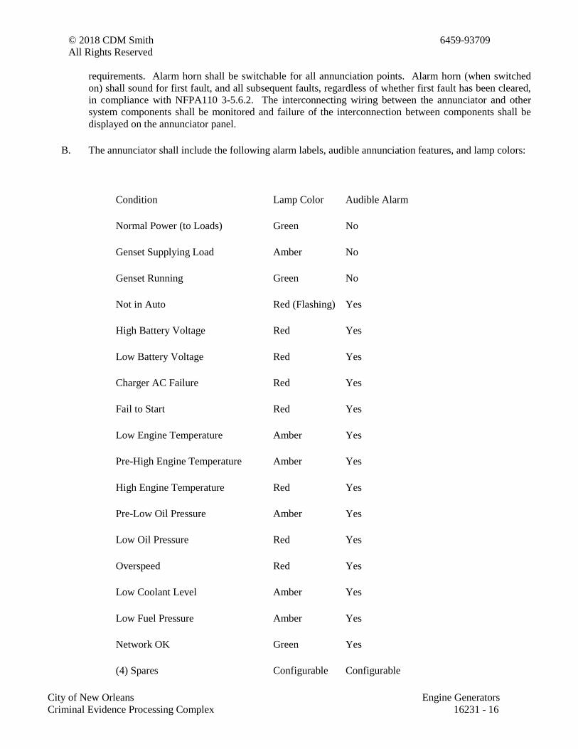
© 2018 CDM Smith 6459-93709
All Rights Reserved
City of New Orleans Engine Generators
Criminal Evidence Processing Complex 16231 - 16
requirements. Alarm horn shall be switchable for all annunciation points. Alarm horn (when switched
on) shall sound for first fault, and all subsequent faults, regardless of whether first fault has been cleared,
in compliance with NFPA110 3-5.6.2. The interconnecting wiring between the annunciator and other
system components shall be monitored and failure of the interconnection between components shall be
displayed on the annunciator panel.
B. The annunciator shall include the following alarm labels, audible annunciation features, and lamp colors:
Condition Lamp Color Audible Alarm
Normal Power (to Loads) Green No
Genset Supplying Load Amber No
Genset Running Green No
Not in Auto Red (Flashing) Yes
High Battery Voltage Red Yes
Low Battery Voltage Red Yes
Charger AC Failure Red Yes
Fail to Start Red Yes
Low Engine Temperature Amber Yes
Pre-High Engine Temperature Amber Yes
High Engine Temperature Red Yes
Pre-Low Oil Pressure Amber Yes
Low Oil Pressure Red Yes
Overspeed Red Yes
Low Coolant Level Amber Yes
Low Fuel Pressure Amber Yes
Network OK Green Yes
(4) Spares Configurable Configurable
© 2018 CDM Smith 6459-93709
All Rights Reserved
City of New Orleans Engine Generators
Criminal Evidence Processing Complex 16231 - 17
Low battery voltage lamp shall also be lighted for low cranking voltage or weak battery alarm.
C. The generator set shall be provided with a mounted main line circuit breaker, sized to carry the rated
output current of the generator set. The circuit breaker shall incorporate an electronic trip unit that
operates to protect the alternator under all overcurrent conditions, or a thermal-magnetic trip with other
overcurrent protection devices that positively protect the alternator under overcurrent conditions. The
supplier shall submit time overcurrent characteristic curves and thermal damage curve for the alternator,
demonstrating the effectiveness of the protection provided.
D. Sound Attenuated Outdoor Weather-Protective Enclosure
1. The generator set shall be provided with an outdoor enclosure. Enclosure shall withstand a
minimum of 150mph wind. The package shall comply with the requirements of the National
Electrical Code for all wiring materials and component spacing. The total assembly of generator
set and enclosure shall be designed to be lifted into place using spreader bars. Housing shall
provide ample airflow for generator set operation at rated load in an ambient temperature of 104F.
The housing shall have hinged access doors as required to maintain easy access for all operating
and service functions. All doors shall be lockable, and include retainers to hold the door open
during service. Enclosure roof shall be cambered to prevent rainwater accumulation. Openings
shall be screened to limit access of rodents into the enclosure. All electrical power and control
interconnections shall be made within the perimeter of the enclosure. The enclosure shall have a
sound level for the generator set of 74 dba, while operating at full rated load, at any location 7
meters from the generator set in a free field environment. Insulation in the enclosure shall be made
with non-hydroscopic materials.
2. All sheet metal shall be primed for corrosion protection and finish painted with the manufacturers
standard color using a powder coat paint process, or equal meeting the performance requirements
specified below. All surfaces of all metal parts shall be primed and painted.
3. Enclosure shall be constructed of minimum 12 gauge steel for framework and 14 gauge steel for
panels. All hardware and hinges shall be stainless steel. If generator set is mounted on an open
floor structure (platform), a floor must be included with the generator set.
4. A factory-mounted, critical grad exhaust silencer shall be installed inside of the enclosure. Exhaust
connections to the generator set shall be through seamless flexible connections.
5. The enclosure shall include the following maintenance provisions:
a. Flexible coolant and lubricating oil drain lines, that extend to the exterior of the enclosures,
with internal drain valves
b. External radiator fill provision

© 2018 CDM Smith 6459-93709
All Rights Reserved
City of New Orleans Engine Generators
Criminal Evidence Processing Complex 16231 - 18
PART 3 - EXECUTION
3.1 EXAMINATION
A. Examine areas, equipment bases, and conditions, with Installer present, for compliance with requirements
for installation and other conditions affecting packaged engine-generator performance.
B. Examine roughing-in of piping systems and electrical connections. Verify actual locations of connections
before packaged engine-generator installation.
C. Proceed with installation only after unsatisfactory conditions have been corrected.
3.2 INSTALLATION
A. Comply with packaged engine-generator manufacturers' written installation and alignment instructions
and with NFPA 110.
B. Install packaged engine generator to provide access, without removing connections or accessories, for
periodic maintenance.
C. Install packaged engine generator on cast-in-place concrete equipment bases. Comply with requirements
for equipment bases and foundations specified in Section 033000 "Cast-in-Place Concrete." Retain first
subparagraph below for projects in seismic areas. Indicate seismic-control device type and minimum
deflection in supported equipment schedule on Drawings.
1. Comply with requirements for vibration isolation devices specified in this section.
D. Install remote radiator with elastomeric isolator pads having a minimum deflection of 1 inch (25 mm) on
concrete base on grade.
E. Electrical Wiring: Install electrical devices furnished by equipment manufacturers but not specified to be
factory mounted.
3.3 CONNECTIONS
A. Piping installation requirements are specified in other Sections. Drawings indicate general arrangement of
piping and specialties.
B. Connect fuel, cooling-system, and exhaust-system piping adjacent to packaged engine generator to allow
service and maintenance.
C. Connect cooling-system water piping to engine-generator set and remote radiator with flexible
connectors.
D. Connect engine exhaust pipe to engine with flexible connector.
© 2018 CDM Smith 6459-93709
All Rights Reserved
City of New Orleans Engine Generators
Criminal Evidence Processing Complex 16231 - 19
E. Connect fuel piping to engines with a gate valve and union and flexible connector.
F. Ground equipment according to Section 16060 "Grounding and Bonding for Electrical Systems."
G. Connect wiring according to Section 16120 "Conductors and Cables."
3.4 IDENTIFICATION
A. Identify system components according to Section 16075 "Identification for Electrical Systems."
3.5 FIELD QUALITY CONTROL
A. Testing Agency: Engage a qualified testing agency to perform tests and inspections and prepare test
reports.
B. Manufacturer's Field Service: Engage a factory-authorized service representative to inspect, test, and
adjust components, assemblies, and equipment installations, including connections. Report results in
writing.
C. Perform tests and inspections and prepare test reports.
1. Manufacturer's Field Service: Engage a factory-authorized service representative to inspect
components, assemblies, and equipment installations, including connections, and to assist in
testing.
D. Tests and Inspections:
1. Perform tests recommended by manufacturer and each electrical test and visual and mechanical
inspection (except those indicated to be optional) for "AC Generators and for Emergency Systems"
specified in NETA Acceptance Testing Specification. Certify compliance with test parameters.
2. NFPA 110 Acceptance Tests: Perform tests required by NFPA 110 that are additional to those
specified here including, but not limited to, single-step full-load pickup test.
3. Battery Tests: Equalize charging of battery cells according to manufacturer's written instructions.
Record individual cell voltages.
a. Measure charging voltage and voltages between available battery terminals for full-charging
and float-charging conditions. Check electrolyte level and specific gravity under both
conditions.
b. Test for contact integrity of all connectors. Perform an integrity load test and a capacity load
test for the battery.
c. Verify acceptance of charge for each element of the battery after discharge.
© 2018 CDM Smith 6459-93709
All Rights Reserved
City of New Orleans Engine Generators
Criminal Evidence Processing Complex 16231 - 20
d. Verify that measurements are within manufacturer's specifications.
4. Battery-Charger Tests: Verify specified rates of charge for both equalizing and float-charging
conditions.
5. System Integrity Tests: Methodically verify proper installation, connection, and integrity of each
element of engine-generator system before and during system operation. Check for air, exhaust,
and fluid leaks.
6. Exhaust-System Back-Pressure Test: Use a manometer with a scale exceeding 40-inch wg (120 kPa).
Connect to exhaust line close to engine exhaust manifold. Verify that back pressure at full-rated
load is within manufacturer's written allowable limits for the engine.
7. Exhaust Emissions Test: Comply with applicable government test criteria.
8. Voltage and Frequency Transient Stability Tests: Use recording oscilloscope to measure voltage
and frequency transients for 50 and 100 percent step-load increases and decreases, and verify that
performance is as specified.
9. Harmonic-Content Tests: Measure harmonic content of output voltage under 25 percent and at 100
percent of rated linear load. Verify that harmonic content is within specified limits.
10. Noise Level Tests: Measure A-weighted level of noise emanating from generator-set installation,
including engine exhaust and cooling-air intake and discharge, at four locations on the property
line, and compare measured levels with required values.
E. Coordinate tests with tests for transfer switches and run them concurrently.
F. Test instruments shall have been calibrated within the last 12 months, traceable to standards of NIST, and
adequate for making positive observation of test results. Make calibration records available for
examination on request.
G. Leak Test: After installation, charge system and test for leaks. Repair leaks and retest until no leaks exist.
H. Operational Test: After electrical circuitry has been energized, start units to confirm proper motor rotation
and unit operation.
I. Test and adjust controls and safeties. Replace damaged and malfunctioning controls and equipment.
J. Remove and replace malfunctioning units and retest as specified above.
K. Retest: Correct deficiencies identified by tests and observations and retest until specified requirements are
met.
L. Report results of tests and inspections in writing. Record adjustable relay settings and measured insulation
resistances, time delays, and other values and observations. Attach a label or tag to each tested component
indicating satisfactory completion of tests.
© 2018 CDM Smith 6459-93709
All Rights Reserved
City of New Orleans Engine Generators
Criminal Evidence Processing Complex 16231 - 21
M. Infrared Scanning: After Substantial Completion, but not more than 60 days after Final Acceptance,
perform an infrared scan of each power wiring termination and each bus connection. Remove all access
panels so terminations and connections are accessible to portable scanner.
1. Follow-up Infrared Scanning: Perform an additional follow-up infrared scan 11 months after date
of Substantial Completion.
2. Instrument: Use an infrared scanning device designed to measure temperature or to detect
significant deviations from normal values. Provide calibration record for device.
3. Record of Infrared Scanning: Prepare a certified report that identifies terminations and connections
checked and that describes scanning results. Include notation of deficiencies detected, remedial
action taken, and observations after remedial action.
3.6 DEMONSTRATION
A. Engage a factory-authorized service representative to train Owner's maintenance personnel to adjust,
operate, and maintain packaged engine generators. Refer to Section 01820 "Demonstration and Training."
END OF SECTION 16231
© 2018 CDM Smith 6459-93709
All Rights Reserved
City of New Orleans Static Uninterruptible Power Supply
Criminal Evidence Processing Complex 16264 - 1
SECTION 16264 - STATIC UNINTERRUPTIBLE POWER SUPPLY
PART 1 - GENERAL
1.1 RELATED DOCUMENTS
A. Drawings and general provisions of the Contract, including General and Supplementary
Conditions and Division 01 Specification Sections, apply to this Section.
1.2 SUMMARY
A. Section Includes:
1. Three-phase, on-line, double-conversion, static-type, UPS units with the following
features:
a. Surge suppression.
b. Input harmonics reduction.
c. Rectifier-charger.
d. Inverter.
e. Static bypass transfer switch.
f. Battery and battery disconnect device.
g. Internal maintenance bypass/isolation switch.
h. Output isolation transformer.
i. Remote UPS monitoring provisions.
j. Battery monitoring.
k. Remote monitoring.
1.3 DEFINITIONS
A. EMI: Electromagnetic interference.
B. LCD: Liquid-crystal display.
C. LED: Light-emitting diode.
D. PC: Personal computer.
E. THD: Total harmonic distortion.
F. UPS: Uninterruptible power supply.
1.4 PERFORMANCE REQUIREMENTS
A. Seismic Performance: UPS shall withstand the effects of earthquake motions determined
according to ASCE/SEI 7.
© 2018 CDM Smith 6459-93709
All Rights Reserved
City of New Orleans Static Uninterruptible Power Supply
Criminal Evidence Processing Complex 16264 - 2
1. The term "withstand" means "the unit will remain in place without separation of any parts
from the device when subjected to the seismic forces specified[ and the unit will be fully
operational after the seismic event]."
1.5 ACTION SUBMITTALS
A. Product Data: For each type of product indicated. Include data on features, components, ratings,
and performance.
B. Shop Drawings: For UPS. Include plans, elevations, sections, details, and attachments to other
work.
1. Detail equipment assemblies and indicate dimensions, weights, components, and location
and identification of each field connection. Show access, workspace, and clearance
requirements; details of control panels; and battery arrangement.
2. Wiring Diagrams: For power, signal, and control wiring.
1.6 INFORMATIONAL SUBMITTALS
A. Qualification Data: For qualified power quality specialist.
B. Seismic Qualification Certificates: For UPS equipment, from manufacturer.
1. Basis for Certification: Indicate whether withstand certification is based on actual test of
assembled components or on calculation.
2. Dimensioned Outline Drawings of Equipment Unit: Identify center of gravity and locate
and describe mounting and anchorage provisions.
3. Detailed description of equipment anchorage devices on which the certification is based
and their installation requirements.
C. Manufacturer Certificates: For each product, from manufacturer.
D. Factory Test Reports: Comply with specified requirements.
E. Field quality-control reports.
F. Performance Test Reports: Indicate test results compared with specified performance
requirements, and provide justification and resolution of differences if values do not agree.
G. Warranties: Sample of special warranties.
1.7 CLOSEOUT SUBMITTALS
A. Operation and Maintenance Data: For UPS units to include in emergency, operation, and
maintenance manuals.

© 2018 CDM Smith 6459-93709
All Rights Reserved
City of New Orleans Static Uninterruptible Power Supply
Criminal Evidence Processing Complex 16264 - 3
1.8 MAINTENANCE MATERIAL SUBMITTALS
A. Furnish extra materials that match products installed and that are packaged with protective
covering for storage and identified with labels describing contents.
1. Fuses: One for every 10 of each type and rating, but no fewer than one of each.
2. Cabinet Ventilation Filters: One complete set(s).
1.9 QUALITY ASSURANCE
A. Power Quality Specialist Qualifications: A registered professional electrical engineer or
engineering technician, currently certified by the National Institute for Certification in
Engineering Technologies, NICET Level 4, minimum, experienced in performance testing UPS
installations and in performing power quality surveys similar to that required in "Performance
Testing" Article.
B. Testing Agency Qualifications: Member company of NETA or an NRTL.
1. Testing Agency's Field Supervisor: Currently certified by NETA to supervise on-site
testing.
C. Electrical Components, Devices, and Accessories: Listed and labeled as defined in NFPA 70, by
a qualified testing agency, and marked for intended location and application.
D. UL Compliance: Listed and labeled under UL 1778 by an NRTL.
E. NFPA Compliance: Mark UPS components as suitable for installation in computer rooms
according to NFPA 75.
1.10 WARRANTY
A. Special Battery Warranties: Specified form in which manufacturer and Installer agree to repair
or replace UPS system storage batteries that fail in materials or workmanship within specified
warranty period.
1. Warranted Cycle Life for Valve-Regulated, Lead-Calcium Batteries: Equal to or greater
than that represented in manufacturer's published table, including figures corresponding
to the following, based on annual average battery temperature of 77 deg F:
Discharge Rate Discharge Duration Discharge End
Voltage
Cycle Life
8 hours 8 hours 1.67 6 cycles
30 minutes 30 minutes 1.67 20 cycles
15 minutes 45 seconds 1.67 120 cycles
2. Warranted Cycle Life for Premium Valve-Regulated, Lead-calcium Batteries: Equal to or
greater than that represented in manufacturer's published table, including figures
corresponding to the following, based on annual average battery temperature of 77 deg F:
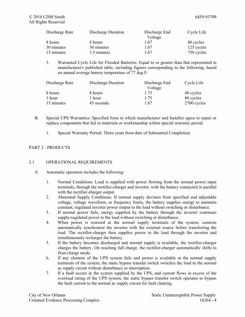
© 2018 CDM Smith 6459-93709
All Rights Reserved
City of New Orleans Static Uninterruptible Power Supply
Criminal Evidence Processing Complex 16264 - 4
Discharge Rate Discharge Duration Discharge End
Voltage
Cycle Life
8 hours 8 hours 1.67 40 cycles
30 minutes 30 minutes 1.67 125 cycles
15 minutes 1.5 minutes 1.67 750 cycles
3. Warranted Cycle Life for Flooded Batteries: Equal to or greater than that represented in
manufacturer's published table, including figures corresponding to the following, based
on annual average battery temperature of 77 deg F:
Discharge Rate Discharge Duration Discharge End
Voltage
Cycle Life
8 hours 8 hours 1.75 40 cycles
1 hour 1 hour 1.75 80 cycles
15 minutes 45 seconds 1.67 2700 cycles
B. Special UPS Warranties: Specified form in which manufacturer and Installer agree to repair or
replace components that fail in materials or workmanship within special warranty period.
1. Special Warranty Period: Three years from date of Substantial Completion.
PART 2 - PRODUCTS
2.1 OPERATIONAL REQUIREMENTS
A. Automatic operation includes the following:
1. Normal Conditions: Load is supplied with power flowing from the normal power input
terminals, through the rectifier-charger and inverter, with the battery connected in parallel
with the rectifier-charger output.
2. Abnormal Supply Conditions: If normal supply deviates from specified and adjustable
voltage, voltage waveform, or frequency limits, the battery supplies energy to maintain
constant, regulated inverter power output to the load without switching or disturbance.
3. If normal power fails, energy supplied by the battery through the inverter continues
supply-regulated power to the load without switching or disturbance.
4. When power is restored at the normal supply terminals of the system, controls
automatically synchronize the inverter with the external source before transferring the
load. The rectifier-charger then supplies power to the load through the inverter and
simultaneously recharges the battery.
5. If the battery becomes discharged and normal supply is available, the rectifier-charger
charges the battery. On reaching full charge, the rectifier-charger automatically shifts to
float-charge mode.
6. If any element of the UPS system fails and power is available at the normal supply
terminals of the system, the static bypass transfer switch switches the load to the normal
ac supply circuit without disturbance or interruption.
7. If a fault occurs in the system supplied by the UPS, and current flows in excess of the
overload rating of the UPS system, the static bypass transfer switch operates to bypass
the fault current to the normal ac supply circuit for fault clearing.
© 2018 CDM Smith 6459-93709
All Rights Reserved
City of New Orleans Static Uninterruptible Power Supply
Criminal Evidence Processing Complex 16264 - 5
8. When the fault has cleared, the static bypass transfer switch returns the load to the UPS
system.
9. If the battery is disconnected, the UPS continues to supply power to the load with no
degradation of its regulation of voltage and frequency of the output bus.
B. Manual operation includes the following:
1. Turning the inverter off causes the static bypass transfer switch to transfer the load
directly to the normal ac supply circuit without disturbance or interruption.
2. Turning the inverter on causes the static bypass transfer switch to transfer the load to the
inverter.
C. Maintenance Bypass/Isolation Switch Operation: Switch is interlocked so it cannot be operated
unless the static bypass transfer switch is in the bypass mode. Device provides manual selection
among the three conditions in subparagraphs below without interrupting supply to the load
during switching:
1. Full Isolation: Load is supplied, bypassing the UPS. Normal UPS ac input circuit, static
bypass transfer switch, and UPS load terminals are completely disconnected from
external circuits.
2. Maintenance Bypass: Load is supplied, bypassing the UPS. UPS ac supply terminals are
energized to permit operational checking, but system load terminals are isolated from the
load.
3. Normal: Normal UPS ac supply terminals are energized and the load is supplied through
either the static bypass transfer switch and the UPS rectifier-charger and inverter, or the
battery and the inverter.
D. Environmental Conditions: The UPS shall be capable of operating continuously in the following
environmental conditions without mechanical or electrical damage or degradation of operating
capability, except battery performance.
1. Ambient Temperature for Electronic Components: 32 to 104 deg F.
2. Ambient Temperature for Battery: 41 to 95 deg F.
3. Relative Humidity: 0 to 95 percent, noncondensing.
4. Altitude: Sea level to 4000 feet.
2.2 PERFORMANCE REQUIREMENTS
A. The UPS shall perform as specified in this article while supplying rated full-load current,
composed of any combination of linear and nonlinear load, up to 100 percent nonlinear load
with a load crest factor of 3.0, under the following conditions or combinations of the following
conditions:
1. Inverter is switched to battery source.
2. Steady-state ac input voltage deviates up to plus or minus 10 percent from nominal
voltage.
3. Steady-state input frequency deviates up to plus or minus 5 percent from nominal
frequency.
4. THD of input voltage is 15 percent or more with a minimum crest factor of 3.0, and the
largest single harmonic component is a minimum of 5 percent of the fundamental value.

© 2018 CDM Smith 6459-93709
All Rights Reserved
City of New Orleans Static Uninterruptible Power Supply
Criminal Evidence Processing Complex 16264 - 6
5. Load is 30 percent unbalanced continuously.
B. Minimum Duration of Supply: If battery is sole energy source supplying rated full UPS load
current at 80 percent power factor, duration of supply is 15 minutes.
C. Input Voltage Tolerance: System steady-state and transient output performance remains within
specified tolerances when steady-state ac input voltage varies plus 10, minus 15 percent from
nominal voltage.
D. Overall UPS Efficiency: Shall be determined with the owners representative prior to
installation. (Equal to or greater than 80 percent at 100 percent load, <Insert number> percent at
75 percent load, and <Insert number> percent at 50 percent load.)
E. Maximum Acoustical Noise: 50 "A" weighting, emanating from any UPS component under any
condition of normal operation, measured 10 foot from nearest surface of component enclosure.
F. Maximum Energizing Inrush Current: Six times the full-load current.
G. Maximum AC Output-Voltage Regulation for Loads up to 50 Percent Unbalanced: Plus or
minus 2 percent over the full range of battery voltage.
H. Output Frequency: 60 Hz, plus or minus 0.5 percent over the full range of input voltage, load,
and battery voltage.
I. Limitation of harmonic distortion of input current to the UPS shall be as follows:
1. Description: Either a tuned harmonic filter or an arrangement of rectifier-charger circuits
shall limit THD to 5 percent, maximum, at rated full UPS load current, for power sources
with X/R ratio between 2 and 30.
2. Description: THD is limited to a maximum of 32 percent, at rated full UPS load current,
for power sources with X/R ratio between 2 and 30.
J. Maximum Harmonic Content of Output-Voltage Waveform: 5 percent rms total and 3 percent
rms for any single harmonic, for 100 percent rated nonlinear load current with a load crest
factor of 3.0.
K. Maximum Harmonic Content of Output-Voltage Waveform: 5 percent rms total and 3 percent
rms for any single harmonic, for rated full load with THD up to 50 percent, with a load crest
factor of 3.0.
L. Minimum Overload Capacity of UPS at Rated Voltage: 125 percent of rated full load for 10
minutes, and 150 percent for 30 seconds in all operating modes.
M. Maximum Output-Voltage Transient Excursions from Rated Value: For the following
instantaneous load changes, stated as percentages of rated full UPS load, voltage shall remain
within stated percentages of rated value and recover to, and remain within, plus or minus 2
percent of that value within 100 ms:
1. 50 Percent: Plus or minus 5 percent.
2. 100 Percent: Plus or minus 5 percent.
3. Loss of AC Input Power: Plus or minus 1 percent.
© 2018 CDM Smith 6459-93709
All Rights Reserved
City of New Orleans Static Uninterruptible Power Supply
Criminal Evidence Processing Complex 16264 - 7
4. Restoration of AC Input Power: Plus or minus 1 percent.
N. Input Power Factor: A minimum of 0.85 lagging when supply voltage and current are at
nominal rated values and the UPS is supplying rated full-load current.
O. EMI Emissions: Comply with FCC Rules and Regulations and with 47 CFR 15 for Class A
equipment.
2.3 UPS SYSTEMS
A. Manufacturers: Subject to compliance with requirements, available manufacturers offering
products that may be incorporated into the Work include, but are not limited to, the following:
B. Basis-of-Design Product: Subject to compliance with requirements, provide product indicated
on Drawings or comparable product by one of the following:
1. Eaton Corporation.
2. Liebert Corporation.
3. MGE UPS SYSTEMS.
4. Mitsubishi Electric Automation, Inc.
5. Toshiba Corporation; Industrial Systems.
C. Electronic Equipment: Solid-state devices using hermetically sealed, semiconductor elements.
Devices include rectifier-charger, inverter, static bypass transfer switch, and system controls.
D. Enclosures: Comply with NEMA 250, Type 1, unless otherwise indicated.
E. Control Assemblies: Mount on modular plug-ins, readily accessible for maintenance.
F. Surge Suppression: Protect internal UPS components from surges that enter at each ac power
input connection including main disconnect switch, static bypass transfer switch, and
maintenance bypass/isolation switch. Protect rectifier-charger, inverter, controls, and output
components.
1. Use factory-installed surge suppressors tested according to IEEE C62.41.1 and
IEEE C62.41.2, Category B.
2. Additional Surge Protection: Protect internal UPS components from low-frequency, high-
energy voltage surges described in IEEE C62.41.1 and IEEE C62.41.2. Design the
circuits connecting with external power sources and select circuit elements, conductors,
conventional surge suppressors, and rectifier components and controls so input
assemblies will have adequate mechanical strength and thermal and current-carrying
capacity to withstand stresses imposed by 40-Hz, 180 percent voltage surges described in
IEEE C62.41.1 and IEEE C62.41.2.
G. Maintainability Features: Mount rectifier-charger and inverter sections and the static bypass
transfer switch on modular plug-ins, readily accessible for maintenance.
H. Capacity Upgrade Capability: Arrange wiring, controls, and modular component plug-in
provisions to permit future 25 percent increase in UPS capacity.
© 2018 CDM Smith 6459-93709
All Rights Reserved
City of New Orleans Static Uninterruptible Power Supply
Criminal Evidence Processing Complex 16264 - 8
I. Seismic-Restraint Design: UPS assemblies, subassemblies, and components (and fastenings and
supports, mounting, and anchorage devices for them) shall be designed and fabricated to
withstand static and seismic forces.
J. UPS Cabinet Ventilation: Redundant fans or blowers draw in ambient air near the bottom of
cabinet and discharge it near the top rear.
K. Output Circuit Neutral Bus, Conductor, and Terminal Ampacity: Rated phase current times a
multiple of 1.73, minimum.
2.4 RECTIFIER-CHARGER
A. Capacity: Adequate to supply the inverter during rated full output load conditions and
simultaneously recharge the battery from fully discharged condition to 95 percent of full charge
within 10 times the rated discharge time for duration of supply under battery power at full load.
B. Output Ripple: Limited by output filtration to less than 0.5 percent of rated current, peak to
peak.
C. Control Circuits: Immune to frequency variations within rated frequency ranges of normal and
emergency power sources.
1. Response Time: Field adjustable for maximum compatibility with local generator-set
power source.
D. Battery Float-Charging Conditions: Comply with battery manufacturer's written instructions for
battery terminal voltage and charging current required for maximum battery life.
2.5 INVERTER
A. Description: Pulse-width modulated, with sinusoidal output.
B. Description: Pulse-width modulated, with sinusoidal output. Include a bypass phase
synchronization window adjustment to optimize compatibility with local engine-generator-set
power source.
2.6 STATIC BYPASS TRANSFER SWITCH
A. Description: Solid-state switching device providing uninterrupted transfer. A contactor or
electrically operated circuit breaker automatically provides electrical isolation for the switch.
B. Switch Rating: Continuous duty at the rated full UPS load current, minimum.
2.7 BATTERY
A. Description: Valve-regulated, recombinant, lead-calcium units, factory assembled in an isolated
compartment of UPS cabinet, complete with battery disconnect switch.
© 2018 CDM Smith 6459-93709
All Rights Reserved
City of New Orleans Static Uninterruptible Power Supply
Criminal Evidence Processing Complex 16264 - 9
1. Arrange for drawout removal of battery assembly from cabinet for testing and inspecting.
B. Description: Valve-regulated, premium, heavy-duty, recombinant, lead-calcium units; factory
assembled in an isolated compartment or in a separate matching cabinet, complete with battery
disconnect switch.
1. Arrange for drawout removal of battery assembly from cabinet for testing and inspecting.
C. Description: Flooded, lead-calcium, heavy-duty industrial units in styrene acrylonitrile
containers mounted on three-tier, acid-resistant, painted steel racks. Assembly includes battery
disconnect switch, intercell connectors, hydrometer syringe, and thermometer with specific
gravity-correction scales.
D. Manufacturers: Subject to compliance with requirements, available manufacturers offering
products that may be incorporated into the Work include, but are not limited to, the following]
E. Basis-of-Design Product: Subject to compliance with requirements, provide product indicated
on Drawings or comparable product by one of the following:
1. C&D Technologies, Inc.
2. Eaton Corporation.
3. EnerSys.
4. Panasonic Corporation of North America; Panasonic Industrial Company.
F. Seismic-Restraint Design: Battery racks, cabinets, assemblies, subassemblies, and components
(and fastenings and supports, mounting, and anchorage devices for them) shall be designed and
fabricated to withstand static and seismic forces.
2.8 CONTROLS AND INDICATIONS
A. Description: Group displays, indications, and basic system controls on a common control panel
on front of UPS enclosure.
B. Minimum displays, indicating devices, and controls include those in lists below. Provide
sensors, transducers, terminals, relays, and wiring required to support listed items. Alarms
include audible signals and visual displays.
C. Indications: Plain-language messages on a digital LCD or LED.
1. Quantitative indications shall include the following:
a. Input voltage, each phase, line to line.
b. Input current, each phase, line to line.
c. Bypass input voltage, each phase, line to line.
d. Bypass input frequency.
e. System output voltage, each phase, line to line.
f. System output current, each phase.
g. System output frequency.
h. DC bus voltage.
i. Battery current and direction (charge/discharge).
© 2018 CDM Smith 6459-93709
All Rights Reserved
City of New Orleans Static Uninterruptible Power Supply
Criminal Evidence Processing Complex 16264 - 10
j. Elapsed time discharging battery.
2. Basic status condition indications shall include the following:
a. Normal operation.
b. Load-on bypass.
c. Load-on battery.
d. Inverter off.
e. Alarm condition.
3. Alarm indications shall include the following:
a. Bypass ac input overvoltage or undervoltage.
b. Bypass ac input overfrequency or underfrequency.
c. Bypass ac input and inverter out of synchronization.
d. Bypass ac input wrong-phase rotation.
e. Bypass ac input single-phase condition.
f. Bypass ac input filter fuse blown.
g. Internal frequency standard in use.
h. Battery system alarm.
i. Control power failure.
j. Fan failure.
k. UPS overload.
l. Battery-charging control faulty.
m. Input overvoltage or undervoltage.
n. Input transformer overtemperature.
o. Input circuit breaker tripped.
p. Input wrong-phase rotation.
q. Input single-phase condition.
r. Approaching end of battery operation.
s. Battery undervoltage shutdown.
t. Maximum battery voltage.
u. Inverter fuse blown.
v. Inverter transformer overtemperature.
w. Inverter overtemperature.
x. Static bypass transfer switch overtemperature.
y. Inverter power supply fault.
z. Inverter transistors out of saturation.
aa. Identification of faulty inverter section/leg.
bb. Inverter output overvoltage or undervoltage.
cc. UPS overload shutdown.
dd. Inverter current sensor fault.
ee. Inverter output contactor open.
ff. Inverter current limit.
4. Controls shall include the following:
a. Inverter on-off.
b. UPS start.
c. Battery test.
d. Alarm silence/reset.
© 2018 CDM Smith 6459-93709
All Rights Reserved
City of New Orleans Static Uninterruptible Power Supply
Criminal Evidence Processing Complex 16264 - 11
e. Output-voltage adjustment.
D. Dry-form "C" contacts shall be available for remote indication of the following conditions:
1. UPS on battery.
2. UPS on-line.
3. UPS load-on bypass.
4. UPS in alarm condition.
5. UPS off (maintenance bypass closed).
E. Emergency Power Off Switch: Capable of local operation and operation by means of activation
by external dry contacts.
2.9 MAINTENANCE BYPASS/ISOLATION SWITCH
A. Description: Manually operated switch or arrangement of switching devices with mechanically
actuated contact mechanism arranged to route the flow of power to the load around the rectifier-
charger, inverter, and static bypass transfer switch.
1. Switch shall be electrically and mechanically interlocked to prevent interrupting power to
the load when switching to bypass mode.
2. Switch shall electrically isolate other UPS components to permit safe servicing.
B. Comply with NEMA PB 2 and UL 891.
C. Switch Rating: Continuous duty at rated full UPS load current.
D. Mounting Provisions: Internal to system cabinet.
E. Key interlock requires unlocking maintenance bypass/isolation switch before switching from
normal position with key that is released only when the UPS is bypassed by the static bypass
transfer switch. Lock is designed specifically for mechanical and electrical component
interlocking.
2.10 OUTPUT ISOLATION TRANSFORMER
A. Description: Shielded unit with low forward transfer impedance up to 3 kHz, minimum. Include
the following features:
1. Comply with applicable portions of UL 1561, including requirements for nonlinear load
current-handling capability for a K-factor of approximately 13.
2. Output Impedance at Fundamental Frequency: Between 3 and 4 percent.
3. Regulation: 5 percent, maximum, at rated nonlinear load current.
4. Full-Load Efficiency at Rated Nonlinear Load Current: 96 percent, minimum.
5. Electrostatic Shielding of Windings: Independent for each winding.
6. Coil Leads: Physically arranged for minimum interlead capacitance.
7. Shield Grounding Terminal: Separately mounted; labeled "Shield Ground."
8. Capacitive Coupling between Primary and Secondary: 33 picofarads, maximum, over a
frequency range of 20 Hz to 1 MHz.
© 2018 CDM Smith 6459-93709
All Rights Reserved
City of New Orleans Static Uninterruptible Power Supply
Criminal Evidence Processing Complex 16264 - 12
2.11 OUTPUT DISTRIBUTION SECTION
A. Panelboards: Comply with Section 16442 "Panelboards" except provide assembly integral to
UPS cabinet.
2.12 MONITORING BY REMOTE STATUS AND ALARM PANEL
A. Description: Labeled LEDs on panel faceplate indicate five basic status conditions. Audible
signal indicates alarm conditions. Silencing switch in face of panel silences signal without
altering visual indication.
1. Cabinet and Faceplate: Surface or flush mounted to suit mounting conditions indicated.
2.13 MONITORING BY REMOTE COMPUTER
A. Description: Communication module in unit control panel provides capability for remote
monitoring of status, parameters, and alarms specified in "Controls and Indications" Article.
The remote computer and the connecting signal wiring are not included in this Section. Include
the following features:
1. Connectors and network interface units or modems for data transmission via RS-232 link.
2. Software designed for control and monitoring of UPS functions and to provide on-screen
explanations, interpretations, diagnosis, action guidance, and instructions for use of
monitoring indications and development of meaningful reports. Permit storage and
analysis of power-line transient records. Designs for Windows applications, software, and
computer are not included in this Section.
3. Software and Hardware: Compatible with that specified in Section 16215 "Electrical
Power Monitoring and Control."
2.14 BASIC BATTERY MONITORING
A. Manufacturers: Subject to compliance with requirements, available manufacturers offering
products that may be incorporated into the Work include, but are not limited to, the following]:
B. Basis-of-Design Product: Subject to compliance with requirements, provide product indicated
on Drawings or comparable product by one of the following:
1. Albercorp.
2. BTECH, Inc.
3. Eaton Corporation.
C. Battery Ground-Fault Detector: Initiates alarm when resistance to ground of positive or negative
bus of battery is less than 5000 ohms.
D. Battery compartment smoke/high-temperature detector initiates an alarm when smoke or a
temperature greater than 75 deg C occurs within the compartment.
E. Annunciation of Alarms: At UPS control panel.
© 2018 CDM Smith 6459-93709
All Rights Reserved
City of New Orleans Static Uninterruptible Power Supply
Criminal Evidence Processing Complex 16264 - 13
2.15 ADDITIONAL BATTERY MONITORING
A. Monitoring features and components shall include the following:
1. Factory-wired sensing leads to cell and battery terminals and cell temperature sensors.
2. Connections for data transmission via RS-232 link, network interface and modem and
external signal wiring to computer. External signal wiring and computer are not specified
in this Section.
3. PC-based software designed to store and analyze battery data. Software compiles reports
on individual-cell parameters and total battery performance trends, and provides data for
scheduling and prioritizing battery maintenance.
B. Performance: Automatically measures and electronically records the following parameters on a
routine schedule and during battery discharge events. During discharge events, records
measurements timed to nearest second; includes measurements of the following parameters:
1. Total battery voltage and ambient temperature.
2. Individual-cell voltage, impedance, and temperature. During battery-discharging events
such as utility outages, measures battery and cell voltages timed to nearest second.
3. Individual-cell electrolyte levels.
2.16 BATTERY-CYCLE WARRANTY MONITORING
A. Description: Electronic device, acceptable to battery manufacturer as a basis for warranty
action, for monitoring of charge-discharge cycle history of batteries covered by cycle-life
warranties.
B. Performance: Automatically measures and records each discharge event, classifies it according
to duration category, and totals discharges according to warranty criteria, displaying remaining
warranted battery life on front panel display.
C. Additional monitoring functions and features shall include the following:
1. Measuring and Recording: Total voltage at battery terminals; initiates alarm for
excursions outside the proper float-voltage level.
2. Monitors: Ambient temperature at battery; initiates alarm if temperature deviates from
normally acceptable range.
3. Keypad on Device Front Panel: Provides access to monitored data using front panel
display.
4. Alarm Contacts: Arranged to initiate abnormal battery voltage or temperature.
5. Memory: Stores recorded data in nonvolatile electronic memory.
6. RS-232 Port: Permits downloading of data to a portable PC.
7. Modem: Makes measurements and recorded data accessible to a remote PC via telephone
line. Computer is not specified in this Section.
2.17 SOURCE QUALITY CONTROL
A. Factory test complete UPS system before shipment. Use actual batteries that are part of final
installation. Include the following:
© 2018 CDM Smith 6459-93709
All Rights Reserved
City of New Orleans Static Uninterruptible Power Supply
Criminal Evidence Processing Complex 16264 - 14
1. Test and demonstration of all functions, controls, indicators, sensors, and protective
devices.
2. Full-load test.
3. Transient-load response test.
4. Overload test.
5. Power failure test.
B. Observation of Test: Give 14 days' advance notice of tests and provide opportunity for Owner's
representative to observe tests at Owner's choice.
C. Report test results. Include the following data:
1. Description of input source and output loads used. Describe actions required to simulate
source load variation and various operating conditions and malfunctions.
2. List of indications, parameter values, and system responses considered satisfactory for
each test action. Include tabulation of actual observations during test.
3. List of instruments and equipment used in factory tests.
PART 3 - EXECUTION
3.1 EXAMINATION
A. Examine areas and conditions, with Installer present, for compliance with requirements for
conditions affecting performance of the UPS.
B. Proceed with installation only after unsatisfactory conditions have been corrected.
3.2 INSTALLATION
A. Equipment Mounting: Install UPS on concrete base. Comply with requirements for concrete
base specified in Section 03300 "Cast-in-Place Concrete.
1. Install dowel rods to connect concrete base to concrete floor. Unless otherwise indicated,
install dowel rods on 18-inch centers around the full perimeter of concrete base.
2. For supported equipment, install epoxy-coated anchor bolts that extend through concrete
base and anchor into structural concrete floor.
3. Place and secure anchorage devices. Use setting drawings, templates, diagrams,
instructions, and directions furnished with items to be embedded.
4. Install anchor bolts to elevations required for proper attachment to supported equipment.
B. Maintain minimum clearances and workspace at equipment according to manufacturer's written
instructions and NFPA 70.
C. Connections: Interconnect system components. Make connections to supply and load circuits
according to manufacturer's wiring diagrams unless otherwise indicated.
© 2018 CDM Smith 6459-93709
All Rights Reserved
City of New Orleans Static Uninterruptible Power Supply
Criminal Evidence Processing Complex 16264 - 15
3.3 GROUNDING
A. Separately Derived Systems: If not part of a listed power supply for a data-processing room,
comply with NFPA 70 requirements for connecting to grounding electrodes and for bonding to
metallic piping near isolation transformer.
3.4 IDENTIFICATION
A. Identify components and wiring according to Section 16075 "Electrical Identification."
1. Identify each battery cell individually.
3.5 BATTERY EQUALIZATION
A. Equalize charging of battery cells according to manufacturer's written instructions. Record
individual-cell voltages.
3.6 FIELD QUALITY CONTROL
A. Testing Agency: Engage a qualified testing agency to perform tests and inspections.
B. Manufacturer's Field Service: Engage a factory-authorized service representative to inspect, test,
and adjust components, assemblies, and equipment installations, including connections.
C. Perform tests and inspections.
1. Manufacturer's Field Service: Engage a factory-authorized service representative to
inspect components, assemblies, and equipment installations, including connections, and
to assist in testing.
D. Tests and Inspections:
1. Comply with manufacturer's written instructions.
2. Inspect interiors of enclosures, including the following:
a. Integrity of mechanical and electrical connections.
b. Component type and labeling verification.
c. Ratings of installed components.
3. Inspect batteries and chargers according to requirements in NETA Acceptance Testing
Specifications.
4. Test manual and automatic operational features and system protective and alarm
functions.
5. Test communication of status and alarms to remote monitoring equipment.
6. Load the system using a variable-load bank to simulate kilovolt amperes, kilowatts, and
power factor of loads for unit's rating. Use instruments calibrated within the previous six
months according to NIST standards.
a. Simulate malfunctions to verify protective device operation.
© 2018 CDM Smith 6459-93709
All Rights Reserved
City of New Orleans Static Uninterruptible Power Supply
Criminal Evidence Processing Complex 16264 - 16
b. Test duration of supply on emergency, low-battery voltage shutdown, and transfers
and restoration due to normal source failure.
c. Test harmonic content of input and output current less than 25, 50, and 100 percent
of rated loads.
d. Test output voltage under specified transient-load conditions.
e. Test efficiency at 50, 75, and 100 percent of rated loads.
f. Test remote status and alarm panel functions.
g. Test battery-monitoring system functions.
E. Seismic-restraint tests and inspections shall include the following:
1. Inspect type, size, quantity, arrangement, and proper installation of mounting or
anchorage devices.
2. Test mounting and anchorage devices according to requirements in Section 16074
"Seismic Controls for Electrical Systems."
F. The UPS system will be considered defective if it does not pass tests and inspections.
G. Record of Tests and Inspections: Maintain and submit documentation of tests and inspections,
including references to manufacturers' written instructions and other test and inspection criteria.
Include results of tests, inspections, and retests.
H. Prepare test and inspection reports.
3.7 PERFORMANCE TESTING
A. Engage the services of a qualified power quality specialist to perform tests and activities
indicated for each UPS system.
B. Monitoring and Testing Schedule: Perform monitoring and testing in four 10-day periods, each
in a different season of the year.
1. Schedule monitoring and testing activity with Owner, through Architect, with at least 14
days' advance notice.
2. Schedule monitoring and testing after Substantial Completion, when the UPS is
supplying power to its intended load.
C. Monitoring and Testing Instruments: Three-phase, recording, power monitors. Instruments shall
provide continuous simultaneous monitoring of electrical parameters at UPS input terminals and
at input terminals of loads served by the UPS. Instruments shall monitor, measure, and graph
voltage current and frequency simultaneously and provide full-graphic recordings of the values
of those parameters before and during power-line disturbances that cause the values to deviate
from normal beyond the adjustable threshold values. Instruments shall be capable of recording
either on paper or on magnetic media and have a minimum accuracy of plus or minus 2 percent
for electrical parameters. Parameters to be monitored include the following:
1. Current: Each phase and neutral and grounding conductors.
2. Voltage: Phase to phase, phase to neutral, phase to ground, and neutral to ground.
3. Frequency transients.
4. Voltage swells and sags.
© 2018 CDM Smith 6459-93709
All Rights Reserved
City of New Orleans Static Uninterruptible Power Supply
Criminal Evidence Processing Complex 16264 - 17
5. Voltage Impulses: Phase to phase, phase to neutral, phase to ground, and neutral to
ground.
6. High-frequency noise.
7. Radio-frequency interference.
8. THD of the above currents and voltages.
9. Harmonic content of currents and voltages above.
D. Monitoring and Testing Procedures for Each Test Period:
1. Exploratory Period: For the first two days[ of the first scheduled monitoring and testing
period], make recordings at various circuit locations and with various parameter-
threshold and sampling-interval settings. Make these measurements with the objective of
identifying optimum UPS, power system, load, and instrumentation setup conditions for
subsequent test and monitoring operations.
2. Remainder of Test Period: Perform continuous monitoring of at least two circuit locations
selected on the basis of data obtained during exploratory period.
a. Set thresholds and sampling intervals for recording data at values selected to
optimize data on performance of the UPS for values indicated, and to highlight the
need to adjust, repair, or modify the UPS, distribution system, or load component
that may influence its performance or that may require better power quality.
b. Perform load and UPS power source switching and operate the UPS on generator
power during portions of test period according to directions of Owner's power
quality specialist.
c. Operate the UPS and its loads in each mode of operation permitted by UPS
controls and by the power distribution system design.
d. Using loads and devices available as part of the facility's installed systems and
equipment, create and simulate unusual operating conditions, including outages,
voltage swells and sags, and voltage, current, and frequency transients. Maintain
normal operating loads in operation on system to maximum extent possible during
tests.
e. Using temporarily connected resistive/inductive load banks, create and simulate
unusual operating conditions, including outages, voltage swells and sags, and
voltage, current, and frequency transients. Maintain normal operating loads in
operation on system to maximum extent possible during tests.
f. Make adjustments and repairs to UPS, distribution, and load equipment to correct
deficiencies disclosed by monitoring and testing and repeat appropriate monitoring
and testing to verify success of corrective action.
E. Coordination with Specified UPS Monitoring Functions: Obtain printouts of built-in monitoring
functions specified for the UPS and its components in this Section that are simultaneously
recorded with portable instruments in this article.
1. Provide the temporary use of an appropriate PC and printer equipped with required
connections and software for recording and printing if such units are not available on-site.
2. Coordinate printouts with recordings for monitoring performed according to this article,
and resolve and report any anomalies in and discrepancies between the two sets of
records.
F. Monitoring and Testing Assistance by Contractor:
© 2018 CDM Smith 6459-93709
All Rights Reserved
City of New Orleans Static Uninterruptible Power Supply
Criminal Evidence Processing Complex 16264 - 18
1. Open UPS and electrical distribution and load equipment and wiring enclosures to make
monitoring and testing points accessible for temporary monitoring probe and sensor
placement and removal as requested.
2. Observe monitoring and testing operations; ensure that UPS and distribution and load
equipment warranties are not compromised.
3. Perform switching and control of various UPS units, electrical distribution systems, and
load components as directed by power quality specialist. Specialist shall design this
portion of monitoring and testing operations to expose the UPS to various operating
environments, conditions, and events while response is observed, electrical parameters
are monitored, and system and equipment deficiencies are identified.
4. Make repairs and adjustments to the UPS and to electrical distribution system and load
components, and retest and repeat monitoring as needed to verify validity of results and
correction of deficiencies.
5. Engage the services of the UPS manufacturer's factory-authorized service representative
periodically during performance testing operations for repairs, adjustments, and
consultations.
G. Documentation: Record test point and sensor locations, instrument settings, and circuit and load
conditions for each monitoring summary and power disturbance recording. Coordinate
simultaneous recordings made on UPS input and load circuits.
H. Analysis of Recorded Data and Report: Review and analyze test observations and recorded data
and submit a detailed written report. Include the following in each report:
1. Description of corrective actions performed during monitoring and survey work and their
results.
2. Recommendations for further action to provide optimum performance by the UPS and
appropriate power quality for non-UPS loads. Include a statement of priority ranking and
a cost estimate for each recommendation that involves system or equipment revisions.
3. Copies of monitoring summary graphics and graphics illustrating harmonic content of
significant voltages and currents.
4. Copies of graphics of power disturbance recordings that illustrate findings, conclusions,
and recommendations.
5. Recommendations for operating, adjusting, or revising UPS controls.
6. Recommendation for alterations to the UPS installation.
7. Recommendations for adjusting or revising generator-set or automatic transfer switch
installations or their controls.
8. Recommendations for power distribution system revisions.
9. Recommendations for adjusting or revising electrical loads, their connections, or
controls.
I. Interim and Final Reports: Provide an interim report at the end of each test period and a final
comprehensive report at the end of final test and analysis period.
3.8 DEMONSTRATION
A. Engage a factory-authorized service representative to train Owner's maintenance personnel to
adjust, operate, and maintain the UPS.

© 2018 CDM Smith 6459-93709
All Rights Reserved
City of New Orleans Static Uninterruptible Power Supply
Criminal Evidence Processing Complex 16264 - 19
END OF SECTION 16264
© 2018 CDM Smith 6459-93709
All Rights Reserved
City of New Orleans Surge Protection for Low-Voltage Power Circuits
Criminal Evidence Processing Complex 16289 - 1
SECTION 16289 - SURGE PROTECTION FOR LOW-VOLTAGE ELECTRICAL POWER CIRCUITS
PART 1 - GENERAL
1.1 RELATED DOCUMENTS
A. Drawings and general provisions of the Contract, including General and Supplementary
Conditions and Division 01 Specification Sections, apply to this Section.
1.2 SUMMARY
A. Section includes field-mounted SPDs for low-voltage (120 to 600 V) power distribution and
control equipment.
B. Related Requirements:
1. Section 16441 "Switchboards" for factory-installed SPDs.
2. Section 16442 "Panelboards" for factory-installed SPDs.
1.3 DEFINITIONS
A. Inominal: Nominal discharge current.
B. MCOV: Maximum continuous operating voltage.
C. Mode(s), also Modes of Protection: The pair of electrical connections where the VPR applies.
D. MOV: Metal-oxide varistor; an electronic component with a significant non-ohmic current-
voltage characteristic.
E. OCPD: Overcurrent protective device.
F. SCCR: Short-circuit current rating.
G. SPD: Surge protective device.
H. VPR: Voltage protection rating.
1.4 ACTION SUBMITTALS
A. Product Data: For each type of product.
1. Include rated capacities, operating characteristics, electrical characteristics, and furnished
specialties and accessories.
© 2018 CDM Smith 6459-93709
All Rights Reserved
City of New Orleans Surge Protection for Low-Voltage Power Circuits
Criminal Evidence Processing Complex 16289 - 2
2. Copy of UL Category Code VZCA certification, as a minimum, listing the tested values
for VPRs, Inominal ratings, MCOVs, type designations, OCPD requirements, model
numbers, system voltages, and modes of protection.
1.5 INFORMATIONAL SUBMITTALS
A. Field quality-control reports.
B. Sample Warranty: For manufacturer's special warranty.
1.6 CLOSEOUT SUBMITTALS
A. Maintenance Data: For SPDs to include in maintenance manuals.
1.7 WARRANTY
A. Manufacturer's Warranty: Manufacturer agrees to replace or replace SPDs that fail in materials
or workmanship within specified warranty period.
1. Warranty Period: Ten years from date of Substantial Completion.
PART 2 - PRODUCTS
2.1 GENERAL SPD REQUIREMENTS
A. SPD with Accessories: Listed and labeled as defined in NFPA 70, by a qualified testing
agency, and marked for intended location and application.
B. Comply with NFPA 70.
C. Comply with UL 1449.
D. MCOV of the SPD shall be the nominal system voltage.
2.2 SERVICE ENTRANCE AND TRANSFER SWITCH SUPPRESSOR
A. Manufacturers: Subject to compliance with requirements, provide products by one of the
following:
B. Basis-of-Design Product: Subject to compliance with requirements, provide product indicated
on Drawings or comparable product by one of the following:
1. ABB France.
2. Advanced Protection Technologies Inc. (APT).
3. Eaton Corporation.
4. Emerson Electric Co.
© 2018 CDM Smith 6459-93709
All Rights Reserved
City of New Orleans Surge Protection for Low-Voltage Power Circuits
Criminal Evidence Processing Complex 16289 - 3
5. GE Zenith Controls.
6. LEA International; Protection Technology Group.
7. Leviton Manufacturing Co., Inc.
8. PowerLogics, Inc.
9. Schneider Electric Industries SAS.
10. Siemens Industry, Inc.
C. SPDs: Comply with UL 1449, Type 1.
D. SPDs: Listed and labeled by an NRTL acceptable to authorities having jurisdiction as
complying with UL 1449, Type 1
1. SPDs with the following features and accessories:
a. Integral disconnect switch.
b. Internal thermal protection that disconnects the SPD before damaging internal
suppressor components.
c. Indicator light display for protection status.
d. Form-C contacts rated at 2 A and 24-V acone normally open and one normally
closed, for remote monitoring of protection status. Contacts shall reverse on
failure of any surge diversion module or on opening of any current-limiting device.
Coordinate with building power monitoring and control system.
e. Surge counter.
E. Comply with UL 1283.
F. Peak Surge Current Rating: The minimum single-pulse surge current withstand rating per phase
shall not be less than 480 kA. The peak surge current rating shall be the arithmetic sum of the
ratings of the individual MOVs in a given mode.
G. Protection modes and UL 1449 VPR for grounded wye circuits with 480Y/277 V, three-phase,
four-wire circuits shall not exceed the following:
1. Line to Neutral: 1200 V for 480Y/277 V.
2. Line to Ground: 1200 V for 480Y/277 V.
3. Line to Line: 2000 V for 480Y/277 V.
H. SCCR: Equal or exceed 200 kA.
I. Inominal Rating: 20 kA.
2.3 PANEL SUPPRESSORS
A. Manufacturers: Subject to compliance with requirements, available manufacturers offering
products that may be incorporated into the Work include, but are not limited to, the following:
B. Basis-of-Design Product: Subject to compliance with requirements, provide product indicated
on Drawings or comparable product by one of the following:
1. ABB France.
© 2018 CDM Smith 6459-93709
All Rights Reserved
City of New Orleans Surge Protection for Low-Voltage Power Circuits
Criminal Evidence Processing Complex 16289 - 4
2. Advanced Protection Technologies Inc. (APT).
3. Eaton Corporation.
4. Emerson Electric Co.
5. GE Zenith Controls.
6. LEA International; Protection Technology Group.
7. Leviton Manufacturing Co., Inc.
8. PowerLogics, Inc.
9. Schneider Electric Industries SAS.
10. Siemens Industry, Inc.
C. SPDs: Comply with UL 1449, Type 1.
1. Include LED indicator lights for power and protection status.
2. Internal thermal protection that disconnects the SPD before damaging internal suppressor
components.
3. Include Form-C contacts rated at 5 A and 250-V ac, one normally open and one normally
closed, for remote monitoring of protection status. Contacts shall reverse on failure of
any surge diversion module or on opening of any current-limiting device. Coordinate
with building power monitoring and control system.
D. Peak Surge Current Rating: The minimum single-pulse surge current withstand rating per phase
shall not be less than 100 kA. The peak surge current rating shall be the arithmetic sum of the
ratings of the individual MOVs in a given mode.
E. Comply with UL 1283.
F. Protection modes and UL 1449 VPR for grounded wye circuits with 480Y/277 V , three-phase,
four-wire circuits shall not exceed the following:
1. Line to Neutral: 1200 V for 480Y/277 V.
2. Line to Ground: 1200 V for 480Y/277 V.
3. Neutral to Ground: 1200 V for 480Y/277 V.
4. Line to Line: 2000 V for 480Y/277 V.
G. Protection modes and UL 1449 VPR for 240/120-V, single-phase, three-wire circuits shall not
exceed the following:
1. Line to Neutral: 700 V.
2. Line to Ground: 700 V.
3. Neutral to Ground: 700 V.
4. Line to Line: 1200 V.
H. SCCR: Equal or exceed 200 kA.
I. Inominal Rating: 20 kA.
2.4 ENCLOSURES
A. Indoor Enclosures: NEMA 250, Type 1.
© 2018 CDM Smith 6459-93709
All Rights Reserved
City of New Orleans Surge Protection for Low-Voltage Power Circuits
Criminal Evidence Processing Complex 16289 - 5
B. Outdoor Enclosures: NEMA 250, Type 4.
2.5 CONDUCTORS AND CABLES
A. Power Wiring: Same size as SPD leads, complying with Section 16120 "Conductors and
Cables."
B. Class 2 Control Cables: Multiconductor cable with copper conductors not smaller than No. 18
AWG, complying with Section 16120 "Conductors and Cables."
C. Class 1 Control Cables: Multiconductor cable with copper conductors not smaller than No. 14
AWG, complying with Section 16120 "Conductors and Cables."
PART 3 - EXECUTION
3.1 INSTALLATION
A. Comply with NECA 1.
B. Install an OCPD or disconnect as required to comply with the UL listing of the SPD.
C. Install SPDs with conductors between suppressor and points of attachment as short and straight
as possible, and adjust circuit-breaker positions to achieve shortest and straightest leads. Do not
splice and extend SPD leads unless specifically permitted by manufacturer. Do not exceed
manufacturer's recommended lead length. Do not bond neutral and ground.
D. Use crimped connectors and splices only. Wire nuts are unacceptable.
E. Wiring:
1. Power Wiring: Comply with wiring methods in Section 16120 "Conductors and Cables."
2. Controls: Comply with wiring methods in Section 16120 "Conductors and Cables."
3.2 FIELD QUALITY CONTROL
A. Perform the following tests and inspections with the assistance of a factory-authorized service
representative.
1. Compare equipment nameplate data for compliance with Drawings and Specifications.
2. Inspect anchorage, alignment, grounding, and clearances.
3. Verify that electrical wiring installation complies with manufacturer's written installation
requirements.
B. An SPD will be considered defective if it does not pass tests and inspections.
C. Prepare test and inspection reports.
© 2018 CDM Smith 6459-93709
All Rights Reserved
City of New Orleans Surge Protection for Low-Voltage Power Circuits
Criminal Evidence Processing Complex 16289 - 6
3.3 STARTUP SERVICE
A. Complete startup checks according to manufacturer's written instructions.
B. Do not perform insulation-resistance tests of the distribution wiring equipment with SPDs
installed. Disconnect SPDs before conducting insulation-resistance tests, and reconnect them
immediately after the testing is over.
C. Energize SPDs after power system has been energized, stabilized, and tested.
3.4 DEMONSTRATION
A. Engage a factory-authorized service representative to train Owner's maintenance personnel to
operate and maintain SPDs.
END OF SECTION 16289
© 2018 CDM Smith 6459-93709
All Rights Reserved
City of New Orleans Enclosed Switches and Circuit Breakers
Criminal Evidence Processing Complex 16410 - 1
SECTION 16410 - ENCLOSED SWITCHES AND CIRCUIT BREAKERS
PART 1 - GENERAL
1.1 RELATED DOCUMENTS
A. Drawings and general provisions of the Contract, including General and Supplementary
Conditions and other Division 01 Specification Sections, apply to this Section.
1.2 SUMMARY
A. Section Includes:
1. Fusible switches.
2. Nonfusible switches.
3. Receptacle switches.
4. Shunt trip switches.
5. Molded-case circuit breakers (MCCBs).
6. Molded-case switches.
7. Enclosures.
1.3 DEFINITIONS
A. NC: Normally closed.
B. NO: Normally open.
C. SPDT: Single pole, double throw.
1.4 PERFORMANCE REQUIREMENTS
A. Seismic Performance: Enclosed switches and circuit breakers shall withstand the effects of
earthquake motions determined according to ASCE/SEI 7.
1. The term "withstand" means "the unit will remain in place without separation of any parts
from the device when subjected to the seismic forces specified."
1.5 ACTION SUBMITTALS
A. Product Data: For each type of enclosed switch, circuit breaker, accessory, and component
indicated. Include dimensioned elevations, sections, weights, and manufacturers' technical data
on features, performance, electrical characteristics, ratings, accessories, and finishes.
1. Enclosure types and details for types other than NEMA 250, Type 1.
2. Current and voltage ratings.
© 2018 CDM Smith 6459-93709
All Rights Reserved
City of New Orleans Enclosed Switches and Circuit Breakers
Criminal Evidence Processing Complex 16410 - 2
3. Short-circuit current ratings (interrupting and withstand, as appropriate).
4. Include evidence of NRTL listing for series rating of installed devices.
5. Detail features, characteristics, ratings, and factory settings of individual overcurrent
protective devices, accessories, and auxiliary components.
6. Include time-current coordination curves (average melt) for each type and rating of
overcurrent protective device; include selectable ranges for each type of overcurrent
protective device.
B. Shop Drawings: For enclosed switches and circuit breakers. Include plans, elevations, sections,
details, and attachments to other work.
1. Wiring Diagrams: For power, signal, and control wiring.
1.6 INFORMATIONAL SUBMITTALS
A. Qualification Data: For qualified testing agency.
B. Seismic Qualification Certificates: For enclosed switches and circuit breakers, accessories, and
components, from manufacturer.
1. Basis for Certification: Indicate whether withstand certification is based on actual test of
assembled components or on calculation.
2. Dimensioned Outline Drawings of Equipment Unit: Identify center of gravity and locate
and describe mounting and anchorage provisions.
3. Detailed description of equipment anchorage devices on which the certification is based
and their installation requirements.
C. Field quality-control reports.
1. Test procedures used.
2. Test results that comply with requirements.
3. Results of failed tests and corrective action taken to achieve test results that comply with
requirements.
D. Manufacturer's field service report.
1.7 CLOSEOUT SUBMITTALS
A. Operation and Maintenance Data: For enclosed switches and circuit breakers to include in
emergency, operation, and maintenance manuals. In addition to items specified in
Section 01782 "Operation and Maintenance Data," include the following:
1. Manufacturer's written instructions for testing and adjusting enclosed switches and circuit
breakers.
2. Time-current coordination curves (average melt) for each type and rating of overcurrent
protective device; include selectable ranges for each type of overcurrent protective
device.

© 2018 CDM Smith 6459-93709
All Rights Reserved
City of New Orleans Enclosed Switches and Circuit Breakers
Criminal Evidence Processing Complex 16410 - 3
1.8 MAINTENANCE MATERIAL SUBMITTALS
A. Furnish extra materials that match products installed and that are packaged with protective
covering for storage and identified with labels describing contents.
1. Fuses: Equal to 10 percent of quantity installed for each size and type, but no fewer than
three of each size and type.
2. Fuse Pullers: Two for each size and type.
1.9 QUALITY ASSURANCE
A. Testing Agency Qualifications: Member company of NETA or an NRTL.
1. Testing Agency's Field Supervisor: Currently certified by NETA to supervise on-site
testing.
B. Source Limitations: Obtain enclosed switches and circuit breakers, overcurrent protective
devices, components, and accessories, within same product category, from single source from
single manufacturer.
C. Product Selection for Restricted Space: Drawings indicate maximum dimensions for enclosed
switches and circuit breakers, including clearances between enclosures, and adjacent surfaces
and other items. Comply with indicated maximum dimensions.
D. Electrical Components, Devices, and Accessories: Listed and labeled as defined in NFPA 70, by
a qualified testing agency, and marked for intended location and application.
E. Comply with NFPA 70.
1.10 PROJECT CONDITIONS
A. Environmental Limitations: Rate equipment for continuous operation under the following
conditions unless otherwise indicated:
1. Ambient Temperature: Not less than minus 22 deg F and not exceeding 104 deg F.
2. Altitude: Not exceeding 6600 feet.
B. Interruption of Existing Electric Service: Do not interrupt electric service to facilities occupied
by Owner or others unless permitted under the following conditions and then only after
arranging to provide temporary electric service according to requirements indicated:
1. Notify Construction Manager no fewer than seven days in advance of proposed
interruption of electric service.
2. Indicate method of providing temporary electric service.
3. Do not proceed with interruption of electric service without Construction Manager's
written permission.
4. Comply with NFPA 70E.
© 2018 CDM Smith 6459-93709
All Rights Reserved
City of New Orleans Enclosed Switches and Circuit Breakers
Criminal Evidence Processing Complex 16410 - 4
1.11 COORDINATION
A. Coordinate layout and installation of switches, circuit breakers, and components with equipment
served and adjacent surfaces. Maintain required workspace clearances and required clearances
for equipment access doors and panels.
PART 2 - PRODUCTS
2.1 FUSIBLE SWITCHES
A. Manufacturers: Subject to compliance with requirements, available manufacturers offering
products that may be incorporated into the Work include, but are not limited to, the following:
B. Basis-of-Design Product: Subject to compliance with requirements, provide product indicated
on Drawings or comparable product by one of the following:
1. Eaton Electrical Inc.; Cutler-Hammer Business Unit.
2. General Electric Company; GE Consumer & Industrial - Electrical Distribution.
3. Siemens Energy & Automation, Inc.
4. Square D; a brand of Schneider Electric.
C. Type GD, General Duty, Single Throw, 240-V ac, 800 A and Smaller: UL 98 and NEMA KS 1,
horsepower rated, with cartridge fuse interiors to accommodate indicated fuses, lockable handle
with capability to accept two padlocks, and interlocked with cover in closed position.
D. Type HD, Heavy Duty, Single Throw, 600-V ac, 1200 A and Smaller: UL 98 and NEMA KS 1,
horsepower rated, with clips or bolt pads to accommodate indicated fuses, lockable handle with
capability to accept three padlocks, and interlocked with cover in closed position.
E. Accessories:
1. Equipment Ground Kit: Internally mounted and labeled for copper and aluminum ground
conductors.
2. Neutral Kit: Internally mounted; insulated, capable of being grounded and bonded;
labeled for copper and aluminum neutral conductors.
3. Isolated Ground Kit: Internally mounted; insulated, capable of being grounded and
bonded; labeled for copper and aluminum neutral conductors.
4. Class R Fuse Kit: Provides rejection of other fuse types when Class R fuses are specified.
5. Lugs: Mechanical type, suitable for number, size, and conductor material.
6. Service-Rated Switches: Labeled for use as service equipment.
2.2 NONFUSIBLE SWITCHES
A. Manufacturers: Subject to compliance with requirements, available manufacturers offering
products that may be incorporated into the Work include, but are not limited to, the following:
B. Basis-of-Design Product: Subject to compliance with requirements, provide product indicated
on Drawings or comparable product by one of the following:
© 2018 CDM Smith 6459-93709
All Rights Reserved
City of New Orleans Enclosed Switches and Circuit Breakers
Criminal Evidence Processing Complex 16410 - 5
1. Eaton Electrical Inc.; Cutler-Hammer Business Unit.
2. General Electric Company; GE Consumer & Industrial - Electrical Distribution.
3. Siemens Energy & Automation, Inc.
4. Square D; a brand of Schneider Electric.
C. Type GD, General Duty, Single Throw, 600 A and Smaller: UL 98 and NEMA KS 1,
horsepower rated, lockable handle with capability to accept two padlocks, and interlocked with
cover in closed position.
D. Type HD, Heavy Duty, Single Throw, 600-V ac, 1200 A and Smaller: UL 98 and NEMA KS 1,
horsepower rated, lockable handle with capability to accept three padlocks, and interlocked with
cover in closed position.
E. Accessories:
1. Equipment Ground Kit: Internally mounted and labeled for copper and aluminum ground
conductors.
2. Neutral Kit: Internally mounted; insulated, capable of being grounded and bonded;
labeled for copper and aluminum neutral conductors.
3. Isolated Ground Kit: Internally mounted; insulated, capable of being grounded and
bonded; labeled for copper and aluminum neutral conductors.
4. Hookstick Handle: Allows use of a hookstick to operate the handle.
5. Lugs: Mechanical type, suitable for number, size, and conductor material.
F. Type HD, Heavy-Duty, Single-Throw Fusible Switch: 600-V ac, 30, 60, 100 A; UL 98 and
NEMA KS 1; horsepower rated, with clips or bolt pads to accommodate indicated fuses;
lockable handle with capability to accept three padlocks; interlocked with cover in closed
position.
G. Type HD, Heavy-Duty, Single-Throw Nonfusible Switch: 600-V ac, 30, 60, 100 A; UL 98 and
NEMA KS 1; horsepower rated, lockable handle with capability to accept three padlocks;
interlocked with cover in closed position.
H. Interlocking Linkage: Provided between the receptacle and switch mechanism to prevent
inserting or removing plug while switch is in the on position, inserting any plug other than
specified, and turning switch on if an incorrect plug is inserted or correct plug has not been fully
inserted into the receptacle.
2.3 SHUNT TRIP SWITCHES
A. Manufacturers: Subject to compliance with requirements, available manufacturers offering
products that may be incorporated into the Work include, but are not limited to, the following:
B. Basis-of-Design Product: Subject to compliance with requirements, provide product indicated
on Drawings or comparable product by one of the following:
1. Cooper Bussmann, Inc.
2. Ferraz Shawmut, Inc.
3. Littelfuse, Inc.
© 2018 CDM Smith 6459-93709
All Rights Reserved
City of New Orleans Enclosed Switches and Circuit Breakers
Criminal Evidence Processing Complex 16410 - 6
C. General Requirements: Comply with ASME A17.1, UL 50, and UL 98, with 200-kA
interrupting and short-circuit current rating when fitted with Class J fuses.
D. Switches: Three-pole, horsepower rated, with integral shunt trip mechanism and Class J fuse
block; lockable handle with capability to accept three padlocks; interlocked with cover in closed
position.
E. Control Circuit: 120-V ac; obtained from integral control power transformer, with primary and
secondary fuses, 120VAC with a control power transformer of enough capacity to operate shunt
trip, connected pilot, and indicating and control devices.
F. Accessories:
1. Oiltight key switch for key-to-test function.
2. Oiltight red ON pilot light.
3. Isolated neutral lug; 100 percent rating.
4. Mechanically interlocked auxiliary contacts that change state when switch is opened and
closed.
5. Form C alarm contacts that change state when switch is tripped.
6. Three-pole, double-throw, fire-safety and alarm relay; 24-V dc coil voltage.
7. Three-pole, double-throw, fire-alarm voltage monitoring relay complying with NFPA 72.
2.4 ENCLOSURES
A. Enclosed Switches and Circuit Breakers: NEMA AB 1, NEMA KS 1, NEMA 250, and UL 50,
to comply with environmental conditions at installed location.
1. Indoor, Dry and Clean Locations: NEMA 250, Type 1.
2. Outdoor Locations: NEMA 250, Type 3R .
3. Wash-Down] Areas: NEMA 250, Type 4X, stainless steel.
4. Other Wet or Damp, Indoor Locations: NEMA 250, Type 4.
5. Indoor Locations Subject to Dust, Falling Dirt, and Dripping Noncorrosive Liquids:
NEMA 250, Type 12.
6. Hazardous Areas Indicated on Drawings: NEMA 250, Type 7<Insert type>.
PART 3 - EXECUTION
3.1 EXAMINATION
A. Examine elements and surfaces to receive enclosed switches and circuit breakers for compliance
with installation tolerances and other conditions affecting performance of the Work.
B. Proceed with installation only after unsatisfactory conditions have been corrected.
© 2018 CDM Smith 6459-93709
All Rights Reserved
City of New Orleans Enclosed Switches and Circuit Breakers
Criminal Evidence Processing Complex 16410 - 7
3.2 INSTALLATION
A. Install individual wall-mounted switches and circuit breakers with tops at uniform height unless
otherwise indicated.
B. Comply with mounting and anchoring requirements specified in Section 16074 "Seismic
Controls for Electrical Systems."
C. Temporary Lifting Provisions: Remove temporary lifting eyes, channels, and brackets and
temporary blocking of moving parts from enclosures and components.
D. Install fuses in fusible devices.
E. Comply with NECA 1.
3.3 IDENTIFICATION
A. Comply with requirements in Section 16075 "Electrical Identification."
1. Identify field-installed conductors, interconnecting wiring, and components; provide
warning signs.
2. Label each enclosure with engraved metal or laminated-plastic nameplate.
3.4 FIELD QUALITY CONTROL
A. Testing Agency: Engage a qualified testing agency to perform tests and inspections.
B. Manufacturer's Field Service: Engage a factory-authorized service representative to inspect, test,
and adjust components, assemblies, and equipment installations, including connections.
C. Perform tests and inspections.
1. Manufacturer's Field Service: Engage a factory-authorized service representative to
inspect components, assemblies, and equipment installations, including connections, and
to assist in testing.
D. Acceptance Testing Preparation:
1. Test insulation resistance for each enclosed switch and circuit breaker, component,
connecting supply, feeder, and control circuit.
2. Test continuity of each circuit.
E. Tests and Inspections:
1. Perform each visual and mechanical inspection and electrical test stated in NETA
Acceptance Testing Specification. Certify compliance with test parameters.
2. Correct malfunctioning units on-site, where possible, and retest to demonstrate
compliance; otherwise, replace with new units and retest.
3. Perform the following infrared scan tests and inspections and prepare reports:
© 2018 CDM Smith 6459-93709
All Rights Reserved
City of New Orleans Enclosed Switches and Circuit Breakers
Criminal Evidence Processing Complex 16410 - 8
a. Initial Infrared Scanning: After Substantial Completion, but not more than 60 days
after Final Acceptance, perform an infrared scan of each enclosed switch and
circuit breaker. Remove front panels so joints and connections are accessible to
portable scanner.
b. Follow-up Infrared Scanning: Perform an additional follow-up infrared scan of
each enclosed switch and circuit breaker 11 months after date of Substantial
Completion.
c. Instruments and Equipment: Use an infrared scanning device designed to measure
temperature or to detect significant deviations from normal values. Provide
calibration record for device.
4. Test and adjust controls, remote monitoring, and safeties. Replace damaged and
malfunctioning controls and equipment.
F. Enclosed switches and circuit breakers will be considered defective if they do not pass tests and
inspections.
G. Prepare test and inspection reports, including a certified report that identifies enclosed switches
and circuit breakers and that describes scanning results. Include notation of deficiencies
detected, remedial action taken, and observations after remedial action.
3.5 ADJUSTING
A. Adjust moving parts and operable components to function smoothly, and lubricate as
recommended by manufacturer.
B. Set field-adjustable circuit-breaker trip ranges.
END OF SECTION 16410
© 2018 CDM Smith 6459-93709
All Rights Reserved
City of New Orleans Transfer Switches
Criminal Evidence Processing Complex 16415 - 1
SECTION 16415 - TRANSFER SWITCHES
PART 1 - GENERAL
1.1 RELATED DOCUMENTS
A. Drawings and general provisions of the Contract, including General and Supplementary
Conditions and Division 01 Specification Sections, apply to this Section.
1.2 SUMMARY
A. Section includes transfer switches rated 600 V and less, including the following:
1. Automatic transfer switches.
2. Remote annunciation systems
B. Related Requirements:
1. Section 13921 "Electric-Drive, Centrifugal Fire Pumps" for automatic transfer switches
for fire pumps.
2. Section 13926 "Electric-Drive, Vertical-Turbine Fire Pumps" for automatic transfer
switches for fire pumps.
1.3 ACTION SUBMITTALS
A. Product Data: For each type of product indicated. Include rated capacities, weights, operating
characteristics, furnished specialties, and accessories.
B. Shop Drawings: Dimensioned plans, elevations, sections, and details showing minimum
clearances, conductor entry provisions, gutter space, installed features and devices, and material
lists for each switch specified.
1. Single-Line Diagram: Show connections between transfer switch, bypass/isolation
switch, power sources, and load; and show interlocking provisions for each combined
transfer switch and bypass/isolation switch.
1.4 INFORMATIONAL SUBMITTALS
A. Qualification Data: For manufacturer.
B. Manufacturer Seismic Qualification Certification: Submit certification that transfer switches
accessories, and components will withstand seismic forces defined in Section 16074 "Seismic
Controls for Electrical Systems." Include the following:
1. Basis for Certification: Indicate whether withstand certification is based on actual test of
assembled components or on calculation.

© 2018 CDM Smith 6459-93709
All Rights Reserved
City of New Orleans Transfer Switches
Criminal Evidence Processing Complex 16415 - 2
a. The term "withstand" means "the unit will remain in place without separation of
any parts from the device when subjected to the seismic forces specified."
b. The term "withstand" means "the unit will remain in place without separation of
any parts from the device when subjected to the seismic forces specified and the
unit will be fully operational after the seismic event."
2. Dimensioned Outline Drawings of Equipment Unit: Identify center of gravity and locate
and describe mounting and anchorage provisions.
3. Detailed description of equipment anchorage devices on which the certification is based
and their installation requirements.
C. Field quality-control reports.
1.5 CLOSEOUT SUBMITTALS
A. Operation and Maintenance Data: For each type of product to include in emergency, operation,
and maintenance manuals. In addition to items specified in Section 01782 "Operation and
Maintenance Data," include the following:
1. Features and operating sequences, both automatic and manual.
2. List of all factory settings of relays; provide relay-setting and calibration instructions,
including software, where applicable.
1.6 QUALITY ASSURANCE
A. Manufacturer Qualifications: Maintain a service center capable of providing training, parts, and
emergency maintenance repairs within a response period of less than eight hours from time of
notification.
B. Testing Agency Qualifications: An independent agency, with the experience and capability to
conduct the testing indicated, that is a member company of the InterNational Electrical Testing
Association or is a nationally recognized testing laboratory (NRTL) as defined by OSHA in
29 CFR 1910.7, and that is acceptable to authorities having jurisdiction.
1. Testing Agency's Field Supervisor: Person currently certified by the InterNational
Electrical Testing Association or the National Institute for Certification in Engineering
Technologies to supervise on-site testing specified in Part 3.
C. Source Limitations: Obtain automatic transfer switches remote annunciators and remote
annunciator and control panels through one source from a single manufacturer.
D. Electrical Components, Devices, and Accessories: Listed and labeled as defined in NFPA 70, by
a qualified testing agency, and marked for intended location and application.
E. Comply with NEMA ICS 1.
F. Comply with NFPA 70.
G. Comply with NFPA 99.
© 2018 CDM Smith 6459-93709
All Rights Reserved
City of New Orleans Transfer Switches
Criminal Evidence Processing Complex 16415 - 3
H. Comply with NFPA 110.
I. Comply with UL 1008 unless requirements of these Specifications are stricter.
1.7 FIELD CONDITIONS
A. Interruption of Existing Electrical Service: Do not interrupt electrical service to facilities
occupied by Owner or others unless permitted under the following conditions and then only
after arranging to provide temporary electrical service:
1. Notify Construction Manage no fewer than two] days in advance of proposed
interruption of electrical service.
2. Do not proceed with interruption of electrical service without Construction Manager's
written permission.
1.8 COORDINATION
A. Coordinate size and location of concrete bases. Cast anchor-bolt inserts into bases. Concrete,
reinforcement, and formwork requirements are specified in Section 03300 "Cast-in-Place
Concrete."
PART 2 - PRODUCTS
2.1 MANUFACTURED UNITS
2.2 AUTOMATIC TRANSFER SWITCHES
A. Comply with Level 1 equipment according to NFPA 110.
B. Switching Arrangement: Double-throw type, incapable of pauses or intermediate position stops
during normal functioning, unless otherwise indicated.
C. Manual Switch Operation: Under load, with door closed and with either or both sources
energized. Transfer time is same as for electrical operation. Control circuit automatically
disconnects from electrical operator during manual operation.
D. Manual Switch Operation: Unloaded. Control circuit automatically disconnects from electrical
operator during manual operation.
E. Signal-Before-Transfer Contacts: A set of normally open/normally closed dry contacts operates
in advance of retransfer to normal source. Interval is adjustable from 1 to 30 seconds.
F. Digital Communication Interface: Matched to capability of remote annunciator or annunciator
and control panel.
G. Transfer Switches Based on Molded-Case-Switch Components: Comply with NEMA AB 1,
UL 489, and UL 869A.

© 2018 CDM Smith 6459-93709
All Rights Reserved
City of New Orleans Transfer Switches
Criminal Evidence Processing Complex 16415 - 4
H. Automatic Closed-Transition Transfer Switches: Include the following functions and
characteristics:
1. Fully automatic make-before-break operation.
2. Load transfer without interruption, through momentary interconnection of both power
sources not exceeding 100 ms.
3. Initiation of No-Interruption Transfer: Controlled by in-phase monitor and sensors
confirming both sources are present and acceptable.
a. Initiation occurs without active control of generator.
b. Controls ensure that closed-transition load transfer closure occurs only when the 2
sources are within plus or minus 5 electrical degrees maximum, and plus or minus
5 percent maximum voltage difference.
4. Failure of power source serving load initiates automatic break-before-make transfer.
I. In-Phase Monitor: Factory-wired, internal relay controls transfer so it occurs only when the two
sources are synchronized in phase. Relay compares phase relationship and frequency difference
between normal and emergency sources and initiates transfer when both sources are within 15
electrical degrees, and only if transfer can be completed within 60 electrical degrees. Transfer is
initiated only if both sources are within 2 Hz of nominal frequency and 70 percent or more of
nominal voltage.
J. Motor Disconnect and Timing Relay: Controls designate starters so they disconnect motors
before transfer and reconnect them selectively at an adjustable time interval after transfer.
Control connection to motor starters is through wiring external to automatic transfer switch.
Time delay for reconnecting individual motor loads is adjustable between 1 and 60 seconds, and
settings are as indicated. Relay contacts handling motor-control circuit inrush and seal currents
are rated for actual currents to be encountered.
K. Programmed Neutral Switch Position: Switch operator has a programmed neutral position
arranged to provide a midpoint between the two working switch positions, with an intentional,
time-controlled pause at midpoint during transfer. Pause is adjustable from 0.5 to 30 seconds
minimum and factory set for 0.5 second, unless otherwise indicated. Time delay occurs for both
transfer directions. Pause is disabled unless both sources are live.
L. Automatic Transfer-Switch Features:
1. Undervoltage Sensing for Each Phase of Normal Source: Sense low phase-to-ground
voltage on each phase. Pickup voltage shall be adjustable from 85 to 100 percent of
nominal, and dropout voltage is adjustable from 75 to 98 percent of pickup value. Factory
set for pickup at 90 percent and dropout at 85 percent.
2. Adjustable Time Delay: For override of normal-source voltage sensing to delay transfer
and engine start signals. Adjustable from zero to six seconds, and factory set for one
second.
3. Voltage/Frequency Lockout Relay: Prevent premature transfer to generator. Pickup
voltage shall be adjustable from 85 to 100 percent of nominal. Factory set for pickup at
90 percent. Pickup frequency shall be adjustable from 90 to 100 percent of nominal.
Factory set for pickup at 95 percent.
© 2018 CDM Smith 6459-93709
All Rights Reserved
City of New Orleans Transfer Switches
Criminal Evidence Processing Complex 16415 - 5
4. Time Delay for Retransfer to Normal Source: Adjustable from 0 to 30 minutes, and
factory set for 10 minutes to automatically defeat delay on loss of voltage or sustained
undervoltage of emergency source, provided normal supply has been restored.
5. Test Switch: Simulate normal-source failure.
6. Switch-Position Pilot Lights: Indicate source to which load is connected.
7. Source-Available Indicating Lights: Supervise sources via transfer-switch normal- and
emergency-source sensing circuits.
a. Normal Power Supervision: Green light with nameplate engraved "Normal Source
Available."
b. Emergency Power Supervision: Red light with nameplate engraved "Emergency
Source Available."
8. Unassigned Auxiliary Contacts: Two normally open, single-pole, double-throw contacts
for each switch position, rated 10 A at 240-V ac.
9. Transfer Override Switch: Overrides automatic retransfer control so automatic transfer
switch will remain connected to emergency power source regardless of condition of
normal source. Pilot light indicates override status.
10. Engine Starting Contacts: One isolated and normally closed, and one isolated and
normally open; rated 10 A at 32-V dc minimum.
11. Engine Shutdown Contacts: Instantaneous; shall initiate shutdown sequence at remote
engine-generator controls after retransfer of load to normal source.
12. Engine Shutdown Contacts: Time delay adjustable from zero to five minutes, and factory
set for five minutes. Contacts shall initiate shutdown at remote engine-generator controls
after retransfer of load to normal source.
13. Engine-Generator Exerciser: Solid-state, programmable-time switch starts engine
generator and transfers load to it from normal source for a preset time, then retransfers
and shuts down engine after a preset cool-down period. Initiates exercise cycle at preset
intervals adjustable from 7 to 30 days. Running periods are adjustable from 10 to 30
minutes. Factory settings are for 7-day exercise cycle, 20-minute running period, and 5-
minute cool-down period. Exerciser features include the following:
a. Exerciser Transfer Selector Switch: Permits selection of exercise with and without
load transfer.
b. Push-button programming control with digital display of settings.
c. Integral battery operation of time switch when normal control power is not
available.
2.3 REMOTE ANNUNCIATOR AND CONTROL SYSTEM
A. Functional Description: Include the following functions for indicated transfer switches:
1. Indication of sources available, as defined by actual pickup and dropout settings of
transfer-switch controls.
2. Indication of switch position.
3. Indication of switch in test mode.
4. Indication of failure of digital communication link.
5. Key-switch or user-code access to control functions of panel.
6. Control of switch-test initiation.
7. Control of switch operation in either direction.
© 2018 CDM Smith 6459-93709
All Rights Reserved
City of New Orleans Transfer Switches
Criminal Evidence Processing Complex 16415 - 6
8. Control of time-delay bypass for transfer to normal source.
B. Malfunction of annunciator, annunciation and control panel, or communication link shall not
affect functions of automatic transfer switch. In the event of failure of communication link,
automatic transfer switch automatically reverts to stand-alone, self-contained operation.
Automatic transfer-switch sensing, controlling, or operating function shall not depend on
remote panel for proper operation.
C. Remote Annunciation and Control Panel: Solid-state components. Include the following
features:
1. Controls and indicating lights grouped together for each transfer switch.
2. Label each indicating light control group. Indicate transfer switch it controls, location of
switch, and load it serves.
3. Digital Communication Capability: Matched to that of transfer switches supervised.
4. Mounting: Flush, modular, steel cabinet, unless otherwise indicated.
2.4 SOURCE QUALITY CONTROL
A. Factory test and inspect components, assembled switches, and associated equipment. Ensure
proper operation. Check transfer time and voltage, frequency, and time-delay settings for
compliance with specified requirements. Perform dielectric strength test complying with
NEMA ICS 1.
PART 3 - EXECUTION
3.1 INSTALLATION
A. Design each fastener and support to carry load indicated by seismic requirements and according
to seismic-restraint details. See Section 16074 "Seismic Controls for Electrical Systems."
B. Floor-Mounting Switch: Anchor to floor by bolting.
1. Concrete Bases: 4 inches high, reinforced, with chamfered edges. Extend base no more
than 4 inches in all directions beyond the maximum dimensions of switch, unless
otherwise indicated or unless required for seismic support. Construct concrete bases
according to Section 16073 "Hangers and Supports for Electrical Systems."
C. Annunciator and Control Panel Mounting: Flush in wall, unless otherwise indicated.
D. Identify components according to Section 16075 "Electrical Identification."
E. Set field-adjustable intervals and delays, relays, and engine exerciser clock.
© 2018 CDM Smith 6459-93709
All Rights Reserved
City of New Orleans Transfer Switches
Criminal Evidence Processing Complex 16415 - 7
3.2 CONNECTIONS
A. Wiring to Remote Components: Match type and number of cables and conductors to control and
communication requirements of transfer switches as recommended by manufacturer. Increase
raceway sizes at no additional cost to Owner if necessary to accommodate required wiring.
B. Ground equipment according to Section 16060 "Grounding and Bonding."
C. Connect wiring according to Section 16120 "Conductors and Cables."
3.3 FIELD QUALITY CONTROL
A. Testing Agency: Engage a qualified testing agency to perform tests and inspections.
B. Manufacturer's Field Service: Engage a factory-authorized service representative to test and
inspect components, assemblies, and equipment installations, including connections.
C. Perform the following tests and inspections with the assistance of a factory-authorized service
representative:
1. After installing equipment and after electrical circuitry has been energized, test for
compliance with requirements.
2. Perform each visual and mechanical inspection and electrical test stated in NETA
Acceptance Testing Specification. Certify compliance with test parameters.
3. Measure insulation resistance phase-to-phase and phase-to-ground with insulation-
resistance tester. Include external annunciation and control circuits. Use test voltages and
procedure recommended by manufacturer. Comply with manufacturer's specified
minimum resistance.
a. Check for electrical continuity of circuits and for short circuits.
b. Inspect for physical damage, proper installation and connection, and integrity of
barriers, covers, and safety features.
c. Verify that manual transfer warnings are properly placed.
d. Perform manual transfer operation.
4. After energizing circuits, demonstrate interlocking sequence and operational function for
each switch at least three times.
a. Simulate power failures of normal source to automatic transfer switches and of
emergency source with normal source available.
b. Simulate loss of phase-to-ground voltage for each phase of normal source.
c. Verify time-delay settings.
d. Verify pickup and dropout voltages by data readout or inspection of control
settings.
e. Test bypass/isolation unit functional modes and related automatic transfer-switch
operations.
f. Perform contact-resistance test across main contacts and correct values exceeding
500 microhms and values for 1 pole deviating by more than 50 percent from other
poles.
© 2018 CDM Smith 6459-93709
All Rights Reserved
City of New Orleans Transfer Switches
Criminal Evidence Processing Complex 16415 - 8
g. Verify proper sequence and correct timing of automatic engine starting, transfer
time delay, retransfer time delay on restoration of normal power, and engine cool-
down and shutdown.
5. Ground-Fault Tests: Coordinate with testing of ground-fault protective devices for power
delivery from both sources.
a. Verify grounding connections and locations and ratings of sensors.
D. Testing Agency's Tests and Inspections:
1. After installing equipment and after electrical circuitry has been energized, test for
compliance with requirements.
2. Perform each visual and mechanical inspection and electrical test stated in NETA
Acceptance Testing Specification. Certify compliance with test parameters.
3. Measure insulation resistance phase-to-phase and phase-to-ground with insulation-
resistance tester. Include external annunciation and control circuits. Use test voltages and
procedure recommended by manufacturer. Comply with manufacturer's specified
minimum resistance.
a. Check for electrical continuity of circuits and for short circuits.
b. Inspect for physical damage, proper installation and connection, and integrity of
barriers, covers, and safety features.
c. Verify that manual transfer warnings are properly placed.
d. Perform manual transfer operation.
4. After energizing circuits, demonstrate interlocking sequence and operational function for
each switch at least three times.
a. Simulate power failures of normal source to automatic transfer switches and of
emergency source with normal source available.
b. Simulate loss of phase-to-ground voltage for each phase of normal source.
c. Verify time-delay settings.
d. Verify pickup and dropout voltages by data readout or inspection of control
settings.
e. Test bypass/isolation unit functional modes and related automatic transfer-switch
operations.
f. Perform contact-resistance test across main contacts and correct values exceeding
500 microhms and values for 1 pole deviating by more than 50 percent from other
poles.
g. Verify proper sequence and correct timing of automatic engine starting, transfer
time delay, retransfer time delay on restoration of normal power, and engine cool-
down and shutdown.
5. Ground-Fault Tests: Coordinate with testing of ground-fault protective devices for power
delivery from both sources.
a. Verify grounding connections and locations and ratings of sensors.
E. Coordinate tests with tests of generator and run them concurrently.
© 2018 CDM Smith 6459-93709
All Rights Reserved
City of New Orleans Transfer Switches
Criminal Evidence Processing Complex 16415 - 9
F. Report results of tests and inspections in writing. Record adjustable relay settings and measured
insulation and contact resistances and time delays. Attach a label or tag to each tested
component indicating satisfactory completion of tests.
G. Remove and replace malfunctioning units and retest as specified above.
H. Prepare test and inspection reports.
I. Infrared Scanning: After Substantial Completion, but not more than 60 days after Final
Acceptance, perform an infrared scan of each switch. Remove all access panels so joints and
connections are accessible to portable scanner.
1. Follow-up Infrared Scanning: Perform an additional follow-up infrared scan of each
switch 11 months after date of Substantial Completion.
2. Instrument: Use an infrared scanning device designed to measure temperature or to detect
significant deviations from normal values. Provide calibration record for device.
3. Record of Infrared Scanning: Prepare a certified report that identifies switches checked
and that describes scanning results. Include notation of deficiencies detected, remedial
action taken, and observations after remedial action.
3.4 DEMONSTRATION
A. Engage a factory-authorized service representative to train Owner's maintenance personnel to
adjust, operate, and maintain transfer switches and related equipment as specified below. Refer
to Section 01820 "Demonstration and Training."
B. Coordinate this training with that for generator equipment.
END OF SECTION 16415
© 2018 CDM Smith 6459-93709
All Rights Reserved
City of New Orleans Enclosed Controllers
Criminal Evidence Processing Complex 16420 - 1
SECTION 16420 - ENCLOSED CONTROLLERS
PART 1 - GENERAL
1.1 RELATED DOCUMENTS
A. Drawings and general provisions of the Contract, including General and Supplementary
Conditions and Division 01 Specification Sections, apply to this Section.
1.2 SUMMARY
A. Section includes the following enclosed controllers rated 600 V and less:
1. Full-voltage manual.
2. Full-voltage magnetic.
3. Reduced-voltage magnetic.
4. Reduced-voltage solid state.
5. Multispeed.
B. Related Section:
1. Section 16269 "Variable-Frequency Motor Controllers" for general-purpose, ac,
adjustable-frequency, pulse-width-modulated controllers for use on variable torque loads
in ranges up to 200 hp.
1.3 DEFINITIONS
A. CPT: Control power transformer.
B. MCCB: Molded-case circuit breaker.
C. MCP: Motor circuit protector.
D. N.C.: Normally closed.
E. N.O.: Normally open.
F. OCPD: Overcurrent protective device.
G. SCR: Silicon-controlled rectifier.
1.4 PERFORMANCE REQUIREMENTS
A. Seismic Performance: Enclosed controllers shall withstand the effects of earthquake motions
determined according to ASCE/SEI 7.
© 2018 CDM Smith 6459-93709
All Rights Reserved
City of New Orleans Enclosed Controllers
Criminal Evidence Processing Complex 16420 - 2
1. The term "withstand" means "the unit will remain in place without separation of any parts
from the device when subjected to the seismic forces specified."
1.5 ACTION SUBMITTALS
A. Product Data: For each type of enclosed controller. Include manufacturer's technical data on
features, performance, electrical characteristics, ratings, and enclosure types and finishes.
B. Shop Drawings: For each enclosed controller. Include dimensioned plans, elevations, sections,
details, and required clearances and service spaces around controller enclosures.
1. Show tabulations of the following:
a. Each installed unit's type and details.
b. Factory-installed devices.
c. Nameplate legends.
d. Short-circuit current rating of integrated unit.
e. Listed and labeled for integrated short-circuit current (withstand) rating of OCPDs
in combination controllers by an NRTL acceptable to authorities having
jurisdiction.
f. Features, characteristics, ratings, and factory settings of individual OCPDs in
combination controllers.
2. Wiring Diagrams: For power, signal, and control wiring.
1.6 INFORMATIONAL SUBMITTALS
A. Qualification Data: For qualified testing agency.
B. Seismic Qualification Certificates: For enclosed controllers, accessories, and components, from
manufacturer.
1. Basis for Certification: Indicate whether withstand certification is based on actual test of
assembled components or on calculation.
2. Dimensioned Outline Drawings of Equipment Unit: Identify center of gravity and locate
and describe mounting and anchorage provisions.
3. Detailed description of equipment anchorage devices on which the certification is based
and their installation requirements.
C. Field quality-control reports.
D. Load-Current and Overload-Relay Heater List: Compile after motors have been installed, and
arrange to demonstrate that selection of heaters suits actual motor nameplate full-load currents.
E. Load-Current and List of Settings of Adjustable Overload Relays: Compile after motors have
been installed, and arrange to demonstrate that switch settings for motor running overload
protection suit actual motors to be protected.
© 2018 CDM Smith 6459-93709
All Rights Reserved
City of New Orleans Enclosed Controllers
Criminal Evidence Processing Complex 16420 - 3
1.7 CLOSEOUT SUBMITTALS
A. Operation and Maintenance Data: For enclosed controllers to include in emergency, operation,
and maintenance manuals. In addition to items specified in Section 01782 "Operation and
Maintenance Data," include the following:
1. Routine maintenance requirements for enclosed controllers and installed components.
2. Manufacturer's written instructions for testing and adjusting circuit breaker and MCP trip
settings.
3. Manufacturer's written instructions for setting field-adjustable overload relays.
4. Manufacturer's written instructions for testing, adjusting, and reprogramming reduced-
voltage solid-state controllers.
1.8 MATERIALS MAINTENANCE SUBMITTALS
A. Furnish extra materials that match products installed and that are packaged with protective
covering for storage and identified with labels describing contents.
1. Fuses for Fused Switches: Equal to 10 percent of quantity installed for each size and type,
but no fewer than three of each size and type.
2. Control Power Fuses: Equal to 10 percent of quantity installed for each size and type, but
no fewer than two of each size and type.
3. Indicating Lights: Two of each type and color installed.
4. Auxiliary Contacts: Furnish one spare(s) for each size and type of magnetic controller
installed.
5. Power Contacts: Furnish three spares for each size and type of magnetic contactor
installed.
1.9 QUALITY ASSURANCE
A. Testing Agency Qualifications: Member company of NETA or an NRTL.
1. Testing Agency's Field Supervisor: Currently certified by NETA to supervise on-site
testing.
B. Electrical Components, Devices, and Accessories: Listed and labeled as defined in NFPA 70, by
a qualified testing agency, and marked for intended location and application.
C. Comply with NFPA 70.
D. IEEE Compliance: Fabricate and test enclosed controllers according to IEEE 344 to withstand
seismic forces defined in Section 16074 "Seismic Controls for Electrical Systems."
1.10 DELIVERY, STORAGE, AND HANDLING
A. Store enclosed controllers indoors in clean, dry space with uniform temperature to prevent
condensation. Protect enclosed controllers from exposure to dirt, fumes, water, corrosive
substances, and physical damage.
© 2018 CDM Smith 6459-93709
All Rights Reserved
City of New Orleans Enclosed Controllers
Criminal Evidence Processing Complex 16420 - 4
B. If stored in areas subject to weather, cover enclosed controllers to protect them from weather,
dirt, dust, corrosive substances, and physical damage. Remove loose packing and flammable
materials from inside controllers; install temporary electric heating, with at least 250 W per
controller.
1.11 PROJECT CONDITIONS
A. Environmental Limitations: Rate equipment for continuous operation under the following
conditions unless otherwise indicated:
1. Ambient Temperature: Not less than minus 22 deg F and not exceeding 104 deg F.
2. Altitude: Not exceeding 6600 feet.
B. Interruption of Existing Electrical Systems: Do not interrupt electrical systems in facilities
occupied by Owner or others unless permitted under the following conditions and then only
after arranging to provide temporary electrical service according to requirements indicated:
1. Notify Construction Manager no fewer than two days in advance of proposed
interruption of electrical systems.
2. Indicate method of providing temporary utilities.
3. Do not proceed with interruption of electrical systems without Construction Manager's
written permission.
4. Comply with NFPA 70E.
1.12 COORDINATION
A. Coordinate layout and installation of enclosed controllers with other construction including
conduit, piping, equipment, and adjacent surfaces. Maintain required workspace clearances and
required clearances for equipment access doors and panels.
B. Coordinate sizes and locations of concrete bases with actual equipment provided. Cast anchor-
bolt inserts into bases. Concrete, reinforcement, and formwork requirements are specified with
concrete.
C. Coordinate installation of roof curbs, equipment supports, and roof penetrations.
PART 2 - PRODUCTS
2.1 FULL-VOLTAGE CONTROLLERS
A. General Requirements for Full-Voltage Controllers: Comply with NEMA ICS 2, general
purpose, Class A.
B. Motor-Starting Switches: "Quick-make, quick-break" toggle or push-button action; marked to
show whether unit is off or on.
© 2018 CDM Smith 6459-93709
All Rights Reserved
City of New Orleans Enclosed Controllers
Criminal Evidence Processing Complex 16420 - 5
1. Manufacturers: Subject to compliance with requirements, available manufacturers
offering products that may be incorporated into the Work include, but are not
limited to, the following:
2. Basis-of-Design Product: Subject to compliance with requirements, provide product
indicated on Drawings or comparable product by one of the following:
a. Eaton Electrical Inc.; Cutler-Hammer Business Unit.
b. General Electric Company; GE Consumer & Industrial - Electrical Distribution.
c. Rockwell Automation, Inc.; Allen-Bradley brand.
d. Siemens Energy & Automation, Inc.
e. Square D; a brand of Schneider Electric.
3. Configuration: Non-reversing or Reversing.
4. Surface mounting.
5. Red pilot light.
6. Additional Nameplates: FORWARD and REVERSE for reversing switches.
C. Fractional Horsepower Manual Controllers: "Quick-make, quick-break" toggle or push-button
action; marked to show whether unit is off, on, or tripped.
1. Manufacturers: Subject to compliance with requirements, available manufacturers
offering products that may be incorporated into the Work include, but are not
limited to, the following:
2. Basis-of-Design Product: Subject to compliance with requirements, provide product
indicated on Drawings or comparable product by one of the following:
a. Eaton Electrical Inc.; Cutler-Hammer Business Unit.
b. General Electric Company; GE Consumer & Industrial - Electrical Distribution.
c. Rockwell Automation, Inc.; Allen-Bradley brand.
d. Siemens Energy & Automation, Inc.
e. Square D; a brand of Schneider Electric.
3. Configuration: Non reversing.
4. Overload Relays: Inverse-time-current characteristics; NEMA ICS 2, Class 10 tripping
characteristics; heaters matched to nameplate full-load current of actual protected motor;
external reset push button; bimetallic type.
5. Surface mounting.
6. Red pilot light.
D. Integral Horsepower Manual Controllers: "Quick-make, quick-break" toggle or push-button
action; marked to show whether unit is off, on, or tripped.
1. Manufacturers: Subject to compliance with requirements, available manufacturers
offering products that may be incorporated into the Work include, but are not
limited to, the following:
2. Basis-of-Design Product: Subject to compliance with requirements, provide product
indicated on Drawings or comparable product by one of the following:
a. Eaton Electrical Inc.; Cutler-Hammer Business Unit.
b. General Electric Company; GE Consumer & Industrial - Electrical Distribution.
c. Rockwell Automation, Inc.; Allen-Bradley brand.
© 2018 CDM Smith 6459-93709
All Rights Reserved
City of New Orleans Enclosed Controllers
Criminal Evidence Processing Complex 16420 - 6
d. Siemens Energy & Automation, Inc.
e. Square D; a brand of Schneider Electric.
3. Configuration: Nonreversing Reversing.
4. Overload Relays: Inverse-time-current characteristics; NEMA ICS 2, Class 10 tripping
characteristics; heaters and sensors in each phase, matched to nameplate full-load current
of actual protected motor and having appropriate adjustment for duty cycle; external reset
push button; bimetallic type.
5. Surface mounting.
6. Red pilot light.
7. Additional Nameplates: FORWARD and REVERSE for reversing controllers
8. N.O. & N.C. auxiliary contact.
E. Magnetic Controllers: Full voltage, across the line, electrically held.
1. Manufacturers: Subject to compliance with requirements, [available manufacturers
offering products that may be incorporated into the Work include, but are not
limited to, the following]
2. Basis-of-Design Product: Subject to compliance with requirements, provide product
indicated on Drawings or comparable product by one of the following:
a. Eaton Electrical Inc.; Cutler-Hammer Business Unit.
b. General Electric Company; GE Consumer & Industrial - Electrical Distribution.
c. Rockwell Automation, Inc.; Allen-Bradley brand.
d. Siemens Energy & Automation, Inc.
e. Square D; a brand of Schneider Electric.
3. Configuration: Nonreversing Reversing.
4. Contactor Coils: Pressure-encapsulated type.
a. Operating Voltage: Depending on contactor NEMA size and line-voltage rating,
manufacturer's standard matching control power or line voltage.
5. Power Contacts: Totally enclosed, double-break, silver-cadmium oxide; assembled to
allow inspection and replacement without disturbing line or load wiring.
6. Control Circuits: 24 or 120 V ac, as required by the mechanical equipment supplied;
obtained from integral CPT, with primary and secondary fuses power supply as noted
on the mechanical equipment, with control power source of sufficient capacity to
operate integral devices and remotely located pilot, indicating, and control devices.
a. CPT Spare Capacity: as required by mechanical equipment VA.
7. Melting Alloy Overload Relays:
a. Inverse-time-current characteristic.
b. Class 20 tripping characteristic.
c. Heaters in each phase matched to nameplate full-load current of actual protected
motor and with appropriate adjustment for duty cycle.
8. Bimetallic Overload Relays:
© 2018 CDM Smith 6459-93709
All Rights Reserved
City of New Orleans Enclosed Controllers
Criminal Evidence Processing Complex 16420 - 7
a. Inverse-time-current characteristic.
b. Class 10 tripping characteristic.
c. Heaters in each phase matched to nameplate full-load current of actual protected
motor and with appropriate adjustment for duty cycle.
d. Ambient compensated.
e. Automatic resetting.
9. Solid-State Overload Relay:
a. Switch or dial selectable for motor running overload protection.
b. Sensors in each phase.
c. Class 10/20 selectable tripping characteristic selected to protect motor against
voltage and current unbalance and single phasing.
d. Class II ground-fault protection, with start and run delays to prevent nuisance trip
on starting.
e. Analog communication module.
10. N.C. & N.O., isolated overload alarm contact.
11. External overload reset push button.
F. Combination Magnetic Controller: Factory-assembled combination of magnetic controller,
OCPD, and disconnecting means.
1. Manufacturers: Subject to compliance with requirements, available manufacturers
offering products that may be incorporated into the Work include, but are not
limited to, the following:
2. Basis-of-Design Product: Subject to compliance with requirements, provide product
indicated on Drawingsor comparable product by one of the following:
a. Eaton Electrical Inc.; Cutler-Hammer Business Unit.
b. General Electric Company; GE Consumer & Industrial - Electrical Distribution.
c. Rockwell Automation, Inc.; Allen-Bradley brand.
d. Siemens Energy & Automation, Inc.
e. Square D; a brand of Schneider Electric.
3. Fusible Disconnecting Means:
a. NEMA KS 1, heavy-duty, horsepower-rated, fusible switch with clips or bolt pads
to accommodate Class R indicated fuses.
b. Lockable Handle: Accepts three padlocks and interlocks with cover in closed
position.
4. Auxiliary Contacts: N.O./N.C., arranged to activate before switch blades open.
5. Nonfusible Disconnecting Means:
a. NEMA KS 1, heavy-duty, horsepower-rated, nonfusible switch.
b. Lockable Handle: Accepts three padlocks and interlocks with cover in closed
position.
c. Auxiliary Contacts: N.O./N.C., arranged to activate before switch blades open.
6. MCP Disconnecting Means:
© 2018 CDM Smith 6459-93709
All Rights Reserved
City of New Orleans Enclosed Controllers
Criminal Evidence Processing Complex 16420 - 8
a. UL 489, NEMA AB 1, and NEMA AB 3, with interrupting capacity to comply
with available fault currents, instantaneous-only circuit breaker with front-
mounted, field-adjustable, short-circuit trip coordinated with motor locked-rotor
amperes.
b. Lockable Handle: Accepts three padlocks and interlocks with cover in closed
position.
c. Auxiliary contacts "a" and "b" arranged to activate with MCP handle.
d. N.C. & N.O. alarm contact that operates only when MCP has tripped.
e. Current-limiting module to increase controller short-circuit current (withstand)
rating to 100 kA.
7. Fusible Disconnecting Means:
a. NEMA KS 1, heavy-duty, horsepower-rated, fusible switch with clips or bolt pads
to accommodate Class R fuses.
b. Lockable Handle: Accepts three padlocks and interlocks with cover in closed
position.
c. Auxiliary Contacts: N.O./N.C., arranged to activate before switch blades open.
8. Nonfusible Disconnecting Means:
a. NEMA KS 1, heavy-duty, horsepower-rated, nonfusible switch.
b. Lockable Handle: Accepts three padlocks and interlocks with cover in closed
position.
c. Auxiliary Contacts: N.O./N.C., arranged to activate before switch blades open.
9. MCP Disconnecting Means:
a. UL 489, NEMA AB 1, and NEMA AB 3, with interrupting capacity to comply
with available fault currents, instantaneous-only circuit breaker with front-
mounted, field-adjustable, short-circuit trip coordinated with motor locked-rotor
amperes.
b. Lockable Handle: Accepts three padlocks and interlocks with cover in closed
position.
c. Auxiliary contacts "a" and "b" arranged to activate with MCP handle.
d. [N.C.] [N.O.] alarm contact that operates only when MCP has tripped.
e. Current-limiting module to increase controller short-circuit current (withstand)
rating to 100 kA.
2.2 ENCLOSURES
A. Enclosed Controllers: NEMA ICS 6, to comply with environmental conditions at installed
location.
1. Dry and Clean Indoor Locations: Type 1.
2. Outdoor Locations: Type 3R.
3. Wash-Down Areas: Type 4X, stainless steel.
4. Other Wet or Damp Indoor Locations: Type 4.
© 2018 CDM Smith 6459-93709
All Rights Reserved
City of New Orleans Enclosed Controllers
Criminal Evidence Processing Complex 16420 - 9
5. Indoor Locations Subject to Dust, Falling Dirt, and Dripping Noncorrosive Liquids:
Type 12.
6. Hazardous Areas Indicated on Drawings: Type 7.
2.3 ACCESSORIES
A. General Requirements for Control Circuit and Pilot Devices: NEMA ICS 5; factory installed in
controller enclosure cover unless otherwise indicated.
1. Push Buttons, Pilot Lights, and Selector Switches: Heavy-duty, oiltight type.
a. Push Buttons: Covered types; maintained or momentary as indicated.
b. Pilot Lights: LED types; colors as indicated.
c. Selector Switches: Rotary] type.
2. Elapsed Time Meters: Heavy duty with digital readout in hours resettable.
3. Meters: Panel type, 2-1/2-inch minimum size with 90- or 120-degree scale and plus or
minus two percent accuracy. Where indicated, provide selector switches with an off
position.
B. Reversible N.C./N.O. auxiliary contact(s).
C. Control Relays: Auxiliary and adjustable solid-state time-delay relays.
D. Phase-Failure, Phase-Reversal, and Undervoltage and Overvoltage Relays: Solid-state sensing
circuit with isolated output contacts for hard-wired connections. Provide adjustable
undervoltage, overvoltage, and time-delay settings.
E. Breather and drain assemblies, to maintain interior pressure and release condensation in Type 7
& Type 9 enclosures installed outdoors or in unconditioned interior spaces subject to humidity
and temperature swings.
F. Space heaters, with N.C. auxiliary contacts, to mitigate condensation in Type 4X enclosures
installed outdoors or in unconditioned interior spaces subject to humidity and temperature
swings.
G. Sun shields installed on fronts, sides, and tops of enclosures installed outdoors and subject to
direct and extended sun exposure.
H. Cover gaskets for Type 1 enclosures.
I. Spare control wiring terminal blocks, quantity as indicated unwired.
PART 3 - EXECUTION
3.1 EXAMINATION
A. Examine areas and surfaces to receive enclosed controllers, with Installer present, for
compliance with requirements and other conditions affecting performance of the Work.
© 2018 CDM Smith 6459-93709
All Rights Reserved
City of New Orleans Enclosed Controllers
Criminal Evidence Processing Complex 16420 - 10
B. Examine enclosed controllers before installation. Reject enclosed controllers that are wet,
moisture damaged, or mold damaged.
C. Proceed with installation only after unsatisfactory conditions have been corrected.
3.2 INSTALLATION
A. Wall-Mounted Controllers: Install enclosed controllers on walls with tops at uniform height
unless otherwise indicated, and by bolting units to wall or mounting on lightweight structural-
steel channels bolted to wall. For controllers not at walls, provide freestanding racks complying
with Section 16073 "Hangers and Supports for Electrical Systems."
B. Floor-Mounted Controllers: Install enclosed controllers on 4-inch nominal-thickness concrete
base. Comply with requirements for concrete base specified in Section 03300 "Cast-in-Place
Concrete.”
1. Install dowel rods to connect concrete base to concrete floor. Unless otherwise indicated,
install dowel rods on 18-inch centers around the full perimeter of concrete base.
2. For supported equipment, install epoxy-coated anchor bolts that extend through concrete
base and anchor into structural concrete floor.
3. Place and secure anchorage devices. Use setting drawings, templates, diagrams,
instructions, and directions furnished with items to be embedded.
4. Install anchor bolts to elevations required for proper attachment to supported equipment.
C. Seismic Bracing: Comply with requirements specified in Section 16074 "Seismic Controls for
Electrical Systems."
D. Temporary Lifting Provisions: Remove temporary lifting eyes, channels, and brackets and
temporary blocking of moving parts from enclosures and components.
E. Install fuses in each fusible-switch enclosed controller.
F. Install fuses in control circuits if not factory installed. Comply with requirements in
Section 16491 "Fuses."
G. Install heaters in thermal overload relays. Select heaters based on actual nameplate full-load
amperes after motors have been installed.
H. Install, connect, and fuse thermal-protector monitoring relays furnished with motor-driven
equipment.
I. Install power factor correction capacitors. Connect to the [line] [load] side of overload relays. If
connected to the load side of overload relays, adjust overload heater sizes to accommodate the
reduced motor full-load currents.
J. Comply with NECA 1.

© 2018 CDM Smith 6459-93709
All Rights Reserved
City of New Orleans Enclosed Controllers
Criminal Evidence Processing Complex 16420 - 11
3.3 IDENTIFICATION
A. Identify enclosed controllers, components, and control wiring. Comply with requirements for
identification specified in Section 16075 "Electrical Identification."
1. Identify field-installed conductors, interconnecting wiring, and components; provide
warning signs.
2. Label each enclosure with engraved nameplate.
3. Label each enclosure-mounted control and pilot device.
3.4 CONTROL WIRING INSTALLATION
A. Install wiring between enclosed controllers and remote devices. Comply with requirements in
Section 16123 "Control-Voltage Electrical Power Cables."
B. Bundle, train, and support wiring in enclosures.
C. Connect selector switches and other automatic-control selection devices where applicable.
1. Connect selector switches to bypass only those manual- and automatic-control devices
that have no safety functions when switch is in manual-control position.
2. Connect selector switches with enclosed-controller circuit in both manual and automatic
positions for safety-type control devices such as low- and high-pressure cutouts, high-
temperature cutouts, and motor overload protectors.
3.5 FIELD QUALITY CONTROL
A. Testing Agency: Engage a qualified testing agency to perform tests and inspections.
B. Manufacturer's Field Service: Engage a factory-authorized service representative to inspect, test,
and adjust components, assemblies, and equipment installations, including connections.
C. Perform tests and inspections.
1. Manufacturer's Field Service: Engage a factory-authorized service representative to
inspect components, assemblies, and equipment installations, including connections, and
to assist in testing.
D. Acceptance Testing Preparation:
1. Test insulation resistance for each enclosed controller, component, connecting supply,
feeder, and control circuit.
2. Test continuity of each circuit.
E. Tests and Inspections:
1. Inspect controllers, wiring, components, connections, and equipment installation.
2. Test insulation resistance for each enclosed-controller element, component, connecting
motor supply, feeder, and control circuits.
© 2018 CDM Smith 6459-93709
All Rights Reserved
City of New Orleans Enclosed Controllers
Criminal Evidence Processing Complex 16420 - 12
3. Test continuity of each circuit.
4. Verify that voltages at controller locations are within plus or minus 10 percent of motor
nameplate rated voltages. If outside this range for any motor, notify Construction
Managerbefore starting the motor(s).
5. Test each motor for proper phase rotation.
6. Perform each electrical test and visual and mechanical inspection stated in
NETA Acceptance Testing Specification. Certify compliance with test parameters.
7. Correct malfunctioning units on-site, where possible, and retest to demonstrate
compliance; otherwise, replace with new units and retest.
8. Perform the following infrared (thermographic) scan tests and inspections and prepare
reports:
a. Initial Infrared Scanning: After Substantial Completion, but not more than 60 days
after Final Acceptance, perform an infrared scan of each multi-pole enclosed
controller. Remove front panels so joints and connections are accessible to portable
scanner.
b. Follow-up Infrared Scanning: Perform an additional follow-up infrared scan of
each multi-pole enclosed controller 11 months after date of Substantial
Completion.
c. Instruments and Equipment: Use an infrared scanning device designed to measure
temperature or to detect significant deviations from normal values. Provide
calibration record for device.
9. Test and adjust controls, remote monitoring, and safeties. Replace damaged and
malfunctioning controls and equipment.
F. Enclosed controllers will be considered defective if they do not pass tests and inspections.
G. Prepare test and inspection reports including a certified report that identifies enclosed
controllers and that describes scanning results. Include notation of deficiencies detected,
remedial action taken, and observations after remedial action.
3.6 ADJUSTING
A. Set field-adjustable switches, auxiliary relays, time-delay relays, timers, and overload-relay
pickup and trip ranges.
B. Adjust overload-relay heaters or settings if power factor correction capacitors are connected to
the load side of the overload relays.
C. Adjust the trip settings of MCPs and thermal-magnetic circuit breakers with adjustable
instantaneous trip elements. Initially adjust to six times the motor nameplate full-load ampere
ratings and attempt to start motors several times, allowing for motor cooldown between starts. If
tripping occurs on motor inrush, adjust settings in increments until motors start without tripping.
Do not exceed eight times the motor full-load amperes (or 11 times for NEMA Premium
Efficient motors if required). Where these maximum settings do not allow starting of a motor,
notify Construction Manager before increasing settings.
© 2018 CDM Smith 6459-93709
All Rights Reserved
City of New Orleans Enclosed Controllers
Criminal Evidence Processing Complex 16420 - 13
3.7 PROTECTION
A. Temporary Heating: Apply temporary heat to maintain temperature according to manufacturer's
written instructions until enclosed controllers are ready to be energized and placed into service.
B. Replace controllers whose interiors have been exposed to water or other liquids prior to
Substantial Completion.
3.8 DEMONSTRATION
A. Engage a factory-authorized service representative to train Owner's maintenance personnel
to adjust, operate, and maintain enclosed controllers.
END OF SECTION 16420
© 2018 CDM Smith 6459-93709
All Rights Reserved
City of New Orleans Panelboards
Criminal Evidence Processing Complex 16442 - 1
SECTION 16442 - PANELBOARDS
PART 1 - GENERAL
1.1 RELATED DOCUMENTS
A. Drawings and general provisions of the Contract, including General and Supplementary
Conditions and Division 01 Specification Sections, apply to this Section.
1.2 SUMMARY
A. Section Includes:
1. Distribution panelboards.
2. Lighting and appliance branch-circuit panelboards.
3. Load centers.
4. Electronic-grade panelboards.
1.3 DEFINITIONS
A. SVR: Suppressed voltage rating.
B. TVSS: Transient voltage surge suppressor.
1.4 ACTION SUBMITTALS
A. Product Data: For each type of panelboard, switching and overcurrent protective device,
transient voltage suppression device, accessory, and component indicated. Include dimensions
and manufacturers' technical data on features, performance, electrical characteristics, ratings,
and finishes.
B. Shop Drawings: For each panelboard and related equipment.
1. Include dimensioned plans, elevations, sections, and details. Show tabulations of installed
devices, equipment features, and ratings.
2. Detail enclosure types and details for types other than NEMA 250, Type 1.
3. Detail bus configuration, current, and voltage ratings.
4. Short-circuit current rating of panelboards and overcurrent protective devices.
5. Include evidence of NRTL listing for series rating of installed devices.
6. Detail features, characteristics, ratings, and factory settings of individual overcurrent
protective devices and auxiliary components.
7. Include wiring diagrams for power, signal, and control wiring.
8. Include time-current coordination curves for each type and rating of overcurrent
protective device included in panelboards. Submit on translucent log-log graft paper;
include selectable ranges for each type of overcurrent protective device.
© 2018 CDM Smith 6459-93709
All Rights Reserved
City of New Orleans Panelboards
Criminal Evidence Processing Complex 16442 - 2
1.5 INFORMATIONAL SUBMITTALS
A. Qualification Data: For qualified testing agency.
B. Seismic Qualification Certificates: Submit certification that panelboards, overcurrent protective
devices, accessories, and components will withstand seismic forces defined in Section 16074
"Seismic Controls for Electrical Systems." Include the following:
1. Basis for Certification: Indicate whether withstand certification is based on actual test of
assembled components or on calculation.
2. Dimensioned Outline Drawings of Equipment Unit: Identify center of gravity and locate
and describe mounting and anchorage provisions.
3. Detailed description of equipment anchorage devices on which the certification is based
and their installation requirements.
C. Field Quality-Control Reports:
1. Test procedures used.
2. Test results that comply with requirements.
3. Results of failed tests and corrective action taken to achieve test results that comply with
requirements.
D. Panelboard Schedules: For installation in panelboards. Submit final versions after load
balancing.
1.6 CLOSEOUT SUBMITTALS
A. Operation and Maintenance Data: For panelboards and components to include in emergency,
operation, and maintenance manuals. In addition to items specified in Section 01782 "Operation
and Maintenance Data," include the following:
1. Manufacturer's written instructions for testing and adjusting overcurrent protective
devices.
2. Time-current curves, including selectable ranges for each type of overcurrent protective
device that allows adjustments.
1.7 MAINTENANCE MATERIAL SUBMITTALS
A. Furnish extra materials that match products installed and that are packaged with protective
covering for storage and identified with labels describing contents.
1. Keys: Two spares for each type of panelboard cabinet lock.
2. Circuit Breakers Including GFCI and Ground Fault Equipment Protection (GFEP) Types:
Two spares for each panelboard.
3. Fuses for Fused Switches: Equal to 10 percent of quantity installed for each size and type,
but no fewer than three of each size and type.
4. Fuses for Fused Power-Circuit Devices: Equal to 10 percent of quantity installed for each
size and type, but no fewer than three of each size and type.
© 2018 CDM Smith 6459-93709
All Rights Reserved
City of New Orleans Panelboards
Criminal Evidence Processing Complex 16442 - 3
1.8 QUALITY ASSURANCE
A. Testing Agency Qualifications: Member company of NETA or an NRTL.
1. Testing Agency's Field Supervisor: Currently certified by NETA to supervise on-site
testing.
B. Source Limitations: Obtain panelboards, overcurrent protective devices, components, and
accessories from single source from single manufacturer.
C. Product Selection for Restricted Space: Drawings indicate maximum dimensions for
panelboards including clearances between panelboards and adjacent surfaces and other items.
Comply with indicated maximum dimensions.
D. Electrical Components, Devices, and Accessories: Listed and labeled as defined in NFPA 70, by
a qualified testing agency, and marked for intended location and application.
E. Comply with NEMA PB 1.
F. Comply with NFPA 70.
1.9 DELIVERY, STORAGE, AND HANDLING
A. Remove loose packing and flammable materials from inside panelboards; install temporary
electric heating (250 W per panelboard) to prevent condensation.
B. Handle and prepare panelboards for installation according to NEMA PB 1.
1.10 PROJECT CONDITIONS
A. Environmental Limitations:
1. Do not deliver or install panelboards until spaces are enclosed and weathertight, wet work
in spaces is complete and dry, work above panelboards is complete, and temporary
HVAC system is operating and maintaining ambient temperature and humidity conditions
at occupancy levels during the remainder of the construction period.
2. Rate equipment for continuous operation under the following conditions unless otherwise
indicated:
a. Ambient Temperature: Not exceeding 23 deg F to plus 104 deg F.
b. Altitude: Not exceeding 6600 feet.
B. Service Conditions: NEMA PB 1, usual service conditions, as follows:
1. Ambient temperatures within limits specified.
2. Altitude not exceeding 6600 feet.
C. Interruption of Existing Electric Service: Do not interrupt electric service to facilities occupied
by Owner or others unless permitted under the following conditions and then only after
arranging to provide temporary electric service according to requirements indicated:
© 2018 CDM Smith 6459-93709
All Rights Reserved
City of New Orleans Panelboards
Criminal Evidence Processing Complex 16442 - 4
1. Notify Construction Manager no fewer than two days in advance of proposed
interruption of electric service.
2. Do not proceed with interruption of electric service without Construction Manager's
written permission.
3. Comply with NFPA 70E.
1.11 COORDINATION
A. Coordinate layout and installation of panelboards and components with other construction that
penetrates walls or is supported by them, including electrical and other types of equipment,
raceways, piping, encumbrances to workspace clearance requirements, and adjacent surfaces.
Maintain required workspace clearances and required clearances for equipment access doors
and panels.
B. Coordinate sizes and locations of concrete bases with actual equipment provided. Cast anchor-
bolt inserts into bases. Concrete, reinforcement, and formwork requirements are specified with
concrete.
1.12 WARRANTY
A. Special Warranty: Manufacturer's standard form in which manufacturer agrees to repair or
replace transient voltage suppression devices that fail in materials or workmanship within
specified warranty period.
1. Warranty Period: Five years from date of Substantial Completion.
PART 2 - PRODUCTS
2.1 GENERAL REQUIREMENTS FOR PANELBOARDS
A. Fabricate and test panelboards according to IEEE 344 to withstand seismic forces defined in
Section 16074 "Seismic Controls for Electrical Systems."
B. Enclosures: Flush- and surface-mounted cabinets.
1. Rated for environmental conditions at installed location.
a. Indoor Dry and Clean Locations: NEMA 250, Type 1.
b. Outdoor Locations: NEMA 250, Type 3R.
c. Wash-Down Areas: NEMA 250, Type 4X, stainless steel.
d. Other Wet or Damp Indoor Locations: NEMA 250, Type 4.
e. Indoor Locations Subject to Dust, Falling Dirt, and Dripping Noncorrosive
Liquids: NEMA 250, Type 12.
2. Front: Secured to box with concealed trim clamps. For surface-mounted fronts, match
box dimensions; for flush-mounted fronts, overlap box.
© 2018 CDM Smith 6459-93709
All Rights Reserved
City of New Orleans Panelboards
Criminal Evidence Processing Complex 16442 - 5
3. Hinged Front Cover: Entire front trim hinged to box and with standard door within
hinged trim cover.
4. Skirt for Surface-Mounted Panelboards: Same gage and finish as panelboard front with
flanges for attachment to panelboard, wall, and ceiling or floor.
5. Gutter Extension and Barrier: Same gage and finish as panelboard enclosure; integral
with enclosure body. Arrange to isolate individual panel sections.
6. Finishes:
a. Panels and Trim: Steel and galvanized steel, factory finished immediately after
cleaning and pretreating with manufacturer's standard two-coat, baked-on finish
consisting of prime coat and thermosetting topcoat.
b. Back Boxes: Galvanized steel.
c. Fungus Proofing: Permanent fungicidal treatment for overcurrent protective
devices and other components.
7. Directory Card: Inside panelboard door, mounted in metal frame with transparent
protective cover.
C. Incoming Mains Location: Top and bottom.
D. Phase, Neutral, and Ground Buses:
1. Material: Tin-plated aluminum.
2. Equipment Ground Bus: Adequate for feeder and branch-circuit equipment grounding
conductors; bonded to box.
3. Isolated Ground Bus: Adequate for branch-circuit isolated ground conductors; insulated
from box.
4. Extra-Capacity Neutral Bus: Neutral bus rated 200 percent of phase bus and UL listed as
suitable for nonlinear loads.
5. Split Bus: Vertical buses divided into individual vertical sections.
E. Conductor Connectors: Suitable for use with conductor material and sizes.
1. Material: Hard-drawn copper, 98 percent conductivity.
2. Main and Neutral Lugs: Mechanical type.
3. Ground Lugs and Bus-Configured Terminators: Mechanical type.
4. Feed-Through Lugs: Mechanical type, suitable for use with conductor material. Locate
at opposite end of bus from incoming lugs or main device.
5. Subfeed (Double) Lugs: Mechanical type suitable for use with conductor material.
Locate at same end of bus as incoming lugs or main device.
6. Gutter-Tap Lugs: Mechanical type suitable for use with conductor material. Locate at
same end of bus as incoming lugs or main device.
7. Extra-Capacity Neutral Lugs: Rated 200 percent of phase lugs mounted on extra-capacity
neutral bus.
F. Service Equipment Label: NRTL labeled for use as service equipment for panelboards or load
centers with one or more main service disconnecting and overcurrent protective devices.
G. Future Devices: Mounting brackets, bus connections, filler plates, and necessary appurtenances
required for future installation of devices.
© 2018 CDM Smith 6459-93709
All Rights Reserved
City of New Orleans Panelboards
Criminal Evidence Processing Complex 16442 - 6
H. Panelboard Short-Circuit Current Rating: Rated for series-connected system with integral or
remote upstream overcurrent protective devices and labeled by an NRTL. Include size and type
of allowable upstream and branch devices, listed and labeled for series-connected short-circuit
rating by an NRTL.
I. Panelboard Short-Circuit Current Rating: Fully rated to interrupt symmetrical short-circuit
current available at terminals.
2.2 PERFORMANCE REQUIREMENTS
A. Surge Suppression: Factory installed as an integral part of indicated panelboards, complying
with UL 1449 SPD Type 1.
2.3 DISTRIBUTION PANELBOARDS
A. Manufacturers: Subject to compliance with requirements, available manufacturers offering
products that may be incorporated into the Work include, but are not limited to, the
following:
B. Basis-of-Design Product: Subject to compliance with requirements, provide product indicated
on Drawings or comparable product by one of the following:
1. Eaton Electrical Inc.; Cutler-Hammer Business Unit.
2. General Electric Company; GE Consumer & Industrial - Electrical Distribution.
3. Siemens Energy & Automation, Inc.
4. Square D; a brand of Schneider Electric.
C. Panelboards: NEMA PB 1, power and feeder distribution type.
D. Doors: Secured with vault-type latch with tumbler lock; keyed alike.
1. For doors more than 36 inches high, provide two latches, keyed alike.
E. Mains: Circuit breaker or Lugs only as noted on the drawings.
F. Branch Overcurrent Protective Devices for Circuit-Breaker Frame Sizes 125 A and Smaller:
Bolt-on circuit breakers.
G. Branch Overcurrent Protective Devices for Circuit-Breaker Frame Sizes Larger Than 125 A:
Bolt-on circuit breakers; plug-in circuit breakers where individual positive-locking device
requires mechanical release for removal.
H. Branch Overcurrent Protective Devices: Fused switches.
I. Contactors in Main Bus: NEMA ICS 2, Class A, mechanically held, general-purpose controller,
with same short-circuit interrupting rating as panelboard.
1. Internal Control-Power Source: Control-power transformer, with fused primary and
secondary terminals, connected to main bus ahead of contactor connection.
© 2018 CDM Smith 6459-93709
All Rights Reserved
City of New Orleans Panelboards
Criminal Evidence Processing Complex 16442 - 7
2.4 LIGHTING AND APPLIANCE BRANCH-CIRCUIT PANELBOARDS
A. Manufacturers: Subject to compliance with requirements, available manufacturers offering
products that may be incorporated into the Work include, but are not limited to, the
following:
B. Basis-of-Design Product: Subject to compliance with requirements, provide product indicated
on Drawings > or comparable product by one of the following:
1. Eaton Electrical Inc.; Cutler-Hammer Business Unit.
2. General Electric Company; GE Consumer & Industrial - Electrical Distribution.
3. Siemens Energy & Automation, Inc.
4. Square D; a brand of Schneider Electric.
C. Panelboards: NEMA PB 1, lighting and appliance branch-circuit type.
D. Mains: Circuit breaker or lugs only.
E. Branch Overcurrent Protective Devices: Bolt-on circuit breakers, replaceable without disturbing
adjacent units.
F. Contactors in Main Bus: NEMA ICS 2, Class A, mechanically held, general-purpose controller,
with same short-circuit interrupting rating as panelboard.
1. Internal Control-Power Source: Control-power transformer, with fused primary and
secondary terminals, connected to main bus ahead of contactor connection.
2. External Control-Power Source: 120-V branch circuit.
G. Doors: Concealed hinges; secured with flush latch with tumbler lock; keyed alike.
H. Column-Type Panelboards: Narrow gutter extension, with cover, to overhead junction box
equipped with ground and neutral terminal buses.
2.5 ELECTRONIC-GRADE PANELBOARDS
A. Manufacturers: Subject to compliance with requirements, available manufacturers offering
products that may be incorporated into the Work include, but are not limited to, the
following:
B. Basis-of-Design Product: Subject to compliance with requirements, provide product indicated
on Drawings or comparable product by one of the following:
1. Current Technology; a subsidiary of Danahar Corporation.
2. Eaton Electrical Inc.; Cutler-Hammer Business Unit.
3. General Electric Company; GE Consumer & Industrial - Electrical Distribution.
4. Liebert Corporation.
5. Siemens Energy & Automation, Inc.
6. Square D; a brand of Schneider Electric.
© 2018 CDM Smith 6459-93709
All Rights Reserved
City of New Orleans Panelboards
Criminal Evidence Processing Complex 16442 - 8
C. Panelboards: NEMA PB 1; with factory-installed, integral TVSS; labeled by an NRTL for
compliance with UL 67 after installing TVSS.
D. Doors: Secured with vault-type latch with tumbler lock; keyed alike.
E. Main Overcurrent Protective Devices: Bolt-on thermal-magnetic circuit breakers.
F. Branch Overcurrent Protective Devices: Bolt-on thermal-magnetic circuit breakers.
G. Buses:
1. Copper phase and neutral buses; 200 percent capacity neutral bus and lugs.
2. Copper equipment and isolated ground buses.
2.6 DISCONNECTING AND OVERCURRENT PROTECTIVE DEVICES
A. Manufacturers: Subject to compliance with requirements, manufacturers offering products
that may be incorporated into the Work include, but are not limited to, the following:
B. Basis-of-Design Product: Subject to compliance with requirements, provide product indicated
on Drawings or comparable product by one of the following:
1. Eaton Electrical Inc.; Cutler-Hammer Business Unit.
2. General Electric Company; GE Consumer & Industrial - Electrical Distribution.
3. Siemens Energy & Automation, Inc.
4. Square D; a brand of Schneider Electric.
C. Molded-Case Circuit Breaker (MCCB): Comply with UL 489, with series-connected rating to
meet available fault currents.
1. Thermal-Magnetic Circuit Breakers: Inverse time-current element for low-level
overloads, and instantaneous magnetic trip element for short circuits. Adjustable
magnetic trip setting for circuit-breaker frame sizes 250 A and larger.
2. Adjustable Instantaneous-Trip Circuit Breakers: Magnetic trip element with front-
mounted, field-adjustable trip setting.
3. Electronic trip circuit breakers with rms sensing; field-replaceable rating plug or field-
replicable electronic trip; and the following field-adjustable settings:
a. Instantaneous trip.
b. Long- and short-time pickup levels.
c. Long- and short-time time adjustments.
d. Ground-fault pickup level, time delay, and I2t response.
4. Current-Limiting Circuit Breakers: Frame sizes 400 A and smaller; let-through ratings
less than NEMA FU 1, RK-5.
5. GFCI Circuit Breakers: Single- and two-pole configurations with Class A ground-fault
protection (6-mA trip).
6. Ground-Fault Equipment Protection (GFEP) Circuit Breakers: Class B ground-fault
protection (30-mA trip).

© 2018 CDM Smith 6459-93709
All Rights Reserved
City of New Orleans Panelboards
Criminal Evidence Processing Complex 16442 - 9
7. Arc-Fault Circuit Interrupter (AFCI) Circuit Breakers: Comply with UL 1699; 120/240-
V, single-pole configuration.
8. Molded-Case Circuit-Breaker (MCCB) Features and Accessories:
a. Standard frame sizes, trip ratings, and number of poles.
b. Lugs: Mechanical style, suitable for number, size, trip ratings, and conductor
materials.
c. Application Listing: Appropriate for application; Type SWD for switching
fluorescent lighting loads; Type HID for feeding fluorescent and high-intensity
discharge (HID) lighting circuits.
d. Ground-Fault Protection: Integrally mounted relay and trip unit with adjustable
pickup and time-delay settings, push-to-test feature, and ground-fault indicator.
e. Shunt Trip: 120-V trip coil energized from separate circuit, set to trip at 55 percent
of rated voltage.
f. Undervoltage Trip: Set to operate at 35 to 75 percent of rated voltage without
intentional time delay.
g. Auxiliary Contacts: [One SPDT switch] [Two SPDT switches] with "a" and "b"
contacts; "a" contacts mimic circuit-breaker contacts and "b" contacts operate in
reverse of circuit-breaker contacts.
h. Alarm Switch: Single-pole, normally open contact that actuates only when circuit
breaker trips.
i. Key Interlock Kit: Externally mounted to prohibit circuit-breaker operation; key
shall be removable only when circuit breaker is in off position.
j. Zone-Selective Interlocking: Integral with electronic trip unit; for interlocking
ground-fault protection function with other upstream or downstream devices.
k. Multipole units enclosed in a single housing or factory assembled to operate as a
single unit.
l. Handle Padlocking Device: Fixed attachment, for locking circuit-breaker handle in
on or off position.
m. Handle Clamp: Loose attachment, for holding circuit-breaker handle in on
position.
D. Fused Switch: NEMA KS 1, Type HD; clips to accommodate specified fuses; lockable handle.
1. Fuses, and Spare-Fuse Cabinet: Comply with requirements specified in Section 16491
"Fuses."
2. Fused Switch Features and Accessories: Standard ampere ratings and number of poles.
3. Auxiliary Contacts: Two normally open and normally closed contact(s) that operate with
switch handle operation.
2.7 ACCESSORY COMPONENTS AND FEATURES
A. Accessory Set: Include tools and miscellaneous items required for overcurrent protective device
test, inspection, maintenance, and operation.
B. Portable Test Set: For testing functions of solid-state trip devices without removing from
panelboard. Include relay and meter test plugs suitable for testing panelboard meters and
switchboard class relays.
© 2018 CDM Smith 6459-93709
All Rights Reserved
City of New Orleans Panelboards
Criminal Evidence Processing Complex 16442 - 10
PART 3 - EXECUTION
3.1 EXAMINATION
A. Receive, inspect, handle, and store panelboards according to NEMA PB 1.1.
B. Examine panelboards before installation. Reject panelboards that are damaged or rusted or have
been subjected to water saturation.
C. Examine elements and surfaces to receive panelboards for compliance with installation
tolerances and other conditions affecting performance of the Work.
D. Proceed with installation only after unsatisfactory conditions have been corrected.
3.2 INSTALLATION
A. Install panelboards and accessories according to NEMA PB 1.1.
B. Equipment Mounting: Install panelboards on concrete bases, 4-inch nominal thickness. Comply
with requirements for concrete base specified in Section 03300 "Cast-in-Place Concrete."
1. Install dowel rods to connect concrete base to concrete floor. Unless otherwise indicated,
install dowel rods on 18-inch centers around full perimeter of base.
2. For panelboards, install epoxy-coated anchor bolts that extend through concrete base and
anchor into structural concrete floor.
3. Place and secure anchorage devices. Use setting drawings, templates, diagrams,
instructions, and directions furnished with items to be embedded.
4. Install anchor bolts to elevations required for proper attachment to panelboards.
5. Attach panelboard to the vertical finished or structural surface behind the panelboard.
C. Temporary Lifting Provisions: Remove temporary lifting eyes, channels, and brackets and
temporary blocking of moving parts from panelboards.
D. Comply with mounting and anchoring requirements specified in Section 16074 "Seismic
Controls for Electrical Systems."
E. Mount top of trim 90 inches above finished floor unless otherwise indicated.
F. Mount panelboard cabinet plumb and rigid without distortion of box. Mount recessed
panelboards with fronts uniformly flush with wall finish and mating with back box.
G. Install overcurrent protective devices and controllers not already factory installed.
1. Set field-adjustable, circuit-breaker trip ranges.
H. Install filler plates in unused spaces.
I. Stub four 1-inch empty conduits from panelboard into accessible ceiling space or space
designated to be ceiling space in the future. Stub four 1-inch empty conduits into raised floor
space or below slab not on grade.
© 2018 CDM Smith 6459-93709
All Rights Reserved
City of New Orleans Panelboards
Criminal Evidence Processing Complex 16442 - 11
J. Arrange conductors in gutters into groups and bundle and wrap with wire ties after completing
load balancing.
K. Comply with NECA 1.
3.3 IDENTIFICATION
A. Identify field-installed conductors, interconnecting wiring, and components; provide warning
signs complying with Section 16075 "Electrical Identification."
B. Create a directory to indicate installed circuit loads after balancing panelboard loads]
incorporate Owner's final room designations. Obtain approval before installing. Use a computer
or typewriter to create directory; handwritten directories are not acceptable.
C. Panelboard Nameplates: Label each panelboard with a nameplate complying with requirements
for identification specified in Section 16075 "Electrical Identification."
D. Device Nameplates: Label each branch circuit device in distribution panelboards with a
nameplate complying with requirements for identification specified in Section 16075 "Electrical
Identification."
3.4 FIELD QUALITY CONTROL
A. Testing Agency: Engage a qualified testing agency to perform tests and inspections.
B. Manufacturer's Field Service: Engage a factory-authorized service representative to inspect, test,
and adjust components, assemblies, and equipment installations, including connections.
C. Perform tests and inspections.
1. Manufacturer's Field Service: Engage a factory-authorized service representative to
inspect components, assemblies, and equipment installations, including connections, and
to assist in testing.
D. Acceptance Testing Preparation:
1. Test insulation resistance for each panelboard bus, component, connecting supply, feeder,
and control circuit.
2. Test continuity of each circuit.
E. Tests and Inspections:
1. Perform each visual and mechanical inspection and electrical test stated in NETA
Acceptance Testing Specification. Certify compliance with test parameters.
2. Correct malfunctioning units on-site, where possible, and retest to demonstrate
compliance; otherwise, replace with new units and retest.
3. Perform the following infrared scan tests and inspections and prepare reports:
© 2018 CDM Smith 6459-93709
All Rights Reserved
City of New Orleans Panelboards
Criminal Evidence Processing Complex 16442 - 12
a. Initial Infrared Scanning: After Substantial Completion, but not more than 60 days
after Final Acceptance, perform an infrared scan of each panelboard. Remove front
panels so joints and connections are accessible to portable scanner.
b. Follow-up Infrared Scanning: Perform an additional follow-up infrared scan of
each panelboard 11 months after date of Substantial Completion.
c. Instruments and Equipment:
1) Use an infrared scanning device designed to measure temperature or to
detect significant deviations from normal values. Provide calibration record
for device.
F. Panelboards will be considered defective if they do not pass tests and inspections.
G. Prepare test and inspection reports, including a certified report that identifies panelboards
included and that describes scanning results. Include notation of deficiencies detected, remedial
action taken, and observations after remedial action.
3.5 ADJUSTING
A. Adjust moving parts and operable component to function smoothly, and lubricate as
recommended by manufacturer.
B. Set field-adjustable circuit-breaker trip ranges
C. Load Balancing: After Substantial Completion, but not more than 60 days after Final
Acceptance, measure load balancing and make circuit changes.
1. Measure as directed during period of normal system loading.
2. Perform load-balancing circuit changes outside normal occupancy/working schedule of
the facility and at time directed. Avoid disrupting critical 24-hour services such as fax
machines and on-line data processing, computing, transmitting, and receiving equipment.
3. After circuit changes, recheck loads during normal load period. Record all load readings
before and after changes and submit test records.
4. Tolerance: Difference exceeding 20 percent between phase loads, within a panelboard, is
not acceptable. Rebalance and recheck as necessary to meet this minimum requirement.
3.6 PROTECTION
A. Temporary Heating: Apply temporary heat to maintain temperature according to manufacturer's
written instructions.
END OF SECTION 16442
© 2018 CDM Smith 6459-93709
All Rights Reserved
City of New Orleans Low-Voltage Transformers
Criminal Evidence Processing Complex 16461 - 1
SECTION 16461 - LOW-VOLTAGE TRANSFORMERS
PART 1 - GENERAL
1.1 RELATED DOCUMENTS
A. Drawings and general provisions of the Contract, including General and Supplementary
Conditions and Division 01 Specification Sections, apply to this Section.
1.2 SUMMARY
A. This Section includes the following types of dry-type transformers rated 600 V and less, with
capacities up to 1000 kVA:
1. Distribution transformers.
2. Buck-boost transformers.
1.3 ACTION SUBMITTALS
A. Product Data: Include rated nameplate data, capacities, weights, dimensions, minimum
clearances, installed devices and features, and performance for each type and size of
transformer indicated.
B. Shop Drawings: Detail equipment assemblies and indicate dimensions, weights, loads, required
clearances, method of field assembly, components, and location and size of each field
connection.
1. Wiring Diagrams: Power, signal, and control wiring.
1.4 INFORMATIONAL SUBMITTALS
A. Manufacturer Seismic Qualification Certification: Submit certification that transformers,
accessories, and components will withstand seismic forces defined in Section 16074 "Seismic
Controls for Electrical Systems." Include the following:
1. Basis for Certification: Indicate whether withstand certification is based on actual test of
assembled components or on calculation.
a. The term "withstand" means "the unit will remain in place without separation of
any parts from the device when subjected to the seismic forces specified."
b. The term "withstand" means "the unit will remain in place without separation of
any parts from the device when subjected to the seismic forces specified and the
unit will be fully operational after the seismic event."
2. Dimensioned Outline Drawings of Equipment Unit: Identify center of gravity and locate
and describe mounting and anchorage provisions.
© 2018 CDM Smith 6459-93709
All Rights Reserved
City of New Orleans Low-Voltage Transformers
Criminal Evidence Processing Complex 16461 - 2
3. Detailed description of equipment anchorage devices on which the certification is based
and their installation requirements.
B. Qualification Data: For testing agency.
C. Source quality-control test reports.
D. Field quality-control test reports.
1.5 CLOSEOUT SUBMITTALS
A. Operation and Maintenance Data: For transformers to include in emergency, operation, and
maintenance manuals.
1.6 QUALITY ASSURANCE
A. Testing Agency Qualifications: An independent agency, with the experience and capability to
conduct the testing indicated, that is a member company of the InterNational Electrical Testing
Association or is a nationally recognized testing laboratory (NRTL) as defined by OSHA in
29 CFR 1910.7, and that is acceptable to authorities having jurisdiction.
1. Testing Agency's Field Supervisor: Person currently certified by the InterNational
Electrical Testing Association or the National Institute for Certification in Engineering
Technologies to supervise on-site testing specified in Part 3.
B. Testing Agency Qualifications: An independent agency, with the experience and capability to
conduct the testing indicated, that is a nationally recognized testing laboratory (NRTL) as
defined by OSHA in 29 CFR 1910.7.
C. Source Limitations: Obtain each transformer type through one source from a single
manufacturer.
D. Electrical Components, Devices, and Accessories: Listed and labeled as defined in NFPA 70,
Article 100, by a testing agency acceptable to authorities having jurisdiction, and marked for
intended use.
E. Comply with IEEE C57.12.91, "Test Code for Dry-Type Distribution and Power Transformers."
1.7 DELIVERY, STORAGE, AND HANDLING
A. Temporary Heating: Apply temporary heat according to manufacturer's written instructions
within the enclosure of each ventilated-type unit, throughout periods during which equipment is
not energized and when transformer is not in a space that is continuously under normal control
of temperature and humidity.
© 2018 CDM Smith 6459-93709
All Rights Reserved
City of New Orleans Low-Voltage Transformers
Criminal Evidence Processing Complex 16461 - 3
1.8 COORDINATION
A. Coordinate size and location of concrete bases with actual transformer provided. Cast anchor-
bolt inserts into bases. Concrete, reinforcement, and formwork requirements are specified with
concrete.
B. Coordinate installation of wall-mounting and structure-hanging supports with actual transformer
provided.
PART 2 - PRODUCTS
2.1 MANUFACTURERS
A. Available Manufacturers: Subject to compliance with requirements, manufacturers offering
products that may be incorporated into the Work include, but are not limited to, the following:
B. Manufacturers: Subject to compliance with requirements, provide products by one of the
following:
1. Acme Electric Corporation.
2. Challenger Electrical Equipment Corp.
3. Controlled Power Company.
4. Eaton Electrical Sector; Eaton Corporation; Cutler-Hammer Products.
5. Federal Pacific Transformer Company.
6. General Electric Company.
7. Hammond Co.
8. Magnetek Power Electronics Group.
9. Micron Industries Corp.
10. Myers Power Products, Inc.
11. Siemens Energy & Automation, Inc.
12. Sola/Hevi-Duty.
13. Square D Co./Groupe Schneider NA; Schneider Electric.
2.2 GENERAL TRANSFORMER REQUIREMENTS
A. Description: Factory-assembled and -tested, air-cooled units for 60-Hz service.
B. Cores: Grain-oriented, non-aging silicon steel.
C. Coils: Continuous windings without splices except for taps.
1. Internal Coil Connections: Brazed or pressure type.
2. Coil Material: Copper.
2.3 DISTRIBUTION TRANSFORMERS
A. Comply with NEMA ST 20, and list and label as complying with UL 1561.
© 2018 CDM Smith 6459-93709
All Rights Reserved
City of New Orleans Low-Voltage Transformers
Criminal Evidence Processing Complex 16461 - 4
B. Provide transformers that are constructed to withstand seismic forces specified in Section 16074
"Seismic Controls for Electrical Systems."
C. Cores: One leg per phase.
D. Enclosure: Totally enclosed, nonventilated, NEMA 250, Type 2.
1. Core and coil shall be encapsulated within resin compound, sealing out moisture and air.
E. Enclosure: Totally enclosed, nonventilated, NEMA 250, Type 3R.
1. Core and coil shall be encapsulated within resin compound, sealing out moisture and air.
F. Transformer Enclosure Finish: Comply with NEMA 250.
1. Finish Color: ANSI 49 gray.
G. Taps for Transformers Smaller Than 3 kVA: None.
H. Taps for Transformers 7.5 to 24 kVA: Two 5 percent taps below rated voltage.
I. Taps for Transformers 25 kVA and Larger: Two 2.5 percent taps above and four 2.5 percent
taps below normal full capacity.
J. Insulation Class: 220 deg C, UL-component-recognized insulation system with a maximum of
115 deg C rise above 40 deg C ambient temperature.
K. Energy Efficiency for Transformers Rated 15 kVA and Larger:
1. Complying with NEMA TP 1, Class 1 efficiency levels.
2. Tested according to NEMA TP 2.
L. K-Factor Rating: Transformers indicated to be K-factor rated shall comply with UL 1561
requirements for nonsinusoidal load current-handling capability to the degree defined by
designated K-factor.
1. Unit shall not overheat when carrying full-load current with harmonic distortion
corresponding to designated K-factor.
2. Indicate value of K-factor on transformer nameplate.
M. Electrostatic Shielding: Each winding shall have an independent, single, full-width copper
electrostatic shield arranged to minimize interwinding capacitance.
1. Arrange coil leads and terminal strips to minimize capacitive coupling between input and
output terminals.
2. Include special terminal for grounding the shield.
3. Shield Effectiveness:
a. Capacitance between Primary and Secondary Windings: Not to exceed 33
picofarads over a frequency range of 20 Hz to 1 MHz.
© 2018 CDM Smith 6459-93709
All Rights Reserved
City of New Orleans Low-Voltage Transformers
Criminal Evidence Processing Complex 16461 - 5
b. Common-Mode Noise Attenuation: Minimum of minus 120 dBA at 0.5 to 1.5 kHz;
minimum of minus 65 dBA at 1.5 to 100 kHz.
c. Normal-Mode Noise Attenuation: Minimum of minus 52 dBA at 1.5 to 10 kHz.
N. Wall Brackets: Manufacturer's standard brackets.
O. Fungus Proofing: Permanent fungicidal treatment for coil and core.
P. Low-Sound-Level Requirements: Minimum of 3 dBA less than NEMA ST 20 standard sound
levels when factory tested according to IEEE C57.12.91.
Q. Low-Sound-Level Requirements: Maximum sound levels, when factory tested according to
IEEE C57.12.91, as follows:
1. 9 kVA and Less: 45 dBA
2. 30 to 50 kVA: 65 dBA
3. 51 to 150 kVA: 70 dBA
4. 151 to 300 kVA: 75 dBA
5. 301 to 500 kVA: 75 dBA
6. 501 to 750 kVA: 75 dBA
7. 751 to 1000 kVA: 75 dBA
2.4 BUCK-BOOST TRANSFORMERS
A. Description: Self-cooled, two-winding dry type, rated for continuous duty and with wiring
terminals suitable for connection as autotransformer. Transformers shall comply with
NEMA ST 1 and shall be listed and labeled as complying with UL 506 or UL 1561.
B. Enclosure: Ventilated, NEMA 250, Type 2.
1. Finish Color: ANSI 49 gray.
2.5 IDENTIFICATION DEVICES
A. Nameplates: Engraved, laminated-plastic or metal nameplate for each distribution transformer,
mounted with corrosion-resistant screws. Nameplates and label products are specified in
Section 16075 "Electrical Identification."
2.6 SOURCE QUALITY CONTROL
A. Test and inspect transformers according to IEEE C57.12.91.
B. Factory Sound-Level Tests: Conduct sound-level tests on equipment for this Project.

© 2018 CDM Smith 6459-93709
All Rights Reserved
City of New Orleans Low-Voltage Transformers
Criminal Evidence Processing Complex 16461 - 6
PART 3 - EXECUTION
3.1 EXAMINATION
A. Examine conditions for compliance with enclosure- and ambient-temperature requirements for
each transformer.
B. Verify that field measurements are as needed to maintain working clearances required by
NFPA 70 and manufacturer's written instructions.
C. Examine walls, floors, roofs, and concrete bases for suitable mounting conditions where
transformers will be installed.
D. Verify that ground connections are in place and requirements in Section 16060 "Grounding and
Bonding" have been met. Maximum ground resistance shall be 5 ohms at location of
transformer.
E. Proceed with installation only after unsatisfactory conditions have been corrected.
3.2 INSTALLATION
A. Install wall-mounting transformers level and plumb with wall brackets fabricated by
transformer manufacturer.
1. Brace wall-mounting transformers as specified in Section 16074 "Seismic Controls for
Electrical Systems."
B. Construct concrete bases and anchor floor-mounting transformers according to manufacturer's
written instructions, and requirements in Section 16073 "Hangers and Supports for Electrical
Systems."
3.3 CONNECTIONS
A. Ground equipment according to Section 16060 "Grounding and Bonding."
B. Connect wiring according to Section 16120 "Conductors and Cables."
3.4 FIELD QUALITY CONTROL
A. Testing Agency: Engage a qualified testing agency to perform tests and inspections and prepare
test reports.
B. Manufacturer's Field Service: Engage a factory-authorized service representative to inspect, test,
and adjust components, assemblies, and equipment installations, including connections. Report
results in writing.
C. Perform tests and inspections and prepare test reports.
© 2018 CDM Smith 6459-93709
All Rights Reserved
City of New Orleans Low-Voltage Transformers
Criminal Evidence Processing Complex 16461 - 7
1. Manufacturer's Field Service: Engage a factory-authorized service representative to
inspect components, assemblies, and equipment installations, including connections, and
to assist in testing.
D. Tests and Inspections:
1. Perform each visual and mechanical inspection and electrical test stated in NETA
Acceptance Testing Specification. Certify compliance with test parameters.
E. Remove and replace units that do not pass tests or inspections and retest as specified above.
F. Infrared Scanning: Two months after Substantial Completion, perform an infrared scan of
transformer connections.
1. Use an infrared-scanning device designed to measure temperature or detect significant
deviations from normal values. Provide documentation of device calibration.
2. Perform 2 follow-up infrared scans of transformers, one at 4 months and the other at 11
months after Substantial Completion.
3. Prepare a certified report identifying transformer checked and describing results of
scanning. Include notation of deficiencies detected, remedial action taken, and scanning
observations after remedial action.
G. Test Labeling: On completion of satisfactory testing of each unit, attach a dated and signed
"Satisfactory Test" label to tested component.
3.5 ADJUSTING
A. Record transformer secondary voltage at each unit for at least 48 hours of typical occupancy
period. Adjust transformer taps to provide optimum voltage conditions at secondary terminals.
Optimum is defined as not exceeding nameplate voltage plus 10 percent and not being lower
than nameplate voltage minus 3 percent at maximum load conditions. Submit recording and tap
settings as test results.
B. Connect buck-boost transformers to provide nameplate voltage of equipment being served, plus
or minus 5 percent, at secondary terminals.
C. Output Settings Report: Prepare a written report recording output voltages and tap settings.
3.6 CLEANING
A. Vacuum dirt and debris; do not use compressed air to assist in cleaning.
END OF SECTION 16461
© 2018 CDM Smith 6459-93709
All Rights Reserved
City of New Orleans Fuses
Criminal Evidence Processing Complex 16491 - 1
SECTION 16491 - FUSES
PART 1 - GENERAL
1.1 RELATED DOCUMENTS
A. Drawings and general provisions of the Contract, including General and Supplementary
Conditions and Division 01 Specification Sections, apply to this Section.
1.2 SUMMARY
A. Section Includes:
1. Cartridge fuses rated 600-V ac and less for use in enclosed switches, and enclosed
controllers].
2. Spare-fuse cabinets.
1.3 ACTION SUBMITTALS
A. Product Data: For each type of product indicated. Include construction details, material,
dimensions, descriptions of individual components, and finishes for spare-fuse cabinets. Include
the following for each fuse type indicated:
1. Ambient Temperature Adjustment Information: If ratings of fuses have been adjusted to
accommodate ambient temperatures, provide list of fuses with adjusted ratings.
a. For each fuse having adjusted ratings, include location of fuse, original fuse rating,
local ambient temperature, and adjusted fuse rating.
b. Provide manufacturer's technical data on which ambient temperature adjustment
calculations are based.
2. Dimensions and manufacturer's technical data on features, performance, electrical
characteristics, and ratings.
3. Current-limitation curves for fuses with current-limiting characteristics.
4. Time-current coordination curves (average melt) and current-limitation curves
(instantaneous peak let-through current) for each type and rating of fuse.
5. Coordination charts and tables and related data.
6. Fuse sizes for elevator feeders and elevator disconnect switches.
1.4 CLOSEOUT SUBMITTALS
A. Operation and Maintenance Data: For fuses to include in emergency, operation, and
maintenance manuals. In addition to items specified in Section 01782 "Operation and
Maintenance Data," include the following:
1. Ambient temperature adjustment information.
© 2018 CDM Smith 6459-93709
All Rights Reserved
City of New Orleans Fuses
Criminal Evidence Processing Complex 16491 - 2
2. Current-limitation curves for fuses with current-limiting characteristics.
3. Time-current coordination curves (average melt) and current-limitation curves
(instantaneous peak let-through current) for each type and rating of fuse.
4. Coordination charts and tables and related data.
1.5 MAINTENANCE MATERIAL SUBMITTALS
A. Furnish extra materials that match products installed and that are packaged with protective
covering for storage and identified with labels describing contents.
1. Fuses: Equal to 10 percent of quantity installed for each size and type, but no fewer than
two of each size and type.
1.6 QUALITY ASSURANCE
A. Source Limitations: Obtain fuses, for use within a specific product or circuit, from single source
from single manufacturer.
B. Electrical Components, Devices, and Accessories: Listed and labeled as defined in NFPA 70, by
a qualified testing agency, and marked for intended location and application.
C. Comply with NEMA FU 1 for cartridge fuses.
D. Comply with NFPA 70.
E. Comply with UL 248-11 for plug fuses.
1.7 PROJECT CONDITIONS
A. Where ambient temperature to which fuses are directly exposed is less than 40 deg F or more
than 100 deg F, apply manufacturer's ambient temperature adjustment factors to fuse ratings.
1.8 COORDINATION
A. Coordinate fuse ratings with utilization equipment nameplate limitations of maximum fuse size
and with system short-circuit current levels.
PART 2 - PRODUCTS
2.1 MANUFACTURERS
A. Manufacturers: Subject to compliance with requirements, available manufacturers offering
products that may be incorporated into the Work include, but are not limited to, the following:
1. Cooper Bussmann, Inc.
2. Edison Fuse, Inc.
© 2018 CDM Smith 6459-93709
All Rights Reserved
City of New Orleans Fuses
Criminal Evidence Processing Complex 16491 - 3
3. Ferraz Shawmut, Inc.
4. Littelfuse, Inc.
2.2 CARTRIDGE FUSES
A. Characteristics: NEMA FU 1, nonrenewable cartridge fuses with voltage ratings consistent with
circuit voltages.
2.3 PLUG FUSES
A. Characteristics: UL 248-11, nonrenewable plug fuses; 125-V ac.
2.4 PLUG-FUSE ADAPTERS
A. Characteristics: Adapters for using Type S, rejection-base plug fuses in Edison-base fuseholders
or sockets; ampere ratings matching fuse ratings; irremovable once installed.
2.5 SPARE-FUSE CABINET
A. Characteristics: Wall-mounted steel unit with full-length, recessed piano-hinged door and key-
coded cam lock and pull.
1. Size: Adequate for storage of spare fuses specified with 15] percent spare capacity
minimum.
2. Finish: Gray, baked enamel.
3. Identification: "SPARE FUSES" in 1-1/2-inch-high letters on exterior of door.
4. Fuse Pullers: For each size of fuse, where applicable and available, from fuse
manufacturer.
PART 3 - EXECUTION
3.1 EXAMINATION
A. Examine fuses before installation. Reject fuses that are moisture damaged or physically
damaged.
B. Examine holders to receive fuses for compliance with installation tolerances and other
conditions affecting performance, such as rejection features.
C. Examine utilization equipment nameplates and installation instructions. Install fuses of sizes
and with characteristics appropriate for each piece of equipment.
D. Evaluate ambient temperatures to determine if fuse rating adjustment factors must be applied to
fuse ratings.
E. Proceed with installation only after unsatisfactory conditions have been corrected.

© 2018 CDM Smith 6459-93709
All Rights Reserved
City of New Orleans Fuses
Criminal Evidence Processing Complex 16491 - 4
3.2 FUSE APPLICATIONS
A. Cartridge Fuses:
1. Service Entrance: Class L, time.
2. Feeders: Class L, time delay.
3. Motor Branch Circuits: Class RK5, time delay.
4. Other Branch Circuits: Class RK5, time delay.
5. Control Circuits: Class CC, fast acting.
3.3 INSTALLATION
A. Install fuses in fusible devices. Arrange fuses so rating information is readable without
removing fuse.
B. Install plug-fuse adapters in Edison-base fuseholders and sockets. Ensure that adapters are
irremovable once installed.
C. Install spare-fuse cabinet(s).
3.4 IDENTIFICATION
A. Install labels complying with requirements for identification specified in Section 16075
"Electrical Identification" and indicating fuse replacement information on inside door of each
fused switch and adjacent to each fuse block, socket, and holder.
END OF SECTION 16491
© 2018 CDM Smith 6459-93709
All Rights Reserved
City of New Orleans Interior Lighting
Criminal Evidence Processing Complex 16511 - 1
SECTION 16511 - INTERIOR LIGHTING
PART 1 - GENERAL
1.1 RELATED DOCUMENTS
A. Drawings and general provisions of the Contract, including General and Supplementary
Conditions and Division 01 Specification Sections, apply to this Section.
1.2 SUMMARY
A. Section Includes:
1. Interior lighting fixtures, lamps, and ballasts.
2. Emergency lighting units.
3. Exit signs.
4. Lighting fixture supports.
5. Retrofit kits for fluorescent lighting fixtures.
B. Related Sections:
1. Section 13847 "Addressable-Fixture Lighting Controls" and Section 13848 "Relay-Based
Lighting Controls" for manual or programmable control systems with low-voltage control
wiring or data communication circuits.
2. Section 16140 "Wiring Devices" for manual wall-box dimmers for incandescent lamps.
3. Section 16145 "Lighting Control Devices" for automatic control of lighting, including
time switches, photoelectric relays, occupancy sensors, and multipole lighting relays and
contactors.
1.3 DEFINITIONS
A. BF: Ballast factor.
B. CCT: Correlated color temperature.
C. CRI: Color-rendering index.
D. HID: High-intensity discharge.
E. LER: Luminaire efficacy rating.
F. Lumen: Measured output of lamp and luminaire, or both.
G. Luminaire: Complete lighting fixture, including ballast housing if provided.
© 2018 CDM Smith 6459-93709
All Rights Reserved
City of New Orleans Interior Lighting
Criminal Evidence Processing Complex 16511 - 2
1.4 ACTION SUBMITTALS
A. Product Data: For each type of lighting fixture, arranged in order of fixture designation. Include
data on features, accessories, finishes, and the following:
1. Physical description of lighting fixture including dimensions.
2. Emergency lighting units including battery and charger.
3. Ballast, including BF.
4. Energy-efficiency data.
5. Air and Thermal Performance Data: For air-handling lighting fixtures. Furnish data
required in "Action Submittals" Article in Section 15855 "Diffusers, Registers, and
Grilles."
6. Sound Performance Data: For air-handling lighting fixtures. Indicate sound power level
and sound transmission class in test reports certified according to standards specified in
Section 15855 "Diffusers, Registers, and Grilles."
7. Life, output (lumens, CCT, and CRI), and energy-efficiency data for lamps.
8. Photometric data and adjustment factors based on laboratory tests, complying with
IESNA Lighting Measurements Testing & Calculation Guides, of each lighting fixture
type. The adjustment factors shall be for lamps, ballasts, and accessories identical to
those indicated for the lighting fixture as applied in this Project.
a. Testing Agency Certified Data: For indicated fixtures, photometric data shall be
certified by a qualified independent testing agency. Photometric data for remaining
fixtures shall be certified by manufacturer.
b. Manufacturer Certified Data: Photometric data shall be certified by a
manufacturer's laboratory with a current accreditation under the National
Voluntary Laboratory Accreditation Program for Energy Efficient Lighting
Products.
B. Shop Drawings: For nonstandard or custom lighting fixtures. Include plans, elevations, sections,
details, and attachments to other work.
1. Detail equipment assemblies and indicate dimensions, weights, loads, required
clearances, method of field assembly, components, and location and size of each field
connection.
2. Wiring Diagrams: For power, signal, and control wiring.
C. Samples: For each lighting fixture indicated in the Interior Lighting Fixture Schedule. Each
Sample shall include the following:
1. Lamps and ballasts, installed.
2. Cords and plugs.
3. Pendant support system.
D. Installation instructions.
© 2018 CDM Smith 6459-93709
All Rights Reserved
City of New Orleans Interior Lighting
Criminal Evidence Processing Complex 16511 - 3
1.5 INFORMATIONAL SUBMITTALS
A. Coordination Drawings: Reflected ceiling plan(s) and other details, drawn to scale, on which the
following items are shown and coordinated with each other, using input from installers of the
items involved:
1. Lighting fixtures.
2. Suspended ceiling components.
3. Partitions and millwork that penetrate the ceiling or extends to within 12 inches of the
plane of the luminaires.
4. Ceiling-mounted projectors.
5. Structural members to which suspension systems for lighting fixtures will be attached.
6. Other items in finished ceiling including the following:
a. Air outlets and inlets.
b. Speakers.
c. Sprinklers.
d. Smoke and fire detectors.
e. Occupancy sensors.
f. Access panels.
7. Perimeter moldings.
B. Qualification Data: For qualified agencies providing photometric data for lighting fixtures.
C. Product Certificates: For each type of ballast for bi-level and dimmer-controlled fixtures, from
manufacturer.
D. Field quality-control reports.
E. Warranty: Sample of special warranty.
1.6 CLOSEOUT SUBMITTALS
A. Operation and Maintenance Data: For lighting equipment and fixtures to include in emergency,
operation, and maintenance manuals.
1. Provide a list of all lamp types used on Project; use ANSI and manufacturers' codes.
1.7 MAINTENANCE MATERIAL SUBMITTALS
A. Furnish extra materials that match products installed and that are packaged with protective
covering for storage and identified with labels describing contents.
1. Lamps: 10 for every 100 of each type and rating installed. Furnish at least one of each
type.
2. Plastic Diffusers and Lenses: One for every 100 of each type and rating installed. Furnish
at least one of each type.

© 2018 CDM Smith 6459-93709
All Rights Reserved
City of New Orleans Interior Lighting
Criminal Evidence Processing Complex 16511 - 4
3. Fluorescent-fixture-mounted, emergency battery pack: One for every 20 emergency
lighting unit.
4. Ballasts: One for every 100 of each type and rating installed. Furnish at least one of each
type.
5. Globes and Guards: One for every 20 of each type and rating installed. Furnish at least
one of each type.
1.8 QUALITY ASSURANCE
A. Luminaire Photometric Data Testing Laboratory Qualifications: Provided by manufacturers'
laboratories that are accredited under the National Volunteer Laboratory Accreditation Program
for Energy Efficient Lighting Products.
B. Luminaire Photometric Data Testing Laboratory Qualifications: Provided by an independent
agency, with the experience and capability to conduct the testing indicated, that is an NRTL as
defined by OSHA in 29 CFR 1910, complying with the IESNA Lighting Measurements Testing
& Calculation Guides.
C. Electrical Components, Devices, and Accessories: Listed and labeled as defined in NFPA 70, by
a qualified testing agency, and marked for intended location and application.
D. Comply with NFPA 70.
E. FM Global Compliance: Lighting fixtures for hazardous locations shall be listed and labeled for
indicated class and division of hazard by FM Global.
F. Mockups: Provide interior lighting fixtures for room or module mockups, complete with power
and control connections.
1. Obtain Architect's approval of fixtures for mockups before starting installations.
2. Maintain mockups during construction in an undisturbed condition as a standard for
judging the completed Work.
3. Approved fixtures in mockups may become part of the completed Work if undisturbed at
time of Substantial Completion.
1.9 COORDINATION
A. Coordinate layout and installation of lighting fixtures and suspension system with other
construction that penetrates ceilings or is supported by them, including HVAC equipment, fire-
suppression system, and partition assemblies.
1.10 WARRANTY
A. Special Warranty for Emergency Lighting Batteries: Manufacturer's standard form in which
manufacturer of battery-powered emergency lighting unit agrees to repair or replace
components of rechargeable batteries that fail in materials or workmanship within specified
warranty period.
© 2018 CDM Smith 6459-93709
All Rights Reserved
City of New Orleans Interior Lighting
Criminal Evidence Processing Complex 16511 - 5
1. Warranty Period for Emergency Lighting Unit Batteries: 10 years from date of
Substantial Completion. Full warranty shall apply for first year, and prorated warranty for
the remaining nine years.
2. Warranty Period for Emergency Fluorescent Ballast and Self-Powered Exit Sign
Batteries: Seven years from date of Substantial Completion. Full warranty shall apply for
first year, and prorated warranty for the remaining six years.
3. Warranty Period for LED Lighting Sources and driver units: Five years from date of
Substantial Completion. Full warranty shall apply for first year, and prorated warranty for
the remaining five years.
PART 2 - PRODUCTS
2.1 MANUFACTURERS
A. Products: Subject to compliance with requirements, provide product indicated on Drawings or
equal.
2.2 GENERAL REQUIREMENTS FOR LIGHTING FIXTURES AND COMPONENT
2.3 PRODUCTS
A. Operating Nominal Voltage: 277 V ac.
B. Luminaire Types:
1. Cylinder.
2. Downlight.
3. Highbay, linear.
4. Linear, industrial.
5. Lowbay.
6. Parking garage.
7. Recessed linear.
8. Strip light.
9. Surface mount, linear.
10. Surface mount, nonlinear.
11. Suspended, linear.
12. Suspended, nonlinear.
2.4 MATERIALS
A. Lighting Diffusers: as noted on drawings.
B. Housings:
1. As noted on drawings.
© 2018 CDM Smith 6459-93709
All Rights Reserved
City of New Orleans Interior Lighting
Criminal Evidence Processing Complex 16511 - 6
C. Factory-applied labels: Labels shall include the following lamp characteristics:
1. As noted on drawings.
D. Fixture Support Components:
1. As noted on drawings.
E. Recessed Fixtures: Comply with NEMA LE 4 for ceiling compatibility for recessed fixtures.
F. Incandescent Fixtures: Comply with UL 1598. Where LER is specified, test according to
NEMA LE 5A.
G. Fluorescent Fixtures: Comply with UL 1598. Where LER is specified, test according to
NEMA LE 5 and NEMA LE 5A as applicable.
H. HID Fixtures: Comply with UL 1598. Where LER is specified, test according to NEMA LE 5B.
I. Metal Parts: Free of burrs and sharp corners and edges.
J. Sheet Metal Components: Steel unless otherwise indicated. Form and support to prevent
warping and sagging.
K. Doors, Frames, and Other Internal Access: Smooth operating, free of light leakage under
operating conditions, and designed to permit relamping without use of tools. Designed to
prevent doors, frames, lenses, diffusers, and other components from falling accidentally during
relamping and when secured in operating position.
L. Diffusers and Globes:
1. Acrylic Lighting Diffusers: 100 percent virgin acrylic plastic. High resistance to
yellowing and other changes due to aging, exposure to heat, and UV radiation.
a. Lens Thickness: At least 0.125 inch minimum unless otherwise indicated.
b. UV stabilized.
2. Glass: Annealed crystal glass unless otherwise indicated.
M. Factory-Applied Labels: Comply with UL 1598. Include recommended lamps and ballasts.
Labels shall be located where they will be readily visible to service personnel, but not seen from
normal viewing angles when lamps are in place.
1. Label shall include the following lamp and ballast characteristics:
a. "USE ONLY" and include specific lamp type.
b. Lamp diameter code (T-4, T-5, T-8, T-12, etc.), tube configuration (twin, quad,
triple, etc.), base type, and nominal wattage for fluorescent and compact
fluorescent luminaires.
c. Lamp type, wattage, bulb type (ED17, BD56, etc.) and coating (clear or coated) for
HID luminaires.
© 2018 CDM Smith 6459-93709
All Rights Reserved
City of New Orleans Interior Lighting
Criminal Evidence Processing Complex 16511 - 7
d. Start type (preheat, rapid start, instant start, etc.) for fluorescent and compact
fluorescent luminaires.
e. ANSI ballast type (M98, M57, etc.) for HID luminaires.
f. CCT and CRI for all luminaires.
N. Electromagnetic-Interference Filters: Factory installed to suppress conducted electromagnetic
interference as required by MIL-STD-461E. Fabricate lighting fixtures with one filter on each
ballast indicated to require a filter.
O. Air-Handling Fluorescent Fixtures: For use with plenum ceiling for air return and heat
extraction and for attaching an air-diffuser-boot assembly specified in Section 15855 "Diffusers,
Registers, and Grilles."
1. Air-Supply Units: Slots in one or both side trims join with air-diffuser-boot assemblies.
2. Heat-Removal Units: Air path leads through lamp cavity.
3. Combination Heat-Removal and Air-Supply Unit: Heat is removed through lamp cavity
at both ends of the fixture door with air supply same as for air-supply units.
4. Dampers: Operable from outside fixture for control of return-air volume.
5. Static Fixture: Air-supply slots are blanked off, and fixture appearance matches active
units.
2.5 BALLASTS FOR LINEAR FLUORESCENT LAMPS
A. General Requirements for Electronic Ballasts:
1. Comply with UL 935 and with ANSI C82.11.
2. Designed for type and quantity of lamps served.
3. Ballasts shall be designed for full light output unless another BF, dimmer, or bi-level
control is indicated.
4. Sound Rating: Class A.
5. Total Harmonic Distortion Rating: Less than 10 percent.
6. Transient Voltage Protection: IEEE C62.41.1 and IEEE C62.41.2, Category A or better.
7. Operating Frequency: 42 kHz or higher.
8. Lamp Current Crest Factor: 1.7 or less.
9. BF: 0.88 or higher.
10. Power Factor: 0.98 or higher.
11. Parallel Lamp Circuits: Multiple lamp ballasts shall comply with ANSI C82.11 and shall
be connected to maintain full light output on surviving lamps if one or more lamps fail.
B. Luminaires controlled by occupancy sensors shall have programmed-start ballasts.
C. Electronic Programmed-Start Ballasts for T5, T8, T5HO, T5 and T5HO Lamps: Comply with
ANSI C82.11 and the following:
1. Lamp end-of-life detection and shutdown circuit for T5 diameter lamps.
2. Automatic lamp starting after lamp replacement.
D. Electromagnetic Ballasts: Comply with ANSI C82.1; energy saving, high-power factor, Class P,
and having automatic-reset thermal protection.
© 2018 CDM Smith 6459-93709
All Rights Reserved
City of New Orleans Interior Lighting
Criminal Evidence Processing Complex 16511 - 8
1. Ballast Manufacturer Certification: Indicated by label.
E. Single Ballasts for Multiple Lighting Fixtures: Factory wired with ballast arrangements and
bundled extension wiring to suit final installation conditions without modification or rewiring in
the field.
F. Ballasts for Low-Temperature Environments:
1. Temperatures 0 Deg F and Higher: Electronic or electromagnetic type rated for 0 deg F
starting and operating temperature with indicated lamp types.
2. Temperatures Minus 20 Deg F and Higher: Electromagnetic type designed for use with
indicated lamp types.
G. Ballasts for Residential Applications: Fixtures designated as "Residential" may use low-power-
factor electronic ballasts having a Class B sound rating and total harmonic distortion of
approximately 30 percent.
H. Ballasts for Low Electromagnetic-Interference Environments: Comply with 47 CFR 18, Ch. 1,
Subpart C, for limitations on electromagnetic and radio-frequency interference for consumer
equipment.
I. Ballasts for Dimmer-Controlled Lighting Fixtures: Electronic type.
1. Dimming Range: 100 to 5 percent of rated lamp lumens.
2. Ballast Input Watts: Can be reduced to 20 percent of normal.
3. Compatibility: Certified by manufacturer for use with specific dimming control system
and lamp type indicated.
4. Control: Coordinate wiring from ballast to control device to ensure that the ballast,
controller, and connecting wiring are compatible.
J. Ballasts for Bi-Level Controlled Lighting Fixtures: Electronic type.
1. Operating Modes: Ballast circuit and leads provide for remote control of the light output
of the associated lamp between high- and low-level and off.
a. High-Level Operation: 100 percent of rated lamp lumens.
b. Low-Level Operation: 30 percent of rated lamp lumens.
2. Ballast shall provide equal current to each lamp in each operating mode.
3. Compatibility: Certified by manufacturer for use with specific bi-level control system and
lamp type indicated.
K. Ballasts for Tri-Level Controlled Lighting Fixtures: Electronic type.
1. Operating Modes: Ballast circuit and leads provide for remote control of the light output
of the associated lamp between high- and low-level and off.
a. High-Level Operation: 100 percent of rated lamp lumens.
b. Low-Level Operation: 30 and 50 percent of rated lamp lumens.
2. Ballast shall provide equal current to each lamp in each operating mode.
© 2018 CDM Smith 6459-93709
All Rights Reserved
City of New Orleans Interior Lighting
Criminal Evidence Processing Complex 16511 - 9
3. Compatibility: Certified by manufacturer for use with specific tri-level control system
and lamp type indicated.
2.6 BALLASTS FOR COMPACT FLUORESCENT LAMPS
A. Description: Electronic-programmed rapid-start type, complying with UL 935 and with
ANSI C 82.11, designed for type and quantity of lamps indicated. Ballast shall be designed for
full light output unless dimmer or bi-level control is indicated:
1. Lamp end-of-life detection and shutdown circuit.
2. Automatic lamp starting after lamp replacement.
3. Sound Rating: Class A.
4. Total Harmonic Distortion Rating: Less than 20 percent.
5. Transient Voltage Protection: IEEE C62.41.1 and IEEE C62.41.2, Category A or better.
6. Operating Frequency: 20 kHz or higher.
7. Lamp Current Crest Factor: 1.7 or less.
8. BF: 0.95 or higher unless otherwise indicated.
9. Power Factor: 0.98, except fixtures designated as "Residential" may use low-power-
factor electronic ballasts or higher.
10. Interference: Comply with 47 CFR 18, Ch. 1, Subpart C, for limitations on
electromagnetic and radio-frequency interference for nonconsumer equipment.
2.7 EMERGENCY FLUORESCENT POWER UNIT
A. Internal Type: Self-contained, modular, battery-inverter unit, factory mounted within lighting
fixture body and compatible with ballast. Comply with UL 924.
1. Emergency Connection: Operate one fluorescent lamp(s) continuously at an output of
1100 lumens each. Connect switched circuit to battery-inverter unit and switched circuit
to fixture ballast.
2. Nightlight Connection: Operate one fluorescent lamp continuously.
3. Test Push Button and Indicator Light: Visible and accessible without opening fixture or
entering ceiling space.
a. Push Button: Push-to-test type, in unit housing, simulates loss of normal power
and demonstrates unit operability.
b. Indicator Light: LED indicates normal power on. Normal glow indicates trickle
charge; bright glow indicates charging at end of discharge cycle.
4. Battery: Sealed, maintenance-free, nickel-cadmium type.
5. Charger: Fully automatic, solid-state, constant-current type with sealed power transfer
relay.
6. Remote Test: Switch in hand-held remote device aimed in direction of tested unit initiates
coded infrared signal. Signal reception by factory-installed infrared receiver in tested unit
triggers simulation of loss of its normal power supply, providing visual confirmation of
either proper or failed emergency response.
7. Integral Self-Test: Factory-installed electronic device automatically initiates code-
required test of unit emergency operation at required intervals. Test failure is annunciated
by an integral audible alarm and a flashing red LED.
© 2018 CDM Smith 6459-93709
All Rights Reserved
City of New Orleans Interior Lighting
Criminal Evidence Processing Complex 16511 - 10
B. External Type: Self-contained, modular, battery-inverter unit, suitable for powering one or more
fluorescent lamps, remote mounted from lighting fixture. Comply with UL 924.
1. Emergency Connection: Operate one fluorescent lamp continuously. Connect unswitched
circuit to battery-inverter unit and switched circuit to fixture ballast.
2. Nightlight Connection: Operate one fluorescent lamp in a remote fixture continuously.
3. Battery: Sealed, maintenance-free, nickel-cadmium type.
4. Charger: Fully automatic, solid-state, constant-current type.
5. Housing: NEMA 250, Type 1 enclosure.
6. Test Push Button: Push-to-test type, in unit housing, simulates loss of normal power and
demonstrates unit operability.
7. LED Indicator Light: Indicates normal power on. Normal glow indicates trickle charge;
bright glow indicates charging at end of discharge cycle.
8. Remote Test: Switch in hand-held remote device aimed in direction of tested unit initiates
coded infrared signal. Signal reception by factory-installed infrared receiver in tested unit
triggers simulation of loss of its normal power supply, providing visual confirmation of
either proper or failed emergency response.
9. Integral Self-Test: Factory-installed electronic device automatically initiates code-
required test of unit emergency operation at required intervals. Test failure is annunciated
by an integral audible alarm and a flashing red LED.
2.8 BALLASTS FOR HID LAMPS
A. Electromagnetic Ballast for Metal-Halide Lamps: Comply with ANSI C82.4 and UL 1029.
Include the following features unless otherwise indicated:
1. Ballast Circuit: Constant-wattage autotransformer or regulating high-power-factor type.
2. Minimum Starting Temperature: Minus 22 deg F for single-lamp ballasts.
3. Rated Ambient Operating Temperature: 104 deg F.
4. Open-circuit operation that will not reduce average life.
5. Low-Noise Ballasts: Manufacturers' standard epoxy-encapsulated models designed to
minimize audible fixture noise.
B. Electronic Ballast for Metal-Halide Lamps: Include the following features unless otherwise
indicated:
1. Minimum Starting Temperature: Minus 20 deg F for single-lamp ballasts.
2. Rated Ambient Operating Temperature: 130 deg F.
3. Lamp end-of-life detection and shutdown circuit.
4. Sound Rating: Class A.
5. Total Harmonic Distortion Rating: Less than 20 percent.
6. Transient Voltage Protection: IEEE C62.41.1 and IEEE C62.41.2, Category A or better.
7. Lamp Current Crest Factor: 1.5 or less.
8. Power Factor: 0.90 or higher.
9. Interference: Comply with 47 CFR 18, Ch. 1, Subpart C, for limitations on
electromagnetic and radio-frequency interference for nonconsumer equipment.
10. Protection: Class P thermal cutout.
11. Bi-Level Dimming Ballast: Ballast circuit and leads provide for remote control of the
light output of the associated fixture between high- and low-level and off.
© 2018 CDM Smith 6459-93709
All Rights Reserved
City of New Orleans Interior Lighting
Criminal Evidence Processing Complex 16511 - 11
a. High-Level Operation: 100 percent of rated lamp lumens.
b. Low-Level Operation: 35 percent of rated lamp lumens.
c. Compatibility: Certified by ballast manufacturer for use with specific bi-level
control system and lamp type indicated. Certified by lamp manufacturer that
ballast operating modes are free from negative effect on lamp life and color-
rendering capability.
12. Continuous Dimming Ballast: Dimming range shall be from 100 to 35 percent of rated
lamp lumens without flicker.
a. Ballast Input Watts: Reduced to a maximum of 50 percent of normal at lowest
dimming setting.
C. High-Pressure Sodium Ballasts: Electromagnetic type, with solid-state igniter/starter.
Igniter/starter shall have an average life in pulsing mode of 10,000 hours at an igniter/starter-
case temperature of 90 deg C.
1. Instant-Restrike Device: Integral with ballast, or solid-state potted module, factory
installed within fixture and compatible with lamps, ballasts, and mogul sockets up to
150 W.
2. Minimum Starting Temperature: Minus 40 deg F.
2.9 QUARTZ LAMP LIGHTING CONTROLLER
A. General Requirements for Controllers: Factory installed by lighting fixture manufacturer.
Comply with UL 1598.
B. Standby (Quartz Restrike): Automatically switches quartz lamp on when a HID lamp in the
fixture is initially energized and during the HID lamp restrike period after brief power outages.
C. Connections: Designed for a single branch -circuit connection.
D. Switching Off: Automatically switches quartz lamp off when HID lamp strikes.
E. Switching Off: Automatically switches quartz lamp off when HID lamp reaches approximately
60 percent light output.
2.10 EXIT SIGNS
A. General Requirements for Exit Signs: Comply with UL 924; for sign colors, visibility,
luminance, and lettering size, comply with authorities having jurisdiction.
B. Internally Lighted Signs:
1. Lamps for AC Operation: Fluorescent, two for each fixture, 20,000 hours of rated lamp
life.
2. Lamps for AC Operation: LEDs, 50,000 hours minimum rated lamp life.
3. Self-Powered Exit Signs (Battery Type): Integral automatic charger in a self-contained
power pack.

© 2018 CDM Smith 6459-93709
All Rights Reserved
City of New Orleans Interior Lighting
Criminal Evidence Processing Complex 16511 - 12
a. Battery: Sealed, maintenance-free, nickel-cadmium type.
b. Charger: Fully automatic, solid-state type with sealed transfer relay.
c. Operation: Relay automatically energizes lamp from battery when circuit voltage
drops to 80 percent of nominal voltage or below. When normal voltage is restored,
relay disconnects lamps from battery, and battery is automatically recharged and
floated on charger.
d. Test Push Button: Push-to-test type, in unit housing, simulates loss of normal
power and demonstrates unit operability.
e. LED Indicator Light: Indicates normal power on. Normal glow indicates trickle
charge; bright glow indicates charging at end of discharge cycle.
f. Remote Test: Switch in hand-held remote device aimed in direction of tested unit
initiates coded infrared signal. Signal reception by factory-installed infrared
receiver in tested unit triggers simulation of loss of its normal power supply,
providing visual confirmation of either proper or failed emergency response.
g. Integral Self-Test: Factory-installed electronic device automatically initiates code-
required test of unit emergency operation at required intervals. Test failure is
annunciated by an integral audible alarm and a flashing red LED.
4. Master/Remote Sign Configurations:
a. Master Unit: Comply with requirements above for self-powered exit signs, and
provide additional capacity in LED power supply battery for power connection to
remote unit.
b. Remote Unit: Comply with requirements above for self-powered exit signs, except
omit power supply, battery, and test features. Arrange to receive full power
requirements from master unit. Connect for testing concurrently with master unit
as a unified system.
2.11 EMERGENCY LIGHTING UNITS
A. General Requirements for Emergency Lighting Units: Self-contained units complying with
UL 924.
1. Battery: Sealed, maintenance-free, lead-acid type.
2. Charger: Fully automatic, solid-state type with sealed transfer relay.
3. Operation: Relay automatically turns lamp on when power-supply circuit voltage drops to
80 percent of nominal voltage or below. Lamp automatically disconnects from battery
when voltage approaches deep-discharge level. When normal voltage is restored, relay
disconnects lamps from battery, and battery is automatically recharged and floated on
charger.
4. Test Push Button: Push-to-test type, in unit housing, simulates loss of normal power and
demonstrates unit operability.
5. LED Indicator Light: Indicates normal power on. Normal glow indicates trickle charge;
bright glow indicates charging at end of discharge cycle.
6. Wire Guard: Heavy-chrome-plated wire guard protects lamp heads or fixtures.
7. Integral Time-Delay Relay: Holds unit on for fixed interval of 15 minutes when power is
restored after an outage.
8. Remote Test: Switch in hand-held remote device aimed in direction of tested unit initiates
coded infrared signal. Signal reception by factory-installed infrared receiver in tested unit
© 2018 CDM Smith 6459-93709
All Rights Reserved
City of New Orleans Interior Lighting
Criminal Evidence Processing Complex 16511 - 13
triggers simulation of loss of its normal power supply, providing visual confirmation of
either proper or failed emergency response.
9. Integral Self-Test: Factory-installed electronic device automatically initiates code-
required test of unit emergency operation at required intervals. Test failure is annunciated
by an integral audible alarm and a flashing red LED.
2.12 FLUORESCENT LAMPS
A. T8 rapid-start lamps, rated 32 W maximum, nominal length of 48 inches, 2800 initial lumens
(minimum), CRI 75 (minimum), color temperature 3500 K, and average rated life 20,000 hours
unless otherwise indicated.
B. T8 rapid-start lamps, rated 17 W maximum, nominal length of 24 inches, 1300 initial lumens
(minimum), CRI 75 (minimum), color temperature 3500 K, and average rated life of 20,000
hours unless otherwise indicated.
C. T5 rapid-start lamps, rated 28 W maximum, nominal length of 45.2 inches, 2900 initial lumens
(minimum), CRI 85 (minimum), color temperature 3000 K, and average rated life of 20,000
hours unless otherwise indicated.
D. T5HO rapid-start, high-output lamps, rated 54 W maximum, nominal length of 45.2 inches,
5000 initial lumens (minimum), CRI 85 (minimum), color temperature 4100 K, and average
rated life of 20,000 hours unless otherwise indicated.
E. Compact Fluorescent Lamps: 4-Pin, CRI 80 (minimum), color temperature 3500 K, average
rated life of 10,000 hours at three hours operation per start, and suitable for use with dimming
ballasts unless otherwise indicated.
1. 13 W: T4, double or triple tube, rated 900 initial lumens (minimum).
2. 18 W: T4, double or triple tube, rated 1200 initial lumens (minimum).
3. 26 W: T4, double or triple tube, rated 1800 initial lumens (minimum).
4. 32 W: T4, triple tube, rated 2400 initial lumens (minimum).
5. 42 W: T4, triple tube, rated 3200 initial lumens (minimum).
6. 57 W: T4, triple tube, rated 4300 initial lumens (minimum).
7. 70 W: T4, triple tube, rated 5200 initial lumens (minimum).
2.13 HID LAMPS
A. High-Pressure Sodium Lamps: ANSI C78.42, CRI 21 (minimum), color temperature 1900 K,
and average rated life of 24,000 hours, minimum.
1. Dual-Arc Tube Lamps: Arranged so only one of two arc tubes is lighted at one time and,
when power is restored after an outage, the cooler arc tube, with lower internal pressure,
lights instantly, providing an immediate 8 to 15 percent of normal light output.
B. Metal-Halide Lamps: ANSI C78.43, with minimum CRI 65, and color temperature 4000 K.
C. Pulse-Start, Metal-Halide Lamps: Minimum CRI 65, and color temperature 4000 K.
© 2018 CDM Smith 6459-93709
All Rights Reserved
City of New Orleans Interior Lighting
Criminal Evidence Processing Complex 16511 - 14
D. Ceramic, Pulse-Start, Metal-Halide Lamps: Minimum CRI 80, and color temperature 4000 K.
E. Low-Pressure Sodium Lamps: ANSI 78.41, CRI 0, and color temperature 1800 K.
2.14 LIGHTING FIXTURE SUPPORT COMPONENTS
A. Comply with Section 16073 "Hangers and Supports for Electrical Systems" for channel- and
angle-iron supports and nonmetallic channel and angle supports.
B. Single-Stem Hangers: 1/2-inch steel tubing with swivel ball fittings and ceiling canopy. Finish
same as fixture.
C. Twin-Stem Hangers: Two, 1/2-inch steel tubes with single canopy designed to mount a single
fixture. Finish same as fixture.
D. Wires: ASTM A 641/A 641M, Class 3, soft temper, zinc-coated steel, [12 gage] <Insert size>.
E. Wires for Humid Spaces: ASTM A 580/A 580M, Composition 302 or 304, annealed stainless
steel, 12 gage.
F. Rod Hangers: 3/16-inch minimum diameter, cadmium-plated, threaded steel rod.
G. Hook Hangers: Integrated assembly matched to fixture and line voltage and equipped with
threaded attachment, cord, and locking-type plug.
2.15 RETROFIT KITS FOR FLUORESCENT LIGHTING FIXTURES
A. Reflector Kit: UL 1598, Type I. Suitable for two- to four-lamp, surface-mounted or recessed
lighting fixtures by improving reflectivity of fixture surfaces.
B. Ballast and Lamp Change Kit: UL 1598, Type II. Suitable for changing existing ballast, lamps,
and sockets.
PART 3 - EXECUTION
3.1 INSTALLATION
A. Lighting fixtures:
1. Set level, plumb, and square with ceilings and walls unless otherwise indicated.
2. Install lamps in each luminaire.
B. Temporary Lighting: If it is necessary, and approved by Architect, to use permanent luminaires
for temporary lighting, install and energize the minimum number of luminaires necessary.
When construction is sufficiently complete, remove the temporary luminaires, disassemble,
clean thoroughly, install new lamps, and reinstall.
© 2018 CDM Smith 6459-93709
All Rights Reserved
City of New Orleans Interior Lighting
Criminal Evidence Processing Complex 16511 - 15
C. Remote Mounting of Ballasts: Distance between the ballast and fixture shall not exceed that
recommended by ballast manufacturer. Verify, with ballast manufacturers, maximum distance
between ballast and luminaire.
D. Lay-in Ceiling Lighting Fixtures Supports: Use grid as a support element.
1. Install ceiling support system rods or wires, independent of the ceiling suspension
devices, for each fixture. Locate not more than 6 inches from lighting fixture corners.
2. Support Clips: Fasten to lighting fixtures and to ceiling grid members at or near each
fixture corner with clips that are UL listed for the application.
3. Fixtures of Sizes Less Than Ceiling Grid: Install as indicated on reflected ceiling plans or
center in acoustical panel, and support fixtures independently with at least two 3/4-inch
metal channels spanning and secured to ceiling tees.
4. Install at least one independent support rod or wire from structure to a tab on lighting
fixture. Wire or rod shall have breaking strength of the weight of fixture at a safety factor
of 3.
E. Suspended Lighting Fixture Support:
1. Pendants and Rods: Where longer than 48 inches, brace to limit swinging.
2. Stem-Mounted, Single-Unit Fixtures: Suspend with twin-stem hangers.
3. Continuous Rows: Use tubing or stem for wiring at one point and tubing or rod for
suspension for each unit length of fixture chassis, including one at each end.
4. Do not use grid as support for pendant luminaires. Connect support wires or rods to
building structure.
F. Air-Handling Lighting Fixtures: Install with dampers closed and ready for adjustment.
G. Connect wiring according to Section 16120 "Conductors and Cables."
3.2 IDENTIFICATION
A. Install labels with panel and circuit numbers on concealed junction and outlet boxes. Comply
with requirements for identification specified in Section 16075 "Electrical Identification."
3.3 FIELD QUALITY CONTROL
A. Test for Emergency Lighting: Interrupt power supply to demonstrate proper operation. Verify
transfer from normal power to battery and retransfer to normal.
B. Verify that self-luminous exit signs are installed according to their listing and the requirements
in NFPA 101.
C. Prepare a written report of tests, inspections, observations, and verifications indicating and
interpreting results. If adjustments are made to lighting system, retest to demonstrate
compliance with standards.
© 2018 CDM Smith 6459-93709
All Rights Reserved
City of New Orleans Interior Lighting
Criminal Evidence Processing Complex 16511 - 16
3.4 STARTUP SERVICE
A. Burn-in all lamps that require specific aging period to operate properly, prior to occupancy by
Owner. Burn-in fluorescent and compact fluorescent lamps intended to be dimmed, for at least
100 hours at full voltage.
3.5 ADJUSTING
A. Occupancy Adjustments: When requested within 12 months of date of Substantial Completion,
provide on-site assistance in adjusting aimable luminaires to suit actual occupied conditions.
Provide up to two visits to Project during other-than-normal occupancy hours for this purpose.
Some of this work may be required after dark.
1. Adjust aimable luminaires in the presence of Architect.
END OF SECTION 16511
© 2018 CDM Smith 6459-93709
All Rights Reserved
City of New Orleans Exterior Lighting
Criminal Evidence Processing Complex 16521 - 1
SECTION 16521 - EXTERIOR LIGHTING
PART 1 - GENERAL
1.1 RELATED DOCUMENTS
A. Drawings and general provisions of the Contract, including General and Supplementary
Conditions and Division 01 Specification Sections, apply to this Section.
1.2 SUMMARY
A. Section Includes:
1. Exterior luminaires with lamps and ballasts.
2. Luminaire-mounted photoelectric relays.
3. Poles and accessories.
4. Luminaire lowering devices.
B. Related Sections:
1. Section 16511 "Interior Lighting" for exterior luminaires normally mounted on exterior
surfaces of buildings.
1.3 DEFINITIONS
A. CCT: Correlated color temperature.
B. CRI: Color-rendering index.
C. HID: High-intensity discharge.
D. LER: Luminaire efficacy rating.
E. Luminaire: Complete lighting fixture, including ballast housing if provided.
F. Pole: Luminaire support structure, including tower used for large area illumination.
G. Standard: Same definition as "Pole" above.
1.4 STRUCTURAL ANALYSIS CRITERIA FOR POLE SELECTION
A. Dead Load: Weight of luminaire and its horizontal and vertical supports, lowering devices, and
supporting structure, applied as stated in AASHTO LTS-4-M.
B. Live Load: Single load of 500 lbf, distributed as stated in AASHTO LTS-4-M.
© 2018 CDM Smith 6459-93709
All Rights Reserved
City of New Orleans Exterior Lighting
Criminal Evidence Processing Complex 16521 - 2
C. Ice Load: Load of 3 lbf/sq. ft., applied as stated in AASHTO LTS-4-M Ice Load Map.
D. Wind Load: Pressure of wind on pole and luminaire and banners and banner arms, calculated
and applied as stated in AASHTO LTS-4-M.
1. Basic wind speed for calculating wind load for poles exceeding 49.2 feet in height is 150
mphvalue from AASHTO LTS-4-M for this Project .
a. Wind Importance Factor: 1.0.
b. Minimum Design Life: 50 years.
c. Velocity Conversion Factors: [1.0] <Insert value from Table 3-2>.
2. Basic wind speed for calculating wind load for poles 50 feet high or less is 140 mph
AASHTO LTS-4-M for this Project.
a. Wind Importance Factor: 1.0.
b. Minimum Design Life: 25 years.
c. Velocity Conversion Factors: 1.0.
1.5 ACTION SUBMITTALS
A. Product Data: For each luminaire, pole, and support component, arranged in order of lighting
unit designation. Include data on features, accessories, finishes, and the following:
1. Physical description of luminaire, including materials, dimensions, effective projected
area, and verification of indicated parameters.
2. Details of attaching luminaires and accessories.
3. Details of installation and construction.
4. Luminaire materials.
5. Photometric data based on laboratory tests of each luminaire type, complete with
indicated lamps, ballasts, and accessories.
a. Testing Agency Certified Data: For indicated luminaires, photometric data shall be
certified by a qualified independent testing agency. Photometric data for remaining
luminaires shall be certified by manufacturer.
b. Manufacturer Certified Data: Photometric data shall be certified by manufacturer's
laboratory with a current accreditation under the National Voluntary Laboratory
Accreditation Program for Energy Efficient Lighting Products.
6. Photoelectric relays.
7. Ballasts, including energy-efficiency data.
8. Lamps, including life, output, CCT, CRI, lumens, and energy-efficiency data.
9. Materials, dimensions, and finishes of poles.
10. Means of attaching luminaires to supports, and indication that attachment is suitable for
components involved.
11. Anchor bolts for poles.
12. Manufactured pole foundations.
B. Shop Drawings: Include plans, elevations, sections, details, and attachments to other work.
© 2018 CDM Smith 6459-93709
All Rights Reserved
City of New Orleans Exterior Lighting
Criminal Evidence Processing Complex 16521 - 3
1. Detail equipment assemblies and indicate dimensions, weights, loads, required
clearances, method of field assembly, components, and location and size of each field
connection.
2. Anchor-bolt templates keyed to specific poles and certified by manufacturer.
3. Design calculations, certified by a qualified professional engineer, indicating strength of
screw foundations and soil conditions on which they are based.
4. Wiring Diagrams: For power, signal, and control wiring.
C. Samples: For products designated for sample submission in the Exterior Lighting Device
Schedule. Each Sample shall include lamps and ballasts.
1.6 INFORMATIONAL SUBMITTALS
A. Pole and Support Component Certificates: Signed by manufacturers of poles, certifying that
products are designed for indicated load requirements in AASHTO LTS-4-M and that load
imposed by luminaire and attachments has been included in design. The certification shall be
based on design calculations by a professional engineer.
B. Qualification Data: For qualified agencies providing photometric data for lighting fixtures.
C. Field quality-control reports.
D. Warranty: Sample of special warranty.
1.7 CLOSEOUT SUBMITTALS
A. Operation and Maintenance Data: For luminaires and poles to include in emergency, operation,
and maintenance manuals.
1.8 MAINTENANCE MATERIAL SUBMITTALS
A. Furnish extra materials that match products installed and that are packaged with protective
covering for storage and identified with labels describing contents.
1. Lamps: One for every 100 of each type and rating installed. Furnish at least one of each
type.
2. Glass and Plastic Lenses, Covers, and Other Optical Parts: One for every 100 of each
type and rating installed. Furnish at least one of each type.
3. Ballasts: One for every 100 of each type and rating installed. Furnish at least one of each
type.
4. Globes and Guards: One for every 20 of each type and rating installed. Furnish at least
one of each type.
© 2018 CDM Smith 6459-93709
All Rights Reserved
City of New Orleans Exterior Lighting
Criminal Evidence Processing Complex 16521 - 4
1.9 QUALITY ASSURANCE
A. Luminaire Photometric Data Testing Laboratory Qualifications: Provided by manufacturers'
laboratories that are accredited under the National Volunteer Laboratory Accreditation Program
for Energy Efficient Lighting Products.
B. Luminaire Photometric Data Testing Laboratory Qualifications: Provided by an independent
agency, with the experience and capability to conduct the testing indicated, that is an NRTL as
defined by OSHA in 29 CFR 1910.
C. Electrical Components, Devices, and Accessories: Listed and labeled as defined in NFPA 70, by
a qualified testing agency, and marked for intended location and application.
D. Comply with IEEE C2, "National Electrical Safety Code."
E. Comply with NFPA 70.
1.10 DELIVERY, STORAGE, AND HANDLING
A. Package aluminum poles for shipping according to ASTM B 660.
B. Store poles on decay-resistant-treated skids at least 12 inches above grade and vegetation.
Support poles to prevent distortion and arrange to provide free air circulation.
C. Handle wood poles so they will not be damaged. Do not use pointed tools that can indent pole
surface more than 1/4 inch deep. Do not apply tools to section of pole to be installed below
ground line.
D. Retain factory-applied pole wrappings on fiberglass and laminated wood poles until right before
pole installation. Handle poles with web fabric straps.
E. Retain factory-applied pole wrappings on metal poles until right before pole installation. For
poles with nonmetallic finishes, handle with web fabric straps.
1.11 WARRANTY
A. Special Warranty: Manufacturer's standard form in which manufacturer agrees to repair or
replace products that fail in materials or workmanship; that corrode; or that fade, stain,
perforate, erode, or chalk due to effects of weather or solar radiation within specified warranty
period. Manufacturer may exclude lightning damage, hail damage, vandalism, abuse, or
unauthorized repairs or alterations from special warranty coverage.
1. Warranty Period for Luminaires: Five years from date of Substantial Completion.
2. Warranty Period for Metal Corrosion: Five years from date of Substantial Completion.
3. Warranty Period for Color Retention: Five years from date of Substantial Completion.
4. Warranty Period for Poles: Repair or replace lighting poles and standards that fail in
finish, materials, and workmanship within manufacturer's standard warranty period, but
not less than three years from date of Substantial Completion.
© 2018 CDM Smith 6459-93709
All Rights Reserved
City of New Orleans Exterior Lighting
Criminal Evidence Processing Complex 16521 - 5
PART 2 - PRODUCTS
2.1 MANUFACTURERS
A. Products: Subject to compliance with requirements, provide product indicated on Drawings or
equal.
2.2 GENERAL REQUIREMENTS FOR LUMINAIRES
2.3 PRODUCTS
LED Fixtures
A. CRI of minimum 80. CCT of 3000 K.
B. L70 lamp life of 50,000 hours.
C. Operating Voltage: 277 V ac.
D. In-line Fusing: Separate in-line fuse for each luminaire.
E. Luminaire Certification: ENERGY STAR
F. LED Luminaire Types:
1. Area and site.
2. Bollard.
3. Border.
4. Canopy.
5. Decorative post top.
6. Roadway
G. Luminaires shall comply with UL 1598 and be listed and labeled for installation in wet
locations by an NRTL acceptable to authorities having jurisdiction.
1. LER Tests Incandescent Fixtures: Where LER is specified, test according to
NEMA LE 5A.
2. LER Tests Fluorescent Fixtures: Where LER is specified, test according to NEMA LE 5
and NEMA LE 5A as applicable.
3. LER Tests HID Fixtures: Where LER is specified, test according to NEMA LE 5B.
H. Lateral Light Distribution Patterns: Comply with IESNA RP-8 for parameters of lateral light
distribution patterns indicated for luminaires.
I. Metal Parts: Free of burrs and sharp corners and edges.
J. Sheet Metal Components: Corrosion-resistant aluminum unless otherwise indicated. Form and
support to prevent warping and sagging.
© 2018 CDM Smith 6459-93709
All Rights Reserved
City of New Orleans Exterior Lighting
Criminal Evidence Processing Complex 16521 - 6
K. Housings: Rigidly formed, weather- and light-tight enclosures that will not warp, sag, or deform
in use. Provide filter/breather for enclosed luminaires.
L. Doors, Frames, and Other Internal Access: Smooth operating, free of light leakage under
operating conditions, and designed to permit relamping without use of tools. Designed to
prevent doors, frames, lenses, diffusers, and other components from falling accidentally during
relamping and when secured in operating position. Doors shall be removable for cleaning or
replacing lenses. Designed to disconnect ballast when door opens.
M. Exposed Hardware Material: Stainless steel.
N. Plastic Parts: High resistance to yellowing and other changes due to aging, exposure to heat, and
UV radiation.
O. Light Shields: Metal baffles, factory installed and field adjustable, arranged to block light
distribution to indicated portion of normally illuminated area or field.
P. Reflecting surfaces shall have minimum reflectance as follows unless otherwise indicated:
1. White Surfaces: 85 percent.
2. Specular Surfaces: 83 percent.
3. Diffusing Specular Surfaces: 75 percent.
Q. Lenses and Refractors Gaskets: Use heat- and aging-resistant resilient gaskets to seal and
cushion lenses and refractors in luminaire doors.
R. Luminaire Finish: Manufacturer's standard paint applied to factory-assembled and -tested
luminaire before shipping. Where indicated, match finish process and color of pole or support
materials.
S. Factory-Applied Finish for Steel Luminaires: Comply with NAAMM's "Metal Finishes Manual
for Architectural and Metal Products" for recommendations for applying and designating
finishes.
1. Surface Preparation: Clean surfaces to comply with SSPC-SP 1, "Solvent Cleaning," to
remove dirt, oil, grease, and other contaminants that could impair paint bond. Grind
welds and polish surfaces to a smooth, even finish. Remove mill scale and rust, if present,
from uncoated steel, complying with SSPC-SP 5/NACE No. 1, "White Metal Blast
Cleaning," or SSPC-SP 8, "Pickling."
2. Exterior Surfaces: Manufacturer's standard finish consisting of one or more coats of
primer and two finish coats of high-gloss, high-build polyurethane enamel.
a. Color: As selected from manufacturer's standard catalog of colors.
b. Color: Match Architect's sample of manufacturer's standard color.
c. Color: As selected by Architect from manufacturer's full range.
T. Factory-Applied Finish for Aluminum Luminaires: Comply with NAAMM's "Metal Finishes
Manual for Architectural and Metal Products" for recommendations for applying and
designating finishes.
© 2018 CDM Smith 6459-93709
All Rights Reserved
City of New Orleans Exterior Lighting
Criminal Evidence Processing Complex 16521 - 7
1. Finish designations prefixed by AA comply with the system established by the
Aluminum Association for designating aluminum finishes.
2. Natural Satin Finish: Provide fine, directional, medium satin polish (AA-M32); buff
complying with AA-M20; and seal aluminum surfaces with clear, hard-coat wax.
3. Class I, Clear Anodic Finish: AA-M32C22A41 (Mechanical Finish: medium satin;
Chemical Finish: etched, medium matte; Anodic Coating: Architectural Class I, clear
coating 0.018 mm or thicker) complying with AAMA 611.
4. Class I, Color Anodic Finish: AA-M32C22A42/A44 (Mechanical Finish: medium satin;
Chemical Finish: etched, medium matte; Anodic Coating: Architectural Class I, integrally
colored or electrolytically deposited color coating 0.018 mm or thicker) complying with
AAMA 611.
a. Color:Dark bronze.
U. Factory-Applied Labels: Comply with UL 1598. Include recommended lamps and ballasts.
Labels shall be located where they will be readily visible to service personnel, but not seen from
normal viewing angles when lamps are in place.
1. Label shall include the following lamp and ballast characteristics:
a. "USES ONLY" and include specific lamp type.
b. Lamp diameter code (T-4, T-5, T-8, T-12), tube configuration (twin, quad, triple),
base type, and nominal wattage for fluorescent and compact fluorescent
luminaires.
c. Lamp type, wattage, bulb type (ED17, BD56, etc.) and coating (clear or coated) for
HID luminaires.
d. Start type (preheat, rapid start, instant start) for fluorescent and compact
fluorescent luminaires.
e. ANSI ballast type (M98, M57, etc.) for HID luminaires.
f. CCT and CRI for all luminaires.
2. .
2.4 FLUORESCENT BALLASTS AND LAMPS
A. Ballasts for Low-Temperature Environments:
1. Temperatures 0 Deg F and Higher: Electronic or electromagnetic type rated for 0 deg F
starting and operating temperature with indicated lamp types.
2. Temperatures Minus 20 Deg F and Higher: Electromagnetic type designed for use with
indicated lamp types.
B. Ballast Characteristics:
1. Power Factor: 90 percent, minimum.
2. Sound Rating: Class A (Class A except Class B for T12/HO ballasts).
3. Total Harmonic Distortion Rating: Less than [10] [20] percent.
4. Electromagnetic Ballasts: Comply with ANSI C82.1, energy-saving, high power factor,
Class P, automatic-reset thermal protection.
5. Case Temperature for Compact Lamp Ballasts: 65 deg C, maximum.
© 2018 CDM Smith 6459-93709
All Rights Reserved
City of New Orleans Exterior Lighting
Criminal Evidence Processing Complex 16521 - 8
6. Transient-Voltage Protection: Comply with IEEE C62.41.1 and IEEE C62.41.2,
Category A or better.
C. Low-Temperature Lamp Capability: Rated for reliable starting and operation with ballast
provided at temperatures 0 deg F and higher.
2.5 BALLASTS FOR HID LAMPS
A. Comply with ANSI C82.4 and UL 1029 and capable of open-circuit operation without reduction
of average lamp life. Include the following features unless otherwise indicated:
1. Ballast Circuit: Constant-wattage autotransformer or regulating high-power-factor type.
2. Minimum Starting Temperature: Minus 22 deg F.
3. Normal Ambient Operating Temperature: 104 deg F.
4. Ballast Fuses: One in each ungrounded power supply conductor. Voltage and current
ratings as recommended by ballast manufacturer.
B. Auxiliary, Instant-On, Quartz System: Factory-installed feature automatically switches quartz
lamp on when fixture is initially energized and when momentary power outages occur. System
automatically turns quartz lamp off when HID lamp reaches approximately 60 percent of light
output.
C. High-Pressure Sodium Ballasts: Electromagnetic type with solid-state igniter/starter and capable
of open-circuit operation without reduction of average lamp life. Igniter/starter shall have an
average life in pulsing mode of 10,000 hours at an igniter/starter-case temperature of 90 deg C.
1. Instant-Restrike Device: Integral with ballast, or solid-state potted module, factory
installed within fixture and compatible with lamps, ballasts, and mogul sockets up to
150 W.
a. Restrike Range: 105- to 130-V ac.
b. Maximum Voltage: 250-V peak or 150-V ac rms.
2. Minimum Starting Temperature: Minus 40 deg F.
2.6 HID LAMPS
A. High-Pressure Sodium Lamps: ANSI C78.42, CRI 21 (minimum), CCT color temperature
1900 K, and average rated life of 24,000 hours, minimum.
1. Dual-Arc Tube Lamp: Arranged so only one of two arc tubes is lighted at one time and,
when power is restored after an outage, the cooler arc tube, with lower internal pressure,
lights instantly, providing an immediate 8 to 15 percent of normal light output.
B. Low-Pressure Sodium Lamps: ANSI C78.43.
C. Metal-Halide Lamps: ANSI C78.43, with minimum CRI 65, and CCT color temperature 4000
K.
© 2018 CDM Smith 6459-93709
All Rights Reserved
City of New Orleans Exterior Lighting
Criminal Evidence Processing Complex 16521 - 9
D. Pulse-Start, Metal-Halide Lamps: Minimum CRI 65, and CCT color temperature 4000 K.
E. Ceramic, Pulse-Start, Metal-Halide Lamps: Minimum CRI 80, and CCT color temperature
4000 K.
2.7 GENERAL REQUIREMENTS FOR POLES AND SUPPORT COMPONENTS
A. Structural Characteristics: Comply with AASHTO LTS-4-M.
1. Wind-Load Strength of Poles: Adequate at indicated heights above grade without failure,
permanent deflection, or whipping in steady winds of speed indicated in "Structural
Analysis Criteria for Pole Selection" Article.
2. Strength Analysis: For each pole, multiply the actual equivalent projected area of
luminaires and brackets by a factor of 1.1 to obtain the equivalent projected area to be
used in pole selection strength analysis.
B. Luminaire Attachment Provisions: Comply with luminaire manufacturers' mounting
requirements. Use stainless-steel fasteners and mounting bolts unless otherwise indicated.
C. Mountings, Fasteners, and Appurtenances: Corrosion-resistant items compatible with support
components.
1. Materials: Shall not cause galvanic action at contact points.
2. Anchor Bolts, Leveling Nuts, Bolt Caps, and Washers: Hot-dip galvanized after
fabrication unless otherwise indicated.
3. Anchor-Bolt Template: Plywood or steel.
D. Handhole: Oval-shaped, with minimum clear opening of 2-1/2 by 5 inches, with cover secured
by stainless-steel captive screws. Provide on all poles.
E. Concrete Pole Foundations: Cast in place, with anchor bolts to match pole-base flange.
Concrete, reinforcement, and formwork are specified in Section 03300 "Cast-in-Place
Concrete."
F. Power-Installed Screw Foundations: Factory fabricated by pole manufacturer, with structural
steel complying with ASTM A 36/A 36M and hot-dip galvanized according to
ASTM A 123/A 123M; and with top-plate and mounting bolts to match pole base flange and
strength required to support pole, luminaire, and accessories.
G. Breakaway Supports: Frangible breakaway supports, tested by an independent testing agency
acceptable to authorities having jurisdiction, according to AASHTO LTS-4-M.
2.8 STEEL POLES
A. Poles: Comply with ASTM A 500, Grade B, carbon steel with a minimum yield of 46,000 psig;
one-piece construction up to 40 feet in height with access handhole in pole wall.
1. Shape: Round, tapered; Round, straight; Square, tapered; and Square, straight.

© 2018 CDM Smith 6459-93709
All Rights Reserved
City of New Orleans Exterior Lighting
Criminal Evidence Processing Complex 16521 - 10
2. Mounting Provisions: Butt flange for bolted mounting on foundation or breakaway
support.
B. Steel Mast Arms: Davit type, continuously welded to pole attachment plate. Material and finish
same as pole.
C. Brackets for Luminaires: Detachable, cantilever, without underbrace.
1. Adapter fitting welded to pole, allowing the bracket to be bolted to the pole mounted
adapter, then bolted together with galvanized-steel bolts.
2. Cross Section: Tapered oval, with straight tubular end section to accommodate luminaire.
3. Match pole material and finish.
D. Pole-Top Tenons: Fabricated to support luminaire or luminaires and brackets indicated, and
securely fastened to pole top.
E. Steps: Fixed steel, with nonslip treads, positioned for 15-inch vertical spacing, alternating on
opposite sides of pole; first step at elevation 10 feet above finished grade.
F. Intermediate Handhole and Cable Support: Weathertight, 3-by-5-inch handhole located at
midpoint of pole with cover for access to internal welded attachment lug for electric cable
support grip.
G. Grounding and Bonding Lugs: Welded 1/2-inch threaded lug, complying with requirements in
Section 16060 "Grounding and Bonding," listed for attaching grounding and bonding
conductors of type and size listed in that Section, and accessible through handhole.
H. Cable Support Grip: Wire-mesh type with rotating attachment eye, sized for diameter of cable
and rated for a minimum load equal to weight of supported cable times a 5.0 safety factor.
I. Platform for Lamp and Ballast Servicing: Factory fabricated of steel with finish matching that
of pole.
J. Prime-Coat Finish: Manufacturer's standard prime-coat finish ready for field painting.
K. Galvanized Finish: After fabrication, hot-dip galvanize complying with ASTM A 123/A 123M.
L. Factory-Painted Finish: Comply with NAAMM's "Metal Finishes Manual for Architectural and
Metal Products" for recommendations for applying and designating finishes.
1. Surface Preparation: Clean surfaces to comply with SSPC-SP 1, "Solvent Cleaning," to
remove dirt, oil, grease, and other contaminants that could impair paint bond. Grind
welds and polish surfaces to a smooth, even finish. Remove mill scale and rust, if present,
from uncoated steel, complying with SSPC-SP 5/NACE No. 1, "White Metal Blast
Cleaning," or with SSPC-SP 8, "Pickling."
2. Interior Surfaces of Pole: One coat of bituminous paint, or otherwise treat for equal
corrosion protection.
3. Exterior Surfaces: Manufacturer's standard finish consisting of one or more coats of
primer and two finish coats of high-gloss, high-build polyurethane enamel.
© 2018 CDM Smith 6459-93709
All Rights Reserved
City of New Orleans Exterior Lighting
Criminal Evidence Processing Complex 16521 - 11
a. Color: As indicated by manufacturer's designations or as selected by Architect
from manufacturer's full range.
2.9 ALUMINUM POLES
A. Poles: Seamless, extruded structural tube complying with ASTM B 429/B 429M, Alloy 6063-
T6 with access handhole in pole wall.
B. Poles: ASTM B 209, 5052-H34 marine sheet alloy with access handhole in pole wall.
1. Shape: Round, tapered; Round, straight; Square, tapered; and Square, straight.
2. Mounting Provisions: Butt flange for bolted mounting on foundation or breakaway
support.
C. Pole-Top Tenons: Fabricated to support luminaire or luminaires and brackets indicated, and
securely fastened to pole top.
D. Grounding and Bonding Lugs: Welded 1/2-inch threaded lug, complying with requirements in
Section 16060 "Grounding and Bonding," listed for attaching grounding and bonding
conductors of type and size listed in that Section, and accessible through handhole.
E. Brackets for Luminaires: Detachable, with pole and adapter fittings of cast aluminum. Adapter
fitting welded to pole and bracket, then bolted together with stainless-steel bolts.
1. Tapered oval cross section, with straight tubular end section to accommodate luminaire.
2. Finish: Same as pole.
F. Prime-Coat Finish: Manufacturer's standard prime-coat finish ready for field painting.
G. Aluminum Finish: Comply with NAAMM's "Metal Finishes Manual for Architectural and
Metal Products" for recommendations for applying and designating finishes.
1. Finish designations prefixed by AA comply with the system established by the
Aluminum Association for designating aluminum finishes.
2. Natural Satin Finish: Provide fine, directional, medium satin polish (AA-M32); buff
complying with AA-M20; and seal aluminum surfaces with clear, hard-coat wax.
3. Class I, Clear Anodic Finish: AA-M32C22A41 (Mechanical Finish: medium satin;
Chemical Finish: etched, medium matte; Anodic Coating: Architectural Class I, clear
coating 0.018 mm or thicker) complying with AAMA 611.
4. Class I, Color Anodic Finish: AA-M32C22A42/A44 (Mechanical Finish: medium satin;
Chemical Finish: etched, medium matte; Anodic Coating: Architectural Class I, integrally
colored or electrolytically deposited color coating 0.018 mm or thicker) complying with
AAMA 611.
a. Color: As selected by Architect from manufacturer's full range.
© 2018 CDM Smith 6459-93709
All Rights Reserved
City of New Orleans Exterior Lighting
Criminal Evidence Processing Complex 16521 - 12
2.10 POLE ACCESSORIES
A. Duplex Receptacle: 120 V, 20 A in a weatherproof assembly complying with Section 16140
"Wiring Devices" for ground-fault circuit-interrupter type.
1. Recessed, 12 inches above finished grade.
2. Nonmetallic polycarbonate plastic or reinforced fiberglass, weatherproof in use, cover,
that when mounted results in NEMA 250, Type 3R enclosure.
3. With cord opening.
4. With lockable hasp and latch that complies with OSHA lockout and tag-out requirements.
B. Minimum 1800-W transformer, protected by replaceable fuses, mounted behind access cover.
C. Base Covers: Manufacturers' standard metal units, arranged to cover pole's mounting bolts and
nuts. Finish same as pole.
D. Transformer Type Base: Same material and color as pole. Coordinate dimensions to suit pole's
base flange and accept indicated accessories.
PART 3 - EXECUTION
3.1 LUMINAIRE INSTALLATION
A. Install lamps in each luminaire.
B. Fasten luminaire to indicated structural supports.
1. Use fastening methods and materials selected to resist seismic forces defined for the
application and approved by manufacturer.
C. Adjust luminaires that require field adjustment or aiming
D. Retain "Alignment" Paragraph below if luminaire alignment for desired light distribution
depends on alignment of pole.
E. Alignment: Align pole foundations and poles for optimum directional alignment of luminaires
and their mounting provisions on the pole.
F. Clearances: Maintain the following minimum horizontal distances of poles from surface and
underground features unless otherwise indicated on Drawings:
1. Fire Hydrants and Storm Drainage Piping: 60 inches.
2. Water, Gas, Electric, Communication, and Sewer Lines: 10 feet.
3. Trees: 15 feet from tree trunk.
G. Concrete Pole Foundations: Set anchor bolts according to anchor-bolt templates furnished by
pole manufacturer. Concrete materials, installation, and finishing requirements are specified in
Section 03300 "Cast-in-Place Concrete."
© 2018 CDM Smith 6459-93709
All Rights Reserved
City of New Orleans Exterior Lighting
Criminal Evidence Processing Complex 16521 - 13
H. Foundation-Mounted Poles: Mount pole with leveling nuts, and tighten top nuts to torque level
recommended by pole manufacturer.
1. Use anchor bolts and nuts selected to resist seismic forces defined for the application and
approved by manufacturer.
2. Grout void between pole base and foundation. Use nonshrink or expanding concrete
grout firmly packed to fill space.
3. Install base covers unless otherwise indicated.
4. Use a short piece of 1/2-inch-diameter pipe to make a drain hole through grout. Arrange
to drain condensation from interior of pole.
I. Embedded Poles with Tamped Earth Backfill: Set poles to depth below finished grade indicated
on Drawings, but not less than one-sixth of pole height.
1. Dig holes large enough to permit use of tampers in the full depth of hole.
2. Backfill in 6-inch layers and thoroughly tamp each layer so compaction of backfill is
equal to or greater than that of undisturbed earth.
J. Embedded Poles with Concrete Backfill: Set poles in augered holes to depth below finished
grade indicated on Drawings, but not less than one-sixth of pole height.
1. Make holes 6 inches in diameter larger than pole diameter.
2. Fill augered hole around pole with air-entrained concrete having a minimum compressive
strength of 3000 psi at 28 days, and finish in a dome above finished grade.
3. Use a short piece of 1/2-inch-diameter pipe to make a drain hole through concrete dome.
Arrange to drain condensation from interior of pole.
4. Cure concrete a minimum of 72 hours before performing work on pole.
K. Poles and Pole Foundations Set in Concrete Paved Areas: Install poles with minimum of 6-inch-
wide, unpaved gap between the pole or pole foundation and the edge of adjacent concrete slab.
Fill unpaved ring with [pea gravel] <Insert material> to a level 1 inch below top of concrete
slab.
L. Raise and set poles using web fabric slings (not chain or cable).
3.2 BOLLARD LUMINAIRE INSTALLATION
A. Align units for optimum directional alignment of light distribution.
B. Install on concrete base with top 4 inches above finished grade or surface at bollard location.
Cast conduit into base, and shape base to match shape of bollard base. Finish by troweling and
rubbing smooth. Concrete materials, installation, and finishing are specified in Section 03300
"Cast-in-Place Concrete."
3.3 INSTALLATION OF INDIVIDUAL GROUND-MOUNTING LUMINAIRES
A. Install on concrete base with top 4 inches above finished grade or surface at luminaire location.
Cast conduit into base, and finish by troweling and rubbing smooth. Concrete materials,
installation, and finishing are specified in Section 03300 "Cast-in-Place Concrete."
© 2018 CDM Smith 6459-93709
All Rights Reserved
City of New Orleans Exterior Lighting
Criminal Evidence Processing Complex 16521 - 14
3.4 CORROSION PREVENTION
A. Aluminum: Do not use in contact with earth or concrete. When in direct contact with a
dissimilar metal, protect aluminum by insulating fittings or treatment.
B. Steel Conduits: Comply with Section 16130 "Raceways and Boxes." In concrete foundations,
wrap conduit with 0.010-inch-thick, pipe-wrapping plastic tape applied with a 50 percent
overlap.
3.5 GROUNDING
A. Ground metal poles and support structures according to Section 16060 "Grounding and
Bonding."
1. Install grounding electrode for each pole unless otherwise indicated.
2. Install grounding conductor pigtail in the base for connecting luminaire to grounding
system.
B. Ground nonmetallic poles and support structures according to Section 16060 "Grounding and
Bonding."
1. Install grounding electrode for each pole.
2. Install grounding conductor and conductor protector.
3. Ground metallic components of pole accessories and foundations.
3.6 FIELD QUALITY CONTROL
A. Inspect each installed fixture for damage. Replace damaged fixtures and components.
B. Illumination Observations: Verify normal operation of lighting units after installing luminaires
and energizing circuits with normal power source.
1. Verify operation of photoelectric controls.
C. Illumination Tests:
1. Measure light intensities at night. Use photometers with calibration referenced to NIST
standards. Comply with the following IESNA testing guide(s):
a. IESNA LM-5, "Photometric Measurements of Area and Sports Lighting
Installations."
b. IESNA LM-50, "Photometric Measurements of Roadway Lighting Installations."
c. IESNA LM-52, "Photometric Measurements of Roadway Sign Installations."
d. IESNA LM-64, "Photometric Measurements of Parking Areas."
e. IESNA LM-72, "Directional Positioning of Photometric Data."
D. Prepare a written report of tests, inspections, observations, and verifications indicating and
interpreting results. If adjustments are made to lighting system, retest to demonstrate
compliance with standards.
© 2018 CDM Smith 6459-93709
All Rights Reserved
City of New Orleans Exterior Lighting
Criminal Evidence Processing Complex 16521 - 15
3.7 DEMONSTRATION
A. Engage a factory-authorized service representative to train Owner's maintenance personnel to
adjust, operate, and maintain luminaire lowering devices.
END OF SECTION 16521
© 2018 CDM Smith 6459-93709
All Rights Reserved
City of New Orleans Pathways for Communications Systems
Criminal Evidence Processing Complex 16711 - 1
SECTION 16711 - PATHWAYS FOR COMMUNICATIONS SYSTEMS
PART 1 - GENERAL
1.1 RELATED DOCUMENTS
A. Drawings and general provisions of the Contract, including General and Supplementary
Conditions and Division 01 Specification Sections, apply to this Section.
1.2 SUMMARY
A. Section Includes:
1. Metal conduits and fittings.
2. Nonmetallic conduits and fittings.
3. Optical-fiber-cable pathways and fittings.
4. Metal wireways and auxiliary gutters.
5. Nonmetallic wireways and auxiliary gutters.
6. Surface pathways.
7. Boxes, enclosures, and cabinets.
8. Handholes and boxes for exterior underground cabling.
B. Related Requirements:
1. Section 02584 "Underground Ducts and Utility Structures" for exterior ductbanks,
manholes, and underground utility construction.
2. Section 16130 "Raceways and Boxes" for conduits, wireways, surface raceways, boxes,
enclosures, cabinets, handholes, and faceplate adapters serving electrical systems.
3. Section 16712 "Pathways for Electronic Safety and Security" for conduits, surface
pathways, innerduct, boxes, and faceplate adapters serving electronic safety and security.
1.3 DEFINITIONS
A. ARC: Aluminum rigid conduit.
B. GRC: Galvanized rigid steel conduit.
C. IMC: Intermediate metal conduit.
1.4 ACTION SUBMITTALS
A. Product Data: For surface pathways, wireways and fittings, floor boxes, hinged-cover
enclosures, and cabinets.
B. LEED Submittals:
© 2018 CDM Smith 6459-93709
All Rights Reserved
City of New Orleans Pathways for Communications Systems
Criminal Evidence Processing Complex 16711 - 2
1. Product Data for Credit IEQ 4.1: For solvent cements and adhesive primers,
documentation including printed statement of VOC content.
2. Laboratory Test Reports for Credit IEQ 4: For solvent cements and adhesive primers,
documentation indicating that products comply with the testing and product requirements
of the California Department of Health Services' "Standard Practice for the Testing of
Volatile Organic Emissions from Various Sources Using Small-Scale Environmental
Chambers."
C. Shop Drawings: For custom enclosures and cabinets. Include plans, elevations, sections, and
attachment details.
1.5 INFORMATIONAL SUBMITTALS
A. Coordination Drawings: Pathway routing plans, drawn to scale, on which the following items
are shown and coordinated with each other, using input from installers of items involved:
1. Structural members in paths of pathway groups with common supports.
2. HVAC and plumbing items and architectural features in paths of conduit groups with
common supports.
B. Qualification Data: For professional engineer.
C. Seismic Qualification Certificates: For pathway racks, enclosures, cabinets, equipment racks
and their mounting provisions, including those for internal components, from manufacturer.
1. Basis for Certification: Indicate whether withstand certification is based on actual test of
assembled components or on calculation.
2. Dimensioned Outline Drawings of Equipment Unit: Identify center of gravity and locate
and describe mounting and anchorage provisions.
3. Detailed description of equipment anchorage devices on which certification is based and
their installation requirements.
4. Detailed description of conduit support devices and interconnections on which
certification is based and their installation requirements.
D. Source quality-control reports.
PART 2 - PRODUCTS
2.1 METAL CONDUITS AND FITTINGS
A. Manufacturers: Subject to compliance with requirements, provide products by the following]
[provide products by one of the following or equal:
1. AFC Cable Systems, Inc.
2. Allied Tube & Conduit.
3. Alpha Wire Company.
4. Anamet Electrical, Inc.
5. Electri-Flex Company.
© 2018 CDM Smith 6459-93709
All Rights Reserved
City of New Orleans Pathways for Communications Systems
Criminal Evidence Processing Complex 16711 - 3
6. O-Z/Gedney.
7. Picoma Industries.
8. Republic Conduit.
9. Robroy Industries.
10. Southwire Company.
11. Thomas & Betts Corporation.
12. Western Tube and Conduit Corporation.
13. Wheatland Tube Company.
B. General Requirements for Metal Conduits and Fittings:
1. Listed and labeled as defined in NFPA 70, by a qualified testing agency, and marked for
intended location and application.
2. Comply with TIA-569-B.
C. GRC: Comply with ANSI C80.1 and UL 6.
D. ARC: Comply with ANSI C80.5 and UL 6A.
E. IMC: Comply with ANSI C80.6 and UL 1242.
F. EMT: Comply with ANSI C80.3 and UL 797.
G. Fittings for Metal Conduit: Comply with NEMA FB 1 and UL 514B.
1. Conduit Fittings for Hazardous (Classified) Locations: Comply with UL 886 and
NFPA 70.
2. Fittings for EMT:
a. Material: Steel, for outdoor application or die cast for indoor applications.
b. Type: Setscrew for indoor or compression for outdoor applications.
3. Expansion Fittings: PVC or steel to match conduit type, complying with UL-467, rated
for environmental conditions where installed, and including flexible external bonding
jumper.
H. Joint Compound for IMC, GRC, or ARC: Approved, as defined in NFPA 70, by authorities
having jurisdiction for use in conduit assemblies, and compounded for use to lubricate and
protect threaded conduit joints from corrosion and to enhance their conductivity.
2.2 NONMETALLIC CONDUITS AND FITTINGS
A. Manufacturers: Subject to compliance with requirements, provide products by the following or
equal:
1. AFC Cable Systems, Inc.
2. Allied Tube & Conduit.
3. Anamet Electrical, Inc.
4. Arnco Corporation.
© 2018 CDM Smith 6459-93709
All Rights Reserved
City of New Orleans Pathways for Communications Systems
Criminal Evidence Processing Complex 16711 - 4
5. CANTEX Inc.
6. CertainTeed Corporation.
7. Condux International, Inc.
8. Electri-Flex Company.
9. Kraloy.
10. Lamson & Sessions; Carlon Electrical Products.
11. Niedax-Kleinhuis USA, Inc.
12. RACO; Hubbell.
13. Thomas & Betts Corporation.
B. General Requirements for Nonmetallic Conduits and Fittings:
1. Listed and labeled as defined in NFPA 70, by a qualified testing agency, and marked for
intended location and application.
2. Comply with TIA-569-B.
C. RTRC: Comply with UL 1684A and NEMA TC 14.
D. Fittings for RNC: Comply with NEMA TC 3; match to conduit or tubing type and material.
E. Solvent cements and adhesive primers shall have a VOC content of 510 and 550 g/L or less,
respectively, when calculated according to 40 CFR 59, Subpart D (EPA Method 24).
F. Solvent cements and adhesive primers shall comply with the testing and product requirements
of the California Department of Health Services' "Standard Practice for the Testing of Volatile
Organic Emissions from Various Sources Using Small-Scale Environmental Chambers."
2.3 OPTICAL-FIBER-CABLE PATHWAYS AND FITTINGS
A. Manufacturers: Subject to compliance with requirements, provide products by the following]
[provide products by one of the following or equal:
1. Alpha Wire Company.
2. Arnco Corporation.
3. Endot Industries Inc.
4. IPEX.
5. Lamson & Sessions; Carlon Electrical Products.
B. Description: Comply with UL 2024; flexible-type pathway, approved for riser installation
unless otherwise indicated.
1. Listed and labeled as defined in NFPA 70, by a qualified testing agency, and marked for
intended location and application.
2. Comply with TIA-569-B.
2.4 METAL WIREWAYS AND AUXILIARY GUTTERS
A. Manufacturers: Subject to compliance with requirements, provide products by the following:
© 2018 CDM Smith 6459-93709
All Rights Reserved
City of New Orleans Pathways for Communications Systems
Criminal Evidence Processing Complex 16711 - 5
1. Cooper B-Line, Inc.
2. Hoffman.
3. Mono-Systems, Inc.
4. Square D.
B. Description: Sheet metal, complying with UL 870 and NEMA 250, Type 1, Type 3R, Type 4, or
Type 12 unless otherwise indicated, and sized according to NFPA 70.
1. Metal wireways installed outdoors shall be listed and labeled as defined in NFPA 70, by a
qualified testing agency, and marked for intended location and application.
2. Comply with TIA-569-B.
C. Fittings and Accessories: Include covers, couplings, offsets, elbows, expansion joints, adapters,
hold-down straps, end caps, and other fittings to match and mate with wireways as required for
complete system.
D. Wireway Covers: Flanged-and-gasketed type unless otherwise indicated.
E. Finish: Manufacturer's standard enamel finish.
F. Fittings and Accessories: Couplings, offsets, elbows, expansion joints, adapters, hold-down
straps, end caps, and other fittings shall match and mate with wireways as required for complete
system.
2.5 SURFACE PATHWAYS
A. General Requirements for Surface Pathways:
1. Listed and labeled as defined in NFPA 70, by a qualified testing agency, and marked for
intended location and application.
2. Comply with TIA-569-B.
B. Surface Metal Pathways: Galvanized steel with snap-on covers complying with UL 5.
Manufacturer's standard enamel finish in color selected by Architect.
1. Manufacturers: Subject to compliance with requirements, provide products by the
following or equal:
a. Mono-Systems, Inc.
b. Niedax-Kleinhuis USA, Inc.
c. Panduit Corp.
d. Wiremold / Legrand.
C. Tele-Power Poles:
1. Manufacturers: Subject to compliance with requirements, provide products by the
following or equal:
a. Mono-Systems, Inc.
b. Panduit Corp.
© 2018 CDM Smith 6459-93709
All Rights Reserved
City of New Orleans Pathways for Communications Systems
Criminal Evidence Processing Complex 16711 - 6
c. Wiremold / Legrand.
2. Material: Galvanized steel with ivory baked-enamel finish.
3. Fittings and Accessories: Dividers, end caps, covers, cutouts, wiring harnesses, devices,
mounting materials, and other fittings shall match and mate with tele-power pole as
required for complete system.
2.6 BOXES, ENCLOSURES, AND CABINETS
A. Manufacturers: Subject to compliance with requirements, provide products by the following or
equal:
1. Adalet.
2. Cooper Technologies Company; Cooper Crouse-Hinds.
3. EGS/Appleton Electric.
4. Erickson Electrical Equipment Company.
5. Hoffman.
6. Lamson & Sessions; Carlon Electrical Products.
7. Milbank Manufacturing Co.
8. Molex; Woodhead Brand.
9. Mono-Systems, Inc.
10. O-Z/Gedney.
11. Quazite:Hubbell Power Systems, Inc.
12. RACO; Hubbell.
13. Robroy Industries.
14. Spring City Electrical Manufacturing Company.
15. Stahlin Non-Metallic Enclosures.
16. Thomas & Betts Corporation.
17. Wiremold / Legrand.
B. General Requirements for Boxes, Enclosures, and Cabinets:
1. Comply with TIA-569-B.
2. Boxes, enclosures and cabinets installed in wet locations shall be listed for use in wet
locations.
C. Sheet-Metal Outlet and Device Boxes: Comply with NEMA OS 1 and UL 514A.
D. Cast-Metal Outlet and Device Boxes: Comply with NEMA FB 1, [ferrous alloy] [aluminum],
Type FD, with gasketed cover.
E. Box extensions used to accommodate new building finishes shall be of same material as
recessed box.
F. Metal Floor Boxes:
1. Material: Cast metal or sheet metal.
2. Type: Fully adjustable.
3. Shape: Rectangular.
© 2018 CDM Smith 6459-93709
All Rights Reserved
City of New Orleans Pathways for Communications Systems
Criminal Evidence Processing Complex 16711 - 7
4. Listing and Labeling: Metal floor boxes shall be listed and labeled as defined in
NFPA 70, by a qualified testing agency, and marked for intended location and
application.
G. Small Sheet Metal Pull and Junction Boxes: NEMA OS 1.
H. Cast-Metal Access, Pull, and Junction Boxes: Comply with NEMA FB 1 and UL 1773,
galvanized, cast iron with gasketed cover.
I. Device Box Dimensions: 4 inches square by 2-1/8 inches deep or 4-11/16 inches by 2-1/8
inches by 2-1/8 inches deep >.
J. Gangable boxes are prohibited.
K. Hinged-Cover Enclosures: Comply with UL 50 and NEMA 250, Type 1, Type 3R, Type 4, or
Type 12 as applicable for the application with continuous-hinge cover with flush latch unless
otherwise indicated.
1. Metal Enclosures: Steel, finished inside and out with manufacturer's standard enamel.
2. Interior Panels: Steel; all sides finished with manufacturer's standard enamel.
L. Cabinets:
1. NEMA 250, Type 1, Type 3R, Type 4, or Type 12 as applicable for the application,
galvanized-steel box with removable interior panel and removable front, finished inside
and out with manufacturer's standard enamel.
2. Hinged door in front cover with flush latch and concealed hinge.
3. Key latch to match panelboards.
4. Metal barriers to separate wiring of different systems and voltage.
5. Accessory feet where required for freestanding equipment.
6. Nonmetallic cabinets shall be listed and labeled as defined in NFPA 70, by a qualified
testing agency, and marked for intended location and application.
2.7 HANDHOLES AND BOXES FOR EXTERIOR UNDERGROUND CABLING
A. General Requirements for Handholes and Boxes:
1. Boxes and handholes for use in underground systems shall be designed and identified as
defined in NFPA 70, for intended location and application.
2. Boxes installed in wet areas shall be listed and labeled as defined in NFPA 70, by a
qualified testing agency, and marked for intended location and application.
3. Comply with TIA-569-B.
B. Polymer-Concrete Handholes and Boxes with Polymer-Concrete Cover: Molded of sand and
aggregate, bound together with polymer resin, and reinforced with steel, fiberglass, or a
combination of the two.
1. Manufacturers: Subject to compliance with requirements, provide products by the
following] [provide products by one of the following or equal:
© 2018 CDM Smith 6459-93709
All Rights Reserved
City of New Orleans Pathways for Communications Systems
Criminal Evidence Processing Complex 16711 - 8
2. Basis-of-Design Product: Subject to compliance with requirements, provide product
indicated on Drawings or comparable product by one of the following:
a. Armorcast Products Company.
b. Carson Industries LLC.
c. NewBasis.
d. Oldcastle Precast, Inc; Christy Concrete Products.
e. Quazite: Hubbell Power System, Inc; Hubbell Power Systems.
f. Synertech Moulded Products.
3. Standard: Comply with SCTE 77.
4. Configuration: Designed for flush burial with [open] [closed] [integral closed] bottom
unless otherwise indicated.
5. Cover: Weatherproof, secured by tamper-resistant locking devices and having structural
load rating consistent with enclosure and handhole location.
6. Cover Finish: Nonskid finish shall have a minimum coefficient of friction of 0.50.
7. Cover Legend: Molded lettering, "COMMUNICATIONS.".
8. Conduit Entrance Provisions: Conduit-terminating fittings shall mate with entering ducts
for secure, fixed installation in enclosure wall.
9. Handholes 12 Inches Wide by 24 Inches Long and Larger: Have inserts for cable racks
and pulling-in irons installed before concrete is poured.
2.8 SOURCE QUALITY CONTROL FOR UNDERGROUND ENCLOSURES
A. Handhole and Pull-Box Prototype Test: Test prototypes of handholes and boxes for compliance
with SCTE 77. Strength tests shall be for specified tier ratings of products supplied.
1. Tests of materials shall be performed by an independent testing agency.
2. Strength tests of complete boxes and covers shall be by either an independent testing
agency or manufacturer. A qualified registered professional engineer shall certify tests by
manufacturer.
3. Testing machine pressure gages shall have current calibration certification complying
with ISO 9000 and ISO 10012, and traceable to NIST standards.
PART 3 - EXECUTION
3.1 PATHWAY APPLICATION
A. Outdoors: Apply pathway products as specified below unless otherwise indicated:
1. Exposed Conduit: GRC.
2. Concealed Conduit, Aboveground: EMT.
3. Underground Conduit: RNC, Schedule 40, direct buried and/or concrete encased as
indicated on the drawings.
4. Boxes and Enclosures, Aboveground: NEMA 250, Type 4.
B. Indoors: Apply pathway products as specified below unless otherwise indicated:
© 2018 CDM Smith 6459-93709
All Rights Reserved
City of New Orleans Pathways for Communications Systems
Criminal Evidence Processing Complex 16711 - 9
1. Exposed, Not Subject to Physical Damage: EMT.
2. Exposed, Not Subject to Severe Physical Damage: EMT.
3. Exposed and Subject to Severe Physical Damage: GRC. Pathway locations include the
following:
a. Loading dock.
b. Corridors used for traffic of mechanized carts, forklifts, and pallet-handling units.
c. Mechanical rooms.
d. Vehicle Inspection Areas.
e. Platforms in Exterior Areas.
f. Roof Mounted Equipment.
4. Concealed in Ceilings and Interior Walls and Partitions: EMT.
5. Damp or Wet Locations: GRC
6. Pathways for Optical-Fiber or Communications Cable in Spaces Used for Environmental
Air: EMT.
7. Pathways for Optical-Fiber or Communications-Cable Risers in Vertical Shafts: Riser-
type, communications-cable pathway EMT.
8. Pathways for Concealed General-Purpose Distribution of Optical-Fiber or
Communications Cable: Plenum-type, communications-cable pathway EMT.
9. Boxes and Enclosures: NEMA 250 Type 1, except use NEMA 250 Type 4 stainless steel
in institutional and commercial kitchens and damp or wet locations.
C. Minimum Pathway Size: 3/4-inch trade size. Minimum size for optical-fiber cables is 1 inch.
D. Pathway Fittings: Compatible with pathways and suitable for use and location.
1. Rigid and Intermediate Steel Conduit: Use threaded rigid steel conduit fittings unless
otherwise indicated. Comply with NEMA FB 2.10.
2. PVC Externally Coated, Rigid Steel Conduits: Use only fittings listed for use with this
type of conduit. Patch and seal all joints, nicks, and scrapes in PVC coating after
installing conduits and fittings. Use sealant recommended by fitting manufacturer and
apply in thickness and number of coats recommended by manufacturer.
3. EMT: Use setscrew for indoor applications or compression for outdoor installations. Use
steel for outdoor applications or cast-metal for indoor fittings. Comply with
NEMA FB 2.10.
E. Do not install aluminum conduits, boxes, or fittings in contact with concrete or earth.
F. Install surface pathways only where indicated on Drawings.
G. Do not install nonmetallic conduit where ambient temperature exceeds 120 deg F .
3.2 INSTALLATION
A. Comply with NECA 1, NECA 101, and TIA-569-B for installation requirements except where
requirements on Drawings or in this article are stricter. Comply with NECA 102 for aluminum
pathways. Comply with NFPA 70 limitations for types of pathways allowed in specific
occupancies and number of floors.
© 2018 CDM Smith 6459-93709
All Rights Reserved
City of New Orleans Pathways for Communications Systems
Criminal Evidence Processing Complex 16711 - 10
B. Keep pathways at least 6 inches away from parallel runs of flues and steam or hot-water pipes.
Install horizontal pathway runs above water and steam piping.
C. Complete pathway installation before starting conductor installation.
D. Comply with requirements in Section 16073 "Hangers and Supports for Electrical Systems" for
hangers and supports.
E. Arrange stub-ups so curved portions of bends are not visible above finished slab.
F. Install no more than the equivalent of two 90-degree bends in any pathway run. Support within
12 inches of changes in direction. Utilize long radius ells for all optical-fiber cables.
G. Conceal conduit and EMT within finished walls, ceilings, and floors unless otherwise indicated.
Install conduits parallel or perpendicular to building lines.
H. Support conduit within 12 inches of enclosures to which attached.
I. Pathways Embedded in Slabs:
1. Run conduit larger than 1-inch trade size, parallel or at right angles to main
reinforcement. Where at right angles to reinforcement, place conduit close to slab
support. Secure pathways to reinforcement at maximum 10-foot intervals.
2. Arrange pathways to cross building expansion joints at right angles with expansion
fittings.
3. Arrange pathways to keep a minimum of [1 inch] [2 inches] <Insert dimension> of
concrete cover in all directions.
4. Do not embed threadless fittings in concrete unless specifically approved by Architect for
each specific location.
J. Stub-ups to Above Recessed Ceilings:
1. Use EMT, IMC, or RMC for pathways.
2. Use a conduit bushing or insulated fitting to terminate stub-ups not terminated in hubs or
in an enclosure.
K. Threaded Conduit Joints, Exposed to Wet, Damp, Corrosive, or Outdoor Conditions: Apply
listed compound to threads of pathway and fittings before making up joints. Follow compound
manufacturer's written instructions.
L. Coat field-cut threads on PVC-coated pathway with a corrosion-preventing conductive
compound prior to assembly.
M. Terminate threaded conduits into threaded hubs or with locknuts on inside and outside of boxes
or cabinets. Install insulated bushings on conduits terminated with locknuts.
N. Install pathways square to the enclosure and terminate at enclosures with locknuts. Install
locknuts hand tight plus 1/4 turn more.
O. Do not rely on locknuts to penetrate nonconductive coatings on enclosures. Remove coatings in
the locknut area prior to assembling conduit to enclosure to assure a continuous ground path.
© 2018 CDM Smith 6459-93709
All Rights Reserved
City of New Orleans Pathways for Communications Systems
Criminal Evidence Processing Complex 16711 - 11
P. Cut conduit perpendicular to the length. For conduits of 2-inch trade size and larger, use roll
cutter or a guide to ensure cut is straight and perpendicular to the length.
Q. Install pull wires in empty pathways. Use polypropylene or monofilament plastic line with not
less than 200-lbtensile strength. Leave at least 12 inchesof slack at each end of pull wire. Cap
underground pathways designated as spare above grade alongside pathways in use.
R. Surface Pathways:
1. Install surface pathway for surface telecommunications outlet boxes only where indicated
on Drawings.
2. Install surface pathway with a minimum 2-inch radius control at bend points.
3. Secure surface pathway with screws or other anchor-type devices at intervals not
exceeding 48 inches and with no less than two supports per straight pathway section.
Support surface pathway according to manufacturer's written instructions. Tape and glue
are not acceptable support methods.
S. Pathways for Optical-Fiber and Communications Cable: Install pathways, metal and
nonmetallic, rigid and flexible, as follows:
1. 3/4-Inch Trade Size and Smaller: Install pathways in maximum lengths of 50 feet.
2. 1-Inch Trade Size and Larger: Install pathways in maximum lengths of 75 feet.
3. Install with a maximum of two 90-degree bends or equivalent for each length of pathway
unless Drawings show stricter requirements. Separate lengths with pull or junction boxes
or terminations at distribution frames or cabinets where necessary to comply with these
requirements.
T. Install pathway sealing fittings at accessible locations according to NFPA 70 and fill them with
listed sealing compound. For concealed pathways, install each fitting in a flush steel box with a
blank cover plate having a finish similar to that of adjacent plates or surfaces. Install pathway
sealing fittings according to NFPA 70.
U. Install devices to seal pathway interiors at accessible locations. Locate seals so no fittings or
boxes are between the seal and the following changes of environments. Seal the interior of all
pathways at the following points:
1. Where conduits pass from warm to cold locations, such as boundaries of refrigerated
spaces.
2. Where an underground service pathway enters a building or structure.
3. Where otherwise required by NFPA 70.
V. Comply with manufacturer's written instructions for solvent welding PVC conduit and fittings.
W. Expansion-Joint Fittings:
1. Install in each run of aboveground RNC that is located where environmental temperature
change may exceed 30 deg F, and that has straight-run length that exceeds 25 feet. Install
in each run of aboveground RMC and EMT conduit that is located where environmental
temperature change may exceed 100 deg F and that has straight-run length that exceeds
100 feet.
© 2018 CDM Smith 6459-93709
All Rights Reserved
City of New Orleans Pathways for Communications Systems
Criminal Evidence Processing Complex 16711 - 12
2. Install type and quantity of fittings that accommodate temperature change listed for each
of the following locations:
a. Outdoor Locations Not Exposed to Direct Sunlight: 125 deg F temperature change.
b. Outdoor Locations Exposed to Direct Sunlight: 155 deg F temperature change.
c. Indoor Spaces Connected with Outdoors without Physical Separation: 125 deg F
temperature change.
d. Attics: 135 deg F temperature change.
3. Install fitting(s) that provide expansion and contraction for at least 0.00041 inch per foot
of length of straight run per deg F of temperature change for PVC conduits. Install
fitting(s) that provide expansion and contraction for at least 0.000078 inch per foot of
length of straight run per deg F of temperature change for metal conduits.
4. Install expansion fittings at all locations where conduits cross building or structure
expansion joints.
5. Install each expansion-joint fitting with position, mounting, and piston setting selected
according to manufacturer's written instructions for conditions at specific location at time
of installation. Install conduit supports to allow for expansion movement.
X. Mount boxes at heights indicated on Drawings. If mounting heights of boxes are not
individually indicated, give priority to ADA requirements. Install boxes with height measured to
bottom of box unless otherwise indicated.
Y. Recessed Boxes in Masonry Walls: Saw-cut opening for box in center of cell of masonry block,
and install box flush with surface of wall. Prepare block surface to provide a flat surface for a
raintight connection between box and cover plate or supported equipment and box.
Z. Horizontally separate boxes mounted on opposite sides of walls so they are not in the same
vertical channel.
AA. Support boxes of three gangs or more from more than one side by spanning two framing
members or mounting on brackets specifically designed for the purpose.
BB. Fasten junction and pull boxes to or support from building structure. Do not support boxes by
conduits.
CC. Set metal floor boxes level and flush with finished floor surface.
DD. Set nonmetallic floor boxes level. Trim after installation to fit flush with finished floor surface.
3.3 INSTALLATION OF UNDERGROUND CONDUIT
A. Direct-Buried Conduit:
1. Excavate trench bottom to provide firm and uniform support for conduit. Prepare trench
bottom as specified in Section 02300 "Earthwork" for pipe less than 6 inches in nominal
diameter.
2. Install backfill as specified in Section 02300 "Earthwork."
3. After installing conduit, backfill and compact. Start at tie-in point, and work toward end
of conduit run, leaving conduit at end of run free to move with expansion and contraction
© 2018 CDM Smith 6459-93709
All Rights Reserved
City of New Orleans Pathways for Communications Systems
Criminal Evidence Processing Complex 16711 - 13
as temperature changes during this process. Firmly hand tamp backfill around conduit to
provide maximum supporting strength. After placing controlled backfill to within 12
inches of finished grade, make final conduit connection at end of run and complete
backfilling with normal compaction as specified in Section 02300 "Earthwork."
4. Install manufactured duct elbows for stub-ups at poles and equipment and at building
entrances through floor unless otherwise indicated. Encase elbows for stub-up ducts
throughout length of elbow.
5. Install manufactured rigid steel conduit elbows for stub-ups at poles and equipment and
at building entrances through floor.
a. Couple steel conduits to ducts with adapters designed for this purpose, and encase
coupling with 3 inches of concrete for a minimum of 12 inches on each side of the
coupling.
b. For stub-ups at equipment mounted on outdoor concrete bases and where conduits
penetrate building foundations, extend steel conduit horizontally a minimum of 60
inches from edge of foundation or equipment base. Install insulated grounding
bushings on terminations at equipment.
6. Warning Planks: Bury warning planks approximately 12 inches above direct-buried
conduits, but a minimum of 6 inches below grade. Align planks along centerline of
conduit.
7. Underground Warning Tape: Comply with requirements in Section 16075 "Electrical
Identification."
3.4 INSTALLATION OF UNDERGROUND HANDHOLES AND BOXES
A. Install handholes and boxes level and plumb and with orientation and depth coordinated with
connecting conduits to minimize bends and deflections required for proper entrances.
B. Unless otherwise indicated, support units on a level bed of crushed stone or gravel, graded from
1/2-inch sieve to No. 4 sieve and compacted to same density as adjacent undisturbed earth.
C. Elevation: In paved areas, set so cover surface will be flush with finished grade. Set covers of
other enclosures 1 inch above finished grade.
D. Install handholes with bottom below frost line, <Insert depth of frost line below grade at Project
site> below grade.
E. Install removable hardware, including pulling eyes, cable stanchions, cable arms, and insulators,
as required for installation and support of cables and conductors and as indicated. Select arm
lengths to be long enough to provide spare space for future cables, but short enough to preserve
adequate working clearances in enclosure.
F. Field cut openings for conduits according to enclosure manufacturer's written instructions. Cut
wall of enclosure with a tool designed for material to be cut. Size holes for terminating fittings
to be used, and seal around penetrations after fittings are installed.
© 2018 CDM Smith 6459-93709
All Rights Reserved
City of New Orleans Pathways for Communications Systems
Criminal Evidence Processing Complex 16711 - 14
3.5 SLEEVE AND SLEEVE-SEAL INSTALLATION FOR COMMUNICATIONS
PENETRATIONS
A. Install sleeves and sleeve seals at penetrations of exterior floor and wall assemblies. Comply
with requirements in Section 16092 "Sleeves and Sleeve Seals for Communications Pathways
and Cabling."
3.6 FIRESTOPPING
A. Install firestopping at penetrations of fire-rated floor and wall assemblies. Comply with
requirements in Section 07841 "Through-Penetration Firestop Systems."
3.7 PROTECTION
A. Protect coatings, finishes, and cabinets from damage or deterioration.
1. Repair damage to galvanized finishes with zinc-rich paint recommended by
manufacturer.
2. Repair damage to PVC coatings or paint finishes with matching touchup coating
recommended by manufacturer.
END OF SECTION 16711
© 2018 CDM Smith 6459-93709
All Rights Reserved
City of New Orleans Communications Horizontal Cabling
Criminal Evidence Processing Complex 16717 - 1
SECTION 16717 - COMMUNICATIONS HORIZONTAL CABLING
PART 1 - GENERAL
1.1 RELATED DOCUMENTS
A. Drawings and general provisions of the Contract, including General and Supplementary
Conditions and Division 01 Specification Sections, apply to this Section.
1.2 SUMMARY
A. Section Includes:
1. UTP cabling.
2. 62.5/125-micrometer, optical fiber cabling.
3. Coaxial cable.
4. Multiuser telecommunications outlet assemblies.
5. Cable connecting hardware, patch panels, and cross-connects.
6. Telecommunications outlet/connectors.
7. Cabling system identification products.
8. Cable management system.
B. Related Requirements:
1. Section 16716 "Communications Backbone Cabling" for voice and data cabling
associated with system panels and devices.
2. Section 16718 "Conductors and Cables for Electronic Safety and Security" for voice and
data cabling associated with system panels and devices.
1.3 DEFINITIONS
A. BICSI: Building Industry Consulting Service International.
B. Consolidation Point: A location for interconnection between horizontal cables extending from
building pathways and horizontal cables extending into furniture pathways.
C. Cross-Connect: A facility enabling the termination of cable elements and their interconnection
or cross-connection.
D. EMI: Electromagnetic interference.
E. IDC: Insulation displacement connector.
F. LAN: Local area network.
G. MUTOA: Multiuser telecommunications outlet assembly, a grouping in one location of several
telecommunications outlet/connectors.
© 2018 CDM Smith 6459-93709
All Rights Reserved
City of New Orleans Communications Horizontal Cabling
Criminal Evidence Processing Complex 16717 - 2
H. Outlet/Connectors: A connecting device in the work area on which horizontal cable or outlet
cable terminates.
I. RCDD: Registered Communications Distribution Designer.
J. UTP: Unshielded twisted pair.
1.4 ADMINISTRATIVE REQUIREMENTS
A. Coordinate layout and installation of telecommunications cabling with Owner's
telecommunications and LAN equipment and service suppliers.
B. Coordinate telecommunications outlet/connector locations with location of power receptacles at
each work area.
1.5 ACTION SUBMITTALS
A. Product Data: For each type of product.
1. For coaxial cable, include the following installation data for each type used:
a. Nominal OD.
b. Minimum bending radius.
c. Maximum pulling tension.
B. Shop Drawings:
1. System Labeling Schedules: Electronic copy of labeling schedules, in software and
format selected by Owner.
2. System Labeling Schedules: Electronic copy of labeling schedules that are part of the
cabling and asset identification system of the software.
3. Cabling administration drawings and printouts.
4. Wiring diagrams to show typical wiring schematics, including the following:
a. Cross-connects.
b. Patch panels.
c. Patch cords.
5. Cross-connects and patch panels. Detail mounting assemblies, and show elevations and
physical relationship between the installed components.
C. Samples: For workstation outlets, jacks, jack assemblies, in specified finish, one for each size
and outlet configuration and faceplates for color selection and evaluation of technical features.
1.6 INFORMATIONAL SUBMITTALS
A. Qualification Data: For Installer, qualified layout technician, installation supervisor, and field
inspector.
© 2018 CDM Smith 6459-93709
All Rights Reserved
City of New Orleans Communications Horizontal Cabling
Criminal Evidence Processing Complex 16717 - 3
B. Source quality-control reports.
C. Field quality-control reports.
1.7 CLOSEOUT SUBMITTALS
A. Maintenance Data: For splices and connectors to include in maintenance manuals.
B. Software and Firmware Operational Documentation:
1. Software operating and upgrade manuals.
2. Program Software Backup: On magnetic media or compact disk, complete with data files.
3. Device address list.
4. Printout of software application and graphic screens.
1.8 MAINTENANCE MATERIAL SUBMITTALS
A. Furnish extra materials that match products installed and that are packaged with protective
covering for storage and identified with labels describing contents.
1. Patch-Panel Units: One of each type.
2. Connecting Blocks: One of each type.
3. Device Plates: 10 of each type.
4. Multiuser Telecommunications Outlet Assemblies: 10 of each type.
1.9 QUALITY ASSURANCE
A. Installer Qualifications: Cabling Installer must have personnel certified by BICSI on staff.
1. Layout Responsibility: Preparation of Shop Drawings and Cabling Administration
Drawings, Cabling Administration Drawings, and field testing program development by
an RCDD.
2. Installation Supervision: Installation shall be under the direct supervision of Registered
Technician, who shall be present at all times when Work of this Section is performed at
Project site.
3. Testing Supervisor: Currently certified by BICSI as an RCDD to supervise on-site
testing.
B. Testing Agency Qualifications: An NRTL.
1. Testing Agency's Field Supervisor: Currently certified by BICSI as an RCDD to
supervise on-site testing.
1.10 DELIVERY, STORAGE, AND HANDLING
A. Test cables upon receipt at Project site.
© 2018 CDM Smith 6459-93709
All Rights Reserved
City of New Orleans Communications Horizontal Cabling
Criminal Evidence Processing Complex 16717 - 4
1. Test optical fiber cables to determine the continuity of the strand end to end. Use optical
fiber flashlight or optical loss test set.
2. Test optical fiber cables while on reels. Use an optical time domain reflectometer to
verify the cable length and locate cable defects, splices, and connector; including the loss
value of each. Retain test data and include the record in maintenance data.
3. Test each pair of UTP cable for open and short circuits.
PART 2 - PRODUCTS
2.1 HORIZONTAL CABLING DESCRIPTION
A. Horizontal cable and its connecting hardware provide the means of transporting signals between
the telecommunications outlet/connector and the horizontal cross-connect located in the
communications equipment room. This cabling and its connecting hardware are called a
"permanent link," a term that is used in the testing protocols.
1. TIA/EIA-568-B.1 requires that a minimum of two telecommunications outlet/connectors
be installed for each work area.
2. Horizontal cabling shall contain no more than one transition point or consolidation point
between the horizontal cross-connect and the telecommunications outlet/connector.
3. Bridged taps and splices shall not be installed in the horizontal cabling.
4. Splitters shall not be installed as part of the optical fiber cabling.
B. A work area is approximately 100 sq. ft., and includes the components that extend from the
telecommunications outlet/connectors to the station equipment.
C. The maximum allowable horizontal cable length is 295 feet. This maximum allowable length
does not include an allowance for the length of 16 feet to the workstation equipment or in the
horizontal cross-connect.
2.2 PERFORMANCE REQUIREMENTS
A. General Performance: Horizontal cabling system shall comply with transmission standards in
TIA/EIA-568-B.1 when tested according to test procedures of this standard.
B. Surface-Burning Characteristics: Comply with ASTM E 84; testing by a qualified testing
agency. Identify products with appropriate markings of applicable testing agency.
1. Flame-Spread Index: 25 or less.
2. Smoke-Developed Index: 50 or less.
C. Electrical Components, Devices, and Accessories: Listed and labeled as defined in NFPA 70, by
a qualified testing agency, and marked for intended location and application.
D. Grounding: Comply with J-STD-607-A.
© 2018 CDM Smith 6459-93709
All Rights Reserved
City of New Orleans Communications Horizontal Cabling
Criminal Evidence Processing Complex 16717 - 5
2.3 BACKBOARDS
A. Backboards: Plywood, fire-retardant treated, 3/4 by 48 by 96 inches. Comply with requirements
in Section 06100 "Rough Carpentry" for plywood backing panels.
2.4 UTP CABLE
A. Manufacturers: Subject to compliance with requirements, provide products by the following or
equal:
B. Basis-of-Design Product: Subject to compliance with requirements, provide product indicated
on Drawings or comparable product by one of the following:
1. ADC.
2. Belden Inc.
3. Berk-Tek; a Nexans company.
4. CommScope, Inc.
5. Draka Cableteq USA.
6. Genesis Cable Products; Honeywell International, Inc.
7. Mohawk; a division of Belden Networking, Inc.
8. Superior Essex Inc.
9. SYSTIMAX Solutions; a CommScope, Inc. brand.
10. 3M Communication Markets Division.
11. Tyco Electronics Corporation; AMP Products.
C. Description: 100-ohm, four-pair UTP, formed into 25-pair, binder groups covered with a blue
thermoplastic jacket.
1. Comply with ICEA S-90-661 for mechanical properties.
2. Comply with TIA/EIA-568-B.1 for performance specifications.
3. Comply with TIA/EIA-568-B.2, Category 6.
4. Listed and labeled by an NRTL acceptable to authorities having jurisdiction as complying
with UL 444 and NFPA 70 for the following types:
a. Communications, General Purpose: Type CM or CMG; or MPP, CMP, MPR,
CMR, MP, or MPG.
b. Communications, Plenum Rated: Type CMP or MPP, complying with NFPA 262.
c. Communications, Riser Rated: Type CMR; or MPP, CMP, or MPR, complying
with UL 1666.
d. Communications, Limited Purpose: Type CMX; or MPP, CMP, MPR, CMR, MP,
MPG, CM, or CMG.
e. Multipurpose: Type MP or MPG; or MPP or MPR.
f. Multipurpose, Plenum Rated: Type MPP, complying with NFPA 262.
g. Multipurpose, Riser Rated: Type MPR or MPP, complying with UL 1666.
2.5 UTP CABLE HARDWARE
A. Manufacturers: Subject to compliance with requirements, provide products by the following or
equal:
© 2018 CDM Smith 6459-93709
All Rights Reserved
City of New Orleans Communications Horizontal Cabling
Criminal Evidence Processing Complex 16717 - 6
B. Basis-of-Design Product: Subject to compliance with requirements, provide product indicated
on Drawings or comparable product by one of the following:
1. ADC.
2. American Technology Systems Industries, Inc.
3. Belden Inc.
4. Dynacom Inc.
5. Hubbell Premise Wiring.
6. Leviton Commercial Networks Division.
7. Molex Premise Networks; a division of Molex, Inc.
8. Panduit Corp.
9. Siemon Co. (The).
10. Tyco Electronics Corporation; AMP Products.
C. General Requirements for Cable Connecting Hardware: Comply with TIA/EIA-568-B.2, IDC
type, with modules designed for punch-down caps or tools. Cables shall be terminated with
connecting hardware of same category or higher.
D. Connecting Blocks: 110-style IDC for Category 6. Provide blocks for the number of cables
terminated on the block, plus 25 percent spare. Integral with connector bodies, including plugs
and jacks where indicated.
E. Cross-Connect: Modular array of connecting blocks arranged to terminate building cables and
permit interconnection between cables.
1. Number of Terminals per Field: One for each conductor in assigned cables.
F. Patch Panel: Modular panels housing multiple-numbered jack units with IDC-type connectors at
each jack for permanent termination of pair groups of installed cables.
1. Number of Jacks per Field: One for each four-pair conductor group of indicated cables,
plus spares and blank positions adequate to suit specified expansion criteria.
G. Jacks and Jack Assemblies: Modular, color-coded, eight-position modular receptacle units with
integral IDC-type terminals.
H. Patch Cords: Factory-made, four-pair cables in 36-inch] lengths; terminated with eight-position
modular plug at each end.
1. Patch cords shall have bend-relief-compliant boots and color-coded icons to ensure
Category 6 performance. Patch cords shall have latch guards to protect against snagging.
2. Patch cords shall have color-coded boots for circuit identification.
2.6 OPTICAL FIBER CABLE
A. Manufacturers: Subject to compliance with requirements, provide products by the following or
equal:
B. Basis-of-Design Product: Subject to compliance with requirements, provide product indicated
on Drawings or comparable product by one of the following:
© 2018 CDM Smith 6459-93709
All Rights Reserved
City of New Orleans Communications Horizontal Cabling
Criminal Evidence Processing Complex 16717 - 7
1. Belden Inc.
2. Berk-Tek; a Nexans company.
3. CommScope, Inc.
4. Corning Cable Systems.
5. CSI Technologies Inc.
6. General Cable Technologies Corporation.
7. Mohawk; a division of Belden Networking, Inc.
8. Superior Essex Inc.
9. SYSTIMAX Solutions; a CommScope, Inc. brand.
10. 3M Communication Markets Division.
11. Tyco Electronics Corporation; AMP Products.
C. Description: Multimode, 62.5/125-micrometer, 24-fiber, nonconductive, tight buffer, optical
fiber cable.
1. Comply with ICEA S-83-596 for mechanical properties.
2. Comply with TIA/EIA-568-B.3 for performance specifications.
3. Comply with TIA-492AAAB for detailed specifications.
4. Listed and labeled by an NRTL acceptable to authorities having jurisdiction as complying
with UL 444, UL 1651, and NFPA 70 for the following types:
a. General Purpose, Nonconductive: Type OFN or OFNG, or OFNR, OFNP.
b. Plenum Rated, Nonconductive: Type OFNP, complying with NFPA 262.
c. Riser Rated, Nonconductive: Type OFNR or OFNP, complying with UL 1666.
d. General Purpose, Conductive: Type OFC or OFCG; or OFNG, OFN, OFCR,
OFNR, OFCP, or OFNP.
e. Plenum Rated, Conductive: Type OFCP or OFNP, complying with NFPA 262.
f. Riser Rated, Conductive: Type OFCR; or OFNR, OFCP, or OFNP, complying
with UL 1666.
5. Conductive cable shall be aluminum armored type.
6. Maximum Attenuation: 3.50 dB/km at 850 nm; 1.5 dB/km at 1300 nm.
7. Minimum Modal Bandwidth: 160 MHz-km at 850 nm; 500 MHz-km at 1300 nm.
D. Jacket:
1. Jacket Color: Orange for 62.5/125-micrometer cable.
2. Cable cordage jacket, fiber, unit, and group color shall be according to TIA-598-C.
3. Imprinted with fiber count, fiber type, and aggregate length at regular intervals not to
exceed 40 inches.
2.7 OPTICAL FIBER CABLE HARDWARE
A. Manufacturers: Subject to compliance with requirements, provide products by the following or
equal:
B. Basis-of-Design Product: Subject to compliance with requirements, provide product indicated
on Drawings or comparable product by one of the following:
1. ADC.
© 2018 CDM Smith 6459-93709
All Rights Reserved
City of New Orleans Communications Horizontal Cabling
Criminal Evidence Processing Complex 16717 - 8
2. American Technology Systems Industries, Inc.
3. Belden Inc.
4. Berk-Tek; a Nexans company.
5. Corning Cable Systems.
6. CSI Technologies Inc.
7. Dynacom Inc.
8. Hubbell Premise Wiring.
9. Molex Premise Networks; a division of Molex, Inc.
10. Siemon Co. (The).
C. Cross-Connects and Patch Panels: Modular panels housing multiple-numbered, duplex cable
connectors.
1. Number of Connectors per Field: One for each fiber of cable or cables assigned to field,
plus spares and blank positions adequate to suit specified expansion criteria.
D. Patch Cords: Factory-made, dual-fiber cables in 36-inch lengths.
E. Cable Connecting Hardware:
1. Comply with Optical Fiber Connector Intermateability Standards (FOCIS) specifications
of TIA-604-2-B, TIA-604-3-B, and TIA/EIA-604-12. Comply with TIA/EIA-568-B.3.
2. Quick-connect, simplex and duplex, Type SC connectors. Insertion loss not more than
0.75 dB.
3. Type SFF connectors may be used in termination racks, panels, and equipment packages.
2.8 COAXIAL CABLE
A. Manufacturers: Subject to compliance with requirements, provide products by the following or
equal:
B. Basis-of-Design Product: Subject to compliance with requirements, provide product indicated
on Drawings or comparable product by one of the following:
1. Alpha Wire Company.
2. Belden Inc.
3. Coleman Cable, Inc.
4. CommScope, Inc.
5. Draka Cableteq USA.
C. Cable Characteristics: Broadband type, recommended by cable manufacturer specifically for
broadband data transmission applications. Coaxial cable and accessories shall have 75-ohm
nominal impedance with a return loss of 20 dB maximum from 7 to 806 MHz.
D. RG-11/U: NFPA 70, Type CATV.
1. No. 14 AWG, solid, copper-covered steel conductor.
2. Gas-injected, foam-PE insulation.
3. Double shielded with 100 percent aluminum polyester tape and 60 percent aluminum
braid.
© 2018 CDM Smith 6459-93709
All Rights Reserved
City of New Orleans Communications Horizontal Cabling
Criminal Evidence Processing Complex 16717 - 9
4. Jacketed with sunlight-resistant, black PVC or PE.
5. Suitable for outdoor installations in ambient temperatures ranging from minus 40 to plus
85 deg C.
E. RG59/U: NFPA 70, Type CATVR.
1. No. 20 AWG, solid, silver-plated, copper-covered steel conductor.
2. Gas-injected, foam-PE insulation.
3. Triple shielded with 100 percent aluminum polyester tape and 95 percent aluminum
braid; covered by aluminum foil with grounding strip.
4. Color-coded PVC jacket.
F. RG-6/U: NFPA 70, Type CATV or CM.
1. No. 16 AWG, solid, copper-covered steel conductor; gas-injected, foam-PE insulation.
2. Double shielded with 100 percent aluminum-foil shield and 60 percent aluminum braid.
3. Jacketed with black PVC or PE.
4. Suitable for indoor installations.
G. RG59/U: NFPA 70, Type CATV.
1. No. 20 AWG, solid, copper-covered steel conductor; gas-injected, foam-PE insulation.
2. Double shielded with 100 percent aluminum polyester tape and 40 percent aluminum
braid.
3. PVC jacket.
H. RG59/U (Plenum Rated): NFPA 70, Type CMP.
1. No. 20 AWG, solid, copper-covered steel conductor; foam fluorinated ethylene propylene
insulation.
2. Double shielded with 100 percent aluminum-foil shield and 65 percent aluminum braid.
3. Copolymer jacket.
I. NFPA and UL compliance, listed and labeled by an NRTL acceptable to authorities having
jurisdiction as complying with UL 1655 and with NFPA 70 "Radio and Television Equipment"
and "Community Antenna Television and Radio Distribution" Articles. Types are as follows:
1. CATV Cable: Type CATV, or CATVP or CATVR.
2. CATV Plenum Rated: Type CATVP, complying with NFPA 262.
3. CATV Riser Rated: Type CATVR; or CATVP, CATVR, or CATV, complying with
UL 1666.
4. CATV Limited Rating: Type CATVX.
2.9 COAXIAL CABLE HARDWARE
A. Manufacturers: Subject to compliance with requirements, provide products by the following or
equal:
B. Basis-of-Design Product: Subject to compliance with requirements, provide product indicated
on Drawings or comparable product by one of the following:
© 2018 CDM Smith 6459-93709
All Rights Reserved
City of New Orleans Communications Horizontal Cabling
Criminal Evidence Processing Complex 16717 - 10
1. Emerson Network Power Connectivity Solutions.
2. Leviton Commercial Networks Division.
3. Siemon Co. (The).
C. Coaxial-Cable Connectors: Type BNC, 75 ohms.
2.10 CONSOLIDATION POINTS
A. Manufacturers: Subject to compliance with requirements, provide products by the following or
equal:
B. Basis-of-Design Product: Subject to compliance with requirements, provide product indicated
on Drawings or comparable product by one of the following:
1. American Technology Systems Industries, Inc.
2. Belden Inc.
3. Chatsworth Products, Inc.
4. Dynacom Inc.
5. Hubbell Premise Wiring.
6. Molex Premise Networks; a division of Molex, Inc.
7. Ortronics, Inc.; a subsidiary of Legrand Group.
8. Panduit Corp.
9. Siemon Co. (The).
C. Description: Consolidation points shall comply with requirements for cable connecting
hardware.
1. Number of Terminals per Field: One for each conductor in assigned cables.
2. Number of Connectors per Field:
a. On for each four-pair UTP cable indicated.
b. One for each four-pair conductor group of indicated cables, plus 25 percent spare
positions.
3. Mounting: Recessed in ceiling Wall Desk or Furniture as applicable.
4. NRTL listed as complying with UL 50 and UL 1863.
5. When installed in plenums used for environmental air, NRTL listed as complying with
UL 2043.
2.11 MULTIUSER TELECOMMUNICATIONS OUTLET ASSEMBLY (MUTOA)
A. Manufacturers: Subject to compliance with requirements, provide products by the following or
equal:
B. Basis-of-Design Product: Subject to compliance with requirements, provide product indicated
on Drawings or comparable product by one of the following:
1. Belden Inc.
2. Chatsworth Products, Inc.
© 2018 CDM Smith 6459-93709
All Rights Reserved
City of New Orleans Communications Horizontal Cabling
Criminal Evidence Processing Complex 16717 - 11
3. Hubbell Premise Wiring.
4. Molex Premise Networks; a division of Molex, Inc.
5. Ortronics, Inc.; a subsidiary of Legrand Group.
6. Panduit Corp.
7. Siemon Co. (The).
C. Description: MUTOAs shall meet the requirements for cable connecting hardware.
1. Number of Terminals per Field: One for each conductor in assigned cables.
2. Number of Connectors per Field:
a. One for each four-pair UTP cable indicated.
b. One for each four-pair conductor group of indicated cables, plus 25 percent spare
positions.
3. Mounting: Recessed in ceiling Wall Desk or Furniture as applicable.
4. NRTL listed as complying with UL 50 and UL 1863.
5. Label shall include maximum length of work area cords, based on TIA/EIA-568-B.1.
6. When installed in plenums used for environmental air, NRTL listed as complying with
UL 2043.
2.12 TELECOMMUNICATIONS OUTLET/CONNECTORS
A. Jacks: 100-ohm, balanced, twisted-pair connector; four-pair, eight-position modular. Comply
with TIA/EIA-568-B.1.
B. Workstation Outlets: Four-port-connector assemblies mounted in single or multigang faceplate.
1. Plastic Faceplate: High-impact plastic. Coordinate color with Section 16140 "Wiring
Devices."
2. Metal Faceplate: Stainless steel complying with requirements in Section 16140 "Wiring
Devices."
3. For use with snap-in jacks accommodating any combination of UTP, optical fiber, and
coaxial work area cords.
a. Flush mounting jacks, positioning the cord at a 45-degree angle.
4. Legend: Factory labeled by silk-screening or engraving for stainless steel faceplates.
5. Legend: Machine printed, in the field, using adhesive-tape label.
6. Legend: Snap-in, clear-label covers and machine-printed paper inserts.
2.13 GROUNDING
A. Comply with requirements in Section 16060 "Grounding and Bonding" for grounding
conductors and connectors.
B. Comply with J-STD-607-A.
© 2018 CDM Smith 6459-93709
All Rights Reserved
City of New Orleans Communications Horizontal Cabling
Criminal Evidence Processing Complex 16717 - 12
2.14 IDENTIFICATION PRODUCTS
A. Comply with TIA/EIA-606-A and UL 969 for labeling materials, including label stocks,
laminating adhesives, and inks used by label printers.
B. Comply with requirements in Section 16075 "Electrical Identification."
2.15 CABLE MANAGEMENT SYSTEM
A. Manufacturers: Subject to compliance with requirements, provide products by the following or
equal:
B. Basis-of-Design Product: Subject to compliance with requirements, provide product indicated
on Drawings or comparable product by one of the following:
1. iTRACS Corporation, Inc.
2. TelSoft Solutions.
C. Description: Computer-based cable management system, with integrated database capabilities.
D. Document physical characteristics by recording the network, TIA/EIA details, and connections
between equipment and cable.
E. Information shall be presented in database view, schematic plans, or technical drawings.
1. AutoCAD drawing software shall be used as drawing and schematic plans software.
F. System shall interface with the following testing and recording devices:
1. Direct upload tests from circuit testing instrument into the personal computer.
2. Direct download circuit labeling into labeling printer.
2.16 SOURCE QUALITY CONTROL
A. Testing Agency: Engage a qualified testing agency to evaluate cables.
B. Factory test UTP and optical fiber cables on reels according to TIA/EIA-568-B.1.
C. Factory test UTP cables according to TIA/EIA-568-B.2.
D. Factory test multimode optical fiber cables according to TIA-526-14-A and TIA/EIA-568-B.3.
E. Factory-sweep test coaxial cables at frequencies from 5 MHz to 1 GHz. Sweep test shall test the
frequency response, or attenuation over frequency, of a cable by generating a voltage whose
frequency is varied through the specified frequency range and graphing the results.
F. Cable will be considered defective if it does not pass tests and inspections.
G. Prepare test and inspection reports.
© 2018 CDM Smith 6459-93709
All Rights Reserved
City of New Orleans Communications Horizontal Cabling
Criminal Evidence Processing Complex 16717 - 13
PART 3 - EXECUTION
3.1 ENTRANCE FACILITIES
A. Coordinate backbone cabling with the protectors and demarcation point provided by
communications service provider.
3.2 WIRING METHODS
A. Install cables in pathways and cable trays except within consoles, cabinets, desks, and
counters and except in accessible ceiling spaces and in gypsum board partitions where
unenclosed wiring method may be used. Conceal pathways and cables except in unfinished
spaces.
1. Install plenum cable in environmental air spaces, including plenum ceilings.
2. Comply with requirements in Section 16711 "Pathways for Communications Systems."
3. Comply with requirements in Section 16136 "Cable Trays for Communications
Systems."
B. Conceal conductors and cables in accessible ceilings, walls, and floors where possible.
C. Wiring within Enclosures:
1. Bundle, lace, and train conductors to terminal points with no excess and without
exceeding manufacturer's limitations on bending radii.
2. Install lacing bars and distribution spools.
3. Install conductors parallel with or at right angles to sides and back of enclosure.
3.3 INSTALLATION OF CABLES
A. Comply with NECA 1.
B. General Requirements for Cabling:
1. Comply with TIA/EIA-568-B.1.
2. Comply with BICSI ITSIM, Ch. 6, "Cable Termination Practices."
3. Install 110-style IDC termination hardware unless otherwise indicated.
4. MUTOA shall not be used as a cross-connect point.
5. Consolidation points may be used only for making a direct connection to
telecommunications outlet/connectors:
a. Do not use consolidation point as a cross-connect point, as a patch connection, or
for direct connection to workstation equipment.
b. Locate consolidation points for UTP at least 49 feet from communications
equipment room.
6. Terminate conductors; no cable shall contain unterminated elements. Make terminations
only at indicated outlets, terminals, cross-connects, and patch panels.

© 2018 CDM Smith 6459-93709
All Rights Reserved
City of New Orleans Communications Horizontal Cabling
Criminal Evidence Processing Complex 16717 - 14
7. Cables may not be spliced. Secure and support cables at intervals not exceeding 30 inches
and not more than 6 inches from cabinets, boxes, fittings, outlets, racks, frames, and
terminals.
8. Install lacing bars to restrain cables, to prevent straining connections, and to prevent
bending cables to smaller radii than minimums recommended by manufacturer.
9. Bundle, lace, and train conductors to terminal points without exceeding manufacturer's
limitations on bending radii, but not less than radii specified in BICSI ITSIM, "Cabling
Termination Practices" Chapter. Install lacing bars and distribution spools.
10. Do not install bruised, kinked, scored, deformed, or abraded cable. Do not splice cable
between termination, tap, or junction points. Remove and discard cable if damaged
during installation and replace it with new cable.
11. Cold-Weather Installation: Bring cable to room temperature before dereeling. Heat lamps
shall not be used for heating.
12. In the communications equipment room, install a 10-foot-long service loop on each end
of cable.
13. Pulling Cable: Comply with BICSI ITSIM, Ch. 4, "Pulling Cable." Monitor cable pull
tensions.
C. UTP Cable Installation:
1. Comply with TIA/EIA-568-B.2.
2. Do not untwist UTP cables more than 1/2 inch from the point of termination to maintain
cable geometry.
D. Optical Fiber Cable Installation:
1. Comply with TIA/EIA-568-B.3.
2. Cable may be terminated on connecting hardware that is rack or cabinet mounted.
E. Open-Cable Installation:
1. Install cabling with horizontal and vertical cable guides in telecommunications spaces
with terminating hardware and interconnection equipment.
2. Suspend UTP cable not in a wireway or pathway a minimum of 8 inches above ceilings
by cable supports not more than 60 inches apart.
3. Cable shall not be run through structural members or in contact with pipes, ducts, or other
potentially damaging items.
F. Installation of Cable Routed Exposed under Raised Floors:
1. Install plenum-rated cable only.
2. Install cabling after the flooring system has been installed in raised floor areas.
3. Coil cable 6 feet long not less than 12 inches in diameter below each feed point.
G. Outdoor Coaxial Cable Installation:
1. Install outdoor connections in enclosures complying with NEMA 250, Type 4X. Install
corrosion-resistant connectors with properly designed O-rings to keep out moisture.
2. Attach antenna lead-in cable to support structure at intervals not exceeding 36 inches.
H. Group connecting hardware for cables into separate logical fields.
© 2018 CDM Smith 6459-93709
All Rights Reserved
City of New Orleans Communications Horizontal Cabling
Criminal Evidence Processing Complex 16717 - 15
I. Separation from EMI Sources:
1. Comply with BICSI TDMM and TIA-569-B for separating unshielded copper voice and
data communication cable from potential EMI sources, including electrical power lines
and equipment.
2. Separation between open communications cables or cables in nonmetallic raceways and
unshielded power conductors and electrical equipment shall be as follows:
a. Electrical Equipment Rating Less Than 2 kVA: A minimum of 5 inches.
b. Electrical Equipment Rating between 2 and 5 kVA: A minimum of 12 inches.
c. Electrical Equipment Rating More Than 5 kVA: A minimum of 24 inches.
3. Separation between communications cables in grounded metallic raceways and
unshielded power lines or electrical equipment shall be as follows:
a. Electrical Equipment Rating Less Than 2 kVA: A minimum of 2-1/2 inches.
b. Electrical Equipment Rating between 2 and 5 kVA: A minimum of 6 inches.
c. Electrical Equipment Rating More Than 5 kVA: A minimum of 12 inches.
4. Separation between communications cables in grounded metallic raceways and power
lines and electrical equipment located in grounded metallic conduits or enclosures shall
be as follows:
a. Electrical Equipment Rating Less Than 2 kVA: No requirement.
b. Electrical Equipment Rating between 2 and 5 kVA: A minimum of 3 inches.
c. Electrical Equipment Rating More Than 5 kVA: A minimum of 6 inches.
5. Separation between Communications Cables and Electrical Motors and Transformers, 5
kVA or HP and Larger: A minimum of 48 inches.
6. Separation between Communications Cables and Fluorescent Fixtures: A minimum of 5
inches.
3.4 FIRESTOPPING
A. Comply with requirements in Section 07841 "Through-Penetration Firestop Systems."
B. Comply with TIA-569-B, Annex A, "Firestopping."
C. Comply with BICSI TDMM, "Firestopping Systems" Article.
3.5 GROUNDING
A. Install grounding according to BICSI TDMM, "Grounding, Bonding, and Electrical Protection"
Chapter.
B. Comply with J-STD-607-A.
C. Locate grounding bus bar to minimize the length of bonding conductors. Fasten to wall
allowing at least 2-inch clearance behind the grounding bus bar. Connect grounding bus bar
© 2018 CDM Smith 6459-93709
All Rights Reserved
City of New Orleans Communications Horizontal Cabling
Criminal Evidence Processing Complex 16717 - 16
with a minimum No. 4 AWG grounding electrode conductor from grounding bus bar to suitable
electrical building ground.
D. Bond metallic equipment to the grounding bus bar, using not smaller than No. 6 AWG
equipment grounding conductor.
3.6 IDENTIFICATION
A. Identify system components, wiring, and cabling complying with TIA/EIA-606-A. Comply with
requirements for identification specified in Section 16075 "Electrical Identification."
1. Administration Class: 1.
2. Color-code cross-connect fields. Apply colors to voice and data service backboards,
connections, covers, and labels.
B. Using cable management system software specified in Part 2, develop Cabling Administration
Drawings for system identification, testing, and management. Use unique, alphanumeric
designation for each cable and label cable, jacks, connectors, and terminals to which it connects
with same designation. At completion, cable and asset management software shall reflect as-
built conditions.
C. Comply with requirements in Section 09912 "Interior Painting" for painting backboards. For
fire-resistant plywood, do not paint over manufacturer's label.
D. Paint and label colors for equipment identification shall comply with TIA/EIA-606-A for
Class 2 level of administration[, including optional identification requirements of this standard].
E. Cable Schedule: Post in prominent location in each equipment room and wiring closet. List
incoming and outgoing cables and their designations, origins, and destinations. Protect with
rigid frame and clear plastic cover. Furnish an electronic copy of final comprehensive schedules
for Project.
F. Cabling Administration Drawings: Show building floor plans with cabling administration-point
labeling. Identify labeling convention and show labels for telecommunications closets,
backbone pathways and cables, entrance pathways and cables, terminal hardware and positions,
horizontal cables, work areas and workstation terminal positions, grounding buses and
pathways, and equipment grounding conductors. Follow convention of TIA/EIA-606-A. Furnish
electronic record of all drawings, in software and format selected by Owner.
G. Cable and Wire Identification:
1. Label each cable within 4 inches of each termination and tap, where it is accessible in a
cabinet or junction or outlet box, and elsewhere as indicated.
2. Each wire connected to building-mounted devices is not required to be numbered at
device if color of wire is consistent with associated wire connected and numbered within
panel or cabinet.
3. Exposed Cables and Cables in Cable Trays and Wire Troughs: Label each cable at
intervals not exceeding 15 feet.
4. Label each terminal strip and screw terminal in each cabinet, rack, or panel.
© 2018 CDM Smith 6459-93709
All Rights Reserved
City of New Orleans Communications Horizontal Cabling
Criminal Evidence Processing Complex 16717 - 17
a. Individually number wiring conductors connected to terminal strips, and identify
each cable or wiring group being extended from a panel or cabinet to a building-
mounted device shall be identified with name and number of particular device as
shown.
b. Label each unit and field within distribution racks and frames.
5. Identification within Connector Fields in Equipment Rooms and Wiring Closets: Label
each connector and each discrete unit of cable-terminating and connecting hardware.
Where similar jacks and plugs are used for both voice and data communication cabling,
use a different color for jacks and plugs of each service.
6. Uniquely identify and label work area cables extending from the MUTOA to the work
area. These cables may not exceed the length stated on the MUTOA label.
H. Labels shall be preprinted or computer-printed type with printing area and font color that
contrasts with cable jacket color but still complies with requirements in TIA/EIA-606-A.
1. Cables use flexible vinyl or polyester that flex as cables are bent.
3.7 FIELD QUALITY CONTROL
A. Testing Agency: Engage a qualified testing agency to perform tests and inspections.
B. Manufacturer's Field Service: Engage a factory-authorized service representative to test and
inspect components, assemblies, and equipment installations, including connections.
C. Perform the following tests and inspections with the assistance of a factory-authorized service
representative:
1. Visually inspect UTP and optical fiber cable jacket materials for NRTL certification
markings. Inspect cabling terminations in communications equipment rooms for
compliance with color-coding for pin assignments, and inspect cabling connections for
compliance with TIA/EIA-568-B.1.
2. Visually confirm Category 6, marking of outlets, cover plates, outlet/connectors, and
patch panels.
3. Visually inspect cable placement, cable termination, grounding and bonding, equipment
and patch cords, and labeling of all components.
4. Test UTP backbone copper cabling for DC loop resistance, shorts, opens, intermittent
faults, and polarity between conductors. Test operation of shorting bars in connection
blocks. Test cables after termination but not cross-connection.
a. Test instruments shall meet or exceed applicable requirements in TIA/EIA-568-
B.2. Perform tests with a tester that complies with performance requirements in
"Test Instruments (Normative)" Annex, complying with measurement accuracy
specified in "Measurement Accuracy (Informative)" Annex. Use only test cords
and adapters that are qualified by test equipment manufacturer for channel or link
test configuration.
5. Optical Fiber Cable Tests:
© 2018 CDM Smith 6459-93709
All Rights Reserved
City of New Orleans Communications Horizontal Cabling
Criminal Evidence Processing Complex 16717 - 18
a. Test instruments shall meet or exceed applicable requirements in TIA/EIA-568-
B.1. Use only test cords and adapters that are qualified by test equipment
manufacturer for channel or link test configuration.
b. Link End-to-End Attenuation Tests:
1) Horizontal and multimode backbone link measurements: Test at 850 or 1300
nm in 1 direction according to TIA-526-14-A, Method B, One Reference
Jumper.
2) Attenuation test results for backbone links shall be less than 2.0 dB.
Attenuation test results shall be less than that calculated according to
equation in TIA/EIA-568-B.1.
6. UTP Performance Tests:
a. Test for each outlet and MUTOA. Perform the following tests according to
TIA/EIA-568-B.1 and TIA/EIA-568-B.2:
1) Wire map.
2) Length (physical vs. electrical, and length requirements).
3) Insertion loss.
4) Near-end crosstalk (NEXT) loss.
5) Power sum near-end crosstalk (PSNEXT) loss.
6) Equal-level far-end crosstalk (ELFEXT).
7) Power sum equal-level far-end crosstalk (PSELFEXT).
8) Return loss.
9) Propagation delay.
10) Delay skew.
7. Optical Fiber Cable Performance Tests: Perform optical fiber end-to-end link tests
according to TIA/EIA-568-B.1 and TIA/EIA-568-B.3.
8. Coaxial Cable Tests: Conduct tests according to Section 16785 "Master Antenna
Television System."
9. Final Verification Tests: Perform verification tests for UTP and optical fiber systems
after the complete communications cabling and workstation outlet/connectors are
installed.
a. Voice Tests: These tests assume that dial tone service has been installed. Connect
to the network interface device at the demarcation point. Go off-hook and listen
and receive a dial tone. If a test number is available, make and receive a local, long
distance, and digital subscription line telephone call.
b. Data Tests: These tests assume the Information Technology Staff has a network
installed and is available to assist with testing. Connect to the network interface
device at the demarcation point. Log onto the network to ensure proper connection
to the network.
D. Document data for each measurement. Data for submittals shall be printed in a summary report
that is formatted similar to Table 10.1 in BICSI TDMM, or transferred from the instrument to
the computer, saved as text files, and printed and submitted.
E. End-to-end cabling will be considered defective if it does not pass tests and inspections.
© 2018 CDM Smith 6459-93709
All Rights Reserved
City of New Orleans Communications Horizontal Cabling
Criminal Evidence Processing Complex 16717 - 19
F. Prepare test and inspection reports.
3.8 SOFTWARE SERVICE AGREEMENT
A. Technical Support: Beginning with Substantial Completion, provide software support for [two]
<Insert number> years.
B. Upgrade Service: Update software to latest version at Project completion. Install and program
software upgrades that become available within two years from date of Substantial Completion.
Upgrading software shall include operating system. Upgrade shall include new or revised
licenses for use of software.
1. Provide 30 days' notice to Owner to allow scheduling and access to system and to allow
Owner to upgrade computer equipment if necessary.
3.9 DEMONSTRATION
A. Engage a factory-authorized service representative to train Owner's maintenance personnel in
cable-plant management operations, including changing signal pathways for different
workstations, rerouting signals in failed cables, and keeping records of cabling assignments and
revisions when extending wiring to establish new workstation outlets. Include training in
cabling administration software.
END OF SECTION 16717
© 2018 CDM Smith 6459-93709
All Rights Reserved
City of New Orleans Digital, Addressable Fire Alarm System
Criminal Evidence Processing Complex 16721 - 1
SECTION 16721 - DIGITAL, ADDRESSABLE FIRE-ALARM SYSTEM
1.1 SUMMARY
A. Section Includes:
1. Fire-alarm control unit.
2. Manual fire-alarm boxes.
3. System smoke detectors.
4. Nonsystem smoke detectors.
5. Heat detectors.
6. Notification appliances.
7. Magnetic door holders.
8. Remote annunciator.
9. Addressable interface device.
10. Digital alarm communicator transmitter.
B. Related Requirements:
1. SECTION 280513 "CONDUCTORS AND CABLES FOR ELECTRONIC SAFETY
AND SECURITY" for cables and conductors for fire-alarm systems.
1.2 ACTION SUBMITTALS
A. Product Data: For each type of product, including furnished options and accessories.
B. Shop Drawings: For fire-alarm system.
1. Comply with recommendations and requirements in the "Documentation" section of the
"Fundamentals" chapter in NFPA 72.
2. Include plans, elevations, sections, details, and attachments to other work.
3. Include details of equipment assemblies. Indicate dimensions, weights, loads, required
clearances, method of field assembly, components, and locations. Indicate conductor
sizes, indicate termination locations and requirements, and distinguish between factory
and field wiring.
4. Detail assembly and support requirements.
5. Include voltage drop calculations for notification-appliance circuits.
6. Include battery-size calculations.
7. Include input/output matrix.
8. Include statement from manufacturer that all equipment and components have been tested
as a system and meet all requirements in this Specification and in NFPA 72.
9. Include performance parameters and installation details for each detector.
10. Verify that each duct detector is listed for complete range of air velocity, temperature,
and humidity possible when air-handling system is operating.
11. Include plans, sections, and elevations of heating, ventilating, and air-conditioning ducts,
drawn to scale; coordinate location of duct smoke detectors and access to them.
© 2018 CDM Smith 6459-93709
All Rights Reserved
City of New Orleans Digital, Addressable Fire Alarm System
Criminal Evidence Processing Complex 16721 - 2
a. Show critical dimensions that relate to placement and support of sampling tubes,
detector housing, and remote status and alarm indicators.
b. Show field wiring required for HVAC unit shutdown on alarm.
c. Locate detectors according to manufacturer's written recommendations.
12. Include floor plans to indicate final outlet locations showing address of each addressable
device. Show size and route of cable and conduits and point-to-point wiring diagrams.
C. General Submittal Requirements:
1. Submittals shall be approved by authorities having jurisdiction prior to submitting them
to Architect.
2. Shop Drawings shall be prepared by persons with the following qualifications:
a. Trained and certified by manufacturer in fire-alarm system design.
b. NICET-certified, fire-alarm technician; Level IV minimum.
c. Licensed or certified by authorities having jurisdiction.
D. Delegated-Design Submittal: For notification appliances and smoke and heat detectors, in
addition to submittals listed above, indicate compliance with performance requirements and
design criteria, including analysis data signed and sealed by the qualified professional engineer
responsible for their preparation.
1. Drawings showing the location of each notification appliance and smoke and heat
detector, ratings of each, and installation details as needed to comply with listing
conditions of the device.
2. Design Calculations: Calculate requirements for selecting the spacing and sensitivity of
detection, complying with NFPA 72. Calculate spacing and intensities for strobe signals
and sound-pressure levels for audible appliances.
3. Indicate audible appliances required to produce square wave signal per NFPA 72.
1.3 INFORMATIONAL SUBMITTALS
A. Qualification Data: For Installer.
B. Seismic Qualification Certificates: For fire-alarm control unit, accessories, and components,
from manufacturer.
C. Field quality-control reports.
D. Sample warranty.
1.4 CLOSEOUT SUBMITTALS
A. Operation and Maintenance Data: For fire-alarm systems and components to include in
emergency, operation, and maintenance manuals.
1. In addition to items specified in SECTION 017200 "PROJECT RECORD DOCS,"
include the following and deliver copies to authorities having jurisdiction:

© 2018 CDM Smith 6459-93709
All Rights Reserved
City of New Orleans Digital, Addressable Fire Alarm System
Criminal Evidence Processing Complex 16721 - 3
a. Comply with the "Records" section of the "Inspection, Testing and Maintenance"
chapter in NFPA 72.
b. Provide "Fire Alarm and Emergency Communications System Record of
Completion Documents" according to the "Completion Documents" Article in the
"Documentation" section of the "Fundamentals" chapter in NFPA 72.
c. Complete wiring diagrams showing connections between all devices and
equipment.
d. Riser diagram.
e. Record copy of site-specific software.
f. Provide "Inspection and Testing Form" according to the "Inspection, Testing and
Maintenance" chapter in NFPA 72, and include the following:
1) Equipment tested.
2) Frequency of testing of installed components.
3) Frequency of inspection of installed components.
4) Requirements and recommendations related to results of maintenance.
5) Manufacturer's user training manuals.
g. Manufacturer's required maintenance related to system warranty requirements.
h. Abbreviated operating instructions for mounting at fire-alarm control unit and each
annunciator unit.
B. Software and Firmware Operational Documentation:
1. Software operating and upgrade manuals.
2. Program Software Backup: On magnetic media or compact disk, complete with data files.
3. Device address list.
4. Printout of software application and graphic screens.
1.5 QUALITY ASSURANCE
A. Installer Qualifications: Personnel shall be trained and certified by manufacturer for installation
of units required for this Project.
B. Installer Qualifications: Installation shall be by personnel certified by NICET as fire-alarm
Level IV technician.
C. NFPA Certification: Obtain certification according to NFPA 72 by an NRTL (nationally
recognized testing laboratory).
D. NFPA Certification: Obtain certification according to NFPA 72 by a UL-listed alarm company.
E. NFPA Certification: Obtain certification according to NFPA 72 in the form of a placard by an
FM Global-approved alarm company.
F. NFPA Certification: Obtain certification according to NFPA 72 by State Fire Marshalls Office
for the State of Louisiana.

© 2018 CDM Smith 6459-93709
All Rights Reserved
City of New Orleans Digital, Addressable Fire Alarm System
Criminal Evidence Processing Complex 16721 - 4
1.6 WARRANTY
A. Special Warranty: Manufacturer agrees to repair or replace fire-alarm system equipment and
components that fail in materials or workmanship within specified warranty period.
1. Warranty Extent: All equipment and components not covered in the Maintenance Service
Agreement.
2. Warranty Period: Five years from date of Substantial Completion.
PART 2 - PRODUCTS
2.1 SYSTEM DESCRIPTION
A. Source Limitations for Fire-Alarm System and Components: Components shall be compatible
with, and operate as an extension of, existing system. Provide system manufacturer's
certification that all components provided have been tested as, and will operate as, a system.
B. Noncoded, UL-certified addressable system, with multiplexed signal transmission and
horn/strobe evacuation.
C. Automatic sensitivity control of certain smoke detectors.
D. All components provided shall be listed for use with the selected system.
E. Electrical Components, Devices, and Accessories: Listed and labeled as defined in NFPA 70, by
a qualified testing agency, and marked for intended location and application.
2.2 SYSTEMS OPERATIONAL DESCRIPTION
A. Fire-alarm signal initiation shall be by one or more of the following devices and systems:
1. Manual stations.
2. Heat detectors.
3. Smoke detectors.
4. Duct smoke detectors.
5. Carbon monoxide detectors.
6. Automatic sprinkler system water flow.
7. Fire-extinguishing system operation.
8. Fire standpipe system.
9. Dry system pressure flow switch.
10. <Insert alarm-initiating devices and systems>.
B. Fire-alarm signal shall initiate the following actions:
1. Continuously operate alarm notification appliances.
2. Identify alarm and specific initiating device at fire-alarm control unit.
3. Transmit an alarm signal to the remote alarm receiving station.
4. Unlock electric door locks in designated egress paths.
© 2018 CDM Smith 6459-93709
All Rights Reserved
City of New Orleans Digital, Addressable Fire Alarm System
Criminal Evidence Processing Complex 16721 - 5
5. Release fire and smoke doors held open by magnetic door holders.
6. Switch heating, ventilating, and air-conditioning equipment controls to fire-alarm mode.
7. Close smoke dampers in air ducts of designated air-conditioning duct systems.
8. Activate preaction system.
9. Recall elevators to primary or alternate recall floors.
10. Activate elevator power shunt trip.
11. Activate emergency lighting control.
12. Activate emergency shutoffs for gas and fuel supplies.
13. Record events in the system memory.
C. Supervisory signal initiation shall be by one or more of the following devices and actions:
1. Valve supervisory switch.
2. High- or low-air-pressure switch of a dry-pipe or pre-action sprinkler system.
3. Elevator shunt-trip supervision.
4. Loss of communication with any panel on the network.
D. System trouble signal initiation shall be by one or more of the following devices and actions:
1. Open circuits, shorts, and grounds in designated circuits.
2. Opening, tampering with, or removing alarm-initiating and supervisory signal-initiating
devices.
3. Loss of communication with any addressable sensor, input module, relay, control
module, or remote annunciator.
4. Loss of primary power at fire-alarm control unit.
5. Ground or a single break in internal circuits of fire-alarm control unit.
6. Abnormal ac voltage at fire-alarm control unit.
7. Break in standby battery circuitry.
8. Failure of battery charging.
9. Abnormal position of any switch at fire-alarm control unit or annunciator.
E. System Supervisory Signal Actions:
1. Initiate notification appliances.
2. Identify specific device initiating the event at fire-alarm control unit and remote
annunciators.
3. After a time delay of 200 seconds, transmit a trouble or supervisory signal to the remote
alarm receiving station.
2.3 PERFORMANCE REQUIREMENTS
A. Seismic Performance: Fire-alarm control unit and raceways shall withstand the effects of
earthquake motions determined according to ASCE/SEI 7.
1. The term "withstand" means "the unit will remain in place without separation of any parts
from the device when subjected to the seismic forces specified."
© 2018 CDM Smith 6459-93709
All Rights Reserved
City of New Orleans Digital, Addressable Fire Alarm System
Criminal Evidence Processing Complex 16721 - 6
2.4 FIRE-ALARM CONTROL UNIT
A. Manufacturers: Subject to compliance with requirements, provide products by one of the
following available manufacturers offering products that may be incorporated into the
Work include, but are not limited to, the following:
B. Basis-of-Design Product: Subject to compliance with requirements, provide or comparable
product by one of the following:
1. Bosch Security Systems.
2. Faraday.
3. Fike Corporation.
4. Fire-Lite Alarms.
5. GAMEWELL.
6. GE UTC Fire & Security; A United Technologies Company.
7. Keltron Corporation.
8. Mircom Technologies, Ltd.
9. Notifier.
10. Siemens Industry, Inc.; Fire Safety Division.
11. Silent Knight.
12. SimplexGrinnell LP.
C. General Requirements for Fire-Alarm Control Unit:
1. Field-programmable, microprocessor-based, modular, power-limited design with
electronic modules, complying with UL 864.
2. Addressable Initiation Device Circuits: The FACP shall indicate which communication
zones have been silenced and shall provide selective silencing of alarm notification
appliance by building communication zone.
3. Addressable Control Circuits for Operation of Notification Appliances and Mechanical
Equipment: The FACP shall be listed for releasing service.
D. Alphanumeric Display and System Controls: Arranged for interface between human operator at
fire-alarm control unit and addressable system components including annunciation and
supervision. Display alarm, supervisory, and component status messages and the programming
and control menu.
1. Annunciator and Display: Liquid-crystal type, 80 characters, minimum.
2. Keypad: Arranged to permit entry and execution of programming, display, and control
commands.
E. Initiating-Device, Notification-Appliance, and Signaling-Line Circuits:
1. Pathway Class Designations: NFPA 72, Class B.
2. Pathway Survivability: Level 1.
F. Notification-Appliance Circuit:
1. Audible appliances shall sound in a three-pulse temporal pattern, as defined in NFPA 72.
2. Where notification appliances provide signals to sleeping areas, the alarm signal shall be
a 520-Hz square wave with an intensity 15 dB above the average ambient sound level or
© 2018 CDM Smith 6459-93709
All Rights Reserved
City of New Orleans Digital, Addressable Fire Alarm System
Criminal Evidence Processing Complex 16721 - 7
5 dB above the maximum sound level, or at least 75 dBA, whichever is greater, measured
at the pillow.
3. Visual alarm appliances shall flash in synchronization where multiple appliances are in
the same field of view, as defined in NFPA 72.
G. Elevator Recall:
1. Elevator recall shall be initiated only by one of the following alarm-initiating devices:
a. Elevator lobby detectors except the lobby detector on the designated floor.
b. Smoke detector in elevator machine room.
c. Smoke detectors in elevator hoistway.
2. Elevator controller shall be programmed to move the cars to the alternate recall floor if
lobby detectors located on the designated recall floors are activated.
3. Water-flow alarm connected to sprinkler in an elevator shaft and elevator machine room
shall shut down elevators associated with the location without time delay.
a. Water-flow switch associated with the sprinkler in the elevator pit may have a
delay to allow elevators to move to the designated floor.
H. Door Controls: Door hold-open devices that are controlled by smoke detectors at doors in
smoke-barrier walls shall be connected to fire-alarm system.
I. Remote Smoke-Detector Sensitivity Adjustment: Controls shall select specific addressable
smoke detectors for adjustment, display their current status and sensitivity settings, and change
those settings. Allow controls to be used to program repetitive, time-scheduled, and automated
changes in sensitivity of specific detector groups. Record sensitivity adjustments and
sensitivity-adjustment schedule changes in system memory.
J. Transmission to Remote Alarm Receiving Station: Automatically transmit alarm, supervisory,
and trouble signals to a remote alarm station.
K. Primary Power: 24-V dc obtained from 120-V ac service and a power-supply module. Initiating
devices, notification appliances, signaling lines, trouble signals, supervisory and digital alarm
communicator transmitters shall be powered by 24-V dc source.
1. Alarm current draw of entire fire-alarm system shall not exceed 80 percent of the power-
supply module rating.
L. Secondary Power: 24-V dc supply system with batteries, automatic battery charger, and
automatic transfer switch.
2.5 MANUAL FIRE-ALARM BOXES
A. Manufacturers: Subject to compliance with requirements, available manufacturers offering
products that may be incorporated into the Work include, but are not limited to, the
following:
1. AMSECO - A Potter Brand.
© 2018 CDM Smith 6459-93709
All Rights Reserved
City of New Orleans Digital, Addressable Fire Alarm System
Criminal Evidence Processing Complex 16721 - 8
2. Bosch Security Systems.
3. Cooper Wheelock.
4. Faraday.
5. Federal Signal Corporation.
6. Fike Corporation.
7. Fire-Lite Alarms.
8. GAMEWELL.
9. GE UTC Fire & Security; A United Technologies Company.
10. Keltron Corporation.
11. Mircom Technologies, Ltd.
12. Notifier.
13. Siemens Industry, Inc.; Fire Safety Division.
14. Silent Knight.
15. SimplexGrinnell LP.
16. System Sensor.
B. General Requirements for Manual Fire-Alarm Boxes: Comply with UL 38.
1. Single-action mechanism, breaking-glass or plastic-rod type; with integral addressable
module arranged to communicate manual-station status (normal, alarm, or trouble) to
fire-alarm control unit.
2. Station Reset: Key- or wrench-operated switch.
2.6 SYSTEM SMOKE DETECTORS
A. Manufacturers: Subject to compliance with requirements, available manufacturers offering
products that may be incorporated into the Work include, but are not limited to, the
following:
1. Bosch Security Systems.
2. Faraday.
3. Fenwal Protection Systems; A UTC Fire & Security Company.
4. Fire-Lite Alarms.
5. GAMEWELL.
6. GE UTC Fire & Security; A United Technologies Company.
7. Gentex Corporation.
8. Harrington Signal, Inc.
9. Keltron Corporation.
10. Mircom Technologies, Ltd.
11. Notifier.
12. Siemens Industry, Inc.; Fire Safety Division.
13. Silent Knight.
14. SimplexGrinnell LP.
15. System Sensor.
B. General Requirements for System Smoke Detectors:
1. Comply with UL 268; operating at 24-V dc, nominal.
2. Detectors shall be two-wire type.
© 2018 CDM Smith 6459-93709
All Rights Reserved
City of New Orleans Digital, Addressable Fire Alarm System
Criminal Evidence Processing Complex 16721 - 9
3. Integral Addressable Module: Arranged to communicate detector status (normal, alarm,
or trouble) to fire-alarm control unit.
4. Base Mounting: Detector and associated electronic components shall be mounted in a
twist-lock module that connects to a fixed base. Provide terminals in the fixed base for
connection to building wiring.
5. Self-Restoring: Detectors do not require resetting or readjustment after actuation to
restore them to normal operation.
6. Integral Visual-Indicating Light: LED type, indicating detector has operated and power-
on status.
7. Remote Control: Unless otherwise indicated, detectors shall be digital-addressable type,
individually monitored at fire-alarm control unit for calibration, sensitivity, and alarm
condition.
a. Rate-of-rise temperature characteristic of combination smoke- and heat-detection
units shall be selectable at fire-alarm control unit for 15 or 20 deg F per minute.
b. Fixed-temperature sensing characteristic of combination smoke- and heat-detection
units shall be independent of rate-of-rise sensing and shall be settable at fire-alarm
control unit to operate at 135 or 155 deg F.
c. Multiple levels of detection sensitivity for each sensor.
d. Sensitivity levels based on time of day.
C. Photoelectric Smoke Detectors:
1. Detector address shall be accessible from fire-alarm control unit and shall be able to
identify the detector's location within the system and its sensitivity setting.
2. An operator at fire-alarm control unit, having the designated access level, shall be able to
manually access the following for each detector:
a. Primary status.
b. Device type.
c. Present average value.
d. Present sensitivity selected.
e. Sensor range (normal, dirty, etc.).
D. Ionization Smoke Detector:
1. Detector address shall be accessible from fire-alarm control unit and shall be able to
identify the detector's location within the system and its sensitivity setting.
2. An operator at fire-alarm control unit, having the designated access level, shall be able to
manually access the following for each detector:
a. Primary status.
b. Device type.
c. Present average value.
d. Present sensitivity selected.
e. Sensor range (normal, dirty, etc.).
E. Duct Smoke Detectors: Photoelectric type complying with UL 268A.
1. Detector address shall be accessible from fire-alarm control unit and shall be able to
identify the detector's location within the system and its sensitivity setting.
© 2018 CDM Smith 6459-93709
All Rights Reserved
City of New Orleans Digital, Addressable Fire Alarm System
Criminal Evidence Processing Complex 16721 - 10
2. An operator at fire-alarm control unit, having the designated access level, shall be able to
manually access the following for each detector:
a. Primary status.
b. Device type.
c. Present average value.
d. Present sensitivity selected.
e. Sensor range (normal, dirty, etc.).
3. Weatherproof Duct Housing Enclosure: NEMA 250, Type 4X; NRTL listed for use with
the supplied detector for smoke detection in HVAC system ducts.
4. Each sensor shall have multiple levels of detection sensitivity.
5. Sampling Tubes: Design and dimensions as recommended by manufacturer for specific
duct size, air velocity, and installation conditions where applied.
6. Relay Fan Shutdown: Fully programmable relay rated to interrupt fan motor-control
circuit.
2.7 CARBON MONOXIDE DETECTORS
A. General: Carbon monoxide detector listed for connection to fire-alarm system.
1. Mounting: Adapter plate for outlet box mounting.
2. Testable by introducing test carbon monoxide into the sensing cell.
3. Detector shall provide alarm contacts and trouble contacts.
4. Detector shall send trouble alarm when nearing end-of-life, power supply problems, or
internal faults.
5. Comply with UL 2075.
6. Locate, mount, and wire according to manufacturer's written instructions.
7. Provide means for addressable connection to fire-alarm system.
8. Test button simulates an alarm condition.
2.8 NONSYSTEM SMOKE DETECTORS
A. General Requirements for Nonsystem Smoke Detectors:
1. Nonsystem smoke detectors shall be listed as compatible with the fire-alarm equipment
installed or shall have a contact closure interface listed for the connected load.
2. Nonsystem smoke detectors shall meet the monitoring for integrity requirements in
NFPA 72.
B. Single-Station Smoke Detectors:
1. Comply with UL 217; suitable for NFPA 101, residential occupancies; operating at 120-
V ac.
2. Auxiliary Relays: One Form C, rated at 0.5 A.
3. Audible Notification Appliance: Piezoelectric sounder rated at 90 dBA at 10 feet
according to UL 464.
4. Visible Notification Appliance: 177-cd strobe.
5. Heat sensor, 135 deg F combination rate-of-rise and fixed temperature.
© 2018 CDM Smith 6459-93709
All Rights Reserved
City of New Orleans Digital, Addressable Fire Alarm System
Criminal Evidence Processing Complex 16721 - 11
6. Test Switch: Push to test; simulates smoke at rated obscuration.
7. Tandem Connection: Allow tandem connection of number of indicated detectors; alarm
on one detector shall actuate notification on all connected detectors.
8. Plug-in Arrangement: Detector and associated electronic components shall be mounted in
a plug-in module that connects to a fixed base. Provide terminals in the fixed base for
connection to building wiring.
9. Self-Restoring: Detectors shall not require resetting or readjustment after actuation to
restore them to normal operation.
10. Integral Visual-Indicating Light: LED type, indicating detector has operated and power-
on status.
C. Single-Station Duct Smoke Detectors:
1. Comply with UL 268A; operating at 120-V ac.
2. Sensor: LED or infrared light source with matching silicon-cell receiver.
a. Detector Sensitivity: Smoke obscuration between 2.5 and 3.5 percent/foot when
tested according to UL 268A.
3. Base Mounting: Detector and associated electronic components shall be mounted in a
twist-lock module that connects to a fixed base. The fixed base shall be designed for
mounting directly to air duct. Provide terminals in the fixed base for connection to
building wiring.
a. Weatherproof Duct Housing Enclosure: NEMA 250, Type 4X; listed for use with
the supplied detector.
4. Sampling Tubes: Design and dimensions as recommended by manufacturer for specific
duct size, air velocity, and installation conditions where applied.
5. Relay Fan Shutdown: Rated to interrupt fan motor-control circuit.
2.9 HEAT DETECTORS
A. Manufacturers: Subject to compliance with requirements, available manufacturers offering
products that may be incorporated into the Work include, but are not limited to, the
following:
1. Bosch Security Systems.
2. Faraday.
3. Fire-Lite Alarms.
4. GAMEWELL.
5. GE UTC Fire & Security; A United Technologies Company.
6. Gentex Corporation.
7. Harrington Signal, Inc.
8. Keltron Corporation.
9. Mircom Technologies, Ltd.
10. Notifier.
11. Siemens Industry, Inc.; Fire Safety Division.
12. Silent Knight.
13. SimplexGrinnell LP.
© 2018 CDM Smith 6459-93709
All Rights Reserved
City of New Orleans Digital, Addressable Fire Alarm System
Criminal Evidence Processing Complex 16721 - 12
14. System Sensor.
B. General Requirements for Heat Detectors: Comply with UL 521.
1. Temperature sensors shall test for and communicate the sensitivity range of the device.
C. Heat Detector, Combination Type: Actuated by either a fixed temperature or a rate of rise.
1. Mounting: Twist-lock base interchangeable with smoke-detector bases.
2. Integral Addressable Module: Arranged to communicate detector status (normal, alarm,
or trouble) to fire-alarm control unit.
D. Heat Detector, Fixed-Temperature Type: Actuated by temperature that exceeds a fixed
temperature.
1. Mounting: Twist-lock base interchangeable with smoke-detector bases.
2. Integral Addressable Module: Arranged to communicate detector status (normal, alarm,
or trouble) to fire-alarm control unit.
2.10 NOTIFICATION APPLIANCES
A. Manufacturers: Subject to compliance with requirements, available manufacturers offering
products that may be incorporated into the Work include, but are not limited to, the
following:
1. Cooper Wheelock.
2. Federal Signal Corporation.
3. GE UTC Fire & Security; A United Technologies Company.
4. Gentex Corporation.
5. Harrington Signal, Inc.
6. Keltron Corporation.
7. Mircom Technologies, Ltd.
8. Siemens Industry, Inc.; Fire Safety Division.
9. SimplexGrinnell LP.
10. System Sensor.
B. General Requirements for Notification Appliances: Connected to notification-appliance signal
circuits, zoned as indicated, equipped for mounting as indicated, and with screw terminals for
system connections.
1. Combination Devices: Factory-integrated audible and visible devices in a single-
mounting assembly, equipped for mounting as indicated, and with screw terminals for
system connections.
C. Chimes: Vibrating type.
D. Horns: Electric-vibrating-polarized type, 24-V dc; with provision for housing the operating
mechanism behind a grille. Comply with UL 464.
© 2018 CDM Smith 6459-93709
All Rights Reserved
City of New Orleans Digital, Addressable Fire Alarm System
Criminal Evidence Processing Complex 16721 - 13
E. Visible Notification Appliances: Xenon strobe lights complying with UL 1971, with clear or
nominal white polycarbonate lens mounted on an aluminum faceplate. The word "FIRE" is
engraved in minimum 1-inch-high letters on the lens.
1. Mounting: Wall mounted unless otherwise indicated.
2. Flashing shall be in a temporal pattern, synchronized with other units.
3. Strobe Leads: Factory connected to screw terminals.
4. Mounting Faceplate: Factory finished, red.
2.11 MAGNETIC DOOR HOLDERS
A. Description: Units are equipped for wall or floor mounting as indicated and are complete with
matching doorplate.
1. Electromagnets: Require no more than 3 W to develop 25-lbf holding force.
2. Wall-Mounted Units: Flush mounted unless otherwise indicated.
3. Rating: 24-V ac or dc.
4. Rating: 120-V ac.
B. Material and Finish: Match door hardware.
2.12 REMOTE ANNUNCIATOR
A. Description: Annunciator functions shall match those of fire-alarm control unit for alarm,
supervisory, and trouble indications. Manual switching functions shall match those of fire-alarm
control unit, including acknowledging, silencing, resetting, and testing.
1. Mounting: Surface cabinet, NEMA 250, Type 1.
B. Display Type and Functional Performance: Alphanumeric display and LED indicating lights
shall match those of fire-alarm control unit. Provide controls to acknowledge, silence, reset, and
test functions for alarm, supervisory, and trouble signals.
2.13 ADDRESSABLE INTERFACE DEVICE
A. General:
1. Include address-setting means on the module.
2. Store an internal identifying code for control panel use to identify the module type.
3. Listed for controlling HVAC fan motor controllers.
B. Monitor Module: Microelectronic module providing a system address for alarm-initiating
devices for wired applications with normally open contacts.
C. Integral Relay: Capable of providing a direct signal to elevator controller to initiate elevator
recall and to circuit-breaker shunt trip for power shutdown.
1. Allow the control panel to switch the relay contacts on command.
© 2018 CDM Smith 6459-93709
All Rights Reserved
City of New Orleans Digital, Addressable Fire Alarm System
Criminal Evidence Processing Complex 16721 - 14
2. Have a minimum of two normally open and two normally closed contacts available for
field wiring.
D. Control Module:
1. Operate notification devices.
2. Operate solenoids for use in sprinkler service.
2.14 DIGITAL ALARM COMMUNICATOR TRANSMITTER
A. Digital alarm communicator transmitter shall be acceptable to the remote central station and
shall comply with UL 632.
B. Functional Performance: Unit shall receive an alarm, supervisory, or trouble signal from fire-
alarm control unit and automatically capture two telephone line(s) and dial a preset number for
a remote central station. When contact is made with central station(s), signals shall be
transmitted. If service on either line is interrupted for longer than 45 seconds, transmitter shall
initiate a local trouble signal and transmit the signal indicating loss of telephone line to the
remote alarm receiving station over the remaining line. Transmitter shall automatically report
telephone service restoration to the central station. If service is lost on both telephone lines,
transmitter shall initiate the local trouble signal.
C. Local functions and display at the digital alarm communicator transmitter shall include the
following:
1. Verification that both telephone lines are available.
2. Programming device.
3. LED display.
4. Manual test report function and manual transmission clear indication.
5. Communications failure with the central station or fire-alarm control unit.
D. Digital data transmission shall include the following:
1. Address of the alarm-initiating device.
2. Address of the supervisory signal.
3. Address of the trouble-initiating device.
4. Loss of ac supply.
5. Loss of power.
6. Low battery.
7. Abnormal test signal.
8. Communication bus failure.
E. Secondary Power: Integral rechargeable battery and automatic charger.
F. Self-Test: Conducted automatically every 24 hours with report transmitted to central station.
© 2018 CDM Smith 6459-93709
All Rights Reserved
City of New Orleans Digital, Addressable Fire Alarm System
Criminal Evidence Processing Complex 16721 - 15
PART 3 - EXECUTION
3.1 EQUIPMENT INSTALLATION
A. Comply with NFPA 72, NFPA 101, and requirements of authorities having jurisdiction for
installation and testing of fire-alarm equipment. Install all electrical wiring to comply with
requirements in NFPA 70 including, but not limited to, Article 760, "Fire Alarm Systems."
B. Connecting to Existing Equipment: Verify that existing fire-alarm system is operational before
making changes or connections.
C. Equipment Mounting: Install fire-alarm control unit on finished floor.
D. Install wall-mounted equipment, with tops of cabinets not more than 78 inches above the
finished floor.
E. Manual Fire-Alarm Boxes:
1. Install manual fire-alarm box in the normal path of egress within 60 inches of the exit
doorway.
2. Mount manual fire-alarm box on a background of a contrasting color.
3. The operable part of manual fire-alarm box shall be between 42 inches and 48 inches
above floor level. All devices shall be mounted at the same height unless otherwise
indicated.
F. Smoke- or Heat-Detector Spacing: Comply with NFPA 72.
G. Duct Smoke Detectors: Comply with NFPA 72 and NFPA 90A. Install sampling tubes so they
extend the full width of duct. Tubes more than 36 inches long shall be supported at both ends.
H. Elevator Shafts: Coordinate temperature rating and location with sprinkler rating and location.
Do not install smoke detectors in sprinklered elevator shafts.
I. Single-Station Smoke Detectors: Where more than one smoke alarm is installed within a
dwelling or suite, they shall be connected so that the operation of any smoke alarm causes the
alarm in all smoke alarms to sound.
J. Remote Status and Alarm Indicators: Install in a visible location near each smoke detector,
sprinkler water-flow switch, and valve-tamper switch that is not readily visible from normal
viewing position.
K. Audible Alarm-Indicating Devices: Install not less than 6 inches below the ceiling. Install bells
and horns on flush-mounted back boxes with the device-operating mechanism concealed behind
a grille. Install all devices at the same height unless otherwise indicated.
L. Visible Alarm-Indicating Devices: Install adjacent to each alarm bell or alarm horn and at least
6 inches below the ceiling. Install all devices at the same height unless otherwise indicated.
M. Device Location-Indicating Lights: Locate in public space near the device they monitor.
© 2018 CDM Smith 6459-93709
All Rights Reserved
City of New Orleans Digital, Addressable Fire Alarm System
Criminal Evidence Processing Complex 16721 - 16
3.2 PATHWAYS
A. Pathways above recessed ceilings and in nonaccessible locations may be routed exposed.
1. Exposed pathways located less than 96 inches above the floor shall be installed in EMT.
B. Pathways shall be installed in EMT.
C. Exposed EMT shall be painted red enamel.
3.3 CONNECTIONS
A. For fire-protection systems related to doors in fire-rated walls and partitions and to doors in
smoke partitions, comply with requirements in SECTION 087100 "DOOR HARDWARE."
Connect hardware and devices to fire-alarm system.
1. Verify that hardware and devices are listed for use with installed fire-alarm system before
making connections.
B. Make addressable connections with a supervised interface device to the following devices and
systems. Install the interface device less than 36 inches from the device controlled. Make an
addressable confirmation connection when such feedback is available at the device or system
being controlled.
1. Smoke dampers in air ducts of designated HVAC duct systems.
2. Magnetically held-open doors.
3. Electronically locked doors and access gates.
4. Alarm-initiating connection to elevator recall system and components.
5. Alarm-initiating connection to activate emergency lighting control.
6. Alarm-initiating connection to activate emergency shutoffs for gas and fuel supplies.
7. Supervisory connections at valve supervisory switches.
8. Supervisory connections at low-air-pressure switch of each dry-pipe sprinkler system.
9. Supervisory connections at elevator shunt-trip breaker.
10. Supervisory connections at fire-extinguisher locations.
3.4 IDENTIFICATION
A. Identify system components, wiring, cabling, and terminals.
B. Install framed instructions in a location visible from fire-alarm control unit.
3.5 GROUNDING
A. Ground fire-alarm control unit and associated circuits; comply with IEEE 1100. Install a ground
wire from main service ground to fire-alarm control unit.
B. Ground shielded cables at the control panel location only. Insulate shield at device location.
© 2018 CDM Smith 6459-93709
All Rights Reserved
City of New Orleans Digital, Addressable Fire Alarm System
Criminal Evidence Processing Complex 16721 - 17
3.6 FIELD QUALITY CONTROL
A. Field tests shall be witnessed by Architect, electrical engineer and authorities having
jurisdiction Perform the following tests and inspections with the assistance of a factory-
authorized service representative:
1. Visual Inspection: Conduct visual inspection prior to testing.
a. Inspection shall be based on completed record Drawings and system
documentation that is required by NFPA 72 in its "Completion Documents,
Preparation" table in the "Documentation" section of the "Fundamentals" chapter.
b. Comply with the "Visual Inspection Frequencies" table in the "Inspection" section
of the "Inspection, Testing and Maintenance" chapter in NFPA 72; retain the
"Initial/Reacceptance" column and list only the installed components.
2. System Testing: Comply with the "Test Methods" table in the "Testing" section of the
"Inspection, Testing and Maintenance" chapter in NFPA 72.
3. Test audible appliances for the public operating mode according to manufacturer's written
instructions. Perform the test using a portable sound-level meter complying with Type 2
requirements in ANSI S1.4.
4. Test audible appliances for the private operating mode according to manufacturer's
written instructions.
5. Test visible appliances for the public operating mode according to manufacturer's written
instructions.
6. Factory-authorized service representative shall prepare the "Fire Alarm System Record of
Completion" in the "Documentation" section of the "Fundamentals" chapter in NFPA 72
and the "Inspection and Testing Form" in the "Records" section of the "Inspection,
Testing and Maintenance" chapter in NFPA 72.
B. Reacceptance Testing: Perform reacceptance testing to verify the proper operation of added or
replaced devices and appliances.
C. Fire-alarm system will be considered defective if it does not pass tests and inspections.
D. Prepare test and inspection reports.
E. Maintenance Test and Inspection: Perform tests and inspections listed for weekly, monthly,
quarterly, and semiannual periods. Use forms developed for initial tests and inspections.
F. Annual Test and Inspection: One year after date of Substantial Completion, test fire-alarm
system complying with visual and testing inspection requirements in NFPA 72. Use forms
developed for initial tests and inspections.
3.7 SOFTWARE SERVICE AGREEMENT
A. Comply with UL 864.
B. Technical Support: Beginning at Substantial Completion, service agreement shall include
software support for two years.
© 2018 CDM Smith 6459-93709
All Rights Reserved
City of New Orleans Digital, Addressable Fire Alarm System
Criminal Evidence Processing Complex 16721 - 18
C. Upgrade Service: At Substantial Completion, update software to latest version. Install and
program software upgrades that become available within two years from date of Substantial
Completion. Upgrading software shall include operating system and new or revised licenses for
using software.
1. Upgrade Notice: At least 30 days to allow Owner to schedule access to system and to
upgrade computer equipment if necessary.
3.8 DEMONSTRATION
A. Train Owner's maintenance personnel to adjust, operate, and maintain fire-alarm system.
END OF SECTION 16721
