appendix l - bidnet
TRANSCRIPT
APPENDIX L
Freight Depot/Crew Building
Fire Alarm Data

Sacramento Engineering Consultants 10555 Old Placerville Rd Sacramento CA, 95827
FreightDepot/CrewBuilding1050FrontSt.CSFMFileNumber#01‐34‐0011‐002
FIRE ALARM EQUIPMENT
Firelite MS9050UD Fire Alarm Control Panel 7165‐0075:0210
Firelite ANN80 Fire Alarm Remote Annunciator 7120‐0075:0211
Honeywell IPGSM‐4G Commercial Fire Communicator 7300‐1645:0199
Firelite BG‐12LX Dual Action Manual Pull Station 7150‐0075:0184
Firelite SD355 Photoelectric Smoke Detector 7272‐0075:0194
Firelite MMF300 Monitor Module 7300‐0075:0185
System Sensor P2R Wall Mounted Horn/Strobe 7125‐1653:0188
System Sensor SCR Ceiling Mounted Strobe 7125‐1653:0186
October 23, 2017
DF-52418:E1 • 1/27/12 — Page 1 of 4
MS-9050UD(E)Fire Alarm Control Panelwith DACT
Addressable
DF-52418:E1 • A1-20
5241
8cov
.jpg
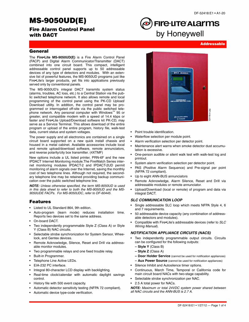
General The Fire•Lite MS-9050UD(E) is a Fire Alarm Control Panel(FACP) and Digital Alarm Communicator/Transmitter (DACT)combined into one circuit board. This compact, intelligentaddressable control panel supports up to 50 addressabledevices of any type of detectors and modules. With an exten-sive list of powerful features, the MS-9050UD programs just likeFire•Lite’s larger products, yet fits into applications previouslyserved only by conventional panels.
The MS-9050UD’s integral DACT transmits system status(alarms, troubles, AC loss, etc.) to a Central Station via the pub-lic switched telephone network. It also allows remote and localprogramming of the control panel using the PK-CD Upload/Download utility. In addition, the control panel may be pro-grammed or interrogated off-site via the public switched tele-phone network. Any personal computer with Windows™ 95 orgreater, and compatible modem with a speed of 14.4 kbps orfaster and Fire•Lite Upload/Download software kit PK-CD, mayserve as a Service Terminal. This allows download of the entireprogram or upload of the entire program, history file, walk-testdata, current status and system voltages.
The power supply and all electronics are contained on a singlecircuit board supported on a new quick install chassis andhoused in a metal cabinet. Available accessories include localand remote upload/download software, remote annunciators,and reverse polarity/city box transmitter. (4XTMF)
New options include a UL listed printer, PRN-6F and the newIPDACT Internet Monitoring module.The FireWatch Series inter-net monitoring modules IPDACT-2 and IPDACT-2UD permitmonitoring of alarm signals over the Internet, saving the monthlycost of two telephone lines. Although not required, the second-ary telephone line may be retained providing backup communi-cation over the public switched telephone line.
NOTE: Unless otherwise specified, the term MS-9050UD is usedin this data sheet to refer to both the MS-9050UD and the MS-9050UDE FACPs. For MS-9050UDC, refer to DF-60445.
Features• Listed to UL Standard 864, 9th edition.• Auto-program (learn mode) reduces installation time.
Reports two devices set to the same address.• On-board DACT.• Two independently programmable Style Z (Class A) or Style
Y (Class B) NAC circuits.• Selectable strobe synchronization for System Sensor, Whee-
lock, and Gentex devices.• Remote Acknowledge, Silence, Reset and Drill via address-
able monitor modules.• Two programmable relays and one fixed trouble relay.• Built-in Programmer.• Telephone Line Active LEDs.• EIA-232 PC interface.• Integral 80-character LCD display with backlighting.• Real-time clock/calendar with automatic daylight savings
control.• History file with 500 event capacity.• Automatic detector sensitivity testing (NFPA 72 compliant).• Automatic device type-code verification.
• Point trouble identification.• Waterflow selection per module point.• Alarm verification selection per detector point.• Maintenance alert warns when smoke detector dust accumu-
lation is excessive.• One-person audible or silent walk test with walk-test log and
printout.• System alarm verification selection per detector point.• PAS (Positive Alarm Sequence) and Pre-signal per point
(NFPA 72 compliant).• Up to eight ANN-BUS annunciators• Remote Acknowledge, Alarm Silence, Reset and Drill via
addressable modules or remote annunciator.• Upload/Download (local or remote) of program and data via
integral DACT.
SLC COMMUNICATION LOOP• Single addressable SLC loop which meets NFPA Style 4, 6
and 7 requirements.• 50 addressable device capacity (any combination of address-
able detectors and modules).• Compatible with Fire•Lite’s addressable devices (refer to SLC
Wiring Manual).
NOTIFICATION APPLIANCE CIRCUITS (NACS)• Two independently programmable output circuits. Circuits
can be configured for the following outputs:– Style Y (Class B)– Style Z (Class A)– Door Holder Service (cannot be used for notification appliances)
– Aux Power Source (cannot be used for notification appliances)
• Silence Inhibit and Autosilence timer options.• Continuous, March Time, Temporal or California code for
main circuit board NACs with two-stage capability.• Selectable strobe synchronization per NAC.• 2.5 A total power for NACs.NOTE: Maximum or total 24VDC system power shared betweenall NAC circuits and the ANN-BUS is 2.7 A.
Page 2 of 4 — DF-52418:E1 • 1/27/12
PROGRAMMING AND SOFTWARE• Autoprogram (learn mode) reduces installation time.• Custom English labels (per point) may be manually entered
or selected from an internal library file.• Two programmable Form-C relay outputs.• 20 software zones.• Continuous fire protection during online programming at the
front panel. • Program Check automatically catches common errors not
linked to any zone or input point.• OFFLINE PROGRAMMING: Create the entire program in
your office using a Windows®-based software package(orderprogramming kit PK-CD, containing PS-Tools, separately).Upload/download system programming locally.
User interface
LED INDICATORS• AC Power (green)• Fire Alarm (red)
• Supervisory (yellow)• Trouble (yellow)• Alarm Silenced signals (yellow)
KEYPAD• 16 key alpha-numeric pad• Acknowledge/Step
• Alarm Silenced• Drill (Manual Evacuate)• Reset (lamp test)
Product Line InformationMS-9050UD(E): Combination DACT/Fire Alarm Control Panelwith one SLC loop. Includes main circuit board with display,chassis with transformer, backbox with door, plastic bag contain-ing screws, cables, key, etc., manual. (For MS-9050UDC, referto DF-60445.)
PK-CD: Contains PS-Tools programming software for Win-dows®-based PC computer (cable not included).
DP-51050: Optional dress panel for the MS-9050UD.
TR-CE: Optional trim ring for semi-flush mounting.
BB-2F: Optional cabinet for one or two modules.
BB-6F: Optional cabinet for up to six modules mounted onCHS-6 chassis.
BB-26: Battery backbox, holds up to two 25 AH batteries andCHG-75.
BB-55F: Battery box, houses two 55 AH batteries
CHS-6: Chassis, mounts up to six multi-modules in a BB-6Fcabinet.
CHG-75: Battery charger for lead-acid batteries with a rating of25 to 75 AH.
CHG-120F: Remote battery charging system for lead-acid bat-teries with a rating of 55 to 120 AH. Requires additional BB-55Ffor mounting.
BAT Series: Batteries, see data sheet DF-52397.
PRT/PK-CABLE: Cable printer/personal computer interfacecable.
PRN-6F: UL listed compatible event printer. Uses tractor-fedpaper.
IPDACT, IPDACT-2/2UD Internet Monitoring Module: Mountsin bottom of enclosure with optional mounting kit (PN IPBRKT).Connects to primary and secondary DACT telephone outputports for internet communications over customer provided ether-
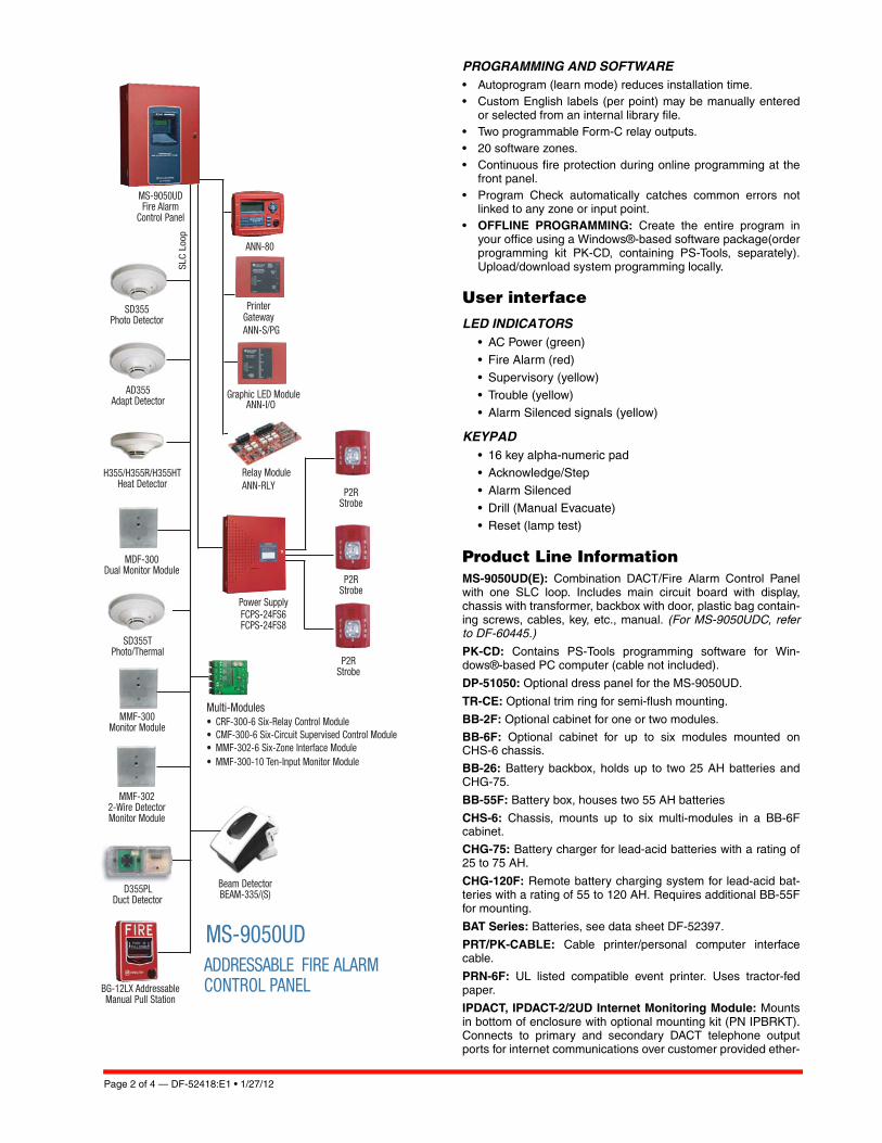
ADDRESSABLE FIRE ALARM CONTROL PANEL
MS-9050UD
MS-9050UDFire Alarm
Control Panel
pooL CLS
SD355Photo Detector
AD355Adapt Detector
MMF-300Monitor Module
P2RStrobe
P2RStrobe
MMF-3022-Wire DetectorMonitor Module
BG-12LX Addressable Manual Pull Station
Power SupplyFCPS-24FS6FCPS-24FS8
SD355TPhoto/Thermal
ANN-80
MDF-300Dual Monitor Module
H355/H355R/H355HTHeat Detector
D355PLDuct Detector
Multi-Modules• CRF-300-6 Six-Relay Control Module• CMF-300-6 Six-Circuit Supervised Control Module• MMF-302-6 Six-Zone Interface Module• MMF-300-10 Ten-Input Monitor Module
P2RStrobe
Beam DetectorBEAM-335/(S)
Printer Gateway ANN-S/PG
Graphic LED Module
Relay ModuleANN-RLY
ANN-I/O
DF-52418:E1 • 1/27/12 — Page 3 of 4
net internet connection. Requires compatible Teldat VisoralarmCentral Station Receiver. Can use DHCP or static IP. (See datasheet df-52424 for more information.)
IPBRKT: Mounting kit for IPDACT-2/2UD in common enclosure.
IPSPLT: Y-adaptor option allows connection of both panel dialeroutputs to one IPDACT-2/2UD cable input.
AC-TRMBLK: AC Terminal Block mounts to a metal bracket, inturn, mounts to the FACP chassis. Use AC-TRMBLK when wirenuts are not allowed for AC connections to the transformer.
OPTIONAL MODULES4XTMF Reverse Polarity Transmitter Module: Provides asupervised output for local energy municipal box transmitter,alarm and trouble. Includes a disable switch and disable troubleLED.
ANN-SEC: Optional secondary ANN-BUS interface module.Note: Used only with firmware 3.0 or higher.
COMPATIBLE ANNUNCIATORSANN-80(-W): Remote LCD annunciator mimics the informationdisplayed on the FACP LCD display. Recommended wire type isun-shielded. (Basic model is red; order -W version for white; seeDF-52417.)
ANN-I/O: LED Driver Module provides connections to a usersupplied graphic annunciator. (See DF-52430.)
ANN-LED: Annunciator Module provides three LEDs for eachzone: Alarm, Trouble, and Supervisory. Ships with red enclo-sure. (See DF-60241.)
ANN-RLED: Provides alarm (red) indicators for up to 30 inputzones or addressable points. (See DF-60241.)
ANN-RLY: Relay Module provides 10 programmable Form-Crelays. Can be mounted inside the cabinet. (See DF-52431.)
ANN-S/PG: Serial/Parallel Printer Gateway module provides aconnection for a serial or parallel printer. (See DF-52429.)
ADDRESSABLE DEVICESAll feature a polling LED and rotary switches for addressing.
CP355: Addressable low-profile ionization smoke detector.
SD355: Addressable low-profile photoelectric smoke detector.
SD355T: Addressable low-profile photoelectric smoke detectorwith thermal sensor.
SD355R: Remote test capable addressable photoelectricsmoke detector for use with DNR(W) duct detector housing.
H355: Fast-response, low-profile heat detector.
H355R: Fast-response, low-profile heat detector with rate-of-rise option.
H355HT: Fast-response, low-profile heat detector that activatesat 190°F/88°C.
AD355: Low-profile, intelligent, “Adapt” multi-sensor detector(B350LP base included).
BEAM355: Intelligent beam smoke detector.
BEAM355S: Intelligent beam smoke detector with integral sen-sitivity test.
D355PL: InnovairFlex low-flow non-relay duct-detector housing;includes SD355R.
DNR: InnovairFlex low-flow non-relay duct-detector housing.(Order SD355R separately.)
DNRW: InnovairFlex low-flow non-relay duct-detector housing,with NEMA-4 rating. Watertight. (Order SD355R separately.)
MMF-300: Addressable Monitor Module for one zone of nor-mally-open dry-contact initiating devices. Mounts in standard
4.0" (10.16 cm.) box. Includes plastic cover plate and end-of-lineresistor. Module may be configured for either a Style B (Class B)or Style D (Class A) IDC.
MDF-300: Dual Monitor Module. Same as MMF-300 except itprovides two Style B (Class B) only IDCs.
MMF-301: Miniature version of MMF-300. Excludes LED andStyle D option. Connects with wire pigtails. May mount in devicebackbox.
MMF-302A: Similar to MMF-300A. Addressable Monitor Modulefor one zone of conventional two-wire detectors. Requires reset-table 24 VDC power. Refer to the Device Compatibility Docu-ment for listed compatible devices and quantity limitation.
CMF-300: Addressable Control Module for one Style Y/Z (ClassB/A) zone of supervised polarized Notification Appliances.Mounts directly to a 4.0" (10.16 cm.) electrical box. NotificationAppliance Circuit option requires external 24 VDC to power noti-fication appliances.
CRF-300: Addressable relay module containing two isolatedsets of Form-C contacts, which operate as a DPDT switch.Mounts directly to a 4.0" (10.16 cm.) box, surface mount usingthe SMB500.
BG-12LX: Addressable manual pull station with interface mod-ule mounted inside.
I300: This module isolates the SLC loop from short circuit condi-tions (required for Style 6 or 7 operation).
SMB500: Used to mount all modules except the MMF-301 andM301.
MMF-300-10: Ten-input monitor module. Mount one or two mod-ules in a BB-2F cabinet (optional). Mount up to six modules on aCHS-6 chassis in a BB-6F cabinet.
MMF-302-6: Six-zone interface module. Mount one or two mod-ules in a BB-2F cabinet (optional). Mount up to six modules on aCHS-6 chassis in a BB-6F cabinet.
CMF-300-6: Six-circuit supervised control module. Mount one ortwo modules in a BB-2F cabinet (optional). Mount up to six mod-ules on a CHS-6 chassis in a BB-6F cabinet.
CRF-300-6: Six-relay control module (Form-C relays). Mountone or two modules in a BB-2F cabinet (optional). Mount up tosix modules on a CHS-6 chassis in a BB-6F cabinet.
NOTE: For more information on Compatible Addressable Devicesfor use with the MS-9050UD, see the following data sheets (docu-ment numbers): AD355 (DF-52386), BG-12LX (DF-52013), CMF-300-6 (DF-52365), CRF-300-6 (DF-52374), CMF/CRF Series (DF-52130), CP355 (DF-52383), H355 Series (DF-52385), I300 (DF-52389), MMF-300 Series/MDF-300 (DF-52121), MMF-300-10(DF-52347), MMF-302-6 (DF-52356), SD355/SD355T (DF-52384).
ADDRESSABLE DEVICE ACCESSORIESEnd-of-Line Resistor Assembly (R-47K and R-3.9K): The47k ohm assembly supervises the MMF-300, MDF-300, MMF-301, and CMF-300 module circuits. The 3.9k ohm assemblysupervises the MMF-302 module circuit. These resistors areincluded with each module.
Power Supervision Relay: Supervises the power to 4-wiresmoke detectors and notification appliances.
Wiring RequirementsWhile shielded wire is not required, it is recommended that allSLC wiring be twisted-pair to minimize the effects of electricalinterference. Refer to the panel manual for wiring details.
Page 4 of 4 — DF-52418:E1 • 1/27/12
This document is not intended to be used for installation purposes. We try to keep our product information up-to-date and accurate.
We cannot cover all specific applications or anticipate all requirements. All specifications are subject to change without notice.
For more information, contact Fire•Lite Alarms. Phone: (800) 627-3473, FAX: (877) 699-4105.www.firelite.com
Made in the U.S. A.
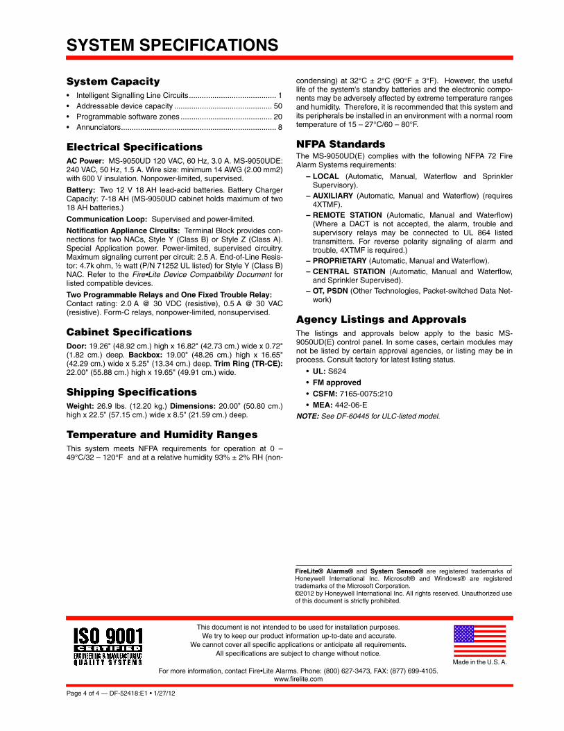
System Capacity• Intelligent Signalling Line Circuits......................................... 1 • Addressable device capacity .............................................. 50• Programmable software zones ........................................... 20• Annunciators......................................................................... 8
Electrical SpecificationsAC Power: MS-9050UD 120 VAC, 60 Hz, 3.0 A. MS-9050UDE:240 VAC, 50 Hz, 1.5 A. Wire size: minimum 14 AWG (2.00 mm2)with 600 V insulation. Nonpower-limited, supervised.
Battery: Two 12 V 18 AH lead-acid batteries. Battery ChargerCapacity: 7-18 AH (MS-9050UD cabinet holds maximum of two18 AH batteries.)
Communication Loop: Supervised and power-limited.
Notification Appliance Circuits: Terminal Block provides con-nections for two NACs, Style Y (Class B) or Style Z (Class A).Special Application power. Power-limited, supervised circuitry.Maximum signaling current per circuit: 2.5 A. End-of-Line Resis-tor: 4.7k ohm, ½ watt (P/N 71252 UL listed) for Style Y (Class B)NAC. Refer to the Fire•Lite Device Compatibility Document forlisted compatible devices.
Two Programmable Relays and One Fixed Trouble Relay: Contact rating: 2.0 A @ 30 VDC (resistive), 0.5 A @ 30 VAC(resistive). Form-C relays, nonpower-limited, nonsupervised.
Cabinet SpecificationsDoor: 19.26" (48.92 cm.) high x 16.82" (42.73 cm.) wide x 0.72"(1.82 cm.) deep. Backbox: 19.00" (48.26 cm.) high x 16.65"(42.29 cm.) wide x 5.25" (13.34 cm.) deep. Trim Ring (TR-CE):22.00" (55.88 cm.) high x 19.65" (49.91 cm.) wide.
Shipping SpecificationsWeight: 26.9 lbs. (12.20 kg.) Dimensions: 20.00” (50.80 cm.)high x 22.5” (57.15 cm.) wide x 8.5” (21.59 cm.) deep.
Temperature and Humidity RangesThis system meets NFPA requirements for operation at 0 –49°C/32 – 120°F and at a relative humidity 93% ± 2% RH (non-
condensing) at 32°C ± 2°C (90°F ± 3°F). However, the usefullife of the system's standby batteries and the electronic compo-nents may be adversely affected by extreme temperature rangesand humidity. Therefore, it is recommended that this system andits peripherals be installed in an environment with a normal roomtemperature of 15 – 27°C/60 – 80°F.
NFPA StandardsThe MS-9050UD(E) complies with the following NFPA 72 FireAlarm Systems requirements:
– LOCAL (Automatic, Manual, Waterflow and SprinklerSupervisory).
– AUXILIARY (Automatic, Manual and Waterflow) (requires4XTMF).
– REMOTE STATION (Automatic, Manual and Waterflow)(Where a DACT is not accepted, the alarm, trouble andsupervisory relays may be connected to UL 864 listedtransmitters. For reverse polarity signaling of alarm andtrouble, 4XTMF is required.)
– PROPRIETARY (Automatic, Manual and Waterflow).– CENTRAL STATION (Automatic, Manual and Waterflow,
and Sprinkler Supervised).– OT, PSDN (Other Technologies, Packet-switched Data Net-
work)
Agency Listings and ApprovalsThe listings and approvals below apply to the basic MS-9050UD(E) control panel. In some cases, certain modules maynot be listed by certain approval agencies, or listing may be inprocess. Consult factory for latest listing status.
• UL: S624• FM approved
• CSFM: 7165-0075:210• MEA: 442-06-E
NOTE: See DF-60445 for ULC-listed model.
FireLite® Alarms® and System Sensor® are registered trademarks ofHoneywell International Inc. Microsoft® and Windows® are registeredtrademarks of the Microsoft Corporation. ©2012 by Honeywell International Inc. All rights reserved. Unauthorized useof this document is strictly prohibited.
SYSTEM SPECIFICATIONS
CALIFORNIA DEPARTMENT OF FORESTRY & FIRE PROTECTION
OFFICE OF THE STATE FIRE MARSHAL
FIRE ENGINEERING - BUILDING MATERIALS LISTING PROGRAM
LISTING SERVICE
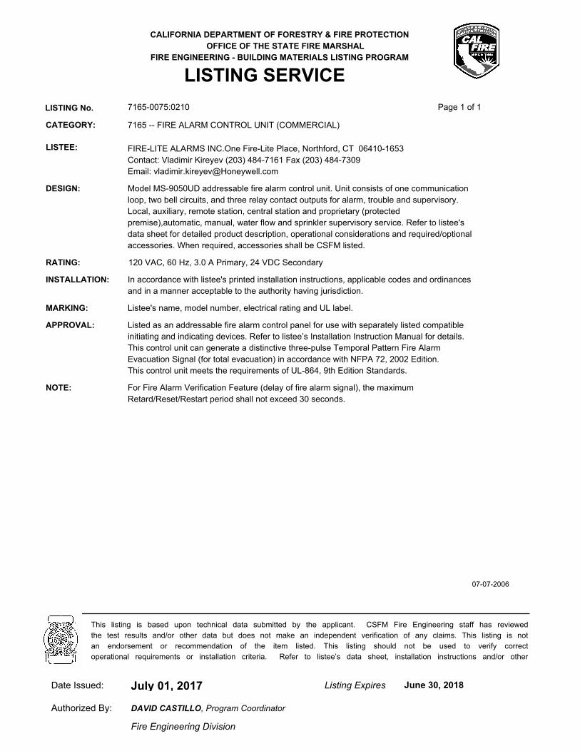
LISTING No. 7165-0075:0210 Page 1 of 1
CATEGORY: 7165 -- FIRE ALARM CONTROL UNIT (COMMERCIAL)
LISTEE: FIRE-LITE ALARMS INC.One Fire-Lite Place, Northford, CT 06410-1653
Contact: Vladimir Kireyev (203) 484-7161 Fax (203) 484-7309
Email: [email protected]
DESIGN: Model MS-9050UD addressable fire alarm control unit. Unit consists of one communication
loop, two bell circuits, and three relay contact outputs for alarm, trouble and supervisory.
Local, auxiliary, remote station, central station and proprietary (protected
premise),automatic, manual, water flow and sprinkler supervisory service. Refer to listee's
data sheet for detailed product description, operational considerations and required/optional
accessories. When required, accessories shall be CSFM listed.
RATING: 120 VAC, 60 Hz, 3.0 A Primary, 24 VDC Secondary
INSTALLATION: In accordance with listee's printed installation instructions, applicable codes and ordinances
and in a manner acceptable to the authority having jurisdiction.
MARKING: Listee's name, model number, electrical rating and UL label.
APPROVAL: Listed as an addressable fire alarm control panel for use with separately listed compatible
initiating and indicating devices. Refer to listee’s Installation Instruction Manual for details.
This control unit can generate a distinctive three-pulse Temporal Pattern Fire Alarm
Evacuation Signal (for total evacuation) in accordance with NFPA 72, 2002 Edition.
This control unit meets the requirements of UL-864, 9th Edition Standards.
NOTE: For Fire Alarm Verification Feature (delay of fire alarm signal), the maximum
Retard/Reset/Restart period shall not exceed 30 seconds.
07-07-2006
July 01, 2017Date Issued: Listing Expires June 30, 2018
Authorized By:
Fire Engineering Division
This listing is based upon technical data submitted by the applicant. CSFM Fire Engineering staff has reviewed
the test results and/or other data but does not make an independent verification of any claims. This listing is not
an endorsement or recommendation of the item listed. This listing should not be used to verify correct
operational requirements or installation criteria. Refer to listee’s data sheet, installation instructions and/or other
DAVID CASTILLO, Program Coordinator
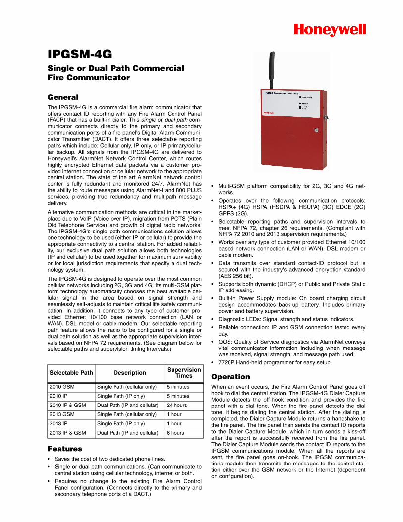
IPGSM-4GSingle or Dual Path Commercial Fire Communicator
GeneralThe IPGSM-4G is a commercial fire alarm communicator thatoffers contact ID reporting with any Fire Alarm Control Panel(FACP) that has a built-in dialer. This single or dual path com-municator connects directly to the primary and secondarycommunication ports of a fire panel's Digital Alarm Communi-cator Transmitter (DACT). It offers three selectable reportingpaths which include: Cellular only, IP only, or IP primary/cellu-lar backup. All signals from the IPGSM-4G are delivered toHoneywell’s AlarmNet Network Control Center, which routeshighly encrypted Ethernet data packets via a customer pro-vided internet connection or cellular network to the appropriatecentral station. The state of the art AlarmNet network controlcenter is fully redundant and monitored 24/7. AlarmNet hasthe ability to route messages using AlarmNet-I and 800 PLUSservices, providing true redundancy and multipath messagedelivery.
Alternative communication methods are critical in the market-place due to VoIP (Voice over IP), migration from POTS (PlainOld Telephone Service) and growth of digital radio networks.The IPGSM-4G's single path communications solution allowsone technology to be used (either IP or cellular) to provide theappropriate connectivity to a central station. For added reliabil-ity, our exclusive dual path solution allows both technologies(IP and cellular) to be used together for maximum survivabilityor for local jurisdiction requirements that specify a dual tech-nology system.
The IPGSM-4G is designed to operate over the most commoncellular networks including 2G, 3G and 4G. Its multi-GSM plat-form technology automatically chooses the best available cel-lular signal in the area based on signal strength andseamlessly self-adjusts to maintain critical life safety communi-cation. In addition, it connects to any type of customer pro-vided Ethernet 10/100 base network connection (LAN orWAN), DSL model or cable modem. Our selectable reportingpath feature allows the radio to be configured for a single ordual path solution as well as the appropriate supervision inter-vals based on NFPA 72 requirements. (See diagram below forselectable paths and supervision timing intervals.)
Features• Saves the cost of two dedicated phone lines.• Single or dual path communications. (Can communicate to
central station using cellular technology, internet or both.• Requires no change to the existing Fire Alarm Control
Panel configuration. (Connects directly to the primary andsecondary telephone ports of a DACT.)
• Multi-GSM platform compatibility for 2G, 3G and 4G net-works.
• Operates over the following communication protocols:HSPA+ (4G) HSPA (HSDPA & HSUPA) (3G) EDGE (2G)GPRS (2G).
• Selectable reporting paths and supervision intervals tomeet NFPA 72, chapter 26 requirements. (Compliant withNFPA 72 2010 and 2013 supervision requirements.)
• Works over any type of customer provided Ethernet 10/100based network connection (LAN or WAN), DSL modem orcable modem.
• Data transmits over standard contact-ID protocol but issecured with the industry's advanced encryption standard(AES 256 bit).
• Supports both dynamic (DHCP) or Public and Private StaticIP addressing.
• Built-In Power Supply module: On board charging circuitdesign accommodates back-up battery. Includes primarypower and battery supervision.
• Diagnostic LEDs: Signal strength and status indicators.
• Reliable connection: IP and GSM connection tested everyday.
• QOS: Quality of Service diagnostics via AlarmNet conveysvital communicator information including when messagewas received, signal strength, and message path used.
• 7720P Hand-held programmer for easy setup.
OperationWhen an event occurs, the Fire Alarm Control Panel goes offhook to dial the central station. The IPGSM-4G Dialer CaptureModule detects the off-hook condition and provides the firepanel with a dial tone. When the fire panel detects the dialtone, it begins dialing the central station. After the dialing iscompleted, the Dialer Capture Module returns a handshake tothe fire panel. The fire panel then sends the contact ID reportsto the Dialer Capture Module, which in turn sends a kiss-offafter the report is successfully received from the fire panel.The Dialer Capture Module sends the contact ID reports to theIPGSM communications module. When all the reports aresent, the fire panel goes on-hook. The IPGSM communica-tions module then transmits the messages to the central sta-tion either over the GSM network or the Internet (dependenton configuration).
Selectable Path Description Supervision Times
2010 GSM Single Path (cellular only) 5 minutes
2010 IP Single Path (IP only) 5 minutes
2010 IP & GSM Dual Path (IP and cellular) 24 hours
2013 GSM Single Path (cellular only) 1 hour
2013 IP Single Path (IP only) 1 hour
2013 IP & GSM Dual Path (IP and cellular) 6 hours
Easy to ProgramThe IPGSM-4G communicator can be pre-programmed usingthe 7720P programmer to enter all central-station information.This is saved to the IPGSM-4G communicator panel memory.When the IPGSM-4G communicator is installed at the site andconnected to the Internet/Intranet, it registers itself with theAlarmNet receiver.
.For most installations, the only required parameters are:
• Primary City ID (two digits) obtained from your monitoringstation.
• Primary Central Station ID (two digits) obtained from yourmonitoring station.
• Primary Subscriber ID (four digits) obtained from your mon-itoring station.
• Communication Module's MAC ID, and MAC CRC numberlocated on outside of box, and inside of the module.
All of these parameters are assigned by the monitoring station.
NOTE: Some assembly is required. See Installation and SetupGuide #800-12454 for full details.
Fire Communicator CapabilityThe IPGSM-4G is compatible with fire panels that use theContact ID communications format as described in the SIADC-05 standard.
AlarmNetHoneywell's AlarmNet has been the nationwide leader inalarm communications technology since 1986. A reliable alter-native for the transmission of alarm signals, our radio networkprovides extensive coverage in the United States and Canada.AlarmNet Network Control center processes signals from pow-erful servers in multiple locations equipped with 24/7 infra-structure support. The AlarmNet network consist of redundanthardware servers, hot back-up databases and generators withbattery back-up at all locations to ensure continuity of service.Signals from Alarm-Net are transmitted to the central station'sreceivers using multiple communications paths consisting ofthe Internet, radio network or toll-free POTS service.
Installation Requirements
UL COMPLIANCETo meet UL864/NFPA, ensure the following:
• IPGSM-4G must be installed in accordance with NFPA(National Fire Protection Association) standards 70 and 72.
• IPGSM-4G must be mounted in the same room and within20 feet of the fire panel.
• IPGSM-4G, and all equipment used for the IP connection(such as the router, hub, modem, etc.) shall be listed, mustbe powered from an un-switched branch circuit, and be pro-vided with appropriate standby power.
• IPGSM-4G must use the 7AH battery (not supplied) to pro-vide 24-hour backup capability.
Electrical SpecificationsTransformer:
– Primary 120VAC, 60Hz, 0.5A.
– Secondary: 18VDC, 50VA.Battery:
– One 12 V 7.0 AH lead-acid battery (not supplied).
– Battery charging current: 1 Amp maximum.– Battery discharge current: Standby 230mA, Active
950mA.
Cabinet SpecificationsDimensions: 14.875" H x 12.75" W x 3.0" D (37.8 cm H x 32.4cm W x 7.6 cm D).Color: Red.
Shipping SpecificationsWeight: 5.3 lbs. (6.94 kg).Dimensions: 15.625" H x 13.79" W x 9.25" D (39.7 cm H x34.9 cm W x 23.9 cm D)
Temperature and Humidity RangesThis system meets NFPA requirements for operation at 0 -49°C/32 - 120°F and at a relative humidity 93% ± 2% RH (noncondensing at 32°C ± 2°C (90°F ± 3°F). However, the usefullife of the system's standby batteries and the electronic com-ponents may be adversely affected by extreme temperatureranges and humidity. Therefore, it is recommended that thissystem and its peripherals be installed in an environment witha normal room temperature of 15 - 27°C/60 - 80°F.
Product Line InformationIPGSM-4G: Internet and Digital Cellular Fire Alarm Communi-cator Panel. Includes red cabinet with Ademco key and lock,wall outlet box, Dialer Capture Module, IGSM CommunicationsModule, antenna & mounting adapter, PowerBoost1 powersupply, LED display board, transformer, manual, & requiredscrews, cables, etc.Antenna KitsGSM-ANT3DB25KT: 25 ft. antenna kit. Includes GSM-ANT3DB,WA7626-CA adapter cable, and a 25’ RF cable.GSM-ANT3DB50KT: 50 ft. antenna kit. Includes GSM-ANT3DB,WA7626-CA adapter cable, and a 50’ RF cable.Antenna External HardwareGSM-ANT3DB: 3db gain external/remote antenna.WA7626-CA: SNA to N Adapter.7626-50HC: 50 ft. antenna cable, low loss.7626-25HC: 25 ft. antenna cable, low loss.NOTE: The GSM-ANT3DB and the WA7626-CA are both requiredfor installing an external antenna along with the necessary cableneeded (7626-50HC: 50 ft. or 7626-25HC: 25 ft.)
Other Accessories7720P: IPGSM-4G hand held programmer.HPTCOVER: Plug in transformer box for IPGSM communicator.BAT-1270: Battery 12 Volts, 7 AH, sealed.
Agency Listings and ApprovalsThe listings and approvals below apply to the basic IPGSM-4Gcommunicator panel. In some cases, certain modules may not belisted by certain approval agencies, or listing may be in process.
Consult factory for latest listing status.
UL Listed: S789.
CSFM: 7300-1645:0199.
FDNY: COA #6219.
Page 2 of 3 — DH-60769:D • 9/16/16 www.honeywell.com

Automation and Control Solutions
Honeywell
12 Clintonville Road 1(877) HPP-POWRNorthford, CT 06472-1610 [email protected]
This document is not intended to be used for installation purposes. We try to keep our product information up-to-date and accurate. We cannot cover all specificapplications or anticipate all requirements. All specifications are subject to change without notice.©2016 by Honeywell International Inc. All rights reserved. Unauthorized use of this document is strictly prohibited.
DH-60769:DSeptember 2016Made in the U.S.A.® U.S. Registered Trademark© 2016 Honeywell International Inc.Page 3 of 3
CALIFORNIA DEPARTMENT OF FORESTRY & FIRE PROTECTION
OFFICE OF THE STATE FIRE MARSHAL
FIRE ENGINEERING - BUILDING MATERIALS LISTING PROGRAM
LISTING SERVICE
LISTING No. 7300-1645:0199 Page 1 of 1
CATEGORY: 7300 -- FIRE ALARM CONTROL UNIT ACCESSORIES/MISC. DEVICES
LISTEE: HONEYWELL SECURITY2 Corporate Center Dr, Ste. 100, Melville, NY 11747
Contact: Issa Khouryawad (516) 577-2312 Fax (516) 577-3540
Email: [email protected]
DESIGN: Models iPGSM-COM, iPGSM-DP, iPGSM-4G and *IGSMCFP4G Internet and Digital Cellular
Fire Communicators. Units are suitable for residential and commercial applications. Refer to
listee's data sheet for detailed product description and operational considerations.
INSTALLATION: In accordance with listee's printed installation instructions, applicable codes & ordinances
and in a manner acceptable to the authority having jurisdiction.
MARKING: Listee's name, model number, electrical rating, and UL label.
APPROVAL: Listed as a control unit accessory for use with separately listed compatible commercial and
residential fire alarm control units. *Model IGSMCFP4G is intended for use with specific
Honeywell Security control units that employ the ECP bus. Refer to listee’s installation
Instruction Manual for details.
NOTE: Burglary and other non-fire functions were not examined.
iPGSM-COM, iPGSM-DP formerly listed in 7300-1645:0183.
*Rev 07-01-14 gt
July 01, 2017Date Issued: Listing Expires June 30, 2018
Authorized By:
Fire Engineering Division
This listing is based upon technical data submitted by the applicant. CSFM Fire Engineering staff has reviewed
the test results and/or other data but does not make an independent verification of any claims. This listing is not
an endorsement or recommendation of the item listed. This listing should not be used to verify correct
operational requirements or installation criteria. Refer to listee’s data sheet, installation instructions and/or other
DAVID CASTILLO, Program Coordinator
df-52417:c • 05/22/09 — Page 1 of 2
ANN-8080-Character LCD Serial Annunciator
Annunciators
df-52417:c • B-90
5241
7cov
.jpg
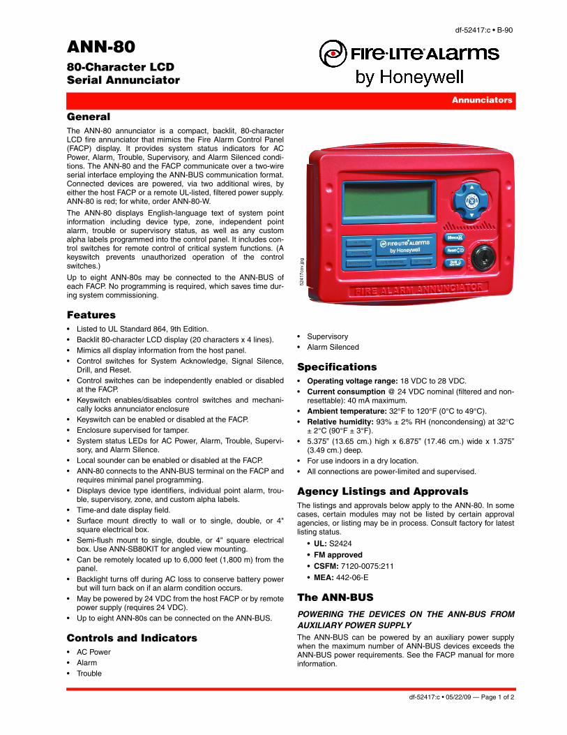
GeneralThe ANN-80 annunciator is a compact, backlit, 80-characterLCD fire annunciator that mimics the Fire Alarm Control Panel(FACP) display. It provides system status indicators for ACPower, Alarm, Trouble, Supervisory, and Alarm Silenced condi-tions. The ANN-80 and the FACP communicate over a two-wireserial interface employing the ANN-BUS communication format.Connected devices are powered, via two additional wires, byeither the host FACP or a remote UL-listed, filtered power supply.ANN-80 is red; for white, order ANN-80-W.
The ANN-80 displays English-language text of system pointinformation including device type, zone, independent pointalarm, trouble or supervisory status, as well as any customalpha labels programmed into the control panel. It includes con-trol switches for remote control of critical system functions. (Akeyswitch prevents unauthorized operation of the controlswitches.)
Up to eight ANN-80s may be connected to the ANN-BUS ofeach FACP. No programming is required, which saves time dur-ing system commissioning.
Features• Listed to UL Standard 864, 9th Edition.• Backlit 80-character LCD display (20 characters x 4 lines).• Mimics all display information from the host panel.• Control switches for System Acknowledge, Signal Silence,
Drill, and Reset.• Control switches can be independently enabled or disabled
at the FACP.• Keyswitch enables/disables control switches and mechani-
cally locks annunciator enclosure • Keyswitch can be enabled or disabled at the FACP.• Enclosure supervised for tamper.• System status LEDs for AC Power, Alarm, Trouble, Supervi-
sory, and Alarm Silence.• Local sounder can be enabled or disabled at the FACP.• ANN-80 connects to the ANN-BUS terminal on the FACP and
requires minimal panel programming.• Displays device type identifiers, individual point alarm, trou-
ble, supervisory, zone, and custom alpha labels.• Time-and date display field.• Surface mount directly to wall or to single, double, or 4"
square electrical box.• Semi-flush mount to single, double, or 4" square electrical
box. Use ANN-SB80KIT for angled view mounting.• Can be remotely located up to 6,000 feet (1,800 m) from the
panel.• Backlight turns off during AC loss to conserve battery power
but will turn back on if an alarm condition occurs.• May be powered by 24 VDC from the host FACP or by remote
power supply (requires 24 VDC).• Up to eight ANN-80s can be connected on the ANN-BUS.
Controls and Indicators• AC Power• Alarm• Trouble
• Supervisory• Alarm Silenced
Specifications• Operating voltage range: 18 VDC to 28 VDC.• Current consumption @ 24 VDC nominal (filtered and non-
resettable): 40 mA maximum.• Ambient temperature: 32°F to 120°F (0°C to 49°C).• Relative humidity: 93% ± 2% RH (noncondensing) at 32°C
± 2°C (90°F ± 3°F).• 5.375” (13.65 cm.) high x 6.875” (17.46 cm.) wide x 1.375”
(3.49 cm.) deep.• For use indoors in a dry location.• All connections are power-limited and supervised.
Agency Listings and ApprovalsThe listings and approvals below apply to the ANN-80. In somecases, certain modules may not be listed by certain approvalagencies, or listing may be in process. Consult factory for latestlisting status.
• UL: S2424• FM approved• CSFM: 7120-0075:211
• MEA: 442-06-E
The ANN-BUS
POWERING THE DEVICES ON THE ANN-BUS FROMAUXILIARY POWER SUPPLYThe ANN-BUS can be powered by an auxiliary power supplywhen the maximum number of ANN-BUS devices exceeds theANN-BUS power requirements. See the FACP manual for moreinformation.

Page 2 of 2 — df-52417:c • 05/22/09
This document is not intended to be used for installation purposes. We try to keep our product information up-to-date and accurate.
We cannot cover all specific applications or anticipate all requirements. All specifications are subject to change without notice.
For more information, contact Fire•Lite Alarms. Phone: (800) 627-3473, FAX: (877) 699-4105.www.firelite.com
FireLite® Alarms is a registered trademark of Honeywell International Inc.©2009 by Honeywell International Inc. All rights reserved. Unauthorized useof this document is strictly prohibited.
Made in the U.S. A.
ANN-BUS DEVICE ADDRESSINGEach ANN-BUS device requires a unique address (ID Number)in order to communicate with the FACP. A maximum of 8 devicescan be connected to the FACP ANN-BUS communication circuit.See the FACP manual for more information.
WIRE REQUIREMENTS: COMMUNICATIONS CIRCUITThe ANN-80 connects to the FACP ANN-BUS communicationscircuit. To determine the type of wire and the maximum wiringdistance that can be used with FACP ANN-BUS accessory mod-ules, it is necessary to calculate the total worst case currentdraw for all modules on a single 4-conductor bus. The total worstcase current draw is calculated by adding the individual worstcase currents for each module.
NOTE: For total worst case current draw on a single ANN-BUSrefer to appropriate FACP manual.
After calculating the total worst case current draw, the followingtable specifies the maximum distance the modules can belocated from the FACP on a single wire run. The table ensures6.0 volts of line drop maximum. In general, the wire length is lim-ited by resistance, but for heavier wire gauges, capacitance isthe limiting factor.
These cases are marked in the chart with an asterisk (*). Maxi-mum length can never be more than 6,000 feet (1,800 m),regardless of gauge used. See table below.
WIRE REQUIREMENTS: POWER CIRCUIT• 14 to 18 AWG (0.75 - 2.08 mm2) wire for 24 VDC power cir-
cuit is acceptable. Power wire distance limitation is set by 1.2volt maximum line drop form source to end of circuit.
• All connections are power-limited and supervised.• A maximum of eight ANN-80 modules may be connected to
this circuit.
WIRING CONFIGURATIONThe following figure illustrates the wiring between the FACP andANN-BUS devices.
FACP Wiring to ANN-BUS Device
ORDERING OPTIONS:ANN-80: Red 80 character LCD Annunciator.
ANN-80-W: White, 80 character LCD Annunciator. ANN-SB80KIT-R: Red surface mount backbox with angledwedge.
ANN-SB80KIT-W: White surface mount backbox with angledwedge.
Communication Pair Wiring Distance: FACP to Last ANN-BUS ModuleTotal Worst Case Current Draw (amps) 22 Gauge 18 Gauge 16 Gauge 14 Gauge
0.100 1,852 ft. 4,688 ft. * 6,000 ft. *6,000 ft.
0.200 926 ft. 2,344 ft. 3,731 ft. 5,906 ft.
0.300 617 ft. 1,563 ft. 2,488 ft. 3,937 ft.
0.400 463 ft. 1,172 ft. 1,866 ft. 2,953 ft.
0.500 370 ft. 938 ft. 1,493 ft. 2,362 ft.
0.600 309 ft. 781 ft. 1,244 ft. 1,969 ft.
0.700 265 ft. 670 ft. 1,066 ft. 1,687 ft.
0.800 231 ft. 586 ft. 933 ft. 1,476 ft.
0.900 206 ft. 521 ft. 829 ft. 1,312 ft.
1.000 (max.) 185 ft. 469 ft. 746 ft. 1,181 ft.
ANN-BUS and power wiring are supervised and power-limited.
ANN-BUS Device
MS-9050UD
CALIFORNIA DEPARTMENT OF FORESTRY & FIRE PROTECTION
OFFICE OF THE STATE FIRE MARSHAL
FIRE ENGINEERING - BUILDING MATERIALS LISTING PROGRAM
LISTING SERVICE
LISTING No. 7120-0075:0211 Page 1 of 1
CATEGORY: 7120 -- ANNUNCIATORS
LISTEE: FIRE-LITE ALARMS INC.One Fire-Lite Place, Northford, CT 06410-1653
Contact: Vladimir Kireyev (203) 484-7161 Fax (203) 484-7309
Email: [email protected]
DESIGN: Model ANN-80 and *ANN-80W remote fire annunciators. Unit is a 80-character, supervised
backlit LCD fire annunciator. Communication between the control panel and the annunciator
is accomplished over a two-wire serial interface employing the ANN-BUS protocol. Refer to
listee's data sheet for additional detailed product description and operational considerations.
INSTALLATION: In accordance with listee's printed installation instructions, applicable codes & ordinances
and in manner acceptable to the authority having jurisdiction.
MARKING: Listee's name, product number, electrical rating and UL label.
APPROVAL: Listed as an annunciators for use separately listed compatible fire alarm control units. Refer
to Manufacturers Installation Manual for details.
*Rev. 04-28-08 bh
July 01, 2017Date Issued: Listing Expires June 30, 2018
Authorized By:
Fire Engineering Division
This listing is based upon technical data submitted by the applicant. CSFM Fire Engineering staff has reviewed
the test results and/or other data but does not make an independent verification of any claims. This listing is not
an endorsement or recommendation of the item listed. This listing should not be used to verify correct
operational requirements or installation criteria. Refer to listee’s data sheet, installation instructions and/or other
DAVID CASTILLO, Program Coordinator
DF-52013:D • 4/13/2012 — Page 1 of 2
BG-12LXAddressable Manual Pull Station
Addressable Devices
DF-52013:D • E-100
FLP
ullS
tatio
n.jp
g
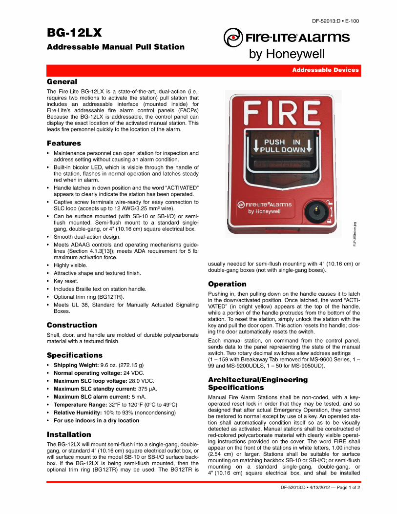
GeneralThe Fire·Lite BG-12LX is a state-of-the-art, dual-action (i.e.,requires two motions to activate the station) pull station thatincludes an addressable interface (mounted inside) forFire·Lite’s addressable fire alarm control panels (FACPs)Because the BG-12LX is addressable, the control panel candisplay the exact location of the activated manual station. Thisleads fire personnel quickly to the location of the alarm.
Features• Maintenance personnel can open station for inspection and
address setting without causing an alarm condition.
• Built-in bicolor LED, which is visible through the handle ofthe station, flashes in normal operation and latches steadyred when in alarm.
• Handle latches in down position and the word “ACTIVATED”appears to clearly indicate the station has been operated.
• Captive screw terminals wire-ready for easy connection toSLC loop (accepts up to 12 AWG/3.25 mm² wire).
• Can be surface mounted (with SB-10 or SB-I/O) or semi-flush mounted. Semi-flush mount to a standard single-gang, double-gang, or 4" (10.16 cm) square electrical box.
• Smooth dual-action design.• Meets ADAAG controls and operating mechanisms guide-
lines (Section 4.1.3[13]); meets ADA requirement for 5 lb.maximum activation force.
• Highly visible.• Attractive shape and textured finish.
• Key reset.• Includes Braille text on station handle.• Optional trim ring (BG12TR).
• Meets UL 38, Standard for Manually Actuated SignalingBoxes.
ConstructionShell, door, and handle are molded of durable polycarbonatematerial with a textured finish.
Specifications• Shipping Weight: 9.6 oz. (272.15 g)• Normal operating voltage: 24 VDC.• Maximum SLC loop voltage: 28.0 VDC.
• Maximum SLC standby current: 375 μA.• Maximum SLC alarm current: 5 mA.• Temperature Range: 32°F to 120°F (0°C to 49°C)
• Relative Humidity: 10% to 93% (noncondensing)• For use indoors in a dry location
InstallationThe BG-12LX will mount semi-flush into a single-gang, double-gang, or standard 4" (10.16 cm) square electrical outlet box, orwill surface mount to the model SB-10 or SB-I/O surface back-box. If the BG-12LX is being semi-flush mounted, then theoptional trim ring (BG12TR) may be used. The BG12TR is
usually needed for semi-flush mounting with 4" (10.16 cm) ordouble-gang boxes (not with single-gang boxes).
OperationPushing in, then pulling down on the handle causes it to latchin the down/activated position. Once latched, the word “ACTI-VATED” (in bright yellow) appears at the top of the handle,while a portion of the handle protrudes from the bottom of thestation. To reset the station, simply unlock the station with thekey and pull the door open. This action resets the handle; clos-ing the door automatically resets the switch.
Each manual station, on command from the control panel,sends data to the panel representing the state of the manualswitch. Two rotary decimal switches allow address settings (1 – 159 with Breakaway Tab removed for MS-9600 Series, 1 –99 and MS-9200UDLS, 1 – 50 for MS-9050UD).
Architectural/Engineering SpecificationsManual Fire Alarm Stations shall be non-coded, with a key-operated reset lock in order that they may be tested, and sodesigned that after actual Emergency Operation, they cannotbe restored to normal except by use of a key. An operated sta-tion shall automatically condition itself so as to be visuallydetected as activated. Manual stations shall be constructed ofred-colored polycarbonate material with clearly visible operat-ing instructions provided on the cover. The word FIRE shallappear on the front of the stations in white letters, 1.00 inches(2.54 cm) or larger. Stations shall be suitable for surfacemounting on matching backbox SB-10 or SB-I/O; or semi-flushmounting on a standard single-gang, double-gang, or4" (10.16 cm) square electrical box, and shall be installed
Page 2 of 2 — DF-52013:D • 4/13/2012
This document is not intended to be used for installation purposes. We try to keep our product information up-to-date and accurate.
We cannot cover all specific applications or anticipate all requirements. All specifications are subject to change without notice.
For more information, contact Fire•Lite Alarms. Phone: (800) 627-3473, FAX: (877) 699-4105.www.firelite.com
FireLite® Alarms® is a registered trademark of Honeywell International Inc.©2012 by Honeywell International Inc. All rights reserved. Unauthorized useof this document is strictly prohibited.
Made in the U.S. A.
within the limits defined by the Americans with Disabilities Act(ADA) or per national/local requirements. Manual Stationsshall be Underwriters Laboratories listed.
Manual stations shall connect with two wires to one of the con-trol panel SLC loops. The manual station shall, on commandfrom the control panel, send data to the panel representing thestate of the manual switch. Manual stations shall provideaddress setting by use of rotary decimal switches.
Product Line InformationBG-12LX: Dual-action addressable pull station. Includes keylocking feature. (Listed for Canadian and non-Canadian appli-cations.)
SB-10: Surface backbox; metal.
SB-I/O: Surface backbox; plastic.
BG12TR: Optional trim ring.
17003: Keys, set of two.
Agency Listings and ApprovalsIn some cases, certain modules or applications may not belisted by certain approval agencies, or listing may be in pro-cess. Consult factory for latest listing status.
• UL/ULC Listed: S711 (listed for Canadian and non-Cana-dian applications).
• MEA: 67-02-E.
• CSFM: 7150-0075:0184.• FM Approved. Patented: U.S. Patent No. D428,351; 6,380,846; 6,314,772;6,632,108.
CALIFORNIA DEPARTMENT OF FORESTRY & FIRE PROTECTION
OFFICE OF THE STATE FIRE MARSHAL
FIRE ENGINEERING - BUILDING MATERIALS LISTING PROGRAM
LISTING SERVICE
LISTING No. 7150-0075:0184 Page 1 of 1
CATEGORY: 7150 -- FIRE ALARM PULL BOXES
LISTEE: FIRE-LITE ALARMS INC.One Fire-Lite Place, Northford, CT 06410-1653
Contact: Vladimir Kireyev (203) 484-7161 Fax (203) 484-7309
Email: [email protected]
DESIGN: Models BG-12, BG-12S, BG-12NC, BG-12W, BG-12LW, BG-12WP, BG-12LWP, BG-12L,
BG-12LX, BG-12LA, BG-12PS, BG-12LSP, BG-12SP, BG-12LR, BG-12LRA, BG-12LAO,
BG-12LAOB, BG-12-LO, BG-12LOB, BG-12LPS, BG-12LPSP, BG-12SL, UT-PS1 and
UT-PS2 fire alarm pull boxes. The BG-12 series is a dual action pull station that has
normally open switch contacts. Refer to listee's data sheet for detailed product description
and operational considerations.
INSTALLATION: In accordance with listee's printed installation instructions, applicable codes and ordinances
and in a manner acceptable to the authority having jurisdiction.
MARKING: Listee's name, model number and UL label.
APPROVAL: Listed as fire alarm boxes for use with separately listed compatible fire alarm control units.
Models BG-12WP, BG-12W, BG-12LW and BG-12LWP are intended for outdoor use when
installed with Model WP-10 back box. Models BG-LAOB and BG-12LOB are intended for
outdoor use when installed with Model WBB or WP-10 back box.
* These manual pull boxes meet the requirements of UL Standard 38, 1999 Edition and
California amendments.
XLF: 7150-0028:0199
*Updated 08-17-09 fm
July 01, 2017Date Issued: Listing Expires June 30, 2018
Authorized By:
Fire Engineering Division
This listing is based upon technical data submitted by the applicant. CSFM Fire Engineering staff has reviewed
the test results and/or other data but does not make an independent verification of any claims. This listing is not
an endorsement or recommendation of the item listed. This listing should not be used to verify correct
operational requirements or installation criteria. Refer to listee’s data sheet, installation instructions and/or other
DAVID CASTILLO, Program Coordinator
SD355(A) SeriesAddressable Photoelectric Smoke Detectors
Addressable Devices
DF-52384:D • E-160
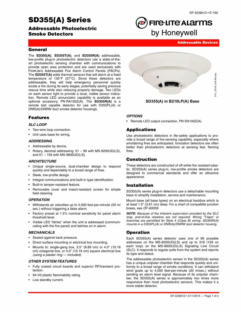
GeneralThe SD355(A), SD355T(A), and SD355R(A) addressable,low-profile plug-in photoelectric detectors use a state-of-the-art photoelectric sensing chamber with communications toprovide open area protection and are used exclusively withFire•Lite’s Addressable Fire Alarm Control Panels (FACPs).The SD355T(A) adds thermal sensors that will alarm at a fixedtemperature of 135°F (57°C). Since these detectors areaddressable, they will help emergency personnel quicklylocate a fire during its early stages, potentially saving preciousrescue time while also reducing property damage. Two LEDson each sensor light to provide a local, visible sensor indica-tion. Remote LED annunciator capability is available as anoptional accessory, PN RA100Z(A). The SD355R(A) is aremote test capable detector for use with D355PL(A) orDNR(A)/DNRW duct smoke detector housings.
Features
SLC LOOP• Two-wire loop connection.• Unit uses base for wiring.
ADDRESSING• Addressable by device.• Rotary, decimal addressing: 01 – 99 with MS-9200UD(LS),
and 01 – 159 with MS-9600UD(LS).
ARCHITECTURE• Unique single-source, dual-chamber design to respond
quickly and dependably to a broad range of fires.
• Sleek, low-profile design.• Integral communications and built-in type identification.• Built-in tamper-resistant feature.
• Removable cover and insect-resistant screen for simplefield cleaning.
OPERATION• Withstands air velocities up to 4,000 feet-per-minute (20 m/
sec.) without triggering a false alarm.• Factory preset at 1.5% nominal sensitivity for panel alarm
threshold level.• Visible LED “blinks” when the unit is addressed (communi-
cating with the fire panel) and latches on in alarm.
MECHANICALS• Sealed against back pressure.• Direct surface mounting or electrical box mounting.• Mounts to: single-gang box, 3.5" (8.89 cm) or 4.0" (10.16
cm) octagonal box, or 4.0" (10.16 cm) square electrical box(using a plaster ring — included).
OTHER SYSTEM FEATURES• Fully coated circuit boards and superior RF/transient pro-
tection.
• 94-V0 plastic flammability rating.• Low standby current.
OPTIONS• Remote LED output connection, PN RA100Z(A).
Applications
Use photoelectric detectors in life-safety applications to pro-vide a broad range of fire-sensing capability, especially wheresmoldering fires are anticipated. Ionization detectors are oftenbetter than photoelectric detectors at sensing fast, flamingfires.
ConstructionThese detectors are constructed of off-white fire resistant plas-tic. SD355(A) series plug-in, low-profile smoke detectors aredesigned to commercial standards and offer an attractiveappearance.
InstallationSD355(A) series plug-in detectors use a detachable mountingbase to simplify installation, service and maintenance.
Mount base (all base types) on an electrical backbox which isat least 1.5" (3.81 cm) deep. For a chart of compatible junctionboxes, see DF-60059.
NOTE: Because of the inherent supervision provided by the SLCloop, end-of-line resistors are not required. Wiring “T-taps” orbranches are permitted for Style 4 (Class B) wiring. SD355R(A)mounts in a D355PL(A) or DNR(A)/DNRW duct detector housing.
OperationEach SD355(A) series detector uses one of 99 possibleaddresses on the MS-9200UD(LS) and up to 318 (159 oneach loop) on the MS-9600UD(LS) Signaling Line Circuit(SLC). It responds to regular polls from the system and reportsits type and status.
The addressable photoelectric sensor in the SD355(A) serieshas a unique unipolar chamber that responds quickly and uni-formly to a broad range of smoke conditions. It can withstandwind gusts up to 4,000 feet-per-minute (20 m/sec.) withoutsending an alarm level signal. Because of its unipolar cham-ber, the SD355(A) series is approximately two times moreresponsive than most photoelectric sensors. This makes it amore stable detector.
SD355(A) in B210LP(A) Base
2151_2251B_CEILING.png
DF-52384:D • 2/11/2015 — Page 1 of 2
FireLite® Alarms is a registered trademark of Honeywell International Inc.©2015 by Honeywell International Inc. All rights reserved. Unauthorized useof this document is strictly prohibited.
Detector Sensitivity TestEach detector can have its sensitivity tested (required perNFPA 72, Chapter 14 on Inspection, Testing and Maintenance)when installed/connected to a MS-9200UD(LS) or MS-9600UD(LS) addressable fire alarm control panel. The resultsof the sensitivity test can be printed off the MS-9200UD(LS) orMS-9600UD(LS) for record keeping.
SpecificationVoltage range: 15 – 32 VDC (peak).
Standby current: 300 µA @ 24 VDC.
LED current: 6.5 mA @ 24 VDC (latched “ON”).
Air velocity: 4,000 ft./min. (20 m/sec.) maximum.
Size: 2.1" (5.33 cm) high; base determines diameter.
– B210LP(A): 6.1" (15.5 cm) diameter.– B501(A): 4.1" (10.4 cm) diameter.– B200SR(A): 6.875" (17.46 cm) diameter.
– B224RB(A): 6.2" (15.748 cm) diameter. Weight: 3.6 oz. (102 g).
Operating temperature range: for SD355(A): 0°C to 49°C(32°F to 120°F); for SD355T(A): 0°C to 38°C (32°F to 100°F).SD355R(A): installed in a DNR(A)/DNRW -20°C to 70°C (-4°Fto 158°F).
Temperature: 0°C – 49°C (32°F – 120°F).
Relative humidity: 10% – 93%, non-condensing.
ListingsListings and approvals below apply to the SD355(A),SD355T(A), and SD355RT(A) detectors. In some cases, cer-tain modules may not be listed by certain approval agencies,or listing may be in process. Consult factory for latest listingstatus.
• UL Listed: S1059.• ULC Listed: S1059.• CSFM: 7272-0075:0194.
• MEA: 243-02-E.• FM approved.
Product Line InformationNOTE: “A” suffix indicates ULC Listed model.
SD355: Addressable photoelectric detector; B210LP baseincluded.
SD355A: Sames as SD355 with ULC Listing; B210LPA baseincluded.
SD355T: Same as SD355 but with thermal element; B210LPbase included.
SD355TA: Same as SD355T with ULC Listing; B210LPA baseincluded.
SD355R: Remote test capable addressable photoelectricdetector for use with a D355PL(A) or DNRA/DNRW ductdetector housing; B210LP base included.
SD355RA: Same as SD355R with ULC Listing for use with aD355PLA or DNRA duct detector housing; B210LPA baseincluded.
INTELLIGENT BASESNOTE: “A” suffix indicates ULC Listed model.
NOTE: The detector’s plug-in base can be changed off for specialapplications. For details about intelligent bases and their mount-ing, see DF-60059.
B210LP(A): Plug-in detector base (included); standard U.S.flanged low-profile mounting base.
B210LPBP: Bulk pack of B210LP; package contains 10.
B501(A): Standard European flangeless mounting base.
B501BP: Bulk pack of B501; package contains 10.
B200SR(A): Intelligent sounder base capable of producingsound output with ANSI Temporal 3 or continuous tone.Replaces B501BH series bases in retrofit applications.
B224RB(A): Plug-in System Sensor relay base. Screw termi-nals: up to 14 AWG (2.0 mm²). Relay type: Form-C. Rating: 2.0A @ 30 VDC resistive; 0.3 A @ 110 VDC inductive; 1.0 A @30 VDC inductive.
B224BI(A): Plug-in System Sensor isolator detector base.Maximum 25 devices between isolator bases (see DF-52389).
ACCESSORIESF110: Retrofit flange to convert B210LP(A) to match theB350LP(A) profile, or to convert older high-profile bases tolow-profile.
F110BP: Bulk pack of F110; package contains 15.
F210: Replacement flange for B210LP(A) base.
RA100Z(A): Remote LED annunciator. 3 – 32 VDC. Mounts toa U.S. single-gang electrical box. For use with B501(A) andB210LP(A) bases only.
SMB600: Surface mounting kit
M02-04-00:Test magnet.
M02-09-00: Test magnet with telescoping handle.
XR2B: Detector removal tool. Allows installation and/orremoval of detector heads from bases in high ceiling applica-tions.
XP-4: Extension pole for XR2B. Comes in three 5-foot(1.524 m) sections.
T55-127-010: Detector removal tool without pole.
BCK-200B: Black detector covers for use with SD355(A) only;box of 10.
WCK-200B: White detector covers for use with SD355(A)only; box of 10.
Page 2 of 2 — DF-52384:D • 2/11/2015
This document is not intended to be used for installation purposes. We try to keep our product information up-to-date and accurate.
We cannot cover all specific applications or anticipate all requirements. All specifications are subject to change without notice.
For more information, contact Fire•Lite Alarms. Phone: (800) 627-3473, FAX: (877) 699-4105.www.firelite.com
CALIFORNIA DEPARTMENT OF FORESTRY & FIRE PROTECTION
OFFICE OF THE STATE FIRE MARSHAL
FIRE ENGINEERING - BUILDING MATERIALS LISTING PROGRAM
LISTING SERVICE
LISTING No. 7272-0075:0194 Page 1 of 1
CATEGORY: 7272 -- SMOKE DETECTOR-SYSTEM TYPE-PHOTOELECTRIC
LISTEE: FIRE-LITE ALARMS INC.One Fire-Lite Place, Northford, CT 06410-1653
Contact: Vladimir Kireyev (203) 484-7161 Fax (203) 484-7309
Email: [email protected]
DESIGN: Models SD350, SD350T, SD355, SD355R*, SD355T and AD355 photoelectric type smoke
detectors. Model SD350T and SD355T has a 135°F supplement integral heat sensor which
only assists in a fire situation. The purpose of this thermal circuitry is to increase the
sensitivity of the detector. This thermal circuitry is NOT approved for use as a heat detector.
Refer to listee's printed data sheet for additional detailed product description and operational
considerations.
RATING: 24VDC
INSTALLATION: In accordance with listee's printed installation instructions, applicable codes & ordinances
and a manner acceptable to the authority having jurisdiction.
MARKING: Listee's name, model number, electrical rating and UL label.
APPROVAL: Listed as photoelectric smoke detectors for use with separately listed compatible fire alarm
control units. All units are suitable for open areas and inside duct installations with air
velocities between 0-4,000 FPM. Models SD355 and SD355R* are also approved for
installations inside Fire-Lite Duct Housing D355PL (CSFM Listing No. 3242-0075:221) and
System Sensor Duct Housing DNRW (CSFM Listing No. 3242-1653:210).
NOTE: The photoelectric type detectors are generally more effective at detecting slow, smoldering
fires which smolder for hours before bursting into flame. Sources of these fires may include
cigarettes burning in couches or bedding. The ionization type detectors are generally more
effective at detecting fast, flaming fires which consume combustible materials rapidly and
spread quickly. Sources of these fires may include paper burning in a waste container or a
grease fire in the kitchen.
*Rev. 01-11-2010 fm
July 01, 2017Date Issued: Listing Expires June 30, 2018
Authorized By:
Fire Engineering Division
This listing is based upon technical data submitted by the applicant. CSFM Fire Engineering staff has reviewed
the test results and/or other data but does not make an independent verification of any claims. This listing is not
an endorsement or recommendation of the item listed. This listing should not be used to verify correct
operational requirements or installation criteria. Refer to listee’s data sheet, installation instructions and/or other
DAVID CASTILLO, Program Coordinator
MMF-300(A) Series, MDF-300Addressable Monitor Modules
Addressable Devices
DF-52121:E • E-325
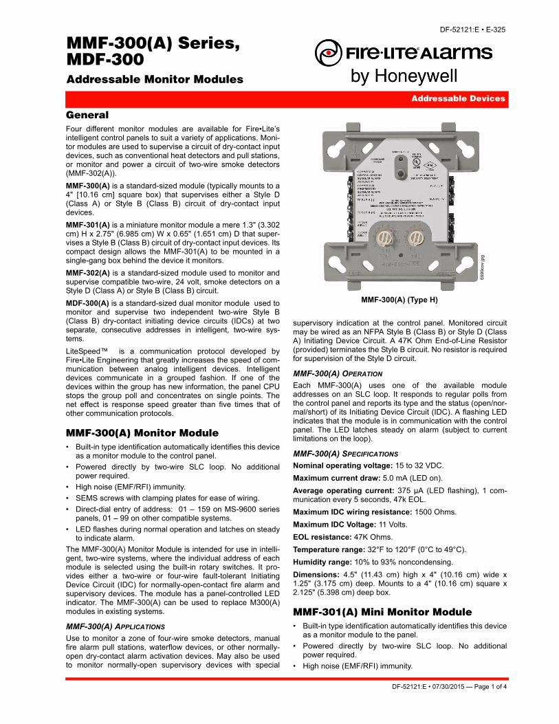
GeneralFour different monitor modules are available for Fire•Lite’sintelligent control panels to suit a variety of applications. Moni-tor modules are used to supervise a circuit of dry-contact inputdevices, such as conventional heat detectors and pull stations,or monitor and power a circuit of two-wire smoke detectors(MMF-302(A)).
MMF-300(A) is a standard-sized module (typically mounts to a4" [10.16 cm] square box) that supervises either a Style D(Class A) or Style B (Class B) circuit of dry-contact inputdevices.
MMF-301(A) is a miniature monitor module a mere 1.3" (3.302cm) H x 2.75" (6.985 cm) W x 0.65" (1.651 cm) D that super-vises a Style B (Class B) circuit of dry-contact input devices. Itscompact design allows the MMF-301(A) to be mounted in asingle-gang box behind the device it monitors.
MMF-302(A) is a standard-sized module used to monitor andsupervise compatible two-wire, 24 volt, smoke detectors on aStyle D (Class A) or Style B (Class B) circuit.
MDF-300(A) is a standard-sized dual monitor module used tomonitor and supervise two independent two-wire Style B(Class B) dry-contact initiating device circuits (IDCs) at twoseparate, consecutive addresses in intelligent, two-wire sys-tems.
LiteSpeed™ is a communication protocol developed byFire•Lite Engineering that greatly increases the speed of com-munication between analog intelligent devices. Intelligentdevices communicate in a grouped fashion. If one of thedevices within the group has new information, the panel CPUstops the group poll and concentrates on single points. Thenet effect is response speed greater than five times that ofother communication protocols.
MMF-300(A) Monitor Module• Built-in type identification automatically identifies this device
as a monitor module to the control panel.
• Powered directly by two-wire SLC loop. No additionalpower required.
• High noise (EMF/RFI) immunity.
• SEMS screws with clamping plates for ease of wiring.
• Direct-dial entry of address: 01 – 159 on MS-9600 seriespanels, 01 – 99 on other compatible systems.
• LED flashes during normal operation and latches on steadyto indicate alarm.
The MMF-300(A) Monitor Module is intended for use in intelli-gent, two-wire systems, where the individual address of eachmodule is selected using the built-in rotary switches. It pro-vides either a two-wire or four-wire fault-tolerant InitiatingDevice Circuit (IDC) for normally-open-contact fire alarm andsupervisory devices. The module has a panel-controlled LEDindicator. The MMF-300(A) can be used to replace M300(A)modules in existing systems.
MMF-300(A) APPLICATIONS
Use to monitor a zone of four-wire smoke detectors, manualfire alarm pull stations, waterflow devices, or other normally-open dry-contact alarm activation devices. May also be usedto monitor normally-open supervisory devices with special
supervisory indication at the control panel. Monitored circuitmay be wired as an NFPA Style B (Class B) or Style D (ClassA) Initiating Device Circuit. A 47K Ohm End-of-Line Resistor(provided) terminates the Style B circuit. No resistor is requiredfor supervision of the Style D circuit.
MMF-300(A) OPERATION
Each MMF-300(A) uses one of the available moduleaddresses on an SLC loop. It responds to regular polls fromthe control panel and reports its type and the status (open/nor-mal/short) of its Initiating Device Circuit (IDC). A flashing LEDindicates that the module is in communication with the controlpanel. The LED latches steady on alarm (subject to currentlimitations on the loop).
MMF-300(A) SPECIFICATIONS
Nominal operating voltage: 15 to 32 VDC.
Maximum current draw: 5.0 mA (LED on).
Average operating current: 375 µA (LED flashing), 1 com-munication every 5 seconds, 47k EOL.
Maximum IDC wiring resistance: 1500 Ohms.
Maximum IDC Voltage: 11 Volts.
EOL resistance: 47K Ohms.
Temperature range: 32°F to 120°F (0°C to 49°C).
Humidity range: 10% to 93% noncondensing.
Dimensions: 4.5" (11.43 cm) high x 4" (10.16 cm) wide x1.25" (3.175 cm) deep. Mounts to a 4" (10.16 cm) square x2.125" (5.398 cm) deep box.
MMF-301(A) Mini Monitor Module• Built-in type identification automatically identifies this device
as a monitor module to the panel.
• Powered directly by two-wire SLC loop. No additionalpower required.
• High noise (EMF/RFI) immunity.
MMF-300(A) (Type H)
6999
cov.
jpg
DF-52121:E • 07/30/2015 — Page 1 of 4
• Tinned, stripped leads for ease of wiring.
• Direct-dial entry of address: 01 – 159 on MS-9600 seriespanels, 01 – 99 on other compatible systems
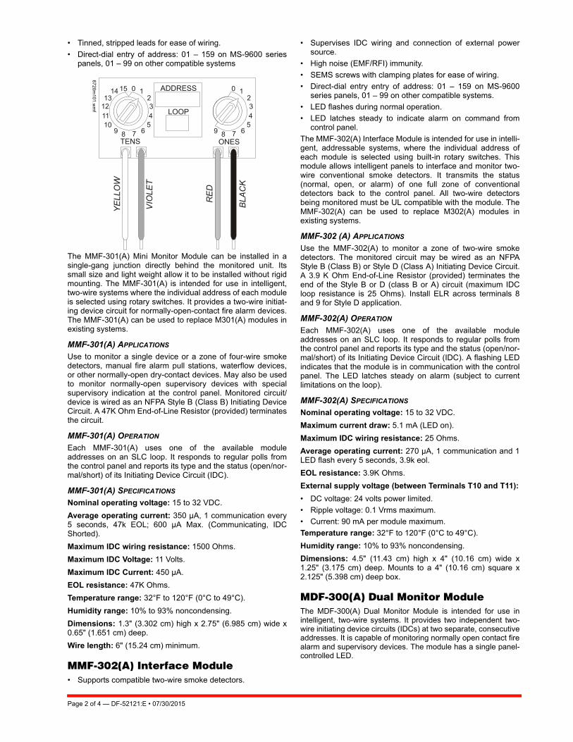
The MMF-301(A) Mini Monitor Module can be installed in asingle-gang junction directly behind the monitored unit. Itssmall size and light weight allow it to be installed without rigidmounting. The MMF-301(A) is intended for use in intelligent,two-wire systems where the individual address of each moduleis selected using rotary switches. It provides a two-wire initiat-ing device circuit for normally-open-contact fire alarm devices.The MMF-301(A) can be used to replace M301(A) modules inexisting systems.
MMF-301(A) APPLICATIONS
Use to monitor a single device or a zone of four-wire smokedetectors, manual fire alarm pull stations, waterflow devices,or other normally-open dry-contact devices. May also be usedto monitor normally-open supervisory devices with specialsupervisory indication at the control panel. Monitored circuit/device is wired as an NFPA Style B (Class B) Initiating DeviceCircuit. A 47K Ohm End-of-Line Resistor (provided) terminatesthe circuit.
MMF-301(A) OPERATION
Each MMF-301(A) uses one of the available moduleaddresses on an SLC loop. It responds to regular polls fromthe control panel and reports its type and the status (open/nor-mal/short) of its Initiating Device Circuit (IDC).
MMF-301(A) SPECIFICATIONS
Nominal operating voltage: 15 to 32 VDC.
Average operating current: 350 µA, 1 communication every5 seconds, 47k EOL; 600 µA Max. (Communicating, IDCShorted).
Maximum IDC wiring resistance: 1500 Ohms.
Maximum IDC Voltage: 11 Volts.
Maximum IDC Current: 450 µA.
EOL resistance: 47K Ohms.
Temperature range: 32°F to 120°F (0°C to 49°C).
Humidity range: 10% to 93% noncondensing.
Dimensions: 1.3" (3.302 cm) high x 2.75" (6.985 cm) wide x0.65" (1.651 cm) deep.
Wire length: 6" (15.24 cm) minimum.
MMF-302(A) Interface Module• Supports compatible two-wire smoke detectors.
• Supervises IDC wiring and connection of external powersource.
• High noise (EMF/RFI) immunity.
• SEMS screws with clamping plates for ease of wiring.
• Direct-dial entry entry of address: 01 – 159 on MS-9600series panels, 01 – 99 on other compatible systems.
• LED flashes during normal operation.
• LED latches steady to indicate alarm on command fromcontrol panel.
The MMF-302(A) Interface Module is intended for use in intelli-gent, addressable systems, where the individual address ofeach module is selected using built-in rotary switches. Thismodule allows intelligent panels to interface and monitor two-wire conventional smoke detectors. It transmits the status(normal, open, or alarm) of one full zone of conventionaldetectors back to the control panel. All two-wire detectorsbeing monitored must be UL compatible with the module. TheMMF-302(A) can be used to replace M302(A) modules inexisting systems.
MMF-302 (A) APPLICATIONS
Use the MMF-302(A) to monitor a zone of two-wire smokedetectors. The monitored circuit may be wired as an NFPAStyle B (Class B) or Style D (Class A) Initiating Device Circuit.A 3.9 K Ohm End-of-Line Resistor (provided) terminates theend of the Style B or D (class B or A) circuit (maximum IDCloop resistance is 25 Ohms). Install ELR across terminals 8and 9 for Style D application.
MMF-302(A) OPERATION
Each MMF-302(A) uses one of the available moduleaddresses on an SLC loop. It responds to regular polls fromthe control panel and reports its type and the status (open/nor-mal/short) of its Initiating Device Circuit (IDC). A flashing LEDindicates that the module is in communication with the controlpanel. The LED latches steady on alarm (subject to currentlimitations on the loop).
MMF-302(A) SPECIFICATIONS
Nominal operating voltage: 15 to 32 VDC.
Maximum current draw: 5.1 mA (LED on).
Maximum IDC wiring resistance: 25 Ohms.
Average operating current: 270 µA, 1 communication and 1LED flash every 5 seconds, 3.9k eol.
EOL resistance: 3.9K Ohms.
External supply voltage (between Terminals T10 and T11):• DC voltage: 24 volts power limited.
• Ripple voltage: 0.1 Vrms maximum.
• Current: 90 mA per module maximum.
Temperature range: 32°F to 120°F (0°C to 49°C).
Humidity range: 10% to 93% noncondensing.
Dimensions: 4.5" (11.43 cm) high x 4" (10.16 cm) wide x1.25" (3.175 cm) deep. Mounts to a 4" (10.16 cm) square x2.125" (5.398 cm) deep box.
MDF-300(A) Dual Monitor ModuleThe MDF-300(A) Dual Monitor Module is intended for use inintelligent, two-wire systems. It provides two independent two-wire initiating device circuits (IDCs) at two separate, consecutiveaddresses. It is capable of monitoring normally open contact firealarm and supervisory devices. The module has a single panel-controlled LED.
6720m
101.w
mf
Page 2 of 4 — DF-52121:E • 07/30/2015
NOTE: The MDF-300(A) provides two Style B (Class B) IDC cir-cuits ONLY. Style D (Class A) IDC circuits are NOT supported inany application.
MDF-300(A) SPECIFICATIONS
Normal operating voltage range: 15 to 32 VDC.
Maximum current draw: 6.4 mA (LED on).
Average operating current: 750 µA (LED flashing).
Maximum IDC wiring resistance: 1,500 Ohms.
Maximum IDC Voltage: 11 Volts.
Maximum IDC Current: 240 µA
EOL resistance: 47K Ohms.
Temperature range: 32° to 120°F (0° to 49°C).
Humidity range: 10% to 93% (non-condensing).
Dimensions: 4.5" (11.43 cm) high x 4" (10.16 cm) wide x1.25" (3.175 cm) deep. Mounts to a 4" (10.16 cm) square x2.125" (5.398 cm) deep box.
MDF-300(A) AUTOMATIC ADDRESSING
The MDF-300(A) automatically assigns itself to two address-able points, starting with the original address. For example, ifthe MDF-300(A) is set to address “26”, then it will automati-cally assign itself to addresses “26” and “27”.
NOTE: “Ones” addresses on the MDF-300(A) are 0, 2, 4, 6, or 8only. Terminals 6 and 7 use the first address, and terminals 8 and9 use the second address.
InstallationMMF-300(A), MMF-302(A), and MDF-300(A) modules mountdirectly to a standard 4" (10.16 cm) square, 2.125" (5.398 cm)deep, electrical box. They may also be mounted to theSMB500 surface-mount box. Mounting hardware and installa-tion instructions are provided with each module. All wiringmust conform to applicable local codes, ordinances, and regu-lations. These modules are intended for power-limited wiringonly.
The MMF-301(A) module is intended to be wired and mountedwithout rigid connections inside a standard electrical box. Allwiring must conform to applicable local codes, ordinances,and regulations.
Agency Listings and ApprovalsIn some cases, certain modules may not be listed by certainapproval agencies, or listing may be in process. Consult fac-tory for latest listing status.
• UL: S2424.
• ULC: S2424.
• FM Approved. • CSFM: 7300-0075:0185.
• MEA: 72-01-E.
Product Line InformationNOTE: “A” suffix indicates ULC-listed model.
MMF-300(A): Monitor module.
MMF-301(A): Monitor module, miniature.
MMF-302(A): Monitor module, two-wire detectors.
MDF-300(A): Monitor module, dual, two independent Class Bcircuits.
SMB500: Optional surface-mount backbox.
NOTE: See installation instructions and refer to the SLC WiringManual, PN 51309.
Architects’/Engineers’ SpecificationsSpecifications of these devices and all FireLite products areavailable from FireLite.
CAUTION: Avoid duplicating addresses on the system.
DF-52121:E • 07/30/2015 — Page 3 of 4

Fire·Lite® is a registered trademark and LiteSpeed™ and FireWatch™ aretrademarks of Honeywell International Inc.©2015 by Honeywell International Inc. All rights reserved. Unauthorized useof this document is strictly prohibited.
Page 4 of 4 — DF-52121:E • 07/30/2015
This document is not intended to be used for installation purposes. We try to keep our product information up-to-date and accurate.
We cannot cover all specific applications or anticipate all requirements. All specifications are subject to change without notice.
For more information, contact Fire•Lite Alarms. Phone: (800) 627-3473, FAX: (877) 699-4105.www.firelite.com
CALIFORNIA DEPARTMENT OF FORESTRY & FIRE PROTECTION
OFFICE OF THE STATE FIRE MARSHAL
FIRE ENGINEERING - BUILDING MATERIALS LISTING PROGRAM
LISTING SERVICE
LISTING No. 7300-0075:0185 Page 1 of 1
CATEGORY: 7300 -- FIRE ALARM CONTROL UNIT ACCESSORIES/MISC. DEVICES
LISTEE: FIRE-LITE ALARMS INC.One Fire-Lite Place, Northford, CT 06410-1653
Contact: Vladimir Kireyev (203) 484-7161 Fax (203) 484-7309
Email: [email protected]
DESIGN: Models MDF-300, MMF-301, MMF-300, MMF-302, MCF-300 monitor modules; Models
CRF-300 and CMF-300 control modules; and MMF-302-6 six zone interface signaling device
module. Refer to listee's data sheet for additional detailed product description and operational
considerations.
RATING: 15-32 VDC
INSTALLATION: In accordance with listee's printed installation instructions, applicable codes and ordinances
and in a manner acceptable to the authority having jurisdiction.
MARKING: Listee's name, model designation, electrical rating, and UL label.
APPROVAL: Listed as control unit accessories for use with listee's separately listed electrically
compatible fire alarm control units.
NOTE:
*Rev. 05-06-05 JW
July 01, 2017Date Issued: Listing Expires June 30, 2018
Authorized By:
Fire Engineering Division
This listing is based upon technical data submitted by the applicant. CSFM Fire Engineering staff has reviewed
the test results and/or other data but does not make an independent verification of any claims. This listing is not
an endorsement or recommendation of the item listed. This listing should not be used to verify correct
operational requirements or installation criteria. Refer to listee’s data sheet, installation instructions and/or other
DAVID CASTILLO, Program Coordinator
Agency Listings
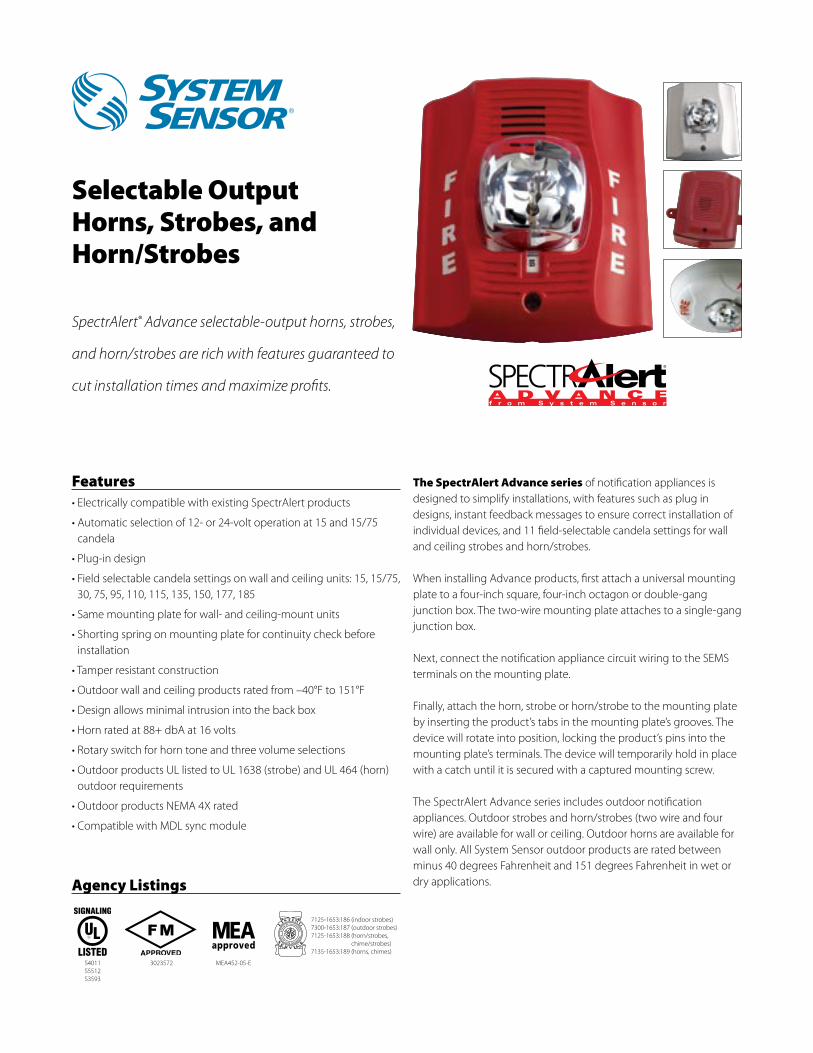
Features• Electrically compatible with existing SpectrAlert products
• Automatic selection of 12- or 24-volt operation at 15 and 15/75 candela
• Plug-in design
• Field selectable candela settings on wall and ceiling units: 15, 15/75, 30, 75, 95, 110, 115, 135, 150, 177, 185
• Same mounting plate for wall- and ceiling-mount units
• Shorting spring on mounting plate for continuity check before installation
• Tamper resistant construction
• Outdoor wall and ceiling products rated from –40°F to 151°F
• Design allows minimal intrusion into the back box
• Horn rated at 88+ dbA at 16 volts
• Rotary switch for horn tone and three volume selections
• Outdoor products UL listed to UL 1638 (strobe) and UL 464 (horn) outdoor requirements
• Outdoor products NEMA 4X rated
• Compatible with MDL sync module
The SpectrAlert Advance series of notification appliances is designed to simplify installations, with features such as plug in designs, instant feedback messages to ensure correct installation of individual devices, and 11 field-selectable candela settings for wall and ceiling strobes and horn/strobes.
When installing Advance products, first attach a universal mounting plate to a four-inch square, four-inch octagon or double-gang junction box. The two-wire mounting plate attaches to a single-gang junction box.
Next, connect the notification appliance circuit wiring to the SEMS terminals on the mounting plate.
Finally, attach the horn, strobe or horn/strobe to the mounting plate by inserting the product’s tabs in the mounting plate’s grooves. The device will rotate into position, locking the product’s pins into the mounting plate’s terminals. The device will temporarily hold in place with a catch until it is secured with a captured mounting screw.
The SpectrAlert Advance series includes outdoor notification appliances. Outdoor strobes and horn/strobes (two wire and four wire) are available for wall or ceiling. Outdoor horns are available for wall only. All System Sensor outdoor products are rated between minus 40 degrees Fahrenheit and 151 degrees Fahrenheit in wet or dry applications.
Selectable OutputHorns, Strobes, andHorn/Strobes
SpectrAlert® Advance selectable-output horns, strobes,
and horn/strobes are rich with features guaranteed to
cut installation times and maximize profits.
MEA452-05-E3023572
7125-1653:186 (indoor strobes)7300-1653:187 (outdoor strobes)7125-1653:188 (horn/strobes,
chime/strobes)7135-1653:189 (horns, chimes)
S4011S5512S3593
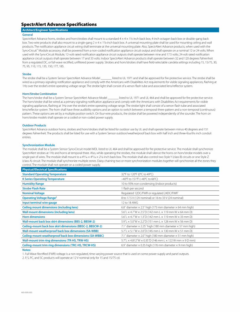
A05-0395-005
SpectrAlert Advance SpecificationsArchitect/Engineer SpecificationsGeneralSpectrAlert Advance horns, strobes and horn/strobes shall mount to a standard 4 × 4 × 1½-inch back box, 4-inch octagon back box or double-gang back box. Two-wire products shall also mount to a single-gang 2 × 4 × 17⁄8-inch back box. A universal mounting plate shall be used for mounting ceiling and wall products. The notification appliance circuit wiring shall terminate at the universal mounting plate. Also, SpectrAlert Advance products, when used with the Sync•Circuit™ Module accessory, shall be powered from a non-coded notification appliance circuit output and shall operate on a nominal 12 or 24 volts. When used with the Sync•Circuit Module, 12-volt rated notification appliance circuit outputs shall operate between nine and 17.5 volts; 24-volt rated notification appliance circuit outputs shall operate between 17 and 33 volts. Indoor SpectrAlert Advance products shall operate between 32 and 120 degrees Fahrenheit from a regulated DC, or full-wave rectified, unfiltered power supply. Strobes and horn/strobes shall have field-selectable candela settings including 15, 15/75, 30, 75, 95, 110, 115, 135, 150, 177, 185.
StrobeThe strobe shall be a System Sensor SpectrAlert Advance Model _______ listed to UL 1971 and shall be approved for fire protective service. The strobe shall be wired as a primary-signaling notification appliance and comply with the Americans with Disabilities Act requirements for visible signaling appliances, flashing at 1Hz over the strobe’s entire operating voltage range. The strobe light shall consist of a xenon flash tube and associated lens/reflector system.
Horn/Strobe CombinationThe horn/strobe shall be a System Sensor SpectrAlert Advance Model _______ listed to UL 1971 and UL 464 and shall be approved for fire protective service. The horn/strobe shall be wired as a primary-signaling notification appliance and comply with the Americans with Disabilities Act requirements for visible signaling appliances, flashing at 1Hz over the strobe’s entire operating voltage range. The strobe light shall consist of a xenon flash tube and associated lens/reflector system. The horn shall have three audibility options and an option to switch between a temporal three-pattern and a non-temporal (continuous) pattern. These options are set by a multiple position switch. On four-wire products, the strobe shall be powered independently of the sounder. The horn on horn/strobe models shall operate on a coded or non-coded power supply.
Outdoor ProductsSpectrAlert Advance outdoor horns, strobes and horn/strobes shall be listed for outdoor use by UL and shall operate between minus 40 degrees and 151 degrees Fahrenheit. The products shall be listed for use with a System Sensor outdoor/weatherproof back box with half inch and three-fourths inch conduit entries.
Synchronization ModuleThe module shall be a System Sensor Sync•Circuit model MDL listed to UL 464 and shall be approved for fire protective service. The module shall synchronize SpectrAlert strobes at 1Hz and horns at temporal three. Also, while operating the strobes, the module shall silence the horns on horn/strobe models over a single pair of wires. The module shall mount to a 411⁄16 × 411⁄16 × 21⁄8-inch back box. The module shall also control two Style Y (class B) circuits or one Style Z (class A) circuit. The module shall synchronize multiple zones. Daisy chaining two or more synchronization modules together will synchronize all the zones they control. The module shall not operate on a coded power supply.
Physical/Electrical SpecificationsStandard Operating Temperature 32°F to 120°F (0°C to 49°C)
K Series Operating Temperature –40°F to 151°F (–40°C to 66°C)
Humidity Range 10 to 93% non-condensing (indoor products)
Strobe Flash Rate 1 flash per second
Nominal Voltage Regulated 12DC/FWR or regulated 24DC/FWR1
Operating Voltage Range2 8 to 17.5 V (12V nominal) or 16 to 33 V (24 nominal)
Input terminal wire gauge 12 to 18 AWG
Ceiling mount dimensions (including lens) 6.8˝ diameter × 2.5˝ high (173 mm diameter × 64 mm high)
Wall mount dimensions (including lens) 5.6˝L × 4.7˝W × 2.5˝D (142 mm L × 119 mm W × 64 mm D)
Horn dimensions 5.6˝L × 4.7˝W × 1.3˝D (142 mm L × 119 mm W × 33 mm D)
Wall-mount back box skirt dimensions (BBS-2, BBSW-2) 5.9˝L × 5.0˝W × 2.2˝D (151 mm L × 128 mm W × 56 mm D)
Ceiling-mount back box skirt dimensions (BBSC-2, BBSCW-2) 7.1˝ diameter × 2.25˝ high (180 mm diameter × 57 mm high)
Wall-mount weatherproof back box dimensions (SA-WBB) 5.7˝L × 5.1˝W × 2.0˝D (145 mm L × 130 mm W × 51 mm D)
Ceiling-mount weatherproof back box dimensions (SA-WBBC) 7.1˝ diameter × 2.0˝ high (180 mm diameter × 51 mm high)
Wall-mount trim ring dimensions (TR-HS, TRW-HS) 5.7˝L × 4.812˝W × 0.35˝D (146 mm L × 122 W mm × 9 D mm)
Ceiling-mount trim ring dimensions (TRC-HS, TRCW-HS) 6.9˝ diameter × 0.35 high (176 mm diameter × 9 mm high)
Notes:1. Full Wave Rectified (FWR) voltage is a non-regulated, time varying power source that is used on some power supply and panel outputs.2. P, S, PC, and SC products will operate at 12 V nominal only for 15 and 15/75 cd.
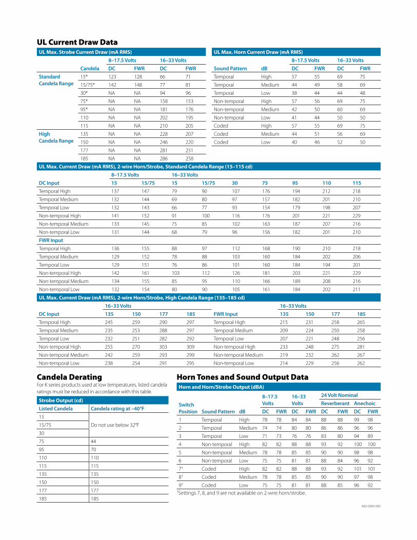
A05-0395-005
Horn and Horn/Strobe Output (dBA)
Switch Position Sound Pattern dB
8–17.5 Volts
16–33Volts
24 Volt NominalReverberant Anechoic
DC FWR DC FWR DC FWR DC FWR1 Temporal High 78 78 84 84 88 88 99 98
2 Temporal Medium 74 74 80 80 86 86 96 96
3 Temporal Low 71 73 76 76 83 80 94 89
4 Non-temporal High 82 82 88 88 93 92 100 100
5 Non-temporal Medium 78 78 85 85 90 90 98 98
6 Non-temporal Low 75 75 81 81 88 84 96 92
7† Coded High 82 82 88 88 93 92 101 101
8† Coded Medium 78 78 85 85 90 90 97 98
9† Coded Low 75 75 81 81 88 85 96 92 †Settings 7, 8, and 9 are not available on 2-wire horn/strobe.
UL Max. Strobe Current Draw (mA RMS)
Candela8–17.5 Volts 16–33 VoltsDC FWR DC FWR
Standard Candela Range
15* 123 128 66 71
15/75* 142 148 77 81
30* NA NA 94 96
75* NA NA 158 153
95* NA NA 181 176
110 NA NA 202 195
115 NA NA 210 205
HighCandela Range
135 NA NA 228 207
150 NA NA 246 220
177 NA NA 281 251
185 NA NA 286 258
UL Max. Current Draw (mA RMS), 2-wire Horn/Strobe, Standard Candela Range (15–115 cd)
DC Input8–17.5 Volts 16–33 Volts15 15/75 15 15/75 30 75 95 110 115
Temporal High 137 147 79 90 107 176 194 212 218
Temporal Medium 132 144 69 80 97 157 182 201 210
Temporal Low 132 143 66 77 93 154 179 198 207
Non-temporal High 141 152 91 100 116 176 201 221 229
Non-temporal Medium 133 145 75 85 102 163 187 207 216
Non-temporal Low 131 144 68 79 96 156 182 201 210
FWR InputTemporal High 136 155 88 97 112 168 190 210 218
Temporal Medium 129 152 78 88 103 160 184 202 206
Temporal Low 129 151 76 86 101 160 184 194 201
Non-temporal High 142 161 103 112 126 181 203 221 229
Non-temporal Medium 134 155 85 95 110 166 189 208 216
Non-temporal Low 132 154 80 90 105 161 184 202 211
UL Max. Horn Current Draw (mA RMS)
Sound Pattern dB8–17.5 Volts 16–33 VoltsDC FWR DC FWR
Temporal High 57 55 69 75
Temporal Medium 44 49 58 69
Temporal Low 38 44 44 48
Non-temporal High 57 56 69 75
Non-temporal Medium 42 50 60 69
Non-temporal Low 41 44 50 50
Coded High 57 55 69 75
Coded Medium 44 51 56 69
Coded Low 40 46 52 50
UL Current Draw Data
Horn Tones and Sound Output Data
UL Max. Current Draw (mA RMS), 2-wire Horn/Strobe, High Candela Range (135–185 cd)
DC Input16–33 Volts
FWR Input16–33 Volts
135 150 177 185 135 150 177 185Temporal High 245 259 290 297 Temporal High 215 231 258 265
Temporal Medium 235 253 288 297 Temporal Medium 209 224 250 258
Temporal Low 232 251 282 292 Temporal Low 207 221 248 256
Non-temporal High 255 270 303 309 Non-temporal High 233 248 275 281
Non-temporal Medium 242 259 293 299 Non-temporal Medium 219 232 262 267
Non-temporal Low 238 254 291 295 Non-temporal Low 214 229 256 262
Candela DeratingFor K series products used at low temperatures, listed candela ratings must be reduced in accordance with this table.
Strobe Output (cd)Listed Candela Candela rating at –40°F15
Do not use below 32°F15/75
30
75 44
95 70
110 110
115 115
135 135
150 150
177 177
185 185
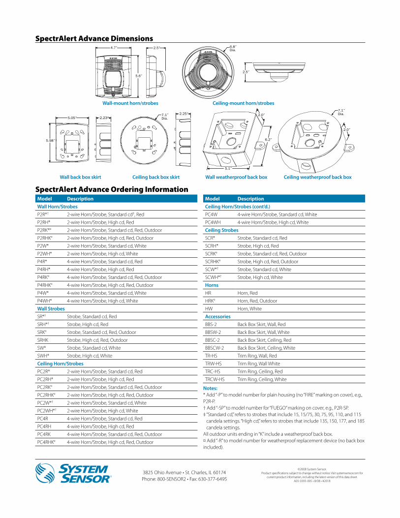
3825 Ohio Avenue • St. Charles, IL 60174 Phone: 800-SENSOR2 • Fax: 630-377-6495
©2008 System Sensor.Product specifications subject to change without notice. Visit systemsensor.com for
current product information, including the latest version of this data sheet.A05-0395-005 • 8/08 • #2018
SpectrAlert Advance Dimensions
Model DescriptionWall Horn/StrobesP2R*† 2-wire Horn/Strobe, Standard cd‡, Red
P2RH* 2-wire Horn/Strobe, High cd, Red
P2RK*¤ 2-wire Horn/Strobe, Standard cd, Red, Outdoor
P2RHK¤ 2-wire Horn/Strobe, High cd, Red, Outdoor
P2W* 2-wire Horn/Strobe, Standard cd, White
P2WH* 2-wire Horn/Strobe, High cd, White
P4R* 4-wire Horn/Strobe, Standard cd, Red
P4RH* 4-wire Horn/Strobe, High cd, Red
P4RK¤ 4-wire Horn/Strobe, Standard cd, Red, Outdoor
P4RHK¤ 4-wire Horn/Strobe, High cd, Red, Outdoor
P4W* 4-wire Horn/Strobe, Standard cd, White
P4WH* 4-wire Horn/Strobe, High cd, White
Wall StrobesSR*† Strobe, Standard cd, Red
SRH*† Strobe, High cd, Red
SRK¤ Strobe, Standard cd, Red, Outdoor
SRHK Strobe, High cd, Red, Outdoor
SW* Strobe, Standard cd, White
SWH* Strobe, High cd, White
Ceiling Horn/StrobesPC2R* 2-wire Horn/Strobe, Standard cd, Red
PC2RH* 2-wire Horn/Strobe, High cd, Red
PC2RK¤ 2-wire Horn/Strobe, Standard cd, Red, Outdoor
PC2RHK¤ 2-wire Horn/Strobe, High cd, Red, Outdoor
PC2W*† 2-wire Horn/Strobe, Standard cd, White
PC2WH*† 2-wire Horn/Strobe, High cd, White
PC4R 4-wire Horn/Strobe, Standard cd, Red
PC4RH 4-wire Horn/Strobe, High cd, Red
PC4RK 4-wire Horn/Strobe, Standard cd, Red, Outdoor
PC4RHK¤ 4-wire Horn/Strobe, High cd, Red, Outdoor
Model DescriptionCeiling Horn/Strobes (cont’d.)PC4W 4-wire Horn/Strobe, Standard cd, White
PC4WH 4-wire Horn/Strobe, High cd, White
Ceiling StrobesSCR* Strobe, Standard cd, Red
SCRH* Strobe, High cd, Red
SCRK¤ Strobe, Standard cd, Red, Outdoor
SCRHK¤ Strobe, High cd, Red, Outdoor
SCW*† Strobe, Standard cd, White
SCWH*† Strobe, High cd, White
HornsHR Horn, Red
HRK¤ Horn, Red, Outdoor
HW Horn, White
AccessoriesBBS-2 Back Box Skirt, Wall, Red
BBSW-2 Back Box Skirt, Wall, White
BBSC-2 Back Box Skirt, Ceiling, Red
BBSCW-2 Back Box Skirt, Ceiling, White
TR-HS Trim Ring, Wall, Red
TRW-HS Trim Ring, Wall White
TRC-HS Trim Ring, Ceiling, Red
TRCW-HS Trim Ring, Ceiling, White
SpectrAlert Advance Ordering Information
Notes:* Add “-P” to model number for plain housing (no “FIRE” marking on cover), e.g., P2R-P.† Add “-SP” to model number for “FUEGO” marking on cover, e.g., P2R-SP.‡ “Standard cd,” refers to strobes that include 15, 15/75, 30, 75, 95, 110, and 115
candela settings. “High cd,” refers to strobes that include 135, 150, 177, and 185 candela settings.
All outdoor units ending in “K” include a weatherproof back box.¤ Add “-R” to model number for weatherproof replacement device (no back box included).
4.7˝
5.6˝
6.8˝Dia.
2.5˝
2.5˝
2.23˝5.05˝
5.98˝
7.1˝Dia.
2.25˝
5.1˝
2.0˝
6.2˝
7.1˝Dia.
2.0˝
Wall-mount horn/strobes Ceiling-mount horn/strobes
Wall back box skirt Wall weatherproof back boxCeiling back box skirt Ceiling weatherproof back box
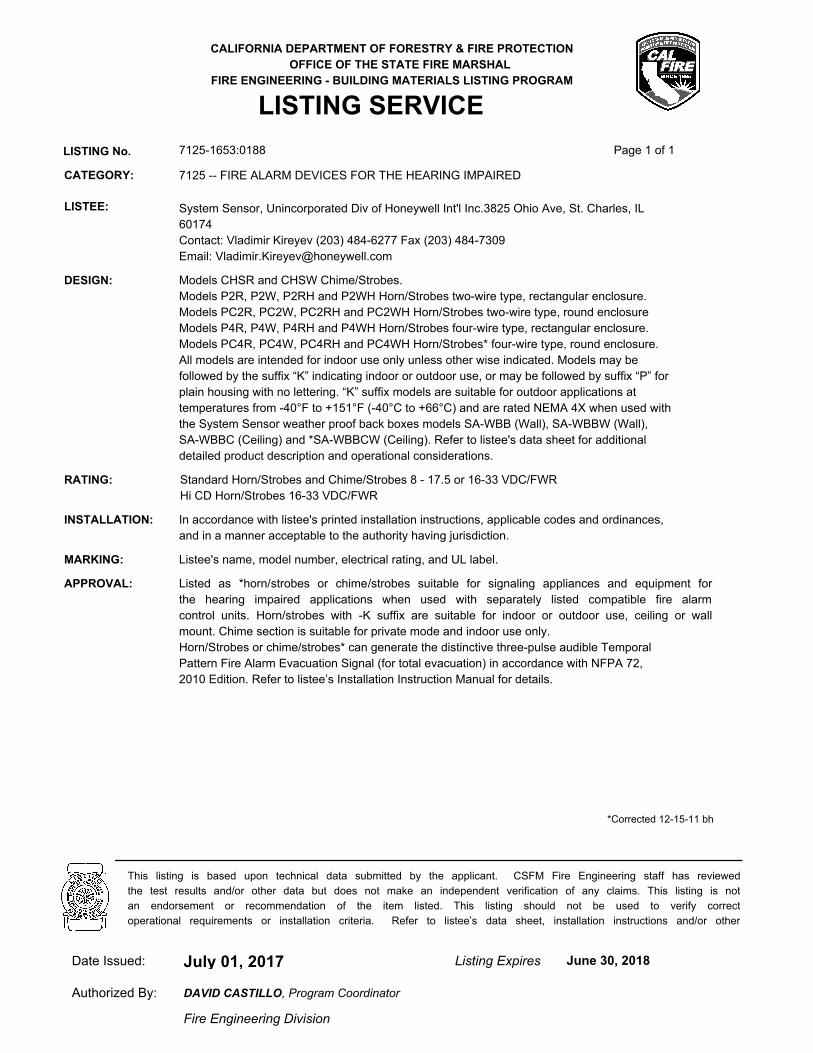
CALIFORNIA DEPARTMENT OF FORESTRY & FIRE PROTECTION
OFFICE OF THE STATE FIRE MARSHAL
FIRE ENGINEERING - BUILDING MATERIALS LISTING PROGRAM
LISTING SERVICE
LISTING No. 7125-1653:0188 Page 1 of 1
CATEGORY: 7125 -- FIRE ALARM DEVICES FOR THE HEARING IMPAIRED
LISTEE: System Sensor, Unincorporated Div of Honeywell Int'l Inc.3825 Ohio Ave, St. Charles, IL
60174
Contact: Vladimir Kireyev (203) 484-6277 Fax (203) 484-7309
Email: [email protected]
DESIGN: Models CHSR and CHSW Chime/Strobes.
Models P2R, P2W, P2RH and P2WH Horn/Strobes two-wire type, rectangular enclosure.
Models PC2R, PC2W, PC2RH and PC2WH Horn/Strobes two-wire type, round enclosure
Models P4R, P4W, P4RH and P4WH Horn/Strobes four-wire type, rectangular enclosure.
Models PC4R, PC4W, PC4RH and PC4WH Horn/Strobes* four-wire type, round enclosure.
All models are intended for indoor use only unless other wise indicated. Models may be
followed by the suffix “K” indicating indoor or outdoor use, or may be followed by suffix “P” for
plain housing with no lettering. “K” suffix models are suitable for outdoor applications at
temperatures from -40°F to +151°F (-40°C to +66°C) and are rated NEMA 4X when used with
the System Sensor weather proof back boxes models SA-WBB (Wall), SA-WBBW (Wall),
SA-WBBC (Ceiling) and *SA-WBBCW (Ceiling). Refer to listee's data sheet for additional
detailed product description and operational considerations.
RATING: Standard Horn/Strobes and Chime/Strobes 8 - 17.5 or 16-33 VDC/FWR
Hi CD Horn/Strobes 16-33 VDC/FWR
INSTALLATION: In accordance with listee's printed installation instructions, applicable codes and ordinances,
and in a manner acceptable to the authority having jurisdiction.
MARKING: Listee's name, model number, electrical rating, and UL label.
APPROVAL: Listed as *horn/strobes or chime/strobes suitable for signaling appliances and equipment for
the hearing impaired applications when used with separately listed compatible fire alarm
control units. Horn/strobes with -K suffix are suitable for indoor or outdoor use, ceiling or wall
mount. Chime section is suitable for private mode and indoor use only.
Horn/Strobes or chime/strobes* can generate the distinctive three-pulse audible Temporal
Pattern Fire Alarm Evacuation Signal (for total evacuation) in accordance with NFPA 72,
2010 Edition. Refer to listee’s Installation Instruction Manual for details.
*Corrected 12-15-11 bh
July 01, 2017Date Issued: Listing Expires June 30, 2018
Authorized By:
Fire Engineering Division
This listing is based upon technical data submitted by the applicant. CSFM Fire Engineering staff has reviewed
the test results and/or other data but does not make an independent verification of any claims. This listing is not
an endorsement or recommendation of the item listed. This listing should not be used to verify correct
operational requirements or installation criteria. Refer to listee’s data sheet, installation instructions and/or other
DAVID CASTILLO, Program Coordinator
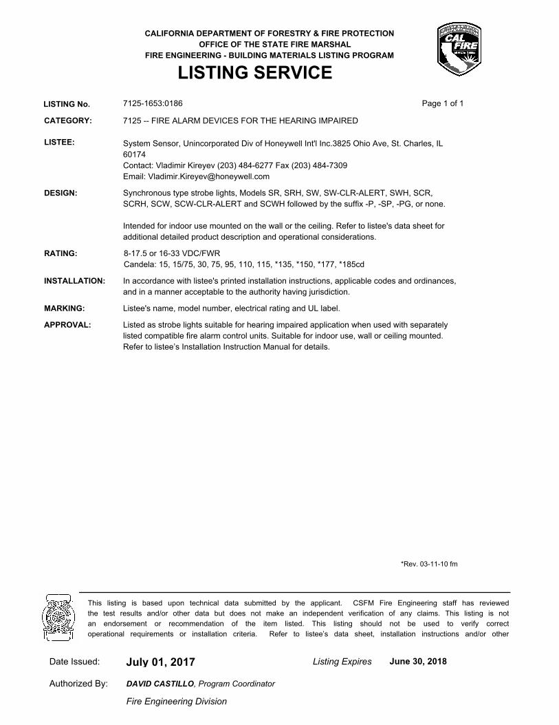
CALIFORNIA DEPARTMENT OF FORESTRY & FIRE PROTECTION
OFFICE OF THE STATE FIRE MARSHAL
FIRE ENGINEERING - BUILDING MATERIALS LISTING PROGRAM
LISTING SERVICE
LISTING No. 7125-1653:0186 Page 1 of 1
CATEGORY: 7125 -- FIRE ALARM DEVICES FOR THE HEARING IMPAIRED
LISTEE: System Sensor, Unincorporated Div of Honeywell Int'l Inc.3825 Ohio Ave, St. Charles, IL
60174
Contact: Vladimir Kireyev (203) 484-6277 Fax (203) 484-7309
Email: [email protected]
DESIGN: Synchronous type strobe lights, Models SR, SRH, SW, SW-CLR-ALERT, SWH, SCR,
SCRH, SCW, SCW-CLR-ALERT and SCWH followed by the suffix -P, -SP, -PG, or none.
Intended for indoor use mounted on the wall or the ceiling. Refer to listee's data sheet for
additional detailed product description and operational considerations.
RATING: 8-17.5 or 16-33 VDC/FWR
Candela: 15, 15/75, 30, 75, 95, 110, 115, *135, *150, *177, *185cd
INSTALLATION: In accordance with listee's printed installation instructions, applicable codes and ordinances,
and in a manner acceptable to the authority having jurisdiction.
MARKING: Listee's name, model number, electrical rating and UL label.
APPROVAL: Listed as strobe lights suitable for hearing impaired application when used with separately
listed compatible fire alarm control units. Suitable for indoor use, wall or ceiling mounted.
Refer to listee’s Installation Instruction Manual for details.
*Rev. 03-11-10 fm
July 01, 2017Date Issued: Listing Expires June 30, 2018
Authorized By:
Fire Engineering Division
This listing is based upon technical data submitted by the applicant. CSFM Fire Engineering staff has reviewed
the test results and/or other data but does not make an independent verification of any claims. This listing is not
an endorsement or recommendation of the item listed. This listing should not be used to verify correct
operational requirements or installation criteria. Refer to listee’s data sheet, installation instructions and/or other
DAVID CASTILLO, Program Coordinator