information handout - bidnet
TRANSCRIPT

INFORMATION HANDOUT For Contract No. 02-4G6204
At 02-Tri-299-3.6
Identified by
Project ID 0214000029
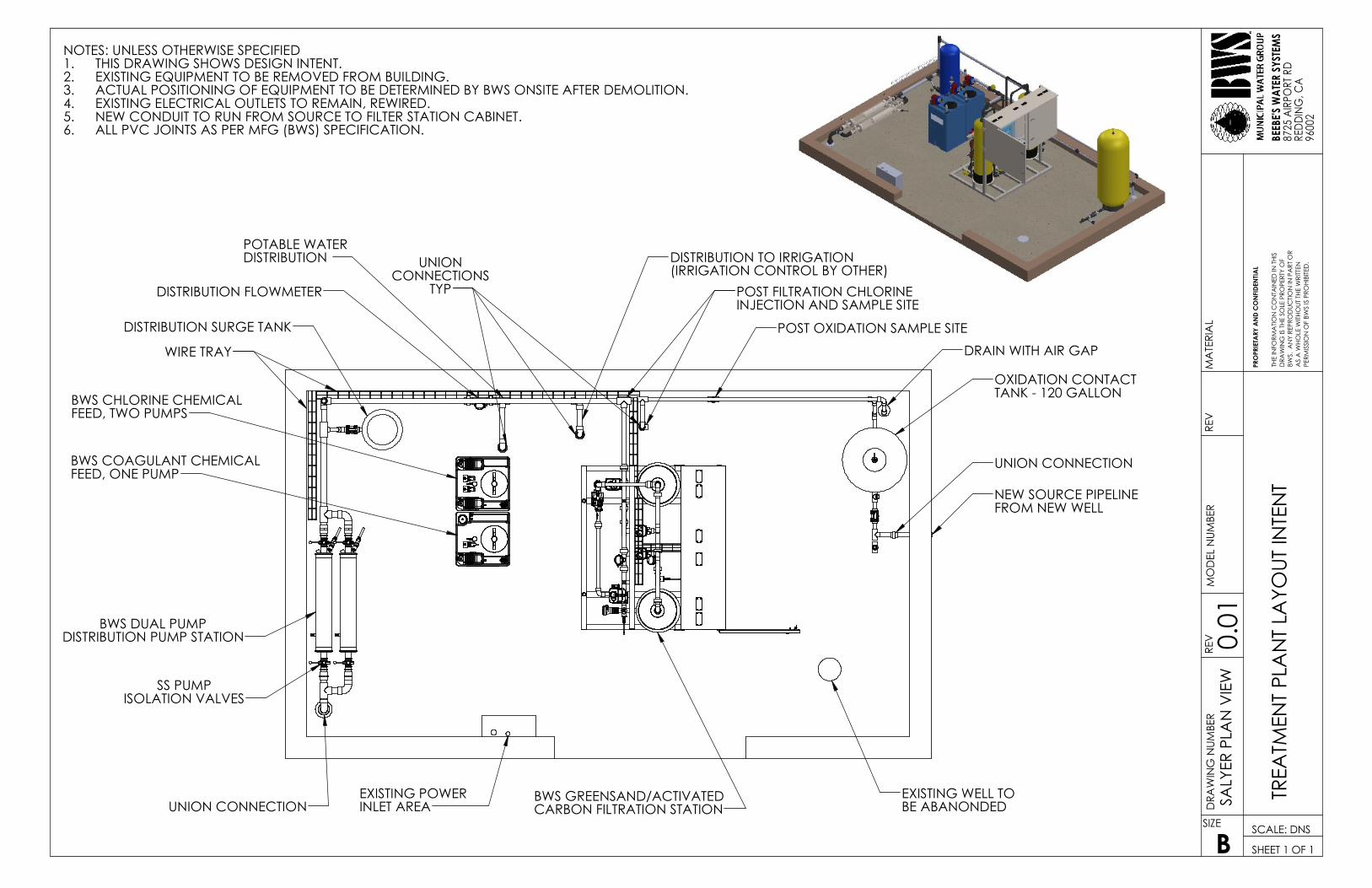
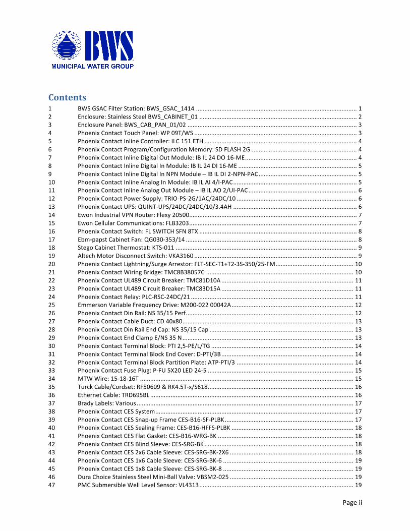
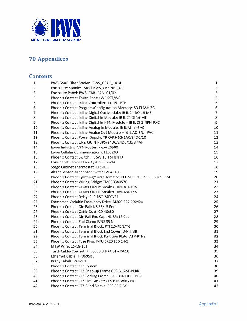
1. TREATMENT PLANT LAYOUT
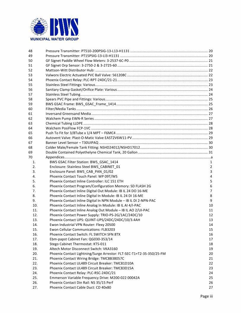
2. CFS, DP, DC, 40 GAL
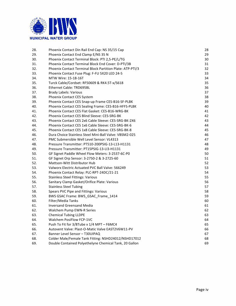
3. CFS, SP, DC, 40 GAL
4. FILTER STATION, GS-CARBON
5. PUMP STATION, DP, 32 GPM, 30-60 PSI
6. BWS-GLSRAA-WT PROJECT
7. DWFS, BWS, PRICE QUOTES

INFORMATION HANDOUT For Contract No. 02-4G6204
At 02-Tri-299-3.6
Identified by
Project ID 0214000029
1. TREATMENT PLANT LAYOUT
2. CFS, DP, DC, 40 GAL
3. CFS, SP, DC, 40 GAL
4. FILTER STATION, GS-CARBON
5. PUMP STATION, DP, 32 GPM, 30-60 PSI
6. BWS-GLSRAA-WT PROJECT
7. DWFS, BWS, PRICE QUOTES
DRA
WIN
G N
UM
BER
BWS.
AN
Y RE
PRO
DU
CTI
ON
IN P
ART
OR
AS
A W
HO
LE W
ITH
OU
T TH
E W
RITT
EN
SHEET 1 OF 1
MA
TERI
AL
THE
INFO
RMA
TIO
N C
ON
TAIN
ED IN
TH
IS
PERM
ISSI
ON
OF
BWS
IS P
ROH
IBIT
ED.
SIZE
B
PRO
PRIE
TARY
AN
D C
ON
FID
ENTI
AL
DRA
WIN
G IS
TH
E SO
LE P
ROPE
RTY
OF
TREA
TMEN
T PL
AN
T LA
YOU
T IN
TEN
TBE
EBE'
S W
ATE
R SY
STEM
S87
25 A
IRPO
RT R
DRE
DD
ING
, CA
REV
9600
2
SALY
ER P
LAN
VIE
WM
OD
EL N
UM
BER
SCALE: DNS
REV 0.01
NOTES: UNLESS OTHERWISE SPECIFIEDTHIS DRAWING SHOWS DESIGN INTENT.1.EXISTING EQUIPMENT TO BE REMOVED FROM BUILDING.2.ACTUAL POSITIONING OF EQUIPMENT TO BE DETERMINED BY BWS ONSITE AFTER DEMOLITION.3.EXISTING ELECTRICAL OUTLETS TO REMAIN, REWIRED.4.NEW CONDUIT TO RUN FROM SOURCE TO FILTER STATION CABINET.5.ALL PVC JOINTS AS PER MFG (BWS) SPECIFICATION.6.
DISTRIBUTION PUMP STATIONBWS DUAL PUMP
DISTRIBUTION FLOWMETER
ISOLATION VALVESSS PUMP
BWS GREENSAND/ACTIVATED
FROM NEW WELL
EXISTING WELL TOCARBON FILTRATION STATION BE ABANONDED
NEW SOURCE PIPELINE
UNION CONNECTION
INLET AREA
INJECTION AND SAMPLE SITEPOST FILTRATION CHLORINE
EXISTING POWER
OXIDATION CONTACT
DRAIN WITH AIR GAP
DISTRIBUTION
FEED, TWO PUMPSBWS CHLORINE CHEMICAL TANK - 120 GALLON
DISTRIBUTION SURGE TANK
POTABLE WATER
UNION CONNECTION
UNIONCONNECTIONS
TYP
WIRE TRAY
BWS COAGULANT CHEMICALFEED, ONE PUMP
POST OXIDATION SAMPLE SITE
DISTRIBUTION TO IRRIGATION(IRRIGATION CONTROL BY OTHER)

INFORMATION HANDOUT For Contract No. 02-4G6204
At 02-Tri-299-3.6
Identified by
Project ID 0214000029
1. TREATMENT PLANT LAYOUT
2. CFS, DP, DC, 40 GAL
3. CFS, SP, DC, 40 GAL
4. FILTER STATION, GS-CARBON
5. PUMP STATION, DP, 32 GPM, 30-60 PSI
6. BWS-GLSRAA-WT PROJECT
7. DWFS, BWS, PRICE QUOTES
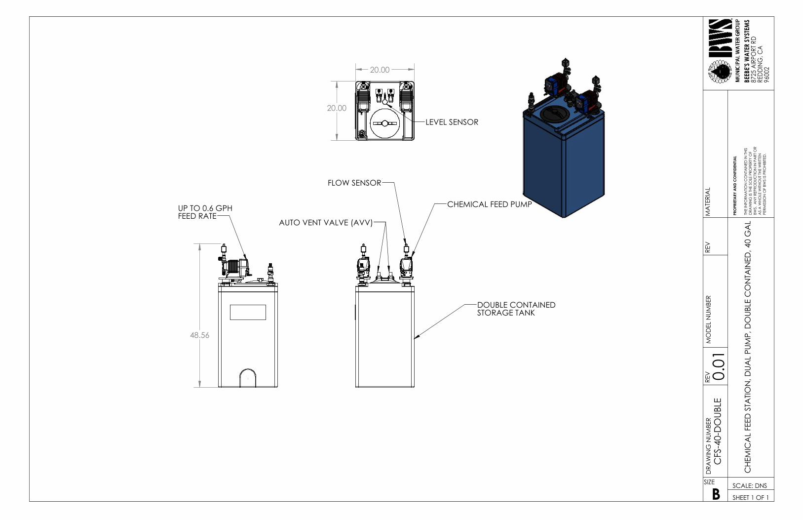
FLOW SENSOR
CHEMICAL FEED PUMP
AUTO VENT VALVE (AVV)
DOUBLE CONTAINEDSTORAGE TANK
AS
A W
HO
LE W
ITH
OU
T TH
E W
RITT
EN
BWS.
AN
Y RE
PRO
DU
CTI
ON
IN P
ART
OR
PRO
PRIE
TARY
AN
D C
ON
FID
ENTI
AL
REV
PERM
ISSI
ON
OF
BWS
IS P
ROH
IBIT
ED.
SIZE
B
REV
8725
AIR
PORT
RD
SCALE: DNS
SHEET 1 OF 1
MA
TERI
AL
RED
DIN
G, C
A
DRA
WIN
G IS
TH
E SO
LE P
ROPE
RTY
OF
CH
EMIC
AL
FEED
STA
TIO
N, D
UA
L PU
MP,
DO
UBL
E C
ON
TAIN
ED, 4
0 G
AL
CFS
-40-
DO
UBL
EM
OD
EL N
UM
BER
DRA
WIN
G N
UM
BER
9600
2
0.01
THE
INFO
RMA
TIO
N C
ON
TAIN
ED IN
TH
ISBE
EBE'
S W
ATE
R SY
STEM
S
LEVEL SENSOR
20.00
20.00
UP TO 0.6 GPHFEED RATE
48.56

INFORMATION HANDOUT For Contract No. 02-4G6204
At 02-Tri-299-3.6
Identified by
Project ID 0214000029
1. TREATMENT PLANT LAYOUT
2. CFS, DP, DC, 40 GAL
3. CFS, SP, DC, 40 GAL
4. FILTER STATION, GS-CARBON
5. PUMP STATION, DP, 32 GPM, 30-60 PSI
6. BWS-GLSRAA-WT PROJECT
7. DWFS, BWS, PRICE QUOTES

LEVEL SENSOR
20.00
20.00
REV
RED
DIN
G, C
A
MA
TERI
AL
PRO
PRIE
TARY
AN
D C
ON
FID
ENTI
AL
PERM
ISSI
ON
OF
BWS
IS P
ROH
IBIT
ED.
SIZE
B
REV
8725
AIR
PORT
RD
9600
2
SHEET 1 OF 1
AS
A W
HO
LE W
ITH
OU
T TH
E W
RITT
EN
BWS.
AN
Y RE
PRO
DU
CTI
ON
IN P
ART
OR
DRA
WIN
G IS
TH
E SO
LE P
ROPE
RTY
OF
SCALE: DNS
CFS
-40-
SIN
GLE
MO
DEL
NU
MBE
RD
RAW
ING
NU
MBE
R
CH
EMIC
AL
FEED
STA
TIO
N, S
ING
LE P
UM
P, D
OU
BLE
CO
NTA
INED
, 40
GA
L
0.01
THE
INFO
RMA
TIO
N C
ON
TAIN
ED IN
TH
ISBE
EBE'
S W
ATE
R SY
STEM
S
STORAGE TANK
FLOW SENSOR CHEMICAL FEED PUMP
DOUBLE CONTAINED
AUTO VENT VALVE (AVV)
UP TO 0.6 GPHFEED RATE
48.56

INFORMATION HANDOUT For Contract No. 02-4G6204
At 02-Tri-299-3.6
Identified by
Project ID 0214000029
1. TREATMENT PLANT LAYOUT
2. CFS, DP, DC, 40 GAL
3. CFS, SP, DC, 40 GAL
4. FILTER STATION, GS-CARBON
5. PUMP STATION, DP, 32 GPM, 30-60 PSI
6. BWS-GLSRAA-WT PROJECT
7. DWFS, BWS, PRICE QUOTES
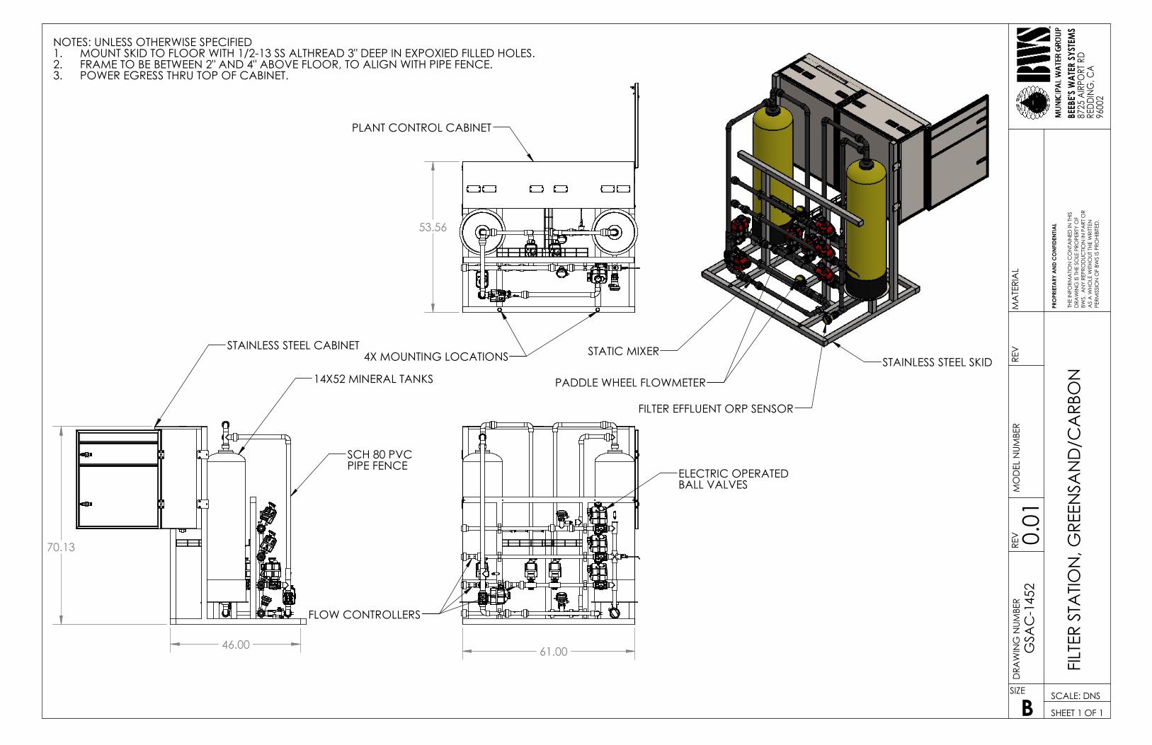
STATIC MIXERSTAINLESS STEEL SKID
PADDLE WHEEL FLOWMETER
FILTER EFFLUENT ORP SENSOR
REV
THE
INFO
RMA
TIO
N C
ON
TAIN
ED IN
TH
IS
PRO
PRIE
TARY
AN
D C
ON
FID
ENTI
AL
FILT
ER S
TATI
ON
, GRE
ENSA
ND
/CA
RBO
NBE
EBE'
S W
ATE
R SY
STEM
S
AS
A W
HO
LE W
ITH
OU
T TH
E W
RITT
EN
8725
AIR
PORT
RD
PERM
ISSI
ON
OF
BWS
IS P
ROH
IBIT
ED.
SIZE
MO
DEL
NU
MBE
R
BSCALE: DNS
SHEET 1 OF 1
MA
TERI
AL
BWS.
AN
Y RE
PRO
DU
CTI
ON
IN P
ART
OR
DRA
WIN
G IS
TH
E SO
LE P
ROPE
RTY
OF
9600
2
GSA
C-1
452
RED
DIN
G, C
A
DRA
WIN
G N
UM
BER
REV 0.01
NOTES: UNLESS OTHERWISE SPECIFIEDMOUNT SKID TO FLOOR WITH 1/2-13 SS ALTHREAD 3" DEEP IN EXPOXIED FILLED HOLES.1.FRAME TO BE BETWEEN 2" AND 4" ABOVE FLOOR, TO ALIGN WITH PIPE FENCE.2.POWER EGRESS THRU TOP OF CABINET.3.
ELECTRIC OPERATEDBALL VALVES
FLOW CONTROLLERS
61.00
STAINLESS STEEL CABINET
14X52 MINERAL TANKS
SCH 80 PVCPIPE FENCE
46.00
70.13
4X MOUNTING LOCATIONS
PLANT CONTROL CABINET
53.56

INFORMATION HANDOUT For Contract No. 02-4G6204
At 02-Tri-299-3.6
Identified by
Project ID 0214000029
1. TREATMENT PLANT LAYOUT
2. CFS, DP, DC, 40 GAL
3. CFS, SP, DC, 40 GAL
4. FILTER STATION, GS-CARBON
5. PUMP STATION, DP, 32 GPM, 30-60 PSI
6. BWS-GLSRAA-WT PROJECT
7. DWFS, BWS, PRICE QUOTES
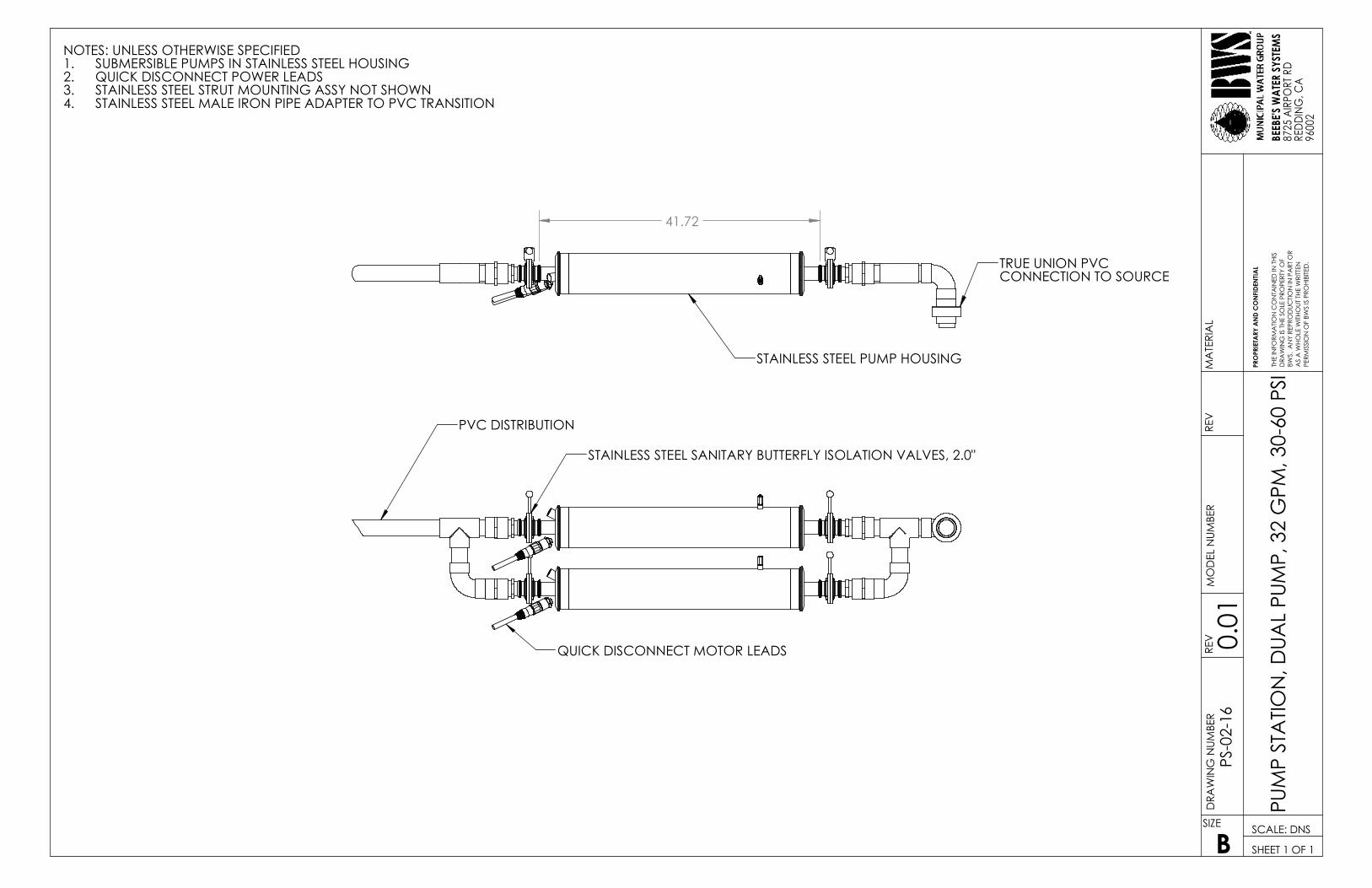
QUICK DISCONNECT MOTOR LEADS
PVC DISTRIBUTION
STAINLESS STEEL SANITARY BUTTERFLY ISOLATION VALVES, 2.0"
MO
DEL
NU
MBE
R
8725
AIR
PORT
RD
BEEB
E'S
WA
TER
SYST
EMS
PUM
P ST
ATI
ON
, DU
AL
PUM
P, 3
2 G
PM, 3
0-60
PSI
PRO
PRIE
TARY
AN
D C
ON
FID
ENTI
AL
MA
TERI
AL
THE
INFO
RMA
TIO
N C
ON
TAIN
ED IN
TH
IS
PERM
ISSI
ON
OF
BWS
IS P
ROH
IBIT
ED.
SIZE
BSCALE: DNS
SHEET 1 OF 1
AS
A W
HO
LE W
ITH
OU
T TH
E W
RITT
EN
BWS.
AN
Y RE
PRO
DU
CTI
ON
IN P
ART
OR
REV
DRA
WIN
G IS
TH
E SO
LE P
ROPE
RTY
OF
9600
2
PS-0
2-16
RED
DIN
G, C
A
DRA
WIN
G N
UM
BER
REV 0.01
NOTES: UNLESS OTHERWISE SPECIFIEDSUBMERSIBLE PUMPS IN STAINLESS STEEL HOUSING1.QUICK DISCONNECT POWER LEADS2.STAINLESS STEEL STRUT MOUNTING ASSY NOT SHOWN3.STAINLESS STEEL MALE IRON PIPE ADAPTER TO PVC TRANSITION4.
STAINLESS STEEL PUMP HOUSING
TRUE UNION PVCCONNECTION TO SOURCE
41.72

INFORMATION HANDOUT For Contract No. 02-4G6204
At 02-Tri-299-3.6
Identified by
Project ID 0214000029
1. TREATMENT PLANT LAYOUT
2. CFS, DP, DC, 40 GAL
3. CFS, SP, DC, 40 GAL
4. FILTER STATION, GS-CARBON
5. PUMP STATION, DP, 32 GPM, 30-60 PSI
6. BWS-GLSRAA-WT PROJECT
7. DWFS, BWS, PRICE QUOTES
Project Name: CALTRANS PROJECT NO. 02-4E6804
PROJECT ID: 0212000032 GRASS LAKE SAFETY ROADSIDE REST AREA,
Route 97 19 miles south of Macdoel, California, 96058
Date: August 12, 2018
Contractor: Enloe Drilling & Pumps, Inc.
6845 Granada Dr. Redding, California 96002
Supplier: BWS Municipal, Inc. 8715 Airport Road
Redding California 96002
Document Number: BWS-GLSRAA-WATERTREATMENT-02
Prepared By: BWS Municipal, Inc. 8715 Airport Road
Redding California 96002
Pageii
Contents1 BWSGSACFilterStation:BWS_GSAC_1414...............................................................................................12 Enclosure:StainlessSteelBWS_CABINET_01.............................................................................................23 EnclosurePanel:BWS_CAB_PAN_01/02....................................................................................................34 PhoenixContactTouchPanel:WP09T/WS................................................................................................35 PhoenixContactInlineController:ILC151ETH..........................................................................................46 PhoenixContactProgram/ConfigurationMemory:SDFLASH2G..............................................................47 PhoenixContactInlineDigitalOutModule:IBIL24DO16-ME..................................................................48 PhoenixContactInlineDigitalInModule:IBIL24DI16-ME......................................................................59 PhoenixContactInlineDigitalInNPNModule–IBILDI2-NPN-PAC..........................................................510 PhoenixContactInlineAnalogInModule:IBILAI4/I-PAC.........................................................................511 PhoenixContactInlineAnalogOutModule–IBILAO2/UI-PAC................................................................612 PhoenixContactPowerSupply:TRIO-PS-2G/1AC/24DC/10.......................................................................613 PhoenixContactUPS:QUINT-UPS/24DC/24DC/10/3.4AH.........................................................................614 EwonIndustrialVPNRouter:Flexy20500...................................................................................................715 EwonCellularCommunications:FLB3203...................................................................................................716 PhoenixContactSwitch:FLSWITCHSFN8TX.............................................................................................817 Ebm-papstCabinetFan:QG030-353/14.....................................................................................................818 StegoCabinetThermostat:KTS-011...........................................................................................................919 AltechMotorDisconnectSwitch:VKA3160................................................................................................920 PhoenixContactLightning/SurgeArrestor:FLT-SEC-T1+T2-3S-350/25-FM..............................................1021 PhoenixContactWiringBridge:TMC8B38057C.......................................................................................1022 PhoenixContactUL489CircuitBreaker:TMC81D10A..............................................................................1123 PhoenixContactUL489CircuitBreaker:TMC83D15A..............................................................................1124 PhoenixContactRelay:PLC-RSC-24DC/21................................................................................................1125 EmmersonVariableFrequencyDrive:M200-02200042A........................................................................1226 PhoenixContactDinRail:NS35/15Perf...................................................................................................1227 PhoenixContactCableDuct:CD40x80.....................................................................................................1328 PhoenixContactDinRailEndCap:NS35/15Cap.....................................................................................1329 PhoenixContactEndClampE/NS35N.....................................................................................................1330 PhoenixContactTerminalBlock:PTI2,5-PE/L/TG....................................................................................1431 PhoenixContactTerminalBlockEndCover:D-PTI/3B..............................................................................1432 PhoenixContactTerminalBlockPartitionPlate:ATP-PTI/3.....................................................................1433 PhoenixContactFusePlug:P-FU5X20LED24-5......................................................................................1534 MTWWire:15-18-16T..............................................................................................................................1535 TurckCable/Cordset:RF50609&RK4.5T-x/S618......................................................................................1636 EthernetCable:TRD695BL........................................................................................................................1637 BradyLabels:Various................................................................................................................................1738 PhoenixContactCESSystem.....................................................................................................................1739 PhoenixContactCESSnap-upFrameCES-B16-SF-PLBK............................................................................1740 PhoenixContactCESSealingFrame:CES-B16-HFFS-PLBK........................................................................1841 PhoenixContactCESFlatGasket:CES-B16-WRG-BK................................................................................1842 PhoenixContactCESBlindSleeve:CES-SRG-BK........................................................................................1843 PhoenixContactCES2x6CableSleeve:CES-SRG-BK-2X6.........................................................................1844 PhoenixContactCES1x6CableSleeve:CES-SRG-BK-6.............................................................................1945 PhoenixContactCES1x8CableSleeve:CES-SRG-BK-8.............................................................................1946 DuraChoiceStainlessSteelMini-BallValve:VBSM2-025.........................................................................1947 PMCSubmersibleWellLevelSensor:VL4313...........................................................................................19
Pageiii
48 PressureTransmitter:PT510-200PSIG-13-L13-H1131..............................................................................2049 PressureTransmitter:PT15PSIG-13-LI3-H1131........................................................................................2050 GFSignetPaddleWheelFlowMeters:3-2537-6C-P0...............................................................................2151 GFSignetOrpSensor:3-2750-2&3-2725-60...........................................................................................2152 Mattson-WittDistributorHub:.................................................................................................................2253 ValworxElectricActuatedPVCBallValve:561208C.................................................................................2254 PhoenixContactRelay:PLC-RPT-24DC/21-21...........................................................................................2355 StainlessSteelFittings:Various.................................................................................................................2356 SanitaryClampGasket/OrificePlate:Various...........................................................................................2457 StainlessSteelTubing................................................................................................................................2458 SpearsPVCPipeandFittings:Various.......................................................................................................2559 BWSGSACFrame:BWS_GSAC_Frame_1414............................................................................................2560 Filter/MediaTanks....................................................................................................................................2661 InversandGreensandMedia.....................................................................................................................2762 WalchemPumpEWN-RSeries..................................................................................................................2763 ChemicalTubingLLDPE.............................................................................................................................2864 WalchemPosiFlowFCP-1VC.....................................................................................................................2865 PushToFitfor3/8Tubex1/4MPT–F6MC4............................................................................................2966 AutoventValve:Plast-O-MaticValveEAST2V6W11-PV............................................................................2967 BannerLevelSensor–T30UIPAQ.............................................................................................................3068 ColderMale/FemaleTankFitting:NSHD24012/NSHD17012....................................................................3069 DoubleContainedPolyethelyneChemicalTank,20Gallon......................................................................3170 Appendices...................................................................................................................................................a
1. BWSGSACFilterStation:BWS_GSAC_1414 12. Enclosure:StainlessSteelBWS_CABINET_01 23. EnclosurePanel:BWS_CAB_PAN_01/02 34. PhoenixContactTouchPanel:WP09T/WS 45. PhoenixContactInlineController:ILC151ETH 56. PhoenixContactProgram/ConfigurationMemory:SDFLASH2G 67. PhoenixContactInlineDigitalOutModule:IBIL24DO16-ME 78. PhoenixContactInlineDigitalInModule:IBIL24DI16-ME 89. PhoenixContactInlineDigitalInNPNModule–IBILDI2-NPN-PAC 910. PhoenixContactInlineAnalogInModule:IBILAI4/I-PAC 1011. PhoenixContactInlineAnalogOutModule–IBILAO2/UI-PAC 1112. PhoenixContactPowerSupply:TRIO-PS-2G/1AC/24DC/10 1213. PhoenixContactUPS:QUINT-UPS/24DC/24DC/10/3.4AH 1314. EwonIndustrialVPNRouter:Flexy20500 1415. EwonCellularCommunications:FLB3203 1516. PhoenixContactSwitch:FLSWITCHSFN8TX 1617. Ebm-papstCabinetFan:QG030-353/14 1718. StegoCabinetThermostat:KTS-011 1819. AltechMotorDisconnectSwitch:VKA3160 1920. PhoenixContactLightning/SurgeArrestor:FLT-SEC-T1+T2-3S-350/25-FM 2021. PhoenixContactWiringBridge:TMC8B38057C 2122. PhoenixContactUL489CircuitBreaker:TMC81D10A 2223. PhoenixContactUL489CircuitBreaker:TMC83D15A 2324. PhoenixContactRelay:PLC-RSC-24DC/21 2425. EmmersonVariableFrequencyDrive:M200-02200042A 2526. PhoenixContactDinRail:NS35/15Perf 2627. PhoenixContactCableDuct:CD40x80 27
Pageiv
28. PhoenixContactDinRailEndCap:NS35/15Cap 2829. PhoenixContactEndClampE/NS35N 2930. PhoenixContactTerminalBlock:PTI2,5-PE/L/TG 3031. PhoenixContactTerminalBlockEndCover:D-PTI/3B 3132. PhoenixContactTerminalBlockPartitionPlate:ATP-PTI/3 3233. PhoenixContactFusePlug:F-FU5X20LED24-5 3334. MTWWire:15-18-16T 3435. TurckCable/Cordset:RF50609&RK4.5T-x/S618 3536. EthernetCable:TRD695BL 3637. BradyLabels:Various 3738. PhoenixContactCESSystem 3839. PhoenixContactCESSnap-upFrameCES-B16-SF-PLBK 3940. PhoenixContactCESSealingFrame:CES-B16-HFFS-PLBK 4041. PhoenixContactCESFlatGasket:CES-B16-WRG-BK 4142. PhoenixContactCESBlindSleeve:CES-SRG-BK 4243. PhoenixContactCES2x6CableSleeve:CES-SRG-BK-2X6 4344. PhoenixContactCES1x6CableSleeve:CES-SRG-BK-6 4445. PhoenixContactCES1x8CableSleeve:CES-SRG-BK-8 4546. DuraChoiceStainlessSteelMini-BallValve:VBSM2-025 4647. PMCSubmersibleWellLevelSensor:VL4313 4748. PressureTransmitter:PT510-200PSIG-13-L13-H1131 4849. PressureTransmitter:PT15PSIG-13-LI3-H1131 4950. GFSignetPaddleWheelFlowMeters:3-2537-6C-P0 5051. GFSignetOrpSensor:3-2750-2&3-2725-60 5152. Mattson-WittDistributorHub 5253. ValworxElectricActuatedPVCBallValve:566249 5354. PhoenixContactRelay:PLC-RPT-24DC/21-21 5455. StainlessSteelFittings:Various 5556. SanitaryClampGasket/OrificePlate:Various 5657. StainlessSteelTubing 5758. SpearsPVCPipeandFittings:Various 5859. BWSGSACFrame:BWS_GSAC_Frame_1414 5960. Filter/MediaTanks 6061. InversandGreensandMedia 6162. WalchemPumpEWN-RSeries 6263. ChemicalTubingLLDPE 6364. WalchemPosiFlowFCP-1VC 6465. PushToFitfor3/8Tubex1/4MPT–F6MC4 6566. AutoventValve:Plast-O-MaticValveEAST2V6W11-PV 6667. BannerLevelSensor–T30UIPAQ 6768. ColderMale/FemaleTankFitting:NSHD24012/NSHD17012 6869. DoubleContainedPolyethelyneChemicalTank,20Gallon 69
BWS-GLSRAA-WATERTREATMENT-02 Page1
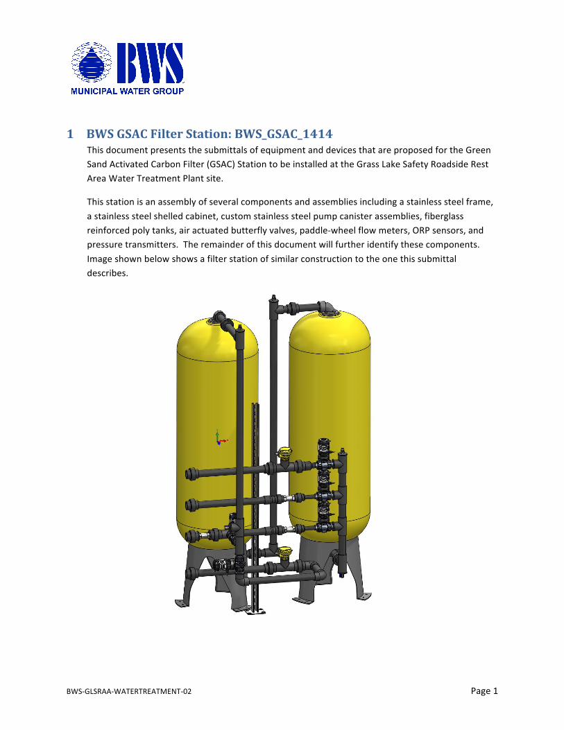
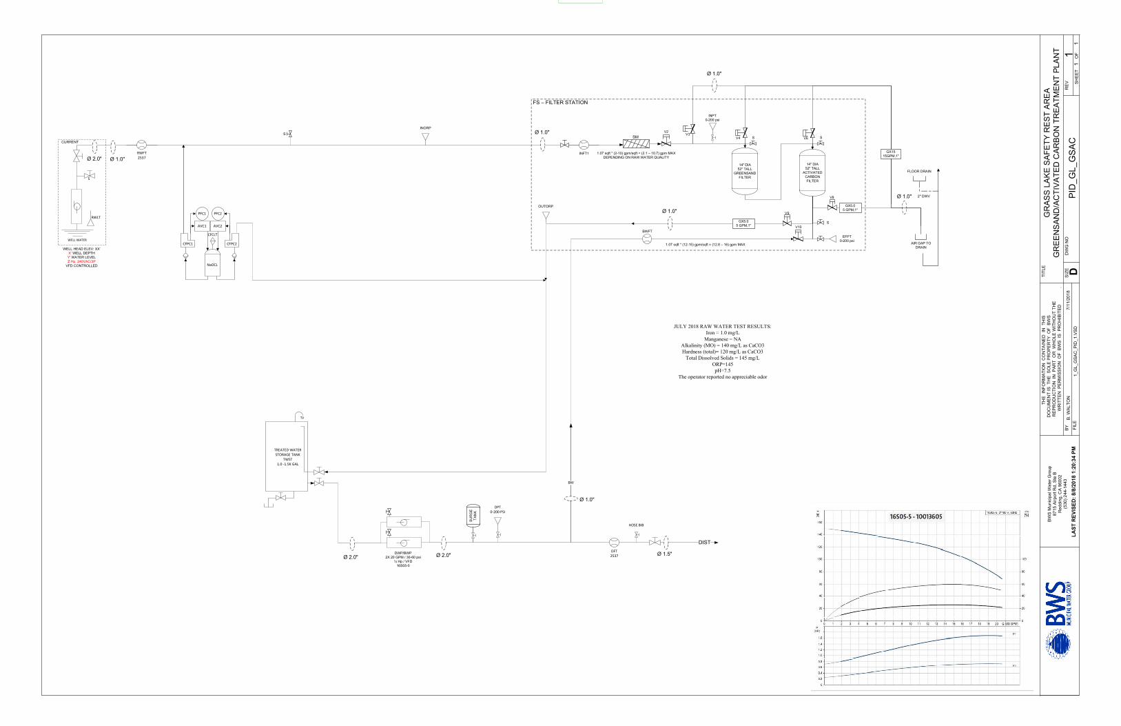
1 BWSGSACFilterStation:BWS_GSAC_1414ThisdocumentpresentsthesubmittalsofequipmentanddevicesthatareproposedfortheGreenSandActivatedCarbonFilter(GSAC)StationtobeinstalledattheGrassLakeSafetyRoadsideRestAreaWaterTreatmentPlantsite.
Thisstationisanassemblyofseveralcomponentsandassembliesincludingastainlesssteelframe,astainlesssteelshelledcabinet,customstainlesssteelpumpcanisterassemblies,fiberglassreinforcedpolytanks,airactuatedbutterflyvalves,paddle-wheelflowmeters,ORPsensors,andpressuretransmitters.Theremainderofthisdocumentwillfurtheridentifythesecomponents.Imageshownbelowshowsafilterstationofsimilarconstructiontotheonethissubmittaldescribes.
BWS-GLSRAA-WATERTREATMENT-02 Page2
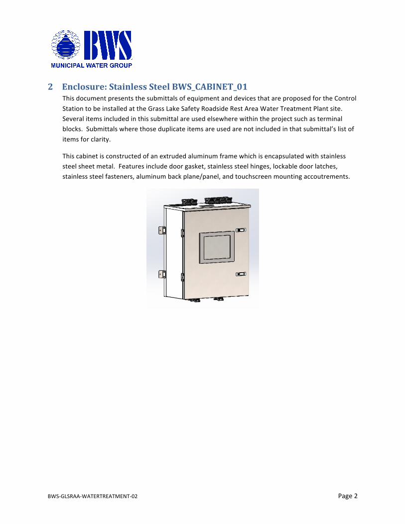
2 Enclosure:StainlessSteelBWS_CABINET_01ThisdocumentpresentsthesubmittalsofequipmentanddevicesthatareproposedfortheControlStationtobeinstalledattheGrassLakeSafetyRoadsideRestAreaWaterTreatmentPlantsite.Severalitemsincludedinthissubmittalareusedelsewherewithintheprojectsuchasterminalblocks.Submittalswherethoseduplicateitemsareusedarenotincludedinthatsubmittal’slistofitemsforclarity.
Thiscabinetisconstructedofanextrudedaluminumframewhichisencapsulatedwithstainlesssteelsheetmetal.Featuresincludedoorgasket,stainlesssteelhinges,lockabledoorlatches,stainlesssteelfasteners,aluminumbackplane/panel,andtouchscreenmountingaccoutrements.
BWS-GLSRAA-WATERTREATMENT-02 Page3
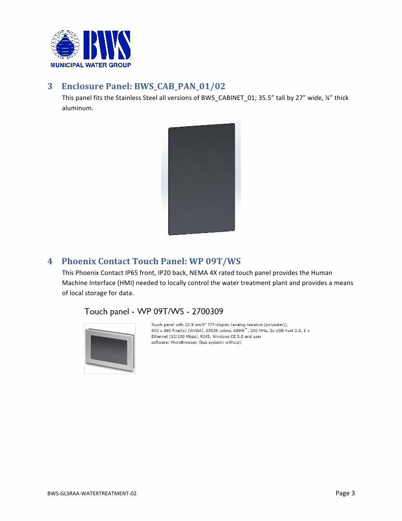
3 EnclosurePanel:BWS_CAB_PAN_01/02ThispanelfitstheStainlessSteelallversionsofBWS_CABINET_01;35.5”tallby27”wide,¼”thickaluminum.
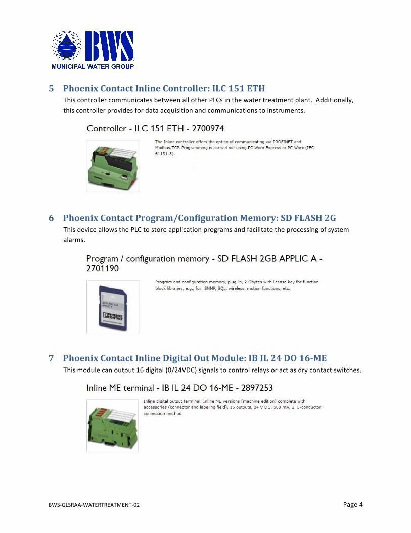
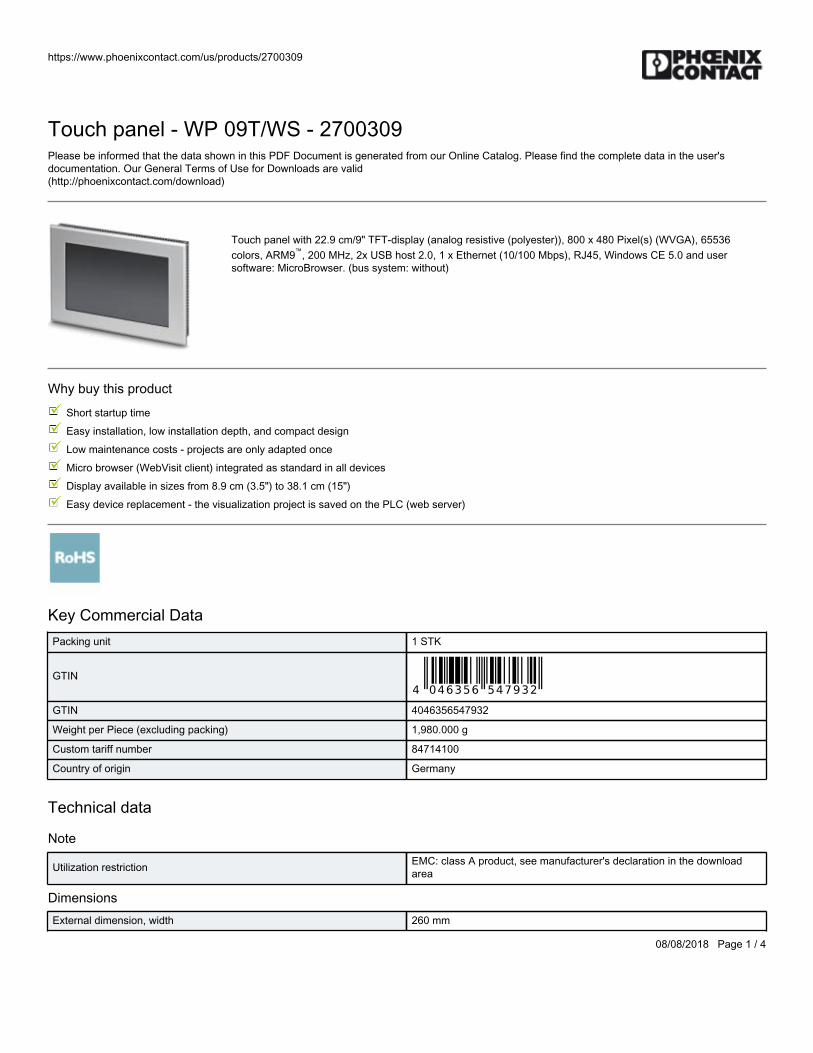
4 PhoenixContactTouchPanel:WP09T/WSThisPhoenixContactIP65front,IP20back,NEMA4XratedtouchpanelprovidestheHumanMachineInterface(HMI)neededtolocallycontrolthewatertreatmentplantandprovidesameansoflocalstoragefordata.
BWS-GLSRAA-WATERTREATMENT-02 Page4
5 PhoenixContactInlineController:ILC151ETHThiscontrollercommunicatesbetweenallotherPLCsinthewatertreatmentplant.Additionally,thiscontrollerprovidesfordataacquisitionandcommunicationstoinstruments.
6 PhoenixContactProgram/ConfigurationMemory:SDFLASH2GThisdeviceallowsthePLCtostoreapplicationprogramsandfacilitatetheprocessingofsystemalarms.
7 PhoenixContactInlineDigitalOutModule:IBIL24DO16-METhismodulecanoutput16digital(0/24VDC)signalstocontrolrelaysoractasdrycontactswitches.
BWS-GLSRAA-WATERTREATMENT-02 Page5
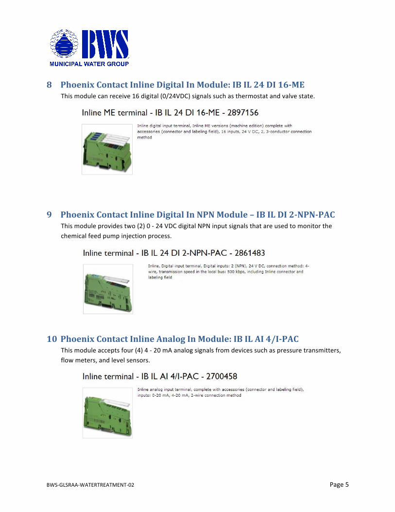
8 PhoenixContactInlineDigitalInModule:IBIL24DI16-METhismodulecanreceive16digital(0/24VDC)signalssuchasthermostatandvalvestate.
9 PhoenixContactInlineDigitalInNPNModule–IBILDI2-NPN-PACThismoduleprovidestwo(2)0-24VDCdigitalNPNinputsignalsthatareusedtomonitorthechemicalfeedpumpinjectionprocess.
10 PhoenixContactInlineAnalogInModule:IBILAI4/I-PACThismoduleacceptsfour(4)4-20mAanalogsignalsfromdevicessuchaspressuretransmitters,flowmeters,andlevelsensors.
BWS-GLSRAA-WATERTREATMENT-02 Page6
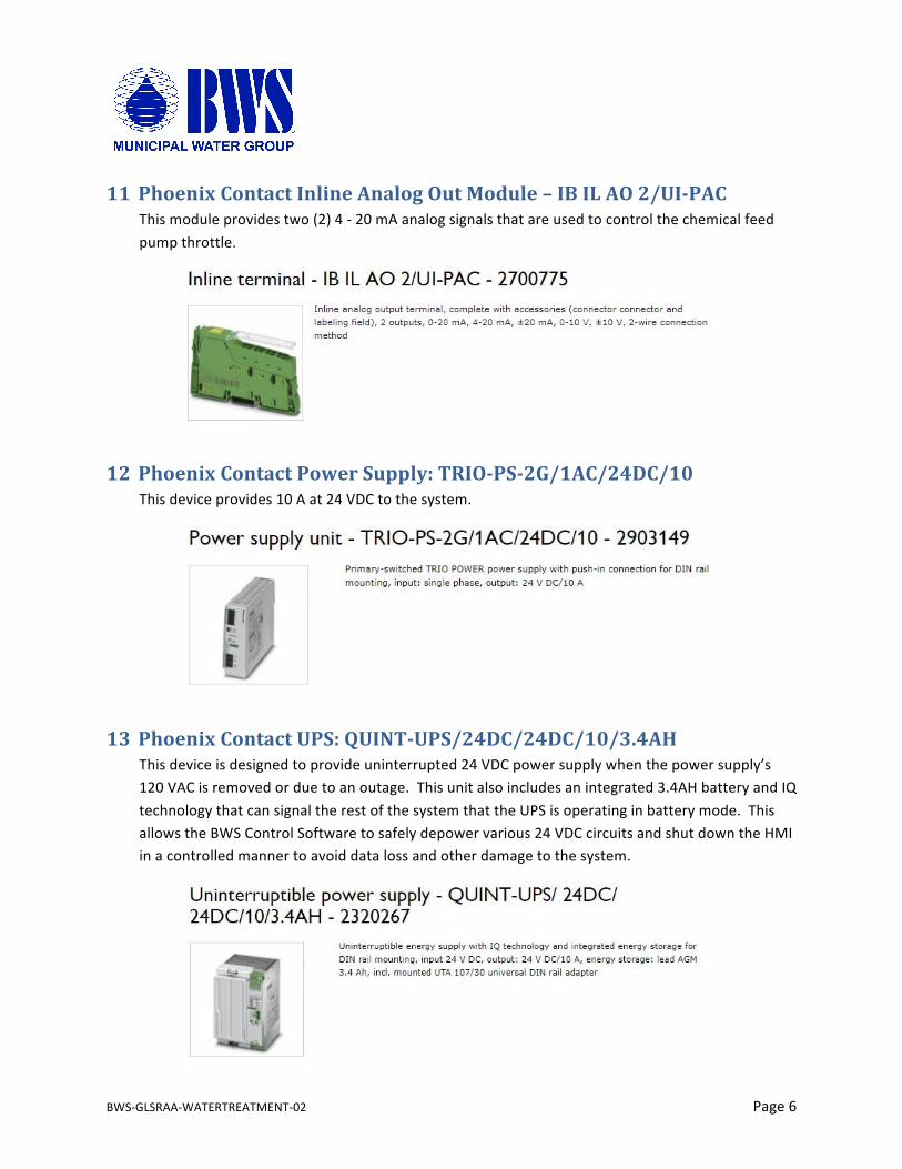
11 PhoenixContactInlineAnalogOutModule–IBILAO2/UI-PACThismoduleprovidestwo(2)4-20mAanalogsignalsthatareusedtocontrolthechemicalfeedpumpthrottle.
12 PhoenixContactPowerSupply:TRIO-PS-2G/1AC/24DC/10Thisdeviceprovides10Aat24VDCtothesystem.
13 PhoenixContactUPS:QUINT-UPS/24DC/24DC/10/3.4AHThisdeviceisdesignedtoprovideuninterrupted24VDCpowersupplywhenthepowersupply’s120VACisremovedorduetoanoutage.Thisunitalsoincludesanintegrated3.4AHbatteryandIQtechnologythatcansignaltherestofthesystemthattheUPSisoperatinginbatterymode.ThisallowstheBWSControlSoftwaretosafelydepowervarious24VDCcircuitsandshutdowntheHMIinacontrolledmannertoavoiddatalossandotherdamagetothesystem.
BWS-GLSRAA-WATERTREATMENT-02 Page7
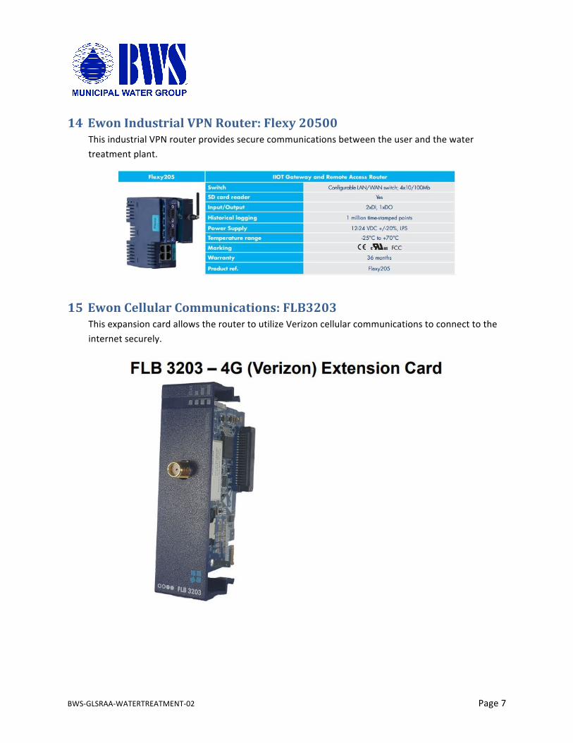
14 EwonIndustrialVPNRouter:Flexy20500ThisindustrialVPNrouterprovidessecurecommunicationsbetweentheuserandthewatertreatmentplant.
15 EwonCellularCommunications:FLB3203ThisexpansioncardallowstheroutertoutilizeVerizoncellularcommunicationstoconnecttotheinternetsecurely.
BWS-GLSRAA-WATERTREATMENT-02 Page8
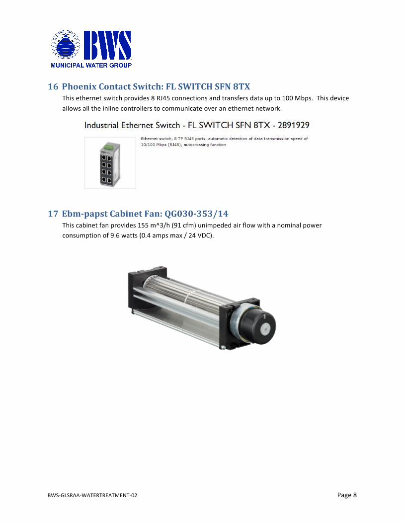
16 PhoenixContactSwitch:FLSWITCHSFN8TXThisethernetswitchprovides8RJ45connectionsandtransfersdataupto100Mbps.Thisdeviceallowsalltheinlinecontrollerstocommunicateoveranethernetnetwork.
17 Ebm-papstCabinetFan:QG030-353/14Thiscabinetfanprovides155m^3/h(91cfm)unimpededairflowwithanominalpowerconsumptionof9.6watts(0.4ampsmax/24VDC).
BWS-GLSRAA-WATERTREATMENT-02 Page9
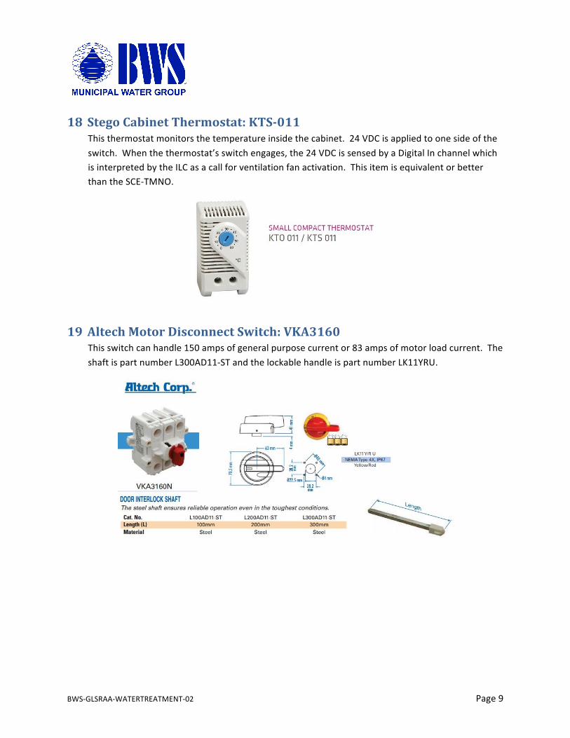
18 StegoCabinetThermostat:KTS-011Thisthermostatmonitorsthetemperatureinsidethecabinet.24VDCisappliedtoonesideoftheswitch.Whenthethermostat’sswitchengages,the24VDCissensedbyaDigitalInchannelwhichisinterpretedbytheILCasacallforventilationfanactivation.ThisitemisequivalentorbetterthantheSCE-TMNO.
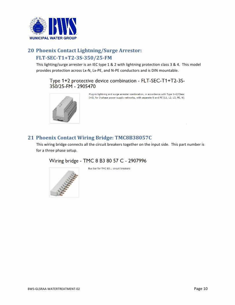
19 AltechMotorDisconnectSwitch:VKA3160Thisswitchcanhandle150ampsofgeneralpurposecurrentor83ampsofmotorloadcurrent.TheshaftispartnumberL300AD11-STandthelockablehandleispartnumberLK11YRU.
BWS-GLSRAA-WATERTREATMENT-02 Page10
20 PhoenixContactLightning/SurgeArrestor:FLT-SEC-T1+T2-3S-350/25-FMThislighting/surgearresterisanIECtype1&2withlightningprotectionclass3&4.ThismodelprovidesprotectionacrossLx-N,Lx-PE,andN-PEconductorsandisDINmountable.
21 PhoenixContactWiringBridge:TMC8B38057CThiswiringbridgeconnectsallthecircuitbreakerstogetherontheinputside.Thispartnumberisforathreephasesetup.

BWS-GLSRAA-WATERTREATMENT-02 Page11
22 PhoenixContactUL489CircuitBreaker:TMC81D10AThesecircuitbreakersaredesignedtoprotectcircuitswithinacontrolcabinet.This10ampbreakerwillprotectthe24VDCPowerSupplycircuitand120VACaccessoriescircuit.
23 PhoenixContactUL489CircuitBreaker:TMC83D15AThesecircuitbreakersaredesignedtoprotectcircuitswithinacontrolcabinet.This15ampbreakerwillprotectthevariablefrequencydriveassociatedwitheachpump.
24 PhoenixContactRelay:PLC-RSC-24DC/21Thisrelayisactivatedwitha24VDCsignalandcanswitchloadsupto1500VAat250VAC.
BWS-GLSRAA-WATERTREATMENT-02 Page12
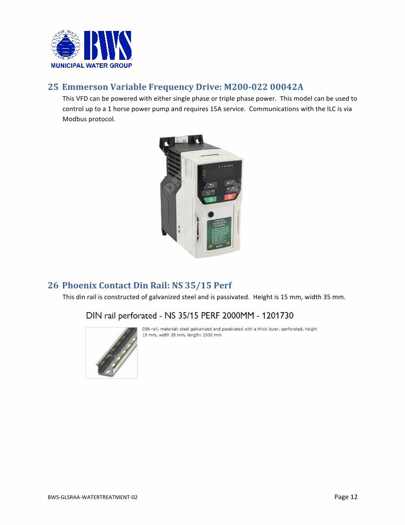
25 EmmersonVariableFrequencyDrive:M200-02200042AThisVFDcanbepoweredwitheithersinglephaseortriplephasepower.Thismodelcanbeusedtocontroluptoa1horsepowerpumpandrequires15Aservice.CommunicationswiththeILCisviaModbusprotocol.
26 PhoenixContactDinRail:NS35/15PerfThisdinrailisconstructedofgalvanizedsteelandispassivated.Heightis15mm,width35mm.
BWS-GLSRAA-WATERTREATMENT-02 Page13
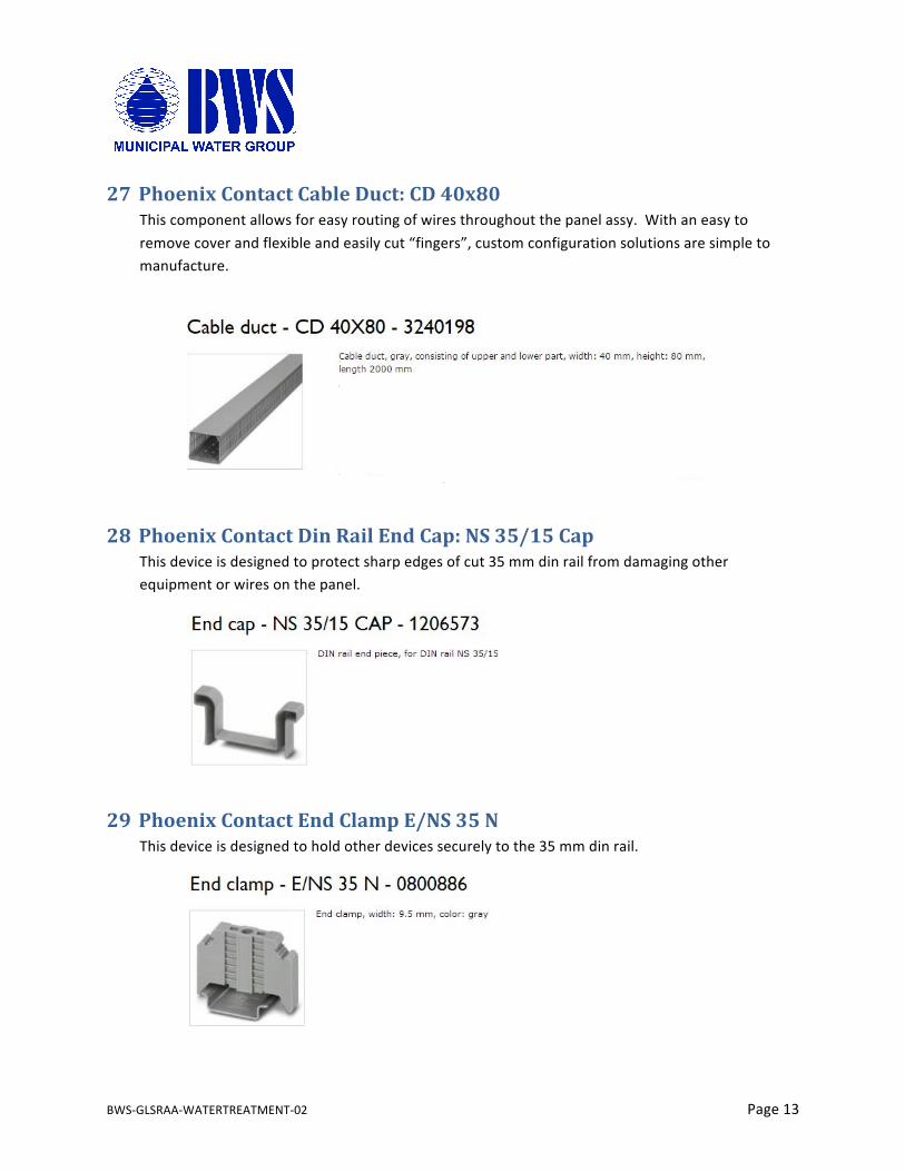
27 PhoenixContactCableDuct:CD40x80Thiscomponentallowsforeasyroutingofwiresthroughoutthepanelassy.Withaneasytoremovecoverandflexibleandeasilycut“fingers”,customconfigurationsolutionsaresimpletomanufacture.
28 PhoenixContactDinRailEndCap:NS35/15CapThisdeviceisdesignedtoprotectsharpedgesofcut35mmdinrailfromdamagingotherequipmentorwiresonthepanel.
29 PhoenixContactEndClampE/NS35NThisdeviceisdesignedtoholdotherdevicessecurelytothe35mmdinrail.
BWS-GLSRAA-WATERTREATMENT-02 Page14
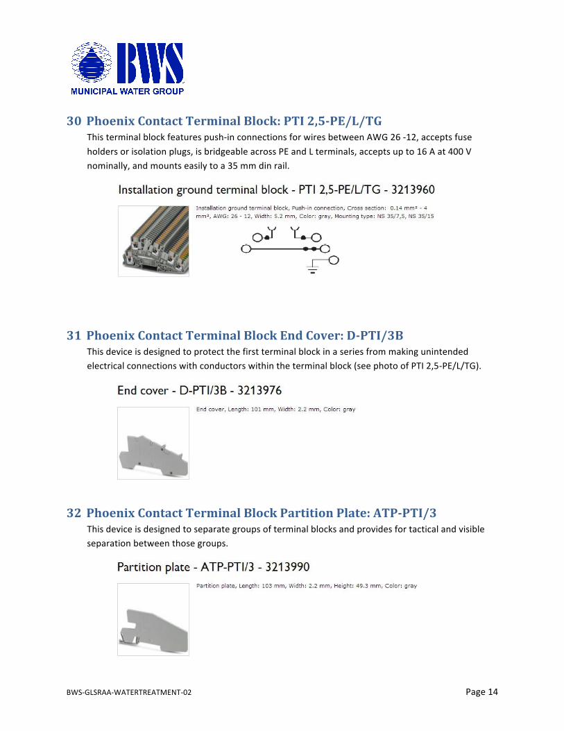
30 PhoenixContactTerminalBlock:PTI2,5-PE/L/TGThisterminalblockfeaturespush-inconnectionsforwiresbetweenAWG26-12,acceptsfuseholdersorisolationplugs,isbridgeableacrossPEandLterminals,acceptsupto16Aat400Vnominally,andmountseasilytoa35mmdinrail.
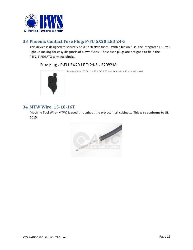
31 PhoenixContactTerminalBlockEndCover:D-PTI/3BThisdeviceisdesignedtoprotectthefirstterminalblockinaseriesfrommakingunintendedelectricalconnectionswithconductorswithintheterminalblock(seephotoofPTI2,5-PE/L/TG).
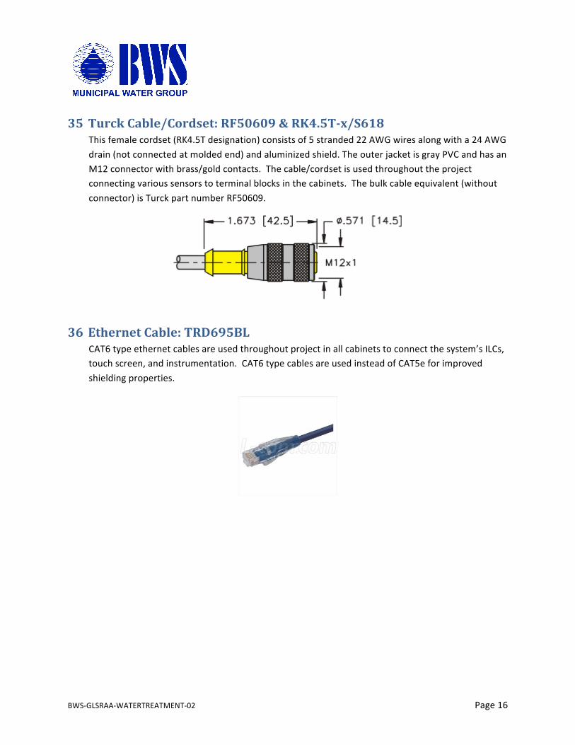
32 PhoenixContactTerminalBlockPartitionPlate:ATP-PTI/3Thisdeviceisdesignedtoseparategroupsofterminalblocksandprovidesfortacticalandvisibleseparationbetweenthosegroups.
BWS-GLSRAA-WATERTREATMENT-02 Page15
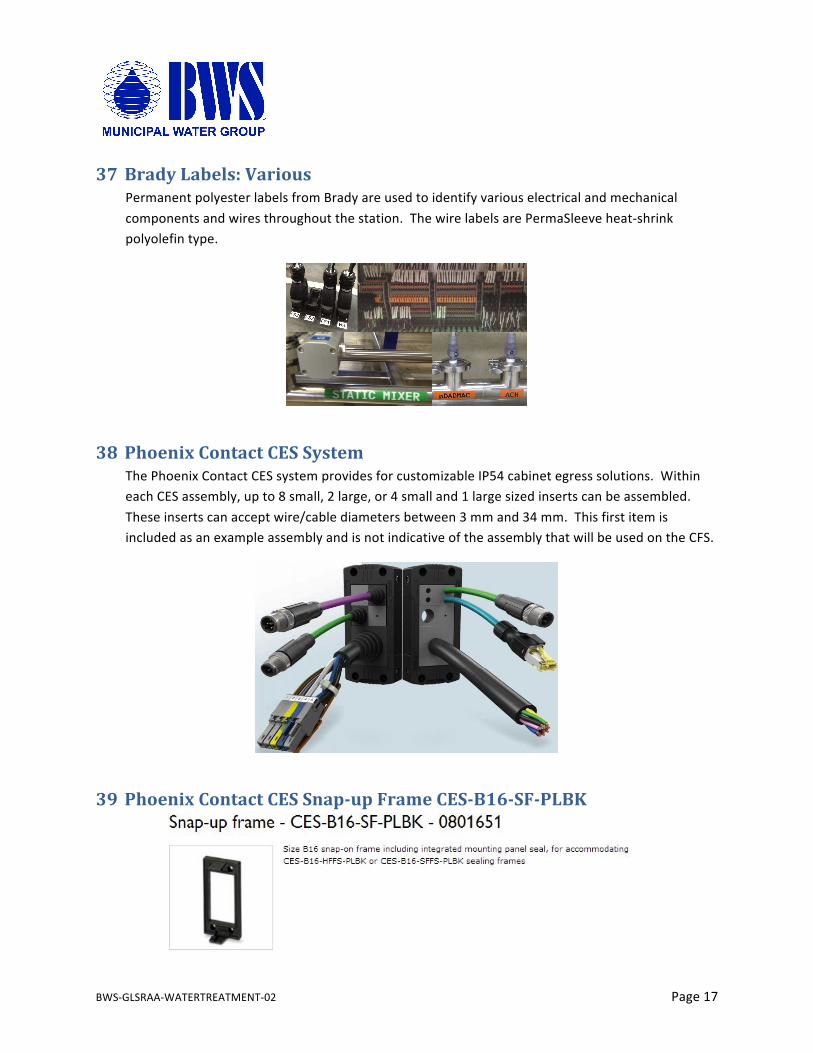
33 PhoenixContactFusePlug:P-FU5X20LED24-5Thisdeviceisdesignedtosecurelyhold5X20stylefuses.Withablownfuse,theintegratedLEDwilllightupmakingforeasydiagnosisofblownfuses.ThesefuseplugsaredesignedtofitinthePTI2,5-PE/L/TGterminalblocks.
34 MTWWire:15-18-16TMachineToolWire(MTW)isusedthroughouttheprojectinallcabinets.ThiswireconformstoUL1015.
BWS-GLSRAA-WATERTREATMENT-02 Page16
35 TurckCable/Cordset:RF50609&RK4.5T-x/S618Thisfemalecordset(RK4.5Tdesignation)consistsof5stranded22AWGwiresalongwitha24AWGdrain(notconnectedatmoldedend)andaluminizedshield.TheouterjacketisgrayPVCandhasanM12connectorwithbrass/goldcontacts.Thecable/cordsetisusedthroughouttheprojectconnectingvarioussensorstoterminalblocksinthecabinets.Thebulkcableequivalent(withoutconnector)isTurckpartnumberRF50609.
36 EthernetCable:TRD695BLCAT6typeethernetcablesareusedthroughoutprojectinallcabinetstoconnectthesystem’sILCs,touchscreen,andinstrumentation.CAT6typecablesareusedinsteadofCAT5eforimprovedshieldingproperties.
BWS-GLSRAA-WATERTREATMENT-02 Page17
37 BradyLabels:VariousPermanentpolyesterlabelsfromBradyareusedtoidentifyvariouselectricalandmechanicalcomponentsandwiresthroughoutthestation.ThewirelabelsarePermaSleeveheat-shrinkpolyolefintype.
38 PhoenixContactCESSystemThePhoenixContactCESsystemprovidesforcustomizableIP54cabinetegresssolutions.WithineachCESassembly,upto8small,2large,or4smalland1largesizedinsertscanbeassembled.Theseinsertscanacceptwire/cablediametersbetween3mmand34mm.ThisfirstitemisincludedasanexampleassemblyandisnotindicativeoftheassemblythatwillbeusedontheCFS.
39 PhoenixContactCESSnap-upFrameCES-B16-SF-PLBK
BWS-GLSRAA-WATERTREATMENT-02 Page18
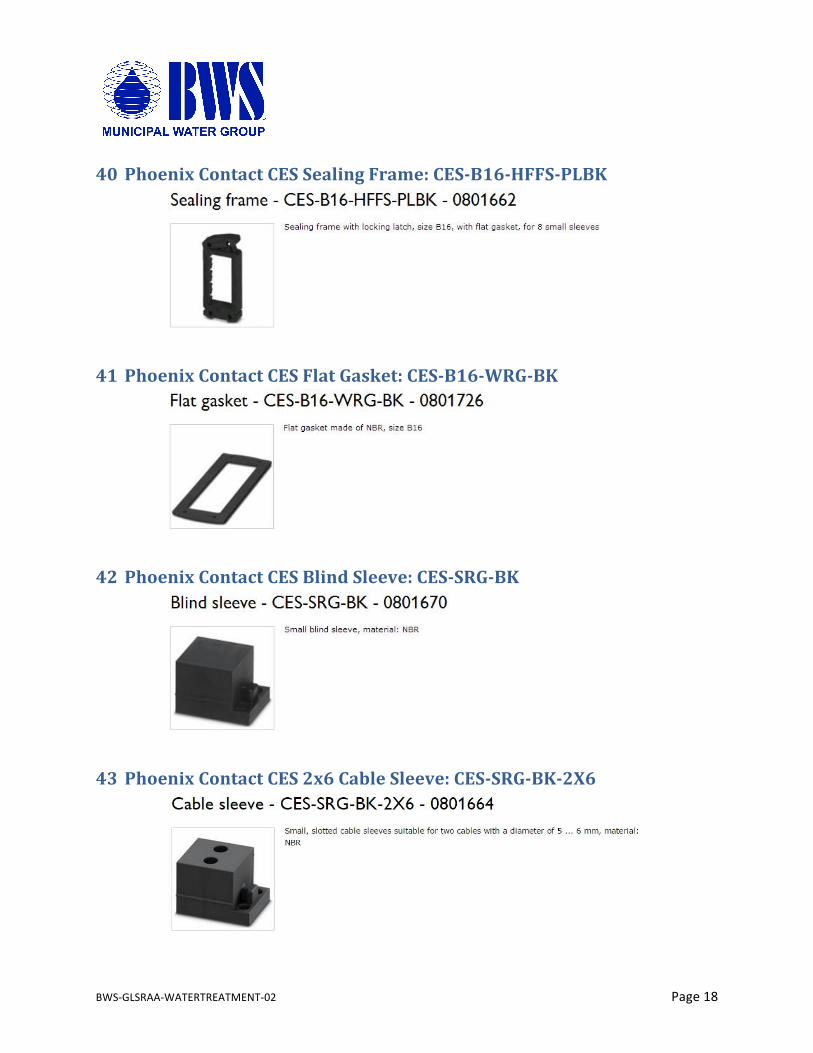
40 PhoenixContactCESSealingFrame:CES-B16-HFFS-PLBK
41 PhoenixContactCESFlatGasket:CES-B16-WRG-BK
42 PhoenixContactCESBlindSleeve:CES-SRG-BK
43 PhoenixContactCES2x6CableSleeve:CES-SRG-BK-2X6
BWS-GLSRAA-WATERTREATMENT-02 Page19
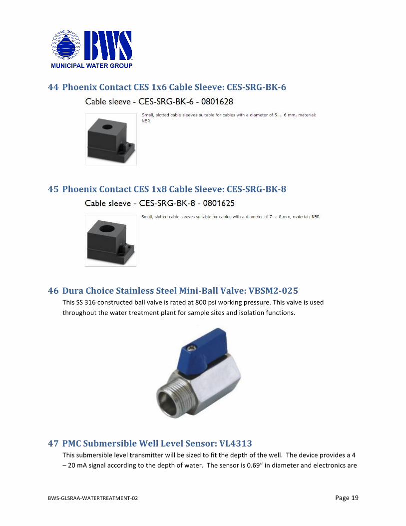
44 PhoenixContactCES1x6CableSleeve:CES-SRG-BK-6
45 PhoenixContactCES1x8CableSleeve:CES-SRG-BK-8
46 DuraChoiceStainlessSteelMini-BallValve:VBSM2-025ThisSS316constructedballvalveisratedat800psiworkingpressure.Thisvalveisusedthroughoutthewatertreatmentplantforsamplesitesandisolationfunctions.
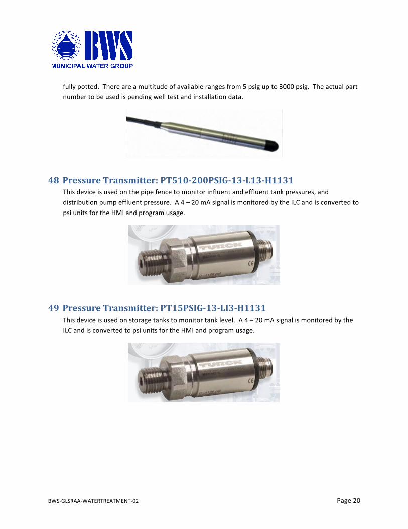
47 PMCSubmersibleWellLevelSensor:VL4313Thissubmersibleleveltransmitterwillbesizedtofitthedepthofthewell.Thedeviceprovidesa4–20mAsignalaccordingtothedepthofwater.Thesensoris0.69”indiameterandelectronicsare
BWS-GLSRAA-WATERTREATMENT-02 Page20
fullypotted.Thereareamultitudeofavailablerangesfrom5psigupto3000psig.Theactualpartnumbertobeusedispendingwelltestandinstallationdata.
48 PressureTransmitter:PT510-200PSIG-13-L13-H1131Thisdeviceisusedonthepipefencetomonitorinfluentandeffluenttankpressures,anddistributionpumpeffluentpressure.A4–20mAsignalismonitoredbytheILCandisconvertedtopsiunitsfortheHMIandprogramusage.
49 PressureTransmitter:PT15PSIG-13-LI3-H1131Thisdeviceisusedonstoragetankstomonitortanklevel.A4–20mAsignalismonitoredbytheILCandisconvertedtopsiunitsfortheHMIandprogramusage.
BWS-GLSRAA-WATERTREATMENT-02 Page21
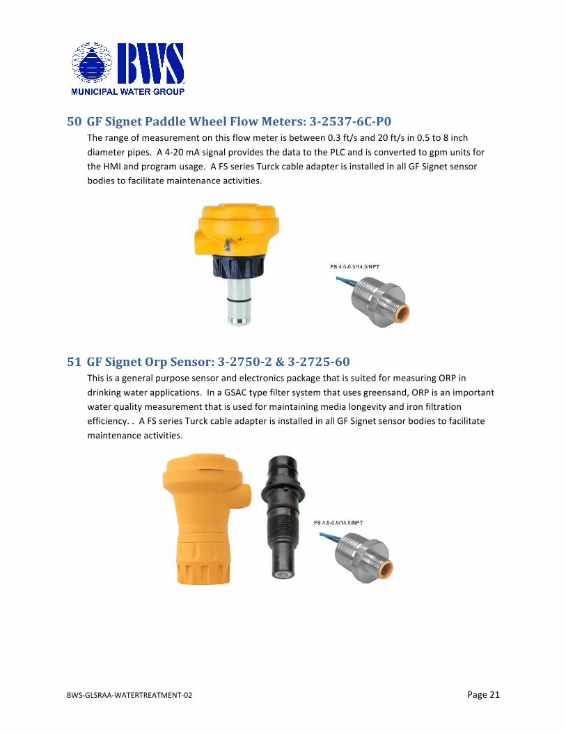
50 GFSignetPaddleWheelFlowMeters:3-2537-6C-P0Therangeofmeasurementonthisflowmeterisbetween0.3ft/sand20ft/sin0.5to8inchdiameterpipes.A4-20mAsignalprovidesthedatatothePLCandisconvertedtogpmunitsfortheHMIandprogramusage.AFSseriesTurckcableadapterisinstalledinallGFSignetsensorbodiestofacilitatemaintenanceactivities.
51 GFSignetOrpSensor:3-2750-2&3-2725-60ThisisageneralpurposesensorandelectronicspackagethatissuitedformeasuringORPindrinkingwaterapplications.InaGSACtypefiltersystemthatusesgreensand,ORPisanimportantwaterqualitymeasurementthatisusedformaintainingmedialongevityandironfiltrationefficiency..AFSseriesTurckcableadapterisinstalledinallGFSignetsensorbodiestofacilitatemaintenanceactivities.
BWS-GLSRAA-WATERTREATMENT-02 Page22
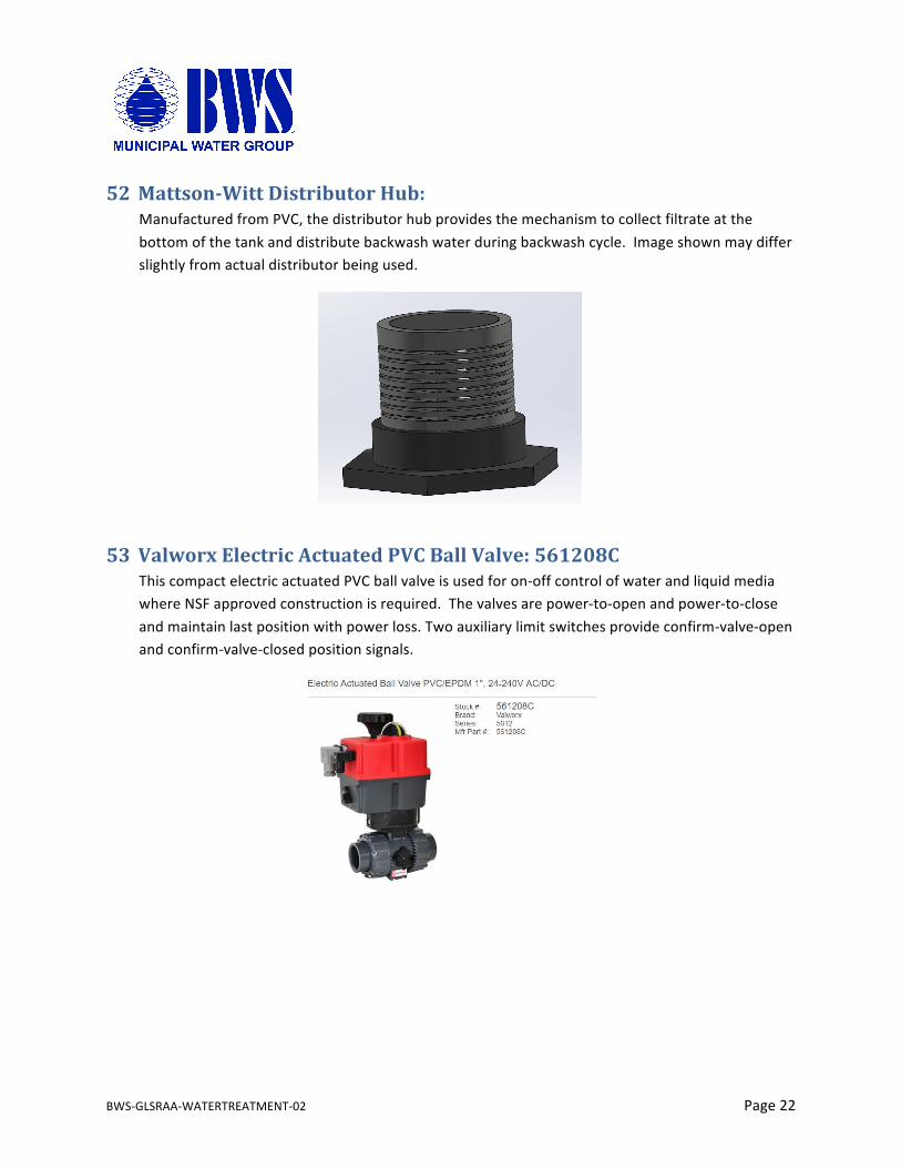
52 Mattson-WittDistributorHub:ManufacturedfromPVC,thedistributorhubprovidesthemechanismtocollectfiltrateatthebottomofthetankanddistributebackwashwaterduringbackwashcycle.Imageshownmaydifferslightlyfromactualdistributorbeingused.
53 ValworxElectricActuatedPVCBallValve:561208CThiscompactelectricactuatedPVCballvalveisusedforon-offcontrolofwaterandliquidmediawhereNSFapprovedconstructionisrequired.Thevalvesarepower-to-openandpower-to-closeandmaintainlastpositionwithpowerloss.Twoauxiliarylimitswitchesprovideconfirm-valve-openandconfirm-valve-closedpositionsignals.

BWS-GLSRAA-WATERTREATMENT-02 Page23
54 PhoenixContactRelay:PLC-RPT-24DC/21-21Thisrelayisactivatedwitha24VDCsignalandcanswitchloadsupto1500VAat250VAC.Thisrelayisusedtoswapthepolarityoftheenergysuppliedtotheelectricactuator;poweropenandpowercloseddependingonthecurrentcycleofthefilter.
55 StainlessSteelFittings:VariousThedistributionpumpsarehousedinastainlesssteelcanisterandprovidethreadedconnectionstoconnecttothesitepvcplumbing.Thecanisterisconstructedofferrules,caps,half-couplings,andclamps,allofwhicharemanufacturedfromeither304or316stainlesssteel.

BWS-GLSRAA-WATERTREATMENT-02 Page24
56 SanitaryClampGasket/OrificePlate:VariousSanitarytypefittingsrequireagasketororificeplatetobeusedwiththeclamp.TheseitemsaremanufacturedfromavarietyofmaterialsincludingBUNA,Viton,andTeflonandareselectedbasedonchemicalcompatibilityoftheworkingfluid.InthecaseoftheGSAC,EPDMgasketsandorificeplatesareusedexclusively.
57 StainlessSteelTubingRath-GibsonA270stainlesssteeltubingisusedforthepumpcanisters.Sixinchandtwodiameterproductsareused.AllweldsareorbitalorfreehandGTAW;mechanicalandchemicalpassivationisperformedimmediatelyafterwelding.
BWS-GLSRAA-WATERTREATMENT-02 Page25
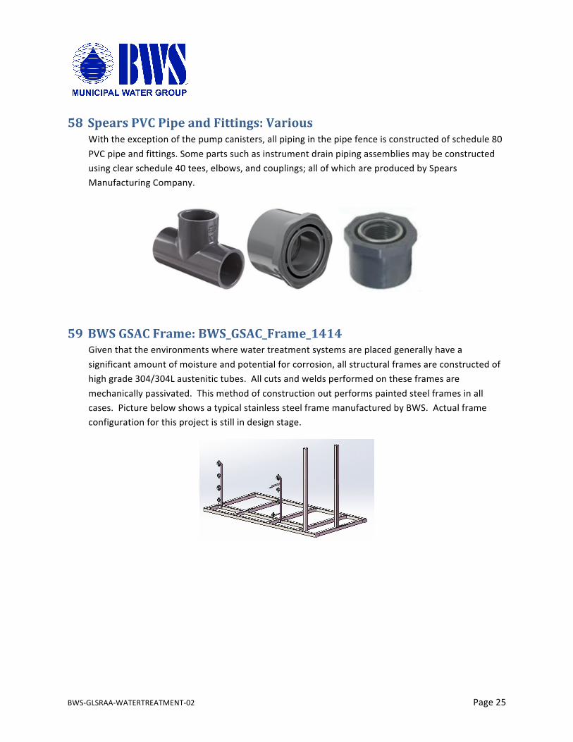
58 SpearsPVCPipeandFittings:VariousWiththeexceptionofthepumpcanisters,allpipinginthepipefenceisconstructedofschedule80PVCpipeandfittings.Somepartssuchasinstrumentdrainpipingassembliesmaybeconstructedusingclearschedule40tees,elbows,andcouplings;allofwhichareproducedbySpearsManufacturingCompany.
59 BWSGSACFrame:BWS_GSAC_Frame_1414Giventhattheenvironmentswherewatertreatmentsystemsareplacedgenerallyhaveasignificantamountofmoistureandpotentialforcorrosion,allstructuralframesareconstructedofhighgrade304/304Laustenitictubes.Allcutsandweldsperformedontheseframesaremechanicallypassivated.Thismethodofconstructionoutperformspaintedsteelframesinallcases.PicturebelowshowsatypicalstainlesssteelframemanufacturedbyBWS.Actualframeconfigurationforthisprojectisstillindesignstage.
BWS-GLSRAA-WATERTREATMENT-02 Page26
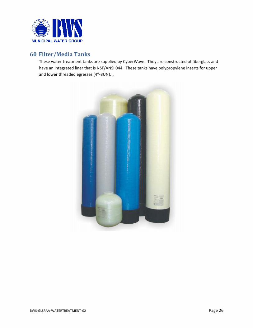
60 Filter/MediaTanksThesewatertreatmenttanksaresuppliedbyCyberWave.TheyareconstructedoffiberglassandhaveanintegratedlinerthatisNSF/ANSI044.Thesetankshavepolypropyleneinsertsforupperandlowerthreadedegresses(4”-8UN)..
BWS-GLSRAA-WATERTREATMENT-02 Page27
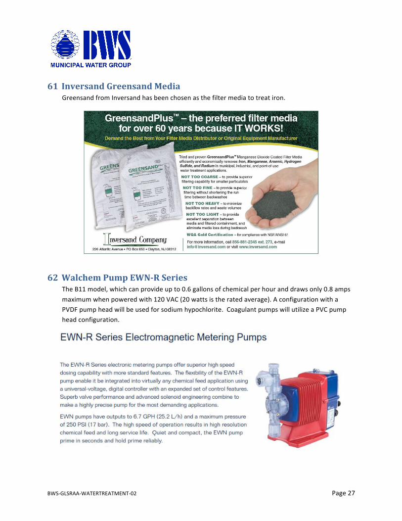
61 InversandGreensandMediaGreensandfromInversandhasbeenchosenasthefiltermediatotreatiron.
62 WalchemPumpEWN-RSeriesTheB11model,whichcanprovideupto0.6gallonsofchemicalperhouranddrawsonly0.8ampsmaximumwhenpoweredwith120VAC(20wattsistheratedaverage).AconfigurationwithaPVDFpumpheadwillbeusedforsodiumhypochlorite.CoagulantpumpswillutilizeaPVCpumpheadconfiguration.
BWS-GLSRAA-WATERTREATMENT-02 Page28
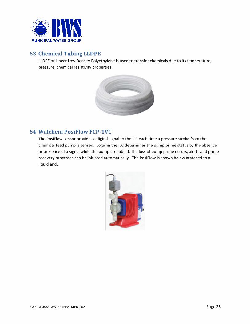
63 ChemicalTubingLLDPELLDPEorLinearLowDensityPolyethyleneisusedtotransferchemicalsduetoitstemperature,pressure,chemicalresistivityproperties.
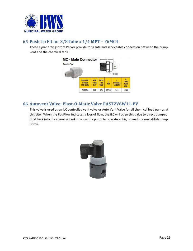
64 WalchemPosiFlowFCP-1VCThePosiFlowsensorprovidesadigitalsignaltotheILCeachtimeapressurestrokefromthechemicalfeedpumpissensed.LogicintheILCdeterminesthepumpprimestatusbytheabsenceorpresenceofasignalwhilethepumpisenabled.Ifalossofpumpprimeoccurs,alertsandprimerecoveryprocessescanbeinitiatedautomatically.ThePosiFlowisshownbelowattachedtoaliquidend.
BWS-GLSRAA-WATERTREATMENT-02 Page29
65 PushToFitfor3/8Tubex1/4MPT–F6MC4TheseKynarfittingsfromParkerprovideforasafeandserviceableconnectionbetweenthepumpventandthechemicaltank.
66 AutoventValve:Plast-O-MaticValveEAST2V6W11-PVThisvalveisusedasanILCcontrolledventvalveorAutoVentValveforallchemicalfeedpumpsatthissite.WhenthePosiFlowindicatesalossofflow,theILCwillopenthisvalvetodirectpumpedfluidbackintothechemicaltanktoallowthepumptooperateathighspeedtore-establishpumpprime.
BWS-GLSRAA-WATERTREATMENT-02 Page30
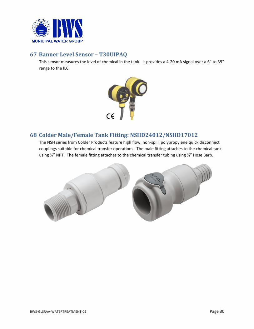
67 BannerLevelSensor–T30UIPAQThissensormeasuresthelevelofchemicalinthetank.Itprovidesa4-20mAsignalovera6”to39”rangetotheILC.
68 ColderMale/FemaleTankFitting:NSHD24012/NSHD17012TheNSHseriesfromColderProductsfeaturehighflow,non-spill,polypropylenequickdisconnectcouplingssuitableforchemicaltransferoperations.Themalefittingattachestothechemicaltankusing¾”NPT.Thefemalefittingattachestothechemicaltransfertubingusing¾”HoseBarb.
BWS-GLSRAA-WATERTREATMENT-02 Page31
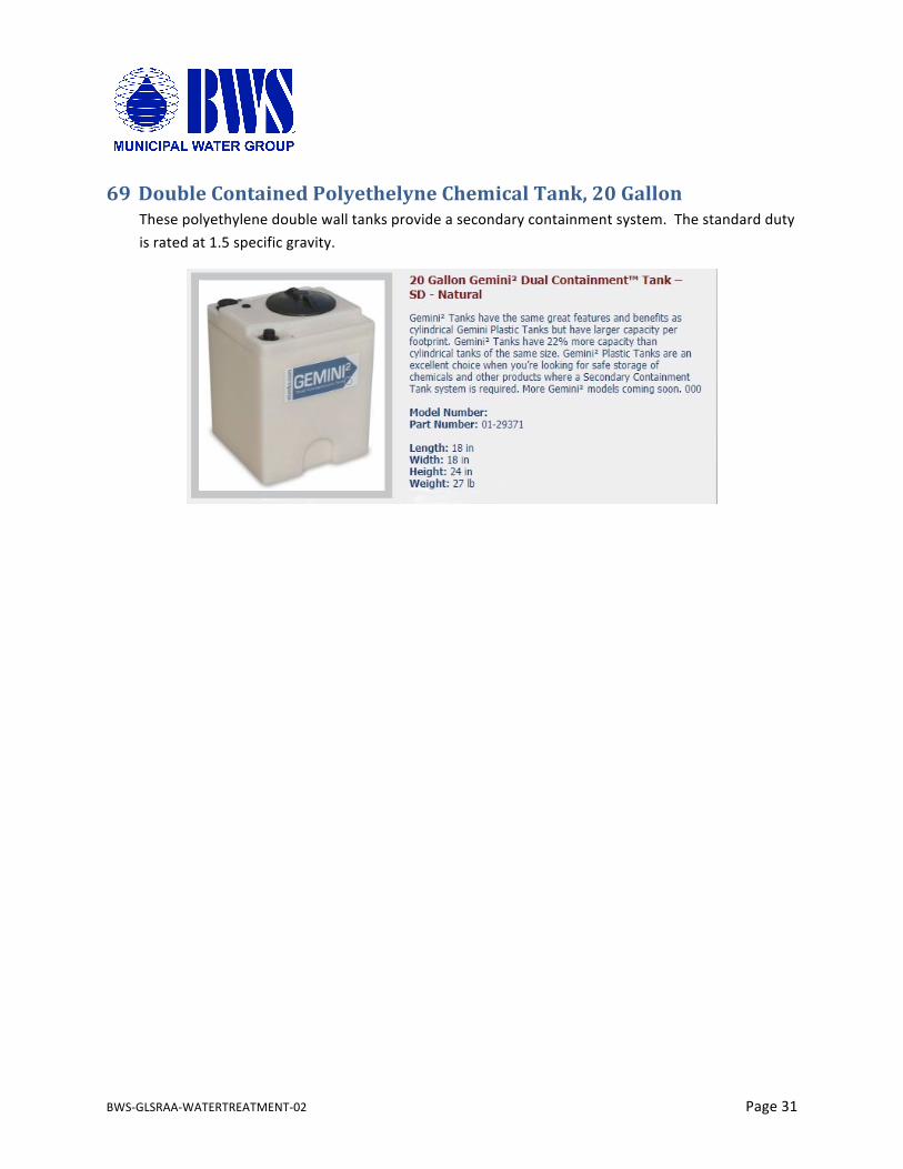
69 DoubleContainedPolyethelyneChemicalTank,20GallonThesepolyethylenedoublewalltanksprovideasecondarycontainmentsystem.Thestandarddutyisratedat1.5specificgravity.
BWS-WCR-MUCS-01 Appendixi
70 Appendices
Contents1. BWSGSACFilterStation:BWS_GSAC_1414 12. Enclosure:StainlessSteelBWS_CABINET_01 23. EnclosurePanel:BWS_CAB_PAN_01/02 34. PhoenixContactTouchPanel:WP09T/WS 45. PhoenixContactInlineController:ILC151ETH 56. PhoenixContactProgram/ConfigurationMemory:SDFLASH2G 67. PhoenixContactInlineDigitalOutModule:IBIL24DO16-ME 78. PhoenixContactInlineDigitalInModule:IBIL24DI16-ME 89. PhoenixContactInlineDigitalInNPNModule–IBILDI2-NPN-PAC 910. PhoenixContactInlineAnalogInModule:IBILAI4/I-PAC 1011. PhoenixContactInlineAnalogOutModule–IBILAO2/UI-PAC 1112. PhoenixContactPowerSupply:TRIO-PS-2G/1AC/24DC/10 1213. PhoenixContactUPS:QUINT-UPS/24DC/24DC/10/3.4AH 1314. EwonIndustrialVPNRouter:Flexy20500 1415. EwonCellularCommunications:FLB3203 1516. PhoenixContactSwitch:FLSWITCHSFN8TX 1617. Ebm-papstCabinetFan:QG030-353/14 1718. StegoCabinetThermostat:KTS-011 1819. AltechMotorDisconnectSwitch:VKA3160 1920. PhoenixContactLightning/SurgeArrestor:FLT-SEC-T1+T2-3S-350/25-FM 2021. PhoenixContactWiringBridge:TMC8B38057C 2122. PhoenixContactUL489CircuitBreaker:TMC81D10A 2223. PhoenixContactUL489CircuitBreaker:TMC83D15A 2324. PhoenixContactRelay:PLC-RSC-24DC/21 2425. EmmersonVariableFrequencyDrive:M200-02200042A 2526. PhoenixContactDinRail:NS35/15Perf 2627. PhoenixContactCableDuct:CD40x80 2728. PhoenixContactDinRailEndCap:NS35/15Cap 2829. PhoenixContactEndClampE/NS35N 2930. PhoenixContactTerminalBlock:PTI2,5-PE/L/TG 3031. PhoenixContactTerminalBlockEndCover:D-PTI/3B 3132. PhoenixContactTerminalBlockPartitionPlate:ATP-PTI/3 3233. PhoenixContactFusePlug:F-FU5X20LED24-5 3334. MTWWire:15-18-16T 3435. TurckCable/Cordset:RF50609&RK4.5T-x/S618 3536. EthernetCable:TRD695BL 3637. BradyLabels:Various 3738. PhoenixContactCESSystem 3839. PhoenixContactCESSnap-upFrameCES-B16-SF-PLBK 3940. PhoenixContactCESSealingFrame:CES-B16-HFFS-PLBK 4041. PhoenixContactCESFlatGasket:CES-B16-WRG-BK 4142. PhoenixContactCESBlindSleeve:CES-SRG-BK 42
BWS-GL-02 Appendixii
43. PhoenixContactCES2x6CableSleeve:CES-SRG-BK-2X6 4344. PhoenixContactCES1x6CableSleeve:CES-SRG-BK-6 4445. PhoenixContactCES1x8CableSleeve:CES-SRG-BK-8 4546. DuraChoiceStainlessSteelMini-BallValve:VBSM2-025 4647. PMCSubmersibleWellLevelSensor:VL4313 4748. PressureTransmitter:PT510-200PSIG-13-L13-H1131 4849. PressureTransmitter:PT15PSIG-13-LI3-H1131 4950. GFSignetPaddleWheelFlowMeters:3-2537-6C-P0 5051. GFSignetOrpSensor:3-2750-2&3-2725-60 5152. Mattson-WittDistributorHub 5253. ValworxElectricActuatedPVCBallValve:566249 5354. PhoenixContactRelay:PLC-RPT-24DC/21-21 5455. StainlessSteelFittings:Various 5556. SanitaryClampGasket/OrificePlate:Various 5657. StainlessSteelTubing 5758. SpearsPVCPipeandFittings:Various 5859. BWSGSACFrame:BWS_GSAC_Frame_1414 5960. Filter/MediaTanks 6061. InversandGreensandMedia 6162. WalchemPumpEWN-RSeries 6263. ChemicalTubingLLDPE 6364. WalchemPosiFlowFCP-1VC 6465. PushToFitfor3/8Tubex1/4MPT–F6MC4 6566. AutoventValve:Plast-O-MaticValveEAST2V6W11-PV 6667. BannerLevelSensor–T30UIPAQ 6768. ColderMale/FemaleTankFitting:NSHD24012/NSHD17012 6869. DoubleContainedPolyethelyneChemicalTank,20Gallon 69

BWS-GLSRAA-WATERTREATMENT-02 Appendix1
1. BWSGSACFilterStation:BWS_GSAC_1414
ON-SKID
14" TANKS
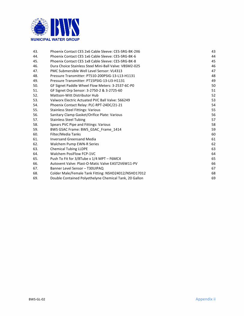
ELECTRICAL EGRESS
STORAGE TANKS
FILTER SKID
WELL HEAD
DISTRIBUTION EFFLUENT
TREATED WATER
PIPE FENCE ON FLOOR
FLOOR DRAIN
SEWER DRAIN
4X 500 GALLON
SINK CONNECTION
CABINETCONTROL
CHEMICAL FEED TANK ASSY LOCATION
SERVICE PANEL LOCATION
0.01
REV
DRA
WIN
G N
UMBE
RM
OD
EL N
UMBE
R
GLS
RRA
-WTP
-01
PRO
PRIE
TARY
AN
D C
ON
FIDE
NTIA
L
PERM
ISSI
ON
OF
BWS
IS P
ROHI
BITE
D.
SIZE
B
REV
SCALE: DNS
GRA
SS L
AKE
SRR
A W
TP L
AYO
UT P
ROPO
SAL
SHEET 1 OF 1
AS
A W
HOLE
WITH
OUT
THE
WRI
TTEN
BW
S. A
NY
REPR
OD
UCTIO
N IN
PA
RT O
R D
RAW
ING
IS T
HE S
OLE
PRO
PERT
Y O
F
9600
2
THE
INFO
RMA
TION
CO
NTA
INED
IN T
HIS
BEEB
E'S W
ATER
SYST
EMS
8725
AIR
PORT
RD
REDD
ING
, CA
MA
TERI
AL
SECTION A-ASCALE 1/16
SECTION B-BSCALE 1/16
SHEET 1 OF 1
DRAWN
CHECKED
QA
MFG
APPROVED
Jerry Paulson 7/16/2010
DWG NO
TITLE
500 GALLON FREE STANDING WATER TANK
SIZE
BSCALE: 1/16
NORWESCO, INC., ST. BONIFACIUS, MN
REV
A
A
B B
67 7/8
74
31
R15 1/2
34
8 1/2
12
R4
11
P20 1/4
1
58 7/8
24
6
R24 3/8
R2 7/8
100°
R15 1/2
R15 1/2
24 3/8
2
DTITL
E
DW
G N
OSI
ZER
EV SHEE
T
O
FFI
LE1_
GL_
GSA
C_P
ID_1
.VSD
1
BYB.
WAL
TON
.
THE
INFO
RM
ATIO
N C
ON
TAIN
ED I
N T
HIS
D
OC
UM
ENT
IS T
HE
SO
LE P
RO
PER
TY O
F B
WS
REP
RO
DU
CTI
ON
IN
PAR
T O
R W
HO
LE W
ITH
OU
T TH
E
WR
ITTE
N P
ERM
ISSI
ON
OF
BW
S IS
PR
OH
IBIT
ED
11
GR
ASS
LAKE
SAF
ETY
RES
T AR
EAG
REE
NSA
ND
/AC
TIVA
TED
CAR
BON
TR
EATM
ENT
PLAN
T
PID
_GL_
GSA
C7/
11/2
018
BWS
Mun
icip
al W
ater
Gro
up87
15 A
irpor
t Rd,
Ste
BR
eddi
ng, C
A 96
002
(530
) 244
-144
3.
LAST
REV
ISED
: 8/8
/201
8 1:
20:3
4 PMTREATED WATER
STORAGE TANKTWST
1.0 -1.5K GAL
TV
DIST
DPT0-200 PSI
SUR
GE
TAN
K
BW
Ø 1.0"
DWP/BWP2X 20 GPM / 30-60 psi
½ Hp / VFD16S05-5
S
WELL WATER
RWFT2537
WELL HEAD ELEV: XX’X’ WELL DEPTH
Y' WATER LEVELZ Hp, 240VAC/3P
VFD CONTROLLED
CURRENT
DFT2537
SS
AIR GAP TODRAIN
FLOOR DRAIN
2" DWV
EFPT0-200 psi
14" DIA 52" TALL
ACTIVATED CARBON FILTER
V8
V9
14" DIA52" TALL
GREENSAND FILTER
V3V2
INPT0-200 psi
V10S
INFT1
1.07 sqft * (12-15) gpm/sqft = (12.8 – 16) gpm MAX
HOSE BIB
BWFT
GX5.05 GPM,1"
Ø 2.0" Ø 2.0" Ø 1.5"
Ø 1.0"Ø 2.0"
Ø 1.0"
Ø 1.0"
Ø 1.0"
V4 SV6SM
FS – FILTER STATION
Ø 1.0"
GX5.05 GPM,1"
CFCLT
NaOCL
CFPC2
AVC2
PFC2
CFPC1
AVC1
PFC1
1.07 sqft * (2-10) gpm/sqft = (2.1 – 10.7) gpm MAXDEPENDING ON RAW WATER QUALITY
JULY 2018 RAW WATER TEST RESULTS:Iron = 1.0 mg/L
Manganese = NAAlkalinity (MO) = 140 mg/L as CaCO3Hardness (total)= 120 mg/L as CaCO3
Total Dissolved Solids = 145 mg/LORP=145pH=7.5
The operator reported no appreciable odor
RWLT
GX1515GPM,1"
INORP
OUTORP
BWS
Mun
icip
al W
ater
Gro
up87
15 A
irpor
t Rd,
Ste
B.
Red
ding
, CA
9600
2(5
30) 2
44-1
453
THE
INFO
RM
ATIO
N C
ON
TAIN
ED I
N T
HIS
D
OC
UM
ENT
IS T
HE
SO
LE P
RO
PER
TY O
F B
WS
REP
RO
DU
CTI
ON
IN
PAR
T O
R W
HO
LE W
ITH
OU
T TH
E
WR
ITTE
N P
ERM
ISSI
ON
OF
BW
S IS
PR
OH
IBIT
ED
DTITL
E
DW
G N
OSI
ZER
EV SHEE
T
O
FFI
LE2_
GL_
GSA
C_T
OPO
_1.V
SD1
BYB.
WAL
TON
1
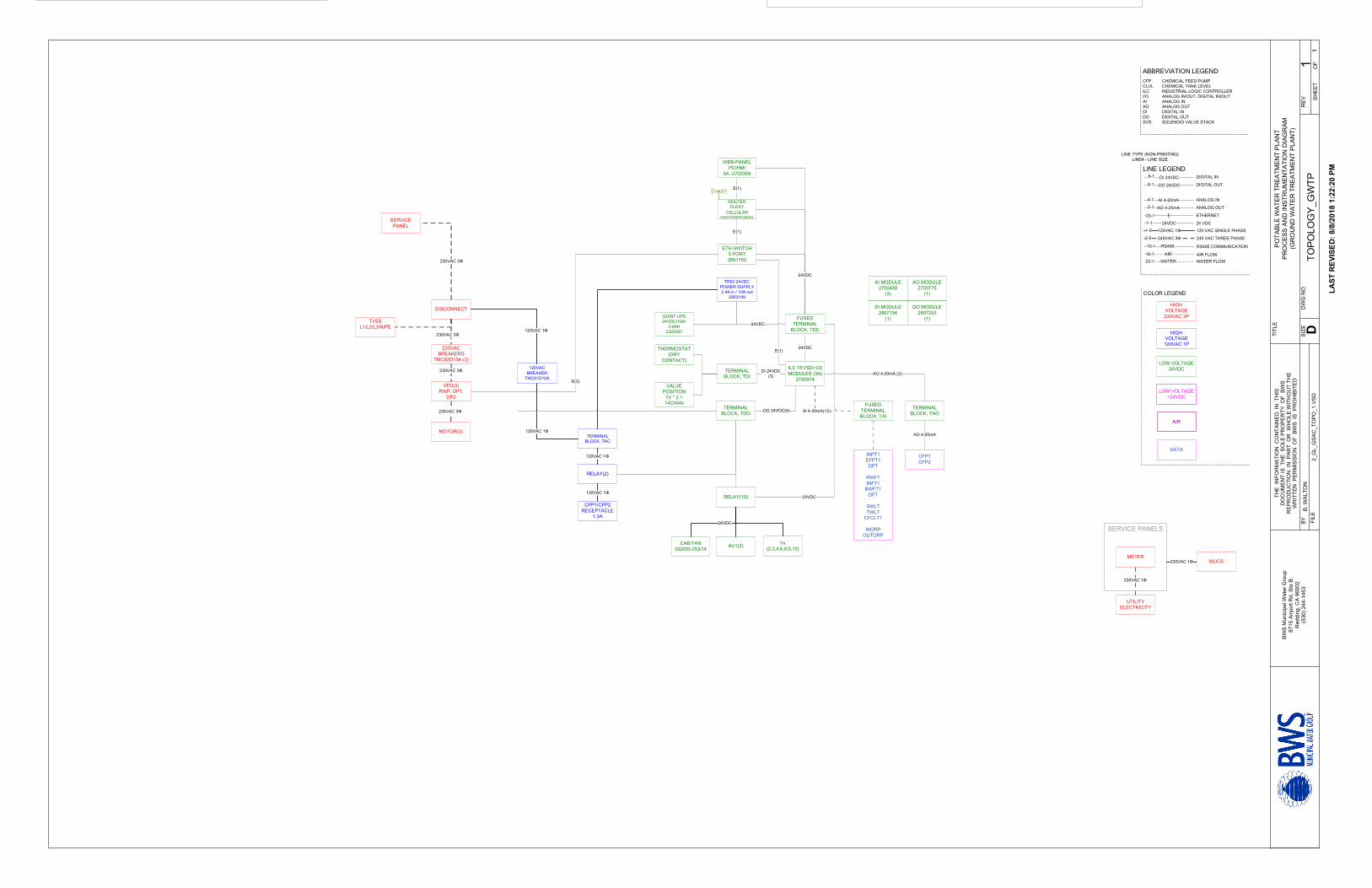
POTA
BLE
WAT
ER T
REA
TMEN
T PL
ANT
PRO
CES
S AN
D IN
STR
UM
ENTA
TIO
N D
IAG
RAM
(GR
OU
ND
WAT
ER T
REA
TMEN
T PL
ANT)
TOPO
LOG
Y_G
WTP
LAST
REV
ISED
: 8/8
/201
8 1:
22:2
0 PM
ABBREVIATION LEGENDCFP CHEMICAL FEED PUMPCLVL CHEMICAL TANK LEVELILC INDUSTRIAL LOGIC CONTROLLERI/O ANALOG IN/OUT, DIGITAL IN/OUTAI ANALOG INAO ANALOG OUTDI DIGITAL INDO DIGITAL OUTSVS SOLENOID VALVE STACK
DO 24VDC
AI 4-20mA
E
DIGITAL OUT
ANALOG IN
DI 24VDC DIGITAL IN
AO 4-20mA ANALOG OUT
120VAC 1Φ
ETHERNET
120 VAC SINGLE PHASE
240VAC 3Φ 240 VAC THREE PHASE
6-1
8-1
4-1
5-1
23-1
1-5
2-5
LINE TYPE (NON-PRINTING)LINE# - LINE SIZE
24VDC 24 VDC1-1
RS48510-1
AIR16-1WATER22-1
LINE LEGEND
RS485 COMMUNICATION
AIR FLOWWATER FLOW
UTILITY ELECTRICITY
METER
230VAC 1Φ
SERVICE PANELS
TERMINAL BLOCK, TAC
120VAC 1Φ
WEB-PANELPC/HMI
5A -2700309
ILC 151/SD+I/O MODULES (3A)
2700974
TRIO 24VDC POWER SUPPLY2.4A in / 10A out
2903149
24VDC
24VDC
ETH SWITCH5 PORT2891152
E(1)
E(1)
FUSED TERMINAL
BLOCK, TDC
TERMINAL BLOCK, TDO
RELAY(2)
120VAC 1Φ
TERMINAL BLOCK, TDI
DI 24VDC(3)
FUSED TERMINAL BLOCK, TAI
AI 4-20mA(12)DO 24VDC(8)
ROUTERFLEXY
CELLULARFLEXY20500/FLB3203
HIGH VOLTAGE230VAC 3P
LOW VOLTAGE24VDC
HIGH VOLTAGE120VAC 1P
COLOR LEGEND
LOW VOLTAGE <24VDC
AIR
DATA
E(1)
230VAC 1Φ MUCS
RELAY(10) 24VDC
CFP1/CFP2RECEPTACLE
1.3A
120VAC 1Φ
AV1(2)CAB FANQG030-353/14
24VDC
INPT1EFPT1
DPT
RWFTINFT1
BWFT1DFT
SWLTTWLT
CFCLT1
INORPOUTORP
Vx(2,3,4,6,8,9,10)
24VDC
DISCONNECT
230VAC BREAKERS
TMC82D15A (3)
VFD(3)RWP, DP1,
DP2
230VAC 3Φ
MOTOR(3)
230VAC 3Φ
230VAC 3Φ
SERVICE PANEL
120VAC BREAKER
TMC81D10A
TERMINAL BLOCK, TAO
AO 4-20mA (2)
CFP1CFP2
AO 4-20mA
E(3)
AI MODULE2700458
(3)
AO MODULE2700775
(1)
DI MODULE2897156
(1)
DO MODULE2897253
(1)
230VAC 3Φ
THERMOSTAT(DRY
CONTACT)
VALVE POSITION
7V * 2 = 14CHAN
120VAC 1Φ
QUINT UPS 24VDC/10A/
3.4AH 2320267
TVSSL1/L2/L3/N/PE
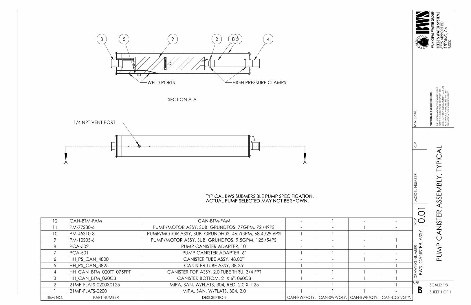
1/4 NPT VENT PORT
AA
29 8
WELD PORTS
4
SECTION A-A
5 53
HIGH PRESSURE CLAMPS
ITEM NO. PART NUMBER DESCRIPTION CAN-RWP/QTY. CAN-SWP/QTY. CAN-BWP/QTY. CAN-LDIST/QTY.
12 CAN-BTM-FAM CAN-BTM-FAM - 1 - -11 PM-77S30-6 PUMP/MOTOR ASSY, SUB, GRUNDFOS, 77GPM, 72'/49PSI - - 1 -10 PM-45S10-3 PUMP/MOTOR ASSY, SUB, GRUNDFOS, 46.7GPM, 68.4'/29.6PSI 1 1 - -9 PM-10S05-6 PUMP/MOTOR ASSY, SUB, GRUNDFOS, 9.5GPM, 125'/54PSI - - - 18 PCA-502 PUMP CANISTER ADAPTER, 10" - - - 17 PCA-501 PUMP CANISTER ADAPTER, 6" 1 1 - -6 HH_PS_CAN_4800 CANISTER TUBE ASSY, 48.00"" - - 1 -5 HH_PS_CAN_3825 CANISTER TUBE ASSY, 38.25" 1 1 - 14 HH_CAN_BTM_020TT_075FPT CANISTER TOP ASSY, 2.0 TUBE THRU, 3/4 FPT 1 1 1 13 HH_CAN_BTM_020CB CANISTER BOTTOM, 2" X 6", 060CB 1 - 1 12 21MP-FLATS-0200X0125 MIPA, SAN, W/FLATS, 304, RED, 2.0 X 1.25 - 1 - 11 21MP-FLATS-0200 MIPA, SAN, W/FLATS, 304, 2.0 1 1 1 -
TYPICAL BWS SUBMERSIBLE PUMP SPECIFICATION.ACTUAL PUMP SELECTED MAY NOT BE SHOWN.TYPICAL BWS SUBMERSIBLE PUMP SPECIFICATION.ACTUAL PUMP SELECTED MAY NOT BE SHOWN.
BWS.
AN
Y RE
PRO
DUC
TION
IN P
ART
OR
AS
A W
HOLE
WITH
OUT
THE
WRI
TTEN
SHEET 1 OF 1
PUM
P C
AN
ISTE
R A
SSEM
BLY,
TYP
ICA
LD
RAW
ING
IS T
HE S
OLE
PRO
PERT
Y O
F
REV
9600
2
BWS_
CA
NIS
TER_
ASS
YM
OD
EL N
UMBE
R
SCALE: 1:8
REV
DRA
WIN
G N
UMBE
R
PRO
PRIE
TARY
AN
D C
ON
FIDE
NTIA
L
PERM
ISSI
ON
OF
BWS
IS P
ROHI
BITE
D.
SIZE
0.01
B
THE
INFO
RMA
TION
CO
NTA
INED
IN T
HIS
BEEB
E'S W
ATER
SYST
EMS
8725
AIR
PORT
RD
REDD
ING
, CA
MA
TERI
AL

BWS-GL-02 Appendix2
2. Enclosure:StainlessSteelBWS_CABINET_01
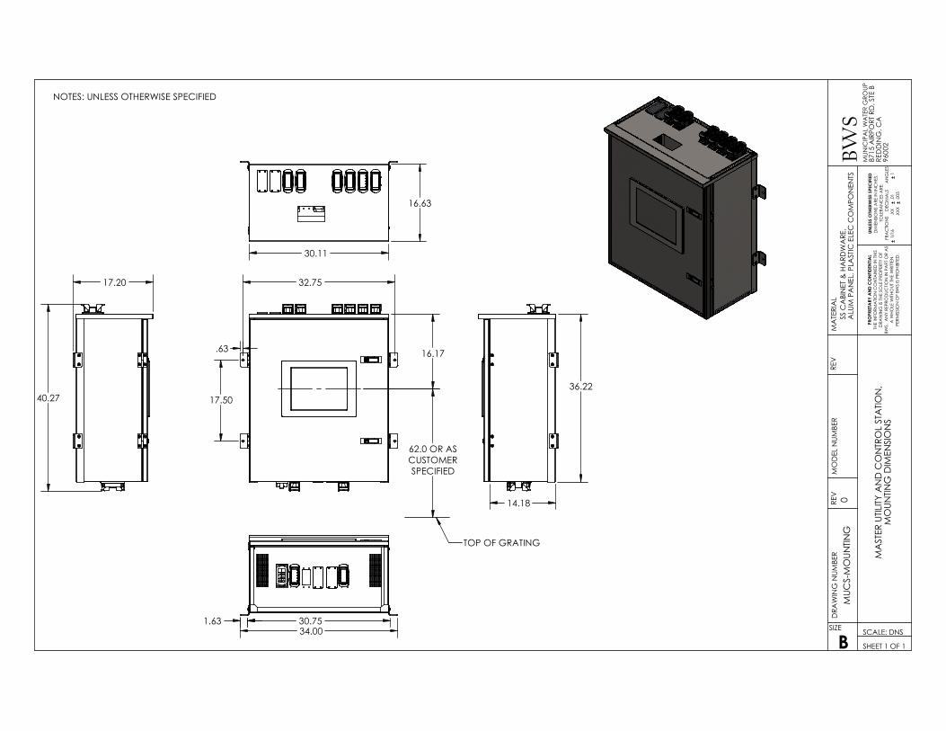
62.0 OR ASCUSTOMERSPECIFIED
A W
HOLE
WITH
OUT
THE
WRI
TTEN
ALU
M P
AN
EL, P
LAST
IC E
LEC
CO
MPO
NEN
TS
NOTES: UNLESS OTHERWISE SPECIFIED
.XXX
DRA
WIN
G IS
THE
SO
LE P
ROPE
RTY
OF
RED
DIN
G, C
A
SIZE
B
REV
SCALE: DNS
SHEET 1 OF 1
MUC
S-M
OUN
TING
REV
DRA
WIN
G N
UMBE
R
.01
1
.005
PE
RMISS
ION
OF
BWS
IS PR
OHI
BITE
D.
0
THE
INFO
RMA
TION
CO
NTA
INED
IN T
HIS
BWS.
AN
Y RE
PRO
DUC
TION
IN P
ART
OR
AS
MA
TERI
AL
SS C
ABI
NET
& H
ARD
WA
RE,
MO
DEL
NUM
BER
9600
2
UNLE
SS O
THER
WIS
E SP
ECIFI
EDD
IMEN
SION
S A
RE IN
INC
HES.
T
OLE
RAN
CES
ARE
:FR
AC
TION
S
DEC
IMA
LS
AN
GLE
S 1
/16
.X
X
PRO
PRIE
TARY
AND
CO
NFID
ENTIA
L
BWS
MUN
ICIP
AL
WA
TER
GRO
UP87
15 A
IRPO
RT R
D, S
TE B
MA
STER
UTIL
ITY A
ND
CO
NTR
OL
STA
TION
, M
OUN
TING
DIM
ENSI
ON
S
TOP OF GRATING
32.75
17.50
.63 16.17
17.20
40.27
30.11
16.63
14.18
36.22
34.00 30.75 1.63

BWS-GL-02 Appendix3
3. EnclosurePanel:BWS_CAB_PAN_01/02
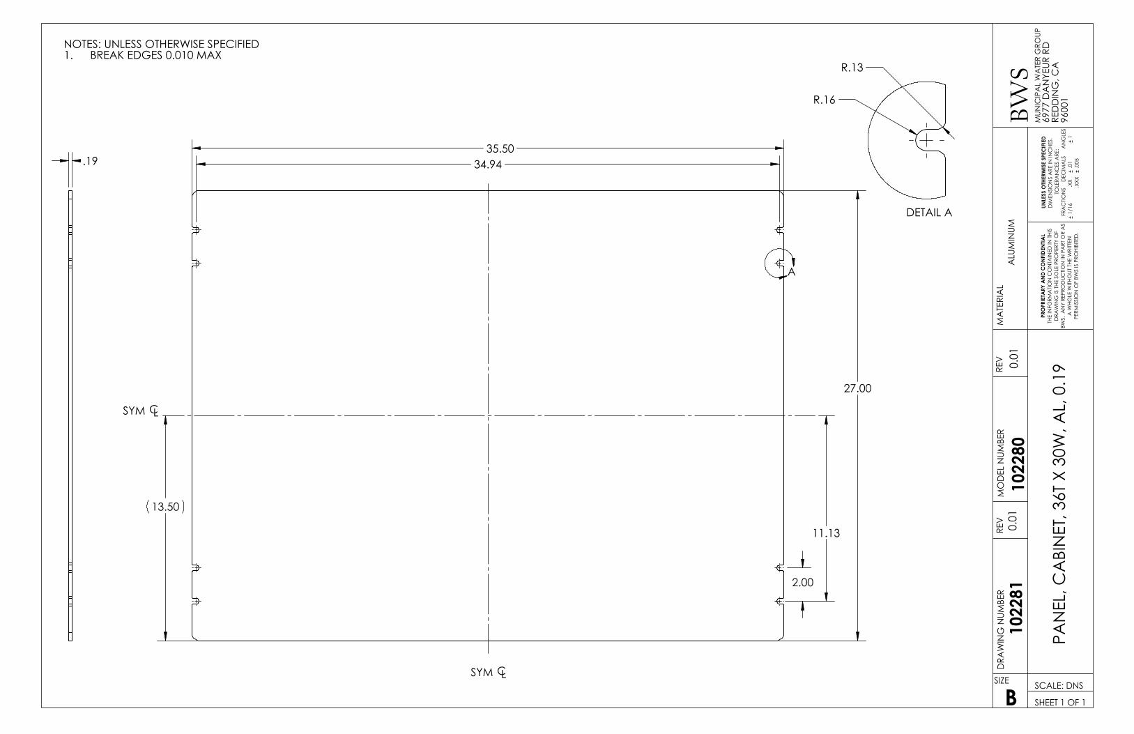
35.50
27.00
13.50
11.13
34.94
2.00
A
SYM CL
SYM CL
R.16
R.13
DETAIL A
.19
SIZE
B
REV
SCALE: DNS
0.01
PAN
EL, C
ABI
NET
, 36T
X 3
0W, A
L, 0
.19
SHEET 1 OF 1
1022
80
SMM
P-PS
R-PA
NEL
MO
DEL
NUM
BER
DRA
WIN
G N
UMBE
RRE
V 0.01
MA
TERI
AL
UNLE
SS O
THER
WIS
E SP
ECIF
IED
DIM
ENSI
ON
S A
RE IN
INC
HES.
T
OLE
RAN
CES
ARE
:FR
AC
TION
S
DEC
IMA
LS
AN
GLE
S 1
/16
.X
X
.01
1
.XXX
.0
05
PRO
PRIE
TARY
AN
D C
ON
FIDE
NTIA
LTH
E IN
FORM
ATIO
N C
ON
TAIN
ED IN
THI
SD
RAW
ING
IS T
HE S
OLE
PRO
PERT
Y O
FBW
S. A
NY
REPR
OD
UCTIO
N IN
PA
RT O
R A
S A
WHO
LE W
ITHO
UT T
HE W
RITT
EN
PERM
ISSI
ON
OF
BWS
IS P
ROHI
BITE
D.
ALU
MIN
UM
NOTES: UNLESS OTHERWISE SPECIFIEDBREAK EDGES 0.010 MAX1.
BWS
MUN
ICIP
AL
WA
TER
GRO
UP69
77 D
AN
YEUR
RD
RED
DIN
G, C
A96
001
PUM
P ST
ATIO
N -
REM
OTE
CA
BIN
ET A
LUM
INUM
PA
NEL
SAN
MA
TEO
MEM
ORI
AL
PARK
PAN
EL-3
0W-3
6T
1022
81

BWS-GL-02 Appendix4
4. PhoenixContactTouchPanel:WP09T/WS
https://www.phoenixcontact.com/us/products/2700309
08/08/2018 Page 1 / 4
Touch panel - WP 09T/WS - 2700309Please be informed that the data shown in this PDF Document is generated from our Online Catalog. Please find the complete data in the user'sdocumentation. Our General Terms of Use for Downloads are valid(http://phoenixcontact.com/download)
Touch panel with 22.9 cm/9" TFT-display (analog resistive (polyester)), 800 x 480 Pixel(s) (WVGA), 65536colors, ARM9™, 200 MHz, 2x USB host 2.0, 1 x Ethernet (10/100 Mbps), RJ45, Windows CE 5.0 and usersoftware: MicroBrowser. (bus system: without)
Why buy this product
Short startup time
Easy installation, low installation depth, and compact design
Low maintenance costs - projects are only adapted once
Micro browser (WebVisit client) integrated as standard in all devices
Display available in sizes from 8.9 cm (3.5") to 38.1 cm (15")
Easy device replacement - the visualization project is saved on the PLC (web server)
Key Commercial DataPacking unit 1 STK
GTIN
GTIN 4046356547932
Weight per Piece (excluding packing) 1,980.000 g
Custom tariff number 84714100
Country of origin Germany
Technical data
Note
Utilization restriction EMC: class A product, see manufacturer's declaration in the downloadarea
DimensionsExternal dimension, width 260 mm

https://www.phoenixcontact.com/us/products/2700309
08/08/2018 Page 2 / 4
Touch panel - WP 09T/WS - 2700309Technical data
DimensionsExternal dimension, height 172 mm
External dimension, depth 5 mm
Note regarding external dimension Dimensions of the front plate
Installation dimension, width 252 mm
Installation dimension, height 164 mm
Installation dimension, depth 54 mm
DisplayDisplay 22.9 cm/9" TFT
Screen resolution 800 x 480 Pixel(s) (WVGA)
Backlighting LED
Display backlight MTBF > 50000 h
Touch technology analog resistive (polyester)
Colors 65536 colors
Computer data
Processor ARM9™, 200 MHz
Operating systems Windows® CE 5.0
User software MicroBrowser
RAM 64 MB SDRAM
Mass storage Flash, 32 MB
Network 1 x Ethernet (10/100 Mbps), RJ45
Interfaces 2x USB host 2.0
Bus system without
GeneralMaterial front plate Aluminum (natural anodized)
Housing material Steel sheet, zinc-plated
Mounting type Front installation
Weight 1300 g
Ambient conditionsDegree of protection IP65 (front), IP20 (back)
NEMA 4X
Ambient temperature (operation) 0 °C ... 50 °C
Ambient temperature (storage/transport) -25 °C ... 70 °C
Permissible humidity (operation) 20 % ... 85 % (non-condensing)
Permissible humidity (storage/transport) 10 % ... 95 % (non-condensing)
Vibration (operation) DIN EN 60068-2-6
https://www.phoenixcontact.com/us/products/2700309
08/08/2018 Page 3 / 4
Touch panel - WP 09T/WS - 2700309Technical data
Ambient conditionsShock DIN EN 60068-2-27
Device supplyPower supply unit 24 V DC ±20 %
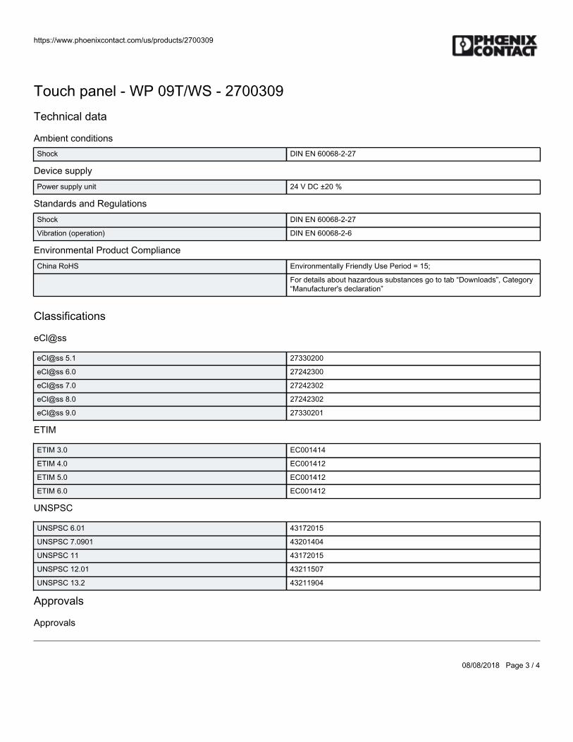
Standards and RegulationsShock DIN EN 60068-2-27
Vibration (operation) DIN EN 60068-2-6
Environmental Product ComplianceChina RoHS Environmentally Friendly Use Period = 15;
For details about hazardous substances go to tab “Downloads”, Category“Manufacturer's declaration”
Classifications
eCl@ss
eCl@ss 5.1 27330200
eCl@ss 6.0 27242300
eCl@ss 7.0 27242302
eCl@ss 8.0 27242302
eCl@ss 9.0 27330201
ETIM
ETIM 3.0 EC001414
ETIM 4.0 EC001412
ETIM 5.0 EC001412
ETIM 6.0 EC001412
UNSPSC
UNSPSC 6.01 43172015
UNSPSC 7.0901 43201404
UNSPSC 11 43172015
UNSPSC 12.01 43211507
UNSPSC 13.2 43211904
Approvals
Approvals
https://www.phoenixcontact.com/us/products/2700309
08/08/2018 Page 4 / 4
Touch panel - WP 09T/WS - 2700309Approvals
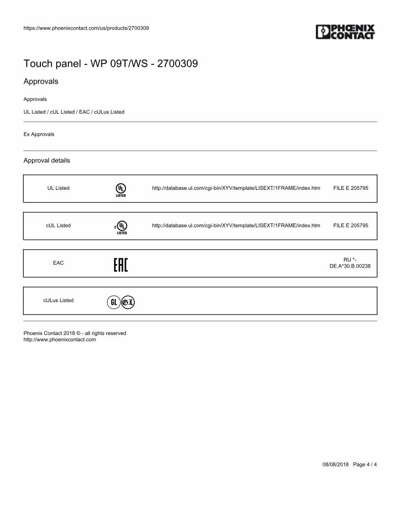
Approvals
UL Listed / cUL Listed / EAC / cULus Listed
Ex Approvals
Approval details
UL Listed http://database.ul.com/cgi-bin/XYV/template/LISEXT/1FRAME/index.htm FILE E 205795
cUL Listed http://database.ul.com/cgi-bin/XYV/template/LISEXT/1FRAME/index.htm FILE E 205795
EAC RU *-DE.A*30.B.00238
cULus Listed
Phoenix Contact 2018 © - all rights reservedhttp://www.phoenixcontact.com

BWS-GL-02 Appendix5
5. PhoenixContactInlineController:ILC151ETH

https://www.phoenixcontact.com/us/products/2700974
06/15/2016 Page 1 / 5
Controller - ILC 151 ETH - 2700974Please be informed that the data shown in this PDF Document is generated from our Online Catalog. Please find the complete data in the user'sdocumentation. Our General Terms of Use for Downloads are valid(http://phoenixcontact.com/download)
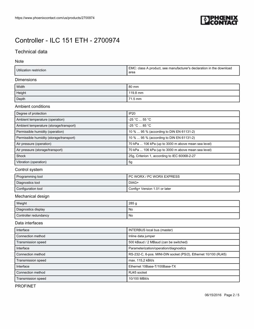
The Inline controller offers the option of communicating via PROFINET and Modbus/TCP. Programming is carriedout using PC Worx Express or PC Worx (IEC 61131-3).
Product DescriptionThe ILC 151 ETH modular small-scale controller for the Inline I/O system is at the heart of Easy Automation. The ILC 1X1 series is characterized by itssupport for the Modbus/TCP and PROFINET Ethernet-based protocols. A new feature is the support for an optional SD card.
Product Features PROFINET-Device
Modbus/TCP-Client
Numerous protocols supported such as: http, https, FTP, SNTP, SNMP, SMTP, SQL, MySQL, DCP, etc.
Free engineering with PC Worx Express (IEC 61131-3)
Program memory and mass storage (256 kB/256 kB)
Modbus/TCP server
HTML 5
Integrated web server for visualization with WebVisit/atvise®
Complete INTERBUS master (4096 I/O points)
SD card up to 2 GB as optional plug-in parameterization memory
Key Commercial DataPacking unit 1 pc
Weight per Piece (excluding packing) 360.0 g
Country of origin Germany
Technical data
Note
https://www.phoenixcontact.com/us/products/2700974
06/15/2016 Page 2 / 5
Controller - ILC 151 ETH - 2700974Technical data
Note
Utilization restriction EMC: class A product, see manufacturer's declaration in the downloadarea
DimensionsWidth 80 mm
Height 119.8 mm
Depth 71.5 mm
Ambient conditionsDegree of protection IP20
Ambient temperature (operation) -25 °C ... 55 °C
Ambient temperature (storage/transport) -25 °C ... 85 °C
Permissible humidity (operation) 10 % ... 95 % (according to DIN EN 61131-2)
Permissible humidity (storage/transport) 10 % ... 95 % (according to DIN EN 61131-2)
Air pressure (operation) 70 kPa ... 106 kPa (up to 3000 m above mean sea level)
Air pressure (storage/transport) 70 kPa ... 106 kPa (up to 3000 m above mean sea level)
Shock 25g, Criterion 1, according to IEC 60068-2-27
Vibration (operation) 5g
Control systemProgramming tool PC WORX / PC WORX EXPRESS
Diagnostics tool DIAG+
Configuration tool Config+ Version 1.01 or later
Mechanical designWeight 285 g
Diagnostics display No
Controller redundancy No
Data interfacesInterface INTERBUS local bus (master)
Connection method Inline data jumper
Transmission speed 500 kBaud / 2 MBaud (can be switched)
Interface Parameterization/operation/diagnostics
Connection method RS-232-C, 6-pos. MINI-DIN socket (PS/2), Ethernet 10/100 (RJ45)
Transmission speed max. 115,2 kBit/s
Interface Ethernet 10Base-T/100Base-TX
Connection method RJ45 socket
Transmission speed 10/100 MBit/s
PROFINET
https://www.phoenixcontact.com/us/products/2700974
06/15/2016 Page 3 / 5
Controller - ILC 151 ETH - 2700974Technical data
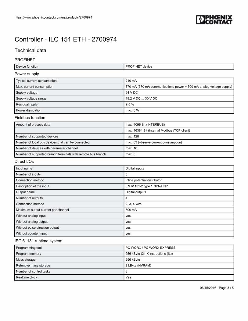
PROFINETDevice function PROFINET device
Power supplyTypical current consumption 210 mA
Max. current consumption 870 mA (370 mA communications power + 500 mA analog voltage supply)
Supply voltage 24 V DC
Supply voltage range 19.2 V DC ... 30 V DC
Residual ripple ± 5 %
Power dissipation max. 5 W
Fieldbus functionAmount of process data max. 4096 Bit (INTERBUS)
max. 16384 Bit (internal Modbus /TCP client)
Number of supported devices max. 128
Number of local bus devices that can be connected max. 63 (observe current consumption)
Number of devices with parameter channel max. 16
Number of supported branch terminals with remote bus branch max. 3
Direct I/OsInput name Digital inputs
Number of inputs 8
Connection method Inline potential distributor
Description of the input EN 61131-2 type 1 NPN/PNP
Output name Digital outputs
Number of outputs 4
Connection method 2, 3, 4-wire
Maximum output current per channel 500 mA
Without analog input yes
Without analog output yes
Without pulse direction output yes
Without counter input yes
IEC 61131 runtime systemProgramming tool PC WORX / PC WORX EXPRESS
Program memory 256 kByte (21 K instructions (IL))
Mass storage 256 kByte
Retentive mass storage 8 kByte (NVRAM)
Number of control tasks 8
Realtime clock Yes
https://www.phoenixcontact.com/us/products/2700974
06/15/2016 Page 4 / 5
Controller - ILC 151 ETH - 2700974Technical data
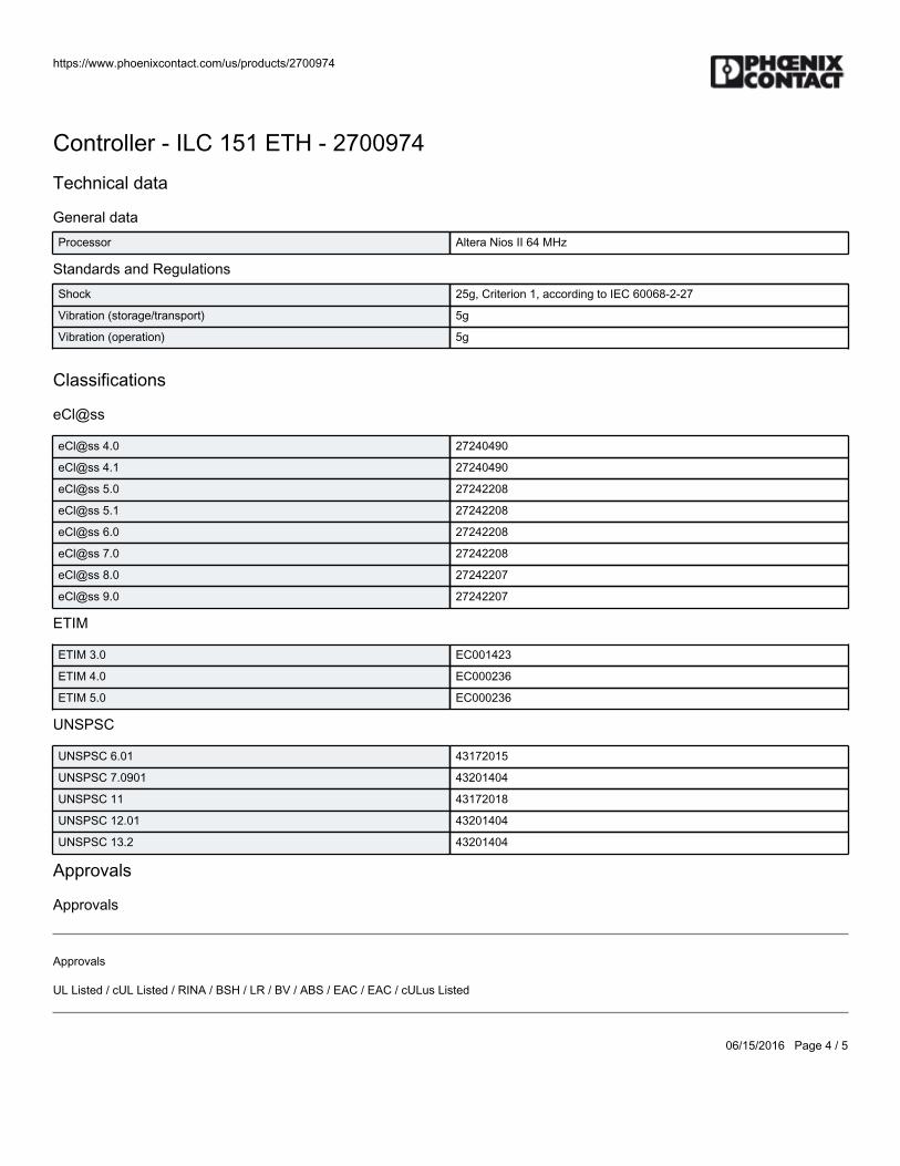
General dataProcessor Altera Nios II 64 MHz
Standards and RegulationsShock 25g, Criterion 1, according to IEC 60068-2-27
Vibration (storage/transport) 5g
Vibration (operation) 5g
Classifications
eCl@ss
eCl@ss 4.0 27240490
eCl@ss 4.1 27240490
eCl@ss 5.0 27242208
eCl@ss 5.1 27242208
eCl@ss 6.0 27242208
eCl@ss 7.0 27242208
eCl@ss 8.0 27242207
eCl@ss 9.0 27242207
ETIM
ETIM 3.0 EC001423
ETIM 4.0 EC000236
ETIM 5.0 EC000236
UNSPSC
UNSPSC 6.01 43172015
UNSPSC 7.0901 43201404
UNSPSC 11 43172018
UNSPSC 12.01 43201404
UNSPSC 13.2 43201404
Approvals
Approvals
Approvals
UL Listed / cUL Listed / RINA / BSH / LR / BV / ABS / EAC / EAC / cULus Listed
https://www.phoenixcontact.com/us/products/2700974
06/15/2016 Page 5 / 5
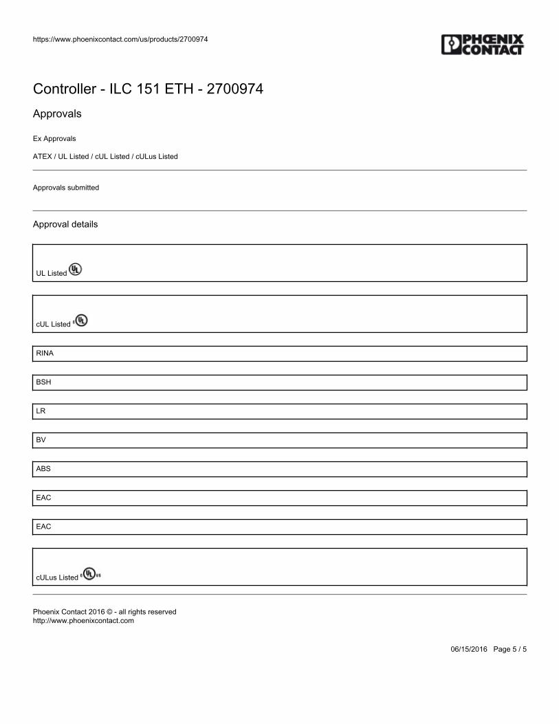
Controller - ILC 151 ETH - 2700974Approvals
Ex Approvals
ATEX / UL Listed / cUL Listed / cULus Listed
Approvals submitted
Approval details
UL Listed
cUL Listed
RINA
BSH
LR
BV
ABS
EAC
EAC
cULus Listed
Phoenix Contact 2016 © - all rights reservedhttp://www.phoenixcontact.com

BWS-GL-02 Appendix6
6. PhoenixContactProgram/ConfigurationMemory:SDFLASH2G
https://www.phoenixcontact.com/us/products/2988162
06/20/2014 Page 1 / 2
Memory - SD FLASH 2GB - 2988162Please be informed that the data shown in this PDF Document is generated from our Online Catalog. Please find the complete data in the user'sdocumentation. Our General Terms of Use for Downloads are valid(http://phoenixcontact.com/download)
Program and configuration memory
Similar figure
Product descriptionProgram and configuration memory to save the application programs and other files in the file system of the PLC. Alternatively, a program and configuration memory with integrated license is available to disconnect various function blocks.
Product Features
Program and configuration memory, plug-in, 2 Gbytes
For storing application programs and other files in the file system of the PLC
Key commercial dataPacking unit 1 pc
Weight per Piece (excluding packing) 9.2 GRM
Custom tariff number 85235110
Country of origin Taiwan
Technical data
Product type Parameterization memory
Classifications
eCl@ss
eCl@ss 4.0 27240403
eCl@ss 4.1 27240403
eCl@ss 5.0 27242212
eCl@ss 5.1 27242212
eCl@ss 6.0 19150702
eCl@ss 7.0 19150702
eCl@ss 8.0 19150702
https://www.phoenixcontact.com/us/products/2988162
06/20/2014 Page 2 / 2
Memory - SD FLASH 2GB - 2988162Classifications
ETIM
ETIM 3.0 EC000192
ETIM 4.0 EC000192
ETIM 5.0 EC000192
UNSPSC
UNSPSC 6.01 43172015
UNSPSC 7.0901 43201404
UNSPSC 11 39121311
UNSPSC 12.01 32101601
UNSPSC 13.2 32101601
Phoenix Contact 2014 © - all rights reservedhttp://www.phoenixcontact.com

BWS-GL-02 Appendix7
7. PhoenixContactInlineDigitalOutModule:IBIL24DO16-ME

https://www.phoenixcontact.com/us/products/2897253
06/13/2014 Page 1 / 4
Inline ME terminal - IB IL 24 DO 16-ME - 2897253Please be informed that the data shown in this PDF Document is generated from our Online Catalog. Please find the complete data in the user'sdocumentation. Our General Terms of Use for Downloads are valid(http://phoenixcontact.com/download)
Inline digital output terminal, Inline ME versions (machine edition) complete with accessories (connector andlabeling field), 16 outputs, 24 V DC, 500 mA, 2, 3-conductor connection method
Product Features
16 digital outputs
Connection of actuators in 2 and 3-wire technology
Nominal current per output: 500 mA
Total current of the terminal: 8 A
Short-circuit-proof and overload-protected outputs
Diagnostic and status indicators
Key commercial dataPacking unit 1 pc
Minimum order quantity 4 pc
Weight per Piece (excluding packing) 199.2 GRM
Custom tariff number 85389091
Country of origin Germany
Technical data
Note
Utilization restriction EMC: class A product, see manufacturer's declaration in the downloadarea
DimensionsWidth 48.8 mm
Height 119.8 mm
Depth 71.5 mm
Note on dimensions Housing dimensions

https://www.phoenixcontact.com/us/products/2897253
06/13/2014 Page 2 / 4
Inline ME terminal - IB IL 24 DO 16-ME - 2897253Technical data
Ambient conditionsAmbient temperature (operation) -25 °C ... 55 °C
Ambient temperature (storage/transport) -25 °C ... 85 °C
Permissible humidity (operation) 10 % ... 95 % (according to DIN EN 61131-2)
Permissible humidity (storage/transport) 10 % ... 95 % (according to DIN EN 61131-2)
Air pressure (operation) 70 kPa ... 106 kPa (up to 3000 m above sea level)
Air pressure (storage/transport) 70 kPa ... 106 kPa (up to 3000 m above sea level)
Degree of protection IP20
GeneralWeight 130 g
Note on weight specifications Without plug
Mounting type DIN rail
Protection class III, IEC 61140, EN 61140, VDE 0140-1
Test section 5 V supply, incoming remote bus/7.5 V supply (bus logics) 500 V AC 50 Hz1 min
5 V supply, outgoing remote bus/7.5 V supply (bus logics) 500 V AC 50 Hz1 min
7.5 V supply (bus logics)/24 V supply (I/O) 500 V AC 50 Hz 1 min
24 V supply (I/O) / functional earth ground 500 V AC 50 Hz 1 min
Diagnostics messages Short-circuit / overload of the digital outputs Error message in thediagnostic code (bus) and display (2 Hz) via the LED (D) on the module
InterfacesFieldbus system INTERBUS
Designation Inline local bus
Connection method Inline data jumper
Transmission speed 500 kBit/s
Transmission physics Copper
Power supply for module electronicsSupply voltage 24 V DC (nominal value)
Supply voltage range 19.2 V DC ... 30 V DC (including all tolerances, including ripple)
Supply current 90 mA
Communications power UL 7.5 V (via voltage jumper)
Current consumption max. 90 mA (from the local bus)
Power consumption max. 0.675 W
Inline potentialsCommunications power UL 7.5 V DC
Current consumption from UL max. 90 mA
https://www.phoenixcontact.com/us/products/2897253
06/13/2014 Page 3 / 4
Inline ME terminal - IB IL 24 DO 16-ME - 2897253Technical data
Inline potentialsSegment supply voltage US 24 V DC (nominal value)
Current consumption from US max. 8 A
Digital outputsOutput name Digital outputs
Connection method Spring-cage connection
2, 3-wire
Number of outputs 16
Protective circuit Overload protection, short-circuit protection of outputs
Output voltage 24 V DC (US - 1 V)
Nominal output voltage 24 V DC (voltage difference at Inom ≤ 1 V)
Maximum output current per channel 500 mA
Maximum output current per module 8 A
Nominal load, inductive 12 W
Nominal load, lamp 12 W
Nominal load, ohmic 12 VA
Classifications
eCl@ss
eCl@ss 4.0 27250302
eCl@ss 4.1 27250302
eCl@ss 5.0 27250302
eCl@ss 5.1 27242604
eCl@ss 6.0 27242604
eCl@ss 7.0 27242604
eCl@ss 8.0 27242604
ETIM
ETIM 2.0 EC001430
ETIM 3.0 EC001599
ETIM 4.0 EC001599
ETIM 5.0 EC001599
UNSPSC
UNSPSC 6.01 43172015
UNSPSC 7.0901 43201404
UNSPSC 11 43172015
https://www.phoenixcontact.com/us/products/2897253
06/13/2014 Page 4 / 4
Inline ME terminal - IB IL 24 DO 16-ME - 2897253Classifications
UNSPSCUNSPSC 12.01 43201404
UNSPSC 13.2 43201404
Phoenix Contact 2014 © - all rights reservedhttp://www.phoenixcontact.com

BWS-GL-02 Appendix8
8. PhoenixContactInlineDigitalInModule:IBIL24DI16-ME
https://www.phoenixcontact.com/us/products/2897156
06/13/2014 Page 1 / 3
Inline ME terminal - IB IL 24 DI 16-ME - 2897156Please be informed that the data shown in this PDF Document is generated from our Online Catalog. Please find the complete data in the user'sdocumentation. Our General Terms of Use for Downloads are valid(http://phoenixcontact.com/download)
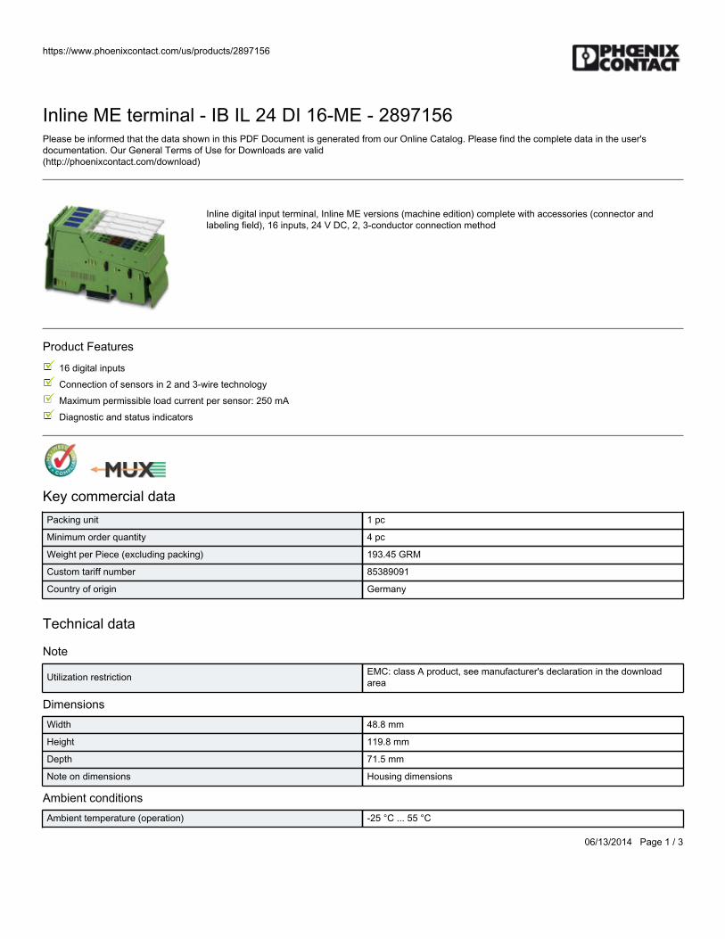
Inline digital input terminal, Inline ME versions (machine edition) complete with accessories (connector andlabeling field), 16 inputs, 24 V DC, 2, 3-conductor connection method
Product Features
16 digital inputs
Connection of sensors in 2 and 3-wire technology
Maximum permissible load current per sensor: 250 mA
Diagnostic and status indicators
Key commercial dataPacking unit 1 pc
Minimum order quantity 4 pc
Weight per Piece (excluding packing) 193.45 GRM
Custom tariff number 85389091
Country of origin Germany
Technical data
Note
Utilization restriction EMC: class A product, see manufacturer's declaration in the downloadarea
DimensionsWidth 48.8 mm
Height 119.8 mm
Depth 71.5 mm
Note on dimensions Housing dimensions
Ambient conditionsAmbient temperature (operation) -25 °C ... 55 °C
https://www.phoenixcontact.com/us/products/2897156
06/13/2014 Page 2 / 3
Inline ME terminal - IB IL 24 DI 16-ME - 2897156Technical data
Ambient conditionsAmbient temperature (storage/transport) -25 °C ... 85 °C
Permissible humidity (operation) 10 % ... 95 % (according to DIN EN 61131-2)
Permissible humidity (storage/transport) 10 % ... 95 % (according to DIN EN 61131-2)
Air pressure (operation) 70 kPa ... 106 kPa (up to 3000 m above sea level)
Air pressure (storage/transport) 70 kPa ... 106 kPa (up to 3000 m above sea level)
Degree of protection IP20
GeneralWeight 122 g
Note on weight specifications Without plug
Mounting type DIN rail
Protection class III, IEC 61140, EN 61140, VDE 0140-1
Test section 5 V supply, incoming remote bus/7.5 V supply (bus logics) 500 V AC 50 Hz1 min
5 V supply, outgoing remote bus/7.5 V supply (bus logics) 500 V AC 50 Hz1 min
7.5 V supply (bus logics)/24 V supply (I/O) 500 V AC 50 Hz 1 min
24 V supply (I/O) / functional earth ground 500 V AC 50 Hz 1 min
InterfacesFieldbus system Lokalbus
Designation Inline local bus
Connection method Inline data jumper
Transmission speed 500 kBit/s (automatic recognition)
Power supply for module electronicsSupply voltage 24 V DC (via voltage jumper)
Supply voltage range 19.2 V DC ... 30 V DC (including all tolerances, including ripple)
Communications power UL 7.5 V (via voltage jumper)
Current consumption max. 60 mA (from the local bus)
Inline potentialsCommunications power UL 7.5 V DC
Current consumption from UL max. 60 mA
Main circuit supply UM 24 V DC
Current consumption from UM max. 8 A DC
Segment supply voltage US 24 V DC (nominal value)
Current consumption from US max. 4 A
Digital inputs
https://www.phoenixcontact.com/us/products/2897156
06/13/2014 Page 3 / 3
Inline ME terminal - IB IL 24 DI 16-ME - 2897156Technical data
Digital inputsInput name Digital inputs
Connection method Spring-cage connection
2, 3-wire
Number of inputs 16 (EN 61131-2 type 1)
Typical response time < 1 ms
Protective circuit Short-circuit and overload protection
Input voltage 24 V DC (via voltage jumper)
Input voltage range "0" signal -3 V DC ... 5 V
Input voltage range "1" signal 15 V DC ... 30 V DC
Classifications
eCl@ss
eCl@ss 4.0 27250302
eCl@ss 4.1 27250302
eCl@ss 5.0 27250302
eCl@ss 5.1 27242604
eCl@ss 6.0 27242604
eCl@ss 7.0 27242604
eCl@ss 8.0 27242604
ETIM
ETIM 2.0 EC001430
ETIM 3.0 EC001599
ETIM 4.0 EC001599
ETIM 5.0 EC001599
UNSPSC
UNSPSC 6.01 43172015
UNSPSC 7.0901 43201404
UNSPSC 11 43172015
UNSPSC 12.01 43201404
UNSPSC 13.2 43201404
Phoenix Contact 2014 © - all rights reservedhttp://www.phoenixcontact.com

BWS-GL-02 Appendix9
9. PhoenixContactInlineDigitalInNPNModule–IBILDI2-NPN-PAC
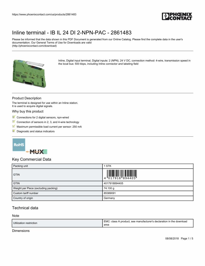
https://www.phoenixcontact.com/us/products/2861483
08/08/2018 Page 1 / 5
Inline terminal - IB IL 24 DI 2-NPN-PAC - 2861483Please be informed that the data shown in this PDF Document is generated from our Online Catalog. Please find the complete data in the user'sdocumentation. Our General Terms of Use for Downloads are valid(http://phoenixcontact.com/download)
Inline, Digital input terminal, Digital inputs: 2 (NPN), 24 V DC, connection method: 4-wire, transmission speed inthe local bus: 500 kbps, including Inline connector and labeling field
Product DescriptionThe terminal is designed for use within an Inline station. It is used to acquire digital signals.
Why buy this product
Connections for 2 digital sensors, npn-wired
Connection of sensors in 2, 3, and 4-wire technology
Maximum permissible load current per sensor: 250 mA
Diagnostic and status indicators
Key Commercial DataPacking unit 1 STK
GTIN
GTIN 4017918894405
Weight per Piece (excluding packing) 74.100 g
Custom tariff number 85389091
Country of origin Germany
Technical data
Note
Utilization restriction EMC: class A product, see manufacturer's declaration in the downloadarea
Dimensions
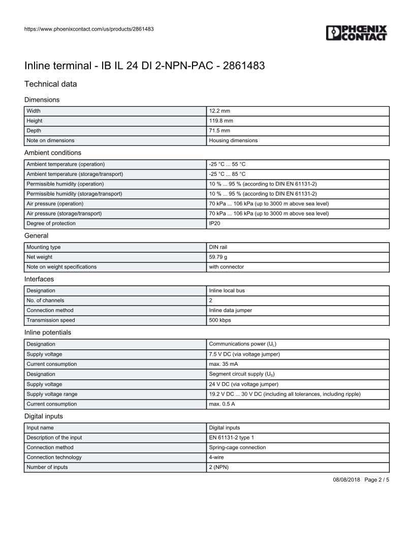
https://www.phoenixcontact.com/us/products/2861483
08/08/2018 Page 2 / 5
Inline terminal - IB IL 24 DI 2-NPN-PAC - 2861483Technical data
DimensionsWidth 12.2 mm
Height 119.8 mm
Depth 71.5 mm
Note on dimensions Housing dimensions
Ambient conditionsAmbient temperature (operation) -25 °C ... 55 °C
Ambient temperature (storage/transport) -25 °C ... 85 °C
Permissible humidity (operation) 10 % ... 95 % (according to DIN EN 61131-2)
Permissible humidity (storage/transport) 10 % ... 95 % (according to DIN EN 61131-2)
Air pressure (operation) 70 kPa ... 106 kPa (up to 3000 m above sea level)
Air pressure (storage/transport) 70 kPa ... 106 kPa (up to 3000 m above sea level)
Degree of protection IP20
GeneralMounting type DIN rail
Net weight 59.79 g
Note on weight specifications with connector
InterfacesDesignation Inline local bus
No. of channels 2
Connection method Inline data jumper
Transmission speed 500 kbps
Inline potentialsDesignation Communications power (UL)
Supply voltage 7.5 V DC (via voltage jumper)
Current consumption max. 35 mA
Designation Segment circuit supply (US)
Supply voltage 24 V DC (via voltage jumper)
Supply voltage range 19.2 V DC ... 30 V DC (including all tolerances, including ripple)
Current consumption max. 0.5 A
Digital inputsInput name Digital inputs
Description of the input EN 61131-2 type 1
Connection method Spring-cage connection
Connection technology 4-wire
Number of inputs 2 (NPN)
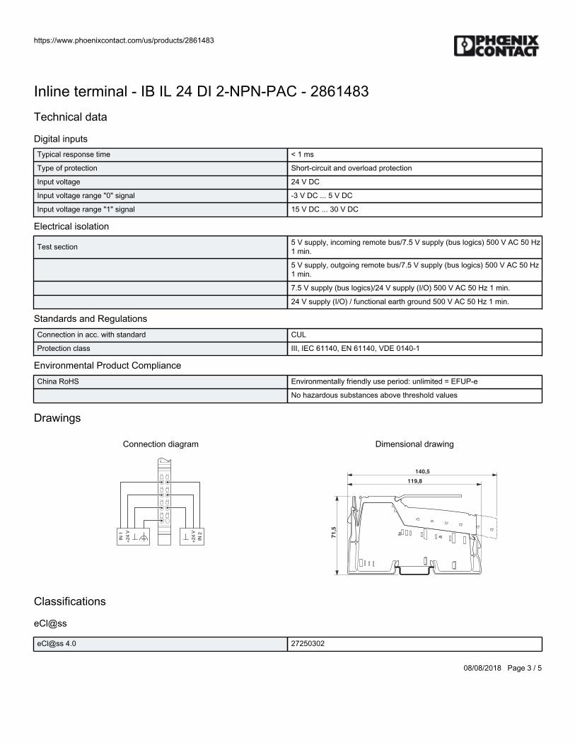
https://www.phoenixcontact.com/us/products/2861483
08/08/2018 Page 3 / 5
Inline terminal - IB IL 24 DI 2-NPN-PAC - 2861483Technical data
Digital inputsTypical response time < 1 ms
Type of protection Short-circuit and overload protection
Input voltage 24 V DC
Input voltage range "0" signal -3 V DC ... 5 V DC
Input voltage range "1" signal 15 V DC ... 30 V DC
Electrical isolation
Test section 5 V supply, incoming remote bus/7.5 V supply (bus logics) 500 V AC 50 Hz1 min.
5 V supply, outgoing remote bus/7.5 V supply (bus logics) 500 V AC 50 Hz1 min.
7.5 V supply (bus logics)/24 V supply (I/O) 500 V AC 50 Hz 1 min.
24 V supply (I/O) / functional earth ground 500 V AC 50 Hz 1 min.
Standards and RegulationsConnection in acc. with standard CUL
Protection class III, IEC 61140, EN 61140, VDE 0140-1
Environmental Product ComplianceChina RoHS Environmentally friendly use period: unlimited = EFUP-e
No hazardous substances above threshold values
Drawings
Connection diagram
1.1
1.2
1.3
1.4
2.1
2.2
2.3
2.4
IN2
+2
4V
IN1
+2
4V
Dimensional drawing
140,5
119,8
71
,5
Classifications
eCl@ss
eCl@ss 4.0 27250302
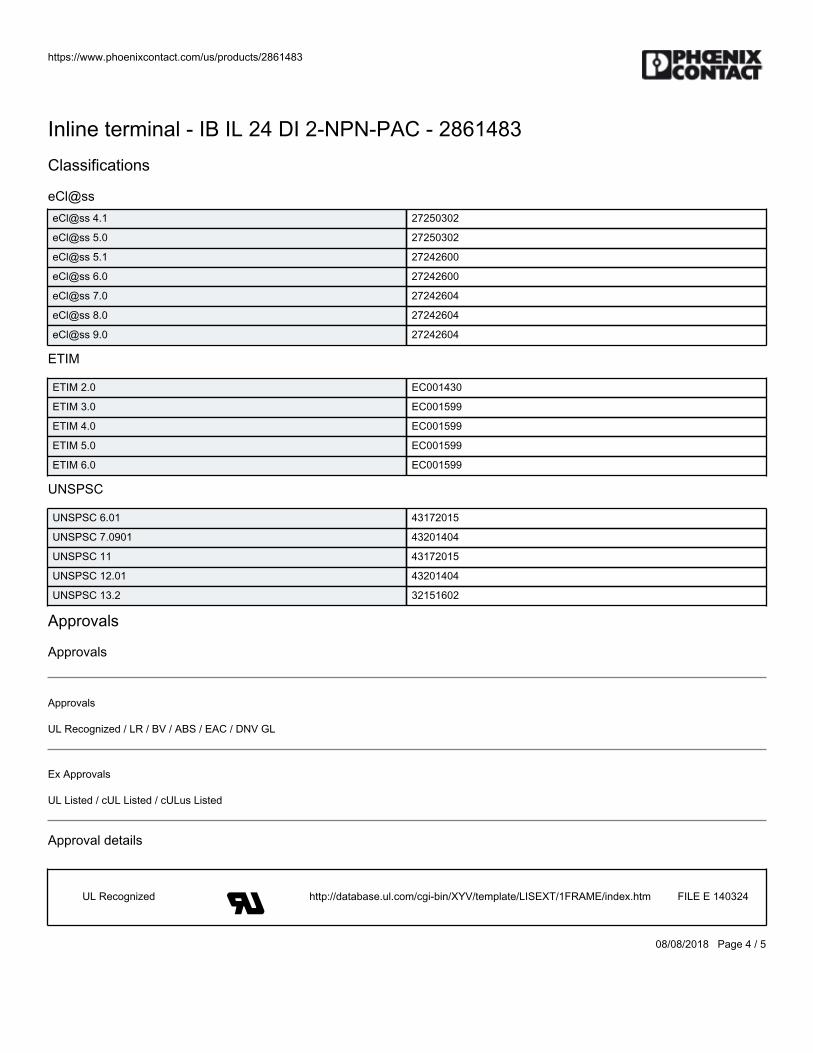
https://www.phoenixcontact.com/us/products/2861483
08/08/2018 Page 4 / 5
Inline terminal - IB IL 24 DI 2-NPN-PAC - 2861483Classifications
eCl@sseCl@ss 4.1 27250302
eCl@ss 5.0 27250302
eCl@ss 5.1 27242600
eCl@ss 6.0 27242600
eCl@ss 7.0 27242604
eCl@ss 8.0 27242604
eCl@ss 9.0 27242604
ETIM
ETIM 2.0 EC001430
ETIM 3.0 EC001599
ETIM 4.0 EC001599
ETIM 5.0 EC001599
ETIM 6.0 EC001599
UNSPSC
UNSPSC 6.01 43172015
UNSPSC 7.0901 43201404
UNSPSC 11 43172015
UNSPSC 12.01 43201404
UNSPSC 13.2 32151602
Approvals
Approvals
Approvals
UL Recognized / LR / BV / ABS / EAC / DNV GL
Ex Approvals
UL Listed / cUL Listed / cULus Listed
Approval details
UL Recognized http://database.ul.com/cgi-bin/XYV/template/LISEXT/1FRAME/index.htm FILE E 140324
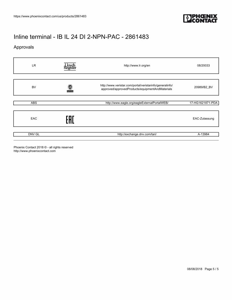
https://www.phoenixcontact.com/us/products/2861483
08/08/2018 Page 5 / 5
Inline terminal - IB IL 24 DI 2-NPN-PAC - 2861483Approvals
LR http://www.lr.org/en 08/20033
BV http://www.veristar.com/portal/veristarinfo/generalinfo/approved/approvedProducts/equipmentAndMaterials 20989/B2_BV
ABS http://www.eagle.org/eagleExternalPortalWEB/ 17-HG1621871-PDA
EAC EAC-Zulassung
DNV GL http://exchange.dnv.com/tari/ A-13984
Phoenix Contact 2018 © - all rights reservedhttp://www.phoenixcontact.com

BWS-GL-02 Appendix10
10. PhoenixContactInlineAnalogInModule:IBILAI4/I-PAC
https://www.phoenixcontact.com/us/products/2700458
06/13/2014 Page 1 / 5
Inline terminal - IB IL AI 4/I-PAC - 2700458Please be informed that the data shown in this PDF Document is generated from our Online Catalog. Please find the complete data in the user'sdocumentation. Our General Terms of Use for Downloads are valid(http://phoenixcontact.com/download)
Inline analog input terminal, complete with accessories (connector and labeling field), inputs: 0-20 mA, 4-20 mA,2-wire connection method
Product Features
Excellent interference suppression and common mode rejection
High measuring accuracy
Overload-protected current inputs
Integrated short-circuit-proof sensor supply
Key commercial dataPacking unit 1 pc
Weight per Piece (excluding packing) 95.0 GRM
Custom tariff number 85389091
Country of origin Germany
Technical data
Note
Utilization restriction EMC: class A product, see manufacturer's declaration in the downloadarea
DimensionsWidth 12.2 mm
Height 119.8 mm
Depth 71.5 mm
Note on dimensions Housing dimensions
Ambient conditionsAmbient temperature (operation) -25 °C ... 55 °C
Ambient temperature (storage/transport) -25 °C ... 85 °C
https://www.phoenixcontact.com/us/products/2700458
06/13/2014 Page 2 / 5
Inline terminal - IB IL AI 4/I-PAC - 2700458Technical data
Ambient conditionsPermissible humidity (operation) 10 % ... 95 % (according to DIN EN 61131-2)
Permissible humidity (storage/transport) 10 % ... 95 % (according to DIN EN 61131-2)
Air pressure (operation) 70 kPa ... 106 kPa (up to 3000 m above sea level)
Air pressure (storage/transport) 70 kPa ... 106 kPa (up to 3000 m above sea level)
Degree of protection IP20
GeneralWeight 66 g
Note on weight specifications with connector
Mounting type DIN rail
Protection class III, IEC 61140, EN 61140, VDE 0140-1
Test section 5 V supply, incoming remote bus/7.5 V supply (bus logics) 500 V AC 50 Hz1 min
5 V supply, outgoing remote bus/7.5 V supply (bus logics) 500 V AC 50 Hz1 min
7.5 V supply (bus logic), 24 V supply UANA / I/O 500 V AC 50 Hz 1 min
7.5 V supply (bus logic), 24 V supply UANA/functional earth ground 500 VAC 50 Hz 1 min
I/O / functional earth ground 500 V AC 50 Hz 1 min
Conformance with EMC directivesNoise immunity test in accordance with EN 61000-6-2 Electrostaticdischarge (ESD) EN 61000‑4‑2/IEC 61000‑4‑2 Criterion B; 6 kV contactdischarge, 8 kV air discharge
Noise immunity test in accordance with EN 61000-6-2 Electromagneticfields EN 61000‑4‑3/IEC 61000‑4‑3 Criterion A; Field intensity: 10 V/m
Noise immunity test in accordance with EN 61000-6-2 Fast transients(burst) EN 61000‑4‑4/IEC 61000‑4‑4 Criterion B, 2 kV
Noise immunity test in accordance with EN 61000-6-2 Transient surgevoltage (surge) EN 61000‑4‑5/IEC 61000‑4‑5 Criterion B; supply lines DC:±1 kV/±1 kV (symmetrical/asymmetrical); shielded I/O cables: ±1 kV
Noise immunity test in accordance with EN 61000-6-2 Conductedinterference EN 61000‑4‑6/IEC 61000‑4‑6 Criterion A; Test voltage 10 V
Noise emission test according to EN 61000-6-3 Radio interferenceproperties EN 55022 Class A
Diagnostics messages Failure of the internal I/O supply I/O error message sent to the bus coupler
I/O supply failure Message in the diagnostic code (in the IB IL format)
Overrange or underrange Message in the diagnostic code (in the IB ILformat)
Configuration invalid Message in the diagnostic code (in the IB IL format)
InterfacesFieldbus system Lokalbus
Designation Inline local bus
https://www.phoenixcontact.com/us/products/2700458
06/13/2014 Page 3 / 5
Inline terminal - IB IL AI 4/I-PAC - 2700458Technical data
InterfacesConnection method Inline data jumper
Transmission speed 500 kBit/s
Transmission physics Copper
Power supply for module electronicsCommunications power UL 7.5 V (via voltage jumper)
Inline potentialsCommunications power UL 7.5 V DC (via voltage jumper)
Current consumption from UL typ. 55 mA
I/O supply voltage UANA 24 V DC
Current consumption from UANA typ. 30 mA
Power consumption typ. 0.94 W (total)
Analog inputsNumber of inputs 4 (differential inputs, current)
Connection method 2-wire
Input name Analog inputs
A/D conversion time max. 6.5 µs
Resolution A/D 12 bit
Data formats IB IL, S7-compatible
Measured value resolution 13 bits (12 bits + sign bit)
Measured value representation 13 bits (12 bits + sign bit)
Current input signal 0 mA ... 20 mA
4 mA ... 20 mA
Filtering None or mean-value generation over 4, 16, or 32 measured values
Number of inputs 4 (differential inputs, current)
Open circuit response Going to 0 mA; open-circuit detection from 4 mA ... 20 mA
Classifications
eCl@ss
eCl@ss 4.0 27250303
eCl@ss 4.1 27250303
eCl@ss 5.0 27250303
eCl@ss 5.1 27242601
eCl@ss 6.0 27242601
eCl@ss 7.0 27242601
eCl@ss 8.0 27242601
https://www.phoenixcontact.com/us/products/2700458
06/13/2014 Page 4 / 5
Inline terminal - IB IL AI 4/I-PAC - 2700458Classifications
ETIM
ETIM 3.0 EC001596
ETIM 4.0 EC001596
ETIM 5.0 EC001596
UNSPSC
UNSPSC 6.01 43172015
UNSPSC 7.0901 43201404
UNSPSC 11 43172015
UNSPSC 12.01 43201404
UNSPSC 13.2 43201404
Approvals
Approvals
Approvals
UL Listed / cUL Listed / cULus Listed
Ex Approvals
Approvals submitted
Approval details
UL Listed
cUL Listed
cULus Listed
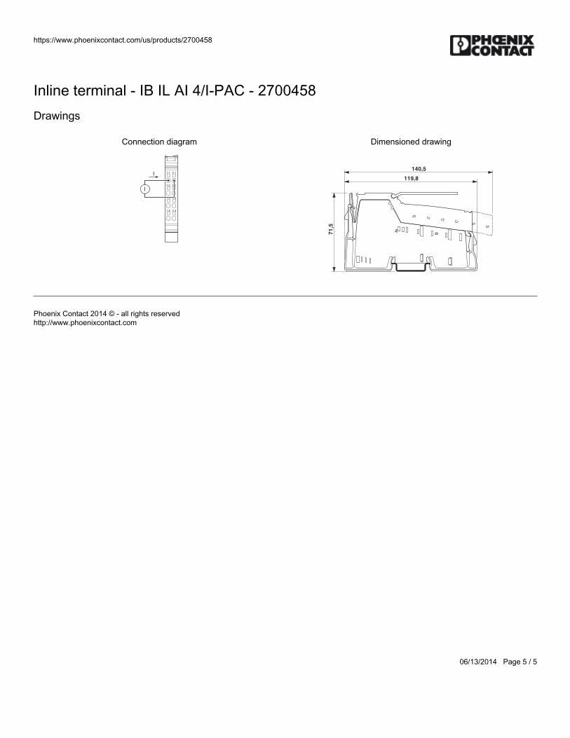
https://www.phoenixcontact.com/us/products/2700458
06/13/2014 Page 5 / 5
Inline terminal - IB IL AI 4/I-PAC - 2700458Drawings
Connection diagram
1.1 2.1
1.2 2.2
1.3 2.3
1.4 2.4
I
I
Dimensioned drawing
140,5
119,8
71
,5
Phoenix Contact 2014 © - all rights reservedhttp://www.phoenixcontact.com

BWS-GL-02 Appendix11
11. PhoenixContactInlineAnalogOutModule–IBILAO2/UI-PAC
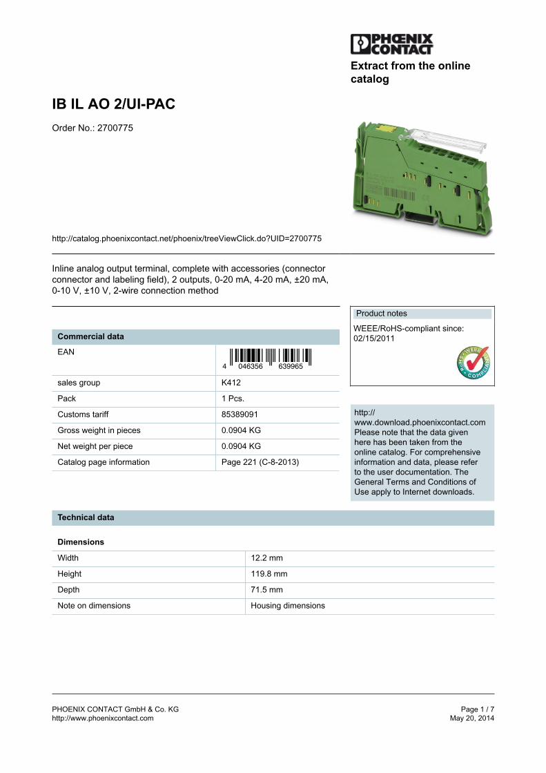
PHOENIX CONTACT GmbH & Co. KG Page 1 / 7http://www.phoenixcontact.com May 20, 2014
Extract from the onlinecatalog
IB IL AO 2/UI-PACOrder No.: 2700775
http://catalog.phoenixcontact.net/phoenix/treeViewClick.do?UID=2700775
Inline analog output terminal, complete with accessories (connectorconnector and labeling field), 2 outputs, 0-20 mA, 4-20 mA, ±20 mA,0-10 V, ±10 V, 2-wire connection method
Commercial data
EAN
4 046356 639965
sales group K412
Pack 1 Pcs.
Customs tariff 85389091
Gross weight in pieces 0.0904 KG
Net weight per piece 0.0904 KG
Catalog page information Page 221 (C-8-2013)
Product notes
WEEE/RoHS-compliant since:02/15/2011
http://www.download.phoenixcontact.comPlease note that the data givenhere has been taken from theonline catalog. For comprehensiveinformation and data, please referto the user documentation. TheGeneral Terms and Conditions ofUse apply to Internet downloads.
Technical data
Dimensions
Width 12.2 mm
Height 119.8 mm
Depth 71.5 mm
Note on dimensions Housing dimensions
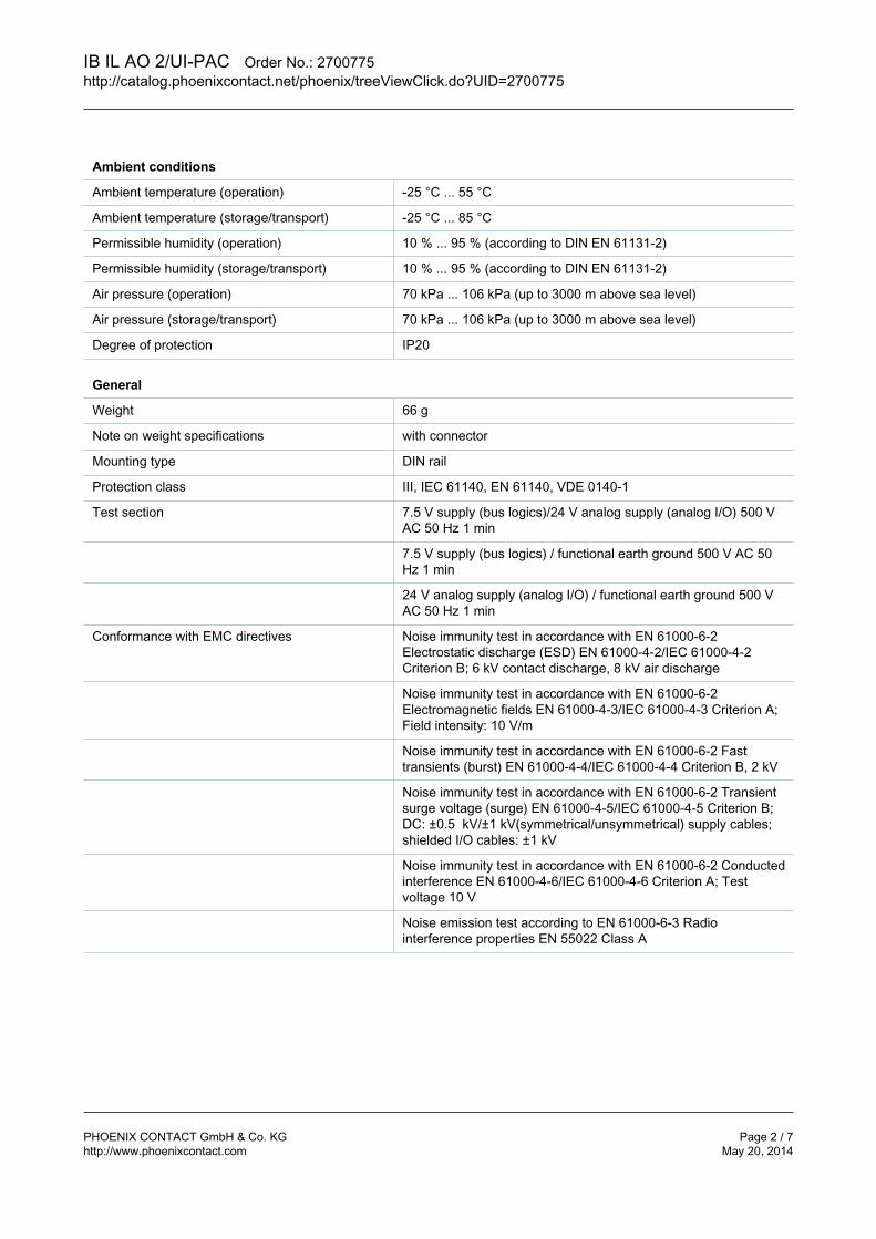
IB IL AO 2/UI-PAC Order No.: 2700775http://catalog.phoenixcontact.net/phoenix/treeViewClick.do?UID=2700775
PHOENIX CONTACT GmbH & Co. KG Page 2 / 7http://www.phoenixcontact.com May 20, 2014
Ambient conditions
Ambient temperature (operation) -25 °C ... 55 °C
Ambient temperature (storage/transport) -25 °C ... 85 °C
Permissible humidity (operation) 10 % ... 95 % (according to DIN EN 61131-2)
Permissible humidity (storage/transport) 10 % ... 95 % (according to DIN EN 61131-2)
Air pressure (operation) 70 kPa ... 106 kPa (up to 3000 m above sea level)
Air pressure (storage/transport) 70 kPa ... 106 kPa (up to 3000 m above sea level)
Degree of protection IP20
General
Weight 66 g
Note on weight specifications with connector
Mounting type DIN rail
Protection class III, IEC 61140, EN 61140, VDE 0140-1
Test section 7.5 V supply (bus logics)/24 V analog supply (analog I/O) 500 VAC 50 Hz 1 min
7.5 V supply (bus logics) / functional earth ground 500 V AC 50Hz 1 min
24 V analog supply (analog I/O) / functional earth ground 500 VAC 50 Hz 1 min
Conformance with EMC directives Noise immunity test in accordance with EN 61000-6-2Electrostatic discharge (ESD) EN 61000‑4‑2/IEC 61000‑4‑2Criterion B; 6 kV contact discharge, 8 kV air discharge
Noise immunity test in accordance with EN 61000-6-2Electromagnetic fields EN 61000‑4‑3/IEC 61000‑4‑3 Criterion A;Field intensity: 10 V/m
Noise immunity test in accordance with EN 61000-6-2 Fasttransients (burst) EN 61000‑4‑4/IEC 61000‑4‑4 Criterion B, 2 kV
Noise immunity test in accordance with EN 61000-6-2 Transientsurge voltage (surge) EN 61000‑4‑5/IEC 61000‑4‑5 Criterion B;DC: ±0.5 kV/±1 kV(symmetrical/unsymmetrical) supply cables;shielded I/O cables: ±1 kV
Noise immunity test in accordance with EN 61000-6-2 Conductedinterference EN 61000‑4‑6/IEC 61000‑4‑6 Criterion A; Testvoltage 10 V
Noise emission test according to EN 61000-6-3 Radiointerference properties EN 55022 Class A
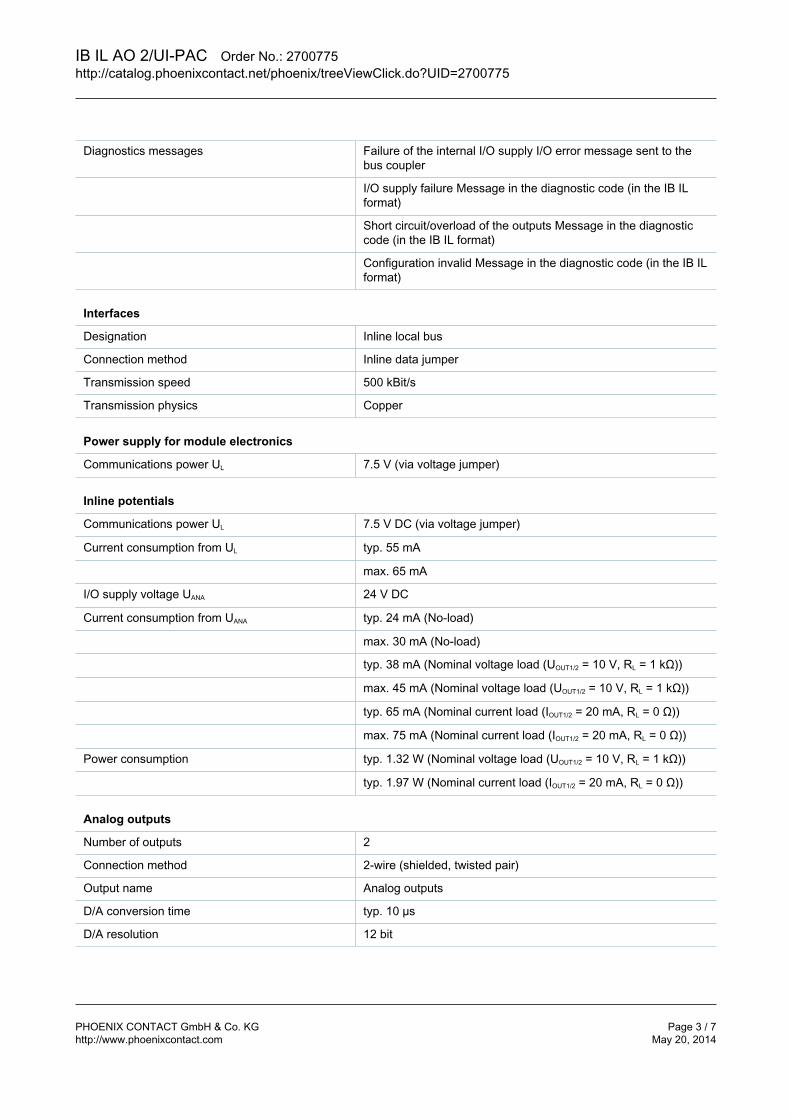
IB IL AO 2/UI-PAC Order No.: 2700775http://catalog.phoenixcontact.net/phoenix/treeViewClick.do?UID=2700775
PHOENIX CONTACT GmbH & Co. KG Page 3 / 7http://www.phoenixcontact.com May 20, 2014
Diagnostics messages Failure of the internal I/O supply I/O error message sent to thebus coupler
I/O supply failure Message in the diagnostic code (in the IB ILformat)
Short circuit/overload of the outputs Message in the diagnosticcode (in the IB IL format)
Configuration invalid Message in the diagnostic code (in the IB ILformat)
Interfaces
Designation Inline local bus
Connection method Inline data jumper
Transmission speed 500 kBit/s
Transmission physics Copper
Power supply for module electronics
Communications power UL 7.5 V (via voltage jumper)
Inline potentials
Communications power UL 7.5 V DC (via voltage jumper)
Current consumption from UL typ. 55 mA
max. 65 mA
I/O supply voltage UANA 24 V DC
Current consumption from UANA typ. 24 mA (No-load)
max. 30 mA (No-load)
typ. 38 mA (Nominal voltage load (UOUT1/2 = 10 V, RL = 1 kΩ))
max. 45 mA (Nominal voltage load (UOUT1/2 = 10 V, RL = 1 kΩ))
typ. 65 mA (Nominal current load (IOUT1/2 = 20 mA, RL = 0 Ω))
max. 75 mA (Nominal current load (IOUT1/2 = 20 mA, RL = 0 Ω))
Power consumption typ. 1.32 W (Nominal voltage load (UOUT1/2 = 10 V, RL = 1 kΩ))
typ. 1.97 W (Nominal current load (IOUT1/2 = 20 mA, RL = 0 Ω))
Analog outputs
Number of outputs 2
Connection method 2-wire (shielded, twisted pair)
Output name Analog outputs
D/A conversion time typ. 10 µs
D/A resolution 12 bit
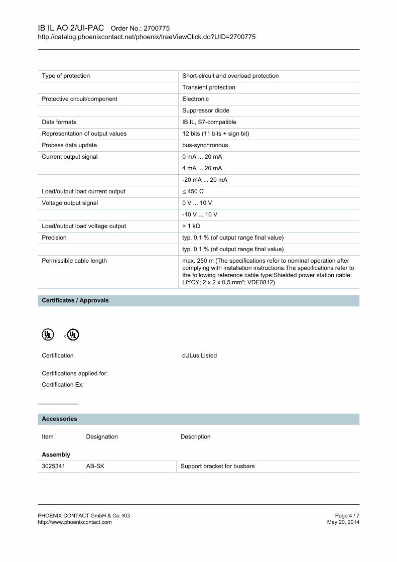
IB IL AO 2/UI-PAC Order No.: 2700775http://catalog.phoenixcontact.net/phoenix/treeViewClick.do?UID=2700775
PHOENIX CONTACT GmbH & Co. KG Page 4 / 7http://www.phoenixcontact.com May 20, 2014
Type of protection Short-circuit and overload protection
Transient protection
Protective circuit/component Electronic
Suppressor diode
Data formats IB IL, S7-compatible
Representation of output values 12 bits (11 bits + sign bit)
Process data update bus-synchronous
Current output signal 0 mA ... 20 mA
4 mA ... 20 mA
-20 mA ... 20 mA
Load/output load current output ≤ 450 Ω
Voltage output signal 0 V ... 10 V
-10 V ... 10 V
Load/output load voltage output > 1 kΩ
Precision typ. 0.1 % (of output range final value)
typ. 0.1 % (of output range final value)
Permissible cable length max. 250 m (The specifications refer to nominal operation aftercomplying with installation instructions.The specifications refer tothe following reference cable type:Shielded power station cable:LiYCY; 2 x 2 x 0,5 mm²; VDE0812)
Certificates / Approvals
Certification cULus Listed
Certifications applied for:
Certification Ex:
Accessories
Item Designation Description
Assembly
3025341 AB-SK Support bracket for busbars
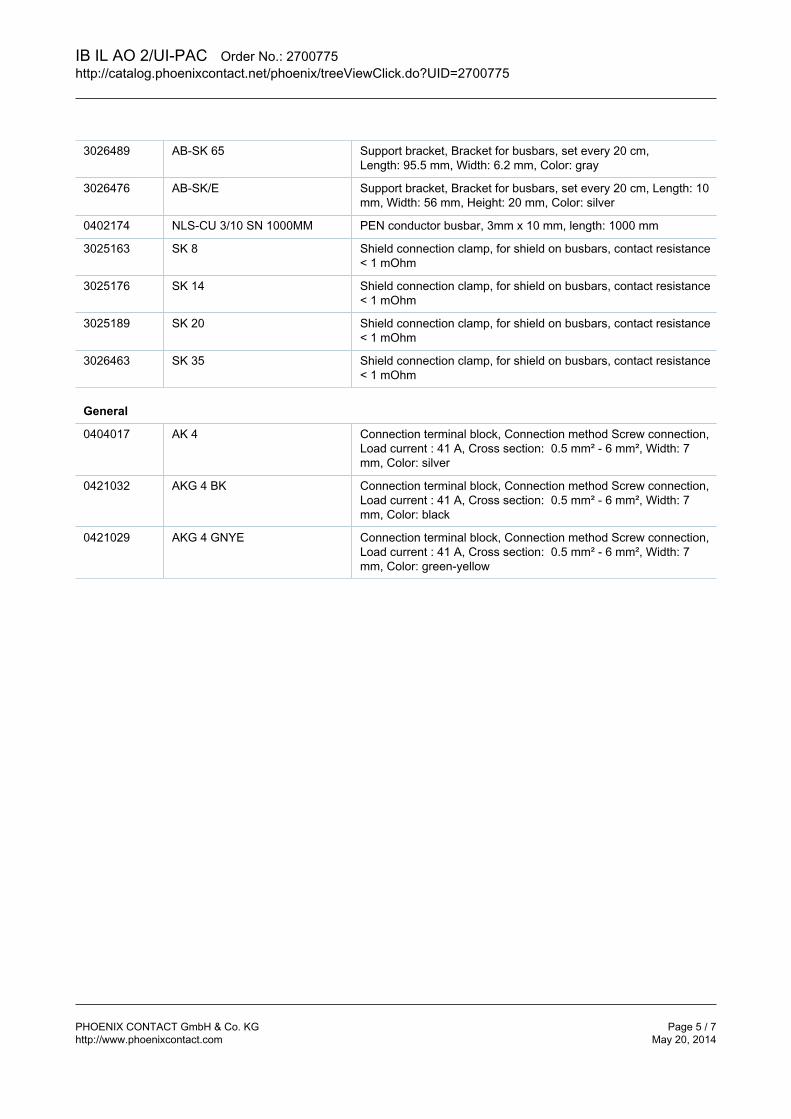
IB IL AO 2/UI-PAC Order No.: 2700775http://catalog.phoenixcontact.net/phoenix/treeViewClick.do?UID=2700775
PHOENIX CONTACT GmbH & Co. KG Page 5 / 7http://www.phoenixcontact.com May 20, 2014
3026489 AB-SK 65 Support bracket, Bracket for busbars, set every 20 cm,Length: 95.5 mm, Width: 6.2 mm, Color: gray
3026476 AB-SK/E Support bracket, Bracket for busbars, set every 20 cm, Length: 10mm, Width: 56 mm, Height: 20 mm, Color: silver
0402174 NLS-CU 3/10 SN 1000MM PEN conductor busbar, 3mm x 10 mm, length: 1000 mm
3025163 SK 8 Shield connection clamp, for shield on busbars, contact resistance< 1 mOhm
3025176 SK 14 Shield connection clamp, for shield on busbars, contact resistance< 1 mOhm
3025189 SK 20 Shield connection clamp, for shield on busbars, contact resistance< 1 mOhm
3026463 SK 35 Shield connection clamp, for shield on busbars, contact resistance< 1 mOhm
General
0404017 AK 4 Connection terminal block, Connection method Screw connection,Load current : 41 A, Cross section: 0.5 mm² - 6 mm², Width: 7mm, Color: silver
0421032 AKG 4 BK Connection terminal block, Connection method Screw connection,Load current : 41 A, Cross section: 0.5 mm² - 6 mm², Width: 7mm, Color: black
0421029 AKG 4 GNYE Connection terminal block, Connection method Screw connection,Load current : 41 A, Cross section: 0.5 mm² - 6 mm², Width: 7mm, Color: green-yellow
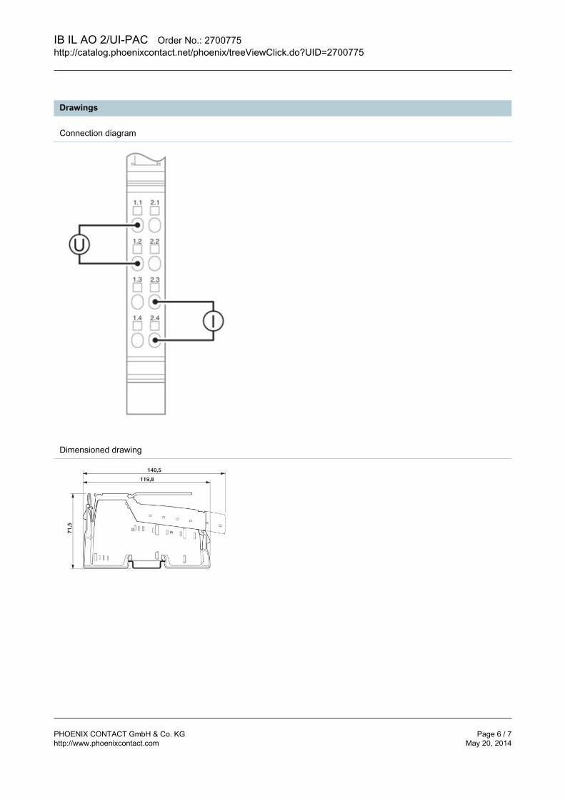
IB IL AO 2/UI-PAC Order No.: 2700775http://catalog.phoenixcontact.net/phoenix/treeViewClick.do?UID=2700775
PHOENIX CONTACT GmbH & Co. KG Page 6 / 7http://www.phoenixcontact.com May 20, 2014
Drawings
Connection diagram
Dimensioned drawing
IB IL AO 2/UI-PAC Order No.: 2700775http://catalog.phoenixcontact.net/phoenix/treeViewClick.do?UID=2700775
PHOENIX CONTACT GmbH & Co. KG Page 7 / 7http://www.phoenixcontact.com May 20, 2014
Address
PHOENIX CONTACT GmbH & Co. KGFlachsmarktstr. 832825 Blomberg,GermanyPhone +49 5235 3 00Fax +49 5235 3 41200http://www.phoenixcontact.com
© 2014 Phoenix ContactTechnical modifications reserved;

BWS-GL-02 Appendix12
12. PhoenixContactPowerSupply:TRIO-PS-2G/1AC/24DC/10
https://www.phoenixcontact.com/us/products/2903149
08/08/2018 Page 1 / 7
Power supply unit - TRIO-PS-2G/1AC/24DC/10 - 2903149Please be informed that the data shown in this PDF Document is generated from our Online Catalog. Please find the complete data in the user'sdocumentation. Our General Terms of Use for Downloads are valid(http://phoenixcontact.com/download)
Primary-switched TRIO POWER power supply with push-in connection for DIN rail mounting, input: single phase,output: 24 V DC/10 A
Product DescriptionTRIO POWER power supplies with standard functionality The TRIO POWER power supply range with push-in connection has been perfected for use in machine building. All functions and the space-savingdesign of the single and three-phase modules are optimally tailored to the stringent requirements. Under challenging ambient conditions, the powersupply units, which feature an extremely robust electrical and mechanical design, ensure the reliable supply of all loads.
Why buy this product
Save time and costs, thanks to the Push-in connection and narrow design
Increase system availability, thanks to dynamic boost with 150% of the nominal current for five seconds
Maximum flexibility due to the wide temperature range from -25°C to +70°C and device startup at -40°C
Rugged design
Key Commercial DataPacking unit 1 STK
GTIN
GTIN 4046356960854
Weight per Piece (excluding packing) 1,200.000 g
Custom tariff number 85044030
Country of origin China
Technical data
DimensionsWidth 42 mm
Height 130 mm
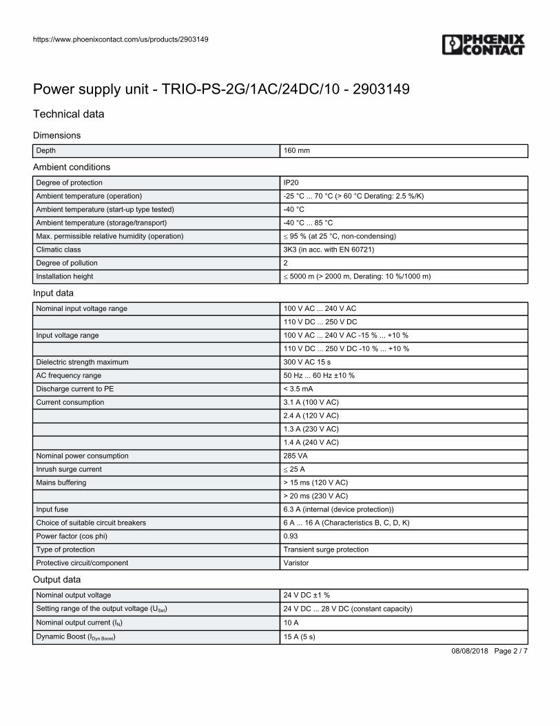
https://www.phoenixcontact.com/us/products/2903149
08/08/2018 Page 2 / 7
Power supply unit - TRIO-PS-2G/1AC/24DC/10 - 2903149Technical data
DimensionsDepth 160 mm
Ambient conditionsDegree of protection IP20
Ambient temperature (operation) -25 °C ... 70 °C (> 60 °C Derating: 2.5 %/K)
Ambient temperature (start-up type tested) -40 °C
Ambient temperature (storage/transport) -40 °C ... 85 °C
Max. permissible relative humidity (operation) ≤ 95 % (at 25 °C, non-condensing)
Climatic class 3K3 (in acc. with EN 60721)
Degree of pollution 2
Installation height ≤ 5000 m (> 2000 m, Derating: 10 %/1000 m)
Input dataNominal input voltage range 100 V AC ... 240 V AC
110 V DC ... 250 V DC
Input voltage range 100 V AC ... 240 V AC -15 % ... +10 %
110 V DC ... 250 V DC -10 % ... +10 %
Dielectric strength maximum 300 V AC 15 s
AC frequency range 50 Hz ... 60 Hz ±10 %
Discharge current to PE < 3.5 mA
Current consumption 3.1 A (100 V AC)
2.4 A (120 V AC)
1.3 A (230 V AC)
1.4 A (240 V AC)
Nominal power consumption 285 VA
Inrush surge current ≤ 25 A
Mains buffering > 15 ms (120 V AC)
> 20 ms (230 V AC)
Input fuse 6.3 A (internal (device protection))
Choice of suitable circuit breakers 6 A ... 16 A (Characteristics B, C, D, K)
Power factor (cos phi) 0.93
Type of protection Transient surge protection
Protective circuit/component Varistor
Output dataNominal output voltage 24 V DC ±1 %
Setting range of the output voltage (USet) 24 V DC ... 28 V DC (constant capacity)
Nominal output current (IN) 10 A
Dynamic Boost (IDyn.Boost) 15 A (5 s)
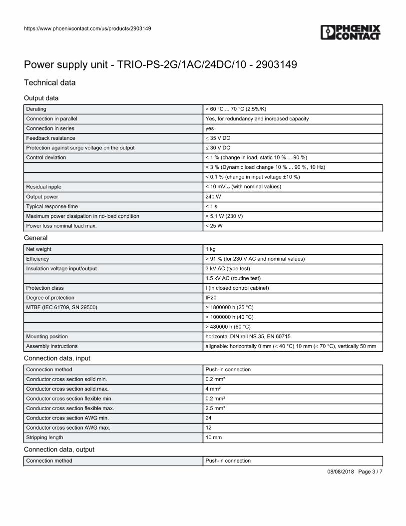
https://www.phoenixcontact.com/us/products/2903149
08/08/2018 Page 3 / 7
Power supply unit - TRIO-PS-2G/1AC/24DC/10 - 2903149Technical data
Output dataDerating > 60 °C ... 70 °C (2.5%/K)
Connection in parallel Yes, for redundancy and increased capacity
Connection in series yes
Feedback resistance ≤ 35 V DC
Protection against surge voltage on the output ≤ 30 V DC
Control deviation < 1 % (change in load, static 10 % ... 90 %)
< 3 % (Dynamic load change 10 % ... 90 %, 10 Hz)
< 0.1 % (change in input voltage ±10 %)
Residual ripple < 10 mVPP (with nominal values)
Output power 240 W
Typical response time < 1 s
Maximum power dissipation in no-load condition < 5.1 W (230 V)
Power loss nominal load max. < 25 W
GeneralNet weight 1 kg
Efficiency > 91 % (for 230 V AC and nominal values)
Insulation voltage input/output 3 kV AC (type test)
1.5 kV AC (routine test)
Protection class I (in closed control cabinet)
Degree of protection IP20
MTBF (IEC 61709, SN 29500) > 1800000 h (25 °C)
> 1000000 h (40 °C)
> 480000 h (60 °C)
Mounting position horizontal DIN rail NS 35, EN 60715
Assembly instructions alignable: horizontally 0 mm (≤ 40 °C) 10 mm (≤ 70 °C), vertically 50 mm
Connection data, inputConnection method Push-in connection
Conductor cross section solid min. 0.2 mm²
Conductor cross section solid max. 4 mm²
Conductor cross section flexible min. 0.2 mm²
Conductor cross section flexible max. 2.5 mm²
Conductor cross section AWG min. 24
Conductor cross section AWG max. 12
Stripping length 10 mm
Connection data, outputConnection method Push-in connection
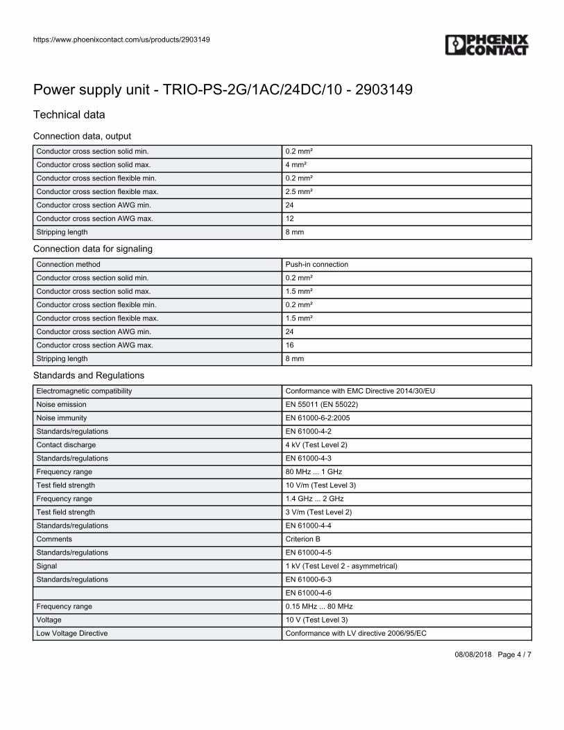
https://www.phoenixcontact.com/us/products/2903149
08/08/2018 Page 4 / 7
Power supply unit - TRIO-PS-2G/1AC/24DC/10 - 2903149Technical data
Connection data, outputConductor cross section solid min. 0.2 mm²
Conductor cross section solid max. 4 mm²
Conductor cross section flexible min. 0.2 mm²
Conductor cross section flexible max. 2.5 mm²
Conductor cross section AWG min. 24
Conductor cross section AWG max. 12
Stripping length 8 mm
Connection data for signalingConnection method Push-in connection
Conductor cross section solid min. 0.2 mm²
Conductor cross section solid max. 1.5 mm²
Conductor cross section flexible min. 0.2 mm²
Conductor cross section flexible max. 1.5 mm²
Conductor cross section AWG min. 24
Conductor cross section AWG max. 16
Stripping length 8 mm
Standards and RegulationsElectromagnetic compatibility Conformance with EMC Directive 2014/30/EU
Noise emission EN 55011 (EN 55022)
Noise immunity EN 61000-6-2:2005
Standards/regulations EN 61000-4-2
Contact discharge 4 kV (Test Level 2)
Standards/regulations EN 61000-4-3
Frequency range 80 MHz ... 1 GHz
Test field strength 10 V/m (Test Level 3)
Frequency range 1.4 GHz ... 2 GHz
Test field strength 3 V/m (Test Level 2)
Standards/regulations EN 61000-4-4
Comments Criterion B
Standards/regulations EN 61000-4-5
Signal 1 kV (Test Level 2 - asymmetrical)
Standards/regulations EN 61000-6-3
EN 61000-4-6
Frequency range 0.15 MHz ... 80 MHz
Voltage 10 V (Test Level 3)
Low Voltage Directive Conformance with LV directive 2006/95/EC
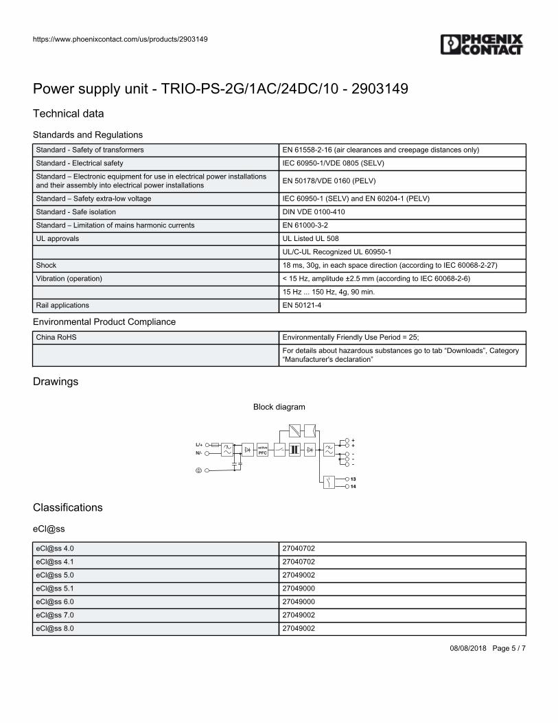
https://www.phoenixcontact.com/us/products/2903149
08/08/2018 Page 5 / 7
Power supply unit - TRIO-PS-2G/1AC/24DC/10 - 2903149Technical data
Standards and RegulationsStandard - Safety of transformers EN 61558-2-16 (air clearances and creepage distances only)
Standard - Electrical safety IEC 60950-1/VDE 0805 (SELV)
Standard – Electronic equipment for use in electrical power installationsand their assembly into electrical power installations EN 50178/VDE 0160 (PELV)
Standard – Safety extra-low voltage IEC 60950-1 (SELV) and EN 60204-1 (PELV)
Standard - Safe isolation DIN VDE 0100-410
Standard – Limitation of mains harmonic currents EN 61000-3-2
UL approvals UL Listed UL 508
UL/C-UL Recognized UL 60950-1
Shock 18 ms, 30g, in each space direction (according to IEC 60068-2-27)
Vibration (operation) < 15 Hz, amplitude ±2.5 mm (according to IEC 60068-2-6)
15 Hz ... 150 Hz, 4g, 90 min.
Rail applications EN 50121-4
Environmental Product ComplianceChina RoHS Environmentally Friendly Use Period = 25;
For details about hazardous substances go to tab “Downloads”, Category“Manufacturer's declaration”
Drawings
Block diagram
14
13
active
PFC
L/+
N/-
13
14
++
---
Classifications
eCl@ss
eCl@ss 4.0 27040702
eCl@ss 4.1 27040702
eCl@ss 5.0 27049002
eCl@ss 5.1 27049000
eCl@ss 6.0 27049000
eCl@ss 7.0 27049002
eCl@ss 8.0 27049002
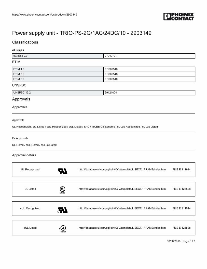
https://www.phoenixcontact.com/us/products/2903149
08/08/2018 Page 6 / 7
Power supply unit - TRIO-PS-2G/1AC/24DC/10 - 2903149Classifications
eCl@sseCl@ss 9.0 27040701
ETIM
ETIM 4.0 EC002540
ETIM 5.0 EC002540
ETIM 6.0 EC002540
UNSPSC
UNSPSC 13.2 39121004
Approvals
Approvals
Approvals
UL Recognized / UL Listed / cUL Recognized / cUL Listed / EAC / IECEE CB Scheme / cULus Recognized / cULus Listed
Ex Approvals
UL Listed / cUL Listed / cULus Listed
Approval details
UL Recognized http://database.ul.com/cgi-bin/XYV/template/LISEXT/1FRAME/index.htm FILE E 211944
UL Listed http://database.ul.com/cgi-bin/XYV/template/LISEXT/1FRAME/index.htm FILE E 123528
cUL Recognized http://database.ul.com/cgi-bin/XYV/template/LISEXT/1FRAME/index.htm FILE E 211944
cUL Listed http://database.ul.com/cgi-bin/XYV/template/LISEXT/1FRAME/index.htm FILE E 123528
https://www.phoenixcontact.com/us/products/2903149
08/08/2018 Page 7 / 7
Power supply unit - TRIO-PS-2G/1AC/24DC/10 - 2903149Approvals
EAC RU C-DE.A*30.B.01082
IECEE CB Scheme http://www.iecee.org/ DK-45300-A1-UL
cULus Recognized http://database.ul.com/cgi-bin/XYV/template/LISEXT/1FRAME/index.htm
cULus Listed
Phoenix Contact 2018 © - all rights reservedhttp://www.phoenixcontact.com

BWS-GL-02 Appendix13
13. PhoenixContactUPS:QUINT-UPS/24DC/24DC/10/3.4AH
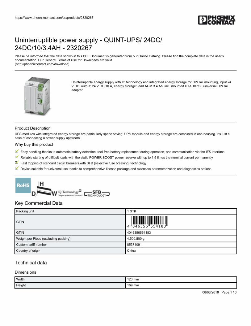
https://www.phoenixcontact.com/us/products/2320267
08/08/2018 Page 1 / 6
Uninterruptible power supply - QUINT-UPS/ 24DC/24DC/10/3.4AH - 2320267Please be informed that the data shown in this PDF Document is generated from our Online Catalog. Please find the complete data in the user'sdocumentation. Our General Terms of Use for Downloads are valid(http://phoenixcontact.com/download)
Uninterruptible energy supply with IQ technology and integrated energy storage for DIN rail mounting, input 24V DC, output: 24 V DC/10 A, energy storage: lead AGM 3.4 Ah, incl. mounted UTA 107/30 universal DIN railadapter
Product DescriptionUPS modules with integrated energy storage are particularly space saving: UPS module and energy storage are combined in one housing. It's just acase of connecting a power supply upstream.
Why buy this product
Easy handling thanks to automatic battery detection, tool-free battery replacement during operation, and communication via the IFS interface
Reliable starting of difficult loads with the static POWER BOOST power reserve with up to 1.5 times the nominal current permanently
Fast tripping of standard circuit breakers with SFB (selective fuse breaking) technology
Device suitable for universal use thanks to comprehensive license package and extensive parameterization and diagnostics options
Key Commercial DataPacking unit 1 STK
GTIN
GTIN 4046356554183
Weight per Piece (excluding packing) 4,500.800 g
Custom tariff number 85371091
Country of origin China
Technical data
DimensionsWidth 120 mm
Height 169 mm
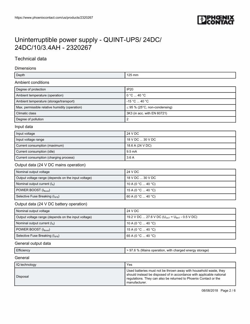
https://www.phoenixcontact.com/us/products/2320267
08/08/2018 Page 2 / 6
Uninterruptible power supply - QUINT-UPS/ 24DC/24DC/10/3.4AH - 2320267Technical data
DimensionsDepth 125 mm
Ambient conditionsDegree of protection IP20
Ambient temperature (operation) 0 °C ... 40 °C
Ambient temperature (storage/transport) -15 °C ... 40 °C
Max. permissible relative humidity (operation) ≤ 95 % (25°C, non-condensing)
Climatic class 3K3 (in acc. with EN 60721)
Degree of pollution 2
Input dataInput voltage 24 V DC
Input voltage range 18 V DC ... 30 V DC
Current consumption (maximum) 18.6 A (24 V DC)
Current consumption (idle) 9.5 mA
Current consumption (charging process) 3.6 A
Output data (24 V DC mains operation)Nominal output voltage 24 V DC
Output voltage range (depends on the input voltage) 18 V DC ... 30 V DC
Nominal output current (IN) 10 A (0 °C ... 40 °C)
POWER BOOST (IBoost) 15 A (0 °C ... 40 °C)
Selective Fuse Breaking (ISFB) 60 A (0 °C ... 40 °C)
Output data (24 V DC battery operation)Nominal output voltage 24 V DC
Output voltage range (depends on the input voltage) 19.2 V DC ... 27.6 V DC (UOUT = UBAT - 0.5 V DC)
Nominal output current (IN) 10 A (0 °C ... 40 °C)
POWER BOOST (IBoost) 15 A (0 °C ... 40 °C)
Selective Fuse Breaking (ISFB) 65 A (0 °C ... 40 °C)
General output dataEfficiency > 97.6 % (Mains operation, with charged energy storage)
GeneralIQ technology Yes
Disposal
Used batteries must not be thrown away with household waste, theyshould instead be disposed of in accordance with applicable nationalregulations. They can also be returned to Phoenix Contact or themanufacturer.

https://www.phoenixcontact.com/us/products/2320267
08/08/2018 Page 3 / 6
Uninterruptible power supply - QUINT-UPS/ 24DC/24DC/10/3.4AH - 2320267Technical data
GeneralNet weight 3.8 kg
Memory medium Lead rechargeable battery module, 3.4 Ah
Protection class III
MTBF (IEC 61709, SN 29500) > 806000 h (40 °C)
Mounting position horizontal DIN rail NS 35, EN 60715
Assembly instructions alignable: horizontal 5 mm, vertical 50 mm
Connection data, inputConnection method Pluggable screw connection
Conductor cross section solid min. 0.2 mm²
Conductor cross section solid max. 2.5 mm²
Conductor cross section flexible min. 0.2 mm²
Conductor cross section flexible max. 2.5 mm²
Conductor cross section AWG min. 16
Conductor cross section AWG max. 12
Stripping length 7 mm
Screw thread M4
Connection data, outputConnection method Pluggable screw connection
Conductor cross section solid min. 0.2 mm²
Conductor cross section solid max. 2.5 mm²
Conductor cross section flexible min. 0.2 mm²
Conductor cross section flexible max. 2.5 mm²
Conductor cross section AWG min. 16
Conductor cross section AWG max. 12
Stripping length 7 mm
Screw thread M4
Connection data for signalingConductor cross section solid min. 0.2 mm²
Conductor cross section solid max. 2.5 mm²
Conductor cross section flexible min. 0.2 mm²
Conductor cross section flexible max. 2.5 mm²
Conductor cross section AWG min. 24
Conductor cross section AWG max. 12
Screw thread M4
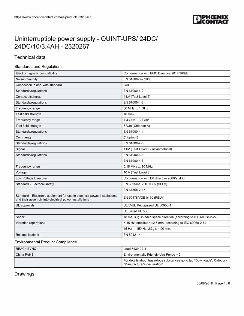
https://www.phoenixcontact.com/us/products/2320267
08/08/2018 Page 4 / 6
Uninterruptible power supply - QUINT-UPS/ 24DC/24DC/10/3.4AH - 2320267Technical data
Standards and RegulationsElectromagnetic compatibility Conformance with EMC Directive 2014/30/EU
Noise immunity EN 61000-6-2:2005
Connection in acc. with standard CUL
Standards/regulations EN 61000-4-2
Contact discharge 4 kV (Test Level 2)
Standards/regulations EN 61000-4-3
Frequency range 80 MHz ... 1 GHz
Test field strength 10 V/m
Frequency range 1.4 GHz ... 2 GHz
Test field strength 3 V/m (Criterion A)
Standards/regulations EN 61000-4-4
Comments Criterion B
Standards/regulations EN 61000-4-5
Signal 1 kV (Test Level 2 - asymmetrical)
Standards/regulations EN 61000-6-3
EN 61000-4-6
Frequency range 0.15 MHz ... 80 MHz
Voltage 10 V (Test Level 3)
Low Voltage Directive Conformance with LV directive 2006/95/EC
Standard - Electrical safety EN 60950-1/VDE 0805 (SELV)
EN 61558-2-17
Standard – Electronic equipment for use in electrical power installationsand their assembly into electrical power installations EN 50178/VDE 0160 (PELV)
UL approvals UL/C-UL Recognized UL 60950-1
UL Listed UL 508
Shock 18 ms, 30g, in each space direction (according to IEC 60068-2-27)
Vibration (operation) < 15 Hz, amplitude ±2.5 mm (according to IEC 60068-2-6)
15 Hz ... 150 Hz, 2.3g tv = 90 min.
Rail applications EN 50121-4
Environmental Product ComplianceREACh SVHC Lead 7439-92-1
China RoHS Environmentally Friendly Use Period = 3
For details about hazardous substances go to tab “Downloads”, Category“Manufacturer's declaration”
Drawings
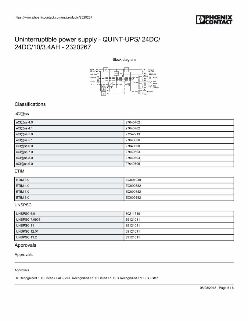
https://www.phoenixcontact.com/us/products/2320267
08/08/2018 Page 5 / 6
Uninterruptible power supply - QUINT-UPS/ 24DC/24DC/10/3.4AH - 2320267
Block diagram
13
23
33
14
24
34R1
R2
Alarm
Bat.-Mode
Bat.-Charge
Remote
Confirm
Data-Port
InputDC 24V
OutputDC 24V
24V 0 2A,
I < IN
C!
t [min]max
Battery
24VDC
"
"
Classifications
eCl@ss
eCl@ss 4.0 27040702
eCl@ss 4.1 27040702
eCl@ss 5.0 27242213
eCl@ss 5.1 27040600
eCl@ss 6.0 27040600
eCl@ss 7.0 27040603
eCl@ss 8.0 27040603
eCl@ss 9.0 27040705
ETIM
ETIM 3.0 EC001039
ETIM 4.0 EC000382
ETIM 5.0 EC000382
ETIM 6.0 EC000382
UNSPSC
UNSPSC 6.01 30211510
UNSPSC 7.0901 39121011
UNSPSC 11 39121011
UNSPSC 12.01 39121011
UNSPSC 13.2 39121011
Approvals
Approvals
Approvals
UL Recognized / UL Listed / EAC / cUL Recognized / cUL Listed / cULus Recognized / cULus Listed
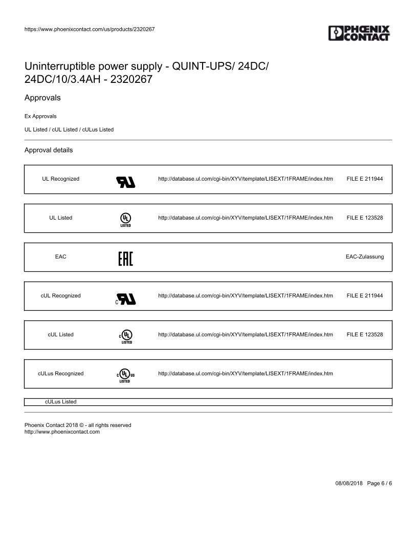
https://www.phoenixcontact.com/us/products/2320267
08/08/2018 Page 6 / 6
Uninterruptible power supply - QUINT-UPS/ 24DC/24DC/10/3.4AH - 2320267Approvals
Ex Approvals
UL Listed / cUL Listed / cULus Listed
Approval details
UL Recognized http://database.ul.com/cgi-bin/XYV/template/LISEXT/1FRAME/index.htm FILE E 211944
UL Listed http://database.ul.com/cgi-bin/XYV/template/LISEXT/1FRAME/index.htm FILE E 123528
EAC EAC-Zulassung
cUL Recognized http://database.ul.com/cgi-bin/XYV/template/LISEXT/1FRAME/index.htm FILE E 211944
cUL Listed http://database.ul.com/cgi-bin/XYV/template/LISEXT/1FRAME/index.htm FILE E 123528
cULus Recognized http://database.ul.com/cgi-bin/XYV/template/LISEXT/1FRAME/index.htm
cULus Listed
Phoenix Contact 2018 © - all rights reservedhttp://www.phoenixcontact.com

BWS-GL-02 Appendix14
14. EwonIndustrialVPNRouter:Flexy20500
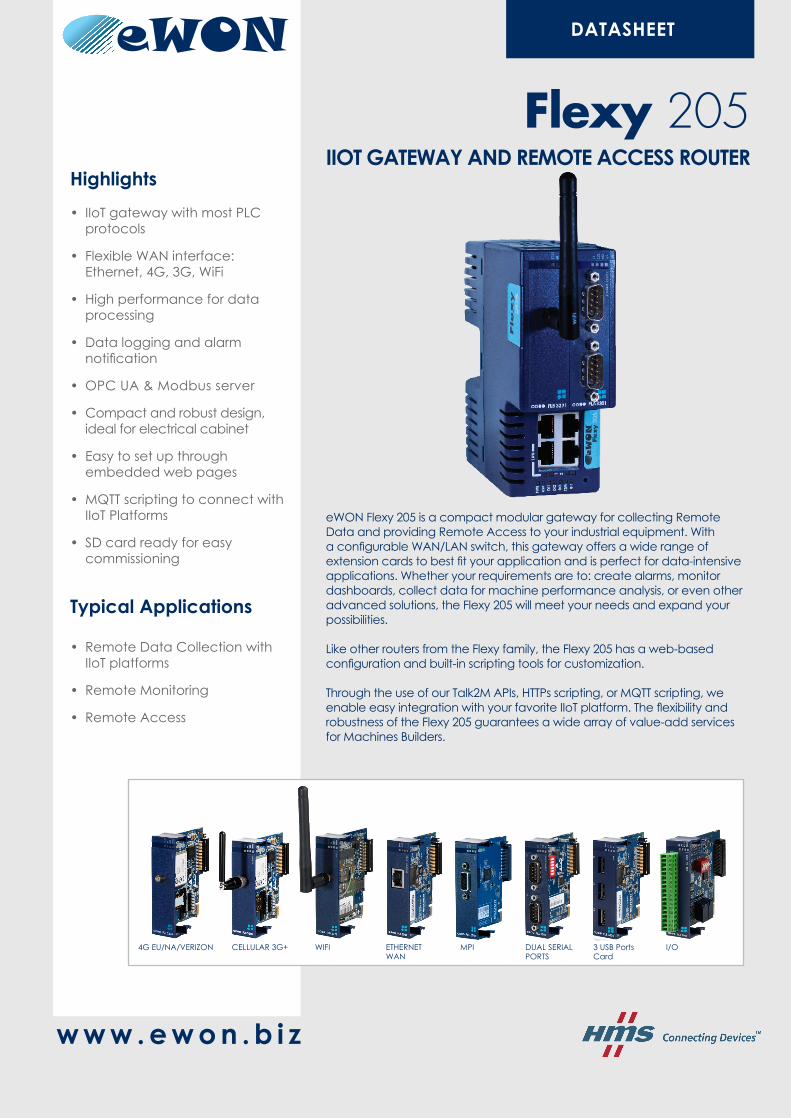
DATASHEET
Highlights
• IIoT gateway with most PLC protocols
• Flexible WAN interface: Ethernet, 4G, 3G, WiFi
• High performance for data processing
• Data logging and alarm notification
• OPC UA & Modbus server
• Compact and robust design, ideal for electrical cabinet
• Easy to set up through embedded web pages
• MQTT scripting to connect with IIoT Platforms
• SD card ready for easy commissioning
Typical Applications
• Remote Data Collection with IIoT platforms
• Remote Monitoring
• Remote Access
eWON Flexy 205 is a compact modular gateway for collecting Remote Data and providing Remote Access to your industrial equipment. With a configurable WAN/LAN switch, this gateway offers a wide range of extension cards to best fit your application and is perfect for data-intensive applications. Whether your requirements are to: create alarms, monitor dashboards, collect data for machine performance analysis, or even other advanced solutions, the Flexy 205 will meet your needs and expand your possibilities.
Like other routers from the Flexy family, the Flexy 205 has a web-based configuration and built-in scripting tools for customization.
Through the use of our Talk2M APIs, HTTPs scripting, or MQTT scripting, we enable easy integration with your favorite IIoT platform. The flexibility and robustness of the Flexy 205 guarantees a wide array of value-add services for Machines Builders.
Flexy 205IIOT GATEWAY AND REMOTE ACCESS ROUTER
w w w . e w o n . b i z
DUAL SERIAL PORTS
ETHERNET WAN
MPICELLULAR 3G+ WIFI I/O3 USB Ports Card
4G EU/NA/VERIZON
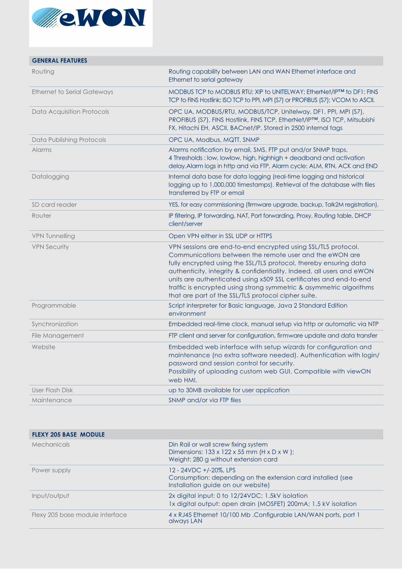
Routing Routing capability between LAN and WAN Ethernet interface and Ethernet to serial gateway
Ethernet to Serial Gateways MODBUS TCP to MODBUS RTU; XIP to UNITELWAY; EtherNet/IP™ to DF1; FINS TCP to FINS Hostlink; ISO TCP to PPI, MPI (S7) or PROFIBUS (S7); VCOM to ASCII.
Data Acquisition Protocols OPC UA, MODBUS/RTU, MODBUS/TCP, Unitelway, DF1, PPI, MPI (S7), PROFIBUS (S7), FINS Hostlink, FINS TCP, EtherNet/IP™, ISO TCP, Mitsubishi FX, Hitachi EH, ASCII, BACnet/IP. Stored in 2500 internal tags
Data Publishing Protocols OPC UA, Modbus, MQTT, SNMPAlarms Alarms notification by email, SMS, FTP put and/or SNMP traps.
4 Thresholds : low, lowlow, high, highhigh + deadband and activation delay.Alarm logs in http and via FTP, Alarm cycle: ALM, RTN, ACK and END
Datalogging Internal data base for data logging (real-time logging and historical logging up to 1,000,000 timestamps). Retrieval of the database with files transferred by FTP or email
SD card reader YES, for easy commissioning (firmware upgrade, backup, Talk2M registration).
Router IP filtering, IP forwarding, NAT, Port forwarding, Proxy, Routing table, DHCP client/server
VPN Tunnelling Open VPN either in SSL UDP or HTTPS
VPN Security VPN sessions are end-to-end encrypted using SSL/TLS protocol. Communications between the remote user and the eWON are fully encrypted using the SSL/TLS protocol, thereby ensuring data authenticity, integrity & confidentiality. Indeed, all users and eWON units are authenticated using x509 SSL certificates and end-to-end traffic is encrypted using strong symmetric & asymmetric algorithms that are part of the SSL/TLS protocol cipher suite.
Programmable Script interpreter for Basic language, Java 2 Standard Edition environment
Synchronization Embedded real-time clock, manual setup via http or automatic via NTP
File Management FTP client and server for configuration, firmware update and data transfer
Website Embedded web interface with setup wizards for configuration and maintenance (no extra software needed). Authentication with login/password and session control for security. Possibility of uploading custom web GUI. Compatible with viewON web HMI.
User Flash Disk up to 30MB available for user applicationMaintenance SNMP and/or via FTP files
Mechanicals Din Rail or wall screw fixing system Dimensions: 133 x 122 x 55 mm (H x D x W );Weight: 280 g without extension card
Power supply 12 - 24VDC +/-20%, LPSConsumption: depending on the extension card installed (see Installation guide on our website)
Input/output 2x digital input: 0 to 12/24VDC; 1.5kV isolation1x digital output: open drain (MOSFET) 200mA; 1.5 kV isolation
Flexy 205 base module interface 4 x RJ45 Ethernet 10/100 Mb .Configurable LAN/WAN ports, port 1 always LAN
FLEXY 205 BASE MODULE
GENERAL FEATURES
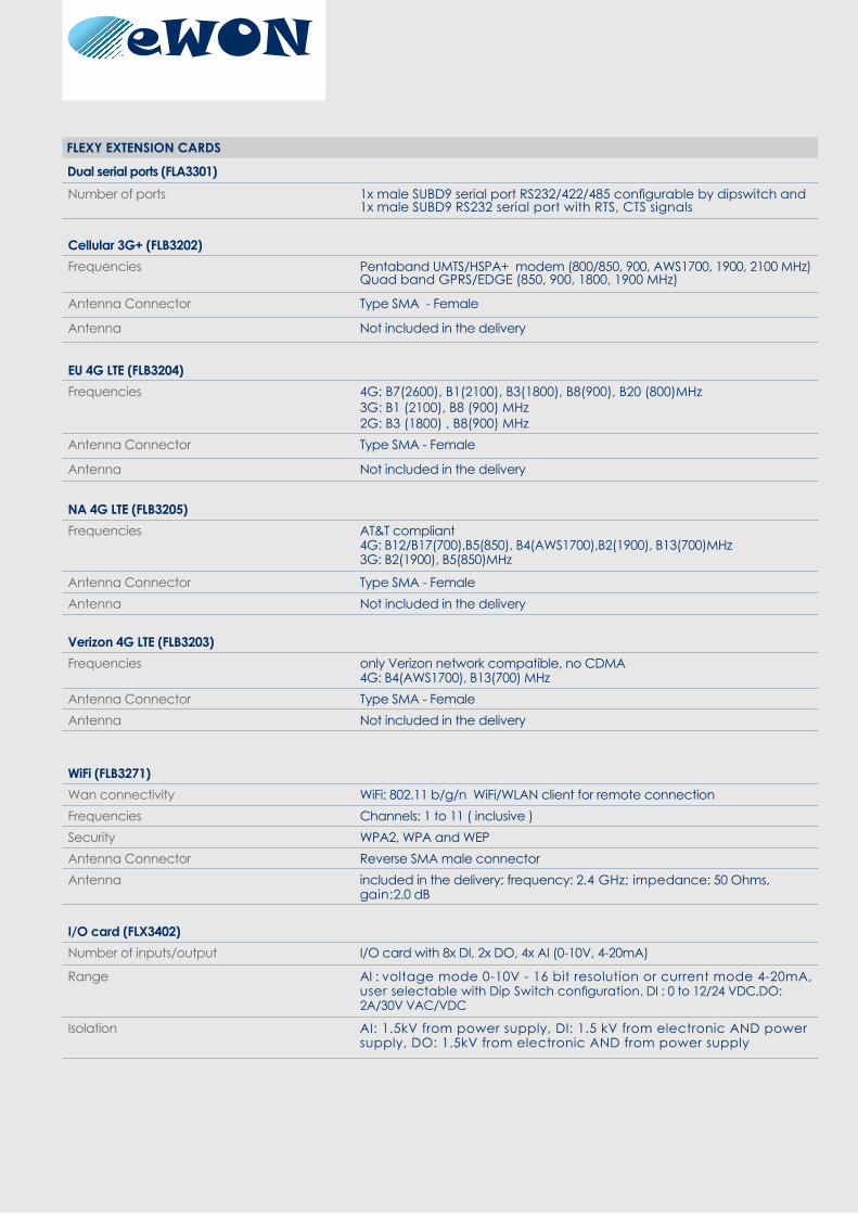
Dual serial ports (FLA3301)Number of ports 1x male SUBD9 serial port RS232/422/485 configurable by dipswitch and
1x male SUBD9 RS232 serial port with RTS, CTS signals
Cellular 3G+ (FLB3202)Frequencies Pentaband UMTS/HSPA+ modem (800/850, 900, AWS1700, 1900, 2100 MHz)
Quad band GPRS/EDGE (850, 900, 1800, 1900 MHz)
Antenna Connector Type SMA - Female
Antenna Not included in the delivery
EU 4G LTE (FLB3204)Frequencies 4G: B7(2600), B1(2100), B3(1800), B8(900), B20 (800)MHz
3G: B1 (2100), B8 (900) MHz2G: B3 (1800) , B8(900) MHz
Antenna Connector Type SMA - Female
Antenna Not included in the delivery
NA 4G LTE (FLB3205)Frequencies AT&T compliant
4G: B12/B17(700),B5(850), B4(AWS1700),B2(1900), B13(700)MHz3G: B2(1900), B5(850)MHz
Antenna Connector Type SMA - FemaleAntenna Not included in the delivery
Verizon 4G LTE (FLB3203)Frequencies only Verizon network compatible, no CDMA
4G: B4(AWS1700), B13(700) MHzAntenna Connector Type SMA - FemaleAntenna Not included in the delivery
WiFi (FLB3271)Wan connectivity WiFi: 802.11 b/g/n WiFi/WLAN client for remote connectionFrequencies Channels: 1 to 11 ( inclusive )Security WPA2, WPA and WEPAntenna Connector Reverse SMA male connectorAntenna included in the delivery; frequency: 2.4 GHz; impedance: 50 Ohms,
gain:2.0 dB
I/O card (FLX3402)Number of inputs/output I/O card with 8x DI, 2x DO, 4x AI (0-10V, 4-20mA)
Range AI : voltage mode 0-10V - 16 bit resolution or current mode 4-20mA, user selectable with Dip Switch configuration. DI : 0 to 12/24 VDC,DO: 2A/30V VAC/VDC
Isolation AI: 1.5kV from power supply, DI: 1.5 kV from electronic AND power supply, DO: 1.5kV from electronic AND from power supply
FLEXY EXTENSION CARDS
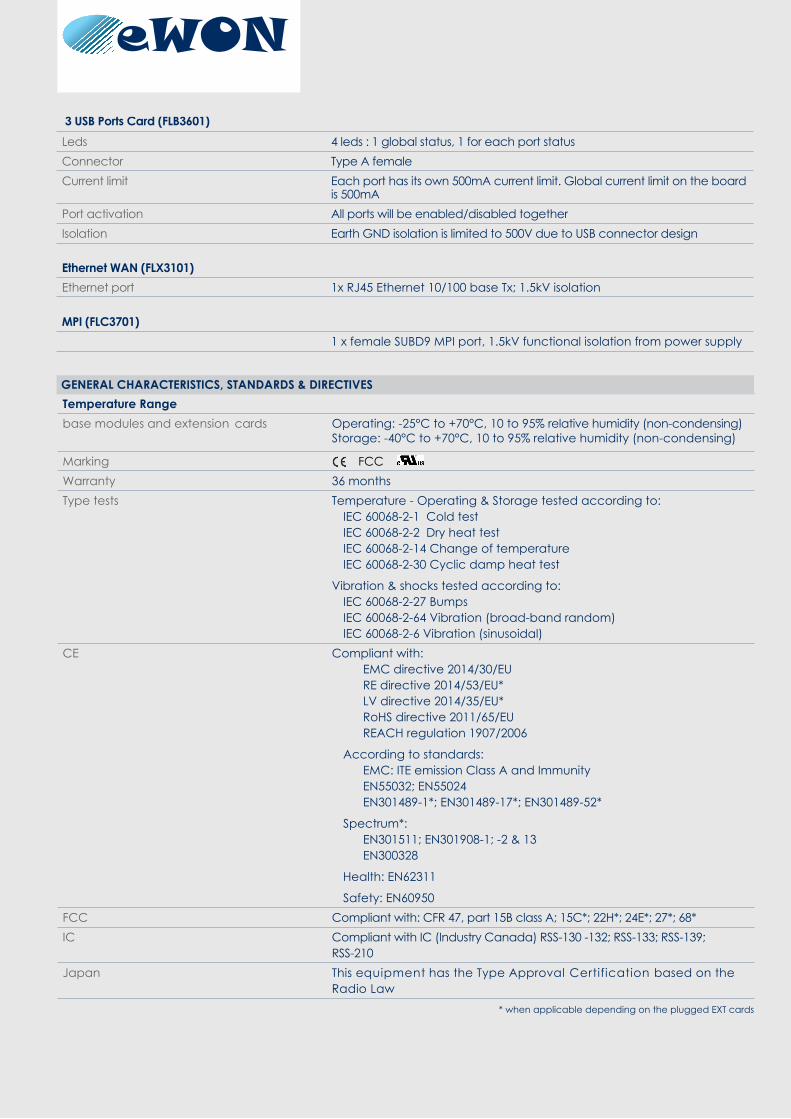
Temperature Range base modules and extension cards Operating: -25°C to +70°C, 10 to 95% relative humidity (non-condensing)
Storage: -40°C to +70°C, 10 to 95% relative humidity (non-condensing)
Marking FCCWarranty 36 monthsType tests Temperature - Operating & Storage tested according to:
IEC 60068-2-1 Cold testIEC 60068-2-2 Dry heat testIEC 60068-2-14 Change of temperatureIEC 60068-2-30 Cyclic damp heat test
Vibration & shocks tested according to:IEC 60068-2-27 BumpsIEC 60068-2-64 Vibration (broad-band random)IEC 60068-2-6 Vibration (sinusoidal)
CE Compliant with: EMC directive 2014/30/EU RE directive 2014/53/EU* LV directive 2014/35/EU* RoHS directive 2011/65/EU REACH regulation 1907/2006
According to standards: EMC: ITE emission Class A and Immunity EN55032; EN55024 EN301489-1*; EN301489-17*; EN301489-52*
Spectrum*: EN301511; EN301908-1; -2 & 13 EN300328
Health: EN62311
Safety: EN60950FCC Compliant with: CFR 47, part 15B class A; 15C*; 22H*; 24E*; 27*; 68*IC Compliant with IC (Industry Canada) RSS-130 -132; RSS-133; RSS-139;
RSS-210Japan This equipment has the Type Approval Certification based on the
Radio Law
GENERAL CHARACTERISTICS, STANDARDS & DIRECTIVES
3 USB Ports Card (FLB3601)Leds 4 leds : 1 global status, 1 for each port statusConnector Type A femaleCurrent limit Each port has its own 500mA current limit. Global current limit on the board
is 500mAPort activation All ports will be enabled/disabled togetherIsolation Earth GND isolation is limited to 500V due to USB connector design
Ethernet WAN (FLX3101)Ethernet port 1x RJ45 Ethernet 10/100 base Tx; 1.5kV isolation
MPI (FLC3701)1 x female SUBD9 MPI port, 1.5kV functional isolation from power supply
* when applicable depending on the plugged EXT cards
Dual serial ports FLA3301
Cellular 3G+ FLB3202EU 4G LTE FLB3204NA 4G LTE FLB3205VERIZON 4G LTE FLB3203WIFI FLB32713 USB Ports Cards FLB3601Ethernet WAN FLX3101Extension I/O card FLX3402MPI FLC3701
Base Module Part Number Flexy 205 Flexy205
Extension Cards
PART NUMBER
Safety Conform to: EN60950-1; UL60950-1; CSA-C22.2 n° 60950-1-07 UL recognized: file number E350576
www.ewon .b i z Rev
1.0.
Sub
ject
to c
hang
e w
ithou
t not
ice.
HMS - Sweden (HQ) Tel : +46 35 17 29 00 (Halmstad HQ) E-mail: [email protected]
HMS - Belgium (eWON) Tel: +32 67 895 800 E-mail: [email protected] HMS - China Tel : +86 010 8532 3183 E-mail: [email protected]
HMS - France Tel: +33 (0)3 67 88 02 50 (Mulhouse office) E-mail: [email protected]
HMS - Germany Tel: +49 721 989777-000 E-mail: [email protected]
HMS - India Tel: +91 83800 66578 E-mail: [email protected]
HMS - Italy Tel : +39 039 59662 27 E-mail: [email protected] HMS - Japan Tel: +81 45 478 5340 E-mail: [email protected]
HMS - Switzerland Tel: +41 61 511342-0 E-mail: [email protected] HMS - UK Tel: +44 1926 405599 E-mail: [email protected] HMS - United States Tel: +1 312 829 0601 E-mail: [email protected]

BWS-GL-02 Appendix15
15. EwonCellularCommunications:FLB3203

www.ewon.b iz
Many field-based applications do not have access to a wired Internet connection, instead requiring cellular connectivity. Using a 4G cellular connection provides the advantages of innovation and cutting edge technology and can sometimes be the only cellular connectivity in a remote area. The 4G LTE Flexy extension card addresses these requests while allowing an eWON Flexy to connect to the Internet. For remote access requirements, a simple SIM card with data plan is all that is needed to connect to the Talk2M cloud-based solution. Similarly for SCADA-like applications, secure remote VPN connectivity can also benefit from this simple SIM card without the burden of provisioning a fixed IP address on the remote site.
4G LTEExtension card
4G LTE connectivity
Speed up your broadband connectivity on your Flexy with the 4G extension card.
forFlexy
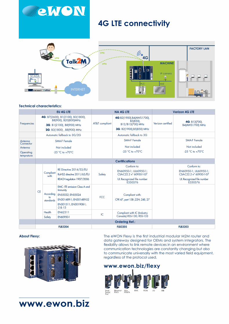
> Secure connection using the Factory WiFi/LAN network> Free to use WiFi/WLAN client compared to cellular modems> Hassle-free to connect
PLC HMI
IP camera
MACHINE
FACTORY LAN
4GVPN
VPN
VPN
4G LTE connectivity
Technical characteristics:EU 4G LTE NA 4G LTE Verizon 4G LTE
Frequencies
4G: B7(2600), B1(2100), B3(1800), B8(900), B20(800)MHz
3G: B1(2100), B8(900) MHz
2G: B3(1800) , B8(900) MHz
AT&T compliant
4G:B2(1900),B4(AWS1700), B5(850),
B12/B13(700) MHz
3G: B2(1900),B5(850) MHz
Verizon certified 4G: B13(700), B4(AWS1700) MHz
Automatic fallback to 3G/2G Automatic fallback to 3G
Antenna ConnectorAntenna
Operating temprature
SMA-F Female
Not included
-25 °C to +70°C
SMA-F Female
Not included
-25 °C to +70°C
SMA-F Female
Not included
-25 °C to +70°C
Certifications
CE
Compliant with
RE Directive 2014/53/EU
RoHS2 directive 2011/65/EU
REACH regulation 1907/2006
Safety
Conform to:
EN60950-1; UL60950-1; CSA-C22.2 n° 60950-1-07
UL Recognized file number E350576
Conform to:
EN60950-1; UL60950-1; CSA-C22.2 n° 60950-1-07
UL Recognized file number E350576
According to
standards
EMC: ITE emission Class A and Immunity
EN55032; EN55024
EN301489-1; EN301489-52
EN301511; EN301908-1; -2 & -13
FCCCompliant with:
CFR 47, part 15B ;22H; 24E; 27
Health EN62311IC Compliant with IC (Industry
Canada) RSS-130; RSS-133Safety EN60950-1
Ordering Ref.:FLB3204 FLB3205 FLB3203
www.ewon.biz
About Flexy:
www.ewon.biz/flexy
The eWON Flexy is the first industrial modular M2M router and data gateway designed for OEMs and system integrators. The flexibility allows to link remote devices in an environment where communication technologies are constantly changing but also to communicate universally with the most varied field equipment, regardless of the protocol used.

BWS-GL-02 Appendix16
16. PhoenixContactSwitch:FLSWITCHSFN8TX
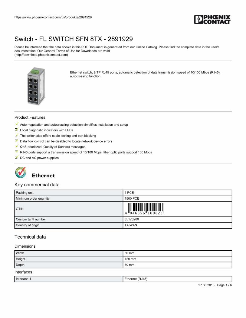
https://www.phoenixcontact.com/us/produkte/2891929
27.06.2013 Page 1 / 6
Switch - FL SWITCH SFN 8TX - 2891929Please be informed that the data shown in this PDF Document is generated from our Online Catalog. Please find the complete data in the user'sdocumentation. Our General Terms of Use for Downloads are valid(http://download.phoenixcontact.com)
Ethernet switch, 8 TP RJ45 ports, automatic detection of data transmission speed of 10/100 Mbps (RJ45),autocrossing function
Product Features
Auto negotiation and autocrossing detection simplifies installation and setup
Local diagnostic indicators with LEDs
The switch also offers cable locking and port blocking
Data flow control can be disabled to locate network device errors
QoS-prioritized (Quality of Service) messages
RJ45 ports support a transmission speed of 10/100 Mbps; fiber optic ports support 100 Mbps
DC and AC power supplies
Key commercial dataPacking unit 1 PCE
Minimum order quantity 1500 PCE
GTIN
Custom tariff number 85176200
Country of origin TAIWAN
Technical data
DimensionsWidth 50 mm
Height 120 mm
Depth 70 mm
InterfacesInterface 1 Ethernet (RJ45)
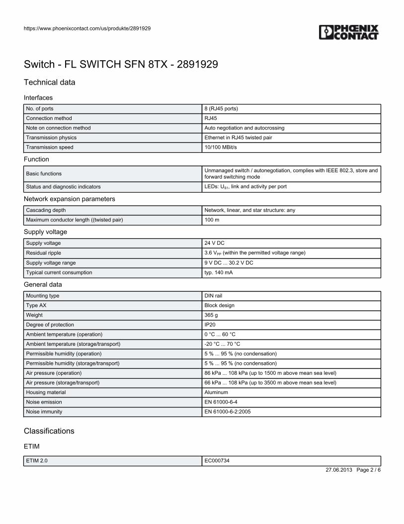
https://www.phoenixcontact.com/us/produkte/2891929
27.06.2013 Page 2 / 6
Switch - FL SWITCH SFN 8TX - 2891929Technical data
InterfacesNo. of ports 8 (RJ45 ports)
Connection method RJ45
Note on connection method Auto negotiation and autocrossing
Transmission physics Ethernet in RJ45 twisted pair
Transmission speed 10/100 MBit/s
Function
Basic functions Unmanaged switch / autonegotiation, complies with IEEE 802.3, store andforward switching mode
Status and diagnostic indicators LEDs: US1, link and activity per port
Network expansion parametersCascading depth Network, linear, and star structure: any
Maximum conductor length ((twisted pair) 100 m
Supply voltageSupply voltage 24 V DC
Residual ripple 3.6 VPP (within the permitted voltage range)
Supply voltage range 9 V DC ... 30.2 V DC
Typical current consumption typ. 140 mA
General dataMounting type DIN rail
Type AX Block design
Weight 365 g
Degree of protection IP20
Ambient temperature (operation) 0 °C ... 60 °C
Ambient temperature (storage/transport) -20 °C ... 70 °C
Permissible humidity (operation) 5 % ... 95 % (no condensation)
Permissible humidity (storage/transport) 5 % ... 95 % (no condensation)
Air pressure (operation) 86 kPa ... 108 kPa (up to 1500 m above mean sea level)
Air pressure (storage/transport) 66 kPa ... 108 kPa (up to 3500 m above mean sea level)
Housing material Aluminum
Noise emission EN 61000-6-4
Noise immunity EN 61000-6-2:2005
Classifications
ETIM
ETIM 2.0 EC000734
https://www.phoenixcontact.com/us/produkte/2891929
27.06.2013 Page 3 / 6
Switch - FL SWITCH SFN 8TX - 2891929Classifications
ETIMETIM 3.0 EC000734
ETIM 4.0 EC000734
ETIM 5.0 EC000734
UNSPSC
UNSPSC 11 43172015
UNSPSC 12.01 43201410
UNSPSC 13.2 43201410
UNSPSC 6.01 43172015
UNSPSC 7.0901 43201404
eCl@ss
eCl@ss 4.0 27250501
eCl@ss 4.1 27250501
eCl@ss 5.0 27250501
eCl@ss 5.1 27250501
eCl@ss 6.0 19170106
eCl@ss 7.0 19170106
Approvals
Approvals
Approvals
UL Listed / cUL Listed / cULus Listed
Ex Approvals
UL Listed / cUL Listed / cULus Listed
Approvals submitted
Approval details
UL Listed
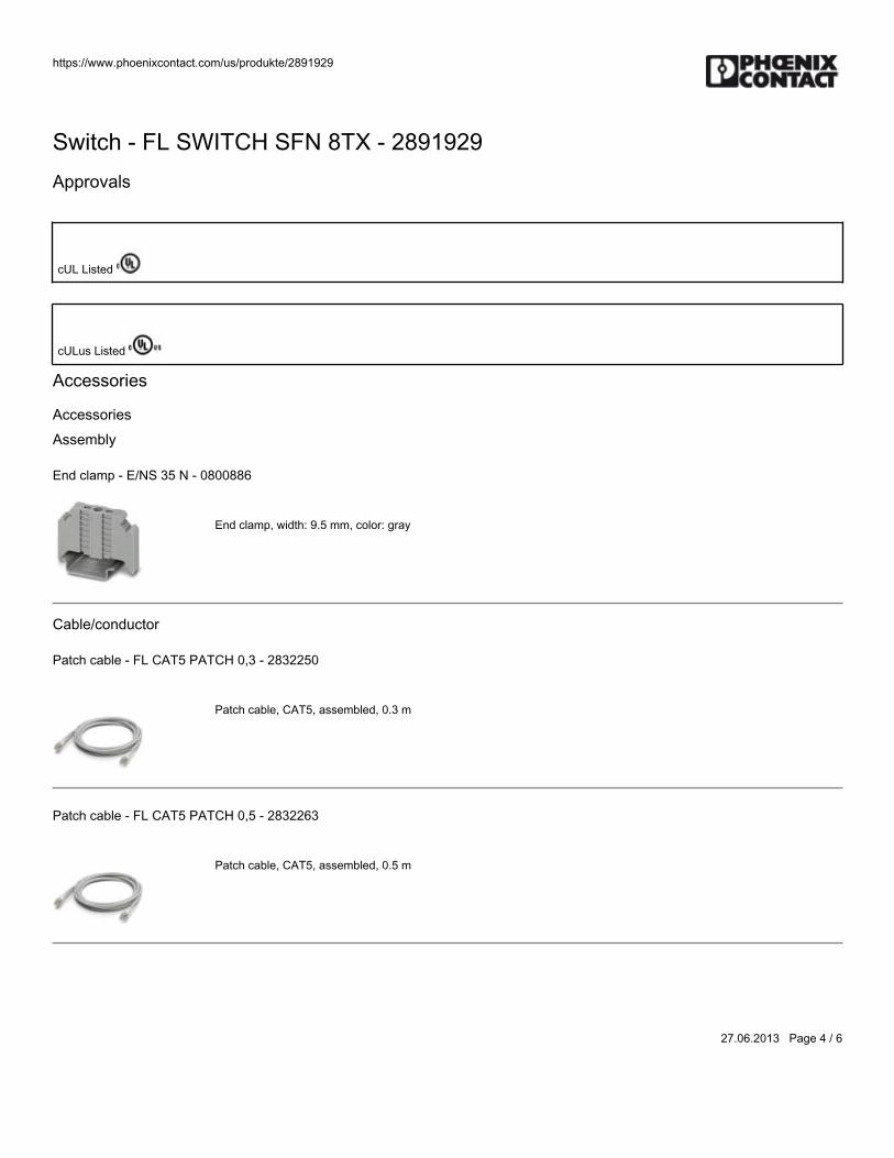
https://www.phoenixcontact.com/us/produkte/2891929
27.06.2013 Page 4 / 6
Switch - FL SWITCH SFN 8TX - 2891929Approvals
cUL Listed
cULus Listed
Accessories
Accessories
Assembly
End clamp - E/NS 35 N - 0800886
End clamp, width: 9.5 mm, color: gray
Cable/conductor
Patch cable - FL CAT5 PATCH 0,3 - 2832250
Patch cable, CAT5, assembled, 0.3 m
Patch cable - FL CAT5 PATCH 0,5 - 2832263
Patch cable, CAT5, assembled, 0.5 m
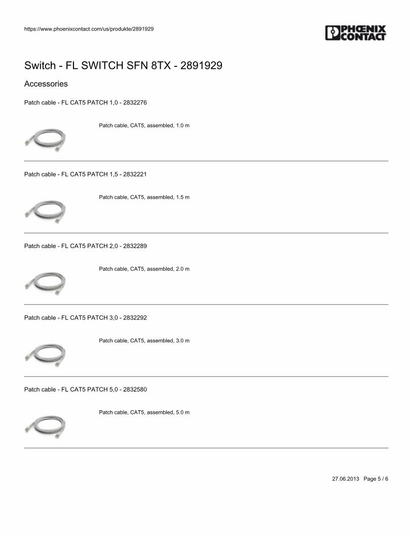
https://www.phoenixcontact.com/us/produkte/2891929
27.06.2013 Page 5 / 6
Switch - FL SWITCH SFN 8TX - 2891929Accessories
Patch cable - FL CAT5 PATCH 1,0 - 2832276
Patch cable, CAT5, assembled, 1.0 m
Patch cable - FL CAT5 PATCH 1,5 - 2832221
Patch cable, CAT5, assembled, 1.5 m
Patch cable - FL CAT5 PATCH 2,0 - 2832289
Patch cable, CAT5, assembled, 2.0 m
Patch cable - FL CAT5 PATCH 3,0 - 2832292
Patch cable, CAT5, assembled, 3.0 m
Patch cable - FL CAT5 PATCH 5,0 - 2832580
Patch cable, CAT5, assembled, 5.0 m
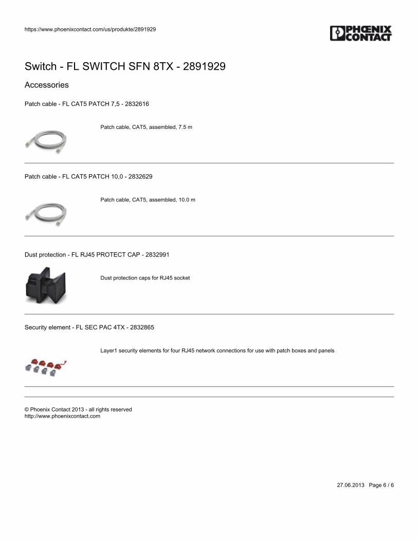
https://www.phoenixcontact.com/us/produkte/2891929
27.06.2013 Page 6 / 6
Switch - FL SWITCH SFN 8TX - 2891929Accessories
Patch cable - FL CAT5 PATCH 7,5 - 2832616
Patch cable, CAT5, assembled, 7.5 m
Patch cable - FL CAT5 PATCH 10,0 - 2832629
Patch cable, CAT5, assembled, 10.0 m
Dust protection - FL RJ45 PROTECT CAP - 2832991
Dust protection caps for RJ45 socket
Security element - FL SEC PAC 4TX - 2832865
Layer1 security elements for four RJ45 network connections for use with patch boxes and panels
© Phoenix Contact 2013 - all rights reservedhttp://www.phoenixcontact.com

BWS-GL-02 Appendix17
17. Ebm-papstCabinetFan:QG030-353/14
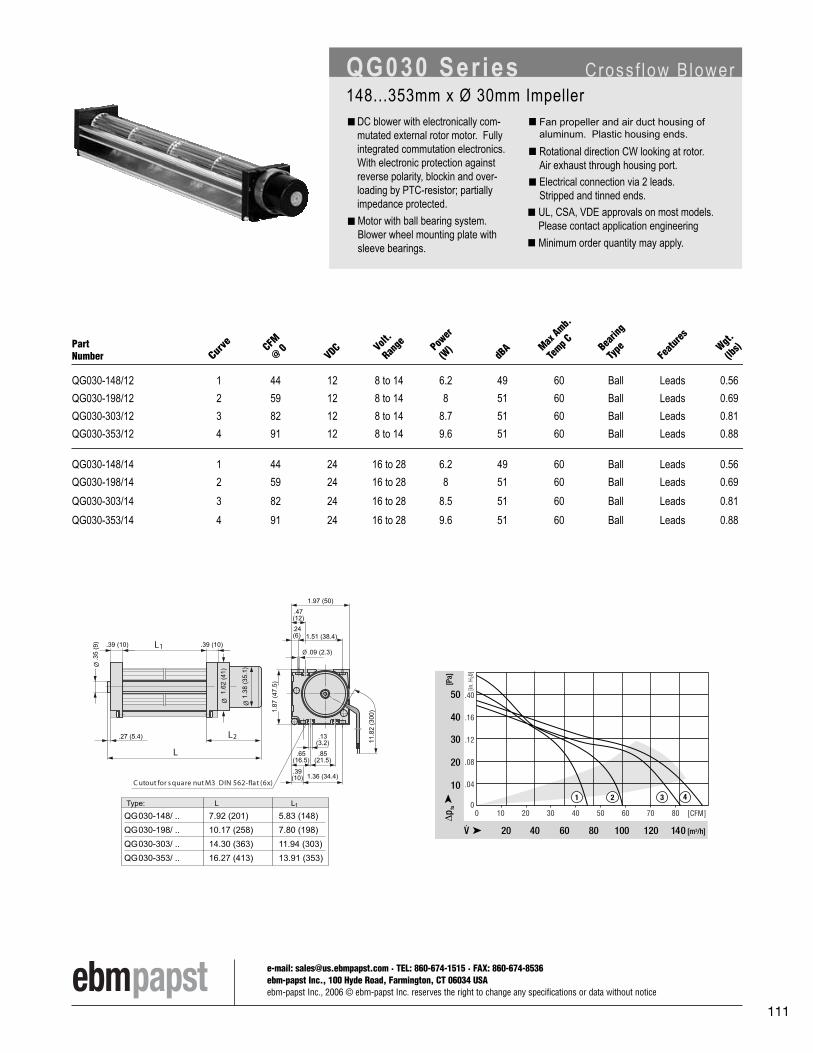
e-mail: [email protected] · TEL: 860-674-1515 · FAX: 860-674-8536ebm-papst Inc., 100 Hyde Road, Farmington, CT 06034 USAebm-papst Inc., 2006 © ebm-papst Inc. reserves the right to change any specifications or data without notice
111
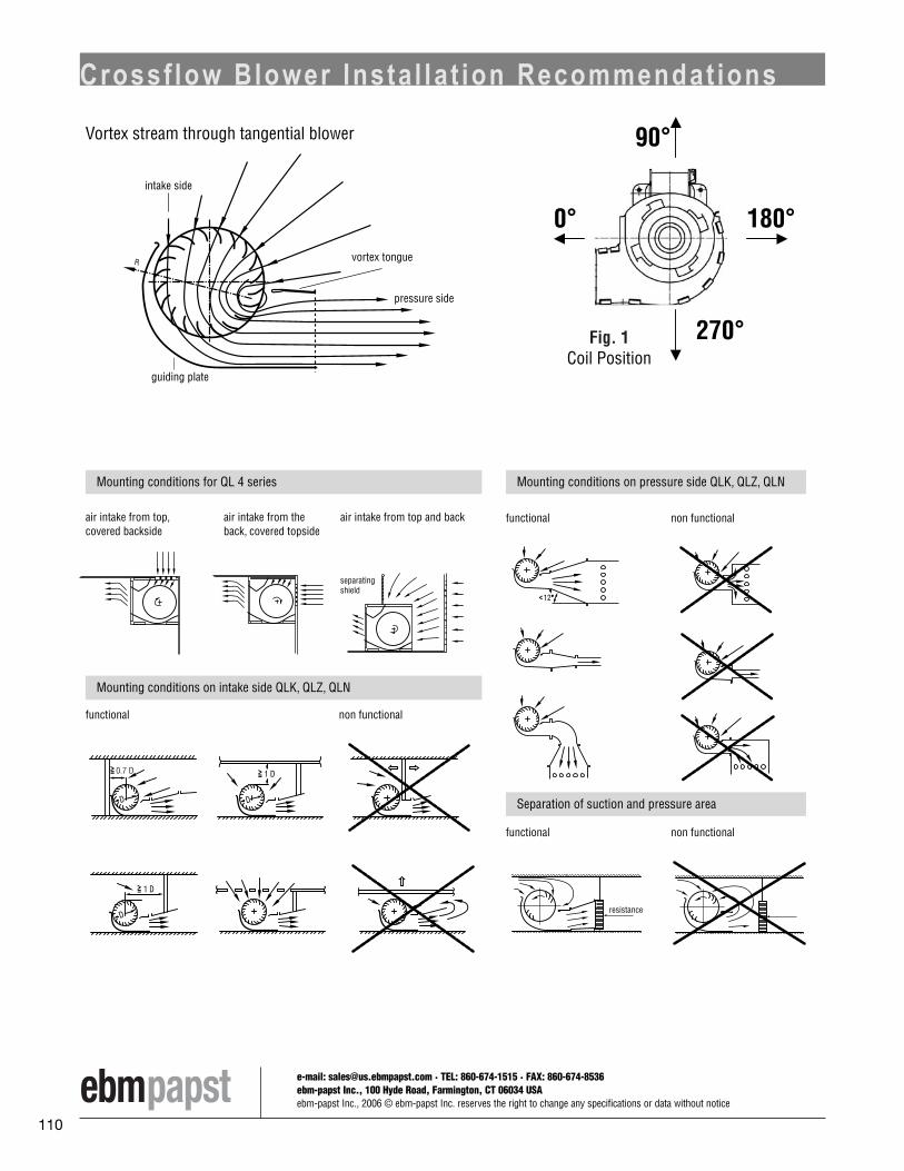
e-mail: [email protected] · TEL: 860-674-1515 · FAX: 860-674-8536ebm-papst Inc., 100 Hyde Road, Farmington, CT 06034 USAebm-papst Inc., 2006 © ebm-papst Inc. reserves the right to change any specifications or data without notice
110

Mouser Electronics Authorized Distributor Click to View Pricing, Inventory, Delivery & Lifecycle Information: ebm-papst: QG030-148/12 QG030-148/14 QG030-198/12 QG030-198/14 QG030-303/12 QG030-303/14 QG030-353/12 QG030-353/14

BWS-GL-02 Appendix18
18. StegoCabinetThermostat:KTS-011
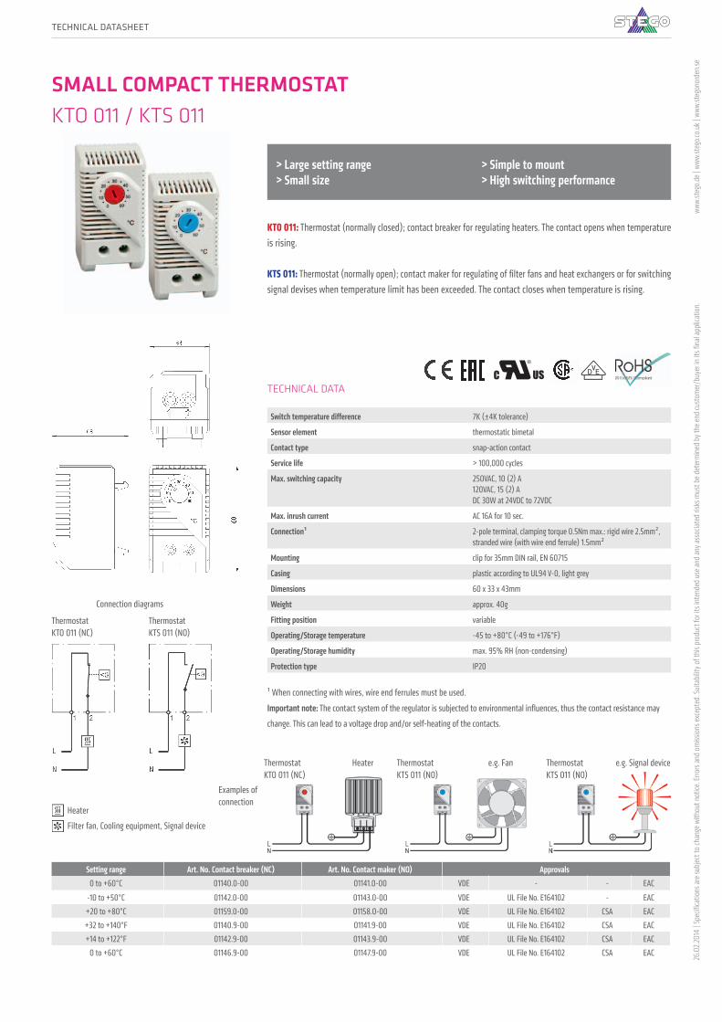
48 PRODUCT CATALOGUE - STEGOPRODUCT CATALOGUE - STEGOREGULATING
TECHNICAL DATA
Switch temperature difference 7K (±4K tolerance)
Sensor element thermostatic bimetal
Contact type snap-action contact
Service life > 100,000 cycles
Max. switching capacity 250VAC, 10 (2) A 120VAC, 15 (2) A DC 30W at 24VDC to 72VDC
Max. inrush current AC 16A for 10 sec.
Connection¹ 2-pole terminal, clamping torque 0.5Nm max.: rigid wire 2.5mm², stranded wire (with wire end ferrule) 1.5mm²
Mounting clip for 35mm DIN rail, EN 60715
Casing plastic according to UL94 V-0, light grey
Dimensions 60 x 33 x 43mm
Weight approx. 40g
Fitting position variable
Operating/Storage temperature -45 to +80°C (-49 to +176°F)
Operating/Storage humidity max. 95% RH (non-condensing)
Protection type IP20
¹ When connecting with wires, wire end ferrules must be used.
Important note: The contact system of the regulator is subjected to environmental influences, thus the contact resistance may
change. This can lead to a voltage drop and/or self-heating of the contacts.
KTO 011: Thermostat (normally closed); contact breaker for regulating heaters. The contact opens when temperature is rising.
KTS 011: Thermostat (normally open); contact maker for regulating of filter fans and heat exchangers or for switching signal devises when temperature limit has been exceeded. The contact closes when temperature is rising.
> Large setting range > Small size
> Simple to mount > High switching performance
Connection diagrams
ThermostatKTO 011 (NC)
ThermostatKTS 011 (NO)
Examples of connection
e.g. Signal deviceThermostat KTS 011 (NO)
e.g. FanThermostat KTS 011 (NO)
HeaterThermostat KTO 011 (NC)
Heater
Filter fan, Cooling equipment, Signal device
SMALL COMPACT THERMOSTAT KTO 011 / KTS 011
Setting range Art. No. Contact breaker (NC) Art. No. Contact maker (NO) Approvals0 to +60°C 01140.0-00 01141.0-00 VDE - - EAC
-10 to +50°C 01142.0-00 01143.0-00 VDE UL File No. E164102 - EAC+20 to +80°C 01159.0-00 01158.0-00 VDE UL File No. E164102 CSA EAC+32 to +140°F 01140.9-00 01141.9-00 VDE UL File No. E164102 CSA EAC+14 to +122°F 01142.9-00 01143.9-00 VDE UL File No. E164102 CSA EAC
0 to +60°C 01146.9-00 01147.9-00 VDE UL File No. E164102 CSA EAC
TECHNICAL DATASHEET
26.0
2.201
4 | S
pecifi
catio
ns ar
e sub
ject t
o ch
ange
with
out n
otice
. Erro
rs an
d om
issio
ns ex
cept
ed. S
uita
bilit
y of t
his p
rodu
ct fo
r its
inte
nded
use
and
any a
ssoc
iated
risk
s mus
t be d
eter
min
ed b
y the
end
cust
omer
/buy
er in
its fi
nal a
pplic
atio
n.ww
w.st
ego.d
e | w
ww.st
ego.c
o.uk |
www
.steg
onor
den.
se

BWS-GL-02 Appendix19
19. AltechMotorDisconnectSwitch:VKA3160


BWS-GL-02 Appendix20
20. PhoenixContactLightning/SurgeArrestor:FLT-SEC-T1+T2-3S-350/25-FM

https://www.phoenixcontact.com/us/products/2905470
08/08/2018 Page 1 / 9
Type 1+2 protective device combination - FLT-SEC-T1+T2-3S-350/25-FM - 2905470Please be informed that the data shown in this PDF Document is generated from our Online Catalog. Please find the complete data in the user'sdocumentation. Our General Terms of Use for Downloads are valid(http://phoenixcontact.com/download)
Plug-in lightning and surge arrester combination, in accordance with Type 1+2/Class I+II, for 3-phase powersupply networks, with separate N and PE (L1, L2, L3, PE, N).
Why buy this product
Directly coordinated combination of type 1 spark gap without line follow current and type 2 varistor arrester
Particularly suitable for maximum protection of sensitive devices in harsh environments
High continuous voltage of 350 V AC for 230/400 V AC networks with high voltage fluctuations
Pluggable
Low voltage protection level of 1.5 kV
Optical, mechanical status indicator
With floating remote indication contact
Plugs can be checked with CHECKMASTER 2
Key Commercial DataPacking unit 1 STK
GTIN
GTIN 4046356950664
Weight per Piece (excluding packing) 1,380.000 g
Custom tariff number 85363030
Country of origin Germany
Technical data
Dimensions
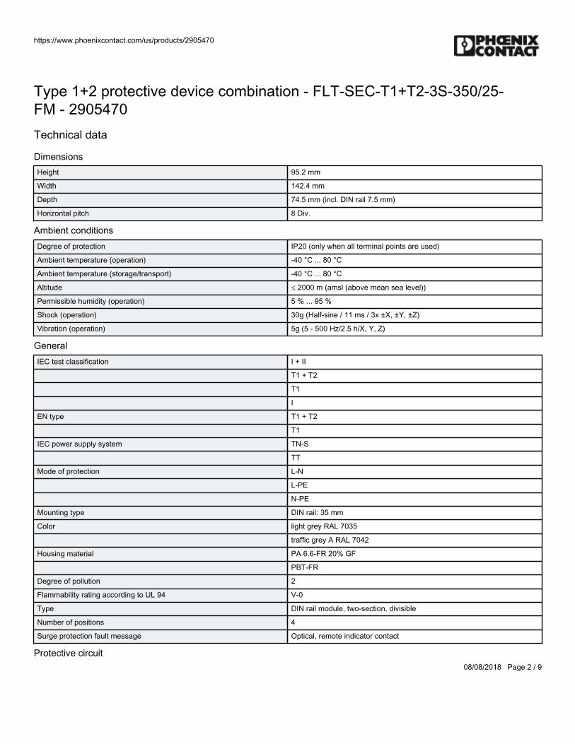
https://www.phoenixcontact.com/us/products/2905470
08/08/2018 Page 2 / 9
Type 1+2 protective device combination - FLT-SEC-T1+T2-3S-350/25-FM - 2905470Technical data
DimensionsHeight 95.2 mm
Width 142.4 mm
Depth 74.5 mm (incl. DIN rail 7.5 mm)
Horizontal pitch 8 Div.
Ambient conditionsDegree of protection IP20 (only when all terminal points are used)
Ambient temperature (operation) -40 °C ... 80 °C
Ambient temperature (storage/transport) -40 °C ... 80 °C
Altitude ≤ 2000 m (amsl (above mean sea level))
Permissible humidity (operation) 5 % ... 95 %
Shock (operation) 30g (Half-sine / 11 ms / 3x ±X, ±Y, ±Z)
Vibration (operation) 5g (5 - 500 Hz/2.5 h/X, Y, Z)
GeneralIEC test classification I + II
T1 + T2
T1
I
EN type T1 + T2
T1
IEC power supply system TN-S
TT
Mode of protection L-N
L-PE
N-PE
Mounting type DIN rail: 35 mm
Color light grey RAL 7035
traffic grey A RAL 7042
Housing material PA 6.6-FR 20% GF
PBT-FR
Degree of pollution 2
Flammability rating according to UL 94 V-0
Type DIN rail module, two-section, divisible
Number of positions 4
Surge protection fault message Optical, remote indicator contact
Protective circuit
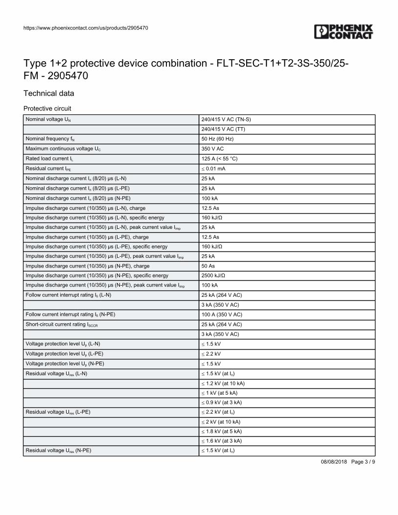
https://www.phoenixcontact.com/us/products/2905470
08/08/2018 Page 3 / 9
Type 1+2 protective device combination - FLT-SEC-T1+T2-3S-350/25-FM - 2905470Technical data
Protective circuitNominal voltage UN 240/415 V AC (TN-S)
240/415 V AC (TT)
Nominal frequency fN 50 Hz (60 Hz)
Maximum continuous voltage UC 350 V AC
Rated load current IL 125 A (< 55 °C)
Residual current IPE ≤ 0.01 mA
Nominal discharge current In (8/20) µs (L-N) 25 kA
Nominal discharge current In (8/20) µs (L-PE) 25 kA
Nominal discharge current In (8/20) µs (N-PE) 100 kA
Impulse discharge current (10/350) µs (L-N), charge 12.5 As
Impulse discharge current (10/350) µs (L-N), specific energy 160 kJ/Ω
Impulse discharge current (10/350) µs (L-N), peak current value Iimp 25 kA
Impulse discharge current (10/350) µs (L-PE), charge 12.5 As
Impulse discharge current (10/350) µs (L-PE), specific energy 160 kJ/Ω
Impulse discharge current (10/350) µs (L-PE), peak current value Iimp 25 kA
Impulse discharge current (10/350) µs (N-PE), charge 50 As
Impulse discharge current (10/350) µs (N-PE), specific energy 2500 kJ/Ω
Impulse discharge current (10/350) µs (N-PE), peak current value Iimp 100 kA
Follow current interrupt rating Ifi (L-N) 25 kA (264 V AC)
3 kA (350 V AC)
Follow current interrupt rating Ifi (N-PE) 100 A (350 V AC)
Short-circuit current rating ISCCR 25 kA (264 V AC)
3 kA (350 V AC)
Voltage protection level Up (L-N) ≤ 1.5 kV
Voltage protection level Up (L-PE) ≤ 2.2 kV
Voltage protection level Up (N-PE) ≤ 1.5 kV
Residual voltage Ures (L-N) ≤ 1.5 kV (at In)
≤ 1.2 kV (at 10 kA)
≤ 1 kV (at 5 kA)
≤ 0.9 kV (at 3 kA)
Residual voltage Ures (L-PE) ≤ 2.2 kV (at In)
≤ 2 kV (at 10 kA)
≤ 1.8 kV (at 5 kA)
≤ 1.6 kV (at 3 kA)
Residual voltage Ures (N-PE) ≤ 1.5 kV (at In)
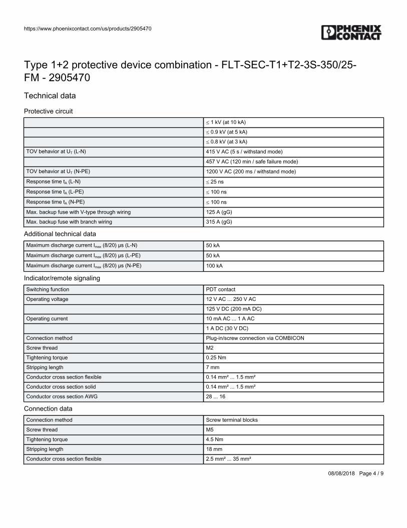
https://www.phoenixcontact.com/us/products/2905470
08/08/2018 Page 4 / 9
Type 1+2 protective device combination - FLT-SEC-T1+T2-3S-350/25-FM - 2905470Technical data
Protective circuit≤ 1 kV (at 10 kA)
≤ 0.9 kV (at 5 kA)
≤ 0.8 kV (at 3 kA)
TOV behavior at UT (L-N) 415 V AC (5 s / withstand mode)
457 V AC (120 min / safe failure mode)
TOV behavior at UT (N-PE) 1200 V AC (200 ms / withstand mode)
Response time tA (L-N) ≤ 25 ns
Response time tA (L-PE) ≤ 100 ns
Response time tA (N-PE) ≤ 100 ns
Max. backup fuse with V-type through wiring 125 A (gG)
Max. backup fuse with branch wiring 315 A (gG)
Additional technical dataMaximum discharge current Imax (8/20) µs (L-N) 50 kA
Maximum discharge current Imax (8/20) µs (L-PE) 50 kA
Maximum discharge current Imax (8/20) µs (N-PE) 100 kA
Indicator/remote signalingSwitching function PDT contact
Operating voltage 12 V AC ... 250 V AC
125 V DC (200 mA DC)
Operating current 10 mA AC ... 1 A AC
1 A DC (30 V DC)
Connection method Plug-in/screw connection via COMBICON
Screw thread M2
Tightening torque 0.25 Nm
Stripping length 7 mm
Conductor cross section flexible 0.14 mm² ... 1.5 mm²
Conductor cross section solid 0.14 mm² ... 1.5 mm²
Conductor cross section AWG 28 ... 16
Connection dataConnection method Screw terminal blocks
Screw thread M5
Tightening torque 4.5 Nm
Stripping length 18 mm
Conductor cross section flexible 2.5 mm² ... 35 mm²
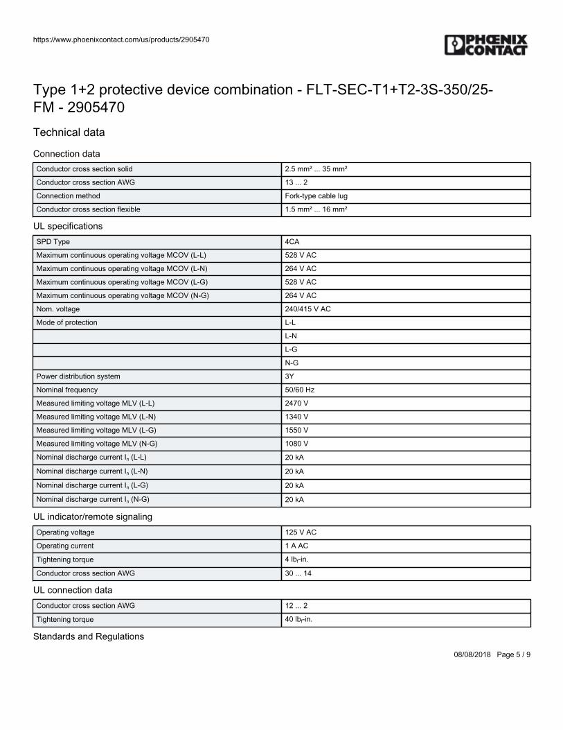
https://www.phoenixcontact.com/us/products/2905470
08/08/2018 Page 5 / 9
Type 1+2 protective device combination - FLT-SEC-T1+T2-3S-350/25-FM - 2905470Technical data
Connection dataConductor cross section solid 2.5 mm² ... 35 mm²
Conductor cross section AWG 13 ... 2
Connection method Fork-type cable lug
Conductor cross section flexible 1.5 mm² ... 16 mm²
UL specificationsSPD Type 4CA
Maximum continuous operating voltage MCOV (L-L) 528 V AC
Maximum continuous operating voltage MCOV (L-N) 264 V AC
Maximum continuous operating voltage MCOV (L-G) 528 V AC
Maximum continuous operating voltage MCOV (N-G) 264 V AC
Nom. voltage 240/415 V AC
Mode of protection L-L
L-N
L-G
N-G
Power distribution system 3Y
Nominal frequency 50/60 Hz
Measured limiting voltage MLV (L-L) 2470 V
Measured limiting voltage MLV (L-N) 1340 V
Measured limiting voltage MLV (L-G) 1550 V
Measured limiting voltage MLV (N-G) 1080 V
Nominal discharge current In (L-L) 20 kA
Nominal discharge current In (L-N) 20 kA
Nominal discharge current In (L-G) 20 kA
Nominal discharge current In (N-G) 20 kA
UL indicator/remote signalingOperating voltage 125 V AC
Operating current 1 A AC
Tightening torque 4 lbf-in.
Conductor cross section AWG 30 ... 14
UL connection dataConductor cross section AWG 12 ... 2
Tightening torque 40 lbf-in.
Standards and Regulations
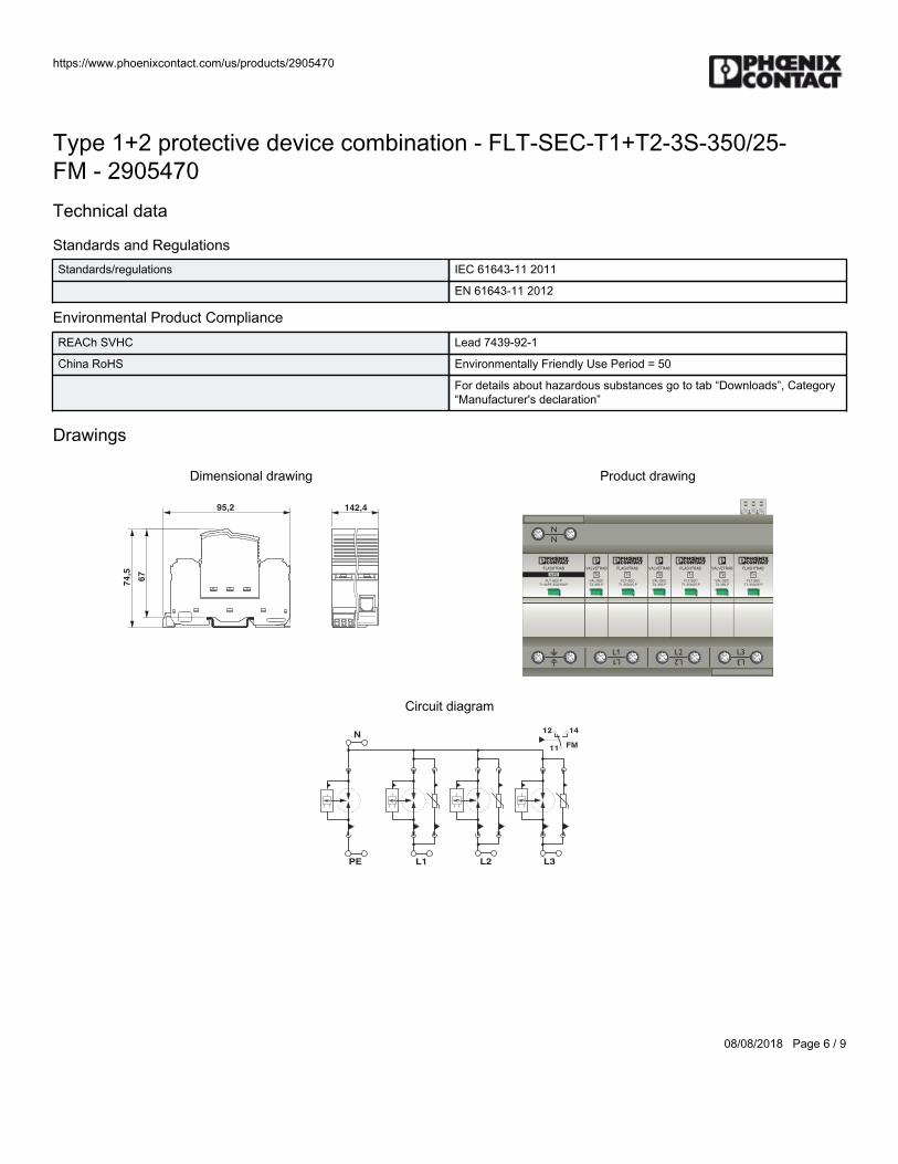
https://www.phoenixcontact.com/us/products/2905470
08/08/2018 Page 6 / 9
Type 1+2 protective device combination - FLT-SEC-T1+T2-3S-350/25-FM - 2905470Technical data
Standards and RegulationsStandards/regulations IEC 61643-11 2011
EN 61643-11 2012
Environmental Product ComplianceREACh SVHC Lead 7439-92-1
China RoHS Environmentally Friendly Use Period = 50
For details about hazardous substances go to tab “Downloads”, Category“Manufacturer's declaration”
Drawings
Dimensional drawing
74
,5
67
95,2 142,4
Product drawing
VALVETRAB
VAL-SEC
T2-350-P
T2
VALVETRAB
VAL-SEC
T2-350-P
T2
VALVETRAB
VAL-SEC
T2-350-P
T2
VALVETRAB
VAL-SEC
T2-350-P
T2
VALVETRAB
VAL-SEC
T2-350-P
T2
FLASHTRAB
FLT-SEC-P
T1-N/PE-350/100-P
N/PE
VALVETRAB
VAL-SEC
T2-350-P
T2
FLASHTRAB
FLT-SEC
T1-350/25-P
T1
FLASHTRAB
FLT-SEC
T1-350/25-P
T1
FLASHTRAB
FLT-SEC
T1-350/25-P
T1
Circuit diagram12 14
11 FM
N
PE L2L1 L3
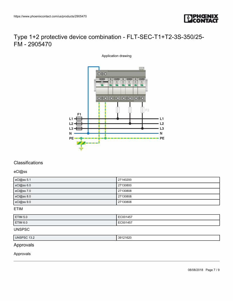
https://www.phoenixcontact.com/us/products/2905470
08/08/2018 Page 7 / 9
Type 1+2 protective device combination - FLT-SEC-T1+T2-3S-350/25-FM - 2905470
Application drawing
L1
F1
F2
L2
L3
N
PE
L1
L2
L3
N
PE
VALVETRAB
VAL-SEC
T2-350-P
T2
VALVETRAB
VAL-SEC
T2-350-P
T2
VALVETRAB
VAL-SEC
T2-350-P
T2
VALVETRAB
VAL-SEC
T2-350-P
T2
VALVETRAB
VAL-SEC
T2-350-P
T2
FLASHTRAB
FLT-SEC-P
T1-N/PE-350/100-P
N/PE
VALVETRAB
VAL-SEC
T2-350-P
T2
FLASHTRAB
FLT-SEC
T1-350/25-P
T1
FLASHTRAB
FLT-SEC
T1-350/25-P
T1
FLASHTRAB
FLT-SEC
T1-350/25-P
T1
Classifications
eCl@ss
eCl@ss 5.1 27140200
eCl@ss 6.0 27130800
eCl@ss 7.0 27130808
eCl@ss 8.0 27130808
eCl@ss 9.0 27130808
ETIM
ETIM 5.0 EC001457
ETIM 6.0 EC001457
UNSPSC
UNSPSC 13.2 39121620
Approvals
Approvals
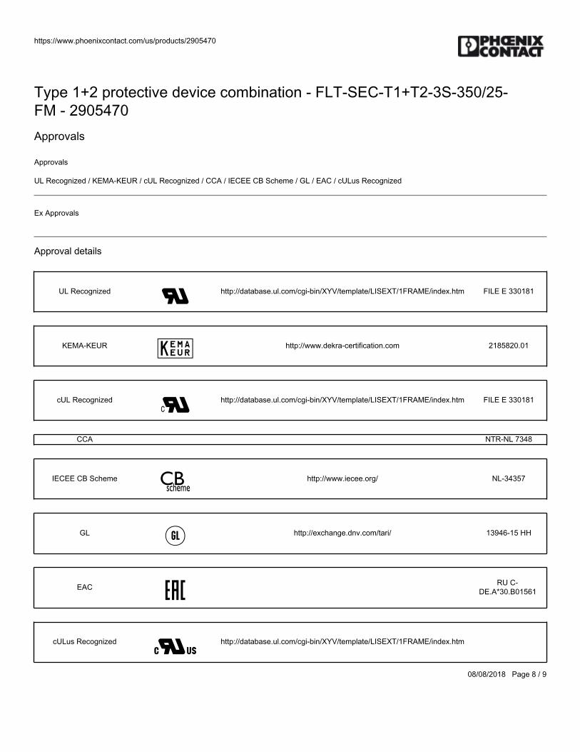
https://www.phoenixcontact.com/us/products/2905470
08/08/2018 Page 8 / 9
Type 1+2 protective device combination - FLT-SEC-T1+T2-3S-350/25-FM - 2905470Approvals
Approvals
UL Recognized / KEMA-KEUR / cUL Recognized / CCA / IECEE CB Scheme / GL / EAC / cULus Recognized
Ex Approvals
Approval details
UL Recognized http://database.ul.com/cgi-bin/XYV/template/LISEXT/1FRAME/index.htm FILE E 330181
KEMA-KEUR http://www.dekra-certification.com 2185820.01
cUL Recognized http://database.ul.com/cgi-bin/XYV/template/LISEXT/1FRAME/index.htm FILE E 330181
CCA NTR-NL 7348
IECEE CB Scheme http://www.iecee.org/ NL-34357
GL http://exchange.dnv.com/tari/ 13946-15 HH
EAC RU C-DE.A*30.B01561
cULus Recognized http://database.ul.com/cgi-bin/XYV/template/LISEXT/1FRAME/index.htm

https://www.phoenixcontact.com/us/products/2905470
08/08/2018 Page 9 / 9
Phoenix Contact 2018 © - all rights reservedhttp://www.phoenixcontact.com

BWS-GL-02 Appendix21
21. PhoenixContactWiringBridge:TMC8B38057C
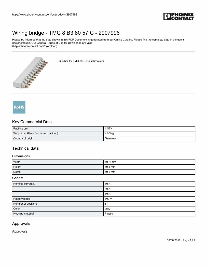
https://www.phoenixcontact.com/us/products/2907996
08/08/2018 Page 1 / 2
Wiring bridge - TMC 8 B3 80 57 C - 2907996Please be informed that the data shown in this PDF Document is generated from our Online Catalog. Please find the complete data in the user'sdocumentation. Our General Terms of Use for Downloads are valid(http://phoenixcontact.com/download)
Bus bar for TMC 83... circuit breakers
Key Commercial DataPacking unit 1 STK
Weight per Piece (excluding packing) 1.000 g
Country of origin Germany
Technical data
DimensionsWidth 1031 mm
Height 19.3 mm
Depth 59.2 mm
GeneralNominal current IN 80 A
80 A
80 A
Rated voltage 600 V
Number of positions 57
Color gray
Housing material Plastic
Approvals
Approvals
https://www.phoenixcontact.com/us/products/2907996
08/08/2018 Page 2 / 2
Wiring bridge - TMC 8 B3 80 57 C - 2907996Approvals
Approvals
UL Listed / cUL Listed / cULus Listed
Ex Approvals
Approval details
UL Listed http://database.ul.com/cgi-bin/XYV/template/LISEXT/1FRAME/index.htm FILE E 123528
cUL Listed http://database.ul.com/cgi-bin/XYV/template/LISEXT/1FRAME/index.htm FILE E 123528
cULus Listed
Phoenix Contact 2018 © - all rights reservedhttp://www.phoenixcontact.com

BWS-GL-02 Appendix22
22. PhoenixContactUL489CircuitBreaker:TMC81D10A
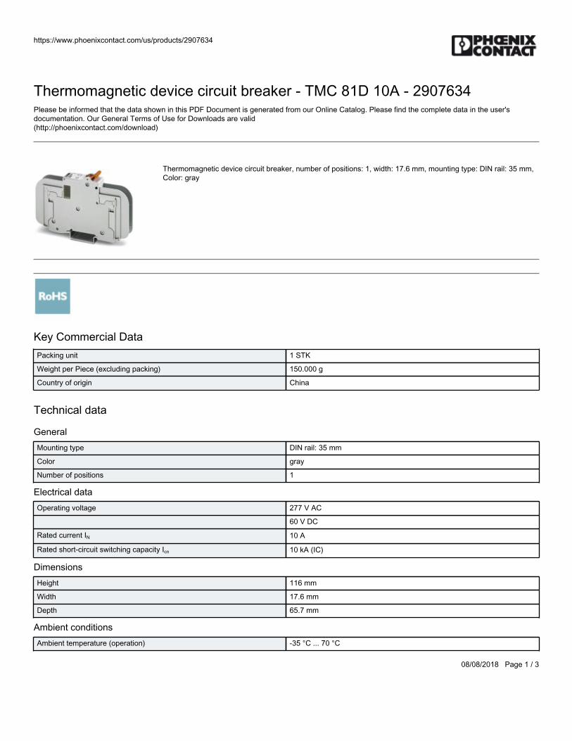
https://www.phoenixcontact.com/us/products/2907634
08/08/2018 Page 1 / 3
Thermomagnetic device circuit breaker - TMC 81D 10A - 2907634Please be informed that the data shown in this PDF Document is generated from our Online Catalog. Please find the complete data in the user'sdocumentation. Our General Terms of Use for Downloads are valid(http://phoenixcontact.com/download)
Thermomagnetic device circuit breaker, number of positions: 1, width: 17.6 mm, mounting type: DIN rail: 35 mm,Color: gray
Key Commercial DataPacking unit 1 STK
Weight per Piece (excluding packing) 150.000 g
Country of origin China
Technical data
GeneralMounting type DIN rail: 35 mm
Color gray
Number of positions 1
Electrical dataOperating voltage 277 V AC
60 V DC
Rated current IN 10 A
Rated short-circuit switching capacity Icn 10 kA (IC)
DimensionsHeight 116 mm
Width 17.6 mm
Depth 65.7 mm
Ambient conditionsAmbient temperature (operation) -35 °C ... 70 °C
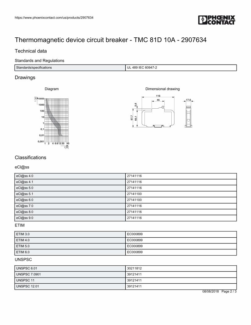
https://www.phoenixcontact.com/us/products/2907634
08/08/2018 Page 2 / 3
Thermomagnetic device circuit breaker - TMC 81D 10A - 2907634Technical data
Standards and RegulationsStandards/specifications UL 489 IEC 60947-2
Drawings
Diagram
10000
1000
100
10
1
0,1
0,01
0,0011 2 204 506 8
I [A]
t [
s]
12
Dimensional drawing
67
,7
60
,15
,6
45
116
17,6
Classifications
eCl@ss
eCl@ss 4.0 27141116
eCl@ss 4.1 27141116
eCl@ss 5.0 27141116
eCl@ss 5.1 27141100
eCl@ss 6.0 27141100
eCl@ss 7.0 27141116
eCl@ss 8.0 27141116
eCl@ss 9.0 27141116
ETIM
ETIM 3.0 EC000899
ETIM 4.0 EC000899
ETIM 5.0 EC000899
ETIM 6.0 EC000899
UNSPSC
UNSPSC 6.01 30211812
UNSPSC 7.0901 39121411
UNSPSC 11 39121411
UNSPSC 12.01 39121411
https://www.phoenixcontact.com/us/products/2907634
08/08/2018 Page 3 / 3
Thermomagnetic device circuit breaker - TMC 81D 10A - 2907634Classifications
UNSPSCUNSPSC 13.2 39121620
Approvals
Approvals
Approvals
UL Listed / cUL Listed / cULus Listed
Ex Approvals
Approval details
UL Listed http://database.ul.com/cgi-bin/XYV/template/LISEXT/1FRAME/index.htm FILE E 320373
cUL Listed http://database.ul.com/cgi-bin/XYV/template/LISEXT/1FRAME/index.htm FILE E 320373
cULus Listed
Phoenix Contact 2018 © - all rights reservedhttp://www.phoenixcontact.com

BWS-GL-02 Appendix23
23. PhoenixContactUL489CircuitBreaker:TMC83D15A
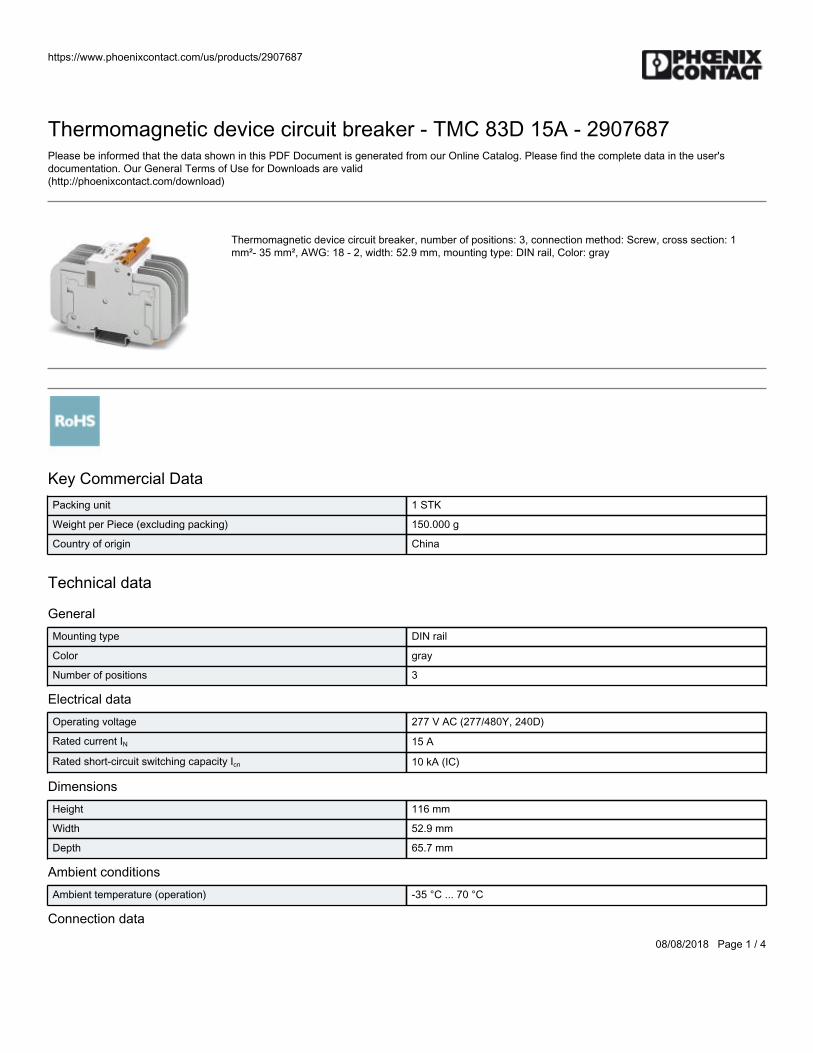
https://www.phoenixcontact.com/us/products/2907687
08/08/2018 Page 1 / 4
Thermomagnetic device circuit breaker - TMC 83D 15A - 2907687Please be informed that the data shown in this PDF Document is generated from our Online Catalog. Please find the complete data in the user'sdocumentation. Our General Terms of Use for Downloads are valid(http://phoenixcontact.com/download)
Thermomagnetic device circuit breaker, number of positions: 3, connection method: Screw, cross section: 1mm²- 35 mm², AWG: 18 - 2, width: 52.9 mm, mounting type: DIN rail, Color: gray
Key Commercial DataPacking unit 1 STK
Weight per Piece (excluding packing) 150.000 g
Country of origin China
Technical data
GeneralMounting type DIN rail
Color gray
Number of positions 3
Electrical dataOperating voltage 277 V AC (277/480Y, 240D)
Rated current IN 15 A
Rated short-circuit switching capacity Icn 10 kA (IC)
DimensionsHeight 116 mm
Width 52.9 mm
Depth 65.7 mm
Ambient conditionsAmbient temperature (operation) -35 °C ... 70 °C
Connection data
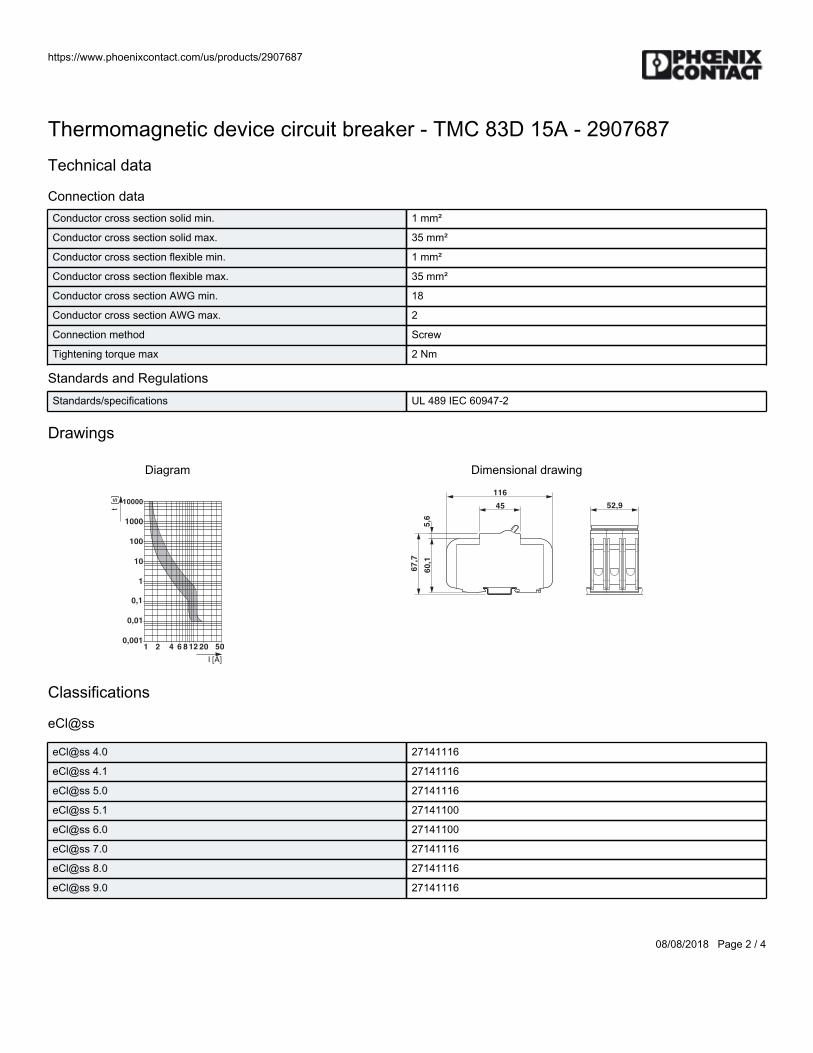
https://www.phoenixcontact.com/us/products/2907687
08/08/2018 Page 2 / 4
Thermomagnetic device circuit breaker - TMC 83D 15A - 2907687Technical data
Connection dataConductor cross section solid min. 1 mm²
Conductor cross section solid max. 35 mm²
Conductor cross section flexible min. 1 mm²
Conductor cross section flexible max. 35 mm²
Conductor cross section AWG min. 18
Conductor cross section AWG max. 2
Connection method Screw
Tightening torque max 2 Nm
Standards and RegulationsStandards/specifications UL 489 IEC 60947-2
Drawings
Diagram
10000
1000
100
10
1
0,1
0,01
0,0011 2 204 506 8
I [A]
t [
s]
12
Dimensional drawing
67
,7
60
,15
,6
45
116
52,9
Classifications
eCl@ss
eCl@ss 4.0 27141116
eCl@ss 4.1 27141116
eCl@ss 5.0 27141116
eCl@ss 5.1 27141100
eCl@ss 6.0 27141100
eCl@ss 7.0 27141116
eCl@ss 8.0 27141116
eCl@ss 9.0 27141116
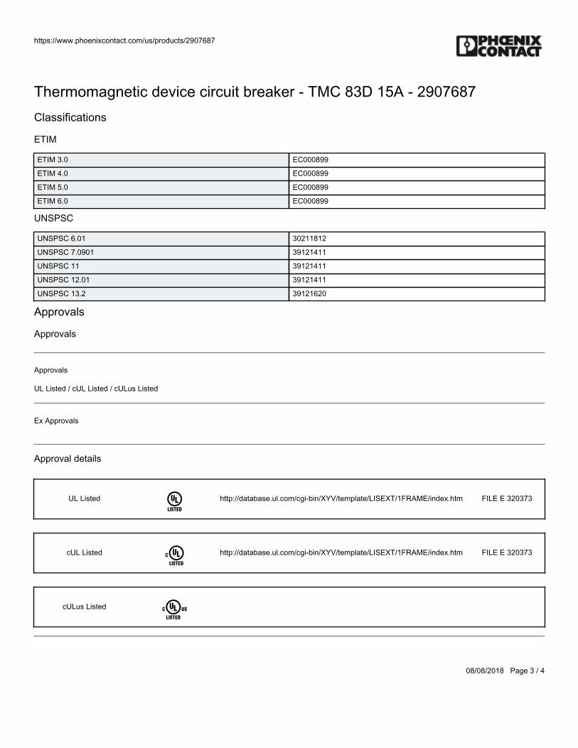
https://www.phoenixcontact.com/us/products/2907687
08/08/2018 Page 3 / 4
Thermomagnetic device circuit breaker - TMC 83D 15A - 2907687Classifications
ETIM
ETIM 3.0 EC000899
ETIM 4.0 EC000899
ETIM 5.0 EC000899
ETIM 6.0 EC000899
UNSPSC
UNSPSC 6.01 30211812
UNSPSC 7.0901 39121411
UNSPSC 11 39121411
UNSPSC 12.01 39121411
UNSPSC 13.2 39121620
Approvals
Approvals
Approvals
UL Listed / cUL Listed / cULus Listed
Ex Approvals
Approval details
UL Listed http://database.ul.com/cgi-bin/XYV/template/LISEXT/1FRAME/index.htm FILE E 320373
cUL Listed http://database.ul.com/cgi-bin/XYV/template/LISEXT/1FRAME/index.htm FILE E 320373
cULus Listed

https://www.phoenixcontact.com/us/products/2907687
08/08/2018 Page 4 / 4
Phoenix Contact 2018 © - all rights reservedhttp://www.phoenixcontact.com

BWS-GL-02 Appendix24
24. PhoenixContactRelay:PLC-RSC-24DC/21
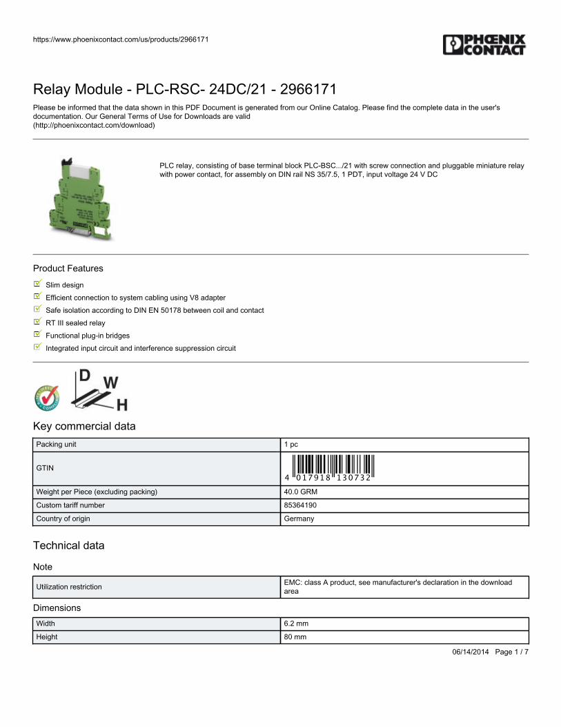
https://www.phoenixcontact.com/us/products/2966171
06/14/2014 Page 1 / 7
Relay Module - PLC-RSC- 24DC/21 - 2966171Please be informed that the data shown in this PDF Document is generated from our Online Catalog. Please find the complete data in the user'sdocumentation. Our General Terms of Use for Downloads are valid(http://phoenixcontact.com/download)
PLC relay, consisting of base terminal block PLC-BSC.../21 with screw connection and pluggable miniature relaywith power contact, for assembly on DIN rail NS 35/7.5, 1 PDT, input voltage 24 V DC
Product Features
Slim design
Efficient connection to system cabling using V8 adapter
Safe isolation according to DIN EN 50178 between coil and contact
RT III sealed relay
Functional plug-in bridges
Integrated input circuit and interference suppression circuit
Key commercial dataPacking unit 1 pc
GTIN
Weight per Piece (excluding packing) 40.0 GRM
Custom tariff number 85364190
Country of origin Germany
Technical data
Note
Utilization restriction EMC: class A product, see manufacturer's declaration in the downloadarea
DimensionsWidth 6.2 mm
Height 80 mm
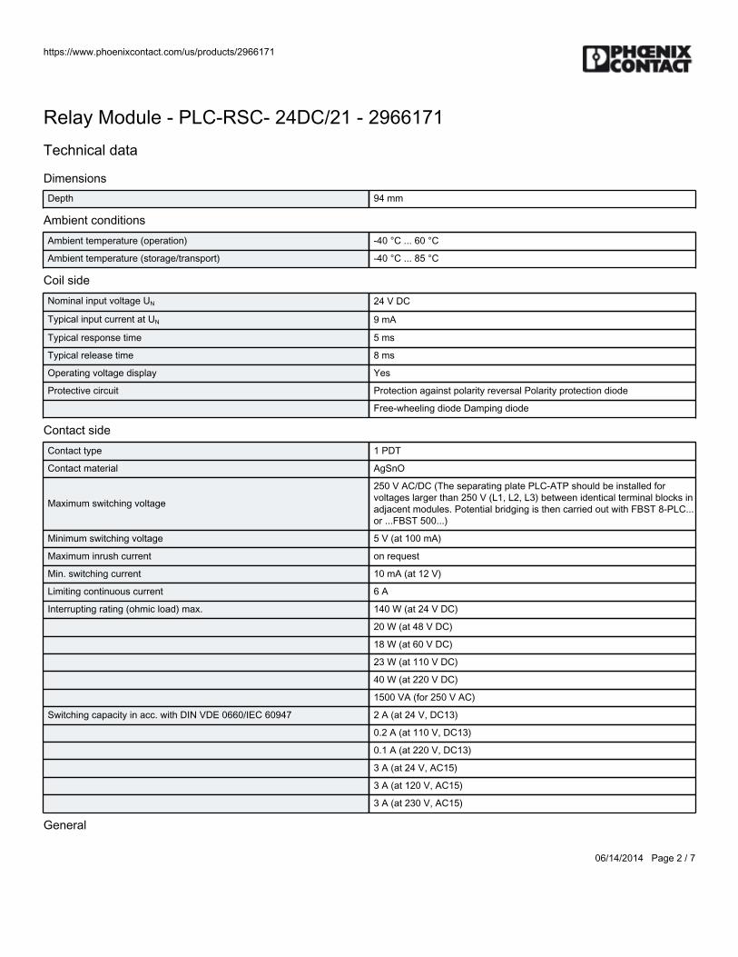
https://www.phoenixcontact.com/us/products/2966171
06/14/2014 Page 2 / 7
Relay Module - PLC-RSC- 24DC/21 - 2966171Technical data
DimensionsDepth 94 mm
Ambient conditionsAmbient temperature (operation) -40 °C ... 60 °C
Ambient temperature (storage/transport) -40 °C ... 85 °C
Coil sideNominal input voltage UN 24 V DC
Typical input current at UN 9 mA
Typical response time 5 ms
Typical release time 8 ms
Operating voltage display Yes
Protective circuit Protection against polarity reversal Polarity protection diode
Free-wheeling diode Damping diode
Contact sideContact type 1 PDT
Contact material AgSnO
Maximum switching voltage
250 V AC/DC (The separating plate PLC-ATP should be installed forvoltages larger than 250 V (L1, L2, L3) between identical terminal blocks inadjacent modules. Potential bridging is then carried out with FBST 8-PLC...or ...FBST 500...)
Minimum switching voltage 5 V (at 100 mA)
Maximum inrush current on request
Min. switching current 10 mA (at 12 V)
Limiting continuous current 6 A
Interrupting rating (ohmic load) max. 140 W (at 24 V DC)
20 W (at 48 V DC)
18 W (at 60 V DC)
23 W (at 110 V DC)
40 W (at 220 V DC)
1500 VA (for 250 V AC)
Switching capacity in acc. with DIN VDE 0660/IEC 60947 2 A (at 24 V, DC13)
0.2 A (at 110 V, DC13)
0.1 A (at 220 V, DC13)
3 A (at 24 V, AC15)
3 A (at 120 V, AC15)
3 A (at 230 V, AC15)
General
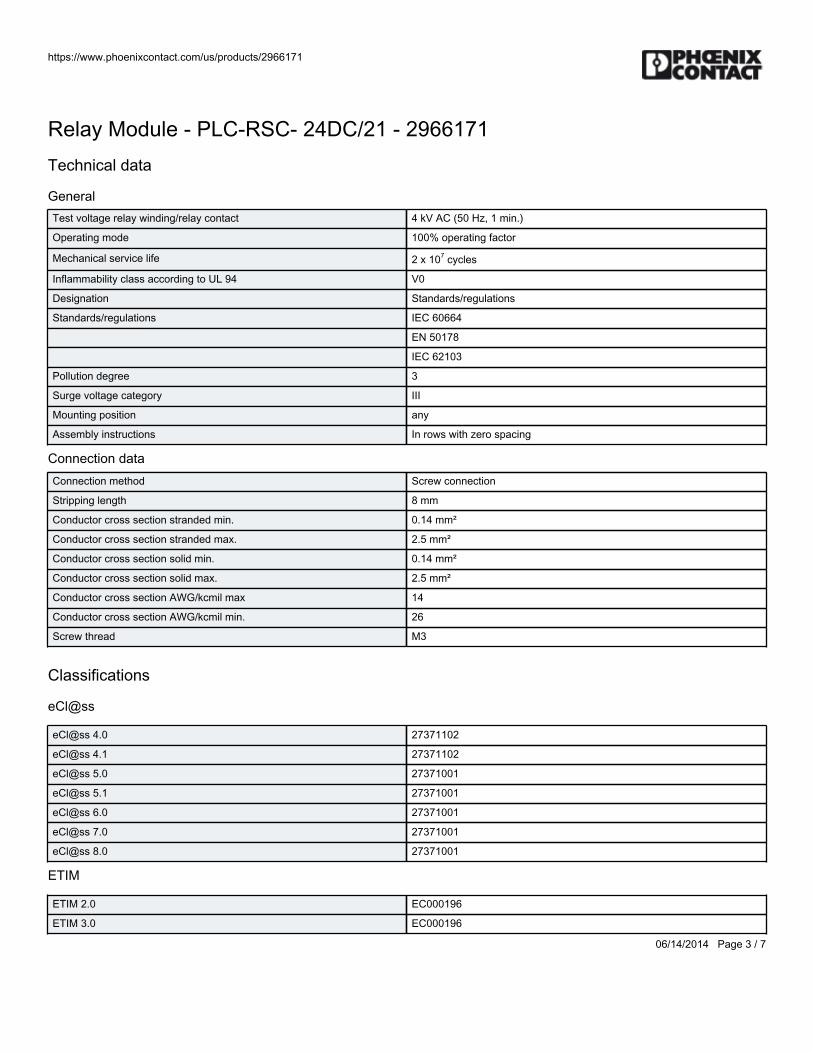
https://www.phoenixcontact.com/us/products/2966171
06/14/2014 Page 3 / 7
Relay Module - PLC-RSC- 24DC/21 - 2966171Technical data
GeneralTest voltage relay winding/relay contact 4 kV AC (50 Hz, 1 min.)
Operating mode 100% operating factor
Mechanical service life 2 x 10⁷ cycles
Inflammability class according to UL 94 V0
Designation Standards/regulations
Standards/regulations IEC 60664
EN 50178
IEC 62103
Pollution degree 3
Surge voltage category III
Mounting position any
Assembly instructions In rows with zero spacing
Connection dataConnection method Screw connection
Stripping length 8 mm
Conductor cross section stranded min. 0.14 mm²
Conductor cross section stranded max. 2.5 mm²
Conductor cross section solid min. 0.14 mm²
Conductor cross section solid max. 2.5 mm²
Conductor cross section AWG/kcmil max 14
Conductor cross section AWG/kcmil min. 26
Screw thread M3
Classifications
eCl@ss
eCl@ss 4.0 27371102
eCl@ss 4.1 27371102
eCl@ss 5.0 27371001
eCl@ss 5.1 27371001
eCl@ss 6.0 27371001
eCl@ss 7.0 27371001
eCl@ss 8.0 27371001
ETIM
ETIM 2.0 EC000196
ETIM 3.0 EC000196
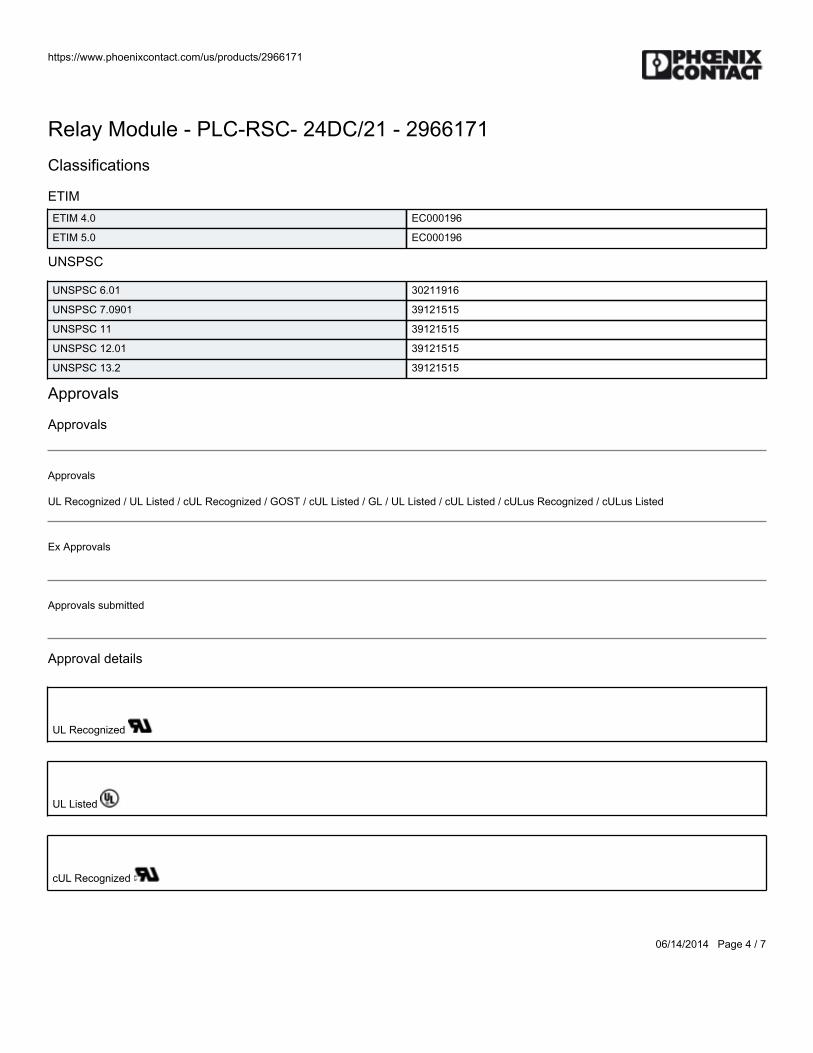
https://www.phoenixcontact.com/us/products/2966171
06/14/2014 Page 4 / 7
Relay Module - PLC-RSC- 24DC/21 - 2966171Classifications
ETIMETIM 4.0 EC000196
ETIM 5.0 EC000196
UNSPSC
UNSPSC 6.01 30211916
UNSPSC 7.0901 39121515
UNSPSC 11 39121515
UNSPSC 12.01 39121515
UNSPSC 13.2 39121515
Approvals
Approvals
Approvals
UL Recognized / UL Listed / cUL Recognized / GOST / cUL Listed / GL / UL Listed / cUL Listed / cULus Recognized / cULus Listed
Ex Approvals
Approvals submitted
Approval details
UL Recognized
UL Listed
cUL Recognized
https://www.phoenixcontact.com/us/products/2966171
06/14/2014 Page 5 / 7
Relay Module - PLC-RSC- 24DC/21 - 2966171Approvals
GOST
cUL Listed
GL
UL Listed
cUL Listed
cULus Recognized
cULus Listed
Drawings
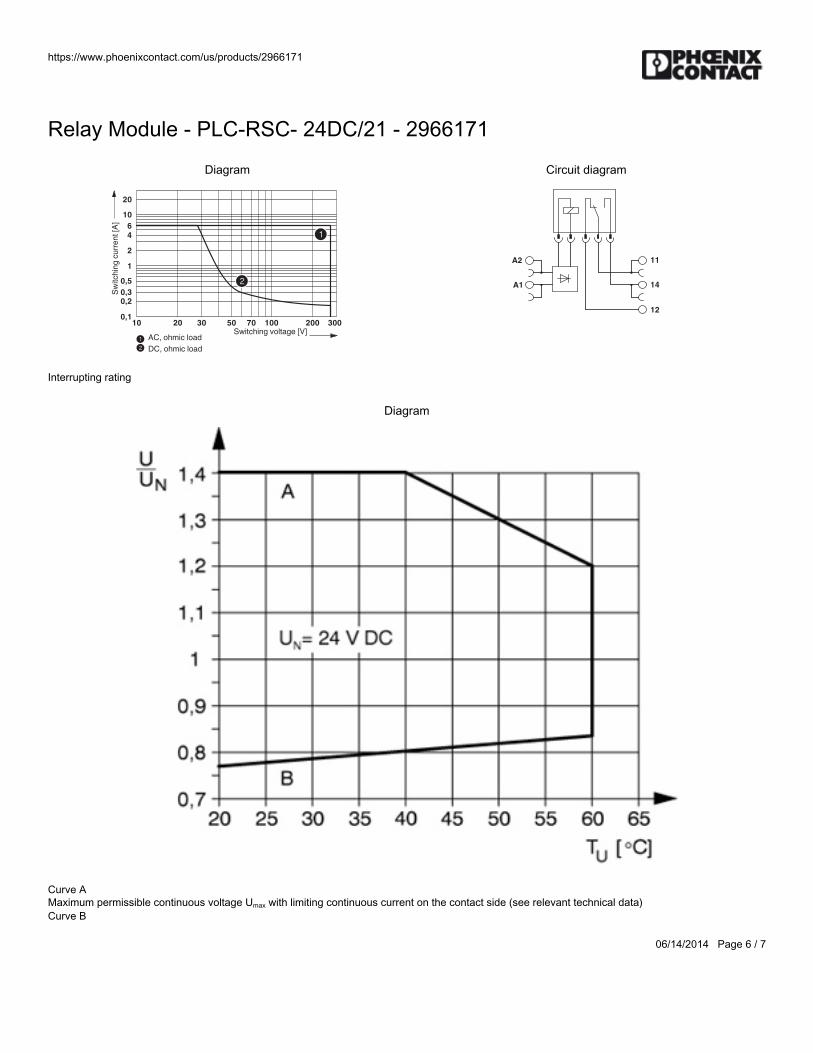
https://www.phoenixcontact.com/us/products/2966171
06/14/2014 Page 6 / 7
Relay Module - PLC-RSC- 24DC/21 - 2966171
Diagram
0,1
0,20,3
0,5
1
2
4
10
20
10 20 30 50 70 100 300200
12
1
2
6
AC,ohmicload
DC,ohmicload
Switchingvoltage[V]
Sw
itch
ing
cu
rre
nt
[A]
Interrupting rating
Circuit diagram
A1
A2 11
14
12
Diagram
Curve A Maximum permissible continuous voltage Umax with limiting continuous current on the contact side (see relevant technical data) Curve B

https://www.phoenixcontact.com/us/products/2966171
06/14/2014 Page 7 / 7
Relay Module - PLC-RSC- 24DC/21 - 2966171Minimum permissible operate voltage Uop after pre-excitation (see relevant technical data)
Phoenix Contact 2014 © - all rights reservedhttp://www.phoenixcontact.com

BWS-GL-02 Appendix25
25. EmmersonVariableFrequencyDrive:M200-02200042A
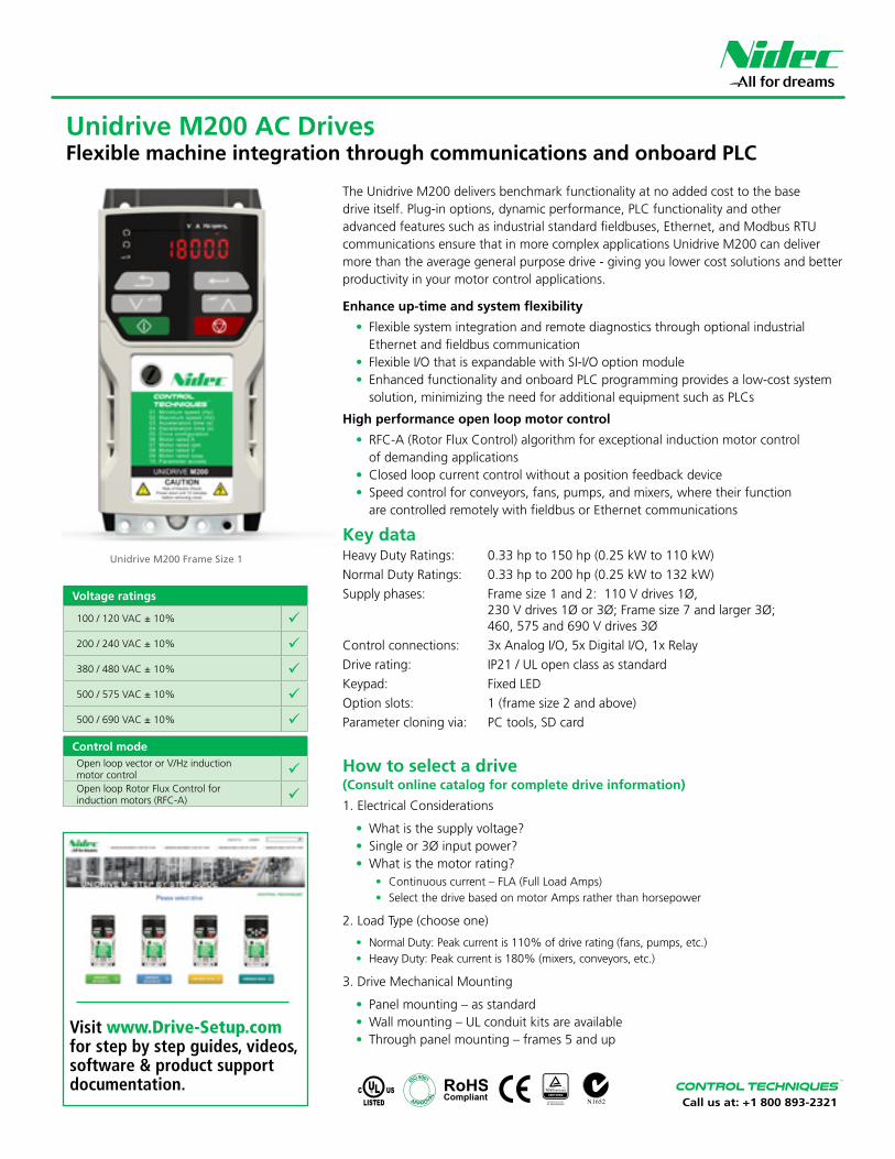
Call us at: +1 800 893-2321
The Unidrive M200 delivers benchmark functionality at no added cost to the base drive itself. Plug-in options, dynamic performance, PLC functionality and other advanced features such as industrial standard fieldbuses, Ethernet, and Modbus RTU communications ensure that in more complex applications Unidrive M200 can deliver more than the average general purpose drive - giving you lower cost solutions and better productivity in your motor control applications.
Enhance up-time and system flexibility
• Flexible system integration and remote diagnostics through optional industrial Ethernet and fieldbus communication
• Flexible I/O that is expandable with SI-I/O option module• Enhanced functionality and onboard PLC programming provides a low-cost system
solution, minimizing the need for additional equipment such as PLCs
High performance open loop motor control
• RFC-A (Rotor Flux Control) algorithm for exceptional induction motor control of demanding applications
• Closed loop current control without a position feedback device• Speed control for conveyors, fans, pumps, and mixers, where their function
are controlled remotely with fieldbus or Ethernet communications
Key dataHeavy Duty Ratings: 0.33 hp to 150 hp (0.25 kW to 110 kW)Normal Duty Ratings: 0.33 hp to 200 hp (0.25 kW to 132 kW) Supply phases: Frame size 1 and 2: 110 V drives 1Ø,
230 V drives 1Ø or 3Ø; Frame size 7 and larger 3Ø; 460, 575 and 690 V drives 3Ø
Control connections: 3x Analog I/O, 5x Digital I/O, 1x RelayDrive rating: IP21 / UL open class as standardKeypad: Fixed LEDOption slots: 1 (frame size 2 and above)Parameter cloning via: PC tools, SD card
Unidrive M200 Frame Size 1
How to select a drive (Consult online catalog for complete drive information)
1. Electrical Considerations
• What is the supply voltage?• Single or 3Ø input power?• What is the motor rating?
• Continuous current – FLA (Full Load Amps)• Select the drive based on motor Amps rather than horsepower
2. Load Type (choose one)
• Normal Duty: Peak current is 110% of drive rating (fans, pumps, etc.)• Heavy Duty: Peak current is 180% (mixers, conveyors, etc.)
3. Drive Mechanical Mounting
• Panel mounting – as standard• Wall mounting – UL conduit kits are available• Through panel mounting – frames 5 and up
Unidrive M200 AC DrivesFlexible machine integration through communications and onboard PLC
Voltage ratings
100 / 120 VAC ± 10% ü
200 / 240 VAC ± 10% ü
380 / 480 VAC ± 10% ü
500 / 575 VAC ± 10% ü
500 / 690 VAC ± 10% ü
Control modeOpen loop vector or V/Hz induction motor control üOpen loop Rotor Flux Control for induction motors (RFC-A) ü
APPR OVAL
IS
O 9002
APPR OVAL
IS
O 9002
APPR OVAL
IS
O 9002
APPROVAL
I
SO 9001
Visit www.Drive-Setup.com for step by step guides, videos, software & product support documentation.
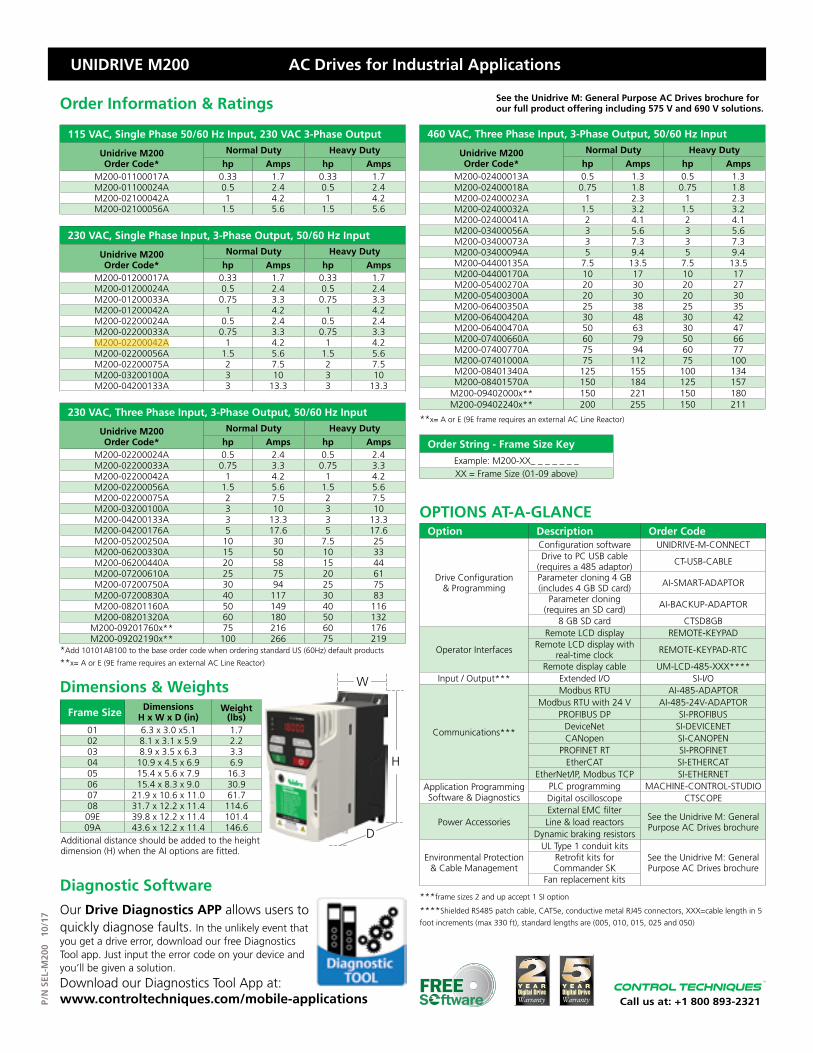
P/N
SEL
-M20
0 1
0/17
UNIDRIVE M200 AC Drives for Industrial Applications
Call us at: +1 800 893-2321
115 VAC, Single Phase 50/60 Hz Input, 230 VAC 3-Phase Output
Unidrive M200Order Code*
Normal Duty Heavy Dutyhp Amps hp Amps
M200-01100017A 0.33 1.7 0.33 1.7M200-01100024A 0.5 2.4 0.5 2.4M200-02100042A 1 4.2 1 4.2M200-02100056A 1.5 5.6 1.5 5.6
230 VAC, Single Phase Input, 3-Phase Output, 50/60 Hz Input
Unidrive M200Order Code*
Normal Duty Heavy Dutyhp Amps hp Amps
M200-01200017A 0.33 1.7 0.33 1.7M200-01200024A 0.5 2.4 0.5 2.4M200-01200033A 0.75 3.3 0.75 3.3M200-01200042A 1 4.2 1 4.2M200-02200024A 0.5 2.4 0.5 2.4M200-02200033A 0.75 3.3 0.75 3.3M200-02200042A 1 4.2 1 4.2M200-02200056A 1.5 5.6 1.5 5.6M200-02200075A 2 7.5 2 7.5M200-03200100A 3 10 3 10M200-04200133A 3 13.3 3 13.3
230 VAC, Three Phase Input, 3-Phase Output, 50/60 Hz Input
Unidrive M200Order Code*
Normal Duty Heavy Dutyhp Amps hp Amps
M200-02200024A 0.5 2.4 0.5 2.4M200-02200033A 0.75 3.3 0.75 3.3M200-02200042A 1 4.2 1 4.2M200-02200056A 1.5 5.6 1.5 5.6M200-02200075A 2 7.5 2 7.5M200-03200100A 3 10 3 10M200-04200133A 3 13.3 3 13.3M200-04200176A 5 17.6 5 17.6M200-05200250A 10 30 7.5 25M200-06200330A 15 50 10 33M200-06200440A 20 58 15 44M200-07200610A 25 75 20 61M200-07200750A 30 94 25 75M200-07200830A 40 117 30 83M200-08201160A 50 149 40 116M200-08201320A 60 180 50 132
M200-09201760x** 75 216 60 176M200-09202190x** 100 266 75 219
*Add 10101AB100 to the base order code when ordering standard US (60Hz) default products
**x= A or E (9E frame requires an external AC Line Reactor)
460 VAC, Three Phase Input, 3-Phase Output, 50/60 Hz Input
Unidrive M200Order Code*
Normal Duty Heavy Dutyhp Amps hp Amps
M200-02400013A 0.5 1.3 0.5 1.3M200-02400018A 0.75 1.8 0.75 1.8M200-02400023A 1 2.3 1 2.3M200-02400032A 1.5 3.2 1.5 3.2M200-02400041A 2 4.1 2 4.1M200-03400056A 3 5.6 3 5.6M200-03400073A 3 7.3 3 7.3M200-03400094A 5 9.4 5 9.4M200-04400135A 7.5 13.5 7.5 13.5M200-04400170A 10 17 10 17M200-05400270A 20 30 20 27M200-05400300A 20 30 20 30M200-06400350A 25 38 25 35M200-06400420A 30 48 30 42M200-06400470A 50 63 30 47M200-07400660A 60 79 50 66M200-07400770A 75 94 60 77M200-07401000A 75 112 75 100M200-08401340A 125 155 100 134M200-08401570A 150 184 125 157
M200-09402000x** 150 221 150 180M200-09402240x** 200 255 150 211
**x= A or E (9E frame requires an external AC Line Reactor)
Order String - Frame Size KeyExample: M200-XX_ _ _ _ _ _ _ XX = Frame Size (01-09 above)
Option Description Order Code
Drive Configuration & Programming
Configuration software UNIDRIVE-M-CONNECTDrive to PC USB cable
(requires a 485 adaptor) CT-USB-CABLE
Parameter cloning 4 GB(includes 4 GB SD card) AI-SMART-ADAPTOR
Parameter cloning(requires an SD card) AI-BACKUP-ADAPTOR
8 GB SD card CTSD8GB
Operator Interfaces
Remote LCD display REMOTE-KEYPADRemote LCD display with
real-time clock REMOTE-KEYPAD-RTC
Remote display cable UM-LCD-485-XXX****Input / Output*** Extended I/O SI-I/O
Communications***
Modbus RTU AI-485-ADAPTORModbus RTU with 24 V AI-485-24V-ADAPTOR
PROFIBUS DP SI-PROFIBUSDeviceNet SI-DEVICENETCANopen SI-CANOPEN
PROFINET RT SI-PROFINETEtherCAT SI-ETHERCAT
EtherNet/IP, Modbus TCP SI-ETHERNETApplication Programming Software & Diagnostics
PLC programming MACHINE-CONTROL-STUDIODigital oscilloscope CTSCOPE
Power AccessoriesExternal EMC filter
See the Unidrive M: General Purpose AC Drives brochureLine & load reactors
Dynamic braking resistors
Environmental Protection & Cable Management
UL Type 1 conduit kitsSee the Unidrive M: General Purpose AC Drives brochure
Retrofit kits for Commander SK
Fan replacement kits
***frame sizes 2 and up accept 1 SI option
****Shielded RS485 patch cable, CAT5e, conductive metal RJ45 connectors, XXX=cable length in 5 foot increments (max 330 ft), standard lengths are (005, 010, 015, 025 and 050)
OPTIONS AT-A-GLANCE
W
H
D
Frame Size Dimensions H x W x D (in)
Weight (lbs)
01 6.3 x 3.0 x5.1 1.702 8.1 x 3.1 x 5.9 2.203 8.9 x 3.5 x 6.3 3.304 10.9 x 4.5 x 6.9 6.905 15.4 x 5.6 x 7.9 16.306 15.4 x 8.3 x 9.0 30.907 21.9 x 10.6 x 11.0 61.708 31.7 x 12.2 x 11.4 114.609E 39.8 x 12.2 x 11.4 101.409A 43.6 x 12.2 x 11.4 146.6
Dimensions & Weights
Additional distance should be added to the height dimension (H) when the AI options are fitted.
Diagnostic SoftwareOur Drive Diagnostics APP allows users to quickly diagnose faults. In the unlikely event that you get a drive error, download our free Diagnostics Tool app. Just input the error code on your device and you’ll be given a solution. Download our Diagnostics Tool App at: www.controltechniques.com/mobile-applications
See the Unidrive M: General Purpose AC Drives brochure for our full product offering including 575 V and 690 V solutions.Order Information & Ratings

BWS-GL-02 Appendix26
26. PhoenixContactDinRail:NS35/15Perf
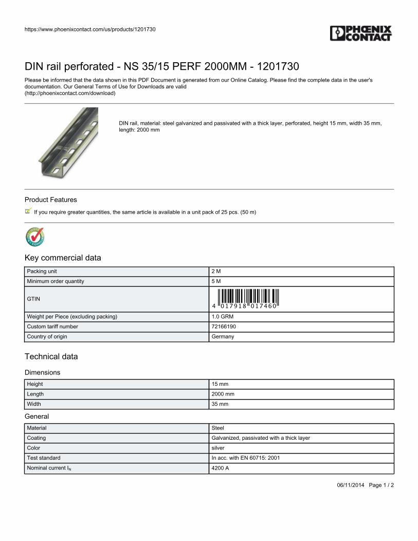
https://www.phoenixcontact.com/us/products/1201730
06/11/2014 Page 1 / 2
DIN rail perforated - NS 35/15 PERF 2000MM - 1201730Please be informed that the data shown in this PDF Document is generated from our Online Catalog. Please find the complete data in the user'sdocumentation. Our General Terms of Use for Downloads are valid(http://phoenixcontact.com/download)
DIN rail, material: steel galvanized and passivated with a thick layer, perforated, height 15 mm, width 35 mm,length: 2000 mm
Product Features
If you require greater quantities, the same article is available in a unit pack of 25 pcs. (50 m)
Key commercial dataPacking unit 2 M
Minimum order quantity 5 M
GTIN
Weight per Piece (excluding packing) 1.0 GRM
Custom tariff number 72166190
Country of origin Germany
Technical data
DimensionsHeight 15 mm
Length 2000 mm
Width 35 mm
GeneralMaterial Steel
Coating Galvanized, passivated with a thick layer
Color silver
Test standard In acc. with EN 60715: 2001
Nominal current IN 4200 A
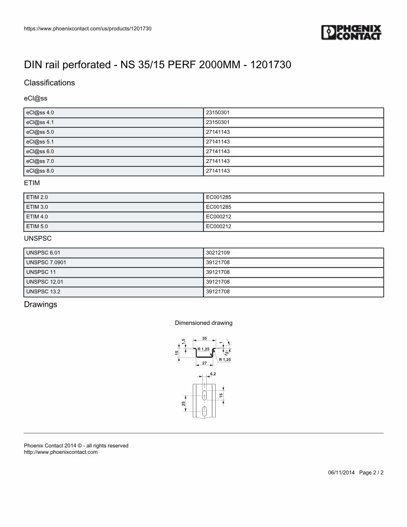
https://www.phoenixcontact.com/us/products/1201730
06/11/2014 Page 2 / 2
DIN rail perforated - NS 35/15 PERF 2000MM - 1201730Classifications
eCl@ss
eCl@ss 4.0 23150301
eCl@ss 4.1 23150301
eCl@ss 5.0 27141143
eCl@ss 5.1 27141143
eCl@ss 6.0 27141143
eCl@ss 7.0 27141143
eCl@ss 8.0 27141143
ETIM
ETIM 2.0 EC001285
ETIM 3.0 EC001285
ETIM 4.0 EC000212
ETIM 5.0 EC000212
UNSPSC
UNSPSC 6.01 30212109
UNSPSC 7.0901 39121708
UNSPSC 11 39121708
UNSPSC 12.01 39121708
UNSPSC 13.2 39121708
Drawings
Dimensioned drawing
25
15
6,2
35
27
R 1,25
R 1,25
15°
1
15
1,5
Phoenix Contact 2014 © - all rights reservedhttp://www.phoenixcontact.com

BWS-GL-02 Appendix27
27. PhoenixContactCableDuct:CD40x80

https://www.phoenixcontact.com/us/products/3240198
07/21/2016 Page 1 / 3
Cable duct - CD 40X80 - 3240198Please be informed that the data shown in this PDF Document is generated from our Online Catalog. Please find the complete data in the user'sdocumentation. Our General Terms of Use for Downloads are valid(http://phoenixcontact.com/download)
Cable duct, gray, consisting of upper and lower part, width: 40 mm, height: 80 mm, length 2000 mm
Why buy this product Easy, burr-free cutting with minimum effort using the CUTFOX-CD cable duct cutter
Thanks to its leverage and special cutting geometry, the PPS CD cable duct cutter enables easy, burr-free cutting with minimum effort
Predetermined breaking point enables tool-free, burr-free removal of bars
The wide, diagonal heads of the cable duct bars make it easy to fit the cover and hold it securely in place
Installed conductors are securely held in place by means of wire retaining clips that can be snapped onto bars on the side
Plastic body-bound rivets enable easy fixing of cable ducts using the rivet setting tool
Key Commercial DataPacking unit 1 STK
Minimum order quantity 10 STK
Weight per Piece (excluding packing) 1.0 g
Custom tariff number 39259020
Country of origin Germany
Technical data
DimensionsLength (b) 2000 mm
Width (a) 40 mm
Height 80 mm
Ambient conditionsAmbient temperature (operation) -5 °C ... 60 °C
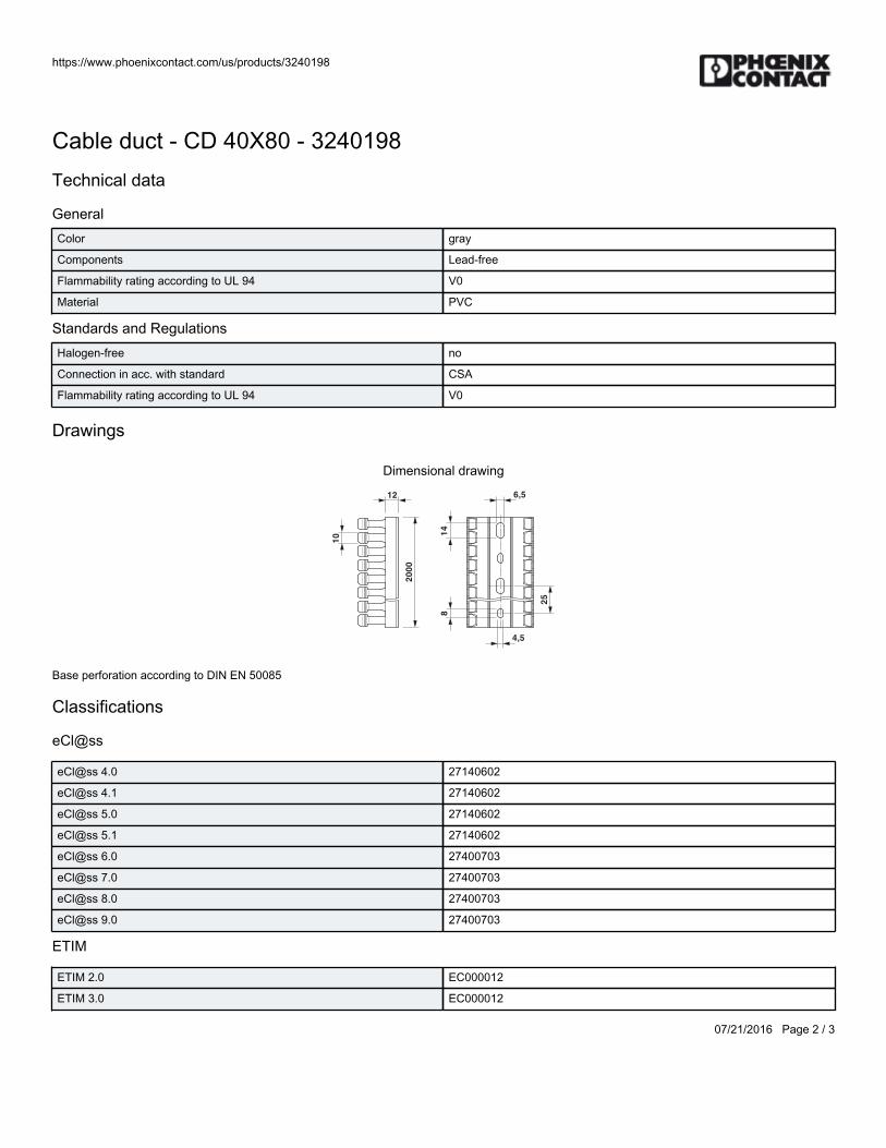
https://www.phoenixcontact.com/us/products/3240198
07/21/2016 Page 2 / 3
Cable duct - CD 40X80 - 3240198Technical data
GeneralColor gray
Components Lead-free
Flammability rating according to UL 94 V0
Material PVC
Standards and RegulationsHalogen-free no
Connection in acc. with standard CSA
Flammability rating according to UL 94 V0
Drawings
Dimensional drawing
20
00
25
10 1
48
12 6,5
4,5
Base perforation according to DIN EN 50085
Classifications
eCl@ss
eCl@ss 4.0 27140602
eCl@ss 4.1 27140602
eCl@ss 5.0 27140602
eCl@ss 5.1 27140602
eCl@ss 6.0 27400703
eCl@ss 7.0 27400703
eCl@ss 8.0 27400703
eCl@ss 9.0 27400703
ETIM
ETIM 2.0 EC000012
ETIM 3.0 EC000012
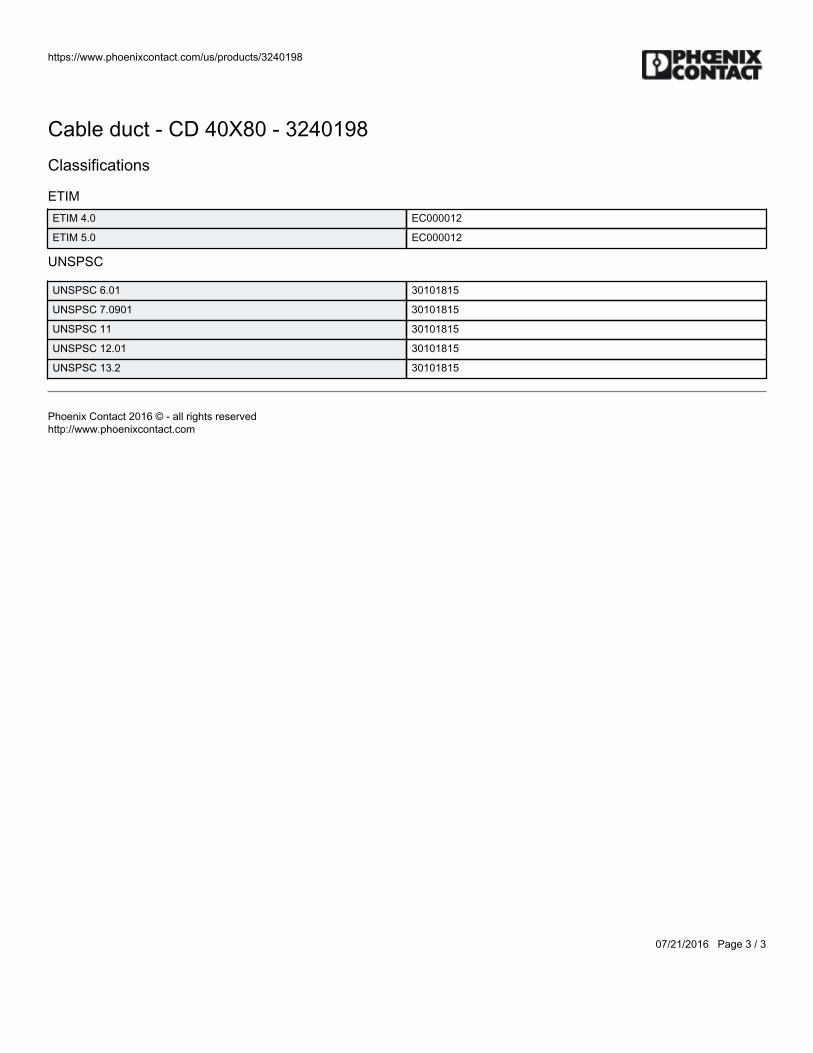
https://www.phoenixcontact.com/us/products/3240198
07/21/2016 Page 3 / 3
Cable duct - CD 40X80 - 3240198Classifications
ETIMETIM 4.0 EC000012
ETIM 5.0 EC000012
UNSPSC
UNSPSC 6.01 30101815
UNSPSC 7.0901 30101815
UNSPSC 11 30101815
UNSPSC 12.01 30101815
UNSPSC 13.2 30101815
Phoenix Contact 2016 © - all rights reservedhttp://www.phoenixcontact.com

BWS-GL-02 Appendix28
28. PhoenixContactDinRailEndCap:NS35/15Cap

https://www.phoenixcontact.com/us/products/1206573
06/11/2014 Page 1 / 2
End cap - NS 35/15 CAP - 1206573Please be informed that the data shown in this PDF Document is generated from our Online Catalog. Please find the complete data in the user'sdocumentation. Our General Terms of Use for Downloads are valid(http://phoenixcontact.com/download)
DIN rail end piece, for DIN rail NS 35/15
Product Features
NS 35/... CAP end caps can be attached to the ends of NS 35/7,5 and NS 35/15 DIN rails
Key commercial dataPacking unit 1 pc
Minimum order quantity 100 pc
Weight per Piece (excluding packing) 0.8 GRM
Custom tariff number 39269097
Country of origin Germany
Technical data
DimensionsHeight 16.5 mm
Length 37.5 mm
Width 7 mm
GeneralMaterial PP
Coating uncoated
Color gray
Classifications
eCl@ss
eCl@ss 4.0 27110804
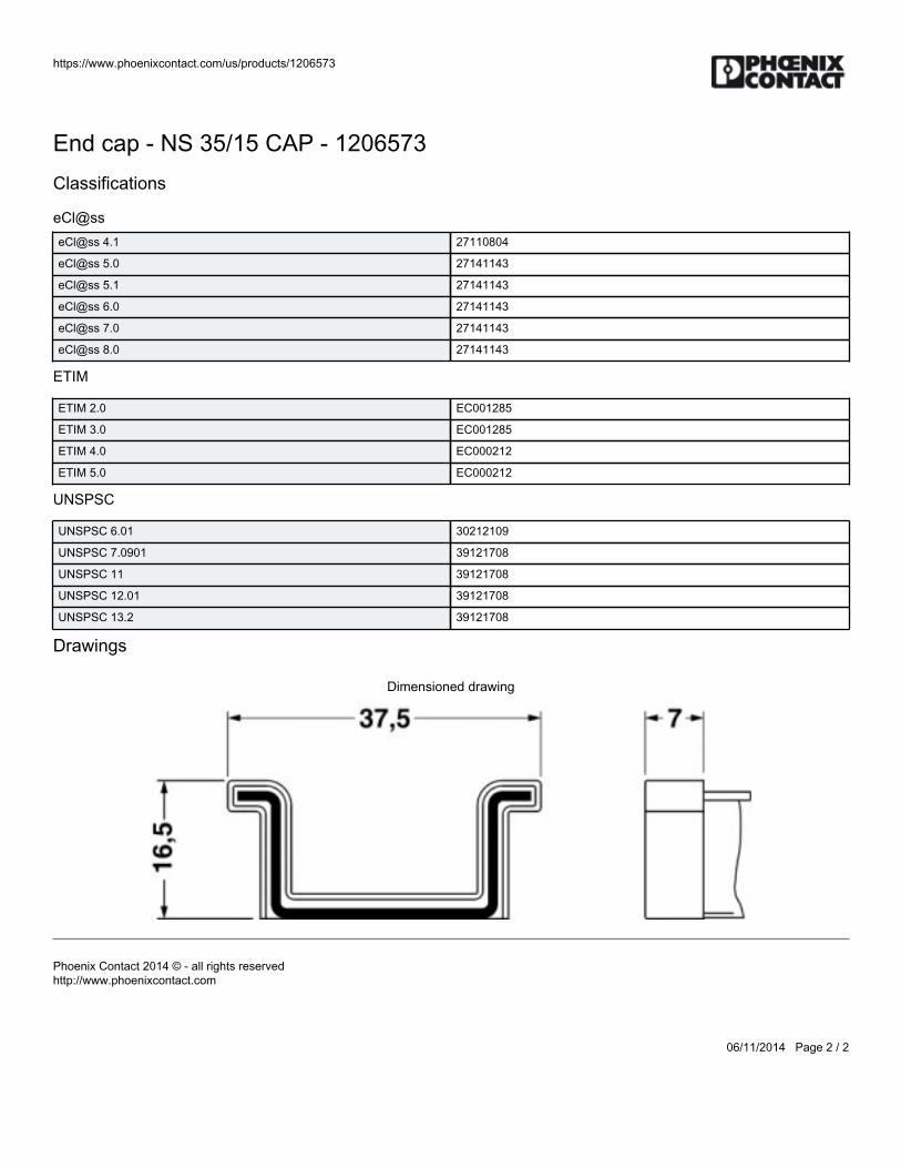
https://www.phoenixcontact.com/us/products/1206573
06/11/2014 Page 2 / 2
End cap - NS 35/15 CAP - 1206573Classifications
eCl@sseCl@ss 4.1 27110804
eCl@ss 5.0 27141143
eCl@ss 5.1 27141143
eCl@ss 6.0 27141143
eCl@ss 7.0 27141143
eCl@ss 8.0 27141143
ETIM
ETIM 2.0 EC001285
ETIM 3.0 EC001285
ETIM 4.0 EC000212
ETIM 5.0 EC000212
UNSPSC
UNSPSC 6.01 30212109
UNSPSC 7.0901 39121708
UNSPSC 11 39121708
UNSPSC 12.01 39121708
UNSPSC 13.2 39121708
Drawings
Dimensioned drawing
Phoenix Contact 2014 © - all rights reservedhttp://www.phoenixcontact.com

BWS-GL-02 Appendix29
29. PhoenixContactEndClampE/NS35N
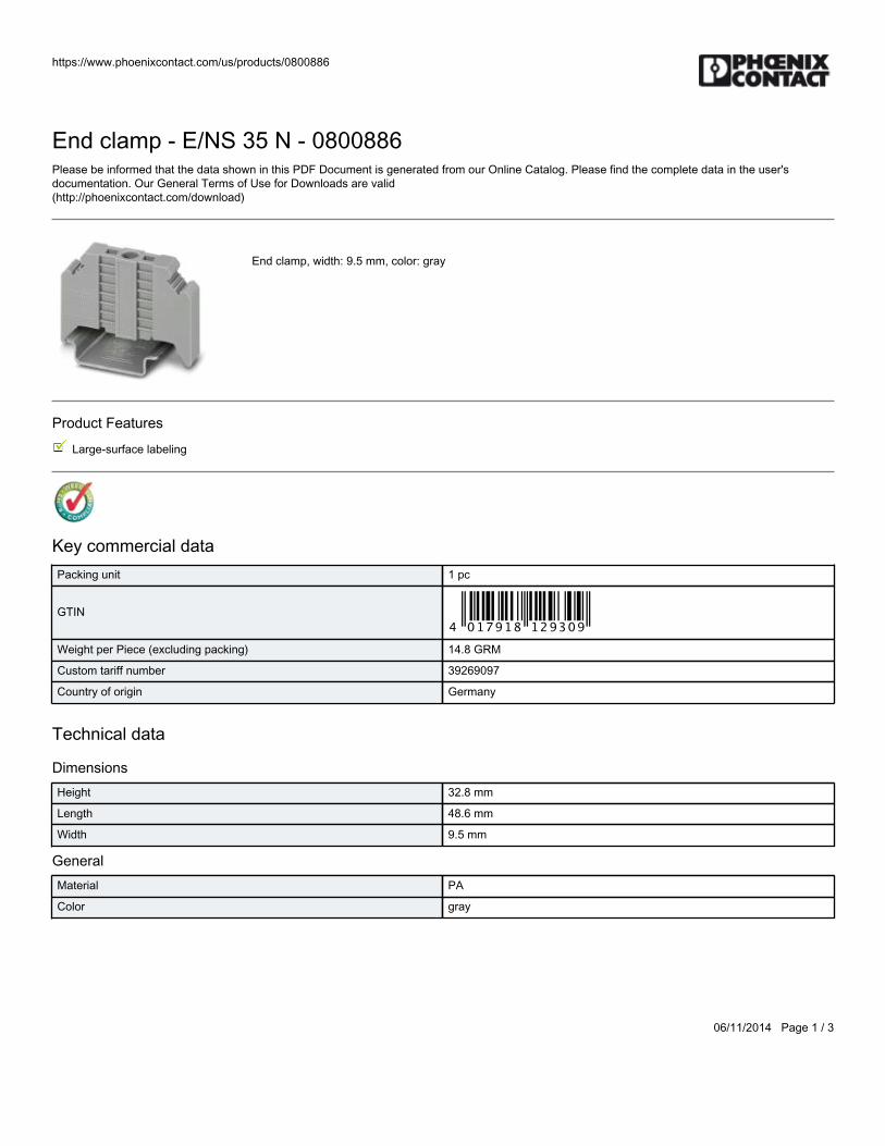
https://www.phoenixcontact.com/us/products/0800886
06/11/2014 Page 1 / 3
End clamp - E/NS 35 N - 0800886Please be informed that the data shown in this PDF Document is generated from our Online Catalog. Please find the complete data in the user'sdocumentation. Our General Terms of Use for Downloads are valid(http://phoenixcontact.com/download)
End clamp, width: 9.5 mm, color: gray
Product Features
Large-surface labeling
Key commercial dataPacking unit 1 pc
GTIN
Weight per Piece (excluding packing) 14.8 GRM
Custom tariff number 39269097
Country of origin Germany
Technical data
DimensionsHeight 32.8 mm
Length 48.6 mm
Width 9.5 mm
GeneralMaterial PA
Color gray
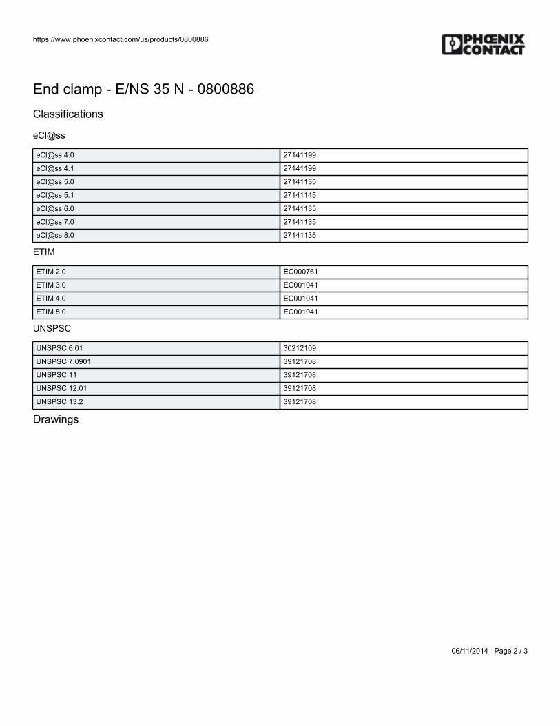
https://www.phoenixcontact.com/us/products/0800886
06/11/2014 Page 2 / 3
End clamp - E/NS 35 N - 0800886Classifications
eCl@ss
eCl@ss 4.0 27141199
eCl@ss 4.1 27141199
eCl@ss 5.0 27141135
eCl@ss 5.1 27141145
eCl@ss 6.0 27141135
eCl@ss 7.0 27141135
eCl@ss 8.0 27141135
ETIM
ETIM 2.0 EC000761
ETIM 3.0 EC001041
ETIM 4.0 EC001041
ETIM 5.0 EC001041
UNSPSC
UNSPSC 6.01 30212109
UNSPSC 7.0901 39121708
UNSPSC 11 39121708
UNSPSC 12.01 39121708
UNSPSC 13.2 39121708
Drawings
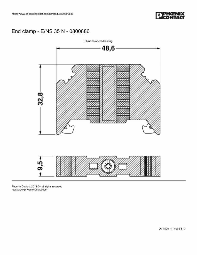
https://www.phoenixcontact.com/us/products/0800886
06/11/2014 Page 3 / 3
End clamp - E/NS 35 N - 0800886
Dimensioned drawing
Phoenix Contact 2014 © - all rights reservedhttp://www.phoenixcontact.com

BWS-GL-02 Appendix30
30. PhoenixContactTerminalBlock:PTI2,5-PE/L/TG
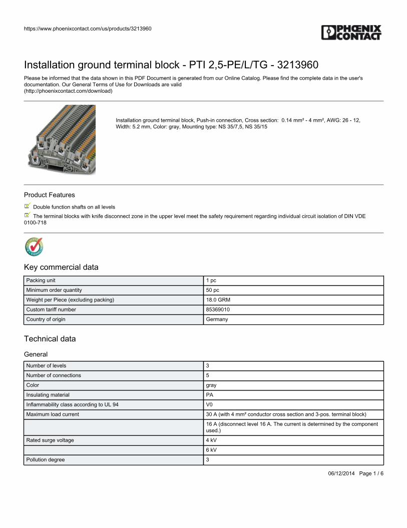
https://www.phoenixcontact.com/us/products/3213960
06/12/2014 Page 1 / 6
Installation ground terminal block - PTI 2,5-PE/L/TG - 3213960Please be informed that the data shown in this PDF Document is generated from our Online Catalog. Please find the complete data in the user'sdocumentation. Our General Terms of Use for Downloads are valid(http://phoenixcontact.com/download)
Installation ground terminal block, Push-in connection, Cross section: 0.14 mm² - 4 mm², AWG: 26 - 12,Width: 5.2 mm, Color: gray, Mounting type: NS 35/7,5, NS 35/15
Product Features
Double function shafts on all levels
The terminal blocks with knife disconnect zone in the upper level meet the safety requirement regarding individual circuit isolation of DIN VDE0100-718
Key commercial dataPacking unit 1 pc
Minimum order quantity 50 pc
Weight per Piece (excluding packing) 18.0 GRM
Custom tariff number 85369010
Country of origin Germany
Technical data
GeneralNumber of levels 3
Number of connections 5
Color gray
Insulating material PA
Inflammability class according to UL 94 V0
Maximum load current 30 A (with 4 mm² conductor cross section and 3-pos. terminal block)
16 A (disconnect level 16 A. The current is determined by the componentused.)
Rated surge voltage 4 kV
6 kV
Pollution degree 3
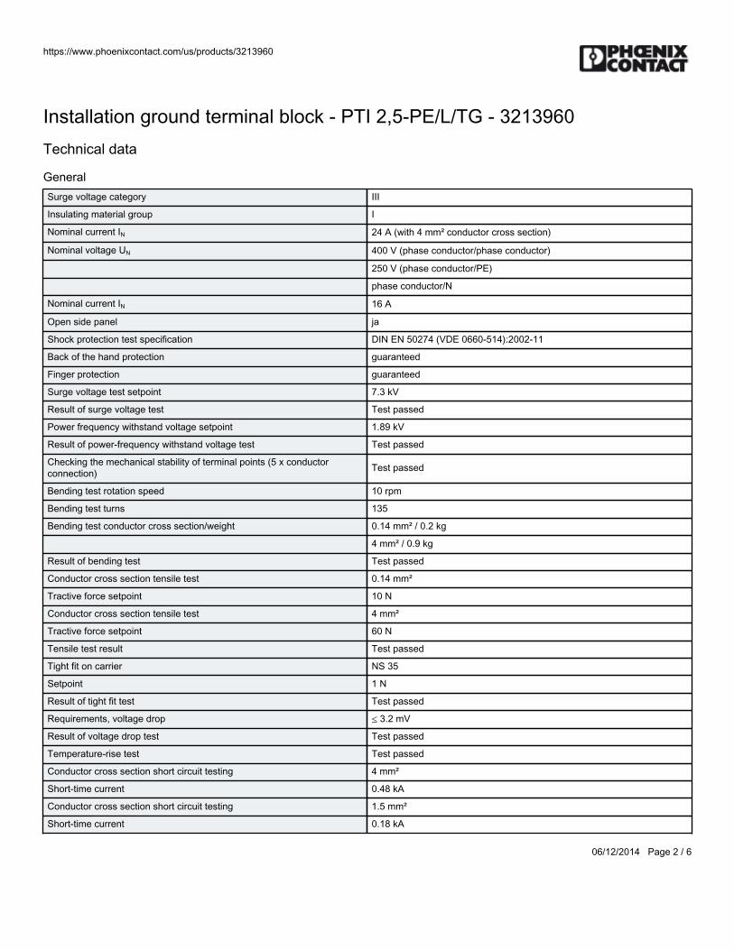
https://www.phoenixcontact.com/us/products/3213960
06/12/2014 Page 2 / 6
Installation ground terminal block - PTI 2,5-PE/L/TG - 3213960Technical data
GeneralSurge voltage category III
Insulating material group I
Nominal current IN 24 A (with 4 mm² conductor cross section)
Nominal voltage UN 400 V (phase conductor/phase conductor)
250 V (phase conductor/PE)
phase conductor/N
Nominal current IN 16 A
Open side panel ja
Shock protection test specification DIN EN 50274 (VDE 0660-514):2002-11
Back of the hand protection guaranteed
Finger protection guaranteed
Surge voltage test setpoint 7.3 kV
Result of surge voltage test Test passed
Power frequency withstand voltage setpoint 1.89 kV
Result of power-frequency withstand voltage test Test passed
Checking the mechanical stability of terminal points (5 x conductorconnection) Test passed
Bending test rotation speed 10 rpm
Bending test turns 135
Bending test conductor cross section/weight 0.14 mm² / 0.2 kg
4 mm² / 0.9 kg
Result of bending test Test passed
Conductor cross section tensile test 0.14 mm²
Tractive force setpoint 10 N
Conductor cross section tensile test 4 mm²
Tractive force setpoint 60 N
Tensile test result Test passed
Tight fit on carrier NS 35
Setpoint 1 N
Result of tight fit test Test passed
Requirements, voltage drop ≤ 3.2 mV
Result of voltage drop test Test passed
Temperature-rise test Test passed
Conductor cross section short circuit testing 4 mm²
Short-time current 0.48 kA
Conductor cross section short circuit testing 1.5 mm²
Short-time current 0.18 kA
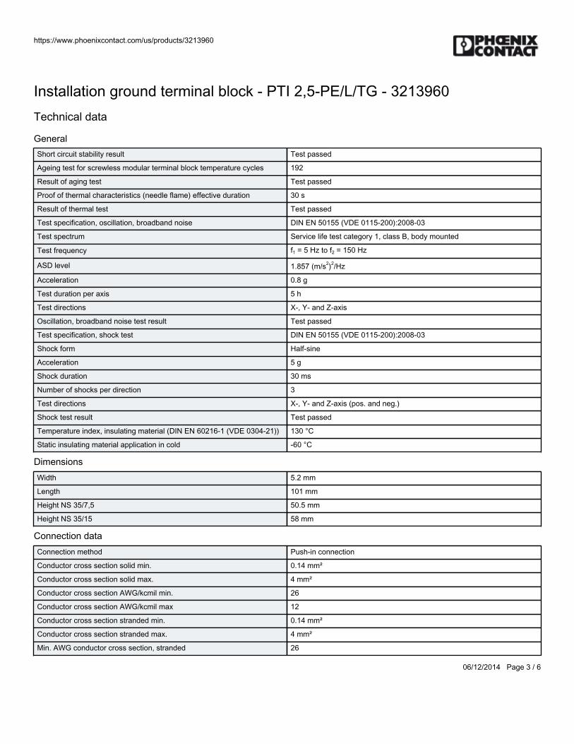
https://www.phoenixcontact.com/us/products/3213960
06/12/2014 Page 3 / 6
Installation ground terminal block - PTI 2,5-PE/L/TG - 3213960Technical data
GeneralShort circuit stability result Test passed
Ageing test for screwless modular terminal block temperature cycles 192
Result of aging test Test passed
Proof of thermal characteristics (needle flame) effective duration 30 s
Result of thermal test Test passed
Test specification, oscillation, broadband noise DIN EN 50155 (VDE 0115-200):2008-03
Test spectrum Service life test category 1, class B, body mounted
Test frequency f1 = 5 Hz to f2 = 150 Hz
ASD level 1.857 (m/s2)2/Hz
Acceleration 0.8 g
Test duration per axis 5 h
Test directions X-, Y- and Z-axis
Oscillation, broadband noise test result Test passed
Test specification, shock test DIN EN 50155 (VDE 0115-200):2008-03
Shock form Half-sine
Acceleration 5 g
Shock duration 30 ms
Number of shocks per direction 3
Test directions X-, Y- and Z-axis (pos. and neg.)
Shock test result Test passed
Temperature index, insulating material (DIN EN 60216-1 (VDE 0304-21)) 130 °C
Static insulating material application in cold -60 °C
DimensionsWidth 5.2 mm
Length 101 mm
Height NS 35/7,5 50.5 mm
Height NS 35/15 58 mm
Connection dataConnection method Push-in connection
Conductor cross section solid min. 0.14 mm²
Conductor cross section solid max. 4 mm²
Conductor cross section AWG/kcmil min. 26
Conductor cross section AWG/kcmil max 12
Conductor cross section stranded min. 0.14 mm²
Conductor cross section stranded max. 4 mm²
Min. AWG conductor cross section, stranded 26
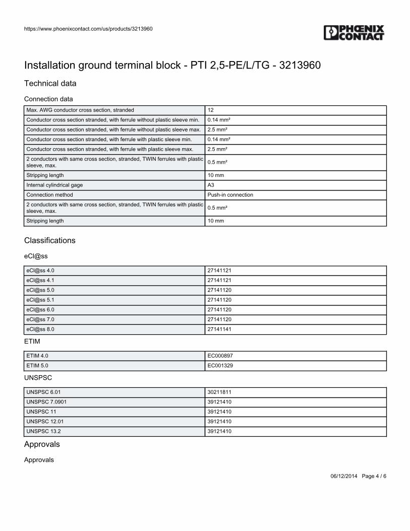
https://www.phoenixcontact.com/us/products/3213960
06/12/2014 Page 4 / 6
Installation ground terminal block - PTI 2,5-PE/L/TG - 3213960Technical data
Connection dataMax. AWG conductor cross section, stranded 12
Conductor cross section stranded, with ferrule without plastic sleeve min. 0.14 mm²
Conductor cross section stranded, with ferrule without plastic sleeve max. 2.5 mm²
Conductor cross section stranded, with ferrule with plastic sleeve min. 0.14 mm²
Conductor cross section stranded, with ferrule with plastic sleeve max. 2.5 mm²
2 conductors with same cross section, stranded, TWIN ferrules with plasticsleeve, max. 0.5 mm²
Stripping length 10 mm
Internal cylindrical gage A3
Connection method Push-in connection
2 conductors with same cross section, stranded, TWIN ferrules with plasticsleeve, max. 0.5 mm²
Stripping length 10 mm
Classifications
eCl@ss
eCl@ss 4.0 27141121
eCl@ss 4.1 27141121
eCl@ss 5.0 27141120
eCl@ss 5.1 27141120
eCl@ss 6.0 27141120
eCl@ss 7.0 27141120
eCl@ss 8.0 27141141
ETIM
ETIM 4.0 EC000897
ETIM 5.0 EC001329
UNSPSC
UNSPSC 6.01 30211811
UNSPSC 7.0901 39121410
UNSPSC 11 39121410
UNSPSC 12.01 39121410
UNSPSC 13.2 39121410
Approvals
Approvals
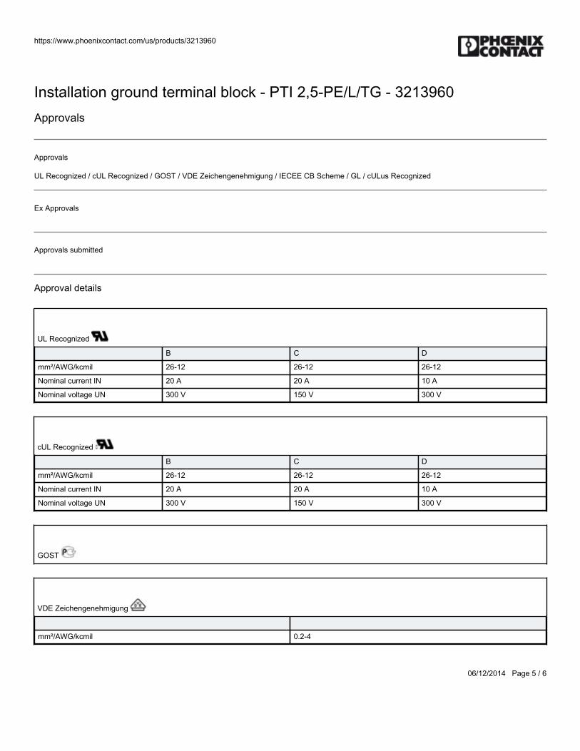
https://www.phoenixcontact.com/us/products/3213960
06/12/2014 Page 5 / 6
Installation ground terminal block - PTI 2,5-PE/L/TG - 3213960Approvals
Approvals
UL Recognized / cUL Recognized / GOST / VDE Zeichengenehmigung / IECEE CB Scheme / GL / cULus Recognized
Ex Approvals
Approvals submitted
Approval details
UL Recognized
B C D
mm²/AWG/kcmil 26-12 26-12 26-12
Nominal current IN 20 A 20 A 10 A
Nominal voltage UN 300 V 150 V 300 V
cUL Recognized
B C D
mm²/AWG/kcmil 26-12 26-12 26-12
Nominal current IN 20 A 20 A 10 A
Nominal voltage UN 300 V 150 V 300 V
GOST
VDE Zeichengenehmigung
mm²/AWG/kcmil 0.2-4
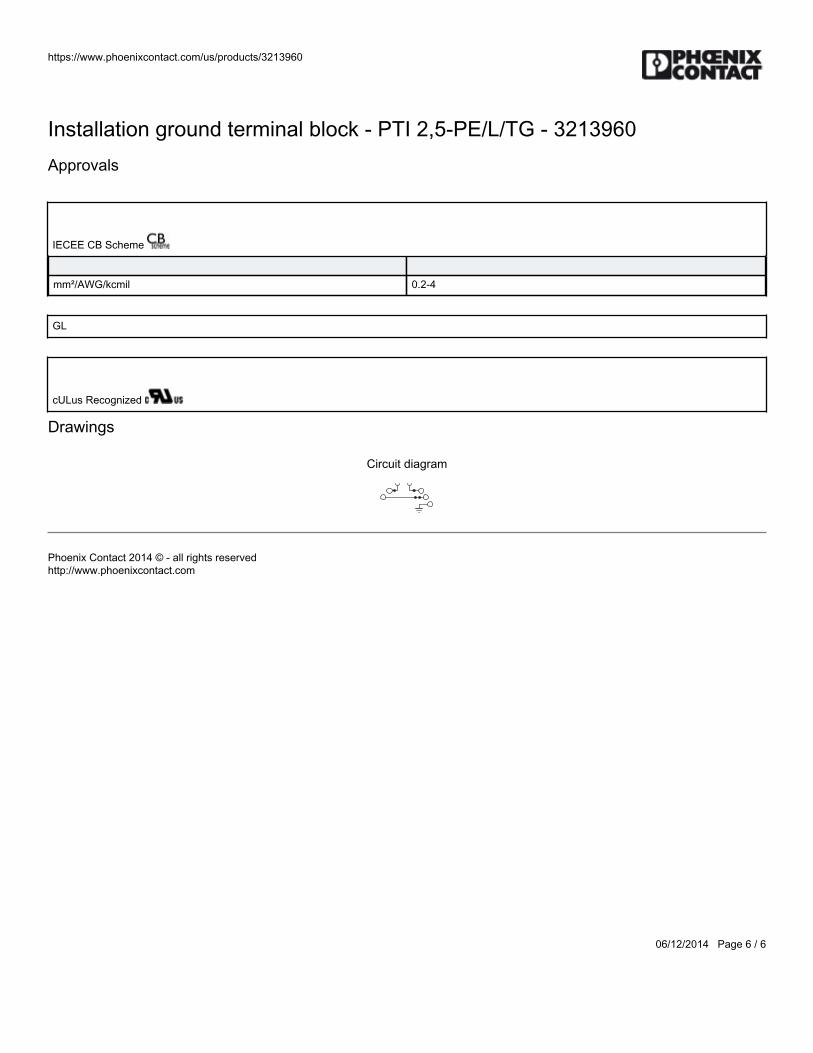
https://www.phoenixcontact.com/us/products/3213960
06/12/2014 Page 6 / 6
Installation ground terminal block - PTI 2,5-PE/L/TG - 3213960Approvals
IECEE CB Scheme
mm²/AWG/kcmil 0.2-4
GL
cULus Recognized
Drawings
Circuit diagram
Phoenix Contact 2014 © - all rights reservedhttp://www.phoenixcontact.com

BWS-GL-02 Appendix31
31. PhoenixContactTerminalBlockEndCover:D-PTI/3B
https://www.phoenixcontact.com/us/products/3213976
06/12/2014 Page 1 / 2
End cover - D-PTI/3B - 3213976Please be informed that the data shown in this PDF Document is generated from our Online Catalog. Please find the complete data in the user'sdocumentation. Our General Terms of Use for Downloads are valid(http://phoenixcontact.com/download)
End cover, Length: 101 mm, Width: 2.2 mm, Color: gray
Key commercial dataPacking unit 1 pc
Minimum order quantity 50 pc
Weight per Piece (excluding packing) 4.6 GRM
Custom tariff number 85389099
Country of origin Poland
Technical data
GeneralColor gray
Insulating material PA
Inflammability class according to UL 94 V0
DimensionsWidth 2.2 mm
Length 101 mm
GeneralTemperature index, insulating material (DIN EN 60216-1 (VDE 0304-21)) 130 °C
Static insulating material application in cold -60 °C
Classifications
eCl@ss
eCl@ss 4.0 27141111
eCl@ss 4.1 27141111
eCl@ss 5.0 27141133
https://www.phoenixcontact.com/us/products/3213976
06/12/2014 Page 2 / 2
End cover - D-PTI/3B - 3213976Classifications
eCl@sseCl@ss 5.1 27141133
eCl@ss 6.0 27141133
eCl@ss 7.0 27141133
eCl@ss 8.0 27141133
ETIM
ETIM 4.0 EC000886
ETIM 5.0 EC000886
UNSPSC
UNSPSC 6.01 30211827
UNSPSC 7.0901 39121424
UNSPSC 11 39121424
UNSPSC 12.01 39121424
UNSPSC 13.2 39121424
Approvals
Approvals
Approvals
GOST
Ex Approvals
Approvals submitted
Approval details
GOST
Phoenix Contact 2014 © - all rights reservedhttp://www.phoenixcontact.com

BWS-GL-02 Appendix32
32. PhoenixContactTerminalBlockPartitionPlate:ATP-PTI/3
https://www.phoenixcontact.com/us/products/3213990
06/12/2014 Page 1 / 2
Partition plate - ATP-PTI/3 - 3213990Please be informed that the data shown in this PDF Document is generated from our Online Catalog. Please find the complete data in the user'sdocumentation. Our General Terms of Use for Downloads are valid(http://phoenixcontact.com/download)
Partition plate, Length: 103 mm, Width: 2.2 mm, Height: 49.3 mm, Color: gray
Key commercial dataPacking unit 1 pc
Minimum order quantity 50 pc
Weight per Piece (excluding packing) 9.2 GRM
Custom tariff number 85472000
Country of origin Poland
Technical data
GeneralColor gray
Inflammability class according to UL 94 V0
DimensionsWidth 2.2 mm
Length 103 mm
Height 49.3 mm
Height NS 35/7,5 50.5 mm
Height NS 35/15 58 mm
GeneralTemperature index, insulating material (DIN EN 60216-1 (VDE 0304-21)) 125 °C
Static insulating material application in cold -60 °C
Classifications
eCl@ss
eCl@ss 4.0 27141199
https://www.phoenixcontact.com/us/products/3213990
06/12/2014 Page 2 / 2
Partition plate - ATP-PTI/3 - 3213990Classifications
eCl@sseCl@ss 4.1 27141199
eCl@ss 5.0 27141145
eCl@ss 5.1 27141145
eCl@ss 6.0 27141133
eCl@ss 7.0 27141133
eCl@ss 8.0 27141133
ETIM
ETIM 2.0 EC000886
ETIM 3.0 EC000886
ETIM 4.0 EC000886
ETIM 5.0 EC000886
UNSPSC
UNSPSC 6.01 30211828
UNSPSC 7.0901 39121425
UNSPSC 11 39121425
UNSPSC 12.01 39121425
UNSPSC 13.2 39121425
Phoenix Contact 2014 © - all rights reservedhttp://www.phoenixcontact.com

BWS-GL-02 Appendix33
33. PhoenixContactFusePlug:F-FU5X20LED24-5
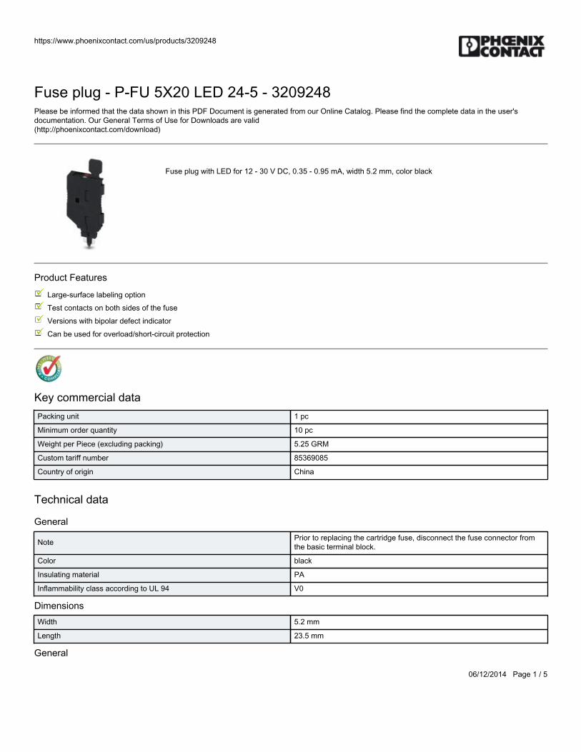
https://www.phoenixcontact.com/us/products/3209248
06/12/2014 Page 1 / 5
Fuse plug - P-FU 5X20 LED 24-5 - 3209248Please be informed that the data shown in this PDF Document is generated from our Online Catalog. Please find the complete data in the user'sdocumentation. Our General Terms of Use for Downloads are valid(http://phoenixcontact.com/download)
Fuse plug with LED for 12 - 30 V DC, 0.35 - 0.95 mA, width 5.2 mm, color black
Product Features
Large-surface labeling option
Test contacts on both sides of the fuse
Versions with bipolar defect indicator
Can be used for overload/short-circuit protection
Key commercial dataPacking unit 1 pc
Minimum order quantity 10 pc
Weight per Piece (excluding packing) 5.25 GRM
Custom tariff number 85369085
Country of origin China
Technical data
General
Note Prior to replacing the cartridge fuse, disconnect the fuse connector fromthe basic terminal block.
Color black
Insulating material PA
Inflammability class according to UL 94 V0
DimensionsWidth 5.2 mm
Length 23.5 mm
General
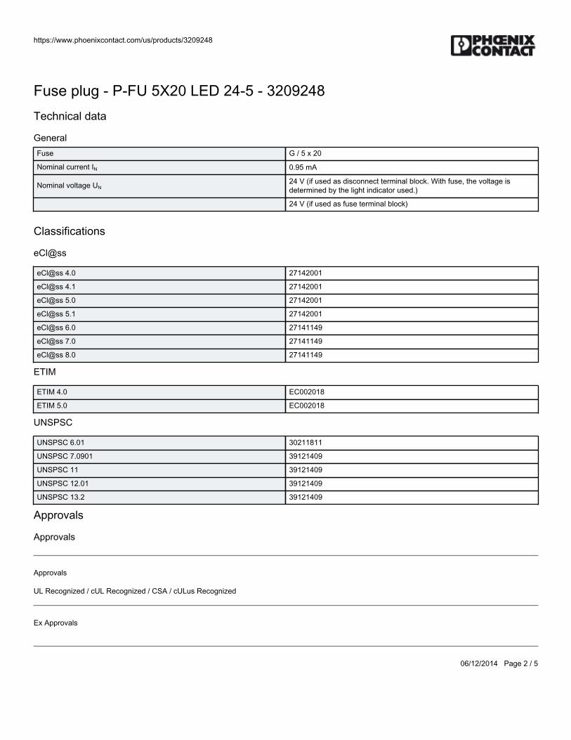
https://www.phoenixcontact.com/us/products/3209248
06/12/2014 Page 2 / 5
Fuse plug - P-FU 5X20 LED 24-5 - 3209248Technical data
GeneralFuse G / 5 x 20
Nominal current IN 0.95 mA
Nominal voltage UN24 V (if used as disconnect terminal block. With fuse, the voltage isdetermined by the light indicator used.)
24 V (if used as fuse terminal block)
Classifications
eCl@ss
eCl@ss 4.0 27142001
eCl@ss 4.1 27142001
eCl@ss 5.0 27142001
eCl@ss 5.1 27142001
eCl@ss 6.0 27141149
eCl@ss 7.0 27141149
eCl@ss 8.0 27141149
ETIM
ETIM 4.0 EC002018
ETIM 5.0 EC002018
UNSPSC
UNSPSC 6.01 30211811
UNSPSC 7.0901 39121409
UNSPSC 11 39121409
UNSPSC 12.01 39121409
UNSPSC 13.2 39121409
Approvals
Approvals
Approvals
UL Recognized / cUL Recognized / CSA / cULus Recognized
Ex Approvals
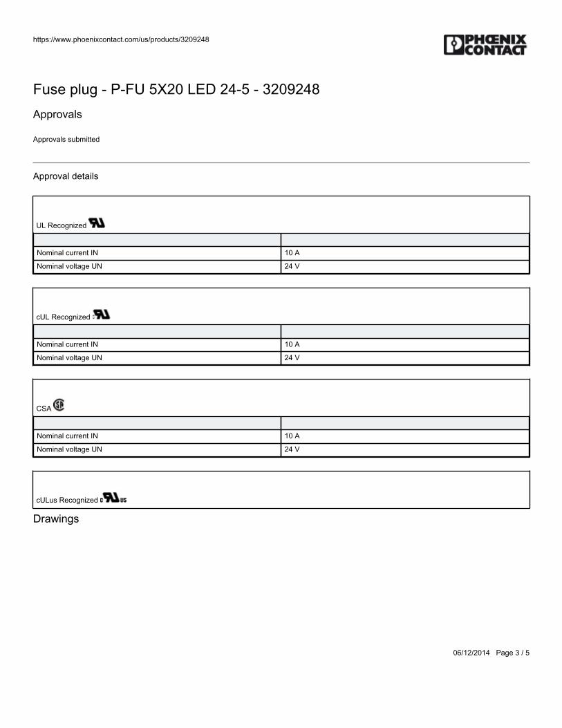
https://www.phoenixcontact.com/us/products/3209248
06/12/2014 Page 3 / 5
Fuse plug - P-FU 5X20 LED 24-5 - 3209248Approvals
Approvals submitted
Approval details
UL Recognized
Nominal current IN 10 A
Nominal voltage UN 24 V
cUL Recognized
Nominal current IN 10 A
Nominal voltage UN 24 V
CSA
Nominal current IN 10 A
Nominal voltage UN 24 V
cULus Recognized
Drawings
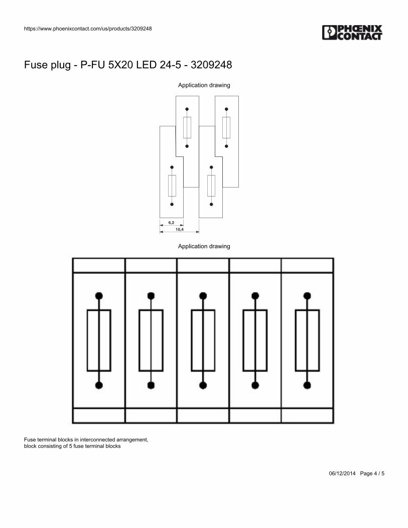
https://www.phoenixcontact.com/us/products/3209248
06/12/2014 Page 4 / 5
Fuse plug - P-FU 5X20 LED 24-5 - 3209248
Application drawing
6,2
10,4
Application drawing
Fuse terminal blocks in interconnected arrangement, block consisting of 5 fuse terminal blocks
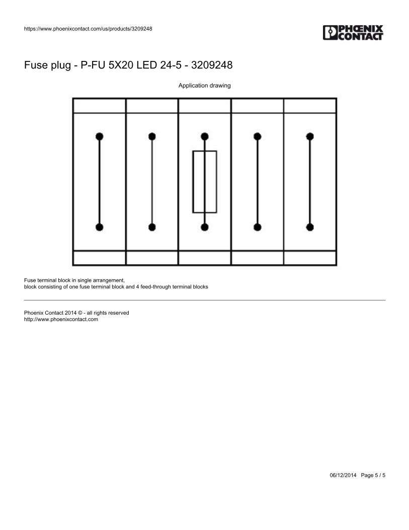
https://www.phoenixcontact.com/us/products/3209248
06/12/2014 Page 5 / 5
Fuse plug - P-FU 5X20 LED 24-5 - 3209248
Application drawing
Fuse terminal block in single arrangement, block consisting of one fuse terminal block and 4 feed-through terminal blocks
Phoenix Contact 2014 © - all rights reservedhttp://www.phoenixcontact.com

BWS-GL-02 Appendix34
34. MTWWire:15-18-16T
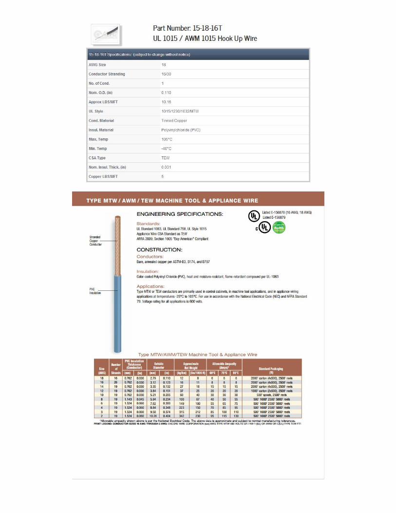

BWS-GL-02 Appendix35
35. TurckCable/Cordset:RF50609&RK4.5T-x/S618
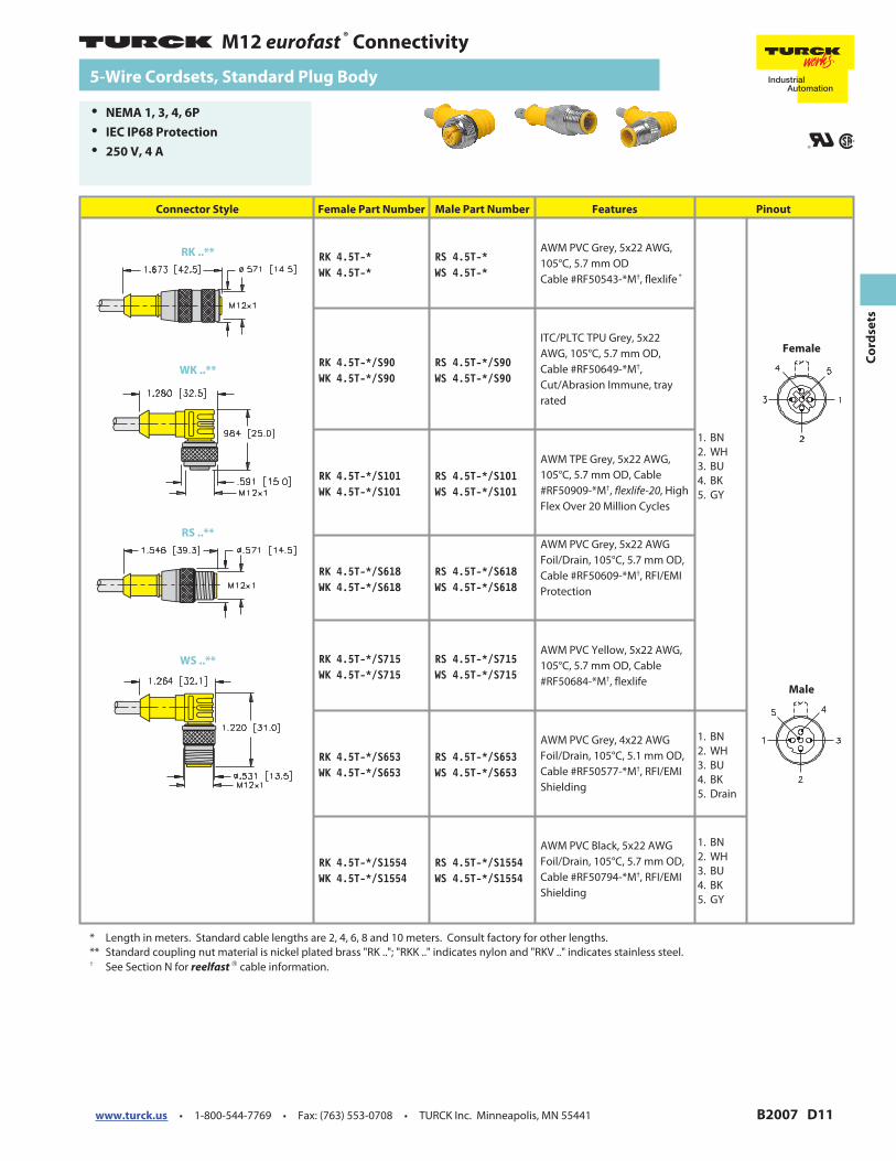
www.turck.us · 1-800-544-7769 · Fax: (763) 553-0708 · TURCK Inc. Minneapolis, MN 55441 B2007 D11
M12 eurofast®
Connectivity
Co
rd
se
ts
Connector Style Female Part Number Male Part Number Features Pinout
RK 4.5T-*WK 4.5T-*
RS 4.5T-*WS 4.5T-*
AWM PVC Grey, 5x22 AWG,
105°C, 5.7 mm OD
Cable #RF50543-*M†, flexlife ®
1. BN
2. WH
3. BU
4. BK
5. GY
RK 4.5T-*/S90WK 4.5T-*/S90
RS 4.5T-*/S90WS 4.5T-*/S90
ITC/PLTC TPU Grey, 5x22
AWG, 105°C, 5.7 mm OD,
Cable #RF50649-*M†,
Cut/Abrasion Immune, tray
rated
RK 4.5T-*/S101WK 4.5T-*/S101
RS 4.5T-*/S101WS 4.5T-*/S101
AWM TPE Grey, 5x22 AWG,
105°C, 5.7 mm OD, Cable
#RF50909-*M†, flexlife-20, High
Flex Over 20 Million Cycles
RK 4.5T-*/S618WK 4.5T-*/S618
RS 4.5T-*/S618WS 4.5T-*/S618
AWM PVC Grey, 5x22 AWG
Foil/Drain, 105°C, 5.7 mm OD,
Cable #RF50609-*M†, RFI/EMI
Protection
RK 4.5T-*/S715WK 4.5T-*/S715
RS 4.5T-*/S715WS 4.5T-*/S715
AWM PVC Yellow, 5x22 AWG,
105°C, 5.7 mm OD, Cable
#RF50684-*M†, flexlife
RK 4.5T-*/S653WK 4.5T-*/S653
RS 4.5T-*/S653WS 4.5T-*/S653
AWM PVC Grey, 4x22 AWG
Foil/Drain, 105°C, 5.1 mm OD,
Cable #RF50577-*M†, RFI/EMI
Shielding
1. BN
2. WH
3. BU
4. BK
5. Drain
RK 4.5T-*/S1554WK 4.5T-*/S1554
RS 4.5T-*/S1554WS 4.5T-*/S1554
AWM PVC Black, 5x22 AWG
Foil/Drain, 105°C, 5.7 mm OD,
Cable #RF50794-*M†, RFI/EMI
Shielding
1. BN
2. WH
3. BU
4. BK
5. GY
* Length in meters. Standard cable lengths are 2, 4, 6, 8 and 10 meters. Consult factory for other lengths.
** Standard coupling nut material is nickel plated brass "RK .."; "RKK .." indicates nylon and "RKV .." indicates stainless steel.†
See Section N for reelfast®
cable information.
RK ..**
5-Wire Cordsets, Standard Plug Body
• NEMA 1, 3, 4, 6P
• IEC IP68 Protection
• 250 V, 4 A
WK ..**
Female
RS ..**
Male
WS ..**
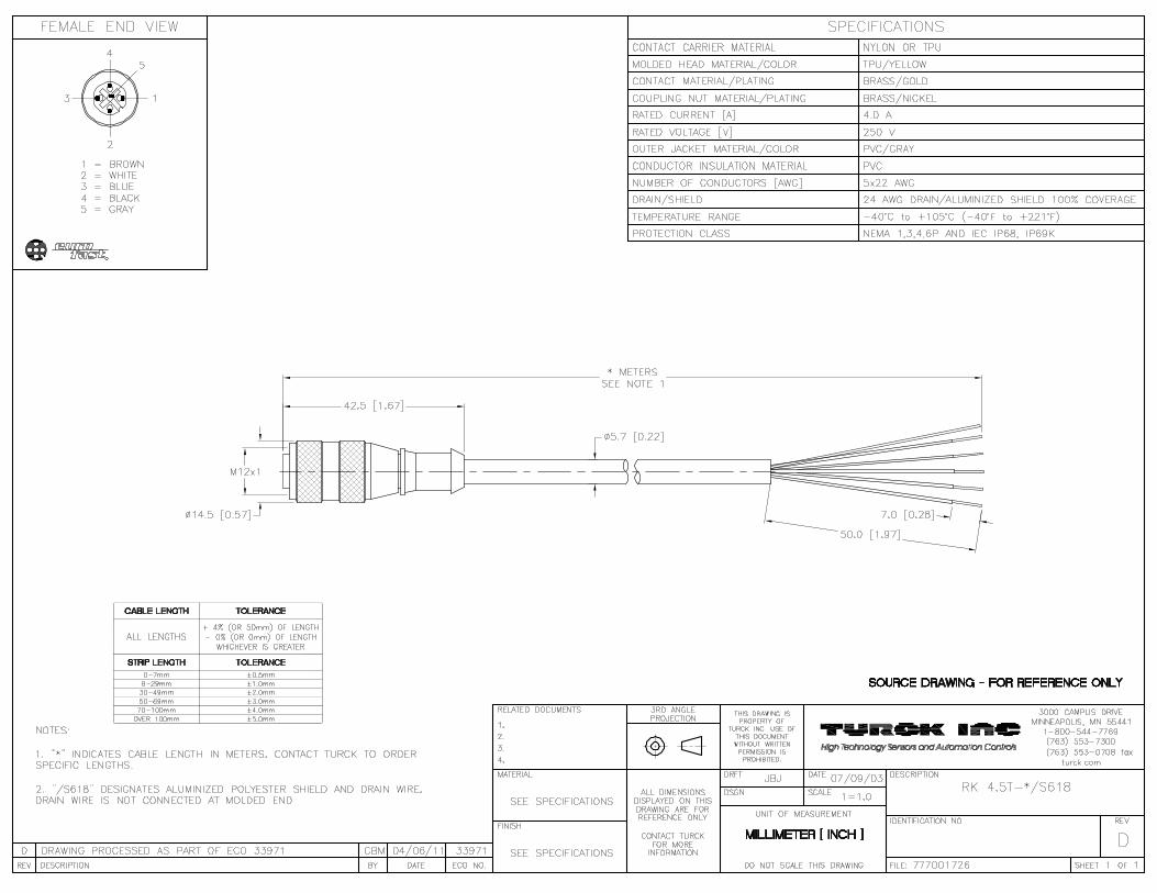

BWS-GL-02 Appendix36
36. EthernetCable:TRD695BL
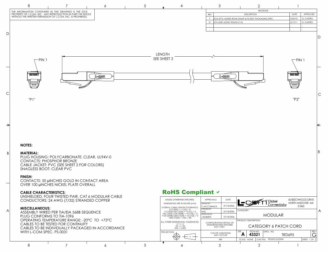
LENGTHSEE SHEET 2PIN 1 PIN 1
"P1"
NOTES:
MATERIAL:PLUG HOUSING: POLYCARBONATE, CLEAR, UL94V-0CONTACTS: PHOSPHOR BRONZECABLE JACKET: PVC (SEE SHEET 2 FOR COLORS)SNAGLESS BOOT: CLEAR PVC
FINISH:CONTACTS: 50 µINCHES GOLD IN CONTACT AREA OVER 100 µINCHES NICKEL PLATE OVERALL
CABLE CHARACTERISTICS:UNSHIELDED, FOUR TWISTED PAIR, CAT 6 MODULAR CABLECONDUCTORS: 24 AWG (7/32) STRANDED COPPER
MISCELLANEOUS:ASSEMBLY WIRED PER TIA/EIA 568B SEQUENCEPLUG CONFORMS TO TIA-1096OPERATING TEMPERATURE RANGE: -20°C TO +75°CCABLES TO BE TESTED FOR CONTINUITYCABLES TO BE INDIVIDUALLY PACKAGED IN ACCORDANCEWITH L-COM SPEC. PS-0031
"P2"
RoHS Compliant D
A
B
C
D
45 BEECHWOOD DRIVENORTH ANDOVER, MA
01845
SCALE:
SIZE
CAD FILE:
DWG. NO.ASHEET OF
REV.
DATEAPPROVALS
DRAWN BY
CHECKED BY
APPROVED BY
12345678
THE INFORMATION CONTAINED IN THIS DRAWING IS THE SOLEPROPERTY OF L-COM, INC. ANY REPRODUCTION IN PART OR WHOLEWITHOUT THE WRITTEN PERMISSION OF L-COM, INC. IS PROHIBITED.
A
B
C
D
12345678
TRD695 GTRD695.SLDDRW 1 2
ENG 07/18/2006
REVISIONS
DESCRIPTION APPROVEDREV DATE
J.ROBERTS 07/18/2006
5/24/10F
G
ECN 4772: ADDED ROHS STAMP & PS-0031 PACKAGING SPECECN 5508: ADDED TRD695VLT-XX 5/17/11
D. CASTRO
D. CASTRO
- - - -
CATEGORY
PRODUCT DESCRIPTION
DIMENSIONS ARE IN INCHES [mm]
- - - -
CONFIGURATION DETAILS OFUNDIMENSIONED FEATURES
MAY VARY
NONE
FSCM NO.
43321
CATEGORY 6 PATCH CORD
MODULAR
PROJECTION
UNLESS OTHERWISE SPECIFIED,
REF
C.MCCORMICK
COLOR VARIATIONSMAY OCCUR
07/18/2006OVERALL CABLE LENGTH TOLERANCE:
≤12 [305] = +1 [25] / -0>12 [305] ≤60 [1524] = +2 [51] / -0
>60 [1524] ≤120 [3048] = +4 [102] / -0>120 [3048] ≤300 [7620] = +6 [152] / -0
>300 [7620] = +5% / -0%
ALL OTHER DIMENSIONAL TOLERANCES:.X = ± .2
.XX = ± .02.XXX = ±.005
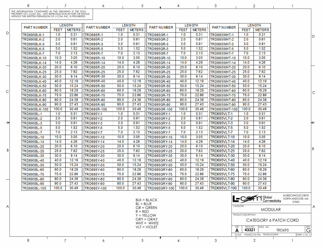
BLK = BLACKBL = BLUEGR = GREENR = REDY = YELLOWGRY = GRAYWHT = WHITEVLT = VIOLET
A
B
C
D
45 BEECHWOOD DRIVENORTH ANDOVER, MA
01845
SCALE:
SIZE
CAD FILE:
DWG. NO.
ASHEET OF
REV.
12345678
THE INFORMATION CONTAINED IN THIS DRAWING IS THE SOLEPROPERTY OF L-COM, INC. ANY REPRODUCTION IN PART OR WHOLEWITHOUT THE WRITTEN PERMISSION OF L-COM, INC. IS PROHIBITED.
A
B
C
D
12345678
TRD695 GTRD695.SLDDRW 2 2
CATEGORY
PRODUCT DESCRIPTION
NONE
FSCM NO.
43321
CATEGORY 6 PATCH CORD
MODULAR

BWS-GL-02 Appendix37
37. BradyLabels:Various
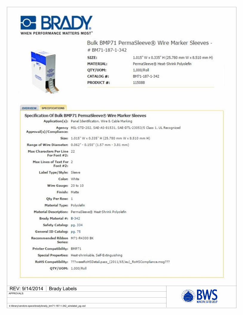
REV: 9/14/2014 Brady Labels
k:\library\vendors-specs\brady\brady_bm71-187-1-342_wirelabel_pg.vsd
APPROVALS:
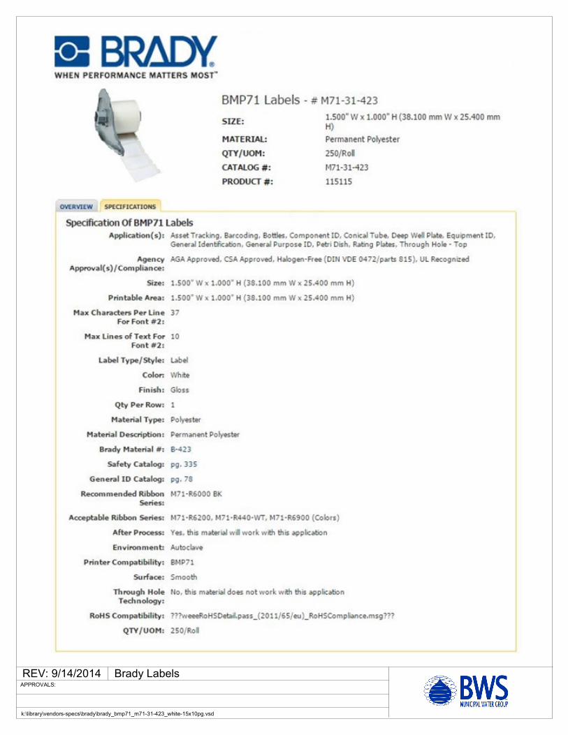
REV: 9/14/2014 Brady Labels
k:\library\vendors-specs\brady\brady_bmp71_m71-31-423_white-15x10pg.vsd
APPROVALS:
REV: 9/14/2014 Brady Labels
k:\library\vendors-specs\brady\brady_bmp71_m71c-1000-595-or_10_pg.vsd
APPROVALS:
REV: 9/14/2014 Brady Labels
k:\library\vendors-specs\brady\brady_bmp71_m71c-1000-595-yl_10_pg.vsd
APPROVALS:
REV: 9/14/2014 Brady Labels
k:\library\vendors-specs\brady\brady_bmp71_m71-r4400-wt_20_pg.vsd
APPROVALS:

BWS-GL-02 Appendix38
38. PhoenixContactCESSystem
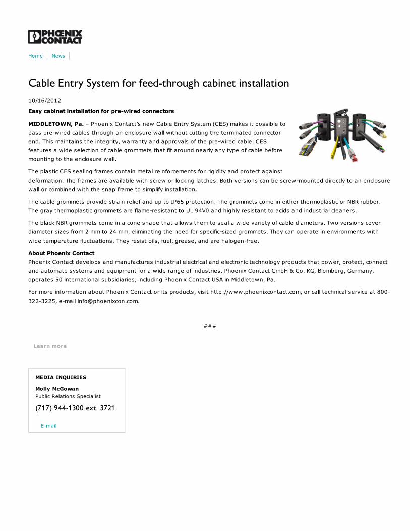

BWS-GL-02 Appendix39
39. PhoenixContactCESSnap-upFrameCES-B16-SF-PLBK
https://www.phoenixcontact.com/us/products/0801651
06/23/2014 Page 1 / 3
Snap-up frame - CES-B16-SF-PLBK - 0801651Please be informed that the data shown in this PDF Document is generated from our Online Catalog. Please find the complete data in the user'sdocumentation. Our General Terms of Use for Downloads are valid(http://phoenixcontact.com/download)
Size B16 snap-on frame including integrated mounting panel seal, for accommodating CES-B16-HFFS-PLBK orCES-B16-SFFS-PLBK sealing frames
Product descriptionSnap-on frame, medium
Key commercial dataPacking unit 1 pc
Weight per Piece (excluding packing) 56.0 GRM
Custom tariff number 39174000
Country of origin Germany
Technical data
DimensionsLength 128 mm
Width 64 mm
Height 38 mm
Ambient conditionsDegree of protection IP54
Ambient temperature (operation) -20 °C ... 80 °C
GeneralProduct description Snap-on frame, medium
Frame type Snap-on frame
Material PA
Inflammability class according to UL 94 V0
Color black
https://www.phoenixcontact.com/us/products/0801651
06/23/2014 Page 2 / 3
Snap-up frame - CES-B16-SF-PLBK - 0801651Technical data
GeneralInstallation instructions M4 mounting screw
Classifications
eCl@ss
eCl@ss 4.0 27081002
eCl@ss 4.1 27081002
eCl@ss 5.0 27081002
eCl@ss 5.1 27081002
eCl@ss 6.0 27081002
eCl@ss 7.0 27081002
eCl@ss 8.0 27081002
ETIM
ETIM 3.0 EC000451
ETIM 4.0 EC000451
ETIM 5.0 EC000451
UNSPSC
UNSPSC 6.01 30212109
UNSPSC 7.0901 39121708
UNSPSC 11 39121708
UNSPSC 12.01 39121708
UNSPSC 13.2 39121708
Drawings
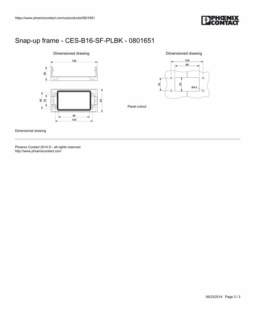
https://www.phoenixcontact.com/us/products/0801651
06/23/2014 Page 3 / 3
Snap-up frame - CES-B16-SF-PLBK - 0801651
Dimensioned drawing
128
38
103
85
32
46
64
Dimensional drawing
Dimensioned drawing
103
86
32
35
Ø4,5
Panel cutout
Phoenix Contact 2014 © - all rights reservedhttp://www.phoenixcontact.com

BWS-GL-02 Appendix40
40. PhoenixContactCESSealingFrame:CES-B16-HFFS-PLBK
https://www.phoenixcontact.com/us/products/0801662
06/23/2014 Page 1 / 3
Sealing frame - CES-B16-HFFS-PLBK - 0801662Please be informed that the data shown in this PDF Document is generated from our Online Catalog. Please find the complete data in the user'sdocumentation. Our General Terms of Use for Downloads are valid(http://phoenixcontact.com/download)
Sealing frame with locking latch, size B16, with flat gasket, for 8 small sleeves
Key commercial dataPacking unit 1 pc
Weight per Piece (excluding packing) 140.0 GRM
Custom tariff number 85472000
Country of origin Poland
Technical data
DimensionsLength 120 mm
Width 58.5 mm
Height 20 mm
Ambient conditionsDegree of protection IP54
Ambient temperature (operation) -40 °C ... 120 °C
GeneralFrame type Sealing frame
Material PA
Inflammability class according to UL 94 V0
Color black
Installation instructions One large sleeve requires the space of 4 small sleeves, M4 mountingscrews
Leak-tightness is guaranteed with underwall and perpendicular mounting;the CES-B24-WRG-BK flat gasket (supplied as standard) should be
https://www.phoenixcontact.com/us/products/0801662
06/23/2014 Page 2 / 3
Sealing frame - CES-B16-HFFS-PLBK - 0801662Technical data
Generalinserted between the wall and the sealing frame in the case of wallmounting.
Classifications
eCl@ss
eCl@ss 4.0 23110102
eCl@ss 4.1 23110102
eCl@ss 5.0 23110102
eCl@ss 5.1 23110102
eCl@ss 6.0 23110102
eCl@ss 7.0 23110102
eCl@ss 8.0 23110102
ETIM
ETIM 3.0 EC001121
ETIM 4.0 EC002498
ETIM 5.0 EC002498
UNSPSC
UNSPSC 6.01 27113201
UNSPSC 7.0901 27113201
UNSPSC 11 27113201
UNSPSC 12.01 27113201
UNSPSC 13.2 27113201
Approvals
Approvals
Approvals
UL Recognized / cUL Recognized / cULus Recognized
Ex Approvals
Approvals submitted
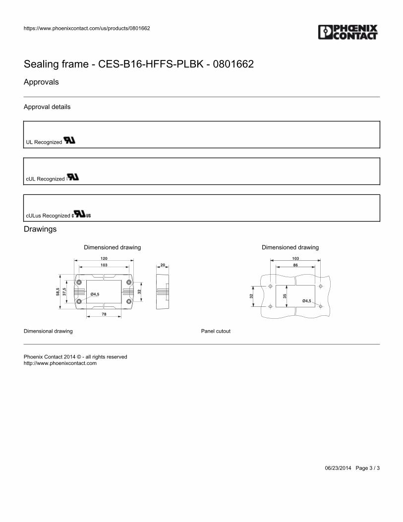
https://www.phoenixcontact.com/us/products/0801662
06/23/2014 Page 3 / 3
Sealing frame - CES-B16-HFFS-PLBK - 0801662Approvals
Approval details
UL Recognized
cUL Recognized
cULus Recognized
Drawings
Dimensioned drawing
120
103
78
58
,5
37
,5
32
Ø4,5
20
Dimensional drawing
Dimensioned drawing
103
86
32
35
Ø4,5
Panel cutout
Phoenix Contact 2014 © - all rights reservedhttp://www.phoenixcontact.com

BWS-GL-02 Appendix41
41. PhoenixContactCESFlatGasket:CES-B16-WRG-BK
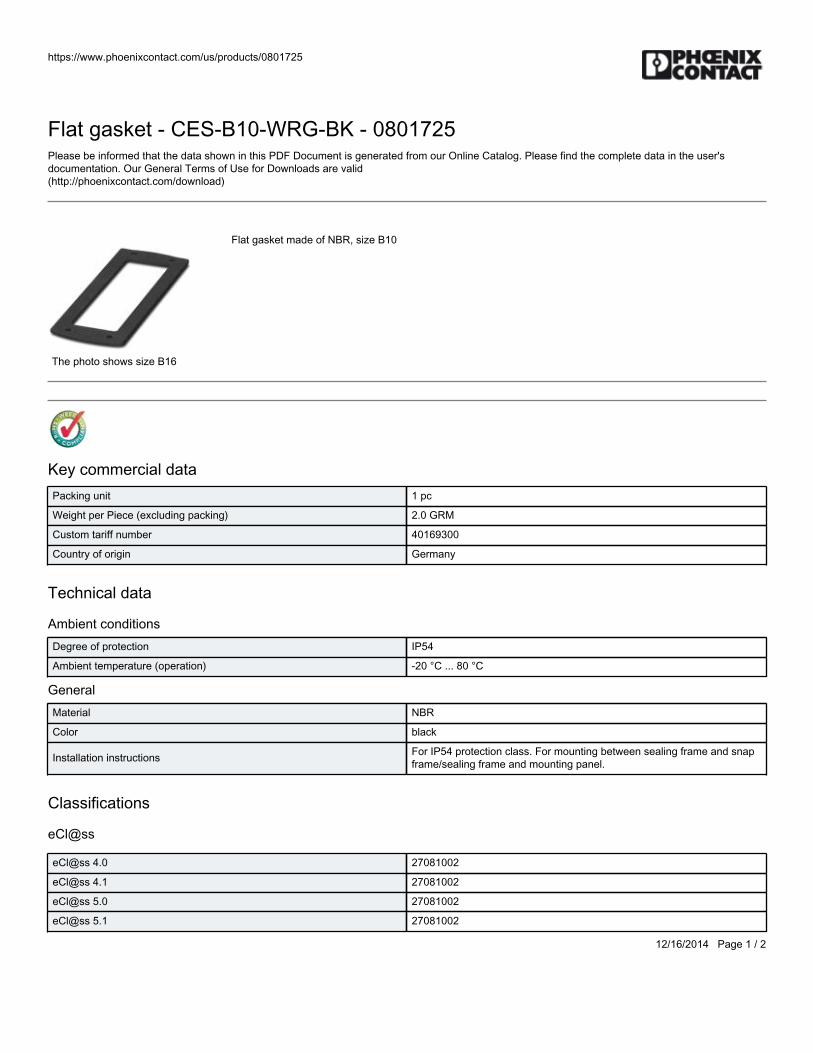
https://www.phoenixcontact.com/us/products/0801725
12/16/2014 Page 1 / 2
Flat gasket - CES-B10-WRG-BK - 0801725Please be informed that the data shown in this PDF Document is generated from our Online Catalog. Please find the complete data in the user'sdocumentation. Our General Terms of Use for Downloads are valid(http://phoenixcontact.com/download)
Flat gasket made of NBR, size B10
The photo shows size B16
Key commercial dataPacking unit 1 pc
Weight per Piece (excluding packing) 2.0 GRM
Custom tariff number 40169300
Country of origin Germany
Technical data
Ambient conditionsDegree of protection IP54
Ambient temperature (operation) -20 °C ... 80 °C
GeneralMaterial NBR
Color black
Installation instructions For IP54 protection class. For mounting between sealing frame and snapframe/sealing frame and mounting panel.
Classifications
eCl@ss
eCl@ss 4.0 27081002
eCl@ss 4.1 27081002
eCl@ss 5.0 27081002
eCl@ss 5.1 27081002
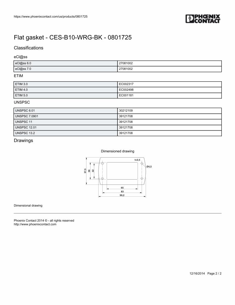
https://www.phoenixcontact.com/us/products/0801725
12/16/2014 Page 2 / 2
Flat gasket - CES-B10-WRG-BK - 0801725Classifications
eCl@sseCl@ss 6.0 27081002
eCl@ss 7.0 27081002
ETIM
ETIM 3.0 EC002317
ETIM 4.0 EC002498
ETIM 5.0 EC001181
UNSPSC
UNSPSC 6.01 30212109
UNSPSC 7.0901 39121708
UNSPSC 11 39121708
UNSPSC 12.01 39121708
UNSPSC 13.2 39121708
Drawings
Dimensioned drawing
65
83
99,2
57
,5
36
32
Ø4,5
t=2,5
Dimensional drawing
Phoenix Contact 2014 © - all rights reservedhttp://www.phoenixcontact.com

BWS-GL-02 Appendix42
42. PhoenixContactCESBlindSleeve:CES-SRG-BK
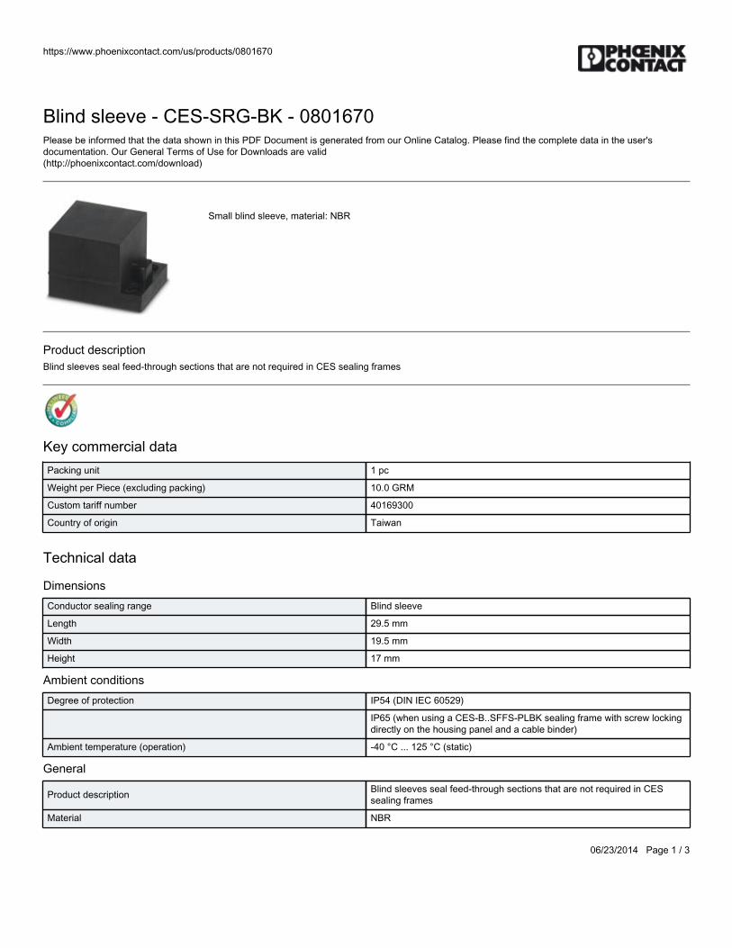
https://www.phoenixcontact.com/us/products/0801670
06/23/2014 Page 1 / 3
Blind sleeve - CES-SRG-BK - 0801670Please be informed that the data shown in this PDF Document is generated from our Online Catalog. Please find the complete data in the user'sdocumentation. Our General Terms of Use for Downloads are valid(http://phoenixcontact.com/download)
Small blind sleeve, material: NBR
Product descriptionBlind sleeves seal feed-through sections that are not required in CES sealing frames
Key commercial dataPacking unit 1 pc
Weight per Piece (excluding packing) 10.0 GRM
Custom tariff number 40169300
Country of origin Taiwan
Technical data
DimensionsConductor sealing range Blind sleeve
Length 29.5 mm
Width 19.5 mm
Height 17 mm
Ambient conditionsDegree of protection IP54 (DIN IEC 60529)
IP65 (when using a CES-B..SFFS-PLBK sealing frame with screw lockingdirectly on the housing panel and a cable binder)
Ambient temperature (operation) -40 °C ... 125 °C (static)
General
Product description Blind sleeves seal feed-through sections that are not required in CESsealing frames
Material NBR
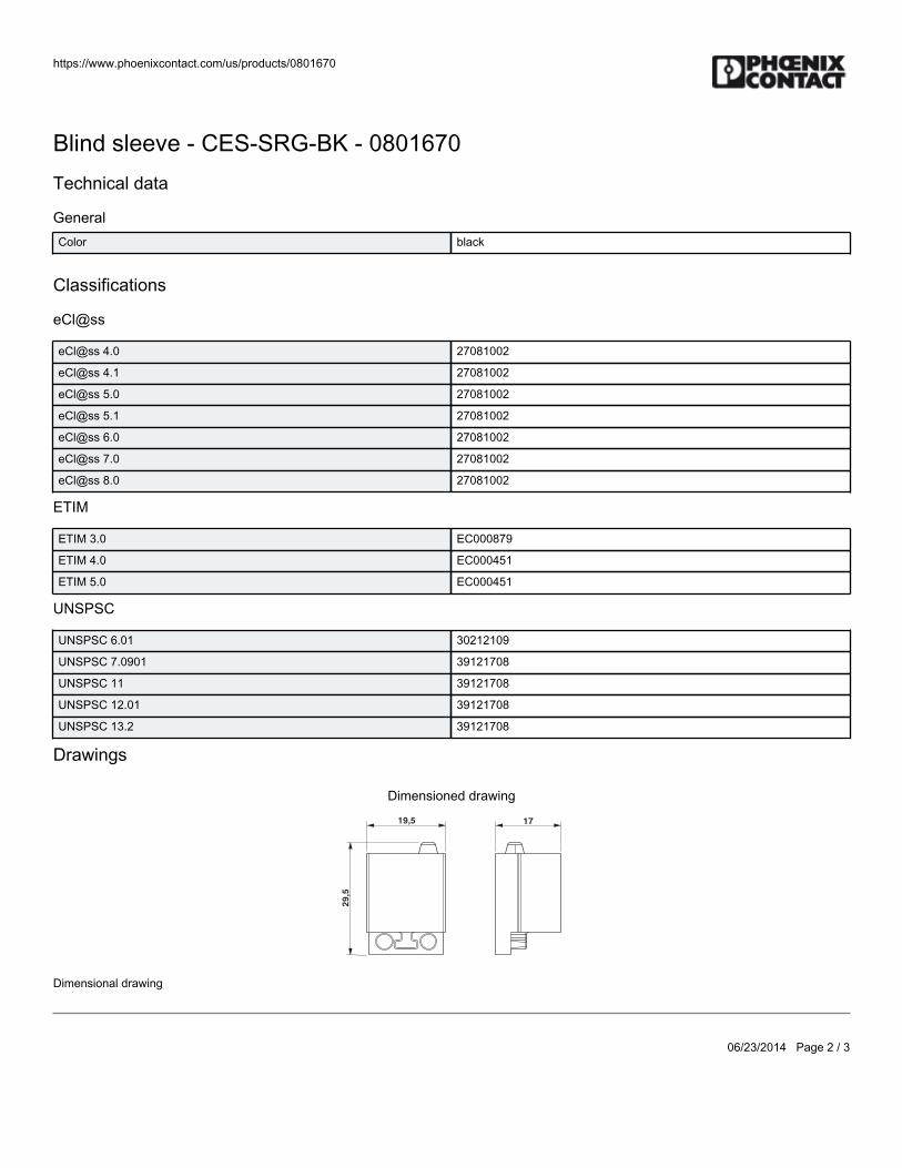
https://www.phoenixcontact.com/us/products/0801670
06/23/2014 Page 2 / 3
Blind sleeve - CES-SRG-BK - 0801670Technical data
GeneralColor black
Classifications
eCl@ss
eCl@ss 4.0 27081002
eCl@ss 4.1 27081002
eCl@ss 5.0 27081002
eCl@ss 5.1 27081002
eCl@ss 6.0 27081002
eCl@ss 7.0 27081002
eCl@ss 8.0 27081002
ETIM
ETIM 3.0 EC000879
ETIM 4.0 EC000451
ETIM 5.0 EC000451
UNSPSC
UNSPSC 6.01 30212109
UNSPSC 7.0901 39121708
UNSPSC 11 39121708
UNSPSC 12.01 39121708
UNSPSC 13.2 39121708
Drawings
Dimensioned drawing
17
29
,5
19,5
Dimensional drawing

https://www.phoenixcontact.com/us/products/0801670
06/23/2014 Page 3 / 3
Phoenix Contact 2014 © - all rights reservedhttp://www.phoenixcontact.com

BWS-GL-02 Appendix43
43. PhoenixContactCES2x6CableSleeve:CES-SRG-BK-2X6
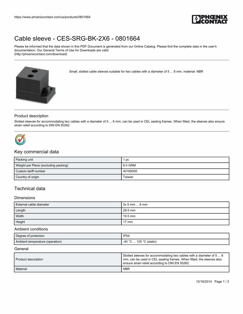
https://www.phoenixcontact.com/us/products/0801664
12/16/2014 Page 1 / 3
Cable sleeve - CES-SRG-BK-2X6 - 0801664Please be informed that the data shown in this PDF Document is generated from our Online Catalog. Please find the complete data in the user'sdocumentation. Our General Terms of Use for Downloads are valid(http://phoenixcontact.com/download)
Small, slotted cable sleeves suitable for two cables with a diameter of 5 ... 6 mm, material: NBR
Product descriptionSlotted sleeves for accommodating two cables with a diameter of 5 ... 6 mm, can be used in CEL sealing frames. When fitted, the sleeves also ensurestrain relief according to DIN EN 50262.
Key commercial dataPacking unit 1 pc
Weight per Piece (excluding packing) 8.0 GRM
Custom tariff number 40169300
Country of origin Taiwan
Technical data
DimensionsExternal cable diameter 2x 5 mm ... 6 mm
Length 29.5 mm
Width 19.5 mm
Height 17 mm
Ambient conditionsDegree of protection IP54
Ambient temperature (operation) -40 °C ... 125 °C (static)
General
Product descriptionSlotted sleeves for accommodating two cables with a diameter of 5 ... 6mm, can be used in CEL sealing frames. When fitted, the sleeves alsoensure strain relief according to DIN EN 50262.
Material NBR

https://www.phoenixcontact.com/us/products/0801664
12/16/2014 Page 2 / 3
Cable sleeve - CES-SRG-BK-2X6 - 0801664Technical data
GeneralColor black
Classifications
eCl@ss
eCl@ss 4.0 27081002
eCl@ss 4.1 27081002
eCl@ss 5.0 27081002
eCl@ss 5.1 27081002
eCl@ss 6.0 27081002
eCl@ss 7.0 27081002
ETIM
ETIM 3.0 EC000879
ETIM 4.0 EC000451
ETIM 5.0 EC000451
UNSPSC
UNSPSC 6.01 30212109
UNSPSC 7.0901 39121708
UNSPSC 11 39121708
UNSPSC 12.01 39121708
UNSPSC 13.2 39121708
Drawings
Dimensioned drawing
Ø6
17
29
,5
19,5
Dimensional drawing

https://www.phoenixcontact.com/us/products/0801664
12/16/2014 Page 3 / 3
Phoenix Contact 2014 © - all rights reservedhttp://www.phoenixcontact.com

BWS-GL-02 Appendix44
44. PhoenixContactCES1x6CableSleeve:CES-SRG-BK-6
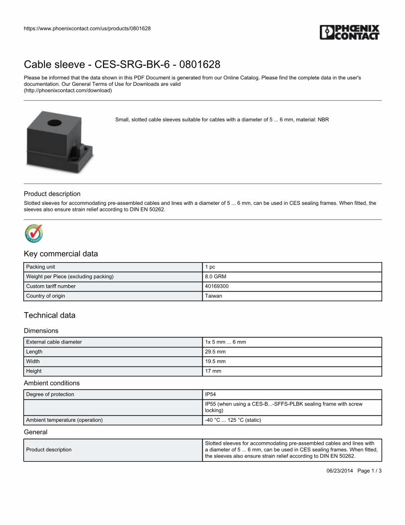
https://www.phoenixcontact.com/us/products/0801628
06/23/2014 Page 1 / 3
Cable sleeve - CES-SRG-BK-6 - 0801628Please be informed that the data shown in this PDF Document is generated from our Online Catalog. Please find the complete data in the user'sdocumentation. Our General Terms of Use for Downloads are valid(http://phoenixcontact.com/download)
Small, slotted cable sleeves suitable for cables with a diameter of 5 ... 6 mm, material: NBR
Product descriptionSlotted sleeves for accommodating pre-assembled cables and lines with a diameter of 5 ... 6 mm, can be used in CES sealing frames. When fitted, thesleeves also ensure strain relief according to DIN EN 50262.
Key commercial dataPacking unit 1 pc
Weight per Piece (excluding packing) 8.0 GRM
Custom tariff number 40169300
Country of origin Taiwan
Technical data
DimensionsExternal cable diameter 1x 5 mm ... 6 mm
Length 29.5 mm
Width 19.5 mm
Height 17 mm
Ambient conditionsDegree of protection IP54
IP55 (when using a CES-B...-SFFS-PLBK sealing frame with screwlocking)
Ambient temperature (operation) -40 °C ... 125 °C (static)
General
Product descriptionSlotted sleeves for accommodating pre-assembled cables and lines witha diameter of 5 ... 6 mm, can be used in CES sealing frames. When fitted,the sleeves also ensure strain relief according to DIN EN 50262.
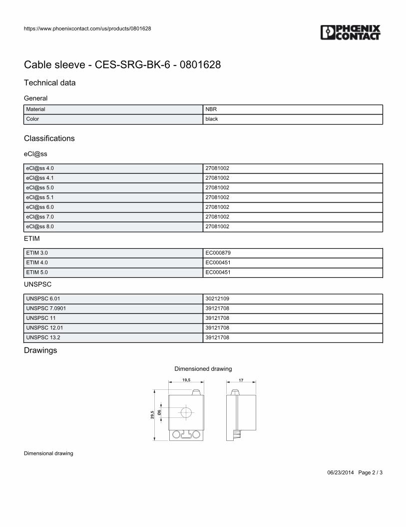
https://www.phoenixcontact.com/us/products/0801628
06/23/2014 Page 2 / 3
Cable sleeve - CES-SRG-BK-6 - 0801628Technical data
GeneralMaterial NBR
Color black
Classifications
eCl@ss
eCl@ss 4.0 27081002
eCl@ss 4.1 27081002
eCl@ss 5.0 27081002
eCl@ss 5.1 27081002
eCl@ss 6.0 27081002
eCl@ss 7.0 27081002
eCl@ss 8.0 27081002
ETIM
ETIM 3.0 EC000879
ETIM 4.0 EC000451
ETIM 5.0 EC000451
UNSPSC
UNSPSC 6.01 30212109
UNSPSC 7.0901 39121708
UNSPSC 11 39121708
UNSPSC 12.01 39121708
UNSPSC 13.2 39121708
Drawings
Dimensioned drawing
Ø6
17
29
,5
19,5
Dimensional drawing

https://www.phoenixcontact.com/us/products/0801628
06/23/2014 Page 3 / 3
Phoenix Contact 2014 © - all rights reservedhttp://www.phoenixcontact.com

BWS-GL-02 Appendix45
45. PhoenixContactCES1x8CableSleeve:CES-SRG-BK-8
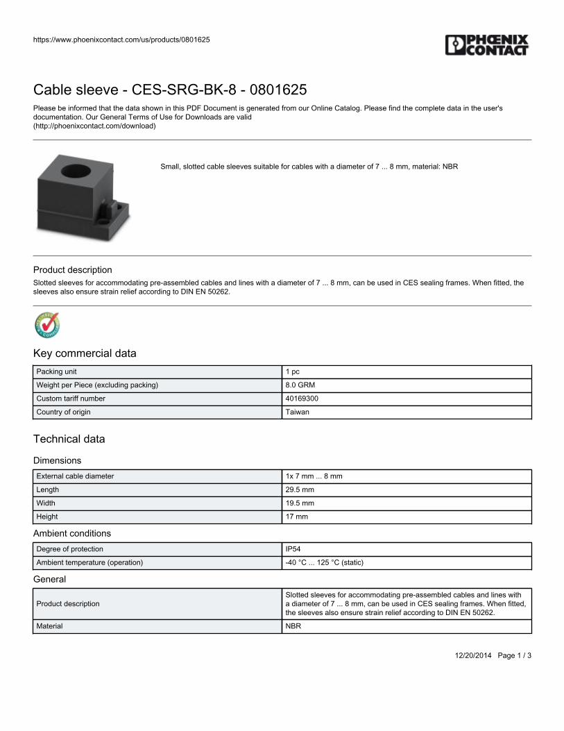
https://www.phoenixcontact.com/us/products/0801625
12/20/2014 Page 1 / 3
Cable sleeve - CES-SRG-BK-8 - 0801625Please be informed that the data shown in this PDF Document is generated from our Online Catalog. Please find the complete data in the user'sdocumentation. Our General Terms of Use for Downloads are valid(http://phoenixcontact.com/download)
Small, slotted cable sleeves suitable for cables with a diameter of 7 ... 8 mm, material: NBR
Product descriptionSlotted sleeves for accommodating pre-assembled cables and lines with a diameter of 7 ... 8 mm, can be used in CES sealing frames. When fitted, thesleeves also ensure strain relief according to DIN EN 50262.
Key commercial dataPacking unit 1 pc
Weight per Piece (excluding packing) 8.0 GRM
Custom tariff number 40169300
Country of origin Taiwan
Technical data
DimensionsExternal cable diameter 1x 7 mm ... 8 mm
Length 29.5 mm
Width 19.5 mm
Height 17 mm
Ambient conditionsDegree of protection IP54
Ambient temperature (operation) -40 °C ... 125 °C (static)
General
Product descriptionSlotted sleeves for accommodating pre-assembled cables and lines witha diameter of 7 ... 8 mm, can be used in CES sealing frames. When fitted,the sleeves also ensure strain relief according to DIN EN 50262.
Material NBR
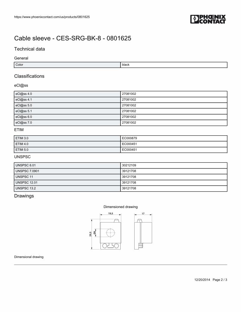
https://www.phoenixcontact.com/us/products/0801625
12/20/2014 Page 2 / 3
Cable sleeve - CES-SRG-BK-8 - 0801625Technical data
GeneralColor black
Classifications
eCl@ss
eCl@ss 4.0 27081002
eCl@ss 4.1 27081002
eCl@ss 5.0 27081002
eCl@ss 5.1 27081002
eCl@ss 6.0 27081002
eCl@ss 7.0 27081002
ETIM
ETIM 3.0 EC000879
ETIM 4.0 EC000451
ETIM 5.0 EC000451
UNSPSC
UNSPSC 6.01 30212109
UNSPSC 7.0901 39121708
UNSPSC 11 39121708
UNSPSC 12.01 39121708
UNSPSC 13.2 39121708
Drawings
Dimensioned drawing
Ø8
17
29
,5
19,5
Dimensional drawing

https://www.phoenixcontact.com/us/products/0801625
12/20/2014 Page 3 / 3
Phoenix Contact 2014 © - all rights reservedhttp://www.phoenixcontact.com

BWS-GL-02 Appendix46
46. DuraChoiceStainlessSteelMini-BallValve:VBSM2-025
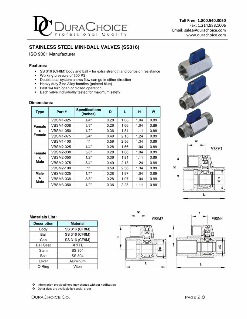
DuraChoice Co. page 2.8
Toll Free: 1.800.540.3050 Fax: 1.214.988.1006
Email: [email protected] www.durachoice.com
STAINLESS STEEL MINI-BALL VALVES (SS316) ISO 9001 Manufacturer Features:
SS 316 (CF8M) body and ball – for extra strength and corrosion resistance Working pressure of 800 PSI Double seal system allows flow can go in either direction Heavy duty Zinc Alloy handles (painted blue) Fast 1/4 turn open or closed operation Each valve individually tested for maximum safety
Dimensions:
Type Part # Specifications (inches) D L H W
Female x
Female
VBSM1-025 1/4" 0.28 1.66 1.04 0.89 VBSM1-038 3/8" 0.28 1.66 1.04 0.89 VBSM1-050 1/2" 0.36 1.81 1.11 0.89 VBSM1-075 3/4" 0.49 2.13 1.24 0.89 VBSM1-100 1" 0.59 2.56 1.34 0.89
Female
x Male
VBSM2-025 1/4" 0.28 1.66 1.04 0.89 VBSM2-038 3/8" 0.28 1.66 1.04 0.89 VBSM2-050 1/2" 0.36 1.81 1.11 0.89 VBSM2-075 3/4" 0.49 2.13 1.24 0.89 VBSM2-100 1" 0.59 2.56 1.34 0.89
Male x
Male
VBSM3-025 1/4" 0.28 1.97 1.04 0.89 VBSM3-038 3/8" 0.28 1.97 1.04 0.89 VBSM3-050 1/2" 0.36 2.28 1.11 0.89
Materials List: Description Material
Body SS 316 (CF8M) Ball SS 316 (CF8M) Cap SS 316 (CF8M)
Ball Seat RPTFE Stem SS 304 Bolt SS 304
Lever Aluminum O-Ring Viton
Information provided here may change without notification Other sizes are available by special order

BWS-GL-02 Appendix47
47. PMCSubmersibleWellLevelSensor:VL4313
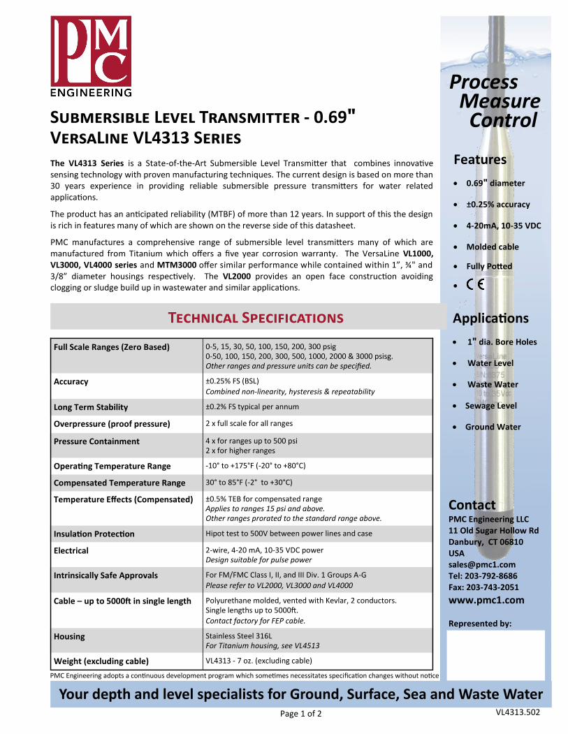
Page 1 of 2
PMC Engineering adopts a continuous development program which sometimes necessitates specification changes without notice
Your depth and level specialists for Ground, Surface, Sea and Waste Water VL4313.502
Features 0.69" diameter
±0.25% accuracy
4-20mA, 10-35 VDC
Molded cable
Fully Potted
Applications
1" dia. Bore Holes
Water Level
Waste Water
Sewage Level
Ground Water
Technical Specifications
Process Measure Control Submersible Level Transmitter - 0.69"
VersaLine VL4313 Series
Contact PMC Engineering LLC 11 Old Sugar Hollow Rd Danbury, CT 06810 USA [email protected] Tel: 203-792-8686 Fax: 203-743-2051 www.pmc1.com Represented by:
Full Scale Ranges (Zero Based) 0-5, 15, 30, 50, 100, 150, 200, 300 psig 0-50, 100, 150, 200, 300, 500, 1000, 2000 & 3000 psisg. Other ranges and pressure units can be specified.
Accuracy ±0.25% FS (BSL) Combined non-linearity, hysteresis & repeatability
Long Term Stability ±0.2% FS typical per annum
Overpressure (proof pressure) 2 x full scale for all ranges
Pressure Containment 4 x for ranges up to 500 psi 2 x for higher ranges
Operating Temperature Range -10° to +175°F (-20° to +80°C)
Compensated Temperature Range 30° to 85°F (-2° to +30°C)
Temperature Effects (Compensated) ±0.5% TEB for compensated range Applies to ranges 15 psi and above. Other ranges prorated to the standard range above.
Insulation Protection Hipot test to 500V between power lines and case
Electrical 2-wire, 4-20 mA, 10-35 VDC power Design suitable for pulse power
Intrinsically Safe Approvals For FM/FMC Class I, II, and III Div. 1 Groups A-G Please refer to VL2000, VL3000 and VL4000
Cable – up to 5000ft in single length Polyurethane molded, vented with Kevlar, 2 conductors. Single lengths up to 5000ft. Contact factory for FEP cable.
Housing Stainless Steel 316L For Titanium housing, see VL4513
Weight (excluding cable) VL4313 - 7 oz. (excluding cable)
The VL4313 Series is a State-of-the-Art Submersible Level Transmitter that combines innovative sensing technology with proven manufacturing techniques. The current design is based on more than 30 years experience in providing reliable submersible pressure transmitters for water related applications.
The product has an anticipated reliability (MTBF) of more than 12 years. In support of this the design is rich in features many of which are shown on the reverse side of this datasheet.
PMC manufactures a comprehensive range of submersible level transmitters many of which are manufactured from Titanium which offers a five year corrosion warranty. The VersaLine VL1000, VL3000, VL4000 series and MTM3000 offer similar performance while contained within 1”, ¾" and 3/8” diameter housings respectively. The VL2000 provides an open face construction avoiding clogging or sludge build up in wastewater and similar applications.
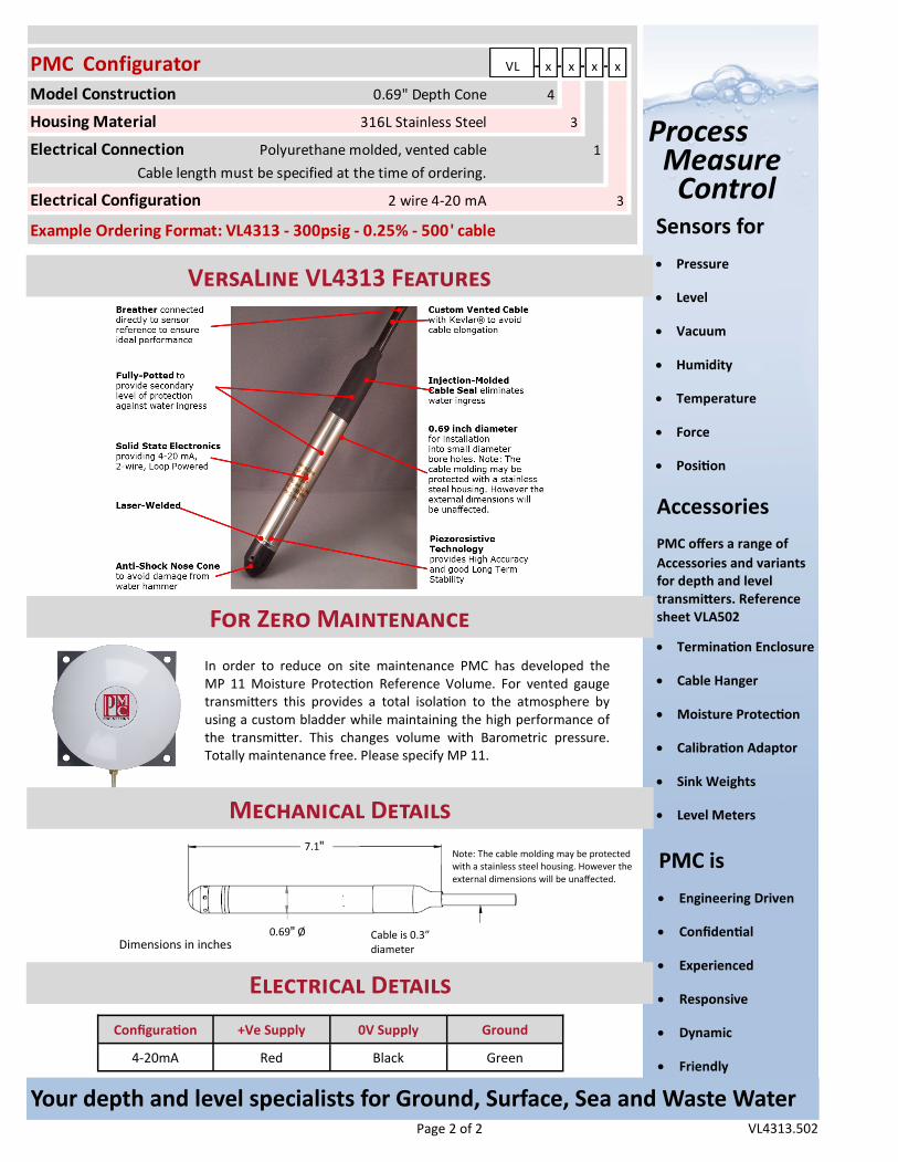
Page 2 of 2
Sensors for Pressure
Level
Vacuum
Humidity
Temperature
Force
Position
PMC is Engineering Driven
Confidential
Experienced
Responsive
Dynamic
Friendly
Accessories PMC offers a range of Accessories and variants for depth and level transmitters. Reference sheet VLA502
Termination Enclosure
Cable Hanger
Moisture Protection
Calibration Adaptor
Sink Weights
Level Meters
Your depth and level specialists for Ground, Surface, Sea and Waste Water VL4313.502
Process Measure Control
VersaLine VL4313 Features
Configuration +Ve Supply 0V Supply Ground
4-20mA Red Black Green
For Zero Maintenance
Cable is 0.3” diameter
7.1"
0.69" Ø Dimensions in inches
Note: The cable molding may be protected with a stainless steel housing. However the external dimensions will be unaffected.
Electrical Details
In order to reduce on site maintenance PMC has developed the MP 11 Moisture Protection Reference Volume. For vented gauge transmitters this provides a total isolation to the atmosphere by using a custom bladder while maintaining the high performance of the transmitter. This changes volume with Barometric pressure. Totally maintenance free. Please specify MP 11.
Mechanical Details
PMC Configurator VL - x - x - x - x
Model Construction 0.69" Depth Cone 4
Housing Material 316L Stainless Steel 3
Electrical Connection Polyurethane molded, vented cable 1 Cable length must be specified at the time of ordering.
Electrical Configuration 2 wire 4-20 mA 3
Example Ordering Format: VL4313 - 300psig - 0.25% - 500' cable

BWS-GL-02 Appendix48
48. PressureTransmitter:PT510-200PSIG-13-L13-H1131
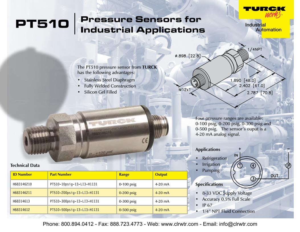
PT510
Technical Data
ID Number Part Number Range Output
H683146210 PT510-10psig-13-LI3-H1131 0-100 psig 4-20 mA
H683146211 PT510-200psig-13-LI3-H1131 0-200 psig 4-20 mA
H68314613 PT510-300psig-13-LI3-H1131 0-300 psig 4-20 mA
H68314612 PT510-500psig-13-LI3-H1131 0-500 psig 4-20 mA
Specifications
8-33 VDC Supply VoltageAccuracy 0.5% Full ScaleIP 671/4” NPT Fluid Connection
••••
The PT510 pressure sensor from TURCK has the following advantages:
Stainless Steel DiaphragmFully Welded ConstructionSilicon Gel Filled
•••
Pressure Sensors for Industrial Applications
Four pressure ranges are available: 0-100 psig, 0-200 psig, 0-300 psig and 0-500 psig. The sensor’s ouput is a 4-20 mA analog signal.
Applications
RefrigerationIrrigationPumping
•••
Phone: 800.894.0412 - Fax: 888.723.4773 - Web: www.clrwtr.com - Email: [email protected]

BWS-GL-02 Appendix49
49. PressureTransmitter:PT15PSIG-13-LI3-H1131
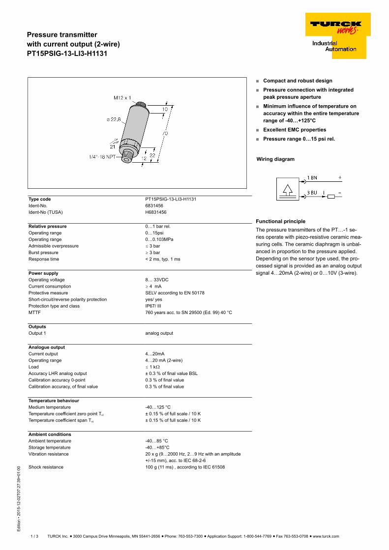
Pressure transmitterwith current output (2-wire)PT15PSIG-13-LI3-H1131
Edi
tion
• 201
5-12
-02T
07:2
7:39
+01:
00
1 / 3 TURCK Inc. ñ 3000 Campus Drive Minneapolis, MN 55441-2656 ñ Phone: 763-553-7300 ñ Application Support: 1-800-544-7769 ñ Fax 763-553-0708 ñ www.turck.com
Type code PT15PSIG-13-LI3-H1131Ident-No. 6831456Ident-No (TUSA) H6831456
Relative pressure 0…1 bar rel.Operating range 0…15psiOperating range 0…0.103MPaAdmissible overpressure ð 3 barBurst pressure ï 3 barResponse time < 2 ms, typ. 1 ms
Power supplyOperating voltage 8… 33VDCCurrent consumption ï 4 mAProtective measure SELV according to EN 50178Short-circuit/reverse polarity protection yes/ yesProtection type and class IP67/ IIIMTTF 760 years acc. to SN 29500 (Ed. 99) 40 °C
OutputsOutput 1 analog output
Analogue outputCurrent output 4…20mAOperating range 4…20 mA (2-wire)Load ð 1 kòAccuracy LHR analog output ± 0.3 % of final value BSLCalibration accuracy 0-point 0.3 % of final valueCalibration accuracy, of final value 0.3 % of final value
Temperature behaviourMedium temperature -40…125 °CTemperature coefficient zero point Tk0 ± 0.15 % of full scale / 10 KTemperature coefficient span TkS ± 0.15 % of full scale / 10 K
Ambient conditionsAmbient temperature -40…85 °CStorage temperature -40…+85°CVibration resistance 20 x g (9…2000 Hz, 2…9 Hz with an amplitude
+/-15 mm), acc. to IEC 68-2-6Shock resistance 100 g (11 ms) , according to IEC 61508
Compact and robust design
Pressure connection with integratedpeak pressure aperture
Minimum influence of temperature onaccuracy within the entire temperaturerange of -40…+125°C
Excellent EMC properties
Pressure range 0…15 psi rel.
Wiring diagram
Functional principleThe pressure transmitters of the PT…-1 se-ries operate with piezo-resistive ceramic mea-suring cells. The ceramic diaphragm is unbal-anced in proportion to the pressure applied.Depending on the sensor type used, the pro-cessed signal is provided as an analog outputsignal 4…20mA (2-wire) or 0…10V (3-wire).
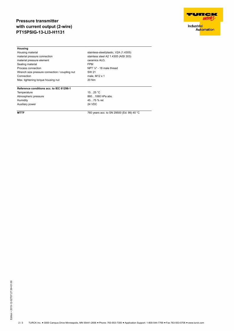
Pressure transmitterwith current output (2-wire)PT15PSIG-13-LI3-H1131
Edi
tion
• 201
5-12
-02T
07:2
7:39
+01:
00
2 / 3 TURCK Inc. ñ 3000 Campus Drive Minneapolis, MN 55441-2656 ñ Phone: 763-553-7300 ñ Application Support: 1-800-544-7769 ñ Fax 763-553-0708 ñ www.turck.com
HousingHousing material stainless-steel/plastic, V2A (1.4305)material pressure connection stainless steel A2 1.4305 (AISI 303)material pressure element ceramics Al2O3
Sealing material FPMProcess connection NPT ¼″ - 18 male threadWrench size pressure connection / coupling nut SW 21Connection male, M12 x 1Max. tightening torque housing nut 20 Nm
Reference conditions acc. to IEC 61298-1Temperature 15…25 °CAtmospheric pressure 860…1060 hPa abs.Humidity 45…75 % rel.Auxiliary power 24 VDC
MTTF 760 years acc. to SN 29500 (Ed. 99) 40 °C
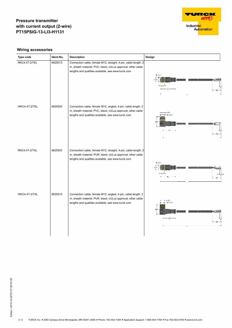
Pressure transmitterwith current output (2-wire)PT15PSIG-13-LI3-H1131
Edi
tion
• 201
5-12
-02T
07:2
7:39
+01:
00
3 / 3 TURCK Inc. ñ 3000 Campus Drive Minneapolis, MN 55441-2656 ñ Phone: 763-553-7300 ñ Application Support: 1-800-544-7769 ñ Fax 763-553-0708 ñ www.turck.com
Wiring accessories
Type code Ident-No. Description Design
RKC4.4T-2/TEL 6625013 Connection cable, female M12, straight, 4-pin, cable length: 2m, sheath material: PVC, black; cULus approval; other cablelengths and qualities available, see www.turck.com
WKC4.4T-2/TEL 6625025 Connection cable, female M12, angled, 4-pin, cable length: 2m, sheath material: PVC, black; cULus approval; other cablelengths and qualities available, see www.turck.com
RKC4.4T-2/TXL 6625503 Connection cable, female M12, straight, 4-pin, cable length: 2m, sheath material: PUR, black; cULus approval; other cablelengths and qualities available, see www.turck.com
WKC4.4T-2/TXL 6625515 Connection cable, female M12, angled, 4-pin, cable length: 2m, sheath material: PUR, black; cULus approval; other cablelengths and qualities available, see www.turck.com

BWS-GL-02 Appendix50
50. GFSignetPaddleWheelFlowMeters:3-2537-6C-P0
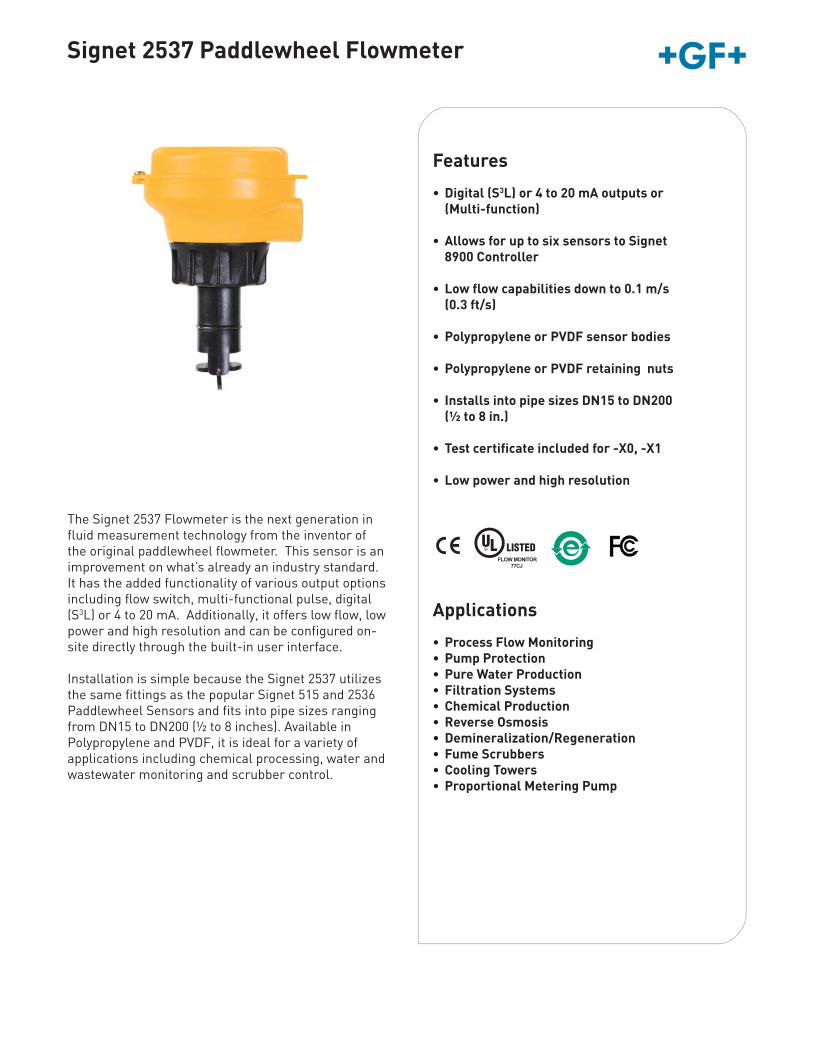
www.gfsignet.com
Signet 2537 Paddlewheel Flowmeter
Features
• Digital (S3L) or 4 to 20 mA outputs or (Multi-function)
• Allows for up to six sensors to Signet 8900 Controller
• Low flow capabilities down to 0.1 m/s (0.3 ft/s)
• Polypropylene or PVDF sensor bodies
• Polypropylene or PVDF retaining nuts
• Installs into pipe sizes DN15 to DN200 (½ to 8 in.)
• Test certificate included for -X0, -X1
• Low power and high resolution
The Signet 2537 Flowmeter is the next generation in fluid measurement technology from the inventor of the original paddlewheel flowmeter. This sensor is an improvement on what’s already an industry standard. It has the added functionality of various output options including flow switch, multi-functional pulse, digital (S3L) or 4 to 20 mA. Additionally, it offers low flow, low power and high resolution and can be configured on-site directly through the built-in user interface.
Installation is simple because the Signet 2537 utilizes the same fittings as the popular Signet 515 and 2536 Paddlewheel Sensors and fits into pipe sizes ranging from DN15 to DN200 (½ to 8 inches). Available in Polypropylene and PVDF, it is ideal for a variety of applications including chemical processing, water and wastewater monitoring and scrubber control.
Applications
• Process Flow Monitoring• Pump Protection• Pure Water Production• Filtration Systems• Chemical Production• Reverse Osmosis• Demineralization/Regeneration• Fume Scrubbers• Cooling Towers• Proportional Metering Pump
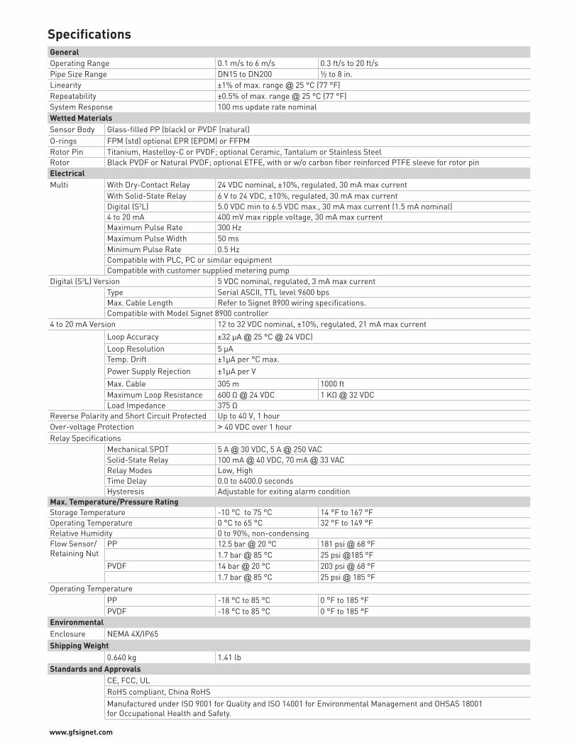
www.gfsignet.com
SpecificationsGeneralOperating Range 0.1 m/s to 6 m/s 0.3 ft/s to 20 ft/sPipe Size Range DN15 to DN200 ½ to 8 in.Linearity ±1% of max. range @ 25 °C (77 °F)Repeatability ±0.5% of max. range @ 25 °C (77 °F)System Response 100 ms update rate nominalWetted MaterialsSensor Body Glass-filled PP (black) or PVDF (natural)O-rings FPM (std) optional EPR (EPDM) or FFPMRotor Pin Titanium, Hastelloy-C or PVDF; optional Ceramic, Tantalum or Stainless SteelRotor Black PVDF or Natural PVDF; optional ETFE, with or w/o carbon fiber reinforced PTFE sleeve for rotor pinElectricalMulti With Dry-Contact Relay 24 VDC nominal, ±10%, regulated, 30 mA max current
With Solid-State Relay 6 V to 24 VDC, ±10%, regulated, 30 mA max currentDigital (S3L) 5.0 VDC min to 6.5 VDC max., 30 mA max current (1.5 mA nominal)4 to 20 mA 400 mV max ripple voltage, 30 mA max currentMaximum Pulse Rate 300 HzMaximum Pulse Width 50 msMinimum Pulse Rate 0.5 HzCompatible with PLC, PC or similar equipmentCompatible with customer supplied metering pump
Digital (S3L) Version 5 VDC nominal, regulated, 3 mA max currentType Serial ASCII, TTL level 9600 bpsMax. Cable Length Refer to Signet 8900 wiring specifications.Compatible with Model Signet 8900 controller
4 to 20 mA Version 12 to 32 VDC nominal, ±10%, regulated, 21 mA max current
Loop Accuracy ±32 μA @ 25 °C @ 24 VDC)Loop Resolution 5 μATemp. Drift ±1μA per °C max.Power Supply Rejection ±1μA per V
Max. Cable 305 m 1000 ftMaximum Loop Resistance 600 Ω @ 24 VDC 1 KΩ @ 32 VDCLoad Impedance 375 Ω
Reverse Polarity and Short Circuit Protected Up to 40 V, 1 hourOver-voltage Protection > 40 VDC over 1 hourRelay Specifications
Mechanical SPDT 5 A @ 30 VDC, 5 A @ 250 VACSolid-State Relay 100 mA @ 40 VDC, 70 mA @ 33 VACRelay Modes Low, HighTime Delay 0.0 to 6400.0 secondsHysteresis Adjustable for exiting alarm condition
Max. Temperature/Pressure RatingStorage Temperature -10 °C to 75 °C 14 °F to 167 °FOperating Temperature 0 °C to 65 °C 32 °F to 149 °FRelative Humidity 0 to 90%, non-condensingFlow Sensor/Retaining Nut
PP 12.5 bar @ 20 °C 181 psi @ 68 °F1.7 bar @ 85 °C 25 psi @185 °F
PVDF 14 bar @ 20 °C 203 psi @ 68 °F1.7 bar @ 85 °C 25 psi @ 185 °F
Operating TemperaturePP -18 °C to 85 °C 0 °F to 185 °FPVDF -18 °C to 85 °C 0 °F to 185 °F
EnvironmentalEnclosure NEMA 4X/IP65Shipping Weight
0.640 kg 1.41 lbStandards and Approvals
CE, FCC, ULRoHS compliant, China RoHSManufactured under ISO 9001 for Quality and ISO 14001 for Environmental Management and OHSAS 18001 for Occupational Health and Safety.
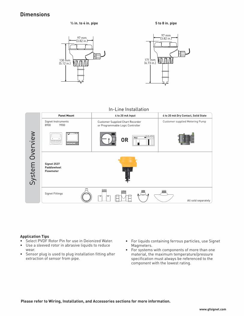
www.gfsignet.com
Application Tips• Select PVDF Rotor Pin for use in Deionized Water.• Use a sleeved rotor in abrasive liquids to reduce
wear.• Sensor plug is used to plug installation fitting after
extraction of sensor from pipe.
• For liquids containing ferrous particles, use Signet Magmeters.
• For systems with components of more than one material, the maximum temperature/pressure specification must always be referenced to the component with the lowest rating.
Please refer to Wiring, Installation, and Accessories sections for more information.
97 mm(3.82 in.)
130 mm(5.12 in.)
½ in. to 4 in. pipe
Dimensions5 to 8 in. pipe
97 mm(3.82 in.)
171 mm(6.73 in.)
4 to 20 mA Input
PLC
4 to 20 mA Dry Contact, Solid State
Customer supplied Metering Pump
Signet Fittings
Signet Instruments8900 9900
All sold separately
Panel Mount
Signet 2537 PaddlewheelFlowmeter
ENTER
Syst
em O
verv
iew
In-Line Installation
Customer Supplied Chart Recorderor Programmable Logic Controller
OR
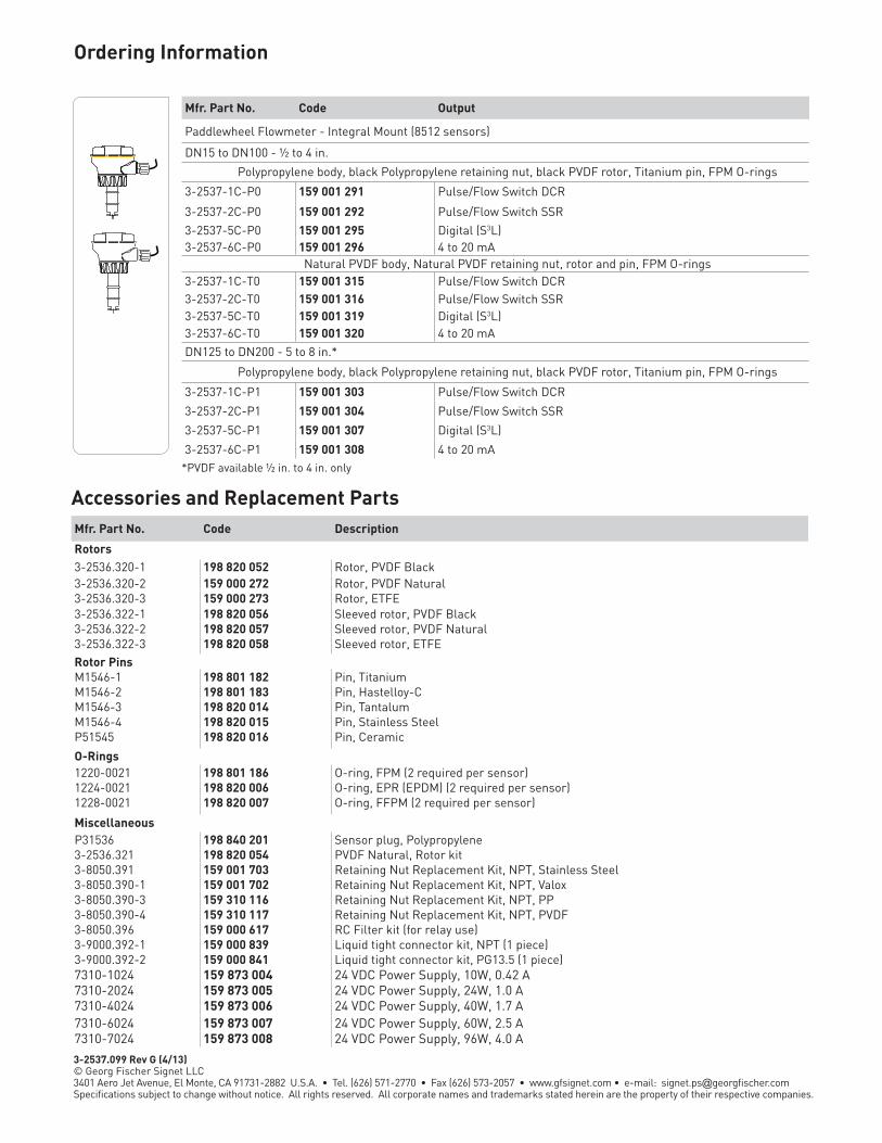
www.gfsignet.com
*PVDF available ½ in. to 4 in. only
Ordering Information
Accessories and Replacement PartsMfr. Part No. Code Description
Rotors 3-2536.320-1 198 820 052 Rotor, PVDF Black3-2536.320-2 159 000 272 Rotor, PVDF Natural3-2536.320-3 159 000 273 Rotor, ETFE3-2536.322-1 198 820 056 Sleeved rotor, PVDF Black3-2536.322-2 198 820 057 Sleeved rotor, PVDF Natural3-2536.322-3 198 820 058 Sleeved rotor, ETFERotor PinsM1546-1 198 801 182 Pin, TitaniumM1546-2 198 801 183 Pin, Hastelloy-CM1546-3 198 820 014 Pin, TantalumM1546-4 198 820 015 Pin, Stainless SteelP51545 198 820 016 Pin, Ceramic
O-Rings1220-0021 198 801 186 O-ring, FPM (2 required per sensor)1224-0021 198 820 006 O-ring, EPR (EPDM) (2 required per sensor)1228-0021 198 820 007 O-ring, FFPM (2 required per sensor)
MiscellaneousP31536 198 840 201 Sensor plug, Polypropylene3-2536.321 198 820 054 PVDF Natural, Rotor kit3-8050.391 159 001 703 Retaining Nut Replacement Kit, NPT, Stainless Steel3-8050.390-1 159 001 702 Retaining Nut Replacement Kit, NPT, Valox3-8050.390-3 159 310 116 Retaining Nut Replacement Kit, NPT, PP3-8050.390-4 159 310 117 Retaining Nut Replacement Kit, NPT, PVDF3-8050.396 159 000 617 RC Filter kit (for relay use)3-9000.392-1 159 000 839 Liquid tight connector kit, NPT (1 piece)3-9000.392-2 159 000 841 Liquid tight connector kit, PG13.5 (1 piece)7310-1024 159 873 004 24 VDC Power Supply, 10W, 0.42 A7310-2024 159 873 005 24 VDC Power Supply, 24W, 1.0 A7310-4024 159 873 006 24 VDC Power Supply, 40W, 1.7 A7310-6024 159 873 007 24 VDC Power Supply, 60W, 2.5 A7310-7024 159 873 008 24 VDC Power Supply, 96W, 4.0 A
Mfr. Part No. Code Output
Paddlewheel Flowmeter - Integral Mount (8512 sensors)
DN15 to DN100 - ½ to 4 in.
Polypropylene body, black Polypropylene retaining nut, black PVDF rotor, Titanium pin, FPM O-rings
3-2537-1C-P0 159 001 291 Pulse/Flow Switch DCR
3-2537-2C-P0 159 001 292 Pulse/Flow Switch SSR
3-2537-5C-P0 159 001 295 Digital (S3L)3-2537-6C-P0 159 001 296 4 to 20 mA
Natural PVDF body, Natural PVDF retaining nut, rotor and pin, FPM O-rings3-2537-1C-T0 159 001 315 Pulse/Flow Switch DCR3-2537-2C-T0 159 001 316 Pulse/Flow Switch SSR3-2537-5C-T0 159 001 319 Digital (S3L)3-2537-6C-T0 159 001 320 4 to 20 mADN125 to DN200 - 5 to 8 in.*
Polypropylene body, black Polypropylene retaining nut, black PVDF rotor, Titanium pin, FPM O-rings
3-2537-1C-P1 159 001 303 Pulse/Flow Switch DCR
3-2537-2C-P1 159 001 304 Pulse/Flow Switch SSR
3-2537-5C-P1 159 001 307 Digital (S3L)
3-2537-6C-P1 159 001 308 4 to 20 mA
3-2537.099 Rev G (4/13) © Georg Fischer Signet LLC3401 Aero Jet Avenue, El Monte, CA 91731-2882 U.S.A. • Tel. (626) 571-2770 • Fax (626) 573-2057 • www.gfsignet.com • e-mail: [email protected] subject to change without notice. All rights reserved. All corporate names and trademarks stated herein are the property of their respective companies.
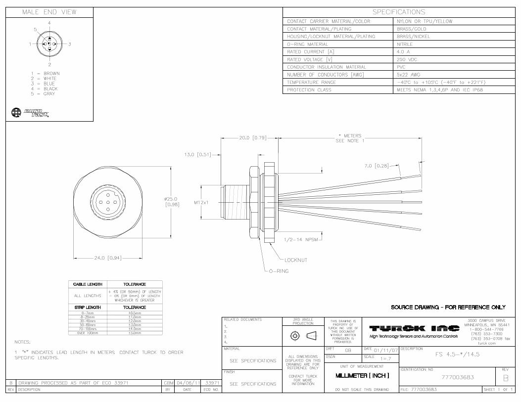

BWS-GL-02 Appendix51
51. GFSignetOrpSensor:3-2750-2&3-2725-60
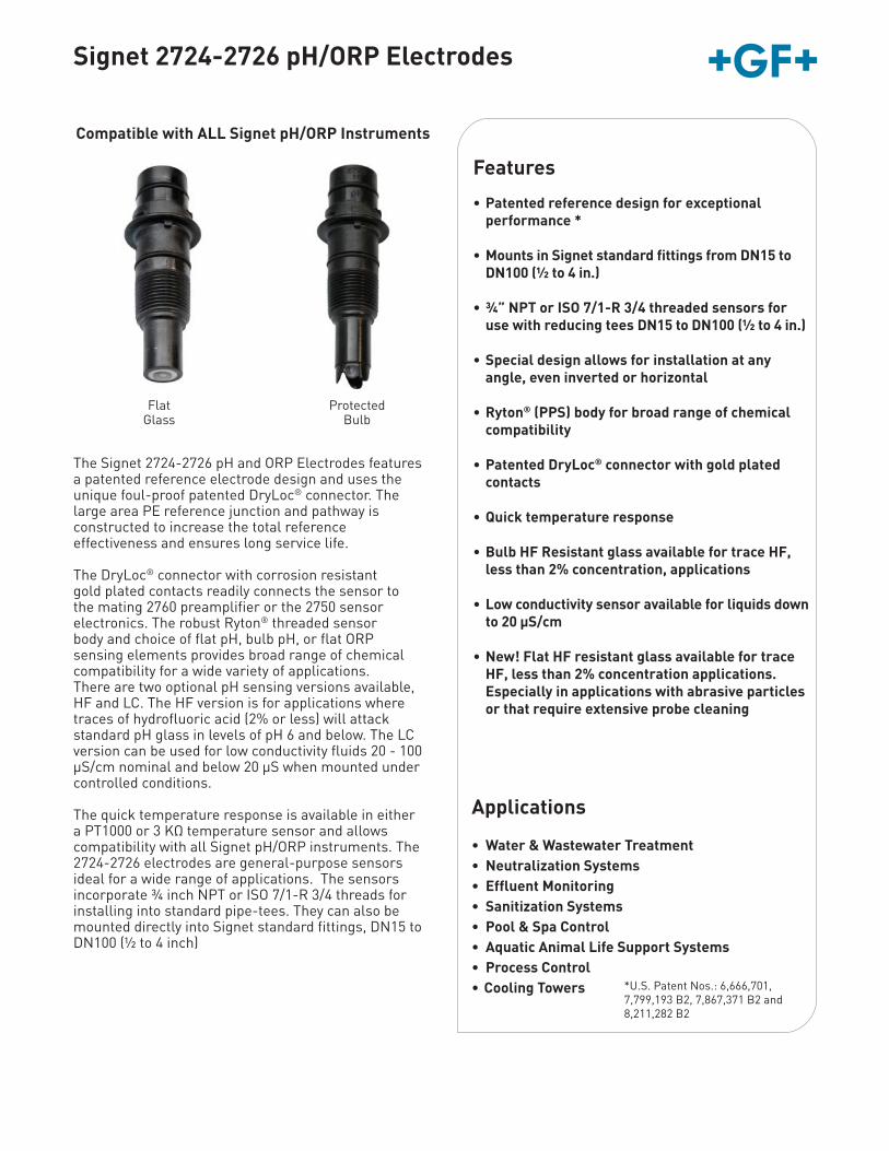
Signet 2724-2726 pH/ORP Electrodes
Features
• Patented reference design for exceptional performance *
• Mounts in Signet standard fittings from DN15 to DN100 (½ to 4 in.)
• ¾” NPT or ISO 7/1-R 3/4 threaded sensors for use with reducing tees DN15 to DN100 (½ to 4 in.)
• Special design allows for installation at any angle, even inverted or horizontal
• Ryton® (PPS) body for broad range of chemical compatibility
• Patented DryLoc® connector with gold plated contacts
• Quick temperature response
• Bulb HF Resistant glass available for trace HF, less than 2% concentration, applications
• Low conductivity sensor available for liquids down to 20 μS/cm
• New! Flat HF resistant glass available for trace HF, less than 2% concentration applications. Especially in applications with abrasive particles or that require extensive probe cleaning
Applications
• Water & Wastewater Treatment• Neutralization Systems• Effluent Monitoring• Sanitization Systems• Pool & Spa Control• Aquatic Animal Life Support Systems• Process Control• Cooling Towers
Compatible with ALL Signet pH/ORP Instruments
ProtectedBulb
FlatGlass
*U.S. Patent Nos.: 6,666,701, 7,799,193 B2, 7,867,371 B2 and8,211,282 B2
The Signet 2724-2726 pH and ORP Electrodes features a patented reference electrode design and uses the unique foul-proof patented DryLoc® connector. The large area PE reference junction and pathway is constructed to increase the total referenceeffectiveness and ensures long service life.
The DryLoc® connector with corrosion resistant gold plated contacts readily connects the sensor to the mating 2760 preamplifier or the 2750 sensor electronics. The robust Ryton® threaded sensor body and choice of flat pH, bulb pH, or flat ORP sensing elements provides broad range of chemical compatibility for a wide variety of applications. There are two optional pH sensing versions available, HF and LC. The HF version is for applications where traces of hydrofluoric acid (2% or less) will attack standard pH glass in levels of pH 6 and below. The LC version can be used for low conductivity fluids 20 - 100 μS/cm nominal and below 20 μS when mounted under controlled conditions.
The quick temperature response is available in either a PT1000 or 3 KΩ temperature sensor and allows compatibility with all Signet pH/ORP instruments. The 2724-2726 electrodes are general-purpose sensors ideal for a wide range of applications. The sensors incorporate ¾ inch NPT or ISO 7/1-R 3/4 threads for installing into standard pipe-tees. They can also be mounted directly into Signet standard fittings, DN15 to DN100 (½ to 4 inch)
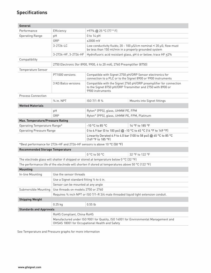
www.gfsignet.com
Specifications
See Temperature and Pressure graphs for more information
General
Performance Efficiency >97% @ 25 °C (77 ° F)
Operating Range pH 0 to 14 pH
ORP ±2000 mV
3-2726-LC Low conductivity fluids; 20 - 100 μS/cm nominal < 20 μS; flow mustbe less than 150 ml/min in a properly grounded system
3-2724-HF, 3-2726-HF Hydrofluoric acid resistant glass, pH 6 or below; trace HF <2%
Compatibility
2750 Electronic (for 8900, 9900, 4 to 20 mA), 2760 Preamplifier (8750)
Temperature Sensor
PT1000 versions Compatible with Signet 2750 pH/ORP Sensor electronics forconnection to a PLC or to the Signet 8900 or 9900 instruments
3 KΩ Balco versions Compatible with the Signet 2760 pH/ORP preamplifier for connectionto the Signet 8750 pH/ORP Transmitter and 2750 with 8900 or 9900 instruments
Process Connection
¾ in. NPT ISO 7/1-R ¾ Mounts into Signet fittings
Wetted Materials
pH Ryton® (PPS), glass, UHMW PE, FPM
ORP Ryton® (PPS), glass, UHMW PE, FPM, Platinum
Max. Temperature/Pressure Rating
Operating Temperature Range* -10 °C to 85 °C 14 °F to 185 °F
Operating Pressure Range 0 to 6.9 bar (0 to 100 psi) @ -10 °C to 65 °C (14 °F to 149 °F)
Linearity Derated 6.9 to 4.0 bar (100 to 58 psi) @ 65 °C to 85 °C (149 °F to 185 °F)
*Best performance for 2724-HF and 2726-HF sensors is above 10 °C (50 °F)
Recommended Storage Temperature
0 °C to 50 °C 32 °F to 122 °F
The electrode glass will shatter if shipped or stored at temperature below 0 °C (32 °F)
The performance life of the electrode will shorten if stored at temperatures above 50 °C (122 °F)
Mounting
In-line Mounting Use the sensor threads
Use a Signet standard fitting ½ to 4 in.
Sensor can be mounted at any angle
Submersible Mounting Use threads on models 2750 or 2760
Requires ¾ inch NPT or ISO 7/1-R 3/4 male threaded liquid tight extension conduit.
Shipping Weight
0.25 kg 0.55 lb
Standards and Approvals
RoHS Compliant, China RoHS
Manufactured under ISO 9001 for Quality, ISO 14001 for Environmental Management and OHSAS 18001 for Occupational Health and Safety
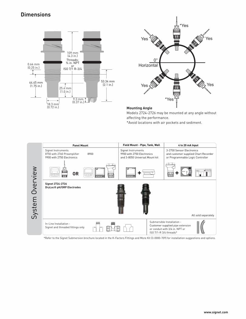
www.signet.com
Dimensions
109 mm(4.3 in.)
9.3 mm(0.37 in.)
25.4 mm(1.0 in.)
Threads:¾ in. NPT
orISO 7/1 R-3/4
53.34 mm(2.1 in.)
44.45 mm(1.75 in.)
18.3 mm(0.72 in.)
0.64 mm(0.25 in.)
0°Horizontal
*Yes
Yes Yes
Yes
*Yes
Yes
Mounting AngleModels 2724-2726 may be mounted at any angle without affecting the performance. *Avoid locations with air pockets and sediment.
ENTERENTER
In-Line Installation - Signet and threaded fittings only
Signet 2724-2726 DryLoc® pH/ORP Electrodes
Syst
em O
verv
iew
All sold separately
Panel Mount 4 to 20 mA Input
PLC
3-2750 Sensor Electronicsand customer supplied Chart Recorderor Programmable Logic Controller
Field Mount - Pipe, Tank, Wall
Signet Instruments 9900 with 2750 Electronics and 3-8050 Universal Mount kit
Signet Instruments8750 with 2760 Preamplifier 89009900 with 2750 Electronics
+ +OR
*Refer to the Signet Submersion brochure located in the K-Factors Fittings and More Kit (3-0000-709) for installation suggestions and options.
Submersible Installation - Customer supplied pipe extensionor conduit with 3/4 in. NPT or ISO 7/1-R 3/4 threads*
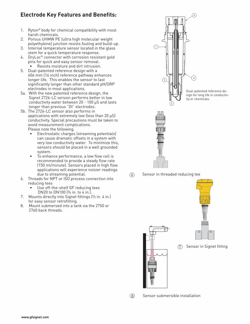
www.gfsignet.com
Electrode Key Features and Benefits: 4
5
1
3
2
Dual-patented reference de-sign for long life in conductiv-ity or chemicals.
Sensor in threaded reducing tee
Sensor in Signet fitting
Sensor submersible installation
6
8
7
1. Ryton® body for chemical compatibility with most harsh chemicals.2. Porous UHMW PE (ultra high molecular weight polyethylene) junction resists fouling and build-up.3. Internal temperature sensor located in the glass stem for a quick temperature response.4. DryLoc® connector with corrosion resistant gold pins for quick and easy sensor removal.
• Resists moisture and dirt intrusion.5. Dual-patented reference design with a
406 mm (16 inch) reference pathway enhances longer life. This enables the sensor to last significantly longer than other standard pH/ORP electrodes in most applications.
5a. With the new patented reference design, the Signet 2726-LC version performs better in low conductivity water between 20 - 100 μS and lasts longer than previous “DI” electrodes.5b. The 2726-LC sensor also performs in applications with extremely low (less than 20 μS) conductivity. Special precautions must be taken to avoid measurement complications. Please note the following.
• Electrostatic charges (streaming potentials) can cause dramatic offsets in a system with very low conductivity water. To minimize this, sensors should be placed in a well grounded system.
• To enhance performance, a low flow cell is recommended to provide a steady flow rate (150 ml/minute). Sensors placed in high flow applications will experience noisier readings due to streaming potential.
6. Threads for NPT or ISO process connection into reducing tees
• Use off-the-shelf GF reducing teesDN20 to DN100 (¾ in. to 4 in.).
7. Mounts directly into Signet fittings (½ in. 4 in.) for easy sensor retrofitting.8. Mount submersed into a tank via the 2750 or 2760 back threads.
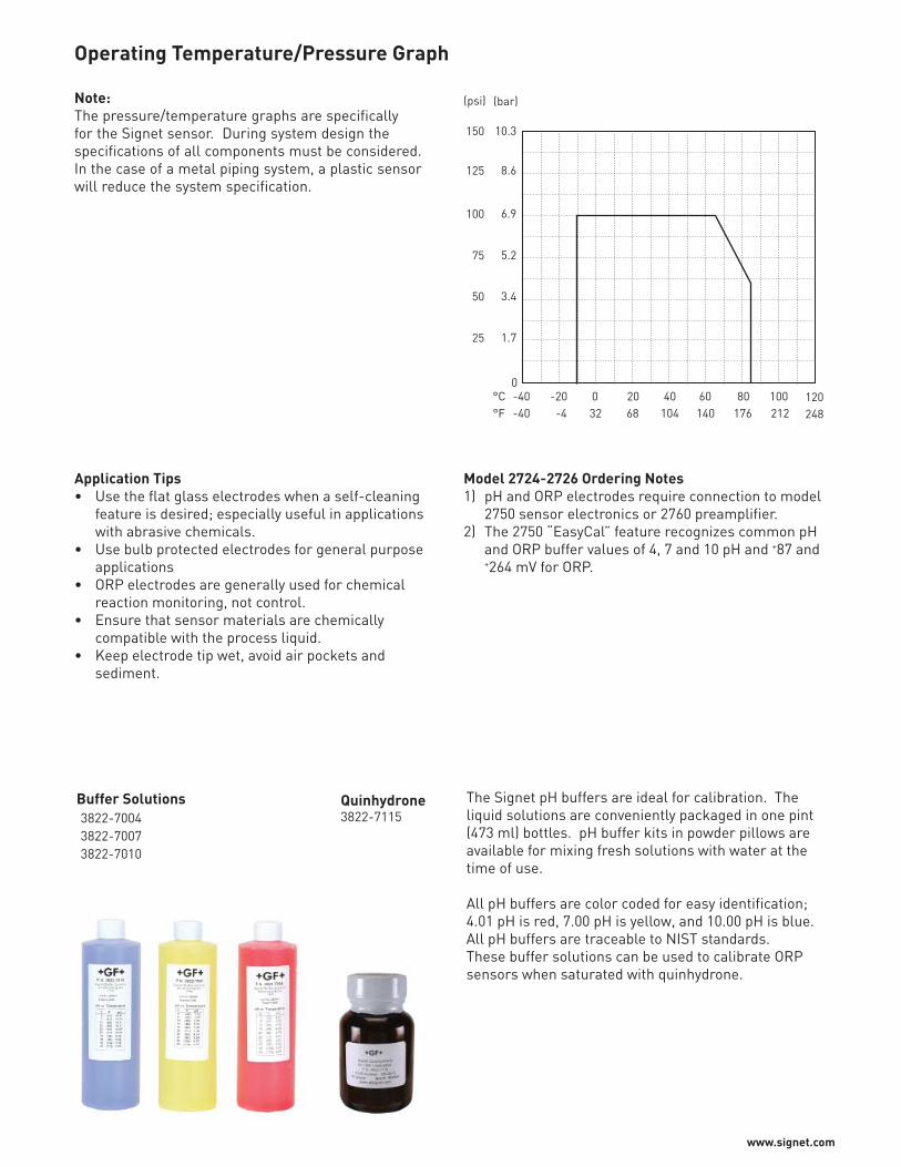
www.signet.com
The Signet pH buffers are ideal for calibration. The liquid solutions are conveniently packaged in one pint (473 ml) bottles. pH buffer kits in powder pillows are available for mixing fresh solutions with water at the time of use.
All pH buffers are color coded for easy identification; 4.01 pH is red, 7.00 pH is yellow, and 10.00 pH is blue. All pH buffers are traceable to NIST standards.These buffer solutions can be used to calibrate ORP sensors when saturated with quinhydrone.
Model 2724-2726 Ordering Notes1) pH and ORP electrodes require connection to model
2750 sensor electronics or 2760 preamplifier.2) The 2750 “EasyCal” feature recognizes common pH
and ORP buffer values of 4, 7 and 10 pH and +87 and +264 mV for ORP.
Application Tips• Use the flat glass electrodes when a self-cleaning
feature is desired; especially useful in applications with abrasive chemicals.
• Use bulb protected electrodes for general purpose applications
• ORP electrodes are generally used for chemical reaction monitoring, not control.
• Ensure that sensor materials are chemically compatible with the process liquid.
• Keep electrode tip wet, avoid air pockets and sediment.
0-40 -20 0 20 40 60 80 100 120
°F°C
-40 -4 32 68 104 140 176 212 248
(bar)(psi)
1.7
3.4
5.2
6.9
8.6
10.3
25
50
75
100
125
150
Note:The pressure/temperature graphs are specifically for the Signet sensor. During system design the specifications of all components must be considered. In the case of a metal piping system, a plastic sensor will reduce the system specification.
Operating Temperature/Pressure Graph
Buffer Solutions3822-70043822-70073822-7010
Quinhydrone3822-7115
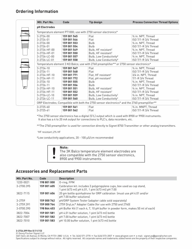
3-2724.099 Rev D (11/13) © Georg Fischer Signet LLC3401 Aero Jet Avenue, El Monte, CA 91731-2882 U.S.A. • Tel. (626) 571-2770 • Fax (626) 573-2057 • www.gfsignet.com • e-mail: [email protected] subject to change without notice. All rights reserved. All corporate names and trademarks stated herein are the property of their respective companies.
Mfr. Part No. Code Tip design Process Connection Thread Options
pH Electrodes
Temperature element PT1000; use with 2750 sensor electronics* 3-2724-00 159 001 545 Flat ¾ in. NPT, Thread3-2724-01 159 001 546 Flat ISO 7/1-R 3/4 Thread3-2726-00 159 001 553 Bulb ¾ in. NPT, Thread3-2726-01 159 001 554 Bulb ISO 7/1-R 3/4 Thread3-2726-HF-00 159 001 549 Bulb, HF resistant¹ ¾ in. NPT, Thread3-2726-HF-01 159 001 550 Bulb, HF resistant¹ ISO 7/1-R 3/4 Thread3-2726-LC-00 159 001 557 Bulb, Low Conductivity² ¾ in. NPT, Thread3-2726-LC-01 159 001 558 Bulb, Low Conductivity² ISO 7/1-R 3/4 ThreadTemperature element 3 KΩ Balco; use with 2760 preamplifier** or 2750 sensor electronics*3-2724-10 159 001 547 Flat ¾ in. NPT, Thread3-2724-11 159 001 548 Flat ISO 7/1-R 3/4 Thread3-2724-HF-10 159 001 771 Flat, HF resistant¹ 3/4 in. NPT, Thread3-2724-HF-11 159 001 772 Flat, pH resistant¹ 7/1-R 3/4 Thread3-2726-10 159 001 555 Bulb ¾ in. NPT, Thread3-2726-11 159 001 556 Bulb ISO 7/1-R 3/4 Thread3-2726-HF-10 159 001 551 Bulb, HF resistant1 ¾ in. NPT, Thread3-2726-HF-11 159 001 552 Bulb, HF resistant1 ISO 7/1-R 3/4 Thread3-2726-LC-10 159 001 559 Bulb, Low Conductivity2 ¾ in. NPT, Thread3-2726-LC-11 159 001 560 Bulb, Low Conductivity2 ISO 7/1-R 3/4 ThreadORP Electrodes; Compatible with both the 2750 sensor electronics* and the 2760 preamplifier**3-2725-60 159 001 561 Flat ¾ in. MNPT, Thread3-2725-61 159 001 562 Flat ISO 7/1-R 3/4 Thread
*The 2750 sensor electronics has a digital (S3L) output which is used with 8900 or 9900 instruments. It also has a 4 to 20 mA output for connections to PLC’s, data recorders, etc.
**The 2760 preamplifier is used for connection directly to Signet 8750 Transmitter or other analog transmitters.
¹HF resistant ‹2% HF
²Low conductivity applications, 20 - 100 μS/cm recommended
Ordering Information
Accessories and Replacement PartsMfr. Part No. Code Description1220-0021 198 801 000 O-ring, FPM3-2700.395 159 001 605 Calibration kit: includes 3 polypropylene cups, box used as cup stand,
1 pint (473 ml) pH 4.01, 1 pint (473 ml) pH 7.003822-7115 159 001 606 20 gm bottle quinhydrone for ORP calibration (must use pH 4.01 and/or
pH 7.00 buffer solutions)3-2759 159 000 762 pH/ORP System Tester (adapter cable sold separately)3-2759.391 159 000 764 2759 DryLoc® Adapter Cable (for use with 2750 and 2760)3-0700.390 198 864 403 pH Buffer Kit (1 each 4, 7, 10 pH buffer in powder form, makes 50 ml of each)
3822-7004 159 001 581 pH 4.01 buffer solution, 1 pint (473 ml) bottle3822-7007 159 001 582 pH 7.00 buffer solution, 1 pint (473 ml) bottle3822-7010 159 001 583 pH 10.00 buffer solution, 1 pint (473 ml) bottle
Note:The 3K Balco temperature element electrodes are also compatible with the 2750 sensor electronics, 8900 and 9900 instruments.!
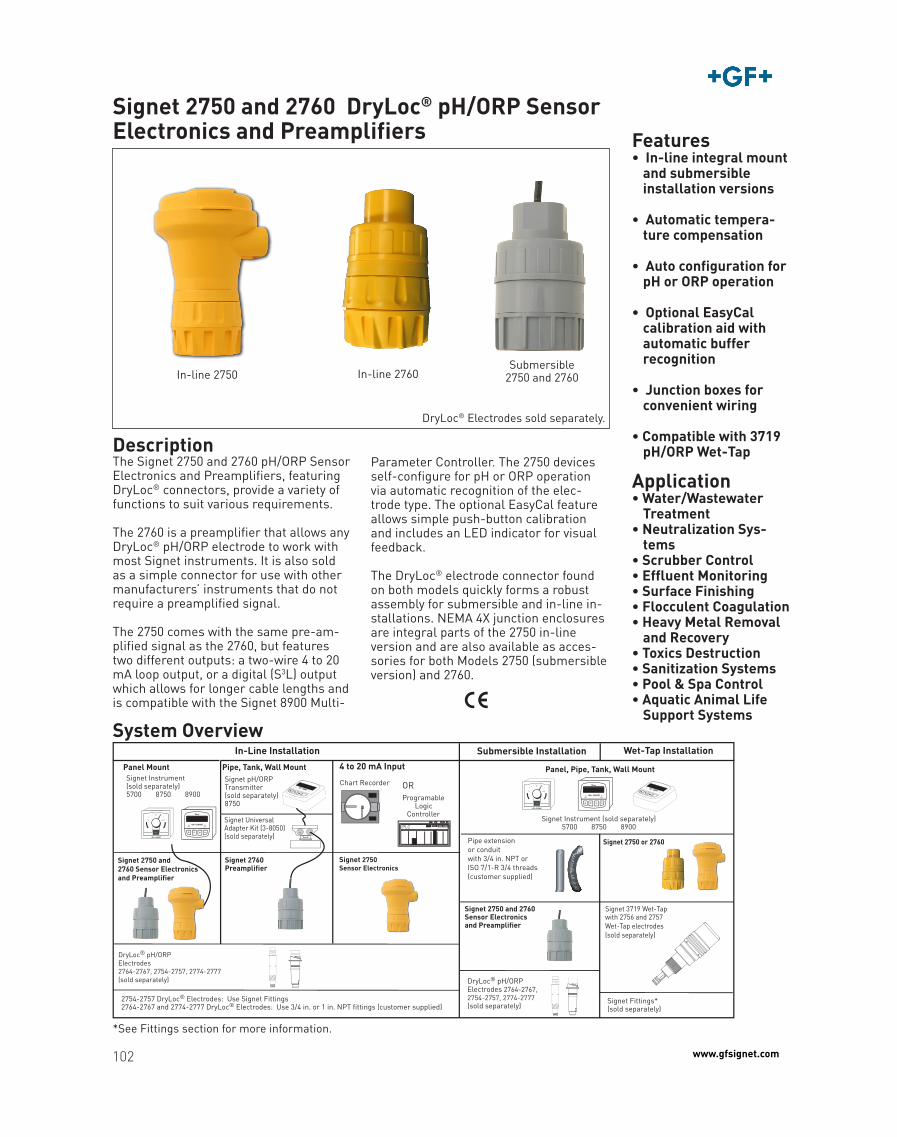
102 www.gfsignet.com
Features• In-line integral mount
and submersible installation versions
• Automatic tempera-ture compensation
• Auto configuration for pH or ORP operation
• Optional EasyCal calibration aid with automatic buffer
recognition
• Junction boxes for convenient wiring
• Compatible with 3719 pH/ORP Wet-Tap
Application• Water/Wastewater
Treatment• Neutralization Sys-
tems• Scrubber Control• Effluent Monitoring• Surface Finishing• Flocculent Coagulation• Heavy Metal Removal
and Recovery• Toxics Destruction• Sanitization Systems• Pool & Spa Control• Aquatic Animal Life
Support Systems
Signet 2750 and 2760 DryLoc® pH/ORP Sensor Electronics and Preamplifiers
DescriptionThe Signet 2750 and 2760 pH/ORP Sensor Electronics and Preamplifiers, featuring DryLoc® connectors, provide a variety of functions to suit various requirements.
The 2760 is a preamplifier that allows any DryLoc® pH/ORP electrode to work with most Signet instruments. It is also sold as a simple connector for use with other manufacturers’ instruments that do not require a preamplified signal.
The 2750 comes with the same pre-am-plified signal as the 2760, but features two different outputs: a two-wire 4 to 20 mA loop output, or a digital (S3L) output which allows for longer cable lengths and is compatible with the Signet 8900 Multi-
In-line 2750
DryLoc® Electrodes sold separately.
Parameter Controller. The 2750 devices self-configure for pH or ORP operation via automatic recognition of the elec-trode type. The optional EasyCal feature allows simple push-button calibration and includes an LED indicator for visual feedback.
The DryLoc® electrode connector found on both models quickly forms a robust assembly for submersible and in-line in-stallations. NEMA 4X junction enclosures are integral parts of the 2750 in-line version and are also available as acces-sories for both Models 2750 (submersible version) and 2760.
System Overview
Signet Instrument(sold separately)5700 8750 8900
Signet Universal Adapter Kit (3-8050)(sold separately)
Signet pH/ORPTransmitter(sold separately)8750
Pipe, Tank, Wall MountPanel Mount
Flow
0 100
50
In-Line Installation Submersible Installation
Pipe extensionor conduitwith 3/4 in. NPT or ISO 7/1-R 3/4 threads(customer supplied)
ProgramableLogic
Controller
4 to 20 mA Input
Chart Recorder OR
Signet 2750 Sensor Electronics
Signet 2750 and 2760Sensor Electronicsand Preamplifier
2754-2757 DryLoc® Electrodes: Use Signet Fittings 2764-2767 and 2774-2777 DryLoc® Electrodes: Use 3/4 in. or 1 in. NPT fittings (customer supplied)
DryLoc® pH/ORPElectrodes2764-2767, 2754-2757, 2774-2777(sold separately) DryLoc® pH/ORP
Electrodes 2764-2767,2754-2757, 2774-2777(sold separately)
Signet 2760Preamplifier
Wet-Tap Installation
Signet Fittings*(sold separately)
Signet 3719 Wet-Tap
Signet 2750 or 2760
Panel, Pipe, Tank, Wall Mount
Flow
0 100
50
Signet Instrument (sold separately)5700 8750 8900
Signet 2750 and 2760 Sensor Electronicsand Preamplifier
PLC
with 2756 and 2757Wet-Tap electrodes(sold separately)
In-line 2760Submersible
2750 and 2760
*See Fittings section for more information.
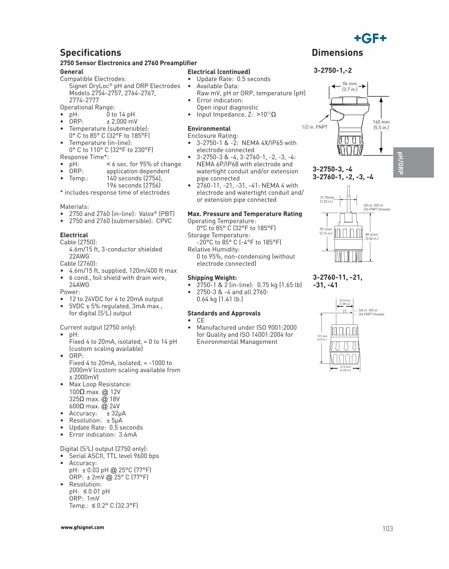
103www.gfsignet.com
Choosing
Products
FlowC
onductivity/ R
esistivityTem
perature, P
ressure, Level
Multi-P
a-ram
eter Instrum
entO
therP
roductsW
iring &
InstallationTechnical R
eferenceG
lossary of Term
sIndex
pH/O
RP
Temperature/
Pressure G
raphsP
art No.
Reference
GeneralCompatible Electrodes: Signet DryLoc® pH and ORP Electrodes Models 2754-2757, 2764-2767, 2774-2777Operational Range: • pH: 0 to 14 pH• ORP: ± 2,000 mV • Temperature (submersible): 0° C to 85° C (32°F to 185°F)• Temperature (in-line): 0° C to 110° C (32°F to 230°F)Response Time*: • pH: < 6 sec. for 95% of change • ORP: application dependent • Temp.: 140 seconds (2754), 196 seconds (2756)* includes response time of electrodes
Materials: • 2750 and 2760 (in-line): Valox® (PBT)• 2750 and 2760 (submersible): CPVC Electrical Cable (2750): 4.6m/15 ft, 3-conductor shielded 22AWG Cable (2760):• 4.6m/15 ft, supplied, 120m/400 ft max• 6 cond., foil shield with drain wire,
24AWG Power: • 12 to 24VDC for 4 to 20mA output• 5VDC ± 5% regulated, 3mA max., for digital (S3L) output
Current output (2750 only): • pH: Fixed 4 to 20mA, isolated, = 0 to 14 pH
(custom scaling available)• ORP: Fixed 4 to 20mA, isolated, = -1000 to
2000mV (custom scaling available from ± 2000mV)
• Max Loop Resistance: 100Ω max. @ 12V 325Ω max. @ 18V 600Ω max. @ 24V• Accuracy: ± 32μA• Resolution: ± 5μA• Update Rate: 0.5 seconds • Error indication: 3.6mA
Digital (S3L) output (2750 only): • Serial ASCII, TTL level 9600 bps• Accuracy: pH: ± 0.03 pH @ 25°C (77°F) ORP: ± 2mV @ 25° C (77°F)• Resolution: pH: ≤ 0.01 pH ORP: 1mV Temp.: ≤ 0.2° C (32.3°F)
Dimensions
3-2750-1,-2Electrical (continued)• Update Rate: 0.5 seconds• Available Data: Raw mV, pH or ORP, temperature (pH)• Error indication: Open input diagnostic• Input Impedance, Z: >1011Ω
EnvironmentalEnclosure Rating: • 3-2750-1 & -2: NEMA 4X/IP65 with
electrode connected• 3-2750-3 & -4, 3-2760-1, -2, -3, -4:
NEMA 6P/IP68 with electrode and watertight conduit and/or extension pipe connected
• 2760-11, -21, -31, -41: NEMA 4 with electrode and watertight conduit and/or extension pipe connected
Max. Pressure and Temperature RatingOperating Temperature: 0°C to 85° C (32°F to 185°F)Storage Temperature: -20°C to 85° C (-4°F to 185°F)Relative Humidity: 0 to 95%, non-condensing (without
electrode connected)
Shipping Weight: • 2750-1 & 2 (in-line): 0.75 kg (1.65 lb)• 2750-3 & -4 and all 2760: 0.64 kg (1.41 lb.)
Standards and Approvals• CE• Manufactured under ISO 9001:2000
for Quality and ISO 14001:2004 for Environmental Management
140 mm(5.5 in.)
94 mm(3.7 in.)
1/2 in. FNPT
31.75mm(1.25 in.)
89.4mm(3.52 in.)
70.1mm(2.76 in.)
3/4 in. ISO or3/4 FNPT threads
3-2750-3, -4 3-2760-1, -2, -3, -4
2750 Sensor Electronics and 2760 PreamplifierSpecifications
35.0 mm(1.38 in.)
61.0 mm(2.40 in.)
101 mm(4.0 in.)
3/4 in. ISO or3/4 FNPT threads
3-2760-11, -21, -31, -41
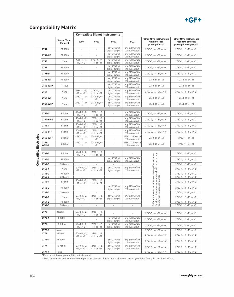
104 www.gfsignet.com
Compatibility MatrixCompatible Signet Instruments
Sensor Temp. Element 5700 8750 8900 PLC
Other Mfr’s Instruments with internal
preamplifiers*
Other Mfr’s Instruments requiring external
preamplified signals**
Com
pati
ble
Elec
trod
es
2754 PT 1000 - - any 2750 w/digital output
any 2750 w/4 to 20 mA output 2760-3, -4, -31, or -41 2760-1, -2, -11, or -21
2754-HF PT 1000 - - any 2750 w/digital output
any 2750 w/4 to 20 mA output 2760-3, -4, -31, or -41 2760-1, -2, -11, or -21
2755 None 2760-1, -2, -11, or -21
2760-1, -2, -11, or -21
any 2750 w/digital output
any 2750 w/4 to 20 mA output 2760-3, -4, -31, or -41 2760-1, -2, -11, or -21
2756 PT 1000 - - any 2750 w/digital output
any 2750 w/4 to 20 mA output 2760-3, -4, -31, or -41 2760-1, -2, -11, or -21
2756-DI PT 1000 - - any 2750 w/digital output
any 2750 w/4 to 20 mA output 2760-3, -4, -31, or -41 2760-1, -2, -11, or -21
2756-WT PT 1000 - - any 2750 w/digital output
any 2750 w/4 to 20 mA output 2760-31 or -41 2760-11 or -21
2756-WTP PT1000 - - any 2750 w/digital output
any 2750 w/4 to 20 mA output 2760-31 or -41 2760-11 or -21
2757 None 2760-1, -2, -11, or -21
2760-1, -2, -11, or -21
any 2750 w/digital output
any 2750 w/4 to 20 mA output 2760-3, -4, -31, or -41 2760-1, -2, -11, or -21
2757-WT None 2760-11, or -21
2760-11, or -21
any 2750 w/digital output
any 2750 w/4 to 20 mA output 2760-31 or -41 2760-11 or -21
2757-WTP None 2760-11, or -21
2760-11, or -21
any 2750 w/digital output
any 2750 w/4 to 20 mA output 2760-31 or -41 2760-11 or -21
2754-1 3 Kohm 2760-1, -2, -11, or -21
2760-1, -2, -11, or -21 - any 2750 w/4 to
20 mA output 2760-3, -4, -31, or -41 2760-1, -2, -11, or -21
2754-HF-1 3 Kohm 2760-1, -2, -11, or -21
2760-1, -2, -11, or -21 - any 2750 w/4 to
20 mA output 2760-3, -4, -31, or -41 2760-1, -2, -11, or -21
2756-1 3 Kohm 2760-1, -2, -11, or -21
2760-1, -2, -11, or -21 - any 2750 w/4 to
20 mA output 2760-3, -4, -31, or -41 2760-1, -2, -11, or -21
2756-DI-1 3 Kohm 2760-1, -2, -11, or -21
2760-1, -2, -11, or -21 - any 2750 w/4 to
20 mA output 2760-3, -4, -31, or -41 2760-1, -2, -11, or -21
2756-WT-1 3 Kohm 2760-11, or -21
2760-11, or -21 - 2750-1, -2 w/4 to
20 mA output 2760-31 or -41 2760-11, or -21
2756-WTP-1 3 Kohm 2760-11, or
-212760-11, or
-21 - 2750-1, -2 w/4 to 20 mA output 2760-31 or -41 2760-11, or -21
2764-1 3 Kohm 2760-1, -2, -11, or -21
2760-1, -2, -11, or -21 - -D
iffer
entia
l sen
sors
mus
t use
pre
ampl
ifier
at s
enso
r lo
catio
n; o
ther
wis
e, s
enso
r si
gnal
will
be
too
erra
tic
due
to h
igh
impe
danc
e si
gnal
s
2760-1, -2, -11, or -21
2764-2 PT 1000 - - any 2750 w/digital output
any 2750 w/4 to 20 mA output 2760-1, -2, -11, or -21
2764-3 300 ohm - - - - 2760-1, -2, -11, or -21
2765-1 None 2760-1, -2, -11, or -21
2760-1, -2, -11, or -21
any 2750 w/digital output
any 2750 w/4 to 20 mA output 2760-1, -2, -11, or -21
2765-2 PT 1000 - - - - 2760-1, -2, -11, or -212765-3 300 ohm - - - - 2760-1, -2, -11, or -21
2766-1 3 Kohm 2760-1, -2, -11, or -21
2760-1, -2, -11, or -21 - - 2760-1, -2, -11, or -21
2766-2 PT 1000 - - any 2750 w/digital output
any 2750 w/4 to 20 mA output 2760-1, -2, -11, or -21
2766-3 300 ohm - - - - 2760-1, -2, -11, or -21
2767-1 None 2760-1, -2, -11, or -21
2760-1, -2, -11, or -21
any 2750 w/digital output
any 2750 w/4 to 20 mA output 2760-1, -2, -11, or -21
2767-2 PT 1000 - - - - 2760-1, -2, -11, or -212767-3 300 ohm - - - - 2760-1, -2, -11, or -21
2774 3 Kohm 2760-1, -2, -11, or -21
2760-1, -2, -11, or -21 - - 2760-3, -4, -31, or -41 2760-1, -2, -11, or -21
2774-1 PT 1000 - - any 2750 w/digital output
any 2750 w/4 to 20 mA output 2760-3, -4, -31, or -41 2760-1, -2, -11, or -21
2775 10 Kohm 2760-1, -2, -11, or -21
2760-1, -2, -11, or -21
any 2750 w/digital output
any 2750 w/4 to 20 mA output 2760-3, -4, -31, or -41 2760-1, -2, -11, or -21
2775-1 None - - - - 2760-3, -4, -31, or -41 2760-1, -2, -11, or -212776 3 Kohm 2760-1, -2,
-11, or -21 2760-1, -2, -11, or -21 - - 2760-3, -4, -31, or -41 2760-1, -2, -11, or -21
2776-1 PT 1000 - - any 2750 w/digital output
any 2750 w/4 to 20 mA output 2760-3, -4, -31, or -41 2760-1, -2, -11, or -21
2777 10 Kohm 2760-1, -2, -11, or -21
2760-1, -2, -11, or -21
any 2750 w/digital output
any 2750 w/4 to 20 mA output 2760-3, -4, -31, or -41 2760-1, -2, -11, or -21
2777-1 None - - - - 2760-3, -4, -31, or -41 2760-1, -2, -11, or -21*Must have internal preamplifier in instrument**Must use sensor with compatible temperature element. For further assistance, contact your local Georg Fischer Sales Office.
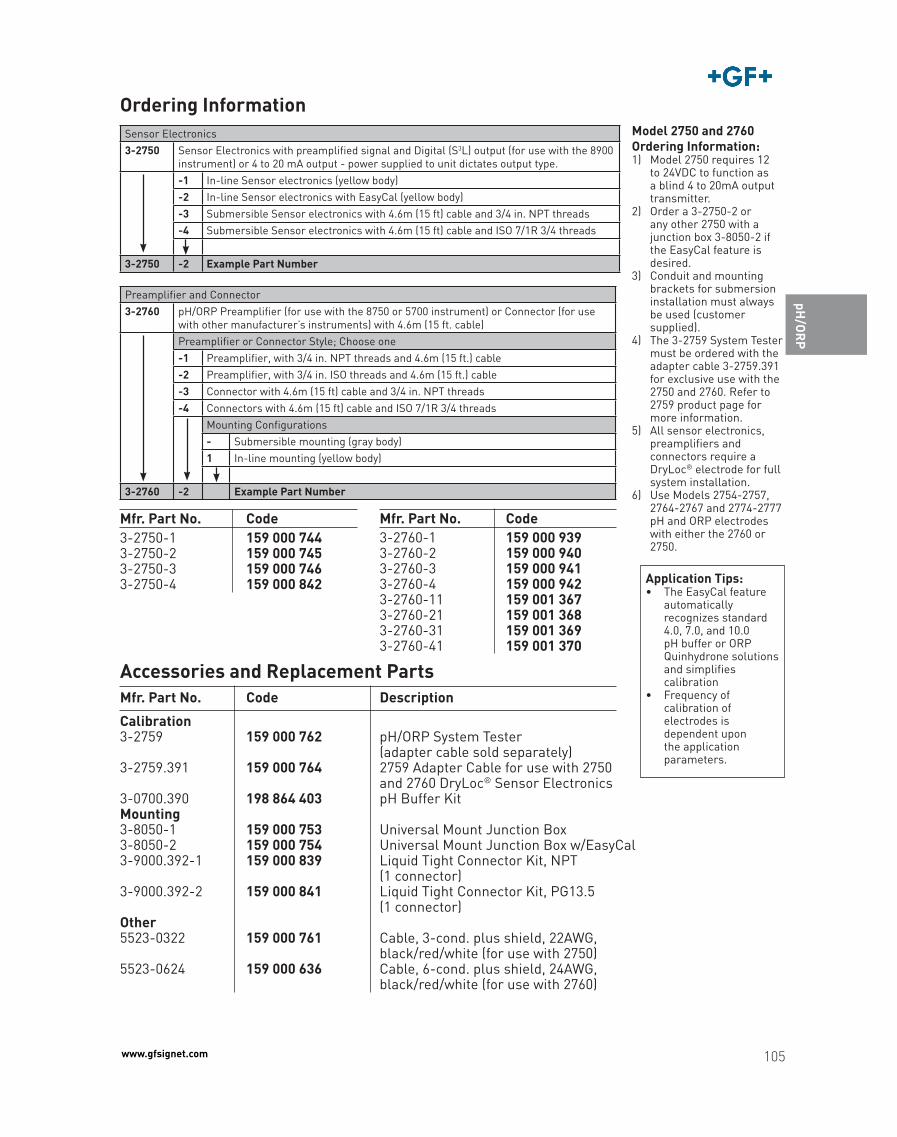
105www.gfsignet.com
Choosing
Products
FlowC
onductivity/ R
esistivityTem
perature, P
ressure, Level
Multi-P
a-ram
eter Instrum
entO
therP
roductsW
iring &
InstallationTechnical R
eferenceG
lossary of Term
sIndex
pH/O
RP
Temperature/
Pressure G
raphsP
art No.
Reference
Mfr. Part No. Code Description
Accessories and Replacement Parts
Calibration3-2759 159 000 762 pH/ORP System Tester (adapter cable sold separately) 3-2759.391 159 000 764 2759 Adapter Cable for use with 2750 and 2760 DryLoc® Sensor Electronics3-0700.390 198 864 403 pH Buffer KitMounting3-8050-1 159 000 753 Universal Mount Junction Box3-8050-2 159 000 754 Universal Mount Junction Box w/EasyCal3-9000.392-1 159 000 839 Liquid Tight Connector Kit, NPT (1 connector)3-9000.392-2 159 000 841 Liquid Tight Connector Kit, PG13.5 (1 connector)Other 5523-0322 159 000 761 Cable, 3-cond. plus shield, 22AWG, black/red/white (for use with 2750)5523-0624 159 000 636 Cable, 6-cond. plus shield, 24AWG, black/red/white (for use with 2760)
Application Tips:• The EasyCal feature
automatically recognizes standard 4.0, 7.0, and 10.0 pH buffer or ORP Quinhydrone solutions and simplifies calibration
• Frequency of calibration of electrodes is dependent upon the application parameters.
3-2750-1 159 000 7443-2750-2 159 000 7453-2750-3 159 000 7463-2750-4 159 000 842
Ordering Information
Mfr. Part No. Code Mfr. Part No. Code3-2760-1 159 000 9393-2760-2 159 000 9403-2760-3 159 000 9413-2760-4 159 000 9423-2760-11 159 001 3673-2760-21 159 001 3683-2760-31 159 001 3693-2760-41 159 001 370
Model 2750 and 2760 Ordering Information:1) Model 2750 requires 12
to 24VDC to function as a blind 4 to 20mA output transmitter.
2) Order a 3-2750-2 or any other 2750 with a junction box 3-8050-2 if the EasyCal feature is desired.
3) Conduit and mounting brackets for submersion installation must always be used (customer supplied).
4) The 3-2759 System Tester must be ordered with the adapter cable 3-2759.391 for exclusive use with the 2750 and 2760. Refer to 2759 product page for more information.
5) All sensor electronics, preamplifiers and connectors require a DryLoc® electrode for full system installation.
6) Use Models 2754-2757, 2764-2767 and 2774-2777 pH and ORP electrodes with either the 2760 or 2750.
Sensor Electronics 3-2750 Sensor Electronics with preamplified signal and Digital (S3L) output (for use with the 8900
instrument) or 4 to 20 mA output - power supplied to unit dictates output type. -1 In-line Sensor electronics (yellow body)-2 In-line Sensor electronics with EasyCal (yellow body)-3 Submersible Sensor electronics with 4.6m (15 ft) cable and 3/4 in. NPT threads-4 Submersible Sensor electronics with 4.6m (15 ft) cable and ISO 7/1R 3/4 threads
3-2750 -2 Example Part Number
Preamplifier and Connector3-2760 pH/ORP Preamplifier (for use with the 8750 or 5700 instrument) or Connector (for use
with other manufacturer’s instruments) with 4.6m (15 ft. cable)Preamplifier or Connector Style; Choose one-1 Preamplifier, with 3/4 in. NPT threads and 4.6m (15 ft.) cable-2 Preamplifier, with 3/4 in. ISO threads and 4.6m (15 ft.) cable-3 Connector with 4.6m (15 ft) cable and 3/4 in. NPT threads-4 Connectors with 4.6m (15 ft) cable and ISO 7/1R 3/4 threads
Mounting Configurations- Submersible mounting (gray body)1 In-line mounting (yellow body)
3-2760 -2 Example Part Number

BWS-GL-02 Appendix52
52. Mattson-WittDistributorHub

BWS-GL-02 Appendix53
53. ValworxElectricActuatedPVCBallValve:566249
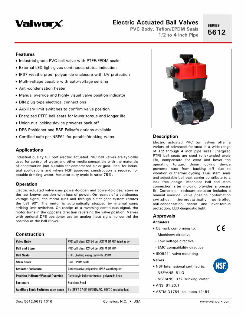
1
SERIES
5612
Features
Applications
Construction
Description
Doc: 5612.5613.1016 Cornelius, N.C. • USA www.valworx.com
Electric Actuated Ball Valves PVC Body, Teflon/EPDM Seals
1/2 to 4 inch Pipe
Industrial grade PVC ball valve with PTFE/EPDM seals
External LED light gives continuous status indication
IP67 weatherproof polyamide enclosure with UV protection
Multi-voltage capable with auto-voltage sensing
Anti-condensation heater
Manual override and highly visual valve position indicator
DIN plug type electrical connections
Auxiliary limit switches to confirm valve position
Energized PTFE ball seats for lower torque and longer life
Union nut locking device prevents back-off
DPS Positioner and BSR Failsafe options available
Certified safe per NSF61 for potable/drinking water
Industrial quality full port electric actuated PVC ball valves are typically used for control of water and other media compatible with the materials of construction (not suitable for compressed air or gas). Ideal for indus-trial applications and where NSF approved construction is required for potable drinking water. Actuator duty cycle is rated 75%.
Electric actuated PVC ball valves offer a variety of advanced features in a wide range of 1/2 through 4 inch pipe sizes. Energized PTFE ball seats are used to extended cycle life, compensate for wear and lower the operating torque. Union locking device prevents nuts from backing off due to vibration or thermal cycling. Dual stem seals and adjustable ball seat carrier contribute to a leak free design. Machined ball and stem connection after molding provides a precise fit. Corrosion resistant actuator includes a manual override, valve position confirmation switches, thermostatically controlled anti-condensation heater and over-torque protection. LED diagnostic light.
Operation
Approvals Actuators
• CE mark conforming to:
- Machinery directive
- Low voltage directive
- EMC compatibility directive
• ISO5211 valve mounting
Valves
• NSF International certified to:
- NSF/ANSI 61 G
- NSF/ANSI 372 Drinking Water
• ANSI B1.20.1
• ASTM D1784, cell class 12454
Electric actuated valve uses power-to-open and power-to-close, stays in the last known position with loss of power. On receipt of a continuous voltage signal, the motor runs and through a flat gear system rotates the ball 90º. The motor is automatically stopped by internal cams striking limit switches. On receipt of a reversing continuous signal, the motor turns in the opposite direction reversing the valve position. Valves with optional DPS positioner use an analog input signal to control the position of the ball (flow).
Valve Body PVC cell class 12454 per ASTM D1784 (dark gray)
Ball and Stem PVC cell class 12454 per ASTM D1784
Ball Seats PTFE (Teflon) energized with EPDM
Stem Seals Dual EPDM seals
Actuator Enclosure Anti-corrosive polyamide, IP67 weatherproof
Position Indicator/Manual Override Dome style indicator/manual polyamide knob
Fasteners Stainless Steel
Auxiliary Limit Switches on-off models 2 x SPST 3A@125/250VAC, 30VDC resistive load
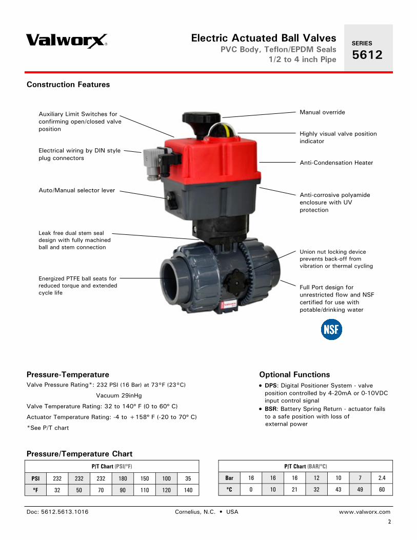
2
Doc: 5612.5613.1016 Cornelius, N.C. • USA www.valworx.com
Electric Actuated Ball Valves PVC Body, Teflon/EPDM Seals
1/2 to 4 inch Pipe
Optional Functions DPS: Digital Positioner System - valve
position controlled by 4-20mA or 0-10VDC input control signal
BSR: Battery Spring Return - actuator fails to a safe position with loss of
external power
Pressure-Temperature Valve Pressure Rating*: 232 PSI (16 Bar) at 73°F (23°C)
Vacuum 29inHg
Valve Temperature Rating: 32 to 140º F (0 to 60º C)
Actuator Temperature Rating: -4 to +158º F (-20 to 70º C)
*See P/T chart
Construction Features
Auxiliary Limit Switches for confirming open/closed valve position
Electrical wiring by DIN style plug connectors
Auto/Manual selector lever
Leak free dual stem seal design with fully machined ball and stem connection
Energized PTFE ball seats for reduced torque and extended cycle life
Manual override
Highly visual valve position indicator
Anti-Condensation Heater
Anti-corrosive polyamide enclosure with UV protection
Union nut locking device prevents back-off from vibration or thermal cycling
Full Port design for unrestricted flow and NSF certified for use with potable/drinking water
P/T Chart (BAR/ºC)
Bar 16 16 16 12 10 7 2.4
ºC 0 10 21 32 43 49 60
P/T Chart (PSI/ºF)
PSI 232 232 232 180 150 100 35
ºF 32 50 70 90 110 120 140
Pressure/Temperature Chart
SERIES
5612
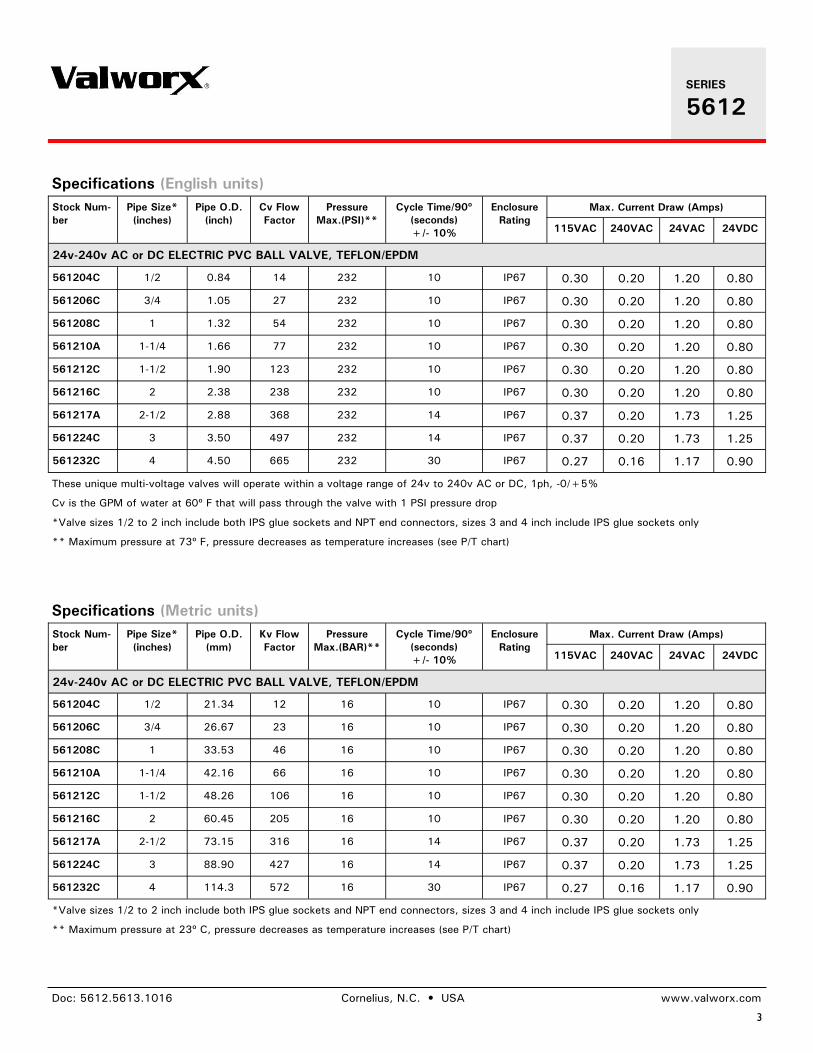
3
Doc: 5612.5613.1016 Cornelius, N.C. • USA www.valworx.com
Specifications (English units) Stock Num-ber
Pipe Size* (inches)
Pipe O.D. (inch)
Cv Flow Factor
Pressure Max.(PSI)**
Cycle Time/90º (seconds) +/- 10%
Enclosure Rating
Max. Current Draw (Amps)
115VAC 240VAC 24VAC 24VDC
24v-240v AC or DC ELECTRIC PVC BALL VALVE, TEFLON/EPDM
561204C 1/2 0.84 14 232 10 IP67 0.30 0.20 1.20 0.80
561206C 3/4 1.05 27 232 10 IP67 0.30 0.20 1.20 0.80
561208C 1 1.32 54 232 10 IP67 0.30 0.20 1.20 0.80
561210A 1-1/4 1.66 77 232 10 IP67 0.30 0.20 1.20 0.80
561212C 1-1/2 1.90 123 232 10 IP67 0.30 0.20 1.20 0.80
561216C 2 2.38 238 232 10 IP67 0.30 0.20 1.20 0.80
561217A 2-1/2 2.88 368 232 14 IP67 0.37 0.20 1.73 1.25
561224C 3 3.50 497 232 14 IP67 0.37 0.20 1.73 1.25
561232C 4 4.50 665 232 30 IP67 0.27 0.16 1.17 0.90
These unique multi-voltage valves will operate within a voltage range of 24v to 240v AC or DC, 1ph, -0/+5%
Cv is the GPM of water at 60º F that will pass through the valve with 1 PSI pressure drop
*Valve sizes 1/2 to 2 inch include both IPS glue sockets and NPT end connectors, sizes 3 and 4 inch include IPS glue sockets only
** Maximum pressure at 73º F, pressure decreases as temperature increases (see P/T chart)
SERIES
5612
Specifications (Metric units) Stock Num-ber
Pipe Size* (inches)
Pipe O.D. (mm)
Kv Flow Factor
Pressure Max.(BAR)**
Cycle Time/90º (seconds) +/- 10%
Enclosure Rating
Max. Current Draw (Amps)
115VAC 240VAC 24VAC 24VDC
24v-240v AC or DC ELECTRIC PVC BALL VALVE, TEFLON/EPDM
561204C 1/2 21.34 12 16 10 IP67 0.30 0.20 1.20 0.80
561206C 3/4 26.67 23 16 10 IP67 0.30 0.20 1.20 0.80
561208C 1 33.53 46 16 10 IP67 0.30 0.20 1.20 0.80
561210A 1-1/4 42.16 66 16 10 IP67 0.30 0.20 1.20 0.80
561212C 1-1/2 48.26 106 16 10 IP67 0.30 0.20 1.20 0.80
561216C 2 60.45 205 16 10 IP67 0.30 0.20 1.20 0.80
561217A 2-1/2 73.15 316 16 14 IP67 0.37 0.20 1.73 1.25
561224C 3 88.90 427 16 14 IP67 0.37 0.20 1.73 1.25
561232C 4 114.3 572 16 30 IP67 0.27 0.16 1.17 0.90
*Valve sizes 1/2 to 2 inch include both IPS glue sockets and NPT end connectors, sizes 3 and 4 inch include IPS glue sockets only
** Maximum pressure at 23º C, pressure decreases as temperature increases (see P/T chart)
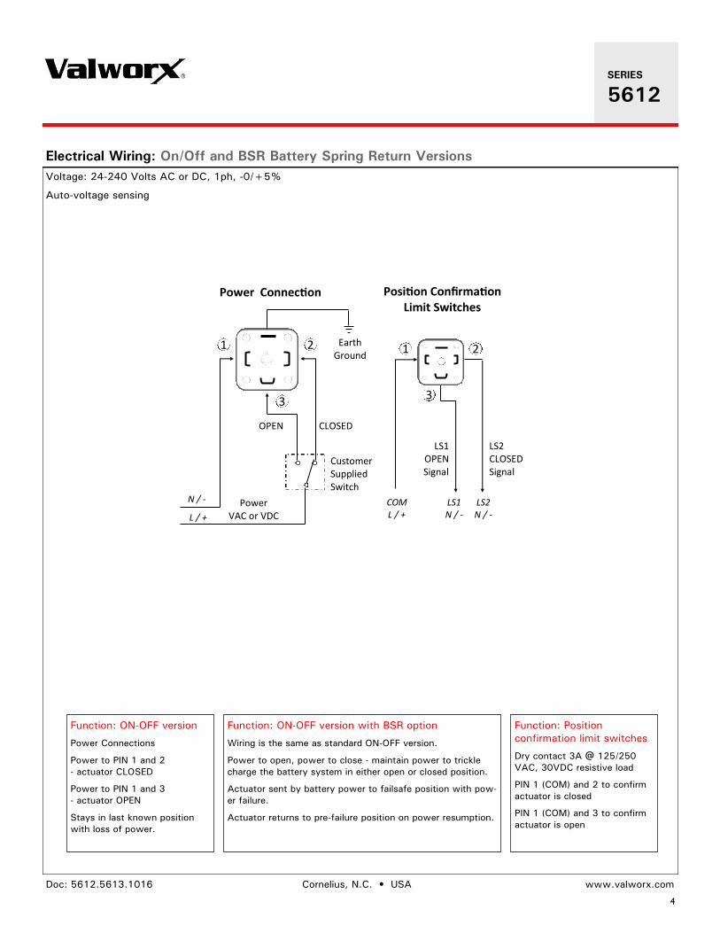
4
Doc: 5612.5613.1016 Cornelius, N.C. • USA www.valworx.com
Function: ON-OFF version
Power Connections
Power to PIN 1 and 2 - actuator CLOSED
Power to PIN 1 and 3 - actuator OPEN
Stays in last known position with loss of power.
Function: ON-OFF version with BSR option
Wiring is the same as standard ON-OFF version.
Power to open, power to close - maintain power to trickle charge the battery system in either open or closed position.
Actuator sent by battery power to failsafe position with pow-er failure.
Actuator returns to pre-failure position on power resumption.
Electrical Wiring: On/Off and BSR Battery Spring Return Versions Voltage: 24-240 Volts AC or DC, 1ph, -0/+5%
Auto-voltage sensing
1 2
3
CLOSED OPEN
Customer Supplied Switch
Power Connection
LS1 OPEN Signal
LS2 CLOSED Signal
Position Confirmation Limit Switches
1 2
3
N / -
L / + LS1 N / -
LS2 N / -
COM L / +
Earth Ground
Power VAC or VDC
Function: Position confirmation limit switches
Dry contact 3A @ 125/250 VAC, 30VDC resistive load
PIN 1 (COM) and 2 to confirm actuator is closed
PIN 1 (COM) and 3 to confirm actuator is open
SERIES
5612
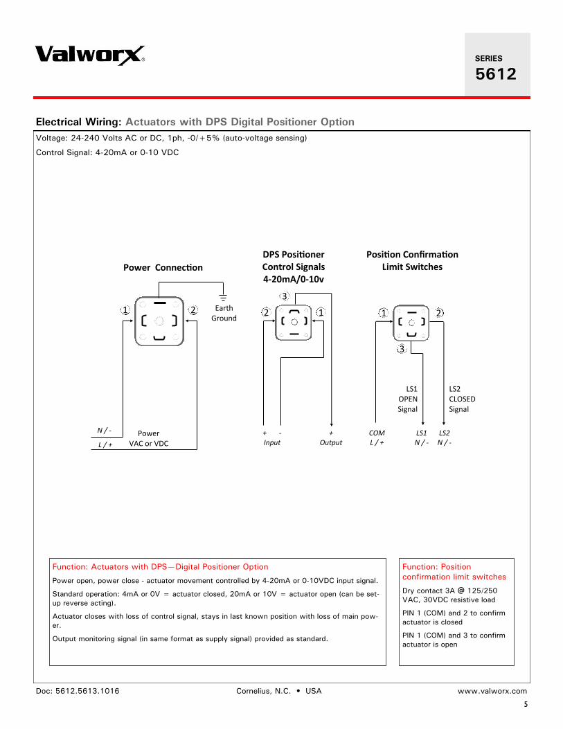
5
Doc: 5612.5613.1016 Cornelius, N.C. • USA www.valworx.com
Function: Actuators with DPS—Digital Positioner Option
Power open, power close - actuator movement controlled by 4-20mA or 0-10VDC input signal.
Standard operation: 4mA or 0V = actuator closed, 20mA or 10V = actuator open (can be set-up reverse acting).
Actuator closes with loss of control signal, stays in last known position with loss of main pow-er.
Output monitoring signal (in same format as supply signal) provided as standard.
Electrical Wiring: Actuators with DPS Digital Positioner Option Voltage: 24-240 Volts AC or DC, 1ph, -0/+5% (auto-voltage sensing) Control Signal: 4-20mA or 0-10 VDC
1 2
Power Connection
LS1 OPEN Signal
LS2 CLOSED Signal
Position Confirmation Limit Switches
1 2
3
N / -
L / + LS1 N / -
LS2 N / -
COM L / +
Earth Ground
DPS Positioner Control Signals 4-20mA/0-10v
2 1
3
+ -Input
+ Output
Power VAC or VDC
Function: Position confirmation limit switches
Dry contact 3A @ 125/250 VAC, 30VDC resistive load
PIN 1 (COM) and 2 to confirm actuator is closed
PIN 1 (COM) and 3 to confirm actuator is open
SERIES
5612
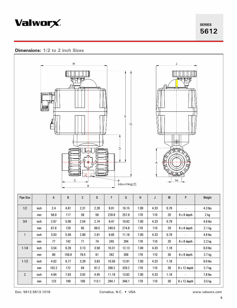
6
Doc: 5612.5613.1016 Cornelius, N.C. • USA www.valworx.com
Pipe Size A B C D F G H J M P Weight
1/2 inch 2.4 4.61 2.31 2.28 9.01 10.15 7.00 4.33 0.79 - 4.3 lbs
mm 56.9 117 59 58 228.9 257.9 178 110 20 6 x 8 depth 2 kg
3/4 inch 2.67 5.08 2.54 2.74 9.47 10.82 7.00 4.33 0.79 - 4.6 lbs
mm 67.8 129 65 69.5 240.5 274.8 178 110 20 6 x 8 depth 2.1 kg
1 inch 3.03 5.59 2.80 2.91 9.65 11.18 7.00 4.33 0.79 - 4.8 lbs
mm 77 142 71 74 245 284 178 110 20 6 x 8 depth 2.2 kg
inch 3.54 6.26 3.13 3.58 10.31 12.13 7.00 4.33 1.18 - 6.0 lbs 1-1/4
mm 90 158.9 79.5 91 262 308 178 110 30 6 x 8 depth 2.7 kg
1-1/2 inch 4.02 6.77 3.29 3.83 10.56 12.61 7.00 4.33 1.18 - 6.0 lbs
mm 102.2 172 84 97.2 268.2 320.2 178 110 30 8 x 12 depth 2.7 kg
2 inch 4.84 7.83 3.92 4.45 11.19 13.62 7.00 4.33 1.18 - 7.6 lbs
mm 123 199 100 113.1 284.1 346.1 178 110 30 8 x 12 depth 3.5 kg
Dimensions: 1/2 to 2 inch Sizes
SERIES
5612
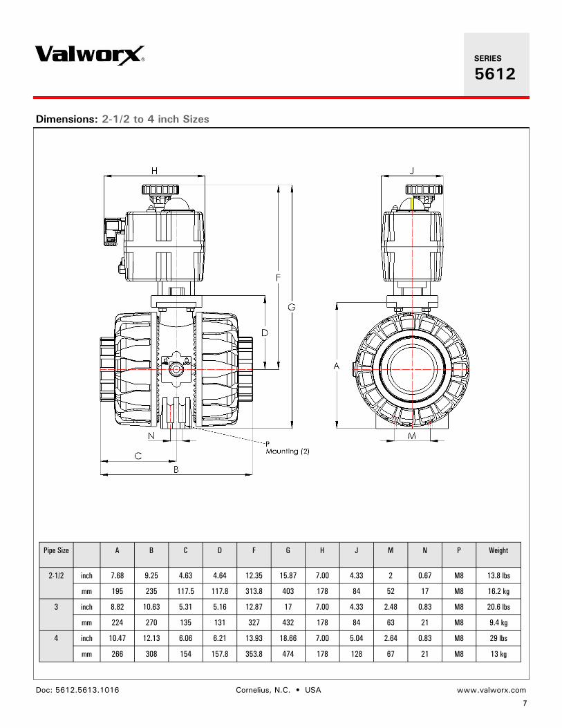
7
Doc: 5612.5613.1016 Cornelius, N.C. • USA www.valworx.com
Pipe Size A B C D F G H J M N P Weight
2-1/2 inch 7.68 9.25 4.63 4.64 12.35 15.87 7.00 4.33 2 0.67 M8 13.8 lbs
mm 195 235 117.5 117.8 313.8 403 178 84 52 17 M8 16.2 kg
inch 8.82 10.63 5.31 5.16 12.87 17 7.00 4.33 2.48 0.83 M8 20.6 lbs 3
mm 224 270 135 131 327 432 178 84 63 21 M8 9.4 kg
4 inch 10.47 12.13 6.06 6.21 13.93 18.66 7.00 5.04 2.64 0.83 M8 29 lbs
mm 266 308 154 157.8 353.8 474 178 128 67 21 M8 13 kg
Dimensions: 2-1/2 to 4 inch Sizes
SERIES
5612

BWS-GL-02 Appendix54
54. PhoenixContactRelay:PLC-RPT-24DC/21-21
https://www.phoenixcontact.com/us/products/2900330
12/15/2015 Page 1 / 7
Relay Module - PLC-RPT- 24DC/21-21 - 2900330Please be informed that the data shown in this PDF Document is generated from our Online Catalog. Please find the complete data in the user'sdocumentation. Our General Terms of Use for Downloads are valid(http://phoenixcontact.com/download)
PLC-INTERFACE, consisting of PLC-BPT.../21-21 basic terminal block with push-in connection and plug-inminiature relay with power contact, for mounting on NS 35/7,5 DIN rail, 2 PDTs, input voltage 24 V DC
The figure shows a version with ascrew connection
Product Features
Slim design
Efficient connection to system cabling using V8 adapter
RT III sealed relay
Safe isolation according to DIN EN 50178 between coil and contact
Integrated input circuit and interference suppression circuit
Functional plug-in bridges
Key Commercial DataPacking unit 1 pc
Weight per Piece (excluding packing) 62.0 g
Custom tariff number 85364900
Country of origin Germany
Technical data
Note
Utilization restriction EMC: class A product, see manufacturer's declaration in the downloadarea
DimensionsWidth 14 mm
Height 80 mm
Depth 94 mm
https://www.phoenixcontact.com/us/products/2900330
12/15/2015 Page 2 / 7
Relay Module - PLC-RPT- 24DC/21-21 - 2900330Technical data
Ambient conditionsAmbient temperature (operation) -40 °C ... 60 °C
Ambient temperature (storage/transport) -40 °C ... 85 °C
Coil sideNominal input voltage UN 24 V DC
Typical input current at UN 18 mA
Typical response time 8 ms
Typical release time 10 ms
Protective circuit Protection against polarity reversal Polarity protection diode
Free-wheeling diode Damping diode
Operating voltage display Yellow LED
Power dissipation for nominal condition 0.43 W
Contact sideContact type 2 PDT
Contact material AgNi
Maximum switching voltage
250 V AC/DC (The separating plate PLC-ATP should be installed forvoltages larger than 250 V (L1, L2, L3) between identical terminal blocks inadjacent modules. Potential bridging is then carried out with FBST 8-PLC...or ...FBST 500...)
Minimum switching voltage 5 V AC/DC (at 10 mA)
Min. switching current 10 mA (At 5 V)
Maximum inrush current 15 A (300 ms)
Limiting continuous current 6 A
Interrupting rating (ohmic load) max. 140 W (at 24 V DC)
85 W (at 48 V DC)
60 W (at 60 V DC)
44 W (at 110 V DC)
60 W (at 220 V DC)
1500 VA (for 250 V AC)
Switching capacity in acc. with DIN VDE 0660/IEC 60947 2 A (at 24 V, DC13)
0.2 A (at 250 V, DC13)
3 A (at 24 V, AC15)
3 A (at 120 V, AC15)
3 A (at 250 V, AC15)
Connection data input sideConnection name Coil side
Connection method Push-in connection
Stripping length 8 mm
https://www.phoenixcontact.com/us/products/2900330
12/15/2015 Page 3 / 7
Relay Module - PLC-RPT- 24DC/21-21 - 2900330Technical data
Connection data input sideConductor cross section solid 0.14 mm² ... 2.5 mm²
Conductor cross section flexible 0.14 mm² ... 2.5 mm²
Conductor cross section AWG 26 ... 14
Connection data output sideConnection name Contact side
Connection method Push-in connection
Stripping length 8 mm
Conductor cross section solid 0.14 mm² ... 2.5 mm²
Conductor cross section flexible 0.14 mm² ... 2.5 mm²
Conductor cross section AWG 26 ... 14
GeneralOperating mode 100% operating factor
Degree of protection RT III (Relay)
Mechanical service life 3 x 10⁷ cycles
Flammability rating according to UL 94 V0
Designation Standards/regulations
Standards/regulations IEC 60664
EN 50178
IEC 62103
Rated surge voltage/insulation 6 kV (safe isolation: control side / contact side)
Pollution degree 2
Overvoltage category III
Mounting position any
Assembly instructions In rows with zero spacing
Standards and RegulationsConnection in acc. with standard CUL
Designation Standards/regulations
Standards/regulations IEC 60664
EN 50178
IEC 62103
Rated surge voltage/insulation 6 kV (safe isolation: control side / contact side)
Pollution degree 2
Overvoltage category III
Flammability rating according to UL 94 V0
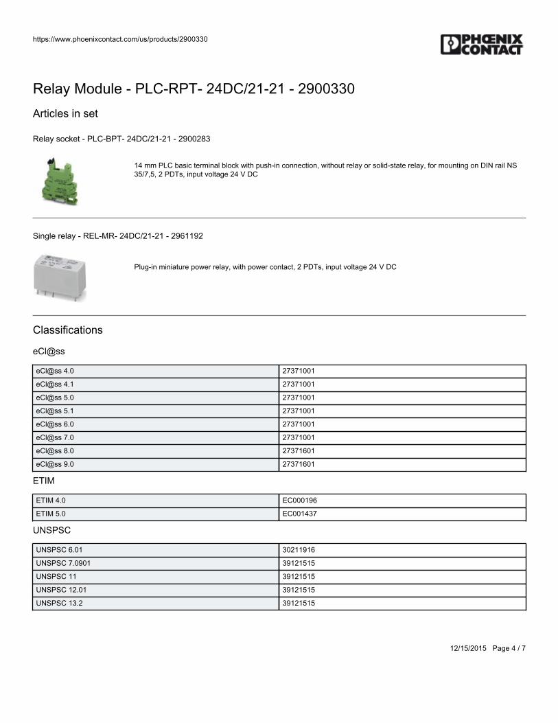
https://www.phoenixcontact.com/us/products/2900330
12/15/2015 Page 4 / 7
Relay Module - PLC-RPT- 24DC/21-21 - 2900330Articles in set
Relay socket - PLC-BPT- 24DC/21-21 - 2900283
14 mm PLC basic terminal block with push-in connection, without relay or solid-state relay, for mounting on DIN rail NS35/7,5, 2 PDTs, input voltage 24 V DC
Single relay - REL-MR- 24DC/21-21 - 2961192
Plug-in miniature power relay, with power contact, 2 PDTs, input voltage 24 V DC
Classifications
eCl@ss
eCl@ss 4.0 27371001
eCl@ss 4.1 27371001
eCl@ss 5.0 27371001
eCl@ss 5.1 27371001
eCl@ss 6.0 27371001
eCl@ss 7.0 27371001
eCl@ss 8.0 27371601
eCl@ss 9.0 27371601
ETIM
ETIM 4.0 EC000196
ETIM 5.0 EC001437
UNSPSC
UNSPSC 6.01 30211916
UNSPSC 7.0901 39121515
UNSPSC 11 39121515
UNSPSC 12.01 39121515
UNSPSC 13.2 39121515
https://www.phoenixcontact.com/us/products/2900330
12/15/2015 Page 5 / 7
Relay Module - PLC-RPT- 24DC/21-21 - 2900330Approvals
Approvals
Approvals
GL / UL Listed / cUL Listed / UL Recognized / cUL Recognized / EAC / RC FRT / EAC / cULus Recognized / cULus Listed
Ex Approvals
Approvals submitted
Approval details
GL
UL Listed
cUL Listed
UL Recognized
cUL Recognized
EAC
RC FRT
EAC
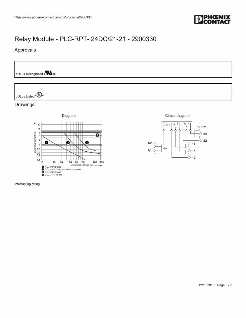
https://www.phoenixcontact.com/us/products/2900330
12/15/2015 Page 6 / 7
Relay Module - PLC-RPT- 24DC/21-21 - 2900330Approvals
cULus Recognized
cULus Listed
Drawings
Diagram
0,1
0,20,3
0,5
1
2
4
6
10
20
10 20 30 50 70 100 300200
1234
3
1
4 2
AC,ohmicloadSwitchingvoltage[V]
Sw
itch
ing
cu
rre
nt
[A]
DC,ohmicload,contactsinseriesDC,ohmicloadDC,L/R=40ms
Interrupting rating
Circuit diagram
A2
24
21
22
14
11
12
A1
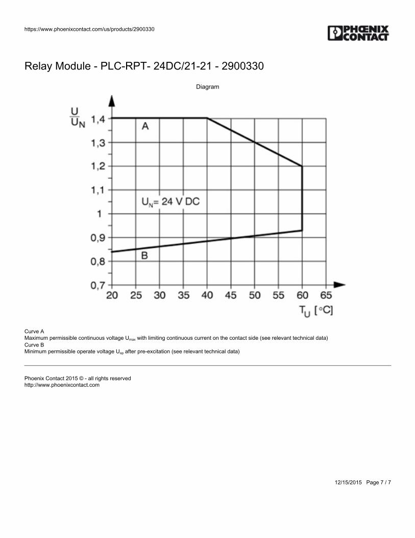
https://www.phoenixcontact.com/us/products/2900330
12/15/2015 Page 7 / 7
Relay Module - PLC-RPT- 24DC/21-21 - 2900330
Diagram
Curve A Maximum permissible continuous voltage Umax with limiting continuous current on the contact side (see relevant technical data) Curve B Minimum permissible operate voltage Uop after pre-excitation (see relevant technical data)
Phoenix Contact 2015 © - all rights reservedhttp://www.phoenixcontact.com

BWS-GL-02 Appendix55
55. StainlessSteelFittings:Various

BWS-GL-02 Appendix56
56. SanitaryClampGasket/OrificePlate:Various
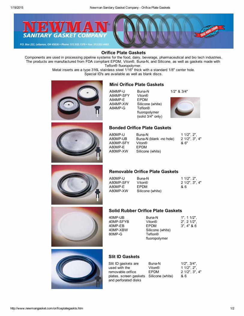

BWS-GL-02 Appendix57
57. StainlessSteelTubing

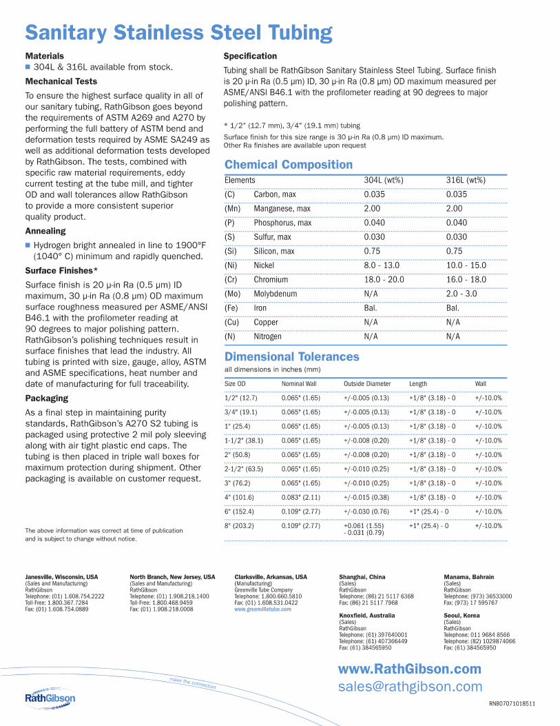

BWS-GL-02 Appendix58
58. SpearsPVCPipeandFittings:Various
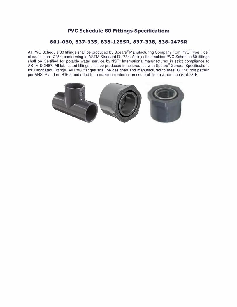
PVC Schedule 80 Fittings Specification:
801-030, 837-335, 838-128SR, 837-338, 838-247SR All PVC Schedule 80 fittings shall be produced by Spears® Manufacturing Company from PVC Type I, cell classification 12454, conforming to ASTM Standard D 1784. All injection molded PVC Schedule 80 fittings shall be Certified for potable water service by NSF® International manufactured in strict compliance to ASTM D 2467. All fabricated fittings shall be produced in accordance with Spears® General Specifications for Fabricated Fittings. All PVC flanges shall be designed and manufactured to meet CL150 bolt pattern per ANSI Standard B16.5 and rated for a maximum internal pressure of 150 psi, non-shock at 73°F.

BWS-GL-02 Appendix59
59. BWSGSACFrame:BWS_GSAC_Frame_1414

BWS-GL-02 Appendix60
60. Filter/MediaTanks
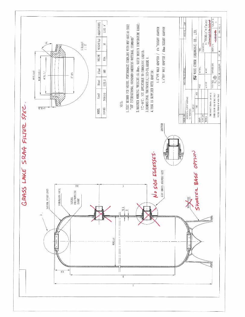

BWS-GL-02 Appendix61
61. InversandGreensandMedia
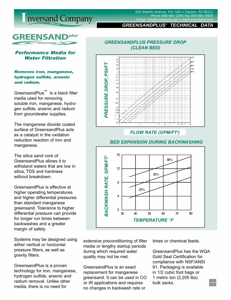
226 Atlantic Avenue, P.O. 650 Clayton, NJ 08312 Phone 856-881-2345 Fax 856-881-6859
Email: [email protected] www.inversand.com
Removes iron, manganese,hydrogen sulfide, arsenicand radium.
GreensandPlus™ is a black filtermedia used for removing soluble iron, manganese, hydro-gen sulfide, arsenic and radiumfrom groundwater supplies.
The manganese dioxide coatedsurface of GreensandPlus actsas a catalyst in the oxidationreduction reaction of iron andmanganese.
The silica sand core ofGreensandPlus allows it to withstand waters that are low insilica, TDS and hardness without breakdown.
GreensandPlus is effective athigher operating temperaturesand higher differential pressuresthan standard manganese greensand. Tolerance to higherdifferential pressure can providefor longer run times betweenbackwashes and a greater margin of safety.
Systems may be designed usingeither vertical or horizontal pressure filters, as well as gravity filters.
GreensandPlus is a proven technology for iron, manganese,hydrogen sulfide, arsenic andradium removal. Unlike othermedia, there is no need for
extensive preconditioning of filtermedia or lengthy startup periodsduring which required water quality may not be met.
GreensandPlus is an exactreplacement for manganesegreensand. It can be used in COor IR applications and requiresno changes in backwash rate or
times or chemical feeds.
GreensandPlus has the WQAGold Seal Certification forcompliance with NSF/ANSI61. Packaging is available in 1/2 cubic foot bags or 1 metric ton (2,205 lbs) bulk sacks. 1 of 4
Performance Media forWater Filtration
BED EXPANSION DURING BACKWASHING
GREENSANDPLUS PRESSURE DROP (CLEAN BED)
PRES
SUR
E D
RO
P, P
SI/F
T
FLOW RATE (GPM/FT2)
BA
CK
WA
SH R
ATE,
GPM
/FT2
TEMPERATURE °F
GREENSANDPLUS™ TECHNICAL DATA
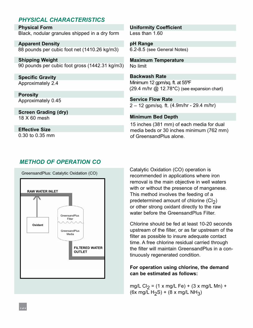
Physical Form
Apparent Density
Shipping Weight
Specific Gravity
Porosity
Screen Grading (dry)
Effective Size
Uniformity Coefficient
pH Range
Maximum Temperature
Backwash Rate
Service Flow Rate
Minimum Bed Depth
PHYSICAL CHARACTERISTICS
For operation using chlorine, the demandcan be estimated as follows:
FILTERED WATEROUTLET
2 of 4
METHOD OF OPERATION CO
RAW WATER INLET
Oxidant
88 pounds per cubic foot net (1410.26 kg/m3)
90 pounds per cubic foot gross (1442.31 kg/m3)
(4.9m/hr - 29.4 m/hr)
(29.4 m/hr @ 12.78*C) (see expansion chart)
15 inches (381 mm) of each media for dual media beds or 30 inches minimum (762 mm) of GreensandPlus alone.
FILTERED WATEROUTLET
RAW WATER INLET
Oxidant
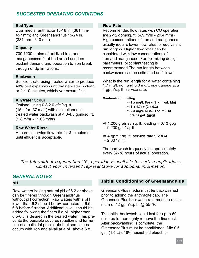
3 of 4
The Intermittent regeneration (IR) operation is available for certain applications.Contact your Inversand representative for additional information.
SUGGESTED OPERATING CONDITIONS
Bed TypeDual media; anthracite 15-18 in. (381 mm- 457 mm) and GreensandPlus 15-24 in.(381 mm - 610 mm)
Capacity700-1200 grains of oxidized iron and manganese/sq.ft. of bed area based on oxidant demand and operation to iron breakthrough or dp limitations.
BackwashSufficient rate using treated water to produce
40% bed expansion until waste water is clear, or for 10 minutes, whichever occurs first.
Air/Water ScourOptional using 0.8-2.0 cfm/sq. ft. (15 m/hr -37 m/hr) with a simultaneous treated water backwash at 4.0-4.5 gpm/sq. ft.(9.8 m/hr - 11.03 m/hr)
Raw Water RinseAt normal service flow rate for 3 minutes oruntil effluent is acceptable.
Flow RateRecommended flow rates with CO operationare 2-12 gpm/sq. ft. (4.9 m/hr - 29.4 m/hr).High concentrations of iron and manganeseusually require lower flow rates for equivalentrun lengths. Higher flow rates can beconsidered with low concentrations ofiron and manganese. For optimizing designparameters, pilot plant testing isrecommended.The run length betweenbackwashes can be estimated as follows:
What is the run length for a water containing1.7 mg/L iron and 0.3 mg/L manganese at a4 gpm/sq. ft. service rate:
Contaminant loading= (1 x mg/L Fe) + (2 x mg/L Mn)= (1 x 1.7) + (2 x 0.3)= (2.3 mg/L or 2.3/17.1 = 0.13
grains/gal. (gpg)
At 1,200 grains / sq. ft. loading ÷ 0.13 gpg = 9,230 gal./sq. ft.
At 4 gpm / sq. ft. service rate 9,230/4 = 2,307 min.
The backwash frequency is approximatelyevery 32-38 hours of actual operation.
GENERAL NOTESpH
Raw waters having natural pH of 6.2 or abovecan be filtered through GreensandPlus without pH correction. Raw waters with a pHlower than 6.2 should be pH-corrected to 6.5-6.8 before filtration. Additional alkali should be added following the filters if a pH higher than 6.5-6.8 is desired in the treated water. This pre-vents the possible adverse reaction and forma-tion of a colloidal precipitate that sometimesoccurs with iron and alkali at a pH above 6.8.
Initial Conditioning of GreensandPlus
GreensandPlus media must be backwashedprior to adding the anthracite cap. TheGreensandPlus backwash rate must be a mini-mum of 12 gpm/sq. ft. @ 55 °F.
This initial backwash could last for up to 60minutes to thoroughly remove the fine dust.After backwashing is complete, theGreensandPlus must be conditioned. Mix 0.5gal. (1.9 L) of 6% household bleach or

Disclaimer: The information and recommendations in this publication are true and
reliable to the best of our knowledge. These recommendations are offered in good
faith but without warranty or liability for consequential damage as conditions and
method of use of our products are varied and beyond our control. We suggest the
user determine the suitability and performance of our products before they are
adopted on a commercial scale.
REFERENCES
4 of 4
226 Atlantic Avenue • P.O. Box 650Clayton, NJ 08312 USA T: 856-881-2345 • F: 856-881-6859 E:[email protected] •www.inversand.com
The manufacturing of GreensandPlus is an ongoing, 24/7 process to ensure the highest quality water treatment media.
Initial Conditioning of GreensandPlus
USA USA
International
0.2 gal (0.75 L) of 12% sodium hypochlorite for
every 1 cu. ft. (28.3 L cu. m) of GreensandPlus
into 6.5 gallons (25 L) of water.
Drain the filter enough to add the diluted chlo-
rine mix. Apply the diluted chlorine to the filter
being sure to allow the solution to contact the
GreensandPlus media. Let soak for a minimum
of 4 hours, then rinse to waste until the “free”
chlorine residual is less than 0.2 mg/L. The
GreensandPlus is now ready for service.
American Water Company, CA
San Jacinto, CA
City of Tallahassee, FL
Adedge Technologies, Inc., Buford, GA
City of Mason City, IL
City of Goshen, IN
City of Hutchinson, KS
City of Burlington, MA
Dedham Water Co., MA
Raynham Center, MA
Northbrook Farms, MD
Sykesville, MD
Tonka Equipment Company, Plymouth, MN
City of New Bern, NC
Onslow County, NC
Hungerford & Terry, Inc., Clayton, NJ
Fort Dix, NJ
Jackson Twsp. MUA, NJ
Watergroup, Saskatoon, SK CanadaBI Pure Water, Surrey, BC Canada Sydney, Nova Scotia, CanadaPT Besflo Prima, Jakarta, IndonesiaEurotrol, Milanese, ItalyGargon Industrial, Mexico City, MexicoFiltration Tech, Auckland, New ZealandAlamo Water Poland, Izabelin, PolandAquatrol Company, Moscow, RussiaImpulse Group, St. Petersburg, RussiaBrenntag Nordic, Taby, SwedenNema Kimya, Istanbul, TurkeyMinh Tam, Ho Chi Minh City, Vietnam
Radium and Arsenic Removal Using GreensandPlus
The GreensandPlus CO process has been
found to be successful in removing radium and
arsenic from well water. This occurs via adsorp-
tion onto the manganese and/or iron precipi-
tates that are formed. For radium removal,
soluble manganese must be present in or
added to the raw water for removal to occur.
Arsenic removal requires iron to be present in
or added to the raw water to accomplish
removal. Pilot plant testing is recommended in
either case.
Churchill County, NV
Suffolk County Water Authority, NY
City of Urbana, OH
Roberts Filter Group, Darby, PA
Distributed by:©20
12Inversa
nd Com
pany (1
M) 2
/12

ACTIVATED CARBON COCONUT SHELL FOR WATER PURIFICATION This type of carbon is made from coconut shell and activated thru high temperature & high pressure steam in order to create the internal pore structure to obtain maximum efficiency in the adsorption process; it is desirable to have the greatest possible surface area within a small volume. Also is used for the promotion of oxidation, reduction and elimination reactions. Specific applications include chloramines, organic compounds including pesticides and herbicides form drinking water including cartridge manufacturing for potable water, beverage water etc. Carbon Type PSC1240 Activity (ASTM 3467) 60 CTC Particle Size 12x40 US MESH Apparent Density (ASTM 2864) 0.47-0.49gm/cc Specific Surface Area (N2 Bet Method) 1100-1150 m2/gm Ash Content (ASTM 2866) 2% Hardness (ASTM 3802) 99.0% Minimum Iodine Number 1150 mg/gm Bulk Density 27.5 Lb/ft3
Standard Packaging: one/two cu.ft. Polypropylene bags. 1,100 lb. super sacks are available.

BWS-GL-02 Appendix62
62. WalchemPumpEWN-RSeries
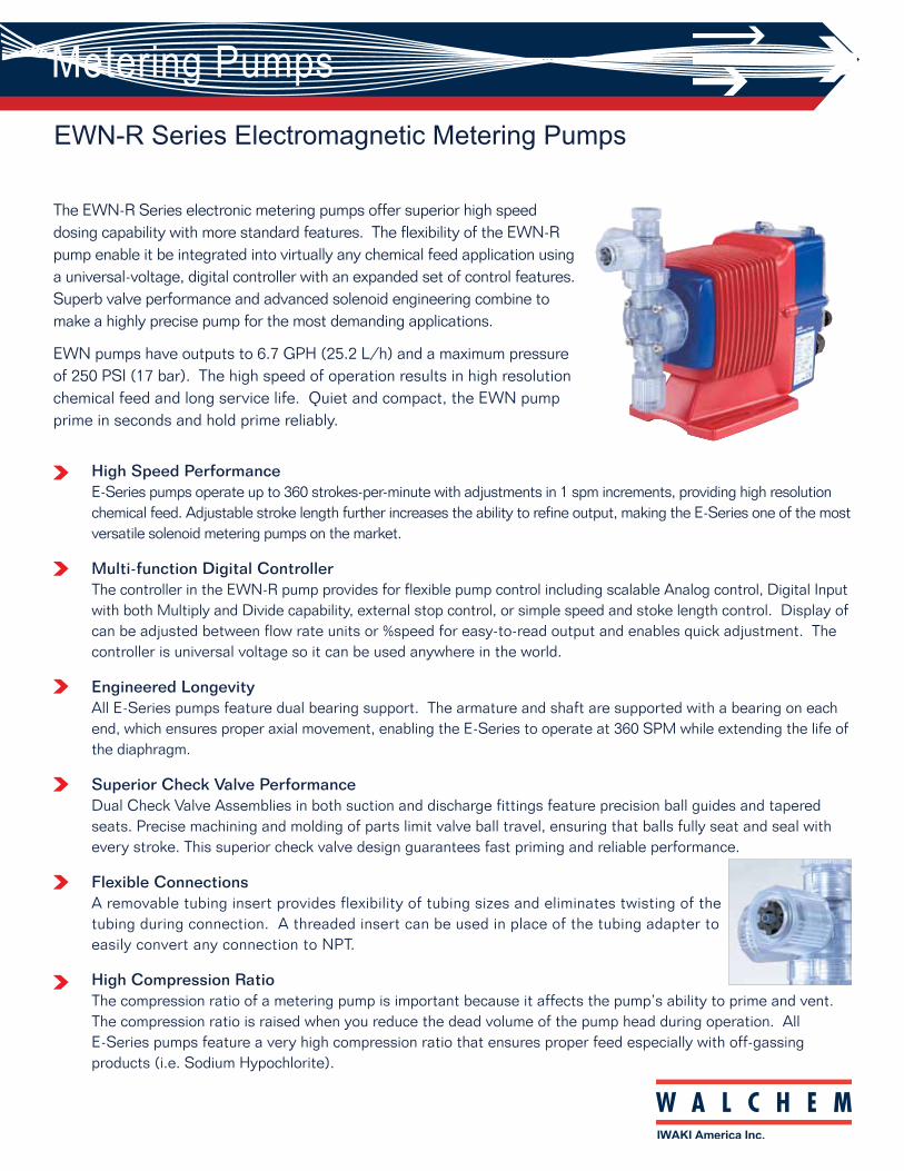
Metering Pumps
EWN-R Series Electromagnetic Metering Pumps
The EWN-R Series electronic metering pumps offer superior high speed dosing capability with more standard features. The flexibility of the EWN-R pump enable it be integrated into virtually any chemical feed application using a universal-voltage, digital controller with an expanded set of control features. Superb valve performance and advanced solenoid engineering combine to make a highly precise pump for the most demanding applications.
EWN pumps have outputs to 6.7 GPH (25.2 L/h) and a maximum pressure of 250 PSI (17 bar). The high speed of operation results in high resolution chemical feed and long service life. Quiet and compact, the EWN pump prime in seconds and hold prime reliably.
High Speed Performance E-Series pumps operate up to 360 strokes-per-minute with adjustments in 1 spm increments, providing high resolution chemical feed. Adjustable stroke length further increases the ability to refine output, making the E-Series one of the most versatile solenoid metering pumps on the market.
Multi-function Digital ControllerThe controller in the EWN-R pump provides for flexible pump control including scalable Analog control, Digital Input with both Multiply and Divide capability, external stop control, or simple speed and stoke length control. Display of can be adjusted between flow rate units or %speed for easy-to-read output and enables quick adjustment. The controller is universal voltage so it can be used anywhere in the world.
Engineered LongevityAll E-Series pumps feature dual bearing support. The armature and shaft are supported with a bearing on each end, which ensures proper axial movement, enabling the E-Series to operate at 360 SPM while extending the life of the diaphragm.
Superior Check Valve PerformanceDual Check Valve Assemblies in both suction and discharge fittings feature precision ball guides and tapered seats. Precise machining and molding of parts limit valve ball travel, ensuring that balls fully seat and seal with every stroke. This superior check valve design guarantees fast priming and reliable performance.
Flexible ConnectionsA removable tubing insert provides flexibility of tubing sizes and eliminates twisting of the tubing during connection. A threaded insert can be used in place of the tubing adapter to easily convert any connection to NPT.
High Compression Ratio The compression ratio of a metering pump is important because it affects the pump’s ability to prime and vent. The compression ratio is raised when you reduce the dead volume of the pump head during operation. All E-Series pumps feature a very high compression ratio that ensures proper feed especially with off-gassing products (i.e. Sodium Hypochlorite).
Walchem, Iwaki America Inc. Five Boynton Road Hopping Brook Park Holliston, MA 01746 USA Phone: 508-429-1110 www.walchem.com
High Compression Model High Pressure Model High Viscosity ModelIncreasing the compression ratio by minimizing dead volume in the liquid end further helps to eliminate gas in the pump heads. In addition to reducing air lock conditions, the increased compression ratio helps with accuracy at low output ranges.
Construction
180623.A August 2014
Valve
O-ring
Diaphragm
Pump head
Gasket
Valve seat
Valve
O-ring
Diaphragm
Pump headGasket
Valve seat
ValveO-ring
Diaphragm
Pump head
Gasket
Spring
Valve seat
Auto Degassing Valve Model
O-ring
Diaphragm
Pump head
Gasket
Valve seat
Valve
Wet-end materialMaterial codePump headValveValve seatGasketO-ringDiaphragm
VC VEPVCCE
FKM EPDMPTFE
FKM EPDMPTFE+EPDM
Wet-end materialMaterial codePump headValveValve seatGasketO-ringDiaphragm
GFRPPPC
CEFKM
FKM
SUS316SH
HCSUS316
—
PE
EPDMPTFE
EPDMPTFE+EPDM
Wet-end materialMaterial codePump headValveValve seat
GasketO-ringDiaphragm
GFRPPPC
CEPCTFE
Spring Hastelloy C276
FKMPTFE
PTFE+EPDM
P6
316 SS
316 SS
EPDM
Wet-end materialMaterial codePump headValveValve seatGasketO-ringDiaphragm
VC VEPVCCE
FKM EPDMPTFE
FKM EPDMPTFE+EPDM
Discharge pressure Stroke rate Stroke length range
mL/minCapacity
20 - 100 (0.25 - 1.25) 20 - 100 (0.3 - 1.50)
GPH
mL/shot 0.09 - 0.43105
781.2
0.01 - 0.07150
120.2
0.03 - 0.13150
230.4
0.04 - 0.22105
400.6
0.06 - 0.30150
540.9
0.07 - 0.3560
631.0
Model C21B09 B11 B16 C16B21
PSI0.1 - 100 (1-180)% (spm)
% (mm)
Note 1: Each discharge capacity shown above is at discharge pressure (stroke length 100%, stroke rate 100%) and increases as a discharge pressure reduces.Note 2: The performance is based on pumping clean water at ambient temperature at rated voltage.
Specifications
Discharge pressureStroke rateStroke length range
mL/minCapacityGPH
mL/shot
Model
20 - 100 (0.2 - 1.0)
0.02 - 0.1250
250.4
B11
20 - 100 (0.25 - 1.25)
0.03 - 0.17250
400.6
C16
PSI0.1 - 100 (1-240)% (spm)
% (mm) 20 - 100 (0.25 - 1.25)
0.13 - 0.6373
1502.4
C31
0.1 - 100 (1-240)
B11High Pressure Models High Pressure Models (300 psi) High Viscosity Models
High Compression Models
70 - 100 (0.5 - 0.9)
0.05 - 0.07290
170.3
0.1 - 100 (1-240)
C21B11 B16 C16B21Auto Degassing Valve
0.04 - 0.08150
300.5
0.08 - 0.15105
550.9
0.12 - 0.2460
861.4
0.07 - 0.18150
651.0
0.12 - 0.31105
1101.7
0.1 - 100 (1-360)20 - 100 (0.2 - 1.0) 20 - 100 (0.25 - 1.25)
Chemicals that outgas, such as Sodium Hypochlorite or Hydrogen Peroxide, can generate enough gas to gas lock metering pumps. Using a dual check valve system, the Auto Degassing Valve vents any gas to atmosphere to eliminate gas lock conditions and keep the pump primed.
The high pressure model is capable of operating at flow rates of 0.4 or 0.6GPH (25 or 40mL/min) at a maximum discharge pressure up to 250PSI. This makes it suitable for applications such as chemical injection into boiler makeup water.
The High Viscosity pump has a uniquely designed liquid end with oversized flow paths and spring loaded valve checks. Coupled with a reduced max speed, the HV pumps are designed for polymer/coagulant injection in water treatment applications.
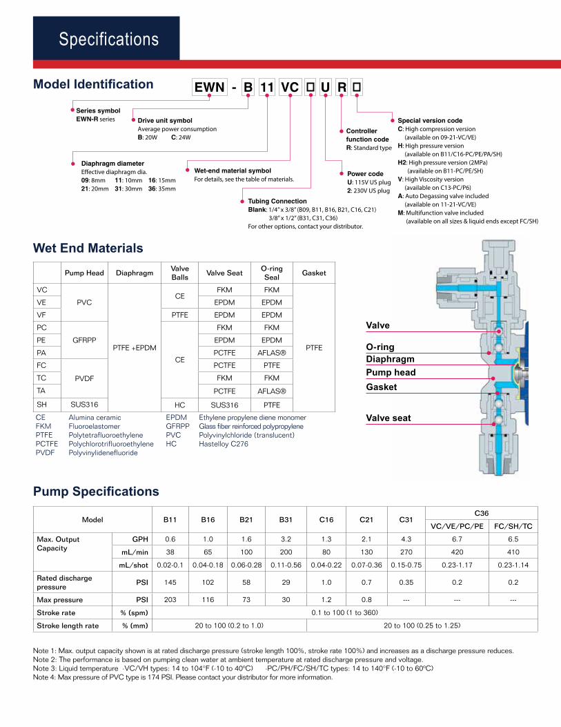
Specifications Specifications
EWN - B 11 VC U R
Series symbolEWN-R series Drive unit symbol
Average power consumptionB: 20W C: 24W
Diaphragm diameterEffective diaphragm dia.09: 8mm 11: 10mm 16: 15mm21: 20mm 31: 30mm 36: 35mm
Wet-end material symbolFor details, see the table of materials.
Special version codeC: High compression version (available on 09-21-VC/VE)H: High pressure version (available on B11/C16-PC/PE/PA/SH)H2: High pressure version (2MPa) (available on B11-PC/PE/SH)V: High Viscosity version (available on C13-PC/P6)A: Auto Degassing valve included (available on 11-21-VC/VE)M: Multifunction valve included (available on all sizes & liquid ends except FC/SH)
Controller function codeR: Standard type
Power codeU: 115V US plug2: 230V US plug
Tubing ConnectionBlank: 1/4” x 3/8” (B09, B11, B16, B21, C16, C21) 3/8” x 1/2” (B31, C31, C36)For other options, contact your distributor.
Valve
O-ringDiaphragmPump headGasket
Valve seat
Pump Head DiaphragmValve Balls
Valve SeatO-ring Seal
Gasket
VC
PVC
PTFE +EPDM
CEFKM FKM
PTFE
VE EPDM EPDM
VF PTFE EPDM EPDM
PC
GFRPP
CE
FKM FKM
PE EPDM EPDM
PA PCTFE AFLAS®
FC
PVDF
PCTFE PTFE
TC FKM FKM
TA PCTFE AFLAS®
SH SUS316 HC SUS316 PTFE
Wet End Materials
0RGHO,GHQWL¿FDWLRQ
Model B11 B16 B21 B31 C16 C21 C31C36
VC/VE/PC/PE FC/SH/TC
Max. Output Capacity
GPH 0.6 1.0 1.6 3.2 1.3 2.1 4.3 6.7 6.5
mL/min 38 65 100 200 80 130 270 420 410
mL/shot 0.02-0.1 0.04-0.18 0.06-0.28 0.11-0.56 0.04-0.22 0.07-0.36 0.15-0.75 0.23-1.17 0.23-1.14
Rated discharge pressure
PSI 145 102 58 29 1.0 0.7 0.35 0.2 0.2
Max pressure PSI 203 116 73 30 1.2 0.8 --- --- ---
Stroke rate % (spm) 0.1 to 100 (1 to 360)
Stroke length rate % (mm) 20 to 100 (0.2 to 1.0) 20 to 100 (0.25 to 1.25)
3XPS6SHFL¿FDWLRQV
Operational mode
MAN 0.1 to 100% stroke rate
EXT control
DIV (Dividing) /1 to 0000
MULT (Multiply) x1 to 9999
ANA. R (Analog, rigid) 4 to 20, 0 to 20, 20 to 4, 20 to 0 mA
ANA. V (Analog, variable) 2 points 0.0 to 20.0 mA range 0.0 to 100% stroke rate
Display
LCD 14 segment 5 digits %, ml/m, L/H, GPH, STOP, PRIME, AUX etc
LEDON Green Green lights when ON blinks OFF synchronous with stroke.
STOP Orange/Red Orange lights when Pre-STOP is made, red when STOP is made.
Keypad 5 keys START/STOP, EXT, (UP), (DOWN), Disp
Control function
STOP/Pre-STOP Pump keeps running when Pre-STOP is made. Pump stops when STOP is made.
Prime Pump runs at max. stroke rate while up and down keys are pressed.
Key lock Keypad can be locked and unlocked.
Calibration Discharge capacity per shot is calculated automatically by operating and stopping pump in the calibration mode to determine the flow rate.
Buffer memory ON or OFF selectable. Max. 65535 stroke pulses are stored in memory.
Input
Pulse No voltage contact or open collector. Max 200 Hz. NO/NC selectable
Current '&P$,QSXWUHVLVWDQFH
Stop/Pre-stop No Voltage contact or open collector
AUX Pump runs at max.stroke rate when made. No Voltage contact or open collector
OutputPhoto-MOS relay AC/DC24V 0.1A
STOP, Synchronous with stroke
Note 1: If the max. stroke rate by calculation exceeds 100% stroke rate because of the relation between the setting and input signal when the pump is in EXT operation, the operation is fixed at Maximum stroke rate speed of manual operation.Note 2: By changing the setting, the pump can run when the contact signal comes in. Note 3: The max. frequency of input pulse is 200 Hz. ON time of input pulse is 10 to 100 mS. Note 4: The max. potential voltage at a contact is 12V and current is 0.1mA. If a contact such as relay is used, the minimum application load should be 0.1mA or less.
Note 1: Max. output capacity shown is at rated discharge pressure (stroke length 100%, stroke rate 100%) and increases as a discharge pressure reduces.Note 2: The performance is based on pumping clean water at ambient temperature at rated discharge pressure and voltage.Note 3: Liquid temperature ·VC/VH types: 14 to 104°F (-10 to 40ºC) ·PC/PH/FC/SH/TC types: 14 to 140°F (-10 to 60ºC)Note 4: Max pressure of PVC type is 174 PSI. Please contact your distributor for more information.
&RQWUROOHU6SHFL¿FDWLRQV
dL(77)
(68)
(266
)
125
40 15 20 20 15
80
10 a10
0b
H
6100
c
Material Model H L a b c d
PC/PE/PA VC/VE/VF
TC/TA
EWN-11,16, 21 7.83 10.43 0.94 6.45 0.90 1.85
EWN-31 8.34 10.51 0.23 6.97 0.98 1.89
EWN-36 8.30 10.51 0.27 6.93 0.94 1.89
SH
EWN-11,16, 21 7.91 9.13 1.73 6.10 0.86 0.59
EWN-31 8.38 9.17 1.34 6.49 0.90 0.59
EWN-36 8.50 9.17 1.26 6.69 0.90 0.59
FC
EWN-11,16, 21 6.53 9.09 1.57 6.31 0.90 0.51
EWN-31 6.97 9.29 0.90 6.97 0.98 0.63
EWN-36 6.97 9.25 0.90 6.97 0.94 0.63
dL(77)
(68)
(266
)
125
40 15 20 20 15
80
10
a10
0 bH
6100
c
dL(77)
(68)
(266
)
125
40 15 20 20 15
80
10
a10
0 b H
6100
c
PC/PE/PA/VC/VE/VF/TC/TA Models
Dimensions (in inches)
SH Models
FC Models
R S T
X Y Z Z Y
U V
EW Model R S T U V X Y Z
11,16, 214.57” 3.94” 0.24” 3.15” 4.17” 1.57” 0.59” 0.79”
31, 36
Mounting Dimensions
Safety Certifications
The EWN series metering pumps are tested by Intertek to UL and CSA standards.
CE Alumina ceramic EPDM Ethylene propylene diene monomerFKM Fluoroelastomer GFRPP Glass fiber reinforced polypropylenePTFE Polytetrafluoroethylene PVC Polyvinylchloride (translucent)PCTFE Polychlorotrifluoroethylene HC Hastelloy C276PVDF Polyvinylidenefluoride
The EWN series metering pumps* are WQA tested and certified to NSF/ANSI Standard 50 and Standard 61. * See www.wqa.org for specific chemicals and certification parameters.
EWN EWN-B EWN-C
50/60 Hz, 1 phase 20 Watt avg. 24 Watt avg.
100-240VAC ±10% 0.8 Amp max. 1.2 Amp max.
Shipping weightEWN-B: 10 lbs (4.5 kg)EWN-C: 12 lbs (5.5 kg)
Electrical Specifications
ĦBottom View
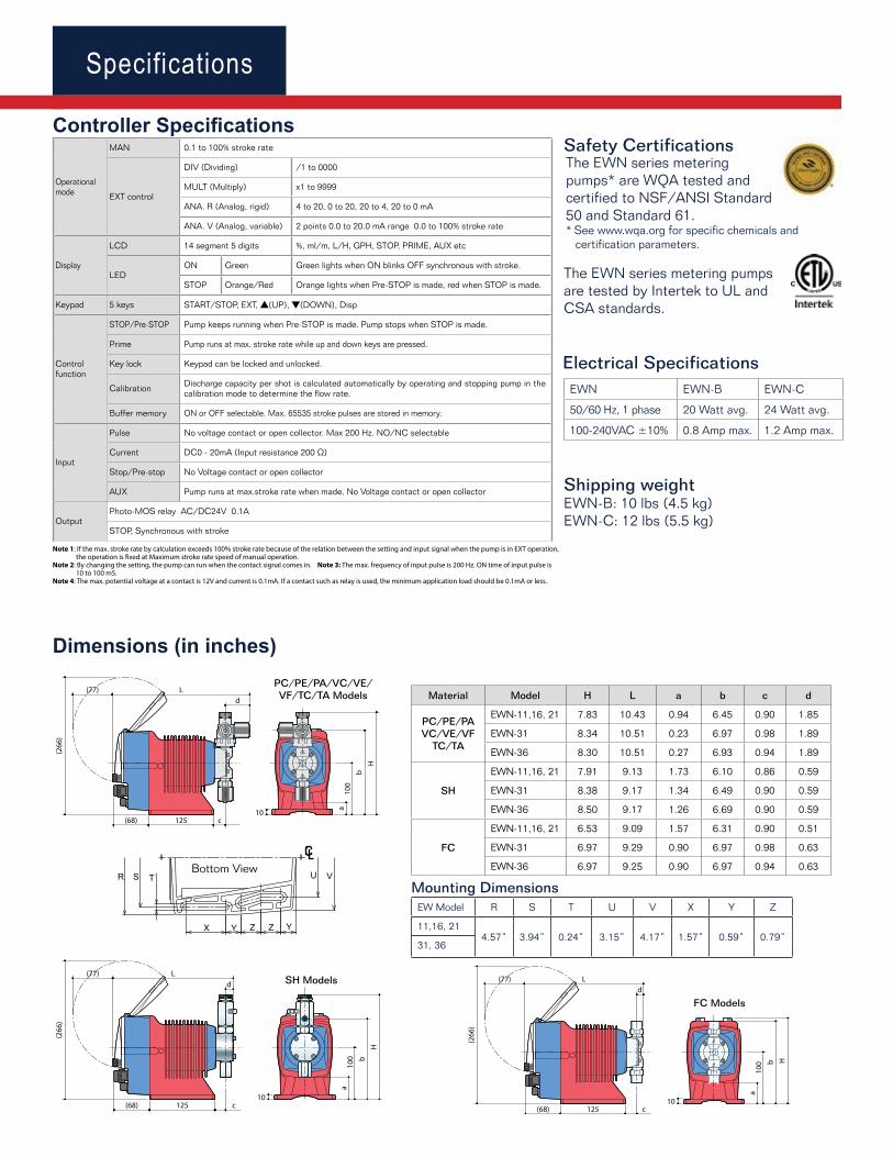
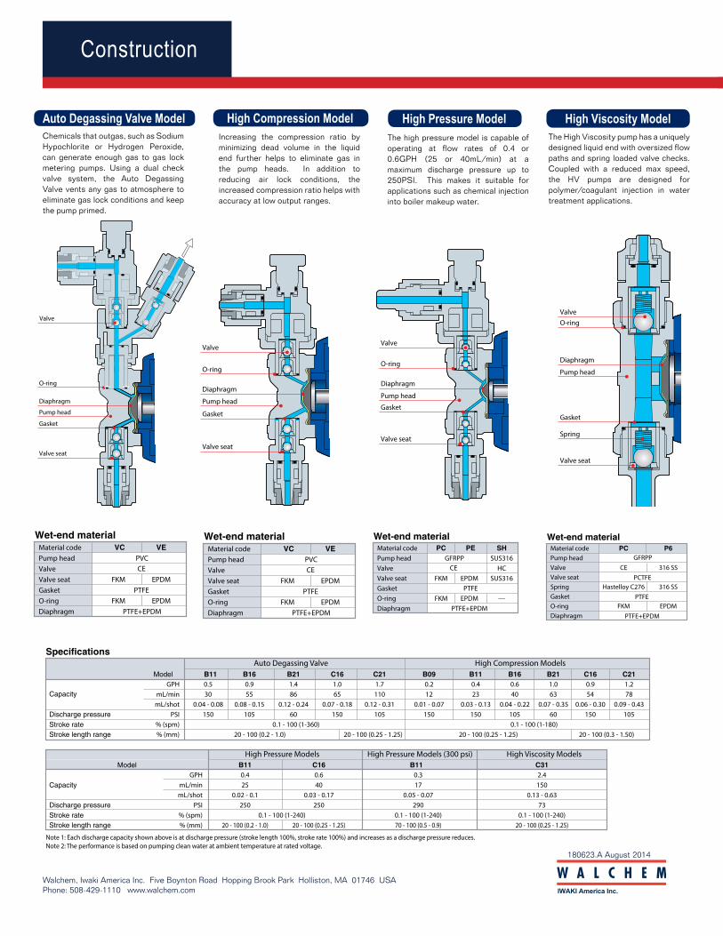
Metering Pumps
EWN-R Series Electromagnetic Metering Pumps
The EWN-R Series electronic metering pumps offer superior high speed dosing capability with more standard features. The flexibility of the EWN-R pump enable it be integrated into virtually any chemical feed application using a universal-voltage, digital controller with an expanded set of control features. Superb valve performance and advanced solenoid engineering combine to make a highly precise pump for the most demanding applications.
EWN pumps have outputs to 6.7 GPH (25.2 L/h) and a maximum pressure of 250 PSI (17 bar). The high speed of operation results in high resolution chemical feed and long service life. Quiet and compact, the EWN pump prime in seconds and hold prime reliably.
High Speed Performance E-Series pumps operate up to 360 strokes-per-minute with adjustments in 1 spm increments, providing high resolution chemical feed. Adjustable stroke length further increases the ability to refine output, making the E-Series one of the most versatile solenoid metering pumps on the market.
Multi-function Digital ControllerThe controller in the EWN-R pump provides for flexible pump control including scalable Analog control, Digital Input with both Multiply and Divide capability, external stop control, or simple speed and stoke length control. Display of can be adjusted between flow rate units or %speed for easy-to-read output and enables quick adjustment. The controller is universal voltage so it can be used anywhere in the world.
Engineered LongevityAll E-Series pumps feature dual bearing support. The armature and shaft are supported with a bearing on each end, which ensures proper axial movement, enabling the E-Series to operate at 360 SPM while extending the life of the diaphragm.
Superior Check Valve PerformanceDual Check Valve Assemblies in both suction and discharge fittings feature precision ball guides and tapered seats. Precise machining and molding of parts limit valve ball travel, ensuring that balls fully seat and seal with every stroke. This superior check valve design guarantees fast priming and reliable performance.
Flexible ConnectionsA removable tubing insert provides flexibility of tubing sizes and eliminates twisting of the tubing during connection. A threaded insert can be used in place of the tubing adapter to easily convert any connection to NPT.
High Compression Ratio The compression ratio of a metering pump is important because it affects the pump’s ability to prime and vent. The compression ratio is raised when you reduce the dead volume of the pump head during operation. All E-Series pumps feature a very high compression ratio that ensures proper feed especially with off-gassing products (i.e. Sodium Hypochlorite).
Walchem, Iwaki America Inc. Five Boynton Road Hopping Brook Park Holliston, MA 01746 USA Phone: 508-429-1110 www.walchem.com
High Compression Model High Pressure Model High Viscosity ModelIncreasing the compression ratio by minimizing dead volume in the liquid end further helps to eliminate gas in the pump heads. In addition to reducing air lock conditions, the increased compression ratio helps with accuracy at low output ranges.
Construction
180623.A August 2014
Valve
O-ring
Diaphragm
Pump head
Gasket
Valve seat
Valve
O-ring
Diaphragm
Pump headGasket
Valve seat
ValveO-ring
Diaphragm
Pump head
Gasket
Spring
Valve seat
Auto Degassing Valve Model
O-ring
Diaphragm
Pump head
Gasket
Valve seat
Valve
Wet-end materialMaterial codePump headValveValve seatGasketO-ringDiaphragm
VC VEPVCCE
FKM EPDMPTFE
FKM EPDMPTFE+EPDM
Wet-end materialMaterial codePump headValveValve seatGasketO-ringDiaphragm
GFRPPPC
CEFKM
FKM
SUS316SH
HCSUS316
—
PE
EPDMPTFE
EPDMPTFE+EPDM
Wet-end materialMaterial codePump headValveValve seat
GasketO-ringDiaphragm
GFRPPPC
CEPCTFE
Spring Hastelloy C276
FKMPTFE
PTFE+EPDM
P6
316 SS
316 SS
EPDM
Wet-end materialMaterial codePump headValveValve seatGasketO-ringDiaphragm
VC VEPVCCE
FKM EPDMPTFE
FKM EPDMPTFE+EPDM
Discharge pressure Stroke rate Stroke length range
mL/minCapacity
20 - 100 (0.25 - 1.25) 20 - 100 (0.3 - 1.50)
GPH
mL/shot 0.09 - 0.43105
781.2
0.01 - 0.07150
120.2
0.03 - 0.13150
230.4
0.04 - 0.22105
400.6
0.06 - 0.30150
540.9
0.07 - 0.3560
631.0
Model C21B09 B11 B16 C16B21
PSI0.1 - 100 (1-180)% (spm)
% (mm)
Note 1: Each discharge capacity shown above is at discharge pressure (stroke length 100%, stroke rate 100%) and increases as a discharge pressure reduces.Note 2: The performance is based on pumping clean water at ambient temperature at rated voltage.
Specifications
Discharge pressureStroke rateStroke length range
mL/minCapacityGPH
mL/shot
Model
20 - 100 (0.2 - 1.0)
0.02 - 0.1250
250.4
B11
20 - 100 (0.25 - 1.25)
0.03 - 0.17250
400.6
C16
PSI0.1 - 100 (1-240)% (spm)
% (mm) 20 - 100 (0.25 - 1.25)
0.13 - 0.6373
1502.4
C31
0.1 - 100 (1-240)
B11High Pressure Models High Pressure Models (300 psi) High Viscosity Models
High Compression Models
70 - 100 (0.5 - 0.9)
0.05 - 0.07290
170.3
0.1 - 100 (1-240)
C21B11 B16 C16B21Auto Degassing Valve
0.04 - 0.08150
300.5
0.08 - 0.15105
550.9
0.12 - 0.2460
861.4
0.07 - 0.18150
651.0
0.12 - 0.31105
1101.7
0.1 - 100 (1-360)20 - 100 (0.2 - 1.0) 20 - 100 (0.25 - 1.25)
Chemicals that outgas, such as Sodium Hypochlorite or Hydrogen Peroxide, can generate enough gas to gas lock metering pumps. Using a dual check valve system, the Auto Degassing Valve vents any gas to atmosphere to eliminate gas lock conditions and keep the pump primed.
The high pressure model is capable of operating at flow rates of 0.4 or 0.6GPH (25 or 40mL/min) at a maximum discharge pressure up to 250PSI. This makes it suitable for applications such as chemical injection into boiler makeup water.
The High Viscosity pump has a uniquely designed liquid end with oversized flow paths and spring loaded valve checks. Coupled with a reduced max speed, the HV pumps are designed for polymer/coagulant injection in water treatment applications.

BWS-GL-02 Appendix63
63. ChemicalTubingLLDPE

Polyethylene Tubing - LLDPE Tubing
.
Polyethylene Tubing - LLDPE Tubing
• Linear Low Density (LLDPE) formulations; also available in Low Density formulation (LDPE)
• Made from non-toxic ingredients conforming to FDA standards
• Does not impart a taste or odor • Flexible, lightweight, durable • Translucent natural or opaque colors • Made from 100% virgin grade raw materials • Good dielectric properties • Low density is listed by the National Sanitation
Foundation (NSF 51) • Linear Low Density Tubing offers enhanced resistance
to stress cracking • Chemically inert; forms a good barrier to gases, vapors,
and moisture • Limited stock availability; lead times and minimums may
apply – call for details. APPLICATIONS
Air Lines • Chemical Lines • Fluid Lines • Food & Beverage • Hospital Uses • Instrumentation • Laboratory Uses • OEM Large Machines • Spacers • Wire Jacketing
Physical Properties** Low Density Linear Low
Density Hardness, Shore D ±5 50 50 Tensile Strength, psi 1600 2250 Elongation at Break, % 500 600 Brittle Temperature -76°F -76°F Vicat Softening Point 201°F 196°F Max. Operating Temperature 150°F 140°F
**Values listed are typical and are meant only as a guide to aid in design. Field testing should be performed to find the actual values for the application.
LLDPE - LINEAR LOW DENSITY POLYETHYLENE TUBING

BWS-GL-02 Appendix64
64. WalchemPosiFlowFCP-1VC
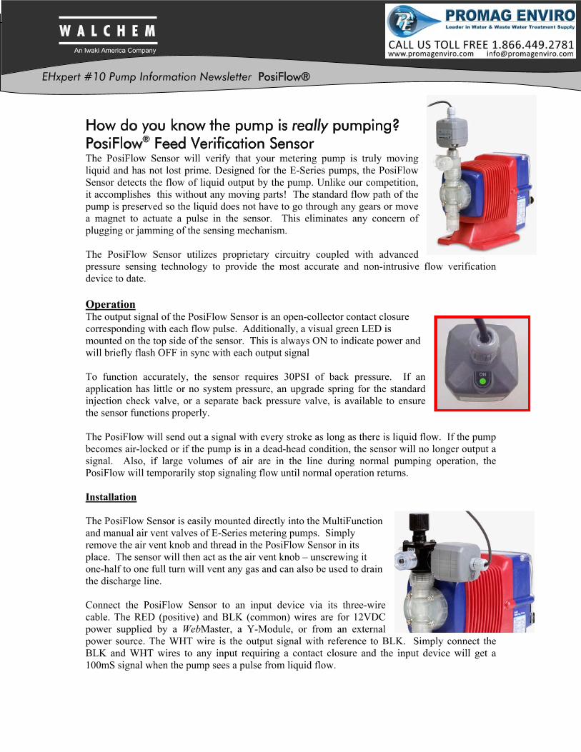
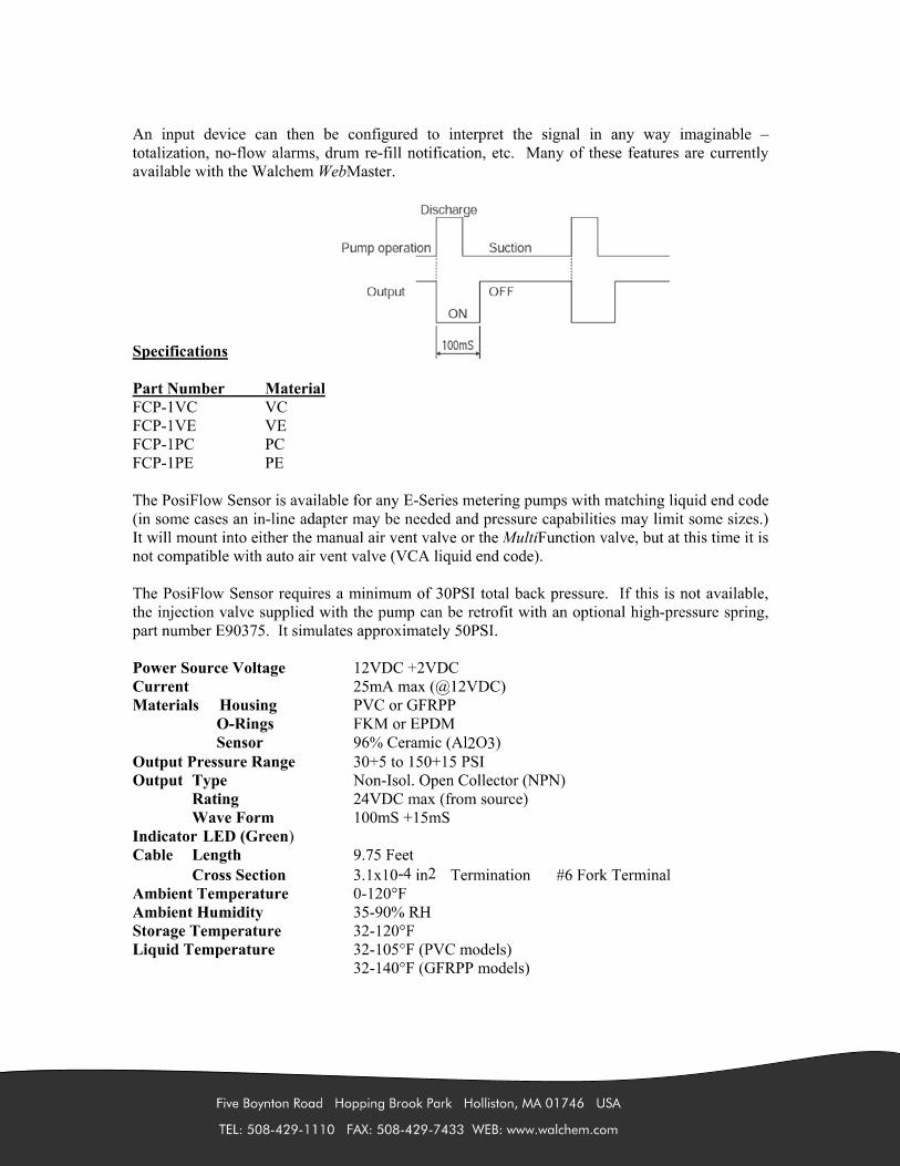

BWS-GL-02 Appendix65
65. PushToFitfor3/8Tubex1/4MPT–F6MC4
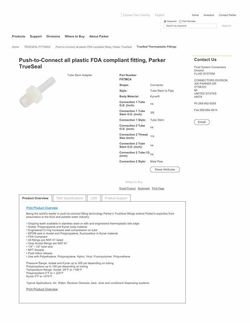
Products Support Divisions Where to Buy About Parker
Home TRUESEAL FITTINGS Push-to-Connect all plastic FDA compliant fitting, Parker TrueSeal TrueSeal Thermoplastic Fittings
Home Investors Contact ParkerChoose Your Country English
Keyword Part Number
Search by keyword
Tube Stem Adapter
Email Product Bookmark Print Page
Part NumberF6TMC4
Shape: Connector
Style: Tube Stem to Pipe
Body Material: Kynar®
Connection 1 TubeO.D. (inch): na
Connection 1 TubeStem O.D. (inch): 3/8
Connection 1 Style: Tube Stem
Connection 2 TubeO.D. (inch): na
Connection 2 ThreadSize (inch): 1/4
Connection 2 TubeStem O.D. (inch): na
Connection 2 Tube I.D.(inch): na
Connection 2 Style: Male Pipe
Push-to-Connect all plastic FDA compliant fitting, ParkerTrueSeal
Contact UsFluid System ConnectorsDivisionFLUID SYSTEM
CONNECTORS DIVISION300 PARKER DROTSEGOMIUNITED STATES49078
Ph:269-692-6555
Fax:269-694-4614
Tech Specifications CAD Product Support
Print Product Overview
Being the world's leader in push-to-connect fitting technology Parker's TrueSeal fittings extend Parker's expertise frompneumatics to the food and potable water industry.
• Gripping teeth available in stainless steel or with and engineered thermoplastic bite edge• Acetal, Polypropylene and Kynar body material• Engineered O-ring increases seal compression on tube• EPDM seal in Acetal and Polypropylene, fluorocarbon in Kynar material• FDA Compliant• All fittings are NSF-51 listed• Gray Acetal fittings are NSF-61• 1/4" - 1/2" tube size• NPT threads• Push bitton release• Use with Polyethylene, Polypropylene, Nylon, Vinyl, Fluoropolymer, Polyurethane
Pressure Range: Acteal and Kynar up to 300 psi depending on tubingPolypropylene up to 150 psi depending on tubingTemperature Range: Acetal -20°F to +180°FPolypropylene 0°F to + 225°FKynar 0°F to +275°F
Typical Applications: Air, Water, Reverse Osmosis, beer, wine and condiment dispensing systems
Print Product Overview
Search
Reset Attributes
Where to Buy
Product Overview

© Parker Hannifin Corp 2013 Site Map Safety Privacy Policies Terms & Conditions
About Parker Contact Parker Careers Working With Parker Investors News ParkerStore™ Brands

BWS-GL-02 Appendix66
66. AutoventValve:Plast-O-MaticValveEAST2V6W11-PV

CATALOG EAST
Compact & Economical PTFE BellowsThermoplastic Solenoid Valve…
For applications requiring a compact,cost-effective and high-pressure ratedvalve with extended cycle life.
Features:• Compact Size: Only 4-9/16'' high, these valves
are ideal for limited space installations. • Economical: Low unit cost coupled with high
pressure ratings and considerable flow rates(Cv of 0.5 or 0.8) offer excellent opportunitiesfor systems requiring quick opening/quickclosing solenoid valves.
• High Pressures: Particularly for applicationswhere high back-pressures (up to 70 PSI) arerequired e.g. controlling flow to spray nozzles,high pressure chemical injections, etc. Inletpressure to 140 PSI.
• Unique Design: PTFE Bellows barrier typedynamic seal prevents leaking of fugitiveemissions to the atmosphere.
• Versatility: Can be used with all type solutions.Includes acids, caustics, solvents, chlorinesolutions and ultra-pure liquids. For pressure,drain or vacuum service.
• Superior Performance: 2,000,000 cycle design. • Energy Efficient: Molded 11 watt NEMA 4X style coil with DIN standard connector results in low energy consumption. • Sizes: 1/4'' and 1/2'' pipe sizes with 3/16'' (4.8 mm) or 1/4'' (6.4 mm) orifice. • Corrosion Resistant: Rugged thermoplastic construction is resistant to both internal and atmospheric corrosion.
No metal parts in wetted areas. • Safety/Dependability: Patented Fail-Dry® safety design feature provides advance visual warning if seal malfunctions,
while permitting valves to continue operating until maintenance can be scheduled. • Coil Connector Light: Can be ordered with this optional feature, which lights up brightly to show when the
solenoid is energized. • Material Construction: Bodies: PTFE Bellows solenoid valve bodies are available in PVC, Polypropylene, and
PVDF (Kynar®). Seals: Standard seal material for all Bellows solenoid valves is a special treated Viton®, so that asingle valve can handle virtually all types of solutions. Multi-purpose capability results in significant convenienceand cost-efficiency. EPDM also available.
New!
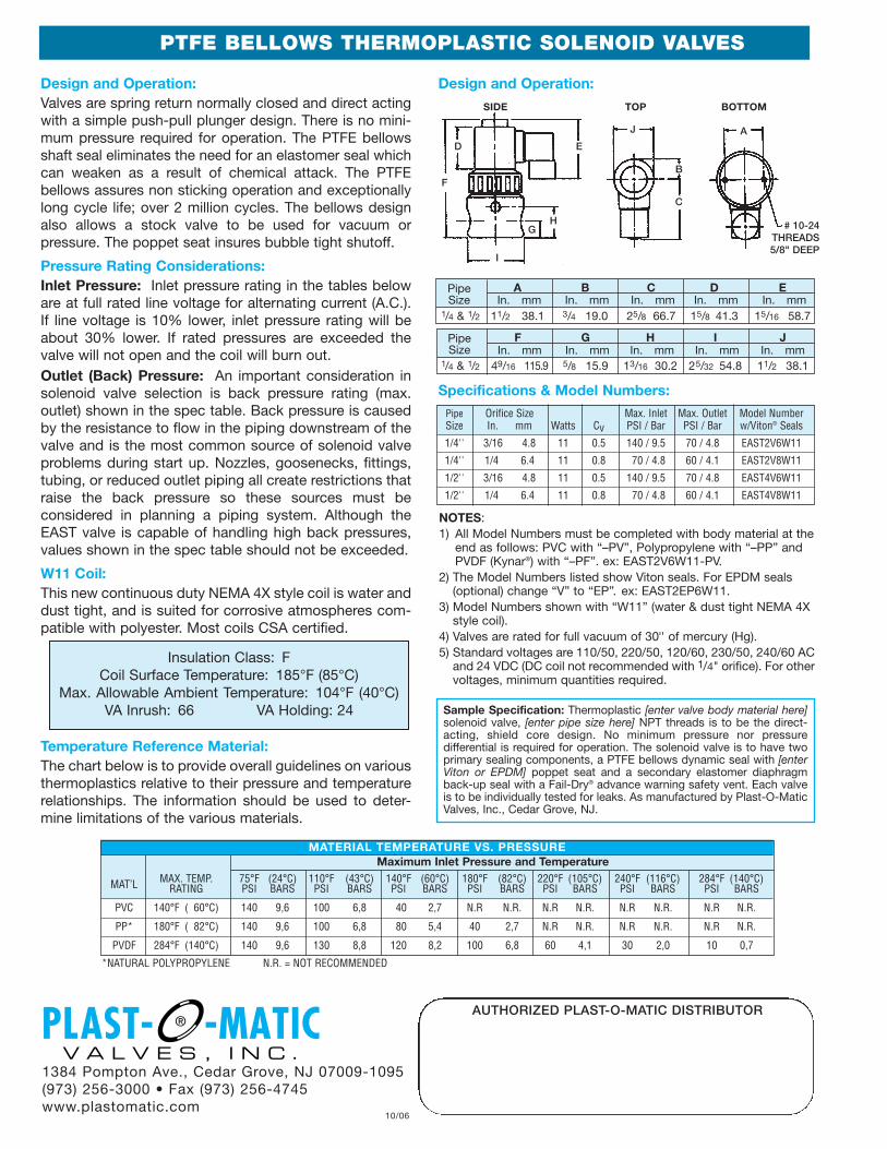
Pipe F G H I JSize In. mm In. mm In. mm In. mm In. mm
1/4 & 1/2 49/16 115.9 5/8 15.9 13/16 30.2 25/32 54.8 11/2 38.1
PTFE BELLOWS THERMOPLASTIC SOLENOID VALVES
Design and Operation:Valves are spring return normally closed and direct actingwith a simple push-pull plunger design. There is no mini-mum pressure required for operation. The PTFE bellowsshaft seal eliminates the need for an elastomer seal whichcan weaken as a result of chemical attack. The PTFEbellows assures non sticking operation and exceptionallylong cycle life; over 2 million cycles. The bellows designalso allows a stock valve to be used for vacuum orpressure. The poppet seat insures bubble tight shutoff.
Pressure Rating Considerations:Inlet Pressure: Inlet pressure rating in the tables beloware at full rated line voltage for alternating current (A.C.).If line voltage is 10% lower, inlet pressure rating will beabout 30% lower. If rated pressures are exceeded thevalve will not open and the coil will burn out. Outlet (Back) Pressure: An important consideration insolenoid valve selection is back pressure rating (max.outlet) shown in the spec table. Back pressure is causedby the resistance to flow in the piping downstream of thevalve and is the most common source of solenoid valveproblems during start up. Nozzles, goosenecks, fittings,tubing, or reduced outlet piping all create restrictions thatraise the back pressure so these sources must beconsidered in planning a piping system. Although theEAST valve is capable of handling high back pressures,values shown in the spec table should not be exceeded.
W11 Coil: This new continuous duty NEMA 4X style coil is water anddust tight, and is suited for corrosive atmospheres com-patible with polyester. Most coils CSA certified.
Temperature Reference Material:The chart below is to provide overall guidelines on variousthermoplastics relative to their pressure and temperaturerelationships. The information should be used to deter-mine limitations of the various materials.
1384 Pompton Ave., Cedar Grove, NJ 07009-1095(973) 256-3000 • Fax (973) 256-4745www.plastomatic.com
10/06
NOTES:1) All Model Numbers must be completed with body material at the
end as follows: PVC with “–PV”, Polypropylene with “–PP” andPVDF (Kynar®) with “–PF”. ex: EAST2V6W11-PV.
2) The Model Numbers listed show Viton seals. For EPDM seals(optional) change “V” to “EP”. ex: EAST2EP6W11.
3) Model Numbers shown with “W11” (water & dust tight NEMA 4Xstyle coil).
4) Valves are rated for full vacuum of 30'' of mercury (Hg). 5) Standard voltages are 110/50, 220/50, 120/60, 230/50, 240/60 AC
and 24 VDC (DC coil not recommended with 1/4" orifice). For othervoltages, minimum quantities required.
AUTHORIZED PLAST-O-MATIC DISTRIBUTOR
Insulation Class: FCoil Surface Temperature: 185°F (85°C)
Max. Allowable Ambient Temperature: 104°F (40°C)VA Inrush: 66 VA Holding: 24
*NATURAL POLYPROPYLENE N.R. = NOT RECOMMENDED
Pipe A B C D ESize In. mm In. mm In. mm In. mm In. mm
1/4 & 1/2 11/2 38.1 3/4 19.0 25/8 66.7 15/8 41.3 15/16 58.7
Pipe Orifice Size Max. Inlet Max. Outlet Model NumberSize In. mm Watts Cv PSI / Bar PSI / Bar w/Viton® Seals
1/4'' 3/16 4.8 11 0.5 140 / 9.5 70 / 4.8 EAST2V6W11
1/4'' 1/4 6.4 11 0.8 70 / 4.8 60 / 4.1 EAST2V8W11
1/2'' 3/16 4.8 11 0.5 140 / 9.5 70 / 4.8 EAST4V6W11
1/2'' 1/4 6.4 11 0.8 70 / 4.8 60 / 4.1 EAST4V8W11
Specifications & Model Numbers:
Design and Operation:
Sample Specification: Thermoplastic [enter valve body material here]solenoid valve, [enter pipe size here] NPT threads is to be the direct-acting, shield core design. No minimum pressure nor pressuredifferential is required for operation. The solenoid valve is to have twoprimary sealing components, a PTFE bellows dynamic seal with [enterViton or EPDM] poppet seat and a secondary elastomer diaphragmback-up seal with a Fail-Dry® advance warning safety vent. Each valveis to be individually tested for leaks. As manufactured by Plast-O-MaticValves, Inc., Cedar Grove, NJ.
SIDE TOP BOTTOM
D
F
I
G
E
J A
C
B
H # 10-24THREADS5/8" DEEP
MATERIAL TEMPERATURE VS. PRESSUREMaximum Inlet Pressure and Temperature
MAT’L MAX. TEMP. 75°F (24°C) 110°F (43°C) 140°F (60°C) 180°F (82°C) 220°F (105°C) 240°F (116°C) 284°F (140°C)RATING PSI BARS PSI BARS PSI BARS PSI BARS PSI BARS PSI BARS PSI BARS
PVC 140°F ( 60°C) 140 9,6 100 6,8 40 2,7 N.R N.R. N.R N.R. N.R N.R. N.R N.R.
PP* 180°F ( 82°C) 140 9,6 100 6,8 80 5,4 40 2,7 N.R N.R. N.R N.R. N.R N.R.
PVDF 284°F (140°C) 140 9,6 130 8,8 120 8,2 100 6,8 60 4,1 30 2,0 10 0,7

BWS-GL-02 Appendix67
67. BannerLevelSensor–T30UIPAQ
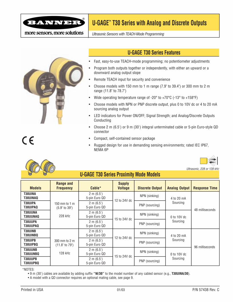
U-GAGE T30 Series Proximity Mode Models
U-GAGE™ T30 Series with Analog and Discrete OutputsUltrasonic Sensors with TEACH-Mode Programming
Printed in USA 01/03 P/N 57438 Rev. C
U-GAGE T30 Series Features• Fast, easy-to-use TEACH-mode programming; no potentiometer adjustments
• Program both outputs together or independently, with either an upward or adownward analog output slope
• Remote TEACH input for security and convenience
• Choose models with 150 mm to 1 m range (7.9" to 39.4") or 300 mm to 2 mrange (11.8" to 78.7")
• Wide operating temperature range of -20° to +70°C (-13° to +158°F)
• Choose models with NPN or PNP discrete output, plus 0 to 10V dc or 4 to 20 mAsourcing analog output
• LED indicators for Power ON/OFF; Signal Strength; and Analog/Discrete OutputsConducting
• Choose 2 m (6.5') or 9 m (30') integral unterminated cable or 5-pin Euro-style QDconnector
• Compact, self-contained sensor package
• Rugged design for use in demanding sensing environments; rated IEC IP67, NEMA 6P
*NOTES:• 9 m (30') cables are available by adding suffix “W/30” to the model number of any cabled sensor (e.g., T30UINA/30).• A model with a QD connector requires an optional mating cable, see page 9.
Ultrasonic, 228 or 128 kHz
ModelsRange andFrequency Cable*
SupplyVoltage Discrete Output Analog Output Response Time
T30UINAT30UINAQ
150 mm to 1 m(5.9" to 39")
228 kHz
2 m (6.5')5-pin Euro QD
12 to 24V dcNPN (sinking)
4 to 20 mASourcing
48 milliseconds
T30UIPAT30UIPAQ
2 m (6.5')5-pin Euro QD PNP (sourcing)
T30UUNAT30UUNAQ
2 m (6.5')5-pin Euro QD NPN (sinking)
0 to 10V dcSourcingT30UUPA
T30UUPAQ2 m (6.5')
5-pin Euro QD PNP (sourcing)
T30UINBT30UINBQ
300 mm to 2 m(11.8" to 79")
128 kHz
2 m (6.5')5-pin Euro QD NPN (sinking)
4 to 20 mASourcing
96 milliseconds
T30UIPBT30UIPBQ
2 m (6.5')5-pin Euro QD PNP (sourcing)
T30UUNBT30UUNBQ
2 m (6.5')5-pin Euro QD NPN (sinking)
0 to 10V dcSourcingT30UUPB
T30UUPBQ2 m (6.5')
5-pin Euro QD PNP (sourcing)15 to 24V dc
12 to 24V dc
15 to 24V dc
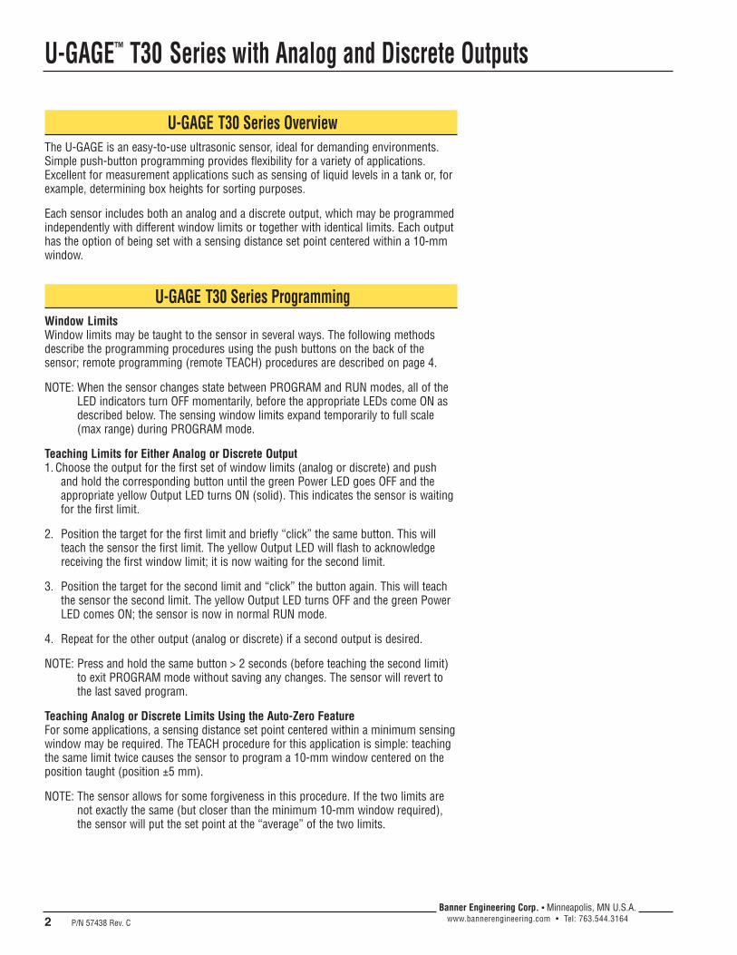
U-GAGE™ T30 Series with Analog and Discrete Outputs
2 P/N 57438 Rev. C
Banner Engineering Corp. • Minneapolis, MN U.S.A.www.bannerengineering.com • Tel: 763.544.3164
U-GAGE T30 Series OverviewThe U-GAGE is an easy-to-use ultrasonic sensor, ideal for demanding environments.Simple push-button programming provides flexibility for a variety of applications.Excellent for measurement applications such as sensing of liquid levels in a tank or, forexample, determining box heights for sorting purposes.
Each sensor includes both an analog and a discrete output, which may be programmedindependently with different window limits or together with identical limits. Each outputhas the option of being set with a sensing distance set point centered within a 10-mmwindow.
U-GAGE T30 Series ProgrammingWindow LimitsWindow limits may be taught to the sensor in several ways. The following methodsdescribe the programming procedures using the push buttons on the back of thesensor; remote programming (remote TEACH) procedures are described on page 4.
NOTE: When the sensor changes state between PROGRAM and RUN modes, all of theLED indicators turn OFF momentarily, before the appropriate LEDs come ON asdescribed below. The sensing window limits expand temporarily to full scale(max range) during PROGRAM mode.
Teaching Limits for Either Analog or Discrete Output1. Choose the output for the first set of window limits (analog or discrete) and push
and hold the corresponding button until the green Power LED goes OFF and theappropriate yellow Output LED turns ON (solid). This indicates the sensor is waitingfor the first limit.
2. Position the target for the first limit and briefly “click” the same button. This willteach the sensor the first limit. The yellow Output LED will flash to acknowledgereceiving the first window limit; it is now waiting for the second limit.
3. Position the target for the second limit and “click” the button again. This will teachthe sensor the second limit. The yellow Output LED turns OFF and the green PowerLED comes ON; the sensor is now in normal RUN mode.
4. Repeat for the other output (analog or discrete) if a second output is desired.
NOTE: Press and hold the same button > 2 seconds (before teaching the second limit)to exit PROGRAM mode without saving any changes. The sensor will revert tothe last saved program.
Teaching Analog or Discrete Limits Using the Auto-Zero FeatureFor some applications, a sensing distance set point centered within a minimum sensingwindow may be required. The TEACH procedure for this application is simple: teachingthe same limit twice causes the sensor to program a 10-mm window centered on theposition taught (position ±5 mm).
NOTE: The sensor allows for some forgiveness in this procedure. If the two limits arenot exactly the same (but closer than the minimum 10-mm window required),the sensor will put the set point at the “average” of the two limits.
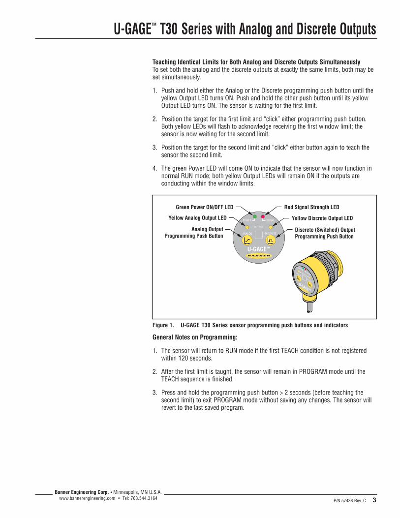
U-GAGE™ T30 Series with Analog and Discrete Outputs
P/N 57438 Rev. C 3Banner Engineering Corp. • Minneapolis, MN U.S.A.
www.bannerengineering.com • Tel: 763.544.3164
Teaching Identical Limits for Both Analog and Discrete Outputs SimultaneouslyTo set both the analog and the discrete outputs at exactly the same limits, both may beset simultaneously.
1. Push and hold either the Analog or the Discrete programming push button until theyellow Output LED turns ON. Push and hold the other push button until its yellowOutput LED turns ON. The sensor is waiting for the first limit.
2. Position the target for the first limit and “click” either programming push button.Both yellow LEDs will flash to acknowledge receiving the first window limit; thesensor is now waiting for the second limit.
3. Position the target for the second limit and “click” either button again to teach thesensor the second limit.
4. The green Power LED will come ON to indicate that the sensor will now function innormal RUN mode; both yellow Output LEDs will remain ON if the outputs areconducting within the window limits.
U-GAGE™
ANALOG
POWER
SIGNALOUTPUT
DISCRETE
U-GAGE™
ANALOG
POWER SIGNAL
OUTPUT
DISCRETE
Green Power ON/OFF LED
Yellow Analog Output LED
Red Signal Strength LED
Analog OutputProgramming Push Button
Yellow Discrete Output LED
Discrete (Switched) OutputProgramming Push Button
Figure 1. U-GAGE T30 Series sensor programming push buttons and indicators
General Notes on Programming:
1. The sensor will return to RUN mode if the first TEACH condition is not registeredwithin 120 seconds.
2. After the first limit is taught, the sensor will remain in PROGRAM mode until theTEACH sequence is finished.
3. Press and hold the programming push button > 2 seconds (before teaching thesecond limit) to exit PROGRAM mode without saving any changes. The sensor willrevert to the last saved program.
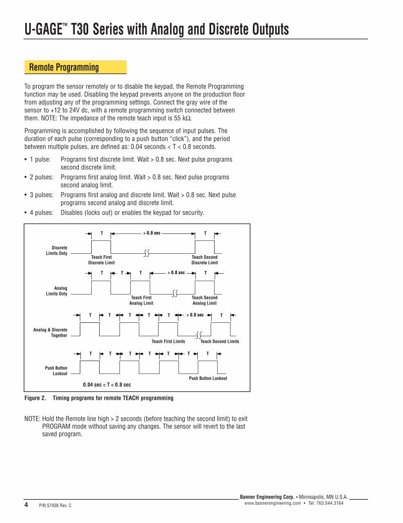
U-GAGE™ T30 Series with Analog and Discrete Outputs
4 P/N 57438 Rev. C
Banner Engineering Corp. • Minneapolis, MN U.S.A.www.bannerengineering.com • Tel: 763.544.3164
Figure 2. Timing programs for remote TEACH programming
Teach FirstDiscrete Limit
DiscreteLimits Only
Teach SecondDiscrete Limit
Teach FirstAnalog Limit
Teach First Limits Teach Second Limits
Push Button Lockout
AnalogLimits Only
Teach SecondAnalog Limit
Analog & DiscreteTogether
Push ButtonLockout
T > 0.8 sec
> 0.8 secT T
T T TT
T T TT
T TT
T > 0.8 sec T
T T
T
0.04 sec < T < 0.8 sec
Remote Programming
To program the sensor remotely or to disable the keypad, the Remote Programmingfunction may be used. Disabling the keypad prevents anyone on the production floorfrom adjusting any of the programming settings. Connect the gray wire of the sensor to +12 to 24V dc, with a remote programming switch connected betweenthem. NOTE: The impedance of the remote teach input is 55 kΩ.
Programming is accomplished by following the sequence of input pulses. Theduration of each pulse (corresponding to a push button “click”), and the periodbetween multiple pulses, are defined as: 0.04 seconds < T < 0.8 seconds.
• 1 pulse: Programs first discrete limit. Wait > 0.8 sec. Next pulse programssecond discrete limit.
• 2 pulses: Programs first analog limit. Wait > 0.8 sec. Next pulse programs second analog limit.
• 3 pulses: Programs first analog and discrete limit. Wait > 0.8 sec. Next pulseprograms second analog and discrete limit.
• 4 pulses: Disables (locks out) or enables the keypad for security.
NOTE: Hold the Remote line high > 2 seconds (before teaching the second limit) to exitPROGRAM mode without saving any changes. The sensor will revert to the lastsaved program.
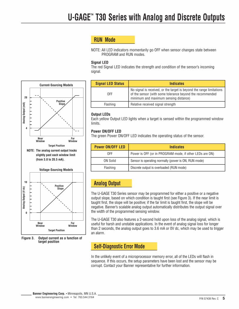
U-GAGE™ T30 Series with Analog and Discrete Outputs
P/N 57438 Rev. C 5Banner Engineering Corp. • Minneapolis, MN U.S.A.
www.bannerengineering.com • Tel: 763.544.3164
RUN Mode
NOTE: All LED indicators momentarily go OFF when sensor changes state betweenPROGRAM and RUN modes.
Signal LEDThe red Signal LED indicates the strength and condition of the sensor’s incomingsignal.
Signal LED Status Indicates
OFFNo signal is received, or the target is beyond the range limitationsof the sensor (with some tolerance beyond the recommendedminimum and maximum sensing distance)
Flashing Relative received signal strength
Power ON/OFF LED Indicates
OFF Power is OFF (or in PROGRAM mode, if other LEDs are ON)
ON Solid Sensor is operating normally (power is ON, RUN mode)
Output LEDsEach yellow Output LED lights when a target is sensed within the programmed windowlimits.
Power ON/OFF LEDThe green Power ON/OFF LED indicates the operating status of the sensor.
Analog Output
The U-GAGE T30 Series sensor may be programmed for either a positive or a negativeoutput slope, based on which condition is taught first (see Figure 3). If the near limit istaught first, the slope will be positive; if the far limit is taught first, the slope will benegative. Banner’s scalable analog output automatically distributes the output signal overthe width of the programmed sensing window.
The U-GAGE T30 also features a 2-second hold upon loss of the analog signal, which isuseful for harsh and unstable applications. In the event of analog signal loss for longerthan 2 seconds, the analog output goes to 3.6 mA or 0V dc, which may be used to triggeran alarm.
Self-Diagnostic Error Mode
In the unlikely event of a microprocessor memory error, all of the LEDs will flash insequence. If this occurs, the setup parameters have been lost and the sensor may becorrupt. Contact your Banner representative for further information.
0
NearWindow
FarWindow
10
Target Position
Anal
og O
utpu
t (V
dc) Positive
Slope
Voltage-Sourcing Models
Figure 3. Output current as a function oftarget position
NOTE: The analog current output tracksslightly past each window limit(from 3.8 to 20.5 mA).
4
NearWindow
FarWindow
20
Target Position
Anal
og O
utpu
t (m
A)
PositiveSlope
Current-Sourcing Models
Flashing Discrete output is overloaded (RUN mode)
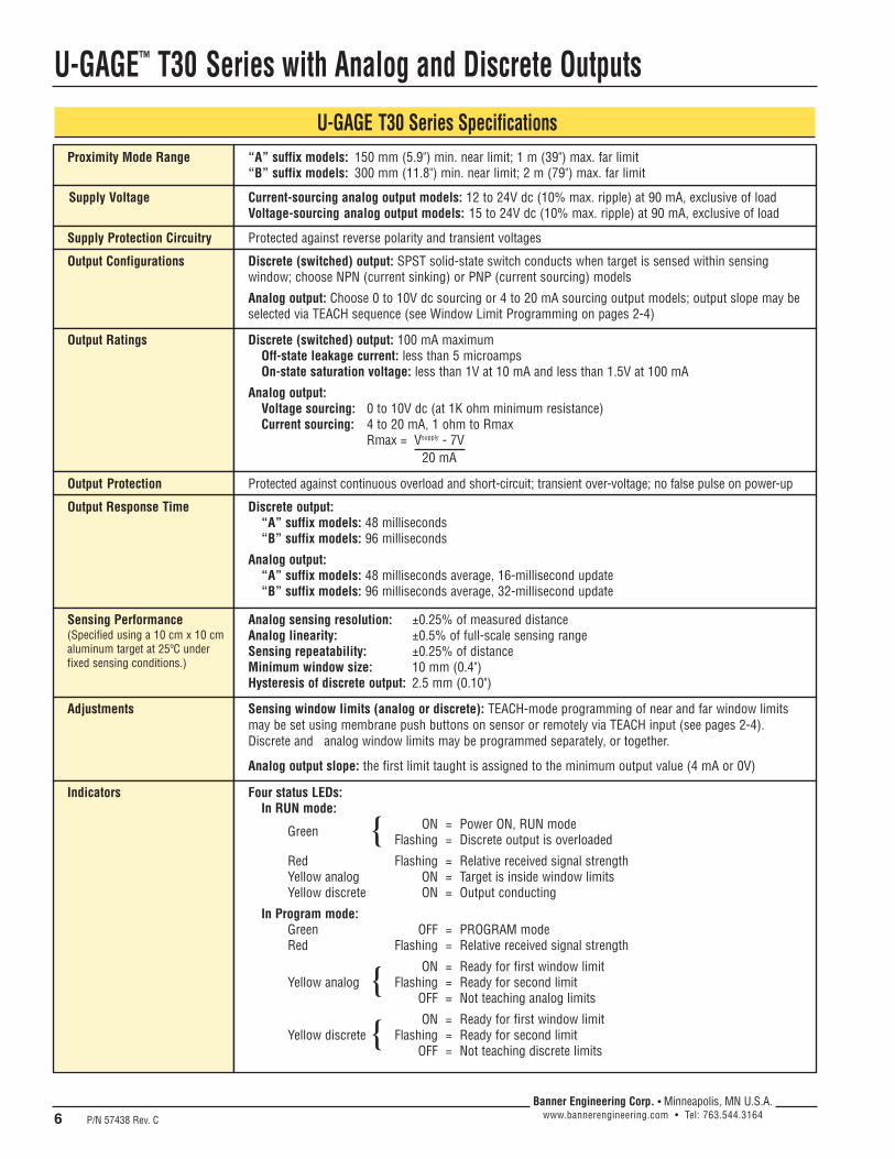
U-GAGE™ T30 Series with Analog and Discrete Outputs
6 P/N 57438 Rev. C
Banner Engineering Corp. • Minneapolis, MN U.S.A.www.bannerengineering.com • Tel: 763.544.3164
U-GAGE T30 Series SpecificationsProximity Mode Range
Supply Voltage Current-sourcing analog output models: 12 to 24V dc (10% max. ripple) at 90 mA, exclusive of loadVoltage-sourcing analog output models: 15 to 24V dc (10% max. ripple) at 90 mA, exclusive of load
Supply Protection Circuitry Protected against reverse polarity and transient voltages
Output Configurations Discrete (switched) output: SPST solid-state switch conducts when target is sensed within sensingwindow; choose NPN (current sinking) or PNP (current sourcing) modelsAnalog output: Choose 0 to 10V dc sourcing or 4 to 20 mA sourcing output models; output slope may beselected via TEACH sequence (see Window Limit Programming on pages 2-4)
Output Ratings Discrete (switched) output: 100 mA maximumOff-state leakage current: less than 5 microampsOn-state saturation voltage: less than 1V at 10 mA and less than 1.5V at 100 mA
Analog output: Voltage sourcing: 0 to 10V dc (at 1K ohm minimum resistance)Current sourcing: 4 to 20 mA, 1 ohm to Rmax
Rmax = Vsupply - 7V20 mA
Output Response Time Discrete output:“A” suffix models: 48 milliseconds“B” suffix models: 96 milliseconds
Analog output: “A” suffix models: 48 milliseconds average, 16-millisecond update“B” suffix models: 96 milliseconds average, 32-millisecond update
Sensing Performance(Specified using a 10 cm x 10 cmaluminum target at 25ºC underfixed sensing conditions.)
Analog sensing resolution: ±0.25% of measured distanceAnalog linearity: ±0.5% of full-scale sensing rangeSensing repeatability: ±0.25% of distanceMinimum window size: 10 mm (0.4")Hysteresis of discrete output: 2.5 mm (0.10")
Adjustments Sensing window limits (analog or discrete): TEACH-mode programming of near and far window limitsmay be set using membrane push buttons on sensor or remotely via TEACH input (see pages 2-4).Discrete and analog window limits may be programmed separately, or together.
Analog output slope: the first limit taught is assigned to the minimum output value (4 mA or 0V)
“A” suffix models: 150 mm (5.9") min. near limit; 1 m (39") max. far limit“B” suffix models: 300 mm (11.8") min. near limit; 2 m (79") max. far limit
Output Protection Protected against continuous overload and short-circuit; transient over-voltage; no false pulse on power-up
Indicators Four status LEDs:In RUN mode:
Green ON = Power ON, RUN modeFlashing = Discrete output is overloaded
Red Flashing = Relative received signal strengthYellow analog ON = Target is inside window limitsYellow discrete ON = Output conducting
In Program mode: Green OFF = PROGRAM modeRed Flashing = Relative received signal strength
ON = Ready for first window limitYellow analog Flashing = Ready for second limit
OFF = Not teaching analog limitsON = Ready for first window limit
Yellow discrete Flashing = Ready for second limitOFF = Not teaching discrete limits
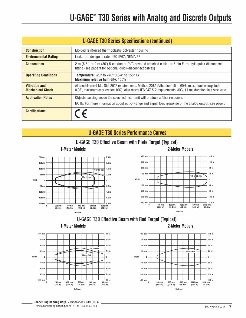
U-GAGE™ T30 Series with Analog and Discrete Outputs
P/N 57438 Rev. C 7Banner Engineering Corp. • Minneapolis, MN U.S.A.
www.bannerengineering.com • Tel: 763.544.3164
U-GAGE T30 Series Specifications (continued)Construction
Environmental Rating Leakproof design is rated IEC IP67; NEMA 6P
Molded reinforced thermoplastic polyester housing
Vibration andMechanical Shock
All models meet Mil. Std. 202F requirements. Method 201A (Vibration: 10 to 60Hz max., double amplitude0.06", maximum acceleration 10G). Also meets IEC 947-5-2 requirements: 30G, 11 ms duration, half sine wave.
Operating Conditions Temperature: -20° to +70° C (-4° to 158° F)Maximum relative humidity: 100%
Application Notes Objects passing inside the specified near limit will produce a false response.NOTE: For more information about out-of-range and signal loss response of the analog output, see page 5.
Connections 2 m (6.5') or 9 m (30') 5-conductor PVC-covered attached cable, or 5-pin Euro-style quick-disconnectfitting (see page 9 for optional quick-disconnect cables)
U-GAGE T30 Series Performance CurvesU-GAGE T30 Effective Beam with Plate Target (Typical)
1-Meter Models 2-Meter Models
U-GAGE T30 Effective Beam with Rod Target (Typical)1-Meter Models 2-Meter Models
0
0 200 mm(8.0 in)
400 mm(16.0 in)
600 mm(24.0 in)
800 mm(32.0 in)
1000 mm(40.0 in)
50 mm
50 mm
100 mm
100 mm
150 mm
150 mm
200 mm
200 mm
0
2.0 in
2.0 in
4.0 in
4.0 in
6.0 in
6.0 in
8.0 in
8.0 in
100 x 100 mm
10 x 10 mmWidth
Distance
0
0 400 mm(16.0 in)
800 mm(32.0 in)
1200 mm(48.0 in)
1600 mm(64.0 in)
2000 mm(80.0 in)
100 mm
100 mm
200 mm
200 mm
300 mm
300 mm
400 mm
400 mm
0
4.0 in
4.0 in
8.0 in
8.0 in
12.0 in
12.0 in
16.0 in
16.0 in
100 x 100 mm
Width
Distance
0
0 200 mm(8.0 in)
400 mm(16.0 in)
600 mm(24.0 in)
800 mm(32.0 in)
1000 mm(40.0 in)
50 mm
50 mm
100 mm
100 mm
150 mm
150 mm
200 mm
200 mm
0
2.0 in
2.0 in
4.0 in
4.0 in
6.0 in
6.0 in
8.0 in
8.0 in
25 mm Rod
10 mm RodWidth
Distance
0
0 400 mm(16.0 in)
800 mm(32.0 in)
1200 mm(48.0 in)
1600 mm(64.0 in)
2000 mm(80.0 in)
100 mm
100 mm
200 mm
200 mm
300 mm
300 mm
400 mm
400 mm
0
4.0 in
4.0 in
8.0 in
8.0 in
12.0 in
12.0 in
16.0 in
16.0 in
25 mm Rod
Width
Distance
Certifications
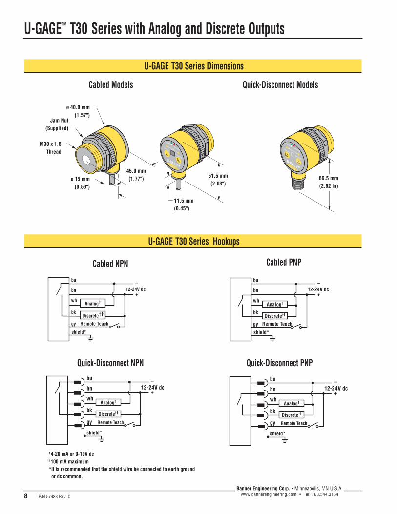
U-GAGE™ T30 Series with Analog and Discrete Outputs
8 P/N 57438 Rev. C
Banner Engineering Corp. • Minneapolis, MN U.S.A.www.bannerengineering.com • Tel: 763.544.3164
Jam Nut(Supplied)
11.5 mm(0.45")
M30 x 1.5Thread
ø 15 mm(0.59")
ø 40.0 mm(1.57")
45.0 mm(1.77") 51.5 mm
(2.03")66.5 mm(2.62 in)
U-GAGE T30 Series Dimensions
Cabled Models Quick-Disconnect Models
U-GAGE T30 Series Hookups
12-24V dc–
+
Remote Teach
bu
wh
bk
bn
gy
Analog†
Discrete††
shield*
Cabled NPN
12-24V dc–
+
Remote Teach
bu
wh
bk
bn
gy
Analog†
Discrete††
shield*
12-24V dc–
+
Remote Teach
bu
wh
bk
bn
gy
Analog†
Discrete††
shield*
12-24V dc–
+
Remote Teach
bu
wh
bk
bn
gy
Analog†
Discrete††
shield*
Cabled PNP
Quick-Disconnect NPN Quick-Disconnect PNP
† 4-20 mA or 0-10V dc†† 100 mA maximum*It is recommended that the shield wire be connected to earth groundor dc common.
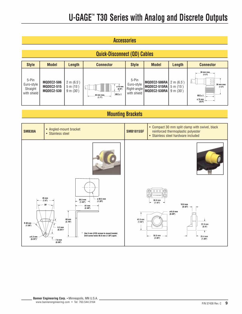
U-GAGE™ T30 Series with Analog and Discrete Outputs
P/N 57438 Rev. C 9Banner Engineering Corp. • Minneapolis, MN U.S.A.
www.bannerengineering.com • Tel: 763.544.3164
Quick-Disconnect (QD) Cables
Accessories
5-Pin Euro-style
Right-anglewith shield
5-Pin Euro-styleStraight
with shield
MQDEC2-506MQDEC2-515MQDEC2-530
2 m (6.5')5 m (15')9 m (30')
Style Model Length Connector
MQDEC2-506RAMQDEC2-515RAMQDEC2-530RA
2 m (6.5')5 m (15')9 m (30')
Style Model
M12 x 1
ø 15 mm(0.6")
44 mm max.(1.7")
Length Connector
38 mm max.(1.5")
M12 x 1
ø 15 mm(0.6")
38 mm max.(1.5")
Mounting Brackets
SMB30A • Angled-mount bracket• Stainless steel SMB1815SF
• Compact 30 mm split clamp with swivel, blackreinforced thermoplastic polyester
• Stainless steel hardware included
ø 30.5 mm(1.20")
38.5 mm(1.52")
61 mm(2.40")
69 mm(2.70")
30°
45 mm(1.8")
R 40 mm(1.58")
ø 6.3 mm(0.25")*
6.3 mm(0.25")*
* Use 5 mm (#10) screws to mount bracket.Drill screw holes 40.0 mm (1.58") apart.
7.6 mm(0.30")
36.0 mm(1.42")
50.8 mm(2.00")
42.0 mm(1.65")
22.9 mm(0.9")
25.4 mm(1.00")
10.6 mm(0.42")
ø15.0 mm(0.59")
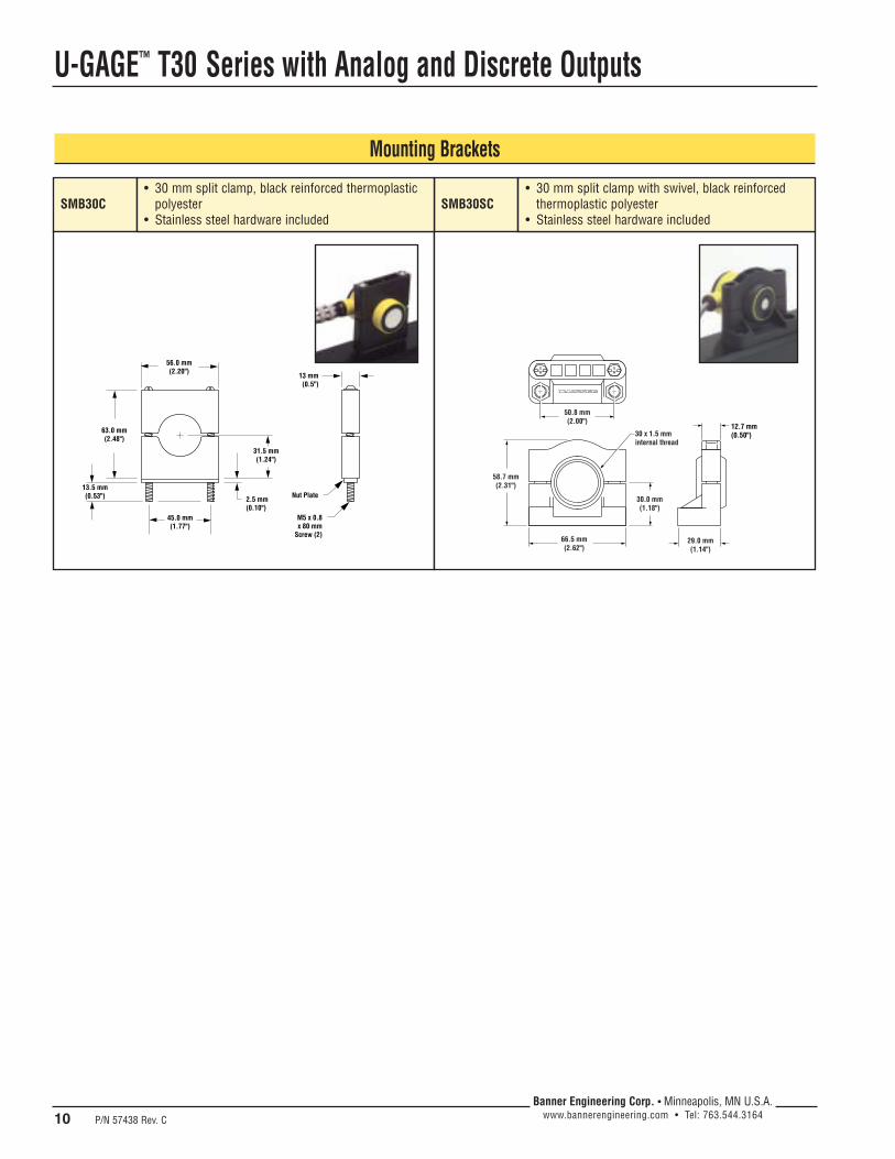
U-GAGE™ T30 Series with Analog and Discrete Outputs
10 P/N 57438 Rev. C
Banner Engineering Corp. • Minneapolis, MN U.S.A.www.bannerengineering.com • Tel: 763.544.3164
SMB30C SMB30SC
56.0 mm(2.20")
63.0 mm(2.48")
45.0 mm(1.77")
2.5 mm(0.10")
31.5 mm(1.24")
Nut Plate
M5 x 0.8x 80 mm
Screw (2)
13 mm(0.5")
13.5 mm(0.53")
50.8 mm(2.00")
58.7 mm(2.31")
66.5 mm(2.62")
30.0 mm(1.18")
30 x 1.5 mminternal thread
29.0 mm(1.14")
12.7 mm(0.50")
• 30 mm split clamp with swivel, black reinforcedthermoplastic polyester
• Stainless steel hardware included
• 30 mm split clamp, black reinforced thermoplasticpolyester
• Stainless steel hardware included
Mounting Brackets

U-GAGE™ T30 Series with Analog and Discrete Outputs
P/N 57438 Rev. C 11Banner Engineering Corp. • Minneapolis, MN U.S.A.
www.bannerengineering.com • Tel: 763.544.3164

U-GAGE™ T30 Series with Analog and Discrete Outputs
Banner Engineering Corp., 9714 Tenth Ave. No., Mpls, MN 55441 • Ph: 763.544.3164 • www.bannerengineering.com • [email protected]
WARRANTY: Banner Engineering Corp. warrants its products to be free from defects for one year. Banner Engineering Corp. will repair orreplace, free of charge, any product of its manufacture found to be defective at the time it is returned to the factory during the warranty period.This warranty does not cover damage or liability for the improper application of Banner products. This warranty is in lieu of any other warrantyeither expressed or implied.
WARNING . . . Not To Be Used for Personnel ProtectionNever use these products as sensing devices for personnel protection. Doing so could lead to serious injury or death.
These sensors do NOT include the self-checking redundant circuitry necessary to allow their use in personnel safety applications.A sensor failure or malfunction can cause either an energized or de-energized sensor output condition. Consult your current Banner SafetyProducts catalog for safety products which meet OSHA, ANSI and IEC standards for personnel protection.
!
P/N 57438 Rev. C

BWS-GL-02 Appendix68
68. ColderMale/FemaleTankFitting:NSHD24012/NSHD17012
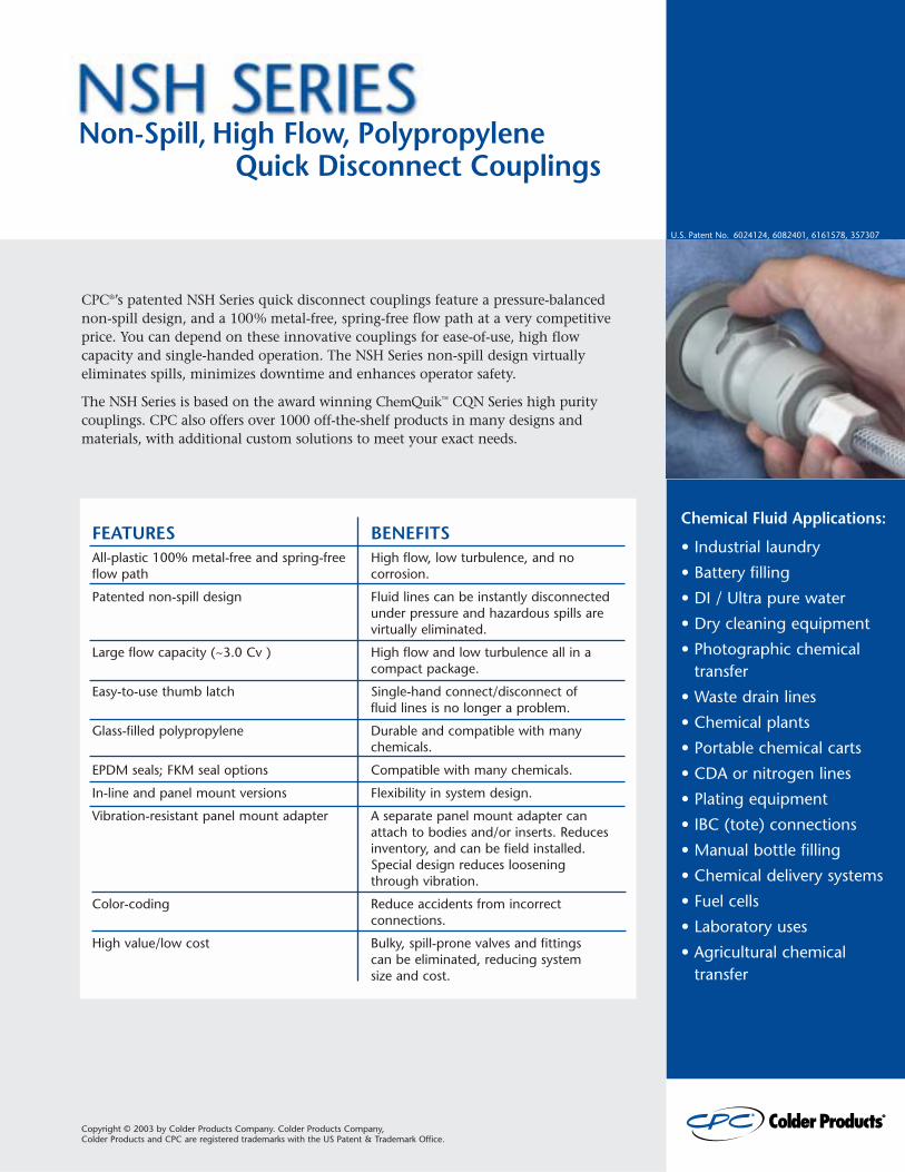
Non-Spill, High Flow, Polypropylene Quick Disconnect Couplings
CPC®’s patented NSH Series quick disconnect couplings feature a pressure-balanced non-spill design, and a 100% metal-free, spring-free flow path at a very competitiveprice. You can depend on these innovative couplings for ease-of-use, high flowcapacity and single-handed operation. The NSH Series non-spill design virtuallyeliminates spills, minimizes downtime and enhances operator safety.
The NSH Series is based on the award winning ChemQuik™ CQN Series high puritycouplings. CPC also offers over 1000 off-the-shelf products in many designs andmaterials, with additional custom solutions to meet your exact needs.
FEATURES BENEFITSAll-plastic 100% metal-free and spring-free High flow, low turbulence, and no flow path corrosion.
Patented non-spill design Fluid lines can be instantly disconnectedunder pressure and hazardous spills arevirtually eliminated.
Large flow capacity (~3.0 Cv ) High flow and low turbulence all in acompact package.
Easy-to-use thumb latch Single-hand connect/disconnect of fluid lines is no longer a problem.
Glass-filled polypropylene Durable and compatible with many chemicals.
EPDM seals; FKM seal options Compatible with many chemicals.
In-line and panel mount versions Flexibility in system design.
Vibration-resistant panel mount adapter A separate panel mount adapter canattach to bodies and/or inserts. Reducesinventory, and can be field installed.Special design reduces loosening through vibration.
Color-coding Reduce accidents from incorrectconnections.
High value/low cost Bulky, spill-prone valves and fittings can be eliminated, reducing system size and cost.
Chemical Fluid Applications:
• Industrial laundry• Battery filling• DI / Ultra pure water• Dry cleaning equipment• Photographic chemical
transfer• Waste drain lines• Chemical plants• Portable chemical carts• CDA or nitrogen lines• Plating equipment• IBC (tote) connections• Manual bottle filling• Chemical delivery systems• Fuel cells• Laboratory uses• Agricultural chemical
transfer
U.S. Patent No. 6024124, 6082401, 6161578, 357307
Copyright © 2003 by Colder Products Company. Colder Products Company, Colder Products and CPC are registered trademarks with the US Patent & Trademark Office.
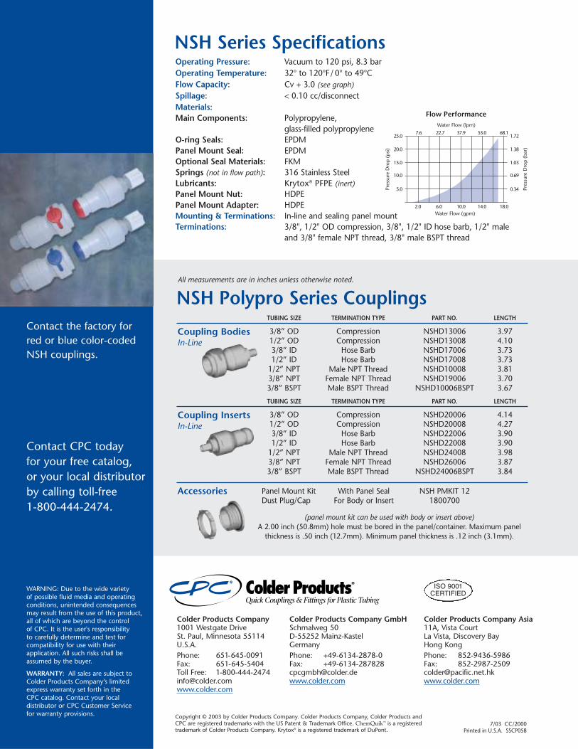
Contact CPC today for your free catalog, or your local distributorby calling toll-free 1-800-444-2474.
WARNING: Due to the wide variety of possible fluid media and operatingconditions, unintended consequencesmay result from the use of this product,all of which are beyond the control of CPC. It is the user's responsibility to carefully determine and test forcompatibility for use with theirapplication. All such risks shall beassumed by the buyer.
WARRANTY: All sales are subject toColder Products Company’s limitedexpress warranty set forth in the CPC catalog. Contact your localdistributor or CPC Customer Service for warranty provisions.
Contact the factory forred or blue color-codedNSH couplings.
Panel Mount Kit With Panel Seal NSH PMKIT 12 Dust Plug/Cap For Body or Insert 1800700
Accessories
Coupling BodiesIn-Line
TUBING SIZE TERMINATION TYPE PART NO. LENGTH
3/8” OD Compression NSHD13006 3.971/2” OD Compression NSHD13008 4.103/8” ID Hose Barb NSHD17006 3.731/2” ID Hose Barb NSHD17008 3.73
1/2” NPT Male NPT Thread NSHD10008 3.81 3/8” NPT Female NPT Thread NSHD19006 3.703/8” BSPT Male BSPT Thread NSHD10006BSPT 3.67
Coupling InsertsIn-Line
(panel mount kit can be used with body or insert above)A 2.00 inch (50.8mm) hole must be bored in the panel/container. Maximum panel
thickness is .50 inch (12.7mm). Minimum panel thickness is .12 inch (3.1mm).
NSH Series SpecificationsOperating Pressure: Vacuum to 120 psi, 8.3 barOperating Temperature: 32° to 120°F/ 0° to 49°CFlow Capacity: Cv + 3.0 (see graph)Spillage: < 0.10 cc/disconnect Materials:Main Components: Polypropylene,
glass-filled polypropyleneO-ring Seals: EPDMPanel Mount Seal: EPDMOptional Seal Materials: FKMSprings (not in flow path): 316 Stainless SteelLubricants: Krytox® PFPE (inert)Panel Mount Nut: HDPEPanel Mount Adapter: HDPEMounting & Terminations: In-line and sealing panel mountTerminations: 3/8", 1/2" OD compression, 3/8", 1/2" ID hose barb, 1/2" male
and 3/8" female NPT thread, 3/8" male BSPT thread
5.0
7.6 22.7Water Flow (lpm)
Water Flow (gpm)
Pres
sure
Dro
p (p
si)
Pres
sure
Dro
p (b
ar)
Flow Performance
37.9 53.0 68.1
2.0 6.0 10.0 14.0 18.0
10.0
15.0
20.0
25.0
0.34
0.69
1.03
1.38
1.72
NSH Polypro Series CouplingsAll measurements are in inches unless otherwise noted.
TUBING SIZE TERMINATION TYPE PART NO. LENGTH
3/8” OD Compression NSHD20006 4.141/2” OD Compression NSHD20008 4.273/8” ID Hose Barb NSHD22006 3.901/2” ID Hose Barb NSHD22008 3.90
1/2” NPT Male NPT Thread NSHD24008 3.983/8” NPT Female NPT Thread NSHD26006 3.873/8” BSPT Male BSPT Thread NSHD24006BSPT 3.84
Colder Products Company1001 Westgate DriveSt. Paul, Minnesota 55114U.S.A.Phone: 651-645-0091Fax: 651-645-5404Toll Free: [email protected]
Colder Products Company GmbHSchmalweg 50D-55252 Mainz-KastelGermanyPhone: +49-6134-2878-0Fax: [email protected]
Colder Products Company Asia11A, Vista CourtLa Vista, Discovery BayHong KongPhone: 852-9436-5986Fax: [email protected]
ISO 9001CERTIFIED
Copyright © 2003 by Colder Products Company. Colder Products Company, Colder Products andCPC are registered trademarks with the US Patent & Trademark Office. ChemQuik™ is a registeredtrademark of Colder Products Company. Krytox® is a registered trademark of DuPont.
7/03 CC/2000Printed in U.S.A. SSCP058

BWS-GL-02 Appendix69
69. DoubleContainedPolyethelyneChemicalTank,20Gallon
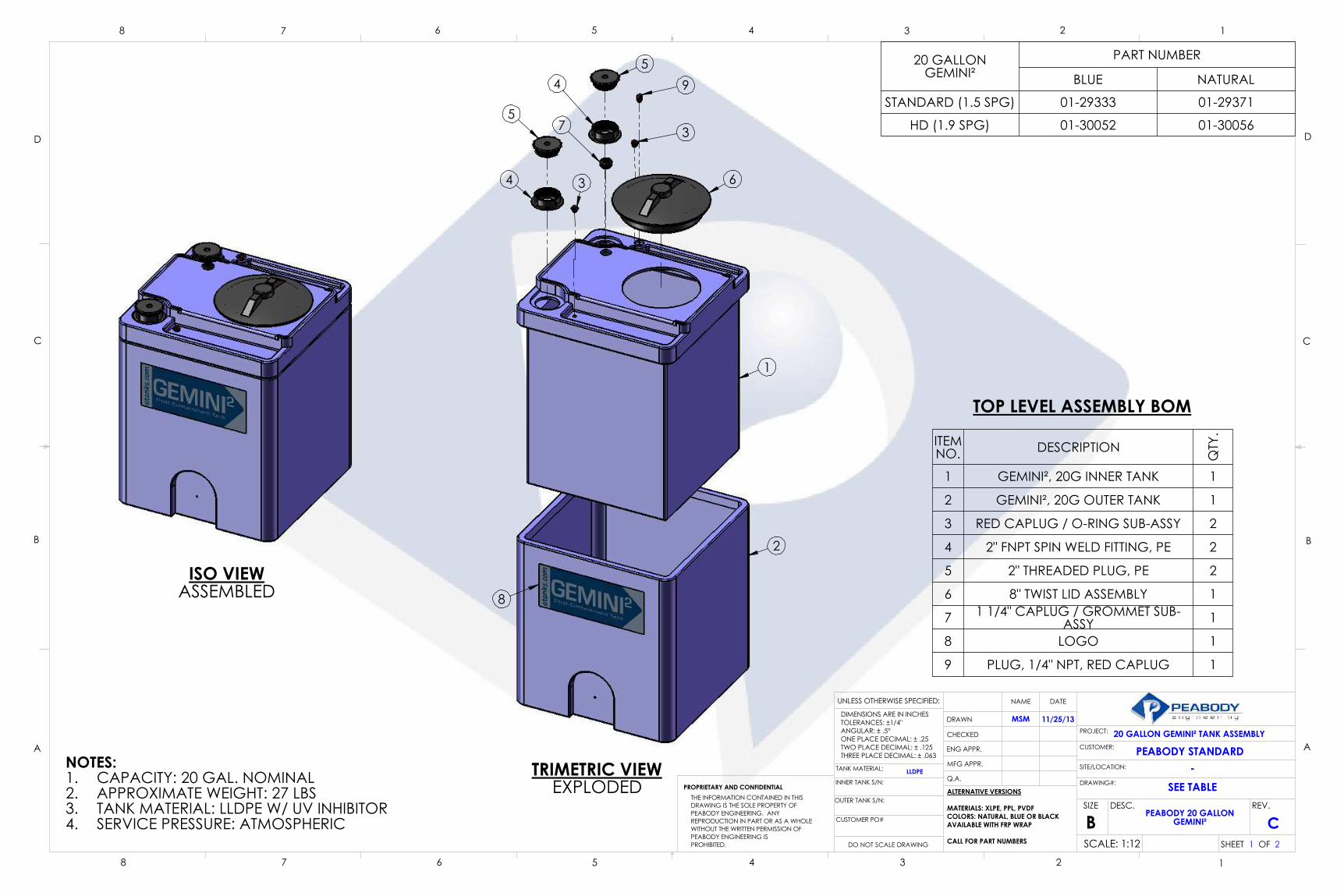
ITEM NO. DESCRIPTION
QTY
.
1 GEMINI², 20G INNER TANK 1
2 GEMINI², 20G OUTER TANK 1
3 RED CAPLUG / O-RING SUB-ASSY 2
4 2" FNPT SPIN WELD FITTING, PE 2
5 2" THREADED PLUG, PE 2
6 8" TWIST LID ASSEMBLY 1
7 1 1/4" CAPLUG / GROMMET SUB-ASSY 1
8 LOGO 1
9 PLUG, 1/4" NPT, RED CAPLUG 1
TRIMETRIC VIEWEXPLODED
TOP LEVEL ASSEMBLY BOM
20 GALLONGEMINI²
PART NUMBER
BLUE NATURAL
STANDARD (1.5 SPG) 01-29333 01-29371
HD (1.9 SPG) 01-30052 01-30056
2
C
MSM 11/25/13
LLDPE
20 GALLON GEMINI² TANK ASSEMBLY
PEABODY STANDARD-
1
GEMINI²PEABODY 20 GALLON
SEE TABLEDRAWING#:
D
C
B
AA
B
C
D
12345678
8 7 6 5 4 3 2 1
AVAILABLE WITH FRP WRAP
THE INFORMATION CONTAINED IN THISALTERNATIVE VERSIONS
MATERIALS: XLPE, PPL, PVDFCOLORS: NATURAL, BLUE OR BLACK
PROHIBITED.
PROPRIETARY AND CONFIDENTIAL
PEABODY ENGINEERING IS WITHOUT THE WRITTEN PERMISSION OFREPRODUCTION IN PART OR AS A WHOLEPEABODY ENGINEERING. ANY DRAWING IS THE SOLE PROPERTY OF
THREE PLACE DECIMAL: ± .063
TANK MATERIAL:
CUSTOMER PO#
DRAWN
CHECKED
ENG APPR.
MFG APPR.
Q.A.
DIMENSIONS ARE IN INCHES
TWO PLACE DECIMAL: ± .125ONE PLACE DECIMAL: ± .25ANGULAR: ± .5°TOLERANCES: ±1/4"
CALL FOR PART NUMBERS
DATENAME
BSCALE: 1:12
UNLESS OTHERWISE SPECIFIED:
DO NOT SCALE DRAWING
PROJECT:
DESC.SIZE REV.
CUSTOMER:
SITE/LOCATION:
SHEET OF
INNER TANK S/N:
OUTER TANK S/N:
NOTES:CAPACITY: 20 GAL. NOMINAL1.APPROXIMATE WEIGHT: 27 LBS2.TANK MATERIAL: LLDPE W/ UV INHIBITOR3.SERVICE PRESSURE: ATMOSPHERIC4.
ISO VIEWASSEMBLED 8
1
6
5
4
54
3
3
7
2
9
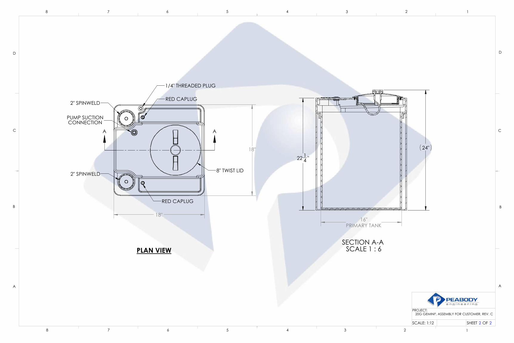
PLAN VIEW
2 2
PROJECT:
D
C
B
AA
B
C
D
12345678
8 7 6 5 4 3 2 1
SCALE: 1:12
20G GEMINI², ASSEMBLY FOR CUSTOMER, REV. C
SHEET OF
RED CAPLUG
2" SPINWELD
8" TWIST LID2" SPINWELD
CONNECTION
RED CAPLUG
PUMP SUCTION
1/4" THREADED PLUG
18"
18"
A A
SECTION A-A SCALE 1 : 6
16"PRIMARY TANK
24"
22 14 "

INFORMATION HANDOUT For Contract No. 02-4G6204
At 02-Tri-299-3.6
Identified by
Project ID 0214000029
1. TREATMENT PLANT LAYOUT
2. CFS, DP, DC, 40 GAL
3. CFS, SP, DC, 40 GAL
4. FILTER STATION, GS-CARBON
5. PUMP STATION, DP, 32 GPM, 30-60 PSI
6. BWS-GLSRAA-WT PROJECT
7. DWFS, BWS, PRICE QUOTES
Memorandum
5/29/2020
Domestic Water Filtration System (DWFS)
Francis B. Mathews Safety Roadside Rest Area
02-4H620 (02 1400 0029)
TRI-299-3.56
Re: Price quotes* valid thru 06/30/2021 by BWS, Inc. for the following:
DWFS: Model BWS-Salyer-2019, Complete water treatment plant
Control Station: Control center
Remove existing equipment: Demolition, removal, and disposal of the existing equipment
* Price quotes are shown on next page (Page 1 of 1)

Page 1 of 1
TEL. 530.244.1453 FAX 530.722.4232 8715 AIRPORT RD., SUITE B,
REDDING, CA, 96002
s
Mike Mogen, P.E. Project Manager, Lassen County 1031 Butte Street, MS# 93 Redding, CA Office: 530-225-2543 Fax: 530-225-3324 Dear Mike, Thank you for considering BWS, Inc. as a provider of pre-engineered water treatment plants for the Francis B. Mathews State Roadside Rest Area. We are pleased to provide the following three quotes per your direction and are as follows:
Quote for one control center including all programable logic controls, operator interface, stainless steel cabinets, power protection, fusing, instrument power supply, instrument power uninterruptable power supply, backup battery, sensors, sensor installation fittings (specials as required), sensor connecting cables, cable tray and miscellaneous support material. Installation is not included. Training is included (duration and frequency are specified elsewhere). The price quoted and fully paid for is valid thru 06/30/2021 and is $135,000.00 Quote for one complete water treatment plant including all programable logic controls, operator interface, stainless steel cabinets, power protection, fusing, instrument power supply, instrument power uninterruptable power supply, backup battery sensors, sensor installation fittings, sensor connecting cables, cable tray, plumbing, stainless steel frame, stainless steel plumbing, stainless steel valves, pneumatic actuators, filter vessels, filter media and miscellaneous support material. Installation, commissioning, regulatory compliance documentation, and training is included (duration and frequency are specified elsewhere). The price quoted and fully paid for is valid thru 06/30/2021 and is $187,500.00 Quote for one complete water treatment plant including all programable logic controls, operator interface, stainless steel cabinets, power protection, fusing, instrument power supply, instrument power uninterruptable power supply, backup battery sensors, sensor installation fittings, sensor connecting cables, cable tray, plumbing, stainless steel frame, stainless steel plumbing, stainless steel valves, pneumatic actuators, filter vessels, filter media and miscellaneous support material. Demolition and disposal of the existing equipment is included. Installation, commissioning, regulatory compliance documentation, and training is included (duration and frequency are specified elsewhere). The price quoted and fully paid for is valid thru 06/30/2021 and is $206,250.00
I hope you find this document to be satisfactory and complete. Thank you, Chris Beebe