federal project - bidnet
TRANSCRIPT

Updated 01/15/19
FEDERAL PROJECT
1

Effective November 05, 2014Supersedes January 19, 2012
BIDDING INSTRUCTIONS
FOR ALL PROJECTS:
1. Use pen and ink to complete all paper Bids. 2. As a minimum, the following must be received prior to the time of Bid opening:
For a Paper Bid:a) a copy of the Notice to Contractors, b) the completed Acknowledgement of Bid
Amendments form, c) the completed Schedule of Items, d) two copies of the completed and signed Contract Offer, Agreement & Award form, e) a Bid Guaranty, (if required), and f) any other certifications or Bid requirements listed in the Bid Documents as due by Bid opening.
For an Electronic Bid: a) a completed Bid using Expedite® software and submitted via the Bid Express™ web-
based service, b) an electronic Bid Guaranty (if required) or a faxed copy of a Bid Bond (with original to be delivered within 72 hours), and c) any other Certifications or Bid requirements listed in the Bid Documents as due by Bid opening.
3. Include prices for all items in the Schedule of Items (excluding non-selected alternates).4. Bid Guaranty acceptable forms are:
a) a properly completed and signed Bid Bond on the Department’s prescribed form (or on a form that does not contain any significant variations from the Department’s form as determined by the Department) for 5% of the Bid Amount or
b) an Official Bank Check, Cashier’s Check, Certified Check, U.S. Postal Money Order or Negotiable Certificate of Deposit in the amount stated in the Notice to Contractors or
c) an electronic bid bond submitted with an electronic bid.
5. If a paper Bid is to be sent, “FedEx First Overnight” delivery is suggested as the package is delivered directly to the DOT Headquarters Building located at 16 Child Street in Augusta. Other means, such as U.S. Postal Service’s Express Mail has proven not to be reliable.
IN ADDITION, FOR FEDERAL AID PROJECTS:
6. Complete the DBE Proposed Utilization form, and submit with your bid. If you are submitting your bid electronically, you must FAX the form to (207) 624-3431. This is a curable defect.
If you need further information regarding Bid preparation, call the DOT Contracts Section at (207) 624-3410.
For complete bidding requirements, refer to Section 102 of the Maine Department of Transportation, Standard Specifications, November 2014 Edition.
2

April 28, 2017 Supersedes November 05, 2014
Page 1 of 1
NOTICEThe Maine Department of Transportation is attempting to improve the way Bid Amendments/Addendums are handled, and allow for an electronic downloading of bid packages from our website, while continuing to maintain an optional plan holders list.
Prospective bidders, subcontractors or suppliers who wish to download a copy of the bid package and receive a courtesy notification of project specific bid amendments must fill out the on-line plan holder registration form and provide an email address to the MDOT Contracts mailbox at: [email protected]. Each bid package will require a separate request.
Additionally, interested parties will be responsible for reviewing and retrieving the Bid Amendments from our web site, and acknowledging receipt and incorporating those Bid Amendments in their bids using the Acknowledgement of Bid Amendment Form.
The downloading of bid packages from the MDOT website is not the same as providing an electronic bid to the Department. Electronic bids must be submitted via http://www.BIDX.com. For information on electronic bidding contact Rebecca Snowden at [email protected] or Diane Barnes at [email protected].
3

NOTICE For security and other reasons, all Bid Packages which are mailed, shall be provided in double (one envelope inside the other) envelopes. The Inner Envelope shall have the following information provided on it:
Bid Enclosed - Do Not Open PIN: Town: Date of Bid Opening: Name of Contractor with mailing address and telephone number:
In Addition to the usual address information, the Outer Envelope should have written or typed on it:
Double Envelope: Bid Enclosed PIN: Town: Date of Bid Opening: Name of Contractor: This should not be much of a change for those of you who use Federal Express or similar services.
Hand-carried Bids may be in one envelope as before, and should be marked with the following information:
Bid Enclosed: Do Not Open PIN: Town: Name of Contractor:
October 16, 2001
4
STATE OF MAINE DEPARTMENT OF TRANSPORTATION Bid Guaranty-Bid Bond Form
KNOW ALL MEN BY THESE PRESENTS THAT , of the City/Town of and State of as Principal, and as Surety, a Corporation duly organized under the laws of the State of and having a usual place of Business in and hereby held and firmly bound unto the Treasurer of the State of Maine in the sum of ,for payment which Principal and Surety bind themselves, their heirs, executers, administrators, successors and assigns, jointly and severally. The condition of this obligation is that the Principal has submitted to the Maine Department of Transportation, hereafter Department, a certain bid, attached hereto and incorporated as a part herein, to enter into a written contract for the construction of and if the Department shall accept said bid and the Principal shall execute and deliver a contract in the form attached hereto (properly completed in accordance with said bid) and shall furnish bonds for this faithful performance of said contract, and for the payment of all persons performing labor or furnishing material in connection therewith, and shall in all other respects perform the agreement created by the acceptance of said bid, then this obligation shall be null and void; otherwise it shall remain in full force, and effect. Signed and sealed this day of 20 WITNESS: PRINCIPAL: By By: By: WITNESS SURETY: By By: Name of Local Agency:
5

NOTICEBidders:
Please use the attached “Request for Information” form when submitting questions concerning specific Contracts that have been advertised for Bid, include additional numbered pages as required. RFI’s may be faxed to 207-624-3431, submitted electronically through the Departments web page of advertised projects by selecting the RFI tab on the project details page or via e-mail to [email protected].
These are the only allowable mechanisms for answering Project specific questions. Maine DOT will not be bound to any answers to Project specific questions received during the Bidding phase through other processes.
When submitting RFIs by Email please follow the same guidelines as stated on the “Request for Information” form and include the word “RFI” along with the Project name and Identification number in the subject line.
6

State of Maine RFI No: ________
Department of Transportation
REQUEST FOR INFORMATION Date _______________ Time __________
Information Requested for:
WIN(S): _________________ Town(s): __________________________ Bid Date: _______________
Question(s):_________________________________________________________________________________________________________________________________________________________________________________________________________________________________________________________________________________________________________________________________________________________________________________________________________________________________________________________________________________________________________________________________________________________________________________________________________________________________________________________________________________________________________________________________________________________________________________________________________________________________________________________Request by:Company Name:______________________________Phone:(______)___________________
Email: _________________________________ Fax: (_____)________________________
Complete this form and fax to 207-624-3431, Attn: Project Manager (name listed on the “Notice to Contractors”), or Email questions to [email protected], Please include the word “RFI” along with the Project Name and Identification Number in the Subject line, or electronically by using the RFI Tab located on the Individual Projects Detail page.
7

NOTICEDisadvantaged Business Enterprise Proposed Utilization
The Apparent Low Bidder shall submit the Disadvantaged Business Enterprise Proposed Utilization form with their bid. This is a curable bid defect.
The Contractor’s Disadvantaged Business Enterprise Proposed Utilization Plan form contains additional information that is required by USDOT.
The Contractor’s Disadvantaged Business Enterprise Proposed Utilization Plan form should be used.
A copy of the new Contractor’s Disadvantaged Business Enterprise Proposed Utilization Plan and instructions for completing it are attached.
Note: Questions about DBE firms, or to obtain a printed copy of the DBE Directory, contact The Office of Civil Rights at (207) 624-3066.
MDOTs DBE Directory of Certified firms can also be obtained athttp://www.maine.gov/mdot/civilrights/dbe.htm
8

INSTRUCTIONS FOR PREPARING THE MaineDOT CONTRACTOR’S DBE/SUBCONTRACTOR
UTILIZATION FORM
The Contractor Shall Extend equal opportunity to MaineDOT certified DBE firms (as listed in MaineDOT’s DBE Directory of Certified Businesses) in the selection and utilization of Subcontractors and Suppliers.
SPECIFIC INSTRUCTIONS FOR COMPLETING THE FORM:
Insert Contractor name, the name of the person(s) preparing the form, and that person(s) telephone, fax number and e-mail address.
Calculate and provide percentage of your bid that will be allocated to DBE firms, Federal Project Identification Number, and location of the Project work.
In the columns, name each subcontractor, DBE and non-DBE firm to be used, provide the Unit/Item cost of the work/product to be provided by the subcontractor, give a brief description and the dollar value of the work.
Revised 1/12
9

DBE GOAL NOTICE FFY 2019-2021 Maine Department of Transportation
Disadvantaged Business Enterprise Program
Notice is hereby given that in accordance with US DOT regulation 49 CFR Part 26, the Maine Department of Transportation (MaineDOT) has established a Disadvantaged Business Enterprise Program (DBE) for disadvantaged business participation in the federal-aid highway and bridge construction programs; MaineDOT contracts covered by the program include consulting, construction, supplies, manufacturing, and service contracts. For FFY 2019-21 (October 1, 2018 through September 30, 2021) MaineDOT has established an annual DBE participation goal of 2.4% to be achieved through race/gender neutral means. This goal has been approved by the Federal Highway Administration and remains in effect through September 30, 2021. Maine DOT must meet this goal each federal fiscal year. If the goal is not met, MaineDOT must provide a justification for not meeting the goal and provide a plan to ensure the goal is met, which may include placing contract goals on certain projects that contractors will be required to meet. MaineDOT asks all contractors, consultants and subcontractors to seek certified DBE firms for projects and to work to meet the determined 2.4% goal without the need to impose contract goals. DBE firms are listed on the MaineDOT website at: http://www.maine.gov/mdot/disadvantaged-business-enterprises/pdf/directory.pdf Interested parties may view MaineDOT’s DBE goal setting methodology, also posted on this website. If you have questions regarding this goal or the DBE program you may contact Sherry Tompkins at the Maine Department of Transportation, Civil Rights Office by telephone at (207) 624-3066 or by e-mail at: [email protected] .
10

Page ___ of ___
MaineDOT CONTRACTOR’S DBE/SUBCONTRACTORPROPOSED UTILIZATION FORM
Contractor: ______________________________ Telephone: __________________ Ext _________
Contact Person: ____________________________ Fax: _____________________
E-mail: ________________________________
BID DATE: ______________________
FEDERAL PROJECT PIN # _______________ PROJECT LOCATION: ___________________________________
TOTAL ANTICIPATED DBE ____ % PARTICIPATION FOR THIS CONTRACT
WB E
DB E
Non DBE
Firm Name Item Number & Description of Work
Quantity Cost Per Unit/Item
Anticipated $ Value
SubcontractorTotal>
DBE Total >
NOTE: THIS INFORMATION IS USED TO TRACK AND REPORT ANTICIPATED DBE PARTICIPATION IN ALL FEDERALLY FUNDED MAINE DOT CONTRACTS. THE ANTICIPATED DBE AMOUNT IS VOLUNTARY AND WILL NOT BECOME A PART OF THE CONTRACTUAL TERMS.
For a complete list of certified firms and company designation (WBE/DBE) go to http://www.maine.gov/mdot/civilrights/
Rev. 01/15
Equal Opportunity Use:
Form received: ___/___/___ Verified by: ___________________________________________
FHWA FTA FAA
All Bidders must furnish this form with their bid on Bid Opening day
W:\civilrights\documents\2015\DBEContractorUtilization.doc11

Maine Department of Transportation Civil Rights Office
Directory of Certified Disadvantaged Business Enterprises
Listing can be found at:
http://www.maine.gov/mdot/civilrights/dbe.htm
For additional information and guidance contact:
Civil Rights Office at (207) 624-3066
It is the responsibility of the Contractor to access the DBE Directory at this site in order to have the most current listing.
12
September 14, 2007
Vendor Registration
Prospective Bidders must register as a vendor with the Department of Administrative & Financial Services if the vendor is awarded a contract. Vendors will not be able to receive payment without first being registered. Vendors/Contractors will find information and register through the following link – http://www.maine.gov/purchases/venbid/index.shtml
13

14
NOTICE
All bids for Federal Projects be accompanied by the DBE Proposed Utilization form. If you are submitting an electronic bid, the DBE Utilization Form may be faxed to 207-624-3431.
215

April 14, 2011 Supersedes August 3, 2004
Page 1 of 1
SPECIAL PROVISION 102.7.3 ACKNOWLEDGMENT OF BID AMENDMENTS
With this form, the Bidder acknowledges its responsibility to check for all Amendments to the Bid Package. For each Project under Advertisement, Amendments are located at http://www.maine.gov/mdot/contractors/ . It is the responsibility of the Bidder to determine if there are Amendments to the Project, to download them, to incorporate them into their Bid Package, and to reference the Amendment number and the date on the form below. The Maine DOT will not post Bid Amendments any later than noon the day before Bid opening without individually notifying all the planholders.
Amendment Number Date
The Contractor, for itself, its successors and assigns, hereby acknowledges that it has received all of the above referenced Amendments to the Bid Package.
CONTRACTOR
____ ________________ __Date Signature of authorized representative
_____________________________(Name and Title Printed)
16
��������������� �����������
���������
�������������������� �� �!"�#����������$��%�&'%���
� ()*+,-.�/.,01234��56�
7��2����� 7���8����
4���!��
9�:�7��;�<�����!�7���=����>;���?���:<������!�����
�������������@���6;�8� ������ 4��� ������ 4���
AAAAAAAAA�AAAAA
���� %�����
BCDEF/GH EB
%����
AAAAAAAAA�AAAAA
AAAAAAAAA�AAAAA
��%� %���%I
FDJKL/GH�M/GHCD�NFDD�NK(�KGCO DE
������
AAAAAAAAA�AAAAA
���������������
���� ������
��� ������� �
������
���������������
���� ������
��� ���� �� ����� �� ��������������������� ������
���������������
���� �������
��� ��������������� ��
�� �������
���������������
���������������
��!� ������
����������� �� ��
�" "������
���������������
���������������
���� ������
���#������� �� ��
������
���������������
���������������
��"� ������
��������������$ ��
� �������
���������������
���������������
���� ��!��!�
��������������%������� ���&��� �������� ������������ ����$�����
��
������
���������������
���������������
���� ��!���
��������������#������� ���&��� �������� ������������
��
�������
���������������
���������������
���� ��!��"�
��������������%������� ���&�'������������
��
� �������
���������������
���������������
���� ��!����
��������������#������� ���&�'������������
��
�������
���������������
()*+*,-.�/01234.2�*5�6728, �9:;���<=���
17

��������������� �����������
���������
�������������������� �� �!"�#����������$��%�&'%���
� ()*+,-.�/.,01234��56�
7��2����� 7���8����
4���!��
9�:�7��;�<�����!�7���=����>;���?���:<������!�����
�������������@���6;�8� ������ 4��� ������ 4���
AAAAAAAAA�AAAAA
��B� B�C���
DEEFGEDHG�IJKKDIG�LMJFIG�NEFDOGP
LQ
�C$C������
AAAAAAAAA�AAAAA
AAAAAAAAA�AAAAA
��C� B�C��&
DEEFGEDHG�KDIG�LMJFIG�N�HQ(GL
LQ
C$RB�����
AAAAAAAAA�AAAAA
AAAAAAAAA�AAAAA
���� B���B&
SJPP�TG(HU�LMVLFGHGFJKKP/WDH/MV
IQ
��$�������
AAAAAAAAA�AAAAA
AAAAAAAAA�AAAAA
��&� C�B�%�R�
�%���XX�(MPQXGF�XMT/S/GT�UMHX/Y�DI(UDPH
H
B$�CR����
AAAAAAAAA�AAAAA
AAAAAAAAA�AAAAA
���� C�B�%�'
UMH�X/Y�DI(UDPH�'���XXZI/TG[DP\I$�TF/OGI$�/VL/TGVHDPI]
H
�$�������
AAAAAAAAA�AAAAA
AAAAAAAAA�AAAAA
��R� C�B�%��
UMH�X/Y�DI(UDPH�ZIU/XX/VE] H
������
AAAAAAAAA�AAAAA
AAAAAAAAA�AAAAA
��'� C�B�%�B
UMH�X/Y�DI(UDPH��%���XX�KDIG H
�$�&B����
AAAAAAAAA�AAAAA
AAAAAAAAA�AAAAA
�%�� C�'���
K/HJX/VMJI�HDL\�LMDH�N�D((P/GT E
�$&������
AAAAAAAAA�AAAAA
�%�� ��%�%�'
IHFJLHJFDP�LMVLFGHG$DKJHXGVHI�DVT�FGHD/V/VE�[DPPI
AAAAAAAAA�AAAAAPJX(�IJX PJX(�IJX
�%%� ��%�%&
IHFJLHJFDP�LMVLFGHG�FMDT[DQDVT�I/TG[DP\�IPDKI�MV�IHGGPKF/TEGI
AAAAAAAAA�AAAAAPJX(�IJX PJX(�IJX
�%B� ��%�B�
IHFJLHJFDP�LMVLFGHGD((FMDLU�IPDKI
AAAAAAAAA�AAAAAPJX(�IJX PJX(�IJX
��������2!̂�:;���� ����� (_̀,�%�*a���
18

��������������� �����������
���������
�������������������� �� �!"�#����������$��%�&'%���
� ()*+,-.�/.,01234��56�
7��2����� 7���8����
4���!��
9�:�7��;�<�����!�7���=����>;���?���:<������!�����
�������������@���6;�8� ������ 4��� ������ 4���
AAAAAAAAA�AAAAA
�%B� ��%�CB%
DEFGHEGFIJ�HKLHFMEM�FKINOIPEFGHQ�I(FKL
HP
�B����
AAAAAAAAA�AAAAA
�%�� ��%�B'
DEFGHEGFIJ�HKLHFMEM�HGFRDILN�D/NMOIJQD
AAAAAAAAA�AAAAAJGS(�DGS JGS(�DGS
AAAAAAAAA�AAAAA
�%&� ��%��&�
HKLHFMEM�T/JJ HP
UC�����
AAAAAAAAA�AAAAA
AAAAAAAAA�AAAAA
�%�� ��C��%
FM/LTKFH/LV�DEMMJ$�TIRF/HIEMNILN�NMJ/WMFMN
JR
BC$U������
AAAAAAAAA�AAAAA
AAAAAAAAA�AAAAA
�%U� ��C��C
FM/LTKFH/LV�DEMMJ$�(JIH/LV JR
BC$U������
AAAAAAAAA�AAAAA
AAAAAAAAA�AAAAA
�%'� ��C�%&
DEI/LJMDD�DEMMJ�FM/LTKFHMSMLEX�TIRF/HIEMN�Y�NMJ/WMFMN
JR
C�$B������
AAAAAAAAA�AAAAA
AAAAAAAAA�AAAAA
�C�� ��C�%�
DEI/LJMDD�DEMMJ�FM/LTKFHMSMLEX�(JIH/LV
JR
C�$B������
AAAAAAAAA�AAAAA
�C�� �����U%�
DEMMJ�RF/NVM�FI/J/LV$�C�RIF AAAAAAAAA�AAAAAJGS(�DGS JGS(�DGS
�C%� �����UC�
DEMMJ�RF/NVM�FI/J/LV$�B�RIF AAAAAAAAA�AAAAAJGS(�DGS JGS(�DGS
�CC� ��U��B
Z/VZ�(MFTKFSILHMOIEMF(FKKT/LV�SMSRFILM
AAAAAAAAA�AAAAAJGS(�DGS JGS(�DGS
�CB� ��'��BC
HKS(KD/EM�EGR�V/FNMF$TIRF/HIE/KL
AAAAAAAAA�AAAAAJGS(�DGS JGS(�DGS
��������2![�:;���� ����� (\],�C�*̂���
19
��������������� �����������
���������
�������������������� �� �!"�#����������$��%�&'%���
� ()*+,-.�/.,01234��56�
7��2����� 7���8����
4���!��
9�:�7��;�<�����!�7���=����>;���?���:<������!�����
�������������@���6;�8� ������ 4��� ������ 4���
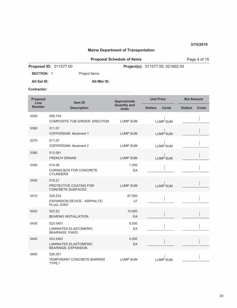
�A�� ��'��BB
CDE(DF/GH�GIJ�K/LMHL$�HLHCG/DN OOOOOOOOO�OOOOOPIE(�FIE PIE(�FIE
�A&� ������
CDQQHLMRES�RTU.0,V.�� OOOOOOOOO�OOOOOPIE(�FIE PIE(�FIE
�A�� ������
CDQQHLMRES�RTU.0,V.�% OOOOOOOOO�OOOOOPIE(�FIE PIE(�FIE
�AW� ��%��W�
QLHNCX�MLR/NF OOOOOOOOO�OOOOOPIE(�FIE PIE(�FIE
OOOOOOOOO�OOOOO
�A'� ��B��&
CIL/NK�JDY�QDL�CDNCLHGHCZP/NMHLF
HR
�����
OOOOOOOOO�OOOOO
�B�� ����%�
(LDGHCG/[H�CDRG/NK�QDLCDNCLHGH�FILQRCHF
OOOOOOOOO�OOOOOPIE(�FIE PIE(�FIE
OOOOOOOOO�OOOOO
�B�� �%��%A%
HY(RNF/DN�MH[/CH�\�RF(XRPG/C(PIK�]D/NG
PQ
&�����
OOOOOOOOO�OOOOO
OOOOOOOOO�OOOOO
�B%� �%A��%
JHRL/NK�/NFGRPPRG/DN HR
������
OOOOOOOOO�OOOOO
OOOOOOOOO�OOOOO
�BA� �%A��B��
PRE/NRGHM�HPRFGDEHL/CJHRL/NKF$�Q/YHM
HR
�����
OOOOOOOOO�OOOOO
OOOOOOOOO�OOOOO
�BB� �%A��B�%
PRE/NRGHM�HPRFGDEHL/CJHRL/NKF$�HY(RNF/DN
HR
�����
OOOOOOOOO�OOOOO
�B�� �%&�A��
GHE(DLRLZ�CDNCLHGH�JRLL/HLGZ(H�/
OOOOOOOOO�OOOOOPIE(�FIE PIE(�FIE
��������2!̂�:;���� ����� (_̀,�B�*a���
20

��������������� �����������
���������
�������������������� �� �!"�#����������$��%�&'%���
� ()*+,-.�/.,01234��56�
7��2����� 7���8����
4���!��
9�:�7��;�<�����!�7���=����>;���?���:<������!�����
�������������@���6;�8� ������ 4��� ������ 4���
AAAAAAAAA�AAAAA
�B&� �%&�CB
(DEFGHDHI�JKHJEDIDIEGHL/I/KH�MGEE/DE
DG
B����
AAAAAAAAA�AAAAA
AAAAAAAAA�AAAAA
�B�� �%��CB
NKEO�PKHD�JEGLQ�JRLQ/KHL RH
�����
AAAAAAAAA�AAAAA
AAAAAAAAA�AAAAA
�BS� &�%�C�
TUKNGMUD�JKHJEDID�T/UU JV
�C����
AAAAAAAAA�AAAAA
AAAAAAAAA�AAAAA
�B'� &�C���'
�%�/HJQ�JRUWDEI�(/(D�K(I/KH�/// UT
B������
AAAAAAAAA�AAAAA
AAAAAAAAA�AAAAA
���� &�C��&'
���/HJQ�JRUWDEI�(/(D�K(I/KH�/// UT
C&�����
AAAAAAAAA�AAAAA
AAAAAAAAA�AAAAA
���� &�C����
�S�/HJQ�ED/HTKEJDX�JKHJEDID(/(D�JUGLL�///
UT
C'�����
AAAAAAAAA�AAAAA
AAAAAAAAA�AAAAA
��%� &�C���'
�S�/HJQ�JRUWDEI�(/(D�K(I/KH�/// UT
%%�����
AAAAAAAAA�AAAAA
AAAAAAAAA�AAAAA
��C� &�C��'�
%B�/HJQ�ED/HTKEJDX�JKHJEDID(/(D�JUGLL�///
UT
B�����
AAAAAAAAA�AAAAA
AAAAAAAAA�AAAAA
��B� &�C��''
%B�/HJQ�JRUWDEI�(/(D�K(I/KH�/// UT
�������
AAAAAAAAA�AAAAA
AAAAAAAAA�AAAAA
���� &�C���
JKHJEDID�(/(D�I/DL Y(
%%����
AAAAAAAAA�AAAAA
AAAAAAAAA�AAAAA
��&� &�B���%
JGIJQ�MGL/H�IV(D�G�ZJ DG
�����
AAAAAAAAA�AAAAA
AAAAAAAAA�AAAAA
���� &�B��'
JGIJQ�MGL/H�IV(D�M� DG
�����
AAAAAAAAA�AAAAA
��������2![�:;���� ����� (\],���*̂���
21

��������������� �����������
���������
�������������������� �� �!"�#����������$��%�&'%���
� ()*+,-.�/.,01234��56�
7��2����� 7���8����
4���!��
9�:�7��;�<�����!�7���=����>;���?���:<������!�����
�������������@���6;�8� ������ 4��� ������ 4���
AAAAAAAAA�AAAAA
��B� &�C��'%
DEFDG�HEI/J�FK(L�H�MD LE
%'����
AAAAAAAAA�AAAAA
AAAAAAAAA�AAAAA
��'� &�C��'&
&��/JDG�DEFDG�HEI/J�FK(L�H�MD LE
�����
AAAAAAAAA�AAAAA
AAAAAAAAA�AAAAA
�&�� &�C��'�
�%�/JDG�DEFDG�HEI/J�FK(L�H�MD LE
N����
AAAAAAAAA�AAAAA
AAAAAAAAA�AAAAA
�&�� &�C���
DEFDG�HEI/J�FK(L�D� LE
%����
AAAAAAAAA�AAAAA
AAAAAAAAA�AAAAA
�&%� &�C��&�
EOFLP/JQ�DEFDG�HEI/J LE
%����
AAAAAAAAA�AAAAA
AAAAAAAAA�AAAAA
�&N� &�C�%C�%
HLG/JR�DSPH�DEFDG�HEI/J LE
C����
AAAAAAAAA�AAAAA
AAAAAAAAA�AAAAA
�&C� &�C�%C%
DEFDG�HEI/J�FK(L�TN LE
&����
AAAAAAAAA�AAAAA
AAAAAAAAA�AAAAA
�&�� &�C�%CC
DEFDG�HEI/J�FK(L�TC LE
%�����
AAAAAAAAA�AAAAA
AAAAAAAAA�AAAAA
�&&� &�C�%C&
DEFDG�HEI/J�FK(L�T� LE
�����
AAAAAAAAA�AAAAA
AAAAAAAAA�AAAAA
�&�� &�C�%C�
DEFDG�HEI/J�FK(L�T�MD LE
������
AAAAAAAAA�AAAAA
AAAAAAAAA�AAAAA
�&B� &�C�%CB
DEFDG�HEI/J�FK(L�T& LE
%����
AAAAAAAAA�AAAAA
AAAAAAAAA�AAAAA
�&'� &�C�%C'
DEFDG�HEI/J�FK(L�T&MD LE
�����
AAAAAAAAA�AAAAA
AAAAAAAAA�AAAAA
���� &����'
&�/JDG�SJRLPRPE/J�FK(L�H OT
�$N������
AAAAAAAAA�AAAAA
��������2!U�:;���� ����� (VW,�&�*X���
22

��������������� �����������
���������
�������������������� �� �!"�#����������$��%�&'%���
� ()*+,-.�/.,01234��56�
7��2����� 7���8����
4���!��
9�:�7��;�<�����!�7���=����>;���?���:<������!�����
�������������@���6;�8� ������ 4��� ������ 4���
AAAAAAAAA�AAAAA
���� &�����
&�/BCD�EBFGHFHI/B�JEKLGK LM
�&�����
AAAAAAAAA�AAAAA
AAAAAAAAA�AAAAA
��%� &�����
�%�/BCD�EBFGHFHI/B�KN(G�C LM
O$�������
AAAAAAAAA�AAAAA
AAAAAAAAA�AAAAA
��O� &����%
���/BCD�EBFGHFHI/B�KN(G�C LM
�$P������
AAAAAAAAA�AAAAA
AAAAAAAAA�AAAAA
��Q� &����O
�P�/BCD�EBFGHFHI/B�KN(G�C LM
�$P������
AAAAAAAAA�AAAAA
AAAAAAAAA�AAAAA
���� &�����
%Q�/BCD�EBFGHFHI/B�KN(G�C LM
�������
AAAAAAAAA�AAAAA
AAAAAAAAA�AAAAA
��&� &�&��O��
O�R�STUV�WH$�V/FTSIN�X(L/CGTXWLMICGF
LM
Q'�����
AAAAAAAAA�AAAAA
AAAAAAAAA�AAAAA
���� &�&��O�O
O�R�STUV�WH$�V/FTSIN�X(L/CGT��YHIF�IBF�LGXX
LM
%�����
AAAAAAAAA�AAAAA
AAAAAAAAA�AAAAA
��P� &�&��O�Q
O�R�STUV�WH$�V/FTSIN�X(L/CGTJZGH��Y�HIF
LM
�������
AAAAAAAAA�AAAAA
AAAAAAAAA�AAAAA
��'� &�&��O��
O�R�STUV�WH$�V/FTSIN�X(L/CGMLIHGF�KGHV/BIL
GI
�����
AAAAAAAAA�AAAAA
AAAAAAAAA�AAAAA
�P�� &�&��O��
UH/FWG�KHIBX/K/JB[IXNVVGKH/CIL\�T�KN(G��
GI
Q����
AAAAAAAAA�AAAAA
AAAAAAAAA�AAAAA
�P�� &�&�%&�
KGHV/BIL�GBF�T�X/BWLG�HI/L�TWILZIB/]GF�XKGGL
GI
O����
AAAAAAAAA�AAAAA
��������2!̂�:;���� ����� (_̀,���*a���
23
��������������� �����������
���������
�������������������� �� �!"�#����������$��%�&'%���
� ()*+,-.�/.,01234��56�
7��2����� 7���8����
4���!��
9�:�7��;�<�����!�7���=����>;���?���:<������!�����
�������������@���6;�8� ������ 4��� ������ 4���
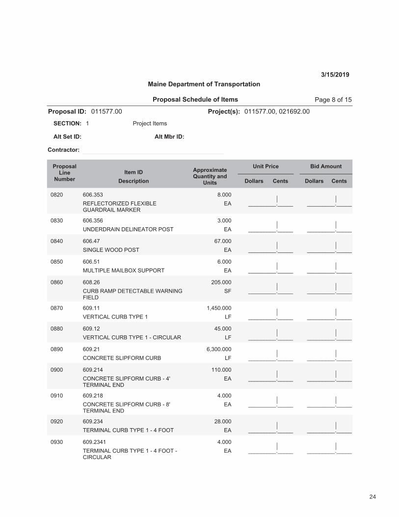
AAAAAAAAA�AAAAA
�B%� &�&�C�C
DEFGEHIJD/KEL�FGEM/NGEOPQDLDQ/G�RQDSED
EQ
B����
AAAAAAAAA�AAAAA
AAAAAAAAA�AAAAA
�BC� &�&�C�&
PTLEDLDQ/T�LEG/TEQIJD�(JUI EQ
C����
AAAAAAAAA�AAAAA
AAAAAAAAA�AAAAA
�BV� &�&�V�
U/TOGE�WJJL�(JUI EQ
&�����
AAAAAAAAA�AAAAA
AAAAAAAAA�AAAAA
�B�� &�&���
RPGI/(GE�RQ/GNJM�UP((JDI EQ
&����
AAAAAAAAA�AAAAA
AAAAAAAAA�AAAAA
�B&� &�B�%&
HPDN�DQR(�LEIEHIQNGE�WQDT/TOF/EGL
UF
%������
AAAAAAAAA�AAAAA
AAAAAAAAA�AAAAA
�B�� &�'���
XEDI/HQG�HPDN�IY(E�� GF
�$V������
AAAAAAAAA�AAAAA
AAAAAAAAA�AAAAA
�BB� &�'��%
XEDI/HQG�HPDN�IY(E���Z�H/DHPGQD GF
V�����
AAAAAAAAA�AAAAA
AAAAAAAAA�AAAAA
�B'� &�'�%�
HJTHDEIE�UG/(FJDR�HPDN GF
&$C������
AAAAAAAAA�AAAAA
AAAAAAAAA�AAAAA
�'�� &�'�%�V
HJTHDEIE�UG/(FJDR�HPDN�Z�V[IEDR/TQG�ETL
EQ
�������
AAAAAAAAA�AAAAA
AAAAAAAAA�AAAAA
�'�� &�'�%�B
HJTHDEIE�UG/(FJDR�HPDN�Z�B[IEDR/TQG�ETL
EQ
V����
AAAAAAAAA�AAAAA
AAAAAAAAA�AAAAA
�'%� &�'�%CV
IEDR/TQG�HPDN�IY(E���Z�V�FJJI EQ
%B����
AAAAAAAAA�AAAAA
AAAAAAAAA�AAAAA
�'C� &�'�%CV�
IEDR/TQG�HPDN�IY(E���Z�V�FJJI�ZH/DHPGQD
EQ
V����
AAAAAAAAA�AAAAA
��������2!\�:;���� ����� (]̂,�B�*_���
24
��������������� �����������
���������
�������������������� �� �!"�#����������$��%�&'%���
� ()*+,-.�/.,01234��56�
7��2����� 7���8����
4���!��
9�:�7��;�<�����!�7���=����>;���?���:<������!�����
�������������@���6;�8� ������ 4��� ������ 4���
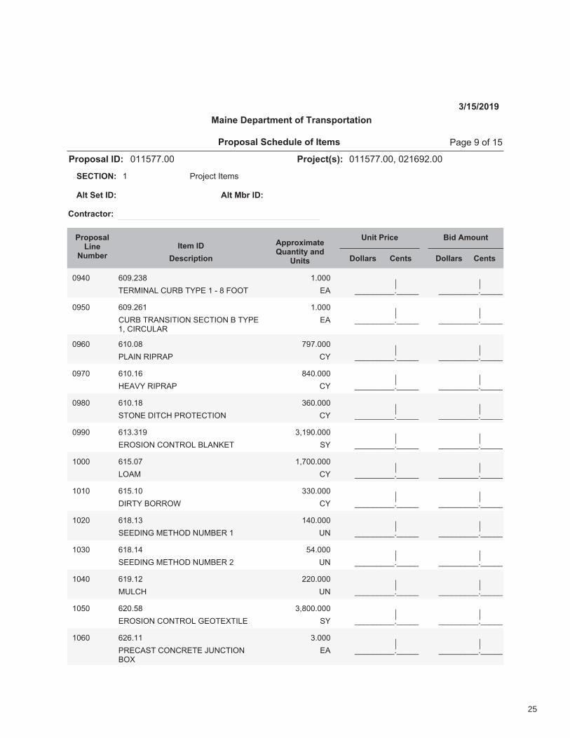
AAAAAAAAA�AAAAA
�'B� &�'�%CD
EFGH/IJK�LMGN�EO(F���P�D�QRRE FJ
�����
AAAAAAAAA�AAAAA
AAAAAAAAA�AAAAA
�'�� &�'�%&�
LMGN�EGJIS/E/RI�SFLE/RI�N�EO(F�$�L/GLMKJG
FJ
�����
AAAAAAAAA�AAAAA
AAAAAAAAA�AAAAA
�'&� &����D
(KJ/I�G/(GJ( LO
�'�����
AAAAAAAAA�AAAAA
AAAAAAAAA�AAAAA
�'�� &����&
TFJUO�G/(GJ( LO
DB�����
AAAAAAAAA�AAAAA
AAAAAAAAA�AAAAA
�'D� &����D
SERIF�V/ELT�(GREFLE/RI LO
C&�����
AAAAAAAAA�AAAAA
AAAAAAAAA�AAAAA
�''� &�C�C�'
FGRS/RI�LRIEGRK�NKJIWFE SO
C$�'�����
AAAAAAAAA�AAAAA
AAAAAAAAA�AAAAA
���� &�����
KRJH LO
�$�������
AAAAAAAAA�AAAAA
AAAAAAAAA�AAAAA
���� &�����
V/GEO�NRGGRX LO
CC�����
AAAAAAAAA�AAAAA
AAAAAAAAA�AAAAA
��%� &�D��C
SFFV/IY�HFETRV�IMHNFG�� MI
�B�����
AAAAAAAAA�AAAAA
AAAAAAAAA�AAAAA
��C� &�D��B
SFFV/IY�HFETRV�IMHNFG�% MI
�B����
AAAAAAAAA�AAAAA
AAAAAAAAA�AAAAA
��B� &�'��%
HMKLT MI
%%�����
AAAAAAAAA�AAAAA
AAAAAAAAA�AAAAA
���� &%���D
FGRS/RI�LRIEGRK�YFREFZE/KF SO
C$D������
AAAAAAAAA�AAAAA
AAAAAAAAA�AAAAA
��&� &%&���
(GFLJSE�LRILGFEF�[MILE/RINRZ
FJ
C����
AAAAAAAAA�AAAAA
��������2!\�:;���� ����� (]̂,�'�*_���
25

��������������� �����������
���������
�������������������� �� �!"�#����������$��%�&'%���
� ()*+,-.�/.,01234��56�
7��2����� 7���8����
4���!��
9�:�7��;�<�����!�7���=����>;���?���:<������!�����
�������������@���6;�8� ������ 4��� ������ 4���
AAAAAAAAA�AAAAA
���� &%&�%%�
BCBDEFGHII/J�JCBKL/G�JCBJMFGFFBJHNFK
IO
&������
AAAAAAAAA�AAAAA
AAAAAAAAA�AAAAA
��P� &%���QQ
RS�TU/GF�CM�VFIICT�(H/BGFK(HWFEFBG�EHMX/BY�I/BF
IO
%�$�������
AAAAAAAAA�AAAAA
AAAAAAAAA�AAAAA
��'� &%����
TU/GF�CM�VFIICT�(HWFEFBG�ZJLM[�EHMX/BY
NO
%$�������
AAAAAAAAA�AAAAA
AAAAAAAAA�AAAAA
���� &%���P
GFE(CMHMV�R�/BJU�(H/BGFK(HWFEFBG�EHMX/BY�I/BF$�TU/GFCM�VFIICT
IO
�R$�������
AAAAAAAAA�AAAAA
AAAAAAAAA�AAAAA
���� &%'���
UHBK�IH[CM$�NGMH/YUG�G/EF UM
%&�����
AAAAAAAAA�AAAAA
AAAAAAAAA�AAAAA
��%� &Q����
H/M�JCE(MFNNCM�\/BJILK/BYC(FMHGCM]
UM
������
AAAAAAAAA�AAAAA
AAAAAAAAA�AAAAA
��Q� &Q����
H/M�GCCI�\/BJILK/BY�C(FMHGCM] UM
������
AAAAAAAAA�AAAAA
AAAAAAAAA�AAAAA
��R� &Q���%
HII�(LM(CNF�F̂ JHWHGCM\/BJILK/BY�C(FMHGCM]
UM
&�����
AAAAAAAAA�AAAAA
AAAAAAAAA�AAAAA
���� &Q����%
GMLJX�D�IHMYF�\/BJILK/BYC(FMHGCM]
UM
�������
AAAAAAAAA�AAAAA
AAAAAAAAA�AAAAA
��&� &Q��%�
NGLE(�JU/((FM�\/BJILK/BYC(FMHGCM]
UM
������
AAAAAAAAA�AAAAA
AAAAAAAAA�AAAAA
���� &Q��%%
OMCBG�FBK�ICHKFM�\/BJILK/BYC(FMHGCM]
UM
%�����
AAAAAAAAA�AAAAA
��������2!_�:;���� ����� (̀a,����*b���
26

��������������� �����������
���������
�������������������� �� �!"�#����������$��%�&'%���
� ()*+,-.�/.,01234��56�
7��2����� 7���8����
4���!��
9�:�7��;�<�����!�7���=����>;���?���:<������!�����
�������������@���6;�8� ������ 4��� ������ 4���
AAAAAAAAA�AAAAA
��B� &C��C%
DEFGHIJ�DFHKLHI�M/LDFEN/LOP(HIKJPIQ
RI
������
AAAAAAAAA�AAAAA
AAAAAAAAA�AAAAA
��'� &C'��B
S/HFN�PSS/DH�JT(H�K HK
�����
AAAAAAAAA�AAAAA
AAAAAAAAA�AAAAA
�%�� &U��%'%
IHOEFKJPIT$�VKIL/LO$DPLS/IWKJ/PL�KLN�IPEJHWKIXHI�KYYHWZFT�Y/OLY�JT(H�//
YS
&'����
AAAAAAAAA�AAAAA
AAAAAAAAA�AAAAA
�%�� &�%�C�%
JT(H�///�ZKII/DKNH HK
&����
AAAAAAAAA�AAAAA
AAAAAAAAA�AAAAA
�%%� &�%�CC
NIEW HK
�������
AAAAAAAAA�AAAAA
AAAAAAAAA�AAAAA
�%C� &�%�CU
DPLH HK
�������
AAAAAAAAA�AAAAA
AAAAAAAAA�AAAAA
�%U� &�%�C�
DPLYJIEDJ/PL�Y/OLY YS
�$�������
AAAAAAAAA�AAAAA
AAAAAAAAA�AAAAA
�%�� &�%�C&
WK/LJHLKLDH�PS�JIKSS/DDPLJIPF�NHG/DHY
DN
�������
AAAAAAAAA�AAAAA
AAAAAAAAA�AAAAA
�%&� &�%�CB
SFKOOHI RI
%�$%������
AAAAAAAAA�AAAAA
�%�� &�&���
JHW(PIKIT�YP/F�HIPY/PL�KLNVKJHI�(PFFEJ/PL�DPLJIPF
AAAAAAAAA�AAAAAFEW(�YEW FEW(�YEW
AAAAAAAAA�AAAAA
�%B� &�B�%�
KDITF/D�FKJH[�DPFPI�S/L/YR$OIHHL
YT
C�����
AAAAAAAAA�AAAAA
�%'� &�'���
WPZ/F/\KJ/PL AAAAAAAAA�AAAAAFEW(�YEW FEW(�YEW
��������2!]�:;���� ����� (̂_,����*̀���
27
��������������� �����������
���������
�������������������� �� �!"�#����������$��%�&'%���
� ()*+,-.�/.,01234��56�
7��2����� 7���8����
4���!��
9�:�7��;�<�����!�7���=����>;���?���:<������!�����
�������������@���6;�8� ������ 4��� ������ 4���
AAAAAAAAA�AAAAA
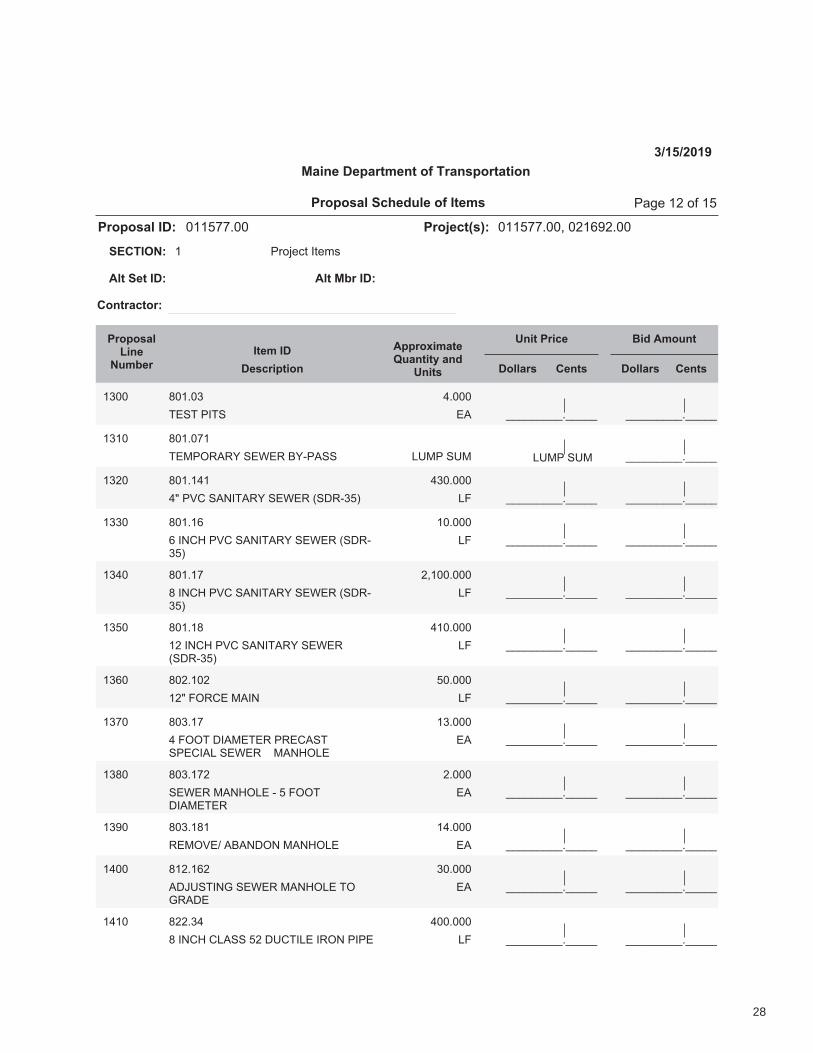
�B�� C����B
DEFD�(/DF EG
H����
AAAAAAAAA�AAAAA
�B�� C������
DEI(JKGKL�FEMEK�NLO(GFF AAAAAAAAA�AAAAAPQI(�FQI PQI(�FQI
AAAAAAAAA�AAAAA
�B%� C����H�
HR�(ST�FGU/DGKL�FEMEK�VFWKOB�X PY
HB�����
AAAAAAAAA�AAAAA
AAAAAAAAA�AAAAA
�BB� C����&
&�/UTZ�(ST�FGU/DGKL�FEMEK�VFWKOB�X
PY
������
AAAAAAAAA�AAAAA
AAAAAAAAA�AAAAA
�BH� C�����
C�/UTZ�(ST�FGU/DGKL�FEMEK�VFWKOB�X
PY
%$�������
AAAAAAAAA�AAAAA
AAAAAAAAA�AAAAA
�B�� C����C
�%�/UTZ�(ST�FGU/DGKL�FEMEKVFWKOB�X
PY
H������
AAAAAAAAA�AAAAA
AAAAAAAAA�AAAAA
�B&� C�%���%
�%R�YJKTE�IG/U PY
������
AAAAAAAAA�AAAAA
AAAAAAAAA�AAAAA
�B�� C�B���
H�YJJD�W/GIEDEK�(KETGFDF(ET/GP�FEMEK����IGUZJPE
EG
�B����
AAAAAAAAA�AAAAA
AAAAAAAAA�AAAAA
�BC� C�B���%
FEMEK�IGUZJPE�O���YJJDW/GIEDEK
EG
%����
AAAAAAAAA�AAAAA
AAAAAAAAA�AAAAA
�B'� C�B��C�
KEIJSE[�GNGUWJU�IGUZJPE EG
�H����
AAAAAAAAA�AAAAA
AAAAAAAAA�AAAAA
�H�� C�%��&%
GW\QFD/U]�FEMEK�IGUZJPE�DJ]KGWE
EG
B�����
AAAAAAAAA�AAAAA
AAAAAAAAA�AAAAA
�H�� C%%�BH
C�/UTZ�TPGFF��%�WQTD/PE�/KJU�(/(E PY
H������
AAAAAAAAA�AAAAA
��������2!̂�:;���� ����� (_̀,��%�*a���
28
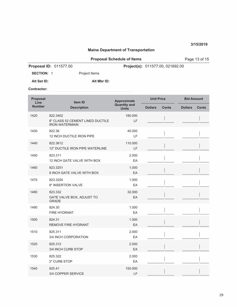
��������������� �����������
���������
�������������������� �� �!"�#����������$��%�&'%���
� ()*+,-.�/.,01234��56�
7��2����� 7���8����
4���!��
9�:�7��;�<�����!�7���=����>;���?���:<������!�����
�������������@���6;�8� ������ 4��� ������ 4���
AAAAAAAAA�AAAAA
�B%� C%%�DB�%
CE�FGHII��%�FJKJLM�G/LJN�NOFM/GJ/PQL�RHMJPKH/L
GS
�C�����
AAAAAAAAA�AAAAA
AAAAAAAAA�AAAAA
�BD� C%%�D&
�%�/LFT�NOFM/GJ�/PQL�(/(J GS
B�����
AAAAAAAAA�AAAAA
AAAAAAAAA�AAAAA
�BB� C%%�D&�%
�%E�NOFM/GJ�/PQL�(/(J�RHMJPG/LJ GS
�������
AAAAAAAAA�AAAAA
AAAAAAAAA�AAAAA
�B�� C%D�D��
�%�/LFT�UHMJ�VHGVJ�R/MT�WQX JH
%����
AAAAAAAAA�AAAAA
AAAAAAAAA�AAAAA
�B&� C%D�D%��
C�/LFT�UHMJ�VHGVJ�R/MT�WQX JH
�����
AAAAAAAAA�AAAAA
AAAAAAAAA�AAAAA
�B�� C%D�D%�B
CE�/LIJPM/QL�VHGVJ JH
�����
AAAAAAAAA�AAAAA
AAAAAAAAA�AAAAA
�BC� C%D�DD%
UHMJ�VHGVJ�WQX$�HNYOIM�MQUPHNJ
JH
D%����
AAAAAAAAA�AAAAA
AAAAAAAAA�AAAAA
�B'� C%B�D�
S/PJ�TZNPHLM JH
�����
AAAAAAAAA�AAAAA
AAAAAAAAA�AAAAA
���� C%B�D�
PJKQVJ�S/PJ�TZNPHLM JH
�����
AAAAAAAAA�AAAAA
AAAAAAAAA�AAAAA
���� C%��D��
D[B�/LFT�FQP(QPHM/QL JH
%����
AAAAAAAAA�AAAAA
AAAAAAAAA�AAAAA
��%� C%��D�%
D[B�/LFT�FOPW�IMQ( JH
%����
AAAAAAAAA�AAAAA
AAAAAAAAA�AAAAA
��D� C%��D%%
%E�FOPW�IMQ( JH
%����
AAAAAAAAA�AAAAA
AAAAAAAAA�AAAAA
��B� C%��B�
D[B�FQ((JP�IJPV/FJ GS
�������
AAAAAAAAA�AAAAA
��������2!\�:;���� ����� (]̂,��D�*_���
29

��������������� �����������
���������
�������������������� �� �!"�#����������$��%�&'%���
� ()*+,-.�/.,01234��56�
7��2����� 7���8����
4���!��
9�:�7��;�<�����!�7���=����>;���?���:<������!�����
�������������@���6;�8� ������ 4��� ������ 4���
AAAAAAAAA�AAAAA
���� B%��C%
%D�EF((GH�IGHJ/EG KL
C�����
AAAAAAAAA�AAAAA
AAAAAAAAA�AAAAA
��&� B%���C�
MGN(FHOHP�QOMGH�NO/R KL
S������
AAAAAAAAA�AAAAA
AAAAAAAAA�AAAAA
���� B%��S�
HFET�GUEOJOM/FRV�HGNFJG�ORWHGL/KK
EP
�������
AAAAAAAAA�AAAAA
AAAAAAAAA�AAAAA
��B� B%��S�%
XRIX/MOYKG�IF/K�GUEOJOM/FR�VYGKFQ�ZHOWG
EP
�������
AAAAAAAAA�AAAAA
AAAAAAAAA�AAAAA
��'� B%��S�%
IGKGEM�YOETL/KK EP
�������
AAAAAAAAA�AAAAA
AAAAAAAAA�AAAAA
�&�� B%��SS
MHGRE[�/RIXKOM/FR KL
%������
AAAAAAAAA�AAAAA
�&�� BS����
QOMGH�NO/R�YH/WZG�EHFII/RZ AAAAAAAAA�AAAAAKXN(�IXN KXN(�IXN
�&%� BS���S
IGQGH�NO/R�YH/WZG�EHFII/RZ AAAAAAAAA�AAAAAKXN(�IXN KXN(�IXN
�&S� BS%���
FQRGHI�MGIM/RZ�OKKFQOREG�V[\]��I,\,)
�$������KXN(�IXN KXN(�IXN
�&C� BS%���
FQRGHI�MGIM/RZ�OKKFQOREG�V[\]��Q .̂,)
%$������KXN(�IXN KXN(�IXN
�&�� BS%���
FQRGHI�MGIM/RZ�OKKFQOREG�Z)_1.N_̀̀�Y)�
�$������KXN(�IXN KXN(�IXN
2�!����� AAAAAAAAA�AAAAA�����
��������2!a�:;���� ����� (̂b,��C�*c���
30

�������� ���������������
31

CONTRACT AGREEMENT, OFFER & AWARD
AGREEMENT made on the date last signed below, by and between the State of Maine, acting through and by its Department of Transportation (Department), an agency of state government with its principal administrative offices located at Child Street, Augusta, Maine, with a mailing address at 16 State House Station, Augusta, Maine 04333-0016, and ________________ ____________a corporation or other legal entity organized under the laws of the State of _ _______, with its principal place of business located at ___ _____ ________________________________________________________________________
The Department and the Contractor, in consideration of the mutual promises set forth in this Agreement (the “Contract”), hereby agree as follows:
A. The Work.
The Contractor agrees to complete all Work as specified or indicated in the Contract including Extra Work in conformity with the Contract, WINS. 011577.00 / 021692.00for Highway Reconstruction and Bridge Replacement in the town of Hampden,County of Penobscot, Maine. The Work includes construction, maintenance during construction, warranty as provided in the Contract, and other incidental work.
The Contractor shall be responsible for furnishing all supervision, labor, equipment, tools supplies, permanent materials and temporary materials required to perform the Work including construction quality control including inspection, testing and documentation, all required documentation at the conclusion of the project, warranting its work and performing all other work indicated in the Contract.
The Department shall have the right to alter the nature and extent of the Work as provided in the Contract; payment to be made as provided in the same.
B. Time.
The Contractor agrees to complete all Work, except warranty work, on or before June 20, 2021. Further, the Department may deduct from moneys otherwise due the Contractor, not as a penalty, but as Liquidated Damages in accordance with Sections 107.7 and 107.8 of the State of Maine Department of Transportation Standard Specifications, November 2014 Edition and related Special Provisions.
32

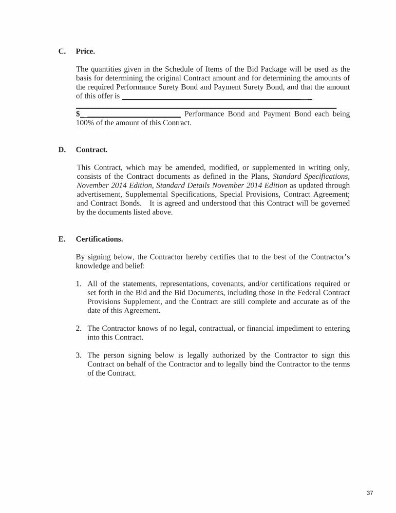
C. Price.
The quantities given in the Schedule of Items of the Bid Package will be used as the basis for determining the original Contract amount and for determining the amounts of the required Performance Surety Bond and Payment Surety Bond, and that the amount of this offer is ______________________________________________ _ ___________________________________________________________________$_ ________________________ Performance Bond and Payment Bond each being 100% of the amount of this Contract.
D. Contract.
This Contract, which may be amended, modified, or supplemented in writing only, consists of the Contract documents as defined in the Plans, Standard Specifications, November 2014 Edition, Standard Details November 2014 Edition as updated through advertisement, Supplemental Specifications, Special Provisions, Contract Agreement; and Contract Bonds. It is agreed and understood that this Contract will be governed by the documents listed above.
E. Certifications.
By signing below, the Contractor hereby certifies that to the best of the Contractor’s knowledge and belief:
1. All of the statements, representations, covenants, and/or certifications required or set forth in the Bid and the Bid Documents, including those in the Federal Contract Provisions Supplement, and the Contract are still complete and accurate as of the date of this Agreement.
2. The Contractor knows of no legal, contractual, or financial impediment to entering into this Contract.
3. The person signing below is legally authorized by the Contractor to sign this Contract on behalf of the Contractor and to legally bind the Contractor to the terms of the Contract.
33
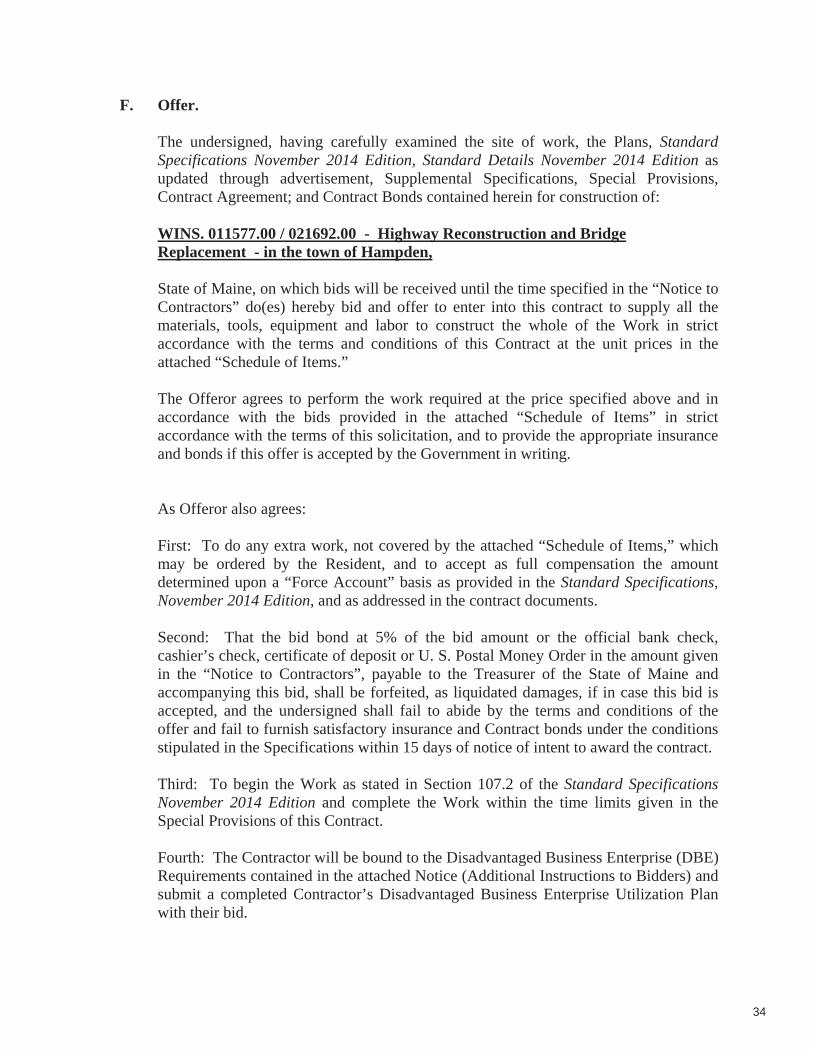
F. Offer.
The undersigned, having carefully examined the site of work, the Plans, StandardSpecifications November 2014 Edition, Standard Details November 2014 Edition as updated through advertisement, Supplemental Specifications, Special Provisions, Contract Agreement; and Contract Bonds contained herein for construction of:
WINS. 011577.00 / 021692.00 - Highway Reconstruction and Bridge Replacement - in the town of Hampden,
State of Maine, on which bids will be received until the time specified in the “Notice to Contractors” do(es) hereby bid and offer to enter into this contract to supply all the materials, tools, equipment and labor to construct the whole of the Work in strict accordance with the terms and conditions of this Contract at the unit prices in the attached “Schedule of Items.”
The Offeror agrees to perform the work required at the price specified above and in accordance with the bids provided in the attached “Schedule of Items” in strict accordance with the terms of this solicitation, and to provide the appropriate insurance and bonds if this offer is accepted by the Government in writing.
As Offeror also agrees:
First: To do any extra work, not covered by the attached “Schedule of Items,” which may be ordered by the Resident, and to accept as full compensation the amount determined upon a “Force Account” basis as provided in the Standard Specifications, November 2014 Edition, and as addressed in the contract documents.
Second: That the bid bond at 5% of the bid amount or the official bank check, cashier’s check, certificate of deposit or U. S. Postal Money Order in the amount given in the “Notice to Contractors”, payable to the Treasurer of the State of Maine and accompanying this bid, shall be forfeited, as liquidated damages, if in case this bid is accepted, and the undersigned shall fail to abide by the terms and conditions of the offer and fail to furnish satisfactory insurance and Contract bonds under the conditions stipulated in the Specifications within 15 days of notice of intent to award the contract.
Third: To begin the Work as stated in Section 107.2 of the Standard Specifications November 2014 Edition and complete the Work within the time limits given in the Special Provisions of this Contract.
Fourth: The Contractor will be bound to the Disadvantaged Business Enterprise (DBE) Requirements contained in the attached Notice (Additional Instructions to Bidders) and submit a completed Contractor’s Disadvantaged Business Enterprise Utilization Plan with their bid.
34

Fifth: That this offer shall remain open for 30 calendar days after the date of opening of bids.
Sixth: The Bidder hereby certifies, to the best of its knowledge and belief that: the Bidder has not, either directly or indirectly, entered into any agreement, participated in any collusion, or otherwise taken any action in restraint of competitive bidding in connection with its bid, and its subsequent contract with the Department.
IN WITNESS WHEREOF, the Contractor, for itself, its successors and assigns, hereby execute two duplicate originals of this Agreement and thereby binds itself to all covenants, terms, and obligations contained in the Contract Documents.
CONTRACTOR
____________________________ _______________________________________ Date (Signature of Legally Authorized Representative of the Contractor)
____________________________ _______________________________________ Witness (Name and Title Printed)
G. Award.
Your offer is hereby accepted. This award consummates the Contract, and the documents referenced herein.
MAINE DEPARTMENT OF TRANSPORTATION
____ ________________ __ Date By: Bruce A. Van Note, Commissioner
Witness
35

CONTRACT AGREEMENT, OFFER & AWARD
AGREEMENT made on the date last signed below, by and between the State of Maine, acting through and by its Department of Transportation (Department), an agency of state government with its principal administrative offices located at Child Street, Augusta, Maine, with a mailing address at 16 State House Station, Augusta, Maine 04333-0016, and ________________ ____________a corporation or other legal entity organized under the laws of the State of _ _______, with its principal place of business located at ___ _____ ________________________________________________________________________
The Department and the Contractor, in consideration of the mutual promises set forth in this Agreement (the “Contract”), hereby agree as follows:
A. The Work.
The Contractor agrees to complete all Work as specified or indicated in the Contract including Extra Work in conformity with the Contract, WINS. 011577.00 / 021692.00for Highway Reconstruction and Bridge Replacement in the town of Hampden,County of Penobscot, Maine. The Work includes construction, maintenance during construction, warranty as provided in the Contract, and other incidental work.
The Contractor shall be responsible for furnishing all supervision, labor, equipment, tools supplies, permanent materials and temporary materials required to perform the Work including construction quality control including inspection, testing and documentation, all required documentation at the conclusion of the project, warranting its work and performing all other work indicated in the Contract.
The Department shall have the right to alter the nature and extent of the Work as provided in the Contract; payment to be made as provided in the same.
B. Time.
The Contractor agrees to complete all Work, except warranty work, on or before June 20, 2021. Further, the Department may deduct from moneys otherwise due the Contractor, not as a penalty, but as Liquidated Damages in accordance with Sections 107.7 and 107.8 of the State of Maine Department of Transportation Standard Specifications, November 2014 Edition and related Special Provisions.
36
C. Price.
The quantities given in the Schedule of Items of the Bid Package will be used as the basis for determining the original Contract amount and for determining the amounts of the required Performance Surety Bond and Payment Surety Bond, and that the amount of this offer is ______________________________________________ _ ___________________________________________________________________$_ ________________________ Performance Bond and Payment Bond each being 100% of the amount of this Contract.
D. Contract.
This Contract, which may be amended, modified, or supplemented in writing only, consists of the Contract documents as defined in the Plans, Standard Specifications, November 2014 Edition, Standard Details November 2014 Edition as updated through advertisement, Supplemental Specifications, Special Provisions, Contract Agreement; and Contract Bonds. It is agreed and understood that this Contract will be governed by the documents listed above.
E. Certifications.
By signing below, the Contractor hereby certifies that to the best of the Contractor’s knowledge and belief:
1. All of the statements, representations, covenants, and/or certifications required or set forth in the Bid and the Bid Documents, including those in the Federal Contract Provisions Supplement, and the Contract are still complete and accurate as of the date of this Agreement.
2. The Contractor knows of no legal, contractual, or financial impediment to entering into this Contract.
3. The person signing below is legally authorized by the Contractor to sign this Contract on behalf of the Contractor and to legally bind the Contractor to the terms of the Contract.
37

F. Offer.
The undersigned, having carefully examined the site of work, the Plans, StandardSpecifications November 2014 Edition, Standard Details November 2014 Edition as updated through advertisement, Supplemental Specifications, Special Provisions, Contract Agreement; and Contract Bonds contained herein for construction of:
WINS. 011577.00 / 021692.00 - Highway Reconstruction and Bridge Replacement - in the town of Hampden,
State of Maine, on which bids will be received until the time specified in the “Notice to Contractors” do(es) hereby bid and offer to enter into this contract to supply all the materials, tools, equipment and labor to construct the whole of the Work in strict accordance with the terms and conditions of this Contract at the unit prices in the attached “Schedule of Items.”
The Offeror agrees to perform the work required at the price specified above and in accordance with the bids provided in the attached “Schedule of Items” in strict accordance with the terms of this solicitation, and to provide the appropriate insurance and bonds if this offer is accepted by the Government in writing.
As Offeror also agrees:
First: To do any extra work, not covered by the attached “Schedule of Items,” which may be ordered by the Resident, and to accept as full compensation the amount determined upon a “Force Account” basis as provided in the Standard Specifications, November 2014 Edition, and as addressed in the contract documents.
Second: That the bid bond at 5% of the bid amount or the official bank check, cashier’s check, certificate of deposit or U. S. Postal Money Order in the amount given in the “Notice to Contractors”, payable to the Treasurer of the State of Maine and accompanying this bid, shall be forfeited, as liquidated damages, if in case this bid is accepted, and the undersigned shall fail to abide by the terms and conditions of the offer and fail to furnish satisfactory insurance and Contract bonds under the conditions stipulated in the Specifications within 15 days of notice of intent to award the contract.
Third: To begin the Work as stated in Section 107.2 of the Standard Specifications November 2014 Edition and complete the Work within the time limits given in the Special Provisions of this Contract.
Fourth: The Contractor will be bound to the Disadvantaged Business Enterprise (DBE) Requirements contained in the attached Notice (Additional Instructions to Bidders) and submit a completed Contractor’s Disadvantaged Business Enterprise Utilization Plan with their bid.
38

Fifth: That this offer shall remain open for 30 calendar days after the date of opening of bids.
Sixth: The Bidder hereby certifies, to the best of its knowledge and belief that: the Bidder has not, either directly or indirectly, entered into any agreement, participated in any collusion, or otherwise taken any action in restraint of competitive bidding in connection with its bid, and its subsequent contract with the Department.
IN WITNESS WHEREOF, the Contractor, for itself, its successors and assigns, hereby execute two duplicate originals of this Agreement and thereby binds itself to all covenants, terms, and obligations contained in the Contract Documents.
CONTRACTOR
____________________________ _______________________________________ Date (Signature of Legally Authorized Representative of the Contractor)
____________________________ _______________________________________ Witness (Name and Title Printed)
G. Award.
Your offer is hereby accepted. This award consummates the Contract, and the documents referenced herein.
MAINE DEPARTMENT OF TRANSPORTATION
____ ________________ __ Date By: Bruce A. Van Note, Commissioner
Witness
39
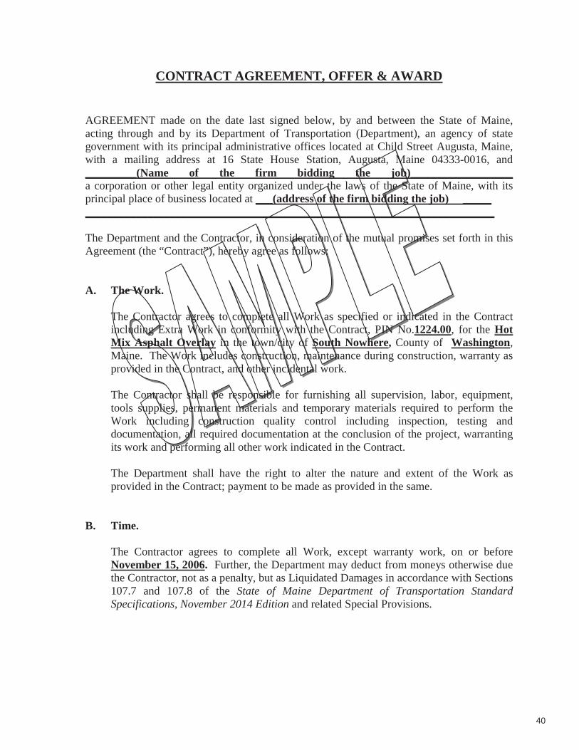
CONTRACT AGREEMENT, OFFER & AWARD
AGREEMENT made on the date last signed below, by and between the State of Maine, acting through and by its Department of Transportation (Department), an agency of state government with its principal administrative offices located at Child Street Augusta, Maine, with a mailing address at 16 State House Station, Augusta, Maine 04333-0016, and _________(Name of the firm bidding the job)__________________ a corporation or other legal entity organized under the laws of the State of Maine, with its principal place of business located at ___(address of the firm bidding the job) _____ ________________________________________________________________________
The Department and the Contractor, in consideration of the mutual promises set forth in this Agreement (the “Contract”), hereby agree as follows:
A. The Work.
The Contractor agrees to complete all Work as specified or indicated in the Contract including Extra Work in conformity with the Contract, PIN No.1224.00, for the Hot Mix Asphalt Overlay in the town/city of South Nowhere, County of Washington,Maine. The Work includes construction, maintenance during construction, warranty as provided in the Contract, and other incidental work.
The Contractor shall be responsible for furnishing all supervision, labor, equipment, tools supplies, permanent materials and temporary materials required to perform the Work including construction quality control including inspection, testing and documentation, all required documentation at the conclusion of the project, warranting its work and performing all other work indicated in the Contract.
The Department shall have the right to alter the nature and extent of the Work as provided in the Contract; payment to be made as provided in the same.
B. Time.
The Contractor agrees to complete all Work, except warranty work, on or before November 15, 2006. Further, the Department may deduct from moneys otherwise due the Contractor, not as a penalty, but as Liquidated Damages in accordance with Sections 107.7 and 107.8 of the State of Maine Department of Transportation Standard Specifications, November 2014 Edition and related Special Provisions.
40
C. Price.
The quantities given in the Schedule of Items of the Bid Package will be used as the basis for determining the original Contract amount and for determining the amounts of the required Performance Surety Bond and Payment Surety Bond, and that the amount of this offer is ____(Place bid here in alphabetical form such as One Hundred and Two dollars and 10 cents) ________________________________$_ (repeat bid here in numerical terms, such as $102.10)__________ Performance Bond and Payment Bond each being 100% of the amount of this Contract.
D. Contract.
This Contract, which may be amended, modified, or supplemented in writing only,consists of the Contract documents as defined in the Plans, Standard Specifications, November 2014 Edition, Standard Details November 2014 Edition, Supplemental Specifications, Special Provisions, Contract Agreement; and Contract Bonds. It is agreed and understood that this Contract will be governed by the documents listed above.
E. Certifications.
By signing below, the Contractor hereby certifies that to the best of the Contractor’s knowledge and belief:
1. All of the statements, representations, covenants, and/or certifications required or set forth in the Bid and the Bid Documents, including those in Appendix A to Division 100 of the Standard Specifications November 2014 Edition (Federal Contract Provisions Supplement), and the Contract are still complete and accurate as of the date of this Agreement.
2. The Contractor knows of no legal, contractual, or financial impediment to entering into this Contract.
3. The person signing below is legally authorized by the Contractor to sign this Contract on behalf of the Contractor and to legally bind the Contractor to the terms of the Contract.
41

F. Offer.
The undersigned, having carefully examined the site of work, the Plans, Standard Specifications, November 2014 Edition, Standard Details November 2014 Edition,Supplemental Specifications, Special Provisions, Contract Agreement; and Contract Bonds contained herein for construction of:
________PIN 1234.00 South Nowhere, Hot Mix Asphalt Overlay ,State of Maine, on which bids will be received until the time specified in the “Notice to Contractors” do(es) hereby bid and offer to enter into this contract to supply all the materials, tools, equipment and labor to construct the whole of the Work in strict accordance with the terms and conditions of this Contract at the unit prices in the attached “Schedule of Items.”
The Offeror agrees to perform the work required at the price specified above and in accordance with the bids provided in the attached “Schedule of Items” in strict accordance with the terms of this solicitation, and to provide the appropriate insurance and bonds if this offer is accepted by the Government in writing.
As Offeror also agrees:
First: To do any extra work, not covered by the attached “Schedule of Items,” which may be ordered by the Resident, and to accept as full compensation the amount determined upon a “Force Account” basis as provided in the Standard Specifications, November 2014 Edition, and as addressed in the contract documents.
Second: That the bid bond at 5% of the bid amount or the official bank check, cashier’s check, certificate of deposit or U. S. Postal Money Order in the amount given in the “Notice to Contractors”, payable to the Treasurer of the State of Maine and accompanying this bid, shall be forfeited, as liquidated damages, if in case this bid is accepted, and the undersigned shall fail to abide by the terms and conditions of the offer and fail to furnish satisfactory insurance and Contract bonds under the conditions stipulated in the Specifications within 15 days of notice of intent to award the contract.
Third: To begin the Work as stated in Section 107.2 of the Standard Specifications November 2014 Edition and complete the Work within the time limits given in the Special Provisions of this Contract.
Fourth: The Contractor will be bound to the Disadvantaged Business Enterprise (DBE) Requirements contained in the attached Notice (Additional Instructions to Bidders) and submit a completed Contractor’s Disadvantaged Business Enterprise Utilization Plan with their bid.
Fifth: That this offer shall remain open for 30 calendar days after the date of opening of bids.
42

Sixth: The Bidder hereby certifies, to the best of its knowledge and belief that: the Bidder has not, either directly or indirectly, entered into any agreement, participated in any collusion, or otherwise taken any action in restraint of competitive bidding in connection with its bid, and its subsequent contract with the Department.
IN WITNESS WHEREOF, the Contractor, for itself, its successors and assigns, hereby execute two duplicate originals of this Agreement and thereby binds itself to all covenants, terms, and obligations contained in the Contract Documents.
CONTRACTOR
____________________________ ______________(Sign Here)_______________Date (Signature of Legally Authorized Representative
of the Contractor)
____(Witness Sign Here)__ __ __________(Print Name Here)____________Witness (Name and Title Printed)
G. Award.
Your offer is hereby accepted. This award consummates the Contract, and the documents referenced herein.
MAINE DEPARTMENT OF TRANSPORTATION
________________________________ __________________________________Date By: Bruce A. Van Note, Commissioner
________________________________ (Witness)
43

BOND # _____________________
CONTRACT PERFORMANCE BOND (Surety Company Form)
KNOW ALL MEN BY THESE PRESENTS: That _________________________________________________ in the State of _________________________, as principal, and……………………………………….............................................................................,a corporation duly organized under the laws of the State of ........................ and having a usual place of business ...................... .................................................................................., as Surety, are held and firmly bound unto the Treasurer of the State of Maine in the sum of ______________________________________ and 00/100 Dollars ($ ),to be paid said Treasurer of the State of Maine or his successors in office, for which payment well and truly to be made, Principal and Surety bind themselves, their heirs, executors and administrators, successors and assigns, jointly and severally by these presents.
The condition of this obligation is such that if the Principal designated as Contractor in the Contract to construct Project Number ____________ in the Municipality of ______________________ promptly and faithfully performs the Contract, then this obligation shall be null and void; otherwise it shall remain in full force and effect.
The Surety hereby waives notice of any alteration or extension of time made by the State of Maine.
Signed and sealed this .................................. day of ............................................, 20….. .
WITNESSES: SIGNATURES: CONTRACTOR: Signature.................................................... ..........................................…........................Print Name Legibly ................................... Print Name Legibly ...……......................... SURETY: Signature ................................................... .....……........................................................Print Name Legibly .................................. Print Name Legibly ..................................... SURETY ADDRESS: NAME OF LOCAL AGENCY: .................................................................. ADDRESS .................................................................................................................... ..……………............................................... .................................................................. .......…………….......................................... TELEPHONE........................................... .......……………..........................................
vii
44

BOND # _______________________
CONTRACT PAYMENT BOND (Surety Company Form)
KNOW ALL MEN BY THESE PRESENTS: That _____________________________________________________ in the State of ______________________, as principal, and....................................................................….................................................................. a corporation duly organized under the laws of the State of .......................... and having a usual place of business in .....................…………………………………………………., as Surety, are held and firmly bound unto the Treasurer of the State of Maine for the use and benefit of claimants as herein below defined, in the sum of__________________________________________ and 00/100 Dollars ($ )for the payment whereof Principal and Surety bind themselves, their heirs, executors and administrators, successors and assigns, jointly and severally by these presents.
The condition of this obligation is such that if the Principal designated as Contractor in the Contract to construct Project Number ____________ in the Municipality of _________________________ promptly satisfies all claims and demands incurred for all labor and material, used or required by him in connection with the work contemplated by said Contract, and fully reimburses the obligee for all outlay and expense which the obligee may incur in making good any default of said Principal, then this obligation shall be null and void; otherwise it shall remain in full force and effect.
A claimant is defined as one having a direct contract with the Principal or with a Subcontractor of the Principal for labor, material or both, used or reasonably required for use in the performance of the contract.
Signed and sealed this ............................. day of ...………......................................., 20 ... . WITNESS: SIGNATURES: CONTRACTOR: Signature……............................................ ......….............................................................Print Name Legibly .........................…….. Print Name Legibly .….................................
SURETY:Signature.................................................... ...…...............................................................Print Name Legibly .................................. Print Name Legibly .….................................. SURETY ADDRESS: NAME OF LOCAL AGENCY: ...…............................................................ ADDRESS …................................................ ................................................................... …………….................................................... TELEPHONE ........................................... ………………................................................
viii
45

��������� ��������� ���� ������������������������������ �������
��������� ���� ������������������������������ ������� ��
!"#"$%&'(")*+*,#'-./0"$1'23456678'649679:645''2378'';.<"$+"="='!"#"$%&'(")*+*,#'-./0"$1'23:64>64:?'';@%@"1'2%*#"''A,#+@$.)@*,#'BC<"1'D*EFG%C''A,.#@C1'H"#,0+),@'A,.#@C'*#'2%*#"I''DJ!DKLM'AN-;BOPABJN-'HONQ3AB;'''-,@"1'P#="$'3R").@*S"'N$="$'T3NU'4?VW>X'%#'F,.$&C'/*#*/./'G%E"',Y'Z46IV6'Y,$')%&"#=%$'C"%$':645'%<<&*"+'@,'%&&'),#@$%)@+'+.0[")@'@,'@F"'(%S*+\]%),#'L)@'Y,$'GF*)F'@F"'),#@$%)@'*+'%G%$="='T%#='%#C'+,&*)*@%@*,#'G%+'*++."=U',#',$'%Y@"$'Q%#.%$C'4X':64WI'JY'@F*+'),#@$%)@'*+'),S"$"='0C'@F"'3NX'@F"'),#@$%)@,$'/.+@'<%C'%&&'G,$̂"$+'*#'%#C')&%++*Y*)%@*,#'&*+@"=',#'@F*+'G%E"'="@"$/*#%@*,#'%@'&"%+@'Z46IV6'<"$'F,.$'T,$'@F"'%<<&*)%0&"'G%E"'$%@"'&*+@"=',#'@F*+'G%E"'="@"$/*#%@*,#X'*Y'*@'*+'F*EF"$U'Y,$'%&&'F,.$+'+<"#@'<"$Y,$/*#E',#'@F"'),#@$%)@'*#')%&"#=%$'C"%$':645I''JY'@F*+'),#@$%)@'*+'),S"$"='0C'@F"'3N'%#='%'')&%++*Y*)%@*,#'),#+*="$"='#")"++%$C'Y,$'<"$Y,$/%#)"',Y'G,$̂',#''@F"'),#@$%)@'=,"+'#,@'%<<"%$',#'@F*+'G%E"'="@"$/*#%@*,#X'@F"''),#@$%)@,$'/.+@'<%C'G,$̂"$+'*#'@F%@')&%++*Y*)%@*,#'%@'&"%+@''@F"'G%E"'$%@"'="@"$/*#"='@F$,.EF'@F"'),#Y,$/%#)"'<$,)"++'+"@''Y,$@F'*#':5'A_O'WIWT%UT4UT**U'T,$'@F"'3N'/*#*/./'G%E"'$%@"X'*Y'*@'*+'F*EF"$'@F%#'@F"'),#Y,$/"='G%E"'$%@"UI''BF"'3N'/*#*/./''G%E"'$%@"'G*&&'0"'%=[.+@"='%##.%&&CI''H&"%+"'#,@"'@F%@''@F*+'3N'%<<&*"+'@,'@F"'%0,S"\/"#@*,#"='@C<"+',Y'),#@$%)@+''"#@"$"='*#@,'0C'@F"'Y"="$%&'E,S"$#/"#@'@F%@'%$"'+.0[")@''@,'@F"'(%S*+\]%),#'L)@'*@+"&YX'0.@'*@'=,"+'#,@'%<<&C''@,'),#@$%)@+'+.0[")@',#&C'@,'@F"'(%S*+\]%),#'O"&%@"='L)@+X''*#)&.=*#E'@F,+"'+"@'Y,$@F'%@':5'A_O'WI4T%UT:U\TV6UI'L==*@*,#%&''*#Y,$/%@*,#',#'),#@$%)@,$'$"̀.*$"/"#@+'%#='G,$̂"$'<$,@")@*,#+''.#="$'@F"'3N'*+'%S%*&%0&"'%@'GGGI=,&IE,S9GF=9E,S),#@$%)@+I''''2,=*Y*)%@*,#'-./0"$'''''H.0&*)%@*,#'(%@"'''''''''''6'''''''''''''649679:645''a'3-!J6667\667'679649:64>''''''''''''''''''''''''''''''''''''O%@"+''''''''''_$*#E"+''HNK3O'3bPJH23-B'NH3OLBNO1''''''''!$%="$9]&%="X'2")F%#*)X'''''''H%S"$'TL+<F%&@X'LEE$"E%@"X'''''''%#='A,#)$"@"UX'O,&&"$'''''''L+<F%&@IIIIIIIIIIIIIIIIIIIIIZ'::IV4''''''''''''4:IW6'\\\\\\\\\\\\\\\\\\\\\\\\\\\\\\\\\\\\\\\\\\\\\\\\\\\\\\\\\\\\\\\\''B3L26?76\66?'649649:648''''''''''''''''''''''''''''''''''''O%@"+''''''''''_$*#E"+''BOPAc'(OJd3O'Td%)../'B$.)̂UIIIIIIZ'47I>7''''''''''''4?I6>'\\\\\\\\\\\\\\\\\\\\\\\\\\\\\\\\\\\\\\\\\\\\\\\\\\\\\\\\\\\\\\\\''';P23:647\67:'6V9:?9:648''''''''''''''''''''''''''''''''''''O%@"+''''''''''_$*#E"+''ALOH3-B3OX'J#)&.="+'_,$/'K,$̂IIIIZ'4>I5W'''''''''''''?I:?'
46
��������� ��������� ���� ������������������������������ �������
��������� ���� ������������������������������ ������� ��
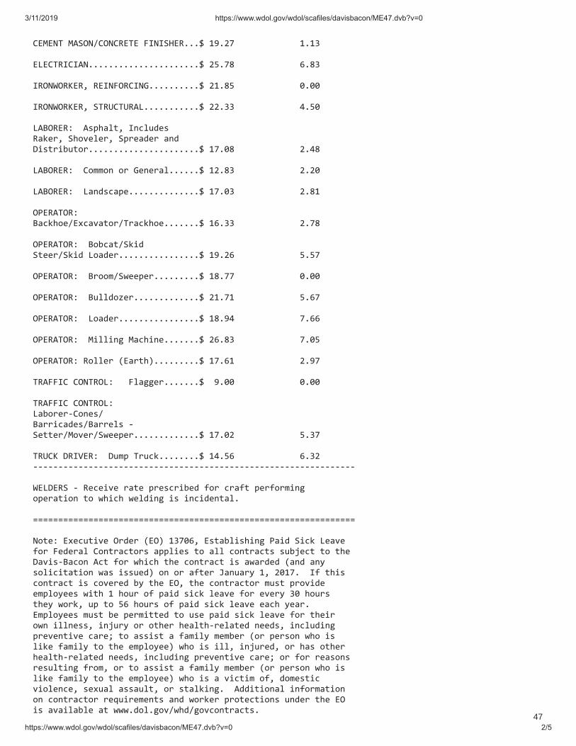
!!!"#$#%&!$'()%*")%"+#&#!,-%-(.#+///0!12/34!!!!!!!!!!!!!1/15!!!!#6#"&+-"-'%//////////////////////0!37/48!!!!!!!!!!!!!9/85!!!!-+)%:)+;#+<!+#-%,)+"-%=//////////0!31/87!!!!!!!!!!!!!>/>>!!!!-+)%:)+;#+<!(&+?"&?+'6///////////0!33/55!!!!!!!!!!!!!@/7>!!!!6'A)+#+B!!'CDEFGH<!-IJGKLMC!!!!+FNMO<!(EPQMGMO<!(DOMFLMO!FIL!!!!RSCHOSTKHPO//////////////////////0!14/>8!!!!!!!!!!!!!3/@8!!!!6'A)+#+B!!"PUUPI!PO!=MIMOFG//////0!13/85!!!!!!!!!!!!!3/3>!!!!6'A)+#+B!!6FILCJFDM//////////////0!14/>5!!!!!!!!!!!!!3/81!!!!)V#+'&)+B!!!!!AFJNEPM*#WJFQFHPO*&OFJNEPM///////0!19/55!!!!!!!!!!!!!3/48!!!!)V#+'&)+B!!APTJFH*(NSL!!!!(HMMO*(NSL!6PFLMO////////////////0!12/39!!!!!!!!!!!!!7/74!!!!)V#+'&)+B!!AOPPU*(XMMDMO/////////0!18/44!!!!!!!!!!!!!>/>>!!!!)V#+'&)+B!!AKGGLPYMO/////////////0!31/41!!!!!!!!!!!!!7/94!!!!)V#+'&)+B!!6PFLMO////////////////0!18/2@!!!!!!!!!!!!!4/99!!!!)V#+'&)+B!!$SGGSIZ!$FJESIM///////0!39/85!!!!!!!!!!!!!4/>7!!!!)V#+'&)+B!+PGGMO![#FOHE\/////////0!14/91!!!!!!!!!!!!!3/24!!!!&+',,-"!")%&+)6B!!!,GFZZMO///////0!!2/>>!!!!!!!!!!!!!>/>>!!!!&+',,-"!")%&+)6B!!!!!!6FTPOMO]"PIMC*!!!!AFOOSJFLMC*AFOOMGC!]!!!!!(MHHMO*$PQMO*(XMMDMO/////////////0!14/>3!!!!!!!!!!!!!7/54!!!!&+?";!R+-̂#+B!!RKUD!&OKJN////////0!1@/79!!!!!!!!!!!!!9/53!]]]]]]]]]]]]]]]]]]]]]]]]]]]]]]]]]]]]]]]]]]]]]]]]]]]]]]]]]]]]]]]]!!:#6R#+(!]!+MJMSQM!OFHM!DOMCJOSTML!_PO!JOF_H!DMO_POUSIZ!PDMOFHSPI!HP!XESJE!XMGLSIZ!SC!SIJSLMIHFG/!!`̀`̀`̀`̀`̀`̀`̀`̀`̀`̀`̀`̀`̀`̀`̀`̀`̀`̀`̀`̀`̀`̀`̀`̀`̀`̀`̀`̀`̀`̀`̀`̀!!!%PHMB!#WMJKHSQM!)OLMO![#)\!154>9<!#CHFTGSCESIZ!VFSL!(SJN!6MFQM!_PO!,MLMOFG!"PIHOFJHPOC!FDDGSMC!HP!FGG!JPIHOFJHC!CKTaMJH!HP!HEM!RFQSC]AFJPI!'JH!_PO!XESJE!HEM!JPIHOFJH!SC!FXFOLML![FIL!FIb!CPGSJSHFHSPI!XFC!SCCKML\!PI!PO!F_HMO!cFIKFOb!1<!3>14/!!-_!HESC!JPIHOFJH!SC!JPQMOML!Tb!HEM!#)<!HEM!JPIHOFJHPO!UKCH!DOPQSLM!MUDGPbMMC!XSHE!1!EPKO!P_!DFSL!CSJN!GMFQM!_PO!MQMOb!5>!EPKOC!HEMb!XPON<!KD!HP!79!EPKOC!P_!DFSL!CSJN!GMFQM!MFJE!bMFO/!#UDGPbMMC!UKCH!TM!DMOUSHHML!HP!KCM!DFSL!CSJN!GMFQM!_PO!HEMSO!PXI!SGGIMCC<!SIaKOb!PO!PHEMO!EMFGHE]OMGFHML!IMMLC<!SIJGKLSIZ!DOMQMIHSQM!JFOMd!HP!FCCSCH!F!_FUSGb!UMUTMO![PO!DMOCPI!XEP!SC!GSNM!_FUSGb!HP!HEM!MUDGPbMM\!XEP!SC!SGG<!SIaKOML<!PO!EFC!PHEMO!EMFGHE]OMGFHML!IMMLC<!SIJGKLSIZ!DOMQMIHSQM!JFOMd!PO!_PO!OMFCPIC!OMCKGHSIZ!_OPU<!PO!HP!FCCSCH!F!_FUSGb!UMUTMO
��������� ��������� ���� ������������������������������ �������
��������� ���� ������������������������������ ������� ��
!"#$%&'()!*$+&&%,%*+'%-#&!#(()()!,-.!/-.0!#-'!%#*$1)()!/%'2%#!'2(!&*-3(!-,!'2(!*$+&&%,%*+'%-#&!$%&'()!4+5!6(!+))()!+,'(.!+/+.)!-#$5!+&!3.-7%)()!%#!'2(!$+6-.!&'+#)+.)&!*-#'.+*'!*$+1&(&!89:;<=!>?>!8+@!8A@!8%%@@?!!!BBBBBBBBBBBBBBBBBBBBBBBBBBBBBBBBBBBBBBBBBBBBBBBBBBBBBBBBBBBBBBBB!!!!C2(!6-)5!-,!(+*2!/+D(!)('(.4%#+'%-#!$%&'&!'2(!*$+&&%,%*+'%-#!+#)!/+D(!.+'(&!'2+'!2+7(!6((#!,-1#)!'-!6(!3.(7+%$%#D!,-.!'2(!*%'()!'53(8&@!-,!*-#&'.1*'%-#!%#!'2(!+.(+!*-7(.()!65!'2(!/+D(!)('(.4%#+'%-#?!C2(!*$+&&%,%*+'%-#&!+.(!$%&'()!%#!+$32+6('%*+$!-.)(.!-,!E%)(#'%,%(.&E!'2+'!%#)%*+'(!/2('2(.!'2(!3+.'%*1$+.!.+'(!%&!+!1#%-#!.+'(!8*1..(#'!1#%-#!#(D-'%+'()!.+'(!,-.!$-*+$@F!+!&1.7(5!.+'(!8/(%D2'()!+7(.+D(!.+'(@!-.!+!1#%-#!+7(.+D(!.+'(!8/(%D2'()!1#%-#!+7(.+D(!.+'(@?!!"#%-#!=+'(!G)(#'%,%(.&!!H!,-1.!$(''(.!*$+&&%,%*+'%-#!+66.(7%+'%-#!%)(#'%,%(.!(#*$-&()!%#!)-''()!$%#(&!6(D%##%#D!/%'2!*2+.+*'(.&!-'2(.!'2+#!EI"E!-.!E"HJKE!)(#-'(&!'2+'!'2(!1#%-#!*$+&&%,%*+'%-#!+#)!.+'(!/(.(!3.(7+%$%#D!,-.!'2+'!*$+&&%,%*+'%-#!%#!'2(!&1.7(5?!LM+43$(N!OP"QRA:SBRR>!RTURAU9RAV?!OP"Q!%&!+#!+66.(7%+'%-#!%)(#'%,%(.!-,!'2(!1#%-#!/2%*2!3.(7+%$()!%#!'2(!&1.7(5!,-.!'2%&!*$+&&%,%*+'%-#F!/2%*2!%#!'2%&!(M+43$(!/-1$)!6(!O$146(.&?!RA:S!%#)%*+'(&!'2(!$-*+$!1#%-#!#146(.!-.!)%&'.%*'!*-1#*%$!#146(.!/2(.(!+33$%*+6$(F!%?(?F!O$146(.&!P-*+$!RA:S?!C2(!#(M'!#146(.F!RR>!%#!'2(!(M+43$(F!%&!+#!%#'(.#+$!#146(.!1&()!%#!3.-*(&&%#D!'2(!/+D(!)('(.4%#+'%-#?!RTURAU9RAV!%&!'2(!(,,(*'%7(!)+'(!-,!'2(!4-&'!*1..(#'!#(D-'%+'()!.+'(F!/2%*2!%#!'2%&!(M+43$(!%&!W1$5!AF!9RAV?!!"#%-#!3.(7+%$%#D!/+D(!.+'(&!+.(!13)+'()!'-!.(,$(*'!+$$!.+'(!*2+#D(&!%#!'2(!*-$$(*'%7(!6+.D+%#%#D!+D.((4(#'!8;XH@!D-7(.#%#D!'2%&!*$+&&%,%*+'%-#!+#)!.+'(?!!I1.7(5!=+'(!G)(#'%,%(.&!!;$+&&%,%*+'%-#&!$%&'()!1#)(.!'2(!EI"E!%)(#'%,%(.!%#)%*+'(!'2+'!#-!-#(!.+'(!3.(7+%$()!,-.!'2%&!*$+&&%,%*+'%-#!%#!'2(!&1.7(5!+#)!'2(!316$%&2()!.+'(!%&!)(.%7()!65!*-431'%#D!+!/(%D2'()!+7(.+D(!.+'(!6+&()!-#!+$$!'2(!.+'(&!.(3-.'()!%#!'2(!&1.7(5!,-.!'2+'!*$+&&%,%*+'%-#?!!H&!'2%&!/(%D2'()!+7(.+D(!.+'(!%#*$1)(&!+$$!.+'(&!.(3-.'()!%#!'2(!&1.7(5F!%'!4+5!%#*$1)(!6-'2!1#%-#!+#)!#-#B1#%-#!.+'(&?!LM+43$(N!I"PH9RA9BRRT!>UAYU9RAV?!I"!%#)%*+'(&!'2(!.+'(&!+.(!&1.7(5!.+'(&!6+&()!-#!+!/(%D2'()!+7(.+D(!*+$*1$+'%-#!-,!.+'(&!+#)!+.(!#-'!4+Z-.%'5!.+'(&?!PH!%#)%*+'(&!'2(!I'+'(!-,!P-1%&%+#+?!9RA9!%&!'2(!5(+.!-,!&1.7(5!-#!/2%*2!'2(&(!*$+&&%,%*+'%-#&!+#)!.+'(&!+.(!6+&()?!C2(!#(M'!#146(.F!RRT!%#!'2(!(M+43$(F!%&!+#!%#'(.#+$!#146(.!1&()!%#!3.-)1*%#D!'2(!/+D(!)('(.4%#+'%-#?!>UAYU9RAV!%#)%*+'(&!'2(!&1.7(5!*-43$('%-#!)+'(!,-.!'2(!*$+&&%,%*+'%-#&!+#)!.+'(&!1#)(.!'2+'!%)(#'%,%(.?!!I1.7(5!/+D(!.+'(&!+.(!#-'!13)+'()!+#)!.(4+%#!%#!(,,(*'!1#'%$!+!#(/!&1.7(5!%&!*-#)1*'()?!!"#%-#!H7(.+D(!=+'(!G)(#'%,%(.&!!;$+&&%,%*+'%-#8&@!$%&'()!1#)(.!'2(!"HJK!%)(#'%,%(.!%#)%*+'(!'2+'!#-!&%#D$(!4+Z-.%'5!.+'(!3.(7+%$()!,-.!'2-&(!*$+&&%,%*+'%-#&[!2-/(7(.F!ARR\!-,!'2(!)+'+!.(3-.'()!,-.!'2(!*$+&&%,%*+'%-#&!/+&!1#%-#!)+'+?!L]HQOPLN!"HJKB̂_BRRAR!
48

��������� ��������� ���� ������������������������������ �������
��������� ���� ������������������������������ ������� ��
!"#$%#$!&'()*+,-)./0.12345)3623)364)7234).5)2)84.96340):/.;/)2<47294)7234()=>)./0.12345)364)53234()?64)/4@3)/:AB47C)!!&!)./)364)4@2ADE4C).5)2/)./347/2E)/:AB47):540)./)D7;0:1./9)364)8294)04347A./23.;/()!"#$%#$!&')./0.12345)364)5:7<4F)1;ADE43.;/)0234)G;7)364)1E255.G.123.;/5)2/0)72345):/047)3623).04/3.G.47())+)*+,-)7234)8.EE)B4):D02340);/14)2)F427C):5:2EEF)./)H2/:27F);G)4216)F427C)3;)74GE413)2)84.96340)2<47294);G)364)1:774/3)/49;3.2340#IJ+)7234);G)364):/.;/)E;12E5)G7;A)86.16)364)7234).5)B2540()))))KKKKKKKKKKKKKKKKKKKKKKKKKKKKKKKKKKKKKKKKKKKKKKKKKKKKKKKKKKKKKKKK)))))))))))))))))))))L+-M)NM?MOPQR+?Q=R)+SSM+TU)SO=IMUU))&(V)>25)36474)B44/)2/)./.3.2E)041.5.;/)./)364)A23347W)?6.5)12/)B4X))Y))2/)[email protected]./9)D:BE.5640)8294)04347A./23.;/)Y))2)5:7<4F):/047EF./9)2)8294)04347A./23.;/)Y))2)L294)2/0)>;:7)N.<.5.;/)E43347)5433./9)G;736)2)D;5.3.;/);/))))2)8294)04347A./23.;/)A23347)Y))2)1;/G;7A2/14)Z200.3.;/2E)1E255.G.123.;/)2/0)7234V)7:E./9))=/)5:7<4F)74E2340)A233475C)./.3.2E)1;/3213C)./1E:0./9)74[:4535)G;7)5:AA27.45);G)5:7<4F5C)56;:E0)B4)8.36)364)L294)2/0)>;:7)O49.;/2E)=GG.14)G;7)364)2742)./)86.16)364)5:7<4F)825)1;/0:1340)B412:54)36;54)O49.;/2E)=GG.145)62<4)745D;/5.B.E.3F)G;7)364)N2<.5KJ21;/)5:7<4F)D7;972A()QG)364)745D;/54)G7;A)36.5)./.3.2E)1;/3213).5)/;3)523.5G213;7FC)364/)364)D7;1455)04517.B40)./)$(V)2/0)\(V)56;:E0)B4)G;EE;840())L.36)749270)3;)2/F);3647)A23347)/;3)F43)7.D4)G;7)364)G;7A2E)D7;1455)04517.B40)6474C)./.3.2E)1;/3213)56;:E0)B4)8.36)364)J72/16);G)I;/537:13.;/)L294)N4347A./23.;/5())L7.34)3;X))))))))))))))J72/16);G)I;/537:13.;/)L294)N4347A./23.;/5)))))))))))))L294)2/0)>;:7)N.<.5.;/)))))))))))))*(U()N4D273A4/3);G)T2B;7)))))))))))))$!!)I;/53.3:3.;/)+<4/:4C)R(L()))))))))))))L256./93;/C)NI)$!$&!))$(V)QG)364)2/5847)3;)364)[:453.;/)./)&(V).5)F45C)364/)2/)./34745340)D273F)Z36;54)2GG41340)BF)364)213.;/V)12/)74[:453)74<.48)2/0)741;/5.04723.;/)G7;A)364)L294)2/0)>;:7)+0A./.53723;7)ZU44)$%)I]O)S273)&(")2/0)$%)I]O)S273)̂V()L7.34)3;X))))))))))))))L294)2/0)>;:7)+0A./.53723;7)))))))))))))*(U()N4D273A4/3);G)T2B;7)))))))))))))$!!)I;/53.3:3.;/)+<4/:4C)R(L()))))))))))))L256./93;/C)NI)$!$&!))?64)74[:453)56;:E0)B4)211;AD2/.40)BF)2)G:EE)53234A4/3);G)364)./34745340)D273F_5)D;5.3.;/)2/0)BF)2/F)./G;7A23.;/)Z8294)D2FA4/3)0232C)D7;̀413)04517.D3.;/C)2742)D7213.14)A2347.2EC)431(V)3623)364)74[:453;7)1;/5.0475)74E4<2/3)3;)364).55:4())\(V)QG)364)041.5.;/);G)364)+0A./.53723;7).5)/;3)G2<;72BE4C)2/)./34745340)D273F)A2F)2DD42E)0.7413EF)3;)364)+0A./.53723.<4)O4<.48)J;270)ZG;7A47EF)364)L294)+DD42E5)J;270V())L7.34)3;X))))))))))))))+0A./.53723.<4)O4<.48)J;270)))))))))))))*(U()N4D273A4/3);G)T2B;7)
49

��������� ��������� ���� ������������������������������ �������
��������� ���� ������������������������������ ������� �
!!!!!!!!!!!!"##!$%&'()(*()%&!+,-&*-.!/010!!!!!!!!!!!!!12'3)&4(%&.!5$!"#"6#!!708!+99!:-;)')%&'!<=!(3-!+:>)&)'(?2(),-!@-,)-A!B%2?:!2?-!C)&290!!DDDDDDDDDDDDDDDDDDDDDDDDDDDDDDDDDDDDDDDDDDDDDDDDDDDDDDDDDDDDDDDD!!!!!!!!!!!!E/5!FG!HE/E@+I!5E$JKJF/!!!
50
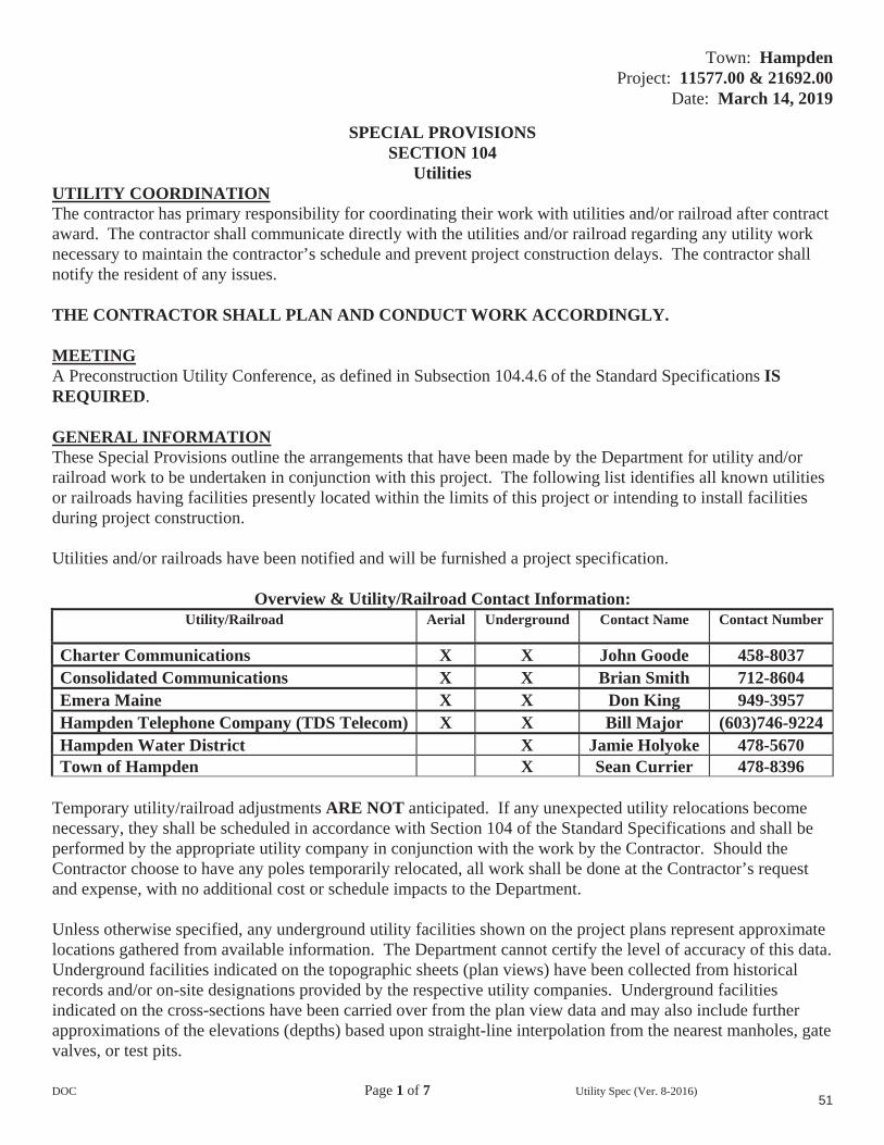
Town: HampdenProject: 11577.00 & 21692.00
Date: March 14, 2019
DOC Page 1 of 7 Utility Spec (Ver. 8-2016)
SPECIAL PROVISIONS SECTION 104
UtilitiesUTILITY COORDINATION The contractor has primary responsibility for coordinating their work with utilities and/or railroad after contract award. The contractor shall communicate directly with the utilities and/or railroad regarding any utility work necessary to maintain the contractor’s schedule and prevent project construction delays. The contractor shall notify the resident of any issues.
THE CONTRACTOR SHALL PLAN AND CONDUCT WORK ACCORDINGLY.
MEETINGA Preconstruction Utility Conference, as defined in Subsection 104.4.6 of the Standard Specifications ISREQUIRED.
GENERAL INFORMATIONThese Special Provisions outline the arrangements that have been made by the Department for utility and/or railroad work to be undertaken in conjunction with this project. The following list identifies all known utilities or railroads having facilities presently located within the limits of this project or intending to install facilities during project construction.
Utilities and/or railroads have been notified and will be furnished a project specification.
Overview & Utility/Railroad Contact Information: Utility/Railroad Aerial Underground Contact Name Contact Number
Charter Communications X X John Goode 458-8037 Consolidated Communications X X Brian Smith 712-8604 Emera Maine X X Don King 949-3957 Hampden Telephone Company (TDS Telecom) X X Bill Major (603)746-9224 Hampden Water District X Jamie Holyoke 478-5670 Town of Hampden X Sean Currier 478-8396
Temporary utility/railroad adjustments ARE NOT anticipated. If any unexpected utility relocations become necessary, they shall be scheduled in accordance with Section 104 of the Standard Specifications and shall be performed by the appropriate utility company in conjunction with the work by the Contractor. Should the Contractor choose to have any poles temporarily relocated, all work shall be done at the Contractor’s request and expense, with no additional cost or schedule impacts to the Department.
Unless otherwise specified, any underground utility facilities shown on the project plans represent approximate locations gathered from available information. The Department cannot certify the level of accuracy of this data. Underground facilities indicated on the topographic sheets (plan views) have been collected from historical records and/or on-site designations provided by the respective utility companies. Underground facilities indicated on the cross-sections have been carried over from the plan view data and may also include further approximations of the elevations (depths) based upon straight-line interpolation from the nearest manholes, gate valves, or test pits.
51

Town: HampdenProject: 11577.00 & 21692.00
Date: March 14, 2019
DOC Page 2 of 7 Utility Spec (Ver. 8-2016)
All adjustments are to be made by the respective utility/railroad unless otherwise specified herein.
Fire hydrants shall not be disturbed until all necessary work has been accomplished to provide proper fire protection.
All clearing and tree removal in areas where utilities are involved must be completed before the utilities are able to relocate their facilities.
It is the responsibility of the Contractor with the Utility Pole owner, to layout all of the proposed pole locations in the field prior to the start of utility relocations. Should any adjustments be needed, the Utility will document adjustments and inform the Department prior to utility relocations.
The Contractor shall provide the utilities access to the new pole locations. Construction of any spot cuts or fills in excess of 2 feet must be completed prior to utility relocations. All cut/fill depths listed on the pole list are approximate and will need to be verified by the contractor prior to poles being set. The Contractor shall prepare a plan for how access and the spot cuts and fills will be accomplished and what the schedule will be for performing the work. This plan will be discussed at the pre-construction utility meeting.
** Specific information regarding the line voltage can be requested from Emera Maine**
Utility/railroad working days are Monday through Friday. Times are estimated on the basis of a single crew for each utility/railroad. Any times and dates mentioned are estimates only and are dependent upon favorable weather, working conditions, and freedom from emergencies. The Contractor shall have no claim against the Department if they are exceeded.
AERIALSummary:
UtilityPoleSet
NewWires/Cables
Trans.Wires/Cables
Remove Poles
EstimatedWorking Days
(Bridge)
EstimatedWorking Days
(Highway)
TotalEstimated
Working Days Emera Maine X X X X 10 60 70
Charter Communications X X 5 10 15 TDS Telecom X X 15 10 25
Consolidated Communications X X 5 45 50 Total: 35 125 160
Utility Specific Issues: Emera MaineEmera Maine has approximately 96 poles to set as per the pole list included in this specification and has cables to run/transfer to the new pole locations. The contractor shall notify Emera once all poles are staked, pole access is provided and the clearing and spot cuts/fills are completed. Emera will require two weeks to schedule their work after notice is received. Once work is scheduled Emera estimates 70 working days to complete their work. Emera will remove the old poles once all transfers are complete.
52

Town: HampdenProject: 11577.00 & 21692.00
Date: March 14, 2019
DOC Page 3 of 7 Utility Spec (Ver. 8-2016)
Charter Communications Charter Communications has cables to run/transfer to the new pole locations. After Emera has completed their work, Charter shall begin their work. The contractor and/or Emera shall notify Charter once all of Emera’s work is completed. Charter will require two weeks to schedule their work after notice is received. Once work is scheduled Charter estimates 15 working days to complete their work.
Hampden Telephone Company (TDS Telecom) Hampden Telephone Company (TDS Telecom) has cables to run/transfer to the new pole locations. TDS has a fiber cable that is attached below Charter but above CCI that will need to be relocated as phase 1. TDS has a copper cable that is attached below CCI that will need to be relocated as phase 2. After Charter has completed their work, TDS shall begin their phase 1 fiber work. The contractor and/or Charter shall notify TDS once all of Charter’s work is completed. TDS will require two weeks to schedule phase 1 of their work after notice is received. After CCI has completed their work TDS can complete phase 2 of their work. The contractor and/or CCI shall notify TDS once all of CCI’s work is completed. TDS will require two weeks to schedule their work after notice is received. Once work is scheduled TDS estimates a total 25 working days to complete both phases of their work.
Consolidated Communications Consolidated Communications (CCI) has cables to run/transfer to the new pole locations. After TDS has completed their phase 1 fiber work, CCI shall begin their work. The contractor and/or TDS shall notify CCI once all of TDS’s phase 1 fiber work is completed. CCI will require two weeks to schedule their work after notice is received. Once work is scheduled CCI estimates 50 working days to complete their work.
CCI also has a dual pole line on the northwest side of the road (station left) that is being abandoned. The old poles and conductor will be removed either prior to or during this project.
Pole List:Existing Pole #
Existing Station
Left/Right
Existing Offset
ProposedStation
Left/Right
ProposedOffset Comments
C/F
LT
RT
LT
RT
1334/3 11+32.87 X 23.98 OK (OFF PROJECT) - 1334.5 11+83.01 X 20.21 OK (OFF PROJECT) - 3000/7 12+42.65 X 255.91 OK (OFF PROJECT) - 3000/5 12+55.54 X 211.7 OK (OFF PROJECT) - 3000/7 12+79.40 X 269.61 OK (OFF PROJECT) -
13+16.08 X 140.74 OK (OFF PROJECT) - 1335/6000/1 13+51.81 X 27.58 OK (OFF PROJECT) - 3010/1 13+56.90 X 57.06 OK (OFF PROJECT) - 2/1336 14+87.78 X 22.52 OK (OFF PROJECT) -
15+85.71 X 100.21 OK (OFF PROJECT) - 1337/3 16+04.03 X 20.31 15+94 X 21’ REPLACE <2’ 55149, 1337 17+02.49 X 20.96 OK (BEHIND CURB) - 1338/4, 155148 17+47.97 X 22.06 17+36 X 17.5’ MOVE (IN SIDEWALK) <2’ 1338S 17+36 X 20’ NEW STUB POLE <2’ 4 18+25.39 X 20.12 S/S X 21.6’ MOVE (6’ RULE) <2’1339/2000/5, 155146 18+79.60 X 19.23 18+84 X 17.5’ MOVE (IN SIDEWALK) <2’ 2000/5, 155145 19+19.00 X 20.15 19+23 X 22’ MOVE (6’ RULE) <2’1340/6, 155144 19+82.60 X 17.37 S/S X 17.5’ REPLACE <2’ 155143 20+20.25 X 21.81 20+22 X 22’ REPLACE <2’
53

Town: HampdenProject: 11577.00 & 21692.00
Date: March 14, 2019
DOC Page 4 of 7 Utility Spec (Ver. 8-2016)
1341/7, 155141 21+37.10 X 16.59 21+46 X 17.5’ MOVE (IN CURB) <2’ 1341/7, 155142 21+68.45 X 21.34 REMOVE POLE -1342/8, 155117, 1343 22+69.68 X 24.01 23+27 X 17.5’ MOVE (DRAINAGE) 2’ 5201/134/9, 155119 22+92.12 X 21.7 REMOVE POLE -
23+24.55 X 48.06 REMOVE POLE -1343/9, 155116 23+73.25 X 23.05 REMOVE POLE -11 24+87.82 X 22.71 OK (2’ C.Z. RULE) -
24+89.49 X 23.98 OK (BEHIND SIDEWALK) - 1344/00/10, 155115 25+17.99 X 20.79 25+20 X 17.5’ MOVE (IN SIDEWALK) 3’ 1345/11, 155114 26+35.49 X 21.21 26+37 X 17.5’ MOVE (IN SIDEWALK) 2’ 1346/12, 155113 27+43.79 X 19.33 27+42 X 17.5’ MOVE (IN SIDEWALK) <2’ 1 28+58.53 X 21.28 REMOVE POLE -155112, 1346 1/2 28+61.44 X 21.62 28+66 17.5’ MOVE (IN SIDEWALK) <2’ 1353/14, 155107,1347 29+72.74 X 26.18 29+74 X 17.5’ REPLACE <2’ 1353S, 155106,1347S 29+73.96 X 24.71 OK (BEHIND DITCH) - 2000/15,155108,1347½ 31+16.07 X 36.22 31+14 X 25’ REPLACE <2’ 1353.5, 155105 31+38.25 X 20.61 OK (BEHIND GR) - 31+91.83 X 140.65 OK (WAY OFF ROAD) - 16, 155109, 1348 32+42.14 X 56.12 31+95 X 31.7’ REPLACE <2’ 1354/17, 155104 32+93.50 X 20.69 REMOVE POLE -135/18,155103,1348½ 34+28.05 X 23.42 33+30 X 45’ MOVE (BRIDGE) <2’ 34+90.29 X 80.84 REMOVE POLE -519/1/2400/1, 35+03.25 X 140.49 35+05 X 132’ REPLACE (DUDLEY RD) <2’ 1355 35+27.79 X 71.44 OK (WAY OFF ROAD) - 134/90, 154157, 1349 35+50.40 X 64.94 35+39 X 47.6’ RELOCATE POLE <2’ 238_1355 35+54.67 X 69.35 REMOVE POLE -2300/2 35+98.36 X 199.95 REMOVE POLE -133/2000/20,154156,1350 36+70.91 X 40.68 36+79 X 34’ REPLACE 2’ 21/5/6,154154, 1350 ½ 38+34.32 X 24.99 38+37 X 29’ MOVE (DITCH)/OUTRIG <2’ 1358, 154155 38+36.46 X 25.88 S/S X 26’ REPLACE <2’ 1359 40+04.89 X 28.21 REMOVE POLE -1351S 40+19 X 26’ NEW STUB POLE <2’ 132/22, 154153, 1351 40+15.15 X 23.65 40+19 X 24’ REPLACE/OUTRIG <2’ 23, 154052 41+26.94 X 27 OK (BEHIND SIDEWALK) - 23, 154049, 1352 41+40.59 X 28.59 41+40 X 25’ MOVE (DRAIN)/OUTRIG <2’ 154048 41+69.76 X 30.04 REMOVE POLE -36 41+70.40 X 27.99 REMOVE POLE -5/130,154046, 1352 ½ 42+35.71 X 19.03 42+24 X 22’ MOVE (6’ RULE) <2’ 1352 1/2S 42+25 X 26’ NEW STUB POLE <2’ 5/130, 154047 42+70.90 X 21.12 REMOVE POLE -136 43+19.64 X 20.47 REMOVE POLE -129/2000/25,154045,1353 43+46.45 X 22.2 S/S X 24.6’ REPLACE <2’ 1363, 154043, 1354S 44+70.04 X 21.2 44+72 X 32’ MOVE (IN SIDEWALK) <2’ 135/128/26, 154042, 1354 44+74.57 X 20.84 44+76 X 22’ MOVE (6’ RULE) <2’ 1364 45+63.53 X 18.12 REMOVE POLE -1355S 45+89 X 28’ NEW STUB POLE 3’ 127/27, 154041, 1355 45+87.17 X 22.42 45+89 X 22’ REPLACE <2’ 126/28, 154041, 1356 47+02.81 X 22.67 47+05 X 22’ REPLACE <2’ 1365, 154040 47+23.93 X 20.23 47+26 X 31’ MOVE (IN SIDEWALK) <2’ 5/125/29, 154038, 1357 48+13.99 X 21.74 48+12 X 22’ REPLACE <2’ 1366, 154037, 49+33.99 X 20.58 49+36 X 32’ MOVE (IN SIDEWALK) <2’ 124, 154035, 1358 49+77.90 X 22.72 49+80 X 22’ REPLACE <2’ 1367 50+90.40 X 21.28 REMOVE POLE -123/31, 154034, 1359 51+63.90 X 22.36 51+66 X 22’ REPLACE <2’
54

Town: HampdenProject: 11577.00 & 21692.00
Date: March 14, 2019
DOC Page 5 of 7 Utility Spec (Ver. 8-2016)
1368, 154033 52+67.60 X 22.99 52+70 X 32’ MOVE (IN SIDEWALK) <2’ 122/32, 154032, 1360 52+90.70 X 21.45 52+93 X 22’ MOVE (6’ RULE) <2’ 121/33, 154030, 1361 53+92.52 X 22.01 53+95 X 22’ REPLACE <2’ 154031 54+21.58 X 23.34 54+20 X 32’ MOVE (IN SIDEWALK) <2’ 5-120/34, 154028, 1362 55+19.01 X 22.05 55+21 X 22’ REPLACE <2’
55+55.60 X 124.44 OK (SIDE ROAD) -1370/P99, 154027 55+94.84 X 23.4 S/S X 32’ MOVE (IN SIDEWALK) <2’ 119/2000/35, 154026, 1363 56+77.29 X 21.74 56+79 X 22’ REPLACE <2’
57+57.87 X 24.95 OK (BEHIND SIDEWALK) - 1371, 154025 57+58.26 X 21.3 REMOVE POLE -118/36, 154024, 1364 57+77.89 X 21.83 57+80 X 22’ REPLACE <2’ 137 59+13.09 X 20.39 REMOVE POLE -117/37, 154023, 1365 59+20.18 X 22.04 59+22 X 22’ REPLACE <2’ 116/38, 154022, 1366 60+27.54 X 21.95 60+27 X 22’ REPLACE <2’ 1375, 154021 60+72.37 X 20.7 REMOVE POLE -5/115/39, 154020, 1367 61+59.05 X 21.78 61+63 X 22’ REPLACE <2’ 1374 62+43.63 X 18.97 REMOVE POLE -114/2000/40, 154018, 1368 62+82.14 X 21.5 62+80 X 22’ MOVE (6’ RULE) <2’ 63+23.06 X 61.36 OK (SIDE ROAD) -
63+71.27 X 59.68 OK (SIDE ROAD) -63+76.25 X 51.11 OK (SIDE ROAD) -
1375 64+01.51 X 20.12 63+99 X 32’ MOVE (IN SIDEWALK) <2’ 113/41, 154016, 1369 64+11.78 X 19.55 64+15 X 22’ MOVE (CZ/6’ RULE) <2’ 112/42, 154015, 1370 65+45.18 X 18.95 65+47 X 22’ REPLACE <2’ 1376, 154014 66+34.16 X 21.06 66+67 X 29’ MOVE (IN SIDEWALK) <2’ 111/43, 154013, 1371 66+65.9 X 18.5 66+67 X 22’ MOVE (CZ/6’ RULE) <2’ 5/110/11, 154012, 1372 67+80.30 X 18.7 67+82 X 22’ MOVE (CZ/6’ RULE) <2’ 1377, 154011 68+12.28 X 21.83 REMOVE POLE -109/2000/45, 154010, 1373 68+98.14 X 19.6 69+00 X 22’ MOVE (CZ/6’ RULE) <2’ 1378 69+86.43 X 28.81 REMOVE POLE -P512/1D 70+22.51 X 54.77 OK (OUTSIDE CZ) - 47/108.5,154009,1374 70+57.63 X 25.66 70+60 X 23’ REPLACE <2’ 1379 71+44.37 X 26.98 REMOVE POLE -108/48,154008, 1375 71+53.30 X 21.92 S/S X 22’ REPLACE <2’ 107/49, 154007, 1376 72+58.04 X 20.91 S/S X 22’ MOVE (6’ RULE) <2’ 106.5 73+54.27 X 20.97 REMOVE POLE -106.5/50,154002,1377 73+55.75 X 20.5 73+56 X 22’ REPLACE <2’ 1380, 154003 73+64.59 X 23.32 73+62 X 30’ MOVE (IN SIDEWALK) <2’ L2/2800/1 73+91.04 X 182.75 OK (OUTSIDE CZ) - 106/51, 154001, 1378 74+59.46 X 20.67 74+61 X 22’ MOVE (CZ/6’ RULE) <2’ 1381, 154875 75+83.36 X 21.36 75+94 X 29’ MOVE (IN SIDEWALK) <2’ 154873, 154874 76+15.09 X 21.16 REMOVE POLE -154873,154874,105,1379 76+15.36 X 21.52 76+17 X 22’ MOVE (CZ/6’ RULE) <2’ 104/53,1382,154872, 1380 77+07.68 X 22.71 77+10 X 22’ REPLACE <2’ 1382, 154871 77+76.15 X 21.32 77+80 X 29’ MOVE (IN SIDEWALK) <2’ 103/54, 154870, 1381 78+21.30 X 27.44 78+22 X 22’ REPLACE <2’ 154869, 1383 79+38.78 X 19.92 79+41 X 29’ MOVE (IN SIDEWALK) 2’ 102/2000/55 154868, 1382 79+75.32 X 25.76 79+76 X 22’ REPLACE <2’ 101/36 154866, 1383 81+20.82 X 23.36 S/S X 22’ REPLACE <2’ 13, 154867, 81+49.07 X 20.34 81+21 X 29’ MOVE (IN SIDEWALK) 2’ 5/100/57, 154865, 1384 83+03.10 X 20.58 83+02 X 22’ MOVE (CZ/6’ RULE) <2’ 1385 83+64.71 X 19.09 REMOVE POLE -58/99, 154864, 238/1385 84+19.40 X 19.22 84+21 X 22’ MOVE (CZ/6’ RULE) <2’ 98/59, 154862, 1386 85+32.83 X 19.93 85+35 X 22’ MOVE (CZ/6’ RULE) <2’
55
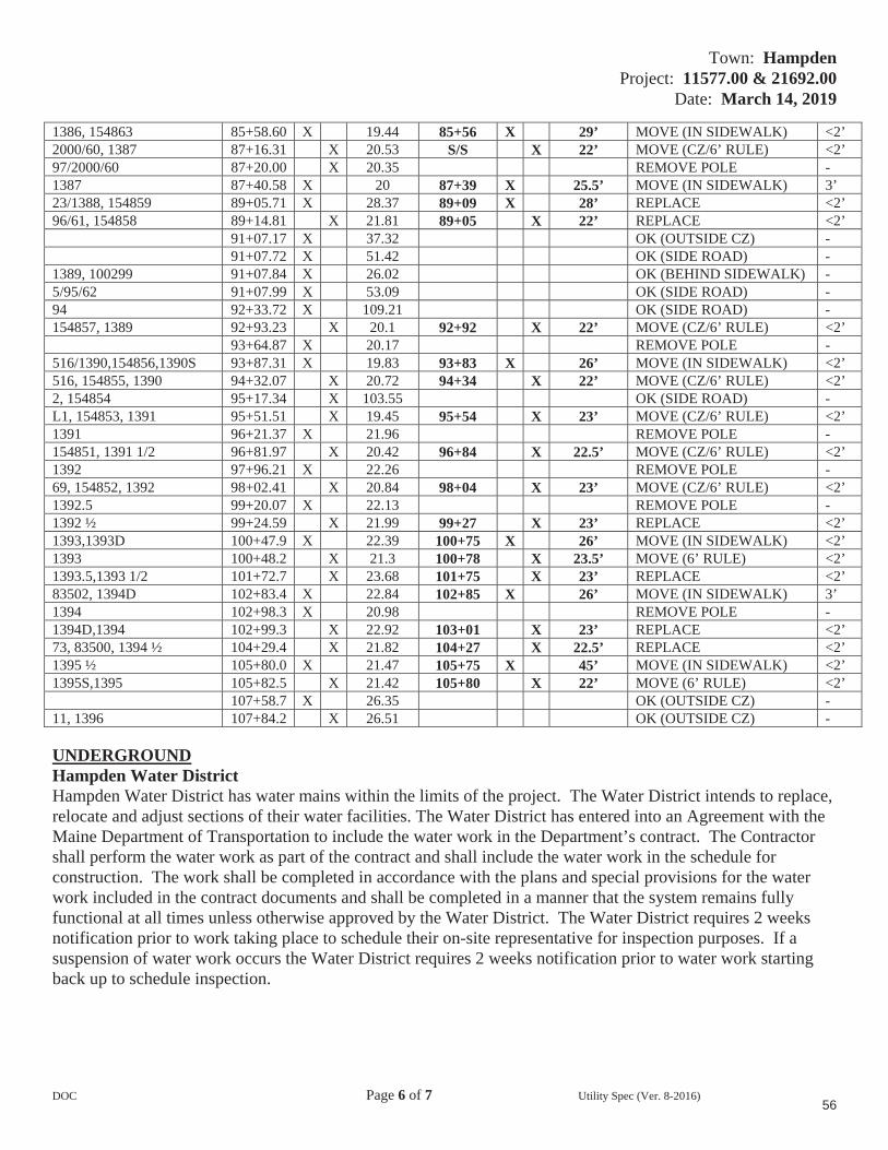
Town: HampdenProject: 11577.00 & 21692.00
Date: March 14, 2019
DOC Page 6 of 7 Utility Spec (Ver. 8-2016)
1386, 154863 85+58.60 X 19.44 85+56 X 29’ MOVE (IN SIDEWALK) <2’ 2000/60, 1387 87+16.31 X 20.53 S/S X 22’ MOVE (CZ/6’ RULE) <2’ 97/2000/60 87+20.00 X 20.35 REMOVE POLE -1387 87+40.58 X 20 87+39 X 25.5’ MOVE (IN SIDEWALK) 3’ 23/1388, 154859 89+05.71 X 28.37 89+09 X 28’ REPLACE <2’ 96/61, 154858 89+14.81 X 21.81 89+05 X 22’ REPLACE <2’
91+07.17 X 37.32 OK (OUTSIDE CZ) - 91+07.72 X 51.42 OK (SIDE ROAD) -
1389, 100299 91+07.84 X 26.02 OK (BEHIND SIDEWALK) - 5/95/62 91+07.99 X 53.09 OK (SIDE ROAD) -94 92+33.72 X 109.21 OK (SIDE ROAD) -154857, 1389 92+93.23 X 20.1 92+92 X 22’ MOVE (CZ/6’ RULE) <2’
93+64.87 X 20.17 REMOVE POLE -516/1390,154856,1390S 93+87.31 X 19.83 93+83 X 26’ MOVE (IN SIDEWALK) <2’ 516, 154855, 1390 94+32.07 X 20.72 94+34 X 22’ MOVE (CZ/6’ RULE) <2’ 2, 154854 95+17.34 X 103.55 OK (SIDE ROAD) -L1, 154853, 1391 95+51.51 X 19.45 95+54 X 23’ MOVE (CZ/6’ RULE) <2’ 1391 96+21.37 X 21.96 REMOVE POLE -154851, 1391 1/2 96+81.97 X 20.42 96+84 X 22.5’ MOVE (CZ/6’ RULE) <2’ 1392 97+96.21 X 22.26 REMOVE POLE -69, 154852, 1392 98+02.41 X 20.84 98+04 X 23’ MOVE (CZ/6’ RULE) <2’ 1392.5 99+20.07 X 22.13 REMOVE POLE -1392 ½ 99+24.59 X 21.99 99+27 X 23’ REPLACE <2’ 1393,1393D 100+47.9 X 22.39 100+75 X 26’ MOVE (IN SIDEWALK) <2’ 1393 100+48.2 X 21.3 100+78 X 23.5’ MOVE (6’ RULE) <2’1393.5,1393 1/2 101+72.7 X 23.68 101+75 X 23’ REPLACE <2’ 83502, 1394D 102+83.4 X 22.84 102+85 X 26’ MOVE (IN SIDEWALK) 3’ 1394 102+98.3 X 20.98 REMOVE POLE -1394D,1394 102+99.3 X 22.92 103+01 X 23’ REPLACE <2’ 73, 83500, 1394 ½ 104+29.4 X 21.82 104+27 X 22.5’ REPLACE <2’ 1395 ½ 105+80.0 X 21.47 105+75 X 45’ MOVE (IN SIDEWALK) <2’ 1395S,1395 105+82.5 X 21.42 105+80 X 22’ MOVE (6’ RULE) <2’
107+58.7 X 26.35 OK (OUTSIDE CZ) - 11, 1396 107+84.2 X 26.51 OK (OUTSIDE CZ) -
UNDERGROUNDHampden Water District Hampden Water District has water mains within the limits of the project. The Water District intends to replace, relocate and adjust sections of their water facilities. The Water District has entered into an Agreement with the Maine Department of Transportation to include the water work in the Department’s contract. The Contractor shall perform the water work as part of the contract and shall include the water work in the schedule for construction. The work shall be completed in accordance with the plans and special provisions for the water work included in the contract documents and shall be completed in a manner that the system remains fully functional at all times unless otherwise approved by the Water District. The Water District requires 2 weeks notification prior to work taking place to schedule their on-site representative for inspection purposes. If a suspension of water work occurs the Water District requires 2 weeks notification prior to water work starting back up to schedule inspection.
56

Town: HampdenProject: 11577.00 & 21692.00
Date: March 14, 2019
DOC Page 7 of 7 Utility Spec (Ver. 8-2016)
Town of Hampden Town of Hampden has sewer mains within the limits of the project. The Town intends to replace, relocate and adjust sections of their sewer facilities. The Town has entered into an Agreement with the Maine Department of Transportation to include the sewer work in the Department’s contract. The Contractor shall perform the sewer work as part of the contract and shall include the sewer work in the schedule for construction. The work shall be completed in accordance with the plans and special provisions for the sewer work included in the contract documents and shall be completed in a manner that the system remains fully functional at all times unless otherwise approved by the Town. The Town requires 2 weeks notification prior to work taking place to schedule their on-site representative for inspection purposes. If a suspension of sewer work occurs the Town requires 2 weeks notification prior to sewer work starting back up to schedule inspection.
A new sewer main to a potential future sub-development may need to be installed at approximately station 50+20 Lt. across Route 1A to the sewer main on the right side of the road. If the development is approved and moves forward this work will need to be completed during construction of the project by the developer. The work will need to be coordinated between the contractor and the developer.
PLEASE NOTE Charter Communications, Consolidated Communications, Emera Maine & TDS Telecom all have underground service facilities located within the project limits. Underground service transfers have been included in the aerial working days estimates. No impacts are anticipated to their service facilities.
PLEASE NOTE All underground utilities require 3 working days’ notice for any/all excavation or any other subsurface work around any underground facilities to schedule an on-site representative to be present. The contractor shall hand dig around all the underground facilities.
MAINTAINING UTILITY LOCATION MARKINGS The Contractor will be responsible for maintaining the buried utility/railroad location markings following the initial locating by the appropriate utility/railroad or their designated representative.
UTILITY SIGNINGAny utility/railroad working within the construction limits of this project shall ensure that the traveling public is adequately protected at all times. All work areas shall be signed, lighted, and traffic flaggers employed as determined by field conditions. All traffic controls shall be in accordance with the latest edition of the Manual on Uniform Traffic Control Devices for Streets and Highways, as issued by the Federal Highway Administration.
57

December 17, 2010Supersedes December 30, 2009
1 of 1
SPECIAL PROVISION SECTION 104
GENERAL RIGHTS AND RESPONSIBILITIES(Electronic Payroll Submission)
(Payment Tracking)
104.3.8.1 Electronic Payroll Submission The prime contractor and all subcontractors and lower-tier subcontractors will submit their certified payrolls electronically on this contract utilizing the Elation System web based reporting. There is no charge to the contracting community for the use of this service. The submission of paper payrolls will not be allowed or accepted. Additional information can be found at http://www.maine.gov/mdot/contractors/ under the first “Notice”.
104.3.8.2 Payment Tracking The prime contractor and all subcontractors and lower-tier subcontractors will track and confirm the delivery and receipt of all payments through the Elation System
58

Town: HampdenWIN #: 11577.00 – 21692.00 Date: 3/15/2019 Page 1 SPECIAL PROVISION
SECTION 105General Scope of Work
(Environmental Requirements) In-Water work consists of any activity conducted below the normal high water mark of a river, steam, brook, lake, pond or “Coastal Wetland” areas that are subject to tidal action during the highest tide level for the year which an activity is proposed as identified in the tide tables published by the National Ocean Service. http://www.oceanservice.noaa.gov/ For the full definition of “Coastal Wetlands”, please refer to 38 MRSA 480-B(2)
I. In-Water Work shall not be allowed between the dates of October 1 and June 30. (In-Water work is allowed from July 1 to September 30)
II. In-Water work window applies to the following water bodies at the following station #’s: 1. Souadabscook Stream at proposed bridge replacement (approx. Sta. 32+75 to 34+40 Rt. and Sta. 33+75
to 34+20 Lt.) 2. Souadabscook Stream at proposed outfall pipe (approx. Sta. 31+85 Rt.)
III. Special Conditions: 1. Individual Permit Application with the Army Corps of Engineers is currently pending. In-water
work may not begin until an ACOE permit has been issued. These documents will be provided to the contractor as soon as they are available. In-water work shall NOT begin without written permission from the MaineDOT.
2. Special Conditions of Formal Endangered Species Act (Section 7) Consultation with U.S. Fish and Wildlife Service apply (summarized in this Special Provision 105, and PENDING ACOE permit).
3. Conditions of the Maine Department of Environmental Protection Permit By Rule Section 11 shall apply to this project (see permit and conditions in the contract document).
4. The Contractor shall hold a pre-construction meeting with appropriate MaineDOT Environmental Office staff, other MaineDOT staff, and the Contractor(s) to review all procedures and requirements for avoiding and minimizing effects to Atlantic salmon (ATS). The following individuals/agencies shall be invited: ACOE (Jay Clement, [email protected]); FHWA (Eva Birk, [email protected]); and NOAA National Marine Fisheries Service ([email protected]).
5. The Contractor shall contact MaineDOT to coordinate the start of in-stream work. MaineDOT shall contact NOAA NMFS ([email protected]) within 3 days of the commencement of in-stream work, and again within 3 days of the completion of the activity.
6. In-stream work shall not exceed 12 hours in any 24-hour period. 7. The Contractor shall conduct all construction activities in accordance with the MEDOT-approved Soil
Erosion and Water Pollution Control Plan. In stream turbidity shall be visually monitored and all erosion controls will be inspected daily to ensure that the measures taken are adequate. If inspection shows that the erosion controls are ineffective, immediate action shall be taken to repair, replace, or reinforce controls as necessary.
8. As a component of the Soil Erosion and Water Pollution Control Plan (SEWPCP) for each project, the MaineDOT or their contractor will develop and implement a Spill Prevention Control and Countermeasure Plan (SPCCP) designed to avoid any stream impacts from hazardous chemicals associated with construction activities, such as diesel fuel, oil, lubricants, and other hazardous materials. All refueling or other construction equipment maintenance will be done at a location consistent with SPCCP and in a manner that avoids chemical or other hazardous materials getting into the stream. These measures include the following: a. All vehicle and equipment refueling activities shall occur more than 100 feet (30.5 meters) from any
water source.b. All vehicles carrying fuel shall have specific equipment and materials needed to contain or clean up
any incidental spills at the project site. Equipment and materials would include spill kits
59

Town: HampdenWIN #: 11577.00 – 21692.00 Date: 3/15/2019 Page 2
appropriately sized for specific quantities of fuel, shovels, absorbent pads, straw bales, containment structures and liners, and/or booms.
c. During use, all pumps and generators shall have appropriate spill containment structures and/or absorbent pads in place
d. All equipment used for in-stream work shall be cleaned of external oil, grease, dirt, and mud. Any leaks or accumulations of these materials would be corrected before entering streams or areas that drain directly to streams or wetlands.
9. Demolition and debris removal and disposal shall comply with Section 202.03 of MaineDOT’s Standard Specifications. The contractor will contain all demolition debris from wearing surface removal, saw cut slurry, dust, etc., and will not allow it to discharge to any resource. The Contractor shall dispose of debris in accordance with the Maine Solid Waste Law (Title 38 MRSA, Section 1301 et. seq.). The demolition plan, containment, and disposal of demolition debris shall be addressed in the Contractor’s SEWPCP.
10. The contractor shall contact Eric Ham of MaineDOT Environmental Office (207-215-7356, [email protected]) at least two weeks prior to the start of in-water work. Prior to the start of each day in-stream work completed outside of a cofferdam, MaineDOT Environmental Office Staff shall survey the immediate area for endangered species presence. .
11. All work located in the channel of the Souadabscook Stream shall be completed at low tide. 12. The contractor shall contact Eric Ham of MaineDOT Environmental Office (207-215-7356,
[email protected]) at least two weeks prior to installation of cofferdams to coordinate fish evacuation. Fish evacuation includes electrofishing. Electrofishing activities are prohibited when water temperature is greater than or equal to 22 degrees Celsius (71.6 degrees Fahrenheit).
13. All Atlantic salmon mortalities from electrofishing or any other project related activities shall be reported to the NOAA NMFS ([email protected]) within 24 hours of occurrence. Any Atlantic salmon death(s) shall be immediately preserved (refrigerate or freeze) for delivery to the Service’s office in East Orland, Maine. If the Service is not available, contact the National Marine Fisheries Service in Orono, Maine at 207/866-3755 (Dan Tierney) to arrange for delivery.
14. Adult Atlantic salmon are not expected in the project area. If adult Atlantic salmon are observed during active construction, all activities shall cease and the MaineDOT shall immediately contact the NOAANMFS within 24 hours of occurrence. The MaineDOT will complete a fish evacuation following the plan found in Appendix B of the BO as water flows permit.
15. Piles required for new abutments shall be driven in the dry.16. All concrete shall be poured in the dry, or within confined waters not being dewatered to surface
waters. Prior to release to a natural resource, any impounded water that has been in contact with concrete placed during construction shall have a pH between 6.0 and 8.5, shall be within one pH unit of the background pH level of the resource and shall have a turbidity level no greater than the receiving resource. This requirement is applicable to concrete that is placed or spilled (including leakage from forms) as well as indirect contact via tools or equipment.
17. Vegetation clearing adjacent to the river to the maximum extent practicable. Disturbed areas adjacent to the stream will be stabilized and revegetated with a seed mix appropriate for riparian areas in Maine, except where riprap has been placed.
18. Riprap placed in the channel shall be cleaned prior to installation. In-stream placement of riprap will utilize turbidity curtains where practicable.
19. All areas of temporary waterways or wetland fill shall be restored to their original contour and character upon completion of the project.
20. The contractor shall maintain a zone of fish passage through the construction area at all times.
60

Town: HampdenWIN #: 11577.00 – 21692.00 Date: 3/15/2019 Page 3
IV. Approvals: 1. Temporary Soil Erosion and Water Pollution Control Plan 2. Maine DEP Permit-By-Rule Section 11 3. Resource Impacts (square feet) Approval Pending:
Non-tidal/Freshwater Stream (RUS):Permanent: 210 Temporary: 780
Tidal/Estuarine Stream (ERS):Permanent: 1,250 Temporary: 4,890
V. All activities are prohibited (including placement and removal of cofferdams unless otherwise permitted by Regulatory Agencies) below the normal high water mark if outside the prescribed in-water work window, except for the following:
1. Work within a cofferdam constructed according to MaineDOT’s Standard Specifications and in adherencewith the contractors approved “Soil Erosion and Water Pollution Control Plan”.
VI. No work is allowed that completely blocks a river, stream, or brook without providing downstream flow.
NOTE: Regulatory Review and Approval is required to modify the existing In-Water work window. Requests for work window extensions must be submitted to the MaineDOT Environmental Office. Approval of requests for work window extensions is not guaranteed and may result in delays in construction schedule that are the sole responsibility of the contractor.
61
May 9, 2011
Page 1 of 4
SPECIAL PROVISION 105GENERAL SCOPE OF WORK
Equal Opportunity and Civil Rights (Disadvantaged Business Enterprises Program)
105.10.1.1 Disadvantaged Business Enterprises Program The Maine Department of Transportation (MaineDOT) has established a Disadvantaged Business Enterprise (DBE) program in accordance with regulations of the United States Department of Transportation (USDOT), 49 CFR Part 26. The MaineDOT receives federal financial assistance from USDOT, and as a condition of receiving this assistance, the Department has signed an assurance that it will comply with 49 CFR Part 26.The MaineDOT is responsible for determining the eligibility of and certifying DBE firms in Maine.
A DBE is defined as a for-profit business that is owned and controlled by one or more socially and economically disadvantaged person(s). For the purpose of this definition:
1. “Socially and economically disadvantaged person” means an individual who is a citizen or lawful permanent resident of the United States and who is Black, Hispanic, Native American, Asian, Female; or a member of another group or an individual found to be disadvantaged by the Small Business Administration pursuant to Section 3 of the Small Business Act.
2. “Owned and controlled” means a business which is: a. A sole proprietorship legitimately owned and controlled by an individual who is a
disadvantaged person.b. A partnership or limited liability company in which at least 51% of the beneficial
ownership interests legitimately are held by a disadvantaged person(s).c. A corporation or other entity in which at least 51% of the voting interest and 51%
of the beneficial ownership interests legitimately are held by a disadvantaged person(s).
The disadvantaged group owner(s) or stockholder(s) must possess control over management, interest in capital, and interest in earnings commensurate with the percentage of ownership. If the disadvantaged group ownership interests are real, substantial and continuing and not created solely to meet the requirements of this program, a firm is considered a bona fide DBE.
105.10.1.2 Commercially Useful Function MaineDOT will count expenditures of a DBE contractor toward DBE goals only if the DBE is performing a commercially useful function on that contract. A DBE performs a commercially useful function when it is responsible for execution of the work of the contract and is carrying out its responsibilities by actually performing, managing, and supervising the work involved. Credit will only be given when the DBE meets all conditions for a CUF. Credit for labor will be in accordance with the responsibilities outlined in the contract. To perform a commercially useful function, the DBE must also be responsible, with respect to materials and supplies used on the Contract, for negotiating price, determining quality and quantity, ordering the materials, and installing (where applicable) and paying for the material itself. To determine whether a DBE is performing a commercially useful function, MaineDOT will evaluate the amount of work subcontracted, industry practices, whether the amount the firm is to be paid under the Contract is commensurate with the work it is actually performing and DBE credit claimed for its performance of the work, and other relevant factors.
62

May 9, 2011
Page 2 of 4
Rented equipment used by the DBE must not be rented from the Prime Contractor on a job that the DBE is subcontracted with that Prime Contractor for regular course of business.
A current listing of certified DBEs that may wish to participate in the highway construction program and the scope of work for which they are certified can be found at http://www.maine.gov/mdot/disadvantaged-business-enterprises/pdf/directory.pdf. Credit will be given for the value described by a DBE performing as:
A. A prime contractor; 100% of actual value of work performed by own workforces. B. An approved subcontractor; 100% of work performed by own workforces. C. An owner-operator of construction equipment; 100% of expenditures committed. D. A manufacturer; 100% of expenditures committed. The manufacturer must be a firm that
operates or maintains a factory or establishment that produces on the premises the materials or supplies obtained by the Contractor. Brokers and packagers shall not be regarded as manufacturers.
E. A regular dealer; 60% of expenditures committed. A regular dealer is defined as a firm that owns, operates, or maintains a store, warehouse or other establishment in which the materials or supplies required for the performance of the contract are bought, kept in stock, and regularly sold to the public. For purposes of this provision a “Broker” is a DBE that has entered into a legally binding relationship to provide goods or services delivered or performed by a third party. Brokers and packagers shall not be regarded as regular dealers.
F. A bona fide service provider; 100% of reasonable fees or commissions. Eligible services include professional, technical, consultant, or managerial, services and assistance in the procurement of essential personnel, facilities, equipment, materials or supplies required for the performance of the contract. Eligible services also include agencies providing bonding and insurance specifically required for the performance of the contract.
G. A trucking, hauling or delivery operation. 100% of expenditures committed when trucks are owned, operated, licensed and insured by the DBE and used on the contract and, if applicable, includes the cost of the self supplied materials and supplies.100% of expenditures committed when the DBE leases trucks from another DBE firm including an owner-operator. 100% of reasonable fees or commissions the DBE receives as a result of a lease arrangement for trucks from a non-DBE, including an owner-operator.
H. Any combination of the above.
105.10.1.3 Race-neutral Goals The Maine DOT is required to set an annual goal (approved on a three year basis) for DBE participation in Federal-aid projects. In order to fulfill that goal, bidders are encouraged to utilize DBE businesses certified by the MaineDOT. MaineDOT seeks to meet the established DBE goal solely through race-neutral means. Race-neutral DBEparticipation occurs when a DBE is awarded a prime contract through customary competitive procurement procedures, is awarded a subcontract on a contract that does not carry a DBE contract goal, or wins a subcontract from a prime contractor that did not consider its DBE status in making the award. A DBE/subcontractor Utilization Proposed Form is required to be included in bid documents.
MaineDOT will analyze each project and create a Project Availability Target (PAT), based on a number of factors including project scope, available DBE firms, firms certified in particular project work, etc. Each bid will request that the contractor attempt to meet the PAT. This PAT is developed to assist contractors to better understand what the MaineDOT expectations are for a
63

May 9, 2011
Page 3 of 4
specific project. The PAT is NOT a mandate but an assessment of what this particular project can bear for DBE participation. The Department anticipates that each contractor will make the best effort to reach or exceed this PAT for the project.
105.10.1.4 Race-conscious Project Goals If it is determined by the Department that the annual DBE goal will not be met through race-neutral means, the Department may implement race-conscious contract goals on some projects. Race-conscious contract goals are goals that are enforceable by the Department and require that the prime contractor use good faith effort to achieve the goal set by the Department for that particular project. If race conscious means are implemented on a project, the Prime must comply with the requirements of 49 CFR.
At the time of the bid opening, all Bidders shall submit with their bid a Disadvantaged Business Enterprise (DBE) Commitment Form provided by the Department. This form will list the DBE and non-DBE firms that are proposed to be used during the execution of the Work. The list shall show the name of the firm, the item/material/type of work involved and the dollar amount of work to be performed. The dollar total of each commitment shall be totaled and a percentage determined.
If the project goal is not met, acceptable documentation showing all good faith efforts made to obtain participation may be required in order to award the project. Failure to provide the required listing with the dollar participation total or acceptable documentation of good faith efforts to obtain DBE participation within 3 days after the bid opening date will be considered a lack of responsiveness on the part of the low bidder. Rejection of the low bid under these circumstances will require the low bidder to surrender the Proposal Guaranty to the Department. The submission and approval of the above forms does not constitute a formal subcontract.
If for any reason during the progress of the Work the Contractor finds that DBEs included on the list are unable to perform the proposed work, the Contractor, with written release by the committed DBE or approval of the Department, may substitute other DBE firms for those named on the list. If the Contractor is able to clearly document their inability to find qualified substitute firms to meet the project goal, the Contractor may request in writing approval to substitute the DBE with a non-DBE firm. If at any time during the life of the Contract it is determined that the Contractor is not fulfilling the goal or commitment(s) and is not making a good faith effort to fulfill the DBE requirement, the Department may withhold progress payments. If good faith effort is determined by the Department, failure to meet the DBE contract goal will not be a detriment to the bid award. Fulfillment of the goal percentage shall be determined by dividing the dollars committed to the DBEs by the actual contract dollars. These requirements are in addition to all other Equal Employment Opportunity requirements on Federal-aid contracts.
105.10.1.5 Certification of DBE attainment on Contracts The MaineDOT must certify that it has conducted post-award monitoring of all contracts to ensure that DBEs had done the work for which credit was claimed. The certification is for the purpose of ensuring accountability for monitoring which the regulation already requires. The MaineDOT will certify these contracts through review of CUF forms, Elations sub-contract payment tracking as well as occasional on-site reviews of projects and through the project’s final closeout documentation provided by our Contracts Section.
64
May 9, 2011
Page 4 of 4
105.10.1.6 Bidders’ List Survey Pursuant to 49 CFR 26.11 the MaineDOT is required to “create and maintain” a bidders list and gather bidder information on our construction/consultant projects, Contractors will maintain information on all subcontract bids submitted by DBE and Non-DBE firms and provide that information to the Department. The Following information is required:
Firm Name Firm Address Firm status (DBE or non-DBE) Age of firm (years) And the annual gross receipts amount as indicated by defined brackets, i.e. $500,000 to $800,000, rather than requesting exact figures.
Not only is this information critical in determining the availability of DBE businesses relative to other businesses that do similar work, but the Federal Highway Administration requires that we obtain this information.
65
Hampden 11577.00 / 21692.00
March 6, 2019
MaineDOT DBE Project Attainment Target (PAT) for this Project is %
The MaineDOT seeks to meet the specified annual Disadvantaged Business Enterprise (DBE) usage goal set out by 49 CFR 26.45 through the efforts of contractors seeking to employ qualified DBE subcontractors. We seek to meet this goal by race neutral means and do not, at this time, use contract specific requirements for each project. We do however, understand the capacity of Maine’s DBE community and the unique characteristics a project may have that would differ from the broad annual goal.
Taking this into consideration, the MaineDOT will review each project and develop an anticipated attainment or Project Attainment Target (PAT) based on several factors that are project specific. Those factors include:
Scope of WorkDBE availability according to Specification ItemGeographic locationDBE capacity
This PAT is developed to assist contractors to better understand the DBE participation that the MaineDOT can reasonably expect for a specific project. The PAT is NOT a mandate but an assessment of the DBE opportunities that this project could meet or exceed. MaineDOT anticipates that each contractor will make the best effort to reach or exceed the PAT for this project.
66
Project No. STP-1157(700)X – STP-2169(200)
SPECIAL PROVISION 105 CONSTRUCTION AREA
A Construction Area located in the Town of Hampden has been established by the Maine Department of Transportation (MDOT) in accordance with provisions of 29-A § 2382 Maine Revised Statutes Annotated (MRSA).
(a) (US.Rte.1A) The section of highway under construction beginning at Sta. 16+70.00 and ending at Sta. 108+35.68 of the construction centerline plus approaches.
Per 29-A § 2382 (7) MRSA, the MDOT may “issue permits for stated periods of time for loads and equipment employed on public way construction projects, United States Government projects or construction of private ways, when within construction areas established by the Department of Transportation. The permit:
A. Must be procured from the municipal officers for a construction area within that municipality;
B. May require the contractor to be responsible for damage to ways used in the construction areas and may provide for:
(1) Withholding by the agency contracting the work of final payment under contract; or
(2) The furnishing of a bond by the contractor to guarantee suitable repair or payment of damages.
The suitability of repairs or the amount of damage is to be determined by the Department of Transportation on state-maintained ways and bridges, otherwise by the municipal officers;
C. May be granted by the Department of Transportation or by the state engineer in charge of the construction contract; and
D. For construction areas, carries no fee and does not come within the scope of this section.”
The Municipal Officers for the Town of Hampden agreed that an Overlimit Permit will be issued to the Contractor for the purpose of using loads and equipment on municipal ways in excess of the limits as specified in 29-A MRSA, on the municipal ways as described in the “Construction Area”.
As noted above, a bond may be required by the municipality, the exact amount of said bond to be determined prior to use of any municipal way. The MDOT will assist in determining the bond amount if requested by the municipality.
The maximum speed limits for trucks on any town way will be 25 mph (40 km per hour) unless a higher legal limit is specifically agreed upon in writing by the Municipal Officers concerned.
67

December 10, 2004 Supercedes February 7, 1996
Page 1 of 3
SPECIAL PROVISION 105OVERLIMIT PERMITS
Title 29-A § 2382 MRSA Overlimit Movement Permits.
1. Overlimit movement permits issued by State. The Secretary of State, acting under guidelines and advice of the Commissioner of Transportation, may grant permits to move nondivisible objects having a length, width, height or weight greater than specified in this Title over a way or bridge maintained by the Department of Transportation
2. Permit fee. The Secretary of State, with the advice of the Commissioner of Transportation, may set the fee for single trip permits, at not less than $6, nor more than $30, based on weight, height, length and width. The Secretary of State may, by rule, implement fees that have been set by the Commissioner of Transportation for multiple trip, long-term overweight movement permits. Rules established pursuant to this section are routine technical rules pursuant to Title 5, chapter 375, subchapter II-A.
3. County and municipal permits. A county commissioner or municipal officer may grant a permit, for a reasonable fee, for travel over a way or bridge maintained by that county or municipality
4. Permits for weight. A vehicle granted a permit for excess weight must first be registered for the maximum gross vehicle weight allowed for that vehicle.
5. Special mobile equipment. The Secretary of State may grant a permit, for no more than one year, to move pneumatic-tire equipment under its own power, including Class A and Class B special mobile equipment, over ways and bridges maintained by the Department of Transportation. The fee for that permit is $15 for each 30-day period.
6. Scope of permit. A permit is limited to the particular vehicle or object to be moved, the trailer or semitrailer hauling the overlimit object and particular ways and bridges.
7. Construction permits. A permit for a stated period of time may be issued for loads and equipment employed on public way construction projects, United States Government projects or construction of private ways, when within construction areas established by the Department of Transportation. The permit:
A. Must be procured from the municipal officers for a construction area within that municipality;
B. May require the contractor to be responsible for damage to ways used in the construction areas and may provide for:
(1) Withholding by the agency contracting the work of final payment under contract; or
68
December 10, 2004 Supercedes February 7, 1996
Page 2 of 3
(2) The furnishing of a bond by the contractor to guarantee suitable repair or payment of damages.
The suitability of repairs or the amount of damage is to be determined by the Department of Transportation on state-maintained ways and bridges, otherwise by the municipal officers;
C. May be granted by the Department of Transportation or by the state engineer in charge of the construction contract; and
D. For construction areas, carries no fee and does not come within the scope of this section.
8. Gross vehicle weight permits. The following may grant permits to operate a vehicle having a gross vehicle weight exceeding the prescribed limit:
A. The Secretary of State, with the consent of the Department of Transportation, for state and state aid highways and bridges within city or compact village limits;
B. Municipal officers, for all other ways and bridges within that city and compact village limits; and
C. The county commissioners, for county roads and bridges located in unorganized territory.
9. Pilot vehicles. The following restrictions apply to pilot vehicles.
A. Pilot vehicles required by a permit must be equipped with warning lights and signs as required by the Secretary of State with the advice of the Department of Transportation.
B. Warning lights may be operated and lettering on the signs may be visible on a pilot vehicle only while it is escorting a vehicle with a permit on a public way.
With the advice of the Commissioner of Transportation and the Chief of the State Police, the Secretary of State shall establish rules for the operation of pilot vehicles.
9-A. Police escort. A person may not operate a single vehicle or a combination of vehicles of 125 feet or more in length or 16 feet or more in width on a public way unless the vehicle or combination of vehicles is accompanied by a police escort. The Secretary of State, with the advice of the Commissioner of Transportation, may require a police escort for vehicles of lesser dimensions.
69
December 10, 2004 Supercedes February 7, 1996
Page 3 of 3
A. The Bureau of State Police shall establish a fee for state police escorts to defray the costs of providing a police escort. A county sheriff or municipal police department may establish a fee to defray the costs of providing police escorts.
B. The Bureau of State Police shall provide a police escort if a request is made by a permittee. A county sheriff or municipal police department may refuse a permittee's request for a police escort.
C. A vehicle or combination of vehicles for which a police escort is required must be accompanied by a state police escort when operating on the interstate highway system.
10. Taxes paid. A permit for a mobile home may not be granted unless the applicant provides reasonable assurance that all property taxes, sewage disposal charges and drain and sewer assessments applicable to the mobile home, including those for the current tax year, have been paid or that the mobile home is exempt from those taxes. A municipality may waive the requirement that those taxes be paid before the issuance of a permit if the mobile home is to be moved from one location in the municipality to another location in the same municipality for purposes not related to the sale of the mobile home.
11. Violation. A person who moves an object over the public way in violation of this section commits a traffic infraction.
Section History:PL 1993, Ch. 683, §A2 (NEW).PL 1993, Ch. 683, §B5 (AFF).PL 1997, Ch. 144, §1,2 (AMD).PL 1999, Ch. 117, §2 (AMD).PL 1999, Ch. 125, §1 (AMD).PL 1999, Ch. 580, §13 (AMD).PL 2001, Ch. 671, §30 (AMD).PL 2003, Ch. 166, §13 (AMD).PL 2003, Ch. 452, §Q73,74 (AMD). PL 2003, Ch. 452, §X2 (AFF).
70
Hampden Grist Mill Bridge WIN 021692.00
February 26, 2019
1 of 1
SPECIAL PROVISION SECTION 107
TIME(Scheduling of Work)
The Department and the University of Maine will need complete access to the new bridge for two consecutive Calendar Days during the road closure period for testing of the Composite Tub Girder superstructure system. These two days shall be figured into the Contractor’s schedule of work and included in the Schedule of Work submittals.
At a minimum, the membrane, base pavement, and bridge rail shall be installed and complete before the two days of testing. These criteria shall be shown as such in the Contractor’s Schedule of Work.
The first day of testing will be dedicated to setup which will involve using an under-bridge inspection truck (UBIT) on the deck to install instrumentation underneath on the Composite Tub Girders. The second day of testing will be dedicated to loading the bridge with up to four dump trucks, recording measurements, and removal of instrumentation with the UBIT. The dump trucks and UBIT will be provided by the Department.
The Contractor may still work during the two days of testing, but shall cooperate with the Department and the University of Maine to accommodate the testing. There shall be no delay claims exercised by the Contractor due to accommodating the two days of testing.
The Contractor shall not change the dates of the planned two days of testing in their Schedule of Work once within one week of the scheduled two days. Schedule Revisions after the two days of testing shall be done in accordance with Section 107.
Andrew Schanck will be the lead point of contact for the University of Maine. He shall be notified of progress meeting times and location(s). He shall also be included on the distribution of the Schedule of Work and any Schedule Revisions. Andrew’s contact information is as follows:
E-mail: [email protected]
Phone: (207) 904-5005
71

Hampden Route 1A
Grist Mill Bridge WIN 011577.00 WIN 021692.00 March 15, 2019
1 of 1
SPECIAL PROVISION SECTION 107
TIME(Contract Completion and Supplemental Liquidated Damages)
The Grist Mill Bridge may be closed to traffic during construction in either 2019 or 2020. The bridge closure shall not begin until after the last day of school for the Hampden School District (RSU 22). In the same year that the bridge is closed, the new bridge shall be substantially complete and reopen to traffic on or before November 15. The new bridge will be considered substantially complete when the following items are complete, in place, inspected and accepted: membrane, base lift of pavement on the bridge deck, bridge rail, transition barriers, and bridge approach guardrail. If not completed in the same year as the bridge closure, surface pavement on the bridge deck shall be completed in the spring following the year of the closure.
The Contractor will be assessed Supplemental Liquidated Damages at the rate of one thousand dollars ($1000.00) per Day for each Day, or any portion of a Day, that the new bridge is not substantially complete and open to traffic as described above. This assessment of Supplemental Liquidated Damages will be in addition to the Liquidated Damages specified in Standard Specifications Section 107.
The Route 1A highway reconstruction project from Station 16+70 to 32+50 and 37+00 to 108+35.68 shall be complete, including surface pavement, by November 28, 2020. The Contractor will be assessed Supplemental Liquidated Damages at the rate of one thousand dollars ($1000.00) per Day for each Day, or any portion of a Day, that this section is not complete after the date above. This assessment of Supplemental Liquidated Damages will be in addition to the Liquidated Damages specified in Standard Specifications Section 107. Surface pavement from Station 32+50 to 37+00, including the intersections of Dudley Road and Coldbrook Road, shall be completed at the same time as the bridge deck surface paving.
The specified Contract Completion Date is June 20, 2021.
72

Hampden WIN: 021692.00
February 27, 2019
Page 1 of 2
SPECIAL PROVISIONSECTION 202
REMOVING STRUCTURES AND OBSTRUCTIONS (Removing Existing Bridge)
Description
This work shall include the complete removal and satisfactory disposal of the existing Grist Mill Bridge #2334 and remnants of the Grist Mill Dam, except such portions thereof as may be required or permitted to be left in place in accordance with the Plans or as directed by the Resident. This provision neither amends nor modifies other provisions of Section 202 except as specified below.
Construction Requirements
The Contractor shall provide a detailed demolition plan to the Resident to ensure the Department is in agreement with what portions of the existing bridge will be removed and what may remain. The demolition plan shall be approved by the Department prior to the start of any removal activities.
The existing superstructure of the Grist Mill Bridge shall be removed in its entirety. The existing abutments and retaining walls for Grist Mill Bridge shall be removed as noted on the Plans or as directed by the Resident, a minimum of 1’-6” beyond the required excavation limits and structure limits shown on the Plans.
The Grist Mill Dam remnants existing on site shall be removed to the limits shown on the Plans or as directed by the Resident, to the extent possible in the dry. Portions of the existing dam structure which are not removed shall be cleaned of all loose concrete and exposed reinforcement shall be cut flush with the concrete surface. The structure to remain shall be free of burrs and sharp edges with final condition approved by the Resident.
All components of the removed structures shall become the property of the Contractor upon removal, unless otherwise specified in the Plans.
Method of Measurement
Removing Existing Bridge will be measured by the lump sum and will include the removal of the superstructure, including fill material carried by the structure, reinforced concrete, rail, substructure (abutments and wing walls) and fill material between the existing structure and structural excavation limits to the extent specified on the Plans and herein.
Basis of Payment
The accepted quantity of Removing Existing Bridge will be paid for at the contract lump sum price, which shall be full compensation for removing and disposing of the existing bridge and associated items to the extent specified on the Plans and herein. The work associated with
73
Hampden WIN: 021692.00
February 27, 2019
Page 2 of 2
furnishing a demolition plan, including any revisions required by the Resident, will also be considered included and paid for under this item.
Payment will be made under:
Pay Item Pay Unit
202.19 Removing Existing Bridge - Grist Mill Bridge Lump Sum
74

February 8, 2019
Page 1 of 3
SPECIAL PROVISIONS SECTION 202
REMOVING STRUCTURES AND OBSTRUCTIONS(Removing Pavement Surface)
The November 2014 Revision of the Standard Specifications, Section 202-Removing Structures and Obstructions, subsection 202.061-Removing Pavement Surface, has been removed and replaced in its entirety by the following:
202.061 Removing Pavement Surface The equipment for removing the bituminous surface shall be a power operated milling machine or grinder capable of removing bituminous concrete pavement to the required depth, transverse cross slope, and profile grade using an automated grade and slope control system. The controls shall automatically increase or decrease the pavement removal depth as required, and readily maintain desired cross slope, to compensate for surface irregularities in the existing pavement course. The equipment shall be capable of accurately establishing profile grades by referencing from a fixed reference such as a 30 foot minimum contact ski (floating beam), 24 foot non-contact ski (floating beam) with 3 or more sensors; or 3 non-contact sensors directly affixed at the fore, mid, and aft points of the milling machine. Grade control sensors shall all be located on the same side. A single sensor, contact or otherwise, shall not be permitted unless otherwise approved by the Department.
The rotary drum shall utilize carbide tip tools at a minimum triple wrap configuration. The difference in height from the top of any ridge to the bottom of the groove adjacent to that ridge shall not exceed 1/4 inch. The forward speed of the milling machine shall be adjusted to produce a milled surface meeting the groove spacing, groove depth, and surface tolerance requirements of this specification. The tools on the revolving cutting drum must be continually maintained and shall be replaced as warranted to provide a uniform pavement texture. The Department may evaluate the texture of the milled surface for information purposes by performing the Sand Patch test according to ASTM E 965.
The Contractor shall locate and remove all objects in the pavement through the work area that would be detrimental to the planing or grinding machine. Any structures or obstructions left within the travel lane or shoulders shall have tapers installed according to Standard Detail 202(01). The finished milled surface will be inspected before being accepted, and any deviations in the profile exceeding 1/2 inch under a 16 foot string line or straightedge placed parallel to the centerline will be corrected. Any deviations in the cross-slope that exceed 3/8 inch under a 10 foot string line or straightedge placed transversely to centerline will be corrected. All corrections will be made with approved methods and materials. Any areas that require corrective measures will be subject to the same acceptance tolerances. Excess material that becomes bonded to the milled surface will be removed to the Resident’s satisfaction before the area is accepted.
On roadways with adjoining lanes carrying traffic, the Contractor shall remove the pavement surface in each lane per the conditions in Table 1, unless otherwise noted by the Department in Special Provision, Section 105 – Limitations of Operations.
75
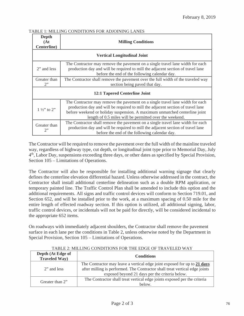
February 8, 2019
Page 2 of 3
TABLE 1: MILLING CONDITIONS FOR ADJOINING LANES Depth
(AtCenterline)
Milling Conditions
Vertical Longitudinal Joint
2” and less The Contractor may remove the pavement on a single travel lane width for each
production day and will be required to mill the adjacent section of travel lane before the end of the following calendar day.
Greater than 2”
The Contractor shall remove the pavement over the full width of the traveled way section being paved that day.
12:1 Tapered Centerline Joint
1 ½” to 2”
The Contractor may remove the pavement on a single travel lane width for each production day and will be required to mill the adjacent section of travel lane
before weekend or holiday suspension. A maximum unmatched centerline joint length of 0.5 miles will be permitted over the weekend.
Greater than 2”
The Contractor shall remove the pavement on a single travel lane width for each production day and will be required to mill the adjacent section of travel lane
before the end of the following calendar day.
The Contractor will be required to remove the pavement over the full width of the mainline traveled way, regardless of highway type, cut depth, or longitudinal joint type prior to Memorial Day, July 4th, Labor Day, suspensions exceeding three days, or other dates as specified by Special Provision, Section 105 – Limitations of Operations.
The Contractor will also be responsible for installing additional warning signage that clearly defines the centerline elevation differential hazard. Unless otherwise addressed in the contract, the Contractor shall install additional centerline delineation such as a double RPM application, or temporary painted line. The Traffic Control Plan shall be amended to include this option and the additional requirements. All signs and traffic control devices will conform to Section 719.01, and Section 652, and will be installed prior to the work, at a maximum spacing of 0.50 mile for the entire length of effected roadway section. If this option is utilized, all additional signing, labor, traffic control devices, or incidentals will not be paid for directly, will be considered incidental to the appropriate 652 items.
On roadways with immediately adjacent shoulders, the Contractor shall remove the pavement surface in each lane per the conditions in Table 2, unless otherwise noted by the Department in Special Provision, Section 105 – Limitations of Operations.
TABLE 2: MILLING CONDITIONS FOR THE EDGE OF TRAVELED WAY Depth (At Edge of
Traveled Way) Conditions
2” and less The Contractor may leave a vertical edge joint exposed for up to 21 daysafter milling is performed. The Contractor shall treat vertical edge joints
exposed beyond 21 days per the criteria below.
Greater than 2” The Contractor shall treat vertical edge joints exposed per the criteria below.
76

February 8, 2019
Page 3 of 3
When required by Table 2, the Contractor shall treat vertical edge joints through one of the options below:
1. The vertical edge shall be tapered to a zero edge by means of milling a 12:1 transition fromthe edge of traveled way onto the shoulder before opening the lane to traffic. Tapers shallbe removed to form a vertical edge prior to the placement of the new pavement course. Noadditional payment will be made for tapers, or taper removal.
2. An additional 2 feet of pavement shall be removed from the shoulder to eliminate thevertical edge at the edge of travelway before opening the lane to traffic. Unless otherwiseauthorized by the Department, no additional payment will be made for the additionalmilling.
3. A pavement layer shall be placed to reduce the vertical edge to 1 inch or less before openingthe lane to traffic.
As a minimum, the use of temporary painted line, or RPMs placed along the edge of traveled way at 200 foot intervals is required for all elevation differentials. When pavement milling is extended into the shoulder (including milled tapers), appropriate channelization devices shall be placed 2 feet outside the edge of the vertical face at intervals not exceeding 600 feet, and RPMs shall be placed on the remaining pavement surface along the vertical edge at 200 foot intervals. Uneven pavement signs shall be placed at a maximum spacing of ½ mile when any pavement milling operations leaves an exposed uneven pavement surface.
Weepers shall be ground across the full width sections adjacent shoulders or remaining pavement surface matching the milled travel way or shoulder milled depth to minimize water ponding in any lanes carrying traffic. Weepers shall typically be 18 – 24” inches in width, installed along each lane, at a frequency of approximately one per half mile at locations as directed by the Resident or in areas that will provide drainage for the milled areas. Installation of weepers will not be paid for directly but will be considered incidental to the contracts pavement removal item. The replacement of mix in the weeper locations shall be performed concurrently within the pavement placement operation closure using the appropriate HMA item produced for the Contract or a MaineDOT approved 9.5mm HMA. There will be no separate payment for repaving the weeper locations as they are considered incidental to the square yard price of the contracts pavement removal item.
Any areas of concern, such as de-lamination or pot-holing shall be identified on a continuous basis as milling progresses. Proper corrective action will be determined by the Resident and paid for under the appropriate contract items, and if required, completed prior to opening lane to traffic. Any issues that arise up to 7 calendar days after being milled will be the responsibility of the MaineDOT unless otherwise noted in Special Provision Section 105 – Limitations Of Operations.
Pay Item Pay Unit
202.202 Removing Pavement Surface S.Y.
77

Page 1 of 1
HampdenWIN 21692.00
March 15, 2019
SPECIAL PROVISIONSECTION 203
EXCAVATION AND EMBANKMENT(Dredge Materials)
Description: Dredge Material (See MaineDOT Standard Specifications § 101.2 Definitions) is regulated as a Special Waste.
Work associated with the Hampden Bridge Replacement initiative will require the excavation of select Dredge Material. Up to 500-cubic yards of dredge can be beneficially reused in an area adjacent to and draining into the dredged water body. It is anticipated that approximately 21-cubic yards of Dredge Material will be excavated. There is onsite Beneficial Use for all of the Dredge Material.
It is acknowledged that the excavation of Dredge for this work may include some boulders. The Maine Department of Environmental Protection has determined that sound boulders (rock 12-inches or more in diameter), that are free of adhering sediment or other contaminants, shall be deemed to be Inert Fill material and shall not be included in the Dredge Material Quantities.
The contractor shall Beneficially Use all Dredge Material excavated at the Hamden BridgeReplacement project in an area adjacent to and draining into the dredged water body. No more than 500-cubic yards of Dredge Material may be excavated at the Bridge location.
CONSTRUCTION REQUIREMENTS
Management: The contractor shall Beneficially Use all Dredge Material excavated at the Hampden Bridge Replacement project in areas adjacent to and draining into the dredged water body. No more than 500-cubic yards of Dredge Material may be excavated at the Bridgelocation.
Method of Measurement: Dredge Material will be measured by the cubic yard of material removed.
Basis of Payment: Payment for the Beneficial Use of Dredge Material will be incidental to the Contract Pay Items.
Payment shall be full compensation for dewatering, managing, transporting, and placement of the Dredge Materials.
78

Hampden STP-1157(700)X
11577.00 Route 1A
February 5, 2019
Page 1 of 4
SPECIAL PROVISION
SECTION 311
Full Depth Concrete Rubblization
311.01 Description This work shall consist of pulverizing/rubblizing Portland cement concrete pavement full depth to provide a rubblized concrete base on which to pave. The contractor shall grade and compact this material to the lines, grades, and dimensions shown on the plans or established in the field by the Resident.
MATERIALS
311.02 Rubblized Material Rubblized material shall consist of the existing Portland cement concrete pavement being rubblized to a material where all particles are 6 inches or less in the largest dimension. In general, the particle sizes should be 2 inches or less at the surface of the rubblized base.
311.021 Recycled Material Recycled pavement material salvaged from the project or from offsite stockpiles shall be used. Material must be processed so that 100% of the material passes a 1 ½ inch square mesh sieve. Recycled material shall be conditionally accepted at the source by the Resident. It shall be free of winter sand, granular fill, construction debris, and other materials not generally considered bituminous pavement.
EQUIPMENT
311.03 Concrete Rubblizer Rubblizing shall be accomplished with a resonant breaker that breaks the PCC pavement into the required particle sizes without damaging the existing subbase material and without excessively displacing the rubblized material into the base or subgrade. The rubblization equipment shall be a self-contained, self-propelled unit utilizing resonant frequency to produce a low amplitude breaking force. The concrete rubblizing machine shall be specifically manufactured for full-depth concrete rubblizing work and capable of reducing the required existing materials to a size that will meet the requirements of subsection 311.02 Rubblized Material. The rubblizing machine shall be equipped with an approved watering system which shall be used as needed to suppress dust generated by the rubblizing operation.
311.04 Health and Safety/Right-to-Know Portland cement is considered a hazardous chemical under US OSHA Hazard Communication Rule 29 CFR 1910.120, therefore, all Contractors and Subcontractors are required to notify their workers of the potential health hazards associated with working with Portland cement. In no area of the work site, where cement or cement-pavement-gravel combination is being applied, re-worked, rolled or graded, shall respirable dust be allowed
79

Hampden STP-1157(700)X
11577.00 Route 1A
February 5, 2019
Page 2 of 4
to exceed the NIOSH [1974] established respirable dust standard (RDS) recommended exposure limit (REL) of 0.05 mg/m3 (for up to a 10 hour workday during a 40 hour work week).
The Contractor shall notify the Resident before commencing any work that involves Portland cement application, reclaiming, rolling, or grading.
The Contractor shall designate a Hazardous Waste Operations “Competent Person” to provide direct on-site supervision plus health and safety monitoring for work in the Portland cement impacted sections of the project. The Competent Person shall have certified training and experience in field implementation of the aforementioned regulations.
Submittals The Contractor shall submit a site specific Health and Safety Plan (HASP) to the Resident at least two weeks in advance of any Portland cement related work on the project. Health and Safety Monitoring In any area of the project where Portland cement is being worked, the Contractor’s designated Competent Person shall monitor the worker breathing zone for respirable dust. In the event the OSHA respirable dust REL is exceeded, the Contractor’s Competent Person shall direct operations to cease. Operations will not recommence until the situation is corrected and respirable air returns to acceptable levels. The Contractor shall provide all required health and safety monitoring equipment.
311.05 Rollers The full depth concrete rubblized material shall be rolled with a 10 ton vibratory steel roller and Type II 18 ton pneumatic tire roller. The 10 ton steel roller shall have a minimum contact area per foot of 17 in2 and a minimum width of 84 inches. The pneumatic tire roller shall meet the requirements of Section 401.10 and the minimum allowable tire pressure shall be 85 psi.
311.08 Surface Tolerance The completed surface of the Full Depth concrete rubblization shall be shaped using Recycled Asphalt Pavement (RAP) as a variable depth shim.
311.09 Full Depth Rubblizing Procedure The existing concrete pavement material shall pulverized/rubblized into a homogeneous mass passing the gradation as specified in section 311.02. Material found not to meet the gradation as specified in section 311.02 shall be required to be reprocessed by the rubblizer. The material shall then be shaped to the cross slope and grade shown on the plans, typicals, or as directed by the Resident and meeting the tolerances of section 311.08. The rubblized concrete shall then be compacted using the rollers specified in section 311.05. Each roller shall make four passes with a pass being down and back. The 10 ton vibratory roller shall make the initial four passes and then the Type II 18 ton pneumatic tire roller shall make the final four passes. If the rubblized material still shows signs of movement or lack of compaction more passes will be required.
80

Hampden STP-1157(700)X
11577.00 Route 1A
February 5, 2019
Page 3 of 4
If at this time it is apparent that the existing sub-grade and sub-base has been damaged, the contractor shall excavate down to sub-grade and replace with 304.13 Dense Graded Crushed Aggregate Sub-base from sub-grade to finish grade of the rubblized Portland Cement.
Concrete Pavement If the Department determines the damage was caused by the contractor and their operations, The Department will not reimburse the contractor for any expenses to correct any damages.
Any exposed steel shall be removed prior to placing the leveling course.
After compaction of the rubblized concrete material, the contractor shall place a leveling course of recycled asphalt pavement provided from the project as needed and directed by the Department. The placement and fine grading of RAP shall be incidental to the 311.36 item. This course will then be required to be compacted by making as many passes as needed with a 10 ton vibratory roller to assure the Department that the material is properly compacted. The leveling course of new aggregate shall be fine-graded to ± 3/8 inch tolerance.
Sufficient water shall be added during the compaction process to aide in the compaction of both the rubblized concrete material and the leveling course of new aggregate. The resultant material shall be graded and compacted to the cross-slope and profile shown on the plans or as directed by the Resident. The Contractor will also be responsible for reestablishing the existing profile grade as specified on the typical, in the plans, or as directed by the Resident in the field. The Department’s intent of the new profile grade is to be within 3” of the old profile grade (except for areas such as bridges and overpasses where the grade must be adjusted or for areas where the Department wishes to correct minor depressions).
QUALITY CONTROL
311.10 Quality Control The Contractor shall operate in accordance with the approved Quality Control Plan (QCP) to assure a product meeting the contract requirements. The QCP shall meet the requirements of Section 106.4 - Quality Control and this Section. The Contractor shall not begin recycling operations until the Department approves the QCP in writing.
Prior to performing any rubblizing, the Department and the Contractor shall hold a Prerubblization conference to discuss the rubblizing schedule, type and amount of equipment to be used, sequence of operations, and traffic control. A copy of the QC random numbers to be used on the project shall be provided to the Resident. All field supervisors including the responsible onsite supervisor for the rubblizing operation shall attend this meeting.
The QCP shall address any items that affect the quality of the Rubblizing Process including, but not limited to, the following:
A. Make and type of rollers including weight, weight per inch of steel wheels, and average contact pressure for pneumatic tired rollers.
81

Hampden STP-1157(700)X
11577.00 Route 1A
February 5, 2019
Page 4 of 4
B. Rubblizing operations including type of equipment, speed of equipment, monitoring, methods to ensure that segregation is minimized, and procedures for grading and compacting operations.
C. Method of grade checks.
D. Name, responsibilities, and qualifications of the Responsible onsite Rubblizing Supervisor experienced and knowledgeable with the process.
E. Access to operators manual on all equipment.
The Project Superintendent shall be named in the QCP, and the responsibilities for successful implementation of the QCP shall be outlined.
At the initiation of and during rubblizing, establish, demonstrate and document the capability of the equipment, including the machine’s speed and impact frequency to achieve the required results.
At a minimum frequency of one every 2500 feet per lane, inspect the rubblized concrete pavement full depth to determine whether the gradation is being met and whether the reinforcement is de-bonded.
The completed rubblized surface shall have a uniform appearance without unbroken strips of pavement, exposed reinforcement steel, rubberized crack seal material, and excessive voids or cross slope issues.
311.12 Method of Measurement Full Depth Concrete Rubblization will be measured by square yard.
311.13 Basis of Payment The accepted quantity of Full Depth Concrete Rubblization will be paid for at the contract unit price per square yard, complete in-place which price will be full compensation for furnishing all equipment and labor for rubblizing, grading, compacting, and for all incidentals necessary to complete the work.
The addition of materials to restore profile grade and/or cross-slope in areas shown on the plans or described in the construction notes will be incidental to rubblization items.
Payments will be made under:
Pay Item Pay Unit
311.36 Full Depth Concrete Rubblization Square Yard
82

January 23, 2019
Page 1 of 25
SECTION 401 - HOT MIX ASPHALT PAVEMENT
401.01 Description The Contractor shall furnish a uniformly blended, homogeneous mixture placed as one or more courses of Hot Mix Asphalt Pavement (HMA) on an approved base in accordance with the contract documents and in reasonably close conformity with the lines, grades, thickness, and typical cross sections shown on the plans or established by the Resident. The Department will accept this work under Quality Assurance provisions, in accordance with these specifications and the requirements of Section 106 – Quality, the provisions of AASHTO M 323 except where otherwise noted in sections 401 and 703 of these specifications, and the MaineDOT Policies and Procedures for HMA Sampling and Testing.
401.02 Materials Materials shall meet the requirements specified in Section 700 - Materials:Asphalt Cement 702.01Aggregates for HMA Pavement 703.07RAP for HMA Pavement 703.08HMA Mixture Composition 703.09
401.03 Composition of Mixtures The Contractor shall compose the Hot Mix Asphalt Pavement with aggregate, Performance Graded Asphalt Binder (PGAB), and mineral filler if required. HMA shall be designed and tested according to AASHTO R35 and the volumetric criteria in Table 1. The Contractor shall size, uniformly grade, and combine the aggregate fractions in proportions that provide a mixture meeting the grading requirements of the Job Mix Formula (JMF). Unless otherwise noted in Special Provision 403 - Hot Mix Asphalt Pavement, the design, verification, Quality Control, and Acceptance tests for this mix will be performed at 65 gyrations.
The Contractor shall submit for Department approval a JMF to the Asphalt Pavement Engineer for each mixture to be supplied. The Department shall then have 15 calendar days in which to process a new design before approval. The JMF shall establish a single percentage of aggregate passing each sieve size within the limits shown in section 703.09. The mixture shall be designed and produced, including all production tolerances, to comply with the allowable control points for the particular type of mixture as outlined in 703.09. The JMF shall state the original source, gradation, and percentage to be used of each portion of the aggregate including RAP when utilized, and mineral filler if required. It shall also state the proposed PGAB content, the name and location of the supplier, the source of PGAB submitted for approval, the type of PGAB modification if applicable, and the location of the terminal if applicable.
In addition, the Contractor shall provide the following information with the proposed JMF:Properly completed JMF indicating all mix properties (Gmm, VMA, VFB, etc.)Stockpile Gradation SummaryDesign Aggregate Structure Consensus Property SummaryDesign Aggregate Structure Trial Blend Gradation Plots (0.45 power chart)Trial Blend Test Results for at least three different asphalt contents Design Aggregate Structure
Test results for the selected aggregate blend at a minimum of three binder contents Recommended mixing and compaction temperatures from the PGAB supplier Safety Data Sheets (SDS) For PGABAsphalt Content vs. Air Voids trial blend curve
Test report for Contractor’s Verification sample
At the time of JMF submittal, the Contractor shall identify and make available the stockpiles of all proposed aggregates at the plant site. There must be a minimum of 150 ton for coarse aggregate stockpiles and 75 ton for fine aggregate stockpiles before the JMF may be submitted. The Contractor shall provide aggregate
83

January 23, 2019
Page 2 of 25
samples to the Department unless otherwise required. The Contractor shall also make available to the Department the PGAB proposed for use in the mix in sufficient quantity to test the properties of the asphalt and to produce samples for testing of the mixture. The JMF will be approved by the Department in accordance with the MaineDOT HMA Policies and Procedures for HMA Sampling and Testing Manual. The first day’s production shall be monitored, and the approval may be withdrawn if the mixture exhibits undesirable characteristics such as checking, shoving or displacement.
The Contractor shall be allowed to submit aim changes for a JMF within 24 hours of receipt of the first Acceptance test result. Should all of the Acceptance samples of a Lot be obtained prior to the reporting of the first Acceptance result, the Department will not allow the aim changes to be applied to that Lot. Adjustments will be allowed of up to 2% on the percent passing the 2.36 mm sieve through the 0.075 mm and 3% on the percent passing the 4.75 mm or larger sieves. Adjustments will be allowed on the %PGAB of up to 0.2%. Adjustments will be allowed on Gmm of up to 0.010.
The Contractor shall submit a new JMF for approval each time a change in material source or materials properties is proposed. The same approval process shall be followed. The cold feed percentage of any aggregate may be adjusted up to 10 percentage points from the amount listed on the JMF, however no aggregate listed on the JMF shall be eliminated. The cold feed percentage for RAP may be reduced up to 10 percentage points from the amount listed on the JMF and shall not exceed the percentage of RAP approved in the JMF or for the specific application under any circumstances.
TABLE 1: VOLUMETRIC DESIGN CRITERIA
Design ESAL’s (Million
s)
Required Density(Percent of Gmm)
Voids in the Mineral Aggregate(VMA)(Minimum Percent)
Voids Filled with Binder
(VFB)(Minimum
%)
Fines/Eff.Binder Ratio
Nominal Maximum Aggregate Size (mm)Ninitial Ndesign Nmax 25 19 12.5 9.5 4.75
<0.3 <91.5
96.0 <98.0 13.0 14.0 15.0 16.0 16.0
70-80
0.6-1.2 0.3 to <3 <90.5 65-803 to <10
<89.0 65-80* 10 to <30> 30
*For 9.5 mm nominal maximum aggregate size mixtures, the maximum VFB is 82. *For 4.75 mm nominal maximum aggregate size mixtures, the maximum VFB is 84.
401.031 Warm Mix Technology The Contractor may place Hot Mix Asphalt Pavement produced with an accepted WMA technology if approved by the Department. Methods or technologies shall generally be at the Contractors option, but will be limited to proven, Agency and Industry accepted practice. Mixture production, placement and volumetric testing details, including temperatures, shall be included in the project specific QCP, and submitted to the Department for approval prior to any work.
401.04 Temperature Requirements After the JMF is established, the temperatures of the mixture shall conform to the following tolerances unless otherwise authorized by the Department:
In the truck at the mixing plant – allowable range 275 to 325°F At the Paver – allowable range 275 to 325°F
The JMF and the mix subsequently produced shall meet the requirements of Tables 1 and Section 703.07.
84

January 23, 2019
Page 3 of 25
401.05 Performance Graded Asphalt Binder The Contractor shall utilize either a PG58-28, PG64-28, or other grade as specified in the 403 Special Provision. The Contractor shall utilize a PG64-28 if no liquid grade is specified within the 403 Special Provision.
401.06 Weather and Seasonal Limitations The State is divided into two paving zones as follows:
a. Zone 1 Areas north of US Route 2 from Gilead to Bangor and north of Route 9 from Bangor to Calais.
b. Zone 2 Areas south of Zone 1 including the US Route 2 and Route 9 boundaries.
TABLE 2: SEASONAL AND TEMPERATURE LIMITATIONS
UseMinimum
Ambient Air Temperature
Zone 1 Allowable Placement Dates
Zone 2 Allowable Placement Dates
Surface course (travelway & adjacent shoulders) less than 1 in. thick placed during conditions defined as
“night work”50°F June 1 to Saturday following September 1
Surface course (travelway & adjacent shoulders) less than 1 in. thick 50°F May 15 to Saturday following September 15
Travelway surface course greater than or equal to 1 in. thick 50°F May 1 to Saturday
following October 1April 15 to Saturday following October 15
HMA for surface course on bridge decks 50°F May 1 to Saturday following October 1
April 15 to Saturday following October 15
HMA for base or shim course on bridge decks 50°F April 15 to November 15HMA for use other than travelway surface course 40°F April 15 to November 15
HMA for curb, driveways, sidewalks, islands, or other incidentals 40°F N/A N/A
HMA produced with an approved WMA technology for base or shim course 35°F April 15 to November 15
The ambient air temperature shall be determined by an approved thermometer placed in the shade at the paving location. Unless otherwise specified, the Contractor shall not place Hot Mix Asphalt Pavement on a wet or frozen surface regardless of the ambient air temperature. The Hot Mix Asphalt Pavement produced with an approved WMA technology shall meet the requirements of section 401.04 - Temperature Requirements, unless otherwise approved by the Department. For the purposes of this Section, the traveled way includes truck lanes, ramps, approach roads and auxiliary lanes.
401.07 Hot Mix Asphalt Plant
401.071 General Requirements HMA plants shall conform to AASHTO M156-97.
a. Additives Additives (WMA, anti-strip, etc.) not directly introduced into the binder at the terminal shall be introduced into the HMA plant per the supplier’s recommendations and shall be approved by the Asphalt Pavement Engineer, Pavement Quality Manager, or their authorized representative. The system for introducing additives shall be interlocked with the aggregate feed or weigh system to maintain correct proportions for all rates of production and batch sizes. Additive introduction systems shall be controlled bya proportioning device to the amount required on the JMF plus or minus 0.1% of the target. Additive introduction systems shall be interlocked with the plant and the recordation (batch tickets or drum recordation) shall display the additive and the weight and percentage added.
85

January 23, 2019
Page 4 of 25
b. Stockpiles HMA plants shall have sufficient space for stockpiles, with a minimum of supply for 2 days production of all aggregate products used in MaineDOT approved mix designs currently under production for the facility at all times. A minimum stockpile supply of 100 ton (70 yards) shall be maintained at all times no matter the production rate for the HMA plant. Stockpiles shall be separated and built to minimize segregation.
c. Preparation of Aggregates The Contractor shall dry and heat the aggregates for the HMA to the required temperature. The Contractor shall properly adjust flames to avoid physical damage to the aggregate and to avoid depositing soot on the aggregate.
d. Mixing The Contractor shall combine the dried aggregate in the mixer in the amount of each fraction of aggregate required to meet the JMF. The Contractor shall measure the amount of PGAB and introduce it into the mixer in the amount specified by the JMF. The Contractor shall produce the HMA at the temperature established by the JMF.
The Contractor shall dry the aggregate sufficiently so that the HMA will not flush, foam excessively, or displace excessively under the action of the rollers. The Contractor shall introduce the aggregate into the mixer at a temperature of not more than 25°F above the temperature at which the viscosity of the PGAB being used is 0.150 Pa s.
The Contractor shall store and introduce into the mixer the Performance Graded Asphalt Binder at a uniformly maintained temperature at which the viscosity of the PGAB is between 0.150 Pa s and 0.300 Pa s. The aggregate shall be coated completely and uniformly with a thorough distribution of the PGAB. The Contractor shall determine the wet mixing time for each plant and for each type of aggregate used. The resultant material shall be a uniformly blended, homogeneous HMA mixture.
401.072 Automation of Batching Batch plants shall be automated for weighing, recycling, and monitoring thesystem. In the case of a malfunction of the printing system, the requirements of Section 401.074 c. of this specification will apply.
The batch plant shall accurately proportion the various materials in the proper order by weight. The entire batching and mixing cycle shall be continuous and shall not require any manual operations. The batch plant shall use auxiliary interlock circuits to trigger an audible alarm whenever an error exceeding the acceptable tolerance occurs. Along with the alarm, the printer shall print an asterisk on the delivery slip in the same row containing the out-of-tolerance weight. The automatic proportioning system shall be capable of consistently delivering material within the full range of batch sizes. When RAP is being used, the plant must be capable of automatically compensating for the moisture content of the RAP.
All plants shall be equipped with an approved digital recording device. The delivery slip load ticket shall contain information required under Section 108.1.3 - Provisions Relating to Certain Measurements, Mass and paragraphs a, b, and c of Section 401.073
401.073 Automatic Ticket Printer System on Automatic HMA Plant An approved automatic ticket printer system shall be used with all approved automatic HMA plants. The requirements for delivery slips for payment of materials measured by weight, as given in the following Sections, shall be waived: 108.1.3 a., 108.1.3 b., 108.1.3 c., and 108.1.3 d. The automatic printed ticket will be considered as the Weight Certificate.
The requirements of Section 108.1.3 f. - Delivery Slips, shall be met by the weigh slip or ticket, printed by the automatic system, which accompanies each truckload, except for the following changes:
86

January 23, 2019
Page 5 of 25
a. The quantity information required shall be individual weights of each batch or total net weight of each truckload.
b. Signatures (legible initials acceptable) of Weighmaster (required only in the event of a malfunction as described in 401.074 c.).
c. The MaineDOT designation for the JMF.
401.074 Scales and Weight Checks When the HMA is to be weighed on scales meeting the requirements of Section 108 - Payment, the scales shall be inspected and sealed by the State Sealer (or approved alternative) as often as the Department deems necessary to verify their accuracy based upon the criteria below. Plant scales shall be checked prior to the start of the paving season, and each time a plant is moved to a new location. Subsequent checks will be made as determined by the Resident. The Contractor will have at least ten 50 poundmasses for scale testing at batch plants. At least twice during each 5 days of production either of the following checks will be performed:
a. A loaded truck may be intercepted and weighed on a platform scale that has been sealed by the State Sealer of Weights and Measures within the past 12 months. The inspector will notify the producer to take corrective action on any discrepancy over 1.0%. The producer may continue to operate for 48 hours under the following conditions.
1. If the discrepancy does not exceed 1.5%; payment will still be governed by the printed ticket.
2. If the discrepancy exceeds 1.5%, the plant will be allowed to operate as long as payment is determined by truck platform scale net weight.
If, after 48 hours the discrepancy has not been addressed and reduced below 1.0%, than plant operations will cease. Plant operation may resume after the discrepancy has been brought within 1.0%.
b. Where platform scales are not readily available, a check will be made to verify the accuracy and sensitivity of each scale within the normal weighing range and to assure that the interlocking devices and automatic printer system are functioning properly.
c. In the event of a malfunction of the automatic printer system, production may be continued without the use of platform truck scales for a period not to exceed the next two working days, providing total weights of each batch are recorded on weight tickets and certified by a Licensed Public Weighmaster.
401.08 Hauling Equipment Units hauling HMA shall have tight, clean, and smooth metal bodies, which have been thinly coated with a small amount of approved release agent to prevent the mixture from adhering to the bodies. Release agents that dissolve or strip asphalts, including diesel fuel, will not be allowed.
All mix haul units shall have a cover of canvas or other water repellent material capable of heat retention, which completely covers the mixture. The cover shall be securely fastened on the truck, unless unloading. All mix haul units shall have an opening on both sides, which will accommodate a thermometer stem. The opening shall be located near the midpoint of the body, at least 12 in above the bed.
401.09 Pavers The Contractor shall use pavers meeting the requirements of this section unless otherwise authorized by the Department. Pavers shall be self-contained, self-propelled units with an activated heated screed capable of placing courses of Hot Mix Asphalt Pavement in full lane widths specified in the contract on the main line, shoulder, or similar construction.
87

January 23, 2019
Page 6 of 25
Pavers shall be of sufficient class and size to place Hot Mix Asphalt Pavement over the full width of the mainline travel way with a 10 ft minimum main screed with activated extensions.
The Contractor shall place Hot Mix Asphalt Pavement on the main line with a paver using an automatic grade and slope controlled screed, unless otherwise authorized by the Department. The controls shall automatically adjust the screed and increase or decrease the layer thickness to compensate for irregularities in the preceding course. The controls shall maintain the proper transverse slope and be readily adjustable so that transitions and superelevated curves can be properly paved. The controls shall operate from a fixed or moving reference such as a grade wire or ski type device (floating beam) with a minimum length of 30 ft, a non-contact grade control with a minimum span of 24 ft, except that a 40 ft reference shall be used on Expressway projects.
The Contractor shall operate the paver in such a manner as to produce a visually uniform surface texture and a thickness within the requirements of Section 401.11 - Surface Tolerances. The paver shall have a receiving hopper with sufficient capacity for a uniform spreading operation and a distribution system to place the mixture uniformly, without segregation in front of the screed. The screed assembly shall produce a finished surface of the required evenness and texture without tearing, shoving, or gouging the mixture. Pavers with extendible screeds shall have auger extensions and tunnel extenders as per the manufacturer’s recommendations, a copy of which shall be available if requested.
The Contractor shall have the paver at the project site sufficiently before the start of paving operations to be inspected and approved by the Department. The Contractor shall repair or replace any paver found worn or defective, either before or during placement, to the satisfaction of the Department. Pavers that produce an unevenly textured or non-uniform mat will be repaired or replaced before continuing to place HMA on MaineDOT projects.
On a daily basis, the Contractor shall perform density testing across the mat being placed, prior to being compacted by equipment at 12 in intervals. If the density values vary by more than 2.0% from the mean, the Contractor shall make adjustments to the screed until the inconsistencies are remedied. Failure to replace or repair defective placement equipment may result in a letter of suspension of work and notification of a quality control violation resulting in possible monetary penalties as governed by Section 106 - Quality
401.10 Rollers Rollers shall be static steel, pneumatic tire, oscillatory, or approved vibrator type. Rollers shall be in good mechanical condition, capable of starting and stopping smoothly, and be free from backlash when reversing direction. Rollers shall be equipped and operated in such a way as to prevent the picking up of hot mixed material by the roller surface. The use of rollers, which result in crushing of the aggregate or in displacement of the HMA will not be permitted. Any Hot Mix Asphalt Pavement that becomes loose, broken, contaminated, shows an excess or deficiency of Performance Graded Asphalt Binder, or is in any other way defective shall be removed and replaced at no additional cost with fresh Hot Mix Asphalt Pavement, which shall be immediately compacted to conform to the adjacent area.
The Contractor shall repair or replace any roller found to be worn or defective, either before or during placement, to the satisfaction of the Department. Rollers that produce grooved, unevenly textured or non-uniform mat will be repaired or replaced before continuing to place HMA on MaineDOT projects. The type of rollers to be used and their relative position in the compaction sequence shall generally be the Contractor’s option, provided specification densities are attained and with the following requirements:
a. On variable-depth courses, the first lift of pavement over gravel, reclaimed pavement, on irregular or milled surfaces, or on bridges, at least one roller shall be 16 ton pneumatic-tired. Pneumatic-tired rollers
88

January 23, 2019
Page 7 of 25
shall be equipped with skirting to minimize the pickup of HMA materials from the paved surface. When required by the Resident, the roller shall be ballasted to 20 ton.b. Compaction with a vibratory or steel wheel roller shall precede pneumatic-tired rolling, unless otherwise authorized by the Department. c. Vibratory rollers shall not be operated in the vibratory mode when checking or cracking of the mat occurs, or on bridge decks. d. Any method, which results in cracking or checking of the mat, will be discontinued and corrective action taken. e. The use of an oscillating steel roller shall be required to compact all mixtures placed on bridge decks.
The maximum operating speed for a steel wheel or pneumatic roller shall not exceed the manufacturer’s recommendations, a copy of which shall be available if requested.
401.11 Surface Tolerances The Department will check the following surface tolerances:
a.) Longitudinally: The pavement surface profile shall be free of deviations in excess of +/- ¼ inches from the required pavement surface profile grade. To verify the surface tolerance a straight plane shall be established using 16 foot straight edge or a taught string line placed parallel to the direction of travel and checked continuously across the width of the lane.
b.) Transversely: The pavement surface profile shall be free of deviations in excess of 0 inches below and ¼ inches above the required cross sectional profile grade. To verify the surface tolerance a straight planeshall be established using a 10 foot straight edge or taught string line placed perpendicular to the direction of travel and checked continuously along the length of the lane.
The Contractor shall correct defective areas by removing defective work and replacing it with new material as directed by the Department. The Contractor shall furnish a 10 foot straightedge for the Department’s use.
401.12 Preparation of Existing Surface The Contractor shall thoroughly clean the surface upon which Hot Mix Asphalt Pavement is to be placed of all objectionable material. When the surface of the existing base or pavement is irregular, the Contractor shall bring it to uniform grade and cross section. All surfaces shall have a tack coat applied prior to placing any new HMA course. Tack coat shall conform to the requirements of Section 409 – Bituminous Tack Coat, Section 702 – Bituminous Material, and all applicable sections of the contract.
401.13 Spreading and Finishing On areas where irregularities or unavoidable obstacles make the use of mechanical spreading and finishing equipment impracticable, the Contractor shall spread, rake, and lute the HMA with hand tools to provide the required compacted thickness. Release agents that dissolve or strip asphalts, including diesel fuel, will not be allowed.
On roadways with adjoining lanes carrying traffic, the Contractor shall place each course per the conditions in Table 3, unless otherwise noted by the Department in Section 403 - Hot Mix Asphalt Pavement.
89

January 23, 2019
Page 8 of 25
TABLE 3: PLACEMENT CONDITIONS FOR ADJOINING LANESDepth
(at centerline)
Placement Conditions
Vertical Longitudinal Joint
¾” and less(incl. shim)
The Contractor may place the HMA course over the full single travel lane width for each production day.
1” to 1 ¼” The Contractor may place the HMA course over the full single travel lane width for each production day and will be required to place a matching course of HMA over the adjacent
section of travel lane before weekend or holiday suspension.
1 ½” to 2” The Contractor may place the HMA course over the full single travel lane width for each production day and will be required to place a matching course of HMA over the adjacent
section of travel lane before the end of the following calendar day.Greater than
2”The Contractor shall place each course over the full width of the traveled way section being
paved that day.
Notched-Wedge Longitudinal Joint
1 ½” to 2”
The Contractor may place the HMA course over the full single travel lane width for each production day and will be required to place a matching course of HMA over the adjacent
section of travel lane before weekend or holiday suspension. A maximum unmatched centerline joint length of 0.5 miles will be permitted over the weekend.
Greater than 2”
The Contractor may place the HMA course over the full single travel lane width for each production day and will be required to place a matching course of HMA over the adjacent
section of travel lane before the end of the following calendar day.
The Contractor will be required to place the specified course over the full width of the mainline traveled way being paved, regardless of use, depth, or longitudinal joint type prior to Memorial Day, July 4th, Labor Day, paving suspensions exceeding three days, or other dates as specified by special provision.
The Contractor will also be responsible for installing additional warning signage that clearly defines the centerline elevation differential hazard. Unless otherwise addressed in the contract, the Contractor shall install additional centerline delineation such as a double RPM application, or temporary painted line. The Traffic Control Plan shall be amended to include this option and the additional requirements. All signs and traffic control devices will conform to Section 719.01, and Section 652, and will be installed prior to the work, at a maximum spacing of 0.50 mile for the entire length of effected roadway section. If this option is utilized, all additional signing, labor, traffic control devices, or incidentals will not be paid for directly, will be considered incidental to the appropriate 652 items.
401.14 Hot Mix Asphalt Placement on Bridge Decks Hot mix asphalt pavement placed on bridges shall also conform to Section 508.04 and the following requirements.
a. The bottom course shall be placed with an approved rubber mounted paver of such type and operated in such a manner that the membrane waterproofing will not be damaged in any way.
b. The top course shall not be placed until the bottom course has cooled sufficiently to provide stability.
c. The Contractor will not be required to cut sample cores from the compacted pavement on the bridge deck, unless otherwise directed by Special Provision.
90

January 23, 2019
Page 9 of 25
d. After the top course has been placed, the shoulder areas shall be sealed 3 ft wide with two applications of an emulsified bituminous sealer meeting the requirements of Section 612.03 – Sealing and Section 702.12 - Emulsified Bituminous Sealing Compound. The first application shall be pre-mixed with fine, sharp sand, similar to mortar sand, as needed to fill all voids in the mix in the area being sealed. The second application may be applied without sand. The sealer shall be carried to the curb at the gutter line in sufficient quantity to leave a bead or fillet of material at the face of the curb. The area to be sealed shall be clean, dry and the surface shall be at ambient temperature.
e. The furnishing and applying of the required quantity of sealer for the bridge shoulder areas shall be incidental to placing the hot mix asphalt pavement.
f. The minimum production and placement temperature for the Hot Mix Asphalt placed over membrane shall conform to the manufacturer’s recommendations.
The area between the edge of the membrane and the vertical surface shall be completely sealed with hot-applied rubberized asphalt material, meeting the requirements of Type 4 crack seal; shall be applied to form a complete seal between the membrane and the vertical surface and shall extend up the vertical surface to within½ inch of the top of the HMA wearing surface. This work shall be considered incidental to the contract pavement items unless 508 membrane items are included in the contract.
401.15 Compaction Immediately after the Hot Mix Asphalt Pavement has been spread, struck off, and any surface irregularities adjusted, the Contractor shall thoroughly and uniformly compact the HMA by rolling.
The Contractor shall roll the surface when the mixture is in the proper condition and when the rolling does not cause undue displacement, cracking, or shoving. The Contractor shall prevent adhesion of the HMA to the rollers or vibrating compactors without the use of fuel oil or other petroleum based release agents. Solvents designed to strip asphalt binders from aggregates will not be permitted as release agents on equipment, tools, or pavement surfaces.
The Contractor shall immediately correct any displacement occurring as a result of the reversing of the direction of a roller or from other causes to the satisfaction of the Department. Any operation other than placement of variable depth shim course that results in breakdown of the aggregate shall be discontinued. Any new pavement that shows obvious cracking, checking, or displacement shall be removed and replaced for the full lane width as directed by the Resident at no cost to the Department.
Along forms, curbs, headers, walls, and other places not accessible to the rollers, the Contractor shall thoroughly compact the HMA with mechanical vibrating compactors. The Contractor shall only use hand tamping in areas inaccessible to all other compaction equipment. On depressed areas, the Contractor may use a trench roller or cleated compression strips under a roller to transmit compression to the depressed area.
Any HMA that becomes unacceptable due to cooling, cracking, checking, segregation or deformation as a result of an interruption in mix delivery shall be removed and replaced, with material that meets contract specifications at no cost to the Department.
401.16 Joints The Contractor shall construct wearing course transverse and longitudinal joints in such a manner that minimum tolerances shown in Section 401.11 - Surface Tolerances are met when measured with a straightedge.
91

January 23, 2019
Page 10 of 25
The paver shall maintain a uniform head of HMA during transverse and longitudinal joint construction.
The HMA shall be free of segregation and meet temperature requirements outlined in Section 401.04. Transverse joints of the wearing course shall be straight and neatly trimmed. The Contractor may form a vertical face exposing the full depth of the course by inserting a header, by breaking the bond with the underlying course, or by cutting back with hand tools.
The Contractor shall apply a coating of emulsified asphalt immediately before paving all joints to the vertical face and 3 in of the adjacent portion of any pavement being overlaid except those formed by pavers operating in echelon. The Contractor shall use an approved spray apparatus designed for covering a narrow surface. The Department may approve application by a brush for small surfaces, or in the event of a malfunction of the spray apparatus, but for a period of not more than one working day.
Where pavement under this contract joins an existing pavement, or when the Department directs, the Contractor shall cut the existing pavement along a smooth line, producing a neat, even, vertical joint. The Department will not permit broken or raveled edges. The cost of all work necessary for the preparation of joints is incidental to related contract pay items.
Longitudinal joints shall be generally straight to the line of travel, and constructed in a manner that best ensure joint integrity. Methods or activities that prove detrimental to the construction of straight, sound longitudinal joints will be discontinued.
The Contractor may utilize an approved notched wedge joint device on all HMA layers 1 ½ inches in depth or greater. A notched wedge joint shall be constructed as shown in Figure 1 using a device that is attached to the paver screed and is capable of independently adjusting the top and bottom vertical notches.
FIGURE 1: Notched Wedge JointNotes
1. An emulsified tack coat shall be applied to the vertical edges and the wedge surface so that the total rate is 0.05 G/SY plus the normal specified rate prior to placing the adjacent layer. The Contractor may elect to apply the emulsified tack coat in one or multiple passes.
2. Dimensions shown are compacted depths (after rolling is complete).
The Department reserves the right to have centerline cores cut by the Contractor’s QC personnel for informational purposes to monitor the density along the joint. Informational cores at the centerline joint will be taken centered over the tapered part of the wedge joint.
Any notched wedge joint constructed areas that become cracked or broken shall be trimmed back to the limits affected prior to placing the adjoining lane. Any materials that become unbound or separated from the wedge or tapered joint section, or contaminated by materials determined by the Department as being detrimental to the
92

January 23, 2019
Page 11 of 25
construction of a sound construction joint, shall be removed by sweeping, compressed air and lance, or by hand tools as required. This work, if necessary, will not be paid for directly, but shall be considered incidental to the related contract items.
The Contractor shall apply a coating of emulsified asphalt on the vertical and tapered surface of the longitudinal centerline joint immediately before paving if the notched wedge joint device is used. The total rate of application shall be 0.050 G/SY plus the normal specified tack coat rate. The Contractor shall use an approved spray apparatus designed for covering a narrow surface. The Department may approve application by a brush for small surfaces.
401.17 Hot Mix Asphalt Documentation The Contractor and the Department shall agree on the amount of Hot Mix Asphalt Pavement that has been placed each day. All delivery slips shall conform to the requirements of 401.073.
401.18 Quality Control Method A, B & C The Contractor shall operate in accordance with the approved Quality Control Plan (QCP) to assure a product meeting the contract requirements. The QCP shall meet the requirements of Section 106.6 - Acceptance and this Section. The Contractor shall not begin paving operations until the Department approves the QCP in writing.
Prepave Meeting Prior to placing any mix, the Department and the Contractor shall hold a Pre-paving conference to discuss the paving schedule, source of mix, type and amount of equipment to be used, sequence of paving pattern, rate of mix supply, random sampling, project lots and sublots and traffic control. A copy of the density QC random numbers to be used on the project shall be provided to the Resident. The Departments’ random numbers for Acceptance testing shall be generated and on file with the Resident and the Project Manager. All personnel of the Department and the Contractor who have significant information relevant to the paving items shall attend, including the responsible onsite paving supervisor for the Contractor. The Resident will prepare minutes of the conference and distribute them to all attendees. Any requests to revise the minutes must be made to the Resident within 7 Days of Receipt. These minutes will constitute the final record of the Pre-paving conference.
On the first day of paving and whenever there is a change in the onsite paving foreman or paving inspector, the Department and the Contractor shall hold an informal onsite meeting to review the minutes of the Pre-paving conference, Project Specific QCP, Plans, Typicals, Special Provisions and communication process. This meeting shall be held prior to placing any mix. The onsite paving supervisor, QCT, Superintendent, Resident and/or paving inspector shall attend.
Quality Control Plan The QCP shall address any items that affect the quality of the Hot Mix Asphalt Pavement including, but not limited to, the following:
a. JMF(s)b. Hot mix asphalt plant details c. Stockpile Management (to include provisions for how the requirements of 401.071b will be met)d. Make and type of paver(s) e. Make and type of rollers including weight, weight per inch of steel wheels, and average contact
pressure for pneumatic tired rollers f. Name of QCP Administrator, and certification numberg. Name of Process Control Technician(s) and certification number(s) h. Name of Quality Control Technicians(s) and certification number(s)
93

January 23, 2019
Page 12 of 25
i. Mixing & transportation including process for ensuring that truck bodies are clean and free of debris or contamination that could adversely affect the finished pavement
j. Testing Plank. Laydown operations including longitudinal joint construction, procedures for avoiding paving in
inclement weather, type of release agent to be used on trucks tools and rollers, compaction of shoulders, tacking of all joints, methods to ensure that segregation is minimized, procedures to determine the maximum rolling and paving speeds based on best engineering practices as well as past experience in achieving the best possible smoothness of the pavement. Solvent based agents developed to strip asphalts from aggregates will not be allowed as release agents.
l. Examples of Quality Control forms including a daily plant report, daily paving report, and delivery slip template for any plant to be utilized.
m. Silo management and details (can show storage for use on project of up to 36 hours) n. Provisions for varying mix temperature due to extraordinary conditions or production limitations. If a
warm-mix technology is utilized, a proposed target production temperature range (not to exceed 50°F) will be provided for each mix design.
o. Name and responsibilities of the Responsible onsite Paving Supervisor.p. Method for calibration/verification of Density Gaugeq. A note that all testing will be done in accordance with AASHTO and the MaineDOT Policies and
Procedures for HMA Sampling and Testing. r. A detailed description of RAP processing, stockpiling and introduction into the plant as well as a note
detailing conditions under which the percent of RAP will vary from that specified on the JMF. s. A detailed procedure outlining when production will be halted due to QC or Acceptance testing results. t. A plan to address the change in PGAB source or supplier and the potential co-mingling of differing
PGAB’s.u. A procedure to take immediate possession of acceptance samples once released by MaineDOT and
deliver said samples to the designated acceptance laboratory. v. Provisions for how the QCP will be communicated to the Contractor’s field personnel
The QCP shall include the following technicians together with following minimum requirements:
a. QCP Administrator - A qualified individual shall administer the QCP. The QCP Administrator must be a full-time employee of or a consultant engaged by the Contractor or paving subcontractor. The QCP Administrator shall have full authority to institute any and all actions necessary for the successful operation of the QCP. The QCP Administrator (or its designee in the QCP Administrator’s absence) shall be available to communicate with the Department at all times. The QCP Administrator shall be certified as a Quality Assurance Technologist certified by the New England Transportation Technician Certification Program (NETTCP).
b. Process Control Technician(s) (PCT) shall utilize test results and other quality control practices to assure the quality of aggregates and other mix components and control proportioning to meet the JMF(s). The PCT shall inspect all equipment used in mixing to assure it is operating properly and that mixing conforms to the mix design(s) and other Contract requirements, and that delivery slips and plant recordation accurately reflects the mix being produced with all the required information. The QCP shall detail how these duties and responsibilities are to be accomplished and documented, and whether more than one PCT is required. The Plan shall include the criteria to be utilized by the PCT to correct or reject unsatisfactory materials. The PCT shall be certified as a Plant Technician by the NETTCP.
c. Quality Control Technician(s) (QCT) shall perform and utilize quality control tests at the job site to assure that delivered materials meet the requirements of the JMF(s). The QCT shall inspect all equipment
94
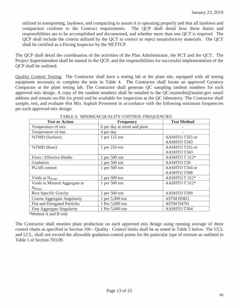
January 23, 2019
Page 13 of 25
utilized in transporting, laydown, and compacting to assure it is operating properly and that all laydown and compaction conform to the Contract requirements. The QCP shall detail how these duties and responsibilities are to be accomplished and documented, and whether more than one QCT is required. The QCP shall include the criteria utilized by the QCT to correct or reject unsatisfactory materials. The QCT shall be certified as a Paving Inspector by the NETTCP.
The QCP shall detail the coordination of the activities of the Plan Administrator, the PCT and the QCT. The Project Superintendent shall be named in the QCP, and the responsibilities for successful implementation of the QCP shall be outlined.
Quality Control Testing The Contractor shall have a testing lab at the plant site, equipped with all testing equipment necessary to complete the tests in Table 4. The Contractor shall locate an approved Gyratory Compactor at the plant testing lab. The Contractor shall generate QC sampling random numbers for each approved mix design. A copy of the random numbers shall be emailed to the [email protected] email address and remain on-file (in print) and be available for inspection at the QC laboratory. The Contractor shall sample, test, and evaluate Hot Mix Asphalt Pavement in accordance with the following minimum frequenciesper each approved mix design:
TABLE 4: MINIMUM QUALITY CONTROL FREQUENCIESTest or Action Frequency Test Method
Temperature of mix 6 per day at street and plant -Temperature of mat 4 per day -%TMD (Surface) 1 per 125 ton AASHTO T355 or
AASHTO T343%TMD (Base) 1 per 250 ton AASHTO T355 or
AASHTO T343Fines / Effective Binder 1 per 500 ton AASHTO T 312*Gradation 1 per 500 ton AASHTO T30 PGAB content 1 per 500 ton AASHTO T164 or
AASHTO T308Voids at Ndesign 1 per 500 ton AASHTO T 312*Voids in Mineral Aggregate at Ndesign
1 per 500 ton AASHTO T 312*
Rice Specific Gravity 1 per 500 ton AASHTO T209Coarse Aggregate Angularity 1 per 5,000 ton ASTM D5821Flat and Elongated Particles 1 Per 5,000 ton ASTM D4791Fine Aggregate Angularity 1 Per 5,000 ton AASHTO T304
*Method A and B only
The Contractor shall monitor plant production on each approved mix design using running average of threecontrol charts as specified in Section 106 - Quality. Control limits shall be as noted in Table 5 below. The UCL and LCL, shall not exceed the allowable gradation control points for the particular type of mixture as outlined in Table 1 of Section 703.09.
95
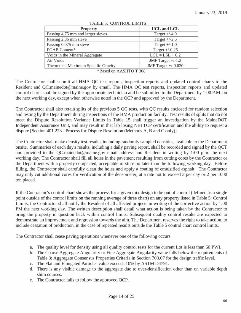
January 23, 2019
Page 14 of 25
TABLE 5: CONTROL LIMITSProperty UCL and LCL
Passing 4.75 mm and larger sieves Target +/-4.0Passing 2.36 mm sieve Target +/-2.5Passing 0.075 mm sieve Target +/-1.0PGAB Content* Target +/-0.25Voids in the Mineral Aggregate LCL = LSL + 0.2Air Voids JMF Target +/-1.2Theoretical Maximum Specific Gravity JMF Target +/-0.020
*Based on AASHTO T 308
The Contractor shall submit all HMA QC test reports, inspection reports and updated control charts to the Resident and [email protected] by email. The HMA QC test reports, inspection reports and updated control charts shall be signed by the appropriate technician and be submitted to the Department by 1:00 P.M. on the next working day, except when otherwise noted in the QCP and approved by the Department.
The Contractor shall also retain splits of the previous 5 QC tests, with QC results enclosed for random selection and testing by the Department during inspections of the HMA production facility. Test results of splits that do not meet the Dispute Resolution Variance Limits in Table 15 shall trigger an investigation by the MaineDOT Independent Assurance Unit, and may result in that lab losing NETTCP certification and the ability to request a dispute [Section 401.223 - Process for Dispute Resolution (Methods A, B and C only)].
The Contractor shall make density test results, including randomly sampled densities, available to the Department onsite. Summaries of each day's results, including a daily paving report, shall be recorded and signed by the QCT and provided to the [email protected] email address and Resident in writing by 1:00 p.m. the next working day. The Contractor shall fill all holes in the pavement resulting from cutting cores by the Contractor or the Department with a properly compacted, acceptable mixture no later than the following working day. Before filling, the Contractor shall carefully clean the holes and apply a coating of emulsified asphalt. The Contractor may only cut additional cores for verification of the densometer, at a rate not to exceed 3 per day or 2 per 1000 ton placed.
If the Contractor’s control chart shows the process for a given mix design to be out of control (defined as a single point outside of the control limits on the running average of three chart) on any property listed in Table 5: Control Limits, the Contractor shall notify the Resident of all affected projects in writing of the corrective action by 1:00 PM the next working day. The written description shall detail what action is being taken by the Contractor to bring the property in question back within control limits. Subsequent quality control results are expected to demonstrate an improvement and regression towards the aim. The Department reserves the right to take action, to include cessation of production, in the case of repeated results outside the Table 5 control chart control limits.
The Contractor shall cease paving operations whenever one of the following occurs:
a. The quality level for density using all quality control tests for the current Lot is less than 60 PWL.b. The Coarse Aggregate Angularity or Fine Aggregate Angularity value falls below the requirements of
Table 3: Aggregate Consensus Properties Criteria in Section 703.07 for the design traffic level.c. The Flat and Elongated Particles value exceeds 10% by ASTM D4791.d. There is any visible damage to the aggregate due to over-densification other than on variable depth
shim courses.e. The Contractor fails to follow the approved QCP.
96

January 23, 2019
Page 15 of 25
The Contractor shall notify the Resident in writing as to the reason for shutdown, as well as the corrective action,by the end of the work day. Failure to do so will be treated as a second incident under 106.4.6 QCP Non-compliance. The Department will only allow the continuation of paving operations when it is satisfied the corrective action will result in an improvement in results. The Department may require the submittal of a passing verification sample to allow further production. The Department retains the exclusive right, with the exception of the first day’s production of a new JMF, to determine whether the resumption of production involves a significant change to the production process. If the Department so determines, then the current lot will be terminated, a pay factor established, and a new lot will begin.
The Contractor may utilize innovative equipment or techniques not addressed by the Contract documents to produce or monitor the production of the mix, subject to approval by the Department.
401.19 Quality Control Method D Unless otherwise noted in Section 403 - Hot Mix Asphalt Pavement, the Contractor shall submit a modified QC Plan detailing, how the mix is to be placed, what equipment is to be used, and what HMA plant is to be used for Items covered under Method D. All mix designs (JMF) shall be approved and verified by MaineDOT prior to use. Certified QC personnel shall not be required. The Contractor shall certify the mix and the test results for each item by a Certificate of Compliance.
401.20 Acceptance Method A, B & C These methods utilizes Quality Level Analysis and pay factor specifications. For Hot Mix Asphalt Pavement designated for acceptance under Quality Assurance provisions, the Department will sample once per sublot on a statistically random basis, test, and evaluate in accordance with the following Acceptance Criteria:
TABLE 6: ACCEPTANCE CRITERIAProperties Point of Sampling Test MethodGradation Paver Hopper AASHTO T30PGAB Content Paver Hopper AASHTO T308%TMD (Surface) Mat behind all Rollers AASHTO T269%TMD (Base or Binder) Mat behind all Rollers AASHTO T269Air Voids at Nd Paver Hopper AASHTO T 312%VMA at Nd Paver Hopper AASHTO T 312Fines to Effective Binder Paver Hopper AASHTO T 312%VFB Paver Hopper AASHTO T 312
In the event the Department terminates a Lot prematurely but fails to obtain the required number of acceptance samples to calculate the volumetric property pay factor under the test method specified in the contract, the pay factor shall be calculated using the number of samples actually obtained from the contract. Should the number of acceptance samples taken total less than three, the resulting pay factor shall be 1.0 for mixture properties. A minimum of three cores will be used for a density pay factor using the contract’s specified Acceptance method, if applicable, for quantities placed to date.
Should the Contractor request a termination of the Lot in progress prior to three acceptance samples being obtained, and the Department agrees to terminate the Lot, then the pay factor for mixture properties shall be 0.80. A minimum of three cores will be used to determine a density pay factor using the contract’s specified Acceptance method, if applicable, for quantities placed to date.
Lot Size For purposes of evaluating all acceptance test properties, a lot shall consist of the total quantity represented by each item listed under the lot size heading.
97

January 23, 2019
Page 16 of 25
Sublot size Refer to Sections 401.201, 401.202, and 401.203 for minimum size and number of sublots. The quantity represented by each sample will constitute a sublot.
If there is less than one-half of a sublot remaining at the end, then it shall be combined with the previous sublot. If there is more than one-half sublot remaining at the end, then it shall constitute the last sublot and shall be represented by test results. If it becomes apparent partway through a Lot that, due to an underrun, there will be insufficient mix quantity to obtain the minimum number of sublots needed, the Resident may adjust the size of the remaining sublots and select new sample locations based on the estimated quantity of material remaining in the Lot.
Acceptance Testing The Department will obtain samples of Hot Mix Asphalt Pavement in conformance with AASHTO T168 Sampling Bituminous Paving Mixtures, and the MaineDOT Policies and Procedures for HMA Sampling and Testing, which will then be transported by the Contractor to the designated MaineDOT Laboratorywithin 48 hours (except when otherwise noted in the project specific QCP and approved by the Department), as directed by MaineDOT in approved transport containers to be provided by the Department, unless otherwise directed by the Resident. Failure to deliver an acceptance sample to the designated acceptance laboratory will be considered the second incident under 106.4.6–QCP Non-Compliance.
The Department will take the sample randomly within each sublot. Target values shall be as specified in the JMF. The Department will use Table 6 for calculating pay factors for gradation, PGAB Content, Air Voids at Ndesign, VMA, Fines to Effective Binder and VFB. The Department will withhold reporting of the test results for the Acceptance sample until 7:00 AM, on the second working day of receipt of the sample, or after receipt of the Contractors results of the Acceptance sample split. Upon conclusion of each lot, where there is a minimum of four sublots, results shall be examined for statistical outliers, as stated in Section 106.7.2 - Statistical Outliers.
Isolated Areas During the course of inspection, should it appear that there is an isolated area that is not representative of the lot based on a lack of observed compactive effort, excessive segregation, a change in processor any other questionable practice, that area may be isolated and tested separately. An area so isolated that has a calculated pay factor below 0.80 for Method A and C or below 0.86 for Method B, based on three random tests shall be removed and replaced at the expense of the Contractor for the full lane width and a length not to be less than 150 ft.
Pavement Density The Department will measure pavement density using core samples tested according to AASHTO T-166. The Department will randomly determine core locations. The Contractor shall cut 6 inchdiameter cores at no additional cost to the Department by the end of the working day following the day the pavement is placed, and immediately give them to the Department. Cores for Acceptance testing shall be cut such that the nearest edge is never within 9 inches of any joint. The cores will be placed in a transport container provided by the Department and transported by the Contractor to the designated MaineDOT Lab as directed by the Department. Pre-testing of the cores will not be allowed. At the time of sampling, the Contractor and the Department shall mutually determine if a core is damaged. If it is determined that the core(s) is damaged, the Contractor shall cut new core(s) at the same offset and within 3 ft of the initial sample. At the time the core is cut, the Contractor and the Department will mutually determine if saw cutting of the core is needed, and will mark the core at the point where sawing is needed. The core will be saw cut by the Department in a MaineDOT Lab without disturbing the layer being tested to remove lower layers of Hot Mix Asphalt Pavement, gravel, or RAP. No recuts are allowed at a test location after the core has been tested. Upon conclusion of each lot, density results shall be examined for statistical outliers as stated in Section 106.7.2.
98

January 23, 2019
Page 17 of 25
On all sections of overlay with wearing courses designed to be 3/4 in or less in thickness, there shall be no pay adjustment for density otherwise noted in Section 403 - Hot Mix Asphalt Pavement. For overlays designed to be 3/4 in or less in thickness, density shall be obtained by the same rolling train and methods as used on mainline travelway surface courses with a pay adjustments for density, unless otherwise directed by the Department.
There shall be no pay adjustment for density on shoulders unless otherwise noted in Section 403 - Hot Mix Asphalt Pavement. Density for shoulders shall be obtained by the same rolling train and methods as used on mainline travelway, unless otherwise directed by the Department. Efforts to obtain optimum compaction will not be waived by the Department unless it is apparent during construction that local conditions make densification to this point detrimental to the finished pavement surface course.
The Contractor shall cease paving operations whenever one of the following occurs on a lot in progress:
a. Method A: The Pay Factor for VMA, Voids @ Nd, Percent PGAB, composite gradation, VFB, fines to effective binder or density using all Acceptance tests for the current lot is less than 0.85.
b. Method B: The Pay Factor for VMA, Voids @ Nd, Percent PGAB, composite gradation, VFB, fines to effective binder or density using all Acceptance tests for the current lot is less than 0.90.
c. Method C: The Pay Factor for Percent PGAB, percent passing the nominal maximum sieve, percent passing 2.36 mm sieve, percent passing 0.300 mm sieve, percent passing 0.075 mm sieve or density using all Acceptance tests for the current lot is less than 0.85. No ceasing of paving operations shall be required for percent passing the nominal maximum sieve, percent passing 2.36 mm sieve, percent passing 0.300 mm sieve, or percent passing 0.075 mm sieve if the mean test value is equal to the LSL or USL and s = 0.
d. Each of the first 2 Acceptance tests for a Method A or B lot fall outside the upper or lower limits for VMA, Voids @ Nd, or Percent PGAB; or under Method C, each of the first 2 Acceptance tests for the lot fall outside the upper or lower limits for the nominal maximum, 2.36 mm, 0.300 mm or 0.075 mm sieves, or percent PGAB.
In cases where the Contractor is to cease paving operations based upon an Acceptance result or payfactor, the Contractor will submit a corrective action plan to the Department. The Department will only allow the continuation of paving operations when it is satisfied the corrective action will result in an improvement in results. The Department may require the submittal of a passing verification sample to allow further production.
401.201 Method A Lot Size will be the entire production per JMF for the project, or if so agreed at the Pre-paving Conference, equal lots of up to 4500 tons, with unanticipated over-runs of up to 1500 ton rolled into the last lot. Sublot sizes shall be 750 ton for mixture properties, 500 ton for base or binder densities and 250 ton for surface densities. The minimum number of sublots for mixture properties shall be four, and the minimum number of sublots for density shall be five.
99

January 23, 2019
Page 18 of 25
TABLE 7: METHOD A ACCEPTANCE LIMITSProperty USL and LSL
Percent Passing 4.75 mm and larger sieves Target +/-7%Percent Passing 2.36 mm to 1.18 mm sieves Target +/-4%Percent Passing 0.60 mm Target +/-3%Percent Passing 0.30 mm to 0.075 mm sieve Target +/-2%PGAB Content Target +/-0.4%Air Voids 4.0% +/-1.5%Fines to Effective Binder 0.9 +/-0.3Voids in the Mineral Aggregate LSL Only from Table 1Voids Filled with Binder Table 1 values plus a 4% production
tolerance for USL only% TMD (In-place Density) 95.0% +/- 2.5%
401.202 Method B Lot Size will be the entire production per JMF for the project and shall be divided into three equal sublots for Mixture Properties and five equal sublots for density.
TABLE 8: METHOD B ACCEPTANCE LIMITSProperty USL and LSL
Percent Passing 4.75 mm and larger sieves Target +/-7%Percent Passing 2.36 mm to 1.18 mm sieves Target +/-5%Percent Passing 0.60 mm Target +/-4%Percent Passing 0.30 mm to 0.075 mm sieve Target +/-3%PGAB Content Target +/-0.5%Air Voids 4.0% +/-2.0%Fines to Effective Binder 0.9 +/-0.3Voids in the Mineral Aggregate LSL from Table 1Voids Filled with Binder Table1 plus a 4% production tolerance
for USL.% TMD (In-place Density) 95.0% +/- 2.5%
401.203 Method C Lot Size will be the entire production per JMF for the project, or if so agreed at the Pre-paving Conference, equal lots of up to 4500 tons, with unanticipated over-runs of up to 1500 ton rolled into the last lot. Sublot sizes shall be 750 ton for mixture properties, 500 ton for base or binder densities and 250 ton for surface densities. The minimum number of sublots for mixture properties shall be four, and the minimum number of sublots for density shall be five.
TABLE 9: METHOD C ACCEPTANCE LIMITSProperty USL and LSL
Passing 4.75 mm and larger sieves Target +/-7%Passing 2.36 mm to 1.18 mm sieves Target +/-5%Passing 0.60 mm Target +/-4%Passing 0.30 mm to 0.075 mm sieve Target +/-2%PGAB Content Target +/-0.4%% TMD (In place density) 95.0% +/- 2.5%
401.204 Method D For hot mix asphalt items designated as Method D in Section 403 - Hot Mix Asphalt Pavement, one sample will be taken from the paver hopper or the truck body per 250 ton per pay item. The mix will be tested for gradation and PGAB content. Disputes will not be allowed. If the mix is within the tolerances listed in Table 10: Method D Acceptance Limits, the Department will pay the contract unit price.
100

January 23, 2019
Page 19 of 25
Contractor shall cut two 6 in cores, which shall be tested for percent TMD per AASHTO T-269 unless otherwise noted in Section 403 - Hot Mix Asphalt Pavement. If the average for the two tests falls below 92.5% the disincentive shall apply. If the test results for each 250 ton increment are outside these limits, the following deductions (Table 11) shall apply to the HMA quantity represented by the test.
TABLE 10: METHOD D ACCEPTANCE LIMITSProperty USL and LSL
Percent Passing 4.75 mm and larger sieves Target +/-7%Percent Passing 2.36 mm to 1.18 mm sieves Target +/-5%Percent Passing 0.60 mm Target +/-4%Percent Passing 0.30 mm to 0.075 mm sieve Target +/-3%PGAB Content Target +/-0.5%% TMD (In-place Density) 95.0% +/- 2.5%
TABLE 11: METHOD “D” PRICE ADJUSTMENTSProperty Pay Adjustment
PGAB Content -5%Percent Passing 2.36 mm sieve -2%Percent Passing 0.30 mm sieve -1%Percent Passing 0.075 mm sieve -2%% TMD (In-place Density) -10%
401.21 Method of Measurement The Department will measure Hot Mix Asphalt Pavement by the ton in accordance with Section 108.1 - Measurement of Quantities for Payment.
401.22 Basis of Payment The Department will pay for the work, in place and accepted, in accordance with the applicable sections of this Section, for each type of HMA specified.
The Department will pay for the work specified in Section 401.12, for the HMA used, except that cleaning objectionable material from the pavement and furnishing and applying bituminous material to joints and contact surfaces is incidental. Payment for this work under the appropriate pay items shall be full compensation for all labor, equipment, materials, and incidentals necessary to meet all related contract requirements, including design of the JMF, implementation of the QCP, obtaining core samples, transporting cores and samples, filling core holes, applying emulsified asphalt to joints, and providing testing facilities and equipment.The Department will make a pay adjustment for quality as specified below.
401.221 Pay Adjustment The Department will sample, test, and evaluate Hot Mix Asphalt Pavement in accordance with Section 106 - Quality and Section 401.20 - Acceptance, of this Specification.
In addition, for 9.5 mm NMAS mixtures the following pay adjustment shall also apply:
The average percent passing for the 0.075 mm sieve shall be evaluated for each Lot. If the average is greater than 6.5%, a pay adjustment according to Table 12 below shall apply in addition to the other pay adjustments for the given method of testing.
101

January 23, 2019
Page 20 of 25
TABLE 12: 0.075 MM SIEVE PAY ADJUSTMENTAverage Percent Passing 0.075 mm Sieve Pay Adjustment
6.6% - 7.0% -5%> 7.0% -10%
The Department shall notify the Contractor whenever the average of at least three samples in a given Lot is greater than 6.5%.
401.222 Pay Factor (PF) The Department will use the following criteria for pay adjustment using the pay adjustment factors under Section 106.7 - Quality Level Analysis:
Density If the pay factor for Density falls below 0.80 for Method A or C or 0.86 for Method B, all of the cores will be randomly re-cut by Sublot. A new pay factor will be calculated that combines all initial and retest results. If the resulting pay factor is below 0.80 for Method A or C or below 0.86 for Method B, the entire Lot shall be removed and replaced with material meeting the specifications at no additional cost to the Department, except that the Department may, when it appears that there is a distinct pattern of defective material, isolate any defective material by investigating each mix sample sublot and require removal of defective mix sample sublots only, leaving any acceptable material in place if it is found to be free of defective material. Pay factors equal to or greater than the reject level will be paid accordingly.
Gradation For HMA evaluated under Acceptance Method A or B, the Department will determine a composite pay factor (CPF) using applicable price adjustment factors “f“ from Table 13: Table of Gradation Composite “f” Factors, and Acceptance limits from Table 7: Method A Acceptance Limits, for Method A or Table 8: Method B Acceptance Limits, for Method B. The Department will not make price adjustments for gradation on Methods A and B except for 9.5mm NMAS mixtures as outlined in Table 12. Gradations for Methods A and B shall be monitored as shutdown criteria.
TABLE 13: TABLE OF GRADATION COMPOSITE "f " FACTORS (Methods A and B)
Constituent"f" Factor
19 mm 12.5 mm 9.5 mm 4.75 mm
Gradation
25 mm - - - -19 mm 4 - - -
12.5 mm 4 4 -9.50 mm 42.36 mm 6 6 6 81.18 mm0.60 mm 2 2 2 20.30 mm 2 2 2 20.075 mm 6 6 6 8
For HMA evaluated under Acceptance Method C, the Department will determine a pay factor using acceptance limits from Table 9: Method C Acceptance Limits.
Mix Properties The Department will determine a pay factor (PF) using the applicable Acceptance Limits. If any single pay factor for PGAB Content, VMA, or Air Voids falls below 0.80 for Method A, then the composite pay factor for PGAB Content, VMA, and Air Voids shall be 0.55. If any single pay factor for PGAB Content, VMA, or Air Voids falls below 0.86 for Method B, then the composite pay factor for PGAB Content, VMA, and Air Voids shall be 0.70. If the PGAB content falls below 0.80 for Method C, then the PGAB pay factor shall be 0.55.
102

January 23, 2019
Page 21 of 25
The following variables will be used for pay adjustment:
PA = Pay Adjustment Q = Quantity represented by PF in ton
P = Contract price per ton PF = Pay Factor
Pay Adjustment Methods A, B & C The Department will determine a pay adjustment using Table 14: Pay Adjustment Calculations in conjunction with Tables 7, 8, & 9 as follows:
TABLE 14: PAY ADJUSTMENT CALCULATIONSAcceptance
Method Mix Properties / Gradation Density
METHOD A PA = (voids @ Nd PF- 1.0)(Q)(P)x0.20 + (VMA @ Nd PF- 1.0)(Q)(P)x0.20 + (PGAB PF- 1.0)(Q)(P)x0.10
PA = (density PF- 1.0)(Q)(P)x0.50
METHOD B PA = (voids @ Nd PF- 1.0)(Q)(P)x0.20 + (VMA @ Nd PF- 1.0)(Q)(P)x0.20 + (PGAB PF- 1.0)(Q)(P)x0.10
METHOD CPA = (% Passing Nom. Max PF-1.0)(Q)(P)x0.05+(% passing 2.36 mm PF-
1.0)(Q)(P)x0.05+(%passing 0.30 mm PF-1.0)(Q)(P)x0.05+(%passing 0.075 mm PF-1.0)(Q)(P)x0.10+(PGAB PF-1.0)(Q)(P)x0.25
Pay Adjustment Method D The Department will use density, Performance Graded Asphalt Binder content, and the screen sizes listed in Table 10 for the type of HMA represented in the JMF. If test results do not meet the Table 10 requirements, deducts as shown in Table 11 shall be applied to the quantity of mix represented by the test.
401.223 Process for Dispute Resolution (Methods A, B, & C only)
a. Dispute Resolution sampling At the time of Hot-Mix Asphalt sampling, the Department will obtain a split sample of each Acceptance test random sample for possible dispute resolution testing. The Contractor shall also obtain a split sample of the HMA at this same time. If the Contractor wishes to retain the option of requesting dispute testing of the initial Acceptance sample, the Contractor will test their split of the Acceptance sample and shall report their results to the Resident, with a copy to [email protected] by 7:00 AM, on the second working day from time of QA sampling, otherwise dispute resolution will not be initiated. The Department’s dispute resolution split sample will be properly labeled and stored for a period of at least two weeks after it has been reported, or until the sample is tested.
b. Disputing Acceptance results The Contractor may dispute the Department’s Acceptance results and request (Methods A, B, & C) that the dispute resolution split sample be tested by notifying the Department’s Resident and the QA Engineer in writing within two working days after the results of the Acceptance test are reported. The following shall be provided in the request:
Acceptance sample reference number The specific test result(s) or property(ies) being disputed, and The complete, signed report of the Contractor’s testing (In a lab certified by the NETTCP and MaineDOT) of their split of the Acceptance sample indicating that the variances in Table 15:Dispute Resolution Variance Limits, for the specific test result(s) or property(ies) were exceeded.
103

January 23, 2019
Page 22 of 25
c. Disputable items For Methods A and B: The Contractor may dispute any or all of the following test results when the difference between the Department’s value and the Contractor’s value for that test equals or exceeds the corresponding allowable variation in Table 15: Dispute Resolution Variance Limits, PGAB content, Gmb, and Gmm. In addition, if the allowable variation for the Gmb or Gmm is not met or exceeded, the Contractor may dispute either or both of the following material properties provided the difference between results for them equals or exceeds the corresponding allowable variation in Table 15: Voids at Ndesign, and VMA. The Contractor may dispute the 0.075 mm sieve test result when a 9.5 mm NMAS mixture is used.
For Method C only: The results for PGAB content and the screen sizes used for pay adjustment may be disputed.
d. Outcome The value of any disputed result or property reported for the initial Acceptance sample shall stand if the value reported for the dispute resolution sample is not closer to the value the Contractor reported for their split sample than to the value reported for the initial Acceptance sample. If the value reported for the dispute resolution falls precisely half-way between the other two values the value reported for the dispute resolution will replace the original acceptance value. Otherwise, the value reported for the dispute resolution sample will replace the value reported for the initial Acceptance sample, and will be used to re-calculate any other affected results or properties.
TABLE 15: DISPUTE RESOLUTION VARIANCE LIMITS Property Variance Limits
PGAB Content +/-0.4%Gmb +/-0.030Gmm +/-0.020Voids @ Nd +/-0.8%VMA +/-0.8%Passing 4.75 mm and larger sieves +/- 4.0%Passing 2.36 mm to 0.60 mm sieves +/- 3.0%Passing 0.30 mm to 0.15 +/- 2.0 %0.075 mm sieve +/- 0.8%
104
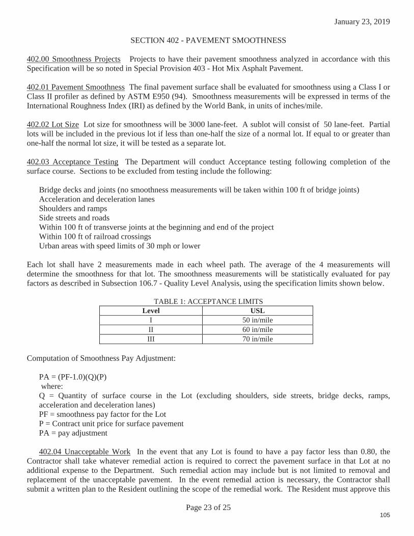
January 23, 2019
Page 23 of 25
SECTION 402 - PAVEMENT SMOOTHNESS
402.00 Smoothness Projects Projects to have their pavement smoothness analyzed in accordance with this Specification will be so noted in Special Provision 403 - Hot Mix Asphalt Pavement.
402.01 Pavement Smoothness The final pavement surface shall be evaluated for smoothness using a Class I or Class II profiler as defined by ASTM E950 (94). Smoothness measurements will be expressed in terms of the International Roughness Index (IRI) as defined by the World Bank, in units of inches/mile.
402.02 Lot Size Lot size for smoothness will be 3000 lane-feet. A sublot will consist of 50 lane-feet. Partial lots will be included in the previous lot if less than one-half the size of a normal lot. If equal to or greater than one-half the normal lot size, it will be tested as a separate lot.
402.03 Acceptance Testing The Department will conduct Acceptance testing following completion of the surface course. Sections to be excluded from testing include the following:
Bridge decks and joints (no smoothness measurements will be taken within 100 ft of bridge joints) Acceleration and deceleration lanesShoulders and ramps Side streets and roadsWithin 100 ft of transverse joints at the beginning and end of the project Within 100 ft of railroad crossings Urban areas with speed limits of 30 mph or lower
Each lot shall have 2 measurements made in each wheel path. The average of the 4 measurements will determine the smoothness for that lot. The smoothness measurements will be statistically evaluated for pay factors as described in Subsection 106.7 - Quality Level Analysis, using the specification limits shown below.
TABLE 1: ACCEPTANCE LIMITSLevel USL
I 50 in/mileII 60 in/mileIII 70 in/mile
Computation of Smoothness Pay Adjustment:
PA = (PF-1.0)(Q)(P) where:
Q = Quantity of surface course in the Lot (excluding shoulders, side streets, bridge decks, ramps, acceleration and deceleration lanes)
PF = smoothness pay factor for the Lot P = Contract unit price for surface pavement
PA = pay adjustment
402.04 Unacceptable Work In the event that any Lot is found to have a pay factor less than 0.80, the Contractor shall take whatever remedial action is required to correct the pavement surface in that Lot at no additional expense to the Department. Such remedial action may include but is not limited to removal and replacement of the unacceptable pavement. In the event remedial action is necessary, the Contractor shall submit a written plan to the Resident outlining the scope of the remedial work. The Resident must approve this
105
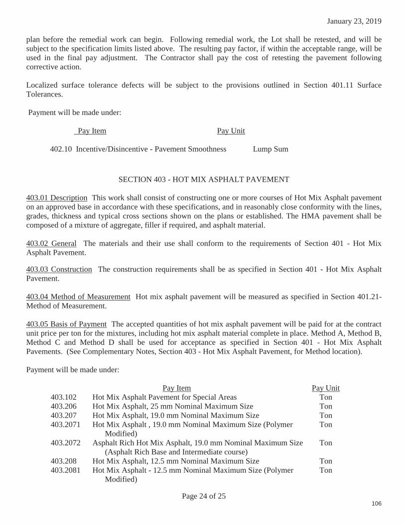
January 23, 2019
Page 24 of 25
plan before the remedial work can begin. Following remedial work, the Lot shall be retested, and will be subject to the specification limits listed above. The resulting pay factor, if within the acceptable range, will be used in the final pay adjustment. The Contractor shall pay the cost of retesting the pavement following corrective action.
Localized surface tolerance defects will be subject to the provisions outlined in Section 401.11 Surface Tolerances.
Payment will be made under:
Pay Item Pay Unit
402.10 Incentive/Disincentive - Pavement Smoothness Lump Sum
SECTION 403 - HOT MIX ASPHALT PAVEMENT
403.01 Description This work shall consist of constructing one or more courses of Hot Mix Asphalt pavement on an approved base in accordance with these specifications, and in reasonably close conformity with the lines, grades, thickness and typical cross sections shown on the plans or established. The HMA pavement shall be composed of a mixture of aggregate, filler if required, and asphalt material.
403.02 General The materials and their use shall conform to the requirements of Section 401 - Hot Mix Asphalt Pavement.
403.03 Construction The construction requirements shall be as specified in Section 401 - Hot Mix Asphalt Pavement.
403.04 Method of Measurement Hot mix asphalt pavement will be measured as specified in Section 401.21- Method of Measurement.
403.05 Basis of Payment The accepted quantities of hot mix asphalt pavement will be paid for at the contract unit price per ton for the mixtures, including hot mix asphalt material complete in place. Method A, Method B, Method C and Method D shall be used for acceptance as specified in Section 401 - Hot Mix Asphalt Pavements. (See Complementary Notes, Section 403 - Hot Mix Asphalt Pavement, for Method location).
Payment will be made under:
Pay Item Pay Unit403.102 Hot Mix Asphalt Pavement for Special Areas Ton403.206 Hot Mix Asphalt, 25 mm Nominal Maximum Size Ton403.207 Hot Mix Asphalt, 19.0 mm Nominal Maximum Size Ton403.2071 Hot Mix Asphalt , 19.0 mm Nominal Maximum Size (Polymer
Modified)Ton
403.2072 Asphalt Rich Hot Mix Asphalt, 19.0 mm Nominal Maximum Size (Asphalt Rich Base and Intermediate course)
Ton
403.208 Hot Mix Asphalt, 12.5 mm Nominal Maximum Size Ton403.2081 Hot Mix Asphalt - 12.5 mm Nominal Maximum Size (Polymer
Modified)Ton
106

January 23, 2019
Page 25 of 25
403.209 Hot Mix Asphalt, 9.5 mm Nominal Maximum Size (sidewalks, drives, islands & incidentals)
Ton
403.210 Hot Mix Asphalt, 9.5 mm Nominal Maximum Size Ton403.2101 Hot Mix Asphalt, 9.5 mm Nominal Maximum Size (Polymer
Modified)Ton
403.2102 Asphalt Rich Hot Mix Asphalt, 9.5 mm Nominal Maximum Size (Asphalt Rich Intermediate course)
Ton
403.2104 Hot Mix Asphalt, 9.5 mm Nominal Maximum Size (Thin Lift Surface Treatment)
Ton
403.211 Hot Mix Asphalt, 9.5 mm Nominal Maximum Size (Shimming) Ton403.2111 Hot Mix Asphalt, 9.5 mm Nominal Maximum Size (Shimming,
Polymer Modified))Ton
403.212 Hot Mix Asphalt, 4.75 mm Nominal Maximum Size Ton403.213 Hot Mix Asphalt, 12.5 mm Nominal Maximum Size (Base and
Intermediate Base course)Ton
403.2131 Hot Mix Asphalt, 12.5 mm Nominal Maximum Size (Base and Intermediate Base course, Polymer Modified)
Ton
403.2132 Asphalt Rich Hot Mix Asphalt, 12.5 mm Nominal Maximum Size (Base and Intermediate Base course)
Ton
403.214 Hot Mix Asphalt, 4.75 Nominal Maximum Size (5/8” Surface Treatment)
Ton
107

December 29, 2016
SPECIAL PROVISIONSECTION 401
HOT MIX ASPHALT PAVEMENT
401 HOT MIX ASPHALT LONGITUDINAL JOINT DENSITY
401.30 Description The Department will measure the pavement density of longitudinal joints constructed between adjoining travel lanes. Core samples shall be tested according to AASHTO T-166. The Department will randomly determine core locations. The Contractor shall cut 6 indiameter cores at no additional cost to the Department by the end of the working day following the day the pavement is placed, and immediately give them to the Department. The cores will be placed in a transport container provided by the Department and transported by the Contractor to the designated MaineDOT Lab as directed by the Department. Pre-testing of the acceptance cores will not be allowed. At the time of sampling, the Contractor and the Department shall mutually determine if a core is damaged. If it is determined that the core(s) is damaged, the Contractor shall cut new core(s) at the same offset and within 3 ft of the initial sample. At the time the core is cut, the Contractor and the Department will mutually determine if saw cutting of the core is needed, and will mark the core at the point where sawing is needed. The core may be saw cut by the Contractor in the Department's presence onsite, or in a MaineDOT Lab by the Department, without disturbing the layer being tested to remove lower layers of Hot Mix Asphalt Pavement, gravel, or RAP. No recuts are allowed at a test location after the core has been tested.
Cores shall be taken directly over the construction joint. Should the notched wedge joint device be used, the cores shall be cut directly over the center of the taper portion of the wedge (approximately centered 3” from the visible joint).
As part of the project specific QCP, the Contractor shall include details as to methods of construction, rolling and compaction efforts, and action plan to adjust methods or equipmentshould the Quality level fall below 50 percent within limits. The Contractor shall be required to measure the joint density at randomly selected locations with a minimum frequency of one measurement per 750 linear feet. The Contractor shall have the option to cut calibration/verification cores at a rate not to exceed 1 per day.
If the Quality level for density falls below 50 percent within limits, the Contractor shall cease placement operations and submit a corrective action letter to the Department before proceeding with the Lot or before starting a new Lot. The Department will respond and either accept or reject the Contractor’s proposed corrective action. If the Department accepts the corrective action, three stratified verification cores will be taken from the first 1500 foot section of centerline constructedfor the purpose of evaluating the corrective action. These cores will be in addition to any Acceptance cores that may be designated in this area. The results from these cores shall be combined with the cores from the Lot in progress. Should the combined Quality level for densityshow an improvement, the Department will accept the corrective action and normal Acceptance sampling frequency shall resume. If an improvement has not been made to the combined Quality level for density, the Contractor shall cease production and submit an additional corrective action letter for consideration.
Page 1 of 2 108
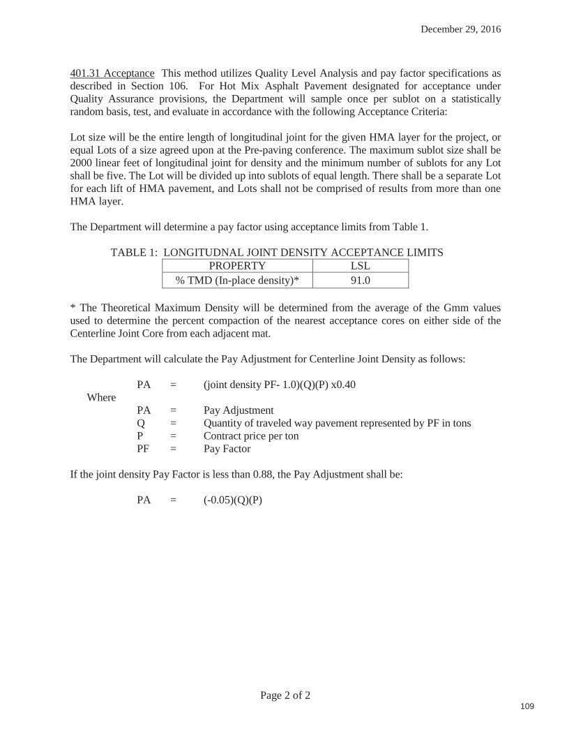
December 29, 2016
401.31 Acceptance This method utilizes Quality Level Analysis and pay factor specifications as described in Section 106. For Hot Mix Asphalt Pavement designated for acceptance under Quality Assurance provisions, the Department will sample once per sublot on a statistically random basis, test, and evaluate in accordance with the following Acceptance Criteria:
Lot size will be the entire length of longitudinal joint for the given HMA layer for the project, or equal Lots of a size agreed upon at the Pre-paving conference. The maximum sublot size shall be 2000 linear feet of longitudinal joint for density and the minimum number of sublots for any Lot shall be five. The Lot will be divided up into sublots of equal length. There shall be a separate Lot for each lift of HMA pavement, and Lots shall not be comprised of results from more than one HMA layer. The Department will determine a pay factor using acceptance limits from Table 1.
TABLE 1: LONGITUDNAL JOINT DENSITY ACCEPTANCE LIMITSPROPERTY LSL
% TMD (In-place density)* 91.0
* The Theoretical Maximum Density will be determined from the average of the Gmm values used to determine the percent compaction of the nearest acceptance cores on either side of the Centerline Joint Core from each adjacent mat. The Department will calculate the Pay Adjustment for Centerline Joint Density as follows:
PA = (joint density PF- 1.0)(Q)(P) x0.40 Where
PA = Pay AdjustmentQ = Quantity of traveled way pavement represented by PF in tons
P = Contract price per tonPF = Pay Factor
If the joint density Pay Factor is less than 0.88, the Pay Adjustment shall be:
PA = (-0.05)(Q)(P)
Page 2 of 2 109
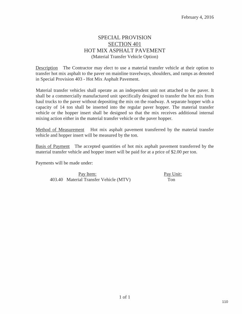
February 4, 2016
SPECIAL PROVISIONSECTION 401
HOT MIX ASPHALT PAVEMENT(Material Transfer Vehicle Option)
Description The Contractor may elect to use a material transfer vehicle at their option to transfer hot mix asphalt to the paver on mainline travelways, shoulders, and ramps as denoted in Special Provision 403 - Hot Mix Asphalt Pavement.
Material transfer vehicles shall operate as an independent unit not attached to the paver. It shall be a commercially manufactured unit specifically designed to transfer the hot mix from haul trucks to the paver without depositing the mix on the roadway. A separate hopper with a capacity of 14 ton shall be inserted into the regular paver hopper. The material transfer vehicle or the hopper insert shall be designed so that the mix receives additional internal mixing action either in the material transfer vehicle or the paver hopper.
Method of Measurement Hot mix asphalt pavement transferred by the material transfer vehicle and hopper insert will be measured by the ton.
Basis of Payment The accepted quantities of hot mix asphalt pavement transferred by the material transfer vehicle and hopper insert will be paid for at a price of $2.00 per ton.
Payments will be made under:
Pay Item: Pay Unit:403.40 Material Transfer Vehicle (MTV) Ton
1 of 1110
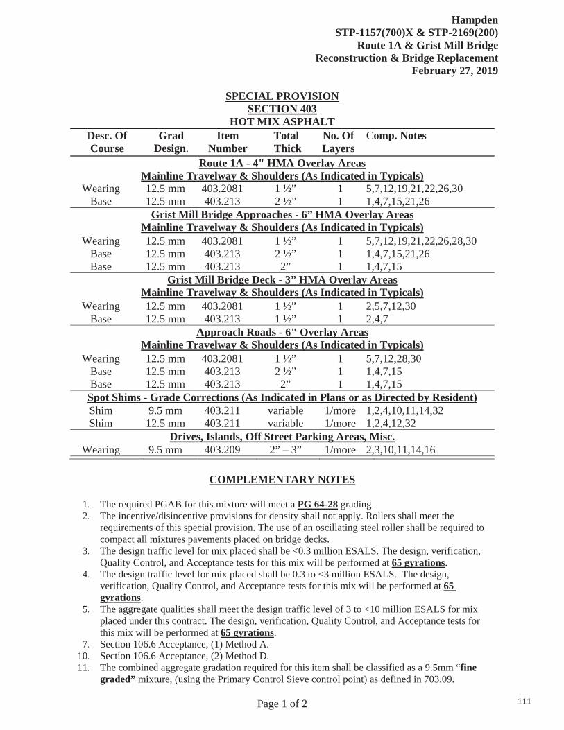
HampdenSTP-1157(700)X & STP-2169(200)
Route 1A & Grist Mill Bridge Reconstruction & Bridge Replacement
February 27, 2019
Page 1 of 2
SPECIAL PROVISION SECTION 403
HOT MIX ASPHALT Desc. Of Course
GradDesign.
ItemNumber
Total Thick
No. Of Layers
Comp. Notes
Route 1A - 4" HMA Overlay Areas Mainline Travelway & Shoulders (As Indicated in Typicals)
Wearing 12.5 mm 403.2081 1 ½” 1 5,7,12,19,21,22,26,30 Base 12.5 mm 403.213 2 ½” 1 1,4,7,15,21,26
Grist Mill Bridge Approaches - 6” HMA Overlay Areas Mainline Travelway & Shoulders (As Indicated in Typicals)
Wearing 12.5 mm 403.2081 1 ½” 1 5,7,12,19,21,22,26,28,30 Base 12.5 mm 403.213 2 ½” 1 1,4,7,15,21,26 Base 12.5 mm 403.213 2” 1 1,4,7,15
Grist Mill Bridge Deck - 3” HMA Overlay Areas Mainline Travelway & Shoulders (As Indicated in Typicals)
Wearing 12.5 mm 403.2081 1 ½” 1 2,5,7,12,30 Base 12.5 mm 403.213 1 ½” 1 2,4,7
Approach Roads - 6" Overlay Areas Mainline Travelway & Shoulders (As Indicated in Typicals)
Wearing 12.5 mm 403.2081 1 ½” 1 5,7,12,28,30 Base 12.5 mm 403.213 2 ½” 1 1,4,7,15 Base 12.5 mm 403.213 2” 1 1,4,7,15 Spot Shims - Grade Corrections (As Indicated in Plans or as Directed by Resident) Shim 9.5 mm 403.211 variable 1/more 1,2,4,10,11,14,32 Shim 12.5 mm 403.211 variable 1/more 1,2,4,12,32
Drives, Islands, Off Street Parking Areas, Misc.Wearing 9.5 mm 403.209 2” – 3” 1/more 2,3,10,11,14,16
COMPLEMENTARY NOTES
1. The required PGAB for this mixture will meet a PG 64-28 grading.2. The incentive/disincentive provisions for density shall not apply. Rollers shall meet the
requirements of this special provision. The use of an oscillating steel roller shall be required tocompact all mixtures pavements placed on bridge decks.
3. The design traffic level for mix placed shall be <0.3 million ESALS. The design, verification,Quality Control, and Acceptance tests for this mix will be performed at 65 gyrations.
4. The design traffic level for mix placed shall be 0.3 to <3 million ESALS. The design,verification, Quality Control, and Acceptance tests for this mix will be performed at 65gyrations.
5. The aggregate qualities shall meet the design traffic level of 3 to <10 million ESALS for mixplaced under this contract. The design, verification, Quality Control, and Acceptance tests forthis mix will be performed at 65 gyrations.
7. Section 106.6 Acceptance, (1) Method A.10. Section 106.6 Acceptance, (2) Method D.11. The combined aggregate gradation required for this item shall be classified as a 9.5mm “fine
graded” mixture, (using the Primary Control Sieve control point) as defined in 703.09.
111
HampdenSTP-1157(700)X & STP-2169(200)
Route 1A & Grist Mill Bridge Reconstruction & Bridge Replacement
February 27, 2019
Page 2 of 2
12. The combined aggregate gradation required for this item shall be classified as a 12.5mm “finegraded ” mixture, (using the Primary Control Sieve control point) as defined in 703.09.
14. The combined aggregate gradation required for this item shall be classified as a 9.5mm ThinLift Mixture (TLM) mixture, using the Aggregate Gradation Control Points as defined in703.09.
15. The entire HMA base pavement section (consisting of all base layers) shall be completedbefore winter suspension. Any surface or base HMA placed after the seasonal limitations shallbe considered temporary and removed and replaced the following construction season. TheDepartment will not be responsible for costs or time related to the placement, removal orreplacement of temporary pavement.
16. Compaction of the new Hot Mix Asphalt Pavement will be obtained using a minimal rollertrain consisting of a 3-5 ton vibratory roller. Areas less than 2 feet wide shall be compactedwith a minimum of a 150 pound plate compactor. An approved release agent is required toensure the mixture does not adhere to hand tools, rollers, pavers, and truck bodies. The use ofpetroleum based fuel oils, or asphalt stripping solvents will not be permitted.
19. The Contractor may, at their option, use a Material Transfer Vehicle (MTV) for all mainlinetravelway and adjacent shoulders surface course if paved in the same operation. SeeSpecial Provision 401 – Material Transfer Vehicle for specifics.
21. At the discretion of the Contractor, the use of concrete fill will be allowed in lieu of pavementand gravel to back fill around granite curbing (Type 1 & 5). When utilized, at least 3” of HMAshall be placed on top of the concrete fill for cover on the mainline edge of curb (face of curb).At minimum, the Concrete shall be a 3000 psi Class A concrete. Flowable fill shall not bepermitted. There will not be additional compensation for the Concrete Fill, but shall beconsidered incidental to the 609 items.
22. The final pavement surface shall be evaluated for smoothness in accordance with the mostcurrent 400 Standard Specification section 402 – Pavement Smoothness. Acceptance limitsshall be as outlined under the Level II classification.
26. Centerline joint density testing shall be applied to the specified HMA layer. See SpecialProvision 401 – Hot Mix Asphalt Longitudinal Joint Density for project specifics.
30. The required PGAB shall be a storage-stable, homogeneous, polymer modified asphalt binderthat meets PG 64E-28 grading requirements in AASHTO M 332. All polymer modifiedasphalt grades utilized on the Project shall be treated with an approved liquid anti-strip. PGbinders shall be treated either at the asphalt source terminal with the required dose rate on thedelivery documentation, or at the hot mix asphalt plant utilizing a system integrated with theplants controls that will introduce a minimum 0.50 percent anti-strip by weight of asphaltbinder used unless a rate is otherwise recommended by the anti-strip manufacturer. The PGABand anti-strip blend shall meet the PG 64E-28 requirements. The Contractor shall providesupporting test data showing the PGAB and anti-strip blend meet the required criteria.
32. In areas where additional material is needed to bring the existing profile and crossslope to the proposed grades, the Contractor shall utilize an HMA shim layer. In areaswhere the corrections required are in excess of 1 ½”, the Contractor shall utilize a 12.5mm HMA. Individual lift thicknesses shall not exceed 2 ½”.
Tack Coat A tack coat of emulsified asphalt, RS-1, RS-1h, CRS-1 or CRS-1h, Item 409.15 shall be applied to any existing pavement at a rate of approximately 0.030 gal/yd², and on milled pavement approximately 0.05 gal/yd² prior to placing a new course. A fog coat of emulsified asphalt shall be applied between shim /base courses and surface course as well as to any bridge membrane prior to the placement of HMA layers at a rate not to exceed 0.030 gal/yd². Tack used will be paid for at the contract unit price for Item 409.15 Bituminous Tack Coat.
112

Hampden WIN 11577.00 WIN 21692.00
January 19, 2019
SPECIAL PROVISION SECTION 502
STRUCTURAL CONCRETE (QC/QA Acceptance Methods)
CLASS OF
CONCRETE ITEM
NUMBER DESCRIPTION P METHOD
A 502.219 STRUCTURAL CONCRETE ABUTMENT AND RETAINING WALLS
400 A
A 502.26 STRUCTURAL CONCRETE ROADWAY AND SIDEWALK SLAB ON STEEL
BRIDGES
400 A
A 502.31 STRUCTURAL CONCRETE APPROACH SLAB
- C
A 502.33 STRUCTURAL CONCRETE CULVERT END WALL
400 A
LP 502.342 STRUCTURAL CONCRETE ROADWAY TRUCK APRON
B
LP 502.49 STRUCTURAL CONCRETE CURBS AND SIDEWALKS
- C
A 502.565 CONCRETE FILL - C LP 526.34 PERMANENT CONCRETE TRANSITION
BARRIER - C
P Values listed above reflect the price per cubic yard (CY) for all Pay Adjustment purposes.
The quantity used for Pay Adjustment purposes shall be the actual quantity of concrete placed and accepted. This quantity shall be computed by the Contractor and submitted to the Resident
for approval.
113
Hampden STP-1157(700)X
11577.00 Route 1A
February 15, 2019
Page 1 of 2
SPECIAL PROVISIONS
SECTION 502
STRUCTURAL CONCRETE
(Roadway Truck Apron)
Description This work shall consist of furnishing and placing a portland cement concrete pavement and incidental construction as shown on the plans and as directed. Except as otherwise specified in this Special Provision, all work shall be in conformity with the applicable provisions of Section 502, Structural Concrete; Section 503, Reinforcing Steel; and Section 515, Protective Coating for Concrete Surfaces.
MATERIALS
Concrete Concrete shall be LP.
Reinforcement Reinforcement shall be 4” x 4” W4 x W4 Steel Welded Wire Fabric, Deformed, conforming to Section 503 and Section 709.02.
Preformed Expansion Joint Filler Preformed Expansion Joint Fillers shall meet the requirements of Section 705.01.
CONSTRUCTION REQUIREMENTS
Preparation of Foundation The existing material shall be removed to the depth shown on the plans. The foundation bed shall be well graded and compacted, as directed by the Resident, and additional gravel shall be placed to provide the thickness of concrete indicated on the plans.
Prior to the concrete placement, the foundation bed shall be thoroughly and uniformly saturated with water. The bed shall be free of puddles and excessive surface water.
Placement of Concrete Concrete shall be placed in a continuous placement operation between preformed expansion joints. No construction joints will be allowed. Expansion joints shall have an approved expansion joint sealer installed as detailed on the plans. Preformed expansion joints shall be continuous and of an approved material, and control joints shall be sawcut into the surface of the concrete. Expansion joints and control joints shall be placed as shown on the details.
The surface of the concrete shall receive a float finish in accordance with Subsection 502.14(A). Immediately following the float finish, the surface shall be textured at right angles to the roadway using an approved open-pile, stiff bristle broom or mat.
114

Hampden STP-1157(700)X
11577.00 Route 1A
February 15, 2019
Page 2 of 2
The curing period for the concrete shall be seven days and shall meet the requirements of Standard Specifications Section 502.15. The finished surface of the concrete shall receive a protective coating in accordance with Section 515.
Quality Assurance Quality assurance of Structural Concrete, Roadway Truck Apron will be by as defined in Special Provision 502 QC/QA Acceptance.
Method of Measurement Structural Concrete, Roadway Truck Apron, satisfactorily placed and accepted, will be measured for payment by the cubic yard, in accordance with the dimensions shown on the plans or authorized by the Resident.
Basis of Payment The accepted quantity of Structural Concrete, Roadway Truck Apron will be paid for at the contract unit price per cubic yard, which payment will be full compensation for all labor, materials, equipment and incidentals necessary to complete the work, including the fabrication, delivery and placement of reinforcement; the furnishing and placement of expansion and contraction joints and joint sealant; and the furnishing and application of protective coating.
Any grading or shimming of the existing subbase material that may be necessary after pavement removal to provide a suitable foundation for Structural Concrete, Roadway Truck Apron will be incidental to payment under Pay Item 502.342. Excavation for the placement of Structural Concrete, Roadway Truck Apron will be paid under the appropriate contract item, Section 203 – Excavation and Embankments.
Payment will be made under:
Pay Item Pay Unit
502.342 Structural Concrete, Roadway Truck Apron Cubic Yard
115

Hampden Grist Mill Bridge WIN 021692.00 March 14, 2019
Page 1 of 8
SPECIAL PROVISION SECTION 509
COMPOSITE TUB GIRDER
509.01 Description
This work shall consist of furnishing and erecting Composite Tub Girders (CT Girders) to the dimensions shown on the plans and according to the requirements of the Standard Specifications and these Special Provisions. CT Girders for incorporation into the project shall include the FRP CT Girders, shear bolts, utility support connection plate, and high strength bolts used to attach the bent plate for utility support channel as detailed on the Plans. Anchor bolts, shim plates, masonry plates, sole plates, and bearings will be paid for separately under separate pay items.
509.02 Quality Control / Quality Assurance
At least thirty (30) calendar days prior to fabrication, the Contractor shall submit to the Department a Quality Control/Quality Assurance (QC/QA) Plan for fabrication of the CT Girders. Fabrication of the CT Girders shall not commence until the QC/QA Plan has been reviewed and commented upon by the Department.
509.03 Definitions
Terms and definitions found within this document shall be defined as outlined in the Standard Specifications, with the following added terms:
Composite Tub Girder (CT Girder): A structural member consisting of a Fiber Reinforced Polymer (FRP) lamina composed of glass fiber, carbon fiber, foam core, and resin.
Shear Bolt: A member with one end embedded in the concrete deck and the opposing end bolted through the top flange. A plurality of shear bolts are utilized to provide a positive connection to the bridge deck and to facilitate composite bending behavior between the CT Girder and the concrete deck.
Closure Plate: A member permanently bonded across the top flange of the CT Girder to provide transverse and torsional stability and prevent concrete from entering the girder.
Utility Support Connection Plate: A member permanently installed on the inside surface of the girder and designed to provide support for the bent plate that supports the utility channel and hangers.
Preforms: Individual element components of materials to be incorporated into the CT Girder, e.g. glass fiber fabric, carbon fiber fabric, foam core.
Tooling: The molds or forms that are used in the fabrication of CT Girders.
Manufacturer: The supplier of the CT Girders is Advanced Infrastructure Technologies, LLC (AIT) of 20 Godfrey Drive, Orono, ME 04473.
116

Hampden Grist Mill Bridge WIN 021692.00 March 14, 2019
Page 2 of 8
509.04 Materials
Materials shall conform to the following. Any substitutions to the materials specified below must be submitted to the Department for approval.
1) Reinforcement: The CT Girder fiber reinforcement shall be comprised of a mix of carbon fiber fabric, glass fiber fabric, foam core, and a resin matrix.
a. Carbon Fiber Fabric: Carbon fibers shall be standard modulus fibers. Tensile strength, tensile modulus, and strain of the fibers shall be documented in accordance with the manufacturer’s test specifications. In lieu of material testing, a Certificate of Conformance may be submitted to the Department for approval.
i. Unidirectional Carbon Fiber Reinforcement specifications: 1. Physical Properties
a. Minimum Aerial Weight 36.3 oz/yd2 1.23 kg/m2
Acceptable Manufacturers include: 1) Vectorply2) Flotex3) Approved equal
b. Glass Fiber Fabric: Glass fibers shall be E-glass manufactured in accordance with ASTM D578 and tested in accordance with ASTM D2343. In lieu of material testing, a Certificate of Conformance may be submitted to the Department for approval.
i. Unidirectional Glass Fiber Reinforcement specifications: 1. Physical Properties
a. Minimum Aerial Weight 41.5 oz/yd2 1.41 kg/m2
ii. Biaxial Glass Fiber Reinforcement specifications: 1. Physical Properties
a. Minimum Aerial Weight 24.2 oz/yd2 0.82 kg/m2
Acceptable Manufacturers include: 1) Vectorply2) Approved equal
c. Foam Core: The foam core shall be comprised of medium density closed cell foam with an average density of 5.9-6.6 lbs/cubic foot as determined by ASTM D1622 and a compressive strength greater than 200-300 lbs/square inch as measured by ISO 844 or ASTM D1621. Acceptable Products include:
1) Airex T92.100 as manufactured by 3A 2) Approved equal
d. Resin: The matrix used in the manufacturing of CT Girders shall be an epoxy-vinyl ester resin with a dynamic viscosity between 100 and 400 centipoise at 77° Fahrenheit appropriate for resin infusion
117

Hampden Grist Mill Bridge WIN 021692.00 March 14, 2019
Page 3 of 8
using the Vacuum Infusion Process (VIP). Clear casting tensile strength and tensile modulus shall be documented in accordance with ASTM D638. Clear casting flexural strength and modulus shall be documented in accordance with ASTM D790. Heat distortion temperature shall be documented in accordance with ASTM D648. In lieu of testing, a Certificate of Analysis may be submitted in the QA documentation. If the resin is not pre-promoted, then it should be promoted in accordance with the manufacturer’s recommendations. If the resin material is pre-promoted, then no additional promotion is necessary. The resin shall be catalyzed in accordance with the manufacturer’s recommendations. Prior to infusing with the resin, gel time tests shall be conducted in the infusion environment to determine the desired dosage rate to produce the required gel time necessary to ensure proper wet out and saturation of fibers. Acceptable Products include:
1) DERAKANE 610 C-150 P as manufactured by Ashland 2) Approved equal
Additional non-structural layers of glass veil such as a 1.5 oz/yd2 continuous strand mat may be used to enhance resin infusion. Additional non-structural layers of resin distribution media may be placed around the tension reinforcement to promote more efficient means of infusion.
2) Shear Bolts: The shear bolts shall be comprised of ASTM F3125 Grade A490 Type 1 bolts. Heavy hex nuts shall conform to ASTM A563 Grade DH and washers shall conform to ASTM F436 Type 1.
3) Closure Plate: The closure plate shall be comprised of FRP stock flat sheets, with dimensions in conformance to the Plans, bonded to the top flange of the girder using a structural adhesive. The closure plate shall be bonded to the top flange of the CT Girder using 2 - 3/8” beads of structural adhesive on each top flange.
4) Structural Adhesives: Structural adhesives shall be used where indicated on the Working Drawings. Structural adhesives shall be a two-component, medium viscosity, methacrylate or urethane suitable for bonding FRP.
Acceptable Products include: 1) Pliogrip 7770 as manufactured by Ashland 2) Plexus MA560-1 as manufactured by ITW 3) Approved equal
5) Utility Connection Plate: The utility connection plate on the inside of the CT Girders shall consist of ¼” hot-dip galvanized A36 plates with four ¾” A325 hot-dip galvanized bolts tack welded to the plate as indicated on the Working Drawings. The plate shall be bonded to the inside surface of the CT Girder using structural adhesive as indicated on the Working Drawings.
509.05 Equipment
A vacuum pump capable of sustaining a pressure equal to or greater than 25 inches of mercury shall be required for the vacuum infusion of the CT Girder. The vacuum system shall be outfitted with a reservoir system to accumulate any over filling of the matrix in the mold and protect the vacuum pump.
118

Hampden Grist Mill Bridge WIN 021692.00 March 14, 2019
Page 4 of 8
509.06 Working Drawings
Prior to beginning fabrication, the Contractor shall submit complete Working Drawings to the Department for review and comment in accordance with Section 105.7 Working Drawings of the Standard Specifications. Each drawing shall provide adequate space for review and comments. If the Working Drawings have significant discrepancies, revised sets must be submitted until details comply with the contract requirements.
As a minimum, Working Drawings shall include:
1) Layout drawings identifying piece marks and orientation in the structure (including a north arrow) 2) Individual piece drawings indicating the length, depth, width, and thickness of piece, along with the spacing
of shear bolts, location of piece marks, weight, location of all holes and/or inserts, location of lifting points, and any other information necessary to adequately fabricate each girder.
509.07 Fabrication
The Contractor shall make arrangements with the Manufacturer to fabricate and store the CT Girders by August 2, 2019.
The Manufacturer shall notify the Fabrication Engineer a minimum of two weeks prior to the start of work. In addition, the Manufacturer shall provide the Fabrication Engineer with a copy of the production schedule. If the production schedule changes, notify the Fabrication Engineer no less than 3 working days prior to the initial start-up date.
The Quality Assurance Inspector’s (QAI) presence is required for, but not limited to, the following activities: batching of matrix resin, infusion of part, and final inspection. The QAI’s office shall meet the requirements of Section 504.09 – Facilities for Fabrication Inspection.
CT Girders shall be fabricated and stored according to the following requirements:
1) Preform Storage and Preparation: Glass and carbon fiber fabrics, foam core, and non structural media material used to aid in resin flow shall be stored in a clean, dry environment in the original packaging until ready for use. They shall be protected from water, dirt, grease, grinding dust, and other foreign matter. The fabrics shall be cut on a clean cutting surface, free of any corrosive or deleterious material that could adhere to the fabrics prior to layup in the tooling. Cut-outs within the fabric to accommodate details of the infusion process and/or details of the finished CT Girder shall be clearly indicated on the Working Drawings.
Lap splices in the fabric will be permitted in the longitudinal direction of the girder. Longitudinal lap splices shall be no less than 6 inches in length. Lap splices in the fabric will be permitted in transverse direction. Transverse lap splices shall be no less than 2 inches in length.
Foam core shall be machine cut to full depth sections and may be butt jointed together longitudinally. Gaps in the joints between adjacent pieces of foam shall not exceed ¼ inch prior to pulling vacuum on the tooling.
119
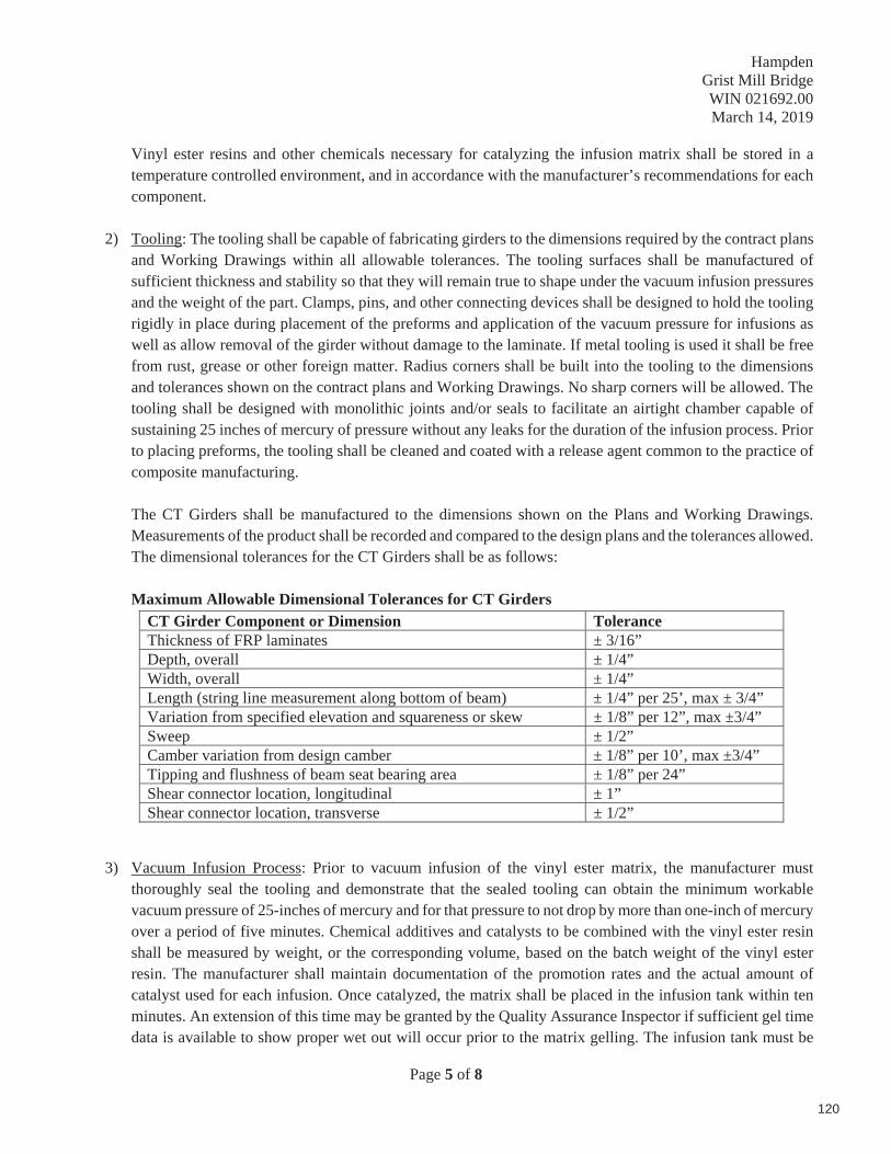
Hampden Grist Mill Bridge WIN 021692.00 March 14, 2019
Page 5 of 8
Vinyl ester resins and other chemicals necessary for catalyzing the infusion matrix shall be stored in a temperature controlled environment, and in accordance with the manufacturer’s recommendations for each component.
2) Tooling: The tooling shall be capable of fabricating girders to the dimensions required by the contract plans and Working Drawings within all allowable tolerances. The tooling surfaces shall be manufactured of sufficient thickness and stability so that they will remain true to shape under the vacuum infusion pressures and the weight of the part. Clamps, pins, and other connecting devices shall be designed to hold the tooling rigidly in place during placement of the preforms and application of the vacuum pressure for infusions as well as allow removal of the girder without damage to the laminate. If metal tooling is used it shall be free from rust, grease or other foreign matter. Radius corners shall be built into the tooling to the dimensions and tolerances shown on the contract plans and Working Drawings. No sharp corners will be allowed. The tooling shall be designed with monolithic joints and/or seals to facilitate an airtight chamber capable of sustaining 25 inches of mercury of pressure without any leaks for the duration of the infusion process. Prior to placing preforms, the tooling shall be cleaned and coated with a release agent common to the practice of composite manufacturing.
The CT Girders shall be manufactured to the dimensions shown on the Plans and Working Drawings. Measurements of the product shall be recorded and compared to the design plans and the tolerances allowed. The dimensional tolerances for the CT Girders shall be as follows:
Maximum Allowable Dimensional Tolerances for CT Girders CT Girder Component or Dimension Tolerance Thickness of FRP laminates ± 3/16” Depth, overall ± 1/4” Width, overall ± 1/4” Length (string line measurement along bottom of beam) ± 1/4” per 25’, max ± 3/4” Variation from specified elevation and squareness or skew ± 1/8” per 12”, max ±3/4” Sweep ± 1/2”Camber variation from design camber ± 1/8” per 10’, max ±3/4” Tipping and flushness of beam seat bearing area ± 1/8” per 24” Shear connector location, longitudinal ± 1” Shear connector location, transverse ± 1/2”
3) Vacuum Infusion Process: Prior to vacuum infusion of the vinyl ester matrix, the manufacturer must thoroughly seal the tooling and demonstrate that the sealed tooling can obtain the minimum workable vacuum pressure of 25-inches of mercury and for that pressure to not drop by more than one-inch of mercury over a period of five minutes. Chemical additives and catalysts to be combined with the vinyl ester resin shall be measured by weight, or the corresponding volume, based on the batch weight of the vinyl ester resin. The manufacturer shall maintain documentation of the promotion rates and the actual amount of catalyst used for each infusion. Once catalyzed, the matrix shall be placed in the infusion tank within ten minutes. An extension of this time may be granted by the Quality Assurance Inspector if sufficient gel time data is available to show proper wet out will occur prior to the matrix gelling. The infusion tank must be
120

Hampden Grist Mill Bridge WIN 021692.00 March 14, 2019
Page 6 of 8
charged with a sufficient amount of resin at all times to prevent air bubbles from entering the infusion ports in the tooling. Once resin is introduced into the tooling, the infusion process shall continue uninterrupted until it has been demonstrated that all evacuation ports have a surplus of resin flowing past the finished surface of the tooling and that no less than the predicted volume of resin has been introduced into the tool.
A Barcol hardness tester may be used to determine the cured state of the composite. The girder should not be removed from the tooling unless a Barcol hardness reading of 35 or more can be obtained in multiple locations along the length and section of the girder. In the absence of tests used to determine the cured state of the resin matrix, the tooling shall remain in place, under at least 25-inches of mercury for at least 6 hours after all evacuation lines have been clamped and the infusion process is considered to have been completed.
Subscale witness panels representative of the full depth CT Girder laminate shall be tested in accordance with the specified ASTM Standards in conformance with the minimum properties outlined in the table below. Adequate supporting documentation for the properties shall be obtained from the Manufacturer and provided to the Department. The following properties shall be tested using at least five samples cut from the first infused girder end. If the experimental values tested exceed the minimum allowable values below, the production lot is approved and no further testing is required. If the experimental tested values fall below the values listed below, each subsequent CT girder shall have witness panels tested until the average of all tested values exceeds the minimum values below. If the average of all tested values falls below the minimum values below, the production lot shall be rejected.
Tensile strength witness panel coupons shall be representative of the bottom flange laminate. Compressive strength witness panel coupons shall be representative of the top flange laminate. Shear strength witness panel coupons shall be representative of the web face sheet laminate.
4) Post Processing: Once the laminate has been allowed to cure, the CT Girder may be removed from the tooling and all post processing work may begin. This will include, de-bagging, removal of peel ply, sanding, grinding, cutting, drilling, machining, attachment of shear bolts, closure plate, and utility support connection plates.
509.08 Handling, Storage, and Transportation
The CT Girder complete with closure plate may be placed upright, upside down, or on its side, as necessary for drilling and post-processing of the finished piece. Care shall be taken in the handling of the CT Girder so as to not damage the surface finish of the laminate.
Prior to moving any CT Girders to storage, it shall be clearly marked with the mark number which indicates the date of fabrication and the location shown on the Working Drawings. All CT Girders shall be stored in an upright position on suitable dunnage, not in contact with the ground, at the support points shown on the Working Drawings.
PROPERTY UNITS ASTM TEST METHOD MINIMUM Tensile Strength psi D3039 58,000
Compressive Strength psi D6641 49,000Shear Strength psi D3518 8,500
121

Hampden Grist Mill Bridge WIN 021692.00 March 14, 2019
Page 7 of 8
The CT Girders may be stacked. When stacking, the CT Girders shall be maintained in the upright position at all times and each beam shall be supported with cribbing at the same location as the girder below.
CT Girders shall not be released for shipment until all dimensional tolerances have been checked. If the CT Girders are to be stored at a location other than the manufacturer’s facility, including the bridge site, the same provisions outlined above for storage at the manufacturer’s facility shall apply.
Transportation will be the responsibility of the Contractor. The Manufacturer will be responsible for loading the CT Girders on the Contractor’s truck. The Contractor is responsible for securing and transporting the CT Girders from Penobscot Logistics Systems (PLS), 70 Bennett Street, Bangor, ME 04401 to the project site. All CT Girders shall be shipped upright and supported by cribbing at the locations shown in the Working Drawings.
If the CT Girders are damaged during transport, handling, and/or storage prior to their incorporation into the structure, the damaged CT Girders shall be repaired or replaced by the Contractor at the Resident Engineer’s discretion and at no additional cost to the Department.
509.09 Erection
The CT Girders shall be erected to the lines and grades as indicated in the Plans and in accordance with the requirements of these Special Provisions. At least 30 days prior to erection, the Contractor shall submit an Erection Plan indicating lifting methods, erection sequence, and any other pertinent information. Penetrations in the CT Girder for construction purposes shall be shown on the Erection Plan and will not be permitted unless approved by the Engineer of Record.
Girders shall be placed on clean bridge seats and tops of bearing devices. Any shifting of the girders shall be done while they are free of the supports.
Girders shall be handled with a suitable hoisting device or crane of sufficient capacity to handle the members. Nylon slings or other approved methods shall be used to prevent damage to the surface of the girders. Lifting anchors sized and located in accordance with the Working Drawings may be used to hoist the girders only if explicitly stated on the Working Drawings.
The Contractor shall provide temporary bracing of the girders to prevent rotation along the girder centerline until the backwall concrete has been cast.
The Contractor is responsible for providing and installing the bent plates and utility c-channels for all utility support connections.
509.10 Method of Measurement and Basis of Payment
Item No. 509.743 Composite Tub Girder - Fabrication will be paid for at the lump sum price. Payment shall be compensation for fabrication of the CT Girders. Related materials and work include fabrication and post-processing of the CT Girders, installation of closure plate, shear bolts, internal utility support connection plates and bolts for connecting to the FRP, storage at the manufacturer’s lot and all submittals related to this work.
122

Hampden Grist Mill Bridge WIN 021692.00 March 14, 2019
Page 8 of 8
Item No. 509.744 Composite Tub Girder – Erection will be paid for at the lump sum price. Payment shall be compensation for transportation, storage, handling, temporary bracing, erecting, bent plates, utility channels, and all submittals required for approval prior to execution of this work. Anchor bolts and bearings will be paid for separately under separate pay items.
Payment will be made under:
Pay Item Pay Unit 509.743 Composite Tub Girder – Fabrication Lump Sum 509.744 Composite Tub Girder – Erection Lump Sum
123

Hampden Grist Mill Bridge WIN 021692.00 March 26, 2018
1 of 4
SPECIAL PROVISION SECTION 520
EXPANSION DEVICES – NON-MODULAR (Asphaltic Plug Joint)
520.01 Description This work consists of furnishing and installing asphaltic plug joint systems at the locations
shown on the Plans, in accordance with these Specifications, and as directed by the Resident. This work shall include furnishing, installation, and removal of all bond breaking materials used to prevent asphalt pavement layers from adhering to waterproofing membrane, all temporary header(s) installed with the intent to form the asphaltic plug joint channel, and all preparation required for the installation of the asphaltic plug joint.
This work shall also include having the approved manufacturer provide a qualified technical representative to supervise the installation of the joint systems. The representative shall instruct, train, and supervise the Contractor’s personnel in the proper methods of installation. All costs associated with this service shall be included in the unit price of the work.
520.02 Submittals Prior to construction, the Contractor shall submit the following to the Resident for review
and approval:
(a) Complete and detailed Shop Drawings of the asphaltic plug joint system. Shop Drawings shall include information covering materials, their properties, installation procedures, storage and handling requirements, and Safety Data Sheets.
(b) The resume of the manufacturer’s technical representative, which shall include the representative’s experience installing the asphaltic plug joint system along with the names and telephone numbers of contact persons for recent projects where technical assistance was provided.
(c) Certified test reports of the asphaltic binder, closed cell foam backer rod, and the plastic compound.
(d) Certificates of Compliance for bridging plates, centering nails, and aggregate.
520.03 Materials An asphaltic plug joint system from MaineDOT’s Qualified Products List for Expansion
Devices – Non-Modular (Asphaltic Plug Joints) shall be used.
The bridging plate, where required, shall be ASTM A36 steel, a minimum of 1/4 inch thick, and galvanized. Holes for the centering nails shall be approximately 1 foot center to center along the centerline of plates.
124

Hampden Grist Mill Bridge WIN 021692.00 March 26, 2018
2 of 4
Centering nails shall be 16d or larger and hot dip galvanized in accordance with ASTM A153.
Bridging plates are not required for this project.
520.04 Installation The asphaltic plug joint system shall be installed in accordance with the manufacturer’s latest
instructions and this specification. Manufacturer’s representatives shall be present during the entire installation to ensure satisfactory results are obtained.
The asphaltic plug joint system shall allow total joint movement for up to 2 inches. The installation shall be centered over the expansion joint gap as indicated on the Plans. It shall not be installed when ambient or substrate temperatures are below 40°F, when rain is imminent, or as directed by the Resident. The area shall be free of dirt, dust, moisture, petroleum, or solvents that might contaminate the joint materials or reduce the bond of the joint system to the substrate or vertical faces. The use of compressed air and heat may be required to dry the area before installing the joint system.
The asphalt pavement layers shall be removed to the required dimensions shown on the plans. The asphalt pavement shall be sawcut to a depth that will not damage the waterproofing membrane, but permit the removal of the asphalt pavement layer. The pavement layer shall be removed in a manner that will not damage the waterproofing membrane. Bond breakers such as interlayers and fabrics, or temporary header(s), may be used with new hot mix asphalt placements to avoid unnecessary sawcuts and protect the waterproofing membrane from damage. The method of attaching temporary header(s) to the concrete deck shall be approved by the Resident. The use of a temporary header shall not be allowed if it will need to be anchored into a precast prestressed concrete member. Should a concrete levelling course be required before installing the bridging plates, and the membrane layer is removed in the process, it shall be replaced before the asphaltic plug joint system is installed. Vertical surfaces of the asphalt pavement layers shall be cleaned to remove all water, dust, or other contaminates.
Backer rods shall be installed in expansion joint openings at a minimum of 1 inch depth or as indicated on the Plans.
Unless otherwise specified by the asphaltic plug joint system manufacturer, liquid asphalt binder meeting the requirements of a 64-28 or 58-28 PGAB shall be used to coat the membrane and bridging plate surfaces.
The binder shall be heated to 350°F to 410°F, or a safe temperature as recommended by manufacturer. Heating kettles shall be equipped with continuous agitation system, temperature controller, calibrated thermometer, and double steel jacket with an oil layer in between, to prevent scorching of the binder. During application, the temperature of the binder shall be maintained at a minimum of 350°F, but not greater than 410°F. It shall be poured and leveled
125

Hampden Grist Mill Bridge WIN 021692.00 March 26, 2018
3 of 4
into the expansion joint openings until overfilled, and the excess binder spread over the area covered by the bridging plates.
Where required, steel bridging plates shall be placed from curb to curb on the roadway portion of expansion joints. The plates shall be centered over the joint opening. Centering nails shall be placed in pre-drilled holes and hammered in to secure the plates.
Once the bridging plates are installed, liquid asphalt binder shall be poured and leveled over the bridging plates and adjacent membrane surfaces in a manner that ensures full coverage. Areas with excessive application, such as pooling of liquid, should be removed or dispersed along the joint area.
Asphaltic plug joint system aggregate shall be heated in a rotating drum mixer to a minimum of 350°F but not greater than 410°F, or as recommended by the manufacturer. The thermoplastic polymeric modified asphalt binder shall be added to the mixer to pre-coat the aggregates.
Coated aggregate shall be placed into blockouts in layers as recommended by the manufacturer. Blockouts shall be overfilled with coated aggregate as required to compensate for compaction. Equipment for compaction shall be as recommended by the manufacturer. Additional thermoplastic polymeric modified asphalt binder shall be screeded over the compacted joint to fill all surface voids.
Top dressing aggregate shall be applied per the manufacturer’s recommendation.
Plastic compound shall be used for repairing overcuts in bituminous concrete. Cleaning, mixing, and application shall be in conformance to the manufacturer’s instructions.
Vehicular traffic may pass over finished joints two-hours after compaction, or as recommended by the manufacturer.
520.05 Method of Measurement The Asphaltic Plug Joint system will be measured by the linear foot along the top surface of
installed joints to the limits shown on the Plans. Preparation of surfaces for the proposed joint system including cutting, grinding, and cleaning will not be measured separately for payment, but shall be incidental to the Asphaltic Plug Joint.
520.06 Basis of Payment The Asphaltic Plug Joint system will be paid for at the Contract unit price per linear foot,
which price shall be full compensation for all labor, materials, equipment, and incidentals required for furnishing and installing the Asphaltic Plug Joint system as shown on the Plans, in accordance with these Specifications, and as directed by the Resident. Payment shall also include all work required to repair the concrete deck where anchors were used with a temporary header, and all patching needed for the waterproofing membrane.
126

Hampden Grist Mill Bridge WIN 021692.00 March 26, 2018
4 of 4
Payment will be made under:
Pay Item Pay Unit
520.232 Expansion Device - Asphaltic Plug Joint Linear Foot
127

Hampden STP-1157(700)X
11577.00 Route 1 A
February 5,2019
Page 1 of 3
SPECIAL PROVISION SECTION 602
FLOWABLE CONCRETE FILL
Description This work shall consist of providing and placing flowable concrete fill at the locations designated on the Plans and as directed by the Resident.
MATERIALS
Materials shall conform to the requirements specified in the following Subsections of Division 700 — Materials:
Portland Cement 701.01 Water 701.02 Air Entraining Admixtures 701.03 Fine Aggregate 703.01 Fly Ash 701.10 Water Reducing Admixtures 701.04 Accelerating Admixtures AASHTO M-194 Type “C”
CONSTRUCTION REQUIREMENTS
Composition and Proportioning Flowable concrete fill shall be composed of a homogeneous mixture of Portland cement and/or pozzolans, fine aggregate, water, and chemical admixtures proportioned according to these Specifications. The flowable concrete fill shall be proportioned to produce a 28-day compressive strength of 1000 psi. The water cement ratio for flowable concrete fill shall not be high enough to cause segregation of the mix. Air content of 5 to 15% is the target. Higher air contents may be acceptable, but will increase set time. All flowable concrete fill shall be air entrained by the addition of an air entraining admixture or other chemical admixtures. At least 30 days prior to the first placement, a flowable concrete fill mix design shall be submitted by the Contractor to the Department for approval. No flowable concrete fill shall be placed on the project until the mix design is approved by the Department. At a minimum, the mix design submitted by the Contractor shall include the following:
A. Target water cement ratio B. Target strength C. Target air content
Quality Control Process control measurements of air content, mix temperature, and slump
128

Hampden STP-1157(700)X
11577.00 Route 1 A
February 5,2019
Page 2 of 3
shall be performed on the portion or portions of flowable concrete fill batches delivered to the site. At least one set of measurements for air content, temperature, and slump of flowable concrete fill mix shall be performed per placement or per day, whichever is less frequent. Test cylinders will not be required. Air content shall be measured following the requirements of AASHTO T152 utilizing Type B equipment. Slump shall be measured by Modified Slump Test as described below:
Apparatus: Scoop, measuring tape, flat edge, 75 mm (3 inch) x 150 mm (6 inch) cylinder mold open at both ends, and a flat non-absorbent surface. Procedure:
1. Set cylinder upright on flat non-absorbent surface. 2. Scoop representative sample of flowable concrete fill. 3. Fill the cylinder, with the sample in one lift without tamping. Strike off the top with the flat edge to form a level surface. 4. Clear any residue from around the bottom of the cylinder. 5. During a count of three seconds, lift the cylinder straight up allowing the sample to spread on the flat surface. 6. Measure the spread diameter to the nearest 15 mm [⅝ in]. A spread of 225- 350 mm [9 to 14 in] is considered flowable.
Batching Measuring and batching of materials shall be performed at an approved batching plant, either commercial or otherwise. Mixing and Delivery The Contractor shall provide a Certificate of Compliance as described in Standard Specification 502 Structural Concrete, Section 502.0501 Quality Control METHOD A, METHOD B and METHOD C for each truckload of flowable concrete fill. Cold Weather Placement The requirements of Standard Specification 502 Structural Concrete, Section 502.08 Cold Weather Concrete, amended as follows, apply. The Cold Weather Temperature Table does not apply to flowable concrete fill. The minimum concrete temperature as placed shall be 4.40°C [40 °F]. No housing framework or heating will be required when placed under approved cold weather conditions. Forms and Containment Berms When necessary to contain flowable concrete fill within a defined area, berms shall be constructed of compacted granular material or riprap as determined in the field by the Department.
Placing Flowable Concrete Fill Flowable concrete fill shall not be placed until forms and/or containment berms/riprap have been checked and approved by the Resident. Flowable concrete fill shall not be placed underwater. The method and sequence of placing flowable concrete fill shall be approved by the Department before any flowable concrete fill is placed.
129

Hampden STP-1157(700)X
11577.00 Route 1 A
February 5,2019
Page 3 of 3
All flowable concrete fill shall be placed before it has taken its initial set. Flowable concrete fill shall be placed in such a manner as to avoid separation and segregation of the mix. Consolidation, tamping, and vibration is not required or allowed. Flowable concrete fill shall be discharged directly from the truck into the space to be filled. The drop height of the flowable concrete fill shall be as low as practicable. Flowable concrete fill shall not flow down the vertical face of a trench causing erosion of the trench face. Finishing and curing of flowable concrete fill is not required.
Method of Measurement Flowable concrete fill satisfactorily placed and accepted will be measured by the cubic yard as determined from the theoretical yield of the design mix or in the case of transit mixed concrete, by delivery ticket at the discretion of the Resident.
Basis of Payment The accepted work done under flowable concrete fill will be paid for at the contract unit price per cubic yard. Payment will be full compensation for furnishing and placing flowable concrete fill, including all forms, berms, granular material, pumping, dewatering, testing and necessary incidentals.
Payment will be made under:
Pay Item Pay Unit 602.30 Flowable Concrete Fill Cubic Yard
130

March 17, 2017
Page 1 of 1
SPECIAL PROVISIONSECTION 603
PIPE CULVERTS AND STORM DRAINS
603.12 Basis of Payment: This section shall be amended with the addition of the following:
Pay Item Pay Unit
603.175 18 Inch Reinforced Concrete Pipe Class III Linear Foot603.195 24 Inch Reinforced Concrete Pipe Class III Linear Foot
131
1 of 1
Hampden STP-1157(700)X
11577.00 Route 1A
November 20, 2018
SPECIAL PROVISION SECTION 604
MANHOLES AND CATCH BASINS (Behind Curb Catch Basin)
This section is amended by addition of the following:
Description. This work shall consist of constructing behind curb catch basins in accordance with the requirements of Section 604 of the Standard Specifications and the Standard Details as applicable. The behind curb catch basin, including curb inlet frame, grate, and curb box, shall conform to Neenah Foundry Item R-3303 or an approved equal.
CONSTRUCTION REQUIREMENTS
Method of Measurement. Each special catch basin will be measured by each unit, complete in place and accepted.
Basis of Payment. Payment shall be in accordance with Subsection 604.06.
Payment will be made under:
Pay Item Pay Unit
604.2402 Behind Curb Catch Basin Each
132

February 10, 2016
SPECIAL PROVISIONSECTION 606GUARDRAIL
606.09 Basis of Payment: This section shall be amended with the addition of the following:
Pay Item Pay Unit
606.1301 31” W Beam Guardrail Mid Way Splice(Steel Post, 8” Offset Blocks, Single Faced) Linear Foot
606.1302 31” W Beam Guardrail Mid Way Splice(Steel Post, 8” Offset Blocks, Double Faced) Linear Foot
606.1303 31” W Beam Guardrail Mid Way Splice(Steel Post, 8” Offset Blocks, 15’ Radius and Less) Linear Foot
606.1304 31” W Beam Guardrail Mid Way Splice(Steel Post, 8” Offset Blocks, Over 15’ Radius) Linear Foot
606.1305 31” W Beam Guardrail Mid Way Splice Flared Terminal(31” Height) Each
606.1306 31” W Beam Guardrail Mid Way Splice Tangent Terminal(31” Height) Each
606.1307 Bridge Transition (Asymmetrical) – Type 1 Each
606.1308 Buried in Slope Guardrail End, Mid Way Splice Each
133

134

December 7, 2018 Supersedes November 13, 2017
Page 1 of 2
SPECIAL PROVISION SECTION 609 – CURB
STRUCTURAL CONCRETE (Slipform Concrete Curb)
609.01-Description This work shall consist of furnishing and placing Slipform Concrete Curb in close conformity with the plans, or as authorized by the Resident.
609.02 Materials Except as provided below, the materials used shall meet the requirements specified in Section 700 – Materials:
Portland Cement and Portland Pozzolan Cement 701.01 Water 701.02 Fine Aggregate for Concrete 703.01 Coarse Aggregate for Concrete 703.02 Air Entraining Admixtures 703.03
The aggregate shall conform to the requirements of Subsections 703.01 and 703.02.
A mix design for the Portland Cement Concrete shall be submitted to the Resident meeting the requirements of Class A or Class LP with the exception that permeability requirements shall be waived.Entrained air content of Slipform curbing shall be 4.0% to 7.0%.Partially discharged loads may be retempered with water provided the maximum water to cement ratio is not exceeded. Maximum concrete temperature at placement shall be 90 F. Proposed mix designs may contain polypropylene fibers.
609.03-General
a. Preparation of Base Before placing the curb, the foundation course shall be thoroughly cleaned of all foreign and objectionable material. The Contractor shall not place Slipform Concrete Curb on a wet or frozen base. Base pavement for placing epoxy resin binder and slipform curbing may be in an SSD condition but no standing water shall be allowed. String or chalk lines shall be positioned on the prepared base to provide guide lines. For HMA or PCC base the foundation shall be uniformly painted with an epoxy resin adhesive that meets AASHTO M 235, Type I, II, III, IV, or V. Proposed Epoxy Resin Adhesive from the Departments QPL shall be submitted with the concrete mix design for approval prior to placement and used in accordance with manufacturers recommendations.
b. Placing Concrete shall be placed with an approved Slipform machine that will produce a finished product according to the design specified in the plans. For cold weather Slipforming, the outside temperature must be at least 36°F (2.2°C) and rising. The curb shall be placed on a firm, uniform bearing surface, shall conform to the section profile specified in the plans, and shall match the appropriate grade. Expansion joints will be provided at ends of curve radii, or wherever the curb meets rigid structures such as building foundations or fire hydrants. Contraction joints will be placed at 10 foot (3 m) intervals using sawing methods, which shall cut 1-3" into the concrete. Joints shall be constructed perpendicular to the subgrade and match other joints in roadways, sidewalks or other structures when applicable.
135

December 7, 2018 Supersedes November 13, 2017
Page 2 of 2
c. Curing and Sealing Proper curing shall be insured through the use of either a combination curing/sealing compound spray that meets ASTM 1315Type 1-Class A, or a curing compound spray that meets ASTM 309 type 1-D – Class A. Curing may also be accomplished by the methods specified in Section 502.15 of the Specifications.
If a combination curing/sealing compound spray is not used, a separate sealing compound from the MaineDOT Qualified Products List for a Type 2 sealer shall be applied after the concrete has cured.
d. Protection Slipform curb must be adequately protected after placement. The concrete shall be allowed to cure for at least 72 hours. During cold weather conditions, when temperatures drop below the required temperature of 36°F (2.2°C) after placement, curbing shall be protected by concrete blankets or a combination of plastic sheeting and straw. After any placement of Slipform curb, regardless of weather conditions, the placed curb shall be adequately protected by traffic control devices as necessary.
e. Marking When required, the curb shall be painted and coated with glass beads in accordance with Section 627 - Pavement Marking. Curb designated to be painted shall not be sealed unless a combination curing/sealing compound is used.
f. Acceptance Curb shall be accepted or rejected based on finish, alignment, entrained air content, and compressive strength. Acceptance testing for air content and compressive strength will be under 502 Method C. All damaged curb shall be removed and replaced at the Contractor's expense.
609.04-Method of Measurement Concrete Slipform curb will be measured by the linear foot along the front face of the curb at the elevation of the finished pavement, complete in place and accepted.
609.05 Basis of Payment The accepted quantities of curb will be paid for at the contract unit price per linear foot as specified.
There will be no separate payment for concrete, sealing, incidental materials, or labor needed to install the curb, but these will be considered included in the work of the related curb.
Removal of existing curb and necessary excavation for installing curb will not be paid for directly, but shall be considered to be included in the curb pay item. Base and Subbase material will be paid for under Section 304 - Aggregate Base and Subbase Course. Backing up machine laid curb is incidental to the curb items. Loam, as directed, will be paid under 615 – Loam.
Payment will be made under:
Pay Item Pay Unit
609.21 Concrete slipform curb Linear Foot
609.214 Concrete slipform curb – 4’ terminal end Each
609.218 Concrete slipform curb – 8’ terminal end Each
136

Hampden11577.00
March 1, 2019
Page of 1 1 of 1
SPECIAL PROVISION SECTION 609
Curb
609.10 Basis of Payment: This section shall be amended with the addition of the following:
Pay Item Pay Unit
609.2341 Terminal Curb Type I – 4ft. - Circular Each
137

13, 201
Page 1 of 1
SPECIAL PROVISIONS SECTION 626
CONDUIT(Non-Metallic Conduit, Concrete Encased)
Description. This work shall consist of furnishing and installing all materials for concrete encased non-metallic conduit, as shown on the plans, special details and as directed by the Resident.
MATERIALS
General. All non-metallic conduit furnished by the Contractor shall be schedule 80 and shall meet the requirements of Section 626.02 and Section 715.03 of the Standard Specifications.
Concrete for encasement of buried non-metallic conduit shall have a minimum compressive strength of 2,900 psi and a maximum aggregate size of one inch.
CONSTRUCTION REQUIREMENTS
General. Concrete encasement shall be a minimum of four inches (4”) thickness above, below, and on the sides of buried non-metallic conduit. Spacing between multiple conduits shall be two inches (2”). Minimum cover over encasement shall be thirty-six inches (36”). All other construction requirements of Section 626.03, Section 626.031 and Section 626.033 of the Standard Specifications pertaining to non-metallic conduit shall apply, except as they may conflict with this Special Provision.
Method of Measurement. Non-Metallic Conduit, Concrete Encased, satisfactorily installed and accepted, will be measured for payment by the linear foot, for each non-metallic conduit installed and accepted. Non-metallic conduit embedded in structures will be incidental to other items of the contract.
Basis of Payment. The accepted quantity of Non-Metallic Conduit, Concrete Encased, will be paid for at the contract unit price per linear foot, which payment will be full compensation for all labor, materials, equipment and incidentals necessary to complete the work, including but not limited to furnishing and installing the conduit, excavating, furnishing and placing concrete encasement and other special backfill materials that may be specified on the plans, connections to utility vaults, pull-lines, fittings, bonding, test cleaning interiors of conduits, and related incidental work and materials.
Payment will be made under:
Pay Item Pay Unit 626.221 Non-Metallic Conduit, Concrete Encased Linear Foot
138

Hampden Grist Mill Bridge WIN 021692.00
February 12, 2019
1 of 1
SPECIAL PROVISION SECTION 652
MAINTENANCE OF TRAFFIC (Detour Route)
The signed detour route during the bridge closure incorporated into the Traffic Control Plan shall utilize Western Avenue in Hampden, U.S. Route 202, I-395 in Bangor, and Route 1A.
139
February 4, 2011 Supersedes February 27, 2003
SPECIAL PROVISION SECTION 652
MAINTENANCE OF TRAFFIC
Approaches Approach signing shall include the following signs as a minimum. Field conditions may warrant the use of additional signs as determined by the Resident.
Road work Next x Miles Road work 500 Feet End Road Work
Work Area At each work site, signs and channelizing devices shall be used as directed by the Resident. Signs include:
Road Work xxxx ¹
One Lane Road Ahead Flagger Sign
Other typical signs include:
Be Prepared to Stop Low Shoulder Bump Pavement Ends
The above lists of Approach signs and Work Area signs are representative of the contract Requirements. Other sign legends may be required.
The Contractor shall conduct their operations in such a manner that the roadway will not be restricted to one lane for more than 800 m [2,500 ft] at each work area. To encourage quality paving in warm-weather conditions, the length can be extended to 4,000 ft depending on the traffic impacts. Where more than one work area restricts traffic to one lane operation, these work areas shall be separated by at least 1.6 km [1 mile] of two way operation.
Temporary Centerline A temporary centerline shall be placed each day on all new pavement to be used by traffic. The temporary centerline, when specified of reflectorized traffic paint, shall conform to the standard marking patterns used for permanent markings.
Failure to apply a temporary centerline daily will result in a Traffic Control Violation and suspension of paving operations until temporary markers are applied to all previously placed pavement.
¹ “Road Work Ahead” to be used in mobile operations and “Road Work xx ft” to be used in stationary operations as directed by the Resident. Page 1 of 1
140

August 25, 2011
SPECIAL PROVISION SECTION 803
TEST PITS
Description. This work shall consist of excavating test pits for buried site features. At least 10 CY of material must be excavated to qualify as a test pit. Only one test pit payment per specific site will be made.
Method of Measurement. Test Pits will be measured by the unit each, complete.
Basis of Payment. Payment for test pits shall include clearing, excavation, dewatering, backfill and compaction in locations as shown on the plans or as directed.
Pay Item Pay Unit
801.03 Test Pits Each
141

WIN 1 .00 14, 201
SPECIAL PROVISION SECTION 801
SANITARY SEWER
Description This work shall consist of constructing cellar drain inspection standpipes, in accordance with these specifications and in reasonably close conformity with the lines and grades shown on the plans and as directed by the resident in the field.
Materials Meet Sections:
Sewer Line Bedding and Initial Backfilling Stone 703.02 for class AA PVC Pipes & Fittings (4 in ) ASTM D3034 (SDR 35)
Construction Requirements
Excavation Trenches shall be excavated in accordance with the requirements of Section 206 - Structural Excavation and wide enough to allow joining the pipe and compacting the bedding and backfill material under and around the pipe. Unless otherwise designated, trench walls shall be as nearly vertical as possible and the trench width no greater than necessary for installation of the pipe.
Bedding The inspection standpipe and pipe line shall be bedded in original material.
Laying The Contractor shall not install nor backfill cellar drain inspection standpipes between December 15th and April 1st without written permission. Installing shall begin at the downhill end of the cellar drain line. Bell or groove ends shall be placed facing uphill.
Joining The pipe ends shall be thoroughly cleaned before the joint is made. Joints shall be made in accordance with the manufacturer's recommended procedures.
Backfilling After the inspection standpipe and pipe are installed, it will be inspected before any backfill material is placed. All pipe found to be out of alignment, unduly settled or damaged to the extent that full performance is impaired, shall be taken up and re-laid or replaced. One bag of concrete mix shall be installed around the foot of the standpipe, placement as per manufacturer’s recommendations.
Trenches shall be backfilled in accordance with Section 206.03 and as follows. The backfill shall be original excavation in 12 in maximum lifts and shall be thoroughly compacted with power tampers or vibratory compactors or other approved equipment or combination of equipment.
Method of Measurement PVC pipe will be measured by the length in meter [foot] along the invert, horizontally and vertically, including fittings and caps, laid as directed, complete
142

in place, and accepted. Pipe laid in excess of the authorized length will not be included. Pipe installed inside a manhole will not be measured for payment.
Basis of Payment The accepted quantities of pipe will be paid for at the contract unit price per meter [linear foot], for the types and sizes specified, complete in place and shall be full compensation for all labor, materials, equipment, excavation, dewatering, bedding, furnishing and installing pipe, removal and disposal of existing pipes, connecting to manholes, connecting to existing cellar drain, concrete footing, backfill, compacting, cleaning, testing, maintaining existing flows, and all other incidental required.
No payment will be made for pipe ordered without written approval of the Resident when such pipe is not required to be installed for completion of the work.
Payment will be made under:
Pay Item Pay Unit
801.141 4” PVC Sanitary Sewer (SDR-35) Linear Foot 801.16 6” PVC Sanitary Sewer (SDR-35) Linear Foot
143
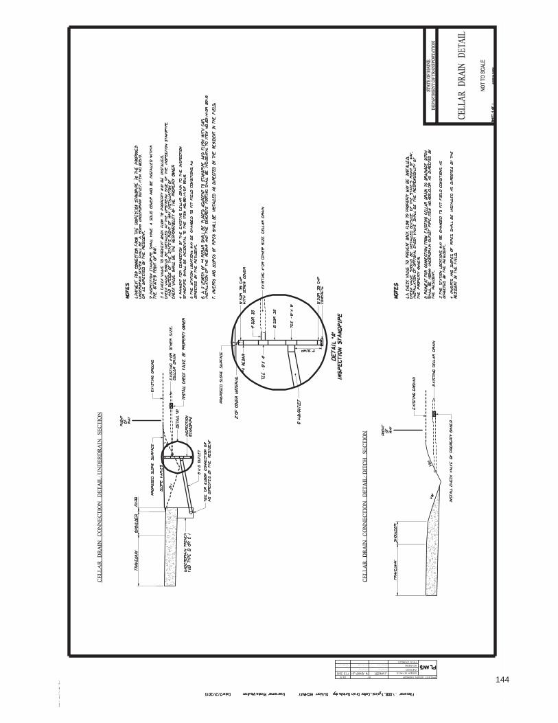
144

Issue for BidNot for Construction
woodardcurran.comCOMMITMENT & INTEGRITY DRIVE RESULTS
TOWN OF HAMPDEN, ME AND HAMPDEN WATER DISTRICT
Grist Mill Bridge Utility Crossing and Sewer Replacement
One Merchants Plaza, Suite 501Bangor, Maine 04401
800-564-2333
0213302.15Town of Hampden, ME and Hampden Water District
February 2019145

213302.15 Grist Mill Bridge Utility Crossing and Sewer ReplacementIssue Date: February 2019 Town of Hampden, ME and Hampden Water District
TABLE OF CONTENTSWOODARD & CURRAN 00 01 10-1
SECTION 00 01 10
TABLE OF CONTENTS
DIVISION 00 PROCUREMENT AND CONTRACTING REQUIREMENTS
INTRODUCTORY INFORMATION00 01 10 Table of Contents
PROCUREMENT/BIDDING REQUIREMENTS AND CONTRACTING REQUIREMENTS00 73 05 Supplementary Conditions
SPECIFICATIONS
DIVISION 01 GENERAL REQUIREMENTS01 11 00 Summary of Work01 20 25 Measurement and Payment01 32 23 Survey Tie Sheet01 33 00 Submittals01 42 00 Definitions and Standards01 51 38 Temporary Water Bypass01 51 40 Temporary Sewage Bypass01 91 15 Startup and Commissioning Requirements
DIVISION 03 – CONCRETE03 41 26 Precast Concrete Structures
DIVISION 10 - SPECIALTIES10 14 00 Signage
DIVISION 26 - ELECTRICAL26 05 00 Common Work Results for Electrical26 05 19 Low-Voltage Electrical Power Conductors and Cables26 05 26 Grounding and Bonding for Electrical Systems26 05 33 Raceways and Boxes for Electrical Systems26 05 43 Underground Ducts and Raceways for Electrical Systems
DIVISION 31 – EARTHWORK31 20 00 Earthwork31 40 00 Shoring and Bracing31 71 16 Controlled Blasting
146
213302.15 Grist Mill Bridge Utility Crossing and Sewer ReplacementIssue Date: February 2019 Town of Hampden, ME and Hampden Water District
TABLE OF CONTENTSWOODARD & CURRAN 00 01 10-2
DIVISION 33 – UTILITIES33 01 10.58 Disinfection of Water Utility Piping Systems33 10 00 Water Distribution Piping, Valves and Fittings33 31 00 Sanitary Utility Sewerage Piping
DIVISION 40 – PROCESS INTEGRATION40 00 00 Basic Process Materials and Methods40 05 14 Process Pipe Couplings and Connectors40 05 15 Process Pipe Supports40 05 17 Process Pipe Sleeves and Seals40 41 13 Process Pipe Heat Tracing40 42 13 Process Pipe Insulation
END OF SECTION
147

213302.15 Grist Mill Bridge Utility Crossing and Sewer ReplacementIssue Date: February 2019 Town of Hampden, ME and Hampden Water District
SUPPLEMENTARY CONDITIONSWOODARD & CURRAN 00 73 05-1
SECTION 00 73 05
SUPPLEMENTARY CONDITIONS
This Specification shall apply only to the Town of Hampden, Maine Work for the above-referenced Project, as shown on the Drawings titled Grist Mill Bridge Utility Crossing and Sewer Replacement, dated February 2019 and includes Clean Water State Revolving Fund (CWSRF) Construction Contract Requirements for this Project.
Advertisement for Bid
1. Agency Not a Party
“This Contract is expected to be funded in whole or in part by the State of Maine Department of Environmental Protection (DEP) Clean Water State Revolving Loan Fund (CWSRF) program. Neither the State of Maine nor any of its departments, agencies, or employees is or will be a party to this Contract. The word “agency” in the Contract Documents refers to the DEP and all other involved funding agencies.”
2. SRF Disadvantaged Business Enterprises Program
“The Contractor must comply with the Disadvantaged Business Enterprises (DBE) SRF special requirements contained in the CWSRF Supplementary Conditions. Failure of the successful bidder to complete the pre-award requirements of this program may result in finding that the bidder is non- responsible and therefore not entitled to award of this Contract.”
3. Federal Requirements
“The Contractor must comply with all Federal Requirements per the CWSRF Supplementary Conditions.”
4. Davis-Bacon and Related Acts
“The Contractor must comply with Davis-Bacon (DB) and Davis-Bacon Related Acts (DBRA) as stated in the CWSRF Supplementary Conditions. All laborers and mechanics employed by the Contractor and subcontractors on this project shall not be paid less than the prevailing wage rates contained in the wage determination published in the Bidding Documents. Any laborers and mechanics not listed in the wage determination shall be paid at least as much as the lowest wage rate for other similar trade classifications already contained in the wage determination published in the Bidding Documents.”
5. American Iron and Steel
“The Contractor shall comply with the Use of American Iron and Steel requirements on this project”.
148
213302.15 Grist Mill Bridge Utility Crossing and Sewer ReplacementIssue Date: February 2019 Town of Hampden, ME and Hampden Water District
SUPPLEMENTARY CONDITIONSWOODARD & CURRAN 00 73 05-2
Instructions for Bidders
1. Agency Not a Party
“This Contract is expected to be funded in whole or in part by the State of Maine Department of Environmental Protection (DEP) Clean Water State Revolving Loan Fund (CWSRF) program. Neither the State of Maine nor any of its departments, agencies, or employees is or will be a party to this Contract. The word “agency” in the Contract Documents refers to the DEP and all other involved funding agencies.”
2. Taxes
“The Owner is exempt from Maine state sales and use taxes on all materials to be incorporated in the Work. Said taxes shall not be included in the bid. Detailed information can be found in the General Conditions and the CWSRF Supplementary Conditions.”
3. American Iron and Steel
“The Contractor shall comply with the Use of American Iron and Steel in accordance with Public Law 113-76, Section 436. The law and its requirements and guidance, including certification forms, can be found in the SRF supplementary conditions.”
4. SRF Disadvantaged Business Enterprise Program
“The Contractor shall not discriminate on the basis of race, color, national origin or sex in the performance of this Contract. The Contractor shall carry out applicable requirements of 40 CFR part 33, Disadvantaged Business Enterprises (DBE), in the award and administration of subcontracts.
Failure by the Contractor to carry out these requirements is a material breach of this Contract which may result in the termination of this Contract or other legally available remedies.
1. During the bidding period, the Contractor is required to make the good faith efforts as described in the CWSRF Supplementary Conditions if they will be awarding subcontracts. Contractors should initiate solicitation efforts early in the bidding period.
2. The Contractor must comply with the following provisions when submitting their bid:
(a) The Contractor must complete and submit EPA Form 6100–4, ‘DBE Program Subcontractor Utilization Form’ (copy attached) as part of the prime Contractor’s bid or proposal package to the Owner. Note, only DBE subcontractors should be listed. If no DBE subcontractors are to be used, the Contractor must still complete and submit the form.
(b) The Contractor must have each of its proposed DBE subcontractors complete the EPA Form 6100–3, ‘DBE Program Subcontractor Performance Form’ (copy attached). The completed forms must be submitted as part of the prime Contractor’s bid or proposal package to the Owner.
149

213302.15 Grist Mill Bridge Utility Crossing and Sewer ReplacementIssue Date: February 2019 Town of Hampden, ME and Hampden Water District
SUPPLEMENTARY CONDITIONSWOODARD & CURRAN 00 73 05-3
3. Prior to Contract award, as the Successful Bidder, the Contractor must comply with the following provisions:
(a) The Contractor must submit to the Owner documentation of its good faith efforts (such as copies of solicitation letters and emails) and data relied upon in formulating its fair share objectives. Solicitation documentation must include proof of receipt. The records must be submitted to the Owner even if the goals were met.
(b) The Contractor must submit to the Owner a bidders list of all firms that bid or quote on subcontracts, including both MBE/WBEs and non-MBE/WBEs. The purpose of a bidders list is to provide Contractors who conduct competitive bidding with as accurate a database as possible about the universe of MBE/WBE and non-MBE/WBE subcontractors. The list must include the following information:
(1) Entity's name with point of contact;
(2) Entity's mailing address, telephone number, and e-mail address;
(3) The procurement on which the entity bid or quoted, and when; and
(4) Entity's status as an MBE/WBE or non-MBE/WBE.
Additional information and forms may be found in the CWSRF Supplementary Conditions.”
10. Suspension and Debarment
“The eligibility of successful bidder will be verified through the federal government’s Excluded Parties List System prior to Maine Department of Environmental Protection approval of the Contract award.
Furthermore, by entering into the Contract, the Contractor shall certify that no part of the Contract shall be subcontracted to a Debarred or Suspended person or firm. Detailed information may be found in the CWSRF Supplementary Conditions.”
11. Davis-Bacon and Related Acts
“The Contractor must comply with Davis-Bacon (DB) and Davis-Bacon Related Acts (DBRA). All laborers and mechanics employed by the Contractor and subcontractors on this project shall not be paid less than the prevailing wage rates contained in the wage determination published in these Bidding Documents. All laborers and mechanics not listed in the wage determination but employed by the Contractor and subcontractors on this project shall be paid at least as much as the lowest wage rate for other similar trade classifications already contained in the wage determination published in these Bidding Documents. A form 1444 submission will be required to obtain additional employee rate classifications, after Contract award. No allowances or extra considerations on behalf of any Contractor or subcontractor will be permitted subsequently by reason of error or oversight on account of Department of Labor wage determinations. The Contractor and subcontractors shall pay all employees weekly. The Contractor and subcontractors shall submit weekly certified payrolls to the owner or designated representative, including a payroll summary with signed certification form WH-347.
Detailed information and forms can be found in the CWSRF Supplementary Conditions.”
150

213302.15 Grist Mill Bridge Utility Crossing and Sewer ReplacementIssue Date: February 2019 Town of Hampden, ME and Hampden Water District
SUPPLEMENTARY CONDITIONSWOODARD & CURRAN 00 73 05-4
12. Federal Requirements
“The Contractor must comply with all Federal requirements found in the CWSRF Supplementary Conditions.”
13. State Minimum Wages
“All laborers and mechanics employed or working upon the construction site of the project shall be paid not less than the prevailing State minimum wage rate regardless of any contractual relationship which may be alleged to exist between the Contractor and such laborers and mechanics.”
CWSRF Supplementary Conditions
1. Agency Not a Party
“This Contract is expected to be funded in whole or in part by the State of Maine Department of Environmental Protection (DEP) Clean Water State Revolving Loan Fund (CWSRF) program. Neither the State of Maine nor any of its departments, agencies, or employees is or will be a party to this Contract. The word “agency” in the Contract Documents refers to the DEP and all other involved funding agencies.”
2. Contract Award Approval
“The Owner and Contractor shall furnish the documents as required by this Contract to the State of Maine Department of Environmental Protection (DEP) Clean Water State Revolving Loan Fund (CWSRF) program for Contract award approval. Concurrence by the Agency in the award of the Contract is required before the Contract is effective.”
3. Conflict of Interest
“Contractor may not knowingly contract with a supplier or manufacturer if the individual or entity who prepared the plans and specifications has a corporate or financial affiliation with the supplier or manufacturer. Owner’s officers, employees, or agents shall not engage in the award or administration of this Contract if a conflict of interest, real or apparent, would be involved. Such a conflict would arise when: (I) the employee, officer or agent; (ii) any member of their immediate family; (iii) their partner or (iv) an organization that employs, or is about to employ, any of the above, has a financial interest in Contractor. Owner’s officers, employees, or agents shall neither solicit nor accept gratuities, favors or anything of monetary value from Contractor or subcontractors.”
4. Gratuities
“If Owner finds after a notice and hearing that Contractor, or any of Contractor’s agents or representatives, offered or gave gratuities (in the form of entertainment, gifts, or otherwise) to any official, employee, or agent of Owner or Agency in an attempt to secure this Contract or favorable treatment in awarding, amending, or making any determinations related to the performance of this Contract, Owner may, by written notice to Contractor, terminate this Contract. Owner may also pursue other rights and remedies that the law or this Contract provides. However, the existence of the facts on which Owner bases such findings shall be an issue and may be reviewed in proceedings
151

213302.15 Grist Mill Bridge Utility Crossing and Sewer ReplacementIssue Date: February 2019 Town of Hampden, ME and Hampden Water District
SUPPLEMENTARY CONDITIONSWOODARD & CURRAN 00 73 05-5
under the dispute resolution provisions of this Contract. In the event this Contract is terminated as provided in above paragraph, Owner may pursue the same remedies against Contractor as it could pursue in the event of a breach of this Contract by Contractor. As a penalty, in addition to any other damages to which it may be entitled by law, Owner may pursue exemplary damages in an amount (as determined by Owner) which shall not be less than three nor more than ten times the costs Contractor incurs in providing any such gratuities to any such officer or employee.”
5. Audit and Access to Records
“Owner, Agency, the Comptroller General, or any of their duly authorized representatives, shall have access to any books, documents, papers, and records of the Contractor, which are pertinent to the Contract, for the purpose of making audits, examinations, excerpts and transcriptions. Contractor shall maintain all required records for three years after final payment is made and all other pending matters are closed.”
6. Anti-Kickback
“Contractor shall comply with the Copeland Anti-Kickback Act (18 USC 874 and 40 USC 276c) as supplemented by Department of Labor regulations (29 CFR Part 3, “Contractors and Subcontractors on Public Buildings or Public Works Financed in Whole or in Part by Loans or Grants of the United States”). The Act provides that Contractor or subcontractor shall be prohibited from inducing, by any means, any person employed in the construction, completion, or repair of public facilities, to give up any part of the compensation to which they are otherwise entitled. Owner shall report all suspected or reported violations to Agency.”
7. Clean Air and Pollution Control Acts
“If this Contract exceeds $100,000, Contractor shall comply with all applicable standards, orders or regulations issued pursuant to the Clean Air Act (42 USC 7401 et seq.) and the Federal Water Pollution Control Act as amended (33 USC 1251 et seq.). Contractor will report violations to the Agency and the Regional Office of the EPA.”
8. State Energy Policy
“Contractor shall comply with the Energy Policy and Conservation Act (P.L. 94-163). Mandatory standards and policies relating to energy efficiency, contained in any applicable State Energy Conservation Plan, shall be utilized.”
9. Equal Opportunity Requirements
A. “If this Contract exceeds $10,000, Contractor shall comply with Executive Order 11246, “Equal Employment Opportunity,” as amended by Executive Order 11375, “Amending Executive Order 11246 Relating to Equal Employment Opportunity,” and as supplemented by regulations at 41 CFR part 60, “Office of Federal Contract Compliance Programs, Equal Employment Opportunity, Department of Labor.”
B. “Contractor’s compliance with Executive Order 11246 shall be based on its implementation of the Equal Opportunity Clause, specific affirmative active obligations required by the Standard Federal Equal Employment Opportunity Construction Contract Specifications, as set forth in 41 CFR Part 60-4 and its efforts to meet the goals established for the
152
213302.15 Grist Mill Bridge Utility Crossing and Sewer ReplacementIssue Date: February 2019 Town of Hampden, ME and Hampden Water District
SUPPLEMENTARY CONDITIONSWOODARD & CURRAN 00 73 05-6
geographical area where the Contract is to be performed. The hours of minority and female employment and training must be substantially uniform throughout the length of the Contract, and in each trade, and Contractor shall make a good faith effort to employ minorities and women evenly on each of its projects. The transfer of minority or female employees or trainees from Contractor to Contractor or from project to project for the sole purpose of meeting Contractor’s goals shall be a violation of the Contract, the Executive Order, and the regulations in 41 CFR Part 60-4. Compliance with the goals will be measured against the total Work hours performed.”
C. “Contractor shall provide written notification to the Director of the Office of Federal Contract Compliance Programs within 10 working days of award of any construction subcontract in excess of $10,000 at any tier for construction Work under the Contract resulting from this solicitation. The notification shall list the name, address, and telephone number of the subcontractor; employer identification number; estimated dollar amount of subcontract; estimated starting and completion dates of the subcontract; and the geographical area in which the Contract is to be performed.”
10. Environmental Requirements
“When constructing a project involving trenching and/or other related earth excavations, Contractor shall comply with the following environmental constraints:
1. Wetlands – When disposing of excess, spoil, or other construction materials on public or private property, Contractor shall not fill in or otherwise convert wetlands.
2. Floodplains – When disposing of excess, spoil, or other construction materials on public or private property, Contractor shall not fill in or otherwise convert 100-year floodplain areas delineated on the latest Federal Emergency Management Agency Floodplain Maps, or other appropriate maps, i.e., alluvial soils on NRCS Soil Survey Maps.
3. Historic Preservation – Any excavation by Contractor that uncovers an historical or archaeological artifact shall be immediately reported to Owner and a representative of Agency. Construction shall be temporarily halted pending the notification process and further directions issued by Agency after consultation with the State Historic Preservation Officer (SHPO).
4. Endangered Species – Contractor shall comply with the Endangered Species Act, which provides for the protection of endangered and/or threatened species and critical habitat. Should any evidence of the presence of endangered and/or threatened species or their critical habitat be brought to the attention of Contractor, Contractor will immediately report this evidence to Owner and a representative of Agency. Construction shall be temporarily halted pending the notification process and further directions issued by Agency after consultation with the U.S. Fish and Wildlife Service.”
11. Suspension and Debarment
“The Contractor must comply with Subpart B and Subpart C of 2 CFR Part 180 and Part 1532. By entering into this Contract, the Contractor certifies that neither the Contractor’s firm, nor any person or firm who has an interest in the Contractor firm, is a Debarred or Suspended person or firm.
153

213302.15 Grist Mill Bridge Utility Crossing and Sewer ReplacementIssue Date: February 2019 Town of Hampden, ME and Hampden Water District
SUPPLEMENTARY CONDITIONSWOODARD & CURRAN 00 73 05-7
Furthermore, by entering into this Contract, the Contractor shall certify that no part of this Contract shall be subcontracted to a Debarred or Suspended person or firm. Contractors may access the federal government’s Excluded Parties List System on the internet for verification of excluded parties.”
12. Taxes
“The Owner is exempt from Maine state sales and use taxes on all materials to be incorporated in the Work. The Owner will furnish the required certificates of tax exemption to Contractor for use in the purchase of supplies and materials to be incorporated into the Work. The Owner’s exemption does not apply to construction tools, machinery, equipment, or other property purchased or leased by Contractor or to supplies or materials not incorporated into the Work.”
13. State Minimum wages
“All laborers and mechanics employed or working upon the construction site of the project shall be paid not less than the prevailing State minimum wage rate regardless of any contractual relationship which may be alleged to exist between the Contractor and such laborers and mechanics. The most current version of the State of Maine poster for Minimum Wage (as per the Department of Labor website) must be posted where it can be easily seen by employees.”
14. Posting Documents
“The Contractor shall post documents in accordance with all applicable state and federal labor and employment laws. Posters shall be located and maintained by the Contractor at such place or places on the project site where employees can easily see them. Posters displayed outdoors must be laminated or otherwise protected from the weather. The most current version of workplace posters can be found on the internet on the state and federal Department of Labor websites.”
15. SRF Project Sign
“At the start of the project, the Contractor shall provide and erect a project sign as detailed and specified in the attachment to these supplementary conditions. The location of the sign shall be as directed by the Engineer. No other Contractor, subcontractor, or material references will be permitted on the sign. The Contractor shall maintain and keep the project sign in good condition until the Work is completed when the sign will be removed. Provide adequate supports for the sign as site conditions may require and keep sign a proper distance above prevailing grade to permit public viewing.”
16. SRF Disadvantaged Business Enterprises Program
“The Contractor shall not discriminate on the basis of race, color, national origin or sex in the performance of this Contract. The Contractor shall carry out applicable requirements of 40 CFR part 33, Disadvantaged Business Enterprises (DBE), in the award and administration of subcontracts.
Failure by the Contractor to carry out these requirements is a material breach of this Contract which may result in the termination of this Contract or other legally available remedies.
The goals for this project are a minimum of 0.64% certified Minority Business Enterprise (MBE) and a minimum of 1.64% certified Women’s Business Enterprise (WBE) participation. Lists of
154

213302.15 Grist Mill Bridge Utility Crossing and Sewer ReplacementIssue Date: February 2019 Town of Hampden, ME and Hampden Water District
SUPPLEMENTARY CONDITIONSWOODARD & CURRAN 00 73 05-8
certified businesses may be found on the following internet websites: EPA Office of Small and Disadvantaged Business Utilization (OSDBU), State of Maine Department of Transportation (DOT), and the United States Small Business Administration (SBA).
The Contractor must maintain all records documenting its compliance with the requirements of this part, including documentation of its good faith efforts (such as copies of solicitation letters and emails) and data relied upon in formulating its fair share objectives.
1. During the bidding period, the Contractor is required to make the following good faith efforts if they will be awarding subcontracts:
(a) Ensure DBEs are made aware of contracting opportunities to the fullest extent practicable through outreach and recruitment activities. This will include placing DBEs on solicitation lists and soliciting them whenever they are potential sources.
(b) Make information on forthcoming opportunities available to DBEs and arrange time frames for contracts and establish delivery schedules, where the requirements permit, in a way that encourages and facilitates participation by DBEs in the competitive process. This includes, whenever possible, posting solicitations for bids or proposals for a minimum of 30 calendar days before the bid or proposal closing date.
(c) Consider in the contracting process whether firms competing for large contracts could subcontract with DBEs. This will include dividing total requirements when economically feasible into smaller tasks or quantities to permit maximum participation by DBEs in the competitive process.
(d) Encourage contracting with a consortium of DBEs when a contract is too large for one of these firms to handle individually.
(e) Use the services and assistance of the SBA and the Minority Business Development Agency of the Department of Commerce.
(f) Employ the good faith efforts described above even if the prime Contractor has achieved its fair share objectives under subpart D of this part.
2. The Contractor must comply with the following provisions when submitting their bid:
(a) The Contractor must complete and submit EPA Form 6100–4, ‘DBE Program Subcontractor Utilization Form’ (copy attached) as part of the prime Contractor’s bid or proposal package to the Owner. Note, only DBE subcontractors should be listed. If no DBE subcontractors are to be used, the Contractor must still complete and submit the form.
(b) The Contractor must have each of its proposed DBE subcontractors complete the EPA Form 6100–3, ‘DBE Program Subcontractor Performance Form’ (copy attached). The completed forms must be submitted as part of the prime Contractor’s bid or proposal package to the Owner.
155

213302.15 Grist Mill Bridge Utility Crossing and Sewer ReplacementIssue Date: February 2019 Town of Hampden, ME and Hampden Water District
SUPPLEMENTARY CONDITIONSWOODARD & CURRAN 00 73 05-9
3. Prior to Contract award, as the Successful Bidder, the Contractor must comply with the following provisions:
(a) The Contractor must submit to the Owner documentation of its good faith efforts (such as copies of solicitation letters and emails) and data relied upon in formulating its fair share objectives. Solicitation documentation must include proof of receipt. The records must be submitted to the Owner even if the goals were met.
(b) The Contractor must submit to the Owner a bidders list of all firms that bid or quote on subcontracts, including both MBE/WBEs and non-MBE/WBEs. The purpose of a bidders list is to provide Contractors who conduct competitive bidding with as accurate a database as possible about the universe of MBE/WBE and non-MBE/WBE subcontractors. The list must include the following information:
(1) Entity's name with point of contact;
(2) Entity's mailing address, telephone number, and e-mail address;
(3) The procurement on which the entity bid or quoted, and when; and
(4) Entity's status as an MBE/WBE or non-MBE/WBE.
4. Following Contract award, the Contractor must comply with the following additional provisions:
(a) The Contractor must provide EPA Form 6100–2, ‘DBE Program Subcontractor Participation Form’ (copy attached) to all DBE subcontractors listed on Form 6100-4. EPA Form 6100–2 gives a DBE subcontractor the opportunity to describe the Work the DBE subcontractor received from the prime Contractor, how much the DBE subcontractor was paid and any other concerns the DBE subcontractor might have during the course of the project, for example, reasons why the DBE subcontractor believes it was terminated by the prime Contractor. If DBE subcontractors choose to complete this form, the completed form should be sent directly to the DEP DBE Coordinator. The address is: Maine Department of Environmental Protection, Attn: Ms. Kelly Stevens, DBE Coordinator, Bureau of Land and Water Quality, Division of Water Quality Management, 17 State House Station, Augusta, Maine 04333-0017.
(b) Complete the CWSRF DEP Progress Report of DBE Subcontractor Utilization Form (copy attached) for all Contractor pay applications whether or not they include invoiced amounts from DBE subcontractors. The progress report should be attached to the corresponding pay application for processing through the Owner.
(c) Pay subcontractors for satisfactory performance no more than 30 days from the prime Contractor's receipt of payment from the Owner.
(d) Notify the Owner in writing prior to any termination of a DBE subcontractor for convenience by the prime Contractor.
(e) If a DBE subcontractor fails to complete Work under the subcontract for any reason, the prime Contractor must employ the good faith efforts described above if soliciting a
156
213302.15 Grist Mill Bridge Utility Crossing and Sewer ReplacementIssue Date: February 2019 Town of Hampden, ME and Hampden Water District
SUPPLEMENTARY CONDITIONSWOODARD & CURRAN 00 73 05-10
replacement subcontractor. Documentation of good faith efforts shall be submitted to the Owner upon request.”
17. Davis-Bacon and Related Acts
“The Contractor must comply with the following Contract and subcontract provisions of the Davis- Bacon and Davis-Bacon Related acts. Attachments to these provisions include: the wage determination for this Contract, four forms, and a poster.
1. Applicability of the Davis-Bacon (DB) prevailing wage requirements
Davis-Bacon prevailing wage requirements apply to the construction, alteration, and repair of treatment Work carried out in whole or in part with assistance made available by a State water pollution control revolving fund. If an Owner encounters a unique situation at a site that presents uncertainties regarding DB applicability, the Owner must discuss the situation with the State official before authorizing Work on that site.
2. Obtaining Wage Determinations
(a) Owners shall obtain the wage determination for the locality in which a covered activity subject to DB will take place prior to issuing requests for bids, proposals, quotes or other methods for soliciting contracts (solicitation) for activities subject to DB. These wage determinations shall be incorporated into solicitations and any subsequent contracts. Prime Contracts must contain a provision requiring that subcontractors follow the wage determination incorporated into the prime Contract.
(i) While the solicitation remains open, the Owner shall monitor www.wdol.gov weekly to ensure that the wage determination contained in the solicitation remains current. The Owner shall amend the solicitation if DOL issues a modification more than 10 days prior to the closing date, the Owner may request a finding from the State official that there is not a reasonable time to notify interested Contractors of the modification of the wage determination. The State official will provide a report of its findings to the Owner.
(ii) If the Owner does not award the Contract within 90 days of the closure of the solicitation, any modifications or supersedes DOL makes to the wage determination contained in the solicitation shall be effective unless the State official, at the request of the Owner, obtains an extension of the 90-day period from DOL pursuant to 20 CFR 1.6(c)(3)(iv). The Owner shall monitor www.wdol.gov on a weekly basis if it does not award the Contract within 90 days of closure of the solicitation to ensure that wage determinations contained in the solicitation remain current.
(b) If the Owner carries out activity subject to DB by issuing a task order, Work assignment or similar instrument to an existing Contractor (ordering instrument) rather than by publishing a solicitation, the Owner shall insert the appropriate DOL wage determination from www.wdol.gov into the ordering instrument.
(c) Owners shall review all subcontracts subject to DB entered into by prime Contractor to verify that the prime Contractor has required its subcontractors to include the applicable wage determinations.
157

213302.15 Grist Mill Bridge Utility Crossing and Sewer ReplacementIssue Date: February 2019 Town of Hampden, ME and Hampden Water District
SUPPLEMENTARY CONDITIONSWOODARD & CURRAN 00 73 05-11
(d) As provided in 29 CFR 1.6(f), DOL may issue a revised wage determination applicable to an Owner’s Contract after the award of a Contract or the issuance of an ordering instrument if DOL determines that the Owner has failed to incorporate a wage determination or has used a wage determination that clearly does not apply to the Contract or ordering instrument. If this occurs, the Owner shall either terminate the Contract or ordering instrument and issue a revised solicitation or ordering instrument or incorporate DOL’s wage determination retroactive to the beginning of the Contract or ordering instrument by change order. The Owner’s Contractor must be compensated for any increases in wages resulting from the use of DOL’s revised wage determination.
3. Contract and Subcontract provisions
(a) The State official shall insure that the Owner(s) shall insert in full in any Contract in excess of $2,000 which is entered into for the actual construction, alteration and/or repair, including painting and decorating, of a treatment Work under the CWSRF financed in whole or in part from Federal funds or in accordance with guarantees of a Federal agency or financed from funds obtained by pledge of any Contract of a Federal agency to make a loan, grant or annual contribution (except where a different meaning is expressly indicated), and which is subject to the labor standards provisions of any of the acts listed in § 5.1, the following clauses:
(1) Minimum wages.
(i) All laborers and mechanics employed or working upon the site of the Work will be paid unconditionally and not less often than once a week, and without subsequent deduction or rebate on any account (except such payroll deductions as are permitted by regulations issued by the Secretary of Labor under the Copeland Act (29 CFR part 3) ), the full amount of wages and bona fide fringe benefits (or cash equivalents thereof) due at time of payment computed at rates not less than those contained in the wage determination of the Secretary of Labor which is attached hereto and made a part hereof, regardless of any contractual relationship which may be alleged to exist between the Contractor and such laborers and mechanics.
Contributions made or costs reasonably anticipated for bona fide fringe benefits under section 1(b)(2) of the Davis-Bacon Act on behalf of laborers or mechanics are considered wages paid to such laborers or mechanics, subject to the provisions of paragraph (a)(1)(iv) of this section; also, regular contributions made or costs incurred for more than a weekly period (but not less often than quarterly) under plans, funds, or programs which cover the particular weekly period, are deemed to be constructively made or incurred during such weekly period. Such laborers and mechanics shall be paid the appropriate wage rate and fringe benefits on the wage determination for the classification of Work actually performed, without regard to skill, except as provided in § 5.5(a)(4). Laborers or mechanics performing Work in more than one classification may be compensated at the rate specified for each classification for the time actually worked therein: Provided, that the employer's payroll records accurately set forth the time spent in each classification in which Work is performed. The wage determination (including any additional classification and wage rates conformed under paragraph (a)(1)(ii) of this section) and the Davis-Bacon poster (WH-1321, attached) shall be posted at all times by the Contractor and its subcontractors at the site of the Work in a prominent and accessible place where it can be easily seen by the workers. Additional copies of this poster can be obtained from the US Department of Labor website.
158
213302.15 Grist Mill Bridge Utility Crossing and Sewer ReplacementIssue Date: February 2019 Town of Hampden, ME and Hampden Water District
SUPPLEMENTARY CONDITIONSWOODARD & CURRAN 00 73 05-12
(ii) (A) Any class of laborers or mechanics, including helpers, which is not listed in the wage determination and which is to be employed under the Contract shall be classified in conformance with the wage determination. The EPA award official shall approve an additional classification and wage rate and fringe benefits therefore only when the following criteria have been met:
(1) The Work to be performed by the classification requested is not performed by a classification in the wage determination; and
(2) The classification is utilized in the area by the construction industry; and
(3) The proposed wage rate, including any bona fide fringe benefits, bears a reasonable relationship to the wage rates contained in the wage determination.
(B) If the Contractor and the laborers and mechanics to be employed in the classification (if known), or their representatives, and the Owner agree on the classification and wage rate (including the amount designated for fringe benefits where appropriate), Form 1444 (attached) shall be completed and sent by the Owner to the State official. The State official will transmit the request, to the Administrator of the Wage and Hour Division, Employment Standards Administration, U.S. Department of Labor, Washington, DC 20210 and to the EPA DB Regional Coordinator concurrently. The Administrator, or an authorized representative, will approve, modify, or disapprove every additional classification action within 30 days of receipt and so advise the State official or will notify the State official within the 30- day period that additional time is necessary. Additional copies of Form 1444 may be obtained from the US Department of Labor website.
(C) In the event the Contractor, the laborers or mechanics to be employed in the classification or their representatives, and the Owner do not agree on the proposed classification and wage rate (including the amount designated for fringe benefits, where appropriate), the State official shall refer the questions, including the views of all interested parties and the recommendation of the State official, to the Administrator for determination. The request shall be sent to the EPA DB Coordinator concurrently. The Administrator, or an authorized representative, will issue a determination within 30 days of receipt and so advise the State official or will notify the State official within the 30-day period that additional time is necessary.
(D) The wage rate (including fringe benefits where appropriate) determined pursuant to paragraphs (a)(1)(ii)(B) or (C) of this section, shall be paid to all workers performing Work in the classification under this Contract from the first day on which Work is performed in the classification.
(iii) Whenever the minimum wage rate prescribed in the Contract for a class of laborers or mechanics includes a fringe benefit which is not expressed as an hourly rate, the Contractor shall either pay the benefit as stated in the wage determination or shall pay another bona fide fringe benefit or an hourly cash equivalent thereof.
(iv) If the Contractor does not make payments to a trustee or other third person, the Contractor may consider as part of the wages of any laborer or mechanic the amount of any costs reasonably anticipated in providing bona fide fringe benefits under a plan or program, provided, that the Secretary of Labor has found, upon the written request of the Contractor, that the applicable standards of the Davis-Bacon Act have been met. The Secretary of Labor may require the
159

213302.15 Grist Mill Bridge Utility Crossing and Sewer ReplacementIssue Date: February 2019 Town of Hampden, ME and Hampden Water District
SUPPLEMENTARY CONDITIONSWOODARD & CURRAN 00 73 05-13
Contractor to set aside in a separate account asset for the meeting of obligations under the plan or program.
(2) Withholding. The Owner shall upon written request of the EPA Award Official or an authorized representative of the Department of Labor, withhold or cause to be withheld from the Contractor under this Contract or any other Federal Contract with the same prime Contractor, or any other federally- assisted Contract subject to Davis-Bacon prevailing wage requirements, which is held by the same prime Contractor, so much of the accrued payments or advances as may be considered necessary to pay laborers and mechanics, including apprentices, trainees, and helpers, employed by the Contractor or any subcontractor the full amount of wages required by the Contract. In the event of failure to pay any laborer or mechanic, including any apprentice, trainee, or helper, employed or working on the site of the Work, all or part of the wages required by the Contract, the State Official may, after written notice to the Contractor, sponsor, applicant, or owner, take such action as may be necessary to cause the suspension of any further payment, advance, or guarantee of funds until such violations have ceased.
(3) Payrolls and basic records.
(i) Payrolls and basic records relating thereto shall be maintained by the Contractor during the course of the Work and preserved for a period of three years thereafter for all laborers and mechanics working at the site of the Work. Such records shall contain the name, address, and social security number of each such worker, his or her correct classification, hourly rates of wages paid (including rates of contributions or costs anticipated for bona fide fringe benefits or cash equivalents thereof of the types described in section 1(b)(2)(B) of the Davis-Bacon Act), daily and weekly number of hours worked, deductions made and actual wages paid. Whenever the Secretary of Labor has found under 29 CFR 5.5(a)(1)(iv) that the wages of any laborer or mechanic include the amount of any costs reasonably anticipated in providing benefits under a plan or program described in section 1(b)(2)(B) of the Davis- Bacon Act, the Contractor shall maintain records which show that the commitment to provide such benefits is enforceable, that the plan or program is financially responsible, and that the plan or program has been communicated in writing to the laborers or mechanics affected, and records which show the costs anticipated or the actual cost incurred in providing such benefits. Contractors employing apprentices or trainees under approved programs shall maintain written evidence of the registration of apprenticeship programs and certification of trainee programs, the registration of the apprentices and trainees, and the ratios and wage rates prescribed in the applicable programs.
(ii) (A) The Contractor shall submit weekly, for each week in which any Contract Work is performed, a copy of all payrolls to the Owner. Such documentation shall be available on request of the State Official or EPA. As to each payroll copy received, the Owner shall provide written confirmation in a form satisfactory to the State indicating whether or not the project is in compliance with the requirements of 29 CFR 5.5(a)(1) based on the most recent payroll copies for the specified week. The payrolls shall set out accurately and completely all the information required to be maintained under 29 CFR 5.5(a)(3)(i), except that full social security numbers and home addresses shall not be included on the weekly payrolls. Instead the payrolls shall only need to include an individually identifying number for each employee (e.g., the last four digits of the employee's social security number). The required weekly payroll information may be submitted in any form desired. Optional Form WH-347 (attached) is
160

213302.15 Grist Mill Bridge Utility Crossing and Sewer ReplacementIssue Date: February 2019 Town of Hampden, ME and Hampden Water District
SUPPLEMENTARY CONDITIONSWOODARD & CURRAN 00 73 05-14
available for this purpose. Additional copies of the form are available from the US Department of Labor Wage and Hour Division Web site. The prime Contractor is responsible for the submission of copies of payrolls by all subcontractors. Contractors and subcontractors shall maintain the full social security number and current address of each covered worker and shall provide them upon request to the Owner for transmission to the State or EPA if requested by EPA, the State, the Contractor, or the Wage and Hour Division of the Department of Labor for purposes of an investigation or audit of compliance with prevailing wage requirements. It is not a violation of this section for a prime Contractor to require a subcontractor to provide addresses and social security numbers to the prime Contractor for its own records, without weekly submission to the Owner.
(B) Each payroll submitted shall be accompanied by a “Statement of Compliance,” signed by the Contractor or subcontractor or his or her agent who pays or supervises the payment of the persons employed under the Contract and shall certify the following:
(1) That the payroll for the payroll period contains the information required to be provided under § 5.5 (a)(3)(ii) of Regulations, 29 CFR part 5, the appropriate information is being maintained under § 5.5 (a)(3)(i) of Regulations, 29 CFR part 5, and that such information is correct and complete;
(2) That each laborer or mechanic (including each helper, apprentice, and trainee) employed on the Contract during the payroll period has been paid the full weekly wages earned, without rebate, either directly or indirectly, and that no deductions have been made either directly or indirectly from the full wages earned, other than permissible deductions as set forth in Regulations, 29 CFR part 3;
(3) That each laborer or mechanic has been paid not less than the applicable wage rates and fringe benefits or cash equivalents for the classification of Work performed, as specified in the applicable wage determination incorporated into the Contract.
(C) The weekly submission of a properly executed certification set forth on the reverse side of Optional Form WH-347 (page 2 of the form is attached) shall satisfy the requirement for submission of the “Statement of Compliance” required by paragraph (a)(3)(ii)(B) of this section.
(D) The falsification of any of the above certifications may subject the Contractor or subcontractor to civil or criminal prosecution under section 1001 of title 18 and section 231 of title 31 of the United States Code.
(iii) The Contractor or subcontractor shall make the records required under paragraph (a)(3)(i) of this section available for inspection, copying, or transcription by authorized representatives of the State, EPA or the Department of Labor, and shall permit such representatives to interview employees during working hours on the job. If the Contractor or subcontractor fails to submit the required records or to make them available, the Federal agency or State may, after written notice to the Contractor, sponsor, applicant, or owner, take such action as may be necessary to cause the suspension of any further payment, advance, or guarantee of funds. Furthermore, failure to submit the required records upon request or to make such records available may be grounds for debarment action pursuant to 29 CFR 5.12.
161

213302.15 Grist Mill Bridge Utility Crossing and Sewer ReplacementIssue Date: February 2019 Town of Hampden, ME and Hampden Water District
SUPPLEMENTARY CONDITIONSWOODARD & CURRAN 00 73 05-15
(4) Apprentices and Trainees--
(i) Apprentices. Apprentices will be permitted to Work at less than the predetermined rate for the Work they performed when they are employed pursuant to and individually registered in a bona fide apprenticeship program registered with the U.S. Department of Labor, Employment and Training Administration, Office of Apprenticeship Training, Employer and Labor Services, or with a State Apprenticeship Agency recognized by the Office, or if a person is employed in his or her first 90 days of probationary employment as an apprentice in such an apprenticeship program, who is not individually registered in the program, but who has been certified by the Office of Apprenticeship Training, Employer and Labor Services or a State Apprenticeship Agency (where appropriate) to be eligible for probationary employment as an apprentice. The allowable ratio of apprentices to journeymen on the job site in any craft classification shall not be greater than the ratio permitted to the Contractor as to the entire Work force under the registered program. Any worker listed on a payroll at an apprentice wage rate, who is not registered or otherwise employed as stated above, shall be paid not less than the applicable wage rate on the wage determination for the classification of Work actually performed. In addition, any apprentice performing Work on the job site in excess of the ratio permitted under the registered program shall be paid not less than the applicable wage rate on the wage determination for the Work actually performed. Where a Contractor is performing construction on a project in a locality other than that in which its program is registered, the ratios and wage rates (expressed in percentages of the journeyman's hourly rate) specified in the Contractor's or subcontractor's registered program shall be observed. Every apprentice must be paid at not less than the rate specified in the registered program for the apprentice's level of progress, expressed as a percentage of the journeymen hourly rate specified in the applicable wage determination. Apprentices shall be paid fringe benefits in accordance with the provisions of the apprenticeship program. If the apprenticeship program does not specify fringe benefits, apprentices must be paid the full amount of fringe benefits listed on the wage determination for the applicable classification. If the Administrator determines that a different practice prevails for the applicable apprentice classification, fringes shall be paid in accordance with that determination. In the event the Office of Apprenticeship Training, Employer and Labor Services, or a State Apprenticeship Agency recognized by the Office, withdraws approval of an apprenticeship program, the Contractor will no longer be permitted to utilize apprentices at less than the applicable predetermined rate for the Work performed until an acceptable program is approved.
(ii) Trainees. Except as provided in 29 CFR 5.16, trainees will not be permitted to Work at less than the predetermined rate for the Work performed unless they are employed pursuant to and individually registered in a program which has received prior approval, evidenced by formal certification by the U.S. Department of Labor, Employment and Training Administration. The ratio of trainees to journeymen on the job site shall not be greater than permitted under the plan approved by the Employment and Training Administration. Every trainee must be paid at not less than the rate specified in the approved program for the trainee's level of progress, expressed as a percentage of the journeyman hourly rate specified in the applicable wage determination. Trainees shall be paid fringe benefits in accordance with the provisions of the trainee program. If the trainee program does not mention fringe benefits, trainees shall be paid the full amount of fringe benefits listed on the wage determination unless the Administrator of the Wage and Hour Division determines that there is an apprenticeship program associated with the corresponding journeyman wage rate on the wage determination which provides for
162

213302.15 Grist Mill Bridge Utility Crossing and Sewer ReplacementIssue Date: February 2019 Town of Hampden, ME and Hampden Water District
SUPPLEMENTARY CONDITIONSWOODARD & CURRAN 00 73 05-16
less than full fringe benefits for apprentices. Any employee listed on the payroll at a trainee rate who is not registered and participating in a training plan approved by the Employment and Training Administration shall be paid not less than the applicable wage rate on the wage determination for the classification of Work actually performed. In addition, any trainee performing Work on the job site in excess of the ratio permitted under the registered program shall be paid not less than the applicable wage rate on the wage determination for the Work actually performed. In the event the Employment and Training Administration withdraws approval of a training program, the Contractor will no longer be permitted to utilize trainees at less than the applicable predetermined rate for the Work performed until an acceptable program is approved.
(iii) Equal employment opportunity. The utilization of apprentices, trainees and journeymen under this part shall be in conformity with the equal employment opportunity requirements of Executive Order 11246, as amended, and 29 CFR part 30.
(5) Compliance with Copeland Act requirements. The Contractor shall comply with the requirements of 29 CFR part 3, which are incorporated by reference in this Contract.
(6) Subcontracts. The Contractor or subcontractor shall insert in any subcontracts the clauses contained in 29 CFR 5.5(a)(1) through (10) and such other clauses as the EPA determines may by appropriate, and also a clause requiring the subcontractors to include these clauses in any lower tier subcontracts. The prime Contractor shall be responsible for the compliance by any subcontractor or lower tier subcontractor with all the Contract clauses in 29 CFR 5.5.
(7) Contract termination: debarment. A breach of the Contract clauses in 29 CFR 5.5 may be grounds for termination of the Contract, and for debarment as a Contractor and a subcontractor as provided in 29 CFR 5.12.
(8) Compliance with Davis-Bacon and Related Act requirements. All rulings and interpretations of the Davis-Bacon and Related Acts contained in 29 CFR parts 1, 3, and 5 are herein incorporated by reference in this Contract.
(9) Disputes concerning labor standards. Disputes arising out of the labor standards provisions of this Contract shall not be subject to the general disputes’ clause of this Contract. Such disputes shall be resolved in accordance with the procedures of the Department of Labor set forth in 29 CFR parts 5, 6, and 7. Disputes within the meaning of this clause include disputes between the Contractor (or any of its subcontractors) and Owner, State, EPA, the U.S. Department of Labor, or the employees or their representatives.
(10) Certification of eligibility.
(i) By entering into this Contract, the Contractor certifies that neither it (nor he or she) nor any person or firm who has an interest in the Contractor's firm is a person or firm ineligible to be awarded Government contracts by virtue of section 3(a) of the Davis-Bacon Act or 29 CFR 5.12(a)(1).
(ii) No part of this Contract shall be subcontracted to any person or firm ineligible for award of a Government Contract by virtue of section 3(a) of the Davis-Bacon Act or 29 CFR 5.12(a)(1).
163

213302.15 Grist Mill Bridge Utility Crossing and Sewer ReplacementIssue Date: February 2019 Town of Hampden, ME and Hampden Water District
SUPPLEMENTARY CONDITIONSWOODARD & CURRAN 00 73 05-17
(iii) The penalty for making false statements is prescribed in the U.S. Criminal Code, 18 U.S.C. 1001.
4. Contract Provision for Contracts in Excess of $100,000.
(a) Contract Work Hours and Safety Standards Act. The Owner shall insert the following clauses set forth in paragraphs (a)(1), (2), (3), and (4) of this section in full in any Contract in an amount in excess of $100,000 and subject to the overtime provisions of the Contract Work Hours and Safety Standards Act. These clauses shall be inserted in addition to the clauses required by Item 3, above or 29 CFR 4.6. As used in this paragraph, the terms laborers and mechanics include watchmen and guards.
(1) Overtime requirements. No Contractor or subcontractor contracting for any part of the Contract Work which may require or involve the employment of laborers or mechanics shall require or permit any such laborer or mechanic in any workweek in which he or she is employed on such Work to work in excess of forty hours in such workweek unless such laborer or mechanic receives compensation at a rate not less than one and one-half times the basic rate of pay for all hours worked in excess of forty hours in such workweek.
(2) Violation; liability for unpaid wages; liquidated damages. In the event of any violation of the clause set forth in paragraph (a)(1) of this section the Contractor and any subcontractor responsible therefore shall be liable for the unpaid wages. In addition, such Contractor and subcontractor shall be liable to the United States (in the case of Work done under Contract for the District of Columbia or a territory, to such District or to such territory), for liquidated damages. Such liquidated damages shall be computed with respect to each individual laborer or mechanic, including watchmen and guards, employed in violation of the clause set forth in paragraph (a)(1) of this section, in the sum of $10 for each calendar day on which such individual was required or permitted to Work in excess of the standard Workweek of forty hours without payment of the overtime wages required by the clause set forth in paragraph (a)(1) of this section.
(3) Withholding for unpaid wages and liquidated damages. The Owner, upon written request of the EPA Award Official or an authorized representative of the Department of Labor, shall withhold or cause to be withheld, from any moneys payable on account of Work performed by the Contractor or subcontractor under any such Contract or any other Federal Contract with the same prime Contractor, or any other federally-assisted Contract subject to the Contract Work Hours and Safety Standards Act, which is held by the same prime Contractor, such sums as may be determined to be necessary to satisfy any liabilities of such Contractor or subcontractor for unpaid wages and liquidated damages as provided in the clause set forth in paragraph (b)(2) of this section.
(4) Subcontracts. The Contractor or subcontractor shall insert in any subcontracts the clauses set forth in paragraph (a)(1) through (4) of this section and also a clause requiring the subcontractors to include these clauses in any lower tier subcontracts. The prime Contractor shall be responsible for compliance by any subcontractor or lower tier subcontractor with the clauses set forth in paragraphs (a)(1) through (4) of this section.
(b) In addition to the clauses contained in Item 3, above, in any Contract subject only to the Contract Work Hours and Safety Standards Act and not to any of the other statutes cited in 29
164
213302.15 Grist Mill Bridge Utility Crossing and Sewer ReplacementIssue Date: February 2019 Town of Hampden, ME and Hampden Water District
SUPPLEMENTARY CONDITIONSWOODARD & CURRAN 00 73 05-18
CFR 5.1, the Owner shall insert a clause requiring that the Contractor or subcontractor shall maintain payrolls and basic payroll records during the course of the Work and shall preserve them for a period of three years from the completion of the Contract for all laborers and mechanics, including guards and watchmen, working on the Contract. Such records shall contain the name and address of each such employee, social security number, correct classifications, hourly rates of wages paid, daily and weekly number of hours worked, deductions made, and actual wages paid. Further, the Owner shall insert in any such Contract a clause providing that the records to be maintained under this paragraph shall be made available by the Contractor or subcontractor for inspection, copying, or transcription by authorized representatives of the State and the Department of Labor, and the Contractor or subcontractor will permit such representatives to interview employees during working hours on the job.
5. Compliance Verification
(a) The Owner shall periodically interview a sufficient number of employees entitled to DB prevailing wages (covered employees) to verify that Contractors or subcontractors are paying the appropriate wage rates. As provided in 29 CFR 5.6(a)(6), all interviews must be conducted in confidence. The Owner must use Standard Form 1445 or equivalent documentation to memorialize the interviews. Copies of the SF 1445 are attached and are available from EPA on request.
(b) The Owner shall establish and follow an interview schedule based on its assessment of the risks of noncompliance with DB posed by Contractors or subcontractors and the duration of the Contract or subcontract. Owners must conduct more frequent interviews if the initial interviews or other information indicates that there is a risk that the Contractor or subcontractor is not complying with DB. Owners shall immediately conduct necessary interviews in response to an alleged violation of the prevailing wage requirements. All interviews shall be conducted in confidence.
(c) The Owner shall periodically conduct spot checks of a representative sample of weekly payroll data to verify that Contractors or subcontractors are paying the appropriate wage rates. The Owner shall establish and follow a spot check schedule based on its assessment of the risks of noncompliance with DB posed by Contractors or subcontractors and the duration of the Contract or subcontract. At a minimum, if practicable, the Owner must spot check payroll data within two weeks of each Contractor or subcontractor’s submission of its initial payroll data and two weeks prior to the completion date the Contract or subcontract. Owners must conduct more frequent spot checks if the initial spot check or other information indicates that there is a risk that the Contractor or subcontractor is not complying with DB. In addition, during the examinations the Owner shall verify evidence of fringe benefit plans and payments there under by Contractors and subcontractors who claim credit for fringe benefit contributions.
(d) The Owner shall periodically review Contractors and subcontractors use of apprentices and trainees to verify registration and certification with respect to apprenticeship and training programs approved by either the U.S Department of Labor or a state, as appropriate, and that Contractors and subcontractors are not using disproportionate numbers of, laborers, trainees and apprentices. These reviews shall be conducted in accordance with the schedules for spot checks and interviews described in Item 5(b) and (c) above.
165

213302.15 Grist Mill Bridge Utility Crossing and Sewer ReplacementIssue Date: February 2019 Town of Hampden, ME and Hampden Water District
SUPPLEMENTARY CONDITIONSWOODARD & CURRAN 00 73 05-19
(e) Owners must immediately report potential violations of the DB prevailing wage requirements to the EPA DB Regional Coordinator, the State Official, and to the appropriate DOL Wage and Hour District Office listed at http://www.dol.gov/esa/contacts/whd/america2.htm.
18. American Iron and Steel (AIS) Requirements
“The Contractor acknowledges, to and for the benefit of the Owner and the State (Maine Department of Environmental Protection), that it understands the goods and services under this Agreement are being funded with monies made available by the Clean Water State Revolving Fund (CWSRF) that have statutory requirements commonly known as “American Iron and Steel;” that requires all of the iron and steel products used in the project to be produced in the United States (“American Iron and Steel Requirement”) including iron and steel products provided by the Contactor pursuant to this Agreement. See attached Public Law 113-76, Section 436. The Contractor hereby represents and warrants, to and for the benefit of the Owner and the State, that (a) the Contractor has reviewed and understands the American Iron and Steel Requirement, (b) all of the iron and steel products used in the project will be and/or have been produced in the United States in a manner that complies with the American Iron and Steel Requirement, unless a waiver of the requirement is approved, and (c) the Contractor will provide any further verified information, certification or assurance of compliance with this paragraph, or information necessary to support a waiver of the American Iron and Steel Requirement, as may be requested by the Owner or the State. While the Contractor has no direct contractual privity with the State, as a lender to the Owner for the funding of its project, the Owner and the Contractor agree that the State is a third-party beneficiary and neither this paragraph (nor any other provision of this Agreement necessary to give this paragraph force or effect) shall be amended or waived without the prior written consent of the State.
The Owner shall maintain files on the project site for American Iron and Steel (AIS) manufacturer certifications. The Contractor and subcontractors shall provide step manufacturer certifications to the Owner for each AIS item delivered to the site. The files shall be made available to State and Federal officials for inspection upon request. See sample Step Manufacturer Certification attachment for information that should be included.
The Contractor and its subcontractors shall submit to the Owner, an AIS Compliance Certification (see form attached) with each Contractor pay application. The Owner, shall in turn, submit this certification from the Contractor, with their AIS Compliance Certification (see form attached), to the State with the SRF pay requisition.
The nationwide waiver to the American Iron and Steel law permits the use of products when they occur in de minimis incidental components of such projects funded by the Act that may otherwise be prohibited under section 436(a). Funds used for such de minimis incidental components cumulatively may comprise no more than a total of 5 percent of the total cost of the materials used in and incorporated into a project; the cost of an individual item may not exceed 1 percent of the total cost of the materials used in and incorporated into a project. It is the State’s interpretation that all CWSRF projects will contain incidental components that might not comply with the law and therefore it is likely that the Owner will use the de minimis waiver. The Contractor is required to provide the necessary documentation. See attached sample de minimis tracking form. Owners should, in consultation with their Contractors, determine the items to be covered by this waiver, must retain relevant documentation (i.e., invoices) as to those items in their project files, and must summarize the items to which this waiver is applied, the total cost of incidental components
166

213302.15 Grist Mill Bridge Utility Crossing and Sewer ReplacementIssue Date: February 2019 Town of Hampden, ME and Hampden Water District
SUPPLEMENTARY CONDITIONSWOODARD & CURRAN 00 73 05-20
covered by the waiver, and the calculations by which they determined the total cost of materials used in and incorporated into the project. The Owner shall maintain files on the project site for this documentation. The files shall be made available to State and Federal officials for inspection upon request.”
The Contractor shall refer to the attached guidance taken from an EPA Memorandum. Additional information regarding the AIS requirements can be found on this website http://water.epa.gov/grants_funding/aisrequirement.cfm.
19. List of Attachments to the CWSRF Supplementary ConditionsSRF Project Sign DrawingDBE Program Subcontractor Utilization Form - EPA 6100-4DBE Program Subcontractor Performance Form - EPA 6100-3DBE Program Subcontractor Participation Form - EPA 6100-2Progress Report of DBE Subcontractor Utilization Form - DEP formDavis Bacon Poster “Employee Rights” WH-1321Davis Bacon DOL Form 1444Davis Bacon DOL Form 1445Davis Bacon DOL form WH-347 page 1 (optional), and page 2 (mandatory)Owner’s Davis Bacon Compliance ReportAIS Covered Products Q &AAIS LawAIS Certification by OwnerAIS Certification by ContractorAIS Step Manufacturer CertificationAIS DeMinimis Tracking Form
167

168

Disadvantaged Business Enterprise Program (DBE) Subcontractor Utilization Form
This form is intended to capture the prime contractor’s actual and/or anticipated use of identified certified DBE1 subcontractors2 and the estimated dollar amount of each subcontract. An EPA Financial Assistance Agreement Recipient must require its prime contractors to complete this form and include it in the bid or proposal package. Prime contractors should also maintain a copy of this form on file.
Prime Contractor Name Project Name
Bid /Proposal No. Assistance Agreement ID No. (if known) Point of Contact
Address
Telephone No. Email Address
Issuing/Funding Entity:
I have identified potential DBE certified subcontractors _____ YES _____ NO
If yes, please complete the table below. If no, please explain:
Subcontractor Name/Company Name
Company Address/Phone/Email Est. Dollar Amt.
Currently DBE
Certified?
Continue on back if needed
1A DBE is a Disadvantaged, Minority, or Woman Business Enterprise that has been certified by an entity from which EPA accepts certifications as described in 40 CFR 33.204-33.205 or certified by EPA. EPA accepts certifications from entities that meet or exceed EPA certification standards as described in 40 CFR 33.202.
2Subcontractor is defined as a company, firm, joint venture, or individual who enters into an agreement with a contractor to provide services pursuant to an EPA award or financial assistance.
(DBE Subcontractor Utilization Form) DEP FORM 6100-4
169

Disadvantaged Business Enterprise Program (DBE) Subcontractor Utilization Form
I certify under penalty of perjury that the forgoing statements are true and correct. Signing this form does not signify a commitment to utilize the subcontractors above. I am aware that in the event of a replacement of a subcontractor, I will adhere to the replacement requirements set forth in 40 CFR Section 33.202 (c).
Prime Contractor Signature Print Name
Title Date
(DBE Subcontractor Utilization Form) DEP FORM 6100-4
170

Disadvantaged Business Enterprise Program (DBE) Subcontractor Performance Form
This form is intended to capture the DBE1 subcontractor’s2 description of work to be performed and the price of the work submitted to the prime contractor. An EPA Financial Assistance Agreement Recipient must require its prime contractor to have its DBE subcontractors complete this form and include all completed forms in the prime contractors bid or proposal package.
Subcontractor Name Project Name
Bid /Proposal No. Assistance Agreement ID No. (if known) Point of Contact
Address
Telephone No. Email Address
Prime Contractor Name Issuing/Funding Entity:
ContractItem
Number
Description of Work Submitted to the Prime Contractor InvolvingConstruction, Services, Equipment or Supplies
Price of Work Submitted to the
Prime Contractor
DBE Certified By: _____DOT _____SBA
_____Other:_______________________________________
Meets/exceeds EPA certification standards?
_____YES _____NO _____Unknown
1A DBE is a Disadvantaged, Minority, or Woman Business Enterprise that has been certified by an entity from which EPA accepts certifications as described in 40 CFR 33.204-33.205 or certified by EPA. EPA accepts certifications from entities that meet or exceed EPA certification standards as described in 40 CFR 33.202.
2Subcontractor is defined as a company, firm, joint venture, or individual who enters into an agreement with a contractor to provide services pursuant to an EPA award of financial assistance.
(DBE Subcontractor Performance Form) DEP FORM 6100-3
171

Disadvantaged Business Enterprise Program (DBE) Subcontractor Performance Form
I certify under penalty of perjury that the forgoing statements are true and correct. Signing this form does not signify a commitment to utilize the subcontractors above. I am aware of that in the event of a replacement of a subcontractor, I will adhere to the replacement requirements set forth in 40 CFR Part 33 Section 33.202 (c).
Prime Contractor Signature Print Name
Title Date
Subcontractor Signature Print Name
Title Date
(DBE Subcontractor Performance Form) DEP FORM 6100-3
172
Disadvantaged Business Enterprise Program (DBE) Subcontractor Participation Form
An EPA Financial Assistance Agreement Recipient must require its prime contractors to provide this form to its DBE subcontractors. This form gives a DBE1 subcontractor2 the opportunity to describe work received and /or report any concerns regarding the EPA-funded project (e.g. in areas such as termination by prime contractor, late payments, etc.). The DBE subcontractor can, as an option, complete and submit this form to the DEP DBE Coordinator at any time during the project period of performance.
Subcontractor Name Project Name
Bid /Proposal No. Assistance Agreement ID No. (if known) Point of Contact
Address
Telephone No. Email Address
Prime Contractor Name Issuing/Funding Entity:
ContractItem
Number
Description of Work Received from the Prime Contractor Involving Construction, Services, Equipment or Supplies
Amount Receivedby Prime
Contractor
1A DBE is a Disadvantaged, Minority, or Woman Business Enterprise that has been certified by an entity from which EPA accepts certifications as described in 40 CFR 33.204-33.205 or certified by EPA. EPA accepts certifications from entities that meet or exceed EPA certification standards as described in 40 CFR 33.202.
2Subcontractor is defined as a company, firm, joint venture, or individual who enters into an agreement with a contractor to provide services pursuant to an EPA award of financial assistance.
(DBE Subcontractor Participation Form) DEP FORM 6100-2
173
Disadvantaged Business Enterprise Program (DBE) Subcontractor Participation Form
Please use the space below to report any concerns regarding the above EPA-funded project:
Subcontractor Signature Print Name
Title Date
(DBE Subcontractor Participation Form) DEP FORM 6100-2
174

STATE OF MAINE DEPARTMENT OF ENVIRONMENTAL PROTECTION CWSRF DBE PROGRAM
PROGRESS REPORT OF DBE SUBCONTRACTOR UTILIZATION FORM
TO INSURE PROMPT PAYMENT THE FOLLOWING INFORMATION MUST BE SUBMITTED WITH ALL REIMBURSEMENT REQUESTS WHETHER THEY INCLUDE INVOICED AMOUNTS FROM A QUALIFYING WBE OR MBE PARTICIPANT OR NOT:
Municipality/District:_________________________ SRF #:_____________________________
Name of Project:___________________________ Contractor:____________________________
Contractor’s Payment Request No._____ Period covered by the request_____________________
The accompanying Reimbursement Request includes the following WBE/MBE participation:
Name & Address of WBE/MBE firm to be paid WBE MBE
Source of Certification,i.e., DOT, EPA or SBA
Amount to be paid this request Type of Work
This attachment must be signed by an authorized representative of the contractor.
Signature: __________________________________ Date: _____________________________
Name: ____________________________________ Title: _____________________________
Address: ______________________________________________________________________
Phone: ___________________________________ E-Mail: ____________________________
175

EMPLOYEE RIGHTS UNDER THE DAVIS-BACON ACT
FOR LABORERS AND MECHANICS EMPLOYED ON FEDERAL OR FEDERALLY ASSISTED CONSTRUCTION PROJECTS
THE UNITED STATES DEPARTMENT OF LABOR WAGE AND HOUR DIVISION
PREVAILING WAGES
OVERTIME
ENFORCEMENT
APPRENTICES
PROPER PAY
You must be paid not less than the wage rate listed in the Davis-Bacon Wage Decision posted with this Notice for the work you perform.
You must be paid not less than one and one-half times your basic rate of pay for all hours worked over 40 in a work week. There are few exceptions.
Contract payments can be withheld to ensure workers receive wages and overtime pay due, and liquidated damages may apply if overtime pay requirements are not met. Davis-Bacon contract clauses allow contract termination and debarment of contractors from future federal contracts for up to three years. A contractor who falsifies certified payroll records or induces wage kickbacks may be subject to civil or criminal prosecution, fines and/or imprisonment.
Apprentice rates apply only to apprentices properly registered under approved Federal or State apprenticeship programs.
If you do not receive proper pay, or require further information on the applicable wages, contact the Contracting Officer listed below:
or contact the U.S. Department of Labor’s Wage and Hour Division.
1-866-4-USWAGE(1-866-487-9243) TTY: 1-877-889-5627
WWW.WAGEHOUR.DOL.GOVU.S. Department of Labor Employment Standards Administration Wage and Hour Division
WH 1321(Revised April 2009)
For additional information:
176
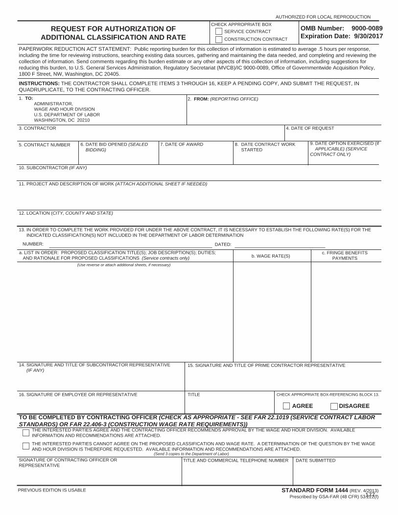
REQUEST FOR AUTHORIZATION OF ADDITIONAL CLASSIFICATION AND RATE
INSTRUCTIONS: THE CONTRACTOR SHALL COMPLETE ITEMS 3 THROUGH 16, KEEP A PENDING COPY, AND SUBMIT THE REQUEST, IN QUADRUPLICATE, TO THE CONTRACTING OFFICER. 1. TO: ADMINISTRATOR, WAGE AND HOUR DIVISION U.S. DEPARTMENT OF LABOR WASHINGTON, DC 20210
2. FROM: (REPORTING OFFICE)
3. CONTRACTOR 4. DATE OF REQUEST
5. CONTRACT NUMBER 6. DATE BID OPENED (SEALED BIDDING)
7. DATE OF AWARD 8. DATE CONTRACT WORK STARTED
9. DATE OPTION EXERCISED (If APPLICABLE) (SERVICE CONTRACT ONLY)
10. SUBCONTRACTOR (IF ANY)
11. PROJECT AND DESCRIPTION OF WORK (ATTACH ADDITIONAL SHEET IF NEEDED)
12. LOCATION (CITY, COUNTY AND STATE)
13. IN ORDER TO COMPLETE THE WORK PROVIDED FOR UNDER THE ABOVE CONTRACT, IT IS NECESSARY TO ESTABLISH THE FOLLOWING RATE(S) FOR THE INDICATED CLASSIFICATION(S) NOT INCLUDED IN THE DEPARTMENT OF LABOR DETERMINATION
NUMBER: DATED:
a. LIST IN ORDER: PROPOSED CLASSIFICATION TITLE(S); JOB DESCRIPTION(S); DUTIES; AND RATIONALE FOR PROPOSED CLASSIFICATIONS (Service contracts only) b. WAGE RATE(S)
c. FRINGE BENEFITS PAYMENTS
(Use reverse or attach additional sheets, if necessary)
14. SIGNATURE AND TITLE OF SUBCONTRACTOR REPRESENTATIVE (IF ANY)
15. SIGNATURE AND TITLE OF PRIME CONTRACTOR REPRESENTATIVE
16. SIGNATURE OF EMPLOYEE OR REPRESENTATIVE TITLE CHECK APPROPRIATE BOX-REFERENCING BLOCK 13.
AGREE DISAGREE
TO BE COMPLETED BY CONTRACTING OFFICER (CHECK AS APPROPRIATE - SEE FAR 22.1019 (SERVICE CONTRACT LABOR STANDARDS) OR FAR 22.406-3 (CONSTRUCTION WAGE RATE REQUIREMENTS))
THE INTERESTED PARTIES AGREE AND THE CONTRACTING OFFICER RECOMMENDS APPROVAL BY THE WAGE AND HOUR DIVISION. AVAILABLE INFORMATION AND RECOMMENDATIONS ARE ATTACHED.
THE INTERESTED PARTIES CANNOT AGREE ON THE PROPOSED CLASSIFICATION AND WAGE RATE. A DETERMINATION OF THE QUESTION BY THE WAGE AND HOUR DIVISION IS THEREFORE REQUESTED. AVAILABLE INFORMATION AND RECOMMENDATIONS ARE ATTACHED.
(Send 3 copies to the Department of Labor)SIGNATURE OF CONTRACTING OFFICER OR REPRESENTATIVE
STANDARD FORM 1444 (REV. 4/2013) Prescribed by GSA-FAR (48 CFR) 53.222(f)
TITLE AND COMMERCIAL TELEPHONE NUMBER DATE SUBMITTED
CHECK APPROPRIATE BOXSERVICE CONTRACT
CONSTRUCTION CONTRACT
AUTHORIZED FOR LOCAL REPRODUCTION
PREVIOUS EDITION IS USABLE
PAPERWORK REDUCTION ACT STATEMENT: Public reporting burden for this collection of information is estimated to average .5 hours per response, including the time for reviewing instructions, searching existing data sources, gathering and maintaining the data needed, and completing and reviewing the collection of information. Send comments regarding this burden estimate or any other aspects of this collection of information, including suggestions for reducing this burden, to U.S. General Services Administration, Regulatory Secretariat (MVCB)/IC 9000-0089, Office of Governmentwide Acquisition Policy, 1800 F Street, NW, Washington, DC 20405.
OMB Number: 9000-0089 Expiration Date: 9/30/2017
177

LABOR STANDARDS INTERVIEWCONTRACT NUMBER EMPLOYEE INFORMATION
LAST NAME FIRST NAME MI
STREET ADDRESS
CITY STATE ZIP CODE
WORK CLASSIFICATION WAGE RATE
NAME OF PRIME CONTRACTOR
NAME OF EMPLOYER
SUPERVISOR'S NAMELAST NAME FIRST NAME MI
ACTION CHECK BELOWYES NO
Do you work over 8 hours per day?
Do you work over 40 hours per week?
Are you paid at least time and a half for overtime hours?
Are you receiving any cash payments for fringe benefits required by the posted wage determination decision?
WHAT DEDUCTIONS OTHER THAN TAXES AND SOCIAL SECURITY ARE MADE FROM YOUR PAY?
HOW MANY HOURS DID YOU WORK ON YOUR LAST WORK DAY BEFORE THIS INTERVIEW?
DATE OF LAST WORK DAY BEFORE INTERVIEW (YYMMDD)
DATE YOU BEGAN WORK ON THIS PROJECT (YYMMDD)
TOOLS YOU USE
THE ABOVE IS CORRECT TO THE BEST OF MY KNOWLEDGEEMPLOYEE'S SIGNATURE DATE (YYMMDD)
INTERVIEWERSIGNATURE TYPED OR PRINTED NAME DATE (YYMMDD)
INTERVIEWER'S COMMENTSACTION (If explanation is needed, use comments section) YES NOWORK EMPLOYEE WAS DOING WHEN INTERVIEWED
IS EMPLOYEE PROPERLY CLASSIFIED AND PAID?
ARE WAGE RATES AND POSTERS DISPLAYED?
FOR USE BY PAYROLL CHECKERIS ABOVE INFORMATION IN AGREEMENT WITH PAYROLL DATA?
YES NO
COMMENTS
CHECKERLAST NAME FIRST NAME MI JOB TITLE
DATE (YYMMDD)SIGNATURE
AUTHORIZED FOR LOCAL REPRODUCTION Previous edition not usable
STANDARD FORM 1445 (REV. 12-96) Prescribed by GSA - FAR (48 CFR) 53.222(g)178

U.S
.Dep
artm
ento
fLab
orPA
YRO
LL(F
orC
ontr
acto
r'sO
ptio
nalU
se;S
ee In
stru
ctio
ns a
t ww
w.d
ol.g
ov/w
hd/fo
rms/
wh3
47in
str.h
tm)
Per
sons
are
not
req
uire
d to
res
pond
to th
e co
llect
ion
of in
form
atio
n un
less
it d
ispl
ays
a cu
rren
tly v
alid
OM
B c
ontr
ol n
umbe
r.
Publ
ic B
urde
n St
atem
ent
179

−
−
180

Owner’s Davis-BaconCompliance Report
Page 1 of _____
Project Name ___________________________________________ SRF Project # C230_______________
Project Owner: ___________________________________________________________________________
Certified Payrolls Reviewed By: _____________________________________________________________ (Printed name of Owner’s Representative) Employee interviews have been conducted in accordance with the contract requirements. Yes No
Prime Contractor: ________________________________________________________________________
Prime Contractor’s Pay Application No: __________ (Note: Only one allowed per Compliance Report)
Application Period: From _____________________ to __________________________
Check one box and sign below:
For the application period indicated, there were no certified payrolls reported because there were no workers on the site that were subject to the Davis-Bacon and Related Acts.
For the application period indicated, the certified payrolls are in compliance with the Davis-Bacon and Related Acts.
For the application period indicated, the certified payrolls are not in compliance with the Davis-Bacon and Related Acts. A Compliance Report for the corrective action will be submitted ASAP.
Summary of noncompliant findings and follow up actions needed:
_______________________________________________________________________________________
__________________________________ _____________________ Owner’s Representative Signature Date
181

Owner’s Davis-BaconCompliance Report
Page 2 of _____
List all weekly certified payrolls for the application period:
Contractor / Subcontractor Name WeekEnding
Compliant (Yes/ No)
Comments
182
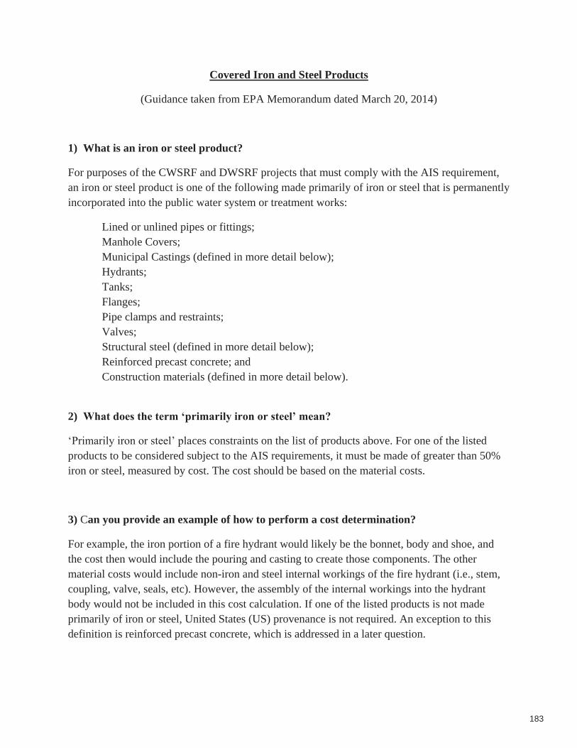
Covered Iron and Steel Products
(Guidance taken from EPA Memorandum dated March 20, 2014)
1) What is an iron or steel product?
For purposes of the CWSRF and DWSRF projects that must comply with the AIS requirement, an iron or steel product is one of the following made primarily of iron or steel that is permanently incorporated into the public water system or treatment works:
Lined or unlined pipes or fittings; Manhole Covers; Municipal Castings (defined in more detail below); Hydrants; Tanks;Flanges; Pipe clamps and restraints;Valves; Structural steel (defined in more detail below); Reinforced precast concrete; and Construction materials (defined in more detail below).
2) What does the term ‘primarily iron or steel’ mean?
‘Primarily iron or steel’ places constraints on the list of products above. For one of the listed products to be considered subject to the AIS requirements, it must be made of greater than 50% iron or steel, measured by cost. The cost should be based on the material costs.
3) Can you provide an example of how to perform a cost determination?
For example, the iron portion of a fire hydrant would likely be the bonnet, body and shoe, and the cost then would include the pouring and casting to create those components. The other material costs would include non-iron and steel internal workings of the fire hydrant (i.e., stem, coupling, valve, seals, etc). However, the assembly of the internal workings into the hydrant body would not be included in this cost calculation. If one of the listed products is not made primarily of iron or steel, United States (US) provenance is not required. An exception to this definition is reinforced precast concrete, which is addressed in a later question.
183

4) If a product is composed of more than 50% iron or steel, but is not listed in the abovelist of items, must the item be produced in the US? Alternatively, must the iron or steel in such a product be produced in the US?
The answer to both question is no. Only items on the above list must be produced in the US. Additionally, the iron or steel in a non-listed item can be sourced from outside the US.
5) What is the definition of steel?
Steel means an alloy that includes at least 50 percent iron, between .02 and 2 percent carbon, and may include other elements. Metallic elements such as chromium, nickel, molybdenum, manganese, and silicon may be added during the melting of steel for the purpose of enhancing properties such as corrosion resistance, hardness, or strength. The definition of steel covers carbon steel, alloy steel, stainless steel, tool steel and other specialty steels.
6) What does ‘produced in the United States’ mean?
Production in the United States of the iron or steel products used in the project requires that all manufacturing processes, including application of coatings, must take place in the United States, with the exception of metallurgical processes involving refinement of steel additives. All manufacturing processes includes processes such as melting, refining, forming, rolling, drawing, finishing, fabricating and coating. Further, if a domestic iron and steel product is taken out of the US for any part of the manufacturing process, it becomes foreign source material. However, raw materials such as iron ore, limestone and iron and steel scrap are not covered by the AIS requirement, and the material(s), if any, being applied as a coating are similarly not covered. Non-iron or steel components of an iron and steel product may come from non-US sources. For example, for products such as valves and hydrants, the individual non-iron and steel components do not have to be of domestic origin.
7) Are the raw materials used in the production of iron or steel required to come from US sources?
No. Raw materials, such as iron ore, limestone, scrap iron, and scrap steel, can come from non-US sources.
8) If an above listed item is primarily made of iron or steel, but is only at the construction site temporarily, must such an item be produced in the US?
184

No. Only the above listed products made primarily of iron or steel, permanently incorporated into the project must be produced in the US. For example trench boxes, scaffolding or equipment, which are removed from the project site upon completion of the project, are not required to be made of U.S. Iron or Steel.
9) What is the definition of ‘municipal castings’?
Municipal castings are cast iron or steel infrastructure products that are melted and cast. They typically provide access, protection, or housing for components incorporated into utility owned drinking water, storm water, wastewater, and surface infrastructure. They are typically made of grey or ductile iron, or steel. Examples of municipal castings are:
Access Hatches; Ballast Screen; Benches (Iron or Steel); Bollards; Cast Bases; Cast Iron Hinged Hatches, Square and Rectangular; Cast Iron Riser Rings; Catch Basin Inlet; Cleanout/Monument Boxes; Construction Covers and Frames; Curb and Corner Guards; Curb Openings; Detectable Warning Plates; Downspout Shoes (Boot, Inlet); Drainage Grates, Frames and Curb Inlets; Inlets; Junction Boxes; Lampposts; Manhole Covers, Rings and Frames, Risers; Meter Boxes; Service Boxes; Steel Hinged Hatches, Square and Rectangular; Steel Riser Rings; Trash receptacles; Tree Grates; Tree Guards; Trench Grates; and Valve Boxes, Covers and Risers.
185

10) What is ‘structural steel’?
Structural steel is rolled flanged shapes, having at least one dimension of their cross-section three inches or greater, which are used in the construction of bridges, buildings, ships, railroad rolling stock, and for numerous other constructional purposes. Such shapes are designated as wide-flange shapes, standard I-beams, channels, angles, tees and zees. Other shapes include H-piles, sheet piling, tie plates, cross ties, and those for other special purposes.
11) What is a ‘construction material’ for purposes of the AIS requirement?
Construction materials are those articles, materials, or supplies made primarily of iron and steel, that are permanently incorporated into the project, not including mechanical and/or electrical components, equipment and systems. Some of these products may overlap with what is also considered “structural steel”. This includes, but is not limited to, the following products: wire rod, bar, angles, concrete reinforcing bar, wire, wire cloth, wire rope and cables, tubing, framing, joists, trusses, fasteners (i.e., nuts and bolts), welding rods, decking, grating, railings, stairs, access ramps, fire escapes, ladders, wall panels, dome structures, roofing, ductwork, surface drains, cable hanging systems, manhole steps, fencing and fence tubing, guardrails, doors, and stationary screens.
12) What is not considered a ‘construction material’ for purposes of the AIS requirement?
Mechanical and electrical components, equipment and systems are not considered construction materials. Mechanical equipment is typically that which has motorized parts and/or is powered by a motor. Electrical equipment is typically any machine powered by electricity and includes components that are part of the electrical distribution system.
The following examples (including their appurtenances necessary for their intended use and operation) are NOT considered construction materials: pumps, motors, gear reducers, drives (including variable frequency drives (VFDs)), electric/pneumatic/manual accessories used to operate valves (such as electric valve actuators), mixers, gates, motorized screens (such as traveling screens), blowers/aeration equipment, compressors, meters, sensors, controls and switches, supervisory control and data acquisition (SCADA), membrane bioreactor systems, membrane filtration systems, filters, clarifiers and clarifier mechanisms, rakes, grinders, disinfection systems, presses (including belt presses), conveyors, cranes, HVAC (excluding ductwork), water heaters, heat exchangers, generators, cabinetry and housings (such as electrical boxes/enclosures), lighting fixtures, electrical conduit, emergency life systems, metal office furniture, shelving, laboratory equipment, analytical instrumentation, and dewatering equipment.
186

13) If the iron or steel is produced in the US, may other steps in the manufacturing process take place outside of the US, such as assembly?
No. Production in the US of the iron or steel used in a listed product requires that all manufacturing processes must take place in the United States, except metallurgical processes involving refinement of steel additives.
14) What processes must occur in the US to be compliant with the AIS requirement for reinforced precast concrete?
While reinforced precast concrete may not be at least 50% iron or steel, in this particular case, the reinforcing bar and wire must be produced in the US and meet the same standards as for any other iron or steel product. Additionally, the casting of the concrete product must take place in the US. The cement and other raw materials used in concrete production are not required to be of domestic origin. If the reinforced concrete is cast at the construction site, the reinforcing bar and wire are considered to be a construction material and must be produced in the US.
187

From the “Consolidated Appropriations Act, 2014”H.R. 3547 (PL113-76, enacted 1/17/2014)
USE OF AMERICAN IRON AND STEEL
“SEC. 436. (a)(1) None of the funds made available by a State water pollution control revolving fund as authorized by title VI of the Federal Water Pollution Control Act (33 U.S.C. 1381 et seq.) or made available by a drinking water treatment revolving loan fund as authorized by section 1452 of the Safe Drinking Water Act (42 U.S.C. 300j–12) shall be used for a project for the construction, alteration, maintenance, or repair of a public water system or treatment works unless all of the iron and steel products used in the project are produced in the United States.
(2) In this section, the term ‘‘iron and steel products’’ means the following products made primarily of iron or steel: lined or unlined pipes and fittings, manhole covers and other municipal castings, hydrants, tanks, flanges, pipe clamps and restraints, valves, structural steel, reinforced precast concrete, and construction materials.
(b) Subsection (a) shall not apply in any case or category of cases in which the Administrator of the Environmental Protection Agency (in this section referred to as the ‘‘Administrator’’) finds that—
(1) applying subsection (a) would be inconsistent with the public interest; (2) iron and steel products are not produced in the United States in sufficient and reasonably
available quantities and of a satisfactory quality; or(3) inclusion of iron and steel products produced in the United States will increase the cost of
the overall project by more than 25 percent. (c) If the Administrator receives a request for a waiver under this section, the Administrator
shall make available to the public on an informal basis a copy of the request and information available to the Administrator concerning the request, and shall allow for informal public input on the request for at least 15 days prior to making a finding based on the request. The Administrator shall make the request and accompanying information available by electronic means, including on the official public Internet Web site of the Environmental Protection Agency.
(d) This section shall be applied in a manner consistent with United States obligations under international agreements.
(e) The Administrator may retain up to 0.25 percent of the funds appropriated in this Act for the Clean and Drinking Water State Revolving Funds for carrying out the provisions described in subsection (a)(1) for management and oversight of the requirements of this section.
(f) This section does not apply with respect to a project if a State agency approves the engineering plans and specifications for the project, in that agency’s capacity to approve such plans and specifications prior to a project requesting bids, prior to the date of the enactment of this Act.”
188

CERTIFICATION BY THE OWNEROF COMPLIANCE WITH THE
USE OF AMERICAN IRON AND STEEL LAW enacted on 1/17/2014
(To be attached to each SRF requisition submitted for payment)
We, the Owner named, __________________________, having obtained a loan from the State
of Maine Clean Water State Revolving Fund (CWSRF), to fund the Project named
__________________________________ , hereby submit to the Department of Environmental
Protection, certification from each contractor working on the Project that the use of American
Iron and Steel in the construction of the Project complies with the law, or that a waiver has been
obtained from the U.S. Environmental Protection Agency. Thereby, it is to the best of the
Owner’s knowledge that the costs being requested with this SRF requisition #______ are in
compliance with the Use of American Iron and Steel Law.
__________________________ _____________________ ___________________ Signature of Official Printed name Date
Attachment: Certification by Contractor
189

CERTIFICATION BY CONTRACTOR OF COMPLIANCE WITH THE
USE OF AMERICAN IRON AND STEEL LAW enacted on 1/17/2014
(To be attached to each pay application submitted for payment)
We, the Prime Contractor and Subcontractors, as named below, hereby certify that the use of
American iron and steel in the construction of the Project named _________________________,
being requested in the pay application (or invoice) #_____ and dated ____________, complies
with the Use of American Iron and Steel Law, or that a waiver been obtained from the U.S.
Environmental Protection Agency.
Prime Contractor Name: _________________________________________________________
____________________________ _________________ ___________________ Signature of Official Printed name Date
---------------------------------------------------------------------------------------------------------------------
Subcontractor Name Signature of Official Date
____________________________ ______________________ ________________
____________________________ ______________________ ________________
____________________________ ______________________ ________________
____________________________ ______________________ ________________
____________________________ ______________________ ________________
____________________________ ______________________ ________________
190

Sample Step Manufacturer Certification(Documentation must be provided on company letterhead)
Date: _________________
Company Name: ___________________________________________________________
Company Address: _________________________________________________________
City, State Zip: ____________________________________________________________
Subject: American Iron and Steel Step Manufacturer Certification
Project Name __________________________________________________
I, _______________________ (company representative), certify that the _________________
(melting, bending, coating, galvanizing, cutting, etc.) process for _______________________
(manufacturing or fabricating) the following products and/or materials shipped or provided for
the project is in full compliance with the American Iron and Steel requirement as mandated in
EPA’s State Revolving Fund Programs.
Item, Products and/or Materials:
1. _____________________________________________________________________
2. _____________________________________________________________________
3. _____________________________________________________________________
Such process took place at the following location:
___________________________________________________________________(address)
If any of the above compliance statements change while providing material to this project we
will immediately notify the prime contractor and the engineer.
_________________________ ___________________ ____________
Company representative Signature Date
191

Maine Clean Water State Revolving Loan Fund (CWSRF)American Iron and Steel - De Minimis Tracking Form (Sample)
Owner: Loan #:
Project Name:
5% Limit: $0 1% limit: $0
Part/Model # Quantity(if applicable)
Cost per Unit(if applicable)
Component'sTotal Cost
Invoice or receiptattached
$$ -
$ -
$ -
$ -
$ -
$ -
$ -
$ -
$ -
$ -
$ -
$ -
Company:
Name: Title:
Signature: Date:
The EPA has issued a public interest waiver for De Minimis incidental components. An Owner wishing to use this waiver shouldconsult with their contractor(s) to maintain an itemized list to track the components covered under De Minimis. The Owner maycreate their own format for the list or use this sample form.
NOTE: The De Minimis waiver is only applicable to the cost of materials for the entire project. Do not include other project costs (labor,installation costs, etc.) in the "Total Cost of Materials". The total cost of a material may be based on estimated, or if available, actualcosts.
Manufacturer & ComponentDescription
Total Cost of Materials:
Funds used for de minimis incidental components cumulatively may comprise no more than a total of 5 percent of the total cost of thematerials used in and incorporated into a project; the cost of an individual item may not exceed 1 percent of the total cost of thematerials used in and incorporated into a project.
Completed by:
Use additional sheets as necessaryTotal Cost of Componentsdeemed to be De Minimis:
192

213302.15 Grist Mill Bridge Utility Crossing and Sewer ReplacementIssue Date: February 2019 Town of Hampden, ME and Hampden Water District
SUMMARY OF WORKWOODARD & CURRAN 01 11 00-1
SECTION 01 11 00
SUMMARY OF WORK
PART 1 – GENERAL
1.01 SECTION INCLUDES
A. Project Description
B. Description of the Work
C. Work Sequence and Coordination
D. Special Requirements
1.02 DESCRIPTION OF THE WORK
A. The Work includes labor, material and equipment, services required for construction, testing, and commissioning of the Project in accordance with the Contract Documents and as more specifically described in the Specifications and Drawings and includes, but is not limited to, the following principal features:
1. Grist Mill Bridge Sewer Utility Crossing
2. Grist Mill Bridge Water Utility Crossing
3. Main Road North (Route 1A) Sewer Replacement
B. Work Site Locations: Generally, as shown on the Drawings.
C. Work by Others
1. The following Work will be performed in conjunction with the following Maine Department of Transportation (MDOT) projects:
a. Project No. STP-1157(700)X U.S. Route 1A, Hampden, Penobscot County
b. Project No. STP-2169(200) Grist Mill Bridge over Souadabscook Stream, Hampden, Penobscot County
D. Existing Conditions and Site Data: Per the Drawings.
1.03 WORK SEQUENCE AND COORDINATION
A. Coordination
1. Ensure that facilities and system flows are maintained and remain in service at all times unless otherwise noted.
193
213302.15 Grist Mill Bridge Utility Crossing and Sewer ReplacementIssue Date: February 2019 Town of Hampden, ME and Hampden Water District
SUMMARY OF WORKWOODARD & CURRAN 01 11 00-2
a. Obtain written approval of the Owner for shutdowns. Notify Owner a minimum of two weeks prior to any required shutdowns.
b. Coordinate Work with the Town and Water District and provide public notice, as required.
2. Maintain access to facilities for the Owner throughout the Project.
B. Sequence
1. Sequence Work to minimize shutdowns and reflect sequencing in the construction schedule.
PART 2 PRODUCTS - NOT USED
PART 3 EXECUTION - NOT USED
END OF SECTION
194
213302.15 Grist Mill Bridge Utility Crossing and Sewer ReplacementIssue Date: February 2019 Town of Hampden, ME and Hampden Water District
MEASUREMENT AND PAYMENTWOODARD & CURRAN 01 20 25-1
SECTION 01 20 25
MEASUREMENT AND PAYMENT
PART 1 - GENERAL
1.01 DESCRIPTION
A. This Section describes the measurement and payment for the Work to be completed under each item in the Bid Form, which may also be referred to as “pay item”.
B. Payment procedures are in accordance with the Contract.
C. Measurement: As determined, verified, or approved by Engineer or Owner in accordance with the Contract, except as otherwise specified.
D. Schedule of Values:
1. Submit preliminary and final Schedule of Values.
2. Provide sufficient detail to allow for determination of the value of the Work at any degree of completion.
3. For each line item, identify number and title of related specification section.
E. The Work described in each pay item shall be as described in the Specifications and shown on the Drawings and not included in other pay items.
1. Pay item descriptions are general and may not specifically describe all associated Work or elements thereof, do not constitute Specifications, and do not supersede the content of the Specifications and Drawings.
2. Review the Specifications and Drawings for Work associated with each pay item. Claims for being unfamiliar with the content of the Specifications and Drawings will not be considered.
F. The following Work is not specifically described or designated as a pay item, is considered incidental to all pay items, and shall not be measured separately for payment.
1. Restoration of unpaved areas disturbed by the Contractor within the limits of Work.
2. Restoration of landscaping within the limits of Work.
195

213302.15 Grist Mill Bridge Utility Crossing and Sewer ReplacementIssue Date: February 2019 Town of Hampden, ME and Hampden Water District
MEASUREMENT AND PAYMENTWOODARD & CURRAN 01 20 25-2
3. Field and laboratory testing and reporting by independent laboratory, including but not limited to compaction of backfill materials; aggregate gradation; and concrete testing.
4. Record Documents.
G. Payment will not be made for restoration of areas disturbed by the Contractor outside the limits of Work.
H. Payment will only be made for those utility services, including sewer, water, and fire services, specifically identified for replacement on the Drawings. Relocation or replacement for the Contractor’s convenience or due to breakage by the Contractor of any other utility services shown on the Drawings, or at locations which could reasonably be assumed, shall be at no cost to Owner.
I. Design, installation and removal of excavation support systems, temporary and permanent utility/structure support systems associated with a pay item shall be considered incidental to that pay item.
J. Additional dewatering and erosion control (including installation, operation, maintenance, removal and off-Site disposal of erosion control devices) associated with a pay item shall be considered incidental to that pay item.
1.02 MEASUREMENT AND PAYMENT BASIS
ITEM 304.10: Aggregate Subbase Course - Gravel
Measurement For aggregate subbase required to repair trenches for water mains and services outside the limits of the MDOT project, aggregate shall be measured by the cubic yard installed.
Payment Unit price per cubic yard as stated in the Bid.
Includes: Aggregate subbase, testing, and all other materials and labor required to provide a complete installation as required by the Contract Documents or as directed by the Engineer in the field.
196

213302.15 Grist Mill Bridge Utility Crossing and Sewer ReplacementIssue Date: February 2019 Town of Hampden, ME and Hampden Water District
MEASUREMENT AND PAYMENTWOODARD & CURRAN 01 20 25-3
ITEM 304.16: Aggregate Base Course – Type C
Measurement For aggregate base required to repair trenches for utility mains and services outside the limits of the MDOT project, aggregate shall be measured by the cubic yard installed.
Payment Unit price per cubic yard as stated in the Bid.
Includes: Aggregate base, testing, and all other materials and labor required to provide a complete installation as required by the Contract Documents or as directed by the Engineer in the field.
ITEM 403.2081: Hot Mix Asphalt, 12.5mm Polymer Modified
Measurement For pavement repair required to repair trenches for water mains and services outside the limits of the MDOT project, pavement shall be measured by the ton installed.
Payment Unit price per ton as stated in the Bid.
Includes: Grinding/removal of existing pavement/cutbacks, pavement markings, testing, and all other materials and labor required to provide a complete installation as required by the Contract Documents or as directed by the Engineer in the field.
ITEM 403.213: Hot Mix Asphalt, 12.5mm Nominal Max. Size (Base)
Measurement For pavement repair required to repair trenches for water mains and services outside the limits of the MDOT project, pavement shall be measured by the ton installed.
Payment Unit price per ton as stated in the Bid.
Includes: Binder course, testing, and all other materials and labor required to provide a complete installation as required by the Contract Documents or as directed by the Engineer in the field.
197

213302.15 Grist Mill Bridge Utility Crossing and Sewer ReplacementIssue Date: February 2019 Town of Hampden, ME and Hampden Water District
MEASUREMENT AND PAYMENTWOODARD & CURRAN 01 20 25-4
ITEM 626.11: Precast Concrete Junction Box
Measurement Measured per each unit installed.
Payment Unit price per each as stated in the Bid.
Includes: All equipment, material, and labor associated with excavation, bedding, structure, frame and cover, backfill, shoring and bracing, dewatering, dust control, testing, loam and seed, and all associated Work as specified and shown on the Drawings.
ITEM 626.221: Non-Metallic Conduit, Concrete Encased
Measurement As measured along the horizontal projection of the centerline of the duct bank.
Payment Unit price per linear foot as stated in the Bid.
Includes: All equipment, material, and labor associated with excavation, bedding, conduit and fittings, reinforcement, concrete dye, marker tape, concrete encasement, backfill, shoring and bracing, dewatering, dust control, testing, loam and seed, and all associated Work as specified and shown on the Drawings.
ITEM 652.36: Maintenance of Traffic Control Devices
Measurement Measured in accordance with Division 600 of the MDOT Standard Specifications.
Payment Unit price per calendar day as stated in the Bid.
Includes: Maintain traffic control devices in accordance with Division 600 of the MDOT Standard Specifications.
ITEM 652.38: Flaggers
Measurement Measured in accordance with Division 600 of the MDOT Standard Specifications.
Payment Unit price per hour as stated in the Bid.
Includes: Provide flaggers in accordance with Division 600 of the MDOT Standard Specifications.
198

213302.15 Grist Mill Bridge Utility Crossing and Sewer ReplacementIssue Date: February 2019 Town of Hampden, ME and Hampden Water District
MEASUREMENT AND PAYMENTWOODARD & CURRAN 01 20 25-5
ITEM 656.75: Temporary Soil Erosion and Water Pollution Control
Measurement Measured in accordance with Division 600 of the MDOT Standard Specifications.
Payment Payment in accordance with Division 600 of the MDOT Standard Specifications.
Includes: Provide Temporary Soil Erosion and Water Pollution Control per Division 600 of the MDOT Standard Specifications.
ITEM 659.10: Mobilization
Measurement Measured in accordance with Division 600 of the MDOT Standard Specifications.
Payment Payment in accordance with Division 600 of the MDOT Standard Specifications.
Includes: Delivery to and removal of equipment from the Project Site, temporary utilities, facilities and controls, obtaining necessary permits including associated fees, insurance and bond costs, signage, development of pre-construction schedules and plans required by the General Conditions, Supplementary Conditions and General Requirements; necessary pre-construction investigations, verifying existing field conditions, coordination, and Site clean-up, restoration and closeout.
ITEM 801.03: Test Pits
Measurement Measured per each test pit completed.
Payment Unit price per each as stated in the Bid.
Includes: Earthwork and surface restoration to perform test pits as required by the Contract Documents and as directed by the Engineer.
199
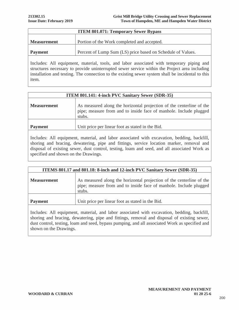
213302.15 Grist Mill Bridge Utility Crossing and Sewer ReplacementIssue Date: February 2019 Town of Hampden, ME and Hampden Water District
MEASUREMENT AND PAYMENTWOODARD & CURRAN 01 20 25-6
ITEM 801.071: Temporary Sewer Bypass
Measurement Portion of the Work completed and accepted.
Payment Percent of Lump Sum (LS) price based on Schedule of Values.
Includes: All equipment, material, tools, and labor associated with temporary piping and structures necessary to provide uninterrupted sewer service within the Project area including installation and testing. The connection to the existing sewer system shall be incidental to this item.
ITEM 801.141: 4-inch PVC Sanitary Sewer (SDR-35)
Measurement As measured along the horizontal projection of the centerline of the pipe; measure from and to inside face of manhole. Include plugged stubs.
Payment Unit price per linear foot as stated in the Bid.
Includes: All equipment, material, and labor associated with excavation, bedding, backfill, shoring and bracing, dewatering, pipe and fittings, service location marker, removal and disposal of existing sewer, dust control, testing, loam and seed, and all associated Work as specified and shown on the Drawings.
ITEMS 801.17 and 801.18: 8-inch and 12-inch PVC Sanitary Sewer (SDR-35)
Measurement As measured along the horizontal projection of the centerline of the pipe; measure from and to inside face of manhole. Include plugged stubs.
Payment Unit price per linear foot as stated in the Bid.
Includes: All equipment, material, and labor associated with excavation, bedding, backfill, shoring and bracing, dewatering, pipe and fittings, removal and disposal of existing sewer, dust control, testing, loam and seed, bypass pumping, and all associated Work as specified and shown on the Drawings.
200
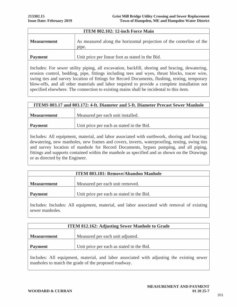
213302.15 Grist Mill Bridge Utility Crossing and Sewer ReplacementIssue Date: February 2019 Town of Hampden, ME and Hampden Water District
MEASUREMENT AND PAYMENTWOODARD & CURRAN 01 20 25-7
ITEM 802.102: 12-inch Force Main
Measurement As measured along the horizontal projection of the centerline of the pipe.
Payment Unit price per linear foot as stated in the Bid.
Includes: For sewer utility piping, all excavation, backfill, shoring and bracing, dewatering, erosion control, bedding, pipe, fittings including tees and wyes, thrust blocks, tracer wire, swing ties and survey location of fittings for Record Documents, flushing, testing, temporary blow-offs, and all other materials and labor required to provide a complete installation not specified elsewhere. The connection to existing mains shall be incidental to this item.
ITEMS 803.17 and 803.172: 4-ft. Diameter and 5-ft. Diameter Precast Sewer Manhole
Measurement Measured per each unit installed.
Payment Unit price per each as stated in the Bid.
Includes: All equipment, material, and labor associated with earthwork, shoring and bracing; dewatering, new manholes, new frames and covers, inverts, waterproofing, testing, swing ties and survey location of manhole for Record Documents, bypass pumping, and all piping, fittings and supports contained within the manhole as specified and as shown on the Drawings or as directed by the Engineer.
ITEM 803.181: Remove/Abandon Manhole
Measurement Measured per each unit removed.
Payment Unit price per each as stated in the Bid.
Includes: Includes: All equipment, material, and labor associated with removal of existing sewer manholes.
ITEM 812.162: Adjusting Sewer Manhole to Grade
Measurement Measured per each unit adjusted.
Payment Unit price per each as stated in the Bid.
Includes: All equipment, material, and labor associated with adjusting the existing sewer manholes to match the grade of the proposed roadway.
201
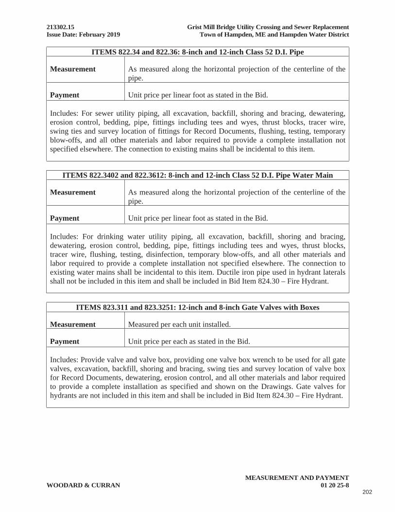
213302.15 Grist Mill Bridge Utility Crossing and Sewer ReplacementIssue Date: February 2019 Town of Hampden, ME and Hampden Water District
MEASUREMENT AND PAYMENTWOODARD & CURRAN 01 20 25-8
ITEMS 822.34 and 822.36: 8-inch and 12-inch Class 52 D.I. Pipe
Measurement As measured along the horizontal projection of the centerline of the pipe.
Payment Unit price per linear foot as stated in the Bid.
Includes: For sewer utility piping, all excavation, backfill, shoring and bracing, dewatering, erosion control, bedding, pipe, fittings including tees and wyes, thrust blocks, tracer wire, swing ties and survey location of fittings for Record Documents, flushing, testing, temporary blow-offs, and all other materials and labor required to provide a complete installation not specified elsewhere. The connection to existing mains shall be incidental to this item.
ITEMS 822.3402 and 822.3612: 8-inch and 12-inch Class 52 D.I. Pipe Water Main
Measurement As measured along the horizontal projection of the centerline of the pipe.
Payment Unit price per linear foot as stated in the Bid.
Includes: For drinking water utility piping, all excavation, backfill, shoring and bracing, dewatering, erosion control, bedding, pipe, fittings including tees and wyes, thrust blocks, tracer wire, flushing, testing, disinfection, temporary blow-offs, and all other materials and labor required to provide a complete installation not specified elsewhere. The connection to existing water mains shall be incidental to this item. Ductile iron pipe used in hydrant laterals shall not be included in this item and shall be included in Bid Item 824.30 – Fire Hydrant.
ITEMS 823.311 and 823.3251: 12-inch and 8-inch Gate Valves with Boxes
Measurement Measured per each unit installed.
Payment Unit price per each as stated in the Bid.
Includes: Provide valve and valve box, providing one valve box wrench to be used for all gate valves, excavation, backfill, shoring and bracing, swing ties and survey location of valve box for Record Documents, dewatering, erosion control, and all other materials and labor required to provide a complete installation as specified and shown on the Drawings. Gate valves for hydrants are not included in this item and shall be included in Bid Item 824.30 – Fire Hydrant.
202

213302.15 Grist Mill Bridge Utility Crossing and Sewer ReplacementIssue Date: February 2019 Town of Hampden, ME and Hampden Water District
MEASUREMENT AND PAYMENTWOODARD & CURRAN 01 20 25-9
ITEM 823.3254: 8-inch Insertion Valve
Measurement Measured per each unit installed.
Payment Unit price per each as stated in the Bid.
Includes: Insertion valve and valve box, surface restoration, loaming and seeding, and all other materials and labor required to provide a complete installation as specified and shown on the Drawings.
ITEM 823.332: Gate Valve Box, Adjust to Grade
Measurement Measured per each unit adjusted to final grade.
Payment Unit price per each as stated in the Bid.
Includes: All labor, materials, testing, submittals, tools, and equipment necessary to adjust existing valve boxes within the limits of work to the final elevation of the pavement, overlay, or grades shown on the Drawings.
ITEM 824.30: Fire Hydrant
Measurement Measured per each unit installed.
Payment Unit price per each as stated in the Bid.
Includes: Provide all fittings, pipe, hydrant tee, 6-inch gate valve, valve box, hydrant extensions if necessary, thrust blocks, accessories, earthwork and materials, swing ties and survey location of manhole for Record Documents, surface restoration including repairing sidewalks and curbs, loaming and seeding, and all other materials and labor required to provide a complete hydrant tee, valve, and hydrant installation as specified and shown on the Drawings.
203

213302.15 Grist Mill Bridge Utility Crossing and Sewer ReplacementIssue Date: February 2019 Town of Hampden, ME and Hampden Water District
MEASUREMENT AND PAYMENTWOODARD & CURRAN 01 20 25-10
ITEM 824.31: Remove Fire Hydrant
Measurement Measured per each unit removed.
Payment Unit price per each as stated in the Bid.
Includes: All materials, labor, and equipment required to remove existing hydrants, pipe, valves, valve box and fittings as specified and shown on the Drawings and in the following locations:
a. Dudley Street, Sta. 270+60±
ITEMS 825.311: 3/4-inch Corporation
Measurement Measured per each unit installed.
Payment Unit price per each as stated in the Bid.
Includes: All equipment, material, and labor associated with installation of water service corporation stops, earthwork, erosion control, backfill, shoring and bracing, for copper service lines as specified and as shown on the Drawings or as directed by the Engineer.
ITEMS 825.312: 3/4-inch Curb Stop and Box
Measurement Measured per each unit installed.
Payment Unit price per each as stated in the Bid.
Includes: Curb stop and service box, surface restoration, earthwork, erosion control, backfill, shoring and bracing, swing ties and survey location of manhole for Record Documents, loaming and seeding, and all other materials and labor required to provide a complete installation as specified and shown on the Drawings.
ITEMS 825.322: 2-inch Curb Stop
Measurement Measured per each unit installed.
Payment Unit price per each as stated in the Bid.
Includes: Curb stop, valve box, surface restoration, earthwork, erosion control, backfill, shoring and bracing, swing ties and survey location of manhole for Record Documents, loaming and seeding, and all other materials and labor required to provide a complete installation as specified and shown on the Drawings.
204
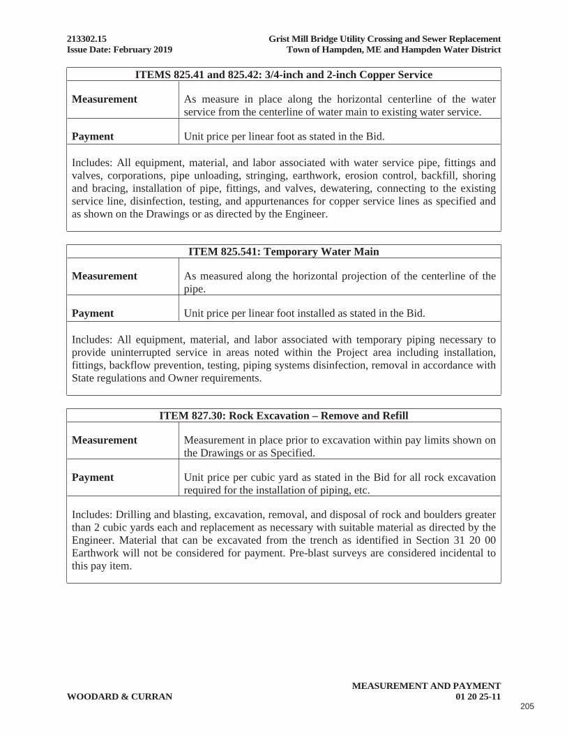
213302.15 Grist Mill Bridge Utility Crossing and Sewer ReplacementIssue Date: February 2019 Town of Hampden, ME and Hampden Water District
MEASUREMENT AND PAYMENTWOODARD & CURRAN 01 20 25-11
ITEMS 825.41 and 825.42: 3/4-inch and 2-inch Copper Service
Measurement As measure in place along the horizontal centerline of the water service from the centerline of water main to existing water service.
Payment Unit price per linear foot as stated in the Bid.
Includes: All equipment, material, and labor associated with water service pipe, fittings and valves, corporations, pipe unloading, stringing, earthwork, erosion control, backfill, shoring and bracing, installation of pipe, fittings, and valves, dewatering, connecting to the existing service line, disinfection, testing, and appurtenances for copper service lines as specified and as shown on the Drawings or as directed by the Engineer.
ITEM 825.541: Temporary Water Main
Measurement As measured along the horizontal projection of the centerline of the pipe.
Payment Unit price per linear foot installed as stated in the Bid.
Includes: All equipment, material, and labor associated with temporary piping necessary to provide uninterrupted service in areas noted within the Project area including installation, fittings, backflow prevention, testing, piping systems disinfection, removal in accordance with State regulations and Owner requirements.
ITEM 827.30: Rock Excavation – Remove and Refill
Measurement Measurement in place prior to excavation within pay limits shown on the Drawings or as Specified.
Payment Unit price per cubic yard as stated in the Bid for all rock excavation required for the installation of piping, etc.
Includes: Drilling and blasting, excavation, removal, and disposal of rock and boulders greater than 2 cubic yards each and replacement as necessary with suitable material as directed by the Engineer. Material that can be excavated from the trench as identified in Section 31 20 00 Earthwork will not be considered for payment. Pre-blast surveys are considered incidental to this pay item.
205

213302.15 Grist Mill Bridge Utility Crossing and Sewer ReplacementIssue Date: February 2019 Town of Hampden, ME and Hampden Water District
MEASUREMENT AND PAYMENTWOODARD & CURRAN 01 20 25-12
ITEM 827.302: Unsuitable Soil Excavation – Below Grade
Measurement As measured by the Engineer within the limits as specified or directed.
Payment Unit price per cubic yard as stated in the Bid.
Includes: Excavation and replacement of materials determined by the Engineer as unsuitable for pipe or structure subgrade.
ITEM 827.312: Select Backfill
Measurement As measured in place within the pay limits shown on the Drawings and as directed by the Engineer.
Payment Unit price per cubic yard as stated in the Bid.
Includes: Select backfill as specified and as directed by the Engineer.
ITEM 827.33: Trench Insulation
Measurement Measured in place as shown on the Drawings or as directed by the Engineer.
Payment Unit price per linear foot as stated in the Bid. Unit price is for 2-inch thick and 4-ft. wide insulation.
Includes: Insulation over pipe as shown on the Drawings or as directed by the Engineer.
ITEM 830.10: Water Main Bridge Crossing
Measurement Portion of the Work completed and accepted.
Payment Percent of Lump Sum (LS) price based on Schedule of Values.
Includes: All Work associated with the future water main bridge crossing over Souadabscook Stream. Includes all materials, equipment, services, and construction inherent to the Work required to accommodate the future water main. Includes backfill, compaction, casing pipe, fittings, shoring, bracing, site restoration, and all Work not included in other bid items.
206
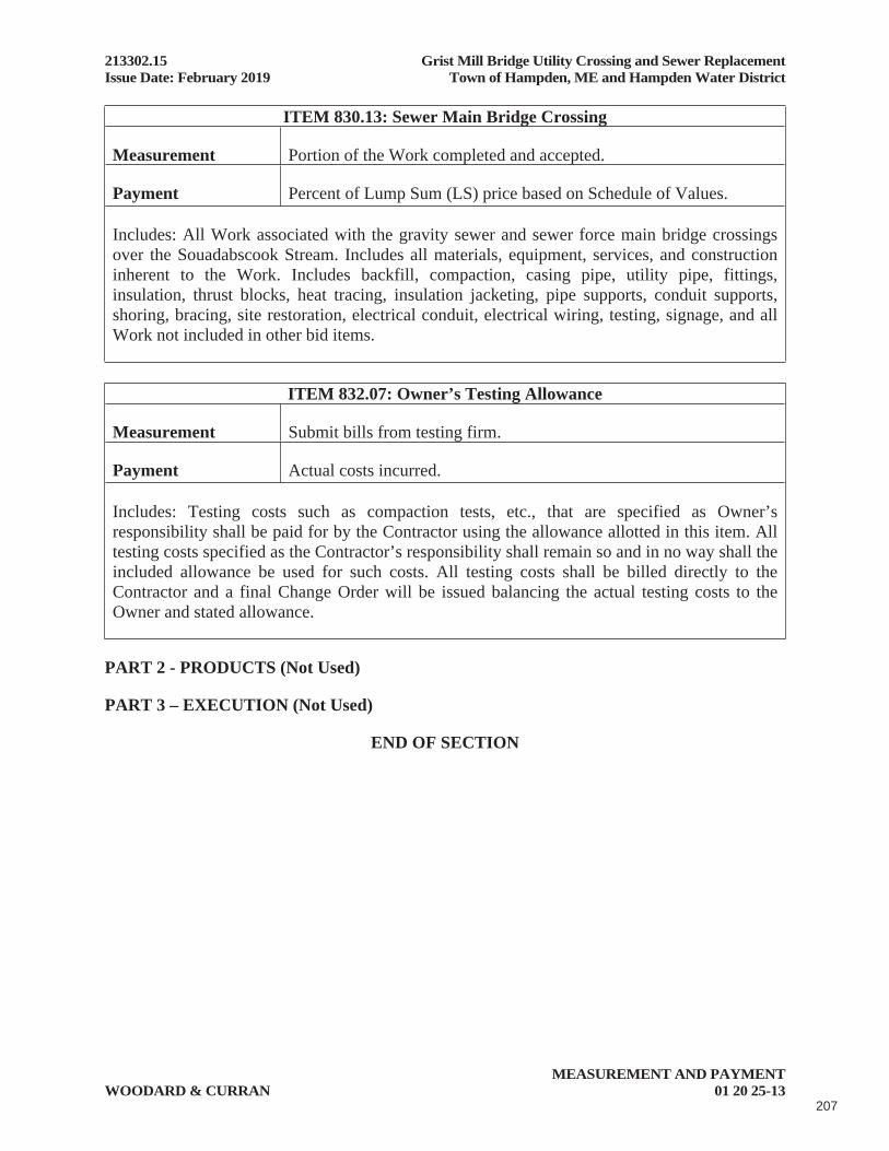
213302.15 Grist Mill Bridge Utility Crossing and Sewer ReplacementIssue Date: February 2019 Town of Hampden, ME and Hampden Water District
MEASUREMENT AND PAYMENTWOODARD & CURRAN 01 20 25-13
ITEM 830.13: Sewer Main Bridge Crossing
Measurement Portion of the Work completed and accepted.
Payment Percent of Lump Sum (LS) price based on Schedule of Values.
Includes: All Work associated with the gravity sewer and sewer force main bridge crossings over the Souadabscook Stream. Includes all materials, equipment, services, and construction inherent to the Work. Includes backfill, compaction, casing pipe, utility pipe, fittings, insulation, thrust blocks, heat tracing, insulation jacketing, pipe supports, conduit supports, shoring, bracing, site restoration, electrical conduit, electrical wiring, testing, signage, and all Work not included in other bid items.
ITEM 832.07: Owner’s Testing Allowance
Measurement Submit bills from testing firm.
Payment Actual costs incurred.
Includes: Testing costs such as compaction tests, etc., that are specified as Owner’s responsibility shall be paid for by the Contractor using the allowance allotted in this item. All testing costs specified as the Contractor’s responsibility shall remain so and in no way shall the included allowance be used for such costs. All testing costs shall be billed directly to the Contractor and a final Change Order will be issued balancing the actual testing costs to the Owner and stated allowance.
PART 2 - PRODUCTS (Not Used)
PART 3 – EXECUTION (Not Used)
END OF SECTION
207

213302.15 Grist Mill Bridge Utility Crossing and Sewer ReplacementIssue Date: February 2019 Town of Hampden, ME and Hampden Water District
SURVEY TIE SHEETWOODARD & CURRAN 01 32 23-1
SECTION 01 32 23
SURVEY TIE SHEET
Town of: ______________________________ Station: _____________________________
Project: _______________________________ Property Owner: ______________________
Date: _________________________________ Located by: __________________________
Street: ________________________________ Project Contractor: ____________________
Survey ties shall be taken to manholes, bends, fittings, service wyes, ends of service laterals, couplings, repairs, etc. Note depth and types of pipes, etc. Three survey ties shall be used for each item. Ties shall be taken to permanent structures, e.g. house, hydrants, utility poles, etc.
LOCATION DIAGRAM
Remarks:
END OF SECTION
208

213302.15 Grist Mill Bridge Utility Crossing and Sewer ReplacementIssue Date: February 2019 Town of Hampden, ME and Hampden Water District
SUBMITTALSWOODARD & CURRAN 01 33 00-1
SECTION 01 33 00
SUBMITTALS
PART 1 – GENERAL
1.01 DESCRIPTION OF REQUIREMENTS
A. Submittal Requirements: Submittal requirements specified in this Section include shop drawings, product data, Record Documents, and miscellaneous Work-related submittals. Individual submittal requirements are specified in applicable Sections for each unit of Work.
B. Definitions: Work-related submittals of this Section are categorized for convenience as follows:
1. Shop drawings include specially-prepared technical data for this Project, including drawings, diagrams, data sheets, schedules, patterns, instructions, measurements and similar information not in standard printed form.
2. Product data include standard printed information on materials, products and systems; not specially-prepared for this Project.
3. Samples include both fabricated and unfabricated physical examples of materials, products and units of Work; both as complete units and as smaller portions of units of Work; either for limited visual inspection or (where indicated) for more detailed testing and analysis.
4. Miscellaneous submittals related directly to the Work (non- administrative) include warranties, quality testing and certifying reports, and copies of industry standards.
1.02 GENERAL SUBMITTAL REQUIREMENTS
A. Scheduling: Show principal Work-related submittals in job progress schedule.
B. Coordination and Sequencing: Coordinate preparation and processing of submittals with performance of the Work so that Work will not be delayed by submittals.
C. Preparation of Submittals: Provide permanent marking on each submittal to identify Project, date, Contractor, subcontractor, submittal name and similar information to distinguish it from other submittals. Show Contractor's executed review and approval marking.
D. Transmittal Form: Provide places to indicate Project, date, "To:", "From:", names of subcontractors, suppliers, manufacturers, required references, category and
209

213302.15 Grist Mill Bridge Utility Crossing and Sewer ReplacementIssue Date: February 2019 Town of Hampden, ME and Hampden Water District
SUBMITTALSWOODARD & CURRAN 01 33 00-2
type of submittal, purpose, description, distribution record (for both transmittal and submittals), and signature of transmitter.
1.03 SPECIFIC-CATEGORY SUBMITTAL REQUIREMENTS
A. General: Except as otherwise indicated in individual Sections, comply with requirements specified herein.
B. Format: Provide submittals in a clear and thorough manner, in English and using English units. Use sheet size of not less than 8 ½ by 11 inches and not more than 24 by 36 inches.
1. Submittals may be provided in electronic format with prior approval of the Engineer. Provide electronic files in PDF format.
C. Shop Drawings: Provide newly-prepared information, with graphic information at accurate scale (except as otherwise indicated), with name of preparer indicated (firm name). Show dimensions and note which dimensions are based on field measurement. Identify materials and products in the Work shown. Indicate compliance with standards and special coordination requirements. Do not allow shop-drawing copies without appropriate final "Action" markings by Engineer to be used in connection with the Work.
1. Submit 3 copies for Engineer’s use; all additional copies will be returned for Contractor’s use.
D. Product Data: Collect required data into one submittal for each unit of Work or system and mark each copy to show which choices and options are applicable to Project. Include manufacturer's standard printed recommendations for application and use, compliance with standards, notation of field measurements, which have been checked, and special coordination requirements. Maintain one set of product data (for each submittal) at Project site, available for reference by Engineer and others.
1. Submit 3 copies for Engineer’s use; all additional copies will be returned for Contractor’s use.
E. Samples: Provide units identical with final condition of proposed materials or products for the Work. Include information with each sample to show generic description, source or product name and manufacturer, limitations, and compliance with standards.
F. Inspection and Test Reports: See individual specification sections for inspection and test report requirements.
G. Warranties: Refer to "Products" section for specific general requirements on warranties, product/workmanship bonds, and maintenance agreements. In addition
210

213302.15 Grist Mill Bridge Utility Crossing and Sewer ReplacementIssue Date: February 2019 Town of Hampden, ME and Hampden Water District
SUBMITTALSWOODARD & CURRAN 01 33 00-3
to copies desired for Contractor's use, furnish 2 executed copies, except furnish 2 additional copies where required for maintenance manuals.
H. Standards: Where workmanship at Project site and elsewhere is governed by standard, furnish additional copies to fabricators, installers and others involved in performance of the Work.
I. Closeout Submittals: Refer to individual Sections and General Conditions for specific requirements.
J. Record Documents:
1. Store Record Documents separate from documents used for construction. Record information concurrent with construction progress.
2. Legibly mark each item to record description of actual equipment and material installed and actual construction on approved submittals, including the following.
a. Manufacturer's name and equipment and material model and number
b. Material and equipment substitutions or alternates utilized
c. Approved changes
d. Measured depths of foundations
e. Measured horizontal and vertical locations of Underground Facilities and appurtenances, referenced to permanent surface improvements
f. Measured locations of internal utilities and appurtenances concealed in construction, referenced to visible and accessible features of the Work
g. Field changes of dimension and detail
h. Details not on original Contract Documents or Shop Drawings
3. Conformed to Construction Record Drawings: Submit 6 prints and electronic files in .DWG format and PDF format on CD for Engineer’s use in preparing final Record Drawings. Indicate "Conformed by Contractor to Construction Records" in revision block and sign.
K. General Distribution: Provide additional distribution of submittals (not included in foregoing copy submittal requirements) to subcontractors, suppliers, fabricators, installers, governing authorities, and others as necessary for proper performance of the Work. Include such additional copies in transmittal to Engineer where required to receive "Action" marking before final distribution. Record distributions on transmittal forms.
211

213302.15 Grist Mill Bridge Utility Crossing and Sewer ReplacementIssue Date: February 2019 Town of Hampden, ME and Hampden Water District
SUBMITTALSWOODARD & CURRAN 01 33 00-4
1.04 ACTION ON SUBMITTALS
A. Engineer's Action: Engineer will review each submittal and return within 10 calendar days of receipt. Where submittal must be held for coordination, Contractor will be so advised by Engineer without delay.
B. Action Stamp: Engineer's action stamp, for use on submittals to be returned to Contractor, is self-explanatory as marked.
PART 2 – PRODUCTS (Not Used)
PART 3 – EXECUTION (Not Used)
END OF SECTION
212

213302.15 Grist Mill Bridge Utility Crossing and Sewer ReplacementIssue Date: February 2019 Town of Hampden, ME and Hampden Water District
DEFINITIONS AND STANDARDSWOODARD & CURRAN 01 42 00 - 1
SECTION 01 42 00
DEFINITIONS AND STANDARDS
PART 1 – GENERAL
1.01 DEFINITIONS
A. General Explanation: A substantial amount of specification language constitutes definitions for terms found in other Contract Documents, including Drawings which must be recognized as diagrammatic in nature and not completely descriptive of requirements indicated thereon. Certain terms used in Contract Documents are defined generally in this article. Definitions and explanations of this Section are not necessarily either complete or exclusive but are general for the Work to the extent not stated more explicitly in another provision of the Contract Documents.
B. General Requirements: The provisions or requirements of Division 01 Sections. General Requirements apply to entire Work of Contract and, where so indicated, to other elements which are included in project.
C. Indicated: The term "Indicated" is a cross-reference to details, notes or schedules on Drawings, to other paragraphs or schedules in the specifications, and to similar means of recording requirements in Contract Documents. Where terms such as "shown," "noted," "scheduled," and "specified" are used in lieu of "indicated," it is for purpose of helping reader locate cross-reference, and no limitation of location is intended except as specifically noted.
D. Directed, Requested, etc.: Where not otherwise explained, terms such as "directed," "requested," "authorized," "selected," "approved," "required," "accepted," and "permitted" mean "directed by Engineer," "requested by Engineer," etc. However, no such implied meaning will be interpreted to extend Engineer's responsibility into Contractor's area of construction supervision.
E. Approve: Where used in conjunction with Engineer's response to submittals, requests, applications, inquiries, reports and claims by Contractor, the meaning of term "approved" will be held to limitations of Engineer's responsibilities and duties as specified in General and Supplementary Conditions. In no case will "approval", by Engineer be interpreted as a release of Contractor from responsibilities to fulfill requirements of Contract Documents.
F. Project Site: The space available to Contractor for performance of the Work, either exclusively or in conjunction with others performing other Work as part of the project. The extent of project site is shown on the Drawings and may or may not be identical with description of the land upon which project is to be built.
213

213302.15 Grist Mill Bridge Utility Crossing and Sewer ReplacementIssue Date: February 2019 Town of Hampden, ME and Hampden Water District
DEFINITIONS AND STANDARDSWOODARD & CURRAN 01 42 00 - 2
G. Furnish: Except as otherwise defined in greater detail, term "furnish" is used to mean supply and deliver to project site, ready for unloading, unpacking, assembly, installation, etc., as applicable in each instance.
H. Install: Except as otherwise defined in greater detail, term "install" is used to describe operations at project site including unloading, unpacking, assembly, erection, placing, anchoring, applying, working to dimension, finishing, curing protecting, cleaning and similar operations, as applicable in each instance.
I. Provide: Except as otherwise defined in greater detail, term "provide" means furnish and install, complete and ready for intended use, as applicable in each instance.
J. Installer: The entity (person or firm) engaged by Contractor or its subcontractor or sub-subcontractor for the performance of a unit of Work at project site, including installation, erection, application and similar required operations. It is a general requirement that such entities (Installers) be expert in operations they are engaged to perform.
K. Testing Laboratory: An independent entity engaged to perform specific inspections or tests of the Work, either at project site or elsewhere, and to report and (if required) interpret results of those inspections or tests.
1.02 SPECIFICATION EXPLANATIONS
A. Overlapping and Conflicting Requirements: Where compliance with two or more industry standards or sets of requirements is specified, and overlapping of those different standards or requirements establishes different or conflicting minimums or levels of quality, most stringent requirement (which is generally recognized to be also most costly) is intended and will be enforced, unless specifically detailed language written into the Contract Documents (not by way of reference to an industry standard) clearly indicates that a less stringent requirement is to be fulfilled. Refer apparently-equal-but-different requirements, and uncertainties as to which level of quality is more stringent, to Engineer for a decision before proceeding.
B. Contractor's Options: Except for overlapping or conflicting requirements, where more than one set of requirements are specified for a unit of Work, option is intended to be Contractor's regardless of whether specifically indicated as such.
C. Minimum Quality/Quantity: In every instance, quality level or quantity shown or specified is intended as minimum for the Work to be performed or provided. Except as otherwise specifically indicated, actual Work may either comply exactly with that minimum (within specified tolerances) or may exceed that minimum within reasonable limits. In complying with requirements, indicated numeric values are either minimums or maximums as noted or as appropriate for context of requirements. Refer instances of uncertainty to Engineer for decision before proceeding.
214

213302.15 Grist Mill Bridge Utility Crossing and Sewer ReplacementIssue Date: February 2019 Town of Hampden, ME and Hampden Water District
DEFINITIONS AND STANDARDSWOODARD & CURRAN 01 42 00 - 3
D. Specialists; Assignments: In certain instances, specification text requires (or at least implies) that specific Work be assigned to specialists or expert entities, who must be engaged for performance of those units of Work. These must be recognized as special requirements over which Contractor has no choice or option. These assignments must not be confused with (and are not intended to interfere with) normal application of regulations, union jurisdictions and similar conventions. One purpose of such assignments is to establish which party or entity involved in a specific unit of Work is recognized as "expert" for indicated construction processes or operations. Nevertheless, final responsibility for fulfillment of entire set of requirements remains with Contractor.
1.03 INDUSTRY STANDARDS
A. General Applicability of Standards: Applicable standards of construction industry have same force and effect (and are made a part of Contract Documents by reference) as if copied directly into Contract Documents, or as if published copies were bound herewith.
1. Referenced standards (referenced directly in Contract Documents or by governing regulations) have precedence over non-referenced standards which are recognized in industry for applicability to Work.
2. Non-referenced standards recognized in the construction industry are hereby defined, except as otherwise limited in Contract Documents, to have direct applicability to the Work, and will be so enforced for performance of the Work.
B. Copies of Standards: Provide where needed for proper performance of the Work; obtain directly from publication sources.
C. Abbreviation and Names: Where acronyms or abbreviations are used in specifications or other Contract Documents, they are defined to mean the industry recognized name of trade association, standards generating organization, governing authority or other entity applicable to context of text provision. Refer to "Encyclopedia of Associations," published by Gale Research Co., available in large libraries.
1.04 SUBMITTALS
A. Permits, Licenses and Certificates: For the Owner's records, submit copies of permits, licenses, certifications, inspection reports, releases, notices, receipts for fee payments, judgments, and similar documents, correspondence and records established in conjunction with compliance with standards and regulations bearing upon performance of the Work.
215
213302.15 Grist Mill Bridge Utility Crossing and Sewer ReplacementIssue Date: February 2019 Town of Hampden, ME and Hampden Water District
DEFINITIONS AND STANDARDSWOODARD & CURRAN 01 42 00 - 4
PART 2 – PRODUCTS (Not Used)
PART 3 – EXECUTION (Not Used)
END OF SECTION
216

213302.15 Grist Mill Bridge Utility Crossing and Sewer ReplacementIssue Date: February 2019 Town of Hampden, ME and Hampden Water District
TEMPORARY WATER BYPASSWOODARD & CURRAN 01 51 38-1
SECTION 01 51 38
TEMPORARY WATER BYPASS
PART 1 – GENERAL
1.01 SUMMARY
A. Section Includes
1. Provide, test, operate and maintain temporary water bypass system in accordance with the Drawings, or as modified by Contractor and approved by Owner and Engineer. Temporary water bypass system is intended to maintain fire protection and water service impacted by the Project until permanent water service and fire protection is restored.
2. Provide public notification as required by the Owner.
3. Provide temporary valves, temporary hydrants, and tap hole connections, in accordance with the Drawings, or as modified by the Contractor and approved by the Owner and Engineer.
4. Provide fire service connections, including tap holes, and domestic service corporations, service hoses, including wye connections at hose bibbs, for each property requiring a temporary domestic and fire service. Close street side valve at meter after activating temporary domestic service connection.
5. Provide temporary hydrant for each Siamese connection.
6. Bury temporary bypass water system at roadway crossings, pedestrian ramps, driveway crossings and areas required by Owner or Engineer to protect the temporary bypass system from damage and maintain public safety.
7. Provide temporary and permanent hot-mix asphalt in accordance with MDOT Specifications for all temporary bypass water main system trenches.
B. Related Requirements
1. Section 33 01 10.58 Disinfection of Water Utility Piping Systems
2. Section 33 10 00 Water Distribution Piping, Valves and Fittings
1.02 PRICE AND PAYMENT PROCEDURES
A. Measurement and Payment Requirements: Per Division 01 General Requirements.
217

213302.15 Grist Mill Bridge Utility Crossing and Sewer ReplacementIssue Date: February 2019 Town of Hampden, ME and Hampden Water District
TEMPORARY WATER BYPASSWOODARD & CURRAN 01 51 38-2
1.03 REFERENCES
A. Reference Standards
1. American National Standards Institute (ANSI)
a. ANSI/NSF 61 Drinking Water System Components – Health Effects
b. ANSI/NSF 372 Drinking Water Components – Lead Content
2. American Water Works Association (AWWA)
a. AWWA C651 Disinfecting Water Mains
b. AWWA C800 Underground Service Line Valves and Fittings
c. AWWA C901 Polyethylene (PE) Pressure Pipe and Tubing, ¾ In. (19 mm) Through 3 In. (76 mm), for Water Service
3. ASTM International (ASTM)
a. ASTM A53 Standard Specification for Pipe, Steel, Black and Hot-Dipped, Zinc-Coated, Welded and Seamless
b. ASTM A183 Standard Specification for Carbon Steel Track Bolts and Nuts
c. ASTM A449 Standard Specification for Hex Cap Screws, Bolts and Studs, Steel, Heat Treated, 120/105/90 ksi Minimum Tensile Strength, General Use
d. ASTM A536 Standard Specification for Ductile Iron Castings
e. ASTM B62 Standard Specification for Composition Bronze or Ounce Metal Castings
f. ASTM B584 Standard Specification for Copper Alloy Sand Castings for General Applications
g. ASTM D2737 Standard Specification for Polyethylene (PE) Plastic Tubing
h. ASTM D3350 Standard Specification for Polyethylene Plastics Pipe and Fittings Materials
i. ASTM F714 Standard Specification for Polyethylene (PE) Plastic Pipe (DR-PR) Based on Outside Diameter
j. ASTM F1055 Standard Specification for Electrofusion Type Polyethylene Fittings for Outside Diameter Controlled Polyethylene and Crosslinked Polyethylene (PEX) Pipe and Tubing
4. Factory Mutual (FM)
5. Underwriters Laboratories Inc. (UL)
218

213302.15 Grist Mill Bridge Utility Crossing and Sewer ReplacementIssue Date: February 2019 Town of Hampden, ME and Hampden Water District
TEMPORARY WATER BYPASSWOODARD & CURRAN 01 51 38-3
1.04 ADMINISTRATIVE REQUIREMENTS
A. Coordination, Sequencing, and Scheduling: In accordance with Division 01 General Requirements.
1.05 SUBMITTALS
A. Submit in accordance with Division 01 General Requirements.
1. Submit a plan and schedule of the proposed temporary water bypass system including any alterations, at least 14 days prior to beginning installation of the temporary water bypass system.
2. Minimum contents of the plan and schedule:
a. Revisions to the temporary water bypass system shown on the Drawings including: connections to existing hydrants, taps to existing water mains and fire services, street crossings, existing valves to be operated, and location of temporary hydrants, temporary valves, and temporary water bypass sampling locations.
b. Description of connection procedures for domestic services, details and a description of installation procedures for tap hole connections to existing mains and fire services, including thrust restraint, and disinfection procedures.
c. Daily schedule outlining the locations where temporary water mains will be installed and notification procedures for business owners and residents.
3. Emergency Contact List: To include name, address, home and mobile telephone numbers of at least 3 Contractor employed personnel, qualified to work on municipal water distribution systems and skilled in the operation, maintenance and repair of the temporary water bypass system in use.
a. Each contact shall be knowledgeable of the temporary water bypass system in use, with specific knowledge of its operation and maintenance requirements and valve locations.
b. Each contact shall be available 24 hours per day/ 7 days per week, and able to respond to emergency repair calls within a maximum of 2 hours.
4. Sample connection/disconnection written notice intended for distribution to property owners.
1.06 QUALITY ASSURANCE
A. Provide in accordance with Division 01 General Requirements.
219

213302.15 Grist Mill Bridge Utility Crossing and Sewer ReplacementIssue Date: February 2019 Town of Hampden, ME and Hampden Water District
TEMPORARY WATER BYPASSWOODARD & CURRAN 01 51 38-4
1.07 SITE CONDITIONS
A. Existing Conditions: Per Division 01 General Requirements.
PART 2 – PRODUCTS
2.01 TEMPORARY BYPASS WATER MAIN
A. Provide high-density polyethylene (HDPE) or galvanized steel pipe with watertight joints capable of withstanding whatever forces, including traffic loads, they will encounter.
1. Pipe:
a. High-Density Polyethylene (HDPE) Pipe: Good condition; manufactured from high density, extra high molecular weight compound equaling a PE 3408 designation and conforming to ASTM D1248 and ASTM D3350, with a cell classification of 345434C; comply with ANSI/NSF 61 and ANSI/NSF 372.
b. Hot-Dipped Galvanized Steel Pipe: In good condition; manufactured to meet the requirements of ASTM A53, UL listed, FM approved; comply with ANSI/NSF 61 and ANSI/NSF 372.
c. Other Pipe Materials: Not permitted for the temporary bypass water system.
2. Working Pressure: Minimum 200 psi.
3. Minimum Wall Thickness
Diameter HDPE (in.) Galvanized Steel (in.)
6-inch 0.736 0.109
4-inch 0.500 0.120
2-inch 0.264 0.134
4. Fittings and Couplings: Victaulic restrained joint design or Engineer-approved equal; ductile iron conforming to ASTM A536; comply with ANSI/NSF 61 and ANSI/NSF 372; designed to resist flexure and torsion loads; UL listed, FM approved; minimum 300 psi working pressure; EPDM gaskets; heat-treated, plated carbon steel, trackhead bolts and nuts complying with ASTM A449 and ASTM A183.
2.02 TEMPORARY WATER SERVICE CONNECTIONS
A. Temporary Water Service Connections: Minimum 3/4-inch polyethylene or rubber hose tubing complying with ANSI/NSF 61 and ANSI/NSF 372 and bearing the imprint of the National Sanitary Foundation approval for potable water (NSF-PW).
220

213302.15 Grist Mill Bridge Utility Crossing and Sewer ReplacementIssue Date: February 2019 Town of Hampden, ME and Hampden Water District
TEMPORARY WATER BYPASSWOODARD & CURRAN 01 51 38-5
2.03 TEMPORARY HYDRANTS AND VALVES
A. Temporary Hydrants: Ductile iron conforming to ASTM A536; comply with ANSI/NSF 61 and ANSI/NSF 372; 4-1/2-inch pumper nozzle; acceptable to and supported by means approved by the local Fire Department to prevent deflection of the hydrant or bypass piping system when the hydrant is in operation.
B. Temporary Valves: Watertight, butterfly, rubber seat type; operating nut controlled by standard wrench; arrow indicating open direction.
PART 3 – EXECUTION
3.01 GENERAL
A. Provide temporary water bypass system as shown on the Drawings and as specified. Submit alterations to the temporary water bypass system in accordance with Article 1.05 prior to beginning any Work on the Project.
B. Provide temporary water bypass main, hydrants, in-line valves, domestic and fire service connections, tap holes, service blow backs and permanent gate valves prior to beginning water main construction.
C. Interruption of water service or fire protection is not permitted during water main construction or bypass installation/removal.
1. Connect temporary bypass water mains to the existing distribution system at both ends to maintain continuity in the distribution system. “Dead-ending” of the temporary water bypass system is not permitted.
2. Take necessary measures, including tapping existing water mains and installing gate valves when existing hydrants and existing gate valves are unavailable for use, to assure continuous water service and fire protection.
D. Provide, maintain, and remove service hoses of approved size, to service all consumers from gated connections on the bypass pipe.
E. Provide separate temporary service connections for each domestic and fire service. Directly connecting one building to another is prohibited.
F. Meet the following minimum requirements if temporary water bypass ystem is not shown on the Drawing.
1. Temporary Main: 6 inches unless otherwise approved in writing.
2. Domestic Service Main: minimum 2 inches in diameter.
3. Temporary Hydrants: Provide for each existing and proposed hydrant and at buildings with Siamese connection. Provide additional temporary
221
213302.15 Grist Mill Bridge Utility Crossing and Sewer ReplacementIssue Date: February 2019 Town of Hampden, ME and Hampden Water District
TEMPORARY WATER BYPASSWOODARD & CURRAN 01 51 38-6
hydrants when required by the local Fire Department at no additional cost to the Owner.
4. Temporary Valves: Provide watertight temporary valves at hydrant connections, tap hole connections, branch lines to provide 3-way control, and at 800 linear foot increments. Provide additional temporary gate valves when directed at no additional cost to the Owner.
5. Temporary Water Bypass Feeds: Connect fire protection main at each end to existing mains that will remain in service. Provide additional fire protection main connections, when directed, at no additional cost to Owner. Provide temporary valves at hydrant connections. Locate temporary valve after temporary hydrant to ensure temporary hydrant remains live when temporary valve is closed.
6. Temporary Service Connections
a. Fire Service: Off fire protection main with minimum 4-inch connection.
b. Domestic Service: Minimum 3/4-inch diameter as specified in Article 2.02.
G. Contact local Fire Department in writing upon installation of temporary water bypass system. Schedule site visit with District Chief to review system. Review District Chief comments with Engineer and make modifications required. Provide copy of notice to District Chief to Owner and Engineer.
H. Provide minimum inconvenience to property owners and water customers during connection and disconnection. Provide public notification as required by the Owner.
3.02 PIPING
A. Provide temporary bypass pipe and other materials with adequate water tightness. Exercise care throughout the installation of the temporary mains and service connections to avoid possible contamination of water mains or house services or contamination of the temporary bypass pipe itself. Flush, disinfect and test all temporary mains and services to prevent contamination in accordance with Section 33 01 10.58.
B. Lay temporary piping along the general lines of streets or roadways to cause minimum disruption and avoid damage. Unless otherwise directed by Owner, ramp 4-inch or smaller bypass piping with temporary bituminous pavement, cold patch, or other approved material on each side of the pipe at driveways and sidewalks. Bury bypass piping greater than 4 inches in diameter at driveway and sidewalk crossings.
222
213302.15 Grist Mill Bridge Utility Crossing and Sewer ReplacementIssue Date: February 2019 Town of Hampden, ME and Hampden Water District
TEMPORARY WATER BYPASSWOODARD & CURRAN 01 51 38-7
1. Take additional precautions to minimize public inconvenience in areas where bypass and/or service pipe or hoses may be considered an obstruction to safe passage, including installation of additional ramping on both sides of the bypass pipe or burying the bypass pipe at building walkway entrances, at sidewalk crossings, and in other areas where the piping is considered an obstruction to safe passage.
2. At roadway, sidewalk and driveway crossings, cut a narrow trench in the existing pavement sufficiently wide and deep enough to allow placement of the bypass pipe just below the roadway surface. Place temporary hot-mix asphalt patch in accordance with MDOT Specifications. Make flush with the adjacent pavement. Compaction of temporary surfacing by vehicular traffic is not allowed. Upon removal of the bypass piping, backfill trench with gravel material, properly compacted, and restore to service with a permanent hot-mix asphalt patch. Temporary and permanent pavement for bypass shall be considered incidental to the temporary water bypass bid items.
3.03 OPERATION AND MAINTENANCE
A. Maintain 24 hours per day, 7 days per week until the Work has been completed and the bypass system has been removed.
B. Complete sections of the Project in progress before the daily low temperature falls below 40 degrees Fahrenheit. Maintain all components of the bypass system impacted by freezing conditions, including service connections and take reasonable measures when scheduling Work as cold weather season approaches. Should it become necessary to stop Work and remove the bypass system due to freezing conditions, re-install, chlorinate, test, and return the temporary bypass system to service at no additional cost to the Owner.
3.04 REMOVAL
A. After the existing water mains have been replaced and new water mains put into service, remove components of the temporary bypass system immediately and perform hot-mix asphalt patching required for temporary lines.
END OF SECTION
223

213302.15 Grist Mill Bridge Utility Crossing and Sewer ReplacementIssue Date: February 2019 Town of Hampden, ME and Hampden Water District
TEMPORARY SEWAGE BYPASSWOODARD & CURRAN 01 51 40-1
SECTION 01 51 40
TEMPORARY SEWAGE BYPASS
PART 1 – GENERAL
1.01 SUMMARY
A. Provide, operate, and maintain a functional bypass pumping system capable of bypassing each area of Work without leakage or spillage of sewage upon the ground or streets or back up of sewage into any building or onto any property for the duration of the Project.
B. Provide temporary sewer bridge crossing per the requirements herein and as shown on the Drawings.
C. Design Requirements
1. Provide temporary bypass pumping adequate to handle dry weather and wet weather flows and to protect against surcharging of the existing system upstream of the Work area.
2. Provide temporary bridge crossing per requirements shown on the Drawings.
1.02 PRICE AND PAYMENT PROCEDURES
A. Measurement and Payment Requirements: Per Division 01 General Requirements.
1.03 ADMINISTRATIVE REQUIREMENTS
A. Coordination, Sequencing, and Scheduling: In accordance with Division 01 General Requirements.
1.04 SUBMITTALS
A. Submit in accordance with Division 01 General Requirements.
B. Bypass pumping plan for each bypass location, stamped by a Professional Engineer registered in the state in which the Project is located, prior to implementation and prior to the start of construction
1. Minimum contents of sewage bypass pumping plan:
a. Standard Operating Procedure: Describe the normal sequence of events to be followed while pumping and setting up and breaking down pumping equipment. Plan must address strategies and safeguards to ensure that public safety and environmental health is
224

213302.15 Grist Mill Bridge Utility Crossing and Sewer ReplacementIssue Date: February 2019 Town of Hampden, ME and Hampden Water District
TEMPORARY SEWAGE BYPASSWOODARD & CURRAN 01 51 40-2
maintained at all times, the possibility of property damage and wetlands impacts, and overall level of inconvenience is minimized.
b. Layout drawing showing locations of equipment on Site and how access to the Site is maintained
c. Equipment lists
d. Pump curves and motor and engine data demonstrating equipment is sufficiently sized to meet all specified and anticipated operating conditions
e. Notification form
f. Emergency Response Plan: Describe the intended means of handling the following situations, including response and clean-up measures, and emergency backup power or backup fuel storage. List equipment to be used and where it will be stored.
1) Break or failure of bypass line (pipe)
2) Failure of bypass pump
3) Overflow
4) Back up into dwelling or onto private property
5) Failure of bypass pumping system to accommodate flow
2. Shop Drawings for equipment and materials including, but not limited to:
a. Pumps
b. Engines and/or Motors
c. Sound Enclosures
d. Pipe or hose
e. Joints/couplings
f. Plugs and/or bladders
3. Statement of Qualifications demonstrating experience of the firm in accordance with Article 1.04 and listing a minimum of 20 successful bypass pumping projects conducted in the last ten years. Provide contact information for no fewer than 5 of these projects which:
a. Have been completed in the last 5 years,
b. Involved similar equipment to that proposed for this Project, and
c. Had duty capacities of not less than 3 mgd.
225

213302.15 Grist Mill Bridge Utility Crossing and Sewer ReplacementIssue Date: February 2019 Town of Hampden, ME and Hampden Water District
TEMPORARY SEWAGE BYPASSWOODARD & CURRAN 01 51 40-3
C. Temporary sewer bridge crossing plan: Provide the following:
1. Layout drawing showing locations of structures, foundation, inlet and outlet pipe connections required for temporary bridge crossing.
2. Emergency Response Plan: Describe the intended means of handling the following situations, including response and clean-up measures for overflow, backup into dwelling or onto private property, failure of system to accommodate flow.
3. Shop Drawing of temporary support structure, stamped by a Professional Engineer registered in the state in which the Project is located, prior to implementation and prior to the start of construction.
1.05 QUALITY ASSURANCE
A. Provide in accordance with Division 01 General Requirements.
B. Qualifications: Per Division 01 General Requirements and as follows.
1. Bypass pumping system shall be provided, operated, and maintained by a firm which has been regularly engaged in providing bypass pumping for a minimum of 10 years.
1.06 SITE CONDITIONS
A. Existing Conditions: Per Division 01 General Requirements.
B. The Project area consists of active sanitary sewers; therefore, flows and flow data are variable depending on location and conditions. Visit the Work locations prior to start of Work to visually inspect flow conditions as necessary.
PART 2 – PRODUCTS
2.01 BYPASS PUMPING SYSTEM
A. Godwin Pumps (a Xylem brand)
B. Griffin Dewatering
C. Rain for Rent
D. Engineer-Approved Equal
2.02 PUMPS, PIPES AND FITTINGS
A. Provide pumps suitable for use with raw, unscreened sewage and capable of conveying the volume of flow anticipated with a sufficient margin of safety. Provide for 100 percent redundancy (2 pumps the Site for every 1 pump required)
226

213302.15 Grist Mill Bridge Utility Crossing and Sewer ReplacementIssue Date: February 2019 Town of Hampden, ME and Hampden Water District
TEMPORARY SEWAGE BYPASSWOODARD & CURRAN 01 51 40-4
if flow cannot be returned to the sewer at any time if pumping system failure occurs.
1. Redundant Pumping: Suction and discharge piping with quick connect couplings to facilitate change out of pumps.
B. Pump Connections: Quick connect couplings to facilitate change out of pumps.
C. Pipe: Carbon steel, fused high-density polyethylene pipe, or Engineer-approved equal.
D. Joints: Victaulic or Engineer-approved equal.
E. Fittings: Quick-connect type.
F. Lay-Flat Hose: Extra heavy duty, highly abrasion resistant, fitted with gasketed couplings, and rated for 150 percent of working pressure.
G. Provide sound attenuation enclosure for engines and pumps in accordance with state and local noise requirements.
H. Control: Automatic level control for pumps. Redundant pump shall start automatically if one duty pump fails.
I. Autodialers: Provide autodialers with capacity to call up to 3 different phone numbers upon low fuel and pump failure.
2.03 TEMPORARY BRIDGE CROSSING SEWER
A. Pressure Sewer Pipe: Provide High Density Polyethylene (HDPE) Type PE/4 pipe per Section 33 31 00.
B. Depressed Sewer/Inverted Siphon Pipe: Provide High Density Polyethylene (HDPE) Type PE/4 pipe per Section 33 31 00.
C. Gravity Sewer Pipe: Provide Type PVC/5 pipe per Section 33 31 00.
D. Temporary Gravity Sewer Inlet Structure: Provide Precast Concrete Structure per the requirements of Section 03 41 26 Precast Concrete Structures and the Drawings, except as follows:
1. Extend top of structure a minimum of 24 inches above existing grade.
2. Provide precast concrete flat top section.
3. Provide standard frame and cover.
4. Dampproofing is not required.
227

213302.15 Grist Mill Bridge Utility Crossing and Sewer ReplacementIssue Date: February 2019 Town of Hampden, ME and Hampden Water District
TEMPORARY SEWAGE BYPASSWOODARD & CURRAN 01 51 40-5
5. Poly frost barrier not required.
PART 3 – EXECUTION
3.01 GENERAL
A. Maintain flows under all flow conditions. Adequately handle flows, even instantaneous peak flows, without damage or overflow, providing for potential large instantaneous flow contributors connected to the sewer under repair.
B. Allow for passage of traffic and protect bypass piping at driveway and street crossings.
C. Coordinate bypassing with low-flow times to the extent possible. Prevent overflows or backups.
D. If Contractor determines bypass pumping is not required at a location due to lack of flow or determines that a Work item does not require bypass pumping to be performed, and Engineer agrees, protect flows from construction debris and ensure no debris enters the sewer system.
E. Repair damage to existing pipes and structures to the satisfaction of the Engineer.
F. Prevent sanitary flow from discharging into salt or fresh water body by means of overflow, bypass pumping, or other methods.
G. Restore normal service to entire system at end of normal working hours each day.
3.02 SHUTDOWN
A. Shutdown is not permitted without prior approval of the Owner. Maintain flow of wastewater at all times with no interruption of service. Any costs associated with the shutdown, coordination with the Utility, or maintaining interrupted service shall be the responsibility of the Contractor.
3.03 TEMPORARY POWER
A. Provide fuel and power to run bypass pumps at no additional cost to Owner.
3.04 PIPING
A. Provide that piping system has adequate water tightness. Perform a leakage test with clean water at Engineer’s direction, at no additional cost to Owner.
B. Lay temporary piping along the general lines of streets or roadways in a manner that causes the minimum amount of disruption and is least likely to be damaged. Use temporary bituminous pavement, cold patch, or other approved material to form a ramp on each side of the pipe or depress the pipe at driveways to allow for property owners to drive over the temporary pipe as directed by the Engineer.
228

213302.15 Grist Mill Bridge Utility Crossing and Sewer ReplacementIssue Date: February 2019 Town of Hampden, ME and Hampden Water District
TEMPORARY SEWAGE BYPASSWOODARD & CURRAN 01 51 40-6
C. Provide pipe support, restraint, and accommodation for pipe thermal expansion as necessary to maintain overall system watertightness. Provide additional supports as directed by the Engineer.
3.05 OPERATION AND MAINTENANCE
A. Continuously monitor bypassing operations regardless of duration or timing of bypassing. Unattended bypass pumping is prohibited.
B. Arrange for bypass pumping past working hours with Engineer and provide adequate sound attenuation and an attendant.
C. Do not allow leaks in bypass pumping systems. Clean and disinfect leaks at no additional cost to Owner.
END OF SECTION
229

213302.15 Grist Mill Bridge Utility Crossing and Sewer ReplacementIssue Date: February 2019 Town of Hampden, ME and Hampden Water District
STARTUP AND COMMISSIONING REQUIREMENTSWOODARD & CURRAN 01 91 15-1
SECTION 01 91 15
STARTUP AND COMMISSIONING REQUIREMENTS
PART 1 – GENERAL
1.01 SUMMARY
A. Section Includes
1. Startup and commissioning of the systems for the Grist Mill Bridge Utility Crossings.
B. A system is defined as an arrangement of items of equipment, components, piping, wiring, materials, or incidentals so related or connected as to form a functional and operational unit.
C. Project Classified Systems: For this Project, system classifications shall include but not necessarily be limited to the following:
1. Sanitary Sewer Force Main Bridge Crossing
2. Sanitary Sewer Gravity Main Bridge Crossing
3. Electrical Heat Trace System
PART 2 – PRODUCTS (NOT USED)
PART 3 – EXECUTION
3.01 SYSTEM STARTUP AND DEMONSTRATION REQUIREMENTS
A. Pre-Startup Requirements
1. Prior to startup, undertake the following procedures, in the order listed.
a. Ensure required written statements and/or guarantees from manufacturers of individual Specification sections comply with Contract Documents. Use a checklist to identify such requirements, by Specification section and submit a copy of completed checklist to the Engineer with manufacturers’ written statements and/or guarantees.
b. Ensure Work is complete before startup of any unit or system. Certify to Owner that specifically services or respective equipment manufacturers’ representative required by individual Specifications have been performed in accordance with Contract Documents.
230
213302.15 Grist Mill Bridge Utility Crossing and Sewer ReplacementIssue Date: February 2019 Town of Hampden, ME and Hampden Water District
STARTUP AND COMMISSIONING REQUIREMENTSWOODARD & CURRAN 01 91 15-2
c. Ensure systems are tested hydraulically, mechanically, and electrically. Ensure systems requiring calibration, commissioning, and balancing are fully certified as complete in performance in accordance with Contract Documents. Ensure required tagging, identification, and/or stenciling is complete.
d. Schedule startup a minimum of 30 days prior, with written notice issued, but not limited to: Owner, Engineer, Subcontractors, and applicable regulatory agencies.
e. Provide labor, supervision, utilities, chemicals, equipment, tools, materials, vehicles and other items necessary to startup, operate, and demonstrate the system.
f. Provide gauges, meters, recorder and monitors as required by the Engineer to supplement or augment the instrumentation system provided under this Contract to properly demonstrate that equipment fully satisfies the requirements of the Contract Documents. Select specific devices employed for the purpose of measuring the performance of the facility’s equipment and systems to provide a level of certainty consistent with the variables to be monitored. Provide that instruments are recently calibrated, and be prepared to demonstrate, through recalibration, the certainty of instruments employed for testing purposes.
1) Calibration Procedures: In accordance with applicable standards of ASTM, ISA and IEEE. Adequacy of gauges, meters, recorders and monitors are subject to review of the Engineer.
g. Provide sign off forms for each item of mechanical, electrical and instrumentation equipment provided or installed and include provisions for recording relevant performance data for original testing, and not less than 3 retests. Provide separate sections on the form to record values for pre-operation checkout, initials of representatives of equipment manufacturers, Contractor and Engineer.
h. Maintain a master file of equipment sign off forms and make available for inspection by the Engineer. Upon completion of equipment testing, submit the original and two copies of the sign off forms for each equipment item.
B. System Startup and Demonstration
1. Comply with applicable requirements of Division 01 specifications.
2. Startup, operate and demonstrate specified performance of each item of equipment and each system at full operation without interruption of
231

213302.15 Grist Mill Bridge Utility Crossing and Sewer ReplacementIssue Date: February 2019 Town of Hampden, ME and Hampden Water District
STARTUP AND COMMISSIONING REQUIREMENTSWOODARD & CURRAN 01 91 15-3
equipment or system or need of adjustment or repair to the satisfaction of the Engineer.
3. During startup of equipment, provide knowledgeable and experienced person(s) to instruct Owner’s designated personnel on the operation and maintenance of each system in addition to services provided by equipment manufacturer’s authorized representative(s) prescribed by individual Specifications. Provide instructions during the startup period in the form of a comprehensive “overview”; do not simply repeat previous operation and maintenance instructions. Provide a minimum of 8 hours of operation and maintenance instructions on each system per the Specifications.
4. Provide or pay for chemicals used during startup.
3.02 EQUIPMENT START-UP & PERFORMANCE TEST PROTOCOL
A. Conduct start-up in the following order:
1. Equipment Pre-Start-up Check
2. Equipment Start-up and Performance Testing
3. Manufacturers’ Equipment Testing
4. Process Start-up
B. Equipment Pre-Start-Up
1. Check out each item of equipment in the presence of the Engineer to demonstrate proper installation, functioning and ready for equipment start-up and performance testing.
2. Minimum requirements include, but are not limited to, the following.
a. Ensure equipment is properly installed, painted, leveled, wired and/or insulated.
b. Ensure piping is properly installed and valving is properly set.
c. Ensure piping is cleaned and pressure tested, as required.
d. Ensure equipment is properly lubricated.
e. Ensure safety related accessories are properly installed.
f. Bump or momentarily jog equipment to establish operation and proper rotation.
3. Arrange for equipment manufacturers to be present or verify that these procedures may be done without the manufacturer’s representatives being present.
232

213302.15 Grist Mill Bridge Utility Crossing and Sewer ReplacementIssue Date: February 2019 Town of Hampden, ME and Hampden Water District
STARTUP AND COMMISSIONING REQUIREMENTSWOODARD & CURRAN 01 91 15-4
C. Equipment Start-up
1. Prior to testing any equipment, obtain written certification from the manufacturer that the equipment is properly installed, calibrated and ready for safe and efficient operation as intended by the Engineer and manufacturer.
2. Thoroughly clean and flush equipment and associated piping, channels, basins, wetwells, etc. prior to start-up and testing of any item of equipment.
3. Start-up and operate each item of equipment, with assistance from the manufacturer’s factory trained service engineer and in the presence of the Engineer, to demonstrate equipment performs according to the requirements of the Specifications to ensure equipment is ready for performance testing.
D. Performance Tests
1. General
a. Make full tests at the Site on each item of equipment after it has been properly installed, started and certified ready for operation to demonstrate that each item of equipment will operate properly by itself and in conjunction with other facility equipment in accordance with the Specifications.
b. Furnish necessary labor, tools, equipment, power, chemicals and clean water, to perform field tests to determine that the supplied equipment, including controls and alarms, meet hydraulic, electric mechanical and performance requirements in accordance with the Specifications.
c. Repeat incomplete and/or unsuccessful tests to the satisfaction of the Engineer.
2. Conveyance/Piping
a. Complete pressure testing as required in applicable Division 33 and/or Division 40 specifications.
3. Electrical
a. Verify proper operation and function of electrical equipment and instruments, and document results, for the following.
1) Heat Trace System
E. Manufacturer’s Training
1. Comply with requirements in Specifications for manufacturer’s training.
233

213302.15 Grist Mill Bridge Utility Crossing and Sewer ReplacementIssue Date: February 2019 Town of Hampden, ME and Hampden Water District
STARTUP AND COMMISSIONING REQUIREMENTSWOODARD & CURRAN 01 91 15-5
2. No training can be conducted until the Owner has received approved manufacturer’s operation & maintenance manuals.
3. Owner will not accept any item of equipment prior to receiving approved manufacturer training for the equipment. This applies only to equipment requiring manufacturer’s training in accordance with the Specifications.
4. Engineer shall approve the completeness of training and verify completion by completing a “Verification of Manufacturer’s Equipment Training” form.
5. Conduct training in addition to and exclusive of start-up and performance testing.
END OF SECTION
234

213302.15 Grist Mill Bridge Utility Crossing and Sewer ReplacementIssue Date: February 2019 Town of Hampden, ME and Hampden Water District
PRECAST CONCRETE STRUCTURESWOODARD & CURRAN 03 41 26-1
SECTION 03 41 26
PRECAST CONCRETE STRUCTURES
PART 1 – GENERAL
1.01 SUMMARY
A. Section Includes
1. Provide precast concrete structures in accordance with this Section and the applicable reference standards listed in Article 1.03.
1.02 PRICE AND PAYMENT PROCEDURES
A. Measurement and Payment Requirements: Per Division 01 General Requirements.
1.03 REFERENCES
A. Reference Standards
1. American Association of State Highway and Transportation Officials (AASHTO)
a. AASHTO HB-17 Standard Specifications for Highway Bridges
b. AASHTO T 111 Standard Method of Test for Mineral Matter or Ash in Asphalt Materials
2. ASTM International (ASTM)
a. ASTM A48/A48M Standard Specification for Gray Iron Castings
b. ASTM A615/A615M Standard Specification for Deformed and Plain Carbon-Steel Bars for Concrete Reinforcement
c. ASTM A1064/1064M Standard Specification for Carbon-Steel Wire and Welded Wire Reinforcement, Plain and Deformed, for Concrete
d. ASTM C32 Standard Specification for Sewer and Manhole Brick (Made from Clay or Shale)
e. ASTM C33/C33M Standard Specification for Concrete Aggregates
f. ASTM C144 Standard Specification for Aggregate for Masonry Mortar
g. ASTM C150/C150M Standard Specification for Portland Cement
h. ASTM C207 Standard Specification for Hydrated Lime for Masonry Purposes
235
213302.15 Grist Mill Bridge Utility Crossing and Sewer ReplacementIssue Date: February 2019 Town of Hampden, ME and Hampden Water District
PRECAST CONCRETE STRUCTURESWOODARD & CURRAN 03 41 26-2
i. ASTM C260/C260M Standard Specification for Air-Entraining Admixtures for Concrete
j. ASTM C478 Standard Specification for Precast Reinforced Concrete Manhole Sections
k. ASTM C494/C494M Standard Specification for Chemical Admixtures for Concrete
l. ASTM C857 Standard Practice for Minimum Structural Design Loading for Underground Precast Concrete Utility Structures
m. ASTM C890 Standard Practice for Minimum Structural Design Loading for Monolithic or Sectional Precast Concrete Water and Wastewater Structures
n. ASTM C990 Standard Specification for Joints for Concrete Pipe, Manholes and Precast Box Sections Using Preformed Flexible Joint Sealants
o. ASTM D113 Standard Test Method for Ductility of Bituminous Materials
p. ASTM D1227 Standard Specification for Emulsified Asphalt Used as a Protective Coating for Roofing
q. ASTM D217 Standard Test Methods for Cone Penetration of Lubricating Grease
r. ASTM D4 Standard Test Method for Bitumen Content
s. ASTM D6/D6M Loss on Heating of Oil and Asphaltic Compounds
t. ASTM D71 Standard Test Method for Relative Density of Solid Pitch and Asphalt (Displacement Method)
3. Federal Specifications (FED)
a. FED SS-S-210A Sealing Compound, Preformed Plastic, for Expansion Joints and Pipe Joints
1.04 ADMINISTRATIVE REQUIREMENTS
A. Coordination, Sequencing, and Scheduling: Per Division 01 General Requirements.
1.05 SUBMITTALS
A. Submit in accordance with the Division 01 General Requirements.
236

213302.15 Grist Mill Bridge Utility Crossing and Sewer ReplacementIssue Date: February 2019 Town of Hampden, ME and Hampden Water District
PRECAST CONCRETE STRUCTURESWOODARD & CURRAN 03 41 26-3
B. Shop Drawings
1. Precast Concrete Structures, including construction details, dimensions, reinforcement, placement, openings, etc.
C. Product Data
1. Joint Sealant
2. Joint Wrap
3. Sealant Primer
4. Dampproofing
5. Pipe Seals
6. Manhole Steps
7. Manhole Covers and Frames
8. Aluminum Hatches
9. Anchorage Hardware
D. Design Data
1. Design calculations, including structural and buoyancy design calculations sealed by a professional engineer licensed in the state where the Project is located, and submitted a minimum of 2 weeks prior to scheduled manufacture.
E. Closeout and Maintenance Material Submittals: Per Division 01 General Requirements.
1.06 QUALITY ASSURANCE
A. Provide in accordance with Division 01 General Requirements.
B. The materials covered by this Specification are intended to be standard materials of proven ability as manufactured by reputable concerns. Materials shall be designed and constructed in accordance with Industry Practice, and shall be installed in accordance with the manufacturer's recommendations. The Specifications call attention to certain features, but do not purport to cover all details entering into the construction of the materials.
1.07 DELIVERY, STORAGE, AND HANDLING
A. Provide in accordance with Division 01 General Requirements.
237

213302.15 Grist Mill Bridge Utility Crossing and Sewer ReplacementIssue Date: February 2019 Town of Hampden, ME and Hampden Water District
PRECAST CONCRETE STRUCTURESWOODARD & CURRAN 03 41 26-4
B. Products shall be shipped, stored, and handled in a manner consistent with the written recommendations of the manufacturer so as not to degrade quality, serviceability, and appearance. Any unit found to be defective, either before or after installation, shall be removed from the Project Site and replaced with a sound unit.
1.08 SITE CONDITIONS
A. Existing Conditions: Per Division 01 General Requirements.
PART 2 – PRODUCTS
2.01 PRECAST CONCRETE STRUCTURES
A. General
1. Precast structures shall have the inside dimensions as shown on the Drawings.
B. Precast Materials
1. Concrete
a. Concrete compressive strength shall be 5,000 psi after 28 days.
b. Minimum concrete thickness shall be 6 inches.
c. Portland cement shall be Type II conforming to ASTM C150/C150M.
d. Fine aggregate shall consist of natural sand conforming to ASTM C33/C33M.
e. Coarse aggregate shall consist of 1/2-inch maximum, well-graded crushed stone conforming to ASTM C33/C33M.
f. Air entrainment admixture shall conform to ASTM C260/C260M. The air-entrained content shall be not less than 4 percent or greater than 7 percent.
g. A super plasticizer shall be used and shall conform to ASTM C494/C494M Type F or G. Concrete shall be placed at a slump of between 5 and 8 inches.
2. Reinforcement
a. Wire fabric shall conform to the requirements of ASTM A1064/1064M.
b. Reinforcing bars shall be new billet steel, deformed, conforming to the requirements of ASTM A615/A615M, Grade 60.
238
213302.15 Grist Mill Bridge Utility Crossing and Sewer ReplacementIssue Date: February 2019 Town of Hampden, ME and Hampden Water District
PRECAST CONCRETE STRUCTURESWOODARD & CURRAN 03 41 26-5
c. Minimum clear concrete cover to reinforcement shall be 1-1/2 inches.
C. Design Loads
1. Vehicle Loads
a. Except as otherwise specified, the design shall meet the requirements of AASHTO HB-17, including a HS-20 vehicle load.
b. A lateral vehicle surcharge load of 125 psf shall be applied.
2. Lateral Pressure
a. The equivalent lateral fluid pressure shall be 100 psf/lf below flood or design groundwater elevation, and 60 psf/lf above such elevation. The specified lateral vehicle surcharge load shall be added to this load.
3. Buoyancy
a. The structure shall be designed with a factor of safety of 1.15 against buoyancy with an assumed flood elevation at the top of the structure. Frictional resistance in this calculation is not permitted. Where the structure is composed of successive vertical segments, the weight of the segments shall provide the same factor of safety for buoyancy, or stainless steel mechanical connections shall be used to connect the segments together. The design shall include positive anchorage to a reinforced concrete anti-buoyancy slab of the required size.
b. If the Engineer determines, at his sole discretion, that the pre-caster's buoyancy calculations are incorrect, the Engineer shall direct the Contractor to implement specific measures to counteract buoyancy to the Engineer's satisfaction. All costs associated with such measures shall be borne entirely by the Contractor and at no additional cost to the Owner.
4. Water and Wastewater Structures Design Load
a. Except where higher loads are specified, water and wastewater structures shall be designed for the loads prescribed in ASTM C890.
5. Utility Structures Design Load
a. Except where higher loads are specified, utility structures shall be designed for the loads prescribed in ASTM C857.
D. Joints
1. Concrete sections shall be provided with shiplap joints.
239

213302.15 Grist Mill Bridge Utility Crossing and Sewer ReplacementIssue Date: February 2019 Town of Hampden, ME and Hampden Water District
PRECAST CONCRETE STRUCTURESWOODARD & CURRAN 03 41 26-6
2. Each joint shall be sealed with a butyl rubber sealant. Sealant shall be applied in accordance with the manufacturer's recommendation.
a. Provide manufacturer recommended compatible primer.
b. Sealant shall be one of the following:
1) Conseal CS-102 by Concrete Sealants, Inc. Conseal CS-202 by Concrete Sealants, Inc. will be used when the temperature during installation is less than 30 F.
2) Kent Seal #2 by Hamilton Kent
3) Pro-Stik by Press-Seal Gasket Corporation
4) Engineer-approved equal.
c. Sealant properties shall be as follows:
1) AASHTO T 111: 30 percent minimum ash content
2) ASTM C990
3) ASTM D4: 50 percent minimum hydrocarbon content
4) ASTM D6/D6M: 2 percent maximum volatile matter
5) ASTM D71: specific gravity between 1.15 - 1.50
6) ASTM D113: 5.0 minimum
7) ASTM D217: 55-100 mm at 77 F
8) FED SS-S-210A: No deterioration, no cracking and no swelling after 30 days immersion in 5 percent solutions of HCl, H2SO4, NaOH, KOH, and H2S.
3. Joint Wrap: Provide self-bonding butyl wrap applied to the exterior face of manhole and centered on each joint.
a. Joint wrap will consist of a flexible 9-inch wide wrap consisting of 4-mil thickness polyolefin or EPDM rubber backing supporting a minimum 0.035-inch thick self-bonding butyl compound meeting the requirements of ASTM C-990.
b. Joint wrap shall be as follows:
1) CS-212 by Concrete Sealants, Inc.
2) Engineer-approved equal.
c. Provide manufacturer recommended compatible primer.
240

213302.15 Grist Mill Bridge Utility Crossing and Sewer ReplacementIssue Date: February 2019 Town of Hampden, ME and Hampden Water District
PRECAST CONCRETE STRUCTURESWOODARD & CURRAN 03 41 26-7
2.02 DAMPPROOFING
A. Dampproofing shall be Hydrocide 700 Mastic as made by Sonneborn, Karnak 920 Anti Hydro Mastic Emulsion, or Engineer-approved equal, conforming to ASTM D 1227.
2.03 MANHOLE STEPS
A. Manhole steps shall be of steel reinforced copolymer polypropylene conforming to ASTM C478/C478M, cast-in-place or installed utilizing inserts approved by the Engineer.
B. All steps shall be 12 inches on center with abrasive step surface and safety edge, drop front design, 1-inch diameter and 16 inches wide. Metal items embedded in concrete shall be painted with a zinc chromate primer.
2.04 PIPE CONNECTIONS
A. Pre-molded elastomeric sealed joints shall be used at the joints between the pipe and precast sections. Pre-molded elastomeric sealed joints shall be A-Lok, Res-Seal, Press-Wedge II, Lock Joints Flexible Manhole Sleeve, Kor-N-Seal Joint Sleeve, or Engineer-approved equal.
2.05 STANDARD MANHOLE FRAMES AND COVERS
A. Manhole frames and covers shall be gray iron conforming to the requirements of ASTM A48/A48M, Class 35B.
1. Provide manhole covers equal to East Jordan Ironworks Model 2111A with the word “SEWER” cast on each cover in 2-inch letters.
2. Provide manhole frames equal to East Jordan Ironworks Model 2266Z with 24-inch clear opening and 6-inch frame height.
2.06 WATERTIGHT FRAMES AND COVERS
1. Watertight manhole frames and covers shall be gray iron conforming to the requirements of ASTM A48/A48M, Class 35B.
2. Provide manhole covers equal to East Jordan Ironworks Model 2114APT with the word “SEWER” cast on each cover in 2-inch letters and four (4) ½-inch stainless steel bolts and rubber washers.
3. Provide manhole frames equal to East Jordan Ironworks Model 2111ZPT with 24-inch clear opening, 8-inch frame height, and ¼-inch neoprene gasket.
241

213302.15 Grist Mill Bridge Utility Crossing and Sewer ReplacementIssue Date: February 2019 Town of Hampden, ME and Hampden Water District
PRECAST CONCRETE STRUCTURESWOODARD & CURRAN 03 41 26-8
2.07 BRICK
A. Brick shall conform to ASTM C32/C32M, and shall be new, first quality, whole, sound brick.
B. Grade MS brick shall be used for setting manhole frames.
2.08 MORTAR
A. Mortar shall be composed of one part portland cement and 2 parts sand with 20 percent hydrated lime.
B. Portland cement shall conform to ASTM C150/C150M. Sand shall conform to ASTM C144/C144M. Hydrated lime shall conform to ASTM C207/C207M.
2.09 ALUMINUM HATCHES
A. Manufacturers: Bilco Company, Halliday Products, Inc., Babcock-Davis, or Engineer-approved equal.
B. Styles, Types and Sizes: Per Drawings, and of single manufacturer.
1. Type J and JD: Single leaf and double leaf, respectively, watertight, self-draining type.
a. Door leaf: 1/4-inch thick aluminum diamond pattern plate, reinforced with aluminum stiffeners, capable of withstanding live load of 300 pounds per square foot. Equip each door leaf with minimum 2 hinges with stainless steel pins, compression spring operators enclosed in telescopic tubes to afford easy operation.
b. Provide automatic hold-open arm with vinyl grip handle to release cover for closing.
c. Equip with snap lock and removable handle.
d. Channel frame: 1/4-inch thick aluminum with anchor flange around the perimeter. Except where connected to a drainage system per Drawings, provide extension from frame drainage coupling to drain to area below.
e. Mechanically attach a continuous ethylene propylene diene monomer (EPDM) debris gasket to frame. Provide 1-1/2 inch drainage coupling in channel frame.
f. Hardware: Stainless steel with factory mill finish.
g. Bituminous coating applied to areas to be embedded in concrete.
h. Where not connected to a drainage system per Drawings with extensions to the drainage coupling, to allow drainage to the area below.
242

213302.15 Grist Mill Bridge Utility Crossing and Sewer ReplacementIssue Date: February 2019 Town of Hampden, ME and Hampden Water District
PRECAST CONCRETE STRUCTURESWOODARD & CURRAN 03 41 26-9
2. Type K and KD: Single leaf and double leaf, respectively.
a. Door leaf: 1/4-inch thick aluminum diamond pattern plate, reinforced with aluminum stiffeners, capable of withstanding live load of 150 pounds per square foot. Equip door leaf with minimum 2 hinges bolted to underside and pivoted on torsion bars to counterbalance door for easy operation.
b. Provide automatic hold-open arm at 90-degree open position, with vinyl grip handle to release cover for closing.
c. Equip with snap lock and removable handle.
d. Channel frame: 1/4-inch thick extruded aluminum with built-in neoprene cushion and strap anchors.
e. Hardware: Stainless steel with factory mill finish.
f. Bituminous coating applied to areas to be embedded in concrete.
C. Fall Protection
1. Equip hatch covers with fall protection grating system of fiberglass or aluminum construction and 316 stainless steel hardware, with live load capacity of 300 psf.
2. Safety Color: Orange or yellow.
3. Provide with spring-loaded lifting handle and aluminum or stainless steel hold open arm and release handle, and automatic lock at 90-degree open position.
4. Provide capability for locking with padlock in the closed position.
2.10 ANCHORAGE HARDWARE
A. Hardware for fastening the precast structure to the anti-buoyancy slab, and to fasten precast segments together for buoyancy shall be stainless steel.
2.11 SOURCE QUALITY CONTROL
A. Provide in accordance with Division 01 General Requirements.
PART 3 – EXECUTION
3.01 PRECAST STRUCTURES
A. Precast structures shall be installed as shown on the Drawings. Precast sections shall be installed so that the entire structure is vertically plumb and aligned, and when not so, shall be removed and replaced. All erection holes shall be filled solid
243

213302.15 Grist Mill Bridge Utility Crossing and Sewer ReplacementIssue Date: February 2019 Town of Hampden, ME and Hampden Water District
PRECAST CONCRETE STRUCTURESWOODARD & CURRAN 03 41 26-10
with non-shrink grout. The Contractor shall furnish and use suitable slings, hooks, and cables for the proper handling of the sections.
3.02 APPLICATION OF DAMPPROOFING
A. Application of dampproofing shall be in accordance with the manufacturer's recommendations.
B. Application shall not be permitted in spaces exposed to inclement weather or when air temperatures are below 40 F, or are expected to go below 40
F within 24 hours after application.
C. Dampproofing can be applied to green or slightly damp surfaces.
D. Apply dampproofing at a rate of 4 to 6 gallons per 100 square feet. If applying 2 coats, each coat shall be 2 to 3 gallons per 100 square feet. First coat must be allowed to dry prior to the application of the second coat. Coating must be continuous and free from breaks and pinholes.
3.03 JOINT SEALANTS
A. Install sealant and joint wrap in accordance with manufacturer recommendations. All concrete surfaces shall be clean and dry prior to sealant or joint wrap installation.
B. A compatible primer shall be applied unless the concrete surface is dry and the concrete temperature is above the minimum application temperature recommended by the manufacturer.
C. All sealing compounds shall be fully applied prior to vacuum testing.
3.04 FIELD TESTING
A. Each manhole shall be tested immediately after assembly or modification, and prior to backfilling. All lift holes shall be plugged with an approved non-shrink epoxy grout.
B. Conduct manhole inspections prior to leakage tests. Correct deficiencies prior to field testing.
C. Tests will be conducted in the presence of the Engineer. If modifications are made to the structure after inspection, retest manhole.
D. Vacuum Test
1. Perform vacuum tests prior to backfilling manhole and constructing manhole inverts and benches. Connect pipes prior to test.
244

213302.15 Grist Mill Bridge Utility Crossing and Sewer ReplacementIssue Date: February 2019 Town of Hampden, ME and Hampden Water District
PRECAST CONCRETE STRUCTURESWOODARD & CURRAN 03 41 26-11
2. Test Procedure
a. Plug pipe openings and securely brace plugs and pipe.
b. Set tester on top section of manhole and inflate compression band to affect a seal between structure and vacuum base.
c. Connect vacuum pump to outlet port, open valve, start motor and draw a vacuum of 10 inches of Mercury (Hg).
d. Close valve and monitor vacuum gauge.
3. Test passes if vacuum holds at 10 inches of Hg or drops no lower than 9 inches of Hg within the following times.
Depth of Manhole Time0 feet to 10 feet 3 minutes10 feet to 15 feet 3.5 minutes15 feet to 20 feet 4 minutes20 feet to 25 feet 4.5 minutesGreater than 25 feet 5 minutes
a. If vacuum drops more than prescribed rate, locate leak, make proper repairs, and retest manhole until it passes.
3.05 MANHOLE COVERS AND FRAMES
A. The covers and frames shall be set 1/4 inch below the finished roadway grade.
B. For temporary roadway surface, set covers 3/4 inch above temporary grade. Provide 6-inch wide, sloped bituminous concrete pavement around entire frame.
C. Voids created when raising frame to final elevation shall be filled with concrete.
3.06 FIELD QUALITY CONTROL
A. Provide in accordance with Division 01 General Requirements.
3.07 CLOSEOUT ACTIVITIES
A. Provide in accordance with Division 01 General Requirements.
3.08 CLEANING
A. Upon completion of all construction, and prior to final acceptance, all debris shall be removed from precast structures.
END OF SECTION
245

213302.15 Grist Mill Bridge Utility Crossing and Sewer ReplacementIssue Date: February 2019 Town of Hampden, ME and Hampden Water District
SIGNAGEWOODARD & CURRAN 10 14 00-1
SECTION 10 14 00
SIGNAGE
PART 1 – GENERAL
1.01 SUMMARY
A. Section Includes
1. Provide interior and exterior signs and directories in accordance with this Section and applicable reference standards listed in Article 1.03.
B. Related Requirements
1. Section 00 73 05 Supplementary Conditions
2. Section 40 05 13 Process Pipe and Fittings
1.02 PRICE AND PAYMENT PROCEDURES
A. Measurement and Payment Requirements: Per Division 01 General Requirements.
1.03 REFERENCES
A. Reference Standards
1. Americans With Disabilities Act (ADA)
2. Maine Department of Transportation (Maine DOT) Utility Accommodation Rules
1.04 ADMINISTRATIVE REQUIREMENTS
A. Coordination, Sequencing, and Scheduling: Per Division 01 General Requirements.
1.05 SUBMITTALS
A. Submit in accordance with the Division 01 General Requirements.
B. The following shall be submitted in accordance with Division 01 General Requirements:
1. Shop Drawings
a. Provide large-scale Shop Drawings for fabrication, installation, and erection of all parts of the Work. Provide large-scale layout of sign wording, spacing, type size, and style. Provide Plans,
246
213302.15 Grist Mill Bridge Utility Crossing and Sewer ReplacementIssue Date: February 2019 Town of Hampden, ME and Hampden Water District
SIGNAGEWOODARD & CURRAN 10 14 00-2
elevations, and details of anchorages, connections, and accessory items. Provide installation templates for Work installed but others. Provide full size spacing templates for individual letters and numbers.
2. Submit manufacturer's product data, installation instructions, use limitations and recommendations for each material used.
3. Samples
a. Submit Samples showing complete range of colors, textures, and finishes available for each material used.
b. Submit representative Samples of each material that is to be exposed in the finished Work, showing the full range of color and finish variations expected. Provide Samples having a minimum area of 144 square inches.
4. Provide certification stating that materials comply with Regulations. Manufacturers shall have at least five years’ experience in the manufacture of sign systems specified.
C. Closeout and Maintenance Material Submittals: Per Division 01 General Requirements.
1.06 QUALITY ASSURANCE
A. Provide in accordance with Division 01 General Requirements.
B. Signage shall comply with Americans with Disabilities Act (ADA) requirements, including Type 2 Braille.
C. Signage shall comply with Maine DOT requirements.
1.07 DELIVERY, STORAGE AND HANDLING
A. Provide in accordance with Division 01 General Requirements.
B. Deliver materials and products in unopened factory labeled packages. Store and handle in strict compliance with manufacturer's instructions and recommendations and protect from damage. Sequence delivers to avoid delays but minimize on-site storage.
1.08 SITE CONDITIONS
A. Existing Conditions: Per Division 01 General Requirements.
247

213302.15 Grist Mill Bridge Utility Crossing and Sewer ReplacementIssue Date: February 2019 Town of Hampden, ME and Hampden Water District
SIGNAGEWOODARD & CURRAN 10 14 00-3
PART 2 – PRODUCTS
2.01 ACCEPTABLE MANUFACTURERS
A. For each type of material required for the Work of this Section, provide primary materials that are the products of one manufacturer. Provide secondary materials that are acceptable to the manufacturers of the primary materials.
1. Andco Industries
2. Cornelius
3. Gemini, Inc.
4. Lynn Sign Company
5. Mohawk Engraving Company
6. Stamprite Supersine
7. Engineer-Approved Equal
2.02 FABRICATION
A. Fabricate Work to be straight, plumb, level, and square with smooth flat surfaces and sharp corners, except where indicated otherwise. Precisely form Work to sizes, shapes, and profiles indicated on approved Shop Drawings. Fabricate metal Work with uniform, invisible joints.
2.03 SOURCE QUALITY CONTROL
A. Provide in accordance with Division 01 General Requirements.
2.04 ELECTRICAL HEAT TRACE SIGNS
A. Provide self-adhesive anodized aluminum electrical heat trace labels to the outside of the thermal insulation jacket on all exposed sections of the force main bridge crossing. Provide signage inside valve access manholes. Labeling shall indicate the presence of electrical heat tracing. Use one label for every 10 linear feet of pipe. Attach labels in locations for maximum visibility as directed by the Engineer.
B. Heat trace labels shall be designed in accordance with the following:
1. Signal Word: “Warning”
2. Word Message: “Electrical Heat Trace Cables Present. Disconnect Prior to Servicing”
248
213302.15 Grist Mill Bridge Utility Crossing and Sewer ReplacementIssue Date: February 2019 Town of Hampden, ME and Hampden Water District
SIGNAGEWOODARD & CURRAN 10 14 00-4
3. Size: 4-inch wide by 2-inch high (minimum)
4. Corners: Square
5. Background Color: White
6. Lettering: Black
2.05 MDOT UTILITY IDENTIFICATION SIGNS
A. Provide utility identification signage at each end of the bridge crossing in accordance with Section 12.1.D of the Maine DOT Utility Accommodation Rules. Signs shall be 0.080 mm reflective aluminum specifically designed for outdoor installation. Signs shall include radius corners. Provide sign posts, anchorage footings, 316 stainless steel attachment hardware and all related appurtenances. Signs shall be designed in accordance with the following:
1. Town of Hampden
a. Line #1 (Authorized Entity): Town of Hampden, ME
b. Line #2 (Type of Attachment): Sanitary Sewer
c. Line #3 (Contact Telephone Number): Contact: 207-862-3337
d. Background: White
e. Lettering: Black
f. Size: Size of signage to accommodate text required by Maine DOT. Minimum size shall be 24 inches high by 18 inches wide.
2.06 PIPE LABELS
A. Provide pipe labels for all exposed (not buried) piping systems as indicated in Section 40 05 13 Process Pipe and Fittings.
2.07 SRF PROJECT SIGN
A. Contractor shall provide and erect a Project sign as detailed and specified in Section 00 73 05 Supplementary Conditions.
PART 3 – EXECUTION
3.01 SEQUENCING AND SCHEDULING
A. Delay installation of Work in this Section until near time of Substantial Completion.
249

213302.15 Grist Mill Bridge Utility Crossing and Sewer ReplacementIssue Date: February 2019 Town of Hampden, ME and Hampden Water District
SIGNAGEWOODARD & CURRAN 10 14 00-5
3.02 INSPECTION
A. The Installer shall examine substrates, supports, and conditions under which this Work is to be performed and notify Contractor, in writing, of conditions detrimental to the proper completion of the Work. Do not proceed with Work until unsatisfactory conditions are corrected. Beginning Work means installer accepts substrates and conditions
3.03 INSTALLATION
A. Strictly comply with manufacturer's instructions and recommendations, except where more restrictive requirements are specified in this Section. Install Work plumb, level, in true plane alignment. Provide signs and graphics where shown or schedule using mounting methods indicated.
3.04 TOLERANCES
A. The following allowable installed tolerances are allowable variations from locations and dimensions indicated by the Contract Document and shall not be added to the allowable tolerances indicated for other Work.
1. Allowable variation from true plumb, level and line: Plus, or minus 1/8 inch in 10 feet.
2. Allowable variation from true plane of adjusted surfaces: Plus, or minus 1/16 inch.
3.05 ADJUSTING, CLEANING AND PROTECTION
A. Adjust Work to present the best possible appearance. Touch-up damaged finishes and repair damage to eliminate evidence of repair. Clean exposed surfaces using materials and methods recommended by manufacturer of material or product being cleaned. Remove and replace Work that cannot be successfully repaired or cleaned.
B. Provide temporary protection to ensure Work being without damage or deterioration at time of final acceptance. Remove protections and re-clean as necessary immediately before final acceptance.
3.06 FIELD QUALITY CONTROL
A. Provide in accordance with Division 01 General Requirements.
3.07 STARTUP & COMMISSIONING
A. Provide in accordance with Division 01 General Requirements.
250

213302.15 Grist Mill Bridge Utility Crossing and Sewer ReplacementIssue Date: February 2019 Town of Hampden, ME and Hampden Water District
SIGNAGEWOODARD & CURRAN 10 14 00-6
3.08 CLOSEOUT ACTIVITIES
A. Provide in accordance with Division 01 General Requirements.
END OF SECTION
251

213302.15 Grist Mill Bridge Utility Crossing and Sewer ReplacementIssue Date: February 2019 Town of Hampden, ME and Hampden Water District
COMMON WORK RESULTS FOR ELECTRICALWOODARD & CURRAN 26 05 00-1
SECTION 26 05 00
COMMON WORK RESULTS FOR ELECTRICAL
PART 1 – GENERAL
1.01 SUMMARY
A. Section Includes
1. Provide the labor, tools, equipment, and materials necessary to furnish and install all electrical Work as specified herein and in accordance with the Drawings and applicable reference standards listed in Article 1.03.
2. In general, electrical Work shall include but not be limited to the following:
a. Power distribution equipment
b. Equipment connections
c. Wiring devices
d. Control wiring
e. Grounding system
f. All support material and hardware for raceway and electrical equipment
g. Branch circuit wiring
h. Underground electrical construction
i. Installation, termination & labeling of all cable and signal wiring for instrumentation and process control equipment.
j. Building wall, floor and roof penetrations for raceways
k. Start up, acceptance testing test reports and instruction of systems operation to the Owner.
1.02 PRICE AND PAYMENT PROCEDURES
A. Measurement and Payment Requirements: Per Division 01 General Requirements.
1.03 REFERENCES
A. Reference Standards
1. Electrical equipment, materials, installation and workmanship shall comply with all state and local building codes, safety and fire law
252

213302.15 Grist Mill Bridge Utility Crossing and Sewer ReplacementIssue Date: February 2019 Town of Hampden, ME and Hampden Water District
COMMON WORK RESULTS FOR ELECTRICALWOODARD & CURRAN 26 05 00-2
Regulations at the location of the Work and shall conform to the latest edition of the applicable codes and standards of the organizations listed:
a. National Electrical Code (NEC)
b. Underwriters' Laboratories (UL)
c. Institute of Electrical and Electronics Engineers (IEEE C2)
d. American National Standards Institute, Inc. (ANSI)
e. National Fire Protection Association (NFPA)
f. National Electrical Manufacturers Association (NEMA)
g. Insulated Power Cable Engineers Association (IPCEA)
h. Association of Edison Illuminating Companies (AEIC)
i. Occupational Safety Health Act (OSHA)
j. Americans with Disabilities Act (ADA)
2. Where the Contract requires the Work or any part of the same, to be above the standards required by applicable Laws, ordinances, rules and Regulations and other statutory provisions pertaining to the Work, such Work shall be performed and completed in accordance with the Contract requirements.
3. Should any changes in the Specifications and Drawings be necessary to conform to the requirements of any of the above-mentioned codes or standards, the Contractor shall so notify the Owner’s Representative.
B. Drawings required by Governing Authorities: Prepare any detailed diagrams or Drawings which may be required by the governing authorities.
C. Permits, Certificates, Inspections, Fees and Utility Costs
1. The Contractor shall obtain and make payments for all permits, licenses, and certificates that are required for the associated Work.
2. Following completion of the Work, the Contractor shall obtain certificates of approval from the responsible agencies concerned with the Work.
3. Arrange for timely inspections required for Work under this Section.
4. All utility company and municipal back charges shall be the responsibility of the Owner. Cost of electricity shall be borne by the Contractor until substantial completion as determined by the Owner.
253

213302.15 Grist Mill Bridge Utility Crossing and Sewer ReplacementIssue Date: February 2019 Town of Hampden, ME and Hampden Water District
COMMON WORK RESULTS FOR ELECTRICALWOODARD & CURRAN 26 05 00-3
1.04 ADMINISTRATIVE REQUIREMENTS
A. Coordination, Sequencing, and Scheduling: Per Division 01 General Requirements.
B. The electrical Work shall be coordinated with the Work of other trades to prevent interferences and so that the progress in construction of the building will in no way be retarded.
C. Coordinate with all local utility companies and make all installations for their services in accordance with all utility company requirements.
D. Where lighting fixtures and other electrical items are shown in conflict with locations of structural members and mechanical or other equipment, furnish and install all required supports and wiring to clear the encroachment for a complete installation.
E. Any Work installed contrary to or without acceptance by the Engineer shall be subject to change as directed by the Engineer, and no extra compensation will be allowed to the Contractor for making these changes.
1.05 SUBMITTALS
A. Submit in accordance with Division 01 General Requirements.
B. Furnish manufacturer's product data, test reports, and materials certifications as required.
C. Follow the procedures specified in Division 01 General Requirements and in addition, the Contractor shall prepare and submit a complete submittal list to the Engineer. The submittal list shall include all submittal items covered in the Division 26 Sections.
D. Shop Drawings shall be submitted to the General Contractor who shall review and approve them prior to submittal to the Engineer for approval. Shop Drawings shall identify the specific equipment and material being supplied; the quantity being supplied; and all accessories, dimensions, descriptions, mounting and connection details, wiring diagrams, elementary control diagrams, equipment interface diagrams and any other information necessary to determine compliance with the Drawings and Specifications. Fabrication and installation shall be in accordance with the approved Shop Drawings.
E. As-built copies of all Shop Drawings shall be submitted to the Engineer.
F. Submit copies of reports, permits, and easements necessary for installation, use, and operation.
G. Submit copies of reports of tests, inspections, and meter readings as specified.
254

213302.15 Grist Mill Bridge Utility Crossing and Sewer ReplacementIssue Date: February 2019 Town of Hampden, ME and Hampden Water District
COMMON WORK RESULTS FOR ELECTRICALWOODARD & CURRAN 26 05 00-4
1.06 QUALITY ASSURANCE
A. Provide in accordance with Division 01 General Requirements.
1.07 DELIVERY, STORAGE, AND HANDLING
A. Provide in accordance with Division 01 General Requirements.
1.08 SITE CONDITIONS
A. Existing Conditions: Per Division 01 General Requirements.
1.09 WARRANTY
A. Special Warranty/Extended Correction Period
B. Compile and assemble the warranties specified in Division 26 into a separate set of vinyl covered three ring binders, tabulated and indexed for easy reference.
C. Provide complete warranty information for each item. Information to include:
1. Product or equipment list
2. Date of beginning of warranty or bond
3. Duration of warranty or bond
4. Names, addresses, and telephone numbers and procedures for filing a claim and obtaining warranty services
1.10 DRAWINGS
A. The Specifications supplement the Drawings and provide information pertaining to the methods and materials to be used in the execution of the Work. When a discrepancy occurs between the two, the stricter of the two shall govern.
B. All electrical equipment such as junction and pull boxes, panelboards, switches, controls and such other apparatus as may require maintenance and operation from time to time shall be made easily accessible and properly labeled.
C. The Contractor shall examine all Contracts and reference Drawings and verify and properly coordinate the placement of outlets. Contractor shall also check all Drawings including mechanical Drawings and Shop Drawings for apparatus for which he must rough-in and to which he must connect.
1.11 RECORD DRAWINGS
A. The Contractor shall maintain a complete and separate set of prints of Drawings and Specifications at job Site for duration of the Contract. The Contractor shall
255

213302.15 Grist Mill Bridge Utility Crossing and Sewer ReplacementIssue Date: February 2019 Town of Hampden, ME and Hampden Water District
COMMON WORK RESULTS FOR ELECTRICALWOODARD & CURRAN 26 05 00-5
record Work completed and all changes from original Contract. Drawings shall clearly and accurately include Work installed as a modification or as an addition to the original design.
B. At completion of Work and prior to final request for payment, the Contractor shall submit a complete set of reproducible Record Drawings showing all systems as actually installed.
1.12 JOB CONDITIONS
A. Existing Conditions
1. Existing Utilities: Locate existing underground utilities in excavation areas. If utilities are indicated to remain, support and protect services during excavation operations.
2. Prior to all Work of this Section, carefully inspect the installed Work of all other trades and verify that all such Work is complete to the point where this installation may properly commence.
3. Verify that the electrical installation may be made in complete accordance with all pertinent codes and Regulations and the original design.
B. Coordination
1. Coordinate the installation of electrical items with the schedules for Work of other trades to prevent unnecessary delays in the total Work.
2. Coordinate with all local utility companies and make all installations for their services in accordance with all utility company requirements.
3. Any changes shall be done at the Contractor’s expense.
4. Where lighting fixtures and other electrical items are shown in conflict with locations of structural members and mechanical or other equipment, furnish and install all required supports and wiring to clear the encroachment for a complete installation.
5. Any Work installed contrary to or without acceptance by the Engineer shall be subject to change as directed by the Engineer, and no extra compensation will be allowed to the Contractor for making these changes.
C. Accuracy of Data
1. The Drawings are diagrammatic and functional only, and are not intended to show exact circuit layouts, number of fittings, components and place in satisfactory operational power, lighting, and other electrical systems shown. Install additional circuits, components and material wherever
256
213302.15 Grist Mill Bridge Utility Crossing and Sewer ReplacementIssue Date: February 2019 Town of Hampden, ME and Hampden Water District
COMMON WORK RESULTS FOR ELECTRICALWOODARD & CURRAN 26 05 00-6
needed to conform to the specific requirements of the equipment whether indicated or specified.
2. Information and components called for in the Specification but not shown on Drawings or vice versa shall apply and shall be provided as though required expressly by both.
3. The locations of equipment, fixtures, outlets and similar devices shown on the Drawings are approximate only. Field measurements shall take precedence over scaled dimensions from Drawings. Exact locations shall be as accepted by Engineer during construction. Obtain in the field all information relevant to the placing of electrical Work and, in case of any interference with other Work, proceed as directed by the Engineer and furnish all labor and materials necessary to complete the Work in an acceptable manner.
4. The Drawings and the Specifications are intended to comply with all pertinent codes, Regulations and standards. In the event of discrepancy, the Contractor shall immediately notify the Engineer in writing of said discrepancies and apply for an interpretation and, unless an interpretation is offered in writing by the Engineer prior to the execution of the Contract, the applicable rules and Regulations shall be complied with as a part of the Contract.
5. In case of difference between building codes, Specifications, state Laws, industry standards and the Contract Documents, the most stringent shall govern. Should the Contractor perform any Work that does not comply with the requirements of the applicable building codes, state Laws, and industry standards, he shall bear all cost arising in correcting these deficiencies.
6. Verify size and ratings of motors and other electrically operated devices supplied by others.
7. Check with Engineer before installation of Work for outlets not specified as to location or for Work that interferes with other trades.
1.13 FLASHING, CUTTING, FIREPROOFING AND WATERPROOFING
A. Flashing around all electrical items penetrating roof or exterior walls shall be the responsibility of the Contractor.
B. All cutting of surfaces, including core drilling of walls and slabs, shall be done by the Contractor.
C. Patching shall be done by the Contractor.
257
213302.15 Grist Mill Bridge Utility Crossing and Sewer ReplacementIssue Date: February 2019 Town of Hampden, ME and Hampden Water District
COMMON WORK RESULTS FOR ELECTRICALWOODARD & CURRAN 26 05 00-7
D. The Contractor shall fireproof, waterproof and seal all openings in slabs and walls.
1.14 PRODUCT DELIVERY, STORAGE, AND HANDLING
A. Use all means necessary to protect electrical system materials before, during and after installation and to protect the installed Work and materials of all other trades.
B. In the event of damage, immediately make all repairs and replacements necessary to the acceptance of the Engineer and at no additional cost to the Owner. If any apparatus has been subject to possible injury by water, it shall be thoroughly dried out and put through such special tests as directed by the Engineer, at the cost and expense of the Contractor, or shall be replaced by the Contractor at his own expense.
C. Protect the Work of other trades. Restore any damage caused to other trades to the condition existing prior to damage at no additional cost to the Owner.
D. Investigate each space in the building through which equipment must pass to reach its final location. If necessary, the manufacture shall be required to ship his material in Sections sized to permit passing through such restricted areas in the building.
1.15 WORK PERFORMANCE
A. Electrical Work shall be accomplished with all affected circuits or equipment de-energized. When an electrical outage cannot be accomplished in this manner for the required Work, the following requirements are mandatory:
1. Electricians must use full protective equipment (i.e., certified and tested insulating material to cover exposed energized electrical components, certified and tested insulated tools, etc.) while working on energized systems in accordance with NFPA 70E.
2. Electricians must wear personal protective equipment while working on energized systems in accordance with NFPA 70E.
3. Before initiating any Work, a job specific Work plan must be developed by the Contractor and the Owner. The Work plan must include procedures to be used on and near the live electrical equipment, barriers to be installed, and safety equipment to be used and exit pathways.
4. Work on energized circuits or equipment cannot begin until prior written approval is obtained from the Owner.
258

213302.15 Grist Mill Bridge Utility Crossing and Sewer ReplacementIssue Date: February 2019 Town of Hampden, ME and Hampden Water District
COMMON WORK RESULTS FOR ELECTRICALWOODARD & CURRAN 26 05 00-8
1.16 DEFINITIONS
A. As used in this Specification, “provide” means “furnish and install”, “furnish” means “to purchase and deliver to the Project Site complete with every necessary appurtenance and support and to store in a secure area in accordance with manufacturer’s instructions”, and “install” means “to unload at the delivery point at the Site or retrieve from storage, move to point of installation and perform every operation necessary to establish secure mounting and correct operation at the proper location in the Project”.
B. Finished Areas: In general, areas with carpet or tile floors, lay-in or fixed ceiling tile, special architectural ceiling treatment, or tiled, plastered, or paneled walls shall be considered finished areas.
C. Interior: For the purposes of this Specification, interior is any area within the boundaries of the foundation of any building within the superstructure or other structures not classified as a building.
1.17 TEMPORARY POWER
A. The Contractor shall furnish, install, maintain, and remove the temporary electrical power and lighting systems, including lamps, and pay for all labor, materials, and equipment required therefore. All such temporary electrical Work shall meet the requirements of the National Electrical Code, the local utility company, and OSHA.
B. The Contractor shall make all necessary arrangements with the local utility company as to where the temporary electric service can be obtained.
C. The Contractor shall secure and pay for all required permits and back charges for Work performed by others, and other expenses incidental to the installation of the temporary electric service.
1.18 POSTED OPERATING INSTRUCTIONS
A. Provide for each system and principal item of equipment as specified in the technical Sections for use by operation and maintenance personnel. The operating instructions shall include the following:
1. Wiring diagrams, control diagrams, and control sequence for each principal system and item of equipment.
2. Start up, proper adjustment, operating, lubrication, and shutdown procedures.
3. Safety precautions.
4. The procedure in the event of equipment failure.
259

213302.15 Grist Mill Bridge Utility Crossing and Sewer ReplacementIssue Date: February 2019 Town of Hampden, ME and Hampden Water District
COMMON WORK RESULTS FOR ELECTRICALWOODARD & CURRAN 26 05 00-9
5. Other items of instruction as recommended by the manufacturer of each system or item of equipment.
B. Print or engrave operating instructions and frame under glass or in approved laminated plastic. Post instructions where directed. For operating instructions exposed to the weather, provide weather-resistant materials or weatherproof enclosures. Operating instructions shall not fade when exposed to sunlight and shall be secured to prevent easy removal or peeling.
1.19 MANUFACTURER’S NAMEPLATE
A. Each item of equipment shall have a nameplate bearing the manufacturer's name, address, model number, and serial number securely affixed in a conspicuous place; the nameplate of the distributing agent will not be acceptable.
1.20 FIELD FABRICATED NAMEPLATES
A. Provide laminated plastic nameplates for each equipment enclosure, relay, switch, and device; as specified in the technical Sections or as indicated on the Drawings. Each nameplate inscription shall identify the name of the equipment, function and, when applicable, the position. Nameplates shall be melamine plastic, 0.125-inch thick, black with white letters. Surface shall be matte finish. Corners shall be square. Accurately align lettering and engrave into the core. Minimum size of nameplates shall be one by 2.5 inches. Lettering shall be a minimum of 0.25-inch high normal block style. All electrical equipment shall be labeled with the following:
1. Panel Name
2. Fed from “Panel Name” & “CKT #”
3. Amps
4. Volts
5. Phase
1.21 ARC FLASH LABEL
A. Provide arc flash labels for all electrical equipment with operating voltages greater than 50 volt per NEC 110.16.
1.22 WARNING SIGNS
A. Exterior warning and caution signs shall be weather resistant, nonfading, preprinted cellulose acetate butyrate signs with 20-gauge, galvanized steel backing, with colors, legend, and size appropriate to the location.
260
213302.15 Grist Mill Bridge Utility Crossing and Sewer ReplacementIssue Date: February 2019 Town of Hampden, ME and Hampden Water District
COMMON WORK RESULTS FOR ELECTRICALWOODARD & CURRAN 26 05 00-10
B. Interior warning and caution signs shall be aluminum signs with preprinted baked enamel finish and punched for fasteners. Colors, legend, and size appropriate to location.
1.23 WIRE AND CABLE MARKERS
A. Underground line marking tape shall be permanent, bright colored, continuous printed, metal backed, plastic tape compounded for direct burial service not less than 6 inches wide. Printed legend indicative of general type of underground line below.
B. Wire labels for wires smaller than No. 4. shall be vinyl or vinyl cloth, self-adhesive, wraparound, wire markers with preprinted numbers and letters. Wire sizes No. 4 and larger and multi conductor cables shall be marked with one-piece, nylon locking marker ties equal to Panduit PLM Series.
PART 2 – PRODUCTS
2.01 MATERIALS
A. Materials and equipment shall be listed by UL unless it can be demonstrated that no UL standards exist for a specific item or class of equipment.
B. All other materials, not specifically described but required for a complete and operable electrical installation, shall be new, first quality of their respective kinds, Specification grade or better, and as selected by the Contractor subject to the acceptance by the Engineer.
C. All materials and equipment furnished and installed on this Project shall meet the most stringent efficiency standards of the local utility to qualify for the maximum rebate.
2.02 MATERIAL AND CONSTRUCTION REQUIREMENTS
A. Unless otherwise shown or specified, all enclosures, motors, wiring and other materials and all construction methods shall conform to the following:
1. Indoor, Above Ground, Dry Areas - NEMA 12, General Purpose, with gasketing for applications where atmospheric conditions are normal. Enclosures shall be sheet steel, treated to resist corrosion, prime painted and finished with a gray baked-on enamel. Control stations shall have NEMA 13, oil tight and dust-tight enclosures.
2. Outdoors, Moist Areas and Indoor Below Grade Areas - NEMA 4, watertight. Enclosures shall be cast aluminum or stainless steel. Where indicated on electrical Drawings provide NEMA 4X enclosures of stainless steel or reinforced non-metallic (Krydon) construction. All installations shall utilize only stainless-steel fasteners/hardware.
261

213302.15 Grist Mill Bridge Utility Crossing and Sewer ReplacementIssue Date: February 2019 Town of Hampden, ME and Hampden Water District
COMMON WORK RESULTS FOR ELECTRICALWOODARD & CURRAN 26 05 00-11
3. Indoor-Outdoor, Subject to Submersion in Liquid - NEMA 6, submersible, liquid tight construction. Enclosures shall be cast aluminum.
4. Hazardous Areas - NEMA 7 & 9, explosion-proof construction for Class 1, Division 1, Group D areas. Enclosures shall be cast aluminum.
5. Corrosive Atmospheres - All Work located in corrosive atmospheres shall be of such construction that the corrosive agent cannot enter and damage the electrical Work. All materials in these areas shall be non-corrodible or finished with an inert coating. Stainless steel, or reinforced PVC electrical enclosures and PVC coated rigid conduit and fittings are required. In addition, provide gas tight seals in all conduits passing from or into corrosive areas (like Crouse Hinds Type EYS), to minimize migration of corrosive fumes to other building areas.
2.03 INTERCHANGEABILITY
A. In all design and purchasing, interchangeability of items of equipment, subassemblies, parts, motors, starters, relays and other items is essential. All similar items shall be of the same manufacturer, type, model and dimensions.
B. For ease of maintenance and parts replacement, to the maximum extent possible, use equipment of a single manufacturer.
C. The Engineer reserves the right to reject any submittal which contains equipment from various manufacturers if suitable materials can be secured from fewer manufacturers and to require that source of materials be unified to the maximum extent possible.
2.04 SOURCE QUALITY CONTROL
A. Provide in accordance with Division 01 General Requirements.
PART 3 – EXECUTION
3.01 COORDINATION
A. Prior to all Work of this Section, carefully inspect the installed Work of all other trades and verify that all such Work is complete to the point where this installation may properly commence.
B. Field verify all locations and dimensions to ensure that the equipment will be properly located, readily accessible, and installed in accordance with all pertinent codes and Regulations, the Contract Documents, and the referenced standards.
C. The Work shall be carefully laid out in advance, and where cutting, drilling, etc., of floors, walls, ceilings, or other surfaces is necessary for the proper installation, this Work shall be carefully done, and any damage to building, piping, or
262

213302.15 Grist Mill Bridge Utility Crossing and Sewer ReplacementIssue Date: February 2019 Town of Hampden, ME and Hampden Water District
COMMON WORK RESULTS FOR ELECTRICALWOODARD & CURRAN 26 05 00-12
equipment shall be repaired by skilled mechanics of the trades involved at no additional cost to the Owner.
D. In the event any discrepancies are discovered, immediately notify the Owner’s Representative in writing. Do not proceed with installation in areas of discrepancy until all such discrepancies have been fully resolved.
3.02 INSTALLATION
A. Install all equipment and fixtures in complete accordance with the manufacturer’s recommendations and all pertinent codes and Regulations.
B. Thoroughly inspect all items of equipment and any items dented, scratched, or otherwise damaged in any manner shall be replaced or repaired and painted to match original finish. All items so repaired and refinished shall be brought to the attention of the Engineer for inspection and acceptance.
C. Coordinate the installation of required supporting devices and sleeves to be set in poured-in-place concrete or supported from or on other structural components, as they are constructed.
D. Sequence, coordinate, and integrate installations of electrical materials and equipment for efficient flow of the Work. Give attention to large equipment requiring positioning prior to closing in the building and equipment which must be placed in service before further construction can take place.
E. Where mounting heights are not detailed or dimensioned, install systems, materials, and equipment to provide the maximum headroom possible.
F. The final routing of raceways shall be determined by structural conditions, interferences with other trades and by terminal locations on apparatus. The Engineer reserves the right of a reasonable amount of shifting at no extra cost up until time of roughing in the Work.
G. Where circuits are shown as “home-runs” all necessary fittings and boxes shall be provided for a complete raceway installation.
H. In general, wiring and raceway systems for security alarm, fire alarm, telephone and intercommunications systems are not indicated on the Drawings but shall be furnished and installed under this Section.
I. Each lighting and each receptacle circuit shall have its own neutral, dedicated to that circuit. A common neutral for more than one signal phase circuit is not allowed.
J. Surface mounted panel boxed, junction boxes, conduits, etc., shall be supported by spacers to provide a clearance between wall and equipment.
263

213302.15 Grist Mill Bridge Utility Crossing and Sewer ReplacementIssue Date: February 2019 Town of Hampden, ME and Hampden Water District
COMMON WORK RESULTS FOR ELECTRICALWOODARD & CURRAN 26 05 00-13
K. Upon completion of all installation, lamping, and testing, thoroughly inspect all exposed portions of the electrical installation and completely remove all exposed labels, soils, markings and foreign material.
3.03 MARKING AND LABELING
A. All panelboards, indoor transformers, cabinets, control panels and other specified equipment shall be labeled with engraved laminated plastic plates with engraved letters. Punch tapes with mastic backings are not acceptable.
B. All starters, disconnect switches and other specified equipment shall be marked with engraved laminated plastic plates and engraved letters. Where individual switches are circuit breakers in power or distribution panel boards do not have cardholders, they shall be marked with 1/2-inch high labels.
C. All empty conduits shall have labels tied to the pull string at each end of each empty conduit, marked as to identification of each end. Junction boxes with circuits provided for future use shall be labeled with appropriate circuit designation.
D. All panelboards directories shall be filled out with typewritten identification of each circuit.
3.04 WIRE AND CABLE MARKERS
A. Tag control circuit conductors at both ends and at junction box splices using wire and cable markers with identification numbers as designated on equipment wiring diagrams. Provide typed listing to identify conductors by number and use.
B. Identify spare conductors, individually, at both ends and at junction box splices with number between 1 and 999. Do not duplicate numbers.
C. Identify wire numbers on terminal block marking strips.
D. Provide permanent plastic name tag indicating load for each feeder for all junction boxes, handholes and manholes. Label all process motor wires to yard equipment in handholes and manholes.
3.05 TEST AND SETTINGS
A. Provide the services of an independent Testing Agency to perform the specified tests outlined in their respective specification Sections.
B. Provide necessary material, equipment, labor and technical supervision to perform and complete the Electrical Acceptance Tests as required.
C. Acceptance tests as herein specified are defined as those tests and inspections required to determine that the equipment involved is acceptable as delivered to the
264
213302.15 Grist Mill Bridge Utility Crossing and Sewer ReplacementIssue Date: February 2019 Town of Hampden, ME and Hampden Water District
COMMON WORK RESULTS FOR ELECTRICALWOODARD & CURRAN 26 05 00-14
job Site, that the equipment may be energized for final operational tests and is in accordance with the Specifications.
D. Final acceptance of the equipment and/or workmanship will depend upon performance characteristics as determined by the subject tests, in addition to complete operation tests, on all electrical equipment to show that it will perform the functions for which it was designed.
E. If the test and inspection data submitted should indicate deficiencies in the operation of the electrical apparatus or in the manufacturer thereof, the Contractor shall promptly implement the necessary adjustments, corrections, modifications and/or replacements necessary to be made to meet the specified requirements.
F. Upon completion of the remedial Work, the Testing Agency shall repeat all the tests on components previously found deficient on the first test or any additional test if they be required. It shall be the responsibility and obligation of the Contractor to have all remedial Work accomplished as may be required by second and/or additional tests.
3.06 CLEANING
A. When all Work is complete and has been tested and accepted by the Owner’s Representative, the Contractor shall clean all light fixtures, equipment, and exposed surfaces that have been directly affected by this Work. The Contractor, insofar as the Work is concerned, shall always keep the premises in a neat and orderly condition and at the completion of the Work shall properly clean up and remove from the Site any excess materials.
3.07 FIELD QUALITY CONTROL
A. Provide in accordance with Division 01 General Requirements.
3.08 STARTUP & COMMISSIONING
A. Provide in accordance with Division 01 General Requirements.
END OF SECTION
265

213302.15 Grist Mill Bridge Utility Crossing and Sewer ReplacementIssue Date: February 2019 Town of Hampden, ME and Hampden Water District
LOW-VOLTAGE ELECTRICAL POWER CONDUCTORS AND CABLESWOODARD & CURRAN 26 05 19-1
SECTION 26 05 19
LOW-VOLTAGE ELECTRICAL POWER CONDUCTORS AND CABLES
PART 1 – GENERAL
1.01 SUMMARY
A. Section Includes
1. Provide the labor, tools, equipment, and materials necessary to install wires, cables, and connectors in accordance with the Drawings and in accordance with this Section and applicable reference standards listed in Article 1.03.
2. This Section includes wires, cables, and connectors for power, lighting, signal, control, and related systems rated 600 volts and less.
B. Related Requirements
1. Section 26 05 00 Common Work Results for Electrical
1.02 PRICE AND PAYMENT PROCEDURES
A. Measurement and Payment Requirements: Per Division 01 General Requirements.
1.03 REFERENCES
A. Reference Standards
1. National Fire Protection Association (NFPA) 70
2. National Electrical Code (NEC)
3. Underwriter's Laboratories, Inc. (UL) Compliance
a. UL Standard 83 Thermoplastic Insulated Wires and Cables
b. UL Standard 486A Wire Connectors and Soldering Lugs for Use with Copper Conductors
c. UL Standard 854 Service Entrance Cable
4. National Electrical Manufacturers Association (NEMA) Compliance
a. WC 5 Thermoplastic Insulated Wire and Cable for the Transmission and Distribution of Electrical Energy
b. WC 7 Cross-Linked Thermosetting Polyethylene Insulated Wire and Cable for the Transmission and Distribution of Electrical Energy
266

213302.15 Grist Mill Bridge Utility Crossing and Sewer ReplacementIssue Date: February 2019 Town of Hampden, ME and Hampden Water District
LOW-VOLTAGE ELECTRICAL POWER CONDUCTORS AND CABLESWOODARD & CURRAN 26 05 19-2
c. WC 8 Ethylene Propylene Rubber Insulated Wire and Cable for the Transmission and Distribution of Electrical Energy
5. Institute of Electrical and Electronic Engineers (IEEE) Compliance
a. Standard 82 Test Procedure for Impulse Voltage Tests on Insulated Conductors
1.04 ADMINISTRATIVE REQUIREMENTS
A. Coordination, Sequencing, and Scheduling: Per Division 01 General Requirements.
1.05 SUBMITTALS
A. Submit in accordance with Division 01 General Requirements.
B. Product Data
1. Product data for electrical wires, cables, and connectors.
2. Product data for Megger insulation testing instrument.
3. Report sheets for Megger testing.
C. Manufacturer Reports
1. Furnish manufacturer's product data, test reports, and materials certifications as required.
1.06 QUALITY ASSURANCE
A. Provide in accordance with Division 01 General Requirements.
1.07 DELIVERY, STORAGE, AND HANDLING
A. Provide in accordance with Division 01 General Requirements.
B. Deliver wire and cable properly packaged in factory fabricated type containers or wound on NEMA specified type wire and cable reels.
C. Store wire and cable in clean dry space in original containers. Protect products from weather, damaging fumes, construction debris, and traffic.
1.08 SITE CONDITIONS
A. Existing Conditions: Per Division 01 General Requirements.
267

213302.15 Grist Mill Bridge Utility Crossing and Sewer ReplacementIssue Date: February 2019 Town of Hampden, ME and Hampden Water District
LOW-VOLTAGE ELECTRICAL POWER CONDUCTORS AND CABLESWOODARD & CURRAN 26 05 19-3
PART 2 – PRODUCTS
2.01 MATERIALS
A. General
1. Provide factory-fabricated wires of sizes, ampacity ratings, and materials for applications and services indicated. Where not indicated, provide proper wire selection as determined by Installer to comply with Project's installation requirements, NEC and NEMA standards.
2. Provide color-coding for phase identification as specified herein.
3. Provide factory-applied nylon or polyvinyl chloride (PVC) external jackets on wires and cables for pulls in raceways over 100 feet in length, for pulls in raceways with more than three equivalent 90-degree bends, for pulls in conduits underground or under slabs on grade, and where indicated.
B. Service & Distribution Wiring
1. 98 percent conductivity copper
2. 600-volt insulation, type XHHW
3. UL listed for underground use in wet locations at 75 degrees C
4. Use XHHW for #4 and larger and THHN/THWN or XHHW for #6 and smaller
C. Building Wiring
1. 98 percent conductivity copper
2. 600-volt insulation, type, THWN/THHN, or XHHW
3. Stranded Conductor: 14 AWG and larger
4. Minimum Branch Circuit: 12 AWG
5. Minimum 10 AWG for 120-volt circuits more than 100 feet long
6. Minimum 10 AWG for 277-volt circuits more than 230 feet long
D. Control Wiring
1. Control wiring for digital/discrete signal wiring, shall be 600V, minimum 14 AWG, THHN/THWN, copper stranded, unless specifically indicated otherwise.
268

213302.15 Grist Mill Bridge Utility Crossing and Sewer ReplacementIssue Date: February 2019 Town of Hampden, ME and Hampden Water District
LOW-VOLTAGE ELECTRICAL POWER CONDUCTORS AND CABLESWOODARD & CURRAN 26 05 19-4
2. Instrument cable for analog signal wiring (4-20mA DC) shall be shielded, 2-conductor, 300-volt rated, minimum 18 AWG, Belden No. 8760, Alpha Wire, or Engineer-approved equal. Provide 600 volt rated cable where cable occupies the same enclosure and/or raceway with voltages greater than 300-volt as specified below
3. Single Shielded Pair Instrument Cable
a. Tinned copper, XLPE insulated stranded conductors, 18 AWG minimum, twisted pair with overall shield, stranded tinned 18 AWG copper drain wire and overall PVC jacket. Rated for 600 volts minimum and conforming to UL 1581. Cables shall be rated for tray cable (TC) use where installed within a cable tray.
4. Multi-Paired Shielded Instrument Cable
a. Tinned copper, XLPE insulated stranded conductors, No. 16 AWG minimum, twisted pairs with shield over each pair, stranded tinned No. 18 AWG copper drain wire, and overall PVC outer jacket. Rated for 600 volts minimum and conforming to UL 1581 or UL 13. Cables shall be rated for tray cable “TC” use where installed within a cable tray.
E. Splices
1. No. 10 and smaller with 600-volt pressure type insulated connector of wire-nut type, or equal; soldered and crimped type not allowed. Ideal type wire nut Buchanan type B-Cap, Minnesota Mining (3M) type Scotchlok or Engineer-approved equal.
2. No. 8 and larger with solderless lugs or solderless connectors of lock-tite or similar type properly taped with plastic insulating tape, Minnesota Mining Co. #33, or Engineer-approved equal, then two half-lap servings of friction tape, Manson, or Engineer-approved equal.
3. Wire connector systems for use with underground conductors shall be UL listed specifically for such use.
4. Service entrance conductors shall be installed without splices. Electrical equipment feeders shall be spliced only where shown or specifically approved. Control and metering conductors shall be installed without splices.
5. All splices shall be made only by specific permission of the Engineer and then only in manholes or pull boxes and shall be sealed watertight with a heat-shrunk insulation.
269

213302.15 Grist Mill Bridge Utility Crossing and Sewer ReplacementIssue Date: February 2019 Town of Hampden, ME and Hampden Water District
LOW-VOLTAGE ELECTRICAL POWER CONDUCTORS AND CABLESWOODARD & CURRAN 26 05 19-5
6. Tighten electrical connectors and terminals in accordance with manufacturer’s published torque tightening values. Where manufacturer’s torqueing requirements are not indicated, tighten connectors and terminals to comply with tightening torques specified in UL Standards 486A and 486B.
7. Use UL listed splice for all underground wires, ducts buried, in conduit and in ducts. Connectors and splices shall be waterproof.
2.02 SOURCE QUALITY CONTROL
A. Provide in accordance with Division 01 General Requirements.
PART 3 – EXECUTION
3.01 WIRE AND CABLE INSTALLATION
A. All wire and cables shall be installed in conduit of size and type indicated on the Drawings and Specifications.
B. Install electrical cables, wires, and connectors in compliance with NEC.
C. Pull conductors simultaneously where more than one is being installed in same raceway. Use UL listed pulling compound or lubricant, where necessary.
D. Use pulling means including, fish tape, cable, rope, and basket weave wire/cable grips, which will not damage cables or raceways. Do not use rope hitches for pulling attachment to wire or cable.
E. Conceal all cable in finished spaces.
F. Install exposed cable parallel and perpendicular to surfaces or exposed structural members, and follow surface contours, where possible.
G. Conductors shall be sized such that voltage drop does not exceed 3 percent for branch circuits or 5 percent for feeder/branch circuit combination.
H. Provide adequate length of conductors within electrical enclosures and train the conductors to terminal points with no excess. Bundle multiple conductors, with conductors larger than 10 AWG cabled in individual circuits. Make terminations so there is no bare conductor at the terminal.
I. All feeder and branch circuit wiring shall be color coded at all termination and splice locations. System neutrals shall be designated in addition to phase conductors. Equipment grounds shall be green.
270

213302.15 Grist Mill Bridge Utility Crossing and Sewer ReplacementIssue Date: February 2019 Town of Hampden, ME and Hampden Water District
LOW-VOLTAGE ELECTRICAL POWER CONDUCTORS AND CABLESWOODARD & CURRAN 26 05 19-6
J. The number of conductors shown on the Drawings is not necessarily the correct number required. As many conductors as are required in each case shall be installed. In general, grounding conductors are not scheduled.
K. In general, wiring for the following systems shall be installed in separate conduits. Do not mix categories in a single raceway.
1. 120 -volt power wiring
2. 120-volt control wiring, including, digital input and output signals
3. 24-volt DC control wiring, including, digital input and output signals
4. 24-volt DC analog control wiring (4-20mA)
5. Communications wiring
6. Special & Emergency Systems
L. Conductors 600 volts and below shall be color coded in accordance with the following:
CONDUCTOR 120 / 208 COLOR 480 / 277 COLOR
Phase A Black BrownPhase B Red OrangePhase C Blue YellowNeutral White White / Gray
Equipment Grounds Green Green
3.02 FIELD QUALITY CONTROL
A. Provide in accordance with Division 01 General Requirements.
B. The Contractor shall test each electrical circuit after permanent cables are in place with terminators installed, but before cable or wire is connected to equipment or devices to demonstrate that each circuit is free from improper grounds and short circuits.
C. The Contractor shall Megger Test the insulation resistance between phases and from each phase to ground for each of the following feeder and motor branch circuits:
1. Heat Trace Circuits
D. The Megger Testing shall be witnessed by the Engineer. The Engineer shall be notified at least 48 hours in advance of testing.
271

213302.15 Grist Mill Bridge Utility Crossing and Sewer ReplacementIssue Date: February 2019 Town of Hampden, ME and Hampden Water District
LOW-VOLTAGE ELECTRICAL POWER CONDUCTORS AND CABLESWOODARD & CURRAN 26 05 19-7
E. Measure the insulation resistance with a digital Megger insulation testing instrument in accordance with manufacturer’s recommendations. All test instruments are to be provided by the Contractor.
F. If any insulation resistance measures less than 50 megohms, the cable shall be considered faulty with the cable failing the insulation test. In moist environments, bag the ends of the cable to prevent a faulty Megger test.
G. Any cable which fails the insulation tests, or which fails when tested under full load conditions shall be replaced with new cable for the full length and retested at no additional cost to Owner.
H. The below-grade service or feeder splice shall be water immersion Megger tested in the presence of the Engineer. Each splice shall be immersed in a grounded water immersion bath for 24 continuous hours prior to and during the test. Criteria for failure shall be as described for cable above.
3.03 STARTUP & COMMISSIONING
A. Provide in accordance with Division 01 General Requirements.
3.04 CLOSEOUT ACTIVITIES
A. Provide in accordance with Division 01 General Requirements.
END OF SECTION
272
213302.15 Grist Mill Bridge Utility Crossing and Sewer ReplacementIssue Date: February 2019 Town of Hampden, ME and Hampden Water District
GROUNDING AND BONDING FOR ELECTRICAL SYSTEMSWOODARD & CURRAN 26 05 26-1
SECTION 26 05 26
GROUNDING AND BONDING FOR ELECTRICAL SYSTEMS
PART 1 – GENERAL
1.01 SUMMARY
A. Provide all labor, tools, equipment, materials and appurtenances necessary to furnish and install grounding materials in accordance with the Drawings and as specified herein. This Section includes solid grounding of electrical systems and equipment.
1.02 PRICE AND PAYMENT PROCEDURES
A. Measurement and Payment Requirements: Per Division 01 General Requirements.
1.03 REFERENCES
A. The publications listed below form a part of this Section to the extent referenced. The publications are referred to within the text by the basic designation only. Unless otherwise noted, the most recent version of the listed publications, including revisions, at time of bid opening shall apply.
B. National Electrical Code (NEC), as applicable to electrical grounding and bonding, Art. 250.
C. Underwriters' Laboratories, Inc. (UL)
1. UL 467 Electrical Grounding and Bonding Equipment
D. Institute of Electrical and Electronic Engineers (IEEE)
1. IEEE 81 Guide for Measuring Earth Resistivity, Ground Impedance, and Earth Surface Potentials of a Grounded System (Part 1)
2. IEEE 141 Recommended Practice for Electric Power Distribution for Industrial Plants
3. IEEE 142 Recommended Practice for Grounding of Industrial and Commercial Power Systems
1.04 ADMINISTRATIVE REQUIREMENTS
A. Coordination, Sequencing, and Scheduling: Per Division 01 General Requirements.
273
213302.15 Grist Mill Bridge Utility Crossing and Sewer ReplacementIssue Date: February 2019 Town of Hampden, ME and Hampden Water District
GROUNDING AND BONDING FOR ELECTRICAL SYSTEMSWOODARD & CURRAN 26 05 26-2
1.05 SUBMITTALS
A. Submit in accordance with Division 01 General Requirements.
B. All submittals shall have pertinent numerical data and information specified in the "English" language using "English" units. The submittals shall include but are not limited to the following in addition to Division 01 General Requirements.
C. Product Data
1. Provide product data for all grounding equipment and appurtenances, including but not limited to; wires, connectors, lugs, clamps, ground rods, bonding jumpers and accessories.
1.06 QUALITY ASSURANCE
A. Provide in accordance with Division 01 General Requirements.
1.07 DELIVERY, STORAGE, AND HANDLING
A. Provide in accordance with Division 01 General Requirements.
1.08 SITE CONDITIONS
A. Existing Conditions: Per Division 01 General Requirements.
PART 2 – PRODUCTS
2.01 GENERAL
A. Provide each electrical grounding system with assembly of materials required for complete installation including wires/cables, connectors, lugs, clamps, ground rods, bonding jumpers and accessories.
B. Provide electrical grounding conductors for grounding connections matched to power supply wiring materials and sized according to NEC.
C. Provide electrical connectors, lugs, clamps, boding jumpers and accessories as recommended by the respective manufacturer for the particular application, unless other indicated.
D. Ground Rods: Solid copper clad, 3/4-inch diameter by 10 feet long.
E. Insulated Conductors: Green in color.
F. Ground Bus: Bare annealed copper bars of rectangular cross section, 1/4-inch x 3-inch x length as required, with 98 percent conductivity, rigidly attached to structure.
274
213302.15 Grist Mill Bridge Utility Crossing and Sewer ReplacementIssue Date: February 2019 Town of Hampden, ME and Hampden Water District
GROUNDING AND BONDING FOR ELECTRICAL SYSTEMSWOODARD & CURRAN 26 05 26-3
G. Bonding Strap Conductor/Connectors: Soft copper, 0.05-inch thick and 2-inches wide, except as indicated.
H. Pressure Connectors: High conductivity plated units.
I. Bolted Clamps: Heavy-duty units listed for the application.
J. Exothermic Welded Connections: Provided in kit form and selected for the specific types, sizes, and combinations of conductors and other items to be connected.
2.02 SOURCE QUALITY CONTROL
A. Provide in accordance with Division 01 General Requirements.
PART 3 – EXECUTION
3.01 GROUNDING & BONDING
A. Use exothermic style ground connections to the ground rods and building steel.
B. Use of conduit system for ground conductor shall not be allowed.
C. Provide and install 600 volt insulated bonding conductors throughout the distribution system with connection to bonding (or grounding) terminal on each panel and panel board with connections to other equipment where specifically indicated and noted.
D. Bonding conductors shall be continuous where possible. Where splices are required, provide compression connectors of approved pattern. Insulate connectors to equivalent thickness of conductors.
E. Provide grounding system for grounded circuit conductors of dry type transformer secondaries in accordance with NEC. Use exothermic style ground connections to building steel. Enclose grounding conductors in schedule 40 PVC conduit.
F. Provide equipment grounding conductors in all conduits containing power, control, or instrumentation conductors on the load side of the service equipment or on the load side of a separately derived system.
G. Comply with NEC Article 250 for sizes and quantities of equipment grounding conductors, except that larger sizes indicated or shown on the Contract Documents shall take precedence. Use of metallic conduit systems for equipment grounding as recognized by the NEC shall not be permitted under this Section.
H. Install grounding bushings on conduits at both primary and secondary entrances to transformers. Ground transformer enclosures to bushings.
275

213302.15 Grist Mill Bridge Utility Crossing and Sewer ReplacementIssue Date: February 2019 Town of Hampden, ME and Hampden Water District
GROUNDING AND BONDING FOR ELECTRICAL SYSTEMSWOODARD & CURRAN 26 05 26-4
I. Install bonding jumper for flexible metal conduit unless fittings are approved for grounding or otherwise comply with NEC.
1. Size jumper to match over-current device.
2. Green insulation.
3. Connect to grounding bushing at each end.
J. Ensure that entire electrical system is electrically continuous and permanently and effectively grounded, including all electrical equipment and motors.
1. Locate ground rods with a minimum of two rod length from each other and at least the same distance from any other grounding electrode. Connect ground conductors to ground rods by means of exothermic welds except at test wells and as otherwise indicated. Drive rods until tops are 24 inches below finished floor or final grade except as otherwise indicated.
K. Route grounding electrode conductors along the shortest and straightest paths possible without obstructing access or placing conductors where they may be subjected to strain, impact, or damage, except as indicated.
L. Ensure that grounding electrode conductor connections to interior piping, structural members, and the like are accessible for periodic inspection during the life of the structure.
3.02 BONDING FOR OTHER TRADES
A. Signal raceways, water piping, heating piping and metallic air ducts shall be bonded together and to the grounding conductor with No. 8 soft drawn bare solid conductors. Connections to pipes shall be made with cast clamps of like material as the pipes to which attached, to ducting terminated in a secure manner by best practical means, bonding across any flexible or insulated connections.
B. All bonding conductors shall be installed in a neat manner properly shaped for contour of surface involved and properly supported. At locations remote from the main service entrance panel boards, bond to the largest raceway nearby.
3.03 FIELD QUALITY CONTROL
A. Provide in accordance with Division 01 General Requirements.
3.04 STARTUP & COMMISSIONING
A. Provide in accordance with Division 01 General Requirements.
276

213302.15 Grist Mill Bridge Utility Crossing and Sewer ReplacementIssue Date: February 2019 Town of Hampden, ME and Hampden Water District
GROUNDING AND BONDING FOR ELECTRICAL SYSTEMSWOODARD & CURRAN 26 05 26-5
3.05 CLOSEOUT ACTIVITIES
A. Provide in accordance with Division 01 General Requirements.
END OF SECTION
277
213302.15 Grist Mill Bridge Utility Crossing and Sewer ReplacementIssue Date: February 2019 Town of Hampden, ME and Hampden Water District
RACEWAYS AND BOXES FOR ELECTRICAL SYSTEMSWOODARD & CURRAN 26 05 33-1
SECTION 26 05 33
RACEWAYS AND BOXES FOR ELECTRICAL SYSTEMS
PART 1 – GENERAL
1.01 SUMMARY
A. Section Includes
1. Provide the labor, tools, equipment, and materials necessary to furnish and install raceways, boxes, and supporting devices in accordance with the Drawings and applicable reference standards listed in Article 1.03.
B. Types of products specified in this Section include
1. Conduit, Raceways and Fittings
2. Supporting Devices
3. Boxes and Fittings
C. Related Requirements
1. Section 26 05 00 Common Work Results for Electrical
2. Section 26 05 43 Underground Ducts and Raceways for Electrical Systems
1.02 PRICE AND PAYMENT PROCEDURES
A. Measurement and Payment Requirements: Per Division 01 General Requirements.
1.03 REFERENCES
A. Reference Standards
1. Underwriters Laboratories, Inc. (UL) Listing and Labeling. Items provided under this Section shall be listed and labeled by UL.
2. National Electrical Code (NEC)
3. National Electrical Manufacturers Association (NEMA)
1.04 ADMINISTRATIVE REQUIREMENTS
A. Coordination, Sequencing, and Scheduling: Per Division 01 General Requirements.
278

213302.15 Grist Mill Bridge Utility Crossing and Sewer ReplacementIssue Date: February 2019 Town of Hampden, ME and Hampden Water District
RACEWAYS AND BOXES FOR ELECTRICAL SYSTEMSWOODARD & CURRAN 26 05 33-2
1.05 SUBMITTALS
A. Submit in accordance with Division 01 General Requirements.
B. Furnish manufacturer's product data, test reports, and material certifications as required.
C. Product data for cabinets and enclosures.
D. Shop Drawings for floor boxes and boxes, enclosures and cabinets that are to be shop fabricated (non-stock items).
1.06 QUALITY ASSURANCE
A. Provide in accordance with Division 01 General Requirements.
1.07 DELIVERY, STORAGE, AND HANDLING
A. Provide in accordance with Division 01 General Requirements.
1.08 SITE CONDITIONS
A. Existing Conditions: Per Division 01 General Requirements.
PART 2 – PRODUCTS
2.01 CONDUIT, RACEWAYS & FITTINGS
A. Provide conduit with 3/4-inch diameter minimum, except where specifically shown smaller on the Drawings.
B. Conduit, connectors, and fittings shall be approved for the installation of electrical conductors.
C. Refer to Table 3.01A for approved conduit installation guidelines.
1. Electrical Metallic Tubing (EMT)
a. EMT shall be rigid metallic conduit of the thin wall type in straight lengths, elbows, or bends and must conform to NEMA C80.3 and the requirements of UL 797.
b. Couplings and connectors shall be steel compression fittings. Where EMT enters outlet boxes, cabinets, or other enclosures, connectors must be the insulated-throat type, with a locknut. Fittings must meet the requirements of NEMA FB 1.
279

213302.15 Grist Mill Bridge Utility Crossing and Sewer ReplacementIssue Date: February 2019 Town of Hampden, ME and Hampden Water District
RACEWAYS AND BOXES FOR ELECTRICAL SYSTEMSWOODARD & CURRAN 26 05 33-3
2. Rigid Galvanized Steel Conduit
a. Rigid steel conduit (RGS), including couplings, elbows, bends, and nipples, shall conform to the requirements of UL 6 and NEMA C80.1 Steel fittings shall be galvanized by the hot-dip process.
b. Fittings for rigid steel conduit shall be threaded and shall conform to NEMA FB 1.
c. Gaskets shall be solid for fittings sized 1-1/2 inches and less. Conduit fittings with blank covers shall have gaskets except in clean, dry areas or at the lowest point of a conduit run where drainage is required.
d. Covers shall have captive screws and be accessible after the Work has been completed.
3. Rigid Aluminum Conduit (RAC)
a. RAC, including couplings, elbows, bends, and nipples, shall conform to the requirements of UL 6 and ANSI C80.5.
b. Fittings for rigid aluminum conduit shall be threaded and shall conform to NEMA FB 1. Fittings shall be galvanized by the hot-dip process, unless manufacturer dictates aluminum for specific application.
c. Gaskets shall be solid for fittings sized 1-1/2 inches and less. Conduit fittings with blank covers shall have gaskets except in clean, dry areas or at the lowest point of a conduit run where drainage is required.
d. Covers shall have captive screws and be accessible after the Work has been completed.
4. PVC-Coated Rigid Metal Conduit
a. Rigid galvanized metal conduit coated with 40 mils thick polyvinylchloride coating.
b. Fittings, elbows, supporting devices and accessories shall include factory-applied 20 mils thick polyvinylchloride coating and be manufactured by the same as that of the conduit.
c. Use tools as recommended by the manufacturer so as not to damage PVC coating. Where coating is damaged, touch-up with PVC paint in the field after installation.
5. Rigid Plastic Conduit
a. PVC Schedule 40: Conduit shall be made of polyvinyl chloride compound that shall be homogeneous plastic material free from cracks, holes or foreign inclusions. Conduit shall be rated for use
280
213302.15 Grist Mill Bridge Utility Crossing and Sewer ReplacementIssue Date: February 2019 Town of Hampden, ME and Hampden Water District
RACEWAYS AND BOXES FOR ELECTRICAL SYSTEMSWOODARD & CURRAN 26 05 33-4
with 90 degree C conductors, UL Listed. Use solvent cement to join conduits as manufactured the same as the conduit manufacturer.
b. PVC Schedule 80: Heavy wall PVC conduit that shall be made of polyvinyl chloride compound that shall be homogeneous plastic material free from cracks, holes or foreign inclusions. Conduit shall be rated for use with 90 degree C conductors, UL Listed. Use solvent cement to join conduits as manufactured the same as the conduit manufacturer.
6. Flexible Metallic Conduit
a. Flexible metallic (FM) conduit shall meet the requirements of UL 1.
b. Liquid tight flexible metallic conduit shall be provided with a protective jacket of PVC extruded over a flexible interlocked galvanized steel core to protect wiring against moisture, oil, chemicals, and corrosive fumes.
c. Fittings for flexible metallic conduit shall meet the requirements of UL 514B, Type I box connector, electrical, Type III coupling, electrical conduit, flexible steel, or Type IV adapter, electrical conduit.
7. Wireways
a. Wireways and auxiliary gutters for use in exposed, dry locations shall be a prefabricated channel-shaped sheet metal trough with hinged or removable covers, associated fittings, and supports for housing, and protecting electrical wires and cables in accordance with UL 870.
b. Straight sections of trough, elbows, tees, crosses, closing plates, connectors, and hanging brackets shall be constructed from sheet steel of commercial quality not less than 16-gage. Sheet metal component parts shall be cleaned, phosphatized, and coated with a corrosion-resistant gray paint.
c. Straight sections of wireways and auxiliary gutters shall be solid or have knockouts as indicated in both sides and bottom, 3 inches on center.
d. Straight sections shall be not more than 5-feet long, with covers held closed with screws.
8. Conduit Seals
a. Provide factory fabricated watertight conduit sealing bushing assemblies suitable for sealing around conduit, or tubing passing through concrete floors and walls. Provide a cast in place water
281

213302.15 Grist Mill Bridge Utility Crossing and Sewer ReplacementIssue Date: February 2019 Town of Hampden, ME and Hampden Water District
RACEWAYS AND BOXES FOR ELECTRICAL SYSTEMSWOODARD & CURRAN 26 05 33-5
stop wall sleeve with a mechanical pipe seal between the conduit and the sleeve. Construct seals with steel sleeve, malleable iron body, neoprene sealing grommets or rings, metal pressure rings, pressure clamps, and cap screws.
b. Provide E.Y.S. seal fittings with appropriate potting material where conduits enter or leave a Class 1, Division 1 or 2 environments or a Class 2, Division 1 or 2 environment, and chemical rooms.
2.02 SUPPORTING DEVICES
A. Supports, support hardware, and fasteners shall be protected with zinc coating or with treatment of equivalent corrosion resistance using approved alternative treatment, finish, or inherent material characteristic. Products for use outdoors shall be hot-dip galvanized unless material is inherently corrosion resistant.
B. Refer to Table 2.02A for approved supporting device installation guidelines.
1. Conduit Supports
a. Single Run Hangers: Galvanized steel conduit straps or clamps or cast metal beam clamps. Perforated straps and spring steel clips and clamps will not be permitted.
b. Group Run Hangers: Minimum 12-gauge galvanized performed U-channel rack with conduit fittings; 25 percent spare capacity.
c. Hanger Rods: Threaded steel, 3/8-inch diameter, or as identified on the Drawings.
d. Vertical Run Supports: Minimum 12-gauge galvanized performed U-channel struts with conduit fittings.
2. Equipment and Lighting Supports
a. 12-gauge galvanized performed U-channel struts with fixture and conduit fittings, as applicable, unless indicated otherwise on the Drawings.
3. Corrosive Area Supports
a. Clamp Hangers, Pipe Straps, and Clamp Back Spacers for use with PVC-coated rigid metal conduit shall have 40 mil gray PVC exterior coating.
b. Clamp Hangers, Pipe Straps, etc. for use with PVC nonmetallic conduit shall be of nonmetallic PVC material.
c. Hanger Rods: 20 mil gray PVC exterior coated rod with threaded ends only 3/8-inch and 1/2-inch sizes as required.
282

213302.15 Grist Mill Bridge Utility Crossing and Sewer ReplacementIssue Date: February 2019 Town of Hampden, ME and Hampden Water District
RACEWAYS AND BOXES FOR ELECTRICAL SYSTEMSWOODARD & CURRAN 26 05 33-6
d. Strut Support: 20 mil gray PVC exterior coating strut. Standard channel, slotted channel, and back to back channel are acceptable.
e. Provide stainless steel supports and accessories in lieu of PVC coated supports when indicated in Table 2.02A below.
TABLE 2.02A – Supporting Devices
Location/Equipment Acceptable Support TypeElectrical & Control Rooms Galvanized SteelUtility & Mechanical Rooms Galvanized Steel
Exterior Galvanized SteelBridge Crossing 304 Stainless Steel
2.03 BOXES AND FITTINGS
A. Boxes must have sufficient volume to accommodate the number of conductors entering the box in accordance with the requirements of NFPA 70 and UL 514A.
B. In general, boxes that are exposed to weather, process areas, normally wet locations, and locations exposed in mechanical spaces shall be cast-metal. Boxes in all other finished areas shall be sheet metal. Boxes installed in corrosive areas, such as the chemical feed room, shall be nonmetallic.
C. Refer to Table 2.03A for approved enclosure types.
1. Sheet Metal Outlet Boxes
a. Sheet Metal Outlet Boxes: Standard-type galvanized steel, minimum four-inch square or octagon by 1-1/2 inch deep.
b. Luminaire and Equipment Supporting Boxes: Rated for weight of equipment supported; include 2-inch male fixture studs where required.
c. Single Wall Type: Minimum size, four inch square by 1-1/2 inch or 2-1/8 inch deep, except as noted. Provide dry wall device covers raised 3/4 inch minimum to insure flush finish mounting.
d. Ganged Wall Type: Minimum depth three inches except as noted, ganged as required under common plate to contain devices shown. On 277-volt circuits, ganged boxes for switches shall contain only one circuit or equip box with permanent barriers per NEC Art 404-8.
2. Cast Outlet Boxes
a. Type FS shallow and type FD deep, cast ferroalloy.
b. Provide number of threaded hubs as required.
283

213302.15 Grist Mill Bridge Utility Crossing and Sewer ReplacementIssue Date: February 2019 Town of Hampden, ME and Hampden Water District
RACEWAYS AND BOXES FOR ELECTRICAL SYSTEMSWOODARD & CURRAN 26 05 33-7
c. Use in all exterior, damp and locations exposed in mechanical spaces.
d. Provide gasketed cover and accessories by box manufacturer for complete weatherproofing. Provide correct box to accept weatherproof covers as specified.
3. Sheet Metal Pull and Junction Boxes
a. Sheet metal boxes shall be standard-type galvanized steel and must conform to UL 50.
b. Box dimensions shall be minimum four-inch square or octagon by 2/1/2-inch deep.
c. Sizes up to 12 by 12 by 6 inches: Provide screw-type or hinged covers.
d. Sizes greater than 12 by 12 by 6 inches: Provide hinged covers.
e. Boxes shall be sized to accommodate all incoming raceways.
4. Nonmetallic Outlet, Device, and Wiring Boxes
a. Conform to NEMA OS 2, Nonmetallic Outlet Boxes, Device Boxes, Covers, and box Supports, and UL 514C, Nonmetallic Outlet Boxes, Flush Device Boxes and Covers. Boxes shall be molded polyvinyl chloride (PVC), or fiberglass units of type, shape, size, and depth to suit location and application.
b. Boxes shall be equipped with threaded screw holes for device and cover plate mounting. Each box shall have a molded cover of matching material suitable for the application and location installed.
TABLE 2.03A – Electrical Enclosure Types
Location/Equipment Acceptable Enclosure TypeElectrical & Control Rooms NEMA 1GUtility & Mechanical Rooms NEMA 12Exterior & Bridge Crossing NEMA 4X
2.04 SOURCE QUALITY CONTROL
A. Provide in accordance with Division 01 General Requirements.
284

213302.15 Grist Mill Bridge Utility Crossing and Sewer ReplacementIssue Date: February 2019 Town of Hampden, ME and Hampden Water District
RACEWAYS AND BOXES FOR ELECTRICAL SYSTEMSWOODARD & CURRAN 26 05 33-8
PART 3 – EXECUTION
3.01 CONDUIT
A. Uses Permitted
1. Use liquid tight flexible metal conduit for the final 24 inches of connections to motors or control items subject to movement or vibration.
2. Use RGS for all exterior above-ground installations unless otherwise noted.
3. Use PVC-coated rigid steel conduit, or as scheduled below, for installation in corrosive areas, and other areas as identified on the Drawings.
4. Exposed raceways in Manufacturing Areas, Utility Rooms, Mechanical Rooms, Warehouse Areas, etc., shall be Rigid Galvanized Steel below 15 feet.
5. Conduit and raceway runs in finished areas concealed in or behind walls, above ceilings, or exposed on walls and ceilings 15 feet or more above finished floors and not subject to mechanical damage may be electrical metallic tubing (EMT).
6. Use Schedule 40 PVC conduit for exterior direct buried installations. Use Schedule 40 PVC conduit for exterior concrete encased installations. Use Schedule 80 PVC conduit for underground installations under driveways. The transition from underground and from concrete encasement to riser shall be rigid galvanized steel conduit to a minimum of 12 inches above finished floor and/or finished grade elevation. All elbows shall be prefabricated Rigid Steel to prevent wire burn through. Reference specification 26 05 43 Underground Ducts and Raceways for Electrical Systems for further requirements.
7. Install conduit seals for conduit penetrations of slabs on grade and exterior walls below grade and where indicated. Tighten sleeve seal screws until sealing grommets have expanded to form watertight seal. Provide seals for the interior of conduits that penetrate exterior or water bearing walls, consisting of gland type sealing bushings or RTV closed cell silicone foam.
285

213302.15 Grist Mill Bridge Utility Crossing and Sewer ReplacementIssue Date: February 2019 Town of Hampden, ME and Hampden Water District
RACEWAYS AND BOXES FOR ELECTRICAL SYSTEMSWOODARD & CURRAN 26 05 33-9
8. Refer to Table 3.01A below for approved conduit types.
TABLE 3.01A – Conduit Types
Location/Equipment Approved Conduit TypeElectrical & Control Rooms Electrical Metallic TubingUtility & Mechanical Rooms Electrical Metallic Tubing
Exterior Rigid Galvanized SteelBridge Crossing Rigid Aluminum
B. Power, lighting, control, emergency light and power, and special-service systems and all related components shall be installed in accordance with NFPA 70 and shall be enclosed in separate conduit or separate conduit systems as indicated on the Drawings and as specified herein.
C. Any run of conduit between outlet and outlet, between fitting and fitting, or between outlet and fitting shall contain no more than the equivalent of three 90-degree bends, including those bends located immediately at the outlet or fitting. Field bends shall be made in accordance with the manufacturer's recommendations, which normally require use of a one-size-larger bender than would be required for uncoated conduit. Installed conduit and fittings shall be free of dirt and trash and shall not be deformed or crushed. Empty conduit shall have a pull rope stalled.
D. Conduit shall be installed with a minimum of 3 inches of free air space separation from mechanical piping.
E. Conduit in finished areas shall be installed concealed. Conduit passing through masonry or concrete walls shall be installed in sleeves. Conduit shall be securely clamped and supported at least every 10 feet vertically and 8 feet horizontally. Galvanized pipe straps shall be fastened to structure with bolts, screws, and anchors. Wooden masonry plugs shall not be used.
F. Install exposed conduits, parallel or perpendicular to walls, ceilings, or structural members. Do not run through structural members. Avoid horizontal runs within partitions or sidewalls. Avoid ceiling inserts, lights, or ventilation ducts or outlets. Do not run conduits across pipe shafts or ventilation duct openings and keep conduits a minimum of 6 inches from parallel runs of flues, hot water pipes, or other sources of heat. Wherever possible, install horizontal raceway runs above water and steam piping.
G. Do not run conduits exposed on the exterior surface of buildings. Conduits penetrating exterior walls below grade, at grade floors, or below grade floors shall be sealed to prevent moisture migration. The exterior of the conduit shall be sealed with a mechanical pipe seal. The interior conduit seal shall be a gland type
286

213302.15 Grist Mill Bridge Utility Crossing and Sewer ReplacementIssue Date: February 2019 Town of Hampden, ME and Hampden Water District
RACEWAYS AND BOXES FOR ELECTRICAL SYSTEMSWOODARD & CURRAN 26 05 33-10
sealing bushing or RTV closed-cell silicone foam. Ensure that conduits do not retain water against these seals.
H. Raceways penetrating fire rated walls, floors, and partitions shall be sealed with a fire-rated sealant.
I. All conduits shall be supported with materials specifically made for this purpose. Do not use wire hangers. Do not attach any parts of the raceway system to ventilation ducts. Conduit supports shall be attached to the building. Support conduits on each side of bends and on a spacing not to exceed the following: 6 feet for conduits smaller than 1 1/4 inches and 8 feet for conduits 1 1/4 inches and larger. Support riser conduits at each floor level with clamp hangers. All underground conduits shall be securely anchored to prevent movement during placement of concrete or backfill. Use precast separators and heavy gauge wire ties or other approved fasteners.
J. Provide E.Y.S. seal fittings with appropriate potting material where conduits enter or leave a Class 1, Division 1 or 2 environments or a Class 2, Division 1 or 2 environment, and chemical rooms.
K. Conduit connections to boxes and fittings shall be supported not more than 36 inches from the connection point. Conduit bends shall be supported not more than 36 inches from each change in direction. Conduit shall be installed in neat symmetrical lines parallel to the centerlines of the building construction and the building outline. Multiple runs shall be parallel and grouped whenever possible on common supports. Exposed ends of conduit without conductors shall be sealed with watertight caps or plugs.
L. Bonding wires shall be used in flexible conduit for all circuits. Flexible conduit shall not be considered a ground conductor.
M. Liquid tight flexible metallic conduits shall be used in wet and oily locations and to complete the connection to motor-driven equipment.
N. Electrical connections to vibration-isolated equipment shall be made with flexible metallic conduit in a manner that will not impair the function of the equipment.
O. A polypropylene pull rope with a tensile strength not less than 130 pounds shall be installed in empty conduit.
P. Electrical conduit may be embedded in concrete according to the provisions of Article 6.3 of ACI 318 Building Code Requirements for Reinforced Concrete, provided the following conditions are met:
1. Outside diameter of conduit shall not exceed 1/3 of concrete thickness. Maximum conduit outside diameter shall not exceed 3 inches when embedded in slab.
287

213302.15 Grist Mill Bridge Utility Crossing and Sewer ReplacementIssue Date: February 2019 Town of Hampden, ME and Hampden Water District
RACEWAYS AND BOXES FOR ELECTRICAL SYSTEMSWOODARD & CURRAN 26 05 33-11
2. Conduit shall not be placed closer than three diameters on center. Route conduit to minimize crossing of different conduit runs.
3. Conduit shall not be embedded in structural concrete slabs less than four inches thick.
4. A 1-1/2-inch minimum concrete cover shall be provided for conduits in structural concrete slabs.
Q. Installation of Underground Conduit
1. Minimum of 3/4-inch conduit in or under concrete slab on grade.
2. Where conduits are installed in concrete slabs, on the ground, underground, or exposed to the weather, make all joints liquid tight and gas tight.
3. Bury all underground conduit, except under concrete slabs placed on fill, to a depth of at least 30 inches below finished grade unless otherwise indicated on the Drawings .
4. Slope ducts to drain away from buildings into manholes and/or handholes. Adjust final slopes to coordinate with existing Site utilities.
5. Install on undisturbed soil where possible. Concrete encase conduits as shown on Drawings. Use pit run gravel and sand, placed 8-inch lifts and compacted for backfill.
1. Reference Section 26 05 43 Underground Ducts and Raceways for Electrical Systems for further requirements.
R. Installation of Rigid Metal Conduit
1. Ends of conduit shall be cut square, reamed and threaded, and joints shall be brought butt-to-butt in the couplings. Joints shall be mechanically tight. Conduit shall be protected against damage and the entrance of water or foreign material during construction.
2. Ninety-degree bends of conduit with a diameter larger than 1 inch shall be made with factory-made elbows. Conduit elbows larger than 2 1/2 inches shall be long radius. Field-made bends and offsets shall be made with an approved hickey or conduit-bending machine. Changes in directions of runs shall be made with symmetrical bends or cast-metal fittings.
3. At connections to sheet metal enclosures and boxes, a sufficient number of threads shall project through to permit the bushing to be drawn tight against the end of the conduit, after which the locknut shall be pulled up sufficiently tight to draw the bushing into firm electrical contact with the
288

213302.15 Grist Mill Bridge Utility Crossing and Sewer ReplacementIssue Date: February 2019 Town of Hampden, ME and Hampden Water District
RACEWAYS AND BOXES FOR ELECTRICAL SYSTEMSWOODARD & CURRAN 26 05 33-12
box. Conduit shall be fastened to sheet metal boxes and cabinets with two locknuts where required by NFPA 70 where insulating bushings are used, where bushings cannot be brought into firm contact with the box, and where indicated.
4. Conduit joints shall be made with tapered threads set firmly. Each length of conduit cut in the field shall be reamed before installation. Where conduit is threaded in the field, each threaded end shall consist of at least five full threads. Corrosion-inhibitive compound (cold galvanizing paint) shall be used on all conduit threads or any locations where the original hot galvanized surface has been compromised.
5. Conduit stubbed-up through concrete floors for connections to free-standing equipment except motor-control centers, cubicles, and other such items of equipment shall be provided with a minimum of a 12 inch riser above the floor slab is of sufficient thickness; if not, a floor box shall be provided and set flush with the finished floor. Conduits installed for future use shall be terminated with a coupling and plug set flush with the floor.
3.01 SUPPORTING DEVICES
A. Install supporting devices to fasten electrical components securely and permanently in accordance with NEC requirements.
B. Coordinate with the building structural system and with other electrical installations.
C. Conform to manufacturer's recommendations for selection and installation of supports.
D. Install individual and multiple (trapeze) raceway hangers and riser clamps as necessary to support raceways. Provide U-bolts, clamps, attachments, and other hardware necessary for hanger assembly and for securing hanger rods and conduits.
E. Support parallel runs of horizontal raceways together on trapeze type hangers.
F. Support individual horizontal raceways by separate pipe hangers. Spring steel fasteners may be used in lieu of hangers only for 1 1/2 inch and smaller raceways serving lighting and receptacle branch circuits above suspended ceilings only. For hanger rods with spring steel fasteners, use 1/4-inch diameter or larger threaded steel. Use spring steel fasteners that are specifically designed for supporting single conduits or tubing.
G. In vertical runs, arrange support so the load produced by the weight of the raceway and the enclosed conductors is carried entirely by the conduit supports with no weight load on raceway terminals.
289

213302.15 Grist Mill Bridge Utility Crossing and Sewer ReplacementIssue Date: February 2019 Town of Hampden, ME and Hampden Water District
RACEWAYS AND BOXES FOR ELECTRICAL SYSTEMSWOODARD & CURRAN 26 05 33-13
H. Support miscellaneous electrical components as required to produce the same structural safety factors as specified for raceway supports. Install metal channel racks for mounting cabinets, panelboards, disconnects, control enclosures, pull boxes, junction boxes, transformers, and other devices.
I. Install sleeves in concrete slabs and walls and all other fire rated floors and walls for raceways and cable installations. For sleeves through fire rated wall or floor construction, apply UL listed fire-stopping sealant in gaps between sleeves and enclosed conduits and cables.
3.02 BOXES AND FITTINGS
A. Pull boxes shall be furnished and installed where necessary in the conduit system to facilitate conductor installation. Conduit runs longer than 100 feet or with more than three right angle bends shall have a pull box installed at a convenient intermediate location.
B. Boxes and enclosures shall be securely mounted to the building structure with supporting facilities independent of the conduit entering or leaving the boxes.
C. Bonding jumpers shall be used around concentric or eccentric knockouts.
D. Installation of Outlet Boxes
1. Use nonmetallic boxes in corrosive areas such as chemical feed area and as designated on the Drawings.
2. Use explosion proof boxes in Hazardous areas as identified on the Drawings.
3. Use cast metal boxes in all other locations. Each box with associated covers and fittings shall have a NEMA rating for each location installed.
E. Installation of Pull and Junction Boxes
1. Use general-purpose boxes (NEMA 1) in finished areas with framed construction.
2. Use dust-tight and oil-tight boxes (NEMA 12) in other dry interior areas.
3. Use explosion proof boxes (NEMA 7) in hazardous areas as designated on the Drawings.
4. Use watertight boxes (NEMA 4) for exterior and wet locations on outdoor structure where moisture is present.
5. Use corrosion resistant watertight boxes (NEMA 4X) for wet locations and corrosion filled areas and as identified on the Drawings.
290

213302.15 Grist Mill Bridge Utility Crossing and Sewer ReplacementIssue Date: February 2019 Town of Hampden, ME and Hampden Water District
RACEWAYS AND BOXES FOR ELECTRICAL SYSTEMSWOODARD & CURRAN 26 05 33-14
3.03 FIELD QUALITY CONTROL
A. Provide in accordance with Division 01 General Requirements.
3.04 STARTUP & COMMISSIONING
A. Provide in accordance with Division 01 General Requirements.
3.05 CLOSEOUT ACTIVITIES
A. Provide in accordance with Division 01 General Requirements.
END OF SECTION
291

213302.15 Grist Mill Bridge Utility Crossing and Sewer ReplacementIssue Date: February 2019 Town of Hampden, ME and Hampden Water District
UNDERGROUND DUCTS AND RACEWAYS FOR ELECTRICAL SYSTEMSWOODARD & CURRAN 26 05 43-1
SECTION 26 05 43
UNDERGROUND DUCTS AND RACEWAYS FOR ELECTRICAL SYSTEMS
PART 1 – GENERAL
1.01 SUMMARY
A. Provide all labor, materials, equipment and incidentals as shown, specified and required to furnish and install underground duct banks, manholes and handholes including all necessary excavation, backfill and surface restoration.
B. Provide underground conduit duct banks with manholes and pull boxes for power, and lighting circuits as shown on the Drawings.
C. Coordination: Duct bank routing when shown on the Drawings is diagrammatic. Coordinate installation with piping and other underground systems and structures and locate clear of interferences. Coordinate manhole and handhole installation with piping, sheet piling and other underground systems and structures and locate clear of interferences.
D. Related Requirements
1. Section 26 05 00 Common Work Results for Electrical
2. Section 26 05 33 Raceways and Boxes for Electrical Systems
3. Section 26 05 19 Low-Voltage Electrical Power Conductors and Cables
4. Section 26 05 26 Grounding and Bonding for Electrical Systems
1.02 PRICE AND PAYMENT PROCEDURES
A. Measurement and Payment Requirements: Per Division 01 General Requirements.
1.03 REFERENCES
A. Reference Standards
1. National Electrical Manufacturers Association (NEMA)
2. The American National Standards Institute (ANSI)
3. The Institute of Electrical and Electronic Engineers (IEEE)
4. Insulated Cable Engineers Association (ICEA)
5. National Electrical Code (NEC)
292

213302.15 Grist Mill Bridge Utility Crossing and Sewer ReplacementIssue Date: February 2019 Town of Hampden, ME and Hampden Water District
UNDERGROUND DUCTS AND RACEWAYS FOR ELECTRICAL SYSTEMSWOODARD & CURRAN 26 05 43-2
6. National Electrical Safety Code (NESC)
7. ANSI A14.3, Safety Requirements for Fixed Ladders
8. OSHA
9. ASTM
a. ASTM A 48 Gray Iron Castings
b. ASTM D756 Procedure E: Accelerated Service Exposure
c. ASTM G53 Recommended Practice for Operating Light and Water Exposure on Nonmetallic Materials (with a U.V.A. 340 bulb)
d. ASTM D570 Section 5, 6.1, 6.5: Water Absorption
e. ASTM D790 Flexural Properties
f. ASTM D635 Flammability Test
B. Definitions
1. Duct: Electrical conduit and other raceway, either metallic or nonmetallic, used underground, embedded in earth or concrete.
2. Duct Bank: 2 or more conduits or other raceway installed underground in the same trench or concrete envelope.
3. Handhole: An underground junction box in a duct or duct bank with cover accessible from grade.
4. Manhole: an underground utility structure, large enough for a person to enter, with facilities for installing and maintaining cables. Where required manholes shall comply with the Utility Companies requirements.
1.04 ADMINISTRATIVE REQUIREMENTS
A. Coordination, Sequencing, and Scheduling: Per Division 01 General Requirements.
1.05 SUBMITTALS
A. Submit in accordance with Division 01 General Requirements.
B. Shop Drawings
1. Layouts showing the proposed routing of duct banks and the locations of manholes, handholes and areas of reinforcement.
293
213302.15 Grist Mill Bridge Utility Crossing and Sewer ReplacementIssue Date: February 2019 Town of Hampden, ME and Hampden Water District
UNDERGROUND DUCTS AND RACEWAYS FOR ELECTRICAL SYSTEMSWOODARD & CURRAN 26 05 43-3
2. Profiles of duct banks showing crossings with piping and other underground systems.
3. Typical cross sections.
4. Installation procedures.
5. Manufacturer's technical information for manholes, handholes and accessories proposed for use.
6. Drawings showing interior and exterior manhole and handhole dimensions and details of openings, jointing, inserts, reinforcing, size and locations of openings, and accessory locations.
7. Certificate of concrete and steel used in underground pre-cast concrete utility structures, according to ASTM C858.
8. Product Data for nonmetallic conduit and manhole accessories.
C. Record Drawings
1. Layouts showing the actual routing of duct banks including the dimensions and depth of the top of duct bank below grade. Record Drawings for duct banks should also include cross sections of the duct bank indicating the circuit, use, conduit size, orientation and number of conduits.
2. Locations of manholes, handholes, and areas of reinforcement.
1.06 QUALITY ASSURANCE
A. Provide in accordance with Division 01 General Requirements.
1.07 DELIVERY, STORAGE, AND HANDLING
A. Provide in accordance with Division 01 General Requirements.
1.08 SITE CONDITIONS
A. Existing Conditions: Per Division 01 General Requirements.
PART 2 – PRODUCTS
2.01 DUCT BANK CONDUIT
A. Duct: Schedule 40 and Schedule 80 PVC conduit and fittings in accordance with Section 26 05 33 Raceways and Boxes for Electrical Systems.
294
213302.15 Grist Mill Bridge Utility Crossing and Sewer ReplacementIssue Date: February 2019 Town of Hampden, ME and Hampden Water District
UNDERGROUND DUCTS AND RACEWAYS FOR ELECTRICAL SYSTEMSWOODARD & CURRAN 26 05 43-4
B. Rigid Steel Conduit: Rigid steel conduit and fittings in accordance with Section 26 05 33 Raceways and Boxes for Electrical Systems.
C. All shielded instrumentation and communications cable shall be installed in ferrous metal, steel conduit throughout the entire run of conduit from end to end.
2.02 HANDHOLES
A. The pull/splice box underground enclosures shall be constructed of polymer concrete consisting of sand and aggregate bound together with a polymer resin. Internal reinforcement may be provided by means of steel, fiberglass, or a combination of the two. Handholes for installation in roadways shall concrete reinforced H20 traffic-rated.
B. Enclosure
1. The enclosure must be manufactured with an open or closed bottom and a removable cover. The enclosures shall be green or concrete gray in color.
2. The enclosures shall be designed to be installed flush to grade with the cover fitting flush to the box.
3. The enclosures shall be suitable for installation in either direct or buried native soil, embedded in concrete, or embedded in asphalt surfacing. (A concrete collar is required for installation in asphalt.)
4. The enclosures shall be of a stackable design for greater installation flexibility.
5. All covers are to be equipped with a minimum of two stainless steel lockdown mechanisms. All covers shall have a logo recessed into the cover and it shall read ELECTRIC.
6. All enclosure covers will have some type of recessed access point to allow removal of the cover with a hook. The access points will be placed in such a location to allow for the greatest amount of leverage and safety possible.
7. Enclosures shall be designed and suitable for installation and use through a temperature range of minus 40ºC (minus 40ºF) to 60ºC (140ºF).
8. A certified copy of all test reports must be signed and stamped by a registered professional Engineer and submitted prior to shipment of products.
C. Material Requirements
1. Permanent deflection of any surface shall not exceed 10 percent of the maximum allowable static design load deflection.
295
213302.15 Grist Mill Bridge Utility Crossing and Sewer ReplacementIssue Date: February 2019 Town of Hampden, ME and Hampden Water District
UNDERGROUND DUCTS AND RACEWAYS FOR ELECTRICAL SYSTEMSWOODARD & CURRAN 26 05 43-5
2. The covers shall be skid resistant and have a maximum coefficient of friction of 0.50 on the top surface of the cover. Coatings will not be allowed.
3. Any point on the covers must be able to withstand a 70-foot-pound impact administered with a 12-pound weight having a “C” tup (ASTM D-2444) without puncturing or splitting. The test shall be performed with the cover resting on a flat, rigid surface such as concrete or a 1 steel plate
4. Covers shall have molded lettering, ELECTRIC or COMM as applicable
5. Fastening devices used to secure the cover to the box shall be capable of withstanding a minimum torque of 15 foot-pounds and minimum straight pullout strength of 750 pounds.
6. The material is tested according to the requirements of ASTM D543, Section 7, Procedure 1, for chemical resistance. The manufacturer is responsible for proof of compliance with the latest version of the ASTM standards.
7. Comply with the following acceptance standards:
a. ASTM D756
b. ASTM G53
c. ASTM D570
d. ASTM D790
e. ASTM D635
D. Acceptable Level of Quality for Handholes: Equivalent to Strongwell Quazite or Engineer-approved equal.
2.03 SOURCE QUALITY CONTROL
A. Provide in accordance with Division 01 General Requirements.
PART 3 – EXECUTION
3.01 GENERAL
A. Concrete shall be measured, mixed and placed, and compacted as required in Maine DOT Division 700.
B. Provide not less than 3 inches of concrete between the outside of a duct and the earth. Provide not less than 2 inches of concrete between adjacent ducts. Refer to Drawings for spacing requirements. Provide side forms for each duct bank.
296

213302.15 Grist Mill Bridge Utility Crossing and Sewer ReplacementIssue Date: February 2019 Town of Hampden, ME and Hampden Water District
UNDERGROUND DUCTS AND RACEWAYS FOR ELECTRICAL SYSTEMSWOODARD & CURRAN 26 05 43-6
C. All duct line concrete pours shall be continuous between manholes or handholes and between manholes or handholes and structures.
D. Where duct lines pass through concrete walls, concrete envelopes shall be extended through the finished flush with inside surfaces. Watertight construction joints of an approved type shall be provided.
E. Duct banks shall be reinforced when laid on backfill covering new pipelines, roads, parking lots or any are subject to vehicular traffic. Beneath these areas, install reinforcing bars as shown on the Drawings, extending 10 feet beyond area needing protection.
F. Duct lines shall be laid in trenches on mats of gravel not less than 6 inches thick and well graded.
G. All electrical duct banks shall be colored red for safety purposes.
H. Install raceways to drain away from buildings. Raceways between manholes or handholes shall drain toward the manholes or handholes. Raceway slopes shall not be less than 3 inches per 100 feet.
I. Make raceway entrances to buildings and vaults with hot dipped rigid galvanized steel conduit not less than 10 feet long. Conduits which are not concrete encased for runs below floor slabs in slab-on-grade construction shall be hot dipped rigid galvanized steel conduit. Conduits which are concrete encased for runs below floor slabs in slab-on-grade construction shall be encased under the slab to their respective equipment.
J. Raceway terminations at manholes shall be with end bells for PVC conduit and insulated throat grounding bushings with lay-in type lugs for metal conduit.
3.02 PROJECT CONDITIONS AND COORDINATION
A. Coordination with other Underground Utilities
1. Locate all existing underground utilities using an underground utility piping location Services Company. Locate the existing underground utilities and piping before any excavation is to begin.
2. Coordinate conduit routing, duct bank and manholes with other new and existing underground utilities. Revise locations and elevations as required to suit field conditions and ensure that conduits, duct runs, manholes, and handholes do not interfere with existing and new underground utilities and piping.
297

213302.15 Grist Mill Bridge Utility Crossing and Sewer ReplacementIssue Date: February 2019 Town of Hampden, ME and Hampden Water District
UNDERGROUND DUCTS AND RACEWAYS FOR ELECTRICAL SYSTEMSWOODARD & CURRAN 26 05 43-7
3.03 INSTALLATION
A. Provide excavation and backfilling required for duct bank manhole and handhole installation.
B. Make duct bank installations and penetrations through foundation walls watertight.
C. Assemble duct banks using non-magnetic saddles, spacers, and separators. Position separators to provide 3-inch minimum separation between the outer surfaces of the ducts.
D. Firmly fix ducts in place during pouring of concrete. Carefully spade and vibrate the concrete to insure filling of all spaces between ducts.
E. Make bends with sweeps of not less than 48-inch radius or 5-degree angle couplings.
F. Make a transition from non-metallic to PVC coated rigid steel conduit where duct banks enter structures or turn upward for continuation above grade. Terminate the ducts in insulated grounding bushings. Continue ducts inside buildings with steel, metallic conduit.
G. Where ducts enter manholes and handholes, terminate the ducts in suitable end bells.
H. Provide expansion/deflection fittings in accordance with the requirements specified in Section 26 05 33 Raceways and Boxes for Electrical Systems.
I. Do not backfill with material containing large rock, paving materials, cinders, large or sharply angular substances, corrosive material, or other materials that can damage or contribute to corrosion of ducts or cables or prevent adequate compaction of fill.
J. Slope duct runs for drainage toward manholes and away from buildings with a slope of approximately 3 inches per 100 feet.
K. After completion of the duct bank and prior to pulling cable, pull a mandrel, not less than 12 inches long and with a cross section approximately 1/4 inch less than the inside cross section of the duct, through each duct. Then pull a rag swab or sponge through to make certain that no particles of earth, sand or gravel have been left in the duct.
L. Install a bare stranded copper duct bank ground cable in each duct bank envelope. Make ground electrically continuous throughout the entire duct bank system. Connect ground cable to building and station ground grid or to equipment ground buses. In addition, connect ground cable to steel conduit extensions of the underground duct system. Provide ground clamp and bonding of each steel
298

213302.15 Grist Mill Bridge Utility Crossing and Sewer ReplacementIssue Date: February 2019 Town of Hampden, ME and Hampden Water District
UNDERGROUND DUCTS AND RACEWAYS FOR ELECTRICAL SYSTEMSWOODARD & CURRAN 26 05 43-8
conduit extension, where necessary to maintain continuity of the ground system. Terminate ground conductor at last manhole or handhole for outlying structures.
M. Install a warning ribbon approximately 12 inches below finished grade over all underground duct banks. The identifying ribbon shall be a PVC tape, 3 inches wide, yellow color, permanently imprinted with CAUTION BURIED ELECTRIC LINE BELOW in black letters.
N. Plug and seal all empty spare ducts entering buildings and structures. Seal all ducts in use entering buildings and structures. Seal shall be watertight, O-Z/Gedney Type Dux Duct Sealing Compound or Engineer-approved equal.
O. Install duct banks in conformance with National Electrical Code and National Electrical Safety Code.
P. Install manholes and handholes where shown on Drawings. Verify final locations in field.
Q. Complete installation of manholes and handholes so that structures are watertight. Provide expansion/deflection fitting for each conduit entry into the manholes.
R. Provide sump opening in manhole floor.
S. Provide grading rings or brick stacks for manholes when required to adjust manhole cover to proper grade. Stacks shall be a minimum of 12 inches in height, constructed on the roof slab or cone section on which the manhole frame and cover shall be placed. The height of the stack shall be such as is necessary to bring the manhole frame to the proper grade.
T. Cable Racks
1. Provide cable hooks to support each cable on each rack along the cable run within the manholes.
2. Individually support each cable at each hook, on porcelain insulators.
3. In the manhole, securely tie each cable in place at each insulator block to prevent excessive movement of insulators, cables, or fireproof tape. Tie cables with non-metallic 3/4-inch strapping tape as manufactured by 3M or tie down with nylon straps.
U. Conduits shall extend 3 inches above concrete slab surface, unless otherwise indicated. All conduits shall be bushed to protect cables and provide means for grounding.
V. Duct Bank Conduit Spacers: Non-metallic, snap together intermediate and bottom pieces, sized for conduit diameter and code spacing. Carlon Span-Loc or Engineer-approved equal. Separators shall be compatible with the conduit
299

213302.15 Grist Mill Bridge Utility Crossing and Sewer ReplacementIssue Date: February 2019 Town of Hampden, ME and Hampden Water District
UNDERGROUND DUCTS AND RACEWAYS FOR ELECTRICAL SYSTEMSWOODARD & CURRAN 26 05 43-9
utilized. The joints of the conduits shall be staggered by rows and layers to provide a duct line having the maximum strength. During construction, partially completed duct lines, shall be protected from the entrance of debris such as mud, sand, and dirt by means of suitable conduits plugs. As each section of a duct line is completed, a testing mandrel not less than 12 inches long with a diameter 1/4 inch less than the size of the conduit, shall be drawn through each conduit, after which a brush having the diameter of the duct, and having stiff bristles shall be drawn through until the conduit is clear of all particles of earth, sand and/or gravel; conduit plugs shall then be immediately installed. Provide a plastic pull rope, having a minimum of 3 additional feet at each end, in all spare ducts.
3.04 DUCT BANK INSTALLATION
A. All bends shall have a radius greater than 36 inches or 12 times conduit inside diameter whichever is greater.
B. Install duct with minimum slope of 4 inches per 100 feet. Slope duct away from building entrances.
C. Install no more than equivalent of three 90-degree bends between pull points.
D. Provide suitable fittings to accommodate expansion and deflection where required.
E. Use suitable separators and chairs installed not greater than 4 feet on centers. Conduit separation shall be per code, and not less than 3 inches.
F. Securely anchor duct to prevent movement during concrete placement. Use re-bar holders at spacers and secure with No. 4 re-bar driven into the earth at a minimum of 1 foot.
G. Connect to manhole wall using No. 6 re-bar dowels. Dowels shall be located at each corner, and 12 inches on center. Insert dowels minimum 3 inches into manhole and 3 feet into duct bank.
H. Tops of concrete-encased ducts shall be:
1. Not less than 24 inches and not less than shown on the Drawings, below finished grade.
2. Not less than 30 inches and not less than shown on the Drawings, below roads and other paved surfaces.
I. Tops of direct burial ducts and conduits shall be:
1. Not less than 24 inches and not less than shown on the Drawings, below finished grade.
300

213302.15 Grist Mill Bridge Utility Crossing and Sewer ReplacementIssue Date: February 2019 Town of Hampden, ME and Hampden Water District
UNDERGROUND DUCTS AND RACEWAYS FOR ELECTRICAL SYSTEMSWOODARD & CURRAN 26 05 43-10
2. Not less than 30 inches and not less than shown on the Drawings, below roads and other paved surfaces.
3.05 PRE-CAST MANHOLE INSTALLATION
A. Install and seal pre-cast sections in accordance with manufacturer’s instructions.
B. Install manholes plumb.
C. Attach cable racks to inserts after manhole installation is complete.
D. Provide 12 inches minimum gravel bedding under manholes, and 12 inches gravel fill around manholes.
E. Conduit/Ductwork penetration shall be grouted and sealed. Penetration shall be watertight.
3.06 CABLE PULLING
A. The inspection, handling, storage, temperature conditioning prior to installation, bending and training limits, pulling limits, and calculation parameters for installation of all cables must comply with the manufacturer’s recommendations. For ease of installation and prevention of cable damage, the Contractor shall utilize quadrant blocks located properly along the cable run. Failure to comply with any of the above shall make this Contractor responsible for any cable failures that occur within the manufacturer’s Warranty Period.
B. Cable lubricant shall be soapstone, graphite, or talc for rubber or plastic jacketed cables.
C. Lubricants for assisting in the pulling or jacketed cables shall be those specifically recommended by the cable manufacturer.
D. Cable pulling tensions shall not exceed the maximum pulling tensions recommended by the cable manufacturer.
E. All medium voltage cables shall be individually fire/arc proofed.
3.07 CABLE TERMINATING
A. Terminations of insulated power and lighting cables shall be protected from accidental contact, deterioration of coverings and moisture using terminating devices and materials. Terminations shall be made using materials and method as indicated or specified herein or as designed by the written instruction of the cable manufacturer and termination kit manufacturer.
301

213302.15 Grist Mill Bridge Utility Crossing and Sewer ReplacementIssue Date: February 2019 Town of Hampden, ME and Hampden Water District
UNDERGROUND DUCTS AND RACEWAYS FOR ELECTRICAL SYSTEMSWOODARD & CURRAN 26 05 43-11
3.08 GROUNDING
A. Duct banks shall be grounded with a bare stranded copper ground wire that is run within the duct bank and is bonded and grounded at both ends. Conduit shall not be used as the ground conductor.
B. Manholes shall be grounded with ground rods. A bare stranded copper ground wire from the ground wire loop shall be used to bond together and ground the manhole cover frame, ladder support bracket, concrete inserts, cable racks, duct bank ground conductors, and the shields of any medium voltage cables that are spliced in the manhole.
C. Grounding: Install a ground rod for each manhole. Bond all exposed metal manhole accessories and the concrete reinforcing rods with bare copper wire and connect to the ground rod and to the duct bank ground cable. Provide foam sealant for rod penetration in manhole floor for watertight seal.
D. Install a bare stranded copper duct bank ground cable in each duct bank envelope. Make ground electrically continuous throughout the entire duct bank system. Connect ground cable to building and station ground grid or to equipment ground buses. In addition, connect ground cable to steel conduit extensions of the underground duct system, manholes, and handholes. Provide ground clamp and bonding of each steel conduit extension, where necessary to maintain continuity of the ground system.
3.09 FIELD QUALITY CONTROL
A. Provide in accordance with Division 01 General Requirements.
3.10 STARTUP & COMMISSIONING
A. Provide in accordance with Division 01 General Requirements.
3.11 CLOSEOUT ACTIVITIES
A. Provide in accordance with Division 01 General Requirements.
END OF SECTION
302

213302.15 Grist Mill Bridge Utility Crossing and Sewer ReplacementIssue Date: February 2019 Town of Hampden, ME and Hampden Water District
EARTHWORKWOODARD & CURRAN 31 20 00-1
SECTION 31 20 00
EARTHWORK
PART 1 – GENERAL
1.01 SUMMARY OF WORK
A. Provide all excavation, filling, back filling, removal of materials, surface repair and related appurtenances for the Work as specified and as indicated on the Drawings. Earthwork for utilities is included in this Section.
1.02 REFERENCES
A. Maine Department of Transportation (MaineDOT)
1. Standard Specifications November 2014 Edition
B. National Fire Protection Association (NFPA)
1. NFPA 495 Code for the Manufacturer, Transportation, Storage, and Use of Explosive Materials
1.03 SUBMITTALS
A. The following shall be submitted in accordance with Division 01 General Requirements. All submittals shall have pertinent numerical data and information specified in the "English" language using "English" units. The submittals shall include but are not limited to the following in addition to Division 01 General Requirements.
B. Test Reports
1. Provide test reports for all materials which are used as part of the Work. Include material gradations from a certified testing laboratory for all materials.
2. Provide field compaction testing results for fill areas, paved subgrade areas, utility trenches, etc. as specified and as directed by the Engineer for an independent testing laboratory.
1.04 REGULATORY REQUIREMENTS
A. Conform to applicable codes and NFPA 495 for explosive disintegration of rock.
B. Obtain permits from authorities having jurisdiction before explosives are brought to the project site or drilling is started.
303
213302.15 Grist Mill Bridge Utility Crossing and Sewer ReplacementIssue Date: February 2019 Town of Hampden, ME and Hampden Water District
EARTHWORKWOODARD & CURRAN 31 20 00-2
1.05 PROTECTION
A. Do not operate equipment on paved surfaces which will cause damage.
B. Maintain excavations with approved barricades, lights, and signs to protect life and property until excavation is filled and graded to a condition acceptable to the Engineer.
C. Protect structures, utilities, sidewalks, pavement, and other facilities from damage caused by settlement, lateral movement, undermining, washout and other hazards created by earthwork operations.
1.06 EXISTING SITE CONDITIONS
A. Data on indicated subsurface conditions are not intended as representations or warranties of accuracy or continuity between soil borings. It is expressly understood that Owner will not be responsible for interpretations or conclusions drawn therefrom by the Contractor. Data is made available for convenience of Contractor. Additional test borings and other exploratory operations may be made by Contractor at no cost to the Owner.
B. Demolish and completely remove from the site, all existing underground utilities indicated to be demolished or removed. Provide services of utility companies for shut-off of utilities, services and related systems if lines are active.
C. Provide test pits where shown on the Drawings or as directed by the Engineer. Comply with all requirements of this Section and the Contract Documents.
D. The use of explosives is permitted but requires written authorization from the Engineer.
PART 2 – PRODUCTS
2.01 GENERAL
A. Suitable Materials: Suitable materials shall be as shown on the Drawings or as specified.
B. Unsuitable Materials: Material containing excessive plastic clay, vegetation, organic matter, debris, pavement, stones or boulders over 6 inches in greatest dimension, frozen material, concrete, pavement, CMU, demolition debris and material which, according to the Engineer, will not provide a suitable foundation or subgrade.
C. On-Site Material: Any suitable material from on-site excavation.
D. Material for embankments and general fills may contain pieces of excavated ledge having a greatest dimension of up to 6 inches if approved by the Engineer.
304

213302.15 Grist Mill Bridge Utility Crossing and Sewer ReplacementIssue Date: February 2019 Town of Hampden, ME and Hampden Water District
EARTHWORKWOODARD & CURRAN 31 20 00-3
E. Inspection: The Engineer may inspect off-site sources of materials and order tests of these materials to verify compliance with these Specifications.
2.02 AGGREGATE BASE – TYPE A
A. Hard durable gravel containing only particles passing the 2-inch sieve. All material shall meet MaineDOT “Standard Specification” Section 703.06, Type A aggregate.
2.03 AGGREGATE BASE – TYPE C
A. Hard durable gravel containing only particles passing the 4-inch sieve. All material shall meet MaineDOT “Standard Specification” Section 703.06, Type C aggregate.
2.04 AGGREGATE SUBBASE (GRAVEL)
A. Hard, durable stone with coarse to fine sand. All particles shall pass the 6-inch sieve and meet MaineDOT “Standard Specification” Section 703.06, Type D aggregate.
2.05 SAND
A. All material shall meet MaineDOT “Standard Specification” Section 703.22, Underdrain Backfill Material, Type B.
2.06 3/4-INCH CRUSHED STONE
A. Durable, clean angular rock fragments obtained by breaking and crushing rock material. All material shall meet MaineDOT Standard Specification Section 703.13, Crushed Stone ¾-Inch.
2.07 REFILL MATERIAL
A. Provide 3/4-inch Crushed Stone for refilling excavation below grade or rock excavation unless otherwise directed by the Engineer.
2.08 COMMON BORROW
A. Earth suitable for embankment construction free from frozen material, perishable rubble, peat and other unsuitable material. All material shall meet MaineDOT Standard Specification Section 703.18, Common Borrow.
2.09 MOISTURE CONTENT
A. Moisture content shall be sufficient to provide required compaction and stable embankment but not exceeding 4% above optimum as determined using AASHTO T180, method C or D.
305

213302.15 Grist Mill Bridge Utility Crossing and Sewer ReplacementIssue Date: February 2019 Town of Hampden, ME and Hampden Water District
EARTHWORKWOODARD & CURRAN 31 20 00-4
2.10 SELECT BACKFILL
A. Use Aggregate Base – Type C as specified above.
2.11 RIP RAP
A. Unless otherwise specified, all material shall meet MaineDOT Standard Specification Section 703.26, Plain and Hand Laid Riprap.
B. Heavy Rip Rap: All material shall meet MaineDOT Standard Specification Section 703.28, Heavy Riprap.
2.12 SEPARATION GEOTEXTILE
A. Provide materials in accordance with MDOT "Standard Specification," Section 722.01, Separation Geotextile.
2.13 POLYETHYLENE LINER
A. Provide a U.V. Resistant liner with a minimum thickness of 6 mils.
PART 3 – EXECUTION
3.01 GENERAL
A. Remove all materials encountered to the limits shown on the Drawings or designated in the Specifications.
B. Do not perform rock excavation or excavation of unsuitable materials until material to be excavated has been cross-sectioned and classified by the Engineer. Predrilling and blasting of bedrock through overburden will not be allowed. However, if this method is used, the rock excavation quantities will be adjusted downward in proportion to the ground swell from this blasting method.
3.02 EARTH EXCAVATION
A. Removal and disposal of pavements and other obstructions visible on ground surface, underground structures and utilities indicated to be demolished and removed, and other materials encountered that are not classified as rock excavation or unauthorized excavation.
3.03 EXCAVATION FOR STRUCTURES
A. Conform to elevations and dimensions shown within a tolerance of plus or minus 0.10 ft. and extending a sufficient distance from footings and foundations to permit placing and removal of concrete formwork, installation of services, other construction, and for inspection. In excavating for footings and foundations, take care not to disturb bottom of excavation. Excavate by hand to final grade just
306

213302.15 Grist Mill Bridge Utility Crossing and Sewer ReplacementIssue Date: February 2019 Town of Hampden, ME and Hampden Water District
EARTHWORKWOODARD & CURRAN 31 20 00-5
before concrete reinforcement is placed. Trim bottoms to required lines and grades to leave solid base to receive other Work.
3.04 ROCK EXCAVATION
A. Removal and disposal of materials that cannot be excavated without drilling and blasting, or requiring use of special equipment, except such materials that are classified as earth excavation.
1. Typical materials classified as rock are solid rock, rock in ledges, and rock hard cementitious aggregate deposits.
2. Intermittent drilling or ripping performed to increase production and not necessary to permit excavation of material encountered will be classified as earth excavation.
3. Rock excavation shall not include removal of material which can be removed with a hand pick or power shovel or loose or previously blasted rock or broken stone in rock fills or elsewhere.
B. Rock excavation payment limits shall be in accordance with the following unless otherwise specified or indicated on the Drawings:
1. Two feet outside of concrete Work for which forms are required, except footings and base slabs.
2. Manholes and Precast Concrete Structures: As shown on the Drawings for manholes and precast structures.
3. Pipe and Utility Trenches: As shown on the drawings for piping, utilities including pipe and bedding materials.
4. Concrete Work (No Forms): Neat outside dimensions of concrete Work where no forms are required.
5. Slabs on Grade: 6 inches below bottom of concrete slabs unless otherwise specified or as shown on the Drawings.
3.05 EXCAVATION IN PAVED AREAS
A. Saw cut pavement prior to excavation to provide a clean, uniform edge. Minimize disturbance of remaining pavement. Cut and remove the minimum amount of pavement required to do the Work. Use shoring and bracing where sides of excavation will not stand without undermining pavement.
307

213302.15 Grist Mill Bridge Utility Crossing and Sewer ReplacementIssue Date: February 2019 Town of Hampden, ME and Hampden Water District
EARTHWORKWOODARD & CURRAN 31 20 00-6
3.06 EXCAVATION FOR TRENCHES
A. Produce an evenly graded flat trench bottom at the subgrade elevation required for installation of pipe and bedding material. Load excavated material directly into trucks unless otherwise permitted by the Engineer. Place backfill material directly into trench or excavation. Do not stockpile material to be used as backfill in roadways or along edges of trenches.
3.07 UNAUTHORIZED EXCAVATION
A. Removal of materials beyond indicated subgrade elevations or dimensions without specific direction of the Engineer. Unauthorized excavation, as well as all remedial Work directed by the Engineer including refilling, shall be at the Contractor's expense.
3.08 REFILLING UNAUTHORIZED EXCAVATIONS
A. Trenches: Use crushed stone or gravel as directed by Engineer.
B. Elsewhere, backfill and compact unauthorized excavations as specified for authorized excavations of same classification, unless otherwise directed by the Engineer.
3.09 EXCAVATION OF UNSUITABLE MATERIALS
A. When excavation has reached required subgrade elevations, notify the Engineer who will inspect conditions. If unsuitable bearing materials are encountered at required subgrade elevations, carry excavations deeper as directed by the Engineer and replace excavated material with select backfill.
3.10 MATERIAL STORAGE
A. Stockpile and maintain suitable surplus excavated materials for re-use as backfill anywhere within the Project limits as directed by the Engineer. Place, grade and shape stockpiles for proper drainage. Locate and retain soil materials away from edge of excavations.
3.11 BLASTING
A. Refer to Specification 31 71 16 Controlled Blasting for additional details and requirements.
3.12 STABILITY OF EXCAVATIONS
A. General: Slope sides of excavations to comply with OSHA Regulations and Local Codes. Shore and brace where sloping is not possible due to space restrictions or stability of material excavated. Maintain sides and slopes of excavations in safe condition until completion of backfilling.
308

213302.15 Grist Mill Bridge Utility Crossing and Sewer ReplacementIssue Date: February 2019 Town of Hampden, ME and Hampden Water District
EARTHWORKWOODARD & CURRAN 31 20 00-7
B. Refer to Specification 31 40 00 Shoring and Bracing for additional shoring and bracing requirements.
3.13 DEWATERING
A. Dewatering shall be incidental to the utility bid item.
3.14 RIPRAP PLACEMENT
A. Place required rip-rap to full depth shown on the Drawings in one operation without special handwork. Depth shall be measured perpendicular to the face of the slope to obtain a uniform appearance true to line and grade. Place larger stones at bottom of slope. Place stones in close contact, with interlocking of face stones and backing stones. Fill openings between stones with smaller rocks or coarse gravel.
3.15 BACKFILL AND FILL
A. General: Place acceptable soil material in layers to required elevations as shown on the Drawings and as listed below. Fill, backfill, and compact to produce minimum subsequent settlement of the material and provide adequate support for the surface treatment or structure to be placed on the material. Place material in approximately horizontal layers of beginning at lowest area to be filled. Do not impair drainage.
B. Ground Surface Preparation: Remove vegetation, debris, unsatisfactory soil materials, obstructions, and deleterious materials from ground surface prior to placement of fills. Scarify surfaces so that fill material will bond with existing surface. When existing ground surface has a density less than that specified under "Compaction" for area classification, break up ground surface, pulverize, moisture-condition to optimum moisture content, and compact to required depth and percentage of maximum density.
C. Place backfill and fill materials in layers not more than 12 inches in loose depth for material compacted by heavy compaction equipment, and not more than 6 inches in loose depth for material compacted by hand-operated tampers.
D. Do not place backfill or fill material on surfaces that are muddy, frozen, or contain frost or ice.
E. Place backfill and fill materials evenly adjacent to structures, to required elevations. Take care to prevent wedging action of backfill against structures by carrying material uniformly around structure to approximately same elevation in each lift.
F. Do not allow heavy machinery within 5 feet of structures during backfilling and compacting.
309

213302.15 Grist Mill Bridge Utility Crossing and Sewer ReplacementIssue Date: February 2019 Town of Hampden, ME and Hampden Water District
EARTHWORKWOODARD & CURRAN 31 20 00-8
G. Backfill excavations as promptly as Work permits, but not until completion of the following:
1. Acceptance of construction of below grade finishes including but not limited to, damp proofing, waterproofing, perimeter insulation, pipe insulation, insulation jacket, etc.
2. Inspection and recording locations of underground utilities.
3. Removal of concrete formwork.
4. Removal of shoring and bracing, and backfilling of voids with satisfactory materials. Cut off temporary sheet piling driven below bottom of structures and remove in manner to prevent settlement of the structure or utilities or leave in place if approved by the Engineer.
5. Removal of trash and debris.
6. Permanent or temporary horizontal bracing is in place on horizontally supported walls.
7. Backfill cast-in-place concrete structures when the concrete has developed adequate strength.
8. Use care in backfilling to avoid damage or displacement of underground structures and pipe.
9. Backfill under all existing utility pipes crossed by sewer construction with 3/4-inch crushed stone. The crushed stone back- fill will extend continuously from the bedding of the new sewer to the utility pipe crossed, including a 6-inch thick envelope of crushed stone all around the existing utility pipes.
10. The 3/4-inch crushed stone backfill shall stand at its own angle of repose. No "haunching" or "forming" with common fill will be allowed.
H. Backfilling of Trenches shall be in accordance with the trench details on the Drawings. Bed pipe in accordance with details on the Drawings and as specified for the applicable type of pipe. Limits of bedding and requirements for remaining trench backfill shall be as described in the applicable pipe specification or as indicated on the Drawings.
I. Trenches in cross-country runs shall receive surface restoration to existing conditions prior to construction unless otherwise specified or indicated on the Drawings. Mound trench 6 inches above existing grade if required by the Engineer.
310
213302.15 Grist Mill Bridge Utility Crossing and Sewer ReplacementIssue Date: February 2019 Town of Hampden, ME and Hampden Water District
EARTHWORKWOODARD & CURRAN 31 20 00-9
J. Replacement of unsuitable materials shall be as previously specified for below normal grade conditions. In above normal grade conditions, replace unsuitable material with suitable stored onsite material. All excess suitable on-site material shall be used before additional off-site material is used. If additional material is required, provide Select Backfill.
3.16 COMPACTION
A. Methods: Utilize methods which produce the required degree of compaction throughout the entire depth of material placed without damage to new or existing facilities and which are approved by the Engineer. Adjust moisture content of soil as required. Remove and replace material which is too wet to compact to required density. Compact each horizontal layer of till and slopes as Work progresses.
B. Degree of Compaction: Compact to the following minimum densities unless otherwise specified or indicated on the Drawings:
Fill and Backfill Location Density (% of maximum, see below)
Under structure foundations 95%2 feet under pavement and above 95%2 feet under pavement and below 92%Trenches through unpaved areas 90%Embankments (including slopes) 90%Pipe bedding 92%Beside structure walls, foundation walls, retaining walls, tank walls 90%
Under pipes through structure fills 90%
1. Maximum Density: ASTM D1557, modified.
2. Field Density Tests: ASTM D1556 (sand cone) or ASTM D2167 (rubber balloon), or ASTM D2922 (nuclear methods).
3.17 DENSITY TESTING
A. Determine actual in place densities using field tests as directed by the Engineer. Tests shall be made by an independent laboratory. Perform additional Work to obtain proper compaction if in-place densities do not meet the specified densities. Retesting may be required by the Engineer and shall be at no additional cost to the Owner.
B. The Minimum Number of Tests shall be in accordance with the following criteria:
1. Paved Areas and Building Subgrade: Provide at least one field density test of subgrade for every 2,000 sq. ft. of paved area or building slab, but in no case less than 3 tests.
311
213302.15 Grist Mill Bridge Utility Crossing and Sewer ReplacementIssue Date: February 2019 Town of Hampden, ME and Hampden Water District
EARTHWORKWOODARD & CURRAN 31 20 00-10
2. Other Fill Areas: In each compacted fill layer, make one field density test for every 2,000 sq. ft. of overlaying building slab or paved area, but in no case less than 3 tests per fill area.
3. Pipe Trenches: At least one test per 100 linear feet of trench per fill layer.
3.18 GRADING
A. Grading: Provide uniform grading of areas within limits as specified or as indicated on the Drawings, including adjacent transition areas. Smooth finished surface within specified tolerances, compact with uniform levels or slopes between points where elevations are shown, or between such points and existing grades.
B. Grading Outside Structure Lines: Grade areas adjacent to structure lines to drain away from structures and to prevent ponding.
C. Finish surfaces free from irregular surface changes, and as follows:
1. Lawn or Unpaved Areas: Finish areas to receive topsoil to within not more than 0.10 ft. above or below required subgrade elevations.
2. Pavements: Shape surface of areas under pavement to line, grade and cross-section, with finish surface not more than 1/2 inch above or below required subgrade elevation.
3. Fill Under Slabs: Grade smooth and even, free of voids, compacted as specified, and to required elevation. Provide final grades within a tolerance of 1/2 inch when tested with a 10-foot straightedge.
D. Compaction: After grading, compact subgrade surfaces to the percentage of maximum density for each area classification.
3.19 MAINTENANCE
A. Protection of Graded Areas: Protect newly graded areas from traffic and erosion. Keep free of trash and debris. Repair and re-establish grades in settled, eroded, and rutted areas to specified tolerances.
B. Reconditioning Compacted Areas: Where completed compacted areas are disturbed by subsequent construction operations or adverse weather, scarify surface, re-shape, and compact to required density prior to further construction.
3.20 DISPOSAL OF EXCESS MATERIALS
A. Remove excess excavated material and dispose of it in approved spoils areas. Provide removal and disposal of all excess material from the project site.
312

213302.15 Grist Mill Bridge Utility Crossing and Sewer ReplacementIssue Date: February 2019 Town of Hampden, ME and Hampden Water District
EARTHWORKWOODARD & CURRAN 31 20 00-11
B. Grade material to the satisfaction of the Engineer and Owner of the property on which the material is deposited.
C. Keep roads free of debris. Use suitable watertight vehicles for hauling wet materials over roads and streets. Clean up materials dropped from or spread by vehicles promptly or when directed by the Engineer.
END OF SECTION
313

213302.15 Grist Mill Bridge Utility Crossing and Sewer ReplacementIssue Date: February 2019 Town of Hampden, ME and Hampden Water District
SHORING AND BRACINGWOODARD & CURRAN 31 40 00-1
SECTION 31 40 00
SHORING AND BRACING
PART 1 – GENERAL
1.01 DESCRIPTION OF WORK
A. Provide shoring and bracing to protect existing buildings, utilities, structures and other improvements. Provide shoring and bracing to prevent excavations against caving due to unstable soils. Provide shoring and bracing in accordance with OSHA safety requirements of shoring and bracing. Provide measures to dispose of water in excavations accordance with all local, state, and federal regulations. Provide removal and disposal of all shoring and bracing unless otherwise specified or indicated on the Drawings.
B. Shoring and bracing systems include, but are not limited to, movable boxes and sheet piling. Provide movable box systems where a shoring system is required but sheet piling is not called for. Provide sheet piling where a shoring system is required but a moveable box is not sufficient.
1.02 RELATED WORK
A. Section 31 20 00 Earthwork
B. Section 31 71 16 Controlled Blasting
1.03 SUBMITTALS
A. The following shall be submitted in accordance with Division 01 General Requirements. All submittals shall be in the "English" language with "English" dimensions and units as required. The submittals shall also include but are not limited to the following:
B. Certificates
1. Provide design and submit shoring and bracing systems sealed by a registered professional Engineer in the state of the project location.
2. Submit certification indicating trench box application recommendations and applications for each trench box. Certifications shall be either sealed by a Professional Engineer registered in the state of the project location or shall be provided by the trench box manufacturer.
314
213302.15 Grist Mill Bridge Utility Crossing and Sewer ReplacementIssue Date: February 2019 Town of Hampden, ME and Hampden Water District
SHORING AND BRACINGWOODARD & CURRAN 31 40 00-2
1.04 QUALITY ASSURANCE
A. Design of shoring and bracing systems shall be provided by a registered Professional Engineer in State of Maine. Design of shoring and bracing systems shall comply with local codes and OSHA requirements.
1.05 SITE CONDITIONS
A. Before starting Work, check and verify governing dimensions and elevations. Survey condition of adjoining properties, structures, utilities, etc. with the Engineer. Take photographs, recording any prior settlement or cracking of structures, pavements, and other improvements. Prepare a list of such damages, verified by dated photographs, and signed by the Contractor, Engineer and others conducting the investigation.
B. Survey adjacent structures and improvements, establishing exact elevations at fixed points to act as benchmarks. Clearly identify benchmarks and record existing elevations. Locate datum level used to establish benchmark elevations sufficiently distant so as not to be affected by excavation operations.
C. During excavation, resurvey benchmarks weekly, employing a licensed Land Surveyor or registered Professional Engineer in the State of Maine. Maintain accurate log of surveyed elevations for comparison with original elevations. Notify Engineer if changes in elevations occur or if cracks, sags or other damage is evident.
PART 2 – PRODUCTS
2.01 MATERIALS
A. General: Provide suitable shoring and bracing materials which will support loads imposed. Materials need not be new but should be in serviceable condition.
B. Steel sheet piling and shapes (corners, etc.) shall be continuous interlocking type. Provide section modules and type of sections as required by design.
C. Bracing members shall be wood timbers or A36 steel members.
D. Bolts shall be in accordance with ASTM A307.
PART 3 – EXECUTION
3.01 GENERAL
A. Provide shoring and bracing systems to resist earth and hydrostatic pressures, including surcharges from surface loads and construction equipment.
315

213302.15 Grist Mill Bridge Utility Crossing and Sewer ReplacementIssue Date: February 2019 Town of Hampden, ME and Hampden Water District
SHORING AND BRACINGWOODARD & CURRAN 31 40 00-3
B. Locate shoring and bracing to clear permanent construction and to permit forming and finishing of concrete.
C. Maintain shoring and bracing while excavation is open.
D. Remove systems in stages to prevent disturbance of soils and damage to structures and improvements. Fill voids as soon as sheeting is withdrawn.
3.02 STEEL SHEET PILING AND BRACING
A. Drive sheet piling prior to excavation where possible. Fill and compact voids outside sheeting to hold sides of excavation in place.
B. Brace as required to prevent distortion of piling and other bracing members. If necessary, to move a brace, install new bracing prior to removal of original brace.
C. Cut off sheet piling to be left in place at least two feet below finish grade.
END OF SECTION
316

213302.15 Grist Mill Bridge Utility Crossing and Sewer ReplacementIssue Date: February 2019 Town of Hampden, ME and Hampden Water District
CONTROLLED BLASTINGWOODARD & CURRAN 31 71 16-1
SECTION 31 71 16
CONTROLLED BLASTING
PART 1 – GENERAL
1.01 DESCRIPTION OF WORK
A. All rock (ledge) excavated using drilling and blasting techniques shall be performed in accordance with the requirements of this Section and the Contract Documents. Employ controlled blasting procedures in order to maintain ground vibration readings below the maximum levels specified in this Section, and to minimize stressing and fracturing of the rock (ledge) beyond the limits of excavation as specified of as indicated on the Drawings.
B. A Pre-Blast Survey shall be the responsibility of the Contractor. Provide a Pre-Blast Survey prior to any blasting or blasting related operations.
C. All owners of dwellings or residences located within 300 feet of the blasting location shall be notified, in writing, by the Contractor a minimum of 30 days prior to the scheduled blasting date regarding the proposed blasting and how to request a pre-blast survey. Upon request, the Contractor shall determine the pre-blasting condition of any structure located within this area and prepare a written report. The pre-blast survey shall be limited to the surface conditions of the structures but shall comply in all respects with 30 CFR Section 816.62.
D. The Pre-Blast Survey shall include, but is not limited to the following:
1. Provide video and still photos of each structure within 300 feet of the blasting location to show pre-blast conditions. Highlight existing defects in structures pavements and related site conditions. Provide some means of establishing scale of existing defects (i.e. include tape measure or folding ruler at defect during videotaping).
2. Videotaping shall be done with commercial grade equipment to allow equipment still viewing without distortion of the viewed area.
3. Still photos and DVD videos shall be retained by the pre-blast surveyor and shall be available for viewing by the Owner and Engineer within 24 hours upon request.
E. Notification: The Contractor shall be responsible for publishing notice of the blasting schedule in a newspaper of local publication and circulation. Provide notifications by certified-mail to all property owners within 300 feet of the property at least seven (7) days prior to the start of blasting. Copies of the blasting schedule shall also be distributed to residences and public utilities within a half mile of the blasting activity.
317

213302.15 Grist Mill Bridge Utility Crossing and Sewer ReplacementIssue Date: February 2019 Town of Hampden, ME and Hampden Water District
CONTROLLED BLASTINGWOODARD & CURRAN 31 71 16-2
F. Blast Monitoring: Provide a seismograph capable of providing time-history waveform recording of particle motion, and acoustical data to monitor blasting events. Monitor at locations designated by the Engineer. Air blast and particle velocities shall not exceed standards specified. Immediately notify the Engineer if the standards are exceeded.
G. Documentation: Submit an accurate record of the blasting operation to the Engineer. A copy shall be retained by the blasting firm for at least 3 years. This record shall consist of information as listed in 30 CFR Section 816.68., including but not limited to the following:
1. Name of the firm conducting the blast.
2. Location, date, and time of the blast.
3. Name, signature, and certification number of the blaster conducting the blast.
4. Location of blast points and distances from existing structures.
5. Weather conditions, including those which may cause possible adverse blasting effects.
6. Type of material blasted.
7. Sketches of the blast pattern including number of holes, burden, spacing, decks, and delay pattern.
8. Diameter and depth of holes.
9. Types and total weight of explosives used.
10. Types of detonators used and delay periods.
11. Height or length of stemming.
12. Mats or other protections used.
13. Seismographic and air blast records, which shall include: type of instrument, sensitivity, and calibration signal or certification of annual calibration; exact location of instrument, date, time, distance from the blast; and the peak particle velocities and frequencies) and air blast pressures recorded.
H. Prior to commencement of production blasting, establish site-specific relationship between charge weight, distance and response by using small charges and the required monitoring instruments.
318

213302.15 Grist Mill Bridge Utility Crossing and Sewer ReplacementIssue Date: February 2019 Town of Hampden, ME and Hampden Water District
CONTROLLED BLASTINGWOODARD & CURRAN 31 71 16-3
I. Prior to the commencement of production blasting, the Contractor shall perform a test blasting program to determine maximum peak particle velocities and frequencies, which will allow the Contractor to perform the Work without damaging adjacent property. One week in advance submit details of the test blasting program including but not limited to a detailed description of the test blasting program and monitoring. It is possible that maximum peak particle velocities and frequencies specified may be changed pending the results of the test blast program. If these values require modification, it shall result in no additional cost to the Owner for the Work.
J. In the event that a blasting round results in ground vibrations or air blast overpressures that exceed the blasting limit criteria specified herein, prior to any subsequent rounds, revise the round design as required to appropriately reduce the vibrations and air blast pressures to fall within the specified limits.
K. Review by the Owner’s Representative of documents submitted by the Contractor shall not relieve the Contractor of his sole responsibility for the means, methods, procedures or techniques of the blasting, or the accuracy, adequacy, and safety of the blasting, exercising proper supervision and field judgment, and producing the results within the blasting limits required by these specifications.
1.02 SUBMITTALS
A. The following shall be submitted in accordance with Division 01 General Requirements. All submittals shall be in the "English" language with "English" dimensions and units as required. The submittals shall also include but are not limited to the following:
B. Shop Drawings
1. At least two (2) weeks prior to commencing drilling and blasting operations, submit a plan of proposed blasting operations, including but not limited to the following:
a. Details of the Test Blasting Program.
b. The general method of developing the excavation, lift heights, sequence of blasting, mucking, scaling installation activities, and approximate duration of each activity.
2. Details of typical production round (away from the perimeter of excavation) and specifics of all pre-split blasting at the perimeter of the excavation, including:
a. Diameter, spacing, burden, depth and orientation of drill holes.
b. Type and nomenclature of detonators, and delay pattern(s).
c. Type, nomenclature, and weight per cartridge of explosives to be used, weight and distribution of charge to be used within each
319

213302.15 Grist Mill Bridge Utility Crossing and Sewer ReplacementIssue Date: February 2019 Town of Hampden, ME and Hampden Water District
CONTROLLED BLASTINGWOODARD & CURRAN 31 71 16-4
hole, as well as total weight of explosive charge on each delay, and the total weight for the blast round.
d. Type and distribution of stemming to be used.
e. Estimates of vibration levels at nearest adjacent structures.
3. Methods of matting or covering of the blast area to prevent fly rock particles and air blast pressure.
4. Name and qualifications of the person responsible for designing and directing the blasting. This designated individual must be present and responsible for all blasts. This requirement is mandatory.
5. A copy of the blasting permit obtained to conduct blasting on the site.
6. A plan showing the proposed locations of blast monitoring instruments.
7. A general schedule of all blasting activities.
C. Notify, at least seven (7) days prior to commencement of blasting operations, those identifiable persons, companies, corporations, or public utilities contacted that own, lease, or occupy property or structures in the proximity to the site of the Work in which it is the intention to use explosives. Submit records of each notice delivered.
D. Progress Submittals: Within 24 hours following each blasting day, the Contractor shall submit a Blasting Report, which shall include the following items:
1. Details of the round as shot, including blast number, drill holes diameter, spacing, burden, depths, delay pattern used with charge weights for each delay, and loading configuration of typical holes.
2. A plan drawing, to scale, showing the locations and elevations of each blast monitoring instrument, as well as the location of each round.
3. Results of blast monitoring at each instrument location, including peak particle velocity in inches per second (in./sec.), frequency in hertz (Hz) and peak air blast overpressure in pounds per square inch (psi). Data to be obtained from a Contractor’s testing agency and incorporated into the report.
1.03 BLAST SCHEDULING
A. Coordinate the general blasting schedule with the Owner and Engineer. The Owner will provide a direct phone number to the Town Office. The Contractor shall contact the Town Office with this direct line phone five minutes in advance of each blast round. This requirement is mandatory.
320

213302.15 Grist Mill Bridge Utility Crossing and Sewer ReplacementIssue Date: February 2019 Town of Hampden, ME and Hampden Water District
CONTROLLED BLASTINGWOODARD & CURRAN 31 71 16-5
B. Blasting Hours: 7:30 a.m. to 3:30 p.m. / Monday – Friday. Blasting on weekends and holidays is strictly forbidden unless the Contractor receives advanced written permission from the Owner and Engineer.
1.04 SAFETY PRECAUTIONS
A. Any site where electric blasting caps are located or where explosive charges are being placed or have been placed shall be designated as a “Blasting Area”. A “Blasting Area” within 300 feet of any traveled way shall be marked with information similar to the following:
“BLASTING AREA. TURN OFF ALL TRANSMITTERS AND TWO-WAY RADIOS”
and on the reverse side:
“END OF BLASTING AREA”
The Contractor will be required to conduct a stray current check, in the presence of the Owner and Engineer at all blasting zones and adjacent areas to evaluate potential electrical interference prior to test blasting program.
B. No blasting shall be permitted until all personnel in the danger zone have been moved to a place of safety. A suitable warning system shall be implemented and tested prior to live blasting.
C. Explosives shall be stored, handled, and employed in accordance with federal, state, and local regulations and in accordance with NFPA 495.
D. Determine any and all other safety requirements unique to the blasting operation on this site so as not to endanger life, property, utility services, any existing or new construction, or any property adjacent to the site.
E. No requirements of, or omission to require, any precautions under this Contract shall be deemed to limit or impair any responsibility of obligations assumed by the Contractor under or in connection with this Contract, and the Contractor shall at all times maintain adequate protection to safeguard the public and all persons engaged in the Work, and shall take such precautions as will accomplish such end, without undue interference with the public. The Contractor shall be solely liable and responsible for and pay for all damage to adjacent structures, other property damages, bodily injury and death resulting from conducting blasting.
1.05 QUALITY ASSURANCE
A. Comply with provisions of all applicable safety codes including without limitation the following Codes and Standards:
321
213302.15 Grist Mill Bridge Utility Crossing and Sewer ReplacementIssue Date: February 2019 Town of Hampden, ME and Hampden Water District
CONTROLLED BLASTINGWOODARD & CURRAN 31 71 16-6
1. National Fire Protection Association (NFPA) 495 Code for manufacturing Transportation, Storage and Use of Explosive Materials
2. Occupational Safety and Heath Act of 1970 (Public Law 91-596 of the United States, 29 USC Section 651 et. seq.)
3. State of Maine Department of Public Safety - “Rules and Regulations for Keeping, Dispensing or Transporting of Explosives”
4. State of Maine Department of Transportation “Standard Specifications” Section 107.12, Use of Explosives
5. Associated General Contractors of America, Inc. “Manual of Accident Prevention in Construction”
6. Applicable provisions of local law and ordinances, and any requirements of the of the local Fire department, related to storage and handling of explosives.
PART 2 – PRODUCTS (Not Used)
PART 3 – EXECUTION
3.01 BLASTING REQUIREMENTS
A. Blast only after written approval has been given by the Owner and Engineer to proceed with blasting operations.
B. Blasting shall be done by authorized, skilled operators with a minimum of five (5) years’ experience in a manner which complies with all federal, state and local regulations related to the Work. All necessary precautions shall be taken to avoid damage to persons and property.
C. All necessary precautions shall be taken in blasting operations to preserve the rock (ledge) outside the lines of excavation in the soundest possible condition. Blast only to the lines and grades as specified, as shown on the Drawings or as approved by the Engineer. Blasting operations shall not be carried out within 10 feet of existing structures except where specifically indicated. Rock (ledge) removal within ten feet of existing structures shall be removed by line drilling in close patterns with the use of minimal blasting charges or by manual/ mechanical methods.
D. The explosives used shall be of such quality and power and shall be used at such locations as will neither open seams or crack or damage the rock outside of the prescribed limits of excavation. The firing of system blasts shall be controlled using delay exploders. Millisecond delay firing shall be used in all blasting operations except in holes in a single delay for pre-splitting, unless otherwise approved by the Engineer.
322
213302.15 Grist Mill Bridge Utility Crossing and Sewer ReplacementIssue Date: February 2019 Town of Hampden, ME and Hampden Water District
CONTROLLED BLASTINGWOODARD & CURRAN 31 71 16-7
E. As the excavation approaches the final grade lines, the depth of the holes for blasting and the number of explosives used per hole shall be progressively reduced. Whenever further blasting may injure the rock (ledge), rock slopes, or existing structures, the use of explosives shall be discontinued, and the excavation shall be completed by wedging, barring, channeling, line drilling, broaching, or other suitable methods.
3.02 FLY ROCK
A. Fly rock shall be controlled so that it does not present a hazard to people working on the site or other personnel outside the site. Fly rock shall not be cast beyond the site limits or more than one half the distance to the nearest structure or paved sidewalk or roadway. Blasting mats shall be utilized at all times to prevent fly rock.
3.03 VIBRATION
A. Conduct all blasting operations in such a manner that peak particle velocities (ppv) shall not exceed two (2.0) inches per second. Displacements shall not exceed 0.008 inches. Ground displacements shall be computed from measured ppv and frequency by the following formula.
Displacement (in.) = ppv (in/sec) 6.28 x frequency (Hz)
The ground vibration shall not exceed the frequency dependent peak particle velocity limits shown on the Drawings, U.S. Bureau of Mines RI 8507. A copy of that figure has been included at the end of this Section.
B. New Concrete: Blasting shall be conducted such that the peak particle velocity at new concrete or grout with an age of 7 days shall not exceed 1.0 inch per second.
3.04 AIR BLAST PRESSURES
A. Conduct all blasting operations in such a manner that peak air blast overpressures of 0.014 psi are not exceeded. The sound level at the nearest property line shall not exceed 129 dBL. Blasting shall occur no more than 4 times per day. If multiple blasting operations are to occur in one day the noise level at the nearest property line shall not exceed the following limits per blast:
Number of Blasts per Day Sound Level Limit1 129 dBL2 126 dBL3 124 dBL4 123 dBL
B. Blast sound shall be measured in peak linear sound level (dBL) with a linear response down to 5 Hz.
323
213302.15 Grist Mill Bridge Utility Crossing and Sewer ReplacementIssue Date: February 2019 Town of Hampden, ME and Hampden Water District
CONTROLLED BLASTINGWOODARD & CURRAN 31 71 16-8
3.05 SUB-DRILLING
A. Sub-drilling in excavations to grade without prior written approval by the Engineer is prohibited.
3.06 LIFTERS & SNAKE HOLES
A. Do not use lifters or snake holes without express written approval of the Engineer.
3.07 ROCK REMOVAL
A. Blasting shall not be used as a method of removing rock (ledge) from the excavation.
3.08 LIABILITY
A. The Contractor shall be liable for all damages to property caused by blasting or explosives or arising from neglect to properly guard and protect the excavations and all portions of the Work and shall wholly indemnify the Owner against any claims on such account. No additional compensation shall be permitted to the Contractor in any event, or under any circumstances, for loss incurred or arising from neglect to fully comply with these requirements, the Contract Documents and all applicable blasting regulations.
3.09 BLASTING MONITORING
A. The effects of the blasting and excavation on instrumentation placed for monitoring soil and rock slope movement and excavation closure shall be monitored by the Blasting Contractor. Indications of movement and the Contractor’s proposed remedy for eliminating the movement shall be reported to the Engineer. No remedial construction shall occur without approval of the Engineer.
B. At a minimum, the Contractor shall establish vibration monitors at the nearest adjacent structures. Site specific scaled distance relationships shall be developed from the Contractor’s test blast rounds to determine the allowable charge weight of explosives to be detonated in any 8-millisecond period (to be considered on delay). The scaled distance (DS) is computed by the following equation: DS = D/(W1/2) where, D equals the distance from the charge to the recording instrument in feet. W equals the weight of explosive charge in pounds per single delay.
3.10 SPECIAL PERIMETER CONTROL BLASTING
A. When blasting at the perimeter of the excavation, care shall be taken at the excavation limits to minimize over break and fracturing of remaining rock (ledge).
324

213302.15 Grist Mill Bridge Utility Crossing and Sewer ReplacementIssue Date: February 2019 Town of Hampden, ME and Hampden Water District
CONTROLLED BLASTINGWOODARD & CURRAN 31 71 16-9
B. The specific requirements of this Section are not intended and should not interfere with the ability of the Contractor to alter spacing of holes and explosive loading so that adequate rock breakage may be obtained.
C. Pre-Splitting blast holes shall be loaded and fired separately before production blasting within excavation limits to create a fracture plane along the perimeter of the excavation.
3.11 PEAK PARTICLE VELOCITY LIMITS
END OF SECTION
325

213302.15 Grist Mill Bridge Utility Crossing and Sewer ReplacementIssue Date: February 2019 Town of Hampden, ME and Hampden Water District
DISILFECTIOL OF WATER UTI- ITV PIPILG SVSTEMSWOODARD N CURRAL 33 01 10.5&61
SECTIOL 33 01 10.5&
DISILFECTIOL OF WATER UTI- ITV PIPILG SVSTEMS
PART 1 – GELERA-
1.01 SUMMARV
A. Section Includes
1. Provide disinfection of water utility piping systems in accordance with this Section and applicable reference standards listed in Article 1.03.
B. Related Requirements
1. Section 33 01 10.58 Disinfection of Water Utility Piping Systems
2. Section 33 10 00 Water Distribution Piping, Valves and Fittings
1.02 PRICE ALD PAVMELT PROCEDURES
A. Measurement and Payment Requirements: Per Division 01 General Requirements.
1.03 REFERELCES
A. Reference Standards
1. American Water Works Association (AWWA)
a. AWWA B300 Hypochlorites
b. AWWA C651 Disinfecting Water Mains
c. AWWA C655 Field Dechlorination
2. NSF International (NSF)
a. NSF/ANSI 60 Drinking Water Treatment Chemicals – Health Effects
b. NSF/ANSI 61 Drinking Water System Components – Health Effects
1.0Y ADMILISTRATI4 E REQUIREMELTS
A. Coordination, Sequencing and Scheduling: Per Division 01 General Requirements.
B. Perform disinfection after completing preliminary flushing of water utility piping systems, and after pressure and leakage testing of water utility piping systems are complete and approved by Engineer.
C. Coordinate final flushing with Owner.
326

213302.15 Grist Mill Bridge Utility Crossing and Sewer ReplacementIssue Date: February 2019 Town of Hampden, ME and Hampden Water District
DISILFECTIOL OF WATER UTI- ITV PIPILG SVSTEMSWOODARD N CURRAL 33 01 10.5&62
1.05 SUBMITTA- S
A. Submit in accordance with Division 01 General Requirements.
B. Product Data: Safety Data Sheets (SDS)
C. Certificates
1. Certificate of compliance verifying independent commercial laboratory performing bacteriological sampling analyses is certified with the State Department of Environmental Protection for analyzing public drinking water supplies.
2. Certified bacteriological test results
D. Source and Field Quality Control Submittals
1. Disinfection procedures, including flushing locations, rates of flushing, discharge locations, chlorine form, method of chlorination, procedures for measuring potable water supply, procedures for measuring free chlorine residual, sampling locations and number and frequency of samples for bacteriological tests.
2. Dechlorination Plan
3. Free chlorine residual test results
E. Qualification Statements: Names and qualifications of personnel or firm performing disinfection and dechlorination Work.
F. Closeout and Maintenance Material Submittals: Per Division 01 General Requirements.
1.07 QUA- ITV ASSURALCE
A. Provide in accordance with Division 01 General Requirements.
B. Qualifications: Per Division 01 General Requirements and as follows.
1. Trained personnel or firm with minimum 5 years’ experience with disinfection and dechlorination of water utility piping systems.
C. Regulatory Approvals
1. Chemicals in contact with raw or drinking water meet NSF 60 Drinking Water Treatment Chemicals – Health Effects.
2. Products in contact with raw or drinking water meet NSF 61 Drinking Water System Components – Health Effects.
327

213302.15 Grist Mill Bridge Utility Crossing and Sewer ReplacementIssue Date: February 2019 Town of Hampden, ME and Hampden Water District
DISILFECTIOL OF WATER UTI- ITV PIPILG SVSTEMSWOODARD N CURRAL 33 01 10.5&63
D. Independent Testing: Bacteriological analyses by an independent commercial laboratory certified by the State Department of Health and Human Services Center for Disease Control and Prevention Division of Environmental Health Drinking Water Program for analyzing public drinking water supply samples and the required testing parameters.
1.08 DE- I4 ERV, STORAGE, ALD HALD- ILG
A. Provide in accordance with Division 01 General Requirements.
1.0& SITE COLDITIOLS
A. Existing Conditions: Per Division 01 General Requirements.
PART 2 – PRODUCTS
2.01 MATERIA- S
A. Chlorine: Liquid sodium hypochlorite or granular calcium hypochlorite conforming to AWWA B300.
2.02 SOURCE QUA- ITV COLTRO-
A. Provide in accordance with Division 01 General Requirements.
PART 3 – EXECUTIOL
3.01 DISILFECTIOL
A. Disinfect new water utility piping systems utilizing continuous-feed method in accordance with AWWA C651 before being placed into service.
B. Utilize potable water from existing distribution system or other sources of supply approved by Owner.
C. Prevent contaminated or highly chlorinated water from entering existing, new or previously disinfected water utility piping systems.
D. Provide chemical feed pumps for chlorine solutions to provide accurate measurement of chlorine being introduced.
E. Provide sampling taps in accordance with AWWA C651 at each end of installed piping, at a maximum 1,000-foot interval, and as approved by Owner. Hoses and fire hydrants are not considered suitable sampling locations.
F. Disinfect final connections to existing mains in accordance with AWWA C651.
328

213302.15 Grist Mill Bridge Utility Crossing and Sewer ReplacementIssue Date: February 2019 Town of Hampden, ME and Hampden Water District
DISILFECTIOL OF WATER UTI- ITV PIPILG SVSTEMSWOODARD N CURRAL 33 01 10.5&6Y
3.02 FILA- F- USHILG
A. Flush new water utility piping systems in accordance with AWWA C651 following a minimum 24-hour disinfection retention period with a free chlorine residual of not less than 10 mg/l. Prevent contaminated or highly chlorinated water from entering existing, new or previously disinfected piping systems.
B. Flush using water from existing main. Coordinate flushing with Owner and take necessary measures to prevent damage or flooding. Provide the following minimum flow.
4-inch diameter 120 GPM
6-inch diameter 260 GPM
8-inch diameter 470 GPM
12-inch diameter 1,060 GPM
C. Neutralize chlorine residual of disposed flushing water by chemical dechlorination in accordance with AWWA C655. Provide equipment to dechlorinate at flushing rates indicated.
D. Comply with Federal, State and local regulations for disposal of flushing water.
3.03 BACTERIO- OGICA- TESTS
A. Collect samples at each sampling location in accordance with AWWA C651 after final flushing and before water utility piping systems are placed into service.
B. Perform sampling in accordance with Option A of AWWA C651.
C. Passing Laboratory Results: Absence of any coliform bacteria and heterotrophic plate count (HPC) less than 500/ml in both sets of samples.
D. Re-flush and re-sample water utility piping systems if either set of samples fails to produce passing results in accordance with AWWA C651. If re-sampling results fail, re-chlorinate, re-flush and re-sample in accordance with AWWA C651 until passing results are obtained.
3.0Y REPAIR/RESTORATIOL
A. Remove temporary blow-off and sample lines down to corporation stop once water utility piping system has been accepted and placed into service
3.05 FIE- D QUA- ITV COLTRO-
A. Provide in accordance with Division 01 General Requirements.
329

213302.15 Grist Mill Bridge Utility Crossing and Sewer ReplacementIssue Date: February 2019 Town of Hampden, ME and Hampden Water District
DISILFECTIOL OF WATER UTI- ITV PIPILG SVSTEMSWOODARD N CURRAL 33 01 10.5&65
B. Provide field testing of free chlorine residuals to ensure appropriate concentrations are being achieved during disinfection in accordance with AWWAC651, and during flushing water disposal in accordance with AWWA C655.
3.07 C- OSEOUT ACTI4 ITIES
A. Provide in accordance with Division 01 General Requirements.
ELD OF SECTIOL
330

213302.15 Grist Mill Bridge Utility Crossing and Sewer ReplacementIssue Date: February 2019 Town of Hampden, ME and Hampden Water District
WATER DISTRIBUTION PIPING, VALVES AND FITTINGSWOODARD & CURRAN 33 10 00-1
SECTION 33 10 00
WATER DISTRIBUTION PIPING, VALVES AND FITTINGS
PART 1 – GENERAL
1.01 SUMMARY
A. Work under this Section includes replacement of existing gate valves and hydrants with new gate valves and hydrants, installation of water main pipe, fittings, water services and all appurtenances necessary to complete the Work shown on the Drawings.
B. Related Sections
1. 31 20 00 Earthwork
2. 33 01 10.58 Disinfection of Water Utility Piping Systems
3. 40 42 13 Process Pipe Insulation
1.02 PRICE AND PAYMENT
A. Measurement and Payment Requirements: Per Division 01 General Requirements.
1.03 REFERENCES
A. Reference Standards
1. American National Standards Institute (ANSI)
a. ANSI B16.1 Cast Iron Pipe Flanges and Flanged Fittings
2. American Public Works Association (APWA) Uniform Color Code
3. American Society for Testing and Materials (ASTM)
a. ASTM A307 Standard Specification for Carbon Steel Bolts and Studs 60,000 PSI Tensile Strength
4. American Water Works Association (AWWA)
a. AWWA C104 Cement-Mortar Lining for Ductile-Iron Pressure Pipe and Fittings
b. AWWA C105 Polyethylene Encasement for Ductile-Iron Pipe Systems
c. AWWA C110 Ductile-Iron and Gray-Iron Fittings
331

213302.15 Grist Mill Bridge Utility Crossing and Sewer ReplacementIssue Date: February 2019 Town of Hampden, ME and Hampden Water District
WATER DISTRIBUTION PIPING, VALVES AND FITTINGSWOODARD & CURRAN 33 10 00-2
d. AWWA C111 Rubber-Gasket Joints for Ductile-Iron Pressure Pipe and Fittings
e. AWWA C115 Flanged Ductile-Iron Pipe or Gray-Iron Threaded Flanges
f. AWWA C151 Ductile-Iron Pipe, Centrifugally Cast
g. AWWA C153 Ductile-Iron Compact Fittings.
h. AWWA C600 Installation of Ductile-Iron Water Mains and Their Appurtenances
i. AWWA C651 Disinfecting Water Mains
B. Where reference is made to one of the above standards, the revision in effect at the time of bid opening shall apply.
1.04 ADMINISTRATIVE REQUIREMENTS
A. Coordination, Sequencing, and Scheduling: Per Division 01 General Requirements.
1.05 SUBMITTALS
A. Submit in accordance with Division 01 General Requirements.
B. Product Data: Submit manufacturer's product data and installation instructions for each product specified for water service piping.
C. Shop Drawings
D. Samples and Mockups: As specified in Article 1.06.
E. Certificates
1. Manufacturer's notarized certificate certifying conformance with the Specifications to accompany shipments.
F. Design Data/Submittals
1. Pipe manufacturer’s anti-floatation calculations for each pipe material and details, signed and stamped by a licensed Professional Engineer in the State of Maine based on the following criteria:
a. Groundwater elevation shall be set at grade above the pipe.
b. Factor of safety shall be 1.1; downward forces from the weight of the pipe and soils over pipe shall be 1.1 times the buoyant uplift forces.
332
213302.15 Grist Mill Bridge Utility Crossing and Sewer ReplacementIssue Date: February 2019 Town of Hampden, ME and Hampden Water District
WATER DISTRIBUTION PIPING, VALVES AND FITTINGSWOODARD & CURRAN 33 10 00-3
c. The pipe shall be considered empty. Calculations shall not consider the weight of internal water.
G. Manufacturer Instructions
H. Field Quality Control Submittals
a. Test results
b. Logs of inspection and testing
I. Closeout and Maintenance Material Submittals: Per Division 01 General Requirements.
1. Record depth and take ties as directed by the Engineer for Conformed to Construction Records.
1.06 QUALITY ASSURANCE
A. Provide in accordance with Division 01 General Requirements.
1. Comply with Owner requirements.
2. Code Compliance: Comply with State Plumbing Code and local plumbing codes. Where there is a conflict in the codes, the more stringent code shall apply.
3. AWWA Standards: Comply with requirements of latest revision of AWWA C651 including Section 4.3, "Preventive and Corrective Measures During Construction" for cleanliness.
4. General: All products used in the construction that come in contact with drinking water shall meet the National Sanitation Foundation Standard 61 for Drinking Water System Components - Health Effects. The primary focus of the standard is on contaminants or impurities, which may be imparted indirectly to drinking water. The products and/or materials covered include, but are not limited to, protective materials (coatings, linings, liners, etc.), joining and sealing materials (solvent cements, welding materials, gaskets, etc.), and mechanical devices used in transmission/distribution systems, (valves, etc.).
1.07 DELIVERY, STORAGE, AND HANDLING
A. Provide in accordance with Division 01 General Requirements.
B. Packing, Shipping, Handling, and Unloading
1. Provide that each shipment of pipe, pipe fittings and appurtenances include manufacturers’ Certificate of Conformance.
333
213302.15 Grist Mill Bridge Utility Crossing and Sewer ReplacementIssue Date: February 2019 Town of Hampden, ME and Hampden Water District
WATER DISTRIBUTION PIPING, VALVES AND FITTINGSWOODARD & CURRAN 33 10 00-4
2. Inspect upon delivery and reject pipe immediately that does not conform to the specified requirements or has been damaged beyond repair and immediately remove from Site.
C. Waste Management and Disposal
1. Remove damaged pipe from Site and legally dispose of pipe.
1.08 SITE CONDITIONS
A. Existing Conditions: Per Division 01 General Requirements.
PART 2 – PRODUCTS
2.01 GENERAL
A. Provide fittings of same type and class of materials as pipe. Provide commercially manufactured wyes or tees for service connections. Fitting must have single piece gasket.
2.02 EQUIPMENT
A. Pressure Pipe
1. Copper Tube: Copper tubing shall be Type K meeting the requirements of Federal Specification WW-T 7996 and conforming to ASTM B-75, B-88 and B-68 as they apply to Type K Copper Tubing.
2. Cement-Lined Ductile Iron (CLDI) Pipe (4-inch to 14-inch): Ductile iron pipe used for exterior piping shall be manufactured in accordance with the latest revision of AWWA/ANSI C151/A21.51. Ductile Iron pipe shall be Class 52, centrifugally cast, double cement lined in accordance with AWWA/ANSI C104/A21.4, push-on joint or mechanical joint type, unless otherwise specified on the Drawings. Ductile iron pipe shall be supplied in 18-20 foot lengths with factory applied bituminous coatings in accordance with AWWA C151.
3. Cement-Lined Ductile Iron Pipe (20-inch to 48-inch): Ductile iron pipe greater than 14-inch in diameter shall meet the requirements of ductile iron pipe (4-inch through 14-inch) above and shall be of the restrained joint type with joint restraints designed for a working pressure of 350 psi in sizes 16-inch through 24-inch and 250 psi in sizes 30-inch through 36-inch.
334

213302.15 Grist Mill Bridge Utility Crossing and Sewer ReplacementIssue Date: February 2019 Town of Hampden, ME and Hampden Water District
WATER DISTRIBUTION PIPING, VALVES AND FITTINGSWOODARD & CURRAN 33 10 00-5
B. Gate Valves, Fittings and Stops
1. Fittings: Pipe fittings shall be ductile iron, cement lined fittings. All fittings, except those associated with the flange pipe systems, shall have mechanical joints. The fittings shall be designed in accordance with the latest revision of AWWA/ANSI C153/A21.53 or AWWA/ANSI C110/A21.10, ductile iron and rated for 350 psi working pressure for 3-inch through 24-inch diameter (250 psi working pressure; 30-inch through 48-inch). All exterior fittings are to be bituminous coated, cement lined and seal-coated as previously specified for ductile iron pipe.
2. Accessories: Accessories such as gaskets, glands, bolts, nuts, etc., shall be designed in accordance with AWWA/ANSI C-111/A21.11 and shall be furnished as required to make all piping systems complete.
3. Gate valves: Gate valves shall be manufactured in accordance with the latest revision of ANSI/AWWA C-515. Gate valves shall be OPEN RIGHT (CLOCKWISE), mechanical joint, resilient wedge, non-rising stem type, designed for minimum 250-psi working pressure. Gate valves shall meet or exceed requirements AWWA C-515 of latest revision, shall be UL listed and FM approved. The valves shall be manufactured of high-strength ductile iron with a wall thickness meeting or exceeding the requirements of AWWA C-515. The wedge shall be ductile iron, gray iron, or copper alloy fully encapsulated in rubber in accordance with AWWA C-515, provided with protective wedge guide covers, symmetrical and shall seal equally well with flow in either direction. Valve stems shall be sealed by three (3) O-rings, with two (2) of the O-rings residing above the thrust collar. O-rings above the thrust collar shall be replaceable under full working pressure and with the valve in the full open position. Exterior nuts and bolts shall be type 304 stainless steel, with hexagonal heads and with dimensions conforming to ANSI B18.2.1. The operating nut shall be 2-inch square, ductile iron and constructed to ensure even valve operating input torque. Valve body gaskets shall be of the pressure energized O-ring style. The waterway shall be smooth and oversized with no depressions or cavities in the seat area that will allow foreign material to accumulate and affect closure or sealing. The valve body and bonnet shall be fusion bonded epoxy coated, inside and out per AWWA C-550. The coating shall be electro-statically applied prior to assembly and certified to ANSI/NSF 61 Standard. Gate valves shall be fully assembled in the USA according to AWWA Specifications.
4. Hydrants: Mueller Centurion 250, American AVK 2780, Waterous Classic Pacer, or Engineer-approved equal meeting the following requirements:
a. Break flange construction
b. 5 ¼-inch main valve
335

213302.15 Grist Mill Bridge Utility Crossing and Sewer ReplacementIssue Date: February 2019 Town of Hampden, ME and Hampden Water District
WATER DISTRIBUTION PIPING, VALVES AND FITTINGSWOODARD & CURRAN 33 10 00-6
c. Non-self-draining: Drain hole plugged
d. (2) 2 ½-inch hose nozzles (National Standard Thread)
e. (1) 4 ½-inch pumper nozzle (National Standard Thread)
f. Inlet connection: Mechanical joint
g. Inlet connection size: 6-inch
h. Direction of opening: Right
i. Operating nut: 1 ½-inch pentagon pattern (National Standard)
j. Trench depth: As specified on plans
k. Hydrant color: Yellow
l. Packing: “O” ring
m. Nozzle cap chains
n. Stainless steel nuts and bolts
o. Supplied with mechanical joint accessories, high strength low alloy steel bolts, and heavy hexagon nuts conforming to ANSI/AWWA C111/A 21.11.
5. Corporation Stops: Corporation stops shall be as manufactured by A.Y. McDonald, Ford, Mueller or Engineer-approved equal, conforming to the latest revision of AWWA Standard C800 and shall be individually inspected and tested for leaks by air pressure under water. Corporation stops shall be ball type, straight-through/full port design, with AWWA Standard (CC) inlet threads and compression outlet, designed to prevent blow-out and shall be bubble-tight at 300 psig working pressure. The stop shall be “No-Lead Brass”, defined for this specification as UNS Copper Alloy No. C89520 or C89833 in accordance with the chemical and mechanical requirements of ASTM B584 and AWWA C-800 with double O-ring type Buna-N seals. The ball shall be coated with a nontoxic, non-water soluble, self-lubricating film (Teflon or Engineer-approved equal). Corporation stops shall be capable of being installed using a standard tapping machine.
6. Curb Stops: Curb stops shall be as manufactured by A.Y. McDonald, Ford, Mueller or Engineer-approved equal, conforming to the latest revision of AWWA Standard C800 and shall be individually inspected and tested for leaks by air pressure under water. Curb stops shall be ball type, straight-through/full port design, rated for 150 psig working pressure, with compression joints on both ends, no drain and shall be open left. The stop shall be “No-Lead Brass”, defined for this specification as UNS Copper Alloy No. C89520 or C89833 in accordance with the chemical and mechanical requirements of ASTM B584 and AWWA C-800 with double O-ring type Buna-N seals. The ball shall be coated with a nontoxic, non-water soluble, self-lubricating film (Teflon or Engineer-approved equal).
336

213302.15 Grist Mill Bridge Utility Crossing and Sewer ReplacementIssue Date: February 2019 Town of Hampden, ME and Hampden Water District
WATER DISTRIBUTION PIPING, VALVES AND FITTINGSWOODARD & CURRAN 33 10 00-7
7. Unions: Unions shall meet or exceed AWWA C800 standards, be compression type, with a pressure rating greater than the valve or fitting with which the union is used.
8. Repair Clamps: Shall be Ford, Mueller, ROMAC or Engineer-approved equal, single band, stainless steel 6 inches through 20 inches.
9. Couplings: Shall be Ford, Mueller, ROMAC or Engineer-approved equal, certified to meet ANSI/NSF 61 standard and applicable requirements of AWWA C219. The sleeve shall be fusion bonded, epoxy coated ductile iron, meeting or exceeding the requirements of ASTM A-536. End rings shall be color coded for pipe type and constructed of ductile iron, meeting or exceeding the requirements of ASTM A-536. The gaskets shall be Styrene Butadiene Rubber (SBR) in accordance with ASTM D 2000 embossed with size and end ring color code. The nuts and bolts shall be steel conforming to the standards of ASTM A242 and AWWA C11. Couplings shall be rated for a minimum working pressure of 250 psi.
10. Valve Boxes: Each exterior valve shall be provided with a valve box. Valve boxes shall be cast iron and of the slide type. They shall be so designed and constructed as to prevent the direct transmission of traffic loads to the pipe or valve. The box shall be adjustable through at least 6 inches vertically without reduction of lap between sections to less than 4 inches. The length shall be as necessary to suit the ground elevation. The inside diameter of the box shall be at least 6 inches. Covers shall be close fitting and substantially dirt-tight with the word “WATER” cast in. The top of the cover shall be flush with the top of the box rim.
11. Service Boxes: Service boxes shall be Erie-style with arch pattern, one-inch in diameter, constructed from SC #40 Black Steel, adjustable in length from five feet to six feet, and have 5/8 diameter stainless steel rod 24-inches in length with heavy brass pins. One-inch caps shall be extra heavy with brass pentagon plug and coarse rope thread to fit a one-inch Erie-style box. Two-inch caps shall be a #3 cover, cast iron with brass bushing and brass pentagon plug to fit a two-inch Erie-style box. All caps shall have the word WATER clearly cast in top and be constructed of a magnetic material.
a. Service box foot pieces shall be cast iron and fit all standard one-inch Erie-style service boxes and fit over curb stops larger than one inch.
12. Retainer Glands: Shall be installed on mechanical joints at all valves and fittings. Retainer glands shall be designed for installation on mechanical joints as specified in AWWA C111 and shall include multiple gripping wedges incorporated into a follower gland. Glands shall be rated to provide thrust restraint for a working pressure 350 psi for 3-inch to 16-inch and 250 psi for 18-inch to 48-inch.\
337

213302.15 Grist Mill Bridge Utility Crossing and Sewer ReplacementIssue Date: February 2019 Town of Hampden, ME and Hampden Water District
WATER DISTRIBUTION PIPING, VALVES AND FITTINGSWOODARD & CURRAN 33 10 00-8
13. Flange Adapter: Flanged adapter couplings shall have either a ductile iron ASTM A536 or gray iron ASTM A126 body. Bolt circle, bolt size, and spacing shall conform to ANSI 150 lbs. flange drilling. Grade 30 gasket with either a malleable iron ASTM A47 or ductile iron ASTM A536 follower. Anchor studs shall be installed for a minimum working pressure of 125 psi. Bolts and nuts shall be ductile iron ASTM A536. Manufactured by Smith-Blair or Engineer-approved equal.
14. Service Saddles: Shall be constructed of ductile iron with epoxy or nylon coating and with stainless steel bands, nuts, and washers. Body casting shall be wrap-around design of high tensile ductile iron conforming to ASTM A536. Gasket shall be of 3 1/2-inch diameter and constructed of Buna-N, grooved to conform to pipe surface and bonded in place for easy installation. Finish shall be NCA-1477 nylon fused coat, 10-12 mils thickness, with approximate dielectric strength of 1,000V/mil or epoxy coated. Ford 202N, Smith-Blair 317 or Engineer-approved equal.
15. Tapping Valves: Shall be epoxy coated with 200 psi working pressure, non-rising stem, O ring, open right flanged end conforming to AWWA C207, Class D, ANSI 150 lb. drilling, mechanical joint end conforming to AWWA C111, two-inch ductile iron operating nut with stainless steel bolt, metropolitan design conforming to AWWA C500 or resilient seated gate valve conforming to ANSI/AWWA C509, manufactured by Waterous Series 500, American Darling CRS 80, Mueller A2360, or Engineer-approved equal.
a. Tapping valves shall be supplied with mechanical joint accessories, high strength low alloy steel bolts, and heavy hexagon nuts conforming to ANSI/AWWA C111.A21.11.
b. Tapping valves seal plates and bonnets shall have either all silicone bronze or 316 stainless steel bolts and nuts.
16. Tapping Sleeves: Shall have mechanical joint end seals conforming to AWWA C111, with outlet flange conforming to AWWA C207, class D with ANSI 150 lb. drilling recessed for tapping valve. Tapping sleeve shall fit AWWA standard of 1908, Class AB-CD cast iron pipe. Manufactured by Clow, Mueller, AP Smith, or Engineer-approved equal. Acceptable for cast iron and ductile iron pipe.
17. Stainless steel tapping sleeve shall be 304 stainless steel, outlet flange conforming to AWWA C207 Class D, ANSI 150-lb. drilling recessed for tapping valve. Bolts shall be high strength 18-8 stainless steel with heavy hexagon nuts conforming to ANSI/AWWA C111/A21.11. Gasket material shall be grade 30 or approved equal and shall have a smooth inside taper for uniform seating. Acceptable for ductile iron pipe.
a. All size on size taps require MJ or stainless-steel tapping sleeves.
338

213302.15 Grist Mill Bridge Utility Crossing and Sewer ReplacementIssue Date: February 2019 Town of Hampden, ME and Hampden Water District
WATER DISTRIBUTION PIPING, VALVES AND FITTINGSWOODARD & CURRAN 33 10 00-9
2.03 ACCESSORIES
A. Tools
1. General: Provide anchorages for tees, plugs, caps, and bends. After installation, apply a full coat of asphalt or other acceptable corrosion-retarding material to surfaces of rods and clamps.
2. Clamps, Straps and Washers: Steel, ANSI/ASTM A506.
3. Rods: Steel, ANSI/ASTM A575.
4. Rod Couplings: Malleable iron, ANSI/ASTM A197.
5. Bolts: Steel, ANSI/ASTM A307.
6. Cast Iron Washers: ANSI/ASTM A126, Class A.
7. Thrust Blocks: 3000 psi concrete (min.).
8. Pipe Lubricant: Suitable for use in potable water supply.
9. Valve Box Wrench: Provide one 8-foot long valve box wrench for 2-inch square gate valve nut.
2.04 RIGID INSULATION (TRENCH)
A. Provide rigid insulation for trench insulation as specified, as indicated on the Drawings, or as directed by the Engineer.
B. Insulation shall be a rigid extruded polystyrene (XPS) thermal insulation with closed cells and integral high-density skin, formed by the expansion of polystyrene base resin in an extrusion process to comply with ASTM C 578.
C. Insulation shall conform to the following properties:
1. Thermal Resistance: 5.0 ft2-h-0F/Btu, per ASTM C 518 & ASTM C 177
2. Compressive Strength: 25 psi (minimum), per ASTM D 1621
3. Flexural Strength: 50.0 psi (minimum), per ASTM C203
4. Water Absorption: 0.3% by volume, per ASTM C 272
5. Water Vapor Permeance: 1.5 perms, per ASTM E 96
6. Maximum Use Temperature: 165 0F
7. Coefficient of Linear Expansion: 3.5x10⁻⁵ in/in-0F, per ASTM C 203
339
213302.15 Grist Mill Bridge Utility Crossing and Sewer ReplacementIssue Date: February 2019 Town of Hampden, ME and Hampden Water District
WATER DISTRIBUTION PIPING, VALVES AND FITTINGSWOODARD & CURRAN 33 10 00-10
8. Insulation Type: IV, per ASTM C 578
D. All rigid insulation for trench insulation shall be a product of the following manufacturer:
1. Owens Corning Foam Insulation, LLC - FOAMULAR 250 XPS
2. The Dow Chemical Company – STYROFOAM Brand Square Edge Insulation
3. Engineer-Approved Equal
2.05 UTILITY LOCATION TRACER WIRE
A. Utility Location Tracer Wire shall be a direct bury wire that meets or exceeds the following requirements:
1. Conductor: 12 AWG solid strand soft drawn copper per ASTM B-3. The breaking strength of the wire shall be a minimum of 124 pounds with an O.D. of 0.174. All wire shall be spark tested at 7500 VAC.
2. Insulation: Conductor shall be insulated with high density high molecular weight polyethylene (HDPE) insulation suitable for direct bury applications per ASTM D-1248. The minimum insulation thickness shall be 45 mil. The color of the insulation shall follow APWA Uniform Color Code as follows:
a. Water – Blue
3. Tracer Wire System Manufacturers:
a. Type CU HDPE 45 MIL Tracer Wire by Pro-Line Safety Products Co. of West Chicago, IL
b. Engineer-Approved Equal
4. Service Connectors: Shall be CSA and UL-listed for direct bury applications. Connectors shall be a product of the following manufacturers:
a. Copperhead Industries, LLC: DryConn 3-Way Direct Bury Lug
b. PVC adhesives or sealing compounds are not acceptable.
5. Grounding Anode: Equal to grounding anode by Copperhead Industries, LLC.
340

213302.15 Grist Mill Bridge Utility Crossing and Sewer ReplacementIssue Date: February 2019 Town of Hampden, ME and Hampden Water District
WATER DISTRIBUTION PIPING, VALVES AND FITTINGSWOODARD & CURRAN 33 10 00-11
PART 3 – EXECUTION
3.01 GENERAL
A. Coordinate all water main Work with Owner.
3.02 INSTALLATION
A. General: All materials to be used shall be stored and handled in accordance with the manufacturer's recommendations. The Contractor is responsible for replacing at his/her cost any pipe and/or material damaged during the course of unloading or construction.
B. Pipe Unloading: It is the responsibility of the Contractor to unload and string pipe. Pipe shall be lifted off the truck and placed on the ground with care and in accordance with manufacturer’s recommendations to prevent damage to the pipe and the cement-lined interior of the pipe. Rolling the pipe off the truck or dropping the pipe is prohibited. Pipe may be stacked, but no more than three layers high and only with proper blocking in between layers.
C. Pipe Jointing: For exterior piping, all joints shall be made in a dry trench and in accordance with the manufacturer's recommendations and the best practices for class of pipe laid. The ends of the pipe shall be wiped clean with a dry cloth before making the joint.
D. Trench Payment Limit: For all exterior piping, fittings, valves and appurtenances, the payment limits for excavation and backfill shall be Pipe outside diameter plus 2 feet wide, with a maximum of 8 feet wide, and 6-inches below the invert of the proposed pipe, fitting, etc.
E. Pipe Laying:
1. Installation of ductile iron water main and appurtenances shall be in accordance with the requirements of AWWA C600 (latest revision). The pipe shall be accurately laid to the line and grades shown and to the satisfaction of the Owner. Where necessary, the line and grade may be adjusted by the Owner from that shown on the Drawings to meet field conditions, and no extra compensation shall be claimed therefore.
2. New pipe shall be installed with a minimum of 6 feet of cover, measured from pipe crown to finished grade, unless otherwise shown on the Drawings or approved, in writing, by the Owner.
3. Where new pipe is to connect to existing pipe with less than 6 feet of cover exist, off-sets or joint deflection, in accordance with the allowances specified below, shall be used to transition from existing pipe elevation to new pipe elevation.
341

213302.15 Grist Mill Bridge Utility Crossing and Sewer ReplacementIssue Date: February 2019 Town of Hampden, ME and Hampden Water District
WATER DISTRIBUTION PIPING, VALVES AND FITTINGSWOODARD & CURRAN 33 10 00-12
4. Insulation: All pipe installed with less than 6-feet of equivalent soil cover (where approved) or with less than 6-feet of equivalent soil cover between the pipe and storm drain piping (i.e. culverts, underdrain, etc.) shall be insulated with rigid insulation for trench insulation as specified and as shown on the Drawings. One inch of rigid foam insulation shall be equivalent to one foot of equivalent soil cover. The insulation shall extend the width of the trench, a minimum of 4 feet. Insulation shall be installed on the vertical sides of the trench as shown on the Drawings where the minimum equivalent soil cover is not maintained between the pipe and adjacent storm drain piping. No pipe shall be installed with less than 5 feet of cover without prior written approval of the Owner.
5. Joint Deflection: When it is necessary to deflect pipe from a straight line in either the horizontal or vertical plane, the maximum joint deflection shall not exceed that specified in AWWA C-600 (latest revision) or the maximum allowable deflection permitted by the manufacturer.
6. When mechanical joint, push-on joint, or similar pipe is installed, the bell of the pipe shall be cleaned of excess tar or other obstruction and wiped out before the cleaned and prepared spigot of the next pipe is inserted into it. The gasket, bell, and spigot shall be lubricated with gasket lubricating compound compatible with potable water. The new pipe shall be shoved firmly into place until properly seated and held securely until the joint has been completed. All pipes shall be pushed home by a method that protects the driving end of the pipe. Also, a minimum of two copper or bronze wedges shall be driven between each cast iron and/or ductile joint.
7. Pipe shall be installed beginning at the stub end, unless otherwise approved by the Owner. The interior of each length of pipe shall be swabbed and wiped clean before laying the next length. Whenever the Work is stopped, whether temporarily or for an extended period, the end of the pipe shall be carefully protected to prevent dirt, water, or other extraneous material from entering the pipe by use of a construction cap. Bedding shall be as shown on the plans. No pipe shall be covered or trench backfilled until approved by the Owner.
8. In areas where the Contractor's trenching operation exceeds the typical section, the Contractor may be required to use a higher strength class pipe in lieu of the designated class at no additional cost to the Owner.
9. Restrained joints shall be provided for water mains where any bends, tees, plugs, wyes, or valves are installed. The length of joint restraint shall be in accordance with AWWA Ductile Iron Pipe and Fittings Manual of Practice M41.
F. Valve Installation: All valves shall be installed in accordance AWWA C-600, AWWA C-515 and the manufacturer’s recommendations. Valves shall bear no
342
213302.15 Grist Mill Bridge Utility Crossing and Sewer ReplacementIssue Date: February 2019 Town of Hampden, ME and Hampden Water District
WATER DISTRIBUTION PIPING, VALVES AND FITTINGSWOODARD & CURRAN 33 10 00-13
stresses due to loads from the adjacent pipe. All valves shall be inspected before installation and they shall be cleaned and well lubricated before being installed in the line. Secure to distribution main by means of rods or retainer glands.
G. Tapping Sleeves and Valves and Insertion Valves: Pipe shall be adequately supported such that machinery used to tap the main does not put undue stress on the pipe. Support of pipe may include construction of a concrete pad to distribute the load. Additional payment will not be made for construction of a concrete support pad.
H. Pipe Cutting
1. Where required, sections of pipe may be cut to provide shorter sections of pipe necessary for the construction. The cutting of the pipe shall be done in accordance with the pipe manufacturer's recommendations and subject to the approval of the Owner.
2. In general, the pipe material shall be cut by using a saw or milling process, approved by the pipe manufacturer. The pipe shall be cut, not broken. The cut end of the pipe shall be square to the axis of the pipe and any rough edges ground smooth.
I. Thrust Blocks: Thrust blocks may be used when use of a joint restraint system is not feasible or in conjunction with a joint restraint system, where required by Owner. Concrete used for thrust restraint shall be 3,000 psi (minimum) and shall be sized in accordance with the thrust block schedule provided shown on the Drawings.
J. Water Service Piping: Extend water service piping of size and in location as indicated on the Drawings, or as directed by the Owner. Water services 1-inch or less in diameter shall be replaced with 1-inch Type K copper tubing. Water services 1 ¼-inch to 2-inches in diameter shall be replaced with 2-inch Type K copper tubing. Water services shall be replaced to the property line, as determined by the Owner, unless otherwise shown or approved.
K. Repair Clamps: Repair clamps are not considered as permanent repairs. If a section of main is found to be defective, it shall be cut out and a new section of pipe shall be installed using solid cast couplings, at no additional cost to the Owner.
3.03 SPECIAL REQUIREMENTS
A. Pressure Pipe - Ductile Iron: Valves shall bear no stresses due to loads from the adjacent pipe.
B. Assembling Mechanical Joints: Surfaces against which the gasket will come in contact shall be thoroughly brushed with a wire brush prior to assembly of the joint. The gasket shall be cleaned. The gasket, bell, and spigot shall be lubricated
343

213302.15 Grist Mill Bridge Utility Crossing and Sewer ReplacementIssue Date: February 2019 Town of Hampden, ME and Hampden Water District
WATER DISTRIBUTION PIPING, VALVES AND FITTINGSWOODARD & CURRAN 33 10 00-14
by using gasket-lubricating compound compatible with potable water. The spigot shall be inserted into the bell until it is correctly seated. The gasket shall then be seated evenly in the bell at all points, centering the spigot, and the gland shall be pressed firmly against the gasket. After all bolts have been inserted and the nuts have been made up finger-tight, diametrically opposite nuts shall be progressively and uniformly tightened all around the joint to the proper tension by means of a torque wrench. Mechanical joints shall be assembled with mechanical joint retainer glands.
C. Torque mechanical joint bolts with a torque wrench to the range specified in AWWA C-600. Mechanical joint bolts shall be re-torqued to the range specified in AWWA C-600 after waiting a period of two hours. If effective sealing of the joint is not attained at the maximum torque specified, the joint shall be disassembled and thoroughly cleaned, then reassembled. Bolts shall not be overstressed to tighten a leaking joint.
D. Connection to Existing Water Main: The Contractor shall locate and confirm sizes and materials of existing mains, excavate, cut out a section of existing main, install a tee, pipe, couplings and a valve, and backfill the excavation. The Contractor shall provide all materials, including mechanical joint accessories, valve boxes, and other items necessary to make all joints watertight and provide complete and effective connections to existing water mains. Existing water main shall remain active at all times.
E. Hydrants shall be set so the face of the breakaway flange is located 4 inches above finish grade.
F. Coordinate connections to existing water mains with the Owner of the water mains. Provide 48 hours’ notice prior to such Work. The Contractor is responsible for the cost and all Work associated with connection to existing mains unless otherwise noted.
A. Tracer Wire: Install tracer wire continuously along proposed water main. Where a termination point is not available, i.e. dead-end installation, provide tracer wire grounding anode.
1. Wire is not to be spliced unless approved by the Engineer. Use single length of wire along pipe between access points.
3.04 DISINFECTION
A. Contractor will perform disinfection testing.
B. If initial tests indicate non-compliance, Contractor shall be responsible for all labor, equipment and materials to correct defective Work. Costs of retesting due to non-compliance will be paid by the Contractor.
344

213302.15 Grist Mill Bridge Utility Crossing and Sewer ReplacementIssue Date: February 2019 Town of Hampden, ME and Hampden Water District
WATER DISTRIBUTION PIPING, VALVES AND FITTINGSWOODARD & CURRAN 33 10 00-15
3.05 TESTING OF WATER SERVICE PIPING
A. Perform hydrostatic testing of completed lines. Apply 1.5 times the working pressure for 20 minutes, 2-psi gage drop or less is acceptable.
B. Perform operational testing of valves by opening and closing under water pressure to ensure proper operation.
3.06 PRESSURE AND LEAKAGE TESTING OF WATER MAIN
A. Contractor shall perform hydrostatic pressure testing and leakage testing. If initial tests indicate non-compliance, Contractor shall be responsible for all labor, equipment and materials to correct defective Work. Costs of retesting due to non-compliance will be paid by the Contractor.
B. Contractor shall provide all labor, equipment, material, gauges, pumps, etc. to test for leaks in accordance with AWWA Standard C600 as follows:
1. Pressurization of Pipe
a. Fill each valved pipe section slowly with water at specified test pressure.
b. Apply by means of pump or other approved method.
2. Air Removal
a. Expel all air from pipe, valves, and hydrants before applying test pressure.
b. Install corporation stops at high point to vent air if no release valves available.
c. After air removal, close stops and apply test pressure.
d. After test, remove stops and plug holes or leave stops in place permanently if directed by Engineer.
3. Hydrostatic Testing
a. Test pressure: System shall be tested at a hydrostatic test pressure of one-hundred fifty (150) pounds per square inch (psi).
b. Test pressure: Not to exceed pipe or thrust restraint design pressures.
c. Test duration: 2 hours, minimum.
345

213302.15 Grist Mill Bridge Utility Crossing and Sewer ReplacementIssue Date: February 2019 Town of Hampden, ME and Hampden Water District
WATER DISTRIBUTION PIPING, VALVES AND FITTINGSWOODARD & CURRAN 33 10 00-16
d. Pressure variation tolerance: less than +5 psi for the duration of the test.
e. Test pressure not to exceed valve or hydrant pressure ratings on sections including closed valves or hydrants.
f. Monitor makeup water according to the Leakage Testing section herein.
4. Examination
a. Examine exposed pipe, fittings, valves, hydrants, and joints during test.
b. Repair or replace defective appurtenances discovered during test.
5. Leakage Testing
a. Leakage: Leakage shall be defined as the quantity of makeup water added into the pipeline undergoing hydrostatic pressure testing to maintain pressure within +/- 5 psi of the specified test pressure following pipeline filling and air removal.
b. Provide makeup water using a means allowing accurate measurement of the quantity.
c. Leakage shall not exceed the following limits (testing allowance):
L = SD P ½
148,000
Where L is the allowable leakage (testing allowance) in gallons per hour, S is the length of pipe in feet, D is the nominal diameter in inches, and P is the average hydrostatic test pressure in psi.
3.07 UTILITIES TO BE ABANDONED
A. Close open ends of abandoned underground utilities which are not indicated to be removed. Provide sufficiently strong closures acceptable to Engineer to withstand hydro-static or earth pressure which may result after ends of abandoned utilities have been closed. Remove or fill abandoned pipelines with concrete as directed by the Engineer.
3.08 CLEANING
A. Clean and flush piping after Work is completed and before final acceptance. Flush using water from existing main. Contractor shall coordinate with Owner to obtain all water required. Provide a minimum flushing velocity within the pipe of 2.5
346

213302.15 Grist Mill Bridge Utility Crossing and Sewer ReplacementIssue Date: February 2019 Town of Hampden, ME and Hampden Water District
WATER DISTRIBUTION PIPING, VALVES AND FITTINGSWOODARD & CURRAN 33 10 00-17
feet per second. Contractor to dispose of all water flushed from mains in accordance with applicable laws and regulations.
3.09 CLOSEOUT ACTIVITIES
A. Provide in accordance with Division 01 General Requirements.
END OF SECTION
347
213302.15 Grist Mill Bridge Utility Crossing and Sewer ReplacementIssue Date: February 2019 Town of Hampden, ME and Hampden Water District
SANITARY UTILITY SEWERAGE PIPINGWOODARD & CURRAN 33 31 00-1
SECTION 33 31 00
SANITARY UTILITY SEWERAGE PIPING
PART 1 – GENERAL
1.01 DESCRIPTION OF WORK
A. Provide new sanitary sewer, storm drain, and pressure piping systems as specified and as indicated on the Drawings. The Work may include, but is not limited to, sanitary sewer piping, wastewater force main pressure piping, sewer services, storm drains, culverts, under drains and drain piping associated with clay dams. Provide all related appurtenances including but not limited to pipe fittings, thrust blocks, restraints, pipe supports, couplings and related items for complete systems.
B. The piping included in this Section may or may not all be required for the Work outlined in the Contract Documents. Provide all piping that is indicated on the Drawings, is specified, and/or is required to complete the Work outlined in the Contract Documents.
C. Related Sections
1. 31 20 00 Earthwork
2. 40 05 13 Process Pipe and Fittings
3. 40 05 14 Process Pipe Couplings and Connectors
4. 40 05 15 Process Pipe Supports
5. 40 42 13 Process Pipe Insulation
1.02 REFERENCES
A. The publications listed below form a part of this specification to the extent referenced. The publications are referred to within the text by the basic designation only. Unless otherwise noted, the most recent version of the listed publications, including revisions, at time of bid opening shall apply.
B. American Association of State Highway and Transportation Officials (AASHTO)
1. AASHTO M 252 Standard Specification for Corrugated Polyethylene Drainage Pipe
2. AASHTO M 294 Standard Specification for Corrugated Polyethylene Pipe, 300- to 1500-mm Diameter
348

213302.15 Grist Mill Bridge Utility Crossing and Sewer ReplacementIssue Date: February 2019 Town of Hampden, ME and Hampden Water District
SANITARY UTILITY SEWERAGE PIPINGWOODARD & CURRAN 33 31 00-2
C. ASTM International (ASTM)
1. ASTM D 3350 Polyethylene Plastics Pipe and Fittings Materials
2. ASTM D 3034 Standard Specification for Type PSM Poly(Vinyl Chloride) (PVC) Sewer Pipe and Fittings
3. ASTM D 3212 Standard Specification for Joints for Drain and Sewer Plastic Pipes Using Flexible Elastomeric Seals
4. ASTM F 477 Standard Specification for Elastomeric Seals (Gaskets) for Joining Plastic Pipe
5. ASTM F 405 Corrugated Polyethylene (PE) Tubing and Fittings
D. American Water Works Association (AWWA)
1. AWWA C104/A21.4 Cement-Mortar Lining for Ductile-Iron Pipe and Fittings for Water
2. AWWA C110/A21.10 Ductile-Iron and Gray-Iron Fittings for Water
3. AWWA C111/A21.11 Rubber-Gasket Joints for Ductile-Iron Pressure Pipe and Fittings
4. AWWA C150/A21.50 Thickness Design of Ductile-Iron Pipe
5. AWWA C151/A21.51 Ductile-Iron Pipe, Centrifugally Cast, for Water
6. AWWA C600 Installation of Ductile-Iron Mains and Their Appurtenances
7. AWWA C906 Polyethylene (PE) Pressure Pipe and Fittings, 4 In. (100 mm) through 63 In., (1,575 mm) for Water Distribution and Transmission
E. National Association of Sewer Service Companies (NASSCO)
1. Pipeline Assessment Certification Program (PACP)
1.03 SUBMITTALS
A. The following shall be submitted in accordance with Division 01 General Requirements. All submittals shall have pertinent numerical data and information specified in the "English" language using "English" units. The submittals shall include but are not limited to the following in addition to Division 01 General Requirements.
349

213302.15 Grist Mill Bridge Utility Crossing and Sewer ReplacementIssue Date: February 2019 Town of Hampden, ME and Hampden Water District
SANITARY UTILITY SEWERAGE PIPINGWOODARD & CURRAN 33 31 00-3
B. Product Data
1. Provide Manufacturer's descriptive data, technical literature, catalog cuts, and installation instructions. Product data shall also include dimensional data for each type of pipe, tube, and fitting.
2. Prior to shipment of pipe, submit a certified affidavit of compliance from the pipe Manufacturer stating that the pipe, fittings, gaskets, linings and exterior coatings for this project have been manufactured and tested in accordance with AWWA and ASTM standards as well as the requirements specified herein.
C. Certifications:
1. American Iron and Steel (AIS) Manufacturer Step Certifications for “Cover Iron and Steel Products”
2. NASSCO PACP certification for CCTV operators
D. Reports
1. Construction Records: Maintain and submit Record Documents in accordance with Section 01 33 00 Submittals.
a. Record measured horizontal location and vertical elevation (as determined by survey grade data collection equipment or Engineer-approved GPS data collection) of the following:
1) Sewer inverts
2) Service capped ends, cleanouts, bends in services, connection points to sewer main, and connection to existing service laterals piping.
3) Repairs to existing pipes
4) Force Main Pressure Piping, fittings, changes in direction and/or pipe size, and other concealed features.
b. Submit Conformed to Construction Record Drawings that include recorded locations and elevations according to Section 01 33 00 Submittals.
2. Test Results:
a. The Contractor shall submit Line Acceptance Test reports for each section of piping tested for pressure and leakage.
b. Mandrel Test Reports
350

213302.15 Grist Mill Bridge Utility Crossing and Sewer ReplacementIssue Date: February 2019 Town of Hampden, ME and Hampden Water District
SANITARY UTILITY SEWERAGE PIPINGWOODARD & CURRAN 33 31 00-4
c. CCTV Reports and DVD Video Logs
1.04 QUALITY ASSURANCE
A. Provide removal and disposal of all damaged pipe from the project site.
B. All piping utility Work shall be in accordance with the Maine Department of Transportation (MDOT); Utility Location, Road Opening and Entrance Permits.
1.05 SITE CONDITIONS
A. Weather and seasonal limitations shall be in accordance with MDOT "Standard Specification" Section 401.07.
PART 2 – PRODUCTS
2.01 PIPE AND FITTINGS - GENERAL
A. Unless otherwise indicated, all fittings and appurtenances shall be of the same type and grade of materials as the connecting pipe. All products provided under this section shall conform to current AWWA and ANSI specifications as appropriate to the type of pipe specified.
B. Provide commercially manufactured wyes or tees for service connections. Fittings shall have single piece gasket.
2.02 CULVERTS AND STORM DRAINS
A. Provide culverts, culvert replacement and storm drain piping as specified and as indicated on the Drawings. Pipe and fittings shall be corrugated exterior polyethylene drainage pipe, smooth wall interior, highway grade in accordance with AASHTO M294 and ASTM D3350.
B. Pipe shall be joined using a bell & spigot joint meeting AASHTO M252, AASHTO M294, or ASTM F2306. The joint shall be soil-tight and gaskets, when applicable, shall meet requirements of ASTM F477. Gaskets shall be installed by the pipe manufacturer and shall be covered with a removable wrap to ensure the gasket is free from debris. A joint lubricant supplied by the manufacturer shall be used on the gasket and bell during assembly.
C. Fittings shall conform to AASHTO M252, AASHTO M294, or ASTM F2306. Bell and spigot connections shall utilize a spun-on or welded bell and valley or saddle gasket meeting the soil-tight joint performance requirements of AASHTO M252, AASHTO M294 or ASTM F2306.
D. Virgin material for pipe and fitting production shall be high-density polyethylene conforming with the minimum requirements of cell classification 424420C for 4 inch through diameters, and 435400C for 12 inch through 60-inch diameters, as defined and described in the latest version of ASTM D3350, except that carbon
351
213302.15 Grist Mill Bridge Utility Crossing and Sewer ReplacementIssue Date: February 2019 Town of Hampden, ME and Hampden Water District
SANITARY UTILITY SEWERAGE PIPINGWOODARD & CURRAN 33 31 00-5
black content should not exceed 4%. The 12- through 60-inch virgin pipe material shall comply with the notched constant ligament-stress (NCLS) test as specified in Sections 9.5 and 5.1 of AASHTO M294 and ASTM F2306 respectively.
E. High-density polyethylene storm drain, and culvert piping shall be a product of the following manufacturer:
1. Hancor, Inc. – Surelock
2. ADS, Inc. - N-12 WT IB
3. Engineer-Approved Equal
2.03 GRAVITY SEWER PIPE AND FITTINGS – TYPE (PVC/5)
A. All “TYPE (PVC/5)” gravity sewer piping shall be PVC, SDR 35 in accordance with ASTM D3034 for sizes 4 inch to 15 inch and ASTM F679 for sizes 18 inch to 48 inch. Pipe and fittings shall be PVC in accordance with ASTM D1784 Cells Class 12454 or 12364. Gaskets shall be Nitrile (NBR/Buna-N) in accordance with ASTM F477. Joints shall be push-on integral bell and spigot in accordance with ASTM D3212. Pipe stiffness shall be in accordance with ASTM D2412 with F/ΔY = 46 psi or 115 psi. Provide factory pre-fabricated wyes and fittings which match the properties of the connecting pipe. All gravity sewer piping shall be a product of the following manufacturer:
1. J-M Manufacturing Company – Ring-Tite
2. North American Pipe Corporation
3. Engineer-Approved Equal
2.04 DUCTILE IRON PIPE AND FITTINGS – TYPE (DI/3)
A. All "TYPE (DI/3)" Ductile Iron Piping shall be restrained push-on joint with ductile iron locking segments providing a positive axial lock between bell interior surface and a retainer weldment on the spigot end of the pipe.
B. Performance/Design Criteria
1. Product Standard: Conform to AWWA C151/A21.51.
2. Thickness: Class 52 in accordance with ANSI/AWWA C150/A21.50.
3. Diameter: As shown on Drawings.
4. Joint Type: Restrained joint push-on conforming to AWWA C111/A21.11.
352
213302.15 Grist Mill Bridge Utility Crossing and Sewer ReplacementIssue Date: February 2019 Town of Hampden, ME and Hampden Water District
SANITARY UTILITY SEWERAGE PIPINGWOODARD & CURRAN 33 31 00-6
a. Restrained joint fittings and the restraining components shall be ductile iron in accordance with the applicable requirements of ANSI/AWWA C110/A21.10 and/or C153/A21.53 with the exception of the manufacturer’s proprietary design dimensions.
5. Pipe Lubricant: suitable for use in potable water supply.
6. Interior Lining: double thickness cement mortar lining and asphaltic seal coat conforming to AWWA C104.
7. Exterior: Asphaltic coating conforming to AWWA C151
C. Manufacturer:
1. U.S. Pipe – TR-Flex (Design Basis)
2. American Cast Iron Pipe Company - Flex-Ring
3. Engineer-Approved Equal
2.05 PRE-INSULATED BRIDGE CROSSING PIPE
A. All pipe used in bridge crossing applications and as indicated on the Drawings shall be Type DI/3 restrained push-on joint pipe with factory-installed insulation system as specified herein.
B. Bridge Crossing Insulation System: Provide factory installed insulation system per the requirements of Section 40 42 13 Process Pipe Insulation for Above-Grade Pre-Insulated Pipe System and Below-Grade Pre-Insulated Pipe System.
2.06 PERFORATED UNDERDRAIN PIPE AND FITTINGS
A. Provide non-pressure perforated PVC piping for underdrain applications as specified and as indicated on the Drawings. Piping shall be perforated PVC, per ASTM D3034 or ASTM D3033, SDR 35, with push-on joints per ASTM D3212 and gaskets per ASTM F-477.
2.07 HIGH-DENSITY POLYETHYLENE PRESSURE PIPE – TYPE (PE/4)
A. High-Density Polyethylene Pressure Pipe - Type (PE/4), shall be High Density Polyethylene (HDPE), DR 11, PE 3408 pipe with Iron Pipe Size (IPS) outside diameter. Pipe and fittings shall conform to the requirements of AWWA C906. Provide transition couplings, mechanical joint adaptors and stiffeners as required, as indicated on the Drawings as specified and as recommended by pipe manufacturers. Provide fusion welded connections and molded fittings for all Type (PE/4) piping.
353

213302.15 Grist Mill Bridge Utility Crossing and Sewer ReplacementIssue Date: February 2019 Town of Hampden, ME and Hampden Water District
SANITARY UTILITY SEWERAGE PIPINGWOODARD & CURRAN 33 31 00-7
2.08 PVC PRESSURE PIPE AND FITTINGS – TYPE (PVC/6)
A. PVC Pressure Pipe - (Type PVC/6): Pipe, couplings and fittings shall be manufactured of materials conforming to ASTM D 1784, Class 12454B. Pipe shall conform to AWWA C900 or AWWA C905-10 standards and shall be plain end or gasket bell end, Pressure Class 235 psi (FM 150 psi), (DR 18), with ductile-iron-pipe-equivalent outside diameter. Fittings shall be PVC with push-on joint ends. All pipe bells shall incorporate gaskets which meet the requirements of ASTM F477. All gaskets shall be locked into the pipe bell. The assembled joint shall meet the requirements of ASTM D3139 standards. Pipe shall be designed for pressurized wastewater applications. All PVC pressure pipe shall be a product of the following manufacturer:
1. J-M Manufacturing Company
2. North American Pipe Corporation
3. Engineer-Approved Equal
2.09 CLAY DAM DRAIN PIPE
A. Provide corrugated polyethylene drainage pipe, highway grade, AASHTO M 252, ASTM F 405-74 as shown on the Drawings or directed by the Engineer.
2.10 COUPLINGS
A. Provide couplings, adapters and fittings for pipe transitions as specified and as indicated on the Drawings. Refer to Specification 40 05 14 Process Pipe Couplings and Connectors for additional details and requirements.
2.11 PIPE SUPPORTS
A. Provide pipe supports (within structures) as specified and as indicated on the Drawings. Unless otherwise specified or indicated on the Drawings, all pipe supports shall be 304 stainless steel with 316 stainless steel hardware. Refer to the details on the Drawings as well as Specification 40 05 15 Process Pipe Supports for additional details and requirements.
2.12 NON-WOVEN FILTER FABRIC
A. Provide non-woven filter fabric for a Working Mat. Filter fabric shall be a nonwoven, needle punched geotextile made of 100% polypropylene slit film yarns. The filter fabric shall be designed in accordance MDOT “Standard Specification”, Section 722.
354

213302.15 Grist Mill Bridge Utility Crossing and Sewer ReplacementIssue Date: February 2019 Town of Hampden, ME and Hampden Water District
SANITARY UTILITY SEWERAGE PIPINGWOODARD & CURRAN 33 31 00-8
2.13 SERVICE LOCATION MARKER
A. Electronic service location markers shall be provided at the terminus points of all new services or point of reconnection for all existing services. Markers shall be placed directly over the point of termination at least 6 inches above the pipe. Depth of marker burial shall not be less than 4 feet or more than 6 feet. Markers shall be hand backfilled to 1 foot above the marker to prevent movement or damage.
B. Markers shall consist of a passive waterproof device capable of reflecting a specifically designated repulse frequency turned to the utility being installed. Marker disks shall be color coded green (for Sanitary) in accordance with AWPA Utility Location and Coordinating Council Standards.
C. Manufacturer:
1. Electronic Marker System Ball Marker 1404-XR by 3M Infrastructure Protection Division of Austin, Texas, no exceptions.
2.14 UTILITY LOCATION TRACER WIRE SYSTEM
A. Utility Location Tracer Wire shall be a direct bury wire that meets or exceeds the following requirements:
1. Conductor: 12 AWG solid strand soft drawn copper per ASTM B-3. The breaking strength of the wire shall be a minimum of 124 pounds with an O.D. of 0.174. All wire shall be spark tested at 7500 VAC.
2. Insulation: Conductor shall be insulated with high density high molecular weight polyethylene (HDPE) insulation suitable for direct bury applications per ASTM D-1248. The minimum insulation thickness shall be 45 mil. The color of the insulation shall follow APWA Uniform Color Code as follows:
a. Sewers and Drains – Green
3. Tracer Wire System Manufacturers:
a. Type CU HDPE 45 MIL Tracer Wire by Pro-Line Safety Products Co. of West Chicago, IL
b. Approved equal.
B. Tracer Wire Service Connectors: Shall be CSA and UL-listed for direct bury applications. Connectors shall be a product of the following manufacturers:
a. Copperhead Industries, LLC: DryConn 3-Way Direct Bury Lug
b. PVC adhesives or sealing compounds are not acceptable.
355

213302.15 Grist Mill Bridge Utility Crossing and Sewer ReplacementIssue Date: February 2019 Town of Hampden, ME and Hampden Water District
SANITARY UTILITY SEWERAGE PIPINGWOODARD & CURRAN 33 31 00-9
C. Tracer Wire Grounding Anode: Equal to grounding anode by Copperhead Industries, LLC.
2.15 DETECTABLE UNDERGROUND MARKING TAPE
A. Provide four (4) inch wide detectable underground metallic marking tape for all buried utilities including but not limited to force main pressure piping and gravity sewer piping systems. Provide detectable marking tape as follows:
1. Gravity Sewer Systems - Detectable tape shall be green and shall read "Caution - Buried Sewer Line Below".
2. Sanitary Pressure Piping Systems - Force Mains - Detectable tape shall be brown and shall read "Caution - Buried Force Main Below".
B. Underground marking tape shall be detectable marking tape, with a minimum 5.0 mil overall thickness. Tape shall be manufactured using a 0.8 mil clear virgin polypropylene film, reverse printed and laminated to a 0.35 mil solid aluminum foil core, and then laminated to a 3.75 mil clear virgin polyethylene film. Tape shall be printed using a diagonally striped design for maximum visibility and meet the APWA Color-Code standard for identification of buried utilities.
2.16 THRUST BLOCKS
A. Provide concrete thrust blocks at all pressure pipe fittings as specified, as indicated on the Drawings and as directed by the Engineer. Thrust blocks shall be 3,000 psi (minimum) compressive strength concrete. Cast-in-place concrete thrust blocks shall be ready mixed concrete from a concrete truck. Pre-cast concrete thrust blocks shall also be acceptable. Refer to the Drawings for additional details and requirements.
2.17 RIGID INSULATION (TRENCH)
A. Provide rigid insulation for trench insulation as specified, as indicated on the Drawings, or as directed by the Engineer.
B. Insulation shall be a rigid extruded polystyrene (XPS) thermal insulation with closed cells and integral high-density skin, formed by the expansion of polystyrene base resin in an extrusion process to comply with ASTM C 578.
C. Insulation shall conform to the following properties:
1. Thermal Resistance: 5.0 ft2-h-0F/Btu, per ASTM C 518 & ASTM C 177
2. Compressive Strength: 25 psi (minimum), per ASTM D 1621
3. Flexural Strength: 50.0 psi (minimum), per ASTM C203
356

213302.15 Grist Mill Bridge Utility Crossing and Sewer ReplacementIssue Date: February 2019 Town of Hampden, ME and Hampden Water District
SANITARY UTILITY SEWERAGE PIPINGWOODARD & CURRAN 33 31 00-10
4. Water Absorption: 0.3% by volume, per ASTM C 272
5. Water Vapor Permeance: 1.5 perms, per ASTM E 96
6. Maximum Use Temperature: 165 0F
7. Coefficient of Linear Expansion: 3.5x10⁻⁵ in/in-0F, per ASTM C 203
8. Insulation Type: IV, per ASTM C 578
D. All rigid insulation for trench insulation shall be a product of the following manufacturer:
1. Owens Corning Foam Insulation, LLC - FOAMULAR 250 XPS
2. The Dow Chemical Company, STYROFOAM Brand Square Edge Insulation
3. Engineer-Approved Equal
E. Provide 4-inch minimum compacted sand layers directly above and below insulation, or as directed by the Engineer.
PART 3 – EXECUTION
3.01 INSTALLATION OF GRAVITY SEWER PIPE
A. Install gravity sewer pipe and fittings in accordance with manufacturer's recommendations and the trench details as indicated on the Drawings. Use a laser beam for line and grade unless otherwise permitted by the Engineer. Secure each length of pipe with bedding before placing next length. Plug open ends of pipe when Work is suspended. Bed pipe as shown on the Drawings. A 30-inch minimum cover over the top of PVC pipe should be provided before the trench is wheel-loaded.
B. Lay pipe to alignment and grade shown on the Drawings. If grade is not shown, determine elevations of start and finish points for each run of pipe. Lay pipe to a uniform grade between these points. Line and grade may be adjusted by the Engineer as required by field conditions. Install a mechanical water stop for every 10 vertical feet of sewer main elevation change.
C. Lay pipe in the dry. Do not use installed pipe to remove water from work area.
D. Flush all piping and remove all debris following final connection of all existing sewer and services and prior to testing. Flushing method used shall be approved by the Engineer. Gravity flushing shall not be acceptable. Provide all labor, water, pumps and related appurtenances for pipe flushing.
357

213302.15 Grist Mill Bridge Utility Crossing and Sewer ReplacementIssue Date: February 2019 Town of Hampden, ME and Hampden Water District
SANITARY UTILITY SEWERAGE PIPINGWOODARD & CURRAN 33 31 00-11
E. Connections to manholes and catch basins: Provide short length of pipe so that joints are located within 3 feet of inside surface of manholes and catch basins for piping other than PVC pipe.
F. Unless otherwise specified or indicated on the Drawings residential house service fittings and leads shall be six (6) inch. Provide larger service connections as indicated on the Drawings. Depth and location of service shall be as specified or as indicated on the Drawings unless otherwise directed by the Engineer in the field. Provide pre-fabricated tee/wye or wye fittings on main line pipe. Extend services to property line. Cap and stake ends of new services. Provide stake which extends from cap to one (1) foot above ground surface. Provide assistance and labor to Engineer in measurement of pipe installed and in obtaining swing ties to ends of leads.
G. Provide pre-cast sewer chimneys as specified and as indicated on the Drawings. Install chimneys in accordance with the manufacturer's instructions. Provide services of a Manufacturer's representative to provide a one-day site visit to assist and instruct in the proper installation of sewer chimney products.
H. Provide backwater valves as specified and as indicated on the Drawings. Provide adaptors to transition to solvent weld pipe connection to push-on pipe with flexible adapter.
3.02 INSTALLATION OF FORCE MAIN PRESSURE PIPE
A. Install force main pressure piping in accordance with the manufacturer’s recommendations and the details as shown on the Drawings.
B. Installation of HDPE pressure pipe “Type (PE/4) shall conform to the Plastic Pipe Institute (PPI) Handbook of PE Pipe and the manufacturer's recommendations. Thermal butt fusion or electro-fusion methods are acceptable provided the Contractor has submitted evidence of training by a manufacturer's representative.
C. Lay pipe to line and grade shown on the Drawings. Do not allow positive-negative grade discontinuities. Line and grade may be adjusted by the Engineer as required by field conditions.
D. Flush all piping and remove all debris. Flushing method used shall be approved by the Engineer. Gravity flushing shall not be acceptable. Provide all labor, water, pumps and related appurtenances for pipe flushing.
E. Lay pipe in the dry. Do not use installed pipe to remove water from work area.
F. Provide thrust protection via concrete thrust blocks at all bends in force main pressure piping systems in accordance with the Drawings.
358

213302.15 Grist Mill Bridge Utility Crossing and Sewer ReplacementIssue Date: February 2019 Town of Hampden, ME and Hampden Water District
SANITARY UTILITY SEWERAGE PIPINGWOODARD & CURRAN 33 31 00-12
G. Tracer Wire: Install tracer wire continuously from pump station to end of proposed force main. Where an outlet structure or adjacent manhole is not available, i.e. dead-end installation, provide tracer wire grounding anode.
1. Wire is not to be spliced unless approved by the Engineer. Use single length of wire along pipe between access points. Extend to grade at building foundation.
2. Service connections shall be made by direct bury lug connection.
3. Do not extend tracer wire across bridges or other exposed pipe locations. Provide termination as shown on the Drawings.
H. Measure horizontal location and vertical elevation of pipe, fittings, and other concealed items using Engineer-approved method.
3.03 UTILITIES TO BE ABANDONED
A. Provide closure or removal of abandoned utilities as specified and as indicated on the Drawings. Provide caps, or watertight plugs on open ends of abandoned underground utilities which are not indicated to be removed or demolished. Provide closures to withstand hydro-static or earth pressure which may result after ends of abandoned utilities have been closed.
3.04 INSULATION
A. Provide rigid insulation as shown on the Drawings or directed by the Engineer.
3.05 TESTING OF SANITARY SEWERS
A. Perform tests in the presence of the Engineer. A maximum of 1,000 linear feet of pipe may be installed but not tested at any time.
B. Pneumatic Pipe Test: All newly installed, repaired or modified sewers shall pass a pneumatic Line Acceptance Test test prior to acceptance by the Engineer. Pneumatic testing shall be administered after installation and capping of house service fittings and leads at their upper termination, and after completing backfill of the gravity sewer trench.
1. Equipment used shall meet the following minimum requirements:
a. Pneumatic plugs shall have a sealing length equal to or greater than the diameter of the pipe to be inspected.
b. Pneumatic plugs shall resist internal test pressures without requiring external bracing or blocking.
c. All air used shall pass through a single control panel.
d. Three individual hoses shall be used for the following connections:
359

213302.15 Grist Mill Bridge Utility Crossing and Sewer ReplacementIssue Date: February 2019 Town of Hampden, ME and Hampden Water District
SANITARY UTILITY SEWERAGE PIPINGWOODARD & CURRAN 33 31 00-13
1) From control panel to pneumatic plugs for inflation.
2) From control panel to sealed line for introducing the low pressure air.
3) From sealed line to control panel for continually monitoring the air pressure rise in the sealed line.
e. Internal pipe pressure gauge shall have a pressure range from 0 to 25 psig maximum.
2. All pneumatic plugs shall be seal tested before being used in the actual test installation. One length of pipe shall be laid on the ground and sealed at both ends with pneumatic plugs to be checked. Air shall be introduced into the plugs to 25 psig. The sealed pipe shall be pressurized to 5 psig. The plugs shall hold against this pressure without bracing and without movement of the plugs out of the pipe.
3. After a manhole to manhole reach of pipe has been backfilled and cleaned, and the pneumatic plugs are checked by the above procedure, the plugs shall be placed in the line at each manhole and inflated to 25 psig. Low pressure air shall be introduced into this sealed line until the internal air pressure reaches 4 psig greater than the average back pressure of any groundwater that may be over the pipe. At least two minutes shall be allowed for the air pressure to stabilize.
4. After the stabilization period (3.5 psig minimum pressure in the pipe), the air hose from the control panel to the air supply shall be disconnected. The portion of line being tested shall be termed “acceptable” if the time required in minutes for the pressure to decrease from 3.5 to 2.5 psig (greater than the average back pressure of any groundwater that may be over the pipe) shall not be less than the time shown for the given diameters in the following table:
Nominal Pipe Size (Inches) Time Period (Minutes)4 2.06 3.08 4.010 5.012 5.515 7.518 8.521 10.024 11.5
360
213302.15 Grist Mill Bridge Utility Crossing and Sewer ReplacementIssue Date: February 2019 Town of Hampden, ME and Hampden Water District
SANITARY UTILITY SEWERAGE PIPINGWOODARD & CURRAN 33 31 00-14
5. In areas where groundwater is known to exist, a 1/2 inch diameter capped pipe nipple, approximately 10 inches long, shall be installed through the manhole wall on top of one of the sewer lines entering the manhole. This shall be done at the time the sewer line is installed. Immediately prior to the performance of the Line Acceptance Test, the groundwater shall be determined by removing the pipe cap, blowing air through the pipe nipple into the ground so as to clear it, and then connecting a clear plastic tube to the nipple. The hose shall be held vertically and a measurement of the height in feet shall be divided by 2.3 to establish the pounds of pressure that will be added to all readings. (For example, if the height of water is 11 1/2 feet, then the added pressure will be 5 psig, and the 2.5 psig increased to 7.5 psig. The allowable drop of one pound and the timing remain the same).
6. If the installation fails the pneumatic test, the source of leakage shall be determined and eliminated by repair or replacement at no expense to the Owner.
C. Deflection Test for PVC Gravity Sewer Pipe: Provide testing of all pipe with "GO-NO-GO" gauge allowing a 5% maximum deflection.
D. Deflection Test: An in-place deflection test shall be performed on all PVC gravity pipe by drawing a gauge plug (mandrel) through each section of sewer. Equipment used shall meet the following minimum requirements.
1. The gauge plug shall be constructed of durable, abrasion resistant material in a cylindrical shape. The full diameter barrel length to pipe diameter ratio shall not be less than 1.5 and the minimum barrel diameter shall be 5% less than the un-deflected base inside diameter of the pipe being tested. Each end of the cylinder shall be radiused at not less than one-fourth of the pipe diameter being tested. Each gauge shall have a 1/4 inch tie rod drilled through the entire unit. Tie rod terminations shall be closed eyes. Upon prior approval of the Engineer and under certain conditions only, (pipe grade 1% min. greater than minimum slope, pipe installation was inspected and properly installed, etc.), if the 5% mandrel does not pass, the 7-1/2% mandrel may be used. In no condition shall the 7-1/2% mandrel be acceptable unless prior authorization by the Engineer is given.
2. Pull cord shall be attached to the gauge eyes with safety snaps. This cord shall be high quality material with a minimum test strength of 250 pounds. Cord on each side of the gauge shall be of sufficient length to span the maximum distance between any two adjacent manholes at the project site. This cord shall be marked in such a way that the user can determine the location of any constrictions found in the line as the test is being performed. The gauge plug and pull cord shall be submitted to the Engineer for approval prior to use.
361

213302.15 Grist Mill Bridge Utility Crossing and Sewer ReplacementIssue Date: February 2019 Town of Hampden, ME and Hampden Water District
SANITARY UTILITY SEWERAGE PIPINGWOODARD & CURRAN 33 31 00-15
3. The deflection test shall be performed after the trench has been completely backfilled and compacted, and adequate settlement of the area around the trench has occurred (not less than 30 days following installation of the pipe).
4. To perform this test, the gauge is inserted into the pipe at the upstream manhole and slowly drawn through the line to the downstream manhole. When a constriction is encountered the cord shall be pulled with a force not to exceed 100 pounds, until it can go no further. Location of the constriction shall be noted, the spindle shall be withdrawn to the upstream manhole, and the section of pipe shall be excavated to correct the problem. When the area around the new pipe section has adequately settled, the deflection test shall be performed again along the entire section where the constriction occurred.
E. Special Testing for Gravity Sewer Replacing Existing Sewer: For all new sewer replacing existing sewer and requiring an immediate tie-in of existing services, provide sewer video inspection as follows:
1. Testing shall consist of passing a video camera completely through the interior of the new sewer from the upstream manhole to the downstream manhole, while recording and viewing the results. The video camera shall be self-powered and capable of rotating its lens to look into service connections.
2. Video testing shall be done by a competent firm approved by the Engineer. Inspection shall be conducted by NASSCO-PACP certified technicians.
3. Provide TV Work during low flow periods (1:00 a.m.- 4:00 a.m.) unless otherwise directed by the Engineer. A representative of the Owner and/or Engineer shall be present at the time of inspection.
4. Provide a written report and two (2) DVD copies of inspections to the Engineer upon completion of testing:
F. Provide repair and retesting of all piping systems which do not pass tests using materials and methods approved by the Engineer.
3.06 PRESSURE AND LEAKAGE TESTING OF FORCE MAIN PRESSURE PIPING
A. Contractor shall perform hydrostatic pressure testing and leakage testing. If initial tests indicate non-compliance, Contractor shall be responsible for all labor, equipment and materials to correct defective Work. Costs of retesting due to non-compliance will be paid by the Contractor.
B. Contractor shall provide all labor, equipment, material, gauges, pumps, etc. to test for leaks in accordance with AWWA Standard C600 and as follows:
362

213302.15 Grist Mill Bridge Utility Crossing and Sewer ReplacementIssue Date: February 2019 Town of Hampden, ME and Hampden Water District
SANITARY UTILITY SEWERAGE PIPINGWOODARD & CURRAN 33 31 00-16
1. Pressurization of Pipe
a. Fill each valved pipe section slowly with water at specified test pressure.
b. Apply by means of pump or other approved method.
2. Air Removal
a. Expel all air from pipe, valves, and hydrants before applying test pressure.
b. Install corporation stops at high point to vent air if no release valves available.
c. After air removal, close stops and apply test pressure.
d. After test, remove stops and plug holes or leave stops in place permanently if directed by Engineer.
3. Hydrostatic Testing
a. Test pressure: System shall be tested at a hydrostatic test pressure of one-hundred fifty (150) pounds per square inch (psi).
b. Test pressure: Not to exceed pipe or thrust restraint design pressures.
c. Test duration: 2 hours, minimum.
d. Pressure variation tolerance: less than +5 psi for the duration of the test.
e. Test pressure not to exceed valve or hydrant pressure ratings on sections including closed valves or hydrants.
f. Monitor makeup water according to the Leakage Testing section herein.
4. Examination
a. Examine exposed pipe, fittings, valves, hydrants, and joints during test.
b. Repair or replace defective appurtenances discovered during test.
363

213302.15 Grist Mill Bridge Utility Crossing and Sewer ReplacementIssue Date: February 2019 Town of Hampden, ME and Hampden Water District
SANITARY UTILITY SEWERAGE PIPINGWOODARD & CURRAN 33 31 00-17
5. Leakage Testing
a. Leakage: Leakage shall be defined as the quantity of makeup water added into the pipeline undergoing hydrostatic pressure testing to maintain pressure within +/- 5 psi of the specified test pressure following pipeline filling and air removal.
b. Provide makeup water using a means allowing accurate measurement of the quantity.
c. Leakage shall not exceed the following limits (testing allowance):
L = SD P ½ 148,000
Where L is the allowable leakage (testing allowance) in gallons per hour, S is the length of pipe in feet, D is the nominal diameter in inches, and P is the average hydrostatic test pressure in psi.
END OF SECTION
364

213302.15 Grist Mill Bridge Utility Crossing and Sewer ReplacementIssue Date: February 2019 Town of Hampden, ME and Hampden Water District
BASIC PROCESS MATERIALS AND METHODSWOODARD & CURRAN 40 00 00-1
SECTION 40 00 00
BASIC PROCESS MATERIALS AND METHODS
PART 1 – GENERAL
1.01 SUMMARY
A. Section Includes
1. Provide process equipment and appurtenances in accordance with this Section and applicable reference standards listed in Article 1.03.
2. The following Specification outlines general requirements for process equipment and appurtenances specified in Divisions 40 through 46 as well as general information and requirements, which pertains to the Drawings. Refer to the individual equipment and product Specifications in Divisions 40 through 46 for additional details.
1.02 PRICE AND PAYMENT PROCEDURES
A. Measurement and Payment Requirements: Per Division 01 General Requirements.
1.03 REFERENCES
A. American National Standards Institute (ANSI)
1. ANSI A13.1 Scheme for the Identification of Piping Systems
2. ANSI S12.19 Measurement of Occupational Noise Exposure
B. ASTM International (ASTM)
1. ASTM A 123/A 123M Standard Specification for Zinc (Hot-Dip Galvanized) Coatings on Iron and Steel Products
2. ASTM A 153/A 153M Standard Specification for Zinc Coating (Hot-Dip) on Iron and Steel Hardware
3. ASTM A 307 Standard Specification for Carbon Steel Bolts and Studs, 60000 PSI Tensile Strength
4. ASTM B117 Standard Practice for Operating Salt Spray (Fog) Apparatus
1.04 ADMINISTRATIVE REQUIREMENTS
A. Coordination, Sequencing, and Scheduling: Per Division 01 General Requirements.
365
213302.15 Grist Mill Bridge Utility Crossing and Sewer ReplacementIssue Date: February 2019 Town of Hampden, ME and Hampden Water District
BASIC PROCESS MATERIALS AND METHODSWOODARD & CURRAN 40 00 00-2
1.05 SUBMITTALS
A. Submit in accordance with Division 01 General Requirements.
B. Product Data
1. Qualifications of Manufacturers
2. Warranties
3. Submittal Deviations
4. Drawing Modifications
5. Special Tools
6. Spare Parts
7. Nameplates
8. Equipment Tag Nameplates
9. Field Painting of Equipment
C. All submittals shall include but are not limited to all deviations from the Contract Documents, any and all necessary modifications to the Drawings, all special tools required for maintenance and operation, all spare parts required for normal maintenance of equipment during the manufacturer's Warranty Period, and Samples of information which will be included on equipment, instrument and tank nameplates.
D. Submit engraved equipment and tank nameplates for all equipment, (including associated instrumentation), bearing the alphanumeric tag number and the descriptive name of the equipment as it is referenced on the Drawings.
E. Submit a coordinated process system color scheme finished coating of all ferrous metallic and painted surfaces of new and existing equipment; including but not limited to pipes, valves, motors, gearboxes, supports, base plates, drive guards, enclosures and all associated appurtenances. All painting shall be in accordance with Section 09 90 00 Painting and Coating.
F. Submittal Deviations: Provide submittals to the Engineer of all products and equipment for compliance with the Contract Documents. Submittals for Design Basis products; Named products and equipment other than the design basis; as well as Engineer Approved Equal products and equipment shall specifically outline all deviations from the Contract Documents. Submittals that do not specifically outline all deviations from the Contract Documents will be rejected.
366
213302.15 Grist Mill Bridge Utility Crossing and Sewer ReplacementIssue Date: February 2019 Town of Hampden, ME and Hampden Water District
BASIC PROCESS MATERIALS AND METHODSWOODARD & CURRAN 40 00 00-3
1.06 QUALITY ASSURANCE
A. Provide in accordance with Division 01 General Requirements.
B. Qualifications: per Division 01 General Requirements for design and production of products and as follows.
1. All materials and equipment specified shall be the standard products of a manufacturer regularly engaged in the production of such products and shall essentially duplicate items that have been in satisfactory use in identical applications in other wastewater treatment facilities.
2. The manufacturer shall have a minimum of 5 years of documented experience in the design and production of products and equipment of all types, and not less than 5 years of experience in the production of equal or larger sized models of the exact products and equipment specified in each individual section unless otherwise indicated in the individual Specification sections or indicated on the Drawings.
C. Unless otherwise specified or indicated on the Drawings, all product and equipment manufacturers shall provide an installation list of at least 10 similar United States installations, including contact names and phone numbers. Products and equipment shall be supported by a service organization that is, in the opinion of the Engineer, reasonably convenient to the Site to ensure parts and service can be acquired in a timely fashion
1. The term installations shall mean individual Projects/Contracts. Multiple equipment units for a Project will be considered as 1 installation toward meeting the experience requirements. Installations shall be only those in the United States. Installations shall include, but are not limited to the following
2. Name and location of installation
3. Name of person in direct responsible charge for the products and equipment
4. Address and phone number of the person in direct responsible charge
5. Month and year the equipment was placed in operation
6. Brief description of equipment
7. Provide the name, address, and phone number of the contact person at the company that provided service (both Warranty Period and post-Warranty Period) for the unit to the Owner
D. To ensure quality, conformance, and reliability regarding the manufacturing and production of the equipment, the manufacturer shall meet or exceed all the
367
213302.15 Grist Mill Bridge Utility Crossing and Sewer ReplacementIssue Date: February 2019 Town of Hampden, ME and Hampden Water District
BASIC PROCESS MATERIALS AND METHODSWOODARD & CURRAN 40 00 00-4
requirements of the Contract Documents for each respective product and piece of equipment
1.07 DELIVERY, STORAGE AND HANDLING
A. Provide in accordance Division 01 General Requirements.
B. The equipment manufacturers shall coat all machined surfaces subject to corrosion with an easily removable rust preventive compound prior to shipment. Ship fabricated assemblies in the largest sections permitted by carrier Regulations. All products shall be properly labeled to ensure proper field erection. Deliver all equipment in the manufacturer's original, unopened and undamaged packages, unless mounted on the respective equipment assembles. Store and maintain all equipment in strict accordance with the manufacturer's written short term and long-term storage requirements.
C. Store all products in a manner to protect items with epoxy shop coatings from exposure to UV light, which may cause chalking of the epoxy. Length of acceptable exposure prior to providing UV protective measures shall be in accordance with the coating manufacturer's recommendations. This shall include protection from UV light after installation while awaiting covering or filling of tanks, or prior to field painting for items scheduled to be finish coated. Should damage occur, the Contractor shall immediately make all repairs and replacements necessary to the satisfaction of the Engineer at no additional cost to the Owner.
1.08 SITE CONDITIONS
A. Existing Conditions: Per Division 01 General Requirements.
1.09 WARRANTY
A. Special Warranty/Extended Correction Period: Per Division 00 and Division 01 and individual Specification Sections in Divisions 40 through 46.
PART 2 – PRODUCTS
2.01 NAMED PRODUCT AND EQUIPMENT MANUFACTURERS
A. Acceptable manufacturers may be listed in each Specification section within Divisions 40 through 46. Manufacturer's names listed in each Specification within Division 40 through 46 are intended to indicate the type and quality of materials desired. Where the words Engineer approved equal is indicated, other manufacturers of equal quality that comply fully with the Contract Documents shall be allowed.
B. The Contract Documents direct attention to certain required features of the equipment but do not purport to cover all details entering its design and
368

213302.15 Grist Mill Bridge Utility Crossing and Sewer ReplacementIssue Date: February 2019 Town of Hampden, ME and Hampden Water District
BASIC PROCESS MATERIALS AND METHODSWOODARD & CURRAN 40 00 00-5
construction. Nevertheless, provide products and equipment complete in all details and ready for operation for the intended purpose.
C. The Specifications in Divisions 40 through 46 are intended to provide standard products and equipment of a recognized manufacturer meeting all the requirements of the Contract Documents. Due to differences in equipment and products of various manufacturers, provide complete and detailed submittals for the Engineer to review.
D. All equipment and products of the same type, style, and duty shall be supplied by a single manufacturer. All manufacturers named shall comply completely with the Contract Documents. The Drawings are typically based upon a single product or piece of equipment. As such, the physical installation, all services, all connections, and all appurtenances are designed around the characteristics of a single product or piece of equipment. Other named manufacturers of products and equipment as well as Engineer approved equal manufacturers will be considered.
E. However, named manufacturers' products and equipment other than the design basis, as well as Engineer approved equal manufacturers' products and equipment will differ slightly from the Contract Documents. Modifications, including but not limited to, piping, wiring, controls, foundations, other services, and structures shall be required. Coordinate these modifications with the Engineer. Any additional costs required for these modifications shall be at no additional cost to the Owner or Engineer. No change in Contract time shall be granted for these modifications.
2.02 GENERAL ELECTRICAL REQUIREMENTS
A. Provide motors, with their respective pieces of equipment. Motors and controllers shall conform to and have electrical connections as described in the Contract Documents. Provide internal wiring for components of packaged equipment as an integral part of the equipment. Extended voltage range motors shall not be permitted under any circumstances.
B. Controllers and contactors shall have a maximum of 120-volt control circuits and shall have auxiliary contacts for use with the controls furnished. All electrical work shall conform to NFPA 70 standards and the Contract Documents.
2.03 ELECTRICAL CLASSIFICATIONS AND HAZARD RATINGS
A. Electrical information including but not limited to motor horsepower values, voltage, phase, cycle, hazard classification rating, inverter duty, etc., have been listed for each respective product or piece of equipment in the respective Specification sections for ease in bidding, construction, reference, and submittal review.
B. The Contract Documents specifically outline electrical hazard classifications by area. In the case that a discrepancy between the hazard classification listed in the respective product or equipment specification section and the Contract Documents or Specifications should arise; the Drawings shall govern the electrical hazard
369

213302.15 Grist Mill Bridge Utility Crossing and Sewer ReplacementIssue Date: February 2019 Town of Hampden, ME and Hampden Water District
BASIC PROCESS MATERIALS AND METHODSWOODARD & CURRAN 40 00 00-6
classification of the associated equipment or product and all related appurtenances. It shall be the responsibility of the Contractor and the product and equipment manufacturers to ensure all such items furnished meet the electrical hazard classification ratings which are shown on the Drawings or as indicated in the Specifications.
2.04 SPECIAL TOOLS
A. Each manufacturer shall provide one set of all special tools required to completely assemble, disassemble, or maintain their respective pieces of equipment or systems. Special tools shall refer to oversized or specially dimensioned tools, special attachments or fixtures, or any similar items.
2.05 SPARE PARTS
A. For each piece of equipment furnished, provide spare parts, as specified in the respective Specification sections of Division 40 through 46. All spare parts shall be delivered at the same time as the equipment. Properly store and safeguard such spare parts until completion of the Work, at which time they shall be delivered to the Owner. All spare parts shall be appropriately labeled and shall be properly packaged for long-term storage
2.06 EQUIPMENT DRIVE GUARDS
A. All equipment driven by open shafts, belts, chains, or gears shall be provided with metallic or rigid fiberglass OSHA approved guards enclosing the drive mechanism. Guards shall be securely installed but shall be easily removable with quick open latches. Guards shall be constructed of 2-part epoxy coated sheet steel, epoxy coated steel woven wire, or expanded metal set in a frame of epoxy coated steel members, unless otherwise specified or indicated on the Drawings.
B. All guards shall be secured in position by stainless steel braces or straps, which shall permit easy removal for servicing the respective equipment. All guards shall conform in all respects to all applicable safety codes, OSHA standards, and local Regulations.
2.07 NAMEPLATES
A. Each piece of equipment shall be provided with a 304 stainless steel nameplate, securely fastened in place with 316 stainless steel hardware. All nameplates shall be clearly and permanently inscribed with the manufacturer's name, model or type designation, serial number, principal rated capacities, electrical or other power characteristics, and similar information as appropriate.
B. Nameplates for process chemical storage tanks shall be non-metallic and resistant to the chemical being stored. Chemical storage tank nameplates shall include but are not limited to the following information; manufacturer's name, serial number, rated capacity, name/tag number, etc.
370

213302.15 Grist Mill Bridge Utility Crossing and Sewer ReplacementIssue Date: February 2019 Town of Hampden, ME and Hampden Water District
BASIC PROCESS MATERIALS AND METHODSWOODARD & CURRAN 40 00 00-7
C. An enlarged paper copy of all nameplate data on equipment and motors shall be provided in the submittals as well as the Operation and Maintenance Manuals.
2.08 EQUIPMENT TAG NAMEPLATES
A. Each item of equipment, including all instrumentation, shall have an engraved nameplate bearing the alphanumeric tag number and the descriptive name of the equipment as it is referenced on the Drawings. The nameplate shall be securely affixed in a conspicuous place as approved and directed by the Engineer and Owner. The Contractor shall coordinate the final tag numbers and descriptive names with the Engineer prior to ordering. The Contractor shall install all equipment tag nameplates in a location as directed by the Engineer and Owner.
B. All nameplates shall be resistant to abrasion, heat, and chemicals. Each nameplate shall be manufactured from stain resistant multi-layered acrylic specifically designed for both indoor and outdoor applications. Each nameplate shall be a minimum of 1/16 inch thick, 3-ply, scratch resistant, low glare satin phenolic finish. All nameplates shall conform to Mil Spec LP-387A Type N.D.P. LP 509. The nameplates shall be manufactured of a rigid thermoset material which is electrically non-conductive (lamicoid). Provide contrasting background and lettering colors as selected by the Engineer and Owner.
2.09 FASTENERS AND HARDWARE
A. Provide all necessary fasteners and hardware including but not limited to bolts, anchor bolts, nuts, washers, lock washers, locking nuts, plates, bolt sleeves, etc. as required by the Work in the Contract Documents. All anchor bolts shall have suitable washers, lock washers and, where required, the nuts shall be hexagonal.
B. All fasteners and hardware shall be a minimum of 304-grade stainless steel unless otherwise specified or shown on the Drawings. All fasteners and hardware utilized in submerged applications shall be 316-grade stainless steel. All fasteners and hardware in areas including, but not limited to, the headwork’s, dewatering rooms, chemical rooms, process tankage, splitter structures, sludge tanks, equalization tanks, storage tanks, valve vaults, wet wells, etc., shall be 316-grade stainless steel.
C. Expansion bolts shall have stainless steel composition elements of the required number of units and size. All threads shall be clean cut and shall conform to ANSI B 1.1 for Unified Inch Screw Threads (UN and UNR Thread Form).
D. All fasteners and hardware specified to be galvanized, shall be zinc coated, after being threaded, by the hot-dip process in conformity with the latest revisions of ASTM A 123/A 123M or ASTM A 153/A 153M standards. Galvanized fasteners and hardware shall only be utilized where specified or indicated in the Contract Documents. Galvanized fasteners and hardware are not considered equal to stainless steel.
371

213302.15 Grist Mill Bridge Utility Crossing and Sewer ReplacementIssue Date: February 2019 Town of Hampden, ME and Hampden Water District
BASIC PROCESS MATERIALS AND METHODSWOODARD & CURRAN 40 00 00-8
E. All anchor bolts and expansion bolts shall be set accurately. If anchor bolts are set before the finished concrete has been placed, they shall be carefully held in suitable templates of Engineer approved design. Where indicated on the Drawings, specified, or as required, anchor bolts shall be provided with square plates at least 4 inches by 4 inches by 3/8 inches or shall have square heads and washers and be set in the concrete forms with suitable pipe sleeves, or both. If anchor or expansion bolts are set after the concrete has been placed, all necessary drilling and grouting or caulking shall be provided by the Contractor, and care shall be taken not to damage the structure or finish by cracking, chipping, spalling, or otherwise during the installation.
F. All fasteners and hardware shall be suitable size for the intended purpose, with direct input from the equipment or product manufacturer. In no case shall anchor bolts have a diameter less than 3/8 inches.
2.10 SOURCE QUALITY CONTROL
A. Provide in accordance with Division 01 General Requirements.
PART 3 – EXECUTION
3.01 INSPECTION
A. The Contractor shall carefully inspect receiving structures and anchor supports for defects in workmanship prior to arrival of all equipment. Carefully inspect all equipment for any damage in shipping, defects in workmanship and materials, and tightness of all fastening hardware.
B. The Contractor shall examine all equipment upon delivery for structural soundness, correctness of setting, alignment, and relative arrangement of various parts, adequacy, and correctness of packing, sealing, and lubricants.
3.02 FIELD PAINTING OF EQUIPMENT
A. All field painting shall be provided by the Contractor. All ferrous metallic and painted surfaces of new or existing equipment; including but not limited to pipes, valves, motors, gearboxes, supports, base plates, drive guards, enclosures, etc., and all associated appurtenances shall be provided with a corrosion resistant field applied finished coating system with a coordinated process system color scheme.
B. For retrofit Projects, the color scheme shall match the existing designations for each process system. In all cases, new or retrofit, the color for each process system shall be as directed by the Engineer. Field applied coatings shall be in accordance with section 09 90 00 Painting and Coating. Stainless steel, brass, bronze, plastic, and galvanized surfaces shall not be painted unless specifically indicated or directed by the Engineer.
372
213302.15 Grist Mill Bridge Utility Crossing and Sewer ReplacementIssue Date: February 2019 Town of Hampden, ME and Hampden Water District
BASIC PROCESS MATERIALS AND METHODSWOODARD & CURRAN 40 00 00-9
3.03 FACTORY PAINTING
A. The manufacturer's standard factory painting systems shall be provided, unless otherwise specified or indicated on the Drawings. The manufacturer shall provide a certification that the factory painting system applied for equipment located indoors shall withstand 125 hours in a salt-spray fog test. Equipment located outdoors shall withstand 500 hours in a salt-spray fog test. Salt-spray fog test shall be in accordance with ASTM B 117 standards.
B. Immediately after completion of the testing, the paint shall show no signs of blistering, wrinkling, cracking, or loss of adhesion. The paint shall show no signs of rust creepage beyond 0.125 inches on either side of the scratch mark.
C. The film thickness of the factory painting system applied on the equipment shall not be less than the film thickness used on the test specimen. All manufacturers’ standard factory painting systems shall be designed for the maximum surface temperatures expected to occur on each respective piece of equipment.
3.04 FACTORY PAINTING OF METALLIC SURFACES
A. Clean, pre-treat, prime and paint all metal surfaces. Stainless steel, aluminum, brass, bronze, copper, and plastic surfaces shall not be painted unless specifically indicated in the Contract Documents. Apply all coatings to clean dry surfaces. Clean all surfaces to remove dust, dirt, rust, oil and grease prior to application of paint. Surfaces subject to temperatures in excess of 120 degrees F shall be cleaned to bare metal prior to painting.
B. Where more than one coat of paint is required, apply the second coat after the preceding coat is thoroughly dry. Lightly sand damaged painting and retouch before applying the succeeding coat. Color of finish coat shall be the manufacturer's standard unless otherwise specified or indicated on the Drawings.
C. All metallic surfaces which are designed to experience temperatures less than 120 degrees F shall receive one coat of epoxy pretreatment primer applied to a minimum dry film thickness of 0.3 mils, one coat of epoxy primer applied to a minimum dry film thickness of 1.0 mils; and two coats of epoxy applied to a minimum dry film thickness of 1.0 mils per coat
D. All metallic surfaces which are designed to experience temperatures between 120-and 400 degrees F shall receive two coats of 400 degrees F heat-resisting epoxy applied to a total minimum thickness of 2.0 mils
E. All metallic surfaces which are designed to experience temperatures greater than 400 degrees F shall receive two coats of 1,000 degrees F heat-resisting epoxy paint applied to a total minimum dry film thickness of 2.0 mils.
373

213302.15 Grist Mill Bridge Utility Crossing and Sewer ReplacementIssue Date: February 2019 Town of Hampden, ME and Hampden Water District
BASIC PROCESS MATERIALS AND METHODSWOODARD & CURRAN 40 00 00-10
3.05 INSTALLATION
A. The Contractor shall install all equipment in accordance with the manufacturer's requirements. Do not install any equipment until all defects or inadequacies in receiving structures have been corrected to meet the design as noted in the Contract Documents. Erect and lubricate all products and equipment in strict accordance with the manufacturer's instructions. Installation shall include providing all oils and grease required for proper operation.
B. All equipment mechanisms shall withstand all stresses that may occur during fabrication, erection, intermittent or continuous operation. The Contractor shall furnish and install all supports as indicated on the Drawings, and as required by the equipment manufacturer.
C. Thoroughly clean all equipment and appurtenant piping to remove all dirt, grease, mill scale, tools, dust, and other foreign matter. The Contractor shall touch up all factory finishes to the satisfaction of the Engineer.
3.06 INSTRUCTION TO OWNER'S PERSONNEL
A. Where specified in other sections, the manufacturer shall furnish the services of competent representatives to give full instruction to the designated Owner’s personnel in the adjustment, operation, and maintenance, pertinent safety requirements of the specified equipment or systems. Instructors representatives shall be thoroughly familiar with all parts of the installation and shall be trained in operating theory, controls, electrical requirements, practical operation, and maintenance work.
B. Instruction shall be given during the first regular workweek after the equipment or system has been accepted and turned over to the Owner for regular operation. The number of man-days, (8 hours per day), of instruction furnished shall be as specified for each respective piece of equipment or system. Unless otherwise Specified, approximately half of the time shall be used for classroom instruction. The other half of the time shall be used for field instruction and demonstration with the equipment or system.
C. When significant changes or modifications in the equipment or system are made under the terms of the Contract, the manufacturer shall provide additional instruction to acquaint the operating personnel with the changes and modifications to the equipment or system. Additional instruction shall be at no cost to the Owner.
D. Unless approved by the Engineer and Owner, only one Startup, Testing, or Training session shall be scheduled in a single day. A minimum of 72 hours of prior notice shall be provided prior to testing and training.
3.07 FIELD QUALITY CONTROL
A. Provide in accordance with Division 01 General Requirements.
374
213302.15 Grist Mill Bridge Utility Crossing and Sewer ReplacementIssue Date: February 2019 Town of Hampden, ME and Hampden Water District
BASIC PROCESS MATERIALS AND METHODSWOODARD & CURRAN 40 00 00-11
3.08 STARTUP & COMMISSIONING
A. Provide in accordance with Division 01 General Requirements.
3.09 CLOSEOUT ACTIVITIES
Provide in accordance with Division 01 General Requirements.
END OF SECTION
375

213302.15 Grist Mill Bridge Utility Crossing and Sewer ReplacementIssue Date: February 2019 Town of Hampden, ME and Hampden Water District
NROCESS NINE COUN&I4 GS A4 D CO4 4 ECTORSWOODARD - CURRA4 P0 05 1P–1
SECTIO4 P0 05 1P
NROCESS NINE COUN&I4 GS A4 D CO4 4 ECTORS
NART 1 L GE4 ERA&
1.01 SUMMARY
A. Section Includes
1. Provide process pipe couplings and connectors in accordance with this Section and applicable reference standards listed in Article 1.03.
2. Furnish, install, test, and make ready for operation all process pipe couplings and connectors of the type(s) and size(s) as required and as shown on the Drawings. All couplings and connectors shall conform to the requirements of the Contract Documents. The items include but may not be limited to sleeve-type couplings, split type couplings, flanged adaptors, expansion joints, harnessing and restraints, quick connect couplings, unions, dielectric connectors, and restrained mechanical joint couplings. The aforementioned items may or may not all be required for the Work of the Contract. All items shall be provided for complete and operational systems, as shown on the Drawings, and as specified herein.
3. Furnish one set of all special tools required to completely assemble, disassemble, or maintain the equipment. Special tools shall refer to oversized or specially dimensioned tools, special attachments or fixtures, or any similar items.
1.02 NRICE A4 D NAYME4 T NROCEDURES
A. Measurement and Payment Requirements: Per Division 01 General Requirements.
1.03 REFERE4 CES
A. Reference Standards
1. American Water Works Association (AWWA)
a. AWWA C110/A21.10 Ductile-Iron and Gray-Iron Fittings for Water
b. AWWA C111/A21.11 Rubber-Gasket Joints for Ductile-Iron Pressure Pipe and Fittings
c. AWWA C153/A21.53 Ductile-Iron Compact Fittings for Water Service
d. AWWA C207 Standard for Steel Pipe Flanges for Waterworks Service-Sizes 100 mm through 3600 mm 4 in. through 144 in.
376

213302.15 Grist Mill Bridge Utility Crossing and Sewer ReplacementIssue Date: February 2019 Town of Hampden, ME and Hampden Water District
NROCESS NINE COUN&I4 GS A4 D CO4 4 ECTORSWOODARD - CURRA4 P0 05 1P–2
e. AWWA C600 Installation of Ductile-Iron Water Mains and Their Appurtenances
f. AWWA C606 Grooved and Shouldered Joints
g. AWWA M11 Manual: Steel Pipe: A Guide for Design and Installation
2. ASTM International (ASTM)
a. ASTM A 108 Standard Specification for Steel Bar, Carbon and Alloy, Cold-Finished
b. ASTM A 126 Standard Specification for Gray Iron Castings for Valves, Flanges, and Pipe Fittings
c. ASTM A 183 Standard Specification for Carbon Steel Track Bolts and Nuts
d. ASTM A 197/A 197M Standard Specification for Cupola Malleable Iron
e. ASTM A 307 Standard Specification for Carbon Steel Bolts and Studs, 60 000 PSI Tensile Strength
f. ASTM A 325M Standard Specification for Structural Bolts, Steel, Heat Treated, 830 mpa Minimum Tensile Strength (Metric)
g. ASTM A 36/A 36M Standard Specification for Carbon Structural Steel
h. ASTM A 48/A 48M Standard Specification for Gray Iron Castings
i. ASTM A 512 Standard Specification for Cold-Drawn Buttweld Carbon Steel Mechanical Tubing
j. ASTM A 513 Standard Specification for Electric-Resistance-Welded Carbon and Alloy Steel Mechanical Tubing
k. ASTM A 536 Standard Specification for Ductile Iron Castings
l. ASTM A 564/A 564M Standard Specification for Hot-Rolled and Cold-Finished Age-Hardening Stainless Steel Bars and Shapes
m. ASTM A 575 Standard Specification for Steel Bars, Carbon, Merchant Quality, M-Grades
n. ASTM A 632 Standard Specification for Seamless and Welded Austenitic Stainless Steel Tubing (Small-Diameter) for General Service
o. ASTM B 584 Standard Specification for Copper Alloy Sand Castings for General Applications
p. ASTM B 62 Standard Specification for Composition Bronze or Ounce Metal Castings
377
213302.15 Grist Mill Bridge Utility Crossing and Sewer ReplacementIssue Date: February 2019 Town of Hampden, ME and Hampden Water District
NROCESS NINE COUN&I4 GS A4 D CO4 4 ECTORSWOODARD - CURRA4 P0 05 1P–3
q. ASTM B 633 Standard Specification for Electrodeposited Coatings of Zinc on Iron and Steel
r. ASTM B 88 Standard Specification for Seamless Copper Water Tube
s. ASTM D 2774 Underground Installation of Thermoplastic Pressure Piping
1.0P ADMI4 ISTRATIVE REQUIREME4 TS
A. Coordination, Sequencing, and Scheduling: Per Division 01 General Requirements.
1.05 SUBMITTA&S
A. Submit in accordance with the Division 01 General Requirements.
B. Shop Drawings
1. Provide Drawings of all couplings, connectors, and fittings in the product submittals. The Drawings shall be specifically identified with the applicable style or series designation. The submittal Drawings shall show layouts and dimensions of the couplings and connectors. Drawings shall also show layout and dimensions of all couplings and connectors, major components, key alignment locations and locations of bolt holes.
C. Product Data
1. All bellows type expansion joint manufacturers shall provide materials of construction, including gauge of corrugated element, maximum test pressure force to compress joint, bellows spring rate, shear force and end moment due to calculated traverse only. The manufacturer shall also furnish evidence of completing cycle life testing for the maximum diameter coupling to be installed. Indicate such assured cycle life test results on the materials and information submitted for approval.
2. Provide catalog cut sheets of joints, couplings, harnesses, expansion joints, gaskets, fasteners and all other process pipe couplings and connectors specified in this section.
3. Provide sufficient product data to verify compliance with the Specifications and to illustrate the construction and assembly of the products. Include compliance of materials and components with applicable Chemical Engineering and Advanced Materials (CEAM), ASTM, AGMA, and other standards. List the manufacturer, model and weights of major components. Include catalog cuts, illustrations, schedules, diagrams, performance charts, instructions and brochures illustrating size, physical appearance and other characteristics of materials, systems or equipment.
378

213302.15 Grist Mill Bridge Utility Crossing and Sewer ReplacementIssue Date: February 2019 Town of Hampden, ME and Hampden Water District
NROCESS NINE COUN&I4 GS A4 D CO4 4 ECTORSWOODARD - CURRA4 P0 05 1P–P
D. Operation and Maintenance Data
1. Submit operation and maintenance data in accordance with Division 01, General Requirements. In addition to the requirements, the manual shall include the following:
a. All required cuts, Drawings, equipment lists, descriptions, etc., which are required to instruct operation and maintenance personnel unfamiliar with such equipment. The O&M manuals shall include instructions for cleaning and maintenance.
E. Closeout and Maintenance Material Submittals: Per Division 01 General Requirements.
1.06 QUA&ITY ASSURA4 CE
A. Provide in accordance with Division 01 General Requirements.
B. All welding shall be conducted under qualified welding procedures. All welders and operators shall be certified in accordance with the latest applicable AWS and ANSI codes for shop and Project Site welding of piping work. The Contractor shall furnish written proof of certifications upon request from the Engineer.
C. All piping systems, components, and appurtenances in contact with potable water, including potable water during any stage of treatment or conditioning, shall be certified to meet the requirements of ANSI/NSF 61 for water service.
D. All process piping couplings and connectors shall be new and unused.
E. Provide manufacturer's certification that the submitted materials meet or exceed the minimum requirements as specified. Coordinate dimensions and drilling of flanges with flanges for valves, pumps and other equipment to be installed in the piping systems. Bolt holes in flanges shall straddle the vertical centerline.
1.07 QUA&IFICATIO4 S OF MA4 UFACTURER
A. Materials and equipment shall be the standard products of a manufacturer regularly engaged in the production of such products and shall essentially duplicate items that have been in satisfactory use in identical applications in other wastewater treatment facilities. The manufacturer shall have a minimum of 5 years of documented experience in the design and production of couplings and connectors of all types, and not less than 5 years of experience in the production of equal or larger sized models of the exact equipment as specified herein.
B. The equipment Supplier shall provide a list of at least 10 similar installations, including contact names and phone numbers. All equipment shall be supported by a service organization that is, in the opinion of the Engineer, reasonably convenient to the Site to ensure parts and service can be acquired in a timely fashion.
379
213302.15 Grist Mill Bridge Utility Crossing and Sewer ReplacementIssue Date: February 2019 Town of Hampden, ME and Hampden Water District
NROCESS NINE COUN&I4 GS A4 D CO4 4 ECTORSWOODARD - CURRA4 P0 05 1P–5
1.08 DE&IVERY, STORAGE, A4 D HA4 D&I4 G
A. Provide in accordance with Division 01 General Requirements.
B. Materials delivered and placed in storage shall be stored with protection from the weather, excessive humidity variation, excessive temperature variation, dirt, dust and other contaminants. Proper protection and care of materials before, during, and after installation shall be the Contractor's responsibility. Any materials found to be damaged shall be replaced at the Contractor's expense. Materials shall be stored with protection from puncture, dirt, grease, moisture, mechanical abrasions, excessive heat, ultraviolet (UV) radiation, or other damage.
C. Surfaces such as female threads, internal mechanical joint ends, or flange faces shall be protected from damage during shipment. Inspect the materials delivered to the Site for damage. Store rubber products under cover, and out of direct sunlight. Do not store materials directly on the ground. Keep the inside of couplings, connectors, and fittings free of dirt and debris.
1.09 SITE CO4 DITIO4 S
A. Existing Conditions: Per Division 01 General Requirements.
NART 2 L NRODUCTS
2.01 GE4 ERA&
A. All couplings and connectors shall be of sizes shown on the Drawings or as specified. Provide couplings which are sized to match the connecting piping outside diameters. Where piping outside diameters differ, provide transition type couplings. All couplings and connectors shall have the manufacturer, size, flow directional arrows (if applicable), working pressure for which they were designed and referenced standards, cast in raised letters or permanently marked on the equipment. Unless otherwise specified or indicated on the Drawings, all couplings and connectors shall have a minimum pressure rating of 150 psi or be of the same working pressure as the pipes they connect, whichever is greater.
B. All couplings and connectors shall be designed for the pressures of the application where they are to be installed. The reference of a manufacturer's name and model number in this Specification has been provided for the purpose of establishing the standard of quality or general configuration desired and shall not be considered as proprietary.
C. Unless otherwise specified or indicated on the Drawings, all piping shall be connected using standard flanged, mechanical joint, push-on joint, threaded, welded, or solvent cement welded connections. Couplings and connectors shall be used where specified or indicated on the Drawings. The use of couplings in place of standard piping connections shall not be acceptable unless approved by the Engineer in writing.
380
213302.15 Grist Mill Bridge Utility Crossing and Sewer ReplacementIssue Date: February 2019 Town of Hampden, ME and Hampden Water District
NROCESS NINE COUN&I4 GS A4 D CO4 4 ECTORSWOODARD - CURRA4 P0 05 1P–6
2.02 S&EEVE–TYNE COUN&I4 GS – TYNE C01
A. Provide sleeve-type couplings to join all plain end pipes and exterior below-grade transitions in piping materials as shown on the Drawings, and as specified and outlined in AWWA C 201 standards. In cases where the outside diameters of the piping segments to be connected differ, provide reduction/expansion sleeve-type couplings.
B. Sleeve-type couplings shall also be provided for all exterior below-grade piping runs prior to entering and exiting buildings or structures. The couplings shall be installed prior to the building or structure wall penetration to allow for differential settlement of the piping and structure. All sleeve-type couplings shall conform to the provisions of AWWA C 219 standards. All sleeve-type couplings shall be rated for use with the same operational pressure as the connecting pipes.
C. All sleeve-type couplings for low-pressure air service shall be 304L stainless steel with 316L stainless steel followers.
D. All coupling lugs shall be in accordance with ASTM A 36/A 36M standards. All washers shall be in accordance with ASTM A 325M standards. All couplings shall be fitted with plastic plugs to protect the bolt holes.
E. Provide sleeve couplings on all piping buried directly under a structure at the structure's expansion joints. In applications where the piping is encased in concrete, provide a minimum of 3-inch thick Styrofoam placed perpendicular to the horizontal centerline of the coupling.
F. Fasteners: All bolts shall be installed such that a minimum of 1/4 inch of the bolt projects beyond the surface of the nut. All hexagonal nuts shall be in accordance with ANSI B18.2 standards. Hexagonal nuts shall have threads in accordance with ANSI B1.1 standards. All bolts shall be in accordance with ASTM A 307 and ANSI B1.1 standards. All bolts shall be square or hexagonal head type. Bolts shall be threaded over the full length. All bolt ends shall be rounded or chamfered. Bolts shall be coarse thread fit type. Provide 316 stainless steel hardware for all sleeve-type couplings.
G. Gaskets: Provide gaskets to match the particular service application. Unless otherwise specified or recommended by the coupling manufacturer, all gaskets for low pressure air service shall be ethylene propylene diene monomer (EPDM) and all gaskets for wastewater service shall be Nitrile (Buna-N/NBR). The coupling gasket shall match the gasket material used for the piping system.
H. Middle Ring
1. The pipe stop within the inner surface of the middle ring of couplings shall be omitted as required to permit removal of valves, flow meters, equipment, and appurtenances. All other couplings shall be provided with pipe stops.
381
213302.15 Grist Mill Bridge Utility Crossing and Sewer ReplacementIssue Date: February 2019 Town of Hampden, ME and Hampden Water District
NROCESS NINE COUN&I4 GS A4 D CO4 4 ECTORSWOODARD - CURRA4 P0 05 1P–7
2. The middle ring of each sleeve-type coupling shall have a thickness at least equal to that of the connecting piping on which the coupling is to be used. All sleeve-type couplings shall be a minimum of 10 inches long for pipe 30 inches and larger. All sleeve-type couplings shall be a minimum of 7 inches long for pipe under 30 inches in diameter.
3. Couplings which are designed to be self-restrained are not required to meet the minimum middle ring length requirements specified.
I. Joint Harnesses
1. When specified or when shown on the Drawings, anchor sleeve-coupled joints with harness bolts. Weld all harness lugs to steel pipe. All harnesses shall be in accordance with AWWA M11 standards. All harnesses shall be provided with a minimum of two 5/8-inch diameter bolts.
2. All joint harness bolts shall be of sufficient length. Provide harness lugs and install them such that the coupling can be slipped in one direction to clear the joint. Provide harnesses of sufficient number and strength to withstand the test pressure of the piping being connected. Test pressures shall be as indicated by the Engineer or as specified in Section 40 05 13 Process Pipe and Fittings. Provide 304L stainless steel harnesses for stainless steel piping systems.
J. Finishing: All ferrous metallic surfaces of couplings shall be provided with a standard fusion-bonded epoxy coating. All stainless steel, plastic, brass or bronze parts shall not be painted.
K. Manufacturer: All sleeve-type couplings of the same type, style, and duty shall be supplied by a single manufacturer. All sleeve-type couplings shall be a product of the following manufacturer:
1. Romac Industries, Inc.
2. Smith-Blair, Inc.
3. Engineer-Approved Equal
2.03 F&EJ IB&E S&EEVE–TYNE COUN&I4 GS – TYNE C02
A. Provide flexible sleeve-type couplings to join all plain end pipes and transitions in piping materials as shown on the Drawings and as specified. In cases where the outside diameters of the piping segments to be connected differ, provide concentric or eccentric reduction/expansion flexible sleeve-type couplings.
B. Flexible sleeve-type couplings shall also be provided for all exterior below-grade piping runs prior to entering and exiting buildings or structures. The couplings shall be installed prior to the building or structure wall penetration to allow for
382

213302.15 Grist Mill Bridge Utility Crossing and Sewer ReplacementIssue Date: February 2019 Town of Hampden, ME and Hampden Water District
NROCESS NINE COUN&I4 GS A4 D CO4 4 ECTORSWOODARD - CURRA4 P0 05 1P–8
differential settlement of the piping and structure. All sleeve-type couplings shall be rated for use with the same operational pressure as the connecting pipes. The couplings shall also conform to applicable portions of ASTM A 564/A 564M, ASTM C 443, ASTM C 425 and ASTM D 1869 standards. Provide couplings with a 300 series stainless steel shear ring for all below grade installation applications.
C. The couplings shall be designed for a maximum operating temperature of 140 degrees F (non-consistent) and a minimum operating temperature of minus 30 degrees F. Each coupling shall include two 316 stainless steel band clamps. Each clamp shall be an interlocked housing and band design which strengthens under tension to ensure a positive seal. The bands shall include additional slots to accommodate a greater dimensional range.
D. All flexible sleeve-type couplings of the same type, style, and duty shall be supplied by a single manufacturer. All flexible sleeve-type couplings shall be a product of the following manufacturer
1. Fernco, Inc.
2. Mission Rubber Company, LLC
3. Engineer-Approved Equal
E. Coupling Sleeve (Gasket): The coupling sleeve shall be constructed of polyvinyl chloride (PVC) to allow for flexibility and chemical resistance. The PVC sleeve shall also be resistant to ultraviolet rays, fungus growth and sewer gases. All flexible sleeve-type couplings shall also be designed in accordance with ASTM D 5926, ASTM C 1173 and CSA B602 standards. All coupling sleeves shall be designed and constructed in accordance with the following criteria:
1. Hardness (Shore A): 65 plus or minus 5
2. Tensile Strength: 1,000 psi (minimum)
3. Elongation at Rupture: 250 percent (minimum)
4. Tear Strength: 150 pounds/inch (minimum)
5. Brittleness Temperature: minus 40 degrees F
F. Coupling Shear Rings: For buried applications provide couplings with shear rings which are designed for resistance to heavy earth loads and shear forces to provide improved pipe alignment. The shear ring shall be a minimum of 0.12 inches thick 300 series stainless steel. The width of the shear ring shall be manufactured according to coupling width and the length shall be manufactured according to coupling diameter. Each shear ring shall have clamps spot welded in place at the factory.
383

213302.15 Grist Mill Bridge Utility Crossing and Sewer ReplacementIssue Date: February 2019 Town of Hampden, ME and Hampden Water District
NROCESS NINE COUN&I4 GS A4 D CO4 4 ECTORSWOODARD - CURRA4 P0 05 1P–9
2.0P HAR4 ESSI4 G A4 D RESTRAI4 TS
A. Provide all harnessing as specified, as shown on the Drawings, and as required for couplings and adaptors. Unless otherwise specified or noted, the size and material for tie rods, clamps, plates and hex nuts shall be as shown on the Drawings. When not specifically specified or shown on the Drawings all harnessing and restraints shall be sized per AWWA M11 standards.
B. All restrained joints, such as welded, or locking mechanical joints shall be of the type specified with the individual type of pipe. If not specified, restrained (locking) mechanical joint pipe shall be of the manufacturer's standard design utilizing a locking device (ring or ears) integrally cast with the pipe. The Contractor shall be responsible for all anchorage and restraint for piping installations.
C. Unless otherwise specified or shown on the Drawings, all harnessing and restraint systems, of the same type, style, and duty shall be supplied by a single manufacturer. All manufacturers, named or otherwise, shall comply with the Contract Documents. All harnessing and restraint systems shall be a product of the following manufacturer
1. Dresser, Inc. - Style 440
2. Engineer-Approved Equal
2.05 RESTRAI4 ED MECHA4 ICA& XOI4 T COUN&I4 GS – TYNE C1P
A. Provide restrained mechanical joint couplings where indicated on the Drawings or as specified. Restrained mechanical joint couplings shall only be utilized with written permission of the Engineer when not specified or indicated on the Drawings. Restrained mechanical joint couplings shall not be considered as equivalent to concrete thrust blocks.
B. All restrained mechanical joint couplings shall be listed by UL, as meeting their standard (UL 6M46), latest revision. Restrained mechanical joint couplings shall also comply with Factory Mutual Research Corporation's (FMRC) approvals.
C. Retainer and Follower Glands
1. Mechanical joint retainer glands shall be incorporated in the design of the follower gland and shall include a restraining ring that, when actuated by a wedging action of the gland, imparts a restraining force against the pipe that increases as the pressure increases. The restraining ring shall grip the full pipe circumference.
2. Coupling devices that restrain by a method of point loading on the pipe is not acceptable.
384

213302.15 Grist Mill Bridge Utility Crossing and Sewer ReplacementIssue Date: February 2019 Town of Hampden, ME and Hampden Water District
NROCESS NINE COUN&I4 GS A4 D CO4 4 ECTORSWOODARD - CURRA4 P0 05 1P–10
D. Materials of Construction
1. Glands and restraining rings shall be manufactured of ductile iron meeting ASTM A 536 standards, Grade 65-45-12. Restraining rings shall also be heat treated to a minimum hardness of Rockwell 40. The restrained mechanical joint couplings shall meet the latest revisions of ANSI A21.10, AWWA C111/A21.11, and AWWA C153/A21.53 standards. The restraint ring shall be actuated solely by the tee-head bolts. Provide a 2-part epoxy coating on all ferrous metallic surfaces of couplings.
2. The restrained mechanical joint couplings shall have a working pressure of at least 350 psi with a minimum safety factor of 2:1.
2.06 SOURCE QUA&ITY CO4 TRO&
A. Provide in accordance with Division 01 General Requirements.
NART 3 L EJ ECUTIO4
3.01 I4 STA&&ATIO4 OF S&EEVE–TYNE COUN&I4 GS
A. All sleeve-type couplings shall be installed in strict accordance with the recommendations of the coupling manufacturer. The Contractor shall thoroughly clean all pipe connecting ends prior to installation of sleeve couplings. The pipe ends shall be cleaned a minimum of 8 to 12 inches from the ends of the piping prior to installation. Provide clean soapy water for use as a gasket lubricant.
B. Install the follower ring then the gasket over each pipe end to a distance of approximately 6 inches from the end of the pipe. Place the middle ring over the center of the joint. Insert the pipe length into the middle ring the full and proper distance. The gaskets and followers shall then be pressed evenly into the middle ring flares.
C. Insert all bolts. All bolts shall be finger tightened prior to the use of tools. Progressively tighten diametrically opposite nuts uniformly around the adapter. Once the nuts can no longer be finger tightened use a torque wrench of the appropriate size and torque for the bolts. Utilize the wrench to progressively and uniformly tighten all bolts.
D. The torque applied shall be in accordance with the recommendations of the coupling manufacturer. The correct torque as indicated by a torque wrench shall not exceed 75 foot-pounds for 5/8 inch bolts and 90 foot-pounds for 3/4 inch bolts.
E. Insert and tighten all tapered threaded lock pins. All bolts shall be finger tightened prior to use of tools. Progressively tighten diametrically opposite nuts uniformly around the adapter. Once the nuts can no longer be finger tightened use a torque
385
213302.15 Grist Mill Bridge Utility Crossing and Sewer ReplacementIssue Date: February 2019 Town of Hampden, ME and Hampden Water District
NROCESS NINE COUN&I4 GS A4 D CO4 4 ECTORSWOODARD - CURRA4 P0 05 1P–11
wrench of the appropriate size and torque for the bolts. Utilize the wrench to progressively and uniformly tighten all bolts.
F. Provide and install harnessing or flange clamp assemblies where shown on the Drawings, as specified or as directed by the Engineer. Harnessing or flange clamp assemblies shall be provided to prevent sleeve couplings from being pulled apart under pressure. It is the Contractor's responsibility for locating, providing and installing all restraints. Harnessing, flange clamp assemblies, or tie rods shall be provided on all pressurized lines.
3.02 TESTI4 G
A. All couplings and connectors specified in this section shall be hydrostatically pressure tested with the associated piping as specified in Section 40 05 13 Process Pipe and Fittings or as directed by the Engineer.
3.03 FIE&D QUA&ITY CO4 TRO&
A. Provide in accordance with Division 01 General Requirements.
3.0P STARTUN - COMMISSIO4 I4 G
A. Provide in accordance with Division 01 General Requirements.
3.05 C&OSEOUT ACTIVITIES
A. Provide in accordance with Division 01 General Requirements.
E4 D OF SECTIO4
386

213302.15 Grist Mill Bridge Utility Crossing and Sewer ReplacementIssue Date: February 2019 Town of Hampden, ME and Hampden Water District
PROCESS PIPE SUPPORTSWOODARD & CURRAN 40 05 15-1
SECTION 40 05 15
PROCESS PIPE SUPPORTS
PART 1 – GENERAL
1.01 SUMMARY
A. Provide all labor, materials, equipment, incidentals, hardware and appurtenances to install a complete system of pipe hangers, pipe supports, concrete inserts, anchor bolts and related appurtenances for supporting non-buried piping as shown on the Drawings and as specified herein. All pipe hanger and support systems shall be designed and constructed to resist the seismic forces as specified herein or as indicated on the Drawings.
B. Pipe supports and details are not always specifically shown on the Drawings. The absence of pipe supports and details on the Drawings shall not relieve the responsibility for providing them. Pipe supports indicated on the Drawings are shown only to convey the intent of the design for a specific location and are not intended to represent a complete system.
1.02 PRICE AND PAYMENT PROCEDURES
A. Measurement and Payment Requirements: Per Division 01 General Requirements.
1.03 REFERENCES
A. Reference Standards
1. Manufacturers Standardization Society of the Valve and Fittings Industry (MSS)
a. MSS SP-58 Standard for Pipe Hangers and Supports - Materials, Design and Manufacture
b. MSS SP-69 Standard for Pipe Hangers and Supports – Selection and Application
c. MSS SP-90 Guidelines on Terminology for Pipe Hangers and Supports
2. Sheet Metal and Air Conditioning Contractors' National Association (SMACNA)
a. Seismic Restraints Manual
1.04 ADMINISTRATIVE REQUIREMENTS
A. Coordination, Sequencing, and Scheduling: Per Division 01 General Requirements.
387
213302.15 Grist Mill Bridge Utility Crossing and Sewer ReplacementIssue Date: February 2019 Town of Hampden, ME and Hampden Water District
PROCESS PIPE SUPPORTSWOODARD & CURRAN 40 05 15-2
1.05 SUBMITTALS
A. Submit in accordance with the Division 01 General Requirements.
B. Shop Drawings
1. Submit complete piping layout Drawings for each piping system. Indicate the type and locations of hangers, supports, anchors, guides, anchor bolts, and any other pipe supporting appurtenances.
2. Where standard hangers and/or supports are not suitable, submit detailed Drawings showing materials and methods of construction for each type of custom hanger and support.
3. Submit detailed Drawings any construction-related deviations in piping layouts, materials or routing. The review of construction-related deviation submittals shall only be for conformance to the Specifications and Drawings.
C. Product Data
1. Submit catalog cuts, Specifications and dimensioned Drawings for each type of pipe hanger and support.
2. Indicate materials of construction, important dimensions and range of pipe sizes for which each hanger is suitable.
3. Submit detailed information on anchor bolts, hardware, anti-seize compounds, and any other appurtenant materials.
4. The product data shall include a representative catalog cut for each different type of pipe hanger or support indicating the materials of construction, important dimensions and range of pipe sizes for which that hanger is suitable. Where standard hangers and/or supports are not suitable, submit detailed drawings showing materials and methods of construction for each type of special hanger and/or support.
5. Include design calculations of support reactions transmitted to the structure and type of anchor, guide and other pipe supporting appurtenances including structural fasteners.
D. Closeout and Maintenance Material Submittals: Per Division 01 General Requirements.
1.06 QUALITY ASSURANCE
A. Provide in accordance with Division 01 General Requirements.
388

213302.15 Grist Mill Bridge Utility Crossing and Sewer ReplacementIssue Date: February 2019 Town of Hampden, ME and Hampden Water District
PROCESS PIPE SUPPORTSWOODARD & CURRAN 40 05 15-3
B. The fabricator of pipe hangers, supports, and related appurtenances shall have not less than 5 years of current experience in the design and fabrication of the pipe hangers and supports as specified in this section.
C. Provide pipe hangers and supports which comply with the Manufacturers Standardization Society of the Valve and Fittings Industry (MSS), MSS SP-58 standards. Select and apply pipe hangers and supports, complying with MSS SP-69 standards. Terminology in this Specification is defined in MSS SP-90 standards.
D. All piping hangers, supports, and appurtenances shall conform to the latest applicable requirements of the State Building Code of the Project location and ANSI B31.1, except as supplemented or modified by the requirements of this Specification.
E. Coordinate process piping hangers, supports, and appurtenances to eliminate interference with similar support systems to be installed for plumbing, heating, ventilating, and air conditioning (HVAC), electrical, and other disciplines of Work. The piping support systems shall account for structural expansion joints and co-located piping expansion joints. The piping hanger and support system shall provide and maintain unhindered access to all equipment for both operation and removal. No material handling equipment supports shall be used for piping supports. Do not attach piping hangers, supports, and appurtenances from structural struts or braces unless approved in writing by the Engineer.
F. All process piping and appurtenances connected to equipment shall be supported in such a manner as to prevent any strain or force from being imposed on the equipment. When the equipment manufacturers have indicated that piping loads shall not be transmitted to their equipment, submit a written certification stating that such requirements have been complied with.
1.07 SEISMIC CONDITIONS
A. Provide seismic restraints for all piping systems including but not limited to free standing, suspended or wall mounted piping. Use the restraints defined in the manual when the seismic criteria, and size of piping, are within the limits of the latest edition of the SMACNA Seismic Restraints Manual at the time of bid opening. Select restraints from the tables that represent the highest seismic hazard class or level possible within the State in which the project resides. Provide members of material of equal strength to those in the standards where materials other than carbon steel are specified. All process piping supports shall be designed in accordance with the seismic criteria indicated in the Contract Documents.
1.08 DELIVERY, STORAGE, AND HANDLING
A. Provide in accordance with Division 01 General Requirements.
389

213302.15 Grist Mill Bridge Utility Crossing and Sewer ReplacementIssue Date: February 2019 Town of Hampden, ME and Hampden Water District
PROCESS PIPE SUPPORTSWOODARD & CURRAN 40 05 15-4
1.09 SITE CONDITIONS
A. Existing Conditions: Per Division 01 General Requirements.
1.10 WARRANTY
A. Provide in accordance with Division 01 General Requirements.
PART 2 – PRODUCTS
2.01 PIPING SUPPORTS - GENERAL
A. The products specified are intended to support the various types of process piping systems shown on the Drawings. The Contractor shall be responsible for developing the final details associated with the specific installation conditions. The details include, but are not limited to, piping system temperatures and pressures associated with each application.
B. The Contractor may propose minor adjustments to the piping arrangements to simplify the supports and to adjust the layout of process piping systems. An example of an adjustment shall be a minor change to a pipe centerline elevation so that a single trapeze support may be used for a process piping system.
C. Unless otherwise indicated, process piping hangers and supports shall be a manufacturer's standard product. All products specified or otherwise shall conform to the requirements of MSS SP-58 and MSS SP-69 standards. Any reference to specific catalog or figure numbers from a specific manufacturer shall be for establishing the type, design, and quality of a piping support product. Any references contained in this Specification section shall not be considered as proprietary.
D. All piping supports and hangers of the same type, style, and duty shall be supplied by a single manufacturer. All process piping supports and hangers shall be a product of the following manufacturer:
1. Gulf States Hangers & Supports Manufacturers, Inc.
2. Anvil International, Inc.
3. Carpenter & Paterson, Inc.
4. Eaton B-Line (Formerly Cooper B-Line)
5. PHD Manufacturing, Inc.
6. Unistrut Corporation (For Pipe Support Framework)
7. Globe Strut (For Pipe Support Framework)
390
213302.15 Grist Mill Bridge Utility Crossing and Sewer ReplacementIssue Date: February 2019 Town of Hampden, ME and Hampden Water District
PROCESS PIPE SUPPORTSWOODARD & CURRAN 40 05 15-5
8. Power-Strut (For Pipe Support Framework)
9. MP Husky (For Pipe Support Framework)
10. Engineer-Approved Equal
2.02 PIPING FORCES
A. Provide ridged support of all piping systems. Provide supports to prevent significant stresses in the material, valves, fittings and other connected pipe appurtenances. All supports and anchors shall be designed to secure the pipe in the intended position and alignment.
B. All supports and anchors shall be designed to accommodate thermal expansion and contraction.
C. Pipe supports and anchor design shall specifically account for internal flow forces, all probable external forces from equipment connection, human contact, and all seismic forces. Provide structural steel members to brace any piping system from excessive dislocation. All pipe fittings and appurtenances connected to equipment shall be supported in a manner to prevent any strain from being imposed on the equipment or piping systems. All pipe supports shall be installed such that they do not induce point loadings on the piping. All supports shall distribute pipe loads evenly along the pipe circumference.
D. All piping hangers, supports, and appurtenances shall be adequate to maintain the supported load in proper position under all operating conditions. The minimum working factor of safety for all supporting equipment, except for springs, shall be 1/5 the ultimate tensile strength of the material, assuming a minimum 10 feet of water filled pipe being supported.
2.03 DISSIMILAR METALS
A. All stainless steel piping shall be isolated from all ferrous metals including galvanized steel. Provide a neoprene sheet or stainless steel protection shields to prevent direct contact when installed.
B. Copper piping shall be protected from galvanic corrosion from contact with ferrous metals. Provide corrosion protection by wrapping the copper pipe with 1/16-inch thick neoprene, sheet metal and a galvanized protection shield with isolators. Copper plated or polyvinyl chloride (PVC) coated hangers and supports may also be used to provide dielectric isolation.
2.04 NON-METALLIC PIPING
A. Uninsulated non-metallic piping, including, but not limited to Type (PVC/1), Type (PVC/3), Type (PVC/4) and Type (PE/1), shall be protected from local stress
391

213302.15 Grist Mill Bridge Utility Crossing and Sewer ReplacementIssue Date: February 2019 Town of Hampden, ME and Hampden Water District
PROCESS PIPE SUPPORTSWOODARD & CURRAN 40 05 15-6
concentrations at each support point. Protection from local stresses shall be provided by PVC coated steel or 304 stainless steel protection shields.
B. Pipes which are bottom supported for 180 degrees shall be provided with arc shields. Pipes which are supported for 360 degrees shall be provided with protection shields for the entire exterior pipe circumference. Protection shields shall have an 18-gauge minimum thickness. Protection shields shall be a minimum of 12 inches in length. Securely fasten each protection shield to the pipe with 304 stainless steel straps not less than 1/2 inches in width.
2.05 INSULATED PIPE
A. Insulated piping shall be provided with a rigid insulating saddle at each pipe support location. Provide protection shields at each support location.
2.06 VERTICAL PIPING
A. Whenever possible, support vertical piping using floor supports rather than wall supports. Concrete supports, base elbows, and base tees shall be used when possible and as shown on the Drawings.
B. Support vertical piping by pipe collars, clamps, brackets, or wall rests. Spacing as indicated under “Support Spacing” in this Section.
C. All vertical pipes passing through pipe sleeves shall be secured using a pipe collar.
2.07 MATERIALS OF CONSTRUCTION
A. All piping support systems shall be constructed of the following materials based on location unless otherwise specified or indicated on the Drawings:
1. Bridge Utility Crossing Piping: Hot-Dip Galvanized Carbon Steel
2. All Submerged Piping: 316 stainless steel
3. All Other Outdoor Piping: 316 stainless steel
4. All Interior In-Basin, In-Channel, as well as Piping In Access Vaults (located above the maximum water level): 304 Stainless Steel
5. All Interior Building Piping: 304 Stainless Steel
B. All pipe clamps on plastic pipe shall be provided with a plastic coating or neoprene isolator.
C. All supports for copper pipe shall be copper plated or shall have a minimum 1/16-inch plastic coating.
392

213302.15 Grist Mill Bridge Utility Crossing and Sewer ReplacementIssue Date: February 2019 Town of Hampden, ME and Hampden Water District
PROCESS PIPE SUPPORTSWOODARD & CURRAN 40 05 15-7
D. All fasteners and related hardware for supports, including, but not limited to nuts, bolts, anchors, and washers shall be 316 stainless steel regardless of location, except when hanger is hot-dip galvanized, then provide hot-dip galvanized hardware. Fasteners for submerged support locations shall be 316 stainless steel.
E. All stainless steel components shall be passivated after fabrication.
2.08 HORIZONTAL PIPING HANGERS AND SUPPORTS
A. Unless otherwise specified or indicated on the Drawings, provide factory-fabricated horizontal piping hangers and supports conforming to MSS SP-58 standards. Horizontal piping supports and hangers shall be one of the following MSS types listed below.
1. The specific type of support shall be selected by the Contractor to suit the horizontal piping system layout in accordance with MSS SP-69 standards as well as the piping manufacturer's published support requirements. Whenever possible, use only one type of support system by one manufacturer for each piping service. Select the size of hangers and supports to exactly fit the nominal pipe outside diameter for bare piping, and to exactly fit around piping insulation with a saddle or shield for all insulated piping.
2. Type 5 - Pipe Hangers, Type 12 - Pipe Clamps, and Type 26 - Pipe Clips shall not be used. Type 3 - Three Bolt Pipe Clamps shall not be used on insulated piping systems. Type 24 - U-Bolts shall only be used in conjunction with other supports types including trapeze hanger systems or fabricated frames.
2.09 SINGLE PIPE CLEVIS HANGERS AND THREADED RODS
A. Whenever possible, single process piping runs shall be supported by single pipe adjustable clevis type hangers (MSS Type 1), suspended by hanger rods from structural steel members, concrete ceilings, or the bottom of trapeze hangers. The clevis type hanger shall be specifically designed for the process piping type being supported as follows:
1. Adjustable Clevis Hangers
a. Anvil International, Inc. - Figure No. 260
b. Carpenter & Paterson, Inc. - Figure No. 100
c. PHD Manufacturing, Inc. - Figure No. 425
d. Engineer-Approved Equal
2. Adjustable Clevis Hangers (Insulated Pipe)
a. Anvil International, Inc. - Figure No. 300
393

213302.15 Grist Mill Bridge Utility Crossing and Sewer ReplacementIssue Date: February 2019 Town of Hampden, ME and Hampden Water District
PROCESS PIPE SUPPORTSWOODARD & CURRAN 40 05 15-8
b. Carpenter & Paterson, Inc. - Figure No. 100EL
c. PHD Manufacturing, Inc. - Figure No. 430
d. Engineer-Approved Equal
3. Adjustable Clevis Hangers (Cast Iron or Ductile Iron Pipe)
a. Anvil International, Inc. - Figure No. 590
b. Carpenter & Paterson, Inc. - Figure No. 100DI
c. PHD Manufacturing, Inc. - Figure No. 420
d. Engineer-Approved Equal
4. Threaded Rods
a. Anvil International, Inc. – Figure 140
b. Engineer-Approved Equal
2.10 HANGER ROD ATTACHMENTS AND BEAM CLAMPS
A. All hanger rod attachments shall be carbon steel, machine threaded, and hot-dip galvanized after fabrication. The strength of the rod shall be based on its root diameter. Hanger rods shall be attached to concrete structures using concrete inserts. Threaded rods shall not be formed or bent in the field.
B. All inserts shall be malleable iron, or steel with a galvanized finish. Beam clamps, "C" clamps, or welded beam attachments shall be used for attaching hanger rods to structural steel members.
C. Where required and as approved by the Engineer, expansion anchors shall be used for attaching to concrete structures. Provide a bituminous coating for all iron or steel in direct contact with concrete.
2.11 ANCHORS
A. The Contractor shall anchor piping at locations indicated on the Drawings or required per the specifications. The anchor design and materials shall be in accordance with ANSI/ASME B.31 standards. Additional anchoring shall be provided as approved by the Engineer. All anchors shall be 316 stainless steel regardless of installation location.
B. The length of expansion bolts shall be sufficient to place the wedge portion of the bolt a minimum of one (1) inch behind the steel reinforcement. Concrete anchors for ceiling mounted pipe supports and appurtenances shall be adhesive or expansion type.
394

213302.15 Grist Mill Bridge Utility Crossing and Sewer ReplacementIssue Date: February 2019 Town of Hampden, ME and Hampden Water District
PROCESS PIPE SUPPORTSWOODARD & CURRAN 40 05 15-9
C. Anchors for wall supports, floor supports, and all related appurtenances shall be in accordance with the following. Size all supports as required for proper support as well as to provide compatibility with the associated pipe support.
1. Hilti - Kwok-Bolt
2. Simpson Strong-Tie - Wedge All
3. Powers Power-Stud
4. Engineer-Approved Equal
2.12 INSULATION SHIELDS AND SADDLES
A. Provide Pipe Covering Protective Saddles (MSS Type 39) on insulated pipe four (4) inches and larger when the temperature of the medium is 60 degrees F or higher. All Pipe Covering Protective Saddles shall be welded to the pipe. The saddle materials of construction shall match the connecting pipe.
B. Provide Pipe Protection Shields (MSS Type 40) for use on insulated piping systems less than four (4) inches. Shields may be used on piping systems larger than four (4) inches when the temperature of the medium is 60 Degrees F or less. All shields shall be 304 stainless steel. Shield length and gauge stock shall be sized for the respective piping system.
C. Single process piping protective sleeves (MSS Type 40), shall be galvanized carbon steel sheet metal. All protective shields shall be in accordance with the following:
1. Gulf State Hangers & Supports Manufacturers, Inc. – Figure No. 100
2. Anvil International Inc. - Figure No. 167
3. Carpenter & Patterson Inc. - Figure No. 265
4. PHD Manufacturing Inc. - Figure No. 170
5. Engineer-Approved Equal
2.13 HORIZONTAL SMALL DIAMETER PIPE SUPPORTS
A. Horizontal piping runs less than three (3) inches in diameter shall be held in position by supports fabricated from 304 stainless steel or aluminum "C" channels, welded post bases and pipe clamps.
B. Where required to assure adequate support, fabricate supports using two vertical members and post bases connected by a horizontal member of sufficient load capacity to support the piping run. Wherever possible supports shall be anchored to nearby walls or other structural members to provide horizontal rigidity. More than
395
213302.15 Grist Mill Bridge Utility Crossing and Sewer ReplacementIssue Date: February 2019 Town of Hampden, ME and Hampden Water District
PROCESS PIPE SUPPORTSWOODARD & CURRAN 40 05 15-10
one pipe may be supported from a common fabricated support as approved by the Engineer.
2.14 SMALL DIAMETER PLASTIC PIPE SUPPORT
A. Provide all pipe supports for closely spaced vertical plastic piping systems 3 inches and smaller to provide a rigid support system. The interval of vertical support spacing shall be as required by the pipe manufacturer, but in no case, shall the vertical spacing interval exceed 6 feet between supports. The support system shall consist of a framework suitably anchored to floors, ceilings, roofs or other Engineer approved structural members.
B. Vertical and horizontal supporting members shall be 304 stainless steel or aluminum U-shaped channels. The assemblies shall be furnished complete with all nuts, bolts and fittings for a complete assembly including end caps for all support members.
C. Vertical piping shall be secured to the horizontal members by pipe clamps or pipe straps.
D. The design of each individual framing system for small diameter plastic pipe support systems shall be the responsibility of the Contractor. Shop Drawings, shall be submitted and shall show all details of the installation, including dimensions and types of supports. In all instances the completed frame shall be adequately braced to provide a complete rigid structure when all the piping has been attached.
E. Size all supports for proper support as well as to provide compatibility with the associated piping material. Use only 1 type by 1 manufacturer for each piping service.
1. Unistrut Corporation
2. Globe-Strut
3. Power Strut
4. Cooper B-Line Inc.
5. Engineer-Approved Equal
2.15 CUSTOM FABRICATED PIPE SUPPORTS
A. Whenever possible utilize standard piping supports and appurtenances. If standard supports are not suitable for an application, provide custom fabricated structural shapes, concrete, and anchor hardware for support of process piping systems.
396
213302.15 Grist Mill Bridge Utility Crossing and Sewer ReplacementIssue Date: February 2019 Town of Hampden, ME and Hampden Water District
PROCESS PIPE SUPPORTSWOODARD & CURRAN 40 05 15-11
B. All custom fabricated supports and hardware shall be of approved materials of construction like items previously specified and shall meet all applicable requirements of this specification section.
C. Submit complete design details of the pipe support system and system components. Do not install custom fabricated pipe supports without the written approval of the Engineer.
2.16 THIN-WALLED PIPE SUPPORTS
A. Supports for thin walled pipe shall be provided per the requirements of this Section and shall include saddle bracing to avoid damaging the pipe at the point of contact with the associated support.
2.17 SOURCE QUALITY CONTROL
A. Provide in accordance with Division 01 General Requirements.
PART 3 – EXECUTION
3.01 GENERAL
A. Hangers, supports, and guides shown on the Drawings are for coordination purposes and represent recommendations based on assumed pipe routing. Provide routing and installation of all hangers, supports and guides for complete piping systems.
B. For elevated bridge crossings, provide pipe hanger and support systems with a spacing and configuration as shown on the Drawings.
C. Proceed with the installation of piping and supports only after any building structural Work has been completed and all new concrete has reached its specified design strength in accordance with the requirements of Division 03.
D. The installation of pipe support systems shall in no way interfere with the operation of monorails, access hatches, building systems, overhead doors, etc. The installed systems shall not interfere with maintenance and operational access to equipment.
E. All pipe supports shall be designed with liberal strength and stiffness to support the respective pipes under the maximum combination of peak loading conditions including pipe weight, liquid weight, liquid movement and pressure forces, thermal expansion and contraction, vibrations and all probable externally applied forces, including seismic forces. Prior to installation, all pipe support systems shall be approved by the Engineer.
F. Design and adjust pipe support systems to allow for drainage of pipe.
397
213302.15 Grist Mill Bridge Utility Crossing and Sewer ReplacementIssue Date: February 2019 Town of Hampden, ME and Hampden Water District
PROCESS PIPE SUPPORTSWOODARD & CURRAN 40 05 15-12
3.02 SEISMIC CONDITIONS
A. Design process piping supports in accordance with the stricter of the following:
1. The seismic criteria indicated in the Contract Documents, or
2. The highest seismic hazard class or level possible within the State in which the Project resides.
B. Provide seismic restraints for all piping systems, including, but not limited to free standing, suspended or wall mounted piping. Use the restraints defined in the SMACNA Seismic Restraints Manual when the seismic criteria, and size of piping, are within the limits of the SMACNA Manual. Provide members of material of equal strength to those in the standards where materials other than carbon steel are specified.
3.03 SUPPORT LOCATIONS
A. Support piping such that piping live and dead loading, and stresses from movement, will not be transmitted to connected equipment, valves, tanks, couplings, and any other appurtenances that are not designed to support piping loads. Equipment shall not be used to support piping.
B. Support piping immediately adjacent to each change of direction and where installation of inline equipment produces concentrated loads. Provide support at offsets in piping as necessary to prevent deflection of the pipe axis due to expansion or pressure forces, except where right angle bends are utilized to compensate for expansion.
C. Provide independent support on either side of each valve and in-line instrument. Support shall permit removal and replacement of valve or instrument without affecting support of adjacent piping. Support of valves by connected piping is not acceptable. All electric and hydraulic valve actuators shall be independently supported.
D. Couplings: Support all couplings shown on the Drawings and as specified for connection to tanks, pumps, equipment, and appurtenances. All such couplings shall be rigidly supported, to prevent transfer of force to the equipment. Fixed or restraining supports shall not be installed between a flexible coupling and the connected piece of equipment/appurtenance. The supports shall be located at the end opposite the tank, pump, equipment, and appurtenance.
3.04 SUPPORT SPACING, GENERAL
A. Distance between pipe supports shall be the minimum of pipe manufacturer requirements, location requirements defined above, and spacing defined below.
398

213302.15 Grist Mill Bridge Utility Crossing and Sewer ReplacementIssue Date: February 2019 Town of Hampden, ME and Hampden Water District
PROCESS PIPE SUPPORTSWOODARD & CURRAN 40 05 15-13
B. Space supports so that the sag of the pipe (if any) is within the limits of the piping manufacturer. The support design and layout shall minimize bending stresses on the supported piping from concentrated loads between supports. Where piping of various sizes is to be supported together by trapeze hangers, space hangers for the smallest pipe size or install intermediate supports for smaller diameter pipe.
3.05 SUPPORT SPACING, METALLIC PIPING
A. Minimum Spacing for Rigid Metallic Piping (including cast iron, ductile iron, steel and stainless steel) shall be per the following table:
Pipe Size (Inches) Maximum Span (feet)1½ inches & smaller 5 feet2 inches to 4 inches 10 feet5 inches to 8 inches 15 feet10 inches & larger 20 feet
3.06 SUPPORT SPACING, PLASTIC PIPING
A. Provide continuous support for plastic piping (including PVC and HDPE) whenever possible. Continuous support shall consist of v-troughs or ladder type cable trays.
B. Refer to the Drawings for typical v-trough support details and requirements.
C. All ladder type cable trays shall be constructed of PVC coated aluminum, aluminum or stainless steel. The ladder rung spacing shall be a maximum of l2 inches. The tray width shall be a minimum of 6 inches for single piping runs and l2 inches for double piping runs.
D. Secure plastic pipes to v-trough or ladder trays by clamps or fasteners. The spacing between clamps and fasteners shall not be greater than 10 feet.
E. Minimum Spacing for Rigid Plastic Piping (including PVC and HDPE) shall be per the following table:
Pipe Size (Inches) Maximum Span (feet)1½ inches & smaller 4.5 feet2 inches to 4 inches 6 feet5 inches to 8 inches 9 feet10 inches & larger 10 feet
399
213302.15 Grist Mill Bridge Utility Crossing and Sewer ReplacementIssue Date: February 2019 Town of Hampden, ME and Hampden Water District
PROCESS PIPE SUPPORTSWOODARD & CURRAN 40 05 15-14
3.07 INSTALLATION
A. Install hangers, supports, clamps, and attachments to support piping properly from building structures in accordance with MSS SP-69.
B. Attach pipe supports to concrete walls, columns, structural steel, and other Engineer approved support members. The pipe support system shall not impose loads on the supporting structures in excess of the loads for which the supporting structure was designed.
C. Do not support piping from existing precast concrete tees, metal stairs, ladders, concrete columns or concrete beams or walkways unless specifically directed or authorized in writing by the Engineer. Do not use wire or perforated metal to support piping. Do not support piping from other piping.
D. Install hangers and supports complete with necessary inserts, bolts, rods, nuts, washers, and other accessories. Except as otherwise indicated for exposed continuous pipe runs, install hangers and supports of same type and style as installed for adjacent similar piping.
E. Torque all Top Beam C-Clamps (MSS Type 19), C-Clamps (MSS Type 23), and any other hardware with specific torque requirements in in accordance with MSS SP-69 standards and manufacturer requirements.
F. Except as otherwise permitted, make provisions for vertical adjustment of all hangers after installation.
G. Where temporary supports are used, provide sufficiently rigid support to prevent shifting or distortion of pipe.
H. Apply anti-seize compound to all nuts, bolts, and other associated fasteners. Supports installed without the approved anti-seize compound shall be dismantled and correctly installed, at no additional cost to the Owner or Engineer.
3.08 FINISHING
A. All sharp edges and comers within 7 feet of the floor or walking surfaces shall be ground down and/or protected with plastic protective covers.
B. All ferrous metal surfaces shall be finished in accordance with Specification 09 90 00 Painting and Coating. Stainless steel, galvanized steel, plastic, brass, bronze, copper and fiber-reinforced plastic (FRP) components shall not be painted unless otherwise indicated in the Contract Documents.
3.09 TESTING
A. All pipe support systems shall be tested for compliance with this Specification and referenced standards. After installation, each pipe support system shall be tested in
400

213302.15 Grist Mill Bridge Utility Crossing and Sewer ReplacementIssue Date: February 2019 Town of Hampden, ME and Hampden Water District
PROCESS PIPE SUPPORTSWOODARD & CURRAN 40 05 15-15
conjunction with the respective piping pressure tests as specified in section 40 05 13 Process Pipe and Fittings. If any part of the pipe support system proves to be defective or inadequate, it shall be repaired and/or augmented to the satisfaction of the Engineer, at no additional cost to the Owner or Engineer.
3.10 FIELD QUALITY CONTROL
A. Provide in accordance with Division 01 General Requirements.
3.11 STARTUP & COMMISSIONING
A. Provide in accordance with Division 01 General Requirements.
3.12 CLOSEOUT ACTIVITIES
A. Provide in accordance with Division 01 General Requirements.
END OF SECTION
401

213302.15 Grist Mill Bridge Utility Crossing and Sewer ReplacementIssue Date: February 2019 Town of Hampden, ME and Hampden Water District
PROCESS PIPE SLEEVES AND SEALSWOODARD & CURRAN 40 05 17-1
SECTION 40 05 17
PROCESS PIPE SLEEVES AND SEALS
PART 1 – GENERAL
1.01 SUMMARY
A. Section Includes
1. Provide all labor, materials, equipment, incidentals, and appurtenances required to install pipe penetration assemblies as indicated on the Drawings, in accordance with this Section and applicable reference standards listed in this Section.
2. Refer to the Drawings for additional details and requirements for each penetration configuration.
1.02 PRICE AND PAYMENT PROCEDURES
A. Measurement and Payment Requirements: Per Division 01 General Requirements.
1.03 REFERENCES
A. Reference Standards
1. American Water Works Association (AWWA)
a. AWWA C110/A21.10 Ductile-Iron and Gray-Iron Fittings for Water
b. AWWA C111/A21.11 Rubber-Gasket Joints for Ductile-Iron Pressure Pipe and Fittings
c. AWWA C115/A21.15 Flanged Ductile-Iron Pipe with Ductile-Iron or Gray-Iron Threaded Flanges
d. AWWA C151/A21.51 Ductile-Iron Pipe, Centrifugally Cast, for Water
e. AWWA C153/A21.53 Ductile-Iron Compact Fittings for Water Service
2. ASTM International (ASTM)
a. ASTM D 2000 Standard Classification System for Rubber Products in Automotive Applications
b. ASTM D 297 Rubber Products - Chemical Analysis
c. ASTM D 395 Standard Test Methods for Rubber Property - Compression Set
402
213302.15 Grist Mill Bridge Utility Crossing and Sewer ReplacementIssue Date: February 2019 Town of Hampden, ME and Hampden Water District
PROCESS PIPE SLEEVES AND SEALSWOODARD & CURRAN 40 05 17-2
d. ASTM D 412 Standard Test Methods for Vulcanized Rubber and Thermoplastic Elastomers - Tension
e. ASTM F 593 Stainless Steel Bolts, Hex Cap Screws, and Studs
f. ASTM F 594 Standard Specification for Stainless Steel Nuts
1.04 ADMINISTRATIVE REQUIREMENTS
A. Coordination, Sequencing, and Scheduling: Per Division 01 General Requirements.
1.05 SUBMITTALS
A. Submit in accordance with the Division 01 General Requirements.
B. Product Data
1. Product data shall include manufacturer's descriptive data, technical literature, performance charts, catalog cuts, and installation instructions. Include all spare parts data for each different item of material and equipment specified. Provide literature, installation instructions, and where applicable, fire ratings and certified test results of the various components on all sleeves and seals.
C. Closeout and Maintenance Material Submittals: Per Division 01 General Requirements.
1.06 QUALITY ASSURANCE
A. Provide in accordance with Division 01 General Requirements.
1.07 QUALIFICATIONS OF MANUFACTURER
A. Materials and equipment shall be the standard products of a manufacturer regularly engaged in the production of such products and shall essentially duplicate items that have been in satisfactory use in identical applications in other wastewater treatment facilities. The manufacturer shall have a minimum of 5 years of documented experience in the design and production of pipe sleeves and seals of all types, and not less than 5 years of experience in the production of equal or larger sized models or designs of the exact products as specified.
B. The manufacturer shall provide an installation list of at least 10 similar installations, including contact names and phone numbers. Products shall be supported by a service organization that is, in the opinion of the Engineer, reasonably convenient to the Site to ensure parts and service can be acquired in a timely fashion.
1.08 DELIVERY, STORAGE, AND HANDLING
A. Provide in accordance with Division 01 General Requirements.
403

213302.15 Grist Mill Bridge Utility Crossing and Sewer ReplacementIssue Date: February 2019 Town of Hampden, ME and Hampden Water District
PROCESS PIPE SLEEVES AND SEALSWOODARD & CURRAN 40 05 17-3
1.09 SITE CONDITIONS
A. Existing Conditions: Per Division 01 General Requirements.
PART 2 – PRODUCTS
2.01 SPECIAL TOOLS
A. Furnish one set of all special tools required to completely assemble, disassemble, or maintain the equipment and appurtenances. Special tools shall refer to oversized or specially dimensioned tools, special attachments or fixtures, or any similar items.
2.02 PIPE SLEEVES
A. Provide pipe wall sleeves and seal penetrations as indicated or required to complete the Work. Unless otherwise specified or indicated on the Drawings, all pipe sleeves 24 inches and smaller be constructed of high-density polyethylene (HDPE). The use of ferrous metallic sleeves is not acceptable. All pipe sleeves larger than 24 inches shall be constructed of 304L stainless steel. Pipe sleeves of all sizes and materials shall include a 2 inch (minimum) circumferential water stop welded or integrally molded to the exterior of the sleeve at its midpoint. The sleeve length shall be specifically coordinated with the respective thickness of the penetrated structural wall, floor or ceiling. Unless otherwise indicated, ends of sleeves shall be flush with the wall or ceiling and extend a minimum of 4 inches above finished floors. Refer to the piping penetration details on the Drawings for additional information and requirements. Pipe sleeves which penetrate masonry block walls do not require an integral water stop.
B. Pipe sleeves which are to be sealed with mechanical seals shall be sized in accordance with the recommendations of the seal manufacturer.
C. Sleeves to be sealed by caulking or sleeves for insulated piping shall be sized, constructed and installed as specified or as indicated on the Drawings. Unless otherwise indicated, all pipe sleeves which penetrate fire rated walls, floors or ceilings shall be 304L stainless steel, regardless of size.
D. All pipe sleeves shall be supplied by a single manufacturer. All wall pipe sleeves shall be a product of the following manufacturers
1. Pipeline Seal & Insulator, Inc.
2. Advance Products & Systems, Inc. - Infinity Series
3. Engineer-Approved Equal
404

213302.15 Grist Mill Bridge Utility Crossing and Sewer ReplacementIssue Date: February 2019 Town of Hampden, ME and Hampden Water District
PROCESS PIPE SLEEVES AND SEALSWOODARD & CURRAN 40 05 17-4
2.03 WALL CASTINGS (WALL PIPE)
A. Provide wall castings (wall pipe) as specified or indicated on the Drawings. All wall castings shall be constructed of ductile iron conforming to AWWA C151/A21.51 standards, Class 53, with a diameter to match the connecting piping system. Ductile iron wall castings shall be grade 60-42-10. All wall castings shall have minimum physical properties in accordance with the following
1. Minimum tensile strength: 60,000 psi
2. Minimum yield strength: 42,000 psi
3. Minimum elongation: 10 percent
B. Flanges and mechanical joint bells shall be drilled and tapped for studs where flush with the wall. Castings shall be provided with a 2-inch minimum circumferential flange/waterstop integrally cast with or welded to the pipe. All welded flanges/waterstops shall include a continuous 360-degree fillet weld on both sides of the collar over the entire circumference of the wall pipe. The pipe collar shall be designed for use as both a thrust collar and a water stop mechanism.
C. Unless otherwise noted, all cast flanges shall be in accordance with AWWA C110/A21.10, AWWA C153/A21.53 and AWWA C115/A21.15 standards. All mechanical joints shall be in accordance with AWWA C111/A21.11 standards. Fabricated mechanical joint bells shall be in accordance with applicable portions of AWWA C153/A21.53 standards. Flanges shall be designed for a 125-pound drilling pattern.
D. For castings set flush with walls, locate the flange/waterstop at the center of the overall length of the casting. For castings which extend through the wall, locate the flange/waterstop within the middle third of the wall. All ductile iron wall castings shall be provided with a 2-part epoxy prime and finished coating system in accordance with Section 09 90 00 Painting and Coating. As an alternative to epoxy coating, provide a bituminous coating on all surfaces of wall castings which are in contact with concrete.
E. Stainless steel wall pipes shall be provided for all stainless steel piping systems to match the connecting piping. All stainless steel wall pipes shall be Schedule 10S, Type 304L stainless steel with a 2-inch minimum circumferential flange/waterstop integrally cast with or welded to the pipe. All stainless steel wall pipes shall be in accordance with the requirements of Types SS/1 piping as noted in Section 40 05 13 Process Pipe and Fittings.
F. All ductile iron wall castings shall be supplied by a single manufacturer. All wall castings shall be a product of the following manufacturers:
1. American Cast Iron Pipe Company
405

213302.15 Grist Mill Bridge Utility Crossing and Sewer ReplacementIssue Date: February 2019 Town of Hampden, ME and Hampden Water District
PROCESS PIPE SLEEVES AND SEALSWOODARD & CURRAN 40 05 17-5
2. Clow Water Systems Company
3. Engineer-Approved Equal
2.04 MECHANICAL PIPE SEALS
A. Unless otherwise specified or indicated on the Drawings, all core drilled or sleeved wall, floor and ceiling penetrations shall be provided with a modular, mechanical type, sealing system. The sealing system shall consist of inter-locking synthetic rubber links shaped to continuously fill the annular space between the pipe and the cored opening or pipe sleeve. The elastomeric element shall be sized and selected in accordance with the manufacturer's recommendations and sizing guidelines. Coloration shall be throughout the elastomer as indicated below for the respective seal materials to allow for positive field identification. Each link shall have a permanent identification of the size and manufacturer's name molded into it. Each seal shall be rated by the manufacturer for positive sealing at a minimum pressure of 40 feet of water or 20 psig. All mechanical pipe seals shall have the following properties
1. For General Service Applications, utilize ethylene propylene diene monomer (M-class) rubber (EPDM) seals per ASTM D 2000 standards. Color shall be black. Pressure plates shall be constructed of reinforced nylon polymer or composite material. Seals shall be rated for a temperature range of minus 40 to 250 degrees F. The minimum EPDM durometer hardness (Shore A) shall be 50 plus or minus 5. Areas where this type of seal shall be used include but are not limited to the following:
a. Dry process areas
b. Below grade vaults
2. For Thin Wall Pipe Applications utilize EPDM seals per ASTM D 2000 standards. Color shall be blue. Pressure plates shall be constructed of reinforced nylon polymer or composite material. Seals shall be rated for a temperature range of minus 40 to 250 degrees F. The minimum EPDM durometer hardness (Shore A) shall be 40 plus or minus 5. Examples of thin walled pipe applications include but are not limited to the following
a. Copper Tubing (Type CU/1)
3. For wastewater or corrosive chemical service applications where sewage gas or solvents may present, utilize EPDM seal elements per ASTM D 2000 standards. Color shall be black. Pressure plates shall be constructed of reinforced nylon polymer or composite material. Temperature rating shall be minus 40 degrees F to 250 degrees F. The minimum EPDM durometer hardness (Shore A) shall be 50 plus or minus 5. Areas where this type of seal shall be used include, but are not limited to the following
a. Pumping Station Wet Wells
406

213302.15 Grist Mill Bridge Utility Crossing and Sewer ReplacementIssue Date: February 2019 Town of Hampden, ME and Hampden Water District
PROCESS PIPE SLEEVES AND SEALSWOODARD & CURRAN 40 05 17-6
b. Sewer Manholes
c. Tanks
d. Channels
e. Exterior Areas Exposed to Direct Sunlight
4. For Fire Rated or High Temperature penetration applications utilize silicone or rubber seal elements. All seals shall meet or exceed the fire rating requirements of the wall, floor or ceiling which is penetrated. Provide a double seal for all fire rated penetrations. Color shall be gray or red. All seals shall be rated for a temperature range of at least minus 67 to 400 degrees F. Pressure plates shall be constructed of corrosion resistant zinc plated steel. All fire rated seals shall be factory mutual (FM) approved for the rating of the constructed element being penetrated. Refer to the Drawings for the fire ratings of each respective area.
5. For Oil Resistant Applications utilize Nitrile (NBR/Buna-N) seal elements. Typical oil resistant applications include, but are not limited to areas with exposure to solvents, oil, and hydraulic fluid. Color shall be green. Pressure plates shall be constructed of reinforced nylon polymer or composite material. Temperature rating shall be minus 40 degrees F to 210 degrees F. The minimum durometer hardness (Shore A) shall be 50 plus or minus 5.
B. Provide mechanical seals with wall sleeves for new construction where specified or as indicated on the Drawings. Provide seals for cored openings for existing construction where pipe penetrations pass through a sound concrete wall. When a pipe penetration into a tank or other vessel is below the high-water level, provide 2 mechanical seals, 1 flush with the inside wall and 1 flush with the outside wall. Mechanical seal hardware shall be oriented towards the wall side which allows for future access. Refer to the Drawings for additional details and requirements.
C. All mechanical pipe seals shall be supplied by a single manufacturer. All pipe seals shall be a product of the following manufacturers:
1. Pipeline Seal & Insulator, Inc. - Link-Seal
2. Advance Products & Systems, Inc. - Innerlynx
3. Engineer-Approved Equal
2.05 MECHANICAL PIPE SEAL PROPERTIES
A. All EPDM mechanical pipe seals shall be designed and constructed in accordance with the following minimum physical and chemical properties
1. Tensile strength: 1,450 psi per ASTM D 412
2. Elongation at break: 400 percent per ASTM D 412
407
213302.15 Grist Mill Bridge Utility Crossing and Sewer ReplacementIssue Date: February 2019 Town of Hampden, ME and Hampden Water District
PROCESS PIPE SLEEVES AND SEALSWOODARD & CURRAN 40 05 17-7
3. Compression set: 15 percent after 22 hours at 150 degrees F per ASTM D 395
4. Specific gravity: 1.10 per ASTM D 297
B. All silicone mechanical pipe seals shall be designed and constructed in accordance with the following minimum physical and chemical properties
1. Tensile strength: 860 psi per ASTM D 412
2. Elongation at break: 250 percent per ASTM D 412
3. Compression set: 38 percent after 22 hours at 150 degrees F per ASTM D 395
4. Specific gravity: 1.30 per ASTM D 297
C. All Nitrile (NBR/Buna-N) mechanical pipe seals shall be designed and constructed in accordance with the following minimum physical and chemical properties:
1. Tensile strength: 1,200 psi per ASTM D 412
2. Elongation at break: 300 percent per ASTM D 412
3. Compression set: 45 percent after 22 hours at 150 degrees F per ASTM D 395
4. Specific gravity: 1.15 per ASTM D 297
2.06 SEALING OF FLAMMABLE PIPE
A. Unless otherwise indicated, all pipe sleeves which penetrate fire rated walls, floors or ceilings shall be 304L stainless steel regardless of size. In cases where small diameter flammable plastic pipes penetrate fire rated construction, provide an intumescent pipe wrap with a rating which meets or exceeds the fire resistance requirements of the area. Examples of flammable plastic pipes include but are not limited to polyvinyl chloride (PVC), unplasticized polyvinyl chloride (UPVC), acrylonitrile-butadiene-styrene (ABS), polypropylene, and polyethylene. All intumescent pipe wrap shall be water resistant as well as halogen and plasticizer free. Provide a minimum fire expansion rate of 40:1.
B. In cases where larger diameter flammable plastic pipes penetrate fire rated construction, provide an intumescent pipe collar with a rating which meets or exceeds the fire resistance requirements of the area. The collar shall be surface mounted for existing construction. Provide centrally cast flush fitted collars for new construction.
408

213302.15 Grist Mill Bridge Utility Crossing and Sewer ReplacementIssue Date: February 2019 Town of Hampden, ME and Hampden Water District
PROCESS PIPE SLEEVES AND SEALSWOODARD & CURRAN 40 05 17-8
C. Pipe collars shall be epoxy coated steel and contain high-performance intumescent material. On exposure to heat from a fire, the pipe collars shall rapidly expand inwards to squeeze the collapsing flammable pipe until the aperture is completely sealed. For horizontal installations the collar may be surface mounted or recessed depending upon the construction installation requirements. Install a collar on 1 or both sides of walls, floors, or ceilings according to the direction of risk. Provide fire rated insulation, caulk, putty, mortar, pillows and hardware to provide a complete installation.
D. All fire rated sealing systems shall be supplied by a single manufacturer. All fire rated pipe collars, wraps and related appurtenances shall be a product of the following manufacturers:
1. 3M Fire Protection Products
2. Hilti Corporation
3. RectorSeal Corporation - Bio Fireshield
4. Engineer-Approved Equal
2.07 PIPE CASING SPACERS
A. Casing spacers shall be constructed of circular stainless steel bands, which bolt together forming a shell around the carrier pipe. The spacers shall be designed with runners to support the carrier within the casing and maintain a minimum clearance of 1 inch between the casing inside diameter and the spacer outside diameter. Each spacer shall contain four modular runners, two on each half. Bolts, nuts and washers shall be manufactured of 304 stainless steel. All risers shall be welded to the band via MIG welding. Stainless steel welds shall be fully passivated.
B. The spacer band shall be manufactured of 304 stainless steel. Provide abrasion resistant runners, having a minimum width of 2 inches and a length of 7 inches. Runners shall be attached to each band to minimize friction between the casing pipe and the carrier pipe as it is installed. Runner material shall be glass filled polymer with a compression strength of 33,000 psi, flexural strength of 40,000 psi and tensile strength of 27,000 psi. The ends of all runners shall be beveled to facilitate installation over rough weld beads or the welded ends of misaligned or deformed casing pipe.
C. Interior surfaces of the circular stainless steel band shall be lined with a material as specified. Minimum thickness shall be 0.090 inches with a Durometer “A” hardness of 85-90. All casing spacers shall be designed and constructed in accordance with the following criteria:
1. Band: 14-gauge, 304 stainless steel
2. Riser: 10-gauge, 304 stainless steel
409

213302.15 Grist Mill Bridge Utility Crossing and Sewer ReplacementIssue Date: February 2019 Town of Hampden, ME and Hampden Water District
PROCESS PIPE SLEEVES AND SEALSWOODARD & CURRAN 40 05 17-9
3. Liner: PVC
4. Liner Thickness: 0.090 inches (Minimum)
5. Liner Hardness: Durometer “A” 85-90
6. Dielectric Strength: 60,000 VPM
7. Water Absorption: 1% (Maximum), Overlaps Edges
8. Hardware: 304 Stainless Steel
9. Spacer Type: Centered & Restrained. Provide cluster systems as shown on the Drawings.
D. All runners shall be designed and constructed in accordance with the following criteria:
1. Runners: 2-inch wide, glass filled polymer
2. Runner Length: 7 inches
3. Rockwell Hardness (M): 100, per ASTM D 785
4. Tensile Strength: 27,000 psi, per ASTM D 638
5. Flexural Strength: 40,000 psi, per ASTM D 790
6. Compression Strength: 33,000 psi, per ASTM D 695
7. Deflection Temperature at 264 psi: 487 0F, per ASTM D 648
8. Deformation Under Load at 122 0F, 4,000 lb. Load: 1.2 %, per ASTM D 648
9. Coefficient of Friction: 0.1
2.08 PIPE CASING END SEALS
A. Casing end seals shall be manufactured of 3/8-inch thick SBR rubber, assuring excellent chemical resistance and resiliency. Provide 1/2-inch wide 304 stainless steel bands with a 100% non-magnetic worm gear mechanism. End seal shall be designed to permit movement of the carrier pipe without damage to the seal. Seal shall prevent damage from backfill entering the pipe casing. Each end seal shall be made of 60 Durometer synthetic rubber. End seals shall be concentric molded type. Provide multiple molded penetrations in end seals to accommodate pipe clusters within the pipe casing as shown on the Drawings. Molded end seals shall be designed and constructed in accordance with the following criteria:
410

213302.15 Grist Mill Bridge Utility Crossing and Sewer ReplacementIssue Date: February 2019 Town of Hampden, ME and Hampden Water District
PROCESS PIPE SLEEVES AND SEALSWOODARD & CURRAN 40 05 17-10
1. Temperature: -20 degrees F to 212 degrees F
2. Color: Black
3. Finish: Smooth
4. Durometer: 60 (+/-) 5
5. Average Tensile Strength: 1,000 psi
6. Average Elongation: 350%
7. Specific Gravity: 1.5
8. Polymer Content: 20%
2.09 HARDWARE
A. All process pipe sleeve and seal hardware, including mechanical seal hardware shall be 316 stainless steel in accordance with ASTM F 593 and ASTM F 594 standards. The minimum hardware tensile strength shall be 60,000 psi. Provide dielectric insulation or isolation between ferrous metal surfaces and stainless steel hardware.
2.10 SOURCE QUALITY CONTROL
A. Provide in accordance with Division 01 General Requirements.
PART 3 – EXECUTION
3.01 GENERAL INSTALLATION
A. Install pipe sleeves, seals and wall castings of the types and configurations as indicated on the Drawings. Provide sleeves, seals and wall castings where piping passes through walls, floors, ceilings, and roofs. Do not install sleeves through structural members of Work, except as detailed on the Drawings, or as approved by the Engineer. Install all sleeves and castings accurately centered on pipe runs. Size wall sleeves so that piping and insulation (if any) will have free movement in the sleeve, including allowance for thermal expansion, but not less than 2 pipe sizes larger than the piping run.
B. Provide and install sleeves and wall castings with a length equal to thickness of the construction being penetrated. Unless otherwise specified or indicated on the Drawings, all wall sleeves and castings shall be finished flush to the wall construction being penetrated. Unless otherwise indicated, floor sleeves shall be extended a minimum of 4 inches above the finished floor in process areas. Provide temporary supports of sleeves, and provide temporary closure to prevent concrete and other materials from entering sleeves during construction.
411
213302.15 Grist Mill Bridge Utility Crossing and Sewer ReplacementIssue Date: February 2019 Town of Hampden, ME and Hampden Water District
PROCESS PIPE SLEEVES AND SEALSWOODARD & CURRAN 40 05 17-11
3.02 MECHANICAL PIPE SEAL INSTALLATION
A. Center the pipe in the cored or sleeved opening. Provide temporary support for the pipe on both ends. Loosen the rear pressure plate with nut just enough so mechanical links move freely. Connect both ends of belt around the pipe. Check to be sure all bolt heads are facing the installer. Extra slack or sag is normal. Do not remove links if extra slack exists. On smaller diameter pipe, links may require stretching. Slide belt assembly into annular space. For larger size belts, start inserting the mechanical seal assembly at the 6 o’clock position and work both sides up toward the 12 o’clock position in the annular space.
B. Using a hand socket or offset wrench only, start at 12 o’ clock. Do not tighten any bolt more than 4 turns at a time. Continue in a clockwise manner until links have been uniformly compressed. Approximately 2 or 3 rotations are typical. Make 2 or 3 more passes at 4 turns per bolt maximum, tightening all bolts clockwise until all sealing elements bulge around all pressure plates. If the mechanical seals include type 316 stainless steel bolts, hand wrench tighten only without use of power tools to prevent galling.
3.03 FIELD QUALITY CONTROL
A. Provide in accordance with Division 01 General Requirements.
3.04 STARTUP & COMMISSIONING
A. Provide in accordance with Division 01 General Requirements.
3.05 CLOSEOUT ACTIVITIES
A. Provide in accordance with Division 01 General Requirements.
END OF SECTION
412

213302.15 Grist Mill Bridge Utility Crossing and Sewer ReplacementIssue Date: February 2019 Town of Hampden, ME and Hampden Water District
PROCESS PIPE HEAT TRACINGWOODARD & CURRAN 40 41 13-1
SECTION 40 41 13
PROCESS PIPE HEAT TRACING
PART 1 – GENERAL
1.01 SUMMARY
A. Section Includes
1. Provide process pipe heat tracing in accordance with this Section and applicable reference standards listed in Article 1.03.
B. Furnish, install, test, and make ready for operation, self-limiting process pipe heat tracing, appurtenances and coordinated systems as specified. Provide all related appurtenances, including but not limited to, thermostats, valves, piping, wiring, conduit, attachments, controllers, control relays, foundations, anchors, supports, and all related accessories for complete operational heat tracing systems as specified and as shown on the Drawings.
1.02 PRICE AND PAYMENT PROCEDURES
A. Measurement and Payment Requirements: Per Division 01 General Requirements.
1.03 REFERENCES
A. Reference Standards
1. ASTM International (ASTM)
a. ASTM F 593 Stainless Steel Bolts, Hex Cap Screws, and Studs
b. ASTM F 594 Standard Specification for Stainless Steel Nuts
2. Institute Of Electrical And Electronics Engineers (IEEE)
a. IEEE Standard 515 Standard for the Testing, Design, Installation, and Maintenance of Electrical Resistance Heat Tracing for Industrial Applications
3. National Electrical Manufacturers Association (NEMA)
a. NEMA ICS 1 Industrial Control and Systems: General Requirements
1.04 ADMINISTRATIVE REQUIREMENTS
A. Coordination, Sequencing, and Scheduling: Per Division 01 General Requirements.
413

213302.15 Grist Mill Bridge Utility Crossing and Sewer ReplacementIssue Date: February 2019 Town of Hampden, ME and Hampden Water District
PROCESS PIPE HEAT TRACINGWOODARD & CURRAN 40 41 13-2
1.05 SUBMITTALS
A. Submit in accordance with Division 01 General Requirements.
B. Shop Drawings
1. Shop Drawings shall show layout and dimensions of equipment, major components, key alignment locations, and locations of attachments. Drawings shall also indicate where access points for maintenance and operations are located on the equipment. Drawings shall show critical field dimensions identified by the manufacturer and obtained by the Contractor. Shop Drawings shall include electrical wiring, control wiring, and grounding requirements.
2. Provide sufficient product data to verify compliance with the Specifications and to illustrate the construction and assembly of the products. Include compliance of materials and components with applicable CEAM, ASTM, American Gear Manufacturers Association (AGMA), and other standards. List the manufacture, model and weights of major components. Include catalog cuts, illustrations, schedules, diagrams, performance charts, instructions and brochures. Documentation shall illustrate size, physical appearance and other characteristics of materials, systems, or equipment.
3. Electrical splices, couplings, terminations, and fittings shall be shown on the Drawings and product submittals and shall be specifically identified with the applicable style or series designation. The Drawings shall show layouts and dimensions of the piping and wiring of the heat tracing systems.
C. Product Data
1. Product data shall include a complete list of equipment and materials including manufacturer's descriptive data and technical literature, performance charts, performance curves, catalog cuts, and installation instructions. Include warrantee language for the equipment and all related appurtenances.
2. Submit copies of manufacturers' complete parts list showing all parts, spare parts, and bulletins for the equipment. Clearly show all details, parts, and adequately describe parts or have proper identification marks. Photographs or catalog cuts of components shall be included for identification.
D. Test Reports
1. Provide Manufacturer report of heat trace system configuration and factory-programmed settings.
414

213302.15 Grist Mill Bridge Utility Crossing and Sewer ReplacementIssue Date: February 2019 Town of Hampden, ME and Hampden Water District
PROCESS PIPE HEAT TRACINGWOODARD & CURRAN 40 41 13-3
2. Provide report of required Field-Testing results.
E. Closeout and Maintenance Material Submittals: per Division 01 General Requirements.
1.06 QUALITY ASSURANCE
A. Provide in accordance with Division 01 General Requirements.
B. Qualifications: Per Division 01 General Requirements for manufacturing and as follows.
1. Materials and equipment shall be the standard products of a manufacturer regularly engaged in the production of such equipment and shall essentially duplicate items that have been in satisfactory use in identical applications in other wastewater applications. The manufacturer shall have a minimum of 5 years of documented experience in the design and production of piping heat tracing systems of all types, and not less than 5 years of experience in the production of equal or larger sized models of the exact equipment as specified.
2. The manufacturer shall provide a list of at least 20 similar installations, including contact names and phone numbers. Equipment shall be supported by a service organization that is, in the opinion of the Engineer, reasonably convenient to the Site to ensure parts and service can be acquired in a timely fashion.
1.07 DELIVERY, STORAGE AND HANDLING
A. All spare parts shall be packed in containers bearing labels clearly designating the contents and respective pieces of equipment for which they are intended. All spare parts shall be delivered at the same time as the pertaining equipment.
B. All equipment delivered and placed in storage shall be stored with protection from the weather, humidity, temperature variations, dirt, dust, or other contaminants in accordance with the manufacturer's written instructions.
C. Inspect all equipment and appurtenances for shipping damage or missing parts. Any damage or discrepancy shall be noted in a written claim with the shipper prior to accepting delivery. Validate all equipment serial numbers and parts lists with the shipping documentation. Notify the manufacturer of any unacceptable conditions noted with the shipper.
1.08 SITE CONDITIONS
A. Existing Conditions: Per Division 01 General Requirements.
415
213302.15 Grist Mill Bridge Utility Crossing and Sewer ReplacementIssue Date: February 2019 Town of Hampden, ME and Hampden Water District
PROCESS PIPE HEAT TRACINGWOODARD & CURRAN 40 41 13-4
1.09 WARRANTY
A. Special Warranty/Extended Correction Period
1. The manufacturer shall provide a full and comprehensive warranty for all equipment specified in this section. The equipment shall be warrantied to be free from defects in workmanship, design, and materials for a period of 10 years. If any parts of the equipment supplied under this section should fail during the manufacturer's Warranty Period, replacement of parts or the entire unit itself shall be provided. The units shall be restored to active working service at no expense to the Owner of the equipment. The manufacturer shall incur all costs including, but not limited to parts, labor, service, technicians, shipping, and handling required for restoration of equipment to active service as required under the manufacturer's warranty.
2. The manufacturer's warranty shall commence at the date of substantial completion or partial utilization.
PART 2 – PRODUCTS
2.01 GENERAL
A. Provide self-limiting heat tracing systems, all accessories, and related appurtenances for process piping systems as shown on the Drawings and as specified. All heat tracing systems shall conform to IEEE Std. 515 standards.
B. The heat tracing systems shall be designed and applied to protect all piping, fittings, valves, flow meters, gauges, drains and related appurtenances of each system as shown on the Drawings. Each system shall include over-heat protection.
C. All heating cable shall be parallel conductor type. All heating cable shall be designed for field cutting and splicing as required for installation. Heating elements shall be manufactured of polymers mixed with conductive carbon black. Heating elements shall be specifically designed for creating electrical paths for conducting current between the parallel bus wires along the entire cable length.
D. In each heating cable, the number of electrical paths between the bus wires shall change in response to temperature fluctuations. As the ambient temperature surrounding the heating cable decreases, the conductive core or fiber shall automatically contract microscopically. This contraction shall decrease the electrical resistance and create numerous electrical paths between the bus wires. Current shall flow across these paths to warm the core or fiber of the heat tracing. As the temperature rises, the core or fiber shall automatically expand microscopically. The expansion shall increase electrical resistance and the corresponding number of electrical paths shall decrease. As a result, the heating cable shall automatically begin to reduce its power output.
416
213302.15 Grist Mill Bridge Utility Crossing and Sewer ReplacementIssue Date: February 2019 Town of Hampden, ME and Hampden Water District
PROCESS PIPE HEAT TRACINGWOODARD & CURRAN 40 41 13-5
2.02 UNIT DESCRIPTIONS
A. Provide the following process pipe heat tracing systems as specified and indicated on the Drawings
Tag # DescriptionHeat Trace System #1 Sewer Force Main Bridge CrossingHeat Trace System #2 Gravity Sewer Bridge CrossingHeat Trace System #3 Water Main Bridge Crossing
2.03 PROCESS DESIGN CONDITIONS
A. All electrical heat tracing shall be sized to accommodate the respective process design requirements. Each electrical heat trace system shall be designed and constructed in accordance with the following design criteria and service conditions:
GRIST MILL BRIDGE UTILITY CROSSINGHEAT TRACE DESIGN CRITERIA
Number of Systems Three (3)Approximate Length (Each) See Drawings
Contractor to field verify each runMaintain Temperature 40 degrees F (Minimum)Ambient Air Temperature -20 degrees F (Minimum)Startup Temperature 0 degrees F (Minimum)Shutoff Temperature 60 degrees FPipe Size Sewer Force Main: 8-inch
Gravity Sewer: 12-inchWater Main: 12-inch(See Drawings)
Pipe Material Type Cement-Lined Ductile IronInsulation Type PolyisocyanurateInsulation Thickness 2-inchInsulation Jacket (Above Grade)
22-gauge or 18-gauge galvanized steel
Insulation Jacket(Below Grade)
75 mil Polyethylene Sheet Membrane
Power Supply 208 Volt, 1 Phase, 60 HertzThermal Rating 6 W/ftElectrical Hazard Area C1/D2 – Inside Sewer ManholesElectrical Hazard Area Unclassified – Outside Sewer Manholes
417

213302.15 Grist Mill Bridge Utility Crossing and Sewer ReplacementIssue Date: February 2019 Town of Hampden, ME and Hampden Water District
PROCESS PIPE HEAT TRACINGWOODARD & CURRAN 40 41 13-6
Enclosures(Unclassified Areas)
NEMA 4 or NEMA 4X
Enclosures (Sewer Manholes) Rated for use in C1/D2 environmentSelf-Regulation Factor 90% (Minimum)Thermostat YesLocal Controller YesRemote Control Capabilities YesRemote Monitoring Capability YesPower Connection Kit Yes – above insulation with indicating lightEnd Termination Kit Yes – above insulation with indicating lightSpiral Wrapping No – not requiredLabeling Yes – at all exposed piping segmentsColor Coded YesHeating Cable Jacket FluoropolymerPower Connection Kit Yes – Above Insulation With Indicating LightEnd Termination Kit Yes – Above Insulation With Indicating LightSpiral Wrapping No – Not RequiredLabeling YesTemperature Identification T6, T4 or T3Heating Cable Jacket Polyolefin
B. Provide one (1) Power Connection Kit and one (1) End Termination Kit for each heat tracing system.
C. Each system shall operate using a local electronic thermostat controller. The local controller shall include a separate thermostat above-grade and below-grade piping system. All heat tracing shall be wrapped around all valves, fittings, and related appurtenances according to Manufacturer installation instructions. The system shall be controlled by pipe temperature thermostats and use on/off control to energize the heat tracing if the pipe temperature reaches the specified startup temperature. The heat tracing shall automatically turn off when the pipe temperature reaches the previously specified shut off temperature.
2.04 HEATING CABLE
A. All heating cable shall be “constant wattage” designed for constant heating wattage output per length of cable. Cable shall be suitable for pulling through insulation system integral heat trace channels.
B. All heating cable shall be designed for a maximum continuous exposure (maintain) temperature of 150 Degrees F to 250 Degrees F or an intermittent exposure temperature from 185 0F to 420 0F. The cable shall be designed such that it can be crossed over itself and cut to length in the field if required.
418

213302.15 Grist Mill Bridge Utility Crossing and Sewer ReplacementIssue Date: February 2019 Town of Hampden, ME and Hampden Water District
PROCESS PIPE HEAT TRACINGWOODARD & CURRAN 40 41 13-7
C. The “constant wattage” heating cable shall consist of two fluoropolymers insulated 16 AWG or larger tinned copper bus wires, encased in a fluoropolymer insulated nichrome resistance heating wire inside of a tinned copper grounding braid and fluoropolymer outer jacket. Cables shall be colored coded according to cable voltage and rated wattage.
D. A ground-fault protection device shall be used to protect each circuit.
E. All heating cable shall be CSA certified for wet locations.
F. All heat tracing shall be compatible with the piping material. A power connection kit shall connect each heating cable.
G. Bus wires to power in a junction box. Tees and splices shall accommodate pipe branches to connect 2 or 3 heating cables together as required. An end seal kit shall be used to terminate the end of the heating cable in each system.
2.05 END TERMINATIONS
A. All connection components used to terminate heating cables, including power connectors, splices, tees, and connectors shall be approved for the respective Electrical Hazard Area Classification as previously specified. All connection components shall also be compatible as a system with the particular type of heating cable in use. Under no circumstances shall terminations be used which are not a product of the heating cable manufacturer.
B. In order to keep connections dry and corrosion resistant, components shall be constructed of a nonmetallic, electrostatic, charge-resistant, glass-filled, engineered polymer enclosure rated for the respective Electrical Hazard Area Classification as previously specified. The component stand shall allow for up to 4 inches (100 mm) of thermal insulation. Heating cable terminations shall use cold-applied materials and shall not require the use of a heat gun, torch, or hot work permit for installation.
C. Components shall be rated to a minimum installation temperature of minus 40 degrees F, minimum usage temperature of minus 60 degrees F, and a maximum pipe temperature of 482 degrees F.
2.06 GROUND FAULT PROTECTION
A. All heat tracing shall be provided with ground-fault equipment protection as required by National Electrical Code (NEC) Article 427-22. The protection shall be an integral device supplied as part of the heat tracing equipment.
2.07 POWER CONNECTOR
A. Provide power connection boxes for each heat tracing system. Each power connection box shall be designed for the Electrical Hazard Area Classification
419
213302.15 Grist Mill Bridge Utility Crossing and Sewer ReplacementIssue Date: February 2019 Town of Hampden, ME and Hampden Water District
PROCESS PIPE HEAT TRACINGWOODARD & CURRAN 40 41 13-8
previously indicated. Each connection box shall include a cold-applied heating cable core seal. Provide all pipe straps, attachment hardware and appurtenances required for installation. Each power connector shall include an indicator light to provide local visual indication of heat tracing system operation. All lights shall become illuminated when the heat tracing system becomes activated.
2.08 GLAND KIT
A. Provide all gland kits for transitions of heating cables into junction boxes. Each gland kit shall be provided with 3/4-inch National Pipe Thread Taper (NPT) connections. Each gland kit shall be designed for the Electrical Hazard Area Classification previously specified. Each gland kit shall include a cold-applied heating cable core seal. A 3 by 12 American Wire Gauge (AWG) terminal block shall be included.
2.09 TEE CONNECTIONS
A. Provide tee and splice connections for each heating cable system. Tee and splice connections shall be designed for up to 3 heating cables. Each tee or splice connection shall be designed for the Electrical Hazard Area Classification previously specified. Each tee and splice connection kit shall include a cold-applied heating cable core seal. Provide 2 pipe straps for installation of each tee or splice connection.
2.10 TAPE
A. Provide glass installation tape for attachment of heat tracing to metallic piping systems. The glass tape shall be specifically rated for use with the respective process pipe material. All tape shall be rated for the process design conditions and temperatures previously specified. Strap all heat tracing to metallic piping with glass tape at a maximum of 1-foot intervals. Minimum application temperature shall be in accordance with the recommendations of the manufacturer.
B. Provide aluminum tape for installation of heat tracing on plastic piping systems. Aluminum tape shall have a minimum temperature class rating of 300 degrees F. Minimum application temperature shall be in accordance with the recommendations of the manufacturer.
2.11 LABELING
A. Provide labeling for all piping systems which include heat tracing. Attach each label to the outside of the insulation jacketing to indicate the presence of electrical heat tracing. Provide 1 label at a maximum spacing of every 10 feet. Labels shall be attached to piping systems in clear visible locations. Provide labels for all systems and piping including piping in vaults and under tank covers.
420
213302.15 Grist Mill Bridge Utility Crossing and Sewer ReplacementIssue Date: February 2019 Town of Hampden, ME and Hampden Water District
PROCESS PIPE HEAT TRACINGWOODARD & CURRAN 40 41 13-9
2.12 LOCAL CONTROLLER AND TEMPERATURE SENSORS
A. Provide electronic thermostat control system for each heat trace system that provides on/off control based on pipe temperature sensor inputs. Controller enclosure shall include LED indicator lamps for operating states of “Power On”, “Heat On”, and “Alarm”
B. Controller temperature control shall include 1.8 degrees F temperature deadband. Control settings shall be factory-programmed.
C. Controller shall have auto-cycle function to monitor ground fault conditions at minimum 24-hour intervals. Ground fault detection shall be integral to controller and configurable for “alarm only” or “alarm and trip” functions.
D. Controller shall accept override input signal via dry contact to allow remote enabling of heat trace by the user.
E. Controller shall utilize up to three (3) thermostat inputs, two (2) for pipe temperature, and one (1) for high temperature limit for plastic piping system protection.
F. Temperature sensors shall consist of RTD with minimum 20-foot length PVC extension lead wires for above-grade piping systems and 50-foot length PVC extension lead wires for below-grade piping systems. Temperature sensors shall be affixed to piping with aluminum foil tape per Manufacturer’s instructions.
G. Controller shall include alarm output relay, configurable for low sensor temperature, high sensor temperature sensor, and ground fault detection. Controller shall include dry contact input for remote alarm reset.
2.13 HARDWARE
A. All bolts, nuts, anchors, washers, appurtenances and related fastening hardware shall be type 316 stainless steel. All stainless steel components shall be electro-polished or pacified to obtain maximum corrosion resistance. All necessary hardware, attachments, and related appurtenances for installation of all equipment shall be provided. All stainless steel bolts shall comply with ASTM F 593 standards. Stainless steel nuts shall comply with ASTM F 594 standards.
2.14 NAMEPLATES
A. Each major item of equipment shall have the manufacturer's name, address, type or style, model or serial number, catalog number, rated capacity, voltage, and all other pertinent data on a plate secured to the item of equipment per section 40 00 00 Basic Process Materials And Methods.
421

213302.15 Grist Mill Bridge Utility Crossing and Sewer ReplacementIssue Date: February 2019 Town of Hampden, ME and Hampden Water District
PROCESS PIPE HEAT TRACINGWOODARD & CURRAN 40 41 13-10
2.15 ELECTRICAL WORK
A. All electrical work and controls shall conform to NEMA ICS 1 standards. Provide all controls, as well as wiring for the fully automatic operation of all equipment as shown on the Drawings. The equipment manufacturer shall provide all control wiring diagrams. Submit manufacturers wiring diagrams for review and approval by the Engineer. Electrical equipment and wiring shall be in accordance with the Contract Documents. Electrical characteristics shall be as specified or indicated in the Contract Documents. All electrical work shall be in accordance with the Contract Documents and NEC standards.
2.16 DESIGN BASIS MANUFACTURER
A. All electrical heat tracing equipment of the same type, style, and duty shall be supplied by a single manufacturer. All heat tracing systems shall be a product of the following manufacturers:
1. Urecon Ltd. Of Quebec, Canada
2. Engineer-Approved Equal
2.17 SPARE PARTS
A. The Manufacturer shall provide the following components, at a minimum, as spare parts:
Item Quantity
Temperature SensorsOne (1) for above-grade pipe systemsOne (1) for below-grade pipe systems
2.18 SPECIAL TOOLS
A. Provide 1 set of all special tools required to completely assemble, disassemble, or maintain the equipment. Special tools shall refer to oversized or specially dimensioned tools, special attachments or fixtures, or any similar items. One set of special tools shall be provided for each size of equipment or related system.
2.19 SOURCE QUALITY CONTROL
A. Provide in accordance with Division 01 General Requirements.
PART 3 – EXECUTION
3.01 INSTALLATION
A. All heat tracing shall be installed in accordance with the written instructions of the manufacturer. Correct installation and assembly of the heat tracing systems
422

213302.15 Grist Mill Bridge Utility Crossing and Sewer ReplacementIssue Date: February 2019 Town of Hampden, ME and Hampden Water District
PROCESS PIPE HEAT TRACINGWOODARD & CURRAN 40 41 13-11
and ancillary equipment shall be the Contractor's responsibility. Install all electrical heat tracing in accordance with the Drawings and the manufacturers' installation instruction manual.
B. All appurtenances required for a complete and operating heat tracing system shall be provided, including, but not limited to such items as piping, conduit, wall sleeves, wall pipes, anchors, grouting, drivers, power supply, splices, tees, end seals, attachment tape, labels, pipe straps, thermostats, and junction boxes. Provide wiring of all heat tracing to junction boxes and power supplies.
3.02 FACTORY TESTING
A. Factory inspections and tests shall be conducted for all self-regulating, power limiting, series constant wattage and constant wattage heat tracing cables. Testing shall be conducted per the latest IEEE Std 515 standards as well as all applicable manufacturer's standards.
3.03 FIELD TESTING
A. The heat tracing system startup and demonstration period shall include, but is not limited to that specified.
B. In the field, all heat tracing systems shall be meggered. The following separate field megger readings shall be taken on each heat tracing cable
1. Each heat tracing cable shall be meggered when received at the jobsite before installation.
2. Each heat tracing cable shall be meggered after installation, but before insulation is applied.
3. All heat tracing cable shall be meggered after insulation has been installed.
C. All three of the above field megger readings shall be greater than 20 megohms. Otherwise the heat tracing is not acceptable and shall be replaced at no additional cost to the Owner or Engineer. Field megger tests shall be recorded for each heat tracing system, and certified reports shall be submitted to the Owner and Engineer by the Contractor.
D. Provide a field demonstration test of all heat tracing systems. Testing shall occur prior to installation of all insulation and jacketing, unless installed as a component of a pre-insulated pipe system. Simulate an air temperature or pipe temperature as necessary below the previously specified minimum criteria. Once the temperature reaches a level below the previously specified minimum value, the amperage draw shall be measured from each heat tracing system to confirm proper operation.
423

213302.15 Grist Mill Bridge Utility Crossing and Sewer ReplacementIssue Date: February 2019 Town of Hampden, ME and Hampden Water District
PROCESS PIPE HEAT TRACINGWOODARD & CURRAN 40 41 13-12
E. Amperage draw values shall be compared to the manufacturer supplied ratings for each system. All heat tracing shall also be tested using a 1,000VDC megger. Minimum heat tracing resistance shall be between 20 to 1,000 megohms regardless of the length. Certified field performance test results shall be submitted to the Owner and Engineer.
3.04 FIELD QUALITY CONTROL
A. Provide in accordance with Division 01 General Requirements.
3.05 STARTUP & COMMISSIONING
A. Provide in accordance with Division 01 General Requirements.
3.06 CLOSEOUT ACTIVITIES
A. Provide in accordance with Division 01 General Requirements.
END OF SECTION
424

213302.15 Grist Mill Bridge Utility Crossing and Sewer ReplacementIssue Date: February 2019 Town of Hampden, ME and Hampden Water District
NROCESS NINE IYSULATIOYWOODARD & CURRAY 60 62 1341
SECTIOY 60 62 13
NROCESS NINE IYSULATIOY
NART 1 - GEYERAL
1.01 SUMMARP
A. Section Includes
1. Provide process piping insulation in accordance with this Section and applicable reference standards listed in Article 1.03.
2. Provide process piping insulation as specified on the Drawings. Provide all required insulation and accessories, including, but not limited to jackets, covers, coatings, adhesives, fasteners, lagging, mastics, saddle supporting devices, and appurtenances required for complete and operational pipe insulating systems. Where applicable, replace all insulation removed or damaged during construction activities with new insulation of the same thickness and jacket to match the existing conditions of the insulation as was used previously.
1.02 NRICE AYD NAPMEYT NROCEDURES
A. Measurement and Payment Requirements: Per Division 01 General Requirements.
1.03 REFEREYCES
A. Reference Standards
1. ASTM International
a. ASTM A 666 Standard Specification for Annealed or Cold-Worked Austenitic Stainless Steel Sheet, Strip, Plate and Flat Bar
b. ASTM B 209 Standard Specification for Aluminum and Aluminum-Alloy Sheet and Plate
c. ASTM C 272 Water Absorption of Core Materials for Structural Sandwich Constructions
d. ASTM C 273/ C273M Shear Properties of Sandwich Core Materials
e. ASTM C 518 Steady-State Thermal Transmission Properties by Means of the Heat Flow Meter Apparatus
f. ASTM C 534 Standard Specification for Preformed Flexible Elastomeric Thermal Insulation in Sheet and Tubular Form
425

213302.15 Grist Mill Bridge Utility Crossing and Sewer ReplacementIssue Date: February 2019 Town of Hampden, ME and Hampden Water District
NROCESS NINE IYSULATIOYWOODARD & CURRAY 60 62 1342
g. ASTM C 547 Standard Specification for Mineral Fiber Pipe Insulation
h. ASTM E 96/E 96 M Standard Test Methods for Water Vapor Transmission of Materials
i. ASTM C 203 Breaking Load and Flexural Properties of Block-Type Thermal Insulation
j. ASTM D 792 Density and Specific Gravity (Relative Density) of Plastics by Displacement
k. ASTM C 591 Standard Specification for Unfaced Preformed Rigid Cellular Polyisocyanurate Thermal Insulation
l. ASTM C 795 Standard Specification for Thermal Insulation for Use in Contact with Austenitic Stainless Steel
m. ASTM D 1621 Compressive Properties of Rigid Cellular Plastics
n. ASTM D 1623 Tensile and Tensile Adhesion Properties of Rigid Cellular Plastics
o. ASTM D 2126 Response of Rigid Cellular Plastics to Thermal and Humid Aging
p. ASTM D 2856 Open-Cell Content of Rigid Cellular Plastics by the Air Pycnometer
q. ASTM D 638 Standard Test Method for Tensile Properties of Plastics
r. ASTM C 1136 Standard Specification for Flexible, Low Permeance Vapor Retarders for Thermal Insulation
s. ASTM C 552 Standard Specification for Cellular Glass Thermal Insulation
t. ASTM D 1622 Apparent Density of Rigid Cellular Plastics
u. ASTM D 257 Standard Test Methods for D-C Resistance or Conductance of Insulating Materials
v. ASTM D 790 Flexural Properties of Unreinforced and Reinforced Plastics and Electrical Insulating Materials
w. ASTM E 136 Behavior of Materials in a Vertical Tube Furnace at 750 Degrees C
x. ASTM E 84 Standard Test Method for Surface Burning Characteristics of Building Materials
y. ASTM G 21 Determining Resistance of Synthetic Polymeric Materials to Fungi
426

213302.15 Grist Mill Bridge Utility Crossing and Sewer ReplacementIssue Date: February 2019 Town of Hampden, ME and Hampden Water District
NROCESS NINE IYSULATIOYWOODARD & CURRAY 60 62 1343
1.06 ADMIYISTRATI– E REVUIREMEYTS
A. Coordination, Sequencing, and Scheduling: Per Division 01 General Requirements.
1.05 SUBMITTALS
A. Submit in accordance with Division 01 General Requirements.
B. Product Data
1. Provide catalog cut sheets and dimensional data for pipe insulation, jacketing, covers, coatings, adhesives, fasteners, saddle supporting devices, and appurtenances. Include manufacturer's descriptive data and technical literature for insulation systems. For insulation that will be shipped exposed, provide a description of the protective packaging that will be used during transit.
2. Provide manufacturer’s installation instructions.
C. Closeout and Maintenance Material Submittals: Per Division 01 General Requirements.
1.0Q VUALITP ASSURAYCE
A. Provide in accordance with Division 01 General Requirements.
B. Qualifications: Per Division 01 General Requirements for manufacturing and as follows
1. Materials shall be the standard products of a manufacturer regularly engaged in the production of pipe insulation. The insulation supplied shall essentially duplicate materials that have been in satisfactory use for at least 5 years in identical applications in other wastewater treatment facilities.
2. The insulation manufacturer shall have a minimum of 5 years of documented experience in the design and production of the pipe insulation types specified.
C. Provide final design and installation of all process pipe insulation systems. Conform and correlate all quantities and dimensions of process pipe insulation that is required. Select the appropriate fabrication and techniques of installation for the piping insulation systems. All installations shall be in accordance with the manufacturer's recommendations. Coordinate the Work of all related trades when installing process pipe, appurtenances, and related systems.
427

213302.15 Grist Mill Bridge Utility Crossing and Sewer ReplacementIssue Date: February 2019 Town of Hampden, ME and Hampden Water District
NROCESS NINE IYSULATIOYWOODARD & CURRAY 60 62 1346
D. Multiple manufacturers are indicated as acceptable for each type of insulation in this Specification. The Contractor shall also insure that all materials used are compatible and in compliance with all applicable codes and standards.
E. The Owner and Engineer shall reserve the right to sample and test any materials after delivery and to reject all components represented by a sample that fails to comply with the requirements of this Specification.
1.07 DELI– ERP, STORAGE, AYD HAYDLIYG
A. Provide in accordance with Division 01 General Requirements.
B. All insulation materials shall be inspected for size, quality, and quantity against approved submittals upon delivery. Delivery schedule of all insulation shall be coordinated with the Contractor. All insulation shall be protected from moisture, dirt, stones, and contaminants.
C. All insulation materials shall be suitably packed for shipment and long-term storage. Each package shall be labeled to indicate the Project and the contents. All insulation materials shall be stored in a covered dry location off the ground.
1.08 SITE COYDITIOYS
A. Existing Conditions: Per Division 01 General Requirements.
1.09 WARRAYTP
A. Special Warranty/Extended Correction Period
1. The manufacturer shall provide a full & comprehensive warranty for all insulation, jacketing, and appurtenances specified in this section. The insulation shall be warrantied to be free from defects in workmanship, design, and materials for 1 year. If any parts of the materials supplied under this section should fail during the manufacturer's warranty period, replacement of parts or the materials themselves shall be provided. The materials shall be restored to active working service at no expense to the Owner or Engineer. The manufacturer shall incur all costs, including, but not limited to parts, labor, service, technicians, shipping and handling required for restoration of the insulation and jacket systems to active service as required under the manufacturer's warranty.
2. The manufacturer's warranty shall commence at the date of substantial completion or partial utilization.
428

213302.15 Grist Mill Bridge Utility Crossing and Sewer ReplacementIssue Date: February 2019 Town of Hampden, ME and Hampden Water District
NROCESS NINE IYSULATIOYWOODARD & CURRAY 60 62 1345
NART 2 - NRODUCTS
2.01 NINE IYSULATIOY - GEYERAL
A. Unless otherwise specified or indicated on the Drawings, all insulation materials, integrated insulation assemblies, adhesives, coatings, and other accessories which are provided shall have flame spread ratings not exceeding 25 (fire resistive). The smoke developed rating shall not exceed 50. The fuel contributed rating shall not exceed 50. The ratings are as established by tests conducted in accordance with Interior Federal Standard No. 00136B, entitled Interior Federal Standard Flame-Spread Properties for Materials and the National Fire Code of the NFPA.
B. The insulation manufacturer shall provide permanent treatment of jackets and facings to impart flame and smoke. The use of water-soluble treatments of jackets and facings is not acceptable.
C. Exceptions are allowed for closed cell foam insulation, 1-piece pre-molded polyvinyl chloride (PVC) fittings, PVC valve covers, PVC pipe jacketing, and asphaltic mastic.
D. Piping insulation products containing Asbestos are not permitted under any circumstances.
E. The toxicity of any solvents used for the piping insulation systems shall not exceed a maximum allowable concentration of 200 ppm or the latest value published by the American Conference of Governmental Industrial Hygienists and OSHA. Use low volatile organic compounds (VOC) solvents whenever possible.
2.02 ABO– E4GRADE NRE4IYSULATED NINE SPSTEM
A. Provide Above-Grade Pre-Insulated Piping Systems as specified herein and as indicated on the Drawings. Includes insulation, integral heat trace conduit, jacket, associated joints, fittings, and accessories as required for a complete system.
B. Pipe requirements are specified in the following:
1. Section 33 31 00 Sanitary Utility Sewerage Piping
2. Section 33 10 00 Water Distribution Piping, Valves and Fittings
C. Insulation shall meet the following requirements:
1. Material: Rigid polyurethane foam
2. Minimum Insulation Thickness: Two (2) inches
3. Density: 2.2 to 3.0 lbs./ft3 per ASTM D1622
429

213302.15 Grist Mill Bridge Utility Crossing and Sewer ReplacementIssue Date: February 2019 Town of Hampden, ME and Hampden Water District
NROCESS NINE IYSULATIOYWOODARD & CURRAY 60 62 134Q
4. Closed Cell Content: Minimum 90% per ASTM D6226
5. Water Absorption: 4% by volume per ASTM D2842
6. Thermal Conductivity: 0.14 to 0.17 Btu-in/ft2-hr-deg F
7. Temperature Range: Cryogenic to 200 deg F
D. Insulation system shall include locked-seam, spiral-wound, round metal jacket as follows:
1. Material: Galvanized Steel
2. Jacket Thickness: 22 gauge for pipe systems with outside diameter less than 18 inches, 18 gauge for pipe systems with outside diameter equal to or greater than 18 inches.
3. System Compressive Strength: Minimum 200 psi
4. Provide insulation end caps at terminal ends of insulation system. End cap shall be heat-shrinkable cross-linked polyolefin with mastic lining that seals to the respective outer jacket and carrier pipe surface.
E. Provide integral heat trace conduits of the size and quantity necessary to meet the requirements of Section 40 41 13 Process Piping Heat Tracing.
F. Insulated Pipe Joints:
1. Provide insulation kits consisted of pre-formed rigid polyurethane foam shells matching pipe insulation thickness with polymer coating, fabricated metal jacket matching pipe jacket system, and stainless steel gear clamps.
2. Insulation kits shall be provided matching pipe joint types specified in the respective pipe system specification.
G. All Above-Grade Pre-Insulated Pipe System components shall be supplied by a single manufacturer and shall be a product of the following manufacturer:
1. Urecon Ltd. (Design Basis)
2. Engineer-Approved Equal
2.03 BELOW4GRADE NRE4IYSULATED NINE SPSTEM
A. Provide Below-Grade Pre-Insulated Piping Systems as specified herein and as indicated on the Drawings. Includes insulation, integral heat trace conduit, jacket, associated joints, fittings, and accessories as required for a complete system.
B. Pipe requirements are specified in the following:
430

213302.15 Grist Mill Bridge Utility Crossing and Sewer ReplacementIssue Date: February 2019 Town of Hampden, ME and Hampden Water District
NROCESS NINE IYSULATIOYWOODARD & CURRAY 60 62 1347
1. Section 33 31 00 Sanitary Utility Sewerage Piping
2. Section 33 10 00 Water Distribution Piping, Valves and Fittings
C. Insulation shall be as follows:
1. Material: Rigid polyurethane foam
2. Minimum Insulation Thickness: Two (2) inches
3. Density: 2.2 to 3.0 lbs./ft3 per ASTM D1622
4. Closed Cell Content: Minimum 90% per ASTM D6226
5. Water Absorption: 4% by volume per ASTM D2842
6. Thermal Conductivity: 0.14 to 0.17 Btu-in/ft2-hr-deg F
7. Temperature Range: Cryogenic to 200 deg F
D. Insulation system shall include polyethylene jacket of either tape wrap type system or extruded sheet system as follows:
1. Material: UV-inhibited polyethylene
2. Jacket Thickness: 50 mils for pipe systems with outside diameter less than or equal to 16 inches, 75 gauge for pipe systems with outside diameter greater than 16 inches.
3. System Compressive Strength: Minimum 60 psi
4. Provide insulation end caps where insulation system terminates below-grade. End cap shall be heat-shrinkable cross-linked polyolefin with mastic lining that seals to the respective outer jacket and carrier pipe surface.
E. Provide integral heat trace conduits of the size and quantity necessary to meet the requirements of Section 40 41 13 Process Piping Heat Tracing.
F. Insulated Pipe Joints:
1. Provide insulation kits consisted of pre-formed rigid polyurethane foam shells matching pipe insulation thickness with polymer coating, fabricated metal jacket matching pipe jacket system, sealants, and stainless steel gear clamps.
2. Insulation kits shall be provided matching pipe joint types specified in the respective pipe system specification.
431

213302.15 Grist Mill Bridge Utility Crossing and Sewer ReplacementIssue Date: February 2019 Town of Hampden, ME and Hampden Water District
NROCESS NINE IYSULATIOYWOODARD & CURRAY 60 62 1348
G. All Below-Grade Pre-Insulated Pipe System components shall be supplied by a single manufacturer and shall be a product of the following manufacturer:
1. Urecon Ltd. (Design Basis)
2. Engineer-Approved Equal
2.06 FASTEYIYG BAYDS
A. Provide all fastening bands for insulation jacket and installation of materials as specified and indicated on the Drawings. All fastening bands shall be a minimum 3/4 inch wide. Fastening bands shall be constructed of one of the following materials which shall be compatible with jacket:
1. Stainless steel: ASTM A 666, Type 304/316; 0.10 inches thick
2. Galvanized steel: 0.005 inches thick
3. Aluminum: 0.007 inches thick
4. Brass: 0.010 inches thick
5. Nickel-copper alloy: 0.005 inches thick
2.05 ADHESI– ES AYD COATIYGS
A. All lagging adhesives, vapor barrier coatings, vapor seal adhesives, sealing compound adhesives, weatherproof mastics, and vapor barrier materials shall be compatible with the insulation as recommended by the insulation manufacturer. Submit a certified statement attesting to the approval of the adhesive, coating, sealing compound, mastic and vapor barrier materials by the insulation manufacturer.
B. All adhesives and coatings for pipe insulation of the same type, style, and duty shall be supplied by a single manufacturer. All adhesives, coatings, sealing compounds, mastics, and vapor barriers for process pipe insulation shall be a product of the following manufacturers:
1. Foster Products Company
2. H.B. Fuller Company
3. Childers Products Company
4. Engineer-Approved Equal
2.0Q SOURCE VUALITP COYTROL
A. Provide in accordance with Division 01 General Requirements.
432
213302.15 Grist Mill Bridge Utility Crossing and Sewer ReplacementIssue Date: February 2019 Town of Hampden, ME and Hampden Water District
NROCESS NINE IYSULATIOYWOODARD & CURRAY 60 62 1349
NART 3 - EKECUTIOY
3.01 GEYERAL IYSTALLATIOY
A. Obtain the Engineer's written approval of piping systems prior to the application of insulation. Piping shall not be insulated until testing has been performed on the piping systems as outlined in Section 40 05 13 Process Pipe and Fittings. Piping shall be clean, dry, and painted, if required, prior to insulation application. Insulation shall be clean, dry, and installed, prior to the application of insulation jacket. Short pieces of insulation and jacket materials shall not be used where a full-length section will fit.
B. Provide insulation materials and jackets with smooth and even surfaces, with jackets drawn tight, and secured on longitudinal and end laps. Insulate fittings and piping accessories with pre-molded, precut, or field-fabricated pipe insulation of the same pipe insulation material and thickness as the adjoining pipe insulation. Provide unions, flanges, valves, and piping accessories with removable, snap on sections of insulation. Provide continuous sections of insulation through pipe hangers and pipe supports. Do not step on or walk on insulation or jacket.
C. All insulated piping shall be protected against vapor seal damage at all pipe hangers by use of insulation protection saddles as specified in section 40 05 15 Process Pipe Supports and as shown on the Drawings.
D. Install a continuous insulation protection shield on all insulated piping that passes over electrical enclosures. The shield shall cover a minimum 1/3 of the lower circumference of pipe insulation and be permanently secured to the pipe insulation. The shield length shall extend a minimum of 4 feet beyond the electrical enclosure.
E. Where piping is provided with heat tracing, the insulation shall not be installed until the heat tracing has been tested by the Contractor and accepted to the satisfaction of the Engineer and Owner. Size the insulation to allow for the heat tracing line and all appurtenances without deforming the insulation.
F. Unless otherwise specified or indicated on the Drawings, insulate all valves, fittings, pipe specialties and all other components that are part of the piping system. Insulate valve bonnets to a point just below the stuffing box.
G. Bridge flanges, unions, and pipeline strainers with block or sectional insulation wired in place. The wire shall be 316 stainless steel or other material as directed/approved by the Engineer. Stop all pipe insulation a sufficient distance from pipe flange unions or strainers to allow removal of flange bolts without disturbing the pipe insulation. Extend the block, at least 2 inches over the adjacent pipe insulation. Flange covers shall be designed for removal without damaging the pipe insulation. Fill all voids with blanket insulation.
433

213302.15 Grist Mill Bridge Utility Crossing and Sewer ReplacementIssue Date: February 2019 Town of Hampden, ME and Hampden Water District
NROCESS NINE IYSULATIOYWOODARD & CURRAY 60 62 13410
H. Where possible, all insulation shall be continuous through wall/floor openings and sleeves.
I. All insulation shall be protected from prolonged exposure to UV light and weather upon installation. In applications with UV exposure all insulation shall be covered with a jacketing material within two weeks of installation to eliminate long term exposure to UV light. Do not use screws, staples or other fasteners on lines containing a vapor retarder system.
3.02 NINIYG IYSULATIOY
A. Utilize preformed sectional insulation and jacketing whenever possible. The use of blanket insulation shall only be allowed for fittings that cannot be insulated with sectional insulation. All joints on preformed and fabricated insulation shall be accurately fitted to eliminate voids. Voids shall be eliminated by refitting or replacing the insulation. End joints of all insulation shall be firmly butted to adjoining sections of insulation.
B. Outdoor piping insulation shall be installed to keep the insulation dry at all times. All joints shall be located to prevent the entrance of water. Breaks in jacketing caused by vertical connections or instruments shall be protected by hoods or cones. Where there are breaks in the jacket, plastic moisture barriers shall be provided under the jacketing to protect the insulation. Insulation and jacketing of valves shall be waterproofed. Insulation and jacketing of valves shall be removable to allow servicing of the respective valve.
C. Vapor seal adhesives shall be used to seal seams and butt sections on all cold piping applications if self-sealing laps are not provided. The use of staples or any other fastening methods that could potentially penetrate the vapor barrier shall not be permitted on cold piping systems under any circumstances. Staples may be used on hot piping systems where there is no potential for condensation. All staples shall be 316 stainless steel.
D. Where supports, anchors, or guides are in direct contact with cold piping systems, insulate the item in contact a distance of 4 times the insulation thickness. Clamps and non-welded support devices shall be contained within the insulation. The space within insulating saddles at pipe hangers shall be filled with insulation.
E. On vertical pipe risers exceeding 15 feet in height, provide intermediate support for the insulation. For carbon steel pipe, the supporting shall consist of angle clips or other suitable devices welded to the pipe at approximately 15 feet on center and concealed by the pipe covering. On non-carbon steel piping, clamps or other non-welded devices as approved by the Engineer shall be utilized.
F. In the case of insulated piping runs between 2 different piping systems, the interconnecting line shall be insulated the same as the system having the most rigid insulating requirements. If one of the connecting piping lines is not insulated the interconnecting line shall be insulated the same as the insulated line.
434

213302.15 Grist Mill Bridge Utility Crossing and Sewer ReplacementIssue Date: February 2019 Town of Hampden, ME and Hampden Water District
NROCESS NINE IYSULATIOYWOODARD & CURRAY 60 62 13411
3.03 METALLIC AYD N– C IYSULATIOY XACJ ETIYG
A. Install all metal or plastic jacketing with joints staggered from those of the piping system insulation. All metallic or plastic jacketing shall have a minimum 3-inch overlap on longitudinal joints and end joints. Longitudinal joints in horizontal piping shall have the outer lap of the joint pointed down to shed water. The end of the outer lap shall be located at the 5 or 7 o'clock positions.
B. Where called for on the Drawings or as specified, provide new piping insulation and existing piping insulation affected by Contractor's operations with an aluminum or PVC jacket. Machine cut the jacket to produce a straight, smooth edge. Lap longitudinal and circumferential seams not less than 3 inches.
C. Install jackets on horizontal piping with the longitudinal seam approximately midway between horizontal centerline and the bottom side of pipe. Install with the top edge of the jacket overlapping the bottom edge of the jacket and with the seam of each jacket offset from the seam of the adjacent jacket. Install jackets on vertical piping and on piping pitched from the horizontal from low point to high point so that the lower circumferential edge of each jacket overlaps the jacket below it. Provide factory prefabricated covers for insulation on fittings, valves, flanges and other piping appurtenances as required.
D. Finish jackets neatly at pipe hangers and pipe supports. Terminate jackets neatly at the ends of unions, valves, traps, strainers, and other process piping appurtenances. Secure all jacketing with 316 stainless steel bands and hardware spaced not more than 12 inches on center.
3.06 SHEET MEMBRAYE XACJ ET
A. Prior to application, ensure insulation is dry and free of frost or condensation. Apply jacket by cigarette wrapping. Cut membrane to desired length. Ensure length includes a minimum 2-inch overlap. Start by positioning the membrane such that the finished overlap will allow water to drain over and not into the lap.
B. All longitudinal and circumferential seams on exposed piping systems shall be overlapped a minimum of 2 inches. Ensure complete contact at the laps and to the substrate using a roller or firm pressure throughout. Stagger laps of subsequent pieces. All penetrations, insulation supports, valves, expansion and contraction joints, and other protrusions shall be properly flashed to ensure a complete seal between the protrusion and the membrane’s polymer film.
C. On exterior applications, the wrap shall be protected from the sun within a maximum of 14 days exposure. Jacketing shall be applied as soon as possible to protect the membrane from damage. Consult the manufacturer’s recommendations for installation during low temperatures.
D. On below grade applications longitudinal overlaps shall be increased to a minimum of 3 inches. Backfill shall be sand and free of rocks or other objects that
435
213302.15 Grist Mill Bridge Utility Crossing and Sewer ReplacementIssue Date: February 2019 Town of Hampden, ME and Hampden Water District
NROCESS NINE IYSULATIOYWOODARD & CURRAY 60 62 13412
may puncture the membrane. Fill containing clay or other materials that may result in sticking to the membrane or shrinking and pulling at seams shall not be used. Where soil stress conditions are possible, on large pipes, an un-adhered layer of polyethylene or other fabric should be placed over the wrap and taped in place prior to backfilling thus allowing for expansion and contraction of the insulation and wrap without pulling at the seams.
E. Use a 4-inch wide wrap to spiral wrap elbows or cut gores using appropriate templates. Overlap all seams by 50 percent. If mastic is preferred to cover elbows or fittings adjacent to the membrane wrap, do so by extending the mastic and reinforcing mesh a minimum of 2 inches over the wrap facing. Where white solvent-based mastics are desired, tape terminations of sheet membrane with an acrylic pressure sensitive adhesive (PSA) tape to cover the exposed asphalt cut ends. This will prevent bleed through. Mastic and reinforcing mesh should be extended at least 2 inches past edge of PSA tape onto membrane facing.
3.05 FIELD VUALITP COYTROL
A. Provide in accordance with Division 01 General Requirements.
3.0Q STARTUN & COMMISSIOYIYG
A. Provide in accordance with Division 01 General Requirements.
3.07 CLOSEOUT ACTI– ITIES
A. Provide in accordance with Division 01 General Requirements.
EYD OF SECTIOY
436

June 13, 2018 Supersedes May 17, 2018
Page 1 of 1
STANDARD DETAIL UPDATES
Standard Details and Standard Detail updates are available at: http://maine.gov/mdot/contractors/publications/standarddetail/
Detail # Description Revision Date
501(02) Pipe Pile Splice 3/05/2015 501(03) H – Pile Splice 3/05/2015 504(07) Diaphragm & Cross Frame Notes 10/13/2015 504(10) Drip Bar Details 9/06/2017 505(01) Shear Connectors 10/24/2016 507(13) Steel Bridge Railing 6/03/2015 507(14) Steel Bridge Railing 6/03/2015 507(31) Barrier – Mounted Steel Bridge 8/06/2015 526(02) Temporary Concrete Barrier 2/01/2015 526(02) Temporary Concrete Barrier 2/01/2018 609(9) Concrete Slip Form Curb 5/06/2018 626(07) Conduit Trench for Traffic Signals, Highway Signing and Lighting 5/17/2018 645(06) H-Beam Posts Highway Signing 1/09/2018 652(06) Construction Signs 10/24/2016 652(12) Construction Traffic Control 10/24/2016 802(05) Roadway Culvert End Slope Treatment 1/03/2017
437

February 13, 2019 Supersedes July 19, 2018
Page 1 of 57
SUPPLEMENTAL SPECIFICATIONS (Corrections, Additions, & Revisions to Standard Specifications - November 2014)
SECTION 101 CONTRACT INTERPRETATION
101.1 Abbreviations Revise the definition of AWPA to “American Wood Protection Association”.
101.2 Definitions Page 1-5 – Remove the definition of Bridge in its entirety and replace with: “Bridge A structure that is erected over a depression or an obstruction, such as water, a highway or a railway, and has an opening measured along the centerline of the Roadway of more than 20 feet between: The faces of abutments; spring line of arches; extreme ends of openings of box culverts, pipes or pipe arches; or the extreme ends of openings for multiple box culverts, pipes or pipe arches.”
Page 1-12 – Remove the definition of Large Culvert in its entirety and replace with: “Large Culvert Any structure not defined as a Culvert or Bridge that provides a drainage or non-drainage opening under the Roadway or Approaches to the Roadway, with an opening that is 5 feet but less than 10 feet.”
Remove the definition of Minor Span in its entirety and replace with: “Minor Span Same definition as Bridge, except having an opening of between 10 feet and 20 feet, inclusive.”
SECTION 103 AWARD AND CONTRACTING
Amend this Section by adding the following:
“103.1a Tie Bids - In the case where two responsive bids from responsible bidders are equal monetarily, the Department shall determine the apparent low bidder by flipping a coin. The coin shall have sides clearly marked as heads and tails. The contractor whose first letter in their official company name that comes first in the alphabet shall be heads. If there are three bids, each bidder will flip the coin and the bidder with the odd toss will be the winner. (i.e. if the results are two heads and a tails, the bidder who had tails is the winner). For a three way tie, bidders may flip their own coin or have the Contracts Engineer flip for them. The coin flip will occur at the next bid opening by the Contracts and Specifications Engineer or a designee. The tied bidders may attend the coin flip in person or watch on the internet as they choose.”
438
February 13, 2019 Supersedes July 19, 2018
Page 2 of 57
In 103.3.2 Notice of Determination Revise this section by removing sections A – M and replacing with the following A - K: (A) Default(s) or termination(s) on past or current Contracts. (B) Failure on past or current Contracts to pay or settle all bills for labor, Materials or services; to comply with directives of the Department, to fulfill warranty obligations, or to provide Closeout Documentation. (C) "Below Standard" performance as determined from the Department’s Contractor’s Performance Rating process. (D) Insufficient bonding capability or Inability of the Contractor to obtain or retain performance or Payment Bonds meeting MDOT requirements, or a pattern of unsupported Claims. (E) Failure to accept an Award of a Contract made by the Department. (F) Failure to provide information requested by the Department in a timely manner. (G) Debarment, suspension or a denial of prequalification or ‘award of contract’ by any federal, State, or local governmental procurement agency or the Contractor’s Agreement to refrain from Bidding as part of the settlement with any such agencies or any of the reasons contained in Section 102.02 of the “Rules Regarding Debarment of Contractors”, Maine Department of Transportation Register 17-229, Chapter 102 (October 2, 1985). (H) Failure to demonstrate ability to do work to the satisfaction and at the sole discretion of the Department. (I) Number of personnel working directly for the Contractor with applicable knowledge and experience is significantly below industry standards. (J) Safety Record, Environmental Record, Civil Rights or Equal Opportunity Record significantly below industry standards. (K) Serious misconduct that the Department reasonably determines will substantially and adversely affect the cost, quality or timeliness of Work, or the safety of Workers or the public, any deceptive, evasive or fraudulent statements or omissions contained in the Application, made or omitted at any interview or hearing, or otherwise made to or omitted from the Department; or any other substantial deficiencies in experience or conduct that are clearly below industry standards and that clearly demonstrate in the sole discretion of the Department, that the Contractor is “Not Qualified”.
439

February 13, 2019 Supersedes July 19, 2018
Page 3 of 57
SECTION 104
GENERAL RIGHTS AND RESPONSIBILITES
This Section shall be amended by adding the following two sub-sections: 104.3.8.1 Electronic Payroll Submission On federally funded projects the prime contractor, all subcontractors, and lower-tier subcontractors will submit their certified payrolls electronically utilizing the Elations system. There is no charge to the contracting community for the use of this service. The submission of paper payrolls will not be allowed or accepted. Additional information can be found at http://www.maine.gov/mdot/contractors/ under the “Bidder Info” go to “Electronic Payroll System.” 104.3.8.2 Payment Tracking On federally funded projects the prime contractor and all subcontractors and lower-tier subcontractors will track and confirm the delivery and receipt of all payments through the Elation System
104.4.10 Coordination of Road Closure / Bridge Closure / Bridge Width Restrictions Revise the last sentence by adding a period after ‘Resident’; remove the “and” after Resident; and adding “not covered by Pay Items” between ‘costs’ and ‘will’. So that the last paragraph reads “All Newspaper notices, radio announcements and any notifications will be subject to the approval of the Resident. All costs not covered by Pay Items will be considered incidental to the Contract.”.
104.5.5 Prompt Payment of Subcontractors Add the following paragraph to this subsection:
C. Payment Tracking Federal Projects On federally funded projects, the prime contractor, subcontractors and lower-tier subcontractors will track and confirm the delivery and receipt of all payments through the Elation System. They will be responsible for entering all payments to all sub and lower tier contractors. MaineDOT will run a query monthly to ensure that contractors are complying and generate an e-mail to contractors who have not responded to confirm receipt of MaineDOT payment or contractor payment to lower tier subcontractors.
SECTION 105 GENERAL SCOPE OF WORK
105.2.5 Compliance with Health and Safety Laws Remove the second paragraph of this subsection in its entirety and replace with:
“For related provisions, see Sections 105.2.3 – Project Specific Emergency Planning, 105.3 – Traffic Control and Management and 105.4 – Maintenance of work.”105.4.5 Special Detours Remove this subsection in its entirety and replace with:
440
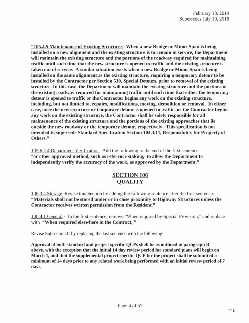
February 13, 2019 Supersedes July 19, 2018
Page 4 of 57
“105.4.5 Maintenance of Existing Structures When a new Bridge or Minor Span is being installed on a new alignment and the existing structure is to remain in service, the Department will maintain the existing structure and the portions of the roadway required for maintaining traffic until such time that the new structure is opened to traffic and the existing structure is taken out of service. A similar situation exists when a new Bridge or Minor Span is being installed on the same alignment as the existing structure, requiring a temporary detour to be installed by the Contractor per Section 510, Special Detours, prior to removal of the existing structure. In this case, the Department will maintain the existing structure and the portions of the existing roadway required for maintaining traffic until such time that either the temporary detour is opened to traffic or the Contractor begins any work on the existing structure, including, but not limited to, repairs, modifications, moving, demolition or removal. In either case, once the new structure or temporary detour is opened to traffic, or the Contractor begins any work on the existing structure, the Contractor shall be solely responsible for all maintenance of the existing structure and the portions of the existing approaches that lie outside the new roadway or the temporary detour, respectively. This specification is not intended to supersede Standard Specification Section 104.3.11, Responsibility for Property of Others.”
105.6.2.4 Department Verification Add the following to the end of the first sentence: “or other approved method, such as reference staking, to allow the Department to independently verify the accuracy of the work, as approved by the Department.”
SECTION 106
QUALITY
106.3.4 Storage Revise this Section by adding the following sentence after the first sentence: “Materials shall not be stored under or in close proximity to Highway Structures unless the Contractor receives written permission from the Resident.”
106.4.1 General - In the first sentence, remove “When required by Special Provision,” and replace with “When required elsewhere in the Contract, ” Revise Subsection C by replacing the last sentence with the following:
Approval of both standard and project specific QCPs shall be as outlined in paragraph B above, with the exception that the initial 14 day review period for standard plans will begin on March 1, and that the supplemental project specific QCP for the project shall be submitted a minimum of 14 days prior to any related work being performed with an initial review period of 7 days.
441

February 13, 2019 Supersedes July 19, 2018
Page 5 of 57
SECTION 107 TIME
107.7.2 SCHEDULE OF LIQUIDATED DAMAGES
Revise this section by removing the numbers in the chart and replace with the following:
Original Contract Amount Per Diem Amount of Liquidated Damages From To and Calendar More Than Including Day $ 0 to $ 100,000.00 $250.00 $ 100,000.00 to $ 250,000.00 $500.00 $ 250,000.00 to $ 500,000.00 $650.00 $ 500,000.00 to $1,000,000.00 $800.00 $1,000,000.00 to $2,000,000.00 $1,000.00 $2,000,000.00 to $4,000,000.00 $1,200.00 $4,000,000.00 and More $2,100.00
SECTION 108 PAYMENT
108.3 Retainage - Remove the paragraph beginning with “ The Contractor may withdraw…” in its entirety.
108.4.1 Price Adjustment for Hot Mix Asphalt: Remove this section in its entirety and replace with the following
For all contracts with hot mix asphalt in excess of 500 tons total, a price adjustment for performance graded binder will be made for the following pay items:
Item 403.102 Hot Mix Asphalt – Special Areas Item 403.206 Hot Mix Asphalt - 25 mm Item 403.207 Hot Mix Asphalt - 19 mm Item 403.2071 Hot Mix Asphalt - 19 mm (Polymer Modified) Item 403.2072 Hot Mix Asphalt - 19 mm (Asphalt Rich Base) Item 403.208 Hot Mix Asphalt - 12.5 mm Item 403.2081 Hot Mix Asphalt - 12.5 mm (Polymer Modified) Item 403.209 Hot Mix Asphalt - 9.5 mm (sidewalks, drives, & incidentals) Item 403.210 Hot Mix Asphalt - 9.5 mm Item 403.2101 Hot Mix Asphalt - 9.5 mm (Polymer Modified) Item 403.2102 Hot Mix Asphalt - 9.5 mm (Asphalt Rich Base)
442

February 13, 2019 Supersedes July 19, 2018
Page 6 of 57
Item 403.2104 Hot Mix Asphalt - 9.5 mm (Thin Lift Surface Treatment) Item 403.21041 Hot Mix Asphalt - 9.5 mm (Polymer Modified Thin Lift Surface Treatment) Item 403.211 Hot Mix Asphalt – Shim Item 403.2111 Hot Mix Asphalt – Shim (Polymer Modified) Item 403.212 Hot Mix Asphalt - 4.75 mm (Shim) Item 403.213 Hot Mix Asphalt - 12.5 mm (base and intermediate course) Item 403.2131 Hot Mix Asphalt - 12.5 mm (base and intermediate course Polymer Modified) Item 403.2132 Hot Mix Asphalt - 12.5 mm (Asphalt Rich Base and intermediate course) Item 403.214 Hot Mix Asphalt - 4.75 mm (Surface) Item 403.235 Hot Mix Asphalt (High Performance Rubberized HMA) Item 403.301 Hot Mix Asphalt (Asphalt Rubber Gap-Graded) Item 404.70 Colored Hot Mix Asphalt – 9.5mm (Surface) Item 404.72 Colored Hot Mix Asphalt – 9.5mm (Islands, sidewalks, & incidentals) Item 461.13 Light Capital Pavement Item 461.210 9.5 mm HMA - Paver Placed Surface Item 462.30 Ultra-Thin Bonded Wearing Course Item 462.301 Polymer Modified Ultra-Thin Bonded Wearing Course
Price adjustments will be based on the variance in costs for the performance graded binder component of hot mix asphalt. They will be determined as follows: The quantity of hot mix asphalt for each pay item will be multiplied by the performance graded binder percentages given in the table below times the difference in price between the base price and the period price of asphalt cement. Adjustments will be made upward or downward, as prices increase or decrease.
Item 403.102–6.2% Item 403.206–4.8% Item 403.207–5.2% Item 403.2071–5.2% Item 403.2072–5.8% Item 403.208–5.6% Item 403.2081–5.6% Item 403.209–6.2% Item 403.210–6.2% Item 403.2101–6.2% Item 403.2102–6.8% Item 403.2104–6.2% Item 403.21041–6.2% Item 403.211–6.2% Item 403.2111–6.2% Item 403.212–6.8% Item 403.213–5.6% Item 403.2131–5.6%
443
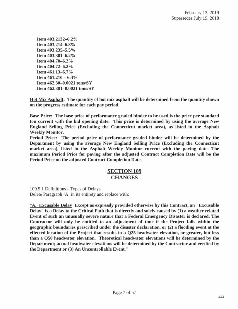
February 13, 2019 Supersedes July 19, 2018
Page 7 of 57
Item 403.2132–6.2% Item 403.214–6.8% Item 403.235–5.5% Item 403.301–6.2% Item 404.70–6.2% Item 404.72–6.2% Item 461.13–6.7% Item 461.210 – 6.4% Item 462.30–0.0021 tons/SY Item 462.301–0.0021 tons/SY
Hot Mix Asphalt: The quantity of hot mix asphalt will be determined from the quantity shown on the progress estimate for each pay period. Base Price: The base price of performance graded binder to be used is the price per standard ton current with the bid opening date. This price is determined by using the average New England Selling Price (Excluding the Connecticut market area), as listed in the Asphalt Weekly Monitor. Period Price: The period price of performance graded binder will be determined by the Department by using the average New England Selling Price (Excluding the Connecticut market area), listed in the Asphalt Weekly Monitor current with the paving date. The maximum Period Price for paving after the adjusted Contract Completion Date will be the Period Price on the adjusted Contract Completion Date.
SECTION 109
CHANGES
109.5.1 Definitions - Types of DelaysDelete Paragraph ‘A’ in its entirety and replace with:
“A. Excusable Delay Except as expressly provided otherwise by this Contract, an "Excusable Delay" is a Delay to the Critical Path that is directly and solely caused by (1) a weather related Event of such an unusually severe nature that a Federal Emergency Disaster is declared. The Contractor will only be entitled to an adjustment of time if the Project falls within the geographic boundaries prescribed under the disaster declaration. or (2) a flooding event at the effected location of the Project that results in a Q25 headwater elevation, or greater, but less than a Q50 headwater elevation. Theoretical headwater elevations will be determined by the Department; actual headwater elevations will be determined by the Contractor and verified by the Department or (3) An Uncontrollable Event.”
444
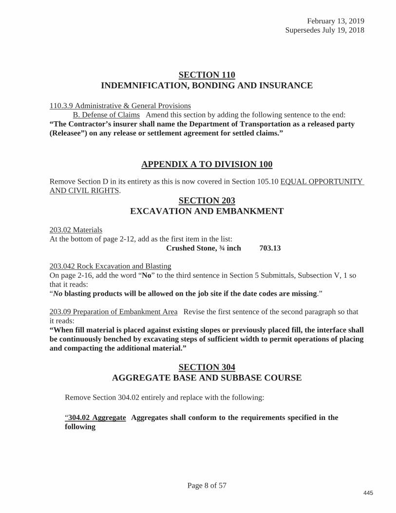
February 13, 2019 Supersedes July 19, 2018
Page 8 of 57
SECTION 110 INDEMNIFICATION, BONDING AND INSURANCE
110.3.9 Administrative & General Provisions B. Defense of Claims Amend this section by adding the following sentence to the end: “The Contractor’s insurer shall name the Department of Transportation as a released party (Releasee”) on any release or settlement agreement for settled claims.”
APPENDIX A TO DIVISION 100
Remove Section D in its entirety as this is now covered in Section 105.10 EQUAL OPPORTUNITY AND CIVIL RIGHTS.
SECTION 203 EXCAVATION AND EMBANKMENT
203.02 Materials At the bottom of page 2-12, add as the first item in the list:
Crushed Stone, ¾ inch 703.13
203.042 Rock Excavation and Blasting On page 2-16, add the word “No” to the third sentence in Section 5 Submittals, Subsection V, 1 so that it reads: “No blasting products will be allowed on the job site if the date codes are missing.” 203.09 Preparation of Embankment Area Revise the first sentence of the second paragraph so that it reads: “When fill material is placed against existing slopes or previously placed fill, the interface shall be continuously benched by excavating steps of sufficient width to permit operations of placing and compacting the additional material.”
SECTION 304 AGGREGATE BASE AND SUBBASE COURSE
Remove Section 304.02 entirely and replace with the following:
“304.02 Aggregate Aggregates shall conform to the requirements specified in the following
445

February 13, 2019 Supersedes July 19, 2018
Page 9 of 57
Aggregate Base Type A & B 703.06 a Aggregate Base Type C 703.06 b Aggregate Subba e Type D&E 703.06 c
Subsections of Division 700 - Materials:
Aggregate for base or subbase courses shall be material meeting the aggregate type requirements specified in the following table.
Material Aggregate Type (Subsection 703.06)
Base Course, Crushed 1A, B or C Subbase Course, Gravel 1D Subbase Course, Gravel, Below 9” 2D or E 1Will be designated on the plans2Contractor’s option
When designated on the plans, Type E Subbase may be used 9 inches below and lower beneath the pavement
For The various classes of base and subbase, at the time it is deposited on the roadbed
shall conform to the gradation requirements of the contract. The Department will obtain samples from the roadbed for Acceptance prior to compaction Oversized stones shall be removed from the aggregate before depositing on the roadway. Oversized stones for the various types are as follows:
Type A will not pass a 2 inch square mesh sieve Type B and Type C will not pass a 4 inch square mesh sieve Type D and E will not pass a 6 inch square mesh sieve. “
SECTION 307
FULL DEPTH RECYCLED PAVEMENT
Remove this Section in its entirety and replace with:
446

February 13, 2019 Supersedes July 19, 2018
Page 10 of 57
SECTION 307
FULL DEPTH RECYCLING (UNTREATED OR TREATED WITH EMULSIFIED ASPHALT STABILIZER)
307.01 Description This work shall consist of pulverizing a portion of the existing roadway structure into a homogenous mass, adding an emulsified asphalt stabilizer (if required) to the depth of the pulverized material specified in the contract, placing and compacting this material to the lines, grades, and dimensions shown on the plans or established by the Resident.
MATERIALS
307.02 Pulverized Material Pulverized material shall consist of the existing asphalt pavement layers and one inch or more as specified of the underlying gravel, pulverized and blended into a homogenous mass. Pulverized material will be processed to 100% passing a 2 inch square mesh sieve.
307.021 New Aggregate and Additional Recycled Material New aggregate, if required by the contract, shall meet the requirements of Subsection 703.10 - Aggregate for Untreated Surface Course and Leveling Course, Type A. Aggregate Subbase Course Gravel Type D processed to 100 percent passing a 2 inch square mesh sieve and meeting the requirements of 703.06 – Aggregate for Base and Subbase may be used in areas requiring depths greater than 2 inches. New aggregate, will be measured and paid for under the appropriate item. Recycled material, if required, shall consist of salvaged asphalt material from the project or from off-site stockpiles that has been processed before use to 100 percent passing a 2 inch square mesh sieve. Recycled material shall be conditionally accepted at the source by the Resident. It shall be free of winter sand, granular fill, construction debris, or other materials not generally considered asphalt pavement. Recycled material generated and salvaged from the project shall be used within the roadway limits to the extent it is available as described in 307.09. No additional payment will be made for material salvaged from the project. Recycled material supplied from off-site stockpiles shall be paid for as described in the contract, or by contract modification. 307.022 Emulsified Asphalt Stabilizer. If required, the emulsified asphalt stabilizer shall be grade MS-2, MS-4, SS-1, or CSS-1 meeting the requirements of Subsection 702.04 Emulsified Asphalt.
307.023 Water Water shall be clean and free from deleterious concentrations of acids, alkalis, salts or other organic or chemical substances.
447

February 13, 2019 Supersedes July 19, 2018
Page 11 of 57
307.024 Portland Cement If required, Portland Cement shall be Type I or II meeting the requirements of AASHTO M85. 307.025 Hydrated Lime If required, Hydrated Lime shall meet the requirements of AASHTO M216.
EQUIPMENT
307.03 Pulverizer The pulverizer shall be a self-propelled machine, specifically manufactured for full-depth recycling work and capable of reducing the required existing materials to a size that will pass a 2 inch square mesh sieve. The machine shall be equipped with standard automatic depth controls and must maintain a consistent cutting depth and width. The machine also shall be equipped with a gauge to show depth of material being processed. 307.04 Liquid Mixer Unit or Distributor. If treatment of the recycled layer with emulsified asphalt is required by the contract, a liquid mixing unit or distributor shall be used to introduce the emulsified asphalt stabilizer into the pulverized material. The mixing unit shall contain a liquid distribution and mixing system which has been specifically manufactured for full-depth recycling work, capable of mixing the pulverized material with an evenly metered distribution of emulsified asphalt into a homogeneous mixture, to the depth and width required. The mixing unit shall be designed, equipped, maintained, and operated so that emulsified asphalt stabilizer at constant temperature may be applied uniformly on variable widths of pulverized material up to 6 feet at readily determined and controlled rates from 0.01 to 1.06 gal/yd2 with uniform pressure and with an allowable variation from any specified rate not to exceed 0.01 gal/ yd2. Mixing units shall include a tachometer, pressure gages, and accurate volume measuring devices or a calibrated tank and a thermometer for measuring temperatures of tank contents. 307.041 Cement or Lime Spreader If required by the contract, spreading of the Portland Cement or Hydrated Lime shall be done with a spreader truck designed to spread dry particulate (such as Portland Cement or Lime) or other approved means to insure a uniform distribution across the roadway and minimize fugitive dust. Pneumatic application, including through a slotted pipe, will not be permitted. Other systems that have been developed include fog systems, vacuum systems, etc. Slurry applications may also be accepted. The Department reserves the right to accept or reject the method of spreading cement. The Contractor shall provide a method for verifying that the correct amount of cement is being applied. 307.05 Placement Equipment Placement of the Full Depth recycled material to the required slope and grade shall be done with an approved highway grader or by another method approved by the Resident.
448

February 13, 2019 Supersedes July 19, 2018
Page 12 of 57
307.06 Rollers The full depth recycled material shall be rolled with a vibratory pad foot roller, a vibratory steel drum soil compactor and a pneumatic tire roller. The pad foot roller drum shall have a minimum of 112 tamping feet 3 inches in height, a minimum contact area per foot of 17 inch2, and a minimum width of 84 inches. The vibratory steel drum roller shall have a minimum 84 inch width single drum. The pneumatic tire roller shall meet the requirements of Section 401.10 and the minimum allowable tire pressure shall be 85 psi.
MIX DESIGN
If treatment of the recycled layer with emulsified asphalt is required by the contract, the Department will supply a mix design for the emulsified asphalt stabilized material based on test results from pavement and soil analysis taken to the design depth. The Department will provide the following information prior to construction: 1. Percent of emulsified asphalt to be used. 2. Quantity of lime or cement to be added.
3. Optimum moisture content for proper compaction. 4. Additional aggregate (if required). After a test strip has been completed or as the work progresses, it may be necessary for the Resident to make necessary adjustments to the mix design. Changes to compensation will be in accordance with the Mix Design Special Provision.
CONSTRUCTION REQUIREMENTS
307.06 Pulverizing The entire depth of existing pavement shall be pulverized together with 1 inch or more of the underlying gravel into a homogenous mass. All pulverizing shall be done with equipment that will provide a homogenous mass of pulverized material, processed in-place, which will pass a 2 inch square mesh sieve.
307.07 Weather Limitations Full depth recycled work shall be performed when;
A. Recycling operations will be allowed between May 15th and September 15th inclusive in Zone 1 - Areas north of US Route 2 from Gilead to Bangor and north of Route 9 from Bangor to Calais. Recycling will be allowed between May 1st and September 30th inclusive in Zone 2 - Areas south of Zone 1 including the US Route 2 and Route 9 boundaries.
B. The atmospheric temperature, as determined by an approved thermometer placed in the shade at the recycling location, is 50°F and rising.
C. When there is no standing water on the surface. D. During generally dry conditions, or when weather conditions are such that proper
pulverizing, mixing, grading, finishing and curing can be obtained using proper procedures, and when compaction can be accomplished as determined by the Resident.
449

February 13, 2019 Supersedes July 19, 2018
Page 13 of 57
E. When the surface is not frozen and when overnight temperatures are expected to be
above 32°F. F. Wind conditions are such that the spreading of lime or cement on the roadway ahead
of the recycling machine will not adversely affect the operation.
307.08 Surface Tolerance The complete surface of the Full Depth Recycled course shall be shaped and maintained to a tolerance, above or below the required cross sectional shape, of inch. 307.09 Full Depth Recycling Procedure New aggregate or recycled material meeting the requirements of Section 307.021 - New Aggregate and Additional Recycled Material, shall be added as necessary to restore cross-slope and/or grade before pulverizing. Locations will be shown on the plans or described in the construction notes. The Resident may add other locations while construction of the project is in progress. The Contractor will use recycled material to the extent it is available, in lieu of new aggregate. The material shall then be pulverized, processed, and blended into a homogeneous mass passing a 2 inch square mesh sieve. Material found not pulverized down to a 2 inch size will be required to be reprocessed by the recycler with successive passes until approved by the Resident.
Should the Contractor be required to add new aggregate or recycled material to restore cross-slope and/or grade after the initial pulverizing process, those areas will require re-processing to blend into a homogenous mass passing a 2 in square mesh sieve. Sufficient water shall be added during the recycling process to maintain optimum moisture for compaction. The resultant material from the initial pulverizing processes shall be graded and compacted to the cross-slope and profile shown on the plans or as directed by the Resident. The Contractor will also be responsible for re-establishing the existing profile grade. The completed surface of the full depth recycled course shall be shaped and maintained to a tolerance, above or below the required cross sectional shape, of inch. Areas not meeting this tolerance will be repaired as described in Section 307.091. The initial pulverizing process density requirements will be the same as Section 307.101 unless otherwise directed by the Resident. Additives, if required, shall be introduced following completion of the initial pulverizing and blending process. Emulsified asphalt stabilizer shall be incorporated into the top of the processed material as specified in section 307.04 to the depth specified in the contract by use of the liquid mixer unit or a distributor, at the rate specified in the mix design. The emulsified asphalt shall then be uniformly blended into a homogeneous mass until an apparent uniform distribution has occurred. The rate of application may be adjusted as necessary by the Resident. Cement or lime shall be introduced as described in section 307.041. The resultant material shall be graded and compacted to the cross-slope and profile shown on the plans or as directed by the Resident. The Contractor will also be responsible for re-establishing the existing profile grade.
450

February 13, 2019 Supersedes July 19, 2018
Page 14 of 57
After final compaction, the roadway surface shall be treated with a light application of water, and rolled with pneumatic-tired rollers to create a close-knit texture. The finished layer shall be free from:
A. Surface laminations. B. Segregation of fine and coarse aggregate. C. Corrugations, centerline differential, potholes, or any other defects that may adversely
affect the performance of the layer, or any layers to be placed upon it. The Contractor shall protect and maintain the recycled layer until a lift of pavement is applied. Any damage or defects in the layer shall be repaired immediately. An even and uniform surface shall be maintained. The recycled surface shall be swept prior to hot mix asphalt overlay placement. 307.091 Repairs Repairs and maintenance of the recycled layers, resulting from damage caused by traffic, weather or environmental conditions, or resulting from damage caused by the Contractor’s operations or equipment, shall be completed at no additional cost to the Department. For recycled layers stabilized with emulsified asphalt, low areas will be repaired using a hot mix asphalt shim. Areas up to 1 inch high can be repaired by milling or shimming with hot mix asphalt. Areas greater than 1 inch high will be repaired using a hot mix asphalt shim. All repair work will be done with the Resident’s approval at the Contractor’s expense.
TESTING REQUIREMENTS
307.10 Quality Control The Contractor shall operate in accordance with the approved Quality Control Plan (QCP) to assure a product meeting the contract requirements. The QCP shall meet the requirements of Section 106.4 - Quality Control and this Section. The Contractor shall not begin recycling operations until the Department approves the QCP in writing. Prior to performing any recycling process, the Department and the Contractor shall hold a Pre-recycle conference to discuss the recycling schedule, type and amount of equipment to be used, sequence of operations, and traffic control. A copy of the QC random numbers to be used on the project shall be provided to the Resident. All field supervisors including the responsible onsite recycling process supervisor shall attend this meeting.
The QCP shall address any items that affect the quality of the Recycling Process including, but not limited to, the following:
A. Sources for all materials, including New Aggregate and Additional Recycled Material.
B. Make and type of rollers including weight, weight per inch of steel wheels, and average contact pressure for pneumatic tired rollers.
C. Testing Plan.
451
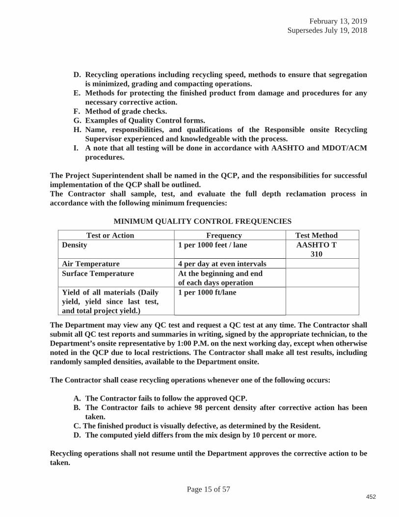
February 13, 2019 Supersedes July 19, 2018
Page 15 of 57
D. Recycling operations including recycling speed, methods to ensure that segregation
is minimized, grading and compacting operations. E. Methods for protecting the finished product from damage and procedures for any
necessary corrective action. F. Method of grade checks. G. Examples of Quality Control forms. H. Name, responsibilities, and qualifications of the Responsible onsite Recycling
Supervisor experienced and knowledgeable with the process.I. A note that all testing will be done in accordance with AASHTO and MDOT/ACM
procedures.
The Project Superintendent shall be named in the QCP, and the responsibilities for successful implementation of the QCP shall be outlined. The Contractor shall sample, test, and evaluate the full depth reclamation process in accordance with the following minimum frequencies:
MINIMUM QUALITY CONTROL FREQUENCIES
Test or Action Frequency Test Method Density 1 per 1000 feet / lane AASHTO T
310 Air Temperature 4 per day at even intervals Surface Temperature At the beginning and end
of each days operation
Yield of all materials (Daily yield, yield since last test, and total project yield.)
1 per 1000 ft/lane
The Department may view any QC test and request a QC test at any time. The Contractor shall submit all QC test reports and summaries in writing, signed by the appropriate technician, to the Department’s onsite representative by 1:00 P.M. on the next working day, except when otherwise noted in the QCP due to local restrictions. The Contractor shall make all test results, including randomly sampled densities, available to the Department onsite.
The Contractor shall cease recycling operations whenever one of the following occurs:
A. The Contractor fails to follow the approved QCP. B. The Contractor fails to achieve 98 percent density after corrective action has been
taken. C. The finished product is visually defective, as determined by the Resident. D. The computed yield differs from the mix design by 10 percent or more.
Recycling operations shall not resume until the Department approves the corrective action to be taken.
452

February 13, 2019 Supersedes July 19, 2018
Page 16 of 57
307.101 Test Strip The contractor shall assemble all items of equipment for the recycling operation on the first day of the recycling work. The Contractor shall construct a test strip for the project at a location approved by the Resident. The Responsible onsite Recycling Supervisor will work with Department personnel to determine the suitability of the mixed material, moisture control within the mixed material, and compaction and surface finish. The test strip section is required to:
A. Demonstrate that the equipment and processes can produce recycled layers to meet the requirements specified in these special provisions.
B. Determine the effect on the gradation of the recycled material by varying the forward speed of the recycling machine and the rotation rate of the milling drum.
C. Determine the optimum moisture necessary to achieve proper compaction of the recycled layer.
D. Determine the sequence and manner of rolling necessary to obtain the compaction requirements and establish a target density. The Contractor and the Department will both conduct testing with their respective gauges at this time.
The test strip shall be at least 300 feet in length of a full lane-width (or a half-road width). Full recycling production will not start until a passing test strip has been accomplished. If a test strip fails to meet the requirements of this specification, the Contractor will be required to repair or replace the test strip to the satisfaction of the Resident. Any repairs, replacement, or duplication of the test strip will be at the Contractor’s expense. After the test strip has been pulverized, and the roadway brought to proper shape, the Contractor shall add water until it is determined that optimum moisture has been obtained. The test strip shall then be rolled using the specified compaction equipment as directed until the density readings show an increase in dry density of less than 1 pcf for the final four roller passes of each roller. The Contractor and Department will each determine a target density using their respective gauges by performing several additional density tests and averaging them. The average of these tests will be used as the target density of the recycled material for QC and Acceptance purposes. Following completion of the test strip, compaction of the material shall continue until a density of not less than 98 percent of the test strip target density has been achieved for the full width and depth of the layer. During the construction and compaction of the Full Depth Recycled base, should three consecutive Acceptance test results for density fail to meet a minimum of 95 percent of the target density, or exceed 102 percent of target density, a new test strip shall be constructed.
ACCEPTANCE TEST FREQUENCY
Property Frequency Test Method
In-place Density 1 per 2000 ft / lane AASHTO T 310
453

February 13, 2019 Supersedes July 19, 2018
Page 17 of 57
307.102 Curing. No new pavement shall be placed on the full depth recycled pavement until curing has reduced the moisture content to 1 percent or less by total weight of the mixture, or a curing period of 4 days has elapsed, whichever comes first.
307.11 Method of Measurement Full Depth Recycled Pavement (Untreated or Treated with Emulsified Asphalt Stabilizer) will be measured by the square yard. 307.12 Basis of Payment The accepted quantity of Full Depth Recycled Asphalt Pavement (Untreated or Treated with Emulsified Asphalt Stabilizer) will be paid for at the contract unit price per square yard, complete in-place which price will be full compensation for furnishing all equipment, materials and labor for pulverizing, blending, placing, grading, compacting, and for all incidentals necessary to complete the work.
The addition of materials to restore profile grade and/or cross-slope in areas shown on the plans or described in the construction notes will be paid separately under designated pay items within the contract. No additional payment will be made for materials salvaged from the project. Payments will be made under: Pay Item Pay Unit
307.331 Full Depth Recycled Pavement (Untreated) Square Yard 307.332 Full Depth Recycled Pavement (with Emulsified Asphalt Stabilizer) 5 in. depth Square Yard 307.333 Full Depth Recycled Pavement (with Emulsified Asphalt Stabilizer) 6 in. depth Square Yard
SECTION 411 UNTREATED AGGREGATE SURFACE COURSE
411.02 – Aggregate Add the following to the end of the first sentence: “- Type A”
SECTION 501 FOUNDATION PILES
501.05 – Method of Measurement
b. Piles Furnished – After the second sentence, add the sentence “Measurement will not include any pile tips”.
c. Piles in Place – Add the sentence to the end of the second paragraph, “Measurement will include the pile tips”.
454

February 13, 2019 Supersedes July 19, 2018
Page 18 of 57
d. Pile Tips – Add the words “on the Pile” to the end of the sentence.
SECTION 502 STRUCTURAL CONCRETE
502.05 Composition and Proportioning Replace Table 1 with
TABLE 1
ConcreteCLASS
Minimum Compressive
Strength(PSI)
Permeability as indicated by Surface Resistivity(KOhm-cm)
EntrainedAir(%)
Notes
LSL LSL USL S 3,000 N/A N/A N/A 4,5 A 4,000 14 6.0 9.0 1,4,5 P ----- ----- 5.5 7.5 1,2,3,4
LP 5,000 17 6.0 9.0 1,4,5 Fill 3,000 N/A 6.0 9.0 4,5
In the list of information submitted by the contractor for a mix design: Item J Replace “Target Coulomb Value.” with “Target KOhm-cm Value.”
Note #1 - Remove, “…Standard Specification Section 711.05, Protective Coating for Concrete Surfaces, and per the manufacturer’s recommendations, at no additional cost to the Department.” and replace with, “…Standard Specification Section 515, Protective Coating for Concrete Surfaces, at no additional cost to the Department.”
502.1703 Acceptance Methods A and B In the paragraph that starts with “The Department will take Acceptance…” Remove the word chloride from chloride permeability in the last sentence.
Replace the paragraph starting with “Rapid Chloride Permeability specimens…” With the following: “Surface Resistivity specimens will be tested by the Department in accordance with AASHTO TP-95 at an age 56 days. Four 4 inch x 8 inch cylinders will be cast per sublot placed.The average of three concrete specimens per sublot will constitute a test result and this average will be used to determine the permeability for pay adjustment computations.”
455
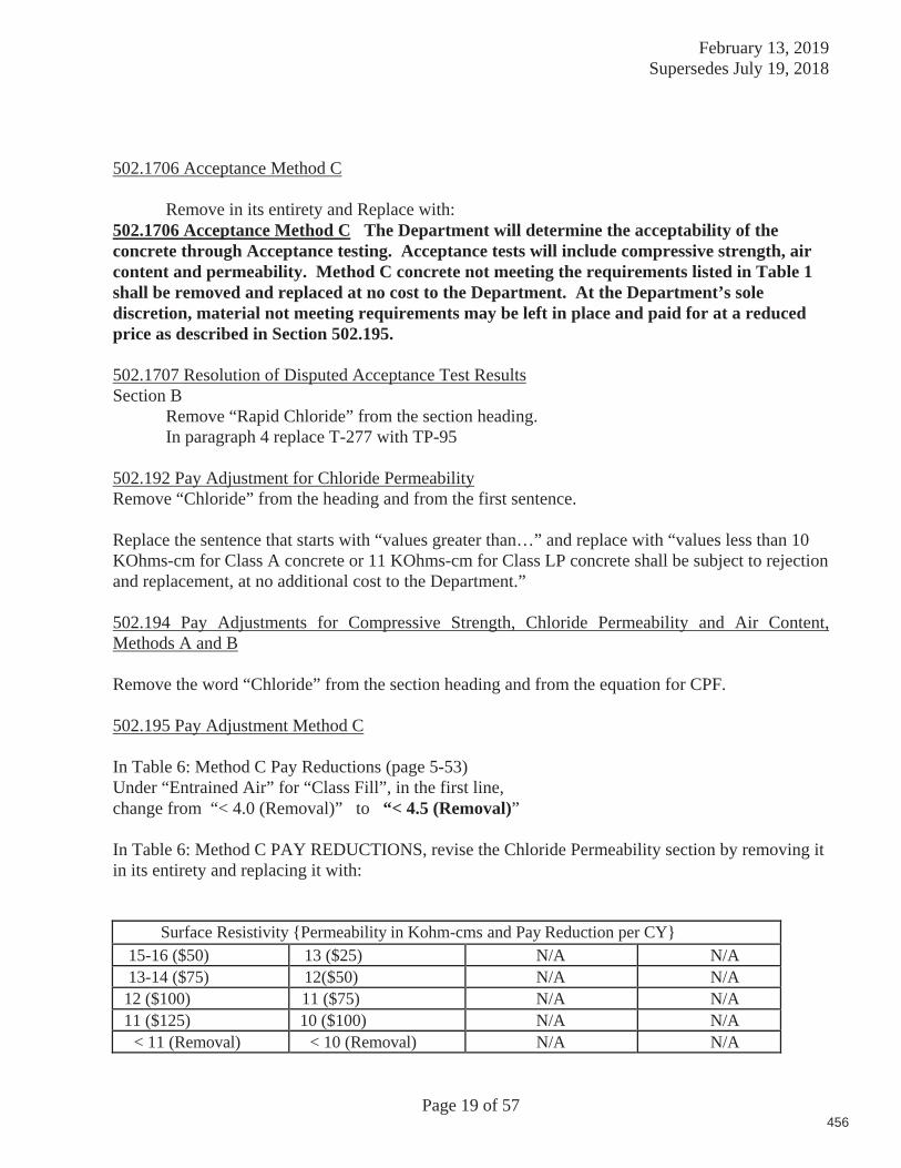
February 13, 2019 Supersedes July 19, 2018
Page 19 of 57
502.1706 Acceptance Method C
Remove in its entirety and Replace with: 502.1706 Acceptance Method C The Department will determine the acceptability of the concrete through Acceptance testing. Acceptance tests will include compressive strength, air content and permeability. Method C concrete not meeting the requirements listed in Table 1 shall be removed and replaced at no cost to the Department. At the Department’s sole discretion, material not meeting requirements may be left in place and paid for at a reduced price as described in Section 502.195.
502.1707 Resolution of Disputed Acceptance Test Results Section B Remove “Rapid Chloride” from the section heading. In paragraph 4 replace T-277 with TP-95
502.192 Pay Adjustment for Chloride Permeability Remove “Chloride” from the heading and from the first sentence.
Replace the sentence that starts with “values greater than…” and replace with “values less than 10 KOhms-cm for Class A concrete or 11 KOhms-cm for Class LP concrete shall be subject to rejection and replacement, at no additional cost to the Department.”
502.194 Pay Adjustments for Compressive Strength, Chloride Permeability and Air Content, Methods A and B
Remove the word “Chloride” from the section heading and from the equation for CPF.
502.195 Pay Adjustment Method C
In Table 6: Method C Pay Reductions (page 5-53)Under “Entrained Air” for “Class Fill”, in the first line, change from “< 4.0 (Removal)” to “< 4.5 (Removal)”
In Table 6: Method C PAY REDUCTIONS, revise the Chloride Permeability section by removing it in its entirety and replacing it with:
Surface Resistivity {Permeability in Kohm-cms and Pay Reduction per CY} 15-16 ($50) 13 ($25) N/A N/A13-14 ($75) 12($50) N/A N/A
12 ($100) 11 ($75) N/A N/A11 ($125) 10 ($100) N/A N/A
< 11 (Removal) < 10 (Removal) N/A N/A
456

February 13, 2019 Supersedes July 19, 2018
Page 20 of 57
SECTION 503 REINFORCING STEEL
503.06 Placing and Fastening Revise this Subsection by removing, in its entirety, the paragraph which begins, “Stainless steel reinforcement shall not be tied to any other type of reinforcement……”
SECTION 504 STRUCTURAL STEEL
504.06 Inspection Revise this section by removing the last sentence in the first paragraph which reads “Make the results of all measurements and testing available to the QAI.” And replace with “Provide a copy of all measurements and testing to the QAI.”
504.08 Rejections Amend this section by adding the following sentences to the end of the 1st paragraph: “Structural Defects: Repair structural defects only with the approval of the Fabrication Engineer. Submit a nonconformance report (NCR) to the Fabrication Engineer with a proposed repair procedure. Do not perform structural repairs without an NCR that has been reviewed by the Fabrication Engineer. Give the QAI adequate notice prior to beginning structural repairs.”
504.13 Unpainted Steel Revise this section by removing the third sentence which reads “Clean steel that is abrasive-blast cleaned prior to fabrication in accordance with SSPC-SP 1 Solvent Cleaning after fabrication is complete.” And replace it with: “Clean steel that is abrasive cleaned prior to fabrication in accordance with SSPC-SP 6 shall be cleaned in accordance with SSPC-SP 1 Solvent Cleaning after fabrication is complete.”
504.26 Welding Remove the second paragraph beginning with “The range of heat….” in its entirety.
504.29 Welding ASTM A 709 HPS 70W Steel. Remove the third paragraph beginning with “Make Weld runoff tabs…” in its entirety.
504.55 Field Welding Revise the first paragraph by replacing the word “Resident” with “Fabrication Engineer”.
504.60 Holes for Base Plates Revise this section by removing the second sentence and replacing it with “The roughness shall not exceed condition of AWS C4.1-77, Sample 4.”
504.64 Non Destructive Testing-Ancillary Bridge Products and Support Structures Revise the first sentence under number 1 by adding “fillet or partial penetration welds on” between the words “of” and “each” so the first sentence reads “ Examine ten percent of fillet or partial penetration welds on each production lot using Magnetic Particle (MT) inspection”.
457

February 13, 2019 Supersedes July 19, 2018
Page 21 of 57
SECTION 506 SHOP APPLIED PROTECTIVE COATING - STEEL
Revise this section by removing the subsection THERMAL SPRAY COATING entirely and replace with: THERMAL SPRAY COATING
506.30 Description This work shall consist of surface preparation and application of Thermal Spray Coatings (TSC) in accordance with the Plans and this Specification. Application of TSC to steel substrate shall be done in accordance with requirements, recommendations and appendices of the current Joint Standard NACE NO. 12/AWS C2.23M/SSPC-CS 23.00, Specification for the Application of Thermal Spray Coatings (Metallizing) of Aluminum, Zinc, and Their Alloys and Composites for the Corrosion Protection of Steel (The Standard) and this Specification.
The applicator shall have a minimum of five years of experience and shall provide copies of application procedures, operator qualifications, QC Manuals and repair procedures.
506.31 Submittals Submit an application procedure and QC Plan for review by the Department prior to beginning work. Submit a certified analysis of the feedstock to the Department. Submit sample copies of QC records for review. Submit copies of applicator qualifications, job history, etc. Provide the name and qualifications of the QCI.
506.32 Surface Preparation Prior to abrasive blast cleaning, round all corners exposed in the assembled product to approximately a 3/32 inch radius. A series of tangents to the approximate radius will be considered acceptable. Remove hardened condition on thermal cut surfaces. Abrasive blast clean all surfaces to be coated in accordance with The Standard and SSPC-SP 5, White Metal Blast Cleaning (SP 5). Use SSPC-VIS. 1 as a visual standard to determine acceptable cleanliness. Inspect the substrate immediately before spray application.
The anchor profile shall be per The Standard (minimum 2.5 mils). Measure and record the anchor profile in accordance with ASTM D4417 Method B or C (Replica Tape) or both on each plane to be sprayed or at 120 ° intervals on pipe or tube. Measure at the frequency in The Standard. Angular blast media shall conform with The Standard. If the anchor profile fails to meet the minimum required profile, re-blast the substrate until the required anchor profile is achieved.
If compressed air is used for abrasive blast cleaning, perform a blotter test in accordance with ASTM D4285 at the beginning of each shift. Empty moisture traps at the beginning of each shift and at any time thereafter when moisture appears to be present on the substrate. Notify the QAI prior to performing the test in order that the QAI can witness the blotter test.
458
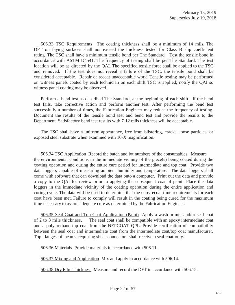
February 13, 2019 Supersedes July 19, 2018
Page 22 of 57
506.33 TSC Requirements The coating thickness shall be a minimum of 14 mils. The DFT on faying surfaces shall not exceed the thickness tested for Class B slip coefficient rating. The TSC shall have a minimum tensile bond per The Standard. Test the tensile bond in accordance with ASTM D4541. The frequency of testing shall be per The Standard. The test location will be as directed by the QAI. The specified tensile force shall be applied to the TSC and removed. If the test does not reveal a failure of the TSC, the tensile bond shall be considered acceptable. Repair or recoat unacceptable work. Tensile testing may be performed on witness panels coated by each technician on each shift TSC is applied; notify the QAI so witness panel coating may be observed.
Perform a bend test as described The Standard, at the beginning of each shift. If the bend test fails, take corrective action and perform another test. After performing the bend test successfully a number of times, the Fabrication Engineer may reduce the frequency of testing. Document the results of the tensile bond test and bend test and provide the results to the Department. Satisfactory bend test results with 7-12 mils thickness will be acceptable.
The TSC shall have a uniform appearance, free from blistering, cracks, loose particles, or exposed steel substrate when examined with 10-X magnification.
506.34 TSC Application Record the batch and lot numbers of the consumables. Measure the environmental conditions in the immediate vicinity of the piece(s) being coated during the coating operation and during the entire cure period for intermediate and top coat. Provide two data loggers capable of measuring ambient humidity and temperature. The data loggers shall come with software that can download the data onto a computer. Print out the data and provide a copy to the QAI for review prior to applying the subsequent coat of paint. Place the data loggers in the immediate vicinity of the coating operation during the entire application and curing cycle. The data will be used to determine that the cure/recoat time requirements for each coat have been met. Failure to comply will result in the coating being cured for the maximum time necessary to assure adequate cure as determined by the Fabrication Engineer.
506.35 Seal Coat and Top Coat Application (Paint) Apply a wash primer and/or seal coat of 2 to 3 mils thickness. The seal coat shall be compatible with an epoxy intermediate coat and a polyurethane top coat from the NEPCOAT QPL. Provide certification of compatibility between the seal coat and intermediate coat from the intermediate coat/top coat manufacturer. Top flanges of beams requiring shear connectors shall receive a seal coat only.
506.36 Materials Provide materials in accordance with 506.11.
506.37 Mixing and Application Mix and apply in accordance with 506.14.
506.38 Dry Film Thickness Measure and record the DFT in accordance with 506.15.
459
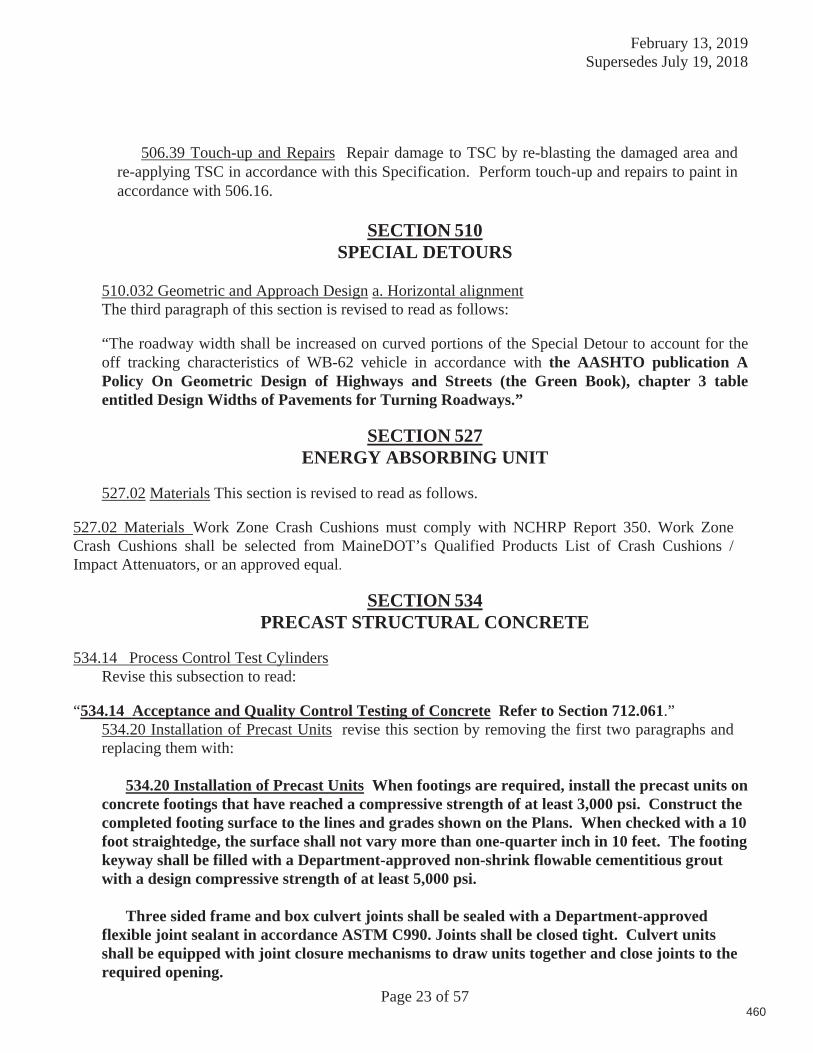
February 13, 2019 Supersedes July 19, 2018
Page 23 of 57
506.39 Touch-up and Repairs Repair damage to TSC by re-blasting the damaged area and re-applying TSC in accordance with this Specification. Perform touch-up and repairs to paint in accordance with 506.16.
SECTION 510 SPECIAL DETOURS
510.032 Geometric and Approach Design a. Horizontal alignment The third paragraph of this section is revised to read as follows:
“The roadway width shall be increased on curved portions of the Special Detour to account for the off tracking characteristics of WB-62 vehicle in accordance with the AASHTO publication A Policy On Geometric Design of Highways and Streets (the Green Book), chapter 3 table entitled Design Widths of Pavements for Turning Roadways.”
SECTION 527
ENERGY ABSORBING UNIT 527.02 Materials This section is revised to read as follows.
527.02 Materials Work Zone Crash Cushions must comply with NCHRP Report 350. Work Zone Crash Cushions shall be selected from MaineDOT’s Qualified Products List of Crash Cushions / Impact Attenuators, or an approved equal.
SECTION 534 PRECAST STRUCTURAL CONCRETE
534.14 Process Control Test Cylinders
Revise this subsection to read:
“534.14 Acceptance and Quality Control Testing of Concrete Refer to Section 712.061.”534.20 Installation of Precast Units revise this section by removing the first two paragraphs and replacing them with:
534.20 Installation of Precast Units When footings are required, install the precast units on concrete footings that have reached a compressive strength of at least 3,000 psi. Construct the completed footing surface to the lines and grades shown on the Plans. When checked with a 10 foot straightedge, the surface shall not vary more than one-quarter inch in 10 feet. The footing keyway shall be filled with a Department-approved non-shrink flowable cementitious grout with a design compressive strength of at least 5,000 psi.
Three sided frame and box culvert joints shall be sealed with a Department-approved
flexible joint sealant in accordance ASTM C990. Joints shall be closed tight. Culvert units shall be equipped with joint closure mechanisms to draw units together and close joints to the required opening.
460
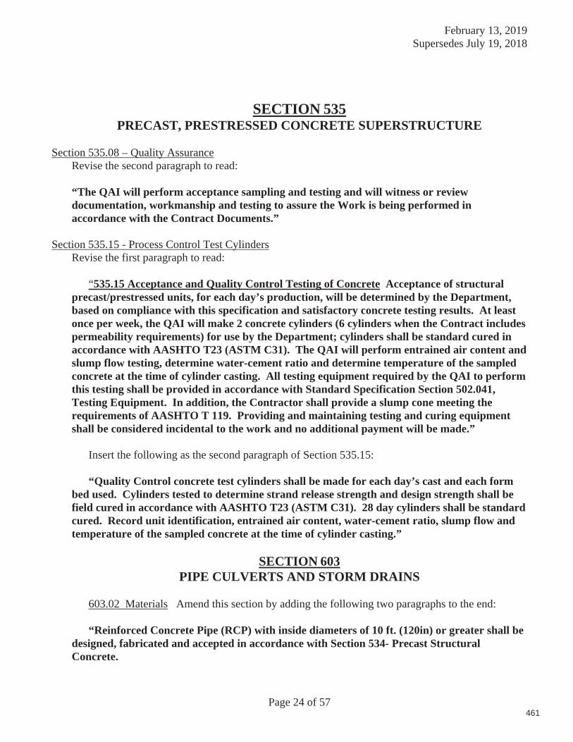
February 13, 2019 Supersedes July 19, 2018
Page 24 of 57
SECTION 535 PRECAST, PRESTRESSED CONCRETE SUPERSTRUCTURE
Section 535.08 – Quality Assurance Revise the second paragraph to read:
“The QAI will perform acceptance sampling and testing and will witness or review documentation, workmanship and testing to assure the Work is being performed in accordance with the Contract Documents.”
Section 535.15 - Process Control Test Cylinders Revise the first paragraph to read:
“535.15 Acceptance and Quality Control Testing of Concrete Acceptance of structural precast/prestressed units, for each day’s production, will be determined by the Department, based on compliance with this specification and satisfactory concrete testing results. At least once per week, the QAI will make 2 concrete cylinders (6 cylinders when the Contract includes permeability requirements) for use by the Department; cylinders shall be standard cured in accordance with AASHTO T23 (ASTM C31). The QAI will perform entrained air content and slump flow testing, determine water-cement ratio and determine temperature of the sampled concrete at the time of cylinder casting. All testing equipment required by the QAI to perform this testing shall be provided in accordance with Standard Specification Section 502.041, Testing Equipment. In addition, the Contractor shall provide a slump cone meeting the requirements of AASHTO T 119. Providing and maintaining testing and curing equipment shall be considered incidental to the work and no additional payment will be made.”
Insert the following as the second paragraph of Section 535.15:
“Quality Control concrete test cylinders shall be made for each day’s cast and each form bed used. Cylinders tested to determine strand release strength and design strength shall be field cured in accordance with AASHTO T23 (ASTM C31). 28 day cylinders shall be standard cured. Record unit identification, entrained air content, water-cement ratio, slump flow and temperature of the sampled concrete at the time of cylinder casting.”
SECTION 603
PIPE CULVERTS AND STORM DRAINS
603.02 Materials Amend this section by adding the following two paragraphs to the end: “Reinforced Concrete Pipe (RCP) with inside diameters of 10 ft. (120in) or greater shall be
designed, fabricated and accepted in accordance with Section 534- Precast Structural Concrete.
461
February 13, 2019 Supersedes July 19, 2018
Page 25 of 57
All Pipes or Culverts with inside diameters of 10 ft. (120in) or greater shall be designed using the current version of the AASHTO LRFD Bridge Design Specifications with Maine Modified HL-93 for Strength 1.”
SECTION 604
MANHOLES, INLETS CATCH BASINS 604.04 Adjusting Catch Basins and Manholes,
Add the following paragraph to the end of 604.04 b:
The Department will allow the use of metal ring inserts set into the manhole top frame or composite risers placed beneath the manhole frame to adjust manhole slope and grade for paving projects. The use of metal ring inserts shall be in accordance with 604.04 d. Ring Insert Requirements. The use of composite risers shall be in accordance with 604.04 e. Composite Riser Requirements.
Add the following paragraph after the first paragraph of 604.04 c:
The Department will allow the use of metal ring inserts set into the manhole top frame or composite risers placed beneath the manhole frame to adjust manhole slope and grade for paving projects. The use of metal ring inserts shall be in accordance with 604.04 d. Ring Insert Requirements. The use of composite risers shall be in accordance with 604.04 e. Composite Riser Requirements. Add the following sections to 604.04:
d. Ring Insert Requirements Ring inserts to adjust manhole top frame slope and grade will are allowed in accordance with the following requirements:
1) Materials
i. All ring inserts must be made of iron. Multiple ring inserts will not be allowed. The single ring insert may be any height up to a maximum of 2 inches tall.
ii. Ring inserts shall not be welded to the manhole frame to prevent brittle failure of the cast iron frame.
iii. Ring inserts shall be fastened to the manhole frame using liquid steel-filled epoxy such as Loctite Fixmaster Steel Liquid or equivalent. The epoxy shall be installed in accordance with the manufacturer’s recommendations.
462
February 13, 2019 Supersedes July 19, 2018
Page 26 of 57
2) Where Ring Inserts May/May Not Be Used
i. MaineDOT will allow the use of a single manhole ring insert to raise
manholes on state and state-aid highways.
ii. Manhole ring inserts may not be used along state and state-aid highway sections where the speed limit is 40 miles per hour or more. The standard brick and mortar or flat composite risers beneath the manhole frame must be used at these locations.
3) Construction Requirements For The Use of Iron Manhole Ring Inserts
i. Wherever iron ring inserts are used to raise manhole top elevations, the rings
shall be fastened to the existing manhole frame using liquid steel-filled epoxy. The liquid steel-filled epoxy shall be placed evenly around the entire manhole frame before placing the ring insert. Unbonded ring inserts will not be allowed. If the manufacturer’s recommended construction practices result in loose or unacceptable manhole cover restraint, standard brick and mortar or flat composite risers beneath the manhole frame must be used at these locations.
e. Composite Riser Requirements Flat or beveled, doughnut-shaped, composite risers placed beneath the manhole frame to adjust slope and grade are allowed. The composite riser shall be fastened to both the top of the concrete cone and bottom of the manhole frame with the manufacturer’s recommended epoxy. Composite risers may be used at all locations on state and state-aid highways under any legal speed limit without restriction.
SECTION 606 GUARDRAIL
606.09 Basis of Payment Amend the first sentence of the eighth paragraph of this subsection by removing the word “meter” and replace it with “linear foot”.
SECTION 608 SIDEWALKS
608.021 Sidewalk Materials Revise this section by removing the second paragraph which begins with “Portland cement concrete shall…” in its entirety and replace with “Portland cement concrete shall be Class A and meet the requirements of Section 502, Structural Concrete.”
463
February 13, 2019 Supersedes July 19, 2018
Page 27 of 57
SECTION 609
CURB
609.03 Vertical Stone Curb, Terminal Section and Transition Sections and Portland Cement Concrete Curb, Terminal Sections and Transition Sections Amend this section by adding the following paragraph to the end of it: “The Contractor may elect to substitute concrete to backfill Stone Curbing or Stone Edging at their option. If the concrete backfill option is elected, the following is added to Standard Specification 609 – Curb”
609.02 Materials Amend this section by adding the following to it:
Portland cement and Portland Pozzolan Cement 701.01 Water 701.02 Fine Aggregate for Concrete 703.01 Coarse Aggregate for Concrete 703.02
The Contractor shall submit a concrete mix design for the Portland Cement Concrete to the Resident, with a minimum designed compressive strength of 3000 psi Class Fill concrete.
609.10 Basis of Payment Revise by changing the fifth paragraph which begins with “There will be no separate payment…” this section by removing the word “cement” and replacing it with “concrete fill, mortar”.
SECTION 619
MULCH
619.07 Basis of Payment Amend this section by adding the words “; Bark Mulch and Erosion Control Mix will be paid for by the Cubic Yard;” into the first sentence so that it reads: “The accepted areas mulched will be paid for at the contract price per unit; Bark Mulch and Erosion Control Mix will be paid for by the Cubic Yard; which shall be full compensation for furnishing and spreading the hay or straw and mulch binder, cellulose fiber mulch, bark mulch or erosion control mix.
Revise the second sentence by removing “ for pay item 619.1201” So that it reads: “When Mulch is measured in Bales, each bale will be paid for at 60% of the contract price per Unit”.
Revise this section by removing all pay items and replace them with the following:
619.12 Mulch Unit619.13 Bark Mulch Cubic Yard619.14 Erosion Control Mix Cubic Yard
464

February 13, 2019 Supersedes July 19, 2018
Page 28 of 57
SECTION 621 LANDSCAPING
621.0002 Materials - General In the list of items change “Organic Humus” to “Humus”.
621.0019 Plant Pits and Beds
c Class A Planting In the third paragraph beginning with “ The plant pit…” change “½ inch” to “1 inch”
SECTION 626
FOUNDATIONS, CONDUIT AND JUNCTION BOXES FOR HIGHWAY SIGNING, LIGHTING AND SIGNALS
626.02 General Amend the Material list by adding the following to the list:
Gravel Borrow 703.20
Revise the Material List by removing:
Prewired Conduit 715.04 Metallic Junction and Fuse Box 715.05
626.021 Miscellaneous Material Amend this section by adding the following to the end of it:
“All concrete for concrete encasement of conduit shall be Fill Class concrete in accordance with the applicable requirements of Section 502 – Structural Concrete.”
Amend the third paragraph that begins with “If grouting is necessary…” by adding “included on the Qualified Product List and” after the word “material”.
626.03 General Amend this section by adding the following section to the end of it
“626.0301 Electrical Supply Lines and Service Connections The following requirements shall apply to Electric Supply Lines and Service Connections feeding traffic signalization equipment control boxes and lighting breaker boxes.
Whenever possible, the meter and breaker panel feeding traffic signal control boxes or
lighting control boxes shall be constructed within 30 feet of the service drop pole.
465

February 13, 2019 Supersedes July 19, 2018
Page 29 of 57
All underground service connections that are constructed in trenches and carrying
Secondary Utility Power to a MaineDOT meter and breaker panel, or, directly to MaineDOT traffic signalization control cabinets or lighting breaker boxes shall be in Rigid Metal Conduit or concrete encased PVC conduit.
Where trenchless technologies are employed to install the service connection conduit, Schedule 120 PVC conduit shall be used for the trenchless bore section of conduit. In addition, concrete encasement shall be used for any PVC conduit placed in trench sections and carrying Secondary Utility Power more than 10 feet before or after the limits of the trenchless bore conduit.
The construction practices described above shall be used for service connections up to a maximum of 600 feet. There may be rare exceptional cases where the service connection must exceed 600 feet. In these cases, the power companies may require primary power be run over 600 feet for the purpose of power consumption and dependable service. These cases will be evaluated on a case-by-case basis for alternate power feed methods and/or the need for steel or concrete encased conduit.”
626.031 Conduit Revise this section by removing the second paragraph which begins with “Trenches for conduits…” and replace it with the following:
“Trenches for conduits shall be excavated to a width that will permit proper installation of the conduit and to a minimum depth of 3 feet below finish grade as measured from the top of the conduit. If deeper depths are required, the conduit shall be installed at the depth shown on the plans or as directed. Conduit shall not interfere with poles, guardrail posts, sign foundations or other objects.”
Amend the third paragraph which begins with “All junction or pull boxes…” by adding “concrete, in accordance with the applicable requirements of Section 502 – Structural Concrete,” after Class LP.
Revise the fifth paragraph which begins with “After the trench has been…” by adding the following to the end of it:
“Where concrete encasement is required around the conduit, backfilling with approved material may begin adjacent to and above the encased conduit no sooner than 24 hours after concrete placement.”
Remove the following: “All underground conduit shall be placed to at least the depth shown on the plans and shall not interfere with poles, guardrail posts, sign foundations or other objects.”
Revise the paragraph beginning with “All conduit ends shall…” by removing “Prewired Conduit shall be sealed during construction to prevent entry of moisture, dirt, or rocks.”
466
February 13, 2019 Supersedes July 19, 2018
Page 30 of 57
626.033 Polyvinylchloride Conduit Installation Amend the first paragraph of this section which begins with “Polyvinylchloride conduit and High Density…” by adding the following to the end of it:
“In addition, PVC conduit used for Electrical Supply Lines and Services constructed as underground service connections in trenches and carrying Secondary Utility Power to a MaineDOT meter and breaker panel, or, directly to MaineDOT traffic signalization control cabinets or lighting breaker boxes shall be concrete encased. When trenchless technologies are used to install PVC conduit, concrete encasement shall not be required.
Concrete encasement shall consist of a minimum of 4 inches of concrete above, below and on both sides of the conduit that shall have a minimum compressive strength of 3000 psi and a maximum aggregate size of 1-inch (Fill Class concrete). The concrete encasement may be backfilled no sooner than 24 hours after placement. “
“NON-METALLIC UNDER PAVEMENT CONDUIT INSTALLATION
Where noted on the drawings, non-metallic under pavement conduit of schedule 80 or greater rating shall be provided to facilitate conduit crossing of the existing highway and ramps without disruption to the existing highway and ramp pavement surface. The non-metallic under pavement conduit shall be hydraulically jacked or directional bored below the highway and ramp at a depth of not less than (36 inches). Under pavement conduit shall extend for a distance of (10 feet) beyond the highway or ramp edge at each side.”
Amend the sixth paragraph which begins with “Where PVC conduit runs are…” by changing “3 inch minimum bedding” to “6 inch minimum bedding”.
626.034 Concrete FoundationsRevise this section by removing the third paragraph which begins with “In the absence of Design
Requirements…” in its entirety and replace with the following:
“In the absence of design requirements being provided on the plans, the Contractor shall prepare and submit the foundation design(s) to the Department for review. The Contractor may propose an alternate shallow spread footing or drilled shaft configuration/design than that set forth on the drawings. Design shall be in accordance with AASHTO LRFD Specifications for Structural Supports for Highway Sign, Luminaires and Traffic Signals, current edition; AASHTO LRFD Bridge Design Specifications, current edition; and FHWA-NHI-10-016 Drilled Shafts, Construction Procedures and Design Methods, current edition. Where conflicting requirements occur, the more stringent requirements shall govern. In addition to other design requirements, foundation design shall account for Torsion for which a minimum Factor of Safety equal to 1.2 shall be achieved. In evaluating axial capacity and torsional resistance in cohesionless soils, load transfer coefficient or side resistance coefficient (beta, ) will be used in accordance with Subsection 13.3.5.1 of FHWA-NHI-10-016, with beta determined in accordance with Equations 13-13 and 13-11 for silty sands to sandy silts (with varying amounts of gravel). The design criteria for the resistance of drilled shaft and spread footing foundations against overturning, sliding and bearing capacity failure shall meet the requirements of Section 4 of AASHTO LRFD Bridge Design Specifications, current edition.
467

February 13, 2019 Supersedes July 19, 2018
Page 31 of 57
The structural design of foundations shall meet the requirements of AASHTO LRFD Bridge Design Specifications, current edition. The Contractor shall submit to the Department for review, three (3) copies of detailed plans and calculations of the proposed design. Design shall be prepared and sealed by a Professional Engineer licensed in the State of Maine. Construction of foundation(s) shall not commence until the Department has reviewed the foundation design.”
On Page 6-85, add the following paragraph before the paragraph beginning with “Drilled shafts shall not be…”.
“ No foundation design will be required for 18- and 24-inch diameter foundations for structures less than 30-feet tall and with no projecting arms. A foundation design prepared by a Professional Engineer licensed in accordance with the laws of the State of Maine will be required for all other foundations Precast foundations will be permitted for 18 and 24-inch diameter foundations for structures less than 30-feet tall and with no projecting arms. Where precast foundations are permitted flowable concrete fill shall be used as backfill in the annular space, and placed from the bottom up. Construction of precast foundations shall conform to the Standard Details and all requirements of Section 712.061 except that the concrete shall have a minimum permeability of 17 kOhm-cm and the use of calcium nitrite will not be required. “
On Page 6-86, Revise the paragraph beginning with “Concrete for drilled shafts…” so that a
portion of it reads as follows:
“….The Contractor shall provide temporary dewatering of excavations for foundations such that concrete is placed in the dry. Concrete for drilled shafts shall be placed in accordance with Section 502.10 as temporary casing is withdrawn to prevent debris from contaminating the foundation and to ensure concrete is cast against the surrounding soil. Concrete for drilled shafts and spread footings shall be Class LP in accordance with Section 502 - Structural Concrete. Precast foundations will not be permitted except as specified above in this Section.Backfill for spread footing foundations shall be Gravel Borrow meeting the requirements of Section 703.20 - Gravel Borrow…..”
626.05 Basis of Payment Amend this section by removing the following paragraphs: The one which starts with “Payment will be made for the total number of linear feet of prewired conduit…”The one which starts with “Prewired conduit within the foundations…”
Amend this subsection by adding the following paragraph and Pay Items: “Payment will be made for the total number of linear feet of under pavement conduit
actually furnished, installed and accepted at the contract price per linear foot. This price shall include the cost of: furnishing and installing the conduit; excavating; furnishing special backfilling materials, pull wire, fittings, grounding and bonding; test cleaning interiors of conduits and all materials, labor, equipment and incidentals necessary to complete the work.”
468
February 13, 2019 Supersedes July 19, 2018
Page 32 of 57
Pay Item PayUnit 626.221 Non-metallic Conduit, Concrete Encased Linear Foot 626.251 Non-Metallic Under pavement Conduit Linear Foot (Schedule 80 or greater rating) Remove the following Pay Items:
626.23 Prewired Conduit Secondary Wiring Linear Foot 626.24 Prewired Conduit Primary Wiring Linear Foot
SECTION 627 PAVEMENT MARKINGS
Revise this section by removing it in its entirety and replacing with the following:
627.01 Description This work shall consist of furnishing and placing reflectorized pavement lines and markings, removing pavement lines and markings, and furnishing and applying reflectorized paint to curbing in reasonably close conformity with the plans and as designated.
627.02 Materials Materials shall conform to the requirements specified in the following Sections of Division 700 - Materials.
Pavement Marking Paint 708.03 Reflectorized Plastic Pavement Marking 712.05
Temporary Bi-directional Yellow Delineators shall be Temporary Object Markers (T.O.M.) as manufactured by the Davidson Plastic Company, 18726 East Valley Highway, Kent, WA 98031 or an approved equal.
627.04 General All pavement lines and markings shall be applied in accordance with the latest edition of Manual on Uniform Traffic Control Devices. Longitudinal lines placed on tangent roadway segments shall be straight and true. Longitudinal lines placed on curves shall be continuous smoothly curved lines consistent with the roadway alignment. All pavement markings placed shall meet the tolerance limits shown on the plans. Unless otherwise shown on the plans, non-interstate lines shall be 4 inches wide and broken lines shall consist of alternate 10 foot painted line segments and 30 foot gaps. On controlled access divided highways and on the interstate system lines shall be 6 inches wide and broken lines shall consist of alternate 15 foot painted line segments and 25 foot gaps. Width tolerance shall be +/- ¼ inch.
469

February 13, 2019 Supersedes July 19, 2018
Page 33 of 57
Temporary pavement marking lines, defined in Special Provision Section 652, Maintenance of Traffic, Temporary Centerline, will be applied as many times as necessary to properly delineate traffic lanes for the safe passage of traffic. Bi-directional delineators may be used in place of temporary lines, except where specified otherwise in Special Provision 652 Maintenance of Traffic, Temporary Centerline. Delineators will be applied at 40 foot intervals.
In overnight lane closure areas that are not to be overlaid, temporary plastic lines or raised pavement markers shall be used through the length of the taper. Newly painted lines, markings and curb shall be protected from traffic by the use of cones, stationary vehicles or other approved methods until the paint is dry. 627.05 Preparation of Surface Immediately before applying the pavement marking paint to the pavement or curb, the surface shall be dry and entirely free from dirt, grease, oil, or other foreign matter. Surface preparation for application of plastic markings shall conform to the manufacturer's recommendations. 627.06 Application Prior to applying paint for final pavement lines, the Contractor shall perform a test for paint thickness by furnishing and placing a piece of smooth, clean metal with an area of at least 144 in² in the path of the striping truck. The striping truck shall be passed over the piece of metal, painting the surface as it passes, without applying beads. The result of this test will be used to determine the pressure setting and speed of the truck when applying paint to obtain the specified thickness. Additional paint thickness testing may be required on the final paint markings. The wet thickness of paint without beads on final pavement lines shall be a minimum of 16 mils. On other final pavement markings and on curb, where the paint is applied by hand painting or spraying, application shall be in two uniform covering coats, each at least 10 mils thick. Before the second coat of paint has dried, the glass beads shall be applied by a pressure system that will force the glass beads onto the undried paint as uniformly as possible.
Glass beads shall be applied to the final and temporary pavement lines, marking and curb at a sufficient rate and in sufficient quantity to assure complete and uniform coverage of hand painted surfaces and achieve proper reflectivity.
Permanent and temporary white lines and markings shall have a minimum final reflectivity value of 250 millicandelas per square meter per lux (mcd/m²/lux) and permanent and temporary yellow lines and markings shall have a minimum final reflectivity value of 150 millicandelas per square meter per lux (mcd/m²/lux), as measured by the Department. Measurements taken to determine reflectivity shall be done within 4 weeks after final placement.
470

February 13, 2019 Supersedes July 19, 2018
Page 34 of 57
If the final reflectivity values are less than the described minimums, the Contractor shall repaint those areas not meeting required reflectivity at no cost to the Department. If the final reflectivity values are less than the described minimums after the second attempt, the Contractor will submit in writing a plan of action to meet the reflectivity minimums prior to continuing any work. Once the plan has been reviewed and approved by the Department, the Contractor shall re apply at no cost to the Department.
Temporary painted lines and markings shall be applied as specified for permanent painted lines, except that the thickness shall be a minimum of 16 mils. Temporary pliant polymer marking material shall be used for temporary markings on the final pavement and on pavements not to be resurfaced when such pavement markings do not conform to the final pavement markings pattern. The plastic final pavement lines and markings shall be applied in accordance with the manufacturer's recommendations by the inlay method of application. 627.07 Establishment Period Inlaid plastic pavement lines and marking material furnished and installed under this contract for final pavement markings shall still be subject to a six-month period of establishment. The period of establishment shall commence as soon as the plastic pavement lines and markings are complete and in place and shall continue for six months. At the end of the establishment period, a minimum of 95% of the plastic pavement lines and markings shall still be in place to be acceptable. If less than 95% of the plastic pavement lines and markings are in place after six months, the Contractor shall replace all unsatisfactory plastic pavement lines and markings on the project without additional payment. Plastic pavement lines and markings designated for replacement shall be installed according to these specifications, unless otherwise directed. Plastic pavement lines and markings replaced at the end of the six month establishment period will not be subject to a further establishment period. 627.08 Removing Lines and Markings When it is necessary to remove pavement lines and markings, it shall be done by high pressure water, grinding or other approved acceptable means. The method chosen must be capable of completely eradicating the existing line or marking without excessive damage to the pavement. Burning and the use of solvents to remove temporary markings from final pavement or from existing pavement not to be resurfaced will not be permitted.
471

February 13, 2019 Supersedes July 19, 2018
Page 35 of 57
627.09 Method of Measurement The quantity of pavement marking lines identified in the contract as a plan quantity pay item, the measurement of payment will be the number of feet shown in the Schedule of Items. This quantity will be considered final and no adjustments will be made except when changes resulting in increases or decreases are made by the Resident.
The accepted quantity of temporary or permanent pavement marking lines when identified in the contract as a linear foot item shall be measured and paid for at the contract unit price per linear foot for the total amount applied and accepted.
Double yellow centerline, broken or solid, will be considered one line for measurement purposes. The measurement of broken lines will include the gaps when painted and will not include the gaps when plastic. Double Yellow Centerline, broken or solid shall not be paid through intersections or side roads and will be paid for the actual length of painted line.
Broken white lines will include the gaps when painted and will not include the gaps when
plastic inlaid pavement lines are applied. Yellow or white solid edge lines and will not be paid through intersections or side roads and will be measured by the actual length of painted line.
Temporary pavement marking lines shall not be paid through intersections or side roads
and will be measured per linear foot of actual length of painted and accepted.
Reflectorized curb will be measured or computed by the square foot of curb surface actually painted and reflectorized. The accepted quantity of removing existing pavement markings will be measured by the square foot. Temporary Bi-directional Yellow Delineators will be measured by each unit, complete in place, maintained, and accepted. 627.10 Basis of Payment The accepted quantity of pavement marking lines identified in the contract as a plan quantity pay item will be paid for at the contract unit price for plan quantity. No adjustment will be made to the quantity for payment, except as described 627.09 Method of Measurement The quantity of permanent or temporary pavement marking lines identified in the contract paid by the linear foot will be measured for payment as described under section 627.09 Method of Measurement.
All other permanent pavement markings will be paid for at the contract unit price per
square foot in accordance with 627.09 Method of Measurement.
472
February 13, 2019 Supersedes July 19, 2018
Page 36 of 57
If allowed by Special Provision, the Contractor may utilize Temporary Bi-Directional
Yellow and White (as required) Delineators. When utilized, payment will be made as temporary pavement marking lines, measured and paid at the contract unit price per linear foot. Such payment will include as many applications as required and removal. Payment for final plastic pavement lines and markings will be made in two parts. The first payment of 75% will be made when plastic pavement lines and markings are placed. The payment of the remaining 25% will be made at the end of the establishment period for all plastic line and pavement markings accepted. The accepted quantity of any pavement marking lines will be paid for at the contract unit price and will include as many applications as required and removal when required.
The accepted quantity of Temporary Bi-directional Yellow Delineators will be paid for at the contract unit price. Payment will be made under:
Pay Item Pay Unit
627.18 12 inch Solid White Pavement Marking Line Linear Foot 627.711 White or Yellow Pavement Marking Line - Plan Quantity Linear Foot 627.733 4” White or Yellow Painted Pavement Marking Line Linear Foot 627.744 6” White or Yellow Painted Pavement Marking Line Linear Foot 627.75 White or Yellow Pavement & Curb Marking Square Foot 627.77 Removing Existing Pavement Marking Square Foot 627.78 Temporary 4“ Painted Pavement Marking Line, White or Yellow Linear Foot 627.781 Temporary 6“ Painted Pavement Marking Line, White or Yellow Linear Foot 627.407 Reflectorized Plastic, White or Yellow Pavement Marking Square Foot 627.4071 Reflectorized Plastic, White or Yellow Pavement Linear Foot Marking Line - Plan Quantity 627.811 Temporary Bi-directional Yellow Delineators Each
SECTION 639 ENGINEERING FACILITIES
Revise this section by removing this section in its entirety and replace with the following:
639.01 Description This work shall consist of providing, erecting, lighting, equipping and maintaining buildings to be solely used by the Resident and other assigned Department representatives as a field office. Upon completion of the work, the buildings and equipment shall remain the property of the Contractor.
473

February 13, 2019 Supersedes July 19, 2018
Page 37 of 57
639.02 Materials Materials for buildings shall be of good quality customarily used in standard frame house or office trailer construction. 639.03 General The building of the type called for shall be provided before the start of work, and shall remain until work is completed and accepted, unless earlier removal is authorized. The location shall be approved by the Resident and should be adjacent or virtually adjacent to the Project. A fire extinguisher shall be provided in each building or office trailer for electrical and chemical fires and effective on all solvents used in the building. Walls, roof, floor, windows, and doors shall be tightly constructed to the required area. Furnishings shall be supplied as called for. Doors shall be equipped with locks and all keys shall be in the possession of the Resident. Windows shall be equipped with latches so they may be locked on the inside. Window screens and screen doors shall be supplied when necessary. Adequate desk and desk space shall be provided. If a portable table is supplied, it should be adjustable to accommodate the various heights of employees. A 5-way adjustable office chair shall be provided in the quantities listed. 639.04 Field Offices Field Offices are designated Type A, Type B, or Type C. Buildings, including trailers, may be provided if they substantially equal or exceed the following requirements. Air conditioning, appropriate to the building size, shall be provided in all field offices. The walls, roof, and floor of the building shall be completely insulated with a minimum insulation value of R-15. Office trailers shall be either new or in very good used condition. The interior walls shall be covered with suitable wall paneling. The entire office trailer shall be for the exclusive use of the Resident. The office trailer shall be winterized and completely enclosed at the bottom, if the trailer will be used in cold weather. Other types of buildings and facilities may be furnished of equal or better quality. A public work area will be provided in the field office that shall be designed and constructed so that individuals with disabilities can approach, enter, and exit this area. At least one accessible route to the field office shall be provided from accessible parking. The accessible route shall comply with the Americans with Disabilities Act Accessibility Guidelines (ADAAG) and this specification.
474

February 13, 2019 Supersedes July 19, 2018
Page 38 of 57
The minimum clear width of an accessible route shall be 36 inches except at doors. The least possible slope shall be used for an accessible route. An accessible route with a running slope greater than 1:20 shall be considered a ramp. Maximum ramp slope is 1:12. The maximum rise for any run of a ramp shall be 30 inches and the minimum clear width shall be 36 inches. Nowhere shall the cross slope of an accessible route exceed 1:50. Changes in level up to ¼ inch may be vertical and without edge treatment. Changes in level between ¼ inch and ½ inch shall be beveled with a slope no greater than 1:2. Ramp floor surfaces shall be stable, firm, and slip-resistant. Ground floor surfaces along accessible routes and in accessible rooms and spaces including floors, walks, ramps, stairs, and curb ramps, shall be stable, firm, and slip-resistant. The main door to the public work area shall have a minimum clear opening of 32 inches with the door opened 90 degrees, measured between the face of door and the opposite stop. Minimum maneuvering clearances at doors shall be provided. The floor or ground area within the required clearances shall be level and clear. The handle and other operating devices on accessible doors shall have a shape that is easy to grasp with one hand and does not require tight grasping. Lever-operated mechanisms push type mechanisms, and U-shaped handles are acceptable designs. Hardware required for accessible door passage shall be mounted no higher than 48 inches above finished floor. A minimum of 3 parking spaces will be supplied for Class B & C Field Offices and 6 for Class A. One wheelchair accessible parking space shall be located on the shortest accessible route of travel from adjacent parking to an accessible entrance. Level landings shall be provided at bottom and top of each run. The landing shall be at least as wide as the ramp run leading to it with a minimum length of 60 inches. If a ramp run has a rise greater than 6 inches or a horizontal projection greater than 72 inches, then it shall have handrails on both sides. Handrails shall have the following features:
1) Handrails shall be provided along both sides of ramp segments. The inside handrail on switchback ramps shall always be continuous.
2) If handrails are not continuous, they shall extend at least 12 inches beyond the top and bottom of the ramp segment and shall be parallel with the floor or ground surface.
3) The clear space between the handrail and the wall shall be 1½ inch.
4) Gripping surfaces shall be continuous.
5) Top of handrail gripping surfaces shall be mounted between 34 and 38 inches above ramp surfaces.
475

February 13, 2019 Supersedes July 19, 2018
Page 39 of 57
6) Ends of handrails shall be either rounded or returned smoothly to floor, wall, or post.
7) Handrails shall not rotate within their fittings.
8) The diameter or width of the gripping surfaces of a handrail shall be 1¼ to 1½ inch, or the shape shall provide an equivalent gripping surface.
Firm and sturdy steps shall also be provided with 7 inch maximum riser and 11 inch minimum depth, and at least one handrail extending from the top of the steps to a minimum 12 inches beyond the bottom of the steps. The Contractor will make reasonable effort(s) to provide wheelchair accessible toilet facilities when "portable" facilities are provided. The Contractor shall provide wheelchair accessible toilet facilities when flush type facilities, that is, those with running water, are provided; and the Contractor shall provide wheelchair accessible portable facilities, if used, when the contract duration exceeds two continuous construction seasons. In addition to the facilities previously specified in this subsection, each field office shall meet the following minimum requirements:
Description Quantity
Type A Type B Type C Floor Area (Outside Dimension) - ft2 312 220 125 Inside Wall Height – feet 7 7 7 Window Area - ft2 55 35 35 Drafting Table Surface Area - ft2 15 15 15 Drafting Stools - each 2 1 1 Office Desks - each 2 1 1 Ergonomic Swivel Chairs -ea (5-way adjustable) 3 2 2 Folding Chairs - each 3 2 2 Lighting Units - each 4 2 2 Electric Wall Outlets - each 6 4 3 Power Strip Surge Protectors - each 3 2 1 Wall Closets - each 1 1 1 Plan Rack for minimum of 6 sets of plans 1 1 0 Toilet Facility 1 1 1 Wastebaskets - each 2 2 1 All windows shall be provided with shades or blinds.
476

February 13, 2019 Supersedes July 19, 2018
Page 40 of 57
The toilet facility shall be for the exclusive use of State personnel. If requested, the Contractor will supply a lock to ensure exclusive use. The Resident will have the option to reject any furniture or supplies provided to the field office based on general condition. One hundred ten volt, 60 cycle, continuous electric service shall be supplied for lighting and 15 amp duplex wall outlets. Lighting shall consist of florescent light units with rapid start bulbs or LED shop style lights located over the work areas for a minimum of 50 foot candles overall. At least one external light source will be provided. Drafting surfaces shall be 40 inches above the floor and have shelves beneath. Shelves for plans and rolls shall also be furnished overhead. Drafting stools shall be approximately 28 inches high. Desks shall be single or double pedestal standard office type, and shall be in addition to “built-in” type desks in the office trailer. Field offices shall be furnished with one four-drawer letter size metal filing cabinet. Wall closets shall be 21 inches wide, 15 inches deep, and at least 4 feet high. Each office shall be furnished with a broom, dustpan, sweeping compound, trash bags, and with cleaning material for cleaning glass. If the field office is carpeted, then a vacuum cleaner will be provided. The contractor will be responsible for disposing of trash from the field office.
The Contractor shall provide a fully functional wireless desktop copier/scanner/printer, capable of copying field books, for the Resident’s use during the project. All maintenance and supplies, except paper, shall be the responsibility of the Contractor. The Contractor shall provide bottled water and a microwave for the duration of the project. All maintenance and supplies shall be the responsibility of the Contractor. Alternate source of water, such as a water cooler, may be provided as approved by resident. The Contractor shall provide a 4 cubic-foot refrigerator in the field office for the duration of the project. Each office shall be furnished with a 10-person general-purpose first aid kit. The first aid kit shall be periodically inspected and refilled as necessary. 639.08 Heat Heat appropriate to the building size shall be supplied by the Contractor to maintain an acceptable room temperature during occupancy.
477

February 13, 2019 Supersedes July 19, 2018
Page 41 of 57
639.091 Broadband Connection The contractor will supply one computer broadband connection, modem lease and router. The router shall have wireless access and be 802.11n or newer capable. The type of connection supplied will be contingent upon the availability of services (i.e. DSL or Cable Broadband). It shall be the contractor’s option to provide dynamic or static IP addresses through the service. The selected service will have a minimum download connection of 5.0 Mbps and 1.0 Mbps upload. The contractor shall be responsible for the installation charges and all reinstallation charges following suspended periods. Monthly service and maintenance charges shall be billed by the Internet Service Provider (ISP) directly to the contractor. 639.10 Method of Measurement Field office will be measured by the unit or lump sum for each building provided, equipped and maintained satisfactorily. 639.11 Basis of Payment The accepted quantity of field office will be paid for at the contract unit price each or lump sum which payment shall be full compensation for furnishing until contract completion, erecting, equipping, maintaining, furnishing electricity, heating, installing and maintaining toilet facilities and if necessary removing the buildings or office trailers. Payment for these items will be made in 3 parts; the first payment of ½ to be made after the Contractor has supplied the building or office trailer and it has been approved. The remaining payments shall be made at intervals as follows:
A second payment of ¼ shall be made when one-half of the anticipated work has been completed.
The final payment of the remaining ¼ shall be made upon completion of the work. Payment will be made under:
Pay Item Pay Unit
639.18 Field Office, Type A Each 639.19 Field Office, Type B Each 639.20 Field Office, Type C Each
SECTION 652 MAINTENANCE OF TRAFFIC
652.2.4 Other Devices Revise this Section by removing the following paragraph: “ STOP/SLOW paddles shall be the primary and preferred hand held signaling device. Flags shall be limited to Emergencies. The paddle shall have an octagonal shape and be at least 18 inches wide with letters at least 6 inches high and should be fabricated from semi-rigid material”
478

February 13, 2019 Supersedes July 19, 2018
Page 42 of 57
And replace with these two paragraphs“Flaggers shall use a STOP / SLOW hand held paddle as the primary and preferred hand signaling device. Use of flags shall be limited to emergency situations. STOP / SLOW paddles shall have high intensity prismatic retro reflective sheeting Type XI, have an octagonal shape on a rigid handle and shall be at least 18 inches wide with letters at least 6 inches high and shall be constructed from light semi-rigid material. The STOP (R1-1) face shall have white letters and a white border on a red background. The SLOW (W20-8) face shall have black letters and a black border on an orange background. Paddles in existing stock meeting the current specification (Type VII, Type VIII, or Type IX) may be utilized until the end of the service life or until 12/31/18. All new paddles must meet the Type XI requirements.”
652.3.3 Submittal of Traffic Control Plan On page 6-148, note f, in the last sentence revise the “105.2.2” to “105.2.3” so that the last sentence reads, “For a related provision, see Section 105.2.3 – Project Specific Emergency Planning.”.
652.3.4 General Revise the eighth paragraph by removing “Earth Berm” and replace it with “Concrete Barrier”.
Amend this section by adding the following paragraph before the paragraph beginning with “Special Detours and temporary structures…”:
“A temporary ramp shall be constructed with HMA at the ends of the roadway section paved or milled each day. The use of millings or RAP will not be allowed, but cold patch may be temporarily utilized until HMA plants are open for the season. The maximum ramp change in elevation shall not exceed 4” vertical. For Interstate Highways or roadways with speed limits equaling or exceeding 50 mph; temporary ramps shall be constructed at a length of eight feet per inch of transition depth. For roadways with speed limits less than 50 mph and greater than 25 mph, temporary ramps shall be constructed at a length of four feet per inch of transition depth. For roadways with speed limits 25 mph or less, temporary ramps shall be constructed at a length of two feet per inch of transition depth. Materials, placement, maintenance, and removal shall be incidental to contract items.”
652.4 Flaggers Revise this section by removing the first paragraph, and replace it with the following”
“The Contractor shall furnish flaggers as required by the TCP or as otherwise specified by the Resident. All flaggers must have successfully completed a flagger test approved by the Department and administered by a Department-approved Flagger-Certifier. All flaggers must carry an official certification card with them at all times while flagging.
For daytime conditions, flaggers shall wear a top (vest, shirt or jacket) that is orange, yellow, yellow-green, or fluorescent versions of these colors meeting ANSI 107-2004, Class 2 or Class 3, along with a hardhat with 360 retro-reflectivity.
479

February 13, 2019 Supersedes July 19, 2018
Page 43 of 57
For nighttime conditions, flaggers shall wear all Class 3 apparel, meeting ANSI 107-2004, including a Class 3 top (vest, shirt or jacket) and a Class E bottom (pants or coveralls), shall be worn along with a hardhat with 360 retro-reflectivity and shall be visible at a minimum distance of 1000 ft. Flagger stations must be illuminated in nighttime conditions to assure visibility and will be specifically addressed in detail in the Contractor’s TCP”. 652.41 TRAFFIC OFFICERSRevise this subsection so that the subsection number and title is
“652.4.1 TRAFFIC OFFICERS ”
652.6.1 Daylight Work Times Revise this section by removing the word “table” in the first sentence and replacing it with “times procured”. Also remove the link http://www.sunrisesunset.com/usa/Maine.asp and replace withhttps://www.sunrisesunset.com/usa/Maine/.
SECTION 656 TEMPORARY SOIL EROSION AND WATER POLLUTION CONTROL
656.3.4 Water Pollution Control Requirements Revise this section by adding the following to the end:
“ g. Water withdrawals for dust control or moisture control for compaction is prohibited from waterbodies in Maine that have identified invasive plant infestations. For current information and a map of waterbodies where withdrawal is prohibited, visit the DEP website;https://www.maine.gov/dep/water/invasives/ . Under the heading, “Control” there is a link to infested waterbodies. “
656.5.2 If No Pay Item Add the following to the end of the first paragraph: “Failure by the Contractor to follow Standard Specification or Special Provision - Section 656 will result in a violation letter and a reduction in payment as shown in the schedule list in 656.5.1. The Department’s Resident or any other representative of The Department reserves the right to suspend the work at any time and request a meeting to discuss violations and remedies. The Department shall not be held responsible for any delay in the work due to any suspension under this item.”
480

February 13, 2019 Supersedes July 19, 2018
Page 44 of 57
SECTION 660
ON-THE-JOB TRAINING
660.06 Method of Measurement
Remove the first sentence in its entirety and replace with “ The OJT item will be measured by the number of OJT hours by a trainee who has successfully completed an approved training program.”
660.07 Basis of payment to the Contractor Remove the last word in the first sentence so that the first sentence reads “ The OJT shall be paid for once successfully completed at the contract unit price per hour.”
Payment will be made under Change the Pay Item from “660.22” to “660.21” and change the Pay Unit from “Each” to “Hour”.
SECTION 672
PRECAST CONCRETE BLOCK GRAVITY WALL
672.031 Concrete Units Revise this section by making the following changes: In the second paragraph remove “A” and underline “Materials”.In the third paragraph remove “B” and underline “Quality Control and Quality Assurance”.Revise this section by removing the paragraph “C Construction…” and replacing it with:
“Construction. Construction requirements are modified as follows:
Add the following paragraph at the end of the Construction section: Face texture of the units shall be a formed finish on all exposed surfaces. Pigment shall be added during the casting process of the concrete unit to achieve a consistent shade of gray or other color as determined by the Resident.
Curing. Curing requirements are modified as follows: Replace the first sentence in the paragraph which begins “Forms shall remain …” with the following: The forms shall remain in place until the concrete has gained sufficient strength such that removal of the forms and subsequent handling will not damage the units.”
In the paragraph beginning with “D” remove “D” and underline “Concrete Testing”.In the paragraph beginning with “E” remove the “E” and underline “Tolerences”. Also in this paragraph add “Replace Tolerance contents in 712.061 with the following:” after Tolerances.
481

February 13, 2019 Supersedes July 19, 2018
Page 45 of 57
672.035 Backfill Material– Revise this section by adding the following after the second paragraph: Backfill materials shall meet the criteria in the following table.
Base Polymer Property Criteria Test Method
Polyester (PET) pH 3< pH < 9 AASHTO T-289
Polyolefin (PP & HDPE) pH pH > 3 AASHTO T-289
672.04 Design Requirements – Revise this section by replacing items 2 and 3 in the second paragraph with the following:
2. FHWA-NHI-10-024 and FHWA-NHI-10-025, Design and Construction of Mechanically Stabilized Earth Walls and Reinforced Soil Slopes, Volumes I and II,current edition. 3. FHWA-NHI-09-087 Corrosion/Degradation of Soil Reinforcements for Mechanically
Stabilized Earth Walls and Reinforced Soil Slopes, current edition.
SECTION 673 WETCAST SMALL LANDSCAPE BLOCK WALL
673.031 Concrete Units Revise this section by making the following changes: In the second paragraph remove “A” and underline “Materials”.In the third paragraph remove “B” and underline “Quality Control and Quality Assurance”.Revise this section by removing the paragraph “C Construction…” and replacing it with:
“Construction Add the following paragraph at the end of the Construction section: Face texture of the units shall be a formed finish on all exposed surfaces. Pigment shall be added during the casting process of the concrete unit to achieve a consistent shade of gray or other color as determined by the Resident.
Curing. Curing requirements are modified as follows: Replace the first sentence in the paragraph which begins “Forms shall remain …” with the following: The forms shall remain in place until the concrete has gained sufficient strength such that removal of the forms and subsequent handling will not damage the units.”
In the paragraph beginning with “D” remove “D” and underline “Concrete Testing”.In the paragraph beginning with “E” remove the “E” and underline “Tolerences”. Also in this paragraph add “Replace Tolerance contents in 712.061 with the following:” after Tolerances.
482

February 13, 2019 Supersedes July 19, 2018
Page 46 of 57
673.035 Backfill Material – Revise this section by adding the following after the second paragraph:
Backfill materials shall meet the criteria in the following table.
Base Polymer Property Criteria Test Method
Polyester (PET) pH 3< pH < 9 AASHTO T-289
Polyolefin (PP & HDPE) pH pH > 3 AASHTO T-289
673.04 Design Requirements – Revise this section by replacing items 2 and 3 in the second paragraph with the following:
2. FHWA-NHI-10-024 and FHWA-NHI-10-025, Design and Construction of Mechanically Stabilized Earth Walls and Reinforced Soil Slopes, Volumes I and II,current edition. 3. FHWA-NHI-09-087 Corrosion/Degradation of Soil Reinforcements for Mechanically
Stabilized Earth Walls and Reinforced Soil Slopes, current edition
SECTION 674 PREFABRICATED CONCRETE MODULAR GRAVITY WALL
674.02 Materials Amend this section by replacing the last sentence in the first paragraph which begins with “Materials shall…”with the following: “Modify requirements in 712.061 as follows:”.
Amend this section by adding the following after “Concrete Units:” and before the paragraph beginning with “Tolerances ”.
Concrete shall be Class P. The concrete shall contain a minimum of 5.5 gallons per cubic yard of calcium nitrite solution. The minimum permeability of the concrete as indicated by Surface Resistivity shall be 17 KOhm-cm. Defects Defects which may cause rejection of precast units include, but are not limited to, the following: Any discontinuity (crack, rock pocket, etc.) of the concrete which could allow moisture to reach the reinforcing steel. Rock pockets or honeycomb over 6 square inches in area or over 1 inch deep. Edge or corner breakage exceeding 12 inches in length or 1 inch in depth. Any other defect that clearly and substantially impacts the quality, durability, or maintainability of the structure, as determined by the Fabrication Engineer.
483

February 13, 2019 Supersedes July 19, 2018
Page 47 of 57
Repair honeycombing, ragged or irregular edges and other non-structural or cosmetic defects using a patching material from the MaineDOT Qualified Products List (QPL). The repair, including preparation of the repair area, mixing and application and curing of the patching material, shall be in accordance with the manufacturer's product data sheet. Corners that are not exposed in the final product may be ground smooth with no further repair necessary if the depth of the defect does not exceed 1/2 inch. Remove form ties and other hardware to a depth of not less than 1 inch from the face of the concrete and patch the holes using a patching material from the MaineDOT QPL. Repair structural defects only with the approval of the Fabrication Engineer. Submit a nonconformance report (NCR) to the Fabrication Engineer with a proposed repair procedure. Do not perform structural repairs without an NCR that has been reviewed by the Fabrication Engineer. Structural defects include, but are not be limited to, exposed reinforcing steel or strand, cracks in bearing areas, through cracks and cracks 0.013 inch in width that extend more than 12 inches in length in any direction. Give the QAI adequate notice prior to beginning any structural repairs.
SECTION 677 MECHANICALLY STABILIZED EARTH RETAINING WALL
677.03 Design Requirements – Revise this section by replacing items 6, 7 and 8 in the second paragraph with the following:
6. FHWA-NHI-10-024, Design and Construction of Mechanically Stabilized Earth Walls and Reinforced Soil Slopes, Volumes I, current edition. 7. FHWA-NHI-10-025, Design and Construction of Mechanically Stabilized Earth Walls and Reinforced Soil Slopes, Volumes II, current edition. 8. FHWA-NHI-09-087 Corrosion/Degradation of Soil Reinforcements for Mechanically
Stabilized Earth Walls and Reinforced Soil Slopes, current edition
On page 6 - 203 change “636.041” to “677.041”
Amend 677.042 Precast Panel Tolerances and Surface Finish by the addition of the following: Defects Defects which may cause rejection of precast units include, but are not limited to, the following: Any discontinuity (crack, rock pocket, etc.) of the concrete which could allow moisture to reach the reinforcing steel. Rock pockets or honeycomb over 6 square inches in area or over 1 inch deep. Edge or corner breakage exceeding 12 inches in length or 1 inch in depth. Any other defect that clearly and substantially impacts the quality, durability, or maintainability of the structure, as determined by the Fabrication Engineer.
484
February 13, 2019 Supersedes July 19, 2018
Page 48 of 57
Repair honeycombing, ragged or irregular edges and other non-structural or cosmetic defects using a patching material from the MaineDOT Qualified Products List (QPL). The repair, including preparation of the repair area, mixing and application and curing of the patching material, shall be in accordance with the manufacturer's product data sheet. Corners that are not exposed in the final product may be ground smooth with no further repair necessary if the depth of the defect does not exceed 1/2 inch. Remove form ties and other hardware to a depth of not less than 1 inch from the face of the concrete and patch the holes using a patching material from the MaineDOT QPL. Repair structural defects only with the approval of the Fabrication Engineer. Submit a nonconformance report (NCR) to the Fabrication Engineer with a proposed repair procedure. Do not perform structural repairs without an NCR that has been reviewed by the Fabrication Engineer. Structural defects include, but are not be limited to, exposed reinforcing steel or strand, cracks in bearing areas, through cracks and cracks 0.013 inch in width that extend more than 12 inches in length in any direction. Give the QAI adequate notice prior to beginning any structural repairs.
SECTION 681 PRECAST AGGREGATE-FILLED, CONCRETE BLOCK GRAVITY WALL
681.031 Concrete Units Revise this section by making the following changes: In the second paragraph remove “A” and underline “Materials”.In the third paragraph remove “B” and underline “Quality Control and Quality Assurance”.In the fourth paragraph remove “C” and underline “Construction”.In the fifth paragraph remove “D” and underline “Concrete Testing”.In the sixth paragraph remove the “E” and underline “Tolerences”.
SECTION 702 BITUMINOUS MATERIAL
702.01 Asphalt Cement - Remove this section in its entirety and replace with the following: Performance-Graded Asphalt Binder (PGAB) that has not been modified with polymer shall conform to the requirements of AASHTO M 320. Polymer modified binder shall meet the requirements of AASHTO M 332 and AASHTO R 92, except that the percent difference in nonrecoverable creep compliance, Jnrdiff, shall not be enforced. Performance-Graded Asphalt Binder shall not contain re-refined engine oil bottoms (REOB). The Contractor shall arrange for the Supplier to furnish the following items to the Department’s Asphalt Pavement Engineer: a. A Quality Control Plan that conforms to the requirements of AASHTO R 26 “Certifying Suppliers of Performance-Graded Asphalt Binders” and
b. A CERTIFICATE OF ANALYSIS for all asphalt materials furnished for use on the project. The Certificate shall include the actual test results of the material in storage from which the shipments are being made. Certificates shall be supplied for each lot, batch, or blend of each type and grade of material. A new certificate shall be issued at least every 30 days or upon receiving or manufacture of a new material. The original of each Certificate of Analysis shall be mailed to the Departments Asphalt Pavement Engineer.
485

February 13, 2019 Supersedes July 19, 2018
Page 49 of 57
The Contractor shall give the supplier sufficient notice of orders to permit testing and certification. Material not certified will not be accepted for use. Deliveries of asphalt materials shall be accompanied by a Bill of Lading containing the information required under Section l08.1.3 f. The Bill of Lading shall include the applicable certificate number and shall include a printed or stamped statement such as the following: “THIS IS TO CERTIFY THAT THE ASPHALT MATERIAL REPRESENTED BY THIS LOADING INVOICE CONFORMS TO THE SPECIFICATIONS OF THE PURCHASER FOR THE MATERIAL TYPE AND GRADE STATED THEREON.” In the event an intermediate hauler of the asphalt material is involved, a copy of their own delivery slip shall be furnished, as well as a copy of the supplier's loading invoice. The hauler's delivery slip and the supplier's loading invoice shall be cross-referenced by use of their respective serial numbers. All non-bituminous components added to the binder prior to the sampling point for binder certification shall be included on the asphalt binder Certificate of Analysis identifying their presence. All non-bituminous components added after the certification sampling point and prior to transport shall be included on the Bill of Lading. All non-bituminous components added to the binder at the HMA plant shall be identified on the mix plant documentation and accompanied by test results and certification showing the effect of the additives introduced, if any.
702.04 Emulsified AsphaltRevise this Section by removing the first paragraph in its entirety and replace with the
following:
Emulsified Asphalt shall conform to the requirements of AASHTO M 140. Cationic emulsified asphalt shall conform to the requirements of AASHTO M 208. Anionic emulsified asphalt Grade RS-1h shall conform to the requirements in the following table:
Type Rapid-SettingGrade RS-1h
Tests on Emulsions min maxViscosity, Saybolt Furol at 25 C SFS 20 100Storage Stability test, 24-h, %A - 1.0Demulsibility, 35 ml, 0.02 N CaCl2, % 60 -Sieve Test, %A - 0.10Residue by distillation, % 55 -
Tests on Residue from Distillation Test min maxPenetration, 25 C 100g, 5 s 40 90Ductility, 25 C 5 cm/min, cm 40 -Solubility in trichloroethylene or n-propyl bromide, % 97.5 -
A This requirement is waived if successful application of material has been achieved in the field.
486

February 13, 2019 Supersedes July 19, 2018
Page 50 of 57
SECTION 703 AGGREGATES
703.01 Fine Aggregate for Concrete Replace the second paragraph with the following:
“All fine aggregate shall be free from injurious amounts of organic impurities. Should the fine aggregate, when subjected to the colorimetric test for organic impurities, AASHTO T 21, produce a color darker than organic plate number 3, the fine aggregate shall be rejected.”
703.0201 Alkali Silica Reactive Aggregates. Remove this section in its entirety and
replace with the following: All coarse and fine aggregates proposed for use in concrete shall be tested for Alkali Silica Reactivity (ASR) potential under AASHTO T 303 (ASTM C 1260), Accelerated Detection of Potentially Deleterious Expansion of Mortar Bars Due to Alkali-Silica Reaction, prior to being accepted for use. Acceptance will be based on testing performed by an accredited independent lab submitted to the Department. Aggregate submittals will be required on a 5-year cycle, unless the source or character of the aggregate in question has changed within 5 years from the last test date. As per AASHTO T 303 (ASTM C 1260): Use of a particular coarse or fine aggregate will be allowed with no restrictions when the mortar bars made with this aggregate expand less than or equal to 0.10 percent at 30 days from casting. Use of a particular coarse or fine aggregate will be classified as potentially reactive when the mortar bars made with this aggregate expand greater than 0.10 percent at 30 days from casting. Use of this aggregate will only be allowed with the use of cement-pozzolan blends and/or chemical admixtures that result in mortar bar expansion of less than 0.10 percent at 30 days from casting as tested under ASTM C 1567. Acceptable pozzolans and chemical admixtures that may be used when an aggregate is classified as potentially reactive include, but are not limited to the following: Class F Coal Fly Ash meeting the requirements of AASHTO M 295. Ground Granulated Blast Furnace Slag (Grade 100 or 120) meeting the requirements of AASHTO M 302. Densified Silica Fume meeting the requirements of AASHTO M 307. Lithium based admixtures Metakaolin Pozzolans or chemical admixtures required to offset the effects of potentially reactive aggregates will be incorporated into the concrete at no additional cost to the Department.
487

February 13, 2019 Supersedes July 19, 2018
Page 51 of 57
703.06 Aggregate for Base and Subbase - Remove the first two paragraphs in their entirety and replace with these: “The following shall apply to Sections (a.) and (c.) below. The material shall have a Micro-Deval value of 25.0 or less as determined by AASHTO T 327. If the Micro- Deval value exceeds 25.0, the Washington State Degradation DOT Test Method T113, Method of Test for Determination of Degradation Value (January 2009 version) shall be performed, except that the test shall be performed on the portion of the sample that passes the ½ in sieve and is retained on the No. 10 sieve. If the material has a Washington Degradation value of less than 15, the material shall be rejected. The material used in Section (b.) below shall have a Micro-Deval value of 25.0 or less as determined by AASHTO T 327. If the Micro-Deval value exceeds 25.0 the material may be used if it does not exceed 25 percent loss on AASHTO T 96, Resistance to Degradation of Small-Size Coarse Aggregate by Abrasion and Impact in the Los Angeles Machine. “
703.081 RAP for Asphalt Pavement Remove this section in its entirety and replace with the following:
703.081 RAP for Asphalt Pavement Recycled Asphalt Pavement (RAP) may be introduced into hot-mix asphalt pavement at percentages approved by the Department according to the MaineDOT Policies and Procedures for HMA Sampling and Testing. If approved by the Department, the Contractor shall provide documentation stating the source, test results for average residual asphalt content, and stockpile gradations showing RAP materials have been sized to meet the maximum aggregate size requirements of each mix designation. The Department will obtain samples for verification and approval prior to its use. The maximum allowable percent of RAP shall be determined by the asphalt content, the percent passing the 0.075 mm sieve, the ratio between the percent passing the 0.075 mm sieve and the asphalt content, and Coarse Micro-Deval loss values as tested by the Department.
488

February 13, 2019 Supersedes July 19, 2018
Page 52 of 57
The maximum percentage of RAP allowable shall be the lowest percentage as determined according to Table 4 below:
Table 4: Maximum Percent RAP According to Test Results
Classification
Maximum RAP
Percentage Allowed
Asphalt content
standard deviation
Percent passing 0.075 mm sieve
standard deviation
Percent passing
0.075 mm sieve /
asphalt content
ratio
Residual aggregate M-D loss
value
Class III 10% 1.0 N/A 4.0
18 Class II 20% 0.5 1.0 2.8
Class I 30% 0.3 0.5 1.8 The Department will monitor RAP asphalt content and gradation during production by testing samples from the stockpile at approximately 15,000 T intervals (in terms of mix production). The allowable variance limits (from the numerical average values used for mix designs) for this testing are determined based upon the maximum allowable RAP percentage, and are shown below in Table 5.
Table 5: RAP Verification Limits
Classification
Asphalt content
(compared to aim)
Percent passing 0.075
mm sieve (compared to
aim)
Class III ± 1.5 ± 2.0
Class II ± 1.0 ± 1.5
Class I ± 0.5 ± 0.7
For specification purposes, RAP will be categorized as follows: Class III – A maximum of 10.0 percent of Class III RAP may be used in any base, intermediate base, surface, or shim mixture. A maximum of 20.0 percent of Class III RAP may be used in hand-placed mixes for item 403.209. Class II – A maximum of 20.0 percent Class II RAP in any base, binder, surface, or shim course.
489

February 13, 2019 Supersedes July 19, 2018
Page 53 of 57
Class I – A maximum of 20.0 percent Class I RAP may be used in any base, intermediate base, surface, or shim mixture without requiring a change to the specified asphalt binder. A maximum of 30.0 percent Class I RAP may be used in in any base or intermediate base mixture provided that a PG 58-28 or PG 58-34 asphalt binder is used. A maximum of 30.0 percent Class I RAP may be used in any surface or shim mixture provided that PG 58-34 asphalt binder is used. Mixtures exceeding 20.0 percent Class I RAP must be evaluated and approved by the Department.
The Contractor may use up to two different RAP sources in any one mix design. The total RAP percentage of the mix shall not exceed the maximum allowed for the highest classification RAP source used (i.e. if a Class I & Class III used, total RAP must not exceed 30.0%). The blended RAP material must meet all the requirements of the classification for which the RAP is entered (i.e. 10% Class III with 20% Class I, blend must meet Class I criteria). The Department may take belt cuts of the blended RAP to verify the material meets these requirements. If the Contractor elects to use more than one RAP source in a design, the Contractor shall provide an acceptable point of sampling blended RAP material from the feed belt. In the event that RAP source or properties change, the Contractor shall notify the Department of the change and submit new documentation stating the new source or properties a minimum of 72 hours prior to the change to allow for obtaining new samples and approval.
703.19 Granular Borrow
Remove the gradation requirements table, and replace with the following:
SieveDesignation
Percentage by WeightPassing Square Mesh Sieves
Material for UnderwaterBackfill
Material for EmbankmentConstruction
6 inch 100No. 40 0 70 0 70No. 200 0 7.0 0 20.0
703.33 Stone Ballast - In the third paragraph, remove the words “ less than” before 2.60 and add the words “or greater” after 2.60.
490

February 13, 2019 Supersedes July 19, 2018
Page 54 of 57
SECTION 705 JOINT MATERIAL
705.03 Flexible Watertight Gaskets Revise this section by deleting it in its entirety and replace with “Flexible gaskets, either rubber or plastic, shall conform to ASTM C990”
SECTION 708 PAINTS AND PRESERVATIVES
708.05 Timber Preservative Revise this section by removing it in its entirety and replacing with: “Timber preservatives shall conform to the requirements of AASHTO M 133 and AWPA Standard U1. All preservatives shall meet the requirements of the US EPA regulations under the Federal Insecticide, Fungicide and Rodenticide Act.”
SECTION 709 REINFORCING STEEL AND WELDED STEEL WIRE FABRIC
709.01 Reinforcing Steel Revise this section by removing the sentence starting with “The chemical composition…” in the third paragraph and replace it with the following: “The chemical composition shall conform to one of the types listed in Table 2 of ASTM A955 or UNS S32304 Duplex.”
SECTION 710 FENCE AND GUARDRAIL
710.07 Guardrail Posts Amend subsection ‘a’ by removing the words “white oak”, “cedar”, “tamarack”, “maple”, “beech”, “birch” and “red oak” from the first sentence. Also in the first sentence, place an “or” between “pine” and “eastern hemlock”. In the second sentence remove the words “well seasoned”. Remove the sentence beginning with “Wood posts and offset brackets…” and replace it with: “Wood posts and offset brackets shall be preservative treated in accordance with the requirements of AASHTO M 133 and AWPA U1, UC4A Commodity Specification A: Sawn Products.”
491

February 13, 2019 Supersedes July 19, 2018
Page 55 of 57
SECTION 712 MISCELLANEOUS HIGHWAY MATERIAL
712.061- Structural Precast Concrete Units
Under the heading, Quality Control and Quality Assurance, revise the fourth paragraph to read: “Acceptance is the prerogative of the Department. The Department will conduct Quality
Assurance (QA) in accordance with Standard Specification Subsection 106.5. Testing deemed necessary by the Department that is in addition to the minimum testing requirements will be scheduled to minimize interference with the production schedule. The QAI will perform acceptance sampling and testing and will witness or review documentation, workmanship and testing to assure the Work is being performed in accordance with the Contract Documents.”
Under the heading, Construction, revise the paragraph beginning with “ Recess inserts one inch…” by removing the first sentence and replacing it with “Recess metal inserts and form ties a minimum of one inch, unless noted otherwise in the Contract.”
Under the heading, Concrete Testing, revise the first paragraph to read as the following two paragraphs:
“Concrete Testing Acceptance of structural precast units, for each day’s production, will
be determined by the Department, based on compliance with this specification and satisfactory concrete testing results.
At least once per week, the QAI will make 2 concrete cylinders (6 cylinders when the Contract includes permeability requirements) for use by the Department; cylinders shall be standard cured in accordance with AASHTO T23 (ASTM C31). The QAI will perform entrained air content and slump flow testing, determine water-cement ratio and determine temperature of the sampled concrete at the time of cylinder casting. All testing equipment required by the QAI to perform this testing shall be in accordance with Standard Specification Section 502.041, Testing Equipment. In addition, the Contractor shall provide a slump cone meeting the requirements of AASHTO T 119. Providing and maintaining testing and curing equipment shall be considered incidental to the work and no additional payment will be made.
Quality Control test cylinders shall be made and tested in accordance with the following standards:
AASHTO T 22 (ASTM C39) Test Method for Compressive Strength of Cylindrical Concrete Specimens
AASHTO T23 (ASTM C31) Practice for Making and Curing Concrete Test Specimens in Field AASHTO T141 (ASTM C172) Practice for Sampling Freshly Mixed Concrete AASHTO T152 (ASTM C231) Test Method for Air Content of Freshly Mixed Concrete by the Pressure Method
492

February 13, 2019 Supersedes July 19, 2018
Page 56 of 57
AASHTO T196 (ASTM C173) Standard Test Method for Air Content of Freshly Mixed Concrete by the Volumetric Method ASTM C1064 Test Method for Temperature of Freshly mixed Portland Cement Concrete ASTM C1611 Standard Test Method for Slump Flow of Self-Consolidating Concrete”
Under the heading, Concrete Testing, delete the paragraph that begins: “At least once per week, the Contractor shall make 2 concrete cylinders..…for use by the Department…..”
Under the heading, Concrete Testing, revise the paragraph beginning with “Perform compressive strength testing…” by replacing the word ”transfer” with the word “stripping”.
Under the heading, Surface Finish and Repairs, Revise this section by removing it and replacing it with:
“Surface Finish and Repairs. Exposed surfaces shall be finished and repaired in conformance with the referenced specification. If the finish is not specified, then surfaces shall have a uniform appearance; make repairs to remove and blend fins, patch minor spalls, tie holes, handling device recesses, entrapped air pockets, honeycombing, ragged or irregular edges and other non-structural or cosmetic defects using a patching material from the MaineDOT Qualified Products List (QPL). The repair, including preparation of the repair area, mixing and application and curing of the patching material, shall be in accordance with the manufacturer's product data sheet. Corners not exposed in the final product may be ground smooth with no further repair necessary, if the depth of the defect does not exceed one-half inch. Remove form ties and other hardware to a depth of not less than one inch from the face of the concrete and patch the holes using a patching material from the MaineDOT QPL.
Repair of structural defects: Structural defects include, but are not be limited
to, exposed reinforcing steel, cracks in bearing areas, through cracks and cracks 0.013 inch in width that extend more than 12 inches in length in any direction. Repair structural defects only with the approval of the Fabrication Engineer. Submit a nonconformance report (NCR) to the Fabrication Engineer with a proposed repair procedure. Do not perform structural repairs without an NCR that has been reviewed by the Fabrication Engineer. Give the QAI adequate notice prior to beginning any structural repairs.”
SECTION 713 STRUCTURAL STEEL AND RELATED MATERIAL
Section 713.01- Structural Steel Revise this Section by removing the sentence: “ Impact test sampling and testing procedures shall be in accordance with AASHTO T.” And replace it with: “Impact test sampling and testing procedures shall be in accordance with AASHTO T 243 M/T 243 and AASHTO T 244.”
493

February 13, 2019 Supersedes July 19, 2018
Page 57 of 57
713.02 High Strength Bolts Revise this section by adding “F3125, Grade” after “ASTM” in the first and fifth paragraphs. In the fifth paragraph, remove “They shall meet the chemical and mechanical requirements of ASTM A 325”
SECTION 717 ROADSIDE IMPROVEMENT MATERIAL
717.02 Agricultural Ground Limestone
In the table after the third paragraph which starts with “Liquid lime…” change the Specification for Nitrogen (N) from “15.5 percent of which 1% is from ammoniac nitrogen and 14.5 /5 is from Nitrate Nitrogen” to read “15.5 % of which 1% is from Ammoniacal Nitrogen and 14.5 % is from Nitrate Nitrogen”717.061 Erosion Control Blankets Revise this section by removing it in its entirety and replacing it with the following:
“717.061 Erosion Control Blankets Shall consist of a machine produced rolled blanket of biodegradable fibers, evenly distributed over the entire area of blanket, of a consistent thickness, sewn into a biodegradable mesh on the top and bottom surface using a cotton blend thread. The blanket shall remain in place when subject to shear stress of 1.55 lb/ft2. The blanket shall remain intact until grass is established. The blanket shall be a product currently listed on the department’s Qualified Products List (QPL) of Erosion Control Products. See Section 618.10 - Seeding, Maintenance and Acceptance.”
SECTION 720 STRUCTURAL SUPPORTS FOR HIGHWAY SIGNS, LUMINAIRES AND
TRAFFIC SIGNALS
720.10 Wood Utility Pole Amend the first sentence in this section by adding “, Red Pine” after “Douglas Fir”.
Replace the paragraph beginning with “Wood Utility poles…” with: “Wood Utility poles shall be pressure treated, after fabrication in accordance with AASHTO Specifications M 133 and AWPA U1, UC4B, Commodity Specification D: Poles.”
720.12 Wood Sign Posts Remove the first sentence and replace with “Wood sign posts shall be rectangular, straight and sound timber, cut from live growing native spruce, red pine, hemlock or cedar trees, free from loose knots or other structurally weakening defects of importance, such as shake or holes or heart rot.”
Remove the paragraph beginning with “When pressure treated sign posts are called for on the plans …” with “When pressure treated sign posts are called for on the plans, the wood shall be Yellow Pine, Number 2 or better, or the species listed above. The pressure treated wood shall meet AASHTO M 133 and AWPA Standard U1, UC4A, Commodity Specification A: Sawn Products.”
494

January 07, 2016 Supersedes February 27, 2015
Page 1 of 38
APPENDIX A TO DIVISION 100
SECTION 1 - BIDDING PROVISIONS
A. Federally Required Certifications By signing and delivering a Bid, the Bidder certifies as provided in all certifications set forth in this Appendix A - Federal Contract Provisions Supplement including:
Certification Regarding No Kickbacks to Procure Contract as provided on this page 1 below. Certification Regarding Non-collusion as provided on page 1 below. Certification Regarding Non-segregated Facilities as provided by FHWA Form 1273, section III set forth on page 21 below. "Certification Regarding Debarment, Suspension, Ineligibility and Voluntary Exclusion" as provided by FHWA Form 1273, section XI set forth on page 32 below. "Certification Regarding Use of Contract Funds for Lobbying" as provided by FHWA Form 1273, section XII set forth on page 35 below.
Unless otherwise provided below, the term "Bidder”, for the purposes of these certifications, includes the Bidder, its principals, and the person(s) signing the Bid. Upon execution of the Contract, the Bidder (then called the Contractor) will again make all the certifications indicated in this paragraph above.
CERTIFICATION REGARDING NO KICKBACKS TO PROCURE CONTRACT Except expressly stated by the Bidder on sheets submitted with the Bid (if any), the Bidder hereby certifies, to the best of its knowledge and belief, that it has not:
(A) employed or retained for a commission, percentage, brokerage, contingent fee, or other consideration, any firm or person (other then a bona fide employee working solely for me) to solicit or secure this contract;
(B) agreed, as an express or implied condition for obtaining this contract, to employ or retain the services of any firm or person in connection with carrying out the contract, or;
C) paid, or agreed to pay, to any firm, organization, or person (other than a bona fide employee working solely for me) any fee, contribution, donation, or consideration of any kind for, or in connection with, procuring or carrying out the contract;
By signing and submitting a Bid, the Bidder acknowledges that this certification is to be furnished to the Maine Department of Transportation and the Federal Highway Administration, U.S. Department of Transportation in connection with this contract in anticipation of federal aid highway funds and is subject to applicable state and federal laws, both criminal and civil.
495

January 07, 2016 Supersedes February 27, 2015
Page 2 of 38
CERTIFICATION REGARDING NONCOLLUSION Under penalty of perjury as provided by federal law (28 U.S.C. §1746), the Bidder hereby certifies, to the best of its knowledge and belief, that:
the Bidder has not, either directly or indirectly, entered into any agreement, participated in any collusion, or otherwise taken any action in restraint of competitive bidding in connection with the Contract.
For a related provisions, see Section 102.7.2 (C) of the Standard Specifications - "Effects of Signing and Delivery of Bids" - "Certifications", Section 3 of this Appendix A entitled "Other Federal Requirements" including section XI - "Certification Regarding Debarment, Suspension, Ineligibility, and Voluntary Exclusion" and section XII. - "Certification Regarding Use of Contract Funds for Lobbying."******************************************************************************
B. Bid Rigging Hotline To report bid rigging activities call: 1-800-424-9071
The U.S. Department of Transportation (DOT) operates the above toll-free “hotline” Monday through Friday, 8:00 a.m. to 5:00 p.m., eastern time. Anyone with knowledge of possible bid rigging, bidder collusion, or other fraudulent activities should use the “hotline” to report such activities.
The “hotline” is part of the DOT’s continuing effort to identify and investigate highway construction contract fraud and abuse and is operated under the direction of the DOT Inspector General. All information will be treated confidentially and caller anonymity will be respected. ******************************************************************************
SECTION 2 - FEDERAL EEO AND CIVIL RIGHTS REQUIREMENTS
Unless expressly otherwise provided in the Bid Documents, the provisions contained in this Section 2 of this "Federal Contract Provisions Supplement" are hereby incorporated into the Bid Documents and Contract.
A. Nondiscrimination & Civil Rights - Title VI The Contractor and its subcontractors shall not discriminate on the basis of race, color, national origin, or sex in the performance of this Contract. The Contractor shall carry out applicable requirements of 49 CFR Part 26 in the award and administration of DOT assisted contracts. Failure by the Contractor to carry out these requirements is a material breach of this contract, which may result in the termination of this contract or such other remedy as the Department deems appropriate. The Contractor and subcontractors shall comply with Title VI of the Civil Rights Act of 1964, as amended, and with all State of Maine and other Federal Civil Rights laws.
For related provisions, see Subsection B - "Nondiscrimination and Affirmative Action - Executive Order 11246" of this Section 2 and Section 3 - Other Federal Requirements of this "Federal Contract Provisions Supplement" including section II - "Nondiscrimination" of the “Required Contract Provisions, Federal Aid Construction Contracts”, FHWA-1273.
B. Nondiscrimination and Affirmative Action - Executive Order 11246 Pursuant to Executive Order 11246, which was issued by President Johnson in 1965 and amended in 1967 and 1978, this Contract provides as follows.
496
January 07, 2016 Supersedes February 27, 2015
Page 3 of 38
The Contractor shall take specific affirmative actions to ensure equal employment opportunity. The evaluation of the Contractor’s compliance with these specifications shall be based upon its efforts to achieve maximum results from its actions. The Contractor shall document these efforts fully, and shall implement affirmative action steps at least as extensive as the following:
Ensure and maintain a working environment free of harassment, intimidations, and coercion at all sites, and in all facilities at which the Contractor’s employees are assigned to work. The Contractor, where possible, will assign two or more women to each construction project. The Contractor shall specifically ensure that all forepersons, superintendents, and other on-site supervisory personnel are aware of and carry out the Contractor’s obligation to maintain such a working environment, with specific attention to minority or female individuals working at such sites or in such facilities.
Establish and maintain a current list of minority and female recruitment sources, provide written notification to minority and female recruitment sources and to community organizations when the Contractor or its union have employment opportunities available, and to maintain a record of the organization’s responses.
Maintain a current file of the names, addresses and telephone numbers of each minority and female off-the-street applicant and minority or female referral from a union, a recruitment source or community organization and of what action was taken with respect to each such individual. If such individual was sent to the union hiring hall for referral and was not referred back to the Contractor by the union or, if referred, not employed by the Contractor, this shall be documented in the file with the reason therefore, along with whatever additional actions the Contractor may have taken.
Provide immediate written notification to the Department’s Civil Rights Office when the union or unions with which the Contractor has a collective bargaining agreement has not referred to the Contractor a minority person or woman sent by the Contractor, or when the Contractor has other information that the union referral process has impeded the Design-Builder’s efforts to meet its obligations.
Develop on-the-job training opportunities and/or participate in training programs for the area which expressly include minorities and women, including upgrading programs and apprenticeship and trainee programs relevant to the Contractor’s employment needs, especially those programs funded or approved by the Department of Labor. The Contractor shall provide notice of these programs to the sources compiled under B above.
Disseminate the Contractor’s EEO policy by providing notice of the policy to unions and training programs and requesting their cooperation in assisting the Contractor in meeting its EEO obligation; by including it in any policy manual and collective bargaining agreement; by publicizing it in the company newspaper, annual report, etc.; by specific review of the policy with all management personnel and with all minority and female employees at least once a year; and by posting the company EEO policy on bulletin boards accessible to all employees at each location where construction work is performed.
497

January 07, 2016 Supersedes February 27, 2015
Page 4 of 38
Review, at least annually, the company’s EEO policy and affirmative action obligations under these specifications with all employees having any responsibility for hiring, assignment, layoff, termination, or other employment decisions including specific review of these items with on-site supervisory personnel such as Superintendents, General Forepersons, etc., prior to the initiation of construction work at any job site. A written record shall be made and maintained identifying the time and place of these meetings, persons attending, subject matter discussed, and disposition of the subject matter.
Disseminate the Contractor’s EEO policy externally by including it in any advertising in the news media, specifically including minority and female news media, and providing written notification to and discussing the Contractor’s EEO policy with other Contractor’s and Subcontractors with whom the Contractor does or anticipates doing business.
Direct its recruitment efforts, both orally and written to minority, female and community organizations, to schools with minority and female students and to minority and female recruitment and training organizations serving the Contractor’s recruitment area and employment needs. Not later that one month prior to the date for the acceptance of applications for apprenticeship or other training by any recruitment source, the Contractor shall send written notification to organizations such as the above describing the openings, screenings, procedures, and test to be used in the selection process.
Encourage present minority and female employees to recruit other minority persons and women and, where reasonable, provide after school, summer and vacation employment to minority and female youth, both on the site and in other areas of a Contractor’s workforce.
Validate all tests and other selection requirements.
Conduct, at least annually, an inventory and evaluation at least of all minority and female personnel for promotional opportunities and encourage these employees to seek or to prepare for, through appropriate training, etc., such opportunities.
Ensure that seniority practices, job classifications, work assignments and other personnel practices, do not have a discriminatory effect by continually monitoring all personnel and employment related activities to ensure that the EEO policy and the Contractor’s obligations under these specifications are being carried out.
Ensure that all facilities and company activities are non segregated except that separate or single-user toilet and necessary changing facilities shall be provided to assure privacy between the sexes.
Document and maintain a record of all solicitations of offers for subcontracts from minority and female construction Contractor’s and suppliers, including circulation of solicitations to minority and female Contractor associations and other business associations.
498

January 07, 2016 Supersedes February 27, 2015
Page 5 of 38
Conduct a review, at least annually, of all supervisors’ adherence to and performance under the Contractor’s EEO policies and affirmative action obligations.
C. Goals for Employment of Women and Minorities Per Executive Order 11246, craft tradesperson goals are 6.9% women and .5% minorities employed. However, goals may be adjusted upward at the mutual agreement of the Contractor and the Department. Calculation of these percentages shall not include On-the-Job Training Program trainees, and shall not include clerical or field clerk position employees.
For a more complete presentation of requirements for such Goals, see the federally required document “Goals for Employment of Females and Minorities” set forth in the next 6 pages below.******************************************************************************
Start of GOALS FOR EMPLOYMENT OF FEMALES AND MINORITIES Federally Required Contract Document
§60-4.2 Solicitations
(d) The following notice shall be included in, and shall be part of, all solicitations for offers and bids on all Federal and federally assisted construction contracts or subcontracts in excess of $10,000 to be performed in geographical areas designated by the Director pursuant to §60-4.6 of this part (see 41 CFR 60-4.2(a)):
Notice of Requirement for Affirmative Action to Ensure Equal Opportunity (Executive Order 11246)
1. The Offeror's or bidder's attention is called to the "Equal Opportunity Clause" and the "Standard Federal Equal Employment Specifications" set forth herein.
2. The goals and timetables for minority and female participation, expressed in percentage terms for the Contractor's aggregate work force in each trade on all construction work in the covered area, are as follows:
Goals for female participation in each trade 6.9%
Goals for minority participation for each trade Maine001 Bangor, ME 0.8% Non-SMSA Counties (Aroostook, Hancock, Penobscot, Piscataquis, Waldo, Washington)
002 Portland-Lewiston, ME SMSA Counties: 4243 Lewiston-Auburn, ME 0.5% (Androscoggin)
6403 Portland, ME 0.6% (Cumberland, Sagadahoc)
499

January 07, 2016 Supersedes February 27, 2015
Page 6 of 38
Non-SMSA Counties: 0.5% (Franklin, Kennebec, Knox, Lincoln, Oxford, Somerset, York)
These goals are applicable to all the Contractor's construction work (whether or not it is Federal or federally assisted) performed in the covered area. If the contractor performs construction work in a geographical area located outside of the covered area, it shall apply the goals established for such geographical area where the work is actually performed. With regard to this second area, the contractor also is subject to the goals for both its federally involved and non federally involved construction.
The contractor's compliance with the Executive Order and the regulations in 41 CFR Part 60-4 shall be based on its implementation of the Equal Opportunity Clause, specific affirmative action obligations required by the specifications set forth in 41 CFR 60-4.3(a), and its efforts to meet the goals. The hours of minority and female employment and training must be substantially uniform throughout the length of the contract, and in each trade, and the contractor shall make a good faith effort to employ minorities and women evenly on each of its projects. The transfer of minority or female employees or trainees from Contractor to Contractor or from project to project for the sole purpose of meeting the Contractor's goals shall be in violation of the contract, the Executive Order and the regulations in 41 CFR Part 60-4. Compliance with the goals will be measured against the total work hours performed.
3. The Contractor shall provide written notification to the Director of the Office of Federal Contract Compliance Programs within 10 working days of award of any construction subcontract in excess of $10,000 at any tier for construction work under the contract resulting from this solicitation. The notification shall list the name, address and telephone number of the subcontractor, employer identification number of the subcontractor, estimated dollar amount of the subcontract; estimated started and completion dates of the subcontract; and the geographical area in which the subcontract is to be performed.
4. As used in this Notice, and in the Contract resulting from this solicitation, the "covered area" is (insert description of the geographical areas where the contract is to be performed giving the state, county and city, if any).
STANDARD FEDERAL EQUAL EMPLOYMENT OPPORTUNITY CONSTRUCTION CONTRACT SPECIFICATIONS (EXECUTIVE ORDER 11246)
1. As used in these specifications:
a. "Covered area" means the geographical area described in the solicitation from which this contract resulted;
b. "Director" means Director, Office of Federal Contract Compliance Programs, United States Department of Labor, or any person to whom the Director delegates authority;
c. "Employer identification number" means the Federal Social Security number used on the Employer's Quarterly Federal Tax Return, U.S. Treasury Department form 941;
d. "Minority" includes:
500

January 07, 2016 Supersedes February 27, 2015
Page 7 of 38
(i) Black (all persons having origins in any of the Black African racial groups not of Hispanic origin);
(ii) Hispanic (all persons of Mexican, Puerto Rican, Cuban, Central or South American or other Spanish Culture or origin, regardless of race);
(iii) Asian and Pacific Islander (all persons having origins in any of the original peoples of the Far East, Southeast Asia, the Indian Subcontinent, or the Pacific Islands); and
(iv) American Indian or Alaskan Native (all persons having origins in any of the original peoples of the North America and maintaining identifiable tribal affiliations through membership and participation or community identification).
2. Whenever the Contractor, or any subcontractor at any tier, subcontracts a portion of the work involving any construction trade, it shall physically include in each subcontract in excess of $10,000 the provisions of these specifications and the Notice which contains the applicable goals for minority and female participation and which is set forth in the solicitations from which this contract resulted.
3. If the contractor, is participating (pursuant to 41 CFR 60-4.5) in a Hometown Plan approved by the U.S. Department of Labor in the covered area either individually or through an association, its affirmative action obligations on all work in the Plan area (including goals and timetables) shall be in accordance with that Plan for those trades which have unions participating in the Plan. Contractors must be able to demonstrate their participation in and compliance with the provisions of any such Hometown Plan. Each Contractor or Subcontractor participating in an approved Plan is individually required to comply with its obligations under the EEO clause, and to make a good faith effort to achieve each goal under the Plan in each trade in which it has employees. The overall good faith performance by other Contractors for Subcontractors toward a goal in an approved Plan does not excuse any covered Contractor's or Subcontractor's failure to take good faith efforts to achieve the Plan goals and timetables.
4. The Contractor shall implement the specific affirmative action standards provided in paragraphs 7 a. through p. of these specifications. The goals set forth in the solicitation from which this contract resulted are expressed as percentages of the total hours of employment and training of minority and female utilization the Contractor should reasonably be able to achieve in each construction trade in which it has employees in contractors performing construction work in geographical areas where they do not have a Federal or federally assisted construction contract shall apply the minority and female goals established for the geographical areas where the work is being performed. Goals are published periodically in the Federal Register in notice form and such notices may be obtained from any Office of Federal Contract Compliance Programs office or from Federal procurement contracting officers. The Contractor is expected to make substantially uniform progress in meeting its goals in each craft during the period specific.
5. Neither the provisions of any collective bargaining agreement, nor the failure by a union with whom the Contractor has a collective bargaining agreement, to refer either minorities or women shall excuse the Contractor's obligations under these specifications, Executive Order 11246, or the regulations promulgated pursuant, thereto.
501

January 07, 2016 Supersedes February 27, 2015
Page 8 of 38
6. In order for the non working training hours of apprentices and trainees to be counted in meeting the goals, such apprentices and trainees must be employed by the Contractor during the training period, and the Contractor must have made a commitment to employ the apprentices and trainees at the completion of their training, subject to the availability of employment opportunities. Trainees must be trained pursuant to training programs approved by the U.S. Department of Labor.
7. The Contractor shall take specific affirmative actions to ensure equal employment opportunity. The evaluation of the Contractor's compliance with these specifications shall be based upon its effort to achieve maximum results from its actions. The Contractor shall document these efforts fully, and shall implement affirmative action steps at least as expensive as the following:
a. Ensure and maintain a working environment free of harassment, intimidation, coercion at all sites, and in all facilities at which the Contractor's employees are assigned to work. The Contractor, when possible, will assign two or more women to each construction project. The Contractor shall specifically ensure that all foremen, superintendents, and other on-site supervisory personnel are aware of and carry out the Contractor's obligation to maintain such a working environment, with specific attention to minority or female individuals working at such sites or in such facilities.
b. Establish and maintain a current list of minority and female recruitment sources provide written notification to minority and female recruitment sources and to community organizations when the Contractor or its unions have employment opportunities available, and maintain a record of the organization's responses.
c. Maintain a current file of the names, addresses and telephone numbers of each minority and female off-the-street applicant and minority or female referral from a union, a recruitment sources or community organization and of what action was taken with respect to each such individual. If such individual was sent to the union hiring hall for referral and was not referred back to the Contractor by the union or, if referred, not employed by the Contractor, this shall be documented in the file with the reason therefore, along with whatever additional actions the Contractor may have taken.
d. Provide immediate written notification to the Director when the union or unions with which the Contractor has a collective bargaining agreement has not referred to the Contractor a minority person or woman sent by the Contractor, or when the Contractor has other information that the union referral process has impeded the Contractor's efforts to meet its obligations.
e. Develop on-the-job training opportunities and/or participate in training programs for the area which expressly include minorities and women, including upgrading programs and apprenticeship and trainee programs relevant to the Contractor's employment needs, especially those programs funded or approved by the Department of Labor. The Contractor shall provide notice of these programs to the sources complied under 7b above.
502
January 07, 2016 Supersedes February 27, 2015
Page 9 of 38
f. Disseminate the Contractor's EEO policy by providing notice of the policy to unions and training programs and requesting their cooperation in assisting the Contractor in meeting its EEO obligations; by including in any policy manual and collective bargaining agreement; by publicizing it in the company newspaper, annual report, etc.; by specific review of the policy with all management personnel and with all minority and female employees at least once a year; and by posting the company EEO policy on bulletin boards accessible to all employees at each location where construction work is performed.
g. Review, at least annually, the company's EEO policy and affirmative action obligations under these specifications with all employees having any responsibility for hiring, assignment, layoff, termination or other employment decisions including specific review of these items with on-site supervisory personnel such as Superintendents, General Foremen, etc., prior to the initiation of construction work at any job site. A written record shall be made and maintained identifying the time and place of these meetings, persons attending, subject matter discussed, and disposition of the subject matter.
h. Disseminate the Contractor's EEO policy externally by including it in any advertising in the news media, specifically including minority and female news media, and providing written notification to and discussing the Contractor's EEO policy with other Contractors and Subcontractors with whom the Contractor does or anticipates doing business.
i. Direct its recruitment, efforts, both oral and written, to minority, female and community organizations, to schools with minority and female students and to minority and female recruitment and training organizations serving the Contractor's recruitment area and employment needs. Not later than one month other training by any recruitment source, the Contractor shall send written notification to organizations such as the above, describing prior to the date for the acceptance of applications for apprenticeship or the openings, screening procedures, and tests to be used in the selection process.
j. Encourage present minority and female employees to recruit other minority persons and women and, where reasonable, provide after school, summer and vacation employment to minority and female youth both on site and in other areas of a Contractor's work force.
k. Validate all tests and other selection requirements where there is an obligation to do so under 41 CFR Part 60-3.
l. Conduct, at least annually, an inventory and evaluation at least of all minority and female personnel for promotional opportunities and encourage these employees to seek or to prepare for, through appropriate training, etc., such opportunities.
m. Ensure that seniority practices, job classifications, work assignments and other personnel practices, do not have a discriminatory effect by continually monitoring all personnel and employment related activities to ensure that the EEO policy and the Contractor's obligations under these specifications are being carried out.
503
January 07, 2016 Supersedes February 27, 2015
Page 10 of 38
n. Ensure that all facilities and company activities are non segregated except that separate or single-user toilet and necessary changing facilities shall be provided to assure privacy between the sexes.
o. Document and maintain a record of all solicitations of offers for subcontracts from minority and female construction contractors and suppliers, including circulation of solicitation to minority and female contractor associations and other business associations.
p. Conduct a review, at least annually, of all supervisor's adherence to and performance under the Contractor's EEO policies and affirmative action obligations.
8. Contractors are encouraged to participate in voluntary associations which assist in fulfilling one or more of their affirmative action obligations (7 a through p.). The efforts of a contractor association, joint contractor-union, contractor-community, or other similar group of which the contractor is a member and participant, may be asserted as fulfilling any one or more of its obligations under 7 a through p. of these specifications provided that the contractor actively participates in the group, makes every effort to assure that the group has a positive impact on the employment of minorities and women in the industry, ensures that the concrete benefits of the program and reflected in the Contractor's minority and female work force participation, makes a good faith effort to meet its individual goals and timetables, and can provide access to documentation which demonstrates the effectiveness of actions take on behalf of the Contractor. The obligation to comply, however, is the Contractor's and failure of such a group to fulfill an obligation shall not be a defense for the Contractor's noncompliance.
9. A single goal for minorities and a separate single goal for women have been established. The Contractor, however, is required to provide equal employment opportunity and to take affirmative action for all minority groups, both make and female, and all women, both minority and non-minority. Consequently, the Contractor may be in violation of the Executive Order if a particular group is employed in a substantially disparate manner (for example, specific minority group of women is underutilized.)
10. The Contractor shall not use the goals and timetables or affirmative action even through the Contractor has achieved its goals for women generally, the Contractor may be in violation of the Executive Order if standards to discriminate against any person because of race, color, religion, sex, or national origin.
11. The Contractor shall not enter into any Subcontract with any person or firm debarred from Government contracts pursuant to Executive Order 11246.
12. The Contractor shall carry out such sanctions and penalties for violation of these specifications and of the Equal Opportunity Clause, including suspension, termination and cancellation of existing subcontracts as may be imposed or ordered pursuant to Executive Order 11246, as amended, and its implementation regulations by the Office of Federal Contract Compliance Programs. Any Contractor who fails to carry out such sanctions and penalties shall be in violation of these specifications and Executive Order 11246, as amended.
504

January 07, 2016 Supersedes February 27, 2015
Page 11 of 38
13. The Contractor, in fulfilling its obligations under these specifications, shall implement specific affirmative action steps, at least as extensive as those standards prescribed in paragraph 7 of these specifications, so as to achieve maximum results from its efforts to ensure equal employment opportunity. If the Contractor fails to comply with the requirements of the Executive Order, the implementing regulations, or these specifications, the Director shall proceed in accordance with 41 CFR 60-4.6.
14. The Contractor shall designate a responsible official to monitor all employment related activity to ensure that the company EEO policy is being carried out, to submit reports relating to the provisions hereof as may be required by the Government and to keep records. Records shall at least include for each employee the name, address, telephone numbers, construction trade, union affiliation if any, employee identification number when assigned, social security number, race, sex, status (e.g. mechanic, apprentice, trainee, helper, or laborer), dates of changes in status, hours worked per week in the indicated trade, rate of pay, and location sat which the work was performed. Records be maintained in an easily understandable and retrievable form; however, to the degree that existing records satisfy this requirement, contractors shall not be required to maintain separate records.
15. Nothing herein provided shall be construed as a limitation upon the application of other laws which establish different standards of compliance or upon the application of requirements for the hiring of local or other area residents (e.g., those under the Public Works Employment Act of 1977 and the Community Development Block Grant Program).
End of GOALS FOR EMPLOYMENT OF FEMALES AND MINORITIES Federally Required Contract Document
******************************************************************************D. Section ‘D Disadvantaged Business Enterprise (DBE) Requirements’ is removed
in its entirety. The DBE material is in: Section 105.10 EQUAL OPPORTUNITY AND CIVIL RIGHTS.
SECTION 3 - OTHER FEDERAL REQUIREMENTS
Unless expressly otherwise provided in the Bid Documents, the provisions contained in this Section 3 of this "Federal Contract Provisions Supplement" are hereby incorporated into the Bid Documents and Contract.
A. Buy America
If the cost of products purchased for permanent use in this project which are manufactured of steel, iron or the application of any coating to products of these materials exceeds 0.1 percent of the contract amount, or $2,500.00, whichever is greater, the products shall have been manufactured and the coating applied in the United States. The coating materials are not subject to this clause, only the application of the coating. In computing that amount, only the cost of the product and coating application cost will be included.
505
January 07, 2016 Supersedes February 27, 2015
Page 12 of 38
Ore, for the manufacture of steel or iron, may be from outside the United States; however, all other manufacturing processes of steel or iron must be in the United States to qualify as having been manufactured in the United States.
United States includes the 50 United States and any place subject to the jurisdiction thereof.
Products of steel include, but are not limited to, such products as structural steel, piles, guardrail, steel culverts, reinforcing steel, structural plate and steel supports for signs, luminaries and signals.
Products of iron include, but are not limited to, such products as cast iron grates.
Application of coatings include, but are not limited to, such applications as epoxy, galvanized and paint.
To assure compliance with this section, the Contractor shall submit a certification letter on its letterhead to the Department stating the following:
“This is to certify that products made of steel, iron or the application of any coating to products of these materials whose costs are in excess of $2,500.00 or 0.1 percent of the original contract amount, whichever is greater, were manufactured and the coating, if one was required, was applied in the United States.”
B. Materials
a. Convict Produced Materials References: 23 U.S.C. 114(b)(2), 23 CFR 635.417 Applicability: FHWA's prohibition against the use of convict material only applies to
Federal-aid highways. Materials produced after July 1, 1991, by convict labor may only be incorporated in a Federal-aid highway construction project if: 1) such materials have been produced by convicts who are on parole, supervised release, or probation from a prison; or 2) such material has been produced in a qualified prison facility, e.g., prison industry, with the amount produced during any 12-month period, for use in Federal-aid projects, not exceeding the amount produced, for such use, during the 12-month period ending July 1, 1987.
Materials obtained from prison facilities (e.g., prison industries) are subject to the same requirements for Federal-aid participation that are imposed upon materials acquired from other sources. Materials manufactured or produced by convict labor will be given no preferential treatment.
The preferred method of obtaining materials for a project is through normal contracting procedures which require the contractor to furnish all materials to be incorporated in the work. The contractor selects the source, public or private, from which the materials are to be obtained (23 CFR 635.407). Prison industries are prohibited from bidding on projects directly (23 CFR 635.112e), but may act as material supplier to construction contractors.
Prison materials may also be approved as State-furnished material. However, since public agencies may not bid in competition with private firms, direct acquisition of materials from a
506
January 07, 2016 Supersedes February 27, 2015
Page 13 of 38
prison industry for use as State-furnished material is subject to a public interest finding with the Division Administrator's concurrence (23 CFR 635.407d). Selection of materials produced by convict labor as State-furnished materials for mandatory use should be cleared prior to the submittal of the Plans Specifications & Estimates (PS&E).
b. Patented/Proprietary Products References: 23 U.S.C. 112, 23 CFR 635.411
FHWA will not participate, directly or indirectly, in payment for any premium or royalty on any patented or proprietary material, specification, or process specifically set forth in the plans and specifications for a project, unless:
the item is purchased or obtained through competitive bidding with equally suitable unpatented items, the STA certifies either that the proprietary or patented item is essential for synchronization with the existing highway facilities or that no equally suitable alternative exists, orthe item is used for research or for a special type of construction on relatively short sections of road for experimental purposes. States should follow FHWA's procedures for "Construction Projects Incorporating Experimental Features" (expermnt.htm) for the submittal of work plans and evaluations.
The primary purpose of the policy is to have competition in selection of materials and allow for development of new materials and products. The policy further permits materials and products that are judged equal may be bid under generic specifications. If only patented or proprietary products are acceptable, they shall be bid as alternatives with all, or at least a reasonable number of, acceptable materials or products listed; and the Division Administrator may approve a single source if it can be found that its utilization is in the public interest.
Trade names are generally the key to identifying patented or proprietary materials. Trade name examples include 3M, Corten, etc. Generally, products identified by their brand or trade name are not to be specified without an "or equal" phrase, and, if trade names are used, all, or at least a reasonable number of acceptable "equal" materials or products should be listed. The licensing of several suppliers to produce a product does not change the fact that it is a single product and should not be specified to the exclusion of other equally suitable products.
c. State Preference References: 23 U.S.C. 112, 23 CFR 635.409
Materials produced within Maine shall not be favored to the exclusion of comparable materials produced outside of Maine. State preference clauses give particular advantage to the designated source and thus restrict competition. Therefore, State preference provisions shall not be used on any Federal-aid construction projects.
This policy also applies to State preference actions against materials of foreign origin, except as otherwise permitted by Federal law. Thus, States cannot give preference to in-State material sources over foreign material sources. Under the Buy America provisions, the States are
507

January 07, 2016 Supersedes February 27, 2015
Page 14 of 38
permitted to expand the Buy America restrictions provided that the STA is legally authorized under State law to impose more stringent requirements.
d. State Owned/Furnished/Designated Materials References: 23 U.S.C. 112, 23 CFR 635.407
Current FHWA policy requires that the contractor must furnish all materials to be incorporated in the work, and the contractor shall be permitted to select the sources from which the materials are to be obtained. Exceptions to this requirement may be made when there is a definite finding, by MaineDOT and concurred in by Federal Highway Administration’s (FHWA) Division Administrator, that it is in the public interest to require the contractor to use materials furnished by the MaineDOT or from sources designated by MaineDOT. The exception policy can best be understood by separating State-furnished materials into the categories of manufactured materials and local natural materials.
Manufactured Materials When the use of State-furnished manufactured materials is approved based on a public interest finding, such use must be made mandatory. The optional use of State-furnished manufactured materials is in violation of our policy prohibiting public agencies from competing with private firms. Manufactured materials to be furnished by MaineDOT must be acquired through competitive bidding, unless there is a public interest finding for another method, and concurred in by FHWA’s Division Administrator.
Local Natural Materials When MaineDOT owns or controls a local natural materials source such as a borrow pit or a stockpile of salvaged pavement material, etc., the materials may be designated for either optional or mandatory use; however, mandatory use will require a public interest finding (PIF) and FHWA’s Division Administrator's concurrence.
In order to permit prospective bidders to properly prepare their bids, the location, cost, and any conditions to be met for obtaining materials that are made available to the contractor shall be stated in the bidding documents.
Mandatory Disposal Sites Normally, the disposal site for surplus excavated materials is to be of the contractor's choosing; although, an optional site(s) may be shown in the contract provisions. A mandatory site shall be specified when there is a finding by MaineDOT, with the concurrence of the Division Administrator, that such placement is the most economical or that the environment would be substantially enhanced without excessive cost. Discussion of the mandatory use of a disposal site in the environmental document may serve as the basis for the public interest finding.
Summarizing FHWA policy for the mandatory use of borrow or disposal sites:
mandatory use of either requires a public interest finding and FHWA’s Division Administrator's concurrence, mandatory use of either may be based on environmental consideration where the environment will be substantially enhanced without excessive additional cost, and where the use is based on environmental considerations, the discussion in the environmental document may be used as the basis for the public interest finding.
508

January 07, 2016 Supersedes February 27, 2015
Page 15 of 38
Factors to justify a public interest finding should include such items as cost effectiveness, system integrity, and local shortages of material.
C. Standard FHWA Contract Provisions - FHWA 1273
Unless expressly otherwise provided in the Bid Documents, the following “Required Contract Provisions, Federal Aid Construction Contracts”, FHWA-1273, are hereby incorporated into the Bid Documents and Contract. ******************************************************************************Cargo Preference Act : Contractor and Subcontractor Clauses. “Use of United States-flag vessels: The contractor agrees—“(1) To utilize privately owned United States-flag commercial vessels to ship at least 50 percent of the gross tonnage (computed separately for dry bulk carriers, dry cargo liners, and tankers) involved, whenever shipping any equipment, material, or commodities pursuant to this contract, to the extent such vessels are available at fair and reasonable rates for United States-flag commercial vessels.“(2) To furnish within 20 days following the date of loading for shipments originating within the United States or within 30 working days following the date of loading for shipments originating outside the United States, a legible copy of a rated, ‘on-board’ commercial ocean bill-of-lading in English for each shipment of cargo described in paragraph (1) of this section to both the Contracting Officer (through the prime contractor in the case of subcontractor bills-of-lading) and to the Division of National Cargo, Office of Market Development, Maritime Administration, Washington, DC 20590.“(3) To insert the substance of the provisions of this clause in all subcontracts issued pursuant to this contract.”(Reorganization Plans No. 21 of 1950 (64 Stat. 1273) and No. 7 of 1961 (75 Stat. 840) as amended by Pub. L. 91-469 (84 Stat. 1036) and Department of Commerce Organization Order 10-8 (38 FR 19707, July 23, 1973)) [42 FR 57126, Nov. 1, 1977]
The Cargo Preference Act requirements apply to materials or equipment that are acquired for a specific Federal-aid highway project. In general, the requirements are not applicable to goods or materials that come into inventories independent of an FHWA funded-contract. For example, the requirements would not apply to shipments of Portland cement, asphalt cement, or aggregates, as industry suppliers and contractors use these materials to replenish existing inventories. In general, most of the materials used for highway construction originate from existing inventories and are not acquired solely for a specific Federal-aid project. However, if materials or equipment are acquired solely for a Federal-aid project, then the Cargo Preference Act requirements apply.” *****************************************************************************
Start of FHWA 1273 REQUIRED CONTRACT PROVISIONS FEDERAL-AID CONSTRUCTION CONTRACTS (As revised through May 1, 2012)
FHWA-1273 -- Revised May 1, 2012
REQUIRED CONTRACT PROVISIONSFEDERAL-AID CONSTRUCTION CONTRACTS
509

January 07, 2016 Supersedes February 27, 2015
Page 16 of 38
I. General II. Nondiscrimination III. Nonsegregated Facilities IV. Davis-Bacon and Related Act Provisions V. Contract Work Hours and Safety Standards Act Provisions VI. Subletting or Assigning the Contract VII. Safety: Accident Prevention VIII. False Statements Concerning Highway Projects IX. Implementation of Clean Air Act and Federal Water Pollution Control Act X. Compliance with Governmentwide Suspension and Debarment Requirements XI. Certification Regarding Use of Contract Funds for Lobbying
ATTACHMENTS
A. Employment and Materials Preference for Appalachian Development Highway System or Appalachian Local Access Road Contracts (included in Appalachian contracts only)
I. GENERAL
1. Form FHWA-1273 must be physically incorporated in each construction contract funded under Title 23 (excluding emergency contracts solely intended for debris removal). The contractor (or subcontractor) must insert this form in each subcontract and further require its inclusion in all lower tier subcontracts (excluding purchase orders, rental agreements and other agreements for supplies or services).
The applicable requirements of Form FHWA-1273 are incorporated by reference for work done under any purchase order, rental agreement or agreement for other services. The prime contractor shall be responsible for compliance by any subcontractor, lower-tier subcontractor or service provider.
Form FHWA-1273 must be included in all Federal-aid design-build contracts, in all subcontracts and in lower tier subcontracts (excluding subcontracts for design services, purchase orders, rental agreements and other agreements for supplies or services). The design-builder shall be responsible for compliance by any subcontractor, lower-tier subcontractor or service provider.
Contracting agencies may reference Form FHWA-1273 in bid proposal or request for proposal documents, however, the Form FHWA-1273 must be physically incorporated (not referenced) in all contracts, subcontracts and lower-tier subcontracts (excluding purchase orders, rental agreements and other agreements for supplies or services related to a construction contract).
2. Subject to the applicability criteria noted in the following sections, these contract provisions shall apply to all work performed on the contract by the contractor's own organization and with the assistance of workers under the contractor's immediate superintendence and to all work performed on the contract by piecework, station work, or by subcontract.
3. A breach of any of the stipulations contained in these Required Contract Provisions may be sufficient grounds for withholding of progress payments, withholding of final payment,
510
January 07, 2016 Supersedes February 27, 2015
Page 17 of 38
termination of the contract, suspension / debarment or any other action determined to be appropriate by the contracting agency and FHWA.
4. Selection of Labor: During the performance of this contract, the contractor shall not use convict labor for any purpose within the limits of a construction project on a Federal-aid highway unless it is labor performed by convicts who are on parole, supervised release, or probation. The term Federal-aid highway does not include roadways functionally classified as local roads or rural minor collectors.
II. NONDISCRIMINATION
The provisions of this section related to 23 CFR Part 230 are applicable to all Federal-aid construction contracts and to all related construction subcontracts of $10,000 or more. The provisions of 23 CFR Part 230 are not applicable to material supply, engineering, or architectural service contracts.
In addition, the contractor and all subcontractors must comply with the following policies: Executive Order 11246, 41 CFR 60, 29 CFR 1625-1627, Title 23 USC Section 140, the Rehabilitation Act of 1973, as amended (29 USC 794), Title VI of the Civil Rights Act of 1964, as amended, and related regulations including 49 CFR Parts 21, 26 and 27; and 23 CFR Parts 200, 230, and 633.
The contractor and all subcontractors must comply with: the requirements of the Equal Opportunity Clause in 41 CFR 60-1.4(b) and, for all construction contracts exceeding $10,000, the Standard Federal Equal Employment Opportunity Construction Contract Specifications in 41 CFR 60-4.3.
Note: The U.S. Department of Labor has exclusive authority to determine compliance with Executive Order 11246 and the policies of the Secretary of Labor including 41 CFR 60, and 29 CFR 1625-1627. The contracting agency and the FHWA have the authority and the responsibility to ensure compliance with Title 23 USC Section 140, the Rehabilitation Act of 1973, as amended (29 USC 794), and Title VI of the Civil Rights Act of 1964, as amended, and related regulations including 49 CFR Parts 21, 26 and 27; and 23 CFR Parts 200, 230, and 633.
The following provision is adopted from 23 CFR 230, Appendix A, with appropriate revisions to conform to the U.S. Department of Labor (US DOL) and FHWA requirements.
1. Equal Employment Opportunity: Equal employment opportunity (EEO) requirements not to discriminate and to take affirmative action to assure equal opportunity as set forth under laws, executive orders, rules, regulations (28 CFR 35, 29 CFR 1630, 29 CFR 1625-1627, 41 CFR 60 and 49 CFR 27) and orders of the Secretary of Labor as modified by the provisions prescribed herein, and imposed pursuant to 23 U.S.C. 140 shall constitute the EEO and specific affirmative action standards for the contractor's project activities under this contract. The provisions of the Americans with Disabilities Act of 1990 (42 U.S.C. 12101 et seq.) set forth under 28 CFR 35 and 29 CFR 1630 are incorporated by reference in this contract. In the execution of this contract, the contractor agrees to comply with the following minimum specific requirement activities of EEO:
511

January 07, 2016 Supersedes February 27, 2015
Page 18 of 38
a. The contractor will work with the contracting agency and the Federal Government to ensure that it has made every good faith effort to provide equal opportunity with respect to all of its terms and conditions of employment and in their review of activities under the contract.
b. The contractor will accept as its operating policy the following statement:
"It is the policy of this Company to assure that applicants are employed, and that employees are treated during employment, without regard to their race, religion, sex, color, national origin, age or disability. Such action shall include: employment, upgrading, demotion, or transfer; recruitment or recruitment advertising; layoff or termination; rates of pay or other forms of compensation; and selection for training, including apprenticeship, pre-apprenticeship, and/or on-the-job training."
2. EEO Officer: The contractor will designate and make known to the contracting officers an EEO Officer who will have the responsibility for and must be capable of effectively administering and promoting an active EEO program and who must be assigned adequate authority and responsibility to do so.
3. Dissemination of Policy: All members of the contractor's staff who are authorized to hire, supervise, promote, and discharge employees, or who recommend such action, or who are substantially involved in such action, will be made fully cognizant of, and will implement, the contractor's EEO policy and contractual responsibilities to provide EEO in each grade and classification of employment. To ensure that the above agreement will be met, the following actions will be taken as a minimum:
a. Periodic meetings of supervisory and personnel office employees will be conducted before the start of work and then not less often than once every six months, at which time the contractor's EEO policy and its implementation will be reviewed and explained. The meetings will be conducted by the EEO Officer.
b. All new supervisory or personnel office employees will be given a thorough indoctrination by the EEO Officer, covering all major aspects of the contractor's EEO obligations within thirty days following their reporting for duty with the contractor.
c. All personnel who are engaged in direct recruitment for the project will be instructed by the EEO Officer in the contractor's procedures for locating and hiring minorities and women.
d. Notices and posters setting forth the contractor's EEO policy will be placed in areas readily accessible to employees, applicants for employment and potential employees.
e. The contractor's EEO policy and the procedures to implement such policy will be brought to the attention of employees by means of meetings, employee handbooks, or other appropriate means.
4. Recruitment: When advertising for employees, the contractor will include in all advertisements for employees the notation: "An Equal Opportunity Employer." All such advertisements will be placed in publications having a large circulation among minorities and women in the area from which the project work force would normally be derived.
512
January 07, 2016 Supersedes February 27, 2015
Page 19 of 38
a. The contractor will, unless precluded by a valid bargaining agreement, conduct systematic and direct recruitment through public and private employee referral sources likely to yield qualified minorities and women. To meet this requirement, the contractor will identify sources of potential minority group employees, and establish with such identified sources procedures whereby minority and women applicants may be referred to the contractor for employment consideration.
b. In the event the contractor has a valid bargaining agreement providing for exclusive hiring hall referrals, the contractor is expected to observe the provisions of that agreement to the extent that the system meets the contractor's compliance with EEO contract provisions. Where implementation of such an agreement has the effect of discriminating against minorities or women, or obligates the contractor to do the same, such implementation violates Federal nondiscrimination provisions.
c. The contractor will encourage its present employees to refer minorities and women as applicants for employment. Information and procedures with regard to referring such applicants will be discussed with employees.
5. Personnel Actions: Wages, working conditions, and employee benefits shall be established and administered, and personnel actions of every type, including hiring, upgrading, promotion, transfer, demotion, layoff, and termination, shall be taken without regard to race, color, religion, sex, national origin, age or disability.
The following procedures shall be followed:
a. The contractor will conduct periodic inspections of project sites to insure that working conditions and employee facilities do not indicate discriminatory treatment of project site personnel.
b. The contractor will periodically evaluate the spread of wages paid within each classification to determine any evidence of discriminatory wage practices.
c. The contractor will periodically review selected personnel actions in depth to determine whether there is evidence of discrimination. Where evidence is found, the contractor will promptly take corrective action. If the review indicates that the discrimination may extend beyond the actions reviewed, such corrective action shall include all affected persons.
d. The contractor will promptly investigate all complaints of alleged discrimination made to the contractor in connection with its obligations under this contract, will attempt to resolve such complaints, and will take appropriate corrective action within a reasonable time. If the investigation indicates that the discrimination may affect persons other than the complainant, such corrective action shall include such other persons. Upon completion of each investigation, the contractor will inform every complainant of all of their avenues of appeal.
6. Training and Promotion:
513

January 07, 2016 Supersedes February 27, 2015
Page 20 of 38
a. The contractor will assist in locating, qualifying, and increasing the skills of minorities and women who are applicants for employment or current employees. Such efforts should be aimed at developing full journey level status employees in the type of trade or job classification involved.
b. Consistent with the contractor's work force requirements and as permissible under Federal and State regulations, the contractor shall make full use of training programs, i.e., apprenticeship, and on-the-job training programs for the geographical area of contract performance. In the event a special provision for training is provided under this contract, this subparagraph will be superseded as indicated in the special provision. The contracting agency may reserve training positions for persons who receive welfare assistance in accordance with 23 U.S.C. 140(a).
c. The contractor will advise employees and applicants for employment of available training programs and entrance requirements for each.
d. The contractor will periodically review the training and promotion potential of employees who are minorities and women and will encourage eligible employees to apply for such training and promotion.
7. Unions: If the contractor relies in whole or in part upon unions as a source of employees, the contractor will use good faith efforts to obtain the cooperation of such unions to increase opportunities for minorities and women.
Actions by the contractor, either directly or through a contractor's association acting as agent, will include the procedures set forth below:
a. The contractor will use good faith efforts to develop, in cooperation with the unions, joint training programs aimed toward qualifying more minorities and women for membership in the unions and increasing the skills of minorities and women so that they may qualify for higher paying employment.
b. The contractor will use good faith efforts to incorporate an EEO clause into each union agreement to the end that such union will be contractually bound to refer applicants without regard to their race, color, religion, sex, national origin, age or disability.
c. The contractor is to obtain information as to the referral practices and policies of the labor union except that to the extent such information is within the exclusive possession of the labor union and such labor union refuses to furnish such information to the contractor, the contractor shall so certify to the contracting agency and shall set forth what efforts have been made to obtain such information.
d. In the event the union is unable to provide the contractor with a reasonable flow of referrals within the time limit set forth in the collective bargaining agreement, the contractor will, through independent recruitment efforts, fill the employment vacancies without regard to race, color, religion, sex, national origin, age or disability; making full efforts to obtain qualified and/or qualifiable minorities and women. The failure of a union to provide sufficient referrals (even
514

January 07, 2016 Supersedes February 27, 2015
Page 21 of 38
though it is obligated to provide exclusive referrals under the terms of a collective bargaining agreement) does not relieve the contractor from the requirements of this paragraph. In the event the union referral practice prevents the contractor from meeting the obligations pursuant to Executive Order 11246, as amended, and these special provisions, such contractor shall immediately notify the contracting agency.
8. Reasonable Accommodation for Applicants / Employees with Disabilities: The contractor must be familiar with the requirements for and comply with the Americans with Disabilities Act and all rules and regulations established there under. Employers must provide reasonable accommodation in all employment activities unless to do so would cause an undue hardship.
9. Selection of Subcontractors, Procurement of Materials and Leasing of Equipment: The contractor shall not discriminate on the grounds of race, color, religion, sex, national origin, age or disability in the selection and retention of subcontractors, including procurement of materials and leases of equipment. The contractor shall take all necessary and reasonable steps to ensure nondiscrimination in the administration of this contract.
a. The contractor shall notify all potential subcontractors and suppliers and lessors of their EEO obligations under this contract.
b. The contractor will use good faith efforts to ensure subcontractor compliance with their EEO obligations.
10. Assurance Required by 49 CFR 26.13(b):
a. The requirements of 49 CFR Part 26 and the State DOT’s U.S. DOT-approved DBE program are incorporated by reference.
b. The contractor or subcontractor shall not discriminate on the basis of race, color, national origin, or sex in the performance of this contract. The contractor shall carry out applicable requirements of 49 CFR Part 26 in the award and administration of DOT-assisted contracts. Failure by the contractor to carry out these requirements is a material breach of this contract, which may result in the termination of this contract or such other remedy as the contracting agency deems appropriate.
11. Records and Reports: The contractor shall keep such records as necessary to document compliance with the EEO requirements. Such records shall be retained for a period of three years following the date of the final payment to the contractor for all contract work and shall be available at reasonable times and places for inspection by authorized representatives of the contracting agency and the FHWA.
a. The records kept by the contractor shall document the following:
(1) The number and work hours of minority and non-minority group members and women employed in each work classification on the project;
515
January 07, 2016 Supersedes February 27, 2015
Page 22 of 38
(2) The progress and efforts being made in cooperation with unions, when applicable, to increase employment opportunities for minorities and women; and
(3) The progress and efforts being made in locating, hiring, training, qualifying, and upgrading minorities and women;
b. The contractors and subcontractors will submit an annual report to the contracting agency each July for the duration of the project, indicating the number of minority, women, and non-minority group employees currently engaged in each work classification required by the contract work. This information is to be reported on Form FHWA-1391. The staffing data should represent the project work force on board in all or any part of the last payroll period preceding the end of July. If on-the-job training is being required by special provision, the contractor will be required to collect and report training data. The employment data should reflect the work force on board during all or any part of the last payroll period preceding the end of July.
III. NONSEGREGATED FACILITIES
This provision is applicable to all Federal-aid construction contracts and to all related construction subcontracts of $10,000 or more.
The contractor must ensure that facilities provided for employees are provided in such a manner that segregation on the basis of race, color, religion, sex, or national origin cannot result. The contractor may neither require such segregated use by written or oral policies nor tolerate such use by employee custom. The contractor's obligation extends further to ensure that its employees are not assigned to perform their services at any location, under the contractor's control, where the facilities are segregated. The term "facilities" includes waiting rooms, work areas, restaurants and other eating areas, time clocks, restrooms, washrooms, locker rooms, and other storage or dressing areas, parking lots, drinking fountains, recreation or entertainment areas, transportation, and housing provided for employees. The contractor shall provide separate or single-user restrooms and necessary dressing or sleeping areas to assure privacy between sexes.
IV. DAVIS-BACON AND RELATED ACT PROVISIONS This section is applicable to all Federal-aid construction projects exceeding $2,000 and to all related subcontracts and lower-tier subcontracts (regardless of subcontract size). The requirements apply to all projects located within the right-of-way of a roadway that is functionally classified as Federal-aid highway. This excludes roadways functionally classified as local roads or rural minor collectors, which are exempt. Contracting agencies may elect to apply these requirements to other projects.
The following provisions are from the U.S. Department of Labor regulations in 29 CFR 5.5 “Contract provisions and related matters” with minor revisions to conform to the FHWA-1273 format and FHWA program requirements.
1. Minimum wages
516

January 07, 2016 Supersedes February 27, 2015
Page 23 of 38
a. All laborers and mechanics employed or working upon the site of the work, will be paid unconditionally and not less often than once a week, and without subsequent deduction or rebate on any account (except such payroll deductions as are permitted by regulations issued by the Secretary of Labor under the Copeland Act (29 CFR part 3)), the full amount of wages and bona fide fringe benefits (or cash equivalents thereof) due at time of payment computed at rates not less than those contained in the wage determination of the Secretary of Labor which is attached hereto and made a part hereof, regardless of any contractual relationship which may be alleged to exist between the contractor and such laborers and mechanics.
Contributions made or costs reasonably anticipated for bona fide fringe benefits under section 1(b)(2) of the Davis-Bacon Act on behalf of laborers or mechanics are considered wages paid to such laborers or mechanics, subject to the provisions of paragraph 1.d. of this section; also, regular contributions made or costs incurred for more than a weekly period (but not less often than quarterly) under plans, funds, or programs which cover the particular weekly period, are deemed to be constructively made or incurred during such weekly period. Such laborers and mechanics shall be paid the appropriate wage rate and fringe benefits on the wage determination for the classification of work actually performed, without regard to skill, except as provided in 29 CFR 5.5(a)(4). Laborers or mechanics performing work in more than one classification may be compensated at the rate specified for each classification for the time actually worked therein: Provided, That the employer's payroll records accurately set forth the time spent in each classification in which work is performed. The wage determination (including any additional classification and wage rates conformed under paragraph 1.b. of this section) and the Davis-Bacon poster (WH–1321) shall be posted at all times by the contractor and its subcontractors at the site of the work in a prominent and accessible place where it can be easily seen by the workers.
b. (1) The contracting officer shall require that any class of laborers or mechanics, including helpers, which is not listed in the wage determination and which is to be employed under the contract shall be classified in conformance with the wage determination. The contracting officer shall approve an additional classification and wage rate and fringe benefits therefore only when the following criteria have been met:
(i) The work to be performed by the classification requested is not performed by a classification in the wage determination; and
(ii) The classification is utilized in the area by the construction industry; and
(iii) The proposed wage rate, including any bona fide fringe benefits, bears a reasonable relationship to the wage rates contained in the wage determination.
(2) If the contractor and the laborers and mechanics to be employed in the classification (if known), or their representatives, and the contracting officer agree on the classification and wage rate (including the amount designated for fringe benefits where appropriate), a report of the action taken shall be sent by the contracting officer to the Administrator of the Wage and Hour Division, Employment Standards Administration, U.S. Department of Labor, Washington, DC 20210. The Administrator, or an authorized representative, will approve, modify, or disapprove every additional classification action within 30 days of receipt and so advise the contracting officer or will notify the contracting officer within the 30-day period that additional time is necessary.
517
January 07, 2016 Supersedes February 27, 2015
Page 24 of 38
(3) In the event the contractor, the laborers or mechanics to be employed in the classification or their representatives, and the contracting officer do not agree on the proposed classification and wage rate (including the amount designated for fringe benefits, where appropriate), the contracting officer shall refer the questions, including the views of all interested parties and the recommendation of the contracting officer, to the Wage and Hour Administrator for determination. The Wage and Hour Administrator, or an authorized representative, will issue a determination within 30 days of receipt and so advise the contracting officer or will notify the contracting officer within the 30-day period that additional time is necessary.
(4) The wage rate (including fringe benefits where appropriate) determined pursuant to paragraphs 1.b.(2) or 1.b.(3) of this section, shall be paid to all workers performing work in the classification under this contract from the first day on which work is performed in the classification.
c. Whenever the minimum wage rate prescribed in the contract for a class of laborers or mechanics includes a fringe benefit which is not expressed as an hourly rate, the contractor shall either pay the benefit as stated in the wage determination or shall pay another bona fide fringe benefit or an hourly cash equivalent thereof.
d. If the contractor does not make payments to a trustee or other third person, the contractor may consider as part of the wages of any laborer or mechanic the amount of any costs reasonably anticipated in providing bona fide fringe benefits under a plan or program, Provided, That the Secretary of Labor has found, upon the written request of the contractor, that the applicable standards of the Davis-Bacon Act have been met. The Secretary of Labor may require the contractor to set aside in a separate account assets for the meeting of obligations under the plan or program.
2. Withholding
The contracting agency shall upon its own action or upon written request of an authorized representative of the Department of Labor, withhold or cause to be withheld from the contractor under this contract, or any other Federal contract with the same prime contractor, or any other federally-assisted contract subject to Davis-Bacon prevailing wage requirements, which is held by the same prime contractor, so much of the accrued payments or advances as may be considered necessary to pay laborers and mechanics, including apprentices, trainees, and helpers, employed by the contractor or any subcontractor the full amount of wages required by the contract. In the event of failure to pay any laborer or mechanic, including any apprentice, trainee, or helper, employed or working on the site of the work, all or part of the wages required by the contract, the contracting agency may, after written notice to the contractor, take such action as may be necessary to cause the suspension of any further payment, advance, or guarantee of funds until such violations have ceased.
3. Payrolls and basic records
a. Payrolls and basic records relating thereto shall be maintained by the contractor during the course of the work and preserved for a period of three years thereafter for all laborers and mechanics working at the site of the work. Such records shall contain the name, address, and social security number of each such worker, his or her correct classification, hourly rates of wages paid (including rates of contributions or costs anticipated for bona fide fringe benefits or cash equivalents thereof of the types described in section 1(b)(2)(B) of the Davis-Bacon Act),
518
January 07, 2016 Supersedes February 27, 2015
Page 25 of 38
daily and weekly number of hours worked, deductions made and actual wages paid. Whenever the Secretary of Labor has found under 29 CFR 5.5(a)(1)(iv) that the wages of any laborer or mechanic include the amount of any costs reasonably anticipated in providing benefits under a plan or program described in section 1(b)(2)(B) of the Davis-Bacon Act, the contractor shall maintain records which show that the commitment to provide such benefits is enforceable, that the plan or program is financially responsible, and that the plan or program has been communicated in writing to the laborers or mechanics affected, and records which show the costs anticipated or the actual cost incurred in providing such benefits. Contractors employing apprentices or trainees under approved programs shall maintain written evidence of the registration of apprenticeship programs and certification of trainee programs, the registration of the apprentices and trainees, and the ratios and wage rates prescribed in the applicable programs.
b. (1) The contractor shall submit weekly for each week in which any contract work is performed a copy of all payrolls to the contracting agency. The payrolls submitted shall set out accurately and completely all of the information required to be maintained under 29 CFR 5.5(a)(3)(i), except that full social security numbers and home addresses shall not be included on weekly transmittals. Instead the payrolls shall only need to include an individually identifying number for each employee ( e.g. , the last four digits of the employee's social security number). The required weekly payroll information may be submitted in any form desired. Optional Form WH–347 is available for this purpose from the Wage and Hour Division Web site at http://www.dol.gov/esa/whd/forms/wh347instr.htm or its successor site. The prime contractor is responsible for the submission of copies of payrolls by all subcontractors. Contractors and subcontractors shall maintain the full social security number and current address of each covered worker, and shall provide them upon request to the contracting agency for transmission to the State DOT, the FHWA or the Wage and Hour Division of the Department of Labor for purposes of an investigation or audit of compliance with prevailing wage requirements. It is not a violation of this section for a prime contractor to require a subcontractor to provide addresses and social security numbers to the prime contractor for its own records, without weekly submission to the contracting agency..
(2) Each payroll submitted shall be accompanied by a “Statement of Compliance,” signed by the contractor or subcontractor or his or her agent who pays or supervises the payment of the persons employed under the contract and shall certify the following:
(i) That the payroll for the payroll period contains the information required to be provided under §5.5 (a)(3)(ii) of Regulations, 29 CFR part 5, the appropriate information is being maintained under §5.5 (a)(3)(i) of Regulations, 29 CFR part 5, and that such information is correct and complete;
(ii) That each laborer or mechanic (including each helper, apprentice, and trainee) employed on the contract during the payroll period has been paid the full weekly wages earned, without rebate, either directly or indirectly, and that no deductions have been made either directly or indirectly from the full wages earned, other than permissible deductions as set forth in Regulations, 29 CFR part 3;
(iii) That each laborer or mechanic has been paid not less than the applicable wage rates and fringe benefits or cash equivalents for the classification of work performed, as specified in the applicable wage determination incorporated into the contract.
519

January 07, 2016 Supersedes February 27, 2015
Page 26 of 38
(3) The weekly submission of a properly executed certification set forth on the reverse side of Optional Form WH–347 shall satisfy the requirement for submission of the “Statement of Compliance” required by paragraph 3.b.(2) of this section.
(4) The falsification of any of the above certifications may subject the contractor or subcontractor to civil or criminal prosecution under section 1001 of title 18 and section 231 of title 31 of the United States Code.
c. The contractor or subcontractor shall make the records required under paragraph 3.a. of this section available for inspection, copying, or transcription by authorized representatives of the contracting agency, the State DOT, the FHWA, or the Department of Labor, and shall permit such representatives to interview employees during working hours on the job. If the contractor or subcontractor fails to submit the required records or to make them available, the FHWA may, after written notice to the contractor, the contracting agency or the State DOT, take such action as may be necessary to cause the suspension of any further payment, advance, or guarantee of funds. Furthermore, failure to submit the required records upon request or to make such records available may be grounds for debarment action pursuant to 29 CFR 5.12.
4. Apprentices and trainees
a. Apprentices (programs of the USDOL).
Apprentices will be permitted to work at less than the predetermined rate for the work they performed when they are employed pursuant to and individually registered in a bona fide apprenticeship program registered with the U.S. Department of Labor, Employment and Training Administration, Office of Apprenticeship Training, Employer and Labor Services, or with a State Apprenticeship Agency recognized by the Office, or if a person is employed in his or her first 90 days of probationary employment as an apprentice in such an apprenticeship program, who is not individually registered in the program, but who has been certified by the Office of Apprenticeship Training, Employer and Labor Services or a State Apprenticeship Agency (where appropriate) to be eligible for probationary employment as an apprentice.
The allowable ratio of apprentices to journeymen on the job site in any craft classification shall not be greater than the ratio permitted to the contractor as to the entire work force under the registered program. Any worker listed on a payroll at an apprentice wage rate, who is not registered or otherwise employed as stated above, shall be paid not less than the applicable wage rate on the wage determination for the classification of work actually performed. In addition, any apprentice performing work on the job site in excess of the ratio permitted under the registered program shall be paid not less than the applicable wage rate on the wage determination for the work actually performed. Where a contractor is performing construction on a project in a locality other than that in which its program is registered, the ratios and wage rates (expressed in percentages of the journeyman's hourly rate) specified in the contractor's or subcontractor's registered program shall be observed.
Every apprentice must be paid at not less than the rate specified in the registered program for the apprentice's level of progress, expressed as a percentage of the journeymen hourly rate specified in the applicable wage determination. Apprentices shall be paid fringe benefits in accordance with the provisions of the apprenticeship program. If the apprenticeship program does not specify fringe benefits, apprentices must be paid the full amount of fringe benefits listed on the wage determination for the applicable classification. If the Administrator determines that a
520
January 07, 2016 Supersedes February 27, 2015
Page 27 of 38
different practice prevails for the applicable apprentice classification, fringes shall be paid in accordance with that determination.
In the event the Office of Apprenticeship Training, Employer and Labor Services, or a State Apprenticeship Agency recognized by the Office, withdraws approval of an apprenticeship program, the contractor will no longer be permitted to utilize apprentices at less than the applicable predetermined rate for the work performed until an acceptable program is approved.
b. Trainees (programs of the USDOL).
Except as provided in 29 CFR 5.16, trainees will not be permitted to work at less than the predetermined rate for the work performed unless they are employed pursuant to and individually registered in a program which has received prior approval, evidenced by formal certification by the U.S. Department of Labor, Employment and Training Administration.
The ratio of trainees to journeymen on the job site shall not be greater than permitted under the plan approved by the Employment and Training Administration.
Every trainee must be paid at not less than the rate specified in the approved program for the trainee's level of progress, expressed as a percentage of the journeyman hourly rate specified in the applicable wage determination. Trainees shall be paid fringe benefits in accordance with the provisions of the trainee program. If the trainee program does not mention fringe benefits, trainees shall be paid the full amount of fringe benefits listed on the wage determination unless the Administrator of the Wage and Hour Division determines that there is an apprenticeship program associated with the corresponding journeyman wage rate on the wage determination which provides for less than full fringe benefits for apprentices. Any employee listed on the payroll at a trainee rate who is not registered and participating in a training plan approved by the Employment and Training Administration shall be paid not less than the applicable wage rate on the wage determination for the classification of work actually performed. In addition, any trainee performing work on the job site in excess of the ratio permitted under the registered program shall be paid not less than the applicable wage rate on the wage determination for the work actually performed.
In the event the Employment and Training Administration withdraws approval of a training program, the contractor will no longer be permitted to utilize trainees at less than the applicable predetermined rate for the work performed until an acceptable program is approved.
c. Equal employment opportunity. The utilization of apprentices, trainees and journeymen under this part shall be in conformity with the equal employment opportunity requirements of Executive Order 11246, as amended, and 29 CFR part 30.
d. Apprentices and Trainees (programs of the U.S. DOT).
Apprentices and trainees working under apprenticeship and skill training programs which have been certified by the Secretary of Transportation as promoting EEO in connection with Federal-aid highway construction programs are not subject to the requirements of paragraph 4 of this Section IV. The straight time hourly wage rates for apprentices and trainees under such programs will be established by the particular programs. The ratio of apprentices and trainees to journeymen shall not be greater than permitted by the terms of the particular program.
521

January 07, 2016 Supersedes February 27, 2015
Page 28 of 38
5. Compliance with Copeland Act requirements. The contractor shall comply with the requirements of 29 CFR part 3, which are incorporated by reference in this contract.
6. Subcontracts. The contractor or subcontractor shall insert Form FHWA-1273 in any subcontracts and also require the subcontractors to include Form FHWA-1273 in any lower tier subcontracts. The prime contractor shall be responsible for the compliance by any subcontractor or lower tier subcontractor with all the contract clauses in 29 CFR 5.5.
7. Contract termination: debarment. A breach of the contract clauses in 29 CFR 5.5 may be grounds for termination of the contract, and for debarment as a contractor and a subcontractor as provided in 29 CFR 5.12.
8. Compliance with Davis-Bacon and Related Act requirements. All rulings and interpretations of the Davis-Bacon and Related Acts contained in 29 CFR parts 1, 3, and 5 are herein incorporated by reference in this contract.
9. Disputes concerning labor standards. Disputes arising out of the labor standards provisions of this contract shall not be subject to the general disputes clause of this contract. Such disputes shall be resolved in accordance with the procedures of the Department of Labor set forth in 29 CFR parts 5, 6, and 7. Disputes within the meaning of this clause include disputes between the contractor (or any of its subcontractors) and the contracting agency, the U.S. Department of Labor, or the employees or their representatives.
10. Certification of eligibility.
a. By entering into this contract, the contractor certifies that neither it (nor he or she) nor any person or firm who has an interest in the contractor's firm is a person or firm ineligible to be awarded Government contracts by virtue of section 3(a) of the Davis-Bacon Act or 29 CFR 5.12(a)(1).
b. No part of this contract shall be subcontracted to any person or firm ineligible for award of a Government contract by virtue of section 3(a) of the Davis-Bacon Act or 29 CFR 5.12(a)(1).
c. The penalty for making false statements is prescribed in the U.S. Criminal Code, 18 U.S.C. 1001.
V. CONTRACT WORK HOURS AND SAFETY STANDARDS ACTThe following clauses apply to any Federal-aid construction contract in an amount in excess of $100,000 and subject to the overtime provisions of the Contract Work Hours and Safety Standards Act. These clauses shall be inserted in addition to the clauses required by 29 CFR 5.5(a) or 29 CFR 4.6. As used in this paragraph, the terms laborers and mechanics include watchmen and guards.
1. Overtime requirements. No contractor or subcontractor contracting for any part of the contract work which may require or involve the employment of laborers or mechanics shall require or permit any such laborer or mechanic in any workweek in which he or she is employed on such work to work in excess of forty hours in such workweek unless such laborer or mechanic receives compensation at a rate not less than one and one-half times the basic rate of pay for all hours worked in excess of forty hours in such workweek.
522
January 07, 2016 Supersedes February 27, 2015
Page 29 of 38
2. Violation; liability for unpaid wages; liquidated damages. In the event of any violation of the clause set forth in paragraph (1.) of this section, the contractor and any subcontractor responsible therefor shall be liable for the unpaid wages. In addition, such contractor and subcontractor shall be liable to the United States (in the case of work done under contract for the District of Columbia or a territory, to such District or to such territory), for liquidated damages. Such liquidated damages shall be computed with respect to each individual laborer or mechanic, including watchmen and guards, employed in violation of the clause set forth in paragraph (1.) of this section, in the sum of $10 for each calendar day on which such individual was required or permitted to work in excess of the standard workweek of forty hours without payment of the overtime wages required by the clause set forth in paragraph (1.) of this section.
3. Withholding for unpaid wages and liquidated damages. The FHWA or the contacting agency shall upon its own action or upon written request of an authorized representative of the Department of Labor withhold or cause to be withheld, from any moneys payable on account of work performed by the contractor or subcontractor under any such contract or any other Federal contract with the same prime contractor, or any other federally-assisted contract subject to the Contract Work Hours and Safety Standards Act, which is held by the same prime contractor, such sums as may be determined to be necessary to satisfy any liabilities of such contractor or subcontractor for unpaid wages and liquidated damages as provided in the clause set forth in paragraph (2.) of this section.
4. Subcontracts. The contractor or subcontractor shall insert in any subcontracts the clauses set forth in paragraph (1.) through (4.) of this section and also a clause requiring the subcontractors to include these clauses in any lower tier subcontracts. The prime contractor shall be responsible for compliance by any subcontractor or lower tier subcontractor with the clauses set forth in paragraphs (1.) through (4.) of this section.
VI. SUBLETTING OR ASSIGNING THE CONTRACT
This provision is applicable to all Federal-aid construction contracts on the National Highway System.
1. The contractor shall perform with its own organization contract work amounting to not less than 30 percent (or a greater percentage if specified elsewhere in the contract) of the total original contract price, excluding any specialty items designated by the contracting agency. Specialty items may be performed by subcontract and the amount of any such specialty items performed may be deducted from the total original contract price before computing the amount of work required to be performed by the contractor's own organization (23 CFR 635.116).
a. The term “perform work with its own organization” refers to workers employed or leased by the prime contractor, and equipment owned or rented by the prime contractor, with or without operators. Such term does not include employees or equipment of a subcontractor or lower tier subcontractor, agents of the prime contractor, or any other assignees. The term may include payments for the costs of hiring leased employees from an employee leasing firm meeting all relevant Federal and State regulatory requirements. Leased employees may only be included in this term if the prime contractor meets all of the following conditions:
523

January 07, 2016 Supersedes February 27, 2015
Page 30 of 38
(1) the prime contractor maintains control over the supervision of the day-to-day activities of the leased employees; (2) the prime contractor remains responsible for the quality of the work of the leased employees; (3) the prime contractor retains all power to accept or exclude individual employees from work on the project; and (4) the prime contractor remains ultimately responsible for the payment of predetermined minimum wages, the submission of payrolls, statements of compliance and all other Federal regulatory requirements.
b. "Specialty Items" shall be construed to be limited to work that requires highly specialized knowledge, abilities, or equipment not ordinarily available in the type of contracting organizations qualified and expected to bid or propose on the contract as a whole and in general are to be limited to minor components of the overall contract.
2. The contract amount upon which the requirements set forth in paragraph (1) of Section VI is computed includes the cost of material and manufactured products which are to be purchased or produced by the contractor under the contract provisions.
3. The contractor shall furnish (a) a competent superintendent or supervisor who is employed by the firm, has full authority to direct performance of the work in accordance with the contract requirements, and is in charge of all construction operations (regardless of who performs the work) and (b) such other of its own organizational resources (supervision, management, and engineering services) as the contracting officer determines is necessary to assure the performance of the contract.
4. No portion of the contract shall be sublet, assigned or otherwise disposed of except with the written consent of the contracting officer, or authorized representative, and such consent when given shall not be construed to relieve the contractor of any responsibility for the fulfillment of the contract. Written consent will be given only after the contracting agency has assured that each subcontract is evidenced in writing and that it contains all pertinent provisions and requirements of the prime contract.
5. The 30% self-performance requirement of paragraph (1) is not applicable to design-build contracts; however, contracting agencies may establish their own self-performance requirements.
VII. SAFETY: ACCIDENT PREVENTION
This provision is applicable to all Federal-aid construction contracts and to all related subcontracts.
1. In the performance of this contract the contractor shall comply with all applicable Federal, State, and local laws governing safety, health, and sanitation (23 CFR 635). The contractor shall provide all safeguards, safety devices and protective equipment and take any other needed actions as it determines, or as the contracting officer may determine, to be reasonably necessary to protect the life and health of employees on the job and the safety of the public and to protect property in connection with the performance of the work covered by the contract.
524
January 07, 2016 Supersedes February 27, 2015
Page 31 of 38
2. It is a condition of this contract, and shall be made a condition of each subcontract, which the contractor enters into pursuant to this contract, that the contractor and any subcontractor shall not permit any employee, in performance of the contract, to work in surroundings or under conditions which are unsanitary, hazardous or dangerous to his/her health or safety, as determined under construction safety and health standards (29 CFR 1926) promulgated by the Secretary of Labor, in accordance with Section 107 of the Contract Work Hours and Safety Standards Act (40 U.S.C. 3704).
3. Pursuant to 29 CFR 1926.3, it is a condition of this contract that the Secretary of Labor or authorized representative thereof, shall have right of entry to any site of contract performance to inspect or investigate the matter of compliance with the construction safety and health standards and to carry out the duties of the Secretary under Section 107 of the Contract Work Hours and Safety Standards Act (40 U.S.C.3704).
VIII. FALSE STATEMENTS CONCERNING HIGHWAY PROJECTS
This provision is applicable to all Federal-aid construction contracts and to all related subcontracts.
In order to assure high quality and durable construction in conformity with approved plans and specifications and a high degree of reliability on statements and representations made by engineers, contractors, suppliers, and workers on Federal-aid highway projects, it is essential that all persons concerned with the project perform their functions as carefully, thoroughly, and honestly as possible. Willful falsification, distortion, or misrepresentation with respect to any facts related to the project is a violation of Federal law. To prevent any misunderstanding regarding the seriousness of these and similar acts, Form FHWA-1022 shall be posted on each Federal-aid highway project (23 CFR 635) in one or more places where it is readily available to all persons concerned with the project:
18 U.S.C. 1020 reads as follows:
"Whoever, being an officer, agent, or employee of the United States, or of any State or Territory, or whoever, whether a person, association, firm, or corporation, knowingly makes any false statement, false representation, or false report as to the character, quality, quantity, or cost of the material used or to be used, or the quantity or quality of the work performed or to be performed, or the cost thereof in connection with the submission of plans, maps, specifications, contracts, or costs of construction on any highway or related project submitted for approval to the Secretary of Transportation; or
Whoever knowingly makes any false statement, false representation, false report or false claim with respect to the character, quality, quantity, or cost of any work performed or to be performed, or materials furnished or to be furnished, in connection with the construction of any highway or related project approved by the Secretary of Transportation; or
Whoever knowingly makes any false statement or false representation as to material fact in any statement, certificate, or report submitted pursuant to provisions of the Federal-aid Roads Act approved July 1, 1916, (39 Stat. 355), as amended and supplemented;
525
January 07, 2016 Supersedes February 27, 2015
Page 32 of 38
Shall be fined under this title or imprisoned not more than 5 years or both."
IX. IMPLEMENTATION OF CLEAN AIR ACT AND FEDERAL WATER POLLUTION CONTROL ACT
This provision is applicable to all Federal-aid construction contracts and to all related subcontracts.
By submission of this bid/proposal or the execution of this contract, or subcontract, as appropriate, the bidder, proposer, Federal-aid construction contractor, or subcontractor, as appropriate, will be deemed to have stipulated as follows:
1. That any person who is or will be utilized in the performance of this contract is not prohibited from receiving an award due to a violation of Section 508 of the Clean Water Act or Section 306 of the Clean Air Act. 2. That the contractor agrees to include or cause to be included the requirements of paragraph (1) of this Section X in every subcontract, and further agrees to take such action as the contracting agency may direct as a means of enforcing such requirements.
X. CERTIFICATION REGARDING DEBARMENT, SUSPENSION, INELIGIBILITY AND VOLUNTARY EXCLUSION
This provision is applicable to all Federal-aid construction contracts, design-build contracts, subcontracts, lower-tier subcontracts, purchase orders, lease agreements, consultant contracts or any other covered transaction requiring FHWA approval or that is estimated to cost $25,000 or more – as defined in 2 CFR Parts 180 and 1200.
1. Instructions for Certification – First Tier Participants:
a. By signing and submitting this proposal, the prospective first tier participant is providing the certification set out below.
b. The inability of a person to provide the certification set out below will not necessarily result in denial of participation in this covered transaction. The prospective first tier participant shall submit an explanation of why it cannot provide the certification set out below. The certification or explanation will be considered in connection with the department or agency's determination whether to enter into this transaction. However, failure of the prospective first tier participant to furnish a certification or an explanation shall disqualify such a person from participation in this transaction.
c. The certification in this clause is a material representation of fact upon which reliance was placed when the contracting agency determined to enter into this transaction. If it is later determined that the prospective participant knowingly rendered an erroneous certification, in addition to other remedies available to the Federal Government, the contracting agency may terminate this transaction for cause of default.
526

January 07, 2016 Supersedes February 27, 2015
Page 33 of 38
d. The prospective first tier participant shall provide immediate written notice to the contracting agency to whom this proposal is submitted if any time the prospective first tier participant learns that its certification was erroneous when submitted or has become erroneous by reason of changed circumstances.
e. The terms "covered transaction," "debarred," "suspended," "ineligible," "participant," "person," "principal," and "voluntarily excluded," as used in this clause, are defined in 2 CFR Parts 180 and 1200. “First Tier Covered Transactions” refers to any covered transaction between a grantee or subgrantee of Federal funds and a participant (such as the prime or general contract). “Lower Tier Covered Transactions” refers to any covered transaction under a First Tier Covered Transaction (such as subcontracts). “First Tier Participant” refers to the participant who has entered into a covered transaction with a grantee or subgrantee of Federal funds (such as the prime or general contractor). “Lower Tier Participant” refers any participant who has entered into a covered transaction with a First Tier Participant or other Lower Tier Participants (such as subcontractors and suppliers).
f. The prospective first tier participant agrees by submitting this proposal that, should the proposed covered transaction be entered into, it shall not knowingly enter into any lower tier covered transaction with a person who is debarred, suspended, declared ineligible, or voluntarily excluded from participation in this covered transaction, unless authorized by the department or agency entering into this transaction.
g. The prospective first tier participant further agrees by submitting this proposal that it will include the clause titled "Certification Regarding Debarment, Suspension, Ineligibility and Voluntary Exclusion-Lower Tier Covered Transactions," provided by the department or contracting agency, entering into this covered transaction, without modification, in all lower tier covered transactions and in all solicitations for lower tier covered transactions exceeding the $25,000 threshold.
h. A participant in a covered transaction may rely upon a certification of a prospective participant in a lower tier covered transaction that is not debarred, suspended, ineligible, or voluntarily excluded from the covered transaction, unless it knows that the certification is erroneous. A participant is responsible for ensuring that its principals are not suspended, debarred, or otherwise ineligible to participate in covered transactions. To verify the eligibility of its principals, as well as the eligibility of any lower tier prospective participants, each participant may, but is not required to, check the Excluded Parties List System website (https://www.epls.gov/), which is compiled by the General Services Administration.
i. Nothing contained in the foregoing shall be construed to require the establishment of a system of records in order to render in good faith the certification required by this clause. The knowledge and information of the prospective participant is not required to exceed that which is normally possessed by a prudent person in the ordinary course of business dealings.
j. Except for transactions authorized under paragraph (f) of these instructions, if a participant in a covered transaction knowingly enters into a lower tier covered transaction with a person who is suspended, debarred, ineligible, or voluntarily excluded from participation in this transaction, in addition to other remedies available to the Federal Government, the department or agency may terminate this transaction for cause or default.
527

January 07, 2016 Supersedes February 27, 2015
Page 34 of 38
* * * * *
2. Certification Regarding Debarment, Suspension, Ineligibility and Voluntary Exclusion – First Tier Participants:
a. The prospective first tier participant certifies to the best of its knowledge and belief, that it and its principals:
(1) Are not presently debarred, suspended, proposed for debarment, declared ineligible, or voluntarily excluded from participating in covered transactions by any Federal department or agency;
(2) Have not within a three-year period preceding this proposal been convicted of or had a civil judgment rendered against them for commission of fraud or a criminal offense in connection with obtaining, attempting to obtain, or performing a public (Federal, State or local) transaction or contract under a public transaction; violation of Federal or State antitrust statutes or commission of embezzlement, theft, forgery, bribery, falsification or destruction of records, making false statements, or receiving stolen property;
(3) Are not presently indicted for or otherwise criminally or civilly charged by a governmental entity (Federal, State or local) with commission of any of the offenses enumerated in paragraph (a)(2) of this certification; and
(4) Have not within a three-year period preceding this application/proposal had one or more public transactions (Federal, State or local) terminated for cause or default.
b. Where the prospective participant is unable to certify to any of the statements in this certification, such prospective participant shall attach an explanation to this proposal.
2. Instructions for Certification - Lower Tier Participants:
(Applicable to all subcontracts, purchase orders and other lower tier transactions requiring prior FHWA approval or estimated to cost $25,000 or more - 2 CFR Parts 180 and 1200)
a. By signing and submitting this proposal, the prospective lower tier is providing the certification set out below.
b. The certification in this clause is a material representation of fact upon which reliance was placed when this transaction was entered into. If it is later determined that the prospective lower tier participant knowingly rendered an erroneous certification, in addition to other remedies available to the Federal Government, the department, or agency with which this transaction originated may pursue available remedies, including suspension and/or debarment.
c. The prospective lower tier participant shall provide immediate written notice to the person to which this proposal is submitted if at any time the prospective lower tier participant learns that its certification was erroneous by reason of changed circumstances.
528

January 07, 2016 Supersedes February 27, 2015
Page 35 of 38
d. The terms "covered transaction," "debarred," "suspended," "ineligible," "participant," "person," "principal," and "voluntarily excluded," as used in this clause, are defined in 2 CFR Parts 180 and 1200. You may contact the person to which this proposal is submitted for assistance in obtaining a copy of those regulations. “First Tier Covered Transactions” refers to any covered transaction between a grantee or subgrantee of Federal funds and a participant (such as the prime or general contract). “Lower Tier Covered Transactions” refers to any covered transaction under a First Tier Covered Transaction (such as subcontracts). “First Tier Participant” refers to the participant who has entered into a covered transaction with a grantee or subgrantee of Federal funds (such as the prime or general contractor). “Lower Tier Participant” refers any participant who has entered into a covered transaction with a First Tier Participant or other Lower Tier Participants (such as subcontractors and suppliers).
e. The prospective lower tier participant agrees by submitting this proposal that, should the proposed covered transaction be entered into, it shall not knowingly enter into any lower tier covered transaction with a person who is debarred, suspended, declared ineligible, or voluntarily excluded from participation in this covered transaction, unless authorized by the department or agency with which this transaction originated.
f. The prospective lower tier participant further agrees by submitting this proposal that it will include this clause titled "Certification Regarding Debarment, Suspension, Ineligibility and Voluntary Exclusion-Lower Tier Covered Transaction," without modification, in all lower tier covered transactions and in all solicitations for lower tier covered transactions exceeding the $25,000 threshold.
g. A participant in a covered transaction may rely upon a certification of a prospective participant in a lower tier covered transaction that is not debarred, suspended, ineligible, or voluntarily excluded from the covered transaction, unless it knows that the certification is erroneous. A participant is responsible for ensuring that its principals are not suspended, debarred, or otherwise ineligible to participate in covered transactions. To verify the eligibility of its principals, as well as the eligibility of any lower tier prospective participants, each participant may, but is not required to, check the Excluded Parties List System website (https://www.epls.gov/), which is compiled by the General Services Administration.
h. Nothing contained in the foregoing shall be construed to require establishment of a system of records in order to render in good faith the certification required by this clause. The knowledge and information of participant is not required to exceed that which is normally possessed by a prudent person in the ordinary course of business dealings.
i. Except for transactions authorized under paragraph e of these instructions, if a participant in a covered transaction knowingly enters into a lower tier covered transaction with a person who is suspended, debarred, ineligible, or voluntarily excluded from participation in this transaction, in addition to other remedies available to the Federal Government, the department or agency with which this transaction originated may pursue available remedies, including suspension and/or debarment.
* * * * *
529

January 07, 2016 Supersedes February 27, 2015
Page 36 of 38
Certification Regarding Debarment, Suspension, Ineligibility and Voluntary Exclusion--Lower Tier Participants:
1. The prospective lower tier participant certifies, by submission of this proposal, that neither it nor its principals is presently debarred, suspended, proposed for debarment, declared ineligible, or voluntarily excluded from participating in covered transactions by any Federal department or agency.
2. Where the prospective lower tier participant is unable to certify to any of the statements in this certification, such prospective participant shall attach an explanation to this proposal.
* * * * *
XI. CERTIFICATION REGARDING USE OF CONTRACT FUNDS FOR LOBBYING
This provision is applicable to all Federal-aid construction contracts and to all related subcontracts which exceed $100,000 (49 CFR 20).
1. The prospective participant certifies, by signing and submitting this bid or proposal, to the best of his or her knowledge and belief, that:
a. No Federal appropriated funds have been paid or will be paid, by or on behalf of the undersigned, to any person for influencing or attempting to influence an officer or employee of any Federal agency, a Member of Congress, an officer or employee of Congress, or an employee of a Member of Congress in connection with the awarding of any Federal contract, the making of any Federal grant, the making of any Federal loan, the entering into of any cooperative agreement, and the extension, continuation, renewal, amendment, or modification of any Federal contract, grant, loan, or cooperative agreement.
b. If any funds other than Federal appropriated funds have been paid or will be paid to any person for influencing or attempting to influence an officer or employee of any Federal agency, a Member of Congress, an officer or employee of Congress, or an employee of a Member of Congress in connection with this Federal contract, grant, loan, or cooperative agreement, the undersigned shall complete and submit Standard Form-LLL, "Disclosure Form to Report Lobbying," in accordance with its instructions.
2. This certification is a material representation of fact upon which reliance was placed when this transaction was made or entered into. Submission of this certification is a prerequisite for making or entering into this transaction imposed by 31 U.S.C. 1352. Any person who fails to file the required certification shall be subject to a civil penalty of not less than $10,000 and not more than $100,000 for each such failure.
3. The prospective participant also agrees by submitting its bid or proposal that the participant shall require that the language of this certification be included in all lower tier subcontracts, which exceed $100,000 and that all such recipients shall certify and disclose accordingly.
530

January 07, 2016 Supersedes February 27, 2015
Page 37 of 38
ATTACHMENT A - EMPLOYMENT AND MATERIALS PREFERENCE FOR APPALACHIAN DEVELOPMENT HIGHWAY SYSTEM OR APPALACHIAN LOCAL ACCESS ROAD CONTRACTS This provision is applicable to all Federal-aid projects funded under the Appalachian Regional Development Act of 1965.
1. During the performance of this contract, the contractor undertaking to do work which is, or reasonably may be, done as on-site work, shall give preference to qualified persons who regularly reside in the labor area as designated by the DOL wherein the contract work is situated, or the subregion, or the Appalachian counties of the State wherein the contract work is situated, except:
a. To the extent that qualified persons regularly residing in the area are not available.
b. For the reasonable needs of the contractor to employ supervisory or specially experienced personnel necessary to assure an efficient execution of the contract work.
c. For the obligation of the contractor to offer employment to present or former employees as the result of a lawful collective bargaining contract, provided that the number of nonresident persons employed under this subparagraph (1c) shall not exceed 20 percent of the total number of employees employed by the contractor on the contract work, except as provided in subparagraph (4) below.
2. The contractor shall place a job order with the State Employment Service indicating (a) the classifications of the laborers, mechanics and other employees required to perform the contract work, (b) the number of employees required in each classification, (c) the date on which the participant estimates such employees will be required, and (d) any other pertinent information required by the State Employment Service to complete the job order form. The job order may be placed with the State Employment Service in writing or by telephone. If during the course of the contract work, the information submitted by the contractor in the original job order is substantially modified, the participant shall promptly notify the State Employment Service.
3. The contractor shall give full consideration to all qualified job applicants referred to him by the State Employment Service. The contractor is not required to grant employment to any job applicants who, in his opinion, are not qualified to perform the classification of work required.
4. If, within one week following the placing of a job order by the contractor with the State Employment Service, the State Employment Service is unable to refer any qualified job applicants to the contractor, or less than the number requested, the State Employment Service will forward a certificate to the contractor indicating the unavailability of applicants. Such certificate shall be made a part of the contractor's permanent project records. Upon receipt of this certificate, the contractor may employ persons who do not normally reside in the labor area to fill positions covered by the certificate, notwithstanding the provisions of subparagraph (1c) above.
5. The provisions of 23 CFR 633.207(e) allow the contracting agency to provide a contractual preference for the use of mineral resource materials native to the Appalachian region.
531

January 07, 2016 Supersedes February 27, 2015
Page 38 of 38
6. The contractor shall include the provisions of Sections 1 through 4 of this Attachment A in every subcontract for work which is, or reasonably may be, done as on-site work.
End of FHWA 1273
532
533

534

535
536

537

538

539

540

541
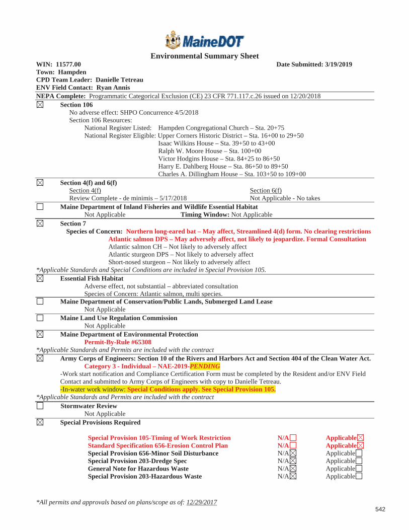
*All permits and approvals based on plans/scope as of: 12/29/2017
Environmental Summary Sheet WIN: 11577.00 Date Submitted: 3/19/2019 Town: Hampden CPD Team Leader: Danielle TetreauENV Field Contact: Ryan AnnisNEPA Complete: Programmatic Categorical Exclusion (CE) 23 CFR 771.117.c.26 issued on 12/20/2018
Section 106 No adverse effect: SHPO Concurrence 4/5/2018 Section 106 Resources:
National Register Listed: Hampden Congregational Church – Sta. 20+75 National Register Eligible: Upper Corners Historic District – Sta. 16+00 to 29+50
Isaac Wilkins House – Sta. 39+50 to 43+00 Ralph W. Moore House – Sta. 100+00 Victor Hodgins House – Sta. 84+25 to 86+50 Harry E. Dahlberg House – Sta. 86+50 to 89+50 Charles A. Dillingham House – Sta. 103+50 to 109+00
Section 4(f) and 6(f)Section 4(f) Review Complete - de minimis – 5/17/2018
Section 6(f) Not Applicable - No takes
Maine Department of Inland Fisheries and Wildlife Essential Habitat Not Applicable Timing Window: Not Applicable
Section 7 Species of Concern: Northern long-eared bat – May affect, Streamlined 4(d) form. No clearing restrictions
Atlantic salmon DPS – May adversely affect, not likely to jeopardize. Formal Consultation Atlantic salmon CH – Not likely to adversely affect
Atlantic sturgeon DPS – Not likely to adversely affect Short-nosed sturgeon – Not likely to adversely affect
*Applicable Standards and Special Conditions are included in Special Provision 105. Essential Fish Habitat
Adverse effect, not substantial – abbreviated consultation Species of Concern: Atlantic salmon, multi species.
Maine Department of Conservation/Public Lands, Submerged Land Lease Not Applicable
Maine Land Use Regulation Commission Not Applicable
Maine Department of Environmental Protection Permit-By-Rule #65308 *Applicable Standards and Permits are included with the contract
Army Corps of Engineers: Section 10 of the Rivers and Harbors Act and Section 404 of the Clean Water Act. Category 3 - Individual – NAE-2019-PENDING -Work start notification and Compliance Certification Form must be completed by the Resident and/or ENV Field
Contact and submitted to Army Corps of Engineers with copy to Danielle Tetreau. -In-water work window: Special Conditions apply. See Special Provision 105.*Applicable Standards and Permits are included with the contract
Stormwater Review Not Applicable
Special Provisions Required
Special Provision 105-Timing of Work Restriction N/A ApplicableStandard Specification 656-Erosion Control Plan N/A ApplicableSpecial Provision 656-Minor Soil Disturbance N/A ApplicableSpecial Provision 203-Dredge Spec N/A ApplicableGeneral Note for Hazardous Waste N/A ApplicableSpecial Provision 203-Hazardous Waste N/A Applicable
542

543

06-096 DEPARTMENT OF ENVIRONMENTAL PROTECTION
Chapter 305: Permit By Rule
-33-
11. State transportation facilities
A. Applicability
(1) This section applies to the maintenance, repair, reconstruction, rehabilitation, replacement or minor construction of a State Transportation Facility carried out by, or under the authority of, the Maine Department of Transportation (MaineDOT) or the Maine Turnpike Authority, including any testing or preconstruction engineering, and associated technical support services.
(2) This section does not apply to an activity within a coastal sand dune system.
NOTE: The construction of a transportation facility other than roads and associated facilities may be subject to the Storm Water Management Law, 38 M.R.S.A. Section 420-D.
B. Standards
(1) Photographs of the area to be altered by the activity must be taken before work on the site begins. The photographs must be kept on file and be made available at the request of the DEP.
(2) The activity must be reviewed by the Department of Inland Fisheries and Wildlife and the Department of Marine Resources, as applicable. The applicant must coordinate with the reviewing agencies and incorporate any recommendations from those agencies into the performance of the activity.
(3) All construction activities undertaken must be detailed in a site-specific Soil Erosion and Water Pollution Control Plan and conducted in accordance with MaineDOT's Best Management Practices for Erosion and Sediment Control, dated January 2000, and Standard Specifications, dated December 2002.
(4) Alignment changes may not exceed a distance of 200 feet between the old and new center lines in any natural resource.
(5) The activity may not alter more than 300 feet of shoreline (both shores added together) within a mile stretch of any river, stream or brook, including any bridge width or length of culvert.
(6) The activity may not alter more than 150 feet of shoreline (both shores added together) within a mile stretch of any outstanding river segment identified in 38 M.R.S.A. 480-P, including any bridge width or length of culvert.
(7) The activity must minimize wetland intrusion. The activity is exempt from the provisions of Chapter 310, the Wetland and Waterbodies Protection Rules, if the activity alters less than 15,000 square feet of natural resources per mile of roadway (centerline measurement) provided that the following impacts are not exceeded within the 15,000 square foot area:
(a) 1,000 square feet of coastal wetland consisting of salt tolerant vegetation or shellfish habitat; or
544

06-096 DEPARTMENT OF ENVIRONMENTAL PROTECTION
Chapter 305: Permit By Rule
-34-
(b) 5,000 square feet of coastal wetland not containing salt tolerant vegetation or shellfish habitat; or
(c) 1,000 square feet of a great pond.
All other activities must be performed in compliance with all sections of Chapter 310, the Wetland Protection Rules, except 310.2(C), 5(A), 9(A), 9(B) and 9(C).
(8) The activity may not permanently block any fish passage in any watercourse containing fish. The applicant must coordinate with the reviewing agencies listed in paragraph 2 above to improve fish passage and incorporate any recommendations from those agencies into the performance of the activity.
NOTE: For guidance on meeting the design objectives for fish passage, including peak flow, maximum velocity, mining depth and gradient, see the MaineDOT Waterbody and Wildlife Crossing Policy and Design Guide (July 2008), developed in conjunction with state and federal resource and regulatory agencies.
(9) Rocks may not be removed from below the normal high water line of any coastal wetland, freshwater wetland, great pond, river, stream or brook except to the minimum extent necessary for completion of work within the limits of construction.
(10) If work is performed in a river, stream or brook that is less than three feet deep at the time and location of the activity, the applicant must isolate the work area from the resource and divert stream flows around the work area, maintaining downstream flows while work is in progress.
(11) Wheeled or tracked equipment may not operate in the water. Equipment operating on the shore may reach into the water with a bucket or similar extension. Equipment may cross streams on rock, gravel or ledge bottom. If avoiding the operation of wheeled or tracked equipment in the water is not possible, the applicant must explain the need to operate in the water. Approval from the DEP to operate in the water must be in writing, and any recommendations from the DEP must be incorporated into the performance of the activity.
(12) All wheeled or tracked equipment that must travel or work in a vegetated wetland area must travel and work on mats or platforms.
(13) Any debris or excavated material must be stockpiled either outside the wetland or on mats or platforms. Erosion and sediment control best management practices must be used, where necessary, to prevent sedimentation. Any debris generated during the activity must be prevented from washing downstream and must be removed from the wetland or water body. Disposal of debris must be in conformance with the Maine Hazardous Waste, Septage and Solid Waste Management Act, 38 M.R.S.A. Section 1301 et seq.
(14) Work below the normal high water line of a great pond, river, stream or brook must be done at low water except for emergency work or work agreed to by the resource agencies listed in paragraph 2 above.
(15) Perimeter controls must be installed before the work starts. Disturbance of natural resources beyond the construction limits shown on the plans is not allowed under this rule.
545

06-096 DEPARTMENT OF ENVIRONMENTAL PROTECTION
Chapter 305: Permit By Rule
-35-
NOTE: Guidance on the location of construction limits can be obtained from the on site Construction Manager.
(16) The use of untreated lumber is preferred. Lumber pressure treated with chromated copper arsenate (CCA) may be used only if necessary and only if use is allowed under federal law and not prohibited from sale under 38 M.R.S.A. 1682, and provided it is cured on dry land in a manner that exposes all surfaces to the air for a period of at least 21 days prior to construction. Wood treated with creosote or pentachlorophenol may not be used where it will contact water.
(17) A temporary road for equipment access must be constructed of crushed stone, blasted ledge, or similar materials that will not cause sedimentation or restrict fish passage. Such roads must be completely removed at the completion of the activity. In addition, any such temporary roads which are in rivers, streams or brooks, must allow for a passage of stormwater flows associated with a 10-year storm.
(18) Non-native species may not be planted in restored areas.
(19) Disposal of debris must be in conformance with Maine Hazardous Waste, Septage and Solid Waste Management Act, 38 M.R.S.A. Sections 1301 et seq.
(20) Disturbance of vegetation must be avoided, if possible. Where vegetation is disturbed outside of the area covered by any road or structure construction, it must be reestablished immediately upon completion of the activity and must be maintained.
(21) A vegetated area at least 25 feet wide must be established and maintained between any new stormwater outfall structure and the high water line of any open water body. A velocity reducing structure must be constructed at the outlet of the stormwater outfall that will create sheet flow of stormwater, and prevent erosion of soil within the vegetated buffer. If the 25 foot vegetated buffer is not practicable, the applicant must explain the reason for a lesser setback in writing. Approval from the DEP must be in writing and any recommendations must be incorporated into the activity.
C. Definitions. The following terms, as used in this chapter, have the following meanings, unless the context indicates otherwise:
(1) Diversion. The rerouting of a river, stream or brook around a construction site and then back to the downstream channel.
(2) Fill. a. (verb) To put into or upon, supply to, or allow to enter a water body or wetland any earth, rock, gravel, sand, silt, clay, peat, or debris; b. (noun) Material, other than structures, placed in or immediately adjacent to a wetland or water body.
(3) Floodplain wetlands. Freshwater wetlands that are inundated with flood water during a 100-year flood event based on flood insurance maps produced by the Federal Emergency Agency or other site specific information.
(4) Riprap. Heavy, irregularly shaped rocks that are fit into place, without mortar, on a slope as defined in the MaineDOT Standard Specifications, dated .
546

*All permits and approvals based on plans/scope as of: 12/29/2017
Environmental Summary SheetWIN: 21692.00 Date Submitted: 3/19/2019 Town: HampdenCPD Team Leader: Danielle Tetreau ENV Field Contact: Ryan AnnisNEPA Complete: Programmatic Categorical Exclusion (CE) 23 CFR 771.117.c.26 issued on 12/20/2018
Section 106 No adverse effect: SHPO Concurrence 4/5/2018Section 106 Resources:
National Register Listed: Hampden Congregational Church – Sta. 20+75National Register Eligible: Upper Corners Historic District – Sta. 16+00 to 29+50
Isaac Wilkins House – Sta. 39+50 to 43+00 Ralph W. Moore House – Sta. 100+00 Victor Hodgins House – Sta. 84+25 to 86+50 Harry E. Dahlberg House – Sta. 86+50 to 89+50 Charles A. Dillingham House – Sta. 103+50 to 109+00
Section 4(f) and 6(f)Section 4(f) Review Complete - de minimis – 5/17/2018
Section 6(f)Not Applicable - No takes
Maine Department of Inland Fisheries and Wildlife Essential HabitatNot Applicable Timing Window: Not Applicable
Section 7Species of Concern: Northern long-eared bat – May affect, Streamlined 4(d) form. No clearing restrictions Atlantic salmon DPS – May adversely affect, not likely to jeopardize. Formal consultation
Atlantic salmon CH – Not likely to adversely affect Atlantic sturgeon DPS – Not likely to adversely affect Short-nosed sturgeon – Not likely to adversely affect
*Applicable Standards and Special Conditions are included in Special Provision 105.Essential Fish Habitat
Adverse effect, not substantial – abbreviated consultation Species of Concern: Atlantic salmon, multi species.
Maine Department of Conservation/Public Lands, Submerged Land LeaseNot Applicable
Maine Land Use Regulation CommissionNot Applicable
Maine Department of Environmental ProtectionPermit-By-Rule #65308
*Applicable Standards and Permits are included with the contractArmy Corps of Engineers: Section 10 of the Rivers and Harbors Act and Section 404 of the Clean Water Act.
Category 3 - Individual – NAE-2019-PENDING -Work start notification and Compliance Certification Form must be completed by the Resident and/or ENV Field
Contact and submitted to Army Corps of Engineers with copy to Danielle Tetreau. -In-water work window: Special Conditions apply. See Special Provision 105.*Applicable Standards and Permits are included with the contract
Stormwater ReviewNot Applicable
Special Provisions RequiredGeneral Note for Hazardous Waste N/A ApplicableSpecial Provision 105-Timing of Work Restriction N/A ApplicableSpecial Provision 203-Dredge Spec N/A ApplicableStandard Specification 656-Erosion Control Plan N/A ApplicableSpecial Provision 656-Minor Soil Disturbance N/A ApplicableSpecial Provision 203-Hazardous Waste N/A Applicable
547

HAMPDENGRIST MILL BRIDGEBRIDGE RECONSTRUCTIONWIN 21692.00
GENERAL NOTE
A Maine Department of Transportation Environmental Office (MaineDOT-ENV)investigation associated with this project encountered subsurface data that suggests low-level petroleum related contamination was potentially present at the bridge project. In particular, soil samples from some Geotech borings exhibitedpotential petroleum like odors. Subsequent follow-up on-site work involving environmental borings and laboratory analysis failed to unearth any issues within this area. However, in light of the available environmental data, the contractor shall employ appropriate health and safety measures to protect its workers against hazards associated with working near petroleum-impacted soils. Furthermore, the Contractor shall remain alert for any additionally evidence of contamination. If the Contractor encounters evidence of soil or groundwater contamination at this location or any other area on the project, the Contractor shall secure the excavation, stop work in the contaminated area, and immediately notify the Resident. The Resident shall contact the Senior Geologistin MaineDOT’s Environmental Office at 207-624-3100 and the Maine Department of Environmental Protection (MDEP) at 800-482-0777. Work may only continue with authorization from the Resident.
548

549
06-096 DEPARTMENT OF ENVIRONMENTAL PROTECTION
Chapter 305: Permit By Rule
-33-
11. State transportation facilities
A. Applicability
(1) This section applies to the maintenance, repair, reconstruction, rehabilitation, replacement or minor construction of a State Transportation Facility carried out by, or under the authority of, the Maine Department of Transportation (MaineDOT) or the Maine Turnpike Authority, including any testing or preconstruction engineering, and associated technical support services.
(2) This section does not apply to an activity within a coastal sand dune system.
NOTE: The construction of a transportation facility other than roads and associated facilities may be subject to the Storm Water Management Law, 38 M.R.S.A. Section 420-D.
B. Standards
(1) Photographs of the area to be altered by the activity must be taken before work on the site begins. The photographs must be kept on file and be made available at the request of the DEP.
(2) The activity must be reviewed by the Department of Inland Fisheries and Wildlife and the Department of Marine Resources, as applicable. The applicant must coordinate with the reviewing agencies and incorporate any recommendations from those agencies into the performance of the activity.
(3) All construction activities undertaken must be detailed in a site-specific Soil Erosion and Water Pollution Control Plan and conducted in accordance with MaineDOT's Best Management Practices for Erosion and Sediment Control, dated January 2000, and Standard Specifications, dated December 2002.
(4) Alignment changes may not exceed a distance of 200 feet between the old and new center lines in any natural resource.
(5) The activity may not alter more than 300 feet of shoreline (both shores added together) within a mile stretch of any river, stream or brook, including any bridge width or length of culvert.
(6) The activity may not alter more than 150 feet of shoreline (both shores added together) within a mile stretch of any outstanding river segment identified in 38 M.R.S.A. 480-P, including any bridge width or length of culvert.
(7) The activity must minimize wetland intrusion. The activity is exempt from the provisions of Chapter 310, the Wetland and Waterbodies Protection Rules, if the activity alters less than 15,000 square feet of natural resources per mile of roadway (centerline measurement) provided that the following impacts are not exceeded within the 15,000 square foot area:
(a) 1,000 square feet of coastal wetland consisting of salt tolerant vegetation or shellfish habitat; or
550

06-096 DEPARTMENT OF ENVIRONMENTAL PROTECTION
Chapter 305: Permit By Rule
-34-
(b) 5,000 square feet of coastal wetland not containing salt tolerant vegetation or shellfish habitat; or
(c) 1,000 square feet of a great pond.
All other activities must be performed in compliance with all sections of Chapter 310, the Wetland Protection Rules, except 310.2(C), 5(A), 9(A), 9(B) and 9(C).
(8) The activity may not permanently block any fish passage in any watercourse containing fish. The applicant must coordinate with the reviewing agencies listed in paragraph 2 above to improve fish passage and incorporate any recommendations from those agencies into the performance of the activity.
NOTE: For guidance on meeting the design objectives for fish passage, including peak flow, maximum velocity, mining depth and gradient, see the MaineDOT Waterbody and Wildlife Crossing Policy and Design Guide (July 2008), developed in conjunction with state and federal resource and regulatory agencies.
(9) Rocks may not be removed from below the normal high water line of any coastal wetland, freshwater wetland, great pond, river, stream or brook except to the minimum extent necessary for completion of work within the limits of construction.
(10) If work is performed in a river, stream or brook that is less than three feet deep at the time and location of the activity, the applicant must isolate the work area from the resource and divert stream flows around the work area, maintaining downstream flows while work is in progress.
(11) Wheeled or tracked equipment may not operate in the water. Equipment operating on the shore may reach into the water with a bucket or similar extension. Equipment may cross streams on rock, gravel or ledge bottom. If avoiding the operation of wheeled or tracked equipment in the water is not possible, the applicant must explain the need to operate in the water. Approval from the DEP to operate in the water must be in writing, and any recommendations from the DEP must be incorporated into the performance of the activity.
(12) All wheeled or tracked equipment that must travel or work in a vegetated wetland area must travel and work on mats or platforms.
(13) Any debris or excavated material must be stockpiled either outside the wetland or on mats or platforms. Erosion and sediment control best management practices must be used, where necessary, to prevent sedimentation. Any debris generated during the activity must be prevented from washing downstream and must be removed from the wetland or water body. Disposal of debris must be in conformance with the Maine Hazardous Waste, Septage and Solid Waste Management Act, 38 M.R.S.A. Section 1301 et seq.
(14) Work below the normal high water line of a great pond, river, stream or brook must be done at low water except for emergency work or work agreed to by the resource agencies listed in paragraph 2 above.
(15) Perimeter controls must be installed before the work starts. Disturbance of natural resources beyond the construction limits shown on the plans is not allowed under this rule.
551

06-096 DEPARTMENT OF ENVIRONMENTAL PROTECTION
Chapter 305: Permit By Rule
-35-
NOTE: Guidance on the location of construction limits can be obtained from the on site Construction Manager.
(16) The use of untreated lumber is preferred. Lumber pressure treated with chromated copper arsenate (CCA) may be used only if necessary and only if use is allowed under federal law and not prohibited from sale under 38 M.R.S.A. 1682, and provided it is cured on dry land in a manner that exposes all surfaces to the air for a period of at least 21 days prior to construction. Wood treated with creosote or pentachlorophenol may not be used where it will contact water.
(17) A temporary road for equipment access must be constructed of crushed stone, blasted ledge, or similar materials that will not cause sedimentation or restrict fish passage. Such roads must be completely removed at the completion of the activity. In addition, any such temporary roads which are in rivers, streams or brooks, must allow for a passage of stormwater flows associated with a 10-year storm.
(18) Non-native species may not be planted in restored areas.
(19) Disposal of debris must be in conformance with Maine Hazardous Waste, Septage and Solid Waste Management Act, 38 M.R.S.A. Sections 1301 et seq.
(20) Disturbance of vegetation must be avoided, if possible. Where vegetation is disturbed outside of the area covered by any road or structure construction, it must be reestablished immediately upon completion of the activity and must be maintained.
(21) A vegetated area at least 25 feet wide must be established and maintained between any new stormwater outfall structure and the high water line of any open water body. A velocity reducing structure must be constructed at the outlet of the stormwater outfall that will create sheet flow of stormwater, and prevent erosion of soil within the vegetated buffer. If the 25 foot vegetated buffer is not practicable, the applicant must explain the reason for a lesser setback in writing. Approval from the DEP must be in writing and any recommendations must be incorporated into the activity.
C. Definitions. The following terms, as used in this chapter, have the following meanings, unless the context indicates otherwise:
(1) Diversion. The rerouting of a river, stream or brook around a construction site and then back to the downstream channel.
(2) Fill. a. (verb) To put into or upon, supply to, or allow to enter a water body or wetland any earth, rock, gravel, sand, silt, clay, peat, or debris; b. (noun) Material, other than structures, placed in or immediately adjacent to a wetland or water body.
(3) Floodplain wetlands. Freshwater wetlands that are inundated with flood water during a 100-year flood event based on flood insurance maps produced by the Federal Emergency Agency or other site specific information.
(4) Riprap. Heavy, irregularly shaped rocks that are fit into place, without mortar, on a slope as defined in the MaineDOT Standard Specifications, dated .
552