hampden township new municipal campus - bidnet
TRANSCRIPT

Project Manual for:
Hampden Township New Municipal Campus
209 South Sporting Hill Road, Mechanicsburg, PA 17050
For Bidding Starting
March 20, 2019
Board of Commissioners Al Bienstock Ken Fetrow
John Gaspich Nathan Silcox John Thomas
Township Manager Keith Metts
Kimmel Bogrette Architecture + Site
Volume 2 of 2, Divisions 22 to 28

Kimmel Bogrette Architecture + Site Hampden Township
New Municipal Campus
GENERAL PROVISIONS - MECHANICAL 20 00 10 - 1
SECTION 20 00 10 – GENERAL PROVISIONS – MECHANICAL
PART 1 - GENERAL
1.1 RELATED DOCUMENTS
A. The bidding requirements, Contract Documents, and Division 01 - General Requirements, are
a part of Divisions 21-23 and Contract for this Work and apply to these Divisions as fully as if
they were repeated therein.
B. Fire Protection Work shall be bid as a separate prime contract in accordance with the bidding
requirements.
1.2 WORK INCLUDED – PLUMBING AND FIRE PROTECTION
A. Plumbing Work and fire protection shall consist of the labor, materials and equipment
required for installation of the plumbing and fire protection systems.
B. Plumbing and fire protection Work shall include the following Specification Sections and
Drawings as outlined:
1. Specifications:
Section 20 00 10 General Provisions – Mechanical
Section 21 10 10 Fire Protection
Section 21 96 10 Wiring of Fire Protection Equipment
Section 22 05 05 Plumbing Basic Materials
Section 22 05 10 Plumbing Pipe and Pipe Fittings
Section 22 05 15 Plumbing Piping Specialties
Section 22 05 20 Plumbing Specialties
Section 22 05 25 Plumbing Valves
Section 22 05 30 Plumbing Supports and Anchors
Section 22 07 10 Plumbing Insulation
Section 22 11 10 Plumbing Pumps
Section 22 13 10 Sanitary Drainage
Section 22 13 20 Interceptors
Section 22 14 10 Storm Drainage
Section 22 33 10 Water Heaters
Section 22 40 10 Plumbing Fixtures

Kimmel Bogrette Architecture + Site Hampden Township
New Municipal Campus
GENERAL PROVISIONS - MECHANICAL 20 00 10 - 2
Section 22 60 30 Fuel Gas Piping and Specialties
Section 22 96 10 Wiring of Plumbing Equipment
2. Drawings:
F1.1 Floor Plan – Fire Protection
P1.1 Floor Plan Part “A” – Plumbing
P1.2 Floor Plan Part “B” – Plumbing
P1.3 Roof Plan - Plumbing
P4.1 Enlarged Plans
P4.2 Enlarged Plans
P5.1 Details
P6.1 Schedules
C. Plumbing and Fire Protection Work shall be bid as a separate prime contract in accordance
with the bidding requirements.
1.3 WORK INCLUDED – HVAC
A. HVAC Work shall consist of the labor, materials and equipment required for installation of the
heating, ventilating and air conditioning systems.
B. HVAC Work shall include the following Specification Sections and Drawings as outlined:
1. Specifications:
Section 20 00 10 General Provisions – Mechanical
Section 23 05 05 HVAC Basic Materials
Section 23 05 10 HVAC Pipe and Pipe Fittings
Section 23 05 15 HVAC Piping Specialties
Section 23 05 25 HVAC Valves
Section 23 05 30 HVAC Supports and Anchors
Section 23 05 35 HVAC Sound and Vibration Control
Section 23 07 10 HVAC Insulation
Section 23 10 20 Variable Frequency Drives
Section 23 21 10 HVAC Pumps
Section 23 30 10 Air Distribution
Section 23 30 20 Variable Air Volume Systems
Section 23 34 10 Fans and Gravity Ventilators

Kimmel Bogrette Architecture + Site Hampden Township
New Municipal Campus
GENERAL PROVISIONS - MECHANICAL 20 00 10 - 3
Section 23 50 10 Central Heating Equipment
Section 23 57 10 Heat Transfer
Section 23 60 10 Central Cooling Equipment
Section 23 73 10 Central Station Air Handling Units
Section 23 81 10 Unitary Equipment
Section 23 82 10 Terminal Heating Units
Section 23 90 10 Building Automation System
Section 23 95 10 Testing, Adjusting and Balancing of HVAC System
Section 23 96 10 Wiring of HVAC Equipment
2. Drawings:
H1.1 Floor Plan Part ‘A’ – Ductwork
H1.2 Floor Plan Part ‘B’ – Ductwork
H1.3 Roof Plan – HVAC
H2.1 Floor Plan Part ‘A’ – Piping
H2.2 Floor Plan Part ‘B’ – Piping
H4.1 Enlarged Plans
H5.1 Details
H5.2 Details
H6.1 Schedules
C. HVAC Work shall be bid as a separate prime contract in accordance with the bidding
requirements.
1.4 TERMINOLOGY
A. Wherever the term “Bidder” is used in Divisions 21-23 of the Specifications, it shall be
interpreted to refer to the person, firm, or corporation who is submitting an offer or
proposal, on the prescribed form, to perform the Work of these Divisions.
B. Wherever the term, “Contractor” is used in of the Specifications, it shall be interpreted to
refer to the Contractor responsible for Work of these Divisions.
C. Those responsible for Work covered by other portions of the Specification will be indicated
by trade, such as Electrical Contractor, General Contractor, etc.
1.5 REFERENCE STANDARDS
A. Portions or all of certain recognized industry or association standards referred to herein as
being a requirement of these Specifications shall be considered as binding as though

Kimmel Bogrette Architecture + Site Hampden Township
New Municipal Campus
GENERAL PROVISIONS - MECHANICAL 20 00 10 - 4
reproduced in full herein. Unless otherwise stated the referenced standard shall be the
standard which is current as of the date of issuance of these Specifications. Reference may be
made to standards either by full name or for the sake of brevity by letter designation only. The
following is a list of the most commonly used standards, but is not all inclusive for these
Specifications:
ABMA American Bearing Manufacturers Association
ADA Americans with Disabilities Act
AGA American Gas Association
AMCA Air Moving and Conditioning Association
ANSI American National Standards Institute
API American Petroleum Institute
ARI American Refrigeration Institute
ASHRAE American Society of Heating, Refrigerating and Air- Conditioning Engineers
ASME American Society of Mechanical Engineers
ASSE American Society of Sanitary Engineers
ASTM American Society for Testing and Materials
AWS American Welding Society
AWWA American Water Works Association
CISPI Cast Iron Soil Pipe Institute
FM Factory Mutual Engineering Corporation
I-B-R Institute of Boiler & Radiator Manufacturers
NEC National Electrical Code
NEMA National Electrical Manufacturers Association
NFPA National Fire Protection Association
OSHA Occupational Safety and Health Administration
PDI Plumbing Drainage Institute
SMACNA Sheet Metal and Air Conditioning Contractors National Association, Inc.
UL Underwriters Laboratories, Inc.
1.6 PERMITS AND INSPECTIONS
A. Secure all permits and inspections required by applicable authorities and utilities and pay all
costs in connection with the Work.
B. Schedule all inspections required by applicable authorities and utilities. Certificates shall be in
triplicate and shall be delivered to Owner.
C. Piping work, specialties, or equipment shall not be concealed or covered until same have been
tested and inspected by municipal inspector(s) and observed by Architect. Municipal
inspector(s) record of inspections shall be delivered to Owner.
D. Architect and municipal inspector’s witnessing of tests shall not relieve Contractor of his
responsibility for concealed piping work and specialties, nor for equipment to perform in
accordance with Contract Documents.

Kimmel Bogrette Architecture + Site Hampden Township
New Municipal Campus
GENERAL PROVISIONS - MECHANICAL 20 00 10 - 5
1.7 CODES AND STANDARDS
A. Mechanical Work is subject to provisions of the Pennsylvania Uniform Construction Code and
has been designed to be in compliance with the Code. Design aspect of the Project shall not
be altered regarding building envelope or selection of HVAC, service water heating systems
and equipment. Supplemental data published by equipment and system manufacturers to
substantiate energy conservation efficiencies throughout the Project shall be furnished at
request of Architect.
B. Mechanical Work shall meet requirements of the National Fire Protection Association, all
federal, state, and municipal authority's laws, rules and regulations applicable to the Work and
public utilities having jurisdiction over systems specified herein.
C. Boilers, domestic water heater(s), heating equipment and pressure vessels shall be constructed
and tested in accordance with recommendations of the National Fire Protection Association,
Pennsylvania Department of Labor and Industry - Boiler Inspection Division, and ASME Code.
Equipment shall be stamped with the ASME symbol and National Board number and shall be
inspected during construction by an inspector who has been commissioned by the
Pennsylvania Department of Labor and Industry to perform such service. Equipment shall be
prepared for initial inspection in accordance with Pennsylvania Department of Labor and
Industry regulations.
D. Plumbing Work shall be installed in conformity with applicable portions of the International
Plumbing Code, state plumbing codes, local ordinances, and shall be approved as Project
progresses by Architect, and local plumbing inspector. Contractor shall certify domestic water
systems for compliance with Pennsylvania Plumbing System Lead Ban & Notification Act (No.
33-1989). Nothing in the Specifications shall be construed to permit deviation from
requirements of governing code(s).
E. Installation of all gas piping and gas burning equipment shall conform to recommendations of
the American Gas Association, Owner’s insurance carrier, and the local utility.
F. The handling and use of CFC and HCFC refrigerants, whether leaking, venting, recovering,
etc., shall be in accordance with US Environmental Protection Agency regulations CFR 58 FR
28660, ASHRAE 15- Safety Code for Mechanical Refrigeration, and ANSI/ASHRAE 34 -
Number Designation and Safety Classification of Refrigerants.
G. Electrical Work shall meet requirements of the National Electrical Code and all federal, state,
and municipal authority’s laws, rules and regulations applicable to the Work.
H. Where applicable, materials and equipment shall bear the label of approval of Underwriters
Laboratories, Inc.
I. Reference to codes and standards listed herein shall constitute minimum acceptable
requirements. Where Drawings and Specification requirements exceed those of codes listed,
Drawings and Specifications shall take precedence for Work of this Project.
J. If Contractor, during the course of work, observes the existence of hazardous materials in the
structure or on the project site, Contractor shall promptly notify Owner and Architect.
Contractor shall not perform any work pertinent to the hazardous material prior to receipt of
special instructions from Owner. “Hazardous materials”, for the purpose of this Specification,

Kimmel Bogrette Architecture + Site Hampden Township
New Municipal Campus
GENERAL PROVISIONS - MECHANICAL 20 00 10 - 6
are defined as asbestos, PCB’s, petroleum, radioactive material, or hazardous waste
substances.
1.8 SUBSTITUTIONS
A. Specifications for each piece of equipment and each item of material are written around a
product of a specific base manufacturer. This base manufacturer is the basis of design,
dimensions and details. The base manufacturer’s name and model information are included
with the product description as the first named manufacturer under the heading “Acceptable
Manufacturer”.
B. “Substitution” manufacturers are defined as any manufacturer other than the one used as the
basis of design. “Substitution” manufacturers will be permitted, in accordance with the bidding
requirements and where indicated herein.
C. Manufacturers named in the product description, in addition to the base manufacturer, are
“substitution” manufacturers, have been determined to be manufacturers capable of
manufacturing products similar to the base manufacturer and these manufacturers are
acceptable “substitution” manufacturers to the base manufacturer. Where additional
manufacturer’s names do not appear with the base manufacturer, the Architect reserves the
right to disallow any “substitution” manufacturers. Where the base manufacturer’s name is
followed by the term “no substitution”, no “substitution” manufacturers will be considered.
D. Naming of specific manufacturers shall not be construed as eliminating products or services of
other “substitution” manufacturers having comparable items. Where permitted by these
Specifications, and where Bidder desires to use other “substitution” manufacturers, he may
submit a request for approval to use the “substitution” manufacturer in accordance with
bidding requirements.
E. Products described in Specifications are intended to set a quality level and ensure a workable
system. “Substitution” of manufacturers, including those herein named, may be made only after
approval of Architect. Bidder shall assume full responsibility for installation and dimensional
changes required by the use of all “substitution” manufacturer’s products, including revisions
to wiring, controls, piping, structural revisions, etc., and all room or space changes as required
due to dimension differences of the “substitution” manufacturer product. Architect, approval
of “substitution” manufacturer’s products shall be limited to compliance with information given
on the Drawings and Specifications.
F. Whenever the term “Alternate Manufacturer” appears in the product description, Bidder is
required to submit the Bid on the basis of furnishing the product of the base manufacturer
specified and that base manufacturer’s product shall be reflected in the Bidder’s base price.
Bidder shall also submit alternate (add or deduct) prices in the bid in accordance with the
Alternates Section of the Specifications.
G. Where the Bidding requirements call for submittal for approval of substitutions prior to bids
due, all approvals given are for “substitution” manufacturers only, not approval of any
particular product. An approved “substitution” manufacturer’s product must comply with all
requirements of the specifications and drawings for the base manufacturer’s product.

Kimmel Bogrette Architecture + Site Hampden Township
New Municipal Campus
GENERAL PROVISIONS - MECHANICAL 20 00 10 - 7
1.9 SHOP DRAWINGS AND PRODUCT DATA
A. Submit shop drawings and product data for approval to Architect. Shop drawings and product
data shall have been reviewed and approved (stamped) by Contractor furnishing the
equipment. If evidence of this Contractor’s approval does not appear on submittal data,
submittals will be returned without review. Following Architect review, submittals not
approved or requiring resubmission shall be corrected and resubmitted until satisfactory.
Work indicated on shop drawings and product data shall not be executed until submittals have
been approved.
B. Each submittal shall contain shop drawings or product data for only one specification section.
Submittals containing information about products from multiple specification sections will be
returned without review. Likewise, each submittal shall contain shop drawings or product
data for all items in one specification section to be provided for this Project. Submittals that
are incomplete may be returned without review.
C. Submittals for equipment and material shall indicate room numbers, drawing identification
symbols, product type, capacities, accessories, connection sizes, electrical characteristics,
wiring diagrams, and installation instructions. Each shop drawing shall have specified items,
accessories and options, as applicable to this Project, clearly marked. Catalog numbers, part
numbers, etc. on shop drawings will not be reviewed for correctness, Contractor is
responsible for verifying correctness of these and that they relate to the options, accessories,
features, etc. marked on the shop drawings. Shop drawings not clearly marked as to only that
which will be provided for this Project will not be approved.
D. In as much as it is not the purpose of the submittal process to assure that the Contractor is
meeting all the requirements of the Contract Documents, submittal review by Architect is for
conformance with design concept of the Project and general compliance with information
given in the construction documents. Approval, corrections and/or comments made as part of
the submittal review do not relieve the Contractor of the responsibility from conformance
with all requirements of the Contract Documents, applicable codes and laws. Contractor is
responsible for dimensions, quantities, and performance requirements to be confirmed and
correlated at the job site; for information that pertains solely to the fabrication processes or
to techniques of construction; and for all coordination with the Work of all trades. Refer to
paragraph entitled “Substitutions” in this section of the specifications.
E. At the time of each submittal, Contractor shall give Architect specific written notice of such
variations, if any, that the Shop Drawing or product submitted may have from the
requirements of the Contract Documents, such notice to be in a written communication
separate from the submittal; and, in addition, shall cause a specific notation to be made on
each Shop Drawing and sample submitted to Architect for review and approval of each such
variation. Architect’s review and approval of Shop Drawings or products shall not relieve
Contractor from responsibility for any variation from the requirements of the Contract
Documents unless Contractor has in writing called the Architect’s attention to each such
variation at the time of each submittal and Architect has given written notation thereof
incorporated in or accompanying the Shop Drawing or product approval; nor will any approval
by Architect relieve contractor from responsibility for complying with the requirements of this
paragraph.
F. Shop drawing submittals shall be accompanied by a transmittal sheet with the applicable
specification section number and the "name" of the item or items being submitted clearly
Kimmel Bogrette Architecture + Site Hampden Township
New Municipal Campus
GENERAL PROVISIONS - MECHANICAL 20 00 10 - 8
indicated on the transmittal. All "names" on the transmittal shall match exactly the "names"
listed in the specifications for the item being submitted.
G. The name of the supplier, distributor, subcontractor, etc., who will furnish equipment and
items to the Contractor shall appear on the shop drawings when submitted. Shop drawing
submittals without supplier’s, distributors, subcontractors, etc., name will not be reviewed and
will be returned without review.
H. If Architect is required to review any shop drawing or product data submittal more than two
times, a Change Order will be issued to the Contractor for a credit due on the Contract Price
to recoup Architect’s expenses associated with the multiple reviews.
I. One complete set of approved shop drawings and product data shall be delivered to Owner at
completion of Work. Include lists of manufacturer’s parts and part numbers.
J. Refer to General Conditions and Division 01.
1.10 COORDINATION – GENERAL
A. Work shall be governed by requirements set forth in the conditions of the Contract and
Section 01-1200, Multiple Contract Summary.
B. Provide all labor, materials, and equipment required by the Contract Documents necessary for
completion of the Work of Divisions 21-23.
C. Drawings are generally indicative of Work to be installed but may not indicate all bends,
fittings, elbows, etc., required to meet conditions. Where items shown on the Drawings, or
herein described, are not clearly understood, Bidders shall confer with Architect.
D. Coordinate Work of Divisions 21-23 with that of other trades so that Work will be installed
in the most direct manner and so that interference between piping, ducts, conduits,
equipment, and architectural or structural features will be avoided. Work installed in an
arbitrary manner without regard for Work of other trades or equipment servicing
requirements will be rejected in any situation where an undesirable condition or an unfair
hardship for other trades, or Owner, results.
E. Provide sufficient scaffolding and hoist or rig material and equipment into place or arrange for
rigging by others. In any case, rigging or hoisting for Work of Divisions 21-23 shall be at the
expense of Contractor.
F. Unless otherwise indicated, provide structural steel members as required for support of
equipment and materials furnished under Divisions 21-23. Provide all hangers and supports, as
specified, detailed, or in accordance with accepted industry standards.
G. Equipment shall be installed in accordance with equipment manufacturer’s installation
instructions. Obtain manufacturer’s installation instructions prior to roughing-in.
H. Where equipment is furnished by other trades for installation as Work under Divisions 21-23,
or where electrical service or utility connection to equipment installed by others is indicated
as Work of Divisions 21-23, obtain approved shop drawings and installation instructions from
Kimmel Bogrette Architecture + Site Hampden Township
New Municipal Campus
GENERAL PROVISIONS - MECHANICAL 20 00 10 - 9
the respective contractor prior to roughing-in. Discrepancies between installation instructions
and Contract Documents shall be brought to the attention of Architect.
I. Where equipment is indicated to be furnished as Work of Divisions 21-23 for installation by
others, or where equipment furnished and installed under Divisions 21-23 requires utility
connections by others, provide to the respective contractor one copy of an approved shop
drawing and installation instructions necessary for execution of his work.
J. Unless specifically indicated, communication between the mechanical and electrical systems
equipment and panels shall be via a dedicated wiring system furnished and installed by the
systems installers. These systems shall be separate from all other data communication
networks within the building. Contractor may request approval for providing communications
on the Owner’s building data network. If Owner’s written approval is obtained, the system
installer shall fully coordinate the necessary data network connections with the Owner, the
Owner’s technology consultant, and the contractor responsible for installing the building data
network system. The systems shall follow the Owner’s data network labeling scheme for
outlets and jacks, operation protocols, and shall adhere to all network security measures. The
system installer shall be responsible for all costs associated with equipment, materials, and
labor necessary to furnish and install the communications network including, but not limited
to: jacks, wall plates, cables, conduits and boxes, patch panels, patch cords, additional Owner
switches and equipment, additional systems equipment, and programming services.
1.11 COORDINATION – NEW CONSTRUCTION
A. Contractor shall provide openings and recesses, including cutting, patching and finishing,
necessary for installation of mechanical equipment in new construction.
B. Where piping is run concealed in concrete masonry unit (block) walls, Contractor shall be
responsible for installing his work in cores of block for mason to wall-in as he carries up wall.
Coordinate locations and scheduling of Work with General Contractor.
C. Provide exterior concrete foundations and pads for mechanical equipment installed under
Divisions 23. Foundations for equipment shall be as specified in subsequent Sections of the
Specifications. Inserts and anchor bolts shall be poured into foundation according to
equipment manufacturer’s instructions. Method of setting, aligning, and anchoring shall be as
recommended by equipment manufacturer. Coordinate concrete pad sizes with equipment
manufacturer’s recommendations.
D. General Contractor will provide concrete foundation pads for mechanical equipment installed
under Divisions 21-23 inside the building. Provide General Contractor with approved shop
drawing, dimensional data for size of base, and insert and anchor bolt locations. Method of
setting, aligning, and anchoring shall be as recommended by equipment manufacturers.
E. General Contractor will furnish and install structural steel members for supporting rooftop
equipment as indicated on Drawings. Provide General Contractor with dimensional data
required for fabrication of supports.
F. General Contractor will furnish and install all flashing for roof mounted equipment and
penetrations. Furnish and install all cap flashing integral to roof mounted equipment and field
fabricated. Coordinate with General Contractor’s roofer.

Kimmel Bogrette Architecture + Site Hampden Township
New Municipal Campus
GENERAL PROVISIONS - MECHANICAL 20 00 10 - 10
G. Electrical Contractor will wire all motors, resistance coils and controllers, except as noted
otherwise in Section 26 96 10, Wiring of Mechanical Equipment. Where motor starters and
disconnect switches are supplied, and shipped loose with mechanical equipment, they shall be
mounted and wired by Electrical Contractor. Verify available power characteristics prior to
ordering equipment.
1.12 COORDINATION – EMERGENCY GENERATOR INSTALLATION
A. Electrical Contractor will furnish and install emergency generator, muffler and generator
exhaust piping and accessories.
B. Plumbing Contractor shall furnish and install gas piping, pressure reducing valves, and pressure
regulator, and make final piping connections.
1.13 CONCRETE
A. General Contractor will furnish and install concrete for Work of Divisions 26-28 installed
inside the building.
B. Furnish and install concrete for Work of Divisions 22 and 23 installed outside the building.
Concrete work shall be in accordance with requirements set forth in Division 03.
1.14 EXCAVATION AND BACKFILL
A. Perform excavation and backfill required for Work of this Division, inside and outside building.
Excavation and backfill shall be in accordance with requirements set forth in Division 31.
1. Work shall include saw cutting, trenching, backfilling, patching of all areas disturbed by
excavation.
2. Banks and excavations shall be retained by means of shoring and braces to avoid cave-
ins. Shoring shall be in accordance with state and local regulatory agencies’
requirements. Shoring shall be maintained until installation, tests and inspections are
complete.
3. Pumping equipment shall be provided and maintained to pump water from excavations.
4. Comply with Pennsylvania Underground Utility Line Protection Act (287-1974 as
amended by Act 187-1996) before commencing any excavation work. Telephone
number for Pennsylvania One-Call Systems, Inc. is 1-800-242-1776.
1.15 PAINTING
A. Equipment furnished under Divisions 21-23 that is pre-painted or pre-finished by manufacturer
shall have all nicks, scratches, blemishes, and rust spots cleaned, primed, and refinished prior
to final acceptance by Owner.
B. General Contractor will paint exposed unfinished equipment, piping, ductwork, etc., installed
under Divisions 21-23.

Kimmel Bogrette Architecture + Site Hampden Township
New Municipal Campus
GENERAL PROVISIONS - MECHANICAL 20 00 10 - 11
1.16 RECORD DOCUMENTS
A. Maintain a set of Contract Documents, i.e., Specifications, Drawings, Addenda, Modifications
and approved submittals at the site, in good order and annotated to show all changes made
during construction process. These record documents shall be delivered to Architect either
prior to or with submission of Application for Final Payment.
B. Refer to Division 01 for additional requirements.
1.17 OPERATION AND MAINTENANCE MANUALS
A. Two (2) complete hard copies and 2 soft copies/electronic sets on compact disc(s) of the
operating and maintenance manual labeled as described herein shall be submitted to the
Owner for approval in as many 3-ring loose leaf binders as required. The copies shall be
submitted a minimum of two weeks prior to any instructions and demonstrations to Owner’s
personnel.
B. The manuals shall be typewritten and the information shall be arranged in a logical order for
use by the Owner in maintaining the equipment and systems installed on the project.
C. The manuals shall include, but not be limited to the following:
1. Table of contents.
2. Materials list with place of purchase.
3. List of normally replaced items, such as filters, fuses, belts, seals, screens, etc., indicating
style, rating, size, etc., and place of purchase.
4. Approved copies of submittals, including component wiring diagrams and BAS wiring
piping diagrams of all installed systems indicating all connections, color coding, functions,
locations, etc. Approved “As-Noted” submittals shall be corrected to incorporate all
approval notes prior to inclusion in the manuals.
5. Installation, servicing, maintenance and operating instructions for all systems and
components with place of original purchase, and name, address and phone number of
person servicing system.
6. Manufacturer’s guarantees and warranties.
7. System and equipment start-up, seasonal changeover, and seasonal shut-down with pre-
start checklists and precautions.
8. System and equipment troubleshooting guides.
9. Reference documents which shall include construction drawings list, record set of
drawings list, test and balance records.
10. Testing and balancing procedures for each system(s) and system(s) components.
11. Copies of all inspection certificates and approvals from all inspection agencies.
12. Copies of approved testing, adjusting and balancing reports.
D. Refer to Division 01 for additional requirements.

Kimmel Bogrette Architecture + Site Hampden Township
New Municipal Campus
GENERAL PROVISIONS - MECHANICAL 20 00 10 - 12
1.18 SPARE PARTS AND EQUIPMENT
A. Furnish to Owner spare parts and equipment at project closeout in accordance with each
respective specification section that requires spare parts and equipment.
1.19 TEMPORARY UTILITIES
A. Refer to General Conditions, Division 01, and Section 01 12 00, Multiple Contract Summary.
PART 2 - PRODUCTS
2.1 MATERIALS
A. All materials and equipment shall be new, without imperfections or blemishes, and shall be
protected from the elements prior to installation.
B. Contractor shall be responsible to verify all furnished materials and equipment are suitable for
the service, temperatures, and pressures where they are installed.
PART 3 - EXECUTION
3.1 INSTALLATION
A. Work shall be installed by mechanics skilled in the trade involved.
B. All mechanical equipment and materials shall be installed to allow access to and to facilitate
service, maintenance, repair, replacement, etc., of components to all equipment furnished and
installed under this Division of the specifications, furnished and installed under all other
Divisions of the specifications, and, where applicable, Owner furnished and installed and
Owner’s existing equipment.
C. Duct work, piping, equipment, etc., shall be installed in such a manner as to preserve access to
equipment installed under this project and, where applicable, existing equipment.
3.2 CLEANING
A. Upon completion of Work, remove all dirt, foreign materials, stains, fingerprints, etc., from all
parts and equipment.
B. Remove all construction debris and vacuum interior spaces of all compartmental equipment.
C. Conduct cleaning and disposal operations to comply with codes, ordinances, regulations and
anti-pollution laws.
D. Work shall be subject to inspection by the Architect.

Kimmel Bogrette Architecture + Site Hampden Township
New Municipal Campus
GENERAL PROVISIONS - MECHANICAL 20 00 10 - 13
3.3 PROTECTION FROM DUST AND DEBRIS
A. During patching, painting, ceiling removal and replacement, working on the ceiling or on things
above the ceiling, etc., maintain cloths or suitable building paper covers to protect building
surfaces. Protective measures (drop cloths, protective covers, etc.) shall be placed and sealed
over all furniture and equipment to keep items clean and protected against dirt, dust and
debris from entering furniture and equipment that the Owner has not removed.
3.4 OPERATING INSTRUCTIONS
A. Engage qualified instructors to instruct Owner's personnel to adjust, operate, and maintain
systems, subsystems, and equipment not part of a system.
B. Provide instruction at mutually agreed on times. Schedule training with Owner, through
Architect, with at least seven days' advance notice.
C. Instructor shall operate system(s) in order to demonstrate fulfillment of contract requirements
and educate Owner’s personnel on the following:
1. Basis of system design and operational requirements.
2. Documentation provided in the operating and maintenance manuals.
3. Startup and normal operation instructions.
4. Warning, trouble indications, emergency operation and failure instructions.
5. Adjustments.
6. Inspection and preventative maintenance.
7. Diagnostics and repairs.
3.5 WARRANTIES
A. Where extended warranties beyond the normal one year warranty are, as specified herein, to
be applied to a particular item of equipment or system, furnish to Owner a description of the
warranty along with any required registration and signature of manufacturer’s authorized
personnel.
B. Contractor shall be responsible for coordinating with and having the manufacturer administer
these warranties for the full extent of time the warranty will be in effect.
C. Contractor shall be responsible for administering and servicing all extended warranties for the
life of each extended warranty at no additional cost to Owner. Owner’s responsibility will be
for additional costs for parts associated with warranties that are warranted on a pro-rated
basis. All labor for administering and servicing the extended warranty, including actual
replacement of parts, will be the responsibility of the Contractor for the extended warranty
period. All unwarranted shipping and handling costs for parts and equipment will be the
responsibility of the Owner.
END OF SECTION 20 00 10

Kimmel Bogrette Architecture + Site Hampden Township
New Municipal Campus
GENERAL PROVISIONS - ELECTRICAL 20 00 20 - 1
SECTION 20 00 20 – GENERAL PROVISIONS – ELECTRICAL
PART 1 - GENERAL
1.1 RELATED DOCUMENTS
A. The bidding requirements, Contract Documents, and Division 01 - General Requirements, are
a part of Divisions 26-28 and Contract for this Work and apply to these Divisions as fully as if
they were repeated therein.
1.2 WORK INCLUDED
A. Electrical Work shall consist of labor, materials, and equipment required for furnishing and
installing the electrical system.
B. Electrical Work shall include the following Specification Sections and Drawings as outlined:
1. Specifications:
Section 20 00 20 General Provisions – Electrical
Section 26 00 25 Electrical Field Quality Control
Section 26 05 05 Basic Materials
Section 26 05 20 Wire and Cable, 600 Volts and Below
Section 26 05 30 Raceway and Fittings
Section 26 05 40 Boxes
Section 26 05 50 Wiring Devices
Section 26 05 60 Grounding Systems
Section 26 05 73 Power System Studies
Section 26 24 10 Electrical Service
Section 26 24 30 Panelboards
Section 26 24 40 Disconnect Switches
Section 26 24 50 Overcurrent Protective Devices
Section 26 24 60 Surge Protection Devices
Section 26 32 10 Power Generation
Section 26 32 20 Automatic Transfer Switches
Section 26 41 10 Lightning Protection System
Section 26 50 10 Lighting
Section 26 50 50 Lighting Controls
Section 26 60 10 Special Systems

Kimmel Bogrette Architecture + Site Hampden Township
New Municipal Campus
GENERAL PROVISIONS - ELECTRICAL 20 00 20 - 2
Section 26 90 10 Controls and Instrumentation
Section 26 96 10 Wiring of Mechanical Equipment
Section 27 05 15 Common Requirements – Telecommunications Systems
Section 27 05 25 Grounding and Bonding for Telecommunications Systems
Section 27 05 30 Pathways for Telecommunications Systems
Section 27 11 10 Telecommunications Spaces, Equipment and Fittings
Section 27 13 10 Backbone Cabling – Telecommunications Systems
Section 27 15 10 Horizontal Distribution Cabling – Telecommunications Systems
Section 27 15 45 Faceplates and Connectors – Telecommunications Systems
Section 27 16 10 Connecting Cords, Devices and Adaptors – Telecommunications
Systems
Section 27 19 10 Telecommunications Cabling System Testing – Copper
Section 27 19 20 Telecommunications Cabling System Testing – Fiber
Section 27 55 10 Sound Distribution System
Section 27 55 60 Assistive Listening System – RF
Section 27 59 20 Television Conduit And Cable Distribution System – CATV
Section 27 60 10 Telecommunications Systems Identification and Documentation
Section 28 10 30 Security Conduit Distribution System
Section 28 23 30 Television Conduit Distribution System – CCTV
Section 28 31 10 Fire Alarm System
2. Drawings:
E0.0 Symbol Schedule, Abbreviations & General Notes
E0.1 Site Plan – Electrical
E0.2 Site Details
E1.1 Floor Plan Part ‘A’ – Lighting
E1.2 Floor Plan Part ‘B’ – Lighting
E2.1 Floor Plan Part ‘A’ – Power
E2.2 Floor Plan Part ‘B’ – Power
E2.3 Roof Plan – Electrical
E3.1 Floor Plan Part ‘A’ – Systems
E3.2 Floor Plan Part ‘B’ – Systems
E5.1 Details
E6.1 Schedules
E6.2 Schedules
Kimmel Bogrette Architecture + Site Hampden Township
New Municipal Campus
GENERAL PROVISIONS - ELECTRICAL 20 00 20 - 3
E7.1 Risers
E7.2 Risers
C. Electrical Work shall be bid as a separate prime contract in accordance with the bidding
requirements.
1.3 TERMINOLOGY
A. Wherever the term “Bidder” is used in Divisions 26-28 of the Specifications, it shall be
interpreted to refer to the person, firm, or corporation who is submitting an offer or
proposal, on the prescribed form, to perform the Work of these Divisions.
B. Wherever the term, “Contractor” is used in Divisions 26-28 of the Specifications, it shall be
interpreted to refer to the Contractor responsible for Work of these Divisions.
C. Those responsible for Work covered by other portions of the Specifications will be indicated
by trade, such as Mechanical Contractor, General Contractor, etc.
1.4 REFERENCE STANDARDS
A. Portions or all of certain recognized industry or association standard referred to herein as
being a requirement of these Specifications shall be considered as binding as though
reproduced in full herein. Unless otherwise stated the reference standard shall be the standard
which is current as of the date of issuance of these Specifications. Reference may be made to
standards either by full name or for the sake of brevity by letter designation only. The
following is a list of the most commonly used standards, but is not all inclusive for these
Specifications:
ADA Americans with Disabilities Act
AES Audio Engineering Society
AIA American Institute of Architects
ANSI American National Standards Institute
ASTM American Society for Testing and Materials
BICSI Building Industry Consulting Services International
EIA Electronics Industry Association
FM Factory Mutual Engineering Corporation
ICC International Code Council
IEEE Institute of Electrical & Electronics Engineers
IES Illuminating Engineering Society
ICEA Insulated Cable Engineers Association
NEC National Electrical Code
NECA National Electrical Contractors Association
NEMA National Electrical Manufacturers Association
NETA National Electrical Testing Association
NESC National Electric Safety Code
NFPA National Fire Protection Association
OSHA Occupational Safety and Health Administration
TIA Telecommunications Industry Association

Kimmel Bogrette Architecture + Site Hampden Township
New Municipal Campus
GENERAL PROVISIONS - ELECTRICAL 20 00 20 - 4
UL Underwriters Laboratories, Inc.
1.5 UNIT PRICES
A. Bidder shall state on Bid a unit price for furnishing and installing a duplex receptacle outlet. A
duplex receptacle outlet shall consist of a duplex receptacle, outlet box, wallplate and wiring
within fifty wire feet of a source of power. Unit price shall reflect an outlet installed during the
normal course of installation.
B. Bidder shall state on Bid a unit price for furnishing and installing a data outlet. A data outlet
shall consist of a single data jack, double gang outlet box, single gang plaster ring, conduit
stubbed up concealed in wall and turned out above accessible ceiling, wallplate and Category 6
cable, including all testing, within 150 cable feet of telecommunications space/room cabinet.
Unit price shall reflect an outlet installed during the normal course of installation.
1.6 PERMITS AND INSPECTIONS
A. Secure all permits and inspections required by applicable authorities and utilities and pay all
costs in connection with the Work.
B. Schedule all inspections required by applicable authorities and utilities. Certificates shall be in
triplicate and shall be delivered to Owner.
C. Electrical inspection shall be made by the Code Official or Code Administrator as directed by
the municipality in which the work is being performed.
1.7 CODES AND STANDARDS
A. Electrical Work is subject to provisions of the Pennsylvania Uniform Construction Code and
has been designed to be in compliance with this code. Design aspect of the Project shall not be
altered regarding building envelope or selection of electrical distribution and illumination
systems and equipment. Supplemental data published by equipment and system manufacturers
to substantiate energy conservation efficiencies throughout the Project shall be furnished at
request of Architect.
B. Work shall meet requirements of the National Electrical Code and all federal, state, and
municipal authority’s laws, rules and regulations applicable to the Work.
C. Where applicable, materials and equipment shall bear the label of approval of Underwriters
Laboratories, Inc.
D. Reference to codes and standards listed herein shall constitute minimum acceptable
requirements. Where Drawings and Specifications requirements exceed those of codes listed,
Drawings and Specifications shall take precedence for Work of this Project.
E. All installations shall be completed in accordance with current National Electrical Contractors
Association (NECA) National Electrical Installation Standards.
Kimmel Bogrette Architecture + Site Hampden Township
New Municipal Campus
GENERAL PROVISIONS - ELECTRICAL 20 00 20 - 5
F. If Contractor, during the course of work, observes the existence of hazardous materials in the
structure or on the project site, Contractor shall promptly notify Owner and Architect.
Contractor shall not perform any work pertinent to the hazardous material prior to receipt of
special instructions from the Owner. “Hazardous materials”, for the purpose of this
Specification, are defined as asbestos, PCB’s, petroleum, radioactive material, or hazardous
waste substances.
1.8 SUBSTITUTIONS
A. Specifications for each piece of equipment and each item of material are written around a
product of a specific base manufacturer. This base manufacturer is the basis of design,
dimensions and details. The base manufacturer’s name and model information are included
with the product description as the first named manufacturer under the heading “Acceptable
Manufacturer”.
B. “Substitution” manufacturers are defined as any manufacturer other than the one used as the
basis of design. “Substitution” manufacturers will be permitted, in accordance with the bidding
requirements and where indicated herein.
C. Manufacturers named in the product description, in addition to the base manufacturer, are
“substitution” manufacturers, have been determined to be manufacturers capable of
manufacturing products similar to the base manufacturer and these manufacturers are
acceptable “substitution” manufacturers to the base manufacturer. Where additional
manufacturer’s names do not appear with the base manufacturer, the Architect reserves the
right to disallow any “substitution” manufacturers. Where the base manufacturer’s name is
followed by the term “no substitution”, no “substitution” manufacturers will be considered.
D. Naming of specific manufacturers shall not be construed as eliminating products or services of
other “substitution” manufacturers having comparable items. Where permitted by these
Specifications, and where Bidder desires to use other “substitution” manufacturers, he may
submit a request for approval to use the “substitution” manufacturer in accordance with
bidding requirements.
E. Products described in Specifications are intended to set a quality level and ensure a workable
system. “Substitution” of manufacturers, including those herein named, may be made only after
approval of Architect. Bidder shall assume full responsibility for installation and dimensional
changes required by the use of all “substitution” manufacturer’s products, including revisions
to wiring, controls, piping, structural revisions, etc., and all room or space changes as required
due to dimension differences of the “substitution” manufacturer product. Architect approval of
“substitution” manufacturer’s products shall be limited to compliance with information given
on the Drawings and Specifications.
F. Where the Bidding requirements call for submittal for approval of substitutions prior to bids
due, all approvals given are for “substitution” manufacturers only, not approval of any
particular product. An approved “substitution” manufacturer’s product must comply with all
requirements of the specifications and drawings for the base manufacturer’s product.

Kimmel Bogrette Architecture + Site Hampden Township
New Municipal Campus
GENERAL PROVISIONS - ELECTRICAL 20 00 20 - 6
1.9 SHOP DRAWINGS AND PRODUCT DATA
A. Submit shop drawings and product data for approval to Architect. Shop drawings and product
data shall have been reviewed and approved (stamped) by Contractor furnishing the
equipment. If evidence of this Contractor’s approval does not appear on submittal data,
submittals will be returned without review. Following Architect review, submittals not
approved or requiring resubmission shall be corrected and resubmitted until satisfactory.
Work indicated on shop drawings and product data shall not be executed until submittals have
been approved.
B. Each submittal shall contain shop drawings or product data for only one specification section.
Submittals containing information about products from multiple specification sections will be
returned without review. Likewise, each submittal shall contain shop drawings or product
data for all items in one specification section to be provided for this Project. Submittals that
are incomplete may be returned without review.
C. Submittals for equipment and material shall indicate room numbers, drawing identification
symbols, product type, capacities, accessories, connection sizes, electrical characteristics,
wiring diagrams, and installation instructions. Each shop drawing shall have specified items,
accessories and options, as applicable to this Project, clearly marked. Catalog numbers, part
numbers, etc. on shop drawings will not be reviewed for correctness, Contractor is
responsible for verifying correctness of these and that they relate to the options, accessories,
features, etc. marked on the shop drawings. Shop drawings not clearly marked as to only that
which will be provided for this Project will not be approved.
D. In as much as it is not the purpose of the submittal process to assure that the Contractor is
meeting all the requirements of the Contract Documents, submittal review by Architect is for
conformance with design concept of the Project and general compliance with information
given in the construction documents. Approval, corrections and/or comments made as part of
the submittal review do not relieve the Contractor of the responsibility from conformance
with all requirements of the Contract Documents, applicable codes and laws. Contractor is
responsible for dimensions, quantities, and performance requirements to be confirmed and
correlated at the job site; for information that pertains solely to the fabrication processes or
to techniques of construction; and for all coordination with the Work of all trades. Refer to
paragraph entitled “Substitutions” in this section of the specifications.
E. At the time of each submittal, Contractor shall give Architect specific written notice of such
variations, if any, that the Shop Drawing or product submitted may have from the
requirements of the Contract Documents, such notice to be in a written communication
separate from the submittal; and, in addition, shall cause a specific notation to be made on
each Shop Drawing and sample submitted to Architect for review and approval of each such
variation. Architect’s review and approval of Shop Drawings or products shall not relieve
Contractor from responsibility for any variation from the requirements of the Contract
Documents unless Contractor has in writing called the Architect’s attention to each such
variation at the time of each submittal and Architect has given written notation thereof
incorporated in or accompanying the Shop Drawing or product approval; nor will any approval
by Architect relieve contractor from responsibility for complying with the requirements of this
paragraph.
F. Shop drawing submittals shall be accompanied by a transmittal sheet with the applicable
specification section number and the "name" of the item or items being submitted clearly

Kimmel Bogrette Architecture + Site Hampden Township
New Municipal Campus
GENERAL PROVISIONS - ELECTRICAL 20 00 20 - 7
indicated on the transmittal. All "names" on the transmittal shall match exactly the "names"
listed in the specifications for the item being submitted.
G. The name of the supplier, distributor, subcontractor, etc., who will furnish equipment and
items to the Contractor shall appear on the shop drawings when submitted. Shop drawing
submittals without supplier’s, distributors, subcontractors, etc., name will not be reviewed and
will be returned without review.
H. If Architect is required to review any shop drawing or product data submittal more than two
times, a Change Order will be issued to the Contractor for a credit due on the Contract Price
to recoup Architect’s expenses associated with the multiple reviews.
I. One complete set of approved shop drawings and product data shall be delivered to Owner at
completion of Work. Include lists of manufacturer’s parts and part numbers.
J. Refer to General Conditions and Division 01.
1.10 COORDINATION - GENERAL
A. Work shall be governed by requirements set forth in the Conditions of the Contract and
Section 01-1200, Multiple Contract Summary.
B. Provide all labor, materials, and equipment required by the Contract Documents necessary for
completion of the Work of Divisions 26-28.
C. Drawings are generally indicative of Work to be installed but may not indicate all bends,
fittings, boxes, etc., required to meet conditions. Where items shown on the Drawings, or
herein described, are not clearly understood, Bidders shall confer with Architect.
D. Coordinate Work of Divisions 26-28 with that of other trades so that Work will be installed
in the most direct manner and so that interference between conduits, piping, ducts,
equipment, and architectural or structural features will be avoided. Work installed in an
arbitrary manner without regard for Work of other trades will be rejected in any situation
where an undesirable condition or an unfair hardship for other trades, or Owner, results.
E. Provide sufficient scaffolding and hoist or rig material and equipment into place, or arrange for
rigging by others. In any case, rigging or hoisting for all Work of Divisions 26-28 shall be at the
expense of Contractor.
F. Unless otherwise indicated, provide structural steel members as required for support of
equipment and materials furnished under Divisions 26-28. Provide all hangers and supports, as
specified, detailed, or in accordance with accepted industry standards.
G. Equipment, including electrical service and utility connection to the equipment, shall be
installed in accordance with equipment manufacturer’s installation instructions. Obtain
manufacturer’s installation instructions prior to roughing-in.
H. Where equipment is furnished by other trades for installation as Work under Divisions 26-28,
or where electrical service or utility connection, to equipment installed by others, is indicated
as Work of this Division, obtain approved shop drawings and installation instructions from

Kimmel Bogrette Architecture + Site Hampden Township
New Municipal Campus
GENERAL PROVISIONS - ELECTRICAL 20 00 20 - 8
respective contractor prior to roughing-in. Discrepancies between installation instructions and
Contract Documents shall be brought to the attention of Architect before Work is begun.
I. Where equipment is indicated to be furnished as Work of Divisions 26-28 for installation by
others, or where equipment furnished and installed under Divisions 26-28 requires utility
connections by others, provide to the respective contractor one copy of an approved shop
drawing and installation instructions necessary for execution of his work.
J. Owner, through Architect, reserves the right to move any outlet or stubbed-up conduit, a
distance of twenty-five feet before roughing-in, without additional cost to Owner.
K. Unless specifically indicated, communication between the mechanical and electrical systems
equipment and panels shall be via a dedicated wiring system furnished and installed by the
systems installers. These systems shall be separate from all other data communication
networks within the building. Contractor may request approval for providing communications
on the Owner’s building data network. If Owner’s written approval is obtained, the system
installer shall fully coordinate the necessary data network connections with the Owner, the
Owner’s technology consultant, and the contractor responsible for installing the building data
network system. The systems shall follow the Owner’s data network labeling scheme for
outlets and jacks, operation protocols, and shall adhere to all network security measures. The
system installer shall be responsible for all costs associated with equipment, materials, and
labor necessary to furnish and install the communications network including, but not limited
to: jacks, wall plates, cables, conduits and boxes, patch panels, patch cords, additional Owner
switches and equipment, additional systems equipment, and programming services.
1.11 COORDINATION - NEW CONSTRUCTION
A. Provide openings and recesses, including cutting, patching and finishing, necessary for
installation of electrical equipment and devices in new construction.
B. Where conduit is run concealed in concrete masonry unit (block) walls, Contractor shall be
responsible for installing his work in cores of block for mason to wall-in as he carries up wall.
Coordinate locations and scheduling of Work with General Contractor.
C. Provide exterior concrete foundations and pads for electrical equipment installed under
Division 26. Foundations for equipment shall be as specified in subsequent Sections of the
Specifications. Inserts and anchor bolts shall be poured into foundation according to
equipment manufacturer’s instructions. Method of setting, aligning, and anchoring shall be as
recommended by equipment manufacturer. Coordinate concrete pad sizes with equipment
manufacturer’s recommendations.
D. General Contractor will provide concrete pads for electrical equipment installed under this
Division inside the building. Provide General Contractor with approved shop drawing,
dimensional data for size of base, and insert and anchor bolt locations. Inserts and anchor bolts
shall be poured into foundation according to equipment manufacturer’s instructions. Method
of setting, aligning, and anchoring shall be as recommended by equipment manufacturer.

Kimmel Bogrette Architecture + Site Hampden Township
New Municipal Campus
GENERAL PROVISIONS - ELECTRICAL 20 00 20 - 9
1.12 COORDINATION – EMERGENCY GENERATOR INSTALLATION
A. Furnish and install emergency generator, muffler, and generator exhaust piping and accessories.
B. Plumbing Contractor will furnish and install gas piping, pressure reducing valves, and pressure
regulator, and make final piping connections to generator.
1.13 CONCRETE
A. General Contractor will furnish and install concrete for Work of Divisions 26-28 installed
inside the building.
B. Furnish and install concrete for Work of Divisions 26-28 installed outside the building.
Concrete work shall be in accordance with requirements set forth in Division 03.
1.14 EXCAVATION AND BACKFILL
A. Perform excavation and backfill required for Work of this Division, inside and outside building.
Excavation and backfill shall be in accordance with requirements set forth in Division 31.
1. Work shall include saw cutting, trenching, backfilling, patching of all areas disturbed by
excavation.
2. Banks and excavations shall be retained by means of shoring and braces to avoid cave-
ins. Shoring shall be in accordance with state and local regulatory agencies’
requirements. Shoring shall be maintained until installation, tests and inspections are
complete.
3. Pumping equipment shall be provided and maintained to pump water from excavations.
4. Comply with Pennsylvania Underground Utility Line Protection Act (287-1974 as
amended by Act 187-1996) before commencing any excavation work. Telephone
number for Pennsylvania One-Call Systems, Inc. is 1-800-242-1776.
1.15 PAINTING
A. Equipment furnished under Divisions 26-28 that is pre-painted or pre-finished by manufacturer
shall have all nicks, scratches, blemishes, and rust spots cleaned, primed, and refinished prior
to final acceptance by Owner.
B. Paint systems junction boxes and covers in specified color as follows:
1. Emergency: Orange
2. Fire Alarm: Red
3. Sound/Intercom, paging: Blue
4. Telecommunications and Data: Yellow
5. Access Control, Security and Security CCTV: Brown
6. CATV: Purple

Kimmel Bogrette Architecture + Site Hampden Township
New Municipal Campus
GENERAL PROVISIONS - ELECTRICAL 20 00 20 - 10
C. General Contractor will paint exposed unfinished equipment, conduit, etc., installed under
Divisions 26-28.
1.16 RECORD DOCUMENTS
A. Maintain a set of Contract Documents, i.e., Specifications, Drawings, Addenda, Modifications
and approved submittals at the site, in good order and annotated to show all changes made
during construction process. These record documents shall be delivered to Architect either
prior to or with submission of Application for Final Payment.
B. Marked up record drawings shall include:
1. The single line diagram of the building electrical distribution system provided under this
contract and;
2. Floor plans indicating location and area served for all distribution.
C. Refer to Division 01 for additional requirements.
1.17 OPERATION AND MAINTENANCE MANUALS
A. Two (2) complete hard copies and 2 soft copy(ies)/electronic set(s) on compact disc(s) of the
operating and maintenance manual labeled as described herein shall be submitted to the
Owner for approval in as many 3-ring loose leaf binders as required. The copies shall be
submitted a minimum of two weeks prior to any instructions and demonstrations to Owner’s
personnel.
B. The manuals shall be typewritten and the information shall be arranged in a logical order for
use by the Owner in maintaining the equipment and systems installed on the project.
C. The manuals shall include, but not be limited to the following:
1. Table of contents.
2. Materials list with place of purchase.
3. List of normally replaced items, such as lamps, fuses, etc., indicating style, rating, size,
etc., and place of purchase.
4. Approved copies of submittals, including component wiring diagrams and BAS wiring
piping diagrams of all installed systems indicating all connections, color coding, functions,
locations, etc. Approved “As-Noted” submittals shall be corrected to incorporate all
approval notes prior to inclusion in the manuals.
5. Installation, servicing, maintenance and operating instructions for all systems and
components with place of original purchase, and name, address and phone number of
person servicing system.
6. Manufacturer’s guarantees and warranties.
7. System and equipment start-up, seasonal changeover, and seasonal shut-down with pre-
start checklists and precautions.
8. System and equipment troubleshooting guides.

Kimmel Bogrette Architecture + Site Hampden Township
New Municipal Campus
GENERAL PROVISIONS - ELECTRICAL 20 00 20 - 11
9. Reference documents which shall include construction drawings list, record set of
drawings list, test and balance records.
10. Copies of all inspection certificates and approvals from all inspection agencies.
D. Refer to Division 01 for additional requirements.
1.18 SPARE PARTS AND EQUIPMENT
A. Furnish to Owner spare parts and equipment at project closeout in accordance with each
respective specification section that requires spare parts and equipment.
1.19 TEMPORARY UTILITIES
A. Refer to General Conditions, Division 01, and Section 01 12 00, Multiple Contract Summary.
PART 2 - PRODUCTS
2.1 MATERIALS
A. All materials and equipment shall be new, without imperfections or blemishes, and shall be
protected from the elements prior to installation.
PART 3 - EXECUTION
3.1 INSTALLATION
A. Work shall be installed by mechanics skilled in the trade involved.
B. All electrical equipment and materials shall be installed to allow access to and to facilitate
service, maintenance, repair, replacement, etc., of components to all equipment furnished and
installed under this Division of the specifications, furnished and installed under all other
Divisions of the specifications, and, where applicable, Owner furnished and installed and
Owner’s existing equipment.
C. Conduit, wire, cable, wiring devices, equipment, etc. shall be installed in such a manner as to
preserve access to equipment installed under this project and, where applicable, existing
equipment.
3.2 CLEANING
A. Upon completion of Work, remove all dirt, foreign materials, stains, fingerprints, etc., from all
parts and equipment.
B. Remove all construction debris and vacuum interior spaces of all compartmental equipment.

Kimmel Bogrette Architecture + Site Hampden Township
New Municipal Campus
GENERAL PROVISIONS - ELECTRICAL 20 00 20 - 12
C. Conduct cleaning and disposal operations to comply with codes, ordinances, regulations and
anti-pollution laws.
D. Work shall be subject to inspection by the Architect.
3.3 PROTECTION FROM DUST AND DEBRIS
A. During patching, painting, ceiling removal and replacement, working on the ceiling or on things
above the ceiling, etc., maintain cloths or suitable building paper covers to protect building
surfaces. Protective measures (drop cloths, protective covers, etc.) shall be placed and sealed
over all furniture and equipment to keep items clean and protected against dirt, dust and
debris from entering furniture and equipment that the Owner has not removed.
B. Upon completion of work each day when building is occupied, remove all temporary covers,
drop cloths and debris and vacuum clean all worked-in areas to eliminate carrying of dirt
materials and dirt tracking throughout building during time construction is not proceeding.
3.4 OPERATING INSTRUCTIONS
A. Engage qualified instructors to instruct Owner's personnel to adjust, operate, and maintain
systems, subsystems, and equipment not part of a system.
B. Provide instruction at mutually agreed on times. Schedule training with Owner, through
Architect, with at least seven days' advance notice.
C. Instructor shall operate system(s) in order to demonstrate fulfillment of contract requirements
and educate Owner’s personnel on the following:
1. Basis of system design and operational requirements.
2. Documentation provided in the operating and maintenance manuals.
3. Startup and normal operation instructions.
4. Warning, trouble indications, emergency operation and failure instructions.
5. Adjustments.
6. Inspection and preventative maintenance.
7. Diagnostics and repairs.
3.5 WARRANTIES
A. Where extended warranties beyond the normal one year warranty are, as specified herein, to
be applied to a particular item of equipment or system, furnish to Owner a description of the
warranty along with any required registration and signature of manufacturer’s authorized
personnel.
B. Contractor shall be responsible for coordinating with and having the manufacturer administer
these warranties for the full extent of time the warranty will be in effect.

Kimmel Bogrette Architecture + Site Hampden Township
New Municipal Campus
GENERAL PROVISIONS - ELECTRICAL 20 00 20 - 13
C. Contractor shall be responsible for administering and servicing all extended warranties for the
life of each extended warranty at no additional cost to Owner. Owner’s responsibility will be
for additional costs for parts associated with warranties that are warranted on a pro-rated
basis. All labor for administering and servicing the extended warranty, including actual
replacement of parts, will be the responsibility of the Contractor for the extended warranty
period. All unwarranted shipping and handling costs for parts and equipment will be the
responsibility of the Owner
END OF SECTION 20 00 20

Kimmel Bogrette Architecture + Site Hampden Township
New Municipal Campus
FIRE PROTECTION 21 10 10 - 1
SECTION 21 10 10 – FIRE PROTECTION
PART 1 - GENERAL
1.1 WORK INCLUDED
A. The Work of this Section shall consist of the labor, materials and equipment required for
installation of a partial sprinkler system and a clean agent system.
B. Water supply for the fire protection system shall be extended from main to curb stop,
including curb stop by local water company. Contractor shall make application for and incur all
costs associated with fire protection system water supply.
1.2 SUBMITTALS
A. Submit for approval in accordance with specified submittal procedures:
1. Backflow Preventers
2. Valves
3. Fire Department Connections
4. Flexible Drop Connections
5. Adjustable Drop Nipples
6. Sprinkler Heads
7. Supervisory System
8. Flow Switches
9. Electric Alarm Bells
10. Clean Agent Fire Suppression System
B. Submit shop drawings, product data and dimensional plans showing the locations of all
sprinkler heads/nozzles, control valves, piping and equipment, clean agent suppression system.
Submittals shall show the relation of Work of this Section to the work of other trades.
C. Acceptance Tests: It is the intention of this Section to furnish and install a complete fire
protection system for the building as specified herein and as indicated on Drawings.
Contractor will be required to furnish applicable Contractor's Material and Test Certificate(s)
to Owner prior to final inspection and acceptance.
1.3 SYSTEM DESIGN
A. Specifications and Drawings are intended to provide a functional system. Contractor shall
prepare final design and installation documents in accordance with applicable code and agency
requirements.

Kimmel Bogrette Architecture + Site Hampden Township
New Municipal Campus
FIRE PROTECTION 21 10 10 - 2
B. Scaled drawings and hydraulic calculations bearing Owner’s Fire Insurance Underwriter
stamp(s) of approval shall be submitted to Architect prior to installation.
PART 2 - PRODUCTS
2.1 PIPE
A. Fire protection system piping (both sprinkler and fire hose piping) aboveground shall be in
accordance with applicable NFPA standards. Pipe fittings and methods of pipe joining shall be
in accordance with applicable NFPA standards. Plastic pipe and fittings will not be permitted.
B. Underground fire lines shall be in accordance with Pipe Specification No. 6. Refer to
Section 22 05 10, Pipe and Pipe Fittings.
2.2 PIPE SUPPORTS
A. Piping shall be supported by means of UL approved type hangers. Hangers shall be sized,
spaced and installed in accordance with NFPA 13.
2.3 BACKFLOW PREVENTERS
A. Double Detector Check Backflow Preventer
1. Acceptable Manufacturer: Watts Series 774 DCDA, Zurn Model 350 DA, or Ames
Series 3000, no substitutions.
2. Components: Two independently acting spring loaded toggle lever check valves, two
OS&Y gate valves and four test cocks, arranged so each check valve can be tested.
Integral bypass with double check backflow preventer and water meter.
3. All materials shall be corrosion resistant. Ferrous metal surfaces shall be protected
against corrosion by epoxy coating.
4. Maximum Working Pressure: 175 psi.
2.4 VALVES
A. Valves for use in fire protection system piping shall be provided as required and shall be the
following types unless noted otherwise:
1. Drain valves and test valves shall be FM/UL approved (minimum cold water pressure
rating of 175 psi, verified with actual system water pressure).
2. Control valves inside building shall be FM/UL approved valves (minimum cold water
pressure rating of 175 psi, verified with actual system water pressure).
3. Post indicator valve shall be FM/UL approved gate valve, non rising stem, with indicator
post flange. Indicator post shall be UL listed vertical type with provision for attachment
of supervisory switch.

Kimmel Bogrette Architecture + Site Hampden Township
New Municipal Campus
FIRE PROTECTION 21 10 10 - 3
4. Check valves shall be FM/UL approved type with synthetic rubber discs for quiet non
return control (minimum cold water pressure rating of 175 psi, verified with actual
system water pressure).
2.5 FIRE DEPARTMENT CONNECTIONS
A. Fire department connection shall be wall type Storz connection, 5 inch size with chrome
polished bronze body and FM/UL approved. Fire department connection shall be lettered
SPRINKLER.
2.6 FLEXIBLE DROP CONNECTIONS
A. Acceptable Manufacturer: Victaulic Inc., or FlexHead Industries Inc.
B. Type: Stainless steel, braided flexible connection may be used where approved by the local
authority having jurisdiction and used in accordance with the manufacturer’s specific listings
and recommendations. All flexible drop connections shall be UL and FM approved; pressure
tested to a working pressure of 175 PSI. The product shall be factory tested and rated for a
failure pressure of not less than 300 PSI.
C. Minimum diameter of flexible drop connections shall be not less than 1 inch IPS. Lengths shall
be 2 feet minimum to 6 feet maximum.
D. Flexible drop connections shall not be acceptable in areas where ceilings are not installed, in
areas where floating ceilings are installed or any other location where visible.
2.7 ADJUSTABLE DROP NIPPLES
A. Acceptable Manufacturer: Merit Brass, Reliable, Anvil International, or CECA, no substitutions.
B. Adjustable drop nipples shall be the following type:
1. Nipples shall be double o-ring seal. Rated to the pressure ratings of the system, with 3
inches of adjustment maximum.
2. Temperature and pressure rating shall conform to system temperature and pressure
rating.
3. Shall be FM and UL approved.
C. Provide 1 spare adjustable nipple for each spare sprinkler head in the sprinkler head cabinet.
2.8 SPRINKLER HEADS
A. Sprinkler heads shall be the following types:
1. Unless noted otherwise, sprinkler heads in finished ceilings shall be adjustable, fully
concealed with white cover plate.
Kimmel Bogrette Architecture + Site Hampden Township
New Municipal Campus
FIRE PROTECTION 21 10 10 - 4
2. Sprinkler heads in holding area and toilet room shall be institutional, tamper-resistant
type.
3. For other areas where ceilings are not installed, sprinkler heads shall be brass and of
appropriate orientation (upright, pendant, or sidewall, etc.)
4. Temperature rating shall be as noted on Drawings.
5. All heads shall be FM/UL approved.
B. Provide the minimum number of spare sprinkler heads, in a cabinet, corresponding to types
and temperature ratings of installed sprinkler heads, in accordance with NFPA 13.
2.9 SUPERVISORY SYSTEM
A. OS&Y Valve
1. Acceptable Manufacturer: Simplex, or Autocall, Potter Signal Company.
2. Supervisory switch for OS&Y valves shall be FM/UL approved with cast aluminum
housing, gasket seal, tamperproof feature, mounting bracket and bolts. Normally open
operation.
3. Contractor shall coordinate voltage and power requirements with fire alarm system
vendor.
2.10 FLOW ALARM SWITCH
A. Acceptable Manufacturer: Simplex, or Autocall, Potter Signal Company.
B. Flow alarm switches shall be pressure actuated type for the system pressure and shall be
FM/UL approved. Normally closed operation.
C. Contractor shall coordinate voltage and power requirements with fire alarm system vendor.
2.11 ELECTRIC ALARM BELL
A. Electric alarm bell shall be FM approved, 6 inch size, with weatherproof bell backbox, fully
addressable and monitored by fire alarm system.
B. Contractor shall coordinate voltage and power requirements with fire alarm system vendor.
2.12 CLEAN AGENT SUPPRESSION SYSTEM
A. Scope
1. This specification outlines the requirements for a “Total Flood” ECARO-25TM clean
agent fire suppression system utilizing HFC-125 as the fire extinguishing agent and with a
SHP PRO® conventional detection and control system. The work described in this
specification includes all engineering, labor, materials, equipment and services necessary,
and required, to complete and test the suppression and detection system.

Kimmel Bogrette Architecture + Site Hampden Township
New Municipal Campus
FIRE PROTECTION 21 10 10 - 5
B. Applicable Standards and Publications
1. The design, equipment, installation, testing and maintenance of the clean agent System
shall be in compliance and accordance with the applicable requirements set forth in the
latest edition of the following codes, standards, and third party approval agencies:
a. NFPA No. 2001 - Clean Agent Fire Extinguishing Systems
b. NFPA No. 70 - National Electrical Code
c. NFPA No. 72 - National Fire Alarm Code
d. FM Approvals
e. Underwriters Laboratory
f. Requirements of the Authority Having Jurisdiction (AHJ)
2. The standards listed, as well as all other applicable codes and standards shall be used as
"minimum" design standards. Also to be considered are the requirements of the
"Authority Having Jurisdiction" and good engineering practices.
C. Requirements
1. The ECARO-25 clean agent system installation shall be made in accordance with the
drawings, specifications and applicable standards. Should a conflict occur between the
drawings and specifications, the specifications shall prevail.
D. Exclusions
1. The work listed below shall be provided by others, or under other sections of this
specification:
a. 120 VAC or 240 VAC power supply to the system control panel.
b. Interlock wiring and conduit for shutdown of HVAC, dampers and/or electric
power supplies, relays or shunt trip breakers.
c. Connection to local/remote fire alarm systems, listed central alarm station(s).
E. Quality Assurance
1. Manufacturer: Fike
a. The manufacturer of the clean agent system hardware and detection components
shall have a minimum of 10 years’ experience in the design and manufacture of
similar types of suppression systems and who refer to similar installations
providing satisfactory service.
b. The name of the manufacturer, part numbers and serial numbers shall appear on
all major components.
c. All devices, components and equipment shall be the products of the same
manufacturer.
d. All devices, components and equipment shall be new, standard products of the
manufacturer’s latest design and suitable to perform the functions intended.
e. All devices and equipment shall be U.L. listed or FM approved.
f. Locks for all cabinets shall be keyed alike.
2. Designer and Installer: Kint Fire Protection
a. The installing contractor shall be trained by the supplier to design, install, test and
maintain a clean agent system.
b. The clean agent fire suppression system designer shall be certified as a NICET
Level II designer (or higher) and shall be employed by the installing fire
suppression system contractor.

Kimmel Bogrette Architecture + Site Hampden Township
New Municipal Campus
FIRE PROTECTION 21 10 10 - 6
c. The installing contractor must demonstrate a minimum of five (5) years’
experience in the design, installation and testing of clean agent, or similar, fire
suppression systems.
d. The installing contractor shall maintain, or have access to, a clean agent
recharging station and demonstrate the ability to recharge the largest clean agent
system within 24 hours after a discharge.
e. The installing contractor shall show proof of emergency service available on a
twenty-four hour, seven-day-a-week basis.
3. Submittals:
a. The installing contractor shall submit the following design information and
drawings for approval prior to starting work on this project:
1) Field installation layout drawings having a scale of not less than 1/8”=1’-0”
detailing the location of all agent storage tanks, pipe runs including pipe
sizes and lengths, control panel(s), detectors, manual pull stations, abort
stations, audible and visual alarms, etc.
2) Auxiliary details and information such as maintenance panels, door holders,
special sealing requirements and equipment shutdowns.
3) Separate layouts, or drawings, shall be provided for each level, (i.e.; room,
underfloor, and above ceiling) and for mechanical and electrical work.
4) A separate layout or drawing, shall show isometric details of agent storage
containers, mounting details and proposed pipe runs and sizes.
5) Electrical layout drawings shall show the location of all devices and include
point-to-point conduit runs and a description of the method(s) used for
detector mounting.
6) Provide an internal control panel wiring diagram which shall include power
supply requirements and field wiring termination points.
7) Graphic Annunciator wiring schematics and dimensioned display panel
illustration shall be provided. (Optional device)
8) Complete hydraulic flow calculations, from Fike’s UL/FM Approved
ECARO-25 Flow Calculation Program, shall be provided for all engineered
Clean Agent systems. The individual sections of pipe to be used, as shown
on the isometrics, must be identified and included in the calculation. Total
agent discharge time must be shown and detailed by zone.
9) Provide calculations for the battery stand-by power supply taking into
consideration the power requirements of all alarms, initiating devices and
auxiliary components under full load conditions.
10) A complete sequence of operation shall be submitted detailing all alarm
devices, shutdown functions, remote signaling, damper operation, time
delay and agent discharge for each zone or system.
b. Submit drawings, calculations and system component data sheets for approval to
the local Fire Prevention Agency, owners Insurance Underwriter, and all other
Authorities Having Jurisdiction before starting installation. Submit approved plans
to the Architect/Engineer for record.
F. System Description and Operation
1. The system shall be a Fike ECARO-25 clean agent system utilizing HFC-125 as the fire
extinguishing agent supplied by:
Fike Corporation
704 South 10th Street
Blue Springs, MO 64015

Kimmel Bogrette Architecture + Site Hampden Township
New Municipal Campus
FIRE PROTECTION 21 10 10 - 7
2. The ECARO-25 system shall provide a minimum design concentration of 9.0%, by
volume, in all areas and/or protected spaces, at the minimum anticipated temperature
within the protected area. Per NFPA 2001, the system design shall not exceed a
maximum exposure limit concentration level of 11.5%, by volume, unless provisions for
room evacuation, before agent release, are provided. All personnel should be able to
leave the protected space prior to the discharge or at least within 5 minutes of the
commencement of discharge.
3. The system shall be complete and fully functional. It shall include all mechanical and
electrical installation, all detection and control equipment, agent storage containers,
ECARO-25 agent, system actuation equipment, discharge nozzles, pipe and fittings,
manual release and abort stations, audible and visual alarm devices, auxiliary devices and
controls, shutdowns, alarm interface, caution/ advisory signs, functional checkout and
testing, training and all other operations necessary for a functional U.L. Listed and/or
F.M. Approved ECARO-25 clean agent system.
4. Provide two (2) inspections during the first year of service. Inspections shall be made at
6 month intervals commencing when the system is first placed into normal service.
5. The general contractor shall be responsible for sealing and securing the protected
spaces against agent loss and/or leakage during the 10 minute "hold" period.
6. The system(s) shall be actuated by a combination of ionization and/or photoelectric
detectors installed in accordance with the guidelines stated in NFPA 72.
7. Detectors shall be wired in Sequential Detection method of operation, standard Cross-
Zoned detection, or single detector release. No other detection / wiring arrangements
will be acceptable.
8. Automatic operation of each protected area shall be as follows:
a. Actuation of one (1) detector, within the system, shall:
1) Illuminate the "ALARM" lamp on the control panel face.
2) Energize an alarm bell and/or an optional visual indicator.
3) Transfer sets of 5 Amp rated auxiliary contacts which can perform auxiliary
system functions such as:
a) Operate door holder/closures on access doors.
b) Transmit a signal to a fire alarm system.
c) Shutdown HVAC equipment.
4) Light an individual lamp on an optional graphic annunciator.
b. Actuation of a 2nd detector, within the system, shall:
1) Illuminate the "PRE-DISCHARGE" lamp on the control panel face.
2) Energize a pre-discharge horn or horn/strobe device.
3) Shut down the HVAC system and/or close dampers.
4) Start time-delay sequence (not to exceed 60 seconds).
5) System abort sequence is enabled at this time.
6) Light an individual lamp on an optional graphic annunciator.
c. After completion of the time-delay sequence, the ECARO-25 clean agent system
shall activate and the following shall occur:
1) Illuminate a "RELEASE" lamp on the control panel face.
2) Shutdown of all power to high-voltage equipment
3) Energize a visual indicator(s) outside the hazard in which the discharge
occurred.
4) Energize a "System Release" audible device. (Optional)
Kimmel Bogrette Architecture + Site Hampden Township
New Municipal Campus
FIRE PROTECTION 21 10 10 - 8
d. The system shall be capable of being actuated by manual discharge devices located
at each hazard exit. Operation of a manual device shall duplicate the sequence
description above except that the time delay and abort functions SHALL be
bypassed. The manual discharge station shall be of the electrical actuation type
and shall be supervised at the main control panel.
e. The system shall be capable of providing a “PRE-ALARM” feature that can give
advanced warning of a possible alarm condition.
G. Materials and Equipment
1. General Requirements:
a. The ECARO-25 clean agent system materials and equipment shall be standard
products of the supplier's latest design and suitable to perform the functions
intended. When one or more pieces of equipment must perform the same
function(s), they shall be duplicates produced by one Manufacturer.
b. All devices and equipment shall be U.L. Listed and/or F.M. Approved.
2. Agent Storage and Distribution:
a. Each system shall have its own supply of clean agent.
b. The system design can be modular, central storage, or a combination of both
design criteria utilizing a fast acting rupture disc valve. The valve shall contain a
scored, non-fragmenting, rupture disc to provide immediate total discharge of the
ECARO-25 agent.
c. Systems shall be designed in accordance with the manufacturer's guidelines.
d. Each supply shall be located within the hazard area, or as near as possible, to
reduce the amount of pipe and fittings required to install the system
e. The clean agent shall be stored in FIKE P/N 70-XXX Series Agent Storage
Containers. Containers shall be super-pressurized, with dry Nitrogen, to an
operating pressure of 360 psi at 70 F (25 bar at 21degrees C). Containers shall
be of high-strength alloy steel construction and conform to NFPA 2001.
f. Containers shall be actuated by the following methods:
1) Single container applications (Electric) – By an Impulse Valve Operator
(IVO) wired through a Fike P/N 10-2748 Impulse Releasing Module (IRM).
This method allows mechanical release.
2) Multiple container applications (Electric / Pneumatic) – The 1st container is
operated by an Impulse Valve Operator (IVO) wired through a Fike P/N
10-2748 Impulse Releasing Module (IRM). 6 additional containers equipped
with Impulse Valve Pneumatic Operator(s) (IVPO) can be operated by the
pressure from the 1st container. This method allows mechanical release.
3) Multiple container applications (Electric) – By Impulse Valve Operators
(IVO) wired through a Fike P/N 10-2748 Impulse Releasing Modules (IRM),
located at each agent storage container. (maximum 6 container system).
This method does not allow mechanical release.
g. Each container shall have a pressure gauge and low pressure switch to provide
visual and electrical supervision of the container pressure. The low pressure
switch shall be wired to the control panel to provide an audible and visual
"Trouble" alarm in the event the container pressure drops below 288 psi (19 bar).
The pressure gauge shall be color coded to provide an easy, visual indication of
container pressure.
h. Each container shall have a pressure relief provision that automatically operates
when the internal temperature exceeds 150 degrees F (66 degrees C).
Kimmel Bogrette Architecture + Site Hampden Township
New Municipal Campus
FIRE PROTECTION 21 10 10 - 9
i. Engineered discharge nozzles shall be provided, within the manufacturer's
guidelines, to distribute the ECARO-25 agent throughout the protected spaces.
The nozzles shall be FIKE P/N 85-XXX designed to provide proper agent quantity
and distribution.
1) Nozzles shall be available in NPT sizes ¼” – 2.0” (8mm- 50mm). Each size
shall be available in 180 degree and 360 degree distribution patterns.
j. Distribution piping, and fittings, shall be installed in accordance with the
manufacturer's requirements, NFPA 2001 and approved piping standards and
guidelines. All distribution piping shall be installed by qualified individuals using
good, accepted practices and quality procedures. All piping shall be adequately
supported and anchored at all directional changes and nozzle locations.
1) All piping shall be reamed, blown clear and swabbed with suitable solvents
to remove burrs, mill varnish and cutting oils before assembly.
2) All pipe threads shall be sealed with Teflon tape pipe sealant applied to the
male thread ONLY.
H. Electrical Requirements
1. Control Panel
a. The control panel shall be a SHP PRO Conventional Control Panel, P/N 10-063-
M-C-P, manufactured by Fike Corporation, Blue Springs, MO.
1) The SHP PRO Control System, and its components, shall be UL listed and
FM approved for releasing service and be suitable for Deluge/Pre-action
sprinkler service.
2) The SHP PRO Control System shall perform all functions necessary to
operate the system detection, actuation and auxiliary functions, as outlined.
3) The SHP PRO Control System shall be capable of providing 7AH or 40AH
battery standby power supplies.
4) The SHP PRO Control System shall be microprocessor based with
hardware and software integration designed to guarantee reliability.
5) The SHP PRO Control System shall support Cross Zoned, Sequential,
Single Detector Release and Manual Release detection/actuation methods.
6) The SHP PRO Control System shall provide the following capabilities and
functions:
a) Three (3) Class B (Style Y) notification appliance circuits rated for
2.0 amps at 24 VDC.
b) Up to two (2) Style B initiating device circuits capable of sequential
alarm, cross-zone, or single detector release operation with an
overall system capacity of 50 detectors maximum.
c) Three (3) Style B initiating device circuits capable of monitoring
closed contact devices.
d) Optional Class A module that converts all five initiating device
circuits to Style D wiring and operation.
e) Optional Class A module that converts all five output circuits to
Style Z (3 NAC, 2 Releasing)
f) Eight (10) Status LEDs plus alpha-numeric display for
troubleshooting: AC normal; alarm; pre-discharge; release;
supervisory; trouble; panel silenced; abort; release disabled; and
ground fault.
g) Programmable pre-discharge and discharge timers
h) Resettable and continuous auxiliary output power

Kimmel Bogrette Architecture + Site Hampden Township
New Municipal Campus
FIRE PROTECTION 21 10 10 - 10
i) Five (5) optional Abort types
j) Intelligent Transistor protection to prevent noise spikes and
microprocessor failure from inadvertently activating release outputs
k) A dedicated Disarm switch for release outputs
l) Dedicated alarm and trouble contacts programmable for alarm,
trouble, pre-discharge, discharge, abort, supervisory or water flow
functions, depending on panel configuration.
m) Two (3) Form “C” relays, rated at 2 amps, are provided on the SHP
PRO panel board. Installation of up to two (2) optional CRM4
Relay Module (P/N 10-2204) will provide up to eight (8) additional 2
amp relays.
n) Multiple input power source - 120 VAC or 240 VAC
o) 4.0 amp at 24 VDC power supply to operate high current draw
horns and strobes.
p) Available in either Red or Gray finish.
b. Detector Bases: The detector bases shall be selected according to their
operational characteristics and size of base.
1) 430 ohm bases are used to provide Sequential or Cross Zone detection on
the SHP PRO initiating circuits. The bases shall be Fike P/N 67-1034
(6”/15mm) base, or P/N 67-1036 (4”/10mm) base. *
2) 220 ohm bases are used to provide Cross Zone or Single Detector Release
detection on the SHP PRO initiating circuits. The bases shall be Fike P/N
67-1035 (6”/15mm) base, or P/N 67-1037 (4”/10mm) base. *
3) When using the SHP PRO in conjunction with a Graphic Annunciator
panel, the following old style bases must be used.
a) Fike P/N 67-1034 (6”/15 cm) 430 ohm base.
b) Fike P/N 67-1036 (4”/10 cm) 430 ohm base.
c) Fike P/N 67-1035 (6”/15 cm) 220 ohm base.
d) Fike P/N 67-1037 (4”/10 cm) 220 ohm base.
*Additional bases are available from Fike Corporation.
c. Detector Bases: The detector bases shall be selected according to their
operational characteristics and size of base.
1) 430 ohm bases are used to provide Sequential or Cross Zone detection on
the SHP PRO initiating circuits. The bases shall be Fike P/N 67-1034
(6”/15mm) base, or P/N 67-1036 (4”/10mm) base. *
2) 220 ohm bases are used to provide Cross Zone or Single Detector Release
detection on the SHP PRO initiating circuits. The bases shall be Fike P/N
67-1035 (6”/15mm) base, or P/N 67-1037 (4”/10mm) base. *
3) When using the SHP PRO in conjunction with a Graphic Annunciator
panel, the following old style bases must be used.
a) Fike P/N 67-1034 (6”/15 cm) 430 ohm base.
b) Fike P/N 67-1036 (4”/10 cm) 430 ohm base.
c) Fike P/N 67-1035 (6”/15 cm) 220 ohm base.
d) Fike P/N 67-1037 (4”/10 cm) 220 ohm base.
*Additional bases are available from Fike Corporation.
d. Manual Release (Electric): The electric manual release switch shall be a dual action
device which provides a means of manually discharging the ECARO-25 clean agent
system when used in conjunction with the Fike SHP PRO Control System.
1) The Manual Release switch shall be a Fike P/N 10-1638 or a Manual Pull
station, P/N 02-3710.

Kimmel Bogrette Architecture + Site Hampden Township
New Municipal Campus
FIRE PROTECTION 21 10 10 - 11
2) The Manual Release switch or Manual Pull station shall be a dual action
device requiring two distinct operations to initiate a system actuation.
3) Manual actuation shall bypass the time delay and abort functions, shall cause
the system to discharge and shall cause all release and shutdown devices to
operate in the same manner as if the system had operated automatically.
4) A Manual Release or Manual Pull switch shall be located at each exit from
the protected hazard and shall have an advisory sign, Fike P/N 02-10312,
provided at each location.
5) The Manual Release or Manual Pull station shall be connected to a FRCM
which is programmed for the intended function.
e. Manual Release (Mechanical): Mechanical Manual Release shall be made available in
the event all battery back-up and commercial power is lost. The Impulse Valve
Operator (IVO) is equipped with a manual strike button for mechanical manual
release for actuation methods a and b in paragraph 5 on page 4. Consideration
should be given for convenience of operation and egress from the hazard area(s).
f. Abort Station (Optional): The optional Abort Station shall be the "Dead Man"
type and shall be located next to each manual switch.
1) "Locking" or "Keyed" abort stations shall not be permitted.
2) The Abort Station shall be a Fike P/N 10-1639.
3) The Abort Station shall be supervised and shall indicate a trouble condition
at the SHP PRO Control Panel, if depressed, and no alarm condition exists.
4) The (optional) Abort Station shall be located adjacent to each manual
station and can be furnished in combination with a Manual Release Switch
or in combination with a Manual Release Switch and (optional) Digital
Countdown Timer (Fike P/N 20-046).
5) The Abort Station shall be connected to a FRCM which is programmed for
the intended function.
g. Audible and Visual Alarms: Alarm audible and visual signal devices shall operate
from the SHP PRO Control Panel.
1) The Alarm Bell, Alarm Horn and Horn/Strobe devices shall be Fike P/N’s
20-XXX, or equal in quality, performance and features. An HFC-125 label
shall be attached to the strobe lens when required.
2) The visual alarm unit shall be a Fike P/N 20-XXX Vertical Strobe device, or
equal in quality, performance and features. An HFC-125 label shall be
attached to the strobe lens when required.
3) A Strobe device shall be placed outside, and above, each exit door from
the protected space. Provide an advisory sign, Fike P/N 02-10313, at each
light location.
h. Caution and Advisory Signs:
1) Provide signs, as required, to comply with NFPA 2001 and the
recommendations of the ECARO-25 equipment supplier:
a) Entrance sign: One (1) required at each entrance into a protected
space. (Fike P/N 02-10314)
b) Manual Discharge sign: One (1) required at each manual discharge
station. (Fike P/N 02-10312)
c) Flashing Light sign: One (1) required at each flashing light over each
exit from a protected space. (Fike P/N 02-10319 or 02-10313)
i. Auxiliary Panels: (Optional)
1) A Graphic Annunciator panel will be mounted adjacent to the SHP PRO
control panel. The graphic annunciator shall show a scale layout of the

Kimmel Bogrette Architecture + Site Hampden Township
New Municipal Campus
FIRE PROTECTION 21 10 10 - 12
protected area(s) and have indicator lamps to locate each system detector
and/or other system components. The panel shall have a lamp test switch
located on the panel face. Other panel options shall be available. Scale shall
not be less than 1/8” = 1’-0” (1:100 m).
j. System and Control Wiring: All system wiring shall be furnished and installed by
the contractor.
1) All wiring shall be installed in electrical metallic tubing (EMT), or conduit,
and must be installed and kept separate from all other building wiring.
2) All system components shall be securely supported independent of the
wiring. Runs of conduit and wiring shall be straight, neatly arranged,
properly supported, installed parallel and perpendicular to walls and
partitions.
3) The sizes of the conductors shall be those specified by the manufacturer.
Color coded wire shall be used. All wires shall be tagged at all junction
points and shall be free from shorts, earth connections (unless so noted on
the system drawings), and crosses between conductors. Final terminations
between the SHP PRO control panel and the system field wiring shall be
made under the direct supervision of a factory trained representative.
4) All wiring shall be installed by qualified individuals, in a neat and
workmanlike manner, to conform to the National Electrical Code, Article
725, and Article 760, except as otherwise permitted for limited energy
circuits, as described in NFPA 72 -1993 edition. Wiring installation shall
meet all local, state, province and/or country codes.
5) The complete system electrical installation, and all auxiliary components,
shall be connected to earth ground in accordance with the National
Electrical Code.
k. System Inspection and Checkout: After the system installation has been
completed, the entire system shall be checked out, inspected and functionally
tested by qualified, trained personnel, in accordance with the manufacturer's
recommended procedures and NFPA standards.
1) All containers and distribution piping shall be checked for proper mounting
and installation.
2) All electrical wiring shall be tested for proper connection, continuity and
resistance to earth.
3) The complete system shall be functionally tested, in the presence of the
owner or his representative, and all functions, including system and
equipment interlocks, must be operational at least five (5) days prior to the
final acceptance tests.
a) Each detector shall be tested in accordance with the manufacturers
recommended procedures, and test values recorded.
b) All system and equipment interlocks, such as door release devices,
audible and visual devices, equipment shutdowns, local and remote
alarms, etc. shall function as required and designed.
c) Each SHP PRO control panel circuit shall be tested for trouble by
inducing a trouble condition into the system. shall be tested for
trouble by inducing a trouble condition into the system.
l. Training Requirements:
1) Prior to final acceptance, the installing contractor shall provide operational
training to each shift of the owners personnel. Each training session shall
include system SHP PRO Control Panel operation, manual and (optional)

Kimmel Bogrette Architecture + Site Hampden Township
New Municipal Campus
FIRE PROTECTION 21 10 10 - 13
abort functions, trouble procedures, supervisory procedures, auxiliary
functions and emergency procedures.
m. Operation and Maintenance:
1) Prior to final acceptance, the installing contractor shall provide complete
operation and maintenance instruction manuals, four (4) copies for each
system, to the owner. All aspects of system operation and maintenance
shall be detailed, including piping isometrics, wiring diagrams of all circuits, a
written description of the system design, sequence of operation and
drawing(s) illustrating control logic and equipment used in the system.
Checklists and procedures for emergency situations, troubleshooting
techniques, maintenance operations and procedures shall be included in the
manual.
n. As-Built Drawings:
1) Upon completion of each system, the installing contractor shall provide
four (4) copies of system "As-Built" drawings to the owner. The drawings
shall show actual installation details including all equipment locations (i.e.:
control panel(s), agent container(s), detectors, alarms, manuals and aborts,
etc.) as well as piping and conduit routing details. Show all room or facilities
modifications, including door and/or damper installations completed. One
(1) copy of reproducible engineering drawings shall be provided reflecting
all actual installation details.
o. Acceptance Tests:
1) At the time "As-Built" drawings and maintenance/operations manuals are
submitted, the installing contractor shall submit a "Test Plan" describing
procedures to be used to test the control system(s). The Test Plan shall
include a step-by-step description of all tests to be performed and shall
indicate the type and location of test apparatus to be employed. The tests
shall demonstrate that the operational and installation requirements of this
specification have been met. All tests shall be conducted in the presence of
the owner and shall not be conducted until the Test Plan has been
approved.
2) The tests shall demonstrate that the entire control system functions as
designed and intended. All circuits shall be tested: automatic actuation,
solenoid and manual actuation, HVAC and power shutdowns, audible and
visual alarm devices and manual override of abort functions. Supervision of
all panel circuits, including AC power and battery power supplies, shall be
tested and qualified.
3) A room pressurization test shall be conducted, in each protected space, to
determine the presence of openings, which would affect the agent system
concentration levels. The test(s) shall be conducted using the Retro-Tec
Corp. Door Fan system, or equivalent, with integrated computer program.
All testing shall be in accordance with NFPA 2001, current edition.
4) If room pressurization testing indicates that openings exist which would
result in leakage and/or loss of the extinguishing agent, the installing
contractor shall be responsible for coordinating the proper sealing of the
protected space(s) by the general contractor or his sub-contractor or
agent. The general contractor shall be responsible for adequately sealing all
protected space(s) against agent loss or leakage. The installing contractor
shall inspect all work to ascertain that the protected space(s) have been
adequately and properly sealed.

Kimmel Bogrette Architecture + Site Hampden Township
New Municipal Campus
FIRE PROTECTION 21 10 10 - 14
THE SUPPRESSION SYSTEM INSTALLING CONTRACTOR SHALL BE
RESPONSIBLE FOR THE SUCCESS OF THE ROOM PRESSURIZATION
TESTS.
If the first room pressurization test is not successful, in accordance with
these specifications, the installing contractor shall direct the general
contractor to determine, and correct, the cause of the test failure. The
installing contractor shall conduct additional room pressurization tests, at
no additional cost to the owner, until a successful test is obtained. Copies
of successful test results shall be submitted to the owner for record.
5) Upon acceptance by the owner, the completed system(s) shall be placed
into service.
p. System Inspections
1) The installing contractor shall provide two (2) inspections of each system,
installed under this contract, during the one-year warranty period. The
first inspection shall be at the six month interval, and the second inspection
at the 12 month interval, after system acceptance. Inspections shall be
conducted in accordance with the manufacturer's guidelines, and the
recommendations of NFPA 2001.
2) Documents certifying satisfactory system(s) operation shall be submitted to
the owner upon completion of each inspection.
q. Warranty:
1) All FIKE system components furnished, and installed under this contract,
shall be guaranteed against defects in design, materials and workmanship
for the full warranty period which is standard with the manufacturer, but in
no case less than one (1) year from the date of system acceptance.
r. Installing Contractor:
KINT FIRE PROTECTION
1300 Crooked Hill Road
Harrisburg, PA. 17110
Todd Van Wagner
717-221-8000 Ext.210
PART 3 - EXECUTION
3.1 INSTALLATION
A. Fire protection system shall conform to requirements of the National Fire Protection
Association, Factory Mutual and all applicable state and local codes.
B. Work shall be installed and tested as specified herein and required by applicable ordinances,
and shall be repeated to the satisfaction of those making inspection. Fire protection system
piping shall be flushed and tested to 200 psi for two hours duration.
C. Coordinate sprinkler piping, equipment, heads, appurtenances, etc. with that of other trades
so that sprinkler work will be installed in the most direct manner and so that interference
between piping, ducts, equipment and architectural or structural features will be avoided.
Sprinkler piping, equipment, heads, appurtenances, etc. installed in an arbitrary manner without
Kimmel Bogrette Architecture + Site Hampden Township
New Municipal Campus
FIRE PROTECTION 21 10 10 - 15
regard for work of other trades will be rejected in any situation where an undesirable
condition or an unfair hardship for other trades, or owner, results.
D. Pipe penetrations through walls, floors and ceilings shall be large enough to accommodate pipe
expansion. Annular space between outside of pipe and inside of pipe sleeves or openings shall
be sealed with fire stop sealing system. Refer to Section 22 05 05, Plumbing Basic Materials.
E. Provide auxiliary drains for draining low points or trapped portions of system piping.
F. Inspector's test shall be provided on each floor.
G. Control, drain and test valves shall be provided with identification tags in accordance with
NFPA 13.
H. Hydraulic design placards shall be placed at the base of each riser indicating design and
demands of the systems.
I. Adjustable drop nipples may only be used in recessed or concealed sprinkler head applications.
Adjustable drop nipple shall be installed prior to the wet pipe sprinkler head and shall be used
only for the adjustment of an individual sprinkler head. Adjustable nipples shall not be installed
in dry pipe applications. Adjustable drop nipples shall be installed prior to pressure testing the
system and according to manufacturer’s recommendations.
J. Upon project completion, contractor shall submit to the Owner two copies of the latest
edition of NFPA 25, “Standard for the Inspection, Testing, and Maintenance of Water Based
Fire Protection Systems”.
K. Standard Contractor's Material and Test Certificate shall be submitted to FM for aboveground
and underground tests.
END OF SECTION 21 10 10
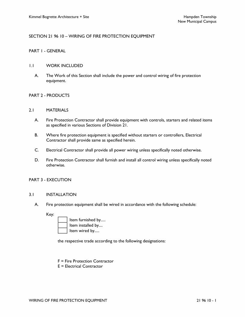
Kimmel Bogrette Architecture + Site Hampden Township
New Municipal Campus
WIRING OF FIRE PROTECTION EQUIPMENT 21 96 10 - 1
SECTION 21 96 10 – WIRING OF FIRE PROTECTION EQUIPMENT
PART 1 - GENERAL
1.1 WORK INCLUDED
A. The Work of this Section shall include the power and control wiring of fire protection
equipment.
PART 2 - PRODUCTS
2.1 MATERIALS
A. Fire Protection Contractor shall provide equipment with controls, starters and related items
as specified in various Sections of Division 21.
B. Where fire protection equipment is specified without starters or controllers, Electrical
Contractor shall provide same as specified herein.
C. Electrical Contractor shall provide all power wiring unless specifically noted otherwise.
D. Fire Protection Contractor shall furnish and install all control wiring unless specifically noted
otherwise.
PART 3 - EXECUTION
3.1 INSTALLATION
A. Fire protection equipment shall be wired in accordance with the following schedule:
Key:
Item furnished by.....
Item installed by....
Item wired by.....
the respective trade according to the following designations:
F = Fire Protection Contractor
E = Electrical Contractor

Kimmel Bogrette Architecture + Site Hampden Township
New Municipal Campus
WIRING OF FIRE PROTECTION EQUIPMENT 21 96 10 - 2
Fire Protection Equipment Wiring Schedule
Equipment
Disconnect Means Controllers Control Devices
Rem
ote
Dis
connect
Sw
itch
Inte
gral
Dis
connect
Sw
itch
Wal
l Sw
itch
Cord
& P
lug
Mag
netic
Moto
r St
r
Com
bin
atio
n M
oto
r St
r
Man
ual
Moto
r St
r
VFD
with D
isco
nnect
Conta
ctor
Lin
e V
olt
age S
tat
Low
Volt
age S
tat
Aquas
tat
Duct
Sm
oke D
ete
ctor
Contr
ol Pan
el
Flo
w/P
ress
/Leve
l Sw
itch
BA
S/A
TC
Contr
ol
Flow and Tamper
Switches F
F
E
Clean Agent System F F
F F
E E
Electric Alarm Bell F
F
E
B. Unless noted, Contractor responsible for wiring of an item shall be responsible for furnishing
and installing all wiring for that item and making all connections associated with this wiring.
END OF SECTION 21 96 10

Kimmel Bogrette Architecture + Site Hampden Township
New Municipal Campus
PLUMBING BASIC MATERIALS 22 05 05 - 1
SECTION 22 05 05 – PLUMBING BASIC MATERIALS
PART 1 - GENERAL
1.1 WORK INCLUDED
A. The Work of this Section shall consist of the labor, materials and equipment required for the
installation of basic materials and motors associated with plumbing systems.
1.2 SUBMITTALS
A. Submit for approval in accordance with specified submittal procedures:
1. Access Panels
2. Fire Stop Sealing System
3. Pipe Penetration Seal
4. Equipment Nameplates; including itemized listing of nameplate equipment designations
5. Motors; submit with each piece of equipment
PART 2 - PRODUCTS
2.1 ACCESS PANELS
A. Access Panel Specification No. 1
1. Acceptable Manufacturer: Milcor Style AP for acoustical plaster, Style AT for acoustical
tile, or Karp, Krieger, Bilco, MiFab.
2. Type: Acoustical ceiling.
3. Construction: 16 gage galvanized steel frame, 18 gage galvanized steel panel. Recessed to
accommodate acoustical ceiling tile. Continuous hinge, steel with stainless steel pin.
4. Closing Feature: Flush, screw driver operated lock with steel cam.
B. Access Panel Specification No. 2
1. Acceptable Manufacturer: Milcor Style DW, or Karp, Krieger, Bilco, MiFab.
2. Type: Gypsum wallboard.
3. Construction: 16 gage steel frame, 14 gage steel panel.
4. Concealed spring hinges. Prime coat finish for field painting.
5. Closing Feature: Flush, screwdriver operated lock with steel cam.

Kimmel Bogrette Architecture + Site Hampden Township
New Municipal Campus
PLUMBING BASIC MATERIALS 22 05 05 - 2
C. Access Panel Specification No. 3
1. Acceptable Manufacturer: Milcor, or Karp.
2. Type: Fire rated.
3. Construction: 16 gage steel frame, 20 gage steel panel.
4. Continuous hinge with stainless steel pin. Automatic panel closer. Factory attached
masonry anchors.
5. Rating: UL listed 1 1/2 hour (B label), temperature rise 30 minutes, 250 degrees F.
maximum.
6. Closing Feature: Self latching lock, direct action knurled knob, interior latch release
mechanism.
D. Access Panel Specification No. 4
1. Acceptable Manufacturer: Milcor Style M, or Karp, Krieger, Bilco, MiFab.
2. Type: Masonry, tile, or wood.
3. Construction: 16 gage frame, 14 gage panel. Concealed spring hinges. Prime coat finish
for field painting or stainless steel, satin finish, as required.
4. Closing Feature: Flush screwdriver operated lock with steel cam.
E. Access Panel Specification No. 5
1. Acceptable Manufacturer: Milcor Style K, or Karp, Krieger, Bilco, MiFab.
2. Type: Plastered surfaces.
3. Construction: 16 gage frame, 14 gage panel. Concealed spring hinges. Prime coat finish
for field painting.
4. Closing Feature: Flush, screwdriver operated lock with steel cam.
2.2 FIRE STOP SEALING SYSTEM
A. Acceptable Manufacturer: Nelson Firestop Products CLK Silicone Sealant, or 3M Fire
Protection Products, RectorSeal, Specified Technologies (STI), Tremco.
B. Materials: Single component, ready-to-use, water-resistant, flexible elastomeric silicone sealant.
Non-sag/gunnable grade for penetrations in vertical surfaces, self-leveling grade for floor
applications.
C. Compliance: Fire endurance tested per ASTM E-814 (UL 1479). In addition to compliance as a
fire stop, the cured sealing system shall not permit smoke or water penetration.
2.3 PIPE PENETRATION SEAL
A. Acceptable Manufacturer: Thunderline Link Seal.

Kimmel Bogrette Architecture + Site Hampden Township
New Municipal Campus
PLUMBING BASIC MATERIALS 22 05 05 - 3
B. Seals shall be modular mechanical type, consisting of interlocking synthetic rubber links shaped
to continuously fill the annular space between the pipe and wall opening. Each link shall have a
bolt/pressure plate tightening assembly. Final installation shall be watertight and provide an
electrical insulation between pipe and wall sleeve/opening.
2.4 EQUIPMENT NAMEPLATES
A. Laminated phenolic, two outer layers of white phenolic and an inner layer of black with
engraving depth to the inner layer.
B. Nameplate and lettering suitably sized for their location, but not less than 1/4 inch high letters.
2.5 EQUIPMENT LOCATION LABELS
A. Equipment location labels shall be self-adhering, 3/4 inch diameter, gloss vinyl circles. Labels
shall be placed on the T-bar of the adjoining ceiling tile to be removed for access to item.
Color-coding of labels shall be as directed by Owner.
2.6 MOTORS
A. Motor Characteristics:
1. Duty: Continuous duty at ambient temperature of 40 degrees C and at an altitude of
3300 feet above sea level.
2. Capacity and Torque Characteristics: Sufficient to start, accelerate, and operate
connected loads at designated speeds, at installed altitude and environment, with
indicated operating sequence, and without exceeding nameplate ratings or considering
service factor. Horsepower rating shall not be less than size indicated on Drawings.
B. Three Phase Motors:
1. Description: NEMA MG 1, Design B, medium induction motor.
2. Efficiency: Premium efficiency, as defined by NEMA MG 1.
3. Voltage: As indicated on Drawings.
4. Service Factor: 1.15.
5. Insulation: NEMA Class F.
6. Sound Power Levels: Conform to NEMA MG 1.
7. Bearings: Grease lubricated anti-friction ball bearings with housings equipped with
plugged provision for re-lubrication, rated for minimum AFBMA 9, L-10 life of 200,000
hours.
8. Thermal Protection: Internal, automatically reset.
9. Motors Used with Variable Frequency Drives:
a. Windings: Copper magnet wire with moisture-resistant varnish, designed and
tested to resist transient spikes, high frequencies, and short time rise pulses
produced by pulse-width modulated inverters.

Kimmel Bogrette Architecture + Site Hampden Township
New Municipal Campus
PLUMBING BASIC MATERIALS 22 05 05 - 4
b. Premium-Efficient Motors: Class B temperature rise; Class F insulation.
c. Inverter-Duty Motors: Class F temperature rise; Class H insulation.
d. Shaft grounding ring.
C. Single Phase Motors:
1. Larger Than 1/20 HP: One of the following, to suit starting torque and requirements of
specific motor applications:
a. Permanent-split capacitor.
b. Split phase.
c. Capacitor start, inductor run.
d. Capacitor start, capacitor run.
2. Motors 1/20 HP and Smaller: Shaded-pole type. Multispeed Motors: Variable-torque,
permanent-split-capacitor type.
3. Voltage: As indicated on Drawings.
4. Bearings: Prelubricated, antifriction ball bearings or sleeve bearings.
D. Thermal Protection: Internal, automatically reset.
2.7 PAINT
A. General
1. Products: Complying with MPI standards indicated and listed in "MPI Approved
Products List."
2. Provide materials for use within each paint system that are compatible with one another
and substrates indicated, under conditions of service and application as demonstrated by
manufacturer, based on testing and field experience.
B. Color: As selected by Owner from manufacturer's full range and colors conforming with
ASME 13.1 for application(s) indicated below:
1. Natural Gas Piping: Yellow
C. Steel Substrates: Quick-drying Enamel System MPI EXT 5.1A.
1. Prime Coat: Quick-Drying Alkyd Metal Primer: MPI #76.
2. Intermediate Coat: Quick-drying enamel matching topcoat.
3. Topcoat: Quick-drying enamel (high gloss): MPI #96 (Gloss Level 7).
D. Galvanized-metal Substrates: Latex System MPI EXT-5.3A
1. Prime Coat: Waterborne galvanized-metal primer.
2. Intermediate Coat: Latex matching topcoat.
3. Topcoat: Exterior Latex (Flat): MPI #10 (Gloss Level 1).

Kimmel Bogrette Architecture + Site Hampden Township
New Municipal Campus
PLUMBING BASIC MATERIALS 22 05 05 - 5
PART 3 - EXECUTION
3.1 INSTALLATION
A. Access Panels
1. Furnish and install access panels in ceilings and walls for service and repair access to
concealed equipment, including, but not limited to:
a. Valves: hand operated and automatic
b. Backflow preventers
c. Gages and thermometers
d. Water hammer arresters
e. Pressure regulating/reducing valves
f. Expansion compensators
g. Calibrated balancing valves
2. Minimum Size: 18 inches by 18 inches. Where restrictions will not permit minimum size,
verify access panel size with Architect.
3. Provide access panels in accordance with the following schedule:
ACCESS PANEL SCHEDULE
Application Access Panel Spec. No.
Acoustical tile or acoustical plaster
finishes
1
Gypsum board (dry wall) finishes 2
Fire rated walls 3
Masonry, tile, or wood finishes 4
Plastered finishes 5
4. Access panel location(s) that are indicated on drawings are of a specific concern.
However, Contractor shall be responsible to furnish and install access panels as
required, whether noted on Drawings or required by this section.
B. Sleeves and Plates
1. Furnish and install sleeves for all pipes passing through floors, walls, partitions, slabs,
grade beams and foundations.
2. Layout, size, and locate sleeves such that they be set and installed prior to pouring
concrete, or when masonry is being constructed. In event sleeves must be placed after
floor, wall, grade beam, etc., has been constructed, submit in writing to and obtain
approval from Architect on location, quantity and proposed method of core drilling and
installing.
3. Core drilled openings above grade in solid concrete need not be sleeved but must be
clean and neat without cracking or spalling.

Kimmel Bogrette Architecture + Site Hampden Township
New Municipal Campus
PLUMBING BASIC MATERIALS 22 05 05 - 6
4. Sleeves shall be standard weight galvanized steel pipe having square cut ends with
anchoring lugs welded on. Horizontal sleeves through walls, grade beams, foundations,
and partitions shall be flush with finished wall faces. Vertical sleeves through floors shall
extend 2 inches above finished floor and be flush with finished ceiling or underside of
floor construction. Sleeves in pits or below grade shall be painted or coated with one
coat of coal tar pitch paint.
5. Size sleeves such that internal diameter is 2 pipe sizes or a minimum of 2 inches larger
than outside diameter of bare pipe for uninsulated lines and 2 inches larger than outside
diameter of insulation and jacket for insulated lines. Center pipes in sleeves.
6. For pipes passing through floors, slabs, walls, grade beams, or foundations at or below
grade and in pits, the annular space between outside of pipe or insulation and inside of
sleeve shall be packed with a pliable, non hardening waterproof mastic sealer or a
cement base quick set repair mortar.
7. For pipes passing through walls and floors above grade and with no fire or smoke rating,
the annular space between outside of pipe or insulation and inside of sleeve or concrete
shall be packed tight with batt type fiberglass insulation.
8. For pipes passing through walls and floors above grade with smoke or fire rating of one
hour or more, the annular space between outside of pipe and insulation and inside of
sleeve or concrete shall be sealed with fire stop sealing system.
C. Fire Stop Sealing System
1. All floor and interior wall penetrations with smoke or fire rating of one hour or more
shall be sealed. Refer to architectural drawings for locations of fire rated floors and
walls.
2. Prepare penetration and install sealing material in accordance with the manufacturer's
recommendations.
3. Through penetration fire stop sealing systems shall be identified on both sides with
permanently mounted, preprinted vinyl labels which include the following information:
a. The words “Warning: Through Penetration Firestop System – Do Not Disturb”
or similar phrase.
b. Manufacturer’s brand name, product type or catalog number
c. Testing agency designation and rating
d. Installer’s Name
e. Installation Date
D. Equipment Nameplates
1. Furnish and install a full complement of nameplates for all items of mechanical
equipment installed as Work of this Division, including water heaters, pumps, mixing
valves and control panels.
2. Install nameplates parallel to equipment lines.
3. Unless noted, nameplates shall be attached with sheet metal screws or epoxy cement.
Epoxy cement shall not be used equipment installed outdoors.
4. Coordinate with Owner for nameplate designations. Submit a complete itemized listing
of nameplate equipment designations for approval.

Kimmel Bogrette Architecture + Site Hampden Township
New Municipal Campus
PLUMBING BASIC MATERIALS 22 05 05 - 7
E. Painting
1. Comply with manufacturer's written instructions and recommendations in "MPI
Architectural Painting Specification Manual" applicable to substrates and paint systems
indicated.
2. Clean substrates of substances that could impair bond of paints, including dirt, oil,
grease, and incompatible paints and encapsulants.
a. Remove incompatible primers and reprime substrate with compatible primers as
required to produce paint systems indicated.
3. Apply paints to produce surface films without cloudiness, spotting, holidays, laps, brush
marks, roller tracking, runs, sags, ropiness, or other surface imperfections. Cut in sharp
lines and color breaks.
4. Protect work of other trades against damage from paint application. Correct damage to
work of other trades by cleaning, repairing, replacing, and refinishing, as approved by
Architect, and leave in an undamaged condition.
5. At completion of construction activities of other trades, touch up and restore damaged
or defaced painted surfaces.
END OF SECTION 22 05 05
Kimmel Bogrette Architecture + Site Hampden Township
New Municipal Campus
PLUMBING PIPE AND PIPE FITTINGS 22 05 10 - 1
SECTION 22 05 10 – PLUMBING PIPE AND PIPE FITTINGS
PART 1 - GENERAL
1.1 WORK INCLUDED
A. The Work of this Section shall consist of the labor, materials and equipment required for the
installation of plumbing piping and pipe fittings.
PART 2 - PRODUCTS
2.1 PIPE AND PIPE FITTINGS
A. Pipe shall conform to the materials specified herein, and shall be installed for piping systems as
scheduled in Part 3 – Execution, of this Section.
2.2 TYPE L COPPER PIPE SPECIFICATION NO. 1
A. Design Pressure: 150 psig.
B. Maximum Design Temperature: 200 degrees F.
C. Sizes 2 inches and smaller:
1. Tubing: Type L hard drawn seamless copper tube, ASTM B88.
2. Joints: Solder type with 95-5 solder, or press coupled.
3. Fittings: Wrought copper solder joint, ANSI B16.22 or cast bronze solder joint, ANSI
B16.18, or with EPDM O-rings, ASME B16.18 or ASME B16.22.
D. Sizes 2 1/2 inches and larger:
1. Tubing: Type L hard drawn seamless copper tube, ASTM B88.
2. Joints: Flanged and solder type with 95-5 solder, or press coupled.
3. Fittings: Wrought copper solder joint, ANSI B16.22 or cast bronze solder joint, ANSI
B16.18, or wrought copper press coupled joint. ANSI B16.22.
4. Flanges: 150 lb. class cast bronze, ANSI B16.24.
2.3 TYPE K COPPER UNDERGROUND PRESSURE PIPE SPECIFICATION NO. 2
A. Design Pressure: 150 psig.
B. Maximum Design Temperature: 150 degrees F.
Kimmel Bogrette Architecture + Site Hampden Township
New Municipal Campus
PLUMBING PIPE AND PIPE FITTINGS 22 05 10 - 2
C. Sizes 2 inches and smaller:
1. Tubing: Type K hard drawn seamless copper tube, ASTM B88.
2. Joints: Solder type with 95-5 solder.
3. Fittings: Wrought copper solder joint, ANSI B16.22 or cast bronze solder joint, ANSI
B16.18.
D. Sizes 2 1/2 inches and 3 inches:
1. Tubing: Type K hard drawn seamless copper tube, ASTM B88.
2. Joints: Flanged and solder type with 95-5 solder.
3. Fittings: Wrought copper solder joint, ANSI B16.22 or cast bronze solder joint, ANSI
B16.18.
4. Flanges: 150 lb. class cast bronze, ANSI B16.24.
E. Pipes penetrating building floors on grade or building walls or pit walls below grade shall be
ductile iron. Refer to Ductile Iron Pressure Pipe Specification No. 6.
2.4 SERVICE WEIGHT CAST IRON PIPE SPECIFICATION NO. 3
A. Approvals: Cast iron soil pipe and pipe fittings shall be marked with the collective trademark of
the Cast Iron Soil Pipe Institute (CISPI) and shall be listed by NSF International.
B. Design Pressure: Gravity.
C. Maximum Design Temperature: 180 degrees F.
D. All Pipe Sizes:
1. Pipe & Fittings
a. Below Grade: Service weight cast iron soil pipe, tar coated inside and outside,
ASTM A74.
b. Above Grade: Hubless cast iron soil pipe, tar coated inside and outside, CISPI
Standard 301, ASTM A888.
2. Joints
a. Below Grade: Hub and spigot, compression.
b. Above Grade: Hubless.
3. Adapters: Transitions from cast iron soil pipe to another pipe material shall be made
with Fernco Joint Sealer Company PVC Donut adapters, or approved equal. Hubless
transitions shall be made with an approved, shielded coupling for the purpose and
material.
E. Vent Flashing: By General Contractor.
2.5 DUCTILE IRON PRESSURE PIPE SPECIFICATION NO. 6
A. Sizes: 4 inches and larger.

Kimmel Bogrette Architecture + Site Hampden Township
New Municipal Campus
PLUMBING PIPE AND PIPE FITTINGS 22 05 10 - 3
B. Pipe: Ductile iron pressure water pipe, thickness Class 51 for 4 inch pipe size, thickness Class
50 for sizes 6 inches through 24 inches, 250 psi rated working pressure, in accordance with
ANSI A21.50 and ANSI A21.51, tar coated outside, and cement mortar lined inside in
accordance with ANSI A21.4. Full lengths of pipe shall be utilized to the greatest extent
possible.
C. Joints: Mechanical or push on joints.
D. Fittings: Push on joint or mechanical joint type shall be cast iron or ductile iron, 250 psi
pressure rating, in accordance with ANSI B21.10, tar coated outside and cement mortar lined
inside in accordance with ANSI A21.4.
E. Flanged type shall be cast iron or ductile iron, short body, 250 psi pressure rating, in
accordance with ANSI A21.10 (drilled and faced in accordance with ANSI B16.1, Class 125),
tar coated outside, and cement mortar lined inside in accordance with ANSI A21.4.
F. Pipe penetrating building floors on grade shall be ductile iron, thickness Class 51 for 4 inch
pipe size, thickness Class 50 for 6 inches through 24 inches, 250 psi rated working pressure, in
accordance with ANSI A21.50 and ANSI A21.51, tar coated outside, and cement mortar lined
inside in accordance with ANSI A21.4. Pipe shall be one piece beginning at engagement of plain
end with 1/4 bend below the floor and terminating six inches above floor level with a ductile
iron flange.
G. Pipe penetrating building walls or pit walls below grade shall be ductile iron, thickness Class 51
for 4 inch pipe size, thickness Class 50 for 6 inches through 24 inches, 250 psi working
pressure, in accordance with ANSI A21.50 and ANSI A21.51, tar coated outside, and cement
mortar lined inside in accordance with ANSI A21.4. Pipe shall terminate approximately 12
inches either side of wall with push on joint bell end or mechanical joint bell end on outside
and ductile iron flange on inside.
2.6 SCHEDULE 40 BLACK STEEL PIPE SPECIFICATION NO. 8
A. Design Pressure: 150 psig.
B. Maximum Design Temperature: 350 degrees F.
C. Sizes 2-1/2 inches and smaller:
1. Pipe: Schedule 40 black steel, threaded and coupled, ASTM A53.
2. Joints: Threaded. (Exception: All gas piping installed in steel conduits; all gas conduit and
conduit vent pipe; all black steel pipe installations below ground; shall be continuous
butt weld joints.)
3. Fittings: 150 lb (S) 300 lb (WOG) black malleable iron.
4. Unions: 250 lb (S) 500 lb (WOG) black malleable iron, ground joint with brass seat.
D. Sizes 3 inches and larger:
1. Pipe: Schedule 40 black steel, beveled ends, ASTM A53.
2. Joints: Butt welded and flanged.

Kimmel Bogrette Architecture + Site Hampden Township
New Municipal Campus
PLUMBING PIPE AND PIPE FITTINGS 22 05 10 - 4
3. Fittings: Schedule 40 seamless steel, butt weld type, ASTM A234.
4. Flanges: 150 lb forged steel, welding neck or slip on, ASTM A181 Class 60.
E. All piping installed below ground shall have factory applied coal tar coating. Below ground
joints shall have a field applied coal tar coating.
2.7 SCHEDULE 40 PVC PIPE SPECIFICATION NO. 13
A. Design Pressure: Gravity.
B. Maximum Design Temperature: 140 degrees F. at continuous flow.
C. All Pipe Sizes:
1. Schedule 40, polyvinyl chloride (PVC), ASTM D2665 with NSF seal.
2. Fittings: Schedule 40, polyvinyl chloride, DWV pattern, ASTM D2665 with NSF seal.
D. Sizes: 2 inches and smaller:
1. Joints: Socket or factory threaded solvent cement ASTM D2564.
E. Sizes: 2-1/2 inches or larger:
1. Joints: Socket or flanged solvent cement ASTM D2564.
F. Vent Flashing: By General Contractor.
2.8 UNDERGROUND POLYETHYLENE NATURAL GAS PIPE SPECIFICATION NO. 23
A. Polyethylene Pipe: ASTM D2513, SDR11.5
1. Fittings: ASTM D2683 or ASTM D2513, socket type.
2. Joints: Fusion welded.
3. Manufacturer of pipe shall be approved by local gas company.
2.9 WARNING TAPE FOR BURIED UTILITIES
A. Acceptable Manufacturer: Harris Industries, Griffolyn, Inc., Stanco, Inc.
B. Type: Detectable underground marker and warning tape, fully detectable using above grade
induction conduction type locaters. Consist of either aluminum foil or stainless steel tracer
wires laminated between multiple layers of polyethylene tape, overall thickness 4.5 to 6 mils.
C. Material: Red, plastic, 6 inches wide, black lettering. Letter shall be abrasion resistant,
subsurface to be protected from being scraped off and protected from underground moisture,
acids, alkalis and other soil substances.
D. Marking: CAUTION – BURIED WATER/FIRE/GAS/PROPANE LINE BELOW, or similar
wording.
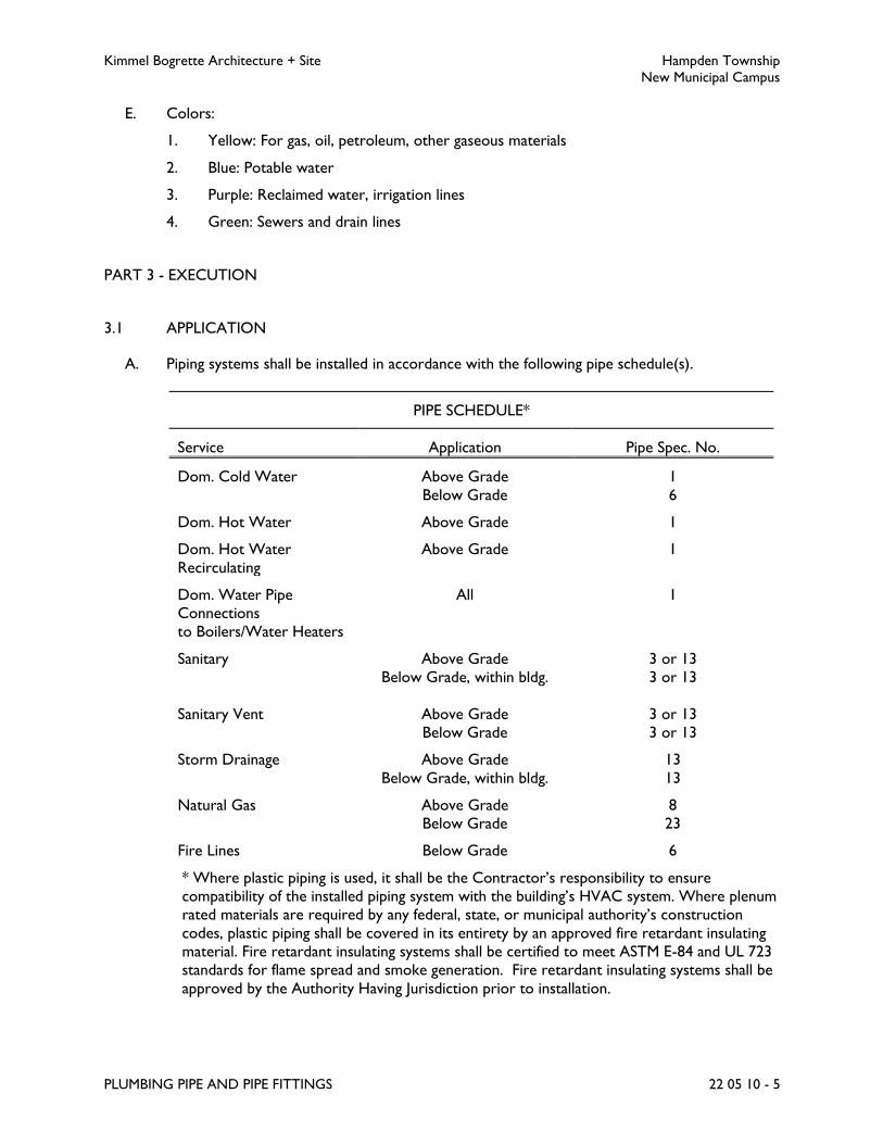
Kimmel Bogrette Architecture + Site Hampden Township
New Municipal Campus
PLUMBING PIPE AND PIPE FITTINGS 22 05 10 - 5
E. Colors:
1. Yellow: For gas, oil, petroleum, other gaseous materials
2. Blue: Potable water
3. Purple: Reclaimed water, irrigation lines
4. Green: Sewers and drain lines
PART 3 - EXECUTION
3.1 APPLICATION
A. Piping systems shall be installed in accordance with the following pipe schedule(s).
PIPE SCHEDULE*
Service Application Pipe Spec. No.
Dom. Cold Water Above Grade
Below Grade
1
6
Dom. Hot Water Above Grade 1
Dom. Hot Water
Recirculating
Above Grade 1
Dom. Water Pipe
Connections
to Boilers/Water Heaters
All 1
Sanitary Above Grade
Below Grade, within bldg.
3 or 13
3 or 13
Sanitary Vent Above Grade
Below Grade
3 or 13
3 or 13
Storm Drainage Above Grade
Below Grade, within bldg.
13
13
Natural Gas Above Grade
Below Grade
8
23
Fire Lines Below Grade 6
* Where plastic piping is used, it shall be the Contractor’s responsibility to ensure
compatibility of the installed piping system with the building’s HVAC system. Where plenum
rated materials are required by any federal, state, or municipal authority’s construction
codes, plastic piping shall be covered in its entirety by an approved fire retardant insulating
material. Fire retardant insulating systems shall be certified to meet ASTM E-84 and UL 723
standards for flame spread and smoke generation. Fire retardant insulating systems shall be
approved by the Authority Having Jurisdiction prior to installation.

Kimmel Bogrette Architecture + Site Hampden Township
New Municipal Campus
PLUMBING PIPE AND PIPE FITTINGS 22 05 10 - 6
3.2 INSTALLATION
A. Contractor shall carefully follow the Drawings in laying out and installing his work and he shall
not deviate therefrom, except for structural or interior finish interferences, and then only
upon Architect's approval.
B. All pipe and fittings shall be carefully inspected for defects in workmanship prior to installation.
Any item found unsuitable, cracked, or otherwise defective shall be rejected and removed
from the jobsite. All pipe and fittings shall have factory applied markings, stampings, or
nameplates with sufficient data for identification to determine their conformance with specified
requirements.
C. Plastic piping shall be installed in strict accordance with pipe manufacturer's recommendations
and in accordance with the recommendations of the Plastic Pipe Institute. Protect plastic piping
from damage by adjacent sharp surfaces with rubber or plastic grommets or sleeves. Plastic
underground drainage piping shall be installed in accordance with ASTM D 2321 Class 1
embedment material.
D. During construction all openings in piping shall be kept closed except when actual work is
being performed on that item. Closures shall be plugs, caps, blind flanges, or other items
specifically intended for this purpose. Exercise all necessary care to prevent foreign objects
from entering material.
E. Run pipe lines straight and true, parallel to building lines with a minimum use of offsets and
couplings. Use full and double lengths of pipe wherever possible.
F. Changes in direction shall be made only with pipe bends or fittings. Changes in size shall be
made with fittings only. All fittings shall be of the long radius type, unless otherwise specified.
Changes in direction on drainage pipe systems shall be made with wye fittings, combination
wye and eighth bends, or one eighth bends. Offset in soil or waste pipes will not be permitted
where avoidable. Offsets shall be made with 45 degree bends or similar fittings.
G. Provide flanges or unions at all final connections to equipment, traps and valves to facilitate
dismantling.
H. Unless otherwise indicated, install all piping to pumps and other equipment at line size with
reduction in size being made only at inlet to pump or equipment connection.
I. All pipe shall be cut to exact measurement, and installed without springing or forcing.
Particular care shall be taken to avoid creating, even temporarily, undue loads, forces or
strains on valves, equipment or building elements with piping connections or piping supports.
J. Install bell and spigot pipe, such that spigot ends point in direction of flow.
K. Unless otherwise indicated, branch take offs shall be from top of mains or headers at either a
45 degree or 90 degree angle from the horizontal plane for air and gas lines, and from top,
bottom or side for liquids.
L. Underground pressure piping shall be provided with concrete anchors and thrust blocks at
ends of runs and changes in direction.
Kimmel Bogrette Architecture + Site Hampden Township
New Municipal Campus
PLUMBING PIPE AND PIPE FITTINGS 22 05 10 - 7
M. Pipe joints connecting dissimilar metals shall be insulating, dielectric connections. Copper
tubing shall be protected from electrolysis at contact points with ferrous metals, including
temporary methods of support, by use of insulating, non conductive spacers such as rubber,
fiberglass or an approved equal. Pipe hangers for bare copper tubing shall be copper plated.
3.3 PIPE JOINTS
A. Heavy-duty No-hub Coupling: Heavy duty coupling shall conform to the requirements of
ASTM C1540 with AISI 304 stainless steel bi-directional corrugated shield with AISI 304
stainless steel clamps and screw housing. Gasket shall conform to ASTMC564.
B. Compression Joints, Hub and Spigot Soil Pipe: Joint shall be one piece double seal compression
type gasket made specifically for joining cast iron soil pipe. The gasket shall be neoprene
material, permitting joint to flex as much as 5 degrees without loss of seal. Gasket shall be
extra heavy conforming to ASTM C564 and ASTM C1563. Installation shall be in accordance
with manufacturer's published instructions.
C. Mechanical Joints: Joints shall conform to ANSI A21.11 Rubber Gasket Joints for Cast Iron
Pressure Pipe and Fittings. Gasket material shall be neoprene. The standard bolts and nuts of
the pipe manufacturer shall be used and shall be coated at the factory with rust preventive
lubricant after threading and tapping. Final tightening of bolts shall be with a torque wrench to
insure equal tension in all bolts.
D. Press Coupled Joints: Copper press fittings in copper domestic water pipe, types L and K, shall
be a NSF-61, ASME B16.22 and ASTM B88 approved external compression system. System
shall be rated to hold 200 PSI working pressure with a temperature range from 0 degrees
Fahrenheit to 250 degrees Fahrenheit. System may be rated for installation on wet or dry
piping for sizes 1/2 inch to 4 inch diameter. Fittings shall be properly cleaned prior in
accordance with manufacturer’s recommendations prior to installation.
E. Solder Joints: Make up joints with 95 percent tin and 5 percent antimony (95-5) solder
conforming to ASTM B32 Solder Metal, Grade 95TA. Cut copper tubing so ends are perfectly
square and remove all burrs inside and outside. Thoroughly clean sockets of fittings and ends
of tubing to remove all oxide, dirt, and grease just prior to soldering. Apply flux evenly, but
sparingly, over all surfaces to be joined. Heat joints uniformly to proper soldering temperature
so solder will flow to all mated surfaces. Wipe excess solder, leaving a uniform fillet around
cup of fitting. Flux shall be non acid type. Remove composition discs from solder end valves
during soldering.
F. Welded Joints: The welding of all pipe joints, both as to procedures and qualification of
welders, shall be in accordance with Section IX, ASME Boiler & Pressure Vessel Code, unless
mandatory local codes take precedence. Ends of pipe and fittings to be joined by butt welding
shall be beveled, cleaned to bare metal and internal diameters aligned before tack welding.
G. Threaded Joints: Pipe screw threads shall conform to ANSI B16.3, Malleable Iron Threaded
Fittings or ASTM B687, Brass, Copper, and Chromium Plated Pipe Nipples. Ream pipe ends
and remove all burrs and chips formed in cutting and threading. Protect plated pipe and brass
valve bodies from wrench marks when making up joint. Apply thread lubricant to male threads
only.
Kimmel Bogrette Architecture + Site Hampden Township
New Municipal Campus
PLUMBING PIPE AND PIPE FITTINGS 22 05 10 - 8
H. Flanged Joints: Steel pipe flanges shall conform to ANSI B16.5, Steel Pipe Flanges and Flanged
Fittings. Cast iron pipe flanges shall conform to ANSI B16.1, Cast Iron Flanges and Flanged
Fittings. Steel flanges shall be raised face except when bolted to flat cast iron flange. Bolting for
services up to 500 degrees F. shall be ASTM A307, Grade B with square head bolts and heavy
hexagonal nuts conforming to ANSI B18.2.1, Square and Hex Bolts and B18.2.2, Square and
Hex Nuts. Set flange bolts beyond finger tightness with an indicating torque wrench to insure
equal tension in all bolts. Tighten bolts such that those 180 degrees apart or directly opposite
are torqued in sequence. Gaskets for flat face flanges shall form to requirements for Group I
Gaskets in ANSI B16.5. Unless otherwise specified, gaskets shall be 3/32 inch thick.
I. Factory Threaded Solvent Cement Joints: Factory threaded solvent cement joints for plastic
pressure piping systems shall be made in accordance with manufacturer's recommendations.
The threads should be lubricated with a non hardening pipe dope or wrapped with Teflon
tape.
END OF SECTION 22 05 10
Kimmel Bogrette Architecture + Site Hampden Township
New Municipal Campus
PLUMBING PIPING SPECIALTIES 22 05 15 - 1
SECTION 22 05 15 – PLUMBING PIPING SPECIALTIES
PART 1 - GENERAL
1.1 WORK INCLUDED
A. The Work of this Section shall consist of the labor, materials, and equipment required for the
installation of plumbing piping specialties.
1.2 SUBMITTALS
A. Submit for approval in accordance with specified submittal procedures:
1. Branch Connections
2. Pipe & Valve Identification
3. Expansion Compensators, Pipe Guides, Anchors
4. Dielectric Connections
5. Thermometers
6. Pressure Gages
PART 2 - PRODUCTS
2.1 BRANCH CONNECTIONS
A. Branch connections shall be made with standard tee of the type required for the service unless
otherwise specified or detailed.
B. At Contractor's option, branch connections from headers and mains may be cut into black
steel pipe using forged weld on fittings. Weld on fittings shall conform to chemical and physical
requirements of ASTM A 234 and design and installation requirements of ANSI B31.1.
C. Weld on fittings shall have a pressure rating equal to, or greater than, the maximum working
pressure of the pipe system where they are installed.
1. Acceptable Manufacturer: Allied Piping Products Co. Branchlets (Shaped nipples), or
Bonney Forge Weldolet & Threadolet
D. At Contractor's option, branch connections from headers and mains may be cut into copper
to be using mechanically extracted collars. Collars shall be formed in a continuous operation
consisting of drilling a pilot hole and drawing out the tube surface to form a collar having a
height of not less than three times the thickness of the tube wall. Main pipe shall be vacuumed
to clear all debris during collar forming procedure. Branch pipe shall be notched to conform
with the inner curve of the run tube and dimpled to insure penetration of the branch pipe into
Kimmel Bogrette Architecture + Site Hampden Township
New Municipal Campus
PLUMBING PIPING SPECIALTIES 22 05 15 - 2
the collar at sufficient depth for brazing. All joints shall be brazed. Mechanical formed branch
collars shall be UL listed.
1. Acceptable Manufacturer: T Drill, Division of Serlachius.
2.2 ESCUTCHEON PLATES
A. Plates shall be installed on all pipes and conduit passing through floors, walls, partitions, etc., in
exposed areas.
B. Plates installed on pipe passing through core drilled openings in solid concrete without sleeves
shall be solid ring, cast iron with one set screw for sizes up to 4 inches and two set screws for
sizes up to 8 inches.
C. Plates installed on pipe and conduit passing through openings with sleeves shall be solid ring,
cast iron.
2.3 PIPE AND VALVE IDENTIFICATION
A. Acceptable Manufacturer: W. H. Brady Company, or Seton Nameplate Corp., Brimar
Industries.
B. Shutoff valves and control equipment shall be marked by means of a brass or plastic disc
minimum of 1 inch in diameter fastened to valve wheel or stem by brass wire or chain. Each
disc shall have a legibly marked identification number. A typewritten chart listing all valve tags,
location, and service shall be included in the operating and maintenance manual. The valve
chart numbering sequence shall be approved by Owner.
C. All piping installed as Work of this Division shall be identified by legend and flow arrow.
Identification system shall conform to ANSI A13.1. Identification markers shall use ANSI
standard background colors and text size. Markers shall be attached to pipe by wrapping with
color coded banding tape. Markers shall be located as follows:
1. Near each valve and control device.
2. Near each branch connection, excluding short takeoffs for fixtures and terminal units.
Where flow pattern is not obvious, mark each pipe at branch.
3. Near penetrations through walls, floors, ceilings, and non-accessible enclosures.
4. At access doors, manhole, and similar access points that permit view of concealed
piping.
5. Near major equipment items and other points of origination and termination.
6. Spaced at maximum intervals of 25 feet along each run.
2.4 EXPANSION COMPENSATORS, GUIDES, ANCHORS
A. Expansion Compensator Type EXC-2
1. Acceptable Manufacturer: Flexonics, or Keflex, Metraflex, Hyspan.

Kimmel Bogrette Architecture + Site Hampden Township
New Municipal Campus
PLUMBING PIPING SPECIALTIES 22 05 15 - 3
2. Compensators shall be suitable for absorbing expansion and contraction in copper pipe
3 inches and smaller. Compensators shall be constructed with two ply phosphor bronze
or stainless steel bellows, brass shroud, and threaded end fittings.
3. Units shall have internal guides, internal anti torque device, positioning clip, 150 psi
maximum working pressure up to 1 inch pipe size, 125 psi over 1 inch pipe size, 400
degrees F maximum operating temperature, and 2 inch stroke.
B. Provide dielectric flanges where compensators are used with copper pipe.
C. Pipe Guides
1. Acceptable Manufacturer: Flexonics Pipe Alignment Guides, or Keflex, Metraflex,
Hyspan.
2. Pipe guides shall be installed as scheduled on the Drawings in accordance with
manufacturer's recommendations. Guides shall consist of steel segmented spider, sized
to the OD of the pipe, and free to move axially in a segmented steel cylinder. Guides
shall be securely attached to the building structure.
D. Pipe Anchors
1. Anchors shall be installed in accordance with pipe guide manufacturer's and expansion
compensator manufacturer's recommendations. Anchors shall securely attach the piping
system to the building structure.
2.5 DIELECTRIC CONNECTIONS
A. Pipe joints connecting dissimilar metals shall be insulating, dielectric connections. Dielectric
connections shall also be furnished for joining similar metals in order to isolate cathodically
protected pipelines from adjoining pipe sections. Such joints, including dielectric material, shall
be rated to withstand the temperature, pressure, and other characteristics of the service for
which it is to be used, including testing pressure.
B. Screwed joints shall be made with insulating transition fittings.
1. Acceptable Manufacturer: Victaulic Dielectric Transition Fittings, Style 647.
C. Flanged joints shall be made up with insulating gaskets, bolt sleeves, and washers.
1. Acceptable Manufacturer: Watts.
2.6 THERMOMETERS
A. Acceptable Manufacturer: Trerice, or Weiss, Miljoco.
B. Thermometers shall be installed where indicated on the Drawings. Thermometers shall be 9
inch scale with 9 3/4 inch cast aluminum case, acrylic window, liquid-filled, and separable
socket. Socket shall be installed in path of water flow. Indication of operating temperature shall
read in middle third of scale. Thermometers installed 7 feet or more above floor shall be
adjustable type.
Kimmel Bogrette Architecture + Site Hampden Township
New Municipal Campus
PLUMBING PIPING SPECIALTIES 22 05 15 - 4
2.7 PRESSURE GAGES
A. Acceptable Manufacturer: Trerice, or Weiss, Miljoco.
B. Pressure gages shall be installed where indicated on the Drawings. Gage shall have a 4 inch
diameter dial with indication of operating pressure read in middle third of scale. Gages shall
have phosphor bronze tube, bronze brushed movement, cast aluminum case with black finish,
and an accuracy of 1 percent of scale range. Pressure gage shall be provided with pigtail and
stop, and shall be installed vertically.
PART 3 - EXECUTION
3.1 INSTALLATION
A. Contractor shall carefully follow the Drawings in laying out and installing his work. He shall not
deviate therefrom, except for structural or interior finish interferences, and then only upon
Architect's approval.
B. All equipment and accessories shall be carefully inspected for defects in workmanship prior to
installation. Any item found unsuitable, cracked, or otherwise defective shall be rejected and
removed from the jobsite. All equipment shall have factory applied markings, stampings, or
nameplates with sufficient data for identification to determine their conformance with specified
requirements.
C. Piping specialties shall be installed in accordance with the equipment manufacturer's
recommendations. A manufacturer's representative shall certify, in writing, any equipment
installation requested by Architect.
D. During construction all openings in equipment shall be kept closed except when actual work is
being performed on that item. Closures shall be plugs, caps, blind flanges, or other items
specifically intended for this purpose. Exercise all necessary care to prevent foreign objects
from entering material.
E. Provide flanges or unions at all final connections to equipment and traps to facilitate
dismantling.
F. Unless otherwise indicated, install all strainers to pumps, and other equipment at line size with
reduction in size being made only at inlet to or pump.
G. Unless otherwise indicated, branch take offs shall be from top of mains or headers at either a
45 degree or 90 degree angle from the horizontal plane for air, or gas lines and from top,
bottom, or side for liquids.
Kimmel Bogrette Architecture + Site Hampden Township
New Municipal Campus
PLUMBING PIPING SPECIALTIES 22 05 15 - 5
H. Pipe joints connecting dissimilar metals shall be insulating dielectric connections. Copper
tubing shall be protected from electrolysis at contact points with ferrous metals, including
temporary methods of support, by use of insulating non conductive spacers such as rubber,
fiberglass, or an approved equal. Pipe hangers for bare copper tubing shall be copper plated.
END OF SECTION 22 05 15

Kimmel Bogrette Architecture + Site Hampden Township
New Municipal Campus
PLUMBING SPECIALTIES 22 05 20 - 1
SECTION 22 05 20 – PLUMBING SPECIALTIES
PART 1 - GENERAL
1.1 WORK INCLUDED
A. The Work of this Section shall consist of the labor, materials and equipment required for
installation of the domestic water systems and associated specialties.
B. Domestic water shall be distributed to all fixtures and equipment indicated on Drawings.
C. Domestic water supply shall be extended from main to curb stop by water company.
Contractor shall make application for service and pay costs associated with same.
1.2 SUBMITTALS
A. Submit for approval in accordance with specified submittal procedures:
1. Hydrants
2. Hose Bibbs
3. Water Hammer Arresters
4. Thermostatic Mixing Valves
5. Backflow Preventers
6. Solenoid Valves
7. Vacuum Breakers
8. Calibrated Balancing Valves
9. Balancing Report (refer to Part 3 – Execution)
B. Submit written verification of testing procedures specified herein.
PART 2 - PRODUCTS
2.1 HYDRANTS
A. Wall Hydrant WH-1
1. Acceptable Manufacturer: J. R. Smith, or Zurn, Wade, Josam, Mifab.
2. Type: Non-freeze.
3. Materials
a. Body: Bronze.
b. Face: Polished bronze, nickel bronze, or brass.
c. Casing: Bronze or brass.
Kimmel Bogrette Architecture + Site Hampden Township
New Municipal Campus
PLUMBING SPECIALTIES 22 05 20 - 2
4. Key: T-handle.
5. Inlet: 3/4 inch IPS.
6. Vacuum Breaker: Integral feature.
2.2 HOSE BIBBS
A. Hose Bibb HB-1
1. Acceptable Manufacturer: Chicago, or T & S Brass.
2. Type: Interior.
3. Finish: Polished chrome plated.
4. Outlet: 3/4 inch hose thread.
5. Inlet: 3/4 inch flanged female IPS.
6. Handle: Removable tee handle/shield cap.
7. Vacuum Breaker: Integral.
2.3 WATER HAMMER ARRESTERS
A. Water Hammer Arrester for Standard Plumbing Fixtures
1. Acceptable Manufacturer: J. R. Smith Hydrotrol, or Zurn, Wade, Watts, Josam, Mifab.
2. Type: Bellows surrounded by hydraulic fluid and nitrogen or argon pressurized chamber
or pre-pressurized tank with butyl diaphragm that separates air and water or free
turning brass piston with 0-ring seals that separates air and water.
3. Material: Stainless steel or steel tank with polypropylene liner surge chamber, or barrel
fabricated of type K hard drawn copper.
4. Location: Noted on Drawings.
2.4 THERMOSTATIC MIXING VALVE
A. Acceptable Manufacturer: Powers Hydroguard, or Symmons.
B. Features: Tamperproof temperature adjustment control, union inlets, combination strainer-
check-stops, built-in shutoff in the event of hot or cold water supply failure, or thermostatic
element failure.
C. Components: Factory assembled
2.5 BACKFLOW PREVENTERS
A. Reduced Pressure Backflow Preventer
1. Sizes 1/2 inch through 2 inches
a. Acceptable Manufacturer: Watts, Zurn, or Ames.

Kimmel Bogrette Architecture + Site Hampden Township
New Municipal Campus
PLUMBING SPECIALTIES 22 05 20 - 3
b. Components: Two independently acting spring loaded toggle lever check valves
with automatically operating pressure differential relief valve, two shutoff valves,
and four test cocks, arranged so each check valve can be tested. Furnish and
install with OS&Y shutoff valves in lieu of standard shutoffs where tamper
switches are shown to be installed for partial sprinkler systems.
c. All materials shall be corrosion resistant. Ferrous metal surfaces shall be
protected against corrosion by epoxy coating.
d. Accessories: Air gap fitting.
e. Maximum Working Pressure: 175 psi.
2. Sizes 2-1/2 inches through 6 inches
a. Acceptable Manufacturer: Watts Series, Zurn, or Ames, no substitutions.
b. Components: Two independently acting spring loaded toggle lever check valves
with automatically operating pressure differential relief valve, two OS&Y gate
valves, and four test cocks, arranged so each check valve can be tested.
c. All materials shall be corrosion resistant. Ferrous metal surfaces shall be
protected against corrosion by epoxy coating.
d. Accessories: Air gap fitting.
e. Maximum Working Pressure: 175 psi.
2.6 SOLENOID VALVE
A. Acceptable Manufacturer: Magnatrol Valve Corp. Type A.
B. Valve Body: Shall be bronze construction, globe pattern design with female threaded pipe
connections. Valve port shall be equal to nominal pipe size and enclosed by renewable
standard size resilient disc.
C. Solenoid: Shall be waterproof and shall be 120 volts, single phase, 60 cycle.
D. Maximum Working Pressure: 300 psi.
E. Maximum Differential Pressure: 125 psi.
F. Accessory: Provide dashpot for delayed closing to reduce water hammer effect.
2.7 VACUUM BREAKER
A. Acceptable Manufacturer: Watts.
B. Type: Antisiphon with bronze body and internal trim, plane brass finish, with full size orifice.
C. Working Pressure: 125 psi.
2.8 CALIBRATED BALANCING VALVES
A. Acceptable Manufacturer: Bell & Gossett Model CB, or Taco.

Kimmel Bogrette Architecture + Site Hampden Township
New Municipal Campus
PLUMBING SPECIALTIES 22 05 20 - 4
B. Construction: Bronze body with threaded ends, brass ball construction with glass and carbon
filled TFE seat rings.
C. Standard Features: Differential pressure readout ports across valve seat area. Readout ports to
be fitted with internal EPT inserts and check valves. Valve body provided with 1/4 inch NPT
tapped drain purge port. Valve furnished with calibrated nameplate indicating specific valve
setting. Valve shall be rated for 300 psig at 250 degrees F. Provide portable master meter kit
for use during start up, testing and balancing. Meter kit shall be delivered to Owner at
completion of Work.
D. Line size(s) indicated on drawings does not necessarily indicate required size for calibrated
balancing valves. Contractor shall be responsible to select appropriate valve size according to
flow characteristics.
PART 3 - EXECUTION
3.1 INSTALLATION
A. Install plumbing specialties in accordance with equipment manufacturer’s recommendations.
Submit manufacturer’s printed installation instructions, operating and maintenance data, and
wiring diagrams for all electric powered equipment at completion of Work.
B. Connections to fixtures and equipment shall be according to manufacturer’s
recommendations. Piping runs shall be made in a manner to insure easy and even flow,
eliminate air pockets, and to permit drainage and venting. Provide 6 inch (minimum) separation
between hot and cold water piping.
C. Mains and principle branches shall be valved for isolation and shall have drain valves installed at
low points for system draining.
D. Furnish and install proper plastic-to-copper adapters for all plumbing fixture supplies.
E. Domestic hot and cold water piping systems shall be disinfected prior to use. Method to be
used shall be that method prescribed by local codes, or, if method is not prescribed by local
code, the International Plumbing Code (latest edition) method should be followed. For plastic
water piping systems verify with plastic pipe manufacturer that disinfection solution to be used
will not harm piping system.
F. Thermostatic mixing valves shall be installed in accordance with manufacturer’s piping
installation diagram(s) and referenced details.
3.2 TESTING AND BALANCING
A. Water Lines: Test water lines in accordance with local codes. If method is not prescribed by
local codes, the International Plumbing Code (latest edition) method shall be followed.
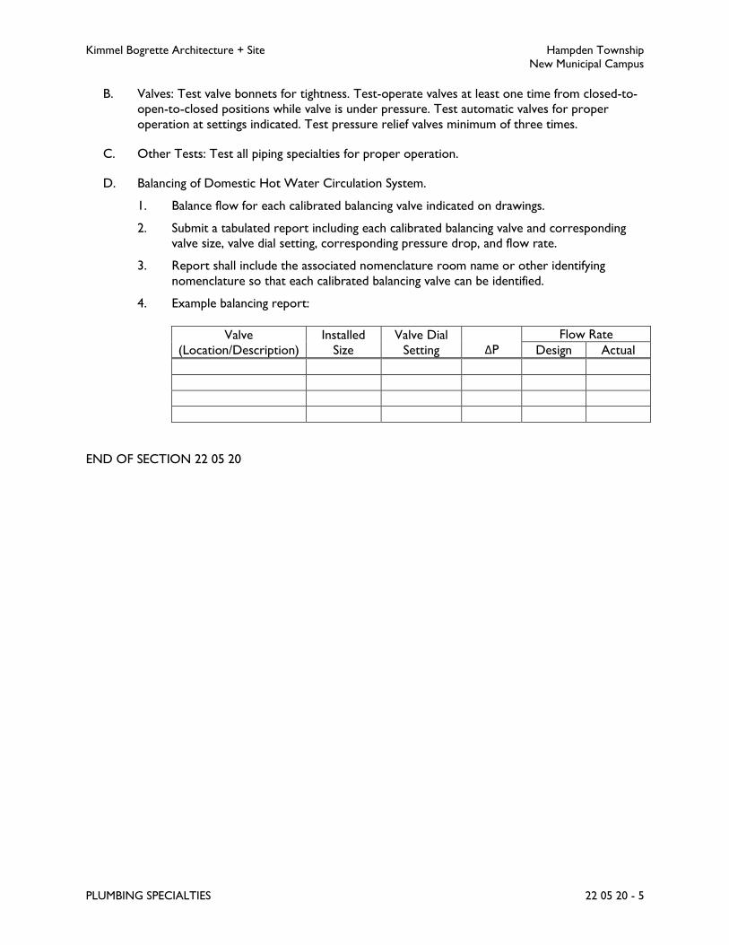
Kimmel Bogrette Architecture + Site Hampden Township
New Municipal Campus
PLUMBING SPECIALTIES 22 05 20 - 5
B. Valves: Test valve bonnets for tightness. Test-operate valves at least one time from closed-to-
open-to-closed positions while valve is under pressure. Test automatic valves for proper
operation at settings indicated. Test pressure relief valves minimum of three times.
C. Other Tests: Test all piping specialties for proper operation.
D. Balancing of Domestic Hot Water Circulation System.
1. Balance flow for each calibrated balancing valve indicated on drawings.
2. Submit a tabulated report including each calibrated balancing valve and corresponding
valve size, valve dial setting, corresponding pressure drop, and flow rate.
3. Report shall include the associated nomenclature room name or other identifying
nomenclature so that each calibrated balancing valve can be identified.
4. Example balancing report:
Valve
(Location/Description)
Installed
Size
Valve Dial
Setting ΔP
Flow Rate
Design Actual
END OF SECTION 22 05 20
Kimmel Bogrette Architecture + Site Hampden Township
New Municipal Campus
PLUMBING VALVES 22 05 25 - 1
SECTION 22 05 25 – PLUMBING VALVES
PART 1 - GENERAL
1.1 WORK INCLUDED
A. The Work of this Section shall consist of the labor, materials and equipment required for the
installation of plumbing valves.
1.2 SUBMITTALS
A. Submit for approval in accordance with specified submittal procedures:
1. Valves
PART 2 - PRODUCTS
2.1 VALVES
A. Furnish and install valves as specified herein and as scheduled in Part 3 - Execution, of this
Section. Insofar as possible all valves shall be of a single manufacturer.
B. Packings, gaskets, discs, seats, diaphragms, lubricants, etc., shall conform to recommendations
of the valve manufacturer for the intended service.
C. If space permits, install valves with stems horizontal or extending vertically upward unless
specifically shown otherwise. Valves shall be installed in accessible locations for operation as
well as for removal, repair, or replacement.
D. Valves installed in Insulated Piping: With stem or neck extensions of sufficient length to
accommodate insulation thickness and the following features:
1. Gate Valves: With rising stem.
2. Ball Valves: With extended operating handle of non-thermal-conductive material, and
protective sleeve that allows operation of valve without breaking the vapor seal or
disturbing insulation.
3. Butterfly Valves: With extended neck.
E. Provide Owner with one operating wrench for every ten (10) valves of each type (but not less
than 2 wrenches) not equipped with handwheels or levers.
F. Valves shall conform to the following schedules:
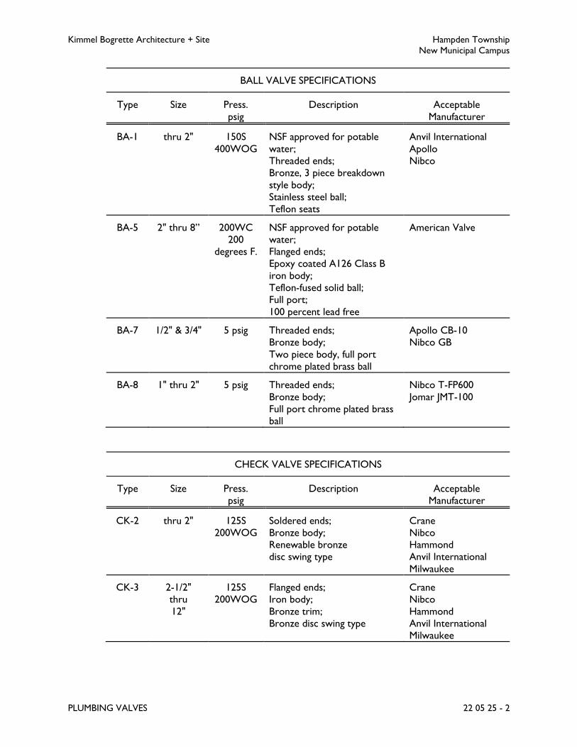
Kimmel Bogrette Architecture + Site Hampden Township
New Municipal Campus
PLUMBING VALVES 22 05 25 - 2
BALL VALVE SPECIFICATIONS
Type Size Press.
psig
Description Acceptable
Manufacturer
BA-1 thru 2" 150S
400WOG
NSF approved for potable
water;
Threaded ends;
Bronze, 3 piece breakdown
style body;
Stainless steel ball;
Teflon seats
Anvil International
Apollo
Nibco
BA-5 2" thru 8” 200WC
200
degrees F.
NSF approved for potable
water;
Flanged ends;
Epoxy coated A126 Class B
iron body;
Teflon-fused solid ball;
Full port;
100 percent lead free
American Valve
BA-7 1/2" & 3/4" 5 psig Threaded ends;
Bronze body;
Two piece body, full port
chrome plated brass ball
Apollo CB-10
Nibco GB
BA-8 1" thru 2" 5 psig Threaded ends;
Bronze body;
Full port chrome plated brass
ball
Nibco T-FP600
Jomar JMT-100
CHECK VALVE SPECIFICATIONS
Type Size Press.
psig
Description Acceptable
Manufacturer
CK-2 thru 2" 125S
200WOG
Soldered ends;
Bronze body;
Renewable bronze
disc swing type
Crane
Nibco
Hammond
Anvil International
Milwaukee
CK-3 2-1/2"
thru
12"
125S
200WOG
Flanged ends;
Iron body;
Bronze trim;
Bronze disc swing type
Crane
Nibco
Hammond
Anvil International
Milwaukee

Kimmel Bogrette Architecture + Site Hampden Township
New Municipal Campus
PLUMBING VALVES 22 05 25 - 3
PLUG VALVE SPECIFICATIONS
Type Size Press.
psig
Description Acceptable
Manufacturer
PL-1 thru 2" 200WOG Threaded ends;
Cast iron body;
Lubricated plug;
Wrench operated
Walworth
PL-2 2-1/2"
thru 10"
200WOG Flanged ends;
Cast iron body;
Lubricated plug;
4" & under: wrench
operated;
over 4": worm gear
operated
Walworth
PART 3 - EXECUTION
3.1 APPLICATION
A. Valves shall be installed in accordance with the following valve schedule:
VALVE SCHEDULE
Piping System
Valve Service
Shut-off Balancing Check
Domestic Water, Copper:
Cold, Hot, Hot Recirc.,
Make-up
BA-1 BA-5
n/a CK-2, CK-3
Natural Gas BA-7, BA-8, PL-1, PL-
2
n/a n/a
3.2 INSTALLATION
A. Contractor shall carefully follow the Drawings in laying out and installing his work and he shall
not deviate therefrom, except for structural or interior finish interferences, and then only
upon Architect's approval.
B. All valves shall be carefully inspected for defects in workmanship prior to installation. Any item
found unsuitable, cracked, or otherwise defective shall be rejected and removed from the job
site. All valves shall have factory applied markings, stampings, or nameplates with sufficient data
for identification to determine their conformance with specified requirements.
C. Provide flanges or unions at all final connections to valves to facilitate dismantling.

Kimmel Bogrette Architecture + Site Hampden Township
New Municipal Campus
PLUMBING VALVES 22 05 25 - 4
D. Unless otherwise indicated, install all shutoff valves to pumps and other equipment at line size
with reduction in size being made only at inlet to pump or other equipment.
END OF SECTION 22 05 25

Kimmel Bogrette Architecture + Site Hampden Township
New Municipal Campus
PLUMBING SUPPORTS AND ANCHORS 22 05 30 - 1
SECTION 22 05 30 – PLUMBING SUPPORTS AND ANCHORS
PART 1 - GENERAL
1.1 WORK INCLUDED
A. The Work of this Section shall consist of the labor, materials and equipment required for the
installation of plumbing supporting devices.
1.2 SUBMITTALS
A. Submit for approval in accordance with specified submittal procedures.
PART 2 - PRODUCTS
2.1 HANGERS – INSULATED PIPING
A. Acceptable Manufacturer: National Pipe Hanger Corporation, Carpenter & Paterson, Inc.,
Anvil, or equal.
B. Hangers used with insulated piping shall be sized to accommodate the pipe, and insulation and
shall have a support shield to prevent the hanger from compressing the insulation. Hanger shall
be clevis type with rod and two nuts or bolt and nut.
2.2 HANGERS – UNINSULATED PIPING
A. Acceptable Manufacturer: National Pipe Hanger Corporation, Carpenter & Paterson, Inc.,
Anvil, or equal.
B. Hangers for uninsulated ferrous pipe shall be clevis type with rod and two nuts or bolt and
nut. Hangers for uninsulated copper pipe shall be clevis type with bolt and nut and shall be
copper plated.
2.3 INSERTS – POURED CONCRETE
A. Acceptable Manufacturer: National Pipe Hanger Corporation, Carpenter & Paterson, Inc.,
Anvil, or equal.
B. Inserts shall have cast malleable iron body and nut with galvanized finish.
2.4 INSERTS – PRECAST OR CURED CONCRETE
A. Acceptable Manufacturer: Hilti HSL.

Kimmel Bogrette Architecture + Site Hampden Township
New Municipal Campus
PLUMBING SUPPORTS AND ANCHORS 22 05 30 - 2
B. A high integrity, torque controlled anchor for heavy duty fastenings. Loads shall not exceed
manufacturer's recommended weight.
2.5 BEAM CLAMPS
A. For pipe sizes of 3 inches and smaller:
1. Acceptable Manufacturer: National Pipe Hanger Corporation, Carpenter & Paterson,
Inc., Anvil, or equal.
2. Clamps for attachment to I beams and/or steel joists shall be malleable iron C clamp
with hardened steel cup and point set screw and locknut.
B. For pipe sizes of 4 inches and larger:
1. Acceptable Manufacturer: Anvil International.
2. Clamps for attachment to I beams and/or steel joists shall be adjustable type with
malleable iron jaw, steel tie rod, nuts, and washer.
PART 3 - EXECUTION
3.1 INSTALLATION
A. The requirements of the applicable Sections of ANSI B31, Pressure Piping shall be considered
as minimum requirements governing fabrication, installation, and support of piping systems
except where more specific or stringent requirements are stated herein or shown on the
Drawings.
B. All piping and piping connected equipment, including valves, strainers, traps, and other
specialties and accessories shall be supported in a manner that will not result in excessive
stress, deflection, swaying, sagging or vibration in the piping or in the building structure either
during erection, cleaning, testing, or normal operation of the systems. Piping shall not be so
restrained, however, as to cause it to snake or buckle between supports or anchors, or to
prevent proper movement due to expansion and contraction. Piping shall be supported at
equipment and valves such that they can be disconnected and removed without further
supporting the piping. Piping shall not introduce any strains or distortion to the connected
equipment.
C. Hangers, riser clamps, and supports shall be installed complete, including locknuts, clamps,
rods, bolts, couplings, swivels, inserts, and required accessory items. Hangers for horizontal
piping shall have adequate means of vertical adjustment for proper alignment of pipe, and shall
be provided with locknuts. All hangers, riser clamps, and supports in direct contact with
copper piping shall be copper plated or plastic coated.
D. Maximum spacing of supports for horizontal piping, except plastic piping, shall be as listed
below. Provide hanger rods in diameters recommended by hanger manufacturer.

Kimmel Bogrette Architecture + Site Hampden Township
New Municipal Campus
PLUMBING SUPPORTS AND ANCHORS 22 05 30 - 3
Pipe
Size
Uninsulated
Steel
Insulated
Steel
Copper
Tubing
Cast
Iron
1/2" 7' 7' 5' -
3/4" 7' 7' 5' -
1" 7' 7' 5' -
1-1/4" 7' 7' 6' -
1-1/2" 9' 9' 8' -
2" 10' 10' 8' 5'
2-1/2" 11' 10' 9' 5'
3" 12' 10' 10' 5'
4" 12' 10' 10' 5'
5" 12' 10' 10' 5'
6" 12' 10' 10' 5'
8" 12' 10' 10' 5'
E. Maximum spacing of supports for horizontal plastic sanitary drainage and vent piping shall be as
listed below. Provide hanger rods in diameters recommended by hanger manufacturer.
Pipe
Size
Sanitary
Drainage
Sanitary
Vent
1-1/2" 3' 4'
2" 3' 4'
3" 3-1/2' 4'
4" 4' 4'
6" 4' 4'
8" 4' 4'
10" 4' 4'
F. Maximum spacing of supports for horizontal plastic rainwater conductors shall be as listed
below. Provide hanger rods in diameters recommended by hanger manufacturer.
Pipe
Size
Storm
Drainage
2" 4'
4" 4'
6" 4'
8" 4'
10" 4'
G. Provide additional supports where pipe changes direction, adjacent to flanged valves and
strainers, at equipment connections and heavy fittings. Provide at least one hanger adjacent to
each joint in cast iron soil pipe and grooved end steel pipe with mechanical couplings. Unless
otherwise indicated on the Drawings, support vertical pipe with riser clamps installed below
hubs, couplings or lugs welded to the pipe.
H. Inserts for supports in precast concrete slabs shall be drilled with rotary electric drill.
Kimmel Bogrette Architecture + Site Hampden Township
New Municipal Campus
PLUMBING SUPPORTS AND ANCHORS 22 05 30 - 4
I. Beam clamps shall be used to attach hanger rods to structural steel.
END OF SECTION 22 05 30

Kimmel Bogrette Architecture + Site Hampden Township
New Municipal Campus
PLUMBING INSULATION 22 07 10 - 1
SECTION 22 07 10 – PLUMBING INSULATION
PART 1 - GENERAL
1.1 WORK INCLUDED
A. The Work of this Section shall consist of the labor, materials and equipment required for
insulating plumbing piping and equipment.
1.2 SUBMITTALS
A. Submit for approval in accordance with specified submittal procedures:
1. Insulation Materials, including application thicknesses
2. Sealants, Adhesives, Coatings
PART 2 - PRODUCTS
2.1 FIBERGLASS PIPE INSULATION SPECIFICATION NO. 1
A. Acceptable Manufacturer: Johns Manville Micro Lok, or Owens Corning Fiberglas SSL II/ASJ.
B. Material: Fiberglass pipe insulation with all purpose vapor barrier jacket for indoor installations.
C. Properties
1. Maximum K Factor: 0.23 at 75 degrees F. mean.
2. Temperature Range: 0 degrees F. to 850 degrees F.
3. Fire Hazard: FHC 25/50 per ASTM E 84 and UL 723.
4. For use on pipe sizes 1/2 inch to 12 inches
D. Seams and Joints: Self sealing (pressure sensitive) lap seams and matching butt strips.
E. Fittings
1. Fiberglass batt inserts with premolded PVC jacket:
a. Acceptable Manufacturer: Johns Manville Zeston 2000 PVC, or Foster Speed Line,
Proto.
b. Properties: 0.28 max. K at 75 degrees F. mean, 0 degrees F. to 450 degrees F.
temperature range, FHC 25/50 fire hazard per ASTM E 84.
2. Fitting insulation shall be same thickness as adjacent insulation.
Kimmel Bogrette Architecture + Site Hampden Township
New Municipal Campus
PLUMBING INSULATION 22 07 10 - 2
2.2 FLEXIBLE ELASTOMERIC PIPE INSULATION SPECIFICATION NO. 2
A. Acceptable Manufacturer: Armacell AP Armaflex w/520 BLV Adhesive, or K-Flex.
B. Material: Flexible elastomeric thermal pipe insulation, black in color.
C. Properties
1. Maximum K Factor: 0.27 at 75 degrees F.
2. Compliance: ASTM E84, 25 flame/50 smoke.
3. Temperature Range: Minus 70 degrees F. to 220 degrees F.
4. For use on pipe sizes: 3/8 inch to 6 inch.
D. Fittings, Joints: Mitered cut, same thickness as adjacent insulation.
E. Adhesive
1. Acceptable Manufacturer: Armacell 520 BLV, K-Flex 720, Foster Drion 85-75, or
Childers Chil Stix C-82.
2. Toluene free, VOC no greater than 50 g/L.
2.3 FLEXIBLE ELASTOMERIC SHEET/ROLL INSULATION SPECIFICATION NO. 4
A. Acceptable Manufacturer: Armacell AP Armaflex w/520 Adhesive, or K-Flex.
B. Material: Exterior flexible elastomeric thermal sheet or roll insulation.
C. Properties
1. Maximum K Factor: 0.27 at 75 degrees F. mean.
2. Compliance: ASTM E84, 25 flame/50 smoke.
3. Temperature Rating: Minus 70 degrees F. to 220 degrees F.
D. Adhesive
1. Acceptable Manufacturer: Armstrong 520 BLV, K-Flex 720, Foster Drion 85-75, or
Childers Chil Stix C-82.
2. Toluene free, VOC no greater than 50 g/L
PART 3 - EXECUTION
3.1 APPLICATION
A. Insulation shall be installed in accordance with the following insulation schedule(s). (Where
more than one insulation type is scheduled, Contractor shall have the option of choosing from
types listed.)

Kimmel Bogrette Architecture + Site Hampden Township
New Municipal Campus
PLUMBING INSULATION 22 07 10 - 3
PIPE INSULATION SCHEDULE
Service
Temp.
Range
Deg. F
Insul.
Spec.
No.
Minimum Pipe Insulation Thickness
Runouts Mains
to 2” to 1”
1-1/4”
to 2”
2-1/2”
to 4”
5” &
larger
Dom Cold
Water 50-65
1
2
1/2
1/2
1/2
1/2
1/2
1/2
1/2
1/2
1/2
1/2
Dom. Hot
Water 100-139
1
2
1
1
1
1
1
1
1
1
1
1
Dom. Hot
Water
Recirculating
100-139
1
2
1
1
1
1
1
1
1
1
1
1
Dom Make-
up Water 50-65
1
2
1/2
1/2
1/2
1/2
1/2
1/2
1/2
1/2
1/2
1/2
Horiz.
Rain Water
Conductors
---
1
2
N/A
N/A
N/A
N/A
N/A
N/A
1/2
1/2
1/2
1/2
EQUIPMENT INSULATION SCHEDULE
Equipment Insulation Spec. No. Thickness, Inches
Roof Drain Body 4 1/2
3.2 INSTALLATION
A. General
1. Surface areas of all pipe to be insulated shall be clean and dry. Insulation shall not be
installed until all tests and inspections of the specific system(s) are complete.
2. All pipe insulation shall be continuous through wall and ceiling/floor penetrations except
where specific sealing requirements are specified, i.e. fire rated separations.
3. Insulate all components in piping systems, including valve bodies, hangers, guides,
anchors, and pump housings. Do not insulate strainers, flexible connectors, or
expansion compensators in hot water systems. Maintain access to all servicing points
and nameplate data.
4. Insulation on all cold surfaces shall provide a continuous unbroken vapor seal.
5. Provide shields at all pipe hangers where protection saddles are not installed on pipes.
Shields shall be galvanized sheet metal, formed to fit insulated pipe outside diameter, and
shall extend up to the pipe centerline. Shield lengths shall be as follows:
Pipe Sizes, Inches Shield Length, Inches
1-1/2 to 2-1/2 10
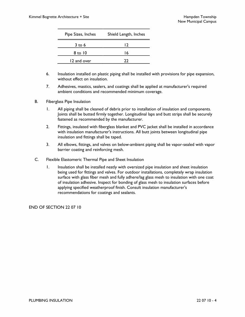
Kimmel Bogrette Architecture + Site Hampden Township
New Municipal Campus
PLUMBING INSULATION 22 07 10 - 4
Pipe Sizes, Inches Shield Length, Inches
3 to 6 12
8 to 10 16
12 and over 22
6. Insulation installed on plastic piping shall be installed with provisions for pipe expansion,
without effect on insulation.
7. Adhesives, mastics, sealers, and coatings shall be applied at manufacturer's required
ambient conditions and recommended minimum coverage.
B. Fiberglass Pipe Insulation
1. All piping shall be cleaned of debris prior to installation of insulation and components.
Joints shall be butted firmly together. Longitudinal laps and butt strips shall be securely
fastened as recommended by the manufacturer.
2. Fittings, insulated with fiberglass blanket and PVC jacket shall be installed in accordance
with insulation manufacturer's instructions. All butt joints between longitudinal pipe
insulation and fittings shall be taped.
3. All elbows, fittings, and valves on below-ambient piping shall be vapor-sealed with vapor
barrier coating and reinforcing mesh.
C. Flexible Elastomeric Thermal Pipe and Sheet Insulation
1. Insulation shall be installed neatly with oversized pipe insulation and sheet insulation
being used for fittings and valves. For outdoor installations, completely wrap insulation
surface with glass fiber mesh and fully adhere/lag glass mesh to insulation with one coat
of insulation adhesive. Inspect for bonding of glass mesh to insulation surfaces before
applying specified weatherproof finish. Consult insulation manufacturer's
recommendations for coatings and sealants.
END OF SECTION 22 07 10
Kimmel Bogrette Architecture + Site Hampden Township
New Municipal Campus
PLUMBING PUMPS 22 11 10 - 1
SECTION 22 11 10 – PLUMBING PUMPS
PART 1 - GENERAL
1.1 WORK INCLUDED
A. The Work of this Section shall consist of the labor, materials and equipment required for the
installation of plumbing pumps.
1.2 RELATED SECTIONS
A. Section 22 05 05, Plumbing Basic Materials: Equipment nameplates and motors.
B. Section 23 90 10, Building Automation System: Controls.
1.3 SUBMITTALS
A. Submit for approval in accordance with specified submittal procedures:
1. Pumps
2. Pump Controllers
PART 2 - PRODUCTS
2.1 INLINE CIRCULATOR PUMP
A. Acceptable Manufacturer: Bell & Gossett, or Taco, Armstrong.
B. Materials
1. Body: Bronze.
2. Impeller: Brass.
3. Shaft: Steel.
4. Pump Bearing: Bronze, sleeve oil lubricating, sleeve oil lubricating.
5. Motor: Refer to Section 22 05 05.
C. Working Pressure: 125 psig, maximum.
2.2 PUMP CONTROLLER
A. Acceptable Manufacturer: Ranco Model ETC-111100-00, or as approved.

Kimmel Bogrette Architecture + Site Hampden Township
New Municipal Campus
PLUMBING PUMPS 22 11 10 - 2
B. NEMA 1 line voltage controller rated for 120/208/240 voltage (matched to associated pump).
C. Temperature thermistor sensor:
1. Range -30 degrees F to 220 degrees F +/- 1 degrees F.
2. 8 foot cable
3. Differential range: 1 – 30 degrees.
D. Digital display, key pad with lock out controls.
E. Time delay feature to protect from frequent restarts.
F. EPROM Memory to retain settings during power outages.
G. Dry contacts (1-10V) to report temperature reading to Building Automation System.
PART 3 - EXECUTION
3.1 INSTALLATION
A. Inline pumps shall be installed with valves, and gages as detailed on the Drawings. Provide
flanges or unions at all pump connections to facilitate dismantling.
B. Diagrammatic representation of inline pumps on the Drawings is only for clarification of pump
location. Actual positioning of pump in the piping system, orientation of pump and motor, and
location of supports for pumps shall be in accordance with pump manufacturer's
recommendations.
C. Contractor shall carefully follow the Drawings in laying out and installing his work and he shall
not deviate therefrom, except for structural or interior finish interferences, and then only
upon Architect's approval.
D. All pumps and accessories shall be carefully inspected for defects in workmanship prior to
installation. Any item found unsuitable, cracked, or otherwise defective shall be rejected and
removed from the jobsite. All pumps shall have factory applied markings, stampings, or
nameplates with sufficient data for identification to determine their conformance with specified
requirements.
E. During construction all openings in pumps shall be kept closed except when actual work is
being performed on that item. Closures shall be plugs, caps, blind flanges, or other items
specifically intended for this purpose. Exercise all necessary care to prevent foreign objects
from entering material.
END OF SECTION 22 11 10
Kimmel Bogrette Architecture + Site Hampden Township
New Municipal Campus
SANITARY DRAINAGE 22 13 10 - 1
SECTION 22 13 10 – SANITARY DRAINAGE
PART 1 - GENERAL
1.1 WORK INCLUDED
A. The Work of this Section shall consist of the labor, materials and equipment required for
installation of the sanitary drainage system.
B. Sanitary drainage shall be collected as indicated and connected to site sanitary lateral(s) at 5'-0"
outside building.
1.2 SUBMITTALS
A. Submit for approval in accordance with specified submittal procedures:
1. Cleanouts
2. Floor Drains
3. Drain Traps
4. Trap Guard Device
B. Submit written verification of testing procedures specified herein.
PART 2 - PRODUCTS
2.1 CLEANOUTS
A. Wall Cleanouts
1. Acceptable Manufacturer: J.R. Smith Fig. 4422, or Zurn, Watts, Wade, Josam, Mifab.
2. Size: Cleanouts shall be full size of pipe to 4 inch and not less than 4 inch for larger pipe
sizes.
3. Plug: Bronze with tapered threads or with lead seal.
4. Cover: Stainless steel shallow cover secured to plug with vandalproof screws.
B. Exterior Cleanouts
1. Acceptable Manufacturer: J.R. Smith Fig. 4251 U, or Zurn, Watts, Wade, Josam, Mifab.
2. Size: Cleanouts shall consist of wye fitting, full size of pipe to 4 inch and not less than 4
inch for larger pipe sizes.
3. Plug: Bronze, countersunk, rectangular slotted, with emulsified lead paste.
4. Cover: Cast iron, non-skid, vandalproof, gasketed, watertight secured independently of
plug.

Kimmel Bogrette Architecture + Site Hampden Township
New Municipal Campus
SANITARY DRAINAGE 22 13 10 - 2
5. Anchoring: 6 inch of concrete shall be poured around wye fitting, cleanout pipe and
cleanout cover frame. Concrete shall terminate 6 inch below grade.
C. Floor Cleanouts, For Finished Floors
1. Acceptable Manufacturer: J.R. Smith Fig. 4021, or Zurn, Watts, Wade, Josam, Mifab.
2. Size: Cleanouts shall consist of wye fitting, full size of pipe to 4 inch and not less than 4
inch for larger pipe sizes.
3. Plug: Bronze, countersunk, rectangular slotted, with emulsified lead paste and spigot
outlet.
4. Cover: Scoriated nickel bronze top.
2.2 FLOOR DRAINS
A. Floor Drain FD-1
1. Acceptable Manufacturer: J.R. Smith Fig. 2010, or Zurn, Watts, Wade, Josam, Mifab.
2. Body: Cast iron.
3. Outlet: Bottom.
4. Flashing Ring: Provided with weepholes.
5. Strainer: Adjustable, 5 inch x 5 inch square with vandalproof screws. Nickel bronze or
nickel brass.
6. Furnish with trap guard device.
B. Floor Drain FD-2
1. Acceptable Manufacturer: J.R. Smith Fig. 2120, or Zurn, Watts, Wade, Josam, Mifab.
2. Body: Cast iron.
3. Outlet: Bottom.
4. Flashing Ring: Provided with weepholes.
5. Grate: Cast iron tractor grate, vandalproof.
6. Furnish with trap guard device.
C. Floor Drain FD-3
1. Acceptable Manufacturer: J.R. Smith Fig. 2120, or Zurn, Watts, Wade, Josam, Mifab.
2. Body: Cast iron.
3. Outlet: Bottom.
4. Flashing Ring: Provided with weepholes.
5. Grate: Cast iron tractor grate, vandalproof.
6. Furnish with trap guard device.
7. Sediment Bucket.

Kimmel Bogrette Architecture + Site Hampden Township
New Municipal Campus
SANITARY DRAINAGE 22 13 10 - 3
2.3 DRAIN TRAPS
A. Acceptable Manufacturer: J.R. Smith Fig. 7222, or Zurn, Watts, Josam, Mifab.
B. Where drains are specified without integral trap, furnish and install deep seal P trap of cast
iron construction with hub inlet, spigot outlet.
2.4 TRAP GUARD DEVICE
A. Acceptable Manufacturer: Proset Trap Guard, or J.R. Smith Quad Close, Sure Seal Trap Sealer
B. Type: Barrier type trap seal protection device, inline floor drain trap sealer, elastomeric,
neoprene rubber. Prevents the evaporation of the trap seal and the emission of sewer gases.
C. Approvals: ASSE 1072-2007.
PART 3 - EXECUTION
3.1 INSTALLATION
A. Drainage lines shall be properly vented, graded and trapped to conform to local and state
requirements.
B. Each fixture shall be vented and trapped. Each vent shall be extended through roof, or shall be
loop vented into a common main, acceptable by code. Where a vertical vent riser connects to
another vent riser, an inverted wye fitting shall be provided.
C. Cleanouts shall be provided in soil and waste piping where shown, at the ends of all mains, at
intersection of branches with mains, at base of vertical stacks, at intermediate points of long
runs not exceeding 40 feet, and at additional locations required by local ordinances.
D. Horizontal sanitary and waste lines shall be graded with a maximum of pitch where shown on
Drawings and connected to existing lines. Unless indicated otherwise, horizontal sanitary and
waste lines 2-1/2 inches and smaller shall be graded 1/4 inch per foot inside building.
Horizontal sanitary and waste line 3 inches and larger shall be graded 1/8 inch per foot and in
accordance with inverts indicated outside building.
E. Sanitary and vent piping below floor, above ceilings, and inside walls shall be minimum 2 inches
inside diameter, no-hub.
F. No-hub fittings shall have a pipe stop on the interior of the fitting as well as a stainless steel
shield that surrounds the coupling material. Dual pipe clamps shall be installed around the
shield.
G. No-hub cast iron fittings shall be supported by clevis hangers. Wire, string, or strapping
supports will not be permitted.

Kimmel Bogrette Architecture + Site Hampden Township
New Municipal Campus
SANITARY DRAINAGE 22 13 10 - 4
H. Vertical sanitary and vent piping shall be supported at each floor with riser clamps. Pipe joints
shall not occur at floor line.
I. Joining of service weight cast iron piping to extra-heavy cast iron shall be done with couplings
designed for that application. Standard no-hub couplings shall not be permitted.
3.2 PURGING AND TESTING
A. Sanitary Piping, Gravity Either of the following testing methods may be used.
1. Water Test: The water test shall be applied to the drainage system either in its entirety
or in sections after rough piping has been installed. If testing entire system, all openings
in the piping shall be closed tightly, except for the highest opening in the system. The
system shall be filled with water to point of overflow. If system is tested in sections,
each opening shall be plugged tightly except for the highest opening in the section under
test. Each section shall then be filled with water. A section shall not be tested with less
than a 10 foot head of water. In testing successive sections, at least the upper 10 feet of
the next preceding section shall be tested so that a joint or pipe in the building (except
the uppermost 10 feet of the system) shall not have been submitted to a test of less
than a 10 foot head of water. Test water shall be kept in the system, or in the portion
under test for 1 hour before start of inspection. The system shall remain tight at all
points throughout inspection. If any leaks occur, those areas shall be corrected and re
tested.
2. Drainage and Vent Air Test: An air test shall be made by forcing air into the system until
there is a uniform gauge pressure of 5 pounds per square inch (psi) (34.5 kPa) or
sufficient to balance a 10 inch (254 mm) column of mercury. This pressure shall be held
for a test period of at least 15 minutes. Any adjustments to the test pressure required
because of changes in ambient temperature of the seating of gaskets shall be made prior
to the beginning of the test period. If any leaks occur those areas shall be corrected and
retested.
END OF SECTION 22 13 10

Kimmel Bogrette Architecture + Site Hampden Township
New Municipal Campus
INTERCEPTORS 22 13 20 - 1
SECTION 22 13 20 – INTERCEPTORS
PART 1 - GENERAL
1.1 WORK INCLUDED
A. The Work of this Section shall consist of the labor, materials and equipment required for
installation of the sanitary system interceptors.
1.2 SUBMITTALS
A. Submit for approval in accordance with specified submittal procedures:
1. Interceptors
PART 2 - PRODUCTS
2.1 OIL AND WATER SEPERATOR
A. Acceptable Manufacturer: Striem OS-75 with SR24 short riser.
B. Type: Oil separator with integral storage compartment and TeleGlide riser. Constructed of
high-density polyethylene (HDPE). Oil reserve cover 24 inch bolted composite heavy traffic
rated. Short riser (SR24) cut to length as indicated on Drawings.
PART 3 - EXECUTION
3.1 INSTALLATION
A. Install interceptors and complete piping connections in accordance with equipment
manufacturer's recommendations. Submit manufacturer's printed installation instructions with
operating and maintenance data at completion of Work.
END OF SECTION 22 13 20

Kimmel Bogrette Architecture + Site Hampden Township
New Municipal Campus
STORM DRAINAGE 22 14 10 - 1
SECTION 22 14 10 – STORM DRAINAGE
PART 1 - GENERAL
1.1 WORK INCLUDED
A. The Work of this Section shall consist of the labor, materials and equipment required for
installation of the storm water drainage system.
1.2 SUBMITTALS
A. Submit for approval in accordance with specified submittal procedures:
1. Cleanouts
2. Roof Drains
3. Overflow Drains
4. Downspout Nozzles
B. Submit written verification of testing procedures specified herein.
PART 2 - PRODUCTS
2.1 CLEANOUTS
A. Wall Cleanouts
1. Acceptable Manufacturer: J.R. Smith, or Zurn, Watts, Wade, Josam, Mifab.
2. Size: Cleanouts shall be full size of pipe to 4 inches pipe size and not less than 4 inches
for larger pipe sizes.
3. Plug: Bronze, countersunk, rectangular slotted, with emulsified lead paste.
4. Cover: Chrome plated bronze face of wall cover secured to plug with vandalproof
screws.
B. Exterior Cleanouts
1. Acceptable Manufacturer: J.R. Smith, or Zurn, Watts, Wade, Josam, Jones
Manufacturing, Mifab.
2. Size: Cleanouts shall consist of wye fitting full size of pipe to 4 inches pipe size and not
less than 4 inches for larger pipe sizes.
3. Plug: Bronze, countersunk, rectangular slotted with emulsified lead paste.
4. Cover: Cast iron, non-skid, vandalproof, gasketed, watertight secured independently of
plug.

Kimmel Bogrette Architecture + Site Hampden Township
New Municipal Campus
STORM DRAINAGE 22 14 10 - 2
5. Anchoring: 6 inches of concrete shall be poured around wye fitting, cleanout pipe, and
cleanout cover frame. Concrete shall terminate 6 inches below grade.
C. Floor Cleanouts, For Finished Floors
1. Acceptable Manufacturer: J.R. Smith Fig. 4021, or Zurn, Watts, Wade, Josam, Mifab.
2. Size: Cleanouts shall consist of wye fitting, full size of pipe to 4 inch and not less than 4
inch for larger pipe sizes.
3. Plug: Bronze, countersunk, rectangular slotted, with emulsified lead paste and spigot
outlet.
4. Cover: Scoriated nickel bronze top.
2.2 ROOF DRAINS
A. Roof Drain RD-1
1. Acceptable Manufacturer: J.R. Smith, or Zurn, Watts, Wade, Josam, Mifab.
2. Type: For installation in insulated precast concrete or insulated metal roof decks where
insulation is sloped to roof deck providing a sump for roof drain.
3. Materials
a. Body: Cast iron.
b. Dome: Cast iron, rough bronze, aluminum or brass.
4. Body: Provide flashing collar and gravel stop, sump receiver and under deck clamp.
5. Dome: Lock type.
6. Outlet: Bottom, inside calk.
2.3 OVERFLOW DRAINS
A. Overflow Drain
1. Acceptable Manufacturer: J.R. Smith, or Zurn, Watts, Wade, Josam, Mifab.
2. Type: For installation in insulated precast concrete or insulated metal roof decks.
3. Materials
a. Body: Cast iron.
b. Dome: Cast iron, rough bronze, aluminum or brass.
4. Body: Provide flashing collar and gravel stop, extension flange, sump receiver, and
under-deck clamp.
5. Dome: Lock type.
6. Outlet: Bottom inside calk.
7. Standpipe: Cut PVC standpipe to achieve ponding depth at base of drain specified by
Architect.

Kimmel Bogrette Architecture + Site Hampden Township
New Municipal Campus
STORM DRAINAGE 22 14 10 - 3
2.4 DOWNSPOUT NOZZLES
A. Downspout Nozzle OFDN-1
1. Acceptable Manufacturer: J.R. Smith 1770 or Zurn, Wade, Josam, Mifab.
2. Material: Cast bronze body and flange.
3. Screen: Stainless steel.
PART 3 - EXECUTION
3.1 INSTALLATION
A. Horizontal rain water conductors and storm sewers within the building shall be graded 1/8
inch per foot or in accordance with inverts indicated on Drawings. Horizontal storm lines
outside building shall be graded in accordance with inverts indicated on Drawings.
B. Cleanouts shall be provided in storm piping where indicated on Drawings, at ends of all mains,
at intersection of branches with mains, at base of vertical stacks, at intermediate points of long
runs not exceeding 40 feet, and at other points required by local ordinances.
3.2 PURGING AND TESTING
A. Storm Piping, Gravity (Either of the following testing methods may be used.)
1. Water Test: The water test shall be applied to the drainage system either in its entirety
or in sections after rough piping has been installed. If testing entire system, all openings
in the piping shall be closed tightly, except for the highest opening in the system. The
system shall be filled with water to point of overflow. If system is tested in sections,
each opening shall be plugged tightly, except for the highest opening of the section
under test. Each section shall then be filled with water. A section shall not be tested
with less than a 10 foot head of water. In testing successive sections, at least the upper
10 feet of the next preceding section shall be tested so that a joint or pipe in the
building (except the uppermost 10 feet of the system) shall not have been submitted to
a test of less than a 10 foot head of water. Test water shall be kept in the system, or in
the portion under test, for 1 hour before start of inspection. The system shall remain
tight at all points throughout inspection. If any leaks occur, those areas shall be
corrected and re tested.
2. Drainage and vent air test. An air test shall be made by forcing air into the system until
there is a uniform gauge pressure of 5 pounds per square inch (psi) (34.5 kPa) or
sufficient to balance a 10 inch (254 mm) column of mercury. This pressure shall be held
for a test period of at least 15 minutes. Any adjustments to the test pressure required
because of changes in ambient temperature of the seating of gaskets shall be made prior
to the beginning of the test period. If any leaks occur those areas shall be corrected and
retested.
END OF SECTION 22 14 10
Kimmel Bogrette Architecture + Site Hampden Township
New Municipal Campus
WATER HEATERS 22 33 10 - 1
SECTION 22 33 10 – WATER HEATERS
PART 1 - GENERAL
1.1 WORK INCLUDED
A. The Work of this Section shall consist of the labor, materials and equipment required for
installation of the domestic water heating equipment.
1.2 SUBMITTALS
A. Submit for approval in accordance with specified submittal procedures:
1. Water Heaters
2. Expansion Tanks
PART 2 - PRODUCTS
2.1 DOMESTIC WATER STORAGE HEATER, GAS COMMERCIAL, HIGH EFFICIENCY
A. Acceptable Manufacturer: A. O. Smith Cyclone Mxi, or Bradford White eF Series, PVI
Conquest.
B. Heater Style: Standard vertical, AGA approved, condensing.
C. Materials
1. Tank: Welded steel, or engineered duplex alloy
2. Tank Lining: Porcelain enamel (glass lined).
3. Tank Jacket: Steel with baked enamel finish.
4. Insulation: Blanket type glass fiber or polyurethane foam.
5. Water Connections: Brass or bronze.
6. Base and Legs: Steel or cast iron.
D. Working Pressure: 150 psi.
E. Fuel: Natural gas.
F. Controls: Electronic control of ignition and temperatures up to 180 F.
G. Venting: PVC, ABS, or CPVC pipe. Venting options shall include horizontal, vertical, and direct
vent sealed combustion.

Kimmel Bogrette Architecture + Site Hampden Township
New Municipal Campus
WATER HEATERS 22 33 10 - 2
H. Venting Accessories: Wall/roof termination kit with exhaust and intake terminals, roof/wall
penetration accessories.
I. Gas Pressure Regulator: Integral to heater.
J. Temperature-Pressure Relief Valve: 3/4 inch, minimum, ASME.
K. Manufacturer's Guarantee: 3 years.
L. Compliance: ASHRAE/IESNA 90.1.
2.2 EXPANSION TANK
A. Acceptable Manufacturer: Amtrol Series ST.
B. Type: Diaphragm, vertical.
C. Tank: Steel.
D. Tank Lining: Polypropylene.
E. Diaphragm: Custom molded butyl.
F. Air Charge: Factory charged. Provide air charging valve on tank for field charging.
PART 3 - EXECUTION
3.1 INSTALLATION
A. Install water heating equipment in accordance with equipment manufacturer's
recommendations. Submit manufacturer's printed installation instructions with operating and
maintenance data at completion of Work.
END OF SECTION 22 33 10

Kimmel Bogrette Architecture + Site Hampden Township
New Municipal Campus
PLUMBING FIXTURES 22 40 10 - 1
SECTION 22 40 10 – PLUMBING FIXTURES
PART 1 - GENERAL
1.1 WORK INCLUDED
A. The Work of this Section shall consist of the labor, materials and equipment required for
installation of plumbing fixtures and associated fittings and trim.
1.2 SUBMITTALS
A. Submit for approval in accordance with specified submittal procedures:
1. Water Closets
2. Urinals
3. Lavatories
4. Sinks
5. Mop Receptors
6. Showers
7. Shower Fittings
8. Electric Water Coolers
9. Bottle Fillers
10. Emergency Eyewashes
11. Wall Boxes
B. Substitute manufacturer's fixtures shall be similar in style, dimensions and quality to the basis
of design manufacturer's specified model number.
PART 2 - PRODUCTS
2.1 MATERIALS
A. Fixtures shall be of one manufacturer, insofar as possible, and of first quality. Wall hung
vitreous china fixture backings shall be drilled and tapped for mounting carriers specified.
2.2 WATER CLOSETS
A. Water Closet WC-1
1. Acceptable Manufacturer: Kohler K-4325, or American Standard, Toto, Sloan, Zurn.

Kimmel Bogrette Architecture + Site Hampden Township
New Municipal Campus
PLUMBING FIXTURES 22 40 10 - 2
2. Type: Wall hung, flush valve type, 1.6 gallon per flush, vitreous china, siphon jet action,
elongated bowl, 1-1/2 inch top spud.
3. Seat:
a. Acceptable Manufacturer: Kohler, or Beneke, Olsonite, Bemis.
b. Extra heavy, elongated, white, open front, check hinge.
4. Electronic Flush Valve:
a. Acceptable Manufacturer: Sloan Optima 111 ES-S with EL154 transformer, or
Toto, Zurn.
b. ADA compliant, 1.6 gallon per flush, less handle opening, electronic powered
infrared sensor, diaphragm or piston valve, flush delay, override button, infrared
sensor adjustment, screw driver check angle stop with vandal resistant cap, sweat
solder adaptor, adjustable tailpiece, vacuum breaker flush connection, spud
coupling, and flange. Plumbing Contractor shall wire from transformer to valve
and make final adjustments to valve.
5. Carrier (compact or standard, as required for the application):
a. Acceptable Manufacturer: Zurn ZN1201-H-4.
b. Cast iron, adjustable, vandal-proof trim.
B. Water Closet WC-2
1. Acceptable Manufacturer: Kohler K-4325, or American Standard, Toto, Sloan, Zurn.
2. Type: Wall hung, flush valve type, 1.6 gallon per flush, vitreous china, siphon jet action,
elongated bowl, 1-1/2 inch top spud.
3. Seat:
a. Acceptable Manufacturer: Kohler, or Beneke, Olsonite, Bemis.
b. Extra heavy, elongated, white, open front, check hinge.
4. Electronic Flush Valve:
a. Acceptable Manufacturer: Sloan Optima 111 ES-S with EL154 transformer, or
Toto, Zurn.
b. ADA compliant, 1.6 gallon per flush, less handle opening, electronic powered
infrared sensor, diaphragm or piston valve, flush delay, override button, infrared
sensor adjustment, screw driver check angle stop with vandal resistant cap, sweat
solder adaptor, adjustable tailpiece, vacuum breaker flush connection, spud
coupling, and flange. Plumbing Contractor shall wire from transformer to valve
and make final adjustments to valve.
5. Carrier (compact or standard, as required for the application):
a. Acceptable Manufacturer: Zurn ZN1201-H-4.
b. Cast iron, adjustable, vandal-proof trim.
C. Water Closet WC-3
1. Acceptable Manufacturer: Kohler K-4368, or American Standard, Toto, Sloan, Zurn.
2. Type: ADA compliant, floor mounted, flush valve type, 1.6 gallon per flush, vitreous
china, siphon jet action, elongated bowl, 1-1/2 inch top spud, 17-19 inches high, floor to
top of seat.
3. Seat:
a. Acceptable Manufacturer: Kohler, or Beneke, Olsonite, Bemis.
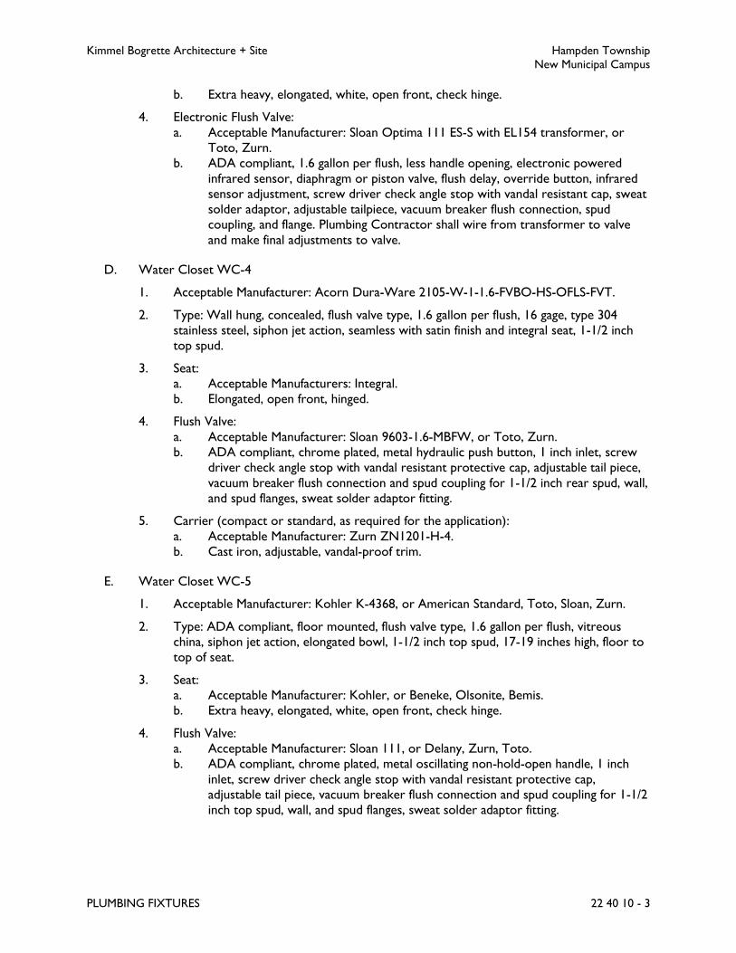
Kimmel Bogrette Architecture + Site Hampden Township
New Municipal Campus
PLUMBING FIXTURES 22 40 10 - 3
b. Extra heavy, elongated, white, open front, check hinge.
4. Electronic Flush Valve:
a. Acceptable Manufacturer: Sloan Optima 111 ES-S with EL154 transformer, or
Toto, Zurn.
b. ADA compliant, 1.6 gallon per flush, less handle opening, electronic powered
infrared sensor, diaphragm or piston valve, flush delay, override button, infrared
sensor adjustment, screw driver check angle stop with vandal resistant cap, sweat
solder adaptor, adjustable tailpiece, vacuum breaker flush connection, spud
coupling, and flange. Plumbing Contractor shall wire from transformer to valve
and make final adjustments to valve.
D. Water Closet WC-4
1. Acceptable Manufacturer: Acorn Dura-Ware 2105-W-1-1.6-FVBO-HS-OFLS-FVT.
2. Type: Wall hung, concealed, flush valve type, 1.6 gallon per flush, 16 gage, type 304
stainless steel, siphon jet action, seamless with satin finish and integral seat, 1-1/2 inch
top spud.
3. Seat:
a. Acceptable Manufacturers: Integral.
b. Elongated, open front, hinged.
4. Flush Valve:
a. Acceptable Manufacturer: Sloan 9603-1.6-MBFW, or Toto, Zurn.
b. ADA compliant, chrome plated, metal hydraulic push button, 1 inch inlet, screw
driver check angle stop with vandal resistant protective cap, adjustable tail piece,
vacuum breaker flush connection and spud coupling for 1-1/2 inch rear spud, wall,
and spud flanges, sweat solder adaptor fitting.
5. Carrier (compact or standard, as required for the application):
a. Acceptable Manufacturer: Zurn ZN1201-H-4.
b. Cast iron, adjustable, vandal-proof trim.
E. Water Closet WC-5
1. Acceptable Manufacturer: Kohler K-4368, or American Standard, Toto, Sloan, Zurn.
2. Type: ADA compliant, floor mounted, flush valve type, 1.6 gallon per flush, vitreous
china, siphon jet action, elongated bowl, 1-1/2 inch top spud, 17-19 inches high, floor to
top of seat.
3. Seat:
a. Acceptable Manufacturer: Kohler, or Beneke, Olsonite, Bemis.
b. Extra heavy, elongated, white, open front, check hinge.
4. Flush Valve:
a. Acceptable Manufacturer: Sloan 111, or Delany, Zurn, Toto.
b. ADA compliant, chrome plated, metal oscillating non-hold-open handle, 1 inch
inlet, screw driver check angle stop with vandal resistant protective cap,
adjustable tail piece, vacuum breaker flush connection and spud coupling for 1-1/2
inch top spud, wall, and spud flanges, sweat solder adaptor fitting.
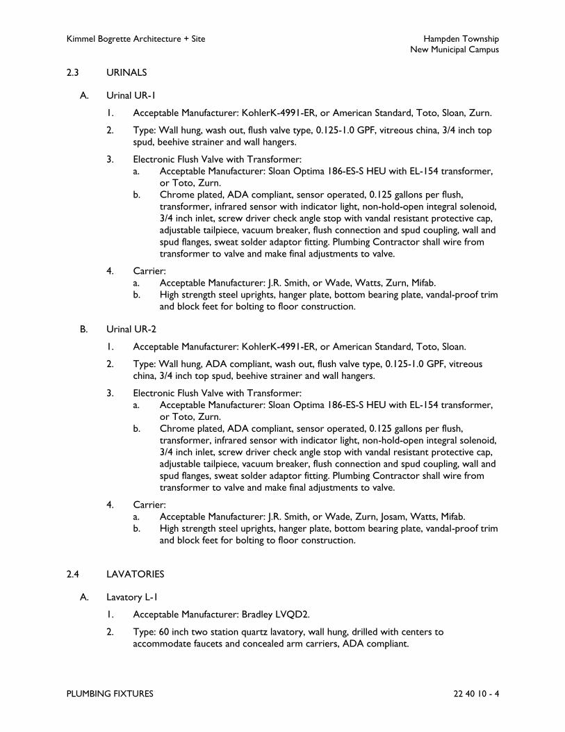
Kimmel Bogrette Architecture + Site Hampden Township
New Municipal Campus
PLUMBING FIXTURES 22 40 10 - 4
2.3 URINALS
A. Urinal UR-1
1. Acceptable Manufacturer: KohlerK-4991-ER, or American Standard, Toto, Sloan, Zurn.
2. Type: Wall hung, wash out, flush valve type, 0.125-1.0 GPF, vitreous china, 3/4 inch top
spud, beehive strainer and wall hangers.
3. Electronic Flush Valve with Transformer:
a. Acceptable Manufacturer: Sloan Optima 186-ES-S HEU with EL-154 transformer,
or Toto, Zurn.
b. Chrome plated, ADA compliant, sensor operated, 0.125 gallons per flush,
transformer, infrared sensor with indicator light, non-hold-open integral solenoid,
3/4 inch inlet, screw driver check angle stop with vandal resistant protective cap,
adjustable tailpiece, vacuum breaker, flush connection and spud coupling, wall and
spud flanges, sweat solder adaptor fitting. Plumbing Contractor shall wire from
transformer to valve and make final adjustments to valve.
4. Carrier:
a. Acceptable Manufacturer: J.R. Smith, or Wade, Watts, Zurn, Mifab.
b. High strength steel uprights, hanger plate, bottom bearing plate, vandal-proof trim
and block feet for bolting to floor construction.
B. Urinal UR-2
1. Acceptable Manufacturer: KohlerK-4991-ER, or American Standard, Toto, Sloan.
2. Type: Wall hung, ADA compliant, wash out, flush valve type, 0.125-1.0 GPF, vitreous
china, 3/4 inch top spud, beehive strainer and wall hangers.
3. Electronic Flush Valve with Transformer:
a. Acceptable Manufacturer: Sloan Optima 186-ES-S HEU with EL-154 transformer,
or Toto, Zurn.
b. Chrome plated, ADA compliant, sensor operated, 0.125 gallons per flush,
transformer, infrared sensor with indicator light, non-hold-open integral solenoid,
3/4 inch inlet, screw driver check angle stop with vandal resistant protective cap,
adjustable tailpiece, vacuum breaker, flush connection and spud coupling, wall and
spud flanges, sweat solder adaptor fitting. Plumbing Contractor shall wire from
transformer to valve and make final adjustments to valve.
4. Carrier:
a. Acceptable Manufacturer: J.R. Smith, or Wade, Zurn, Josam, Watts, Mifab.
b. High strength steel uprights, hanger plate, bottom bearing plate, vandal-proof trim
and block feet for bolting to floor construction.
2.4 LAVATORIES
A. Lavatory L-1
1. Acceptable Manufacturer: Bradley LVQD2.
2. Type: 60 inch two station quartz lavatory, wall hung, drilled with centers to
accommodate faucets and concealed arm carriers, ADA compliant.

Kimmel Bogrette Architecture + Site Hampden Township
New Municipal Campus
PLUMBING FIXTURES 22 40 10 - 5
3. Faucet:
a. Acceptable Manufacturer: Bradley Verge wash bar.
b. Electronic faucet with navigator mixing valve, soap dispenser and hand dryer, 0.5
gpm.
4. Drain:
a. Acceptable Manufacturer: Bradley Verge DR1.
b. Stainless steel trench drain cap, tailpiece and chrome P-trap.
5. Supplies:
a. Acceptable Manufacturer: McGuire 158LK or Brasscraft.
b. 3/8 inch wall supplies, loose key angle stops, flexible tube riser, escutcheon,
chrome finish.
B. Lavatory L-2
1. Acceptable Manufacturer: Kohler K-2032, or American Standard, Eljer, Moen.
2. Type: ADA compliant, vitreous china, wall hung with anti-splash rim, drilled with centers
to accommodate faucet and concealed arm carriers.
3. Faucet:
a. Acceptable Manufacturer: Sloan ETF-600 with BDT.
b. Electronic faucet with mechanical below deck thermostatic mixing valve, 0.5 GPM
spray, vandal resistant head, lavatory protective enclosure.
4. Supplies:
a. Acceptable Manufacturer: McGuire 170LK, or Brasscraft.
b. 3/8 inch wall supplies, loose key angle stops, flexible tube riser, escutcheon,
chrome finish.
5. Trap:
a. Acceptable Manufacturer: McGuire 8872C or Brasscraft.
b. 1-1/4 inch, 17 gage, cast brass adjustable P-trap, cleanout plug, escutcheon,
chrome finish.
6. Carrier:
a. Acceptable Manufacturer: J.R. Smith 700, or Watts, Wade, Zurn, Josam, Mifab.
b. Concealed arms with mechanical locking device, high strength steel uprights with
block bases for bolting to floor construction.
C. Lavatory L-3
1. Acceptable Manufacturer: Acorn Penal-Ware 1652-1-BP-04-M-EVS2.
2. Type: Vandal resistant, ADA approved, pre-molded lavatory system, integral metering
faucet with push button controls.
3. Construction:
a. Stainless steel.
4. Control: Push buttons.
5. Accessories: P-trap, tailpiece, stainless steel supplies, thermostatic mixing valve with
combination stops, strainers, and check valves.

Kimmel Bogrette Architecture + Site Hampden Township
New Municipal Campus
PLUMBING FIXTURES 22 40 10 - 6
D. Lavatory L-4
1. Acceptable Manufacturer: Kohler K-2032, or American Standard, Eljer.
2. Type: ADA compliant, 21 inch x 18 inch vitreous china, wall hung with anti-splash rim,
drilled with centers to accommodate faucet and concealed arm carriers.
3. Faucet:
a. Acceptable Manufacturer: Symmons S-60-GH, or Moen.
b. Four inch center set metering/temperature selection faucet, temperature limit
stop, time limit stop, rose spray outlet, 0.5 GPM flow rate, vandal-proof, grid
strainer drain assembly, blade type handle, chrome finish.
4. Supplies:
a. Acceptable Manufacturer: McGuire 170LK, or Brasscraft.
b. 3/8 inch wall supplies, loose key angle stops, flexible tube riser, escutcheon,
chrome finish.
5. Trap:
a. Acceptable Manufacturer: McGuire 8872C or Brasscraft.
b. 1-1/4 inch, 17 gage cast brass adjustable P-trap, cleanout plug, escutcheon,
chrome finish.
6. Drain and Supply Line Covers:
a. Acceptable Manufacturer: True Bro Model 102W or Prowrap.
b. ADA compliant, flexible vinyl insulation installed on exposed drain piping, hot
water piping and cold water piping.
c. ANSI A117.1-2003.
7. Carrier:
a. Acceptable Manufacturer: J.R. Smith 700, or Wade, Watts, Zurn, Josam, Mifab.
b. Concealed arms with mechanical locking device, high strength steel uprights with
block bases of bolting to floor construction.
2.5 SINKS
A. Sink S-1
1. Acceptable Manufacturer: Elkay Series LRAD, or Just.
2. Type: Single bowl, ADA compliant, type 304 stainless steel, 18 gage, self-rimming, drain
opening shall be located in back center of bowl, sound dampened underside, holes
drilled to accommodate faucet.
3. Faucet:
a. Acceptable Manufacturer: Elkay Series 4100, or Moen, Chicago Faucet, T&S Brass,
Kohler.
b. Chrome plated, single lever, with aerator, 2.5 GPM, washerless.
4. Supplies
a. Acceptable Manufacturer: McGuire, or Brass Craft.
b. 3/8 inch wall supplies, loose key angle stops, flexible tube riser, escutcheon,
chrome finish.
5. Drain Outlet:
a. Acceptable Manufacturer: Elkay LK-35, or Just.

Kimmel Bogrette Architecture + Site Hampden Township
New Municipal Campus
PLUMBING FIXTURES 22 40 10 - 7
b. Chrome plated brass drain, stainless steel basket strainer, chrome plated brass 1-
1/2 inch O.D. tailpiece.
6. Trap: 1-1/2 inch P-trap with cleanout, chrome plated.
7. Drain and Supply Line Covers:
a. Acceptable Manufacturer: True Bro Model 102W or Prowrap.
b. ADA compliant, flexible vinyl insulation installed on exposed drain piping, hot
water piping and cold water piping.
c. ANSI A117.1-2003.
B. Sink S-2
1. Acceptable Manufacturer: Elkay Series LRAD, or Just.
2. Type: Single bowl, ADA compliant, type 304 stainless steel, 18 gage, self-rimming, drain
opening shall be located in back center of bowl, sound dampened underside, holes
drilled to accommodate faucet.
3. Faucet:
a. Acceptable Manufacturer: Elkay Series 4100, or Moen, Chicago Faucet, T&S Brass,
Kohler.
b. Chrome plated, single lever, with aerator, 2.5 GPM, washerless.
4. Supplies
a. Acceptable Manufacturer: McGuire, or Brass Craft.
b. 3/8 inch wall supplies, loose key angle stops, flexible tube riser, escutcheon,
chrome finish.
5. Drain Outlet:
a. Acceptable Manufacturer: Elkay LK-35, or Just.
b. Chrome plated brass drain, stainless steel basket strainer, chrome plated brass 1-
1/2 inch O.D. tailpiece.
6. Trap: 1-1/2 inch P-trap with cleanout, chrome plated.
7. Drain and Supply Line Covers:
a. Acceptable Manufacturer: True Bro Model 102W or Prowrap.
b. ADA compliant, flexible vinyl insulation installed on exposed drain piping, hot
water piping and cold water piping.
c. ANSI A117.1-2003.
2.6 MOP RECEPTORS
A. Mop Receptor MR-1
1. Acceptable Manufacturer: Fiat, or Florestone, Stern-Williams.
2. Type: One piece precast terrazzo, integral cast drain, stainless steel protective cap on
exposed sides, size as scheduled on Drawings.
3. Type: One piece molded construction, seamless, integral drain.
4. Faucet:
a. Acceptable Manufacturer: Kohler K-8928, or Chicago Faucets, T&S Brass.
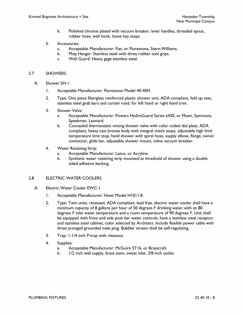
Kimmel Bogrette Architecture + Site Hampden Township
New Municipal Campus
PLUMBING FIXTURES 22 40 10 - 8
b. Polished chrome plated with vacuum breaker, lever handles, threaded spout,
rubber hose, wall hook, loose key stops.
5. Accessories:
a. Acceptable Manufacturer: Fiat, or Florestone, Stern-Williams.
b. Mop Hanger: Stainless steel with three rubber tool grips.
c. Wall Guard: Heavy gage stainless steel.
2.7 SHOWERS
A. Shower SH-1
1. Acceptable Manufacturer: Florestone Model 40-40H.
2. Type: One piece fiberglass reinforced plastic shower unit, ADA compliant, fold up seat,
stainless steel grab bars and curtain road, for left hand or right hand trim.
3. Shower Valve:
a. Acceptable Manufacturer: Powers HydroGuard Series e420, or Moen, Symmons,
Speakman, Leonard.
b. Concealed thermostatic mixing shower valve with color coded dial plate, ADA
compliant, heavy cast bronze body with integral check stops, adjustable high limit
temperature limit stop, hand shower with spiral hose, supply elbow, flange, swivel
connector, glide bar, adjustable shower mount, inline vacuum breaker.
4. Water Retaining Strip:
a. Acceptable Manufacturer: Lasco, or Acryline.
b. Synthetic water retaining strip mounted at threshold of shower using a double
sided adhesive backing.
2.8 ELECTRIC WATER COOLERS
A. Electric Water Cooler EWC-1
1. Acceptable Manufacturer: Haws Model H1011.8.
2. Type: Twin units, recessed, ADA compliant, lead free, electric water cooler shall have a
minimum capacity of 8 gallons per hour of 50 degrees F drinking water with an 80
degrees F inlet water temperature and a room temperature of 90 degrees F. Unit shall
be equipped with front and side push bar water controls, have a stainless steel receptor,
and stainless steel cabinet, color selected by Architect. Include flexible power cable with
three pronged grounded male plug. Bubbler stream shall be self-regulating.
3. Trap: 1-1/4 inch P-trap with cleanout.
4. Supplies:
a. Acceptable Manufacturer: McGuire ST16, or Brasscraft.
b. 1/2 inch wall supply, brass stem, sweat inlet, 3/8 inch outlet.

Kimmel Bogrette Architecture + Site Hampden Township
New Municipal Campus
PLUMBING FIXTURES 22 40 10 - 9
2.9 BOTTLE FILLERS
A. Bottle Filler BF-1
1. Acceptable Manufacturer: Haws Model 2000SN.
2. Type: Twin units, recessed, ADA compliant, lead free, electric water cooler shall have a
minimum capacity of 8 gallons per hour of 50 degrees F drinking water with an 80
degrees F inlet water temperature and a room temperature of 90 degrees F. Unit shall
be equipped with front and side push bar water controls, have a stainless steel receptor,
and stainless steel cabinet, color selected by Architect. Include flexible power cable with
three pronged grounded male plug. Bubbler stream shall be self-regulating.
3. Trap: 1-1/4 inch P-trap with cleanout.
4. Supplies:
a. Acceptable Manufacturer: McGuire ST16, or Brasscraft.
b. 1/2 inch wall supply, brass stem, sweat inlet, 3/8 inch outlet.
2.10 WALL BOXES
A. Wall Box WB-1
1. Acceptable Manufacturer: IPS Corporation/Guy Gray MIB Series.
2. Box and Faceplate: 18 gage steel, white powder coat finish.
3. Supply: 1/2 inch cold water.
4. Valve: Quarter turn ball valve, chrome plated, 1/2 inch sweat connection.
PART 3 - EXECUTION
3.1 INSTALLATION
A. Plumbing fixtures shall be installed square with wall, in line, and level, to give a uniform
appearance. Plumbing trim and exposed supply and waste piping, including traps, shall be
polished chrome plated brass, unless otherwise specified.
B. Each hot and cold water connection to plumbing fixtures and equipment shall be valved, if not
provided with integral stops as specified herein.
C. Calk space watertight between plumbing fixtures and wall or floor; silicone, white for all white
fixtures, clear for all other colors.
D. Contractor shall be responsible to coordinate the orientation of all plumbing fixtures (i.e. left-
hand, right-hand) with ADA requirements and general building conditions. Model numbers are
listed for plumbing fixtures to illustrate a standard of quality for materials and indicate a
specific style.

Kimmel Bogrette Architecture + Site Hampden Township
New Municipal Campus
PLUMBING FIXTURES 22 40 10 - 10
E. Contractor shall be responsible to coordinate carriers with chase dimensions and choose
compact carriers where chase dimensions are narrow and free space will not accommodate
standard size carriers.
F. Bathtub and shower control valves provided with high limit stops shall be adjusted to a
maximum hot water temperature setpoint of 105 degrees F.
G. Coordinate lavatory and sink hole drilling configurations with faucets.
3.2 TESTING
A. Plumbing fixtures shall be filled with water and checked for leaks or retarded flow. Remove
and clean all aerators.
END OF SECTION 22 40 10

Kimmel Bogrette Architecture + Site Hampden Township
New Municipal Campus
FUEL GAS PIPING AND SPECIALTIES 22 60 30 - 1
SECTION 22 60 30 – FUEL GAS PIPING AND SPECIALTIES
PART 1 - GENERAL
1.1 WORK INCLUDED
A. The Work of this Section shall consist of the labor, materials and equipment required for
installation of fuel gas piping and specialties.
B. Natural gas shall be extended from local gas company main. Gas Company will install meter set
and extend piping from main to meter set. Work of this Section shall include extending piping
from meter set to building and distributing piping to all equipment indicated on Drawings or
specified herein. Contractor shall make application and pay all costs invoiced by local gas
company.
1.2 RELATED SECTIONS
A. Section 22 05 10, Plumbing Piping and Pipe Fittings: Natural gas piping and pipe fittings.
B. Section 22 05 25, Plumbing Valves: Natural gas valves.
1.3 SUBMITTALS
A. Submit for approval in accordance with specified submittal procedures:
1. Gas Regulators
B. Submit written verification of piping system testing procedures specified herein.
PART 2 - PRODUCTS
2.1 GAS REGULATORS
A. Line Pressure Regulators
1. Acceptable Manufacturer: Itron, Fisher, or Bellgas.
2. Type: Single stage, suitable for natural gas, steel jacket, and corrosion resistant
components.
3. Body and Diaphragm Case: Cast iron or die-cast aluminum.
4. Springs: Zinc-plated steel; interchangeable.
5. Diaphragm Plate: Zinc-plated steel.
6. Seat Disc: Nitrile rubber resistant to gas impurities, abrasion, and deformation at the
valve port.

Kimmel Bogrette Architecture + Site Hampden Township
New Municipal Campus
FUEL GAS PIPING AND SPECIALTIES 22 60 30 - 2
7. Orifice: Aluminum; interchangeable.
8. Seal Plug: Ultraviolet-stabilized, mineral-filled nylon.
9. Single-port, self-contained regulator with orifice no larger than required at maximum
pressure inlet, and no pressure sensing piping external to regulator.
10. Pressure regulator shall maintain discharge pressure setting downstream, and not to
exceed 150 percent of design discharge pressure at shutoff.
11. Overpressure Protection Device: Factory mounted on pressure regulator.
12. Atmospheric Vent: Factory- or field-installed, stainless steel screen in opening if not
connected to vent piping.
13. Approvals: Comply with ANSI Z21.80.
PART 3 - EXECUTION
3.1 INSTALLATION
A. Piping
1. Extend natural gas piping to equipment indicated on the Drawings or specified herein
with suitable drips and cocks.
2. All welding of gas piping shall be performed by welders approved by local gas company.
3. All exterior gas piping shall be primed and painted.
a. Exterior semi-gloss, acrylic enamel: 2 coats over rust-inhibitive primer.
b. Color selected by Owner.
4. Provide cathodic protection on gas piping as required by local gas company.
5. Rough-in and make final connection to gas fired equipment furnished and installed under
Divisions 22 and 23. Verify locations for rough-in with equipment supplier prior to start
of work.
6. Rough-in and make final connection to natural gas fired emergency generator furnished
and installed under Division 26.
B. Gas Regulators
1. The gas regulator vent shall be extended to the exterior. Vent limiting devices will not
be acceptable. Vent piping shall be installed per local codes and manufacturer’s
recommendations.
2. The gas regulator vent shall be sized as indicated on the drawings, but not less than the
connection size to the regulator.
3. Furnish and install pressure gage upstream and downstream of each pressure regulator.
3.2 PURGING AND TESTING
A. After installation of piping, but before installation of outlet valves, natural gas piping shall be
blown clear by means of oil free dry air or nitrogen.

Kimmel Bogrette Architecture + Site Hampden Township
New Municipal Campus
FUEL GAS PIPING AND SPECIALTIES 22 60 30 - 3
B. Natural gas piping shall be tested in accordance with recommendations of the National Fire
Protection Association (NFPA 54), American Gas Association, and local gas company.
C. Gas piping specialties and equipment shall be tested and inspected in the presence of the utility
inspector and representative of Architect prior to concealing or covering.
END OF SECTION 22 60 30

Kimmel Bogrette Architecture + Site Hampden Township
New Municipal Campus
WIRING OF PLUMBING EQUIPMENT 22 96 10 - 1
SECTION 22 96 10 – WIRING OF PLUMBING EQUIPMENT
PART 1 - GENERAL
1.1 WORK INCLUDED
A. The Work of this Section shall include the power and control wiring of plumbing equipment.
PART 2 - PRODUCTS
2.1 MATERIALS
A. Plumbing Contractor shall provide equipment with controls, starters and related items as
specified in various Sections of Division 22.
B. Where plumbing equipment specified without starters or controllers, Electrical Contractor
shall provide same as specified herein.
C. Electrical Contractor shall provide all power wiring unless specifically noted otherwise.
D. Plumbing Contractor shall furnish and install all control wiring unless specifically noted
otherwise.
PART 3 - EXECUTION
3.1 INSTALLATION
A. Plumbing equipment shall be wired in accordance with the following schedule:
Key:
Item furnished by.....
Item installed by....
Item wired by.....
the respective trade according to the following designations:
P = Plumbing Contractor
E = Electrical Contractor

Kimmel Bogrette Architecture + Site Hampden Township
New Municipal Campus
WIRING OF PLUMBING EQUIPMENT 22 96 10 - 2
Plumbing Equipment Wiring Schedule
Equipment
Disconnect Means Controllers Control Devices
Rem
ote
Dis
connect
Sw
itch
Inte
gral
Dis
connect
Sw
itch
Wal
l Sw
itch
Cord
& P
lug
Mag
netic
Moto
r St
r
Com
bin
atio
n M
oto
r St
r
Man
ual
Moto
r St
r
VFD
with D
isco
nnect
Conta
ctor
Lin
e V
olt
age S
tat
Low
Volt
age S
tat
Aquas
tat
Duct
Sm
oke D
ete
ctor
Contr
ol Pan
el
Flo
w/P
ress
/Leve
l Sw
itch
BA
S/A
TC
Contr
ol
Domestic Water
Heater, DWH-1 P E
P E
E E
Circulating Pump,
CP-1 P E P P
P E P P
E E E E
Electronic Faucets P
P
E
Electric Water
Cooler, EWC-1 P P
P P
E E
Bottle Filler, BF-1 P
P
E
Solenoid Valves P
P
E

Kimmel Bogrette Architecture + Site Hampden Township
New Municipal Campus
WIRING OF PLUMBING EQUIPMENT 22 96 10 - 3
B. Unless noted, Contractor responsible for wiring of an item shall be responsible for furnishing
and installing all wiring for that item and making all connections associated with this wiring.
END OF SECTION 22 96 10

Kimmel Bogrette Architecture + Site Hampden Township
New Municipal Campus
HVAC BASIC MATERIALS 23 05 05 - 1
SECTION 23 05 05 – HVAC BASIC MATERIALS
PART 1 - GENERAL
1.1 WORK INCLUDED
A. The Work of this Section shall consist of the labor, materials and equipment required for the
installation of basic materials and motors associated with HVAC systems.
1.2 SUBMITTALS
A. Submit for approval in accordance with specified submittal procedures:
1. Access Panels
2. Fire Stop Sealing System
3. Pipe Portals
4. Equipment Supports
5. Equipment Nameplates; including itemized listing of nameplate equipment designations
6. Engineered Strut Support System; including structural calculations
7. Motors; submit with each piece of equipment
PART 2 - PRODUCTS
2.1 ACCESS PANELS
A. Access Panel Specification No. 1
1. Acceptable Manufacturer: Milcor Style AP for acoustical plaster, Style AT for acoustical
tile, or Karp, Krieger, Bilco.
2. Type: Acoustical ceiling.
3. Construction: 16 gage galvanized steel frame, 18 gage galvanized steel panel. Recessed to
accommodate acoustical ceiling tile. Continuous hinge, steel with stainless steel pin.
4. Closing Feature: Flush, screw driver operated lock with steel cam.
B. Access Panel Specification No. 2
1. Acceptable Manufacturer: Milcor Style DW, or Karp, Krieger, Bilco.
2. Type: Gypsum wallboard.
3. Construction: 16 gage steel frame, 14 gage steel panel.
4. Concealed spring hinges. Prime coat finish for field painting.
5. Closing Feature: Flush, screwdriver operated lock with steel cam.
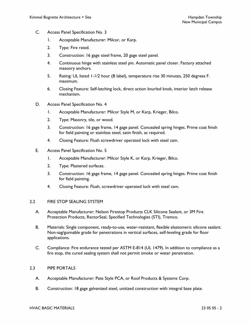
Kimmel Bogrette Architecture + Site Hampden Township
New Municipal Campus
HVAC BASIC MATERIALS 23 05 05 - 2
C. Access Panel Specification No. 3
1. Acceptable Manufacturer: Milcor, or Karp.
2. Type: Fire rated.
3. Construction: 16 gage steel frame, 20 gage steel panel.
4. Continuous hinge with stainless steel pin. Automatic panel closer. Factory attached
masonry anchors.
5. Rating: UL listed 1-1/2 hour (B label), temperature rise 30 minutes, 250 degrees F.
maximum.
6. Closing Feature: Self-latching lock, direct action knurled knob, interior latch release
mechanism.
D. Access Panel Specification No. 4
1. Acceptable Manufacturer: Milcor Style M, or Karp, Krieger, Bilco.
2. Type: Masonry, tile, or wood.
3. Construction: 16 gage frame, 14 gage panel. Concealed spring hinges. Prime coat finish
for field painting or stainless steel, satin finish, as required.
4. Closing Feature: Flush screwdriver operated lock with steel cam.
E. Access Panel Specification No. 5
1. Acceptable Manufacturer: Milcor Style K, or Karp, Krieger, Bilco.
2. Type: Plastered surfaces.
3. Construction: 16 gage frame, 14 gage panel. Concealed spring hinges. Prime coat finish
for field painting.
4. Closing Feature: Flush, screwdriver operated lock with steel cam.
2.2 FIRE STOP SEALING SYSTEM
A. Acceptable Manufacturer: Nelson Firestop Products CLK Silicone Sealant, or 3M Fire
Protection Products, RectorSeal, Specified Technologies (STI), Tremco.
B. Materials: Single component, ready-to-use, water-resistant, flexible elastomeric silicone sealant.
Non-sag/gunnable grade for penetrations in vertical surfaces, self-leveling grade for floor
applications.
C. Compliance: Fire endurance tested per ASTM E-814 (UL 1479). In addition to compliance as a
fire stop, the cured sealing system shall not permit smoke or water penetration.
2.3 PIPE PORTALS
A. Acceptable Manufacturer: Pate Style PCA, or Roof Products & Systems Corp.
B. Construction: 18 gage galvanized steel, unitized construction with integral base plate.
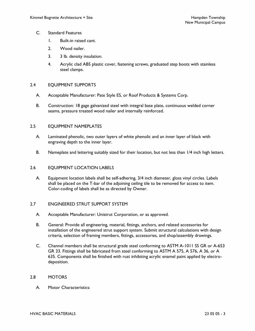
Kimmel Bogrette Architecture + Site Hampden Township
New Municipal Campus
HVAC BASIC MATERIALS 23 05 05 - 3
C. Standard Features
1. Built-in raised cant.
2. Wood nailer.
3. 3 lb. density insulation.
4. Acrylic clad ABS plastic cover, fastening screws, graduated step boots with stainless
steel clamps.
2.4 EQUIPMENT SUPPORTS
A. Acceptable Manufacturer: Pate Style ES, or Roof Products & Systems Corp.
B. Construction: 18 gage galvanized steel with integral base plate, continuous welded corner
seams, pressure treated wood nailer and internally reinforced.
2.5 EQUIPMENT NAMEPLATES
A. Laminated phenolic, two outer layers of white phenolic and an inner layer of black with
engraving depth to the inner layer.
B. Nameplate and lettering suitably sized for their location, but not less than 1/4 inch high letters.
2.6 EQUIPMENT LOCATION LABELS
A. Equipment location labels shall be self-adhering, 3/4 inch diameter, gloss vinyl circles. Labels
shall be placed on the T-bar of the adjoining ceiling tile to be removed for access to item.
Color-coding of labels shall be as directed by Owner.
2.7 ENGINEERED STRUT SUPPORT SYSTEM
A. Acceptable Manufacturer: Unistrut Corporation, or as approved.
B. General: Provide all engineering, material, fittings, anchors, and related accessories for
installation of the engineered strut support system. Submit structural calculations with design
criteria, selection of framing members, fittings, accessories, and shop/assembly drawings.
C. Channel members shall be structural grade steel conforming to ASTM A-1011 SS GR or A-653
GR 33. Fittings shall be fabricated from steel conforming to ASTM A 575, A 576, A 36, or A
635. Components shall be finished with rust inhibiting acrylic enamel paint applied by electro-
deposition.
2.8 MOTORS
A. Motor Characteristics:
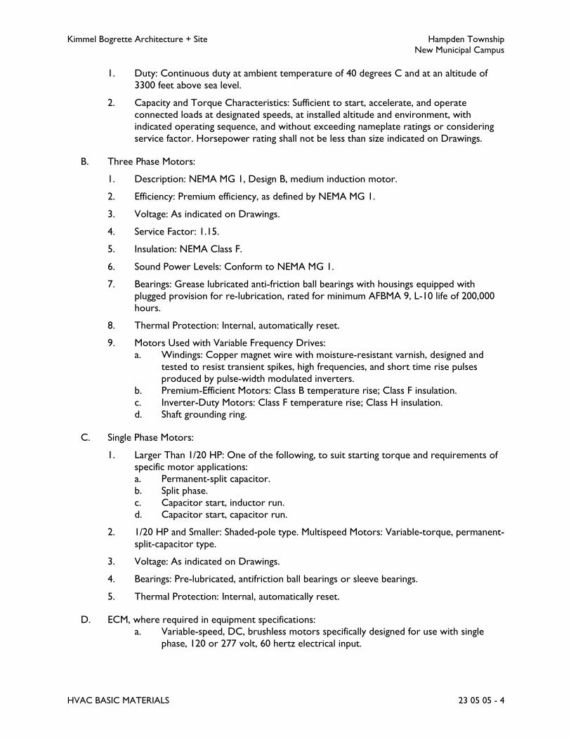
Kimmel Bogrette Architecture + Site Hampden Township
New Municipal Campus
HVAC BASIC MATERIALS 23 05 05 - 4
1. Duty: Continuous duty at ambient temperature of 40 degrees C and at an altitude of
3300 feet above sea level.
2. Capacity and Torque Characteristics: Sufficient to start, accelerate, and operate
connected loads at designated speeds, at installed altitude and environment, with
indicated operating sequence, and without exceeding nameplate ratings or considering
service factor. Horsepower rating shall not be less than size indicated on Drawings.
B. Three Phase Motors:
1. Description: NEMA MG 1, Design B, medium induction motor.
2. Efficiency: Premium efficiency, as defined by NEMA MG 1.
3. Voltage: As indicated on Drawings.
4. Service Factor: 1.15.
5. Insulation: NEMA Class F.
6. Sound Power Levels: Conform to NEMA MG 1.
7. Bearings: Grease lubricated anti-friction ball bearings with housings equipped with
plugged provision for re-lubrication, rated for minimum AFBMA 9, L-10 life of 200,000
hours.
8. Thermal Protection: Internal, automatically reset.
9. Motors Used with Variable Frequency Drives:
a. Windings: Copper magnet wire with moisture-resistant varnish, designed and
tested to resist transient spikes, high frequencies, and short time rise pulses
produced by pulse-width modulated inverters.
b. Premium-Efficient Motors: Class B temperature rise; Class F insulation.
c. Inverter-Duty Motors: Class F temperature rise; Class H insulation.
d. Shaft grounding ring.
C. Single Phase Motors:
1. Larger Than 1/20 HP: One of the following, to suit starting torque and requirements of
specific motor applications:
a. Permanent-split capacitor.
b. Split phase.
c. Capacitor start, inductor run.
d. Capacitor start, capacitor run.
2. 1/20 HP and Smaller: Shaded-pole type. Multispeed Motors: Variable-torque, permanent-
split-capacitor type.
3. Voltage: As indicated on Drawings.
4. Bearings: Pre-lubricated, antifriction ball bearings or sleeve bearings.
5. Thermal Protection: Internal, automatically reset.
D. ECM, where required in equipment specifications:
a. Variable-speed, DC, brushless motors specifically designed for use with single
phase, 120 or 277 volt, 60 hertz electrical input.
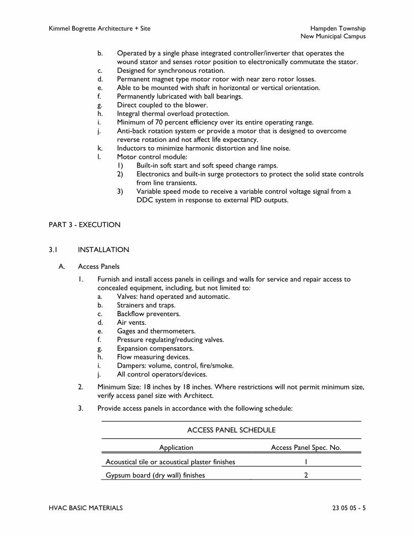
Kimmel Bogrette Architecture + Site Hampden Township
New Municipal Campus
HVAC BASIC MATERIALS 23 05 05 - 5
b. Operated by a single phase integrated controller/inverter that operates the
wound stator and senses rotor position to electronically commutate the stator.
c. Designed for synchronous rotation.
d. Permanent magnet type motor rotor with near zero rotor losses.
e. Able to be mounted with shaft in horizontal or vertical orientation.
f. Permanently lubricated with ball bearings.
g. Direct coupled to the blower.
h. Integral thermal overload protection.
i. Minimum of 70 percent efficiency over its entire operating range.
j. Anti-back rotation system or provide a motor that is designed to overcome
reverse rotation and not affect life expectancy.
k. Inductors to minimize harmonic distortion and line noise.
l. Motor control module:
1) Built-in soft start and soft speed change ramps.
2) Electronics and built-in surge protectors to protect the solid state controls
from line transients.
3) Variable speed mode to receive a variable control voltage signal from a
DDC system in response to external PID outputs.
PART 3 - EXECUTION
3.1 INSTALLATION
A. Access Panels
1. Furnish and install access panels in ceilings and walls for service and repair access to
concealed equipment, including, but not limited to:
a. Valves: hand operated and automatic.
b. Strainers and traps.
c. Backflow preventers.
d. Air vents.
e. Gages and thermometers.
f. Pressure regulating/reducing valves.
g. Expansion compensators.
h. Flow measuring devices.
i. Dampers: volume, control, fire/smoke.
j. All control operators/devices.
2. Minimum Size: 18 inches by 18 inches. Where restrictions will not permit minimum size,
verify access panel size with Architect.
3. Provide access panels in accordance with the following schedule:
ACCESS PANEL SCHEDULE
Application Access Panel Spec. No.
Acoustical tile or acoustical plaster finishes 1
Gypsum board (dry wall) finishes 2

Kimmel Bogrette Architecture + Site Hampden Township
New Municipal Campus
HVAC BASIC MATERIALS 23 05 05 - 6
ACCESS PANEL SCHEDULE
Application Access Panel Spec. No.
Fire rated walls 3
Masonry, tile, or wood finishes 4
Plastered finishes 5
B. Sleeves and Plates
1. Furnish and install sleeves for all pipes passing through floors, walls, partitions, slabs,
grade beams and foundations.
2. Layout, size, and locate sleeves such that they be set and installed prior to pouring
concrete, or when masonry is being constructed. In event sleeves must be placed after
floor, wall, grade beam, etc., has been constructed, submit in writing to and obtain
approval from Architect on location, quantity and proposed method of core drilling and
installing.
3. Core drilled openings above grade in solid concrete need not be sleeved but must be
clean and neat without cracking or spalling.
4. Sleeves shall be standard weight galvanized steel pipe having square cut ends with
anchoring lugs welded on. Horizontal sleeves through walls, grade beams, foundations,
and partitions shall be flush with finished wall faces. Vertical sleeves through floors shall
extend 2 inches above finished floor and be flush with finished ceiling or underside of
floor construction. Sleeves in pits or below grade shall be painted or coated with one
coat of coal tar pitch paint.
5. Size sleeves such that internal diameter is 2 pipe sizes or a minimum of 2 inches larger
than outside diameter of bare pipe for uninsulated lines and 2 inches larger than outside
diameter of insulation and jacket for insulated lines. Center pipes in sleeves.
6. For pipes passing through floors, slabs, walls, grade beams, or foundations at or below
grade and in pits, the annular space between outside of pipe or insulation and inside of
sleeve shall be packed with a pliable, non-hardening waterproof mastic sealer or a
cement-base quick-set repair mortar. Install mechanical modular link pipe penetration
seal where indicated on the Drawings.
7. For lines passing through walls and floors above grade and with no fire or smoke rating,
the annular space between outside of pipe or insulation and inside of sleeve or concrete
shall be packed tight with batt-type fiberglass insulation.
8. For pipes passing through walls and floors above grade with smoke or fire rating of one
hour or more, the annular space between outside of pipe or insulation and inside of
sleeve or concrete shall be sealed with fire stop sealing system.
C. Fire Stop Sealing System
1. All floor and interior wall penetrations with smoke or fire rating of one hour or more
shall be sealed. Refer to architectural drawings for locations of fire rated floors and
walls.

Kimmel Bogrette Architecture + Site Hampden Township
New Municipal Campus
HVAC BASIC MATERIALS 23 05 05 - 7
2. Prepare penetration and install sealing material in accordance with the manufacturer's
recommendations.
3. Through penetration fire stop sealing systems shall be identified on both sides with
permanently mounted, preprinted vinyl labels which include the following information:
a. The words “Warning: Through Penetration Firestop System – Do Not Disturb”
or similar phrase.
b. Manufacturer’s brand name, product type or catalog number
c. Testing agency designation and rating
d. Installer’s Name
e. Installation Date
D. Pipe Portals and Equipment Supports
1. Pipe portals and equipment supports provided as Work of this Section shall be
coordinated with requirements of roofing installer. Shop drawing submittals for pipe
portals and equipment supports, with, or without cants will be considered in compliance
with roofer's requirements.
E. Equipment Nameplates
1. Furnish and install a full complement of nameplates for all items of HVAC equipment
installed as Work of this Division, including boilers, chillers, pumps, air handling units,
fans and building automation system panels.
2. Install nameplates parallel to equipment lines.
3. Unless noted, nameplates shall be attached with sheet metal screws or epoxy cement.
Epoxy cement shall not be used on equipment installed outdoors.
4. Coordinate with Owner for nameplate designations. Submit a complete itemized listing
of nameplate equipment designations for approval.
END OF SECTION 23 05 05

Kimmel Bogrette Architecture + Site Hampden Township
New Municipal Campus
HVAC PIPE AND PIPE FITTINGS 23 05 10 - 1
SECTION 23 05 10 – HVAC PIPE AND PIPE FITTINGS
PART 1 - GENERAL
1.1 WORK INCLUDED
A. The Work of this Section shall consist of the labor, materials and equipment required for the
installation of HVAC piping and pipe fittings.
PART 2 - PRODUCTS
2.1 PIPE AND PIPE FITTINGS
A. Pipe shall conform to the materials specified herein, and shall be installed for piping systems as
scheduled in Part 3 - Execution, of this Section.
2.2 TYPE L COPPER PIPE SPECIFICATION NO. 1
A. Design Pressure: 150 psig.
B. Maximum Design Temperature: 200 degrees F.
C. Sizes 2 inches and smaller:
1. Tubing: Type L hard drawn seamless copper tube, ASTM B88.
2. Joints: Solder type with 95-5 solder, or press coupled. (Exception: All joints below
ground shall be solder joints).
3. Fittings: Wrought copper solder joint, ANSI B16.22 or cast bronze solder joint, ANSI
B16.18, or with EPDM O-rings, ASME B16.18 or ASME B16.22, performance criteria of
IAPMO PS 117.
D. Sizes 2-1/2 inches and larger:
1. Tubing: Type L hard drawn seamless copper tube, ASTM B88.
2. Joints: Flanged and solder type with 95-5 solder or mechanically coupled grooved joints.
(Exception: All joints below ground shall be solder joints.)
3. Fittings: Wrought copper solder joint, ANSI B16.22 or cast bronze solder joint, ANSI
B16.18, or mechanically coupled grooved joints.
4. Flanges: 150 lb. class cast bronze, ANSI B16.24.

Kimmel Bogrette Architecture + Site Hampden Township
New Municipal Campus
HVAC PIPE AND PIPE FITTINGS 23 05 10 - 2
2.3 SCHEDULE 40 BLACK STEEL PIPE SPECIFICATION NO. 2
A. Design Pressure: 125 psig.
B. Maximum Design Temperature: 350 degrees F.
C. Sizes 2 inches and smaller:
1. Pipe: Schedule 40 black steel, threaded and coupled, ASTM A53.
2. Joints:
a. Water: Threaded or mechanically coupled grooved joints.
b. Exception: All joints in piping installed below ground shall be welded.
3. Fittings:
a. Water: 125 lb (S) - 175 lb (WOG) black cast iron, or mechanically coupled
grooved fittings.
4. Unions: 250 lb (S) - 500 lb (WOG) black malleable iron, ground joint with brass seat.
D. Sizes 2-1/2 inches and larger:
1. Pipe: Schedule 40 black steel, beveled ends, ASTM A53.
2. Joints:
a. Water: Butt welded and flanged, or mechanically coupled grooved joints.
b. Exception: All joints in piping installed below ground shall be welded.
3. Fittings:
a. Water: Schedule 40 seamless steel, butt weld type, ASTM A234, or mechanically
coupled fittings.
4. Flanges: 150 lb forged steel, welding neck or slip on, ASTM A181 Class 60.
E. All piping installed below ground shall have factory applied coal tar coating. Below ground
joints shall have a field applied coal tar coating.
2.4 TYPE L COPPER PIPE SPECIFICATION NO. 5
A. Design Pressure: 240 psig.
B. Maximum Design Temperature: 125 degrees F.
C. Sizes 4 inches and smaller:
1. Tubing: Type L hard drawn seamless copper tube, ASTM B280 (ACR).
2. Joints: Brazed, AWS A5.8 B Cup silver/phosphorus/copper alloy.
3. Fittings: Wrought copper solder joint, ANSI B16.22.
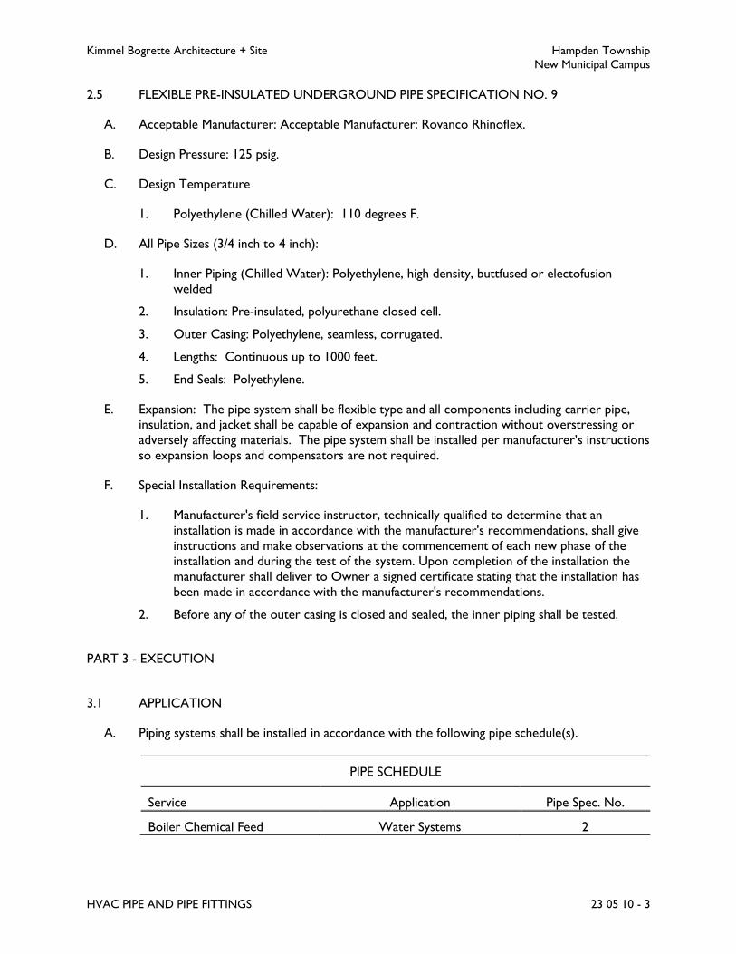
Kimmel Bogrette Architecture + Site Hampden Township
New Municipal Campus
HVAC PIPE AND PIPE FITTINGS 23 05 10 - 3
2.5 FLEXIBLE PRE-INSULATED UNDERGROUND PIPE SPECIFICATION NO. 9
A. Acceptable Manufacturer: Acceptable Manufacturer: Rovanco Rhinoflex.
B. Design Pressure: 125 psig.
C. Design Temperature
1. Polyethylene (Chilled Water): 110 degrees F.
D. All Pipe Sizes (3/4 inch to 4 inch):
1. Inner Piping (Chilled Water): Polyethylene, high density, buttfused or electofusion
welded
2. Insulation: Pre-insulated, polyurethane closed cell.
3. Outer Casing: Polyethylene, seamless, corrugated.
4. Lengths: Continuous up to 1000 feet.
5. End Seals: Polyethylene.
E. Expansion: The pipe system shall be flexible type and all components including carrier pipe,
insulation, and jacket shall be capable of expansion and contraction without overstressing or
adversely affecting materials. The pipe system shall be installed per manufacturer’s instructions
so expansion loops and compensators are not required.
F. Special Installation Requirements:
1. Manufacturer's field service instructor, technically qualified to determine that an
installation is made in accordance with the manufacturer's recommendations, shall give
instructions and make observations at the commencement of each new phase of the
installation and during the test of the system. Upon completion of the installation the
manufacturer shall deliver to Owner a signed certificate stating that the installation has
been made in accordance with the manufacturer's recommendations.
2. Before any of the outer casing is closed and sealed, the inner piping shall be tested.
PART 3 - EXECUTION
3.1 APPLICATION
A. Piping systems shall be installed in accordance with the following pipe schedule(s).
PIPE SCHEDULE
Service Application Pipe Spec. No.
Boiler Chemical Feed Water Systems 2

Kimmel Bogrette Architecture + Site Hampden Township
New Municipal Campus
HVAC PIPE AND PIPE FITTINGS 23 05 10 - 4
PIPE SCHEDULE
Service Application Pipe Spec. No.
Chilled Water All
Below Grade
1 or 2
9
Condensate Drainage, Cold All 1
Heating Hot Water All 1 or 2
Make-up Water All 1
Refrigerant All 5
3.2 INSTALLATION
A. Contractor shall carefully follow the Drawings in laying out and installing his work and he shall
not deviate therefrom, except for structural or interior finish interferences, and then only
upon Architect's approval.
B. All pipe and fittings shall be carefully inspected for defects in workmanship prior to installation.
Any item found unsuitable, cracked, or otherwise defective shall be rejected and removed
from the jobsite. All pipe and fittings shall have factory applied markings, stampings, or
nameplates with sufficient data for identification to determine their conformance with specified
requirements.
C. During construction all openings in piping shall be kept closed except when actual work is
being performed on that item. Closures shall be plugs, caps, blind flanges, or other items
specifically intended for this purpose. Exercise all necessary care to prevent foreign objects
from entering material.
D. Run pipe lines straight and true, parallel to building lines with a minimum use of offsets and
couplings. Use full and double lengths of pipe wherever possible.
E. Changes in direction shall be made only with pipe bends or fittings. Changes in size shall be
made with fittings only. All fittings shall be of the long radius type, unless otherwise specified.
Changes in direction on drainage pipe systems shall be made with wye fittings, combination
wye and eighth bends, or one-eighth bends.
F. Provide flanges or unions at all final connections to equipment, traps and valves to facilitate
dismantling.
G. Unless otherwise indicated, install all supply piping to coils, pumps and other equipment at line
size with reduction in size being made only at inlet to control valve or pump. Install supply
piping from outlet of control valve at full size of connection in equipment served. Install piping
in equipment outlet or return lines beyond dirt pockets the size of tapping in the trap or, if no
trap, the size of the equipment connection.
H. All pipe shall be cut to exact measurement, and installed without springing or forcing.
Particular care shall be taken to avoid creating, even temporarily, undue loads, forces or
strains on valves, equipment or building elements with piping connections or piping supports.

Kimmel Bogrette Architecture + Site Hampden Township
New Municipal Campus
HVAC PIPE AND PIPE FITTINGS 23 05 10 - 5
I. Unless otherwise indicated, branch take-offs shall be from top of mains or headers at either a
45 degree or 90 degree angle from the horizontal plane for steam lines, and from top, bottom
or side for liquids.
J. Pipe joints connecting dissimilar metals shall be insulating, dielectric connections. Copper
tubing shall be protected from electrolysis at contact points with ferrous metals, including
temporary methods of support, by use of insulating, non conductive spacers such as rubber,
fiberglass or an approved equal. Pipe hangers for bare copper tubing shall be copper plated.
K. For refrigerant piping with the circuit access ports installed outdoors, provide a locking-type
resistant cap. Provide key to owner.
3.3 PIPE JOINTS
A. Press Joints:
1. Copper and copper alloy press connections shall be made in accordance with the
manufacturer's installation instructions.
2. Copper press fittings shall be installed using the proper tools, actuator, jaws and rings as
instructed and approved by the press fitting manufacturer.
3. Installer shall be a qualified installer, licensed within the jurisdiction, and familiar with
the installation of copper press joint systems.
4. Follow all installation instructions of manufacturer of press-joint fitting to ensure quality,
leak-tight seal.
5. Provide unions and arrangement of sufficient length of removable sections of tubing at
valves and equipment connections to allow for easy removal and reinstallation for
repairs without having to redo press connections.
B. Mechanically Coupled Grooved Joints:
1. All grooved piping shall be installed and supported in strict adherence to the grooved
manufactures installation and pipe supporting instructions.
2. Select proper gasket material that is compatible with fluid requirements.
3. Gasket lubricant shall be from the same manufacture as the couplings.
4. Pipe shall be grooved to manufactures recommended specifications.
5. Grooving tools shall be from the same manufacture as the couplings.
6. All couplings, fittings, flanges, valves and accessories shall be from the same
manufacturer. All grooved piping products (i.e. couplings, fittings, valves and accessories)
used on hot water systems shall have a temperature rating of at least 250 degrees F.
7. All couplings used up to and including 24 inches shall have a minimum pressure rating of
350 PSI.
8. All couplings shall be the rigid design except as needed or required.
9. All castings shall be date stamped for quality assurance and traceability.
10. The grooved mechanical coupling manufacturer shall have a factory trained field
representative to be available to visit the job site. That representative shall provide
Kimmel Bogrette Architecture + Site Hampden Township
New Municipal Campus
HVAC PIPE AND PIPE FITTINGS 23 05 10 - 6
training for contractor’s field personnel, and view installed product to promote
conformance to installation requirements, if requested by the Owner or Architect. The
name and contact information of that representative should be part of the submittal
package.
C. Solder Joints:
1. Make up joints with 95 percent tin and 5 percent antimony (95-5) solder conforming to
ASTM B32 Solder Metal, Grade 95TA.
2. Cut copper tubing so ends are perfectly square and remove all burrs inside and outside.
3. Thoroughly clean sockets of fittings and ends of tubing to remove all oxide, dirt, and
grease just prior to soldering.
4. Apply flux evenly, but sparingly, over all surfaces to be joined. Heat joints uniformly to
proper soldering temperature so solder will flow to all mated surfaces. Wipe excess
solder, leaving a uniform fillet around cup of fitting. Flux shall be non acid type.
5. Remove composition discs from solder end valves during soldering.
D. Brazed Joints:
1. Make up joints with silver alloy brazing filler metal.
2. Cut copper tubing so ends are perfectly square and remove all burrs inside and outside.
Thoroughly clean sockets of fittings and ends of tubing to remove all oxide, dirt, and
grease just prior to brazing.
3. Apply non-corrosive flux of the type recommended by filler alloy manufacturer evenly,
but sparingly, over all surfaces to be joined. Heat joints uniformly to proper brazing
temperatures using oxygen-acetylene torch with tip size as recommended by fitting
manufacturer. Wipe and brush joint clean after alloy has set.
4. Remove composition discs from solder end valves during brazing.
E. Welded Joints:
1. The welding of all pipe joints, both as to procedures and qualification of welders, shall
be in accordance with Section IX, ASME Boiler & Pressure Vessel Code, unless
mandatory local codes take precedence.
2. Ends of pipe and fittings to be joined by butt welding shall be beveled, cleaned to bare
metal and internal diameters aligned before tack welding.
F. Threaded Joints:
1. Pipe screw threads shall conform to ANSI B16.3, Malleable Iron Threaded Fittings or
ASTM B687, Brass, Copper, and Chromium-Plated Pipe Nipples.
2. Ream pipe ends and remove all burrs and chips formed in cutting and threading.
3. Protect plated pipe and brass valve bodies from wrench marks when making-up joint.
4. Apply thread lubricant to male threads only.
Kimmel Bogrette Architecture + Site Hampden Township
New Municipal Campus
HVAC PIPE AND PIPE FITTINGS 23 05 10 - 7
G. Flanged Joints:
1. Steel pipe flanges shall conform to ANSI B16.5, Steel Pipe Flanges and Flanged Fittings.
Cast iron pipe flanges shall conform to ANSI B16.1, Cast Iron Flanges and Flanged
Fittings.
2. Steel flanges shall be raised face except when bolted to flat cast iron flange.
3. Bolting for services up to 500 degrees F. shall be ASTM A307, Grade B with square
head bolts and heavy hexagonal nuts conforming to ANSI B18.2.1, Square and Hex Bolts
and B18.2.2, Square and Hex Nuts. Set flange bolts beyond finger tightness with an
indicating torque wrench to insure equal tension in all bolts. Tighten bolts such that
those 180 degrees apart or directly opposite are torqued in sequence.
4. Gaskets for flat face flanges shall form to requirements for Group I Gaskets in ANSI
B16.5. Unless otherwise specified, gaskets shall be 3/32 inch thick.
END OF SECTION 23 05 10

Kimmel Bogrette Architecture + Site Hampden Township
New Municipal Campus
HVAC PIPING SPECIALTIES 23 05 15 - 1
SECTION 23 05 15 – HVAC PIPING SPECIALTIES
PART 1 - GENERAL
1.1 WORK INCLUDED
A. The Work of this Section shall consist of the labor, materials, and equipment required for the
installation of HVAC piping specialties.
1.2 SUBMITTALS
A. Submit for approval in accordance with specified submittal procedures:
1. Y-Type Strainers
2. Branch Connections
3. Pipe & Valve Identification
4. Expansion Compensators, Pipe Guides and Anchors
5. Flexible Pipe Connectors
6. Dielectric Connections
7. Thermometers, including scale range
8. Pressure Gages, including scale range
9. Pressure/Temperature (P/T) Test Plugs
B. Product Data: Submit manufacturer's technical product data for each type of measuring
instrument. Submit schedule showing manufacturer's model number, scale range, location, and
accessories for each type and application.
PART 2 - PRODUCTS
2.1 Y-TYPE STRAINERS, WATER PIPING
A. Acceptable Manufacturer: Apollo (Conbraco), Armstrong International, Hoffman Specialty ITT,
Metraflex Co., Spirax Sarco, or Watts Regulator Co
B. Provide strainers full line size of connecting piping, with ends matching piping system materials.
Strainers shall be Y-pattern type having 304 stainless steel screens with perforations/mesh
sizes as follows:

Kimmel Bogrette Architecture + Site Hampden Township
New Municipal Campus
HVAC PIPING SPECIALTIES 23 05 15 - 2
Pipe Size Coarse Straining
(typically at central
Plant equipment)
Medium Straining
(typically at terminal/
control equipment)
1/4 ” to 2” 1/16” 1/32” or 20 mesh
2-1/2” to 4” 1/8” 1/16”
5” and larger 3/16” 1/8”
C. Type WST-1
1. 2 inches and smaller, threaded ends.
2. Cast-iron or bronze body, screwed screen retainer with centered blowdown fitted with
drain plug.
3. Pressure: 400 psig (WOG).
D. Type WST-2
1. 2-1/2 inches and larger, flanged ends.
2. Cast-iron or steel body, bolted screen retainer with off-centered blowdown fitted with
hose end drain valve.
3. Pressure: 175 psig (WOG).
E. Type WST-3
1. Grooved Ends, 2-1/2 inches and larger, grooved ends.
2. Steel, ductile-iron or malleable-iron body and access end cap with off-center blowdown
fitted with hose end drain valve.
3. Pressure: 175 psig (WOG)
2.2 BRANCH CONNECTIONS
A. Branch connections shall be made with standard tee of the type required for the service unless
otherwise specified or detailed.
B. At Contractor's option, branch connections from headers and mains may be cut into black
steel pipe using forged weld-on fittings. Weld-on fittings shall conform to chemical and physical
requirements of ASTM A-234 and design and installation requirements of ANSI B31.1.
C. Weld-on fittings shall have a pressure rating equal to, or greater than, the maximum working
pressure of the pipe system where they are installed.
1. Acceptable Manufacturer: Allied Piping Products Co. Branchlets (Shaped nipples), or
Bonney Forge Weldolet & Threadolet.
D. At Contractor's option, branch connections from headers and mains may be cut into copper
tube using mechanically extracted collars. Collars shall be formed in a continuous operation
consisting of drilling a pilot hole and drawing out the tube surface to form a collar having a
height of not less than three times the thickness of the tube wall. Main pipe shall be vacuumed
Kimmel Bogrette Architecture + Site Hampden Township
New Municipal Campus
HVAC PIPING SPECIALTIES 23 05 15 - 3
to clear all debris during collar forming procedure. Branch pipe shall be notched to conform
with the inner curve of the run tube and dimpled to insure penetration of the branch pipe into
the collar at sufficient depth for brazing. All joints shall be brazed. Mechanical formed branch
collars shall be UL listed.
1. Acceptable Manufacturer: T-Drill, Division of Serlachius.
2.3 ESCUTCHEON PLATES
A. Plates shall be installed on all pipes and conduit passing through floors, walls, partitions, etc., in
exposed areas.
B. Plates installed on pipe passing through core drilled openings in solid concrete without sleeves
shall be solid ring, cast iron with one set screw for sizes up to 4 inches and two set screws for
sizes up to 8 inches.
C. Plates installed on pipe and conduit passing through openings with sleeves shall be solid ring,
cast iron.
2.4 PIPE AND VALVE IDENTIFICATION
A. Acceptable Manufacturer: W. H. Brady Company, or Seton Nameplate Corp., Brimar
Industries.
B. Shutoff valves and control equipment shall be marked by means of a brass or plastic disc
minimum of 1 inch in diameter fastened to valve wheel or stem by brass wire or chain. Each
disc shall have a legibly marked identification number. A typewritten chart listing all valve tags,
location, and service shall be included in the operating and maintenance manual. The valve
chart numbering sequence shall be approved by Owner.
C. All piping installed as Work of this Division shall be identified by legend and flow arrow.
Identification system shall conform to ANSI A-13.1. Identification markers shall use ANSI
standard background colors and be text size. Markers shall be attached to pipe by wrapping
with color coded banding tape. Markers shall be located as follows:
1. Near each valve and control device.
2. Near each branch connection, excluding short takeoffs for fixtures and terminal units.
Where flow pattern is not obvious, mark each pipe at branch.
3. Near penetrations through walls, floors, ceilings, and nonaccessible enclosures.
4. At access doors, manholes, and similar access points that permit view of concealed
piping.
5. Near major equipment items and other points of origination and termination.
6. Spaced at maximum intervals of 25 feet along each run.

Kimmel Bogrette Architecture + Site Hampden Township
New Municipal Campus
HVAC PIPING SPECIALTIES 23 05 15 - 4
2.5 EXPANSION COMPENSATORS, PIPE GUIDES, AND ANCHORS
A. Expansion Compensator Type EXC-3
1. Acceptable Manufacturer: Flexonics, or Keflex, Metraflex, Hyspan.
2. Compensators shall be suitable for absorbing expansion and contraction in copper pipe
2 inch and smaller. Compensators shall be constructed with two ply phosphor bronze
or stainless steel bellows, brass shroud, and solder joint end fittings, 70 psi maximum
working pressure, and 3/4 inch stroke.
B. Provide dielectric flanges where compensators are used with copper pipe.
C. Pipe Guides
1. Acceptable Manufacturer: Flexonics Pipe Alignment Guides, or Keflex, Metraflex,
Hyspan.
2. Pipe guides shall be installed as scheduled on the Drawings in accordance with
manufacturer's recommendations. Guides shall consist of steel segmented spider sized
to the OD of the pipe and free to move axially in a segmented steel cylinder. Guide shall
be securely attached to the building structure.
D. Pipe Anchors: Anchors shall be installed in accordance with pipe guide manufacturer and
expansion compensator manufacturer recommendations. Anchors shall securely attach the
piping system to the building structure.
2.6 FLEXIBLE PIPE CONNECTORS
A. Metal Hose Type
1. Acceptable Manufacturer: Flexonics, or Keflex, Metraflex, Flex-Hose.
2. Connectors shall be constructed of a stainless steel corrugated core covered with high
tensile tubular braiding. Ends for piping 2 inches and smaller shall be screwed or solder
joint as required. Ends for piping 2-1/2 inch and larger shall be flanged.
2.7 DIELECTRIC CONNECTIONS
A. Pipe joints connecting dissimilar metals shall be insulating, dielectric connections. Dielectric
connections shall also be furnished for joining similar metals in order to isolate cathodically
protected pipelines from adjoining pipe sections. Such joints, including dielectric material, shall
be rated to withstand the temperature, pressure, and other characteristics of the service for
which it is to be used, including testing pressure.
B. Screwed joints shall be made with insulating unions.
1. Acceptable Manufacturer: Watts, or Stockham Valves & Fittings.
C. Flanged joints shall be made up with insulating gaskets, bolt sleeves, and washers.
Kimmel Bogrette Architecture + Site Hampden Township
New Municipal Campus
HVAC PIPING SPECIALTIES 23 05 15 - 5
1. Acceptable Manufacturer: Watts.
2.8 THERMOMETERS, LIQUID IN GLASS
A. Acceptable Manufacturer: Ashcroft Inc., or Ernst Flow Industries, Marsh Instruments, Miljoco
Corporation, Trerice, H.O. Co., Weiss Instruments Inc., Weksler.
B. General: Provide stem type glass thermometers, per Standard ASME B40.200, of materials,
capacities, and ranges indicated, designed and constructed for use in service indicated.
C. Case: Die cast aluminum finished in baked epoxy enamel, glass front, spring secured, 9 inches
long, acrylic or glass window face.
D. Adjustable Joint: Die cast aluminum, finished to match case, 180 degree adjustment in vertical
plane, 360 degree adjustment in horizontal plane, with locking device.
E. Tube and Capillary: Glass with magnifying lens, blue or red organic liquid (non-mercury), 1
percent scale range accuracy, shock mounted.
F. Scale: Satin faced, non-reflective aluminum, permanently etched markings.
G. Stem: Copper-plated steel, aluminum, or brass, for separable socket, length to suit installation.
1. Design for Thermowell Installation: Bare stem.
H. Accuracy: Plus or minus 1 percent of scale range or one scale division, to a maximum of 1.5
percent of scale range.
I. Range: Full scale range shall be selected to be approximately 1.33 to 2.0 times the normal
maximum operating temperature. Use the following ranges as a guide.
1. Chilled Water (40-75 degrees F max): 0 – 100 degrees F with 1degree F scale divisions.
2. Hot Water (120-180 degrees F max): 30 – 240 degrees F with 2 degrees F scale
divisions.
J. Thermowells:
1. Standard: ASME B40.200.
2. Description: Pressure-tight, socket-type fitting made for insertion into piping tee fitting.
3. Material for Use with Copper Tubing: Brass
4. Material for Use with Steel Piping: Brass or Stainless Steel.
5. Bore: Diameter required to match thermometer bulb or stem.
6. Insertion Length: Length required to match thermometer bulb or stem.
7. Lagging Extension: Include on thermowells for insulated piping and tubing.
8. Bushings: For converting size of thermowell's internal screw thread to size of
thermometer connection.

Kimmel Bogrette Architecture + Site Hampden Township
New Municipal Campus
HVAC PIPING SPECIALTIES 23 05 15 - 6
9. Heat-transfer compound: Used to improve thermal transfer and to eliminate
condensation forming within the thermowell. Compound shall consist of synthetic,
efficient thermally conductive ceramic or metal oxides in a homogeneous, non-
hardening paste with negligible bleed and evaporation loss. Compound shall not cause
catalytic corrosion between probe material and thermowell).
2.9 PRESSURE GAGES
A. Acceptable Manufacturer: Ashcroft Inc., or Ernst Flow Industries, Marsh Instruments, Miljoco
Corporation, Trerice, H.O. Co., Weiss Instruments Inc., Weksler.
B. General: Provide pressure gages of materials, capacities, and ranges indicated, designed and
constructed for use in service indicated.
C. Type: General HVAC grade, 1 percent accuracy, ANSI B40.1 grade A, glycerine filled phosphor
bronze bourdon type, rotary brass movement with front recalibration adjustment bottom
connection.
D. Case: Aluminum or nylon, glass (or acrylic) lens, 4-1/2 inches diameter.
E. Connector: Brass with 1/4 inch male NPT. Provide protective syphon when used for steam
service.
F. Scale: White coated aluminum, with permanently etched black markings.
G. Set Hands: Where pressure gages are indicated for use across pump suction diffusers or
straining / filter devices, provide adjustable set hands to indicate recommended pressure
ranges of system.
H. Range: Select for normal operating pressure to be approximately mid range of scale with full
scale range shall be selected to be approximately 1.5 to 2.5 times the normal maximum
operating pressure. The following typical ranges are suggested.
1. Water:
a. 0 - 30 psig (between 10 to 20 psig max operating pressure)
b. 0 - 60 psig (between 20 to 40 psig max operating pressure)
c. 0 - 100 psig (between 40 to 60 psig max operating pressure)
2. Steam:
a. 0 - 200 psig (High Pressure – up to 125 psig max operating)
b. 0 - 100 psig (Medium Pressure – up to 50 psig max operating)
c. 0 - 30 psig (Low Pressure – up to 15 psig max operating)
I. Gage Attachments
1. Snubbers: ASME B40.100, brass; with 1/4 inch NPT, ASME B1.20.1 pipe threads and
porous-stainless steel filter-type surge-dampening device. Include extension for use on
insulated piping.
2. Siphons: Loop-shaped section of brass (for normal operating pressure/temperature up
to 200 psi, 325 degrees F) or stainless-steel (for normal operating pressure/temperature
greater than for brass) pipe with 1/4 inch NPT pipe threads.
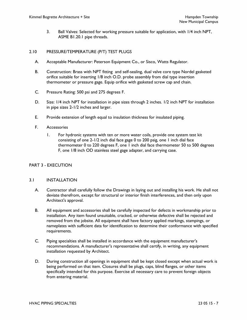
Kimmel Bogrette Architecture + Site Hampden Township
New Municipal Campus
HVAC PIPING SPECIALTIES 23 05 15 - 7
3. Ball Valves: Selected for working pressure suitable for application, with 1/4 inch NPT,
ASME B1.20.1 pipe threads.
2.10 PRESSURE/TEMPERATURE (P/T) TEST PLUGS
A. Acceptable Manufacturer: Peterson Equipment Co., or Sisco, Watts Regulator.
B. Construction: Brass with NPT fitting and self-sealing, dual valve core type Nordel gasketed
orifice suitable for inserting 1/8 inch O.D. probe assembly from dial type insertion
thermometer or pressure gage. Equip orifice with gasketed screw cap and chain.
C. Pressure Rating: 500 psi and 275 degrees F.
D. Size: 1/4 inch NPT for installation in pipe sizes through 2 inches. 1/2 inch NPT for installation
in pipe sizes 2-1/2 inches and larger.
E. Provide extension of length equal to insulation thickness for insulated piping.
F. Accessories
1. For hydronic systems with ten or more water coils, provide one system test kit
consisting of one 2-1/2 inch dial face gage 0 to 200 psig, one 1 inch dial face
thermometer 0 to 220 degrees F, one 1 inch dial face thermometer 50 to 500 degrees
F, one 1/8 inch OD stainless steel gage adapter, and carrying case.
PART 3 - EXECUTION
3.1 INSTALLATION
A. Contractor shall carefully follow the Drawings in laying out and installing his work. He shall not
deviate therefrom, except for structural or interior finish interferences, and then only upon
Architect's approval.
B. All equipment and accessories shall be carefully inspected for defects in workmanship prior to
installation. Any item found unsuitable, cracked, or otherwise defective shall be rejected and
removed from the jobsite. All equipment shall have factory applied markings, stampings, or
nameplates with sufficient data for identification to determine their conformance with specified
requirements.
C. Piping specialties shall be installed in accordance with the equipment manufacturer's
recommendations. A manufacturer's representative shall certify, in writing, any equipment
installation requested by Architect.
D. During construction all openings in equipment shall be kept closed except when actual work is
being performed on that item. Closures shall be plugs, caps, blind flanges, or other items
specifically intended for this purpose. Exercise all necessary care to prevent foreign objects
from entering material.

Kimmel Bogrette Architecture + Site Hampden Township
New Municipal Campus
HVAC PIPING SPECIALTIES 23 05 15 - 8
E. Provide flanges or unions at all final connections to equipment and traps to facilitate
dismantling.
F. Install strainers in horizontal piping, full size of pipe, in accordance with manufacturer's
installation instructions and as follows:
1. Water Piping:
a. Install with screen pocket pointing downwards.
b. Where installation in horizontal piping is not possible, install in vertical piping with
the flow downwards. Installation with upward flow is prohibited.
2. Install pipe nipple and hose end drain valve in strainer blowdown connection, full size of
connection, except for strainers 2 inches and smaller installed ahead of temperature
control valves feeding individual terminals.
3. Where indicated on Drawings, provide drain line from drain valve to plumbing drain, full
size of blowdown connection.
4. Where strainers are installed in pipe branches serving multiple terminals rather than at
each individual terminal, provide isolation valves on each side of the strainer to allow for
routine blowdown service without draining the piping system.
5. Replace any temporary fine mesh start-up screens if used during initial cleaning and
flushing of systems.
G. Unless otherwise indicated, branch take-offs shall be from top of mains or headers at either a
45 degree or 90 degree angle from the horizontal plane for steam, air, or gas lines and from
top, bottom, or side for liquids.
H. Pipe joints connecting dissimilar metals shall be insulating dielectric connections. Copper
tubing shall be protected from electrolysis at contact points with ferrous metals, including
temporary methods of support, by use of insulating non conductive spacers such as rubber,
fiberglass, or an approved equal. Pipe hangers for bare copper tubing shall be copper plated.
I. Thermometers shall be installed where indicated on the Drawings and in locations where they
are easily read from normal operating level. Install thermometers in piping systems in wells in
short couplings. Enlarge pipes smaller than 2-1/2 inch for installation of thermometer wells.
Ensure wells allow clearance from insulation. Fill voids between thermowell and thermometer
and sensor stems with heat conducting compound before installing in wells.
J. Install pressure/temperature test plugs in piping tee where required to allow for balancing and
troubleshooting without requiring permanent pressure gages and thermometers. Position on
pipe at most accessible and readable position.
K. Adjust gages and thermometers to final angle, clean windows and lenses, and calibrate.
1. Adjusting: Adjust faces of meters and gages to proper angle for best visibility.
a. For gages on straining/filtering devices, adjust set hands on pressure gages to
accurately indicate when service is required (approximately 50% above pressure
differential when clean (or as otherwise recommended by strainer/filter
manufacturer).
b. After installation, zero and/or calibrate meters and gages according to
manufacturer's written instructions.
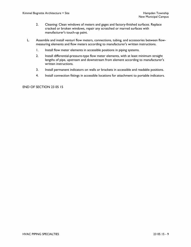
Kimmel Bogrette Architecture + Site Hampden Township
New Municipal Campus
HVAC PIPING SPECIALTIES 23 05 15 - 9
2. Cleaning: Clean windows of meters and gages and factory-finished surfaces. Replace
cracked or broken windows, repair any scratched or marred surfaces with
manufacturer's touch-up paint.
L. Assemble and install venturi flow meters, connections, tubing, and accessories between flow-
measuring elements and flow meters according to manufacturer's written instructions.
1. Install flow meter elements in accessible positions in piping systems.
2. Install differential-pressure-type flow meter elements, with at least minimum straight
lengths of pipe, upstream and downstream from element according to manufacturer's
written instructions.
3. Install permanent indicators on walls or brackets in accessible and readable positions.
4. Install connection fittings in accessible locations for attachment to portable indicators.
END OF SECTION 23 05 15

Kimmel Bogrette Architecture + Site Hampden Township
New Municipal Campus
HVAC VALVES 23 05 25 - 1
SECTION 23 05 25 – HVAC VALVES
PART 1 - GENERAL
1.1 WORK INCLUDED
A. The Work of this Section shall consist of the labor, materials and equipment required for the
installation of HVAC valves.
1.2 SUBMITTALS
A. Submit for approval in accordance with specified submittal procedures:
1. Valves
PART 2 - PRODUCTS
2.1 VALVES
A. Furnish and install valves as specified herein and as scheduled in Part 3 – Execution, of this
Section. Insofar as possible all valves shall be of a single manufacturer.
B. Packings, gaskets, discs, seats, diaphragms, lubricants, etc., shall conform to recommendations
of the valve manufacturer for the intended service.
C. If space permits, install valves with stems horizontal or extending vertically upward unless
specifically shown otherwise. Valves shall be installed in accessible locations for operation as
well as for removal, repair, or replacement.
D. Valves installed in Insulated Piping: With stem or neck extensions of sufficient length to
accommodate insulation thickness and the following features:
1. Gate Valves: With rising stem.
2. Ball Valves: With extended operating handle of non-thermal-conductive material, and
protective sleeve that allows operation of valve without breaking the vapor seal or
disturbing insulation.
3. Butterfly Valves: With extended neck.
E. Provide Owner with one operating wrench for every ten (10) valves of each type (but not less
than 2 wrenches) not equipped with handwheels or levers.
F. Valve body materials shall be compatible with piping system materials.
G. Valves shall have right-handed threads.

Kimmel Bogrette Architecture + Site Hampden Township
New Municipal Campus
HVAC VALVES 23 05 25 - 2
H. Valves shall conform to the following schedules:
I.
BALL VALVE SPECIFICATIONS
Type Size Press.
psig
Description Acceptable
Manufacturer
BA-1 thru 2" 150S
400WOG
Threaded ends;
Bronze breakdown
style body;
Stainless steel ball;
Full port;
Teflon seats
Anvil
International
Apollo
Nibco
BALANCING VALVE SPECIFICATIONS
Type Size Press.
psig
Description Acceptable
Manufacturer
BL-1 thru 2" 125S Threaded ends;
Bronze body;
Square head plug cock
A.Y. McDonald
BUTTERFLY VALVE SPECIFICATIONS
Type Size Press.
psig
Description Acceptable
Manufacturer
BF-1 2-1/2"
thru 12"
150WOG Wafer type flange;
Cast or ductile iron body;
Ductile iron disc;
EPT or EPDM seat;
Stainless steel stem;
Thru 6"-10 position locking
lever handle;
8"-12"-Weatherproof
gear operator
Anvil
International
Crane
Milwaukee
Nibco
Stockham
BF-2 2-1/2"
thru 12"
150WOG Lug type flange;
Cast or ductile iron body;
Ductile iron disc;
EPT or EPDM;
Stainless steel stem;
10-position locking lever
handle (thru 6”);
Weatherproof gear operator
(8"-12")
Anvil
International
Crane
Milwaukee
Nibco
Stockham

Kimmel Bogrette Architecture + Site Hampden Township
New Municipal Campus
HVAC VALVES 23 05 25 - 3
BUTTERFLY VALVE SPECIFICATIONS
Type Size Press.
psig
Description Acceptable
Manufacturer
BF-3 2-1/2"
thru 12"
150WOG High performance;
Lug type flange;
Carbon steel body;
Stainless steel disc with offset
shaft;
RPTFE seat and packing;
Stainless steel stem and trim
components;
10-position locking lever
handle (thru 6”);
Weatherproof gear operator
(8"-12")
Bray /
McCannalock
Series 40,
Cooper,
Cameron,
Dezurik,
Dynacentic,
Fisher,
Jamesbury,
Keystone,
Velan, or
Xomox
CHECK VALVE SPECIFICATIONS
Type Size Press.
psig
Description Acceptable
Manufacturer
CK-1 thru 2" 150S Threaded ends;
Bronze body;
Regrinding swing type
Anvil
International,
Crane,
Hammond,
Milwaukee,
Nibco
CK-2 thru 2" 125S
200WOG
Soldered ends;
Bronze body;
Renewable bronze
disc swing type
Anvil
International,
Crane,
Hammond,
Milwaukee,
Nibco
CK-3 2-1/2"
thru
12"
125S
200WOG
Flanged ends;
Iron body;
Bronze trim;
Bronze disc swing type
Anvil
International,
Crane,
Hammond,
Milwaukee,
Nibco
CK-4 2-1/2”
thru
12”
Class 125
200WOG
Flanged ends;
Cast iron body;
Bronze seat;
Bronze disc;
Stainless steel spring (non-
slam)
Milwaukee,
Nibco

Kimmel Bogrette Architecture + Site Hampden Township
New Municipal Campus
HVAC VALVES 23 05 25 - 4
CHECK VALVE SPECIFICATIONS
Type Size Press.
psig
Description Acceptable
Manufacturer
CK-5 1/2"
thru
2"
150S Screwed ends;
Iron body;
Lift type;
Nickel alloy seat and disc
Crane 366-1/2X
GATE VALVE SPECIFICATIONS
Type Size Press.
psig
Description Acceptable
Manufacturer
GA-6 1/2"
thru 4"
150S
225WOG
Threaded ends;
Iron body;
U-bolt body
Crane,
Hammond,
Stockham
GLOBE VALVE SPECIFICATIONS
Type Size Press.
psig
Description Acceptable
Manufacturer
GL-1 thru 2" 120S
300WOG
Threaded ends;
Bronze body;
Non-metallic disc
Anvil
International,
Crane,
Hammond,
Milwaukee,
Nibco
GL-2 thru 2" 125S
200WOG
Soldered ends;
Bronze body;
Bronze or non-
metallic disc
Anvil
International,
Crane,
Hammond,
Milwaukee,
Nibco
GL-3 2-1/2"
thru
10"
125S
200WOG
& 450
Deg. F.
Flanged ends;
Iron body;
Bronze trim;
Rising stem;
Bronze or bronze
faced iron disc
Anvil
International,
Crane,
Hammond,
Milwaukee,
Nibco

Kimmel Bogrette Architecture + Site Hampden Township
New Municipal Campus
HVAC VALVES 23 05 25 - 5
PART 3 - EXECUTION
3.1 APPLICATION
A. Valves shall be installed in accordance with the following valve schedule:
VALVE SCHEDULE
Piping System
Valve Service
Shut-off Balancing Check
Boiler Isolation GA-1, GA-2, GA-3 n/a n/a
Chemical Feed GA-6 n/a CK-5
Heating Hot Water/
Chilled Water
BA-1
BF-2 BF-3
GL-1, GL-2, GL-3
BF-1, BF-3,
BL-1 (1)
CK-1, CK-2,
CK-3, CK-4
(2)
Make-up Water BA-1 n/a CK-2, CK-3
Note 1: Balancing valve BL-1 to be used in coil piping bypass only. Refer to Section
23 57 10, Heat Transfer for venturi balancing valves.
Note 2: Install non-slam check valves in pump discharges.
3.2 INSTALLATION
A. Contractor shall carefully follow the Drawings in laying out and installing his work and he shall
not deviate therefrom, except for structural or interior finish interferences, and then only
upon Architect's approval.
B. All valves shall be carefully inspected for defects in workmanship prior to installation. Any item
found unsuitable, cracked, or otherwise defective shall be rejected and removed from the job
site. All valves shall have factory applied markings, stampings, or nameplates with sufficient data
for identification to determine their conformance with specified requirements.
C. Provide flanges or unions at all final connections to valves to facilitate dismantling.
D. Unless otherwise indicated, install all shutoff valves to coils, pumps and other equipment at line
size with reduction in size being made only at inlet to control valve or pump. Install check
valves and shutoff valves in equipment outlet or return lines beyond dirt pockets the size of
tapping in the trap or, if no trap, the size of the equipment connection.
E. Where possible, install valves with bonnets in an upright position.
END OF SECTION 23 05 25
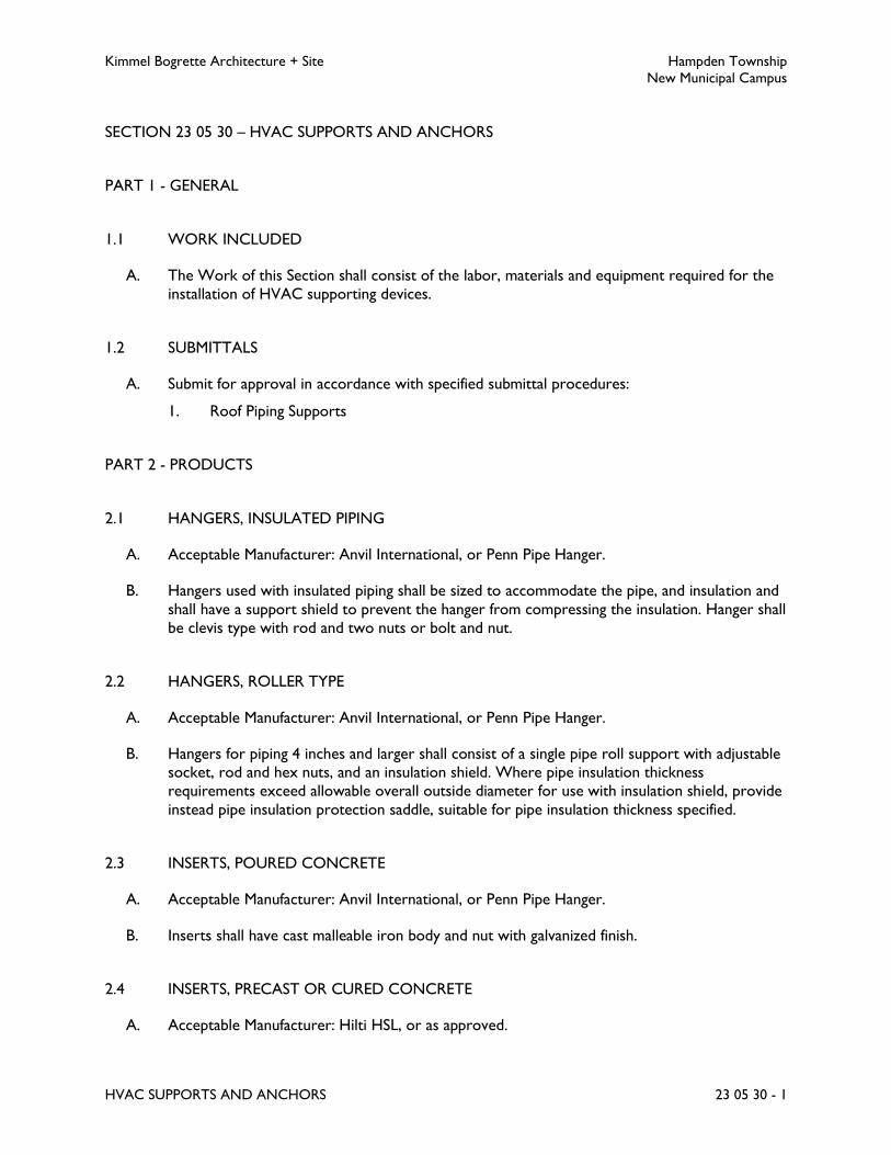
Kimmel Bogrette Architecture + Site Hampden Township
New Municipal Campus
HVAC SUPPORTS AND ANCHORS 23 05 30 - 1
SECTION 23 05 30 – HVAC SUPPORTS AND ANCHORS
PART 1 - GENERAL
1.1 WORK INCLUDED
A. The Work of this Section shall consist of the labor, materials and equipment required for the
installation of HVAC supporting devices.
1.2 SUBMITTALS
A. Submit for approval in accordance with specified submittal procedures:
1. Roof Piping Supports
PART 2 - PRODUCTS
2.1 HANGERS, INSULATED PIPING
A. Acceptable Manufacturer: Anvil International, or Penn Pipe Hanger.
B. Hangers used with insulated piping shall be sized to accommodate the pipe, and insulation and
shall have a support shield to prevent the hanger from compressing the insulation. Hanger shall
be clevis type with rod and two nuts or bolt and nut.
2.2 HANGERS, ROLLER TYPE
A. Acceptable Manufacturer: Anvil International, or Penn Pipe Hanger.
B. Hangers for piping 4 inches and larger shall consist of a single pipe roll support with adjustable
socket, rod and hex nuts, and an insulation shield. Where pipe insulation thickness
requirements exceed allowable overall outside diameter for use with insulation shield, provide
instead pipe insulation protection saddle, suitable for pipe insulation thickness specified.
2.3 INSERTS, POURED CONCRETE
A. Acceptable Manufacturer: Anvil International, or Penn Pipe Hanger.
B. Inserts shall have cast malleable iron body and nut with galvanized finish.
2.4 INSERTS, PRECAST OR CURED CONCRETE
A. Acceptable Manufacturer: Hilti HSL, or as approved.

Kimmel Bogrette Architecture + Site Hampden Township
New Municipal Campus
HVAC SUPPORTS AND ANCHORS 23 05 30 - 2
B. A high integrity, torque controlled anchor for heavy duty fastenings. Loads shall not exceed
manufacturer's recommended weight.
2.5 BEAM CLAMPS
A. For pipe sizes of 3 inches and smaller:
1. Acceptable Manufacturer: Anvil International, or Penn Pipe Hanger.
2. Clamps for attachment to I-beams and/or steel joists shall be malleable iron C-clamp
with hardened steel cup and point set screw and locknut.
B. For pipe sizes of 4 inches and larger:
1. Acceptable Manufacturer: Anvil International.
2. Clamps for attachment to I-beams and/or steel joists shall be adjustable type with
malleable iron jaw, steel tie rod, nuts, and washer.
2.6 PIPE RISER CLAMPS
A. Acceptable Manufacturer: Anvil International, or Penn Pipe Hanger.
B. Pipe riser clamps for both insulated and uninsulated vertical pipe risers shall be 2-piece clamp
complete with 2 bolts and 2 nuts, sized for the OD of the bare pipe to be supported. Clamp
shall be carbon steel construction with galvanized finish for ferrous pipe and copper plated for
copper piping.
PART 3 - EXECUTION
3.1 INSTALLATION
A. The requirements of the applicable Sections of ANSI B31, Pressure Piping shall be considered
as minimum requirements governing fabrication, installation, and support of piping systems
except where more specific or stringent requirements are stated herein or shown on the
Drawings.
B. All piping and piping connected equipment, including valves, strainers, traps, and other
specialties and accessories shall be supported in a manner that will not result in excessive
stress, deflection, swaying, sagging or vibration in the piping or in the building structure either
during erection, cleaning, testing, or normal operation of the systems. Piping shall not be so
restrained, however, as to cause it to snake or buckle between supports or anchors, or to
prevent proper movement due to expansion and contraction. Piping shall be supported at
equipment and valves such that they can be disconnected and removed without further
supporting the piping. Piping shall not introduce any strains or distortion to the connected
equipment.
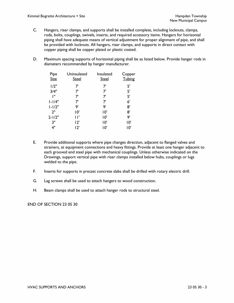
Kimmel Bogrette Architecture + Site Hampden Township
New Municipal Campus
HVAC SUPPORTS AND ANCHORS 23 05 30 - 3
C. Hangers, riser clamps, and supports shall be installed complete, including locknuts, clamps,
rods, bolts, couplings, swivels, inserts, and required accessory items. Hangers for horizontal
piping shall have adequate means of vertical adjustment for proper alignment of pipe, and shall
be provided with locknuts. All hangers, riser clamps, and supports in direct contact with
copper piping shall be copper plated or plastic coated.
D. Maximum spacing supports of horizontal piping shall be as listed below. Provide hanger rods in
diameters recommended by hanger manufacturer.
Pipe
Size
Uninsulated
Steel
Insulated
Steel
Copper
Tubing
1/2" 7' 7' 5'
3/4" 7' 7' 5'
1" 7' 7' 5'
1-1/4" 7' 7' 6'
1-1/2" 9' 9' 8'
2" 10' 10' 8'
2-1/2" 11' 10' 9'
3" 12' 10' 10'
4" 12' 10' 10'
E. Provide additional supports where pipe changes direction, adjacent to flanged valves and
strainers, at equipment connections and heavy fittings. Provide at least one hanger adjacent to
each grooved end steel pipe with mechanical couplings. Unless otherwise indicated on the
Drawings, support vertical pipe with riser clamps installed below hubs, couplings or lugs
welded to the pipe.
F. Inserts for supports in precast concrete slabs shall be drilled with rotary electric drill.
G. Lag screws shall be used to attach hangers to wood construction.
H. Beam clamps shall be used to attach hanger rods to structural steel.
END OF SECTION 23 05 30
Kimmel Bogrette Architecture + Site Hampden Township
New Municipal Campus
HVAC SOUND & VIBRATION CONTROL 23 05 35 - 1
SECTION 23 05 35 – HVAC SOUND AND VIBRATION CONTROL
PART 1 - GENERAL
1.1 WORK INCLUDED
A. The Work of this Section shall consist of the labor, materials, and equipment required for
installation of sound and vibration control devices and materials to prevent sound transmission
and vibration to the building structure.
1.2 RELATED SECTIONS
A. Section 23 05 05, HVAC Basic Materials: Piping and ductwork penetrations.
B. Section 23 05 15, HVAC Piping Specialties: Flexible pipe connectors.
C. Section 23 30 10, Air Distribution: Flexible duct connectors.
1.3 SUBMITTALS
A. Submit for approval in accordance with specified submittal procedures:
1. Isolators
2. Bases
3. Acoustical Treatment Materials
B. Vibration Isolators and Bases: Submittal data shall show type, size, and deflection of each
vibration isolator proposed. Steel bases and concrete inertia bases shall be completely detailed.
Include clearly outlined procedures for installing and adjusting vibration isolators.
C. Acoustical Treatment Materials: Submittal shall include construction details, materials,
dimensions and attachment methods of individual components.
1.4 QUALITY ASSURANCE
A. Vibration isolation devices, including auxiliary steel bases and pouring forms, shall be designed
and furnished by a single manufacturer or supplier to assure single responsibility for
performance of vibration isolators installed.
Kimmel Bogrette Architecture + Site Hampden Township
New Municipal Campus
HVAC SOUND & VIBRATION CONTROL 23 05 35 - 2
PART 2 - PRODUCTS
2.1 GENERAL
A. Vibration isolators and bases for outdoor installations shall be suitably protected to prevent
corrosion. Steel bases shall be primed and painted. Springs, nuts, bolts, etc., shall be cadmium
plated and neoprene coated. Spring housings shall be neoprene coated.
2.2 ISOLATORS
A. Isolator Specification No. 1
1. Acceptable Manufacturer: Kinetics Noise Control Model FDS, or Amber/Booth,
Vibration Mountings & Controls, Mason Industries, Vibration Eliminator Co.
2. Type: Free-standing spring isolator.
3. Description: Adjustable, free-standing, open spring mounting with combination leveling
bolt and equipment fastening bolt. Spring rigidly attached to spring mounting baseplate
and compression plate. A neoprene pad having a minimum thickness of 1/4 inch shall be
bonded to the baseplate.
4. Design: Minimum Kx/Ky (horizontal-to-vertical spring rate) of 1.0 and shall fall into
stable range as defined in the latest ASHRAE Systems Handbook.
B. Isolator Specification No. 3
1. Acceptable Manufacturer: Kinetics Noise Control Model RD, or Amber/Booth,
Vibration Mountings & Controls, Mason Industries, Vibration Eliminator Co.
2. Type: Molded neoprene pad.
3. Description: A double deflection elastomeric mounting having a steel baseplate with
mounting holes and a threaded insert at the top of or crossout the mounting for
attaching equipment. All metal parts shall be completely embedded in elastomeric
material. Elastomeric shall be neoprene or high quality synthetic rubber with anti-ozone
and anti-oxident additives.
4. Design: Mountings shall be designed for approximately 1/4 inch deflection and loaded so
that deflection does not exceed 15 percent of the free height of the mounting.
C. Isolator Specification No. 4
1. Acceptable Manufacturer: Kinetics Noise Control Model NG (neoprene), Model KIP
(fiberglass), or Amber/Booth, Vibration Mountings & Controls, Mason Industries,
Vibration Eliminator Co.
2. Type: Neoprene or fiberglass pad.
3. Description: A pad type mounting consisting of two layers of ribbed or waffled
neoprene pads bonded to a galvanized steel separator plate, or a pad type
precompressed molded fiberglass isolator, individually coated with elastomeric
membrane.

Kimmel Bogrette Architecture + Site Hampden Township
New Municipal Campus
HVAC SOUND & VIBRATION CONTROL 23 05 35 - 3
D. Isolator Specification No. 5
1. Acceptable Manufacturer: Kinetics Noise Control Model SFH, or Amber/Booth,
Vibration Mountings & Controls, Mason Industries, Vibration Eliminator Co.
2. Type: Hanger.
3. Description: A combination spring and elastomeric or fiberglass hanger consisting of a
rectangular steel box, steel spring, and an elastomeric isolation element, with a
neoprene or fiberglass construction.
4. Design: The elements shall be designed for approximately 1/4 inch deflection and
loaded so that deflection does not exceed 15 percent of the free height of the element.
2.3 BASES
A. Base Specification No. 2
1. Acceptable Manufacturer: Kinetics Noise Control Model CIB, or Amber/Booth,
Vibration Mountings & Control, Mason Industries, Vibration Eliminator Co.
2. Type: Concrete inertia base.
3. Description: Base shall consist of a perimeter steel pouring form with reinforcing bars
welded in place, bolting templates with anchor bolts and height saving brackets for side
mounting of spring isolators.
4. Design: Perimeter steel members shall have a minimum depth of 1/12 of the longest
span, but not less than 6 inches deep. Base shall be sized with a minimum overlap of 4
inches around base of equipment and, in the case of belt driven equipment, 4 inches
beyond end of drive shaft. Bases for pumps shall be sized to support suction elbow of
end suction pumps and both suction and discharge elbows of horizontal split case
pumps. Bases shall be T-shaped where necessary to conserve space.
B. Base Specification No. 3
1. Acceptable Manufacturer: Kinetics Noise Control Model KSR, or Amber/Booth,
Vibration Mountings & Controls, Mason Industries, Vibration Eliminator Co.
2. Type: Curb rail isolator.
3. Description: Isolator shall consist of a prefabricated extruded aluminum or a formed
galvanized steel rail system, incorporating 1 inch deflection freestanding stable springs
for vibration isolation, and a continuous air and water seal.
4. Construction: Rail sections shall include integral slot anchoring springs to the bottom
section, but allow horizontal adjustment. Spring elements shall meet specified
characteristics of spring isolators, specified herein, and shall be selected and located to
maintain a level rail assembly and uniform spring deflection of 1 inch after equipment is
installed. A continuous, integral, gravity, water seal and foam or neoprene air seal shall
be incorporated into rail sections, allowing no metal contact between top and bottom
sections.
5. Installation: Curb isolator assembly may be a one piece unitized assembly or may be
provided in multiple sections, designed to fit the base of rooftop equipment and
associated roof curb. Curb isolator shall have mitered corners with an integral alignment
Kimmel Bogrette Architecture + Site Hampden Township
New Municipal Campus
HVAC SOUND & VIBRATION CONTROL 23 05 35 - 4
and connection facility for accurate joining of side and end assemblies. Curb isolators
shall be field calked in accordance with instructions furnished by curb isolator
manufacturer.
2.4 ACOUSTICAL TREATMENT MATERIALS
A. Acoustical Grade Calk
1. Acceptable Manufacturer: BRD Noise & Vibration Control, Inc. HSAC-100.
2. Material: Non-hardening, extruded latex bead, white in color.
3. Compliance: UL 723 and Class “A” per ASTM E-84.
B. Loaded Vinyl Sound Barrier
1. Acceptable Manufacturer: BRD Noise & Vibration Control, Inc. NRLV-100.
2. Material: High temperature-fused, non-reinforced vinyl loaded with non-lead fillers,
0.107 inch nominal thickness, 1.0 lbs/sq.ft.
3. Performance: Barrier shall exhibit a transmission loss not less than indicated below
when tested in accordance with ASTM-E-90-75.
HZ 125 250 500 1000 2000 4000 STC
13 17 22 26 32 37 26
C. High Density Acoustic Insulation
1. Acceptable Manufacturer: BRD Noise & Vibration Control, Inc. HB-200.
2. 2 inch thick batt insulation, nominal 3 lbs./cu.ft. density.
3. Performance: Insulation shall exhibit absorption characteristics not less than shown
below in accordance with ASTM C-423-77.
HZ 125 250 500 1000 2000 4000 NRC
0.07 0.27 0.96 1.13 1.08 0.99 0.85
PART 3 - EXECUTION
3.1 SYSTEM DESIGN
A. Vibration isolation equipment manufacturer shall be responsible for proper selection of spring
rates to accomplish the specified minimum static deflections for all spring and pad type
isolators, based on weight distribution of equipment to be isolated.
B. Vibration isolation equipment manufacturer shall be responsible for structural design of
concrete inertia bases to support mechanical equipment specified herein.
C. Minimum spring deflections shall be selected in accordance with latest ASHRAE Applications
Handbook, unless otherwise indicated on Drawings.

Kimmel Bogrette Architecture + Site Hampden Township
New Municipal Campus
HVAC SOUND & VIBRATION CONTROL 23 05 35 - 5
3.2 APPLICATION
A. Vibration isolators and bases shall be installed in accordance with the following schedule:
VIBRATION ISOLATOR AND BASE SCHEDULE
Application Isolator Spec. No. Base Spec. No.
Boiler 4 Not Req’d.
Chiller, Scroll 3 or 4 Not Req’d.
Condenser-Compressor Unit 3 or 4 Not Req’d.
Fan, Centrifugal Suspended 5 Not Req’d.
Pump, Base-mounted 1 2
Rooftop Equipment, Curb Mtd. n/a 3
* Isolators and bases are not required on air handlers with manufacturer furnished
vibration isolation in motor/fan sections. Confirm with Engineer.
3.3 INSTALLATION
A. Installation of sound and vibration control equipment and materials shall be as indicated on
Drawings and accomplished in accordance with the manufacturer's written instructions.
B. Rigid connections shall not exist between equipment and building structure that will degrade
the sound and vibration control system(s) specified herein.
C. Sound and vibration control equipment and materials manufacturer, or his qualified
representative, shall be responsible for providing such supervision as may be necessary to
assure correct installation and adjustment of the sound and vibration control system. Upon
completion of equipment installation and after the system is placed into operation, the
manufacturer, or his representative, shall make a final inspection and submit a report to
Architect in writing, certifying the correctness of the installation and compliance with
Drawings and Specifications.
D. Piping and ductwork to be vibration isolated shall freely pass through walls and floors without
rigid connections. Penetration points shall be sleeved or otherwise formed to allow passage of
piping or ductwork, and maintain a minimum of 3/4 inch and a maximum of 1-1/4 inch
clearance around the outside surfaces. Refer to Section 23 05 05 for procedures in sealing this
annular space.
E. Rooftop Unit In-curb Acoustical Treatment
1. Alternating layers of sound barrier and acoustic insulation shall line the top surface of
the roof deck inside the curb as indicated on Drawings to reduce the noise levels
radiated inside the curb from the bottom of the rooftop unit to the occupied spaces
below.
Kimmel Bogrette Architecture + Site Hampden Township
New Municipal Campus
HVAC SOUND & VIBRATION CONTROL 23 05 35 - 6
2. Decking shall be maintained inside the curb to a clearance of 1/4 inch maximum around
the duct drops but shall not contact the duct.
3. Sound barrier shall be overlapped a minimum of 3 inches.
4. Acoustic insulation seams shall be butted and insulation shall be packed in air gaps
around duct drops.
5. Seams for every layer shall be staggered.
6. Acoustic grade calk shall be applied in the following areas:
a. Around the entire curb interior perimeter.
b. Single bead at sound barrier overlaps.
c. Around duct drop penetrations through decking.
END OF SECTION 23 05 35
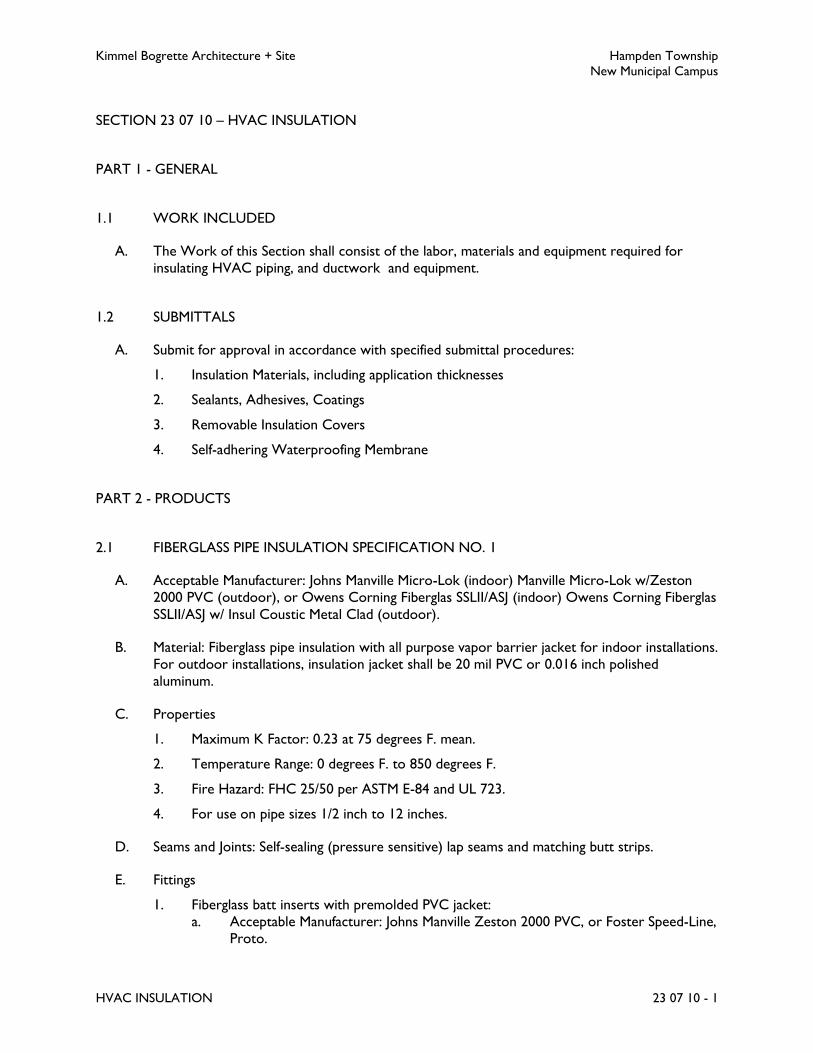
Kimmel Bogrette Architecture + Site Hampden Township
New Municipal Campus
HVAC INSULATION 23 07 10 - 1
SECTION 23 07 10 – HVAC INSULATION
PART 1 - GENERAL
1.1 WORK INCLUDED
A. The Work of this Section shall consist of the labor, materials and equipment required for
insulating HVAC piping, and ductwork and equipment.
1.2 SUBMITTALS
A. Submit for approval in accordance with specified submittal procedures:
1. Insulation Materials, including application thicknesses
2. Sealants, Adhesives, Coatings
3. Removable Insulation Covers
4. Self-adhering Waterproofing Membrane
PART 2 - PRODUCTS
2.1 FIBERGLASS PIPE INSULATION SPECIFICATION NO. 1
A. Acceptable Manufacturer: Johns Manville Micro-Lok (indoor) Manville Micro-Lok w/Zeston
2000 PVC (outdoor), or Owens Corning Fiberglas SSLII/ASJ (indoor) Owens Corning Fiberglas
SSLII/ASJ w/ Insul Coustic Metal Clad (outdoor).
B. Material: Fiberglass pipe insulation with all purpose vapor barrier jacket for indoor installations.
For outdoor installations, insulation jacket shall be 20 mil PVC or 0.016 inch polished
aluminum.
C. Properties
1. Maximum K Factor: 0.23 at 75 degrees F. mean.
2. Temperature Range: 0 degrees F. to 850 degrees F.
3. Fire Hazard: FHC 25/50 per ASTM E-84 and UL 723.
4. For use on pipe sizes 1/2 inch to 12 inches.
D. Seams and Joints: Self-sealing (pressure sensitive) lap seams and matching butt strips.
E. Fittings
1. Fiberglass batt inserts with premolded PVC jacket:
a. Acceptable Manufacturer: Johns Manville Zeston 2000 PVC, or Foster Speed-Line,
Proto.

Kimmel Bogrette Architecture + Site Hampden Township
New Municipal Campus
HVAC INSULATION 23 07 10 - 2
b. Properties: 0.28 max. K at 75 degrees F. mean, 0 degrees F. to 450 degrees F.
temperature range, FHC 25/50 fire hazard per ASTM E-84.
2. Fitting insulation shall be same thickness as adjacent insulation.
2.2 FLEXIBLE ELASTOMERIC PIPE INSULATION SPECIFICATION NO. 2
A. Acceptable Manufacturer: Armacell AP Armaflex, or K-Flex.
B. Material: Flexible elastomeric thermal pipe insulation. Black in color.
C. Properties
1. Maximum K Factor: 0.27 at 75 degrees F.
2. Compliance: ASTM E84, 25 flame/50 smoke.
3. Temperature Range: Minus 70 degrees F. to 220 degrees F.
4. For use on pipe sizes: 3/8 inch to 6 inch.
D. Fittings, Joints: Mitered cut, same thickness as adjacent insulation.
E. Adhesive
1. Acceptable Manufacturer: Armacell 520 BLV, K-Flex 720, Foster Drion 85-75, or
Childers Chil Stix C-82.
2. Toluene free, VOC no greater than 50 g/L
F. Outdoor Installations
1. For outdoor installations, insulation shall be covered with glass fiber mesh embedded in
insulation adhesive and painted with insulation manufacturer's standard protective finish.
2. Acceptable Manufacturer: Armaflex WB Finish, or Foster 30-64.
2.3 FIBERGLASS DUCT LINER INSULATION SPECIFICATION NO. 4
A. Acceptable Manufacturer: Johns Manville Permacote Lina-coustic, or Certain-Teed
ToughGardTM, Owens-Corning Aeroflex Plus, Knauf Duct Liner E-M.
B. Material: Fiberglass blanket duct liner.
C. Properties
1. Maximum K Factor: 0.26 at 75 degrees F. mean.
2. Density: 1.5 or 2.0 pcf.
3. Temperature Rating: 250 degrees F. (maximum)
4. NFPA Requirements: Bulletin 90A and 90B.
5. Compliance: ASTM E84, 25 flame/50 smoke.

Kimmel Bogrette Architecture + Site Hampden Township
New Municipal Campus
HVAC INSULATION 23 07 10 - 3
D. Coating for Duct Liner Butt Joints and Clip Fasteners
1. Acceptable Manufacturer: Foster Jac Tac Edge Sealer 85-62 or Childers Chil Spred CP-
135-2.
2. VOC no greater than 50 g/L.
E. Adhesive for Duct Liner Attachment
1. Acceptable Manufacturer: Foster Quick Tack 85-60 or Childers Chill Quik CP-127.
2. Water-based adhesive meeting ASTM C 916, Type II.
3. VOC no greater than 50 g/L.
2.4 FIBERGLASS DUCT WRAP INSULATION SPECIFICATION NO. 5
A. Acceptable Manufacturer: Johns Manville Microlite, or Certain-Teed Standard Duct Wrap,
Owens-Corning Fiberglas All-Service Duct Wrap, Knauf.
B. Material: Exterior fiberglass duct insulation with foil scrim kraft laminated (FSKL) facing.
C. Properties
1. Maximum K Factor: 0.29 at 75 degrees F. mean.
2. Density: 1.0 pcf or 1.5 pcf.
3. Temperature Rating: 250 degrees F. (maximum)
4. NFPA Requirements: Bulletins No. 90A and 90B.
5. Compliance: ASTM E84, 25 flame/50 smoke.
D. Adhesive for Duct Insulation Attachment
1. Acceptable Manufacturer: Foster Quick Tack 85-60 or Childers Chil Quik CP-127.
2. Water-based adhesive meeting ASTM C 916, Type II.
3. VOC no greater than 50 g/L.
E. Tape for Sealing Duct Insulation Butt Joints, 2 inches Wide
1. Acceptable Manufacturer: Elgen Air-Tite EDT-2.
2.5 FLEXIBLE ELASTOMERIC SHEET/ROLL INSULATION SPECIFICATION NO. 6
A. Acceptable Manufacturer: Armstrong AP Armaflex , or K-Flex.
B. Material: Exterior flexible elastomeric thermal sheet or roll insulation. Black in color.
C. Properties
1. Maximum K Factor: 0.27 at 75 degrees F. mean.
2. Compliance: ASTM E84, 25 flame/50 smoke.

Kimmel Bogrette Architecture + Site Hampden Township
New Municipal Campus
HVAC INSULATION 23 07 10 - 4
3. Temperature Rating: Minus 70 degrees F. to 220 degrees F.
D. Adhesive
1. Acceptable Manufacturer: Armstrong 520 BLV, K-Flex 720, Foster Drion 85-75, or
Childers Chil Stix C-82.
2. Toluene free, VOC no greater than 50 g/L
E. Outdoor Installations
1. For outdoor installations, insulation shall be covered with glass fiber mesh embedded in
insulation adhesive and painted with insulation manufacturer's standard protective finish.
2. Acceptable Manufacturer: Armaflex WB Finish, or Foster 30-64.
2.6 FIBERGLASS BOARD/SHEET INSULATION SPECIFICATION NO. 8
A. Acceptable Manufacturer: Johns Manville 800 Series, Spin-Glas, or Owens-Corning 700 Series
Fiberglas, Certain-Teed CB-600, Knauf.
B. Material: Flexible or non-flexible fiberglass board or sheet with all-purpose vapor barrier
jacket. Insulation installed outdoors on ductwork shall be tapered on top of ductwork and
wrapped and sealed with white EPDM.
C. Properties
1. Maximum K Factor: 0.23 at 75 degrees F. mean.
2. Density: 6 pcf.
3. Temperature Rating: 0 degrees F. to 450 degrees F.
4. Compliance: ASTM E84, 25 flame/50 smoke.
PART 3 - EXECUTION
3.1 APPLICATION
A. Insulation shall be installed in accordance with the following insulation schedule(s). (Where
more than one insulation type is scheduled, Contractor shall have the option of choosing from
types listed.)
PIPE INSULATION SCHEDULE
Service
Temp.
Range
Deg. F
Insul.
Spec.
No.
Minimum Pipe Insulation Thickness
to
1-1/2" 2"
2-1/2"
to 4"
5" &
larger
Domestic Make-up
Water:
50-65 1 1/2 1/2 1/2 1/2
2 1/2 1/2 1/2 1/2

Kimmel Bogrette Architecture + Site Hampden Township
New Municipal Campus
HVAC INSULATION 23 07 10 - 5
PIPE INSULATION SCHEDULE
Service
Temp.
Range
Deg. F
Insul.
Spec.
No.
Minimum Pipe Insulation Thickness
to
1-1/2" 2"
2-1/2"
to 4"
5" &
larger
Hot Water 100-160 1
2
1-1/2
1-1/2
2
2
2
2
2
N/A
Chilled Water 40-55 1
2
1-1/2
1-1/2
1-1/2
1-1/2
1-1/2
1-1/2
1-1/2
1-1/2
Refrigerant,
Suction
All 1 1-1/2 1-1/2 1-1/2 1-1/2
2 1-1/2 1-1/2 1-1/2 N/A
Condensate
Drainage
35-70 1 1/2 1/2 1/2 1
2 1/2 1/2 1/2 1
DUCT INSULATION SCHEDULE
Duct Type/Service Insulation Spec. No. Thickness, Inches
Rectangular Sheet Metal, installed within building thermal envelope:
Supply Air 4 1
5 1-1/2
Return Air 4 1
5 1-1/2
Exhaust Air Not Required ---
Relief Air Not Required ---
Round Sheet Metal, installed within building thermal envelope:
Supply Air 5 1-1/2
Return Air 5 1-1/2
Exhaust Air Not Required ---
Relief Air Not Required ---
Rectangular Sheet Metal, installed exposed in mechanical rooms:
Supply Air 4 1
Return Air 4 1
Exhaust Air Not Required ---
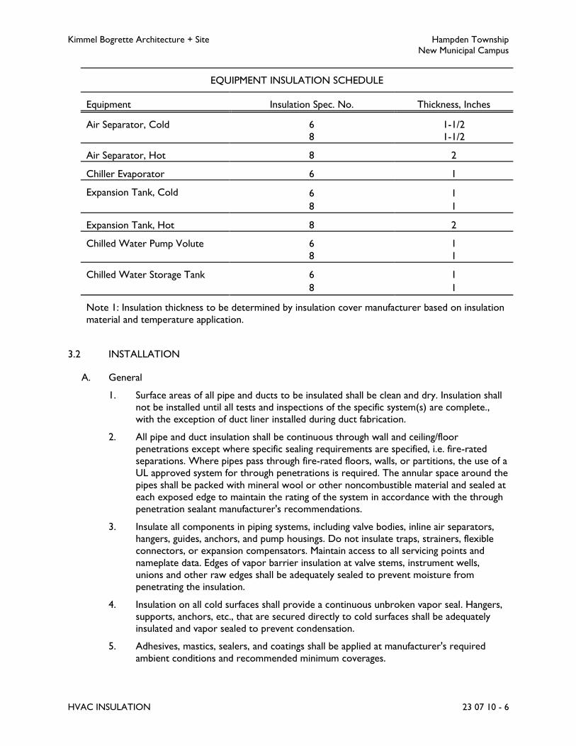
Kimmel Bogrette Architecture + Site Hampden Township
New Municipal Campus
HVAC INSULATION 23 07 10 - 6
EQUIPMENT INSULATION SCHEDULE
Equipment Insulation Spec. No. Thickness, Inches
Air Separator, Cold 6 1-1/2
8 1-1/2
Air Separator, Hot 8 2
Chiller Evaporator 6 1
Expansion Tank, Cold 6 1
8 1
Expansion Tank, Hot 8 2
Chilled Water Pump Volute 6 1
8 1
Chilled Water Storage Tank 6 1
8 1
Note 1: Insulation thickness to be determined by insulation cover manufacturer based on insulation
material and temperature application.
3.2 INSTALLATION
A. General
1. Surface areas of all pipe and ducts to be insulated shall be clean and dry. Insulation shall
not be installed until all tests and inspections of the specific system(s) are complete.,
with the exception of duct liner installed during duct fabrication.
2. All pipe and duct insulation shall be continuous through wall and ceiling/floor
penetrations except where specific sealing requirements are specified, i.e. fire-rated
separations. Where pipes pass through fire-rated floors, walls, or partitions, the use of a
UL approved system for through penetrations is required. The annular space around the
pipes shall be packed with mineral wool or other noncombustible material and sealed at
each exposed edge to maintain the rating of the system in accordance with the through
penetration sealant manufacturer's recommendations.
3. Insulate all components in piping systems, including valve bodies, inline air separators,
hangers, guides, anchors, and pump housings. Do not insulate traps, strainers, flexible
connectors, or expansion compensators. Maintain access to all servicing points and
nameplate data. Edges of vapor barrier insulation at valve stems, instrument wells,
unions and other raw edges shall be adequately sealed to prevent moisture from
penetrating the insulation.
4. Insulation on all cold surfaces shall provide a continuous unbroken vapor seal. Hangers,
supports, anchors, etc., that are secured directly to cold surfaces shall be adequately
insulated and vapor sealed to prevent condensation.
5. Adhesives, mastics, sealers, and coatings shall be applied at manufacturer's required
ambient conditions and recommended minimum coverages.

Kimmel Bogrette Architecture + Site Hampden Township
New Municipal Campus
HVAC INSULATION 23 07 10 - 7
B. Insulation Protective Shields
1. Insulation protection shields fabricated from galvanized steel shall be installed at all pipe
hangers and supports. Shields shall span an arc of 180 degrees.
2. Provide shield lengths and thicknesses as outlined in the latest version of the
International Mechanical Code or MSS-SP69. Minimum shield lengths shall be as follows:
Pipe Sizes,
Inches
Shield Length,
Inches
1-1/2 to 2-1/2 10
3 to 6 12
8 to 10 16
12 and over 22
3. Rigid cellular glass insulation, capable of resisting the crushing effect of the hydraulically
loaded piping, shall be placed under each shield. Jacketing material shall be wrapped
around rigid insulation and adjacent top and butt sections to maintain the jacketing
continuity.
4. Stainless steel shields shall be installed on insulated piping located on the roof.
C. Removable Insulation Covers
1. Equipment shall be insulated to the fullest extent possible. Removable insulation shall be
provided for items that will require insulation removal for periodic maintenance or
inspection, including the following:
a. Steam: Valves, strainers, pressure reducing valves, pressure relief valves, traps,
condensate receivers/pumps, flash tanks, heat exchangers.
b. Hot Water: Valves, strainers, pumps, heat exchangers, expansion tanks, air
separators.
c. Chilled Water: Valves, strainers, pumps, heat exchangers, air separators.
2. Provide removable insulation sections to cover parts of pumps that must be accessed
periodically for maintenance (i.e. strainers, grease fittings, vent/drain plugs or valves, P/T
ports) without damaging insulation or compromising vapor barrier. Include metal vessel
covers, fasteners, flanges, frames and accessories. Ensure that the bearing assembly
grease fittings remain accessible and visible, extending as necessary beyond insulation
thickness. Any vent slots on the sides and bottom of the bearing assembly shall remain
uncovered and completely open. Insulation on pump systems operating below ambient
dew point (such as chilled water) shall be insulated with closed cell foam with all joints
and penetrations sealed to maintain vapor barrier.
D. Fiberglass Pipe Insulation
1. All piping shall be cleaned of debris prior to installation of insulation and components.
Joints shall be butted firmly together. Longitudinal laps and butt strips shall be securely
fastened as recommended by the manufacturer.

Kimmel Bogrette Architecture + Site Hampden Township
New Municipal Campus
HVAC INSULATION 23 07 10 - 8
2. Fittings, insulated with fiberglass blanket and PVC jacket shall be installed in accordance
with insulation manufacturer's instructions. All butt joints between longitudinal pipe
insulation and fittings shall be taped.
E. Flexible Elastomeric Thermal Pipe and Sheet Insulation
1. Insulation shall be installed neatly with oversized pipe insulation and sheet insulation
being used for fittings and valves. For outdoor installations, completely wrap insulation
surface with glass fiber mesh and fully adhere/lag glass mesh to insulation with one coat
of insulation adhesive. Inspect for bonding of glass mesh to insulation surfaces before
applying specified weatherproof finish. Consult insulation manufacturer's
recommendations for coatings and sealants.
F. Duct Liner Insulation
1. Duct liner shall be applied to the flat duct sheet with a minimum of 90 percent coverage
of adhesive.
2. Duct liner shall be cut to assure snug closing corner joints. The smooth surface of the
liner shall face the air stream. On top and sides of duct having a width and/or height
dimension over 15 inches, the liner shall be additionally secured with welded pins and
speed clips or grip-nails on a maximum of 15 inch centers. Pins shall be cut close to the
speed clip. Pins shall start within 2 inches of the leading edge of each section and within
3 inches of the leading edge of cross joints within the duct section. All exposed edges
and joints of the liner shall have coating applied.
G. Duct Wrap Insulation
1. All insulation shall be applied with edges tightly butted. Insulation shall be secured with
adhesive which shall be applied to entire metal surfaces so that insulation conforms to
duct surfaces uniformly and firmly.
H. Fiberglass Board/Sheet Insulation
1. Insulation board/sheet shall be installed by means of weld pins or stick clips. Pins/clips
shall be located a maximum of 3 inches from all leading edges and a minimum of 12
inches on center for remainder of surface area.
2. Removable heads, cover plates, manholes, etc., shall be separately covered with unfaced
board/sheet with 1/2 inch insulating cement finish, leaving bolts and nuts accessible.
Leave nameplates visible.
END OF SECTION 23 07 10

Kimmel Bogrette Architecture + Site Hampden Township
New Municipal Campus
VARIABLE FREQUENCY DRIVES 23 10 20 - 1
SECTION 23 10 20 – VARIABLE FREQUENCY DRIVES
PART 1 - GENERAL
1.1 WORK INCLUDED
A. The Work of this Section shall consist of the labor, materials, and equipment required for
installation of variable frequency drives for air handling units and pumps.
B. Variable frequency drives shall serve as starter, circuit breaker, motor overload protection,
indicator panel, remote signal output and power factor correction for the specific mechanical
equipment.
1.2 SUBMITTALS
A. Submit variable frequency drives for approval in accordance with specified submittal
procedures. Include wiring diagrams, load characteristics, connections and mountings with
submittal data.
PART 2 - PRODUCTS
2.1 VARIABLE FREQUENCY DRIVES
A. Acceptable Manufacturers: ABB, or Allen Bradley, or Yaskawa, Reliance, Toshiba, Graham,
Schneider Electric, Cutler Hammer.
B. General: The drive shall accept three phase input.
1. Suitable for operation on standard NEMA design B motors. Drive shall have a diode
bridge rectifier on the input to minimize generation of electrical noise back into the line
and provide near unity power factor.
2. Drive horsepower rating shall range from 3 HP to 100 HP with a speed range of 3 to
67, 80 or 120 Hz selectable by rotary switch. Drive shall be capable of an overload of
120 percent for 60 seconds.
3. Output devices shall be transistors, IGBT (insulated gate bipolar transistors) for reduced
motor noise.
4. UL listed.
C. Environment Conditions
1. Drive Enclosure Type: NEMA 1 (indoor) or NEMA 3R (outdoor); as required for the
application. The enclosure shall provide protection of all internal components for the
application and environmental conditions at the installed location.
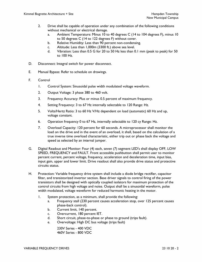
Kimmel Bogrette Architecture + Site Hampden Township
New Municipal Campus
VARIABLE FREQUENCY DRIVES 23 10 20 - 2
2. Drive shall be capable of operation under any combination of the following conditions
without mechanical or electrical damage.
a. Ambient Temperature: Minus 10 to 40 degrees C (14 to 104 degrees F), minus 10
to 50 degrees C (14 to 122 degrees F) without cover.
b. Relative Humidity: Less than 90 percent non-condensing.
c. Altitude: Less than 1,000m (3300 ft.) above sea level.
d. Vibration: Less than 0.5 G for 20 to 50 Hz less than 0.1 mm (peak to peak) for 50
to 100 Hz.
D. Disconnect: Integral switch for power disconnect.
E. Manual Bypass: Refer to schedule on drawings.
F. Control
1. Control System: Sinusoidal pulse width modulated voltage waveform.
2. Output Voltage: 3 phase 380 to 460 volt.
3. Frequency Accuracy: Plus or minus 0.5 percent of maximum frequency.
4. Setting Frequency: 3 to 67 Hz internally selectable to 120 Range: Hz.
5. Volts/Hertz Ratio: 3 to 60 Hz V/Hz dependent on load (automatic) 60 Hz and up,
voltage constant.
6. Operation frequency 0 to 67 Hz, internally selectable to 120 cy Range: Hz.
7. Overload Capacity: 120 percent for 60 seconds. A microprocessor shall monitor the
load on the drive and in the event of an overload, it shall, based on the calculation of a
true inverse time overload characteristic, either trip out or phase back the voltage and
speed as selected by an internal jumper.
G. Digital Readout and Monitor: Four (4) each, seven (7) segment LED's shall display OFF, LOW
SPEED, FREQUENCY and FAULT. Front accessible pushbutton shall permit user to monitor
percent current, percent voltage, frequency, acceleration and deceleration time, input bias,
input gain, upper and lower limit. Drive readout shall also provide drive status and protective
circuits status.
H. Protection: Variable frequency drive system shall include a diode bridge rectifier, capacitor
filter, and transistorized invertor section. Base driver signals to control firing of the power
transistors shall be designed with optically coupled isolators for maximum protection of the
control circuits from high voltage and noise. Output shall be a sinusoidal waveform, pulse
width modulated, voltage waveform for reduced harmonic heating in the motor.
1. System protection, as a minimum, shall provide the following:
a. Frequency stall (230 percent causes acceleration stop, over 125 percent causes
phase-back control).
b. Current limit, 140 percent.
c. Overcurrent, 180 percent IET.
d. Short circuit, phase-to-phase or phase to ground (trips fault).
e. Overvoltage: High DC bus voltage (trips fault)
230V Series - 400 VDC
460V Series - 800 VDC

Kimmel Bogrette Architecture + Site Hampden Township
New Municipal Campus
VARIABLE FREQUENCY DRIVES 23 10 20 - 3
460V H Series - 760 VDC
f. Undervoltage, 85 percent below line voltage (indicates fault).
g. Component burnout, DC bus fuse protection and/or 3 phase input fusing.
h. Digital Indication of Fault: When the drive trips out on a fault, the drive shall
activate a fault relay with normally open and normally closed contacts available to
the user and an LED display shall indicate the reason for the trip as follows:
OC: Overcurrent trip at 180 percent.
OCA: Internal component short circuit.
OCL: Output short circuit.
OL: Overload (when soft stall not selected).
OP: Overvoltage on DC bus.
OPS: Overvoltage on input.
UP: Undervoltage.
OH: Overheat or closing of terminals OH.
EF: Ground fault (earth fault).
i. Auto restart shall be a standard feature of the drive as follows:
1) Auto restart enabled or disabled by jumper selection.
2) If auto restart is selected the microprocessor shall determine, in the event
of a fault, if a restart should be attempted. A restart shall be attempted
under the following conditions:
Undervoltage (UP) - every time as soon as voltage returns to a safe level.
Fault relay is not activated (not jumper selectable).
Input Overvoltage (OPS) and DC Bus Overvoltage (OP) - every time if
voltage returns to normal within 30 seconds, fault relay is not activated and
reset for 30 seconds (jumper selectable).
Overcurrent (OC) - drive delays 1 second and attempts a restart. If drive
trips a second time, it delays 2 seconds and attempts a second restart.
Overall, five attempts are made after successive delays of 1, 2, 4, 8 and 16
seconds. If the restart fails after the fifth attempt, the drive will trip out and
activate the fault relay (jumper selectable).
3) A restart shall not be attempted for any other type of fault and the drive
shall trip out immediately, activate the fault relay and make the appropriate
indication on the display.
j. In the event of a fault trip the microprocessor shall save the status of the drive at
the time of the fault and make that information available on the LED display until
the drive is reset or the control power is removed.
k. An undervoltage condition of less than 30ms duration shall not affect drive
operation. If main power falls below 85 percent of rated voltage for longer than
30ms while control power is retained the drive shall forcibly decelerate the load
in an attempt to force a higher bus voltage through regeneration. This feature,
depending on the inertial of the load, shall allow the drive to "ride through" a
longer condition.
l. The following shall be mounted by drive manufacturer:
1) Incoming motor circuit protector and thermal overload.
2) AC Line Reactor: For reduction of harmonic content, power factor
improvement and line transient suppression.

Kimmel Bogrette Architecture + Site Hampden Township
New Municipal Campus
VARIABLE FREQUENCY DRIVES 23 10 20 - 4
3) If indicated on schedule, provide manual bypass switch which allows motor
operation during service to variable speed drives.
4) Integral disconnect switch.
m. Operational Functions:
1) Acceleration and deceleration time independently adjustable from 0.1 to
30/1 to 300 seconds (selectable ranges).
2) Signal follower 0 to 5VDC, 0 to 10VDC, 4 to 20ma, 0 to 20ma, 1 to 5VDC,
or 0 to 135 ohms selectable by jumper. An increasing input signal can
command increasing or decreasing frequency as required by the application.
3) Ramp-to-stop or coast-to-stop for normal operation (coast-to-stop on
fault).
4) Volts/Hertz patterns selectable by rotary switch.
5) Upper and lower frequency limit adjustments shall be available. When the
drive reaches one of the limits it shall activate an open collector signal
available to the user. A dry contact signal shall be available as an option.
I. Equipment shall be provided with a terminal strip set up to have control input and output
function interaction. Terminal strip shall have the connections to accept safety input, control
signal input, run signal input, motor disconnect input, and fault signal output.
PART 3 - EXECUTION
3.1 INSTALLATION
A. Install variable frequency drives in accordance with manufacturer's recommendations. Submit
manufacturer's printed installation instructions with operating and maintenance data at
completion of Work.
B. Wiring of variable frequency drives shall be in accordance with Division 26 Specifications and
supervised by an authorized factory representative. Drive shall be field commissioned by a
factory trained and employed service technician.
END OF SECTION 23 10 20

Kimmel Bogrette Architecture + Site Hampden Township
New Municipal Campus
HVAC PUMPS 23 21 10 - 1
SECTION 23 21 10 – HVAC PUMPS
PART 1 - GENERAL
1.1 WORK INCLUDED
A. The Work of this Section shall consist of the labor, materials and equipment required for the
installation of pumps and pump specialties.
1.2 RELATED SECTIONS
A. Section 23 05 05, HVAC Basic Materials: Equipment nameplates and motors
B. Section 23 05 35, HVAC Sound and Vibration Control: Vibration isolators and bases.
C. Section 23 10 20, Variable Frequency Drives: VFDs.
D. Section 23 90 10, Building Automation System: Controls.
E. Section 23 95 10, Testing and Balancing of HVAC System: Hydronic system balancing.
1.3 SUBMITTALS
A. Submit for approval in accordance with specified submittal procedures:
1. Pumps
2. Pump Specialties
1.4 QUALITY ASSURANCE
A. Source Limitations: Obtain hydronic pumps of same type from a single manufacturer.
B. Electrical Components, Devices, and Accessories: Listed and labeled as defined in NFPA 70,
Article 100, by a testing agency acceptable to authorities having jurisdiction, and marked for
intended use.
C. UL Compliance: Comply with UL 778 for motor-operated water pumps.
1.5 DELIVERY, STORAGE, AND HANDLING
A. Manufacturer's Preparation for Shipping: Clean flanges and exposed machined metal surfaces
and treat with anticorrosion compound after assembly and testing. Protect flanges, pipe
openings, and nozzles with wooden flange covers or with screwed-in plugs.
B. Store pumps in dry location.

Kimmel Bogrette Architecture + Site Hampden Township
New Municipal Campus
HVAC PUMPS 23 21 10 - 2
C. Retain protective covers for flanges and protective coatings during storage.
D. Protect bearings and couplings against damage from sand, grit, and other foreign matter.
E. Comply with pump manufacturer's written rigging instructions.
PART 2 - PRODUCTS
2.1 BASE MOUNTED PUMP, HIGH EFFICIENCY
A. Acceptable Manufacturer: Bell & Gossett, or Aurora Pump, Taco.
B. Construction:
1. Casing: Cast iron, rated for a minimum of 175 psi working pressure.
2. Shaft: Stainless steel.
3. Shaft Collar: Bronze.
4. Impeller: Bronze, enclosed double suction type, hydraulically and dynamically balanced,
and keyed to shaft by a locking capscrew.
5. Base: Structural steel, common for motor and pump.
6. Shaft Seal: Carbon with ceramic seat, suitable for continuous operation at 225 degrees
F.
7. Bearing Housing: Cast iron, fitted with regreasable camlock type ball bearings equivalent
to electric motor bearing standards for quiet operation, easily accessible for inspection.
8. Motor: Refer to Section 23 05 05.
9. Pump and motor factory aligned and mounted on common structural steel base.
10. Pump internals capable of being serviced without disturbing piping connections or
motor.
11. Factory tested, cleaned and painted.
12. Guards for couplings and rotating components.
C. Selection: Pump efficiency shall exceed 70 percent. Impeller shall not exceed 90 percent of the
maximum published diameter for the casing.
2.2 INLINE PUMP
A. Acceptable Manufacturer: Bell & Gossett, or Taco, Armstrong Pump.
B. Type: Centrifugal, single stage.
C. Materials
1. Casing: Cast iron.
2. Shaft: Steel.

Kimmel Bogrette Architecture + Site Hampden Township
New Municipal Campus
HVAC PUMPS 23 21 10 - 3
3. Shaft Sleeve: Brass or copper furnished under the wetted area of the mechanical seal.
4. Impeller: Brass or bronze enclosed type, hydraulically and dynamically balanced, keyed
to shaft, and secured by a locking capscrew or nut.
5. Pump: Cast iron, bronze fitted, single stage centrifugal with vertical split case, rated for a
minimum of 175 psi working pressure, equipped with gauge parts and suitable for
operation at 225 degrees F.
6. Pump Seal: Mechanical seal with ceramic seal seat and carbon seal ring.
7. Bearing Frame: Cast iron, fitted with oil lubricated bronze bearings.
8. Motor: Refer to Section 23 05 05.
9. Pump internals capable of being serviced without disturbing piping connections.
10. Factory tested, cleaned, and painted.
2.3 CONDENSATE REMOVAL PUMP
A. Acceptable Manufacturer: Little Giant, or as approved.
B. Type: Automatic condensate removal pump with vertical-type pump.
C. Construction
1. 1/2 gallon high–impact ABS tank and volute suitable for liquid temperature up to 120
degrees F.
2. Polypropylene impeller.
3. Stainless steel motor shaft.
4. Removable 3/8 inch OD barbed discharge adaptor.
5. 3 drain holes.
6. 6 foot power cord.
7. Thermal overload protected, 1/50 HP motor, UL/CSA listed.
8. Safety switch that can be connected to shut down an associated air conditioning unit or
alarm to warn of possible tank overflow.
2.4 PUMP SPECIALTIES
A. Suction Diffuser
1. Acceptable Manufacturer: Bell & Gossett, or Taco, Armstrong.
2. Type: Angle type body with inlet vanes and combination diffuser-strainer-orifice cylinder.
3. Temporary Strainer: Disposable.
4. Permanent Strainer: With a free area no less than five times the suction area of the
pump.
5. Support: Adjustable foot to support weight of unit and piping.

Kimmel Bogrette Architecture + Site Hampden Township
New Municipal Campus
HVAC PUMPS 23 21 10 - 4
6. Cooling Tower Application: Diffuser shall have stainless steel orifice cylinder.
B. Triple Duty Valve
1. Acceptable Manufacturer: Bell & Gossett, or Armstrong Pump, Mueller Steam Specialty,
Metraflex.
2. Working Pressure: 175 psig.
3. Maximum Operating Temperature: 300 degrees F.
4. Construction:
a. Body: Cast iron or ductile iron.
b. Disc and Seat: Bronze.
c. Stem and Spring: Stainless steel.
d. Packing: Teflon.
e. Flanges: Class 125 ANSI rated for 300 psi working pressure.
f. Configuration: Straight or angle pattern.
g. Valves: Globe valve and non-slam check valve with spring-loaded disc and
calibrated adjustment to permit regulation of pump discharge flow and shut-off.
Valves designed to permit repacking under full line pressure.
h. Brass readout valves equipped with integral EPT check valve for taking differential
pressure reading across orifice.
PART 3 - EXECUTION
3.1 INSTALLATION
A. Inline and base mounted pumps shall be installed with suction diffuser, triple duty valves,
isolation valves, and gages as detailed on the Drawings.
B. Diagrammatic representation of inline pumps on the Drawings is only for clarification of pump
location. Actual positioning of pump in the piping system, orientation of pump and motor, and
location of supports for pumps shall be in accordance with pump manufacturer's
recommendations.
C. Base mounted pumps shall be provided with vibration isolation as specified in
Section 23 05 35.
D. Comply with inline pump manufacturer’s installation instructions for supporting pump to
maintain proper shaft alignment.
E. Contractor shall carefully follow the Drawings in laying out and installing his work and he shall
not deviate therefrom, except for structural or interior finish interferences, and then only
upon Architect's approval.
F. All pumps and accessories shall be carefully inspected for defects in workmanship prior to
installation. Any item found unsuitable, cracked, or otherwise defective shall be rejected and
removed from the jobsite. All pumps shall have factory applied markings, stampings, or
nameplates with sufficient data for identification to determine their conformance with specified
requirements.

Kimmel Bogrette Architecture + Site Hampden Township
New Municipal Campus
HVAC PUMPS 23 21 10 - 5
G. During construction all openings in pumps shall be kept closed except when actual work is
being performed on that item. Closures shall be plugs, caps, blind flanges, or other items
specifically intended for this purpose. Exercise all necessary care to prevent foreign objects
from entering equipment.
H. Provide flanges or unions at all final connections to pumps to facilitate dismantling.
END OF SECTION 23 21 10

Kimmel Bogrette Architecture + Site Hampden Township
New Municipal Campus
AIR DISTRIBUTION 23 30 10 - 1
SECTION 23 30 10 – AIR DISTRIBUTION
PART 1 - GENERAL
1.1 WORK INCLUDED
A. The Work of this Section shall consist of the labor, materials and equipment required for
installation of the air distribution system ductwork, and associated specialties.
1.2 RELATED SECTIONS
A. Section 23 05 05, HVAC Basic Materials: Access doors.
B. Section 23 07 10, HVAC Insulation: Insulation of ductwork.
1.3 SUBMITTALS
A. Submit for approval in accordance with specified submittal procedures:
1. Single Wall Spiral Round Ductwork, including fittings
2. Double Wall Spiral Round Insulated Ductwork, including fittings
3. Rigid Fiberglass Ductboard
4. Flexible Ductwork
5. Duct Accessories
6. Diffusers, Registers, Grilles
7. Louvers
8. Fire Dampers
B. Submit complete shop (fabrication) drawings of entire ductwork system. Ductwork shop
drawings shall be drawn at a scale of no less than 1/4” equal 1 foot. Ductwork shop drawings
shall be prepared by the ductwork fabricator, or his representative, and shall indicate
coordination with all trades installing work in proximity of the ductwork indicated on the
submittals. Drawings issued as part of the Contract Documents, altered for the purpose of this
submittal requirement, will not be acceptable. Submit quantities of prints in accordance with
specified submittal procedures.
PART 2 - PRODUCTS
2.1 RIGID METAL DUCTWORK
A. Rigid metal ductwork and plenum chambers shall be fabricated from galvanized sheet steel
constructed in accordance with SMACNA, HVAC Duct Construction Standards – Metal and

Kimmel Bogrette Architecture + Site Hampden Township
New Municipal Campus
AIR DISTRIBUTION 23 30 10 - 2
Flexible based on indicated static-pressure class unless otherwise indicated. , and the latest
publication of the ASHRAE Equipment Handbook.
1. Transverse Joints: Select joint types and fabricate according to SMACNA's "HVAC
Duct Construction Standards - Metal and Flexible," Figure 1-4, "Transverse (Girth)
Joints," for static-pressure class, applicable sealing requirements, materials involved,
duct-support intervals, and other provisions in SMACNA's "HVAC Duct Construction
Standards - Metal and Flexible."
2. Longitudinal Seams: Select seam types and fabricate according to SMACNA's "HVAC
Duct Construction Standards - Metal and Flexible," Figure 1-5, "Longitudinal Seams -
Rectangular Ducts," for static-pressure class, applicable sealing requirements, materials
involved, duct-support intervals, and other provisions in SMACNA's "HVAC Duct
Construction Standards - Metal and Flexible."
3. Elbows, Transitions, Offsets, Branch Connections, and Other Duct Construction: Select
types and fabricate according to SMACNA's "HVAC Duct Construction Standards -
Metal and Flexible," Chapter 2, "Fittings and Other Construction," for static-pressure
class, applicable sealing requirements, materials involved, duct-support intervals, and
other provisions in SMACNA's "HVAC Duct Construction Standards - Metal and
Flexible."
B. Duct dimensions shown on Drawings are net clear inside dimensions.
C. Distance from floor to bottom of ductwork shown on Drawings is distance from floor to
bottom of sheet metal, excluding joint reinforcements.
D. Changes in duct sizes shall be gradual with a slope of approximately 15 degrees divergence
wherever possible; maximum 30 degrees divergence upstream of equipment and 45 degrees
divergence downstream.
E. Elbows shall be radius type made with an R/D ratio of 1.5. Square elbows with turning vanes
shall be used where shown on Drawings or where space does not permit the foregoing radius.
F. Un-insulated ductwork installed outdoors shall be fabricated from aluminum or stainless steel.
2.2 SINGLE WALL SPIRAL ROUND METAL DUCTWORK, LOW PRESSURE
A. Acceptable Manufacturer: McGill Airflow, or Semco Mfg., Inc..
B. Low pressure/low velocity round metal ductwork shall be factory fabricated of galvanized steel
meeting ASTM A 527 71. Ducts shall be fabricated with spiral lockseam construction. Fittings
shall be galvanized steel, shall have a flanged saddle tap or slip joint and shall be produced by
the same manufacturer. Metal gages for ducts shall be as follows:
Duct Diameter Duct Gage
3" - 8" 26
9" - 22" 24
23" - 36" 22
37" - 50" 20
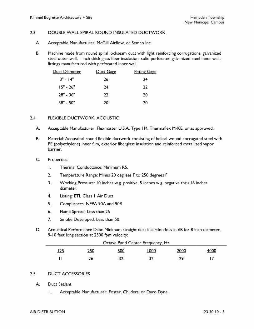
Kimmel Bogrette Architecture + Site Hampden Township
New Municipal Campus
AIR DISTRIBUTION 23 30 10 - 3
2.3 DOUBLE WALL SPIRAL ROUND INSULATED DUCTWORK
A. Acceptable Manufacturer: McGill Airflow, or Semco Inc.
B. Machine made from round spiral lockseam duct with light reinforcing corrugations, galvanized
steel outer wall, 1 inch thick glass fiber insulation, solid perforated galvanized steel inner wall;
fittings manufactured with perforated inner wall.
Duct Diameter Duct Gage Fitting Gage
3" - 14" 26 24
15" - 26" 24 22
28" - 36" 22 20
38" - 50" 20 20
2.4 FLEXIBLE DUCTWORK, ACOUSTIC
A. Acceptable Manufacturer: Flexmaster U.S.A. Type 1M, Thermaflex M-KE, or as approved.
B. Material: Acoustical round flexible ductwork consisting of helical wound corrugated steel with
PE (polyethylene) inner film, exterior fiberglass insulation and reinforced metallized vapor
barrier.
C. Properties:
1. Thermal Conductance: Minimum R5.
2. Temperature Range: Minus 20 degrees F to 250 degrees F
3. Working Pressure: 10 inches w.g. positive, 5 inches w.g. negative thru 16 inches
diameter.
4. Listing: ETL Class 1 Air Duct
5. Compliances: NFPA 90A and 90B
6. Flame Spread: Less than 25
7. Smoke Developed: Less than 50
D. Acoustical Performance Data: Minimum straight duct insertion loss in dB for 8 inch diameter,
9-10 feet long section at 2500 fpm velocity:
Octave Band Center Frequency, Hz
125 250 500 1000 2000 4000
11 26 32 32 29 17
2.5 DUCT ACCESSORIES
A. Duct Sealant
1. Acceptable Manufacturer: Foster, Childers, or Duro Dyne.

Kimmel Bogrette Architecture + Site Hampden Township
New Municipal Campus
AIR DISTRIBUTION 23 30 10 - 4
2. Duct joints and seams shall be sealed to minimize air leakage.
B. Volume Dampers
1. Acceptable Manufacturer: Young Regulator Co. for dampers with smallest dimension 10
inch or less, Louvers & Dampers, Inc. for dampers with smallest dimension 12 inch or
more.
2. Opposed blade volume dampers shall be installed where indicated on Drawings. Each
dampers shall be equipped with adjustable quadrant regulator and lock. Dampers shall
be multiple blade. Single blade damper units will not be permitted. Maximum blade
width shall be 10 inch and maximum blade length shall be 42 inch. Longer spans shall
consist of multiple damper sections.
3. On externally-insulated ducts, mount quadrant regulators on stand-off brackets to
accommodate thickness of insulation.
C. Turning Vanes
1. Turning vanes shall be provided in all square elbows unless specifically noted otherwise.
Turning vanes shall be single thickness vane style, with no trailing (flat) edges. Vanes
shall be securely fastened to runners. Runners shall be securely fastened to ductwork.
For lined ductwork, runners shall be raised hat style to prevent damage to duct liner.
Turning vanes greater than 36 inch in length shall be braced at intermediate points with
tie rods.
2. All turning vanes shall be fabricated and installed in accordance with SMACNA HVAC
Duct Construction Standards.
D. Flexible Duct Connectors
1. Acceptable Manufacturer: Ductmate, Duro Dyne, Elgen, or Ventfabrics.
2. Connector: 24 or 28 gage galvanized steel.
3. Fabric: Woven fiberglass, coated with neoprene. Water proof and airtight. Designed to
meet NFPA 701, 90A and 90B.
E. Take Off Fittings
1. Acceptable Manufacturer: Clevepak Corp., Flexmaster.
2. Take off connections for use in connecting flexible ductwork to rectangular duct
systems shall be straight tap-in type, prefabricated, galvanized steel construction, with
damper. Take off connections shall be same size as flexible duct.
F. Duct Access Doors
1. Acceptable Manufacturer: Cesco Advanced Air.
2. Application: Install in ductwork within working distance of all fire dampers, motor-
operated dampers and volume dampers to permit inspections and adjustments.
3. Construction: Reinforced with angle iron stiffeners and provided with a continuous edge
gasket for airtight fit. Insulated where installed in insulated duct systems.
4. Closure Method: Double cam latch.
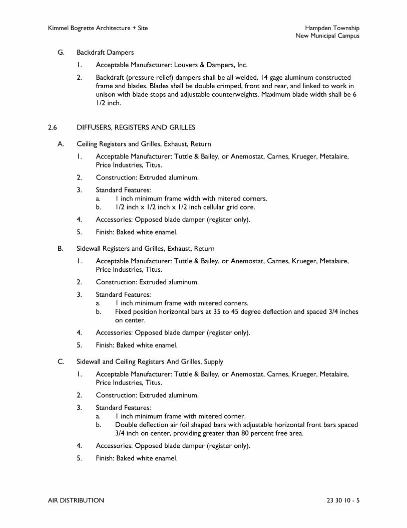
Kimmel Bogrette Architecture + Site Hampden Township
New Municipal Campus
AIR DISTRIBUTION 23 30 10 - 5
G. Backdraft Dampers
1. Acceptable Manufacturer: Louvers & Dampers, Inc.
2. Backdraft (pressure relief) dampers shall be all welded, 14 gage aluminum constructed
frame and blades. Blades shall be double crimped, front and rear, and linked to work in
unison with blade stops and adjustable counterweights. Maximum blade width shall be 6
1/2 inch.
2.6 DIFFUSERS, REGISTERS AND GRILLES
A. Ceiling Registers and Grilles, Exhaust, Return
1. Acceptable Manufacturer: Tuttle & Bailey, or Anemostat, Carnes, Krueger, Metalaire,
Price Industries, Titus.
2. Construction: Extruded aluminum.
3. Standard Features:
a. 1 inch minimum frame width with mitered corners.
b. 1/2 inch x 1/2 inch x 1/2 inch cellular grid core.
4. Accessories: Opposed blade damper (register only).
5. Finish: Baked white enamel.
B. Sidewall Registers and Grilles, Exhaust, Return
1. Acceptable Manufacturer: Tuttle & Bailey, or Anemostat, Carnes, Krueger, Metalaire,
Price Industries, Titus.
2. Construction: Extruded aluminum.
3. Standard Features:
a. 1 inch minimum frame with mitered corners.
b. Fixed position horizontal bars at 35 to 45 degree deflection and spaced 3/4 inches
on center.
4. Accessories: Opposed blade damper (register only).
5. Finish: Baked white enamel.
C. Sidewall and Ceiling Registers And Grilles, Supply
1. Acceptable Manufacturer: Tuttle & Bailey, or Anemostat, Carnes, Krueger, Metalaire,
Price Industries, Titus.
2. Construction: Extruded aluminum.
3. Standard Features:
a. 1 inch minimum frame with mitered corner.
b. Double deflection air foil shaped bars with adjustable horizontal front bars spaced
3/4 inch on center, providing greater than 80 percent free area.
4. Accessories: Opposed blade damper (register only).
5. Finish: Baked white enamel.

Kimmel Bogrette Architecture + Site Hampden Township
New Municipal Campus
AIR DISTRIBUTION 23 30 10 - 6
D. Sidewall Direct Spiral Grilles, Return
1. Acceptable Manufacturer: Tuttle & Bailey, or Titus, Anemostat, Krueger, Metalaire,
Carnes.
2. Construction: Extruded aluminum.
3. Standard Features:
a. 1 inch minimum frame.
b. Perforated face.
c. Grilles shall be constructed with radiused endcaps and foam gaskets for a tight
seal.
4. Finish: As selected by Architect.
E. Sidewall Direct Spiral Registers, Supply
1. Acceptable Manufacturer: Tuttle & Bailey, or Titus, Anemostat, Krueger, Metalaire,
Carnes.
2. Construction: Extruded aluminum.
3. Standard Features:
a. 1 inch minimum frame.
b. Double deflection air foil shaped bars with adjustable horizontal front bars.
c. Grilles shall be constructed with radiused endcaps and foam gaskets for a tight
seal.
4. Accessories: Air scoop/extractor damper (register only).
5. Finish: As selected by Architect.
F. Diffusers, High Performance
1. Acceptable Manufacturer: Titus, or Anemostat, Krueger, Price Industries, Tuttle &
Bailey.
2. Construction: Extruded aluminum.
3. Standard Features:
a. 360 degree air pattern.
b. 24 x 24 full face and panel mounted lay in type frames.
c. Flush cones.
d. Removable inner core.
4. Accessories:
a. Adjustable volume damper.
b. Sectorizing baffle.
5. Finish: Baked white enamel.
2.7 FIRE DAMPERS
A. Fire Damper, Primary
1. Acceptable Manufacturer: Ruskin, or Cesco Products, Prefco Products, Pottorff.
2. Type: Multiple interlocking steel "curtain" damper.

Kimmel Bogrette Architecture + Site Hampden Township
New Municipal Campus
AIR DISTRIBUTION 23 30 10 - 7
3. Construction: Galvanized steel frame and blades; blades stacking out of air stream; for
rectangular damper with smallest dimension 12 inches or less, frame and blades shall be
out of air stream. Damper shall be suitable for vertical or horizontal mounting; labeled
as a dynamic rated 1 1/2 hour fire damper; constructed in accordance with UL 555.
4. Fusible Link: UL listed 165 degrees F.
5. Wall Sleeve: Contractor's option for manufacturer's accessory wall sleeve or contractor
fabricated, in accordance with SMACNA Duct Construction Standards.
6. Compliance: NFPA 90A.
PART 3 - EXECUTION
3.1 INSTALLATION
A. Rigid metal ductwork and associated specialties shall be installed in accordance with SMACNA,
HVAC Duct Construction Standards, and the latest publication of the ASHRAE Equipment
Handbook. Rigid and flexible ductwork shall be installed in sizes indicated on the Drawings
with field supplied rigid metal transitions at connections to equipment duct collars.
B. Protect open ends of ductwork during construction, either stored or installed, with plastic
covering.
C. Flexible duct connectors shall be installed on inlet and outlet of each fan and air handling unit.
D. Fire dampers and fire doors shall be installed in accordance with the International Building
Code, SMACNA Fire, Smoke and Radiation Damper Installation Guide for HVAC Systems, and
manufacturer’s installation requirements. The UL label shall be visible for inspection from a
duct access door which is labeled to identify the damper type.
E. Rectangular sheet metal ductwork shall be insulated internally. Duct dimensions shown on
Drawings are net clear inside dimensions, that is, the inside dimensions of the duct insulation.
Refer to Section 23 07 10.
F. Flexible non metallic ductwork shall be connected to rigid metal duct fittings and terminal unit
duct collars by draw straps. Extend flexible duct insulation and vapor barrier over completed
joint and tape securely.
G. Manual volume dampers shall be installed in all branch ducts for balancing and as indicated on
Drawings.
H. Access panels shall be installed in inaccessible ceilings for access to air distribution devices
requiring adjustment, repair, or replacement. Refer to Section 23 05 05.
I. Installation of Exposed Ductwork
1. Protect ducts exposed in finished spaces from being dented, scratched, or damaged.
2. Trim duct sealants flush with metal. Create a smooth and uniform exposed bead. Do
not use two-part tape sealing system.

Kimmel Bogrette Architecture + Site Hampden Township
New Municipal Campus
AIR DISTRIBUTION 23 30 10 - 8
3. Grind welds to provide smooth surface free of burrs, sharp edges, and weld splatter.
When welding stainless steel with a No. 3 or 4 finish, grind the welds flush, polish the
exposed welds, and treat the welds to remove discoloration caused by welding.
4. Maintain consistency, symmetry, and uniformity in the arrangement and fabrication of
fittings, hangers and supports, duct accessories, and air outlets.
5. Repair or replace damaged sections and finished work that does not comply with these
requirements.
3.2 DUCT SEALING
A. Seal ducts for duct static-pressure, seal classes, and leakage classes specified in "Duct Schedule"
Article according to SMACNA's "HVAC Duct Construction Standards - Metal and Flexible."
B. Joints in exhaust ductwork carrying steam or high humidity (i.e. dishwasher or shower room
exhaust) shall be sealed watertight with clear silicone calk.
3.3 HANGER AND SUPPORT INSTALLATION
A. Comply with SMACNA's "HVAC Duct Construction Standards - Metal and Flexible,"
Chapter 4, "Hangers and Supports."
3.4 DUCT LEAKAGE TESTING
A. Perform duct leakage testing in accordance with SMACNA “HVAC Air Duct Leakage Test
Manual” and submit written letter of compliance.
1. Disassemble, reassemble and seal segments of systems as required to accommodate
testing.
2. Conduct tests at static pressures equal to maximum design pressure of system. Do not
pressurize systems above maximum design operating pressure.
3. Maximum allowable leakage shall be SMACNA Leakage Class 3 for supply air ducts and
Leakage Class 6 for return air ducts.
4. Leaking joints shall be remade and retested until leakage is equal to or less than the
maximum allowable.
3.5 DUCT CONSTRUCTION SCHEDULE
Air System Pressure Class SMACNA Seal Class
Supply Ducts Connected to Central
Station Variable Air Volume Air
Handling Units and Packaged
Rooftop Units
Positive 3 inches w.g. B
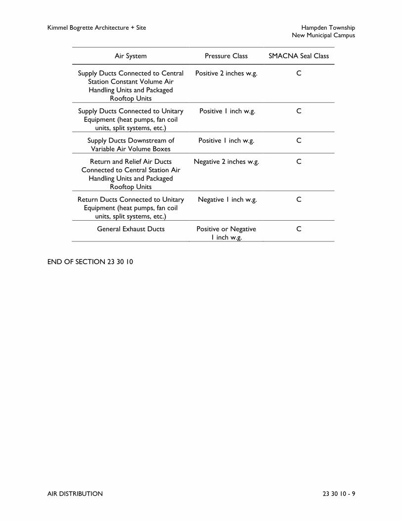
Kimmel Bogrette Architecture + Site Hampden Township
New Municipal Campus
AIR DISTRIBUTION 23 30 10 - 9
Air System Pressure Class SMACNA Seal Class
Supply Ducts Connected to Central
Station Constant Volume Air
Handling Units and Packaged
Rooftop Units
Positive 2 inches w.g. C
Supply Ducts Connected to Unitary
Equipment (heat pumps, fan coil
units, split systems, etc.)
Positive 1 inch w.g. C
Supply Ducts Downstream of
Variable Air Volume Boxes
Positive 1 inch w.g. C
Return and Relief Air Ducts
Connected to Central Station Air
Handling Units and Packaged
Rooftop Units
Negative 2 inches w.g. C
Return Ducts Connected to Unitary
Equipment (heat pumps, fan coil
units, split systems, etc.)
Negative 1 inch w.g. C
General Exhaust Ducts Positive or Negative
1 inch w.g.
C
END OF SECTION 23 30 10

Kimmel Bogrette Architecture + Site Hampden Township
New Municipal Campus
VARIABLE AIR VOLUME SYSTEMS 23 30 20 - 1
SECTION 23 30 20 – VARIABLE AIR VOLUME SYSTEMS
PART 1 - GENERAL
1.1 WORK INCLUDED
A. The Work of this Section shall consist of the labor, materials and equipment required for
installation of variable air volume equipment.
1.2 SUBMITTALS
A. Submit for approval in accordance with specified submittal procedures:
1. Control Reheat Units
PART 2 - PRODUCTS
2.1 SHUTOFF CONTROL REHEAT UNIT, TYPE CRU
A. Acceptable Manufacturer: Trane, or Carrier, Titus, Enviro-Tec/Johnson Controls.
B. Casing: Constructed of galvanized steel and lined with minimum 1-1/2 pound density
thermal/acoustical foil-faced fiberglass insulation meeting UL 181 and NFPA 90 requirements.
Provide access door for inspection and cleaning.
C. Air Volume Control Damper: Factory calibrated air damper assembly, factory set and field
adjustable minimum and maximum airflows.
D. Hot Water Heating Coil
1. Factory mounted to casing, constructed of 1/2 or 5/8 inch OD copper tubes
mechanically expanded onto aluminum fins.
E. Controls
1. Internal regulator to maintain constant airflow independent of inlet static pressure.
2. Factory mounted electric actuator for interface with automatic temperature control
system.
3. Electric heater control panel including contactors required for interface with automatic
temperature control system.
4. Refer to Section 23 90 10, Building Automation System.

Kimmel Bogrette Architecture + Site Hampden Township
New Municipal Campus
VARIABLE AIR VOLUME SYSTEMS 23 30 20 - 2
PART 3 - EXECUTION
3.1 INSTALLATION
A. Install VAV equipment in accordance with equipment manufacturer's recommendations.
Submit manufacturer's printed installation instructions with operating and maintenance data at
completion of Work.
B. Provide supporting steel for support of VAV equipment from substantial building structure.
Do not support VAV equipment from adjacent equipment, piping, or ductwork.
C. Provide sheet metal transitions as required for inlet and discharge connections of VAV
equipment.
END OF SECTION 23 30 20
Kimmel Bogrette Architecture + Site Hampden Township
New Municipal Campus
FANS AND GRAVITY VENTILATORS 23 34 10 - 1
SECTION 23 34 10 – FANS AND GRAVITY VENTILATORS
PART 1 - GENERAL
1.1 WORK INCLUDED
A. The Work of this Section shall consist of the labor, materials and equipment required for
installation of fans and gravity ventilators.
1.2 RELATED SECTIONS
A. Section 23 05 05, HVAC Basic Materials: Motors
B. Section 23 05 35, HVAC Sound and Vibration Control: Vibration isolators.
1.3 SUBMITTALS
A. Submit for approval in accordance with specified submittal procedures:
1. Fans
2. Roof Curbs
B. Product Data: Submit manufacturer's technical product data for fans, including:
1. Selection characteristics and rated capacities.
2. Fan performance curves with system operating conditions indicated.
3. Sound power ratings, with an 8 octave band analysis for large, central system fans.
4. General specifications: Fan type description, material of construction, thicknesses and
finishes.
5. Motor type, ratings and electrical characteristics
6. Accessories furnished
C. Shop Drawings: Include the following:
1. Plans, elevations, sections, and attachment details.
2. Details of equipment assemblies. Indicate dimensions, weights, loads, required
clearances, method of field assembly, components, and location and size of each field
connection.
3. Vibration Isolation Base Details: Detail fabrication, including anchorages and
attachments to structure and to supported equipment. Include auxiliary motor slides
and rails, and base weights.
D. Wiring Diagrams: Submit manufacturer's electrical requirements for power supply wiring to
fan units. Submit manufacturer's ladder-type wiring diagrams for interlock and control wiring.

Kimmel Bogrette Architecture + Site Hampden Township
New Municipal Campus
FANS AND GRAVITY VENTILATORS 23 34 10 - 2
Clearly differentiate between portions of wiring that are factory-installed and portions to be
field-installed.
E. Coordination Drawings: As required to meet project complexity, show fan room layout and
relationships between components and adjacent structural and mechanical elements. Show
support locations, type of support, and weight on each support. Indicate and certify field
measurements.
F. Maintenance Data: Submit operation and maintenance instructions, including lubrication
instructions, motor and drive replacement, and spare parts lists. Include this data, product
data, shop drawings, and wiring diagrams in maintenance manuals.
G. Field quality-control reports.
H. Manufacturer's published fan curve data shall be included with shop drawing submittal data for
fans. Fan curve information shall include operating point, RPM curve for operating point,
minimum and maximum RPM curves for fan, system curve and brake horsepower curves.
Tabular fan performance charts are not an acceptable substitute for fan curve data. Shop
drawing submittals for air handling equipment will be returned without Architect's review if
the fan curve data is not included with the submittal.
1.4 QUALITY ASSURANCE
A. Electrical Components, Devices, and Accessories: Listed and labeled as defined in NFPA 70,
by a qualified testing agency, and marked for intended location and application.
B. Fan rating shall be AMCA certified.
1.5 SOURCE QUALITY CONTROL
A. Fan Sound-Power Level Ratings: Comply with AMCA 301, "Methods for Calculating Fan
Sound Ratings from Laboratory Test Data." Test fans according to AMCA 300, "Reverberant
Room Method for Sound Testing of Fans." Fans shall bear AMCA-certified sound ratings seal.
B. Fan Performance Rating: Factory test fan performance for airflow, pressure, power, air
density, rotation speed, and efficiency. Rate performance according to AMCA 210,
"Laboratory Methods of Testing Fans for Aerodynamic Performance Rating."
PART 2 - PRODUCTS
2.1 GENERAL
A. Fan ratings shall be AMCA certified and statically and dynamically balanced and run tested at
the factory.
B. Bearings: Fans, except power roof ventilators, shall be provided with lubricating type bearings
with extended fittings as required. Extend grease fittings to safe, accessible locations.
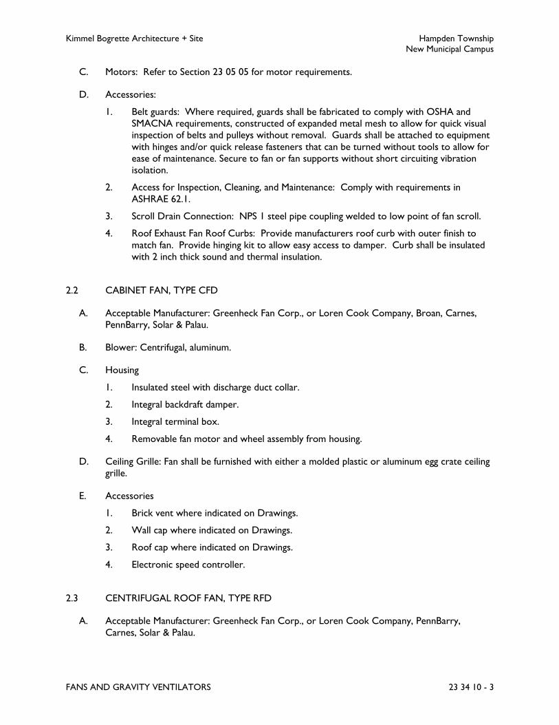
Kimmel Bogrette Architecture + Site Hampden Township
New Municipal Campus
FANS AND GRAVITY VENTILATORS 23 34 10 - 3
C. Motors: Refer to Section 23 05 05 for motor requirements.
D. Accessories:
1. Belt guards: Where required, guards shall be fabricated to comply with OSHA and
SMACNA requirements, constructed of expanded metal mesh to allow for quick visual
inspection of belts and pulleys without removal. Guards shall be attached to equipment
with hinges and/or quick release fasteners that can be turned without tools to allow for
ease of maintenance. Secure to fan or fan supports without short circuiting vibration
isolation.
2. Access for Inspection, Cleaning, and Maintenance: Comply with requirements in
ASHRAE 62.1.
3. Scroll Drain Connection: NPS 1 steel pipe coupling welded to low point of fan scroll.
4. Roof Exhaust Fan Roof Curbs: Provide manufacturers roof curb with outer finish to
match fan. Provide hinging kit to allow easy access to damper. Curb shall be insulated
with 2 inch thick sound and thermal insulation.
2.2 CABINET FAN, TYPE CFD
A. Acceptable Manufacturer: Greenheck Fan Corp., or Loren Cook Company, Broan, Carnes,
PennBarry, Solar & Palau.
B. Blower: Centrifugal, aluminum.
C. Housing
1. Insulated steel with discharge duct collar.
2. Integral backdraft damper.
3. Integral terminal box.
4. Removable fan motor and wheel assembly from housing.
D. Ceiling Grille: Fan shall be furnished with either a molded plastic or aluminum egg crate ceiling
grille.
E. Accessories
1. Brick vent where indicated on Drawings.
2. Wall cap where indicated on Drawings.
3. Roof cap where indicated on Drawings.
4. Electronic speed controller.
2.3 CENTRIFUGAL ROOF FAN, TYPE RFD
A. Acceptable Manufacturer: Greenheck Fan Corp., or Loren Cook Company, PennBarry,
Carnes, Solar & Palau.

Kimmel Bogrette Architecture + Site Hampden Township
New Municipal Campus
FANS AND GRAVITY VENTILATORS 23 34 10 - 4
B. Housing: Heavy gage spun aluminum.
C. Motor and Fan Assembly
1. Vibration isolated motor and fan assembly mounts.
2. Permanently lubricated ball bearing type motor.
3. Prewired to integral UL listed disconnect switch within fan housing.
4. Centrifugal fan wheel, statically and dynamically balanced.
D. Accessories
1. Motor operated damper.
2. Bird screen.
3. Insulated roof curb, 12 inches high minimum.
4. Electronic speed controller.
2.4 ROOF CURBS
A. Acceptable Manufacturer: Pate Co. Style PC, or Roof Products & Systems Corp.
B. Construction: Galvanized sheet steel with continuous welded seams for stiffness and moisture
protection.
C. Standard Features
1. Wood nailer.
2. 1-1/2 inch fiberglass insulation (or 1/2 inch sprayed urethane liner).
3. 12 inch minimum height or higher as required by application.
PART 3 - EXECUTION
3.1 INSTALLATION
A. Install fans in accordance with equipment manufacturer's recommendations. Submit
manufacturer's printed installation instructions with operating and maintenance data at
completion of Work.
B. Install fans level and plumb to prohibit excessive vibration and insure longer life.
C. Protect belts, sheaves, bearings, motors and other fan parts during installation.
D. Access: Provide adequate access and service clearance space around and over fans as
indicated, but in no case less than that recommended by manufacturer. Allow adequate and
safe pathway for components and unit replacement.

Kimmel Bogrette Architecture + Site Hampden Township
New Municipal Campus
FANS AND GRAVITY VENTILATORS 23 34 10 - 5
E. Isolation: Comply with requirements for vibration isolation devices specified in Section
23 05 35.
F. Duct Connections:
1. Minimize Fan System Effects: Avoid poor fan inlet and outlet conditions. Comply with
manufacturer’s installation guidelines.
2. Make final duct connections with flexible connectors.
3. Install ducts adjacent to fans to allow service and maintenance.
4. Provide access door in duct below power roof ventilators to service damper.
G. Secure roof-mounted fans to roof curbs with cadmium-plated hardware.
H. Electrical Connections: Ground equipment and connect control wiring according to Division
26.
I. Roof curbs provided as Work of this Section shall be coordinated with requirements of the
roofing subcontractor. Shop drawing submittals for roof curbs, with, or without, cants will be
considered in compliance with roofer's requirements.
3.2 FIELD QUALITY CONTROL
A. Upon completion of installation of fans, and after motor has been energized with normal
power source, perform the following tests and inspections with the assistance of a factory-
authorized service representative to demonstrate compliance with requirements:
1. Verify that shipping, blocking, and bracing are removed.
2. Verify that unit is secure on mountings and supporting devices and that connections to
ducts and electrical components are complete. Verify that proper thermal-overload
protection is installed in motors, starters, and disconnect switches.
3. Verify that cleaning and adjusting are complete.
4. Disconnect fan drive from motor, verify proper motor rotation direction, and verify fan
wheel free rotation and smooth bearing operation. Reconnect fan drive system, make
final alignments of pulleys and belt tension, and install belt guards.
5. Adjust damper linkages for proper damper operation.
6. Verify lubrication for bearings and other moving parts.
7. Verify that manual volume control and fire dampers in connected ductwork systems are
in fully open position.
8. Test and adjust controls and safeties. Controls and equipment will be considered
defective if they do not pass tests and inspections.
9. Prepare test and inspection reports.
B. Remove and replace malfunctioning units that cannot be satisfactorily corrected and retest as
specified above.

Kimmel Bogrette Architecture + Site Hampden Township
New Municipal Campus
FANS AND GRAVITY VENTILATORS 23 34 10 - 6
END OF SECTION 23 34 10
Kimmel Bogrette Architecture + Site Hampden Township
New Municipal Campus
CENTRAL HEATING EQUIPMENT 23 50 10 - 1
SECTION 23 50 10 – CENTRAL HEATING EQUIPMENT
PART 1 - GENERAL
1.1 WORK INCLUDED
A. The Work of this Section shall consist of the labor, materials and equipment required for
installation of the heat generation equipment and associated support equipment.
1.2 SUBMITTALS
A. Submit for approval in accordance with specified submittal procedures:
1. Boilers, including burners and controls
2. Vent Pipe and Air Intake Pipe
B. Product Data: Include performance data, operating characteristics, furnished specialties, and
accessories.
C. Shop Drawings: For boilers, boiler trim, and accessories. Include plans, elevations, sections,
details, and attachments to other work.
D. Wiring Diagrams: Power, signal, and control wiring.
1.3 QUALITY ASSURANCE
A. Electrical Components, Devices, and Accessories: Listed and labeled as defined in NFPA 70,
Article 100, by a testing agency acceptable to authorities having jurisdiction, and marked for
intended use.
B. ASME Compliance: Fabricate and label boilers to comply with ASME Boiler and Pressure
Vessel Code.
C. UL Compliance: Test factory-built gas appliances for compliance with UL 795, "Commercial-
Industrial Gas Heating Equipment." Boilers shall be listed and labeled by a testing agency
acceptable to authorities having jurisdiction.
D. Comply with PA Department of Labor and Industry requirements.
E. Comply with Owner’s insurance underwriter’s requirements – FM Global.
1.4 EXTENDED WARRANTY
A. 5 years on heat exchanger.
Kimmel Bogrette Architecture + Site Hampden Township
New Municipal Campus
CENTRAL HEATING EQUIPMENT 23 50 10 - 2
1.5 BOILER SYSTEM START UP SERVICE
A. Provide complete start-up services for each boiler. Start-up services shall include
manufacturer’s recommended boil-out procedures, boiler manufacturer inspections during
construction, and burner manufacturer supervised start-up under direction of combustion
management system manufacturer. Each component of the boiler system shall be tested by the
component manufacturer and a summary of all tests shall be submitted by Contractor to the
Architect.
PART 2 - PRODUCTS
2.1 PACKAGED HIGH EFFICIENCY WATERTUBE BOILERS
A. Manufacturer
1. Basis of Design: Lochinvar Crest Series
2. Other Acceptable Manufacturers: AERCO Benchmark Series, Thermal Solutions, Bryan,
Raypack.
B. Description: Boiler shall be natural gas fired, fully condensing design. Power burner shall have
full modulation with a 15:1 turndown ratio and discharge into a positive pressure vent. Boiler
efficiency shall increase with decreasing load (output), while maintaining setpoint. Boiler shall
be factory-fabricated, factory-assembled and factory-tested, condensing boiler with heat
exchanger sealed pressure-tight, built on a steel base, including insulated jacket, flue-gas vent,
combustion-air intake connections, water supply, return and condensate drain connections,
and controls.
C. Heat Exchanger: The heat exchanger shall be constructed of 439 stainless steel fire tubes and
tubesheets, with a one-pass combustion gas flow design. The fire tubes shall be 5/8” OD, with
no less than 0.049” wall thickness. The upper and lower stainless steel tubesheet shall be no
less than 0.25” thick. The pressure vessel/heat exchanger shall be welded construction. The
heat exchanger shall be ASME stamped for a working pressure not less than 160 psig. Access
to the tubesheets and heat exchanger shall be available by burner and exhaust manifold
removal. Minimum access opening shall be no less than 10-inch diameter.
D. Pressure Vessel: The boiler water connections shall be flanged 150-pound, ANSI rated. The
pressure vessel shall be constructed of SA53 carbon steel, with a 0.25-inch thick wall and 0.50-
inch thick upper head. Inspection openings in the pressure vessel shall be in accordance with
ASME Section IV pressure vessel code. The boiler shall be designed so that the thermal
efficiency increases as the boiler firing rate decreases.
E. Burner: The boiler burner shall be capable of a 15-to-1 turndown ratio of the firing rate
without loss of combustion efficiency or staging of gas valves. The burner shall produce less
than 20 ppm of NOx corrected to 3% excess oxygen. The burner shall be metal-fiber mesh
covering a stainless steel body with spark ignition and flame rectification. All burner material
exposed to the combustion zone shall be of stainless steel construction. There shall be no
moving parts within the burner itself. A modulating air/fuel valve shall meter the air and fuel
input. The modulating motor must be linked to both the gas valve body and air valve body with
a single linkage. The linkage shall not require any field adjustment. A variable frequency drive

Kimmel Bogrette Architecture + Site Hampden Township
New Municipal Campus
CENTRAL HEATING EQUIPMENT 23 50 10 - 3
(VFD), controlled cast aluminum pre-mix blower shall be used to ensure the optimum mixing
of air and fuel between the air/fuel valve and the burner.
F. Exhaust Manifold: The exhaust manifold shall be of corrosion resistant cast aluminum or 316
stainless steel. The exhaust manifold shall have a collecting reservoir and a gravity drain for the
elimination of condensation.
G. Blower: The boiler shall include a variable-speed, DC centrifugal fan to operate during the
burner firing sequence and pre-purge the combustion chamber.
H. Ignition: Ignition shall be via spark ignition with 100 percent main-valve shutoff and electronic
flame supervision.
I. Each boiler shall be provided with all necessary trim, including:
1. Motorized automatic main and redundant gas valve and a normally open vent valve in
between.
2. One (1) safety valve shall be provided incompliance with the ASME code
3. One (1) water pressure-temperature gauge.
4. One (1) primary low water flow fuel cutoff. The primary low water flow cutoff shall be a
flow switch as required by ASME Code.
5. One (1) high limit water temperature controller to stop burner operation at excess
water temperature (shall be manually reset).
6. One (1) operating temperature control to control the sequential operation of the
burner.
7. One (1) secondary low water level fuel cutoff. The secondary low water level cutoff
shall be a separate manual reset probe type controller.
J. Trim
1. Safety Relief Valve:
a. Size and Capacity: 50 lb.
b. Description: Fully enclosed steel spring with adjustable pressure range and
positive shutoff; factory set and sealed.
2. Pressure Gage: Minimum 3-1/2 inch diameter. Gage shall have normal operating
pressure about 50 percent of full range.
3. Drain Valves: Minimum NPS 3/4 or nozzle size with hose-end connection.
4. Condensate Neutralization Kit: Factory supplied condensate trap with condensate trip
sensor, high capacity condensate receiver prefilled with appropriate medium.
K. Boiler Controls
1. Boilers shall be provided with Modbus interface for connection to Owner’s building
automation system. Owner’s BAS system shall have capability of turning boilers on and
off, boiler lead/lag capability, and providing system supply temperature setpoint.
2. The combustion safeguard/flame monitoring system shall use spark ignition and a
rectification-type flame sensor.
3. The control panel hardware shall support both RS-232 and RS-485 remote
communications.
Kimmel Bogrette Architecture + Site Hampden Township
New Municipal Campus
CENTRAL HEATING EQUIPMENT 23 50 10 - 4
4. The controls shall annunciate boiler and sensor status and include extensive self-
diagnostic capabilities that incorporate a minimum of eight separate status messages and
34 separate fault messages.
5. Each boiler shall include an electric, single-seated combination safety shutoff
valve/regulator with proof of closure switch in its gas train. Each boiler shall incorporate
dual over-temperature protection with manual reset, in accordance with ASME Section
IV and CSD-1.
6. Each boiler shall have an oxygen monitoring system that will measure the oxygen
content of the exhaust gases in real-time.
7. Each boiler shall have integrated boiler sequencing technology, capable of multi-unit
sequencing with lead-lag functionality and parallel operation. The system will
incorporate the following capabilities:
a. Efficiently sequence 2-to-8 units on the same system to meet load requirement.
b. Automatically rotate lead/lag amongst the units on the chain and monitor run
hours per unit and balance load in an effort to equalize unit run hours.
c. Designated master control, used to display and adjust key system parameters.
d. Automatic bump-less transfer of master function to next unit on the chain in case
of designated master unit failure; master/slave status should be shown on the
individual unit displays.
e. Designated master control, used to display and adjust key system parameters.
L. Provide single point electrical connection for unit power.
M. Warranty
1. Pressure vessel/heat exchanger shall carry a 10 year from shipment limited warranty
against failure due to condensate corrosion, thermal stress, mechanical defects and
workmanship.
2. Manufacturer labeled controls are conditionally warranted against failure for two years
from shipment.
3. All other components, with exception of igniter and flame detector, are conditionally
guaranteed against failure for 18 months from shipment.
2.2 VENT PIPE, HIGH EFFICIENCY BOILER
A. Acceptable Manufacturer: Metal Fab Corr/Guard CG, or Metalbestos, Dura Vent Corp., Van
Packer, Ampco.
B. General: Flue pipe shall have 1 inch air space, double-wall constructed of 0.015 inch AL29-4C
stainless steel inner pipe and 0.018 inch aluminized steel outer pipe. Suitable for 550 degrees F
operating temperature.
C. Codes: Flue pipe shall be UL approved and comply with NFPA standards 37 and 211. Flue pipe
shall be installed in accordance with requirements of local utility and flue manufacturer's
recommendations.
D. Accessories: Provide required quantity of flue pipe sections and fittings to complete flue pipe
installation indicated on Drawings, including straight (fixed, adjustable or variable lengths)

Kimmel Bogrette Architecture + Site Hampden Township
New Municipal Campus
CENTRAL HEATING EQUIPMENT 23 50 10 - 5
sections, tees, wyes and elbows. In addition, provide the following accessories to complete the
installation in accordance with the manufacturer's recommendations:
1. Stack cap
2. Increaser/reducer
3. Roof support assembly
4. Ventilated roof thimble
5. Stack closure ring
6. Storm collar
7. Ceiling Penetration
8. Ceiling support & guide assemblies
9. Guy section & guy tensioners
2.3 AIR INTAKE PIPE, HIGH EFFICIENCY BOILER
A. PVC Pipe: ASTM D1785, Schedule 40 or ASTM D1785, Schedule 80 or ASTM D2241, Class
160, polyvinyl chloride (PVC) material.
1. Fittings: ASTM D2466, Schedule 40, PVC or ASTM D2467, Schedule 80, PVC or ASTM
D2464 PVC threaded.
2. Joints: ASTM D2855, solvent weld with ASTM D2564 solvent cement. Prime joints with
a contrasting color.
B. CPVC Pipe: ASTM F441/F441M, Schedule 40 80, chlorinated polyvinyl chloride (CPVC)
material.
1. Fittings: ASTM F438, CPVC, Schedule 40, socket type or ASTM F439, CPVC, Schedule
80, socket type or ASTM F437, CPVC, Schedule 80, threaded.
2. Joints: ASTM D2846/D2846M, solvent weld with ASTM F493 solvent cement. Prime
joints with a contrasting color.
C. ABS Pipe: ASTM D2661, Acrylonitrile-Butadiene-Styrene (ABS) material.
1. Fittings: ABS, ASTM D2661 or ABS, ASTM D3311.
2. Joints: ASTM D2235, solvent weld applied after cleaning.
PART 3 - EXECUTION
3.1 INSTALLATION
A. Boiler(s) shall be installed in accordance with manufacturer's erection/installation procedures.
Submit manufacturer's printed installation instructions with operating and maintenance data at
completion of Work.

Kimmel Bogrette Architecture + Site Hampden Township
New Municipal Campus
CENTRAL HEATING EQUIPMENT 23 50 10 - 6
B. Consult water treatment supplier before boiler and water system are filled. Treatment
chemicals shall be added at time of initial charge.
C. Contractor shall be responsible for installation and start-up of all Owner supplied equipment.
D. Submit “Intent to Install Boiler” form to PA L&I and arrange for inspection of boiler system by
Pennsylvania Department of Labor and Industry licensed inspector. Install boiler inspection
certificate in protective frame at a visible location in boiler room.
E. Pressure relief valves for hot water boilers shall be piped to floor drain.
END OF SECTION 23 50 10
Kimmel Bogrette Architecture + Site Hampden Township
New Municipal Campus
HEAT TRANSFER 23 57 10 - 1
SECTION 23 57 10 – HEAT TRANSFER
PART 1 - GENERAL
1.1 WORK INCLUDED
A. The Work of this Section shall consist of the labor, materials and equipment required for
installation of heat transfer system components and specialties.
1.2 SUBMITTALS
A. Submit for approval in accordance with specified submittal procedures:
1. Hydronic Specialties
2. Chemical Water Treatment
3. Propylene Glycol
4. Glycol Feed System
5. Electric Heating Cable
6. Chilled Water Buffer Tank
PART 2 - PRODUCTS
2.1 HYDRONIC SPECIALTIES
A. Air Separator, Tangential
1. Acceptable Manufacturer: Taco, or Amtrol, Bell & Gossett.
2. Type: Tangential, reduced velocity type with integral strainer and companion automatic
air vent.
3. Construction: Fabricated steel, suitable for 125 psig working pressure, ASME.
4. Sizes: 2 inches and larger.
B. Automatic Air Vents
1. Acceptable Manufacturer: Hoffman No. 77, or Amtrol, Taco.
2. Body: Brass
3. Internal Working Parts: Stainless steel or nonferrous.
4. Operation: Vacuum breaker and float type valve assembly to automatically vent air from
system.
C. Manual Air Vents

Kimmel Bogrette Architecture + Site Hampden Township
New Municipal Campus
HEAT TRANSFER 23 57 10 - 2
1. Acceptable Manufacturer: Taco 417, or Hoffman.
2. Body: Brass.
3. Operation: Quick venting slotted adjustment with positive shutoff ball check.
D. Expansion Tank
1. Acceptable Manufacturer: Amtrol.
2. Type: Sealed-in diaphragm or removable bladder.
3. Tank: Steel
4. Tank Fittings: Manufacturer shall supply charging valve and proper tank fittings to make
all gage, fill, drain and system connections.
5. Working Pressure: 125 psig
6. Construction: Shall be in accordance with ASME code for unfired pressure vessels and
shall bear ASME label. Shall be guaranteed leakproof for air and water.
E. Relief Valves
1. Acceptable Manufacturer: Bell & Gossett.
2. Relief valves shall be installed in water system at locations and in sizes noted on the
Drawings. Valves shall bear the ASME label.
F. Backflow Preventer
1. Acceptable Manufacturer: Watts Series 009, or Cla Val Company.
2. Type: Reduced pressure.
3. Components: Two independently acting spring loaded toggle lever check valves with
automatically operating pressure differential relief valve and two shutoff valves.
4. Accessories: Air gap fitting.
5. Construction: Bronze body with stainless steel internal parts. 150 psig maximum
working pressure.
G. Pressure Reducing Valve
1. Acceptable Manufacturer: Cash Acme Type B, or Watts.
2. Type: Diaphragm with self cleaning seat.
3. Construction: Bronze.
4. Pressure Range: 200 psig maximum inlet and factory set at discharge pressure indicated
on the Drawings.
5. Installation: Make-up (domestic cold) water line, furnished with three valve bypass as
indicated on the Drawings.
6. Standard Features: Self-contained strainer.

Kimmel Bogrette Architecture + Site Hampden Township
New Municipal Campus
HEAT TRANSFER 23 57 10 - 3
2.2 CHEMICAL WATER TREATMENT
A. Acceptable Manufacturer: Guardian, or Cascade, G.E. Betz, Keeler Co.
B. General: Furnish and install a complete water treatment program. Chemicals, service and
equipment shall be supplied by a single water treatment company for undivided responsibility.
The water treatment chemical and service supplier shall be a recognized specialist, active in the
field of industrial water treatment for at least ten years, whose major business is in the field of
water treatment, and shall have regional water analysis laboratories, development facilities and
service department.
C. Bypass Feeder:
1. Acceptable Manufacturer: Neptune Model DBF, or as approved.
2. Capacity: 2 gallons.
3. Construction:
a. Shell: Steel, minimum 10 gage with wide mouth opening.
b. Head: Steel, minimum 9 gage.
c. Cap: Minimum 4 inch, cast iron with epoxy-coated underside and square ring
Buna N seat ring. Continuous threaded closure.
d. Pressure Rating: 300 psi at 200 degrees F.
e. Full bottom drain.
4. Accessories:
a. Legs with anchor bolt holes to elevate the feeder off the floor.
b. Filter Bag Kit: Filter bag supported by a stainless steel filter basket with tuning and
connectors for side stream filtering.
1) Install 50 micron filter bag during system start-up.
2) Provide Owner with additional 20 micron filter bag.
D. Water Treatment Chemicals: Furnish one year's supply of the recommended formulas for
control of scale, pitting and corrosion of the closed loop systems.
E. Testing Equipment: Furnish testing equipment for treatment control. Equipment shall include
apparatus for determination of pH, treatment residual and bleedoff control as minimum
requirements. Furnish training, instruction, and continuing supervision of Owner's operating
personnel during the service period.
F. Water Management Program: Manufacturer shall provide a water management and service
program for a period of one year from startup of the system to include the following:
1. Initial water analysis and recommendations.
2. System installation and start up assistance.
3. Training of operating personnel.
4. Periodic field service, consultation (all of the above performed by a qualified full time
local representative), laboratory and technical assistance from the manufacturer's
engineering staff.

Kimmel Bogrette Architecture + Site Hampden Township
New Municipal Campus
HEAT TRANSFER 23 57 10 - 4
2.3 PROPYLENE GLYCOL
A. Acceptable Manufacturers: Interstate Chemical Co., or Dow Chemical Co..
B. Heating and cooling systems shall be filled with a pre-blended water/propylene glycol mixture
consisting of 30 percent propylene glycol and 70 percent water by volume. The solution shall
be prepared by thoroughly mixing the glycol in clean containers prior to transferring into
system. Contractor shall flush, fill and test system in accordance with manufacturer's
recommendations and furnish manufacturer's published data certifying percentage of antifreeze
by volume, corresponding protection in degrees F and date of fill. The glycol shall contain
inorganic corrosion inhibitors and anti-foam agents.
C. Glycol system shall be equipped with a mix and fill tank with manual fill capabilities, hose bibb
from domestic water for tank filling, and tank level alarm interconnected with the BAS.
2.4 GLYCOL FEED SYSTEM
A. Acceptable Manufacturer: Neptune Chemical Pump Co., Advantage Controls, or as approved.
B. Provide a completely, preassembled package glycol feed system with bronze rotary gear
pumps; tank, piping, and control panel.
C. Pump:
1. Type: Rotary gear
2. Capacity: 1.5 GPM at a pressure of 100 PSI.
3. Configuration: Pump mounted below the tank.
D. Tank:
1. Capacity: 50 gallon
2. Material: Polyethylene
3. Stand: Four-leg made from carbon steel with four bolt pads, primed and painted.
4. Float switch for low level pump shutoff and alarm.
E. Control Panel:
1. Enclosure: NEMA 4X
2. Electrical: 115 volt, 1 phase with a 8 foot power cord with plug
3. Controls:
a. Hands-Off-Auto selector switch with running light. In Auto position, the pump
shall be operated by a differential pressure switch and interlocked to a low level
float switch.
b. “Low” tank level indicator light.
c. Magnetic starter for feed pump.
d. Pressure Switch: Cut-in Range: 10-45 PSI; Cut-Out Range: 20-60 PSI.
Kimmel Bogrette Architecture + Site Hampden Township
New Municipal Campus
HEAT TRANSFER 23 57 10 - 5
2.5 ELECTRIC HEATING CABLE
A. Acceptable Manufacturer: Thermon FLX, or Chromalox, Raychem.
B. Electric heating cable for exterior piping noted on Drawings shall be self-regulating two wire
cable, rated 5.0 watts per foot at 120 volts. Heating cable shall be installed in the cable length
per foot of pipe indicated to maintain 44 degrees F minimum water temperature.
C. Material: Cable shall consist of two 16 AWG nickel plated copper bus wires embedded in
parallel in a polymer core tape. Heat tape shall be covered with tinned copper braid and a
thermoplastic rubber outer jacket.
D. Furnish and install SPST, solid state, line sensing waterproof temperature controller.
2.6 CHILLED WATER BUFFER TANK
1. Acceptable Manufacturer: Cemline Corporation or Approved equal.
2. Tank: Steel with internal baffle
3. Tank Fittings: Air Vent, drain connection, Flanged or Grooved-end connection for inlet
and outlet chilled water system connections.
4. 1” flexible elastormeric thermal insulation.
5. Working Pressure: 125 psig
6. Construction: Shall be in accordance with ASME code for unfired pressure vessels and
shall bear ASME label. Shall be guaranteed leakproof for air and water
PART 3 - EXECUTION
3.1 INSTALLATION
A. Hydronic Piping
1. Water piping shall be installed with a view for even flow and proper venting to and from
all apparatus without pockets. Piping system shall be installed for quick, sure and positive
drainage. Entire piping system shall present a neat appearance both as to workmanship
and grouping. A calibrated balancing valve and manual air vent shall be installed on the
return runout from each piece of radiation and unit heater All mains shall pitch up to a
high point with automatic air vents provided for air escapement. Provide drains at all
system low points.
2. Provide sufficient access for servicing concealed air vents and drain valves. Refer to
access panels specified in Section 23 05 05, HVAC Basic Materials.
3. Before the boilers or water systems are filled, the water treatment supplier shall be
consulted. Treatment chemicals shall be added at time of initial charge.
4. Following the installation and balancing of all piping systems, gage cocks and ball valves at
all pressure gages shall be closed to prevent damage to the gage movement.

Kimmel Bogrette Architecture + Site Hampden Township
New Municipal Campus
HEAT TRANSFER 23 57 10 - 6
B. Heat Transfer Equipment
1. Install heat transfer equipment and complete piping connections in accordance with
equipment manufacturer's recommendations. Submit manufacturer's printed installation
instructions with operating and maintenance data at completion of Work.
2. Piping systems traced with electric heating cable shall be labeled ELECTRIC TRACED on
exterior of piping insulation. Refer to pipe identification, Section 23 05 15, HVAC Piping
Specialties.
C. Chemical Water Treatment
1. All closed loops shall have a bypass feeder (pot feeder) piped into the circulation line, so
that chemical treatment can be introduced into the system. Feeder shall be installed in
strict accordance with recommendations of water treatment supplier service
representative who is to be consulted prior to installation.
2. Bypass feeders shall be installed across the circulation pump to allow for a minimum 5
psi pressure drop. The discharge side of the pump shall be piped to the bottom of the
feeder and the suction side piped to the top to allow an upward flow of material in the
feeder. The shot feeder shall be located at least 12 inches off the floor, and manual ball
valves shall be located near the bypass feeder to isolate and drain the bypass feeder.
One ball valve shall include a memory stop set to keep a trickle flow through the feeder
to keep seals wetted.
3.2 TESTS
A. Steam and condensate piping shall be leak tested at one and one half times the maximum
system working pressure, but not less than 100 psi static pressure for four hours with
pressure noted each hour. All leaks shall be repaired and proven leakproof by retesting.
B. Water piping shall be leak tested at one and one half times the maximum system design
pressure, but not less than 100 psi static pressure for four hours with pressures noted each
hour. All leaks shall be repaired and proven leakproof by retesting.
C. Following tests for piping, systems shall be cleaned by wasting water until it becomes clear
after which all strainers shall be cleaned.
3.3 CLEANING, FLUSHING AND FILLING
A. Following tests for piping, systems shall be flushed by wasting water until it becomes clear. Use
water meter to fill, record, and tag (permanent tag) the system with the actual system volume.
Chemical cleaner shall be added to remove grease, mill oil, organic soil, flux, iron oxide, etc.
All terminal control valves and valves at end of runs shall be opened so that cleaner is
circulated through the whole system. After cleaning, all strainers shall be flushed, and strainer
screens cleaned or replaced. Once closed loop is chemically cleaned, system shall be dumped
and flushed with water so that all cleaning chemical is removed from the system.
END OF SECTION 23 57 10

Kimmel Bogrette Architecture + Site Hampden Township
New Municipal Campus
CENTRAL COOLING EQUIPMENT 23 60 10 - 1
SECTION 23 60 10 – CENTRAL COOLING EQUIPMENT
PART 1 - GENERAL
1.1 WORK INCLUDED
A. The Work of this Section shall consist of the labor, materials, and equipment required for
installation of central cooling equipment and associated specialties.
1.2 RELATED SECTIONS
A. Section 23 00 50, HVAC Basic Materials: Equipment nameplates and motors.
B. Section 23 05 35, HVAC Sound and Vibration Control: Vibration isolators.
C. Section 23 10 20, Variable Frequency Drives: VFDs.
D. Section 23 90 10, Building Automation System: Controls.
E. Section 23 95 10, Testing and Balancing of HVAC System: Hydronic system balancing.
1.3 SUBMITTALS
A. Submit for approval in accordance with specified submittal procedures:
1. Chillers
B. Product Data: Submit manufacturer's technical product data for chillers, including:
1. Selection characteristics and rated capacities.
2. Performance curves with system operating conditions indicated.
3. Sound pressure levels per ARI Standard 575 for indoor chillers and ARI Standard 370
for outdoor chillers.
4. General specifications: Type description, material of construction, thicknesses and
finishes.
5. Motor type, ratings and electrical characteristics
6. Accessories furnished
C. Shop Drawings: Include the following:
1. Plans, elevations, sections, and attachment details.
2. Details of equipment assemblies. Indicate dimensions, weights, loads, required
clearances, method of field assembly, components, and location and size of each field
connection.

Kimmel Bogrette Architecture + Site Hampden Township
New Municipal Campus
CENTRAL COOLING EQUIPMENT 23 60 10 - 2
3. Auxiliary water piping required for oil cooler and purge condenser, to be furnished and
installed by Contractor
4. Vibration Isolation Base Details: Detail fabrication, including anchorages and attachments
to structure and to supported equipment. Include auxiliary motor slides and rails, and
base weights.
D. Wiring Diagrams: Submit manufacturer's electrical requirements for power supply wiring to
chiller units. Submit manufacturer's ladder-type wiring diagrams for interlock and control
wiring. Clearly differentiate between portions of wiring that are factory-installed and portions
to be field-installed.
E. Coordination Drawings: As required to meet project complexity, show chiller room layout
and relationships between components and adjacent structural and mechanical elements. Show
support locations, type of support, and weight on each support. Indicate and certify field
measurements.
F. Maintenance Data: Submit operation and maintenance instructions, including lubrication
instructions, motor and drive replacement, and spare parts lists. Include this data, product
data, shop drawings, and wiring diagrams in maintenance manuals.
G. Cooling tower shop drawing submittals shall include performance curves in accordance with
the latest issue CTI Acceptance Test Code ATC-105, Section 11, if field acceptance testing will
be performed in lieu of CTI certification as specified in Section 23 95 10, Testing and Balancing
of HVAC Systems. A tower manufacturer’s guarantee, performance bond, or tests by tower
manufacturer will not be acceptable as an alternative to CTI certification or an independent
field test.
1.4 QUALITY ASSURANCE
A. ARI Compliance: Rate and certify chiller performance according to requirements in ARI.
B. ASHRAE Compliance:
1. ASHRAE 15 for safety code for mechanical refrigeration.
2. ASHRAE 147 for refrigerant leaks, recovery, and handling and storage requirements.
3. ASHRAE/IESNA Compliance: Applicable requirements in ASHRAE/IESNA 90.1 OR
ASHRAE 189.1.
C. ASME Compliance: Fabricate and label chillers to comply with ASME Boiler and Pressure
Vessel Code: Section VIII, Division I, as applicable to chiller design. For chillers charged with R-
134a refrigerant, include an ASME U-stamp and nameplate certifying compliance.
D. Comply with NFPA 70.
E. Comply with requirements of UL and UL Canada, and include label by a qualified testing
agency showing compliance.

Kimmel Bogrette Architecture + Site Hampden Township
New Municipal Campus
CENTRAL COOLING EQUIPMENT 23 60 10 - 3
1.5 DELIVERY, STORAGE AND HANDLING
A. Ship each chiller from the factory fully charged with refrigerant.
B. Ship each chiller with a full charge of refrigerant. Charge each chiller with nitrogen if
refrigerant is shipped in containers separate from chiller.
C. Ship each oil-lubricated chiller with a full charge of oil. Ship oil factory installed in chiller.
1.6 CHILLER START UP SERVICE
A. Provide complete start-up services for each chiller. Start-up services shall include chiller
manufacturer inspections during construction and supervised start-up. Each component of the
refrigeration system shall be tested by the component manufacturer and a summary of all tests
shall be submitted by Contractor to the Architect.
1.7 WARRANTY
A. Standard Warranty: Manufacturer's standard form in which manufacturer agrees to repair or
replace components of chillers that fail in materials or workmanship within specified warranty
period of minimum of 2 years from date of Substantial Completion.
B. Special Warranty: Manufacturer's standard form in which manufacturer agrees to repair or
replace components of chillers that fail in materials or workmanship within specified warranty
period. Extended warranties include, but are not limited to, the following:
1. Complete chiller including refrigerant and oil charge. Warranty Period: minimum of 2
years from date of Substantial Completion.
2. Complete compressor and drive assembly including refrigerant and oil charge. Extended
Warranty Period: minimum of 5 years from date of Substantial Completion.
PART 2 - PRODUCTS
2.1 PACKAGED AIR-COOLED CHILLER (UP TO 60 TONS)
A. Manufacturer
1. Basis of Design: Trane.
2. Other Acceptable Manufacturers: Carrier Corp., York International Corp.
B. Furnish unit completely assembled on a fabricated steel base with all interconnecting
refrigerant piping and internal power and control wiring. Unit shall be painted with durable,
weather-resistant alkyd modified vinyl enamel before being skidded and crated for shipment.
Unit shall be certified to conform to AHRI Standard 551/591.

Kimmel Bogrette Architecture + Site Hampden Township
New Municipal Campus
CENTRAL COOLING EQUIPMENT 23 60 10 - 4
C. Evaporator
1. Type: Brazed plate heat exchanger constructed of stainless steel and copper as the
braze material.
2. Tubes: Internally finned copper tubes Roller expanded into tube sheets.
3. Working Pressure: Refrigerant side - 430 psig, water side – 150 psig.
4. Heat tape with thermostat to protect the evaporator from freezing at ambient
temperatures down to -20 degrees F.
5. Shell shall include drain and vent connections, fittings for temperature control sensors,
and 3/4 inch foam plastic insulation.
D. Compressor
1. Refrigeration machine shall consist of a semi hermetic or hermetically sealed type.
Motor shall be squirrel cage induction type designed for constant speed operation and
continuous duty at 3600 RPM. Bearings shall be supplied with forced feed lubrication
from an oil pump. Motors shall be liquid refrigerant or suction gas refrigerant cooled.
Hot gas motor cooling will not be permitted.
2. Compressor shall be of scroll design. Compressor shall be capable of part load
operation down to 15 percent load for extended periods of time chiller manufacturer
shall provide hot gas bypass if compressor cannot unload to 15 percent for extended
periods of time at design leaving chilled water temperatures.
3. Chiller unit shall be UL listed.
E. Condenser and Fans
1. Air-cooled condenser coils consisting of aluminum fins mechanically bonded to internally
finned seamless copper tubing.
2. Condenser fans shall be direct-drive, vertical discharge with permanently lubricated ball
bearings and internal thermal overload protection. Fans shall be both statically and
dynamically balanced.
F. Control Center
1. Components: Unit mounted control panel shall be supplied in a weather tight enclosure
with the following:
a. Three position on-off pump down selector switch.
b. Indicating lights to assist in locating cause of shutdown.
c. Programmed starting timer.
d. Discharge, suction, and oil pressure gages.
e. Four stage solid state operating thermostat.
f. Motor starting equipment for part winding start.
g. Control transformer to reduce line voltage to control voltage.
h. Non-fused power disconnect switch.
i. BAS/ATC communication interface to permit remote chilled water setpoint and
demand limiting by accepting a 4-20mA or 10-20Vdc analog signal.
2. Manufacturer's Accessory Field Installed Sound Attenuation Package

Kimmel Bogrette Architecture + Site Hampden Township
New Municipal Campus
CENTRAL COOLING EQUIPMENT 23 60 10 - 5
3. Provide acoustical material to be wrapped around compressor, oil separator, and
suction and discharge lines off the compressor.
4. Provide Architectural Louvered Panels.
PART 3 - EXECUTION
3.1 INSTALLATION
A. Install refrigerant equipment and associated venting in accordance with manufacturer's
recommendations and the latest issue of ASHRAE Standard 15.
B. Install refrigeration system complete with charging valves, shutoff valves, sight glasses, oil traps
and double risers when recommended by equipment manufacturer. Chiller start-up shall be
supervised by a manufacturer's factory trained technician. Owner's personnel shall be
instructed on operation and maintenance of equipment. Submit manufacturer's printed
installation instructions with operating and maintenance data at completion of Work.
C. Consult water treatment supplier before chiller and condenser water systems are filled.
Treatment chemicals shall be added at time of initial charge.
3.2 TESTS
A. Refrigerant piping shall be leak tested with a mixture of system refrigerant and dry nitrogen.
Pressurize to 350 psi and inspect for and repair all leaks. Purge system. Evacuate system and
charge system with dry nitrogen. Purge system again, evacuate and recharge with system
refrigerant.
END OF SECTION 23 60 10

Kimmel Bogrette Architecture + Site Hampden Township
New Municipal Campus
CENTRAL STATION AIR HANDLING UNITS 23 73 10 - 1
SECTION 23 73 10 – CENTRAL STATION AIR HANDLING UNITS
PART 1 - GENERAL
1.1 WORK INCLUDED
A. The Work of this Section shall consist of the labor, materials and equipment required for
installation of central station air handling units and associated components.
1.2 RELATED SECTIONS
A. Section 23 05 05, HVAC Basic Materials: Equipment nameplates and motors
B. Section 23 05 35, HVAC Sound and Vibration Control: Vibration isolators and bases.
C. Section 23 10 20, Variable Frequency Drives: VFDs.
D. Section 23 84 10, Humidity Control Equipment: Humidifiers.
E. Section 23 41 10, Air Filtration: Filters.
F. Section 23 90 10, Building Automation System: Controls.
G. Section 23 95 10, Testing, Adjusting, and Balancing of HVAC System: Testing, adjusting, and
balancing procedures.
1.3 SUBMITTALS
A. Submit for approval in accordance with specified submittal procedures:
1. Rooftop Air Handling Units, including roof curbs
B. Manufacturer's published fan curve data shall be included with shop drawing submittal data for
air handling units. Fan curve information shall include operating point, RPM curve for operating
point, minimum and maximum RPM curves for fan, system curve and brake horsepower
curves. Tabular fan performance charts are not an acceptable substitute for fan curve data.
Shop drawing submittals for air handling equipment will be returned without Architect's
review if the fan curve data is not included with the submittal.
1.4 QUALITY ASSURANCE
A. Electrical Components, Devices, and Accessories: Listed and labeled as defined in NFPA 70,
by a qualified testing agency, and marked for intended location and application.
B. NFPA Compliance: Comply with NFPA 90A for design, fabrication, and installation of air-
handling units and components.

Kimmel Bogrette Architecture + Site Hampden Township
New Municipal Campus
CENTRAL STATION AIR HANDLING UNITS 23 73 10 - 2
C. Certification: Air-handling units and their components shall be factory tested according to
ANSI/AHRI Standard 430, "Performance Rating of Central-Station Air-Handling Units," and
shall be listed and labeled.
D. Fan rating shall be AMCA certified.
1.5 SOURCE QUALITY CONTROL
A. Fan Sound-Power Level Ratings: Comply with AMCA 301, "Methods for Calculating Fan
Sound Ratings from Laboratory Test Data." Test fans according to AMCA 300, "Reverberant
Room Method for Sound Testing of Fans." Fans shall bear AMCA-certified sound ratings seal.
B. Fan Performance Rating: Factory test fan performance for airflow, pressure, power, air
density, rotation speed, and efficiency. Rate performance according to AMCA 210,
"Laboratory Methods of Testing Fans for Aerodynamic Performance Rating."
1.6 EXTRA MATERIALS
A. Furnish extra materials that match products installed and that are packaged with protective
covering for storage and identified with labels describing contents.
1. Filters: One set for each air-handling unit.
2. Fan Belts: One set for each air-handling unit fan.
PART 2 - PRODUCTS
2.1 ROOFTOP AIR HANDLING UNIT
A. Manufacturer
1. Basis of Design: Trane.
2. Other Acceptable Manufacturers: Carrier Corp., Johnson Controls, Inc., Daikin.
B. Arrangement
1. Arrange air handling unit sections as indicated on Drawings.
C. Unit Construction
1. General
a. Designed and built specifically for outdoor installation on top of roof curb.
Weatherized indoor air handlers will not be acceptable.
b. Leakage Performance: All casings shall be constructed to minimize leakage and
shall be in accordance with duct and plenum leakage class required by the
International Energy Conservation Code or better.
1) The casing air leakage shall not exceed leak class 6 (CL = 6) per ASHRAE
111 at specified casing static pressure (P in inches w.g.) where maximum
casing leakage (cfm/100 ft2 of casing surface area) = CL x P0.65.

Kimmel Bogrette Architecture + Site Hampden Township
New Municipal Campus
CENTRAL STATION AIR HANDLING UNITS 23 73 10 - 3
2) Air leakage shall be determined at 1.25 times maximum casing static
pressure up to a maximum of +/- 8 inches w.g. Specified air leakage shall be
accomplished without the use of calk. Total estimated air leakage shall be
reported for each unit in CFM, as a percentage of supply air, and as an
ASHRAE Leakage Class.
2. Floor
a. Galvanized steel, insulated.
3. Wall and Roof Panels
a. Panels and unit roof double wall construction with panel insulation system
providing a minimum R-13. Insulation shall conform to NFPA 90 requirements.
4. Unit Paint
a. Exterior surface of unit casing prepared and coated with minimum 1.5 mil enamel
finish. Factory-finish able to exceed 500 hour salt spray solution (5 percent)
without any sign of red rust when tested in accordance with ASTM B117.
Manufacturer’s standard paint color.
5. Unit Roof
a. Inner roof surface installed to prevent air bypass between internal components.
Outer roof sloped a minimum 0.125 inches per foot either from one side of unit
to the other, or from center to sides, with overhangs.
6. Pipe Cabinet
a. External, factory-assembled and supplied of construction to match unit casing.
b. Shipped separately and field-installed external to the unit.
c. Manufacturer’s standard internal pipe cabinet will be acceptable.
7. Primary Drain Pans
a. Furnish full length in all coil sections.
b. Insulated, double wall, microbial resistant coated galvanized steel.
c. Fully accessible and cleanable.
d. Designed in accordance with ASHRAE 62.1 being of sufficient size to collect all
condensation produced from the coil and sloped in two planes, pitched toward
drain connections, promoting positive drainage to eliminate stagnant water
conditions when unit is installed level and trapped per manufacturer’s
requirements.
e. Drain connections of same material as pans, located at the lowest point of the
pan and accessible from outside the unit on both sides. Threaded connection with
drain plug. The connection shall be sized to preclude drain pan overflow under
any normally expected operating condition.
8. Access Doors
a. All components shall be accessible via access doors and removable panels.
Provide on drive side of fan sections.
b. Formed and reinforced double wall and insulated panels of same materials and
properties as casing.
c. At least 18 inches wide by full height of unit casing up to a maximum height of 72
inches.
d. Minimum of two ball-bearing hinges or stainless steel piano hinge on each door
with two wedge-lever-type latches, operable from outside and inside the unit.
Doors attached by screws will not be acceptable.
e. Arranged to open against air-pressure differential.
Kimmel Bogrette Architecture + Site Hampden Township
New Municipal Campus
CENTRAL STATION AIR HANDLING UNITS 23 73 10 - 4
f. Neoprene gasketing around full perimeter to prevent air leakage.
D. Curb
1. Provided by unit manufacturer.
2. Constructed of galvanized steel with a wood nailing strip factory installed. Curb shall be
insulated.
3. Jointers, gasketing and bolts for assembly provided as required.
4. Unit condensate drainage system sized and trapped outside unit roof curb to provide
adequate condensate drainage at specified fan suction pressures.
5. Curb designed so that unit will be installed level.
E. Fan Sections
1. General
a. Housed fan performance certified in accordance with AHSI/AHRI Standard 430.
b. AMCA seal.
2. Wheels
a. Double width, double inlet, multi-blade type. Forward curve (FC), backward
inclined (BI) or airfoil (AF) blade design as required for stable operation and
optimum energy efficiency.
3. Shafts
a. Designed for continuous operation at maximum-rated fan speed and motor
horsepower, and with field-adjustable alignment.
b. Turned, ground, and polished hot-rolled solid steel with keyway. Ship with a
protective coating of lubricating oil.
c. Designed to operate at no more than 70 percent of first critical speed at top of
fan's speed range.
4. Bearings
a. Self-aligning, antifriction bearings with an L10 life of 200,000 hours. Bearings shall
be equipped with extended grease lines allowing for lubrication from the drive
side of the fan from a readily accessible location.
5. Fan Isolation
a. Fan isolated from unit casing by a flexible connection.
b. Fan and motor assembly internally isolated from unit casing with 1 inch (nominal
4000 cfm and under) or 2 inch (above 4000 cfm) deflection spring isolators,
furnished and installed by unit manufacturer.
6. Belt Drives
a. Factory mounted drive assemblies with adjustable alignment and belt tensioning.
b. Selected at a minimum of 1.2 service factor based on rated nameplate HP.
c. Belts shall be oil-resistant, heat-resistant, non-sparking and anti-static in matched
sets for multiple-belt drives. Provide a minimum of 2 belts, each rated to carry full
load in case one breaks.
7. Motors
a. Integrally mounted to an isolated fan assembly.
b. Mounted inside unit on adjustable base to permit drive-belt adjustment.
c. Refer to Section 23 05 05 for required characteristics.
Kimmel Bogrette Architecture + Site Hampden Township
New Municipal Campus
CENTRAL STATION AIR HANDLING UNITS 23 73 10 - 5
8. Fan Modulation
a. Factory mounted variable frequency drive to control fan speed for variable air
volume applications.
b. Refer to Section 23 10 20.
9. Belt Guard
a. Expanded metal mesh belt guard to allow inspection of belts and pulleys without
removal. Belt guard shall be attached with hinges and/or quick release fasteners
operable without tools. A tachometer hole shall be aligned with the fan shaft.
F. Coil Sections
1. General:
a. Coils manufactured by the unit manufacturer.
b. All coils enclosed within unit casing. Coil headers and return bends shall not be
exposed.
c. Coils shall be mounted in unit casing to be accessible for service and removable
from unit side without disassembling the unit.
d. Capacities, pressure drops and selection procedure shall be certified in
accordance with ARI 410.
2. Water Coils
a. Aluminum fins and seamless copper tubes. Fins shall have collars drawn, belled
and firmly bonded to tubes by means of mechanical expansion of tubes.
b. Casing, tracks and supports
1) Hot Water: Galvanized steel.
2) Chiller Water: Stainless steel.
c. Round copper headers with vent connections at the highest point and drain
connections at the lowest point. Steel pipe headers will not be acceptable.
d. Factory tested to 300 psig according to ARI 410 and ASHRAE 33.
e. Supply and return header connections shall be clearly labeled such that direction
of coil water-flow is counter to direction of unit air-flow.
G. Filter Sections
1. Filter section(s) shall have angled filter racks and guides to accommodate specified filter
types and thicknesses, at least one access door for filter replacement, and filter block-
offs to prevent air bypass around filters.
2. Factory installed Magnehelic gage to read pressure drop across each filter bank.
3. Filter media shall be UL 900 listed, Class I or Class II.
4. Throwaway:
a. Media: 2 inch thick fiberglass media contained in a rigid frame, rigid supporting
mesh across both entering and leaving faces of media.
b. Maximum Face Velocity: 500 fpm.
c. Rating: 80-85 percent arrestance (MERV 5) when tested in accordance with
ASHRAE Standard 52.2.
H. Mixing Sections
1. Outside Air/Return Air, Relief Air Dampers
a. Separate dampers and operators to modulate volume of minimum outside,
economizer, return and relief air.

Kimmel Bogrette Architecture + Site Hampden Township
New Municipal Campus
CENTRAL STATION AIR HANDLING UNITS 23 73 10 - 6
b. Airfoil design with metal compressible jamb seals and extruded vinyl blade edge
seals, low leakage (2%) type on all blades.
c. Dampers shall be designed in accordance with ASHRAE Guideline 16:
1) Opposed blade damper configuration for outside and relief air.
2) Parallel blade configuration for return air.
3) Minimum outside air damper sized for a minimum of 200 fpm at absolute
minimum outside airflow rate.
d. Stainless steel sleeve bearings.
e. Maximum 60 inches damper blade length.
f. Leakage Rate: Not exceeding 3 cfm/square foot at 1 inch w.g and 8 cfm/square
foot at 4 inches w.g.
g. Actuators: Refer to Section 23 90 10.
I. Other Sections
1. Inlet Hood
a. Designed to not permit moisture to enter the unit at 100 percent airflow through
hood.
b. Heavy-duty bird screen.
2. Exhaust Damper
a. Section with access door supplied to house the exhaust damper for units with
exhaust fan economizer cycle.
b. Airfoil design, with metal compressible jamb seals and extruded vinyl blade edge
seals on all blades.
c. Stainless steel sleeve bearings.
d. Leakage Rate: Not exceeding 5 cfm/square foot at 1 inch w.g and 9 cfm/square
foot at 4 inches w.g.
e. Actuators: Refer to Section 23 90 10.
3. Access/Inspection
a. Supplied in length(s) and position(s) indicated on Drawings with access door to
allow additional access/inspection and space for field installed components.
4. Air Blender
a. Supplied by unit manufacturer and designed to properly mix outdoor and return
air to prevent air stratification across the anticipated airflow range of each
application.
b. Fixed blades with no moving parts.
c. Geometrically scaled to ensure consistent performance across full range of
applications. Blenders that are not geometrically scaled will not be permitted.
d. Installation in unit shall be in accordance with air blender manufacturer’s
installation instructions and SMACNA plenum construction guidelines. Provide
reinforcement as required to eliminate excess vibration or deflection of blank-off
plenum.
J. Controls
1. Combination Starter-Disconnects
a. Sized, mounted and wired by unit manufacturer for each fan motor.
b. Circuit breaker.
c. Control transformer with fusing and secondary grounding.
d. Hand-Off-Auto (H-O-A) switch.

Kimmel Bogrette Architecture + Site Hampden Township
New Municipal Campus
CENTRAL STATION AIR HANDLING UNITS 23 73 10 - 7
e. Two normally open auxiliary contacts
f. Overload heaters.
g. Manual reset overloads.
h. Full metal enclosure, NEMA Type 3R.
2. Building Automation System Controls: Refer to Section 23 90 10.
PART 3 - EXECUTION
3.1 INSTALLATION
A. General:
1. Install air handling units and complete piping and wiring connections in accordance with
equipment manufacturer's published installation instructions and recognized industry
standards. Submit manufacturer's published installation instructions with operating and
maintenance data at completion of Work.
2. Coordinate installation of air handling units with other Work, including roof decking,
ductwork, and piping.
3. Provide access space around air handling units for service as indicated on Drawings and
as recommended by manufacturer.
B. Support:
1. Install units level to prohibit excessive vibration and insure longer life.
2. Roof Mounted Units: Roof curbs provided as Work of this Section shall be coordinated
with requirements of the roofing subcontractor. Product data submittals for roof curbs,
with, or without, cants will be considered in compliance with roofer's requirements.
C. Piping Connections:
1. Refer to Division 23 piping and specialty sections and details on Drawings. Provide
piping, valves, gages, supports, flexible connectors and accessories as indicated.
2. Install piping adjacent to air handling units to allow service and maintenance.
3. Install condensate drain, complete with trap, on all cooling coils furnished with drain
pan. Provide trap seal according to unit manufacturer's recommendations.
D. Ductwork Connections
1. Connect ductwork to air handling units mounted on vibration isolators with flexible
connections.
E. Electrical Wiring:
1. Install electrical devices furnished by manufacturer but not specified to be factory –
mounted. Furnish copy of manufacturer’s wiring diagram to Electrical Contractor.
2. Verify that electrical wiring installation is in accordance with manufacturer’s submittal
and installation requirements of Division 26 sections.
3. Provide positive equipment ground for air handling unit components.
Kimmel Bogrette Architecture + Site Hampden Township
New Municipal Campus
CENTRAL STATION AIR HANDLING UNITS 23 73 10 - 8
4. Do not proceed with equipment start-up until wiring installation is acceptable to
equipment installer.
F. Do not operate units for any purpose, temporary or permanent, until ductwork is clean, filters
are in place, bearings lubricated, and fans have been test run under observation. Replace
temporary filters used during construction with new, clean filters prior to start of air system
testing and balancing.
3.2 FIELD QUALITY CONTROL
A. Upon completion of installation of units, and after motor has been energized with power
source, perform the following tests and inspections with the assistance of a factory-authorized
service representative to demonstrate compliance with requirements:
1. Verify that shipping, blocking, and bracing are removed.
2. Verify that unit is secure on mountings and supporting devices and that connections to
ducts and electrical components are complete. Verify that proper thermal-overload
protection is installed in motors, starters, and disconnect switches.
3. Verify that cleaning and adjusting are complete.
4. Disconnect fan drive from motor, verify proper motor rotation direction, and verify fan
wheel free rotation and smooth bearing operation. Reconnect fan drive system, make
final alignments of pulleys and belt tension, and install belt guards.
5. Adjust damper linkages for proper damper operation.
6. Verify lubrication for bearings and other moving parts.
7. Verify that manual and automatic volume control and fire dampers in connected
ductwork systems are in fully open position.
3.3 START-UP SERVICES
A. Manufacturer shall provide start-up service on units to include control interface with BAS.
END OF SECTION 23 73 10

Kimmel Bogrette Architecture + Site Hampden Township
New Municipal Campus
UNITARY EQUIPMENT 23 81 10 - 1
SECTION 23 81 10 – UNITARY EQUIPMENT
PART 1 - GENERAL
1.1 WORK INCLUDED
A. The Work of this Section shall consist of the labor, materials and equipment required for
installation of unitary equipment.
1.2 RELATED SECTIONS
A. Section 23 05 05, HVAC Basic Materials: Equipment nameplates and motors.
B. Section 23 05 35, HVAC Sound and Vibration Control: Vibration isolators.
C. Section 23 96 10, Wiring of HVAC Equipment: Controls.
D. Section 23 90 10, Building Automation System: Controls.
1.3 SUBMITTALS
A. Submit for approval in accordance with specified submittal procedures:
1. Ductless Split System Air Conditioners
B. Product Data: Include rated capacities, furnished specialties, and accessories for each type of
product indicated. Include performance data in terms of capacities, outlet velocities, static
pressures, sound power characteristics, motor requirements, and electrical characteristics.
C. Shop Drawings: Diagram power, signal, and control wiring.
D. Samples for Color Selection: For units with factory-applied color finishes.
E. Field quality-control test reports.
F. Operation and Maintenance Data: To include in operation, and maintenance manuals.
1.4 QUALITY ASSURANCE
A. Electrical Components, Devices, and Accessories: Listed and labeled as defined in NFPA 70,
Article 100, by a testing agency acceptable to authorities having jurisdiction, and marked for
intended use.
B. ASHRAE Compliance: Applicable requirements in ANSI/ASHRAE Standard 62.1, Section 5 -
"Systems and Equipment" and Section 7 - "Construction and System Start-up."
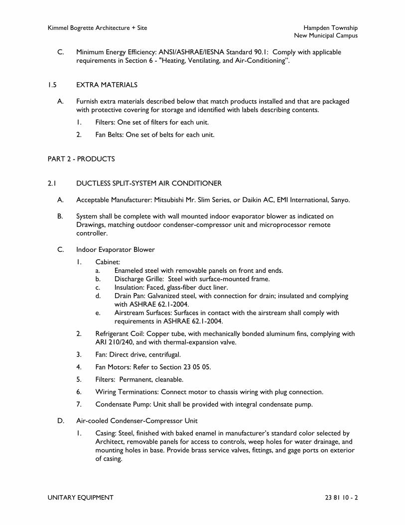
Kimmel Bogrette Architecture + Site Hampden Township
New Municipal Campus
UNITARY EQUIPMENT 23 81 10 - 2
C. Minimum Energy Efficiency: ANSI/ASHRAE/IESNA Standard 90.1: Comply with applicable
requirements in Section 6 - "Heating, Ventilating, and Air-Conditioning”.
1.5 EXTRA MATERIALS
A. Furnish extra materials described below that match products installed and that are packaged
with protective covering for storage and identified with labels describing contents.
1. Filters: One set of filters for each unit.
2. Fan Belts: One set of belts for each unit.
PART 2 - PRODUCTS
2.1 DUCTLESS SPLIT-SYSTEM AIR CONDITIONER
A. Acceptable Manufacturer: Mitsubishi Mr. Slim Series, or Daikin AC, EMI International, Sanyo.
B. System shall be complete with wall mounted indoor evaporator blower as indicated on
Drawings, matching outdoor condenser-compressor unit and microprocessor remote
controller.
C. Indoor Evaporator Blower
1. Cabinet:
a. Enameled steel with removable panels on front and ends.
b. Discharge Grille: Steel with surface-mounted frame.
c. Insulation: Faced, glass-fiber duct liner.
d. Drain Pan: Galvanized steel, with connection for drain; insulated and complying
with ASHRAE 62.1-2004.
e. Airstream Surfaces: Surfaces in contact with the airstream shall comply with
requirements in ASHRAE 62.1-2004.
2. Refrigerant Coil: Copper tube, with mechanically bonded aluminum fins, complying with
ARI 210/240, and with thermal-expansion valve.
3. Fan: Direct drive, centrifugal.
4. Fan Motors: Refer to Section 23 05 05.
5. Filters: Permanent, cleanable.
6. Wiring Terminations: Connect motor to chassis wiring with plug connection.
7. Condensate Pump: Unit shall be provided with integral condensate pump.
D. Air-cooled Condenser-Compressor Unit
1. Casing: Steel, finished with baked enamel in manufacturer’s standard color selected by
Architect, removable panels for access to controls, weep holes for water drainage, and
mounting holes in base. Provide brass service valves, fittings, and gage ports on exterior
of casing.

Kimmel Bogrette Architecture + Site Hampden Township
New Municipal Campus
UNITARY EQUIPMENT 23 81 10 - 3
2. Compressor: Hermetically sealed with crankcase heater and mounted on vibration
isolation. Compressor motor shall have thermal- and current-sensitive overload devices,
start capacitor, relay, and contactor.
3. Compressor Type: Scroll.
4. Two-speed compressor motor with manual-reset high-pressure switch and automatic-
reset low-pressure switch.
5. Refrigerant: R-407C or R-410A.
6. Refrigerant Coil: Copper tube, with mechanically bonded aluminum fins, complying with
ARI 210/240, and with liquid sub cooler.
7. Fan: Aluminum-propeller type, directly connected to motor.
8. Motor: Permanently lubricated, with integral thermal-overload protection.
9. Low Ambient Kit: Permits operation down to 0 degrees F.
E. Controls
1. Thermostat: Wireless infrared functioning to remotely control compressor and
evaporator fan, with the following features:
a. Compressor time delay.
b. 24-hour time control of system stop and start.
c. Liquid-crystal display indicating temperature, set-point temperature, time setting,
operating mode, and fan speed.
d. Fan-speed selection, including auto setting.
2. Refer to Section 23 90 10.
3. Automatic-reset timer to prevent rapid cycling of compressor.
F. Refrigerant Line Kits: Soft-annealed copper suction and liquid lines factory cleaned, dried,
pressurized, and sealed; factory-insulated suction line with flared fittings at both ends.
PART 3 - EXECUTION
3.1 INSTALLATION
A. Install unitary equipment and complete piping connections in accordance with equipment
manufacturer's recommendations. Submit manufacturer's printed installation instructions with
operating and maintenance data at completion of Work.
B. Install condensate drain, complete with trap, on rooftop units in accordance with
manufacturer's recommendation.
C. Install condensate drain, complete with trap, on all cooling coils furnished with drain pan.
Provide trap seal according to equipment manufacturer's recommendations.
D. Install pre charged refrigerant piping in accordance with equipment manufacturer's
recommendations. In lieu of pre charged refrigerant piping, Contractor may elect to provide a
field installed refrigerant piping system. Install refrigerant piping system complete with charging

Kimmel Bogrette Architecture + Site Hampden Township
New Municipal Campus
UNITARY EQUIPMENT 23 81 10 - 4
valves, shutoff valves, sight glasses, oil traps and double risers when required by equipment
manufacturer. Consult manufacturer's literature for specific instructions
3.2 FIELD QUALITY CONTROL
A. Manufacturer's Field Service: Engage a factory-authorized service representative to inspect,
test, and adjust field-assembled components and equipment installation, including connections,
and to assist in field testing. Report results in writing.
B. Perform the following field tests and inspections and prepare test reports:
1. Leak Test: After installation, charge system and test for leaks. Repair leaks and retest
until no leaks exist.
2. Operational Test: After electrical circuitry has been energized, start units to confirm
proper motor rotation and unit operation.
3. Test and adjust controls and safeties. Replace damaged and malfunctioning controls and
equipment.
C. Remove and replace malfunctioning units and retest as specified above.
3.3 TESTS
A. Field installed refrigerant piping shall be leak tested with a mixture of system refrigerant and
dry nitrogen. Pressurize to 350 psi and inspect for and repair all leaks. Purge system. Evacuate
system and charge system with dry nitrogen. Purge system again, evacuate and recharge with
system refrigerant.
END OF SECTION 23 81 10

Kimmel Bogrette Architecture + Site Hampden Township
New Municipal Campus
TERMINAL HEATING UNITS 23 82 10 - 1
SECTION 23 82 10 – TERMINAL HEATING UNITS
PART 1 - GENERAL
1.1 WORK INCLUDED
A. The Work of this Section shall consist of the labor, materials and equipment required for
installation of terminal heating units.
1.2 SUBMITTALS
A. Submit for approval in accordance with specified submittal procedures:
1. Cabinet Unit Heaters, Electric
2. Cabinet Unit Heaters
3. Unit Heaters
PART 2 - PRODUCTS
2.1 CABINET UNIT HEATER, ELECTRIC
A. Acceptable Manufacturer: Qmark SSAR series, or approved equal
B. Cabinet: Die-formed aluminum, phosphatized, powder coat finished of color selected by
Architect.
C. Fans: direct drive and mounted on heavy gauge bracket. Fan shall be five-bladed aluminum.
D. Filter: Throwaway fiberglass type.
E. Motors: Resilient mounted on cushion base, furnished for constant speed operation. Built-in
manual reset thermal overload protection.
F. Heating Elements: 80-20 Ni/Cr resistance wire enclosed in steel sheath with brazed steel plate
fins. Provide automatic reset high limit switch wired in series with each element and located in
discharge air.
G. Installation: as indicated on Drawings.
H. Controls: Refer to Section 23 90 10, Building Automation System., Provided disconnect switch
and dry contact switch for control of unit by building BAS/ATC system.
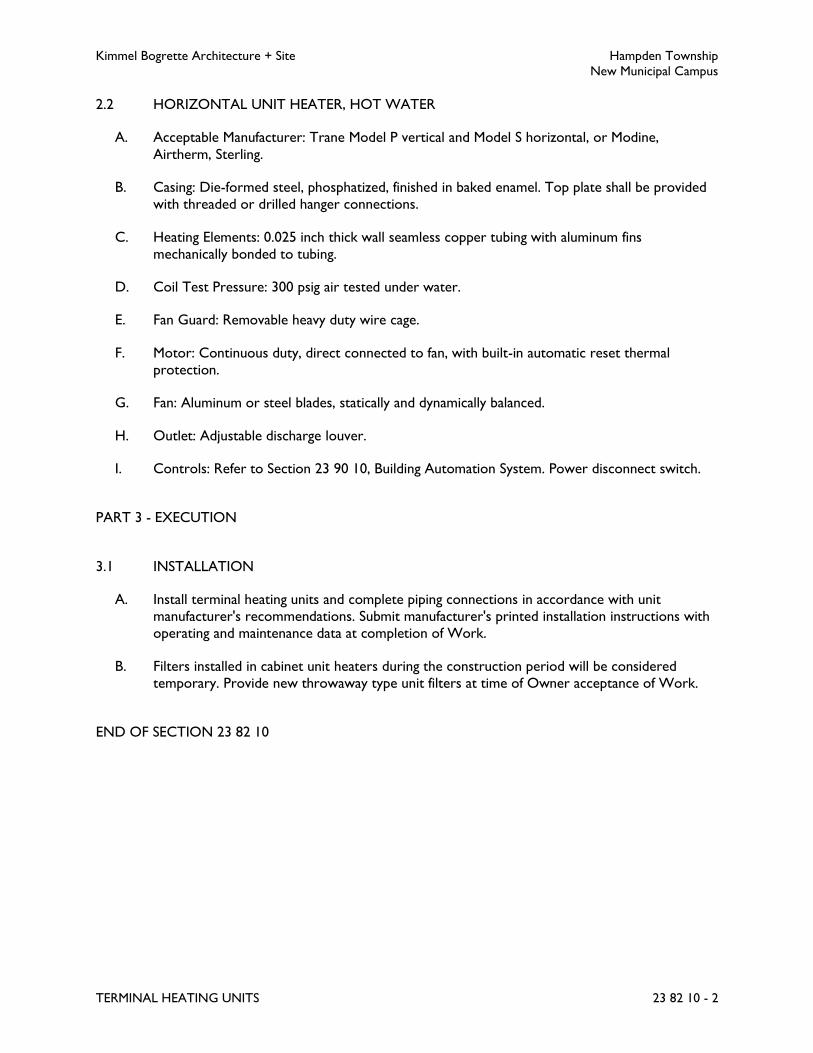
Kimmel Bogrette Architecture + Site Hampden Township
New Municipal Campus
TERMINAL HEATING UNITS 23 82 10 - 2
2.2 HORIZONTAL UNIT HEATER, HOT WATER
A. Acceptable Manufacturer: Trane Model P vertical and Model S horizontal, or Modine,
Airtherm, Sterling.
B. Casing: Die-formed steel, phosphatized, finished in baked enamel. Top plate shall be provided
with threaded or drilled hanger connections.
C. Heating Elements: 0.025 inch thick wall seamless copper tubing with aluminum fins
mechanically bonded to tubing.
D. Coil Test Pressure: 300 psig air tested under water.
E. Fan Guard: Removable heavy duty wire cage.
F. Motor: Continuous duty, direct connected to fan, with built-in automatic reset thermal
protection.
G. Fan: Aluminum or steel blades, statically and dynamically balanced.
H. Outlet: Adjustable discharge louver.
I. Controls: Refer to Section 23 90 10, Building Automation System. Power disconnect switch.
PART 3 - EXECUTION
3.1 INSTALLATION
A. Install terminal heating units and complete piping connections in accordance with unit
manufacturer's recommendations. Submit manufacturer's printed installation instructions with
operating and maintenance data at completion of Work.
B. Filters installed in cabinet unit heaters during the construction period will be considered
temporary. Provide new throwaway type unit filters at time of Owner acceptance of Work.
END OF SECTION 23 82 10

Kimmel Bogrette Architecture + Site Hampden Township
New Municipal Campus
BUILDING AUTOMATION SYSTEM 23 90 10 - 1
SECTION 23 90 10 – BUILDING AUTOMATION SYSTEM
PART 1 - GENERAL
1.1 WORK INCLUDED
A. The Work under this Section shall consist of the labor, materials and equipment required for
installation of the building automation system and automatic temperature control system
(BAS/ATC).
1.2 SUBMITTALS
A. Submit complete BAS/ATC shop drawings for Engineer's approval prior to installation or
fabrication of any equipment. Submittal data shall include a schedule of all devices to be
installed, including proposed locations. Devices shall be properly sized and selected for
optimum system operation.
B. Deviations from the sequence of control specified herein shall be clearly noted in the sequence
of control furnished with shop drawing submittals.
C. Submittals shall include software, control equipment, control valves, motor-operated dampers,
damper actuators, sequence of operations, points list, complete system drawings, etc.
1.3 QUALITY ASSURANCE
A. The BAS/ATC system shall be designed, installed, commissioned and serviced by factory
trained personnel.
1.4 SERVICE AND GUARANTEE
A. At completion of system installation, BAS/ATC system manufacturer shall adjust all
thermostats, control valves, motors and other equipment provided under this contract with
trained personnel in the direct employ of BAS/ATC system manufacturer. He shall place said
equipment in complete operating condition subject to approval of Engineer, and instruct
Owner's operating personnel in the operation of the system.
B. BAS/ATC system, as shown on Drawings and specified herein, shall be guaranteed free from
defects in workmanship and material under normal use and service for a period of 1 year after
acceptance by Owner.
C. Equipment herein described proven to be defective in workmanship or material during the
guarantee period shall be adjusted, repaired, or replaced by BAS/ATC system manufacturer at
no charge to Owner.

Kimmel Bogrette Architecture + Site Hampden Township
New Municipal Campus
BUILDING AUTOMATION SYSTEM 23 90 10 - 2
D. BAS/ATC system manufacturer shall maintain an up to date software program to provide
Owner with backup in the event of system failure at any future date.
1.5 WIRING
A. All power and wiring required by the BAS/ATC system, controllers and required
appurtenances shall be provided by BAS/ATC system supplier.
B. Detailed wiring diagrams and complete field supervision shall be provided by system installer.
C. System installer shall furnish and install control devices specified in this Section unless
specifically stated otherwise.
D. Maximum allowable voltage for wiring inside control panels shall be 120V.
E. All wiring shall conform to the National Electrical Code and requirements of Division 26.
F. Control wiring penetrations at wall-mounted sensors shall be calked and sealed to prevent air
leakage.
PART 2 - PRODUCTS
2.1 MANUFACTURER
A. Basis of Design: The Trane Company
B. Other Acceptable Manufacturers:
1. Automated Logic Corporation
2. Schneider Electric; TAC I/A Series
3. Siemens Industry Building Technologies; Apogee Automation System
C. Refer to Section 01 23 00 - Alternates
2.2 GENERAL
A. BAS/ATC system shall include, but not be limited to, the following components:
1. Operator interface shall consist of hardware and software that allows full user
monitoring and adjustment of system parameters.
2. System application controllers shall manage the energy and building management
capacities of the automation system, as well as, facilitate remote communications and
central monitoring.
3. Application specific controllers shall provide distributed, pre engineered control, specific
to the mechanical equipment specified.

Kimmel Bogrette Architecture + Site Hampden Township
New Municipal Campus
BUILDING AUTOMATION SYSTEM 23 90 10 - 3
4. Custom application controllers with distributed custom programming capability shall
provide control for nonstandard control sequences.
5. Data communications capability shall allow data to be shared between the various
controllers in the architecture.
6. System software shall include system software for global application functions,
application software for distributed controllers, and operator interface software.
7. End devices such as sensors, actuators, dampers, valves, and relays.
B. The failure of any single component shall not interrupt the control strategies of other
operational devices. System expansion shall be through the addition of end devices,
controllers, and other device specified herein.
2.3 OPERATOR INTERFACE
A. Local Interface. Furnish one workstation to be located as directed by Owner. The graphic
based workstation shall be able to access all information in the system, reside on the same high
speed LAN as the central plant controllers, and shall be web-based. Workstation shall be able
to be custom configured based on the needs of the operator.
1. Desktop Computer: The PC Architecture shall be Intel based; Supermicro, Dell, and HP
are acceptable vendors. CPU shall have a minimum of 4 cores with a clock rate of 2.0
Ghz or higher. A minimum of 2 Gigs of RAM operating in dual or triple channel mode
with a single DVD-RW drive. At minimum a 150 GIG Hard Disk operating at 10k RPMs
with an access time of no more than 4.5 ms. Graphics Card shall be of the latest by
either Nvidia or Radeon and have at minimum 512 mb of RAM and be Directx 10
compatible. A three button optical Mouse / Keyboard will be provided with either a
USB or serial connection. The PC shall have a minimum of a 19 inch, flat screen SVGA
monitor; Viewsonic, and Samsung are acceptable vendors.
B. Web Browser: The system shall be capable of supporting an unlimited number of clients using
a standard Web browser such as Internet Explorer™ or Mozilla Firefox. The Web browser
software shall run on any operating system and system configuration that is supported by the
Web browser and provide the same view of the system, in terms of graphics, schedules,
calendars, logs, etc., and provide the same interface methodology as is provided by the
graphical interface. The Web browser client shall support:
1. User log-on identification and password
2. Graphical screens developed for the graphical interface shall be the same screens used
for the Web browser client.
3. Users shall have administrator-defined access privileges including: modifying schedules,
calendars and set points; commands to start and stop objects; viewing of logs and
charts; and viewing and acknowledgement of alarms.
C. For Local Area Network installations, provide access to the LAN from a remote location, via
the Internet. The Owner shall provide a connection to the Internet to enable this access via
high speed cable modem, asynchronous digital subscriber line (ADSL) modem, ISDN line, T1
Line or via the customer’s Intranet to a corporate server providing access to an Internet
Service Provider (ISP).

Kimmel Bogrette Architecture + Site Hampden Township
New Municipal Campus
BUILDING AUTOMATION SYSTEM 23 90 10 - 4
2.4 SYSTEM APPLICATION CONTROLLERS
A. BAS/ATC system shall be composed of one independent, stand alone, microprocessor based
system application controller to manage the global strategies described in application software
section.
B. System application controller shall have ample memory to support its operating system,
database, and programming requirements.
C. Operating system of the system application controller shall manage the input and output
communications signals to allow distributed controllers to share real and virtual point
information and allow central monitoring and alarms.
D. Data shall automatically be shared between system application controllers when they are
networked together.
E. Database and custom programming routines of remote system application controllers shall be
editable from single operator station.
F. System applications controllers shall have the capability of being remotely monitored over
telephone modem. Additional capabilities shall include automatically dialing out alarms,
gathering alarms, reports and logs, programming an downloading databases.
G. Controller shall continually check status of all processor and memory circuits. If a failure is
detected, controller shall:
1. Assume a predetermined failure mode.
2. Emit an alarm.
3. Display card failure identification.
2.5 APPLICATION SPECIFIC CONTROLLERS
A. Application specific controllers shall be stand alone, microprocessor based direct digital
controllers with sufficient memory to handle its operating system, database and programming
requirements.
B. Application specific controller shall be pre programmed, tested, and factory mounted on
mechanical equipment to ensure reliability.
1. Where factory mounting is not possible, controllers shall be factory programmed and
tested prior to shipment to jobsite. Controllers shall be clearly labeled as to controller
type, where installed, and software address (if applicable). Controller shall be fully tested
upon installation to ensure that it is properly matched to the equipment it is controlling.
C. Controller shall communicate with other devices on communication network and be fully
integrated with other system components.
D. Hardware shall be suitable for anticipated ambient conditions.
1. Controllers used outdoors and/or in wet ambient shall be mounted within waterproof
enclosures, and shall be rated for operation at minus 40 degrees F to 155 degrees F.

Kimmel Bogrette Architecture + Site Hampden Township
New Municipal Campus
BUILDING AUTOMATION SYSTEM 23 90 10 - 5
2. Controller used in conditioned ambient shall be mounted in dust proof enclosures, and
shall be rated for operation at 32 degrees F to 120 degrees F.
2.6 CUSTOM APPLICATION CONTROLLERS
A. Custom application controllers shall provide stand alone control and require no additional
system components for complete operation. It shall have sufficient memory to support its
operating system, database, and programming requirements.
B. All programming required for operation shall be memory resident and shall be retained in
permanent memory. Battery backup for a minimum of 72 hours is also permissible.
C. Custom application controller shall be configured such that portable operator interface can be
plugged directly into it or within sight for programming, editing, and other operator functions.
D. Controller hardware shall be suitable for the anticipated ambient conditions.
E. Controllers used outdoors and/or in wet ambient shall be mounted within waterproof
enclosures, and shall be rated for operation at minus 40 degrees F to 155 degrees F.
F. Controller used in conditioned ambient shall be mounted in dust proof enclosures, and shall
be rated for operation at 32 degrees F to 120 degrees F.
2.7 INPUT/OUTPUT INTERFACE
A. Hardwired inputs and outputs may tie into system through system application, or application
specific controllers. Slave devices are also acceptable. Any critical points requiring immediate
reaction shall be tied directly into controller hosting control software algorithm for critical
function.
B. Binary inputs shall allow monitoring of on off signals from remote devices. Binary inputs shall
provide a wetting current of 12MA at 12VDC to be compatible with commonly available
control devices.
1. All status points shown on point list shall be positive proof differential pressure or
current sensing binary switches.
C. Analog inputs shall allow the monitoring of low voltage, current, or resistance signals and shall
have a minimum resolution of 0.1 percent of sensing range. Analog inputs shall be compatible
with, and field configurable to commonly available sensing devices.
D. Binary outputs shall provide a continuous low voltage signal for on off control of remote
devices. Where specified in sequence of operations or indicated on points list, binary outputs
shall have 3 position on off auto override switches, status lights, and shall be selectable for
either normally open or normally closed position.
E. Analog outputs shall provide a modulating signal for control of end devices. Outputs shall
provide either a 0 to 10 VDC or a 4 to 20 milliampere signal as required to provide proper
control of output device.

Kimmel Bogrette Architecture + Site Hampden Township
New Municipal Campus
BUILDING AUTOMATION SYSTEM 23 90 10 - 6
F. System architecture shall allow for point expansion in one of the following ways:
1. Addition of input/output cards to an existing system application controller.
2. A slave controller may be used to expand point capacity.
3. 10 percent expansion capacity for all point types in all DDC panels.
2.8 AUXILIARY CONTROL DEVICES
A. Control Valves
1. Two-way or three-way valves as indicated with linkage for connection to valve operator.
Maximum pressure drop shall be 3 psig at design flow.
B. Valve Actuators
1. Valve actuators shall be electronic, spring return, low voltage (24VAC), and properly
selected for valve body and service.
2. Actuators shall be fully proportioning and be spring return for normally open or
normally closed operation as called out in the sequence of operations.
2.9 TEMPERATURE SENSORS
A. Temperature sensors shall be integrated circuit temperature detector sensors (RTD) or
thermistor as dictated by requirements herein.
B. Immersion sensors shall be provided with a separable stainless steel well.
C. Space sensors shall be equipped with setpoint adjustment and/or override switch as specified
on the Drawings or in the sequence of operations.
D. Accuracies shall be plus or minus 1 degree F for standard applications. Where high accuracy is
required, accuracies shall be plus or minus.2 degrees F.
2.10 PRESSURE SENSOR
A. The pressure sensor shall provide a 4 to 20 mA output. Sensor accuracy shall be + or minus 1
percent of sensing range.
B. Sensor shall have a normal operating pressure range of 0 to 100 psig and a proof pressure of
200 psig.
2.11 OPERATOR INTERFACE SOFTWARE
A. System Security
1. User access shall be secured using individual security passwords for a minimum of eight
users.

Kimmel Bogrette Architecture + Site Hampden Township
New Municipal Campus
BUILDING AUTOMATION SYSTEM 23 90 10 - 7
2. Passwords shall have at least three levels of user access with data entry restrictions
being assignable by password.
3. User logon logoff attempts shall be recorded.
4. System shall protect itself from unauthorized use by automatically logging off following
last keystroke. Delay time shall be user definable.
B. Alarms
1. BAS/ATC system shall provide audio, visual, contact closure, and remote telephone
annunciator for:
a. Remote equipment failure.
b. Equipment run time.
c. Number of start/stops.
d. Program failure.
e. Card failure.
f. Sensor failure.
2. Each analog sensor and binary point shall be individually alarmed for values in excess of
individual high low limits or status.
3. When an alarm state is detected, alarm shall automatically be stored and user notified
by printing alarm message, sounding an audible tone, and flashing an alarm message on
the operator workstation display.
4. An after-hours alarm processing function shall transfer alarm message to alternate
location equipped with a terminal device and an auto answer modem. Telephone
number, and time of day to start and stop after hours processing shall be user
designated.
C. Dial Up Communications
1. An autodial up and auto answer communications utility shall allow standalone system
application controllers to communicate with remote operator stations over voice grade
phone lines.
2. Remote Alarming Reporting:
a. Controllers shall automatically call operator stations to report alarms, and upload
historical data and reports.
b. If controller is unable to connect with remote station, it shall continue to attempt
communication on a predetermined interval until communication is successful.
Capability shall exist to automatically switch to a backup phone number if
communications is unsuccessful with first number.
c. A separate night number capability shall allow alarms to be directed to separate
printer, CTT, or personal computer during off hours.
3. Remote Operator Communications:
a. Operators shall be able to dial up remote system application controllers and gain
access to full control, reporting, and system modification capabilities described in
this Specification.
b. The operator shall dial up remote buildings by selecting the user definable name
associated with the building. Manual dialing is not acceptable.

Kimmel Bogrette Architecture + Site Hampden Township
New Municipal Campus
BUILDING AUTOMATION SYSTEM 23 90 10 - 8
2.12 ENERGY MANAGEMENT SOFTWARE
A. The following energy management capabilities shall be furnished standard as part of the
BAS/ATC system.
1. Scheduling:
a. Scheduling program shall have a minimum of 32 named master schedules. Each
master schedule shall have a minimum of eight day schedules (seven plus holiday).
b. To these master schedules, a minimum of 24 system loads (HVAC equipment,
etc.) or groups of loads can be assigned.
c. Master schedule shall be individually editable for each day of the week and
holiday.
d. On any day, a minimum of six time of day events may be edited including:
1) Equipment start stop.
2) Optimum start stop.
3) Occupied unoccupied.
4) Duty cycle start stop.
5) Night purge cycle start.
B. Optimum Start Stop:
1. An optimum start stop program shall determine the required equipment start stop
timing by applying inside outside temperature information to user's time of day schedule.
2. Optimum start stop program shall run independently for each controlled load or zone.
3. Program shall automatically make adjustments to itself based on historical data.
C. Duty Cycling:
1. Duty cycle program shall cycle a minimum of 32 pieces of equipment according to user
defined on off patterns.
2. User editable parameters shall include period length, off time and delay time. Program
shall incorporate temperature and humidity overrides to ensure that indoor air quality
an occupant comfort are not compromised.
D. Software Graphics:
1. Provide color graphic system flow diagram display for each HVAC system with each
point indicated.
a. Provide text sequence of operation for each system launched from graphic.
b. Graphics based on real-time data.
c. Provide with user adjustable settings.
d. Provide graphic editing tool.
e. Provide library graphics containing basic symbols and icons.
f. Provide color graphic display of each section and floor of the building. Indicate
each zone with values and status. Provide historical data viewer functionality.
g. Provide color graphic display for each system; properly label rooms with actual
name and number.
h. Provide configuration diagrams.
i. Provide navigation tree that will allow user to view and change points but stay in
graphic system.

Kimmel Bogrette Architecture + Site Hampden Township
New Municipal Campus
BUILDING AUTOMATION SYSTEM 23 90 10 - 9
j. Provide custom reports with graphics as specified in article Building Management
Software below.
E. Demand Limiting:
1. Demand limiting program shall monitor building power consumption from signals
generated by a pulse generator (provided by other) mounted at building power meter
or from a watts transducer or current transformer attached to building feeder lines.
2. Demand limiting program shall be based on a predictive sliding window algorithm. The
program shall be self adjusting and shall control a minimum of two independent demand
limiting applications.
3. Demand limiting parameters shall include 15 to 30 minute intervals, shed restore dead
band width as well as maximum off time and temperature limits for each load to ensure
that indoor air quality and occupancy comfort are not compromised.
4. HVAC equipment shall be protected by anti recycle timer described below.
5. Input capability shall also be provided for an end of billing period indication.
F. Wireless Access Protocol:
1. Provide software and protocol to connect remote web-accessed devices such as
handheld phones, laptops and tablets to the BAS/ATC, with the ability for monitoring,
receiving alarms, viewing graphics, and user interface abilities to make setting changes.
2.13 BUILDING MANAGEMENT SOFTWARE
A. The following building management capabilities shall be furnished as part of the BAS/ATC
system.
1. Timed Override:
a. A timed override program shall be provided to enable the building operator to
set up devices or groups of devices to be temporarily turned on for a defined
period of time based on binary inputs, analog inputs, or CRT inputs.
b. Override time shall be adjustable from 1 to 720 minutes.
c. A standard weekly and monthly report shall be provided for easy documentation
of time override operation.
2. Direct Digital Control:
a. Direct digital control program shall allow modulating control of remote devices
based on sensed data.
b. Standard control strategies shall include proportional, proportional plus integral,
and proportional plus integral plus derivative control.
c. Control routines shall be flexible enough to allow operator to set parameters and
make adjustments.
d. Direct digital control loop set up and modification shall be done through pre
formatted edit screens with parameters listed in English language.
e. Program shall include a dynamic graphic display printout routing to indicate status
and real time performance of control loop.
f. As an alternative, auto tuning loops or another method of testing and proving
control loop response may be provided.
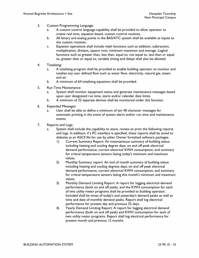
Kimmel Bogrette Architecture + Site Hampden Township
New Municipal Campus
BUILDING AUTOMATION SYSTEM 23 90 10 - 10
3. Custom Programming Language:
a. A custom control language capability shall be provided to allow operator to
create real time, equation based, custom control routines.
b. All binary and analog points in the BAS/ATC system shall be available as inputs to
the custom routines.
c. Equation operations shall include math functions such as addition, subtraction,
multiplication, division, square root, minimum maximum and average. Logical
functions such as greater than, less than, equal to, not equal to, less than or equal
to, greater than or equal to, variable timing and delays shall also be allowed.
4. Totalizing:
a. A totalizing program shall be provided to enable building operator to monitor and
totalize any user defined flow such as water flow, electricity, natural gas, steam
and air.
b. A minimum of 64 totalizing equations shall be provided.
5. Run Time Maintenance:
a. System shall monitor equipment status and generate maintenance messages based
upon user designated run time, starts and/or calendar date limits.
b. A minimum of 32 separate devices shall be monitored under this function.
6. Expanded Messages:
a. User shall be able to define a minimum of ten 40 character messages for
automatic printing in the event of system alarm and/or run time and maintenance
events.
7. Reports and Logs:
a. System shall include the capability to store, review an print the following reports
and logs. In addition, if a PC interface is specified, these reports shall be saved to
diskette as an ASCII file for use by other Owner furnished software packages.
1) Current Summary Report: An instantaneous summary of building status
including heating and cooling degree days, on and off peak electrical
demand performance, current electrical KWH consumption, and summary
for critical temperature sensors listing today's minimum and maximum
values.
2) Monthly Summary report: An end of month summary of building status
including heating and cooling degrees days, on and off peak electrical
demand performance, current electrical KWH consumption, and summary
for critical temperature sensors listing this month's minimum and maximum
values.
3) Monthly Demand Limiting Report: A report for logging electrical demand
performance (both on and off peak), and the KWH consumption for each
of two utility meter programs shall be provided to building operator.
Included shall be times of today's and yesterday's demand peaks as well as
time and date of monthly demand peaks. Report shall log electrical
performance for present day and previous 32 days.
4) Yearly Demand Limiting Report: A report for logging electrical demand
performance (both on and off peak) and KWH consumption for each of
two utility meter programs. Report shall log electrical performance for
present month and previous 12 months.
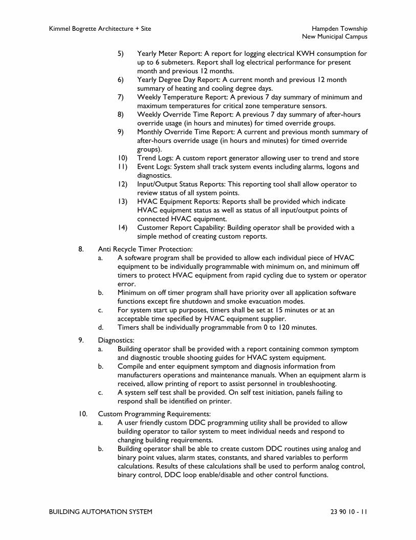
Kimmel Bogrette Architecture + Site Hampden Township
New Municipal Campus
BUILDING AUTOMATION SYSTEM 23 90 10 - 11
5) Yearly Meter Report: A report for logging electrical KWH consumption for
up to 6 submeters. Report shall log electrical performance for present
month and previous 12 months.
6) Yearly Degree Day Report: A current month and previous 12 month
summary of heating and cooling degree days.
7) Weekly Temperature Report: A previous 7 day summary of minimum and
maximum temperatures for critical zone temperature sensors.
8) Weekly Override Time Report: A previous 7 day summary of after-hours
override usage (in hours and minutes) for timed override groups.
9) Monthly Override Time Report: A current and previous month summary of
after-hours override usage (in hours and minutes) for timed override
groups).
10) Trend Logs: A custom report generator allowing user to trend and store
11) Event Logs: System shall track system events including alarms, logons and
diagnostics.
12) Input/Output Status Reports: This reporting tool shall allow operator to
review status of all system points.
13) HVAC Equipment Reports: Reports shall be provided which indicate
HVAC equipment status as well as status of all input/output points of
connected HVAC equipment.
14) Customer Report Capability: Building operator shall be provided with a
simple method of creating custom reports.
8. Anti Recycle Timer Protection:
a. A software program shall be provided to allow each individual piece of HVAC
equipment to be individually programmable with minimum on, and minimum off
timers to protect HVAC equipment from rapid cycling due to system or operator
error.
b. Minimum on off timer program shall have priority over all application software
functions except fire shutdown and smoke evacuation modes.
c. For system start up purposes, timers shall be set at 15 minutes or at an
acceptable time specified by HVAC equipment supplier.
d. Timers shall be individually programmable from 0 to 120 minutes.
9. Diagnostics:
a. Building operator shall be provided with a report containing common symptom
and diagnostic trouble shooting guides for HVAC system equipment.
b. Compile and enter equipment symptom and diagnosis information from
manufacturers operations and maintenance manuals. When an equipment alarm is
received, allow printing of report to assist personnel in troubleshooting.
c. A system self test shall be provided. On self test initiation, panels failing to
respond shall be identified on printer.
10. Custom Programming Requirements:
a. A user friendly custom DDC programming utility shall be provided to allow
building operator to tailor system to meet individual needs and respond to
changing building requirements.
b. Building operator shall be able to create custom DDC routines using analog and
binary point values, alarm states, constants, and shared variables to perform
calculations. Results of these calculations shall be used to perform analog control,
binary control, DDC loop enable/disable and other control functions.

Kimmel Bogrette Architecture + Site Hampden Township
New Municipal Campus
BUILDING AUTOMATION SYSTEM 23 90 10 - 12
c. Building operator shall be able to download these routines to system or custom
application controllers either via modem, direct connect, or through a portable
operator interface.
d. Custom routines in distributed controllers shall be maintained in nonvolatile
memory to prevent loss in a power outage. Custom routines hosted in system
applications controllers may use battery backup so long as a quick method of
system downloading is provided.
2.14 MOTOR OPERATED DAMPERS
A. Remote mounted motor operated dampers shall be furnished by the BAS/ATC system
manufacturer and installed by the HVAC Contractor. Dampers shall be opposed or parallel
blade type as required for the application. Dampers shall be of the low leakage type of not
more than 1 percent leakage based on a 4 inch WC static pressure and a 2000 feet per minute
approach velocity. Seals on damper blades and frames shall be replaceable in the field. Furnish
and install for motor operated dampers, including motor operated dampers furnished by the
unit manufacturer, piston type damper actuators providing ample power to smoothly position
damper to any position. Damper operators shall be equipped with pilot positioners where
specified or required to meet the specified sequence of operation.
PART 3 - EXECUTION
3.1 MOUNTING HEIGHTS
A. Mounting height for space sensors and thermostats shall be 44 inches from the finished floor
to the centerline of the device. If the designated location of a device places it partially between
two finishes, the actual location shall be adjusted to set the device entirely on one finished
surface only, but actual height shall not exceed mounting heights indicated or required by
codes.
PART 4 - SEQUENCE OF OPERATION
4.1 VAV AIR HANDLING UNITS WITH VAV BOXES (AHU-1, 2)
A. Off Mode
1. During unoccupied times or when the unit is de-energized, the unit’s associated
hydronic heating coil valve shall be fully open, the cooling coil valve shall be closed, the
unit fans shall not run, the outdoor air damper and relief damper shall be in the fully
closed position and the return air damper shall be in the fully opened position. The
unit’s associated VAV boxes shall be indexed to 100 percent open. The VAV boxes’
hydronic heating valves shall also be indexed closed.
2. If any associated room space temperature drops below setback heating setpoint (65
degrees F adjustable), the unit shall be energized, the hot water valve shall be fully
modulated open, and the chilled water valve shall be fully modulated closed, and the

Kimmel Bogrette Architecture + Site Hampden Township
New Municipal Campus
BUILDING AUTOMATION SYSTEM 23 90 10 - 13
outside air damper and relief damper shall be closed. When the space temperature is
satisfied, the unit shall be de-energized.
3. If any associated room space temperature rises above setup cooling setpoint set point
(85 degrees F adjustable), the unit shall be energized, the hot water valve shall be fully
modulated closed, and the chilled water valve shall be fully modulated open, and the
outside air damper shall be closed. When the space temperature is satisfied, the unit
shall be de-energized, the cooling valve shall modulate closed and the hot water valve
shall modulate open.
B. Warm Up Mode
1. During Warm Up Mode of operation, the unit supply fan and return fan shall run and
the unit shall produce 85 degrees F (adjustable) supply air via its associated hydronic
duct coil. The hydronic duct coil heating valve shall modulate open (in response to
depressed supply air temperatures) and shut (in response to elevated supply air
temperatures) in order to maintain discharge air temperature set point. The unit’s
outdoor air damper shall be closed and the unit’s return air damper shall be fully open.
2. As the room temperatures begin to rise, the PID loop associated with the room’s
respective VAV box(s) shall begin to close the VAV box in order to optimally arrive at
the space’s adjustable heating set point. The VAV boxes associated with each room shall
be allowed to modulate completely shut during warm up operations. If at any time
during the Warm Up Mode the supply fan and return fan VFD’s output falls below 30
percent (adjustable), the system shall index it’s associated VAV boxes to their respective
minimum heating positions and the system supply air temperature shall be reset to 70
degrees F (adjustable).
3. The room temperatures associated with a given VAV Air Handling Unit’s VAV boxes
shall be averaged and the average temperature value shall be used to initiate the
occupied mode of operation. When the average room temperatures during the Warm
Up Mode are within 1 degree of the average of the occupied set points, the VAV air
handling unit system shall index to the occupied mode.
C. Cool Down Mode
1. During Cool Down Mode of operation, the unit supply fan and return fan shall run and
the unit shall produce 55 degrees F (adjustable) supply air by utilizing its economizer
and/or cooling coil.
2. As the room temperatures begin to fall, the PID loop associated with the room’s
respective VAV box(s) shall begin to close the VAV box in order to optimally arrive at
the space’s adjustable cooling set point. The VAV boxes associated with each room shall
be allowed to modulate completely shut during cool down operations. If at any time
during the Cool Down Mode the supply fan and return fan VFD’s output falls below 30
percent (adjustable), the system shall index it’s associated VAV boxes to their respective
minimum cooling positions and the system supply air temperature shall be reset to
Occupied Mode temperature required by the Cooling Mode Reset Schedule.
3. The room temperatures associated with a given VAV air handling unit’s VAV boxes shall
be averaged and the average temperature value shall be used to initiate the occupied
mode of operation. When the average room temperatures during the Cool Down
Mode are within 1 degree of the average of the occupied set points, the VAV rooftop
unit system shall index to the occupied mode.

Kimmel Bogrette Architecture + Site Hampden Township
New Municipal Campus
BUILDING AUTOMATION SYSTEM 23 90 10 - 14
D. Occupied Mode
1. In the occupied mode of operation, the VAV air handling unit shall deliver supply air
based on the following reset schedules for Heating and Cooling Modes of operation:
Heating Mode Reset Schedule
O.A. Temp. Supply Air Temp.
0 63
55 57
Cooling Mode Reset Schedule
O.A. Temp. Supply Air Temp.
55 55
80 55
The change over from the Heating Mode to the Cooling Mode shall occur at 55 degrees
F (adjustable) outdoor air temperature.
2. During the Heating Mode, the VAV rooftop unit’s outside air damper shall be modulated
to provide the design minimum outside air as scheduled on drawings and shall be
controlled by CO2 monitoring (See Below). The system’s VAV boxes shall prevent
overheating of their spaces by modulating their respective hydronic heating coil valves
shut, and then modulate their air valves to their Heating Minimums. On a drop in space
temperature the reverse shall occur.
3. During the Cooling Mode, the VAV air handling unit’s outside air damper shall be
allowed to modulate with the unit’s return air damper to provide the required supply
air temperature in accordance with the Cooling Mode Supply Air Temperature Reset
Schedule as long as the outdoor air enthalpy is less than the return air enthalpy. The
VAV air handling unit’s outdoor air damper shall design minimum outside air as
scheduled on drawings and shall be controlled by CO2 monitoring (See Below), and the
unit’s cooling coil valve shall modulate to maintain the supply air temperature in
accordance with the Cooling Mode Reset Schedule, if the economizer mode is not in
operation. The system’s VAV boxes shall prevent overcooling of their spaces by first
modulating their air valves to their Cooling Minimums and on a continued fall in space
temperature the air valve shall be indexed to the heating minimum airflow and their
respective hydronic heating coil valves shall modulate open. On a rise in space
temperature the reverse shall occur.. If at any time the space humidity rises above 60
percent RH, the unit shall be indexed to the dehumidification mode.
4. Outside Air/Return Air damper control - when the CO2 level increases above 700 ppm
(above ambient conditions) as sensed by a CO2 monitor in the common return air duct
and a CO2 monitor mounted on the exterior of the building, the outside air damper
shall modulate an additional 10 percent open. If after a period of 1/2 hour, the CO2
level does not fall below 700 ppm (above ambient conditions), the outdoor air damper
shall modulate an additional 10 percent open. Dampers shall continue to modulate
open until the CO2 setpoint is achieved. If CO2 level drops below 500 ppm (above
ambient conditions) for a period of 1/2 hour, the outdoor air damper shall modulate to
its initial 10 outside air position.

Kimmel Bogrette Architecture + Site Hampden Township
New Municipal Campus
BUILDING AUTOMATION SYSTEM 23 90 10 - 15
5. Relief System – The unit controller’s PID loop shall modulate the units relief air damper
to maintain building static pressure setpoint of 0.1 inch w.g. above ambient (setpoint
adjustable).
6. During the Dehumidification Mode, the VAV Air Handling Unit’s cooling valve shall be
indexed fully open, and the outside air damper shall modulate to 10% outside air, and
individual VAV boxes shall operate to maintain space temperatures. When space
humidity drops below setpoint 55% RH (adjustable), the unit shall revert to the standard
cooling sequence of operation.
E. Variable Frequency Drive (VFD) Control
1. The VAV air handling unit’s associated VFD(s) and supply and return fans shall be
controlled by a static pressure sensor located two thirds of the way down the system’s
supply duct main. The VAV system balancer shall determine the required minimum
system static pressure necessary for the most remote (from a static pressure stand
point) VAV box to deliver its maximum scheduled cooling air volume. The minimum
system static pressure necessary for the most remote VAV box to deliver its maximum
scheduled cooling air volume shall be input to the system’s the Cooling Mode Reset
Schedule’s supply static pressure set point (adjustable). The VAV system balancer shall
determine the required minimum system static pressure necessary for the most remote
VAV box to deliver its minimum scheduled heating air volume. The minimum system
static pressure necessary for the most remote VAV box to deliver its minimum
scheduled heating air volume shall be input to the system as the Heating Mode Reset
Schedule’s supply static pressure set point (adjustable). The system’s static pressure shall
change as the system changes back and forth from the Heating Mode Reset Schedule to
the Cooling Mode Reset Schedule.
F. Safeties
1. The VAV air handling unit’s fan shall turn off, its cooling coil valve closed to the coil, and
it’s associated heating valve stroked 100 percent open, if the supply air temperature, as
sensed by the system’s discharge air temperature sensor, drops below 40 degrees F
(adjustable). The air handling unit’s return air damper shall fully open, its outdoor air
damper shall be fully closed and an alarm shall be sounded at the operator interface.
2. The VFD output algorithm shall prevent the system static pressure from exceeding the
heating or cooling static pressure set point by more than 25 percent. If the system static
pressure exceeds the Heating or Cooling static pressure set point by more than 25
percent for more than 10 seconds, the VAV air handling unit’s fan shall turn off, its
cooling valve closed 100 percent, and it’s associated heating valve stroked 100 percent
open. Its return air damper shall fully open, its outdoor air damper shall be fully closed
and an alarm shall be sounded at the operator interface.
3. Safeties: BAS/ATC shall turn off the unit and an alarm shall be reported to the operator
interface if any of the following conditions occurs:
a. Failure of the supply air fan (as sensed KW signal from supply fan VFD).
b. Failure of the return air fan (as sensed KW signal from return fan VFD).
c. Detection of smoke and/or activation of fire alarm system.
d. Coil Freeze Protection: Furnish a low limit thermostat installed in serpentine
fashion across entire face of the upstream side of cooling coil. Thermostat shall
be manual reset type. Whenever temperature of any one foot of sensing element
falls below thermostat's setting (adjustable), unit shall shut down and the heating

Kimmel Bogrette Architecture + Site Hampden Township
New Municipal Campus
BUILDING AUTOMATION SYSTEM 23 90 10 - 16
coil control valve shall fully open. An alarm shall be generated at the BAS/ATC
Operator Interface.
e. Monitor filter pressure drop.
f. The Unit’s secondary drain pan shall be provided with a high level alarm sensor.
On a high water level alarm, the units fan shall be turned off, the chilled water
valve shall be closed, and an alarm shall be reported to the owner’s head end
terminal.
4.2 CENTRAL HOT WATER SYTEM
A. The central hot water heating system shall consist of boiler B-1, and boiler B-2, circulator
pump P-3, circulator pump P-4, and hot water pumps P-1 and P-2. Circulator pump P-3 shall
be directly associated with boiler B-1. Circulator pump P-4 shall be directly associated with
boiler B-2.
B. When outdoor air temperature falls below sixty (60) degrees pump P-1 and the lead boiler
(boiler B-1), and associated circulator pump P-3 shall be energized during occupied modes of
operations (pre event and event modes included). Boiler shall maintain water temperature as
indicated in the following hot water reset schedule:
O.A.
Temp.
Water
Temp.
35 140
60 120
If the leaving water temperature at the common supply header drops 1 degree below setpoint
for more than ½ hour or if the flow rate in the common hot water supply piping rises above
50 gpm for more than ½ hour, the lag boiler (Boiler B-2), and associated circulator pump P-4
shall be energized. Boilers shall maintain water temperature as listed in the hot water reset
schedule.
C. If the water flow rate drops below 50 gpm for more than ½ hour, with all boilers operating,
the lag boiler (Boiler B-2) and associated circulator pump P-4 shall be de-energized. The
remaining boilers and circulator pumps shall remain on and shall maintain water temperature
listed in the hot water reset schedule.
D. During unoccupied mode of operation, the central hot water heating system shall be
deenergized whenever the outdoor air temperature is above fifty five (55) degrees. Below fifty
five (55) degrees the central hot water heating system shall be energized and the above
indicated reset schedule applied to the hot water system. During unoccupied mode if outdoor
air temperature is below sixty (60) degrees and any setback space requires heating, the ATC
system shall enable the central hot water heating system to operate until the space or spaces
below setback temperatures have returned to their required setpoints.
E. Boilers B-1, B-2, and associated circulator pumps shall operate in a lead/lag mode of
operation. The lead/lag operation shall be revised every 400 hours of operation. After the
400 hours are completed, the lead boiler shall become the secondary lag boiler, the primary
Kimmel Bogrette Architecture + Site Hampden Township
New Municipal Campus
BUILDING AUTOMATION SYSTEM 23 90 10 - 17
lag boiler shall become the Lead boiler, and the second lag boiler shall become the primary lag
boiler.
F. Upon failure of any boiler (as sensed by individual temperature sensors for the boiler) the lag
boiler shall be enabled for duty and an alarm reported to owner’s head end terminal.
G. Upon failure of secondary pumps P-1 or P-2 (as sensed by differential pressure sensors) an
alarm shall be reported to owner’s head end terminal.
H. When enabled, the secondary pump's variable frequency drive shall vary the pump's speed to
maintain a constant differential pressure between the supply and return piping as sensed 2/3 of
the way to the furthest coil from the pumps. The hydronic system balancer shall determine the
minimum pressure setting required to ensure full water flow to the most remote coil. Initial
differential set point shall be approximately seven (10) feet of head (adjustable). The VFD’s
shall speed up or slow down their respective pumps to maintain the established minimum
differential pressure within the system.
I. Secondary Pumps P-1 and P-2 shall automatically operate under a lead/lag mode of operation.
The lead/lag operation shall be reversed every two weeks to promote even run times for the
equipment.
4.3 CENTRAL CHILLED WATER SYSTEM
A. Central chilled water system shall consist of Chiller CH-1 and primary pumps P-5, and P-6.
B. When the outdoor air temperature rises above 50 degrees F (adjustable) during occupied
mode or rises above 75 degrees F (adjustable) during the unoccupied mode and chiller CH-1 is
the lead chiller, and the Primary Pumps P-5 shall be turned on. Upon reaching the flow rate
the Chiller CH-1 shall be turned on and shall maintain 44 degree (adjustable) water
temperature via the chiller control system.
C. When the outdoor air temperature drops below 50 degrees F (adjustable) during occupied
mode or drops below 75 degrees F (adjustable) during the unoccupied mode, the central
chilled water system shall be off.
D. Upon failure of any Chiller (as sensed by individual temperature sensors for the chillers) an
alarm reported to owner’s head end terminal.
E. Upon failure of pump P-5 or P-6(as sensed by differential pressure sensors) an alarm shall be
reported to owner’s head end terminal.
F. Pumps P-6 and P-7 shall automatically operate under a lead/lag mode of operation. The lead/lag
operation shall be reversed every two weeks to promote even run times for the equipment.
4.4 DUCTLESS SPLIT SYSTEM AIR CONDITIONERS
A. Air conditioners shall operate under manufacturer's provided controls. Provide low or line
voltage relay/contactor to disable unit under the following conditions: night setback mode
when outdoor air temperature is above fifty five (55) degrees.
Kimmel Bogrette Architecture + Site Hampden Township
New Municipal Campus
BUILDING AUTOMATION SYSTEM 23 90 10 - 18
B. The building automation system shall monitor space temperature and humidity for areas
served by these systems.
C. Monitor the units associated condensate pump for high water level alarm. Alarm shall be
reported to the owner’s head end terminal.
4.5 GENERAL EXHAUST FANS (F-1, 5, 7, 8)
A. Non thermal exhaust fans indicated in Section 23 96 10, Wiring of Mechanical Equipment, shall
be provided with relays/contactors as required to control fan and motor operated dampers.
ATC system shall allow the operator to adjust each fan's occupied/unoccupied times
individually.
4.6 THERMAL EXHAUST FANS (F-6)
A. On a rise in temperature above setpoint as sensed by the associated space thermostat the fan
shall be energized and unit’s associated make-up air dampers shall modulate open. On a drop
in temperature below setpoint the fan shall be de-energized and the dampers shall modulate
closed.
4.7 SWITCH OPERATED FANS (F-2, 3, 4, 9, 10, 11)
A. Fan shall be indexed on and off by the room mounted switch.
4.8 SWITCH OPERATED FAN FOR LAB 158 (F-12)
A. Fan shall be indexed on and off by the room mounted switch. When the fume hood fan
located in Lab 158 is energized, F-12 operation shall be overridden by a relay and shall remain
off.
4.9 UNIT HEATERS
A. The system consists of the following components: supply fan, and hot water heating coil.
B. On a drop in space temperature below heating setpoint (70 degrees F adjustable) the unit's fan
shall be energized and heating valve shall open. When space temperature rises above setpoint
the unit fan shall be de-energized and the valve shall close.
4.10 ELECTRIC CABINET UNIT HEATERS
A. The system consists of the following components: supply fan, and electric heating coil.
B. On a drop in space temperature below heating setpoint (70 degrees F adjustable) the unit's fan
shall be energized and electric heat shall be energized to maintain space temperature. When
space temperature rises above setpoint, the electric heat shall de-energize and the unit fan
shall be de-energized. Cabinet Unit heaters shall be provided with night setback capabilities.

Kimmel Bogrette Architecture + Site Hampden Township
New Municipal Campus
BUILDING AUTOMATION SYSTEM 23 90 10 - 19
4.11 DIGITAL WATER MIXING VALVE
A. The Digital Water Mixing Valve shall be provided by the Plumbing Contractor. Valve shall be
provided with a control module capable of communication with BACnet MSTP or Modbus
protocols. The BAS/ATC shall provide adjustable setpoint for the mixed outlet temperature
through the BAS/ATC operator work station. The BAS/ATC shall monitor the mixed outlet
temperature. The setpoint shall initially be set to 130 degree F.
4.12 LIGHTING CONTROLS
A. The BAS/ATC System shall provide user adjustable control schedules to provide an
occupied/unoccupied signal via relay to control exterior lighting. The exterior lighting shall be
controlled either by photocell, or by an input from the BAS as directed by the owner.
B. Refer to Electrical Drawings for Panel/Relay locations.
END OF SECTION 23 90 10
Kimmel Bogrette Architecture + Site Hampden Township
New Municipal Campus
TESTING, ADJUSTING AND BALANCING OF HVAC SYSTEM 23 95 10 - 1
SECTION 23 95 10 – TESTING, ADJUSTING AND BALANCING OF HVAC SYSTEM
PART 1 - GENERAL
1.1 WORK INCLUDED
A. The Work of this Section shall include the labor, materials, and equipment required for testing
and balancing the water systems and air distribution systems.
B. Contractor shall procure the services of an independent air balance and testing agency to be
approved by the Architect.
1.2 DEFINITIONS
A. AABC: Associated Air Balance Council.
B. NEBB: National Environmental Balancing Bureau.
C. TAB: Testing, adjusting, and balancing.
D. TABB: Testing, Adjusting, and Balancing Bureau.
1.3 SUBMITTALS
A. Qualification Data: Within 30 days of Contractor's Notice to Proceed, submit documentation
that the TAB contractor and this Project's TAB team members meet the qualifications
specified in "Quality Assurance" Article.
B. Qualifications: The testing, adjusting, and balancing (TAB) agency shall submit a company
resume listing personnel and project experience in air and hydronic system balancing and a
copy of the agency's test and balance engineer (TBE) certificate.
C. Field reports indicating deficiencies in systems that would prevent proper testing, adjusting,
and balancing of systems and equipment to achieve specified performance.
D. Certified TAB reports, including instrument calibration reports, within thirty days after
substantial completion of the project. Test and balance reports shall include the following
documentation in addition to the documentation required in Part 3 - Execution:
1. Report table of contents.
2. Each individual final Reporting Form submitted must bear the signature of the person
who recorded the data and the signature of the testing and balancing supervisor of the
performing firm.
3. If more than one certified firm performs the TAB work, all final reports shall be
submitted by that certified firm having managerial responsibility.
4. Identification of all types of instruments used and their last dates of calibration shall be

Kimmel Bogrette Architecture + Site Hampden Township
New Municipal Campus
TESTING, ADJUSTING AND BALANCING OF HVAC SYSTEM 23 95 10 - 2
submitted with the final report.
5. The final test report shall include appropriate reference to all problems regarding the
system(s) encountered prior to, during and after testing and what action taken to
correct the problem(s), including noise and vibration.
6. Prints (reduced in size) or sketches showing the following for easy reference to report
data:
a. Supply, return, and exhaust air outlet locations.
b. Air system(s) schematic(s) including terminal numbers and traverse locations.
c. Hydronic system(s) schematic(s) including flow station locations.
d. An approved copy of the balancing report shall be included in the Operating and
Maintenance Manual submittal.
1.4 QUALITY ASSURANCE
A. TAB Contractor Qualifications: Engage a TAB entity certified by AABC, NEBB, or TABB.
1. TAB Field Supervisor: Employee of the TAB contractor and certified by AABC, NEBB
or TABB.
2. TAB Technician: Employee of the TAB contractor and who is certified by AABC, NEBB
or TABB as a TAB technician.
B. TAB Report Forms: Use standard TAB contractor's forms approved by Architect.
C. Instrumentation Type, Quantity, Accuracy, and Calibration: As described in ASHRAE 111,
Section 5, "Instrumentation."
1.5 PREPARATION AND COORDINATION
A. Shop drawings, submittal data, up-to-date revisions, change orders, and other data required for
planning, preparation, and execution of the TAB work shall be provided to the TAB agency no
later than 30 days prior to the start of TAB work.
B. System installation and equipment startup shall be complete prior to the TAB agency's being
notified to begin.
C. Provide [seven] <___> days' advance notice for each test. Include scheduled test dates and
times.
D. Perform TAB after leakage and pressure tests on air and water distribution systems have been
satisfactorily completed.
1.6 PROJECT CONDITIONS
A. Heating, ventilating, and air conditioning equipment shall be completely installed and in
continuous operation as required to accomplish the test and balance work specified.
B. TAB shall be performed when outside conditions approximate design conditions indicated for
Kimmel Bogrette Architecture + Site Hampden Township
New Municipal Campus
TESTING, ADJUSTING AND BALANCING OF HVAC SYSTEM 23 95 10 - 3
heating and cooling functions.
PART 2 - PRODUCTS
2.1 INSTRUMENTS
A. Instruments used for testing and balancing of systems shall have been calibrated within a period
of six months prior to balancing. Test and balance reports shall include a letter of certification
listing instrumentation used and last date of calibration.
PART 3 - EXECUTION
3.1 AIR SYSTEMS
A. Preliminary
1. Identify and list size, type, and manufacturer of all equipment to be tested, including air
terminals. Use manufacturers' ratings for all equipment to make required calculations
except where field tests show ratings to be impractical.
B. Air Handlers and Fans
1. Provide accessory components for motor drives, or replace complete drive package,
whenever factory furnished drives on mechanical equipment do not provide design air
flows.
2. Record equipment manufacturer, model and serial number.
3. Test and adjust fan RPM to design requirements.
4. Test and record motor voltage and running amperes including motor nameplate data,
and starter heater ratings.
5. Make pitot tube traverse of main supply, exhaust and return ducts, determine CFM at
fans, and adjust fans to design.
6. Test and record system static pressure, suction and discharge.
7. Test and adjust system for design outside air, CFM.
8. Test and adjust system for design recirculated air, CFM.
9. Test and record heating apparatus entering air temperatures, dry bulb.
10. Test and record cooling apparatus entering air temperatures, dry bulb and wet bulb.
11. Test and record heating apparatus leaving air temperatures, dry bulb.
12. Test and record cooling apparatus leaving air temperatures, dry bulb and wet bulb.
C. Distribution: Adjust zones or branch ducts to proper design CFM, supply and return.

Kimmel Bogrette Architecture + Site Hampden Township
New Municipal Campus
TESTING, ADJUSTING AND BALANCING OF HVAC SYSTEM 23 95 10 - 4
D. Air terminals
1. Identify each air terminal from reports as to location and determine required flow
reading.
2. Test and adjust each air terminal to within 10 percent of design requirements.
3. Adjust flow patterns from air terminal units to minimize drafts to extent design and
equipment allows.
E. Verification
1. Prepare summation of readings of observed CFM for each system, compare with
required CFM, and verify that duct losses are within an acceptable range.
2. Verify design CFM at fans as described above.
3.2 HYDRONIC SYSTEMS
A. Preliminary
1. List all mechanical specifications of tested equipment and verify against contract
documents.
2. Open all line valves to full open position, close coil bypass stop valves then set mixing
control valve to full coil flow.
3. For each pump: Verify rotation, test and record pump shutoff head, and test and record
pump wide open head.
4. Verify proper water level in expansion tanks and in the system.
5. Verify that air vents in high points of water systems are installed and operating freely.
B. Central Equipment
1. Record equipment manufacturer, model and serial number.
2. Set chilled water and hot water pumps to proper flow quantity.
3. Adjust flow of chilled water through chiller to design value.
4. Adjust flow of hot water through boilers to design quantity.
5. Observe leaving water temperatures and return water temperatures at chiller and
boilers. Reset to correct design temperatures.
6. Record pump operating suction and discharge pressures, determine final dynamic head.
C. Distribution
1. Balance flow of each hydronic coil.
D. Terminal Units
1. Upon completion of flow readings and adjustments at coil, mark all settings and record
inlet water and leaving water temperatures.
2. Observe pressure drop through coil at set flow rate on call for full cooling and for full
heating.

Kimmel Bogrette Architecture + Site Hampden Township
New Municipal Campus
TESTING, ADJUSTING AND BALANCING OF HVAC SYSTEM 23 95 10 - 5
3. Set valve in bypass to match coil flow pressure drop on full bypass.
E. Verification
1. Record rated and actual running amperage for each pump motor.
2. Record total dynamic head for each pump.
3.3 BUILDING AUTOMATION SYSTEM
A. In cooperation with the building automation system manufacturer's representative, set and
adjust automatically operated devices to achieve required sequence of operations. Refer to
Section 23 90 10, Building Automation System.
B. Testing organization shall verify all controls for proper calibration, setpoints and proper
operation and list those controls requiring adjustment by building automation system installer.
3.4 SYSTEM PERFORMANCE REPORT
A. After the conclusion of balancing operations, make temporary installation of portable
recorders and simultaneously record temperatures and humidity during summer and winter
conditions at representative locations in each system.
B. Recordings shall be made during summer and winter for a 7 day period, continuous over a
weekend, and including at least one period of operation at outside conditions within 5 degrees
F wet bulb temperature of maximum summer design condition and within 10 degrees F dry
bulb temperature of minimum winter design condition.
C. Report of test results shall include original recording and two reproductions.
END OF SECTION 23 95 10

Kimmel Bogrette Architecture + Site Hampden Township
New Municipal Campus
WIRING OF HVAC EQUIPMENT 23 96 10 - 1
SECTION 23 96 10 – WIRING OF HVAC EQUIPMENT
PART 1 - GENERAL
1.1 WORK INCLUDED
A. The Work of this Section shall include the power and control wiring of HVAC equipment. It
shall not include control wiring specifically detailed as part of the automatic temperature
control system specified in Section 23 90 10, Building Automation System.
PART 2 - PRODUCTS
(NOT USED)
PART 3 - EXECUTION
3.1 INSTALLATION
A. Mechanical equipment shall be wired in accordance with the following schedule:
Key:
Item furnished by.....
Item installed by....
Item wired by.....
the respective trade according to the following designations:
H = HVAC Contractor
E = Electrical Contractor

Kimmel Bogrette Architecture + Site Hampden Township
New Municipal Campus
WIRING OF HVAC EQUIPMENT 23 96 10 - 2
HVAC Equipment Wiring Schedule
Equipment
Disconnect Controllers Control Devices
Rem
ote
Dis
connect
Sw
itch
Inte
gral
Dis
connect
Sw
itch
Cord
& P
lug
Rem
ote
VFD
Inte
gral
VFD
Moto
r St
arte
r
On/O
ff S
witch
on W
all
Lin
e V
olt
. T
herm
ost
at
Contr
ol Pan
el
Rela
y
D
DC
Contr
ol
Low
Volt
. T
herm
ost
at
Aquas
tat
Duct
Sm
oke D
ete
ctors
Flo
w
Pre
ssure
Wat
er
Leve
l / Ele
v.
Air Handling Unit
AHU-1, 2 H H H H E
H H H H H
E E H H E
Fan F-1 H H H H
H H H H
E E H H
Fan F-2, 3, 4, 9, 10 H H E
H H E
E E E
Fan F-5 H H H H
H H H H
E E H H
Fan F-6 H H H
H H H
E E E
Fan F-7 H H H H
H H H H
E E H H

Kimmel Bogrette Architecture + Site Hampden Township
New Municipal Campus
WIRING OF HVAC EQUIPMENT 23 96 10 - 3
HVAC Equipment Wiring Schedule
Equipment
Disconnect Controllers Control Devices
Rem
ote
Dis
connect
Sw
itch
Inte
gral
Dis
connect
Sw
itch
Cord
& P
lug
Rem
ote
VFD
Inte
gral
VFD
Moto
r St
arte
r
On/O
ff S
witch
on W
all
Lin
e V
olt
. T
herm
ost
at
Contr
ol Pan
el
Rela
y
D
DC
Contr
ol
Low
Volt
. T
herm
ost
at
Aquas
tat
Duct
Sm
oke D
ete
ctors
Flo
w
Pre
ssure
Wat
er
Leve
l / Ele
v.
Fan F-8 H H H H
H H H H
E E H H
Unit Heater UH-1
thru 4 H H H H
H H H H
E E H H
Cabinet Unit Heater
CUH-1 thru 4 H H H H
H H H H
E E H H
Chiller CH-1 H H H H
H H H H
E E H H
Boiler B-1, 2 H E H H
H E H H
E E H H
Pumps P-1, 2, 5, 6 H H H H
H H H H
E E E H

Kimmel Bogrette Architecture + Site Hampden Township
New Municipal Campus
WIRING OF HVAC EQUIPMENT 23 96 10 - 4
HVAC Equipment Wiring Schedule
Equipment
Disconnect Controllers Control Devices
Rem
ote
Dis
connect
Sw
itch
Inte
gral
Dis
connect
Sw
itch
Cord
& P
lug
Rem
ote
VFD
Inte
gral
VFD
Moto
r St
arte
r
On/O
ff S
witch
on W
all
Lin
e V
olt
. T
herm
ost
at
Contr
ol Pan
el
Rela
y
D
DC
Contr
ol
Low
Volt
. T
herm
ost
at
Aquas
tat
Duct
Sm
oke D
ete
ctors
Flo
w
Pre
ssure
Wat
er
Leve
l / Ele
v.
Pumps -3, 4 H E E H
H E E H
E E E H
Split System Air
Conditioner SSAC-1,
2
H E H H
H E H H
E E H H
Condenser-
Compressor CU-1, 2 H E H
H E H
E E H
Fan F-11 H H E
H H E
E E E
Fan F-12 H H E H H
H H E H H
E E E H H
Electric Heat Trace H H H
H H H
E E E
B. Unless noted, Contractor responsible for wiring of an item shall be responsible for furnishing
and installing all wiring for that item and making all connections associated with this wiring.

Kimmel Bogrette Architecture + Site Hampden Township
New Municipal Campus
WIRING OF HVAC EQUIPMENT 23 96 10 - 5
C. Electrical Contractor shall furnish and install wiring from duct smoke detector to fire alarm
panel. Mechanical Contractor shall furnish and install wiring from normally open auxiliary
contact on duct smoke detector to control circuitry for shut down of equipment if duct
smoke detector is activated.
3.2 MOUNTING HEIGHTS
A. Mounting height for space sensors and thermostats shall be 44 inches from finished floor to
the centerline of the device. If the designated location of a device places it partially between
two finishes, the actual location shall be adjusted to set the device entirely on one finished
surface only, but actual height shall not exceed mounting heights indicated or required by
codes.
END OF SECTION 23 96 10

Kimmel Bogrette Architecture + Site Hampden Township
New Municipal Campus
ELECTRICAL FIELD QUALITY CONTROL 26 00 25 - 1
SECTION 26 00 25 – ELECTRICAL FIELD QUALITY CONTROL
PART 1 - GENERAL
1.1 WORK INCLUDED
A. The Work of this Section shall consist of the labor, material, and equipment required for
testing the electrical equipment and systems.
1.2 ELECTRICAL ACCEPTANCE TESTING
A. Testing shall be performed on electrical equipment and systems to assure that equipment and
systems are operational and within applicable standards and manufacturer’s tolerances.
Testing should verify that equipment and systems are installed in accordance with design
specifications.
B. Testing shall be performed by a NETA accredited testing agency, or an equivalent third-party,
independent testing authority that is professionally independent of the manufacturers,
suppliers, and installers of the equipment or systems being evaluated. The name of the
proposed testing organization shall be submitted to the Owner for approval.
C. Qualified technicians who are trained and regularly employed for testing services shall do all
testing.
D. The testing organization will conform to the general guidelines in their entirety as of the latest
version of NETA Acceptance Testing Specifications. This includes the following:
1. Safety and Precautions
2. Suitability of Test Equipment
3. Test Instrument Calibration
4. Test Report
E. Three copies of each completed report will be furnished to the Owner.
F. The Owner shall be notified in advance of testing. A representative of the Owner shall witness
testing.
G. Inspection and testing of all applicable electrical equipment listed below shall be done in
accordance with the latest version of NETA Acceptance Testing Specifications. This will
include all tests of the following items:
1. Low Voltage Circuit Breakers, to include all types, 100 amp frame and above
2. Protective Relays
3. Instrument Transformers
4. Metering Systems
Kimmel Bogrette Architecture + Site Hampden Township
New Municipal Campus
ELECTRICAL FIELD QUALITY CONTROL 26 00 25 - 2
5. Grounding Systems
6. Ground Fault Protection Systems
7. Motor Starters; All types
8. Variable Speed Drives
9. Surge Protection Devices
10. Emergency/Stand-by Power Generation Systems and Components
11. Automatic Transfer Switches
1.3 SYSTEMS FUNCTION TESTS
A. Perform system function tests upon completion of the equipment tests as previously outlined.
It is the purpose of the system function tests to prove the correct interaction of all sensing,
process, and action devices.
B. Verify the correct operation of all safety devices for fail-safe functions in addition to design
function.
C. Verify the correct operation of all sensing devices, alarms, and indicating devices.
1.4 THERMOGRAPHIC SURVEY
A. A thermographic survey should be performed on all current carrying devices. The survey
should be performed during periods of maximum possible loading and prior to expiration of
the one year warranty period.
B. Imaging equipment shall be capable of detecting a minimum of 1-degree Celsius at 30 degrees
Celsius.
C. A level 2 certified thermographer should perform the survey.
D. A report shall be submitted to the Owner which includes the following:
1. Description of equipment tested
2. Discrepancies
3. Temperature difference between area of concern and reference area
4. Areas inspected
5. Load conditions at time of inspection
6. Provide photographs and/or thermograms of deficient areas
7. Summary which includes listing of deficient areas and corrective action taken by
contractor.

Kimmel Bogrette Architecture + Site Hampden Township
New Municipal Campus
ELECTRICAL FIELD QUALITY CONTROL 26 00 25 - 3
1.5 FIRE ALARM TESTING
A. All connected fire alarm devices furnished and installed under this contract shall be tested for
operation, proper programming, and verified to meet proper sequence of operation. Printout
of test showing test of all these devices and interconnected systems shall be provided. Test is
to include all detectors, pull stations, duct smoke detectors, associated fan shutdown, any fire
alarm sub-system interconnection, etc. Final fire alarm testing is to be completed in the
presence of a representative from the Owner with sufficient prior notification.
B. System shall be tested for code compliant alarm audibility upon completion of construction.
C. Completed and accurate As-Built floor plans shall be used for final testing and copies of these
drawings shall be turned over to Owner immediately after testing. These plans shall include
full floor plans showing all fire alarm devices furnished and installed under this contract with
address and/or loop ID information. Also, a copy of the fire alarm system (as applicable)
program shall be turned over to Owner at this time.
PART 2 - PRODUCTS
(NOT USED)
PART 3 - EXECUTION
(NOT USED)
END OF SECTION 26 00 25

Kimmel Bogrette Architecture + Site Hampden Township
New Municipal Campus
BASIC MATERIALS 26 05 05 - 1
SECTION 26 05 05 – BASIC MATERIALS
PART 1 - GENERAL
1.1 WORK INCLUDED
A. The Work of this Section shall consist of the labor, material and equipment required for
furnishing and installing basic materials associated with electrical systems. The specific
application of these materials shall be as outlined in this Section and subsequent Sections of
this Specification, or as indicated on Drawings.
1.2 SUBMITTALS
A. Submit for approval in accordance with specified submittal procedures:
1. Access Panels
2. Wall Plate Labels
3. Fire Stop Sealing Systems
4. Danger/Warning Labels
B. Submit test reports specified herein.
PART 2 - PRODUCTS
2.1 HANGERS AND SUPPORTS
A. Hangers and supports shall be suitable for intended purpose and, where shown on Drawings,
where detailed, or as noted, shall be of the type indicated.
B. Hangers and supports shall be galvanized finish, or otherwise protected against corrosion,
unless noted otherwise.
C. All fasteners, mounting hardware and materials for supporting electrical items on the exterior
shall be type 316 stainless steel.
2.2 ACCESS PANELS
A. Access Panel Specification No. 2
1. Acceptable Manufacturer: Milcor Style DW, or Karp, Krueger, Boico, Acudor.
2. Type: Gypsum wallboard.
3. Construction: 16 gage steel frame, 14 gage steel panel.

Kimmel Bogrette Architecture + Site Hampden Township
New Municipal Campus
BASIC MATERIALS 26 05 05 - 2
4. Concealed spring hinges. Prime coat finish for field painting.
5. Closing Feature: Flush, screwdriver operated lock with steel cam.
B. Access Panel Specification No. 3
1. Acceptable Manufacturer: Milcor, or Karp, Acudor.
2. Type: Fire rated.
3. Construction: 16 gage steel frame, 20 gage steel panel.
4. Continuous hinge with stainless steel pin. Automatic panel closer. Factory attached
masonry anchors.
5. Closing Feature: Self-latching lock, direct action knurled knob, interior latch release
mechanism, or self-latching lock, flush key-operated cylinder lock with two keys, interior
release mechanism as directed by Owner.
6. Rating: UL listed 1/2 hour (B-label), temperature rise 30 minutes, 250 degrees F.
maximum.
C. Access Panel Specification No. 4
1. Acceptable Manufacturer: Milcor Style M, or Karp, Krueger, Boico, Acudor.
2. Type: Masonry, tile, or wood.
3. Construction: 16 gage frame, 14 gage panel. Concealed spring hinges. Prime coat finish
for field painting or stainless steel, satin finish, as required.
4. Closing Feature: Flush screwdriver operated lock with steel cam or cylinder lock with
two keys as directed by Owner.
2.3 EQUIPMENT BACKBOARDS
A. Plywood
1. Material: 3/4 inch fire resistive plywood, with beveled edges and square cut corners.
Plywood shall be type A/C or better with “C” side towards wall.
2. Backboards shall be sized as required for mounting of electrical equipment at specific
locations. Anchor backboards securely to building structure.
3. Plywood shall have two coats of white fire retardant paint, both sides.
4. Where used for telecommunications, shall have ‘D’ rings, spools, etc., as required for
installing wiring neat and orderly.
2.4 SLEEVES
A. Construction: Sleeves shall be constructed of standard weight, galvanized steel pipe, square cut
ends with anchoring lugs welded to outside surface of pipe.
Kimmel Bogrette Architecture + Site Hampden Township
New Municipal Campus
BASIC MATERIALS 26 05 05 - 3
B. Size: Internal diameter of sleeve shall be 2 inch (minimum) larger than outside diameter of
conduit or EMT.
2.5 NAMEPLATES
A. Nameplates for normal power equipment shall be laminated phenolic with two outer layers of
black phenolic and an inner layer of white with engraving depth to the inner layer. Nameplates
for normal-emergency power equipment shall have a red outer layer.
B. Nameplate and lettering suitably sized for their locations, but not less than 1/4 inch high
letters.
2.6 WALL PLATE LABELING
A. Acceptable Manufacturer: Brady Corporation BradyBondz™ Cat. No. THT-37-430-10, or as
approved.
B. Material: Gloss polyester.
C. Adhesive: Permanent acrylic with high adhesive and translucent properties.
D. Size: 1-1/2 inches wide by 1/2 inch high
E. Color: Clear.
F. Text: Black, 1/4 inch high, all capital letters. Label text shall be printed using recommended
printing procedures and equipment in accordance with label manufacturer’s instructions.
G. Listing: UL Standard 969.
2.7 FIRE STOP SEALING SYSTEMS
A. Fire Stop Sealing System Specification No. 1
1. Acceptable Manufacturer: Nelson Firestop Products CLK Silicone Sealant, or 3M Fire
Protection Products, RectorSeal, Specified Technologies (STI), Tremco.
2. Application: Sealing for floor, wall and ceiling conduit and cable penetrations through
fire-rated assemblies.
3. Materials: Single component, ready-to-use, water-resistant, flexible elastomeric silicone
sealant. Non-sag/gunnable grade for penetrations in vertical surfaces, self-leveling grade
for floor applications.
4. Compliance: Fire endurance tested per ASTM E-814 (UL 1479). In addition to
compliance as a fire stop, the sealing system shall prevent the spread of smoke or water.
B. Fire Stop Sealing System Specification No. 2
Kimmel Bogrette Architecture + Site Hampden Township
New Municipal Campus
BASIC MATERIALS 26 05 05 - 4
1. Acceptable Manufacturer: RectorSeal Metacaulk “Putty Sticks”, or Specified
Technologies (STI).
2. Application: Sealing for floor, wall and ceiling conduit and cable penetrations through
fire-rated assemblies.
3. Compliance: Fire endurance tested per ASTM E-814 (UL 1479). In addition to
compliance as a fire stop, the sealing system shall prevent the spread of smoke or water.
C. Fire Stop Sealing System Specification No. 3
1. Acceptable Manufacturer: RectorSeal Metacaulk “Putty Pads”, “Box Guards”, “Covering
Guards”.
2. Application: Sealing for electrical cabinets, junction and pull boxes, and outlet boxes
installed in fire-rated assemblies.
3. Compliance: Fire endurance tested per ASTM E-814 (UL 1479). In addition to
compliance as a fire stop, the sealing system shall prevent the spread of smoke or water.
D. Fire Stop Sealing System Specification No. 4
1. Acceptable Manufacturer: Specified Technologies (STI) “EZ-Path”, or Wiremold “Flame
Stopper”.
2. Applications: Where conduit sleeves are either shown or required through fire-rated
assemblies, “EZ-Path” or “Flame Stopper” may be used in lieu of the standard conduit
sleeve and sealant/putty.
3. Cable fill as directed by manufacturer.
4. Gang plates, floor plates and retrofit plates furnished and installed as required.
5. Radius control module furnished and installed where vertical cables leave a horizontally
mounted sleeve.
6. Compliance: Fire endurance tested per ASTM E-814 (UL 1479). In addition to
compliance as a fire stop, the sealing system shall prevent the spread of smoke or water.
2.8 DANGER/WARNING LABELS
A. Labels, as specified herein, need not be furnished and installed if the item of electrical
equipment specified to receive the label is furnished with a label, with similar wording as
specified herein, by the manufacturer.
B. Danger Labels for Electrical Equipment That Can Be De-energized:
1. Acceptable Manufacturer: Clarion Safety, part no. H6010/6058.
2. Material: Premium polyester with clear over-laminate, self-adhering.
3. Size: Minimum 4 inches wide by 2 inches high.
4. Place on electrical equipment that can be de-energized for examination, adjustment,
servicing, repairing, maintenance, modifying, installing components within, etc.

Kimmel Bogrette Architecture + Site Hampden Township
New Municipal Campus
BASIC MATERIALS 26 05 05 - 5
C. Warning Labels For Electrical Equipment That Cannot Be De-energized:
1. Acceptable Manufacturer: Clarion Safety, custom labels, or as approved.
2. Material: Premium polyester with clear over-laminate, self-adhering.
3. Size: Minimum 4 inches wide by 2 inches high.
4. Shall be placed on electrical equipment that cannot be de-energized for examination,
adjustment, servicing, repairing, maintaining, modifying, installing components within, etc.
5. Minimum arc flash warning label requirements:
6. Where arc-flash reduction technologies are utilized on service entrance equipment, two
labels shall be provided. An orange label shall contain standard operating information, a
blue label shall contain information applicable when maintenance mode is activated.
2.9 WIRE AND CABLE TESTING AND CERTIFICATION
A. Safety and Application
1. All wire and cable shall be safety and application tested for its environment and use and
shall have the Listed Mark and associated identifiers affixed to the cable outer insulation
or, for multi-conductor jacketed cable, affixed to the outer jacket.
B. Performance
1. Where specified, wire and cable shall be included in a verification program, be
performance tested to the industry and association standards specified herein and shall
bear a “verified” mark affixed to the outer insulation or, for multi-conductor jacketed
cable, affixed to the outer jacket.
Kimmel Bogrette Architecture + Site Hampden Township
New Municipal Campus
BASIC MATERIALS 26 05 05 - 6
C. Manufacturer’s Information
1. Where specified, wire and cable shall have the Manufacturer’s name, month and year in
which cable was manufactured and manufacturer’s job number affixed to the outer
insulation or, for multi-conductor jacketed cable, affixed to the outer jacket.
D. All testing shall be performed by an independent testing agency.
PART 3 - EXECUTION
3.1 INSTALLATION
A. General
1. Install products in accordance with manufacturer’s instructions.
B. Hangers and Supports
1. Furnish and install suitable hangers and supports for materials and equipment to provide
rigid installation. Electrical equipment shall be installed utilizing wood screws on wood,
machine screws or lag bolts on masonry or concrete walls and ceilings. Nails will not be
permitted.
2. Spring steel clips and clamps will be permitted for hanging conduit 3/4 inch or smaller,
above accessible ceilings.
3. Perforated strap hangers will not be permitted. Tie wires will not be permitted.
4. All aluminum components in contact with concrete shall be coated with two coats of
zinc chromate primer or bituminous paint to prevent a reaction between the aluminum
and the concrete.
C. Access Panels
1. Furnish and install access panels, size as required, but not smaller than 12 inch by 16
inch for access to concealed pull boxes, junction boxes, or similar items where no other
means of access is provided.
2. Provide access panels in accordance with the following schedule:
ACCESS PANEL SCHEDULE
Application Access Panel Spec. No.
Gypsum board (dry wall) finished 2
Fire rated walls and ceilings 3
Masonry, tile, or wood finished 4
D. Equipment Backboards

Kimmel Bogrette Architecture + Site Hampden Township
New Municipal Campus
BASIC MATERIALS 26 05 05 - 7
1. Furnish and install backboards so that equipment will be uniformly arranged on
backboard, and connected with wireways and wiretroughs to provide a complete
installation.
2. Backboards requiring support shall have 2 inch by 2 inch by 1/4 inch minimum steel
angles, welded or bolted.
E. Sleeves
1. Furnish and install for EMT and conduit passing through floors, walls, partitions, slabs,
grade beams and foundations.
2. Layout, size and locate sleeves such that they will be set and installed prior to pouring
concrete, or when masonry is being constructed. In the event sleeves must be placed
after floor, wall, grade beam, etc., has been constructed, submit in writing and obtain
approval on location, quantity and proposed method of core drilling and installing.
3. Core drilled openings above grade in solid concrete need not be sleeved but openings
shall be clean and neat without cracking or spalling.
4. Sleeves shall be standard weight galvanized steel pipe having square cut ends with
anchoring lugs welded on. Horizontal sleeves through walls, grade beams, foundations,
and partitions shall be flush with finished wall faces. Vertical sleeves through floors shall
extend 2 inches above finished floor and be flush with finished ceiling or underside of
floor construction.
5. Size sleeves such that internal diameter is a minimum of 2 inches larger than OD of
conduit. Center conduit in sleeves.
6. For conduit passing through floors, slabs, walls, grade beams, or foundations at or below
grade and in pits, the sleeves shall be painted or coated with one coat of coal tar pitch
paint and the annular space between outside of conduit and inside of sleeve shall be
packed with a pliable non-hardening waterproof mastic sealer or a cement base quick-
set repair mortar.
7. For conduit passing through walls and floor above grade and with no fire or smoke
rating, the annular space between outside of conduit and inside of sleeve or concrete
shall be packed tight with batt type fiberglass insulation.
8. For conduit passing through walls and floors above grade with smoke or fire rating of
one hour or more, the annular space between outside of conduit and inside of sleeve or
concrete shall be sealed with fire stop sealing system.
F. Nameplates
1. Furnish and install a full complement of nameplates for all items of electrical equipment
installed as Work of this Division, including motor starters, disconnects, panelboards,
individual circuit breakers and motor protective switches.
2. Install nameplates parallel to equipment lines.
3. Unless noted, nameplates shall be attached with sheet metal screws or epoxy cement.
Epoxy cement shall not be used equipment installed outdoors.
4. Coordinate with Owner for nameplate designations. Submit a complete itemized listing
of nameplate equipment designations for approval.

Kimmel Bogrette Architecture + Site Hampden Township
New Municipal Campus
BASIC MATERIALS 26 05 05 - 8
G. Wall Plate Labeling
1. Furnish and install labels on all receptacle wall plates identifying the panel and branch
circuit breaker number supplying the receptacle (i.e., “LP1-1”, “ELP1-1”, etc.).
2. The label shall be installed parallel with wall plate outside edges, located on the
receptacle center line, and centered between the top of the receptacle and the top of
the wall plate. The label placement shall not be placed over a wall plate mounting screw.
3. Prior to attaching label, wall plate surfaces shall be dried, and cleaned of all dirt, paint,
oils, grease, or other foreign material that would prevent label adhesion.
H. Fire Stop Sealing System
1. All floor and interior wall penetrations with smoke or fire rating of one hour or more
shall be sealed. Refer to architectural drawings for locations of fire rated floor and walls.
2. Outlet boxes, on opposite sides of a fire rated wall and separated by a distance less than
24 inches, shall have fire stop sealants installed, unless the outlet box has been tested
and listed for use in the fire rated assembly.
3. Through penetration fire stop sealing systems shall be identified on both sides with
permanently mounted, preprinted vinyl labels which include the following information:
a. The words “Warning: Through Penetration Firestop System – Do Not Disturb”
or similar phrase.
b. Manufacturer’s brand name, product type or catalog number
c. Testing agency designation and rating
d. Installer’s Name
e. Installation Date
I. Danger/Warning Labels
1. Danger/warning labels shall be installed on all electrical equipment – switchgear,
panelboards and control panels furnished and installed under this contract. The labels
shall be located on the exterior of all control panels and on the exterior of control
panels and panelboards located in other than finished spaces. For panelboards in finished
spaces, the label shall be located inside the panel door, either on the panel front or on
the backside of the panel door.
3.2 TESTS
A. After installation of wiring and apparatus has been completed, electrical conductors shall be
tested to insure continuity, proper splicing, freedom from ground (except “made ground” and
those required for protection), and insulation resistance in accordance with Underwriters
Laboratories requirements. Furnish and employ necessary instruments such as ammeters, volt
meters, meggers, etc. Preliminary testing with magnetos will be permitted, but will not be
acceptable as final or conclusive test. Submit to Owner three copies of final insulation
resistance tests for all feeders rated 100 amps and above.
B. Equipment and wiring systems not indicated as requiring specific tests shall be tested in actual
operation to determine that design functions are obtained and that the required features are
provided.

Kimmel Bogrette Architecture + Site Hampden Township
New Municipal Campus
BASIC MATERIALS 26 05 05 - 9
C. Contractor shall perform all visual, physical, mechanical, etc. inspections on items and
equipment as directed by manufactures. Where specifications indicate a “prior-to-start-up” or
a specific type of test or tests to be performed, testing shall be performed by an independent
testing agency or firm. All testing on electrical equipment or items shall be performed in
accordance with the procedures of the National Electrical Testing Association. Costs for all
testing shall be the responsibility of the Contractor and shall be included in the bid.
D. All test equipment requiring calibration shall be calibrated based on manufacturer’s
recommendations, shall have been calibrated within the manufacturer’s recommended time
period, calibration shall be current and there shall be a label on the instrument indicating the
most recent calibration date and the name of the firm performing the calibration. Type of
instrument used and most recent calibration date shall appear on all submitted test reports.
E. All submitted test results shall have included a summary of the results of the tests and, where
applicable, recommendations for corrective or remedial actions to be taken if the tests results
indicate a failed or borderline condition.
F. Testing shall be scheduled such that the equipment shall be energized immediately after
successful completion of the testing.
G. All equipment or items interconnected or dependent upon other items for operation shall be
tested simultaneously to verify and ensure proper operations and functions.
H. Items, equipment, systems, etc., tested (other than existing items) that result in a failure or
borderline condition shall be corrected by the contractor and re-tested until test results are
satisfactory at no additional costs to the owner.
I. Consult with Architect prior to testing and adjusting to determine intended function of
equipment, wiring and systems. Perform such tests and make necessary adjustments to ensure
that design function is obtained.
J. Where specific tests are specified herein to be performed on equipment or materials, tests
shall be recorded and three copies submitted to Architect. Test records shall properly identify
equipment, or system, and indicate test date.
END OF SECTION 26 05 05
Kimmel Bogrette Architecture + Site Hampden Township
New Municipal Campus
WIRE AND CABLE, 600 VOLTS AND BELOW 26 05 20 - 1
SECTION 26 05 20 – WIRE AND CABLE, 600 VOLTS AND BELOW
PART 1 - GENERAL
1.1 WORK INCLUDED
A. The Work of this Section shall consist of the labor, material and equipment required for
furnishing and installing wire and cable, 600 volts and below. The specific application of these
materials shall be as outlined in this Section and subsequent Sections of this Specification, or as
indicated on the Drawings.
1.2 SUBMITTALS
A. Submit for approval in accordance with specified submittal procedures:
1. Wire and Cable
1.3 CABLE TESTING
A. Wire and cable shall be safety and application tested and shall have this information and the
Manufacturer’s information affixed to the wire and cable as specified in Section 26 05 05, Basic
Materials.
PART 2 - PRODUCTS
2.1 WIRE AND CABLE
A. Acceptable manufacturers of wire and cable shall be as follows: Aetna, Okonite, South Wire,
General Cable, Belden, Amer-Cable, American (AIW), Pyrotenax, Pirelli, Berk-Tek, Kerite.
B. All wire and cable shall conform to the following:
1. Copper shall not be less than 98 percent conductivity.
2. Single conductor, unless otherwise indicated.
3. Color coded.
4. Marked with classification type, conductor size, and voltage rating, every foot, where
applicable.
5. Minimum Size: #12 AWG, unless otherwise specified.
6. Sizes #8 AWG and larger shall be stranded, sizes #10 AWG and smaller for power and
lighting circuits shall be solid conductor, unless otherwise specified.
7. UL listed.
Kimmel Bogrette Architecture + Site Hampden Township
New Municipal Campus
WIRE AND CABLE, 600 VOLTS AND BELOW 26 05 20 - 2
8. Minimum size in flexible metal conduit for final connection to recessed lighting fixtures
shall be #14 AWG.
9. Wire and cable shall be manufactured no more than one year prior to installation.
10. Unless noted, insulation for wire and cable used on voltage systems 600 volts and below
shall be rated 600 volts.
11. Minimum size for control wiring shall be #14 AWG, except 24 volt and below. All
control wiring shall be stranded.
C. Aluminum conductors will not be permitted on this Project.
2.2 WIRE
A. Wire Specification No. 3
1. Type XHHW insulation, UL listed.
2. 600 volt insulation.
3. Ampacity based upon maximum conductor temperature of 75 degrees C. dry locations
and 75 degrees C. wet locations, continuous operation.
4. Moisture and heat resistant cross linked polyethylene (XLP) insulation.
5. Conform to applicable NEMA and IPCEA requirements.
6. Conform to ASTM B3 for solid conductors and ASTM B8 for stranded conductors.
7. Soft copper conductor.
B. Wire Specification No. 4
1. Type THHN/THWN insulation, UL listed.
2. 600 volt insulation.
3. Ampacity based upon maximum conductor temperature of 75 degrees C. dry and wet
locations, continuous operation.
4. Flame retardant, moisture and heat resistant thermoplastic (PVC) insulation with nylon
jacket.
5. Conform to applicable NEMA and IPCEA requirements.
6. Conform to ASTM B3 for solid conductors and ASTM B8 for stranded conductors.
7. Soft copper conductor.
C. Wire Specification No. 7
1. Type MC metal clad cable, UL listed.
2. Interlocked aluminum armor.
3. Internal green insulated copper grounding wire.
4. 600V THHN/THWN insulated single conductors.

Kimmel Bogrette Architecture + Site Hampden Township
New Municipal Campus
WIRE AND CABLE, 600 VOLTS AND BELOW 26 05 20 - 3
5. Two, three or four soft copper conductors, as required.
6. Meets requirements of UL 83, UL 1063, and UL 1569 and all NEC requirements.
7. Conforms to ASTM B3 for solid conductors and ASTM B8 for stranded conductors.
8. Ampacity based upon maximum conductor temperature of 75 degrees C., continuous
operation.
9. For wet locations, provide the following:
a. Metallic covering impervious to moisture.
b. Lead sheath or moisture impervious jacket under the metal covering.
c. Insulated conductors under the metallic covering are acceptable for use in wet
locations.
D. Wire Specification No. 8
1. Solid copper conductor.
2. PVC or rubber insulation.
3. Nylon, PVC, rubber or neoprene jacket.
4. Minimum Size: #18 AWG.
5. Number of conductors as required.
6. 600 volts, UL listed.
2.3 CONNECTORS
A. Connector Specification No. 1
1. Acceptable Manufacturer: Buchanan B-cap, or Ideal Wing-nut, 3M Scotchlok.
2. Type: Splice connectors.
3. For insulated wire, 600 volt and under, #8 AWG and smaller.
4. Compression solderless connector.
5. Insulated or non-insulated.
6. UL listed.
B. Connector Specification No. 2
1. Acceptable Manufacturer: Anderson, or Thomas & Betts, Penn-Union, Dossert, Burndy,
Reliable Electric, Ideal.
2. Type: Splice connectors.
3. For insulated wire, 600 volts and under, #6 AWG and larger.
4. Split bolt pressure connector.
5. Bronze.
6. UL listed.

Kimmel Bogrette Architecture + Site Hampden Township
New Municipal Campus
WIRE AND CABLE, 600 VOLTS AND BELOW 26 05 20 - 4
C. Connector Specification No. 3
1. Acceptable Manufacturer: Anderson, or Thomas & Betts, Dossert, Burndy, MAC, 3M,
Ideal.
2. Type: Splice connectors.
3. For insulated wire, 600 volts and under, #6 AWG and larger.
4. Compression or crimp connector, short sleeve.
5. Copper.
6. UL listed.
D. Connector Specification No. 4
1. Acceptable Manufacturer: Anderson, or Thomas & Betts, Penn-Union, Dossert, Burndy,
MAC, 3M, Ideal.
2. Type: Lug connector.
3. For insulated wire, 600 volt and under, #8 AWG and larger.
4. Compression or crimp connector, short sleeve.
5. Copper.
6. UL listed.
E. Connector Specification No. 5
1. Acceptable Manufacturer: Penn-Union, or Thomas & Betts, Anderson, Dossert, Burndy,
Ideal.
2. Type: Lug connector.
3. For insulated wire, 600 volt and under, #8 AWG and larger.
4. Bolted type pressure connection, hex head or hex socket pressure bolts.
5. Copper.
6. UL listed.
F. Connector Specification No. 6
1. Acceptable Manufacturer: Penn-Union Penn Crimp, or Ideal Crimp Terminal, Thomas &
Betts Sta-Kon, Burndy Insulug, MAC MiniDent, 3M Scotchlok Terminals.
2. Type: Lug connector.
3. For insulated wire, 600 volt and under, #10 AWG and smaller.
4. Compression or crimp type.
5. Standard barrel, insulated for 600 volts.
6. Ring terminal or flanged or flared block spade terminal.
7. Copper.

Kimmel Bogrette Architecture + Site Hampden Township
New Municipal Campus
WIRE AND CABLE, 600 VOLTS AND BELOW 26 05 20 - 5
8. UL listed.
2.4 WIRE MARKERS
A. Wire Marker Specification No. 2
1. Acceptable Manufacturer: Thomas & Betts E-Z-Code, Type WSL, or W.H. Brady Co.
Type CAB.
2. Vinyl plastic or vinyl polyester.
3. Temperature Range: to 250 degrees F.
4. Self-sticking adhesive backing.
5. Waterproof, solvent proof.
6. Printing permanently protected.
2.5 TAPE
A. Tape Specification No. 1
1. Acceptable Manufacturer: 3M Scotch 33+, or Tomic, Okonite.
2. Type: Tape for insulation 600 volts or less.
3. Vinyl plastic all weather electrical tape.
B. Tape Specification No. 2
1. Acceptable Manufacturer: Harris Industries, Griffolyn, Inc., Stanco, Inc.
2. Type: Detectable underground marker and warning tape, fully detectable using above
grade induction conduction type locaters. Consist of either aluminum foil or stainless
steel tracer wires laminated between multiple layers of polyethylene tape, overall
thickness 4.5 to 6 mils.
3. Material: Plastic, 6 inches wide, black lettering. Lettering shall be abrasion resistant,
subsurface to be protected from being scraped off and protected from underground
moisture, acids, alkalis and other soil substances.
4. Color: Red for underground electrical lines and orange for underground
telecommunications, alarm and signal lines in accordance with the American Public
Works Association Uniform Color Code.
5. Marking: Either “CAUTION - BURIED ELECTRIC LINE BELOW”, or “CAUTION -
BURIED TELECOMMUNICATIONS LINE BELOW” or similar wording as applicable.

Kimmel Bogrette Architecture + Site Hampden Township
New Municipal Campus
WIRE AND CABLE, 600 VOLTS AND BELOW 26 05 20 - 6
PART 3 - EXECUTION
3.1 APPLICATION
A. Unless noted, products and material specified in this Section shall be installed in accordance
with the following schedule(s).
WIRE SCHEDULE - BUILDING WIRE
Application Wire Spec. No.
Install in raceways, 600 volt and below:
Feeders 1, 3 or 4
Branch circuit wiring 1, 3 or 4
WIRE SCHEDULE - CONTROL
Application Wire Spec. No.
Control wiring 1, 3 or 4
Control wiring, 24 volts and below 8
Control wiring in enclosures 1, 3 or 4
CONNECTOR SCHEDULE
Application Connector Spec. No.
Splice Connectors:
#8 AWG and smaller 1
#6 AWG and larger 2 or 3
Lug Connectors:
Connection to motor leads 4 or 6
Stranded wire connection under head of binding
screw or bolt
4 or 6
Connection to equipment bus, or screw or bolt
terminals or manufacturer supplied lugs
4, 5, 6
Note: All connectors are for use only on 600 volt or less insulated wire.

Kimmel Bogrette Architecture + Site Hampden Township
New Municipal Campus
WIRE AND CABLE, 600 VOLTS AND BELOW 26 05 20 - 7
WIRE MARKER SCHEDULE
Application Wire Marker Spec. No.
All applications 2
3.2 INSTALLATION
A. General
1. Shared neutral conductors for branch circuits will not be permitted. All branch circuit
phase conductors shall be paired with a dedicated neutral conductor along their entire
length.
2. Wiring shall be installed in raceways unless otherwise noted. Direct burial cable shall
not be used, unless noted.
3. Exterior of wires shall be color coded where applicable, color coding of wires shall
conform to the National Electrical Code.
a. Color coding shall clearly indicate the difference between:
1) Phase wires of different voltage systems.
2) Neutral and phase wires of each voltage system.
3) The grounding system wire.
b. All equipment grounding conductors shall be green in color. All isolated ground
conductors shall be green in color with an over-layed black or yellow stripe.
c. In sizes and insulation types where factory applied colors are not available,
colored plastic tape in overlapping turns shall be applied at all terminal points and
in all points of splicing. Tape shall be applied at minimum intervals of 6 inches
along the wire and cables.
d. Wire color coding for all voltage systems shall conform to Owner’s color coding
system if Owner has a color coding system, verify with Owner.
e. If Owner does not have a wire color coding system or unless required otherwise
by local code authorities, the following color coding scheme shall be used for
120/208 volt system:
120/208 Volt system
Phase A - Black
Phase B - Red
Phase C - Blue
Neutral - Natural Grey or White
4. Pull wire into conduit so that insulation will not be damaged. Approved pulling
compound shall be used to assist in pulling of 600 volt wire into conduit. Oil or grease
will not be permitted. Pulling compound shall be compatible with wire insulation and
conduit. Do not exceed manufacturer’s recommended maximum pulling tensions.
5. Conductors shall be installed continuous from outlet to outlet, without splicing except
within outlet or junction boxes.

Kimmel Bogrette Architecture + Site Hampden Township
New Municipal Campus
WIRE AND CABLE, 600 VOLTS AND BELOW 26 05 20 - 8
6. Noninsulated splices in insulated wire, 600 volts and under shall be factory insulated as
follows:
a. Rubber and friction tape coated with Scotchkote or similar coating.
b. Scotchfil or equivalent electrical putty with Tape Specification No. 1.
c. Insulation of splices shall provide same insulation qualities as insulation of wire
being spliced.
7. Lugs on motor leads shall be fastened with brass machine bolts, lock washers, and nuts.
8. Stranded wire shall not be placed under the head of a binding screw or bolt. Refer to
Part 2 - Products, this Section, for connectors to be used in stranded wire connections
under head of binding screw or bolt.
9. Wire shall be identified by use of wire markers at termination points, including outlet
boxes, pull boxes, junction boxes, wireways and at locations where wire changes
direction within an enclosure.
10. Provide minimum of 6 inches of conductors extended from opening of each outlet box.
11. Wiring in finished area shall be concealed. Wiring serving switch legs, receptacles, and
lighting fixtures on concrete masonry unit type walls in areas such as boiler rooms and
equipment rooms shall be concealed.
12. Circuiting shall be as indicated on Drawings.
13. Feeder Identification:
a. Identify feeders using a two-segment conductor numbering scheme which defines
the origin of the conductor and the destination of the conductor. Example: DSA-
PA where DSA is the origin, and PA is the destination.
b. For conductors with one point of origin and two or more destinations, expand
the destination identification number, e.g., PA, PB, etc.
c. Make the origin and destination identification the specific names for the
equipment used in the Contract Documents. A feeder shall be as defined in the
National Electrical Code.
14. Conduit and wiring indicated on Drawings are diagrammatic. Exact routing of conduit
and placement of boxes for wiring shall be governed by jobsite conditions.
15. Tighten all screws and terminal bolts using torque wrenches and/or drivers to tighten to
the manufacturer, U.L. or code required inch-pound requirements. Re-check tightness
of all connections prior to energizing.
16. Terminals, connectors, etc., shall be of an acceptable type for the materials used.
17. Cap all spare conductors with U.L. Listed end caps.
18. Only one conductor shall be installed per terminal or lug, unless terminal or lugs are
U.L. Rated for more than one conductor.
19. Exact location, material of construction and thickness of all walls to be chased or cut for
installation of wiring shall be verified with General Contractor and Architect before
Work is begun.
20. Underground direct burial cable runs shall have marker or warning tape installed above
cable, 12 inches below finish grade. Tape shall be Tape Specification No. 2.

Kimmel Bogrette Architecture + Site Hampden Township
New Municipal Campus
WIRE AND CABLE, 600 VOLTS AND BELOW 26 05 20 - 9
21. All wiring connections made at or below grade shall be waterproof with UL listed
waterproof connectors.
B. Emergency Power System Wiring
1. Wiring for lights and equipment on either emergency only or normal emergency power
shall be run in non-flexible metal raceways. This wiring shall be kept independent of all
other wiring and equipment and shall not enter the same raceways, boxes, or cabinets
with each other or other wiring, except in transfer switches, bypass/isolation switches,
or lighting fixtures supplied from two sources.
2. Wiring for the life safety (LS) branch and equipment (EQ) branch shall be run in metal
raceways. Branches shall be kept independent of all other wiring and equipment and
shall not enter the same raceways, boxes, or cabinets with each other or other wiring,
except in transfer switches, bypass/isolation switches, or lighting fixtures supplies from
two sources.
C. Metal Clad Cable
1. Metal clad cable shall only be installed where allowed by the National Electrical Code.
MC cable shall not be installed exposed anywhere, shall not be installed in areas without
ceilings and shall not be installed in new masonry walls. MC cable may be run concealed
above ceilings or where concealed in wood or metal stud walls or where concealed in
furred out walls.
2. Installation of MC cable shall meet latest NEC and NECA 120 installation requirements.
3. Conduit and wire shall be installed for all branch circuit homerun wiring from the
panelboard to the first junction or outlet box within the room. The first junction box or
outlet box shall be located within the room where the utilization equipment and wiring
devices, etc., are located. Type MC Cable may be used only in the room in lieu of
conduit and wire for branch circuits #10 wire and smaller from the first junction box or
outlet box after the branch circuit home run wiring enters the room.
4. MC cable may be used between the lighting fixture and junction box in lengths that do
not exceed 6 feet. Wiring directly from recessed lay-in light fixture-to-recessed lay-in
light fixture is not permitted, each recessed lay-in light fixture shall be wired from a
junction box.
END OF SECTION 26 05 20

Kimmel Bogrette Architecture + Site Hampden Township
New Municipal Campus
RACEWAY AND FITTINGS 26 05 30 - 1
SECTION 26 05 30 – RACEWAY AND FITTINGS
PART 1 - GENERAL
1.1 WORK INCLUDED
A. The Work of this Section shall consist of the labor, material and equipment required for the
furnishing and installing of raceways and fittings. The specific application of these materials shall
be outlined in this Section and subsequent Sections of this Specification, or as indicated on the
Drawings.
1.2 SUBMITTALS
A. Submit for approval in accordance with specified submittal procedures:
1. Raceways and Fittings
PART 2 - PRODUCTS
2.1 RACEWAY AND FITTINGS
A. Acceptable manufacturers of raceway and fittings shall be as follows:
1. Rigid Metal Conduit (RMC):
a. Allied Tube & Conduit
b. Wheatland Tube
c. Copperweld
d. Western Tube
2. Electrical Metallic Tubing (EMT):
a. Allied Tube & Conduit
b. Wheatland Tube
c. Copperweld
d. Western Tube
3. Polyvinyl Chloride (PVC) - Schedule 40:
a. Carlon
b. Scepter/Canron
c. Allied Tube & Conduit
4. Flexible Metal Conduit:
a. American Flex Conduit
b. Alflex
c. International Metal Hose
d. Electri-Flex
5. Liquid Tight Flexible Metal Conduit

Kimmel Bogrette Architecture + Site Hampden Township
New Municipal Campus
RACEWAY AND FITTINGS 26 05 30 - 2
a. Anaconda Type UA
b. Electri-Flex Type LA
c. Flexi-Guard
2.2 RACEWAY SPECIFICATION NO. 1
A. Type: Rigid metal conduit (RMC).
B. Mild steel piping, galvanized inside and outside, thoroughly welded seams, circular in cross
section, uniform wall thickness.
C. Ten foot lengths, reamed and threaded at each end, with coupling on one end and protector
on opposite end.
D. Minimum Size: 3/4 inch
E. UL Listed.
F. Threads galvanized after cutting.
G. ANSI C80.1.
H. Conduit Couplings
1. Acceptable Manufacturer: Thomas & Betts, Erickson, or Allied Kwik-Couple.
2. Malleable iron.
3. Galvanized.
I. Bushings
1. Acceptable Manufacturer: Appleton, or Raco, Steel City, Efcor, OZ, Thomas & Betts.
2. Malleable iron.
3. Insulated throat.
4. Ground lug, where required.
5. Screw-on.
J. Expansion Joints
1. Acceptable Manufacturer: OZ Type EX with BJ bonding jumper, or Appleton.
2. Sleeve with fittings to provide for telescoping of conduits into sleeve; 8 inch movement.
3. Galvanized or cadmium finish.
4. Bonding jumper: Copper.
Kimmel Bogrette Architecture + Site Hampden Township
New Municipal Campus
RACEWAY AND FITTINGS 26 05 30 - 3
K. Conduit Bodies
1. Acceptable Manufacturer: Appleton Unilets, or Crouse Hinds, Pyle National, Killark,
OZ, Efcor, Adalet, Neer.
2. Malleable iron or copper-free aluminum.
3. Heavy, threaded hubs.
4. Malleable iron bodies shall be finished with zinc or cadmium, both inside and outside,
after all machine work is finished.
5. Screw-on type covers.
6. Neoprene gaskets and stainless steel screws required for damp or wet locations.
L. Conduit Thru-Wall Seal
1. Acceptable Manufacturer: OZ Type WSK.
2. Consist of oversize sleeve and sealing assembly.
3. Sealing ring between the body and oversize sleeve.
4. Galvanized finish.
M. End Bells
1. Acceptable Manufacturer: OZ Type TNS.
2. Malleable iron.
3. Provide smooth rounded pulling surface.
4. Galvanized finish.
N. Conduit Seals
1. Acceptable Manufacturer: Appleton Sealing Unilets, FO or F, Fiber Filler, Apello Sealing
Cement, or Crouse Hinds, Pyle National, Killark, Adalet.
2. Malleable iron or copper-free aluminum.
3. For sealing horizontal or vertical runs, as required.
4. Drain fittings, where installed in vertical conduit runs between different temperature
zones.
5. Hazardous area classification, as required.
6. Fiber filler and sealing cement.
O. Myers Hubs
1. Stainless Steel, Type 316
2. Grounding
3. Stainless Steel Ground Nut
4. “Vitron (75)” O-Ring

Kimmel Bogrette Architecture + Site Hampden Township
New Municipal Campus
RACEWAY AND FITTINGS 26 05 30 - 4
2.3 RACEWAY SPECIFICATION NO. 2
A. Type: Electrical metallic tubing (EMT).
B. High grade mild steel, thoroughly welded seams, circular in cross section, and uniform wall
thickness.
C. Electro-galvanized coating on exterior and enameled or galvanized on interior.
D. Ten foot lengths; 3/4 inch minimum size.
E. UL listed.
F. Fire alarm wiring to be installed in conduits shall be installed in “Fire Alarm EMT”, red
galvanized topcoat and “E-Z” pull interior finish. (Allied tube and conduit, or as approved.)
G. Couplings and Connectors (Compression Type)
1. Acceptable Manufacturer: Appleton, or Efcor, Raco, OZ, Crouse Hinds, Thomas &
Betts.
2. Compression type, steel. Die cast will not be accepted.
3. Cadmium finish or galvanized.
4. Rain and concrete tight.
5. Box connectors shall have insulated throat.
H. Couplings and Connectors (Set Screw)
1. Acceptable Manufacturer: Appleton, or Efcor, Raco, OZ, Crouse Hinds, Thomas &
Betts, Steel City, or Allied Kwik-Fit.
2. Set screw type, steel, U.L. listed for grounding. Die cast will not be accepted.
3. Concrete tight.
4. Box connectors shall have insulated throat.
I. Other Fittings: Same as Raceway Specification No. 1.
2.4 RACEWAY SPECIFICATION NO. 4
A. Type: Polyvinyl chloride (PVC), Schedule 40.
B. Extruded from virgin polyvinyl chloride compound.
C. Resistant to water, oil, outdoor aging, exposure to sunlight, underground environments, and
corrosive atmosphere.
D. Flame retardant for use above ground, resistant to low temperatures, and resistant to
distortion due to heat under conditions likely to be encountered in intended service.

Kimmel Bogrette Architecture + Site Hampden Township
New Municipal Campus
RACEWAY AND FITTINGS 26 05 30 - 5
E. Sufficient strength to withstand abuse, such as impact and crushing during handling, installation,
and service.
F. Ten foot lengths with one coupling furnished for each length.
G. Minimum Size: 3/4 inch.
H. Each length clearly and durably marked with manufacturer’s name. Markings shall be
permanent for PVC used above ground.
I. PVC conduit shall be UL listed.
J. Comply with applicable ASTM testing procedures and specifications.
K. Fittings:
1. Acceptable Manufacturers: Same as PVC conduit manufacturers.
2. Conform to applicable PVC conduit specifications above.
2.5 RACEWAY SPECIFICATION NO. 5
A. Type: Flexible metal conduit.
B. Formed from a continuous length of high grade mild steel strip, zinc coated and shaped into
interlocking convolutions.
C. Minimum Size: 1/2 inch.
D. UL listed.
E. Approved for grounding.
F. Fittings:
1. Acceptable Manufacturer: OZ, or Efcor, Thomas & Betts.
2. Squeeze, 2-screw double clamp, or hinged clamp type.
3. Threadless.
4. Malleable iron, cadmium plated.
5. Approved for grounding.
6. Insulated throat.
2.6 RACEWAY SPECIFICATION NO. 6
A. Type: Liquid tight flexible metal conduit.
B. Made from strong, flexible, galvanized steel core with smooth, abrasion resistant, liquid-tight
polyvinyl chloride cover.

Kimmel Bogrette Architecture + Site Hampden Township
New Municipal Campus
RACEWAY AND FITTINGS 26 05 30 - 6
C. Minimum Size: 1/2 inch.
D. UL listed.
E. Approved for grounding or built-in, continuous copper ground.
F. Fittings.
1. Acceptable Manufacturer: Appleton Type STB, or OZ, Efcor, Thomas & Betts, Ideal,
Crouse Hinds.
2. Liquid tight.
3. Insulated throat.
4. Steel or malleable iron, cadmium or zinc finish.
5. Approved for grounding.
2.7 RACEWAY SPECIFICATION NO. 9
A. Acceptable Manufacturer: Square D Series LC, or Hoffman, Wiegmann, Keystone.
B. Type: Wireways, oil-tight, lay-in.
C. Code gage steel, oil tight enclosure.
D. Hinged covers.
E. Wireway and fittings shall provide for continuous lay-in of wiring.
F. Flanges at all ends of wireways and fittings.
G. Furnished complete with all fittings and hangers.
H. UL listed.
2.8 RACEWAY SPECIFICATION NO. 10
A. Acceptable Manufacturer: Square D Square Duct, or Hoffman, Wiegman, Keystone.
B. Type: Wireways, NEMA 1, lay-in.
C. Code gage steel, NEMA 1 enclosure.
D. Hinged covers.
E. Provide for continuous lay-in of wiring.
F. Furnished complete with all fittings and hangers.
G. UL listed.
Kimmel Bogrette Architecture + Site Hampden Township
New Municipal Campus
RACEWAY AND FITTINGS 26 05 30 - 7
2.9 RACEWAY SPECIFICATION NO. 13
A. Acceptable Manufacturer: Husky/Burndy, or Globe, P-W, B-line, or as approved.
B. Type: Cable tray, ladder type.
C. Manufactured in accordance with NEMA Standards VE1, installed in accordance with NEMA
Standard VE2.
D. Rung Spacing: 9 inches on centers. If rung spacing is not indicated, rung spacing shall be 6
inches.
E. Loading Depth: 4 inches nominal. If loading depth is not indicated, loading depth shall be 4
inches.
F. Furnish and install all connectors and fittings, as required. Where cables drop out of the cable
tray, “drop-out” fittings shall be furnished and installed.
G. Cable tray shall be approved as a ground conductor or ground conductor claps shall be
furnished and installed for each section with appropriate sized ground wire between sections.
H. Loading shall be as follows:
Working Loads
lbs./ft.
Loading Class
Designation
50 A
75 B
100 C
I. The support spacing shall be as required for the working loads and as determined by field
conditions. If no load class in indicated for the cable tray rungs, a ‘C’ class shall be used. A 250
pound concentrated load applied between side rails at mid span shall also be included with a
safety factor of 2.0.
J. Width and lengths as indicated on Drawings.
K. Radius of inner corners shall be 24 inches. If no radius is indicated, radius shall be 36 inches.
Radius of inner corners for inner corners of cable tray used for data cabling shall be 24 inches,
minimum.
L. Material: 6063-T6 copper free aluminum alloy. Connector plates shall be 6061-T6
“magnesium” alloy. Non-extruded members shall be 5052-H32 copper free, “magnesium”
alloy.
M. Material: Mild carbon steel. Hot dip galvanized after all fabrication, ASTM A123, all edges shall
be coated. Steel nuts and bolts shall be protected against corrosion in accordance with ASTM
B633 or B766 or other equivalent coating.
N. Material: MLD carbon steel, PVC coated. Coating applied either in a fluidized bed or by
electrostatic spray. Coating thickness shall be 15 mils +/- 5 mils minimum. Coating shall be UV
stabilized. All field cuts or damaged areas shall be repaired with a compatible PVC compound
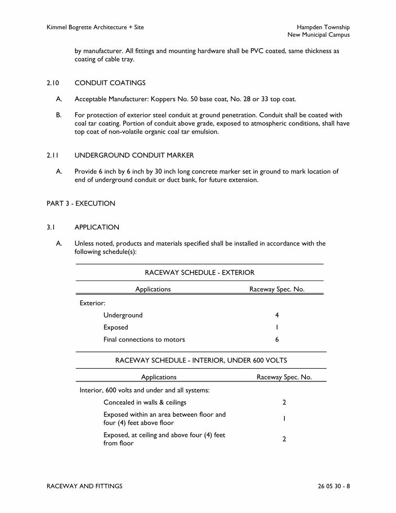
Kimmel Bogrette Architecture + Site Hampden Township
New Municipal Campus
RACEWAY AND FITTINGS 26 05 30 - 8
by manufacturer. All fittings and mounting hardware shall be PVC coated, same thickness as
coating of cable tray.
2.10 CONDUIT COATINGS
A. Acceptable Manufacturer: Koppers No. 50 base coat, No. 28 or 33 top coat.
B. For protection of exterior steel conduit at ground penetration. Conduit shall be coated with
coal tar coating. Portion of conduit above grade, exposed to atmospheric conditions, shall have
top coat of non-volatile organic coal tar emulsion.
2.11 UNDERGROUND CONDUIT MARKER
A. Provide 6 inch by 6 inch by 30 inch long concrete marker set in ground to mark location of
end of underground conduit or duct bank, for future extension.
PART 3 - EXECUTION
3.1 APPLICATION
A. Unless noted, products and materials specified shall be installed in accordance with the
following schedule(s):
RACEWAY SCHEDULE - EXTERIOR
Applications Raceway Spec. No.
Exterior:
Underground 4
Exposed 1
Final connections to motors 6
RACEWAY SCHEDULE - INTERIOR, UNDER 600 VOLTS
Applications Raceway Spec. No.
Interior, 600 volts and under and all systems:
Concealed in walls & ceilings 2
Exposed within an area between floor and
four (4) feet above floor 1
Exposed, at ceiling and above four (4) feet
from floor 2

Kimmel Bogrette Architecture + Site Hampden Township
New Municipal Campus
RACEWAY AND FITTINGS 26 05 30 - 9
RACEWAY SCHEDULE - INTERIOR, UNDER 600 VOLTS
Applications Raceway Spec. No.
Areas subject to mechanical damage, unless
noted 1
Final connections to motors, pipe mounted
equipment and equipment exposed to
vibration
6
Final connection to recessed lighting fixtures 5
RACEWAY SCHEDULE - IN OR UNDER CONCRETE SLABS
Applications Raceway Spec. No.
Underground beneath concrete slabs 1 or 4
In concrete slabs on grade 2 or 4
In concrete slabs above grade 2
RACEWAY SCHEDULE - WIREWAYS, CABLE TRAY, DUCTS
Applications Raceway Spec. No.
Wireways, except in wet, damp and oily
atmospheres 10
Wireways in wet, damp, and oily
atmospheres 9
Cable tray 13
3.2 INSTALLATION
A. General
1. Install products in accordance with manufacturer’s instructions.
2. Raceway connectors, connections and couplings shall be pulled up tight to provide an
electrical bond throughout entire raceway system
3. Raceways shall be installed in such a manner that wires may be removed and replaced at
a later date.
4. Raceways shall be run as direct as possible to minimize number of bends and offsets.
Exposed raceways shall be installed with runs parallel or perpendicular to walls and
ceilings and with right angle turns utilizing proper connectors, conduit bodies or
symmetrical bends. In areas where vertical raceways will be exposed, raceways shall be
run on building walls or columns where possible.
Kimmel Bogrette Architecture + Site Hampden Township
New Municipal Campus
RACEWAY AND FITTINGS 26 05 30 - 10
5. Running threads will not be permitted on raceways requiring threads. Approved
threaded couplings or a conduit coupling shall be used where such construction is
required.
6. Cylindrical metal raceways shall be bent only by use of an approved pipe bending
machine so that raceway will always retain its cylindrical shape.
7. Furnish and install No. 12 non-ferrous or 200 lb. test nylon pull string in each spare or
empty conduit. Conduit shall be identified at each end indicating destination and future
use.
8. Caps shall be installed on all open conduit ends to protect against entrance of dirt and
moisture.
B. Interior Raceways
1. Raceways shall be supported to building structure by use of beam clamps, one hole pipe
straps where applicable, or other approved fasteners. Use of tie wire to support
raceways will not be permitted.
2. Raceway runs shall be separated by a minimum of 6 inches from hot water pipes, steam
pipes and flues inside the building. If a separation of 6 inches or greater cannot be
maintained, an approved pipe covering shall be used over raceway runs for the length of
such exposures.
3. Expansion joints, as specified for particular raceway system, shall be used on all runs that
cross building expansion joints. Raceways shall cross building expansion joints at right
angles. Free ends of conduits shall be installed in accordance with manufacturer’s
instructions.
C. Concrete Slab Raceways
1. Cylindrical metal or PVC schedule 40 raceways, as scheduled, may be laid below or
poured in a concrete slab on grade, depending on the fill below slab, as specified for
underground installation. Cylindrical metal raceways, as scheduled, shall be poured in a
concrete slab above grade. Maximum diameter of raceways to be placed in slab shall be
limited to 1/3 thickness of the slab. Exact placement of cylindrical raceways below or
within concrete slab shall be verified with the prime professional.
2. Where cylindrical raceways are installed in concrete slabs, or under floor slabs, the
minimum permissible size shall be 3/4 inch diameter.
3. Conduits for recessed floor boxes located in slabs on grade and slabs below grade shall
be installed totally within the concrete slab with concrete totally encasing the conduits,
including the point where conduits enter the recessed floor boxes, to ensure a
watertight system and that water does not enter the conduit system. Coordinate with
General Contractor.
4. All slab conduits for floor boxes shall be dry prior to installing cables.
5. Refer to Section 26 05 40, Boxes, for additional information on recessed floor boxes
and conduit connections to recessed floor boxes.
D. Underground Raceways

Kimmel Bogrette Architecture + Site Hampden Township
New Municipal Campus
RACEWAY AND FITTINGS 26 05 30 - 11
1. Raceway shall not be used in or under cinderfill where subject to permanent moisture
unless protected on all sides by a layer of non-cinder concrete at least 2 inches thick or
unless the raceway is at least 18 inches under the fill.
2. Underground raceways or duct banks shall have a marker and warning tape installed
above raceway, 12 inches below finished grade. Use Tape Specification No. 2; refer to
Section 26 05 20, Wire and Cable, 600 Volts and Below. Duct banks with widths over
12 inches shall have 6 inch wide tape runs installed side-by-side on 12 inch (maximum)
centers. Warning tape shall be continuous for entire underground conduit run.
Manufactures splices shall be used to connect tape for long runs.
3. Exterior steel conduit shall be coated with a bitumastic protective covering 6 inches
above and below point where conduit enters ground. Bitumastic coating shall be top
coated with a bituplastic coating above ground after bitumastic coating has been aged
from 2 to 4 weeks. Refer to coating manufacturer’s installation instructions.
4. Where conduits penetrate building walls, manhole walls, etc., underground penetration
shall be made watertight and conduits shall be sealed with duct seal.
E. Raceways Installed in Duct Banks
1. Slope duct bank away from building entrances.
2. Elbows shall be 36 inch radius, minimum.
3. Furnish and install suitable separators. Fasten conduits to separators.
4. Securely anchor conduits to prevent movement during concrete placement.
5. Unless noted, conduits shall be encased in a 3 inch concrete envelope with minimum 2
inch separation between conduits.
6. Where indicated, concrete for duct banks shall be reinforced. Concrete duct banks
under vehicle roadways shall be reinforced to either 10 feet beyond roadway surface or
5 feet beyond roadway right-of-way, whichever is greater.
7. All conduits shall be capped to protect against entrance of dirt and moisture. Before use
and before installation of pull string in spare conduits, conduits shall be “swabbed”.
8. Furnish and install a pull string in all empty and spare conduits.
9. Furnish and install underground warning tape above all duct banks as specified herein for
Raceway Installation, Underground.
F. Raceway Specification No. 1
1. Rigid metal conduit shall be installed as follows:
a. Each end of every conduit run terminating in a steel enclosure of any type shall be
provided with galvanized locknut with metal insulated throat bushing inside and
galvanized locknut outside.
b. Bushing shall have ground lug where required.
c. Fittings specified under Raceway Specification No. 1 shall be used when installing
rigid metal conduit.
d. Conduit bodies shall be used on exposed conduit runs, except at locations where
impractical. At these impractical locations, factory ells shall be used. Factory ells
will not be permitted on exterior of building.

Kimmel Bogrette Architecture + Site Hampden Township
New Municipal Campus
RACEWAY AND FITTINGS 26 05 30 - 12
e. All electrical raceway systems located on the exterior shall be installed to
maintain a NEMA 4 rating using Myers hubs.
f. Where rigid metal conduit passes from one temperature zone to another, a
conduit seal shall be installed on warmer side of wall.
g. Conduit seals shall be installed in conduit runs as required by National Electrical
Code for hazardous areas.
G. Raceway Specification No. 2
1. Electrical metallic tubing shall be installed as follows:
a. Each end of every electrical metallic tubing run termination in a pressed steel box
of any type shall be provided with an insulated throat EMT connector and locknut
on the inside. Bushing with ground lug specified under Raceway Specification No.
1 shall be installed where required.
b. Appropriate threadless couplings and connectors shall be used with electrical
metallic tubing and made up tight so when buried in masonry or concrete,
raceway will remain dry at all times.
c. Fittings specified under Raceway Specification No. 1 shall be used when installing
electrical metallic tubing.
d. Set screw connectors are acceptable for all feeders 2 inches in diameter and
larger containing an equipment grounding conductor sized in accordance with the
latest edition of the National Electric Code.
H. Raceway Specification No. 4
1. PVC conduit shall be installed as follows:
a. Joints in PVC conduit runs shall be in accordance with manufacturer’s
recommendations.
b. Expansion joints shall be installed where expansion and contraction of PVC
conduit occurs due to changing temperature conditions.
c. PVC conduit shall not be used where subject to ambient temperature exceeding
those which conduit has been approved.
d. Fittings specified under Raceway Specifications No. 4 shall be used when installing
PVC conduit.
I. Raceway Specification No. 5
1. Flexible metal conduit shall be installed as follows:
a. Maximum length of flexible metal conduit permitted for final connection to
motors and equipment shall be 2 feet. Flexible metal conduit for final connection
to belt drives shall have sufficient slack to permit motor adjustment.
b. Maximum length of flexible metal conduit permitted for final connection to
recessed lighting fixtures shall be 6 feet and minimum size of 3/8 inch diameter.
c. Fittings specified under Raceway Specification No. 5 shall be used when installing
flexible metal conduit.
J. Raceway Specification No. 6
1. Liquidtight flexible metal conduit shall be installed as follows:
a. Maximum length of liquidtight flexible metal conduit permitted for final
connection to motors and equipment shall be 2 feet. Liquidtight flexible metal

Kimmel Bogrette Architecture + Site Hampden Township
New Municipal Campus
RACEWAY AND FITTINGS 26 05 30 - 13
conduit for final connection to belt drives shall have sufficient slack to permit
motor adjustments.
b. Fittings specified under Raceway Specification No. 6 shall be used when installing
liquidtight flexible metal conduit.
K. Raceway Specification No. 9
1. Wireways, oil tight, lay-in, shall be installed as follows:
a. Wireways shall be adequate size.
b. Wireways shall only be installed for exposed work.
c. Wireways shall be marked with manufacturer’s name (or trademark) which shall
be visible after installation.
L. Raceway Specification No. 10
1. Wireways NEMA 1, lay-in, shall be installed as follows:
a. Wireways shall be adequate size.
b. Wireways shall only be installed for exposed work.
c. Wireways shall be marked with manufacturer’s name (or trademark) which shall
be visible after installation.
M. Raceway Specification No. 13
a. Cable trays shall be installed as follows:
b. Cable tray shall be installed in accordance with NEMA VE2 and the
manufacturer’s recommendations.
c. Cable trays shall be installed above ceilings where indicated on Drawings.
d. Cable trays shall be supported at midpoint of horizontal bends.
e. Horizontal runs shall be supported at spacings recommended by manufacturer
and as determined by the load/span class with concentrated load. Trapeze type
hangers of 1-5/8 inch by 1-5/8 inch strut with 1/2 inch diameter threaded rods
shall be used on spacing as approved by the manufacturer.
f. Expansion joints shall be installed in cable trays at building expansion joints and in
accordance with manufacturer’s recommendations.
g. Cable trays shall be mechanically connected at all joints, fittings, and connections
to provide a continuous ground path and grounded in accordance with the
National Electrical Code. Where ground path is interrupted due to routing or
elevation changes, a copper grounding strap shall be installed.
h. An equipment grounding conductor, size as indicated, shall be installed in all
power cable tray runs.
i. All power cables shall be secured to tray by metal cable clamps, as directed by
manufacturer. All other cables may be secured using nylon cable straps.
j. Sufficient space shall be provided around cable trays to permit adequate access
for installing and maintaining cables. In stacked runs, distance from top of one tray
to bottom of another tray shall not be less than 12 inches.
k. Lay all wire and cables straight and parallel in tray.
l. Gather all wires and cables of the same system in the trays together in bundles, if
a combination of two or more multiple-conductor cables and/or single
conductors are in the run. Determine the grouping and number of wires in each
bundle in the field, mainly with consideration to physical locations of the routing
and destination of the wires. Use nylon cable ties for bundling with a spacing

Kimmel Bogrette Architecture + Site Hampden Township
New Municipal Campus
RACEWAY AND FITTINGS 26 05 30 - 14
between tie points of approximately 8 feet. Do all bundling and clamping before
the end terminations are connected.
m. Install cable trays to leave no exposed raw edges.
n. Furnish and install on each side of cable tray, at minimum of 20 feet centers, a
caution sign stating, “DO NOT USE AS WALKWAY”.
N. Underground Conduit Marker
1. Bury vertically in ground at end of underground conduit or duct bank with 6 inch by 6
inch end of marker flush with grade.
END OF SECTION 26 05 30

Kimmel Bogrette Architecture + Site Hampden Township
New Municipal Campus
BOXES 26 05 40 - 1
SECTION 26 05 40 – BOXES
PART 1 - GENERAL
1.1 WORK INCLUDED
A. The Work of this Section shall consist of the labor, material and equipment required for
furnishing and installing boxes. The specific application of these materials shall be as outlined in
this Section and subsequent Sections of this Specification, or as indicated on the Drawings.
1.2 SUBMITTALS
A. Submit for approval in accordance with specified submittal procedures:
1. Boxes
1.3 SCRUB – WATER PROTECTION
A. All floor boxes, poke-through devices, etc., shall provide for scrub-water protection.
B. The scrub-water protection shall utilize a comprehensive gasketing system to prevent the
ingress of scrub-water from mops and carpet shampooing equipment from entering floor
boxes, poke-through devices, etc. Entrance of dust, dirt and debris shall also be prevented.
PART 2 - PRODUCTS
2.1 BOX SPECIFICATION NO. 1
A. Acceptable Manufacturer: Steel City, or Appleton, Raco.
B. Type: Recessed outlet boxes.
C. Constructed of galvanized, 14 gage pressed steel, square corners, depth as required.
D. Plaster rings for plaster areas.
E. Masonry boxes in masonry areas.
F. Rectangular type covers in special finished area, such as block, paneling or tile.
G. Ganged, where indicated or required.
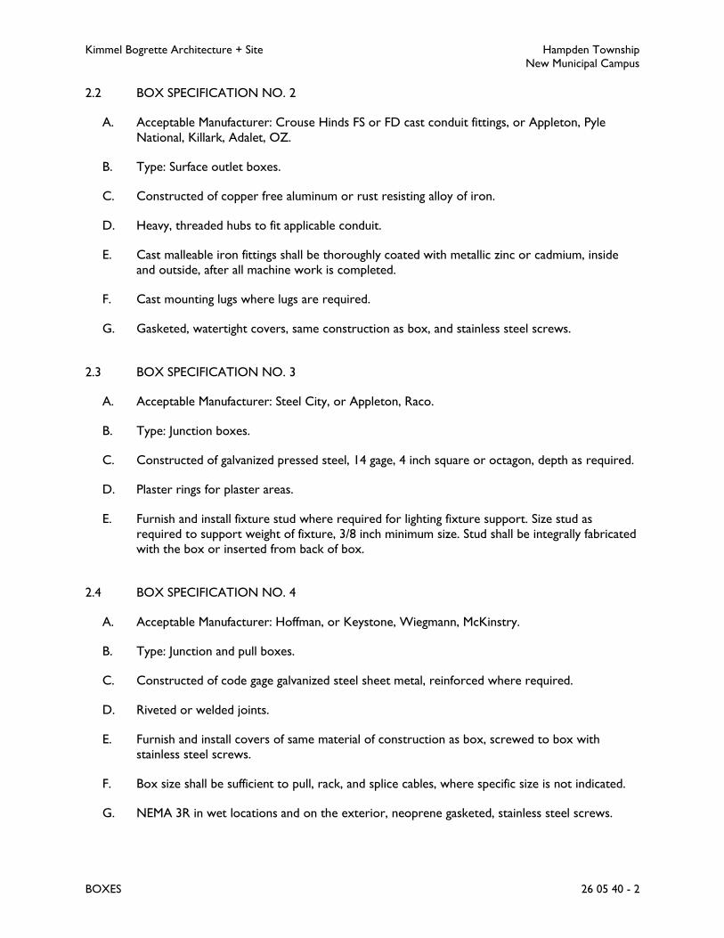
Kimmel Bogrette Architecture + Site Hampden Township
New Municipal Campus
BOXES 26 05 40 - 2
2.2 BOX SPECIFICATION NO. 2
A. Acceptable Manufacturer: Crouse Hinds FS or FD cast conduit fittings, or Appleton, Pyle
National, Killark, Adalet, OZ.
B. Type: Surface outlet boxes.
C. Constructed of copper free aluminum or rust resisting alloy of iron.
D. Heavy, threaded hubs to fit applicable conduit.
E. Cast malleable iron fittings shall be thoroughly coated with metallic zinc or cadmium, inside
and outside, after all machine work is completed.
F. Cast mounting lugs where lugs are required.
G. Gasketed, watertight covers, same construction as box, and stainless steel screws.
2.3 BOX SPECIFICATION NO. 3
A. Acceptable Manufacturer: Steel City, or Appleton, Raco.
B. Type: Junction boxes.
C. Constructed of galvanized pressed steel, 14 gage, 4 inch square or octagon, depth as required.
D. Plaster rings for plaster areas.
E. Furnish and install fixture stud where required for lighting fixture support. Size stud as
required to support weight of fixture, 3/8 inch minimum size. Stud shall be integrally fabricated
with the box or inserted from back of box.
2.4 BOX SPECIFICATION NO. 4
A. Acceptable Manufacturer: Hoffman, or Keystone, Wiegmann, McKinstry.
B. Type: Junction and pull boxes.
C. Constructed of code gage galvanized steel sheet metal, reinforced where required.
D. Riveted or welded joints.
E. Furnish and install covers of same material of construction as box, screwed to box with
stainless steel screws.
F. Box size shall be sufficient to pull, rack, and splice cables, where specific size is not indicated.
G. NEMA 3R in wet locations and on the exterior, neoprene gasketed, stainless steel screws.

Kimmel Bogrette Architecture + Site Hampden Township
New Municipal Campus
BOXES 26 05 40 - 3
2.5 BOX SPECIFICATION NO. 35
A. Acceptable Manufacturer: Quazite Composolite PC1118DA18 box with solid base; Quazite
Composolite PC1118SA00 steel locking cover; Quazite Composolite PC1118HA00 locking
cover, or as approved.
B. Type: Polymer concrete exterior service box, suitable for vehicular traffic.
C. Constructed of polymer concrete and reinforced by a heavy-weave fiberglass.
D. Stackable for extra depth.
E. Stainless steel inserts and bolts.
F. Enclosures and covers shall be rated for no less than 15,000 pounds over a 10 inch by 10 inch
area.
G. Nominal dimensions of 20 inches long by 13 inches wide by 18 inches deep.
2.6 BOX SPECIFICATION NO. 39
A. Acceptable Manufacturer: Hubbell System One Series Recessed Floor Boxes, or Wiremold, or
as approved.
B. Type: Recessed, multi-service floor box, fully adjustable.
C. Cast iron for applications on-grade and below grade, stamped steel for all other applications.
D. Separate power from low voltage wiring.
E. Boxes shall have special capacity to install types and quantities or service fittings indicated on
Drawings.
F. Boxes shall have depth required to allow plugs to be completely concealed below the floor,
connecting to recessed outlets.
G. Steel cover plates with brushed aluminum finish. Cover plates shall have slide feature(s) to
allow cables to pass through covers to recessed outlets in box.
PART 3 - EXECUTION
3.1 APPLICATION
A. Unless noted, products and materials specified in this Section shall be installed in accordance
with the following schedule(s):
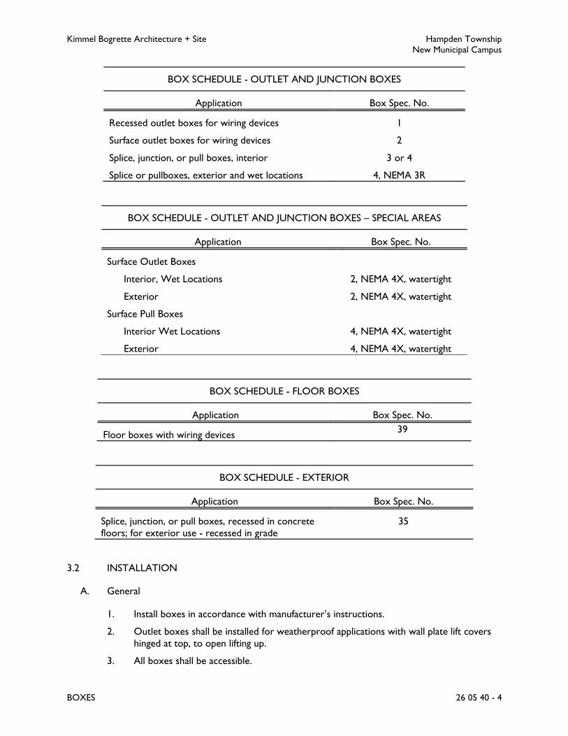
Kimmel Bogrette Architecture + Site Hampden Township
New Municipal Campus
BOXES 26 05 40 - 4
BOX SCHEDULE - OUTLET AND JUNCTION BOXES
Application Box Spec. No.
Recessed outlet boxes for wiring devices 1
Surface outlet boxes for wiring devices 2
Splice, junction, or pull boxes, interior 3 or 4
Splice or pullboxes, exterior and wet locations 4, NEMA 3R
BOX SCHEDULE - OUTLET AND JUNCTION BOXES – SPECIAL AREAS
Application Box Spec. No.
Surface Outlet Boxes
Interior, Wet Locations 2, NEMA 4X, watertight
Exterior 2, NEMA 4X, watertight
Surface Pull Boxes
Interior Wet Locations 4, NEMA 4X, watertight
Exterior 4, NEMA 4X, watertight
BOX SCHEDULE - FLOOR BOXES
Application Box Spec. No.
Floor boxes with wiring devices 39
BOX SCHEDULE - EXTERIOR
Application Box Spec. No.
Splice, junction, or pull boxes, recessed in concrete
floors; for exterior use - recessed in grade
35
3.2 INSTALLATION
A. General
1. Install boxes in accordance with manufacturer’s instructions.
2. Outlet boxes shall be installed for weatherproof applications with wall plate lift covers
hinged at top, to open lifting up.
3. All boxes shall be accessible.

Kimmel Bogrette Architecture + Site Hampden Township
New Municipal Campus
BOXES 26 05 40 - 5
4. Locations indicated are approximate. Coordinate in relation to spaces and equipment
surrounding each outlet. When necessary, relocate outlets to avoid interference with
mechanical equipment or structural features.
5. Locate all boxes for light switches on strike side of doors, unless otherwise indicated, or
if building construction prohibits installation at this location. Locations at other than the
strike side of the door, even if shown on the Drawings, shall be verified with the
Architect before roughing in.
6. Locate all light fixture outlets in a symmetrical pattern according to the room layout
unless otherwise indicated.
7. Mount all boxes plumb and level. Furnish and install flush proper type extension rings or
plaster covers as required. For flush mounted boxes, make holes in the surrounding
surface no larger than required to receive the box.
8. Open no more knockouts in sheet steel boxes than are actually required. Seal any used
openings in any type box.
9. Boxes shall not be fastened to hung ceiling support wires.
10. Support all boxes independently of conduit.
11. Install boxes to maintain fire rating, where applicable.
12. Boxes shall not be installed exposed in finished areas without approval of Architect.
B. Outlet Boxes
1. Outlet boxes of proper size and type shall be furnished at all outlets. Boxes shall be
secured firmly in place and set true and square with building lines.
2. Openings for recessed outlet boxes shall be neatly cut, minimum size as needed for
installation of box. Box shall be set at a depth so wall plate, when installed, shall cover
wall opening and shall seat against the mounting surface on all sides.
3. Recessed outlet boxes shall be installed without damaging wall insulation and without
reducing its effectiveness.
4. Outlet boxes shall not be installed in walls back-to-back, provide a minimum of 6 inches
of separation except in fire walls where minimum separation shall be 24 inches.
C. Junction and Pull Boxes
1. Junction, pull, or splice boxes shall be adequate size, suitable to construction features
and independently supported.
2. Install boxes to maintain adequate head room.
D. Floor Boxes
1. Floor boxes with devices or outlets as specified shall be installed where indicated on
Drawings.
2. Floor boxes recessed in slabs on grade and slabs below grade shall be cast type boxes
and shall have concrete installed on all sides of the floor box with a minimum of 2 inches
of concrete on the bottom of the box. Coordinate with General Contractor.

Kimmel Bogrette Architecture + Site Hampden Township
New Municipal Campus
BOXES 26 05 40 - 6
3. No cables shall be installed to these floor boxes until the building has been sealed from
the elements.
4. Cast boxes shall be installed per manufacturer’s instructions to ensure a water tight box
installation.
5. Water accumulation within these boxes shall be dried out prior to installing cables.
6. Conduit connections to these boxes shall be of the type and installed as directed by the
manufacturer to ensure watertight connection.
7. If when dried out, water continues to enter these boxes, installing contractors, both
General and Electrical, shall take whatever means necessary to correct the water
intrusion situation.
E. Exterior Flush with Grade Boxes
1. Box and cover shall be suitable for heavy vehicular traffic. Pull box to be flush mounted
with grade and be set in 6 inch minimum concrete, sides and bottom. All penetrations in
pull box shall be made watertight.
3.3 DIMENSIONS
A. Unless otherwise noted, dimensions are to the center of finished outlet with all wiring devices
in place. Where indicated as clear, dimensions shall be to top or bottom of wiring device,
plate, or trim.
B. Dimensions specified herein shall be verified by Architect before roughing-in outlets.
3.4 LOCATIONS
A. Locations of outlets and equipment shall be verified by Architect before roughing-in outlets or
conduit. Final location may differ from that indicated on Drawings.
END OF SECTION 26 05 40
Kimmel Bogrette Architecture + Site Hampden Township
New Municipal Campus
WIRING DEVICES 26 05 50 - 1
SECTION 26 05 50 – WIRING DEVICES
PART 1 - GENERAL
1.1 WORK INCLUDED
A. The Work of this Section shall consist of the labor, material and equipment required for
furnishing and installing wiring devices. The specific application of these materials shall be as
outlined in this Section and subsequent Sections of this Specification, or as indicated on the
Drawings.
1.2 SUBMITTALS
A. Submit for approval in accordance with specified submittal procedures:
1. Switches
2. Receptacles
3. Wall Plates
PART 2 - PRODUCTS
2.1 GENERAL WIRING DEVICE REQUIREMENTS
A. Acceptable Manufacturers: Hubbell, Pass and Seymour, Eaton, Leviton.
B. All wiring devices shall be heavy-duty, specification grade, unless noted otherwise.
C. All wiring devices shall be back and side wired, unless noted otherwise.
D. All wiring devices shall be “weather-resistant” type where installed in wet or damp locations.
E. UL Listed and labeled as defined in the National Electrical Code, by a qualified testing agency,
and marked for intended location and application.
F. Source Limitations: Obtain each type of wiring device and associated wall plate from single
source from single manufacturer.
2.2 COLOR
A. Unless otherwise noted, color of all wiring devices shall be as selected by Architect.
B. Wiring devices connected to the emergency power system shall be red.
C. Receptacles and wall plates mounted in finished ceilings shall be white.

Kimmel Bogrette Architecture + Site Hampden Township
New Municipal Campus
WIRING DEVICES 26 05 50 - 2
2.3 STRAIGHT-BLADE RECEPTACLES
A. Standard Receptacle
1. 125 volts, 20 amp, 2 pole, 3 wire, grounding.
2. Simplex or duplex as indicated.
3. NEMA Configuration 5-20R.
4. Description: Single-piece, rivetless, nickel-plated, all-brass grounding system. Nickel-
plated, brass mounting strap. Nylon finder groove. Automatic grounding feature.
B. Tamper Resistant Receptacle
1. 125 volts, 20 amp, 2 pole, 3 wire, grounding.
2. Tamper resistant.
3. Duplex.
4. NEMA Configuration 5-20R.
5. Description: Single-piece, rivetless, nickel-plated, all-brass grounding system. Nickel-
plated, brass mounting strap. Automatic grounding feature.
2.4 GFCI RECEPTACLES
A. General Requirements:
1. All GFCI receptacles shall be UL 943 compliant.
a. Self-Test Function: Periodic, automatic testing of ground fault module. If test fails,
receptacle shall deny power or provide visual and/or audible notification.
b. Line-Load Reversal Function: If line power is connected to load terminals, power
to receptacle face shall be denied.
2. Trip Threshold: 5 mA plus or minus 1 mA, Class A.
3. Trip Time: 0.025 seconds.
4. Test and reset buttons. Indicator light to indicate tripped condition.
5. Automatic grounding feature.
B. Standard GFCI Receptacle
1. 125 volts, 20 amp, 2 pole, 3 wire, grounding.
2. Duplex.
3. NEMA Configuration 5-20R.
2.5 USB CHARGER DEVICES
A. Combination USB Charger Receptacle
1. 125 volts, 20 amp, 2 pole, 3 wire, grounding.
2. Duplex.
3. NEMA Configuration 5-20R.
4. USB Outlets: Dual, Type A.
5. Description: Single-piece, rivetless, nickel-plated, all-brass grounding system. Nickel-
plated, brass mounting strap.
2.6 SWITCHES
A. General Requirements

Kimmel Bogrette Architecture + Site Hampden Township
New Municipal Campus
WIRING DEVICES 26 05 50 - 3
1. Acceptable Manufacturers: Hubbell, Pass and Seymour, Eaton, Leviton. Manufacturers
listed below are basis of design only.
2. All switches shall be rated 120/277 volt, 20 amp, unless noted otherwise.
3. Comply with NEMA WD 1, UL 20, and FS W-S-896.
4. Back and side wired, silver cadmium oxide contacts, stainless steel automatic grounding
clip.
B. Standard Toggle Switch
1. Manufacturer: Hubbell HBL1221 Series.
2. Type: Single or double pole, three-way or four-way as indicated on drawings.
3. Nylon toggle.
2.7 WALL PLATES
A. General Requirements
1. Acceptable Manufacturers: Hubbell, Pass and Seymour, Eaton, Leviton. Manufacturers
listed below are basis of design only.
2. Wall plate configurations and cutouts shall match corresponding wiring devices. Provide
gang plates where devices are ganged.
3. Plate securing screws shall be metal with head color to match plate finish.
B. Wall Plate Specification No. W2
1. Manufacturer: Hubbell ‘SS’ Series.
2. Stainless steel type 302/304, .04 inch thickness, satin finish, smooth (no lines).
3. 18 percent chromium and 8 percent nickel, non-magnetic.
4. Contoured edges.
5. Wall plates indicated to be engraved, shall be engraved by manufacturer.
C. Wall Plate Specification No. W8
1. Manufacturer: Hubbell WP826 Series.
2. NEMA 3R rating while in use, hinged cover/enclosure clearly marked “Suitable for Wet
Locations While in Use”.
3. Grey finish.
4. There shall be a gasket between the enclosure and mounting surface and between the
hinged cover and mounting plate/base to ensure proper seal.
5. Stainless steel mounting screws.
6. Flame retardant, UV stabilized polycarbonate, impact resistant.

Kimmel Bogrette Architecture + Site Hampden Township
New Municipal Campus
WIRING DEVICES 26 05 50 - 4
PART 3 - EXECUTION
3.1 APPLICATION
A. Unless noted, products and material specified in this Section shall be installed in accordance
with the following schedule(s):
WALL PLATE SCHEDULE
Application Wall Plate Spec. No.
Interior W2
Weatherproof (While in Use) W8
3.2 INSTALLATION
A. General
1. Install all wiring devices in accordance with manufacturer’s instructions, plumb and level.
2. All wall openings shall be neatly cut and covered by wall plates. Do not use oversized or
extra-deep plates. Repair wall finishes and remount outlet boxes when standard device
plates do not fit flush or do not cover rough wall opening.
3. Furnish and install wall plates on all wiring devices and all blank boxes.
4. Furnish and install zinc or cadmium coated steel plates on all surface “FS” boxes.
5. Tighten unused terminal screws on the device.
6. When mounting into metal boxes, remove the fiber or plastic washers used to hold
device-mounting screws in yokes, allowing metal-to-metal contact.
7. Clean dirt, dust and debris from all outlet boxes, final cleaning shall be by vacuuming.
8. Replace devices that have been in temporary use during construction and that were
installed before building finishing operations were complete.
9. Verify that all wiring devices are energized and test for proper polarity and proper
operation.
B. Ground Fault Circuit Interrupter Receptacles
1. Ground fault interrupter receptacles shall not be wired for downstream protection.
2. Ground fault receptacles shall be installed in all locations where required by the
National Electrical Code.
3. As a minimum, ground fault receptacles shall be installed in the following locations:
a. All toilet rooms.
b. Within 6 feet of any type sink.
c. Within twenty-five feet of all HVAC equipment as required by the National
Electrical Code.
d. Outdoor locations.
e. All locations in kitchens located in “other than dwelling units” as defined by the
National Electrical Code, not limited to countertop receptacles.
f. For all vending machines.
C. Switches
1. Install switches with “off” position down.
Kimmel Bogrette Architecture + Site Hampden Township
New Municipal Campus
WIRING DEVICES 26 05 50 - 5
2. Switches shall not be connected to neutral conductor.
3. Switches shall be ganged where grouped at specific locations, as indicated on Drawings.
4. Switch outlets shall be located on strike side of door, unless otherwise indicated, or if
building construction prohibits installation at this location. Locations at other than the
strike side of the door, even if shown on the Drawings, shall be verified with the
Architectbefore roughing in.
5. Operate each wall switch with circuit energized and verify proper operation.
D. Coordination with Other Trades
1. Protect installed devices and their boxes. Do not place wall finish materials over device
boxes and do not cut holes for boxes with routers that are guided by riding against
outside of boxes.
2. Keep outlet boxes free of plaster, drywall joint compound, mortar, cement, concrete,
dust, paint, and other material that may contaminate the raceway system, conductors,
and cables.
3. Install device boxes in brick or block walls so that the cover plate does not cross a joint
unless the joint is troweled flush with the face of the wall.
4. Install wiring devices after all wall preparation, including painting, is complete.
E. Conductors
1. Do not strip insulation from conductors until right before they are spliced or
terminated on devices.
2. Strip insulation evenly around the conductor using tools designed for the purpose.
Avoid scoring or nicking of solid wire or cutting strands from stranded wire.
1) The length of free conductors at outlets for devices shall meet provisions
of the National Electrical Code, Article 300, without pigtails.
F. Receptacle Orientation
1. Install ground pin of vertically mounted receptacles up, and on horizontally mounted
receptacles to the right.
3.3 MOUNTING HEIGHTS
A. Mounting height of outlets or receptacles serving special equipment or installed above a
counter shall be determined in field.
B. Mounting heights and locations of all receptacles serving kitchen equipment shall be
coordinated in field with kitchen equipment installer before rough-in.
C. If the designated location of a switch or receptacle places it partially between two finishes, the
actual location shall be adjusted to set the plate entirely on one finished surface only, but
actual height shall not exceed mounting heights indicated herein or required by codes.
D. Outlet boxes for flush mounted wiring devices installed in concrete masonry unit (block) or
brick walls shall be installed so bottom of outlet box coincides with bottom of block or brick
that is below specified mounting height, and actual height shall not exceed mounting heights
indicated herein or required by code.
Kimmel Bogrette Architecture + Site Hampden Township
New Municipal Campus
WIRING DEVICES 26 05 50 - 6
E. Mounting heights, measured to centerline, shall be as follows unless otherwise indicated,:
1. Switches: 42 inches above finished floor
2. Receptacles: 18 inches above finished floor
3. Receptacles, Above Countertop: 6 inches above backsplash.
4. Weatherproof Receptacles on Exterior Lighting Poles: 24 inches above finished grade
5. Weatherproof Receptacles on Exterior of Building: 24 inches above finished grade
6. Weatherproof Receptacles on Roof: 24 inches above roof
END OF SECTION 26 05 50

Kimmel Bogrette Architecture + Site Hampden Township
New Municipal Campus
GROUNDING SYSTEMS 26 05 60 - 1
SECTION 26 05 60 – GROUNDING SYSTEMS
PART 1 - GENERAL
1.1 WORK INCLUDED
A. The Work of this Section shall consist of the labor, material and equipment required for the
installation of grounding systems and devices. The specific application of these materials shall
be as outlined in this Section and subsequent Sections of this Specification, or as indicated on
the Drawings.
1.2 SUBMITTALS
A. Submit for approval in accordance with specified submittal procedures:
1. Ground Rods
2. Ground Connectors
3. Grounding Bus Bars
PART 2 - PRODUCTS
2.1 GROUND RODS
A. Acceptable Manufacturer: Copperweld, or Penn-Union, Weaver.
B. Type: High strength steel core.
C. Construction: Copper exterior welded to the steel core.
D. Chamfered top to prevent mushrooming. Pointed end.
E. Minimum Diameter
1. 10 foot rod: 3/4 inch diameter.
2. Above 10 feet: 1 inch diameter.
F. For lengths over 10 feet, sectional rods with steel driving bolt may be furnished.
Kimmel Bogrette Architecture + Site Hampden Township
New Municipal Campus
GROUNDING SYSTEMS 26 05 60 - 2
2.2 GROUND CONNECTORS
A. Ground Connectors Specification No. 1
1. Acceptable Manufacturer: OZ Types ABG, CG, DG, EG, FG, or HG, or Thomas &
Betts.
2. Type: Wire to pipe connector. U-bolt, clamp type.
3. Copper alloy.
B. Ground Connector Specification No. 2
1. Acceptable Manufacturer: Thomas & Betts, or Burndy.
2. Type: Ground grid clamps. Compression connection to cable or rod.
3. High conductivity cast copper fittings.
4. Cable, rod, plate or combination connector, as required.
5. Suitable for direct burial or imbedded in concrete.
C. Ground Connector Specification No. 3
1. Acceptable Manufacturer: Erico Cadweld, or Burndy Thermite.
2. Type: Cadweld, exothermic welding process. Suitable for joining copper conductors.
3. Cable, rod, or surface connection, as required.
D. Ground Connector Specification No. 4
1. Acceptable Manufacturer: Copperweld Type AB, or Burndy, Penn Union, Dossert,
Anderson.
2. Type: Cable to rod. Bolted pressure type.
3. Copper.
4. Nonferrous hex socket or hex head bolt.
2.3 SERVICE ENTRANCE GROUNDING BUSBAR
A. Acceptable Manufacturer: Erico Eritech “EGBA” Series, Chatsworth or Newtown Instrument
Co.
B. Minimum 1/4 inch thick by 4 inches wide by 24 inches long copper bus bar.
C. Hole pattern with alternate columns of 5/16 inch diameter holes and 7/16 inch diameter holes
– 3 holes per column.
D. Furnish with polyamide, glass fiber reinforced, stand-off insulators and stainless steel mounting
brackets and stainless steel fasteners.
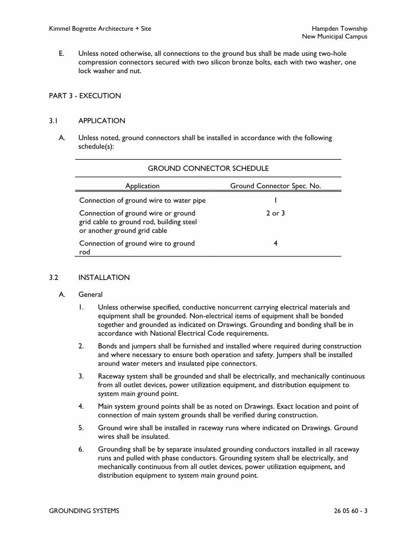
Kimmel Bogrette Architecture + Site Hampden Township
New Municipal Campus
GROUNDING SYSTEMS 26 05 60 - 3
E. Unless noted otherwise, all connections to the ground bus shall be made using two-hole
compression connectors secured with two silicon bronze bolts, each with two washer, one
lock washer and nut.
PART 3 - EXECUTION
3.1 APPLICATION
A. Unless noted, ground connectors shall be installed in accordance with the following
schedule(s):
GROUND CONNECTOR SCHEDULE
Application Ground Connector Spec. No.
Connection of ground wire to water pipe 1
Connection of ground wire or ground
grid cable to ground rod, building steel
or another ground grid cable
2 or 3
Connection of ground wire to ground
rod
4
3.2 INSTALLATION
A. General
1. Unless otherwise specified, conductive noncurrent carrying electrical materials and
equipment shall be grounded. Non-electrical items of equipment shall be bonded
together and grounded as indicated on Drawings. Grounding and bonding shall be in
accordance with National Electrical Code requirements.
2. Bonds and jumpers shall be furnished and installed where required during construction
and where necessary to ensure both operation and safety. Jumpers shall be installed
around water meters and insulated pipe connectors.
3. Raceway system shall be grounded and shall be electrically, and mechanically continuous
from all outlet devices, power utilization equipment, and distribution equipment to
system main ground point.
4. Main system ground points shall be as noted on Drawings. Exact location and point of
connection of main system grounds shall be verified during construction.
5. Ground wire shall be installed in raceway runs where indicated on Drawings. Ground
wires shall be insulated.
6. Grounding shall be by separate insulated grounding conductors installed in all raceway
runs and pulled with phase conductors. Grounding system shall be electrically, and
mechanically continuous from all outlet devices, power utilization equipment, and
distribution equipment to system main ground point.

Kimmel Bogrette Architecture + Site Hampden Township
New Municipal Campus
GROUNDING SYSTEMS 26 05 60 - 4
7. Neutral conductors shall be continuous throughout system and shall be grounded only
at the service neutral.
8. Electrical service shall be grounded in accordance with the National Electrical Code.
9. Separately derived systems shall be grounded in accordance with the National Electrical
Code.
10. Any connections made below grade shall be exothermically welded.
B. Ground Rods
1. Ground rods shall be installed where indicated on Drawings, where specified, or as
required by National Electrical Code.
2. Ground rods shall be driven to a depth so that top of rod is 2 feet below grade.
C. Building Structural Steel Ground
1. Building steel columns shall be connected to ground rods driven alongside column as
indicated on Drawings. Provide #4/0 wire to connect to ground rod.
2. Building steel columns shall be connected to a #4/0 ground loop that shall completely
encircle building. Ground loop shall be 30 inches (minimum) below finished grade and
shall be approximately 24 inches to the outside of exterior column footers. Provide
#4/0 wire to connect columns to ground loop where indicated on Drawings. Ground
rods shall be driven where indicated on Drawings.
D. Service Entrance Grounding Busbar
1. Mount busbar on wall adjacent to service entrance equipment.
2. Exothermically weld the bonding conductor between the service entrance equipment
and the ground bus at the ground bus only.
3. Make bolt-on connections at ground bus for the following grounding conductors.
a. Water service.
b. Ground grid.
c. Building steel.
d. Telecom ground bus(es).
4. Identify each connection to the ground bus with an engraved nameplate.
5. Furnish and install bare copper cable (minimum size #2/0) from ground bus to ground
grid.
3.3 TESTS
A. Ground resistance of main system grounding point shall be tested and shall not exceed values
required by National Electrical Code. Test shall be made using two auxiliary ground rod (three
point) method or other approved method. If resistance is found to be higher than that allowed
by National Electric Code, additional ground rods shall be driven until a resistance below
allowed value is obtained.

Kimmel Bogrette Architecture + Site Hampden Township
New Municipal Campus
GROUNDING SYSTEMS 26 05 60 - 5
B. Outside tests shall not be performed during unusually wet conditions. Tests shall be made
during dry weather conditions.
C. Complete test record in triplicate shall be submitted to Owner stating allowable National
Electrical Code Value, showing resistance values and calculations and shall indicate method of
test.
END OF SECTION 26 05 60
Kimmel Bogrette Architecture + Site Hampden Township
New Municipal Campus
POWER SYSTEM STUDIES 26 05 73 - 1
SECTION 26 05 73 – POWER SYSTEM STUDIES
PART 1 - GENERAL
1.1 WORK INCLUDED
A. The Work of this Section shall consist of the labor, material and equipment required for
performing studies as described below.
B. The scope of the studies shall include all distribution equipment furnished and installed under
this contract.
1.2 SUBMITTALS
A. Provide for review the following studies under one cover:
1. Short Circuit Equipment Evaluation Study; including all associated reports, supporting
documentation, and narrative analysis.
2. Overcurrent Protective Device Coordination Study; including all associated protective
device settings, supporting documentation, time-current curves, narrative analysis, and
recommendations.
3. Arc Flash Hazard Analysis; including all associated tabulated results, supporting
documentation, labels, and narrative analysis.
4. The overcurrent protective device coordination and short circuit analysis shall be
submitted prior to submission of switchgear, panelboards, motor control centers, etc.,
shop drawings. Submittals for switchgear, panelboards, motor control centers, etc., will
not be reviewed and approved until the overcurrent protective device coordination and
short circuit analysis has been submitted.
B. Furnish and install arc flash hazard labels for all equipment included in the arc flash hazard analysis
as specified in Section 26 05 05, Basic Materials. All hazard labels shall, at a minimum, indicate
the wording as specified in Section 26 05 05 and the following:
1. The system model “Bus” or “Protective Device” Component Name corresponding to
specific electrical equipment and/or component applicable to the label.
2. Nominal voltage level of the equipment.
3. Flash Hazard Boundary
4. Incident Energy (cal/cm^2)
5. Limited Approach Distance.
6. Restricted Approach Distance.
7. Prohibited Approach Distance.

Kimmel Bogrette Architecture + Site Hampden Township
New Municipal Campus
POWER SYSTEM STUDIES 26 05 73 - 2
C. After approval of final studies, contractor shall submit 2 hard copies and one electronic copy of
entire report, including (but not limited to) all applicable system input data, analysis reports, and
project model one-line.
D. Submit an electronic copy of the final system project file in the most recent version of SKM
Power Tools software, or converted to the most recent version of SKM Power Tools format
from the format associated with the software program used to perform the analysis.
1.3 QUALIFICATIONS
A. Short circuit, protective device coordination, and arc flash hazard analysis studies shall be
performed by the distribution equipment manufacturer or an independent firm currently
involved in medium and low voltage power system evaluation.
B. The study shall be performed, stamped, and signed by a registered professional engineer licensed
in the state in which the project is located.
C. A minimum of five (5) years’ experience in power system analysis is required for the individual
in charge of the project.
1.4 SOFTWARE
A. Perform all studies using SKM Systems Analysis software, or one of the following approved
equals:
1. Energy-Distribution System Analysis (EDSA), by EDSA Micro Corporation
2. Easy Power, by ESA Inc.
B. Comply with IEEE Standard 399: Recommended Practice for Industrial and Commercial Power
Systems Analysis.
1.5 DATA COLLECTION
A. Contractor shall collect all data as required by the power system studies. The Engineer
performing the short circuit, protective device coordination and arc flash hazard analysis studies
shall furnish the Contractor with a listing of required data immediately after award of the
contract. The Contractor shall expedite collection of the data to assure completion of the
studies as required for final approval of the distribution equipment shop drawings and/or prior
to the release of the equipment for manufacturing.
B. Contractor shall be responsible for collecting all source data from Power Company, including
available fault current and impedance.
C. Contractor shall be responsible for field surveys of all applicable existing electrical distribution
system components as required, including all device data, settings, feeder lengths, etc.
D. Studies shall include contribution of all motors larger than 10 HP.

Kimmel Bogrette Architecture + Site Hampden Township
New Municipal Campus
POWER SYSTEM STUDIES 26 05 73 - 3
E. The contractor shall gather and tabulate including, but not limited to, the following input data:
1. Product Data for overcurrent protective devices specified as part of this project and
involved in overcurrent protective device coordination studies. Use equipment
designation tags that are consistent with electrical distribution system diagrams,
overcurrent protective device submittals, input and output data, and recommended
device settings.
2. Electrical Distribution System Diagram: In hard-copy and electronic-copy formats,
showing the following:
a. Utility contribution.
b. Circuit-breaker and fuse-current ratings and types.
c. Relays and associated power and current transformer ratings and ratios.
d. Transformer kilovolt amperes, primary and secondary voltages, connection type,
impedance, and X/R ratios.
e. Generator kilovolt amperes, size, voltage, and source impedance.
f. Cables: Indicate conduit material, sizes of conductors, conductor material,
insulation, and length.
g. Busway material type, ampacity and impedance.
h. Motor horsepower (nameplate and duty point) and code letter designation
according to NEMA MG 1.
3. Data sheets to supplement electrical distribution system diagram, cross-referenced with
tag numbers on diagram, showing the following:
a. Utility contribution.
b. Special load considerations, including starting inrush currents and frequent starting
and stopping.
c. Transformer characteristics, including primary protective device, magnetic inrush
current, and overload capability.
d. Motor full-load current, locked rotor current, service factor, starting time, type of
start, and thermal-damage curve.
e. Generator thermal-damage curve.
f. Ratings, types, and settings of utility company's overcurrent protective devices.
g. Special overcurrent protective device settings or types stipulated by utility
company.
h. Time-current-characteristic curves of devices indicated to be coordinated.
i. Manufacturer, frame size, interrupting rating in amperes rms symmetrical, ampere
or current sensor rating, long-time adjustment range, short-time adjustment range,
and instantaneous adjustment range for circuit breakers.
j. Manufacturer and type, ampere-tap adjustment range, time-delay adjustment range,
instantaneous attachment adjustment range, and current transformer ratio for
overcurrent relays.
k. Panelboards, switchboards, motor-control center ampacity, and interrupting rating
in amperes rms symmetrical.
PART 2 - PRODUCTS
2.1 SHORT CIRCUIT EQUIPMENT EVALUATION STUDY
A. Analysis shall begin at and include Power Company’s nearest upstream protective device. Study
shall end with either main breaker or largest branch breaker in lighting and appliance
Kimmel Bogrette Architecture + Site Hampden Township
New Municipal Campus
POWER SYSTEM STUDIES 26 05 73 - 4
panelboards. Tie breaker, where indicated, will operate normally open. Equipment will be
provided with ampere interrupting current rating and bus bracings equal to or greater than
values indicated on Drawings, these values will not be decreased as a result of short circuit study.
B. Emergency electrical system shall be included in study.
C. All breakers shall be fully rated for short circuit interrupting, series connected ratings will not
be approved.
D. Use actual conductor impedances if known. If unknown, use typical conductor impedances based
on IEEE Standard 141-1993.
E. Transformer design impedances shall be used when test impedances are not available.
F. Calculate the maximum available short-current in amperes rms symmetrical at overcurrent
protective devices positions in the electrical power distribution system. The calculation shall be
for a three-phase bolted fault at each component including, but not limited to:
1. Switchgear and switchboard bus
2. Motor control center
3. Distribution panelboard
4. Branch panelboard
5. Automatic Transfer Switch (ATS)
6. Uninterruptible Power Supply (UPS) units
7. All other devices which carry a KAIC or KAWC rating including, but not limited to, VFDs,
starters, disconnect switches, busway, etc.
G. Study electrical distribution system from normal and alternate power sources throughout
electrical distribution system for Project. Include studies of system-switching configurations and
alternate operations that could result in maximum fault conditions.
1. Where momentary paralleling occurs during controlled conditions (closed-transition
transfer schemes), the effect of the parallel sources shall be ignored as is permitted in IEEE
666.
H. Calculate momentary and interrupting duties on the basis of maximum available fault current
from all available power sources.
I. The contractor shall be responsible for supplying conductor information (lengths, types, number
per phase, etc.) in a timely manner to allow the short-circuit analysis to be completed prior to
final installation.
J. Comply with IEEE Standard 399: Recommended Practice for Industrial and Commercial Power
Systems Analysis for general procedures of analysis.
K. Study format shall include the following:
1. Calculation methods and assumptions
2. One-line diagram of the system being evaluated

Kimmel Bogrette Architecture + Site Hampden Township
New Municipal Campus
POWER SYSTEM STUDIES 26 05 73 - 5
3. Source impedance data, including electric utility system and motor fault contribution
characteristics.
4. Table of calculated quantities
5. Results, conclusions, recommendations.
2.2 OVERCURRENT PROTECTIVE DEVICE COORDINATION STUDY
A. Analysis shall begin at and include Power Company’s nearest upstream protective device.
Ground fault shall be included. Study shall end with either main breaker or largest branch
breaker in lighting and appliance panelboards. Study will be used to determine settings of
protective devices for selective coordination.
B. Emergency electrical system shall be included in study.
C. Time-Current Curve Graphs
1. Proposed protective device coordination time-current curves shall be displayed on log-
log scale graphs.
2. Terminate device characteristic curves at a point reflecting maximum symmetrical or
asymmetrical fault current to which the device is exposed.
3. Identify the device associated with each curve by manufacturer type, function, and, if
applicable, tap, time delay, and instantaneous settings recommended.
D. Study format shall include the following:
1. Calculation methods and assumptions
2. Applicable Time-Current Curves
3. Results, conclusions, recommendations.
E. For all installations where coordination is required by the NEC and a coordination deficiency is
identified, provide recommendations of equipment or device changes required for system to be
selectively coordinated to required levels.
F. For all installations where coordination is not required by the NEC and a coordination deficiency
is identified, provide recommendations of equipment or device changes required for increasing
system protection or device coordination.
G. Where changes to existing upstream devices or settings are required for selective coordination
of devices or equipment installed under this project, provide analysis and recommendations to
Engineer as part of this study.
2.3 ARC FLASH HAZARD ANALYSIS
A. Calculate Arc Flash Incident Energy (AFIE) levels and flash protection boundary distances. Where
arc-flash reduction technologies are utilized in service entrance equipment, study shall calculate
values for both normal operation settings and arc reduction mode settings.

Kimmel Bogrette Architecture + Site Hampden Township
New Municipal Campus
POWER SYSTEM STUDIES 26 05 73 - 6
B. The Arc Flash Hazard Analysis shall be performed in conjunction with a short circuit equipment
evaluation and an overcurrent protective device coordination study. Arc Flash study shall be
performed using settings and recommendations obtained in associated studies.
C. If the results of the associated fault-current and coordination studies are altered in any way due
to changes in field conditions during construction, shop drawing review, or study
recommendations, the arc flash study shall be revised accordingly to ensure the completed arc
flash study results are based upon the final approved results of all associated studies and reflect
the final electrical system configurations to closely reflect the system as-built conditions to the
extent possible.
D. Results of the Analysis shall be submitted in tabular form, and shall include device or bus name,
bolted fault and arcing fault current levels, flash protection boundary distances, personal-
protective equipment classes and AFIE levels.
E. The analysis shall be performed under all applicable system operational scenarios, but only the
worst-case Arc-Flash conditions must be uniquely reported for each equipment location. The
final report shall describe, when applicable, how the worst-case flash conditions differ from
worst-case bolted fault conditions, and a detailed description of all system operational scenarios
included within the analysis.
F. The Arc-Flash Hazard Analysis shall be performed in compliance with the most recent and
applicable editions of both the IEEE Standard 1584, the IEEE Guide for Performing Arc-Flash
Calculations, and NFPA 70E, the Standard for Electrical Safety in the Workplace.
G. The Arc-Flash Hazard Analysis shall include recommendations for reducing AFIE levels and
enhancing worker safety.
H. Safe working distances shall be based upon the calculated arc flash boundary considering an
incident energy of 1.2 cal/cm2.
I. The short-circuit calculations and the corresponding incident energy calculations for multiple
system scenarios must be compared and the greatest incident energy must be uniquely reported
for each equipment location. Calculations must be performed to represent the maximum and
minimum contributions of fault current magnitude for all normal and emergency operating
conditions. The minimum calculation will assume that the utility contribution is at a minimum
and will assume a minimum motor contribution (all motors off). Conversely, the maximum
calculation will assume a maximum contribution from the utility and will assume the maximum
amount of motors to be operating.
J. Arc Flash calculations shall be based on actual overcurrent protective device clearing time.
Maximum clearing time will be capped at 2 seconds based on IEEE 1584-2002 section B.1.2.
Where it is not physically possible to move outside of the flash protection boundary in less than
2 seconds during an arc flash event, a maximum clearing time based on the specific location shall
be utilized.

Kimmel Bogrette Architecture + Site Hampden Township
New Municipal Campus
POWER SYSTEM STUDIES 26 05 73 - 7
PART 3 - EXECUTION
3.1 GENERAL
A. The power distribution equipment manufacturer shall carry in their bid to the Electrical
Subcontractor, a sufficient allowance to provide modifications to the equipment, if necessary,
based on the results of the studies identified herein.
B. Contractor shall adjust all devices to settings identified in the recommendations section of the
overcurrent protective device coordination study.
3.2 LABELS
A. Contractor shall install labels on all equipment included in arc flash study.
B. Existing labels on equipment included in study shall be removed prior to application of new
labels.
C. Labels shall be installed straight and plumb.
D. Labels shall be installed on outside of panelboard covers. Where a panel is installed in a finished
space, label shall be installed on inside of cover adjacent to panel directory.
END OF SECTION 26 05 73

Kimmel Bogrette Architecture + Site Hampden Township
New Municipal Campus
ELECTRICAL SERVICE 26 24 10 - 1
SECTION 26 24 10 – ELECTRICAL SERVICE
PART 1 - GENERAL
1.1 WORK INCLUDED
A. The Work of this Section shall consist of the labor, materials and equipment required for
furnishing and installing the electrical service system.
1.2 COORDINATION
A. Power Company will furnish, install and connect the following:
1. Primary service terminal pole.
2. Underground primary service conductors from primary service riser pole to pad
mounted transformer and connections at both the riser pole and the transformer.
3. Pad mounted transformer.
4. Primary conduit on riser pole except as noted.
5. Metering conductors.
6. Underground secondary service conductors from pad mount transformer to incoming
line section of CT cabinet and connections at CT cabinet.
7. Meter
B. Contractor shall furnish and install the following:
1. Excavation and backfill for underground primary and secondary service.
2. Underground conduits for primary and secondary service.
3. Ground rods and grid around perimeter of transformer pad per power company
requirements.
4. Barriers to protect transformer from vehicular traffic per power company
requirements.
5. Lugs for secondary connections at transformer.
6. System ground conductor from main distribution panel to grounding grid.
7. Transformer pad, per power company requirements.
8. Meter enclosure, per Power Company requirements.
9. 1 1/4 inch conduit with #12 fish wire from CT cabinet to meter enclosure for Power
Company metering conductors.
10. A #12 fish wire in each primary service conduit.
C. Power company will furnish and Contractor shall install the following:

Kimmel Bogrette Architecture + Site Hampden Township
New Municipal Campus
ELECTRICAL SERVICE 26 24 10 - 2
1. Metering transformers (CT's and PT's) in the CT cabinet.
1.3 POWER COMPANY CUSTOMER SERVICE CHARGES
A. Owner will pay directly to the power company all customer service charges from Power
Company for installation of the electrical service.
1.4 COORDINATION OF ELECTRICAL SERVICE
A. Contact applicable departments of the power company before beginning work on electrical
service and to make arrangements to obtain permanent electrical service to the project.
B. Meter location shall be approved by Power Company prior to installation of meter base.
C. Power Company must approve location of pad mount transformer and inspect all phases of
pad installation.
D. Furnish and install lugs on secondary cables at pad mount transformer. Power Company will
bolt lugs to transformer.
E. Provide quantity and location of barriers around power company transformer pad as directed
by Power Company.
PART 2 - PRODUCTS
2.1 RACEWAYS
A. Underground Secondary Service
1. At main distribution panelboard, under building and 5 feet beyond building: Raceway
Specification No. 1.
2. At transformer pad and 5 feet beyond: Raceway Specification No. 1.
3. Elbows: Raceway Specification No. 1.
4. Between pad and building: Raceway Specification No. 4.
5. At service pole: Raceway Specification No. 1. Provide conduit caps on unused spare
conduits.
6. Between service pole and building: Raceway Specification No. 4.
7. Metering Conductors: Raceway Specification No. 1.
2.2 WIRE AND CABLE
A. Underground Secondary Service: Wire Specification No. 1, 3, or 4.
Kimmel Bogrette Architecture + Site Hampden Township
New Municipal Campus
ELECTRICAL SERVICE 26 24 10 - 3
2.3 BUSHINGS
A. Bushings, with ground lug, shall be Raceway Specification No. 1.
2.4 CONDUIT COATING
A. Acceptable Manufacturer: Koppers No. 50 base coat and Koppers No. 28 or 33 top coat.
B. For protection of exterior steel conduits at ground penetration. Conduits shall be coated with
coal tar coating. Portion of conduit above grade, exposed to atmospheric conditions, shall have
top coat of non-volatile organic coal tar emulsion.
2.5 BARRIERS
A. Provide barriers around local utility's transformer. Unless otherwise required by utility
company, barriers shall consist of concrete filled 4 inch steel post installed 3 feet below grade
and a minimum of 4 feet in height above grade. Consult with utility company. Barriers located
in front of transformer shall be removable.
PART 3 - EXECUTION
3.1 INSTALLATION
A. Conduit
1. Unless noted, PVC schedule 40 shall be encased in minimum 3 inch concrete envelope
with minimum 2 inches separation between conduits.
2. Exterior steel conduit shall be coated with a bitumastic protective covering 6 inches
above and below the point where conduit enters ground. Bitumastic coating shall be top
coated with a bituplastic coating above ground after bitumastic coating has been aged
from 2 to 4 weeks. Refer to coating manufacturer's installation instructions.
3. Each end of every conduit terminating under pad mount transformer and at the main
distribution panel shall be provided with grounding type insulating bushing.
4. Underground primary and secondary service conduit shall be encased in concrete.
5. Cables and conduits shall not remain uncovered in trench overnight.
6. Interior of installed conduits shall be cleaned and free of any gravel, sand, or foreign
materials.
END OF SECTION 26 24 10

Kimmel Bogrette Architecture + Site Hampden Township
New Municipal Campus
PANELBOARDS 26 24 30 - 1
SECTION 26 24 30 – PANELBOARDS
PART 1 - GENERAL
1.1 WORK INCLUDED
A. The Work of this Section shall consist of the labor, materials and equipment required for
furnishing and installing panelboards.
1.2 SUBMITTALS
A. Submit for approval in accordance with specified submittal procedures:
1. Panelboards
PART 2 - PRODUCTS
2.1 PANELBOARDS
A. Acceptable Manufacturer: Square D, or General Electric, Siemens Industry, Eaton.
B. General: Panelboards shall be furnished complete with interior, box, trim and door, and
constructed of code gage steel.
1. Dead front construction
2. Keyed alike.
3. Furnished with manufacturer’s nameplate and panelboard rating.
4. Insert typewritten index card, verified for correctness, in frame provided on panel door.
C. Circuit breaker or fusible switch type shall be as indicated on Drawings and specified herein.
Rating shall be as indicated on Drawings.
D. Devices shall be replaceable without removing adjacent devices and main bus connectors, as
follows:
1. Bolt-on breakers.
2. Rated SWD for switching.
3. Rated HACR where required for HVAC or refrigeration equipment.
4. Rated for personnel ground fault circuit interrupter protection where indicated on
drawings.
5. Rated for ARC-fault protection where indicated on drawings.
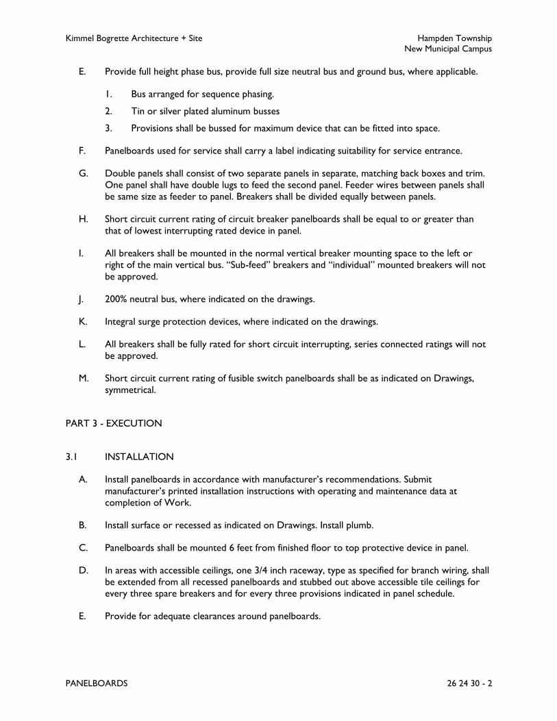
Kimmel Bogrette Architecture + Site Hampden Township
New Municipal Campus
PANELBOARDS 26 24 30 - 2
E. Provide full height phase bus, provide full size neutral bus and ground bus, where applicable.
1. Bus arranged for sequence phasing.
2. Tin or silver plated aluminum busses
3. Provisions shall be bussed for maximum device that can be fitted into space.
F. Panelboards used for service shall carry a label indicating suitability for service entrance.
G. Double panels shall consist of two separate panels in separate, matching back boxes and trim.
One panel shall have double lugs to feed the second panel. Feeder wires between panels shall
be same size as feeder to panel. Breakers shall be divided equally between panels.
H. Short circuit current rating of circuit breaker panelboards shall be equal to or greater than
that of lowest interrupting rated device in panel.
I. All breakers shall be mounted in the normal vertical breaker mounting space to the left or
right of the main vertical bus. “Sub-feed” breakers and “individual” mounted breakers will not
be approved.
J. 200% neutral bus, where indicated on the drawings.
K. Integral surge protection devices, where indicated on the drawings.
L. All breakers shall be fully rated for short circuit interrupting, series connected ratings will not
be approved.
M. Short circuit current rating of fusible switch panelboards shall be as indicated on Drawings,
symmetrical.
PART 3 - EXECUTION
3.1 INSTALLATION
A. Install panelboards in accordance with manufacturer’s recommendations. Submit
manufacturer’s printed installation instructions with operating and maintenance data at
completion of Work.
B. Install surface or recessed as indicated on Drawings. Install plumb.
C. Panelboards shall be mounted 6 feet from finished floor to top protective device in panel.
D. In areas with accessible ceilings, one 3/4 inch raceway, type as specified for branch wiring, shall
be extended from all recessed panelboards and stubbed out above accessible tile ceilings for
every three spare breakers and for every three provisions indicated in panel schedule.
E. Provide for adequate clearances around panelboards.

Kimmel Bogrette Architecture + Site Hampden Township
New Municipal Campus
PANELBOARDS 26 24 30 - 3
F. Ensure clear space over panels and no pipes or ducts are installed over panelboards, both in
accordance with NEC.
G. Rearrange circuits in panelboard to balance loads.
H. Inspect for tightness of all connections.
I. Panelboard indexes shall be provided to reflect installed condition. Indexes shall be
typewritten and shall indicate room numbers and type of load served by each circuit.
Coordinate final room numbers names, numbers and load descriptions with Owner.
J. Furnish and install permanent printed adhesive label on all panelboards indicating source of
power. Label shall be installed plumb and centered above index on inside of panelboard cover.
K. Refer to Section 26 05 05, Basic Materials, for installation of “Danger Labels”.
L. Furnish and install permanent label on all service entrance equipment indicating available short
circuit current, date, and utility company name. Labels shall meet NEC 110 requirements for
markings.
END OF SECTION 26 24 30

Kimmel Bogrette Architecture + Site Hampden Township
New Municipal Campus
DISCONNECT SWITCHES 26 24 40 - 1
SECTION 26 24 40 – DISCONNECT SWITCHES
PART 1 - GENERAL
1.1 WORK INCLUDED
A. The Work of this Section shall consist of the labor, material and equipment required for the
installation of disconnect switches. The specific application of these materials shall be as
outlined in this Section and subsequent Sections of this Specification, or as indicated on the
Drawings.
1.2 SUBMITTALS
A. Submit for approval in accordance with specified submittal procedures:
1. Disconnect Switches
PART 2 - PRODUCTS
2.1 DISCONNECT SWITCHES
A. Acceptable Manufacturer: Square D, or General Electric, Siemens Industry, Eaton.
B. Type: Heavy duty, fusible or non-fusible as indicated on Drawings.
C. Ratings and Accessories: Refer to Drawings.
D. Standard Features:
1. NEMA 1 enclosure, unless otherwise indicated.
2. Handle padlockable in the off position, up to three padlocks.
3. Quick-make, quick-break switching mechanism.
4. Fuse clips shall have rejection type feature for the fuses specified.
E. Furnish cover interlocks to prevent unauthorized opening of switch door when switch is in the
on position, and to prevent closing switch mechanism when door is open.
F. Disconnect used for service entrance shall carry a label indicating suitability for service
entrance.

Kimmel Bogrette Architecture + Site Hampden Township
New Municipal Campus
DISCONNECT SWITCHES 26 24 40 - 2
PART 3 - EXECUTION
3.1 INSTALLATION
A. Install disconnect switches in accordance with manufacturer’s instructions.
B. Disconnect switches shall be installed 5 feet above finished floor.
C. Fuse type and size as required shall be installed in fusible safety switches.
END OF SECTION 26 24 40

Kimmel Bogrette Architecture + Site Hampden Township
New Municipal Campus
OVERCURRENT PROTECTIVE DEVICES 26 24 50 - 1
SECTION 26 24 50 – OVERCURRENT PROTECTIVE DEVICES
PART 1 - GENERAL
1.1 WORK INCLUDED
A. The Work of this Section shall consist of the labor, material and equipment required for
furnishing and installing overcurrent protective devices. The specific application of these
materials shall be as outlined in this Section and subsequent Sections of this Specification, or as
indicated on the Drawings.
1.2 SUBMITTALS
A. Submit for approval in accordance with specified submittal procedures:
1. Fuses, all types
2. Circuit Breakers, All Types
3. Enclosed Circuit Breakers
PART 2 - PRODUCTS
2.1 FUSES
A. Coordination and current limiting for protection of portions of the electrical system has been
designed on the base manufacturer of fuses specified herein for each type or class of fuses. The
option to provide fuses manufactured by any substitute manufacture requires the submission
of a written report verifying the substitute manufacturer’s fuses will provide proper
coordination and current limiting for those portions of the distribution system where the
substitute fuses are proposed. Manufacturer’s fuse curves for the proposed substitute fuses
shall be included with the report. This report shall be submitted in same quantity and
concurrent with shop drawing submission for fuses.
B. Unless otherwise indicated, 10 percent (or a minimum of 3) spare fuses of each size and type
shall be provided to Owner at completion of Work.
C. Fuse Specification No. 2
1. Acceptable Manufacturer: Bussman, or Littelfuse, Gould.
2. Type: Buss fusetron, dual element.
3. Class RK5, with rejection feature, 600 amps and below.
4. Ratings: Refer to Drawings.
5. Fuse shall have either “blown fuse indicator” or “blown fuse indicating” fuse cover.

Kimmel Bogrette Architecture + Site Hampden Township
New Municipal Campus
OVERCURRENT PROTECTIVE DEVICES 26 24 50 - 2
2.2 MOLDED CASE CIRCUIT BREAKERS - GENERAL
A. Acceptable Manufacturer: Same as panelboard manufacturer.
B. Constructed of glass reinforced, or equal, insulation material with current-carrying
components isolated from the handle and accessory mounting area.
C. Molded case circuit breakers shall be over-center, trip free, toggle operating, quick-make,
quick-break, manually operated, and, unless noted, with individual thermal and magnetic trip
units in each pole.
D. Individual trip mechanisms on each pole shall open all poles (common trip).
E. Mechanically trip free so contacts cannot be held closed on an overload or short circuit.
F. When tripped, circuit breaker handle shall reside in a position between “on” and “off”.
G. Clearly marked “on” and “off” positions.
H. Breakers shall be bolted to the bus, unless otherwise noted.
I. Ratings shall be as indicated on Drawings. Ampere rating and U.L. and IEC certification
standards with applicable voltage and ampere interrupting ratings shall be clearly marked on
face of breaker.
J. All breakers shall be fully rated for short circuit interrupting, series connected ratings will not
be approved.
K. Thermal trip units shall be factory preset and sealed.
L. Breakers shall be true RMS current sensing.
M. Breaker frames above 100 amps shall have a single magnetic trip adjustment accessible without
removal of the breaker, cables, etc.
N. Amperes Interrupting Current (AIC) Ratings: 120V, 208V, and 240V breaker - minimum AIC
10,000 amps.
O. Amperes Interrupting Current (AIC) Ratings: 277V and 480V breaker - minimum AIC 14,000
amps.
2.3 GROUND FAULT BREAKERS – PERSONNEL PROTECTION
A. Acceptable Manufacturer: Same as panelboard manufacturer.
B. Unless noted, all 15 amp and 20 amp, single pole breakers indicated as ground fault type shall
be for personnel protection.
C. Shall provide Class A protection – Trip when a fault current to ground is 6 milliamps or
higher.

Kimmel Bogrette Architecture + Site Hampden Township
New Municipal Campus
OVERCURRENT PROTECTIVE DEVICES 26 24 50 - 3
D. Equipped with a push-to-trip button located on the face of the breaker to simulate a ground
fault and mechanically operate the circuit breaker tripping mechanism for maintenance and
testing purposes.
E. Visual ground fault trip indication shall be provided.
2.4 SWITCHING DUTY BREAKERS
A. Acceptable Manufacturer: Same as panelboard manufacturer.
B. U.L. listed as SWD (switching duty) rated.
C. Suitable for switching fluorescent and HID lighting fixtures.
D. Unless noted, all 15 amp and 20 amp, single pole breakers shall be SWD rated.
E. All two pole and three pole breakers feeding fluorescent or HID lighting fixtures shall be SWD
rated.
2.5 HEATING, AIR CONDITIONING AND REFRIGERATION BREAKERS
A. Acceptable Manufacturers: Same as panelboard manufacturer.
B. U.L. listed as HACR (heating, air conditioning, refrigeration equipment) type breakers.
C. All breakers feeding heating, air conditioning and refrigeration type equipment shall be HACR
type breakers, verify with equipment installer.
PART 3 - EXECUTION
3.1 INSTALLATION
A. Fuses
1. Fuses shall not be installed until installation of equipment is complete and tests and
inspections have been completed prior to energizing equipment, including thorough
cleaning, tightening of electrical connections, inspection of ground and grounding
conductors, and conductor insulation tests.
2. Equipment shall not be shipped with fuses in place.
3. Fuses identification label, indication type and size, shall be placed inside door of each
switch.
4. Fuse reducers shall be used where fuse gaps are larger than fuse dimensions.
B. Circuit Breakers
1. Install circuit breakers in accordance with manufacturer’s instructions.

Kimmel Bogrette Architecture + Site Hampden Township
New Municipal Campus
OVERCURRENT PROTECTIVE DEVICES 26 24 50 - 4
2. Test all ground fault breakers to ensure proper operation.
3. On ground fault breakers for personnel, do not connect more than 250 feet of load
conductor for the total one-way run (to prevent nuisance tripping).
4. On all adjustable trip circuit breakers, adjust all settings to values as indicated in the
“Overcurrent Protective Device Coordination Study”.
END OF SECTION 26 24 50

Kimmel Bogrette Architecture + Site Hampden Township
New Municipal Campus
SURGE PROTECTION DEVICES 26 24 60 - 1
SECTION 26 24 60 – SURGE PROTECTION DEVICES
PART 1 - GENERAL
1.1 WORK INCLUDED
A. The Work of this Section shall consist of the labor, materials and equipment required for
furnishing and installing the surge protection devices.
1.2 SUBMITTALS
A. Submit for approval in accordance with specified submittal procedures:
1. Surge Protection Devices, including performance parameters and warranty certificate
1.3 QUALITY ASSURANCE
A. Manufacturer of surge protection devices shall have at least five years’ experience in
manufacturing surge protection devices.
1.4 EXTENDED WARRANTY
A. The surge protection device shall be warranted for a period of five years incorporating
unlimited replacement of all parts, to include both parts and labor.
PART 2 - PRODUCTS
2.1 SURGE PROTECTION DEVICES – INTEGRAL
A. Surge Protection Devices – Panelboard
1. Acceptable Manufacturer: Same as panelboard manufacturer, or as approved.
2. Description:
a. Integral mounted in panelboard at either location of feeder connection in
panelboard or connected directly to load side of main breakers. Unit shall be
connected directly to main bus, no cables between main bus and unit.
b. Listed and component recognized in accordance with UL 1449, 2nd Edition,
February 2007 Revision, and UL 1283.
c. Self contained module design, each suppression element shall be metal oxide
varistor (MOV) based. Module shall consist of either a separate module for each
diversion path or all diversion paths contained in one module.
d. The smallest size MOV used shall be 40 mm diameter. Where parallel MOV’s are
used to achieve the required KA rating as specified herein, the MOV’s shall be
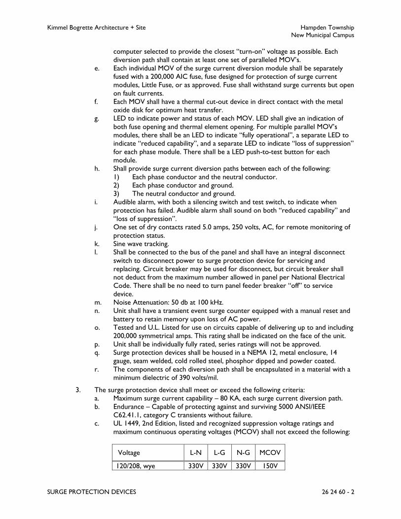
Kimmel Bogrette Architecture + Site Hampden Township
New Municipal Campus
SURGE PROTECTION DEVICES 26 24 60 - 2
computer selected to provide the closest “turn-on” voltage as possible. Each
diversion path shall contain at least one set of paralleled MOV’s.
e. Each individual MOV of the surge current diversion module shall be separately
fused with a 200,000 AIC fuse, fuse designed for protection of surge current
modules, Little Fuse, or as approved. Fuse shall withstand surge currents but open
on fault currents.
f. Each MOV shall have a thermal cut-out device in direct contact with the metal
oxide disk for optimum heat transfer.
g. LED to indicate power and status of each MOV. LED shall give an indication of
both fuse opening and thermal element opening. For multiple parallel MOV’s
modules, there shall be an LED to indicate “fully operational”, a separate LED to
indicate “reduced capability”, and a separate LED to indicate “loss of suppression”
for each phase module. There shall be a LED push-to-test button for each
module.
h. Shall provide surge current diversion paths between each of the following:
1) Each phase conductor and the neutral conductor.
2) Each phase conductor and ground.
3) The neutral conductor and ground.
i. Audible alarm, with both a silencing switch and test switch, to indicate when
protection has failed. Audible alarm shall sound on both “reduced capability” and
“loss of suppression”.
j. One set of dry contacts rated 5.0 amps, 250 volts, AC, for remote monitoring of
protection status.
k. Sine wave tracking.
l. Shall be connected to the bus of the panel and shall have an integral disconnect
switch to disconnect power to surge protection device for servicing and
replacing. Circuit breaker may be used for disconnect, but circuit breaker shall
not deduct from the maximum number allowed in panel per National Electrical
Code. There shall be no need to turn panel feeder breaker “off” to service
device.
m. Noise Attenuation: 50 db at 100 kHz.
n. Unit shall have a transient event surge counter equipped with a manual reset and
battery to retain memory upon loss of AC power.
o. Tested and U.L. Listed for use on circuits capable of delivering up to and including
200,000 symmetrical amps. This rating shall be indicated on the face of the unit.
p. Unit shall be individually fully rated, series ratings will not be approved.
q. Surge protection devices shall be housed in a NEMA 12, metal enclosure, 14
gauge, seam welded, cold rolled steel, phosphor dipped and powder coated.
r. The components of each diversion path shall be encapsulated in a material with a
minimum dielectric of 390 volts/mil.
3. The surge protection device shall meet or exceed the following criteria:
a. Maximum surge current capability – 80 KA, each surge current diversion path.
b. Endurance – Capable of protecting against and surviving 5000 ANSI/IEEE
C62.41.1, category C transients without failure.
c. UL 1449, 2nd Edition, listed and recognized suppression voltage ratings and
maximum continuous operating voltages (MCOV) shall not exceed the following:
Voltage L-N L-G N-G MCOV
120/208, wye 330V 330V 330V 150V

Kimmel Bogrette Architecture + Site Hampden Township
New Municipal Campus
SURGE PROTECTION DEVICES 26 24 60 - 3
277/480, wye 700V 700V 700V 320V
These voltages shall be indicated on the face of the
surge protection device unit.
d. The ANSI/IEEE C62.41.1-2002 category C high let through voltages shall not
exceed the following:
Voltage L-N L-G N-G
120/208V, wye 520V 520V 520V
277/480V, wye 880V 880V 880V
B. Surge Protection Devices – Distribution panel.
1. Acceptable Manufacturer: Same as distribution panelboard manufacturer, or as
approved.
2. Description:
a. Integral mounted in panelboard or motor control center at either location of
feeder connection in panelboard or motor control center or connected directly
to load side of main breakers. Unit shall be connected directly to main bus, no
cables between main bus and unit.
b. Listed and component recognized in accordance with UL 1449, 2nd Edition,
February 2007 Revision, and UL 1283.
c. Self contained module design, each suppression element shall be metal oxide
varistor (MOV) based. Module shall consist of either a separate module for each
diversion path or all diversion paths contained in one module.
d. The smallest size MOV used shall be 40 mm diameter. Where parallel MOV’s are
used to achieve the required KA rating as specified herein, the MOV’s shall be
computer selected to provide the closest “turn-on” voltage as possible. Each
diversion path shall contain at least one set of paralleled MOV’s.
e. Each individual MOV of the surge current diversion module shall be separately
fused with a 200,000 AIC fuse, fuse designed for protection of surge current
modules, Little Fuse, or as approved. Fuse shall withstand surge currents but open
on fault currents.
f. Each MOV shall have a thermal cut-out device in direct contact with the metal
oxide disk for optimum heat transfer.
g. LED to indicate power and status of each MOV. LED shall give an indication of
both fuse opening and thermal element opening. For multiple parallel MOV’s
modules, there shall be an LED to indicate “fully operational”, a separate LED to
indicate “reduced capability”, and a separate LED to indicate “loss of suppression”
for each phase module. There shall be a LED push-to-test button for each
module.
h. Shall provide surge current diversion paths between each of the following:
1) Each phase conductor and the neutral conductor.
2) Each phase conductor and ground.
3) The neutral conductor and ground.
i. Audible alarm, with both a silencing switch and test switch, to indicate when
protection has failed. Audible alarm shall sound on both “reduced capability” and
“loss of suppression”.

Kimmel Bogrette Architecture + Site Hampden Township
New Municipal Campus
SURGE PROTECTION DEVICES 26 24 60 - 4
j. One set of dry contacts rated 5.0 amps, 250 volts, AC, for remote monitoring of
protection status.
k. Sine wave tracking.
l. Shall be connected to the bus of the panel or motor control center and shall have
an integral disconnect switch to disconnect power to surge protection device for
servicing and replacing. Circuit breaker may be used for disconnect, but circuit
breaker shall not deduct from the maximum number allowed in panel per
National Electrical Code. There shall be no need to turn panel feeder breaker
“off” to service device.
m. Noise Attenuation: 50 db at 100 kHz.
n. Unit shall have a transient event surge counter equipped with a manual reset and
battery to retain memory upon loss of AC power.
o. Tested and U.L. Listed for use on circuits capable of delivering up to and including
200,000 symmetrical amps. This rating shall be indicated on the face of the unit.
p. Unit shall be individually fully rated, series ratings will not be approved.
q. Surge protection devices shall be housed in a NEMA 12, metal enclosure, 14
gauge, seam welded, cold rolled steel, phosphor dipped and powder coated.
r. The components of each diversion path shall be encapsulated in a material with a
minimum dielectric of 390 volts/mil.
3. The surge protection device shall meet or exceed the following criteria:
a. Maximum surge current capability – 120 KA, each surge current diversion path.
b. Endurance – Capable of protecting against and surviving 5000 ANSI/IEEE
C62.41.1, category C transients without failure.
c. UL 1449, 2nd Edition, listed and recognized suppression voltage ratings and
maximum continuous operating voltages (MCOV) shall not exceed the following:
Voltage L-N L-G N-G MCOV
120/208, wye 330V 330V 330V 150V
277/480, wye 700V 700V 700V 320V
These voltages shall be indicated on the face of the
surge protection device unit.
d. The ANSI/IEEE C62.41.1-2002 category C high let through voltages shall not
exceed the following:
Voltage L-N L-G N-G
120/208V, wye 520V 520V 520V
277/480V, wye 880V 880V 880V

Kimmel Bogrette Architecture + Site Hampden Township
New Municipal Campus
SURGE PROTECTION DEVICES 26 24 60 - 5
PART 3 - EXECUTION
3.1 INSTALLATION
A. General
1. Surge protection devices shall be installed and tested in accordance with manufacturer’s
instructions.
2. The surge protection device’s ground shall be connected to the ground of the
equipment it is connected to.
END OF SECTION 26 24 60

Kimmel Bogrette Architecture + Site Hampden Township
New Municipal Campus
POWER GENERATION 26 32 10 - 1
SECTION 26 32 10 – POWER GENERATION
PART 1 - GENERAL
1.1 WORK INCLUDED
A. The Work of this Section shall consist of the labor, materials and equipment required to
furnish, install, connect and test the electric power generating system, controls and switching
for the emergency power system.
1.2 SUBMITTALS
A. Submit for approval in accordance with specified submittal procedure:
1. Engine/Generator Set and All Accessories and Components Specified Herein
2. Remote Alarm Annunciator
3. Battery Charger
4. Weatherproof Housing (Non-Walk-In)
B. Schematic wiring diagrams shall be submitted for the following:
1. Engine/Generator Set and Control Panel
2. Remote Alarm Indicating Panels
C. Wiring and interconnecting diagrams shall be submitted for the following:
1. Start-stop and Control Systems.
2. Monitoring, Indicating and Alarm Systems. (Note: Wiring diagram shall show locations
for wiring all engine/generator and all associated power generation system sensors,
indicators and alarms, whether or not furnished by the generator manufacturer).
D. Submit results of prototype tests as specified herein.
E. 5 year comprehensive extended coverage warranty certificate.
1.3 QUALITY ASSURANCE
A. Manufacturer Requirements
1. Power generation system shall be built, tested and shipped by the alternator
manufacturer to establish a single source responsibility. Manufacturer shall be regularly
engaged in the production of engine/alternator sets and associated controls for a
minimum of 10 years.

Kimmel Bogrette Architecture + Site Hampden Township
New Municipal Campus
POWER GENERATION 26 32 10 - 2
2. To be considered an acceptable manufacturer, the builder of the generating set shall
manufacture either the engine or the alternator.
3. Manufacturer shall have available printed catalogs data, brochures, or similar publications
describing standard series/models to meet this Specification. Submitted data indicating
an obvious one-of-a-kind fabrication will not be acceptable.
4. The performance tests of the generating set series shall be in accordance with
procedures certified by an independent testing laboratory. Manufacturer shall have
successfully tested a prototype of the proposed generating set series which shall include:
a. Maximum power level.
b. Maximum motor staring capacity.
c. Structural soundness.
d. Torsigraph analysis in accordance with MIL-STD-705B, method 504.2.
e. Fuel consumption.
f. Engine/alternator cooling air flow.
g. Transient response and steady state governing.
h. Alternator temperature rise in accordance with NEMA MG1-22.40
i. Single step load pickup in accordance with NFPA 110.
j. Harmonic analysis and voltage waveform deviation in accordance with MIL-STD-
705B, method 601.4.
k. Three phase short circuit test for mechanical and electrical strength.
l. Test results shall be submitted when requested.
B. Supplier Requirements
1. Manufacturer's authorized representative who is trained and approved for installation of
units required for this Project.
2. Maintenance Proximity: Not more than four hours' normal travel time from Supplier’s
place of business to Project site.
1.4 WARRANTY
A. When equipped with set exerciser and running time meter, power generation system
manufacturer shall provide an extended limited warranty on the complete electric power
system, including automatic transfer switches and all other accessories, for a period of 5 years
or 1,500 operating hours, whichever occurs first, effective from date of initial start-up.
Coverage shall include all parts, labor, travel expenses, and labor to remove/reinstall this
equipment. No deductibles shall be applied to this warranty.
B. 5 year comprehensive extended coverage warranty certificate shall be submitted with shop
drawings.

Kimmel Bogrette Architecture + Site Hampden Township
New Municipal Campus
POWER GENERATION 26 32 10 - 3
1.5 EMERGENCY USE FUNCTION
A. The power generating system shall perform the following function for emergency use:
1. When the normal power supply fails on any phase at the automatic transfer switch, the
system shall automatically start up and provide power to emergency lights and other
emergency equipment.
2. System shall be capable of producing its emergency rated horsepower continuously for
the duration of each electric power failure.
1.6 COORDINATION - GAS
A. Exhaust pipe, muffler, flexible exhaust pipe and companion flange kit and all associated exhaust
line accessories will be furnished and installed as Work of this Section.
B. Solenoid valve in fuel line will be furnished and installed as Work of this Section.
C. Fuel supply piping and all associated accessories will be furnished, installed and connected to
engine by Plumbing Contractor.
D. Concrete pad for generator will be furnished and installed as Work of this Section.
E. Flexible duct connection, ductwork, louvers, and motorized dampers for engine/generator
cooling air intake and exhaust will be furnished and installed as Work of this Section.
F. The on-site available gas pressure is 11 inches water column.
PART 2 - PRODUCTS
2.1 FUEL PIPING - GAS
A. Interior and above grade gas piping shall be standard weight black steel, threaded and coupled,
ASTM A53 and ANSI B1.20 or B36.10, threaded joints, black malleable iron fittings, 300 lb.
(WOG), ASTM A197, ANSI B16.3. Pipe sizes 2-1/2 inches and larger shall be butt welded
joints, standard weight seamless black steel fittings, ASTM A234 Grade WPB, ANSI B16.9.
B. Flexible pipe connection for natural gas piping shall be as required by the local utility.
2.2 EXHAUST PIPE
A. Exhaust pipe shall be welded schedule 40 black steel. Install insulating thimble at roof
penetration.
B. Exhaust pipe insulation shall be as follows:
1. Acceptable Manufacturer: Manville Thermo-12/Gold calcium silicate blocks and Foster
Sealfos 30-36 sealant. No substitutions for sealant.

Kimmel Bogrette Architecture + Site Hampden Township
New Municipal Campus
POWER GENERATION 26 32 10 - 4
2. Thickness shall be selected to keep the surface temperature below 180 degrees
Fahrenheit based upon the temperature of the exhaust pipe and muffler.
C. Flexible exhaust pipe connection shall be stainless steel constructions, rated for 1500 degrees
F maximum operating temperature, flanged connection.
2.3 VALVES – GAS
A. Plug Valves
1. Acceptable Manufacturer: Walworth.
2. Cast iron body, lubricated plug, wrench operated, with threaded ends for 2 inch valves
or smaller, flanged ends for 2 inch valves and larger. 200 WOG.
2.4 ENGINE/GENERATOR SET
A. Acceptable Manufacturer: Kohler, or Cummins Onan, Caterpillar.
B. Engine
1. Cooling System: Plant mounted radiator with pusher fan.
2. Fuel: Natural gas. Unit shall operate on 7 – 11 in. WC.
3. Fuel System:
a. Lubrication:
1) Full pressure.
2) Lube oil pump.
3) Oil cooler.
4) Oil level indicator.
5) Full flow oil filters with replaceable elements.
6) Oil drain valve with hose extension.
7) Oil pressure gage.
4. Battery Charging Alternator: Manufacturer standard voltage, with transistorized voltage
regulator.
5. Starting System:
a. Two wire.
b. Time delay on start, adjustable, 0 to 5 seconds.
c. Time delay on stop, adjustable, 0 to 30 minutes.
6. Batteries:
a. Lead acid.
b. Sufficient capacity to start engine in 5 seconds.
c. Cycle cranker.
d. Adequate capacity for monitoring the alarm circuits as specified herein.
e. Battery cables and racks.
f. Furnish with 120V battery blanket heater.
7. Positive shift gear engaging starter.

Kimmel Bogrette Architecture + Site Hampden Township
New Municipal Campus
POWER GENERATION 26 32 10 - 5
8. Automatic engine shut down on emergency by shutting off the fuel supply to the
injectors.
9. Diesel engines rated to SAE ambient conditions, but shall also be capable of developing
the brake horsepower specified herein at the altitude of the project site.
10. Unit mounted on structural steel base.
11. Governor: Electronic, isochronous with zero droop.
12. 208 volt external canister type jacket water heater. Size as required to hold water
temperature to 90 degrees F.
13. Exhaust System:
a. Muffler:
1) Critical companion flange kits (1 kit per muffler).
b. Stainless steel flexible exhaust connections.
c. Condensate line with solenoid shutoff valve.
14. Engine sensing elements: Located on the engine to indicate the following pre-alarms,
alarms and engine shut downs:
a. High water temperature pre-alarm and shut down.
b. Low oil pressure pre-alarm and shut down.
c. Low water temperature alarm.
d. Low engine coolant
e. Over-speed shut down and alarm.
f. Over-crank shut down and alarm.
C. Generator
1. Design:
a. KW: 200, at 0.8 power factor.
b. KVA: 250
c. Upsized alternator.
d. Voltage: 120/208
e. Poles: 4
f. Frequency: 60Hz
2. Revolving field.
3. Rotor permanently aligned to engine.
4. Amortisseur windings.
5. Built to NEMA standards.
6. Meet ASA requirements for Class H insulation for windings per NEMA MG1-1.65.
7. Duty: Emergency.
8. Exciter: PMG
9. Voltage Regulator: Response of voltage regulator shall be matched to the response of
the speed regulating governor that controls engine speed. Integrated digital electronic
type.
10. 120 volt fusible circuit on generator output for damper motors.

Kimmel Bogrette Architecture + Site Hampden Township
New Municipal Campus
POWER GENERATION 26 32 10 - 6
D. Unit Performance
1. Temperature Rise: Built to NEMA standards.
2. Voltage Regulation: Plus or minus 1 percent maximum, no load to full load.
3. Frequency Regulation: 1 percent, maximum, no load to full load.
4. Maximum voltage dip on application of full load at rated power factor in one step 35
percent.
5. Maximum frequency change on application of full load at rated power factor in one step
10 percent.
6. Telephone Influence Factors:
a. Balanced: Less than NEMA standards.
b. Residual Component: Less than NEMA standards.
7. Waveshape Deviation Factor: In accordance with NEMA Standards.
8. Total Harmonic Distortion: Less than 10 percent.
E. Unit Installation
1. Ambient temperature range for generator installation 0 degrees F to 100 degrees F.
2. Location: Outdoor.
F. Unit Control Panel:
1. Vibration isolation mounting on generator, NEMA 1 enclosure, to contain the following:
2. Controls:
a. Voltage adjusting rheostat.
b. Output circuit breaker, manual reset.
c. Three-position operator selector switch, run-stop remote positions.
1) Run Position: Generator exercises.
2) Stop Position: Generator inoperative.
3) Remote Position: Generator capable of being started and stopped from
remote locations. Remote position of switch shall have auxiliary set of
contacts for monitoring purposes. Auxiliary contacts shall be open in the
remote position and closed in the run and stop positions.
d. Combination line voltage/phase voltage selector switch.
e. Phase current selector switch.
f. Cycle cranker.
3. Terminals:
a. Remote start-stop terminals.
b. Terminals for 4 damper motor and/or control circuits.
c. Terminals for 2 monitoring and alarm circuits.
d. Terminals for exhaust line solenoid valve.
e. Terminals for tie-in of Owner’s security system to monitor common trouble and
engine running.
4. Indicator lights and pre-alarm, alarm and indicator light contacts and terminals for
connection to remote alarm annunciator per NFPA 110 Level 1 requirements.

Kimmel Bogrette Architecture + Site Hampden Township
New Municipal Campus
POWER GENERATION 26 32 10 - 7
5. Miscellaneous:
a. Starting battery voltage lamps with switch to illuminate panel.
b. Push to test indicator lamps or common lamp test pushbutton.
c. 2 fuse blocks and fuses for damper motor and/or control circuits, 15 amp, 120
volts, taps from generator output.
d. 4 fuse blocks and fuses for monitoring and alarm circuits, 10 amps, 24 volts DC,
from starting batteries.
e. Fuse block and fuses for exhaust line solenoids circuit, 20 amp, 120 volts.
6. Connectivity
a. Unit shall communicate with Building Automation System via protocol compatible
to that system. Furnish network cards and modules in control panel as required.
b. Unit shall have Ethernet connection for remote system monitoring and
diagnostics over Owner’s telecommunications network. Coordinate IP address
with Owner’s telecommunications representative.
G. Miscellaneous Materials
1. Provide two sets of each fuel oil and air filters to Owner.
2.5 REMOTE ALARM ANNUNCIATOR
A. Acceptable Manufacturer: Same as generator manufacturer.
B. Sturdy sheet steel enclosure with removable front panel. Surface mounting.
C. Operated from starting batteries.
D. Battery voltage sensors.
E. Comply with NFPA 110 requirements.
2.6 VIBRATION ISOLATORS
A. Acceptable Manufacturer: Peabody Noise Control or Korfund, Amber Booth, Vibration
Mountings & Controls, Mason Industries, Vibration Eliminators Co.
B. Capacity and characteristics as recommended by plant manufacturer.
2.7 BATTERY CHARGER
A. Acceptable Manufacturer: Onan, or LaMarch, Nife, Kohler.
B. Two Rate
1. Trickle rate capable of maintaining batteries fully charged.
2. High rate, capable of replacing within a 24 hour period the charge taken off of the
batteries by a 5 minute continuous cranking period.

Kimmel Bogrette Architecture + Site Hampden Township
New Municipal Campus
POWER GENERATION 26 32 10 - 8
C. Ammeter to indicate trickle rate of charge.
D. Pilot light to indicate when trickle rate is being applied.
E. Pilot light to indicate when high rate is being applied.
F. Charger shall automatically go to high rate and reset to trickle charge when required.
G. Alarm relays with unit mounted indicator lights and with contacts and terminals for connection
to remote alarm annunciator.
1. Low DC voltage.
2. High DC voltage.
3. Battery charger malfunction.
4. Loss of DC current.
5. AC power failure relay.
H. Protection
1. Fused AC input and double fused DC output.
2. Integral AC surge suppression.
3. Integral current limiting and overload protection.
4. Integrally protected against shorted or reversed battery connections.
I. AC pilot light.
J. Cranking circuit disconnect relay.
K. Input line voltage, 120 volts.
L. Output voltage compatible with battery voltage.
M. Charger designed to operate with the type and voltage of starting batteries specified.
N. Disconnect in output line to batteries will not be permitted.
O. Integral trickle and high rate adjustments.
P. Solid state (SCR) components.
Q. Sheet metal enclosure, NEMA 1, with required ventilation.
2.8 WEATHERPROOF HOUSING (NON-WALK-IN)
A. Acceptable Manufacturer: Same as generator manufacturer.
B. Level 2 sound attenuated enclosure.

Kimmel Bogrette Architecture + Site Hampden Township
New Municipal Campus
POWER GENERATION 26 32 10 - 9
C. 14 to 18 gage sheet steel construction.
D. Painted inside and outside with rust inhibiting primer and enamel.
E. Exterior finish color: Manufacturer’s standard.
F. Side panels easily removable for servicing.
G. Hinged panel for access to the control panel.
H. Lockable latches on side panels and rear panel to prevent tampering.
I. Air intakes at both generator end and radiator end to insure proper cooling without ingress of
moisture during operation.
J. Attached to generator mounting base.
K. Weatherproof enclosure shall provide year-round protection from the elements.
L. Muffler shall be mounted within discharge hood of the enclosure. Muffler may only be
mounted within main generator compartment of enclosure when thermally wrapped to
minimize heat stress on surrounding components. Externally mounted silencers are not
acceptable.
M. Shall house battery charger and starting batteries.
PART 3 - EXECUTION
3.1 INSTALLATION
A. Engine/Generator Set
1. The set structural steel base shall be mounted on vibration isolators, type as
recommended by system manufacturer.
2. Set shall be installed on six inch high concrete pad.
3. Starting batteries shall be placed on a wooden or steel rack, adjacent to set.
4. All pipe and conduit connections to engine/generator set shall be made with flexible
lines.
5. A pipe union shall be installed on each end of the flexible exhaust connection. Long
radius elbows shall be used in exhaust line.
6. Provide drip leg, using a plumbers wye, at first point of rise in exhaust line. Provide a
condensate trap and solenoid valve. Horizontal exhaust lines shall slope down to
condensate trap.
7. Provide manufacturer’s approved ventilated thimbles wherever exhaust lines pass
through walls, roofs, ceiling, or partitions. Provide a drip pan with drain line on thimble
where thimble penetrates roof.

Kimmel Bogrette Architecture + Site Hampden Township
New Municipal Campus
POWER GENERATION 26 32 10 - 10
8. Provide gravity type rain cap on the discharge end of vertical or non-horizontal exhaust
pipes.
9. Discharge end of horizontal exhaust pipes shall have either gravity type rain cap or shall
be cut 30 degrees to the horizontal plane and opening shall be protected with
birdscreen.
10. Voltage for monitoring indicating devices and alarms for the system, engine room and all
accessories shall be taken from the starting batteries. Circuits shall be fused.
11. Voltage for the damper motors and the exhaust line solenoid valve shall be tapped from
the output of the generator. Circuit shall be fused.
12. Before start up, inspect generator connection phase sequence for same sequence as the
local utility, to insure correct rotation of motors.
13. Fill engine with series 3 engine oil, rated for diesel service.
14. Fill engine coolant system with a 50/50 mixture of water and antifreeze solution to
protect engine from freezing to a temperature of minus 20 degrees F.
15. Exhaust system shall not be supported by the engine exhaust manifold.
16. Panelboards for emergency lighting shall have nameplate with emergency lighting.
17. Branch circuit breakers in emergency lighting panels shall be equipped with handle
locking devices.
18. For generators requiring cooling air ducted to outdoors, furnish and install flexible duct
connector between engine radiator and ductwork. Furnish and install motor operator
backdraft damper installed where ductwork penetrates wall.
19. Fuel oil storage tank shall be full when Contractor is finished testing and has placed the
generator in operation.
B. Exhaust Pipe
1. Welded Joints: The welding of all pipe joints, both as to procedures and qualification of
welders, shall be in accordance with Section IX, ASME Boiler & Pressure Vessel Code,
unless mandatory local codes take precedence. Ends of pipe and fittings to be joined by
butt welding shall be beveled, cleaned to bare metal and internal diameters aligned
before tack welding.
C. Exhaust Pipe Insulation
1. On the interior, all exposed portions of exhaust pipe and muffler and on the exterior
portions of exhaust pipe within 8 feet of grade or within possible reach of personnel
shall be insulated.
2. Insulation shall be mechanically fastened by wiring in place using 16 gage wire on 6 inch
centers for 3 inch exhaust pipe size and smaller and 12 gage wire on 9 inch centers for
exhaust pipe size 4 inches and larger.
3. Insulation shall be covered with hexagonal mesh wire, 1/4 inch insulating cement, 8
ounce canvas and waterproof sealant.
D. Gas Piping

Kimmel Bogrette Architecture + Site Hampden Township
New Municipal Campus
POWER GENERATION 26 32 10 - 11
1. Threaded Joints: Pipe screw threads shall conform to ANSIB2.1, Pipe Threads. Ream
pipe ends and remove all burrs and chips formed in cutting and threading. Protect plated
pipe and brass valve bodies from wrench marks when making-up joint. Apply thread
lubricant to male threads only.
2. Joint cement or gasketing will not be permitted to be used on fuel lines.
3. Length of flexible fuel line shall be installed between the pipe from the fuel source and
the electric set fuel inlet.
E. Fuel Oil Level Gage
1. Fuel oil level gage shall be located where indicated on Drawings.
2. Install fuel oil level gage and associated components in accordance with manufacturer’s
instructions.
F. Emergency System Wiring
1. Wiring methods specified herein are in addition to the wiring methods specified in
Section 26 05 30, Raceway and Fittings.
2. Wiring for lights and equipment on normal emergency power shall be run in metal
raceways. Branches shall be kept independent of all other wiring and equipment and
shall not enter the same raceways, boxes, or cabinets with each other or other wiring,
except in transfer switches, bypass/isolation switches, or lighting fixtures supplied from
two sources.
3. Wiring for life safety (LS) branch and equipment (EQ) branch shall be run in metal
raceways. Branches shall be kept independent of all other wiring and equipment and
shall not enter the same raceways, boxes, or cabinets with each other or other wiring,
except in transfer switches, bypass/isolation switches, or lighting fixtures supplied from
two sources.
3.2 START-UP SERVICES
A. Upon completion of the installation, initial start-up shall be performed by a factory trained
representative of the power generating system supplier. System manufacturer shall provide a
printed procedure form for initial start-up and system check and test record. Only this
procedure shall be utilized during initial start-up. Deliver three copies of the completed form
to Owner.
B. Start-up testing shall include a test of the entire emergency power system under actual load
conditions for a minimum of four hours to assure proper functioning of all system components
and auxiliary equipment. Testing shall also include simulated load bank test to demonstrate
generator set meets full rated KW load pick up in one step in accordance with NFPA 110. Any
adjustments deemed necessary to place the equipment in proper operating condition shall be
made prior to the four hour test. Deliver three copies of test report to Owner.
C. At time of start-up, operating instructions and maintenance procedures for the entire system
shall be thoroughly explained to Owner’s operating personnel. Two copies of operating and
maintenance instruction data shall be furnished for the electric set and all auxiliary equipment.

Kimmel Bogrette Architecture + Site Hampden Township
New Municipal Campus
POWER GENERATION 26 32 10 - 12
System manufacturer shall provide both a service maintenance log and an on site maintenance
record in printed form and sufficient copies for Owner’s use. Instruction on use and
completion of these printed forms shall be given to Owner’s representative by the
engine/generator set manufacturer’s representative.
3.3 TESTING
A. Provide full load (equal to 100 percent of the unit nameplate rating) test utilizing portable test
bank for four hours minimum. Simulate power failure including operation of automatic transfer
switch, automatic starting cycle, automatic shut down and return to normal. Unit shall pick-up
100 percent of the nameplate KW rating in one step.
B. During test, record the following at 20 minute intervals:
1. Kilowatts
2. Amperes
3. Voltage
4. Coolant temperature
5. Room temperature, where applicable.
6. Frequency
7. Oil pressure
8. Battery charge rate
C. Test alarm and shutdown circuits by simulating conditions per NFPA 110.
D. Cycle crank test per NFPA 110.
E. All time delays shall be observed and recorded including engine start, cranking time, time to
reach operating speed, voltage and frequency overshoot, time to reach steady state condition,
transfer, re-transfer, engine stop and where applicable, delays between disconnect from
generator until reconnect to normal and from disconnect from normal and connect to
generator.
F. Provide owner with three copies of all test reports. For existing generators, indicate either a
pass or fail condition and, for reports with fail indicated, provide a detailed explanation of the
reason for the failure and the corrective action required to be taken.
3.4 OPERATION AND MAINTENANCE INSTRUCTIONS
A. Provide typewritten instructions for the operation and maintenance of the power generating
system. Insert instructions in clear, sealed mounting and install on a wall adjacent to the
system.

Kimmel Bogrette Architecture + Site Hampden Township
New Municipal Campus
POWER GENERATION 26 32 10 - 13
B. Include instructions for normal operation, routine maintenance requirements, service manuals
for all items, oil sampling and analysis for engine wear and emergency maintenance procedures.
END OF SECTION 26 32 10

Kimmel Bogrette Architecture + Site Hampden Township
New Municipal Campus
AUTOMATIC TRANSFER SWITCH 26 32 20 - 1
SECTION 26 32 20 – AUTOMATIC TRANSFER SWITCHES
PART 1 - GENERAL
1.1 WORK INCLUDED
A. The Work of this Section shall consist of the labor, materials and equipment required to
furnish, install, and test the automatic transfer switches.
1.2 SUBMITTALS
A. Submit for approval in accordance with specified submittal procedures:
1. Automatic Transfer Switches, including schematic wiring diagrams.
PART 2 - PRODUCTS
2.1 AUTOMATIC TRANSFER SWITCH
A. Acceptable Manufacturer: Same as engine/generator set manufacturer.
B. Transfer switch shall be UL listed, standard 1008.
C. Operation
1. Mechanically held on both normal side and emergency side.
2. Electrically operated.
3. Switch mechanically and electrically interlocked to insure only one of two possible
positions, either normal or emergency, except where a programmed neutral position is
specified.
4. Operating current for transfer shall be obtained from the source to which the load is to
be transferred.
5. Manual operator.
6. Automatic Initiation of retransfer from emergency to normal when normal power is
restored.
7. Operating coil contactors.
8. Molded case switches. Molded case switches shall not have magnetic or thermal trip
elements.
D. Rating
1. Ampere and voltage ratings as indicated on Drawings.
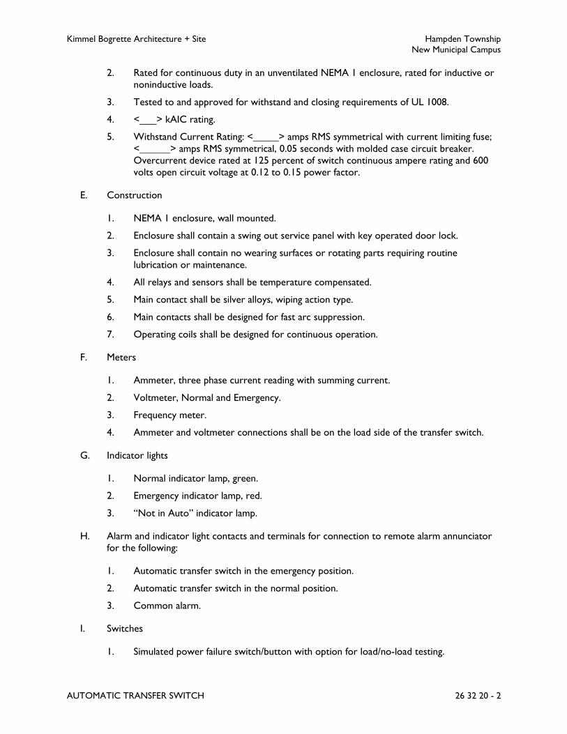
Kimmel Bogrette Architecture + Site Hampden Township
New Municipal Campus
AUTOMATIC TRANSFER SWITCH 26 32 20 - 2
2. Rated for continuous duty in an unventilated NEMA 1 enclosure, rated for inductive or
noninductive loads.
3. Tested to and approved for withstand and closing requirements of UL 1008.
4. <___> kAIC rating.
5. Withstand Current Rating: <_____> amps RMS symmetrical with current limiting fuse;
<______> amps RMS symmetrical, 0.05 seconds with molded case circuit breaker.
Overcurrent device rated at 125 percent of switch continuous ampere rating and 600
volts open circuit voltage at 0.12 to 0.15 power factor.
E. Construction
1. NEMA 1 enclosure, wall mounted.
2. Enclosure shall contain a swing out service panel with key operated door lock.
3. Enclosure shall contain no wearing surfaces or rotating parts requiring routine
lubrication or maintenance.
4. All relays and sensors shall be temperature compensated.
5. Main contact shall be silver alloys, wiping action type.
6. Main contacts shall be designed for fast arc suppression.
7. Operating coils shall be designed for continuous operation.
F. Meters
1. Ammeter, three phase current reading with summing current.
2. Voltmeter, Normal and Emergency.
3. Frequency meter.
4. Ammeter and voltmeter connections shall be on the load side of the transfer switch.
G. Indicator lights
1. Normal indicator lamp, green.
2. Emergency indicator lamp, red.
3. “Not in Auto” indicator lamp.
H. Alarm and indicator light contacts and terminals for connection to remote alarm annunciator
for the following:
1. Automatic transfer switch in the emergency position.
2. Automatic transfer switch in the normal position.
3. Common alarm.
I. Switches
1. Simulated power failure switch/button with option for load/no-load testing.

Kimmel Bogrette Architecture + Site Hampden Township
New Municipal Campus
AUTOMATIC TRANSFER SWITCH 26 32 20 - 3
2. Off position starts plant and assumes load.
3. On position retransfers load to normal supply and stops plant.
4. Manual reset for cranking limiter.
J. Auxiliary Contacts
1. Normally closed, normal position.
2. Normally open, normal position.
3. Normally closed, emergency position.
4. Normally open, emergency position.
5. Auxiliary contact to close 10 seconds prior to retransfer from emergency to normal.
K. Accessories
1. Adjustable voltage sensors:
a. Pickup, both normal and emergency: 85 percent to 98 percent of nominal voltage,
set at 90 percent.
b. Dropout, both normal and emergency: 70 percent to 98 percent of nominal
voltage, set at 85 percent.
2. Adjustable solid state time delays:
Function Adjustable Range Set at
Engine Start 0 to 15 seconds 3 seconds
Transfer - Normal
to emergency
0 to 60 minutes 0 seconds
Re-transfer - Emergency
to normal
0 to 60 minutes 30 minutes
Engine Stop, after Re-transfer 0 to 60 minutes 5 minutes
Pushbuttons to be provided to override the time delay for “re-
transfer” and “engine stop” during routine testing.
3. LED lamps on automatic transfer switch to verify control functions:
a. Source 1 OK
b. Source 2 OK
c. Generator Start Signal
d. Transfer Timing
e. Transfer Complete
f. Re-Transfer Timing
g. Re-Transfer Complete
h. Timing for Stop (Cool Down)
4. Unless otherwise specified, initiate immediate transfer to emergency when any normal
phase falls below specified dropout setting and all phases of emergency reach specified
pickup setting.

Kimmel Bogrette Architecture + Site Hampden Township
New Municipal Campus
AUTOMATIC TRANSFER SWITCH 26 32 20 - 4
5. Initiate retransfer to normal when all normal phases reach specified pickup setting and
after indicated delay.
6. If normal power should fail during the engine stop delay period, time delay shall be
bypassed and switch shall immediately initiate return to the emergency source.
7. Phase sequence relays for transferring and re-transferring from emergency to normal
power.
8. Delay both after disconnect from normal power and before reconnect to emergency
generator and after disconnect from emergency generator and before reconnect to
normal power (programmed neutral positions) to allow for loads to stabilize.
9. Either phase sequence relays for transferring and re-transferring loads from emergency
to normal power or delay both after disconnect from normal power and before
reconnect to emergency generator and after disconnect from emergency generator and
before reconnect to normal power (programmed neutral positions) to allow for loads
to stabilize.
10. Automatic transfer switches using phase sequence relays for transfer and re-transfer of
loads shall have provisions for installation, in the future, a module for programmed
neutral position operation.
11. If the emergency source shall malfunction while furnishing power to the load:
a. Transfer switch shall disconnect load from emergency power.
b. Allow for restarting emergency source with no connected load.
c. After restarting emergency source, shall reconnect the load to the emergency
power.
12. Exerciser clock, exercise plant only, adjustable from 15 minutes to any multiple of 15
minutes as often as desired.
13. Normal power interrupted while generator is exercising load automatically transferred
to emergency.
14. Switch arranged for use with area protection monitor panel and initiate transfer when
area relay indicates power failure. Shall include bypass return to normal if emergency
fails and normal is available at the transfer switch. As directed by the manufacturer,
normal power shall be extended to the area protection monitor panel and connected.
15. Ungrounded neutral bar, full size.
16. Event log screen with record of date, time, and details of last 99 events.
17. ATS status and alarm screen.
18. 120 volt, fused circuit on the emergency side, fused, for damper motors.
PART 3 - EXECUTION
3.1 INSTALLATION
A. Install switches in accordance with manufacturer’s instructions. Submit manufacturer’s printed
installation instructions at completion of Work.

Kimmel Bogrette Architecture + Site Hampden Township
New Municipal Campus
AUTOMATIC TRANSFER SWITCH 26 32 20 - 5
3.2 MANUFACTURER’S FIELD SERVICES
A. Prepare and start systems.
B. Operate transfer switches in both normal and emergency modes and bypass where applicable.
3.3 EMERGENCY SYSTEM WIRING METHODS
A. Wiring methods specified herein are in addition to the wiring methods specified in other
Sections of these Specifications.
B. Wiring for the life safety (LS) branch and equipment automatic (EQA) branch shall be run in
metal raceways. Branch shall be kept independent of all other wiring and equipment and shall
not enter the same raceways, boxes, or cabinets with each other or other wiring, except in
transfer switches, bypass/isolation switches, or lighting fixtures supplied from two sources.
3.4 OPERATION AND MAINTENANCE INSTRUCTIONS
A. Provide instructions for operating equipment including instructions for operating equipment
under emergency conditions when engine generator is running.
B. Provide routine preventative maintenance and lubrication schedule. List maintenance materials
and replacement parts required and provide special tools.
END OF SECTION 26 32 20
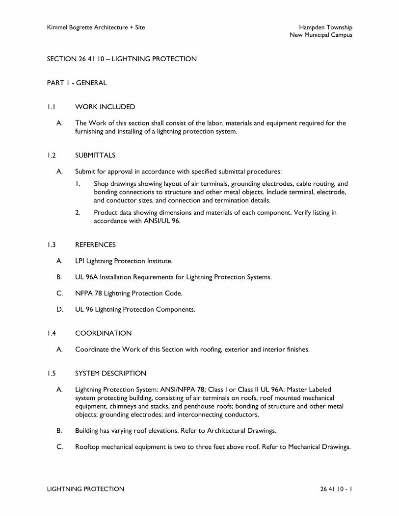
Kimmel Bogrette Architecture + Site Hampden Township
New Municipal Campus
LIGHTNING PROTECTION 26 41 10 - 1
SECTION 26 41 10 – LIGHTNING PROTECTION
PART 1 - GENERAL
1.1 WORK INCLUDED
A. The Work of this section shall consist of the labor, materials and equipment required for the
furnishing and installing of a lightning protection system.
1.2 SUBMITTALS
A. Submit for approval in accordance with specified submittal procedures:
1. Shop drawings showing layout of air terminals, grounding electrodes, cable routing, and
bonding connections to structure and other metal objects. Include terminal, electrode,
and conductor sizes, and connection and termination details.
2. Product data showing dimensions and materials of each component. Verify listing in
accordance with ANSI/UL 96.
1.3 REFERENCES
A. LPI Lightning Protection Institute.
B. UL 96A Installation Requirements for Lightning Protection Systems.
C. NFPA 78 Lightning Protection Code.
D. UL 96 Lightning Protection Components.
1.4 COORDINATION
A. Coordinate the Work of this Section with roofing, exterior and interior finishes.
1.5 SYSTEM DESCRIPTION
A. Lightning Protection System: ANSI/NFPA 78; Class I or Class II UL 96A; Master Labeled
system protecting building, consisting of air terminals on roofs, roof mounted mechanical
equipment, chimneys and stacks, and penthouse roofs; bonding of structure and other metal
objects; grounding electrodes; and interconnecting conductors.
B. Building has varying roof elevations. Refer to Architectural Drawings.
C. Rooftop mechanical equipment is two to three feet above roof. Refer to Mechanical Drawings.

Kimmel Bogrette Architecture + Site Hampden Township
New Municipal Campus
LIGHTNING PROTECTION 26 41 10 - 2
D. Rooftop mechanical equipment is existing and additional equipment will be installed under this
contract, and is six to eight feet above roof.
E. Visit site to verify existing conditions, existing roof elevations and existing rooftop mechanical
equipment and stacks. Review Drawings for locations of mechanical equipment to be installed
under this contract.
1.6 QUALIFICATIONS
A. Manufacturer: Company specializing in lightning protection equipment with minimum three
years documented experience and member of the Lightning Protection Institute.
B. Installer: Authorized installer of manufacturer with minimum three years documented
experience and member of the Lightning Protection Institute.
PART 2 - PRODUCTS
2.1 MATERIALS
A. Components: In accordance with ANSI/UL 96.
B. Air Terminals: Solid copper.
C. Air Terminal for Chimney: Lead coated copper.
D. Grounding Rods: Stainless steel.
E. Ground Plate: Copper.
F. Conductors: Copper cable.
G. Connectors and Splicers: Bronze.
H. Screws and Fasteners: Stainless steel.
I. Conduit: Raceway Specification No. 4, size as required.
PART 3 - EXECUTION
3.1 INSTALLATION
A. Air Terminals: Shall be spaced at intervals not to exceed code requirements and extend above
the protected area and all items to be protected.
B. Conductors: Shall be secured on 3' 0" centers and shall maintain a horizontal or downward
course.

Kimmel Bogrette Architecture + Site Hampden Township
New Municipal Campus
LIGHTNING PROTECTION 26 41 10 - 3
C. Conductor Bend Angles: Shall be maximum 90 degrees with a minimum radius of 8 inches.
D. Down Conductors: Shall run in a 1-1/4 inch PVC conduit with code required cable support at
a maximum of a 100 feet distance on a reinforced concrete building. PVC conduit shall be
schedule 40 painted over its entire length to match adjacent wall surfaces. Follow master label
criteria for other types of construction.
E. Ground Electrode: Connecting to a rod or wing plate shall be made at minimum 2' 6" below
grade and minimum 4' 0" away from footing of foundation wall.
F. Bond: All metal bodies within 6' 0" from the lightning conducting system or a metal body 6' 0"
away, already bonded to the system.
G. Metal Bodies: Extending above the highest air terminal shall be bonded to the system.
H. Tagging: All ground terminals shall be tagged indicating exact vertical depth and tag shall be
attached to or adjacent to each down conductor at 3 feet to 6 feet above grade.
3.2 PROTECTION OF SURROUNDING ELEMENTS
A. Protect elements surrounding Work of this Section from damage or disfiguration.
3.3 EXAMINATION
A. Verify that surfaces are ready to receive work.
B. Verify that field measurements are as shown on shop drawings.
C. Verify existing building conditions at site. Submission of shop drawings shall be interpreted to
mean installer has visited site, has become familiar with exiting conditions and accepts existing
conditions.
3.4 CERTIFICATION
A. The system shall be the product of a manufacturer regularly engaged in production of lightning
protection systems and installed by a contractor regularly engaged in the installation of
lightning protection systems.
B. Obtain the service of Underwriters Laboratories, Inc. to provide inspection and certification of
the lightning protection system under provisions of UL 96A.
C. Upon completion of the installation deliver to Owner a MASTER LABEL issued by the
Underwriters' Laboratories. In the event the master label is not awarded by the
Underwriters' Laboratories due to adjacency to a non protected facility, furnish a certificate of

Kimmel Bogrette Architecture + Site Hampden Township
New Municipal Campus
LIGHTNING PROTECTION 26 41 10 - 4
compliance indicating the work was installed in compliance with all rules and regulations of the
UL regarding a master label installation.
END OF SECTION 26 41 10

Kimmel Bogrette Architecture + Site Hampden Township
New Municipal Campus
LIGHTING 26 50 10 - 1
SECTION 26 50 10 – LIGHTING
PART 1 - GENERAL
1.1 WORK INCLUDED
A. The Work of this Section shall consist of the labor, materials and equipment required for
furnishing and installing lighting fixtures, complete with lamps, for each lighting outlet indicated
on the Drawings and other items associated with lighting as specified herein. The type and
wattage of each light fixture is noted on the Drawings; the letter indicates the type of light
fixture and the numeral indicates the wattage. If type and wattage are omitted from any outlet,
a light fixture of the type and size specified for a similar location shall be provided.
1.2 SUBMITTALS
A. Submit for approval in accordance with specified submittal procedures:
1. LED Luminaires
2. Poles
3. Exit Signs
1.3 SUBSTITUTIONS
A. If, in order to conform to the performance criteria shown on Drawings, a substitute
manufacturer’s quantity of lighting fixtures is greater than the quantity indicated, Electrical
Contractor shall furnish and install quantities of all lighting fixtures, junction boxes, wiring,
conduit, and other accessories which comprise the entire lighting system as required to
conform to the indicated performance criteria. Electrical Contractor shall provide all quantities
required at no additional cost to Owner.
1.4 COORDINATION
A. Electrical Contractor shall furnish and install concrete bases for pole mounted lighting fixtures,
or other exterior lighting fixtures, as Work of this Section.
PART 2 - PRODUCTS
2.1 LED LUMINAIRES
A. LED array color and lumen output shall be as indicated on Drawings. Chips shall be binned to
no more than 2-step MacAdam Ellipse.

Kimmel Bogrette Architecture + Site Hampden Township
New Municipal Campus
LIGHTING 26 50 10 - 2
B. Minimum manufacturer stated LED lifetime shall be 50,000 hours or as indicated on fixture
schedule. Lifetime shall be considered predicted time where average lumen output reaches 70
percent of initial output as measured in accordance with IESNA LM-80 testing requirements.
C. Driver shall be rated for 120 volt to 277 volt input.
D. Power Factor: Greater than 90 percent.
E. Minimum Efficiency: 85 percent.
F. Color Rendering Index: 80 minimum, higher where noted on drawings.
G. Dimming: Where indicated on Drawings, 0-10VDC standard.
H. Luminaire shall comply with FCC Title 47 CFR Part 18 Non-consumer RFI/EMI Standards.
I. Drivers shall be reduction of hazardous substances (ROHS)-compliant.
J. Minimum 5 year warranty on all LED arrays and drivers.
K. UL listed.
2.2 POLES, METAL
A. All poles shall have a hand hole near base of pole.
B. All anchor bolt nuts shall be covered, either by metal pole base cover furnished with pole or
by nut covers furnished by pole manufacturer.
C. All furnished poles shall be sized sufficiently for effective projected area of associated fixtures.
Refer to manufacturer’s recommendations.
2.3 EXIT SIGNS
A. Illuminated Exit Sign, LED Edge-Lit
1. Acceptable Manufacturer: Emergi-Lite (LED) Prestige Series.
2. Red light emitting diodes, less than 5 watt draw per face.
3. Computer engraved lettering in clear, virgin acrylic panel.
4. Optical diffuser to protect LED’s and provide uniform LED light output.
5. 120/277 dual voltage.
6. Directional arrows as indicated on Drawings.
7. Stencil face, red letters, minimum 5 inches high, 2 inches wide (except for “I”) and
minimum 3/4 inch stroke.
8. Distance between letters shall be 3/8 inch minimum.
9. Single face (clear background) or double face (mirrored background) as required.

Kimmel Bogrette Architecture + Site Hampden Township
New Municipal Campus
LIGHTING 26 50 10 - 3
10. Warranty: 5 year full warranty beginning on date of acceptance by Owner.
2.4 LIGHTING FIXTURES
A. The term "acrylic", as applied to fluorescent lighting fixture enclosures, shall require the side
and bottom panels, or the complete wrap around enclosure, to be formed from virgin acrylic
compounds. Mixtures of acrylic or any other plastic material will not be permitted.
B. Refer to Lighting Fixture Schedule on Drawings.
2.5 RACEWAYS
A. Underground raceways for exterior lighting fixtures shall be Raceway Specification No. 4,
minimum 1inch conduit.
PART 3 - EXECUTION
3.1 INSTALLATION
A. Lighting Fixtures
1. Contractor shall consult room finish schedule for type of ceiling construction and shall
be responsible for installing proper fixture with required hardware for specified ceiling.
All recessed fixtures in plaster ceilings shall include a plaster frame and a matt white
trim finish unless noted.
2. Furnish necessary supports, hangers and hardware to properly secure fixtures to
building structures. Fixtures shall be securely hung in place, properly wired and
connected to branch circuits, lamped, tested, cleaned, and left ready for operation.
3. Support all ceiling recessed lighting fixtures in lay in ceilings with one end of each tie
wire attached directly to each corner of the fixture and the other end of each tie wire
attached directly to the building structure above in accordance with code requirements.
4. Diffusers, lenses, globes, etc., shall be as scheduled and shall be suitable for the light
fixture according to fixture manufacturers recommendation. All items shall be inspected
for breakage, cracks, and chips before installation. All diffusers shall be wiped clean and
dust free with a soft cloth.
5. Use of a manufacturer's catalog number shall not relieve Contractor from furnishing a
complete unit, whether a required accessory is or is not part of the catalog number
specified.
6. Rating of wire to all fixtures shall be compatible with fire rating of fixture.
7. Lighting fixtures shall be grounded by grounding wire. Suspended fixtures shall be served
with a three conductor cord or circuit using a green bond wire for connection to the
outlet box or raceway.
B. Normal/Emergency Lighting
Kimmel Bogrette Architecture + Site Hampden Township
New Municipal Campus
LIGHTING 26 50 10 - 4
1. Fixtures shall have quantity of drivers as required for both normal and
normal/emergency wiring.
C. Poles
1. Set poles plumb and in accordance with manufacturer’s recommendations.
3.2 FIXTURE AIMING
A. Aiming of all adjustable fixtures shall be performed to the satisfaction of Owner. Final aiming
of all adjustable fixtures shall be performed in the presence of Owner.
END OF SECTION 26 50 10
Kimmel Bogrette Architecture + Site Hampden Township
New Municipal Campus
LIGHTING CONTROLS 26 50 50 - 1
SECTION 26 50 50 – LIGHTING CONTROLS
PART 1 - GENERAL
1.1 WORK INCLUDED
A. The Work of this Section shall consist of the labor, materials and equipment required for
furnishing and installing all lighting controls as specified herein.
1.2 SUBMITTALS
A. Submit for approval in accordance with specified submittal procedures. All Lighting Control
System components, including wiring and interconnecting diagrams of all items and equipment.
1. Occupancy Sensors
2. Daylight Photosensors
3. Emergency Lighting Relays
4. Digital Lighting Control System
5. Dimmers
1.3 QUALITY CONTROL
A. All occupancy sensors shall be of the same manufacturer, unless specified otherwise herein.
B. Manufacturer shall have minimum 10 years’ experience in manufacture of lighting controls.
C. All units 100 percent tested prior to shipment.
D. All applicable products shall be UL/cUL listed.
1.4 COORDINATION
A. Building Management System Coordination
1. Contractor shall coordinate exact requirements in order to facilitate communication
between digital lighting control system and Owner’s building management system.
B. Digital Lighting Control System Programming
1. Configuration of load and sensor behavior shall be specified by the building owner and
communicated to the system manufacturer’s field service technician prior to start up to
enable the field service technician to program the digital lighting control system.
Kimmel Bogrette Architecture + Site Hampden Township
New Municipal Campus
LIGHTING CONTROLS 26 50 50 - 2
1.5 FUNCTION
A. Owner shall be able to monitor occupancy status of all rooms, change status of lighting, and
re-program low voltage control stations remotely through Digital Lighting Management
system software.
B. Initial programming of all rooms shall be as indicated on Sequence of Operations drawing.
1.6 WARRANTY
A. All devices and components specified herein shall be furnished with five-year manufacturer
warranty.
PART 2 - PRODUCTS
2.1 OCCUPANCY SENSORS
A. Occupancy Sensor Specification No. 1
1. Acceptable Manufacturer: Watt Stopper PW-100 Series, Hubbell, Leviton, or as
approved.
2. The passive infrared sensor shall be a completely self-contained control system that
replaces a standard toggle switch. Switching mechanism shall be a latching air gap relay,
compatible with electronic ballasts, compact fluorescent, and inductive loads. Triac and
other harmonic generating devices shall not be allowed. Sensor shall have ground wire
and grounded strap for safety.
3. Sensor shall be capable of detecting presence in the control area by detecting changes in
infrared energy. Small movements shall be detected, such as when a person is writing
while seated at a desk.
4. Sensor shall utilize advanced control logic based on RISC (Reduced Instruction-Set
Circuit) microcontroller.
5. Detection Signature Processing (DSP) shall be used to avoid false offs and false
activations and to provide immunity to RFI and EMI.
6. Continuously adjusting Zero Cross relay control shall be used to guarantee reliable
operation with non-linear loads (electronic, PL lamp ballasts) even with temperature
changes and product aging.
7. Sensor shall utilize SmartSet™ technology to optimize the sensor behavior to fit
occupant usage patterns and adjust sensitivity and time delay to changing conditions. The
use of SmartSet shall be selectable by user with a DIP switch.
8. Sensor shall have a time off delay that is adjusted automatically (with the SmartSet
setting) or shall have a fixed time off delay of 5, 10, 15, 20 or 30 minutes, walk-through
mode, or test mode, set by DIP switch. In walk-through mode, lights shall turn off 3
minutes after the area is initially occupied if no motion is detected after the first 30
seconds.

Kimmel Bogrette Architecture + Site Hampden Township
New Municipal Campus
LIGHTING CONTROLS 26 50 50 - 3
9. Sensor shall have the choice of light flash alert and/or audible alert of impending light
shut off, selectable with DIP switch.
10. Sensor shall have sensitivity adjustment that is set to either automatic (SmartSet setting)
or reduced sensitivity, and is set with DIP switch.
11. Sensor shall have a built-in light level feature, adjustable from 2 to 200 footcandles,
selectable with DIP switch. During set up of light level control, sensor shall learn desired
hold-off level, requiring only one step.
12. Sensor shall have automatic-ON or manual-ON operation adjustable with DIP switch.
13. Sensor shall have no minimum load requirement and shall be capable of switching 0 to
800 watts fluorescent/incandescent at 120VAC, 0 to 1200 watts fluorescent at 277VAC,
or 1/6 HP at 277VAC, 60 Hz.
14. Sensor shall utilize a temperature compensated, dual element sensor, and a multi-
element Fresnel lens.
15. For vandal resistance, Fresnel lens shall be made of hard, 1.0mm Poly IR 2 material that
offers greater sensitivity to motion and superior detection performance. Lens shall have
grooves facing in to avoid dust and residue build up which affects IR reception.
16. Sensor shall cover up to 300 sq. ft. for walking motion, with a field of view of 180
degrees.
17. Adjustments and mounting hardware shall be concealed under a removable, tamper
resistant cover to prevent tampering of adjustments and hardware.
18. Sensor shall have a 100 percent off switch with no leakage current to the load.
19. Input voltage: 120/277VAC, 60Hz.
20. UL and cUL listed.
B. Occupancy Sensor Specification No. 8
1. Acceptable Manufacturer: Watt Stopper DT-300/305, Hubbell, Leviton, or as approved.
2. The Dual Technology sensor shall be ceiling mounted and capable of detecting presence
in the control area by detecting Doppler shifts in transmitted ultrasound and passive
infrared heat changes.
3. Sensors shall use patent pending ultrasonic diffusion technology that spreads coverage to
a wider area.
4. Sensor shall utilize Dual Sensing Verification Principle for coordination between
ultrasonic and PIR technologies. Detection verification of both technologies must occur
in order to activate lighting systems. Upon verification, detection by either shall hold
lighting on.
5. Sensor shall have a retrigger feature in which detection by either technology shall
retrigger the lighting system on within 5 seconds of being switched off.
6. Sensors shall provide 360 degree coverage.
7. Ultrasonic sensing shall be volumetric in coverage with a frequency of 40 KHz. It shall
utilize Advanced Signal Processing that automatically adjusts the detection threshold
dynamically to compensate for changing levels of activity and airflow throughout
controlled space.

Kimmel Bogrette Architecture + Site Hampden Township
New Municipal Campus
LIGHTING CONTROLS 26 50 50 - 4
8. To avoid false ON activations and to provide immunity to RFI and EMI, Detection
Signature Analysis shall be used to examine the frequency, duration, and amplitude of a
signal, to respond only to those signals caused by human motion.
9. The PIR technology shall utilize a temperature compensated, dual element sensor and a
multi-element Fresnel lens. The lens shall be Poly IR4 material to offer superior
performance in the infrared wavelengths and filter short wavelength IR, such as those
emitted by the sun and other visible light sources. The lens shall have grooves facing in
to avoid dust and residue build up which affects IR reception.
10. Sensors shall utilize SmartSet™ technology to optimize time delay and sensitivity settings
to fit occupant usage patterns. The use of SmartSet shall be selectable with a DIP switch.
11. Sensors shall have a time delay that is adjusted automatically (with the SmartSet setting)
or shall have a fixed time delay of 5 to 30 minutes, set by DIP switch.
12. Sensors shall feature a walk-through mode, where lights turn off 3 minutes after the area
is initially occupied if no motion is detected after the first 30 seconds.
13. Sensors shall have a built-in light level sensor that works from 10 to 300 footcandles.
14. Sensors shall have a manual on function that is facilitated by installing a momentary
switch.
15. Sensors shall have eight occupancy logic options that give the ability to customize control
to meet application needs.
16. Each sensing technology shall have an LED indicator that remains active at all times in
order to verify detection within the area to be controlled. The LED can be disabled for
applications that require less sensor visibility.
17. Sensor shall be used with “power pack” as specified herein.
2.2 PHOTO CONTROLS
A. Photo Control Specification No. 1 – Surface Mount
1. Acceptable Manufacturer: Precision Lumatrol T Series, or as approved.
2. Die cast aluminum vandal proof housing.
3. Weatherproof housing, hermetically sealed light sensitive element.
4. Field adjustable light level of 1 to 10 footcandles.
5. Standard turn on at 1.5 footcandles.
6. Turn on, turn off differential of .5 to 1 foot-candle.
7. Minimum time delay of 15 seconds.
8. Contact position at night, normally closed. Single pole, single throw.
9. Temperature Range: Minus 40 degrees F. to 170 degrees F.
10. Standard pipe thread nipple.
11. 1800 VA rating, voltage as required.
12. If a defect develops in the light sensitive element, the control shall move to and remain in
the closed position.

Kimmel Bogrette Architecture + Site Hampden Township
New Municipal Campus
LIGHTING CONTROLS 26 50 50 - 5
2.3 EMERGENCY LIGHTING RELAY
A. Emergency Lighting Relay Specification No. 1
1. Acceptable Manufacturer: Wattstopper ELCU-200, or as approved.
2. Relay unit shall provide all functionality required to allow standard lighting control device
to control emergency lighting in conjunction with normal lighting in a building. Unit shall
monitor single circuit that provides normal lighting to an area. As long as normal power
is available, unit shall permit control devices to control emergency lighting fixtures. Upon
loss of power, unit shall bypass control device and energize emergency fixtures.
3. Unit can be wired as control device (receives switching signal from relay, occupancy
sensor, switch, etc.) or as a shunt (with dimming device).
4. Integral push-to-test.
5. Zero-cross switching technology.
6. LED indication for emergency and normal operation.
7. UL924 listed.
8. Unit shall meet all applicable NEC, OSHA, and NFPA requirements.
9. 120/277VAC.
10. Maximum load: 20A ballast load, 10A incandescent load, 1HP motor load.
11. Wire per manufacturer’s recommendations.
12. Five year warranty.
2.4 DIGITAL LIGHTING CONTROL SYSTEM
A. Acceptable Manufacturer: WattStopper DLM System, or as approved.
B. System Description
1. Contractor shall furnish and install a plug-and-play, topology-free Digital Lighting
Management (DLM) system as described herein to be wired, connected, and
commissioned. System shall include all devices and equipment as defined in this section
and all system components, cabling, and accessories as required for a fully-functioning,
first-class lighting control system. System components shall include (but not be limited
to):
a. Digital Switches: Self-configuring, digitally addressable pushbutton switches,
dimmers, and scene switches with two-way active infrared (IR) communications.
b. Digital Occupancy Sensors: Self-configuring, digitally addressable and calibrated
occupancy sensors with LCD display and two-way active infrared (IR)
communications.
c. Digital Room Controllers: Self-configuring, digitally addressable one, two or
three relay controllers, with 0-10 volt or forward phase control dimming outputs
where required.
d. Digital Photo Sensors: Single-zone closed loop and multi-zone open loop
daylighting sensors with two-way active infrared (IR) communications, able to
provide switching, bi-level, tri-level or dimming control for daylight harvesting.
Kimmel Bogrette Architecture + Site Hampden Township
New Municipal Campus
LIGHTING CONTROLS 26 50 50 - 6
e. Digital Input/Output Interface: Device shall allow seamless integration with third
party devices.
f. Configuration Tools: Handheld remote for room configuration to provide two
way infrared (IR) communications to digital devices and allow complete
configuration and reconfiguration of the device / room from up to 30 feet away.
Unit shall have Organic LED display, pushbutton interface, and allow bi-directional
communication of room variables and occupancy sensor settings.
g. Computer Software: Personal computer software to allow customized room
settings, installed and configured on Owner’s equipment.
h. Handheld Remote Controllers for Personal Control: One-button dimming, two-
button on/off, or five-button scene remotes provide control using infrared
communications. Remote controllers shall be configurable in the field to control
selected loads or scenes without special tools.
i. Network Bridge: To provide BACnet MS/TP-compliant digital networked
communication between rooms, panels and the Segment Manager or building
automation system (BAS).
j. Segment Manager: To provide a web browser-based user interface for system
control, scheduling, power monitoring, room device parameter administration
and reporting.
k. Digital Lighting Control Local Network: Free topology, plug-in wiring system
using pre-configured or field fabricated Cat 5e Ethernet cables for power and data
to room devices.
2. Refer to Drawings for sequence of operation for lighting control system.
C. Digital Wall Or Ceiling-Mounted Occupancy Sensor
1. Acceptable Manufacturer: WattStopper LMDC (Ceiling) or LMDW (Wall) Series.
2. Wall or ceiling mounted (as indicated on Drawings) dual-technology occupancy sensor.
3. Furnish the manufacturer’s system which accommodates the square-foot coverage
requirements for each area controlled, utilizing room controllers, digital occupancy
sensors and accessories which suit the lighting and electrical system parameters.
4. Digital Occupancy Sensors shall provide graphic LCD display for digital calibration and
electronic documentation. Features include the following:
a. Digital calibration and pushbutton programming for the following variables:
1) Sensitivity: 0-100% in 10% increments
2) Time Delay: 1-30 minutes in 1 minute increments
3) Test Mode: Five second time delay
4) Walk-through mode
5) Load parameters including Auto/Manual-ON, blink warning, and daylight
enable/disable when photo sensors are included in the DLM local network.
b. One or two RJ-45 port(s) for connection to DLM local network.
c. Two-way infrared (IR) transceiver to allow remote programming through
handheld commissioning tool and control by remote personal controls.
d. Device Status LEDs including:
1) PIR detection
2) Ultrasonic detection
3) Configuration mode
4) Load binding

Kimmel Bogrette Architecture + Site Hampden Township
New Municipal Campus
LIGHTING CONTROLS 26 50 50 - 7
e. Assignment of occupancy sensor to a specific load within the room without
wiring or special tools.
f. Manual override of controlled loads.
5. Units shall not have any dip switches or potentiometers for field settings.
6. Multiple occupancy sensors may be installed in a room by simply connecting them to the
free topology DLM local network. No additional configuration shall be required.
D. Digital Wall Stations
1. Acceptable Manufacturer: WattStopper LMSW or LMDM Series.
2. Low voltage momentary pushbutton switches in 1, 2, 3, 4, 5 and 8 button configuration
(as indicated on Drawings).
3. Device color as directed by Architect.
4. Stations shall be compatible with standard decora-style wall plates.
5. Wall stations shall include the following features:
a. Two-way infrared (IR) transceiver for use with personal and configuration remote
controls.
b. Removable buttons for field replacement with engraved buttons and/or alternate
color buttons. Button replacement may be completed without removing the
switch from the wall.
c. Red configuration LED on each switch that blinks to indicate data transmission.
d. Blue Load/Scene Status LED on each switch button with the following
characteristics:
1) Bi-level LED
2) Dim locator level indicates power to switch
3) Bright status level indicates that load or scene is active
e. Dimming switches shall include seven bi-level LEDs to indicate load levels using 14
steps.
6. Two RJ-45 ports for connection to DLM local network.
7. Multiple digital wall switches may be installed in a room by simply connecting them to
the free topology DLM local network. No additional configuration shall be required to
achieve multi-way switching.
8. The following switch attributes shall be capable of being changed or selected using a
wireless configuration tool:
a. Load and Scene button function may be reconfigured for individual buttons (from
Load to Scene, and vice versa).
b. Individual button function may be configured to Dim, Toggle, On only or Off only
for any load or combination of loads.
c. Individual scenes may be locked to prevent unauthorized change.
d. Fade Up and Fade Down times for individual scenes may be adjusted from 0
seconds to 18 hours.
e. Ramp rate may be adjusted for each dimmer switch.
f. Switch buttons may be bound to any load on a room controller and are not load
type dependent; each button may be bound to multiple loads.
g. Individual button may have varied programmable functions based upon time of
day or occupied/unoccupied status.
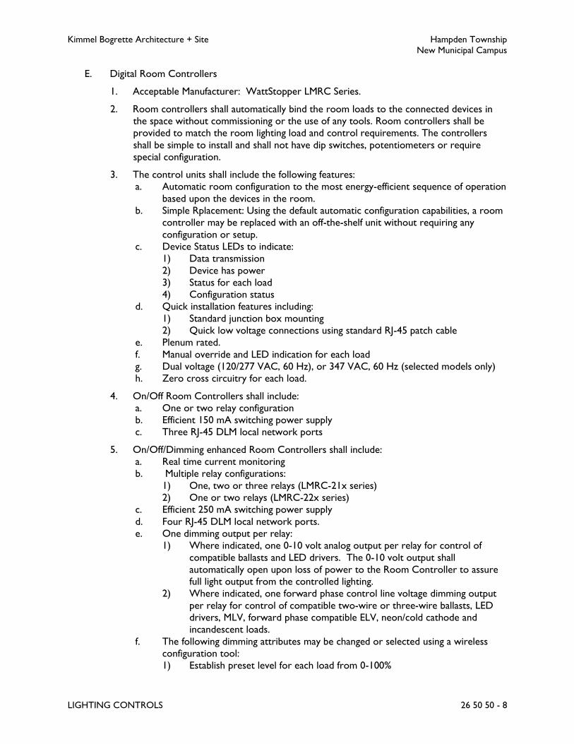
Kimmel Bogrette Architecture + Site Hampden Township
New Municipal Campus
LIGHTING CONTROLS 26 50 50 - 8
E. Digital Room Controllers
1. Acceptable Manufacturer: WattStopper LMRC Series.
2. Room controllers shall automatically bind the room loads to the connected devices in
the space without commissioning or the use of any tools. Room controllers shall be
provided to match the room lighting load and control requirements. The controllers
shall be simple to install and shall not have dip switches, potentiometers or require
special configuration.
3. The control units shall include the following features:
a. Automatic room configuration to the most energy-efficient sequence of operation
based upon the devices in the room.
b. Simple Rplacement: Using the default automatic configuration capabilities, a room
controller may be replaced with an off-the-shelf unit without requiring any
configuration or setup.
c. Device Status LEDs to indicate:
1) Data transmission
2) Device has power
3) Status for each load
4) Configuration status
d. Quick installation features including:
1) Standard junction box mounting
2) Quick low voltage connections using standard RJ-45 patch cable
e. Plenum rated.
f. Manual override and LED indication for each load
g. Dual voltage (120/277 VAC, 60 Hz), or 347 VAC, 60 Hz (selected models only)
h. Zero cross circuitry for each load.
4. On/Off Room Controllers shall include:
a. One or two relay configuration
b. Efficient 150 mA switching power supply
c. Three RJ-45 DLM local network ports
5. On/Off/Dimming enhanced Room Controllers shall include:
a. Real time current monitoring
b. Multiple relay configurations:
1) One, two or three relays (LMRC-21x series)
2) One or two relays (LMRC-22x series)
c. Efficient 250 mA switching power supply
d. Four RJ-45 DLM local network ports.
e. One dimming output per relay:
1) Where indicated, one 0-10 volt analog output per relay for control of
compatible ballasts and LED drivers. The 0-10 volt output shall
automatically open upon loss of power to the Room Controller to assure
full light output from the controlled lighting.
2) Where indicated, one forward phase control line voltage dimming output
per relay for control of compatible two-wire or three-wire ballasts, LED
drivers, MLV, forward phase compatible ELV, neon/cold cathode and
incandescent loads.
f. The following dimming attributes may be changed or selected using a wireless
configuration tool:
1) Establish preset level for each load from 0-100%

Kimmel Bogrette Architecture + Site Hampden Township
New Municipal Campus
LIGHTING CONTROLS 26 50 50 - 9
2) Set high and low trim for each load
3) Set lamp burn in time for each load up to 100 hours
F. Digital Photo Sensors
1. Acceptable Manufacturer: WattStopper LMLS-400 or LMLS-500 Series.
2. Provide open or closed loop photo sensors as recommended by system manufacturer
for individual application.
3. Digital photo sensors work with room controllers to provide automatic switching, bi-
level, or tri-level or dimming daylight harvesting capabilities for any load type connected
to a room controller. Closed loop photo sensors shall measure the ambient light in the
space and control a single lighting zone. Open loop photo sensors shall measure
incoming daylight in the space, and are capable of controlling up to three lighting zones.
4. Photo sensors shall be interchangeable without the need for rewiring.
5. Digital photo sensors shall include the following features:
a. An internal photodiode that measures only within the visible spectrum, and has a
response curve that closely matches the photopic curve. The photodiode shall
not measure energy in either the ultraviolet or infrared spectrums. The photocell
shall have a sensitivity of less than 5% for any wavelengths less than 400
nanometers or greater than 700 nanometers.
b. Sensor light level range shall be from 1-6000 footcandles (fc).
c. The capability of ON/OFF, bi-level or tri-level switching, or dimming, for each
controlled zone, depending on the selection of room controller(s) and load
binding to room controller(s).
d. For switching daylight harvesting, the photosensor shall provide a field-selectable
deadband, or a separation, between the “ON Setpoint” and the “OFF Setpoint”
that shall prevent the lights from cycling excessively after they turn off.
e. For dimming daylight harvesting, the photosensor shall provide the option, when
the daylight contribution is sufficient, of turning lights off or dimming lights to a
field-selectable minimum level.
f. Optional wall switch override to allow occupants to reduce lighting level to
increase energy savings or, if permitted by system administrator, raise lighting
levels for a selectable period of time or cycle of occupancy.
g. Infrared (IR) transceiver for configuration and/or commissioning with a handheld
configuration tool, to transmit detected light level to wireless configuration tool,
and for communication with personal remote controls.
h. Red configuration LED that blinks to indicate data transmission.
i. Blue status LED indicates test mode, override mode and load binding.
j. Recessed switch to turn controlled load(s) ON and OFF.
k. One RJ-45 port for connection to DLM local network.
l. Any load or group of loads in the room can be assigned to a daylighting zone
m. Each load within a daylighting zone shall be capable of being individually enabled
or disabled for discrete control (load independence).
6. Closed loop digital photo sensors shall include the following additional features:
a. An internal photodiode that measures light in a 100 degree angle, cutting off the
unwanted light from bright sources outside of this cone.
b. Automatic self-calibration, initiated from the photosensor, a wireless
configuration tool or a PC with appropriate software.

Kimmel Bogrette Architecture + Site Hampden Township
New Municipal Campus
LIGHTING CONTROLS 26 50 50 - 10
c. Automatically establishes application-specific setpoints following self-calibration.
For switching operation, an adequate deadband between the ON and OFF
setpoints shall prevent the lights from cycling; for dimming operation a sliding
setpoint control algorithm with separate Day and Night setpoints shall prevent
abrupt ramping of loads.
7. Open loop digital photo sensors shall include the following additional features:
a. An internal photodiode that measures light in a 60 degree angle cutting off the
unwanted light from the interior of the room.
b. Automatically establishes application-specific setpoints following manual
calibration using a wireless configuration tool or a PC with appropriate software.
For switching operation, an adequate deadband between the ON and OFF
setpoints for each zone shall prevent the lights from cycling; for dimming
operation, a proportional control algorithm shall maintain the design lighting level
in each zone.
c. Each of the three discrete daylight zones can include any non-overlapping group
of loads in the room.
G. Digital Input/Output Interface
1. Acceptable Manufacturer: Wattstopper LMIO-101 Series.
2. Input/Output interface for integration of third party devices such as building automation
systems (BAS), time clocks, photo cells, etc.
3. 24VDC isolated relay (SPDT with normally open, normally closed, and common outputs)
for output to other systems.
4. 24VDS output and four input terminals for maintained momentary switch closure inputs
or third part logic inputs.
5. Status LED for each input and output.
6. Devices shall have two RJ45 ports.
H. Room Network
1. The DLM local network shall be a free topology lighting control physical connection and
communication protocol designed to control a small area of a building. Digital room
devices shall connect to the network using CAT 5e cables with RJ-45 connectors which
provide both data and power to room devices. Features of the DLM local network shall
include:
a. Plug n’ Go automatic configuration and binding of occupancy sensors, switches
and lighting loads to the most energy-efficient sequence of operation based upon
the device attached.
b. Simple replacement of any device in the network with a standard off the shelf unit
without requiring commissioning, configuration or setup.
c. Push n’ Learn configuration to change the automatic configuration, including
binding and load parameters without tools, using only the buttons on the digital
devices in the local network.
d. Two-way infrared communications for control by handheld remotes, and
configuration by a handheld tool including adjusting load parameters, sensor
configuration and binding, within a line of sight of up to 30 feet from a sensor,
wall switch or IR receiver.

Kimmel Bogrette Architecture + Site Hampden Township
New Municipal Campus
LIGHTING CONTROLS 26 50 50 - 11
I. Configurations Tools
1. A configuration tool shall facilitate optional customization of DLM local networks, and be
used to set up open loop daylighting sensors. A wireless configuration tool shall feature
infrared communications, while PC software shall connect to each local network via a
USB interface.
2. Features and functionality of the wireless configuration tool shall include:
a. Two-way infrared (IR) communication with DLM IR-enabled devices within a
range of approximately 30 feet.
b. High visibility organic LED (OLED) display, pushbutton user interface and menu-
driven operation.
c. Read, modify and send parameters for occupancy sensors, daylighting sensors,
room controllers and buttons on digital wall switches.
d. Save up to nine occupancy sensor setting profiles, and apply profiles to selected
sensors.
e. Temporarily adjust light level of any load(s) on the local network, and incorporate
those levels in scene setting.
f. Adjust or fine-tune daylighting settings established during auto-commissioning, and
input light level data to complete commissioning of open loop daylighting
controls.
J. Network Bridge
1. Acceptable Manufacturer: WattStopper LMBC Series.
2. The network bridge module shall connect a DLM local network to a BACnet-compliant
segment network for communication between rooms, panels and a segment manager or
BAS. Each local network shall include a network bridge component to provide a
connection to the local network room devices. The network bridge shall use industry
standard BACnet MS/TP network communication.
a. The network bridge shall be provided as a separate module connected on the
local network through an available RJ-45 port.
b. Provide Plug n’ Go operation to automatically discover room devices connected
to the local network and make all device parameters visible to the segment
manager via the segment network. No commissioning shall be required for set up
of the network bridge on the local network.
c. The network bridge shall automatically create standard BACnet objects for
selected room device parameters to allow any BACnet-compliant BAS to include
lighting control and power monitoring features as provided by the DLM room
devices on each local network. Standard BACnet objects shall be provided as
follows:
1) Read/write the normal or after hours schedule state for the room
2) Read the detection state of the occupancy sensor
3) Read/write the On/Off state of loads
4) Read/write the dimmed light level of loads
5) Read the button states of switches
6) Read total current in amps, and total power in watts through the room
controller
7) Read/write occupancy sensor time delay, PIR sensitivity and ultrasonic
sensitivity settings
8) Activate a preset scene for the room

Kimmel Bogrette Architecture + Site Hampden Township
New Municipal Campus
LIGHTING CONTROLS 26 50 50 - 12
9) Read/write daylight sensor fade time and day and night setpoints
10) Read the current light level, in footcandles, from interior and exterior
photo sensors and photocells
11) Set daylight sensor operating mode
12) Read/write wall switch lock status
13) Read watts per square foot for the entire controlled room
14) Write maximum light level per load for demand response mode
15) Read/write activation of demand response mode for the room
16) Active/restore demand response mode for the room
K. Segment Manager
1. Acceptable Manufacturer: WattStopper LMSM/NB-ROUTER/NB-SWITCH Series.
2. The digital lighting management system shall include at least one segment manager to
manage network communication. It shall be capable of serving up a graphical user
interface via a standard web browser. Each segment manager shall have integral support
for one, two or three segment networks as indicated. Segment networks may alternately
be connected to the segment manger via external routers and switches, using standard
Ethernet structured wiring. Each router shall accommodate one segment network.
Provide the quantity of routers and switches as shown on the Drawings.
3. Operational features of the Segment Manager shall include the following:
a. Connection to PC or LAN via standard Ethernet TCP/IP.
b. Graphical user interface, compatible with Internet Explorer 8, or equal browser.
c. Log-in security capable of restricting some users to view-only or other limited
operations.
d. Automatic discovery of DLM devices and panels on the segment network(s).
Commissioning beyond activation of the discovery function shall not be required
to provide communication, monitoring or control of all local networks and
lighting control panels.
e. After discovery, all rooms and panels shall be presented in a standard navigation
tree format. Selecting a device from the tree shall allow the device settings and
operational parameters to be viewed and changed by the user.
f. Ability to view and modify room device operational parameters. It shall be
possible to set device parameters independently for normal hours and after hours
operation.
g. Ability to set up schedules for rooms and panels. Schedules shall automatically
set controlled zones or areas to either a normal hours or after hours mode of
operation.
h. Ability to group rooms and loads for common control by schedules, switches or
network commands.
i. Ability to monitor connected load current and display power consumption for
areas equipped with room controllers incorporating the integral current
monitoring feature.
j. Provide capabilities for integration with a BAS via BACnet protocol. At a
minimum, the following points shall be available to the BAS via BACnet IP
connection to the segment manager: room occupancy state; individual occupancy
sensor state; scene activation; schedule mode; room lighting power; room plug-
load power; load ON/OFF state; and load dimming level.

Kimmel Bogrette Architecture + Site Hampden Township
New Municipal Campus
LIGHTING CONTROLS 26 50 50 - 13
PART 3 - EXECUTION
3.1 INSTALLATION
A. Occupancy Sensors
1. Occupancy sensors shall be installed and wired per manufacturer’s instructions.
2. Room and/or areas shown on the Drawings with occupancy sensors shall have the
lighting in those rooms controlled using occupancy sensors. Electrical Contractor shall
verify application and quantity of sensors with manufacturer based on type of space and
coverage of each sensor type and add sensors, power packs, etc., of the types directed
by the manufacturer in order to provide adequate detection throughout entire room.
3. Time-off delay times shall be set as directed by Owner.
4. Ultrasonic sensors shall be located a minimum of 4 feet away from air supply diffusers
and 6 inches from power pack.
5. All wiring shall be tested prior to installation and connection of occupancy sensors.
6. Aiming of all directional occupancy sensors shall be as directed by the manufacturer.
B. Daylight Sensors
1. Daylight sensors shall not be mounted directly above direct/indirect pendant fixtures.
2. Final aiming and location of all daylight sensors shall be per manufacturer’s
recommendations.
C. Photo Controls
1. Photo controls shall be installed where indicated on Drawings.
2. Photo controls installed on roof shall be mounted 2 feet above roof.
3. Where possible, photo controls shall be installed facing north. Exercise care when
installing photo cells to ensure no source of artificial light will inadvertently turn photo
control off.
4. Application: Photo controls shall be installed in accordance with the following schedule:
PHOTO CONTROL SCHEDULE
Application Photo Control Spec. No.
Typical, unless noted 1
Recessed 2
3.2 TESTING
A. Upon completion of all line, load and interconnection wiring, and after all fixtures are installed
and lamped, a qualified factory representative shall completely check the installation prior to

Kimmel Bogrette Architecture + Site Hampden Township
New Municipal Campus
LIGHTING CONTROLS 26 50 50 - 14
energizing the system. Each installed occupancy sensor shall be tested in the test mode to see
that lights turn off and on based on occupancy.
B. Test results shall be documented and tabulated for each sensor and shall include all settings.
Three copies shall be turned over to Owner.
C. At the time of checkout and testing, the owner’s representative shall be thoroughly instructed
in the proper operation of the system.
3.3 PROTECTION
A. Contractor shall protect installed product and finished surfaces from damage during all phases
of installation including preparation, testing, and cleanup.
3.4 SERVICE CONTRACT
A. Electrical Contractor shall include in Base Bid the costs of and turn over to Owner a one year
service contract. The service contract shall include two visits to the site during the period of
the one year service contract, one visit at 3 months and the second visit near the end of the
one year service contract. The visits shall be made by a manufacturer authorized
representative knowledgeable of the products and the operation of the product. During each
visit, the manufacturer’s representative shall check each occupancy sensor for proper
operation and make adjustments as necessary. All settings (sensitivity, time delays, etc.) shall
be compared to initial settings and adjusted as required. Make adjustments and re-set as
directed by Owner due to change in use of room, etc. Controls found to be non-operating,
broken (other than miss-use), defective or not operating properly shall be replaced under the
contract standard one year warranty at no cost to the Owner.
B. Electrical contractor shall provide to Owner manufacturer’s name and contact information to
notify for the 3 months and near end of first year visits.
3.5 DIGITAL LIGHTING MANAGEMENT SYSTEM COMMISSIONING
A. Upon completion of the installation, the system shall be commissioned by the manufacturer's
factory authorized representative who shall verify a complete fully functional system.
B. Upon completion of the system commissioning the factory-authorized technician shall visit site
to set initial scenes and lighting levels, calibrate daylight sensors, and to provide the proper
training to the owner's personnel on the adjustment and maintenance of the system.
C. Electrical Contractor shall include in Base Bid all costs for commissioning of the control
system and all components and devices by an authorized representative of the manufacturer.
The Electrical Contractor shall assist the manufacturer’s representative as required during the
commissioning. The manufacturer’s procedures and instructions shall be followed for the
commissioning and shall include, as a minimum, the following:
1. Prior to submission of shop drawings, the Electrical Contractor shall review with the
manufacturer’s authorized representative the physical details and proposed occupancy
and usage of each area indicated to receive an occupancy sensor and the type and

Kimmel Bogrette Architecture + Site Hampden Township
New Municipal Campus
LIGHTING CONTROLS 26 50 50 - 15
location of the lighting control device(s) in each area for approval by the manufacturer’s
representative. Each area shall be reviewed for sensor location and orientation relative
to occupant location, room geometry, obstacles and false triggering. A letter from the
manufacturer’s authorized representative stating that the review has been completed
and that locations and types of sensors in each area are approved shall be included with
the shop drawing submittal. If, for any reason, the manufacturer’s authorized
representative does not approve the sensor location or type for an area or areas, the
letter shall include a listing of those areas, the reason for non-approval and
recommendations for changes.
2. During construction and prior to device rough-in, the manufacturer authorized
representative shall visit the site and approve the actual location of the occupancy
sensor.
3. After installation, the manufacturer’s authorized representative, in coordination with the
Owner, shall adjust the functions, scheduling, sensitivity and time delays of each sensor
and input device as best for the occupancy and usage of the area as described by the
Owner. The adjustments and settings shall be based upon occupant(s) in and out for
short periods of time, occupant(s) in most of the time and out for long periods of time,
etc.
4. Electrical Contractor shall submit to Owner listing of each area indicating type of device
in each area and device/sensor initial settings.
3.6 OCCUPANCY SENSOR CONTROL SYSTEM COMMISSIONING
A. Electrical Contractor shall include in Base Bid all costs for commissioning of the occupancy
sensors and, where applicable, the occupancy sensors control system(s) by an authorized
representative of the manufacturer. The Electrical Contractor shall assist the manufacturer’s
representative as required during the commissioning. The manufacturer’s procedures and
instructions shall be followed for the commissioning and shall include, as a minimum, the
following:
1. Prior to submission of shop drawings, the Electrical Contractor shall review with the
manufacturer’s authorized representative the physical details and proposed occupancy
and usage of each area indicated to receive an occupancy sensor and the type and
location of the occupancy sensor(s) in each area for approval by the manufacturer’s
representative. Each area shall be reviewed for sensor location and orientation relative
to occupant location, room geometry, obstacles and false triggering. A letter from the
manufacturer’s authorized representative stating that the review has been completed
and that locations and types of sensors in each area are approved shall be included with
the shop drawing submittal. If, for any reason, the manufacturer’s authorized
representative does not approve the sensor location or type for an area or areas, the
letter shall include a listing of those areas, the reason for non-approval and
recommendations for changes.
2. During construction and prior to occupancy sensor rough-in, the manufacturer
authorized representative shall visit the site and approve the actual location of the
occupancy sensor.
3. After installation, the manufacturer’s authorized representative, in coordination with the
Owner, shall adjust the sensitivity and time delays of each sensor as best for the
occupancy and usage of the area as described by the Owner. The adjustments and

Kimmel Bogrette Architecture + Site Hampden Township
New Municipal Campus
LIGHTING CONTROLS 26 50 50 - 16
settings shall be based upon occupant(s) in and out for short periods of time,
occupant(s) in most of the time and out for long periods of time, etc.
4. Electrical Contractor shall submit to Owner listing of each area with an occupancy
sensor, type of sensor in each area and settings of each sensor.
END OF SECTION 26 50 50

Kimmel Bogrette Architecture + Site Hampden Township
New Municipal Campus
SPECIAL SYSTEMS 26 60 10 - 1
SECTION 26 60 10 – SPECIAL SYSTEMS
PART 1 - GENERAL
1.1 WORK INCLUDED
A. The Work of this Section shall consist of the labor, materials, and equipment required for the
furnishing and installing of special equipment specified herein.
PART 2 - PRODUCTS
(NOT USED)
PART 3 - EXECUTION
3.1 INSTALLATION
A. General
1. Install equipment and wiring to equipment in accordance with manufacturer's
instructions.
2. Furnish and install suitable strain relief clamps and fittings for cord connections at outlet
boxes and equipment connection boxes.
B. Automatic Door Operators
1. Automatic door operators and associated controls, wiring and equipment will be
furnished and installed by General Contractor. Furnish and install branch wiring to
junction box indicated and make final connections.
C. Receptacles Furnished with Equipment
1. Receptacles will be furnished by equipment supplier as noted on Drawings. Furnish
materials necessary to install receptacles, install receptacles and furnish and install wiring
to receptacles and make connections.
D. Exterior Building Signs
1. Exterior building sign will be furnished and installed by General Contractor. Furnish and
install power and communications wiring and make required connections as directed by
sign manufacturer.

Kimmel Bogrette Architecture + Site Hampden Township
New Municipal Campus
SPECIAL SYSTEMS 26 60 10 - 2
E. Electrically Operated Sliding Doors
1. Doors with electric operators and overhead releases will be furnished and installed by
General Contractor. General Contractor will furnish push plates, remote key switches,
and electric eyes. Install, wire and connect push plates, key switches and electric eyes,
and furnish and install power wiring to door operators and control wiring from push
plates, overhead releases, electric eyes, and key switches to door operators. Provide
final connection of power wiring and control wiring.
2. Install wiring to sliding door operator through the side door jamb.
F. Electrically Operated Overhead Doors
1. Overhead doors with electric operators will be furnished and installed by General
Contractor. General Contractor will furnish all controls. Install and wire controls and
furnish and install power wiring to door operators and control wiring from controls to
door operators. Provide final connection of power wiring and control. Furnish, install
and wire disconnect switches.
G. Projection Screen
1. Projection screen with motor and starter will be furnished and installed by General
Contractor. Raise lower, key operated, selector switch will be furnished by General
Contractor.
2. Furnish and install power wiring to screen, install raise lower switch, and furnish and
install wiring for raise lower switch.
3.2 COORDINATION
A. Obtain verification from Architect on mounting height and location of all electrical outlets,
conduit stubs, receptacles, switches, disconnect switches, plugmold, motor starters, controls
and other electrical equipment before roughing in.
B. Before roughing in equipment, obtain verification from Architect for all equipment to be wired
as Work of this Section as follows:
1. Verify electrical loads of all equipment.
2. Verify electrical characteristics of all equipment for compatibility with electrical power
provided to the equipment.
C. Before roughing in equipment, obtain verification from Engineer for all equipment to be wired
as Work of this Section as follows:
1. Verify electrical loads of all equipment.
2. Verify electrical characteristics of all equipment for compatibility with electrical power
provided to the equipment.
END OF SECTION 26 60 10

Kimmel Bogrette Architecture + Site Hampden Township
New Municipal Campus
CONTROLS AND INSTRUMENTATION 26 90 10 - 1
SECTION 26 90 10 – CONTROLS AND INSTRUMENTATION
PART 1 - GENERAL
1.1 WORK INCLUDED
A. The Work of this Section shall consist of the labor, materials and equipment required to
furnish, install, and connect the control instrumentation equipment as specified herein and
indicated on the Drawings.
1.2 SUBMITTALS
A. Submit for approval in accordance with specified submittal procedures:
1. Motor Starters
2. Contactors
3. Control Stations
4. Relays
PART 2 - PRODUCTS
2.1 ACCEPTABLE MANUFACTURER
A. Unless otherwise indicated, acceptable manufacturers of equipment and items specified in this
section shall be one of the following:
1. Square D
2. Allen Bradley
3. General Electric
4. Siemens Industry
5. Eaton Cutler Hammer
2.2 MOTOR STARTERS, MANUAL
A. Manual Motor Starter Specification No. MN-1.
1. Acceptable Manufacturer: Square D Class 2510, single-speed, and Class 2512 two-speed.
2. Type: Manual motor starter with overloads, fractional horsepower.
3. 120/240 volts AC, single phase.
4. Surface mounted in unfinished spaces, flush mounted in finished spaces.
5. NEMA 1 enclosure.
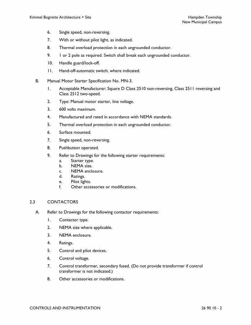
Kimmel Bogrette Architecture + Site Hampden Township
New Municipal Campus
CONTROLS AND INSTRUMENTATION 26 90 10 - 2
6. Single speed, non-reversing.
7. With or without pilot light, as indicated.
8. Thermal overload protection in each ungrounded conductor.
9. 1 or 2 pole as required. Switch shall break each ungrounded conductor.
10. Handle guard/lock-off.
11. Hand-off-automatic switch, where indicated.
B. Manual Motor Starter Specification No. MN-3.
1. Acceptable Manufacturer: Square D Class 2510 non-reversing, Class 2511 reversing and
Class 2512 two-speed.
2. Type: Manual motor starter, line voltage.
3. 600 volts maximum.
4. Manufactured and rated in accordance with NEMA standards.
5. Thermal overload protection in each ungrounded conductor.
6. Surface mounted.
7. Single speed, non-reversing.
8. Pushbutton operated.
9. Refer to Drawings for the following starter requirements:
a. Starter type.
b. NEMA size.
c. NEMA enclosure.
d. Ratings.
e. Pilot lights.
f. Other accessories or modifications.
2.3 CONTACTORS
A. Refer to Drawings for the following contactor requirements:
1. Contactor type.
2. NEMA size where applicable.
3. NEMA enclosure.
4. Ratings.
5. Control and pilot devices.
6. Control voltage.
7. Control transformer, secondary fused. (Do not provide transformer if control
transformer is not indicated.)
8. Other accessories or modifications.

Kimmel Bogrette Architecture + Site Hampden Township
New Municipal Campus
CONTROLS AND INSTRUMENTATION 26 90 10 - 3
B. Contactors shall be group mounted in common enclosure when indicated as mounted side-by-
side.
C. Where indicated as combination, contactors shall have fusible or non-fusible disconnect switch
or circuit breaker in same enclosure. Disconnect switches and circuit breakers shall be as
specified herein.
D. Contactor Specification No. 1
1. Acceptable Manufacturer: Square D Class 8903.
2. Non-motor loads.
3. 2 wire control.
4. Electrically held type.
5. Normally open (NO) holding circuit interlock provided for 3 wire control, when
required.
2.4 CONTROL DEVICES
A. Control Device Specification No.1
1. 1. Acceptable Manufacturer: Square D Class 9001, heavy duty.
2. Heavy duty.
3. Manufactured in accordance with NEMA standards.
4. NEMA 1 enclosure, unless otherwise indicated.
5. Surface mounted, unless indicated.
6. Pushbuttons, selector switches and pilot lights as indicated on Drawings.
7. Push-to-test, 6 to 8 volt, transformer type pilot lights.
8. Colored pilot light lens as indicated on Drawings, or red if no color indicated. Colored
lens shall be interchangeable.
9. Silver contacts.
10. 600 volts AC, maximum; 10 amps continuous current carrying capacity at all AC
voltages.
11. Start pushbuttons shall have fully guarded or flush black button.
12. Stop pushbuttons shall have unguarded or extended red button.
13. Provide appropriate legend or nameplate.
14. Selector switches shall have standard operator, unless otherwise indicated.
15. Panic buttons shall have one NO and one NC contact, momentary contact, red
mushroom head.

Kimmel Bogrette Architecture + Site Hampden Township
New Municipal Campus
CONTROLS AND INSTRUMENTATION 26 90 10 - 4
2.5 RELAYS
A. Relay Specification No. 1
1. Acceptable Manufacturer: Square D Class 8501.
2. Silver contacts, convertible.
3. 10 amp continuous current rating, 600 volts maximum.
4. Ratings, poles and enclosure as indicated on Drawings.
5. Electrically held, unless otherwise indicated.
PART 3 - EXECUTION
3.1 INSTALLATION
A. General
1. Install control and instrumentation equipment in accordance with equipment
manufacturer’s instructions. Submit manufacturer’s printed installation instructions with
operating and maintenance data at completion of Work.
2. Individually mounted motor starter shall be mounted 5 feet above finished floor unless
otherwise noted.
END OF SECTION 26 90 10
Kimmel Bogrette Architecture + Site Hampden Township
New Municipal Campus
WIRING OF MECHANICAL EQUIPMENT 26 96 10 - 1
SECTION 26 96 10 – WIRING OF MECHANICAL EQUIPMENT
PART 1 - GENERAL
1.1 WORK INCLUDED
A. The Work of this Section shall include the labor, materials, and equipment required for
furnishing and installing the power and control wiring of mechanical equipment. It shall not
include control wiring specifically detailed as part of the building automation and automatic
temperature control system specified in Section 23 90 10, Building Automation System.
PART 2 - PRODUCTS
2.1 MATERIALS
A. Mechanical Contractor(s) shall furnish equipment with controls, starters and related items as
specified in various Sections of Divisions 21, 22 and 23.
B. Where mechanical equipment is specified without starters or controllers, Electrical
Contractor shall furnish and install same as specified herein.
C. Electrical Contractor shall furnish and install all power wiring unless specifically noted
otherwise.
D. Mechanical Contractor(s) shall furnish and install all control wiring unless specifically noted
otherwise.
PART 3 - EXECUTION
3.1 INSTALLATION
A. Mechanical equipment shall be wired in accordance with the following schedule:
Key:
Item furnished by ...
Item installed by ...
Item wired by ...
the respective trade according to the following designations:
P = Plumbing Contractor
F = Fire Protection Contractor
H = HVAC Contractor
E = Electrical Contractor
G = General Contractor
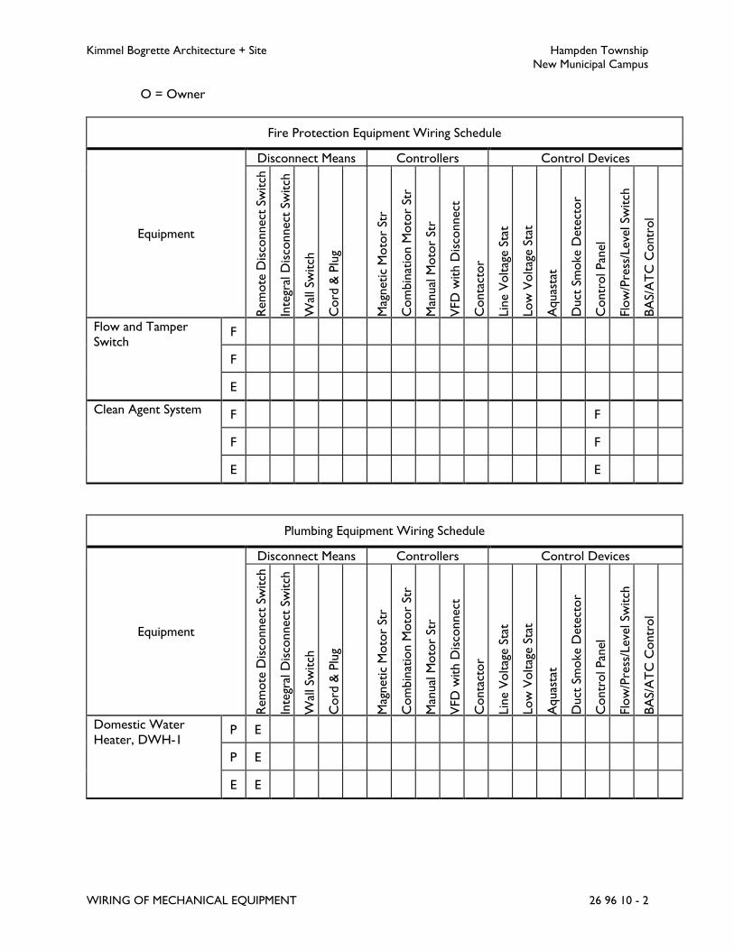
Kimmel Bogrette Architecture + Site Hampden Township
New Municipal Campus
WIRING OF MECHANICAL EQUIPMENT 26 96 10 - 2
O = Owner
Fire Protection Equipment Wiring Schedule
Equipment
Disconnect Means Controllers Control Devices
Rem
ote
Dis
connect
Sw
itch
Inte
gral
Dis
connect
Sw
itch
Wal
l Sw
itch
Cord
& P
lug
Mag
netic
Moto
r St
r
Com
bin
atio
n M
oto
r St
r
Man
ual
Moto
r St
r
VFD
with D
isco
nnect
Conta
ctor
Lin
e V
olt
age S
tat
Low
Volt
age S
tat
Aquas
tat
Duct
Sm
oke D
ete
ctor
Contr
ol Pan
el
Flo
w/P
ress
/Leve
l Sw
itch
BA
S/A
TC
Contr
ol
Flow and Tamper
Switch F
F
E
Clean Agent System F F
F F
E E
Plumbing Equipment Wiring Schedule
Equipment
Disconnect Means Controllers Control Devices
Rem
ote
Dis
connect
Sw
itch
Inte
gral
Dis
connect
Sw
itch
Wal
l Sw
itch
Cord
& P
lug
Mag
netic
Moto
r St
r
Com
bin
atio
n M
oto
r St
r
Man
ual
Moto
r St
r
VFD
with D
isco
nnect
Conta
ctor
Lin
e V
olt
age S
tat
Low
Volt
age S
tat
Aquas
tat
Duct
Sm
oke D
ete
ctor
Contr
ol Pan
el
Flo
w/P
ress
/Leve
l Sw
itch
BA
S/A
TC
Contr
ol
Domestic Water
Heater, DWH-1 P E
P E
E E

Kimmel Bogrette Architecture + Site Hampden Township
New Municipal Campus
WIRING OF MECHANICAL EQUIPMENT 26 96 10 - 3
Plumbing Equipment Wiring Schedule
Equipment
Disconnect Means Controllers Control Devices
Rem
ote
Dis
connect
Sw
itch
Inte
gral
Dis
connect
Sw
itch
Wal
l Sw
itch
Cord
& P
lug
Mag
netic
Moto
r St
r
Com
bin
atio
n M
oto
r St
r
Man
ual
Moto
r St
r
VFD
with D
isco
nnect
Conta
ctor
Lin
e V
olt
age S
tat
Low
Volt
age S
tat
Aquas
tat
Duct
Sm
oke D
ete
ctor
Contr
ol Pan
el
Flo
w/P
ress
/Leve
l Sw
itch
BA
S/A
TC
Contr
ol
Circulating Pump, CP-
1 P E P P
P E P P
E E E E
Electronic Faucets P
P
E
Electric Water
Cooler, EWC-1 P P
P P
E E
Bottle Filler, BF-1 P
P
E
Solenoid Valves P
P
E
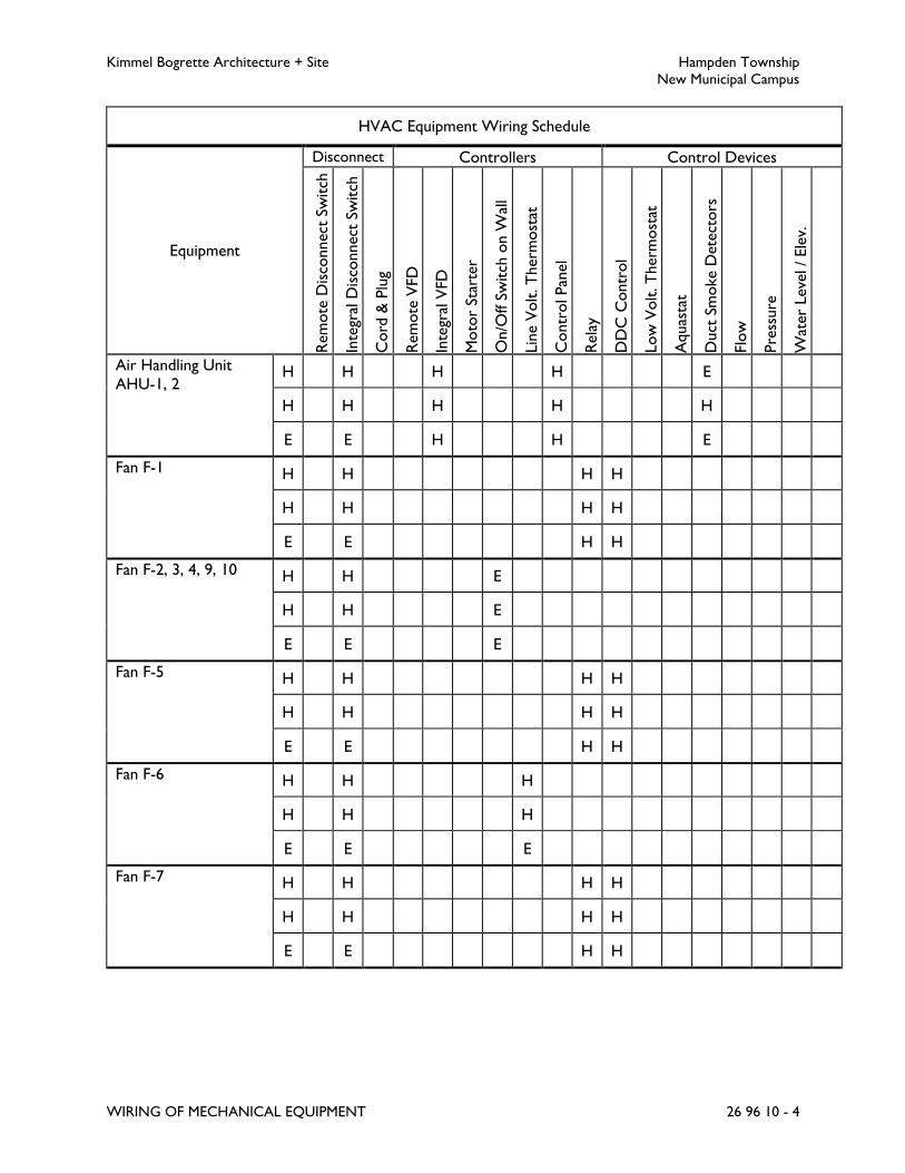
Kimmel Bogrette Architecture + Site Hampden Township
New Municipal Campus
WIRING OF MECHANICAL EQUIPMENT 26 96 10 - 4
HVAC Equipment Wiring Schedule
Equipment
Disconnect Controllers Control Devices
Rem
ote
Dis
connect
Sw
itch
Inte
gral
Dis
connect
Sw
itch
Cord
& P
lug
Rem
ote
VFD
Inte
gral
VFD
Moto
r St
arte
r
On/O
ff S
witch
on W
all
Lin
e V
olt
. T
herm
ost
at
Contr
ol Pan
el
Rela
y
D
DC
Contr
ol
Low
Volt
. T
herm
ost
at
Aquas
tat
Duct
Sm
oke D
ete
ctors
Flo
w
Pre
ssure
Wat
er
Leve
l / Ele
v.
Air Handling Unit
AHU-1, 2 H H H H E
H H H H H
E E H H E
Fan F-1 H H H H
H H H H
E E H H
Fan F-2, 3, 4, 9, 10 H H E
H H E
E E E
Fan F-5 H H H H
H H H H
E E H H
Fan F-6 H H H
H H H
E E E
Fan F-7 H H H H
H H H H
E E H H

Kimmel Bogrette Architecture + Site Hampden Township
New Municipal Campus
WIRING OF MECHANICAL EQUIPMENT 26 96 10 - 5
HVAC Equipment Wiring Schedule
Equipment
Disconnect Controllers Control Devices
Rem
ote
Dis
connect
Sw
itch
Inte
gral
Dis
connect
Sw
itch
Cord
& P
lug
Rem
ote
VFD
Inte
gral
VFD
Moto
r St
arte
r
On/O
ff S
witch
on W
all
Lin
e V
olt
. T
herm
ost
at
Contr
ol Pan
el
Rela
y
D
DC
Contr
ol
Low
Volt
. T
herm
ost
at
Aquas
tat
Duct
Sm
oke D
ete
ctors
Flo
w
Pre
ssure
Wat
er
Leve
l / Ele
v.
Fan F-8 H H H H
H H H H
E E H H
Unit Heater UH-1
thru 4 H H H H
H H H H
E E H H
Cabinet Unit Heater
CUH-1 thru 4 H H H H
H H H H
E E H H
Chiller CH-1 H H H H
H H H H
E E H H
Boiler B-1, 2 H E H H
H E H H
E E H H
Pumps P-1, 2, 5, 6 H H H H
H H H H
E E E H

Kimmel Bogrette Architecture + Site Hampden Township
New Municipal Campus
WIRING OF MECHANICAL EQUIPMENT 26 96 10 - 6
HVAC Equipment Wiring Schedule
Equipment
Disconnect Controllers Control Devices
Rem
ote
Dis
connect
Sw
itch
Inte
gral
Dis
connect
Sw
itch
Cord
& P
lug
Rem
ote
VFD
Inte
gral
VFD
Moto
r St
arte
r
On/O
ff S
witch
on W
all
Lin
e V
olt
. T
herm
ost
at
Contr
ol Pan
el
Rela
y
D
DC
Contr
ol
Low
Volt
. T
herm
ost
at
Aquas
tat
Duct
Sm
oke D
ete
ctors
Flo
w
Pre
ssure
Wat
er
Leve
l / Ele
v.
Pumps -3, 4 H E E H
H E E H
E E E H
Split System Air
Conditioner SSAC-1,
2
H E H H
H E H H
E E H H
Condenser-
Compressor CU-1, 2 H E H
H E H
E E H
Fan F-11 H H E
H H E
E E E
Fan F-12 H H E H H
H H E H H
E E E H H
Electric Heat Trace H H H
H H H
E E E
B. Unless noted, Contractor responsible for wiring of an item shall be responsible for furnishing
and installing all wiring for that item and making all connections associated with this wiring.

Kimmel Bogrette Architecture + Site Hampden Township
New Municipal Campus
WIRING OF MECHANICAL EQUIPMENT 26 96 10 - 7
C. Electrical Contractor shall furnish and install wiring from duct smoke detector to fire alarm
panel. HVAC Contractor shall furnish and install wiring from normally open auxiliary contact
on duct smoke detector to control circuitry for shut down of equipment if duct smoke
detector is activated.
END OF SECTION 26 96 10

Kimmel Bogrette Architecture + Site Hampden Township
New Municipal Campus
COMMON REQUIREMENTS - TELECOMMUNICATIONS SYSTEM 27 05 15 - 1
SECTION 27 05 15 – COMMON REQUIREMENTS – TELECOMMUNICATIONS SYSTEMS
PART 1 - GENERAL
1.1 RELATED DOCUMENTS
A. The requirements stated in Section 20 00 20, General Provisions – Electrical apply to this
Section as if fully repeated herein.
1.2 WORK INCLUDED
A. Telecommunications system work shall consist of labor, materials, and equipment required for
furnishing and installing the complete and operational telecommunications system.
B. The Telecommunications System includes work of the following Specification Sections:
1. Specifications:
Section 27 05 15 Common Requirements – Telecommunications Systems
Section 27 05 25 Grounding and Bonding for Telecommunications Systems
Section 27 05 30 Pathways for Telecommunications Systems
Section 27 11 10 Telecommunications Spaces, Equipment and Fittings
Section 27 13 10 Backbone Cabling – Telecommunications Systems
Section 27 15 10 Horizontal Distribution Cabling – Telecommunications Systems
Section 27 15 45 Faceplates and Connectors - Telecommunications Systems
Section 27 16 10 Connecting Cords, Devices and Adapters –
Telecommunications Systems
Section 27 19 10 Telecommunications Cable System Testing – Copper
Section 27 19 20 Telecommunications Cable System Testing – Fiber
Section 27 19 30 Telecommunications Cable System Testing – Coax
Section 27 60 10 Telecommunications Systems Identification and Documentation
2. Drawings:
E3.1 Floor Plan Part “A” – Systems
E3.2 Floor Plan Part “B” – Systems
E5.1 Details
E7.2 Risers
C. Telecommunications Work shall be bid as a subcontract to the Electrical contract.

Kimmel Bogrette Architecture + Site Hampden Township
New Municipal Campus
COMMON REQUIREMENTS - TELECOMMUNICATIONS SYSTEM 27 05 15 - 2
1.3 SERVICE PROVIDER COSTS
A. Bidder shall include in his price the cost for coordination of telephone service, data service and
CATV service with the respective Service Providers. Coordinate installation, connection and
testing of the Service Providers’ service, up to and including the demarcation point, with the
Owner and the Service Provider. All work of the Service Provider will be contracted directly
between the Service Provider and the Owner.
1.4 TELECOMMUNICATIONS CABLING SYSTEM CONTRACTOR’S QUALIFICATIONS
A. Contractor shall be recognized by the manufacturer providing the cable system performance
warranty as an approved/certified installer of their product. Furnish a certificate from the
manufacturer with the shop drawings.
B. Contractor firm and all employees shall have at least 5 years’ experience in providing certified
communication cabling projects.
C. Contractor shall submit with shop drawings a list of the project team which shall include, as a
minimum, the project manager and foreman. Note on the list the personnel that have been
trained and certified by the data system manufacturer along with a brief description of their
experience and training. Changes to project staffing after contract award must be requested, in
writing, and approved by Owner prior to any changes.
D. At least 50% of the technicians on site shall be BICSI Level I or Level II certified with current
certificates available for review upon request. The foreman shall be, at minimum, BICSI Level II.
E. Where applicable, contractor shall have personnel trained and certified in category rated UTP
and fiber optic cable installation, termination and testing techniques. Personnel shall have
experience using a category rated cable tester, fiber optic light meter and power source and
OTDR.
F. Submit, with shop drawings, a list of at least three certified communication cabling projects of
similar size completed in the past two years. Provide references with telephone numbers for
each project. Only provide projects where the listed project team members participated.
1.5 COORDINATION
A. Unless noted otherwise, the following items will be the responsibility of the Owner:
1. All electronics and active data networking equipment, etc.
2. Telephones, fax machines and modems, etc.
3. PC’s, printers, video display terminals, flat panel displays, etc.
4. Contact the Owner’s network and computer equipment personnel for specific
instructions before starting Work.

Kimmel Bogrette Architecture + Site Hampden Township
New Municipal Campus
COMMON REQUIREMENTS - TELECOMMUNICATIONS SYSTEM 27 05 15 - 3
B. Furnish complete systems documentation as described herein, Section 27 60 10,
Telecommunications System Identification and Documentation, where required in other
specification sections and as required by Division 1.
C. Coordinate outlet locations with existing conditions and the work of other trades prior to
rough-in and installation. Any discrepancies between the work shown on the drawings and
actual field conditions shall immediately be brought to the attention of the Architect for
resolution prior to the start of construction.
D. Coordinate cable lengths with existing conditions and the work of other trades prior to
rough-in and installation. This coordination shall include, but is not limited to, conduit, cable
tray and pathways furnished and installed by other trades. The contractor shall verify that the
installed cables will not exceed the maximum allowable cable length, including all routing, rises,
drops and slack cable as required. Any discrepancies between the work shown on the
drawings and actual field conditions shall immediately be brought to the attention of the
Architect for resolution prior to the start of construction.
E. The Contractor shall coordinate with the work of the Service Provider(s), as it applies to
work around and with the cables, equipment and facilities owned and operated by the Service
Provider. This coordination is required, but is not limited to the following:
1. Provision of a cable and service to a facility or building as part of this project.
2. Installation of Owner’s cables adjacent to, or in, the same manhole/space with cables
from a Service Provider or vendor.
3. Work over, or in contact with cables, equipment and facilities owned and operated by a
Service Provider.
4. Work over, or in contact with cables, equipment and facilities owned and operated by
the Owner.
PART 2 - PRODUCTS
(NOT USED)
PART 3 - EXECUTION
3.1 RECORD DOCUMENTS
A. Maintain a set of Contract Documents, i.e., Specifications, Drawings, Addenda, Modifications
and approved submittals at the site, in good order and annotated to show all changes made
during construction process. These record documents shall be delivered to Owner either
prior to or with submission of Application for Final Payment.
B. Record drawings shall include:
1. The single line diagram of the building telecommunications distribution system provided
under this contract and;

Kimmel Bogrette Architecture + Site Hampden Township
New Municipal Campus
COMMON REQUIREMENTS - TELECOMMUNICATIONS SYSTEM 27 05 15 - 4
2. Drawings indicating location and area served for all distribution.
3. Drawings indicating outlet locations and outlet numbers.
4. Cable distribution pathways.
5. Termination locations (other than in telecommunications spaces and outlets).
3.2 OPERATION AND MAINTENANCE INSTRUCTIONS
A. Furnish an instructor/operator at completion of system(s) installation, who shall operate
system(s) in order to demonstrate fulfillment of contract requirements. During this time,
Owner shall be thoroughly versed in details of operation and maintenance.
B. A minimum of 2 sets of printed instructions covering operation and maintenance of each item
of equipment shall be submitted to Owner during this operating period. Required instructions
from manufacturer’s representatives shall be submitted at this time.
C. Operation and Maintenance Manuals shall include:
1. Submittal data stating equipment rating and selected options for each piece of
equipment requiring maintenance.
2. Manufacturers’ installation instructions for each cable system component and major
hardware component furnished and installed as part of this Work.
3. Operation and maintenance manuals for each piece of equipment requiring maintenance
with required routine maintenance actions clearly identified.
4. Names and addresses of at least one qualified service agency.
5. Complete narrative of how each system is intended to operate.
3.3 WARRANTIES
A. Provide a system warranty covering the installed telecommunications cable system against
defects in workmanship, components, and performance, and follow-on support after project
completion.
B. Installation Warranty: Contractor shall warrant the telecommunications cable system against
defects in workmanship for a period of two years from the date of system acceptance. The
warranty shall cover all labor and materials necessary to correct a failed portion of the system
and to demonstrate performance within the original installation specifications after repairs are
accomplished. This warranty shall be provided at no additional cost to the Owner.
C. Cable System Performance Warranty: Contractor shall facilitate a 25 Year Performance
Warranty between the manufacturer and the Owner. The performance warranty shall warrant
the installed Category rated UTP copper and the backbone optical fiber portions of the cabling
system. Copper links shall be warranted against the link performance minimum expected
results defined in the latest TIA/EIA standard, and the manufacturer's Network Cabling
Contractor Agreement. Fiber optic links shall be warranted against the link and segment
performance minimum expected results defined in the latest TIA/EIA standard, and the

Kimmel Bogrette Architecture + Site Hampden Township
New Municipal Campus
COMMON REQUIREMENTS - TELECOMMUNICATIONS SYSTEM 27 05 15 - 5
manufacturer's Network Cabling Contractor Agreement. All other connectivity components
shall be warranted against defects in materials and workmanship for a period of 25 years.
END OF SECTION 27 05 15

Kimmel Bogrette Architecture + Site Hampden Township
New Municipal Campus
GROUNDING AND BONDING FOR TELECOMMUNICATIONS 27 05 25 - 1
SECTION 27 05 25 – GROUNDING AND BONDING FOR TELECOMMUNICATIONS SYSTEMS
PART 1 - GENERAL
1.1 WORK INCLUDED
A. The Work of this Section shall consist of the labor, material and equipment required for the
installation of the telecommunications grounding and bonding system as part of a complete and
operational telecommunications cable system. The specific application of these materials shall
be as outlined in this Section and Sections of this Division, and as indicated on the Drawings.
1.2 SUBMITTALS
A. Submit for approval in accordance with specified submittal procedures:
1. Ground connectors
2. Grounding busbars
1.3 COORDINATION
A. All items specified or included in this section shall be furnished and installed by, wired and
connected by, and connected by Electrical Contractor, unless noted otherwise.
B. The term “Contractor” as used herein shall mean Electrical Contractor or Electrical
Contractor’s sub-contractor.
C. Contractor shall furnish and install telecommunications grounding busbars,
telecommunications bonding backbone(s), grounding equalizer(s), and equipment bonding
conductors to install a complete telecommunications grounding system.
D. The Electrical Contractor shall furnish and install telecommunications grounding busbars,
telecommunications bonding backbone(s), grounding equalizer(s), and equipment bonding
conductors to install a complete telecommunications grounding system.
PART 2 - PRODUCTS
2.1 GROUND CONNECTORS
A. Acceptable Manufacturer: Burndy/FCI, Thomas & Betts/Blackburn, or as approved.
B. Wire to Wire Connectors:
1. Burndy/FCI KS Series split bolt connector, or as approved.
2. Max Conductor Size:

Kimmel Bogrette Architecture + Site Hampden Township
New Municipal Campus
GROUNDING AND BONDING FOR TELECOMMUNICATIONS 27 05 25 - 2
a. Run: #3/0 AWG
b. Tap: #3/0 AWG
3. Wire Type: Solid or stranded copper.
4. Material: High conductivity copper or bronze alloy.
5. Configuration: Split bolt.
C. Wire to Busbar/Equipment Connectors
1. Thomas & Betts/Blackburn Type L Mechanical Series, or as approved.
2. Max Conductor Size: As required.
3. Wire Type: Solid or stranded copper.
4. Material: High strength bronze alloy or copper.
5. Material: High strength bronze alloy or copper.
6. Configuration: Single conductor mechanical lug with two mounting holes in the tongue.
2.2 TELECOMMUNICATIONS SYSTEMS MAIN GROUNDING BUSBAR
A. Acceptable Manufacturer: Erico Electrical Products “TMGB” Series, Chatsworth or Newtown
Instrument Co., or as approved.
B. Conforms to specifications of TIA/EIA 607.
C. 1/4 inch thick by 4 inches wide by 20 inches long copper bus bar with electro-tin plating.
D. BICSI hole pattern with 27 pairs of 5/16 inch holes - “A” pattern and 3 pairs of 7/16 inch holes
- “C” pattern.
E. Furnish with polyamide, glass fiber reinforced, stand-off insulators and stainless steel mounting
brackets and stainless steel fasteners.
F. All connections to the telecommunications ground bus shall be made using two-hole
compression connectors secured with two silicon bronze bolts, each with two washer, one
lock washer and nut.
2.3 TELECOMMUNICATIONS SYSTEMS GROUNDING BACKBONE AND BONDING
CONDUCTORS
A. Refer to Section 26 05 20, Wire and Cable, 600 Volts and Below, for types and requirements
of wire for telecommunications grounding backbone and bonding conductors.
B. Grounding and bonding conductors shall be Wire Specification No. 4.
C. Grounding and bonding conductors may be non-insulated wire.
D. Stranded or solid grounding and bonding conductors shall be selected based on wire size
requirements as indicated in Section 26 05 20, Wire and Cable, 600 Volts and Below.

Kimmel Bogrette Architecture + Site Hampden Township
New Municipal Campus
GROUNDING AND BONDING FOR TELECOMMUNICATIONS 27 05 25 - 3
PART 3 - EXECUTION
3.1 APPLICATION
A. Unless noted otherwise, the telecommunications grounding system shall be furnished and
installed in accordance with the TIA/EIA/J-STD-607-A, Commercial Building Grounding
(Earthing) and Bonding Requirements for Telecommunications.
B. Unless noted otherwise, wires and connectors for telecommunications grounding system shall
be installed in accordance with the requirements of Section 26 05 20, Wire and Cable, 600
Volts and Below.
C. Unless noted otherwise, ground busbars for telecommunications grounding system shall be
installed in accordance with the requirements of Section 26 05 60, Grounding Systems.
3.2 GROUNDING - GENERAL
A. Unless noted otherwise, conductive non-current carrying electrical materials and equipment
shall be grounded. Non-electrical items of equipment shall be bonded together and grounded
as indicated herein and on drawings. Grounding and bonding shall be in accordance with
National Electrical Code requirements.
B. Raceway system shall be grounded and shall be electrically and mechanically continuous from
all telecommunication rooms to system main ground point
C. Main system ground points shall be as indicated on Drawings. Exact location and point of
connection of main system grounds shall be verified during construction.
D. Grounding conductors shall be installed in telecommunications raceways unless noted
otherwise.
E. Grounding conductors shall be bonded to raceway systems at 100 foot intervals in cable tray
systems and at the entrance and exit of conduits where grounding conductors are installed
through the conduit.
F. The contractor shall furnish and install ground wires from the telecommunications main
grounding busbar to each of the telecommunications grounding busbars in each
telecommunications space. Conductor size shall be as indicated on drawings
G. TMGBs and TGBs shall be mounted on the plywood backboards in each telecommunications
space. The mounts shall include two isolation bushings and two sets of mounting legs for each
bus bar.
H. The contractor shall furnish and install stranded ground wires from the ground bus bars in
each of the telecommunications spaces to the nearest point of connection of:
1. Local electrical distribution panel ground
2. Building steel

Kimmel Bogrette Architecture + Site Hampden Township
New Municipal Campus
GROUNDING AND BONDING FOR TELECOMMUNICATIONS 27 05 25 - 4
I. Conductor size shall be as indicated on Drawings.
J. Furnish and install ground wires, clamps, connectors, etc. as required to connect all racks,
cabinets, frames and all exposed conductive materials and equipment of each
telecommunications system to the ground bar/plate in each telecommunications space.
K. All exposed conductive elements telecommunications systems shall be bonded to the ground
bar in the telecommunications spaces.
L. Lightning protection equipment (primary and secondary protectors) shall be bonded to ground
with a minimum as required by manufacturers recommended wire size and type.
M. Cable shields and splice enclosures shall be bonded to ground as required by the
manufacturer’s recommendations, #10 AWG minimum.
N. Equipment chassis, racks, cabinets and frames shall be bonded to ground as required by the
manufacturer’s recommendations or in lieu of manufacturer’s recommendations as follows:
1. Size grounding conductors as required by the NEC for the largest amperage electrical
circuit available at the specific equipment, rack or cabinet.
END OF SECTION 27 05 25

Kimmel Bogrette Architecture + Site Hampden Township
New Municipal Campus
PATHWAYS FOR TELECOMMUNICATIONS SYSTEMS 27 05 30 - 1
SECTION 27 05 30 – PATHWAYS FOR TELECOMMUNICATIONS SYSTEMS
PART 1 - GENERAL
1.1 WORK INCLUDED
A. The Work of this Section shall consist of the labor, materials and equipment required for
furnishing and installing raceways as part of a complete and operating telecommunications
cabling system.
1.2 RELATED SECTIONS
A. Section 26 05 05, Basic Materials: Fire stop sealing system.
1.3 SUBMITTALS
A. Submit for approval in accordance with specified submittal procedures:
1. All components of the telecommunications raceway system(s), as specified herein.
1.4 COORDINATION
A. All items specified or included in this section shall be furnished and installed by, wired and
connected by, and connected by Electrical Contractor, unless noted otherwise.
B. The term “Contractor” as used herein shall mean Electrical Contractor or Electrical
Contractor’s sub-contractor.
C. Contractor shall furnish and install the following:
1. Conduits for telecommunications service and distribution.
2. Innerduct in underground conduits and innerduct inside building for fiber optic cable.
3. Conduits, raceways, sleeves, pull boxes, and outlet boxes.
4. Surface metallic raceway and all required accessories
5. Cable tray and all fittings.
6. A #14 fish wire or Jet Line No. 232 pull rope in each spare run of conduit and in each
spare run of innerduct.
7. Outlet boxes, outlet plates, straps, jacks and adapters in wall boxes.
8. Floor boxes, outlet plates, straps, jacks and adapters in floor boxes.
9. Boxes above ceilings, outlet plates, straps, jacks and adapters in boxes above ceiling.
Kimmel Bogrette Architecture + Site Hampden Township
New Municipal Campus
PATHWAYS FOR TELECOMMUNICATIONS SYSTEMS 27 05 30 - 2
10. Conduits from outlet boxes to above accessible ceilings in corridors (or to accessible
location if ceilings are not accessible).
11. “J” hook cable supports and associated hardware.
12. Firestopping for conduits, cable tray and conduit sleeve penetrations. Contractor shall
coordinate specific requirements with the Electrical Contractor in order to furnish and
install a UL Classified Firestop System at each penetration in rated assemblies.
D. Coordinate location of outlets with the work of other trades prior to rough-in.
E. Coordinate location of raceways with the work of other trades prior to rough-in.
F. Coordinate location of outlets for connection to equipment (fire alarm, elevator controls,
automatic temperature controls, security, etc.) prior to rough-in.
PART 2 - PRODUCTS
2.1 RACEWAYS
A. Refer to Section 26 05 30, Raceways, for additional raceway types and requirements.
B. Raceways for interior cabling shall be:
1. In walls and above all inaccessible ceilings: Raceway Specification No. 2.
2. Above accessible ceilings, unless noted otherwise on drawings:
a. Main Pathways: Cable Tray, Raceway Specification No. 13
b. Branch Pathways: J-hooks, or other non-continuous raceway system.
3. Cable Runway within telecommunications spaces: Raceway Specification No. 19.
4. Conduit bodies for telecommunications cabling: Madison Electric SmartLB, or approved
equal.
a. Internal radius to accommodate published cable bend radius, in accordance with
BICSI TDMM recommendations.
b. Die-cast aluminum.
c. Suitable for interior, exterior, or plenum installation.
d. Size as required.
2.2 INNERDUCT
A. Acceptable Manufacturer: Endot Industries “ENDOCOR/PL”, or Middle Atlantic, or as
approved.
B. Color: Orange.
C. Size(s) as indicated.
D. Corrugated duct, unless noted.

Kimmel Bogrette Architecture + Site Hampden Township
New Municipal Campus
PATHWAYS FOR TELECOMMUNICATIONS SYSTEMS 27 05 30 - 3
E. Factory installed pull tape
F. Interior, approved for use in air plenums.
G. Exterior, High Density Polyethylene (HDPE)
H. All fiber optic backbone cables shall be installed in innerduct.
2.3 J-HOOKS
A. Acceptable Manufacturer: Erico “Caddy Fastener System – Cable CAT 32 Wide Base Cable
Support System”, or Snake Hook, or as approved.
B. Specifically designed for category rated and fiber optic cables.
C. 2 inch diameter loop.
D. Wide base.
E. Steel construction.
F. With mounting hardware as required by mounting location and surface.
G. Brackets for ganging multiple hooks at a single location where more than one hook is required.
2.4 DUCT PLUGS
A. Acceptable Manufacturer: Tyco Electronics Jack Moon Series, or as approved.
B. Blank, simplex, triplex, quadplex or custom plug configurations for conduits with installed
cables.
C. High impact plastic compression plates.
D. Elastic expansion gaskets.
E. Constructed of corrosive resistant materials.
F. Blank plugs shall have high-impact plastic compression hardware with pull tape tie loop on back
compression plate.
G. Cable entry seals shall be split design for retrofit and addition of cables.
H. Cable entry seals shall have stainless steel compression hardware.
I. Size and configuration as required by application.
J. Furnish and install duct plugs at all conduit entrances and exits in manholes, building entrances
and at stub-ups to telephone poles.
Kimmel Bogrette Architecture + Site Hampden Township
New Municipal Campus
PATHWAYS FOR TELECOMMUNICATIONS SYSTEMS 27 05 30 - 4
1. Furnish and install blank duct plugs in unused conduit and innerduct.
2. Furnish and install cable entry seal duct plugs in conduit and innerduct containing cables.
K. Furnish and install cable entry seals with all required accessories, including but not limited to
bushing sleeves and hole plugs.
L. Pull tapes shall be fed through and captured by cable entry seal duct plugs.
2.5 OUTLET BOXES
A. Refer to Section 26 05 40, Boxes, for box types and requirements.
B. Unless noted otherwise, outlet boxes shall be Box Specification No. 1. Masonry boxes shall
not be used for telecommunications outlets.
C. Furnish and install recessed boxes for wall mount telecommunications outlets as follows:
1. 4-11/16 inches x 4-11/16 inches square, 2-1/8 inches deep.
2. Single or double gang plaster ring as required by outlet type.
3. Plaster ring depth sized for wall type.
D. Furnish and install fittings for surface mount telecommunications outlets as follows:
1. Single or double gang raceway adapter as required by outlet and raceway type.
2. Items, as required, for installation of jacks and blanks, as specified in Section 26 05 40.
E. Furnish and install floor boxes for floor-mount telecommunications outlets as follows:
1. Floor Box Spec No. 39
2. Flush mount floor box adapters and plates, as specified herein and as required by floor
box make and type.
3. Brackets and adapter plates, as required, for installation of jacks and connectors.
4. Conduit(s) as required.
F. Furnish and install recessed boxes for ceiling mount telecommunications outlets as follows:
1. 4-11/16 inches x 4-11/16 inches square, 2-1/8 inches deep.
2. Single or double gang plaster ring as required by outlet type.
3. Plaster ring depth sized for ceiling type.
4. Tile bridge to support ceiling mount back boxes, faceplates and connections.
G. Furnish and install boxes for above ceiling telecommunications outlets as follows:
1. 4-11/16 inches x 4-11/16 inches square, 2-1/8 inches deep.
2. Single or double gang plaster ring as required by outlet type.
3. 4 inch L-bracket or other approved hardware for attaching box to beam clamp.

Kimmel Bogrette Architecture + Site Hampden Township
New Municipal Campus
PATHWAYS FOR TELECOMMUNICATIONS SYSTEMS 27 05 30 - 5
4. Beam clamp or other approved hardware for attaching box to structure above ceiling.
H. Furnish and install outlet boxes for equipment connections as follows:
1. 6 inches x 6 inches x 4 inches square NEMA 1 enclosure.
2. Minimum 1 inch conduit between NEMA 1 enclosure and equipment enclosure.
Increase conduit size if needed to enclose additional connections.
3. Surface mount box
a. 1 or 2 port as required, refer to Drawings for cable and connector type and
quantity.
b. To match manufacturer of connectors and faceplates. Refer to Section 27 15 45,
Faceplates and Connectors – Telecommunications Systems.
I. Furnish and install from each outlet box a minimum 1 inch conduit run concealed in floor
and/or wall to above accessible ceiling and stub out. Install larger conduit as indicated on
Drawings.
PART 3 - EXECUTION
3.1 INSTALLATION
A. General
1. All raceways, boxes and associated hardware shall be placed so as to make efficient use
of available space in coordination with other uses. All raceways and associated hardware
shall be placed so as to not impair the use or capacity of other building systems,
equipment, or hardware placed by others (or existing).
2. All raceways shall be installed as required in Section 26 05 30, Raceways.
3. All boxes shall be installed as required in Section 26 05 40, Boxes.
4. Unless noted otherwise, category rated cables shall be installed in separate raceways
than other systems cables.
5. Wiring above accessible ceilings may be installed in cable tray or on J-hooks as indicated
herein.
6. Installation of cable pathways shall allow for easily access for addition and removal of
cables in the future.
7. Do not attach raceways to pipes, conduits, ducts, etc. Do not attach to wires used for
supporting suspended ceilings.
8. The use of tie-wires or bridle rings is not acceptable for cable pathways or supports.
9. Cable pathways shall be installed to ensure that it is possible to install cables to have a
minimum bending radius greater than 10 times cable diameter.
10. Open cable pathways (e.g. cable trays and J-hooks) shall not be placed near power
sources or other items where interference could develop. Open cable pathways shall be
installed so that cables are not placed within 18 inches of light fixtures and within 3 feet
of motors, transformers, copy machines, or solid state motor starters unless cable is

Kimmel Bogrette Architecture + Site Hampden Township
New Municipal Campus
PATHWAYS FOR TELECOMMUNICATIONS SYSTEMS 27 05 30 - 6
installed in grounded conduit. Contractor shall furnish and install a grounding conduit
system where these minimum clearances cannot be maintained.
11. Furnish and install a #14 jet line or #232 pull rope in all raceways. Pull lines and pull
tapes in occupied conduits and cable shall be installed after all cable is pulled. Pull lines
and pull tapes installed with or used for pulling cables are not acceptable.
12. Cable raceways and pathways shall be documented on the Project Record Documents.
B. Raceways
1. Furnish and install cable tray where indicated on Drawings, and as otherwise required.
2. Furnish and install cable tray along pathways which will have greater than 100 category
rated cables.
3. All cable trays shall be routed so as to avoid interference with any other service or
system, operation, or maintenance purposes such as access boxes, network equipment,
mechanical equipment access doors and covers, switches, electrical panels and lighting
fixtures. Avoid crossing areas horizontally just above or below any riser conduit.
4. Cable tray shall be installed a minimum of 6 inches above drop-in ceiling tile system.
Cable trays shall be installed with a minimum of 12 inches working clearance above and
to one side of the cable tray.
5. Furnish and install cable tray at ceilings of all telecommunications spaces and other areas
where telecommunications terminations, racks, cabinets, enclosures and equipment are
located. Furnish and install all fittings and accessories including by not limited to “tees”,
elbows, drop-outs, etc.
6. Furnish and install sleeves as indicated on Drawings and as required to install all
telecommunications and system cables. Refer to drawing details for additional conduit
sleeve requirements.
7. Unless noted otherwise, furnish and install sleeves through all wall penetrations to
continue cable pathways. Cable tray shall not be installed through wall penetrations.
8. Furnish and install hardware as required to attach raceways (including J-hooks) to
building structure. Telecommunications cable support systems shall not be attached to
or supported by conduits, boxes, pipe, ceiling support systems or the work of other
trades, other than the building structure. Cables shall not be directly supported by the
work of other trades or building structure.
9. Furnish and install continuous conduit from slab on grade floor boxes to the associated
consolidation point. Refer to Section 27 15 10, Horizontal Distribution Cabling –
Telecommunications Systems and Section 27 15 45, Faceplates and Connectors –
Telecommunications Systems for additional requirements for the consolidation point(s).
C. Innerduct
1. All interior fiber optic cables shall be installed in innerduct.
a. All interior fiber cables shall be installed in innerduct to within 12 inches
maximum of termination enclosure.
b. Install pullboxes, 12 inches x 12 inches minimum, as required to limit cable pulls
to two (2) 90 degree bends or 150 feet.
c. Innerduct shall not be kinked or tightly bent in any way.
Kimmel Bogrette Architecture + Site Hampden Township
New Municipal Campus
PATHWAYS FOR TELECOMMUNICATIONS SYSTEMS 27 05 30 - 7
2. All exterior fiber optic cables shall be installed in innerduct.
a. Innerduct shall be installed in conduits containing fiber optic cables.
b. Furnish and install two (2) 1-1/4 inch innerduct and two (2) 1 inch innerduct in
underground 4” conduits with fiber optic cables.
D. J-Hooks
1. Furnish and install hanger brackets/assemblies/loops as required to support all data and
voice cable at no greater than 48 inches with no greater than 3 inches sag between
supports.
2. Do not install more than 50 cables per hook.
3. All wiring in the J-hook fasteners shall be securely clamped using the plenum rated tie-
wrap Erico part number” CATTRC”, number as required.
4. J-hooks shall only support data and voice cabling. No other cabling (i.e.; HVAC control,
video, fire alarm, sound, power, etc.) shall be supported by these systems.
5. Furnish and install multiple runs of J-hooks along pathways which will have greater than
40 category rated cables.
E. Outlet Box
1. Mounting Heights
a. Install system components at the following mounting heights. Coordinate location
and mounting heights of all outlets with Owner and Architect prior to rough-in.
1) Data and Telephone Wall Outlets: 18 inches above finished floor.
2) Data and Telephone Wall Outlets, Above Counter: 6 inches above counter
backsplash. Install horizontally at same height if vertical installation is not
possible. Coordinate these conditions with Architectprior to rough-in.
3) Wireless Access Point Outlets: Install above ceiling at location shown
attached to structure with 4 inch mounting angle and beam clamp or other
detachable attachment method.
4) Pay Telephone Outlets: Accessible for handicapped, maximum 48 inches
above finished floor to highest control device on telephone unit.
Coordinate exact height with Owner’s telephone system equipment
supplier prior to rough-in.
5) Wall Hung Telephone Outlets: Accessible for handicapped, minimum 48
inches above finished floor to highest control device on telephone unit.
Coordinate exact height with Owner’s telephone system equipment
supplier prior to rough-in.
6) Equipment Outlets: Coordinate with contractor responsible for furnishing
and installing the system.
2. Contractor shall coordinate locations of telecommunications outlet boxes with boxes
and devices to be installed for other systems.
3. Unless noted otherwise, all interior wiring shall be installed in raceways, Raceway
Specification No. 2, one inch minimum. Furnish and install conduit from each outlet box
to above accessible ceiling and turn out. Where an outlet is in an area without an
accessible ceiling, the contractor shall continue the conduit from above the outlet to an
area of accessible ceiling or access panel.

Kimmel Bogrette Architecture + Site Hampden Township
New Municipal Campus
PATHWAYS FOR TELECOMMUNICATIONS SYSTEMS 27 05 30 - 8
4. Coordinate location of outlets for equipment connections to automatic temperature
control and building automation systems with Mechanical or HVAC Contractor. Install
outlets for equipment connections adjacent to equipment enclosures. Outlet
enclosures shall be connected to equipment enclosures with conduit where possible.
Where warranty of equipment does not allow this conduit connection directly to the
equipment enclosure, the conduit shall be installed to within 3 inches of enclosure and
the conduit and opening in the equipment enclosure shall have bushings installed.
END OF SECTION 27 05 30

Kimmel Bogrette Architecture + Site Hampden Township
New Municipal Campus
TELECOMMUNICATIONS SPACES EQUIPMENT AND FITTINGS 27 11 10 - 1
SECTION 27 11 10 – TELECOMMUNICATIONS SPACES, EQUIPMENT AND FITTINGS
PART 1 - GENERAL
1.1 WORK INCLUDED
A. The Work of this Section shall consist of the labor, materials and equipment required for
furnishing and installing equipment and fittings as part of a complete and operating
telecommunications cabling system.
1.2 SUBMITTALS
A. Submit for approval in accordance with specified submittal procedures:
1. Racks, cabinets and enclosures.
2. Cable management hardware.
3. Patch panels, all types.
4. Punch down blocks.
5. Primary and secondary building entrance protection.
6. Optical fiber termination enclosures, rack and wall mount.
7. Optical fiber connectors.
8. Surge protection devices.
9. For each cable and equipment cabinet and rack, prior to construction, the vendor shall
develop and submit, for approval by Architect, the elevation of the front of each cable
and equipment cabinet and rack.
10. For each telecommunications space, prior to construction, develop and submit, for
approval by Architect, drawings of each telecom room indicating layout of all items of
equipment including layout of racks, cabinets, blocks, rings, cross connects, backboards,
etc., and ceiling supports for and routing of all cables (including CATV equipment where
applicable).
1.3 COORDINATION
A. All items specified or included in this section shall be furnished and installed by, wired and
connected by, and connected by Electrical Contractor, unless noted otherwise.
B. The term “Contractor” as used herein shall mean Electrical Contractor or Electrical
Contractor’s sub-contractor.
C. Contractor shall furnish and install the following:
1. Racks

Kimmel Bogrette Architecture + Site Hampden Township
New Municipal Campus
TELECOMMUNICATIONS SPACES EQUIPMENT AND FITTINGS 27 11 10 - 2
2. Enclosures
3. Patch panels
4. Cable management panels.
5. Building entrance terminal and protectors.
6. Fiber optic termination enclosures.
7. Fiber optic connectors.
8. Fiber optic cable management.
9. Plywood backboards.
10. Primary and secondary building entrance protection
11. Surge protection devices
12. Power circuits to telecommunications spaces and equipment.
D. Unless noted otherwise, the following items will be the responsibility of the Owner:
1. All electronics and active data networking equipment, etc.
2. Telephones, fax machines and modems, etc.
3. PC’s, printers, video display terminals, flat panel displays, etc.
4. Uninterruptable power supplies in racks.
E. All products shall be provided and installation shall be completed in accordance with Owner’s
current telecommunication standards.
F. Contractor shall coordinate with the Owner’s network and computer equipment personnel
for specific instructions before starting Work.
G. Contractor shall coordinate with the General Contractor for location and type of blocking to
be installed in the walls to support wall mounted equipment.
H. Contractor shall coordinate location of electrical receptacles to be installed on raceways,
racks or inside cabinets.
PART 2 - PRODUCTS
2.1 CABLE RUNWAY – TELECOMMUNICATIONS SPACES
A. Acceptable Manufacturer: Hubbell Premise, CPI, Eaton B-Line, or as approved.
B. Type: Cable tray, cable runway type
C. UL Classified and Listed.
D. Rung Spacing: 9 inches on centers.

Kimmel Bogrette Architecture + Site Hampden Township
New Municipal Campus
TELECOMMUNICATIONS SPACES EQUIPMENT AND FITTINGS 27 11 10 - 3
E. Loading Depth:
1. 4 inch bundles attached to cable runway.
2. For loading depths greater than 4 inches, contractor shall furnish and install vertical
cable retaining posts.
F. Furnish and install all connectors and fittings, as required. Where cables drop out of the cable
tray, “drop-out” fittings shall be furnished and installed.
G. Cable tray shall be approved as a ground conductor or ground conductor clamps shall be
furnished and installed for each section with appropriate sized ground wire between sections.
H. Width as indicated on Drawings.
I. Material: Steel.
J. Finish: Black powder coat
2.2 PUNCH DOWN BLOCKS
A. Punch down blocks shall be 110-type with wall-mount legs. Punch down blocks shall be rated
for Category 6. The contractor shall furnish and install blocks and connecting clips to
terminate all telephone pairs (backbone and horizontal distribution) in each
telecommunications space. Include 25 percent spare capacity (space and connecting clips) on
all horizontal distribution punch down blocks in each closet.
B. 110-type Punch Down Blocks
1. 25-pair, 50-pair and 100-pair wiring blocks, wall mounted
a. For copper telephone backbone cables
b. 110-type with wall-mount legs
c. Material: Polycarbonate UL 94 V-O
d. Accepts Solid or Stranded 26-22 AWG copper conductors
2. Connecting clips
a. 5-pair for backbone applications, unless noted otherwise
b. 4-pair for horizontal distribution applications, unless noted otherwise
c. Category rated to match category rating of cable as required by application.
d. Material: Polycarbonate UL 94 V-O
e. Insulation Displacement Contacts
1) Contact material: Phosphor bronze
2) Contact Plating: Tin/lead solder
3) Accepts solid or 7 conductor stranded 26-22 AWG copper conductors
C. Furnish and install punch down blocks with labels and label holders.
D. Furnish and install protective covers for punch down blocks. Cover colors shall be as follows:
1. Demarcation point – Orange
2. First level backbone – White

Kimmel Bogrette Architecture + Site Hampden Township
New Municipal Campus
TELECOMMUNICATIONS SPACES EQUIPMENT AND FITTINGS 27 11 10 - 4
3. Second level backbone – Gray
4. Network connections – Blue
5. Connection to telephone equipment – Purple
6. Horizontal distribution – Blue
7. Alarms, security, building automation systems – Yellow
8. Connections for fire alarm and life safety systems – Red
E. Furnish and install block accessories and cable management accessories including “D”-rings,
spools and clamps to manage all cables, cross-connects and patch cords.
F. Furnish and install blocks and connecting clips to terminate telephone pairs (backbone,
horizontal distribution and cross-connect from building entrance protectors and telephone
equipment) in each telecommunications space.
G. Furnish and install 25% spare capacity, block space and connecting clips on all horizontal
distribution punch down blocks in each closet.
2.3 PATCH PANELS
A. UTP Patch Panels (Category 6)
1. Acceptable Manufacturer: Hubbell “NEXTSPEED” Series, or Leviton, Siemon, Ortronics,
or as approved.
2. 48-port and 24-port as indicated on Drawings.
3. Non-keyed, unshielded, 4-pair
4. 8-position, 8-wire (RJ-45)
5. Accommodates T568A and T5698B wiring
6. Nose Contacts:
a. Beryllium copper with a minimum of 50-micro inch gold plating over nickel under
plating.
7. Insulation displacement terminals.
a. 110 blocks: Polycarbonate.
b. Jack Contacts: Phosphor bronze with 100 micro-inch tin lead 60/40 over nickel
under plating.
c. Terminates 22-24 AWG solid conductors.
8. Minimum Contact Force: 100 grams with FCC compliant 8-position plug
9. Mating Cycles: 2000+ with FCC compliant 8-position plug.
10. Component Performance shall meet ANSI/TIA/EIA-568-B.2-1 Category 6 component
requirements.
11. Panel shall be constructed of 14 gage steel, rolled edge construction with black powder
coat finish. Panel shall be standard 19 inch rack mount.

Kimmel Bogrette Architecture + Site Hampden Township
New Municipal Campus
TELECOMMUNICATIONS SPACES EQUIPMENT AND FITTINGS 27 11 10 - 5
2.4 FIBER OPTIC RACK MOUNT ENCLOSURE
A. Acceptable Manufacturer: Hubbell FCR Series, or Leviton, Siemon, Ortronics.
B. “Technician’s Side” for securing, storing slack, arranging and securing the fiber optic cable.
C. “User’s Side” with same features for management of fiber optic patch cords.
D. Quick release latches.
E. Locking.
F. Patch cord tie-down features.
G. Tinted, removable Plexiglas cover.
H. 16 gage cold rolled steel construction.
I. Black powder coat finish.
J. Accepts adapter panels as specified herein. Furnish and install type as specified and quantity as
required.
K. Blank panels furnished and installed to close all unused adapter space(s).
2.5 FIBER OPTIC ADAPTER PANELS
A. Acceptable Manufacturer: Hubbell “FSP” Series, or Leviton, Siemon, Ortronics.
B. For installation in the fiber optic rack mount enclosure and in the fiber optic patch panels.
C. Single and multi-mode applications.
D. Standard density version, 6 adapter capacity.
E. Loaded with SC style fiber optic connectors.
F. Quick, snap-in installation.
2.6 FIBER OPTIC CONNECTORS
A. Acceptable Manufacturer: Corning Cable System or Hubbell Premise, or as approved.
B. Connector type and finish as directed by Owner.
C. Pre-polished or splice on type.
D. Singlemode and multimode connectors for data network cable shall be duplex connectors.
E. Singlemode connectors for telephone and CATV backbone cable shall be simplex connectors.

Kimmel Bogrette Architecture + Site Hampden Township
New Municipal Campus
TELECOMMUNICATIONS SPACES EQUIPMENT AND FITTINGS 27 11 10 - 6
F. Zirconia ceramic ferrule.
G. TIZ/EIA-568-B.3 compliant.
H. Strain relief boot.
2.7 FLOOR MOUNT RACKS
A. Acceptable Manufacturer: Hubbell Premise, or CPI, Homaco, Eaton B-Line, Middle Atlantic, or
as approved.
B. Extruded aluminum construction, black finish.
C. 19 inches mounting width by 84 inches height with 16 inch full width base. 500 lb. static weight
capacity.
D. Double sided 12/24 tapped holes, 5/8 inch, 5/8 inch, 1/2 inch EIA standard hole pattern, pre-
threaded holes, 45 rack mount units.
E. 6 inch deep mounting rails.
F. Furnish and install vertical wire management channels on both side of rack, type as specified.
G. Furnish and install horizontal wire management units, quantity and type as specified.
H. Furnish and install ground terminal block/lug for each rack and #6 ground wire to room
ground bus bar.
2.8 VERTICAL CABLE MANAGERS
A. Vertical Cable Manager Specification No. 1
1. Acceptable Manufacturer: Hubbell Premise, Eaton B-Line, or CPI Double Sided Wide
Vertical Cable Section.
2. For use with Floor Mount Racks
3. 7 feet height, 6 inch width, 12 inch depth (nominal).
4. Material: Steel channel and cover. Steel channel shall have coated grommet material on
exposed edges.
5. Black finish.
6. Universal mounting hole pattern.
7. Pass through holes, front to rear.
8. Integral cable latches.
9. Furnish and install with front and rear steel cover.
Kimmel Bogrette Architecture + Site Hampden Township
New Municipal Campus
TELECOMMUNICATIONS SPACES EQUIPMENT AND FITTINGS 27 11 10 - 7
2.9 HORIZONTAL CABLE MANAGERS
A. Acceptable Manufacturer: Hubbell Premise, Eaton B-Line, or CPI, or as approved.
B. 19 inch rack mount steel panel.
C. Front and rear finger type manager.
D. Pass through knock outs in panel.
E. Hinged front and rear cover.
F. 1 or 2 rack units high as indicated on Drawings.
G. Black finish.
H. Furnish and install a horizontal cable management unit beneath each patch panel in each rack
and two spare units per each rack.
2.10 PLYWOOD BACKBOARDS
A. 3/4 inch plywood, size as indicated for plywood backboards in Part 3 – Plywood Backboards.
B. 3-5 ply, 3-layer interior C-D plugged grade or better as defined by the National Institute of
Standards and Technology Voluntary Product Standard PS1-07.
2.11 SURGE PROTECTION DEVICES
A. Acceptable Manufacturer: Leviton Model 5500-192, or approved equal.
B. Furnish and install one 19 inch rack mount multi-outlet power strip with surge protection in
each rack and cabinet.
C. Strip shall have ten rear-mounted receptacles and two front-mounted receptacles.
D. Strip shall be rated for 20 Amps load current.
E. Each receptacle shall provide normal mode (L-N) and common mode (L-G, N-G) protection.
F. On/Off rocker switch.
G. Outlet polarity/ground status LED diagnostics.
H. Re-settable overload circuit breaker.
I. 12 feet length power supply load.
J. Unit shall continue to provide power if protection is lost.
K. UL listed, 1449, 2nd edition.
Kimmel Bogrette Architecture + Site Hampden Township
New Municipal Campus
TELECOMMUNICATIONS SPACES EQUIPMENT AND FITTINGS 27 11 10 - 8
L. Tested to ANSI/IEEE C62.41 for categories A & B.
M. Maximum continuous operating Voltage – 135V.
N. Clamping performance as follows, for normal mode (common mode in parenthesis):
1. Maximum single pulse transient current (8 x 20 µs, amps peak), 33,000 A (26,000 A).
2. EMI/RFI noise rejection at 50 ohms 5 KHz; 100 KHz; 50-60dB (30-40dB).
3. CAT A ring wave (6 KV, 200A, 100 KHz); 190V.
4. CAT B ring wave (6 KV, 500A, 100 KHz); 210V.
5. CAT B impulse (6 KV, 3KVA, 8 x 20 µs); 310V.
6. UL 1449 ratings (8 x 20 µs at 500A) (L-N/L-G/N-G); 330/330/330 volts
2.12 BUILDING ENTRANCE PROTECTORS
A. Acceptable Manufacturer: TII Technologies, Anixter, or as approved.
B. 25-pair, 50-pair and 100-pair as required by application.
C. Housing and cover constructed of 18 gage steel, epoxy powder coated.
D. Input and output terminations shall be 110 type.
E. Protector Modules:
1. 5-pin module.
2. Solid state heat coil.
3. Tin/lead alloy plated contact over spring tempered phosphor base metal.
4. 240V rated.
5. Clamping time less than 5 nanoseconds.
6. Furnish and install quantities sufficient for protecting all incoming and outgoing pairs.
7. Furnish 5 spares per protector.
PART 3 - EXECUTION
3.1 INSTALLATION
A. All termination hardware shall be installed in accordance with manufacturer’s recommended
procedures.
B. All hardware shall be placed so as to make efficient use of available space in coordination with
other uses. All wiring and associated hardware shall be placed so as to not impair the use or
capacity of other building systems, equipment, or hardware placed by others (or existing).

Kimmel Bogrette Architecture + Site Hampden Township
New Municipal Campus
TELECOMMUNICATIONS SPACES EQUIPMENT AND FITTINGS 27 11 10 - 9
C. Hardware shall be installed as to avoid interference with any other service or system,
operation, or maintenance purposes such as access boxes, equipment, mechanical equipment
access doors and covers, switches or electrical panels, and lighting fixtures. Hardware shall be
installed to maintain a minimum 36 inch working clearances in the front and rear of all racks
and cabinets wherever possible.
D. Contractor shall install electrical receptacles on racks, cable runways or inside cabinets.
Electrical receptacles serving racks and cabinets shall be installed at the base of the vertical
cable managers at the rear of the rack, as indicated on Drawings.
E. Contractor shall attach all floor mount racks and cabinets to building structure with hardware
as required by manufacturer, 3/8 inch hardware minimum. Furnish and install seismic rated
hardware where required by local codes. Furnish and install raised floor mounting kits where
racks and cabinets are installed on raised floors.
F. Contractor shall attach all wall mount racks and cabinets to building structure with hardware
as required by the manufacturer. All wall mount racks and cabinets shall be mounted on
plywood backboards. Wall mount racks and cabinets on gypsum wall board walls shall be
attached through the plywood and fastened to wood studs or wood blocking in the wall.
G. Rack configurations indicated on Drawings are typical and may not reflect final installation in all
telecommunications spaces. Contractor shall coordinate final rack layouts with fiber
termination enclosures, patch panels, wire management panels, equipment and equipment to
be furnished and installed by the Owner prior to installation.
H. Punch down blocks shall be mounted on plywood backboard.
I. Contractor is responsible for obtaining minimum loss and reflectance in fiber connections and
polishing in accordance with manufacturer’s specifications. The contractor may fusion splice
factory terminated pigtails to obtain the fiber optic connector performance required.
Contractor shall furnish and install splice trays, splice tray holders, enclosures, splice
protection, etc. for installation of spliced pigtails. Fiber connectors shall be as specified herein.
Fiber pigtails shall be manufactured with fiber optic performance characteristics as indicated in
Section 27 13 10, Backbone Cabling – Telecommunications Systems. Contractor shall provide
additional racks and cabinets as required to accommodate splice enclosures.
J. Backbone termination blocks shall be situated on the left side of the wall mount termination
field. Horizontal distribution cables shall be situated on the right side of the wall mount
termination field.
K. Cable tray shall be installed in accordance with the requirements of Section 26 05 30,
Raceways and Section 27 05 30, Pathways for Telecommunications Systems.
L. Furnish and install quantity of Velcro wraps as required for proper cable bundling, organization
and support. Plastic or nylon cable ties will not be accepted for use on any category rated
cable.
M. Contractor shall coordinate with General Contractor for placement of blocking in walls where
wall mount cabinets are to be installed.
Kimmel Bogrette Architecture + Site Hampden Township
New Municipal Campus
TELECOMMUNICATIONS SPACES EQUIPMENT AND FITTINGS 27 11 10 - 10
N. Furnish and install 3/4 inch wide hook and loop fasteners to bundle all cables in
telecommunications spaces and other areas of telecommunications cable termination,
minimum 8 inches in length; provide by Panduit or HellermanTyton.
O. All copper wires of each cable of every type system entering a building shall be provided with
proper surge and current protection where it enters (and exits) the building as close to the
entrance and exit point as possible.
P. Contractor shall install cards and connections as required to connect UPS systems to the
Owner’s network equipment. The contractor shall program and configure the UPS system to
operate on the Owner’s network. The Contractor shall coordinate installation, configuration,
network and IP addresses, etc. with the Owner as required.
3.2 PLYWOOD BACKBOARDS
A. Plywood backboards shall be installed on three walls of telecommunications rooms up to 12
feet by 12 feet.
B. Plywood backboards in larger spaces shall be installed as indicated on Drawings.
C. Plywood backboards shall be installed from corner to corner with no gaps between boards.
Plywood backboards shall be attached across a minimum of three wall studs. Install plywood
backboards in a horizontal orientation where possible to span more than three wall studs.
D. Where plywood backboards smaller than 8 foot by 4 foot are indicated, the minimum size shall
be 4 foot by 4 foot and shall be installed to span across three wall studs.
E. Install plywood backboards in telecommunications rooms at 12 inches AFF to the bottom edge
of the backboard and 108 inches to the top edge of the backboard.
F. Plywood backboards in telecommunications spaces shall be painted front and back and all
edges with two coats of white fire retardant paint.
G. Plywood backboards in areas other than telecommunications spaces shall be painted front and
back and all edges with two coats of fire retardant paint. Coordinate paint color with
Architect.
END OF SECTION 27 11 10

Kimmel Bogrette Architecture + Site Hampden Township
New Municipal Campus
BACKBONE CABLING - TELECOMMUNICATIONS SYSTEMS 27 13 10 - 1
SECTION 27 13 10 – BACKBONE CABLING – TELECOMMUNICATIONS SYSTEMS
PART 1 - GENERAL
1.1 WORK INCLUDED
A. The Work of this Section shall consist of the labor, materials and equipment required for
furnishing and installing backbone cabling as part of a complete and operating
telecommunications cabling system.
1.2 SUBMITTALS
A. Submit for approval in accordance with specified submittal procedures:
1. Components of the telecommunications system, as specified herein.
1.3 COORDINATION
A. All items specified or included in this section shall be furnished and installed by, wired and
connected by, and connected by Electrical Contractor, unless noted otherwise.
B. The term “Contractor” as used herein shall mean Electrical Contractor or Electrical
Contractor’s sub-contractor.
C. Contractor shall furnish and install the following:
1. Outside plant copper backbone cables
1.4 CABLE TESTING
A. Wire and cable shall be safety and application tested, performance tested and shall have this
information and the Manufacturer’s Information affixed to the wire and cable as specified in
Section 26 05 05, Basic Materials.
PART 2 - PRODUCTS
2.1 MULTI-PAIR CABLE
A. Acceptable Manufacturers: Superior Essex, General Cable, or as approved.
B. Multi-Pair Cable Specification No. 2 - Outside Plant, Direct Buried
1. Cable Type: RUS PE-89.
2. Jacket Material: Low density polyethylene.

Kimmel Bogrette Architecture + Site Hampden Township
New Municipal Campus
BACKBONE CABLING - TELECOMMUNICATIONS SYSTEMS 27 13 10 - 2
3. Shielding:
a. Inner: 8-mil corrugated aluminum tape.
b. Outer: 6-mil corrugated steel tape.
4. Filling Compound: 80 degree C ETPR filling compound in pair interstices and core wrap.
5. Jacket Markings: Manufacturer’s identification, pair count, wire AWG, sequential
footage.
6. Conductors: solid 22 AWG copper.
7. Twisted pairs with varying lay lengths, quantity of pairs as indicated on Drawings.
8. Conductor Insulation: Dual insulated.
a. Inner: Foamed polyolefin.
b. Outer: Solid colored polyolefin.
9. Industry standard color coding, with colored binder tape for cable sizes greater than 25-
pair.
10. Jacket Color: Black
11. Suitable for direct buried installation, underground installation in conduit and aerial
installation on separate messenger strand.
PART 3 - EXECUTION
3.1 INSTALLATION
A. General
1. All cable and associated hardware shall be placed so as to make efficient use of available
space in coordination with other uses. All cable and associated hardware shall be placed
so as to not impair the use or capacity of other building systems, equipment, or
hardware placed by others (or existing).
2. All cabling shall be routed so as to avoid interference with any other service or system,
operation, or maintenance purposes such as access boxes, network equipment,
mechanical equipment access doors and covers, switches or electrical panels, and
lighting fixtures. Avoid crossing areas horizontally just above or below any riser conduit.
Lay and dress cables to allow other cables to enter the conduit/riser at a later time by
maintaining a working distance from these openings. All cable shall be installed to allow
for simple installation and removal of cables in the future.
3. Unless noted, all interior wiring shall be installed in raceways, Raceway Specification No.
2, one inch minimum. Wiring above accessible ceilings may be installed in cable tray and
exposed on "J" hooks.
4. All cables not in raceways shall be riser or plenum rated.
5. All cables running outside the building shall be rated for outside plant installation.
6. Backbone cables shall be grouped separately from horizontal distribution cables. Cable
for other systems shall be grouped separately from cables for telephone and data.

Kimmel Bogrette Architecture + Site Hampden Township
New Municipal Campus
BACKBONE CABLING - TELECOMMUNICATIONS SYSTEMS 27 13 10 - 3
7. All inside cable shall be installed neatly above accessible ceilings using cable tray and "J"
hooks supported from building structure. Do not attach to pipes, conduits, ducts, etc.
Do not allow cable to rest on pipes, conduits, ducts, ceiling tiles, etc. Do not attach to
wires used for supporting suspended ceilings. Do not use tie wires or bridle rings.
8. All wires shall be marked at all junction boxes, pull boxes, cabinets, boxes and
terminations. Each cable run between terminating locations shall be one continuous
cable (no splices or connections).
9. The Contractor shall install cable in such a manner as to prevent stretching, kinking or
sharp bends. Cable damaged during installation or not passing required testing shall be
removed and replaced at no additional cost to Owner.
10. The Contractor shall replace or rework cables showing evidence of improper handling
including stretches, kinks, short radius bends, over tightened bindings, loosely twisted
and over twisted pairs at terminations, and too much jacket removed.
11. Minimum bend radius and maximum pulling tension for all cables shall be maintained
during and after installation. Install cable in accordance with manufacturer's ratings and
instructions.
12. Cables shall not be installed near power sources or other items where interference
could develop. Cables shall not be placed within 18 inches of light fixtures and within 3
feet of motors, transformers, copy machines, or solid state motor starters unless cable
is installed in conduit. Contractor shall furnish and install a grounding conduit system
where these minimum clearances cannot be maintained.
13. In telecommunications spaces, cables shall be routed as close as possible to the ceiling,
floor, or corners to insure that adequate wall or backboard space is available for current
and future equipment and for cable terminations. Cables shall not be tie-wrapped to
existing electrical conduit or other equipment. Minimum bend radius shall be observed.
14. Dress and attach cables to the backboard along the shortest possible route run square
(horizontal and vertical) to the backboard. Bundle similarly routed cables together and
attach by means of clamps or distribution rings. Cable dress and attachment shall
minimize obstruction to future installations of equipment, backboard, or other cables.
15. Cables shall be neatly bundled with hook and loop type fasteners. Nylon tire wraps are
not acceptable. Cables must be neatly bundled in the telecommunications spaces and at
the cable service loop.
16. Cable service loops shall be provided at both ends of backbone cable runs.
a. At the telecommunications room, provide a minimum 8 foot service loop stored
in a figure eight pattern in the cable tray above the racks/cabinets.
b. At the telecommunications room, provide sufficient slack to properly dress and
terminate cables at the racks and cabinets.
1) Provide sufficient slack so that swing gate type racks and cabinets can open
fully
2) Provide sufficient slack so that cables do not catch or bind at swing gate
type rack or cabinet hinge and the cables do not pull taught across the
hinge or edge.
c. A minimum 25 foot service loop shall be maintained at each building entrance and
exit.
17. Contractor shall use only cable lubricants recommended by the manufacturer for use
with the specific cable construction.
Kimmel Bogrette Architecture + Site Hampden Township
New Municipal Campus
BACKBONE CABLING - TELECOMMUNICATIONS SYSTEMS 27 13 10 - 4
18. Should a cable become kinked, skinned or stretched during installation, the cable shall
be removed and replaced at no additional cost to the Owner. Splicing at points other
than those specified will not be acceptable.
B. Outside Plant Cable
1. Cable service loops shall be included in each manhole to allow for proper cable
dressing, splicing the cable outside the manhole in a controlled space and for repairing
damaged cable.
2. Cable service loops shall be provided as indicated herein, and as otherwise indicated
elsewhere in the contract documents and on the Drawings.
3. Install sufficient cable slack to remove cable from the manhole for splicing in a splice van
or tent.
4. In addition to the cable slack required for proper termination/splicing in a splice
enclosure, the Contractor shall install sufficient cable slack to form at least one loop of
cable along the inner perimeter of the manhole.
5. Where no cable splice is planned for a manhole, the contractor shall leave sufficient
slack to form at least twp loops of cable along the inner perimeter of the manhole.
6. Cable service loop lengths shall be adjusted based on manhole size, manhole depth and
existing conditions.
7. Cables slack shall be securely fastened to all four walls of the manhole. Furnish and
install bracket arms for securing and mounting of all cables where built-in racking exists.
8. If racking is not furnished in a manhole, furnish and install a cable sling of weather,
water, oil and solvent resistant material to support the cable(s) on those walls without
built in racking.
9. Cable splice enclosures shall be security fastened to mounting arm brackets attached to
manhole racking. Furnish and install racking and mounting arm brackets to support
splice cases. Cable splice enclosures shall be attached to at least two racks in the
manhole.
10. All cables shall be secured to bracket arms using cable ties and straps resistant to
weather, water, oil, fuel and solvents. Plastic or stainless steel ties/straps rated for this
application shall be acceptable for use.
11. All cable dressing in manholes shall be performed so that the minimum bend radius of
cables is not exceeded.
12. All cable splice enclosures shall be mounted either on the long wall of the manhole or
on the wall parallel with the main cable run entry and exit conduits.
13. Wherever possible in existing manholes, and as a standard for manholes furnished and
installed under this or an associated project, optical cable splice enclosures shall be
mounted on one long wall (or parallel wall as previously defined) and copper cable splice
enclosures shall be mounted on the opposite wall.
14. Wherever possible, large pair count copper cable enclosures shall be mounted at the
vertical mid-line of the manhole and fiber cable splice enclosures shall be mounted at or
above the vertical mid-line.
15. All cables shall be spliced in splice enclosures as specified herein.

Kimmel Bogrette Architecture + Site Hampden Township
New Municipal Campus
BACKBONE CABLING - TELECOMMUNICATIONS SYSTEMS 27 13 10 - 5
a. Furnish and install the maximum slack in each enclosure as recommended by the
cable, splice system and enclosure manufacturer.
b. Furnish and install all splice trays, splice holders, splice tray holders, mounting
brackets, frames, grounding and other ancillary hardware and materials as
required by the cable manufacturer, splice system manufacturer, splice enclosure
manufacturer and standard industry practices.
c. Only technicians trained in the proper assembly of enclosures, splices and splicing
procedures shall be permitted to splice cables.
END OF SECTION 27 13 10

Kimmel Bogrette Architecture + Site Hampden Township
New Municipal Campus
HORIZONTAL DISTRIBUTION CABLING - TELECOMMUNICATIONS SYSTEMS 27 15 10 - 1
SECTION 27 15 10 – HORIZONTAL DISTRIBUTION CABLING – TELECOMMUNICATIONS
SYSTEMS
PART 1 - GENERAL
1.1 WORK INCLUDED
A. The Work of this Section shall consist of the labor, materials and equipment required for
furnishing and installing horizontal distribution cabling as part of a complete and operational
telecommunications cabling system.
1.2 SUBMITTALS
A. Submit for approval in accordance with specified submittal procedures:
1. Components of the telecommunications system, as specified herein.
1.3 COORDINATION
A. All items specified or included in this section shall be furnished and installed by, wired and
connected by, and connected by Electrical Contractor, unless noted otherwise.
B. The term “Contractor” as used herein shall mean Electrical Contractor or Electrical
Contractor’s sub-contractor.
C. Contractor shall furnish and install the following:
1. Copper cables.
2. Pathways as defined in Section 27 05 30, Pathways for Telecommunications System.
D. Contractor shall coordinate with Owner’s IT department and Owner’s security vendor to
determine final color coding of all systems’ cables and shall adjust final cable jacket colors as
directed by Owner.
1.4 CABLE TESTING
A. Wire and cable shall be safety and application tested, performance tested and shall have this
information and the Manufacturer’s Information affixed to the wire and cable as specified in
Section 26 05 05, Basic Materials.

Kimmel Bogrette Architecture + Site Hampden Township
New Municipal Campus
HORIZONTAL DISTRIBUTION CABLING - TELECOMMUNICATIONS SYSTEMS 27 15 10 - 2
PART 2 - PRODUCTS
2.1 CABLE – GENERAL
A. Unless noted otherwise, all cable shall be constructed with solid copper conductors.
B. Four-pair UTP cable jacket shall be color coded as follows:
1. Voice – White
2. Data – Blue
3. Wireless Access Points (Administration Network) – Green
4. Wireless Access Points ( Police Department Network) – Green
5. Wireless Access Points (Guest Network) – Yellow
6. Sound Systems Control - Purple
C. Marking and labeling systems for cable shall comply with UL 969 standard for legibility,
defacement and adhesive characteristics.
D. All horizontal distribution cable shall be of the same manufacturer.
E. All horizontal distribution cable shall be plenum rated.
F. Horizontal distribution cable for telephone system, shall be Category 6.
G. Horizontal distribution cable for data network system (including wireless access point
locations) shall be Category 6.
H. Horizontal distribution cable for slab on grade floor boxes and/or installed through slab on-
grade conduit shall be outside plant rated (OSP) Category 6. OSP rated Cat6 cable shall be
installed from the slab on grade floor box or other type of box to a consolidation point
installed above the accessible ceiling. Refer to Section 27 05 30, Pathways for
Telecommunications System and Section 27 15 45, Faceplates and Connectors -
Telecommunications Systems for additional requirements for the consolidation point(s).
I. Horizontal distribution cable for A/V systems control wiring shall be Category 5E, as directed
by equipment manufacturers.
J. Horizontal distribution cable for CATV system shall be Series 6 Coaxial. Refer to Section
27 59 10, Television System – CATV.
K. Horizontal distribution cable for equipment connections to (including Automatic Temperature
Control/Building Automation System, Fire Alarm, Security/Access Control) shall be Category
6.
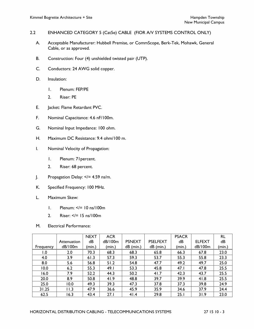
Kimmel Bogrette Architecture + Site Hampden Township
New Municipal Campus
HORIZONTAL DISTRIBUTION CABLING - TELECOMMUNICATIONS SYSTEMS 27 15 10 - 3
2.2 ENHANCED CATEGORY 5 (Cat5e) CABLE (FIOR A/V SYSTEMS CONTROL ONLY)
A. Acceptable Manufacturer: Hubbell Premise, or CommScope, Berk-Tek, Mohawk, General
Cable, or as approved.
B. Construction: Four (4) unshielded twisted pair (UTP).
C. Conductors: 24 AWG solid copper.
D. Insulation:
1. Plenum: FEP/PE
2. Riser: PE
E. Jacket: Flame Retardant PVC.
F. Nominal Capacitance: 4.6 nF/100m.
G. Nominal Input Impedance: 100 ohm.
H. Maximum DC Resistance: 9.4 ohm/100 m.
I. Nominal Velocity of Propagation:
1. Plenum: 71percent.
2. Riser: 68 percent.
J. Propagation Delay: </= 4.59 ns/m.
K. Specified Frequency: 100 MHz.
L. Maximum Skew:
1. Plenum: </= 10 ns/100m
2. Riser: </= 15 ns/100m
M. Electrical Performance:
Frequency
Attenuation
dB/100m
NEXT dB
(min.)
ACR dB/100m
(min.)
PSNEXT
dB (min.)
PSELFEXT
dB (min.)
PSACR dB
(min.)
ELFEXT
dB/100m
RL dB
(min.)
1.0 2.0 70.3 68.3 68.3 65.8 66.3 67.8 23.0
4.0 3.9 61.3 57.3 59.3 53.7 55.3 55.8 23.3
8.0 5.6 56.8 51.2 54.8 47.7 49.2 49.7 25.0
10.0 6.2 55.3 49.1 53.3 45.8 47.1 47.8 25.5
16.0 7.9 52.2 44.3 50.2 41.7 42.3 43.7 25.5
20.0 8.9 50.8 41.9 48.8 39.7 39.9 41.8 25.5
25.0 10.0 49.3 39.3 47.3 37.8 37.3 39.8 24.9
31.25 11.3 47.9 36.6 45.9 35.9 34.6 37.9 24.4
62.5 16.3 43.4 27.1 41.4 29.8 25.1 31.9 23.0
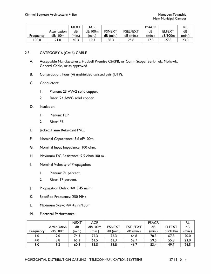
Kimmel Bogrette Architecture + Site Hampden Township
New Municipal Campus
HORIZONTAL DISTRIBUTION CABLING - TELECOMMUNICATIONS SYSTEMS 27 15 10 - 4
Frequency Attenuation
dB/100m
NEXT
dB (min.)
ACR
dB/100m (min.)
PSNEXT dB (min.)
PSELFEXT dB (min.)
PSACR
dB (min.)
ELFEXT dB/100m
RL
dB (min.)
100.0 21.0 40.3 19.3 38.3 25.8 17.3 27.8 23.0
2.3 CATEGORY 6 (Cat 6) CABLE
A. Acceptable Manufacturers: Hubbell Premise C6RPB, or CommScope, Berk-Tek, Mohawk,
General Cable, or as approved.
B. Construction: Four (4) unshielded twisted pair (UTP).
C. Conductors:
1. Plenum: 23 AWG solid copper.
2. Riser: 24 AWG solid copper.
D. Insulation:
1. Plenum: FEP.
2. Riser: PE.
E. Jacket: Flame Retardant PVC.
F. Nominal Capacitance: 5.6 nF/100m.
G. Nominal Input Impedance: 100 ohm.
H. Maximum DC Resistance: 9.5 ohm/100 m.
I. Nominal Velocity of Propagation:
1. Plenum: 71 percent.
2. Riser: 67 percent.
J. Propagation Delay: </= 5.45 ns/m.
K. Specified Frequency: 250 MHz
L. Maximum Skew: </= 45 ns/100m
M. Electrical Performance:
Frequency Attenuation
dB/100m
NEXT
dB (min.)
ACR
dB/100m (min.)
PSNEXT dB (min.)
PSELFEXT dB (min.)
PSACR
dB (min.)
ELFEXT dB/100m
RL
dB (min.)
1.0 2.0 74.3 72.3 72.3 64.8 70.3 67.8 20.0
4.0 3.8 65.3 61.5 63.3 52.7 59.5 55.8 23.0
8.0 5.3 60.8 55.5 58.8 46.7 53.4 49.7 24.5

Kimmel Bogrette Architecture + Site Hampden Township
New Municipal Campus
HORIZONTAL DISTRIBUTION CABLING - TELECOMMUNICATIONS SYSTEMS 27 15 10 - 5
Frequency Attenuation
dB/100m
NEXT
dB (min.)
ACR
dB/100m (min.)
PSNEXT dB (min.)
PSELFEXT dB (min.)
PSACR
dB (min.)
ELFEXT dB/100m
RL
dB (min.)
10.0 6.0 59.3 56.4 57.3 44.8 51.3 47.8 25.0
16.0 7.6 56.2 48.7 54.2 40.7 46.7 43.7 25.0
20.0 8.5 54.8 46.4 52.8 38.8 44.3 41.8 25.0
25.0 9.5 53.3 43.8 51.3 36.8 41.8 39.8 24.3
31.25 10.7 51.9 41.2 49.9 34.9 39.2 37.9 23.6
62.5 15.4 47.4 32.0 45.4 28.8 30.0 31.9 21.5
100.0 19.8 44.3 24.5 42.3 24.8 22.5 27.8 23.0
155.0 25.2 41.4 16.2 39.4 21.0 14.2 24.0 18.8
200.0 29.0 42.8 10.7 37.8 18.8 8.7 21.8 18.0
250.0 32.8 41.4 8.6 39.4 20.0 6.5 23.0 17.5
2.4 CATEGORY 6, OUTSIDE PLANT (OSP) RATED CABLE
A. Acceptable Manufacturers: Hubbell Premise C6OSPB, or CommScope, Berk-Tek, Mohawk,
General Cable, or as approved.
B. Construction: Four (4) unshielded twisted pair (UTP).
C. Conductors: 23 AWG solid copper.
D. Insulation: PE.
E. Jacket: Flooded PE.
F. Nominal Capacitance: 4.6 nF/100m.
G. Nominal Input Impedance: 100 ohm
H. Maximum DC Resistance: 8.16 ohm/100m.
I. Nominal Velocity of Propagation: 62 percent
J. Specified Frequency: 250 MHz
K. Maximum Skew: </= 45 ns/100m
L. Electrical Performance:
Frequency
Attenuation
dB/100m
NEXT dB
(min.)
ACR dB/100m
(min.)
PSNEXT
dB (min.)
PSELFEXT
dB (min.)
PSACR dB
(min.)
ELFEXT
dB/100m
RL dB
(min.)
1.0 2.0 74.3 72.3 72.3 65.8 70.3 64.8 23.0
4.0 3.8 65.3 61.5 63.3 53.7 59.5 52.8 23.0
8.0 5.3 60.8 55.4 58.8 47.7 53.4 46.7 24.5
10.0 6.0 59.3 53.3 57.3 45.8 51.3 44.8 25.0
16.0 7.6 56.2 48.7 54.2 41.7 46.7 40.7 25.0
20.0 8.5 54.8 46.3 52.8 39.7 44.3 38.8 25.0

Kimmel Bogrette Architecture + Site Hampden Township
New Municipal Campus
HORIZONTAL DISTRIBUTION CABLING - TELECOMMUNICATIONS SYSTEMS 27 15 10 - 6
Frequency Attenuation
dB/100m
NEXT
dB (min.)
ACR
dB/100m (min.)
PSNEXT dB (min.)
PSELFEXT dB (min.)
PSACR
dB (min.)
ELFEXT dB/100m
RL
dB (min.)
25.0 9.5 53.3 43.8 51.3 37.8 41.8 36.8 24.3
31.25 10.7 51.9 41.2 49.9 35.9 39.2 34.9 23.6
62.5 15.4 47.4 32.0 45.4 29.8 33.0 28.9 23.0
100.0 19.8 44.3 24.5 42.3 25.8 22.5 24.8 23.0
155.0 25.2 41.4 16.3 39.4 21.9 14.3 21.0 18.8
200.0 29.0 39.8 10.8 37.8 19.7 8.8 18.8 18.0
250.0 32.8 41.4 8.6 39.4 20.0 6.5 23.0 17.5
PART 3 - EXECUTION
3.1 INSTALLATION
A. All cable and associated hardware shall be placed so as to make efficient use of available space
in coordination with other uses. All cable and associated hardware shall be placed so as to not
impair the use or capacity of other building systems, equipment, or hardware placed by others
(or existing).
B. Where cable is placed in ceiling areas or other non-exposed areas, cables shall be installed in
cable trays or in non-continuous cable support system. Non-continuous cable supports shall
be placed at random intervals no greater than 48 inches. Cables in non-continuous support
systems shall be bundled using hook and loop type fasteners. Cable sag between supports shall
not exceed 3 inches. Attaching wire to pipes or other mechanical items is not permitted.
Cables shall not be bundled or tied in conduits, and in cable trays above ceilings.
C. All cabling shall be routed so as to avoid interference with any other service or system,
operation, or maintenance purposes such as access boxes, network equipment, mechanical
equipment access doors and covers, switches or electrical panels, and lighting fixtures. Avoid
crossing areas horizontally just above or below any riser conduit. Lay and dress cables to allow
other cables to enter the conduit/riser at a later time by maintaining a working distance from
these openings. All cable shall be installed to allow for simple installation and removal of cables
in the future.
D. Unless noted, all interior wiring shall be installed in raceways, Raceway Specification No. 2,
one inch minimum. Wiring above accessible ceilings may be installed in cable tray and exposed
on "J" hooks.
E. All cables not in raceways shall be riser or plenum rated.
F. All cables running outside the building shall be rated for outside plant installation.
G. All horizontal distribution cable for slab on grade floor boxes shall be OSP rated. OSP cable
shall be installed from slab on grade floor box in underfloor conduit, rise up in wall, and
terminate in consolidation point above accessible ceiling. Indoor rated cabling shall be used
from consolidation point back to nearest MDF/IDF.

Kimmel Bogrette Architecture + Site Hampden Township
New Municipal Campus
HORIZONTAL DISTRIBUTION CABLING - TELECOMMUNICATIONS SYSTEMS 27 15 10 - 7
H. Backbone cables shall be grouped separately from horizontal distribution cables. Cable for
other systems shall be grouped separately from cables for telephone and data.
I. All inside cable shall be installed neatly above accessible ceilings using cable tray and "J" hooks
supported from building structure. Do not attach to pipes, conduits, ducts, etc. Do not allow
cable to rest on pipes, conduits, ducts, ceiling tiles, etc. Do not attach to wires used for
supporting suspended ceilings. Do not use tie wires or bridle rings.
J. All wires shall be marked at all junction boxes, pull boxes, cabinets, boxes and terminations.
Each cable run between terminating locations shall be one continuous cable (no splices or
connections).
K. Install cable in such a manner as to prevent stretching, kinking or sharp bends. Cable damaged
during installation or not passing required testing shall be removed and replaced at no
additional cost to Owner.
L. Replace or rework cables showing evidence of improper handling including stretches, kinks,
short radius bends, over tightened bindings, loosely twisted and over twisted pairs at
terminations, and too much jacket removed.
M. Minimum bend radius and maximum pulling tension for all cables shall be maintained during
and after installation. Install cable in accordance with manufacturer's ratings and instructions.
N. Cables shall not be installed near power sources or other items where interference could
develop. Cables shall not be placed within 18 inches of light fixtures and within 3 feet of
motors, transformers, copy machines, or solid state motor starters unless cable is installed in
conduit. Contractor shall furnish and install a grounding conduit system where these minimum
clearances cannot be maintained.
O. In telecommunications spaces, cables shall be routed as close as possible to the ceiling, floor,
or corners to insure that adequate wall or backboard space is available for current and future
equipment and for cable terminations. Cables shall not be tie-wrapped to existing electrical
conduit or other equipment. Minimum bend radius shall be observed.
P. Dress and attach cables to the backboard along the shortest possible route run square
(horizontal and vertical) to the backboard. Bundle similarly routed cables together, and attach
by means of clamps or distribution rings. Cable dress and attachment shall minimize
obstruction to future installations of equipment, backboard, or other cables.
Q. Cables shall be neatly bundled with hook and loop type fasteners. Nylon tire wraps are not
acceptable. Cables must be neatly bundled in the telecommunications spaces and at the cable
service loop.
R. Cable service loops shall be provided at both ends of cable runs.
1. At the telecommunications room, provide a minimum 8 foot service loop stored in a
figure eight pattern in the cable tray above the racks/cabinets.
2. At the telecommunications room, provide sufficient slack to properly dress and
terminate cables at the racks and cabinets.
a. Provide sufficient slack so that swing gate type racks and cabinets can open fully

Kimmel Bogrette Architecture + Site Hampden Township
New Municipal Campus
HORIZONTAL DISTRIBUTION CABLING - TELECOMMUNICATIONS SYSTEMS 27 15 10 - 8
b. Provide sufficient slack so that cables do not catch or bind at swing gate type rack
or cabinet hinge and the cables do not pull taught across the hinge or edge.
3. At outlet locations provide 10 feet of slack stored at the last cable support.
4. At wireless access point outlets installed above accessible ceiling, provide 20 feet of
slack stored at the outlet.
S. Any damage to Owner’s existing cabling or existing cable owned by others, caused as a result
of work performed under this scope, shall be brought to the Owner’s attention and be
repaired or replaced within 48 hours.
T. Contractor shall use only cable lubricants recommended by the manufacturer for use with the
specific cable construction.
U. Should a cable become kinked, skinned or stretched during installation, the cable shall be
removed and replaced at no additional cost to the Owner. Splicing at points other than those
specified will not be acceptable.
END OF SECTION 27 15 10

Kimmel Bogrette Architecture + Site Hampden Township
New Municipal Campus
FACEPLATES AND CONNECTORS - TELECOMMUNICATIONS SYSTEMS 27 15 45 - 1
SECTION 27 15 45 – FACEPLATES AND CONNECTORS – TELECOMMUNICATIONS SYSTEMS
PART 1 - GENERAL
1.1 WORK INCLUDED
A. The Work of this Section shall consist of the labor, materials and equipment required for
furnishing and installing telecommunications outlets, faceplates and connectors as part of a
complete and functional telecommunications system.
1.2 SUBMITTALS
A. Submit for approval in accordance with specified submittal procedures:
1. Components of the telecommunications system, as specified herein.
1.3 COORDINATION
A. All items specified or included in this section shall be furnished and installed by, wired and
connected by, and connected by Electrical Contractor.
B. The term “Contractor” as used herein shall mean Electrical Contractor or Electrical
Contractor’s sub-contractor.
C. Refer to Section 26 05 30, Raceways and Section 26 05 40, Boxes for raceway and boxes to be
furnished and installed for telecommunications outlets.
D. Contractor shall furnish and install the following:
1. Jacks, wallplates and connectors, both copper and fiber.
E. Electrical Contractor shall furnish and install the following:
1. Floor boxes, box covers, straps and jacks in floor boxes.
2. Boxes above ceilings, box covers and jacks in boxes above ceiling.
F. Unless noted, the following items will be the responsibility of the Owner:
1. All electronics and active data networking equipment, etc.
2. Telephones, fax machines and modems, etc.
3. PC’s, printers, video display terminals, flat panel displays, etc.
G. Contact the Owner’s network and computer equipment personnel for specific instructions
before starting Work.
Kimmel Bogrette Architecture + Site Hampden Township
New Municipal Campus
FACEPLATES AND CONNECTORS - TELECOMMUNICATIONS SYSTEMS 27 15 45 - 2
PART 2 - PRODUCTS
2.1 ACCEPTABLE MANUFACTURERS
A. All devices specified herein shall be manufactured by Hubbell, Superior, Siemon, Leviton, or as
approved.
B. Manufacturers listed below are basis of design, meant to indicate representative level of
quality.
2.2 WALL PLATES
A. Telecom Wall Plate Specification No. 1 – Flush Mount For Keystone Type Modular Jacks and
Inserts
1. Acceptable Manufacturer: Hubbell “IFP” Series.
2. For mounting on wall boxes.
3. Faceplate, jacks and inserts shall be of the same manufacturer.
4. Supports both fiber and copper applications.
5. UL 94 V-O rated flames retardant material.
6. One, two, three, four or six port faceplates as indicated on Drawings.
7. Single gang or double gang as indicated on Drawings.
8. Quantity of and configuration of jacks and inserts as indicated on Drawings.
9. Label insets with clear label covers.
10. Face plate labels.
11. Blank inserts in all unused port locations.
12. Color as selected by Architect.
2.3 MODULAR JACKS AND ADAPTERS
A. Jacks, Cat 6
1. Acceptable Manufacturer: Hubbell NEXTSPEED Category 6 Series Jacks.
2. Non-keyed, Unshielded, 4-pair.
3. 8-position, 8-wire (RJ-45).
4. Accommodates T568A and T5698B wiring.
5. Accepts 6-position modular plug for telephone use.
6. Useable bandwidth: 500 MHz.
7. Nose Contacts:

Kimmel Bogrette Architecture + Site Hampden Township
New Municipal Campus
FACEPLATES AND CONNECTORS - TELECOMMUNICATIONS SYSTEMS 27 15 45 - 3
a. Beryllium copper with a minimum of 50-micro inch gold plating over nickel under
plating.
8. Insulation displacement terminals.
a. 110 blocks: Polycarbonate.
b. Jack Contacts: Phosphor bronze with 100 micro-inc tin lead 60/40 over nickel
under plating.
c. Terminates 22-24 AWG solid conductors.
9. Minimum Contact Force: 100 grams with FCC compliant 8-position plug
10. Jack Color:
a. Data: Blue
b. Telephone: White
c. Wireless Access Points (Administration Network) – Green
d. Wireless Access Points ( Police Department Network) – Green
e. Wireless Access Points (Guest Network) – Yellow
f. Sound Systems Control - Purple
B. Duplex LC Fiber Optic Adapter Module
1. Acceptable Manufacturer: To match outlet plates.
2. For data network cable applications
3. For use with PC and Ultra PC connectors.
4. Alignment Sleeve:
a. Multimode: Phosphor bronze.
b. Singlemode: Zirconia Ceramic.
5. Adapter Color:
a. Multimode: Beige.
b. Singlemode: Blue.
6. Module Plate Color (where applicable): To match outlet plates.
C. Blank Inserts
1. Acceptable Manufacturer: To match outlet plates.
2. Color to match outlet plates.
D. Connector Adapter Modules
1. Acceptable Manufacturer: To match outlet plates.
2. Multi-media connector adapter modules shall be as specified in Section 27 55 10, Sound
Distribution System, Section 27 41 15, Multi-Media Support Systems, and Section
27 59 10, Television System - CATV.
2.4 CONSOLIDATION POINT
A. Acceptable Manufacturers:

Kimmel Bogrette Architecture + Site Hampden Township
New Municipal Campus
FACEPLATES AND CONNECTORS - TELECOMMUNICATIONS SYSTEMS 27 15 45 - 4
1. Punch Down Blocks: As indicated in Section 27 11 10, Telecommunications Spaces
Equipment and fittings.
2. Enclosures: as indicated in Section 26 05 40, Boxes.
B. The Contractor shall furnish and install consolidation points at locations indicated on the
Drawings and as required where floor box outlets are installed on slab on grade floor
construction.
C. Refer to Section 27 05 30, Pathways for Telecommunications Systems and Section 27 15 10,
Horizontal Distribution Cabling - Telecommunications Systems for additional requirements for
the consolidation point(s).
D. The consolidation point(s) shall be used to interconnect between outside plant rated cables
and indoor rated cables.
E. The consolidation point(s) shall be comprised of punch down blocks mounted in a NEMA 1
enclosure installed above the ceiling.
F. The enclosure shall meet the requirement of Box Specification No. 4.
G. The enclosure shall be sized as required to mount the punch down blocks, accommodate the
quantity of cables to be terminated, and accept the quantity of conduits connected from slab
on grade floor box outlets. Minimum enclosure size shall be 14 inches wide by 12 inches high
by 6 inches deep.
H. The punch down blocks shall have the following specifications:
1. 64-pair wiring blocks, wall mounted.
2. 110-type with wall-mount legs.
3. Material: Polycarbonate UL 94 V-O.
4. Accepts solid 26-22 AWG copper conductors.
5. 4-pair connecting clips.
6. Material: Polycarbonate UL 94 V-O.
7. Insulation displacement contacts.
8. Contact Material: Phosphor bronze.
9. Contact Plating: Tin/lead solder.
10. Accepts solid 26-22 AWG copper conductors.
11. Furnish and install with labels and label holders.
PART 3 - EXECUTION
3.1 INSTALLATION
A. Install all connectors in accordance with manufacturer’s recommended procedures.

Kimmel Bogrette Architecture + Site Hampden Township
New Municipal Campus
FACEPLATES AND CONNECTORS - TELECOMMUNICATIONS SYSTEMS 27 15 45 - 5
B. Flush mount and surface mount outlet plates shall be installed level and plumb. Coordinate
outlet box installation with General Contractor prior to rough-in.
C. Cables shall be marked at all outlet boxes and terminations.
D. Furnish and install cable, outlet plate and connector labeling as indicated in Section 27 60 10,
Telecommunication Systems Identification and Documentation.
E. Provide a minimum service loop of 12 inches in each outlet box.
F. Bending radius of cables shall be as recommended by the manufacturer. Install cable in outlet
boxes per manufacturer's instructions.
G. Furnish and install mounting hardware as required to attach consolidation points above
accessible ceiling. Consolidation points shall be securely fastened to building structure or wall.
3.2 MOUNTING HEIGHTS
A. Refer to Section 27 05 45, Pathways for Telecommunications Systems, for outlet mounting
heights.
END OF SECTION 27 15 45
Kimmel Bogrette Architecture + Site Hampden Township
New Municipal Campus
CONNECTING CORDS, DEVICES AND ADAPTERS - TELECOMMUNICATIONS SYSTEMS 27 16 10 - 1
SECTION 27 16 10 – CONNECTING CORDS, DEVICES AND ADAPTERS –
TELECOMMUNICATIONS SYSTEMS
PART 1 - GENERAL
1.1 WORK INCLUDED
A. The Work of this Section shall consist of the labor, materials and equipment required for
furnishing and installing patch cords, equipment cords, workstation cords, connecting devices
and adapters as part of a complete and operating telecommunications system.
1.2 SUBMITTALS
A. Submit for approval in accordance with specified submittal procedures:
1. Components of the telecommunications system, as specified herein.
1.3 COORDINATION
A. All items specified or included in this section shall be furnished and installed by, wired and
connected by, and connected by Electrical Contractor, unless noted otherwise.
B. The term “Contractor” as used herein shall mean Electrical Contractor or Electrical
Contractor’s sub-contractor.
C. Contractor shall furnish the following:
1. UTP copper patch cords, equipment cords and workstation cords.
2. UTP cross-connect wire.
3. Opto-electronic converters and transceivers.
4. Adapters.
D. Owner shall install the following:
1. UTP copper patch cords, equipment cords and workstation cords.
2. UTP cross-connect wire.
3. Opto-electronic converters and transceivers.
4. Adapters.
E. Owner shall furnish and install the following:
1. Optical fiber patch cords, equipment cords and workstation cords.

Kimmel Bogrette Architecture + Site Hampden Township
New Municipal Campus
CONNECTING CORDS, DEVICES AND ADAPTERS - TELECOMMUNICATIONS SYSTEMS 27 16 10 - 2
1.4 CABLE TESTING
A. Wire and cable shall be safety and application tested, performance tested and shall have this
information and the Manufacturer’s Information affixed to the wire and cable as specified in
Section 26 05 05, Basic Materials.
PART 2 - PRODUCTS
2.1 PATCH CORDS
A. Category 6 UTP Patch Cords, Equipment Cords and Workstation Cords
1. Acceptable Manufacturer: Hubbell NEXTSPEED Cat6 Series, of as approved.
2. 8 conductor, 24 AWG stranded, Category 6.
3. PVC jacket.
4. RJ 45, 8 position, Category 6 plugs on each end.
a. Furnish patch cords with harsh environment sealed connector bodies to match
outlet requirements as indicated on drawings.
5. 100 percent factory tested.
6. Color: To match system cable color as defined in Section 27 15 10 and Section
27 15 45.
7. Furnish hybrid cords (dissimilar connectors on opposite ends of cable) as required by
equipment connections. Coordinate equipment connector type with Owner and
Equipment Supplier prior to submitting products for review.
8. Furnish 2-foot patch cords to connect patch panels to network equipment in each
telecommunications space.
9. Furnish and install length as required equipment cords to connect outlets to equipment
and devices (i.e.; wireless access points; building automation systems; security systems,
etc.).
10. Furnish 15-foot workstation cords to connect from outlets to Owner’s computer
equipment in classrooms, offices and work areas.
11. Furnish and install one patch cord for 100 percent of the data outlets installed as part of
the project plus 2 percent spare, minimum of 10 spare patch cords
12. Furnish and install one equipment cord for 100 percent of the equipment data outlets
installed as part of the project plus 2 percent spare, minimum of 10 spare patch cords.
13. Furnish one 15-foot workstation cord for 80 percent of the data outlets installed as part
of this project plus 5 percent spare, minimum of 10 spare patch cords.
B. Cross-Connect Wire
1. Acceptable Manufacturer: Belden, or General Cable, Siemon, or as approved.
2. Single-pair, 24 AWG solid copper.

Kimmel Bogrette Architecture + Site Hampden Township
New Municipal Campus
CONNECTING CORDS, DEVICES AND ADAPTERS - TELECOMMUNICATIONS SYSTEMS 27 16 10 - 3
3. Color Coded PVC insulated wire.
4. Color Code: Blue/White, unless noted otherwise.
5. For cross-connecting telephone circuits only.
C. Cross-Connect Cords
1. Acceptable Manufacturer (Data): Hubbell 6-110 Cross Connect, Cat6, or approved
equal.
a. 4-pair 110 to 110.
b. 4-pair 110 to RJ-45.
2. 24 AWG stranded twisted pair.
3. 1-, 2-, 4- pair as required by application.
4. Color: To match system cable color as defined in Section 27 15 10 and Section
27 15 45.
5. Furnish hybrid cords (dissimilar connectors on opposite ends of cable) as required by
equipment connections. Coordinate equipment connector type with Owner and
Equipment Supplier prior to submitting products for review.
6. Furnish and install length as required patch cords to connect termination blocks to
network equipment in each telecommunications room.
7. Furnish and install one patch cord for 100 percent of the data outlets installed as part of
the project plus 2 percent spare, minimum of 10 spare patch cords
PART 3 - EXECUTION
3.1 INSTALLATION
A. All patch cords shall be neatly installed and dressed in the vertical and horizontal wire
management systems in each telecommunications space.
B. Patch cords shall be routed so that the wire management system provides proper support of
the connector/cord interface.
C. Patch cords shall be labeled at each end using a machine generated label. Patch cord label shall
indicate patch panel port and network equipment port connected.
D. Patch cords shall not be tied or bundled in the wire management system.
E. Patch cords shall be tied to cable runway (tray) when routed between racks, cabinets and wall
termination fields in telecommunications rooms.
F. Patch cords (where bundled) shall be neatly bundled with Velcro style fasteners. Nylon tire
wraps are not acceptable.
G. Patch cords, equipment cords and workstation cords shall not be installed above accessible
ceiling.

Kimmel Bogrette Architecture + Site Hampden Township
New Municipal Campus
CONNECTING CORDS, DEVICES AND ADAPTERS - TELECOMMUNICATIONS SYSTEMS 27 16 10 - 4
H. Patch cords, equipment cords and workstation cords shall not be installed in conduit except in
short sections of conduit installed from an enclosure for an equipment connection outlet to
the equipment enclosure being served.
I. Install cables along the shortest route in the wire management system. Use the shortest patch
cords available to connect two points.
J. Patch cord slack shall be neatly stored in the wire management system.
K. Equipment cords shall be connected to the outlet, coiled neatly, tied and left for connection to
equipment by others.
L. Workstation area cords shall be turned over to Owner.
M. Install patch cords, equipment cords and workstation area cords in a manner to protect cable
from stretching, kinking or sharp bends. Cords damaged during installation shall be removed
and replaced at no additional cost to Owner.
N. Bending radius of patch cords shall not exceed manufacturer’s recommended bend radius.
O. Install patch cords between outlets for equipment connection and equipment enclosures
through conduit stub. Coordinate placement and connection of patch cords with contractor
responsible for equipment enclosure. Not more than 3 inches of patch cords shall be exposed
between outlet for equipment connection and equipment enclosure.
P. Cross-connect wiring shall be installed along the shortest route between termination points.
Q. Cross-connect wiring shall be routed through distribution rings and around distribution spools
in a manner which provides full support of the wire and termination without additional
support.
R. Cross-connect wires shall be installed with a minimum 3/4 inch drip loop at either end of the
wire to allow manual tracing of the connected circuit.
S. Furnish and install voice grade cross-connect wiring at the telecommunications entrance
facility, MDF and each IDF for all equipment outlets including but not limited to: elevator
equipment room telephone, elevator cab telephone, fire-alarm communications, security
system(s) communications, area of rescue assistance communication, other emergency
communication system(s) and building automation system. Coordinate the requirements for
the cross-connects with system installer as required. Complete the dial-tone circuits from the
service provider demarcation to the point of connection to the equipment. Coordinate dial-
tone requirements with system installer. The Owner shall coordinate service requirements
with their service provider.
T. Furnish and install Cat 6 cross-connect wire to cross-connect circuits from backbone to
horizontal cross-connect. Contractor shall install cross-connects for all outlets installed as
part of this project. Coordinate pairs/circuits to be cross-connected with Owner.
U. Furnish and install Cat 6 cross-connect wiring at MDF and each IDF for all telephone outlets
installed. Coordinate exact cross-connect locations and telephone numbers with Owner and

Kimmel Bogrette Architecture + Site Hampden Township
New Municipal Campus
CONNECTING CORDS, DEVICES AND ADAPTERS - TELECOMMUNICATIONS SYSTEMS 27 16 10 - 5
Owner’s telephone service provider. Owner’s telephone Service Provider shall furnish and
install cross-connects at the demarcation point.
END OF SECTION 27 16 10
Kimmel Bogrette Architecture + Site Hampden Township
New Municipal Campus
TELECOMMUNICATIONS CABLE SYSTEMS TESTING - COPPER 27 19 10 - 1
SECTION 27 19 10 – TELECOMMUNICATIONS CABLE SYSTEMS TESTING – COPPER
PART 1 - GENERAL
1.1 WORK INCLUDED
A. The Work of this Section shall consist of the labor, materials and equipment required for
testing the copper backbone and horizontal distribution system as part of a complete and
operating telecommunications cabling system.
1.2 SUBMITTALS
A. Submit for approval in accordance with specified submittal procedures:
1. Contractor’s test procedures
2. Sample test report format
3. Test reports for all cables
1.3 COORDINATION
A. All items specified or included in this section shall be furnished and installed by, wired and
connected by, and connected by Electrical Contractor, unless noted otherwise.
B. The term “Contractor” as used herein shall mean Electrical Contractor’s sub-contractor.
PART 2 - PRODUCTS
(NOT USED)
PART 3 - EXECUTION
3.1 COPPER CABLE TESTING – MULTI-PAIR, OTHER THAN CATEGORY RATED
A. Copper cable backbone shall be tested for the following. Each wire/pair shall be tested at both
ends for the following:
1. Termination order
2. Polarity
3. Continuity
4. Shorts
5. Grounds

Kimmel Bogrette Architecture + Site Hampden Township
New Municipal Campus
TELECOMMUNICATIONS CABLE SYSTEMS TESTING - COPPER 27 19 10 - 2
6. Cable length
3.2 CABLE SYSTEM PERFORMANCE TESTING – CATEGORY RATED
A. Cables and termination hardware shall be 100 percent tested for defects in installation and to
verify cable performance under installed conditions. All conductors of each installed cable shall
be verified usable by the contractor prior to system acceptance. Any defect in the cable
system installation including but not limited to cable, connectors, feed through coupler, patch
panels, and connector blocks shall be repaired or replaced in order to ensure 100 percent
usable conductors in all cables installed.
B. General Requirements
1. Every cabling link in the installation shall be tested in accordance with the field test
specifications defined in the most recent standard of the Telecommunications Industry
Associations (TIA)/Electronics Industry Association (EIA).
2. The installed twisted-pair horizontal links shall be tested from the data or
telecommunications room to the jack in the wall outlet against the “Permanent Link”
performance limits specification as defined by TIA/EIA.
3. 100% of the installed cabling links must be tested and must pass the requirements of the
TIA/EIA standards. Any failing link must be diagnosed and corrected. The corrective
action shall be followed with a test to prove that the corrected link meets the
performance requirements. The final and passing result of the tests for all links shall be
provided in the test results documentation.
4. Trained technicians who have successfully attended an appropriate training program and
have obtained a certificate as proof thereof shall execute the tests. Appropriate training
programs include but are not limited to installation certification programs provided by
BiCSi (Building Industry Consulting Services International) or the ACP (Association of
Cabling Professionals).
5. The test equipment (tester) shall comply with or exceed the accuracy requirements for
the Level III field testers as defined by TIA. The tester including the appropriate
interface adapter must meet the specified accuracy requirements.
6. The tester shall be within the calibration period recommended by the vendor in order
to achieve the vendor-specified measurement accuracy.
7. The tester interface adapters must be of high quality and the cable shall not show any
twisting or kinking resulting from coiling and storing of the tester interface adapters. In
order to deliver optimum accuracy, preference is given to a permanent link interface
adapter for the tester that can be calibrated to extend the reference plane of the Return
Loss measurement to the permanent link interface. The contractor shall provide proof
that the interface has been calibrated within the period recommended by the vendor.
To ensure that normal handling on the job does not cause measurable Return Loss
change, the adapter cord cable shall not be of twisted-pair construction.
8. The Pass or Fail condition for the link-under-test is determined by the results of the
requirements individual tests. Any Fail or Fail* results yields a Fail for the link-under-
test. In order to achieve an overall Pass condition, the results for each individual test
parameter must Pass or Pass*.

Kimmel Bogrette Architecture + Site Hampden Township
New Municipal Campus
TELECOMMUNICATIONS CABLE SYSTEMS TESTING - COPPER 27 19 10 - 3
9. A Pass or Fail result for each parameter is determined by comparing the measured
values with the specified test limits for the parameter. The test result of a parameter
shall be marked with an asterisk (*) when the result is closer to the test limit than the
accuracy of the field tester. The field tester manufacturer must provide documentation
as an aid to interpret results marked with asterisks.
10. The Contractor shall coordinate with the cable system manufacturer providing the
extended performance warranty to determine whether the manufacturer will accept
Pass* results for their warranty. Only test results which meet the requirements of the
manufacturer’s warranty will be acceptable.
11. The Owner shall be invited to witness field testing. The Owner shall be notified of the
start date of the testing phase 5 business days before testing commences.
12. The Owner (or his authorized representative) may select a random sample of 5%
(minimum of three) of the installed links. The Owner shall test these randomly selected
links and the results are to be stored as specified herein. The results obtained shall be
compared to the data provided by the Contractor. If more that 2% (minimum of 1) of
the sample results differ in terms of the pass/fail determination, the Contractor under
supervision of the Owner’s representative shall repeat 100% testing and the cost shall
be borne by the Contractor.
C. Performance Test Parameters
1. Cables shall be performance tested in accordance with the requirements of the Cable
Category Rating as defined by TIA/EIA. The test of each link shall contain all of the
following parameters: In order to pass the test all measurements (at each frequency in
the TIA/EIA specified test frequency range) must meet or exceed the limit value listed
by TIA/EIA.
a. Wire Map
b. Length
c. Insertion Loss (Attenuation)
d. Near-End Cross-Talk (NEXT) Loss, Pair-to-Pair
e. Power Sum NEXT (PSNEXT) Loss
f. Equal Level Far-end Cross-Talk (ELFEXT) Loss, pair-to-pair
g. Power Sum ELFEXT (PSELFEXT) Loss
h. Return Loss
i. Attenuation to Cross-talk Ratio (ACR)
j. Power Sum ACR (PSACR)
k. Propagation Delay
l. Delay Skew
D. Test Results Documentation
1. The test result information for each link shall be recorded in the memory of the field
tester upon completion of the test.
2. The test result records saved by the tester shall be transferred into a Windows™-based
database utility that allows for the maintenance, inspection and archiving of these test
records. A guarantee must be made that these results are transferred to the PC
unaltered, i.e., “as saved in the tester” at the end of each test and that these results
cannot be modified at a later time. Use cable testers that transfer the numeric

Kimmel Bogrette Architecture + Site Hampden Township
New Municipal Campus
TELECOMMUNICATIONS CABLE SYSTEMS TESTING - COPPER 27 19 10 - 4
measurement data from the tester to the PC in a format which cannot be manipulated
by the user.
a. Comma Separated Value (CSV) format does not provide adequate protection and
shall not be acceptable.
3. The database for the completed job, including twisted-pair copper cabling links if
applicable, shall be stored and delivered on CD-ROM; this CD-ROM shall include the
software tools required to view, inspect, and print any selection of test reports.
4. A paper copy of the test results shall be provided that lists all the links that have been
tested with the following summary information:
a. The identification of the link in accordance with the naming convention defined in
the overall system documentation and as coordinated with Owner
b. The overall Pass/Fail evaluation of the link-under-test including the Attenuation
worst case margin (margin is defined as the difference between the measured
value and the test limit value).
c. The date and time the test results were saved in the memory of the tester
5. General information to be provided in the electronic data base containing the test result
information for each link:
a. The identification of the customer site as specified by the Owner.
b. The overall Pass/Fail evaluation of the link-under-test.
c. The name of the standard selected to execute the stored test results.
d. The cable type and the velocity of propagation used for length calculations.
e. The date and time the test results were saved in the memory of the tester.
f. The brand name, model and serial number of the tester.
g. The revision of the tester software and the revision of the test standards database
in the tester.
END OF SECTION 27 19 10

Kimmel Bogrette Architecture + Site Hampden Township
New Municipal Campus
TELECOMMUNICATIONS CABLE SYSTEMS TESTING - FIBER 27 19 20 - 1
SECTION 27 19 20 – TELECOMMUNICATIONS CABLE SYSTEMS TESTING – FIBER
PART 1 - GENERAL
1.1 WORK INCLUDED
A. The Work of this Section shall consist of the labor, materials and equipment required for
testing the fiber optic backbone and horizontal distribution system as part of a complete and
operating telecommunications cabling system.
B. All items specified or included in this section shall be furnished and installed by Electrical
Contractor, and tested by Electrical Contractor, unless noted otherwise. “Contractor” as
used herein shall mean or Electrical Contractor’s sub-contractor.
1.2 SUBMITTALS
A. Submit for approval in accordance with specified submittal procedures:
1. Contractor’s test procedures
2. Sample test reports
PART 2 - PRODUCTS
(NOT USED)
PART 3 - EXECUTION
3.1 FIBER OPTIC CABLE SYSTEM TESTING
A. All fiber terminations shall be visually inspected with a minimum 100 X microscope to ensure
that no surface imperfections exist after termination.
B. All fiber terminations shall be cleaned in accordance with manufacturer’s recommended
procedures prior to testing.
C. Terminated fiber strands shall be tested for insertion loss (attenuation) with an optical power
meter and light source.
D. Un-terminated fiber strands shall be tested for continuity and length with and optical time
domain reflectometer (OTDR) or meter using similar technology.

Kimmel Bogrette Architecture + Site Hampden Township
New Municipal Campus
TELECOMMUNICATIONS CABLE SYSTEMS TESTING - FIBER 27 19 20 - 2
E. General Requirements – Contractor shall test and document the following:
1. Attenuation and location of any splice and single-point discontinuity. Contractor shall
indicate the location and loss of every splice in each optical fiber cable link, including
existing splices.
2. Attenuation testing shall be performed as defined herein and as defined in the most
recent version of the ANSI/TIA/EIA 568B Standard document.
3. The test shall include the representative connector performance at the connecting
hardware associated with the mating of patch cords. The test shall not, however,
include the performance of the connector at the interface with the test equipment.
4. 100 percent of the installed optical fiber links shall be tested and shall pass the
requirements of the ANSI/TIA/EIA standards. Any failing link shall be diagnosed and
corrected. The corrective action shall be followed with a test to prove that the
corrected link meets the performance requirements. The final and passing result of the
tests for all links shall be provided in the test results documentation.
5. Each outside plant fiber optic cable shall be tested with an ODTR to verify installed
length and to document the installation.
6. Inside plant fiber cables may be tested with an OTDR or meter using similar technology
to verify installed cable length.
7. All fiber optic strands of an inside or outside plant cable where any of the strands of the
cable will be spliced as part of this installation shall be tested and documented with an
OTDR. OTDR testing shall be performed on cables splices at building entrance
transitions. OTDR testing is not required for splicing of pigtails where there are no
mid-span (intermediate) splices in the fiber cable.
8. Trained technicians who have successfully attended an appropriate training program and
have obtained a certificate as proof thereof shall execute the tests. These certificates
may have been issued by any of the following organizations or an equivalent
organization:
a. The manufacturer of the fiber optic cable and the fiber optic connectors
b. The manufacturer of the test equipment used for the field certification
c. Training organizations authorized by BiCSi (Building Industry Consulting Services
International) or by the ACP (Association of Technology Professionals)
Technology Business Institute located in Dallas, Texas.
F. Field test instruments for optical fiber testing shall meet the requirements of the latest
standard of ANSI/TIA/EIA.
1. The tester shall be within the calibration period recommended by the vendor in order
to achieve the vendor-specified measurement accuracy. . The Contactor shall furnish a
valid calibration certificate from the manufacturer or an approved calibration laboratory
with the test documentation. Test dates must fall within the dates of the valid
calibration.

Kimmel Bogrette Architecture + Site Hampden Township
New Municipal Campus
TELECOMMUNICATIONS CABLE SYSTEMS TESTING - FIBER 27 19 20 - 3
2. The fiber optic launch cables and adapters shall be of high quality and the cables shall not
show excessive wear resulting from repetitive coiling and storing of the tester interface
adapters.
3. The Pass or Fail condition for the link-under-test shall be determined by the results of
the required individual tests specified herein.
G. The Owner shall be invited to witness field testing. The Owner shall be notified of the start
date of the testing phase 5 business days before testing commences.
H. The Owner (or his authorized representative) may select a random sample of 5% (minimum of
three) of the installed links. The Owner shall test these randomly selected links and the results
shall be stored as specified herein. The results obtained shall be compared to the data
provided by the Contractor. If more than 2% (minimum of one) of the sample results differ in
terms of the pass/fail determination, the installation contractor under supervision of the
Owner shall repeat 100% testing and the cost shall be borne by the installation contractor.
I. All fiber optic cable test results shall be stored on a CD-ROM along with any required viewing
software, and incorporated into the “Record Documents” package.
3.2 PERFORMANCE TEST PARAMETERS – FIBER OPTIC CABLE
A. ANSI/TIA/EIA standards prescribe that the single performance parameter for field testing of
fiber optic links is link attenuation (alternative and equivalent term: insertion loss), when
installing components compliant with this standard.
1. The link attenuation shall be calculated by the following formulas specified in
ANSI/TIA/EIA 568B:
a. Link Attenuation = Cable_Attn + Connector_Attn + Splice_Attn
2. Cable_Attn (dB) = Attenuation_Coefficient (dB/km) * Length (Km)
3. The values for the Attenuation_Coefficient are listed in the table below:
Type of Optical Fiber Wavelength (nm)
Attenuation_Coefficient
(dB/km)
Multimode 62.5/125 μm 850 3.5
1300 1.5
Multimode 50/125 μm 850 3.5
1300 1.0
Single-mode (Inside plant) 1310 1.0
1550 1.0
Single-mode (Outside
plant)
1310 0.5
B. Connector_Attn (dB) = number_of_connector_pairs*connector_loss (dB)
C. Maximum allowable connector_loss = 0.75 dB
D. Splice_Attn (dB) = Number of splices * splice_loss (dB).

Kimmel Bogrette Architecture + Site Hampden Township
New Municipal Campus
TELECOMMUNICATIONS CABLE SYSTEMS TESTING - FIBER 27 19 20 - 4
E. Maximum allowable splice_loss = 0.3 dB.
F. Link attenuation shall not include any active devices or passive devices other than cable,
connectors, and splices, i.e. link attenuation shall not include such devices as optical bypass
switches, couplers, repeaters, or optical amplifiers.
G. Use test equipment that automatically calculates the link loss based on the above formulas.
H. Test limit attenuation is based on the use of the One Reference Jumper Method specified by
ANSI/TIA/EIA. The contractor shall follow the procedures established by these standards or
application notes to accurately conduct performance testing.
I. The backbone link (multimode) shall be tested in both directions at both operating
wavelengths to account for attenuation deltas associated with wavelength.
J. Multimode backbone links shall be tested at 850 nm and 1300 nm in accordance with
ANSI/EIA/TIA. The “Link Attenuation Equation”, as previously stated, shall be used to
determine limit (acceptance) values for multimode backbone cable.
K. Test the attenuation of backbone fibers in both directions at both wavelengths.
1. Single mode backbone links shall be tested in both directions at 1310 nm and 1550 nm
in accordance with ANSI/TIA/EIA 526-7, Method A1, One Reference Jumper. All single
mode links shall be tested with test equipment using laser light sources at 1310 nm and
1550 nm.
2. Multi-mode backbone links shall be tested in both directions at 850 and 1300 nm in
accordance with ANSI/TIA/EIA 526-14, Method B. All multi-mode links shall be tested
using laser light sources as indicated below
3. For Gigabit Ethernet compliant certification (IEEE std. 802.3z application) test
equipment, use a VCSEL (Vertical cavity surface emitting laser) at 850 nm (compliant
with 1000BASE-SX) and an FP laser at 1310 nm (compliant with 1000BASE-LX).
3.3 OTDR TESTING
A. OTDR testing shall be performed in accordance with the EIA/TIA-455-60, Two-Point Method
A.
B. Test set up shall use a launch fiber which exceeds the dead zone of the OTDR equipment used
for the test.
C. Identify the start of the fiber under test and the end of the fiber under test for each strand.
D. Identify splices, discontinuities or other anomalies in the fiber on the test documentation.
Attenuation of each splice and discontinuity shall be included for each fiber where they occur.
Attenuation for splices to install pigtail connections is not required.
E. The use of an OTDR is not acceptable for end-to-end insertion loss (attenuation) testing.

Kimmel Bogrette Architecture + Site Hampden Township
New Municipal Campus
TELECOMMUNICATIONS CABLE SYSTEMS TESTING - FIBER 27 19 20 - 5
3.4 TEST RESULT DOCUMENTATION
A. The test result information for each link shall be recorded in the memory of the field tester
upon completion of the test.
B. The test result records saved by the tester shall be transferred into a Windows™-based
database utility that allows for the maintenance, inspection and archiving of these test records.
A guarantee must be made that these results are transferred to the PC unaltered, i.e., “as
saved in the tester” at the end of each test and that these results cannot be modified at a later
time. Use cable testers that transfer the numeric measurement data from the tester to the PC
in a format which cannot be manipulated by the user.
1. Comma Separated Value (CSV) format does not provide adequate protection and shall
not be acceptable.
C. The database for the completed job, including twisted-pair copper cabling links if applicable,
shall be stored and delivered on CD-ROM; this CD-ROM shall include the software tools
required to view, inspect, and print any selection of test reports.
D. A paper copy of the test results shall be provided that lists all the links that have been tested
with the following summary information:
1. The identification of the link in accordance with the naming convention defined in the
overall system documentation and as coordinated with Owner
2. The overall Pass/Fail evaluation of the link-under-test including the Attenuation worst
case margin (margin is defined as the difference between the measured value and the
test limit value).
3. The date and time the test results were saved in the memory of the tester
E. General information to be provided in the electronic data base containing the test result
information for each link:
1. The identification of the customer site as specified by the Owner.
2. The overall Pass/Fail evaluation of the link-under-test.
3. The name of the standard selected to execute the stored test results.
4. The cable type and the value of the ‘index of refraction’ used for length calculations.
5. The date and time the test results were saved in the memory of the tester.
6. The brand name, model and serial number of the tester.
7. The revision of the tester software and the revision of the test standards database in the
tester.
F. The detailed test results data to be provided in the electronic database for each tested optical
fiber must contain the following information

Kimmel Bogrette Architecture + Site Hampden Township
New Municipal Campus
TELECOMMUNICATIONS CABLE SYSTEMS TESTING - FIBER 27 19 20 - 6
1. The identification of the link/fiber in accordance with the naming convention defined in
the overall system documentation and as coordinated with Owner.
2. The insertion loss (attenuation) measured at each wavelength, the test limit calculated
for the corresponding wavelength and the margin (difference between the measured
attenuation and the test limit value).
3. The link length shall be reported for each optical fiber for which the test limit was
calculated based on the formulas
END OF SECTION 27 19 20

Kimmel Bogrette Architecture + Site Hampden Township
New Municipal Campus
SOUND DISTRIBUTION SYSTEM 27 55 10 - 1
SECTION 27 55 10 – SOUND DISTRIBUTION SYSTEM
PART 1 - GENERAL
1.1 WORK INCLUDED
A. Work in this Section consists of the labor, materials and equipment required for furnishing and
installing a complete operating sound system.
1.2 SUBMITTALS
A. Submit for approval in accordance with specified submittal procedures:
1. Sound distribution system components.
2. Wiring diagram, showing interconnections between all components.
1.3 COORDINATION
A. All items specified or included in this section shall be furnished and installed by, wired and
connected by, and connected by Electrical Contractor, unless noted otherwise.
B. The term “Contractor” as used herein shall mean Electrical Contractor or Electrical
Contractor’s sub-contractor.
1.4 FUNCTION
A. Systems shall process inputs from multiple program sources and distribute both audio and
video signals to projectors and speakers in Public Meeting Room, Executive Conference Room
and Training Room.
B. Systems shall be controlled from multiple locations in each space through touchpads and/or
preset control stations.
C. Where both audio/visual and sound systems are installed, an overall control system shall be
installed to integrate control of the systems under one platform that shall coordinate functions
of the various systems into a user-friendly control system that shall provide presets for various
functions of the spaces.
1.5 EQUIPMENT SUPPLIER
A. The equipment shall be supplied by a manufacturer certified engineering distributor.
Manufacturer's written certification of the engineering distributorship shall be provided when
requested.

Kimmel Bogrette Architecture + Site Hampden Township
New Municipal Campus
SOUND DISTRIBUTION SYSTEM 27 55 10 - 2
B. When requested, the manufacturer or his certified distributor shall provide evidence that
distributor maintains a fully equipped factory authorized service organization, stocked with
factory approved replacement parts and is capable of furnishing adequate inspection and
service to the equipment.
C. Equipment suppliers employing personnel for local service on a contract basis will not be
acceptable.
1.6 WIRE AND CABLE
A. Wire and cable shall be safety and application tested, performance tested and shall have this
information and the Manufacturer’s information affixed to the wire and cable as specified in
Section 26 05 05, Basic Materials.
PART 2 - PRODUCTS
2.1 ACCAPTABLE MANUFACTURERS
A. Acceptable manufacturers of sound system components shall be as listed herein, or as
approved.
2.2 RACEWAYS
A. Raceway for interior sound system shall be Raceway Specification No. 2.
B. Raceway for underground sound system shall be Raceway Specification No. 4.
2.3 PUBLIC MEETING ROOM 103 / EXECUTIVE CONFERENCE ROOM 104
A. The following equipment shall be installed in the Public Meeting Room, Executive Conference
Room and adjacent spaces as shown on the Drawings and as specified herein
1. Public Meeting Room Speakers: 6 x JBL Control 65 P/T tapped 30W 70V-14/2 wire
2. Executive Conference Room Speakers- 3 x JBL Control 14 tapped 70V-14/2 wire
3. 1 x Ashly neWR5 programmable wall remote for Public Meeting Room-CAT5 to single
gang box
4. 1 x Whirlwind MIPAI media input wall plate in single gang box with 3.5mm and XLR
summing input with dual volume controls at control location for Public Meeting Room
5. 1 x Extron TLP Pro 320C Controller for Public Meeting Room, installed in dais as
indicated on Drawings
6. 1 x Extron EPB50 Wall Controller for Executive Conference Room
7. 2 x Shure MXW Series Access Point Transceiver, one in each room for wireless mics
8. Rack Equipment
Kimmel Bogrette Architecture + Site Hampden Township
New Municipal Campus
SOUND DISTRIBUTION SYSTEM 27 55 10 - 3
a. Furman PL8C Power distribution strip
b. Crown DCi 2/600 600 watt 70V amplifier
c. Ashly Protea 24.24m digital matrix processor with RS-232 configured 16 inputs/8
outputs
d. Ashly FR16 rack mounted fader remote
e. Denon Pro DN300z CD/media player
f. Whirlwind Mix7 record mixer
g. 1 x Extron IN 1608xi A/V Switcher
h. 1 x Extron IPCP Pro 350 Control Processor, mounted on 1RU shelf
i. 1 x Extron XTP PI 100 Power Injector, mounted on 1RU shelf
j. 1 x Extron DTP HD DA 4K 230 Video Splitter
k. 1 x Extron DTP HDMI 4K 230 RX HDMI Extender, mounted on 1RU shelf
l. Tascam SSCDR250-N Solid State recorder
m. 2 x Shure QLXD/SM58 Wireless Handheld systems
n. 3 x Shure MXWAN18 Audio Network Interface
o. 2 x Shure Wall Mounted Access Point Transceiver-Cat 5e wire
p. 1x Listen Tech LS-54-072 IDSP ALS system kit with 4 beltpacks, rack mounting
and antenna kit
q. 4 way Owner’s PoE network switch
r. Middle Atlantic 3U Rack drawer
s. Middle Atlantic 35U floor mounted rack with locking vented rear door and
vented grille front door
9. Microphones/Inputs
a. 12 x Shure MXW8 Cardioid wireless desktop gooseneck microphone with
programmable talk/mute switch, 15 inch gooseneck
b. 4 x ShureMXWNCS8 charging stations for wireless microphones
c. 3 x Floor input boxes with inputs per drawing-West Penn 291 wire
d. 1 x 6’ 3.5mmTRS male-male cable
10. Wiring
a. 1 x CAT5e to neWR5 preset station
b. 1 x CAT5e to Media input plate
c. 1 x CAT5e shielded to floor pockets
d. 1 x CAT5e shielded to each projector or TV monitor outlet
e. 1 x CAT5e to each access point transceiver
f. 2 x CAT5e to wireless microphone charging stations
g. 1 x West Penn 291 control cable to each projector screen to interface with
screen controller
h. West Penn 226 14/2 speaker wire to each zone and jumping 70V pendant
speakers
2.4 TRAINING ROOM 192
A. The following equipment shall be installed in the Training Room and adjacent spaces as shown
on the Drawings and as specified herein
1. Speakers: 6 x JBL Control 14 tapped 70V-14/2 wire
2. 1 x Ashly neWR5 programmable wall remote -CAT5 to single gang box

Kimmel Bogrette Architecture + Site Hampden Township
New Municipal Campus
SOUND DISTRIBUTION SYSTEM 27 55 10 - 4
3. 1 x Whirlwind MIPAI media input wall plate in single gang box with 3.5mm and XLR
summing input with dual volume controls at control location
4. 2 x 2 gang boxes for antenna
5. Rack Equipment
a. Furman PL8C Power conditioner
b. Crown DCi 2/600 600 watt 70V amplifier
c. Ashly Protea 24.24m digital matrix processor with RS-232 configured 16 inputs/8
outputs
d. 1 x Shure QLXD/SM58 Wireless Handheld system
e. 1 x Shure UA845+ antenna combiner
f. 2 x Shure UA864US Wall Mounted antenna-RG59 wire
g. 4 way PoE network switch
h. Middle Atlantic 3U Rack drawer
i. Middle Atlantic 16U wall mounted rack with locking vented rack door
j. 1 x Shure QLXD14/SM35 Wireless system with lapel mic
6. Wiring
a. 1 x CAT5e to neWR5 preset stations in cafeteria
b. 1 x CAT5e to Media input plate in cafeteria
c. 1 x RG59 coax cable to antennas
d. West Penn 226 14/2 speaker wire to each zone (cafeteria and LGI) and jumping
70V pendant speakers
2.5 FLOOR / WALL BOXES
A. Acceptable Manufacturer: Whirlwind FP1 and FP2, or approved equal.
B. Multi- service floor or wall box, sized to accommodate number of devices shown.
C. Backbox shall be stamped steel construction, conduit knock-outs provided on all sides.
D. Internal dividers to separate power wiring from low voltage wiring, in accordance with NEC.
E. Boxes shall be provided with device plates to accommodate outlets. Device plates shall be
custom engraved, labelling shall be reviewed and approved by Owner.
F. Screw-on cover plate with hinged access door and cable access slots.
2.6 WIRE AND CABLE
A. Wire and cable types shall be as indicated on the system wiring diagrams and as recommended
by the system installer for each equipment application.

Kimmel Bogrette Architecture + Site Hampden Township
New Municipal Campus
SOUND DISTRIBUTION SYSTEM 27 55 10 - 5
PART 3 - EXECUTION
3.1 INSTALLATION
A. Install sound distribution system in accordance with system manufacturer's instructions.
Provide all equipment necessary for a complete and operable system. Final connections
between equipment and the wiring system, testing and placing system in operation, shall be
completed under direct supervision of a representative of the manufacturer. Submit
manufacturer's printed installation instructions with operation and maintenance data at
completion of Work.
B. All wires shall be marked at all junction boxes, pull boxes, cabinets, boxes and terminations.
All wiring shall be tested for continuity and freedom of all grounds and short circuits. Each
cable run between terminating locations shall be one continuous cable (no splices or
connections).
C. Proceed with caution when installing cable to protect cable from stretching, kinking or sharp
bends. Cable damaged during installation shall be removed and replaced at no additional cost
to Owner.
D. Unless noted, two additional feet of cable shall be provided at each outlet box and 20 feet of
additional cable shall be provided at each rack or console.
E. Contractor and manufacturer shall correct any condition producing cross talk, appreciable loss
of volume, or distortion in the system after installation has been completed.
F. Loudspeakers shall be properly phased where more than one loudspeaker appears in a single
room or area.
G. Cable lines shall be laced together into separate groups from the wall boxes to the racks to
provide a neat yet flexible arrangement to allow the racks and consoles to be pulled away
from the wall for rear service access.
H. Install input circuits in separate raceways from output circuits.
I. All interior wiring shall be installed in raceways, Raceway Specification No. 2, except above
accessible concealed ceilings where wiring may be surface using approved cable and proper
supports.
J. Furnish and install 1 inch conduit from each wall outlet box to above accessible ceilings and
turn out.
K. Furnish and install conduit above all non-lay in tile ceilings and in all other non-accessible areas
in the building.
L. Where sleeves are indicated on Drawings, furnish and install a measured length of conduit, size
as indicated. Cap all unused conduit sleeves at both ends.
M. Cables shall be bundled by section of building, as directed by Owner.

Kimmel Bogrette Architecture + Site Hampden Township
New Municipal Campus
SOUND DISTRIBUTION SYSTEM 27 55 10 - 6
N. Installation shall allow for easily replacing cables in the future.
O. All sound system cable shall be installed neatly above accessible ceilings using J-hooks or other
Owner approved method and attached to building structure. Do not attach to wires used for
supporting suspended ceilings. Do not attach to pipes, ducts, etc. Do not allow cable to rest
on pipes, ducts, ceiling tiles, etc. Do not use tie wires or bridle rings.
P. All cable not in raceways shall be rated for its intended use (riser, plenum, etc.).
3.2 OPERATING INSTRUCTIONS
A. Equipment manufacturer shall provide three complete sets of operating instructions, including
circuit diagrams and other information, necessary for complete installation, operating and
maintenance service. One copy of this information shall be submitted for review and will be
returned to Contractor after which three copies shall be delivered to Owner upon the
installation and final testing of the equipment.
B. Upon acceptance of the system by Owner, manufacturer shall provide training for Owner's
personnel in proper operation of the system.
3.3 SUPERVISION
A. Installation of this system shall be supervised by a factory trained representative who shall
accompany Owner's representative on an inspection of the entire system and shall
demonstrate satisfactory system performance.
B. A complete operational test of the system and all individual components shall be performed
under the supervision of the manufacturer's representative. Final tests and checks shall be
completed in the presence of the Owner's representative.
C. Equipment manufacturer shall provide a set of operating instructions to Owner, including
circuit diagrams and other information necessary for proper installation, operation and
maintenance.
D. Equipment supplier shall assume complete responsibility for equipment and services supplied,
and for complete supervision of system installation and correction of all malfunctions.
Equipment supplier shall be responsible for correct operation of the system.
3.4 SERVICE CONTRACT
A. Electrical Contractor shall include cost in base bid of, and provide Owner with, a one year
service contract effective from the date of acceptance of the Work. Service contract shall
provide for maintenance and inspection service for the complete system. Provide a minimum
of two inspections during the contract year. Equipment manufacturer shall make available, and
if requested by Owner, the option to extend the service agreement, to provide all parts, labor
and mileage beyond the first year contract period.

Kimmel Bogrette Architecture + Site Hampden Township
New Municipal Campus
SOUND DISTRIBUTION SYSTEM 27 55 10 - 7
3.5 CABLE TESTING
A. The following tests, as applicable, shall be performed on all cable pairs:
1. Opens
2. Shorts (within and between pairs)
3. Polarity reversals
4. Transpositions
5. AC voltage
6. Lengths
7. Noise Susceptibility
8. Connector pinouts (wire mapping) to prevent crossed pairs and split pairs
3.6 MOUNTING HEIGHTS
A. Unless noted, sound system components shall be mounted at the following heights:
1. Call in switch: 40 inches above finished floor.
2. Microphone outlets, wall mounted: 18 inches above finished floor.
3. Local volume controls: 40 inches above finished floor.
END OF SECTION 27 55 10

Kimmel Bogrette Architecture + Site Hampden Township
New Municipal Campus
ASSISTIVE LISTENING SYSTEM - RF 27 55 60 - 1
SECTION 27 55 60 – ASSISTIVE LISTENING SYSTEM – RF
PART 1 - GENERAL
1.1 WORK INCLUDED
A. Work in this Section consists of the labor, materials and equipment required for furnishing and
installing complete operating assistive listening system.
1.2 SUBMITTALS
A. Submit for approval in accordance with specified submittal procedures:
1. Assistive Listening System Components
2. Wiring diagrams showing all components, wiring to all components, and
interconnections between all components and systems.
1.3 COORDINATION
A. All items specified or included in this section shall be furnished and installed by, wired and
connected by, and connected by Electrical Contractor, unless noted otherwise.
B. The term “Contractor” as used herein shall mean Electrical Contractor or Electrical
Contractor’s sub-contractor.
1.4 LOCATIONS
A. An assistive listening system shall be furnished and installed in each of the following locations:
1. Public Meeting Room 103
1.5 EQUIPMENT SUPPLIER
A. The equipment shall be supplied by a manufacturer certified engineering distributor.
Manufacturer's written certification of the engineering distributorship shall be provided when
requested.
B. When requested, the manufacturer or his certified distributor shall provide evidence that
distributor maintains a fully equipped factory authorized service organization, stocked with
factory approved replacement parts and is capable of furnishing adequate inspection and
service to the equipment.
C. Equipment suppliers employing personnel for local service on a contract basis will not be
acceptable.

Kimmel Bogrette Architecture + Site Hampden Township
New Municipal Campus
ASSISTIVE LISTENING SYSTEM - RF 27 55 60 - 2
1.6 CABLE TESTING
A. Wire and cable shall be safety and application tested, performance tested and shall have this
information and the Manufacturer’s Information affixed to the wire and cable as specified in
Section 26 05 05, Basic Materials.
PART 2 - PRODUCTS
2.1 RACEWAYS
A. A. Raceway shall be Raceway Specification No. 2.
2.2 ASSISTIVE LISTENING SYSTEM
A. Acceptable Manufacturer: Telex SM-1 System, or as approved.
B. System to include:
1. ST-200 base transmitter
2. SR-50 receivers
3. SEB-1 ear buds
4. Wall plaque
5. BC-100 battery charger
6. CCS-12 replacement cushion covers
C. Base Transmitter
1. Single channel
2. RF Frequency Range: 72 to 76 MHz
3. Modulation: FM ±25kHz deviation
4. Signal to Noise Ratio: 58dB (64dB A weighted)
5. Maximum Deviation: ±25kHz
6. Maximum Rated Power: 50 mw
7. Audio Input: Balanced XLR-3F plus unbalanced 1/4 inch
8. Antenna: 1/4 wave omnidirectional whip
9. Audio Controls: Audio input level, monitor jack volume
10. Visual Indicators: 5 segment audio level LED, power “on” indicator
11. RF Power Switch:
a. 80K microvolt/meter in high
b. 25K microvolt/meter in low

Kimmel Bogrette Architecture + Site Hampden Township
New Municipal Campus
ASSISTIVE LISTENING SYSTEM - RF 27 55 60 - 3
12. One base transmitter shall be furnished and installed for each location, mounted in the
remote sound system cabinet for that area.
D. Receiver
1. Power Requirements: Two AA batteries, rechargeable, alkaline, 30 hours use.
2. Audio Frequency Response: Less than 3dB variation (100 Hz - 10 kHz).
3. Sensitivity: 0.5 microvolt typical, 1.0 microvolt maximum, 12 dB SINAD.
4. Signal-to-Noise Ratio at 1 millivolt Input: Less than 60 dB.
5. Distortion: Less than 2% THD.
6. Audio output at 10% distortion:
a. Into 8 ohms: 2.0V/15 miliwatt, 3.0V/80 milliwatt
b. Into 32 ohms: 2.0V/10 miliwatt, 3.0V/50 milliwatt
7. Controls: Volume/on/off switch
8. Visual Indicators: Backlit on/tuning indicator
9. External Jack: 3.5mm audio output charger
10. Frequency to be determined by the system supplier.
11. Twelve receivers shall be furnished, complete with batteries.
E. Ear Buds
1. Single ear bud with cord.
2. Twelve ear buds shall be furnished.
F. Wall Plaque
1. Shall indicate that “Assistive Listening Available Here”.
2. One wall plaque shall be furnished and installed for each of the four locations, location
of wall plaque to be as directed by Owner.
G. Battery Charger
1. Charge two SR-50 receivers simultaneously.
2. Six battery chargers shall be furnished.
H. Cushion Covers
1. Replacement cushion covers for the ear bud.
2. One hundred cushion covers shall be provided.
I. Connecting Cables
1. As directed by manufacturer, plenum rated when not in conduit.

Kimmel Bogrette Architecture + Site Hampden Township
New Municipal Campus
ASSISTIVE LISTENING SYSTEM - RF 27 55 60 - 4
PART 3 - EXECUTION
3.1 INSTALLATION
A. Install system in accordance with system manufacturer's instructions. Provide all equipment
necessary for complete and operable system. Final connections between equipment and the
wiring system, testing and placing system in operation, shall be completed under direct
supervision of a representative of the manufacturer. Submit manufacturer's printed installation
instructions with operation and maintenance data at completion of Work.
B. All wires shall be marked at all junction boxes, pull boxes, cabinets, boxes and terminations.
All wiring shall be tested for continuity and freedom of all grounds and short circuits. Each
cable run between terminating locations shall be one continuous cable (no splices or
connections). All wiring and wiring diagrams shall be verified by the system manufacturer prior
to installation.
C. Proceed with caution when installing cable to protect cable from stretching, kinking or sharp
bends. Cable damaged during installation shall be removed and replaced at no additional cost
to Owner.
D. Unless noted, two additional feet of cable shall be provided at each outlet box and 20 feet of
additional cable shall be provided at each rack or console.
E. Contractor and manufacturer shall correct any condition producing cross talk, appreciable loss
of volume, or distortion in the system after installation has been completed.
F. Cable lines shall be laced together into separate groups from the wall boxes to the racks to
provide a neat yet flexible arrangement to allow the racks and consoles to be pulled away
from the wall for rear service access.
G. Install input circuits in separate raceways from output circuits.
H. Wire size, type and quantity shall be as directed by manufacturer.
I. All interior wiring shall be installed in raceways, Raceway Specification No. 2, except above
accessible concealed ceilings where wiring may be run exposed using approved cable and
proper supports.
J. Furnish and install 3/4 inch conduit from each wall outlet box to above accessible ceilings and
turn out.
K. Furnish and install conduit above all non-lay in tile ceilings and in all other non-accessible areas
in the building.
L. Where sleeves are indicated on Drawings, furnish and install a measured length of conduit, size
as indicated. Cap all unused conduit sleeves at both ends.
M. Installation shall allow for easily replacing cables in the future.
Kimmel Bogrette Architecture + Site Hampden Township
New Municipal Campus
ASSISTIVE LISTENING SYSTEM - RF 27 55 60 - 5
N. All signal cable shall be installed neatly above accessible ceilings using bridle rings or other
Owner approved method and attached to building structure. Do not attach to pipes, conduits,
ducts, etc. Do not attach to wires used for supporting suspended ceilings. Do not allow cable
to rest on pipes, conduits, ducts, ceiling tiles, etc. Do not use tie wires or bridle rings.
O. All cable not in raceways shall be rated for its intended use (riser, plenum, etc.).
3.2 OPERATING INSTRUCTIONS
A. Contractor through equipment supplier shall provide five complete sets of bound operating
instructions, including circuit diagrams, part numbers, names, addresses and telephone
numbers of parts source, and other information, necessary for complete installation, operating
and maintenance service. One copy of this information shall be submitted for review and will
be returned to Contractor after which three copies shall be delivered to Owner upon the
installation and final testing of the equipment.
B. Upon acceptance of the system by Owner, Contractor through equipment supplier shall
provide training for Owner's personnel in proper and full potential operation of the system.
3.3 SUPERVISION
A. Installation of this system shall be supervised by a factory trained representative who shall
accompany Owner's representative on an inspection of the entire system and shall
demonstrate satisfactory systems performance.
B. A complete operational test of each system and all individual components shall be performed
under the supervision of the manufacturer's representative. Final tests and checks shall be
completed in the presence of the Owner's representative.
C. Contractor through equipment supplier shall provide a set of operating instructions to Owner,
including circuit diagrams and other information necessary for proper installation, operation
and maintenance.
D. Equipment supplier shall assume complete responsibility for equipment and services supplied,
and for complete supervision of these systems installation and correction of all malfunctions.
Equipment supplier shall be responsible for correct operation of the system.
3.4 SERVICE CONTRACT
A. Electrical Contractor shall include in Base Bid the cost of and shall provide owner with a one
year service contract from the system supplier effective from the date of acceptance of the
Work. Service contract shall provide for maintenance and inspection service for all systems.
Provide a minimum of two inspections of each system during the contract year. Equipment
manufacturer shall make available, if requested by Owner, the option to extend the service
agreement to provide all parts, labor and mileage beyond the one year contract period.
Kimmel Bogrette Architecture + Site Hampden Township
New Municipal Campus
ASSISTIVE LISTENING SYSTEM - RF 27 55 60 - 6
3.5 MOUNTING HEIGHTS AND LOCATIONS
A. Unless noted, sound system components shall be mounted at the following heights:
1. Mounting locations and heights of all items, etc., shall be approved by manufacturer and
verified in field before installation.
3.6 TESTING
A. System shall be fully tested after installation. All alarm functions shall be tested. Provide
written report to Engineer stating that the system and its functions have been tested and that
the Owner has been given operating instructions.
3.7 CABLE TESTING
A. The following tests, as applicable, shall be performed on all cable pairs:
1. Opens
2. Shorts (within and between pairs)
3. Polarity reversals
4. Transpositions
5. AC voltage
6. Lengths
7. Noise Susceptibility
8. Connector pinouts (wire mapping) to prevent crossed pairs and split pairs
END OF SECTION 27 55 60

Kimmel Bogrette Architecture + Site Hampden Township
New Municipal Campus
TELEVISION CONDUIT AND CABLE DISTRIBUTION SYSTEM - CATV 27 59 20 - 1
SECTION 27 59 20 – TELEVISION CONDUIT AND CABLE DISTRIBUTION SYSTEM – CATV
PART 1 - GENERAL
1.1 WORK INCLUDED
A. The Work of this Section shall consist of the labor, materials and equipment required for
furnishing and installing conduit and cable for a future CATV system.
1.2 SUBMITTALS
A. Submit for approval in accordance with specified submittal procedures:
1. Wall Plates
2. Cable
3. Jacks
4. Connectors
1.3 COORDINATION
A. Contractor shall provide the following:
1. Underground conduit for CATV service and conduit and accessories at pole, as directed
by CATV company.
2. CATV service and distribution cable.
3. Conduit and pull boxes for CATV distribution system.
4. Ground wire and ground clamps.
5. Indicated power supply to CATV equipment.
6. A #14 fish wire or Jet Line No. 232 pull rope in each run of conduit.
7. Power supply to CATV equipment.
8. Receptacles (Jacks), wall plates, outlet boxes and connectors. Connectors shall be
installed on all cables at the CATV head end location.
B. The following items will be the responsibility of the Owner:
1. CATV distribution equipment.
2. Monitors.
C. Contact the CATV company, for coordination CATV service, the utility's regulations
governing the Work of this Section, and any requirements regarding cable and connectors.
D. Contact the Owner's CATV equipment supplier, for specific instructions before starting
Work.
Kimmel Bogrette Architecture + Site Hampden Township
New Municipal Campus
TELEVISION CONDUIT AND CABLE DISTRIBUTION SYSTEM - CATV 27 59 20 - 2
1.4 CATV COMPANY CUSTOMER SERVICE CHARGES
A. Owner will pay all costs directly to the CATV service company for work and services
performed by the CATV company.
1.5 WIRE AND CABLE
A. A. Wire and cable shall be safety and application tested, performance tested and shall have this
information and the Manufacturer’s information affixed to the wire and cable as specified in
Section 26 05 05, Basic Materials.
PART 2 - PRODUCTS
2.1 RACEWAYS
A. Underground conduit from pole to building shall be Raceway Specification No. 4.
B. Type of conduit extended up the pole shall be as directed by the CATV company.
C. Raceway for interior CATV system shall be Raceway Specification No. 2.
2.2 BOXES
A. Television outlet boxes for installation in masonry or dry wall:
1. Acceptable Manufacturer: Steel City GW 335C.
2. Two gang, 2-1/2 inches deep.
3. Furnish and install adapter, single gang plaster ring and single gang cover.
B. Television outlet boxes for installation in plaster:
1. Acceptable Manufacturer: Steel City H3 BD (box) 3 GC (cover).
2. Two gang, 2-1/2 inches deep.
3. Furnish and install adapter, single gang plaster ring and single gang cover.
C. Recessed outlet boxes for wall-mount television/monitor outlets:
1. Acceptable Manufacturer: Hubbell NetSelect NSAV62M (Box) and NSAV62C (Cover).
2. Two-gang, 3-1/2 inches deep, recessed combination AV in-wall enclosure.
3. Furnish with duplex receptacle and CATV/telecommunications devices as indicated on
drawings.

Kimmel Bogrette Architecture + Site Hampden Township
New Municipal Campus
TELEVISION CONDUIT AND CABLE DISTRIBUTION SYSTEM - CATV 27 59 20 - 3
2.3 WALL PLATES
A. Furnish and install wall plates with connectors on all CATV outlets. Wall plates shall be Wall
Plate Specification No. W2.
2.4 COAX CABLES
A. Acceptable Manufacturer: West Penn, Belden, Commscope.
B. RG 6U type coaxial cable for all branch cables from distribution tap blocks to television units.
RG-11/U type coaxial cable for trunkline cables.
C. Plenum rated - CATVP markings.
D. Integral copper conductor with two outer shields (quad shield).
E. Attenuation (nominal) shall be as follows:
Frequency
(MHZ)
RG-6U
(dB/100 ft.)
RG-11U
(dB/100 ft.)
1 MHz 0.37 dB 0.15 dB
10 MHz 0.66 dB 0.45 dB
50 MHz 1.41 dB 0.90 dB
100 MHz 1.92 dB 1.28 dB
200 MHz 2.64 dB 1.85 dB
400 MHz 3.73 dB 2.75 dB
700 MHz 5.05 dB 3.92 dB
900 MHz 5.79 dB 4.72 dB
1000 MHz 6.11 dB 5.04 dB
2.5 CONNECTORS
A. Acceptable Manufacturer: Gilbert Engineering, Blonder Tongue or same manufacturer as data
jacks specified in Section 27 15 45, Faceplates and Connectors – Telecommunications Systems.
B. Furnish and install television wall connectors/outlets at locations indicated on Drawings.
C. Television connectors shall be coax `F' connector jacks as specified herein. All connectors shall
be compression type, thread-on and crimp ring types will not be permitted.
D. Connector jacks shall be rated for the full frequency range of the system and approved for use
with the specific coaxial cable that is used.
E. Connector must be rated to withstand 40 pounds, minimum, of pull force without separating
from cable that is used.
Kimmel Bogrette Architecture + Site Hampden Township
New Municipal Campus
TELEVISION CONDUIT AND CABLE DISTRIBUTION SYSTEM - CATV 27 59 20 - 4
2.6 COAX CONNECTION CABLE
A. Furnished and installed between wall connector jack and TV set.
B. Use same cable that is used for cable distribution system.
C. Six feet length.
D. Cable terminated with connectors on both ends.
E. Furnish and install a coax connector cable for each TV connector jack plus 10 percent
(minimum of 3) spares.
PART 3 - EXECUTION
3.1 INSTALLATION
A. All wires shall be marked at all junction boxes, pull boxes, cabinets, boxes and terminations.
All wiring shall be tested for continuity and freedom of all grounds and short circuits. Each
cable run between terminating locations shall be one continuous cable (no splices or
connections).
B. Proceed with caution when installing cable to protect cable from stretching, kinking or sharp
bends. Cable damaged during installation shall be removed and replaced at no additional cost
to Owner.
C. Unless noted, 20 feet of additional cable shall be provided at each rack and at each console.
D. Contractor and manufacturer shall correct any condition producing cross talk, appreciable loss
of signal or distortion in the system after installation has been completed.
E. The cable lines shall be laced together into separate groups from wall boxes to racks to
provide a neat yet flexible arrangement to allow racks and consoles to be pulled away from
wall for rear service access.
F. All connections shall be made with suitable connectors. Splicing of cable in conduit will not be
permitted. Splicing of coaxial cable will not be permitted. Connectors shall be used for
connection of all video cable to equipment.
G. All cables shall be fastened securely with suitable hardware to avoid sharp bends, to prevent
rubbing against sharp corners, and in a manner to prevent damage or physical distortion.
H. Video cables shall be installed in a manner that shall prevent sharp bends and pressure points
which may cause the cable to lose its concentricity due to core migration.
I. Cable shall have double shielding where two or more cables are run in the same conduit.
J. Furnish and install a #14 fish wire or Jet Line No. 232 pull rope in each unused conduit.
Kimmel Bogrette Architecture + Site Hampden Township
New Municipal Campus
TELEVISION CONDUIT AND CABLE DISTRIBUTION SYSTEM - CATV 27 59 20 - 5
K. All interior wiring shall be installed in raceways, Raceway Specification No. 2, except above
accessible concealed ceilings where wiring may be surface using approved cable and proper
supports.
L. Furnish and install 1 inch conduit from each wall outlet box to above accessible ceiling and
turn out.
M. Furnish and install conduit above all non-lay in tile ceilings and in all other non-accessible areas
in the building.
N. Where sleeves are indicated on Drawings, furnish and install a measured length of conduit, size
as indicated. Cap all unused conduit sleeves at both ends.
O. Cables shall be bundled by section of building, as directed by Owner.
P. Installation shall allow for easily replacing cables in the future.
Q. All CATV cable shall be installed neatly above accessible ceilings using J-hooks or other Owner
approved method and attached to building structure. Do not attach to pipes, ducts, etc. Do
not attach to wires used to support suspended ceilings. Do not allow cable to rest on pipes,
ducts, ceiling tiles, etc. Do not use tie wires or bridle rings.
R. All cable not in raceways shall be rated for its intended use (riser, plenum, etc.).
3.2 MOUNTING HEIGHTS
A. Unless noted, CATV system components shall be mounted at the following heights:
1. Wall outlets for floor, desk, tabletop, etc., mounted TV sets: 18 inches above finished
floor.
2. Wall outlets for wall bracket or ceiling mounted TV sets: 80 inches above finished floor.
END OF SECTION 27 59 20
Kimmel Bogrette Architecture + Site Hampden Township
New Municipal Campus
TELECOMMUNICATIONS CABLE SYSTEMS IDENTIFICATION AND DOCUMENTATION 27 60 10 - 1
SECTION 27 60 10 – TELECOMMUNICATIONS CABLE SYSTEMS IDENTIFICATION AND
DOCUMENTATION
PART 1 - GENERAL
1.1 WORK INCLUDED
A. The Work of this Section shall consist of the labor, materials and equipment required for
documenting the complete telecommunications cabling system.
1.2 COORDINATION
A. All items specified or included in this section shall be furnished and installed by, wired and
connected by, and connected by Electrical Contractor, unless noted otherwise.
B. The term “Contractor” as used herein shall mean Electrical Contractor or Electrical
Contractor’s sub-contractor.
C. Contractor shall coordinate exact numbering and identification scheme(s) for all
telecommunications spaces, equipment, hardware, devices and cables with the Owner prior to
rough-in. The numbering and identification scheme(s) shall include, but not be limited to
schemes for:
1. Backbone cables.
2. Horizontal distribution cables
3. Telecommunications outlet plates and jacks
4. Racks
5. Patch panels
6. Punch-down/termination blocks
7. Fiber termination enclosures and panels
8. Telecommunications spaces
PART 2 - PRODUCTS
2.1 SELF-ADHESIVE CABLE LABELS
A. Acceptable Manufacturer: Panduit, or as approved.
B. Labels shall have a clear laminate over wrap to protect printed surface after installation.
C. Size as required to legibly identify cables using the approved labeling scheme.
D. Label field shall be white with black printing unless noted otherwise.

Kimmel Bogrette Architecture + Site Hampden Township
New Municipal Campus
TELECOMMUNICATIONS CABLE SYSTEMS IDENTIFICATION AND DOCUMENTATION 27 60 10 - 2
2.2 SELF-ADHESIVE HARDWARE LABELS
A. Acceptable Manufacturer: Panduit, or Hubbell, or as approved.
B. Labels shall have a clear laminate overlay to protect printed surface after installation
C. Clear laminate overlay shall overlap the label on all edges.
D. Size as required to legibly identify cables using the approved labeling scheme.
E. Label field shall be white with black printing unless noted otherwise.
F. Shall only be installed on smooth surface areas.
2.3 TERMINATION HARDWARE LABELS
A. Acceptable Manufacturer: Panduit, or as approved.
B. Paper labels as furnished with termination hardware or as manufactured to fit the termination
hardware.
C. Machine printed.
D. Fitted behind plastic protective cover as part of or attached to termination hardware.
E. Color coded in accordance with TIA/EIA-606 requirements and as specified herein.
2.4 OUTSIDE PLANT CABLE LABELS
A. Acceptable Manufacturer: Seton or as approved.
B. Labels shall be embedded characters on cable tags and shall be attached to cable with cable
ties.
1. Cable ties for attaching labels shall be UV resistant, resistant to fuels, oils and chemicals
and shall be rated for use in manholes and other outside environments.
C. Cable tags shall be indelible, resistant to chemicals, and designed to withstand underground
environments.
1. Fiber cable tags shall be orange and shall state “FIBER OPTIC CABLE”.
2. Copper cable tags shall be yellow and shall state “CUSTOMER OWNED COPPER
CABLE”.
D. Cable tags shall allow a minimum of 15 character labeling for the cable ID.

Kimmel Bogrette Architecture + Site Hampden Township
New Municipal Campus
TELECOMMUNICATIONS CABLE SYSTEMS IDENTIFICATION AND DOCUMENTATION 27 60 10 - 3
2.5 WARNING LABELS
A. Acceptable Manufacturer: Seton, or as approved.
B. Orange background with the text “CAUTION, FIBER OPTIC CABLE” in embossed black
lettering.
C. Warning labels shall be indelible, resistant to chemicals, and designed to withstand
underground environments.
2.6 UNDERGROUND WARNING TAPE
A. Underground warning tape shall be Tape Specification No. 2. Refer to Section 26 05 20, Wire
and Cable, 600 Volts and Below.
PART 3 - EXECUTION
3.1 LABELING
A. General
1. Using the drawings as a reference, clearly identify all components of the system: racks,
cables, panels and outlets.
2. Label all cables using the labeling scheme as indicated on the Drawings and as
coordinated with the Owner. The final labeling scheme shall be approved by Owner
prior to start of labeling.
3. Handwritten labels are not acceptable.
B. Inside Plant Cable System Labeling
1. Faceplate and cable labels shall be machine printed on adhesive labels. The font shall be
at least 1/8 inch in height, block characters, and legible.
2. Labels shall be white background with black lettering unless noted otherwise.
3. Patch panels ports and punch down blocks for horizontal distribution cables shall be
labeled to indicate outlet number and each cable serving a given outlet.
4. Patch panel ports and punch down blocks for backbone cables shall be labeled to
indicate cable and pair number.
5. Labels on patch panel ports and punch down blocks shall be numerically sequential.
6. Each horizontal distribution cable shall be labeled at both ends with an adhesive label
bearing its respective cable number. The cable number shall include designators for the
telecommunications space, patch panel, and outlet. Refer to details on the Drawings for
specific requirements.
Kimmel Bogrette Architecture + Site Hampden Township
New Municipal Campus
TELECOMMUNICATIONS CABLE SYSTEMS IDENTIFICATION AND DOCUMENTATION 27 60 10 - 4
7. Each backbone cable shall be labeled at both ends with an adhesive label bearing its
respective cable number. The cable number shall include designators for the origin and
destination telecommunications space and building where applicable.
8. Each multi-pair backbone cable binder group shall be tied off with its respective
identifying ribbon at each break-out point.
9. Outlet plates shall be labeled in the label insert space with a clear plastic cover. Outlet
plates that do not have a label insert space shall be labeled a clear label tape with black
lettering.
10. Room numbers shall not be used for telecommunications cable system identifiers
(outlet, cable, telecom space, etc.) unless specifically requested by the Owner.
11. The labeling system for cables shall designate the cable’s origin and destination.
12. Backbone cables, coax and voice, shall designate the cables origin (Entrance Facility,
MDF or TC room number) and destination (Entrance Facility, MDF or TC room
number).
13. Racks and cabinets shall be identified with engraved laminate labels by
telecommunications space number and a unique rack/cabinet identifier.
14. Patch panels and termination enclosures shall be identified with adhesive laminated
labels by telecommunications space number, rack/cabinet number and a unique
panel/enclosures identifier.
15. All labeling information shall be recorded on the record document drawings. Test
documents shall reflect the approved labeling scheme.
C. Outside Plant Cable Labeling
1. Each outside plant cable shall have a cable label installed within 12 inches of:
a. Each manhole entrance/exit.
b. Each splice case.
c. Building entrance.
d. Each termination field.
2. Each outside plant fiber optic cable shall have a warning label installed within 18 inches
of:
a. Each manhole entrance/exit.
b. Each splice case.
c. Building entrance.
d. Each termination field.
3. Furnish and install warning tape in trench above all conduits and duct banks where
optical fiber cable will be installed.
4. Furnish and install warning tape in trench above all direct buried cables.
3.2 SYSTEM DOCUMENTATION
A. Contractor will be provided with one set of drawings at the start of the project. This set will
be designated as the central location to document all record document information as it
occurs throughout the project. The central set will be maintained by the Contractor on a daily

Kimmel Bogrette Architecture + Site Hampden Township
New Municipal Campus
TELECOMMUNICATIONS CABLE SYSTEMS IDENTIFICATION AND DOCUMENTATION 27 60 10 - 5
basis, and shall be available to the Owner's Representative upon request during the course of
the project. No variations will be allowed to the planned termination positions of horizontal
and backbone cables and hardware unless approved in writing by the Owner.
B. Provide an advanced copy of the central drawing set to the Owner’s Information Technology
personnel prior to substantial completion. This copy of the drawing shall properly identify
each outlet and termination location with the final outlet and cable identifiers as specified and
as coordinated with the Owner. This copy of the central drawing set shall be available to the
Owner’s Information Technology personnel at least 30 days prior to the Owner’s scheduled
date of occupancy.
C. Provide the central drawing set to the Owner upon completion of the installation. The marked
up drawing set shall accurately depict the installed status of the system including termination
locations, cable routing, and all administration labeling for the cable system. In addition, a
narrative shall be provided that describes any areas of difficulty encountered during the
installation that could potentially cause problems to the telecommunications system.
3.3 WARRANTY DOCUMENTS
A. Furnish the original warranty certificates(s) and any supporting information to the Owner as
part of the record documents.
END OF SECTION 27 60 10

Kimmel Bogrette Architecture + Site Hampden Township
New Municipal Campus
SECURITY CONDUIT DISTRIBUTION SYSTEM 28 10 30 - 1
SECTION 28 10 30 – SECURITY CONDUIT DISTRIBUTION SYSTEM
PART 1 - GENERAL
1.1 WORK INCLUDED
A. The Work of this Section shall consist of the labor, materials and equipment required for
furnishing and installing a conduit distribution system for an Owner furnished and installed
security system.
1.2 SUBMITTALS
A. Submit for approval in accordance with specified submittal procedures:
1. Wall Plates
1.3 COORDINATION
A. Contractor shall provide the following:
1. Underground conduit for security.
2. Conduit and pull boxes for security distribution systems.
3. Outlet boxes and blank wall plates for wall security outlets.
4. Ground wire and ground clamps.
5. Indicated power supply to cable security equipment.
6. A #14 fish wire or Jet Line No. 232 pull rope in each run of conduit.
B. The following items will be the responsibility of the Owner:
1. Wire and cable.
2. Security equipment.
C. Contact the Owner's security equipment supplier, for specific instructions before starting
Work.
PART 2 - PRODUCTS
2.1 RACEWAYS
A. Raceway for interior security system shall be Raceway Specification No. 2.
B. Raceway for underground security system shall be Raceway Specification No. 1.

Kimmel Bogrette Architecture + Site Hampden Township
New Municipal Campus
SECURITY CONDUIT DISTRIBUTION SYSTEM 28 10 30 - 2
2.2 BOXES
A. Outlet boxes for installation in masonry or dry wall:
1. Acceptable Manufacturer: Steel City GW 335C, or as approved.
2. Two gang, 2 1/2 inches deep.
B. Furnish and install plaster ring, single gang adapter plates and single gang cover.
C. Furnish and install a minimum ¾” conduit from outlet box, recessed in wall, to above an
accessible ceiling and stub out. Furnish and install an insulated bushing on the end of the
conduit.
2.3 WALL PLATES
A. Furnish and install blank wall plates on all security outlets. Wall plates shall be Wall Plate
Specification No. W2.
PART 3 - EXECUTION
3.1 INSTALLATION
A. Furnish and install a #14 fish wire or Jet Line No. 232 pull rope in each run of conduit.
B. Where sleeves are indicated on Drawings, furnish and install a measured length of conduit, size
as indicated, capped at both ends.
3.2 MOUNTING HEIGHTS
A. Unless noted, security system components shall be mounted at the following heights:
1. Arm/Disarm Panel: 44 inches above finished floor.
B. Exact final locations and mounting heights for all cameras shall be coordinated with Owner’s
security equipment supplier before rough-in.
END OF SECTION 28 10 30

Kimmel Bogrette Architecture + Site Hampden Township
New Municipal Campus
TELEVISION CONDUIT DISTRIBUTION SYSTEM – CCTV 28 23 30 - 1
SECTION 28 23 30 – TELEVISION CONDUIT DISTRIBUTION SYSTEM – CCTV
PART 1 - GENERAL
1.1 WORK INCLUDED
A. The Work of this Section shall consist of the labor, materials and equipment required for
furnishing and installing a conduit distribution system for an Owner furnished and installed
closed circuit television (CCTV) system.
1.2 SUBMITTALS
A. Submit for approval in accordance with specified submittal procedures:
1. Wall Plates
1.3 COORDINATION
A. Contractor shall provide the following:
1. Underground conduit for CCTV devices.
2. Conduit and pull boxes for CCTV distribution system.
3. Outlet boxes and blank wall plates for wall mounted camera outlets.
4. Ground wire and ground clamps.
5. Power supply to headend CCTV recording equipment.
6. A #14 fish wire or Jet Line No. 232 pull rope in each run of conduit.
B. The following items will be the responsibility of the Owner’s CCTV equipment supplier:
1. Wire and cable.
2. CCTV distribution equipment.
3. Cameras.
4. Monitors.
5. Keyboard controllers
C. Contact the Owner's CCTV equipment supplier, for specific instructions before starting
Work.

Kimmel Bogrette Architecture + Site Hampden Township
New Municipal Campus
TELEVISION CONDUIT DISTRIBUTION SYSTEM – CCTV 28 23 30 - 2
PART 2 - PRODUCTS
2.1 RACEWAYS
A. Raceway for interior CCTV system shall be Raceway Specification No. 2.
B. Raceway for underground CCTV system shall be Raceway Specification No. 4.
2.2 BOXES
A. Television outlet boxes for installation in masonry or dry wall:
1. Acceptable Manufacturer: Steel City GW 335C, or as approved.
2. Two gang, 2 1/2 inches deep.
3. Furnish and install plaster ring, single gang adapter plates and single gang cover.
2.3 WALL PLATES
A. Furnish and install blank wall plates on all CCTV outlets. Wall plates shall be Wall Plate
Specification No. W2.
PART 3 - EXECUTION
3.1 INSTALLATION
A. Furnish and install a #14 fish wire or Jet Line No. 232 pull rope in each run of conduit.
B. Where sleeves are indicated on Drawings, furnish and install a measured length of conduit, size
as indicated, capped at both ends.
3.2 MOUNTING HEIGHTS
A. Unless noted, CCTV system components shall be mounted at the following heights:
1. Wall Outlet for Interior Cameras (9' 6" ceilings or below): Approximately 12 inches
below finished ceiling.
2. Wall Outlet for Interior Cameras (above 9' 6" ceilings, or no ceilings): 10-0” max.
3. Wall or Pole Outlet for Exterior Cameras: As indicated on Drawings.
B. Exact final locations and mounting heights for all cameras shall be coordinated with Owner’s
CCTV equipment supplier before rough-in.
END OF SECTION 28 23 30

Kimmel Bogrette Architecture + Site Hampden Township
New Municipal Campus
FIRE ALARM SYSTEM 28 31 10 - 1
SECTION 28 31 10 – FIRE ALARM SYSTEM
PART 1 - GENERAL
1.1 WORK INCLUDED
A. Work of this Section shall consist of labor, materials, and equipment required for furnishing
and installing a complete operating intelligent microprocessor based fire alarm system as
follows:
1. Addressable Analog System: A system that shall utilize both on-off initiating devices that
have discrete identification and the on-off status individually identified and sensors that
have discrete identification and the varying degree of condition monitored. System shall
not require separate circuits for fire alarm initiation zones, but shall provide for
individual initiation device annunciation.
2. Alarm tone evacuation: Control panels shall be equipped with the necessary hardware
to allow for pulsed, steady state and temporal alarm tones.
1.2 SUBMITTALS
A. Submit for approval in accordance with specified submittal procedures:
1. All fire alarm system components.
2. Wiring and interconnecting diagrams of all items of equipment.
3. All system product and component data sheets shall have all components highlighted to
indicate the specified products, components, features, and functions. All substitute items
submitted under this contract must provide a detailed line-by-line comparison of how
the submitted product meets, exceeds, or does not comply with this specification.
4. System power and battery charts with performance graphs and voltage drop calculations
to assure that the system will operate per the prescribed backup time periods and
under all voltage conditions per UL and NFPA standards.
5. Product certification signed by the manufacturer of the fire alarm system components
certifying that their products comply with the requirements of the project and all codes
and regulations.
6. Certificate bearing the system designer’s signature and NICET III certification number
certifying that the design complies with the requirements of the project and applicable
codes, regulations and standards.
B. Upon approval of fire alarm submittals, Engineer will provide Electrical Contractor with
deferred submittal letter per Pennsylvania UCC requirements. Electrical Contractor shall
submit approved drawings along with deferred submittal letter to the AHJ for final approval.
Kimmel Bogrette Architecture + Site Hampden Township
New Municipal Campus
FIRE ALARM SYSTEM 28 31 10 - 2
1.3 COORDINATION
A. Fire alarm control panel shall contain supervised digital communicator for connection to an
off-site monitoring station. Modules shall notify off- site monitoring for both alarm and trouble
separately. Contractor shall coordinate with Owner and fire alarm equipment supplier for
central station monitoring agreement.
B. OS&Y valves with supervisory switch and water flow switches will be furnished and installed as
Work of Division 21. and shall be wired as Work of this Section. Electrical contractor shall
furnish and install fire alarm monitor module for each tamper and flow switch.
C. Duct smoke detectors for the control of mechanical equipment shall be installed in air ducts,
where indicated on Drawings. Furnish duct smoke detectors and furnish and install remote
relay modules and fire alarm system wiring. Installation of duct smoke detector will be by
HVAC. Wiring from detector to remote relay module for control of mechanical equipment
shall be furnished and installed by Electrical Contractor. Wiring from the remote relay
module for control of mechanical equipment will be furnished and installed as Work of
Division 23. Coordinate location of duct smoke detector with HVAC Contractor.
D. Duct smoke detectors for the control of smoke dampers shall be installed in air ducts where
indicated on Drawings. Furnish duct smoke detectors and furnish and install remote relay
modules and fire alarm system wiring. Installation of duct smoke detector will be by HVAC
Contractor. Wiring from detector and remote relay module to smoke dampers shall be
furnished and installed by the Electrical Contractor. Coordinate location of duct smoke
detector with HVAC Contractor.
E. Smoke damper with motors will be furnished and installed as Work of Division 23, and wired
and connected as Work of this Division. Fire alarm relays for control of motor operated
dampers shall be furnished and installed as Work of this Section. Smoke dampers will be held
open when voltage is applied, closed when voltage is removed. Fire alarm relay modules shall
be furnished and installed under Work of this Section, and wired to mechanical equipment by
HVAC Contractor.
1.4 SYSTEM DESCRIPTION
A. Furnish and install a complete intelligent, addressable fire alarm system as described herein and
as shown on the Drawings; to be wired, connected, and left in first class operating condition.
Include a control panel, manual pull stations (fire alarm boxes), automatic fire and smoke
detectors, horns, annunciator, remote control devices, all wiring, connections to devices,
outlet boxes, junction boxes, and all other necessary material for a complete operating system.
1.5 FUNCTION
A. When an alarm is initiated at the fire alarm control panel, the audible alarm devices shall sound
and visual alarm devices shall provide notification throughout the protected premises and
notify off-site monitoring station.
B. The system shall be capable of being reset by use of the reset switch located at the fire alarm
control panel(s) and on remote annunciators.

Kimmel Bogrette Architecture + Site Hampden Township
New Municipal Campus
FIRE ALARM SYSTEM 28 31 10 - 3
C. Power failure, an open circuit, or other abnormal conditions shall cause audible trouble
signal(s) to sound and visual trouble lamp(s) to light at the fire alarm panel(s) and on remote
annunciators and notify the off-site monitoring station. Audible trouble signal(s) may be
silenced but visual trouble lamp(s) shall remain lit until the trouble condition(s) is/are
corrected and restored to normal.
D. Upon sensing smoke in air ducts, duct smoke detector(s) shall activate remote relay module(s)
and cause alarm to be initiated at the fire alarm control panel. Remote relay modules(s),
where connected to smoke dampers, shall have a normally closed contact to open upon
detector activation and stop voltage to smoke damper motors causing dampers to close.
Remote relay modules(s), where connected to air handler control circuits, shall have a
normally closed contact to open upon detector activation and open air handler control circuit
causing air handler to shut-down.
E. Activation of a Knox box tamper switch shall when activated, shall cause a supervisory signal
to be initiated at the fire alarm control panel and automatically notify local fire department
through municipal supervised module.
F. Owner will provide for off-site monitoring or on-site central monitoring under separate
contract. Electrical Contractor shall furnish and install wiring (either copper or fiber optic, as
indicated, and jacks) between fire alarm control panel and telecom service entrance backboard
and make all connections as required. Coordinate dial-tone with Owner. Fire alarm
equipment supplier shall provide all programming necessary to allow the digital communicator
to transmit to the central monitoring station.
G. Priority of Signals:
1. Fire alarm events have highest priority.
2. Subsequent alarm events are queued in the order received and do not affect existing
alarm conditions.
3. Priority Two, Supervisory and Trouble events have second-, third-, and fourth-level
priority respectively.
4. Signals of a higher-level priority take precedence over signals of lower priority even
though the lower-priority condition occurred first.
5. Annunciate all events regardless of priority or order received.
H. Non-interfering:
1. An event on one zone shall not prevent the receipt of signals from any other zone.
2. All zones shall be manually resettable from the FACP after the initiating device or
devices are restored to normal.
3. The activation of an addressable device shall not prevent the receipt of signals from
subsequent addressable device activations.
I. Transmission to Remote Central Station:
1. Automatically route alarm, supervisory, and trouble signals to a remote central station
service as provided by Owner under another contract.

Kimmel Bogrette Architecture + Site Hampden Township
New Municipal Campus
FIRE ALARM SYSTEM 28 31 10 - 4
2. System shall be capable of transmitting specific point data to the central station including
type of alarm (smoke, heat, manual, sprinkler, etc.) and location within the building.
J. Annunciation:
1. Operation of alarm and supervisory initiating devices shall be annunciated at the FACP
and the remote annunciator, indicating the location and type of device.
1.6 QUALITY ASSURANCE
A. The fire alarm system shall be furnished and installed to be in compliance with applicable codes
and regulations. Due to there being differences (loudness, brightness, spacing requirements,
etc.) between various fire alarm system components, it shall be the Electrical Contractor and
the fire alarm system supplier’s responsibility to review the Contract Documents
(Specifications and Drawings) in depth and modify the component and device lay-out to ensure
the furnished and installed system complies with applicable codes and regulations.
B. Each and all items of the fire alarm system shall be listed as a product of a single fire alarm
system manufacturer under the appropriate category by Underwriters' Laboratories, Inc. (UL),
and shall bear the "U.L." label. All control equipment is to be listed under UL category UOJZ
as a single control unit. Partial listing shall not be acceptable.
C. The equipment and installation supervision furnished under this specification shall be provided
by a manufacturer who has been engaged in production of this type of equipment for at least
ten (10) years, and has a fully equipped service organization within fifty (50) miles of the
installation. A list of five (5) references of similar installations within fifty (50) miles of this
project shall be provided upon request.
D. The organization furnishing and installing this equipment shall employ factory trained and
NICET certified technicians, and shall provide a list of certified technicians indicating current
certification status upon request.
E. All control equipment shall have transient protection devices to comply with UL864
requirements.
F. In addition to the UL UOJZ requirement mentioned above, the system controls shall be UL
listed for Power Limited Applications per NEC 760. All circuits must be marked in accordance
with NEC article 760 10.
G. Wire and cable shall be safety and application tested, performance tested and shall have this
information and the manufacturer’s information affixed to the wire and cable as specified in
Section 26 05 10, Basic Materials
1.7 EQUIPMENT SUPPLIER
A. The equipment shall be supplied by a manufacturer-certified engineering distributor.
Manufacturer’s written certification of the engineering distributorship shall be provided when
requested.

Kimmel Bogrette Architecture + Site Hampden Township
New Municipal Campus
FIRE ALARM SYSTEM 28 31 10 - 5
B. When requested, the manufacturer or his certified distributor shall provide evidence that
distributor maintains a fully equipped factory authorized service organization, stocked with
factory approved replacement parts, and is capable of furnishing adequate inspection and
service to the equipment.
C. Equipment suppliers employing personnel for local service on a “contract basis” will not be
acceptable.
D. Equipment supplier shall employ factory trained and NICET Level III Certified technicians.
1.8 VARIATIONS TO SPECIFIED MATERIALS AND EQUIPMENT
A. Any variations of materials and equipment specified shall be completely described listing all
variances from that specified. This information shall be submitted with shop drawings of
equipment.
1.9 EXTRA MATERIALS
A. General: Furnish and turn over to Owner extra materials, packaged with protective covering
for storage, and identified with labels clearly describing contents as follows:
1. Fire Alarm Stations: Furnish quantity equal to 2 percent of number of units installed, but
not less than two.
2. Visual Alarm (strobes) and Recessed Ceiling Speaker Units: Furnish quantity equal to 2
percent of the number of each type of units installed, but not less than two.
3. Audible/Visual Alarm Units: Furnish quantity equal to 2 percent of the number of units
installed, but not less than two.
4. Smoke Detectors or Sensors, Ionization Detectors, Fire Detectors, Heat Detectors,
and Flame Detectors: Furnish quantity equal to 10 percent of the number of units of
each type installed but not less than two of each type.
5. Detector or Sensor Bases: Furnish quantity equal to 2 percent of the number of units of
each type installed but not less than two of each type.
6. Relay Modules: Furnish quantity equal to 2 percent of the number of units of each type
installed but not less than two of each type.
7. Pull Station Lexan Shields with Sounders: Furnish six.
PART 2 - PRODUCTS
2.1 FIRE ALARM CONTROL PANEL (FACP)
A. Acceptable Manufacturer: Siemens XLS/XLSV Series, Edwards EST3,or Notifier ONYX Series
fire alarm control panel, or as approved.
B. Listing: UL Listed to UL Std. 864, Fire Detection and Control (UOJZ).

Kimmel Bogrette Architecture + Site Hampden Township
New Municipal Campus
FIRE ALARM SYSTEM 28 31 10 - 6
C. Power limited base panel with cabinet and door, 120 VAC, 60 HZ input power.
D. Minimum of as required by quantity of system devices plus 20 percent spare for future addition
of devices and appliances addressable point capacity per node inclusive of inputs and outputs in
any combination.
E. Minimum of 250 points of annunciation where one (1) point of annunciation of equals one (1)
output or 1 switch input on an I/O module.
F. Minimum of three (3) Class B/Style Y Notification Appliance Circuits (NAC) rated 3 A @ 24
VDC, resistive.
G. Minimum of two (2) form “C” Auxiliary Output Circuits rated 2 A @24 VDC, respective.
1. Operation is programmable for trouble, alarm, supervisory or other selective control
operations.
2. Provide capability for switching up to 1/2 A @ 120 VAC, inductive loads.
H. Connectivity: Minimum of four (4) RS -232-C control and communications ports, Ethernet
port for remote installation, programming, and troubleshooting
I. Supervised serial communication channel for control and monitoring of remotely located LCD
annunciators and I/O panels.
J. System shall include a Digital Alarm Communicating Transmitter (DACT), capable of reception
and transmission of any system-wide activity.
K. Integral power supply and battery charger.
L. Cabinet: Steel, with a locking, transparent front door. 24” wide, height as required for
application.
M. Mounting: Surface-mounted.
N. Front panel controls for testing, operation and maintenance from the front of the enclosure.
O. Alphanumeric display and system controls:
1. Minimum 80 character LCD display to indicate alarm supervisory, and component status
messages
2. Keypad for use in entering and executing commands
P. System Operations
1. A system alarm shall include:
a. Indication of alarm condition at the FACP and the annunciator(s).
b. Identification of the device /zone that is the source of the alarm at the FACP and
the annunciator(s).
c. Transmission of alarm signal to remote central station.
d. Operation of audible and visible notification devices until silenced at FACP.
e. Closing doors normally held open by magnetic door holders.
f. Shutting down supply and return fans serving zone where alarm is initiated.

Kimmel Bogrette Architecture + Site Hampden Township
New Municipal Campus
FIRE ALARM SYSTEM 28 31 10 - 7
g. Notifying the local fire department.
h. Initiation of elevator recall in accordance with ASME/ANSI A17.1, when specified
detectors or detectors are activated.
i. Recording of the event in the FACP historical log.
2. A supervisory alarm from a supervisory device shall include:
a. Activation of the system supervisory service audible signal and illumination of the
LED at the FACP and the remote annunciator.
b. Record the event in the FACP historical log.
c. Transmission of supervisory signal to remote central station.
d. Correction of the condition shall cause the supervisory LED to clear and restore
the system to normal.
3. Alarm Silence, when activated from the FACP or annunciator shall cause all audible
alarm signals to cease operation.
4. System Reset shall be used to return the system to its normal state. The system shall
verify all circuits or devices are restored prior to resetting the system to avoid the
potential for re-alarming the system.
a. Display messages shall provide operator assurance of the sequential steps
involved in reset as they occur.
b. Should an alarm condition continue, the system shall remain in an alarmed state.
5. A manual evacuation (drill) switch shall be provided to operate the notification
appliances without causing other control circuits to be activated. Transmission to the
central station shall be suppressed during manual evacuation.
6. The system shall have the capacity of eight (8) programmable pass code protected one
person testing groups, such that only a portion of the system need be disabled during
testing. Test mode shall operate as follows:
a. The central station connection and any suppression release circuits shall be
bypassed for the testing group.
b. Control relay functions associated with the testing groups shall be bypassed.
c. The control unit shall indicate a trouble condition.
d. The alarm activation of any initiation device in the testing group shall cause the
audible notification appliances assigned only to that group to sound a code to
identify the device or zone.
e. The unit shall automatically reset itself after signaling is complete.
f. Any opening of an initiating or notification appliance circuit wiring shall cause the
audible signals to sound for 4 seconds indicating the trouble condition.
Q. Distributed Module Operation: FACP shall be capable of allowing remote location of the
following modules. Interface of such modules shall be through a supervised serial
communications channel (SLC):
1. Amplifiers, voice and telephone control circuits
2. Addressable Signaling Line Circuits
3. Initiating Device Circuits
4. Notification Appliance Circuits
5. Auxiliary Control Circuits
6. Graphic Annunciator LED/Switch Control Modules
Kimmel Bogrette Architecture + Site Hampden Township
New Municipal Campus
FIRE ALARM SYSTEM 28 31 10 - 8
R. Power Requirements
1. The control unit shall receive AC power via a dedicated fused disconnect circuit.
2. The system shall be provided with sufficient battery capacity to operate the entire
system upon loss of normal AC power in a normal supervisory mode for a period of 24
hours with 15 minutes of alarm operation at the end of this period. The system shall
automatically transfer to battery standby upon power failure. All battery charging and
recharging operations shall be automatic.
3. All circuits requiring system-operating power shall be 24 VDC and shall be individually
fused at the control unit.
4. The incoming power to the system shall be supervised so that any power failure will be
indicated at the control unit. A green "power on" LED shall be displayed continuously at
the user interface while incoming power is present.
5. The system batteries shall be supervised so that a low battery or a depleted battery
condition, or disconnection of the battery shall be indicated at the control unit and
displayed for the specific fault type.
6. The system shall support 100 percent of addressable devices in alarm or operated at the
same time, under both primary (AC) and secondary (battery) power conditions.
7. Loss of primary power shall sound a trouble signal at the FACP. The FACP shall indicate
when the system is operating on an alternate power supply.
S. Analog Smoke Sensors
1. The FACP shall individually monitor sensors for calibration, sensitivity and alarm
condition, and shall individually adjust for sensitivity. The control unit shall determine
the condition of each sensor by comparing the sensor value to the stored values.
2. The FACP shall maintain a moving average of the sensor's smoke chamber value to
automatically compensate for dust, dirt, and other conditions that could affect detection
operations.
3. Photoelectric smoke sensors shall have 7 selectable sensitivity levels ranging from 0.2%
to 3.7%, programmed and monitored from the FACP.
4. The FACP shall provide sensor reports that meet NFPA 72 calibrated test method
requirements. The reports shall be viewed on a display or printed for annual recording
and logging of the calibration maintenance schedule.
5. The FACP shall automatically indicate when an individual sensor needs cleaning. The
system shall provide a means to automatically indicate when a sensor requires cleaning.
a. When a sensor's average value reaches a predetermined value, 3 progressive
levels of reporting are provided.
b. The first level shall indicate if a sensor is close to a trouble reporting condition
and will be indicated on the FACP. This condition provides a means to alert
maintenance staff of a sensor approaching dirty condition without creating a
trouble in the system.
c. If this indicator is ignored and the second level is reached, a "DIRTY SENSOR"
condition shall be indicated at the FACP. The sensor base LED shall glow steady
giving a visible indication at the sensor location. The "DIRTY SENSOR" condition
shall not affect the sensitivity level required to alarm the sensor.

Kimmel Bogrette Architecture + Site Hampden Township
New Municipal Campus
FIRE ALARM SYSTEM 28 31 10 - 9
d. If a "DIRTY SENSOR" is left unattended, and its average value increases to a third
predetermined value, an "EXCESSIVELY DIRTY SENSOR" trouble condition shall
be indicated at the FACP.
6. The FACP shall continuously perform an automatic self-test on each sensor which will
check sensor electronics and ensure the accuracy of the values being transmitted. Any
sensor that fails this test shall indicate a "SELF TEST ABNORMAL" trouble condition.
7. It shall be possible to program relay and sounder bases to operate independently of
their associated sensor.
T. Software
1. The FACP shall allow for loading or editing special instructions and operating sequences
as required. The system shall be capable of on-site programming to accommodate
expansion, building parameter changes, or changes as required by local codes. All
software operations shall be stored in a non-volatile programmable memory within the
FACP. Loss of primary and secondary power shall not erase the instructions stored in
memory.
2. The ability for selective input/output control functions based on Boolean logic–
(ANDing, Oring, NOTing), timing and special coded operations shall be incorporated in
the resident software programming of the system.
3. To accommodate and facilitate job site changes, initiation circuits shall be individually
configurable on-site to provide either alarm/trouble operation, alarm only, trouble only,
current limited alarm, no alarm, normally closed device monitoring, a non-latching
circuit or a alarm verification circuit.
4. To accommodate and facilitate job site changes, notification appliance circuits shall be
individually configurable on-site to provide, upon activation, a temporal code until
silenced or reset, upon any output circuit.
5. To accommodate and facilitate job site changes, all hard-wired initiation and control
circuits shall be individually configurable, on-site, in any combination, to provide initiating
circuit, notification circuit, or auxiliary control circuit operation.
U. History Logs: The system shall provide a means to recall alarms and trouble conditions in
chronological order for the purpose of recreating an event history. A separate alarm and
trouble log shall be provided.
V. Recording of Events: Record all alarm, supervisory, and trouble events by means of a system
printer. The printout shall include the type of signal (alarm, supervisory, or trouble), the device
identification, date and time of the occurrence. The printout shall differentiate alarm signals
from all other printed indications.
W. Storage: Panel shall have dedicated compact flash memory for archiving of status and event
logs.
2.2 FIRE ALARM ANNUNCIATOR PANEL
A. Acceptable Manufacturer: Same as FACP manufacturer, or as approved.

Kimmel Bogrette Architecture + Site Hampden Township
New Municipal Campus
FIRE ALARM SYSTEM 28 31 10 - 10
B. Remote LCD annunciator(s) as required with a front panel interface similar to the FACP
operator interface. The remote LCD annunciator shall feature the same primary operator
controls as the FACP.
C. Annunciator shall receive its operating power from the FACP.
D. Annunciator shall have super-twist LCD display with a minimum of two lines of 40 characters
each. Annunciator shall be provided with a minimum of three (3) programmable LEDs.
E. Under normal conditions the LCD shall display a “SYSTEM IS NORMAL” message and current
time and date.
F. Should an abnormal condition be detected the appropriate LED (Alarm, Supervisory or
Trouble) shall flash. The unit audible signal shall pulse for alarm conditions and sound steady
for trouble and supervisory conditions.
G. The LCD shall display the following information relative to the abnormal condition of a point
in the system:
1. Type of device (e.g. smoke, pull station, water flow)
2. Point status (e.g., alarm, trouble).
H. Operator keys shall be key switch enabled to prevent unauthorized use. The key shall only be
removable in the disabled position. Acknowledge, Silence and Reset operation shall be the
same as the FACP.
2.3 NOTIFICATION APPLIANCE CIRCUIT (NAC) POWER EXTENDER PANEL
A. Acceptable Manufacturer: Same as FACP manufacturer, or as approved.
B. Input Voltage: 120VAC.
C. The NAC power extender panel shall be a stand-alone panel capable of powering a minimum
of 4 notification appliance circuits. Notification appliance circuits shall be Class B Style Y, rated
at 2 amps each.
D. The internal power supply & battery charger shall be capable of charging up to 12 Ah batteries,
internally mounted.
E. NAC Power Extender Panel shall be connected to the addressable loop (SLC), and notification
appliance circuits shall be selectively activated by this connection.
F. Alarms from the host fire panel shall signal the NAC power extender panel to activate. The
panel shall monitor itself and each of its notification appliance circuits for trouble conditions
and shall report trouble conditions to the host panel.
G. NAC power extender panel shall be a standard product offering of the fire alarm system
manufacturer.

Kimmel Bogrette Architecture + Site Hampden Township
New Municipal Campus
FIRE ALARM SYSTEM 28 31 10 - 11
2.4 MANUAL FIRE ALARM BOX (PULL STATION)
A. Acceptable Manufacturer: Same as FACP manufacturer, or as approved.
B. Manual addressable pull station.
C. Double action push-pull type.
D. Break-glass type stations are not acceptable.
E. Construction: Red LEXAN
F. Molded raised-letter identification and operating instructions of contrasting color.
G. Mechanical latch upon operation.
H. Key operated manual reset.
I. Keying common with control units.
J. Communication transmitter and receiver.
K. Unique identification.
L. Capability for status reporting to the FACP.
M. Furnish and install a tamperproof, clear LEXAN protective shield and red frame over manual
pull stations as indicated.
1. Protective shield shall include a battery operated sounder, activated by opening cover.
2.5 DETECTION DEVICES
A. Acceptable Manufacturer: Same as FACP manufacturer, or as approved.
B. Smoke Detector
1. Photoelectric type.
2. UL listed to with UL 268, Smoke Detectors for Fire Protective Signaling Systems.
3. Factory Nameplate: Serial number and type identification.
4. Operating Voltage: 24 VDC, nominal.
5. Self-Restoring: Detectors shall not require resetting or readjustment after actuation to
restore normal operation.
6. LED indicator:
a. Flash when scanned by FACP.
b. Steady during alarm condition.
7. Magnetically actuated test switch.
8. Communication transmitter and receiver
Kimmel Bogrette Architecture + Site Hampden Township
New Municipal Campus
FIRE ALARM SYSTEM 28 31 10 - 12
9. Unique identification.
10. Capability for status reporting to the FACP.
11. Detector address shall be located in base to eliminate false addressing when replacing
detectors.
12. Relay base
13. Detector electronics shall include:
a. Environmental compensation
b. Programmable sensitivity settings
c. Status testing
d. Monitoring of detector dirt accumulation
e. Detector type identification.
14. Detector status shall be communicated to the FACP during each polling cycle.
15. The detector's electronics shall be immune from false alarms caused by EMI and RFI.
C. Duct Detector
1. Duct smoke detector housing.
2. Detector head as specified above
3. Sampling tube of design and dimensions as recommended by the manufacturer for the
specific duct size and installation conditions where applied.
4. Relay control trouble indicator Yellow LED.
5. Transparent cover to monitor for the presence of smoke.
6. Cover shall secure to housing by means of captive fastening screws.
7. Two (2) test ports for measuring airflow and for testing. These ports shall allow
aerosol injection in order to test the activation of the duct smoke detector.
8. Magnetic test area and red detector status LED.
9. For maintenance purposes, it shall be possible to clean the duct housing sampling tubes
by accessing them through the duct housing front cover.
10. Remote Indicator and Test Station
a. Single gang wall mount
b. Alarm indicator LED
c. Keyed test switch.
11. Supervised relay contact drivers for connection to remote relay(s) for control of air
handlers, fans and dampers as required by code.
a. Remote Relay
1) Fully encapsulated circuitry with wire leads for connection to fire alarm
circuits and equipment.
2) Addressable with fully programmable output.
3) End of line resistors as required.
4) Furnish and install in a separate back box within three feet of the
equipment to be controlled.
D. Heat Detector

Kimmel Bogrette Architecture + Site Hampden Township
New Municipal Campus
FIRE ALARM SYSTEM 28 31 10 - 13
1. Combination fixed-temperature and rate-of-rise unit.
2. Plug-in base and alarm indication lamp.
3. Fixed Temperature Setpoint: 200 degrees F, unless noted otherwise on Drawings.
4. Rate-of-rise Threshold: 15 degrees F per minute.
5. Thermal detector: Epoxy encapsulated electronic design.
6. Thermistor-based.
7. Rate-compensated.
8. Self-restoring and shall not be affected by thermal lag.
9. Heat detectors requiring replacement after activation will not be acceptable.
10. Detectors shall include a communication transmitter and receiver having a unique
identification and capability for status reporting to the FACP.
11. Through programming, it shall be possible to utilize the heat detector as a non-alarm
temperature sensing device. Detector shall initiate a supervisory condition at the FACP
when ambient temperature exceeds the programmable high temperature set-point, or
drops below the programmable low temperature set-point.
2.6 ADDRESSABLE CIRCUIT INTERFACE MODULE
A. Acceptable Manufacturer: Same as FACP manufacturer, or as approved.
B. Addressable circuit interface modules will be capable of mounting in a standard electric outlet
box. Modules shall include cover plates to allow surface or flush mounting.
C. Modules shall receive their operating power from the signaling line or a separate two wire pair
running from an appropriate power supply as required.
D. Fire Alarm Monitor Module
1. Furnish and install for all system components that are not otherwise equipped for
addressable communication. Modules shall be used for monitoring of water flow, valve
tamper and all other non-addressable devices.
2. Individually addressable that has both its power and its communications supplied by the
two wire multiplexing signaling line circuit.
3. Location specific addressability to a fire alarm initiating device by monitoring normally
open dry contacts.
4. Location specific addressability for up to five supervisory devices by monitoring normally
closed or normally open dry contacts.
5. Capability of communicating four zone status conditions (normal, alarm, current limited,
trouble) to the FACP.
E. Fire Alarm Relay Module
Kimmel Bogrette Architecture + Site Hampden Township
New Municipal Campus
FIRE ALARM SYSTEM 28 31 10 - 14
1. Furnish and install for all devices which require a change of state during fire alarm
conditions. Modules shall be used for control of air handlers, smoke dampers, elevators,
door holders, etc.
2. Individually addressable that has both its power and its communications supplied by the
two wire multiplexing signaling line circuit.
3. Location specific addressability to a fire alarm point of control.
4. All circuit interface modules shall be supervised and uniquely identified by the control
unit. Module identification shall be transmitted to the control unit for processing
according to the program instructions.
5. On-board LED to provide an indication that the module is powered and communicating
with the FACP. The LEDs shall provide a troubleshooting aid since the LED blinks on
poll whenever the peripheral is powered and communicating.
2.7 NOTIFICATION APPLIANCES
A. Acceptable Manufacturers: Same as FACP manufacturer, or as approved.
B. Horn/Strobe (A/V) Appliance
1. Listed to UL 1971 and UL 464.
2. 24 VDC, supplied by the FACP.
3. Wall or ceiling mounted as indicated on Drawings.
4. Red in color.
5. Strobe Light: Xenon flash tube and associated lens/reflector system, with selectable
minimum flash intensities of 15 cd, 75 cd and 110 cd. Capable of synchronized
operation.
6. Horn Component: Minimum sound pressure level of 85 dBA @ 24 VDC.
7. Enclosure shall mount directly to standard single gang, double gang or 4 inch square
electrical box, without the use of special adapters or trim rings.
8. Notification appliance circuit shall provide synchronization of strobes at a rate of 1 Hz
and shall operate horns with a continuous pattern. The circuit shall provide the
capability to silence the audible signals, while the strobes continue to flash, over a single
pair of wires. The capability to synchronize multiple notification appliance circuits shall
be provided.
C. Strobe Only (V/O) Appliance
1. Listed to UL 1971.
2. 24 VDC, supplied by the FACP.
3. Wall or ceiling mounted as indicated on Drawings.
4. Red in color.
5. Strobe Light: Xenon flash tube and associated lens/reflector system, with selectable
minimum flash intensities of 15 cd, 75 cd and 110 cd, and shall be capable of
synchronized operation.
Kimmel Bogrette Architecture + Site Hampden Township
New Municipal Campus
FIRE ALARM SYSTEM 28 31 10 - 15
6. Enclosure shall mount directly to a standard single gang, double gang or 4 inch square
electrical box without the use of special adapters or trim rings.
7. Notification appliance circuit shall provide synchronization of strobes at a rate of 1 Hz.
The capability to synchronize multiple notification appliance circuits shall be provided.
2.8 KNOX BOX
A. Acceptable Manufacturer: Knox 3200 Series, no substitutions.
B. Recessed mounted with hinged door.
C. UL Listed Tamper Switches: One tamper switch for unauthorized box removal and one
tamper switch for unauthorized box opening.
D. 1/4 inch plate steel housing.
E. 1/2 inch thick steel door with interior gasket seal and stainless steel door hinge.
F. 1/8 inch thick stainless steel dust cover over lock with tamper seal. Item necessary for
installing tamper seal furnished and turned over to Owner.
G. UL listed lock with double-action rotating tumblers and hardened steel pins accessed by a
biased cut key.
H. Weather resistant, black finish.
I. The Contractor shall contact the local fire department to obtain the proper key-code for the
device.
2.9 WIRE AND CABLE
A. Wire and cable type, quantity and size shall be as directed by the fire alarm system equipment
supplier.
B. Wiring/Signal Transmission:
1. Transmission shall be hard-wired, using separate individual circuits for each zone of
alarm operation as required or addressable signal transmission, dedicated to fire alarm
service only.
2. Connections for initiating device circuits shall be Class B/Style B.
3. Connections for notification appliance circuits shall be Class B/Style Y.
4. Connections for signaling line circuits shall be Style 4, Style 6, or Style 7 as
recommended by the fire alarm manufacturer.
5. Circuit Supervision: Circuit faults shall be indicated by a trouble signal at the FACP.
Provide a distinctive indicating audible tone and alphanumeric annunciation.

Kimmel Bogrette Architecture + Site Hampden Township
New Municipal Campus
FIRE ALARM SYSTEM 28 31 10 - 16
C. Wire and cable shall be a type listed for its intended use by an approval agency acceptable to
the Authority Having Jurisdiction (AHJ) and shall be installed in accordance with the
appropriate articles from the current approved edition of NFPA 70: National Electric Code
(NEC).
D. Contractor, through the equipment supplier, shall obtain from the fire alarm system
Manufacturer written instruction regarding the appropriate wire/cable to be used for this
installation. No deviation from the written instruction shall be made by the Contractor
without the prior written approval of the fire alarm system manufacturer.
PART 3 - EXECUTION
3.1 INSTALLATION
A. Install fire alarm system in accordance with NFPA standards and system manufacturer’s
instructions. Furnish and install all equipment necessary for a complete and operable system.
Final connections between equipment and the wiring system, testing, and placing system in
operation shall be completed under direct supervision of a representative of the manufacturer.
Submit manufacturer’s printed installation instruction, with operation and maintenance data at
completion of Work.
B. Installation personnel shall be supervised by persons who are qualified and experienced in the
installation, inspection, and testing of fire alarm systems. Examples of qualified personnel shall
include, but not be limited to, the following:
1. Factory trained and certified personnel.
2. National Institute of Certification in Engineering Technologies (NICET) fire alarm level II
certified personnel.
3. Personnel licensed or certified by state or local authority.
C. Smoke detectors shall not be installed until all major construction and clean-up have been
completed (substantial completion). After major construction and clean-up have been
completed, dust covers shall be installed on all smoke detectors until acceptance by Owner.
For analog addressable systems, the sensitivity of all smoke sensors shall be evaluated for the
area where the detector is installed and the detectors shall be cleaned as required.
D. Smoke detectors shall be installed at a minimum distance of 3 feet from air diffusers.
E. All wires shall be marked at all junction boxes, pull boxes, cabinets, boxes and terminations.
All wiring shall be tested for continuity and freedom of all grounds and short circuits. Each
cable run between terminating locations shall be one continuous cable (no splices or
connections).
F. Equipment, devices, wire and cable damaged during installation shall be removed and replaced
at no additional cost to Owner.
G. Contractor and equipment supplier shall correct any condition producing cross talk,
appreciable loss of volume, or distortion in the system after installation has been completed.

Kimmel Bogrette Architecture + Site Hampden Township
New Municipal Campus
FIRE ALARM SYSTEM 28 31 10 - 17
H. Color Coding: Color-code fire alarm conductors differently from the normal building power
wiring. Use one color code for alarm initiating device circuits wiring and a different color code
for supervisory circuits. Color-code notification appliance circuits differently from alarm-
initiating circuits. Paint fire alarm system junction boxes and covers red.
I. Mark all fire alarm system disconnecting means in red and permanently identify the location of
the disconnecting means at all fire alarm panels. Handle locking devices shall be installed on all
breakers serving fire alarm system components.
J. Power for fire alarm panel(s) shall be taken from the load side of automatic transfer switch.
Operating power shall be taken from neutral and one phase wire and supervisory power shall
be taken from neutral and one of the other phase wires.
K. All interior wiring shall be installed in raceways, Raceway Specification No. 2, except above
accessible concealed ceilings where wiring may be surface using approved cable and proper
supports.
L. Furnish and install 1 inch conduit from each wall outlet box to above accessible ceilings and
turn out.
M. Furnish and install conduit above all non-lay-in tile ceilings and in all non-accessible areas in the
building.
N. Furnish and install conduit sleeves as indicated on Drawings and as required to install all cables.
Refer to Drawings for additional conduit sleeve requirements. Cap all unused conduit sleeves
at both ends. Firestop all wall and floor penetrations in rated structures as indicated in
Section 26 05 05, Basic Materials.
O. Installation shall allow for easily replacing cables in the future.
P. All signal cable shall be installed neatly above accessible ceilings using J-hooks or other
approved method and attached to building structure. Fire alarm wire and cable shall be
installed in dedicated raceways and cable supports separate from other low voltage system
cables.
Q. Do not attach to pipes, conduits, ducts, etc. Do not allow cable to rest on pipes, conduits,
ducts, ceiling tiles, etc. Do not attach to wires used for supporting suspended ceilings. Do not
use tie wires or bridle rings.
R. All cable not in raceways shall be rated plenum, riser, etc.
3.2 WIRE AND CABLE TESTING
A. The following tests, as applicable, shall be performed on all cable pairs:
1. Opens
2. Shorts (within and between pairs)
3. Polarity reversals
4. Transpositions

Kimmel Bogrette Architecture + Site Hampden Township
New Municipal Campus
FIRE ALARM SYSTEM 28 31 10 - 18
5. AC voltage
6. Lengths
7. Noise Susceptibility
8. Connector pinouts (wire mapping) to prevent crossed pairs and split pairs.
B. All abnormalities found shall be corrected prior to energizing system.
3.3 OPERATING INSTRUCTIONS AND TRAINING
A. Contractor, through equipment supplier, shall provide three complete sets of operating
instructions, including circuit diagrams and other information, necessary for complete
installation, operation, and maintenance service to include all features and operating
sequences, both automatic and manual. One copy of this information shall be submitted for
review and will be returned to Contractor after which three copies shall be delivered to
Owner upon the installation and final testing of the equipment. A list of all input and output
points in the system shall be provided with a label indicating location or use of IDC, NAC,
relay, sensor, and auxiliary control circuits.
B. Upon acceptance of the system by Owner and the authority have jurisdiction (AHJ),
Contractor, through equipment supplier, shall provide the services of a factory-authorized
service representative to demonstrate the system and train Owner’s maintenance personnel as
specified below.
1. Train Owner’s maintenance personnel in the procedures and schedules involved in
operating, troubleshooting, servicing, and preventive maintenance of the system.
2. Schedule training with the Owner at least seven days in advance.
C. Provide the names, addresses and telephone numbers of the manufacturer’s authorized service
organization.
3.4 SUPERVISION
A. Installation of this system shall be supervised by a factory trained representative who shall
accompany Owner’s representative on an inspection of the entire system, and shall
demonstrate satisfactory system performance.
B. A complete operational test of the system and all individual components shall be performed
under the supervision of the manufacturer’s representative. Final tests and checks shall be
completed in the presence of the Owner’s representative.
C. Contractor and equipment supplier shall assume complete responsibility for equipment and
services supplied, and for complete supervision of system installation and correction of all
malfunctions. Contractor and equipment supplier shall be responsible for correct operation of
the system.

Kimmel Bogrette Architecture + Site Hampden Township
New Municipal Campus
FIRE ALARM SYSTEM 28 31 10 - 19
3.5 SERVICE CONTRACT
A. Electrical Contractor shall include in Base Bid cost of and shall provide Owner with a two year
service contract effective from the date of acceptance of the Work. Service contract shall
provide for maintenance and inspection service for the complete system. Provide a minimum
of two inspections during the contract year. Inspections shall include all visual inspection
points as required by the NFPA 72 (latest edition) and as required by the system
manufacturer. Equipment supplier shall make available, and if requested by Owner, the option
to extend the service agreement, to provide all parts, labor and mileage beyond the first year
contract period.
3.6 MOUNTING HEIGHTS
A. Unless noted otherwise, fire alarm system components shall be mounted at the following
heights. Where a range of heights is given, the Contractor shall install all devices and
appliances of the same type at the same height throughout the building:
1. Manual fire alarm boxes (pull stations): The operable part of each manual fire alarm box
shall not be lower than 42 inches above finished floor and not be higher than 48 inches
above finished floor.
2. Fire Alarm Visual Devices: No part of the lens of the devices shall be lower than 80
inches above finished floor, and not higher than 96 inches above finished floor. Where
low ceiling heights do not allow for 80” mounting height, device shall be mounted less
than 6 inches below finished ceiling.
3. Fire Alarm Audible Devices: No part of the speaker of the devices shall be lower than
90 inches above finished floor, or less than 6 inches below finished ceiling.
4. Fire Alarm Audible/Visual Devices:
a. Individual audible/visual devices shall be installed in accordance with their
respective requirements as indicated above.
b. Combination audible/visual devices shall be installed in accordance with the
requirement of the fire alarm visual device as indicated above.
5. Fire Alarm Annunciator Panel: 48 inches above finished floor to the top most control
device within the unit. Coordinate exact location and height with the AHJ and Architect
before rough-in.
6. Remote Alarm Indicators/Test Stations: 48 inches above finished floor to the top of the
test switch, in the immediate vicinity of the detector indicated.
7. Knox Box: Coordinate with the AHJ and Architect.
3.7 CLEANING AND ADJUSTING
A. Remove paint splatters and other spots, dirt, and debris from all fire alarm system components
and devices. Clean all smoke detector units internally using methods and materials
recommended by manufacturer. Vacuum clean the interiors of all control panels.

Kimmel Bogrette Architecture + Site Hampden Township
New Municipal Campus
FIRE ALARM SYSTEM 28 31 10 - 20
B. Within one year of date of acceptances, provide on-site assistance in adjusting sound levels and
adjusting controls and sensitivities to suit actual occupied conditions. Provide up to two visits
to the site for this purpose.
3.8 FIELD QUALITY CONTROL
A. Provide services of a factory-authorized service representative to supervise the field assembly
and connection of components and the pretesting, testing, and adjustment of the system.
B. Service personnel shall be qualified and experienced in the inspection, testing, and maintenance
of fire alarm systems. Examples of qualified personnel shall be permitted to include, but shall
not be limited to, individuals with the following qualifications:
1. Factory trained and certified.
2. National Institute for Certification in Engineering Technologies (NICET) fire alarm
certified.
3. International Municipal Signal Association (IMSA) fire alarm certified.
4. Certified by a state or local authority.
5. Trained and qualified personnel employed by an organization listed by a national testing
laboratory for the servicing of fire alarm systems.
C. All devices shall be programmed into the system and verified to ensure the programming is
correct. It shall be the Contractors and fire alarm equipment suppliers joint responsibility to
verify and ensure that all fire alarm system components and devices (pull stations, detectors,
water flow switches, etc.) are installed, connected to the fire alarm system wiring and
operating properly. Contractor and supplier shall take whatever means necessary to
accomplish this and provide to Owner written documentation indicating that this has been
performed and method(s) used to verify this.
D. Determine, through pretesting, the conformance of the system to the requirements of the
Drawings and Specifications and NFPA. Correct deficiencies observed in pretesting. Replace
malfunctioning or damaged items with new and retest until satisfactory performance and
conditions are achieved.
E. The completed fire alarm system shall be tested in accordance with NFPA 72 by the system
manufacturer’s authorized representative, in the presence of the Owner’s representative and,
if required, the local AHJ. Three copies of computer generated or typewritten testing report
shall be submitted, indicating each device tested, type of test performed, and test result.
Control panels, remote processing units, and annunciators shall also be tested and list
measured battery voltages with and without charger, supply voltage, and circuit breaker
number and location. Handwritten reports will not be accepted for this final inspection report.
F. Provide a 10-day minimum notice in writing when the system is ready for final acceptance
testing.
G. Test the system according to the procedures outlined in NFPA 72.

Kimmel Bogrette Architecture + Site Hampden Township
New Municipal Campus
FIRE ALARM SYSTEM 28 31 10 - 21
H. Correct deficiencies indicated by tests and completely retest work affected by such
deficiencies. Verify by the system test that the total system meets the Specifications and
complies with applicable standards.
I. Provide a written record of inspections, tests, and detailed test results in the form of a test log
and include Final Test, Certificate of Completion, and Certificate of Occupancy.
J. Test the system as required by the authority having jurisdiction in order to obtain a certificate
of occupancy.
K. Provide the Owner with a point identification (or zone) print-out and verify with Owner that
the point identification matches exactly the area served.
END OF SECTION 28 31 10