request for bids - bidnet
TRANSCRIPT
1
COMMUNITY DEVELOPMENT AUTHORITY OF THE
CITY OF MADISON
REQUEST FOR BIDS
Project Title: Village on Park North Building MEP Disconnect
RFB Identifier: RFB 10026‐0‐2021‐KK
Address: 2300 S. Park Street, Suite 600, Madison WI 53713
RFB Issue Date: May 24, 2021
Project Tour: 9:00 a.m. on Thursday May 27, 2021
Construction Documents Questions Due: June 11, 2021 Addendum of Questions Posted: On or before June 16, 2021
Bid Bond or Certified Cashier Check Due to City Finance By June 22, 2021 Bid Package Submission Deadline: 2:00 p.m. on June 24, 2021
Bid Packages Opened: After Bid Package Submission Deadline
Parties Notified: June 25, 2021
CDA Board Approval: July 8, 2021
2
TABLE OF CONTENTS
I. BIDDING REQUIREMENTS PAGES
A. Invitation to Bid 3 7
PROJECTLOCATION
PROJECT TIMELINE OBTAINING RFB PRE BID CONFERENCE/PROJECT TOUR BID GUARANTY
SOCIAL EQUITY CONTRACTREQUIREMENTS
AFFIRMATIVE ACTIONNOTICE
RIGHTS RESERVED QUESTIONS
B. Instructions to Bid 8 9
BID DOCUMENTS TO INCLUDE IN YOUR BID PACKAGESUBMITTAL
BID PACKAGE SUBMITTAL PROCEDURE BID PACKAGE SUBMITTAL DEADLINE C. Scope of Services and Construction Documents 10 307
II. BID DOCUMENT FORMS 308 315
A. Bid Form B. Bid Bond Form C. Contractor Profile D. Contractor References E. Affidavit of Financial Resources III. CONTRACTING REQUIREMENTS 316 326
A. CDA Contract B. Insurance Requirements C. Payment and Performance Bond Form
3
Section I: BIDDING REQUIREMENTS
A. Invitation to Bid
The Community Development Authority of the City of Madison (the “CDA”) will receive
electronic Bid Package submittals from general contractors only* to perform the Scope
of Services defined herein (the “Project”) at the Village on Park, 2300 S. Park Street,
Madison, WI 53713 (the “Property”) until 2:00 p.m. on Thursday, June 24, 2021. The
Project involves work related to: general construction, heating and ventilating, MEP
(mechanical, electrical & plumbing), and fire and life safety.
*It is the intent of the CDA to hire one competent and qualified general contractor to
perform the Scope of Services, and will not accept bids from subcontractors.
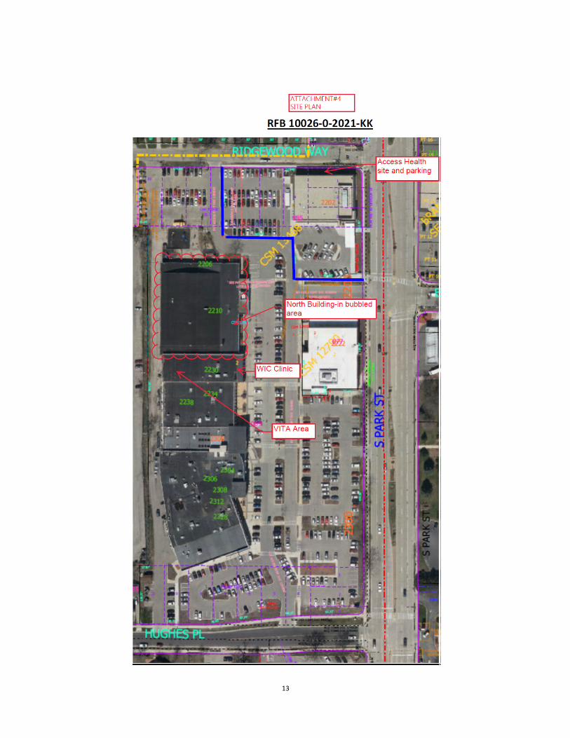
PROJECT LOCATION:
There are two office areas at the Property that are involved with the Project. The first
office area is roughly 4,297 s.f. area, that has an address of 2206 S. Park Street, Suite
600 (the “VITA Area”) and the other area is roughly 3563 s.f., with an address of 2230 S.
Park Street (the “WIC Clinic”). In addition, MEP disconnection services are involved in
the adjacent building to these office areas that has an address of 2210 S. Park Street
(the “North Building”); collectively these areas are defined as (the “Premises”).
The North Building is slated to be demolished via a separate RFB.
PROJECT TIMELINE:
The Scope of Services as described below and in the “Contract” should be substantially
completed by October 15, 2021 (the “Substantial Completion Date”) or later with
approved extensions. If the Scope of Services are revised during this “Bid Process”, then
an addendum to the RFB will be posted on or before June 16, 2021 on Demand Star and
Vendor Net, and the Substantial Completion Date may be changed and noted therein.
Any questions relating to the RFB, the construction drawings, specifications and project
manual prepared by Strang, Inc. dated May 24, 2021 (collectively defined as the
“Construction Documents”) or Bid Documents are due on or before June 16, 2021.

4
It is the Bidder’s responsibility to monitor Demand Star or Vendor Net during the
Bidding Process for important updates or addendums. All Bidder’s will be asked to sign
A sworn affidavit with their Bid Package submittal relating to any addendums being
incorporated into the Scope of Services.
OBTAINING RFB:
Electronic files of this Request for Bid (“RFB”) document may be obtained beginning
May 24, 2021. The RFB will be available electronically on www.demandstar.com and
https://vendornet.wi.gov/.
PRE‐BID CONFERENCE/PROJECT TOUR:
A pre‐bid conference will be held on Thursday, May 27, 2021 at 9:00 a.m. in the North
Building’s conference room located at 2210 S. Park Street, at which time questions
regarding the RFB will be entertained. A tour of the Premises will immediately follow
the pre‐bid conference. All prospective bidders are strongly encouraged to attend. If
you cannot make this date, you can contact Jamah Johnson at 608‐385‐5748 or
[email protected] to arrange an appointment at a mutually agreed upon
date/time.
BID GUARANTY:
Each Bidder must MAIL a surety company Bid Bond (see attached form) or a certified
cashier’s check payable to the order of the Community Development Authority for a
sum not less than five percent (5%) of the Bidder’s total Bid Amount in the Bid Form (the
“Bid Deposit”) that will be held until a successful Bidder is notified.
Bidder’s Bid Bond or certified cashier’s check must be received by City Finance at the
below address on or before June 22nd.
City of Madison Finance Department
c/o Brian Pittelli
City‐County Building
210 Martin Luther King Jr. Blvd., Room 406
Madison, WI 53703

5
The City‐County Building is currently closed and we are not accepting any walk‐in
delivers; therefore it is highly advised to use a mail service that can guaranty delivery on
or before June 22nd.
If a Bidder is not chosen as the lowest “Successful Bidder” under this RFB, then your Bid
Bond or certified cashier’s check will be destroyed by City Finance. The Successful
Bidder’s Bid Bond or certified cashier’s check will be destroyed within forty‐eight (48)
hours following the Successful Bidder’s execution of the Contract and receipt of the
Payment and Performance Bond, as required if the Bid Amount exceeds $100,000.
SOCIAL EQUITY CONTRACT REQUIREMENTS:
The Community Development Authority strongly encourages Minority‐Owned (MBEs)
and Women‐Owned Businesses (WBEs), social and economically disadvantaged
business enterprises, HUD Section 3 businesses, and small businesses to submit bids or
to participate as subcontractors and suppliers on CDA contracts.
AFFIRMATIVE ACTION NOTICE:
The CDA complies with all City of Madison’s Affirmative Action Plan requirements. If
the successful bidder (the “Contractor”) employs 15 or more employees and does
aggregate annual business with
the City of Madison of $50,000 or more for the calendar year in which the Contract
takes effect, Contractor shall file, within thirty (30) days from the Contract Effective
Date and BEFORE RELEASE OF PAYMENT, an Affirmative Action Plan
(https://www.cityofmadison.com/civil‐rights/contract‐compliance/affirmative‐action‐
plan/vendors‐suppliers) designed to ensure that the Contractor provides equal
employment opportunity to all and takes affirmative action in its utilization of
applicants and employees who are women, minorities and/or persons with disabilities.
The Model Affirmative Action Plan for Vendors, Request for Exemption form, and
instructions are available at: http://www.cityofmadison.com/civil‐rights/contract‐
compliance/vendors‐suppliers/forms, or by contacting a Contract Compliance Specialist
at the City of Madison Affirmative Action Division at (608) 266‐4910.
Contractor shall also allow maximum feasible opportunities to small business
enterprises to compete for any subcontracts entered into pursuant to the Contract.
6
Job postings: If Contractor employs 15 or more employees, regardless of dollar amount,
Contractor must notify the City of Madison of all external job openings at locations in
Dane County, WI and Contractor agrees to interview candidates referred by the City or
its designee. Job posting information is available at:
https://www.cityofmadison.com/civil‐rights/programs/referrals‐and‐interviews‐for‐
sustainable‐employment‐raise‐program/raise‐job
RIGHTS RESERVED:
The CDA reserves the right to reject any or all Bid Package proposals, to waive any
informalities in the CD’s or Bid Process or to cancel in whole or in part this RFB if it is in
the best interest of the CDA to do so.
The CDA intends to award a contract based on the lowest TOTAL base Bid Amount, and
most competent and qualified Bidder in a single Contract for all Scope of Services work
to be performed.
Per the CDA’s Financial Policies, a competent bidder is one who meets the following
conditions:
1. Maintains a permanent place of business.
2. Provides a sworn statement upon request, which evidences the bidder has
adequate financial resources to complete the work being bid, as well as all
other work the bidder is presently under contract to complete.
3. Is bondable for the terms of the proposed contract, if required.
4. Has a record of satisfactorily completing past projects.
5. Established and diligently maintained a satisfactory affirmative action
program in accordance with the contract provisions. (Adapted from State of
Wisconsin Department of Administration Administrative Code Chapter
ADM21)
Per the CDA’s Financial Policies, a qualified bidder is one who 1) has completed one
or more projects of similar size or value to the work being bid and 2) has access to all
necessary equipment and has organizational capacity and technical competence
necessary to enable performance of the work properly and expeditiously. (Adapted

7
from State of Wisconsin Department of Administration Administrative Code Chapter
ADM21).
QUESTIONS:
Technical questions regarding the Construction Documents, and Scope of Services may
be directed to: Mike Kundinger, Director of Specifications (the “Architect”) at Strang,
Inc. in writing at mkundinger@strang‐inc.com.
Administrative questions regarding the Bid Process, this RFB and its attached
documents may be directed to the CDA’s representative for this RFB: Kris Koval at
Interpretation or correction of Bid Documents:
Should the Bidder find any discrepancies, omissions, ambiguities or conflicts
during the examination of the Construction Documents, this RFB and its attachments or
after the visit to the Project site then the Bidder should email any questions to the
Architect and Kris Koval no later June 11, 2021.
The Architect and Kris Koval will review any questions, and where information sought is
not clearly indicated or specified, the CDA will issue a clarifying Addendum to the RFB by
June 16, 2021. Included in the Addendum will be a sworn affidavit form for the Bidder to
sign acknowledging its receipt thereof, which will then need to be included in the
Bidder’s Bid Package submittal.
Neither the CDA nor the Architect will be responsible for any oral instructions,
interpretations, corrections or changes additions to or deductions from the amount of
work required under the Contract.
8
B. Instructions to Bid
BID DOCUMENTS TO INCLUDE IN YOUR BID PACKAGE SUBMITTAL:
All the following documents included in Section II hereof (collectively the “Bid
Documents”) must be completed, executed, notarized (where stated) and submitted
with an electronic “Bid Package”:
1. Bid Form*
2. Bid Bond or a certified cashier’s check for the Bid Deposit mailed
separately per the above instructions.
3. Contractor Profile
4. Contractor References
5. Affidavit of Financial Resources
6. If an Addendum to the RFB is issued, the
sworn affidavit therein will need to be signed
and included in the Bid Package.
*The attached Bid Form must be filled out and executed by an authorized party within
the firm that is presenting a Bid Amount or the person who signed the Affidavit of
Financial Resources.
The guaranteed maximum Bid Amount (the “Bid Amount”) shall include but is not
limited to the following costs to perform the Scope of Services: all labor; permits
(excluding the building permit); parts; materials; tools; supplies; equipment; crane
rental; demolition; mechanical, electrical and plumbing services; trash bin and disposal
costs; rest room supplies; cleaning services; insurance costs; bonds; contingency, and
other facilities necessary or proper for, or incidental to, all work as required by, and in
accordance with the Contract.
A Bid Amount breakdown by subcontractor also needs to be filled out in the Bid Form.

9
BID PACKAGE SUBMITTAL PROCEDURE: A complete Bid Package (except for the Bid Deposit which is mailed per the above
instructions) submitted for this Project must be sent electronically to Brian Pittelli in the
City of Madison Finance department at [email protected].
Please note Brian has two “t’s” and two “l’s” in his name/email address.
When submitting the Bid Package, it must be labeled in the subject line of the email to
Brian Pittelli as follows:
Bid Package RFB 10026‐0‐2021‐KK and then reference the Bidder’s company name
afterwards
BID PACKAGE SUBMITTAL DEADLINE:
The submission deadline for the Bid Package is 2:00 p.m. on June 24, 2021. Thereafter,
all Bid Packages will be emailed by Brian Pettelli to Kris Koval and Mike Kundinger for
their review.
Bid Packages missing any Bid Documents or received after 2:00 p.m. may not be
accepted by the CDA, in its sole discretion.
10
C. Scope of Services and Construction Documents
The Scope of Services that are outlined below, and in the below Construction
Documents will be attached to the Contract, as Attachments 2 and 3, respectively.
Contractor (and its subcontractors where applicable) is to:
1. Perform work related to general construction, heating and ventilating, MEP
(mechanical, electrical & plumbing), and fire and life safety construction work
within the Premises as outlined in the Construction Documents that are attached
to this RFB.
2. Contractor will communicate/coordinate work with the Architect, the CDA (Kris
Koval), and the CDA’s property manager (Jamah Johnson).
3. The Architect will be providing the building permit, and Contractor is responsible
for any other permits relating to the Scope of Services.
4. Contractor shall follow all requirements outlined in the Construction Documents
and Contract prior to commencing construction.
5. Contractor will schedule a pre‐construction meeting with the Architect, the CDA,
the CDA’s management representative and any subcontractors engaged by
Contractor within ten days from the Contract’s Effective Date. At this meeting,
Contractor shall provide a construction schedule and submittal log.
6. Contractor and its subcontractors shall park in a designated area identified by
the CDA’s property manager. There shall be no parking on the Access Health site
as noted on Attachment #4.
7. Contractor and its subcontractors shall wear face masks while working in the
Premises, if required by Public Health of Dane County.
11
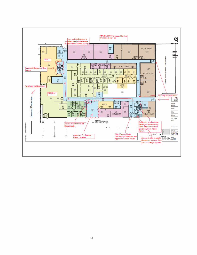
8. The Contractor can use the conference room in the North Building as noted in
Attachment #1.
9. Contractor shall access the North Building per the attached floor plan
(Attachment #1), and not use any other doors.
10. All FOB keycards and hard keys provided to Contractor and its subcontractors
shall not be provided to anyone not working on the Project. Contractor and their
subcontractors need to return all FOB keycards/hard keys within 5 business days
of completion of the scope of work‐otherwise Contractor will be charged a cost
of $50/card to replace.
11. There are children in the North Building; as such all doors to the North Building
shall be closed at all times for security purposes. Contractor or their
subcontractors shall not pry open any door without someone watching the door
during said time frame.
12. Contractor shall not use the rest rooms in the North Building, and should use the
rest rooms in the Vita Area. Contractor is responsible to clean the Vita Area rest
rooms and supply the soap and toilet paper.
13. Contractor shall not use the kitchen in Vita Area for work not related to the
Project.
14. VITA will be moving its FFE in its space or will drape it.
15. In general, the normal working hours (pre‐COVID) at the Property are Monday
through Friday from 7:30 a.m. to 5:30 p.m. All shutdowns, tie‐ins and various
demolition activities producing substantial noise have to be performed outside
normal working hours, and each step shall be coordinated with Jamah Johnson.
16. CDA’s property management team shall provide an area for staging of
materials/equipment and Contractor’s trash bin in alley of Property. Likewise,
CDA’s property management team will work to identify an area for Contractor’s
crane/hoist.
17. Upon Substantial Completion of the work, furnish to the CDA the certificate of
occupancy and all warranties.
12
13
������������ ���������� �����������
������������������������������������������������������ ��������������!�����"����#$�!�������!�������$�%!���!
!����&����&����
$��'����!��$���(
�&�)������!�����"����#�*+*,
��-�!�&�!��&.�����&#
����-�����&�����/*0++�!#����/�!������$�!&��'��102,0 ��&.�����&#�(�*+*,+11�$��3-�������&���� ��$�������$�!�&�����
����-�����&�����/ *0++�!#����/�!����� �$�!&��'��102,0 �$+14*54*+*, �����!�����$��3-�������&���� ��$�������$�!�&����
�
�++,*+*,+11
�����++, �����!�����������++, ���������6&����&��++* �6��!�6��)�����7��&$����6&����&��������������*+, 6��!��6&&��$�&���&����$�6&&�����!�0+, 6��!��6&&����6����$��������������$��&&6����6������&�����&�6�++, 6������&�����&�������!����6�*++ �!�����6������&�����&�����6�*+, 6��!��6&&��6������&�����&������� ����++, �� ���������!�����*+, 6��!��6&&���� ����!���)�����8+, �� ����$����!��������++, ��������������!�����4�!����6�����&�!,+, 6��!��6&&�����������$�&���&�����*+, 6��!��6&&��������������*+* �&&6����������������������++, ���������!) &!"�� ��-����&�!���$���������&��!�,++ &'����-��&-����$�&���&������,+, �������&'����-�����������$�&���&������,,+ 6��!��6&&��&-�������������$�&���&������,,, �������6��!��6&&�����������$�&���&������*+, 6��!��6&&�����������������������0,, �������6��!��6&&������������&'�������5++ &'����-��&-�������������!)!��!�����5,, �������6��!��6&&�����������!)!��!�����9+, ������$�������������!�2+, ��������&�������$�����!�8+, ����������������$����!�:+, ���������!���$��!
��&.����&����&� ��$�!&�
�&#$�!���� ��&�$���
��������������� ��������� ��� ������ ���������������� ���������� ��� ������ ������� ���������������!���"��#�� ���������� ��� ������ ������������$����%�� �����&� '���������� ��� ������ ��(����������$����&)� �����&� '���������� ��� ������ �*++,��-,&.*++,��/,!&*0-*1%1%+��120&�0&3%4%3�&5&6-1%+���+1&�0&3%4%3�05-���+1&3&%5%�7�8&%7819%��+9.!+**+9&��5%781�120&
6&*1%3-5�&5&6-1%+�3+5/,��7*%���/,!&*
�&9��++*�&,+��++*��$����:3���"�-����"�* '�;���<=
=========================
=�-,&&5&6-1%+�*++,��-,&*,�======>?==@!5?=&A%�1%�7��++*�0&3%4%3��&,+5%1%+���+1&=
0*&3-�1�3+�3*&1&3+�3*&1&�,-�+�*2�/�%1�:�&31%+�<!*%3B�:�&31%+�<�1&&5�:�&31%+�<*%7%��%��/5-1%+��:�&31%+�<&A1&*%+*�%��/5-1%+��-���4%�%�8��2�1&,�:�&31%+�<&A1&*%+*�%��/5-1%+��-���4%�%�8��2�1&,�:&5&6-1%+�<0529++��:�&31%+�<7*-�/5-*�4%55�1+�&�6&�&&*�:&5&6-1%+�<�+%5C�%�4%55�+%5C�/��%�1/*!&�
D@�,-AE>�?�F@�,%� E>�?�D@�,%�GH@�,-A1I+I��&-1G>�?�D@ E>�?�F@ -1�-33&��%!5&�/�%1G>�?�J@ ���K?��-55�4%A1/*&�,+/�1%�7�%��1-55-1%+��L�35&-*-�3&��%,&��%+����8-55�,&&1�-55�-�-�-33&��%!%5%12��1-��-*���-����+�-33&��+*2��8-55�0*+M&31�,+*&�18-��N@�4*+,�9-55I?��0*+6%�&�!5+3B%�7�%��9-55��4+*�-55�9-55�,+/�1&��&O/%0,&�1C�-33&��+*%&�C�-���3-!%�&1*2�-��*&O/%*&�P�%�35/�%�7�+9�&*�%1&,�I?��-55�%1&,���8+9��-*&��+1��&3&��-*%52�%��18%��0*+M&31I&5+�7-1&��*%,7*-!�!-*�:7!< G>�?�D�G.H@
GQ@�7*-!�!-*�:7!<9-1&*�35+�&1 /*%�-5H>�?�D@E>�?�J�G.H@ 1+%5&1�0-0&*��%�0&��&*�:10�<7*-!�!-*�:7!<E>�?�E@E>�?�E�G.H@
1+�*&45&31%6&��/*4-3&E>�?�N@H>�?�GF@ H>�?�E@�,%�,%**+*�:,%*<
!+11+,�+4�-0*+�%��/5-1&�0%0&��*-%��L�8+1�9-1&*��/0052�R-55��%�B��98&*&�0I5-,�0-�&5�%���+1��8+9�E>�?�N@
�+-0��%�0&��&*�:��<
1+�+0&*-!5&�3+�1*+5�E>�?�N@�,-A 1+�+0&*-!5&�3+�1*+5�E>�?�N@�,-A H>�?�D@
0-0&*�1+9&5��%�0&��&*�.�*&3&01-35&�:01�.*<�-�%1-*2��-0B%���%�0&��&*�:���<�-�%1-*2��-0B%��*&3&01-35&�:��*<
1+��0+/1�+/15&1E>�?�F@�,-AH>�?�E@�,%�&5&31*%3�9-1&*�3++5&*�:&93<-33&��+*%&�
!I+I�3-!%�&1H>�?�D@
4%*&�&A1%�7/%�8&*3-!%�&1�:4&3<
���S��������� ����� ������������ ,-�%�+�C�9%��T��9-/B&�8-C�9%
�*-9%�7��&1�-1&U
3+02*%781��1*-�7C�%�3I�HFHG
*&6%�%+��0*+M&31��+I
J.HG.HFHG�GHUEVUGG�0,
18&�6%55-7&�+��0-*B HEFF��I�0-*B��1*&&1 ,-�%�+��9%�JEWGE 3�FJ.HN.HFHG 7&�&*-5�%�4+*,-1%+�3�-�?6%55-7&*��+*18�!/%5�%�7�,&0��%�3+��&3
1
7FFGHFHGFJJ
/8 /�%1�8&-1&*/�4 /�4%�%�8&�/�+ /�5&����+1&��+18&*9%�&/* /*%�-56 6&�1C�6+51C�6-56&6-3 6-3//,631 6%�25�3+,0+�%1%+��1%5&6&*1 6&*1%3-56&�1 6&�1%!/5&6�4 6%�25��8&&1�45++*%�761* 6&�1�18*+/78�*++4693 6%�25�9-55�3+6&*%�79 9&�1C�9%�18C�9%�&C�9-11C�9-�1&C�9-1&*9. 9%189.+ 9%18+/19! 9++��!-�&93 9-1&*�35+�&19� 9++�94 9%�&�45-�7&9, 9%*&�,&�890 9-1&*0*++4C�9&-18&*0*++49* 9-1&*�*&�%�1-�1C�9-1&*�*&3&01-35&91 9&%781994 9&5�&��9%*&�4-!*%32� 2-*�
,15 ,&1-5,/5 ,/55%+�� �+*18�%3 �+1�%��3+�1*-31�+ �/,!&*�+, �+,%�-5�0 �+��0+1-!5&�9-1&*�1� �+1�1+��3-5&+- +6&*-55C�+/1�%�&�-%*+3 +��3&�1&*+� +/1�%�&��%-,&1&*+43% +9�&*�4/*�%�8&��3+�1*-31+*�%��1-55&�+44 +44%3&+4+% +9�&*�4/*�%�8&��+9�&*�%��1-55&�+8 +6&*8&-�+83� +6&*8&-��3+%5%�7��++*+8�� +6&*8&-���&31%+�-5��++*+0 +0&*-!5&�0-*1%1%+�+07 +0&�%�7+0�7 +0&�%�7+00 +00+�%1&+00?8 +00+�%1&�8-��0- 0/!5%3�-��*&��03 05/,!%�7�3+�1*-31+*0�+ 0+9&*��++*�+0&*-1+*0&*0 0&*0&��%3/5-*05 05-1&C�0*+0&*12�5%�&05-, 05-�1%3�5-,%�-1&05-� 05-�1&*05!7 05/,!%�70529� 0529++�0* 0-%*01 0-%�101� 0-0&*�1+9&5��%�0&��&*01�.* 0-0&*�1+9&5��%�0&��&*�.�*&3&01-35&01� 0-*1%1%+�01* 0-0&*�1+9&5�*&3&01-35&061 0-6&*�1%5&O1 O/-**2�1%5&* *-�%/�C�*%�&**- *&1/*��-%**! *&�%5%&�1�!-�&*!3 *&�%5%&�1�!-�&�3+6&�*!� *&�%5%&�1��!-�&��1*-%781*� *++4��*-%�*&4 *&4&*&�3&C�*&4*%7&*-1+**&4* *&4*%7&*-1+**&%�4 *&%�4+*3&�*&, *&,+6&*&O *&O/%*&�*&O� *&O/%*&�*4 *&�%�+/��45++*%�7*, *++,C�*-1&��,&1-5*+ *+/78�+0&�%�7*1 */!!&*�1%5&*/! */!!&**9� *&�9++�� �+/18C��%�BC��/0052�L6 �1-%��L�6-*�%�8�-! �+/���-11&�/-1%+��!5-�B&1�-� �-�%1-*2�! �+%5�!+*%�7�3 �+5%��3+*&�3� �&-1�3+6&*��%�0&��&*�38&� �38&�/5&�3+� �&-5&��3+�3*&1&�� �+-0��%�0&��&*�&31 �&31%+��4 �O/-*&�4++1�8 �8&54�8* �8+9&*�81 �8&&1�%, �%,%5-*��* �-�%1-*2��-0B%��*&3&01-35&��6 �-�%1-*2��-0B%��6&��+*�+7 �5-!�+��7*-�&�0&3 �0&3%4%3-1%+��O �O/-*&�� �1-%�5&����1&&5��, �+5%���/*4-3&�,-1&*%-5�1 �1+�&�1- �1-1%+��1� �1-��-*��15 �1&&5�1+* �1+*-7&�1*/3 �1*/31/*-5�/�0 �/�0&��&��2, �2,,&1*%3-51 1*&-�C�18*&�8+5�1L! 1+0�L�!+11+,1L7 1+�7/&�L�7*++6&1&5 1&5&08+�&1&,0 1&,0+*-*2C�1&,0&*-1/*&1&* 1&**-XX+18B 18%3B1B!� 1-3B�!+-*�1+! 1+0�+4�!&-,1+4 1+0�+4�4++1%�71+� 1+0�+4��1&&510� 1+%5&1�0-0&*��%�0&��&*1*-�� 1*-��0-*&�116 1&5&6%�%+�19 1+0�+4�9-55120 120%3-5
&,&* &,&*7&�32&�35 &�35+�/*&&0 &5&31*%3�0-�&5C�&0+A2&O &O/-5&O/%0 &O/%0,&�1&1* &A%�1%�7�1+�*&,-%�&9 &-38�9-2&93 &5&31*%3�9-1&*�3++5&*&98 &5&31*%3�9-1&*�8&-1&*&A8 &A8-/�1&A0 &A0-��%+�&A0+ &A0+�&�&A�1 &A%�1%�7&A1 &A1&*%+*4- 4%*&�-5-*,4! 4-3&�!*%3BC�45++*�!+A4312 4-31+*24� 45++*��*-%�4�� 4+/��-1%+�4& 4%*&�&A1%�7/%�8&*4&! 4%*&�&A1%�7/%�8&*�!*-3B&14&3 4%*&�&A1%%�7/%�8&*�3-!%�&144 4%�%�8�45++*445* 4%1�&���45++*48 4/,&�8++�C�4%*&�8+�&483 4%*&�8+�&�3-!%�&14%� 4%�%�84%A 4%A1/*&45 45++*45/+* 45/+*&�3&�14+ 4%�%�8&��+0&�%�74+3 4-3&�+4�3+�3*&1&4+� 4-3&�+4��1/�40*4 4%*&0*++4%�74*0 4%!&*75-���*&%�4+*3&��05-�1%34*1 4%*&�*&1-*�-�14*X 4*&&X&*41 4++1C�4&&1417 4++1%�74/** 4/**%�74/1 4/1/*&46 4%&5��6&*%427 7-�7- 7-/7&7-56 7-5-�%X&�7! 7*-!�!-*73 7&�&*-5�3+�1*-31+*75 75-��7,7� 75-���,-1�720�/,��8&-1%�77�� 7*+/��79! 720�/,�9-55�!+-*�720 720�/,8 8%788! 8+�&�!%!!8!� 8-*�!+-*�83 8+55+9�3+*&8�9� 8-*�9++�8�9& 8-*�9-*&8, 8+55+9�,&1-58+*%X 8+*%X+�1-580 8+*�&0+9&*8* 8+/*8�� 8+55+9��1*/31/*-5��1&&581 8&%78186-3 8&-1%�7C�6&�1%5-1%+�C�L�-%*�3+��%1%+�%�789� 8-*�9++�%� %��%�&��%-,&1&*%& %�6&*1�&5&6-1%+�%4 %��%�&�4-3&%,0 %��/5-1&��,&1-5�0-�&5%��/5 %��/5-1%+�%�1 %�1&*%+*%1� %,0-31�1*-44%3��++*M-� M-�%1+*M!& M+%�1�!&-*%�7�&5&6-1%+�M1 M+%�1B%1 B%138&�B+ B�+3B+/1B0 B%3B�05-1&B� B�&&��0-3&5 5&�718C�-�75&5-! 5-!+*-1+*25-, 5-,%�-1&5-6 5-6-1+*2558 5+�7�5&7�8+*%X+�1-5556 5+�7�5&7�6&*1%3-551 5%781593 5%781�9&%781�3+�3*&1&,-15 ,-1&*%-5,-A ,-A%,/,,! ,+0�!-�%�,3 ,&38-�%3-5�3+�1*-31+*,&38 ,&38-�%3-5,&,! ,&,!*-�&,&0 ,&38-�%3-5C�&5&31*%3-5C�05/,!%�7,&XX ,&XX-�%�&,4* ,-�/4-31/*&*,8 ,-�8+5&C�,+0�8+5�&*,%� ,%�%,/,,%* ,%**+*,%�3 ,%�3&55-�&+/�,5L0 ,&1-5�5-18�L�05-�1&*,+ ,-�+�*2�+0&�%�7,1� ,+/�1&�
= 0+/��C��/,!&*L -��Y -�75&R -1-?GFF -�5-!&5�?�GFF�,%�/1&�4%*&�*-1%�7!?VF !�5-!&5�?�VF�,%�/1&�4%*&�*-1%�73?NJ 3�5-!&5�?�NJ�,%�/1&�4%*&�*-1%�7�?HF ��5-!&5�?�HF�,%�/1&�4%*&�*-1%�7Z �%-,&1&*C�*+/��C�08-�&-! -�38+*�!+51-!!* -!!*&6%-1%+�-3+/� -3+/�1%3-5-30 -3+/�1%3-5�3&%5%�7�0-�&5-3* -3*25%3C�-3*25%3�,-*B&*�!+-*�-�M -�M/�1-!5&C�-�M-3&�1-44 -!+6&�4%�%�8�45++*-4� -%*�45+9��1-1%+�-77* -77*&7-1&-8/ -%*�8-��5%�7�/�%1-5 -5/,%�/,-51 -51&*�-1&-0 -33&���0-�&5-00*+A -00*+A%,-1&-*38 -*38%1&31/*-5C�-*38%1&31-�08 -�08-51-6 -%*�6-56&!-4 !-445&�!� !+-*�!8� !/5B8&-�!%1/, !%1/,%�+/�!5 !+**+9&��5%1&!5�7 !/%5�%�7!5B7 !5+3B%�7!, !&-,!� !/55�+�&!+ !+11+,�+4!+1 !+11+,!0 !-�&�05-1&!*7 !&-*%�7!�3 !%+?�-4&12�3-!%�&1!1/ !*%1%�8�18&*,-5�/�%1�!1/8 !*%1%�8�18&*,-5�/�%1��0&*�8+/*!19 !&19&&�!/* !/%51?/0�*++43 3+�6&31+*C�38-��&53-! 3-!%�&13! 3-138�!-�%�3&, 3&,&�13&* 3&*-,%3343% 3+�1*-31+*�4/*�%�8&�C�3+�1*-31+*�%��1-55&�34, 3/!%3�4&&1�0&*�,%�/1&37 3+*�&*�7/-*�38 3+-1�8++B38!� 38-5B!+-*�3M 3+�1*+5�M+%�135 3&�1&*�5%�&357 3&%5%�735+� 35+�&135* 35&-*3,/ 3+�3*&1&�,-�+�*2�/�%13+5 3+5/,�3+�3 3+�3*&1&3+�M 3+��1*/31%+��M+%�13+�� 3+��&31%+�3+��1 3+��1*/31%+�3+�1 3+�1*+53+�1* 3+�1*-31+*3+** 3+**%�+*301 3-*0&13* 3-*��*&-�&*3� 3-�1��1+�&31 3&*-,%3�1%5&31* 3&�1&*31�B 3+/�1&*�%�B3/ 3+��&��%�7�/�%13/8 3-!%�&1�/�%1�8&-1&*325 325%��&*� �&018�!- �&3B�!&-*%�7�-�75&�!5 �+/!5&�&,+ �&,+5%1%+�C��&,+5%�8�&01 �&0-*1,&�1�4 �*%�B%�7�4+/�1-%��%- �%-,&1&*�%-7 �%-7+�-5�%, �%,&��%+��%�0 �%�0&��&*�� �+9��+ �+�+6&*C��%11+�0 �-,00*++4%�7�* �++*�� �+9��0+/1��� �/31��,+B&��&1&31+*�1 �*-%��1%5&�15 �&1-%5�97 �*-9%�7�95 �+9&5& &-�1&- &-38C�&A8-/�1�-%*&3 &5&31*%3-5�3+�1*-31+*&4 &A8-/�1�4-�&8� &5&31*%3�8-����*2&*&%4� &A1&*%+*�%��/5-1%+��4%�%�8��2�1&,&M &A0-��%+��M+%�1&5 &5&6-1%+�&5&3 &5&31*%3-5&5&6 &5&6-1+*
�����$������ [���������� ��
�\[������ ��
�3-5&U��G.N@�]�G>?F@��������[���� �S�� S��
�+I�&�3*%0 1%+��-1&
���������� ��������������
� � � ��� ��� ��
� ��� ��
��������������������������������
�������������������������� ��
����������
����������
���
�������� �����������������
�� � � � � � � � � ��
�
! �"�!���
� ���
� �"�!���
�� ����
#���
#���
���� �������
��� #���
#�������$��%���� � ��
%� ���%� �����#� #���
#�� �� �� ���� #�� ��
� �&� �"� ��� ��� ��
� ������
#� ���##�
���%�����%
#� #�� #��#��#�""�& "�� "��
�������
�����&
!��!��
!��
!��!��
!��
! �"�!���
� ���
%� ���%� ��
� �����%�����%
� &"%� &"�� &�� &�� &� � &&� � &&% � &��
� ��� � � �� � ��
� ��%� ��� �"� �&
� ��� &�� &�� &��� &
��� ��������
�'��� ���$#��� #��
��������������������������������
�������������������������� ��
!�#�%�
� �
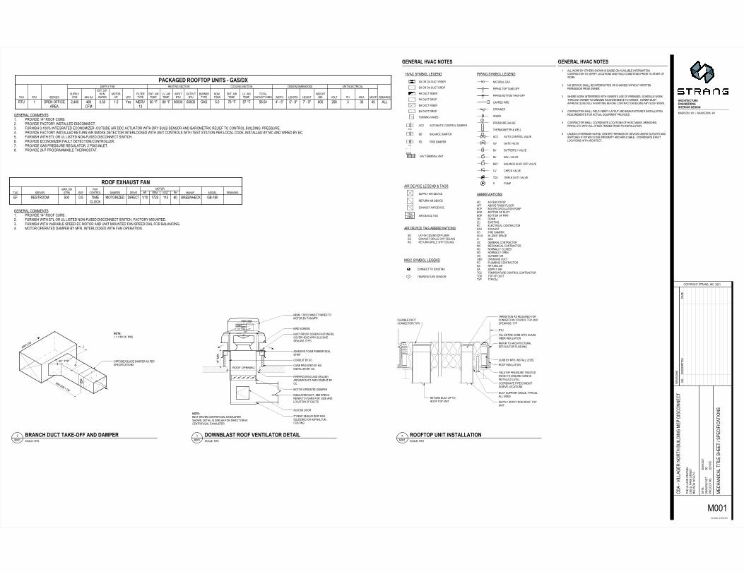
() *(+,-+./$01203$$$45678$49::6$ ;<=>?@<$$7AB$C8BD:6E$06FG$$$$$$$$$$$$$$$$?><;H$7AB$C8BC8B $$$*(+,-+./$I2+/IJ3KLF$78:6M$GN:OF$P6GQF$R9GLFHHSTUV$WGX5YZY$J:$J:R$:C$1::C$[Z6CG\F*(+,-+./$)1+W01]$([23/6:ZR$*B$*Z75LF77J])2$K4$K.[J1(J+K.3_*$$ +*$H<;a$bGR8F6$Uc4+12$12[+[J0.2$10J+./[3456F$1F7578GL\F$I:Z69M$1G85LP7$C:6$[86Z\8Z6G9$:YR:LFL873 +*$H<;a$JGN9F$U<;c[86Z\8Z6G9$46GYF $$$$$$$$$$$$$$$$<$I:Z6*FG65LP$DG997>$2X8F65:6 H$I:Z6*FG65LP$DG997>$+L8F65:6 <$I:Z649::6$:L786Z\85:L <$I:Z61::C$:L786Z\85:L <$I:Z64+12$0,01W3)6:O5QFQ4+12$[)1+.d,21$[][J2W34Z99M$7R65LE9F6FQ$RF6$.4)0$;_
efgh$ijkflmnoifj
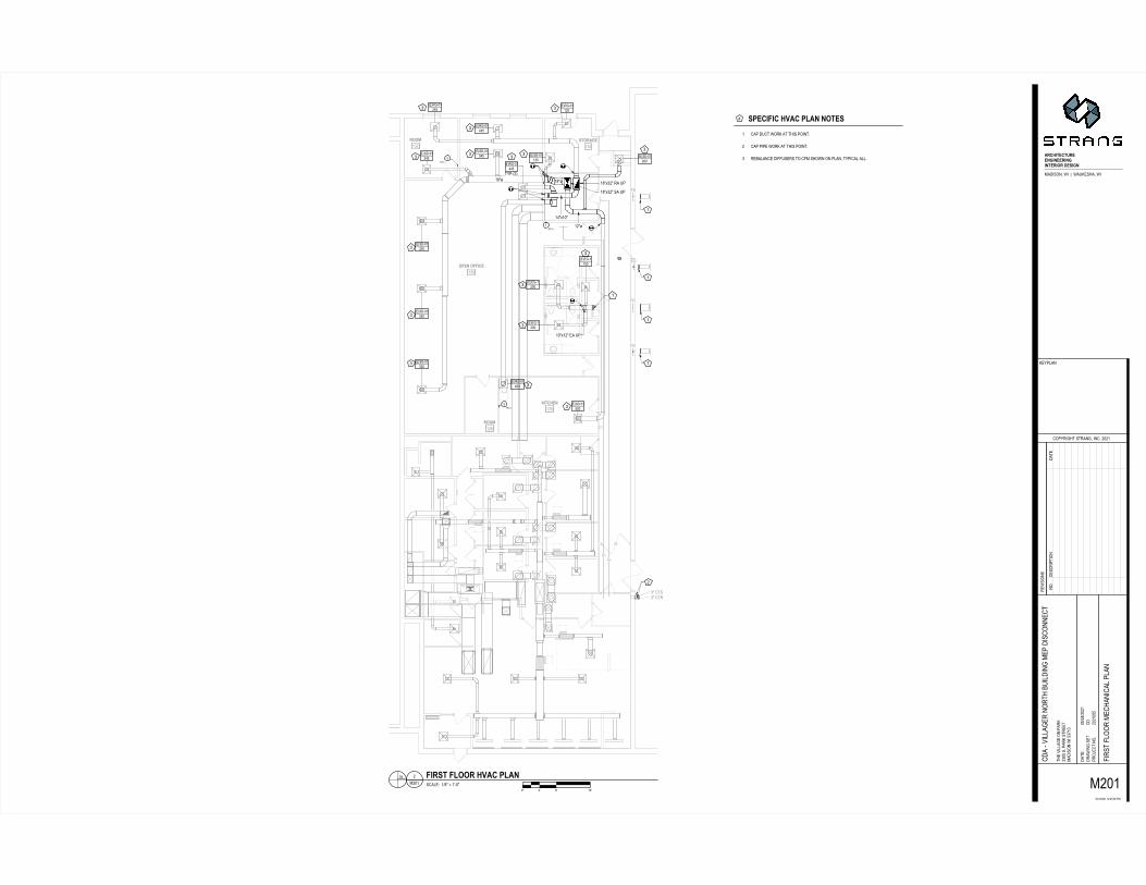
4+12$2pJ+./(+[I212/12[[$-+12J+K.U<V$q$DI22,I0+1$J(1.+./$[)02;$IK(1$10J2-$4+12$)01J+J+K.r$IK(1$10J2-$4+12$)01J+J+K.42.KJ$JK$[0,2sikh$tnkhou$vsnj$shwhjg
0 * ^ - 2 4 / I + x d , W K ) y 1 [ J ( z DHH_r$[B$)01d2p+[J+./$[)K1J[$JKD.{$xK2[[(+J2$HH_?W0-+[K.$0120$J2IB$K,,2/2[(+J2$;;;;
[(+J2$H_<<0J1+(W[(+J2$H_<U2p+[J+./$-0.2$K(.J]$[WK[(+J2$H_;H1+d2J [(+J2$H_<?.0+,$[0,K. [(+J2$H_<r4(J(1212J0+, [(+J2$H_<H4(J(1212J0+,[(+J2$;;_;.2D$[(+J2[(+J2$;;H=.2D$[(+J2
[(+J2$H_H?](2$D0IHH<U$[B$)01d[(+J2$U<<z+J0
HH_<$[B$)01d$D+$T,+.+ HH<U$[B$)01d$[(+J2$U<<I20-$[J01JI0JI2-$0120$+.-+0J2[$[2)010J2$*(+,-+./?>_<<$[yB$4JBc
42
( z D;_refll|
;Ha}ioe~hj�ion$
�ie$esijie
;H@mhjt;H=�fmhjt;H?�nj|;<@�hto|
nle~ioheo�lhhjwijhhlijwijohlifl$ghtiwjW0-+[K.>$D+$$�$$D0(d2[I0>$D+
-10D+./$[2J-0J23
K)]1+/IJ$[J10./>$+.B$H<H;
12z+[+K.[)1Kx2J$.KB
a{H;{H<H;$;H3_@3;H$)W
JI2$z+,,0/2$K.$)01d H_<<$[B$)01d$[J122J W0-+[K.$D+$a_=;_ -<a{Hr{H<H; ,+42$[042J]$),0.$�$K-2$+.4K1W0J+K.-0$Tz+,,0/21$.K1JI$*(+,-+./$W2)$-+[K..2J /<<HH<H;<aa
. [0,23$$;V$�$a<ST<V/<<H; f�hlnss$kilto$ksffl$vsnj�� ��� ��� ����
. [0,23$$;{;UV$�$;ST<V/<<HH kilto$ksffl$sikh$tnkhou$vsnj
[0,23$.J[. /<<H_ tioh$vsnj
�� �� ��� ���
.KB-2[1+) J+K.-0J2
�� ������� ������� ���� ��
����� ������� ���� ������� � ��������
������� ��������
������������� �� !
� " #
��� ��!�$ ��� %����� %������� �� &�����! �����! ��� %������� ���������' %����� %��
��������'� �������� �����
��� %����� %�� �����������!!�������
����!�$��� �
���� �
����
�����!����
������� ������� ���� ��
���� ������� � ��'(��� ��������
������� ������� ������ �������
� " #
����
�����!����
��� ��!�$ ��� %����� %������� ������� ������
������ �������� %����� %����' %����� %��
��'� ������� �� &�����! �����! ��� %�� �����������!! �������
����!�$��� ����� �� ! ���������
�
���� �
���
����
����� � � ���� ������ �����& ���)*+,-./0�#,��1��#*�23-4*0�#,
+5*#,/6�-37+*738
9.�:5,647�-75*/60�,/9;�����
53",-,./-�5.<397�/.;
�=��=�������8��8�'��)
743�",>>*63�./��*52 �����-;��*52�-75337 )*+,-./�#,������ 9+��=��=���� ?,5-7�?>..5�+3).>,7,./�*/+�?>..5��>*/-
9+*�@",>>*635�/.574�A�,>+,/6�)3��+,-9.//39
7
*����������
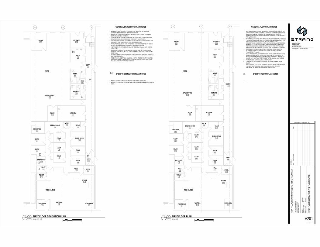
� � ��!��!�����!����� � *>>�+5*#,/6-�*53�.?�3B�*>�,)�.57*/93�,/�+3?,/,/6�743�#.52�.?�7439./75*97�+.9�)3/7-;��9*53?�>>:�-7�+:�*/+�9.)�*53�*>>�+5*#,/6-+�5,/6�743�A,++,/6��35,.+�*/+�A3?.53�,/-7*>>*7,./�.?�#.52;�5.)�7>:�53�.57�,/9./-,-73/9,3-�,/�743�+5*#,/6-�7.�743�*594,7397?.5�9>*5,?,9*7,./;� +.�/.7�-9*>3�+5*#,/6-;��743�+5*#,/6-�*53�/.7�/393--*5,>:�7.�-9*>3@��-3�6,"3/�+,)3/-,./-;�"35,?:�*>>�9./+,7,./-�*/+�+,)3/-,./-�*7�743�5.<397�-,73��5,.5�7.�743�-7*57�.?�9./-75�97,./;��*/:,/9./-,-73/9,3-�+,-9."353+�A:�743�9./75*97.5�-4*>>�A3�53�.573+�5.)�7>:�7.�743�*594,7397�?.5�9>*5,?,9*7,./�A3?.53�9.))3/9,/6743�#.52;�+,)3/-,./-�*53�6,"3/�?5.)�?*93�7.�?*93�.?�#*>>-;��-33#*>>�-397,./-�*/+��*57,7,./�7:�3-�?.5�3C*97�9./-75�97,./�+37*,>-;� #4353�-�39,?,9�+,)3/-,./-0�+37*,>-�.5�+3-,6/�,/73/7�9*//.7�A3+3735),/3+�?5.)�+.9�)3/7-�9./-�>7�743�*594,7397�A3?.53�5.933+,/6�#,74�#.52;� �*7940��53�*53�*/+�=�.5�53-7.53�#.52�-943+�>3+�7.�53)*,/�74*7�,-+*)*63+�*-�*�53-�>7�.?�+3).>,7,./�#.52;�*/:��*794,/6�#.52�7.)*794�3C,-7,/6;�53-7.5*7,./�*/+��*794,/6�#.52�-4*>>�A3�+./3�,/�*)*//35�74*7�)*,/7*,/-�?,53�5*7,/6�.?�5*73+�A�,>+,/6�9.)�./3/7-;� �5.7397�#.52�,/��>*93�+�5,/6�9./-75�97,./� 9..5+,/*73�743�*"*,>*A,>,7:�.?�*53*-�53B�,5,/6�#.52�#,74�743.#/35;� 53?35�7.�4"*90�3>3975,9*>0��>�)A,/60�*/+�?,53��5.7397,./�+5*#,/6-?.5�*++,7,./*>�#.52�*/+�).+,?,9*7,./-�53B�,53+�?.5�4"*903>3975,9*>0��>�)A,/6�*/+�?,53��5.7397,./�-:-73)-;� �������!�����!����� � @D
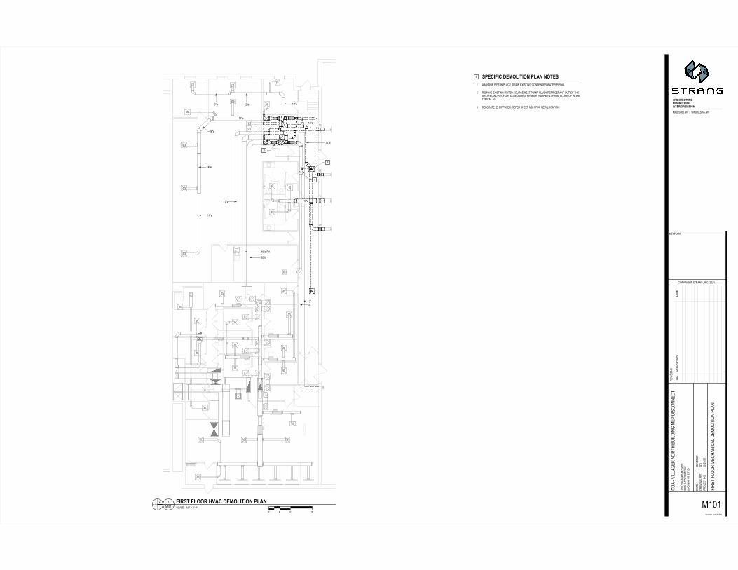
-9*>38�/7-/ *���� �����!�����!��EF GH IH JKH/ -9*>38���='L�M��N@�L*���� �����!����& ��!������!��
� ������& ��!������!����� � 53)."3�3C,-7,/6�*9��93,>,/6�65,+�*/+�7,>3-�,/�74,-�5..)=�*53*� 53)."3�3C,-7,/6�*9��93,>,/6�65,+�*/+�7,>3-�*-�/33+3+�?.5�?,53��5.7397,./#.52;D
EF GH IH JKH
� � ��!�& ��!������!����� � )*,/7*,/�9./7,/�.�-��7,>,7:�-35",93�7.�*>>�-�*93-�,/�743�A�,>+,/6;9..5+,/*73�+,-5��7,./-�,/�-35",93�#,74�.#/35;� �5.7397�,/��>*93�+�5,/6�3/7,53�9./-75�97,./��5.93--8�*>>�?>..5,/60-�5?*93-�*/+�,73)-�7.�53)*,/;� 9..5+,/*73�743�*"*,>*A,>,7:�.?�*53*-�53B�,5,/6�+3).>,7,./�#,74�.#/35;-3B�3/93�#.52�*99.5+,/6>:�*/+�9..5+,/*73�#=�*>>�75*+3-;� 3C,-7,/6�9./-75�97,./�7.�53)*,/�,-�-4.#/�-9533/3+;��9./-75�97,./�*/+3B�,�)3/7�7.�A3�53)."3+�,-�-4.#/�#,74�+*-43+�>,/3-;� �*7940��53�*530�53�*,5�*/+�=�.5�53-7.53�-�5?*93-�-943+�>3+�7.�53)*,/,/7*97�74*7�*53�+*)*63+�*-�*�53-�>7�.?�+3).>,7,./�#.52;� ",-,7�743�-,73��5,.5�7.�-�A),77,/6�*�A,+�7.�A39.)3�?*),>,*5�#,74�3C,-7,/69./+,7,./-;� +3).>,7,./��>*/-�*53�/.7�/393--*5,>:�,/9>�-,"3�.?�*>>�,73)-�/33+,/653)."*>;��9..5+,/*73�#,74�*>>�.7435�+5*#,/6-�*/+�?,3>+�"35,?:�3C,-7,/69./+,7,./-;' 9..5+,/*73�+3).>,7,./�+,)3/-,./-�./�74,-��>*/�#,74�/3#�#.52��>*/-�*/+3C,-7,/6�9./+,7,./-;� 53?35�7.�4"*90�3>3975,9*>0��>�)A,/60�*/+�?,53��5.7397,./�+5*#,/6-�?.5*++,7,./*>�+3).>,7,./�*/+�).+,?,9*7,./-�53B�,53+�?.5�4"*90�3>3975,9*>0�>�)A,/60�*/+�?,53��5.7397,./�-:-73)-;
/.;+3-95,� 7,./+*73
������� ����
��������
�������� ���
����
���� ����
����
����
����
����
�� ��� �
�
�
�
�
����������
������
����
������
�� ��������������� �!���������"�#�$��#����%�& �����' � �(�)��'��*�!++� **, +!���
*���-*.�+!!/�0���,
�12+���, �34��/��5� �-���6!++�
7����+8���9����9��.:!��5�!++�1�9��3�9��0�9��
71, ��!76���;��, +!/7��9��7.�9��
�*2�� ���7��, �:;��6 +��� � +��� *:!��, <�"
*7+����+<<���
% � =
= ���� � ��% &'�����
�� ��
2���������
70��, /
�)'�
���
% � =�
')�>�>'>?���'���'��>&����)����'@% )>'�&�?A�>B�B'@% )>'�&��%�?�CD%�� �E'��?A��>B�BF� ��&���'��?A�(B�BF�%B�B�BG��%�&'�D���E �(�>'>?���'�D���E �(��&� )�H��'���)�?��'�D���E �(�6I?��'�D���E �(D%��A���E'�'��>'>?���'����D �(���'���( �� ��%��& ��=����?���J �(
�KL�MNOPQL�MNOP D��&'�'���R�3I��B�BD��&'�'���R�3I��B�B���&B��'����&
���D��&�%�&%�'
�!�-� �� ;!��������!����� �!�+!�"�,���>�� ���F�= ��S��=�%J'�E�F�=
���= �(��'&��&'T
��)A� (E&��&���(F� ��B��7�
�'� � ���
J'A)���
)��U'�&���B
�V�V�7���T*0T7�)>
&E'�� ���('����)��J �*77��B�)��J��&�''& >�� ����= ��*1* ��7�V�.V�7� D ��&�D������'D�'�&'���' � �(�)�����������D
)�������H� ���('�����&E�?% �� �(�>')�� �����'�
&
�*7�7�7��
����!�����������������+ �, >'�E�� ���F�'�'�&� ���F�����)�%>? �(�D $&%�'���E�=�D�������� ��& ������AB���'D'��&��>B'B)B����= �(��D����� & ����� �D��>�& ��B� )�&�E��' � �(�(� ������& '�������''�'�� ����'���DD'�&'��?A�>')�=��J,����<���!�<��� �"���������������+ �, ��&�����'=���)��' � �(�(� ������& �'�� ��&E ����'�V����>� )�&�E���)��' � �(�(� ������& �'������''�'�W
����'T��&�� �*7 <�!, �<�++!�!�<��� �"������������� � ����'T��V3I�X�#H7I�*7� !++<�����L YZ KZ �[Z L YZ KZ �[Z
����!���!++<�������+ �, �'D'��&���&E'�����= �(�� ��)�����'&�D������ & ����� �D��>�& ����������� ��& ��B� �'� DA�'$ �& �(����� & �����&�&E'��&��&��D����D �(�=��J�&�����D �>�'� (�� �&'�&��E�=�����)����B* ��& DA����E &'�&��D���A�D '���� ���')��� '��)� ���&��&E'��&��&��D����&�%�& ����E�=�����)���B. )��� �'�&�)'�'�� ��%��& ����� �J'&���&�'@% )>'�&��%�?��D��)�� & �'���� ��('�&�����D���� ���������%))'��B� �'D'��&��>'�E�� ���F�'�'�&� ��������)�%>? �(����= �(��D������& �����D�)�%>? �(��'�&�F��&��J�F������&E'�����D�)'�'&��& ���B6 ��>)�'&'����D �(�=��J�)'�����D �(�>��%D��&%�'�#���&�������'&� ���&��>� �&� �����D �(�>��%D��&%�'�#��=�����&AB,����<���!++<�������+ �, �������D��%�?�D����'=��&%�%� &F��''��'&� ��*V�*7� �&%�%� &�&��?'��%))��&'��?A��&��'��&�C�G����D�U� �&�B����&���&��&��D '����'� DA�����& ����������D �>�= &E����E &'�&BW
����'T���V�I�X�#H7I�*7* !++<��;!:�"� ����\�-�����];����� L [L �Z QZ
��B�'��� ) & ����&'
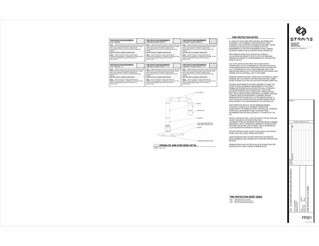
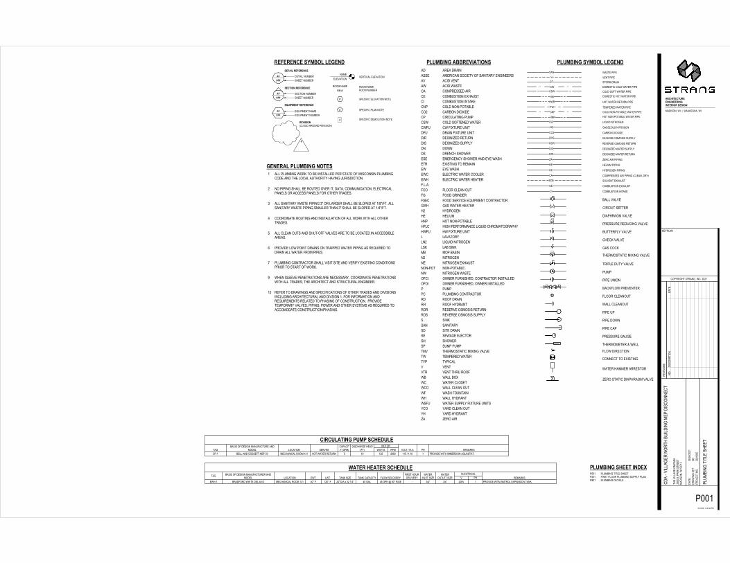
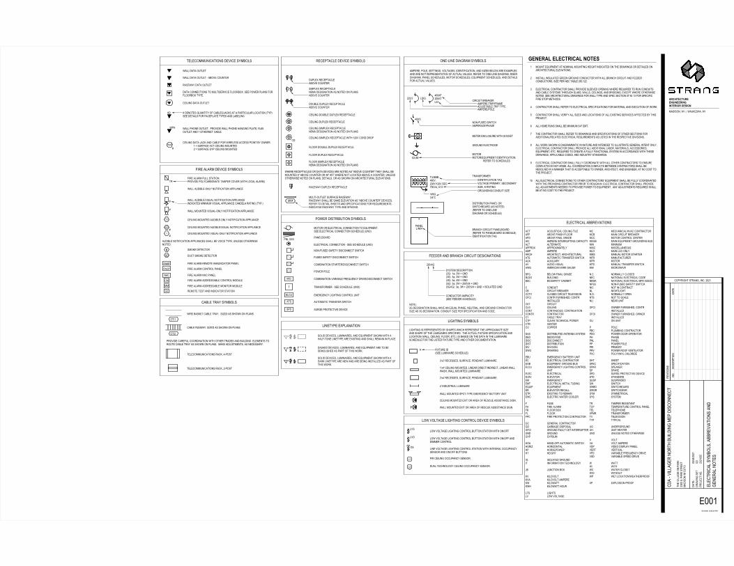
����������������� �� ��� �� ���������������� �������������� ������������������������� ��������������������������������������������������� �������� ����������������� �������� �������������� ������� ����������������� ������������� ������������ ������������������������� ����� ������ �� � ���� ������ ��������� �������������������������� ��������� ���������� ��������������� ��������� ������������������� ����������� ����������������� �������������������������� � ����� � ��������������� � ���� ������������ ��������������� ��������� ������ ���� ����������������� ���������� � ��� ������ ��������� � ����������������� ������ ����������������������������������������� ������������� �������� ���������������������� ������� ���������������������� ����������������������� ���� ��������� ������������������������������ �������������� ���������������� �������������������������� ��������� ������� �������� ������������� �� ��������� ����������������������������������������������������������������������� ������������ ����� ���������������������� ���������������������� ���� ����������������������� �������������� ������������������� ������� � �������������� ������������������� ������� ��������� ���������������������������� ������� ���������� ������ ����������� ���������������������������� !" ��� ��� ����� ��������������������������� ��������������� � �� ������������������ ��������� ������� ��������� ���� � ��� �� ������������������� � ������������������� � �� ������� ����������������������� � �������� ���������������� ������������� ����������������������� ����������������������������������� ����������������������������������������������������� ���������������������� � ���� � ������������� �������������������������������������� ����� � ���������� ������� ������������������� � � #��������������� ��������� ���������� � �������� �� ����������� ����������� ���������� ��� �������� ��������� ������� �����$ ���� � ���� ��������������� � ��� �������������� ������� � ���������� ������� ����������������������������������������� ���������� ������������ ������� � ������������������� ������ � ��������������� ������������� ����� ����������������� ������������ ������� � �������������� �������� ���������������� ��������������������������������� ��������
%&'(�)'*+(,+&*-�'(./&'(0(-+1� ���#���-*+(2 ������������ ��� ���3��������4����������� �������� ������������ ��������� �������������������5� ���#���5���������������� � �� ������� �������3�� ����������� ���������� �������������4�1((�%)667�%*'�%/88�9:;:'<�,8:11&%&,:+&*--*+(2 ������������ ����� � ������� ���������� ����������� ����������� �������� �������� �������� ������ ������������ ��=���� ����� ������ ���%&'(�)'*+(,+&*-�'(./&'(0(-+1��� ������#�����������1((�%)667�%*'�%/88�9:;:'<�,8:11&%&,:+&*- %&'(�)'*+(,+&*-�'(./&'(0(-+1��� ������#����������>1((�%)667�%*'�%/88�9:;:'<�,8:11&%&,:+&*-%&'(�)'*+(,+&*-�'(./&'(0(-+1��� ������#������������$�1((�%)667�%*'�%/88�9:;:'<�,8:11&%&,:+&*- %&'(�)'*+(,+&*-�'(./&'(0(-+1��� ������#����������>�$�1((�%)667�%*'�%/88�9:;:'<�,8:11&%&,:+&*-%&'(�)'*+(,+&*-�'(./&'(0(-+1� ���#����$�1((�%)667�%*'�%/88�9:;:'<�,8:11&%&,:+&*-
-*+(2 ������������ ��� ���3��������4����������� �������� ������������ ��������� �������������������5� ���#���5���������������� � �� ������� �������3�� ����������� ���������� �������������4�-*+(2 ������������ ����� � ������� ���������� ����������� ����������� �������� �������� �������� ������ ������������ ��=���� ����� ������ ���-*+(2 ������������ ��� ���3��������4����������� �������� ������������ ��������� �������������������5� ���#���5���������������� � �� ������� �������3�� ����������� ���������� �������������4�-*+(2 ������������ ����� � ������� ���������� ����������� ����������� �������� �������� �������� ������ ������������ ��=���� ����� ������ ���-*+(2 ������������ ��� ���3��������4����������� �������� ������������ ��������� �������������������5� ���#���5���������������� � �� ������� �������3�� ����������� ���������� �������������4�-*+(2 ������������ ����� � ������� ���������� ����������� ����������� �������� �������� �������� ������ ������������ ��=���� ����� ������ ���
-*+(2 ������������ ��� ���3��������4����������� �������� ������������ ��������� �������������������5� ���#���5���������������� � �� ������� �������3�� ����������� ���������� �������������4�-*+(2 ������������ ����� � ������� ���������� ����������� ����������� �������� �������� �������� ������ ������������ ��=���� ����� ������ ���-*+(2 ������������ ��� ���3��������4����������� �������� ������������ ��������� �������������������5� ���#���5���������������� � �� ������� �������3�� ����������� ���������� �������������4�-*+(2 ������������ ����� � ������� ���������� ����������� ����������� �������� �������� �������� ������ ������������ ��=���� ����� ������ ��� ?@A������� ����������� ����������� � ���� ��������������� ������������ ������� � ������
������������� ����������
:',9&+(,+/'((-B&-(('&-B&-+('&*'�<(1&B-��� ������ ��C������������
���� ��������D
����� ��������� ����>@>�
��� � ���
�������
����������
E=>�=>@>���>D �D ����
��� ������������� >�@@������������� ��� ������ �E�F�� ��@E=> =>@>� � �������� ��� ������
����$� ������������� �� �������� �������
��@@�>@>�@EE%&'(�)'*+(,+&*-�19((+�&-<(G��@@� � �������� ��� ��������>@@ ��������� �������� ���������>@� � ���������� �������� �������
%&'(�)'*+(,+&*-�-*+(1
�����D�����@@�� 1)'&-H8('�:'0I*J('�K(-<�<(+:&8
�������� � �����
���
���
���
����� ����
��������� ������������������������
������ ���
�� ���
����� �� ������� �
������� �
����� ������ ��������������������������� ���������� ��
�� ���!������� �������� �� "��� ���#�������$��� �
����� ��������"�
�������"��
����
���#
��������
���% �������
������"����
��������
����� ��
�������"�� �&���������������������"��
���
'()*+,-./0123*+(3+4(5-12-2*2(6 4(5-12-2*2(-72()*+,-12-2*2(()*+,-58,(39(,(3 :
;<=>?@A=@B<AACD?CAA<?CD?C@A<?E<-FAG?DC98H*+I4J-5*--K--587L(+M8J-5*
H385*4N-+(,H8,(O
PI2Q3*NM,-+,384NJ-*4PR-'S'T
3(U*+*I4+
L(Q2V84
23IW(P,-4IR
XY'TY'S'T-T'OZ/OZ'-29
,M(-U*VV8N(-I4-283L '/SS-+R-283L-+,3((, 98H*+I4J-5*-X/[T/ PHSXY'ZY'S'T \8+(9(4,-1*3(-23I,(P,*I4-2V84
PH8-]U*VV8N(3-4I3,M-\7*VH*4N-9(2-H*+PI44(P
,
12'SS'S'TSXX
4 +P8V(O--TY_--Ta]S_12'SST b;GAcAC@-d?<A-e<E@A=@?EC-ef;Cgh ij kj 6lj
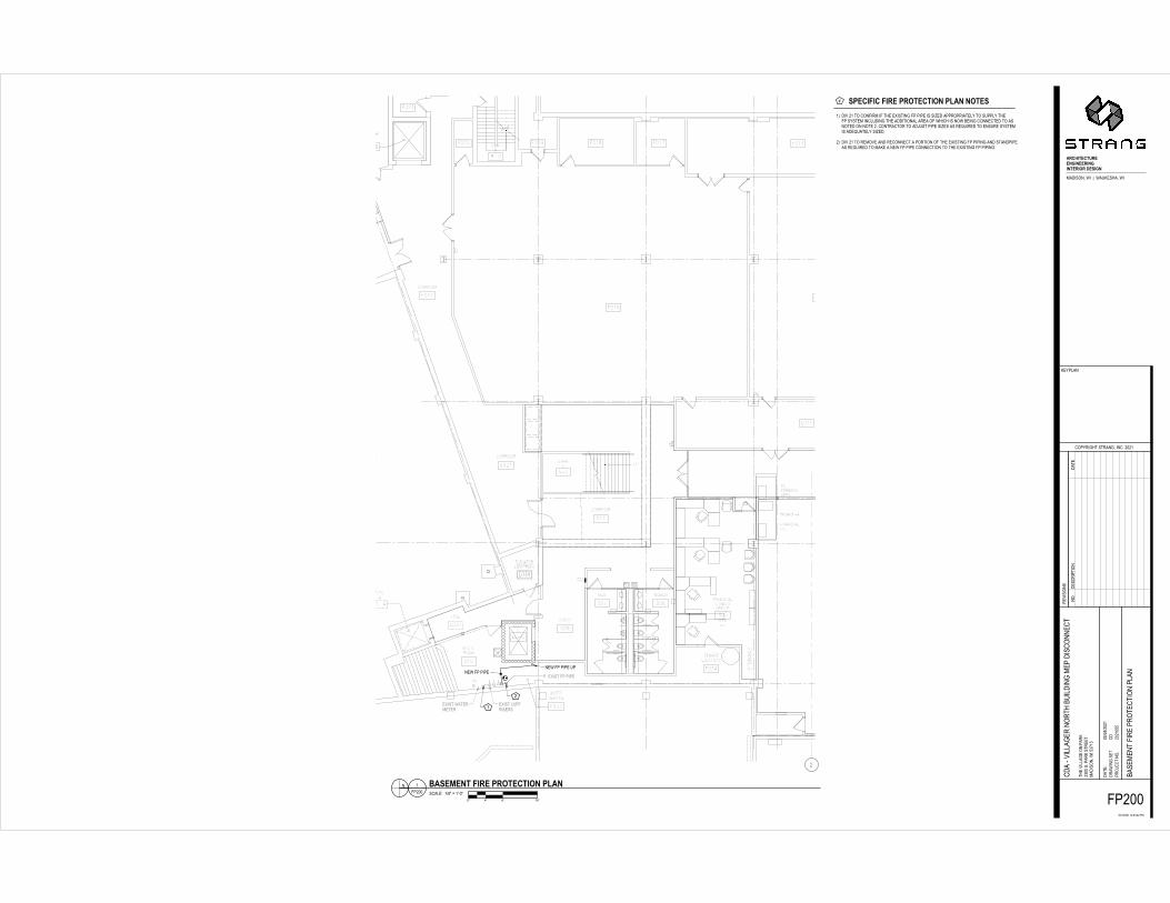
m GeA=?d?=-d?<A-e<E@A=@?EC-ef;C-CE@AGH*U-'T-,I-PI41*39-*1-,M(-()*+,*4N-12-2*2(-*+-+*n(H-8223I23*8,(VQ-,I-+722VQ-,M(12-+Q+,(9-*4PV7H*4N-,M(-8HH*,*I48V-83(8-I1-5M*PM-*+-4I5-\(*4N-PI44(P,(H-,I-8+4I,(H-I4-4I,(-'R-PI4,38P,I3-,I-8HW7+,-2*2(-+*n(+-8+-3(o7*3(H-,I-(4+73(-+Q+,(9*+-8H(o78,(VQ-+*n(HR-H*U-'T-,I-3(9IU(-84H-3(PI44(P,-8-2I3,*I4-I1-,M(-()*+,*4N-12-2*2*4N-84H-+,84H2*2(8+-3(o7*3(H-,I-98L(-8-4(5-12-2*2(-PI44(P,*I4-,I-,M(-()*+,*4N-12-2*2*4NRT0'0
4IRH(+P3*2 ,*I4H8,(
���� ������������
��������
��������� ������ ���������� �������
��������� �������� ������ �� �
�������
�
���
��������� ��
�
�
� �� ����� ��� � ���
�������� ���������
���!���������������������
����������
�"��"� �"��"��"!
��������"
#"��"
���
������������
�"
��������� ������ ���������� �������
��������� �������� ������ �� �
$%&'�()�)*)&�+%
&,*-.�()�)*)&&,*-.�())*)& /&012&�()�)*)&/&012&()�)*)&%&'�()�)*)&&,*-.�()�)*)& 344 4 56789:;<55=>?@A555>?@A55$>?@A
557B;>@89C>D 55E9:FG>955H9:FG>9 5$7I@F9FJK 56$FJ9@L>5$$M@GG 56=N>89<%&'�()�)*)&%&'�()�)*)&%&'�()�)*)&
OP)�())*)&
&,*-.�())*)&
&,*-.�())*)&
@;QMF9>Q9R;>>JKFJ>>;FJKFJ9>;F:;�D>8FKJ0P+*-1%S�'*��T��'PUV&-WPS�'*
+/P'*%X�-&.+P.&Y
O1)Z/*XW.�-./P%XS�*%O[�$6$5
/&2*-*1%-
V&Z)\P%
)/1]&O.�%1[
E$5$6$5�5$Y_7Y__�)0
.W&�2*\\PX&�1%�)P/V $766�-[�)P/V�-./&&. 0P+*-1%S�'*�E757 O+6E$_$6$5 (*/-.�(\11/�(*/&�)/1.&O.*1%�)\P%
O+P�a2*\\PX&/�%1/.W�bU*\+*%X�0&)�+*-O1%%&O
.
()$65$6$56EE
% -OP\&Y��5cd�e�5fa6d()$65$ CF;89�CG::;�CF;>�g;:9>Q9F:J�gG@Jhi jk lk 4mk
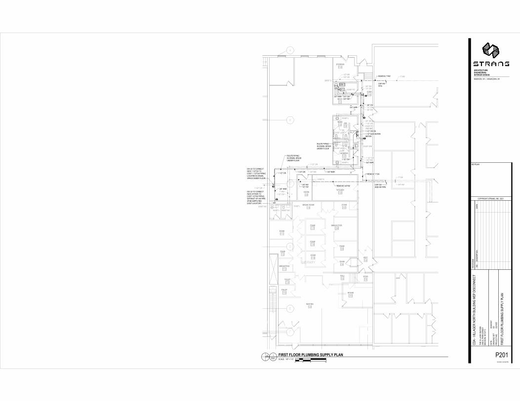
n 8g>QFCFQ�CF;>�g;:9>Q9F:J�gG@J�J:9>8+*2�$5�.1�O1%(*/0�*(�.W&�&,*-.*%X�()�)*)&�*-�-*o&+�P))/1)/*P.&\Z�.1��-U))\Z�.W&�()�0P*%�\1OP.&+�*%�2&-.*bU\&�56=�(1/�.W&�)/1)1-&+�)1*%.�1(�O1%%&O.*1%�-W1'%[+*2�$5�.1�)/12*+&�P))/1)/*P.&\Z�-*o&+�0P*%�*(�)*)*%X�%1.&+�*%�5�Pb12&�*-�%1.�-U((*O*&%.\Z�-*o&+�P%+�P+]U-.�.W&�%&'�()�O1%%&O.*1%�)1*%.�.1�O1%%&O.�*%�2&-.*bU\&�56=[5p$p
%1[+&-O/*) .*1%+P.&
��������������� ��������� ��� ������ ������ ��������������� ���������� ��� ������ ������ ���������������������� �����!� ������� � �������� � ����� �������� ��������� ��������� ���� �" ��#��� � ��������� � �" ��#���"������� � �" ��#���� ������������ $��"� ������ $��"� ������� ������
���������%&'�����(���)*�+&���������� �
����� �� ���� �#�,� �� �� �-� �� "�" ������#������� �����.������-���"���.�� �� "� ���� �� �����.� �� "��"���"� ����,� �� /������ �����
��� ����������/�� ��"�" ��� ���������/�� ��"�" ����/�� ��� �����"�" /��� �"�" ���"�" �����������
"�" ��""�" ���/�"�" ���"�� ���� � ��0�/ ��"� ���� �.��. #��/���� �����
+�*&'�(��%&'�����(��� �" � ��/�� ��"�" �/�
��������� �� ����-#��/�"� �� ����� ������ 1�����./�� ������ ����� ����
��� �� �������#��/�� ��"�" �/�/��/�/��2�2��2��������������$���������. �.��� ���������. �����������1�� � �� �����������""�,� �� ���������� ����� ����3 ��/�� ����""�,� ����3 ��/�� ��� ����
3 �������������"���.�� ��
3� 3 �������"�"��.� � �����"�"��.�2 �,���. ��"�"��.�� ���"� �� ������"�"��.���� ��4���,!��������5"����� �/�� ��"�" ��" �������5"����� �/�� ��"�" ��"��� ��� 1������� � ����������� 1������� ���������������- �� ������������1��.� ��
���6�����*���(�����(������������(�������4�/���7��/��- ���4�/�
���/��.�� ���� 8
��",��.��������.4����9�2:2;
� ������
- ,"���
"��< �����9
=>2;>2:2;�;28?@8?A�"�
�� � ����. ����"��- 2@::��9�"��-���� � �������4�/��=@B;@ ��:=>2?>2:2; "������.����� ��� �����5 ����. ���������������.�� "�������� �
�
"::;2:2;:==+�*&'�(��6�������C"::; "������.����� ��� �"2:; #�����#�����"������.���""�,�"���"D:; "������.�� �����
�� �� ���������� �� ���������� �,��#��������,� �.�� ��� ����� ���/ �����/��� �� ���"� �� ������ ����������� 1������� ���������������- ��" ��������5"����� ��2 ����������1�� �" ����������.�"��"��/ �������#� � ��/�� ��/#� �/�#�1��� ������#� ������#�1��� �������� � ����3 ��� ������� � ����3 ����""�,�� ��/��� �� �������/ � � � �. ��,����/ ������ , �/��� �� 1�����.����� ���� / , �/��� /� � ������/�� ������ � /� � ������/�� ��� �� �#9�9�9#�� #������� ������#. #����.���� �#� � #����� � �� � $��"� �������������./� .���/�� ��� �� ��2 �,���. �� � ������" �������5"����� �"�� ��.��" �#������ ���$������������.��"�,�/#� �/�#�1��� ������ �� ����,��2 ��$���������. ���- �������-�� ��"�������2 �����. �� �����. �� 1��������5"�� ���5"����� �/ �����. ��/��� �#�� �/� ��#������ �4������������������� ��#�� �/� ��#������ �4��/� ��������� �" "��""� "������.������������� ���#�������� ���#��,�������� � � � ���������� ������� � �� �����������""�,� ���-��� �������,�� ��� ������� � /�. � < ������ ���/ ��" ���"�"��"�� �� ������������1��.� �� �/ � �" � ��/�� ��," �,"���� �� �� �����������#/� /������1/� /�� ������ �/�� /������ ������/# /����#�������/� /�����,�����/�#� /�� ����""�,�#�1��� ������,�� ,������ ������,� ,�����,�����3� 3 ������
; ����"�����.�/��-����� �������� ��" ������ ��#�/���������"������.��� ������� ���������������,��� ��.�<�����������92 ���"�"��.�������� ����� ��� ����4�����4��������������4� � �������"�� ��������� ���"�� ���#������ ������ �9@ �����������,�/��� �"�"��.�@E�������. ��������� ����" �����;>DE>#�9�����������,�/��� �"�"��.������ �������@E�������� ����" �����;>?E>#�9? ��������� �������.�������������������#�����/��-�/���������� ����� �9= ������ ����������������5�##� �� ���� ����� ������ �������� ����� �� ��9A "�� �� ���/�"������������������"" ��/�� ��"�"��.����� $��� ��������������/�� ��#����"�" �9B "������.������������������ �������� ����� ��#,� 1�����.�����������"���������������#�/��-9F /� ���� �" � ����������� �� � ����,4���������� �" � ��������/������������ �4��� ������� ������������������ �.�� �9;2 � # ��������/��.�������" ��#����������#���� ������ �������� ��������������.������� ������������� �����;4�#�����#������������� $��� � ����� ��� �����"�����.��#�������������9��"�� �� � �"����,� �� �4�"�"��.4�"�/ ��������� ���,�� ������� $��� ������������� �������������>"�����.9
(������+�*&'�(�����+�*&'�(��''���������
G�����6��������6��*����. �������#�� ��.������#����� �������� � �������� /� �/� ���-���3 ���-���"����, #��/�� �� �, #���������� �� �, /�� ���� ����3 /�� ����� ����3 � ������� � ���-� "� /�5; ����#����/��� �� ��?:5� � ��������������;@; ?:H�# ;2:H�# 2?E�����I�@2�;>?E ?:�.�� ?=�."��J�D:H���� 5 @>?E @>?E 2:D ; "�� �� �/����������� 1"����������-����*����(�+*&+���6��*����. �������#�� ��.������#����� ������� � �������� � � � ��"����,��."�! �������. �� ���#�! ����� ����>�#�� "� � ���-�/���� �"��"5; � �������.��� �����#5@@ � ��������������;@; ����/�� ��� ���� = ;: ;2= 2F=: ;;=�>�;9;: ; "�� �� �/������� �������$������9
��9� ����" �������
�������
�
��
�
��� �������
������������������������������
��������� ���� ������ �����
����������� �������� ���� ������ ���������������������
�!"#$�%&��������������������������������������������!"#$�#�����������������������!"#$�'�!"#$�(�)��
�!"#$�'�!"#$�(�)�� �!"#$�����!"#$�%&*+&��,
�!"#$�#�!"#$�'�!"#$����!"#$��� �!"#$�'
����������������������&" ����$����++��$+�����������$��!"#$���������"�"+-�"$�"+�.���%�����"��#$/,�#/��'0"+-��!"#$�'* *$��01�������� �����������������
���������������������
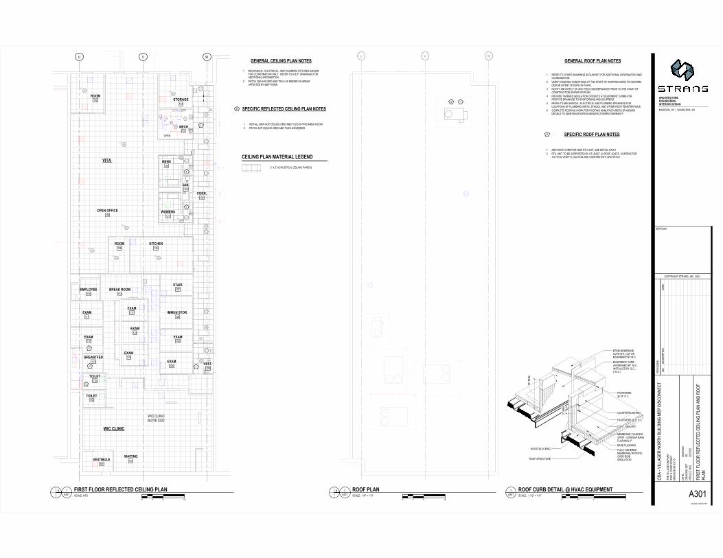
���������&" ����$����++��$+������������$��!"#$�����������"�"+-'��*$�&�"+���*�'#�*���/+&���%'���1 ��������� ��������� �����������/$���"�"+-"+���*�'�#�*��/+&���%'��� ��/$���"�"+-"+���*�'�#�*��/+&���%'��� ����������&+���2345���6789:;3
���4899<��=23>6 ��?@:><
��AB823>6��CDE7453>��.9882���F93:D�9882 �GA67:E9
�G.E22H>�6789<�GC3I:2�G�3I:2��=3I:2��?3I:2
��A3I:2���3I:2���3I:2���F93:67J3K��C78EL37��.78EL37 ���B:E7E>; �G�E>7:D3 �G�6789<�G=M367<���5:LL
�������#/,��*$�����$��
�*�����"��
�*����*+&�����"��
:945E7347H933>;E>339E>;E>739E89�K36E;>�*&"#�+N��"��O���*/P�#�*N��"
&�*�"+-�#�$&*$�Q
���0�"-�$�#$�*+-N�"+�1��G��
�� "#"�+#
P�0�'*+
���R��$�+�1
C�����G�����Q��Q�?���
$��� "''*-���+��*�P ��GG�#1��*�P�#$���$ �*&"#�+N��"�C�A�� �&GC�����G�� %"�#$�%'�����'/�,"+-�#/��'0��'*+
�&*�� "''*-���+��$��,/"'&"+-�����&"#��++��
$
��G��G��GCC
+ #�*'�Q����?��S��T�G���G�� JE967�JL889�ULH2FE>;�6HUULV�UL:>WX YZ [Z \]Z
+�1&�#��"� $"�+&*$�
������������������������ �����������
������������������������������ ������������������������������������������������������������������������������������������������� ���������������� ����������� ��������������������� ��� �������!��������������������������������������"�������������� ��������������������������
������������#���� �����������#����������������������������������������������������������#��#���$�%$$����#�����������&����������� �����������
� �'�������������������� �'����������������������
��'����������
�
��'�������������#��#��������������
������������#���������������#�����������������������������������������������������'�������������������'������#������"�����������#��#�'��%(����
������������� ���������#�������� %) � %* + )% ( �!����#�� ,-./0123-4.�4565
�������������������������������������������������� ������������������������������������������������������������������������������������������������������������������������������������������������������������ �����������������������������������������'����������������������������������������������������������������������#������������� ��������������������������������������������������������#�������� ����
���� ���������������������� ��������������� ����
����������������������������� ����%$$�7��������������������� ����������#
���� ���������������������� ��������������������� ����
����������������������������������������������������������������%$$�7������������������������� ����������#
89:;<=>:=?9>>@A<@>>9<@A<@=>9<B9�C>D<A@������&� ���E�� ������&� �
��� ��#��������'
�����#��������#&������)$)%
��������
������
���������
*�)%�)$)%�%)'��'�F���
���������#������� )�$$�������������� ������&� ��*�G%� ��$*�)��)$)% �������#������������������#���������������#�������������
�
�($%)$)%$**
�����'�����($%% >H>:=9<:�I8=>9�;>8=>9 �����'�����($%) <@H<@>�:<9:?H8=<BJ�K?JK �����'�����($%� :H>L<D�;8@A>9�I<=;�K<K>�D;<>HC�M�<@D?H8=<B@
�����'�����($%� K<K>�K>@>=98=<B@�=;9?�N<9>�98=>C�I8HH �����'�����($%* K<K>�K>@>=98=<B@�=;9?�@B@O98=>C�I8HH ��������� �������
�������������������� ��������� ������������ ���� ����������� ����������
� ����������� �������������� ���������������������������������������� ���� ��� � ��������������������������������� ������ ����������� ����������� ��������������� ������������� ���� ������������������ ������������� ��������������
�� ������������� �
������������� ��������� ���� ���� ����������� �������������������� ��� ���� �������������� �
�������� ��� �������������� ������� ����������� ������������� �������� �������������� ������������ ��� ��� ��� ��� ����������� �������� �������� ���������� ��� ��� ������� ����� �� ������� ������� ����� ������ ����� � �������������� � ����������� �� ����������� ��� �� ������� ����� ���� ������� ���� ����� ����������� ������������ ������ ������� ����������� �����
������������������� ����������������������������������������� ����
�� �������� ������������� ���
������� ����
�����
�������������������� ���������������� �
��������������������������������������������������������������� ���� ��
�� �!"# ��� ����$�%� ������������������������������������ �&'()*��$�+,-���-.�� �������
����+����� �������������������� ����/001�0#23435
%.������������������� 6������������������������� � ����������7����������6������������� ��������8��� ������� ��������������������������������������������������������7� ������������������������������������������������������������ ���7������������������� ������� �������������� �� ���������������� ��� ������ ������ ������� ���� ��������
&'()*�������� ��� �������������������� 7������������������������������ ���������������
9:;�<43
�������������� ���������������������������������������� ������������ �����������������������7� ��������������� ����� ����� ���������������������� ����� �������������� ���7�������������������� ������,�� ��������������� ����������������������������������� ��������������������������� 6���� ������������������� �6
�� �� ������=����������� ��� ������������ ���� ��7���
>?@AB()@(C?))&DB&))?B&DB&()?B'?�E)FBD&����� 7����G����������7��
���� �������H
����������� �7� �6�%I%+
����� �������� �6
J,%+,%I%+�+%H%JHK-���
����������� ����� %KII��6���������� ����� ���JKL+K ��IJ,%-,%I%+ ����� ������������,��������� �
������������� �������� ���������� ��
�II+%I%+IJJ
D)&)?>M�AN>@�&'()F+ ���������������������� ���������� ���������� ������ 6�� ������������������� ��� ��������� �� �������������������6% ������������������ �������������� ������������ ������� �������� ��6K ����������� ������������� ��O����������������7����������������������� ������ �8�� �� �� � ������� ��6���� ����������������������� ��� ����������� ��������� ��� �����������6- �� ������������������������������ ���� �������O�� ������ ��=����� �������������=���� ��������6J �� ����������������� �������� ������������ �7���� ����7�� �7����������������������������� ������ 6P � ������������� ���7��� ������������������������������� ������������ ��������������� �����������6������� ������������ �����������6
D)&)?>M�AN>@�&'()F�� ���������� �+6� �������+-.����������6%6� �������������� ����������� ��6K6� ��� ���I�+IIQ� ���������� ��8�������������������������������������� ����� ��������������������� �������� �����������6-6� �������������� ����������� ����������������� ������������� ��� �������������� ���������������6� �������������� ������������6J6� ��� �������������������� � ����������� �������6P6� ���������� ��8������������� ,�� ������6L6� ����������������������������7�%����� ��6R6� �������%-,L���������������������6�� ���������� �+6� �������+-.����������6%6� ��� �������������������� � ����������� �������7����������� ��6K6� ��� ����������������������������� ��� ���� ����� ������������������� � �6-6� ��������������������������7� �������������� ������� 6
S>@T>D)E�?''U('S�C&B(F�V�D>FWEX�� �� ������ ��������� ��� ������ ���� ������ ���� ���� �� � � ��������� ���������������� � ��� ��6��6�6 � 6���� ������ ��� ������� � 6������6 ��6������6 ���� ������ ��� ����� ��6� � � 6������6 ��6������6 ������������� ��� �� �� ���� �������6 ��� �� ��� ������ + ��� ���������� %7-II -RI��� I6JI +6J �YZ ����+K PI�[� RI�[� RIIII PJIII ��� J6I LP�[� JL�[� JP6I- -\���J. J\���R. L\���J. RII %IR K KI -J ���?''U�)XA>CF(�U>&�� ������ ����������� ��� �� �� ��� ������ ���� ���� �� ��6 ����� ��������� ��� ��� ���� ������� JII I6J ������� ����8�� ����+,+I +L%J ++J PI ���� ���� ���+RI
�����H� ��II+% ]?>&@A�EC@(�(>T)V'UU�>&E�E> S)? �����H� ��II+K E'_&]M>F(�?''U�N)&(BM>('?�E)(>BM �����H� ��II+- ?''U('S�C&B(�B&F(>MM>(B'& �6������ � ���
������
��
���������
����� ����������
�����������
����
��� ����
��������
����
�� �
��������������������������������� ���!�"#$%&'(#)(�*+,$-�'(#
"�(#&.$,/"�/,0
1%23#.-/$/�&.'#&14����
,5#$#%&$
+,326�&
2%7,1/&%4
�8��8������0��0��2!
/-,5#66�.,%&2�+ ����$42�+$/,,/ !�"#$%&(#��9�� 1"��8��8���� :#$/:6%%!,1-��6",!%6#/#%&26�&
1"�;5#66�.,&%/-<*#6"#&.!,2"#$1%&&,1
/
!����������
& $1�6,0�8��=�>;��!���� ?�� �?@����A����B�@�����C@��
D C���?����B�@�����C@������ � �<�&"%&2#2,#&26�1,4"�#&,E#$/#&.1%&",&$,(�/,2#2#&.4� ,!%5,,E#$/#&.(�/,$%*1,-,�/2*!2':6*$-,:#.,�&/%*/%:/-,$3$/,!�&",1316,�$,F*#,"4,!%5,,F*#2!,&/:%!$1%2,%:(%+4/32#1�6�664� ,6%1�/,G,H"#::*$,4,:,$-,,/!���:%&,(6%1�/#%&4
IJ KL ML �NL
&%4",$1#2 /#%&"�/,
������
������������ �
������� ����������
������ ���������
����������� ������ !��� ������ !��������������
����������������� !���
�����������
���������������������������������
"#$%���
�������!���������!��
�������!����&'��&�()$
�*&'��& ()$�*&'��&�()$�*&+ ��&'��& ��&+�*&+ ,
,,,
-
.
.
. . ...
..������ !���. .. .
. ..
������ !���
,"/012,
�/012,
�/012,
�&3"��&3" �&�&
����������� �� ���� �4�����������������5����6(�7�89:;7<;()=��>(:;7
� (;79!��"�("�?
38$# 7!>"�" (9!:793%����
�@7�789�
=�#$A(9
$ 8B�3"98%
�C��C������?��?��$6
">�@7AA(!�89$( = �����%$( =�" ��" 6(�7�89;7��D�� 3���C��C���� E7 �"EA88 6�3>(973(A$A(9
3�(�@7AA(!� 98 ">F)7A�79!6�$�7�3899�3
"
6����������
GH IJ KJ ,LJ9 �3(A�?�C*&M�N��&6���� ������O����P� �O�
Q ��� ��� �P� �O������ 3($�)3";8 =("">7�$879"%� 3($$7$�;8 =("">7�$879"%� �F(A(93��7EE)�� �"83E6�>8;989$A(9%"#$73(A(AA%
98%���3 7$ "789�("�
�����
������� ������ ��������� �� ������������������������������������
�������������������������������������
�� ���� ���� �� ������ ����
�� ����
��� ���� ���� ���� ���� ���� ���� ���� �
!"#$%&'#&("'')*%)''"%)*%)&'"%+"�,'-%*)������ .�/���0��/�������.�/�
���/� ���������1
�������������� �.�� ���232�
������� �
������
���4���� ��
52�232���21251�6���
������������� ����� 2�33��������������� ������ �/��5�7�� ��352232� ���������� �������� �������������� ����������� ����������� ��
�
�232232�355
�����1���8��9��:�3��232� "++;�<'#$!)%#!=�>=!) ?@ AB CB DEB
��������� ��� ����
���������������
���� ���������������������������������������������������������������� ����������������� ������� �������
�������������������
�������������������������������������� �� ��������������������������������������� �������!���������������"����������������������������#���$�����������������������������������
�����������������������%��������������������"����������������������������������������������������� ��������������������������������������������������������������������������������������������&����
�� ������������� �������� ������������������� ����������� ����� ��������������� ����������� ������������' �����'��������� ������� ���������������������� ������������������������' ��'�������� �������������� ����������� �� �� ����������� ������ ������� ��� �������������� ������� ������������� ��������������������� ������������������������������ ������ ���� ��� �������������������������� ��������� ���������� ����������������� ���� ������� ������������������������� ��������� ����������� ��������������� ���������� ������ �� �� ��������������� ��������������� � !������� ����������� �� ����� ���� ������������� ��������� ������� �� ���� ����������������� !��� !������� �������������� '����� ���������� ��������������� ����� ����������� ��������'�� ������� ��������������������� � ������������� �� ���� ��������� ��� ������������������������ ��� ����� �� �������� ����&���&������������������% ����%������� ���������� �� ��� �������� ������� ������������������ ��� ����������'�� ����������� ��������&������ ����������� ����������������� �� ����� ���������
��������������������������
����������������
��������������������������������������������������'��������������������������'��������� ����������� �
�� �������"�������������� ����������������� ����������������� � �����!������� ������� ������� ���������� ������������� ������� �������� ���������������������� ������������� ��������� ���������������������� ���������� �������������� ��������������������� ����������������������������� ���&������������������ ���������������� �� ���� ������ ���������������� ������������ ������������ ��������������������������������� ������������������������������ �������� ������ ������� ������������� ������������������� ������� ������ ����������� ���������� ��������������������� ������������������� ����� �������������� ������� �������� ��� ��������������� ������������� ��������� ��������� ������������ � ����� ����� ������������ ������� ���������������� ���������������������� ������'��� ������������ ������������ ������� ���� ������� ������������� ������������������� ������ ������������ �������������������� ��������� ����������!����������� ����������������� �����"� ������ ����������"�� ���������� ����������"����������'� '�������������
����������������&����������
�������'������������������������������������!������������������������&��������������'����� ���������������������������������������������������!������������������������������������������������������������������������!������������������������������������������������ �������������������������������
���
���������������������������������"���������������������������������������������������������������������������������������
� ���� ��������������&������������������������������������������&������������������������� ���������������������������������� ���������������������������������
������������������� ���� ��������������&�����������������������������������&���������������������������� ��������������"������������������������������������������������������������������������������������������������������������������������#���������������$�� ������������������������������������������ �#����$
���������������������
�� �����������������������������
�� ��������������������������������������������!������������������������������#���$���������
���� ������'������������� ��������������������������� �����'�����������������������������������������(����������(��������������������)(����������������)(�������������������������������������������������������������������������������������������������������������
����'��������������������������'�������������������� ������'��������������*�����������
����'''
����������������������'������������� ���������������������������������
����������������������������������������&��������#���$���&�����������������������������������������������������������������"���������������� ���������������������!��������"�������������� �����������&��������#���$�� �� ����� ���� ��������������� ������������������������� ��� ������������
����������'����������������������'���������� �����������'�����������������'������������� �����������������������
�"� ��������������%�����������������������
�����&�����������������������������������������������(����������(����������������������������������������������!����������������������������������� ����������'������
���������������������&����
��"
��&������� �����������+
�"�*��������������� ��������������&��������������� "�������������������������
����������������������#����������������������$����������������
����������"!��������������������������������������������������������������������#�������$#���������&������� ������������$
�**",�''&
���", ��� � �**���**����� ���������������&����"��������������������������"������������������� �������� �����������������������%����������'�����������������������������������������������������&������� ������������� ��������������������������������!������������������������������������������
��������������� ����� ��������-����������%���&����� �"�����.*�-�*.�"��*����/��������, ������� "���������%� . ,"�(
�������� ����������������������� ����������������������#� $���0�����1� ��#, $��,0��,��1� ��#� $��,0�����1� ��#� $��,0��,��1��**2��1� ��#� 1� $��,0��,��1��**2��1� ���1��������� �����������������#�����������$�**&�
���-� ���� ��������������������!���������������������� ����������������%����, ���� �����������������%����������������������
��������� ��� ���� ������������������������������"������
�� ���� �����������������������������������������'�������%���������������������������������������������'��������������������������#���������� �����������$�������������������������������������������������������'������������������������������ ��'������#����������������$�� ���� ��������
�34�3�������������������������������34�3����� �������������������"����������������������������������������������34�3����������������������������������������������&������ ������������������ ��������'���������������������������� ��������������'���������������������������� ����������� ��� ���� ��������������������3����������������������������� ��� ���� ������������������������������"����������������������� ��������� ��� ���� ������������������������ �����������������������"������������� �������� ���������������� ����������� ������ ����������������
56789:;7:<6;;=>9=;;69=>9=:;69?6�@;A9>=�������������B�������������
������ ������-
����� �������� �������*��
�����������������
�"��"�*�����-��-�,���
�������� �������� �,**������������� ������������,/�, �*�"��"�*�� ��������������������������������
������������&����� ��������������� ����������
�
**��*��*��
� ������!������������������������� ��� ����������������������� ����������������������������������� ����������������� ��� ������������������������������������������������������%�������������*�����, ��������������������������������������� ������!��������������������������������������� �������������������� ����������� �� ��'��������������������������������������� ����������������������������*/�.���,��������������������������� ���������������������������������������������������������'��������������� ���������������������������%����������������������'����� ��������������������������) �����������������������������,"�(����/ ������������������������������� ����������������������������������������������"��������������!����������������������������������������. ��������������������� ����������������������������������������� �������������������������������������������������������������������������������������!������������!������������������������������������������������������������ ����������������������������������������C ���������������������������������������������������������������������������������������������������������������������������������������������������������������������������������������������� ���������������������������* �������������������������������������3�!���������������������������������������������� ���������������������� �&���������������������������������������������������������������������!�������������������������!����������������������������������
>;=;65D�;D;7:6975D�=?:;A
�������� �������
���
���
������
������
���
���
��� ���
�� ����
����������� �������������������������� ��������������������������
��
��
��
�� ��
����
�������������������
�������� ����!���
�����������
������������
������������������� ���������
�����������"��������
���������
�����#��������
��� �� �������������������
��� �� ��#�� ��
����" �����������
�����������������"����������
���� ����������������� �������������
���" �������������
�������������
���#��$�%�����������������������������#"�$�%��������������
��������������������������������
�������������
�� �������������������� �����#�#��������������������������
��"����&��� ������ ������������!��� ��� �������'������
�������������!��
���������
�������!�� �����������
���#��������
�����������������������"��������
����
�������
�������#
���� �������"
�����!����
��������
������������
��� ����������
���#��� �����������
"����
�������!�����(��� �����������������!��
���
)
)
*
*
+
+
,
,
-
-
.
.
/
/
0
0
1
1
2
2
3
3
4
4
5
5
6
6
7
7
89:;::
<=>?@AB>AC=BBDE@DBB=@DE@DAB=@F=�GBH@EDIJKLMNOP�QL��R��QJSTUMVJP�QL
KWJQLOX�MUYKJYUZ
[N\]WLXVY�MYWJOXP�LO[�__a
WUbLMLNOM\WNcU[Y�ON
de_ae__a�a_Zd8Z_f�\I
YVU�bLggJXU�NO�\JWT _h�M�\JWT�MYWUUY IJKLMNO�QL�dhiah [Kde_8e__a gNQUW�gUbUg�NbUWJgg�KUINgLYLNO�\gJO
[KJ�jbLggJXUW�ONWYV�kSLgKLOX�IU\�KLM[NOOU[
Y
Ua`__add
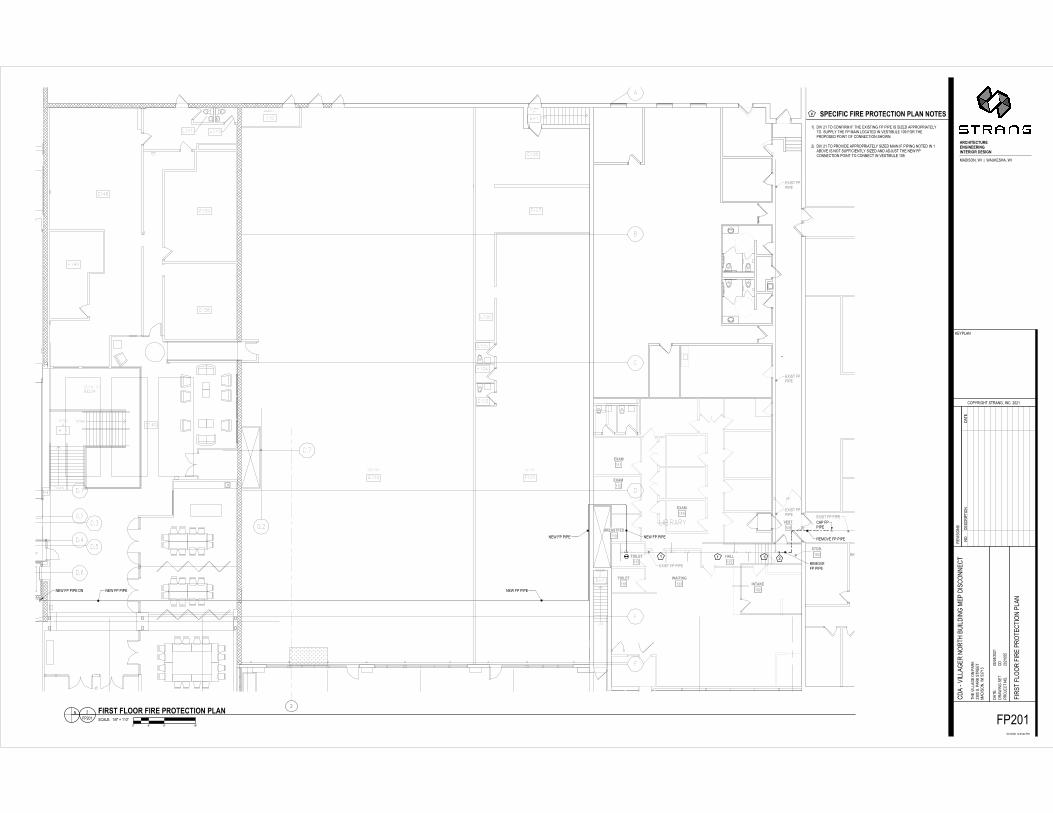
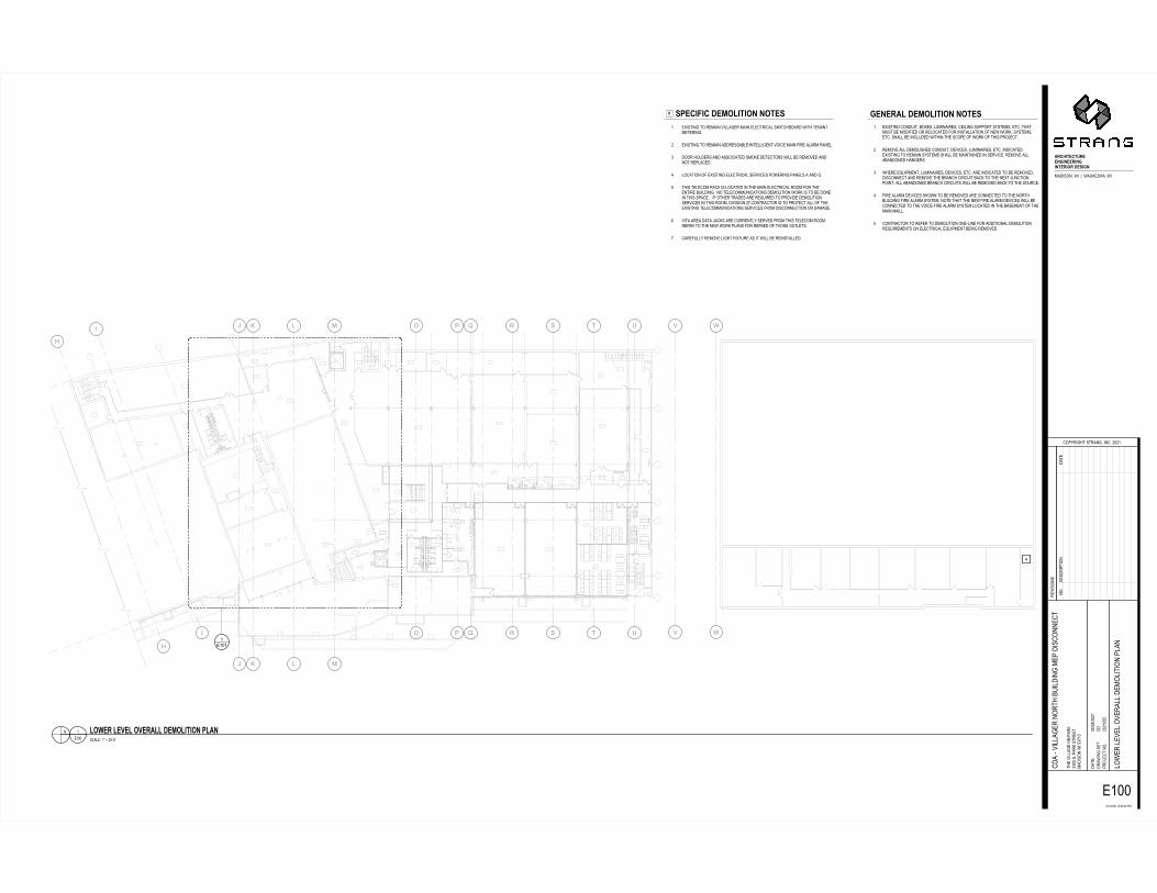
EBDB=<l�GBmFl@A@FD�DFABHn HoB>@p@>�GBmFl@A@FD�DFABHa UqLMYLOX�YN�WUIJLO�bLggJXUW�IJLO�UgU[YWL[Jg�MQLY[VkNJWK�QLYV�YUOJOYIUYUWLOX_ UqLMYLOX�YN�WUIJLO�JKKWUMMJkgUeLOYUggLXUOY�bNL[U�IJLO�rLWU�JgJWI�\JOUgh KNNW�VNgKUWM�JOK�JMMN[LJYUK�MINTU�KUYU[YNWM�QLgg�kU�WUINbUK�JOKONY�WU\gJ[UK8 gN[JYLNO�Nr�UqLMYLOX�UgU[YWL[Jg�MUWbL[UM�\NQUWLOX�\JOUgM�J�JOK�Xd YVLM�YUgU[NI�WJ[T�LM�gN[JYUK�LO�YVU�IJLO�UgU[YWL[Jg�WNNI�rNW�YVUUOYLWU�kSLgKLOX��ON�YUgU[NIISOL[JYLNOM�KUINgLYLNO�QNWT�LM�YN�kU�KNOULO�YVLM�M\J[U���Lr�NYVUW�YWJKUM�JWU�WUsSLWUK�YN�\WNbLKU�KUINgLYLNOMUWbL[UM�LO�YVLM�WNNIP�KLbLMLNO�_i�[NOYWJ[YNW�LM�YN�\WNYU[Y�Jgg�Nr�YVUUqLMYLOX�YUgU[NIISOL[JYLNOM�MUWbL[UM�rWNI�KLM[NOOU[YLNO�NW�KJIJXUt bLYJ�JWUJ�KJYJ�cJ[TM�JWU�[SWWUOYg]�MUWbUK�rWNI�YVLM�YUgU[NI�WNNIWUrUW�YN�YVU�OUQ�QNWT�\gJOM�rNW�WUrUUK�Nr�YVNMU�NSYgUYMi [JWUrSgg]�WUINbU�gLXVY�rLqYSWU�JM�LY�QLgg�kU�WULOMYJggUKa UqLMYLOX�[NOKSLYP�kNqUMP�gSILOJLWUMP�[ULgLOX�MS\\NWY�M]MYUIMP�UY[�YVJYISMY�kU�INKLrLUK�NW�WUgN[JYUK�rNW�LOMYJggJYLNO�Nr�OUQ�QNWTP�M]MYUIMPUY[�MVJgg�kU�LO[gSKUK�QLYVLO�YVU�M[N\U�Nr�QNWT�Nr�YVLM�\WNcU[Y_ WUINbU�Jgg�KUINgLMVUK�[NOKSLYP�KUbL[UMP�gSILOJLWUMP�UY[�LOKL[JYUKUqLMYLOX�YN�WUIJLO�M]MYUIM�MVJgg�kU�IJLOYJLOUK�LO�MUWbL[U�WUINbU�JggJkJOKNOUK�VJOXUWMh QVUWU�UsSL\IUOYP�gSILOJLWUMP�KUbL[UMP�UY[�JWU�LOKL[JYUK�YN�kU�WUINbUKPKLM[NOOU[Y�JOK�WUINbU�YVU�kWJO[V�[LW[SLY�kJ[T�YN�YVU�OUqY�cSO[YLNO\NLOY�Jgg�JkJOKNOUK�kWJO[V�[LW[SLYM�QLgg�kU�WUINbUK�kJ[T�YN�YVU�MNSW[U8 rLWU�JgJWI�KUbL[UM�MVNQO�YN�kU�WUINbUK�JWU�[NOOU[YUK�YN�YVU�ONWYVkSLgKLOX�rLWU�JgJWI�M]MYUI�ONYU�YVJY�YVU�OUQ�rLWU�JgJWI�KUbL[UM�QLgg�kU[NOOU[YUK�YN�YVU�bNL[U�rLWU�JgJWI�M]MYUI�gN[JYUK�LO�YVU�kJMUIUOY�Nr�YVUIJLO�IJLggd [NOYWJ[YNW�YN�WUrUW�YN�KUINgLYLNO�NOUjgLOU�rNW�JKKLYLNOJg�KUINgLYLNOWUsSLWUIUOYM�NO�UgU[YWL[Jg�UsSL\IUOY�kULOX�WUINbUK
O M[JgUZ��au�v�_wjuUaa lFxB=�lByBl�FyB=<ll�GBmFl@A@FD�ol<D
ONKUM[WL\ YLNOKJYU

���
��
�������� � ����
�����������
������������
������������ ���������
���������
������������������ �����������������
������������������
�������������
��������������� �������� �����������
��������������� �
���������
�������� �
����
!��"�������
��������
������������
��������������
���#����
�
�������������$!���������������������� �
%&'(
)
)
*
*
+
+
,
,- . / 01234562571668948661489485614:1;<6=498>&?@ABCD;E@;;F;;E&GHIAJ&D;E@
?K&E@CL;AIM?&MIN
'B(OK@LJM;AMK&CLD;@C'P;.Q.-
KIR@A@BCA(KBSI'M;CBP
/T.-T.Q.-;-.N/UNVV;(>
MJI;R@WW&LI;BC;(&KH .VQQ;AP;(&KH;AMKIIM >&?@ABC;E@;/VX-V '?Q/T.UT.Q.- (&KM@&W;WBEIK;WIRIW;?I>BW@M@BC;(W&C
'?&;YR@WW&LIK;CBKMJ;ZG@W?@CL;>I(;?@A'BCCI'
M
I-Q-.Q.-Q//
968610[;<6\:[454:8;8:56=
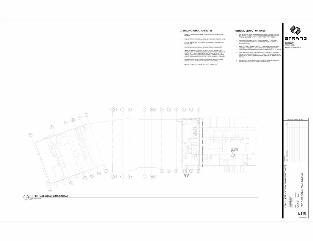
] =624_42;<6\:[454:8;8:56=- I@AM@CL;MB;KI>&@C;R@WW&LIK;>&@C;IWI'MK@'&W;AE@M'JZB&K?;E@MJ;MIC&CM>IMIK@CLP. I@AM@CL;MB;KI>&@C;&??KIAA&ZWIT@CMIWW@LICM;RB@'I;>&@C;%@KI;&W&K>;(&CIWPV ?BBK;JBW?IKA;&C?;&AAB'@&MI?;A>BHI;?IMI'MBKA;E@WW;ZI;KI>BRI?;&C?CBM;KI(W&'I?PU WB'&M@BC;B%;I@AM@CL;IWI'MK@'&W;AIKR@'IA;(BEIK@CL;(&CIWA;&;&C?;LP/ MJ@A;MIWI'B>;K&'H;@A;WB'&MI?;@C;MJI;>&@C;IWI'MK@'&W;KBB>;%BK;MJIICM@KI;ZG@W?@CLP;;CB;MIWI'B>>GC@'&M@BCA;?I>BW@M@BC;EBKH;@A;MB;ZI;?BCI@C;MJ@A;A(&'IP;;;@%;BMJIK;MK&?IA;&KI;KIaG@KI?;MB;(KBR@?I;?I>BW@M@BCAIKR@'IA;@C;MJ@A;KBB>D;?@R@A@BC;.X;'BCMK&'MBK;@A;MB;(KBMI'M;&WW;B%;MJII@AM@CL;MIWI'B>>GC@'&M@BCA;AIKR@'IA;%KB>;?@A'BCCI'M@BC;BK;?&>&LIPb R@M&;&KI&;?&M&;S&'HA;&KI;'GKKICMWO;AIKRI?;%KB>;MJ@A;MIWI'B>;KBB>PKI%IK;MB;MJI;CIE;EBKH;(W&CA;%BK;KI%II?;B%;MJBAI;BGMWIMAPX '&KI%GWWO;KI>BRI;W@LJM;%@MGKI;&A;@M;E@WW;ZI;KI@CAM&WWI?P
- I@AM@CL;'BC?G@MD;ZBIAD;WG>@C&@KIAD;'I@W@CL;AG((BKM;AOAMI>AD;IM'P;MJ&M>GAM;ZI;>B?@%@I?;BK;KIWB'&MI?;%BK;@CAM&WW&M@BC;B%;CIE;EBKHD;AOAMI>ADIM'P;AJ&WW;ZI;@C'WG?I?;E@MJ@C;MJI;A'B(I;B%;EBKH;B%;MJ@A;(KBSI'MP. KI>BRI;&WW;?I>BW@AJI?;'BC?G@MD;?IR@'IAD;WG>@C&@KIAD;IM'P;@C?@'&MI?PI@AM@CL;MB;KI>&@C;AOAMI>A;AJ&WW;ZI;>&@CM&@CI?;@C;AIKR@'IP;KI>BRI;&WW&Z&C?BCI?;J&CLIKAPV EJIKI;IaG@(>ICMD;WG>@C&@KIAD;?IR@'IAD;IM'P;&KI;@C?@'&MI?;MB;ZI;KI>BRI?D?@A'BCCI'M;&C?;KI>BRI;MJI;ZK&C'J;'@K'G@M;Z&'H;MB;MJI;CIM;SGC'M@BC(B@CMP;&WW;&Z&C?BCI?;ZK&C'J;'@K'G@MA;E@WW;ZI;KI>BRI?;Z&'H;MB;MJI;ABGK'IPU %@KI;&W&K>;?IR@'IA;AJBEC;MB;ZI;KI>BRI?;&KI;'BCCI'MI?;MB;MJI;CBKMJZG@W?@CL;%@KI;&W&K>;AOAMI>P;CBMI;MJ&M;MJI;CIE;%@KI;&W&K>;?IR@'IA;E@WW;ZI'BCCI'MI?;MB;MJI;RB@'I;%@KI;&W&K>;AOAMI>;WB'&MI?;@C;MJI;Z&AI>ICM;B%;MJI>&@C;>&@WWP/ 'BCMK&'MBK;MB;KI%IK;MB;?I>BW@M@BC;BCIYW@CI;%BK;&??@M@BC&W;?I>BW@M@BCKIaG@KI>ICMA;BC;IWI'MK@'&W;IaG@(>ICM;ZI@CL;KI>BRI?P
C A'&WIN;;-Tcd;e;-fYQdI-Q-- 01540[;[:g61;[6h6[;<6\:[454:8;[08
CBP?IA'K@( M@BC?&MI
���������� ��������������
�����
� �
�
�
�
�
�
�
�
�
�
�
�
�
�
�
�
�
�
�
�
�
�
�
�
�
�
�
�
�
!
!
"
"
#
#
$
$
%&'() *%((((
+,-./01-02,1134/311,/34/301,/5,6718/439:;<=>?@6A<66B66A:CDE=F:@6A<
;G:A<?H6=EI;:IEJ
K>LMG<HFI6=IG:?H@6<?KN6OPOQ
GER<=<>?=LG>SEKI6?>N
TUOQUOPOQ6QOJTVJWX6L9
IFE6R<YY:HE6>?6L:GD OWPP6=N6L:GD6=IGEEI 9:;<=>?6A<6TWZQW K;PTUOVUOPOQ [<G=I6[Y>>G6>REG:YY6;E9>Y<I<>?6LY:?
K;:6\R<YY:HEG6?>GIF6]C<Y;<?H69EL6;<=K>??EK
I
EQQPOPOQPTT
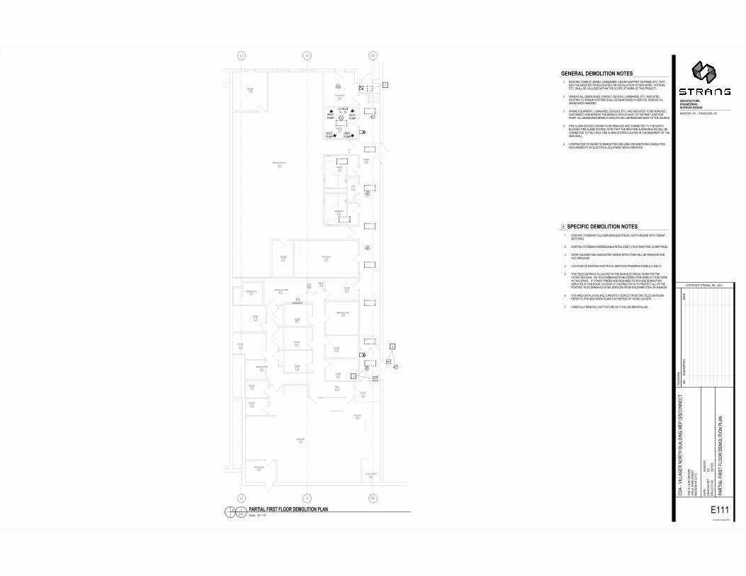
4131,+671_5/0/53635018` 8a1-/b/-671_5/0/53635018Q Ec<=I<?H6I>6GE9:<?6R<YY:HEG69:<?6EYEKIG<K:Y6=A<IKF]>:G;6A<IF6IE?:?I9EIEG<?HNO Ec<=I<?H6I>6GE9:<?6:;;GE==:]YEU<?IEYY<HE?I6R><KE69:<?6[<GE6:Y:G96L:?EYNW ;>>G6F>Y;EG=6:?;6:==>K<:IE;6=9>DE6;EIEKI>G=6A<YY6]E6GE9>RE;6:?;?>I6GELY:KE;NV Y>K:I<>?6>[6Ec<=I<?H6EYEKIG<K:Y6=EGR<KE=6L>AEG<?H6L:?EY=6:6:?;6HNT IF<=6IEYEK>96G:KD6<=6Y>K:IE;6<?6IFE69:<?6EYEKIG<K:Y6G>>96[>G6IFEE?I<GE6]C<Y;<?HN66?>6IEYEK>99C?<K:I<>?=6;E9>Y<I<>?6A>GD6<=6I>6]E6;>?E<?6IF<=6=L:KEN666<[6>IFEG6IG:;E=6:GE6GEdC<GE;6I>6LG>R<;E6;E9>Y<I<>?=EGR<KE=6<?6IF<=6G>>9@6;<R<=<>?6OZ6K>?IG:KI>G6<=6I>6LG>IEKI6:YY6>[6IFEEc<=I<?H6IEYEK>99C?<K:I<>?=6=EGR<KE=6[G>96;<=K>??EKI<>?6>G6;:9:HEN* R<I:6:GE:6;:I:6S:KD=6:GE6KCGGE?IYM6=EGRE;6[G>96IF<=6IEYEK>96G>>9NGE[EG6I>6IFE6?EA6A>GD6LY:?=6[>G6GE[EE;6>[6IF>=E6>CIYEI=NZ K:GE[CYYM6GE9>RE6Y<HFI6[<cICGE6:=6<I6A<YY6]E6GE<?=I:YYE;NQ Ec<=I<?H6K>?;C<I@6]>cE=@6YC9<?:<GE=@6KE<Y<?H6=CLL>GI6=M=IE9=@6EIKN6IF:I9C=I6]E69>;<[<E;6>G6GEY>K:IE;6[>G6<?=I:YY:I<>?6>[6?EA6A>GD@6=M=IE9=@EIKN6=F:YY6]E6<?KYC;E;6A<IF<?6IFE6=K>LE6>[6A>GD6>[6IF<=6LG>SEKINO GE9>RE6:YY6;E9>Y<=FE;6K>?;C<I@6;ER<KE=@6YC9<?:<GE=@6EIKN6<?;<K:IE;NEc<=I<?H6I>6GE9:<?6=M=IE9=6=F:YY6]E69:<?I:<?E;6<?6=EGR<KEN6GE9>RE6:YY:]:?;>?E;6F:?HEG=NW AFEGE6EdC<L9E?I@6YC9<?:<GE=@6;ER<KE=@6EIKN6:GE6<?;<K:IE;6I>6]E6GE9>RE;@;<=K>??EKI6:?;6GE9>RE6IFE6]G:?KF6K<GKC<I6]:KD6I>6IFE6?EcI6SC?KI<>?L><?IN6:YY6:]:?;>?E;6]G:?KF6K<GKC<I=6A<YY6]E6GE9>RE;6]:KD6I>6IFE6=>CGKENV [<GE6:Y:G96;ER<KE=6=F>A?6I>6]E6GE9>RE;6:GE6K>??EKIE;6I>6IFE6?>GIF]C<Y;<?H6[<GE6:Y:G96=M=IE9N6?>IE6IF:I6IFE6?EA6[<GE6:Y:G96;ER<KE=6A<YY6]EK>??EKIE;6I>6IFE6R><KE6[<GE6:Y:G96=M=IE96Y>K:IE;6<?6IFE6]:=E9E?I6>[6IFE9:<?69:<YYNT K>?IG:KI>G6I>6GE[EG6I>6;E9>Y<I<>?6>?E\Y<?E6[>G6:;;<I<>?:Y6;E9>Y<I<>?GEdC<GE9E?I=6>?6EYEKIG<K:Y6EdC<L9E?I6]E<?H6GE9>RE;N
? =K:YEJ66Qe6f6WPg\PeEQQPQ b/,806b55,65h1,+ 671_5/0/536a+3
?>N;E=KG<L I<>?;:IE
�� �
��
� ��� �����
�
�
�
�
�� ���
���� �
����� ��������
������������� ������� !���
�"#������$%�������& ���
�'����()*� ���*�+�� ��
����� �$���*��&���*��
�( ������,��-��
�-������*�+�� �( ��%� ��� � ���� �"����
�&���)����� ��$�-�����-����-��
�-��"�-��
��#������
����**������%�
.
�/�01231 �/�01231�/�01231�/�01231 � 4
056
7
.
89:;<=>:=?9>>@A<@>>9<@A<@=>9<B9�C>D<A@3��EFG�H�IE��J��I�2K/F��H�IE
�L�IE�4�F/0��0/M
�G1NLE4�0�F0L��4H�E��O�6P65
L/QEFEG�F1LGR/�0��GO
ST65T6P65�56MSUMUU�13
0�/�QEVV�4/�G��1�LK 6.PP�FO�1�LK�F0L//0 3��EFG��IE�S.75. ��PST6UT6P65 1�L0E�V�WELF0�WVGGL��/3GVE0EG��1V��
����XQEVV�4/L��GL0��Y2EV�E�4�3/1��EF�G��/�
0
/5556P65PSS
A>@>98Z�C>[BZ<=<B@�@B=>D
\ D]>:<<:�C>[BZ<=<B@�@B=>D5 /_EF0E�4�0G�L/3�E��QEVV�4/L�3�E��/V/�0LE��V�FIE0��YG�L��IE0��0/���03/0/LE�4O6 /_EF0E�4�0G�L/3�E�����L/FF�YV/TE�0/VVE4/�0�QGE�/�3�E��WEL/��V�L3�1��/VO. �GGL��GV�/LF������FFG�E�0/��F3GK/��/0/�0GLF�IEVV�Y/�L/3GQ/������G0�L/1V��/�OU VG��0EG��GW�/_EF0E�4�/V/�0LE��V�F/LQE�/F�1GI/LE�4�1��/VF�������4OS 0�EF�0/V/�G3�L��K�EF�VG��0/��E��0�/�3�E��/V/�0LE��V�LGG3�WGL�0�//�0EL/�Y2EV�E�4O���G�0/V/�G332�E��0EG�F��/3GVE0EG��IGLK�EF�0G�Y/��G�/E��0�EF�F1��/O���EW�G0�/L�0L��/F��L/�L/2EL/��0G�1LGQE�/��/3GVE0EG�F/LQE�/F�E��0�EF�LGG3H��EQEFEG��67��G�0L��0GL�EF�0G�1LG0/�0��VV�GW�0�//_EF0E�4�0/V/�G332�E��0EG�F�F/LQE�/F�WLG3��EF�G��/�0EG��GL���3�4/Oa QE0���L/����0��R��KF��L/��2LL/�0VN�F/LQ/��WLG3�0�EF�0/V/�G3�LGG3OL/W/L�0G�0�/��/I�IGLK�1V��F�WGL�L/W//��GW�0�GF/�G20V/0FO7 ��L/W2VVN�L/3GQ/�VE4�0�WE_02L/��F�E0�IEVV�Y/�L/E�F0�VV/�O
5 /_EF0E�4��G��2E0H�YG_/FH�V23E��EL/FH��/EVE�4�F211GL0�FNF0/3FH�/0�O�0��032F0�Y/�3G�EWE/��GL�L/VG��0/��WGL�E�F0�VV�0EG��GW��/I�IGLKH�FNF0/3FH/0�O�F��VV�Y/�E��V2�/��IE0�E��0�/�F�G1/�GW�IGLK�GW�0�EF�1LGR/�0O6 L/3GQ/��VV��/3GVEF�/���G��2E0H��/QE�/FH�V23E��EL/FH�/0�O�E��E��0/�O/_EF0E�4�0G�L/3�E��FNF0/3F�F��VV�Y/�3�E�0�E�/��E��F/LQE�/O�L/3GQ/��VV�Y���G�/�����4/LFO. I�/L/�/2E13/�0H�V23E��EL/FH��/QE�/FH�/0�O��L/�E��E��0/��0G�Y/�L/3GQ/�H�EF�G��/�0�����L/3GQ/�0�/�YL������EL�2E0�Y��K�0G�0�/��/_0�R2��0EG�1GE�0O��VV��Y���G�/��YL������EL�2E0F�IEVV�Y/�L/3GQ/��Y��K�0G�0�/�FG2L�/OU WEL/��V�L3��/QE�/F�F�GI��0G�Y/�L/3GQ/���L/��G��/�0/��0G�0�/��GL0�Y2EV�E�4�WEL/��V�L3�FNF0/3O��G0/�0��0�0�/��/I�WEL/��V�L3��/QE�/F�IEVV�Y/�G��/�0/��0G�0�/�QGE�/�WEL/��V�L3�FNF0/3�VG��0/��E��0�/�Y�F/3/�0�GW�0�/3�E��3�EVVOS �G�0L��0GL�0G�L/W/L�0G��/3GVE0EG��G�/XVE�/�WGL����E0EG��V��/3GVE0EG�L/2EL/3/�0F�G��/V/�0LE��V�/2E13/�0�Y/E�4�L/3GQ/�O
� F��V/M��5Tbc�d�5eXPc/5555 ]89=<8Z�<9D=�ZBB9�C>[BZ<=<B@�]Z8@
�GO�/F�LE1 0EG���0/
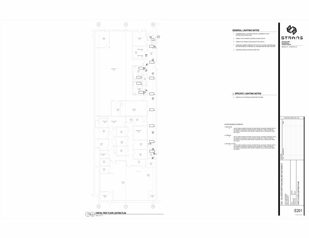
����
��
��
��
����������
������
����
�
�
�� ���� ����������
���������������������
��������� ����
� !"���� #$�����
� %&������� '����������(�)�� ���*���&����� ��!���� ��#�����
��'���+���������#�,������,���� �,�� ��!�,�� ��%�,��
����,���� �,�����*�������-��%���(����'���(��
� �$���������.����*+(� �� �(�)�����
�� ����&���������� ��(( �� .����
/
///////
///
/
/� �0�1��
1�� 1��
22345678958:499;<7;9947;<7;8947=4�>9?7<;@/�A��BC�DA��E��D/FGH�I/C�DA
�J/DABK��HL�/LHM
2�NOJAKIL��LJ/BKC�AB2P��Q��
JH�A�A�B�NJ�RH2L�B�P
ST��T�Q�����MSUMSQ�N@
LIH��A��/KH��B�N/JG �VQQ��P�N/JG��LJHHL @/�A��B�DA�SVW�V 2�QST�UT�Q�� XAJ�L�X���J��AKILABK�N�/B
2�/�Y�A��/KHJ�B�JLI�ZFA��ABK�@HN��A�2�BBH2
L
H�Q��Q��QSS
� 2��J�AB/LH�XAB/����2/LA�B���X��H�A2H�C��F@AB/AJH�C�HL2�DALI/J2IALH2LFJ/��2HA�ABK�N�/B�P� 2�BBH2L��AKIL�XA1LFJH��L��H1A�LABK��AKILABK�2AJ2FAL�PV 2�BBH2L�H1AL��AKB/KH�L��H1A�LABK�H1AL��AKB�2AJ2FAL�PU J��@��/B��2�@@�B�2�JJA��J��DALI�@F�LAN�H��22FN/B2O��HB��J���I/��ZH�ABLHJ2�BBH2LH��L��HBHJKA[H�/����F@AB/AJH���HJ�ABK�/JH/�L�KHLIHJPS �F@AB/AJH��2IH�F�H���2/LH���B��IHHL�H\Q�P
�P� JHAB�L/����AKIL�XA1LFJH��/��/KH��XJ�@�LIA��/JH/P
<9;943]�]7<687;<�;=89?
^ ?_95775�]7<687;<�;=89?
B �2/�HM���Tab�c��dYQbH�Q�� _34873]�74?8�]==4�]7<687;<�_]3;
�AKILABK��HeFHB2H��X��NHJ/LA�B�P�JH�LJ��@�/P� �AKIL��LFJB��B�DIHB��22FN/B2O�A���HLH2LH��ZO��22FN/B2O��HB��JP��A@�L���Qf�DIHB�B���22FN/B2O�A���HLH2LH��X�J��S�@ABFLH�P�LFJB��XX�DIHB�B���22FN/B2O�A���HLH2LH����HJ�LIH�BH1L�S�@ABFLH�P�D/���2�BLJ���HJ�LFJB���XX��AKIL�P�P�2�JJA��J/P� �AKIL��LFJB��B�DIHB��22FN/B2O�A���HLH2LH��ZO��22FN/B2O��HB��J�P��A@�L���Qf�DIHB�B���22FN/B2O�A���HLH2LH��X�J��S�@ABFLH�P�LFJB��XX�DIHB�B���22FN/B2O�A���HLH2LH����HJ�LIH�BH1L�S�@ABFLH�P�D/���2�BLJ���HJ�LFJB���XX��AKIL�PVP�@H2I/BA2/��J��@/P� �AKIL��LFJB��B�DIHB��22FN/B2O�A���HLH2LH��ZO��22FN/B2O��HB��JP��A@�L���Qf�DIHB�B���22FN/B2O�A���HLH2LH��X�J��S�@ABFLH�P�LFJB��XX�DIHB�B���22FN/B2O�A���HLH2LH����HJ�LIH�BH1L�S�@ABFLH�P�D/���2�BLJ���HJ�LFJB���XX��AKIL�P B�P�H�2JAN LA�B�/LH
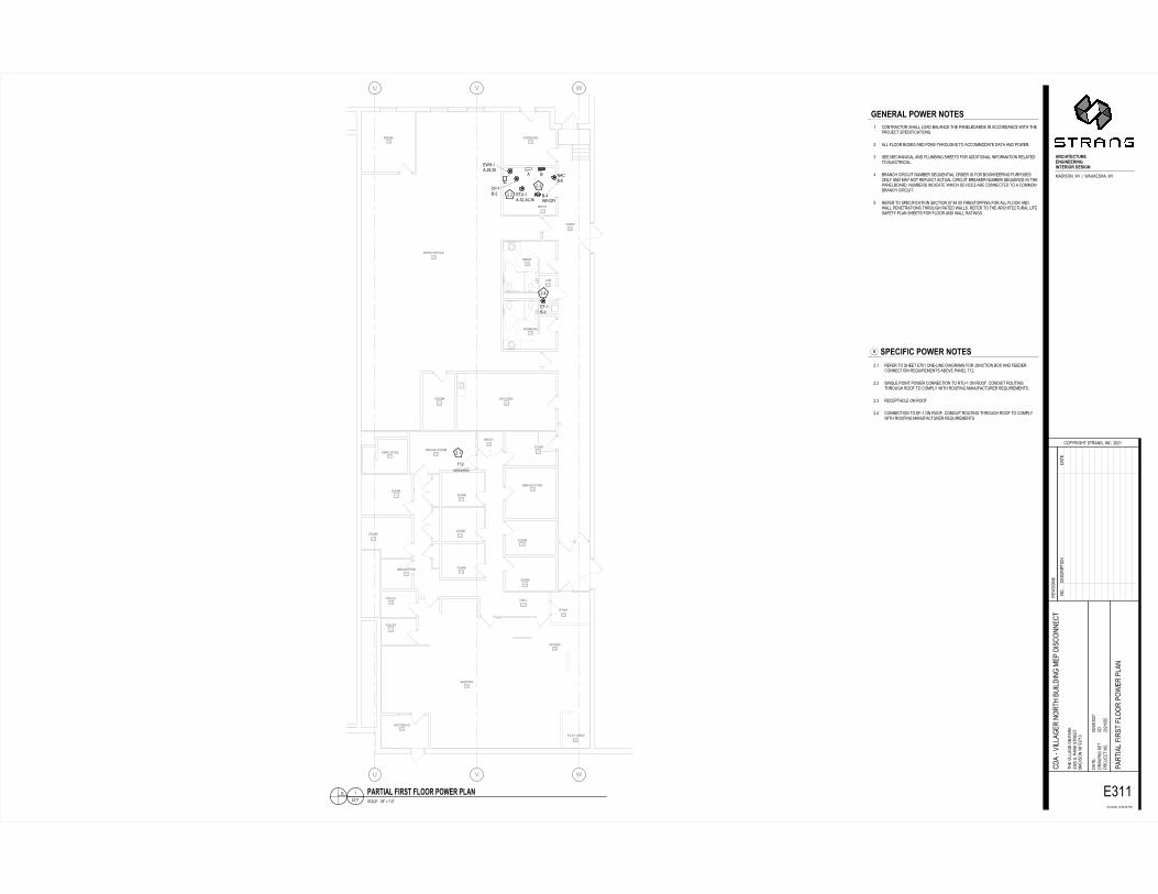
�������
�������
������� ��������
�������������� ������������
�������������������������
�������� !� ����!�"�����
������������!��������!��
����������#����$��
����$��������!�"�� ������������� ������� �������
������ ���������$������$������$��
����$������$��
���������
�����!!���������
%
%
&
&
'
'( )
*+,,-+
.*/0+(01,213214,-1,-, )0356789:;90+)03,-3
;5<0+(0,=21>?60+)0, @(?)04 ABCDEFGCFHBGGIJEIGGBEIJEIFGBEKB�LGMEJIN(O:PQ@2�5:��R��5(/S;P<(2�5:
O.(5:@8�P;*O(*;T
?Q6U.:8<*�P*.(@82�:@?-�,>,+
.;V:P:[email protected];?*�@Q-
X7,+7,>,+�+,TX3TX4�6N
*<;�V:YY(8;�Q@�6(.S ,1>>�P-�6(.S�P*.;;* N(O:PQ@�5:�X1Z+1 ?O>X7,37,>,+ 6(.*:(Y�9:.P*�9YQQ.�6Q5;.�6Y(@
?O(�0V:YY(8;.�@Q.*<�)/:YO:@8�N;6�O:P?Q@@;?
*
;1++,>,+>XX
JGIGBA[�\K]GB�IKFGM
^ M\GCE_EC�\K]GB�IKFGM
+ ?Q@*.(?*Q.�P<(YY�YQ(O�)(Y(@?;�*<;�6(@;Y)Q(.OP�:@�(??Q.O(@?;�5:*<�*<;6.QW;?*�P6;?:9:?(*:Q@P-, (YY�9YQQ.�)Q;P�(@O�6QS;0*<.Q/8<P�*Q�(??QNNQO(*;�O(*(�(@O�6Q5;.-1 P;;�N;?<(@:?(Y�(@O�6Y/N):@8�P<;;*P�9Q.�(OO:*:Q@(Y�:@9Q.N(*:Q@�.;Y(*;O*Q�;Y;?*.:?(Y-3 ).(@?<�?:.?/:*�@/N);.�P;a/;@*:(Y�Q.O;.�:P�9Q.�)QQSS;;6:@8�6/.6QP;PQ@YU�(@O�N(U�@Q*�.;9Y;?*�(?*/(Y�?:.?/:*�).;(S;.�@/N);.�P;a/;@?;�:@�*<;6(@;Y)Q(.O-�@/N);.P�:@O:?(*;�5<:?<�O;V:?;P�(.;�?Q@@;?*;O�*Q�(�?QNNQ@).(@?<�?:.?/:*-X .;9;.�*Q�P6;?:9:?(*:Q@�P;?*:Q@�>Z�=3�>>�9:.;P*Q66:@8�9Q.�(YY�9YQQ.�(@O5(YY�6;@;*.(*:Q@P�*<.Q/8<�.(*;O�5(YYP-�.;9;.�*Q�*<;�(.?<:*;?*/.(Y�Y:9;P(9;*U�6Y(@�P<;;*P�9Q.�9YQQ.�(@O�5(YY�.(*:@8P-
,-+ .;9;.�*Q�P<;;*�;Z>+�Q@;0Y:@;�O:(8.(NP�9Q.�W/@?*:Q@�)Q�(@O�9;;O;.?Q@@;?*:Q@�.;a/:.;N;@*P�()QV;�6(@;Y�*+,-,-, P:@8Y;�6Q:@*�6Q5;.�?Q@@;?*:Q@�*Q�.*/0+�Q@�.QQ9-�?Q@O/:*�.Q/*:@8*<.Q/8<�.QQ9�*Q�?QN6YU�5:*<�.QQ9:@8�N(@/9(?*/.;.�.;a/:.;N;@*P-,-1 .;?;6*(?Y;�Q@�.QQ9-,-3 ?Q@@;?*:Q@�*Q�;90+�Q@�.QQ9-�?Q@O/:*�.Q/*:@8�*<.Q/8<�.QQ9�*Q�?QN6YU5:*<�.QQ9:@8�N(@/9(?*/.;.�.;a/:.;N;@*P-
@ P?(Y;T��+7=b�c�+d0>b;1+++ \ABFEA[�_EBMF�_[KKB�\K]GB�\[AI
@Q-O;P?.:6 *:Q@O(*;
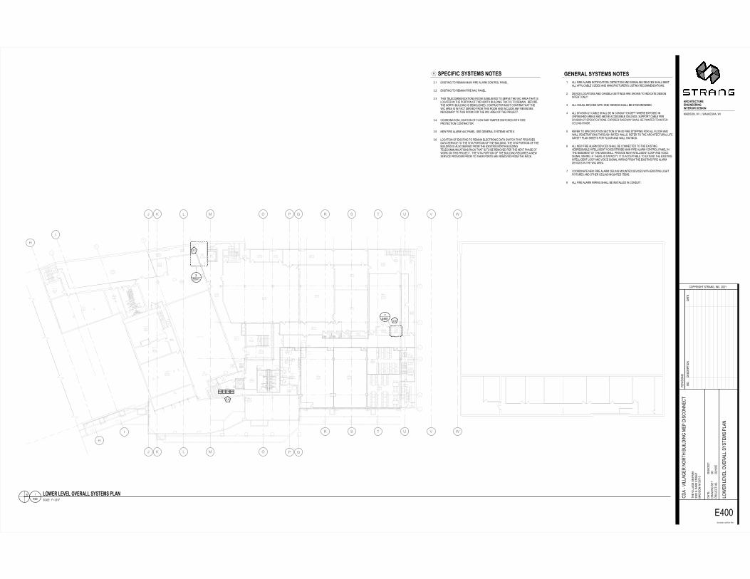
���
���
������
������
���
���
��� ���
�� ����
����������� �������������������������� ��������������������������
��
��
��
�� ��
����
�������������������
�������� ����!���
�����������
������������
�������
������������ ���������
�����������"��������
���������
�����#��������
��� �� �������������������
��� �� ��#�� ��
����" �����������
�����������������"����������
���� ����������������� �������������
���" �������������
�������������
���#��$�%�����������������������������#"�$�%��������������
��������������������������������
�������������
�� �������������������� �����#�#��������������������������
��"����&��� ������ ������������!��� ��� �������'������
�������������!��
���������
�������!�� �����������
���#��������
�����������������������"��������
����
�������
�������#
���� �������"
�����!����
��������
������������
��� ����������
���#��� �����������
"����
�������!�����(��� �����������������!��
���
)) *+,)))-
-
.
.
/
/
0
0
1
1
2
2
3
3
4
4
5
5
6
6
7
7
8
8
9
9
:
:
;
;
<=>?? @A@<=>?B@AC
@AD
EFGHIJKGJLFKKMNIMKKFIMNIMJKFIOF�PKQINM)RST+UVW�XT��Y��XRZ[\+]RW�XT
SRXTV_�+\*SR*\
,UabT_]*�+*RV_W�TV,A�cdcC
\eT+TUV+aUf\,*�VUA
ghcChcdcC�CcggdC�a)
*]\�eTiiR_\�UV�aR[ c@dd�+A�aR[�+*\\* )RST+UV�XT�g@jC@ ,SdghcDhcdcC iUX\�i\e\i�Ue\Rii�+b+*\)+�aiRV
,SR�keTiiR_\�VU*]�lZTiSTV_�)\a�ST+,UVV\,
*
\DddcdcCdgg
NKMKFEm�QnQJKoQ�MOJKQp QqKGIrIG�QnQJKoQ�MOJKQ C Rii�sT\�RiR)�VU*TsT,R*TUVW�S\*\,*TUV�RVS�+T_VRiTV_�S\eT,\+�+]Rii�)\\*Rii�RaaiT,Rli\�,US\+�RVS�)RVZsR,*Z\t+�iT+*TV_�\,U))\VSR*TUV+Ac S\eT,\�iU,R*TUV+�RVS�,RVS\iR�+\**TV_+�R\�+]UXV�*U�TVST,R*\�S\+T_VTV*\V*�UVibA@ Rii�eT+ZRi�S\eT,\+�XT*]�UV\�eT\XTV_�+]Rii�l\�+bV,]UVTu\SAD Rii�STeT+TUV�cj�,Rli\�+]Rii�l\�TV�,UVSZT*�\v,\a*�X]\\�\vaU+\S�TVZVsTVT+]\S�R\R+�RVS�RlUe\�R,,\++Tli\�,\TiTV_+A�+ZaaU*�,Rli\�a\STeT+TUV�cj�+a\,TsT,R*TUV+A�\vaU+\S�R,\XRb�+]Rii�l\�aRTV*\S�*U�)R*,],\TiTV_�sTVT+]Ag \s\�*U�+a\,TsT,R*TUV�+\,*TUV�dj�wD�dd�sT\�+*UaaTV_�sU�Rii�siUU�RVSXRii�a\V\*R*TUV+�*]UZ_]�R*\S�XRii+A�\s\�*U�*]\�R,]T*\,*ZRi�iTs\+Rs\*b�aiRV�+]\\*+�sU�siUU�RVS�XRii�R*TV_+Ax Rii�V\X�sT\�RiR)�S\eT,\+�+]Rii�l\�,UVV\,*\S�*U�*]\�\vT+*TV_RSS\++Rli\�TV*\iiT_\V*�eUT,\h+*Ul\�)RTV�sT\�RiR)�,UV*Ui�aRV\i�TV*]\�lR+\)\V*�Us�*]\�)RTV�)RiiA�aUeTS\�V\X�TV*\iiT_\V*�iUUa�RVS�eUT,\+T_VRi�XTTV_A�Ts�*]\\�T+�,RaR,T*bW�T*�T+�R,,\a*Rli\�*U�\v*\VS�*]\�\vT+*TV_TV*\iiT_\V*�iUUa�RVS�eUT,\�+T_VRi�XTTV_�sU)�*]\�\vT+*TV_�sT\�RiR)S\eT,\+�TV�*]\�XT,�R\RAj ,UUSTVR*\�V\X�sT\�RiR)�,\TiTV_�)UZV*\S�S\eT,\+�XT*]�\vT+*TV_�iT_]*sTv*Z\+�RVS�U*]\�,\TiTV_�)UZV*\S�T*\)+Aw Rii�sT\�RiR)�XTTV_�+]Rii�l\�TV+*Rii\S�TV�,UVSZT*A
@AC \vT+*TV_�*U�\)RTV�)RTV�sT\�RiR)�,UV*Ui�aRV\iA@Ac \vT+*TV_�*U�\)RTV�sT\�VR,�aRV\iA@A@ *]T+�*\i\,U))ZVT,R*TUV+�UU)�T+�l\iT\e\S�*U�+\e\�*]\�XT,�R\R�*]R*�T+iU,R*\S�TV�*]\�aU*TUV�Us�*]\�VU*]�lZTiSTV_�*]R*�T+�*U�\)RTVA��l\sU\*]\�VU*]�lZTiSTV_�T+�S\)UiT+]\SW�,UV*R,*U�)Z+*�,UVsT)�*]R*�*]\XT,�R\R�T+�TV�sR,*�+\e\S�sU)�*]T+�UU)�RVS�TV,iZS\�RVb�\eT+TUV+V\,\++Rb�*U�*]T+�UU)�sU�*]\�XT,�R\R�Us�*]\�aUf\,*A@AD ,UUSTVR*TUV�iU,R*TUV�Us�siUX�RVS�*R)a\�+XT*,]\+�XT*]�sT\aU*\,*TUV�,UV*R,*UA@Ag V\X�sT\�RiR)�VR,�aRV\iA�+\\�_\V\Ri�+b+*\)+�VU*\�xA@Ax iU,R*TUV�Us�\vT+*TV_�*U�\)RTV�\i\,*UVT,�SR*R�+XT*,]�*]R*�aUeTS\+SR*R�+\eT,\�*U�*]\�eT*R�aU*TUV�Us�*]\�lZTiSTV_A�*]\�eT*R�aU*TUV�Us�*]\lZTiSTV_�T+�Ri+U�+\e\S�sU)�*]\�\vT+*TV_�VU*]�lZTiSTV_*\i\,U))ZVT,R*TUV+�R,[�*]R*�T+�*U�l\�\)Ue\S�a\�*]\�V\v*�a]R+\�UsXU[�UV�*]T+�aUf\,*A��*]\�eT*R�aU*TUV�Us�*]\�lZTiSTV_�\yZT\+�R�V\X+\eT,\�aUeTS\�aTU�*U�*]\T�aU*+�R\�\)Ue\S�sU)�*]\�R,[A
V +,Ri\��Cz�{�cdtkdz\DddC mO|KF�mK}Km�O}KFEmm�QnQJKoQ�qmEM
VUAS\+,Ta *TUVSR*\
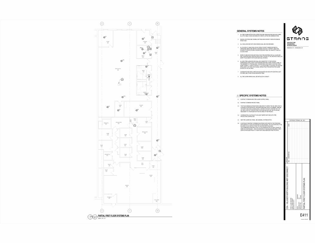
���
���� ��������
����
�������� ���
����
���� ����
����
����
����
����
�
� ������
�
�
�
�
�
��������
������������������
������ ���!�"#�$$%�� ��&��"�
��'(�"���)*���"�
���+%�� �"��,����
��-���%./0� ��!0�1#����
������������%0����,��%0�����.�����$�2����3������3��
����!0�1�� ���.���+#���� �'��� �)���%��,%��/"#�����
���3�����3����&�3��
��'�3����)�3��
���*�%�%"�
��� �00��%"��+�
456
�789 45�
45:
�;<=>?@<?A;@@BC>B@@;>BC>B?@;>D;#E@F>CBG� ��H�I#J�##K##J�8LM�N�I#J�
��J��O#�M7 �7MP
�HQR��ON7#�7���OI#���5#6S6
�MT���H��Q�HUM�7#�H5
�V6V6S6#6P��PS:#QG
7NM#T�WW�OM#H�#Q��L 64SS#�5#Q��L#�7�MM7 G� ��H�#J�#�4X4 � S�V6YV6S6 Q��7��W#Z���7#ZWHH�#�R�7MG�#QW��
� �#9T�WW�OM�#�H�7N#[8�W ��O#GMQ# ���H��M�
7
MY6S6S��
C@B@;�\#F]F?@F#BD?@F
_ F@<>a><#F]F?@F#BD?@F
�WW#Z��M#�W��G#�H7�Z���7�H�I# M7M�7�H�#�� #��O��W��O# MT��M�#�N�WW#GMM7�WW#�QQW���[WM#�H M�#�� #G��8Z��78�M�b�#W��7��O#�M�HGGM� �7�H��56 MT��M#WH��7�H��#�� #��� MW�#�M77��O�#��M#�NHJ�#7H#�� ���7M# M��O���7M�7#H�WR54 �WW#T��8�W# MT��M�#J�7N#H�M#T�MJ��O#�N�WW#[M#�R��N�H��cM 5Y �WW# �T���H�#6X#��[WM#�N�WW#[M#��#�H� 8�7#Md�MQ7#JNM�M#MdQH�M #��8�Z����NM #��M��#�� #�[HTM#���M���[WM#�M�W��O�5#�8QQH�7#��[WM#QM� �T���H�#6X#�QM��Z���7�H��5#MdQH�M #���MJ�R#�N�WW#[M#Q���7M #7H#G�7�N�M�W��O#Z����N5� �MZM�#7H#�QM��Z���7�H�#�M�7�H�#SX#eY#SS#Z��M#�7HQQ��O#ZH�#�WW#ZWHH�#�� J�WW#QM�M7��7�H��#7N�H8ON#��7M #J�WW�5#�MZM�#7H#7NM#���N�7M�78��W#W�ZM��ZM7R#QW��#�NMM7�#ZH�#ZWHH�#�� #J�WW#��7��O�5: �WW#�MJ#Z��M#�W��G# MT��M�#�N�WW#[M#�H��M�7M #7H#7NM#Md��7��O� �M���[WM#��7MWW�OM�7#TH��MV�7�H[M#G���#Z��M#�W��G#�H�7�HW#Q��MW#��7NM#[��MGM�7#HZ#7NM#G���#G�WW5#Q�HT� M#�MJ#��7MWW�OM�7#WHHQ#�� #TH��M��O��W#J����O5#�Z#7NM�M#��#��Q���7RI#�7#��#���MQ7�[WM#7H#Md7M� #7NM#Md��7��O��7MWW�OM�7#WHHQ#�� #TH��M#��O��W#J����O#Z�HG#7NM#Md��7��O#Z��M#�W��G MT��M�#��#7NM#J��#��M�5X �HH� ���7M#�MJ#Z��M#�W��G#�M�W��O#GH8�7M # MT��M�#J�7N#Md��7��O#W�ON7Z�d78�M�#�� #H7NM�#�M�W��O#GH8�7M #�7MG�5e �WW#Z��M#�W��G#J����O#�N�WW#[M#���7�WWM #��#�H� 8�7545 Md��7��O#7H#�MG���#G���#Z��M#�W��G#�H�7�HW#Q��MW5456 Md��7��O#7H#�MG���#Z��M#���#Q��MW5454 7N��#7MWM�HGG8����7�H��#�HHG#��#[MW�MTM #7H#�M�TM#7NM#J��#��M�#7N�7#��WH��7M #��#7NM#QH�7�H�#HZ#7NM#�H�7N#[8�W ��O#7N�7#��#7H#�MG���5##[MZH�M7NM#�H�7N#[8�W ��O#��# MGHW��NM I#�H�7���7H�#G8�7#�H�Z��G#7N�7#7NMJ��#��M�#��#��#Z��7#�M�TM #Z�HG#7N��#�HHG#�� #���W8 M#��R#�MT���H���M�M����R#7H#7N��#�HHG#ZH�#7NM#J��#��M�#HZ#7NM#Q�HUM�7545Y �HH� ���7�H�#WH��7�H�#HZ#ZWHJ#�� #7�GQM�#�J�7�NM�#J�7N#Z��MQ�H7M�7�H�#�H�7���7H�545� �MJ#Z��M#�W��G#���#Q��MW5#�MM#OM�M��W#�R�7MG�#�H7M#:545: WH��7�H�#HZ#Md��7��O#7H#�MG���#MWM�7�H���# �7�#�J�7�N#7N�7#Q�HT� M� �7�#�M�T��M#7H#7NM#T�7�#QH�7�H�#HZ#7NM#[8�W ��O5#7NM#T�7�#QH�7�H�#HZ#7NM[8�W ��O#��#�W�H#�M�TM #Z�HG#7NM#Md��7��O#�H�7N#[8�W ��O7MWM�HGG8����7�H��#���L#7N�7#��#7H#[M#�MGHTM #QM�#7NM#�Md7#QN��M#HZJH�L#H�#7N��#Q�HUM�75##7NM#T�7�#QH�7�H�#HZ#7NM#[8�W ��O#�Mf8��M�#�#�MJ�M�T��M#Q�HT� M�#Q��H�#7H#7NM��#QH�7�#��M#�MGHTM #Z�HG#7NM#���L5
� ���WMP##Veg#h#b9SgMY �;?>�\#a>;F?#a\DD;#F]F?@F#\�B
�H5 M����Q 7�H� �7M
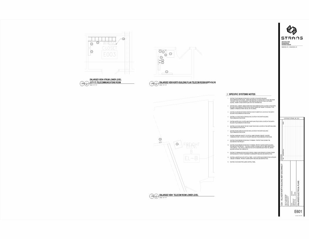
��������������� ���
��������������� �� �� �� ��
��
�!���� �� "#$%&'($')#((*+&*((#&*+&*'(#&,#-.(/&+*0�123456-72--8--7�9:;3<�6-72
1=�725>-3;?1�?;@
�4�A=2><?-3?=�5>6-25�B-�!��
=;C232453�=4D;�?-54B
�E��E�!��-��@��@��-�0
?<;-C2FF�>;-45-��=: ��!!-3B-��=:-3?=;;? 0�12345-72-����� �1!�E��E�!�� ;5F�=>;1-;F;�?=2��F-�F�53
�1�-GC2FF�>;=-54=?<-H92F125>-0;�-123�455;�
?
;�!��!��!��
5 3��F;@--�E�I-J-�KG!I;�!�� (*L"#+(.-M&(N-*,#'%-O)&L.&*+-PL"*-'(L($,Q-#,,Q-*,#'%-OL.+
5 3��F;@--�E�I-J-�KG!I;�!�� (*L"#+(.-M&(N--'(L($,Q-#,,Q-L,N(#-L(M(L
5 3��F;@--�E�I-J-�KG!I;�!�� (*L"#+(.-M&(N-"'#&)Q-L,N(#-L(M(LR$&'S-&'T-'(L($,QQ)*&$"'&,*/-#,,Q U /P($&V&$-/S/'(Q/-*,'(/� ;W23?25>-?;F;�400952��?2453-=��:-F4��?;1-25-?<;-54=?<-H92F125>?;F;�400952��?2453-=440B--?<;=;-�=;-;W23?25>-C2?�-3���;-1�?�-49?F;?- ;1- =40?<23-=��:6-?<;A-72FF-H;-=;X92=;1-?4-H;-=;04C;1-�51-=; ;1- =40-�-12 ;=;5?349=�;B--=; ;=-?4-5;7-74=:-�F�53- 4=-?<�?-25 4=0�?245B� ;W23?25>-7�FF-��H25;?-F�H;F;1-021�F�253-?;F;�400952��?245-F4��?;1-25-?<;-54=?<H92F125>-?;F;�400952��?2453-=440B-�1C23;-475;=-�51-?;5�5?-?4-=;C2;7-2 -?<23��H25;?-23- ;;125>-;2?<;=-?<;-72�-4=-C2?�-�=;�3B� ;W23?25>-?;F;�<45;-5;?74=:-25?;= ��;-H4W-HA-�0;=2?;�<-F4��?;1-25-?<;-54=?<H92F125>-?;F;�400952��?2453-=440B� ;W23?25>-��!-C42�;-�95�<-1475-HF4�:3-F4��?;1-25-?<;-54=?<-H92F125>?;F;�400952��?2453-=440B� ;W23?25>-54=?;F-H4W-F4��?;1-�H4C;-021-�F�253-?;F;�4-H4W-F4��?;1-25-?<;-54=?<H92F125>-?;F;�400952��?2453-=440B� ;W23?25>-�C�A�-H4W-�H4C;-?<;-021-�F�253-?;F;�4-H4W-F4��?;1-25-?<;-54=?<-H92F125>?;F;�400952��?2453-=440B� ;W23?25>-��>25>-�0�F2 2��?245-1;C2�;3-F4��?;1-25-?<;-54=?<-H92F125>?;F;�400952��?2453-=440B� ;W23?25>-95:5475-X9�5?2?A-4 -4�?2��F- 2H;=-3?=�513-F�H;F;1-I�<�=?;=�400952��?2453I-F4��?;1-25-?<;-54=?<-H92F125>-?;F;�400952��?2453-=440B ;W23?25>-?;F;�400952��?2453-=��:-?4-=;0�25B--�=4?;�?-=��:-19=25>-?<;1;�453?=9�?245-�=4D;�?B�! ;W23?25>-?;F;�400952��?2453-=��:-?4-=;0�25B-�=4?;�?-19=25>-54=?<-H92F125>1;�453?=9�?245-�=4D;�?B--?<23-=��:-<493;3-?<;-0�25-4�?2��F- 2H;=-3;=C2�;-25?4?<23-�40�F;WB--?<;-4�?2��F- 2H;=-=49?;3-49?E25-951;=>=4951- =40-?<;-F2H=�=AH92F125>-��=433-?<;-��=:25>-F4?B�� ;W23?25>-?4-=;0�25-:;A3��5-144=-�45?=4F-��5;F3-�51-3;��=�?;-�F?=452W-�47;=39��F2;3-H;F47B-�=4?;�?-;X92�0;5?-19=25>54=?<-H92F125>-1;�453?=9�?245B�� ;W23?25>-F�11;=-=��:-72?<-4�?2��F- 2H;=6--C42�;-�4��;=-�51-74=:3?�?245-��?;>4=A��HF25>-?4-=;0�25B--�=4?;�?-19=25>-54=?<-H92F125>-1;�453?=9�?245B�� ;W23?25>-C42�;-0�25- 2=;-�F�=0-�45?=4F-��5;FB 54B1;3�=2� ?2451�?;
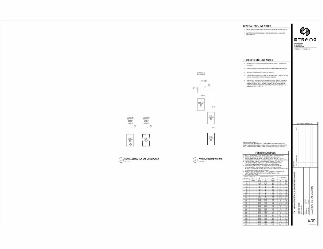
������������������������������������������������������������������������������
��� ������������ ���� ������������� !"#$� %� ����&&�&����� ��� ��������������������
�%'�% �(��(��(��(��(��(��(��(��(�(�(�()��(�)��(�)��(�)��(����(����(����(�)��(�)��(����(����(����(����(����(����(����(����(����(���
�%'�% (�(�(�(�(�(�(�(�(((()�(�)�(�)�(�)�(���(���()���(�)�(�)�(���(���(���(���(���(���(���(���(���(���
�% (�(�(�(�(�(�(�(�(�(�(�(�(�(�(�(�(�(�(�(�(�(()�()�(�)�(�)�(�)�(���(���(���
�%'�% �% �%�)�*�)�*�)�***�)�*�)�*�)�*�)�*�)�*�)�*�)�*�*�*�*��)�*��)�*�*�*�*��)�*�*�*��)�*�*�*�*�*��)�*��)�*
�)�*�)�***�)�*�)�*�)�*�)�*�)�*�)�*�)�*�*�*��)�*��)�*��)�*�*��)�*��)�*���)�*��*�*��)�*�*�*�*��)�*��)�*��)�*��)�*
+,,-,.�/01,-23,��������
4��������&&���� ���������������5����%������%������������6�����&��� 4�4������ ���������������������������6&����7��6$��$'���'�89957�4���������� ���������������� �5��9���$�����6��� ������:�����������4���$4�4������ �����������������������9���������6&��'���;���&&������9� �&������<�4�4������ �������� ���� �����������9�5�������������������4���� ����������������� ����� ������������4��'��� ������������������ ������������� �������������9�5������9�����7&������������� ��%���4�4���������������9�&&� ���������9���� ��=���������������<�&��%�������� ������ ���6����������������4�����������9����� �������� �����������5��������������9�������� ���������������4���6������&��&��������� ���������<��� �����������9�����9�����)��%�����4�4�������&&�&�����>����9���� �����9�&&�9�<����� ������%������%�����������767���9������� ������'�%���� ��%���� �������$'��� ����������������&���� �������$4
�����&�����)��<����&�� ��� �&�����<����&�%? ?@
����8�����%��&�������&�������������9�6��& ��% ����8�����%��&�������&�������������9�6��& ��% �����&�����)��<����&������&�����)��<����&�6��7�%���7�%�����&�����)��<����&���
���7�%���7�%
A B�8�����%���&&��5���96��� C
D.01EF,0F2.,,GHEG,,.EGHEGF,.EI.�-,/EHG�� ����'�5���J��5��K��9�'�5�
��5��%���� ���>
������%9�������%'����4����
��<���������L������4
�)�)�����>��>����
�9��<�&&�%��������K ������4����K������� �� �����5������ � ��)��)��� �&�������&����7&���� ��%����
� ��7<�&&�%�������9�6��& ��%����� ��������
�
���������
�6����������<�&�������5�������5�����%��&&�������� ���5�������%��4� ����������M����������9� �&�����������������&�������&��M���������M���������4 ����<����5������ ������������9�6��& ��%��&�������&� �����6������M�������4� �8�����%������������������� ����������&&���������������5���96��� 4� ��5�L��������6�8��6�<�����&��%��<�������&���4� ����������5��������� �������8�����%���� ��4���� �����������������9����������<������������������������������M���� 4� ����<����%9��� L��������������6���K���������K�������������9����5�7��&��6���K�����5����%����7'�����5��7��&��6���K��������5�����5����&�6'��� �����5��7��&��6���K��������9���&�������5�����9�����4�����������9�����������6�������9�������������&����� ���5��K��9�6����9�����������������&�64
H,G,.D3�IG,N3EG,�GIF,/O /P,0E+E0�IG,N3EG,�GIF,/
���&�>������� PD.FED3�-,QI3EFEIG�IG,N3EG,�-EDH.DQ ���&�>�������� PD.FED3�IG,N3EG,�-EDH.DQ �8�����%�&�� ��������>������ �����%����� ��&��������9�����K� ���� ��<����9��&����������������&������%�����������6��������$�5�����4�K54�����%����4���5������������ �4�����&���&���������9�����'��9���������������<��&�6&���������&���4
��4 ������ ���� ���
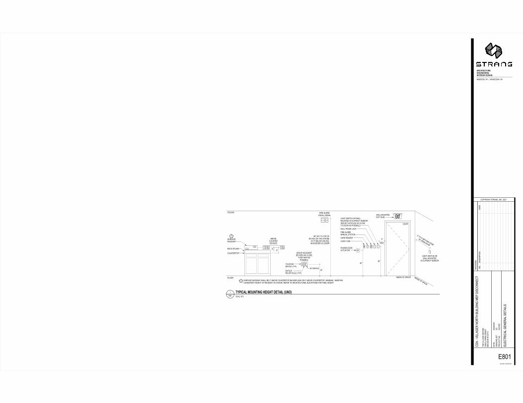
�������
����
������ ������� ������ �� ����� ������� �� ��������
����� ������ � ���� ������ ��������� ����� ������ �������� �� ����� �� �� �� ���������������� ����� ���������� ��������� ����� �� �����
���� ����� ������� ���� ������ ������ ��� ���� ������ ������������ ������ ������������ ���������� ��������������� �� �������� ������� �� ��������� !
����� ������ � ���� ������ ��������� ���������� �� �����
���� ������ ���� �������"#$%#$&#��'(#
) )*# �� "# ����� ����� ���� ��"&# ��� �� ��� �� ����� � ��� ����� �� %# ����� �������+ �������� �� ��������� �� �����
(#$#, ������ ������ ����� �� �# ����� ��������� ���������� � %# ����� ���������+ �������- �������� ���������� ������ �� ������ �� � ���- ��� �� ����������� ���������� �� ����� ������-
,
./01 !�0!2/��34 3��/ 34 3!�/ 5/ 6�7 43������+ �� 8 ��������+ ��
����� ������9
�������� �����+ ���- �&�'
�������������� ��-
:;�';�&�' '�9::9�� ��
��� ������� �� ��� �*&& �- ��� ����� ������ �� :*<'* �&:;�$;�&�' ��������� ������ ������
�� �������� ���� ������� ��� ��������
�
�(&'�&�'&::
�����9 ����(&'' !=> 0.? @523! 34 1� 41! 6�!. ? A235B ��-����� �������
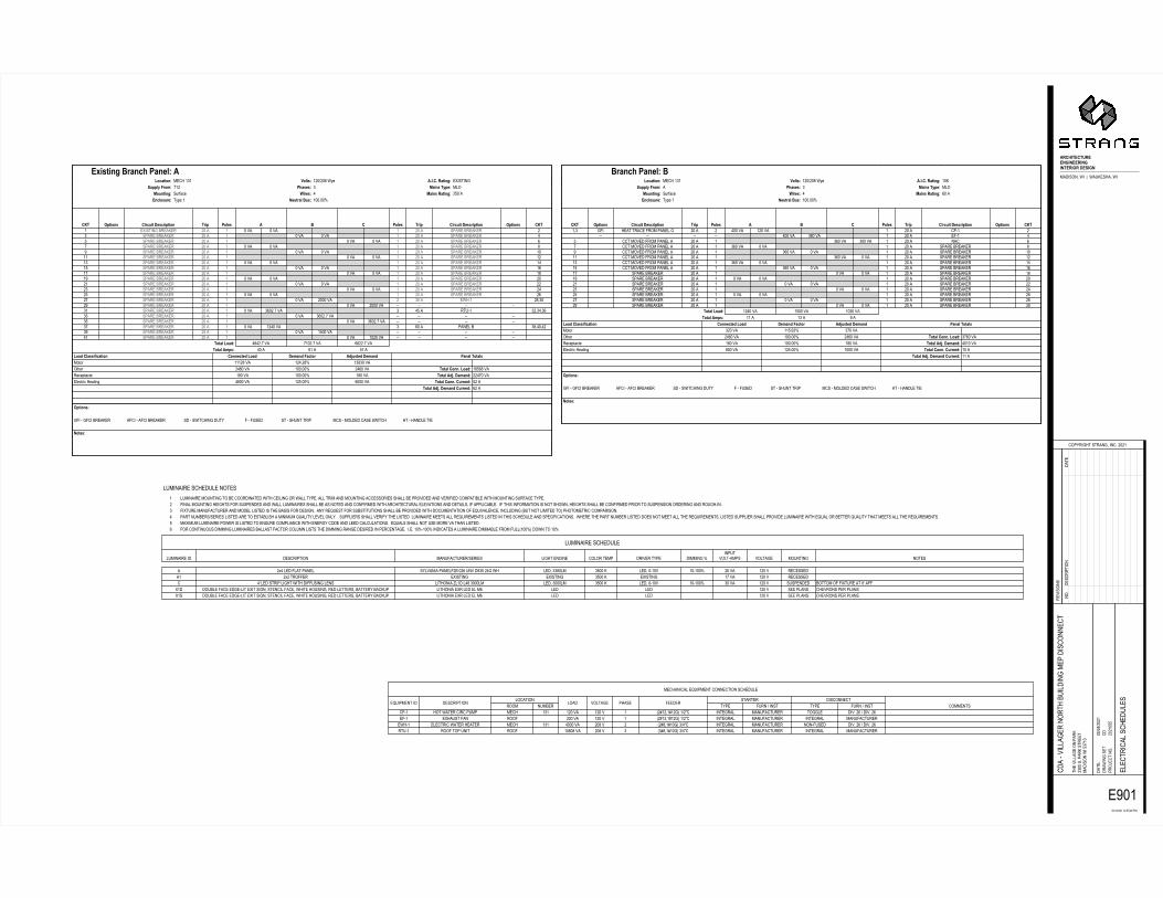
�������������������������� �������������������������������
���������������
!�"#����������������!$�%&%'
��(������"��)�!����$
*+%'+%&%'�'% ** %,�"�
����(�--�������"��� %.&&��$�"���������� �����������*./'. !�&*+%0+%&%' �-�!���!�-��!����-��!���1(�--�����������2��-�������"����!����!
�
�3&'%&%'&**
45678�9��1��9!��2�����������������������9!��1��9!��2���������������������������1�����!��������#��������������������9�1�9�������������������������1����������"����������������������!��1���-����!��������!��������������������1�����-������:5;4<78 �45=>��?@A� 6B=<?��CDD6<58E%���FGHIJKH��GLIKMN 0,&&�(� '%*$&&O E&&&�(� �45=>��4<<A��CDD6<58*%���GHGPILHFG ',&�(� '&&$&&O ',&�(� �45=>��?@A� 6B=<?8%%0/&�(��IQGJ %0E&�(� '&&$&&O %0E&�(� �45=>��4<<A�R4=?8',*E,�(��SISJ '''%,�(� '%0$%,O '.,.&�(�R4=?��>=77;T;U=5;4< �4<<6U56?�R4=? 6B=<?�V=U54D �?@C756?� 6B=<? W=<6>��45=>7�45=>��B:78 0&�� E'�� */���45=>�R4=?8 0,0%$/�(� /'&%$/�(� EE%%$/�(�0' �"����2������ %&�� ' &�(� '&%&�(� 11 11 11 11.3 �"����2������ %&�� ' &�(� '*&&�(� 11 11 11 11./ �"����2������ %&�� ' &�(� '%0&�(� . E&�� "���-�2 .,�0&�0%.* �"����2������ %&�� ' &�(� .E&%$/�(� 11 11 11 11.. �"����2������ %&�� ' &�(� .E&%$/�(� 11 11 11 11.' �"����2������ %&�� ' &�(� .E&%$/�(� . 0*�� ���1' .%�.0�.E%3 �"����2������ %&�� ' &�(� %&&&�(� 11 11 11 11%/ �"����2������ %&�� ' &�(� %&&&�(� % .&�� ���1' %,�.&%* �"����2������ %&�� ' &�(� &�(� ' %&�� �"����2������ %E%. �"����2������ %&�� ' &�(� &�(� ' %&�� �"����2������ %0%' �"����2������ %&�� ' &�(� &�(� ' %&�� �"����2������ %%'3 �"����2������ %&�� ' &�(� &�(� ' %&�� �"����2������ %&'/ �"����2������ %&�� ' &�(� &�(� ' %&�� �"����2������ ','* �"����2������ %&�� ' &�(� &�(� ' %&�� �"����2������ 'E'. �"����2������ %&�� ' &�(� &�(� ' %&�� �"����2������ '0'' �"����2������ %&�� ' &�(� &�(� ' %&�� �"����2������ '%3 �"����2������ %&�� ' &�(� &�(� ' %&�� �"����2������ '&/ �"����2������ %&�� ' &�(� &�(� ' %&�� �"����2������ ,* �"����2������ %&�� ' &�(� &�(� ' %&�� �"����2������ E. �"����2������ %&�� ' &�(� &�(� ' %&�� �"����2������ 0' �X�������2������ %&�� ' &�(� &�(� ' %&�� �"����2������ %�Y� �:5;4<7 �;DUC;5� 67UD;:5;4< �D;: W4>67 � Z � W4>67 �D;: �;DUC;5� 67UD;:5;4< �:5;4<7 �Y��<U>47CD68�[PG�' 6C5D=>�ZC78'&&$&&O\4C<5;<]8�J_LHG ;D6780 \=;<7��=5;<]8%*&���C::>a�VD4B8�'% Wb=7678. \=;<7��a:68�-�R4U=5;4<8��!��'.' c4>578'%&+%&,��[G �A�A�A��=5;<]8�X�������d;75;<]�ZD=<Ub�W=<6>8�45678�9��1��9!��2�����������������������9!��1��9!��2���������������������������1�����!��������#��������������������9�1�9�������������������������1����������"����������������������!��1���-����!��������!��������������������1�����-������:5;4<78 �45=>��?@A� 6B=<?��CDD6<58''���FGHIJKH��GLIKMN ,&&�(� '%*$&&O '&&&�(� �45=>��4<<A��CDD6<58'&���GHGPILHFG ',&�(� '&&$&&O ',&�(� �45=>��?@A� 6B=<?80&'&�(��IQGJ %0E&�(� '&&$&&O %0E&�(� �45=>��4<<A�R4=?8./E&�(��SISJ .%&�(� ''*$E.O ./&�(�R4=?��>=77;T;U=5;4< �4<<6U56?�R4=? 6B=<?�V=U54D �?@C756?� 6B=<? W=<6>��45=>7�45=>��B:78 ''�� '.�� 3���45=>�R4=?8 '%0&�(� '*&&�(� '&%&�(�%3 �"����2������ %&�� ' &�(� &�(� ' %&�� �"����2������ .&%/ �"����2������ %&�� ' &�(� &�(� ' %&�� �"����2������ %,%* �"����2������ %&�� ' &�(� &�(� ' %&�� �"����2������ %E%. �"����2������ %&�� ' &�(� &�(� ' %&�� �"����2������ %0%' �"����2������ %&�� ' &�(� &�(� ' %&�� �"����2������ %%'3 �"����2������ %&�� ' &�(� &�(� ' %&�� �"����2������ %&'/ �"����2������ %&�� ' &�(� &�(� ' %&�� �"����2������ ','* !!����(���9����"���-�� %&�� ' .E&�(� &�(� ' %&�� �"����2������ 'E'. !!����(���9����"���-�� %&�� ' .E&�(� &�(� ' %&�� �"����2������ '0'' !!����(���9����"���-�� %&�� ' .E&�(� &�(� ' %&�� �"����2������ '%3 !!����(���9����"���-�� %&�� ' .E&�(� &�(� ' %&�� �"����2������ '&/ !!����(���9����"���-�� %&�� ' .E&�(� &�(� ' %&�� �"����2������ ,* !!����(���9����"���-�� %&�� ' .E&�(� .&&�(� ' %&�� ��! E11 11 11 11 0&&�(� .,&�(� ' %&�� �91' 0'�. �9� ��������!��9����"���-�� %&�� % 0&&�(� '%&�(� ' %&�� !"1' %�Y� �:5;4<7 �;DUC;5� 67UD;:5;4< �D;: W4>67 � Z � W4>67 �D;: �;DUC;5� 67UD;:5;4< �:5;4<7 �Y��<U>47CD68�[PG�' 6C5D=>�ZC78'&&$&&O\4C<5;<]8�J_LHG ;D6780 \=;<7��=5;<]8E&���C::>a�VD4B8� Wb=7678. \=;<7��a:68�-�R4U=5;4<8��!��'.' c4>578'%&+%&,��[G �A�A�A��=5;<]8'&�ZD=<Ub�W=<6>8Z
��!����!�-��e��"�����!����!������!����-��e��"������� ���!��"���� -�!����� -��� (�-���� "���� 9����� ������� ���!����!� !����������� ���2�� �#"� 9����+����� �#"� 9����+�����!"1' ����������!��!�"��" ��!� '.' '%&�(� '%&�( ' f%g'%�'g'%�h�'+%i! �������- ����9�!����� ����-� ��($�%E�+���($�%E�91' �X������9�� ���9 %&&�(� '%&�( ' f%g'%�'g'%�h�'+%i! �������- ����9�!����� �������- ����9�!��������1' �-�!���!������������� ��!� '.' 0&&&�(� %&,�( % f%g,�'g'&�h�.+0i! �������- ����9�!����� ���19���� ��($�%E�+���($�%E���1' ���9���"����� ���9 '&,&,�(� %&,�( . f.g,�'g'&�h�.+0i! �������- ����9�!����� �������- ����9�!�����
-����������!����-�-����������� ���!��"���� ����9�!�����+������ -����������� !�-������" ���(����#"� ��������O ��"��(�-�1��"� (�-���� �������� ������ %j0�-���9-���"���- �#-(�����"���-9%2�&%E���(��,.*�%0���� -����..,&-� .*&&�� -����&1'&( '&1'&&O %E�(� '%&�( ��!������' %j%����99�� �X������ �X������ .*&&�� �X������ '/�(� '%&�( ��!�����! 0k�-�������"�-������������99������-��� -��������l-'��-0,�.&&&-� -����.&&&-� .*&&�� -����&1'&( '&1'&&O .&�(� '%&�( ���"����� 2�������9�9�X��������,k��99$X'� ���2-��9�!������1-����X�������������!�-�9�!����������������������-��������2�����#�2�!��" -���������X��-����-��E -�� -�� '%&�( ����"-��� !��(�����"���"-���X'� ���2-��9�!������1-����X�������������!�-�9�!����������������������-��������2�����#�2�!��" -���������X��-����-��E -�� -�� '%&�( ����"-��� !��(�����"���"-���-����������!����-�������' -���������������������2��!����������������!��-���������--��#"�$��--��������������������!!������������--�2��"��(���������(���9����!��"���2-�������������������9�!���#"�$% 9���-������������������9������"������������--�-�������������--�2���������������!��9�������������!����!����-��-�(����������������-����9��""-�!�2-�$���9��������9����������������������������������--�2��!��9������"�����������"�������������������������1��$. 9�X���������9�!��������������-�-�������������2�����9���������$����#���e�����9�����2��������������--�2��"��(������������!������������9��e��(�-��!�����!-������f2�������-���������h�"���������!�!��"������$0 "�������2���+�������-�����������������2-��������������e��-��#�-�(�-���-#$�����""-��������--�(���9#�����-�������-����������������--���e����������-���������������!����-�������"�!�9�!������$������������"�������2���-���������������������--�������e���������$�-��������""-�������--�"��(����-���������������e��-����2������e��-��#�������������--�������e���������$* ��X�����-���������"��������-����������������!��"-���!������������#�!��������-����!�-!�-������$���e��-�����--��������������(�������-�����$E 9���!������������������-����������2�--����9�!����!�-����-����������������������������������"��!������$���$�$�'&O1'&&O�����!�������-��������������2-��9����9�--f'&&Oh���������'&O
��$���!��" ��������
SPECIFICATIONS FOR
CDA - VILLAGER NORTH BUILDING MEP DISCONNECT
CONSTRUCTION DOCUMENTS
THE VILLAGE ON PARK
2300 S. PARK STREET
MADISON, WI 53713
PROJECT NO. 2021055
MAY 24, 2021

This page intentionally left blank
CDA - Villager North Building MEP DisconnectProject No. 2021055
PROJECT TITLE PAGE00 01 01 - 1
Architectural and MEP Engineering:Strang, Inc.811 East Washington AveMadison, WI 53703(608) 276-9200

This page intentionally left blank
CDA - Villager North Building MEP DisconnectProject No. 2021055
TABLE OF CONTENTS00 01 10 - 1
SECTION 00 01 10 - TABLE OF CONTENTS
DIVISION 00 - PROCUREMENT AND CONTRACTING REQUIREMENTS(Applied to all Contractors)
00 01 01 Project Title Page00 01 10 Table of Contents
DIVISION 01 - GENERAL REQUIREMENTS 01 10 00 Summary of Work 01 31 00 Procedures and Performances 01 32 00 Schedules, Reports and Payments 01 33 00 Submittals 01 42 00 Definitions and Standards 01 50 00 Temporary Facilities 01 60 00 Products and Substitutions 01 70 00 Project Closeout 01 73 29 Cutting and Patching 01 74 19 Construction Waste Management and Disposal
DIVISION 02 - EXISTING CONDITIONS 02 41 00 Demolition
DIVISION 06 - WOOD, PLASTICS, AND COMPOSITES06 10 63 Miscellaneous Rough Carpentry
DIVISION 07 - THERMAL AND MOISTURE PROTECTION
07 01 50.19 Preparation for Re-Roofing 07 62 00 Sheet Metal Flashing and Trim 07 84 00 Firestopping 07 92 00 Joint Sealants
DIVISION 09 - FINISHES 09 21 16 Gypsum Board Assemblies 09 51 00 Acoustical Ceilings 09 91 23 Interior Painting
DIVISION 21 - FIRE SUPRESSION21 05 10 General Fire Protection Systems
DIVISION 22 - PLUMBING22 05 00 Common Work Results for Plumbing 22 05 15 Piping Specialties 22 05 23 General Duty Valves for Plumbing Piping 22 05 39 Supports, Anchors and Seals 22 07 00 Plumbing Insulation 22 10 50 Pipe, Tube and Fittings 22 11 00 Facility Water Distribution 22 30 00 Plumbing Equipment
DIVISION 23 - HEATING, VENTILATING, AND AIR-CONDITIONING (HVAC)23 05 00 HVAC General Provisions 23 05 29 Supports and Anchors 23 05 93 Testing, Adjusting and Balancing
CDA - Villager North Building MEP DisconnectProject No. 2021055
TABLE OF CONTENTS00 01 10 - 2
23 07 00 Mechanical Insulation 23 11 23 Natural Gas Piping Systems 23 31 13 Low and Medium Pressure Ductwork 23 33 00 Duct Accessories 23 34 16 Fans 23 34 23 Power & Gravity Ventilators 23 74 16 Small Packaged Rooftop Units
DIVISION 26 - ELECTRICAL26 00 00 Electrical General Requirements 26 05 00 Common Work for Electrical 26 05 19 Low-Voltage Electrical Power Conductors and Cables 26 05 26 Grounding and Bonding for Electrical Systems 26 05 29 Hangers and Supports for Electrical Systems 26 05 33 Raceways and Boxes for Electrical Systems 26 05 53 Identification for Electrical Systems 26 09 26 Digital Modular Lighting Controls26 27 26 Wiring Devices 26 51 00 Interior Lighting
DIVISION 27 - COMMUNICATIONS27 05 28 Pathways for Communication Systems 27 15 00 Communications Horizontal Cabling
DIVISION 28 - ELECTRONIC SAFETY AND SECURITY28 31 00 Fire Detection and Alarm
END OF SECTION
CDA - Villager North Building MEP DisconnectProject No. 2021055
SUMMARY OF WORK01 10 00 - 1
SECTION 01 10 00 - SUMMARY OF WORK:
PART 1 - GENERAL
1.1 RELATED DOCUMENTS:
A. Applicable provisions of Division 1 shall govern work under this Section. 1.2 PROJECT/WORK IDENTIFICATION:
A. General: Name of project is CDA - Villager North Building MEP Disconnect located at 2300 S. Park Street on Construction Documents by the Architect, STRANG, INC., 811 East Washington Ave. Madison, WI 53703 dated May 24, 2021.
B. The work will be competed under a single prime contract with one bid package for all work.
1.3 WORK BY OTHERS:
A. Products and materials supplied and installed by Owner or under separate contract:
Not applicable. 1.4 COORDINATION:
A. General: The Contract for General Construction includes coordination of entire work of project from the beginning of activity through the project closeout and warranty periods.
B. Performance Requirements for Completed Work:
1. General: The Construction Documents indicate intended occupancy and utilization of building and its individual systems and facilities. Compliance with governing regulations is intended and required, for the work and for Owner's occupancy and utilization. It is required that every element of the work complies with applicable requirements of Construction Documents and all building systems are complete and fully operational.
1.5 MISCELLANEOUS AND GENERAL PROVISIONS:
A. Cutting and Patching:
1. Definition: Includes cutting and patching of both previously existing work and nominally completed portions of Contract work. Excludes shop fabrication of work and normal installation procedures including the drilling of holes to install fasteners. Excludes special categories of work identified as alterations, demolition, excavating, grading, planting, cleaning, removal/replacement of noncomplying work and similar activities; although some of these activities may require cutting and patching.
B. Mechanical/Electrical Provisions of General Work:
1. General: Except as otherwise indicated, comply with applicable requirements of
Division 22 & 23 sections for mechanical provisions within units of general work
CDA - Villager North Building MEP DisconnectProject No. 2021055
SUMMARY OF WORK01 10 00 - 2
and comply with applicable requirements of Division 26 - 28 sections for electrical provisions within units of general work. Refer to Division 22 through Division 28 sections where applicable for characteristics of mechanical and electrical services to be connected to units of general work and provide units manufactured/fabricated for proper connection and utilization of available services as indicated.
PART 2 - PRODUCTS
Not applicable
PART 3 - EXECUTION
Not applicable
END OF SECTION
CDA - Villager North Building MEP DisconnectProject No. 2021055
PROCEDURES AND PERFORMANCES01 31 00 - 1
SECTION 01 31 00 - PROCEDURES AND PERFORMANCES
PART 1 - GENERAL
1.1 RELATED DOCUMENTS:
A. Applicable provisions of Division 1 shall govern work under this Section. 1.2 SUMMARY:
A. The types of minimum requirements for procedural and performance work of a general nature to be fulfilled by the General Contractor include but are not necessarily limited to the following categories; and require participation by all subcontractors even though certain items of work may be assigned to General Contractor.
Coordination and MeetingsAdministrative/supervisory personnel. Surveys and records or reports. Limitations for use of site. Special reports. Tradesmen and workmanship standards. Inspections, tests and reports. General installation provisions. Cutting and patching. Cleaning and protection.
1.3 COORDINATION AND MEETINGS:
A. General: Contractor shall prepare a written memorandum of general instructions on required coordination activities including notices/reports/meetings and shall distribute memorandum to pertinent subcontractors. Contractor shall, with appropriate explanatory transmittal, distribute copy of memorandum to each engaged entity performing work at project site.
B. Coordination Drawings: Where work by separate entities requires off-site fabrication of products and materials which must be accurately interfaced and closely intermeshed to produce required results, prepare coordination drawings to indicate how the work shown by separate shop drawings will be interfaced, intermeshed and sequenced for installation. Comply with submittal requirements of "Submittals" section.
C. Regular Coordination Meeting: In addition to specific coordination meetings for each major element of work and regular project meetings for other purposes (as indicated elsewhere in the Construction Documents), Contractor shall schedule and hold general project coordination meetings at regularly scheduled times which are convenient for attendance by subcontractors and other entities then involved. Required attendance includes subcontractors and every other entity identified by Contractor as being currently involved in coordination or planning for the work (of the entire project).
1.4 ADMINISTRATIVE/SUPERVISORY PERSONNEL:
A. General: In addition to a Superintendent and other administrative and supervisory personnel required for performance of the work, each major sub-contractor shall provide specific coordinating personnel as reasonably required for interfacing work with other work of total project.
B. Project Coordinator: Contractor shall provide a full-time Project Coordinator who is
CDA - Villager North Building MEP DisconnectProject No. 2021055
PROCEDURES AND PERFORMANCES01 31 00 - 2
experienced in administration and supervision of building construction including mechanical and electrical work and who is hereby authorized to act as the general coordinator of interfaces between the work of all subcontracts. For purpose of this provision "interface" is defined to include the scheduling and sequencing of work, sharing of access to work spaces, installations, protection of each other's work, cutting and patching, tolerances, cleaning, selections, for compatibility, preparation of coordination drawings, inspections, tests and temporary facilities and services.
1.5 SURVEYS AND RECORDS/REPORTS:
A. General: Working from lines and levels established by existing building lines and as shown in relation to the work, Contractor shall establish and maintain bench marks and other dependable markers to set lines and levels for the work at each stage of construction and elsewhere on site as needed to properly locate each element of entire project. Contractor shall calculate and measure required dimensions as shown (within recognized tolerances if not otherwise indicated) and shall not scale drawings to determine dimensions. Advise tradesmen performing the work of marked lines and levels provided for their use in layout of work.
1.6 LIMITATIONS FOR USE OF SITE:
A. General: In addition to site utilization limitations and requirements shown on drawings and indicated by other Construction Documents, Contractor shall administer allocation of available space equitably among subcontractors and other entities needing access and space so as to produce best overall efficiency in performance of total work of project. Contractor shall schedule deliveries so as to minimize space and time requirements for storage of materials and equipment on site. Additional details and provisions are referenced in Division 1 Section - "Summary of Work."
B. See “Site Plan” referenced in the Owner requirements document for additional requirements.
1.7 CRANE RENTAL
A. Contractor shall provide crane rental for new RTU on roof. Refer to “Site Plan” referenced in Owner requirements document for acceptable crane location in alley.
1.8 SPECIAL REPORTS:
A. General: Except as otherwise indicated, submit special reports directly to Owner within one day of occurrence requiring special report with copy to Architect/Engineer and others affected by occurrence.
B. Reporting Unusual Events: When an event of unusual and significant nature occurs at site (examples: visit by County/City officials plus news media; extraordinary weather phenomenon), Contractor shall prepare and submit a special report listing chain of events, persons participating, response by Contractor's personnel and by other Contractors' personnel, evaluation of results or effects and similar pertinent information. When such events are known or predictable in advance it is the responsibility of Contractor to advise Owner in advance at earliest possible date.
C. Reporting Accidents: Contractor shall prepare and submit reports of significant accidents at site and anywhere else work is in progress. Record and document data and actions; comply with industry standards. For this purpose, a significant accident is defined to include events where bodily injury is sustained or property loss of substance is sustained or where the event posed a significant threat of loss or personal injury.
CDA - Villager North Building MEP DisconnectProject No. 2021055
PROCEDURES AND PERFORMANCES01 31 00 - 3
1.9 TRADESMEN AND WORKMANSHIP STANDARDS:
A. General: Contractor shall instigate and maintain procedures to ensure that tradesmen performing work at site are skilled and knowledgeable in methods and craftsmanship needed to produce required quality levels for workmanship in completed work. Remove and replace work which does not comply with workmanship standards as specified and as recognized in the construction industry for applications indicated. Remove and replace other work damaged or deteriorated by faulty workmanship or its replacement.
B. Availability of Tradesmen: At each progress or coordination meeting, Contractor shall review availability of tradesmen and projected needs to accomplish work as scheduled. Require each entity employing tradesmen to report on current and pending trade union actions and jurisdictional matters which might affect progress of work. Where possible dispute or delay is identified, consider alternatives and take actions to avoid disputes and delays.
1.10 INSPECTIONS, TESTS AND REPORTS:
A. General: Required inspection and testing services are intended to assist in determination of probable compliances of the work with requirements, but do not relieve any Contractor of responsibility for those compliances or for general fulfillment of requirements of Construction Documents. Specified inspections and tests are not intended to limit any Contractor's quality control program. Afford reasonable access to agencies performing tests and inspections.
B. Owner's Tests: Where tests or inspections are indicated as Owner's responsibility, Owner will engage independent testing agency to perform required services. Cooperate with testing agency. Schedule inspections and testing on Owner’s behalf
PART 2 - PRODUCTS
Not applicable
PART 3 - EXECUTION
3.1 GENERAL INSTALLATION PROVISIONS:
A. Preinstallation Conferences: Well in advance of installation of every major unit of work which requires coordination and interfacing with other work, Contractor shall meet at project site with installers and representatives of manufacturers and fabricators who are involved in or affected by unit of work and in its coordination or integration with other work which has preceded or will follow. The Contractor shall advise Architect/Engineer of scheduled meeting dates. At each meeting review progress of other work and preparations for particular work under consideration, including requirements of Construction Documents, options, related change orders, purchases, deliveries, shop drawings product data, quality control samples, possible conflicts, compatibility problems, time schedules, weather limitations, temporary facilities, space and access limitations, structural limitations, governing regulations, safety, inspection and testing requirements, required performance results, recording requirements and protection. Contractor shall record significant discussions of each conference and agreements and disagreements, along with final plan of action; and shall distribute record of meeting promptly to everyone concerned, including Architect/Engineer.
CDA - Villager North Building MEP DisconnectProject No. 2021055
PROCEDURES AND PERFORMANCES01 31 00 - 4
B. Do not proceed with unit of work where associated preinstallation conference cannot be concluded successfully. Subcontractor with most involvement shall instigate actions to resolve impediments to performance of the work and reconvene conference at earliest date feasible.
C. Installer's Inspection of Conditions: Installer of each major unit of work shall inspect substrate to receive the work and conditions under which the work will be performed and to report (in writing to Contractor) unsatisfactory conditions. Do not proceed with the work until unsatisfactory conditions have been corrected in a manner acceptable to Installer.
D. Manufacturer's Instructions: Where installations include manufactured products, comply with manufacturer's applicable instructions and recommendations for installation to whatever extent these are more explicit or more stringent than applicable requirements indicated in Construction Documents.
E. Inspect each item of materials or equipment immediately prior to installation and reject damaged and defective items.
F. Provide attachment and connection devices and methods for securing work properly as it is installed; true to line and level and within recognized industry tolerances if not otherwise indicated. Allow for expansions and building movements. Provide uniform joint widths in exposed work, organized for best possible visual effect. Refer questionable visual effect choices to Architect for final decision.
G. Recheck measurements and dimensions of the work, as an integral step of starting each installation.
H. Install work during conditions of temperature, humidity, exposure, forecasted weather and status of project completion which will ensure best possible results for each unit of work, in coordination with entire work. Isolate each unit of work from noncompatible work, as required to prevent deterioration.
I. Coordinate enclosure (closing-in) of work with required inspections and tests, so as to avoid necessity of uncovering work for that purpose.
J. Mounting Heights: Except as otherwise indicated, mount individual units of work as shown on the drawings or specifications at industry recognized standard mounting heights, for applications indicated. Refer questionable mounting height choices to Architect/Engineer for final decision.
K. Welding, Soldering, Use of Electric Arc Equipment, Use of Combustible Gas Equipment, Equipment Producing High Temperature Discharges: Take extra precautions to protect existing in-place construction from potential ignition from high heat producing processes. Provide non-combustible shields, guards, blankets and other available methods expressly developed for the purpose of protecting materials from combustion within the temperature ranges associated with each process.
3.2 CUTTING AND PATCHING:
A. General: Do not cut and patch structural work in a manner resulting in reduction of load carrying capacity or load/deflection ratio; submit proposed cutting and patching to Architect/Engineer for structural approval before proceeding. Do not cut and patch operational elements and safety related components in a manner resulting in reduction of capacities to perform in manner intended or resulting in decreased operational life, increased maintenance or decreased safety. Do not cut and patch work which is exposed on exterior or exposed in occupied spaces of building, in a manner resulting in reduction
CDA - Villager North Building MEP DisconnectProject No. 2021055
PROCEDURES AND PERFORMANCES01 31 00 - 5
of visual qualities or resulting in substantial evidence of cut and patch work, both as judged solely by Architect. Remove and replace work judged by Architect to be cut and patched in a visually unsatisfactory manner.
B. Engage original Fabricator/Installer to perform cutting and patching of structural work, operational/safety related components and visually exposed work; or if not available, engage only recognized experts; employ only proven methods.
C. Materials: Except as otherwise indicated or approved by Architect/Engineer, provide materials for cutting and patching which will result in equal or better work than work being cut and patched, in terms of performance characteristics and including visual effect where applicable. Use materials identical with original materials where feasible and where recognized that satisfactory results can be produced thereby.
D. Temporary Support and Protection: Provide adequate temporary support for work to be cut, to prevent failure. Do not endanger other work. Provide adequate protection of other work during cutting and patching to prevent damage and provide protection of the work from adverse weather exposure.
E. Cut work by methods least likely to damage work to be retained and work adjoining. Where physical cutting action is required, cut work with sawing and grinding tools, not with hammering and chopping tools. Core drill openings through concrete work. Comply with the requirements of applicable sections of Division 2 where cutting and patching requires excavating and backfilling.
F. Patch with seams which are durable and as invisible as possible. Comply with specified tolerances for the work. Where feasible, inspect and test patched areas to demonstrate integrity of work.
G. Restore exposed finishes of patched areas and where necessary extend finish restoration onto retained work adjoining, in a manner which will eliminate evidence of patching. Where patch occurs in a smooth painted surface, extend final paint coat over entire unbroken surface containing patch, after patched area has received prime and base coats.
3.3 CLEANING AND PROTECTION:
A. General: During handling and installation of work at project site, Contractor shall clean and protect work in progress and adjoining work on a basis of perpetual maintenance (including approved restroom areas, access routes, and the approved conference room noted on Access Floor Plan). Apply suitable protective covering on newly installed work where reasonably required to ensure freedom from damage or deterioration at time of substantial completion; otherwise, clean and perform maintenance on newly installed work as frequently as necessarily through remainder of construction period. Adjust and lubricate operable components to ensure operability without damaging effects.
B. Limiting Exposures of Work: To extent possible through reasonable control and protection methods, Contractor shall supervise performance of work in a manner and by means which will ensure that none of the work whether completed or in progress, will be subjected to harmful, dangerous, damaging or otherwise deleterious exposures during construction period. Such exposures include (where applicable, but not by way of limitation) static loading, dynamic loading, internal pressures, external pressures, high or low temperatures, thermal shock, high or low humidity, air contamination or pollution, water, ice, solvents, chemicals, light, radiation, puncture, abrasion, heavy traffic, soiling, bacteria, insect infestation, combustion, electrical current, high speed operation, improper lubrication, unusual wear, misuse, incompatible interface, destructive testing,
CDA - Villager North Building MEP DisconnectProject No. 2021055
PROCEDURES AND PERFORMANCES01 31 00 - 6
misalignment, excessive weathering, unprotected storage, improper shipping/handling, theft and vandalism.
END OF SECTION
CDA - Villager North Building MEP DisconnectProject No. 2021055
SCHEDULES, REPORTS AND PAYMENTS01 32 00 - 1
SECTION 01 32 00 - SCHEDULES, REPORTS AND PAYMENTS
PART 1 - GENERAL
1.1 RELATED DOCUMENTS:
A. Applicable provisions of Division 1 shall govern work under this Section. 1.2 COORDINATION, GENERAL:
A. The Contractor shall provide close administrative and procedural coordination of scheduling/reporting/payment requesting and shall be responsive to overall coordination responsibilities assigned to the Contractor. Coordinate both the procedural timing and the listing (naming and sequencing) of reports/activities required by provisions of this section and other sections, to afford consistency and logical coordination between submitted reports or lists. Maintain coordination and correlation between separate reports by updating at monthly or shorter time intervals. Make appropriate distribution of each report and updated report to entities involved in the work including Architect/Engineer and Owner and including pertinent sucontractors where applicable. In particular, provide close coordination of progress schedule, schedule of values, listing of subcontracts, schedule of submittals, progress reports and payment requests.
1.3 FULLY DEVELOPED PROGRESS SCHEDULE:
A. Bar Chart Schedule: Based on preliminary development of progress schedules (if any) and whatever updating and feedback may have occurred during project start-up, Contractor shall, for entire work, secure critical time commitments for performing major elements of the work. Within 10 days of date established for the Contact Effective Date submit a multi-sheet, comprehensive, integrated, bar chart type progress schedule indicating (by coded symbols) a time bar for each major category or unit of work to be performed at site and including minor units which are, nevertheless, involved in overall sequencing of the work. Show the work of subcontract on a summary sheet of the combined work. Arrange schedules to graphically show major sequences required in intermeshing of work and to show how substantial completion is scheduled to allow for Architect/Engineer's procedure for certification thereto. Prepare and maintain schedules on sufficiently wide sheets or series of sheets to show required data clearly for entire Construction Time and to permit reproduction for required distribution.
1. Phasing: Arrange schedules with notations to show how sequence of work is
affected by requirements for phased completion, work by Owner, prepurchased materials, limitations of continued occupancies, noninterruptable services, partial occupancy prior to substantial completion, site restrictions, provisions for future work, seasonal variations, environmental control and similar provisions of the total project. Refer to the other sections of Division-1 and other Construction Documents for requirements.
2. Individual Work Stages: By uniform targeted symbols and crosshatched bars, show significant stages for each category or unit of work including (where applicable), but not necessarily limited to, subcontract letting, submittals, purchases, mockups, fabrication, sample testing, deliveries, installation, testing, adjusting, curing, start-up and placement into final use and operation. Within long bars showing fabrication or installation of major units of work ( months and longer) show estimated percentage of completion markers at 10 percent increments. As each unit of work progresses, mark each long bar with a contrasting mark (at 10 percent increments) to show actual percentage of completion.
3. Area Separations: Arrange schedules with individual time bars for each major
CDA - Villager North Building MEP DisconnectProject No. 2021055
SCHEDULES, REPORTS AND PAYMENTS01 32 00 - 2
area of construction of each major category or unit of work where it must be sequenced or intermeshed with other work as needed for structural completion, permanent space enclosure, completion of mechanical/electrical work, substantial completion or other recognized stage of completion for overall work in that area. Except as otherwise indicated or subsequently agreed upon with Architect/Engineer, a "major area" is defined for purpose of this article to mean a stage of construction.
4. Distribution: Following initial submittal to and response by Architect/Engineer, Contractor shall distribute progress schedules to Architect/Engineer, Owner, principal subcontractors and suppliers or fabricators, and others with a need-to-know schedule compliance requirement. Post copies in project meeting room and field (temporary) offices. Owner has designated an onsite project meeting room as defined as the conference room in the North Building (reference floor plans). Distribute and post subsequent updated issues to same entities and locations when revision are made; except delete entities from distribution when they have completed assigned work and are no longer involved in performance of scheduled work.
1.4 SUBMITTAL SCHEDULE:
A. General: Immediately following development and acceptance of fully developed progress schedule, Contractor shall prepare a complete schedule of work related submittals. Submit each within 10 days of date required for establishment of related progress schedule. Correlate each submittal schedule with listing of principal subcontractors, as required by the General Conditions and with the "listing of products" or "procurement schedule" as specified in "Products" sections and elsewhere in Construction Documents.
B. Form: Prepare submittal schedule in chronological sequence of submittals. Show category of submittal, name of subcontractor, generic description of work covered, related section numbers, activity or event number on progress schedule, scheduled date for first submission and blank columns for actual date of submittal, resubmittal and final release or approval by Architect/Engineer.
1.5 PROGRESS MEETING, REPORTING:
A. General: In addition to specific coordination meetings for each element of work and other regular project meetings for other purposes, Contractor shall attend general progress meeting each month, with dates and times coordinated in advance with preparation of payment requests. Require each subcontractor and each other entity then involved in planning, coordination or performance of work to be properly represented at each meeting. Review each entity's present and future needs including interface requirements, time, sequences, deliveries, access, site utilization, temporary facilities and services, hours of work, hazards and risks, housekeeping, change orders and documentation of information for payment requests. Discuss whether each element of current work is ahead of schedule, on time or behind time in relation with integrated and updated progress schedule. Determine how behind time work will be expedited and secure commitments from each subcontractor and other major entities involved in doing so. Discuss whether schedule revisions are required to ensure that current work and subsequent work will be completed within Contract Time. Review everything of significance which could affect progress of the work.
1. Initial Progress Meeting: Schedule initial progress meeting, recognized as "Preconstruction Meeting," for a date not more than 7 days after date of Contract Effective Date. Conduct this meeting as an organizational meeting and review responsibilities and personnel assignments. Send out summary of meeting and
CDA - Villager North Building MEP DisconnectProject No. 2021055
SCHEDULES, REPORTS AND PAYMENTS01 32 00 - 3
updated progress schedule within 7 days after meeting to Owner, Architect/Engineer, and all subcontractors.
2. Reporting: Within 3 days after each progress meeting date, Architect will distribute copies of minutes of the meeting to each entity present and to others who should have been present. Include a brief summary (in narrative form) of progress of the work since previous meeting and report.
3. Schedule Updating: Immediately following each progress meeting, where revisions to progress schedule have been made or recognized, Contractor shall revise the integrated progress schedule. Reissue revised schedule concurrently with report of each meeting.
B. Daily Reports: Contractor shall prepare a daily report, recording the following information
concerning events at the site; and shall submit duplicate copies to Architect or Engineer at regular intervals not exceeding weekly intervals.
1. List of subcontractors at the site. 2. Approximate total count of personnel at the site. 3. High/low temperatures, general weather conditions. 4. Accidents (refer to accident reports). 5. Meetings and significant decisions. 6. Unusual events (refer to special reports). 7. Stoppages, delays, shortages, losses. 8. Meter readings and similar recordings. 9. Emergency procedures, field orders. 10. Orders/requests by governing authorities. 11. Change orders received, implemented. 12. Services connected, disconnected. 13. Equipment or system tests and start-ups. 14. Partial completions, occupancies. 15. Substantial completions authorized.
1.6 SCHEDULE OF VALUES:
A. General: Contractor shall prepare a schedule of values, as required by General Conditions, in coordination with the preparation of progress schedule. Correlate line items with other administrative schedules and forms required for the work, including progress schedule, payment request form, listing of subcontractors, schedule of allowances, schedule of alternates, listing of products and principal suppliers and fabricators and schedule of submittals. Provide breakdown of Contract Amount in sufficient detail to facilitate continued evaluation of payment requests and progress reports. Breakdown principal subcontract Amounts into several line items. Round off to nearest whole dollar, but with total equal to Contract Amount. Submit 1 copies of each schedule of values to Architect/Engineer and Owner.
1. Subschedules: Where work is separated into phases which require separately
phased payments to Contractor, provide subschedules showing values correlated with each phase of payment.
2. Material/Fabrication Values: For each unit of work where payment requests will be made on account of materials or equipment purchased/fabricated/delivered but not yet installed, show "initial value" for payment request and "value added" for subsequent stage or stages of completion on that unit of work.
3. Unit Cost Allowances: Show line item value as product of unit cost x measured quantity as estimated from best indication in Construction Documents.
4. Time Coordination: In coordination of initial submittals and other administrative "start-up" activities, submit schedule of values to Architect/Engineer at earliest feasible date, but in no case later than 7 days before initial payment request is to
CDA - Villager North Building MEP DisconnectProject No. 2021055
SCHEDULES, REPORTS AND PAYMENTS01 32 00 - 4
be submitted.5. Listing: Arrange schedule with columns to indicate generic name of item, related
specification sections, subcontractor, supplier/manufacturer/fabricator, change orders (numbers) which have affected value, dollar value of item and percentage of Contract Amount (to nearest one hundredth percent and adjusted to total 100 percent).
6. Margins of Cost: Show line items of indirect costs and margins on actual costs, only to extent such items will be individually listed in payment requests. In general, establish each item in schedule of values (and in payment requests) to be complete with its total expenses and proportionate share of general overhead and profit margin. Except as otherwise indicated, major cost items, which are not directly cost of actual work in place, such as distinct temporary facilities, may be either shown as line items in schedule of values or distributed as general overhead expense, at Contractor's option.
7. Schedule Updating: Update and resubmit schedule of values when change orders affect listing and when actual performance of the work involves necessary changes of substance to values previously listed.
1.7 PAYMENT REQUESTS:
A. General: Sequence of progress payments for Contractor to Owner and Architect shall be on a monthly basis per the terms of the Contract and each must be consistent with previous applications and payments. It is recognized that certain applications involve extra requirements, including initial applications, applications at times of substantial completion and final payment applications.
1. Waivers of Lien: For each payment application the Contractor and all
subcontractors shall submit waivers of lien for every entity (including Contractor) who could lawfully and possibly file a lien in excess of $1000 arising out of Contract and related to the work covered by payment. Submit partial waivers for amount requested (prior to deduction of retainage) on each item; and when application shows completion of item, submit final or full waivers. Owner reserves right to designate which entities involved in the work must submit waivers.
a. Waiver Delays: Each progress payment must be submitted with
Contractor's waiver from period of construction covered by application; but may, at Contractor's option, be submitted with waivers from subcontractors and suppliers for previous period of construction covered by previous application; except final payment application must be submitted with (or preceded by) final or full waivers from every entity involved with performance of the work covered by payment request.
b. Waiver Forms: Submit waivers on forms and executed in a manner acceptable to the Owner.
2. Payment Application Times: The "date for each progress payment" for Contractor is as indicated in Owner-Contractor Contract. The period of construction work covered by each payment request is period for the prior calendar month in which work was completed indicated in Owner-Contractor Contract or, if none is indicated therein, it is period ending 15 days prior to date for each progress payment and period starts on day following end of the preceding period.
3. Payment Application Forms: AIA Document G702 and Continuation Sheets; available from Publications Distribution Div., The American Institute of Architect, 1735 New York Ave., N.W., Washington, DC 20006 (also available at most local AIA chapter offices). Any other forms must be submitted to the Architect prior to
CDA - Villager North Building MEP DisconnectProject No. 2021055
SCHEDULES, REPORTS AND PAYMENTS01 32 00 - 5
its use.4. Application Preparation: Except as otherwise indicated, complete every entry
provided for on the form, including notarization and execution by authorized persons. Incomplete applications will be returned by Architect/Engineer without action. Entries must match current data of schedule of values, progress schedule and reports. Listing must include amounts of change orders issued prior to first day of the "period of construction" covered by application.
5. Initial Payment Application: The principal administrative actions and submittals which must precede or coincide with submittal of Contractor’s first payment application can be summarized as follows, but not necessarily by way of limitation:
a. Listing of subcontractors and principal suppliers and fabricators (as
previously submitted) with contact person, address and telephone number.
b. Schedule of values.c. Progress schedule (preliminary if not final).d. Schedule of submittals (preliminary if not final).e. Listing of Contractor's staff assignments and principal consultants.f. Copies of acquired building permits (unless provided by Architect) and
similar authorizations and licenses from governing authorities for current performance of the work.
g. Performance and/or payment bonds (if required).h. Data needed by Owner to secure related insurance coverages.
6. Application at Time of Substantial Completion: Following issuance of Architect/Engineer's final "certificate of substantial completion" on Contractor’s work and also in part as applicable to prior certificates on portions of completed work as designated, a "special" payment application may be prepared and submitted by Contractor. The principal administrative actions and submittals which must proceed or coincide with such special applications can be summarized as follows, but not necessarily by way of limitation:
a. Occupancy permits and similar approvals or certifications by governing authorities and franchised services, assuring Owner's full access and use of completed work.
b. Warranties, guarantees, maintenance agreements and similar provisions of Construction Documents.
c. Test/adjust/balance records, maintenance instructions, meter readings, start-up performance reports and similar change over information germane to Owner's occupancy, use, operation and maintenance of completed work.
d. Final cleaning of the work.e. Application for reduction (if any) of retainage and consent of surety.f. Advice to Owner on coordination of shifting insurance coverages,
including proof of extended coverages as required.g. Listing of Contractor's incomplete work recognized as exceptions to
Architect/Engineer's certificate of substantial completion.
7. Final Payment Application: The administrative actions and submittals which must precede or coincide with submittal of Contractor's final payment application can be summarized as follows, but not necessarily by way of limitation:
a. Completion of project closeout requirements.b. All waivers of lien for each entity in the project.c. Completion of items specified for completion beyond time of substantial
CDA - Villager North Building MEP DisconnectProject No. 2021055
SCHEDULES, REPORTS AND PAYMENTS01 32 00 - 6
completion (regardless of whether special payment application was previously made).
d. Assurance satisfactory to Owner that unsettled claims will be settled and that work not actually completed and accepted will be completed without undue delay.
e. Transmittal of required project construction records to Owner.f. Proof satisfactory to Owner that taxes, fees and similar obligations of
Contractor have been paid.g. Removal of temporary facilities, services, surplus materials, rubbish and
similar elements.h. Change over of door locks and other provisions for Contractor's access
to Owner's property.i. Consent of surety for final payment.
8. Application Transmittal: Contractor shall submit 3 executed copies of each payment application, one copy of which shall be complete with waivers of lien and similar attachments. Transmit each copy with a transmittal form listing those attachments and recording appropriate information related to application in a manner acceptable to Architect/Engineer. Transmit to Architect/Engineer by means ensuring receipt within 24 hours.
PART 2 - PRODUCTS
Not Applicable
PART 3 - EXECUTION
Not Applicable
END OF SECTION
CDA - Villager North Building MEP DisconnectProject No. 2021055
SUBMITTALS01 33 00 - 1
SECTION 01 33 00 - SUBMITTALS
PART 1 - GENERAL
1.1 RELATED DOCUMENTS:
A. Applicable provisions of Division 1 shall govern work under this Section.B. Section 01 60 00 Products and Substitutions, for substitution procedures. Do not include
substitutions with product submittals.
1.2 SUMMARY:
A. The types of submittal requirements specified in this section include shop drawings, product data, samples and miscellaneous work related submittals. Individual submittal requirements are specified in applicable sections for each unit of work. Refer to other Division 1 sections and other Construction Documents for requirements of administrative submittals.
B. Definitions: Work related submittals of this section are categorized for convenience as follows:
1. Shop drawings include specially prepared technical data for this project; including
drawings, diagrams, performance curves, data sheets, schedules, templates, patterns, reports, calculations, instructions, measurements and similar information not in standard printed form for general application to several projects.
2. Product data include standard printed information on materials, products and systems; not specially prepared for this project, other than the designation of selections from among available choices printed therein.
3. Samples include both fabricated and unfabricated physical examples of materials, products and units of work; both as complete units and as smaller portions of units of work; either for limited visual inspection or (where indicated) for more detailed testing and analysis.
4. Mock-ups are a special form of samples, which are too large or otherwise inconvenient for handling in specified manner for transmittal of sample submittals.
5. Miscellaneous submittals related directly to the work (non-administrative) include warranties, maintenance agreements, workmanship bonds, project photographs, survey data and reports, physical work records, quality testing and certifying reports, copies of industry standards, record drawings, field measurement data, operating and maintenance materials, overrun stock and similar information, devices and materials applicable to the work and not processed as shop drawings, product data or samples.
6. Portable Document Format (PDF): An open standard file format licensed by Adobe Systems used for representing documents in a device-independent and display resolution-independent fixed-layout document format.
1.3 GENERAL SUBMITTAL REQUIREMENTS:
A. Scheduling: Where appropriate in required administrative submittals (listing of products, manufacturers, suppliers and subcontractors and in job progress schedule), show principal work related submittals and time schedules for coordination of submittal activity with related work in each instance.
B. Contractor shall review for compliance with the Construction Documents, approve, and submit to the Architect Shop Drawings, Product Data, Samples, and similar submittals
CDA - Villager North Building MEP DisconnectProject No. 2021055
SUBMITTALS01 33 00 - 2
required by the Construction Documents with reasonable promptness and in such sequence as to cause no delay in the Work or in the activities of the Owner or of separate contractors. Submittals that are not marked as reviewed for compliance with the Construction Documents and approved by the Contractor will be returned by Architect without action.
1. Submittals which are received from sources other than through Contractor's office will be returned "without action."
C. Do not include copies of any of the Construction Documents (drawings/specifications) with the submittal. The Architect may reject any submittal that is not in conformance with this provision, and no extension of the Contract Time shall be considered on account of such rejection.
D. Coordination and Sequencing:
1. Coordinate preparation and processing of submittals with performance of the work so that work will not be delayed by submittals. Coordinate and sequence different categories of submittals for same work and for interfacing units of work, so that one will not be delayed for coordination with another.
2. Submit all submittal items required for each specification Section concurrently unless partial submittals for portions of the Work are indicated or otherwise approved in writing by Architect. An incomplete submittal may be held until all submittal items for that material/system have been submitted to the Architect for review; or, the submittal may be returned “without action.”
3. Provide a separate submittal for each specification Section, unless otherwise indicated.
4. Coordinate transmittal of different types of submittals for related parts of the Work so processing will not be delayed because of need to review submittals concurrently for coordination.a. Architect reserves the right to withhold action on a submittal requiring
coordination with other submittals until related submittals are received.
E. Submittal Types- Physical and Electronic:
1. Send submittals in electronic form, via email to the Architect, or via an Architect designated file transfer system for large files.
2. Physical samples of materials, when requested by the Specification Section, shall be mailed to the Architect’s office for review.
3. Submittals for work designed by the Architect’s Consultant (e.g. Structural, etc.) may be sent directly to the Consultant, with a copy to the Architect. This process will be reviewed with the Contractor at the Pre-Construction Kick-off meeting.
4. Submittals which are received from sources other than through the Contractor's office will be returned "without action."
5. Accompany submittal with Transmittal Form or Cover as specified below.6. Physical Submittal Requirements:
a. Preparation of Submittals: Provide permanent marking on each submittal item to identify project, date, Contractor, subcontractor, submittal name, specification Section number being referenced, and similar information to distinguish it from other submittals. Show Contractor's executed review and approval marking and provide space for Architect/Engineer's "Action" marking. Package each submittal appropriately for transmittal and handling.
7. Electronic Submittal Requirements:
CDA - Villager North Building MEP DisconnectProject No. 2021055
SUBMITTALS01 33 00 - 3
a. Submit an individual file for each submittal in PDF format.b. Preparation of Submittals: Provide marking on each submittal to identify
project, date, Contractor, subcontractor, submittal name, specification Section number being referenced, and similar information to distinguish it from other submittals. Show Contractor's executed review and approval marking and provide space for Architect/Engineer's "Action" marking.
c. Specific marking may be done on each submittal page of the document file in contrasting color:
1) Red color markings are reserved for Architect and Architect's consultants only.
d. At the Contractor's option, a cover page with the required information and written commentary may be provided on the condition that it is integral to the individual file being submitted.
F. Transmittal Form: Include the following information on the transmittal form:
1. Date.2. Contractor’s name address and telephone number, including name of individual
sending the submittal.3. Name of related subcontractor and supplier.4. Submittal description.5. Number of copies submitted.6. Specification Section title and number.7. Other questions or comments related to the submittal.
1.4 SPECIFIC-CATEGORY SUBMITTAL REQUIREMENTS:
A. General: Except as otherwise indicated in individual work sections, comply with requirements specified herein for each indicated category of submittal.
B. Shop Drawings: Submit “newly” prepared information, with graphic information at accurate scale (except as otherwise indicated), and name of preparer indicated (firm name). Show dimensions and note which are based on field measurement. Identify materials and products in the work shown. Indicate compliance with standards and special coordination requirements. Do not allow shop drawing copies without appropriate final "Action" markings by Architect/Engineer to be used in connection with the work.
C. Product Data: Collect required data into one submittal for each unit of work or system; and mark each copy to show which choices and options are applicable to project. If the product data is not marked to show applicable choices and options, the Architect reserves the right to return the submittal as: “incomplete” or “without action.” Include manufacturer's standard printed recommendations for application and use, compliance with standards, application of labels and seals, notation of field measurements which have been checked and special coordination requirements. Maintain one set of product data (for each submittal) at project site, available for reference by Architect/Engineer and others.
1. Do not submit product data or allow its use on the project until compliance with
requirements of Construction Documents has been confirmed by Contractor. Submittal is for information and record, unless otherwise indicated. Initial submittal is final submittal unless returned promptly by Architect/Engineer, marked with an "Action" which indicates an observed noncompliance.
CDA - Villager North Building MEP DisconnectProject No. 2021055
SUBMITTALS01 33 00 - 4
2. Installer's Copy: Do not proceed with installation of materials, products or systems until final copy of applicable product data is in possession of Installer.
D. Samples: Submit units identical with final condition of proposed materials or products for
the work. Include "range" samples (not less than 3 units) where unavoidable variations must be expected and describe or identify variations between units of each set. Submit full set of optional samples where Architect/Engineer's selection is required. Prepare samples to match Architect/Engineer's sample where so indicated. Include information with each sample to show generic description, source or product name and manufacturer, limitations and compliance with standards. Samples are submitted for review and confirmation of color, pattern, texture and "kind" by Architect/Engineer. Architect/Engineer will not "test" samples (except as otherwise indicated) for compliance with other requirements, which are therefore the exclusive responsibility of the Contractor.
1. Submittal: At Contractor's option, submit preliminary submittal of a single set of
samples for Architect/Engineer's review and "Action." Otherwise initial submittal is final submittal unless returned with "Action" which requires resubmittal. Submit two sets of samples in final submittal; one set will be returned.
2. Quality Control Set: Maintain returned final set of samples at project site in suitable condition and available for quality control comparisons by Architect/Engineer and by others.
3. Reusable Samples: Returned samples which are intended or permitted to be incorporated in the work are so indicated in the individual work sections and must be in undamaged condition at time of use.
E. Mock-Ups: Where mock-ups and similar samples are indicated in individual work sections
recognized as a special type of sample, comply with requirements for "samples" to greatest extent possible and process transmittal forms to provide a record of activity. Mock-ups shall be prepared on the project Site for review by the Architect/Engineer.
F. Inspection and Test Reports: Classify each as either "shop drawing" or "product data" depending upon whether report is uniquely prepared for project or a standard publication of workmanship control testing at point of production and process accordingly.
G. Warranties: Refer to "Products" section for specific general requirements on warranties, product/workmanship bonds and maintenance agreements. In addition to copies desired for Contractor's use, furnish 2 executed copies, except furnish 2 additional (conformed) copies where required for maintenance manuals.
H. Survey Data: Refer to "Procedures" section for specific general requirements on property surveys, field measurements, quantitative records of actual work, damage surveys, photographs and similar data required by individual work sections of these specifications. None of specified copies will be returned.
1. Records of Actual Work: Furnish copies as specified in closeout sections.2. Project Photographs: Submit in electronic format (.jpg or .gif).
I. Standards: Where copy submittal is indicated, and except where specified integrally with "Product Data" submittal, submit a single copy for Architect/Engineer's use. Where workmanship at project site and elsewhere is governed by standard, furnish additional copies to fabricators, installers and others involved in performance of the work.
J. Closeout Submittals: Refer to "Project Closeout" Section for specific general requirements on submittal of closeout information, materials, tools and similar items.
CDA - Villager North Building MEP DisconnectProject No. 2021055
SUBMITTALS01 33 00 - 5
1. As Built Copies: Furnish one set of as-built drawings.2. Maintenance/Operating Manuals: Submit an electronic PDF copy of the Manual
that is bookmarked and indexed for each Section/item/material/system for initial review by Architect/Engineer. Furnish bound copies in 3-ring binders and an electronic PDF file of the approved Maintenance/Operating Manuals.
3. Materials and Tools: Refer to individual work sections for required quantities of spare parts, extra and overrun stock, maintenance tools and devices, keys and similar physical units to be submitted.
K. General Distribution: Distribute submittals (not included in foregoing copy submittal
requirements) to subcontractors, suppliers, fabricators, installers, governing authorities and others as necessary for proper performance of the work. Include such additional copies in transmittal to Architect/Engineer where required to receive "Action" marking before final distribution. Show such distributions on transmittal forms.
1.5 ACTION ON SUBMITTALS:
A. Architect/Engineer's Action: Where action and return is required or requested, Architect/Engineer will review each submittal and where possible return within 2 weeks of receipt. Where submittal must be held for coordination, Contractor will be so advised without delay.
B. Architect/Engineer’s Action for Electronic Submittal Copies with Cover Sheet:
1. Final Unrestricted Release: Work may proceed, provided it complies with Construction Documents, when submittal is returned with the following:
Marking: "Approved."
2. Final But Restricted Release: Work may proceed, provided it complies with notations and corrections on submittal and with Construction Documents, when submittal is returned with the following:
Marking: "See Review Comments, No resubmittal."
3. Returned for Resubmittal: Do not proceed with work. Revise submittal in
accordance with notations thereon and resubmit without delay to obtain a different action marking. Do not allow submittals with the following marking (or unmarked submittals where a marking is required) to be used in connection with performance of the work:
Marking: "Revise & Resubmit Entire Submittal."
4. Returned for Partial Resubmittal: Proceed with work except on those items
marked for resubmittal. Revise submittal in accordance with notations thereon and resubmit only indicated items without delay to obtain a different action marking. Do not allow submittals with the following marking (or unmarked submittals where a marking is required) to be used in connection with performance of the work:
Marking: "Revise & Resubmit Items Noted."
5. Returned for New Resubmittal: Do not proceed with work. Submitted item does not meet specification and submittal is not reviewed. Submit new submittal which is in compliance with specification. Resubmit without delay to obtain an initial review of product.
CDA - Villager North Building MEP DisconnectProject No. 2021055
SUBMITTALS01 33 00 - 6
Marking: "Rejected, For The Following Reasons."
6. Action Stamp: Architect/Engineer's action stamp, for use on submittals to be returned to Contractor, is self-explanatory as marked.
PART 2 - PRODUCTS
Not applicable
PART 3 - EXECUTION
Not applicable
END OF SECTION
CDA - Villager North Building MEP DisconnectProject No. 2021055
DEFINITIONS AND STANDARDS01 42 00 - 1
SECTION 01 42 00 - DEFINITIONS AND STANDARDS
PART 1 - GENERAL
1.1 RELATED DOCUMENTS:
A. Applicable provisions of Division 1 shall govern work under this Section.
1.2 DEFINITIONS:
A. “Owner” is CDA.
B. “General Contractor” is the “Contractor” per the Contract. General Contractor and Contractor used in this document are the same entity.
C. The “Contract” or “Contract for General Construction”: Is with the CDA.
D. General Explanation: A substantial amount of specification language constitutes definitions for terms found in other Construction Documents, including the drawings which must be recognized as diagrammatic in nature and not completely descriptive of requirements indicated thereon. Certain terms used in the Construction Documents are defined generally in this article. Definitions and explanations of this section are not necessarily either complete or exclusive, but are general for the work to the extent not stated more explicitly in another provision of the Construction Documents.
E. "General Requirements": The provisions or requirements of Division 1 sections. General Requirements apply to entire work of Contract and, where so indicated, to other elements of work which are included in the project.
F. "Indicated": The term "Indicated" is a cross-reference to details, notes or schedules on the drawings, to other paragraphs or schedules in the specifications and to similar means of recording requirements in the Construction Documents. Where terms such as "shown," "noted," "scheduled," and "specified" are used in lieu of "indicated," it is for purpose of helping reader locate cross-reference and no limitation of location is intended except as specifically noted.
G. "Directed, Requested, Etc.": Where not otherwise explained, terms such as "directed," "requested," "authorized," "selected," "approved," "required," "accepted" and "permitted" mean "directed by Architect/Engineer," "requested by Architect/Engineer," etc. However, no such implied meaning will be interpreted to extend Architect/Engineer's responsibility into Contractor's area of construction supervision.
H. "Approve": Where used in conjunction with Architect/Engineer's response to submittals, requests, applications, inquiries, reports and claims by Contractor, the meaning of term "approved" will be held to limitations of Architect/Engineer's responsibilities and duties as specified in General and Supplementary Conditions. In no case will "approval" by Architect/Engineer be interpreted as a release of Contractor from responsibilities to fulfill requirements of the Construction Documents.
I. "Project Site": The space available to Contractor for performance of the work, either exclusively or in conjunction with others performing other work as part of the project. The extent of project site is shown on the drawings and may or may not be identical with description of the land upon which project is to be built.
J. "Furnish": Except as otherwise defined in greater detail, term "furnish" is used to mean
CDA - Villager North Building MEP DisconnectProject No. 2021055
DEFINITIONS AND STANDARDS01 42 00 - 2
supply and deliver to project site ready for unloading, unpacking, assembly, installation, etc., as applicable in each instance.
K. "Install": Except as otherwise defined in greater detail, term "install" is used to describe operations at project site including unloading, unpacking, assembly, erection, placing, anchoring, applying, working to dimension, finishing, curing protecting, cleaning and similar operations, as applicable in each instance.
L. "Provide": Except as otherwise defined in greater detail, term "provide" means furnish and install, complete and ready for intended use, as applicable in each instance.
M. "Installer": The entity (person or firm) engaged by the Contractor or its subcontractor or sub-subcontractor for the performance of a particular unit of work at the project site, including installation, erection, application and similar required operations. It is a general requirement that such entities (Installers) be expert in operations they are engaged to perform.
N. "Testing Agencies": An independent entity engaged to perform specific inspections or tests of the work, either at project site or elsewhere; and to report and (if required) interpret results of those inspections or tests.
O. "Regulations": The term "regulations" includes laws, ordinances, statutes, and lawful
orders issued by authorities having jurisdiction, as well as rules, conventions, and agreements within the construction industry that control performance of the Work.
1.3 FORMAT AND SPECIFICATION EXPLANATIONS:
A. Specification Production: None of these explanations will be interpreted to modify substance of requirements. Portions of these specifications have been produced by Architect/Engineer's standard methods of editing master specifications and may contain minor deviations from traditional writing formats. Such deviations are a normal result of this production technique and no other meaning will be implied or permitted.
B. Format Explanation: The format of principal portions of these specifications can be described as follows; although other portions may not fully comply and no particular significance will be attached to such compliance or noncompliances:
1. Sections and Divisions: For convenience, basic unit of specification text is a "section" each unit of which is named and numbered. These are organized into related families of sections and various families of sections are organized into "divisions" which are recognized as the present industry consensus on uniform organization and sequencing of specifications. The section title is not intended to limit meaning or content of section nor to be fully descriptive of requirements specified therein nor to be an integral part of text.
2. Each section of specifications has been subdivided into 3 (or less) "parts" for uniformity and convenience (Part 1 - General, Part 2 - Products and Part 3 - Execution). These do not limit the meaning of and are not an integral part of text which specifies requirements.
C. Imperative Language: Used generally in specifications. Except as otherwise indicated, requirements expressed imperatively are to be performed by Contractor. For clarity of reading at certain locations, contrasting subjective language is used to describe responsibilities which must be fulfilled indirectly by Contractor or when so noted by others.
D. Section Numbering: Used to facilitate cross-references in Construction Documents.
CDA - Villager North Building MEP DisconnectProject No. 2021055
DEFINITIONS AND STANDARDS01 42 00 - 3
Sections are placed in Project Manual in numeric sequence; however, numbering sequence is not complete, and listing of sections at beginning of Project Manual must be consulted to determine numbers and names of specification sections in the Construction Documents.
E. Page Numbering: Numbered independently for each section; recorded in listing of sections (Index or Table of Contents) in Project Manual. Section number is shown with page number at bottom of each page, to facilitate location of text in Project Manual.
F. Specification Content: Because of methods by which this project specification has been produced, certain general characteristics of content and conventions in use of language are explained as follows:
1. Specifying Methods: The techniques or methods of specifying to record requirements varies throughout text and may include "prescriptive," "open generic-descriptive," "compliance with standards," "performance," "proprietary" or a combination of these. The method used for specifying one unit of work has no bearing on requirements for another unit of work.
2. Overlapping and Conflicting Requirements: Where compliance with 2 or more industry standards or sets of requirements is specified and overlapping of those different standards or requirements establishes different or conflicting minimums or levels of quality, most stringent requirement (which is generally recognized to be also most costly) is intended and will be enforced, unless specifically detailed language written into the Construction Documents (not by way of reference to an industry standard) clearly indicates that a less stringent requirement is to be fulfilled. Refer apparently equal but different requirements and uncertainties as to which level of quality is more stringent to Architect/Engineer for a decision before proceeding.
3. Contractor's Options: Except for overlapping or conflicting requirements, where more than one set of requirements are specified for a particular unit of work, option is intended to be Contractor's regardless of whether specifically indicated as such.
4. Minimum Quality/Quantity: In every instance, quality level or quantity shown or specified is intended as minimum for the work to be performed or provided. Except as otherwise specifically indicated, actual work may either comply exactly with that minimum (within specified tolerances) or may exceed that minimum within reasonable limits. In complying with requirements, indicated numeric values are either minimums or maximums as noted or as appropriate for context of requirements. Refer instances of uncertainty to Architect/Engineer for decision before proceeding.
5. Specialists; Assignments: In certain instances, specification text requires (or at least implies) that specific work be assigned to specialists or expert entities, who must be engaged for performance of those units of work. These must be recognized as special requirements over which Contractor has no choice or option. These assignments must not be confused with (and are not intended to interfere with) normal application of regulations, union jurisdictions and similar conventions. One purpose of such assignments is to establish which party or entity involved in a specific unit of work is recognized as "expert" for indicated construction processes or operations. Nevertheless, final responsibility for fulfillment of entire set of requirements remains with Contractor.
6. Trades: Except as otherwise indicated, the use of titles such as "carpentry" in specification text, implies neither that the work must be performed by an accredited or unionized tradesman of the corresponding generic name (such as "carpenter"), nor that specified requirements apply exclusively to work by tradesmen of that corresponding generic name.
7. Abbreviations: The language of specifications and other Construction
CDA - Villager North Building MEP DisconnectProject No. 2021055
DEFINITIONS AND STANDARDS01 42 00 - 4
Documents is of the abbreviated type in certain instances and implies words and meanings which will be appropriately interpreted. Actual word abbreviations of a self-explanatory nature have been included in the text. Specific abbreviations have been established, principally for lengthy technical terminology and primarily in conjunction with coordination of specification requirements with notations on drawings and in schedules. These are frequently defined in section at first instance of use. Trade association names and titles of general standards are frequently abbreviated. Singular words will be interpreted as plural and plural words will be interpreted as singular where applicable and where full context of the Construction Documents so indicates.
1.4 DRAWING SYMBOLS:
A. General: Except as otherwise indicated, graphic symbols used on drawings are those symbols recognized in the construction industry for purposes indicated. Where not otherwise noted, symbols are defined by "Architectural Graphic Standards," published by John Wiley & Sons, Inc., latest edition.
1.5 INDUSTRY STANDARDS:
A. General Applicability of Standards: Applicable standards of construction industry have same force and effect (and are made a part of Construction Documents by reference) as if copied directly into Construction Documents or as if published copies were bound herewith.
1. Reference standards (referenced directly in Construction Documents or by governing regulations) have precedence over nonreferenced standards which are recognized in industry for applicability to work.
2. Nonreferenced standards are hereby defined to have no particular applicability to the work, except as a general measurement of whether work complies with standards recognized in construction industry.
B. Publication Dates: Except as otherwise indicated, where compliance with an industry standard is required, comply with standard in effect as of date of Construction Documents.
C. Copies of Standards: Provide where needed for proper performance of the work; obtain directly from publication sources.
D. Abbreviations and Names: Where acronyms or abbreviations are used in specifications or other Construction Documents, they are defined to mean the industry recognized name of trade association, standards generating organization, governing authority or other entity applicable to context of text provision. Refer to "Encyclopedia of Associations," published by Gale Research Co., available in large libraries.
E. Abbreviations and Names: The following acronyms or abbreviations as referenced in Construction Documents are defined to mean the associated names. Both names and addresses are subject to change, and are believed to be, but are not assured to be, accurate and up to date as of date of Construction Documents:
ADAAG Americans with Disabilities Act (ADA) (800) 872-2253Architectural Barriers Act (ABA)Accessibility Guidelines for Buildings and Facilities (202) 272-0080Available from Access Boardwww.access-board.gov
CDA - Villager North Building MEP DisconnectProject No. 2021055
DEFINITIONS AND STANDARDS01 42 00 - 5
FS Federal Specification (215) 697-6257Available from Department of Defense Single Stock Pointwww.dodssp.daps.mil
Available from General Services Administration (202) 501-1021www.fss.gsa.gov
FTMS Federal Test Method Standard(See FS)
ICC-ES ICC Evaluation Service, Inc. (800) 423-6587www.icc-es.org (562) 699-0543
1.1 ABBREVIATIONS AND ACRONYMS
A. Industry Organizations: Where abbreviations and acronyms are used in Specifications or other Construction Documents, they shall mean the recognized name of the entities indicated in Gale Research's "Encyclopedia of Associations" or in Columbia Books' "National Trade & Professional Associations of the U.S."
B. Industry Organizations: Where abbreviations and acronyms are used in Specifications or other Construction Documents, they shall mean the recognized name of the entities in the following list. Names, telephone numbers, and Web-site addresses are subject to change and are believed to be accurate and up-to-date as of the date of the Construction Documents.
AA Aluminum Association, Inc. (The) (202) 862-5100www.aluminum.org
AAADM American Association of Automatic Door Manufacturers (216) 241-7333www.aaadm.com
AABC Associated Air Balance Council (202) 737-0202www.aabchq.com
AAMA American Architectural Manufacturers Association (847) 303-5664www.aamanet.org
AASHTO American Association of State Highway and (202) 624-5800Transportation Officialswww.transportation.org
AATCC American Association of Textile Chemists and Colorists (The) (919) 549-8141www.aatcc.org
ABMA American Bearing Manufacturers Association (202) 367-1155www.abma-dc.org
ACI ACI International (248) 848-3700(American Concrete Institute)www.aci-int.org
ACPA American Concrete Pipe Association (972) 506-7216www.concrete-pipe.org
CDA - Villager North Building MEP DisconnectProject No. 2021055
DEFINITIONS AND STANDARDS01 42 00 - 6
AEIC Association of Edison Illuminating Companies, Inc. (The) (205) 257-2530www.aeic.org
AF&PA American Forest & Paper Association (800) 878-8878www.afandpa.org (202) 463-2700
AGA American Gas Association (202) 824-7000www.aga.org
AGC Associated General Contractors of America (The) (703) 548-3118www.agc.org
AHA American Hardboard Association(Now part of CPA)
AHAM Association of Home Appliance Manufacturers (202) 872-5955www.aham.org
AI Asphalt Institute (859) 288-4960www.asphaltinstitute.org
AIA American Institute of Architects (The) (800) 242-3837www.aia.org (202) 626-7300
AISC American Institute of Steel Construction (800) 644-2400www.aisc.org (312) 670-2400
AISI American Iron and Steel Institute (202) 452-7100www.steel.org
AITC American Institute of Timber Construction (303) 792-9559www.aitc-glulam.org
ALCA Associated Landscape Contractors of America (800) 395-2522www.alca.org (703) 736-9666
ALSC American Lumber Standard Committee, Incorporated (301) 972-1700www.alsc.org
AMCA Air Movement and Control Association International, Inc. (847) 394-0150www.amca.org
ANSI American National Standards Institute (202) 293-8020www.ansi.org
AOSA Association of Official Seed Analysts (505) 522-1437www.aosaseed.com
APA APA - The Engineered Wood Association (253) 565-6600www.apawood.org
APA Architectural Precast Association (239) 454-6989www.archprecast.org
API American Petroleum Institute (202) 682-8000www.api.org
CDA - Villager North Building MEP DisconnectProject No. 2021055
DEFINITIONS AND STANDARDS01 42 00 - 7
ARI Air-Conditioning & Refrigeration Institute (703) 524-8800www.ari.org
ARMA Asphalt Roofing Manufacturers Association (202) 207-0917www.asphaltroofing.org
ASCE American Society of Civil Engineers (800) 548-2723www.asce.org (703) 295-6300
ASHRAE American Society of Heating, Refrigerating and (800) 527-4723Air-Conditioning Engineerswww.ashrae.org (404) 636-8400
ASME ASME International (800) 843-2763(The American Society of Mechanical Engineers International) (212) 591-7722www.asme.org
ASSE American Society of Sanitary Engineering (440) 835-3040www.asse-plumbing.org
ASTM ASTM International (610) 832-9585(American Society for Testing and Materials International)www.astm.org
AWCI AWCI International (703) 534-8300(Association of the Wall and Ceiling Industries International)www.awci.org
AWCMA American Window Covering Manufacturers Association(Now WCSC)
AWI Architectural Woodwork Institute (800) 449-8811www.awinet.org (703) 733-0600
AWPA American Wood-Preservers' Association (334) 874-9800www.awpa.com
AWS American Welding Society (800) 443-9353www.aws.org (305) 443-9353
AWWA American Water Works Association (800) 926-7337www.awwa.org (303) 794-7711
BHMA Builders Hardware Manufacturers Association (212) 297-2122www.buildershardware.com
BIA Brick Industry Association (The) (703) 620-0010www.bia.org
BICSI BICSI (813) 979-1991www.bicsi.org
BIFMA BIFMA International (616) 285-3963(Business and Institutional Furniture Manufacturer'sAssociation International)
CDA - Villager North Building MEP DisconnectProject No. 2021055
DEFINITIONS AND STANDARDS01 42 00 - 8
www.bifma.com
BISSC Baking Industry Sanitation Standards Committee (773) 761-4100www.bissc.org
Cast Stone Institute (770) 972-3011www.caststone.org
CCC Carpet Cushion Council (203) 637-1312www.carpetcushion.org
CDA Copper Development Association Inc. (800) 232-3282www.copper.org (212) 251-7200
CEA Canadian Electricity Association (613) 230-9263www.canelect.ca/connections_online/home.htm
CFFA Chemical Fabrics & Film Association, Inc. (216) 241-7333www.chemicalfabricsandfilm.com
CGA Compressed Gas Association (703) 788-2700www.cganet.com
CGSB Canadian General Standards Board (800) 665-2472w3.pwgsc.gc.ca/cgsb (819) 956-0425
CIMA Cellulose Insulation Manufacturers Association (888) 881-2462www.cellulose.org (937) 222-2462
CISCA Ceilings & Interior Systems Construction Association (630) 584-1919www.cisca.org
CISPI Cast Iron Soil Pipe Institute (423) 892-0137www.cispi.org
CLFMI Chain Link Fence Manufacturers Institute (301) 596-2583www.chainlinkinfo.org
CPA Composite Panel Association (301) 670-0604www.pbmdf.com
CPPA Corrugated Polyethylene Pipe Association (800) 510-2772www.cppa-info.org (202) 462-9607
CRI Carpet & Rug Institute (The) (800) 882-8846www.carpet-rug.com (706) 278-3176
CRSI Concrete Reinforcing Steel Institute (847) 517-1200www.crsi.org
CSA CSA International (800) 463-6727(Formerly: IAS - International Approval Services) (416) 747-4000www.csa-international.org
CSI Construction Specifications Institute (The) (800) 689-2900www.csinet.org (703) 684-0300
CDA - Villager North Building MEP DisconnectProject No. 2021055
DEFINITIONS AND STANDARDS01 42 00 - 9
CSSB Cedar Shake & Shingle Bureau (604) 820-7700www.cedarbureau.org
CTI Cooling Technology Institute (281) 583-4087(Formerly: Cooling Tower Institute)www.cti.org
DHI Door and Hardware Institute (703) 222-2010www.dhi.org
EIA Electronic Industries Alliance (703) 907-7500www.eia.org
EIMA EIFS Industry Members Association (800) 294-3462www.eima.com (770) 968-7945
EJCDC Engineers Joint Construction Documents Committee (800) 548-2723www.asce.org (703) 295-6300
EJMA Expansion Joint Manufacturers Association, Inc. (914) 332-0040www.ejma.org
ESD ESD Association (315) 339-6937www.esda.org
FCI Fluid Controls Institute (216) 241-7333www.fluidcontrolsinstitute.org
FIBA Federation Internationale de Basketball Amateur 41 22 545 00 00(The International Basketball Federation)www.fiba.com
FIVB Federation Internationale de Volleyball 41 21 345 35 35(The International Volleyball Federation)www.fivb.ch
FM Factory Mutual System(Now FMG)
FMG FM Global (401) 275-3000(Formerly: FM - Factory Mutual System)www.fmglobal.com
FRSA Florida Roofing, Sheet Metal & Air Conditioning Contractors Association, Inc.
(407) 671-3772
www.floridaroof.com
FSA Fluid Sealing Association (610) 971-4850www.fluidsealing.com
FSC Forest Stewardship Council 52 951 5146905www.fsc.org
GA Gypsum Association (202) 289-5440www.gypsum.org
CDA - Villager North Building MEP DisconnectProject No. 2021055
DEFINITIONS AND STANDARDS01 42 00 - 10
GANA Glass Association of North America (785) 271-0208www.glasswebsite.com
GS Green Seal (202) 872-6400www.greenseal.org
GSI Geosynthetic Institute (610) 522-8440www.geosynthetic-institute.org
HI Hydraulic Institute (888) 786-7744www.pumps.org (973) 267-9700
HI Hydronics Institute (908) 464-8200www.gamanet.org
HMMA Hollow Metal Manufacturers Association(Part of NAAMM)
HPVA Hardwood Plywood & Veneer Association (703) 435-2900www.hpva.org
HPW H. P. White Laboratory, Inc. (410) 838-6550www.hpwhite.com
IAS International Approval Services(Now CSA International)
IBF International Badminton Federation 441-24 223-4904www.intbadfed.org
ICEA Insulated Cable Engineers Association, Inc. (770) 830-0369www.icea.net
ICRI International Concrete Repair Institute, Inc. (847) 827-0830www.icri.org
IEC International Electrotechnical Commission 41 22 919 02 11www.iec.ch
IEEE Institute of Electrical and Electronics Engineers, Inc. (The) (212) 419-7900www.ieee.org
IESNA Illuminating Engineering Society of North America (212) 248-5000www.iesna.org
IGCC Insulating Glass Certification Council (315) 646-2234www.igcc.org
IGMA Insulating Glass Manufacturers Alliance (The) (613) 233-1510www.igmaonline.org
ILI Indiana Limestone Institute of America, Inc. (812) 275-4426www.iliai.com
ISO International Organization for Standardization 41 22 749 01 11
CDA - Villager North Building MEP DisconnectProject No. 2021055
DEFINITIONS AND STANDARDS01 42 00 - 11
www.iso.ch
ISSFA International Solid Surface Fabricators Association (702) 567-8150www.issfa.net
ITS Intertek (800) 345-3851www.intertek.com (607) 753-6711
ITU International Telecommunication Union 41 22 730 51 11www.itu.int/home
KCMA Kitchen Cabinet Manufacturers Association (703) 264-1690www.kcma.org
LMA Laminating Materials Association(Now part of CPA)
LPI Lightning Protection Institute (800) 488-6864www.lightning.org (847) 577-7200
MBMA Metal Building Manufacturers Association (216) 241-7333www.mbma.com
MFMA Maple Flooring Manufacturers Association (847) 480-9138www.maplefloor.org
MFMA Metal Framing Manufacturers Association (312) 644-6610www.metalframingmfg.org
MH Material Handling(Now MHIA)
MHIA Material Handling Industry of America (800) 345-1815www.mhia.org (704) 676-1190
MIA Marble Institute of America (440) 250-9222www.marble-institute.com
MPI Master Painters Institute (888) 674-8937www.paintinfo.com
MSS Manufacturers Standardization Society of The Valve and (703) 281-6613Fittings Industry Inc.www.mss-hq.com
NAAMM National Association of Architectural Metal Manufacturers (312) 332-0405www.naamm.org
NACE NACE International (281) 228-6200(National Association of Corrosion Engineers International)www.nace.org
NADCA National Air Duct Cleaners Association (202) 737-2926www.nadca.com
NAIMA North American Insulation Manufacturers Association (The) (703) 684-0084
CDA - Villager North Building MEP DisconnectProject No. 2021055
DEFINITIONS AND STANDARDS01 42 00 - 12
www.naima.org
NBGQA National Building Granite Quarries Association, Inc. (800) 557-2848www.nbgqa.com
NCAA National Collegiate Athletic Association (The) (317) 917-6222www.ncaa.org
NCMA National Concrete Masonry Association (703) 713-1900www.ncma.org
NCPI National Clay Pipe Institute (262) 248-9094www.ncpi.org
NCTA National Cable & Telecommunications Association (202) 775-3550www.ncta.com
NEBB National Environmental Balancing Bureau (301) 977-3698www.nebb.org
NECA National Electrical Contractors Association (301) 657-3110www.necanet.org
NeLMA Northeastern Lumber Manufacturers' Association (207) 829-6901www.nelma.org
NEMA National Electrical Manufacturers Association (703) 841-3200www.nema.org
NETA InterNational Electrical Testing Association (303) 697-8441www.netaworld.org
NFHS National Federation of State High School Associations (317) 972-6900www.nfhs.org
NFPA NFPA (800) 344-3555(National Fire Protection Association) (617) 770-3000www.nfpa.org
NFRC National Fenestration Rating Council (301) 589-1776www.nfrc.org
NGA National Glass Association (703) 442-4890www.glass.org
NHLA National Hardwood Lumber Association (800) 933-0318www.natlhardwood.org (901) 377-1818
NLGA National Lumber Grades Authority (604) 524-2393www.nlga.org
NOFMA National Oak Flooring Manufacturers Association (901) 526-5016www.nofma.org
NRCA National Roofing Contractors Association (800) 323-9545www.nrca.net (847) 299-9070
CDA - Villager North Building MEP DisconnectProject No. 2021055
DEFINITIONS AND STANDARDS01 42 00 - 13
NRMCA National Ready Mixed Concrete Association (888) 846-7622www.nrmca.org (301) 587-1400
NSF NSF International (800) 673-6275(National Sanitation Foundation International) (734) 769-8010www.nsf.org
NSSGA National Stone, Sand & Gravel Association (800) 342-1415www.nssga.org (703) 525-8788
NTMA National Terrazzo & Mosaic Association, Inc. (800) 323-9736www.ntma.com (540) 751-0930
NTRMA National Tile Roofing Manufacturers Association(Now TRI)
NWWDA National Wood Window and Door Association(Now WDMA)
OPL Omega Point Laboratories, Inc. (800) 966-5253www.opl.com (210) 635-8100
PCI Precast/Prestressed Concrete Institute (312) 786-0300www.pci.org
PDCA Painting & Decorating Contractors of America (800) 332-7322www.pdca.com (314) 514-7322
PDI Plumbing & Drainage Institute (800) 589-8956www.pdionline.org (978) 557-0720
PGI PVC Geomembrane Institute (217) 333-3929http://pgi-tp.ce.uiuc.edu
PTI Post-Tensioning Institute (602) 870-7540www.post-tensioning.org
RCSC Research Council on Structural Connections (800) 644-2400www.boltcouncil.org (312) 670-2400
RFCI Resilient Floor Covering Institute (301) 340-8580www.rfci.com
RIS Redwood Inspection Service (888) 225-7339www.calredwood.org (415) 382-0662
RTI (Formerly: NTRMA - National Tile Roofing Manufacturers Association)
(Now TRI)
SAE SAE International (724) 776-4841www.sae.org
SDI Steel Deck Institute (847) 462-1930www.sdi.org
CDA - Villager North Building MEP DisconnectProject No. 2021055
DEFINITIONS AND STANDARDS01 42 00 - 14
SDI Steel Door Institute (440) 899-0010www.steeldoor.org
SEFA Scientific Equipment and Furniture Association (516) 294-5424www.sefalabs.com
SEI Structural Engineering Institute (800) 548-2723www.seinstitute.com (703) 295-6195
SGCC Safety Glazing Certification Council (315) 646-2234www.sgcc.org
SIA Security Industry Association (703) 683-2075www.siaonline.org
SIGMA Sealed Insulating Glass Manufacturers Association(Now IGMA)
SJI Steel Joist Institute (843) 626-1995www.steeljoist.org
SMA Screen Manufacturers Association (561) 533-0991www.smacentral.org
SMACNA Sheet Metal and Air Conditioning Contractors' (703) 803-2980National Associationwww.smacna.org
SMPTE Society of Motion Picture and Television Engineers (914) 761-1100www.smpte.org
SPFA Spray Polyurethane Foam Alliance (800) 523-6154(Formerly: SPI/SPFD - The Society of the PlasticsIndustry, Inc.; Spray Polyurethane Foam Division)www.sprayfoam.org
SPIB Southern Pine Inspection Bureau (The) (850) 434-2611www.spib.org
SPI/ SPFD Society of the Plastics Industry, Inc. (The)Spray Polyurethane Foam Division(Now SPFA)
SPRI SPRI (781) 647-7026(Single Ply Roofing Institute)www.spri.org
SSINA Specialty Steel Industry of North America (800) 982-0355www.ssina.com (202) 342-8630
SSPC SSPC: The Society for Protective Coatings (877) 281-7772www.sspc.org (412) 281-2331
STI Steel Tank Institute (847) 438-8265www.steeltank.com
CDA - Villager North Building MEP DisconnectProject No. 2021055
DEFINITIONS AND STANDARDS01 42 00 - 15
SWI Steel Window Institute (216) 241-7333www.steelwindows.com
SWRI Sealant, Waterproofing, & Restoration Institute (816) 472-7974www.swrionline.org
TCA Tile Council of America, Inc. (864) 646-8453www.tileusa.com
TIA/EIA Telecommunications Industry Association/Electronic (703) 907-7700Industries Alliancewww.tiaonline.org
TMS The Masonry Society (303) 939-9700www.masonrysociety.org
TPI Truss Plate Institute, Inc. (608) 833-5900www.tpinst.org
TPI Turfgrass Producers International (800) 405-8873www.turfgrasssod.org (847) 705-9898
TRI Tile Roofing Institute (312) 670-4177(Formerly: RTI - Roof Tile Institute)www.tileroofing.org
UL Underwriters Laboratories Inc. (800) 285-4476www.ul.com (847) 272-8800
UNI Uni-Bell PVC Pipe Association (972) 243-3902www.uni-bell.org
USAV USA Volleyball (888) 786-5539www.usavolleyball.org (719) 228-6800
USGBC U.S. Green Building Council (202) 828-7422www.usgbc.org
USITT United States Institute for Theatre Technology, Inc. (800) 938-7488www.usitt.org (315) 463-6463
WASTEC Waste Equipment Technology Association (800) 424-2869www.wastec.org (202) 244-4700
WCLIB West Coast Lumber Inspection Bureau (800) 283-1486www.wclib.org (503) 639-0651
WCSC Window Covering Safety Council (800) 506-4636(Formerly: WCMA - Window Covering Manufacturers (212) 661-4261Association)www.windowcoverings.org
WDMA Window & Door Manufacturers Association (800) 223-2301(Formerly: NWWDA - National Wood Window and (847) 299-5200Door Association)
CDA - Villager North Building MEP DisconnectProject No. 2021055
DEFINITIONS AND STANDARDS01 42 00 - 16
www.wdma.com
WI Woodwork Institute (Formerly: WIC - Woodwork Institute of California)
(916) 372-9943
www.wicnet.org
WIC Woodwork Institute of California(Now WI)
WMMPA Wood Moulding & Millwork Producers Association (800) 550-7889www.wmmpa.com (530) 661-9591
WSRCA Western States Roofing Contractors Association (800) 725-0333www.wsrca.com (650) 548-0112
WWPA Western Wood Products Association (503) 224-3930www.wwpa.org
1.6 CODE AGENCIES:
A. Where abbreviations and acronyms are used in Specifications or other Construction Documents, they shall mean the recognized name of the entities in the following list. Names, telephone numbers, and Web-site addresses are subject to change and are believed to be accurate and up-to-date as of the date of the Construction Documents.
BOCA BOCA International, Inc.(See ICC)
CABO Council of American Building Officials(See ICC)
IAPMO International Association of Plumbing and Mechanical Officials (909) 472-4100www.iapmo.org
ICBO International Conference of Building Officials(See ICC)
ICBO ES ICBO Evaluation Service, Inc.(See ICC-ES)
ICC International Code Council (703) 931-4533(Formerly: CABO - Council of American Building Officials)www.iccsafe.org
ICC-ES ICC Evaluation Service, Inc. (800) 423-6587www.icc-es.org (562) 699-0543
SBCCI Southern Building Code Congress International, Inc., (See ICC)
1.7 GOVERNING REGULATIONS/AUTHORITIES:
A. General: The procedure followed by the Architect/Engineer has been to contact governing authorities where necessary to obtain information needed for the purpose of preparing the Construction Documents; recognizing that such information may or may not be of significance in relation to the Contractor's responsibilities for performing the work. Contact governing authorities directly for necessary information and decision having a
CDA - Villager North Building MEP DisconnectProject No. 2021055
DEFINITIONS AND STANDARDS01 42 00 - 17
bearing on the performance of the work.
1.8 SUBMITTALS:
A. Permits, Licenses and Certificates: For the Owner's records, submit copies of permits, licenses, certifications, inspection reports, releases, jurisdictional settlements, notices, receipts for fee payments, judgments and similar documents, correspondence and records established in conjunction with compliance with standards and regulations bearing upon performance of the work.
PART 2 - PRODUCTS
Not Applicable
PART 3 - EXECUTION
Not Applicable
END OF SECTION

This page intentionally left blank
CDA - Villager North Building MEP DisconnectProject No. 2021055
TEMPORARY FACILITIES01 50 00 - 1
SECTION 01 50 00 - TEMPORARY FACILITIES
PART 1 - GENERAL
1.1 RELATED DOCUMENTS:
A. Applicable provisions of Division 1 shall govern work under this Section.
1.2 SUMMARY:
A. Definitions: Specific administrative and procedural minimum actions are specified in this section, as extensions of provisions in General Conditions and other Construction Documents. These requirements have been included for special purposes as indicated. Nothing in this section is intended to limit types and amounts of temporary work required and no omission from this section will be recognized as an indication by Architect that such temporary activity is not required for successful completion of the work and compliance with requirements of Construction Documents. Provisions of this section are applicable to, but not by way of limitation, utility services, construction facilities, support facilities and security/protection provisions.
B. General Division of Responsibilities: Contractor is specifically assigned certain responsibilities for temporary facilities to be used by all subcontractors, other contractors/separate entities at the site, the Owner's work forces and other personnel including occupants of the project, the Architect, test agencies, personnel of governing authorities and similar entities and personnel authorized to be at the project site during the contract time span of the contracts.
C. Except as otherwise specifically indicated in Construction Documents, Contractor shall utilize Owner's current utility connections for temporary facilities. Under these conditions no contractor's cost or usage charge for temporary facilities shall be accepted as the basis for a change order extra.
1.3 QUALITY ASSURANCE:
A. General: In addition to compliance with governing regulations and rules/recommendations of franchised utility companies, Contractor shall comply with specific requirements indicated and with applicable local industry standards for construction work (published recommendations by local "building councils").
B. ANSI Standards: Contractor shall comply with applicable provisions of ANSI A10 Series Standards on construction safety, including A10.3, A10.4, A10.5, A10.6, A10.7, A10.8, A10.9, A10.10, A10.11, A10.12, A10.13, A10.14, A10.15, A10.17, A10.18, A10.20, and A10.22.
C. NFPA Code: Contractor shall comply with NFPA Code 241 "Building Construction and Demolition Operations."
D. Conservation: Consistent with conscientious practice regarding energy/materials conservation, Contractor shall install and operate temporary facilities and perform construction activities in manner which reasonably will be conservative and avoid waste of energy and materials including water and fuels.
1.4 JOB CONDITIONS:
A. General: Contractor shall establish and initiate use of each temporary facility at time first
CDA - Villager North Building MEP DisconnectProject No. 2021055
TEMPORARY FACILITIES01 50 00 - 2
reasonably required for proper performance of the total work of project. Terminate use and remove facilities at earliest reasonable time, when no longer needed or when permanent facilities have, with authorized use, replaced the need.
B. Conditions of Use: Contractor shall install, operate, maintain and protect temporary facilities in a manner and at locations which will be safe, nonhazardous, sanitary and protective of persons and property and free of deleterious effects.
PART 2 PRODUCTS
2.1 EQUIPMENT:
A. HVAC Equipment:
1. Permanent HVAC System: If Owner authorizes use of permanent HVAC system for temporary use during construction, provide filter with MERV of 8 at each return air grille in system and remove at end of construction.
2. Cleaning of duct system and equipment may be mandated if contamination is found in system prior to "Substantial Completion."
PART 3 - EXECUTION
3.1 TEMPORARY UTILITY SERVICES:
A. General: Where possible and reasonable, connect to existing franchised utilities for required services and comply with service companies' recommendations on materials and methods or engage service companies to install services. Locate and relocate services (as necessary) to minimize interference with construction operations. The types of services required include, but not by way of limitation the following and each is to be provided by the Contractor as indicated:
1. Land line based telephone service, provided by Contractor.2. Surface drainage provisions, by Contractor.3. Piped water and sewerage, by Contractor (Plumbing and Sewer subcontractor).4. Electrical power, by Contractor (Electrical subcontractor).
B. Potable Water Connection: Water connection (without charge) to Owner's existing
potable water system is limited to one, 3/4 inch pipe size connection and maximum flow of 10 gpm.
C. Sewer Sediment: Prior to start of work at project site, subcontractor for Plumbing and Gas Piping shall engage an independent sewer inspection service to measure existing levels of sediment in sewers and to provide recommendations for minimizing entrance of sediment and polluting substances during construction. At time of substantial completion on elements of work affecting inflow of sewage, check sediment levels and submit report recording changes in condition of sediment in existing sewers. Clean sewers where level has increased significantly, as judged by Architect or as reasonably demanded by sewerage authority. Maintain sewers and temporary connecting sewers in a reasonably clean, nonclogged condition during construction period.
D. Temporary Power: Subcontractor for Electrical Work shall provide service with ground fault circuit interrupter feature, activated from each circuit of 20 amp or less rating, all from existing service, panels and outlets.
CDA - Villager North Building MEP DisconnectProject No. 2021055
TEMPORARY FACILITIES01 50 00 - 3
3.2 TEMPORARY CONSTRUCTION FACILITIES:
A. General: The types of temporary construction facilities required include, but not by way of limitation, water distribution, drainage, dewatering equipment, enclosure of work, heat, ventilation, electrical power distribution, lighting, hoisting facilities, stairs, ladders and roads. Provide facilities reasonably required to perform construction operations properly and adequately. Except as otherwise indicated, where any entity performing work at the site requires construction facilities in excess of those normally required and specified herein, entity has a responsibility to provide such excess facilities. For this purpose "excess" is defined to include larger size or capacity and outside the normal time span for provision of normal facilities. Except as otherwise indicated, normal start-up dates for each temporary construction facility will be set at regularly scheduled progress/coordination meeting.
3.3 TEMPORARY SUPPORT FACILITIES:
A. General: The types of temporary support facilities required include, but not by way of limitation, field offices, storage sheds, fabrication sheds, sanitary facilities, drinking water, first aid facilities, bulletin boards, private and public telephones, clocks, thermometer, project identification signs, clean-up facilities, waste disposal service, rodent/pest control and similar miscellaneous general services, all as may be reasonably required for proficient performance of the work and accommodation of every entity's personnel authorized to be at the site including Owner and Architect's personnel. Discontinue and remove temporary support facilities and make incidental similar use of permanent work of the project, only when and in manner authorized by Architect; and if not otherwise indicated, immediately before time of substantial completion. Locate temporary support facilities for convenience of users and for minimum interference with construction activities.
1. Assigned Responsibilities: Except as otherwise specifically indicated, temporary
support facilities are work of the Contractor for General Work.
B. Contractor's General Field Office: Provide adequate office space for field office personnel of Contractor for General Work, plus one spare work station for incidental use by its subcontractors' personnel; suitably finished, furnished, equipped and conditioned. Include space for project meetings, with table and chairs for seating not less than 8 persons; cover main walls with tackboard material for posting of notices, progress schedule and similar information. Provide shelf space adequate for storage of approved samples.
1. Other subcontractors may each provide suitable field offices for their own
personnel and for incidental use by their personnel. Provide telephone service in the primary superintendent office for telefax and computer connection. Service requiring long-distance charges, shall be provided by each subcontractor at their option.
C. Sanitary Facilities: Starting at time of start of work at project site, provide and maintain self-contained toilet units of type acceptable to governing authorities, adequate (at all stages of construction) for use of personnel at project site. Provide separate facilities for male and female personnel when both sexes are working (in any capacity) at project site. At least at one location provide a piped (wet) hand wash facility with demand-type water heater; except during time when only earthwork and foundation work are in progress, hand wash facilities may be limited to wet type paper hand towels. During construction no Contractors' personnel are permitted to use Owner's facilities.
CDA - Villager North Building MEP DisconnectProject No. 2021055
TEMPORARY FACILITIES01 50 00 - 4
D. Project Identification Sign: At location(s) shown on site plans, provide project identification sign complying with sketch/data sheet included at end of this section or on the drawings. Engage an experienced sign painter to paint graphics as indicated on sign. Construct sign of treated wood framing and posts and 3/4 inch plywood panels of exterior type Grade B-C sanded 2 sides.
E. Cleaning and Trash Disposal: Contractor and each other entity shall be responsible for daily cleaning up of spillages and debris resulting from its operations and from those of its subcontractors and shall be responsible for complete removal and disposition of hazardous and toxic waste materials. Contractor shall provide containers at grade, sufficient for the depositing (by each entity at project site) of nonhazardous/ nontoxic waste materials and shall remove such waste materials from project site at least weekly during cold weather (daily high temperatures below 50 degrees F and at least twice weekly during mild and warm weather. Refer to Division 1 Section - "Construction Waste Management and Disposal" for additional detailed requirements.
3.4 SECURITY/PROTECTION PROVISIONS:
A. General: The types of temporary security and protection provisions required include, but not by way of limitation, fire protection, barricades, warning signs/lights, site enclosure fences, sidewalk bridges, building enclosure/lockup, personnel security program (theft prevention), environmental protection and similar provisions intended to minimize property losses, personal injuries and claims for damages at project site. Provide security/protection services and systems in coordination with activities and in a manner to achieve 24 hour, 7 day per week effectiveness.
1. Assigned Responsibility: Except as otherwise specifically indicated,
security/protection facilities and services are work of the General Contractor. Barricades and warning signs/lights are the responsibility of each entity authorized to perform work at the project site.
B. Fire Extinguishers: Provide types, sizes, numbers and locations as would be reasonably
effective in extinguishing fires during early stages, by personnel at project site. Provide Type A extinguishers at locations of low potential for either electrical or grease oil flammable liquids fires; provide Type ABC dry chemical extinguishers at other locations; comply with recommendations of NFPA No. 10. Post warning and quick instructions at each extinguisher location and instruct all personnel of each entity authorized to be at project site, at time of their first arrival, on proper use of extinguishers and other available facilities at project site. Post local fire department call number on each telephone instrument at project site.
1. Permanent Fire Protection: Contractor (or subcontractor) responsible for any
permanent fire protection work shall complete each facility (or portion of) at earliest reasonable date, make ready for emergency use and instruct personnel at site on availability and proper use.
C. Environment Protection Procedures: Contractor shall provide facilities, establish procedures, and conduct construction activities in a manner, which will ensure its compliance with regulations controlling construction activities at project site. Contractor shall designate one person, the Construction Superintendent, or other to enforce strict discipline on activities related to generation of wastes, pollution of air/water/soil, generation of noise and similar harmful or deleterious effects which might violate regulations or reasonably irritate persons at or in vicinity of project site.
END OF SECTION

CDA - Villager North Building MEP DisconnectProject No. 2021055
PRODUCTS AND SUBSTITUTIONS01 60 00 - 1
SECTION 01 60 00 - PRODUCTS AND SUBSTITUTIONS
PART 1 - GENERAL
1.1 RELATED DOCUMENTS:
A. Applicable provisions of Division 1 shall govern work under this Section. 1.2 SUMMARY:
A. Definitions: "Products" is defined to include purchased items for incorporation into the work, regardless of whether specifically purchased for project or taken from Contractor's stock of previously purchased products. "Materials" is defined as products which must be substantially cut, shaped, worked, mixed, finished, refined or otherwise fabricated, processed, installed or applied to form units of work. "Equipment" is defined as products with operational parts, regardless of whether motorized or manually operated and particularly including products with service connections (wiring, piping, etc.). Definitions in this paragraph are not intended to negate the meaning of other terms used in Construction Documents, including "specialties," "systems," "structure," "finishes," "accessories," "furnishings," "special construction" and similar terms which are self-explanatory and have recognized meanings in the construction industry.
B. Substitutions: The requirements for substitutions do not apply to specified Contractor options on products and construction methods. Revisions to Construction Documents, where requested by Owner, Architect or Engineer, are "changes" not "substitutions." Requested substitutions during bidding period, which have been accepted prior to Contract Date, are included in contract document and are not subject to requirements for substitutions as specified herein. Contractor's determination of and compliance with governing regulations and orders issued by governing authorities do not constitute "substitutions" and do not constitute a basis for change orders, except as provided for in Construction Documents. Otherwise, Contractor's requests for changes in products, materials and methods of construction required by Construction Documents are considered requests for "substitutions" and are subject to requirements hereof.
C. Standards: Refer to Division 1 section "Definitions and Standards" for applicability of industry standards to products of project and for acronyms used in text of specification sections.
1.3 QUALITY ASSURANCE:
A. Source Limitations: To the greatest extent possible, provide products, materials and equipment of a singular generic kind and from a single source.
B. Compatibility of Options: Where more than one choice is available as options for Contractor's selection of a product or material, select an option which is compatible with other products and materials already selected (which may have been from among options for those other products and materials). Total compatibility among options is not assured by limitations within Construction Documents, but must be provided by Contractor. Compatibility is a basic general requirement of product/material selections.
1.4 SUBMITTALS:
A. Requests for Substitutions: Submit 3 copies, fully identified for product or method being replaced by substitution, including related specification section and drawing number(s) and fully documented to show compliance with requirements for substitutions. Include
CDA - Villager North Building MEP DisconnectProject No. 2021055
PRODUCTS AND SUBSTITUTIONS01 60 00 - 2
product data/drawings, description of methods, samples where applicable, Contractor's detailed comparison of significant qualities between specified item and proposed substitution, statement of effect on construction time and coordination with other affected work, cost information or proposal and Contractor's statement to the effect that proposed substitution will result in overall work equal to or better than work originally indicated.
1.5 PRODUCT DELIVERY-STORAGE-HANDLING:
A. General: Deliver, handle and store products in accordance with manufacturer's recommendations and by methods and means which will prevent damage, deterioration and loss including theft. Control delivery schedules to minimize long-term storage of products at site and overcrowding of construction spaces. In particular, provide delivery/installation coordination to ensure minimum holding or storage times for products recognized to be flammable, hazardous, easily damaged or sensitive to deterioration, theft and other sources of loss.
1.6 WARRANTIES (GUARANTEES):
A. Categories of Specific Warranties: Warranties on the work are in several categories, including those of General Conditions and including (but not necessarily limited to) the following specific categories related to individual units of work specified in sections of Divisions 2 through 16 of these specifications:
1. Special Project Warranty (Guarantee): A warranty specifically written and signed
by Contractor for a defined portion of the work and, where required, countersigned by subcontractor, installer, manufacturer or other entity engaged by Contractor.
2. Specified Product Warranty: A warranty which is required by Construction Documents to be provided for a manufactured product incorporated into the work regardless of whether manufacturer has published warranty without regard for specific incorporation of product into the work or has written and executed warranty as a direct result of contract document requirements.
3. Coincidental Product Warranty: A warranty which is not specifically required by Construction Documents (other than as specified in this Section); but which is available on a product incorporated into the work, by virtue of the fact that manufacturer of product has published warranty in connection with purchases and uses of product without regard for specific applications except as otherwise limited by terms of warranty.
B. General Limitations: It is recognized that specific warranties are intended primarily to
protect Owner against failure of the work to perform as required and against deficient, defective and faulty materials and workmanship regardless of sources. Except as otherwise indicated, specific warranties do not cover failures in the work which result from: 1) Unusual and abnormal phenomena of the elements, 2) The Owner's misuse, maltreatment or improper maintenance of the work, 3) Vandalism after time of substantial completion or 4) Insurrection or acts of aggression including war.
C. Related Damages and Losses: In connection with Contractor's correction of warranted work which has failed, remove and replace other work of project which has been damaged as a result of such failure or must be removed and replaced to provide access for correction of warranted work.
D. Consequential Damages: Except as otherwise indicated or required by governing regulation, special project warranties and product warranties are not extended to cover damage to building contents (other than work of Contract) which occurs as a result of failure of warranted work.
CDA - Villager North Building MEP DisconnectProject No. 2021055
PRODUCTS AND SUBSTITUTIONS01 60 00 - 3
E. Reinstatement of Warranty Period: Except as otherwise indicated, when work covered by a special project warranty or product warranty has failed and has been corrected by replacement or restoration, reinstate warranty by written endorsement for the following time period, starting on date of acceptance of replaced or restored work.
1. A period of time ending upon date original warranty would have expired if there
had been no failure, but not less than half of original warranty period of time.
F. Replacement Cost, Obligations: Except as otherwise indicated, costs of replacing or restoring failing warranted units or products is Contractor's obligation, without regard for whether Owner has already benefited from use through a portion of anticipated useful service lives.
G. Rejection of Warranties: Owner reserves the right, at time of substantial completion or thereafter, to reject coincidental product warranties submitted by Contractor, which in opinion of Owner tend to detract from or confuse interpretation of requirements of Construction Documents.
H. Contractor's Procurement Obligations: Do not purchase, subcontract for, or allow others to purchase or subcontract for materials or units of work for project where a special project warranty, specified product warranty, certification or similar commitment is required, until it has been determined that entities required to countersign such commitments are willing to do so.
I. Specific Warranty Forms: Where a special project warranty (guarantee) or specified product warranty is required, prepare a written document to contain terms and appropriate identification, ready for execution by required parties. Submit draft to Owner (through Architect or Engineer) for approval prior to final executions.
PART 2 - PRODUCTS
2.1 GENERAL PRODUCT COMPLIANCE:
A. General: The compliance requirements, for individual products as indicated in Construction Documents, are multiple in nature and may include generic, descriptive, proprietary, performance, prescriptive, compliance with standards, compliance with codes, conformance with graphic details and other similar forms and methods of indicating requirements, all of which must be complied with. Also "allowances" and similar provisions of Construction Documents will have a bearing on selection process.
B. Procedures for Selecting Products: Contractor's options for selecting products are limited by contract document requirements and governing regulations and are not controlled by industry traditions or procedures experienced by Contractor on previous construction projects. Required procedures include, but are not necessarily limited to, the following for various indicated methods of specifying:
1. Single Product/Manufacturer Name: Provide product indicated, except advise
Architect/Engineer before proceeding, where known that named product is not a feasible or acceptable selection.
2. Two or More Product/Manufacturer Names: Provide one of the named products, at Contractor's option; but excluding products which do not comply with requirements. Do not provide or offer to provide an unnamed product, except where none of named products comply with requirements or are a feasible selection; advise Architect/Engineer before proceeding.
CDA - Villager North Building MEP DisconnectProject No. 2021055
PRODUCTS AND SUBSTITUTIONS01 60 00 - 4
3. "Or Approved Equal:" Where named products in specifications text are accompanied by the term "or approved equal," or other language of similar effect, comply with those contract document provisions concerning "substitutions" for obtaining Architect/Engineer's approval (or change order) to provide an unnamed product.
4. "Named" except as otherwise indicated, is defined to mean manufacturer's name for product as recorded in published product literature of latest issue as of date of Construction Documents. Refer requests to use products of a later (or earlier) model to Architect/Engineer for acceptance before proceeding.
5. Standards, Codes and Regulations: Where compliance with an imposed standard, code or regulation is required, selection from among products which comply with requirements including those standards, codes and regulations is Contractor's option.
6. Performance Requirements: Provide products which comply with specific performances indicated, and which are recommended by manufacturer (in published product literature or by individual certification) for application indicated. Overall performance of a product is implied where product is specified for specific performances.
7. Prescriptive Requirements: Provide products which have been produced in accordance with prescriptive requirements, using specified ingredients and components and complying with specified requirements for mixing, fabricating, curing, finishing, testing and similar operations in manufacturing process.
8. Visual Matching: Where matching of an established sample is required, final judgement of whether a product proposed by Contractor matches sample satisfactorily is Architect's judgement. Where no product within specified cost category is available, which matches sample satisfactorily and complies with requirements, comply with contract document provisions concerning, "substitutions" and "change orders" for selection of a matching product outside established cost category or not complying with requirements.
9. Visual Selection: Except as otherwise indicated, where specified product requirements include "...as selected from manufacturer's standard colors, patterns, textures..." or words of similar effect, the selection of manufacturer and basic product (complying with requirements) is Contractor's option and subsequent selection of color, pattern and texture is Architect's selection. Where specified product requirements include "...as selected from standard colors, patterns, textures available within the industry..." or words to that effect, selection of product (complying with requirements and within established cost category) is Architect's selection, including designation of manufacturer where necessary to obtain desired color, pattern or texture.
2.2 SUBSTITUTIONS:
A. Conditions: Contractor's request for substitution will be received and considered when extensive revisions to Construction Documents are not required and changes are in keeping with general intent of Construction Documents; when timely, fully documented and properly submitted and when one or more of following conditions is satisfied, all as judged by Architect/Engineer. Otherwise, requests will be returned without action except to record noncompliance with these requirements.
1. Where request is directly related to an "or approved equal" clause or other
language of same effect in Construction Documents.2. Where required product, material or method cannot be provided within Contract
Time, but not as a result of Contractor's failure to pursue the work promptly or coordinate various activities properly.
3. Where required product, material or method cannot be provided in a manner which is compatible with other materials of the work or cannot be properly
CDA - Villager North Building MEP DisconnectProject No. 2021055
PRODUCTS AND SUBSTITUTIONS01 60 00 - 5
coordinated therewith or cannot be warranted (guaranteed) as required or cannot be used without adversely affecting Owner's insurance coverage on completed work or will encounter other substantial noncompliances which are not possible to otherwise overcome except by making requested substitution, which Contractor thereby certifies to overcome such noncompatibility, noncoordination, nonwarranty, noninsurability or other noncompliance as claimed.
4. Where required product, material or method cannot receive required approval by a governing authority and requested substitution can be so approved.
5. Where substantial advantage is offered Owner, in terms of cost, time or other valuable considerations, after deducting offsetting responsibilities Owner may be required to bear, including additional compensation to Architect/Engineer for redesign and evaluation services, increased cost of other work by Owner or separate contractors and similar considerations.
B. Reimbursement of Architect's Cost:
1. In event substitutions are proposed to the Architect after the date of Contract, the Architect will record all time used by him and his consultants in evaluation of each such proposed substitution.
2. Whether or not the Architect approved a proposed substitution the Contractor shall promptly upon receipt of the Architect's billing reimburse the Architect at their hourly billing rate for the Architect and his consultants for all time spent by them in evaluation of the proposed substitution.
C. Work Related Submittals: Contractor's submittal of and Architect/Engineer's acceptance of shop drawings, product data or samples which indicate work not complying with requirements of Construction Documents, does not constitute an acceptable and valid request for, or approval of a substitution.
2.3 GENERAL PRODUCT REQUIREMENTS:
A. General: Provide products which comply with requirements and which are undamaged and unused at time of installation and which are complete with accessories, trim, finish, safety guards and other devices and details needed for a complete installation and for intended use and effect.
1. Standard Products: Where available, provide standard products of types which
have been produced and used previously and successfully on other projects and in similar applications.
2. Continued Availability: Where additional amounts of a product, by nature of its application, are likely to be needed by Owner at a later date for maintenance and repair or replacement work provide a standard domestically produced product which is likely to be available to Owner at such later date.
B. Nameplates: Except as otherwise indicated for required approval labels and operating data, do not permanently attach or imprint manufacturer's or producer's nameplates or trademarks on exposed surfaces of products which will be exposed to view either in occupied spaces or on exterior of the work.
1. Labels: Locate required labels and stamps on a concealed surface or where
required for observation after installation on an accessible surface which, in occupied spaces, is not conspicuous.
2. Equipment Nameplates: Provide permanent nameplate on each item of service connected or power operated equipment. Indicate manufacturer, product name, model number, serial number, capacity, speed, ratings and similar essential operating data. Locate nameplates on an easily accessed surface which, in
CDA - Villager North Building MEP DisconnectProject No. 2021055
PRODUCTS AND SUBSTITUTIONS01 60 00 - 6
occupied spaces, is not conspicuous.
PART 3 - EXECUTION
Not applicable
END OF SECTION
CDA - Villager North Building MEP DisconnectProject No. 2021055
PROJECT CLOSEOUT01 70 00 - 1
SECTION 01 70 00 - PROJECT CLOSEOUT
PART 1- GENERAL
1.1 RELATED DOCUMENTS:
A. Applicable provisions of Division 1 shall govern work under this Section. 1.2 SUMMARY:
A. Definitions: Closeout is hereby defined to include general requirements near end of Contract Time, in preparation for final acceptance, final payment, normal termination of contract, occupancy by Owner and similar actions evidencing completion of the work. Specific requirements for individual units of work are specified in sections of Divisions 2 through 33. Time of closeout is directly related to "Substantial Completion" and, therefore, may be either a single time period for entire work or multiple time periods for portions of work, which have been certified as substantially complete at different dates. That time variation (if any) shall be applicable to other provisions of this section.
1.3 PREREQUISITES TO SUBSTANTIAL COMPLETION:
A. General: Prior to requesting Architect/Engineer's inspection for certification of substantial completion (for either entire work or portions thereof), complete the following and list known exceptions in request:
1. In progress payment request coincident with or first following date claimed, show
either 100 percent completion for portion of work claimed as "substantially complete" or list incomplete items, value of incompletion and reasons for being incomplete.
2. Include supporting documentation for completion as indicated in these Construction Documents.
3. Submit statement showing accounting of changes to the Contract Sum.4. Advise Owner of pending insurance change over requirements.5. Submit specific warranties, workmanship/maintenance bonds, maintenance
agreements, final certifications and similar documents.6. Obtain and submit releases enabling Owners full and unrestricted use of the
work and access to services and utilities, including (where required) occupancy permits, operating certificates and similar releases.
7. Submit record documents, maintenance manuals, damage or settlement survey, property survey and similar final record information. Deliver tools, spare parts, extra stocks of materials and similar physical items to Owner.
8. Make final change over of locks and transmit keys to Owner and advise Owner's personnel of change over in security provisions.
9. Complete start-up testing of systems, and instructions of Owner's operating/maintenance personnel. Discontinue (or change over) and remove from project site temporary facilities and services, along with construction tools and facilities, mock-ups and similar elements.
10. Complete final cleaning up requirements.11. Touch up and otherwise repair and restore marred exposed finishes.
B. Inspection Procedures: Upon receipt of Contractor's request, Architect/Engineer will
either proceed with inspection or advise Contractor of prerequisites not fulfilled. Following initial inspection, Architect/Engineer will either prepare certificate of substantial completion or advise Contractor of work which must be performed prior to issuance of certificate; and repeat inspection when requested and assured that work has been
CDA - Villager North Building MEP DisconnectProject No. 2021055
PROJECT CLOSEOUT01 70 00 - 2
substantially completed. Results of completed inspection will form initial "punch list" for final acceptance.
1.4 PREREQUISITES TO FINAL ACCEPTANCE:
A. General: Prior to requesting Architect/Engineers final inspection for certification of final acceptance and final payment, as required by General Conditions, complete the following and list known exceptions (if any) in request:
1. Submit final payment request with final releases and supporting documentation
not previously submitted and accepted. Include certificates of insurance for products and completed operations where required.
2. Submit updated final statement, accounting for additional (final) changes to Contract Sum.
3. Submit certified copy of Architect/Engineers final punch list of itemized work to be completed or corrected, stating that each item has been completed or otherwise resolved for acceptance, endorsed and dated by Architect/Engineer.
4. Submit final meter readings for utilities, measured record of stored fuel and similar data as of time of substantial completion or when Owner took possession of and responsibility for corresponding elements of the work.
5. Submit consent of surety.6. Submit final liquidated damages settlement statement, acceptable to Owner.7. Revise and submit evidence of final, continuing insurance coverage complying
with insurance requirements.
B. Reinspection Procedure: Upon receipt of Contractor's notice that work has been completed, including punch list items resulting from earlier inspections, and excepting incomplete items delayed because of acceptable circumstances, Architect/Engineer will reinspect work. Upon completion of reinspection, Architect/Engineer will either prepare certificate of final acceptance or advise Contractor of work not completed or obligations not fulfilled as required for final acceptance. If necessary, procedure will be repeated.
1.5 AS-BUILT DRAWINGS SUBMITTALS:
A. General: Specific requirements for as-built drawings are indicated in individual sections of these specifications. Other requirements are indicated in General Conditions. General submittal requirements are indicated in Division 1 Section - "Submittals" section. Do not use as-built drawings for construction purposes; protect from deterioration and loss in a secure, fire-resistive location; provide access to as-built for Architect/Engineers reference during normal working hours.
B. As-built Drawings: Maintain a white print set of Contract Drawings and shop drawings in clean, undamaged condition, with mark-up of actual installations which vary substantially from the work as originally shown. Mark whichever drawing is most capable of showing "field" condition fully and accurately; however, where shop drawings are used for mark-up, record a cross-reference at corresponding location on Contract Drawings. Mark with red erasable pencil and, where feasible, use other colors to distinguish between variations in separate categories of work. Mark-up new information which is recognized to be of importance to Owner, but was for some reason not shown on either contract drawings or shop drawings. Give particular attention to concealed work, which would be difficult to measure and record at a latter date. Note related change order numbers where applicable. Organize as-built drawing sheets into manageable sets, bind with durable paper cover sheets and print suitable titles, dates and other identification on cover of each set.
CDA - Villager North Building MEP DisconnectProject No. 2021055
PROJECT CLOSEOUT01 70 00 - 3
1. The working set of drawings maintained by each discipline's field superintendent is un-acceptable for submittal as as-built drawings. Significant marks are to be transferred to a clean white print as specified above.
C. Maintenance Manuals: Organize maintenance and operating manual information into suitable sets of manageable size. Furnish an electronic PDF copy of the Manual that is bookmarked and indexed for each Section, item, material and system. Bind hard copies into individual binders properly identified and indexed with tabbed dividers labeled to match index. Include emergency instructions, spare parts listing, warranties, wiring diagrams, recommended "turn-around" cycles, inspection procedures, approved submittals and similar applicable information. Bind each manual of each set in a heavy-duty 2", 3 ring vinyl covered binder and include pocket folders for folded sheet information. Mark identification on both front and spine of each binder. Various technical sections of the specifications may require additional submittals of documentation on an individual basis. Provide Manuals as follows:1. Two bound copies.2. One electronic copy in PDF format.
PART 2 - PRODUCTS
Not Applicable
PART 3 - EXECUTION
3.1 CLOSEOUT PROCEDURES:
A. General Operating/Maintenance Instructions: Arrange for each installer of work requiring continuing maintenance or operation to meet with Owner's personnel at project site to provide basic instruction needed for proper operation and maintenance of entire work. Include instructions by manufacturer's representatives where installers are not expert in the required procedures. Review maintenance manuals, record documentation, tools, spare parts and materials, lubricants, fuels, identification system, control sequences, hazards, cleaning and similar procedures and facilities. For operational equipment demonstrate start-up, shut-down, emergency operations, noise and vibration adjustments, safety, economy/efficiency adjustments and similar operations. Review maintenance and operations in relation with applicable warranties, agreements to maintain, bonds and similar continuing commitments.
3.2 FINAL CLEANING:
A. General: Special cleaning for specific units of work is specified in sections of Divisions 3 through 33. General cleaning during progress of work is specified in General Conditions and as temporary services in "Temporary Facilities" section of this Division. Provide final cleaning of the work, at time indicated, consisting of cleaning each surface or unit of work to normal "clean" condition expected for a first-class building cleaning and maintenance program. Comply with manufacturer's instructions for cleaning operations. The following are examples, but not by way of limitation, of cleaning levels required:
1. Remove labels which are not required as permanent labels.2. Wipe surfaces of mechanical and electrical equipment clean, including elevator
equipment and similar equipment; remove excess lubrication and other substances.
CDA - Villager North Building MEP DisconnectProject No. 2021055
PROJECT CLOSEOUT01 70 00 - 4
3. Remove debris and surface dust from limited access spaces including roofs, plenums, shafts, trenches, equipment vaults, manholes, attics and similar spaces.
4. Clean concrete floors in unoccupied spaces broom clean.5. Vacuum clean carpeted surfaces and similar soft surfaces.6. Clean plumbing fixtures to a sanitary condition, free of stains including those
resulting from water exposure.7. Clean light fixtures and lamps so as to function with full efficiency.8. Clean project site (yard and grounds), including landscape development areas, of
litter and foreign substances. Sweep paved areas to a broom clean condition; remove stains, petro-chemical spills and other foreign deposits. Rake ground which are neither planted nor paved, to a smooth, even textured surface.
B. Pest Control: Engage an experienced exterminator to make a final inspection of project
and to rid project of rodents, insects and other pests.
C. Removal of Protection: Except as otherwise indicated or requested by Architect/Engineer, remove temporary protection devices and facilities which were installed during course of the work to protect previously completed work during remainder of construction period.
D. Compliances: Comply with safety standards and governing regulations for cleaning operations. Do not burn waste materials at site or bury debris or excess materials on Owner's property or discharge volatile or other harmful or dangerous materials into drainage systems; remove waste materials from site and dispose of in a lawful manner.
E. Where extra materials of value remaining after completion of associated work have become Owner's property, dispose of these to Owner's best advantage as directed.
END OF SECTION
CDA - Villager North Building MEP DisconnectProject No. 2021055
CUTTING AND PATCHING01 73 29 - 1
SECTION 01 73 29 - CUTTING AND PATCHING
PART 1 - GENERAL
1.1 RELATED DOCUMENTS
A. Applicable provisions of Division 1 shall govern work under this Section.
1.2 SUMMARY
A. This Section includes procedural requirements for cutting and patching.
B. Related Sections include the following:
1. Division 2 Section "Selective Demolition" for demolition of selected portions of the building for alterations.
2. Divisions 2 through 28 Sections for specific requirements and limitations applicable to cutting and patching individual parts of the Work.
a. Requirements in these Sections apply to Fire Suppression, Plumbing, Mechanical, Electrical, Fire Alarm and Data/Comm installations:
1) Divisions 21 through 28 Sections for other requirements and limitations applicable to cutting and patching mechanical and electrical installations.
1.3 DEFINITIONS
A. Cutting: Removal of existing or new construction necessary to permit installation or performance of other Work.
B. Patching: Fitting and repair work required to restore surfaces to original conditions after installation of other Work.
1.4 SUBMITTALS
A. Cutting and Patching Schedule: Submit a proposed schedule at least 7 days before the time cutting and patching will be performed. Include the following information:
1. Dates: Indicate when cutting and patching will be performed.2. Utilities: List utilities that cutting and patching procedures will disturb or affect.
List utilities that will be relocated and those that will be temporarily out of service. Indicate how long service will be disrupted.
3. Structural Elements: Where cutting and patching involve adding reinforcement to structural elements, submit details and engineering calculations showing integration of reinforcement with original structure.
4. Slip Connections
1.5 QUALITY ASSURANCE
A. Structural Elements: Do not cut and patch structural elements in a manner that could change their load-carrying capacity or load-deflection ratio.
1. Lintels2. Headers
CDA - Villager North Building MEP DisconnectProject No. 2021055
CUTTING AND PATCHING01 73 29 - 2
3. Fasteners and connections.
B. Operational Elements: Do not cut and patch operating elements and related components in a manner that results in reducing their capacity to perform as intended or that results in increased maintenance or decreased operational life or safety.
1. Primary operational systems and equipment.2. Air or smoke barriers.3. Fire-protection systems.4. Control systems.5. Communication systems.6. Conveying systems.7. Electrical wiring systems.
C. Miscellaneous Elements: Do not cut and patch the following elements or related components in a manner that could change their load-carrying capacity, reducing their capacity to perform as intended, or that could result in increased maintenance or decreased operational life or safety.
1. Equipment supports.2. Piping, ductwork, vessels, and equipment.3. Noise- and vibration-control elements and systems.
D. Visual Requirements: Do not cut and patch construction in a manner that results in visual evidence of cutting and patching. Do not cut and patch construction exposed on the exterior or in occupied spaces in a manner that would, in Architect's opinion, reduce the building's aesthetic qualities. Remove and replace construction that has been cut and patched in a visually unsatisfactory manner.
1.6 WARRANTY
A. Existing Warranties: Remove, replace, patch, and repair materials and surfaces cut or damaged during cutting and patching operations, by methods and with materials so as not to void existing warranties.
PART 2 - PRODUCTS
2.1 MATERIALS
A. General: Comply with requirements specified in other Sections of these Specifications.
B. Existing Materials: Use materials identical to existing materials. For exposed surfaces, use materials that visually match existing adjacent surfaces to the fullest extent possible.
1. If identical materials are unavailable or cannot be used, use materials that, when installed, will match the visual and functional performance of existing materials.
PART 3 - EXECUTION
3.1 EXAMINATION
A. Examine surfaces to be cut and patched and conditions under which cutting and patching are to be performed.
CDA - Villager North Building MEP DisconnectProject No. 2021055
CUTTING AND PATCHING01 73 29 - 3
1. Compatibility: Before patching, verify compatibility with and suitability of substrates, including compatibility with existing finishes or primers.
2. Proceed with installation only after unsafe or unsatisfactory conditions have been corrected.
3.2 PREPARATION
A. Temporary Support: Provide temporary support of Work to be cut.
B. Protection: Protect existing construction during cutting and patching to prevent damage. Provide protection from adverse weather conditions for portions of Project that might be exposed during cutting and patching operations.
C. Adjoining Areas: Avoid interference with use of adjoining areas or interruption of free passage to adjoining areas. Provide enclosures, barriers or partitions to keep dust and debris out of adjacent areas.
D. Existing Services: Where existing services are required to be removed, relocated, or abandoned, bypass such services before cutting to avoid or minimize interruption of services to occupied areas.
3.3 PERFORMANCE
A. General: Employ skilled workers to perform cutting and patching. Proceed with cutting and patching at the earliest feasible time, and complete without delay.
1. Cut existing construction to provide for installation of other components or performance of other construction, and subsequently patch as required to restore surfaces to their original condition.
2. Where reuse of existing material is required to patch an opening or architectural element, remove material from existing location with care to preserve enough reusable material to complete the patched areas.
B. Cutting: Cut existing construction by sawing, drilling, breaking, chipping, grinding, and similar operations, including excavation, using methods least likely to damage elements retained or adjoining construction. If possible, review proposed procedures with original Installer; comply with original Installer's written recommendations.
1. In general, use hand or small power tools designed for sawing and grinding, not hammering and chopping. Cut holes and slots as small as possible, neatly to size required, and with minimum disturbance of adjacent surfaces. Temporarily cover openings when not in use.
2. Existing Finished Surfaces: Cut or drill from the exposed or finished side into concealed surfaces.
3. Concrete and Masonry: Cut using a cutting machine, such as an abrasive saw or a diamond-core drill.
4. Mechanical and Electrical Services: Cut off pipe or conduit in walls or partitions to be removed. Cap, valve, or plug and seal remaining portion of pipe or conduit to prevent entrance of moisture or other foreign matter after cutting.
5. Proceed with patching after construction operations requiring cutting are complete.
C. Patching: Patch construction by filling, repairing, refinishing, closing up, and similar operations following performance of other Work. Patch with durable seams that are as
CDA - Villager North Building MEP DisconnectProject No. 2021055
CUTTING AND PATCHING01 73 29 - 4
invisible as possible. Provide materials and comply with installation requirements specified in other Sections of these Specifications.
1. Inspection: Where feasible, test and inspect patched areas after completion to demonstrate integrity of installation.
2. Exposed Finishes: Restore exposed finishes of patched areas and extend finish restoration into retained adjoining construction in a manner that will eliminate evidence of patching and refinishing.
3. Floors and Walls: Where walls or partitions that are removed extend one finished area into another, patch and repair floor and wall surfaces in the new space. Provide an even surface of uniform finish, color, texture, and appearance. Remove existing floor and wall coverings and replace with new materials, if necessary, to achieve uniform color and appearance.
a. Where patching occurs in a painted surface, apply primer and intermediate paint coats over the patch and apply final paint coat over entire unbroken surface containing the patch. Provide additional coats until patch blends with adjacent surfaces.
4. Ceilings: Patch, repair, or rehang existing ceilings as necessary to provide an even-plane surface of uniform appearance.
5. Exterior Building Enclosure: Patch components in a manner that restores enclosure to a weathertight condition.
END OF SECTION
CDA - Villager North Building MEP DisconnectProject No. 2021055
CONSTRUCTION WASTE MANAGEMENT AND DISPOSAL01 74 19 - 1
SECTION 01 74 19 - CONSTRUCTION WASTE MANAGEMENT AND DISPOSAL
PART 1 - GENERAL
1.1 RELATED DOCUMENTS
A. Applicable provisions of the Contract, including General and Supplementary Conditions and Division 01 Specification Sections, apply to this Section.
1.2 SUMMARY
A. This Section includes administrative and procedural requirements for the following:
1. Recycling nonhazardous demolition and construction waste.2. Disposing of nonhazardous demolition and construction waste.
B. Related Sections include the following:
1. Division 01 Section "Temporary Facilities" for environmental-protection measures during construction.
2. Division 02 Section "Selective Demolition" for disposition of waste resulting from partial demolition of buildings, structures, and site improvements.
1.3 DEFINITIONS
A. Construction Waste: Building and site improvement materials and other solid waste resulting from construction, remodeling, renovation, or repair operations. Construction waste includes packaging.
B. Demolition Waste: Building and site improvement materials resulting from demolition or selective demolition operations.
C. Disposal: Removal off-site of demolition and construction waste and subsequent sale, recycling, reuse, or deposit in landfill or incinerator acceptable to authorities having jurisdiction.
D. Recycle: Recovery of demolition or construction waste for subsequent processing in preparation for reuse.
1.4 PERFORMANCE GOALS
A. General: Develop waste management plan that results in end-of-Project rates for salvage/recycling of waste generated by the Work.
B. Recycle Goals: The goal is to salvage and recycle as much nonhazardous demolition and construction waste as possible. Minimum goals are established for the following materials:
1. Demolition Waste (some may not be present in this project):
a. Rough hardware.b. Insulation.c. Door hardware.d. Metal studs.e. Gypsum board.
CDA - Villager North Building MEP DisconnectProject No. 2021055
CONSTRUCTION WASTE MANAGEMENT AND DISPOSAL01 74 19 - 2
f. Acoustical tile and panels.g. Carpet.h. Piping.i. Supports and hangers.j. Valves.k. Sprinklers.l. Electrical conduit.m. Copper wiring.n. Electrical devices.
2. Construction Waste (some may not be present in this project):
a. Metals.b. Insulation.c. Carpet and pad.d. Gypsum board.e. Piping.f. Electrical conduit.g. Packaging: Regardless of salvage/recycle goal indicated above, salvage
or recycle 100 percent of the following uncontaminated packaging materials:
1) Paper.2) Cardboard.3) Boxes.4) Plastic sheet and film.5) Polystyrene packaging.6) Wood crates.7) Plastic pails.
1.5 QUALITY ASSURANCE
A. Regulatory Requirements: Comply with hauling and disposal regulations of authorities having jurisdiction.
B. Waste Management Conference: At Pre-construction Meeting review methods and procedures related to waste management including, but not limited to, the following:
1. Review and discuss waste management goals.2. Review and finalize procedures for materials separation and verify availability of
containers and bins needed to avoid delays.3. Review procedures for periodic waste collection and transportation to recycling
and disposal facilities.4. Review waste management requirements for each trade.
1.6 WASTE MANAGEMENT GENERAL
A. General: Develop plan consisting of waste identification, waste reduction work plan.
B. Waste Identification: Indicate anticipated types and quantities of demolition and construction waste generated by the Work.
C. Waste Reduction Work Guidelines:
CDA - Villager North Building MEP DisconnectProject No. 2021055
CONSTRUCTION WASTE MANAGEMENT AND DISPOSAL01 74 19 - 3
1. Recycle Materials: Include list of local receivers and processors and type of recycled materials each will accept. Include names, addresses, and telephone numbers.
2. Dispose Materials: Indicate how and where materials will be disposed of. Include name, address, and telephone number of each landfill and incinerator facility.
3. Handling and Transportation Procedures: Include method that will be used for separating recyclable waste including sizes of containers, container labeling, and designated location on Project site where materials separation will be located.
PART 2 - PRODUCTS (Not Used)
PART 3 - EXECUTION
3.1 IMPLEMENTATION
A. General: Implement waste management practices as proposed at Pre-construction meeting. Provide handling, containers, storage, signage, transportation, and other items as required to implement waste management plan during the entire duration of the Contract.
1. Comply with Division 01 Section "Temporary Facilities and Controls" for operation, termination, and removal requirements.
B. Waste Management Coordinator: Engage coordinator to be responsible for implementing, monitoring, and reporting status of waste management. Coordinator may be the Project Superintendent.
C. Training: Train workers, subcontractors, and suppliers on proper waste management procedures, as appropriate for the Work occurring at Project site.
D. Site Access and Temporary Controls: Conduct waste management operations to ensure minimum interference with roads, streets, walks, walkways, and other adjacent occupied and used facilities.
1. Designate and label specific areas on Project site necessary for separating materials that are to be salvaged, recycled, reused, donated, and sold.
3.2 RECYCLING DEMOLITION AND CONSTRUCTION WASTE, GENERAL
A. General: Recycle paper and beverage containers used by on-site workers.
B. Procedures: Separate recyclable waste from other waste materials, trash, and debris. Separate recyclable waste by type at Project site to the maximum extent practical.
1. Provide appropriately marked containers or bins for controlling recyclable waste until they are removed from Project site. Include list of acceptable and unacceptable materials at each container and bin.
a. Inspect containers and bins for contamination and remove contaminated materials if found.
2. Stockpile processed materials on-site without intermixing with other materials.
CDA - Villager North Building MEP DisconnectProject No. 2021055
CONSTRUCTION WASTE MANAGEMENT AND DISPOSAL01 74 19 - 4
3. Remove recyclable waste off Owner's property and transport to recycling receiver or processor.
3.3 RECYCLING DEMOLITION WASTE
A. Concrete: Remove reinforcement and other metals from concrete and sort with other metals.
B. Metals: Separate metals by type.
C. Gypsum Board: Stack large clean pieces on wood pallets and store in a dry location. Remove edge trim and sort with other metals. Remove and dispose of fasteners.
D. Carpet: Roll large pieces tightly after removing debris, trash, adhesive, and tack strips.
1. Store clean, dry carpet in work area temporarily until transport to recycling firm.
E. Piping: Reduce piping to straight lengths and store by type and size. Separate supports, hangers, valves, sprinklers, and other components by type and size.
F. Electrical Devices: Separate switches, receptacles, switchgear, transformers, meters, panelboards, circuit breakers, and other devices by type.
G. Conduit: Reduce conduit to straight lengths and store by type and size.
3.4 RECYCLING CONSTRUCTION WASTE
A. Packaging:
1. Cardboard and Boxes: Break down packaging into flat sheets. Bundle and store in a dry location.
2. Polystyrene Packaging: Separate and bag materials.3. Pallets: As much as possible, require deliveries using pallets to remove pallets
from Project site. For pallets that remain on-site, break down pallets into component wood pieces and comply with requirements for recycling wood.
4. Crates: Break down crates into component wood pieces and comply with requirements for recycling wood.
B. Gypsum Board: Stack large clean pieces on wood pallets and store in a dry location.
a. Clean Gypsum Board: Temporarily stage in project area until transporting to recycling facility or off-site storage.
3.5 DISPOSAL OF WASTE
A. General: Except for items or materials to be salvaged or recycled, remove waste materials from Project site and legally dispose of them in a landfill or incinerator acceptable to authorities having jurisdiction.
1. Except as otherwise specified, do not allow waste materials that are to be disposed of accumulate on-site.
2. Remove and transport debris in a manner that will prevent spillage on adjacent surfaces and areas.
B. Burning: Do not burn waste materials.
CDA - Villager North Building MEP DisconnectProject No. 2021055
CONSTRUCTION WASTE MANAGEMENT AND DISPOSAL01 74 19 - 5
C. Disposal: Transport waste materials off Owner's property and legally dispose of them.
END OF SECTION

This page intentionally left blank
CDA - Villager North Building MEP Disconnect
Project No. 2021055
DEMOLITION
02 41 00 - 1
SECTION 02 41 00 - DEMOLITION
PART 1 GENERAL
1.01 SECTION INCLUDES
A. Selective demolition of building elements for alteration purposes.
PART 2 PRODUCTS -- NOT USED
PART 3 EXECUTION
3.01 GENERAL PROCEDURES AND PROJECT CONDITIONS
A. Comply with applicable codes and regulations for demolition operations and safety of adjacent
structures and the public.
1. Obtain required permits.
2. Comply with applicable requirements of NFPA 241.
3. Use of explosives is not permitted.
4. Take precautions to prevent catastrophic or uncontrolled collapse of structures to be
removed; do not allow worker or public access within range of potential collapse of
unstable structures.
5. Provide, erect, and maintain temporary barriers and security devices.
6. Use physical barriers to prevent access to areas that could be hazardous to workers or
the public.
7. Conduct operations to minimize effects on and interference with adjacent structures and
occupants.
8. Do not close or obstruct roadways or sidewalks without permit.
9. Conduct operations to minimize obstruction of public and private entrances and exits; do
not obstruct required exits at any time; protect persons using entrances and exits from
removal operations.
10. Obtain written permission from owners of adjacent properties when demolition equipment
will traverse, infringe upon or limit access to their property.
B. Do not begin removal until receipt of notification to proceed from Owner.
C. Protect existing structures and other elements that are not to be removed.
1. Provide bracing and shoring.
2. Prevent movement or settlement of adjacent structures.
3. Stop work immediately if adjacent structures appear to be in danger.
D. Minimize production of dust due to demolition operations; do not use water if that will result in
ice, flooding, sedimentation of public waterways or storm sewers, or other pollution.

CDA - Villager North Building MEP Disconnect
Project No. 2021055
DEMOLITION
02 41 00 - 2
E. If hazardous materials are discovered during removal operations, stop work and notify Architect
and Owner; hazardous materials include regulated asbestos containing materials, lead, PCB's,
and mercury.
F. Perform demolition in a manner that maximizes salvage and recycling of materials.
1. Dismantle existing construction and separate materials.
2. Set aside reusable, recyclable, and salvageable materials; store and deliver to collection
point or point of reuse.
3.02 SELECTIVE DEMOLITION FOR ALTERATIONS
A. Drawings showing existing construction and utilities are based on casual field observation and
existing record documents only.
1. Verify that construction and utility arrangements are as indicated.
2. Report discrepancies to Architect before disturbing existing installation.
3. Beginning of demolition work constitutes acceptance of existing conditions that would be
apparent upon examination prior to starting demolition.
B. Separate areas in which demolition is being conducted from other areas that are still occupied.
1. Provide, erect, and maintain temporary dustproof partitions of construction specified in
Section 01 50 00 .
C. Maintain weatherproof exterior building enclosure except for interruptions required for
replacement or modifications; take care to prevent water and humidity damage.
D. Remove existing work as indicated and as required to accomplish new work.
1. Remove items indicated on drawings.
E. Services (Including but not limited to HVAC, Plumbing, Fire Protection, Electrical, and
Telecommunications): Remove existing systems and equipment as indicated.
1. Maintain existing active systems that are to remain in operation; maintain access to
equipment and operational components.
2. Where existing active systems serve occupied facilities but are to be replaced with new
services, maintain existing systems in service until new systems are complete and ready
for service.
3. Verify that abandoned services serve only abandoned facilities before removal.
4. Remove abandoned pipe, ducts, conduits, and equipment, including those above
accessible ceilings; remove back to source of supply where possible, otherwise cap stub
and tag with identification.
F. Protect existing work to remain.
1. Prevent movement of structure; provide shoring and bracing if necessary.
2. Perform cutting to accomplish removals neatly and as specified for cutting new work.
3. Repair adjacent construction and finishes damaged during removal work.
4. Patch as specified for patching new work.
CDA - Villager North Building MEP Disconnect
Project No. 2021055
DEMOLITION
02 41 00 - 3
3.03 DEBRIS AND WASTE REMOVAL
A. Remove debris, junk, and trash from site.
B. Remove from site all materials not to be reused on site; comply with requirements of Section 01
74 19 - Waste Management.
C. Leave site in clean condition, ready for subsequent work.
D. Clean up spillage and wind-blown debris from public and private lands.
END OF SECTION

This page intentionally left blank
CDA - Villager North Building MEP Disconnect
Project No. 2021055
MISCELLANEOUS ROUGH CARPENTRY
06 10 53 - 1
SECTION 06 10 53 - MISCELLANEOUS ROUGH CARPENTRY
PART 1 GENERAL
1.01 SECTION INCLUDES
A. Roof-mounted curbs.
B. Roofing nailers.
C. Preservative treated wood materials.
D. Fire retardant treated wood materials.
E. Communications and electrical room mounting boards.
F. Concealed wood blocking, nailers, and supports.
1.02 SUBMITTALS
A. Product Data: Provide technical data on wood preservative materials and application
instructions.
1.03 DELIVERY, STORAGE, AND HANDLING
A. General: Cover wood products to protect against moisture. Support stacked products to prevent
deformation and to allow air circulation.
B. Fire Retardant Treated Wood: Prevent exposure to precipitation during shipping, storage, and
installation.
PART 2 PRODUCTS
2.01 GENERAL REQUIREMENTS
A. Dimension Lumber: Comply with PS 20 and requirements of specified grading agencies.
1. Species: Spruce-Pine-Fir (South), unless otherwise indicated.
2. If no species is specified, provide species graded by the agency specified; if no grading
agency is specified, provide lumber graded by grading agency meeting the specified
requirements.
3. Grading Agency: Grading agency whose rules are approved by the Board of Review,
American Lumber Standard Committee (www.alsc.org) and who provides grading service
for the species and grade specified; provide lumber stamped with grade mark unless
otherwise indicated.
2.02 DIMENSION LUMBER FOR CONCEALED APPLICATIONS
A. Grading Agency: Southern Pine Inspection Bureau, Inc; SPIB (GR).
B. Sizes: Nominal sizes as indicated on drawings, S4S.
C. Moisture Content: S-dry or MC19.
D. Miscellaneous Framing, Blocking, Nailers, Grounds, and Furring:
1. Lumber: S4S, No.2 or Standard Grade.
2. Boards: Standard or No.3.
CDA - Villager North Building MEP Disconnect
Project No. 2021055
MISCELLANEOUS ROUGH CARPENTRY
06 10 53 - 2
2.03 CONSTRUCTION PANELS
A. Communications and Electrical Room Mounting Boards: PS 1, A-D plywood, or medium
density fiberboard; 3/4 inch thick; flame spread index of 25 or less, smoke developed index of
450 or less, when tested in accordance with ASTM E84.
2.04 ACCESSORIES
A. Fasteners and Anchors:
1. Metal and Finish: Hot-dipped galvanized steel complying with ASTM A153/A153M for
high humidity and preservative-treated wood locations, unfinished steel elsewhere.
2.05 FACTORY WOOD TREATMENT
A. Treated Lumber and Plywood: Comply with requirements of AWPA U1 - Use Category System
for wood treatments determined by use categories, expected service conditions, and specific
applications.
1. Fire-Retardant Treated Wood: Mark each piece of wood with producer's stamp indicating
compliance with specified requirements.
2. Preservative-Treated Wood: Provide lumber and plywood marked or stamped by an
ALSC-accredited testing agency, certifying level and type of treatment in accordance with
AWPA standards.
B. Fire Retardant Treatment:
1. Interior Type A: AWPA U1, Use Category UCFA, Commodity Specification H, low
temperature, low hygroscopic type, chemically treated and pressure impregnated; capable
of providing a maximum flame spread index of 25 when tested in accordance with ASTM
E84, with no evidence of significant combustion when test is extended for an additional 20
minutes.
a. Kiln dry wood after treatment to a maximum moisture content of 19 percent for lumber
and 15 percent for plywood.
b. Treat rough carpentry items as indicated.
c. Do not use treated wood in applications exposed to weather or where the wood may
become wet.
C. Preservative Treatment:
1. Preservative Pressure Treatment of Lumber Above Grade: AWPA U1, Use Category
UC3B, Commodity Specification A using waterborne preservative to 0.10 lb/cu ft retention.
a. Kiln dry lumber after treatment to maximum moisture content of 19 percent.
b. Treat lumber in contact with flashing or waterproofing.
c. Treat lumber in contact with masonry or concrete.
d. Treat lumber in other locations as indicated.
CDA - Villager North Building MEP Disconnect
Project No. 2021055
MISCELLANEOUS ROUGH CARPENTRY
06 10 53 - 3
2. Preservative Pressure Treatment of Plywood Above Grade: AWPA U1, Use Category
UC2 and UC3B, Commodity Specification F using waterborne preservative to 0.25 lb/cu ft
retention.
a. Kiln dry plywood after treatment to maximum moisture content of 19 percent.
b. Treat plywood in contact with flashing or waterproofing.
c. Treat plywood in contact with masonry or concrete.
d. Treat plywood in other locations as indicated.
PART 3 EXECUTION
3.01 INSTALLATION - GENERAL
A. Select material sizes to minimize waste.
B. Reuse scrap to the greatest extent possible; clearly separate scrap for use on site as accessory
components, including: shims, bracing, and blocking.
C. Where treated wood is used on interior, provide temporary ventilation during and immediately
after installation sufficient to remove indoor air contaminants.
3.02 BLOCKING, NAILERS, AND SUPPORTS
A. Provide framing and blocking members as indicated or as required to support finishes, fixtures,
specialty items, and trim.
B. In metal stud walls, provide continuous blocking around door and window openings for
anchorage of frames, securely attached to stud framing.
C. In walls, provide blocking attached to studs as backing and support for wall-mounted items,
unless item can be securely fastened to two or more studs or other method of support is
explicitly indicated.
D. Where ceiling-mounting is indicated, provide blocking and supplementary supports above
ceiling, unless other method of support is explicitly indicated.
E. Provide the following specific nonstructural framing and blocking:
1. Cabinets and shelf supports.
2. Wall brackets.
3. Grab bars.
4. Towel and bath accessories.
5. Wall-mounted door stops.
3.03 ROOF-RELATED CARPENTRY
A. Coordinate installation of roofing carpentry with deck construction, framing of roof openings,
and roofing assembly installation.
B. Provide wood curb at roof openings except where specifically indicated otherwise. Form
corners by alternating lapping side members.
CDA - Villager North Building MEP Disconnect
Project No. 2021055
MISCELLANEOUS ROUGH CARPENTRY
06 10 53 - 4
3.04 INSTALLATION OF CONSTRUCTION PANELS
A. Communications and Electrical Room Mounting Boards: Secure with screws to studs with
edges over firm bearing; space fasteners at maximum 24 inches on center on edges and into
studs in field of board.
1. At fire-rated walls, install board over wall board indicated as part of the fire-rated
assembly.
2. Where boards are indicated as full floor-to-ceiling height, install with long edge of board
parallel to studs.
3. Install adjacent boards without gaps.
END OF SECTION
CDA - Villager North Building MEP Disconnect
Project No. 2021055
PREPARATION FOR RE-ROOFING
07 01 50.19 - 1
SECTION 07 01 50.19 - PREPARATION FOR RE-ROOFING
PART 1 GENERAL
1.01 SECTION INCLUDES
A. Partial replacement of existing roofing system in preparation for replacement roofing system in
designated areas as indicated on drawings.
B. Temporary roofing protection.
1.02 SUBMITTALS
A. Product Data: Submit for each type of material.
1.03 FIELD CONDITIONS
A. Existing Roofing System: EPDM single-ply roofing.
B. Do not remove existing roofing membrane when weather conditions threaten the integrity of
building contents or intended continued occupancy.
C. Maintain continuous temporary protection prior to and during installation of new roofing system.
D. Provide notice at least three days before starting activities that will affect normal building
operations.
E. Verify that occupants have been evacuated from building areas when work on structurally
impaired roof decking is scheduled to begin.
F. Owner will occupy building areas directly below re-roofing area.
1. Provide Owner with at least 48 hours written notice of roofing activities that may affect
their operations and to allow them to prepare for upcoming activities as necessary.
2. Do not disrupt Owner's operations or activities.
3. Maintain access of Owner's personnel to corridors, existing walkways, and adjacent
buildings.
1.04 WARRANTY
A. Existing Warranties: Perform this work using methods and materials that will maintain existing
roof system warranties.
1. Notify existing roof system warrantor prior to starting this work and obtain written
instructions for procedures necessary to maintain this existing warranty.
2. Upon completion of this work, notify warrantor of reroofing completion and obtain
documentation to verify that existing roofing system has been inspected and warranty is
still in effect.
a. Submit documentation upon project closeout.
CDA - Villager North Building MEP Disconnect
Project No. 2021055
PREPARATION FOR RE-ROOFING
07 01 50.19 - 2
PART 2 PRODUCTS
2.01 MATERIALS
A. Patching Materials: Provide necessary materials in accordance with requirements of existing
roofing system.
B. Temporary Roofing Protection Materials:
1. Contractor's responsibility to select appropriate materials for temporary protection of
roofing areas as determined necessary for this work.
C. Roofing Recover Materials:
1. Contractor's responsibility to select appropriate materials for roofing re-cover as
determined necessary for this work to match existing.
2.02 ACCESSORIES
A. Fasteners: Type and size as required and compatible with existing and new roofing system to
resist local wind uplift.
PART 3 EXECUTION
3.01 EXAMINATION
A. Verify that existing roof surface has been cleared of materials being removed from existing
roofing system and ready for next phase of work as required.
3.02 PREPARATION
A. Sweep roof surface clean of loose matter.
B. Remove loose refuse and dispose of properly off-site.
3.03 MATERIAL REMOVAL
A. Remove only existing roofing materials that can be replaced with new materials the same day.
B. Remove damaged insulation and fasteners, cant strips, and blocking.
C. Repair existing metal deck surface to provide smooth working surface for new roof system.
3.04 INSTALLATION
A. Coordinate scope of this work with requirements for installation of new roofing system. Comply
with manufacturer's instructions.
3.05 PROTECTION
A. Provide protection of existing roofing system that is not having work performed on it.
B. Do not permit traffic over unprotected or repaired deck surface.
C. Install recover board over existing membrane.
END OF SECTION
CDA - Villager North Building MEP Disconnect
Project No. 2021055
SHEET METAL FLASHING AND TRIM
07 62 00 - 1
SECTION 07 62 00 - SHEET METAL FLASHING AND TRIM
PART 1 GENERAL
1.01 SECTION INCLUDES
A. Fabricated sheet metal items, including flashings and counterflashings.
B. Sealants for joints within sheet metal fabrications.
1.02 QUALITY ASSURANCE
A. Perform work in accordance with SMACNA (ASMM) requirements and standard details, except
as otherwise indicated.
1.03 DELIVERY, STORAGE, AND HANDLING
A. Stack material to prevent twisting, bending, and abrasion, and to provide ventilation. Slope
metal sheets to ensure drainage.
B. Prevent contact with materials that could cause discoloration or staining.
PART 2 PRODUCTS
2.01 SHEET MATERIALS
A. Pre-Finished Aluminum: ASTM B209 (ASTM B209M); 20 gage, (0.032 inch) thick; plain finish
shop pre-coated with fluoropolymer coating.
1. Fluoropolymer Coating: High Performance Organic Finish, AAMA 2604; multiple coat,
thermally cured fluoropolymer finish system.
2. Color: As selected by Architect from manufacturer's standard colors.
2.02 FABRICATION
A. Form sections true to shape, accurate in size, square, and free from distortion or defects.
B. Fabricate cleats of same material as sheet, one gauge thicker, minimum 1.5 inches wide,
interlocking with sheet.
C. Form pieces in longest possible lengths.
D. Hem exposed edges on underside 1/2 inch; miter and seam corners.
E. Form material with lapped seams, except where otherwise indicated; at moving joints, use
sealed lapped, bayonet-type or interlocking hooked seams.
F. Fabricate corners from one piece with minimum 18 inch long legs; seam for rigidity, seal with
sealant.
G. Fabricate flashings to allow toe to extend 2 inches over roofing gravel. Return and brake
edges.
2.03 ACCESSORIES
A. Fasteners: Stainless steel, with soft neoprene washers.
B. Primer: Zinc chromate type.
CDA - Villager North Building MEP Disconnect
Project No. 2021055
SHEET METAL FLASHING AND TRIM
07 62 00 - 2
C. Concealed Sealants: Non-curing butyl sealant.
D. Exposed Sealants: ASTM C920; elastomeric sealant, with minimum movement capability as
recommended by manufacturer for substrates to be sealed; color to match adjacent material.
E. Plastic Cement: ASTM D4586/D4586M, Type I.
PART 3 EXECUTION
3.01 PREPARATION
A. Install starter and edge strips, and cleats before starting installation.
B. Back paint concealed metal surfaces with protective backing paint to a minimum dry film
thickness of 15 mil.
3.02 INSTALLATION
A. Secure flashings in place using concealed fasteners.
B. Apply plastic cement compound between metal flashings and felt flashings.
C. Fit flashings tight in place; make corners square, surfaces true and straight in planes, and lines
accurate to profiles.
D. Seal metal joints watertight.
END OF SECTION
CDA - Villager North Building MEP Disconnect
Project No. 2021055
FIRESTOPPING
07 84 00 - 1
SECTION 07 84 00 - FIRESTOPPING
PART 1 GENERAL
1.01 SECTION INCLUDES
A. Firestopping systems.
B. Firestopping of joints and penetrations in fire-resistance-rated and smoke-resistant assemblies,
whether indicated on drawings or not.
1.02 SUBMITTALS
A. Product Data: Provide data on product characteristics, performance ratings, and limitations.
B. Manufacturer's Installation Instructions: Indicate preparation and installation instructions.
1.03 FIELD CONDITIONS
A. Comply with firestopping manufacturer's recommendations for temperature and conditions
during and after installation; maintain minimum temperature before, during, and for three days
after installation of materials.
B. Provide ventilation in areas where solvent-cured materials are being installed.
PART 2 PRODUCTS
2.01 MANUFACTURERS
A. Firestopping Manufacturers:
1. 3M Fire Protection Products: www.3m.com/firestop/#sle.
2. A/D Fire Protection Systems Inc: www.adfire.com/#sle.
3. Hilti, Inc: www.us.hilti.com/#sle.
4. Specified Technologies Inc: www.stifirestop.com/#sle.
5. Tremco Commercial Sealants & Waterproofing: www.tremcosealants.com/#sle.
6. Or approved equal.
2.02 MATERIALS
A. Firestopping Materials: Any materials meeting requirements.
B. Volatile Organic Compound (VOC) Content: Provide products having VOC content lower than
that required by SCAQMD 1168.
C. Primers, Sleeves, Forms, Insulation, Packing, Stuffing, and Accessories: Provide type of
materials as required for tested firestopping assembly.
2.03 FIRESTOPPING ASSEMBLY REQUIREMENTS
A. Through Penetration Firestopping: Use system that has been tested according to ASTM E814
to have fire resistance F Rating equal to required fire rating of penetrated assembly.
1. Listing by FM (AG), ITS (DIR), UL (DIR), or UL (FRD) in their certification directories will
be considered evidence of successful testing.
CDA - Villager North Building MEP Disconnect
Project No. 2021055
FIRESTOPPING
07 84 00 - 2
2.04 FIRESTOPPING SYSTEMS
A. Firestopping: Any material meeting requirements.
1. Fire Ratings: Use system that is listed by FM (AG), ITS (DIR), or UL (FRD) and tested in
accordance with ASTM E814, ASTM E119, or UL 1479 with F Rating equal to fire rating of
penetrated assembly and minimum T Rating Equal to F Rating and in compliance with
other specified requirements.
PART 3 EXECUTION
3.01 EXAMINATION
A. Verify openings are ready to receive the work of this section.
3.02 PREPARATION
A. Clean substrate surfaces of dirt, dust, grease, oil, loose material, or other materials that could
adversely affect bond of firestopping material.
B. Remove incompatible materials that could adversely affect bond.
C. Install backing materials to prevent liquid material from leakage.
3.03 INSTALLATION
A. Install materials in manner described in fire test report and in accordance with manufacturer's
instructions, completely closing openings.
B. Do not cover installed firestopping until inspected by authorities having jurisdiction.
C. Install labeling required by code.
3.04 FIELD QUALITY CONTROL
A. Repair or replace penetration firestopping and joints at locations where inspection results
indicate firestopping or joints do not meet specified requirements.
3.05 CLEANING
A. Clean adjacent surfaces of firestopping materials.
3.06 PROTECTION
A. Protect adjacent surfaces from damage by material installation.
END OF SECTION
CDA - Villager North Building MEP Disconnect
Project No. 2021055
JOINT SEALANTS
07 92 00 - 1
SECTION 07 92 00 - JOINT SEALANTS
PART 1 GENERAL
1.01 SECTION INCLUDES
A. Nonsag gunnable joint sealants.
B. Joint backings and accessories.
1.02 SUBMITTALS
A. Product Data for Sealants: Submit manufacturer's technical data sheets for each product to be
used, that includes the following.
1. Physical characteristics, including movement capability, VOC content, hardness, cure
time, and color availability.
2. List of backing materials approved for use with the specific product.
3. Substrates that product is known to satisfactorily adhere to and with which it is compatible.
4. Substrates the product should not be used on.
1.03 WARRANTY
A. Correct defective work within a five year period after Date of Substantial Completion.
B. Warranty: Include coverage for installed sealants and accessories that fail to
achieve watertight seal , exhibit loss of adhesion or cohesion, or do not cure.
PART 2 PRODUCTS
2.01 MANUFACTURERS
A. Non-Sag Sealants: Permits application in joints on vertical surfaces without sagging or
slumping.
1. Bostik Inc: www.bostik-us.com/#sle.
2. Dow Chemical Company: consumer.dow.com/en-us/industry/ind-building-
construction.html/#sle.
3. Master Builders Solutions by BASF: www.master-builders-solutions.basf.us/en-us/#sle.
4. Momentive Performance Materials, Inc (formerly GE
Silicones): www.momentive.com/#sle.
5. Pecora Corporation: www.pecora.com/#sle.
6. Sika Corporation: www.usa-sika.com/#sle.
7. Tremco Commercial Sealants & Waterproofing: www.tremcosealants.com/#sle.
8. Or approved equal.
2.02 JOINT SEALANT APPLICATIONS
A. Scope:
CDA - Villager North Building MEP Disconnect
Project No. 2021055
JOINT SEALANTS
07 92 00 - 2
1. Exterior Joints: Seal open joints, whether or not the joint is indicated on drawings, unless
specifically indicated not to be sealed. Exterior joints to be sealed include, but are not
limited to, the following items.
a. Wall expansion and control joints.
b. Joints between door, window, and other frames and adjacent construction.
c. Joints between different exposed materials.
d. Openings below ledge angles in masonry.
e. Other joints indicated below.
2. Interior Joints: Do not seal interior joints unless specifically indicated to be sealed. Interior
joints to be sealed include, but are not limited to, the following items.
a. Joints between door, window, and other frames and adjacent construction.
b. Other joints indicated below.
3. Do not seal the following types of joints.
a. Intentional weepholes in masonry.
b. Joints indicated to be treated with manufactured expansion joint cover or some other
type of sealing device.
c. Joints where sealant is specified to be provided by manufacturer of product to be
sealed.
d. Joints where installation of sealant is specified in another section.
e. Joints between suspended panel ceilings/grid and walls.
B. Exterior Joints: Use non-sag non-staining silicone sealant, unless otherwise indicated.
C. Interior Joints: Use non-sag polyurethane sealant, unless otherwise indicated.
1. Wall and Ceiling Joints in Non-Wet Areas: Acrylic emulsion latex sealant.
2. Joints between Fixtures in Wet Areas and Floors, Walls, and Ceilings: Mildew-resistant
silicone sealant; white.
3. In Sound-Rated Assemblies: Acrylic emulsion latex sealant.
D. Interior Wet Areas: Bathrooms, restrooms, and kitchens; fixtures in wet areas include plumbing
fixtures, countertops, cabinets, and other similar items.
E. Sound-Rated Assemblies: Walls and ceilings identified as "STC-rated", "sound-rated", or
"acoustical".
2.03 NONSAG JOINT SEALANTS
A. Non-Staining Silicone Sealant: ASTM C920, Grade NS, Uses M and A; not expected to
withstand continuous water immersion or traffic.
1. Movement Capability: Plus and minus 35 percent, minimum.
2. Non-Staining To Porous Stone: Non-staining to light-colored natural stone when tested in
accordance with ASTM C1248.
3. Dirt Pick-Up: Reduced dirt pick-up compared to other silicone sealants.
CDA - Villager North Building MEP Disconnect
Project No. 2021055
JOINT SEALANTS
07 92 00 - 3
4. Hardness Range: 15 to 35, Shore A, when tested in accordance with ASTM C661.
5. Color: To be selected by Architect from manufacturer's full range.
B. Mildew-Resistant Silicone Sealant: ASTM C920, Grade NS, Uses M and A; single component,
mildew resistant; not expected to withstand continuous water immersion or traffic.
1. Color: White.
C. Polyurethane Sealant: ASTM C920, Grade NS, Uses M and A; single or multi-component; not
expected to withstand continuous water immersion or traffic.
1. Movement Capability: Plus and minus 35 percent, minimum.
2. Hardness Range: 20 to 35, Shore A, when tested in accordance with ASTM C661.
3. Color: To be selected by Architect from manufacturer's standard range.
4. Service Temperature Range: Minus 40 to 180 degrees F.
D. Acrylic Emulsion Latex: Water-based; ASTM C834, single component, non-staining, non-
bleeding, non-sagging; not intended for exterior use.
1. Color: Standard colors matching finished surfaces, Type OP (opaque).
2. Grade: ASTM C834; Grade Minus 18 Degrees C (0 Degrees F).
E. Acrylic Latex Sealant: ASTM C834; for use as acoustical sealant and in firestopping systems
for expansion joints and through penetrations.
1. Color: Standard colors matching finished surfaces.
2. Fire Rated System: Complies with UL 263 and ASTM E119 with UL fire resistance
classifications.
2.04 ACCESSORIES
A. Backer Rod: Cylindrical cellular foam rod with surface that sealant will not adhere to,
compatible with specific sealant used, and recommended by backing and sealant
manufacturers for specific application.
1. Closed Cell and Bi-Cellular: 25 to 33 percent larger in diameter than joint width.
B. Backing Tape: Self-adhesive polyethylene tape with surface that sealant will not adhere to and
recommended by tape and sealant manufacturers for specific application.
C. Masking Tape: Self-adhesive, nonabsorbent, non-staining, removable without adhesive
residue, and compatible with surfaces adjacent to joints and sealants.
D. Joint Cleaner: Non-corrosive and non-staining type, type recommended by sealant
manufacturer; compatible with joint forming materials.
E. Primers: Type recommended by sealant manufacturer to suit application; non-staining.
PART 3 EXECUTION
3.01 EXAMINATION
A. Verify that joints are ready to receive work.
B. Verify that backing materials are compatible with sealants.
CDA - Villager North Building MEP Disconnect
Project No. 2021055
JOINT SEALANTS
07 92 00 - 4
C. Verify that backer rods are of the correct size.
3.02 PREPARATION
A. Remove loose materials and foreign matter that could impair adhesion of sealant.
B. Clean joints, and prime as necessary, in accordance with manufacturer's instructions.
C. Perform preparation in accordance with manufacturer's instructions and ASTM C1193.
D. Mask elements and surfaces adjacent to joints from damage and disfigurement due to sealant
work; be aware that sealant drips and smears may not be completely removable.
3.03 INSTALLATION
A. Perform work in accordance with sealant manufacturer's requirements for preparation of
surfaces and material installation instructions.
B. Perform installation in accordance with ASTM C1193.
C. Perform acoustical sealant application work in accordance with ASTM C919.
D. Measure joint dimensions and size joint backers to achieve the following, unless otherwise
indicated:
1. Width/depth ratio of 2:1.
2. Neck dimension no greater than 1/3 of the joint width.
3. Surface bond area on each side not less than 75 percent of joint width.
E. Install bond breaker backing tape where backer rod cannot be used.
F. Install sealant free of air pockets, foreign embedded matter, ridges, and sags, and without
getting sealant on adjacent surfaces.
G. Do not install sealant when ambient temperature is outside manufacturer's recommended
temperature range, or will be outside that range during the entire curing period, unless
manufacturer's approval is obtained and instructions are followed.
H. Nonsag Sealants: Tool surface concave, unless otherwise indicated; remove masking tape
immediately after tooling sealant surface.
END OF SECTION
CDA - Villager North Building MEP Disconnect
Project No. 2021055
GYPSUM BOARD ASSEMBLIES
09 21 16 - 1
SECTION 09 21 16 - GYPSUM BOARD ASSEMBLIES
PART 1 GENERAL
1.01 SECTION INCLUDES
A. Metal stud wall framing.
B. Acoustic insulation.
C. Gypsum wallboard.
D. Joint treatment and accessories.
1.02 SUBMITTALS
A. Product Data: Provide data on metal framing, gypsum board, accessories, and joint finishing
system.
PART 2 PRODUCTS
2.01 METAL FRAMING MATERIALS
A. Non-structural Framing System Components: ASTM C645; galvanized sheet steel, of size and
properties necessary to comply with ASTM C754 for the spacing indicated, with maximum
deflection of wall framing of L/240 at 5 psf.
1. Studs: "C" shaped.
2. Runners: U shaped, sized to match studs.
3. Ceiling Channels: C-shaped.
4. Furring Members: Hat-shaped sections, minimum depth of 7/8 inch.
B. Partition Head To Structure Connections: Provide track fastened to structure with legs of
sufficient length to accommodate deflection, for friction fit of studs cut short.
C. Non-structural Framing Accessories:
1. Ceiling Hangers: Type and size as specified in ASTM C754 for spacing required.
2. Framing Connectors: ASTM A653/A653M G90 galvanized steel clips; secures cold rolled
channel to wall studs for lateral bracing.
2.02 BOARD MATERIALS
A. Manufacturers - Gypsum-Based Board:
1. CertainTeed Corporation: www.certainteed.com/#sle.
2. Georgia-Pacific Gypsum: www.gpgypsum.com/#sle.
3. National Gypsum Company: www.nationalgypsum.com/#sle.
4. USG Corporation: www.usg.com/#sle.
5. Or approved equal.
B. Gypsum Wallboard: Paper-faced gypsum panels as defined in ASTM C1396/C1396M; sizes to
minimize joints in place; ends square cut.
1. Application: Use for vertical surfaces and ceilings, unless otherwise indicated.
CDA - Villager North Building MEP Disconnect
Project No. 2021055
GYPSUM BOARD ASSEMBLIES
09 21 16 - 2
2. Mold Resistance: Score of 10, when tested in accordance with ASTM D3273.
a. Mold-resistant board is required whenever board is being installed before the building
is enclosed and conditioned.
b. Mold resistant board is required in toilet and shower rooms.
3. At Assemblies Indicated with Fire-Resistance Rating: Use type required by indicated
tested assembly; if no tested assembly is indicated, use Type X board, UL or WH listed.
4. Thickness: 5/8-inch.
C. Backing Board For Wet Areas:
1. Application: Surfaces behind tile.
2. Mold Resistance: Score of 10, when tested in accordance with ASTM D3273.
3. Glass Mat Faced Board: Coated glass mat water-resistant gypsum backing panel as
defined in ASTM C1178/C1178M.
a. Fire-Resistance-Rated Type: Type X core, thickness 5/8 inch.
2.03 GYPSUM WALLBOARD ACCESSORIES
A. Acoustic Insulation: ASTM C665; preformed glass fiber, friction fit type,
unfaced. Thickness: 3-1/2 inch.
B. Acoustic Sealant: Acrylic emulsion latex or water-based elastomeric sealant; do not use
solvent-based non-curing butyl sealant.
C. Beads, Joint Accessories, and Other Trim: ASTM C1047, rigid plastic, unless noted otherwise.
1. Corner Beads: Standard profile, for 90 degree outside corners.
a. Products:
1) CertainTeed Corporation; No-Coat Drywall Corner: www.certainteed.com/#sle.
2) ClarkDietrich; Strait-Flex Big-Stick: www.clarkdietrich.com/#sle.
3) Trim-Tex, Inc; Corner Bead: www.trim-tex.com/#sle.
2. L-Trim with Tear-Away Strip: Sized to fit 5/8 inch thick gypsum wallboard.
3. Expansion Joints:
a. Type: V-shaped PVC with tear away fins.
D. Joint Materials: ASTM C475/C475M and as recommended by gypsum board manufacturer for
project conditions.
1. Paper Tape: 2 inch wide, creased paper tape for joints and corners.
2. Joint Compound: Drying type, vinyl-based, ready-mixed.
E. Finishing Compound: Surface coat and primer, takes the place of skim coating.
F. Screws for Fastening of Gypsum Panel Products to Cold-Formed Steel Studs Less than 0.033
inches in Thickness and Wood Members: ASTM C1002; self-piercing tapping screws,
corrosion-resistant.
CDA - Villager North Building MEP Disconnect
Project No. 2021055
GYPSUM BOARD ASSEMBLIES
09 21 16 - 3
G. Screws for Fastening of Gypsum Panel Products to Steel Members from 0.033 to 0.112 inch in
Thickness: ASTM C954; steel drill screws, corrosion-resistant.
H. Anchorage to Substrate: Tie wire, nails, screws, and other metal supports, of type and size to
suit application; to rigidly secure materials in place.
PART 3 EXECUTION
3.01 EXAMINATION
A. Verify that project conditions are appropriate for work of this section to commence.
3.02 FRAMING INSTALLATION
A. Metal Framing: Install in accordance with ASTM C754 and manufacturer's instructions.
B. Suspended Ceilings and Soffits: Space framing and furring members as indicated.
C. Studs: Space studs at 16 inches on center.
1. Partitions Terminating at Structure: Attach extended leg top runner to structure, maintain
clearance between top of studs and structure, and brace both flanges of studs with
continuous bridging.
D. Openings: Reinforce openings as required for weight of doors or operable panels, using not
less than double studs at jambs.
E. Standard Wall Furring: Install at concrete and masonry walls scheduled to receive gypsum
board, not more than 4 inches from floor and ceiling lines and abutting walls. Secure in place
on alternate channel flanges at maximum 24 inches on center.
3.03 ACOUSTIC ACCESSORIES INSTALLATION
A. Acoustic Insulation: Place tightly within spaces, around cut openings, behind and around
electrical and mechanical items within partitions, and tight to items passing through partitions.
B. Acoustic Sealant: Install in accordance with manufacturer's instructions.
1. Place continuous bead at perimeter of each layer of gypsum board.
2. Seal around all penetrations by conduit, pipe, ducts, and rough-in boxes, except where
firestopping is provided.
3.04 BOARD INSTALLATION
A. Comply with ASTM C840, GA-216, and manufacturer's instructions. Install to minimize butt end
joints, especially in highly visible locations.
B. Fire-Resistance-Rated Construction: Install gypsum board in strict compliance with
requirements of assembly listing.
C. Installation on Metal Framing: Use screws for attachment of gypsum board except face layer of
nonrated double-layer assemblies, which may be installed by means of adhesive lamination.
3.05 INSTALLATION OF TRIM AND ACCESSORIES
A. Control Joints: Place control joints consistent with lines of building spaces and as indicated.
CDA - Villager North Building MEP Disconnect
Project No. 2021055
GYPSUM BOARD ASSEMBLIES
09 21 16 - 4
1. Not more than 30 feet apart on walls and ceilings over 50 feet long.
B. Corner Beads: Install at external corners, using longest practical lengths.
C. Edge Trim: Install at locations where gypsum board abuts dissimilar materials.
3.06 JOINT TREATMENT
A. Paper Faced Gypsum Board: Use paper joint tape, embed with drying type joint compound and
finish with drying type joint compound.
B. Finish gypsum board in accordance with levels defined in ASTM C840, as follows:
1. Level 4: Walls and ceilings to receive paint finish or wall coverings, unless otherwise
indicated.
2. Level 3: Walls to receive textured wall finish.
3. Level 2: On backing board to receive tile finish.
4. Level 1: Wall areas above finished ceilings, whether or not accessible in the completed
construction.
C. Tape, fill, and sand exposed joints, edges, and corners to produce smooth surface ready to
receive finishes.
1. Feather coats of joint compound so that camber is maximum 1/32 inch.
2. Taping, filling, and sanding are not required at base layer of double-layer applications.
3.07 TOLERANCES
A. Maximum Variation of Finished Gypsum Board Surface from True Flatness: 1/8 inch in 10 feet
in any direction.
END OF SECTION
CDA - Villager North Building MEP DisconnectProject No. 2021055
ACOUSTICAL CEILINGS 09 51 00 - 1
SECTION 09 51 00 - ACOUSTICAL CEILINGS
PART 1 GENERAL
1.01 SECTION INCLUDES
A. Suspended metal grid ceiling system.
B. Acoustical units.
1.02 SUBMITTALS
A. Product Data: Provide data on suspension system components and acoustical units.
B. Samples: Submit two samples 3 by 4 inch in size illustrating material and finish of acoustical
units.
1.03 FIELD CONDITIONS
A. Maintain uniform temperature of minimum 60 degrees F, and maximum humidity of 40 percent
prior to, during, and after acoustical unit installation.
PART 2 PRODUCTS
2.01 MANUFACTURERS
A. Acoustic Tiles/Panels:
1. Armstrong World Industries, Inc: www.armstrong.com/#sle.
2. CertainTeed Corporation: www.certainteed.com/#sle.
3. USG: www.usg.com/#sle.
4. Or approved equal.
B. Suspension Systems:
1. Same as for acoustical units.
2.02 ACOUSTICAL UNITS
A. Acoustical Units - General: ASTM E1264, Class A.
B. Acoustical Panels: Painted mineral fiber, with the following characteristics:
1. Classification: ASTM E1264 Type III.
2. Size: 24 by 24 inches.
3. Thickness: 3/4 inch.
4. Panel Edge: Square.
5. Color: Match existing.
6. Suspension System: Exposed grid.
2.03 SUSPENSION SYSTEM(S)
A. Metal Suspension Systems - General: Complying with ASTM C635/C635M; die cut and
interlocking components, with perimeter moldings, clips, and splices as required.
1. Materials:
CDA - Villager North Building MEP DisconnectProject No. 2021055
ACOUSTICAL CEILINGS 09 51 00 - 2
a. Steel Grid: ASTM A653/A653M, G30 coating, unless otherwise indicated.
B. Exposed Suspension System: Hot-dipped galvanized steel grid and cap.
1. Structural Classification: Intermediate-duty, when tested in accordance with ASTM
C635/C635M.
2. Profile: Tee; 15/16 inch face width.
3. Finish: Baked enamel.
2.04 ACCESSORIES
A. Support Channels and Hangers: Galvanized steel; size and type to suit application and ceiling
system flatness requirement specified.
B. Hanger Wire: 12 gauge, 0.08 inch galvanized steel wire.
C. Perimeter Moldings: Same metal and finish as grid.
PART 3 EXECUTION
3.01 EXAMINATION
A. Verify existing conditions before starting work.
B. Verify that layout of hangers will not interfere with other work.
3.02 PREPARATION
A. Install after major above-ceiling work is complete.
B. Coordinate the location of hangers with other work.
3.03 INSTALLATION - SUSPENSION SYSTEM
A. Install suspension system in accordance with ASTM C636/C636M and manufacturer's
instructions and as supplemented in this section.
B. Rigidly secure system, including integral mechanical and electrical components, for maximum
deflection of 1:360.
C. Do not hang system from roof deck.
D. Perimeter Molding: Install at intersection of ceiling and vertical surfaces and at junctions with
other interruptions.
1. Install in bed of acoustical sealant.
2. Use longest practical lengths.
3. Miter corners.
E. Suspension System, Non-Seismic: Hang suspension system independent of walls, columns,
ducts, pipes and conduit. Where carrying members are spliced, avoid visible displacement of
face plane of adjacent members.
F. Where ducts or other equipment prevent the regular spacing of hangers, reinforce the nearest
affected hangers and related carrying channels to span the extra distance.
G. Do not support components on main runners or cross runners if weight causes total dead load
to exceed deflection capability.
CDA - Villager North Building MEP DisconnectProject No. 2021055
ACOUSTICAL CEILINGS 09 51 00 - 3
H. Support fixture loads using supplementary hangers located within 6 inches of each corner, or
support components independently.
I. Do not eccentrically load system or induce rotation of runners.
3.04 INSTALLATION - ACOUSTICAL UNITS
A. Install acoustical units in accordance with manufacturer's instructions.
B. Fit acoustical units in place, free from damaged edges or other defects detrimental to
appearance and function.
C. Fit border trim neatly against abutting surfaces.
D. Install acoustical units level, in uniform plane, and free from twist, warp, and dents.
E. Cutting Acoustical Units:
1. Make field cut edges of same profile as factory edges.
F. Where round obstructions occur, provide preformed closures to match perimeter molding.
G. Install hold-down clips on panels within 20 ft of an exterior door.
3.05 TOLERANCES
A. Maximum Variation from Flat and Level Surface: 1/8 inch in 10 feet.
B. Maximum Variation from Plumb of Grid Members Caused by Eccentric Loads: 2 degrees.
END OF SECTION

This page intentionally left blank
CDA - Villager North Building MEP Disconnect
Project No. 2021055
INTERIOR PAINTING
09 91 23 - 1
SECTION 09 91 23 - INTERIOR PAINTING
PART 1 GENERAL
1.01 SECTION INCLUDES
A. Surface preparation.
B. Field application of paints.
1.02 SUBMITTALS
A. Product Data: Provide complete list of products to be used, with the following information for
each:
1. Manufacturer's name, product name and/or catalog number, and general product category
(e.g., "alkyd enamel").
2. Cross-reference to specified paint system(s) product is to be used in; include description
of each system.
B. Samples: Submit two paper "draw down" samples, 8-1/2 by 11 inches in size, illustrating range
of colors available for each finishing product specified.
1. Where sheen is specified, submit samples in only that sheen.
C. Maintenance Materials: Furnish the following for Owner's use in maintenance of project.
1. Extra Paint and Finish Materials: 1 gallon of each color; from the same product run, store
where directed.
2. Label each container with color in addition to the manufacturer's label.
1.03 DELIVERY, STORAGE, AND HANDLING
A. Deliver products to site in sealed and labeled containers; inspect to verify acceptability.
B. Container Label: Include manufacturer's name, type of paint, brand name, lot number, brand
code, coverage, surface preparation, drying time, cleanup requirements, color designation, and
instructions for mixing and reducing.
C. Paint Materials: Store at minimum ambient temperature of 45 degrees F and a maximum of 90
degrees F, in ventilated area, and as required by manufacturer's instructions.
1.04 FIELD CONDITIONS
A. Do not apply materials when surface and ambient temperatures are outside the temperature
ranges required by the paint product manufacturer.
B. Follow manufacturer's recommended procedures for producing best results, including testing of
substrates, moisture in substrates, and humidity and temperature limitations.
C. Do not apply materials when relative humidity exceeds 85 percent, at temperatures less than 5
degrees F above the dew point, or to damp or wet surfaces.
D. Minimum Application Temperatures for Paints: 50 degrees F for interiors unless required
otherwise by manufacturer's instructions.
CDA - Villager North Building MEP Disconnect
Project No. 2021055
INTERIOR PAINTING
09 91 23 - 2
E. Provide lighting level of 80 ft candles measured mid-height at substrate surface.
PART 2 PRODUCTS
2.01 MANUFACTURERS
A. Provide paints and finishes from the same manufacturer to the greatest extent possible.
1. If a single manufacturer cannot provide specified products; minor exceptions will be
permitted provided approval by Architect is obtained using the specified procedures for
substitutions.
2.02 PAINTS AND FINISHES - GENERAL
A. Paints and Finishes: Ready-mixed, unless intended to be a field-catalyzed paint.
1. Provide paints and finishes of a soft paste consistency, capable of being readily and
uniformly dispersed to a homogeneous coating, with good flow and brushing properties,
and capable of drying or curing free of streaks or sags.
2. Provide materials that are compatible with one another and the substrates indicated under
conditions of service and application, as demonstrated by manufacturer based on testing
and field experience.
3. Supply each paint material in quantity required to complete entire project's work from a
single production run.
4. Do not reduce, thin, or dilute paint or finishes or add materials unless such procedure is
specifically described in manufacturer's product instructions.
B. Volatile Organic Compound (VOC) Content:
1. Provide paints and finishes that comply with the most stringent requirements specified in
the following:
a. 40 CFR 59, Subpart D--National Volatile Organic Compound Emission Standards for
Architectural Coatings.
b. Ozone Transport Commission (OTC) Model Rule, Architectural, Industrial, and
Maintenance Coatings; www.otcair.org; specifically:
1) Opaque, Flat: 50 g/L, maximum.
2) Opaque, Nonflat: 150 g/L, maximum.
3) Opaque, High Gloss: 250 g/L, maximum.
c. Architectural coatings VOC limits of State in which the project is located.
2. Determination of VOC Content: Testing and calculation in accordance with 40 CFR 59,
Subpart D (EPA Method 24), exclusive of colorants added to a tint base and water added
at project site; or other method acceptable to authorities having jurisdiction.
C. Sheens: Provide the sheens specified; where sheen is not specified, sheen will be selected
later by Architect from the manufacturer's full line.
CDA - Villager North Building MEP Disconnect
Project No. 2021055
INTERIOR PAINTING
09 91 23 - 3
D. Colors: To be selected from manufacturer's full range of available colors .
2.03 PAINT SYSTEMS - INTERIOR
A. Interior Surfaces to be Painted, Unless Otherwise Indicated: Including gypsum board,
uncoated steel, shop primed steel, and galvanized steel.
1. Two top coats and one coat primer.
B. TYPE "A" MATERIAL
1. Benjamin Moore Super Hide Latex Primer/Undercoater, 284
2. Diamond Vogel PVA Primer/Surfacer, DU-1520
3. Hallman Lindsay Pro-Kote Latex Wall Primer, 227
4. PPG 6-2 Quick Dry Primer Sealer
5. Pratt & Lambert SuPrime Interior Wall Primer, Z1004
6. Sherwin Williams Pro Mar 200 Zero VOC Interior Latex Primer B28W2600
C. TYPE "L" MATERIAL
1. Benjamin Moore Ultra Spec 500 Zero VOC Latex Eggshell Finish N538
2. Diamond Vogel Permacryl Interior Latex Eggshell Enamel, DE-Series
3. Hallman Lindsay Wonder Kote Latex Eggshell Enamel, 270
4. PPG 6-411 Speedhide Latex Eggshell Enamel
5. Pratt & Lambert Accolade Velvet Interior 100% Acrylic Paint, PZ4000 Series
6. Sherwin Williams ProMar 200 Zero VOC Latex Eg-Shel, B20-2600 Series
D. TYPE "M" MATERIAL
1. Benjamin Moore Ultra Spec 500 Zero VOC Latex Flat N536
2. Diamond Vogel Pro-Plus Interior latex Flat, DF-Series
3. Hallman Lindsay Wonder Kote Latex Flat Enamel, 260
4. PPG 80 Wallhide Flat Wall Paint
5. Pratt & Lambert Red Seal Interior Flat Wall Paint, Z2000 Series
6. Sherwin Williams ProMar 200 Zero VOC Latex Flat, B30-2600 Series
E. TYPE "P" MATERIAL
1. Benjamin Moore Advance Waterborne Interior Alkyd Satin N792
2. Diamond Vogel Satinamel Interior/Exterior Alkyd Satin Enamel, CS-Series
3. Hallman Lindsay Duraguard Hi-Solids Urethane Alkyd Eggshell Enamel, 276
4. PPG 6-90 Speedhide Lo Luster Enamel
5. Pratt & Lambert Red Seal Interior Oil Eggshell Enamel, S7700 Series
6. Sherwin Williams ProMar 200 WB Acrylic-Alkyd Eg-Shel, B33-8200
2.04 ACCESSORY MATERIALS
A. Accessory Materials: Provide primers, sealers, cleaning agents, cleaning cloths, sanding
materials, and clean-up materials as required for final completion of painted surfaces.
B. Patching Material: Latex filler.
CDA - Villager North Building MEP Disconnect
Project No. 2021055
INTERIOR PAINTING
09 91 23 - 4
C. Fastener Head Cover Material: Latex filler.
PART 3 EXECUTION
3.01 EXAMINATION
A. Do not begin application of paints and finishes until substrates have been adequately prepared.
B. Verify that surfaces are ready to receive work as instructed by the product manufacturer.
C. Examine surfaces scheduled to be finished prior to commencement of work. Report any
condition that may potentially affect proper application.
D. Test shop-applied primer for compatibility with subsequent cover materials.
E. Measure moisture content of surfaces using an electronic moisture meter. Do not apply
finishes unless moisture content of surfaces is below the following maximums:
1. Gypsum Wallboard: 12 percent.
3.02 PREPARATION
A. Clean surfaces thoroughly and correct defects prior to application.
B. Prepare surfaces using the methods recommended by the manufacturer for achieving the best
result for the substrate under the project conditions.
C. Remove surface appurtenances, including electrical plates, hardware, light fixture trim,
escutcheons, and fittings, prior to preparing surfaces or finishing.
D. Seal surfaces that might cause bleed through or staining of topcoat.
E. Gypsum Board: Fill minor defects with filler compound. Spot prime defects after repair.
F. Galvanized Surfaces:
1. Remove surface contamination and oils and wash with solvent according to SSPC-SP 1.
G. Ferrous Metal:
1. Solvent clean according to SSPC-SP 1.
2. Shop-Primed Surfaces: Sand and scrape to remove loose primer and rust. Feather
edges to make touch-up patches inconspicuous. Clean surfaces with solvent. Prime bare
steel surfaces. Re-prime entire shop-primed item.
3. Remove rust, loose mill scale, and other foreign substances using methods recommended
in writing by paint manufacturer and blast cleaning according to SSPC-SP 6 "Commercial
Blast Cleaning". Protect from corrosion until coated.
H. Metal Doors to be Painted: Prime metal door top and bottom edge surfaces.
3.03 APPLICATION
A. Apply products in accordance with manufacturer's written instructions and recommendations in
"MPI Architectural Painting Specification Manual".
B. Do not apply finishes to surfaces that are not dry. Allow applied coats to dry before next coat is
applied.
C. Apply each coat to uniform appearance in thicknesses specified by manufacturer.
CDA - Villager North Building MEP Disconnect
Project No. 2021055
INTERIOR PAINTING
09 91 23 - 5
D. Sand wood and metal surfaces lightly between coats to achieve required finish.
E. Vacuum clean surfaces of loose particles. Use tack cloth to remove dust and particles just prior
to applying next coat.
F. Reinstall electrical cover plates, hardware, light fixture trim, escutcheons, and fittings removed
prior to finishing.
G. Paint all new surfaces and remodeled or patched areas in existing rooms to nearest vertical line
break from floor to ceiling each direction with materials to match in color and sheen.
H. Paint surfaces behind movable equipment and furniture the same as similar exposed
surfaces. Before the final installation of equipment, paint surfaces behind permanently fixed
equipment or furniture with prime coat only.
3.04 CLEANING
A. Collect waste material that could constitute a fire hazard, place in closed metal containers, and
remove daily from site.
3.05 SCHEDULE - PAINT SYSTEMS
A. Finish coats of paint required on various surfaces are indicated as 1A + 2B which will require 1
coat of type A material and 2 coats of type B material.
1. Gypsum Board/Plaster Walls (Latex Eggshell): 1A + 2L
2. Gypsum Board/Plaster Ceilings (Latex Flat): 1A + 2M
3. Primed Ferrous Metals (Solvent Satin): 2P
END OF SECTION

This page intentionally left blank
CDA - Villager North Building MEP DisconnectProject No. 2021055
GENERAL FIRE PROTECTION SYSTEMS21 05 10 - 1
DIVISION 21 – FIRE PROTECTION SECTION 21 05 10 – GENERAL FIRE PROTECTION SYSTEMS
PART 1 - GENERAL 1.1 RELATED DOCUMENTS
A. Applicable provisions of Division 1 & Division 22 shall govern work under this section. 1.2 DESCRIPTION OF WORK
A. Provide all labor, materials, equipment, tools and services for a complete fire protection system as indicated and in specifications. System may include post indicator valve, fire protection service piping, distribution piping to sprinkler heads, test stations, alarm check valves, alarms, controls, standpipe piping from distribution piping to hose valves and drain piping for sprinkler piping drainage.
B. It is not the intention of these specifications to enumerate each and every item for a
complete system, but it shall be distinctly understood that this Contractor is to install the sprinkler system complete in all detailed parts subject to the rules and requirements of the National Fire Protection Agency (NFPA), the Municipal Ordinances, State Requirements and the authority having jurisdiction.
1.3 QUALITY ASSURANCE
A. Products and work shall comply with ANSI/NFPA 13, "Installation of Sprinkler Systems"; ANSI/NFPA 14, "Installation of Standpipe and Hose Systems", ANSI/NFPA 231, Standard for General Storage, and local Fire Department/Marshall regulations.
B. Provide products with appropriate FM and UL labels.
C. To assure uniformity and compatibility of piping components in grooved piping systems, all grooved products utilized shall be supplied by a single manufacturer. Grooving tools shall be supplied by the same manufacturer as the grooved components.
1.4 PROTECTION OF FINISHED SURFACES
Refer to Division 1, General Requirements, Protection of Finished Surfaces.
1.5 CONTINUITY OF EXISTING SERVICES
A. Do not interrupt or change existing services without prior written approval from the Owner’s Project Representative. When interruption is required, coordinate scheduling of down time with Owners to minimize disruption to his activities. Unless specifically stated, all work involved in interrupting or changing existing services is to be done during normal working hours.
CDA - Villager North Building MEP DisconnectProject No. 2021055
GENERAL FIRE PROTECTION SYSTEMS21 05 10 - 2
1.6 SEALING AND FIRESTOPPING
A. Sealing and firestopping of sleeves/opening between piping, etc. and the sleeve or structural opening shall be the responsibility of the contractor whose work penetrates the opening. The contractor responsible shall hire individuals skilled in such work to do the sealing and fireproofing. These individuals hired shall normally and routinely be employed in the sealing and fireproofing occupation.
1.7 WORKING DRAWINGS
A. Working drawings of the entire system showing the piping, locations of each sprinkler head, valves, drains, alarms, etc. shall be submitted by this Contractor to the Architect after approval of the above agencies has been secured.
B. In preparing the working drawings, the Contractor shall cooperate with all other trades
involved with the sprinkler work and all pipe runs and sprinkler locations shall be coordinated with all other trades to avoid conflict with ducts, pipes, lighting, etc.
1.8 SYSTEM DESCRIPTION (SELECT)
A. Fire protection system is a "Wet-Pipe" system employing automatic sprinklers attached to a piping system containing water and connected to a water supply so that water discharges immediately from sprinklers opened by fire.
B. Fire protection system is a "Class III, Standpipe and Hose" system which is an arrangement of piping, valves, hose connections and allied equipment.
1.9 SUBMITTALS
A. Product Data: Submit manufacturer's data sheets showing dimensions and materials.
B. Maintenance Data: Submit maintenance instructions and spare parts lists. Include this information in maintenance manuals.
C. Grooved joint couplings and fittings shall be shown on drawings and product submittals, and be specifically identified with the applicable Victaulic style or series number.
D. SUBMITTAL SHALL BE APPROVED BY AUTHORITY HAVING JURISDICTION PRIOR TO SUBMISSION TO A/E. Obtain departmental approval prior to beginning construction. Pre-submittal to A/E for sensitive areas requiring architectural coordination is permitted.
E. Submit plans indicating water supply location and size, piping layout and size, sprinkler locations and type, hanger locations and type, equipment locations and type, valve locations and type, occupancy classes, hydraulic reference points, design areas and discharge densities.
F. Submit hydraulic calculations for water supply and sprinkler systems. Include summary sheet and detailed work sheets. Describe characteristics of water supply and location of effective point used in calculations. Include graph illustration of water supply, hose demand, sprinkler demand and in-rack sprinkler demand. Where a fire pump is used, graph primary rating point, secondary rating point and churn pressure of pump and combined water supply.
CDA - Villager North Building MEP DisconnectProject No. 2021055
GENERAL FIRE PROTECTION SYSTEMS21 05 10 - 3
PART 2 - PRODUCTS 2.1 FIRE PROTECTION PIPING
A. Provide piping materials of factory fabricated piping products of sizes, types, pressure and temperature ratings, and capacities as indicated below. Where not indicated, provide proper selection as determined by industry standards and governing regulations. Where more than one type of materials or products is indicated, selection is Installer's option.
B. Interior Piping: Pipe or tube used in sprinkler systems shall meet or exceed the standards
outlined in NFPA 13 "Standards for the Installation of Sprinkler Systems."
C. Piping Materials:
1. Copper Tubing -Drawn Temper: ASTM B 88, Type L. with cast copper pressure fittings, ANSI B16.18; wrought copper pressure fittings, ANSI B16.22; copper phosphorous brazing alloy, AWS A5.8 BCuP. Mechanically formed brazed tee connections may be used in lieu of specified tee fittings for branch takeoffs up to one-half (1/2) the diameter of the main
2. Steel Pipe: ASTM A 795, Schedule 40, seamless, black steel pipe, plain ends.
3. Steel Pipe: ASTM A 795, Schedule 10, seamless, blade steel pipe, plain ends.
4. Threaded Lightwall pipe and plastic pipe are not acceptable.
D. Pipe wall Thickness
1. Threaded pipe shall have a minimum wall thickness of schedule 40.2. All other pipe shall have a minimum wall thickness of schedule 10.3. Piping 2” and under shall be minimum schedule 40 unless stated otherwise
herein.
E. Fittings:
1. Cast Iron Threaded Fittings: ANSI B 16.4, Class 250, standard pattern, for threaded joints. Threads shall conform to ANSI B1.20.1.
2. Malleable Iron Threaded Fittings: ANSI B16.3, Class 300, standard pattern, for threaded joints. Threads shall conform to ANSI B1.20.1.
3. Steel Fittings: ASTM A 234, seamless or welded, for welded joints.
4. Grooved Mechanical Fittings for Steel Pipe: ASTM A 536, Grade 65-45-12 ductile iron or ASTM A 53, type F or Types E or S, Grade B fabricated steel fittings with grooves or shoulders designed to accept Victaulic grooved end couplings.
5. Grooved Mechanical Couplings for Steel Pipe: Consist of ductile iron housings, a synthetic rubber gasket of a central cavity pressure responsive design; with nuts, bolts, locking pin, locking toggle or lugs to secure roll grooved pipe and fittings. Grooved mechanical couplings including gaskets used on dry pipe systems shall be listed for dry pipe service.
a. Rigid Type: Housings shall be cast with offsetting, angle-pattern bolt pads to provide system rigidity and support and hanging in accordance
CDA - Villager North Building MEP DisconnectProject No. 2021055
GENERAL FIRE PROTECTION SYSTEMS21 05 10 - 4
with NFPA 13. Tongue and recess rigid type couplings shall only be permitted if the contractor uses a torque wrench for installation. Required torque shall be in accordance with the manufacturer's recommendations. Contractor shall remove and replace any improperly installed joints.1) 1-1/4" thru 4": "Installation Ready" rigid type coupling designed for
direct "stab" installation onto grooved end pipe without prior disassembly of the coupling equal to Victaulic FireLock® EZ Style 009.
2) 5" and Larger: Standard rigid joint equal to Victaulic FireLock® Style 005 or Style 07 Zero-Flex®.
b. Flexible Type: Use in seismic areas where required by NFPA 13. Victaulic Style 75 or 77.
c. Coupling gaskets shall be listed for use as follows:
6. 744.
6. Grooved Joint Flange Adapters for Steel Pipe: ASTM A536 ductile iron casting, flat face, for incorporating flanged components with ANSI Class 125, 150 and 300 bolt-hole patterns to a grooved system. Victaulic Style 741, 743, or 744.
7. Wrought Copper Fittings: ANSI B16.22, streamlined pattern.
8. Grooved Mechanical Fittings for Copper Tube: UL listed, grooved end fittings shall be ASME B16.22 wrought copper with copper tubing sized grooved ends designed to accept Victaulic couplings. Flaring of tube and fitting ends to IPS dimensions is not permitted.
9. Grooved Mechanical Couplings for Copper Tube: UL listed, grooved copper couplings will consist of two ductile iron housings cast with offsetting, angle-pattern bolt pads coated with copper-colored alkyd enamel. Gasket shall be pressure-responsive, synthetic rubber of a FlushSeal® design, secured together with plated steel bolts and nuts. Victaulic Style 606.
10. Grooved Copper Flange Adapters: UL listed, ductile iron casting coated with copper-colored enamel, flat faced, for engaging into roll grooved copper tube and fittings and bolting directly to flanges with ANSI Class 125 and 150 bolt-hole patterns. Victaulic Style 641.
11. Cast Iron Threaded Flanges: ANSI B16.1, Class 250; raised ground face, bolt holes spot faced.
12. Cast Bronze Flanges: ANSI B16.24, Class 300; raised ground face, bolt holes spot faced.
F. Jointing Materials:
1. Welding Materials: Comply with Section II, Part C, ASME Boiler and Pressure Vessel Code for welding materials appropriate for the wall thickness and
Fire Protection Service Temperature Range Gasket RecommendationDry Systems Ambient FlushSeal® or EZ Style 009 design
Grade EPDM, Type AFreezer Applications -40°F to 0°F FlushSeal®, Grade L, SiliconeWater/Wet Systems Ambient C-Shape or EZ Style 009 design
Grade EPDM, Type A
CDA - Villager North Building MEP DisconnectProject No. 2021055
GENERAL FIRE PROTECTION SYSTEMS21 05 10 - 5
chemical analysis of the pipe being welded.
a. Brazing Filler Metals: AWS A5.8, Classification BAgl (silver).
b. Solder Filler Metals: ASTM B 32, 95-5, Tin Antinomy.
2. Gasket Materials: Thickness, material and type suitable for fluid or gas to be handled and design temperatures and pressures.
2.2 SEALING AND FIRE STOPPING
A. Fire and/or smoke rated penetrations
1. Manufacturers: 3M, Hilti, STI/SpecSeal, Tremco, or approved equal.
2. All firestopping systems shall be provided by the same manufacturer.
3. Submittals: Contractor shall submit product data for each firestop system. Submittals shall include product characteristics, performance and limitation criteria, test data, MSDS sheets, installation details and procedures for each method of installation applicable to this project. For non-standard conditions where no UL tested system exists, submit manufacturer's drawings for UL system with known performance for which an engineering judgement can be based upon.
4. Use a product that has a rating not less than the rating of the wall or floor being penetrated. Reference architectural drawings for identification of fire and/or smoke rated walls and floors.
5. Use firestop putty, caulk sealant, intumescent wrapstrips, intumescent firestop collars, firestop mortar or a combination of these products to provide a UL listed system for each application required for this project. Provide mineral wool backing where specified in manufacturer's application detail.
B. Non-rated penetrations
1. Pipe Penetrations Through Below Grade Walls:
In exterior wall openings below grade, use a modular mechanical type seal consisting of interlocking synthetic rubber links shaped to continuously fill the annular space between the uninsulated pipe and the cored opening or a water-stop type wall sleeve. The operating bolts of the mechanical type seal shall be accessible from the building interior.
2. Pipe Penetrations:At pipe penetrations of non-rated interior partitions, floors and exterior walls above grade, use urethane caulk in annular space between pipe insulation and sleeve. For non-rated drywall, plaster or wood partitions where sleeve is not required, use urethane caulk in annular space between pipe insulation and wall material.
2.3 PIPING SPECIALTIES
A. Provide piping specialties that mate and match piping and equipment connections and are UL listed.
B. Pressure gages (3-1/2" dial) shall be 0-250 psi.
C. General Duty Valves:
CDA - Villager North Building MEP DisconnectProject No. 2021055
GENERAL FIRE PROTECTION SYSTEMS21 05 10 - 6
1. Gate Valves, 2" and Smaller: Body and bonnet of cast bronze, 175 lb. cold water working pressure, nonshock, threaded ends, solid wedge, outside screw and yoke, rising stem, screw-in bonnet, and malleable iron handwheel. Valves shall be capable of being repacked under pressure, with valve wide open.
2. Gate Valves, 2-1/2" and Larger: Iron body; bronze mounted, 175 lb. cold water working pressure, nonshock. Valves shall have solid taper wedge; outside screw and yoke, rising stem; flanged bonnet, with body and bonnet conforming to ASTM A 126, Class B; replaceable bronze wedge facing rings; flanged ends; and a packing assembly consisting of a cast iron gland flange, brass gland, packing, bonnet and bronze bonnet bushing. Valves shall be capable of being repacked under pressure with valve wide open.
3. Grooved End Gate Valves, 2-1/2” and Larger: Ductile iron body, bronze mounted, 250 psig cold water working pressure. Resilient wedge, outside screw and yoke, brass rising stem, cast iron bonnet, fusion bonded, grooved ends, and cast iron handwheel. Victaulic FireLock® Series 771.
D. Grooved End Butterfly Valves, 2-1/2” and Larger: Ductile iron body, elastomer coated
ductile iron disc, 300 psig cold water working pressure, weather-proof gear actuator with pre-wired supervisory switches. Victaulic FireLock® Series 705W.
E. Check valve. Valve shall be rated at 175 PSI working pressure with cast iron body (coated with corrosion resistant red paint), brass clapper with Buna-N "O" ring and brass seat. Valve shall have tappings as required for system piping. Valve seat shall be replaceable without removing the check valve from the line.
F. Grooved End Check Valves, 2-1/2” and Larger: Ductile iron body, aluminum bronze or elastomer coated ductile iron disc, stainless steel spring and shaft, PPS coated or welded-in nickel seat. Victaulic FireLock® Series 717 or 717R with riser check kit.
G. Hose outlet valves shall be 2-1/2" angle hose valves complying with UL 668 or as
directed by the Local Fire Department.
H. Provide control supply gate valve at inlet of check valve with tappings as required for system piping.
I. Fire department connection valve shall be iron swing check, 175 psi rated.
Manufacturer: Badger-Powhatan, Croker, Elkhart Brass, J.W. Moon, Potter-Roemer, and W.D. ALLEN
EXPOSED: Polished cast brass(chrome plated) exposed fire department inlet, two-way (three-way) inlet body, swing clappers, pin-lug swivels and plugs with chains, 2-1/2" National Standard female hose thread inlets, 6"(4") outlet, cast brass (chrome plated) lettered identification backplate.
FLUSH: Polished cast brass(chrome plated) or ductile iron flush fire department inlet, two-way (three-way, four-way, six-way)inlet body, swing clappers, pin-lug swivels and caps with chains, 2-1/2" National Standard female hose thread inlets, 6"(4") outlet, cast brass (chrome plated)lettered identification backplate.
J. Water flow indicators shall be vane type flow detectors. Interlock wiring to fire alarm
system by Electrical Contractor.
CDA - Villager North Building MEP DisconnectProject No. 2021055
GENERAL FIRE PROTECTION SYSTEMS21 05 10 - 7
K. Provide supervisory switches as required.
L. Flexible stainless steel hose assemblies equal to FlexHead Commercial Sprinkler Connector or AquaFlex. For use to connect sprinkler heads to the branch lines. Assembly shall include stainless steel braided hose with factory attached threaded end connections and matching ceiling attachment. Assembly shall be UL and Factory Mutual approved for installation in proposed system.
M. Flexible Drop System: In lieu of rigid pipe offsets or return bends for sprinkler drops, the Victaulic FireLock® Flexible Drop system may be used to locate sprinklers as required by final finished ceiling tiles and walls. The drop system shall consist of a braided or corrugated type 304/316 stainless steel hose piece, 1" NPT male threaded adapter for connection to header piping and a 1/2" or 3/4" NPT female adapter for connection to the sprinkler head. Unions shall be provided on either end of the flexible hose for ease of installation. The flexible drop shall attach to the ceiling grid using a one-piece bracket that can be installed without the use of tools and have a 3" minimum bending radius for installation in narrow or confined spaces. The braided drop system is UL listed and FM approved and the corrugated system is UL listed for sprinkler services to 175 psi.
N. Automatic Sprinklers: Manufacturer: Sprinkler head model numbers establish type and
style of head. Products of the following manufacturers determined to be equal by the Architect/Engineer will be accepted: Tyco, Reliable, Victaulic and Viking
1. Office and Lab Areas: Chrome plated, fully concealed, flush pendant equal to Victaulic Model V3802 (Quick Response).
2. Equipment and Storage Rooms (Unfinished Areas): Upright with cast brass finish equal to Victaulic Model V2704 (Quick Response).
3. Emergency Generator Room: Provide freeze proof head equal to Victaulic Model V3606 and piping.
4. Provide 165°F fusible links or 155°F frangible glass bulb, except in boiler rooms, which shall be 175°. Provide 10 spares of each type and rating along with three wrenches for each type of head.
O. Provide wall mounted post-indicating valve with supervisory switch, interlocked with annunciator panel and remote readout. Reference Section 22 05 23.
P. Provide Victaulic Style 720 TestMaster II™ inspectors test and drain lines for each floor.
Q. Provide Siamese connection, as detailed on the drawing. Install a 90 degree elbow with
drain connection at each Siamese connection for complete system drainage. Elbow shall be Victaulic #10-DR.
R. Provide remote readout for supervision of the post indicator valve, as detailed on
drawing.
S. Alarm Check Valve: 175 psig working pressure, designed for horizontal or vertical installations and have cast iron, flanged inlet and outlet, bronze grooved seat with "O" ring seals, single hinge pin and latch design. Provide trim sets for bypass, drain, electric sprinkler alarm switch, pressure gages, drip cup assembly piped without valves separate from main drain line and fill line attachment with strainer.
T. Grooved End Alarm check Valve: UL listed and FMG approved, 225 psig working pressure, designed for horizontal or vertical installations and have ductile iron grooved
CDA - Villager North Building MEP DisconnectProject No. 2021055
GENERAL FIRE PROTECTION SYSTEMS21 05 10 - 8
inlet and outlet or flanged inlet and grooved outlet, brass seat with nitrile seat “O” ring seals, single hinge pin and latch design. Provide valve trim with water bypass line with an in-line check valve, all required pipe, fittings, accessories, and gauges. All internal parts shall be replaceable without having to remove the valve from the installed position. Victaulic FireLock® Series 751.
U. Grooved End Dry-Pipe Valves: UL listed and FMG approved, low differential type, latched clapper design, 300 psig working pressure with ductile iron grooved inlet and outlet for vertical installation, brass seat with Nitrile seat “O” rings, aluminum bronze clapper, EPDM diaphragm and seal. Valve internal parts shall be replaceable without removing the valve from the installed position and be externally resettable. Valve shall be pre-trimmed as a Vic®-Quick Riser with Series 728 or 705W shutoff valve and Series 776 low pressure actuator. Minimum required air pressure is 13 psi and maximum 300 psi water pressure rating. Victaulic FireLock® NXT Series 768.
1. Provide Series 7C7 Compressor Package consisting of a single phase, 1/6 HP or 1/3 HP riser-mounted compressor, Series 757P air maintenance device, and flexible hoses for installation.
V. Dry-Pipe Valves: Differential type, 175 psig working pressure and have cast iron, flanged inlet and outlet, bronze seat with "O" ring seals, single hinge pin and latch design. Provide trim sets for air supply, drain, priming level, alarm connections, ball drip valves, pressure gages, priming chamber attachment and fill line attachment. (SELECT)
W. Air-Pressure Maintenance Device, Dry-Pipe System: An automatic device to maintain the correct air pressure in a dry-pipe system or deluge system. system shall have shutoff valves to permit servicing without shutting down the sprinkler system, bypass valve for quick system filling, pressure regulator or switch to maintain system pressure, strainer; pressure ratings 14 to 60 psig adjustable range and 175 psig maximum inlet pressure. Electrical ratings shall match compressor ratings. (SELECT)
X. Deluge Valves: Cast iron body, 175 psig working pressure, hydraulically operated, differential pressure type valve. Valves shall have flanged inlet and outlet and bronze seat with "O" ring seals. Provide trim sets for bypass, drain, electric sprinkler alarm switch, pressure gages, drip cup assembly piped without valves separate from main drain line, fill line attachment with strainer and push rod chamber supply connection. Provide pilot line trim as follows: (SELECT)
1. Wet pilot trim set includes a gage to read push rod chamber pressure, a glove valve for manual operation of the deluge valve and a connection for the actuation device.
2. Dry pilot trim set includes the dry pilot actuator, air and water pressure gages, low air pressure warning switch, air relief valve and actuation device. Dry pilot line actuator shall be cast iron, 175 psig working pressure, air operated, and diaphragm type valve with a resilient facing plate, resilient diaphragm and a replaceable bronze seat. Valve shall have threaded water and air inlets and water outlet. Loss of air pressure on the dry pilot line side shall allow the pilot line actuator to open and cause the deluge valve to open immediately.
3. Emergency Pull Box: Metal enclosure, labeled with "Manual Emergency Station" and operating instructions, complete with union, 1/2" pipe nipple and bronze ball valve. The enclosure cover shall be held closed by a breakable strut, which prevents accidental opening and must be replaced after each opening.
4. Deluge/Preaction System Control Panel: Panels shall be single area, two area or
CDA - Villager North Building MEP DisconnectProject No. 2021055
GENERAL FIRE PROTECTION SYSTEMS21 05 10 - 9
single area cross zoned type as indicated. Control panel shall consist of a NEMA 1 enclosure and contains detector, alarm and solenoid valve circuitry for operation of deluge valves. Panels shall contain power supply, battery charger, standby batteries, field wiring terminal strip, electrically supervised solenoid valves and polarized fire alarm bell, lamp test facility, SPDT auxiliary alarm contacts and rectifier. Control panel shall be UL listed and FM approved when used with thermal detectors and Class A detector circuit wiring. Electrical characteristics shall be 120 volts AC, 60 Hz with 24 volts DC Gel Cell batteries.
Y. Grooved End Deluge Valves: Ductile iron body, 300 psig working pressure, hydraulically, pneumatically, or electrically operated UL listed and FMG approved, low differential type, latched clapper design, grooved inlet and outlet for vertical installation, brass seat with Nitrile seat “O” rings, aluminum bronze clapper, EPDM diaphragm and seal. Valve internal parts shall be replaceable without removing the valve from the installed position and be externally resettable. Valve shall be pre-trimmed as a Vic®-Quick Riser with Series 728 or 705W shutoff valve and Series 776 low pressure actuator for pneumatic actuation or Series 753-E solenoid valve for electric activation. Minimum required air pressure is 13 psi and maximum 300 psi water pressure rating. Victaulic FireLock® NXT Series 769.
PART 3 - EXECUTION
3.1 INSTALLATION
A. Provide sprinkler density and pipe sizing for light hazard occupancy except for equipment, storage and laboratory rooms, which shall be ordinary hazard, Group II classification. Provide sprinkler density and pipe sizing for warehouse areas with storage heights greater than 12 feet for Class III commodities. Provide standpipe in each new stairway. (EDIT)
B. Install piping and products in accordance with manufacturer's written instructions and requirements of applicable ANSI/NFPA regulations. Coordinate installation with work of other trades.
C. Grooved joint piping systems shall be installed in accordance with the manufacturer's (Victaulic) guidelines and recommendations. The gasket style and elastomeric material (grade) shall be verified as suitable for the intended service as specified. Gaskets shall be supplied by Victaulic. Grooved end shall be clean and free from indentations, projections and roll marks in the area from pipe end to groove. A Victaulic factory trained field representative shall provide on-site training to contractor's field personnel in the installation of grooved piping products. Factory trained representative shall periodically review the product installation. Contractor shall remove and replace any improperly installed products.
D. Install sprinkler heads in center of ceiling tile. Offset run outs to each head as required using flexible assemblies or rigid piping and fittings. (EDIT)
E. The sprinkler bulb protector must remain in place until the sprinkler is completely installed and before the system is placed in service. Remove bulb protectors carefully by hand after installation. Do not use any tools to remove bulb protectors. Do not install sprinkler heads that have been dropped, damaged, or show a visible loss of fluid. Never install sprinklers with cracked bulbs.
F. Install piping so that system can be drain, provide drain piping at low points of system.
CDA - Villager North Building MEP DisconnectProject No. 2021055
GENERAL FIRE PROTECTION SYSTEMS21 05 10 - 10
G. Mount supervisory switches on each sectional valve.
H. Install air vents at high points of system.
I. Alarm wiring and manual shutoff at each audible alarm station will be provided by the Electrical Contractor.
J. Install 2-1/2" standpipe and 1-1/2" hose rack assembly in each stairway. Equal to Potter-Roemer #1604. (SELECT)
3.2 COORDINATION
A. Coordinate all work with other contractors prior to installation. Any work that is not coordinated and that interferes with other contractor's work shall be removed or relocated at the installing contractor's expense.
B. Verify that all devices are compatible for the type of construction and surfaces on which they will be used.
3.3 SEALING AND FIRE STOPPING
A. Fire and/or Smoke Rated Penetrations:
1. Install approved product in accordance with the manufacturer’s instructions where a pipe penetrates a fire/smoke rated surface. When pipe is insulated, use a product which maintains the integrity of the insulation and vapor barrier.
2. Where firestop mortar is used to infill large fire-rated floor openings that could be required to support weight, provide permanent structural forming. Firestope mortar alone is not adequate to support substantial weight.
B. Non-rated penetrations
1. In exterior wall openings below grade, assemble rubber links of mechanical seal to the proper size for the pipe and tighten in place, in accordance with manufacturer's instructions. The bolt heads for the mechanical seal shall face the inside of the building to facilitate repair or replacement of the seal.
2. At all interior partitions and exterior walls, pipe penetrations are required to be sealed. Apply sealant to both sides of the penetration in such a manner that the annular space between the pipe sleeve or cored opening and the pipe or insulation is completely blocked.
C. PENETRATIONS SUBJECT TO WATER INTRUSION:
1. For penetrations (both rated and non-rated) in floors subject to water intrusion or in rooms housing electrical equipment (but not within walls) provide one of the following:
2. Pipe penetration where steel pipe sleeve is used extend steel sleeve 2” above the floor.
3. Pipe penetration where cast in place fire stopping device/sleeve is used, extend device/sleeve 2” above the floor (provided it meets the device’s UL listing).
4. Pipe penetration where there is no steel sleeve or cast in place fire stopping device/sleeve, provide 2”x 2” x 1/8” galvanized steel angles fastened to floor
CDA - Villager North Building MEP DisconnectProject No. 2021055
GENERAL FIRE PROTECTION SYSTEMS21 05 10 - 11
surrounding the penetration or group of penetrations to prevent water from getting to penetration. Provide urethane caulk between angles and floor and fasten angles to floor minimum 8” on center. Seal corners water tight with urethane caulk.
5. Duct penetrations. Provide 2”x 2” x 1/8” galvanized steel angles fastened to floor
surrounding the penetration or group of penetrations to prevent water from getting to penetration. Provide urethane caulk between angles and floor and fasten angles to floor minimum 8” on center. Seal corners water tight with urethane caulk.
3.4 CLEAN AND TEST
A. Before piping is placed in service, flush entire system to remove foreign particles as specified in ANSI/NFPA 13. Continue flushing until water is clear and check to ensure debris has not clogged sprinklers.
B. After flushing system, test piping hydrostatically at 200 psi or 50 psi in excess of
maximum static pressure when static pressure is over 200 psi. Test for a period of 2 hours. Check for leakage. Repair or replace as required to eliminate any leakage and retest. Drain.
END SECTION 21 05 10

This page intentionally left blank
CDA - Villager North Building MEP Disconnect Project No. 2021055
COMMON WORK RESULTS FOR PLUMBING 22 05 00 - 1
DIVISION 22 – PLUMBING
SECTION 22 05 00 – COMMON WORK RESULTS FOR PLUMBING
PART 1 - GENERAL
1.1 RELATED DOCUMENTS
A. Applicable provisions of Division 1 shall govern work under this section.
B. Refer to Section 07 84 00 - Fire stopping, for sealing requirements at penetrations of fire rated surfaces.
1.2 LEAD FREE REQUIREMENTS
A. All materials that contact potable water shall be lead free. Lead free refers to the wetted
surface of pipe, fittings and fixtures in potable water systems that have a weighted average lead content ≤0.25% per the Federal Safe Drinking Water Act as amended January 4th 2011 Section 1417.
B. This requirement applies to all of the subsequent Plumbing Specification Sections and Plumbing Drawings and supersedes any part or model number that may conflict with this requirement.
1.3 CUTTING AND PATCHING
A. Hole cutting is to be held to a minimum. Furnish and set sleeves as construction proceeds. If the Contractor neglects to set sleeves, he retains responsibility for cutting required openings and shall cut same as directed by the Architect. No hole shall be cut for sleeves without the consent of the General Contractor. Work will be done under the supervision of the General Contractor. NOTE: Field cutting of structural steel beams and purlins will not be permitted for alternative routing of piping and ductwork. If alternative openings or additional openings are required, structural fabricator shall be notified prior to steel fabrication and cost of modification shall be the responsibility of this contractor.
B. All patching incidental to the installation of this work shall be included where this
Contractor has cut the opening. Patching will be by the General Contractor, reimbursed by the Contractor responsible for the cutting.
1.4 CODES AND PERMITS
A. Perform all work in strict accordance with the requirements of the State of Wisconsin Plumbing Code. Requirements outlined therein shall be minimum as related to this work.
B. Arrange for Code required inspections and pay for same if not covered by permit costs.
C. Arrange and pay for required meter deposits and utility extension costs.
1.5 DESCRIPTION OF WORK
A. Provide all labor, materials, equipment, tools and services for complete and fully B. operational systems of plumbing as indicated or reasonably implied by drawings and
specifications. If an item is shown or specified, it shall be considered sufficient for
CDA - Villager North Building MEP Disconnect Project No. 2021055
COMMON WORK RESULTS FOR PLUMBING 22 05 00 - 2
inclusion as part of this contract work.
C. Contractor shall verify all job conditions at the site and report any discrepancies to the Engineer immediately.
1.6 QUALITY ASSURANCE A. Substitution of Materials: Refer to Section GC - General Conditions of the Contract,
Equals and Substitutions. B. All products and materials used are to be new, undamaged, clean and in good condition.
Existing products and materials are not to be reused unless specifically indicated. C. Where equipment or accessories are used which differ in arrangement, configuration,
dimensions, ratings, or engineering parameters from those indicated on the contract documents, the contractor is responsible for all costs involved in integrating the equipment or accessories into the system and for obtaining the intended performance from the system into which these items are placed.
1.7 WORK PRIORITY AND COORDINATION
A. Contractor, his mechanics and subcontractors shall cooperate with all others so construction may proceed without hindrances and in all cases to the best interests of the Owner. Confer with others regarding any work that may affect this work and arrange piping, etc. in proper relation to that of others. Coordinate, prior to installation, the arrangement of plumbing work as related to heating and ventilating, electrical work, structural, fire protection and general construction.
1.8 DRAWINGS
A. Consult the drawings for the general location of all equipment, piping, and apparatus. While the sizes and locations have been indicated, the Contractor shall properly adjust his work to meet conditions as they actually exist on the premises. Equipment and piping arrangements shall provide adequate and acceptable clearance for entry, servicing and maintenance. Minor adjustments shall be discussed in the field with the Engineer with the view to convenience of operation and noninterference with other work. The Engineer reserves the right to change the location of any pipe, duct or piece of equipment to suit conditions, with no added cost to the Owner if the requested change does not modify the scope of work. Should the particular equipment which any contractor proposes to install require other space conditions than those indicated on the drawings, the Contractor shall arrange for such space with the Architect along with the shop drawing submittal. Required changes shall be noted on the submittal cover sheet. Should changes become necessary because of failure to comply with these details, the Contractor shall make such changes at his expense.
1.9 SUBMITTALS
A. Furnish shop drawings on items as indicated in individual sections including insulation, valves, plumbing fixtures, other equipment. Submit at least 6 copies for review. The contractor acknowledges its responsibility to submit complete shop drawings and other required submittals. Incomplete submittals will be returned to the contractor unreviewed. No time extensions or cost increases will be allowed for delays caused by return of incomplete submittals. Shop drawings for equipment which are noted as being reviewed by Architect or his Engineer shall not supersede Contract Documents or relieve Contractor from responsibility for deviations from the Contract Documents.
CDA - Villager North Building MEP Disconnect Project No. 2021055
COMMON WORK RESULTS FOR PLUMBING 22 05 00 - 3
B. Furnish (2) sets of Operating and Maintenance Manuals and complete repair parts lists for the Owner for items of equipment and controls. Also include a summary of maintenance procedures required monthly, yearly, etc. for all equipment. Submit in electrical format to Engineer for approval.
C. All Plumbing fixtures and equipment installed in a potable water system shall meet the
Reduction of Lead in drinking water act 2011. All wetted surfaces shall not have more than the weighted average of 0.25% lead. Manufactures model listings are for reference only. It shall be plumbing contractor’s responsibility that products installed shall meet this requirement and should be NSF/ANSI certified.
1.10 REMODELING WORK
A. Wherever remodeling work or demolition of existing equipment, ductwork, piping, etc. is a part of plans and specifications, Contractor shall visit the site and thoroughly examine all existing conditions. Provide all required work necessary for interconnection of existing services with new system and removal of existing unused components. Coordinate and schedule all system shut-downs with occupant prior to beginning work.
B. Contractors shall notify the Architect at least 10 days prior to the bid closing date of any
deviations or required changes that are noticed. No allowance for additional costs for work related to existing conditions will be permitted after bidding unless proof of hidden work, breakage or damage could not be determined by inspection or examination by the Contractor.
1.11 HOUSEKEEPING
A. This Contractor shall periodically remove debris caused by his operations. On completion he shall remove all debris from his work and leave same neat and clean, ready for use by the Owner.
1.12 PROTECTION OF MATERIALS AND EQUIPMENT
A. Materials and equipment shall be protected at all times. This Contractor shall be responsible for all damage caused directly or indirectly by his employees. Pipe openings shall be closed with caps or plugs during installation. Equipment shall be tightly covered and protected against dirt, water, and chemical or mechanical injury. At the completion of all work, the equipment shall be thoroughly cleaned and delivered to the Owner in a condition satisfactory to the Engineer.
1.13 PAINTING
A. All equipment shall have manufacturer's standard baked enamel finish and shall not be job painted "unless otherwise specified". Equipment in finished rooms shall have color selected by Engineer from manufacturer's standard colors. All required touch up painting of prefinished surfaces by this Contractor.
1.14 MECHANICAL IDENTIFICATION
A. Every piece of equipment, starters, disconnect, etc. shall be stenciled with identifying number and area or rooms served, neatly printed and applied on or near item as approved by Engineer. Motors and equipment nameplates and applicable UL labels shall be in place, free from dirt, grease or paint when Project is turned over to Owner.
B. Label all accessible piping with stenciled identifying letters (1-1/2" minimum height) and
direction of flow arrows at intervals of not more than 30' and at points where piping
CDA - Villager North Building MEP Disconnect Project No. 2021055
COMMON WORK RESULTS FOR PLUMBING 22 05 00 - 4
passes through walls, floors or roofs on both sides of partition.
C. Provide 1-1/4" diameter brass valve tag with stamp engraved piping system abbreviation and sequenced valve number. Attach to valve with brass chain. Provide framed and glazed valve schedule stating valve number, service and location. Mount on wall in mechanical room. Furnish additional copies in operating instruction manuals. Exclude hose bibs and plumbing fixture faucets and stops.
1.15 INSTRUCTIONS
A. The Contractor shall review with the Owner's representative complete operating and maintenance procedures for equipment and systems installed under this contract. Provide 365 days of instructions during normal working hours when systems are fully operational and before final payment.
1.16 GUARANTEE
A. Refer to Division 1 for guarantees and warranties. In addition to the requirements in
Division 1, this Contractor shall meet the following requirements.
B. In entering into a contract covering this work, the contractor accepts the specifications and guarantees that the work will be carried out in accordance with the requirements of this specification or such modifications as may be made under the contract documents.
C. Contractor further guarantees that the workmanship and material will be of the best procurable and that none but experienced workmen familiar with each particular class of work will be employed.
D. Contractor further guarantees to replace and make good at his own expense, including travel time, all defects, which may develop within 1 year after final payment and acceptance by the Architect/Engineer, due to faulty workmanship or material, upon, receipt of written notification from the Owner.
PART 2 - PRODUCTS
2.1 QUALITY REQUIREMENTS
A. Items indicated on the drawings and in the specifications are listed by manufacturer in order to describe minimum quality requirements.
B. Materials and equipment shall conform to requirements of Wisconsin Administrative
Code.
C. All materials and equipment furnished shall be new and shall be the standard products of manufacturers regularly engaged in the production of Plumbing and Fire Protection materials and equipment.
2.2 ACCESS PANELS AND CHASES
A. Wherever valves, air vents, controllers, shock absorbers or similar pieces of operating equipment are concealed in building construction, access panels are required. This Contractor shall furnish Milcor, Miami-Carey or Bilco access panels of proper style to match adjacent finish and of approved size. Access panels shall be installed by the General Contractor in location approved by the Architect. Use stainless steel access panels except where specifically noted otherwise. Floor mounted access panels shall have a recessed surface to receive tile or finish floor. Bilco type T or equal. No
CDA - Villager North Building MEP Disconnect Project No. 2021055
COMMON WORK RESULTS FOR PLUMBING 22 05 00 - 5
obstructions allowed between panel and item to be served.
B. LAY-IN CEILINGS:
Removable lay-in ceiling tiles in 2 X 2 foot or 2 X 4 foot configuration provided under Section 09500 are sufficient; no additional access provisions are required unless specifically indicated.
C. CONCEALED SPLINE CEILINGS:
Removable section of ceiling tile held in position with metal slats or tabs compatible with the ceiling system used will be provided under Section 09500.
D. METAL PAN CEILINGS:
Removable sections of ceiling tile held in position by a pressure fit will be provided under Section 09500.
E. PLASTER WALLS AND CEILINGS:
16-gauge frame with not less than a 20-gauge hinged door panel, prime coated steel for general applications, stainless steel for use in toilets, showers, and similar wet areas, concealed hinges, screwdriver operated cam latch for general applications, key lock for use in public or secured areas, UL listed for use in fire rated partitions if required by the application. Use the largest size access opening possible, consistent with the space and the item needing service; minimum size is 12" by 12".
2.3 UNDERGROUND WARNING TAPE:
A. Detectable underground warning tape, 5.0 mil overall thickness, 6" width, .0035" thick
aluminum foil core with polyethylene jacket bonded to both sides. Color code tape and print caution along with name of buried service in bold letters on face of tape. Thor Enterprises Magnatec or equal by Carlton, MSI Marking Services, Seton.
2.4 UNDERGROUND TRACER WIRE:
A. All underground non-metallic sewers/mains and water services/mains shall be provided
with tracer wire installations. Tracer wire installations shall conform with Section 182.0715(2r) of Wisconsin Statutes and prevailing Department of Safety and Professional Services Chapter 384 requirements. Tracer wire shall be continuous solid copper or steel plastic coated with split bolt or compression-type connectors.
2.5 PAINTING
A. Provide painting products as indicated in Division-9 Specifications. 2.6 CODES
A. Comply with requirements of Wisconsin Administrative Code. PART 3 - EXECUTION 3.1 ACCESS PANELS AND CHASES
A. General Contractor to provide access panels and chases where indicated. All other
CDA - Villager North Building MEP Disconnect Project No. 2021055
COMMON WORK RESULTS FOR PLUMBING 22 05 00 - 6
access panels and chases to be furnished by related Contractor in sufficient time to be built into construction by General Contractor as the work proceeds.
B. Comply with manufacturer's instructions for installation of access doors. Set frames
accurately in position and securely attach to supports with face panels plumb or level. Adjust hardware and panels after installation for proper operation.
3.2 DEMOLITION
A. Perform all demolition as indicated on the drawings to accomplish new work. Where
demolition work is to be performed adjacent to existing work that remains in an occupied area, construct temporary dust partition to minimize the amount of contamination of the occupied space. Where pipe is removed and not reconnected with new work, cap ends of existing services as if they were new work. Coordinate work with the Owner to minimize disruption to the existing building occupants.
B. All pipe, fixtures, equipment, wiring and associated conduit, insulation and similar items
demolished, abandoned, or deactivated are to be removed from the site by the Contractor except as specifically noted otherwise. All designated equipment is to be turned over to the user agency for their use at a place and time so designated. Maintain the condition of material and/or equipment that is indicated to be reused equal to that existing before work began.
3.3 PAINTING
A. Refer to Division 9 for paint application specification. All field painting of exposed mechanical shall be work under Division 9.
B. Apply paint in accordance with manufacturer's directions. Use applicators and
techniques best suited for substrate, for type of material being applied, and for ambient conditions. Apply additional coats when undercoats, stains or other conditions show through the final coat.
C. Paint all exterior piping, exterior ductwork, interior rustable ferrous piping in exposed
unfinished areas, and interior mechanical materials and equipment exposed in unfinished areas not already factory finish painted to match adjacent construction.
D. Mechanical equipment in all finished areas is to be painted by General Contractor.
END SECTION 22 05 00
CDA - Villager North Building MEP DisconnectProject No. 2021055
PIPING SPECIALTIES22 05 15 - 1
DIVISION 22 -PLUMBING SECTION 22 05 15 - PIPING SPECIALTIES
PART 1 - GENERAL
1.1 RELATED DOCUMENTS
A. Applicable provisions of Division 1 shall govern work under this section.
1.2 DESCRIPTION OF WORK
A. Extent of piping specialties required by this section is indicated on drawings and/or specified in other Division 22 sections.
B. Types of piping specialties specified in this section include the following:
Thermometers Thermometer SocketsTest Wells Pressure GaugesPipe Escutcheons Strainers Pipeline Strainers Dielectric Unions Drip Pans Sleeves Sleeve Seals Freeze Protection
C. Piping specialties furnished as part of factory fabricated equipment are specified as part of the equipment assembly in other Division 22 sections.
1.3 DESIGN CRITERIA
A. All piping specialties are to be rated for the highest pressures and temperatures in the respective system in accordance with ANSI B31, but not less than 125 psig unless specifically indicated otherwise.
PART 2 - PRODUCTS 2.1 MANUFACTURED PIPING SPECIALTIES
A. General: Provide factory fabricated piping specialties recommended by manufacturer for use in service indicated. Provide piping specialties of types and pressure ratings indicated for each service or if not indicated, provide proper selection as determined by Installer to comply with installation requirements. Provide sizes as indicated and connections which properly mate with pipe, tube and equipment connections. Where more than one type is indicated, selection is Installer's option.
B. Thermometers:
1. Stem Type: Cast aluminum case, nine-inch scale, clear acrylic window. adjustable angle brass stem with stem of sufficient length so the end of the stem is near the middle of a pipe without reducing the thickness of any insulation, red indicating fluid, black lettering against a white background, with scale ranges as follows:
Service Hot Water
Scale Range, ° F 30 - 180Increment, ° F 2
CDA - Villager North Building MEP DisconnectProject No. 2021055
PIPING SPECIALTIES22 05 15 - 2
2. Ashcroft, Marsh, Taylor, H. O. Trerice, Ametek/U. S. Gauge, Weiss, Wika, Weksler.
C. Thermometer Sockets:1. Brass with threaded connections suitable for thermometer stems and
temperature control sensing elements in pipeline. Furnish with extension necks for insulated piping systems.
D. Test Wells
1. Similar to thermometer sockets except with a brass cap that threads into the inside of the test well to prevent dirt from accumulating. Secure cap to body with a short chain. Furnish with extension necks, where appropriate, to accommodate the pipeline insulation.
E. Pressure gauges:
1. Cast aluminum case of not less than 4.5 inches in diameter, double strength glass window, black lettering on a white background, phosphor bronze bourdon tube with bronze bushings, recalibration from the front of the dial, 99% accuracy over the middle half of the scale, 98.5% accuracy over the remainder of the scale, with scale range as follows:
Service Hot Water Cold Water Compressed AirScale Range, psig 0-100 0-100 0-200Increment, psig 1 1 2
2. Ametek/U. S. Gauge, Ashcroft, Marsh, Taylor, H. O. Trerice, Weiss, Wika, Weksler.
F. Strainers
1. Armstrong, Illinois, Keckley, Metraflex, Mueller Steam, Sarco, Watts.
2. Y type; cast bronze body, ASTM B62; 20 mesh stainless steel screens; bolted or threaded screen retainer tapped for a blowoff valve; sweat, threaded or flanged body rated at not less than 150 psi WOG.
3. Y type; cast iron body, ASTM A126; 20 mesh stainless steel screens; bolted or threaded screen retainer tapped for a blowoff valve; threaded or flanged ends; rated at not less than 150 psi WOG.
G. Pipe Escutcheons:
1. General: Provide pipe escutcheons as specified herein with inside diameter closely fitting pipe outside diameter. Select outside diameter of escutcheon to completely cover pipe penetration hole in floors, walls or ceilings; and pipe sleeve extension, if any. Furnish pipe escutcheons with nickel or chrome finish for occupied areas, prime paint finish for unoccupied areas.
2. Pipe Escutcheons for Moist Areas: For waterproof floors and areas where water and condensation can be expected to accumulate, provide cast brass or sheet brass escutcheons, solid or split hinged.
3. Pipe Escutcheons for Dry Areas: Provide sheet steel escutcheons, solid or split
CDA - Villager North Building MEP DisconnectProject No. 2021055
PIPING SPECIALTIES22 05 15 - 3
hinged.
H. Low Pressure Y Type Pipeline Strainers:
1. Manufacturer: Subject to requirements, provide products of one of the following: Armstrong Machine Works, Hoffman Specialty, ITT Fluid Handling Division, Metraflex Company, Spirax Sarco Company, Trane Company, Victaulic Co. of America, Watts Regulator Company, or approved equal.
2. General: Comply with FCI 73-1. Provide strainers full line size of connecting piping with ends matching piping system materials. Select strainers for 125 psi working pressure with Type 304 stainless steel screens with 3/64" perforations @ 233 per square inch.
3. Threaded Ends, 2" and Smaller: Cast iron body, screwed screen retainer with centered blow down fitted with pipe plug.
4. Flanged Ends, 2-1/2" and Larger: Cast iron body, bolted screen retainer with off center blow down fitted with pipe plug.
5. Butt Welded Ends, 2-1/2" and Larger: Schedule 40 cast carbon steel body, bolted screen retainer with off center blow down fitted with pipe plug.
I. Dielectric Unions: (Domestic Water Piping Only)
1. General: Provide standard products recommended by manufacturer for use in service indicated, which effectively isolate ferrous from nonferrous piping (electrical conductance), prevent galvanic action and stop corrosion.
2. Available Manufacturers: Subject to compliance with requirements, manufacturers offering dielectric unions which may be incorporated in the work include: Atlas Products Company; Capital Manufacturing Company; Eclipse, Inc.; Epco Sales, Inc.; FMC Corporation; McNally, Inc.; PSI Industries; Stockham Valves and Fittings; or approved equal.
J. Fabricated Piping Specialties:
1. Drip Pans: Provide drip pans fabricated from galvanized steel sheet metal with watertight joints and with edges turned up 2-1/2". Reinforce top, either by structural angles or by rolling top over 1/4" steel rod. Provide hole, gasket and flange at low point for watertight joint and 1" drain line connection.
2. SEALING AND FIRE STOPPING
a. Provide all fire stopping of fire rated penetrations and sealing of smoke rated penetrations in compliance with section 07 84 00 “Fire Stopping”.
3. Pipe Sleeves: Provide pipe sleeves of one of the following:
a. Sheet Metal: Fabricate from galvanized sheet metal; round tube closed with snaplock joint, welded spiral seams or welded longitudinal joint. Fabricate from the following gages: 3" and smaller, 20 gage; 4" to 6", 16 gage; over 6", 14 gage.
b. Steel Pipe: Fabricate from Schedule 40 galvanized steel pipe; remove burrs.
CDA - Villager North Building MEP DisconnectProject No. 2021055
PIPING SPECIALTIES22 05 15 - 4
c. Iron Pipe: Fabricate from cast iron or ductile iron pipe; remove burrs.
4. Sleeve Seals: Provide sleeve seals for sleeves located in foundation walls below grade, roof penetrations or in exterior walls of one of the following:
a. Lead and Oakum: Caulked between sleeve and pipe.
b. Mechanical Sleeve Seals: Modular mechanical type consisting of interlocking synthetic rubber links shaped to continuously fill annular space between pipe and sleeve, connected with bolts and pressure plates which cause rubber sealing elements to expand when tightened, providing watertight seal and electrical insulation. The operating bolts of the mechanical type seal shall be accessible from the interior of the building.
Manufacturer: Subject to compliance with requirements, offering mechanical sleeve seals which may be incorporated in the work include, but are not limited to, the following: Thunderline Corporation; or approved equal.
5. Sleeve Seals: Provide sleeve seals for sleeves located in interior walls, floors or other interior construction penetrations of one of the following:
a. Mechanical Sleeve Seals: Modular mechanical type consisting of interlocking synthetic rubber links shaped to continuously fill annular space between pipe and sleeve, connected with bolts and pressure plates which cause rubber sealing elements to expand when tightened, providing watertight seal and electrical insulation.
b. Mineral Wool and Caulk: Pack space between sleeve and pipe with mineral wool and an expandable fire retardant caulk or putty 1/2" at each end. For non-rated drywall, plaster or wood partitions where sleeve is not required use urethane caulk in annular space between pipe insulation and wall material.
c. Fire Barrier Penetration Seals:
1. Cracks, Voids or Holes Up to 4" Diameter: Use putty or caulking, one piece an expandable elastomer, noncorrosive to metal, compatible with synthetic cable jackets and capable of expanding 10 times when exposed to flame or heat, UL listed.
2. Openings 4" or Greater: Use sealing system capable of passing 3 hour fire test in accordance with ASTM E 814, consisting of wall wrap or liner, partitions and end caps capable of expanding when exposed to temperatures of 250-350°. F, UL listed.
d. Manufacturer: Subject to compliance with requirements, provide sleeve seals of the following: Manufacturer: Subject to compliance with requirements, provide sleeve seals of the following: Dow Corning; General Electric 850, 851(Pensil); Flamemaster Flamastic 77; C & R Blaze Barrier; Nelson Electric Flameseal Putty; 3M CP25 Caulk, 303 Putty; Thomas and Betts Flamesafe; Thunderline Corporation; U.S. Gypsum Thermafiber; Hilti or approved equal.
CDA - Villager North Building MEP DisconnectProject No. 2021055
PIPING SPECIALTIES22 05 15 - 5
6. New Concrete floor openings
a. Pipe penetrations in new poured concrete horizontal construction requiring F and T rating: Form opening using hole form or core drill opening. Alternatively provide cast in place fire stopping devices/sleeves.
b. Pipe penetrations in new poured concrete horizontal construction requiring F rating but no T rating: Same as pipe penetrations in new poured concrete construction requiring F and T ratings except that schedule 40 steel sleeves may also be used.
c. Pipe penetrations in new poured concrete horizontal construction that do not require F or T ratings: Provide schedule 40 steel pipe sleeve, form opening using hole form or core drill opening.
7. Core drill pipe penetrations in existing floors.
a. Pipe penetrations through existing floors located in food service areas that do not require a T rating: Core drill sleeve opening large enough to insert schedule 40 sleeve, extend sleeve 2 inches above the floor and grout area around sleeve with hydraulic setting, non-shrink grout. Size sleeve to allow insulated pipe to run through sleeve and paint the sleeve.
b. Provide a structural bearing collar or manufactured product designed to carry load where penetrating pipe or conduit weight is supported by floor.
PART 3 - EXECUTION 3.1 INSTALLATION OF MANUFACTURED PIPING SPECIALTIES
A. Thermometers:Stem Type: Install in piping systems as indicated on the drawings and/or details using a separable socket in each location.
B. Thermometer Sockets:Install at each point where a thermometer or temperature control sensing element is located in a pipeline.
C. Test WellsInstall in piping systems as indicated on the drawings and/or details wherever provisions are needed for inserting a thermometer at a later date.
D. Pressure Gauges:Install in locations where indicated on the drawings and/or details, with scale range appropriate to the system operating pressures.
Pressure Snubbers: Install in gauge piping for all gauges used on water services.
Gauge Valves: Install at each gauge location as close to the main as possible and at each location where a gauge tapping is indicated.
E. Strainers:Install all strainers where indicated allowing sufficient space for the screens to be removed. Install a ball valve in the tapped screen retainer.
CDA - Villager North Building MEP DisconnectProject No. 2021055
PIPING SPECIALTIES22 05 15 - 6
F. Pipe Escutcheons:Install pipe escutcheons on each pipe penetration through floors, walls, partitions and ceilings where penetration is exposed to view (except within mechanical equipment room); and on exterior of building. Secure escutcheon to pipe or insulation so escutcheon covers penetration hole and is flush with adjoining surface.
G. Y Type Strainers:Install Y type strainers full size of pipeline, in accordance with manufacturer's installation instructions. Install pipe nipple and shutoff valve in strainer blow down connection, full size of connection, except for strainers 2" and smaller installed ahead of control valves feeding individual terminals. Where indicated, provide drain line from shutoff valve to plumbing drain, full size of blow down connection.
1. Locate Y type strainers in supply line ahead of the following equipment and elsewhere as indicated, if integral strainer is not included in equipment:
Pumps Temperature control valves (1" and larger)
Steam traps Temperature or pressure regulating valves
Pressure reducing valves
H. Dielectric Unions: Install at each domestic water piping joint between ferrous and nonferrous piping. Comply with manufacturer's installation instructions. Dielectric unions to be used on plumbing piping only.
3.2 INSTALLATION OF FABRICATED PIPING SPECIALTIES
A. Drip Pans: Locate drip pans under piping passing over or within 3' horizontally of any electrical equipment and also as indicated below. Hang from structure with rods and building attachments, weld rods to sides of drip pan. Brace to prevent sagging or swaying. Connect 1" drain line to drain connection and run to nearest plumbing drain.
1. Within electrical main distribution equipment rooms. 2. Within emergency generator room or above switchgear.3. Within elevator equipment rooms. 4. Within electrical communications rooms.
B. Sleeves:
1. Install pipe sleeves of types indicated where piping passes through walls, floors, ceilings and roofs. Do not install sleeves through structural members of work except as detailed on drawings or as reviewed by Architect/Engineer. Install sleeves accurately centered on pipe runs. Size sleeves so that piping and insulation (if any) will have free movement in sleeve including allowance for thermal expansion; but not less than 2 pipe sizes larger than piping run. Where insulation includes vapor barrier jacket, provide sleeve with sufficient clearance for installation. Install length of sleeve equal to thickness of construction penetrated and finish flush to surface; except floor sleeves. Extend floor sleeves 1/4" above level floor finish and 3/4" above floor finish sloped to drain. Provide temporary support of sleeves during placement of concrete and other work around sleeves and provide temporary closure to prevent concrete and other materials from entering sleeves.
a. Install sheet metal sleeves at interior partitions. b. Install steel pipe sleeves at all floor slabs and at all fire rated (1 hour or greater)
CDA - Villager North Building MEP DisconnectProject No. 2021055
PIPING SPECIALTIES22 05 15 - 7
walls. c. Install iron pipe sleeves at exterior penetrations, both above and below grade.
C. SEALING AND FIRE STOPPINGFIRE AND/OR SMOKE RATED PENETRATIONS:
Provide all fire stopping of fire rated penetrations and sealing of smoke rated penetrations in compliance with section 07 84 00 Fire Stopping.
D. NON-RATED PARTITIONS:
1. In exterior wall openings below grade, assemble rubber links of mechanical seal to the proper size for the pipe and tighten in place, in accordance with manufacturer's instructions. The bolt heads for the mechanical seal shall face the inside of the building to facilitate repair or replacement of the seal.
E. Sleeve Seals: Install sleeve seals of type indicated in all pipe sleeves. Interior non-firerated non-acoustical partition wall sleeve seals may be deleted.
a. Provide 2-hour fire barrier seals at all 1st floor slabs. b. Provide 2-hour fire barrier seals at all 2-hour rated walls and floors. c. Provide fire barrier seals at walls to match wall fire rating. d. Provide mechanical sleeve seals at all below grade sleeves. e. Provide caulked sleeve seals at all above grade exterior wall sleeves and at all
mechanical & electrical equipment room walls (not noted above) and at all floor slabs (not noted above).
END SECTION 22 05 15

This page intentionally left blank
CDA – Villager North Building MEP Disconnect Project No. 2021055
GENERAL DUTY VALVES FOR PLUMBING PIPING 22 05 23 - 1
DIVISION 2 - PLUMBING SECTION 22 05 23 – GENERAL DUTY VALVES FOR PLUMBING PIPING PART 1 - GENERAL 1.1 RELATED DOCUMENTS
A. Applicable provisions of Division 1 shall govern work under this section. 1.2 DESCRIPTION OF WORK
A. Provide factory fabricated valves recommended by manufacturer for use in service indicated.
B. Provide valves of sizes, types and pressure ratings indicated with connections that
properly mate with pipe, tube and equipment connections.
C. Provide valves at all locations shown on drawings or noted as follows. Provide drain valves at all low points and where required for draining. Provide valves at all automatic control valve locations. Provide valves in all branch take-offs from main supply risers and where necessary to isolate pipe runs. Provide valves on all supply lines to equipment.
D. Types of Valves specified in this section include the following:
Ball Balance Drain
1.3 SUBMITTALS
A. Product Data: Submit catalog cuts, specifications, installation instructions, and dimensioned drawings for each type of valve. Include pressure drop curve or chart for each size and type of valve.
B. Maintenance Data: Submit maintenance data and spare parts lists for each type of valve.
Include this in maintenance manual. 1.4 QUALITY ASSURANCE
A. Marking of valves shall comply with MSS SP-25.
B. Domestic water valve stems shall be ASTM B 371-694 alloy A rod (7% zinc maximum). PART 2 - PRODUCTS
All Plumbing fixtures and equipment installed in a potable water system shall meet the Reduction of Lead in drinking water act of 2011 Section 1417. All wetted surfaces shall not have more than the weighted average of 0.25% lead. Manufactures model listings are for reference only. It shall be plumbing contractor’s responsibility that products installed shall meet this requirement and should be certified to NSF/ANSI 372 & 61 annex G standard.
2.1 BALL VALVES
A. Valve shall have port area equal to or greater than connecting pipe area and shall include
CDA – Villager North Building MEP Disconnect Project No. 2021055
GENERAL DUTY VALVES FOR PLUMBING PIPING 22 05 23 - 2
seat ring designed to hold sealing material.
B. Standards: Cast Iron Valves - MSS SP-72 Steel Valves - ANSI B16.34
C. Domestic Water Service:
1. Threaded ends 2" and smaller shall be Class 125, bronze 2 or 3-piece body,
chrome plated bronze ball, bronze stem, and full port, lever handle.
2. 2 inches and Smaller: Class 150, bronze, two-piece body, type 316 stainless steel ball, full port, teflon seats, blow-out proof stem, threaded, soldered or press-fit ends with union, lever handle.
3. 2 inches and Smaller: Class 150, bronze, three-piece body, type 316 stainless
steel ball, full port, teflon seats, blow-out proof stem, threaded, soldered or press-fit ends, lever handle.
4. Flanged Class 150, split body, full bore, stainless steel ball valve.
1. Description: a. Flanged 2-1/2-inch up to 6-inch, with locking mechanism. b. Split body, full bore. c. Body Material: Stainless steel A-351 grade CF8M. d. Seats: Virgin Teflon. e. Stem: A-276, 316SS. f. Ball: Stainless steel A-351 grade CF8M. g. Port: Full.
5. Soldered ends 3" and smaller shall be Class 125, bronze 3-piece body, chrome
plated bronze ball, bronze stem, and full port.
D. Manufacturer: Subject to compliance with the above, one of the following: Apollo 77LF-200; Crane; Grinnell; Hammond UP8511; Jamesbury; Jenkins; Nibco Scott S580-80LF; Powell; Stockham; Walworth; Watts LFB-6081G2; Whitey; or approved equal.
2.2 BALANCE VALVES
A. 2” and smaller: Bronze body with sweat or threaded ends, brass ball, glass filled Teflon seat, capped read-out ports, tapped drain/purge port, and adjustable memory stop position indicator, rated for 200 psig water working pressure at 250°F minimum. Bell & Gossett Circuit Setter Plus, Watts LFCSM-61-S, or approved equal.
B. 2-1/2 " and larger: Refer to section 22 05 20, “Flow Measuring Gages.” (VERIFY)
C. Include one bellows type differential pressure meter kit that includes a six inch diameter
gauge with 270 arc readout and having an accuracy of ±1% of full scale or better and suitable for the differential pressures of the valves supplied for this project, over-range protection, color coded hoses not less than ten feet in length with brass connectors suitable for connection to the low and high pressure connections on the balance valves, instrument valving so meter can be vented and drained, pressure and temperature rating at least equal to that of the valves. Provide meter and all accessories in a durable case with carrying handle. (VERIFY)
1.) Manufacturer: Subject to compliance with the above, one of the following: Barton
247A; Midwest 809; or approved equal.
CDA – Villager North Building MEP Disconnect Project No. 2021055
GENERAL DUTY VALVES FOR PLUMBING PIPING 22 05 23 - 3
2.17 DRAIN VALVES A. Use 3/4” ball valve, lead free, with threaded hose adaptor where indicated. (Nibco T585-
70-LF-HC, S585-66-LF-HC) B. Two-piece body ASTM B584, full port bronze trim, 3/4" hose connection with cap and
chain, blowout proof stem, MSS SP-110. Nibco S-585-70-HC or approved equal C. Steam and condensate; Use 3/4”, class 200 gate valve with threaded hose adaptor
where indicated. C. Manufacturer: Subject to compliance with the above, one of the following: Nexus; Fisher;
Grinnell; Hammond; Jenkins; Milwaukee; Nibco; Scott; Stockham; Vogt; or approved equal.
PART 3 - EXECUTION 3.1 INSTALLATION
A. Install valves according to manufacturer's recommendations. Locate valves so as to be accessible for operating and servicing with access panels provided where required. Install valves with stems horizontal or above. Provide dielectric unions only on plumbing piping between valves and piping when dissimilar metals are to be joined.
B. Mount valves in locations which allow access for operation, servicing and replacement. C. Provide valve handle extensions for all valves installed in insulated piping. D. Install shut-off valves at each piece of equipment, at each branch take-off from mains for
isolation or repair and elsewhere as indicated.
E. Provide drain valves for complete drainage of all systems. Locations of drain valves include low points of piping systems, downstream of riser isolation valves, equipment locations specified or detailed, other locations required for drainage of systems and elsewhere as indicated.
END SECTION 22 05 23

This page intentionally left blank
CDA – Villager North Building MEP Disconnect Project No. 2021055
SUPPORTS, ANCHORS AND SEALS 22 05 29 - 1
DIVISION 22 - PLUMBING AND SEWERING
SECTION 22 05 29 - SUPPORTS, ANCHORS AND SEALS
PART 1 - GENERAL 1.1 RELATED DOCUMENTS
A. Applicable provisions of Division 1 shall govern work under this section. 1.2 DESCRIPTION OF WORK
A. Extent of supports, anchors and seals required by this section is indicated on drawings and/or specified in other Division 22 sections.
B. Provide all supporting devices as required for the installation of mechanical equipment and materials. All supports and installation procedures are to conform to the latest requirements of the ANSI Code for building piping.
C. Supports, anchors and seals furnished as part of factory fabricated equipment are
specified as part of the equipment assembly in other Division 22 sections. 1.3 QUALITY ASSURANCE
A. Manufacturers: Firms regularly engaged in manufacturer of supports, anchors and seals of types and sizes required, whose products have been in satisfactory use in similar service for not less than 5 years.
B. Code Compliance: Comply with applicable plumbing codes pertaining to product
materials and installation of supports, anchors and seals.
C. UL and FM Compliance: Provide products which are Underwriters Laboratories listed and Factory Mutual approved.
D. MSS Standard Compliance:
1. Provide pipe hangers and supports of which materials, design and manufacture
comply with ANSI/MSS SP-58 and the latest requirements of ANSI code. 2. Select and apply pipe hangers and supports, complying with MSS SP-69 & SP-58.
PART 2 - PRODUCTS 2.1 MANUFACTURERS OF HANGERS AND SUPPORTS
A. Manufacturer: Subject to compliance with requirements, provide hangers and supports of one of the following: Cooper B-Line, F & S Central Manufacturing; Mason Industries; Grinnell; Anvil International; Caddy, Unistrut or approved equal.
2.2 HORIZONTAL PIPING HANGERS AND SUPPORTS
A. General: Except as otherwise indicated, provide factory fabricated horizontal piping hangers and supports complying with ANSI/MSS SP-58 of one of the following types listed, selected by Installer to suit horizontal piping systems in accordance with manufacturer's published product information. Use only one type by one manufacturer for each piping service. Select size of hangers and supports to exactly fit pipe size for
CDA – Villager North Building MEP Disconnect Project No. 2021055
SUPPORTS, ANCHORS AND SEALS 22 05 29 - 2
bare piping and to exactly fit around piping insulation with saddle or shield for insulated piping. Provide copper plated hangers and supports for copper piping systems. For plenum return applications ensure hangers meet UL 2043 flame and smoke testing. Provide the following or approved equal.
B. Adjustable Steel Clevises: (1/2" - 2") B-Line B3100 or Anvil 260. Adjustable swing ring TOLCO Figure 200 Series, Anvil 69 or 70
C. Adjustable Steel Clevises: (2-1/2" - 30") Grinnell Fig. 260, B line B3100, or Anvil 260.
D. Alloy Steel Pipe Clamps: (high temp 4" to 20") Grinnell F224 and 246. B-Line type S with
B-2000 Series clamps, Anvil type PS 200H with PS 1200 clamps. Use B-line B1999 Vibra Cushion for insulated copper piping or manufacturers clamp and cushion assembly.
E. Steel Pipe Clamps: (1/2" - 12" w/no insulation) Grinnell Fig. 212 and 216. B-Line type S
with B-2000 Series clamps, Anvil type AS 200H with PS 1200 clamps. Use B-line B1999 Vibra Cushion for insulated copper piping or manufacturers clamp and cushion assembly.
F. Adjustable Steel Band Hangers: (1/2" - 2" noninsulated) Grinnell Fig. 269.
G. Split Pipe Rings: (3/8" - 2" noninsulated) Anvil Fig. 108. H. U-Bolt: Anvil 137 and 137C.
I. Clips: POWER-STRUT PS 1100 (Non-hanging).
J. Pipe Slides and Slide Plates: Anvil 438, Type 2 and 3.
K. Pipe Stanchion Saddles: Anvil 259, including steel pipe base support and cast iron floor
flange.
L. Single Pipe Rolls: Anvil 171.
M. Adjustable Roller Hangers: Anvil 181.
N. Pipe Roll Stands: Anvil 271.
O. Pipe Rolls and Plates: Anvil 277. 2.3 VERTICAL PIPING CLAMPS
A. General: Except as otherwise indicated, provide factory fabricated vertical piping clamps complying with ANSI/MSS SP-62 of one of the following types listed, selected by Installer to suit vertical piping systems, in accordance with manufacturer's published product information. Select size of vertical piping clamps to exactly fit pipe size of bare pipe. Provide copper plated clamps for copper piping systems.
B. Two Bolt Riser Clamps: Grinnell Fig. 261 and 261C or B-Line B3373, Anvil 261 for above
floor use. 2.4 WALL SUPPORT:
A. Carbon steel welded bracket with hanger. B-Line 3068 Series, Anvil 194 Series. B. Perforated, epoxy painted finish, 16-12 gauge, min., steel channels securely anchored to
wall structure, with interlocking, split-type, bolt secured, galvanized pipe/tubing clamps.
CDA – Villager North Building MEP Disconnect Project No. 2021055
SUPPORTS, ANCHORS AND SEALS 22 05 29 - 3
B-Line type S channel with B-2000 series clamps, Anvil type PS 200 H with PS 1200 clamps. When copper piping is being supported, provide flexible elastomeric/thermoplastic isolation cushion material to completely encircle the piping and avoid contact with the channel or clamp, equal to B-Line B1999 Vibra Cushion or provide manufacturers clamp and cushion assemblies, B-Line BVT series, Anvil PS 1400 series.
2.5 HANGER ROD ATTACHMENTS
A. General: Except as otherwise indicated, provide factory fabricated hanger rod attachments complying with ANSI/MSS SP-58, of one of the following MSS types listed, selected by Installer to suit horizontal piping hangers and building attachments in accordance with manufacturer's published product information. Use only one type by one manufacturer for each piping service. Select size of hanger rod attachments to suit hanger rods. Provide copper plated hanger rod attachments for copper piping systems.
B. 1/2” & 3/8” Grinnell 89. C. 5/8” to 1-1/2” Grinnell 228. D. Steel Turnbuckles: Grinnell 230.
E. Swivel Turnbuckles: Grinnell 114.
2.6 BUILDING ATTACHMENTS
A. General: Except as otherwise indicated, provide factory fabricated building attachments complying with ANSI/MSS SP-58 and MSS SP-69 of one of the following MSS types listed, selected by Installer to suit building substrate conditions, in accordance with manufacturer's published product information. Select size of building attachments to suit hanger rods. Provide copper plated building attachments for copper piping systems.
B. Concrete Inserts: Grinnell Fig. 282 and 281.
C. Side Beam or Channel Clamps: Grinnell Fig. 226 and 266 and 265.
D. Center Beam Clamps: Grinnell Fig. 131.
E. Welded Attachments: Grinnell Fig. 66.
F. C Clamps: Grinnell Fig. 86 and 87.
G. Malleable Beam Clamps: Grinnell Fig. 229. Malleable black iron B-Line B3036L/B3034,
Anvil 86/92, or approved equal. H. Forged Steel Jaw type clamp: MSS SP-69 Type 28 or Type 29, B-Line B3054, Anvil 228
or approved equal.
I. Steel Brackets: One of the following for indicated loading:
Light Duty: (600#) Grinnell 194 Medium Duty: (1200#) Grinnell 195 Heavy Duty: (2400#) Grinnell 199
2.7 SADDLES AND SHIELDS
A. General: Except as otherwise indicated, provide saddles or shields under piping hangers
CDA – Villager North Building MEP Disconnect Project No. 2021055
SUPPORTS, ANCHORS AND SEALS 22 05 29 - 4
and supports, factory fabricated for all insulated piping. Size saddles and shields for exact fit to mate with pipe insulation.
B. Protection Saddles: Grinnell 160-166A; fill interior voids with segments of insulation
matching adjoining insulation.
C. Protection Shields: Grinnell 167; of length recommended by manufacturer to prevent crushing of insulation.
2.8 MISCELLANEOUS MATERIALS
A. Metal Framing: Provide products complying with NEMA STD ML 1.
B. Steel Plates, Shapes and Bars: Provide products complying with ANSI/ASTM A36.
C. Cement Grout: Portland Cement (ANSI/ASTM C150, Type I or Type III) and clean uniformly graded, natural sand (ANSI/ASTM C404, Size No. 2). Mix at a ratio of 1.0 part cement to 3.0 parts sand by volume with a minimum amount of water required for placement and hydration.
D. Pipe Guides: Provide factory fabricated guides of cast semisteel or heavy fabricated steel
consisting of a bolted two section outer cylinder and base with a two section guiding spider bolted tight to pipe. Size guide and spiders to clear pipe and insulation (if any) and cylinder. Provide guides of length recommended by manufacturer to allow indicated travel.
PART 3 - EXECUTION 3.1 PREPARATION
A. Proceed with installation of hangers, supports and anchors only after required building structural work has been completed in areas where the work is to be installed.
B. Correct inadequacies including (but not limited to) proper placement of inserts, anchors
and other building structural attachments. Attachments to structural steel shall be completed prior to installation of structural fireproofing.
3.2 INSTALLATION OF BUILDING ATTACHMENTS
A. Install building attachments at required locations within concrete or on structural steel prior to installation of structural fireproofing for proper piping support. Space attachments within maximum piping span length indicated in MSS SP-69.
B. Install additional building attachments where support is required for additional
concentrated loads including valves, flanges, guides, strainers, expansion joints and at changes in direction of piping. Install concrete inserts before concrete is placed; fasten insert securely to forms.
3.3 INSTALLATION OF HANGERS AND SUPPORTS
A. General: Install hangers, supports, clamps and attachments to support piping properly from building structure; comply with MSS SP-69. Arrange for grouping of parallel runs of horizontal piping to be supported together on trapeze type hangers where possible. Install supports with maximum spacing’s complying with MSS SP-69. Where piping of various sizes is to be supported together by trapeze hangers, space hangers for smallest pipe size or install intermediate supports for smaller diameter pipe. Do not use wire or
CDA – Villager North Building MEP Disconnect Project No. 2021055
SUPPORTS, ANCHORS AND SEALS 22 05 29 - 5
perforated metal to support piping and do not support piping from other piping. Support spacing shall be based on midspan deflection of 0.5" maximum and allowable bending stress of 10,000 psi.
B. Install hangers and supports complete with necessary inserts, bolts, rods, nuts, washers
and other accessories. Except as otherwise indicated for exposed continuous pipe runs, install hangers and supports of same type and style as installed for adjacent similar piping.
C. Equipment room piping over 3-1/2" shall be supported by spring cushion hangers.
D. Prevent electrolysis in support of copper tubing by use of hangers and supports which
are copper plated or by other recognized industry methods.
E. Provisions for Movement: Install hangers and supports to allow controlled movement of piping systems and to permit freedom of movement between pipe anchors and to facilitate action of expansion joints, expansion loops, expansion bends and similar units.
F. Load Distribution: Install hangers and supports so that piping live and dead loading and
stresses from movement will not be transmitted to connected equipment. G. Place a hanger within 12 inches of each horizontal elbow, valve, strainer, or similar piping
specialty item.
H. Pipe Slopes: Install hangers and supports to provide indicated pipe slopes and so that maximum pipe deflections allowed by ANSI B31 are not exceeded.
I. Insulated Piping: Comply with the following installation requirements:
1. Clamps: Attach clamps to hot water and steam piping with clamps projecting
through insulation; do not exceed pipe stresses allowed by ANSI B31.
2. Shields: Where low compressive strength insulation or vapor barriers are indicated on cold or chilled water piping, install coated protective shields. For pipe 8" and over install wood insulation saddles.
3. Saddles: Where insulation without vapor barrier is indicated, install protection
saddles.
4. Size and install hangers and supports, except for riser clamps, for installation on the exterior of piping insulation. Where a vapor barrier is not required, hangers may be installed either on the exterior of pipe insulation or directly on piping.
J. Space hangers for pipe as follows:
Pipe Material Pipe Size Max. Horiz. Spacing Max. Vert. Spacing Copper 1/2" through 3/4" 5'-0" 10'-0" Copper 1" through 1-1/4" 6'-0" 10'-0" Copper 1-1/2" through 2-1/2" 8'-0" 10'-0"
K. Note: Fire protection piping is to be supported independently of other piping supports. 3.4 INSTALLATION OF ANCHORS
A. Install anchors at proper locations to prevent stresses from exceeding those permitted by ANSI B31 and to prevent transfer of loading and stresses to connected equipment. Use
CDA – Villager North Building MEP Disconnect Project No. 2021055
SUPPORTS, ANCHORS AND SEALS 22 05 29 - 6
welding steel shapes, plates, and bars to secure piping to the structure.
B. Fabricate and install anchor by welding steel shapes, plates and bars to piping and to structure prior to installation of structure fireproofing. Comply with ANSI B31 and with AWS standards.
C. Where expansion compensators are indicated install anchors in accordance with
expansion unit manufacturer's written instructions to limit movement of piping and forces to maximums recommended by manufacturer for each unit.
D. Anchor Spacings: Where not otherwise indicated, install anchors at ends of principal pipe
runs, at intermediate points in pipe runs between expansion loops and bends. Make provisions for preset of anchors as required accommodating both expansion and contraction of piping.
3.5 ADJUSTMENT OF HANGERS AND SUPPORTS
A. Adjust hangers and supports and place grout as required under supports to bring piping to proper levels and elevations.
3.6 EQUIPMENT BASES
A. Use structural steel members welded to and supported by pipe supports. Clean, prime, and coat with 3 coats of rust inhibiting alkyd paint or one coat epoxy mastic. Where exposed to weather, treat with atmospheric coating.
B. Provide structural steel stands to support equipment not floor mounted or hung from
structure. Construct of structural steel members or steel pipe and fittings. Provide factory fabricated tank saddles for tanks mounted on steel stands. Use galvanized steel when exposed to the outside.
END SECTION 22 05 29
CDA – Villager North Building MEP Disconnect Project No. 2021055
PLUMBING INSULATION 22 07 00 - 1
DIVISION 22 – PLUMBING SECTION 22 07 00 – PLUMBING INSULATION PART 1 - GENERAL 1.1 RELATED DOCUMENTS:
A. Applicable provisions of Division 1 shall govern work under this section.
1.2 REFERENCES:
A. ANSI/ASTM C533 – Calcium Silicate Block and Pipe Thermal Insulation
B. ANSI/ASTM C534 – Elastomeric Foam Insulation. C. ASTM C591 – Unfaced Preformed Rigid Cellular Polyisocyanurate Insulation D. ASTM E84 – Surface Burning Characteristics of Building Materials. E. NFPA 255 – Surface Burning Characteristics of Building Materials. F. UL 723 – Surface Burning Characteristics of Building Materials.
1.3 DESCRIPTION OF WORK:
A. Provide thermal insulation for piping and equipment as specified herein.
B. Insulation thicknesses required for the various system types are as scheduled on plans, as required by the Wisconsin Administrative Code, and as specified herein. In case of conflict, the more rigid requirement shall apply. All insulation thicknesses listed are based on a minimum thermal efficiency (R-Value) with the intent to provide a minimum thermal efficiency. Install insulation in accordance with latest MICA standards and manufacturer instructions.
C. Insulate portions of existing piping and equipment where existing insulation was removed
by Owner’s abatement contractor, for new connections to existing systems by Division 22 contractor.
1.4 SUBMITTALS:
A. Certifications: Submit certifications or other data as necessary to show compliance with these specifications and governing regulations.
B. Submit a schedule indicating Service (HW, CW, Equipment, etc.), Insulation type, and Insulation Thickness.
1.5 QUALITY ASSURANCE:
A. Installer shall be firm trained and regularly engaged in the application of mechanical insulations. Installer shall be responsible for all debris, rubbish and damages to building parts caused by his operation.
B. Materials: Flame Spread/Smoke developed rating of 25/50 in accordance with ASTM E84, NFPA 255, or UL 723 (where required)
CDA – Villager North Building MEP Disconnect Project No. 2021055
PLUMBING INSULATION 22 07 00 - 2
PART 2 - PRODUCTS 2.1 MANUFACTURERS:
A. Manufacturer: Subject to compliance with requirements, provide products of one of the following: Armstrong; Certainteed; Gustin Bacon; Knauf; Manville Co.; Owens-Corning; United States Gypsum; or approved equals.
2.2 FLAME SPREAD/SMOKE DEVELOPED RATING:
A. Insulation systems shall have a flame spread/smoke developed rating of 25/50 or less.
B. Provide in all areas with plenum ceilings and or raised floor systems. 2.3 FIBERGLASS PIPE INSULATION:
A. Fiberglass pipe insulation shall be rigid heavy density insulation with "K" factor of .23 at 75oF and factory applied fire retardant vapor barrier jacket of white kraft bonded to aluminum foil with fiberglass reinforcing. Manville Microlok 650 or equal.
B. Fiberglass Pipe Fitting Insulation:
1. Hot water pipe fittings and valves shall be insulated with premolded fiberglass
fittings or mineral wool cement with 1/4" coat of hydraulic setting finishing cement to a thickness equal to adjacent pipe insulation. Vapor seal fittings with fiberglass tape and completely seal with Benjamin Foster 30-35. Preformed PVC jackets may be used.
2. All other pipe fittings and valves may be insulated with fiberglass miter segments
of equal thickness of adjoining insulation with 1/4" coat of hydraulic setting finishing cement. Vapor seal fittings with fiberglass tape and completely seal with Benjamin Foster 30-35.
3. ANSI/ASTM C547, .24 maximum “K” value at 75° F non-combustible. All
purpose, white kraft jacket bonded to aluminum foil and reinforced with fiberglass, 25/50 flame spread/smoke developed rating.
2.4 FLEXIBLE ELASTOMERIC PIPE INSULATION:
A. Flexible elastomeric pipe insulation shall have "K" factor of .27 at 75oF ANSI/ASTM C534, flexible plastic, 25/50 flame/smoke developed rating. Armstrong Armaflex II with Armstrong 520 sealant, or equal.
B. Flexible elastomeric pipe insulation fittings shall be fabricated from miter cut piping
insulation or sheet insulation.
2.5 PHENOLIC INSULATION: A. Rigid closed cell, minimum nominal density of 2.2 lbs. per cu. ft., thermal conductivity of
not more than 0.13 at 75 degrees F, minimum compressive strength of 31 psi parallel and 18 psi perpendicular, maximum water vapor transmission 0.117 perm inch, maximum water absorption of .5% by volume, rated for service range of -290 degrees F to 250 degrees F.
CDA – Villager North Building MEP Disconnect Project No. 2021055
PLUMBING INSULATION 22 07 00 - 3
B. Kraft reinforced foil vapor barrier laminate all service jacket, factory applied to insulation with a self-sealing pressure sensitive adhesive lap, maximum permeance of .02 perms and minimum beach puncture resistance of 50 units.
2.6 EXTRUDED POLYSTYRENE INSULATION: A. Rigid closed cell, minimum nominal density of 2.2 lbs. per cu. ft., thermal conductivity of
not more than 0.2 at 75 degrees F, minimum compressive strength of 35 psi, maximum water vapor transmission of 1.1 perm inch, maximum water absorption of .1% by volume, rated for service range of -290 degrees F to 165 degrees F.
2.7 URETHANE INSULATION: A. Rigid closed cell polyisocyanurate, minimum nominal density of 1.8 lbs. per cu. ft.,
thermal conductivity of not more than 0.19 at 75 degrees F aged 180 days, minimum compressive strength of 19 psi parallel and 10 psi perpendicular, maximum water vapor transmission of 4 perm inch, maximum water absorption of .2% by volume, rated for service range of -290 degrees F to 300 degrees F.
2.8 CELLULAR GLASS INSULATION:
A. Rigid closed cell, minimum nominal density of 8.5 lbs. per cu. ft., thermal conductivity of
not more than 0.36 at 50 degrees F, minimum compressive strength of 100 psi, maximum water vapor transmission of 0.0 perm inch, maximum water absorption of .2% by volume, rated for service range of -450 degrees F to 900 degrees F.
2.9 POLYISOCYANURATE INSULATION:
A. Preformed rigid cellular Polyisocyanurate isulation; ANSI/ASTM C591; maximum “K” value of 0.19 at 75°F; moisture resistant; suitable for -297°F to +300°F.
2.10 FLEXIBLE FIBERGLASS EQUIPMENT INSULATION:
A. Flexible fiberglass equipment insulation shall be semirigid fiberglass with fibers perpendicular to jacketing, "K" factor of .25 at 75oF, 3 lbs./cubic foot density, 450oF temperature rating and factory applied fire retardant vapor barrier jacket of white kraft bonded to aluminum foil with fiberglass. Knauf Elevated Temperature Flex-Wrap.
2.11 FIRE BARRIER PLENUM WRAP:
A. Fire resistant flexible fiber wrap consisting of inorganic blanket encapsulated with a scrim-reinforced foil providing a non-combustible enclosure for combustible plastic pipes in return air plenums as tested to ASTM E 84, NFPA 262, UL 910, UL 1887. 3M Fire Barrier Plenum Wrap 5A+ or equal. Recommended for PVC, CPVC, PB, PE, PP, PVDF, and ABS pipes in return plenums.
2.12 ACCESSORIES:
A. Bedding Compounds: Non-shrinking, permanently flexible, compatible with insulation.
B. Vapor Barrier Coating: Nonflammable, fire resistant, polymeric resin, compatible with insulation.
C. Insulating Cement: ANSI/ASTM C195, hydraulic setting mineral wool.
D. Wire Mesh: Corrosive resistant metal, hexagonal pattern.
CDA – Villager North Building MEP Disconnect Project No. 2021055
PLUMBING INSULATION 22 07 00 - 4
PART 3 - EXECUTION 3.1 DOMESTIC WATER PIPING INSULATION:
A. Domestic cold and hot water piping shall be insulated as scheduled. Cold piping shall be provided with vapor barrier.
3.2 EQUIPMENT INSULATION:
A. Insulate equipment as scheduled. 3.3 COMBUSTIBLE PIPE MATERIALS LOCATED IN RETURN AIR PLENUMS:
A. Insulate combustible piping where located in return air plenums with fire barrier plenum wrap. Fire barrier plenum wrap replaces thermal insulation where scheduled to be 1/2” thick. Where thermal insulation is scheduled to be thicker than 1/2”, the pipe material shall be non-combustible.
3.4 INSULATION INSTALLATION:
A. Install insulation products in accordance with manufacturer's written instructions and in accordance with recognized industry standards to ensure that insulation serves its intended purpose. Clean and dry surfaces prior to installation. Apply when surfaces to be insulated are at room temperature. Use adhesives, sealers, protective finishes, staples, bands, wires, studs, pins, clips, etc. as recommended by manufacturer. Staples or other fasteners that may puncture vapor barrier shall not be used on cold water piping. Maintain integrity of vapor barriers. Extend insulation without interruption through walls, floors and similar penetrations, except where otherwise indicated. Install protective metal shields and insulated inserts wherever needed to prevent compression of insulation. Do not insulate over nameplates and labels; bevel and seal around such. Fill cracks, joints, seams and depressions with bedding compound or vapor barrier cement. Provide smooth finish on all insulated surfaces.
B. Fiberglass pipe insulation shall be continuous, uninterrupted through the hanger. Hanger
shall be sized for the outside diameter of the pipe insulation. Install sheet metal shield between bearing point of hanger and insulation. Provide inserts where required. All Insulation material shall be applied only when ambient temperature is between 40° F and 110° F. Adhesive and lap must be free from dirt and water. Pressurize lap seal repeatedly with sealing tool. Wrap end joints with 3" wide vapor barrier tape. Seal off ends of pipe insulation with glass cloth and vapor barrier coating.
C. Flexible elastomeric pipe insulation shall be completely sealed along seams and butt
joints with full covering of adhesive on both surfaces to be joined. Insulation shall not be stretched or forced to a longer length. Paint insulation to match adjacent insulation. Exterior piping insulation shall be painted with UV protective paint.
D. Fire barrier plenum wrap system shall be installed in accordance with UL 910 and the
manufacturer’s instructions using appropriate size sheets, specified perimeter and longitudinal material overlaps, filament tape, minimum 1/2” wide steel or 16 gauge steel wire banding material.
E. Polyisocyanurate insulation use indoors, above or below grade, Polyvinylidene chloride
(PVDC or Saran) vapor retarder film and tape. Seal all longitudinal joints with manufacturer approved adhesive. Secure butt joint strips in similar manner. Refer to manufacturers recommendations for installation guidelines.
CDA – Villager North Building MEP Disconnect Project No. 2021055
PLUMBING INSULATION 22 07 00 - 5
3.5 INSULATION SCHEDULES: Piping Service Insulation Insulation Thickness by Pipe Size Type * 1" and 1-1/4" 2-1/2" 5" to 6" 8" and smaller to 2" to 4" larger . 1. Hot Water
(Supply & Return) Rigid Fiberglass 1-1/2" 1-1/2" 2" 2" 2-1/2" 2. Cold Water Rigid Fiberglass 1" 1" 1" 1" 1"
a. Fire barrier plenum wrap replaces thermal insulation where scheduled to be ½” thick. Where the thermal insulation is scheduled to be thicker than ½”, the pipe material shall be non-combustible.
3.6 EQUIPMENT INSULATION:
A. Do not insulate over equipment access manholes, fittings, nameplates or ASME stamps.
Bevel and seal insulation at these locations. 3.7 SEMI-RIGID FIBERGLASS:
A. Apply insulation to equipment shells using weld pins, bonding adhesive, banded and
wired in place. Fill all joints, seams and depressions with insulating cement to a smooth, even surface. Cover with reinforcing fabric and 2 coats of mastic. Use vapor barrier mastic on systems requiring a vapor barrier.
3.8 ELASTOMERIC/POLYOLEFIN:
A. Apply full cover coat of adhesive to surface to be insulated, insulation and edge butt
joints. Place insulation with edge joints firmly butted pressing to surface for full adhesion. Seal seams and joints vapor tight.
3.9 EQUIPMENT INSULATION SCHEDULE:
A. Provide equipment insulation as follows:
Equipment Type Insulation Type Thickness 1. Water heaters flexible fiberglass 2" 2. Pumps and strainers rigid fiberglass 1-1/2"
(hot and cold media) END SECTION 22 07 00

This page intentionally left blank
CDA – Villager North Building MEP Disconnect Project No. 2021055
PIPE, TUBE AND FITTINGS 22 10 50 - 1
DIVISION 22 - PLUMBING SECTION 22 10 50 - PIPE, TUBE AND FITTINGS PART 1 - GENERAL
1.1 RELATED DOCUMENTS:
A. Applicable provisions of Division 1 shall govern work under this section.
B. Section - 22 07 00 Plumbing Insulation 1.2 DESCRIPTION OF WORK:
A. Extent of pipe, tube and fittings required by this section is indicated on drawings and/or specified in other Division 22 sections.
B. Types of pipe, tube and fittings specified in this section include the following:
1. Piping Materials:
a. Copper Tube
2. Pipe/Tube Fittings:
a. Fittings for Copper Tube
C. Pipe, tube and fittings furnished as part of factory fabricated equipment are specified as part of the equipment assembly in other Division 22 sections.
1.3 QUALITY ASSURANCE:
A. Manufacturers: Firms regularly engaged in manufacturer of pipe, tube and fittings of types and sizes required, whose products have been in satisfactory use in similar service for not less than 5 years.
B. Welding: Quality welding procedures, welders and operators in accordance with ASME
B31.1, or ASME B31.9 as applicable, for shop and project site welding of piping work.
1. Certify welding of piping work using the Standard Procedure Specifications by and welders tested under supervision of the National Certified Pipe Welding Bureau (NCPWB).
C. Brazing: Certify brazing procedures, and operator’s in accordance with ASME Boiler and
Pressure Vessel Code, Section IX, for shop and job site brazing of piping work. 1.4 DELIVERY, STORAGE AND HANDLING:
A. Except for concrete, hub and spigot and similar units of pipe, provide factory applied plastic end caps on each length of pipe and tube. Maintain end caps through shipping, storage and handling as required to prevent pipe end damage and eliminate dirt and moisture from inside of pipe and tube.
B. Where possible store pipe and tube inside and protected from weather. Where
necessary to store outside, elevate above grade and enclose with durable, waterproof wrapping.
CDA – Villager North Building MEP Disconnect Project No. 2021055
PIPE, TUBE AND FITTINGS 22 10 50 - 2
C. Protect flanges and fittings from moisture and dirt by inside storage and enclosure or by
packaging with durable, waterproof wrapping. PART 2 - PRODUCTS 2.1 PIPING MATERIALS:
A. General: Provide pipe and tube of type, joint type, grade, size and weight (wall thickness or Class) indicated for each service.
B. Copper Tube:
1. Copper Tube: ANSI/ASTM B88;
a. Type L for Domestic Water above grade; hard drawn temper.
b. Type K for direct buried Domestic Water; soft copper without joints below grade.
2. DWV Copper Tube: ANSI/ASTM B306
3. ACR Copper Tube: ANSI/ASTM B280:
a. Type L for above grade medical gases; hard drawn temper.
2.2 PIPE/TUBE FITTINGS:
A. General: Provide factory fabricated fittings of type, materials, grade, class and pressure rating indicated for each service and pipe size. Provide sizes and types matching pipe, tube, and valve or equipment connection in each case. Where not otherwise indicated, comply with governing regulations and industry standards for selections and with pipe manufacturer's recommendations where applicable.
B. Fittings for Copper Tube:
1. Wrought Copper Solder Joint Fittings: ANSI B16.22 lead free solder and ASTM
B32 flux.
2. Wrought Copper Solder Joint Drainage Fittings: ANSI B16.29 3. Cast Copper Flared Tube Fittings: ANSI B16.2
4. Bronze Pipe Flanges/Fittings: ANSI B16.24
5. Nonferrous Pipe Flanges: ANSI B16.31
6. Copper Tube Unions: Provide standard products recommended by manufacturer
for use in service indicated. 2.3 MISCELLANEOUS PIPING MATERIALS/PRODUCTS:
A. Soldering Materials: Except as otherwise indicated, provide soldering materials as determined by Installer to comply with installation requirements.
CDA – Villager North Building MEP Disconnect Project No. 2021055
PIPE, TUBE AND FITTINGS 22 10 50 - 3
1. Tin Antimony Solder (95-5 solder): ANSI/ASTM B32, Grade 95TA.
2. Silver Solder (15% silver minimum): ANSI/ASTM B32, Grade 96.5TS.
3. Flux ASTM B813.
B. Brazing Materials: Except as otherwise indicated, provide brazing materials as
determined by Installer to comply with installation requirements.
1. Comply with Section IX, ASME Boiler and Pressure Vessel
2. Code for brazing materials.
3. Copper phosphorous brazing alloy, AWS A5.8 BCuP PART 3 - EXECUTION 3.1 INSTALLATION:
A. General: Install pipe, tube and fittings in accordance with recognized industry practices which will achieve permanently leakproof piping systems capable of performing each indicated service without piping failure. Install each run with minimum joints and couplings, but with adequate and accessible unions for disassembly and maintenance/ replacement of valves and equipment. Reduce sizes (where indicated) by use of reducing fittings. Align piping accurately at connections within 1/16" misalignment tolerance.
B. Locate piping runs, except as otherwise indicated, vertically and horizontally (pitched to
drain) and avoid diagonal runs. Orient horizontal runs parallel with walls and column lines. Locate runs as shown or described by diagrams, details and notations or if not otherwise indicated, run piping in shortest route which does not obstruct usable space or block access for servicing building and its equipment. Hold piping close to walls, overhead construction, columns and other structural and permanent enclosure elements of building; limit clearance to 1/2" where furring is shown for enclosure or concealment of piping but allow for insulation thickness, if any. Where possible, locate insulated piping for 1.0" clearance outside insulation. Wherever possible in finished and occupied spaces, conceal piping from view by locating in column enclosures, in hollow wall construction or above suspended ceilings; do not encase horizontal runs in solid partitions except as indicated.
C. Electrical Equipment Spaces: Do not run piping through transformer vaults and other
electrical or electronic equipment spaces and enclosures. Install drip pan under piping located above and within 3' horizontally of electrical panels.
D. Piping installed in Plenums:
4. All piping installed in air plenums shall be constructed of materials having a 25/50
flame spread/smoke developed rating or less, or have fire barrier plenum wrap installed to achieve required rating per UL 910. See section 22 07 00 Plumbing Insulation.
E. Piping System Joints: Provide joints of type indicated in each piping system.
1. Braze copper tube and fitting joints where indicated in accordance with ANSI
B31.
CDA – Villager North Building MEP Disconnect Project No. 2021055
PIPE, TUBE AND FITTINGS 22 10 50 - 4
2. Solder copper tube and fitting joints where indicated in accordance with
recognized industry practice. Cut tube ends squarely, ream to full inside diameter and clean outside of tube ends and inside of fittings. Apply solder flux to joint areas of both tubes and fittings. Insert tube full depth into fitting and solder in manner which will draw solder full depth and circumference of joint. Wipe excess solder from joint before it hardens.
3. Plastic Pipe/Tube Joints: Comply with manufacturer's instructions and
recommendations and with applicable industry standards:
a. Heat Joining of Thermoplastic Pipe: ANSI/ASTM D2657.
b. Making Solvent Cemented Joints: ANSI/ASTM D2235, ANSI/ASTM F402, and ASTM D2855.
3.2 CLEANING, FLUSHING, INSPECTING:
A. General: Clean exterior surfaces of installed piping systems of superfluous materials and prepare for application of specified coatings (if any). Flush out piping systems with clean water before proceeding with required tests. Inspect each run of each system for completion of joints, supports and accessory items. Inspect pressure piping in accordance with procedures of ANSI B31.
B. As soon as the water distribution system has been flushed out as above specified, it shall
be sterilized in accordance with the requirements of the Health Department or in the absence of such, by the following method:
1. Introduce chlorine or solution of calcium or sodium hypochlorite, filling the lines
slowly and applying the sterilizing agent at a rate of 50 parts per million of chlorine for 24 hours, as determined by residual chlorine tests at the ends of the lines. Open and close all valves and hydrants while the system is being chlorinated.
2. Tests shall be conducted to determine the plate count after the system has been
rinsed of chlorine. The system shall be sterilized and rinsed until a plate count of less than 10 colonies per milliliter is maintained. Three copies of the final test shall be submitted to the owner. Test to confirm an absence of coliform bacteria.
3.3 PIPING TESTS:
A. Test pressure piping in accordance with ANSI B31.
B. General: Notify owner's construction supervisor two working days prior to testing and cleaning piping systems. Owner's construction supervisor to witness and approve procedures and results. Provide temporary equipment for testing including pump and gages. Test piping system before insulation is installed wherever feasible and remove control devices before testing. Test each natural section of each piping system independently but do not use piping system valves to isolate sections where test pressure exceeds valve pressure rating. Fill each section with water and pressurize for indicated pressure and time.
System Test Pressure Remarks Duration
• Above Ground Domestic Water 100 psig - 8 hr
1. Observe each test section for leakage at end of test period. Test fails if leakage is
CDA – Villager North Building MEP Disconnect Project No. 2021055
PIPE, TUBE AND FITTINGS 22 10 50 - 5
observed or if pressure drop exceeds 5% of test pressure.
C. Isolate or remove components from system which are not rated for test pressure. Test piping in sections or entire system as required by sequence of construction. Do not insulate or conceal pipe until it has been successfully tested.
D. Repair piping systems sections that fail required piping test by disassembly and reinstallation, using new materials to extent required to overcome leakage. Do not use chemicals, stop leak compounds, mastics or other temporary repair methods.
E. Drain test water from piping systems after testing and repair work has been completed
F. Reference other Division 22 sections for piping system sterilization and cleaning
procedures required.
G. Prepare test report for each piping system showing piping service, test pressure, test period, required repairs if any, retest data, cleaning and sterilization compounds used. Owner's construction supervisor to witness testing and cleaning procedures and provide approval signature on completed form verifying report data. Submit test report to architect for approval.
END SECTION 22 10 50

This page intentionally left blank
CDA – Villager North Building MEP Disconnect Project No. 2021055
FACILITY WATER DISTRIBUTION 22 11 00 - 1
DIVISION 22 - PLUMBING
SECTION 22 11 00 – FACILITY WATER DISTRIBUTION
PART 1 - GENERAL 1.1 RELATED DOCUMENTS:
A. Applicable provisions of Division 1 shall govern work under this section. 1.2 DESCRIPTION OF WORK:
A. Provide a complete system of domestic hot, cold and recirculation water piping as indicated on drawings and in specifications. Provide a new sub-water meter in conformance with city utility requirements.
1.3 LEAD FREE REQUIREMENTS:
A. All materials that contact potable water shall be lead free. Lead free refers to the wetted surface of pipe, fittings and fixtures in potable water systems that have a weighted average lead content ≤0.25% per the Federal Safe Drinking Water Act as amended January 4th 2011 Section1417.
B. This requirement applies to all of the subsequent Plumbing Specification Sections and
Plumbing Drawings and supersedes any part or model number that may conflict with this requirement.
1.4 SHOP DRAWINGS: A. Schedule from the contractor indicating the ASTM, AWWA or CISPI specification number
of the pipe being proposed along with its type and grade if known at the time of submittal, and sufficient information to indicate the type and rating of fittings for each service.
B. Statement from manufacturer on his letterhead that pipe furnished meets the ASTM,
AWWA or CISPI specification contained in this section.
1.5 QUALITY ASSURANCE: A. Installer shall be a qualified installer, licensed within the jurisdiction, and familiar with the
installation of copper piping systema.
B. The installation of copper tubing for hot and cold water distribution systems shall conform to the requirements of the Wisconsin Plumbing Code.
1.6 WARRANTY:
A. The tubing and fittings manufacturer shall warrant that the tubing and fittings are free from defects and conform to the designated standard. The warranty shall only be applicable to tubing and fittings installed in accordance with the manufacturer’s installation instructions.
PART 2 - PRODUCTS 2.1 DOMESTIC HOT, COLD AND RECIRCULATION WATER PIPING:
CDA – Villager North Building MEP Disconnect Project No. 2021055
FACILITY WATER DISTRIBUTION 22 11 00 - 2
A. General: Provide piping materials of factory fabricated piping products of sizes, types, pressure and temperature ratings, and capacities as indicated. Where not indicated, provide proper selection as determined by industry standards and governing regulations. Where more than one type of materials or products is indicated, selection is Installer's option.
B. Above Grade Piping:
1. Type L copper water tube, H (drawn) temper, ASTM B88; wrought copper pressure fittings, ANSI B16.22; lead free (<.2%) solder, ASTM B32; flux, ASTM B813; copper phosphorous brazing alloy, AWS A5.8 BCuP.
2. H (drawn) temper, ASTM B 75, or ASTM B88; wrought copper pressure fittings,
ANSI B16.22; lead free (<.2%) solder, ASTM B32; flux, ASTM B813; copper phosphorous brazing alloy, AWS A5.8 BCuP. Copper mechanical grooved fittings and couplings on roll grooved pipe may be used in lieu of soldered fittings.
3. Where ASTM B88, type L (drawn) temper copper tubing is specified, ASTM B88,
type K (drawn) temper copper tubing may be substituted at Contractor's option. 2.2 SPECIALTIES:
A. Dielectric unions and flanges: 1. Watts Regulator Company, Lochinvar, Wilkins or EPCO Sales, Inc., dielectric
unions 2" and smaller; dielectric flanges 2" and larger; with iron female pipe thread to copper solder joint or brass female pipe thread end connections, non-asbestos gaskets, having a pressure rating of not less than 175 psig at 180 degrees.
PART 3 - EXECUTION 3.1 INSTALLATION
A. Install valves at each branch and valves and shock stops as indicated and as required by SPS 382.40.
B. Provide vacuum breakers and backflow preventers as indicated and as required by SPS
382.41. C. Provide bypass on water meter on services 1-1/2” and larger per SPS382.40.
D. Extend hot and cold-water piping to plumbing fixtures and mechanical fixtures as
indicated. E. Piping shall be installed to allow for drainage and provide drainage ports at low points of
system.
F. Do not route piping through transformer vaults or above transformers, panel boards, or switchboards, including the required service space for this equipment, unless the piping is serving this equipment.
G. Domestic water:
CDA – Villager North Building MEP Disconnect Project No. 2021055
FACILITY WATER DISTRIBUTION 22 11 00 - 3
1. Maintain piping system in clean condition during installation. Remove dirt and debris from assembly of piping as work progresses. Cap open pipe ends where left unattended or subject to contamination.
H. Where copper or steel piping is embedded in masonry or concrete, provide protective
sleeve covering of elastomeric pipe insulation.
I. Provide anchors, expansion joints, swing joints and/or expansion loops so that piping may expand and contract without damage to itself, equipment, or building.
J. Underground pipe wrap:
1. Use for steel piping encased in concrete or underground which is not in a conduit. Remove all dirt and other foreign material from exterior of pipe. Apply primer as recommended by the manufacturer. Use a spiral wrap process for applying tape to the pipe. Repair any breaks in the tape coating caused by the installation process.
K. Dielectric unions and flanges:
1. Install dielectric unions or flanges at each point where a copper-to-steel pipe
connection is required in domestic water systems.
L. Unions and flanges: 1. Install a union or flange at each connection to each piece of equipment and at
other items which may require removal for maintenance, repair, or replacement. Where a valve is located at a piece of equipment, locate the flange or union connection on the equipment side of the valve. Concealed unions or flanges are not acceptable.
L. Testing:
1. Before pipes are covered, test entire piping systems at 100 psi hydrostatic
pressure for period of 8 hours showing no leaks. Isolate or remove components from system which are not rated for test pressure. Test piping in sections or entire system as required by sequence of construction. Do not insulate or conceal pipe until it has been successfully tested.
M. Sterilization:
1. Flush entire pipe system with clean potable water until no dirty water appears at
outlets. Sterilize system with water and chlorine solution containing at least 250 parts per million of available chlorine. Allow to stand for at least 3 hours. Operate valves within system. Flush solution from system until no chlorine remains.
2. Procedure shall be repeated until bacteria plate count is less than 10
colonies/milliliter for all water piping up to the fire deluge valves, the HVAC make-up valves, and all fixtures. Submit test report to Owner and receive a receipt from Owner prior to occupancy.
END SECTION 22 11 00

This page intentionally left blank
CDA – Villager North Building MEP Disconnect Project No. 2021055
PLUMBING EQUIPMENT 22 30 00 - 1
DIVISION 22 - PLUMBING
SECTION 22 30 00 – PLUMBING EQUIPMENT
PART 1 - GENERAL
1.1 RELATED DOCUMENTS
A. Applicable provisions of Division 1 shall govern work under this section.
B. Work of this section shall conform to requirements of Division 26. 1.2 DESCRIPTION OF WORK
A. Provide Water and Waste Equipment as indicated on drawings and in specifications. Provide factory tested pumps, thoroughly cleaned, and painted with one coat of machinery enamel prior to shipment. Type, size and capacity of each pump are listed in pump schedule. Provide pumps of same type by same manufacturer.
1.3 SUBMITTALS
A. Product Data: Submit catalog cuts, specifications, installation instructions and dimensioned drawings for components of system.
B. Maintenance Data: Submit maintenance data and spare parts lists. Include this data in
maintenance manuals. 1.4 QUALITY ASSURANCE
A. Electrical components shall be listed and labeled by Underwriters Laboratory and comply with NEMA standards. Installation of electrical components shall comply with National Electrical Code.
B. Manufacturer's Qualifications: Firms regularly engaged in manufacturer of types and
capacities required, whose products have been in satisfactory use in similar service for not less than 5 years.
PART 2 – PRODUCTS
All Plumbing fixtures and equipment installed in a potable water system shall meet the Reduction of Lead in drinking water act of 2011 Section 1417. All wetted surfaces shall not have more than the weighted average of 0.25% lead. Manufactures model listings are for reference only. It shall be plumbing contractor’s responsibility that products installed shall meet this requirement and should be certified to NSF/ANSI 372 & 61 annex G standard.
2.1 ELECTRIC WATER HEATERS
A. General: Provide electric water heaters of sizes and capacities as indicated on Schedule.
B. Heater: Construct for working pressure of 150 PSI; 3/4" tapping for relief valve; glass lining on internal surfaces exposed to water.
C. Safety Controls: Equip with automatic shutoff device to shut off power in event of
excessive temperature in tank.
D. Jacket: Insulate tank with vermin-proof glass fiber insulation. Provide outer steel jacket
CDA – Villager North Building MEP Disconnect Project No. 2021055
PLUMBING EQUIPMENT 22 30 00 - 2
with baked enamel finish over bonderized undercoating.
E. Accessories: Provide brass drain valve; 3/4" pressure and temperature relief valve; and radiant floor shield.
F. Controls: Provide thermostat, element staging controls, and temperature limit control.
G. Water heater shall be UL listed.
H. ASHRAE Compliance: Provide water heaters with Performance Efficiencies not less than
prescribed in ASHRAE 90A, "Energy Conservation in New Building Design".
I. Manufacturers: Subject to compliance with requirements, provide commercial gas fired water heaters of one of the following: Bock Water Heaters, Inc.; Lockinvar Water Heater Corp.; PVI Industries, Inc.; Rheem Water Heater; Ruud Water Heater; Smith Corp. (A.O.); State Industries, Inc.; Viking Superior Corp.
2.2 IN-LINE CIRCULATOR PUMPS:
A. General: Provide in-line circulator pump where indicated with capacity as shown on plans.
B. Type: Horizontal, oil lubricated, designed for 125 psi working pressure, 225°F continuous
water temperature and specifically designed for quiet operation.
C. Body: Bronze for domestic water service.
D. Shaft: Stainless steel or carbon steel with stainless steel or bronze sleeve, integral thrust collar.
E. Bearings: Two horizontal sleeve bearings designed for circulating oil.
F. Seal: Mechanical, with carbon seal face rotating against ceramic seat.
G. Motor: Non-overloading at any point on pump curve, open, drip proof, sleeve bearings,
quiet operating, rubber mounted construction, built-in thermal overload protection.
1. See Section 22 05 13 for efficiency requirements. 2. See Schedule on drawings for pump requiring variable frequency drives.
H. Coupling: Self-aligning, flexible coupling.
I. Manufacturer: Subject to compliance with requirements, provide in-line booster pumps of
one of the following: Amtrol, Inc.; Armstrong Pumps, Inc.; Bell & Gossett ITT; Dunham-Bush, Inc.; Taco, Inc.; Grundfos or approved equal.
2.3 EXPANSION TANKS:
A. Provide sealed pressurized bladder-type tanks of size and number indicated. Construct of steel for 150-psi pressure rating complying with ASME Boiler and Pressure Vessel Code and stamped with appropriate symbol. Provide butyl rubber diaphragm capable of field replacement, charging valve, automatic air vent, and drain valve with threaded hose connection. Materials exposed to water to be NSF or FDA approved for potable water service.
B. Manufacturer: Subject to compliance with requirements, provide compression tanks and
CDA – Villager North Building MEP Disconnect Project No. 2021055
PLUMBING EQUIPMENT 22 30 00 - 3
tank fittings of one of the following: Amtrol, Inc.; Bell & Gossett ITT, Wessels; Taco, Inc.; or approved equal.
PART 3 - EXECUTION
3.1 EXAMINATION
A. Examine areas and conditions under which water heaters are to be installed. Do not proceed with work until unsatisfactory conditions have been corrected in manner acceptable to Installer.
3.2 INSTALLATION OF WATER HEATERS
A. General: Install water storage tank and heater in accordance with manufacturer's installation instructions. Install unit plumb and level, firmly anchored in location indicated, and maintain manufacturer's recommended clearances.
B. Support: Provide cradles and place unit on concrete pad, orient so controls and devices
needing service and maintenance have adequate access.
C. Piping: Connect inlet hot water and outlet hot water piping to unit with shutoff valves and unions. Connect recirculating water line to unit with shutoff valve, check valve, and union. Extend relief valve discharge to closest floor drain, or as indicated. [Connect steam supply and condensate return to unit with shutoff valves, steam traps, condensate strainer, steam control valve, and unions.] (SELECT)
D. Gages: Provide thermometers on inlet and outlet piping of water storage tank, [and
provide steam pressure gages on steam inlet and storage tank,] in accordance with Section 22 05 00. (SELECT)
E. Field Quality Control: Start-up, test, and adjust water storage heater in accordance with
manufacturer's start-up instructions. Check and calibrate controls. Provide certificate of factory test, where specified.
F. Size temperature and relief valves per CSA ratings. Pipe temperature and pressure relief
valves to floor drain or floor as indicated. 3.3 INSTALLATION OF PUMPS
A. Install pumps where indicated, in accordance with manufacturer's published installation instructions, with recommended clearances provided for service and maintenance.
B. Install in-line pumps supported from piping system and hanger.
C. Basins: Install sump pump basins in indicated locations and connect to sewer inlets.
Brace interior of basin in accordance with manufacturer's instructions, to prevent distortion or collapse during concrete placement. Refer to Division 3 for concrete work; not work of this section. Set cover over basin, fasten to top flange of basin. Install so cover is flush with finished floor.
D. Install high-pressure, multi-stage, centrifugal pumps per manufacturer’s
recommendations with vibration isolated mounting frame on concrete housekeeping pad provided by others.
E. Provide piping, accessories, hangers, supports, anchors, valves, meters, gages, vibration
isolation as indicated for complete installation.
CDA – Villager North Building MEP Disconnect Project No. 2021055
PLUMBING EQUIPMENT 22 30 00 - 4
F. Check alignment and where necessary realign shafts of motors and pumps within
recommended tolerances by manufacturer's service representative.
G. Lubricate pumps before start up. Start up in accordance with manufacturer's instructions. 3.4 INSTALLATION OF EXPANSION TANKS
A. Expansion Tanks: Install bladder tanks on concrete pad or securely hang from structure and with appropriate metal hanger apparatus. Make piping connections per manufacturer’s requirements with isolation valve, drain valve and pressure gauge.
END SECTION 22 30 00
CDA - Villager North Building MEP DisconnectProject No. 2021055
HVAC GENERAL PROVISIONS23 05 00 - 1
SECTION 23 05 00 - HVAC GENERAL PROVISIONS
PART 1 - GENERAL
1.1 RELATED DOCUMENTS
A. Applicable provisions of Division 1 shall govern work under this section.
B. Refer to Section 07 84 13 – Through-Penetration Fire stop Systems
1.2 CODES AND PERMITS
A. Perform all work in strict accordance with the requirements of the State of Wisconsin Heating, Ventilation and Air Conditioning Code and State of Wisconsin Plumbing Code. Requirements outlined therein shall be minimum requirements as related to this work.
B. Arrange for Code required inspections and pay for same if not covered by permit costs.
C. Arrange and pay for required meter deposits and utility extension costs.
1.3 DESCRIPTION OF WORK
A. Provide all labor, materials, equipment, tools and services for complete and fully operational systems of heating, ventilating and air conditioning as indicated or reasonably implied by drawings and specifications. If an item is shown or specified, it shall be considered sufficient for inclusion as part of this contract work.
B. Contractor shall verify all job conditions at the site and report any discrepancies to the Engineer immediately.
1.4 WORK PRIORITY AND COORDINATION
A. Contractor, his mechanics and subcontractors shall cooperate with all others so construction may proceed without hindrances and in all cases to the best interests of the Owner. Confer with others regarding any work that may affect this work and arrange piping, ductwork, equipment, etc. in proper relation to that of others. Coordinate prior to installation the arrangement of HVAC work as related to plumbing, fire protection, electrical and general construction work.
1.5 DRAWINGS
A. The drawings are schematic in nature indicating the general location of equipment, ductwork, piping, and apparatus. While the sizes and locations have been indicated, the Contractor shall properly adjust his work to meet conditions as they actually exist on the premises. Equipment, ductwork, and piping arrangements shall provide adequate and acceptable clearance for entry, servicing and maintenance. Minor adjustments shall be discussed with the Engineer with the view to convenience of operation and noninterference with other work. The Engineer reserves the right to change the location of any pipe, duct or piece of equipment to suit conditions, with no added cost to the Owner if the requested change does not modify the scope of work. Should the particular equipment, which any contractor proposes to install, require other space conditions, other utility service, or other structural support than those indicated on the drawings, the Contractor shall arrange for such changes with other affected Contractors and with the Architect. Required changes shall be noted on the submittal cover sheet. Should changes become necessary the Contractor shall make such changes at his expense.
1.6 SUBMITTALS
CDA - Villager North Building MEP DisconnectProject No. 2021055
HVAC GENERAL PROVISIONS23 05 00 - 2
A. Furnish shop drawings on all items as indicated in individual sections. Indicate specification section number on each submittal. Refer to section 01 33 00 for general submittal requirements.
B. Furnish 2 sets of Operating and Maintenance manuals for the Owner, one paper copy and one digital copy. Include standard operating instructions and complete repair parts lists for items of equipment and controls. Include a summary of maintenance procedures required monthly, yearly, etc. for all equipment. Include a copy of all stamped submittals at the front of each section. Paper copy to be within binder. Submit with index and section tabs to Engineer for approval.
1.7 REMODELING WORK
A. Wherever remodeling work or demolition of existing equipment, ductwork, piping, and appurtenances is a part of plans and specifications, Contractor shall visit the site and thoroughly examine all existing conditions. Designated equipment shall be turned over to the Owner at a place and time so designated with all other items removed from the site by the Contractor. Provide all required work necessary for interconnection of existing services with new system and coordinate any down-time with the Owner to minimize disruption to their activities.
B. Contractors shall notify the Architect at least 10 days prior to the bid closing date of any deviations or required changes that are noticed. No allowance for additional costs for work related to existing conditions will be permitted after bidding unless proof of hidden work, breakage or damage could not be determined by inspection or examination by the Contractor.
1.8 HOUSEKEEPING
A. This Contractor shall periodically remove debris caused by his operations. On completion he shall remove all debris from his work and leave same neat and clean, ready for use by the Owner.
1.9 PROTECTION OF MATERIALS AND EQUIPMENT
A. Materials and equipment shall be protected at all times. This Contractor shall be responsible for all damage caused directly or indirectly by his workmen. Pipe and duct openings shall be closed with caps or plugs during installation. Equipment shall be tightly covered and protected against dirt, water, and chemical or mechanical injury. At the completion of all work, the equipment shall be thoroughly cleaned and delivered to the Owner in a condition satisfactory to the Engineer.
B. Equipment shall not be used during construction unless approved in writing by the Engineer. Equipment used during construction shall be returned to the original condition, which may include such items as replacing filters, cleaning coils, and cleaning ducts
1.10 PAINTING
A. All equipment shall have manufacturer's standard baked enamel finish and shall not be job painted "unless otherwise specified". Equipment in finished rooms shall have color selected by Engineer from manufacturer's standard colors. All required touch up painting of prefinished surfaces is by this Contractor.
1.11 MECHANICAL IDENTIFICATION
A. Every piece of equipment, starters, disconnect, etc. shall be stenciled with identifying number and area or rooms served, neatly printed and applied on or near item as approved by Engineer. Motors and equipment nameplates and applicable UL labels shall be in place, free from dirt, grease or paint when Project is turned over to Owner.
CDA - Villager North Building MEP DisconnectProject No. 2021055
HVAC GENERAL PROVISIONS23 05 00 - 3
B. Label all accessible piping with direction of flow arrows and stenciled 1-1/2” identifying letters or snap-on plastic self-coiling sheets with 1” letters and flow arrows. Stencil with black enamel on a light background or light enamel on a black background. Snap-on plastic labels shall be held firmly in place without the use of adhesive, straps, or tape. Label at intervals of not less than every 30' and at points where piping passes through walls, floors or roofs on both sides of partition.
1.12 INSTRUCTIONS
A. The Contractor shall review with the Owner's representative complete operating and maintenance procedures for equipment and systems installed under this contract. Provide 2 hours of instruction during normal working hours when systems are fully operational and before final payment.
PART 2 - PRODUCTS
2.1 QUALITY REQUIREMENTS
A. Items indicated on the drawings and in the specifications are listed by manufacturer in order to describe minimum quality requirements.
B. Materials and equipment shall conform to requirements of Wisconsin Administrative Code.
C. All materials and equipment furnished shall be new and shall be the standard products of manufacturers regularly engaged in the production of HVAC and Controls materials and equipment.
PART 3 - EXECUTION
3.1 NOT USED
END SECTION 23 05 00

This page intentionally left blank
CDA - Villager North Building MEP DisconnectProject No. 2021055
SUPPORTS AND ANCHORS23 05 29 - 1
SECTION 23 05 29 – SUPPORTS AND ANCHORS
PART 1 - GENERAL
1.1 RELATED DOCUMENTS
A. Applicable provisions of Division 1 shall govern work under this section.
1. Section 23 05 48 - Vibration isolation used in conjunction with work of this section.
1.2 DESCRIPTION OF WORK
A. Extent of supports, anchors and seals required by this section is indicated on drawings and/or specified in other Division 23 sections.
B. Supports, anchors and seals furnished as part of factory fabricated equipment are specified as part of the equipment assembly in other Division 23 sections.
1.3 QUALITY ASSURANCE
A. Manufacturers: Firms regularly engaged in manufacturer of supports, anchors and seals of types and sizes required, whose products have been in satisfactory use in similar service for not less than 5 years.
B. Code Compliance: Comply with applicable ANSI codes pertaining to product materials and installation of supports, anchors and seals for pressure piping.
C. UL and FM Compliance: Provide products that are Underwriters Laboratories listed and Factory Mutual approved.
PART 2 - PRODUCTS
2.1 MANUFACTURERS OF HANGERS AND SUPPORTS
A. Manufacturer: Subject to compliance with requirements, provide hangers and supports of one of the following: Copper B-Line; Erico; Fee & Mason Manufacturing; FNW Valve; Grinnell/Anvil International; Caddy, Cooper, Unistrut or approved equal. Grinnell model numbers are listed an example of required quality.
2.2 HANGER ROD ATTACHMENTS
A. General: Except as otherwise indicated, provide factory fabricated hanger rod attachments complying with ANSI/MSS SP-69, of one of the following MSS types listed, selected by Installer to suit horizontal piping hangers and building attachments in accordance with manufacturer's published product information. Use only one type by one manufacturer for each piping service. Select type of hanger rod attachments to suit hanger rod size.
B. 1/2” & 3/8”: Grinnell 89.
C. 5/8” to 1-1/2”: Grinnell 228.
2.3 BUILDING ATTACHMENTS
A. General: Except as otherwise indicated, provide factory fabricated building attachments complying with ANSI/MSS SP-69 of one of the following MSS types listed, selected by Installer to suit building substrate conditions, in accordance with manufacturer's published product information. Select size of building attachments to suit hanger rods. Provide copper plated building attachments for copper piping systems.
CDA - Villager North Building MEP DisconnectProject No. 2021055
SUPPORTS AND ANCHORS23 05 29 - 2
B. Steel Brackets: One of the following for indicated loading:
1. Light Duty: ( 600#) Grinnell 194
2. Medium Duty: (1200#) Grinnell 195
3. Heavy Duty: (2400#) Grinnell 199
2.4 ROOF MOUNTED SUPPORT SYSTEMS
A. General: Curb base must be made of 100% recycled rubber and polyurethane prepolymer with a uniform load capacity of 500 pounds per linear foot of support. Base shall be 6 inches wide and 6 ¾ inches high by length required to support multiple pipes. Steel frame shall be 14 gauge strut galvanized per ASTM A653 or 12 gauge strut galvanized per ASTM A653 for bridge series. Attaching hardware to be zinc-plated threaded rod, nuts and attaching hardware per ASTM B633.
B. Equal to Dura-Blok as manufactured by Cooper B-line.
2.5 MISCELLANEOUS MATERIALS
A. Metal Framing: Provide products complying with NEMA STD ML 1.
B. Steel Plates, Shapes and Bars: Provide products complying with ANSI/ASTM A36.
C. Heavy-Duty Steel Trapezes: Fabricate from steel shapes selected for loads required; weld steel in accordance with AWS standards.
PART 3 - EXECUTION
3.1 PREPARATION
A. Proceed with installation of hangers, supports and anchors only after required building structural work has been completed in areas where the work is to be installed.
B. Correct inadequacies including (but not limited to) proper placement of inserts, anchors and other building structural attachments. Attachments to structural steel shall be completed prior to installation of structural fireproofing.
3.2 INSTALLATION OF BUILDING ATTACHMENTS
A. Install building attachments at required locations within concrete or on structural steel prior to installation of structural fireproofing for proper piping support. Space attachments within maximum piping span length indicated in MSS SP-69.
B. Install additional building attachments where support is required for additional concentrated loads including valves, flanges, guides, strainers, expansion joints and at changes in direction of piping. Install concrete inserts before concrete is placed; fasten insert securely to forms.
3.3 INSTALLATION OF HANGERS AND SUPPORTS
A. General: Install hangers, supports, clamps and attachments to support piping properly from building structure; comply with MSS SP-69.
B. Install hangers and supports complete with necessary inserts, bolts, rods, nuts, washers and other accessories.
C. Load Distribution: Install hangers and supports so that piping live and dead loading and stresses from movement will not be transmitted to connected equipment.
3.4 INSTALLATION OF ROOF MOUNTED SUPPORT SYSTEMS
CDA - Villager North Building MEP DisconnectProject No. 2021055
SUPPORTS AND ANCHORS23 05 29 - 3
A. Install accordance with manufactures instructions and recommendations.
B. If gravel top roof, gravel must be removed around and under pipe support.
C. Always consult roofing contractor manufacturer for roof membrane compression capacities. If necessary, a compatible sheet of roof material (rubber pad) may be installed under rooftop support to disperse concentrated loads and add further membrane protection.
D. Gas piping support spacing subject to local code.
E. Use properly sized clamps to suit pipe size.
3.5 ADJUSTMENT OF HANGERS AND SUPPORTS
A. Adjust hangers and supports and place grout as required under supports to bring piping to proper levels and elevations.
END SECTION 23 05 29

This page intentionally left blank
CDA - Villager North Building MEP DisconnectProject No. 2021055
TESTING, ADJUSTING AND BALANCING23 05 93 - 1
SECTION 23 05 93 - TESTING, ADJUSTING AND BALANCING
PART 1 - GENERAL
1.1 RELATED DOCUMENTS
A. Applicable provisions of Division 1 shall govern work under this section.
1.2 DESCRIPTION OF WORK
A. Extent of testing, adjusting and balancing work is indicated by requirements of this section and also by drawings and schedules and is defined to include all air distribution systems, hydronic distribution systems and associated equipment and apparatus of mechanical work. The work consists of setting speed and volume (flow), adjusting facilities provided for systems, recording data, conducting tests, preparing and submitting reports and recommending modifications to work as required by Contract Documents.
B. Component types of testing, adjusting and balancing specified in this section includes all "new" HVAC equipment and all smoke control equipment, but is not limited to the following:
Fans Air Handling UnitsDuctwork Systems Diffusers, Registers and Grilles
1.3 QUALITY ASSURANCE
A. Balancer shall be firm certified by National Environmental Balancing Bureau (NEBB) or Associated Air Balance Council (AABC) in those testing and balancing disciplines similar to those required for this project, which is not Installer of system to be tested and is otherwise independent of project.
B. NEBB or AABC Compliance: Comply with testing procedures as required by NEBB or AABC and record results on approved form as directed by the respective certification as applicable to mechanical air hydronic distribution systems and associated equipment and apparatus.
C. Industry Standards: Comply with American Society of Heating, Refrigeration and Air Conditioning Engineers (ASHRAE) recommendations pertaining to measurements, instruments and testing, adjusting and balancing, except as otherwise indicated.
D. Acceptable contractors; Professional Systems Analysis Inc.; Environmental Systems Analysis Inc.; Badger Balancing LLC or T & B Services Ltd.
1.4 JOB CONDITIONS
A. Coordination: TAB Contractor shall coordinate with HVAC during installation of HVAC work to insure that adequate balancing dampers and valves are provided. Do not proceed with testing, adjusting and balancing work until work has been completed and is operable. Ensure that there is no late residual work still to be completed. Do not proceed until work scheduled for testing, adjusting and balancing is clean and free from debris, dirt and discarded building materials.
1.5 SUBMITTALS
A. Test Report: Prepare report of test results including instrumentation calibration reports and recommendations for correcting unsatisfactory performances in format recommended by applicable original installer. Indicate where necessary, modifications which exceed requirements of Contract. Submit 3 copies to Architect (1 for Architect and 2 for Owner).
CDA - Villager North Building MEP DisconnectProject No. 2021055
TESTING, ADJUSTING AND BALANCING23 05 93 - 2
PART 2 - PRODUCTS
2.1 PATCHING MATERIALS
A. Except as otherwise indicated, use same products as used by original installer for patching holes in insulation, ductwork and housings which have been cut for test instruments, attaching jigs and similar purposes.
B. At tester's option plastic plugs with retainers may be used to patch drilled holes in ductwork and housings.
2.2 TESTING INSTRUMENTS
A. Utilize test instruments and equipment for TAB work required of type, precision and capacity as recommended in NEBB's standard "Procedural Standards for Testing, Adjusting and Balancing of Environmental Systems".
PART 3 - EXECUTION
3.1 TEST, ADJUST AND BALANCE
A. Examine installed work and conditions under which testing is to be done to ensure that work has been completed, cleaned and is operable. Do not proceed with TAB work until unsatisfactory conditions have been corrected in a manner acceptable to tester.
B. Test, adjust, and balance systems subsequent to significant system modifications and submit test results. Final quantities shall be within 10% of design conditions, while maintaining required space pressure relationships.
C. Balancing Contractor shall balance adjustable sheave fans to determine permanent fixed sheave size. Retest fans after permanent sheaves have been installed and submit test results.
3.2 PATCHING
A. Patch holes in insulation, ductwork and housings that have been cut or drilled for test purposes. Patch in manner recommended by original installer.
3.3 MARKING
A. Mark equipment settings including damper control positions, valve indicators, fan speed control levers and similar controls and devices to show final settings at completion of TAB work. Provide markings with paint or other suitable permanent identification materials.
END SECTION 23 05 93
CDA - Villager North Building MEP DisconnectProject No. 2021055
MECHANICAL INSULATION23 07 00 - 1
SECTION 23 07 00 - MECHANICAL INSULATION
PART 1 - GENERAL
1.1 RELATED DOCUMENTS
A. Applicable provisions of Division 1 shall govern work under this section.
B. Section 23 33 00 – Duct Accessories
1.2 DESCRIPTION OF WORK
A. Provide thermal insulation for piping, ductwork and equipment as specified herein.
B. Insulation thicknesses required for the various system types are as scheduled on plans, as required by the Wisconsin Administrative Code, and as specified herein. In case of conflict, the more rigid requirement shall apply. All insulation thicknesses listed are based on a minimum thermal efficiency (R-Value) with the intent to provide a minimum thermal efficiency.
C. Insulate portions of existing piping, ductwork, and equipment where existing insulation was removed by Owner’s abatement contractor and for new connections to existing systems by Division 23 contractor.
1.3 1.3 SUBMITTALS
A. Submit insulation schedule indicating service location, product type (manufacturer), and product thickness. Include performance data for each type of product used.
B. Certifications: Submit certifications, ESR report for material and methods or other data as necessary to show compliance with these specifications and governing regulations.
1.4 QUALITY ASSURANCE
A. Installer shall be firm trained and regularly engaged in the application of mechanical insulations. Installer shall be responsible for all debris, rubbish and damages to building parts caused by his operation.
PART 2 - PRODUCTS
2.1 MANUFACTURERS
A. Insulation products: Subject to compliance with requirements, provide products of one of the following: Armacell, CertainTeed, Manson, Childers, Dow, Extol, Fibrex, Halstead, Foster, Imcoa, ITW, Johns Manville, Knauf Insulation, Owens-Corning, Pittsburgh Corning, or approved equal.
2.2 FLAME SPREAD/SMOKE DEVELOPED RATING
A. Use composite insulation systems (insulation, jackets, sealants, mastics, and adhesives) that have a flame spread rating of 25 or less and smoke developed rating of 50 or less, with the following exceptions:
1. Pipe insulation which is not located in an air plenum may have a flame spread rating not over 25 and a smoke developed rating no higher than 450 when tested in accordance with UL 723 and ASTM E84.
CDA - Villager North Building MEP DisconnectProject No. 2021055
MECHANICAL INSULATION23 07 00 - 2
2.3 FLEXIBLE FIBERGLASS DUCTWORK INSULATION
A. Flexible fiberglass duct wrap shall be blanket type insulation with "K" factor of .26 at 75oF, 1.0 lbs./cubic foot density and aluminum foil scrim kraft facing. Manville Microlite.
2.4 RIGID FIBERGLASS DUCTWORK INSULATION
A. Rigid fiberglass ductwork insulation shall be board type insulation with "K" factor of .25 at 75oF, 6.0 lbs./cubic foot density and foil reinforced kraft facing. Owens-Corning Type 705.
2.5 ACCESSORIES
A. Bedding Compounds: Non-shrinking, permanently flexible, compatible with insulation.
B. Vapor Barrier Coating: Nonflammable, fire resistant, polymeric resin, compatible with insulation.
C. Insulating Cement: ANSI/ASTM C195, hydraulic setting mineral wool.
D. Wire Mesh: Corrosive resistant metal, hexagonal pattern.
PART 3 - EXECUTION
3.1 INTERIOR SUPPLY DUCTWORK INSULATION
A. Interior supply ductwork shall be insulated with rigid exterior fiberglass duct board or flexible fiberglass duct wrap, per schedule. Vapor barrier shall be provided. Provide sound attenuating duct liner with perforated metal covering in main air handling unit supply and return ducts before and after supply and exhaust/return fans, as specified in Section 23 31 13 and to points indicated on drawings. See schedule for thickness. Interior dimensions of lined ducts to be as noted on drawings.
B. Where preinsulated flexible ductwork is used, wrap uninsulated flex duct connections to sheet metal duct and to diffuser with flexible fiberglass duct wrap.
C. Where uninsulated plenum diffusers are utilized, wrap exterior of plenum with flexible fiberglass duct wrap.
3.2 INTERIOR EXHAUST AIR DUCTWORK
A. Exhaust air ductwork shall be insulated per schedule, as specified in Section 23 31 13 (Medium & Low pressure Ductwork) and to points indicated on drawings.
3.3 INSULATION INSTALLATION
A. Install insulation products in accordance with manufacturer's written instructions and in accordance with recognized industry standards to ensure that insulation serves its intended purpose. Clean and dry surfaces prior to installation. Apply when surfaces to be insulated are at room temperature. Use adhesives, sealers, protective finishes, staples, bands, wires, studs, pins, clips, etc. as recommended by manufacturer. Staples or other fasteners that may puncture vapor barrier shall not be used on chilled water, supply air duct or condensate drains. Maintain integrity of vapor barriers. Extend insulation without interruption through walls, floors and similar penetrations, except where otherwise indicated. Install protective metal shields and insulated inserts wherever needed to prevent compression of insulation. Do not insulate over nameplates and labels, bevel and seal around such. Fill cracks, joints, seams and depressions with
CDA - Villager North Building MEP DisconnectProject No. 2021055
MECHANICAL INSULATION23 07 00 - 3
bedding compound or vapor barrier cement. Provide smooth finish on all insulated surfaces.
B. Flexible fiberglass duct wrap shall be secured to ducts over 22” in wide with weld pins, cup pins or speed clips on bottom and sides. Fasten in accordance with the latest addition of SMACNA, but not less than 18” on center or less as required to prevent sagging. Butt all seams and joints, cover with 4” tape and staple tape. Vapor seal all seams, joints, and penetrations.
C. Rigid fiberglass ductwork insulation shall be impaled over suitable mechanical fasteners attached 18" on center maximum and secured with speed washers. Seal all joints and cracks with vapor barrier tape.
Duct Service Insulation Type ThicknessConcealed supply ducts flexible fiberglass 1-½"Exhaust ducts downstream rigid fiberglass 1" of motorized backdraft dampers
END SECTION 23 07 00

This page intentionally left blank
CDA - Villager North Building MEP DisconnectProject No. 2021055
NATURAL GAS PIPING SYSTEMS23 11 23 - 1
SECTION 23 11 23 - NATURAL GAS PIPING SYSTEMS
PART 1 - GENERAL
1.1 RELATED DOCUMENTS:
A. Applicable provisions of Division 1 shall govern work under this section.
1.2 DESCRIPTION OF WORK:
A. Extent of natural gas piping system work is indicated on drawings and by requirements of this section.
B. Natural gas piping systems include the following:
1. Provide gas piping from existing system to new gas fired equipment as shown on drawings.
1.3 QUALITY ASSURANCE:
A. Manufacturers: Firms regularly engaged in manufacture of natural gas piping products of types, materials and sizes required whose products have been in satisfactory use in similar service for not less than 5 years.
B. Installer: A firm with at least 3 years of successful installation experience on projects with
natural gas piping system work similar to that required for project.
C. ANSI Code Compliance: Comply with applicable provisions of ANSI B31 "Fuel Gas Piping."
D. National Fuel Gas Code Compliance: Comply with applicable sections of NFPA 54 (ANSI Z223.1) "National Fuel Gas Code" and ANSI Z223.1a "Supplement to National Fuel Gas Code."
E. Local Utility Compliance: Comply with installation requirements of local utility company.
1.4 SUBMITTALS:
A. Product Data: Submit manufacturer's data for gas piping systems materials and products.
PART 2 - PRODUCTS
2.1 NATURAL GAS PIPING MATERIALS AND PRODUCTS:
A. General: Provide piping materials and factory fabricated piping products of sizes, types, pressure ratings and capacities as indicated. Where not indicated, provide proper selection as determined by installer to comply with installation requirements. Provide materials and products complying with ANSI B31. Where applicable use 150% of base pressure rating on natural gas piping system as maximum design pressures with a minimum of 125 psig. Provide sizes and types matching piping and equipment connections; provide fittings of materials that match pipe materials used in natural gas piping systems. Where more than one type of material or product is indicated, selection is installer's option.
2.2 BASIC PIPE, TUBE AND FITTINGS:
CDA - Villager North Building MEP DisconnectProject No. 2021055
NATURAL GAS PIPING SYSTEMS23 11 23 - 2
A. General: Prior to any welding of metallic pipe Contractor shall prove, upon request,
welder has required ASME certifications, and prior to any welding of nonmetallic pipe Contractor shall prove, upon request, welder has been certified in accordance with Federal regulations.
B. Building Distribution Piping (above grade and to 8” below slab):
1. Pipe: Black steel pipe, ASTM 53 (Schedule 40), type E or S. 2. Fittings-2” or smaller: ASTM A197/ANSI B16.9 class 150 black malleable iron
threaded.
2.3 SPECIAL VALVES:
A. General: Shutoff valves shall be U.L. listed for natural gas systems and shall include the following:
1. Threaded ends 2" and smaller shall be 150 psi WOG, bronze 2 piece body,
stainless steel ball, bronze stem, TFE packing and seats, UL listed for N.G. service shut-off.
2. Pressure Reducing Valves: Provide gas PRV valves for all equipment that cannot
accept the distributed gas pressure of 2 psig. Valves shall be AGA and NFPA compliant for appropriate indoor or outdoor installation, temperature, pressures and sizes required.
B. Manufacturer:
1. Subject to compliance with requirements, provide gas cocks of one of the following: DeZurik; Unit of General Signal; Homestead Industries, Inc., Valve Division; Jenkins Bros.; Lunkenheimer Company, Division of Conval Corp.; NIBCO, Inc.; Powell Company; Walworth Company; or approved equal.
2. Subject to compliance with requirements, provide Pressure reducing valves of one of the following: Sensus; Fischer; Rockwell Manufacturing Company or approved equal.
PART 3 - EXECUTION
3.1 INSTALLATION OF NATURAL GAS PIPING:
A. General: Install natural gas distribution piping in accordance with applicable codes.
B. All gas piping within the building shall be exposed and not concealed within walls or below slabs unless approved by Engineer.
C. Contractor is responsible for field verifying natural gas pressures of existing systems prior to making any new connections. Report any discrepancies to the Engineer.
D. Use sealants on metal gas piping threads that are chemically resistant to natural gas. Use sealants sparingly and apply to only male threads of metal joints.
E. Remove cutting and threading burrs before assembling piping. Do not install defective
piping or fittings. Do not use pipe with threads that are chipped, stripped or damaged.
CDA - Villager North Building MEP DisconnectProject No. 2021055
NATURAL GAS PIPING SYSTEMS23 11 23 - 3
F. Plug each gas outlet, including valves, with threaded plug or cap immediately after installation and retain until continuing piping or equipment connections are completed.
G. Ground gas piping electrically and continuously within project and bond to ground connection.
H. Install 4” drip leg, shut-off cock, and union at each equipment connection.
I. Install "Tee" fitting with bottom outlet plugged or capped at bottom of pipe risers.
J. Use dielectric unions where dissimilar metals are joined together.
K. Install piping with 1" drop in 60' pipe run (0.14%) in direction of flow.
L. Install piping parallel to other piping but maintain minimum of 12" clearance between gas piping and steam or hot water piping above 200ºF. Maintain clearance to other hot surfaces.
3.2 INSTALLATION OF VALVES:
A. Gas Cocks: Provide at connection to gas train for each gas fired equipment item, up stream of each PRV, on risers and branches and where indicated.
B. Locate gas cocks where easily accessible and where they will be protected from possible injury.
C. Pressure Reducing Valves: Install PRV for each gas-fired burner per manufacturer’s recommendations. Provide venting per code. Vent regulators provided with equipment. PRV’s located outdoors shall be installed to prevent moisture from entering vent.
3.3 EQUIPMENT CONNECTIONS:
A. General: Connect gas piping to each gas fired equipment item with drip leg, shutoff gas cock and union. Comply with equipment manufacturer's instructions. Install gas pressure regulator and upstream strainer at each equipment connection, as required. Provide flexible connections where required by code.
B. Verify appropriate gas pressures before initial start-up of any connected equipment.
3.4 PIPING TESTS:
A. Test natural gas piping in accordance with NFPA 31.
1. Test entire piping system with air at 100 psig for 8 hours. Provide temporary equipment for testing including pump and gages. Prior to test protect controls, burners and appliances by temporarily removing the device or closing shutoff valve at the burner and appliance.
2. Purging of lines and recharging of lines shall conform to NFPA 54 or local utility standards.
END SECTION 23 11 13

This page intentionally left blank
CDA - Villager North Building MEP DisconnectProject No. 2021055
LOW AND MEDIUM PRESSURE DUCTWORK23 31 13 - 1
SECTION 23 31 13 – LOW AND MEDIUM PRESSURE DUCTWORK
PART 1 - GENERAL
1.1 RELATED DOCUMENTS
A. Applicable provisions of Division 1 shall govern work under this section.
B. 23 05 29 - Supports and Anchors
C. 23 33 00 – Duct Accessories 1.2 DESCRIPTION OF WORK
A. Extent of low-pressure ductwork is indicated by the requirements of this section. Low pressure ductwork is hereby defined as ductwork subjected to velocities of 2500 fpm or less and operating pressure of 2" w.g. or less, positive or negative. Types of low-pressure ductwork required for project include the following:
1. Power ventilator exhaust systems.2. Supply and return air ductwork; non-VAV systems.
B. Extent of medium pressure ductwork is indicated by the requirements of this section. Medium pressure ductwork is hereby defined as ductwork subjected to velocities of 3500 fpm or less and operating pressure of 4" or less, positive or negative.
Types of medium pressure ductwork required for project include the following:
1. None Anticipated
C. Refer to Section 23 07 00 for external insulation required in conjunction with medium and low pressure ductwork; not work of this section.
1.3 SUBMITTALS
A. Product Data:
1. Submit schedule of materials, proposed joints, reinforcement and sealants to be used for shop fabricated ductwork use for work of this section.
2. Submit manufacturer's specifications on manufactured products and factory fabricated ductwork, used for work of this section.
B. Record Drawings: At project closeout submit record drawings of installed ductwork, duct
accessories and outlets and inlets; in accordance with requirements of Division 1.
1.4 QUALITY ASSURANCE
A. SMACNA Standards: Comply with SMACNA "Duct Construction Standards", latest editions, for fabrication, installation, and testing of medium and low pressure ductwork.
B. NFPA Compliance: Comply with ANSI/NFPA 90A "Standard for the Installation of Air
Conditioning and Ventilating Systems" and ANSI/NFPA 90B "Standard for the Installation of Warm Air Heating and Air Conditioning Systems."
CDA - Villager North Building MEP DisconnectProject No. 2021055
LOW AND MEDIUM PRESSURE DUCTWORK23 31 13 - 2
1.5 DELIVERY, STORAGE AND HANDLING
A. Protect shop fabricated and factory fabricated ductwork, accessories and purchased products from damage during shipping, storage and handling. Prevent end damage and prevent dirt and moisture from entering ducts and fittings.
B. Where possible, store ductwork inside and protect from weather. Where necessary to
store outside, store above grade and enclose with waterproof wrapping. Lined ducts shall not be stored outside.
PART 2 - PRODUCTS
2.1 DUCTWORK MATERIALS
A. Sheet Metal: Except as otherwise indicated, fabricate ductwork from galvanized sheet steel complying with ASTM A 653, lock forming quality, galvanized coating 1.20 ounces per square foot or greater, both sides, G90 per ASTM A90; MINIMUM 26 GAGE; mill phosphatized for exposed locations. Provide paint grip finish on exterior ductwork. Where welded black steel sheet is indicated, use first quality, soft steel sheet capable of welding or double seaming without fracture.
B. Flexible Ductwork: Factory fabricated flexible ductwork may be used in lieu of above sheet metal in concealed accessible ceiling spaces for 4' maximum upstream of supply diffusers only. Flexible duct shall be factory made insulated round air duct with a reinforced outer vapor barrier jacket enclosing 1-1/2" thick fiberglass insulation wrapped around a continuous vapor barrier film reinforced with a steel wire helix. Duct shall meet 25/50 flame spread/smoke developed rating and have a "K" factor of .30/inch at 75°F. Duct shall bear UL Class I air duct label as tested by UL 181. Duct shall be rated for 4" w.g. static pressure and 3000-FPM velocity.
MISCELLANEOUS DUCTWORK MATERIALS
A. General: Provide miscellaneous materials and products of types and sizes indicated and, where not otherwise indicated, provide type and size required to comply with ductwork system requirements including proper connection of ductwork and equipment.
B. Duct Sealant: Nonhardening, nonmigrating mastic or liquid elastic sealant (type applicable for fabrication/installation detail) as compounded and recommended by manufacturer specifically for sealing joints and seams in ductwork.
C. Duct Cement: Nonhardening migrating mastic or liquid neoprene based cement (type applicable for fabrication/installation detail) as compounded and recommended by manufacturer specifically for cementing fitting components or longitudinal seams in ductwork.
D. Ductwork Support Materials: Except as otherwise indicated, provide hot-dipped galvanized steel fasteners, anchors, rods, straps, trim and angles for support of ductwork.
2.2 FABRICATION
A. Shop-fabricate ductwork of gages and reinforcement complying with SMACNA "HVAC Duct Construction Standards.” Galvanized ducts shall be used unless otherwise indicated.
CDA - Villager North Building MEP DisconnectProject No. 2021055
LOW AND MEDIUM PRESSURE DUCTWORK23 31 13 - 3
B. Fabricate duct fittings to match adjoining ducts and to comply with duct requirements as applicable to fittings. Except as otherwise indicated, fabricate elbows with centerline radius equal to 1.5 times the associated duct width. Fabricate turning vanes in elbows where shorter radius is necessary. Limit angular tapers to 30° for contracting tapers and 20° for expanding tapers. Use high efficiency 45 degree take-offs for branch ducts. Use bell mouth take-offs at plenum connections.
C. Fabricate ductwork with accessories installed during fabrication to the greatest extent
possible. Refer to Section 23 33 00 "Duct Accessories" for accessory requirements.
2.3 FACTORY FABRICATED DUCTWORK
A. General: At installer's option, provide factory-fabricated duct and fittings, in lieu of shop fabricated duct and fittings.
B. Materials and gages as specified in section 2.1.
C. Elbows: One-piece construction for 90° and 45° elbows 14" and smaller. Provide multiple core construction for larger diameters with standing seam circumferential joint.
D. Divided Flow Fittings: 90° tees, constructed with saddle tap spot welded and bonded to duct fitting body.
E. Manufacturer: Subject to compliance with requirements for application, provide factory fabricated ductwork of one of the following: United Sheet Metal Div., United McGill Corp.; Semco Mfg., Inc.; Steelcraft Corp.; or approved equal.
PART 3 - EXECUTION
3.1 INSTALLATION OF DUCTWORK
A. General: Assemble and install ductwork in accordance with recognized industry practices which will achieve airtight and noiseless (no objectionable noise) systems capable of performing each indicated service. Install each run with minimum of joints. Align ductwork accurately at connections within 1/8" misalignment tolerance and with internal surfaces smooth. Support ducts rigidly with suitable ties, braces, hangers and anchors of type that will hold ducts true to shape and to prevent buckling, oil-canning, and tinning.
B. Seal ductwork after installation to SMACNA Class "B" for low pressure and Class “A” for medium pressure systems, as described in SMACNA "Duct Standards". Spiral round standing seams do not require sealing.
C. Locate ductwork runs, except as otherwise indicated, vertically and horizontally and avoid diagonal runs wherever possible. Locate runs as indicated by diagrams, details and notations or if not otherwise indicated, run ductwork in shortest route which does not obstruct useable space or block access for servicing building and its equipment. Hold ducts close to walls, overhead construction, columns and other structural and permanent enclosure elements of building. Limit clearance to 1/2" where furring is shown for enclosure or concealment of ducts, but allow for insulation thickness, if any. Where possible, locate insulated ductwork for 1" clearance outside of insulation. Wherever possible in finished and occupied spaces conceal ductwork from view by locating in mechanical shafts, hollow wall construction or above suspended ceilings. Do not encase horizontal runs in solid partitions, except as specifically shown. Coordinate layout with suspended ceiling and lighting layouts and similar finished work.
CDA - Villager North Building MEP DisconnectProject No. 2021055
LOW AND MEDIUM PRESSURE DUCTWORK23 31 13 - 4
D. Coordinate duct installations with installation of accessories, dampers, coil frames, equipment, controls and other associated work of ductwork system.
E. Support ductwork in manner complying with SMACNA hangers and supports section.
3.2 CLEANING
A. Clean ductwork internally, unit by unit as it is installed of dust and debris. Clean external surfaces of foreign substances that might cause corrosive deterioration of metal or where ductwork is to be painted, might interfere with painting or cause paint deterioration.
3.3 BALANCING
A. Refer to Section 23 05 93 "Testing, Adjusting and Balancing" for air distribution balancing of medium and low-pressure ductwork; not work of this section. Seal any leaks in ductwork that become apparent in balancing process.
END SECTION 23 31 13
CDA - Villager North Building MEP DisconnectProject No. 2021055
DUCT ACCESSORIES23 33 00 - 1
SECTION 23 33 00 - DUCT ACCESSORIES
PART 1 - GENERAL
1.1 RELATED DOCUMENTS
A. Applicable provisions of Division 1 shall govern work under this section.
B. 23 31 13 – Low and Medium Pressure Ductwork
1.2 DESCRIPTION OF WORK
A. Extent of duct accessories work is indicated on drawings and in schedules and by requirements of this section. Equipment included herein includes the following: (SELECT)
dampers turning vanesduct hardware duct access doorssmoke detectors
1.3 SUBMITTALS
A. Product Data: Submit manufacturer's specifications for each type of duct accessory including dimensions, capacities, materials of construction, performance data (e.g. air pressure drop tables), and installation instructions.
B. Shop Drawings: Submit assembly type shop drawings for each type of duct accessory
showing interfacing requirements with ductwork and method of fastening or support.
C. Maintenance Data: Submit manufacturer's maintenance data including parts lists for each type of duct accessory; include this data in Maintenance Manual.
1.4 QUALITY ASSURANCE
A. SMACNA Compliance: Comply with applicable portions of Sheet Metal and Air Conditioning Contractor's National Association (SMACNA) "HVAC Duct Construction Standards, Metal and Flexible-Second Edition, 1995"
B. Industry Standards: Comply with American Society of Heating, Refrigerating and Air
Conditioning Engineers, Inc. (ASHRAE) recommendations pertaining to construction of duct accessories, except as otherwise indicated.
C. UL Compliance: Construct, test and label fire dampers in accordance with Underwriters
Laboratories (UL) Standard 555 "Fire Dampers and Ceiling Dampers." Flexible connections and similar materials to be fire retardant and UL 214 listed.
PART 2 - PRODUCTS
2.1 DAMPERS
A. Volume Dampers: Provide dampers constructed in accordance with SMACNA Fig. 2-12, Fig. 2-13, and associated notes. Provide continuous rod on single blade dampers as indicated in fig. 2-12. All volume dampers shall be provided with lockable quadrants and stand-off brackets on insulated ducts.
CDA - Villager North Building MEP DisconnectProject No. 2021055
DUCT ACCESSORIES23 33 00 - 2
B. Manufacturer: Subject to compliance with requirements, provide dampers of one of the following: Air Balance, Inc.; Airguide Corp.; Air Balance; Arrow Louver and Damper; Greenheck, Penn Ventilator Co.; Ruskin Manufacturing Co.; Vent Products; Sheet Metal Connectors or approved equal.
2.2 TURNING VANES
A. Manufactured Turning Vanes: Provide air foil turning vanes constructed of 1-1/2" wide curved blades set at 1-1/2" o.c., supported with bars perpendicular to blades set at 2" o.c., and set into side strips suitable for mounting in medium pressure ducts, or for ducts 18” or wider. Provide single width type turning vanes in square elbows less than 18” wide in low pressure ducts. Constructed of same material as the ductwork served i.e.; galvanized, stainless steel or PVC, etc.
2.3 DUCT HARDWARE
A. General: Provide duct hardware manufactured by one manufacturer for all items on project for the following:
1. Test Holes: Provide in ductwork at fan inlet and outlet and elsewhere as
indicated, duct test holes, consisting of slot and cover, for instrument tests.
2. Quadrant Locks: Provide for each damper, quadrant lock device on one end of shaft and end bearing plate on other end for damper lengths over 12". Provide extended quadrant locks and end extended bearing plates for externally insulated ductwork.
B. Available Manufacturers: Subject to compliance with requirements, manufacturers
offering duct hardware which may be incorporated in the work include, but are not limited to, the following: Ventfabrics, Inc.; Young Regulator Company; or approved equal.
2.4 DUCT ACCESS DOORS
A. General: Provide where indicated and where required for service or cleaning of duct enclosed equipment. Examples include fire and smoke dampers, motorized damper, and control valves & actuators. Provide duct access doors of size required for intended service, 12" x 3/4 duct dimension minimum or 18” x 24” where head and shoulder access is required.
B. Construction: Construct of same or greater gage as ductwork served and of same
material i.e.; galvanized, stainless steel or PVC. Provide insulated doors for insulated ductwork. Provide flush frames for uninsulated ductwork, extended frames for externally insulated duct. Provide one side hinged other side with one handle type latch for doors 12" high and smaller, two handle type latches for larger doors.
C. Available Manufacturers: Subject to compliance with requirements, manufacturers
offering duct access doors which may be incorporated in the work include, but are not limited to, the following: Air Balance, Inc.; Duro Dyne Corporation; Ruskin Manufacturing Company; Ventfabrics, Inc.; Ward Industries, Inc.
2.5 SMOKE DETECTORS
A. Smoke detectors are furnished and installed by the Electrical Contractor.
CDA - Villager North Building MEP DisconnectProject No. 2021055
DUCT ACCESSORIES23 33 00 - 3
PART 3 - EXECUTION
3.1 INSPECTION
A. Examine areas and conditions under which duct accessories will be installed. Do not proceed with work until unsatisfactory conditions have been corrected.
3.2 INSTALLATION OF ACCESSORIES
A. Install duct accessories in accordance with manufacturer's installation instructions with applicable portions of details of construction as shown in SMACNA standards and in accordance with recognized industry practices to ensure that products serve intended function.
B. Install turning vanes in square or rectangular 90° elbows and tees, and in elbows and
tees with centerline radius less than one duct width and elsewhere as indicated.
C. Install access doors adjacent to damper operators or motors, fire dampers, damper quadrants, plenums, filters, AFCV's, coils, fan motors, valves, traps, bearings, inlet and outlet of fan in air handling units, oiling devices, and other devices which require attention and are not accessible through other means and elsewhere as indicated.
D. Provide balancing damper upstream of each outlet and inlet. Damper shall be at take off,
or as far upstream as possible to minimize air dampering noise.
E. Coordinate with other work including ductwork as necessary to interface installation of duct accessories properly with other work.
F. Field Quality Control: Operate installed duct accessories to demonstrate compliance with
requirements. Test for air leakage while system is operating. Repair or replace faulty accessories as required to obtain proper operation and leak-proof performance.
END SECTION 23 33 00

This page intentionally left blank
CDA - Villager North Building MEP DisconnectProject No. 2021055
POWER & GRAVITY VENTILATORS23 34 23 - 1
SECTION 23 34 23 - POWER VENTILATORS
PART 1 - GENERAL
1.1 RELATED DOCUMENTS
A. Applicable provisions of Division 1 shall govern work under this section.
1.2 DESCRIPTION OF WORK
A. Extent of power ventilator work required by this section is indicated on drawings and schedules, and by requirements of this section.
B. Types of power ventilators specified in this section include the following:
1. Power Ventilators:
a. Centrifugal roof ventilators
2. Prefabricated roof curbs
C. Refer to Division 7 sections for installation of roof curbs; not work of this section.
D. Refer to Division 26 sections for the following work; not work of this section.
1. Power supply wiring from power source to power connection on fan motor. Include starters, disconnects and required electrical devices, except where specified as furnished or factory installed, by manufacturer.
2. Interlock wiring between fan units; and between fans and field installed control devices.
1.3 SUBMITTALS
A. Product Data: Submit manufacturer's technical data for power and gravity ventilators, including specifications, capacity ratings, dimensions, weights, materials, accessories furnished, and installation instructions. Single point operating curves are NOT acceptable.
B. Shop Drawings: Submit assembly type shop drawings showing unit dimensions, construction details, methods of assembly of components, and field connection detail.
C. Wiring Diagrams: Submit manufacturer's electrical requirements for power supply wiring to power ventilators. Submit manufacturer's ladder type wiring diagrams for interlock and control wiring. Clearly differentiate between portions of wiring that are factory installed and portions to be field installed.
D. Maintenance Data: Submit maintenance data and parts list of each type of power and gravity ventilator, accessory, and control. Include this data, product data, shop drawings, and wiring diagrams in maintenance manual; in accordance with requirements of Division 1.
1.4 QUALITY ASSURANCE
A. Provide equipment with AMCA Certified Ratings and UL listed and labeled electrical components. Sound rate in accordance with AMCA 300.
CDA - Villager North Building MEP DisconnectProject No. 2021055
POWER & GRAVITY VENTILATORS23 34 23 - 2
1.5 DELIVERY, STORAGE AND HANDLING
A. Deliver ventilation equipment with factory installed shipping skids and lifting lugs; pack components in factory fabricated protective containers.
B. Handle ventilation equipment carefully. Do not install damaged components; replace and return damaged components to manufacturer.
C. Store ventilation equipment in clean dry place and protect from weather and construction traffic. Comply with manufacturer's rigging and installation instructions.
PART 2 - PRODUCTS
2.1 POWER VENTILATORS
A. General: Except as otherwise indicated, provide standard prefabricated power ventilator units of type and size indicated, modified as necessary to comply with requirements, and as required for complete installation.
B. Centrifugal Roof Ventilators: Provide centrifugal roof type, curb mounted, power ventilators of type, size, and capacity as scheduled, and as specified herein.
1. Type: Centrifugal fan, belt driven as scheduled. Provide aluminum, galvanized steel, or fiberglass weatherproof housings as scheduled. Provide square base to suit roof curb. Provide paint grip finish. Housing design to be as scheduled: Hooded dome; Hooded low contour; Upblast; or Louvered penthouse type.
2. Direct Drive Units: Provide electronically commutated variable speed DC motors. Include unit mounted speed dial or analog speed input (as scheduled).
3. Electrical: Provide factory-wired nonfusible type disconnect switch at motor in fan housing. Provide thermal overload protection in fan motor. Provide conduit chase within unit for electrical connection.
4. Bird Screens: Provide removable bird screens, ½" mesh, 16-gage aluminum or brass wire.
5. Provide minimum 18” high roof curb of size to match unit dimensions constructed of galvanized metal with 1 ½” thick fiberglass insulation and wood nailing block around entire perimeter.
6. Dampers: Motor-operated dampers at inlets wired to fan operation.
7. Manufacturer: Subject to compliance with requirements, provide centrifugal roof ventilators of one of the following: Acme; Aerovent; Carnes Co; Cook (Loren) Co.; Greenheck; JennFan; Penn Ventilator; Power Line; Soler & Palau or approved equals.
2.2 PREFABRICATED ROOF CURBS
A. General: Provide manufacturer's standard shop fabricated units, modified if necessary to comply with requirements.
B. Fabricate structural framing for units of structural quality sheet steel (ASTM A 570, Grade
CDA - Villager North Building MEP DisconnectProject No. 2021055
POWER & GRAVITY VENTILATORS23 34 23 - 3
40), formed to profiles indicated or, if not indicated, to manufacturer's standard profiles for coordination with roofing, insulation and deck construction. Include 45º cant strips and deck flanges with offsets to accommodate roof insulation. Weld corners and seams to form watertight units. Delete 45º cant strips where not required or acceptable with roofing type. Coordinate with roofing contractor.
1. Fabricate units from zinc coated steel, ASTM A 446, Grade C, designation G90 hot-dip coating, mill phosphatized.
C. Reinforce continuous runs of over 3'-0" length by inserting welded stiffeners of heavy gage with flanges as required to provide sufficient rigidity and strength to withstand maximum lateral forces in addition to superimposed vertical loads.
D. Gage and Height: Fabricate units of zinc coated steel, gage and to height above roof surface as indicated. Where gage or height are not indicated, fabricate units of 18-gage steel, and nominal height of 12” above the top of the roof.
E. Provide pressure treated wood nailer, not less than 1-1/2" thick and of width indicated, but not less than width of support wall assembly. Anchor nailer securely to top of metal frame unit.
F. Fabricate exterior support profile to receive insulation of thickness indicated or, if not indicated, of 1" thickness.
G. Insulate units inside structural support wall with rigid glass fiber insulation board of approximately 3-lb. density and 1-1/2" minimum thickness, except as otherwise indicated.
H. Provide support liners where shown, formed of 22 gage galvanized sheet metal, mill phosphatized, flanged at lower edges.
1. Extend support liners through deck construction to coordinate with ductwork below as indicated.
2. Use perforated metal for support liners, with approximately 1000, 3/32" diameter holes per sq. ft., to provide sound absorbing surfaces.
3. Provide sound insulation insert for curbs so indicated. Construct of 1" thick rigid fiberglass panels secured in galvanized steel framework, with rounded edges to minimize airflow resistance.
I. Metal Deck Reinforcement: Where indicated as integral part of support units. Provide channel shaped metal deck closure strips to reinforce opening through metal decking. Fabricate strips from 14-gage metal to match metal and finish of curb units, except as otherwise indicated.
J. Manufacturer: Subject to compliance with requirements, provide prefabricated roof curbs of one of the following: Custom Curb; Pate; S & L Manufacturing; ThyCurb; or approved equals.
PART 3 - EXECUTION
3.1 INSPECTION
A. General: Examine areas and conditions under which power ventilators are to be installed. Do not proceed with work until unsatisfactory conditions have been corrected.
CDA - Villager North Building MEP DisconnectProject No. 2021055
POWER & GRAVITY VENTILATORS23 34 23 - 4
3.2 INSTALLATION OF POWER VENTILATORS
A. General: Except as otherwise indicated or specified, install ventilators in accordance with manufacturer's installation instructions and recognized industry practices to insure that ventilators serve their intended function.
B. Coordinate ventilator work with work of roofing, and ceilings, as necessary for proper interfacing.
C. Ductwork: Refer to Section 23 31 13 "Medium and Low Pressure Ductwork". Connect ducts to ventilators in accordance with manufacturer's installation instructions.
1. Provide access door in duct below ventilator to service damper.
2. Solder bottom joints and up 2" of side joints of duct under roof ventilator to retain any moisture entering ventilator.
D. Roof Curbs: Coordinate with General Contractor. Not work of this Section.
E. Electrical Wiring: Install electrical devices furnished by manufacturer but not specified to be factory mounted. Furnish copy of manufacturer's wiring diagram submittal to Electrical Installer.
Verify that electrical wiring installation is in accordance with manufacturer's submittal and installation requirements of Division 26 sections. Verify proper rotation direction of fan wheels. Do not proceed with equipment start-up until wiring installation is acceptable to equipment installer.
F. Remove shipping bolts and temporary supports within ventilators. Attach units securely to roof curbs with galvanized or aluminum fasteners.
3.3 FIELD QUALITY CONTROL
A. Testing: After installation of ventilators has been completed, test each ventilator to demonstrate proper operation of units at performance requirements specified. When possible, field-correct malfunctioning units, then retest to demonstrate compliance. Replace units that cannot be satisfactorily corrected.
3.4 ADJUSTING AND CLEANING
A. Cleaning: Clean factory finished surfaces. Repair any marred or scratched surfaces with manufacturer's touch up paint.
END SECTION 23 34 23
CDA - Villager North Building MEP DisconnectProject No. 2021055
SMALL ROOFTOP HEATING AND COOLING UNITS23 74 16 - 1
SECTION 23 74 16 – SMALL PACKAGED ROOFTOP UNITS
PART 1 - GENERAL
RELATED DOCUMENTS
A. Applicable provisions of Division 1 and Division 23 shall govern work under this section.
1.2 DESCRIPTION OF WORK
A. Extent of air handling unit work is indicated by drawings and schedules and by requirements of this section. Each unit is defined to include (but not by way of limitation) casing, fan, high efficiency motor, cooling and heating coils, drip pan, humidifiers, thermal insulation, filter, access sections and access doors.
B. Refer to Division 26 sections for the following work; not work of this section.
1. Power supply wiring from power source to power connection on fan motor. Include starters, disconnects and required electrical devices, except where specified as furnished or factory installed, by manufacturer.
2. Interlock wiring between fan units; and between fans and field installed control devices.
1.3 SUBMITTALS
A. Product Data: Submit manufacturer's technical product data, including rated capacities of selected model clearly indicated, dimensions, required clearances, weights, furnished specialties and accessories; and installation and start-up instructions.
B. Shop Drawings:
1. Submit shop drawings detailing the manufacturer's electrical requirements for power supply wiring for rooftop heating and cooling units. Submit manufacturer's ladder type wiring diagrams for interlock and control wiring. Clearly differentiate between portions of wiring that are factory installed and portions to be field installed. Provide manufacturer’s standard color chart for color selection by Architect.
2. Submit shop drawings detailing the mounting, securing, and flashing of the roof curb to the roof structure. Indicate coordinating requirements with roof membrane system.
C. Operation and Maintenance Data: Submit maintenance data and parts list for each rooftop units, including "trouble shooting" maintenance guide, servicing guide and preventative maintenance in accordance with requirements of Division 1.
1.2 QUALITY ASSURANCE
A. Manufacturer's Qualifications: Firms regularly engaged in manufacture of rooftop heating and cooling units, of types and capacities required, whose products have been in satisfactory use in similar service for not less than 5 years.
B. Codes and Standards:
1. AMCA Compliance: Test and rate air handling units in accordance with AMCA
CDA - Villager North Building MEP DisconnectProject No. 2021055
SMALL ROOFTOP HEATING AND COOLING UNITS23 74 16 - 2
standards.2. ASHRAE Compliance: Construct and install refrigerant system and coils in
accordance with ASHRAE 15 "Safety Code for Mechanical Refrigeration". Energy Efficiency Ratio (EER) of rooftop units shall be equal to or greater than prescribed by ASHRAE 90A "Energy Conservation in New Building Design".
3. ARI Compliance: Test and rate air handling units in accordance with ARI 430 "Standard for Central Station Air Handling Units", display certification symbol on units of certified models.a. Testing and rating of rooftop units under 135,000 BTU/hour capacity shall
be in accordance with ARI 210 "Standard for Unitary Air Conditioning Equipment", and provide Certified Rating Seal.
b. Sound testing and rating of units shall be in accordance with ARI 270 "Standard for Sound Rating of Outdoor Unitary Equipment". Units shall bear Certified Rating Seal.
4. NFPA Compliance: Provide air handling unit internal insulation having flame spread rating not over 25 and smoke developed rating no higher than 50; and complying with NFPA 90A "Standard for the Installation of Air Conditioning and Ventilating Systems".
5. UL and NEMA Compliance: Provide electrical components required as part of air handling units, which have been listed and labeled by UL and comply with NEMA Standards. Rooftop units shall be designed, manufactured, and tested in accordance with UL requirements. Rooftop units shall be listed by UL and have UL label as a unit.
6. NEC Compliance: Comply with National Electrical Code (NFPA 70) as applicable to installation and electrical connections of ancillary electrical components of air handling units.
7. AGA Compliance: Gas fired furnace section construction shall be in accordance with AGA safety standards. Furnace section shall bear the AGA label.
1.3 DELIVERY, STORAGE, AND HANDLING
A. Handle rooftop units and components carefully to prevent damage. Replace damaged rooftop units or components with new.
B. Store rooftop units and components in clean dry place, off the ground, and protect from weather, water, and physical damage.
C. Rig rooftop units to comply with manufacturer's rigging and installation instructions for unloading rooftop units, and moving them to final location.
1.4 SCHEDULING AND SEQUENCING
A. Coordinate installation of roof mounting curb with roof structure.
B. Coordinate roof opening locations and for mechanical and electrical connections.
1.5 WARRANTY
A. Warranty on Parts (1 year), Compressor (5 year), and Heat Exchanger (10 year): Provide written warranty, signed by manufacturer, agreeing to replace/repair, within warranty period, compressors and heat exchangers with inadequate and defective materials and workmanship, including leakage, breakage, improper assembly, or failure to perform as required; provided manufacturer's instructions for handling, installing, protecting, and maintaining units have been adhered to during warranty period. Replacement is limited to component replacement only, and does not include labor for removal and reinstallation.
CDA - Villager North Building MEP DisconnectProject No. 2021055
SMALL ROOFTOP HEATING AND COOLING UNITS23 74 16 - 3
B. Warranty Period: Starts on date of substantial completion.
PART 2 - PRODUCTS
2.1 ACCEPTABLE MANUFACTURERS
A. Manufacturer: Subject to compliance with requirements, provide units of one of the following: Johnson Contols, Inc.; Carrier Air Conditioning; Daikin Inc.; Trane Co; Lennox or approved equal.
2.2 ROOFTOP UNITS LESS THAN 10 TONS
A. General Description: Units shall be factory assembled and tested, designed for roof or slab installation, and consisting of compressors, condensers, evaporator coils, condenser and evaporator fans, refrigeration and temperature controls, filters, and dampers. Capacities and electrical characteristics are scheduled (at the end of this Section) (on the Drawings).
B. Casing: Manufacturer's standard casing construction, having corrosion protection coating, and exterior finish. Casings shall have removable panels or access doors for inspection and access to internal parts, a minimum of ½" thick thermal insulation, knockouts for electrical and piping connections and an exterior condensate drain connection and lifting lugs.
C. Roof Curbs: Manufacturer's standard construction, insulated and having corrosive protective coating, complete with factory installed wood nailer and drain nipple. Construction shall be in accordance with NRCA Standards.
D. Evaporator Fans: Forward-curved, centrifugal, belt-driven fans with adjustable sheaves or direct-driven fans; and permanently lubricated motor bearings.
E. Condenser Fans: Propeller Type, direct-driven fans with permanently lubricated bearings.
F. Coils:
1. General: Aluminum plate fin and seamless copper tube type. Fins shall have collars drawn, belled and firmly bonded to the tubes by means of mechanical expansion of the tubes. No soldering or tinning shall be used in the bonding process. Coils shall have a galvanized steel casing. Coils shall be mounted in the coil casing with same end connections accessible for service. Coils shall be removable from the unit through the roof or through the piping enclosure. Coil section shall be completely insulated.
2. Refrigerant Cooling Coils: Have an equalizing type vertical distributor to ensure each coil circuit receives the same amount of refrigerant. Coils shall be proof (450 psig) and leak (300 psig) tested with air pressure under water, then cleaned, dehydrated, and sealed with a holding charge of nitrogen or fully charged with refrigerant.
G. Compressors: Compressor shall be industrial grade, energy efficient direct drive 3600 RPM maximum speed reciprocating or scroll type. The motor shall of a suction gas cooled hermetic design.
H. Safety Controls: Manual reset type for:1. low pressure cutout;
CDA - Villager North Building MEP DisconnectProject No. 2021055
SMALL ROOFTOP HEATING AND COOLING UNITS23 74 16 - 4
2. high pressure cutout;3. compressor motor overload protection.
I. Heat Exchangers: Manufacturer's standard construction for gas-fired heat exchangers and burners on unit with less than 20% outside air, stainless steel construction otherwise. Include the following controls:1. redundant gas valve;2. intermittent pilot ignition;3. electronic spark ignition system;4. forced draft proving switch.
J. Economizer Control: Return and outside air dampers, outside air filter, fully modulating electric control system with dry bulb control, and adjustable mixed air thermostat. System shall have 100% outside air economizer capability. Provide automatic changeover through adjustable enthalpy control device.
K. Accessories: Units shall include the following accessories as indicated or scheduled:1. Thermostat: 7-day programmable. Assembly shall provide for staged heating and
cooling with manual or automatic changeover on standard subbase.
L. Filters Section: 2" thick, fiberglass throwaway filters in filter rack.
PART 3 - EXECUTION
3.1 EXAMINATION
A. Examine areas and conditions under which rooftop units are to be installed. Do not proceed with work until unsatisfactory conditions have been corrected in manner acceptable to Installer.
3.2 INSTALLATION
A. General: Install rooftop units in accordance with manufacturer's installation instructions. Install units plumb and level, firmly anchored in locations indicated, and maintain manufacturer's recommended clearances.
B. Support: Install and secure roof curb to roof structure, in accordance with National Roofing Contractor’s Association (NRCA) installation recommendations and shop drawings. Install and secure rooftop units on curbs and coordinate roof penetrations and flashing.
C. Electrical Connections: Refer to Division 26 sections for electrical connections for equipment for final connections to equipment and installation of loose shipped electrical components.
3.3 DEMONSTRATION
A. Start-Up Services: Provide the services of a factory authorized service representative to start-up rooftop units, in accordance with manufacturer's written start-up instructions. Test controls and demonstrate compliance with requirements. Replace damaged or malfunctioning controls and equipment.
B. Operating and Maintenance Training: Provide services of manufacturer's service representative to instruct Owner's personnel in operation and maintenance of rooftop units. Training shall include start-up and shutdown, servicing and preventative maintenance schedule and procedures, and troubleshooting procedures plus procedures
CDA - Villager North Building MEP DisconnectProject No. 2021055
SMALL ROOFTOP HEATING AND COOLING UNITS23 74 16 - 5
for obtaining repair parts and technical assistance. Review operating and maintenance data contained in the Operating and Maintenance Manuals specified in Division One. Schedule training with Owner, provide at least 7-days prior notice to the Architect/Engineer.
C. Piping Connections: Refer to Division 23 HVAC sections. Provide piping, valves, accessories, gages, supports, and flexible connectors as indicated.
D. Duct Connections: Refer to Division 23 air distribution section. Provide ductwork, accessories, and flexible connections as indicated.
E. Grounding: Provide positive equipment ground for air handling unit components.
3.4 FIELD QUALITY CONTROL
A. Testing: Upon completion of installation of air handling units, start-up and operate equipment to demonstrate capability and compliance with requirements. Field correct malfunctioning units, than retest to demonstrate compliance.
3.5 EXTRA STOCK
A. Provide one complete extra set of filters for each air handling unit. Install new filters at completion of air handling system work, and prior to testing, adjusting, and balancing work. Obtain receipt form Owner that new filters have been installed.
END SECTION 23 74 16

This page intentionally left blank
CDA - Villager North Building MEP DisconnectProject No. 2021055
ELECTRICAL GENERAL REQUIREMENTS26 00 00 - 1
SECTION 26 00 00 ELECTRICAL GENERAL REQUIREMENTS
PART 1 - GENERAL
1.1 RELATED DOCUMENTS
A. All drawings and general provisions of the Contract, including General and Supplementary Conditions and Division 01 Specification Sections, apply to this Section and the work of this Contractor.
B. Contractor shall review the entire set of documents, including those in the scope of all others, to determine any items that require coordination with electrical equipment or require power, systems or technology provisions. This coordination and provisions shall be provided by the Contractor.
C. All Division 26, 27 and 28 Specifications, Electrical Drawings and Technology Drawings relate and apply to each other as applicable and fall under the requirements of this section.
1.2 CODES AND PERMITS
A. Perform all work in accordance with all state, local and municipal electrical codes, ordinances and authorities having jurisdiction.
B. Submit required paperwork for permits and inspections and pay all associated fees.
1.3 DRAWINGS
A. The Contractor shall be responsible for providing and constructing complete and fully-functional systems.
1. The Contractor acknowledges and understands that the drawings are a two-dimensional representation or a three-dimensional object.
a. Drawings may be based on imperfect or assumed data, code interpretations and may include unforeseen conflicts and items requiring field coordination.
b. Drawings do not show all accessories and equipment necessary for complete and fully functional systems.
c. While the sizes and locations, of design-basis equipment, may be indicated, the Contractor shall properly make all adjustments to meet conditions as they actually exist on the premises.
2. It is the Contractors responsibility to provide all the additional items necessary to create complete and fully functional systems and to adjust work to meet the requirements of all local codes, ordinances and AHJ requirements, applicable industry standards and manufacturers’ requirements, while meeting the intent/design of the contract documents.
a. Adjustments that influence the design/intent of the documents shall be approved by the Architect/Engineer.
b. Contractor shall coordinate and provide all changes required at no additional cost.
CDA - Villager North Building MEP DisconnectProject No. 2021055
ELECTRICAL GENERAL REQUIREMENTS26 00 00 - 2
c. The Contractor shall make such changes at his expense, included changes required to other Contractors’ work.
B. Should equipment, which contractor proposes to install, require other space conditions, other utility service, or other structural support than those indicated on the drawings, the Contractor shall arrange for such changes with other affected Contractors and with the Architect.
1. Required changes shall be noted on the submittal cover sheet. 2. The Contractor shall make such changes at his expense, included changes
required to other Contractors’ work.
C. Equipment and devices shall provide adequate clearance as determined by applicable codes and manufacturers’ instructions for entry, servicing and maintenance.
D. Adjustments shall be discussed with the Engineer with the view to convenience of operation and noninterference with other work.
1. The Engineer reserves the right to change the location of any conduit, device or piece of equipment to suit conditions, with no added cost to the Owner or the Project Contingency if the requested change does not modify the scope of work.
1.4 CONFLICTING INFORMATION
1. Where conflicting information occurs within the contract documents or between the contract documents and any codes, ordinances, industry standards or authorities having jurisdiction, it shall be brought to the attention of the Engineer prior to bidding.
2. If conflict cannot be clarified or resolved prior to the bid date, the Contractor shall bid the most expensive option that meets the intent and shall provide a deduct, during construction, if Engineer allows the less costly option.
1.5 SUBMITTALS
A. Submit complete manufacturers’ product data, dimensioned shop drawings field test reports and, where required, floorplan layouts and system riser diagrams.
1. Contractors shall provide submittals to Engineer in a timely manner, well before ordering of equipment is necessary, as to not require an expedited review.
2. Incomplete submittals or those that do not meet all the requirements will be returned to the Contractor unreviewed.
3. No time extensions or cost increases will be allowed for delays caused by returned, rejected, noted or incomplete submittals.
4. Submittal review by Architect or Engineer is for general conformance only and does not relieve Contractor of responsibility to fulfill all specifications and requirements of contract documents.
B. Electronic Submittals
1. All electronic submittals shall utilize the Portable Document File (PDF) format. 2. All files shall be fully searchable using the PDF reader “find” functionality. 3. Files that contain data for more than one device or piece of equipment shall have
a hyperlinked table of contents or shall utilize the bookmark functionality.
CDA - Villager North Building MEP DisconnectProject No. 2021055
ELECTRICAL GENERAL REQUIREMENTS26 00 00 - 3
a. The Table of Contents or Bookmarks shall allow the reviewer to jump directly to each submitted piece of equipment, without scrolling through the document.
b. Bookmarks or Table of Contents items shall be labeled to correspond with the nomenclature or symbol used in the construction documents.
4. Information relating to one device or piece of equipment shall be grouped together in a single location in the document. This label shall be located at the top of every page.
5. The nomenclature or symbology used on the drawings and specifications shall be clearly marked on the submittal page for that item.
6. Information, including part numbers, shall not be duplicated, in any way, on different pages of the submittal.
a. Part numbers and options chosen shall be clearly marked on the item’s cut sheet or shop drawing.
b. Bill of materials or table of contents shall not provide duplicate information, including part numbers, of that which is shown on the cut sheets or shop drawings.
7. Any information that refers to equipment, options or accessories not being provided for this project shall be crossed out.
8. These requirements are in addition to Division 1 requirements. See Division 1 for additional requirements.
1.6 COORDINATION
A. Coordinate chases, slots, inserts, sleeves, and openings with general construction work and arrange in building structure during progress of construction to facilitate the electrical installations that follow.
1. Set inserts and sleeves in poured-in-place concrete, masonry work, and other structural components as they are constructed.
B. Sequence, coordinate, and integrate installing electrical materials and equipment for efficient flow of the Work. Coordinate installing large equipment requiring positioning before closing in the building.
C. Coordinate location of access panels and doors for electrical items that are concealed by finished surfaces. Access doors and panels are specified in Division 08 "Access Doors."
D. Coordinate all work with Division 23. Electrical Contractor shall provide all wiring and final connection to all line voltage thermostats. Thermostat provided and installed by Division 23. Electrical contractor shall provide monitoring and final connection to all duct type smoke detectors furnished with HVAC units as detailed on the electrical plans.
E. All electrical drawings are to be read in conjunction with the project specifications and all other related contract drawings.
F. The contractor shall examine the site and observe the conditions under which the work will be done or other circumstances which will affect the contemplated work. No allowance will be made subsequently in the connection for any error or negligence on the contractor’s part.
CDA - Villager North Building MEP DisconnectProject No. 2021055
ELECTRICAL GENERAL REQUIREMENTS26 00 00 - 4
G. The contractor shall verify exact location, size and extent of all existing utilities, obstructions and/or other conditions which may affect the proposed work under the project. The contractor shall take every precaution to prevent damage to existing work and shall repair any damage as a result of this work.
H. The contractor shall verify all door swings in the field and mount switches on knob side of doors or as approved by the architect.
I. The contractor shall carefully examine all contract drawings/specifications and be responsible for the proper fittings of materials and equipment at each location as indicated without substantial alteration. The drawings are generally diagrammatic and because of the small scale of the drawings, it is not possible to indicate all offsets, fittings and accessories which may be required. Furnishing such fittings that are required to meet such conditions shall be furnished and installed at no cost.
1.7 OPERATIONS AND MAINTENANCE MANUALS
A. Operation and Maintenance Manuals shall include the following information for all devices, systems and equipment:
1. Standard operating instructions.2. Complete repair parts lists.3. Summary of maintenance procedures required monthly, yearly, etc. for all
equipment. If none are required, this shall be noted.4. Copies of approved submittals.5. Warranty information for all equipment, systems and devices.6. See Division 1 for additional requirements.
1.8 WARRANTY
A. Provide 1-year warranty to include all parts and labor.
PART 2 - PRODUCTS
2.1 QUALITY REQUIREMENTS
A. Items indicated on the drawings and in the specifications are listed by manufacturer in order to describe minimum quality requirements.
B. All materials and equipment furnished shall be new and shall be the standard products of manufacturers regularly engaged in the production of Electrical materials and equipment.
C. All products shall be warranted as required by these specifications, regardless of manufacturer’s standard warranty terms.
1. Where items are required to have warranty terms beyond the standard manufacturer’s warranty, an extended warranty, which meets or exceeds these requirements shall be provided at no additional cost.
2. Where the factory will not warrant the item, per this specifications, the contractor shall provide the warranty service and replacement, per specifications.
3. Where no warranty requirements are provided in the specifications, the manufacturer’s warranty terms of the basis of design product shall be applied to equals provided.
CDA - Villager North Building MEP DisconnectProject No. 2021055
ELECTRICAL GENERAL REQUIREMENTS26 00 00 - 5
PART 3 - EXECUTION
3.1 WORK PRIORITY AND COORDINATION
A. Coordinate arrangement, clearances and installation sequence, prior to installation, with all other contractors to ensure:
1. Proper clearance per applicable codes2. Proper clearance for maintenance and operation per manufacturer.3. Future expansion capability where specified.4. Layout of lighting fixtures as shown on plans.5. Proper layout of other devices with code-required spacing or location.6. Coordination of chases, slots, inserts, sleeves, and openings with general
construction work and arrange.7. Electrical, Systems or Technology provisions required for other Contractor’s
equipment, whether shown or not in the construction documents. 8. Coordinate location of access panels and doors for electrical items that are
concealed by finished surfaces or, otherwise, made inaccessible by other equipment or surfaces.
9. Where electrical identification devices are applied to field-finished surfaces, coordinate installation of identification devices with completion of finished surface.
10. Where electrical identification markings and devices will be concealed by acoustical ceilings and similar finishes, coordinate installation of these items before ceiling installation
B. PROJECT CONDITIONS
1. The Electrical Contractor shall review the conduit system and shall notify the Consultant, the Architect and the Electrical Engineer of any deficiencies or inadequacies in the conduit system design prior to submitting a bid.
2. The Electrical Contractor shall visit the site and/or review the Architectural Drawings prior to submitting a bid. No allowance or claim for additional services or fees will be allowed for failing to observe or verify conditions that may affect the installation.
3. The Electrical Contractor shall report in writing to the Architect, Consultant and Electrical Engineer any discrepancies between the specification, drawings, and existing conditions prior to submitting a bid.
3.2 HOUSEKEEPING
A. This Contractor shall remove debris caused by his operations at the end of each day. On completion he shall remove all debris from his work and leave same neat and clean, ready for use by the Owner.
3.3 CLEANING AND PROTECTION OF MATERIALS AND EQUIPMENT
A. This Contractor shall be responsible for all damage caused directly or indirectly by subcontractors and employees.
1. Protect materials, equipment and installations and maintain conditions to ensure that coatings, finishes, and cabinets are without damage or deterioration at time of Substantial Completion.
2. Equipment shall be tightly covered and protected against dirt, water, and chemical or mechanical injury
CDA - Villager North Building MEP DisconnectProject No. 2021055
ELECTRICAL GENERAL REQUIREMENTS26 00 00 - 6
a. Any equipment or material damaged shall be removed from the site immediately and replaced at the cost of the Contractor.
b. Any equipment or material exposed to conditions that it is not designed for, shall be removed from the site immediately and replaced at the cost of the Contractor.
B. At the completion of all work, the equipment shall be thoroughly cleaned and delivered to the Owner in a condition satisfactory to the Engineer.
C. Equipment used during construction shall be returned to the original condition, which may include such items as replacing lamps, cleaning lenses, and replacing damaged devices.
D. On completion of installation, including outlets, fittings, and devices, inspect exposed finish. Remove burrs, dirt, paint spots, and construction debris.
3.4 INSTRUCTIONS
A. The Contractor shall review with the Owner's representative complete operating and maintenance procedures for equipment and systems installed under this contract. Provide 1 days of instructions during normal working hours when systems are fully operational and before final payment.
END SECTION 26 00 00
CDA - Villager North Building MEP DisconnectProject No. 2021055
COMMON WORK FOR ELECTRICAL26 05 00 - 1
SECTION 26 05 00 – COMMON WORK FOR ELECTRICAL
PART 1 - GENERAL
1.1 RELATED DOCUMENTS
A. All drawings and general provisions of the Contract, including General and Supplementary Conditions and Division 01 Specification Sections, apply to this Section and the work of this Contractor.
B. Requirements of 26 00 00 apply to this section.
1.2 QUALITY ASSURANCE
A. Electrical Components, Devices, and Accessories:
1. Listed and labeled as defined in NFPA 70, Article 100, by a testing agency acceptable to authorities having jurisdiction, and marked for intended use.
2. Comply with NFPA 70.
PART 2 - PRODUCTS
2.1 TOUCHUP PAINT
A. Paint materials shall meet minimum requirements as specified in Division 9 Section "Painting."
B. For Equipment:
1. Equipment manufacturer's paint selected to match installed equipment finish.
C. For Galvanized Surfaces:
1. Zinc-rich paint recommended by item manufacturer.
PART 3 - EXECUTION
3.1 FIRESTOPPING
A. Apply firestopping to cable and raceway penetrations of fire-rated floor and wall assemblies to achieve fire-resistance rating of the assembly. Firestopping materials and installation requirements are specified in Division 7
CDA - Villager North Building MEP DisconnectProject No. 2021055
COMMON WORK FOR ELECTRICAL26 05 00 - 2
3.2 REMODEL WORK
A. Wherever remodeling work or demolition of existing equipment, light fixtures, conduit, etc. is a part of plans and specifications, Contractor shall visit the site and thoroughly examine all existing conditions.
1. Provide all required work necessary for interconnection of existing services with new system and removal of existing unused components.
2. Provide all required work necessary for reconnection of existing services disrupted by remodeling or demolition.
B. Contractors shall notify the Architect at least 10 days prior to the bid closing date of any deviations or required changes that are noticed based on existing conditions
1. No allowance for additional costs for work related to existing conditions will be permitted after bidding unless proof of hidden work, breakage or damage could not be determined by inspection or examination by the Contractor.
3.3 DEMOLITION
A. Coordinate requirements of Demolition with Division 02 requirements.
B. Wherever demolition of existing equipment, light fixtures, conduit, etc. is a part of plans and specifications, Contractor shall visit the site and thoroughly examine all existing conditions.
1. Provide all required work necessary for reconnection of existing services disrupted by demolition.
C. Protect existing electrical equipment and installations indicated to remain.
1. If damaged or disturbed in the course of the Work, remove damaged portions and install new products of equal capacity, quality, and functionality.
D. Accessible Work:
1. Remove exposed electrical equipment and installations, indicated to be demolished, in their entirety.
E. Abandoned Work:
1. Cut and remove buried raceway and wiring, indicated to be abandoned in place, 2 inches below the surface of adjacent construction.
2. Cap raceways and patch surface to match existing finish.
F. Demolished Items
1. Remove demolished material from Project site.2. Arrange with Owner to retain the following demolished equipment or material for
spare stock or use in future projects.
CDA - Villager North Building MEP DisconnectProject No. 2021055
COMMON WORK FOR ELECTRICAL26 05 00 - 3
a. Electrical equipment, devices, luminaires, cabling, and materials as noted on drawings.
G. Relocated Items
1. Remove, store, repair, clean, reinstall, reconnect, and make operational components indicated for relocation.
3.4 CUTTING AND PATCHING
A. Cut, channel, chase, and drill floors, walls, partitions, ceilings, and other surfaces required to permit electrical installations.
1. All cutting, repair and refinishing shall be performed by skilled tradespeople to the standards called out in the pertinent sections.
2. Repair and refinish disturbed finish materials and other surfaces to match adjacent undisturbed surfaces.
3. Install new fireproofing where existing firestopping has been disturbed.
B. Structural analysis and x-ray shall be performed prior to cutting or drilling any structural element, precast panel or above grade slab.
3.5 FINISHING AND TOUCHUP PAINTING
A. Touchup: Clean field welds and abraded areas of shop paint. Paint exposed areas immediately after erecting hangers and supports. Use same materials as used for shop painting. Comply with SSPC-PA 1 requirements for touching up field-painted surfaces.
B. Touchup: Comply with requirements in Division 09 for cleaning and touchup painting of field welds, bolted connections, and abraded areas of shop paint on miscellaneous metal.
C. Galvanized Surfaces: Clean welds, bolted connections, and abraded areas and apply galvanizing-repair paint to comply with ASTM A 780 and Division 09
3.6 CLEANING AND PROTECTION
A. Protect equipment and installations and maintain conditions to ensure that coatings, finishes, and cabinets are without damage or deterioration at time of Substantial Completion.
B. On completion of installation:
1. Inspect exposed finish, including outlets, fittings, and devices
C. Remove burrs, dirt, paint spots, and construction debris.
3.7 FIELD QUALITY CONTROL
A. Inspect installed components for damage and faulty work, including the following:
1. Electrical demolition.2. Cutting and patching for electrical construction.3. Touchup painting.
CDA - Villager North Building MEP DisconnectProject No. 2021055
COMMON WORK FOR ELECTRICAL26 05 00 - 4
END OF SECTION 26 05 00
CDA - Villager North Building MEP DisconnectProject No. 2021055
LOW-VOLTAGE ELECTRICAL POWER CONDUCTORS AND CABLES 26 05 19 - 1
SECTION 26 05 19 - LOW-VOLTAGE ELECTRICAL POWER CONDUCTORS AND CABLES
PART 1 - GENERAL
1.1 RELATED DOCUMENTS
A. Drawings and general provisions of the Contract, including General and Supplementary Conditions and Division 01 Specification Sections, apply to this Section.
B. Requirements of 26 00 00 apply to this section.
1.2 DEFINITIONS
A. VFC: Variable frequency controller.
1.3 SUBMITTALS
A. Product Data: For each type of product.
B. Voltage Drop Calculations.
C. Qualification Data: For testing agency.
D. Field quality-control reports.
1.4 QUALITY ASSURANCE
A. Testing Agency Qualifications: Member Company of NETA or an NRTL.
1. Testing Agency's Field Supervisor: Certified by NETA to supervise on-site testing.
PART 2 - PRODUCTS
2.1 CONDUCTORS AND CABLES
A. Manufacturers: Subject to compliance with requirements, provide products by one of the following:
1. Alpha Wire.2. Belden Inc.3. Encore Wire Corporation.4. General Cable Technologies Corporation.5. Southwire Company6. Cerro Wire
CDA - Villager North Building MEP DisconnectProject No. 2021055
LOW-VOLTAGE ELECTRICAL POWER CONDUCTORS AND CABLES 26 05 19 - 2
B. Copper Conductors: Comply with NEMA WC 70/ICEA S-95-658.
C. Conductor Insulation: Comply with NEMA WC 70/ICEA S-95-658 for Type THW-2, Type THHN-2-THWN-2, Type XHHW-2, Type UF, Type USE and Type SO.
D. Multiconductor Cable: Comply with NEMA WC 70/ICEA S-95-658 for metal-clad cable, Type MC, Type SO and Type USE with ground wire. Use only where specifically indicated on documents.
E. VFC Cable:
1. Comply with UL 1277, UL 1685 and NFPA 70 for Type TC-ER cable.2. Type TC-ER with oversized cross-linked polyethylene insulation, spiral-wrapped
foil plus 85 percent coverage braided shields and insulated full-size ground wire and sunlight- and oil-resistant outer PVC jacket.
2.2 CONNECTORS AND SPLICES
A. Manufacturers: Subject to compliance with requirements available manufacturers offering products that may be incorporated into the Work include, but are not limited to, the following:
1. AFC Cable Systems, Inc.2. Gardner Bender.3. Hubbell Power Systems, Inc.4. Ideal Industries, Inc.5. Ilsco; a branch of Bardes Corporation.6. NSi Industries LLC.7. O-Z/Gedney; a brand of the EGS Electrical Group.8. 3M; Electrical Markets Division.9. Tyco Electronics.
B. Description: Factory-fabricated connectors and splices of size, ampacity rating, material, type and class for application and service indicated.
2.3 SYSTEM DESCRIPTION
A. Electrical Components, Devices and Accessories: Listed and labeled as defined in NFPA 70, by a qualified testing agency, and marked for intended location and application.
B. Comply with NFPA 70.
PART 3 - EXECUTION
3.1 CONDUCTOR MATERIAL APPLICATIONS
A. Feeders: Copper. Solid for No. 10 AWG and smaller, stranded for No. 8 AWG and larger.
B. Branch Circuits: Copper. Solid for No. 12 AWG and smaller, stranded for No. 10 AWG and larger. Stranded conductors shall be used with compression connectors serving motors and equipment regardless of size.
CDA - Villager North Building MEP DisconnectProject No. 2021055
LOW-VOLTAGE ELECTRICAL POWER CONDUCTORS AND CABLES 26 05 19 - 3
3.2 CONDUCTOR INSULATION AND MULTICONDUCTOR CABLE APPLICATIONS AND WIRING METHODS
A. Exposed Feeders: Type THHN-2-THWN-2, single conductors in raceway or Type XHHW-2, single conductors in raceway.
B. Feeders Concealed in Ceilings, Walls, and Partitions: Type THHN-2-THWN-2, single conductors in raceway.
C. Exposed Branch Circuits: Type THHN-2-THWN-2, single conductors in raceway.
D. Branch Circuits Concealed in Ceilings, Walls and Partitions: Type THHN-2-THWN-2, single conductors in raceway where specifically noted and approved by AHJ.
E. Cord Drops and Portable Appliance Connections: Type SO, hard service cord with stainless steel, wire-mesh, and strain relief device at terminations to suit application.
F. VFC Output Circuits: Type XHHW-2 in metal conduit, Type TC-ER cable with dual shield; verify requirements with VFC manufacturer.
G. Fire Alarm circuits: Type THHN/THWN, in raceway. Power-limited, fire-protective, signaling circuit cable is acceptable where allowed by state and local codes and local authority having jurisdiction.
H. Class 1 Control Circuits: Type THHN/THWN, in raceway.
I. Class 2 Control Circuits: Type THHN/THWN, in raceway. Power-limited cable, concealed in building finishes is acceptable where allowed by state and local codes and local authority having jurisdiction.
3.3 INSTALLATION OF CONDUCTORS AND CABLES
A. Conceal cables in finished walls, ceilings and floors unless otherwise indicated.
B. Complete raceway installation between conductor and cable termination points according to Section 260533 "Raceways and Boxes for Electrical Systems" prior to pulling conductors and cables.
C. Use manufacturer-approved pulling compound or lubricant where necessary; compound used must not deteriorate conductor or insulation. Do not exceed manufacturer's recommended maximum pulling tensions and sidewall pressure values.
D. Use pulling means; including fish tape, cable, rope and basket-weave wire/cable grips that will not damage cables or raceway.
E. Install exposed cables parallel and perpendicular to surfaces of exposed structural members, and follow surface contours where possible.
F. Support cables according to Section 260529 "Hangers and Supports for Electrical Systems."
G. Unless specifically noted on the plans, branch circuit and feeder conductors shall be upsized, above the code minimums, as needed to limit the total voltage drop to 5%, between the service entrance and any device, fixture or receptacle.
CDA - Villager North Building MEP DisconnectProject No. 2021055
LOW-VOLTAGE ELECTRICAL POWER CONDUCTORS AND CABLES 26 05 19 - 4
1. Wiring utilized in 20A, 120V circuits shall be sized as follows:
a. #12 wiring if the one-way circuit length is up to 70’b. #10 wiring if the one-way circuit length is between70’-100’.c. #8 wiring if the one-way circuit length is between 100’-170’.
2. Other amperage, voltage or distance conditions shall be calculated as follows
a. Where branch circuits and feeders serve hardwired loads, 2-times the full load current of all loads on the circuit/feeder (up to 80% of the breaker rating) shall be used to calculate voltage drop.
b. Where branch circuits and feeders serve receptacles or panelboards, 80% of the breaker rating shall be used to calculate voltage drop.
3. Where conductors are upsized to account for voltage drop, it is acceptable mix conductor sizes within the same circuit, provided the voltage drop does not exceed 5% and this practice is not prohibited by local codes or AHJ requirements.
a. It is recognized that many pieces of equipment cannot accommodate upsized wiring due to lug or wiring compartment size and that short runs of smaller wire have a minimal effect on the total voltage drop. Examples of this include (but are not limited to):
1) Between a panelboard and a nearby lighting relay panel.2) From the base to the top of a site lighting pole3) The final drop to a receptacle or fixture.4) Fixture whips and device pigtails.
3.4 CONNECTIONS
A. Tighten electrical connectors and terminals according to manufacturer's published torque-tightening values. If manufacturer's torque values are not indicated, use those specified in UL 486A-486B.
B. Make splices, terminations and taps that are compatible with conductor material and that possess equivalent or better mechanical strength and insulation ratings than unspliced conductors.
C. Wiring at Outlets: Install conductor at each outlet, with at least 12 inches of slack.
3.5 IDENTIFICATION
A. Identify and color-code conductors and cables according to Section 260553 "Identification for Electrical Systems."
B. Identify each spare conductor at each end with identity number and location of other end of conductor, and identify as spare conductor.
3.6 FIRESTOPPING
A. Apply firestopping to electrical penetrations of fire-rated floor and wall assemblies to restore original fire-resistance rating of assembly. Firestopping materials and installation requirements are specified in Division 7
CDA - Villager North Building MEP DisconnectProject No. 2021055
LOW-VOLTAGE ELECTRICAL POWER CONDUCTORS AND CABLES 26 05 19 - 5
3.7 FIELD QUALITY CONTROL
A. Perform the following tests and inspections with the assistance of a factory-authorized service representative:
1. After installing conductors and cables and before electrical circuitry has been energized, test feeder conductors for compliance with NETA requirements.
2. Perform visual and mechanical inspection on all conductors.3. Certify compliance with test parameters.
B. Test and Inspection Reports: Prepare a written report to record the following:
1. Procedures used.2. Results that comply with requirements.3. Results that do not comply with requirements and corrective action taken to
achieve compliance with requirements.
C. Cables will be considered defective if they do not pass tests and inspections.
END OF SECTION 26 05 19

This page intentionally left blank
CDA - Villager North Building MEP DisconnectProject No. 2021055
GROUNDING AND BONDING FOR ELECTRICAL SYSTEMS26 05 26 - 1
SECTION 26 05 26 - GROUNDING AND BONDING FOR ELECTRICAL SYSTEMS
PART 1 - GENERAL
1.1 RELATED DOCUMENTS
A. Drawings and general provisions of the Contract, including General and Supplementary Conditions and Division 01 Specification Sections, apply to this Section.
B. Requirements of 26 00 00 apply to this section.
1.2 ACTION SUBMITTALS
A. Product Data: For each type of product indicated.
1.3 QUALITY ASSURANCE
A. Electrical Components, Devices and Accessories: Listed and labeled as defined in NFPA 70, by a qualified testing agency, and marked for intended location and application.
B. Comply with UL 467 for grounding and bonding materials and equipment.
PART 2 - PRODUCTS
2.1 MANUFACTURERS
A. Manufacturers: Subject to compliance with requirements, manufacturers offering products that may be incorporated into the Work include, but are not limited to, the following:
1. Burndy; Part of Hubbell Electrical Systems.2. ERICO International Corporation.3. Galvan Industries, Inc.; Electrical Products Division, LLC.4. O-Z/Gedney; A Brand of the EGS Electrical Group.
2.2 SYSTEM DESCRIPTION
A. Electrical Components, Devices and Accessories: Listed and labeled as defined in NFPA 70, by a qualified testing agency, and marked for intended location and application.
B. Comply with UL 467 for grounding and bonding materials and equipment.
2.3 CONDUCTORS
A. Insulated Conductors: Copper wire or cable insulated for 600 V unless otherwise required by applicable Code or authorities having jurisdiction.
2.4 CONNECTORS
A. Listed and labeled by an NRTL acceptable to authorities having jurisdiction for applications in which used and for specific types, sizes, and combinations of conductors and other items connected.
B. Bolted Connectors for Conductors and Pipes: Copper or copper alloy compression type.
CDA - Villager North Building MEP DisconnectProject No. 2021055
GROUNDING AND BONDING FOR ELECTRICAL SYSTEMS26 05 26 - 2
PART 3 - EXECUTION
3.1 APPLICATIONS
A. Conductors: Install solid conductor for No. 8 AWG and smaller, and stranded conductors for No. 6 AWG and larger unless otherwise indicated.
B. Conductor Terminations and Connections:
1. Pipe and Equipment Grounding Conductor Terminations: Bolted connectors.2. Connections to Structural Steel: Welded connectors.
3.2 EQUIPMENT GROUNDING
A. Install insulated equipment grounding conductors with the following items, in addition to those required by NFPA 70:
1. Feeders and branch circuits.2. Lighting circuits.3. Receptacle circuits.4. Single-phase motor and appliance branch circuits.5. Three-phase motor and appliance branch circuits.6. Flexible raceway circuits.
B. Air-Duct Equipment Circuits: Install insulated equipment grounding conductor to duct-mounted electrical devices operating at 120 V and more, including air cleaners, heaters, dampers, humidifiers, and other duct electrical equipment. Bond conductor to each unit and to air duct and connected metallic piping.
C. Water Heater, Heat-Tracing, and Antifrost Heating Cables: Install a separate insulated equipment grounding conductor to each electric water heater and heat-tracing cable. Bond conductor to heater units, piping, connected equipment, and components.
3.3 INSTALLATION
A. Grounding Conductors: Route along shortest and straightest paths possible unless otherwise indicated or required by Code. Avoid obstructing access or placing conductors where they may be subjected to strain, impact, or damage.
B. Bonding Straps and Jumpers: Install in locations accessible for inspection and maintenance except where routed through short lengths of conduit.
1. Bonding to Structure: Bond straps directly to basic structure, taking care not to penetrate any adjacent parts.
2. Bonding to Equipment Mounted on Vibration Isolation Hangers and Supports: Install bonding so vibration is not transmitted to rigidly mounted equipment.
3. Use exothermic-welded connectors for outdoor locations; if a disconnect-type connection is required, use a bolted clamp.
C. Bonding Interior Metal Ducts: Bond metal air ducts to equipment grounding conductors of associated fans, blowers, electric heaters, and air cleaners. Install bonding jumper to bond across flexible duct connections to achieve continuity.
3.4 FIELD QUALITY CONTROL
A. Perform tests and inspections.
CDA - Villager North Building MEP DisconnectProject No. 2021055
GROUNDING AND BONDING FOR ELECTRICAL SYSTEMS26 05 26 - 3
1. After installing grounding system but before permanent electrical circuits have been energized, test for compliance with requirements.
2. Inspect physical and mechanical condition. Verify tightness of accessible, bolted, electrical connections with a calibrated torque wrench according to manufacturer's written instructions.
B. Grounding system will be considered defective if it does not pass tests and inspections.C. Prepare test and inspection reports.
END OF SECTION 26 05 26

This page intentionally left blank
CDA - Villager North Building MEP DisconnectProject No. 2021055
HANGERS AND SUPPORTS FOR ELECTRICAL SYSTEMS26 05 29 - 1
SECTION 26 05 29 - HANGERS AND SUPPORTS FOR ELECTRICAL SYSTEMS
PART 1 - GENERAL
1.1 RELATED DOCUMENTS
A. Drawings and general provisions of the Contract, including General and Supplementary Conditions and Division 01 Specification Sections, apply to this Section.
B. Requirements of 26 00 00 apply to this section.
1.2 DEFINITIONS
A. EMT: Electrical metallic tubing.
B. IMC: Intermediate metal conduit.C. RMC: Rigid metal conduit.
1.3 PERFORMANCE REQUIREMENTS
A. Delegated Design: Design supports for multiple raceways, including comprehensive engineering analysis by a qualified professional engineer, using performance requirements and design criteria indicated.
B. Design supports for multiple raceways capable of supporting combined weight of supported systems and its contents.
C. Design equipment supports capable of supporting combined operating weight of supported equipment and connected systems and components.
D. Rated Strength: Adequate in tension, shear, and pullout force to resist maximum loads calculated or imposed for this Project, with a minimum structural safety factor of five (5) times the applied force.
1.4 ACTION SUBMITTALS
A. Product Data: For the following:
1. Steel slotted support systems.Individual raceway supports.
B. Shop Drawings: Show fabrication and installation details and include calculations for the following:
1. Trapeze hangers and supports. Include Product Data for components.
CDA - Villager North Building MEP DisconnectProject No. 2021055
HANGERS AND SUPPORTS FOR ELECTRICAL SYSTEMS26 05 29 - 2
2. Steel slotted channel systems. Include Product Data for components.3. Equipment supports.
1.5 INFORMATIONAL SUBMITTALS
A. Welding certificates.
1.6 QUALITY ASSURANCE
A. Welding: Qualify procedures and personnel according to AWS D1.1/D1.1M, "Structural Welding Code - Steel."
B. Comply with NFPA 70.
1.7 COORDINATION
A. Coordinate size and location of concrete bases. Cast anchor-bolt inserts into bases. Concrete, reinforcement and formwork requirements are specified together with concrete Specifications.
PART 2 - PRODUCTS
2.1 SUPPORT, ANCHORAGE, AND ATTACHMENT COMPONENTS
A. Steel Slotted Support Systems: Comply with MFMA-4, factory-fabricated components for field assembly.
1. Manufacturers: Subject to compliance with requirements, provide products by one of the following:
a. Allied Tube & Conduit.b. Cooper B-Line, Inc.c. ERICO International Corporation.d. GS Metals Corp.e. Thomas & Betts Corporation.f. Unistrut; Atkore International.g. Wesanco, Inc.
2. Painted Coatings: Manufacturer's standard painted coating applied according to MFMA-4.
3. Channel Dimensions: Selected for applicable load criteria.
B. Raceway and Cable Supports: As described in NECA 1 and NECA 101.C. Conduit and Cable Support Devices: Steel hangers, clamps, and associated fittings,
designed for types and sizes of raceway or cable to be supported.D. Support for Conductors in Vertical Conduit: Factory-fabricated assembly consisting of
threaded body and insulating wedging plug or plugs for non-armored electrical conductors or cables in riser conduits. Plugs shall have number, size and shape of conductor gripping pieces as required to suit individual conductors or cables supported. Body shall be malleable iron.
E. Structural Steel for Fabricated Supports and Restraints: ASTM A 36/A 36M, steel plates, shape, and bars; black and galvanized.
CDA - Villager North Building MEP DisconnectProject No. 2021055
HANGERS AND SUPPORTS FOR ELECTRICAL SYSTEMS26 05 29 - 3
F. Mounting, Anchoring, and Attachment Components: Items for fastening electrical items or their supports to building surfaces include the following:
1. Mechanical-Expansion Anchors: Insert-wedge-type, zinc-coated steel, for use in hardened Portland cement concrete with tension, shear, and pullout capacities appropriate for supported loads and building materials in which used.
a. Manufacturers: Subject to compliance with requirements, provide products by one of the following:
1) Cooper B-Line, Inc.2) Empire Tool and Manufacturing Co., Inc.3) Hilti, Inc.4) ITW Ramset/Red Head; Illinois Tool Works, Inc.5) MKT Fastening, LLC.
2. Concrete Inserts: Steel or malleable-iron, slotted support system units similar to MSS Type 18; complying with MFMA-4 or MSS SP-58.
3. Clamps for Attachment to Steel Structural Elements: MSS SP-58, type suitable for attached structural element.
4. Through Bolts: Structural type, hex head and high strength. Comply with ASTM A 325.
5. Toggle Bolts: All-steel springhead type.6. Hanger Rods: Threaded steel.
PART 3 - EXECUTION
3.1 APPLICATION
A. Maximum Support Spacing and Minimum Hanger Rod Size for Raceway: Space supports for EMT, IMC and RMC as required by NFPA 70. Minimum rod size shall be 1/4 inch in diameter.
B. Multiple Raceways or Cables: Install trapeze-type supports fabricated with steel slotted or other support system, sized so capacity can be increased by at least 25 percent in future without exceeding specified design load limits.
1. Secure raceways and cables to these supports with two-bolt conduit clamps or single-bolt conduit clamps using spring friction action for retention in support channel.
C. Spring-steel clamps designed for supporting single conduits without bolts may be used for 1-1/2-inch and smaller raceways serving branch circuits and communication systems above suspended ceilings and for fastening raceways to trapeze supports.
3.2 SUPPORT INSTALLATION
A. Do not support any items from roof metal decking. If a support location requirement does not align with structural elements provide C-channel supports spanning structural elements.
B. Comply with NECA 1 and NECA 101 for installation requirements except as specified in this Article.
C. Strength of Support Assemblies: Where not indicated, select sizes of components so strength will be adequate to carry present and future static loads within specified loading limits. Minimum static design load used for strength determination shall be weight of supported components plus 200 lb.
CDA - Villager North Building MEP DisconnectProject No. 2021055
HANGERS AND SUPPORTS FOR ELECTRICAL SYSTEMS26 05 29 - 4
D. Mounting and Anchorage of Surface-Mounted Equipment and Components: Anchor and fasten electrical items and their supports to building structural elements by the following methods unless otherwise indicated by code:
1. To Wood: Fasten with lag screws or through bolts.2. To New Concrete: Bolt to concrete inserts.3. To Masonry: Approved toggle-type bolts on hollow masonry units and expansion
anchor fasteners on solid masonry units.4. To Existing Concrete: Expansion anchor fasteners.5. To Steel: Welded threaded studs complying with AWS D1.1/D1.1M, with lock
washers and nuts, beam clamps (MSS Type 19, 21, 23, 25, or 27) complying with MSS SP-69.
6. To Light Steel: Sheet metal screws.7. Items Mounted on Hollow Walls and Nonstructural Building Surfaces: Mount
cabinets, panelboards, disconnect switches, control enclosures, pull and junction boxes, transformers, and other devices on slotted-channel racks attached to substrate.
E. Drill holes for expansion anchors in concrete at locations and to depths that avoid reinforcing bars.
3.3 PAINTING
A. Touchup: Clean field welds and abraded areas of shop paint. Paint exposed areas immediately after erecting hangers and supports. Use same materials as used for shop painting. Comply with SSPC-PA 1 requirements for touching up field-painted surfaces.
1. Apply paint by brush or spray to provide minimum dry film thickness of 2.0 mils.
B. Touchup: Comply with requirements in Section 09 91 00 "Painting" for cleaning and touchup painting of field welds, bolted connections, and abraded areas of shop paint on miscellaneous metal.
C. Galvanized Surfaces: Clean welds, bolted connections, and abraded areas and apply galvanizing-repair paint to comply with ASTM A 780.
END OF SECTION 26 05 29
CDA - Villager North Building MEP DisconnectProject No. 2021055
RACEWAYS AND BOXES FOR ELECTRICAL SYSTEMS26 05 33 - 1
SECTION 26 05 33 - RACEWAYS AND BOXES FOR ELECTRICAL SYSTEMS
PART 1 - GENERAL
1.1 RELATED DOCUMENTS
A. Drawings and general provisions of the Contract, including General and Supplementary Conditions and Division 1 Specification Sections, apply to this Section.
B. Requirements of 26 00 00 apply to this section.
1.2 DEFINITIONS
A. EMT: Electrical metallic tubingB. FMC: Flexible metal conduit.C. IMC: Intermediate metal conduit.D. LFMC: Liquidtight flexible metal conduit.
1.3 SUBMITTALS
A. Product Data: For surface raceways, wireways and fittings, floor boxes, hinged-cover enclosures, and cabinets.
B. Shop Drawings: Show fabrication and installation details of components for raceways, fittings, boxes, enclosures, and cabinets.
1.4 QUALITY ASSURANCE
A. Electrical Components, Devices, and Accessories: Listed and labeled as defined in NFPA 70, Article 100, by a testing agency acceptable to authorities having jurisdiction, and marked for intended use.
B. Comply with NFPA 70.
1.5 COORDINATION
A. Coordinate layout and installation of raceways, boxes, enclosures, cabinets, and suspension system with other construction that penetrates ceilings or is supported by them, including light fixtures, HVAC equipment, fire-suppression system, and partition assemblies.
B. Coordinate fire rated partition penetrations and sealants.
PART 2 - PRODUCTS
2.1 MANUFACTURERS
A. In other Part 2 articles where subparagraph titles below introduce lists, the following requirements apply for product selection:
1. Available Manufacturers: Subject to compliance with requirements, manufacturers offering products that may be incorporated into the Work include, but are not limited to, the manufacturers specified.
2. Manufacturers: Subject to compliance with requirements, provide products by the manufacturers specified.
CDA - Villager North Building MEP DisconnectProject No. 2021055
RACEWAYS AND BOXES FOR ELECTRICAL SYSTEMS26 05 33 - 2
2.2 METAL CONDUIT AND TUBING
A. Manufacturers
1. AFC Cable Systems, Inc.2. Alflex Inc.3. Anamet Electrical, Inc.; Anaconda Metal Hose.4. Electri-Flex Co.5. Grinnell Co./Tyco International; Allied Tube and Conduit Div.6. LTV Steel Tubular Products Company.7. Manhattan/CDT/Cole-Flex.8. O-Z Gedney; Unit of General Signal.9. Wheatland Tube Co.
B. Rigid Steel Conduit: ANSI C80.1.
C. IMC: ANSI C80.6.
D. Plastic-Coated Steel Conduit and Fittings: NEMA RN 1.
E. Plastic-Coated IMC and Fittings: NEMA RN 1.
F. EMT and Fittings: ANSI C80.3.
1. Fittings: Set-screw or compression type.2. Fittings: All steel, set screw, water tight, concrete tight.
a. Insulated throat connectors. b. No push-on or indenter types permitted.
3. Conduit Bodies: All steel threaded conduit bodies.
G. FMC: Zinc-coated steel.
H. LFMC: Flexible steel conduit with PVC jacket.
I. Fittings: NEMA FB 1; compatible with conduit and tubing materials.
J. Refer to color code requirements on Sheet E001.
2.3 BOXES, ENCLOSURES, AND CABINETS
A. Manufacturers
1. Cooper Crouse-Hinds; Div. of Cooper Industries, Inc.2. Emerson/General Signal; Appleton Electric Company.3. Erickson Electrical Equipment Co.4. Hoffman.5. Hubbell, Inc.; Killark Electric Manufacturing Co.6. O-Z/Gedney; Unit of General Signal.7. RACO; Division of Hubbell, Inc.8. Robroy Industries, Inc.; Enclosure Division.9. Scott Fetzer Co.; Adalet-PLM Division.10. Spring City Electrical Manufacturing Co.11. Thomas & Betts Corporation.12. Walker Systems, Inc.; Wiremold Company (The).13. Woodhead, Daniel Company; Woodhead Industries, Inc. Subsidiary.14. Strongwell Corp.
CDA - Villager North Building MEP DisconnectProject No. 2021055
RACEWAYS AND BOXES FOR ELECTRICAL SYSTEMS26 05 33 - 3
B. Sheet Metal Outlet and Device Boxes: NEMA OS 1.
C. Cast-Metal Outlet and Device Boxes: NEMA FB 1, Type FD, with gasketed cover.
D. Small Sheet Metal Pull and Junction Boxes: NEMA OS 1.
E. Hinged-Cover Enclosures: NEMA 250, Type 1, with continuous hinge cover and flush latch.
1. Metal Enclosures: Steel, finished inside and out with manufacturer's standard enamel.
F. Cabinets: NEMA 250, Type 1, galvanized steel box with removable interior panel and removable front, finished inside and out with manufacturer's standard enamel. Hinged door in front cover with flush latch and concealed hinge. Key latch to match panelboards. Include metal barriers to separate wiring of different systems and voltage and include accessory feet where required for freestanding equipment.
G. Refer to color code requirements on Sheet E001.
2.4 FACTORY FINISHES
A. Finish: For raceway, enclosure, or cabinet components, provide manufacturer's standard prime-coat finish ready for field painting.
B. Finish: For raceway, enclosure, or cabinet components, provide manufacturer's standard paint applied to factory-assembled surface raceways, enclosures, and cabinets before shipping.
PART 3 - EXECUTION
3.1 RACEWAY APPLICATION
A. Indoors:
1. Exposed: EMT.2. Concealed: EMT.3. Connection to Vibrating Equipment (Including Transformers and Hydraulic,
Pneumatic, Electric Solenoid, or Motor-Driven Equipment): FMC; except use LFMC in damp or wet locations.
4. Damp or Wet Locations: Rigid steel conduit.5. Boxes and Enclosures: NEMA 250, Type 1, except as follows:
a. Damp or Wet Locations: NEMA 250, Type 4 metallic.
B. Minimum Raceway Size: 3/4-inch trade size (DN 21).
C. Raceway Fittings: Compatible with raceways and suitable for use and location.
1. Intermediate Steel Conduit: Use threaded rigid steel conduit fittings, unless otherwise indicated.
3.2 INSTALLATION
CDA - Villager North Building MEP DisconnectProject No. 2021055
RACEWAYS AND BOXES FOR ELECTRICAL SYSTEMS26 05 33 - 4
A. Keep raceways at least 6 inches (150 mm) away from parallel runs of flues and steam or hot-water pipes. Install horizontal raceway runs above water and steam piping.
B. Complete raceway installation before starting conductor installation.
C. Support raceways as specified in Division 26 Section "Common Work Results for Electrical."
D. Install temporary closures to prevent foreign matter from entering raceways.
E. Protect stub-ups from damage where conduits rise through floor slabs. Arrange so curved portions of bends are not visible above the finished slab.
F. Make bends and offsets so ID is not reduced. Keep legs of bends in the same plane and keep straight legs of offsets parallel, unless otherwise indicated.
G. Conceal conduit and EMT within finished walls, ceilings, and floors, unless otherwise indicated.
1. Install concealed raceways with a minimum of bends in the shortest practical distance, considering type of building construction and obstructions, unless otherwise indicated.
H. Install exposed raceways parallel or at right angles to nearby surfaces or structural members and follow surface contours as much as possible.
1. Run parallel or banked raceways together on common supports.2. Make parallel bends in parallel or banked runs. Use factory elbows only where
elbows can be installed parallel; otherwise, provide field bends for parallel raceways.
I. Join raceways with fittings designed and approved for that purpose and make joints tight.
1. Use insulating bushings to protect conductors.
J. Tighten set screws of threadless fittings with suitable tools.
K. Terminations:
1. Where raceways are terminated with locknuts and bushings, align raceways to enter squarely and install locknuts with dished part against box. Use two locknuts, one inside and one outside box.
2. Where raceways are terminated with threaded hubs, screw raceways or fittings tightly into hub so end bears against wire protection shoulder. Where chase nipples are used, align raceways so coupling is square to box; tighten chase nipple so no threads are exposed.
L. Install pull wires in empty raceways. Use polypropylene or monofilament plastic line with not less than 200-lb (90-kg) tensile strength. Leave at least 12 inches (300 mm) of slack at each end of pull wire.
M. Telephone and Signal System Raceways, 2-Inch Trade Size (DN 53) and Smaller: In addition to above requirements, install raceways in maximum lengths of 150 feet (45 m) and with a maximum of two 90-degree bends or equivalent. Separate lengths with pull or junction boxes where necessary to comply with these requirements.
CDA - Villager North Building MEP DisconnectProject No. 2021055
RACEWAYS AND BOXES FOR ELECTRICAL SYSTEMS26 05 33 - 5
N. Install raceway sealing fittings at suitable, approved, and accessible locations and fill them with UL-listed sealing compound. For concealed raceways, install each fitting in a flush steel box with a blank cover plate having a finish similar to that of adjacent plates or surfaces. Install raceway sealing fittings at the following points:
1. Where conduits pass from warm to cold locations, such as boundaries of refrigerated spaces.
2. Where otherwise required by NFPA 70.
O. Stub-up Connections: Extend conduits through concrete floor for connection to freestanding equipment. Install with an adjustable top or coupling threaded inside for plugs set flush with finished floor. Extend conductors to equipment with rigid steel conduit; FMC may be used 6 inches (150 mm) above the floor. Install screwdriver-operated, threaded plugs flush with floor for future equipment connections.
P. Flexible Connections: Use maximum of 72 inches (1830 mm) of flexible conduit for recessed and semirecessed lighting fixtures; for equipment subject to vibration, noise transmission, or movement; and for all motors. Use LFMC in damp or wet locations. Install separate ground conductor across flexible connections.
Q. Install hinged-cover enclosures and cabinets plumb. Support at each corner.
R. Refer to color code requirements on Sheet E001.
3.3 PROTECTION
A. Provide final protection and maintain conditions that ensure coatings, finishes, and cabinets are without damage or deterioration at time of Substantial Completion.
1. Repair damage to galvanized finishes with zinc-rich paint recommended by manufacturer.
2. Repair damage to PVC or paint finishes with matching touchup coating recommended by manufacturer.
3.4 CLEANING
A. After completing installation of exposed, factory-finished raceways and boxes, inspect exposed finishes and repair damaged finishes.
END OF SECTION 26 05 33

This page intentionally left blank
CDA - Villager North Building MEP DisconnectProject No. 2021055
IDENTIFICATION FOR ELECTRICAL SYSTEMS26 05 53 - 1
SECTION 26 05 53 - IDENTIFICATION FOR ELECTRICAL SYSTEMS
PART 1 - GENERAL
1.1 RELATED DOCUMENTS
A. Drawings and general provisions of the Contract, including applicable provisions of Division 1 shall govern work under this section.
B. Requirements of 26 00 00 apply to this section.
1.2 SUMMARY
A. This Section includes the following:
1. Raceway labeling and color coding2. Wire and cable Labeling and color coding.3. Equipment labeling and nameplates
1.3 SUBMITTALS
A. Include schedule for nameplates and stenciling.
1. Prior to installation, Contractor shall provide samples of all label types planned for the project.
2. These samples shall include examples of the lettering to be used. Samples shall be mounted on 8 1/2” x 11” sheets annotated, explaining their purposed use.
PART 2 - PRODUCTS
2.1 Labels:
A. All labels shall be permanent, and machine generated.
1. NO HANDWRITTEN OR NON-PERMANENT LABELS ARE ALLOWED.
a. Exception: back side of device plates and junction boxes may use handwritten and legible labeling on concealed junction box covers, unless specifically prohibited elsewhere.
B. Cable label size shall be appropriate for the conductor or cable size(s), outlet faceplate layout and patch panel design.
C. Labels for conduit and wires shall be of adequate size to accommodate the circumference of the items being labeled and properly self-laminate over the full extent of the printed area of the label
D. All labels shall be self-laminating, white/transparent vinyl and be wrapped around the cable or sheath.
E. Labels for power conductors (600V and lower) shall be cloth-type.
1. Flag type labels are not allowed.
CDA - Villager North Building MEP DisconnectProject No. 2021055
IDENTIFICATION FOR ELECTRICAL SYSTEMS26 05 53 - 2
2.2 Identification Nameplates:
A. Non-Fading, Weather Resistant, Engraved three-layer laminated plastic
1. Normal Systems shall use black letters on a white background.2. Instructions shall utilize black letters on a white background.
2.3 Instructional Signs:
A. Non-Fading, Weather Resistant, Engraved three-layer laminated plastic
1. Instructions shall utilize black letters on a white background.
2.4 Interior Warning Labels
A. Factory-printed, multicolor, pressure-sensitive adhesive labels, configured for display on front cover, door, or other access to equipment unless otherwise indicated.
2.5 Colored Tape:
A. Scotch #35 tape in appropriate colors for system voltage and phase.B. Adhesive type labels not permitted except for phase and wire identification. C. Machine generated adhesive labels shall be permitted for device plates, 4-11/16” and
smaller junction boxes, Fire alarm and control devices.
2.6 Colored Conduit
A. Factory dyed conduit available in the following colors
1. Black2. Red3. Orange4. Yellow5. Green6. Blue7. Purple8. White
B. Colored conduit shall meet all requirements of 26 05 33 in addition to being color coded.
PART 3 - EXECUTION
3.1 GENERAL
A. Where mixed voltages are used in one building (e.g. 480 volt, 208 volt) each switch, switchboard, junction box, equipment, etc., on each system must be labeled for voltage in addition to other requirements listed herein.
B. All branch circuit and power panels must be identified with the same symbol used in circuit directory in main distribution center.
3.2 INSTALLATION
A. All labels, signs, nameplates installed on equipment receiving a field finish (such as panelboards in finished spaces) shall be installed after final finishes have been applied.
CDA - Villager North Building MEP DisconnectProject No. 2021055
IDENTIFICATION FOR ELECTRICAL SYSTEMS26 05 53 - 3
1. All labels, stickers or nameplates on surfaces to be finished shall be removed prior to finishing by others.
2. In finished areas, install panelboard identification nameplates and warning labels on the inside cover, unless prohibited by the AHJ.
B. Install warning signs and instruction signs where required by the documents, manufacturers or AHJ.
C. Clean all surfaces before attaching labels with the label manufacturer’s recommended cleaning agent.
D. Install all labels firmly as recommended by the label manufacturer.E. Labels shall be installed plumb and neatly on all equipment.F. Install nameplates parallel to equipment lines.G. Secure nameplates to equipment fronts using screws, rivets or manufacturer approved
adhesive or cement.H. Embossed tape will not be permitted for any application.
3.3 JUNCTION, PULLBOX AND CONDUIT IDENTIFICATION
A. Backboxes, junction boxes, pullboxes and conduit shall be identified with the following color code:
System Box/Cover Conduit
Fire Alarm Red Red
Standby Power Green Green
Emergency Power Yellow Yellow
Temperature Controls Blue Blue
1. This list is intended only to specify conduit color where conduit is required by other sections of the specifications, drawings or by code
a. It is not intended to be a schedule of which systems are required to be in conduit.
b. See 26 05 33 for conduit requirements.
B. Color code junction boxes, backboxes, pullboxes and conduits as follows
1. Concealed above accessible ceilings:
a. Spray-paint or factory applied color coding on the exterior of the box and cover
b. Factory-colored conduit.
2. Recessed in walls or non-accessible ceilings:
a. Spray-paint color-coding on interior of box, prior to installation of drywall. b. Factory-colored conduit.
3. Exposed on non-field finished surfaces or structure:
a. Spray-paint color coding on the cover and entire exterior of box prior to installation of box.
b. Factory-colored conduit.
CDA - Villager North Building MEP DisconnectProject No. 2021055
IDENTIFICATION FOR ELECTRICAL SYSTEMS26 05 53 - 4
4. Exposed on painted surfaces or structure which have not received final painting by others at the time of installation.
a. Spray-paint color coding on inside of box and cover, prior to surface painting by others (to avoid overspray onto finished surfaces).
b. Exterior of box and cover shall be painted to match surface.c. No conduit color coding required.d. Conduit shall be painted to match surface.
5. Exposed on surfaces that have already received final painting at the time of installation or unpainted decorative surfaces such as brick, stone or wood surfaces
a. Spray-paint color coding on inside of box, prior to installation of box. b. Exterior of box and cover shall be painted per architect’s color selection,
prior to installation.c. No conduit color-coding required.d. Conduit and supports shall be painted per architect’s color selection,
prior to installation.
C. Other systems shall be identified as shown on details or approved shop drawings.
3.4 POWER AND CONTROL WIRE IDENTIFICATION
A. Provide wire markers on each conductor in panelboard gutters, pull boxes, outlet and junction boxes, and at load connection.
1. Identify with branch circuit or feeder number for power and lighting circuits, and with control wire number as indicated on schematic and interconnection diagrams or equipment manufacturer's shop drawings for control wiring.
2. All wiring shall be labeled within 2 to 4 inches of terminations. Each end of a wire or cable shall be labeled as soon as it is terminated including wiring used for temporary purposes.
3.5 WIRING DEVICE IDENTIFICATION
1. Wall switches, receptacles, occupancy sensors, wall dimmers, device plates and box covers, poke-through fittings, access floor boxes, emergency power transfer devices, photocells and time clocks shall be identified with circuit numbers and source.
a. In exposed areas, identifications should be made inside of device covers, unless directed otherwise.
b. Use machine-generated labels, or neatly hand-written permanent marker.
3.6 NAMEPLATE ENGRAVING
A. Provide nameplates of minimum letter height as scheduled below.
1. Panelboards:
a. 1 inch (25 mm)
1) Identify equipment designation.
CDA - Villager North Building MEP DisconnectProject No. 2021055
IDENTIFICATION FOR ELECTRICAL SYSTEMS26 05 53 - 5
b. 1/2 inch (13 mm)
1) Identify voltage rating, source and room location of the source.
2. Equipment Enclosures:
a. 1 inch (25 mm)
1) Identify equipment designation.
3. Individual Circuit Breakers, Disconnect Switches, Enclosed Switches, and Motor Starters:
a. ½ inch (13 mm)
1) Identify source and load served.
4. Junction boxes:
a. Junction boxes may be neatly identified using a permanent marker
1) Identify system source(s) and load(s) served.
3.7 PANELBOARD DIRECTORIES
1. Typed directories for panels must be covered with clear plastic, have a metal frame.
a. Room number on directories shall be Owner's numbers not Plan numbers unless Owner so specifies.
3.8 COMMUNICATION, SECURITY, AUDIO/VISUAL RACEWAY LABELING
A. All conduits installed for Telecommunications, Data, Technology, Security, Surveillance or A/V Equipment shall be clearly labeled.
1. Label according to ANSI/TIA/EIA-606 and the following. 2. Both ends of the conduits shall be labeled.3. If the end of the conduit is concealed the inside of the junction box or floorbox
shall be labeled.4. All labels shall be mechanical, no hand written labels. 5. The label shall indicate the location of the far end of the conduit run and a unique
conduit number. (i.e. TR-1A-01 or Room #216 – 01).6. Individual drops from above ceiling to a wall backbox box do not required
labeling.7. All room numbers shall be the final Owner numbering, not the Plan numbering.
3.9 IDENTIFICATION MATERIALS AND DEVICES
A. Install at locations for most convenient viewing without interference with operation and maintenance of equipment.
B. Coordinate names, abbreviations, colors, and other designations used for electrical identification with corresponding designations indicated in the Contract Documents or required by codes and standards. Use consistent designations throughout Project.
C. Self-Adhesive Identification Products: Clean surfaces before applying.
CDA - Villager North Building MEP DisconnectProject No. 2021055
IDENTIFICATION FOR ELECTRICAL SYSTEMS26 05 53 - 6
D. Tag and label circuits designated to be extended in the future. Identify source and circuit numbers in each cabinet, pull and junction box, and outlet box. Color-coding may be used for voltage and phase identification.
E. Color-code 208/120-V system secondary service, feeder, and branch-circuit conductors throughout the secondary electrical system as follows:
1. Phase A: Black.2. Phase B: Red.3. Phase C: Blue.
F. Install warning, caution, and instruction signs where required to comply with 29 CFR, Chapter XVII, Part 1910.145, and where needed to ensure safe operation and maintenance of electrical systems and of items to which they connect. Install engraved plastic-laminated instruction signs with approved legend where instructions are needed for system or equipment operation. Install metal-backed butyrate signs for outdoor items.
END OF SECTION 26 05 53
CDA - Villager North Building MEP DisconnectProject No. 2021055
DIGITAL MODULAR LIGHTING CONTROLS 26 09 26 - 1
SECTION 26 09 26 – DIGITAL MODULAR LIGHTING CONTROLS
PART 1 - GENERAL1.1 RELATED DOCUMENTS
A. Drawings and general provisions of the Contract, including applicable provisions of Division 1 shall govern work under this section.
B. Requirements of 26 00 00 apply to this section.
1.2 SUMMARY
A. Section Includes:
1. Digital Lighting Control Systems and associated components.
B. Related Requirements:
1. See Section 26 27 26 "Wiring Devices" for coverplate and device color requirements2. See Section 26 09 23 “Basic Lighting Control Devices” for non-digital/networked lighting
controls.
1.3 SUBMITTALS
A. Product Data: For each type of product.B. Layout, Coverage and Wiring Drawings: C. Layout Drawings:
1. Manufacturer-approved sensor layout.2. Lighting plan showing control station layout.3. Riser diagram showing component and backbone interconnection.
D. Factory commentary/recommendations on each Sequence of Operation including:
1. Note items in sequences which are not feasible for the specified system.2. Note items in sequences which do not meet factory interpretation of adopted energy
code.3. Make suggestions to sequences which may provide more straightforward user interaction
or simplified facility maintenance.
a. Whether suggestions are accepted is at the discretion of the Lighting Designer.
4. Provide contact of factory representative creating submittal and reviewing sequences, including email and telephone to allow discussion during submittal review.
5. Provide a letter, signed (by the factory representative, above) certifying system can and will be programmed as called out in sequences and that all the equipment provided can accommodate the sequences as called out unless specifically noted as not feasible.
1.4 INFORMATIONAL SUBMITTALS
A. Field quality-control reports.B. Sample Warranty: For manufacturer's warranties.
CDA - Villager North Building MEP DisconnectProject No. 2021055
DIGITAL MODULAR LIGHTING CONTROLS 26 09 26 - 2
C. Interconnection diagrams showing field-installed wiring.D. Include diagrams for power, signal, and control wiring.
1.5 CLOSEOUT SUBMITTALS
A. Operation and Maintenance Data: For each type of lighting control device to include in operation and maintenance manuals.
1.6 WARRANTY
A. Manufacturer's Warranty: Manufacturer and Installer agree to repair or replace lighting control devices that fail(s) in materials or workmanship within specified warranty period.
1. Failures include, but are not limited to, the following:
a. Faulty operation of lighting control software.b. Faulty operation of lighting control devices.
2. Warranty Period 5 year(s) from date of Substantial Completion.
B. Warranty shall be all-inclusive and include shipping, tools (such as lifts, scaffolding, etc) labor and materials.
PART 2 - PRODUCTS2.1 MANUFACTURERS
A. Provide product by the following:
1. Acuity Brands nLight, or approved equal.
2.2 GENERAL
A. Contractor shall enlist the manufacturer to design a digital modular lighting control system that provides distributed control of lighting through a proprietary network of sensors, control stations and room controllers.
B. System shall provide programmable functions including the following:
1. Occupancy and Vacancy Control
a. Ability to program system to activate scenes or zones to preset levels based on occupancy or vacancy.
2. Manual Control
a. Zone Based dimming and switching
CDA - Villager North Building MEP DisconnectProject No. 2021055
DIGITAL MODULAR LIGHTING CONTROLS 26 09 26 - 3
C. Unless specifically noted, all wall control stations shall match color requirements for Wiring Devices as noted in 26 27 26.
D. Unless specifically noted, wall plates for all wall control stations shall match color and material requirements for Wiring Devices as noted in 26 27 26.
2.3 ROOM CONTROLLERS
A. Room controllers shall function as the hubs for each area or room and shall provide zone switching and dimming as required. One or more room controller zones shall be provided in each area to provide the following functions
1. Air gap contacts rated for 20A of ballast or LED driver loads.2. Dimming control to each zone of luminaires which is indicated to be dimmed on the
Luminaire Schedule.
a. Dimmers shall provide smooth, silent dimming down to the lowest dimming percentage as specified on the Luminaire Schedule using the dimming method specified on the Luminaire Schedule.
B. Separate room controller zones/outputs shall be provided:
1. For each lighting control zone, as indicated on drawings:2. For each circuit, as indicated on drawings3. For each room or area.4. As necessary to power the quantity of sensors/stations provided in an area5. As necessary to control the quantity of luminaires provided in an area6. For each luminaire type within an area.7. For each dimming or switching type within an area.
C. All room controllers within a contiguous area or room shall be interconnected.
2.4 INDOOR OCCUPANCY AND VACANCY SENSORS
A. Layout Verification
1. Sensor layouts on drawings are provided to show general intent and coordination. 2. Manufacturer-trained technicians shall review layout with their product offering and
contractor shall provide additional sensors, as needed, to ensure reliable and trouble-free operation in all areas.
B. Occupancy and Vacancy Sensors shall provide occupancy data to connected room controllers.C. Through programming, the room controllers control associated lighting zones to preset levels,
scenes or off depending on occupancy or vacancyD. All sensors shall be Dual-Technology, unless otherwise noted, and shall detect occupants in
coverage area using PIR and ultrasonic/microphonic detection methods.
1. The particular technology or combination of technologies that control on-off functions is selectable in the field through the system programming interface.
2. Sensitivity Adjustment: Separate for each sensing technology.3. Detection coverage and sensitivity shall be provided recommended by manufacturer to
ensure reliable detection and minimize false triggers in each space shown on plans.
E. Where sequences of operation require two steps of light level, etc, a dual channel occupancy sensor shall be provided.
CDA - Villager North Building MEP DisconnectProject No. 2021055
DIGITAL MODULAR LIGHTING CONTROLS 26 09 26 - 4
2.5 BUTTON CONTROL STATIONS
A. Button control stations shall be fully programmable and shall be provided with the functionality and button quantity as indicated on the drawings.
2.6 CONDUCTORS AND CABLES
A. Power Wiring to Supply Side of Remote-Control Power Sources: Not smaller than No. 12 AWG. Comply with requirements in Section 260519 "Low-Voltage Electrical Power Conductors and Cables."
B. Classes 2 and 3 Control Cable:
1. As required by manufacturer.2. Plenum rated
PART 3 - EXECUTION3.1 EXAMINATION
A. Examine lighting control devices before installation. Reject lighting control devices that are wet, moisture damaged, or mold damaged.
B. Examine walls and ceilings for suitable conditions where lighting control devices will be installed.
C. Proceed with installation only after unsatisfactory conditions have been corrected.
3.2 SENSOR INSTALLATION
A. Comply with NECA 1.B. Coordinate layout and installation of ceiling-mounted devices with other construction that
penetrates ceilings or is supported by them, including light fixtures, HVAC equipment, smoke detectors, fire-suppression systems, and partition assemblies.
C. Install and aim sensors in locations to achieve not less than 90-percent coverage of areas indicated. Do not exceed coverage limits specified in manufacturer's written instructions.
3.3 WIRING INSTALLATION
A. Comply with NECA 1.B. Wiring Method: Comply with Section 26 05 19 "Low-Voltage Electrical Power Conductors and
Cables." C. Wiring within Enclosures: Comply with NECA 1. Separate power-limited and non-power-limited
conductors according to conductor manufacturer's written instructions.D. Size conductors according to lighting control device manufacturer's written instructions unless
otherwise indicated.E. Splices, Taps, and Terminations: Make connections only on numbered terminal strips in
junction, pull, and outlet boxes; terminal cabinets; and equipment enclosures.F. Where non-networked systems are utilized care shall be taken to ensure that an end of line
open RJ45 jack (where a technician would connect a laptop or other programming devices) is in a location which does not require a ladder to access. Acceptable locations include
1. Wall Stations (it is acceptable to require the removal of a wall station from the wall)2. Graphic Stations (built in USB port is acceptable)3. Room controllers wall mounted and visible in an electrical or storage room, below 6’ AFF.
CDA - Villager North Building MEP DisconnectProject No. 2021055
DIGITAL MODULAR LIGHTING CONTROLS 26 09 26 - 5
4. A separate RJ45 jack installed in an electrical or storage room below 6’ AFF
a. Clearly label this device as part of the nLight system and which rooms it connects to.
3.4 ROOM CONTROLLER INSTALLATION
A. Room controllers shall be installed to the exterior of junction boxes where low voltage wiring is allowed to be installed without conduit.
B. Where conduit is required for low voltage wiring, a separated junction box (or two boxes joined together shall be provided.
C. All power packs shall be installed concealed in accessible areas or visible within electrical rooms.
3.5 IDENTIFICATION
A. Identify components and power and control wiring according to Section 260553 "Identification for Electrical Systems."
1. Identify controlled circuits in lighting contactors.2. Identify circuits or luminaires controlled by photoelectric and occupancy sensors at each
sensor.
3.6 FIELD QUALITY CONTROL
A. Manufacturer's Field Service: Engage a factory-authorized service representative to test and inspect components, assemblies, and equipment installations, including connections.
B. Perform the following tests and inspections:
1. Operational Test: After installing time switches and sensors, and after electrical circuitry has been energized, start units to confirm proper unit operation.
2. Test and adjust controls and safeties. Replace damaged and malfunctioning controls and equipment.
C. Lighting control devices will be considered defective if they do not pass tests and inspections.D. Prepare test and inspection reports.
3.7 VERIFICATION AND ADJUSTING
A. The Contractor shall review and confirm lighting control is programmed per the drawings.
END OF SECTION 26 09 23

This page intentionally left blank
CDA - Villager North Building MEP DisconnectProject No. 2021055
WIRING DEVICES26 27 26 - 1
SECTION 26 27 26 - WIRING DEVICES
PART 1 - GENERAL
1.1 RELATED DOCUMENTS
A. Drawings and general provisions of the Contract, including General and Supplementary Conditions and Division 1 Specification Sections, apply to this Section.
B. Requirements of 26 00 00 apply to this section.
1.2 SUMMARY
A. This Section includes the following:
1. Single and duplex receptacles2. Ground-fault circuit interrupters receptacles3. Twist-locking receptacles.4. Pendant cord-connector devices.5. Device wall plates.6. Cord reels
1.3 DEFINITIONS
A. EMI: Electromagnetic interference.
B. GFCI: Ground-fault circuit interrupter.
C. PVC: Polyvinyl chloride.
D. RFI: Radio-frequency interference.
E. SPD: Surge protective device.
F. UTP: Unshielded twisted pair.
1.4 SUBMITTALS
A. Product Data: For each type of product indicated.
B. Shop Drawings: List of legends and description of materials and process used for premarking wall plates.
C. Samples: One for each type of device and wall plate specified, in each color specified.
D. Field quality-control test reports.
1.5 QUALITY ASSURANCE
A. Source Limitations: Obtain each type of wiring device through one source from a single manufacturer.
B. Electrical Components, Devices, and Accessories: Listed and labeled as defined in NFPA 70, Article 100, by a testing agency acceptable to authorities having jurisdiction, and marked for intended use.
C. Comply with NFPA 70.
CDA - Villager North Building MEP DisconnectProject No. 2021055
WIRING DEVICES26 27 26 - 2
1.6 WARRANTY A. Provide 1-year warranty to include all parts and labor.
1.7 COORDINATION
A. Receptacles for Owner-Furnished Equipment: Match plug configurations.
B. Cord and Plug Sets for Owner-Furnished Equipment: Match equipment requirements.
C. Colors and finishes of all wiring devices and cover plates shall be of a type and color as selected by the Architect on a room by room basis and as noted on equipment shop drawings as noted.
PART 2 - PRODUCTS
2.1 MANUFACTURERS
A. Manufacturers: Subject to compliance with requirements, provide products by one of the following:
1. Wiring Devices:
a. Hubbell Incorporated; Wiring Device-Kellems.b. Leviton Mfg. Company Inc.c. Pass & Seymour/Legrand; Wiring Devices Div.d. Lutron Electronics Company, Inc (888-LUTRON1)e. Cooper
2. Cord Reelsa. Woodhead 997-3000
2.2 RECEPTACLES
A. STRAIGHT-BLADE-TYPE RECEPTACLES: Configuration 5-20R duplex receptacle. Comply with NEMA WD 1, NEMA WD 6, DSCC W-C-596G, and UL 498.
B. STRAIGHT-BLADE AND LOCKING RECEPTACLES: Heavy-Duty grade.
C. GFCI RECEPTACLES: Straight blade, non-feed-through type, Heavy-Duty grade, with integral NEMA WD 6, Configuration 5-20R duplex receptacle; complying with NEMA WD 1, UL 498, UL 943 Class A, and FS W-C-596. Design units for installation in a 2-3/4-inch- (70-mm-) deep outlet box without an adapter.
1. Include indicator light that shows when the GFCI has malfunctioned and no longer provides proper GFCI protection.
D. TWIST-LOCKING RECEPTACLES1. Twist-Lock, Single Convenience Receptacles: 125 V, 20 A; comply with NEMA
WD 1, NEMA WD 6 Configuration L5-20R unless noted otherwise, and UL 498.
E. Exterior receptacles shall be marked “Weather-resistant” per NEC
F. Proprietary connectors for wiring of receptacles are not acceptable.
2.3 PENDANT CORD-CONNECTOR DEVICESA. Description:

CDA - Villager North Building MEP DisconnectProject No. 2021055
WIRING DEVICES26 27 26 - 3
1. Matching, locking-type plug and receptacle body connector.2. NEMA WD 6 Configurations L5-20P and L5-20R, heavy-duty grade, and FS W-C-
596.3. Body: Nylon, with screw-open, cable-gripping jaws and provision for attaching
external cable grip.4. External Cable Grip: Woven wire-mesh type made of high-strength, galvanized-
steel wire strand, matched to cable diameter, and with attachment provision designed for corresponding connector.
2.4 WALL PLATES
A. Single and combination types to match corresponding wiring devices.
1. Plate-Securing Screws: Metal with head color to match plate finish.2. Provide plates for all devices and outlets with opening configuration suitable for
devices to be covered. 3. Plates shall be smooth Urea Thermoset plastic secured in place with screws
finished to match the plates. a. Back of the house areas, such as electrical rooms and mechanical
rooms, and unfinished areas shall have galvanized steel plates. 4. Weatherproof plates shall be used where exposed to the weather.
B. Wet-Location, Weatherproof Cover Plates: NEMA 250, complying with Type 3R, weather-resistant, die-cast aluminum with lockable cover.
2.5 CORD AND PLUG SETS
A. Description: Match voltage and current ratings and number of conductors to requirements of equipment being connected.
B. Cord: Rubber-insulated, stranded-copper conductors, with type SOW-A jacket. Green-insulated grounding conductor, and equipment-rating ampacity plus a minimum of 30 percent.
C. Plug: Nylon body and integral cable-clamping jaws. Match cord and receptacle type for connection.
2.6 FINISHES
A. Color:
1. Wall devices: light almond.2. Ceiling devices: white.3. Wall Plate Color: For plastic covers, match device color.
CDA - Villager North Building MEP DisconnectProject No. 2021055
WIRING DEVICES26 27 26 - 4
2.7 CORD REELS
A. Standard Duty 15 Amps with 35’ cord and duplex receptacle.
PART 3 - EXECUTION
3.1 INSTALLATION
A. Install devices and assemblies level, plumb, and square with building lines.
B. Arrangement of Devices: Unless otherwise indicated, mount flush, with long dimension vertical, and with grounding terminal of receptacles on top. Group adjacent switches under single, multigang wall plates.
C. Remove wall plates and protect devices and assemblies during painting.
D. Provide general purpose GFI duplex receptacles (20A, 120 volt) weatherproof type, within 25 feet of rooftop mounted ventilation, heating, air conditioning and/or refrigeration equipment. The outlet(s) shall be located on the same roof level.
E. Do not install devices back-to-back in adjoining rooms. Box installation require a minimum 6” separation.
F. Finish all installation of outlet and switch plates with the screws in the vertical slot position.
3.2 IDENTIFICATION
A. Comply with Division 26 Section "Common Work Results for Electrical"
1. Comply with Section 26 05 53 - Identification For Electrical Systems
2. Receptacles: Identify panelboard and circuit number from which served. Use machine printing with black-filled lettering on back of plate, and durable wire markers or tags inside outlet boxes.
3.3 CONNECTIONS
A. Side wire all devices. Back wiring of devices is not acceptable. Do not use device as a splice point. Where wiring is required to extend to and from a device, utilize pigtails in outlet box to connect device. Utilize “stake on” type connectors at ground screws.
B. Provide individual GFCI receptacle at each location shown on drawings or required by Code. Feed-through wiring to protect downstream devices is not acceptable.
C. Ground equipment according to Division 26 Section "Grounding and Bonding for Electrical Systems."
D. Connect wiring according to Division 26 Section "Low-Voltage Electrical Power Conductors and Cables."
E. Tighten electrical connectors and terminals according to manufacturer's published torque-tightening values. If manufacturer's torque values are not indicated, use those specified in UL 486A and UL 486B.
CDA - Villager North Building MEP DisconnectProject No. 2021055
WIRING DEVICES26 27 26 - 5
2.8 CORD REELS
A. Support cord reels directly from structure. Do not support cord reels from metal roof decking. Provide C-channel supports spanning structure as required.
3.4 FIELD QUALITY CONTROL
A. Perform the following field tests and inspections and prepare test reports:
1. After installing wiring devices and after electrical circuitry has been energized, test for proper polarity, ground continuity, and compliance with requirements.
2. Test GFCI operation with both local and remote fault simulations according to manufacturer's written instructions.
3. Remove malfunctioning units, replace with new units, and retest as specified above.
END OF SECTION 26 27 26

This page intentionally left blank
CDA - Villager North Building MEP DisconnectProject No. 2021055
INTERIOR LIGHTING26 51 00 - 1
SECTION 26 51 00 - INTERIOR LIGHTING
PART 1 - GENERAL
1.1 RELATED DOCUMENTS
A. Drawings and general provisions of the Contract, including General and Supplementary Conditions and Division 01 Specification Sections, apply to this Section.
B. Requirements of 26 00 00 apply to this section.
1.2 DEFINITIONS
A. CCT: Correlated color temperature.
B. CRI: Color-rendering index.C. LER: Luminaire efficacy rating.D. LED: Light Emitting DiodeE. Lumen: Measured output of lamp, luminaire, or both.F. Luminaire: Complete lighting fixture, including driver housing if provided.
1.3 SUBMITTALS
A. Product Data: For each type of lighting fixture, arranged in order of fixture designation. Include data on features, accessories, finishes, and the following:
1. Physical description of lighting fixture including dimensions.2. Energy-efficiency data.3. For dimmed LED:
a. Test results and a signed certification stating:
1) That the driver/module/dimmer combination, utilized on this project, has been tested and provides smooth, flicker-free, dimming down to the level indicated.
2) That each dimmer has capability of reliably dimming the quantity of fixtures shown connected (or that dimming amplifiers or additional dimmers have been provided).
B. Shop Drawings:
1. Detail equipment assemblies and indicate dimensions, weights, loads, required clearances, method of field assembly, components, and location and size of each field connection.
2. Wiring Diagrams: For power, signal, and control wiring.
C. Installation instructions.D. Product Certificates: For each type of driver for bi-level and dimmer-controlled fixtures,
from manufacturer.E. Warranty: Sample of warranty.F. Operation and Maintenance Data: For lighting equipment and fixtures to include in
emergency, operation, and maintenance manuals.
1. Provide a list of all lamp types used on Project; use ANSI and manufacturers' codes.
CDA - Villager North Building MEP DisconnectProject No. 2021055
INTERIOR LIGHTING26 51 00 - 2
2. Provide a spare parts list, including part numbers, for LED drivers, engines, lenses, shades.
1.4 QUALITY ASSURANCE
A. Electrical Components, Devices, and Accessories: Listed and labeled as defined in NFPA 70, by a qualified testing agency, and marked for intended location and application.
B. Comply with NFPA 70.
1.5 COORDINATION
A. Coordinate layout and installation of lighting fixtures and suspension system with other construction that penetrates ceilings or is supported by them, including HVAC equipment, fire-suppression system, and partition assemblies.
1.6 WARRANTY
A. Warranty for Emergency Lighting and Exit Signs (including batteries): Battery-powered lighting unit manufacturer shall agree to repair or replace components that fail in materials or workmanship within specified warranty period.
1. Warranty Period for Emergency Lighting Units, including batteries: 10 years from date of Substantial Completion. Full warranty shall apply for 5 years, and prorated warranty for the remaining nine years.
B. Warranty for LED fixtures and self-ballasted LED lamps: Fixture manufacturer agrees to repair or replace any LED component that fails in materials or workmanship or dims to less than 70% of initial lumen output within the specified warranty period.
1. Warranty Period for dedicated LED fixtures, drivers and modules: 5 years from date of Substantial Completion.
2. Warranty Period for LED, retrofit-style, lamps with integral drivers: 3 years from date of Substantial Completion.
PART 2 - PRODUCTS
2.1 MANUFACTURERS
A. Products: Subject to compliance with requirements, provide one of the products indicated on Drawings.
2.2 GENERAL REQUIREMENTS FOR LIGHTING FIXTURES AND COMPONENTS
A. Refer to the Luminaire Fixture Schedule for basis of design product manufacturer and model as well as additional requirements. Equals submitted shall perform within the following tolerances of the basis of design and any additional requirements noted in the Luminaire Fixture Schedule.
1. Delivered Lumens +10%, -5%2. Luminaire Efficacy: +/-5%3. Color Temperature +/- 200K4. Beam Spread: +/-4°5. Spacing Ratio: +/- 0.1
CDA - Villager North Building MEP DisconnectProject No. 2021055
INTERIOR LIGHTING26 51 00 - 3
6. Physical Platform: Recessed luminaire housings shall be the same size or smaller than design basis.
7. LED TM-21, L70 ratings shall be equal or greater than design basis product ratings.
8. Wattage consumed shall be less than or equal to the design basis product ratings or the maximum as listed on the light fixture schedule.
B. Engineer reserves the right to request side-by-side point-by-point photometric comparison between the design basis and any equals submitted for consideration.
C. Recessed Fixtures: Comply with NEMA LE 4 for ceiling compatibility for recessed fixtures.
D. Metal Parts: Free of burrs and sharp corners and edges.E. Sheet Metal Components: Form and support to prevent warping and sagging.F. Doors, Frames, and Other Internal Access: Smooth operating, free of light leakage under
operating conditions, and designed to permit relamping without use of tools. Designed to prevent doors, frames, lenses, diffusers, and other components from falling accidentally during relamping and when secured in operating position.
G. Diffusers and Globes:
1. Acrylic Lighting Diffusers:
a. 100% virgin acrylic plastic, unless otherwise indicated. b. High resistance to yellowing and other changes due to aging, exposure
to heat, and UV radiation.c. Lens Thickness: At least 0.156 inch minimum unless otherwise indicated.d. UV stabilized.
H. Factory-Applied Labels: Comply with UL 1598. Include recommended engine and driver. Labels shall be located where they will be readily visible to service personnel, but not seen from normal viewing angles when lamps are in place.
1. Label shall include the following lamp and driver characteristics:
a. "USE ONLY" and include specific lamp type.b. CCT and CRI for all luminaires.c. Where a fixture is capable of a wide variety of lamp types (such as
medium base fixtures) the UL label shall be customized to only allow only the lamp wattage specified in the Light Fixture Schedule (or otherwise noted).
2.3 DRIVERS AND MODULES FOR LED FIXTURES
A. The following requirements shall be met by the driver/module combination provided. The driver and modules shall be designed and tested to work together to meet or exceed:
1. All requirements listed on the Light Fixture Schedule.2. Class A Sound Rating3. CRI 80 (minimum) color temperature or as noted on Luminaire Schedule4. TM-21, L70 of no less than the 50,000 hours.
a. Where a design basis fixture has better TM-21 specifications than noted above, any equal submissions shall meet or exceed the TM-21 specifications of the design basis fixture.
CDA - Villager North Building MEP DisconnectProject No. 2021055
INTERIOR LIGHTING26 51 00 - 4
5. All LED driver/module combinations connected to dimmers shall be tested and certified by the dimmer manufacturer to:
a. Provide smooth, flicker free, dimming down to percentage indicated on Light Fixture Schedule.
b. Control all of the fixtures shown on the plan connected to that dimmer, providing smooth, flicker free, dimming down to the percentage indicated on Light Fixture Schedule.
c. Provide the ability to be dimmed up from off without needing to be brought to 100% first.
d. Maintain Class A sound rating throughout entire dimming spectrum.e. Where fixtures/dimmers combinations are specified that have not already
been tested and certified, Contractor shall:
1) Arrange for testing with dimmer manufacturer.2) Provide test fixtures to dimmer manufacturer.3) Pay any fees or shipping costs associated with testing.4) Provide test results with shop drawing submittals.
f. In the event of a failure to comply with tests, Contractor shall provide an alternate driver/dimmer which meets this specification and functions as required.
g. In the event that the fixture passes the initial tests and issues arise after the fixtures are installed, Contractor, Fixture Manufacturer and Controls Manufacturer shall fully coordinate and cooperate with each other to remedy the problem at no cost to the project.
2.4 EXIT SIGNS
A. General Requirements for Exit Signs: Comply with UL 924; for sign colors, visibility, luminance, and lettering size, comply with authorities having jurisdiction.
B. Internally Illuminated Signs:
1. Lamps for AC Operation: LEDs, 50,000 hours minimum rated lamp life.2. Self-Powered Exit Signs (Battery Type): Integral automatic charger in a self-
contained power pack.
a. Battery: Sealed, maintenance-free, nickel-cadmium type.b. Charger: Fully automatic, solid-state type with sealed transfer relay.c. Operation: Relay automatically energizes lamp from battery when circuit
voltage drops to 80% of nominal voltage or below. When normal voltage is restored, relay disconnects lamps from battery, and battery is automatically recharged and floated on charger.
d. Test Push Button: Push-to-test type, in unit housing, simulates loss of normal power and demonstrates unit operability.
e. LED Indicator Light: Indicates normal power on. Normal glow indicates trickle charge; bright glow indicates charging at end of discharge cycle.
f. Integral Self-Test: Factory-installed electronic device automatically initiates code-required test of unit emergency operation at required intervals. Test failure is annunciated by an integral audible alarm and a flashing red LED.
CDA - Villager North Building MEP DisconnectProject No. 2021055
INTERIOR LIGHTING26 51 00 - 5
2.5 LIGHTING FIXTURE SUPPORT COMPONENTS
A. Comply with Section 260529 "Hangers and Supports for Electrical Systems" for channel- and angle-iron supports and nonmetallic channel and angle supports.
B. Single-Stem Hangers: As provided by manufacturer or 1/2-inch steel tubing with swivel ball fittings and ceiling canopy. Finish same as fixture.
C. Twin-Stem Hangers: As provided by manufacturer or Two, 1/2-inch steel tubes with single canopy designed to mount a single fixture. Finish same as fixture.
D. Concealed Wires: As indicated or ASTM A 641/A 641M, Class 3, soft temper, zinc-coated steel, 12 gauge.
E. Wires for Humid Spaces or exposed installation: ASTM A 580/A 580M, Composition 302 or 304, stainless steel aircraft cable, 12 gauge.
F. Rod Hangers: 3/16-inch minimum diameter, cadmium-plated, threaded steel rod.G. Hook Hangers: Integrated assembly matched to fixture and line voltage and equipped
with threaded attachment, cord, and locking-type plug.
PART 3 - EXECUTION
3.1 INSTALLATION
A. General
1. Fixture types, trims and mounting shall be coordinated with the material/construction that it is attached to or recessed in. Contractor shall verify all parameters and shall provide all fixture accessories or options required for mounting in the ceiling type provided or existing.
2. All accessories and mounting equipment shall be provided for mounting.3. Fixture mounting and layout shall be coordinated with other trades' equipment,
casework and architectural details and elevations.4. Contractor shall verify if any ceiling conditions require fire-rated tents.5. Contractor shall verify if any ceilings require IC rated fixtures and shall provide
equal or better fixtures that are IC rated.6. Contractor shall verify if any above ceiling insulation contact conditions exist,
including proximately to insulated ductwork or piping, will require IC rated fixtures and shall provide equal or better fixtures that are IC rated, to comply with NEC.
B. Lighting fixtures:
1. Set level, plumb, and square with ceilings and walls unless otherwise indicated.2. Install lamps in each luminaire.
C. Lay-in Ceiling Lighting Fixtures Supports: Use grid as a support element.
1. Install ceiling support system rods or wires, independent of the ceiling suspension devices, for each fixture. Locate not more than 6 inches from lighting fixture corners.
2. Support Clips: Fasten to lighting fixtures and to ceiling grid members at or near each fixture corner with clips that are UL listed for the application.
3. Fixtures of Sizes Less Than Ceiling Grid: Install as indicated on reflected ceiling plans or center in acoustical panel, and support fixtures independently with at least two 3/4-inch (20-mm) metal channels spanning and secured to ceiling tees.
END OF SECTION 26 51 00

This page intentionally left blank
CDA - Villager North Building MEP DisconnectProject No. 2021055
PATHWAYS FOR COMMUNICATIONS SYSTEMS 27 05 28 - 1
SECTION 27 05 28 - PATHWAYS FOR COMMUNICATIONS SYSTEMS
PART 1 - GENERAL
1.1 RELATED DOCUMENTS
A. Drawings and general provisions of the Contract, including General and Supplementary Conditions and Division 01 Specification Sections, apply to this Section.
1.2 SUMMARY
A. Section Includes:
1. J-Hooks2. Expandable Braided Sleeving
B. Related Requirements:
1. Section 260533 "Raceways and Boxes for Electrical Systems" for additional requirements regarding conduits, wireways, surface raceways, boxes, enclosures, cabinets, and faceplate adapters serving electrical, communications and safety and security systems.
2. Applicable provisions of Division 26 Apply to this section
1.3 SUBMITTALS
A. Product Data: For J-Hooks; Expandable Braided Sleeving. Include all attachment components, accessories, mounting equipment, etc.
B. Coordination Drawings: Pathway routing plans, drawn to scale, on which the following items are shown and coordinated with each other, using input from installers of items involved:
1. Structural members in paths of pathway groups with common supports.2. HVAC and plumbing items and architectural features in paths of conduit groups
with common supports.
PART 2 - PRODUCTS
2.3 NON-CONTININOUS CABLE SUPPORTS – J-HOOKS
A. Acceptable Manufacturers – Erico, Caddy, Panduit.
B. Non-continuous cable supports shall provide a bearing surface of sufficient width to comply with required bend radii of high-performance cables (CAT 6 and Cat 6 Augmented); UL Listed.
PATHWAYS FOR COMMUNICATIONS SYSTEMS27 05 28 - 2
C. Non-continuous cable supports shall have flared edges to prevent damage while installing cables.
D. Non-continuous cable supports shall have an electro-galvanized finish and shall be rated for indoor use in non-corrosive environments.
PATHWAYS FOR COMMUNICATIONS SYSTEMS27 05 28 - 3
2.4 EXPANDABLE BRAIDED SLEEVING
A. Acceptable Manufacturers: Panduit, Techflex.
B. Material: PET (fire resistive polyester)
C. Expandable or braided sleeving, non-fray, designed to expand and adjust to irregular shapes, used to protect cable bundles.
D. Color: Black
PART 3 - EXECUTION
3.1 PATHWAY APPLICATION
A. See 26 05 33
B. Minimum Pathway Size for division 27 cables: 1-inch trade size.
3.2 INSTALLATION
A. Comply with NECA 1, NECA 101, and TIA-569-B for installation requirements except where requirements on drawings or in this article are stricter. Comply with NFPA 70 limitations for types of pathways allowed in specific occupancies, return air plenum ceiling cavities, and number of floors.
B. Keep pathways at least 6 inches away from parallel runs of flues and steam or hot-water pipes. Install horizontal pathway runs above water and steam piping.
C. Verify pathway and HVAC systems in each area of installation to confirm the use of plenum or non-plenum rating required. Complete pathway installation before starting conductor installation.
D. Comply with requirements in Section 26 05 29 "Hangers and Supports for Electrical Systems" for hangers and supports.
E. Install no more than the equivalent of two 90-degree bends in any pathway run for division 27 cables. Support within 12 inches of changes in direction. Utilize long radius ells for all optical-fiber cables.
F. Support within 12 inches of enclosures to which attached.
3.3 Expandable Braided Sleeving
A. Sleeving shall be installed on all exposed cable runs installed on cable runway within the telecommunications closets. Sleeve(s) shall extend from the cable entrance point into the telecommunications room down to the entrance point of the vertical cable managers on each rack position.
B. Cables shall be bundled into a maximum of 25 cables per bundle, each individual bundle shall be enclosed in separate sleeves. Cable bundles shall be secured to the cable runway with soft synch cable wraps installed12” on center. Cable sleeves shall be installed in a neat and workman like manner.
PATHWAYS FOR COMMUNICATIONS SYSTEMS27 05 28 - 4
C. Where not installed in a continuous length, splice sleeve segments using manufactures recommended method for that purpose.
D. Contractor shall determine optimum sleeve size and quantity to satisfy the requirements of the installation to ensure that the overall cable diameter(s) and mechanical limitations - including Minimum Bend Radius - of the cables are considered.
END OF SECTION 27 05 28
CDA - Villager North Building MEP DisconnectProject No. 2021055
COMMUNICATIONS HORIZONTAL CABLING27 15 00 - 1
SECTION 27 15 00 - COMMUNICATIONS HORIZONTAL CABLING
PART 1 - GENERAL
1.1 RELATED DOCUMENTS
A. Drawings and general provisions of the Contract, including General and Supplementary Conditions and Division 01 Specification Sections, apply to this Section.
1.2 SUMMARY
A. Section Includes:
1. UTP cabling.2. Cable connecting hardware, patch panels, and cross-connects.3. Telecommunications outlet/connectors.4. Cabling system identification products.5. Cable management system.
B. Related Requirements:
1. 26 05 33 Raceways and Boxes for Electrical Systems2. 27 05 28 Pathways for Communications Systems
C. This section applies to communications cabling for the: Data system network.
1.3 DEFINITIONS
A. BICSI: Building Industry Consulting Service International.
B. Consolidation Point: A location for interconnection between horizontal cables extending from building pathways and horizontal cables extending into furniture pathways.
C. Cross-Connect: A facility enabling the termination of cable elements and their interconnection or cross-connection.
D. EMI: Electromagnetic interference.
E. IDC: Insulation displacement connector.
F. LAN: Local area network.
G. Outlet/Connectors: A connecting device in the work area on which horizontal cable or outlet cable terminates.
H. RCDD: Registered Communications Distribution Designer.
I. UTP: Unshielded twisted pair.
1.4 ADMINISTRATIVE REQUIREMENTS
A. Coordinate layout and installation of telecommunications cabling with Owner's telecommunications and LAN equipment and service suppliers.
CDA - Villager North Building MEP DisconnectProject No. 2021055
COMMUNICATIONS HORIZONTAL CABLING27 15 00 - 2
B. Coordinate telecommunications outlet/connector locations with location of power receptacles at each work area.
1.5 SUBMITTALS
A. Product Data: For each type of product.
1. Custom instrumentation junction boxes: backbox, faceplate, cable connectors, etc.
B. Shop Drawings:
1. Cross-connects and patch panels. Detail mounting assemblies and show elevations and physical relationship between the installed components.
1.6 QUALITY ASSURANCE
A. Installer Qualifications: Cabling Installer must have personnel certified by BICSI on staff.
1. Layout Responsibility: Preparation of Shop Drawings Cabling Administration Drawings, and field-testing program development by an RCDD.
2. Installation Supervision: Installation shall be under the direct supervision of Registered Technician, who shall be present at all times when Work of this Section is performed at Project site.
1.7 DELIVERY, STORAGE, AND HANDLING
A. Test cables upon receipt at Project site.
1. Test each pair of UTP cable for open and short circuits.
PART 2 - PRODUCTS
2.1 HORIZONTAL CABLING DESCRIPTION
A. Horizontal cable and its connecting hardware provide the means of transporting signals between the Rees System panels and associated monitoring devices, telecommunications outlet/connector and the horizontal cross-connect located in the communications equipment room. This cabling and its connecting hardware are called a "permanent link," a term that is used in the testing protocols.
1. Quantities of outlets at each location are indicated on the drawings.2. Quantities of cables to each outlet are indicated on the drawings.3. Horizontal cabling shall contain no transitions points or consolidation points
between the horizontal cross-connect and the telecommunications outlet/connector.
4. Bridged taps and splices shall not be installed in the horizontal cabling.
B. The maximum allowable horizontal cable length is 270 feet. This maximum allowable length does not include an allowance for the length of 15 feet to the workstation equipment or in the horizontal cross-connect.
2.2 PERFORMANCE REQUIREMENTS
A. General Performance: Horizontal cabling system shall comply with transmission standards in TIA/EIA-568-B.1 when tested according to test procedures of this standard.
CDA - Villager North Building MEP DisconnectProject No. 2021055
COMMUNICATIONS HORIZONTAL CABLING27 15 00 - 3
B. Surface-Burning Characteristics: Comply with ASTM E 84; testing by a qualified testing agency. Identify products with appropriate markings of applicable testing agency.
1. Flame-Spread Index: 25 or less.2. Smoke-Developed Index: 50 or less.
C. Electrical Components, Devices, and Accessories: Listed and labeled as defined in NFPA 70, by a qualified testing agency, and marked for intended location and application.
D. Grounding: Comply with J-STD-607-A.
2.3 UTP CABLE FOR TELECOMMUNICATIONS (DATA) OUTLETS
A. Manufacturers: Subject to compliance with requirements, provide products by one of the following:
1. ADC2. Belden Inc.3. CommScope, Inc.4. Mohawk5. Panduit
B. Description: Contractor to provide the 100-ohm, four-pair UTP CATEGORY 6 cables designated as DATA shall be a Blue thermoplastic jacket. 100-ohm, four-pair, CATEGORY 6A cables designated as WAP devices shall be a GREEN thermoplastic jacket.
1. Comply with ICEA S-90-661 for mechanical properties.2. Comply with TIA/EIA-568-B.1 for performance specifications.3. Comply with TIA/EIA-568-B.2, Category 6.4. Listed and labeled by an NRTL acceptable to authorities having jurisdiction as
complying with UL 444 and NFPA 70 for the following types:5. Communications Plenum Rated: Type CMP complying with NFPA 262.
2.4 UTP CABLE HARDWARE FOR COMMUNICATIONS SYSTEMS
A. General Requirements for Cable Connecting Hardware: Comply with TIA/EIA-568-B.2, IDC type, with modules designed for punch-down caps or tools. Cables shall be terminated with connecting hardware of same category or higher.
B. Provide the patch panel: Category 6, Category 6A. modular flat panel housing 48 port jack units with IDC-type connectors at each jack for permanent termination of pair groups of installed cables.
1. Number of Jacks per Field: One for each four-pair UTP cable indicated plus 25% spares.
C. Provide the jacks and jack Assemblies: Modular, Category 6, Category 6A, color-coded, eight-position modular receptacle units with integral IDC-type terminals.
D. Owner to provide the patch cords: Factory-made, four-pair cables, Category 6A, Blue in color, 12-inch lengths (verify final lengths with Owner’s IT representative) BLUE in color, 4-inch lengths (verify final length with Owner’s IT representative), terminated with eight-position modular plug at each end.
CDA - Villager North Building MEP DisconnectProject No. 2021055
COMMUNICATIONS HORIZONTAL CABLING27 15 00 - 4
1. Patch cords shall have bend-relief-compliant boots and color-coded icons to ensure Category 6, Category 6A, performance. Patch cords shall have latch guards to protect against snagging.
2. Patch cords shall have color-coded boots for circuit identification.
2.5 COMMUNICATIONS OUTLET/CONNECTORS
A. Provide the jacks: 100-ohm, balanced, twisted-pair connector; four-pair, eight-position Category 6 and 6A modular. Comply with TIA/EIA 568-B.1.
B. Communications Systems Outlets: Contractor to work with owner to provide number of ports indicated at each location plus 1 spare in port-connector assemblies mounted in single or multigang faceplate.
1. Plastic Faceplate: High-impact plastic. Coordinate color with Section 26 27 26 "Wiring Devices."
2. For use with snap-in jacks accommodating any combination of UTP, work area cords.
3. Flush mounting jacks, positioning the cord at a 45-degree angle.4. Snap in jacks for Data system shall be ORANGE in color.5. Snap in, and panel mounted shall be BLACK in color.6. Legend: Snap-in, clear-label covers and machine-printed paper inserts.
2.6 GROUNDING
A. Comply with requirements in Section 260526 "Grounding and Bonding for Electrical Systems" for grounding conductors and connectors.
B. Comply with J-STD-607-A.
2.7 IDENTIFICATION PRODUCTS
A. Comply with TIA/EIA-606-A and UL 969 for labeling materials, including label stocks, laminating adhesives, and inks used by label printers.
B. Comply with requirements in Section 260553 "Identification for Electrical Systems."
PART 3 - EXECUTION
3.1 WIRING METHODS
A. Install cables in raceway except within consoles, cabinets, desks, counters and in accessible ceiling spaces. Provide J-Hooks attached to building structure within accessible ceiling spaces. In unfinished spaces, cable shall be installed in raceway from the device back box up to the structural ceiling.
1. Install plenum cable in environmental air spaces, including plenum ceilings.
B. Conceal conductors and cables in accessible ceilings, walls, and floors where possible.
C. Wiring within Enclosures:
1. Bundle, lace, and train conductors to terminal points with no excess and without exceeding manufacturer's limitations on bending radii.
2. Install lacing bars and distribution spools.
CDA - Villager North Building MEP DisconnectProject No. 2021055
COMMUNICATIONS HORIZONTAL CABLING27 15 00 - 5
3. Install conductors parallel with or at right angles to sides and back of enclosure.
3.2 INSTALLATION OF CABLES
A. Comply with NECA 1.
B. General Requirements for Communications Cabling:
1. Comply with TIA/EIA-568-B.1.2. Comply with BICSI ITSIM, Ch. 6, "Cable Termination Practices."3. Terminate conductors; no cable shall contain unterminated elements. Make
terminations only at indicated outlets, terminals, cross-connects, and patch panels.4. Cables may not be spliced.5. Secure and support cables at intervals not exceeding 36 inches and not more than
6 inches from cabinets, boxes, fittings, outlets, racks, frames, and terminals.6. Bundle, lace, and train conductors and cables to terminal points without exceeding
manufacturer's limitations on bending radii. Cables shall be laced with soft cinch type hook and loop fasteners. Plastic type cable ties are not acceptable.
7. Install lacing bars to restrain cables, to prevent straining connections, and to prevent bending cables to smaller radii than minimums recommended by manufacturer.
8. Do not install bruised, kinked, scored, deformed, or abraded cable.9. Do not splice cable between termination, tap, or junction points. Remove and
discard cable if damaged during installation and replace it with new cable.10. Cold-Weather Installation: Bring cable to room temperature before unreeling. Heat
lamps shall not be used for warming.
C. UTP Communications Cable Installation:
1. Comply with TIA/EIA-568-B.2.2. Do not untwist UTP cables more than 1/2 inch from the point of termination to
maintain cable geometry.
D. Communication Systems Terminations:
1. DATA cables shall be terminated as T568B pin-to-pair assignment.
E. The Owner will be responsible for all installing all cross-connects between the data cable patch panels and network electronics.
F. Group connecting hardware for cables into separate logical fields.
G. Separation from EMI Sources:
1. Comply with BICSI TDMM and TIA-569-B for separating unshielded copper data communication cable from potential EMI sources, including electrical power lines and equipment.
2. Separation between open communications cables or cables in nonmetallic raceways and unshielded power conductors and electrical equipment shall be as follows:
a. Electrical Equipment Rating Less Than 2 kVA: A minimum of 5 inches.b. Electrical Equipment Rating between 2 and 5 kVA: A minimum of 12
inches.c. Electrical Equipment Rating More Than 5 kVA: A minimum of 24 inches.
CDA - Villager North Building MEP DisconnectProject No. 2021055
COMMUNICATIONS HORIZONTAL CABLING27 15 00 - 6
d. Separation between communications cables in grounded metallic raceways and power lines and electrical equipment located in grounded metallic conduits or enclosures shall be as follows:
e. Separation between Communications Cables and Electrical Motors and Transformers, 5 kVA or HP and Larger: A minimum of 48 inches.
f. Separation between Communications Cables and Fluorescent Fixtures: A minimum of 5 inches.
3. Any cable found non-compliant with the above will be removed and rerouted at this contractor’s expense.
3.3 FIRESTOPPING
A. Verify each wall penetration with architectural drawings to determine wall type. Provide appropriate fire stop method per Division 07 specifications. Comply with requirements in section on 07 84 13.
B. Comply with TIA-569-B, Annex A, "Firestopping."
C. Comply with BICSI TDMM, "Firestopping Systems" Article.
3.4 GROUNDING
A. Install grounding according to BICSI TDMM, "Grounding, Bonding, and Electrical Protection" Chapter.
B. Comply with J-STD-607-A.
C. Bond metallic equipment to the grounding bus bar.
3.5 IDENTIFICATION
A. Identify Communications System components, wiring, and cabling complying with TIA/EIA-606-A. Comply with requirements for identification specified in Section 260553 "Identification for Electrical Systems."
1. Administration Class: 4.2. Color-code cross-connect fields. Apply colors to data service backboards,
connections, covers, and labels.
B. Using cable management system software specified in Part 2, develop Cabling Administration Drawings for system identification, testing, and management. Use unique, alphanumeric designation for each cable and label cable, jacks, connectors, and terminals to which it connects with same designation. At completion, cable and asset management software shall reflect as-built conditions.
C. Comply with requirements in Section 099123 "Interior Painting" for painting backboards. For fire-resistant plywood, do not paint over manufacturer's label.
D. Paint and label colors for equipment identification shall comply with TIA/EIA-606-A for Class 4 level of administration.
E. Cable Schedule: Post in prominent location in each equipment room and wiring closet. List incoming and outgoing cables and their designations, origins, and destinations. Pro
CDA - Villager North Building MEP DisconnectProject No. 2021055
COMMUNICATIONS HORIZONTAL CABLING27 15 00 - 7
tect with rigid frame and clear plastic cover. Furnish an electronic copy of final comprehensive schedules for Project.
F. Cabling Administration Drawings: Show building floor plans with cabling administration-point labeling. Identify labeling convention and show labels for telecommunications closets, backbone pathways and cables terminal hardware and positions, horizontal cables, work areas and workstation terminal positions, grounding buses and pathways, and equipment grounding conductors. Follow convention of TIA/EIA-606-A. Furnish electronic record of all drawings, in software and format selected by Owner.
G. Cable and Wire Identification:
1. Label each cable within 4 inches of each termination and tap, where it is accessible in a cabinet or junction or outlet box, and elsewhere as indicated.
2. Each wire connected to building-mounted devices is not required to be numbered at device if color of wire is consistent with associated wire connected and numbered within panel or cabinet.
3. Exposed Cables and Cables in Cable Trays and Wire Troughs: Label each cable at intervals not exceeding 15 feet.
4. Label each terminal strip and screw terminal in each cabinet, rack, or panel.5. Individually number wiring conductors connected to terminal strips and identify
each cable or wiring group being extended from a panel or cabinet to a building-mounted device shall be identified with name and number of particular devices as shown.
6. Label each unit and field within distribution racks and frames.7. Identification within Connector Fields in Equipment Rooms and Wiring Closets:
Label each connector and each discrete unit of cable-terminating and connecting hardware.
8. Uniquely identify and label work area cables extending from the MUTOA to the work area. These cables may not exceed the length stated on the MUTOA label.
H. Labels shall be preprinted or computer-printed type with printing area and font color that contrasts with cable jacket color but still complies with requirements in TIA/EIA-606-A.
1. Labels shall be flexible vinyl or polyester that flex as cables are bent.
3.6 FIELD QUALITY CONTROL
A. Perform the following tests and inspections with the assistance of a factory-authorized service representative:
1. Visually inspect UTP and optical fiber cable jacket materials for NRTL certification markings. Inspect cabling terminations in communications equipment rooms for compliance with color-coding for pin assignments and inspect cabling connections for compliance with TIA/EIA-568-B.1.
2. Visually confirm Category 6, marking of outlets, cover plates, outlet/connectors, and patch panels.
3. Visually inspect cable placement, cable termination, grounding and bonding, equipment and patch cords, and labeling of all components.
4. UTP Performance Tests:5. Test for each outlet and MUTOA. Perform the following tests according to TIA/EIA-
568-B.1 and TIA/EIA-568-B.2:
a. Wire map.b. Length (physical vs. electrical, and length requirements).
CDA - Villager North Building MEP DisconnectProject No. 2021055
COMMUNICATIONS HORIZONTAL CABLING27 15 00 - 8
c. Insertion loss.d. Near-end crosstalk (NEXT) loss.e. Power sum near-end crosstalk (PSNEXT) loss.f. Equal-level far-end crosstalk (ELFEXT).g. Power sum equal-level far-end crosstalk (PSELFEXT).h. Return loss.i. Propagation delay.j. Delay skew.
6. Final Verification Tests: Perform verification tests for UTP systems after the complete communications cabling and workstation outlet/connectors are installed.
7. Data Tests: These tests assume the Information Technology Staff has a network installed and is available to assist with testing. Connect to the network interface device at the demarcation point. Log onto the network to ensure proper connection to the network.
B. Document data for each measurement. Data for submittals shall be printed in a summary report that is formatted similar to Table 10.1 in BICSI TDMM, or transferred from the instrument to the computer, saved as text files, and printed and submitted.
C. End-to-end cabling will be considered defective if it does not pass tests and inspections.
D. Prepare test and inspection reports, include with close out documents.
END OF SECTION 27 15 00
CDA - Villager North Building MEP DisconnectProject No. 2021055
FIRE DETECTION AND ALARM28 31 00 - 1
SECTION 28 31 00 - FIRE DETECTION AND ALARM
PART 1 - GENERAL
1.1 SECTION INCLUDESA. Automatic and Manual Fire Alarm System, complete per NFPA 70, 72, 90A and 101 and
applicable local, state and national codes B. The Contract Documents are to relay minimum design intent. It is the Contractor's
responsibility to provide a complete approved and operable system.C. The Contractor shall supply an addressable system to comply with this specification.
1.2 RELATED DOCUMENTS
A. Drawings and general provisions of the Contract, including General and Supplementary Conditions and Division 1 Specification Sections, apply to this Section.
B. This section is a Design-Build or Performance based specification.C. Franchise Standards apply to the work of this section.
D. The work of this section shall be in accordance with all applicable federal, state and local laws, codes ordinances, rules, regulations, orders and decrees of any government or quasi-government entity having jurisdiction over the Project or Site.
E. In the event of any inconsistency, conflict or ambiguity between or among the requirements of the Contract Documents, the more stringent requirement shall take precedence.
1.3 RELATED SECTIONS
A. DIVISION 8 OPENINGS and the following:1. 08 70 00 Hardware
B. DIVISION 26 ELECTRICAL and the following:1. 26 00 00 Electrical General Requirements2. 26 05 00 Common Work For Electrical
1.4 SUMMARY
A. This Section includes fire alarm systems for the following:
1. This Section covers expanding the existing fire alarm systems, including
new initiating devices, new notification appliances, new manual stations,
new controls, new power supplies, and new supervisory devices.
2. Work covered by this section includes the furnishing of labor, equipment, and materials for installation of the fire alarm system as indicated on the drawings and specifications.
3. Connect into existing Building Fire Alarm System serving this area.
4. Provide a Fire Alarm Fire Alarm Box at each end of corridor within the work area.
5. The Fire Alarm System shall consist of all necessary hardware equipment and software programming to perform the following functions:
a. Fire alarm operations.
CDA - Villager North Building MEP DisconnectProject No. 2021055
FIRE DETECTION AND ALARM28 31 00 - 2
1.5 DEFINITIONS
A. AFF: Above Finished Floor.
B. FACP: Fire Alarm Control Panel.
C. FAAP: Fire Alarm Annunciator Panel
D. LED: Light-Emitting Diode.
E. NICET: National Institute for Certification in Engineering Technologies.
F. U.N.O.: Unless Noted Otherwise.
G. Definitions in NFPA 72 apply to fire alarm terms used in this Section.
1.6 SYSTEM DESCRIPTION
A. Provide a complete code compliant fire alarm system including:1. Expanding the existing fire alarm system by adding new initiating devices,
notification appliances as indicated on the drawings and as specified herein.
1.7 PERFORMANCE REQUIREMENTS
A. Manufacturer and contractor shall be responsible for the final system design per state and local AHJ, codes and ordinances. Bid documents are intended to show only general intent and coordination.
B. Comply with NFPA 72.
C. Premises protection includes construction type and occupancy groups as noted on the Life Safety Plan and Code Information sheet.
D. Fire alarm signal initiation shall be by one or more of the following devices:
1. Manual stations.2. Sprinkler activation via existing flow switch.
E. Fire alarm signal shall initiate the following actions:
1. Alarm notification appliances shall operate continuously.2. Identify alarm at the FACP and remote annunciators.3. Transmit an alarm signal to the remote alarm receiving station.4. Switch heating, ventilating, and air-conditioning equipment controls to fire alarm
mode.5. Record events in the system memory.
F. System trouble signal initiation shall be by one or more of the following devices or actions:
1. Open circuits, shorts and grounds of wiring for initiating device, signaling line, and notification-appliance circuits.
2. Opening, tampering, or removal of alarm-initiating and supervisory signal-initiating devices.
3. A break in standby battery circuitry.4. Failure of battery charging.
CDA - Villager North Building MEP DisconnectProject No. 2021055
FIRE DETECTION AND ALARM28 31 00 - 3
1.8 SUBMITTALS
A. Product Data: For each type of product indicated.
B. Shop Drawings:
1. Shop Drawings shall be prepared by persons with the following qualifications:
a. Trained and certified by manufacturer in fire alarm system design.b. Fire alarm certified by NICET, minimum Level III.
2. System Operation Description: Detailed description for this Project, including method of operation and supervision of each type of circuit and sequence of operations for manually and automatically initiated system inputs and outputs. Manufacturer's standard descriptions for generic systems are not acceptable.
3. Device Address List: Coordinate with final system programming.4. System riser diagram with device addresses, conduit sizes, and cable and wire
types and sizes.5. Wiring Diagrams: Power, signal, and control wiring. Include diagrams for
equipment and for system with all terminals and interconnections identified. Show wiring color code.
6. Batteries: Size calculations.7. Floor Plans: Indicate final locations showing each device.
C. Qualification Data: For Installer.
D. Field quality-control test reports.
E. Operation and Maintenance Data: For fire alarm system to include in emergency, operation, and maintenance manuals. Comply with NFPA 72, Appendix A, recommendations for Owner/tenant's manual.
F. Submittals to Authorities Having Jurisdiction:
1. Fire alarm manufacturer shall provide required State and Local submittals and design. The manufacturer/contractor shall stamp and seal fire alarm drawings, as required, and submit drawings for approval, after shop drawing comments have been reviewed and incorporated.
2. This includes providing additional equipment, not shown on the construction documents, as required to meet requirements.
3. Manufacturer/contractor is responsible for meeting all requirements. Bid documents are for coordination purposes and general intent only.
G. Documentation:
1. Approval and Acceptance: Provide the "Record of Completion" form according to NFPA 72 to Owner/tenant, Landlord, and authorities having jurisdiction.
2. Record of Completion Documents: Provide the "Permanent Records" according to NFPA 72 to Owner/tenant and Landlord. Format of the written sequence of operation shall be the optional input/output matrix.
a. Hard copies on paper to the Owner.b. Electronic media provided to the Owner and Architect.
CDA - Villager North Building MEP DisconnectProject No. 2021055
FIRE DETECTION AND ALARM28 31 00 - 4
1.9 QUALITY ASSURANCE
A. Installer Qualifications: Personnel shall be trained and certified by manufacturer for installation of units required for this Project.
B. Installer Qualifications: Work of this Section be performed by a UL-listed company.
C. Installer Qualifications: Personnel certified by NICET as Fire Alarm Level II.
D. Electrical Components, Devices, and Accessories: Listed and labeled as defined in NFPA 70, Article 100, by a testing agency acceptable to authorities having jurisdiction, and marked for intended use.
PART 2 - PRODUCTS
2.1 MANUFACTURERS
A. Manufacturers: Subject to compliance with requirements, provide products by one of the following:
1. FACP and Equipment:
a. Existing Simplex 4100U Fire Alarm System
2. Wire and Cable:
a. Comtran Corporation.b. Helix/HiTemp Cables, Inc.; a Draka USA Company.c. Rockbestos-Suprenant Cable Corporation; a Marmon Group Company.d. West Penn Wire/CDT; a division of Cable Design Technologies.
3. Audible and Visual Signals: Provide devices in color “RED”. All Fire Alarm Devices are to match in color
a. UL approved for use with the Simplex FACP.
2.2 FIRE ALARM CONTROL PANEL - FACP
A. The Fire Alarm Control Panel is an existing system. Where the existing system is not capable of controlling the new or existing devices or is not code compliant, notify the Landlord, Owner/Tenant and Architect/Engineer.
B. The fire alarm devices shall be speaker/strobe for use with the existing voice system.
CDA - Villager North Building MEP DisconnectProject No. 2021055
FIRE DETECTION AND ALARM28 31 00 - 5
2.3 MANUAL FIRE ALARM BOXES
A. Description: UL 38 listed; finished in red with molded, raised-letter operating instructions in contrasting color. Station shall show visible indication of operation. Mounted on recessed outlet box; if indicated as surface mounted, provide manufacturer's surface back box.
1. Double-action mechanism, pull-lever type. With integral addressable module, arranged to communicate manual-station status (normal, alarm, or trouble) to the FACP.
2.4 NOTIFICATION APPLIANCES
A. General Requirements for Notification Appliances: Individually addressed, connected to a signaling line circuit, equipped for mounting as indicated and with screw terminals for system connections. Mounting Faceplate: Factory finished, white finish for ceiling devices, red for wall mounted devices.
B. Combination Devices: Factory-integrated audible and visible devices in a single-mounting assembly. Equipped for mounting as indicated and with screw terminals for system connections.
C. Speakers: Reproducing voice frequency range announcements. Provide sound pressure level compliant with NFPA in installed condition.
D. Horns: Electric-vibrating-polarized type, 24-V dc; with provision for housing the operating mechanism behind a grille. Comply with UL 464. Horns shall produce a sound-pressure level of 90 dBA, measured 10 feet from the horn, using the coded signal prescribed in UL 464 test protocol.
E. Visible Notification Devices: Xenon strobe lights listed under UL 1971, with clear or nominal white polycarbonate lens mounted on an aluminum faceplate. The word "FIRE" is engraved in minimum 1-inch-high letters on the lens.1. Rated Light Output: 15/30/75/110 cd, selectable in the field. 2. Strobe Leads: Factory connected to screw terminals.3. Strobes shall be synchronized with a temporal pattern.4. For units with guards to prevent physical damage, light output ratings shall be
determined with guards in place.
2.5 WIRE AND CABLE
A. Wire and cable for fire alarm systems shall be UL listed and labeled as complying with NFPA 70, Article 760.
B. Signaling Line Circuits: Twisted, shielded pair, size as recommended by system manufacturer.
1. Circuit Integrity Cable: Twisted shielded pair, NFPA 70 Article 760, Classification CI, for power-limited fire alarm signal service. UL listed as Type FPL, and complying with requirements in UL 1424 and in UL 2196 for a 2-hour rating.
CDA - Villager North Building MEP DisconnectProject No. 2021055
FIRE DETECTION AND ALARM28 31 00 - 6
C. Non-Power-Limited Circuits: Solid-copper conductors with 600-V rated, 75 deg C, color-coded insulation.1. Low-Voltage Circuits: No. 16 AWG, minimum.2. Line-Voltage Circuits: No. 12 AWG, minimum.
PART 3 - EXECUTION
3.1 EQUIPMENT INSTALLATION
A. Audible/Visual and Visual Only Alarm-Indicating Devices: Install such that the entire lens is not less than 80” AFF or not greater than 96” AFF. Devices shall all be mounted at the same elevation throughout project, U.N.O. Install bells and horns on flush-mounted back boxes with the device-operating mechanism concealed behind a grille.
B. Manual fire alarm boxes: Install such that the pull handle is ADA compliant and matching existing devices in the building.
C. NAC panels: Surface mount with tops of cabinets not more than 72 inches above the finished floor.
3.2 WIRING INSTALLATION
A. System Wiring: 1. Wire and cable shall be a type listed for its intended use by an approval agency
acceptable to the Authority Having Jurisdiction (AHJ) and shall be installed in accordance with the appropriate articles from the current approved edition of NFPA 70: National Electric Code (NEC), NECA 1, TIA/EIA 568-A.
B. Wiring Methods:1. Install wiring in metal raceway according to Division 26 Section 26 05 33
"Raceways and Boxes for Electrical Systems."2. Fire alarm circuits and equipment control wiring associated with the fire alarm
system shall be installed in a dedicated raceway system. This system shall not be used for any other wire or cable.
C. Wiring within Enclosures: Separate power-limited and non-power-limited conductors as recommended by manufacturer. Install conductors parallel with or at right angles to sides and back of the enclosure. Bundle, lace, and train conductors to terminal points with no excess. Connect conductors that are terminated, spliced, or interrupted in any enclosure associated with the fire alarm system to terminal blocks. Mark each terminal according to the system's wiring diagrams. Make all connections with approved crimp-on terminal spade lugs, pressure-type terminal blocks, or plug connectors.
D. Cable Taps: Use numbered terminal strips in junction, pull, and outlet boxes, cabinets, or equipment enclosures where circuit connections are made.
E. Color-Coding: Color-code fire alarm conductors differently from the normal building power wiring. Use one color-code for alarm circuit wiring and a different color-code for supervisory circuits. Color-code audible alarm-indicating circuits differently from alarm-initiating circuits. Use different colors for visible alarm-indicating devices. Paint fire alarm system junction boxes and covers red.
CDA - Villager North Building MEP DisconnectProject No. 2021055
FIRE DETECTION AND ALARM28 31 00 - 7
3.3 IDENTIFICATION
A. Identify system components, wiring, cabling, and terminals according to Division 26 Section1. 26 05 00 Common Work Results for Electrical2. 26 05 53 Identification for Electrical Systems.
B. Paint power-supply disconnect switch red and label "FIRE ALARM."
3.4 FIELD QUALITY CONTROL
A. Manufacturer's Field Services: Provide services of a factory-authorized service representative to supervise the field assembly and connection of components and the pretesting, testing, and adjustment of the system. Report results in writing.
B. Service personnel shall be qualified and experienced in the inspection, testing, and maintenance of fire alarm systems. Examples of qualified personnel shall be permitted to include, but shall not be limited to, individuals with the following qualifications: 1. Factory trained and certified. 2. National Institute for Certification in Engineering Technologies (NICET) fire alarm
certified. 3. International Municipal Signal Association (IMSA) fire alarm certified. 4. Certified by a state or local authority. 5. Trained and qualified personnel employed by an organization listed by a national
testing laboratory for the servicing of fire alarm systems. C. Perform the following field tests and inspections and prepare test reports:
1. Before requesting final approval of the installation, submit a written statement using the form for Record of Completion shown in NFPA 72.
2. Perform each electrical test and visual and mechanical inspection listed in NFPA 72. Certify compliance with test parameters. All tests shall be conducted under the direct supervision of a NICET technician certified under the Fire Alarm Systems program at Level III.a. Include the existing system in tests and inspections.
3. Visual Inspection: Conduct a visual inspection before any testing. Use as-built drawings and system documentation for the inspection. Identify improperly located, damaged, or nonfunctional equipment, and correct before beginning tests.
4. Final Test Notice: Provide a 10-day minimum notice in writing when the system is ready for final acceptance testing.
5. Testing: Follow procedure and record results complying with requirements in NFPA 72.a. Detectors that are outside their marked sensitivity range shall be
replaced.6. Test and Inspection Records: Prepare according to NFPA 72, including
demonstration of sequences of operation by using the matrix-style form in Appendix A in NFPA 70.
7. Test completed system in the presence of the Public Authority. 8. Retesting: Correct deficiencies indicated by tests and completely retest work
affected by such deficiencies. Verify by the system test that the total system meets the Specifications and complies with applicable standards.
9. Report of Tests and Inspections: Provide a written record of inspections, tests, and detailed test results in the form of a test log.
10. Final Test, Certificate of Completion, and Certificate of Occupancy: a. Test the system as required by the Authority Having Jurisdiction in order
to obtain a certificate of occupancy.
CDA - Villager North Building MEP DisconnectProject No. 2021055
FIRE DETECTION AND ALARM28 31 00 - 8
3.5 ADJUSTING
A. Occupancy Adjustments: When requested within 12 months of date of Substantial Completion, provide on-site assistance in adjusting system to suit actual occupied conditions. Provide up to two visits to Project outside normal occupancy hours for this purpose.
B. Follow-Up Tests and Inspections: After date of Substantial Completion, test the fire alarm system complying with testing and visual inspection requirements in NFPA 72. Perform tests and inspections listed for three monthly, and one quarterly, periods.
C. Semiannual Test and Inspection: Six months after date of Substantial Completion, test the fire alarm system complying with the testing and visual inspection requirements in NFPA 72. Perform tests and inspections listed for monthly, quarterly, and semiannual periods. Use forms developed for initial tests and inspections.
D. Annual Test and Inspection: One year after date of Substantial Completion, test the fire alarm system complying with the testing and visual inspection requirements in NFPA 72. Perform tests and inspections listed for monthly, quarterly, semiannual, and annual periods. Use forms developed for initial tests and inspections.
3.6 CLEANING
A. Remove paint splatters and other spots, dirt, and debris. Clean unit internally using methods and materials recommended by manufacturer.
END OF SECTION 28 31 00
308
Section II: BID DOCUMENT FORMS
See the below forms on the following pages to include in your electronic* Bid
Package submittal
A. Bid Form
A. Bid Bond Form*this needs to be mailed per the above instructions.
B. Contractor Profile
C. Contractor References
D. Affidavit of Financial Resources
E. Sworn Affidavit Addendum to RFB, if applicable
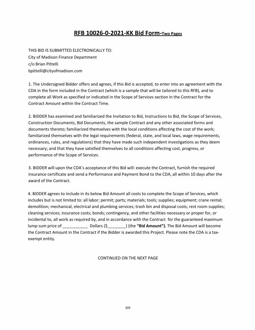
309
RFB 10026‐0‐2021‐KK Bid Form‐Two Pages
THIS BID IS SUBMITTED ELECTRONICALLY TO:
City of Madison Finance Department
c/o Brian Pittelli
1. The Undersigned Bidder offers and agrees, if this Bid is accepted, to enter into an agreement with the
CDA in the form included in the Contract (which is a sample that will be tailored to this RFB), and to
complete all Work as specified or indicated in the Scope of Services section in the Contract for the
Contract Amount within the Contract Time.
2. BIDDER has examined and familiarized the Invitation to Bid, Instructions to Bid, the Scope of Services,
Construction Documents, Bid Documents, the sample Contract and any other associated forms and
documents thereto; familiarized themselves with the local conditions affecting the cost of the work;
familiarized themselves with the legal requirements (federal, state, and local laws, wage requirements,
ordinances, rules, and regulations) that they have made such independent investigations as they deem
necessary; and that they have satisfied themselves to all conditions affecting cost, progress, or
performance of the Scope of Services.
3. BIDDER will upon the CDA’s acceptance of this Bid will: execute the Contract, furnish the required
insurance certificate and send a Performance and Payment Bond to the CDA, all within 10 days after the
award of the Contract.
4. BIDDER agrees to include in its below Bid Amount all costs to complete the Scope of Services, which
includes but is not limited to: all labor; permit; parts; materials; tools; supplies; equipment; crane rental;
demolition; mechanical, electrical and plumbing services; trash bin and disposal costs; rest room supplies;
cleaning services; insurance costs; bonds; contingency, and other facilities necessary or proper for, or
incidental to, all work as required by, and in accordance with the Contract for the guaranteed maximum
lump sum price of ___________ Dollars ($________) (the “Bid Amount”). The Bid Amount will become
the Contract Amount in the Contract if the Bidder is awarded this Project. Please note the CDA is a tax‐
exempt entity.
CONTINUED ON THE NEXT PAGE
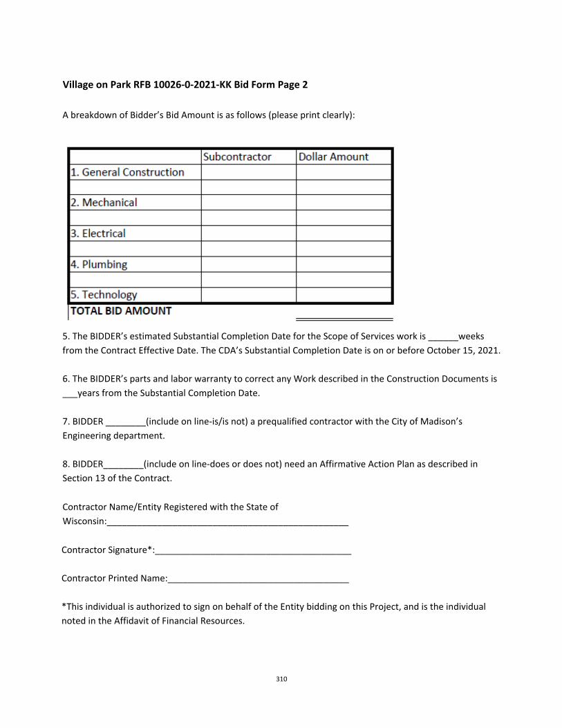
310
Village on Park RFB 10026‐0‐2021‐KK Bid Form Page 2
A breakdown of Bidder’s Bid Amount is as follows (please print clearly):
5. The BIDDER’s estimated Substantial Completion Date for the Scope of Services work is ______weeks
from the Contract Effective Date. The CDA’s Substantial Completion Date is on or before October 15, 2021.
6. The BIDDER’s parts and labor warranty to correct any Work described in the Construction Documents is
___years from the Substantial Completion Date.
7. BIDDER ________(include on line‐is/is not) a prequalified contractor with the City of Madison’s
Engineering department.
8. BIDDER________(include on line‐does or does not) need an Affirmative Action Plan as described in
Section 13 of the Contract.
Contractor Name/Entity Registered with the State of
Wisconsin:________________________________________________
Contractor Signature*:_______________________________________
Contractor Printed Name:____________________________________
*This individual is authorized to sign on behalf of the Entity bidding on this Project, and is the individual
noted in the Affidavit of Financial Resources.
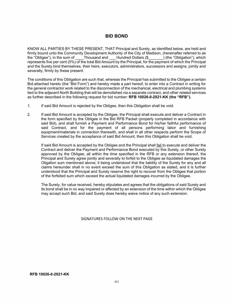
311
BID BOND
KNOW ALL PARTIES BY THESE PRESENT, THAT Principal and Surety, as identified below, are held and firmly bound unto the Community Development Authority of the City of Madison, (hereinafter referred to as the “Obligee”), in the sum of ____Thousand and ___ Hundred Dollars ($_______) (the “Obligation”), which represents five per cent (5%) of the total Bid Amount by the Principal, for the payment of which the Principal and the Surety bind themselves, their heirs, executors, administrators, successors and assigns, jointly and severally, firmly by these present.
The conditions of this Obligation are such that, whereas the Principal has submitted to the Obligee a certain Bid-attached hereto (the “Bid Form”) and hereby made a part hereof, to enter into a Contract in writing for the general contractor work related to the disconnection of the mechanical, electrical and plumbing systems tied to the adjacent North Building that will be demolished via a separate contract, and other related services as further described in the following request for bid number: RFB 10026-0-2021-KK (the “RFB”). 1. If said Bid Amount is rejected by the Obligee, then this Obligation shall be void.
2. If said Bid Amount is accepted by the Obligee, the Principal shall execute and deliver a Contract in
the form specified by the Obligee in the Bid RFB Packet (properly completed in accordance with said Bid), and shall furnish a Payment and Performance Bond for his/her faithful performance of said Contract, and for the payment of all persons performing labor and furnishing equipment/materials in connection therewith, and shall in all other respects perform the Scope of Services created by the acceptance of said Bid Amount, then this Obligation shall be void.
If said Bid Amount is accepted by the Obligee and the Principal shall fail to execute and deliver the Contract and deliver the Payment and Performance Bond executed by this Surety, or other Surety approved by the Obligee, all within the time specified in the RFB or any extension thereof, the Principal and Surety agree jointly and severally to forfeit to the Obligee as liquidated damages the Oligation sum mentioned above; it being understood that the liability of the Surety for any and all claims hereunder shall in no event exceed the sum of this Obligation as stated, and it is further understood that the Principal and Surety reserve the right to recover from the Obligee that portion of the forfeited sum which exceed the actual liquidated damages incurred by the Obligee.
The Surety, for value received, hereby stipulates and agrees that the obligations of said Surety and its bond shall be in no way impaired or affected by an extension of the time within which the Obligee may accept such Bid, and said Surety does hereby waive notice of any such extension.
SIGNATURES FOLLOW ON THE NEXT PAGE
RFB 10026-0-2021-KK
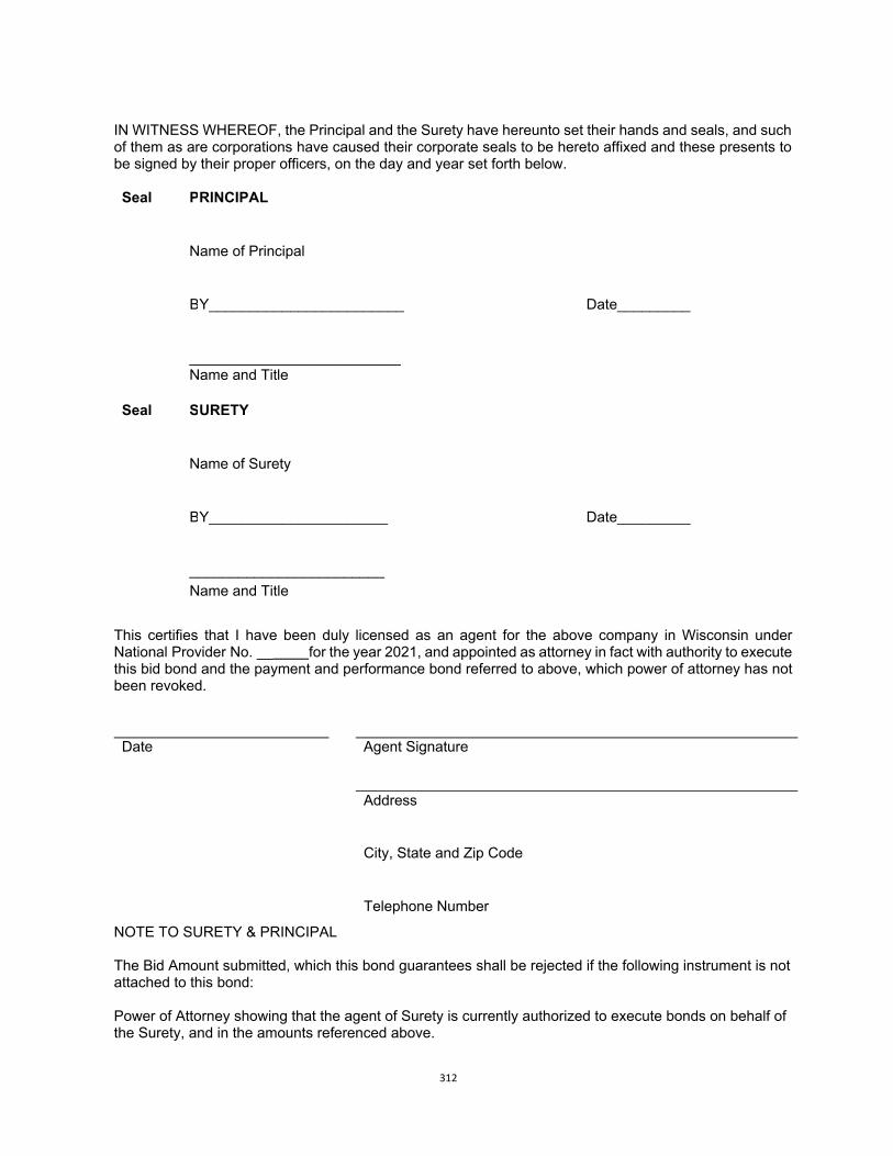
312
IN WITNESS WHEREOF, the Principal and the Surety have hereunto set their hands and seals, and such of them as are corporations have caused their corporate seals to be hereto affixed and these presents to be signed by their proper officers, on the day and year set forth below.
Seal PRINCIPAL
Name of Principal
BY________________________ Date_________
__________________________ Name and Title
Seal S
URETY
Name of Surety
BY______________________ Date_________
________________________ N d Titl Name and Title
This certifies that I have been duly licensed as an agent for the above company in Wisconsin under National Provider No. __ for the year 2021, and appointed as attorney in fact with authority to execute this bid bond and the payment and performance bond referred to above, which power of attorney has not been revoked.
Date Agent Signature
Address
City, State and Zip Code
Telephone Number
NOTE TO SURETY & PRINCIPAL
The Bid Amount submitted, which this bond guarantees shall be rejected if the following instrument is not attached to this bond:
Power of Attorney showing that the agent of Surety is currently authorized to execute bonds on behalf of the Surety, and in the amounts referenced above.
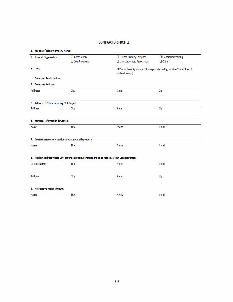
313
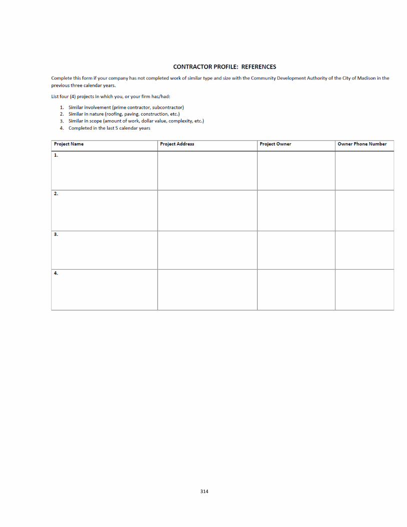
314
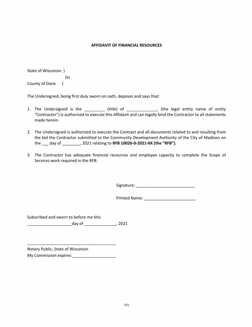
315
AFFIDAVIT OF FINANCIAL RESOURCES
State of Wisconsin )
)ss
County of Dane )
The Undersigned, being first duly sworn on oath, deposes and says that:
1. The Undersigned is the _________ (title) of ______________ (the legal entity name of entity “Contractor”) is authorized to execute this Affidavit and can legally bind the Contractor to all statements made herein.
2. The Undersigned is authorized to execute the Contract and all documents related to and resulting from the bid the Contractor submitted to the Community Development Authority of the City of Madison on the ___ day of ________, 2021 relating to RFB 10026‐0‐2021‐KK (the “RFB”).
3. The Contractor has adequate financial resources and employee capacity to complete the Scope of Services work required in the RFB.
Signature: __________________________
Printed Name: _______________________
Subscribed and sworn to before me this
day of , 2021
Notary Public, State of Wisconsin
My Commission expires:
316
Section III: CONTRACTING REQUIREMENTS
If the Bidder is selected by the CDA for this Project, then within ten days of the award of the
Project it will need to fill out and return the CDA Contract, a certificate of insurance per the below
terms, and provide a Performance and Payment Bond.
A. CDA Contract
See the attached sample Contract on the next page that will be tailored to the Bid.
As noted in the Contract, Bidder/Contractor will need to comply with the insurance requirements
outlined in Section B below.

317
THIS IS A SAMPLE CONTRACT SUBJECT TO CHANGE
CONTRACT FOR PURCHASE OF SERVICES (RFB 10026-0-2021-KK) between the Community Development Authority of the City of Madison
and______________________.
1. PARTIES. This is a “Contract” or “Agreement” between the Community Development Authority of the City of Madison, Wisconsin, hereafter referred to as the "CDA" and ___________, hereafter referred to as "Contractor”. The Contractor is a: Corporation Limited Liability Company General Partnership LLP (to be completed by Contractor) Sole Proprietor Unincorporated Association Other: .
2. PURPOSE.
The purpose of this Contract is for the Contractor to perform general contractor work related to the Scope of Services, as set forth in Section 3, at the Village on Park Mall located at 2300 S. Park Street, Madison WI (the “Property”).
3. SCOPE OF SERVICES AND SCHEDULE OF PAYMENTS.
Contractor will perform the scope of services as described in Attachment 2 per the Construction Documents in Attachment 3 (collectively the “Scope of Services”). The attachments to the Contract are as follows:
a. Attachment 1: Floor Plan b. Attachment 2: Scope of Services c. Attachment 3: Plans and Specifications/Project Manual prepared by Strang, Inc.(collectively the “Construction
Documents”) d. Attachment 4: Site Plan
Contractor shall invoice the CDA monthly for work completed per the Scope of Services; see Section 24 for more detail on the basis for payment. In the case of any conflict between the provisions of Exhibit A and this Agreement, the provisions of this Agreement shall control.
4. TERM AND EFFECTIVE DATE.
This Contract shall become effective upon execution by both parties. The Contract Effective Date is the latest date signed by the CDA. No work shall commence before such time. The Scope of Services shall be completed no later than October 15, 2021, unless both parties agree to amend the Contract per the terms of Section 9.
5. ENTIRE AGREEMENT.
This Contract for Purchase of Services, including any and all attachments, exhibits and other documents referenced in Section 3 (hereafter, “Agreement” or “Contract”) is the entire Agreement of the parties and supersedes any and all oral contracts and negotiations between the parties.
6. ASSIGNABILITY/SUBCONTRACTING.
Contractor shall not assign or subcontract any interest or obligation under this Contract without the CDA’s prior written approval. All of the services required hereunder will be performed by Contractor and employees of Contractor.
7. DESIGNATED REPRESENTATIVE.
A. Contractor designates _______ as Contract Agent with primary responsibility for the performance of this Contract. In case this Contract Agent is replaced by another for any reason, the Contractor will designate another Contract Agent within seven (7) calendar days of the time the first terminates his or her employment or responsibility using the procedure set forth in Section 15, Notices.
B. In the event of the death, disability, removal or resignation of the person designated above as the Contract agent, the CDA may accept another person as the Contract agent or may terminate this Agreement under Section 25, at its option.
8. PROSECUTION AND PROGRESS.
A. Services under this Agreement shall commence upon written order from the CDA to the Contractor when it delivers a fully executed Agreement. This order will constitute authorization to proceed, unless another date for commencement is specified elsewhere in this Contract including documents incorporated in Section 3.
B. The Contractor shall complete the services under this Agreement within the time for completion specified in the Scope of Services, including any amendments. The Contractor’s services are completed when the CDA notifies the
318
Contractor in writing that the services are complete and are acceptable. The time for completion shall not be extended because of any delay attributable to the Contractor, but it may be extended by the CDA in the event of a delay attributable to the CDA, or in the event of unavoidable delay caused by war, insurrection, natural disaster, or other unexpected event beyond the control of the Contractor. If at any time the Contractor believes that the time for completion of the work should be extended because of unavoidable delay caused by an unexpected event, or because of a delay attributable to the CDA, the Contractor shall notify the CDA as soon as possible, but not later than seven (7) calendar days after such an event. Such notice shall include any justification for an extension of time and shall identify the amount of time claimed to be necessary to complete the work.
C. Services by the Contractor shall proceed continuously and expeditiously through completion of each phase of the work.
D. Progress reports documenting the extent of completed services shall be prepared by the Contractor and submitted to the CDA with each invoice under Section 24 of this Agreement, and at such other times as the CDA may specify.
E. The Contractor shall notify the CDA in writing when the Contractor has determined that the Scope of Services under this Agreement have been completed. When the CDA determines that the Scope of Services are complete and are acceptable, the CDA will provide written notification to the Contractor, acknowledging formal acceptance of the completed Scope of Services. In the event the CDA does not believe Substantial Completion has occurred it will provide Contractor with a punch list it needs to cure as set forth in the PlansSpecs.
9. AMENDMENT.
This Contract shall be binding on the parties hereto, their respective heirs, devisees, and successors, and cannot be varied or waived by any oral representations or promise of any agent or other person of the parties hereto. Any other change in any provision of this Contract may only be made by a written amendment, signed by the duly authorized agent or agents who executed this Contract.
10. EXTRA SERVICES.
The CDA may require the Contractor to perform extra services or decreased services, according to the procedure set forth in Section 24. Extra services or decreased services means services which are not different in kind or nature from the services called for in the Scope of Services, Section 3, but which may increase or decrease the quantity and kind of labor or materials or expense of performing the services. Extra services may not increase the total Contract Price, as set forth in Section 23, unless the Contract is amended as provided in Section 9 above.
11. NO WAIVER.
No failure to exercise, and no delay in exercising, any right, power or remedy hereunder on the part of the CDA or Contractor shall operate as a waiver thereof, nor shall any single or partial exercise of any right, power or remedy preclude any other or further exercise thereof or the exercise of any other right, power or remedy. No express waiver shall affect any event or default other than the event or default specified in such waiver, and any such waiver, to be effective, must be in writing and shall be operative only for the time and to the extent expressly provided by the CDA or Contractor therein. A waiver of any covenant, term or condition contained herein shall not be construed as a waiver of any subsequent breach of the same covenant, term or condition.
12. NON-DISCRIMINATION.
In the performance of work under this Contract, the Contractor agrees not to discriminate against any employee or applicant for employment because of race, religion, marital status, age, color, sex, handicap, national origin or ancestry, income level or source of income, arrest record or conviction record, less than honorable discharge, physical appearance, sexual orientation, gender identity, political beliefs or student status. Contractor further agrees not to discriminate against any subcontractor or person who offers to subcontract on this Contract because of race, religion, color, age, disability, sex, sexual orientation, gender identity or national origin.
13. AFFIRMATIVE ACTION. By policy, the CDA has opted to require contractors to comply with the Affirmative Action and Workforce utilization requirements
of the City of Madison. Under this Agreement, Contractor shall comply with the following:
A. The following language applies to all contractors employing fifteen (15) or more employees: (MGO 39.02(9)(c).) The Contractor agrees that, within thirty (30) days after the Effective Date of this Contract, Contractor will provide to the City of Madison Department of Civil Rights (the “Department”), certain workforce utilization statistics, using a form provided by the City of Madison (the “City”). If the Contract is still in effect, or if the CDA enters into a new agreement with the Contractor, within one year after the date on which the form was required to be provided, the Contractor will provide updated workforce information using a second form, also to be furnished by the City. The second form will be submitted to the Department no later than one year after the date on which the first form was required to be provided. The Contractor further agrees that, for at least twelve (12) months after the Effective Date of this Contract, it will notify the Department of each of its job openings at facilities in Dane County for which applicants not already employees of the Contractor are to be considered. The notice will include a job description, classification, qualifications, and application procedures and deadlines. The Contractor agrees to interview and consider candidates referred by the Department if the candidate meets the minimum qualification standards established by the Contractor, and if the referral is timely. A referral is timely if it is received by the Contractor on or before the date stated in the notice.
319
The Department will determine if the Contractor is exempt from the above requirements (Sec. 13.A) at the time the Request for Exemption in 13.B(2) is made.
B. Articles of Agreement, Request for Exemption, and Release of Payment: The “ARTICLES OF AGREEMENT” beginning on the following page, apply to all contractors, unless determined to be exempt under the following table and procedures:
NUMBER OF EMPLOYEES LESS THAN $50,000
Aggregate Annual Business with the City* $50,000 OR MORE
Aggregate Annual Business with the City*
14 or less Exempt** Exempt**
15 or more Exempt** Not Exempt
*As determined by the Finance Director **As determined by the Department of Civil Rights
REQUEST FOR EXEMPTION: (MGO 39.02(9)(a)2.) Contractors who believe they are Exempt from the Articles of Agreement according to the table above, shall submit a Request for Exemption on a form provided by the Department of Civil Rights (“Department”), within thirty (30) days of the effective date of this Contract. The Department makes the final determination as to whether a contractor is exempt from the Articles of Agreement. In the event the Contractor is not exempt, the Articles of Agreement shall apply. CONTRACTORS WITH 15 OR MORE EMPLOYEES WILL LOSE THIS EXEMPTION AND BECOME SUBJECT TO THE ARTICLES OF AGREEMENT UPON REACHING $50,000 OR MORE ANNUAL AGGREGATE BUSINESS WITH THE CITY WITHIN THE CALENDAR YEAR. RELEASE OF PAYMENT: (MGO 39.02(9)(e)1.b.) Within thirty (30) days from the effective date of this Contract, and prior to release of payment by the CDA, all non-exempt contractors are required to have on file with the Department, an Affirmative Action plan meeting the requirements of Article IV below. Additionally, contractors that are exempt from the Articles of Agreement under Table 13-B, must have a Request for Exemption form on-file with the Department, prior to release of payment by the CDA.
ARTICLES OF AGREEMENT
ARTICLE I
The Contractor shall take affirmative action in accordance with the provisions of this Contract to insure that applicants are employed, and that employees are treated during employment without regard to race, religion, color, age, marital status, disability, sex, sexual orientation, gender identity or national origin and that the employer shall provide harassment-free work environment for the realization of the potential of each employee. Such action shall include, but not be limited to, the following: employment, upgrading, demotion or transfer, recruitment or recruitment advertising, layoff or termination, rates of pay or other forms of compensation and selection for training including apprenticeship insofar as it is within the control of the Contractor. The Contractor agrees to post in conspicuous places available to employees and applicants notices to be provided by the CDA setting out the provisions of the nondiscrimination clauses in this Contract.
ARTICLE II
The Contractor shall in all solicitations or advertisements for employees placed by or on behalf of the Contractor state that all qualified or qualifiable applicants will be employed without regard to race, religion, color, age, marital status, disability, sex, sexual orientation, gender identity or national origin.
ARTICLE III
The Contractor shall send to each labor union or representative of workers with which it has a collective bargaining Agreement or other Contract or understanding a notice to be provided by the CDA advising the labor union or workers representative of the Contractor’s equal employment opportunity and affirmative action commitments. Such notices shall be posted in conspicuous places available to employees and applicants for employment.
ARTICLE IV
(This Article applies to non-public works contracts.)
The Contractor agrees that it will comply with all provisions of the Affirmative Action Ordinance of the City of Madison including the Contract compliance requirements. The Contractor warrants and certifies that, of the following two paragraphs, paragraph A or B is true (check one):
A. It has prepared and has on file an affirmative action plan that meets the format requirements of Federal Revised Order No, 4, 41 CFR part 60-2, as established by 43 FR 51400 November 3, 1978, including appendices required by City of Madison ordinances or it has prepared and has on file a model affirmative action plan approved by the Madison Common Council.
B. Within thirty (30) days after the effective date of this Contract, it will complete an affirmative action plan that meets the format requirements of Federal Revised Order No. 4, 41 CFR Part 60-2, as established by 43 FR 51400, November 3, 1978, including appendices required by City of Madison ordinance or within thirty (30) days after the effective date of this Contract, it will complete a model affirmative action plan approved by the Madison Common Council.
320
ARTICLE V
(This Article applies only to public works contracts.)
The Contractor agrees that it will comply with all provisions of the Affirmative Action Ordinance of the City of Madison, including the Contract compliance requirements. The Contractor agrees to submit the model affirmative action plan for public works Contractors in a form approved by the Director of Affirmative Action.
ARTICLE VI
The Contractor will maintain records as required by Section 39.02(9)(f) of the Madison General Ordinances and will provide the City's Department of Affirmative Action with access to such records and to persons who have relevant and necessary information, as provided in Section 39.02(9)(f). The City agrees to keep all such records confidential, except to the extent that public inspection is required by law.
ARTICLE VII
In the event of the Contractor’s or subcontractor's failure to comply with the Equal Employment Opportunity and Affirmative Action provisions of this Contract or Sections 39.03 and 39.02 of the Madison General Ordinances, it is agreed that the CDA at its option may do any or all of the following:
A. Cancel, terminate or suspend this Contract in whole or in part. B. Declare the Contractor ineligible for further CDA contracts until the Affirmative Action requirements are met. C. Recover on behalf of the CDA from the prime Contractor 0.5 percent of the Contract award price for each week that
such party fails or refuses to comply, in the nature of liquidated damages, but not to exceed a total of five percent (5%) of the Contract price, or ten thousand dollars ($10,000), whichever is less. Under public works contracts, if a subcontractor is in noncompliance, the CDA may recover liquidated damages from the prime Contractor in the manner described above. The preceding sentence shall not be construed to prohibit a prime Contractor from recovering the amount of such damage from the noncomplying subcontractor.
ARTICLE VIII
(This Article applies to public works contracts only.)
The Contractor shall include the above provisions of this Contract in every subcontract so that such provisions will be binding upon each subcontractor. The Contractor shall take such action with respect to any subcontractor as necessary to enforce such provisions, including sanctions provided for noncompliance.
ARTICLE IX
The Contractor shall allow the maximum feasible opportunity to small business enterprises to compete for any subcontracts entered into pursuant to this Contract. (In federally funded contracts the terms "DBE, MBE, and WBE" shall be substituted for the term "small business" in this Article.)
14. SEVERABILITY.
It is mutually agreed that in case any provision of this Contract is determined by any court of law to be unconstitutional, illegal or unenforceable, it is the intention of the parties that all other provisions of this Contract remain in full force and effect.
15. NOTICES.
All notices to be given under the terms of this Contract shall be in writing, dated and signed by the person serving the same, and shall be sent electronic mail, to the email addresses of the parties listed below. When sending electronic mail, an active read receipt shall be attached and include a statement that the electronic mail constitutes notice under the terms of this Contract. All time periods with respect to notice shall commence on the date that electronic notice is sent.
FOR THE CDA: City of Madison Office of Real Estate Service
c/o Kris Koval, Real Estate Development Specialist III 215 Martin Luther King Jr Blvd Suite 300 Madison, WI 53703 [email protected]
FOR THE CONTRACTOR:
16. STATUS OF CONTRACTOR/INDEPENDENT/TAX FILING.
It is agreed that Contractor is an independent Contractor and not an employee of the CDA, and that any persons who the Contractor utilizes and provides for services under this Contract are employees of the Contractor and are not employees of the CDA. Contractor shall provide its taxpayer identification number (or social security number) on a W-9 form filled out and sent to Kris Koval, prior to payment. The Contractor is informed that as an independent Contractor, s/he may have a responsibility to make estimated tax returns, file tax returns, and pay income taxes and make social security payments on the amounts received under this Contract and that no amounts will be withheld from payments made to this Contractor for these purposes and that payment of taxes and making social security payments are solely the responsibility and obligation of the Contractor. The Contractor is further informed that s/he may be subject to civil and/or criminal penalties if s/he fails to properly report income and pay taxes and social security taxes on the amount received under this Contract.
17. GOODWILL.
Any and all goodwill arising out of this Contract inures solely to the benefit of the CDA; Contractor waives all claims to benefit of such goodwill.
321
18. THIRD PARTY RIGHTS.
This Contract is intended to be solely between the parties hereto. No part of this Contract shall be construed to add, supplement, amend, abridge or repeal existing rights, benefits or privileges of any third party or parties, including but not limited to employees of either of the parties.
19. AUDIT AND RETAINING OF DOCUMENTS.
The Contractor agrees to provide all reports requested by the CDA including, but not limited to, financial statements and reports, reports and accounting of services rendered, and any other reports or documents requested. Financial and service reports shall be provided according to a schedule (when applicable) to be included in this Contract. Any other reports or documents shall be provided within five (5) working days after the Contractor receives the CDA’s written requests, unless the parties agree in writing on a longer period. Payroll records and any other documents relating to the performance of services under the terms of this Contract shall be retained by the Contractor for a period of three (3) years after completion of all work under this Contract, in order to be available for audit by the CDA or its designee.
20. CHOICE OF LAW AND FORUM SELECTION.
This Contract shall be governed by and construed, interpreted and enforced in accordance with the laws of the State of Wisconsin. The parties agree, for any claim or suit or other dispute relating to this Contract that cannot be mutually resolved, the venue shall be a court of competent jurisdiction within the State of Wisconsin and the parties agree to submit themselves to the jurisdiction of said court, to the exclusion of any other judicial district that may have jurisdiction over such a dispute according to any law.
21. COMPLIANCE WITH APPLICABLE LAWS.
The Contractor shall become familiar with, and shall at all times comply with and observe all federal, state, and local laws, ordinances, and regulations which in any manner affect the services or conduct of the Contractor and its agents and employees. If Contractor discovers that the prescribed work is not in accordance with codes, Contractor will promptly notify CDA and await direction from CDA.
22. CONFLICT OF INTEREST.
A. The Contractor warrants that it and its agents and employees have no public or private interest, and will not acquire directly or indirectly any such interest, which would conflict in any manner with the performance of the services under this Agreement.
B. The Contractor shall not employ or Contract with any person currently employed by the CDA for any services included under the provisions of this Agreement.
23. COMPENSATION/ CONTRACT AMOUNT
It is expressly understood and agreed that in no event will the total compensation for the Scope of Services under this Contract shall exceed -------- ($_______) or the “Contract Price”. This Contract Price includes all permits (excluding the building permit) and fees related to the Scope of Services.
24. BASIS FOR PAYMENT. A. GENERAL
(1) The CDA will pay the Contractor for the completed and accepted services rendered under this Contract on the basis and at the Contract Price set forth in Section 23 of this Contract. The CDA will pay the Contractor for completed and approved "extra services", if any, if such "extra services" are authorized according to the procedure established in this section. The rate of payment for "extra services" shall be the rate established in this Contract. Such payment shall be full compensation for services rendered and for all labor, material, supplies, equipment and incidentals necessary to complete the services.
(2) The Contractor shall submit monthly invoices to the CDA as work is completed, on the AIA® contractor form G702 Application and Certificate for Payment along with a partial lien waiver. The final invoice shall be submitted to the CDA within three months of completion of services under this Agreement.
(3) Should this Agreement contain more than one service, a separate invoice and a separate final statement shall be submitted for each individual service.
(4) Payment shall not be construed as CDA acceptance of unsatisfactory or defective services or improper materials.
(5) Final payment of any balance due the Contractor will be made upon acceptance by the CDA of the services under the Agreement and upon receipt by the CDA of documents required to be returned or to be furnished by the Contractor under this Agreement.
(6) The CDA has the equitable right to set off against any sum due and payable to the Contractor under this Agreement, any amount the CDA determines the Contractor owes the CDA, whether arising under this Agreement or under any other Agreement or otherwise.
(7) Compensation in excess of the total Contract Price will not be allowed unless authorized by an amendment under Section 9, AMENDMENT.
(8) The CDA will not compensate for unsatisfactory performance by the Contractor.
B. SERVICE ORDERS, EXTRA SERVICE, OR DECREASED SERVICE. (1) Written orders regarding the services, including extra services or decreased services, will be given by the
CDA, using the procedure set forth in Section 15, NOTICES. (2) The CDA may, by written order, request extra services or decreased services, as defined in Section 10 of
this Contract. Unless the Contractor believes the extra services entitle it to extra compensation or additional time, the Contractor shall proceed to furnish the necessary labor, materials, and professional services to
322
complete the services within the time limits specified in the Scope of Services, Section 3 of this Agreement, including any amendments under Section 9 of this Agreement.
(3) If in the Contractor's opinion the order for extra service would entitle it to extra compensation or extra time, or both, the Contractor shall not proceed to carry out the extra service, but shall notify the CDA, pursuant to Section 15 of this Agreement. The notification shall include the justification for the claim for extra compensation or extra time, or both, and the amount of additional fee or time requested.
(4) The CDA shall review the Contractor's submittal and respond in writing, either authorizing the Contractor to perform the extra service, or refusing to authorize it. The Contractor shall not receive additional compensation or time unless the extra compensation is authorized by the CDA in writing.
25. DEFAULT/TERMINATION.
A. In the event Contractor shall default in any of the covenants, agreements, commitments, or conditions herein contained, and any such default shall continue unremedied for a period of ten (10) days after written notice thereof to Contractor, the CDA may, at its option and in addition to all other rights and remedies which it may have at law or in equity against Contractor, including expressly the specific enforcement hereof, forthwith have the cumulative right to immediately terminate this Contract and all rights of Contractor under this Contract.
B. Notwithstanding paragraph A., above, the CDA may in its sole discretion and without any reason terminate this Agreement at any time by furnishing the Contractor with ten (10) days' written notice of termination. In the event of termination under this subsection, the CDA will pay for all work completed by the Contractor and accepted by the CDA as of the termination date.
26. INDEMNIFICATION.
Contractor shall be liable to and hereby agrees to indemnify, defend and hold harmless the CDA and the City, and their officers, officials, agents, and employees against all loss or expense (including liability costs and attorney’s fees) by reason of any claim or suit, or of liability imposed by law upon the CDA and the City or their officers, officials, agents or employees for damages because of bodily injury, including death at any time resulting therefrom, sustained by any person or persons or on account of damages to Property, including loss of use thereof, arising from, in connection with, caused by or resulting from the Contractor’s and/or subcontractor’s negligent acts, errors or omissions, in the performance of this Agreement. The provisions of this Section shall survive termination of this Agreement.
27. INSURANCE.
A. The Contractor will insure, and will require each subcontractor to insure, as indicated, against the following risks to the extent stated below. The Contractor shall not commence work under this Contract, nor shall the Contractor allow any Subcontractor to commence work on its Subcontract, until the insurance coverage required below has been obtained and approved by the City Risk Manager, under the procedures in Section 27. C, below.
Commercial General Liability The Contractor shall procure and maintain during the life of this Contract, Commercial General Liability insurance including, but
not limited to bodily injury, property damage, personal injury, and products and completed operations (unless determined to be inapplicable by the Risk Manager) in an amount not less than $1,000,000 per occurrence. This policy shall also provide contractual liability in the same amount. Contractor’s coverage shall be primary and list the CDA and the City, its officers, officials, agents and employees as additional insureds. Contractor shall require all subcontractors under this Contract (if any) to procure and maintain insurance meeting the above criteria, applying on a primary basis and listing the CDA and the City, its officers, officials, agents and employees as additional insureds..
Automobile Liability
The Contractor shall procure and maintain during the life of this Contract Business Automobile Liability insurance covering owned, non-owned and hired automobiles with limits of not less than $1,000,000 combined single limit per accident. Contractor shall require all subcontractors under this Contract (if any) to procure and maintain insurance covering each subcontractor and meeting the above criteria.
Worker's Compensation
The Contractor shall procure and maintain during the life of this Contract statutory Workers’ Compensation insurance as required by the State of Wisconsin. The Contractor shall also carry Employers Liability limits of at least $100,000 Each Accident, $100,000 Disease – Each Employee, and $500,000 Disease – Policy Limit. Contractor shall require all subcontractors under this Contract (if any) to procure and maintain such insurance, covering each subcontractor.
Professional Liability The Contractor shall procure and maintain professional liability insurance with coverage of not less than $1,000,000. If such policy is a “claims made” policy, all renewals thereof during the life of the Contract shall include “prior acts coverage” covering at all times all claims made with respect to Contractor’s work performed under the Contract. This Professional Liability coverage must be kept in force for a period of six (6) years after the services have been accepted by the CDA. B. Acceptability of Insurers. The above-required insurance is to be placed with insurers who have an A.M. Best rating of
no less than A- (A minus) and a Financial Category rating of no less than VII. C. Proof of Insurance, Approval. The Contractor shall provide the CDA with certificate(s) of insurance showing the type,
amount, effective dates, and expiration dates of required policies prior to commencing work under this Contract. Contractor shall provide the certificate(s) to the City’s representative upon execution of the Contract, or sooner, for approval by the City Risk Manager. If any of the policies required above expire while this Contract is still in effect, Contractor shall provide renewal certificate(s) to the City for approval. Certificate Holder language should be listed as follows:
323
City of Madison ATTN: Risk Management, Room 406 210 Martin Luther King, Jr. Blvd. Madison, WI 53703 The Contractor shall provide copies of additional insured endorsements or insurance policies, if requested by the City Risk Manager. The Contractor and/or Insurer shall give the City thirty (30) days advance written notice of cancellation, non-renewal or material changes to any of the above-required policies during the term of this Contract.
D. Notice of Cancellation. The Contractor and/or Insurer shall give the City thirty (30) days advance written notice of cancellation, non-renewal or material changes to any of the above-required policies during the term of this Contract.
28. OWNERSHIP OF CONTRACT PRODUCT.
The original drawings and specifications, renderings, models, scale details, approved copies of shop drawings, record drawings and other such documents prepared by the Contractor pursuant to this Contract shall become the property of the CDA on completion and acceptance of the Contractor's work, or upon termination of the Contract, and shall be delivered to the CDA. Documents prepared under this Contract may be distributed by the CDA for informational purposes without additional compensation to the Contractor. Specifications and isolated, detail drawings inherent to the Contractorural design of the project, whether provided by the CDA or generated by the Contractor, shall be available for future use by the parties to this Contract and other parties, each at their own risk. If design and documentation has been completed using automated or computerized techniques, the Contractor shall provide a copy of project documents upon request in a format approved by the CDA.
29. WEAPONS PROHIBITION. Contractor shall prohibit, and shall require its subcontractors to prohibit, its employees from carrying weapons, including concealed weapons, in the course of performance of work under this Contract, other than while at the Contractor’s or subcontractor’s own business premises. This requirement shall apply to vehicles used at any City work site and vehicles used to perform any work under this Contract, except vehicles that are an employee’s “own motor vehicle” pursuant to Wis. Stat. sec. 175.60(15m).
30. AUTHORITY. Contractor represents that it has the authority to enter into this Contract. If the Contractor is not an individual, the person signing on behalf of the Contractor represents and warrants that he or she has been duly authorized to bind the Contractor and sign this Contract on the Contractor’s behalf.
31. COUNTERPARTS, ELECTRONIC DELIVERY. This Contract may be signed in counterparts, each of which shall be taken together as a whole to comprise a single document. Signatures on this Contract may be exchanged between the parties by facsimile, electronic scanned copy (.pdf) or similar technology and shall be as valid as original. Executed copies or counterparts of this Contract may be delivered by facsimile or email and upon receipt will be deemed original and binding upon the parties hereto, whether or not a hard copy is also delivered. Copies of this Contract, fully executed, shall be as valid as an original.
SIGNATURES FOLLOW ON THE NEXT PAGE
324
IN WITNESS WHEREOF, the parties hereto have set their hands at Madison, Wisconsin.
CONTRACTOR
(Type or Print Name of Contracting Entity)
By: (Authorized Signature)
Date: COMMUNITY DEVELOPMENT AUTHORITY OF THE CITY OF
MADISON, WISCONSIN a body corporate & public
By: _____________________________________________ Claude Gilmore, Chair CDA
By: Matt Wachter, Executive Director CDA
Effective Date:
ATTACHMENTS 1‐4 TO CONTRACT FOR PURCHASE OF SERVICES INCLUDED ABOVE IN THIS RFB WILL BE ATTACHED TO THE CONTRACT
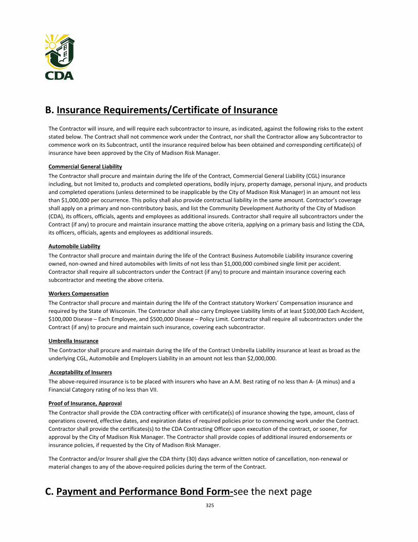
325
B. Insurance Requirements/Certificate of Insurance
The Contractor will insure, and will require each subcontractor to insure, as indicated, against the following risks to the extent
stated below. The Contract shall not commence work under the Contract, nor shall the Contractor allow any Subcontractor to
commence work on its Subcontract, until the insurance required below has been obtained and corresponding certificate(s) of
insurance have been approved by the City of Madison Risk Manager.
Commercial General Liability
The Contractor shall procure and maintain during the life of the Contract, Commercial General Liability (CGL) insurance
including, but not limited to, products and completed operations, bodily injury, property damage, personal injury, and products
and completed operations (unless determined to be inapplicable by the City of Madison Risk Manager) in an amount not less
than $1,000,000 per occurrence. This policy shall also provide contractual liability in the same amount. Contractor’s coverage
shall apply on a primary and non‐contributory basis, and list the Community Development Authority of the City of Madison
(CDA), its officers, officials, agents and employees as additional insureds. Contractor shall require all subcontractors under the
Contract (if any) to procure and maintain insurance matting the above criteria, applying on a primary basis and listing the CDA,
its officers, officials, agents and employees as additional insureds.
Automobile Liability
The Contractor shall procure and maintain during the life of the Contract Business Automobile Liability insurance covering
owned, non‐owned and hired automobiles with limits of not less than $1,000,000 combined single limit per accident.
Contractor shall require all subcontractors under the Contract (if any) to procure and maintain insurance covering each
subcontractor and meeting the above criteria.
Workers Compensation
The Contractor shall procure and maintain during the life of the Contract statutory Workers’ Compensation insurance and
required by the State of Wisconsin. The Contractor shall also carry Employee Liability limits of at least $100,000 Each Accident,
$100,000 Disease – Each Employee, and $500,000 Disease – Policy Limit. Contractor shall require all subcontractors under the
Contract (if any) to procure and maintain such insurance, covering each subcontractor.
Umbrella Insurance
The Contractor shall procure and maintain during the life of the Contract Umbrella Liability insurance at least as broad as the
underlying CGL, Automobile and Employers Liability in an amount not less than $2,000,000.
Acceptability of Insurers
The above‐required insurance is to be placed with insurers who have an A.M. Best rating of no less than A‐ (A minus) and a
Financial Category rating of no less than VII.
Proof of Insurance, Approval
The Contractor shall provide the CDA contracting officer with certificate(s) of insurance showing the type, amount, class of
operations covered, effective dates, and expiration dates of required policies prior to commencing work under the Contract.
Contractor shall provide the certificates(s) to the CDA Contracting Officer upon execution of the contract, or sooner, for
approval by the City of Madison Risk Manager. The Contractor shall provide copies of additional insured endorsements or
insurance policies, if requested by the City of Madison Risk Manager.
The Contractor and/or Insurer shall give the CDA thirty (30) days advance written notice of cancellation, non‐renewal or
material changes to any of the above‐required policies during the term of the Contract.
C. Payment and Performance Bond Form‐see the next page
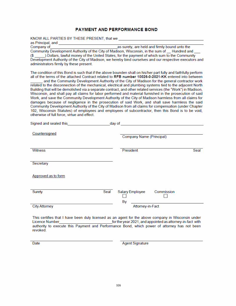
326